SR650 - Uncategorized SRS - Free user manual and instructions
Find the device manual for free SR650 SRS in PDF.


User questions about SR650 SRS
0 question about this device. Answer the ones you know or ask your own.
Ask a new question about this device
Download the instructions for your Uncategorized in PDF format for free! Find your manual SR650 - SRS and take your electronic device back in hand. On this page are published all the documents necessary for the use of your device. SR650 by SRS.
USER MANUAL SR650 SRS
Model SR640 Dual-Channel Filters

text_image
NSRSStanford Research Systems
1290-D Reamwood Avenue
Sunnyvale, California 94089
Phone: (408) 744-9040 • Fax: (408) 744-9049
email: info@thinkSRS.com • www.thinkSRS.com
Copyright © 1989, 1999, 2007 by SRS, Inc.
All Rights Reserved.
Revision 2.7 (7/2007)
Notice: The information described in this manual pertains to the SR640 dual channel low-pass filter, the SR645 dual channel high-pass filter, and the SR650 low-pass high-pass filter. The manual refers to all three filter models as "SR640". Any differences among the three models are explicitly noted.
TABLE OF CONTENTS
CONDENSED INFORMATION
Safety and Preparation for Use 3
Specifications 5
INSTRUMENT OVERVIEW
Front Panel Operation 7
Power Button
Frequency Display 7
Source Select 7
Coupling and Invert 8
Input and Output Gain 8
Filter In / Out 8
Clear / Local 8
Store and Recall 8
Error, Activity, and Remote 8
7
GUIDE TO PROGRAMMING
Communicating with the SR640 9
Configuration Switches 9
Command Syntax 9
RS-232 Echo 9
COMMAND LIST
Filter Commands 11
Status and Interface Commands 11
PROGRAMMING EXAMPLES
Basic 13
FORTRAN 13
C 14
INSTRUMENT DESCRIPTION
Circuit Description 16
PART LIST 18
Front Panel Board Parts List 18
Digital Board Parts List 20
Filter Board Parts List 22
Chassis Assembly Parts List 34
Miscellaneous Parts List 35
SCHEMATIC DIAGRAMS
Symbols you may find on SRS products.
| Symbol | Description |
 | Alternating current |
 | Caution - risk of electric shock |
 | Frame or chassis terminal |
 | Caution - refer to accompanying documents |
 | Earth (ground) terminal |
 | Battery |
 | Fuse |
| On (supply) | |
| Off (supply) |
SAFETY AND PREPARATION FOR USE
**** CAUTION ****
This instrument may be damaged if operated with the LINE VOLTAGE SELECTOR set for the wrong AC line voltage or if the wrong fuse is installed.
LINE VOLTAGE SELECTION
The SR640 operates from 100, 120, 220 or 240 Volts nominal AC power source with a line frequency of 50 or 60 Hz. Before connecting the power cord to a power source, verify that the LINE VOLTAGE SELECTOR card, located in the rear panel fuse holder, is set so that the correct AC input voltage is visible.
Conversion to other AC input voltages requires a change in the fuse holder voltage card position and fuse value. Disconnect the power cord, open the fuse holder cover door and rotate the fuse-pull lever to remove the fuse. Remove the small printed circuit board and select the operating voltage by orienting the printed circuit board to position the desired voltage to be visible when pushed firmly into its slot. Rotate the fuse-pull lever back into its normal position and insert the correct fuse into the fuse holder.
Verify that the correct line fuse is installed before connecting the line cord. For 100V/120V, use a 1 Amp fuse and for 220V/240V, use a 1/2 Amp fuse.
LINE CORD
The SR640 series uses a detachable, three-wire power cord for connection to the power source and to a protective ground. The exposed metal parts of the instrument are connected to the outlet ground to protect against electrical shock. Always use an outlet which has a properly connected protective ground.
GROUNDING
The SR640's BNC connector shields are NOT connected to the unit's chassis ground. This is done in order to provide the user with maximum flexibility in connecting the instrument's grounds for optimum noise-reduction. However, the user should be aware that improper connection of the SR640 to a hazardous voltage source could result in hazardous voltages present at the exposed BNC shield terminals. Please see the guide to operations for additional information concerning grounding.
LINE FUSE
SR640 SPECIFICATIONS
GENERAL INFORMATION
The SR640 consists of two independent low-pass filter channels. Each filter is preceded by a low-noise pre-amplifier with selectable gain of 0 to 60 dB. The filters are an 8-pole, 6-zero elliptical design with 0.1 dB maximum passband ripple and 115 dB/octave attenuation slope. A variable gain output amplifier with gains of 0dB, 10dB, and 20dB follows each filter. The filter may be bypassed to allow each channel to be used simply as an amplifier.
The filters are controlled by a CMOS microprocessor which also handles the RS-232 and IEEE-488 interfaces. In addition, nonvolatile storage is provided for up to 9 complete instrument settings defined by the user.
No direct electrical connection exists between the microprocessor section of the SR640 and the filter channels. Filter and gain control is accomplished strictly through optoisolated interfaces. In addition, each channel's ground is isolated from the digital section's ground as well as from the other filter section. Each channel's isolated ground is made available to the user on a rear-panel BNC connector to provide maximum flexibility in connecting the SR640.
FILTER SPECIFICATIONS
Frequency Range 1Hz to 100 kHz with 3-digit resolution
Type 8-pole, 6-zero elliptic
Rolloff 115 dB/octave
Passband Ripple 0.1 dB pk-pk, typical
Stopband Attenuation 80 dB, typical
INPUT SPECIFICATIONS
Impedance 1 MΩ // 15 pF
Configuration Single ended (A or B) or Differential (A-B)
Common Mode Rejection >90 dB at 100 Hz
Coupling AC or DC
Input Noise 10 nV/√Hz at 1 kHz with 60 dB input gain
Gain 0,10,20,30,40,50,60 dB ±0.2 dB
Maximum Input Signal 10 Volts pk-pk
OUTPUT SPECIFICATIONS
Impedance <1 Ω
Full Scale Output Signal 10 Volts pk-pk into >300 Ω
DC Offset Adjustable to 0 Volts DC
Gain 0,10,20 dB ±0.2 dB
Harmonic Distortion No greater than 80 dB below full scale at 100 Hz signal
Spurious Components No greater than 80 dB below full scale with input source <50 Ω
Crosstalk Between Channels No greater than 80 dB below full scale with input source <50 Ω
Phase Match Between Channels ±2°, DC to cutoff frequency
GENERAL
Interfaces IEEE-488 and RS-232 standard. All instrument functions can be
controlled and read through the interface.
Stored Settings 9 complete 2 channel instrument configurations may be stored in nonvolatile memory.
Power 100/120/220/240 VAC, 50/60 Hz
15.7"W X 3.0"H X 14.0"L
Dimensions
One year parts and labor on materials and workmanship
Warranty
INSTRUMENT OVERVIEW
FRONT PANEL SUMMARY
text_image
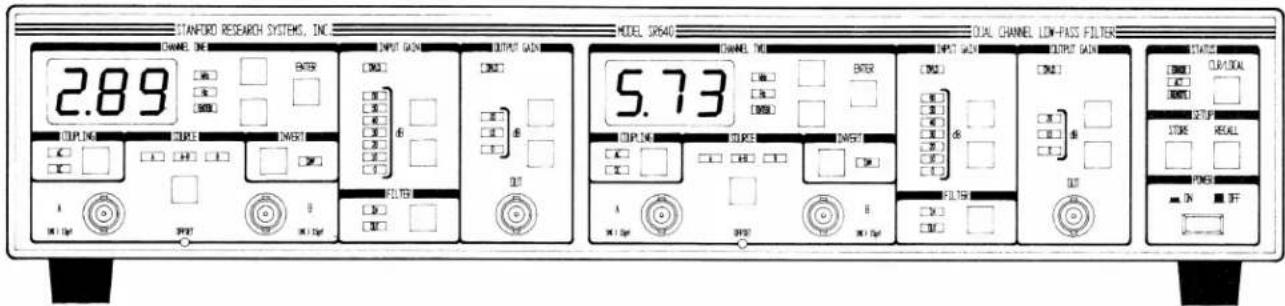
STANFORD RESEARCH SYSTEMS, INC CHANNEL IN 2.89 INPUT GAIN OUTPUT GAIN DOUBLE 5.73 OUTPUT GAIN OUTPUT GAIN OUT IN OUT IN OUT IN OUT IN OUT IN OUT IN OUT IN OUT IN OUT IN OUT IN OUT IN OUT IN OUT IN OUT IN OUT IN OUT IN OUT IN OUT IN OUT IN OUT IN OUT IN OUT IN OUT IN OUT IN OUT IN OUT OUT IN OUT IN OUT IN OUT IN OUT IN OUT IN OUT IN OUT IN OUT IN OUT IN OUT IN OUT IN OUT IN OUT IN OUT IN OUT IN OUT IN OUTThe front panel has been designed to be nearly self-explanatory. The effect of each keypress is usually reflected by a change in the state of a nearby LED. The front panel controls for each filter channel are identical. The following discussion of the front panel controls applies to both channel 1 and channel 2.
POWER BUTTON
The SR640 is turned on by depressing the POWER button. When the unit is turned on, the model number, serial number and firmware version number will appear briefly on the LED displays. When the unit is powered off, all instrument settings are stored in non-volatile memory. Upon power up, the SR640 checks the consistency of the stored settings. If an error appears on power up, the instrument is returned to its default state. The default state for each filter channel is:
Cutoff Frequency: 5 kHz
Coupling: DC
Source: A
Invert: Off
InputGain: 0 dB
Output Gain: 0 dB
Filter: In
FREQUENCY DISPLAY
The three digit LED displays indicate the cutoff frequency of each filter. The adjacent unit LEDs indicate whether the displayed frequency is in Hz or kHz. The cutoff frequency for either channel may be changed using the frequency increment and decrement buttons to the right of the display. When one of these buttons is pressed, the displayed frequency will begin scrolling up or down. Note, however, that the actual filter cutoff frequency does NOT change until the ENTER button is pressed. The ENTER LED will light to indicate that the displayed frequency does not match the actual filter cutoff frequency. When the ENTER button is pressed, the ENTER LED will turn off and the filter frequency will change to match the displayed frequency. If the frequency display has been changed but it is not desired to change the actual filter cutoff frequency, pressing the CLR/LOCAL button will reset the display to the actual filter frequency.
SOURCE SELECT
There are two input BNC connectors provided for each filter channel. When source LED 'A' is on, the input signal is measured between the center conductor of the 'A' BNC connector and its shield. When the 'B' LED is on, the signal is measured between the center conductor of the 'B' BNC connector and its shield. When the 'A-B' LED is on, the signal is taken between the center conductor of the 'A' connector and the center conductor of the 'B' connector. In all cases, the shields of the 'A' and 'B' BNC connectors are connected to
each other and to the filter ground. The filter ground is NOT connected to the unit's chassis ground.
Filter ground for each channel is available at a rear panel BNC connector. With this connector, the user can connect filter ground to chassis ground or to any other desired point.
COUPLING AND INVERT
The COUPLING button selects either AC or DC input coupling for both the 'A' and 'B' input connectors. The AC coupling has a nominal -3dB point of 0.1Hz. Selecting INVERT on the front panel simply inverts the sign of the output signal with respect to the input.
INPUT AND OUTPUT GAIN
The input and output gain indicators display the amount of gain present before and after the filter. Changing the gain is accomplished with the up and down buttons to the right of the respective indicators. The gain can be changed in 10 dB increments up to a maximum of 60 dB of input gain (prefilter) and 20 dB of output gain (postfilter).
FILTER IN/OUT
Selecting filter IN on the front panel puts the filter in the signal path. Selecting filter OUT leaves the input and output amplifiers in the signal path but bypasses the filter. The -3dB point for the input and output amplifiers with the filter bypassed is approximately 450 kHz.
OFFSET ADJUST
The front panel offset adjust allows the user to dial in approximately ±150 mV of input offset voltage. Note that this is a true input offset and the actual output offset voltage will depend on the selected gain.
CLR/LOCAL
The CLR/LOCAL button has two functions. If the displayed frequency for either filter channel has been changed, pressing the CLR/LOCAL button resets the display to the actual filter frequency. If the SR640 has been placed in the REMOTE mode by a command from the computer interface, pressing the CLR/LOCAL button will return the unit to the LOCAL mode and enable front panel control. Note that the CLR/LOCAL button will not re-
turn the unit to local operation if the unit has been placed in the LOCAL LOCKOUT mode.
STORE AND RECALL
The SR640 can store and recall up to 9 complete instrument setups. To store the current instrument configuration, press the STORE button. The setup number (1-9) will appear in the channel 2 frequency display. To change the setup number, use the channel 2 frequency up and down buttons. When the setup number is correct, press the channel 2 ENTER button to store the setup. Recalling previously stored setups is done in the same manner. Recalling setup '0' places the instrument in its default configuration. Pressing the CLR/LOCAL button while storing or recalling a setup aborts the operation and returns the display to its normal mode. If an attempt is made to recall a setup which has not been previously stored, the display will indicate an error. In this case, the CLR/LOCAL button should be pressed to resume normal operation.
ERROR, ACTIVITY, AND REMOTE LEDs
The ACT LED lights to indicate any activity over the interface, such as the receipt of a command. The ERROR LED will light when a bad command is received over the computer interface. The REMOTE LED lights to indicate the SR640 is either in the REMOTE or LOCAL LOCKOUT mode of operation. In either of these modes, the front panel buttons are not operational. Only in the REMOTE mode can front panel operation be regained by pressing the CLR/LOCAL button.
GUIDE TO PROGRAMMING
The SR640 dual channel low-pass filter is remotely programmable via both RS-232 and GPIB interfaces. All front panel features (except offset adjustment) may be controlled and read via the computer interfaces.
Communicating with the SR640
Before using either the RS-232 or GPIB interface, the appropriate configuration switches must be set. The configuration switch is located on the rear panel and label 'SW1'. Bit 8 of the switch selects GPIB or RS-232 operation. If bit 8 is 'on', GPIB operation is selected, if it is 'off', the RS-232 interface is enabled. The other bits of the switch take their meaning depending upon whether RS-232 or GPIB operation has been selected.
When a bit is 'on', it is in the DOWN position.
GPIB:
Bit Explanation
8 Always on for GPIB
7 not used
6 not used
5 high order bit of GPIB address
4 GPIB address (on = 1 off = 0)
3 GPIB address
2 GPIB address
1 low order bit of GPIB address
RS-232:
Bit Explanation
8 Always off for RS-232
7 on = echo off = no echo (normally off)
6 on = 8 bit word off =7 bit word
5 on = even parity off = odd parity
4 on = parity enabled off = disabled
3 baud rate select
2 baud rate select
1 baud rate select
Bit 3_ 2_ 1_ Baud Rate
on on on 19200
on on off 9600
on off on 7200
on off off 4800
off on on 3600
off on off 2400
off off on 2000
off off off 1800
Note that the configuration switch is only read on power-up. If a setting needs to be changed, the unit must be turned off and turned on again for the change to be recognized.
Command Syntax
Communication with the SR640 is accomplished by sending and receiving strings of ASCII characters. Characters sent to the SR640 may be sent in either UPPER or lower case.
A command to the SR640 consists of 4 ASCII characters followed by an optional question mark '?' character, followed by a list of arguments separated by commas, followed by a line-feed (
| FREQ1,23600. | set the channel 1 filter frequency to 23.6 kHz |
| FREQ?2 | read the channel 2 filter frequency |
| *CLS | clear the status byte |
Multiple commands may be sent on a single line. The commands must be separated by semicolon characters. An example of a multiple command would be:
FREQ1,23.6E3;FREQ2,100
The presence of a question mark character in a command indicates that the command is a request to the SR640 to send back a value. Values returned by the SR640 are terminated with a carriage return
RS-232 Echo and No Echo Operation
In order to allow the SR640 to be operated from a terminal, an echo feature has been included which causes the unit to echo back characters received over the RS-232 port. This feature is enabled by setting bit 7 of the configuration switch on. When using the unit with a computer, this feature should be disabled to prevent spurious characters from being sent to the computer. The echo feature is not operational when the unit is being used with the GPIB interface.
Tips on using National Instruments GPIB cards
To successfully interface the SR640 to a PC via the GPIB, the instrument, interface card, and inter-
face driver must all be configured properly. To configure theSR640, the GPIB address must be properly set using the DIP switch on the back panel. The SR640 is shipped with the GPIB address set to 23.
Make sure that you follow all the instructions for installing the GPIB card. The National Instruments card cannot simply be unpacked and put into your computer. To configure the card you must first set jumpers and switches to set interrupt levels and I/O addresses. You must then run the program IB-CONF to configure the DOS resident GPIB driver. Please refer to the National Instruments manuals for complete details.
Once all the hardware and software has been configured properly, try using the IBIC program supplied with the National Instruments card to send commands and receive data from the SR640. If you cannot talk to the SR640 with the IBIC pro-
gram, there is no point in trying to write a program.
Although the National Instruments language contains many commands, to avoid confusion it is best to start with a few simple ones. Use IBWRT and IBRD to write and read from the SR640. After you are familiar with the simple commands you can explore other, more complex, programming commands.
COMMAND LIST
The command list of the SR640 is detailed below. Commands that may be queried have a question mark ? in parentheses (?) after the four character command mnemonic. Commands that may ONLY be queried have a ? after the mnemonic. Parameters shown in brackets {} should be omitted if the command is used as a query. Do not send () or {} as part of the command. The variable i used in many of the commands indicates which filter channel the command will operate on. This variable can only be 1 (for channel 1) or 2 (for channel 2). The variable n is an integer variable, and must be sent as an integer, i.e. no decimal points or exponents. The variable x is a real number and may be expressed in fixed or floating point format, with or without a decimal point.
FILTER COMMANDS
ACDC(?) i{,n}
The ACDC command sets the input coupling for channel i to AC (n=0) or DC (n=1).
FLTR(?) i{,n}
If n=1, the FLTR command puts the channel i filter into the signal path. If n=0, the filter is bypassed.
FREQ(?) i{,x}
The FREQ command sets the filter cutoff frequency for channel i to x. Allowed values are 1.0 ≤ x ≤ 99,900 (Hz).
INVT(?) i{,n}
The INVT command inverts the output signal with respect to the input (n=1), or leaves it uninverted (n=0).
LOCL n
The LOCL command sets the local/remote mode of the instrument. Allowed values are:
n mode ____
0 local
1 remote
2 remote with local lockout
OVLD?
The OVLD? command queries the overload status of the instrument. The result is returned as a decimal number (0-15) which represents a 4 bit bi-
nary number. The binary number is coded as follows:
bit meaning
3 (msb) channel 2 output overload
2 channel 2 input overload
1 channel 1 output overload
0 (lsb) channel 1 input overload
PREG(?) i{,n}
The PREG command sets the input gain for channel i to the value specified by n. Allowed values of n are:
| n | Input Gain |
| 0 | 0 db |
| 1 | 10 db |
| 2 | 20 db |
| 3 | 30 db |
| 4 | 40 db |
| 5 | 50 db |
| 6 | 60 db |
PSTG(?) i{,n}
The PSTG command sets the output gain for channel i to the value specified by n. Allowed values of n are:
n Output Gain
0 0 db
1 10 db
2 20 db
SRCE(?) i{,n}
The SRCE command selects the input source for channel i. The permitted values for n are:
n Input Source
0 A
1 A-B
2 B
STATUS AND INTERFACE COMMANDS
\*IDN?
The *IDN? command returns the SR640's identification string. The string format is:
Stanford Research Systems, SR640, S/N0001, v
1.01
\*RST
The *RST command resets the instrument. It is equivalent to a RCL 0 command (recall default set-up).
\*STB? {n}
The *STB? command queries the value of the SR640's status byte. The byte is returned as a decimal number (0-255). The *STB? n command reads the value of bit n. The range of n is 0-7. The value returned is either 0 or 1. The various bits in the status byte have the following meanings:
bit meaning
0 READY. Indicates unit has completed all pending commands.
1 OUTPUT FULL. Indicates the unit's output queue is full.
2 EXECUTION ERROR. Indicates an illegal value was encountered while executing a command.
3 SYNTAX ERROR. Indicates the SR640 could not interpret received characters as a command.
4 OUTPUT NOT EMPTY. Indicates the SR640 has characters waiting to be sent.
5 INPUT FULL. Input queue full. The user should send commands more slowly.
6 SRQ. Indicates the unit has requested service from the GPIB controller.
7 POWER ON. Indicates the SR640 has been powered on.
Each of the bits is set when the associated condition first becomes true. The status byte is only cleared after the *STB? or *CLS command.
\*CLS
The *CLS command clears the SR640's internal status byte. This status byte is the byte returned by the SR640 when it is serial polled via the GPIB interface. It may also be queried using the *STB? command.
\*SRE(?) {n}
The *SRE command sets the service request enable byte to the value specified by n. Allowed values are 0 through 255. When a bit is set in the status byte, the byte is logically 'anded' with the service request enable byte. If the corresponding bit in the service request enable byte is set, the SR640 issues a SRQ (service request) to the GPIB controller. This command may only be used with the GPIB interface.
\*RCL n
The *RCL n command recalls the nth stored instrument settings. Allowed values for n are 0 through 9.
\*SAV n
The *SAV command saves the current instrument configuration as stored setting n. Values for n are 1 through 9.
\*PSC (?) n
The *PSC command sets the power-on status clear bit. If n=1, the service request enable byte is cleared upon power up. If n=0, the status byte and service request enable byte maintain their values when the unit is powered down. This allows the generation of a service request upon power up.
WAIT(?)n
The WAIT command sets the RS-232 transmission delay between characters. This is sometimes useful when interfacing with slower computers and terminals. The wait interval is set to about 2ms * n. Allowable values for n are 0 < n < 255.
PROGRAMMING EXAMPLES
The following are examples of programs which communicate with the SR640 in a variety of languages over both RS232 and GPIB. In each case, the program does the same thing: Set the channel 1 pregain to 10 db, the Channel 2 postgain to 20 db, and read the value of the channel 1 cutoff frequency. Once the basics of writing to and reading from the SR640 are mastered, the task of programming is reduced to simply finding the appropriate command from the command list.
Program Example 1 IBM PC, BASIC, via RS232
In this example, the IBM PC's COM2: serial port is used to communicate with the SR640. Note that a "straight through" RS232 cable (NOT a null modem cable) should be used to connect the PC to the SR640. The SR640 should be set to operate at 9600 baud, 8 bits, no parity.
10'Example program for the SR640 filter using IBM BASIC over the COM2: port 20'
30'Open the COM2: port for 9600, 8 bits, no parity, ignore handshake
40 OPEN "COM2:9600,N,8,2,CS,DS,CD" AS #1
50'
60' Clear COM2 port
70 PRINT #1," "
80' Set channel 1 pregain and postgain
90 PRINT #1,"PREG1,1;PSTG2,2"
100 'Now read channel 1 cutoff frequency
110 PRINT #1,"FREQ?1"
120 INPUT #1, FREQ 'read answer
130 PRINT "frequency = ",FREQ
140 STOP
Program Example 2 IBM PC, Microsoft FORTRAN, National Instruments GPIB Card
Please refer to the "Guide to Programming" section for additional information on using the National Instruments GPIB card. The GPIB.COM driver must be configured with IBCONF before using the National Instruments cards.
c example program for the SR620 using Microsoft FORTRAN and National Instruments GPIB card
c compile with /FPa /AL and link with MFIBL.OBJ (supplied by National Instruments)
\$storage:2
c this line must be in the source file common /ibglob/ibsta, iberr, ibcnt integer sr640
character *80 string
real*4answer
c initialize gpib card
call ibinit(ibsta)
c get device id for sr640
sr640 = ibfind('sr640')
c set pregain and postgain
call ibwrt (sr640,'PREG1,1;PSTG2,2',15)
c now query stage 1 filter cutoff
call ibwrt (sr640,'FREQ?1',6)
call ibrd (sr640, string, 30)
read (string,1000) answer
1000 format (bn,f14.0)
write (*,*) answer
stop
end
Program Example 3
IBM PC, Microsoft C, National Instruments GPIB card
/* Program to test SR640 communication using National Instruments GPIB card and Microsoft C. Compile with /AL /FPa /c and link with the CIBL.OBJ module supplied by National Instruments */
include
include
include
include
/* function prototypes */
void main(void);
/* variables defined in CIBL module */
extern int ibsta;
extern int iberr;
extern int ibcnt;
void main (void)
{
    int sr640;
    char string[30];
    float answer;

    sr640 = ibinit("SR640");    /* locate device */
    if (sr640 < 0)
    error();

    ibwrt (sr640, "PREG1,1;PREG2,2", 15);    /* set gain */

    ibwrt (sr640, "FREQ?1", 6);

    /* query frequency */
    ibrd (sr640, string, 30);

    /* and get answer */

    sscanf(string, "%f", &answer);
    printf("answer = %f", answer);
}
Circuit Description
INTRODUCTION
Schematics for the SR640 series dual-channel filters are shown on the following pages. They include the following: Preamplifier, filter stage, output amplifier, optoisolated interface, microprocessor section, communications section, front panel interface, power supplies, and front panel. The preamplifier, filter stages (4/channel), output amplifier, and optoisolated interface are located on the individual filter boards (2/instrument). The microprocessor and communication components are located on the digital board at the rear of the instrument.
Preamplifier
The preamplifier is a low-noise fully differential amplifier with gains from 0 to 60 db. Relays K1 and K2 select the input source and coupling, while K4 switches in a X10 attenuator used at the three lowest gain settings. The Dual FET U2, along with low-noise op-amps U3 and U4 form the feedback stabilized differential pair at the heart of the preamplifier. U6 and U8 provide additional amplification. The output of the preamplifier is switched by U9 to the first filter stage or directly to the output amplifier if the filter has been bypassed.
Filter Stages
Each of the four filter stages is derived from a 3 op-amp biquadratic filter with a low pass transfer function of:
$$ T (s) = \frac {s ^ {2} + \omega_ {z} ^ {2}}{s ^ {2} + \frac {\omega_ {p}}{Q} s + \omega_ {p} ^ {2}} $$
Stage parameters for low-pass filter are:
| Stg | ω_p | Q | ω_z/_p |
| 1.6347 | .5493 | - | |
| 2 | .8060 | .9507 | 2.0793 |
| 3 | .9850 | 2.095 | 1.9653 |
| 4 | 1.076 | 7.375 | 2.6776 |
For the high-pass filter, the parameters are simply related by the low-pass to high-pass transformation.
Component designations for the filter stage will be referred to as UnXX where n designates the stage number. Un14A, C, and D form the actual filter section. The tuning capacitors Cn20-Cn27 are switched by relays Kn05 and Kn06 according the the decade. Fine tuning within a decade is accomplished by the 10 bit parallel resistor networks composed of Rn40 through Rn59. Switching of the resistors is done with the FET switches Qn00 through Qn19 and their associated driver diodes.
The dual 8 bit DAC Un12 and its related output op-amps along with Un13A and differential amp Un13D allow the pole frequency and Q of the circuit to be fine tuned by adjusting the values sent to the dual DAC. This is how the unit is calibrated. The magnitude of the 'fine tuning' is set by Rn60 and Rn61.
The zero frequency of the circuit is not digitally adjustable but is instead set by resistors Rn71 and Rn72. Jumpers JPn05-n07 allow the zero-forming network to be removed from the circuit in stages that do not have zeros. The single op-amp Un15 forms the output buffer for the stage.
Output Amplifier
Un16A and B select the filter output or bypassed output from the preamplifier. The 8-bit DAC U17 provides output gain adjustment. The actual output amplifier is U119 which has its gain selected by switch U21. Output inversion is accomplished with U22 in conjunction with the switches U16C and U16D. The optional component U23 provides a high current output buffer. Dual Comparator U20 care of output overload detection.
Optoisolated Interface
No direct electrical connection exists between the microprocessor section and the filter boards. Control signals for the filter boards originate from the two 32 bit latched serial input shift registers U25 and U26. These shift registers are in turn controlled by the output of opto isolator U24. Optoisolator U11 provides output isolation for overload signal which are read by the processor section. Shift register U26 is run between -15V and ground so that its open collector outputs may be pulled up to +15V. These ±15V signals control the FET switch which determine the filter stage frequencies.
Microprocessor and Communications
The microprocessor U4 is a Z80, clocked at 3.6864 MHz by U3. U6 is an 8K ROM, while U7 provides 2K of battery backed up RAM. U1 is a 64K ROM which contains the calibration information for the filter channels. The calibration ROM is mapped as I/O, requiring flip-flop U5B to switch between the normal I/O space and the calibration ROM. U9A gates the clock to the processor enabling the processor clock to be removed during quiescent operation. The clock is restored by a control signal from flip-flop U5A in response to a keyboard or communication interrupt. Commu-
nication is accomplished with the UART U15 and GPIB chip U12.
Power Supplies
Regulators U101 provides 5V power to the microprocessor and communications circuits, while regulators U102 - 105 provide ±15V power to the filter sections. Note that the 5V power supply is the only one referenced to the chassis ground. Note also that each filter power supply is taken from a separate transformer secondary for maximum isolation.
Note: The SR645 and SR650 units contain additional regulators (U27 and U28) on the high-pass filter boards to provide ± 5V to the VTC4706 op-amps.
Front Panel
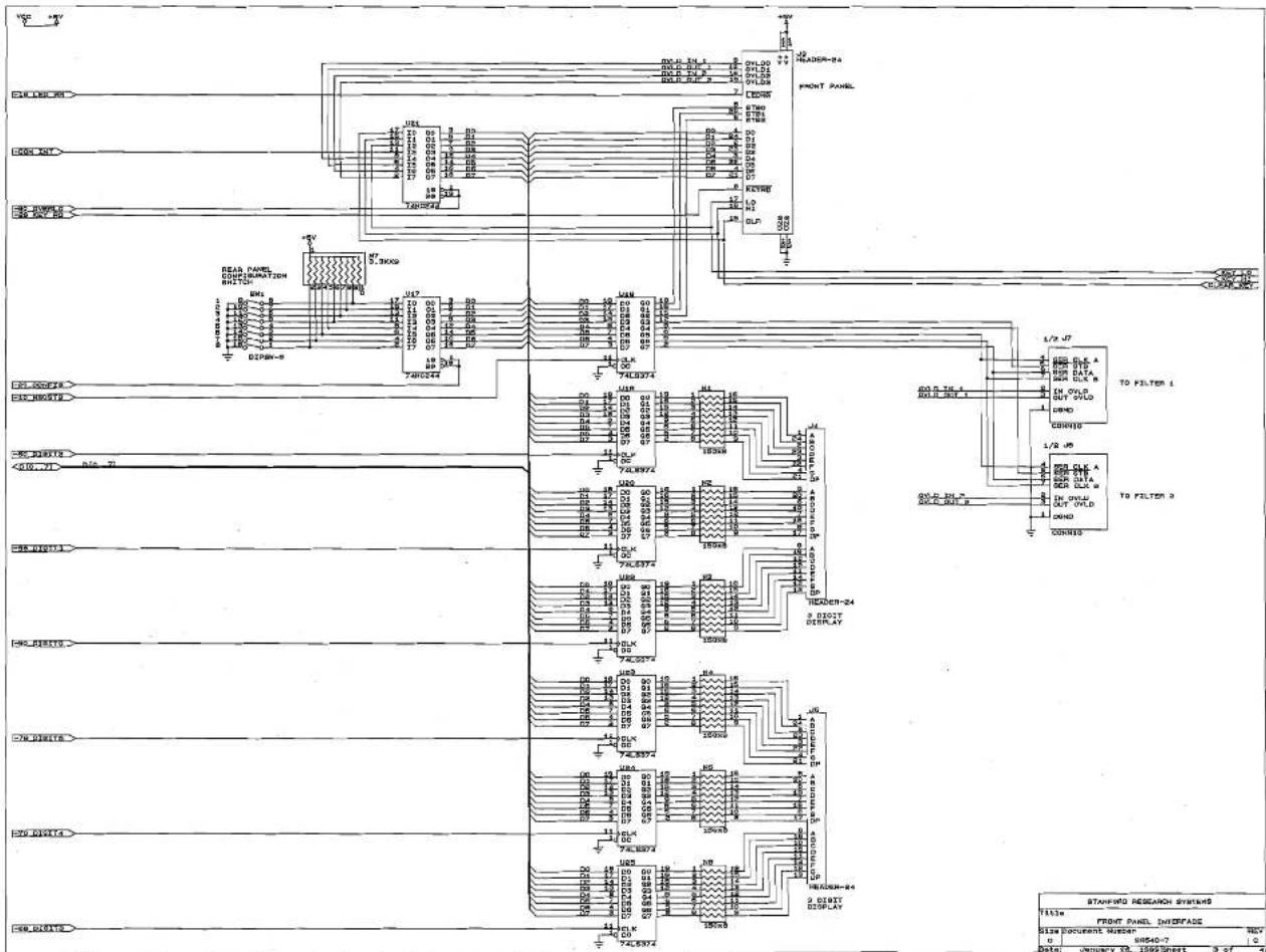
Shift Registers U201-U206 provide control signals for the front panel LEDs. Switches SW301-SW324 comprise the switch matrix which is read by the processor via input port U301. LED digits DS101-DS106 are controlled via output ports U18-U25.
SR640 Component List
Front Panel Board Parts List
| D 201 | 3-00012-306 | GREEN | LED, Rectangular |
| D 202 | 3-00013-306 | RED | LED, Rectangular |
| D 203 | 3-00012-306 | GREEN | LED, Rectangular |
| D 204 | 3-00012-306 | GREEN | LED, Rectangular |
| D 205 | 3-00012-306 | GREEN | LED, Rectangular |
| D 206 | 3-00012-306 | GREEN | LED, Rectangular |
| D 207 | 3-00012-306 | GREEN | LED, Rectangular |
| D 208 | 3-00012-306 | GREEN | LED, Rectangular |
| D 209 | 3-00012-306 | GREEN | LED, Rectangular |
| D 210 | 3-00175-306 | YELLOW | LED, Rectangular |
| D 211 | 3-00012-306 | GREEN | LED, Rectangular |
| D 212 | 3-00012-306 | GREEN | LED, Rectangular |
| D 213 | 3-00013-306 | RED | LED, Rectangular |
| D 214 | 3-00013-306 | RED | LED, Rectangular |
| D 215 | 3-00012-306 | GREEN | LED, Rectangular |
| D 216 | 3-00012-306 | GREEN | LED, Rectangular |
| D 217 | 3-00012-306 | GREEN | LED, Rectangular |
| D 218 | 3-00012-306 | GREEN | LED, Rectangular |
| D 219 | 3-00012-306 | GREEN | LED, Rectangular |
| D 220 | 3-00012-306 | GREEN | LED, Rectangular |
| D 221 | 3-00012-306 | GREEN | LED, Rectangular |
| D 222 | 3-00012-306 | GREEN | LED, Rectangular |
| D 223 | 3-00012-306 | GREEN | LED, Rectangular |
| D 224 | 3-00012-306 | GREEN | LED, Rectangular |
| D 225 | 3-00175-306 | YELLOW | LED, Rectangular |
| D 226 | 3-00012-306 | GREEN | LED, Rectangular |
| D 227 | 3-00012-306 | GREEN | LED, Rectangular |
| D 228 | 3-00012-306 | GREEN | LED, Rectangular |
| D 229 | 3-00012-306 | GREEN | LED, Rectangular |
| D 230 | 3-00012-306 | GREEN | LED, Rectangular |
| D 231 | 3-00012-306 | GREEN | LED, Rectangular |
| D 232 | 3-00012-306 | GREEN | LED, Rectangular |
| D 233 | 3-00175-306 | YELLOW | LED, Rectangular |
| D 234 | 3-00012-306 | GREEN | LED, Rectangular |
| D 235 | 3-00012-306 | GREEN | LED, Rectangular |
| D 236 | 3-00013-306 | RED | LED, Rectangular |
| D 237 | 3-00013-306 | RED | LED, Rectangular |
| D 238 | 3-00012-306 | GREEN | LED, Rectangular |
| D 239 | 3-00012-306 | GREEN | LED, Rectangular |
| D 240 | 3-00012-306 | GREEN | LED, Rectangular |
| D 241 | 3-00012-306 | GREEN | LED, Rectangular |
| D 242 | 3-00012-306 | GREEN | LED, Rectangular |
| D 243 | 3-00012-306 | GREEN | LED, Rectangular |
| D 244 | 3-00012-306 | GREEN | LED, Rectangular |
| D 245 | 3-00012-306 | GREEN | LED, Rectangular |
| D 246 | 3-00012-306 | GREEN | LED, Rectangular |
| D 247 | 3-00012-306 | GREEN | LED, Rectangular |
| D 248 | 3-00012-306 | GREEN | LED, Rectangular |
| D 249 | 3-00012-306 | GREEN | LED, Rectangular |
| D 301 | 3-00004-301 | 1N4148 | Diode |
Component List
| D 302 | 3-00004-301 | 1N4148 | Diode |
| D 303 | 3-00004-301 | 1N4148 | Diode |
| DS101 | 3-00255-340 | HDSP-5601 | Integrated Circuit (Thru-hole Pkg) |
| DS102 | 3-00255-340 | HDSP-5601 | Integrated Circuit (Thru-hole Pkg) |
| DS103 | 3-00255-340 | HDSP-5601 | Integrated Circuit (Thru-hole Pkg) |
| DS104 | 3-00255-340 | HDSP-5601 | Integrated Circuit (Thru-hole Pkg) |
| DS105 | 3-00255-340 | HDSP-5601 | Integrated Circuit (Thru-hole Pkg) |
| DS106 | 3-00255-340 | HDSP-5601 | Integrated Circuit (Thru-hole Pkg) |
| J 101 | 1-00097-130 | 24 PIN DIL | Connector, Male |
| J 102 | 1-00097-130 | 24 PIN DIL | Connector, Male |
| J 103 | 1-00097-130 | 24 PIN DIL | Connector, Male |
| N 201 | 4-00252-425 | 100X5 | Resistor Network SIP 1/4W 2% (Common) |
| N 202 | 4-00252-425 | 100X5 | Resistor Network SIP 1/4W 2% (Common) |
| N 203 | 4-00252-425 | 100X5 | Resistor Network SIP 1/4W 2% (Common) |
| N 204 | 4-00252-425 | 100X5 | Resistor Network SIP 1/4W 2% (Common) |
| N 205 | 4-00252-425 | 100X5 | Resistor Network SIP 1/4W 2% (Common) |
| N 301 | 4-00276-425 | 10KX9 | Resistor Network SIP 1/4W 2% (Common) |
| R 202 | 4-00079-401 | 4.7K | Resistor, Carbon Film, 1/4W, 5% |
| SW301 | 2-00031-201 | D6-01-05 | Switch, Momentary Push Button |
| SW302 | 2-00031-201 | D6-01-05 | Switch, Momentary Push Button |
| SW303 | 2-00031-201 | D6-01-05 | Switch, Momentary Push Button |
| SW304 | 2-00031-201 | D6-01-05 | Switch, Momentary Push Button |
| SW305 | 2-00031-201 | D6-01-05 | Switch, Momentary Push Button |
| SW306 | 2-00031-201 | D6-01-05 | Switch, Momentary Push Button |
| SW307 | 2-00031-201 | D6-01-05 | Switch, Momentary Push Button |
| SW308 | 2-00031-201 | D6-01-05 | Switch, Momentary Push Button |
| SW309 | 2-00031-201 | D6-01-05 | Switch, Momentary Push Button |
| SW310 | 2-00031-201 | D6-01-05 | Switch, Momentary Push Button |
| SW311 | 2-00031-201 | D6-01-05 | Switch, Momentary Push Button |
| SW312 | 2-00031-201 | D6-01-05 | Switch, Momentary Push Button |
| SW313 | 2-00031-201 | D6-01-05 | Switch, Momentary Push Button |
| SW314 | 2-00031-201 | D6-01-05 | Switch, Momentary Push Button |
| SW315 | 2-00031-201 | D6-01-05 | Switch, Momentary Push Button |
| SW316 | 2-00031-201 | D6-01-05 | Switch, Momentary Push Button |
| SW317 | 2-00031-201 | D6-01-05 | Switch, Momentary Push Button |
| SW318 | 2-00031-201 | D6-01-05 | Switch, Momentary Push Button |
| SW319 | 2-00031-201 | D6-01-05 | Switch, Momentary Push Button |
| SW320 | 2-00031-201 | D6-01-05 | Switch, Momentary Push Button |
| SW321 | 2-00031-201 | D6-01-05 | Switch, Momentary Push Button |
| SW322 | 2-00031-201 | D6-01-05 | Switch, Momentary Push Button |
| SW323 | 2-00031-201 | D6-01-05 | Switch, Momentary Push Button |
| SW324 | 2-00031-201 | D6-01-05 | Switch, Momentary Push Button |
| SW325 | 2-00031-201 | D6-01-05 | Switch, Momentary Push Button |
| U 201 | 3-00053-340 | 74LS164 | Integrated Circuit (Thru-hole Pkg) |
| U 202 | 3-00053-340 | 74LS164 | Integrated Circuit (Thru-hole Pkg) |
| U 203 | 3-00053-340 | 74LS164 | Integrated Circuit (Thru-hole Pkg) |
| U 204 | 3-00053-340 | 74LS164 | Integrated Circuit (Thru-hole Pkg) |
| U 205 | 3-00053-340 | 74LS164 | Integrated Circuit (Thru-hole Pkg) |
| U 206 | 3-00053-340 | 74LS164 | Integrated Circuit (Thru-hole Pkg) |
| U 301 | 3-00044-340 | 74HC244 | Integrated Circuit (Thru-hole Pkg) |
| U 302 | 3-00254-340 | 74HC4002 | Integrated Circuit (Thru-hole Pkg) |
| Z 0 | 0-00111-053 | 1-3/4"#24B | Wire #24 UL1007 Strip 1/4x1/4 Tin |
| Z 0 | 0-00112-053 | 1-3/4"#24R | Wire #24 UL1007 Strip 1/4x1/4 Tin |
| Z 0 | 0-00187-021 | 4-40X1/4PP | Screw, Panhead Phillips |
| Z 0 | 0-00255-044 | SR640 | Window |
| Z 0 | 1-00073-120 | INSL | Connector, BNC |
Component List
| Z 0 | 7-00158-701 | SR640-28 | Printed Circuit Board |
| Z 0 | 7-00160-709 | SR640-30 | Lexan Overlay |
| Z 0 | 7-00174-710 | SR640-29 | Front Panel |
| Z 0 | 7-00273-709 | SR645 | Lexan Overlay |
| Z 0 | 7-00274-709 | SR650 | Lexan Overlay |
Digital Board Parts List
| B 1 | 6-00001-612 | BR-2/3A 2PIN PC Battery | |
| C 1 | 5-00178-501 | 62P | Capacitor, Ceramic Disc, 50V, 10%, SL |
| C 2 | 5-00040-509 | 1.0U | Capacitor, Electrolytic, 50V, 20%, Rad |
| C 3 | 5-00040-509 | 1.0U | Capacitor, Electrolytic, 50V, 20%, Rad |
| C 4 | 5-00178-501 | 62P | Capacitor, Ceramic Disc, 50V, 10%, SL |
| C 5 | 5-00012-501 | 330P | Capacitor, Ceramic Disc, 50V, 10%, SL |
| C 6 | 5-00012-501 | 330P | Capacitor, Ceramic Disc, 50V, 10%, SL |
| C 7 | 5-00012-501 | 330P | Capacitor, Ceramic Disc, 50V, 10%, SL |
| C 8 | 5-00012-501 | 330P | Capacitor, Ceramic Disc, 50V, 10%, SL |
| C 9 | 5-00098-517 | 10U | Capacitor, Tantalum, 35V, 20%, Rad |
| C 101 | 5-00147-521 | 3300U | Capacitor, Electrolytic, 25V, 20%, Rad |
| C 102 | 5-00192-542 | 22U MIN | Cap, Mini Electrolytic, 50V, 20% Radial |
| C 103 | 5-00100-517 | 2.2U | Capacitor, Tantalum, 35V, 20%, Rad |
| C 104 | 5-00023-529 | .1U | Cap, Monolythic Ceramic, 50V, 20%, Z5U |
| C 105 | 5-00212-520 | 15000U | Capacitor, Electrolytic, 16V, 20%, Rad |
| C 106 | 5-00192-542 | 22U MIN | Cap, Mini Electrolytic, 50V, 20% Radial |
| C 107 | 5-00023-529 | .1U | Cap, Monolythic Ceramic, 50V, 20%, Z5U |
| C 108 | 5-00100-517 | 2.2U | Capacitor, Tantalum, 35V, 20%, Rad |
| C 109 | 5-00098-517 | 10U | Capacitor, Tantalum, 35V, 20%, Rad |
| C 110 | 5-00147-521 | 3300U | Capacitor, Electrolytic, 25V, 20%, Rad |
| C 111 | 5-00192-542 | 22U MIN | Cap, Mini Electrolytic, 50V, 20% Radial |
| C 112 | 5-00100-517 | 2.2U | Capacitor, Tantalum, 35V, 20%, Rad |
| C 113 | 5-00098-517 | 10U | Capacitor, Tantalum, 35V, 20%, Rad |
| C 114 | 5-00023-529 | .1U | Cap, Monolythic Ceramic, 50V, 20%, Z5U |
| C 115 | 5-00147-521 | 3300U | Capacitor, Electrolytic, 25V, 20%, Rad |
| C 116 | 5-00147-521 | 3300U | Capacitor, Electrolytic, 25V, 20%, Rad |
| C 117 | 5-00192-542 | 22U MIN | Cap, Mini Electrolytic, 50V, 20% Radial |
| C 118 | 5-00192-542 | 22U MIN | Cap, Mini Electrolytic, 50V, 20% Radial |
| C 119 | 5-00100-517 | 2.2U | Capacitor, Tantalum, 35V, 20%, Rad |
| C 120 | 5-00098-517 | 10U | Capacitor, Tantalum, 35V, 20%, Rad |
| C 121 | 5-00100-517 | 2.2U | Capacitor, Tantalum, 35V, 20%, Rad |
| C 122 | 5-00098-517 | 10U | Capacitor, Tantalum, 35V, 20%, Rad |
| C 123 | 5-00030-520 | 2200U | Capacitor, Electrolytic, 16V, 20%, Rad |
| C 150 | 5-00023-529 | .1U | Cap, Monolythic Ceramic, 50V, 20%, Z5U |
| C 151 | 5-00023-529 | .1U | Cap, Monolythic Ceramic, 50V, 20%, Z5U |
| C 152 | 5-00023-529 | .1U | Cap, Monolythic Ceramic, 50V, 20%, Z5U |
| C 153 | 5-00023-529 | .1U | Cap, Monolythic Ceramic, 50V, 20%, Z5U |
| C 154 | 5-00023-529 | .1U | Cap, Monolythic Ceramic, 50V, 20%, Z5U |
| C 155 | 5-00023-529 | .1U | Cap, Monolythic Ceramic, 50V, 20%, Z5U |
| C 156 | 5-00023-529 | .1U | Cap, Monolythic Ceramic, 50V, 20%, Z5U |
| D 1 | 3-00004-301 | 1N4148 | Diode |
| D 2 | 3-00004-301 | 1N4148 | Diode |
| D 3 | 3-00004-301 | 1N4148 | Diode |
| D 101 | 3-00062-340 | KBP201G/BR-81D | Integrated Circuit (Thru-hole Pkg) |
| D 103 | 3-00221-301 | 1N4004 | Diode |
| D 104 | 3-00221-301 | 1N4004 | Diode |
| D 105 | 3-00221-301 1N4004 | Diode |
| D 106 | 3-00221-301 1N4004 | Diode |
| D 107 | 3-00062-340 KBP201G/BR-81D | Integrated Circuit (Thru-hole Pkg) |
| D 108 | 3-00062-340 KBP201G/BR-81D | Integrated Circuit (Thru-hole Pkg) |
| J 1 | 1-00238-161 GPIB SHIELDED | Connector, IEEE488, Reverse, R/A, Female |
| J 2 | 1-00016-160 RS232 25 PIN D | Connector, D-Sub, Right Angle PC, Female |
| J 3 | 1-00097-130 24 PIN DIL | Connector, Male |
| J 4 | 1-00097-130 24 PIN DIL | Connector, Male |
| J 5 | 1-00097-130 24 PIN DIL | Connector, Male |
| J 7 | 1-00096-130 10 PIN SI | Connector, Male |
| J 8 | 1-00096-130 10 PIN SI | Connector, Male |
| N 1 | 4-00419-420 150X8 | Resistor Network, DIP, 1/4W,2%,8 Ind |
| N 2 | 4-00419-420 150X8 | Resistor Network, DIP, 1/4W,2%,8 Ind |
| N 3 | 4-00419-420 150X8 | Resistor Network, DIP, 1/4W,2%,8 Ind |
| N 4 | 4-00419-420 150X8 | Resistor Network, DIP, 1/4W,2%,8 Ind |
| N 5 | 4-00419-420 150X8 | Resistor Network, DIP, 1/4W,2%,8 Ind |
| N 6 | 4-00419-420 150X8 | Resistor Network, DIP, 1/4W,2%,8 Ind |
| N 7 | 4-00261-425 2.2KX9 | Resistor Network SIP 1/4W 2% (Common) |
| Q 1 | 3-00021-325 2N3904 | Transistor, TO-92 Package |
| Q 2 | 3-00021-325 2N3904 | Transistor, TO-92 Package |
| Q 3 | 3-00021-325 2N3904 | Transistor, TO-92 Package |
| Q 101 | 3-00022-325 2N3906 | Transistor, TO-92 Package |
| R 1 | 4-00034-401 10K | Resistor, Carbon Film, 1/4W, 5% |
| R 2 | 4-00032-401 100K | Resistor, Carbon Film, 1/4W, 5% |
| R 3 | 4-00034-401 10K | Resistor, Carbon Film, 1/4W, 5% |
| R 4 | 4-00054-401 200K | Resistor, Carbon Film, 1/4W, 5% |
| R 5 | 4-00022-401 1.0M | Resistor, Carbon Film, 1/4W, 5% |
| R 6 | 4-00062-401 270 | Resistor, Carbon Film, 1/4W, 5% |
| R 7 | 4-00027-401 1.5K | Resistor, Carbon Film, 1/4W, 5% |
| R 8 | 4-00045-401 2.0K | Resistor, Carbon Film, 1/4W, 5% |
| R 9 | 4-00032-401 100K | Resistor, Carbon Film, 1/4W, 5% |
| R 10 | 4-00079-401 4.7K | Resistor, Carbon Film, 1/4W, 5% |
| R 11 | 4-00079-401 4.7K | Resistor, Carbon Film, 1/4W, 5% |
| R 12 | 4-00086-401 51 | Resistor, Carbon Film, 1/4W, 5% |
| R 101 | 4-00372-431 50-30-25 | Thermistor, PTC (Positive Temp Control) |
| R 102 | 4-00029-401 1.8K | Resistor, Carbon Film, 1/4W, 5% |
| R 103 | 4-00045-401 2.0K | Resistor, Carbon Film, 1/4W, 5% |
| R 104 | 4-00045-401 2.0K | Resistor, Carbon Film, 1/4W, 5% |
| R 105 | 4-00060-401 240 | Resistor, Carbon Film, 1/4W, 5% |
| R 106 | 4-00475-407 2.61K | Resistor, Metal Film, 1/8W, 1%, 50PPM |
| R 107 | 4-00038-401 120 | Resistor, Carbon Film, 1/4W, 5% |
| R 108 | 4-00439-407 1.33K | Resistor, Metal Film, 1/8W, 1%, 50PPM |
| R 109 | 4-00475-407 2.61K | Resistor, Metal Film, 1/8W, 1%, 50PPM |
| R 110 | 4-00060-401 240 | Resistor, Carbon Film, 1/4W, 5% |
| R 111 | 4-00439-407 1.33K | Resistor, Metal Film, 1/8W, 1%, 50PPM |
| R 112 | 4-00038-401 120 | Resistor, Carbon Film, 1/4W, 5% |
| SO1 | 1-00026-150 28 PIN 600 MIL | Socket, THRU-HOLE |
| SO3 | 1-00021-150 14 PIN 300 MIL | Socket, THRU-HOLE |
| SO6 | 1-00026-150 28 PIN 600 MIL | Socket, THRU-HOLE |
| SO7 | 1-00025-150 24 PIN 600 MIL | Socket, THRU-HOLE |
| SW1 | 2-00014-207 SPSTX8 | Switch, DIP |
| U 2 | 3-00165-340 74HC08 | Integrated Circuit (Thru-hole Pkg) |
| U 3 | 3-00051-340 74HCU04 | Integrated Circuit (Thru-hole Pkg) |
| U 4 | 3-00298-340 Z80H | Integrated Circuit (Thru-hole Pkg) |
| U 5 | 3-00049-340 74HC74 | Integrated Circuit (Thru-hole Pkg) |
| U 7 | 3-00081-341 2KX8-100 | STATIC RAM, I.C. |
Component List
| U 8 | 3-00039-340 74HC14 | Integrated Circuit (Thru-hole Pkg) |
| U 9 | 3-00045-340 74HC32 | Integrated Circuit (Thru-hole Pkg) |
| U 10 | 3-00158-340 74HC154N | Integrated Circuit (Thru-hole Pkg) |
| U 11 | 3-00109-340 MC1488 | Integrated Circuit (Thru-hole Pkg) |
| U 12 | 3-00645-340 NAT9914APD | Integrated Circuit (Thru-hole Pkg) |
| U 13 | 3-00078-340 DS75160A | Integrated Circuit (Thru-hole Pkg) |
| U 14 | 3-00079-340 DS75161A | Integrated Circuit (Thru-hole Pkg) |
| U 15 | 3-00247-340 SCN2641 | Integrated Circuit (Thru-hole Pkg) |
| U 16 | 3-00110-340 MC1489 | Integrated Circuit (Thru-hole Pkg) |
| U 17 | 3-00044-340 74HC244 | Integrated Circuit (Thru-hole Pkg) |
| U 18 | 3-00046-340 74HC374 | Integrated Circuit (Thru-hole Pkg) |
| U 19 | 3-00300-340 74LS374 | Integrated Circuit (Thru-hole Pkg) |
| U 20 | 3-00300-340 74LS374 | Integrated Circuit (Thru-hole Pkg) |
| U 21 | 3-00044-340 74HC244 | Integrated Circuit (Thru-hole Pkg) |
| U 22 | 3-00300-340 74LS374 | Integrated Circuit (Thru-hole Pkg) |
| U 23 | 3-00300-340 74LS374 | Integrated Circuit (Thru-hole Pkg) |
| U 24 | 3-00300-340 74LS374 | Integrated Circuit (Thru-hole Pkg) |
| U 25 | 3-00300-340 74LS374 | Integrated Circuit (Thru-hole Pkg) |
| U 102 | 3-00149-329 LM317T | Voltage Reg., TO-220 (TAB) Package |
| U 103 | 3-00141-329 LM337T | Voltage Reg., TO-220 (TAB) Package |
| U 104 | 3-00149-329 LM317T | Voltage Reg., TO-220 (TAB) Package |
| U 105 | 3-00141-329 LM337T | Voltage Reg., TO-220 (TAB) Package |
| X 1 | 6-00037-620 3.6864 MHZ | Crystal |
| Z 0 | 0-00435-000 #30 - 1/8 DRILL | Hardware, Misc. |
| Z 0 | 0-00447-007 TO-220 | Heat Sinks |
| Z 0 | 1-00091-114 10 PIN, WHITE | Header, Amp, MTA-100 |
| Z 0 | 7-00221-701 SR640-45 | Printed Circuit Board |
Filter Board Parts List
| C 1 | 5-00060-512 1.0U | Cap, Stacked Metal Film 50V 5% -40/+85c |
| C 2 | 5-00060-512 1.0U | Cap, Stacked Metal Film 50V 5% -40/+85c |
| C 3 | 5-00100-517 2.2U | Capacitor, Tantalum, 35V, 20%, Rad |
| C 4 | 5-00038-509 10U | Capacitor, Electrolytic, 50V, 20%, Rad |
| C 5 | 5-00100-517 2.2U | Capacitor, Tantalum, 35V, 20%, Rad |
| C 7 | 5-00023-529 .1U | Cap, Monolythic Ceramic, 50V, 20%, Z5U |
| C 8 | 5-00023-529 .1U | Cap, Monolythic Ceramic, 50V, 20%, Z5U |
| C 9 | 5-00023-529 .1U | Cap, Monolythic Ceramic, 50V, 20%, Z5U |
| C 10 | 5-00023-529 .1U | Cap, Monolythic Ceramic, 50V, 20%, Z5U |
| C 11 | 5-00008-501 22P | Capacitor, Ceramic Disc, 50V, 10%, SL |
| C 12 | 5-00023-529 .1U | Cap, Monolythic Ceramic, 50V, 20%, Z5U |
| C 13 | 5-00023-529 .1U | Cap, Monolythic Ceramic, 50V, 20%, Z5U |
| C 14 | 5-00040-509 1.0U | Capacitor, Electrolytic, 50V, 20%, Rad |
| C 40 | 5-00023-529 .1U | Cap, Monolythic Ceramic, 50V, 20%, Z5U |
| C 41 | 5-00003-501 10P | Capacitor, Ceramic Disc, 50V, 10%, SL |
| C 42 | 5-00040-509 1.0U | Capacitor, Electrolytic, 50V, 20%, Rad |
| C 43 | 5-00100-517 2.2U | Capacitor, Tantalum, 35V, 20%, Rad |
| C 44 | 5-00100-517 2.2U | Capacitor, Tantalum, 35V, 20%, Rad |
| C 45 | 5-00100-517 2.2U | Capacitor, Tantalum, 35V, 20%, Rad |
| C 46 | 5-00100-517 2.2U | Capacitor, Tantalum, 35V, 20%, Rad |
| C 47 | 5-00098-517 10U | Capacitor, Tantalum, 35V, 20%, Rad |
| C 48 | 5-00098-517 10U | Capacitor, Tantalum, 35V, 20%, Rad |
| C 120 | 5-00148-545 1000P | Capacitor, Monolythic Ceramic, COG, 1% |
| C 121 | 5-00149-545 .01U | Capacitor, Monolythic Ceramic, COG, 1% |
| C 122 | 5-00181-540 .1U | Capacitor, Metallized Polycarbonate |
| C 123 | 5-00160-540 | 1.0U | Capacitor, Metallized Polycarbonate |
| C 124 | 5-00139-516 | 910P | Capacitor, Silver Mica, 500V, 5%, DM15 |
| C 125 | 5-00149-545 | .01U | Capacitor, Monolythic Ceramic, COG, 1% |
| C 126 | 5-00181-540 | .1U | Capacitor, Metallized Polycarbonate |
| C 127 | 5-00160-540 | 1.0U | Capacitor, Metallized Polycarbonate |
| C 130 | 5-00023-529 | .1U | Cap, Monolythic Ceramic, 50V, 20%, Z5U |
| C 131 | 5-00207-532 | 43P | Capacitor, Ceramic Disc, 50V, 10% NPO |
| C 131* | 5-00226-532 | 33P | Capacitor, Ceramic Disc, 50V, 10% NPO |
| C 132 | 5-00207-532 | 43P | Capacitor, Ceramic Disc, 50V, 10% NPO |
| C 133 | 5-00204-523 | 3P | Capacitor, Silver Mica, Miniature |
| C 135 | 5-00098-517 | 10U | Capacitor, Tantalum, 35V, 20%, Rad |
| C 136 | 5-00098-517 | 10U | Capacitor, Tantalum, 35V, 20%, Rad |
| C 137 | 5-00098-517 | 10U | Capacitor, Tantalum, 35V, 20%, Rad |
| C 138 | 5-00098-517 | 10U | Capacitor, Tantalum, 35V, 20%, Rad |
| C 220 | 5-00148-545 | 1000P | Capacitor, Monolythic Ceramic, COG, 1% |
| C 221 | 5-00149-545 | .01U | Capacitor, Monolythic Ceramic, COG, 1% |
| C 222 | 5-00181-540 | .1U | Capacitor, Metallized Polycarbonate |
| C 223 | 5-00160-540 | 1.0U | Capacitor, Metallized Polycarbonate |
| C 224 | 5-00139-516 | 910P | Capacitor, Silver Mica, 500V, 5%, DM15 |
| C 225 | 5-00149-545 | .01U | Capacitor, Monolythic Ceramic, COG, 1% |
| C 226 | 5-00181-540 | .1U | Capacitor, Metallized Polycarbonate |
| C 227 | 5-00160-540 | 1.0U | Capacitor, Metallized Polycarbonate |
| C 230 | 5-00023-529 | .1U | Cap, Monolythic Ceramic, 50V, 20%, Z5U |
| C 231 | 5-00207-532 | 43P | Capacitor, Ceramic Disc, 50V, 10% NPO |
| C 231* | 5-00179-532 | 15P | Capacitor, Ceramic Disc, 50V, 10% NPO |
| C 232 | 5-00207-532 | 43P | Capacitor, Ceramic Disc, 50V, 10% NPO |
| C 233 | 5-00204-523 | 3P | Capacitor, Silver Mica, Miniature |
| C 235 | 5-00098-517 | 10U | Capacitor, Tantalum, 35V, 20%, Rad |
| C 236 | 5-00098-517 | 10U | Capacitor, Tantalum, 35V, 20%, Rad |
| C 237 | 5-00098-517 | 10U | Capacitor, Tantalum, 35V, 20%, Rad |
| C 238 | 5-00098-517 | 10U | Capacitor, Monolythic Ceramic, COG, 1% |
| C 321 | 5-00149-545 | .01U | Capacitor, Monolythic Ceramic, COG, 1% |
| C 322 | 5-00181-540 | .1U | Capacitor, Metallized Polycarbonate |
| C 323 | 5-00160-540 | 1.0U | Capacitor, Metallized Polycarbonate |
| C 324 | 5-00139-516 | 910P | Capacitor, Silver Mica, 500V, 5%, DM15 |
| C 325 | 5-00149-545 | .01U | Capacitor, Monolythic Ceramic, COG, 1% |
| C 326 | 5-00181-540 | .1U | Capacitor, Metallized Polycarbonate |
| C 327 | 5-00160-540 | 1.0U | Capacitor, Metallized Polycarbonate |
| C 330 | 5-00023-529 | .1U | Cap, Monolythic Ceramic, 50V, 20%, Z5U |
| C 331 | 5-00208-532 | 36P | Capacitor, Ceramic Disc, 50V, 10% NPO |
| C 331* | 5-00210-532 | 27P | Capacitor, Ceramic Disc, 50V, 10% NPO |
| C 332 | 5-00207-532 | 43P | Capacitor, Ceramic Disc, 50V, 10% NPO |
| C 333 | 5-00204-523 | 3P | Capacitor, Silver Mica, Miniature |
| C 335 | 5-00098-517 | 10U | Capacitor, Tantalum, 35V, 20%, Rad |
| C 336 | 5-00098-517 | 10U | Capacitor, Tantalum, 35V, 20%, Rad |
| C 337 | 5-00098-517 | 10U | Capacitor, Tantalum, 35V, 20%, Rad |
| C 338 | 5-00098-517 | 10U | Capacitor, Tantalum, 35V, 20%, Rad |
| C 420 | 5-00148-545 | 1000P | Capacitor, Monolythic Ceramic, COG, 1% |
| C 421 | 5-00149-545 | .01U | Capacitor, Monolythic Ceramic, COG, 1% |
| C 422 | 5-00181-540 | .1U | Capacitor, Metallized Polycarbonate |
| C 423 | 5-00160-540 | 1.0U | Capacitor, Metallized Polycarbonate |
| C 424 | 5-00139-516 | 910P | Capacitor, Silver Mica, 500V, 5%, DM15 |
| C 425 | 5-00149-545 | .01U | Capacitor, Monolythic Ceramic, COG, 1% |
| C 426 | 5-00181-540 | .1U | Capacitor, Metallized Polycarbonate |
| C 427 | 5-00160-540 | 1.0U | Capacitor, Metallized Polycarbonate |
| C 430 | 5-00023-529 | .1U | Cap, Monolythic Ceramic, 50V, 20%, Z5U |
Component List
| C 431 | 5-00209-532 | 30P | Capacitor, Ceramic Disc, 50V, 10% NPO |
| C 431* | 5-00210-532 | 27P | Capacitor, Ceramic Disc, 50V, 10% NPO |
| C 432 | 5-00207-532 | 43P | Capacitor, Ceramic Disc, 50V, 10% NPO |
| C 433 | 5-00204-523 | 3P | Capacitor, Silver Mica, Miniature |
| C 435 | 5-00098-517 | 10U | Capacitor, Tantalum, 35V, 20%, Rad |
| C 436 | 5-00098-517 | 10U | Capacitor, Tantalum, 35V, 20%, Rad |
| C 437 | 5-00098-517 | 10U | Capacitor, Tantalum, 35V, 20%, Rad |
| C 438 | 5-00098-517 | 10U | Capacitor, Tantalum, 35V, 20%, Rad |
| D 21 | 3-00230-301 | 1N5240A | Diode |
| D 22 | 3-00004-301 | 1N4148 | Diode |
| D 100 | 3-00004-301 | 1N4148 | Diode |
| D 101 | 3-00004-301 | 1N4148 | Diode |
| D 102 | 3-00004-301 | 1N4148 | Diode |
| D 103 | 3-00004-301 | 1N4148 | Diode |
| D 104 | 3-00004-301 | 1N4148 | Diode |
| D 105 | 3-00004-301 | 1N4148 | Diode |
| D 106 | 3-00004-301 | 1N4148 | Diode |
| D 107 | 3-00004-301 | 1N4148 | Diode |
| D 108 | 3-00004-301 | 1N4148 | Diode |
| D 109 | 3-00004-301 | 1N4148 | Diode |
| D 110 | 3-00004-301 | 1N4148 | Diode |
| D 111 | 3-00004-301 | 1N4148 | Diode |
| D 112 | 3-00004-301 | 1N4148 | Diode |
| D 113 | 3-00004-301 | 1N4148 | Diode |
| D 114 | 3-00004-301 | 1N4148 | Diode |
| D 115 | 3-00004-301 | 1N4148 | Diode |
| D 116 | 3-00004-301 | 1N4148 | Diode |
| D 117 | 3-00004-301 | 1N4148 | Diode |
| D 118 | 3-00004-301 | 1N4148 | Diode |
| D 119 | 3-00004-301 | 1N4148 | Diode |
| D 200 | 3-00004-301 | 1N4148 | Diode |
| D 201 | 3-00004-301 | 1N4148 | Diode |
| D 202 | 3-00004-301 | 1N4148 | Diode |
| D 203 | 3-00004-301 | 1N4148 | Diode |
| D 204 | 3-00004-301 | 1N4148 | Diode |
| D 205 | 3-00004-301 | 1N4148 | Diode |
| D 206 | 3-00004-301 | 1N4148 | Diode |
| D 207 | 3-00004-301 | 1N4148 | Diode |
| D 208 | 3-00004-301 | 1N4148 | Diode |
| D 209 | 3-00004-301 | 1N4148 | Diode |
| D 210 | 3-00004-301 | 1N4148 | Diode |
| D 211 | 3-00004-301 | 1N4148 | Diode |
| D 212 | 3-00004-301 | 1N4148 | Diode |
| D 213 | 3-00004-301 | 1N4148 | Diode |
| D 214 | 3-00004-301 | 1N4148 | Diode |
| D 215 | 3-00004-301 | 1N4148 | Diode |
| D 216 | 3-00004-301 | 1N4148 | Diode |
| D 217 | 3-00004-301 | 1N4148 | Diode |
| D 218 | 3-00004-301 | 1N4148 | Diode |
| D 219 | 3-00004-301 | 1N4148 | Diode |
| D 300 | 3-00004-301 | 1N4148 | Diode |
| D 301 | 3-00004-301 | 1N4148 | Diode |
| D 302 | 3-00004-301 | 1N4148 | Diode |
| D 303 | 3-00004-301 | 1N4148 | Diode |
| D 304 | 3-00004-301 | 1N4148 | Diode |
| D 305 | 3-00004-301 | 1N4148 | Diode |
Component List
| D 306 | 3-00004-301 | 1N4148 | Diode |
| D 307 | 3-00004-301 | 1N4148 | Diode |
| D 308 | 3-00004-301 | 1N4148 | Diode |
| D 309 | 3-00004-301 | 1N4148 | Diode |
| D 310 | 3-00004-301 | 1N4148 | Diode |
| D 311 | 3-00004-301 | 1N4148 | Diode |
| D 312 | 3-00004-301 | 1N4148 | Diode |
| D 313 | 3-00004-301 | 1N4148 | Diode |
| D 314 | 3-00004-301 | 1N4148 | Diode |
| D 315 | 3-00004-301 | 1N4148 | Diode |
| D 316 | 3-00004-301 | 1N4148 | Diode |
| D 317 | 3-00004-301 | 1N4148 | Diode |
| D 318 | 3-00004-301 | 1N4148 | Diode |
| D 319 | 3-00004-301 | 1N4148 | Diode |
| D 400 | 3-00004-301 | 1N4148 | Diode |
| D 401 | 3-00004-301 | 1N4148 | Diode |
| D 402 | 3-00004-301 | 1N4148 | Diode |
| D 403 | 3-00004-301 | 1N4148 | Diode |
| D 404 | 3-00004-301 | 1N4148 | Diode |
| D 405 | 3-00004-301 | 1N4148 | Diode |
| D 406 | 3-00004-301 | 1N4148 | Diode |
| D 407 | 3-00004-301 | 1N4148 | Diode |
| D 408 | 3-00004-301 | 1N4148 | Diode |
| D 409 | 3-00004-301 | 1N4148 | Diode |
| D 410 | 3-00004-301 | 1N4148 | Diode |
| D 411 | 3-00004-301 | 1N4148 | Diode |
| D 412 | 3-00004-301 | 1N4148 | Diode |
| D 413 | 3-00004-301 | 1N4148 | Diode |
| D 414 | 3-00004-301 | 1N4148 | Diode |
| D 415 | 3-00004-301 | 1N4148 | Diode |
| D 416 | 3-00004-301 | 1N4148 | Diode |
| D 417 | 3-00004-301 | 1N4148 | Diode |
| D 418 | 3-00004-301 | 1N4148 | Diode |
| D 419 | 3-00004-301 | 1N4148 | Diode |
| DU25 | 3-00230-301 | 1N5240A | Diode |
| J 4 | 1-00096-130 | 10 PIN SI | Connector, Male |
| JP101 | 1-00006-130 | 2 PIN DI | Connector, Male |
| JP102 | 1-00006-130 | 2 PIN DI | Connector, Male |
| JP103 | 1-00006-130 | 2 PIN DI | Connector, Male |
| JP104 | 1-00006-130 | 2 PIN DI | Connector, Male |
| JP105 | 1-00006-130 | 2 PIN DI | Connector, Male |
| JP201 | 1-00006-130 | 2 PIN DI | Connector, Male |
| JP202 | 1-00006-130 | 2 PIN DI | Connector, Male |
| JP203 | 1-00006-130 | 2 PIN DI | Connector, Male |
| JP204 | 1-00006-130 | 2 PIN DI | Connector, Male |
| JP301 | 1-00006-130 | 2 PIN DI | Connector, Male |
| JP302 | 1-00006-130 | 2 PIN DI | Connector, Male |
| JP303 | 1-00006-130 | 2 PIN DI | Connector, Male |
| JP304 | 1-00006-130 | 2 PIN DI | Connector, Male |
| JP401 | 1-00006-130 | 2 PIN DI | Connector, Male |
| JP402 | 1-00006-130 | 2 PIN DI | Connector, Male |
| JP403 | 1-00006-130 | 2 PIN DI | Connector, Male |
| JP404 | 1-00006-130 | 2 PIN DI | Connector, Male |
| K 1 | 3-00240-335 | HS-211-12 | Relay |
| K 2 | 3-00240-335 | HS-211-12 | Relay |
| K 3 | 3-00239-335 | HS-212-12 | Relay |
Component List
| K 4 | 3-00239-335 HS-212-12 | Relay |
| K 105 | 3-00239-335 HS-212-12 | Relay |
| K 106 | 3-00239-335 HS-212-12 | Relay |
| K 205 | 3-00239-335 HS-212-12 | Relay |
| K 206 | 3-00239-335 HS-212-12 | Relay |
| K 305 | 3-00239-335 HS-212-12 | Relay |
| K 306 | 3-00239-335 HS-212-12 | Relay |
| K 405 | 3-00239-335 HS-212-12 | Relay |
| K 406 | 3-00239-335 HS-212-12 | Relay |
| L 101 | 6-00006-602 33U | Inductor, Radial |
| L 101* | 6-00036-602 100U | Inductor, Radial |
| L 201 | 6-00006-602 33U | Inductor, Radial |
| L 301 | 6-00006-602 33U | Inductor, Radial |
| N 1 | 4-00252-425 100X5 | Resistor Network SIP 1/4W 2% (Common) |
| N 2 | 4-00298-425 470X5 | Resistor Network SIP 1/4W 2% (Common) |
| N 3 | 4-00293-421 470X4 | Res. Network, SIP, 1/4W,2% (Isolated) |
| N 4 | 4-00549-425 100KX5 | Resistor Network SIP 1/4W 2% (Common) |
| N 5 | 4-00549-425 100KX5 | Resistor Network SIP 1/4W 2% (Common) |
| P 1 | 4-00535-450 50 | Pot, Multi-Turn Trim, End Adj., Side Mt. |
| P 2 | 4-00486-441 50 | Pot, Multi-Turn Trim, 3/8" Square Top Ad |
| P 3 | 4-00487-441 20 | Pot, Multi-Turn Trim, 3/8" Square Top Ad |
| P 105 | 4-00353-441 100 | Pot, Multi-Turn Trim, 3/8" Square Top Ad |
| P 205 | 4-00326-441 200 | Pot, Multi-Turn Trim, 3/8" Square Top Ad |
| P 206 | 4-00485-441 1K | Pot, Multi-Turn Trim, 3/8" Square Top Ad |
| P 305 | 4-00370-441 500 | Pot, Multi-Turn Trim, 3/8" Square Top Ad |
| P 306 | 4-00485-441 1K | Pot, Multi-Turn Trim, 3/8" Square Top Ad |
| P 405 | 4-00485-441 1K | Pot, Multi-Turn Trim, 3/8" Square Top Ad |
| P 406 | 4-00485-441 1K | Pot, Multi-Turn Trim, 3/8" Square Top Ad |
| Q 22 | 3-00021-325 2N3904 | Transistor, TO-92 Package |
| Q 100 | 3-00030-325 J310 | Transistor, TO-92 Package |
| Q 101 | 3-00030-325 J310 | Transistor, TO-92 Package |
| Q 102 | 3-00030-325 J310 | Transistor, TO-92 Package |
| Q 103 | 3-00030-325 J310 | Transistor, TO-92 Package |
| Q 104 | 3-00030-325 J310 | Transistor, TO-92 Package |
| Q 105 | 3-00030-325 J310 | Transistor, TO-92 Package |
| Q 106 | 3-00030-325 J310 | Transistor, TO-92 Package |
| Q 107 | 3-00030-325 J310 | Transistor, TO-92 Package |
| Q 108 | 3-00030-325 J310 | Transistor, TO-92 Package |
| Q 109 | 3-00030-325 J310 | Transistor, TO-92 Package |
| Q 110 | 3-00030-325 J310 | Transistor, TO-92 Package |
| Q 111 | 3-00030-325 J310 | Transistor, TO-92 Package |
| Q 112 | 3-00030-325 J310 | Transistor, TO-92 Package |
| Q 113 | 3-00030-325 J310 | Transistor, TO-92 Package |
| Q 114 | 3-00030-325 J310 | Transistor, TO-92 Package |
| Q 115 | 3-00030-325 J310 | Transistor, TO-92 Package |
| Q 116 | 3-00030-325 J310 | Transistor, TO-92 Package |
| Q 117 | 3-00030-325 J310 | Transistor, TO-92 Package |
| Q 118 | 3-00030-325 J310 | Transistor, TO-92 Package |
| Q 119 | 3-00030-325 J310 | Transistor, TO-92 Package |
| Q 200 | 3-00030-325 J310 | Transistor, TO-92 Package |
| Q 201 | 3-00030-325 J310 | Transistor, TO-92 Package |
| Q 202 | 3-00030-325 J310 | Transistor, TO-92 Package |
| Q 203 | 3-00030-325 J310 | Transistor, TO-92 Package |
| Q 204 | 3-00030-325 J310 | Transistor, TO-92 Package |
| Q 205 | 3-00030-325 J310 | Transistor, TO-92 Package |
| Q 206 | 3-00030-325 J310 | Transistor, TO-92 Package |
Component List
| Q 207 | 3-00030-325 J310 | Transistor, TO-92 Package |
| Q 208 | 3-00030-325 J310 | Transistor, TO-92 Package |
| Q 209 | 3-00030-325 J310 | Transistor, TO-92 Package |
| Q 210 | 3-00030-325 J310 | Transistor, TO-92 Package |
| Q 211 | 3-00030-325 J310 | Transistor, TO-92 Package |
| Q 212 | 3-00030-325 J310 | Transistor, TO-92 Package |
| Q 213 | 3-00030-325 J310 | Transistor, TO-92 Package |
| Q 214 | 3-00030-325 J310 | Transistor, TO-92 Package |
| Q 215 | 3-00030-325 J310 | Transistor, TO-92 Package |
| Q 216 | 3-00030-325 J310 | Transistor, TO-92 Package |
| Q 217 | 3-00030-325 J310 | Transistor, TO-92 Package |
| Q 218 | 3-00030-325 J310 | Transistor, TO-92 Package |
| Q 219 | 3-00030-325 J310 | Transistor, TO-92 Package |
| Q 300 | 3-00030-325 J310 | Transistor, TO-92 Package |
| Q 301 | 3-00030-325 J310 | Transistor, TO-92 Package |
| Q 302 | 3-00030-325 J310 | Transistor, TO-92 Package |
| Q 303 | 3-00030-325 J310 | Transistor, TO-92 Package |
| Q 304 | 3-00030-325 J310 | Transistor, TO-92 Package |
| Q 305 | 3-00030-325 J310 | Transistor, TO-92 Package |
| Q 306 | 3-00030-325 J310 | Transistor, TO-92 Package |
| Q 307 | 3-00030-325 J310 | Transistor, TO-92 Package |
| Q 308 | 3-00030-325 J310 | Transistor, TO-92 Package |
| Q 309 | 3-00030-325 J310 | Transistor, TO-92 Package |
| Q 310 | 3-00030-325 J310 | Transistor, TO-92 Package |
| Q 311 | 3-00030-325 J310 | Transistor, TO-92 Package |
| Q 312 | 3-00030-325 J310 | Transistor, TO-92 Package |
| Q 313 | 3-00030-325 J310 | Transistor, TO-92 Package |
| Q 314 | 3-00030-325 J310 | Transistor, TO-92 Package |
| Q 315 | 3-00030-325 J310 | Transistor, TO-92 Package |
| Q 316 | 3-00030-325 J310 | Transistor, TO-92 Package |
| Q 317 | 3-00030-325 J310 | Transistor, TO-92 Package |
| Q 318 | 3-00030-325 J310 | Transistor, TO-92 Package |
| Q 319 | 3-00030-325 J310 | Transistor, TO-92 Package |
| Q 400 | 3-00030-325 J310 | Transistor, TO-92 Package |
| Q 401 | 3-00030-325 J310 | Transistor, TO-92 Package |
| Q 402 | 3-00030-325 J310 | Transistor, TO-92 Package |
| Q 403 | 3-00030-325 J310 | Transistor, TO-92 Package |
| Q 404 | 3-00030-325 J310 | Transistor, TO-92 Package |
| Q 405 | 3-00030-325 J310 | Transistor, TO-92 Package |
| Q 406 | 3-00030-325 J310 | Transistor, TO-92 Package |
| Q 407 | 3-00030-325 J310 | Transistor, TO-92 Package |
| Q 408 | 3-00030-325 J310 | Transistor, TO-92 Package |
| Q 409 | 3-00030-325 J310 | Transistor, TO-92 Package |
| Q 410 | 3-00030-325 J310 | Transistor, TO-92 Package |
| Q 411 | 3-00030-325 J310 | Transistor, TO-92 Package |
| Q 412 | 3-00030-325 J310 | Transistor, TO-92 Package |
| Q 413 | 3-00030-325 J310 | Transistor, TO-92 Package |
| Q 414 | 3-00030-325 J310 | Transistor, TO-92 Package |
| Q 415 | 3-00030-325 J310 | Transistor, TO-92 Package |
| Q 416 | 3-00030-325 J310 | Transistor, TO-92 Package |
| Q 417 | 3-00030-325 J310 | Transistor, TO-92 Package |
| Q 418 | 3-00030-325 J310 | Transistor, TO-92 Package |
| Q 419 | 3-00030-325 J310 | Transistor, TO-92 Package |
| R 1 | 4-00022-401 1.0M | Resistor, Carbon Film, 1/4W, 5% |
| R 2 | 4-00022-401 1.0M | Resistor, Carbon Film, 1/4W, 5% |
| R 3 | 4-00045-401 2.0K | Resistor, Carbon Film, 1/4W, 5% |
Component List
| R 4 | 4-00272-407 | 221 |
| R 5 | 4-00081-401 | 470 |
| R 6 | 4-00081-401 | 470 |
| R 7 | 4-00409-408 | 1.210K |
| R 8 | 4-00409-408 | 1.210K |
| R 9 | 4-00476-408 | 976.0 |
| R 10 | 4-00145-407 | 110 |
| R 11 | 4-00145-407 | 110 |
| R 12 | 4-00047-401 | 2.2 |
| R 13 | 4-00047-401 | 2.2 |
| R 14 | 4-00358-402 | 510 |
| R 15 | 4-00196-407 | 6.04K |
| R 16 | 4-00210-407 | 9.09K |
| R 17 | 4-00130-407 | 1.00K |
| R 18 | 4-00056-401 | 22 |
| R 19 | 4-00215-407 | 909 |
| R 20 | 4-00141-407 | 100 |
| R 21 | 4-00215-407 | 909 |
| R 22 | 4-00141-407 | 100 |
| R 23 | 4-00411-407 | 1.37K |
| R 24 | 4-00477-407 | 432 |
| R 25 | 4-00165-407 | 200 |
| R 26 | 4-00215-407 | 909 |
| R 27 | 4-00141-407 | 100 |
| R 27* | 4-00152-407 | 140 |
| R 28 | 4-00031-401 | 100 |
| R 29 | 4-00031-401 | 100 |
| R 30 | 4-00031-401 | 100 |
| R 31 | 4-00031-401 | 100 |
| R 32 | 4-00151-407 | 130K |
| R 33 | 4-00479-407 | 66.5K |
| R 33* | 4-00569-407 | 44.2K |
| R 34 | 4-00479-407 | 66.5K |
| R 34* | 4-00569-407 | 44.2K |
| R 35 | 4-00151-407 | 130K |
| R 36 | 4-00021-401 | 1.0K |
| R 39 | 4-00079-401 | 4.7K |
| R 77 | 4-00052-401 | 20 |
| R 80 | 4-00030-401 | 10 |
| R 81 | 4-00158-407 | 2.00K |
| R 82 | 4-00483-407 | 1.05K |
| R 83 | 4-00483-407 | 1.05K |
| R 84 | 4-00158-407 | 2.00K |
| R 85 | 4-00021-401 | 1.0K |
| R 86 | 4-00130-407 | 1.00K |
| R 87 | 4-00130-407 | 1.00K |
| R 88 | 4-00084-401 | 5.1K |
| R 89 | 4-00130-407 | 1.00K |
| R 90 | 4-00141-407 | 100 |
| R 90* | 4-00241-407 | 787 |
| R 91 | 4-00130-407 | 1.00K |
| R 92 | 4-00467-407 | 2.43K |
| R 92* | 4-00237-407 | 4.87K |
| R 93 | 4-00130-407 | 1.00K |
| R 94 | 4-00212-407 | 9.76K |
| R 94* | 4-00157-407 | 16.9K |
| Resistor, Metal Film, 1/8W, 1%, 50PPM |
| Resistor, Carbon Film, 1/4W, 5% |
| Resistor, Carbon Film, 1/4W, 5% |
| Resistor, Metal Film, 1/8W, 0.1%, 25ppm |
| Resistor, Metal Film, 1/8W, 0.1%, 25ppm |
| Resistor, Metal Film, 1/8W, 0.1%, 25ppm |
| Resistor, Metal Film, 1/8W, 1%, 50PPM |
| Resistor, Metal Film, 1/8W, 1%, 50PPM |
| Resistor, Carbon Film, 1/4W, 5% |
| Resistor, Carbon Film, 1/4W, 5% |
| Resistor, Carbon Comp, 1/2W, 5% |
| Resistor, Metal Film, 1/8W, 1%, 50PPM |
| Resistor, Metal Film, 1/8W, 1%, 50PPM |
| Resistor, Metal Film, 1/8W, 1%, 50PPM |
| Resistor, Metal Film, 1/4W, 5% |
| Resistor, Metal Film, 1/8W, 1%, 50PPM |
| Resistor, Metal Film, 1/8W, 1%, 50PPM |
| Resistor, Metal Film, 1/8W, 1%, 50PPM |
| Resistor, Metal Film, 1/8W, 1%, 50PPM |
| Resistor, Metal Film, 1/8W, 1%, 50PPM |
| Resistor, Metal Film, 1/8W, 1%, 50PPM |
| Resistor, Metal Film, 1/8W, 1%, 50PPM |
| Resistor, Metal Film, 1/8W, 1%, 50PPM |
| Resistor, Metal Film, 1/8W, 1%, 50PPM |
| Resistor, Metal Film, 1/AW, 5% |
| Resistor, Carbon Film, 1/4W, 5% |
| Resistor, Carbon Film, 1/4W, 5% |
| Resistor, Carbon Film, 1/4W, 5% |
| Resistor, Metal Film, 1/8W, 1%, 50PPM |
| Resistor, Metal Film, 1/8W, 1%, 50PPM |
| Resistor, Metal Film, 1/8W, 1%, 50PPM |
| Resistor, Metal Film, 1/8W, 1%, 50PPM |
| resistor, Metal Film, 1/8W, 1%, 50PPM |
| Resistor, Metal Film, 1/8W, 1%, 50PPM |
| Resistor, Metal Film, 1/4W, 5% |
| Resistor, Carbon Film, 1/4W, 5% |
| Resistor, Carbon Film, 1/4W, 5% |
| Resistor, Metal Film, 1/8W, 1%, 50PPM |
| Resistor, Metal Film, 1/8W, 1%, 50PPM |
| Resistor, Metal Film, 1/8W, 1%, 50PPM |
| Resistor, Metal Film, 1/8W, 5% |
| Resistor, Metal Film, 1/8W, 1%, 50PPM |
| Resistor, Metal Film, 1/8W, 1%, 50PPM |
| Resistor, Metal Film, 1/8W, 1%, 50PPM |
| Resistor, Metal Film, 1/8W, 1%, 50P |
| Resistor, Metal Film, 1/8W, 1%, 50PPM |
| Resistor, Metal Film, 1/8W, 1%, 50PPM |
| Resistor, Metal Film, 1/8W, 1%, 50PPM |
| Resistor, Metal Film, 1/8W, 1%, 50PPM |
| RESistor, Metal Film, 1/8W, 1%, 50PPM |
| Resistor, Metal Film, 1/8W, 1%, 50PPM |
| Resistor, Metal Film, 1/8W, 1%, 50PPM |
| Resistor, Metal Film, 1/8W, 1%, 50PPM |
| Resistor, Metal Film, 1/8W, 1%, 50PPM |
| Resistor, Metal Film, 1/8W, 1%, 50PPM |
| Resistor, Metal Film, 1/8W, 1%, 50PPM |
| Resistor, Metal Film, 1/8W,1%, 50PPM |
| Resistor, Metal Film, 1/8W, 1%, 50PPM |
| Resistor, Metal Film, 1/8W, 1%, 50PPM |
| Resistor, Metal Film, 1/8W, 1%, 50PPM |
| Resistor, Metal Film, 1/8W, 1%, 50PPM Resistor, Metal Film, 1/8W, 1%, 50PPM |
Component List
| R 96 | 4-00030-401 | 10 |
| R 97 | 4-00030-401 | 10 |
| R 98 | 4-00030-401 | 10 |
| R 99 | 4-00030-401 | 10 |
| R 140 | 4-00405-407 | 2.49M |
| R 140* | 4-00131-407 | 1.00M |
| R 141 | 4-00401-407 | 1.24M |
| R 141* | 4-00398-407 | 499K |
| R 142 | 4-00399-407 | 634K |
| R 142* | 4-00518-407 | 255K |
| R 143 | 4-00395-407 | 316K |
| R 143* | 4-00598-407 | 127K |
| R 144 | 4-00393-407 | 158K |
| R 144* | 4-00584-407 | 63.4K |
| R 145 | 4-00391-407 | 78.7K |
| R 145* | 4-00386-407 | 30.9K |
| R 146 | 4-00387-407 | 39.2K |
| R 146* | 4-00600-407 | 15.8K |
| R 147 | 4-00332-407 | 19.6K |
| R 147* | 4-00303-407 | 7.87K |
| R 148 | 4-00212-407 | 9.76K |
| R 148* | 4-00607-407 | 3.92K |
| R 149 | 4-00237-407 | 4.87K |
| R 149* | 4-00601-407 | 1.96K |
| R 150 | 4-00405-407 | 2.49M |
| R 150* | 4-00131-407 | 1.00M |
| R 151 | 4-00401-407 | 1.24M |
| R 151* | 4-00398-407 | 499K |
| R 152 | 4-00399-407 | 634K |
| R 152* | 4-00518-407 | 255K |
| R 153 | 4-00395-407 | 316K |
| R 153* | 4-00598-407 | 127K |
| R 154 | 4-00393-407 | 158K |
| R 154* | 4-00584-407 | 63.4K |
| R 155 | 4-00391-407 | 78.7K |
| R 155* | 4-00386-407 | 30.9K |
| R 156 | 4-00387-407 | 39.2K |
| R 156* | 4-00600-407 | 15.8K |
| R 157 | 4-00332-407 | 19.6K |
| R 157* | 4-00303-407 | 7.87K |
| R 158 | 4-00212-407 | 9.76K |
| R 158* | 4-00607-407 | 3.92K |
| R 159 | 4-00237-407 | 4.87K |
| R 159* | 4-00601-407 | 1.96K |
| R 160 | 4-00479-407 | 66.5K |
| R 160* | 4-00446-407 | 47.5K |
| R 161 | 4-00446-407 | 47.5K |
| R 162 | 4-00130-407 | 1.00K |
| R 163 | 4-00138-407 | 10.0K |
| R 164 | 4-00329-407 | 402 |
| R 165 | 4-00218-408 | 10.00K |
| R 166 | 4-00278-407 | 10.7K |
| R 167 | 4-00218-408 | 10.00K |
| R 168 | 4-00218-408 | 10.00K |
| R 169 | 4-00218-408 | 10.00K |
| R 170 | 4-00218-408 | 10.00K |
| Resistor, Carbon Film, 1/4W, 5% |
| Resistor, Carbon Film, 1/4W, 5% |
| Resistor, Carbon Film, 1/4W, 5% |
| Resistor, Carbon Film, 1/4W, 5% |
| Resistor, Metal Film, 1/8W, 1%, 50PPM |
| Resistor, Metal Film, 1/8W, 1%, 50PPM |
| Resistor, Metal Film, 1/8W, 1%, 50PPM |
| Resistor, Metal Film, 1/8W, 1%, 50PPM |
| Resistor, Metal Film, 1/8W, 1%, 50PPM |
| Resistor, Metal Film, 1/8W, 1%, 50PPM |
| Resistor, Metal Film, 1/8W, 1%, 50PPM |
| Resistor, Metal Film, 1/8W, 1%, 50PPM |
| Resistor, Metal Film, 1/8W, 1%, 50PPM |
| Resistor, Metal Film, 18W, 1%, 50PPM |
| Resistor, Metal Film, 1/8W, 1%, 50PPM |
| Resistor, Metal Film, 1/8W, 1%, 50PPM |
| Resistor, Metal Film, 1/8W, 1%, 50PPM |
| Resistor, Metal Film, 1/8W,1%, 50PPM |
| Resistor, Metal Film, 1/8W, 1%, 50PPM |
| Resistor, Metal Film, 1/8W, 1%, 50PPM |
| Resistor, Metal Film, 1/8W, 1%, 50PPM |
| Resistor, Metal Film, 1/8W, 1%, 25ppm |
| Resistor, Metal Film, 1/8W, 1%, 50PPM |
| Resistor, Metal Film, 1/8W, 0.1%, 25ppm |
| Resistor, Metal Film, 1/8W, 0.1%, 25ppm |
| Resistor, Metal Film, 1/8W, 0.1%, 25ppm |
| Resistor, Metal Film, 1/8W, 0.1%, 25ppm |
Component List
| R 172 | 4-00021-401 | 1.0K | Resistor, Carbon Film, 1/4W, 5% |
| R 173 | 4-00031-401 | 100 | Resistor, Carbon Film, 1/4W, 5% |
| R 174 | 4-00031-401 | 100 | Resistor, Carbon Film, 1/4W, 5% |
| R 175 | 4-00031-401 | 100 | Resistor, Carbon Film, 1/4W, 5% |
| R 176 | 4-00031-401 | 100 | Resistor, Carbon Film, 1/4W, 5% |
| R 177 | 4-00030-401 | 10 | Resistor, Carbon Film, 1/4W, 5% |
| R 240 | 4-00404-407 | 1.96M | Resistor, Metal Film, 1/8W, 1%, 50PPM |
| R 240* | 4-00401-407 | 1.24M | Resistor, Metal Film, 1/8W, 1%, 50PPM |
| R 241 | 4-00131-407 | 1.00M | Resistor, Metal Film, 1/8W, 1%, 50PPM |
| R 241* | 4-00339-407 | 634K | Resistor, Metal Film, 1/8W, 1%, 50PPM |
| R 242 | 4-00398-407 | 499K | Resistor, Metal Film, 1/8W, 1%, 50PPM |
| R 242* | 4-00604-407 | 324K | Resistor, Metal Film, 1/8W, 1%, 50PPM |
| R 243 | 4-00170-407 | 249K | Resistor, Metal Film, 1/8W, 1%, 50PPM |
| R 243* | 4-00558-407 | 162K | Resistor, Metal Film, 1/8W, 1%, 50PPM |
| R 244 | 4-00389-407 | 124K | Resistor, Metal Film, 1/8W, 1%, 50PPM |
| R 244* | 4-00480-407 | 80.6K | Resistor, Metal Film, 1/8W, 1%, 50PPM |
| R 245 | 4-00390-407 | 61.9K | Resistor, Metal Film, 1/8W, 1%, 50PPM |
| R 245* | 4-00387-407 | 39.2K | Resistor, Metal Film, 1/8W, 1%, 50PPM |
| R 246 | 4-00386-407 | 30.9K | Resistor, Metal Film, 1/8W, 1%, 50PPM |
| R 246* | 4-00164-407 | 20.0K | Resistor, Metal Film, 1/8W, 1%, 50PPM |
| R 247 | 4-00384-407 | 15.4K | Resistor, Metal Film, 1/8W, 1%, 50PPM |
| R 247* | 4-00138-407 | 10.0K | Resistor, Metal Film, 1/8W, 1%, 50PPM |
| R 248 | 4-00381-407 | 7.68K | Resistor, Metal Film, 1/8W, 1%, 50PPM |
| R 248* | 4-00188-407 | 4.99K | Resistor, Metal Film, 1/8W, 1%, 50PPM |
| R 249 | 4-00178-407 | 3.83K | Resistor, Metal Film, 1/8W, 1%, 50PPM |
| R 249* | 4-00161-407 | 2.49K | Resistor, Metal Film, 1/8W, 1%, 50PPM |
| R 250 | 4-00404-407 | 1.96M | Resistor, Metal Film, 1/8W, 1%, 50PPM |
| R 250* | 4-00401-407 | 1.24M | Resistor, Metal Film, 1/8W, 1%, 50PPM |
| R 251 | 4-00131-407 | 1.00M | Resistor, Metal Film, 1/8W, 1%, 50PPM |
| R 251* | 4-00399-407 | 634K | Resistor, Metal Film, 1/8W, 1%, 50PPM |
| R 252 | 4-00398-407 | 499K | Resistor, Metal Film, 1/8W, 1%, 50PPM |
| R 252* | 4-00604-407 | 324K | Resistor, Metal Film, 1/8W, 1%, 50PPM |
| R 253 | 4-00170-407 | 249K | Resistor, Metal Film, 1/8W, 1%, 50PPM |
| R 253* | 4-00558-407 | 162K | Resistor, Metal Film, 1/8W, 1%, 50PPM |
| R 254 | 4-00389-407 | 124K | Resistor, Metal Film, 1/8W, 1%, 50PPM |
| R 254* | 4-00480-407 | 80.6K | Resistor, Metal Film, 1/8W, 1%, 50PPM |
| R 255 | 4-00390-407 | 61.9K | Resistor, Metal Film, 1/8W, 1%, 50PPM |
| R 255* | 4-00387-407 | 39.2K | Resistor, Metal Film, 1/8W, 1%, 50PPM |
| R 256 | 4-00386-407 | 30.9K | Resistor, Metal Film, 1/8W, 1%, 50PPM |
| R 256* | 4-00164-407 | 20.0K | Resistor, Metal Film, 1/8W, 1%, 50PPM |
| R 257 | 4-00384-407 | 15.4K | Resistor, Metal Film, 1/8W, 1%, 50PPM |
| R 257* | 4-00138-407 | 10.0K | Resistor, Metal Film, 1/8W, 1%, 50PPM |
| R 258 | 4-00381-407 | 7.68K | Resistor, Metal Film, 1/8W, 1%, 50PPM |
| R 258* | 4-00188-407 | 4.99K | Resistor, Metal Film, 1/8W, 1%, 50PPM |
| R 259 | 4-00178-407 | 3.83K | Resistor, Metal Film, 1/8W, 1%, 50PPM |
| R 259* | 4-00161-407 | 2.49K | Resistor, Metal Film, 1/8W, 1%, 50PPM |
| R 260 | 4-00479-407 | 66.5K | Resistor, Metal Film, 1/8W, 1%, 50PPM |
| R 260* | 4-00446-407 | 47.5K | Resistor, Metal Film, 1/8W, 1%, 50PPM |
| R 261 | 4-00480-407 | 80.6K | Resistor, Metal Film, 1/8W, 1%, 50PPM |
| R 262 | 4-00130-407 | 1.00K | Resistor, Metal Film, 1/8W, 1%, 50PPM |
| R 263 | 4-00138-407 | 10.0K | Resistor, Metal Film, 1/8W, 1%, 50PPM |
| R 264 | 4-00523-407 | 649 | Resistor, Metal Film, 1/8W, 1%, 50PPM |
| R 265 | 4-00218-408 | 10.00K | Resistor, Metal Film, 1/8W, 0.1%, 25ppm |
| R 266 | 4-00278-407 | 10.7K | Resistor, Metal Film, 1/8W, 1%, 50PPM |
| R 267 | 4-00218-408 | 10.00K | Resistor, Metal Film, 1/8W, 0.1%, 25ppm |
| R 268 | 4-00218-408 | 10.00K | Resistor, Metal Film, 1/8W, 0.1%, 25ppm |
Component List
| R 269 | 4-00218-408 | 10.00K |
| R 270 | 4-00218-408 | 10.00K |
| R 271 | 4-00176-407 | 3.01K |
| R 272 | 4-00021-401 | 1.0K |
| R 273 | 4-00031-401 | 100 |
| R 274 | 4-00031-401 | 100 |
| R 275 | 4-00031-401 | 100 |
| R 276 | 4-00031-401 | 100 |
| R 277 | 4-00030-401 | 10 |
| R 340 | 4-00403-407 | 1.62M |
| R 340* | 4-00403-407 | 1.62M |
| R 341 | 4-00207-407 | 806K |
| R 341* | 4-00606-407 | 787K |
| R 342 | 4-00397-407 | 402K |
| R 342* | 4-00602-407 | 392K |
| R 343 | 4-00166-407 | 200K |
| R 343* | 4-00594-407 | 196K |
| R 344 | 4-00142-407 | 100K |
| R 344* | 4-00520-407 | 97.6K |
| R 345 | 4-00192-407 | 49.9K |
| R 345* | 4-00514-407 | 48.7K |
| R 346 | 4-00171-407 | 25.5K |
| R 346* | 4-00597-407 | 24.3K |
| R 347 | 4-00383-407 | 12.7K |
| R 347* | 4-00148-407 | 12.1K |
| R 348 | 4-00380-407 | 6.34K |
| R 348* | 4-00196-407 | 6.04K |
| R 349 | 4-00377-407 | 3.16K |
| R 349* | 4-00176-407 | 3.01K |
| R 350 | 4-00403-407 | 1.62M |
| R 350* | 4-00403-407 | 1.62M |
| R 351 | 4-00207-407 | 806K |
| R 351* | 4-00606-407 | 787K |
| R 352 | 4-00397-407 | 402K |
| R 352* | 4-00602-407 | 392K |
| R 353 | 4-00166-407 | 200K |
| R 353* | 4-00594-407 | 196K |
| R 354 | 4-00142-407 | 100K |
| R 354* | 4-00520-407 | 97.6K |
| R 355 | 4-00192-407 | 49.9K |
| R 355* | 4-00514-407 | 48.7K |
| R 356 | 4-00171-407 | 25.5K |
| R 356* | 4-00597-407 | 24.3K |
| R 357 | 4-00383-407 | 12.7K |
| R 357* | 4-00148-407 | 12.1K |
| R 358 | 4-00380-407 | 6.34K |
| R 358* | 4-00196-407 | 6.04K |
| R 359 | 4-00377-407 | 3.16K |
| R 359* | 4-00176-407 | 3.01K |
| R 360 | 4-00479-407 | 66.5K |
| R 360* | 4-00432-407 | 56.2K |
| R 361 | 4-00480-407 | 80.6K |
| R 362 | 4-00130-407 | 1.00K |
| R 363 | 4-00138-407 | 10.0K |
| R 364 | 4-00483-407 | 1.05K |
| R 365 | 4-00218-408 | 10.00K |
| Resistor, Metal Film, 1/8W, 0.1%, 25ppm |
| Resistor, Metal Film, 1/8W, 0.1%, 25ppm |
| Resistor, Metal Film, 1/8W, 1%, 50PPM |
| Resistor, Carbon Film, 1/4W, 5% |
| Resistor, Carbon Film, 1/4W, 5% |
| Resistor, Carbon Film, 1/4W, 5% |
| Resistor, Carbon Film, 1/4W, 5% |
| Resistor, Carbon Film, 1/4W, 5% |
| Resistor, Metal Film, 1/8W, 1%, 50PPM |
| Resistor, Metal Film, 1/8W, 1%, 50PPM |
| Resistor, Metal Film, 1/8W, 1%, 50PPM |
| Resistor, Metal Film, 1/8W, 1%, 50PPM |
| Resistor, Metal Film, 1/8W, 1%, 50PPM |
| Resistor, Metal Film, 1/8W, 1%, 50PPM |
| Resistor, Metal Film, 1/8W, 1%, 50PPM |
| Resistor, Metal Film, 1/8W, 1%, 50PPM |
| Resistor, Metal Film, 1/8W, 1%, 50PPM |
| Resistor, Metal Film, 1/8W,1%, 50PPM |
| Resistor, Metal Film, 1/8W, 1%, 50PPM |
| Resistor, Metal Film, 1/8W, 1%, 50PPM |
| Resistor, Metal Film, 1/8W, 1%, 50PPM |
| Resistor, Metal Film, 1/8W, 1%, 50PPM Resistor, Metal Film, 1/8W, 1%, 50PPM |
| Resistor, Metal Film, 1/8W, 1%, 50PPM |
| Resistor, Metal Film, 1/8W, 1%, 50PPM |
| Resistor, Metal Film, 1/8W, 1%, 50PPM |
| Resistor, Metal Film, 18W, 1%, 50PPM |
| Resistor, Metal Film, 1/8W, 1%, 50PPM |
| Resistor, Metal Film, 1/8W, 1%, 50PPM |
| Resistor, Metal Film, 1/8W, 1%, 50PPM |
| Resistor, Metal Film, 1/8W, 1%, 60PPM |
| Resistor, Metal Film, 1/8W, 1%, 50PPM |
| Resistor, Metal Film, 1/8W, 1%, 50PPM |
| Resistor, Metal Film, 1/8W, 1%, 50PPM |
| Resistor, Metal Film, 1/8W, 1%, 50PPM |
| Resistor, Metal Film, 1/8W, 1%, 50PPM |
| Resistor, Metal Film, 1/8W, 1%, 50PPM |
| Resistor, Metal Film, 1/8W, 1%, 50PPM |
| Resistor, Metal Film, 1/8W, 1%, 50PPM |
| Resistor, Metal Film, 1/9W, 1%, 50PPM |
| Resistor, Metal Film, 1/8W, 1%, 50PPM |
| Resistor, Metal Film, 1/8W, 1%, 50PPM |
| Resistor, Metal Film, 1/8W, 1%, 50PPM |
| Resistor, Metal Film, 1/8W, 1%, 55PPM |
| Resistor, Metal Film, 1/8W, 1%, 50PPM |
| Resistor, Metal Film, 1/8W, 1%, 50PPM |
| Resistor, Metal Film, 1/8W, 1%, 50PPM |
| Resistor, Metal Film, 1/8W, 1%, 50PPM |
| Resistor |
Component List
| R 366 | 4-00278-407 | 10.7K |
| R 367 | 4-00218-408 | 10.00K |
| R 368 | 4-00218-408 | 10.00K |
| R 369 | 4-00218-408 | 10.00K |
| R 370 | 4-00218-408 | 10.00K |
| R 371 | 4-00351-407 | 2.32K |
| R 372 | 4-00021-401 | 1.0K |
| R 373 | 4-00031-401 | 100 |
| R 374 | 4-00031-401 | 100 |
| R 375 | 4-00031-401 | 100 |
| R 376 | 4-00031-401 | 100 |
| R 377 | 4-00030-401 | 10 |
| R 415 | 4-00007-440 | 20K |
| R 440 | 4-00402-407 | 1.47M |
| R 440* | 4-00609-407 | 1.69M |
| R 441 | 4-00400-407 | 732K |
| R 441A* | 4-00605-407 | 105K |
| R 441B* | 4-00205-407 | 750K |
| R 442 | 4-00396-407 | 374K |
| R 442* | 4-00599-407 | 422K |
| R 443 | 4-00394-407 | 187K |
| R 443* | 4-00596-407 | 215K |
| R 444 | 4-00392-407 | 93.1K |
| R 444* | 4-00608-407 | 107K |
| R 445 | 4-00388-407 | 46.4K |
| R 445* | 4-00603-407 | 53.6K |
| R 446 | 4-00385-407 | 23.2K |
| R 446* | 4-00484-407 | 26.7K |
| R 447 | 4-00382-407 | 11.5K |
| R 447* | 4-00595-407 | 13.3K |
| R 448 | 4-00379-407 | 5.76K |
| R 448* | 4-00198-407 | 6.65K |
| R 449 | 4-00376-407 | 2.87K |
| R 449* | 4-00309-407 | 3.32K |
| R 450 | 4-00402-407 | 1.47M |
| R 450* | 4-00609-407 | 1.69M |
| R 451 | 4-00400-407 | 732K |
| R 451A* | 4-00605-407 | 105K |
| R 451B* | 4-00205-407 | 750K |
| R 452 | 4-00396-407 | 374K |
| R 452* | 4-00599-407 | 422K |
| R 453 | 4-00394-407 | 187K |
| R 453* | 4-00596-407 | 215K |
| R 454 | 4-00392-407 | 93.1K |
| R 454* | 4-00608-407 | 107K |
| R 455 | 4-00388-407 | 46.4K |
| R 455* | 4-00603-407 | 53.6K |
| R 456 | 4-00385-407 | 23.2K |
| R 456* | 4-00484-407 | 26.7K |
| R 457 | 4-00382-407 | 11.5K |
| R 457* | 4-00595-407 | 13.3K |
| R 458 | 4-00379-407 | 5.76K |
| R 458* | 4-00198-407 | 6.65K |
| R 459 | 4-00376-407 | 2.87K |
| R 459* | 4-00309-407 | 3.32K |
| R 460 | 4-00479-407 | 66.5K |
| Resistor, Metal Film, 1/8W, 1%, 50PPM |
| Resistor, Metal Film, 1/8W, 0.1%, 25ppm |
| Resistor, Metal Film, 1/8W, 0.1%, 25ppm |
| Resistor, Metal Film, 1/8W, 0.1%, 25ppm |
| Resistor, Metal Film, 1/8W, 0.1%, 25ppm |
| Resistor, Metal Film, 1/8W, 1%, 50PPM |
| Resistor, Carbon Film, 1/4W, 5% |
| Resistor, Carbon Film, 1/4W, 5% |
| Resistor, Carbon Film, 1/4W, 5% |
| Resistor, Carbon Film, 1/4W, 5% |
| Resistor, Carbon Film, 1/4W, 5% |
| Resistor, Carbon Film, 1/4W, 5% |
| Resistor, Carbon Film,1/4W, 5% |
| Trim Pot, Single Turn, In-Line Leads |
| Resistor, Metal Film, 1/8W, 1%, 50PPM |
| Resistor, Metal Film, 1/8W, 1%, 50PPM |
| Resistor, Metal Film, 1/8W, 1%, 50PPM |
| Resistor, Metal Film, 1/8W, 1%, 50PPM |
| Resistor, Metal Film, 1/8W, 1%, 50PPM |
| Resistor, Metal Film, 1/8W, 1%, 50PPM |
| Resistor, Metal Film, 1/8W, 1%, 50PPM |
| Resistor, Metal Film, 1/8W, 1%, 50PPM |
| Resistor, Metal Film, 1/8W, 1%, 50PPM |
| Resistor, Metal Film, 18W, 1%, 50PPM |
| Resistor, Metal Film, 1/8W, 1%, 50PPM |
| Resistor, Metal Film, 1/8W, 1%, 50PPM |
| Resistor, Metal Film, 1/8W, 1%, 50PPM |
| Resistor, Metal Film, 1/8W,1%, 50PPM |
| Resistor, Metal Film, 1/8W, 1%, 50PPM |
| Resistor, Metal Film, 1/8W, 1%, 50PPM |
| Resistor, Metal Film, 1/8W, 1%, 50PPM |
| Resistor, Metal Film, 1/8W, 1%, 30PPM |
| Resistor, Metal Film, 1/8W, 1%, 50PPM |
| Resistor, Metal Film, 1/8W, 1%, 50PPM |
| Resistor, Metal Film, 1/8W, 1%, 50PPM |
| Resistor, Metal Film, 1/8W, 1%, 50PPM Resistor, Metal Film, 1/8W, 1%, 50PPM |
| Resistor, Metal Film, 1/8W, 1%, 50PPM |
| Resistor, Metal Film, 1/8W, 1%, 50PPM |
| Resistor, Metal Film, 1/8W, 1%, 50PPM |
| Resistor, Metal Film, 1/8W, 1%, 50PPM |
| Resistor, Metal Film, 1/8W, 1%, 50PPM |
| Resistor, Metal Film, 1/8W, 1%, 50PPM |
| Resistor, Metal Film, 1/8W,1%, 50PPM |
| Resistor, Metal Film, 1/8W, 1%, 50PPM |
| Resistor, Metal Film, 1/8W, 1%, 50PPM |
| Resistor, Metal Film, 1/8W, 1%, 50PPM |
| Resistor, Metal Film, 1/8W, 1%, 50PPM Resistor, Metal Film, 1/8W, 1%, 50PPM |
| Resistor, Metal Film, 1/8W, 1%, 50PPM |
| Resistor, Metal Film, 1/8W, 1%, 50PPM |
| Resistor, Metal Film, 1/8W, 1%, 50PPM |
| Resistor, Metal Film, 18W, 1%, 50PPM |
| Resistor, Metal Film, 1/8W, 1%, 50PPM |
| Resistor, Metal Film, 1/8W, 1%, 50PPM |
| Resistor, Metal Film, 1/8W, 1%, 50PPM |
| Resistor, Metal Film, 1/8W, 1%, 60PPM |
| Resistor, Metal Film, 1/8W, 1%, 50PPM |
| Resistor, Metal Film, 1/8W, 1%, 50PPM |
| Resistor, Metal Film, 1/8W, 1%, 50PPM |
| Resistor, Metal Film, 1/8W, 1%, 50PPM |
| Resistor, Metal Film, 1/8W, 1%, 50PPM |
| Resistor, Metal Film, 1/8W, 1%, 50PPM |
| Resistor, Metal Film, 1/8W, 1%, 50PPM |
| Resistor, Metal Film, 1/8W, 1%, 50PPM |
| Resistor, Metal Film, 1/9W, 1%, 50PPM |
| Resistor, Metal Film, 1/9W, 1%, 50PPM |
| Resistor, Metal Film, 1/9W, 1%, 50PPM |
| Resistor, Metal Film, 1/9W, 1%, 50PPM |
| Resistor, Metal Film, 1/9W, 1%, 55PPM |
| Resistor, Metal Film, 1/9W, 1%, 50PPM |
| R 461 | 4-00389-407 | 124K | Resistor, Metal Film, 1/8W, 1%, 50PPM |
| R 462 | 4-00130-407 | 1.00K | Resistor, Metal Film, 1/8W, 1%, 50PPM |
| R 463 | 4-00138-407 | 10.0K | Resistor, Metal Film, 1/8W, 1%, 50PPM |
| R 464 | 4-00160-407 | 2.26K | Resistor, Metal Film, 1/8W, 1%, 50PPM |
| R 465 | 4-00218-408 | 10.00K | Resistor, Metal Film, 1/8W, 0.1%, 25ppm |
| R 466 | 4-00278-407 | 10.7K | Resistor, Metal Film, 1/8W, 1%, 50PPM |
| R 467 | 4-00218-408 | 10.00K | Resistor, Metal Film, 1/8W, 0.1%, 25ppm |
| R 468 | 4-00218-408 | 10.00K | Resistor, Metal Film, 1/8W, 0.1%, 25ppm |
| R 469 | 4-00218-408 | 10.00K | Resistor, Metal Film, 1/8W, 0.1%, 25ppm |
| R 470 | 4-00218-408 | 10.00K | Resistor, Metal Film, 1/8W, 0.1%, 25ppm |
| R 471 | 4-00196-407 | 6.04K | Resistor, Metal Film, 1/8W, 1%, 50PPM |
| R 472 | 4-00021-401 | 1.0K | Resistor, Carbon Film, 1/4W, 5% |
| R 473 | 4-00031-401 | 100 | Resistor, Carbon Film, 1/4W, 5% |
| R 474 | 4-00031-401 | 100 | Resistor, Carbon Film, 1/4W, 5% |
| R 475 | 4-00031-401 | 100 | Resistor, Carbon Film, 1/4W, 5% |
| R 476 | 4-00031-401 | 100 | Resistor, Carbon Film, 1/4W, 5% |
| R 477 | 4-00030-401 | 10 | Resistor, Carbon Film, 1/4W, 5% |
| RC21 | 5-00254-501 | 130P | Capacitor, Ceramic Disc, 50V, 10%, SL |
| RC21* | 5-00254-501 | 130P | Capacitor, Ceramic Disc, 50V, 10%, SL |
| RC26 | 5-00005-501 | 150P | Capacitor, Ceramic Disc, 50V, 10%, SL |
| RC26* | 5-00254-501 | 130P | Capacitor, Ceramic Disc, 50V, 10%, SL |
| RC90* | 5-00003-501 | 10P | Capacitor, Ceramic Disc, 50V, 10%, SL |
| RC94 | 5-00009-501 | 24P | Capacitor, Ceramic Disc, 50V, 10%, SL |
| RU25 | 4-00021-401 | 1.0K | Resistor, Carbon Film, 1/4W, 5% |
| RX172 | 0-00112-053 | 1-3/4"#24R | Wire #24 UL1007 Strip 1/4x1/4 Tin |
| U 1 | 3-00088-340 | LF353 | Integrated Circuit (Thru-hole Pkg) |
| U 2 | 3-00246-340 | NPD5564 | Integrated Circuit (Thru-hole Pkg) |
| U 3 | 3-00252-340 | LT1037 | Integrated Circuit (Thru-hole Pkg) |
| U 4 | 3-00252-340 | LT1037 | Integrated Circuit (Thru-hole Pkg) |
| U 5 | 3-00076-340 | DG211 | Integrated Circuit (Thru-hole Pkg) |
| U 6 | 3-00252-340 | LT1037 | Integrated Circuit (Thru-hole Pkg) |
| U 7 | 3-00076-340 | DG211 | Integrated Circuit (Thru-hole Pkg) |
| U 8 | 3-00252-340 | LT1037 | Integrated Circuit (Thru-hole Pkg) |
| U 9 | 3-00076-340 | DG211 | Integrated Circuit (Thru-hole Pkg) |
| U 10 | 3-00143-340 | LM393 | Integrated Circuit (Thru-hole Pkg) |
| U 11 | 3-00250-340 | PS2401A-2 | Integrated Circuit (Thru-hole Pkg) |
| U 16 | 3-00076-340 | DG211 | Integrated Circuit (Thru-hole Pkg) |
| U 17 | 3-00058-340 | AD7524 | Integrated Circuit (Thru-hole Pkg) |
| U 18 | 3-00297-340 | LT1028 | Integrated Circuit (Thru-hole Pkg) |
| U 19 | 3-00106-340 | LT1007 | Integrated Circuit (Thru-hole Pkg) |
| U 19* | 3-00297-340 | LT1028 | Integrated Circuit (Thru-hole Pkg) |
| U 20 | 3-00143-340 | LM393 | Integrated Circuit (Thru-hole Pkg) |
| U 21 | 3-00076-340 | DG211 | Integrated Circuit (Thru-hole Pkg) |
| U 22 | 3-00189-340 | LF356 | Integrated Circuit (Thru-hole Pkg) |
| U 23 | 3-00320-340 | LT1010 | Integrated Circuit (Thru-hole Pkg) |
| U 24 | 3-00249-340 | PS2401A-4 | Integrated Circuit (Thru-hole Pkg) |
| U 25 | 3-00245-340 | UCN5818A | Integrated Circuit (Thru-hole Pkg) |
| U 26 | 3-00244-340 | UCN5832A | Integrated Circuit (Thru-hole Pkg) |
| U 27* | 0-00001-340 | Wire | Hardware, Miscellaneous |
| U 28* | 0-00001-340 | Wire | Hardware, Miscellaneous |
| U 112 | 3-00241-340 | AD7528JN | Integrated Circuit (Thru-hole Pkg) |
| U 113 | 3-00087-340 | LF347 | Integrated Circuit (Thru-hole Pkg) |
| U 114 | 3-00296-340 | OPA404 | Integrated Circuit (Thru-hole Pkg) |
| U 114* | 3-00553-340 | OP467GP | Integrated Circuit (Thru-hole Pkg) |
| U 115 | 3-00189-340 | LF356 | Integrated Circuit (Thru-hole Pkg) |
| U 212 | 3-00241-340 | AD7528JN | Integrated Circuit (Thru-hole Pkg) |
Component List
| U 213 | 3-00087-340 | LF347 | Integrated Circuit (Thru-hole Pkg) |
| U 214 | 3-00296-340 | OPA404 | Integrated Circuit (Thru-hole Pkg) |
| U 214* | 3-00553-340 | OP467GP | Integrated Circuit (Thru-hole Pkg) |
| U 215 | 3-00189-340 | LF356 | Integrated Circuit (Thru-hole Pkg) |
| U 312 | 3-00241-340 | AD7528JN | Integrated Circuit (Thru-hole Pkg) |
| U 313 | 3-00087-340 | LF347 | Integrated Circuit (Thru-hole Pkg) |
| U 314 | 3-00296-340 | OPA404 | Integrated Circuit (Thru-hole Pkg) |
| U 314* | 3-00553-340 | OP467GP | Integrated Circuit (Thru-hole Pkg) |
| U 315 | 3-00189-340 | LF356 | Integrated Circuit (Thru-hole Pkg) |
| U 412 | 3-00241-340 | AD7528JN | Integrated Circuit (Thru-hole Pkg) |
| U 413 | 3-00087-340 | LF347 | Integrated Circuit (Thru-hole Pkg) |
| U 414 | 3-00296-340 | OPA404 | Integrated Circuit (Thru-hole Pkg) |
| U 414* | 3-00553-340 | OP467GP | Integrated Circuit (Thru-hole Pkg) |
| U 415 | 3-00189-340 | LF356 | Integrated Circuit (Thru-hole Pkg) |
| Z 0 | 0-00478-055 | 1.5"X#30 BLK | Wire, Other |
| Z 0 | 7-00159-701 | SR643 ANALOG | Printed Circuit Board |
| Z 0 | 9-00494-924 | COPPER FOIL,1/4 | Tape, All types |
* High-pass board component
Chassis Assembly Parts List
| D 200 | 3-00329-301 | 1N5235 | Diode | |
| F 1 | 0-00014-002 | 6J4 | Power_Entry Hardware | |
| J 101 | 1-00003-120 | BNC | Connector, BNC | |
| J 102 | 1-00003-120 | BNC | Connector, BNC | |
| Q 102 | 3-00233-329 | TIP31B | Voltage Reg., TO-220 (TAB) Package | |
| SW101 | 2-00023-218 | DPDT | Switch, Panel Mount, Power, Rocker | |
| T 101 | 6-00034-610 | SR640 | Transformer | |
| U 101 | 3-00112-329 | 7805 | Voltage Reg., TO-220 (TAB) Package | |
| Z 0 | 0-00016-000 | TIE ANCHOR | Hardware, Misc. | |
| Z 0 | 0-00017-002 | TRANSCOVER | Power_Entry Hardware | |
| Z 0 | 0-00025-005 | 3/8" | Lugs | |
| Z 0 | 0-00043-011 | 4-40 KEP | Nut, Kep | |
| Z 0 | 0-00048-011 | 6-32 KEP | Nut, Kep | |
| Z 0 | 0-00079-031 | 4-40X3/16 M/F | Standoff | |
| Z 0 | 0-00089-033 | 4" | Tie | |
| Z 0 | 0-00096-041 | #4 SPLIT | Washer, Split | |
| Z 0 | 0-00098-042 | #6 LOCK | Washer, lock | |
| Z 0 | 0-00150-026 | 4-40X1/4PF | Screw, Black, All Types | |
| Z 0 | 0-00153-057 | GROMMET2 | Grommet | |
| Z 0 | 0-00158-000 | 60MM 24V | Hardware, Misc. | |
| Z 0 | 0-00185-021 | 6-32X3/8PP | Screw, Panhead Phillips | |
| Z 0 | 0-00186-021 | 6-32X1-3/8PP | Screw, Panhead Phillips | |
| Z 0 | 0-00187-021 | 4-40X1/4PP | Screw, Panhead Phillips | |
| Z 0 | 0-00190-030 | #8X1" | Spacer | |
| Z 0 | 0-00231-043 | #4 SHOULDER | Washer, nylon | |
| Z 0 | 0-00237-016 | F1404 | Power Button | |
| Z 0 | 0-00240-026 | 4-40X3/8PF | Screw, Black, All Types | |
| Z 0 | 0-00243-003 | TO-220 | Insulators | |
| Z 0 | 0-00250-000 | HANDLE2 | Hardware, Misc. | |
| Z 0 | 0-00256-043 | #6 SHOULDER | Washer, nylon | |
| Z 0 | 0-00267-052 | 6-1/2" #22 RED | Wire #22 UL1007 | |
Component List
| Z 0 | 0-00268-052 | 6-1/2" #22 BL | Wire #22 UL1007 |
| Z 0 | 0-00269-052 | 7-3/4" #22 WH | Wire #22 UL1007 |
| Z 0 | 0-00270-052 | 7-3/4" #22 BLUE | Wire #22 UL1007 |
| Z 0 | 0-00494-021 | 6-32X1/2"PP | Screw, Panhead Phillips |
| Z 0 | 0-00500-000 | 554808-1 | Hardware, Misc. |
| Z 0 | 0-00524-048 | 8-1/4" #18 | Wire, #18 UL1015 Strip 3/8 x 3/8 No Tin |
| Z 0 | 0-00541-052 | 8.5" #22GRN/YEL | Wire #22 UL1007 |
| Z 0 | 0-00893-026 | 8-32X3/8PF | Screw, Black, All Types |
| Z 0 | 1-00092-171 | 24 COND | Cable Assembly, Ribbon |
| Z 0 | 1-00093-171 | 24 COND | Cable Assembly, Ribbon |
| Z 0 | 1-00094-171 | 10 PIN SIL | Cable Assembly, Ribbon |
| Z 0 | 1-00095-171 | 10 PIN SIL | Cable Assembly, Ribbon |
| Z 0 | 1-00098-112 | 10 PIN,28AWG/GR | Connector, Amp, MTA-100 |
| Z 0 | 6-00004-611 | 1A 3AG | Fuse |
| Z 0 | 7-00177-720 | SR640-35 | Fabricated Part |
| Z 0 | 7-00180-720 | SR640-40 | Fabricated Part |
| Z 0 | 7-00182-720 | SR640-42 | Fabricated Part |
| Z 0 | 7-00183-720 | SR640-43 | Fabricated Part |
| Z 0 | 7-00226-720 | SR640-46 | Fabricated Part |
| Z 0 | 7-00237-715 | SR640-47 | Bracket |
| Z 0 | 9-00183-917 | SR640 SERIAL | Product Labels |
| Z 0 | 9-00267-917 | GENERIC | Product Labels |
Miscellaneous Parts List
| U 1 | 3-00345-342 | 64KX8-120 | EPROM/PROM, I.C. |
| U 6 | 3-00229-342 | 27256-200 | EPROM/PROM, I.C. |
| Z 0 | 0-00150-026 | 4-40X1/4PF | Screw, Black, All Types |
| Z 0 | 0-00167-023 | 6-32X1/2RP | Screw, Roundhead Phillips |
| Z 0 | 0-00179-000 | RIGHT FOOT | Hardware, Misc. |
| Z 0 | 0-00180-000 | LEFT FOOT | Hardware, Misc. |
| Z 0 | 0-00185-021 | 6-32X3/8PP | Screw, Panhead Phillips |
| Z 0 | 0-00204-000 | REAR FOOT | Hardware, Misc. |
| Z 0 | 0-00247-026 | 6-32X1/4 TRUSSP | Screw, Black, All Types |
| Z 0 | 0-00248-026 | 10-32X3/8TRUSSP | Screw, Black, All Types |
| Z 0 | 1-00087-131 | 2 PIN JUMPER | Connector, Female |
| Z 0 | 7-00147-720 | BAIL | Fabricated Part |
| Z 0 | 7-00178-720 | SR640-38 | Fabricated Part |
| Z 0 | 7-00179-720 | SR640-39 | Fabricated Part |
| Z 0 | 7-00181-720 | SR640-41 | Fabricated Part |

text_image
Electrical schematic diagram of a power supply circuit with labeled components and connections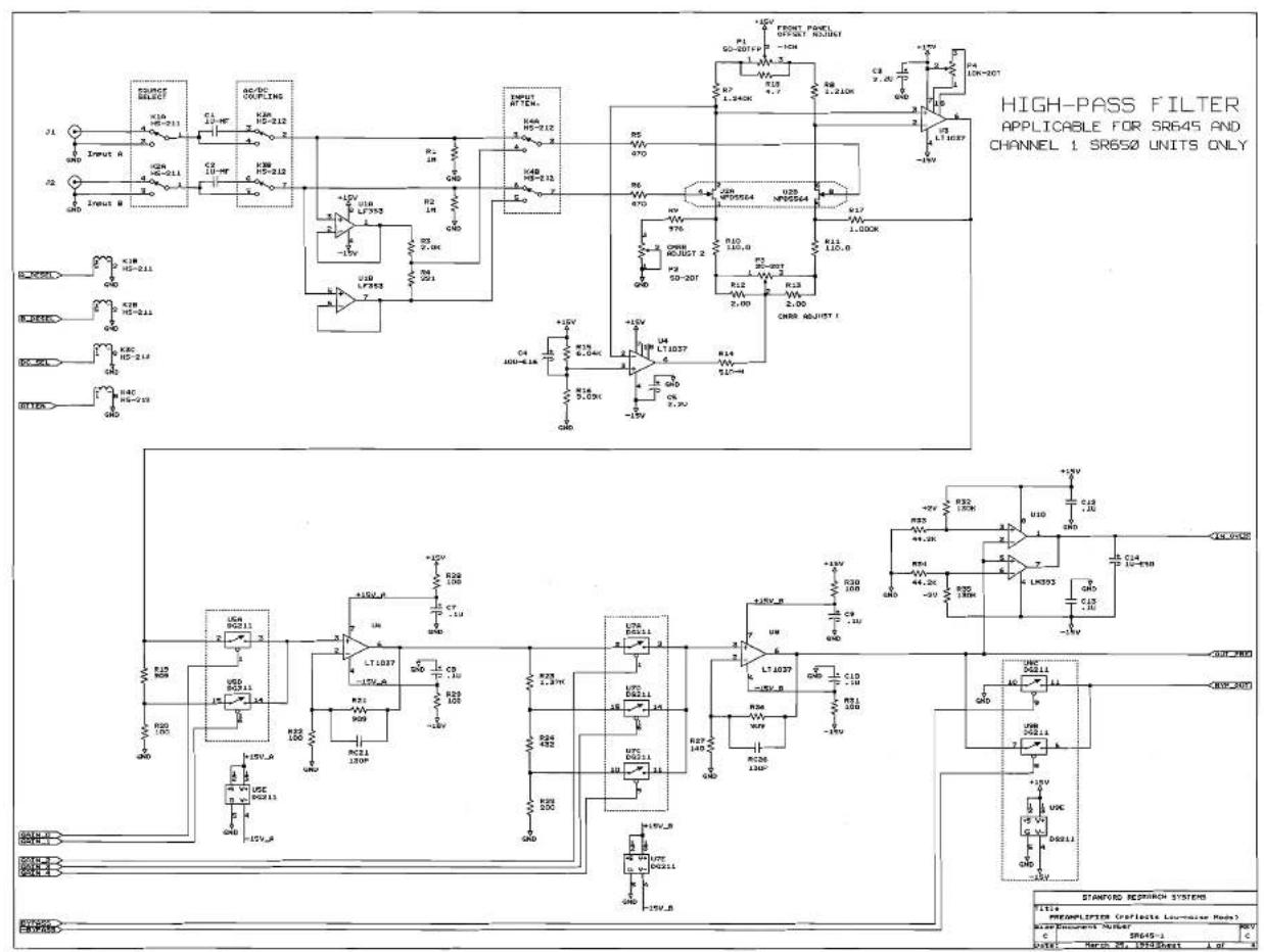
text_image
HIGH-PASS FILTER APPLICABLE FOR SR645 AND CHANNEL 1 SR650 UNITS ONLY STANDARD RESEARCH SYSTEMS FILTS PREAMPLIPTER (Reflective Low-Mixer Modem) AIP Document Number: SR645-1 C D GND SNR Input A K1B HS-211 C1 12.4V K2B HS-212 K3B HS-213 K4B HS-214 K5B HS-215 K6B HS-216 K7B HS-217 K8B HS-218 K9B HS-219 K10B HS-21A K11B HS-21B K12B HS-21C K13B HS-21D K14B HS-21E K15B HS-21F K16B HS-21G K17B HS-21H K18B HS-21I K19B HS-21J K20B HS-21K K21B HS-21L K22B HS-21M K23B HS-21N K24B HS-21O K25B HS-21P K26B HS-21Q K27B HS-21R K28B HS-21S K29B HS-21T K30B HS-21U K31B HS-21V K32B HS-21W K33B HS-21X K34B HS-21Y K35B HS-21Z K36B HS-21A K37B HS-21B K38B HS-21C K39B HS-21D K40B HS-21E K41B HS-21F K42B HS-21G K43B HS-21H K44B HS-21I K45B HS-21J K46B HS-21K K47B HS-21L K48B HS-21M K49B HS-21N K50B HS-21O K51B HS-21P K52B HS-21Q K53B HS-21R K54B HS-21S K55B HS-21T K56B HS-21U K57B HS-21V K58B HS-21W K59B HS-21X K60B HS-21Y K61B HS-21Z K62B HS-21A K63B HS-21B K64B HS-21C K65B HS-21D K66B HS-21E K67B HS-21F K68B HS-21G K69B HS-21H K70B HS-21I +UV VOUT RONUT RONUT RONUT RONUT RONUT RONUT RONUT RONUT RONUT RONUT RONUT RONUT RONUT RONUT RONUT RONUT RONUT RONUT RONUT RONUT RONUT RONUT RONUT RONUT RONUT RONUT RONUT RONUT RONUT RONUT RONUT RONUT RONUT RONUT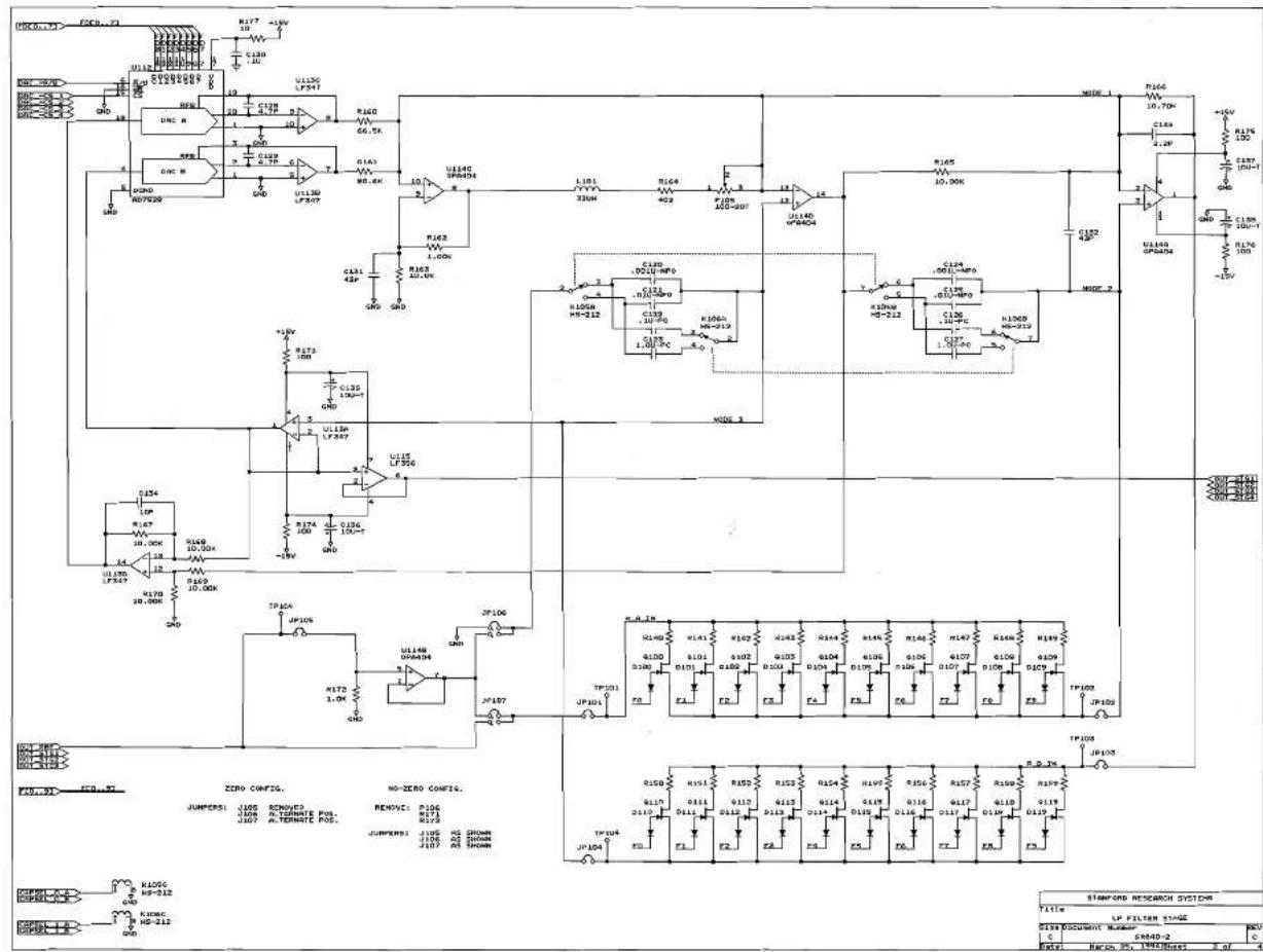
text_image
U1130 LF541 R160 V7 C120 1.10 U1130 LF541 R160 V7 C120 1.10 U1130 LF541 R160 V7 C120 1.10 U1130 LF541 R160 V7 C120 1.10 U1130 LF541 R423 V7 L100K U1140 OPA934 L101 330H R164 V7 C120 1.10 U1140 OPA934 R165 V7 C120 1.10 U1140 OPA934 R165 V7 C120 1.10 U1140 OPA934 R165 V7 C120 1.10 U1140 OPA934 R165 V7 C120 2.0V U1130 LF547 R165 V7 C120 2.0V U1130 LF547 R165 V7 C120 2.0V U1130 LF547 R165 V7 C120 2.0V U1130 LF547 R165 V7 C125 2.0V U1130 LF547 R165 V7 C125 2.0V U1130 LF547 R165 V7 C125 2.0V U1130 LF547 R165 V7 C125 2.0V U1130 LP-237 R165 V7 C125 2.0V U1130 LP-237 R165 V7 C125 2.0V U1130 LP-237 R165 V7 C125 2.0V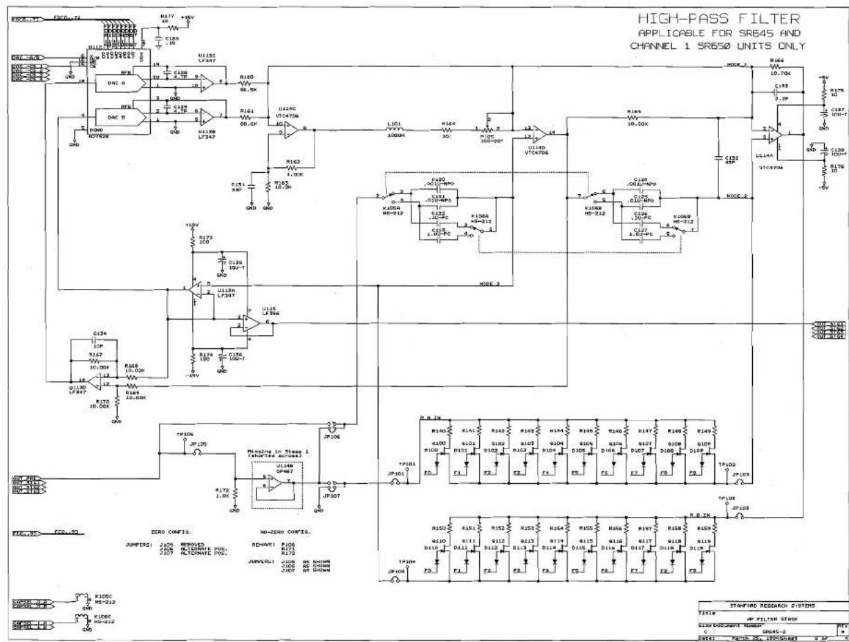
text_image
HIGH-PASS FILTER APPLICABLE FOR SR645 AND CHANNEL 1 SR650 UNITS ONLY STAMP 100 RESEARCH SYSTEMS TITLE HP FILTER STAGE SIZE DOCUMENT NUMBER: SR645-2 DATE: SEP-CH, NO-200000001 R177 +RV U138 LF347 R160 86.5K U138 LF347 R161 VGA 00.0K U138 LF347 R162 L100K C131 XD GND +15V S173 10V C138 10J-1T GND U138 LF347 R124 10J-1T GND U138 LF347 R124 10J-1T GND U138 LF347 R124 10J-1T GND U138 LF347 R124 10J-1T GND U138 LF347 R129 10J-1T GND U138 LF347 R129 10J-1T GND U138 LF347 R129 10J-1T GND U138 LF347 R129 10J-1T GND U138 LF347 R124 10J-1T GND U138 LF347 R129 10J-1T GND U138 LF347 R129 10J-1T GND U138 LF347 R124 10J-1T GND U138 LF347 R124 10J-1T GND U138 LF347 R129 10J-1T GND U138 LF347 R124 10J-1T GND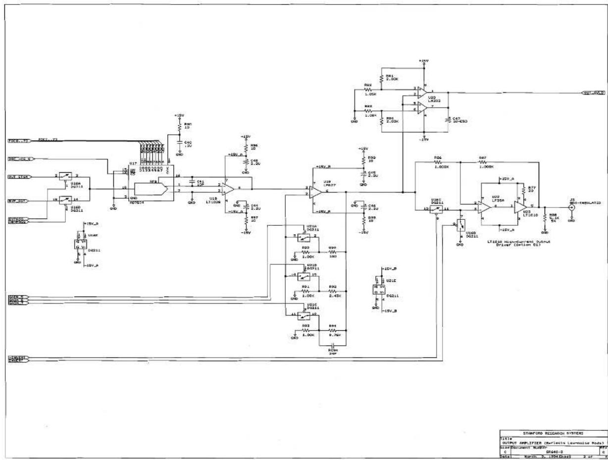
text_image
STANFORD RESEARCH SYSTEMS LT14 OUTPUT AMPLIFIER (Reflects Luminator Node) Output Protocol Number: 800 C SM640-3 Date: March 5, 1994 (Red) 2.07 0 +10V R01 1.00K U2D LFS23 10-450 +10V R02 1.00K U2D LFS23 10-450 +10V R03 1.00K U2D LFS23 10-450 +10V R04 1.00K U2D LFS23 10-450 +10V R05 1.00K U2D LFS23 10-450 +10V R06 1.00K U2D LFS23 10-450 +10V R07 1.00K U2D LFS23 10-450 +10V R08 1.00K U2D LFS23 10-450 +10V R09 1.00K U2D LFS23 10-450 +10V R10 1.00K U2D LFS23 10-450 +10V R11 1.00K U2D LFS23 10-450 +10V R12 1.00K U2D LFS23 10-450 +10V R13 1.00K U2D LFS23 10-450 +10V R14 1.00K U2D LFS23 10-450 +10V R15 1.00K U2D LFS23 10-450 +10V R16 1.00K U2D LFS23 10-450 +10V R17 1.00K U2D LFS23 10-450 +10V R18 1.00K U2D LFS23 10-450 +10V R19 1.00K U2D LFS23 10-450 +10V R20 1.00K U2D LFS23 10-450 +10V R21E CQ21I CQ2I- CQ2I- CQ2I- CQ2I- CQ2I- CQ2I- CQ2I- CQ2I- CQ2I- CQ2I- CQ2I- CQ2I- CQ2I- CQ2I- CQ2I- CQ2I- CQ2I- CQ2I- CQ2I- CQ2I- CQ2I, CQ2I- CQ2I- CQ2I- CQ2I- CQ2I- CQ2I- CQ2I- CQ2I- CQ2I- CQ2I- CQ2I- CQ2I- CQ2I- CQ2I- CQ2I- CQ2I- CQ2I- CQ2I- CQ2I- CQ2I. CQ2I- CQ2I- CQ2I- CQ2I- CQ2I- CQ2I- CQ2I- CQ2I- CQ2I- CQ2I- CQ2I- CQ2I- CQ2I- CQ2I- CQ2I- CQ2I- CQ2I- CQ2I- CQ2I- CQ2I - CQ2I- CQ2I- CQ2I- CQ2I- CQ2I- CQ2I- CQ2I- CQ2I- CQ2I- CQ2I- CQ2I- CQ2I- CQ2I- CQ2I- CQ2I- CQ2I- CQ2I- CQ2I- CQ2I- CQ2I+ CQ2I- CQ2I- CQ2I- CQ2I- CQ2I- CQ2I- CQ2I- CQ2I- CQ2I- CQ2I- CQ2I- CQ2I- CQ2I- CQ2I- CQ2I- CQ2I- CQ2I- CQ2I- CQ2I- CQ2I-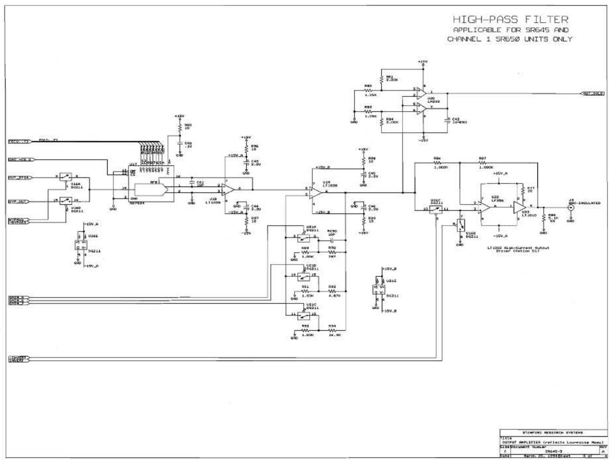
text_image
HIGH-PASS FILTER APPLICABLE FOR SR645 AND CHANNEL 1 SR650 UNITS ONLY STAMPORD RESEARCH SYSTEMS TITLE OUTPUT AMPLIFIER (reflects Lou-noise Mon) CEM DOCUMENT "S###" C Date: Nov-15, 10931East 3 of N +15V R00 10 C00 1.20 GND +15V_A 10 C01 100 GND +15V_B 10 C02 2.20 GND +15V_C 10 C03 2.20 GND +15V_D 10 U19 LF1008 2.7 +15V_E 10 C04 2.20 GND +15V_F 10 C05 2.20 GND +15V_G 10 C06 2.20 GND +15V_H 10 C07 2.20 GND +15V_I 10 C08 2.20 GND +15V_J 10 C09 2.20 GND +15V_K 10 C10 2.20 GND +15V_L 10 C11 2.20 GND +15V_M 10 C12 2.20 GND +15V_N 10 C13 2.20 GND +15V_O 10 C14 2.20 GND +15V_P 10 C15 2.20 GND +15V_OE 10 C16 2.20 GND +15V_OELEOLED
text_image
STAFFIO RESEARCH SYSTEM TITLE OPTICOLATED INTERFACE Size Document Number: NC C 100A-4 Date: October 26, 1998/Event c of :4 +15V +10V +10V +10V +10V +10V +10V +10V +10V +10V +10V +10V +10V +10V +10V +10V +10V +10V +10V +10V +10V +15V +15V +15V +15V +15V +15V +15V +15V +15V +15V +15V +15V +15V +15V +15V +15V +15V +15V +15V +15V +10V +10V +10V +10V +10V +10V +10V +10V +10V +10V +10V +10V +10V +10V +10V +10V +10V +10V +10%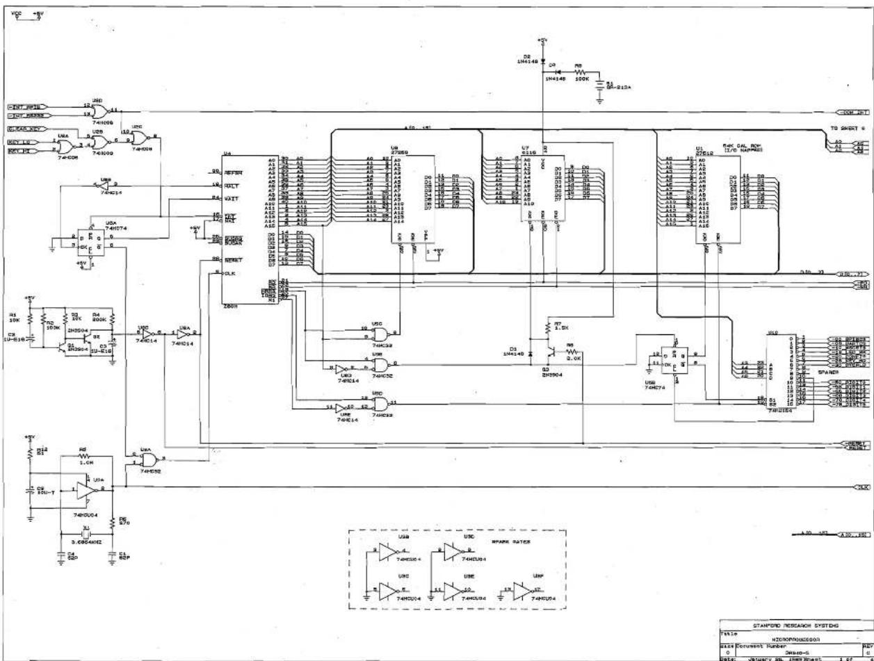
text_image
VCC +V 12 74HC05 74HC09 74HC14 74HC14 74HC14 74HC14 74HC14 74HC14 74HC14 74HC14 74HC14 74HC14 74HC14 74HC14 74HC14 74HC14 74HC14 74HC14 74HC14 74H213A 74HC14 74HC14 74HC14 74HC14 74HC14 74HC14 74HC14 74HC14 74HC14 74HC14 74HC14 74HC14 74HC14 74HC14 74HC14 74HC14 74HG0000000000000000000000000000000000000000000000000000000000000000000000000000000000000000000000000000 USS USS USS USS USS USS USS USS USS USS USS USS USS USS USS USS USS USS USS USS USS USS USS USS USS USS USS USS USS USS USS USS USS USS 213A TDS SHEET 6 RAC GAL RCM 11/6 NAPMOSI 2.12 2.22 2.32 2.42 2.52 2.62 2.72 2.82 2.92 3.02 3.12 3.22 3.32 3.42 3.52 3.62 3.72 3.82 3.92 4.02 4.12 4.22 4.32 4.42 4.52 4.62 4.72 4.82 4.92 5.02 5.12 5.22 5.32 5.42 5.52 5.62 5.72 5.82 5.92 6.02 6.12 6.22 6.32 6.42 6.52 6.62 6.72 6.82 6.92 7.02 7.12 7.22 7.32 7.42 7.52 7.62 7.72 7.82 7.92 8.02 8.12 8.22 8.32 8.42 8.52 8.62 8.72 8.82 8.92 9.02 9.12 9.22 9.32 9.42 9.52 9.62 9.72 9.82 9.92 10.02 10.12 10.22 10.32 10.42 10.52 10.62 10.72 10.82 10.92 11.02 11.12 11.22 11.32 11.42 11.52 11.62 11.72 11.82 11.92 12.02 12.12 12.22 12.32 12.42 12.52 12.62 12.72 12.82 13.02 13.12 13.22 13.32 13.42 13.52 13.62 13.72 13.82 13.92 15.0B TDS SHEET S RAC GAL RCM 11/6 NAPMOSI TDS SHEET S RAC GAL RCM 11/6 NAPMOSI TDS SHEET S RAC GAL RCM TDS SHEET S RAC GAL RCM TDS SHEET S RAC GAL RCM TDS SHEET S RAC GAL RCM TDS SHEET S RAC GAL RCM TDS SHEET S RAC GAL RCM TDS SHEET S RAC GAL RCM TDS SHEET S RAC GAL RCM TDS SHEET S RAC GAL RCM TDS SHUTS S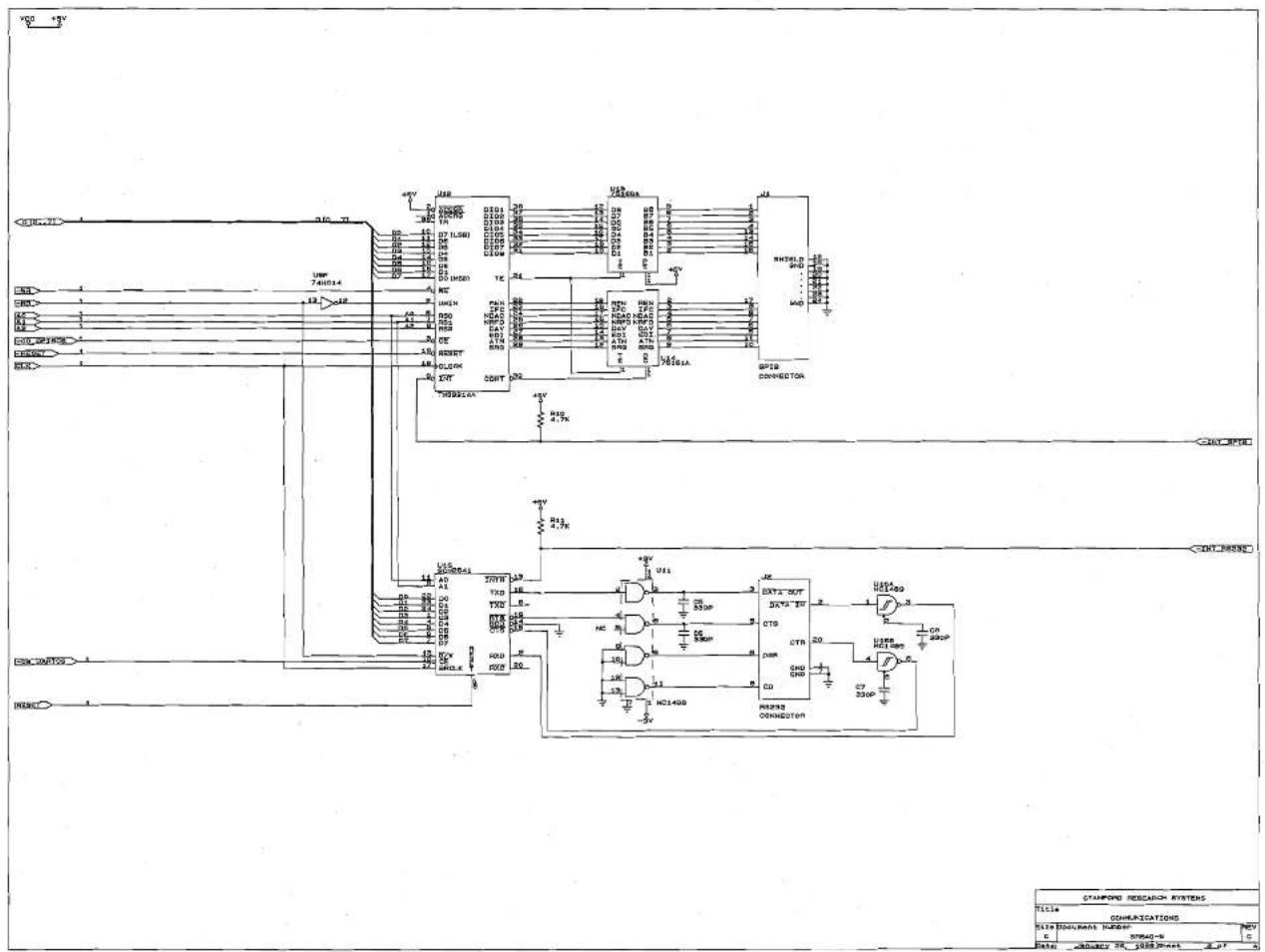
text_image
CMOS RESEARCH SYSTEMS TITLE COMMUNICATIONS S137 MAULINAN HUROCK STRAO-9 G C Date: ADJDECY 20, 1088/2041 2.27