Sumo - Automotive Tata - Free user manual and instructions
Find the device manual for free Sumo Tata in PDF.


User questions about Sumo Tata
0 question about this device. Answer the ones you know or ask your own.
Ask a new question about this device
Download the instructions for your Automotive in PDF format for free! Find your manual Sumo - Tata and take your electronic device back in hand. On this page are published all the documents necessary for the use of your device. Sumo by Tata.
USER MANUAL Sumo Tata
natural_image
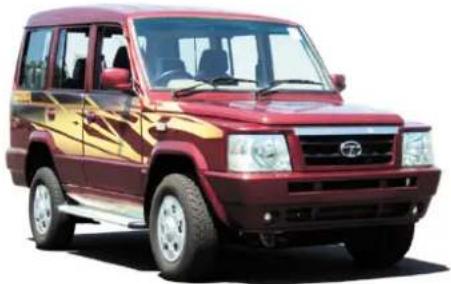
Exterior view of a red and gold SUV with visible grille and alloy stripes (no signage or text)SUMO GOLD
CR-4 (BS-IV) & 4SPTC (BS-III)
OWNER'S MANUAL & SERVICE BOOK
TATA MOTORS
CAR IDENTIFICATION AND RECORD
OWNER'S NAME
ADDRESS
SELLING DEALER CODE
DATE OF DELIVERY
DATE OF REGISTRATION
REGISTRATION NO.
CHASSIS NO.
ENGINE NO.
GEAR BOX NO.
REAR AXLE NO.
BATTERY MAKE
BATTERY SR. NO.
BATTERY CODE
THE WARRANTY ON THIS CAR IS VALID ONLY IF THE DETAILS ARE FILLED, SIGNED & STAMPED BY THE SELLING DEALER.
DEALER'S SIGNATURE AND STAMP
natural_image
Exterior view of a red Toyota SUV (no visible text or symbols)Following items are provided with your TATA SUMO GOLD:
-
Owner's Manual & Service Book
-
Battery warranty Card
-
First Aid Kit
-
Advance Warning Triangle
-
Jack and Handle
-
Spare Headlamps Bulbs - 2 Nos
-
Spare Fuses - (Provided in fuse box)
-
Pre-delivery inspection and service.
-
Complimentary diesel in the fuel tank.
-
Music System Manual (if fitted)
-
Immobiliser Manual
-
Tool Kit
a. Wheel Spanner
b. Screw Driver
c. Ring Spanner (8-9)
d. Socket Handle
TATA SUMO GOLDA SUMO GOLD
CR-4 (BS-IV) & 4SPTC (BS-III)
Owner's Manual & Service Book
TATA MOTORS
- Mumbai • Pune •
The contents given in this book are not binding, subject to change without notice and are for illustration purpose only.
DO YOU KNOW?
While taking delivery of your New TATA Sumo Gold
you are privileged to have the following :
- Owner's Manual & Service Book 02. Battery warranty Card
- First Aid Kit 04. Advance Warning Triangle
- Jack and Handle 06. Spare Headlamps Bulbs - 2 Nos.
- Spare Fuses - (Provided in fuse box) 08. Pre - delivery inspection and service.
- Complimentary diesel in the fuel tank. 10. Music System Manual (if fitted)
- Immobiliser Manual 12. Tool Kit
a. Wheel Spanner b. Screw Driver
c. Ring Spanner (8-9) d. Socket Handle
You are also entitled for :
- Free Services as per details given in your Owner's manual and service book, at any TATA MOTORs Dealership or TATA MOTORS Authorised Service Centre (TASC) or Tata Motors Authorised Service Point (TASP).
- On the spot settlement of warranty as per terms and conditions given in this book.
We welcome your suggestions for better service.
Should you require any assistance, please contact Works Manager of TATA MOTORS Dealership or TASC.
EXCELLENT CUSTOMER SUPPORT FOR TOTAL SATISFACTION
Dear Customer,
Thank you for choosing the Tata Sumo Gold another quality offering from the company's growing range of passenger vehicles.
We would request you to get acquainted with the details in this owner's manual, which will enable you to derive optimum performance from your Tata Sumo gold. We look forward to having you as a satisfied customer and hope to have you retain us as your first choice for any of your motoring needs.
We are privileged to have you as our customer.
TATA MOTORS LIMITED
DO YOU KNOW?
FOREWORD
Thank you for selecting TATA Sumo Gold vehicle of your choice.
We welcome you to the world of advanced automotive engineering in a form especially suited to our operating conditions.
This book gives you all the information necessary for making your ownership of the vehicle, a thoroughly satisfying experience.
To assist you in maintaining your vehicle as per recommended schedule, we have a widespread network of dealers and service centres. The list is included in this book for your convenience.
Should you need any special assistance, please call on our Authorised dealer.
Please note that by adhering to the correct operating procedures and by availing the scheduled maintenance services at our authorised service outlets, you can obtain the maximum performance from your vehicle.
We request you to go through the book and drive many miles of motoring pleasure.
We provide safe, high quality, high performance vehicles. In order to maintain the level of performance and reliability in the vehicle, it is important that only Tata motors genuine accessories are to be fitted. Any accessory that is fitted or modification that is carried out without authorisation can hamper the safety and performance of the vehicle besides depriving you of your warranty benefits.
Use of genuine parts, designed and manufactured to our exacting standards, are the best way to maintain your vehicle in peak operating condition. Please do not use substitutes. They always prove costlier in the long run.
Failure to use genuine parts can invalidate any future warranty claims.
The information and specification given in this book are valid as on the date of printing. Tata Motors reserves the right to make changes in design and specifications and / or to make additions to or improvements in this product without obligation to install them on products previously sold.
TATA MOTORS
CONTENTS
FOREWORD 5
ENVIRONMENT PROTECTION 6
WARRANTY TERMS & 8 CONDITION
DO'S 10
DONT'S 13
HANDLING 16
Aggregate Numbering 16
Key 18
Anti-theft Device 18
Door Locking 19
Manual Window Winding 19
Power Windows 20
Sun Visors 21
Outer Rear View Mirrors 22
Inner Rear View Mirror 22
Driver's & Co-driver's Seat 23
Middle Seat 24
Seats at Rear 24
Seat Belt 25
Adjustable Head Restraint 27
Driving Controls 28
Instrument Panel 29
Indicators 31
Gauges 34
Steering Lock Cum Ignition
Switch 37
Combi-Switch 39
Music System with USB & Blue Tooth 41
Antenna 41
Micro Phone 41
Engine Compartment Lamp 41
Tail Lamp 42
Registration Plate lamp 42
High Mounted Stop Lamp 42
Interior Roof Lamps 43
Headlamp Leveling Switch 44
Accessory Switches 45
Power Socket 47
Mobile Holder 47
Grab Handle 48
Glove Box with Cup Holder 48
Gear Shift Lever 49
Parking Brake Lever 49
Bonnet Opening & Closing 50
Fuel Filling Cap Opening 50
Spare Wheel 52
Vehicle Jack & Tools 53
Catalytic Converter 54
EGR System 54
Turbocharger 55
Power Steering 56
Air Conditioning 58
Roof AC 61
Preparing the vehicle for the drive 62
DRIVING INSTRUCTION
Driving Instruction 65
Braking 66
Fuel Economy 66
Driving in Adverse Conditions 67
Towing the Vehicle 70
Driving Safety 71
Safety Checks 72
CONTENTS
VEHICLE MAINTENANCE
Engine Compartment - CR-4 73
Engine Compartment - 4SPTC 74
Changing Engine Oil 75
Changing Oil Filter 75
Engine Air Filter 76
Fuel Filter & Priming CR-4 77
Fuel Filter & Priming 4SPTC 77
Fan Belt Tension Adjustment 78
Brake Clutch System Bleeding 79
Cooling System 80
Brake System 80
Brake Adjustment 82
Wheels & Tyres 83
Wheel Change 83
Wheel Alignment 83
Tyre Pressure 83
Wheel Balancing 84
Replacing Tyre / Tube 84
Replacing Tyre / Rim 84
Tyre Rotation 85
Headlamps 85
Head Lamp Adjustment 85
Head Lamp Bulb Replacement 86
Bulb Specification 87
Fuses 88
Vehicle Care 89
FUEL, LUBRICANTS & COOLANTS
Fuel 92
Lubricants 93
Coolants 93
Recommended Oils, Lubricants 94
TECHNICAL SPECIFICATIONS 95
SPECIAL INSTRUCTIONS 99
SERVICE SCHEDULE 101
RECORD OF SERVICE PERFORMED
RECORD OF REPAIRS
CARRIED OUT 107
ALPHABETICAL INDEX 108
ABBREVIATIONS 110
ENVIRONMENT AL PROTECTION
TATA MOTORS is committed to produce vehicles using environmentally sustainable technology. A number of features have been incorporated in Tata Motors Passenger Car Vehicles which have been designed to ensure environmental compatibility throughout the life cycle of the vehicle. We would like to inform you that your vehicle meets Emission norms and this is being regularly validated at the stage of manufacturing.
As a user, you too can protect the environment by operating your vehicle in a pro-active manner. A lot depends on your driving style and the way you maintain your vehicle. We are giving below a few tips for your guidance.
Driving
- Avoid frequent and violent accelerations.
- Do not carry any unnecessary weight on the vehicle as it
overloads the engine. Avoid using devices requiring high power consumption during slow traffic condition.
- Monitor the cars fuel consumption regularly and if it shows a rising trend, get the car immediately attended at our Authorised Service Centre.
- Switch off the engine during long stops at traffic jams or signals. If the situation demands that engine be kept running, avoid frequent revving up of the engine. Also avoid frequent stopping and restarting, if uncalled for.
- It is not necessary to rev up the engine before turning it off as it unnecessarily burns the fuel.
- Shift to higher gears as soon as possible. Use each gear upto 2/3rd of its maximum engine speed. A chart indicating gear shifting speed is given in this book.
Maintenance of the vehicle
- Ensure that recommended maintenance is carried out on the vehicle regularly at our Authorised Service Outlets.
- As soon as you see any leakages of oil or fuel in the car, get it attended immediately.
- Use only recommended brands and grades of lubricants and clean uncontaminated fuels.
- Get your vehicle checked for emission periodically by authorised dealer and regularly renew the P.U.C. certificate.
- Ensure that fuel filter, oil filter and breathers are periodically checked and if required, replace the same by only genuine Tata Motor's recommended brands.
- Do not pour used oils or coolants into the sewage drains, garden soil or open streams. Dispose the used
filters and batteries in compliance with the current legislation.
- Do not allow any unauthorised person to tamper with engine settings or to carry modifications on the vehicle.
- Never allow the vehicle to run out of fuel.
- Parts like brake liners, clutch disc should be vacuum cleaned. Do not use the compressed air for cleaning these parts which may spread the dust in the atmosphere.
While carrying out the servicing or repairs on your vehicle, you should pay keen attention to some of the important aggregates, which greatly affect emission. These components are :
- Fuel injection pump, Injectors/Nozzles
-
Air intake & Exhaust system especially for leakages
-
Cylinder head for valve leakage
- All filters such as air, oil and fuel filters (check periodically)
- Turbocharger and intercooler (if fitted)
- Catalytic converter (if fitted)
- EGR System and components
- Electrical Connections for EGR
This Owner's Manual contains further information on driving precautions and maintenance care leading to environment protection. Please familiarise yourself with these aspects before driving.
We WARRANT each TATA SUMO GOLD vehicles & parts thereof manufactured by us to be free from defect in material and workmanship, subject to the following terms & conditions :
- The warranty for the vehicle shall be for 36 months from the date of sale of the vehicle OR 1,00,000 kms, whichever is earlier.
- Our obligation under this warranty shall be limited to repairing or replacing, free of charge, such parts of the vehicle which, in our opinion, are defective, on the vehicle being brought to us or to our dealers within the warranty period. The parts so repaired or replaced shall also be warranted for quality and workmanship but such warranty shall be co-terminus with this original warranty.
- Any part which is found to be defective and is replaced by us
under the warranty shall be our property.
- As for such parts as tyres, batteries & electrical equipment, fuel injection equipment, power steering equipment, A/C equipment & anti-theft device not manufactured by us but supplied by other parties, this warranty shall not apply, but buyers of the vehicle shall be entitled to, so far as permissible by law, all such rights as we may have against such parties under their warranties in respect of such parts. Our Dealers/TASC's will assist the purchaser in taking up the complaint with the respective manufacturers and their decision on the warranty will be final.
- This warranty shall not apply if the vehicle or any part thereof is repaired or altered otherwise than in accordance with our standard repair procedure, or by any person other than our sales or service
establishments, our authorised dealers or service centres or service points in any way so as, in our judgement which shall be final and binding, to effect its reliability, nor shall it apply if, in our opinion which shall be final and binding the vehicle is subjected to misuse, negligence, improper or inadequate maintenance or accident or loading in excess of such carrying capacity as certified by us, or such services as prescribed in our Owner's Manual and Service Book are not carried out by the buyer through our sales or service establishments, our authorised dealers or service centres or service points.
- This warranty shall not cover normal wear and tear or any inherent normal deterioration of the vehicle or any of its parts arising from the actual use of the vehicle or any damage due to negligent or improper operation or storage of the
vehicle. This warranty shall not apply to normal maintenance services viz. oils & fluid changes, head lamps focussing, fastener retightening, wheel balancing, tyre rotation, adjustment of valve clearance, fuel timing, ignition timing and consumables like bulbs, fuel filters and oil filters etc. This warranty shall not apply to any damage or deterioration caused by environmental pollution or bird droppings. This warranty shall not apply to V-belts, hoses and gas leaks in case of air conditioned vehicle. Slight irregularities not recognised as affecting the function or quality of the vehicle or parts, such as slight noise or vibration, defects appearing only under particular or irregular operations are items considered characteristic of the vehicle.
- This warranty shall be null and void if the vehicle is subjected to abnormal use such as rallying,
racing or participation in any other competitive sports. This warranty shall not apply to any repairs or replacement as a result of accident or collision.
-
This warranty is expressly in lieu of all warranties, whether by law or otherwise, expressed or implied, and all other obligations or liabilities on our part and we neither assume nor authorise any person to assume on our behalf, any other liability arising from the sale of the vehicle or any agreement in relation thereto.
-
The buyer shall have no other rights except those set out above and have, particular, no right to repudiate the sale, or any agreement or to claim any reduction in the purchase price of the vehicle, or to demand any damages or compensation for losses, incidental or indirect, or inconvenience or consequential damages, loss of vehicle, or loss
of time, otherwise, incurred or accrued.
-
Any claim arising from this warranty shall be recognised only if it is notified in writing to us or to our concerned dealer without any delay soon after such defect as covered and ascertained under this warranty.
-
This warranty shall stand terminated if the vehicle is transferred or otherwise alienated by the buyer without our prior written consent.
-
We reserve our rights to make any change or modification in the design of the vehicle or its parts or to introduce any improvement therein or to incorporate in the vehicle any additional part or accessory at any time without incurring any obligation to incorporate the same in the vehicles previously sold.
TATA MOTORS
Do's
- Use recommended oils and lubricants only.
- Change oil in engine, gear box, steering system and rear axle at prescribed intervals.
- Use only genuine oil filter and fuel filter elements. Replace them at regular intervals.
- Clean air filter element regularly. Replace filter element when service indicator shows red band even after cleaning the filter element.
- Ensure periodic servicing as per maintenance schedule.
- Insist on use of genuine spare parts.
- Ensure that caps of auxiliary tank and radiator are firmly fitted to keep the cooling system pressurised and to maintain coolant level. Always use genuine
radiator cap only of 1.0 kg/cm² (14 PSI), for replacement.
- Check tyres for damage from time to time and remove any foreign bodies embedded in treads.
In case of tyre replacement or repairs due to puncture have the wheel balanced Keep grease, oil and fuel away from the tyres. In case of uneven tyre wear get the vehicle attended to by any of our authorised service set-ups.
-
Maintain correct tyre pressure.
-
Check battery every week and top up electrolyte level. Keep battery terminals clean and cable joints tight. Apply vaseline / petroleum jelly on terminals. Use distilled water only for topping up.
-
Observe correct polarity when connecting battery terminals.
Do's
- Disconnect alternator terminals while carrying out any welding on the vehicle.
- Avoid panic braking. Use lower gears while descending gradients.
- Start the vehicle always in the 1st gear to avoid premature clutch wear.
- Keep both foot and parking brakes properly adjusted.
16 Before engaging reverse gear, ensure that vehicle has come to a stop, declutch, wait for a few seconds and shift into reverse gear. - When parking on slopes, use wheel chocks, apply parking brake and keep vehicle in low gear.
-
In case of emergency parking or breakdown on road, push the hazard warning switch to flash all the blinker lights to warn other road users.
-
Release parking brake before driving off.
- Release the ignition key as soon as engine starts.
- Retighten wheel mounting nuts after 100 km of every wheel change. Tightening Torque : 12 - 15 mkg.
- Use only recommended FUSES and always keep spare fuses in the box.
- In case of engine not starting first check the fuse of fuel injection pump solenoid.
-
Ensure doors are properly closed.
-
If your vehicle has a turbocharged engine, keep engine at idling speed for atleast a minute after starting and also before stopping it, to protect the turbocharger against damage due to oil starvation.
Do's
Where Air conditioning system is installed
- After parking in the sun, drive with windows rolled down for a few minutes to blow off hot air before switching on A/C.
- Keep all windows rolled-up when AC system is working.
- If you feel irritation in the eyes due to smoke or during long drive, stop A/C and ventilate for half a minute by winding down door glasses or use fresh air mode provided with HVAC system.
- Before stopping the engine first switch "OFF" A/C and then the blower.
- During off-season operate the air conditioner a few times every month to lubricate components.
Dont's
- Do not use Clutch Pedal as Foot Rest. This will reduce clutch life.
- Do not Coast vehicle in Neutral and engine switched-off position. This is a safety hazard.
- Do not run engine without Radiator Cap. Use genuine Cap only, to keep system pressurised.
- Do not overtighten engine oil filter.
- Front and rear suspension shock absorbers fitted on this vehicle have in-built rebound stopper. There is no separate rebound stopper fitted on the vehicle. Hence, do not drive the vehicle either without shock absorbers OR with non-genuine shock absorbers, otherwise suspension is likely to be damaged.
-
If your vehicle has a turbocharged engine, do not stop the engine at once, allow it to run at idling speed for atleast 1 minute. Also do not accelerate engine till the engine oil pressure has built up.
-
Do not cause heating of A/C pipe (where fitted), while welding/brazing in its viscosity.
- Do not disturb the fast idling control device actuator setting, where fitted.
- Do not open any hose/pipe points of A/C system (where fitted).
- Do not put your hand inside the condenser fan when the grille is removed. Disconnect power supply to fan and switch off engine before any maintenance work, where applicable.
- Do not open HP system under any condition. It should be handled by trained professional only. (i.e. HP Pump, Rail, Injector, HP lines)
- Do not clean Engine Compartment with high pressure water jet. It can cause Malfunctioning of electronic components. Cleaning can be done with high pressure air.
HANDLING LOCATION OF CHASSIS & AGGREGATE SERIAL NUMBERS
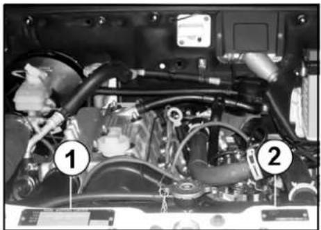
natural_image
Interior view of a car engine bay with numbered components (1 and 2), showing hoses and wiring (no readable text or symbols)- Chassis number plate (4SPTC-BS-III)
- Body Shell (Cab) no. plate (4SPTC-BS-III)
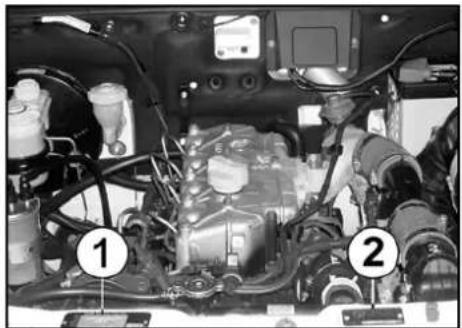
natural_image
Interior view of a car engine bay with numbered components (1 and 2), showing internal wiring and structural elements (no readable text or symbols)- Chassis number plate (CR-4 BS-IV)
- Body Shell (Cab) no. plate (CR-4 BS-IV)
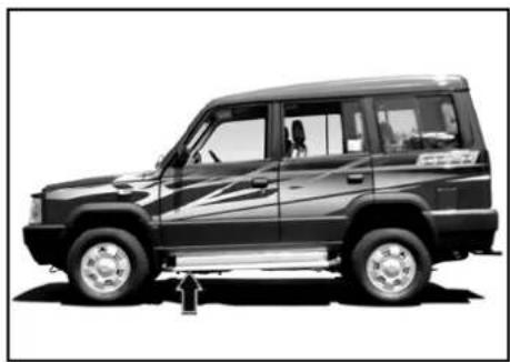
natural_image
Side profile of a black SUV with silver trim and white suspension, no visible text or symbolsChassis number on frame
natural_image
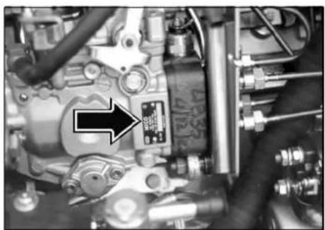
Close-up of an internal mechanical assembly with hoses and components, no visible text or symbolsFIP number
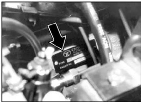
text_image
TKA TYPE EXCELLE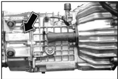
natural_image
Close-up of a mechanical transmission unit with visible gears and housing (no text or symbols)Gear box numberEngine number
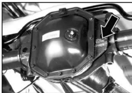
natural_image
Close-up of a mechanical component with hexagonal housing and bolted joints (no visible text or symbols)Rear axle number (Tata Motors)
Key
Your vehicle comes with two identical keys.
With this key, you can operate - 1. Door Locks 2. Steering Lock cum Ignition switch 3. Tail gate Lock 4. Glove Box 5. Fuel Flap lock (if fitted). It is advisable to keep one of the keys in a safe place for use in case of an emergency.

CAUTION
Do not use a locally made key, but obtain a duplicate through your TATA MOTORS dealer.
Do not leave the key inside the car.
Anti-theft Device (if installed)
This is an electronic car security system with remote (keyless) operation for door Unlock/Lock. It immobilises the vehicleby disabling vital circuits related to engine.
Please refer supplier's instruction manual supplied along with the vehicle for further details of operations and features.
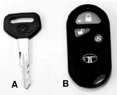
A. Key B. Remote - Anti Theft Device
text_image
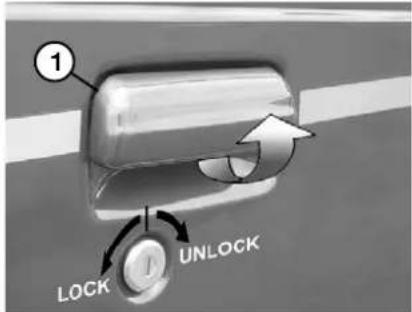
① LOCK UNLOCK- Door opening from outside
Door Locking
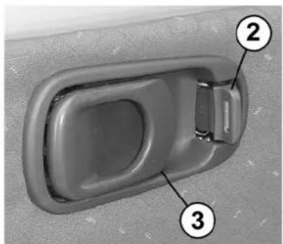
The front doors can be locked and unlocked from the outside with the key or from the inside using the door lock lever. In your vehicle, the driver's door & co-driver's door (if provided) have separate locking facilities. To lock from inside turn the lever (2) towards the inner hinged handle (3).
Where the central locking system is provided, if you lock/unlock the driver door with the key, the remaining three doors get locked/unlocked at a time. The tail gate door is not part of the central locking provision.
To open the door from the outside use the swing handle (1). After unlocking the door with the key, pull the swing handle upward. The swing handles are provided on each door.
To open the door from the inside pull hinged handle outward.
Manual window winding
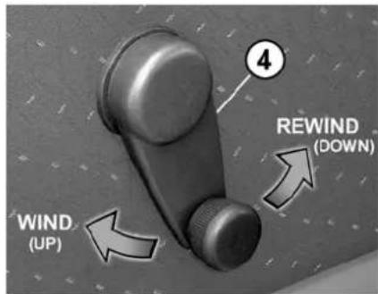
For raising and lowering window glasses use handle (1)
natural_image
Close-up of a car interior component with numbered labels (2, 3), showing a curved handle and side clip (no text or symbols beyond labels)- Locking / Unlocking Lever
- Hinged Handle
text_image
4 REWIND (DOWN) WIND (UP)- Window winding Lever
HANDLING POWER WINDOWS
Power Windows : (if provided)
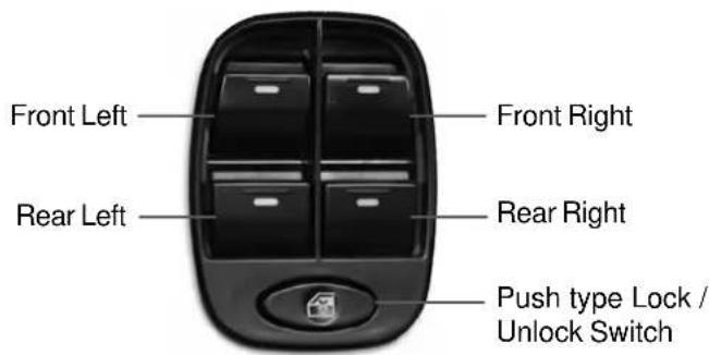
Separate knobs are provided on the switch to operate the four door window glasses individually.
To open the door window glass, push the respective knobs down.
To close the door window glass, pull the respective knobs up.
In the lock position, the rear window switches become inoperative. However the rear windows can be operated by the switches on the console. Illumination on rear window switches goes 'OFF' in locked position. press down the lock button to unlock. Express power down on driver and co-driver windows are provided.
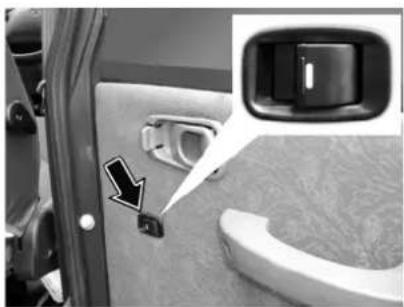
Individual window winding switches have been provided only on the rear doors.
text_image
Front Left Rear Left Front Right Rear Right Push type Lock / Unlock Switch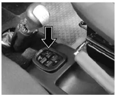
natural_image
Close-up of a car gear shift lever with a black arrow pointing to the pivot point (no text or symbols visible)Switches on the central console for operating the door glasses
natural_image
Close-up of a car door with a side panel and a highlighted button, showing no text or symbols.Individual Switches on the rear doors for operating the rear door glasses
Sun visors
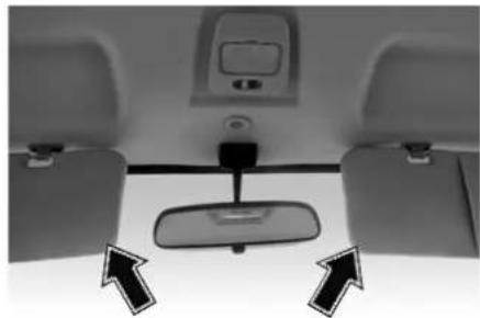
Two adjustable sun visors are provided inside the cab to prevent sun glare.
Lower the sun visors to protect the eyes from bright sunlight. The sun visors also moves sideways towards the door.
A vanity mirror has been provided on the co-driver's sun visor.
natural_image
Interior view of a car showing the rearview mirror and side-mounted dashboard (no text or symbols visible)Sun Visors
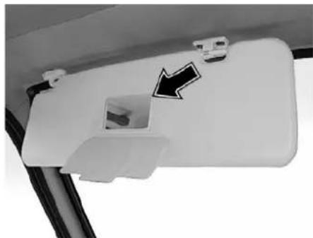
natural_image
Close-up of a white plastic door handle with a black arrow pointing to a small component, mounted on a curved surface (no text or symbols visible)Vanity Mirror
HANDLING OUTER & INNER REAR VIEW MIRRORS
Outer Rear view mirrors
Outer rear view mirror is fitted on the driver's door from the outside. It can be adjusted to the desired positions by hand. In few versions it can be adjusted by the lever provided inside the door. The mirror can be folded backwards for convenience when the vehicle is to be driven through narrow passages. In few versions, the same rear view mirror is also provided on co-driver's door.
Inner Rear view mirror
Inner rear view mirror is also fitted inside the cab between sun visors.
In few versions an additional adjustable anti-glare rear view mirror is provided inside the cab. Provision has been made for two positions.
- Normal position
- Anti-glare position
Use anti-glare position only if necessary as it reduces the rear view clarity considerably.
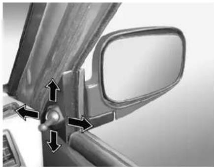
natural_image
Close-up of a car's side mirror and dashboard, showing alignment arrows (no text or symbols)Outside Rear View Mirror
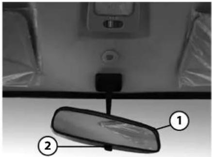
text_image
Technical diagram of a car rearview mirror with labeled parts 1 and 2- Inner rear view mirror
- Operating Knob
Driver's & Co-driver's seat
Adjustable type seat is provided for driver and co-driver. The driver seat is fitted with lever and handle, to adjust the seat. The seat can be adjusted in forward and backward directions. In few versions, both seats are also provided with lumbar support (3) to give you maximum driving comfort.
To achieve correct position for proper driving, lift the handle (2) and slide the seat either forward or backward. Once the desired position is achieved push down the handle to lock the seat. Turn the lever (1) to adjust backrest to the desired position. Release the lever to lock it.
Do not adjust seat while driving.
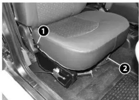
natural_image
Interior view of a car seat assembly with numbered components (no visible text or symbols)- Seat backrest inclination adjustment lever
- Seat sliding (forward & backward) lever
- Lumbar support adjustment knob (if fitted)
natural_image
Interior view of a car door with a numbered component (3) and directional arrow, no visible text or symbolsHANDLING OUTER & INNER REAR VIEW MIRRORS
Middle seat
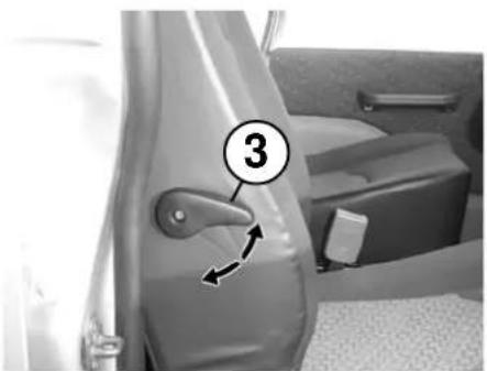
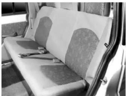
A cushion bench seat has been provided for the middle passengers. In few versions, a cushion bench 60:40 split seat has been provided for the middle passengers. Any one of the split can be folded by releasing the latch, on the backrest simultaneously (Fig. 1 on next page). For more luggage space or to access front facing third row seat, the folded middle seat can be somersaulted further.
For fixing the rear seat back upright, just push back the seat in position. It will get locked by itself.
natural_image
Interior view of a car backseat with patterned covers and seat covers (no visible text or symbols)Middle seat
Seats at rear
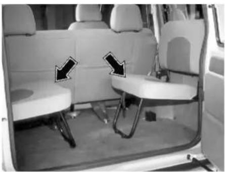
Two rows of seats, single or double are provided at rear for passengers (Fig. 4 on previous page). These seats can be folded for carrying bulkier baggage as per procedure given below:
- Lift the seat squab and hold against backrest.
- Engage strap with the hook on seat squab.
- Fold the seat stand.
To open the seats follow the reverse order. Ensure stand is fully opened and vertical to the floor.
natural_image
Interior view of a car showing two white seats with black arrows pointing to the side of each seat (no text or symbols visible)Rear jump seat
SEAT BELT
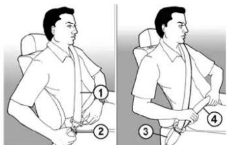
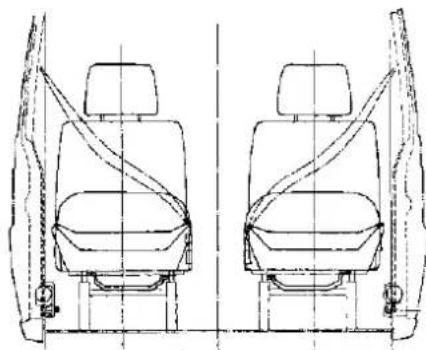
The vehicle has been fitted with three point belt for extra safety for driver, co-driver and passengers on middle seat. If not fastened, with key in 'IGN' position, audio alarm (only for GX) and visual indication is given on instrument panel.
Fastening the belt
Insert belt tongue into buckle, a positive locking 'click' indicates correct and safe assembly.
Releasing the belt
Press the release button, the tongue will be ejected clear of the locking mechanism within the buckle.
Belt adjustment
When the vehicle is at rest, adjust the length of the belt to suit convenience. Insert belt tongue in buckle. A positive click indicates correct assembly.
Adjust length of the belt to suit you and fasten. The lap section should be comfortably tight, the diagonal sections should be adjusted so that a flat hand will pass between the chest and the strap.
To tighten (shorten) the belt.
Pull free end of webbing through adjuster until required adjustment is achieved.
To loosen (lengthen) the belt.
Tilt the adjuster by means of the grip and slide it along the strap until suitably adjusted.
text_image
Illustration showing a person seated in two positions with numbered instructions for each position.- Seat Belt 2. Tongue 3. Lock Buckle 4. Lap Belt
natural_image
Technical line drawing of two car seats with seatbelt straps, no text or symbols presentSeat-belt Arrangement on Driver & Co-driver's Seat
Lap belt for middle passengers of front bench seat.
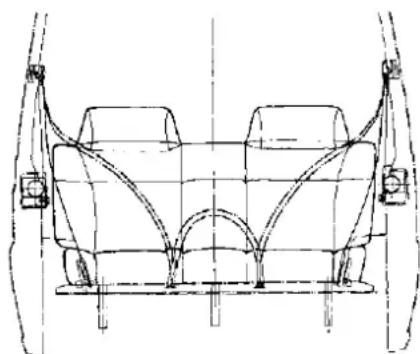
Middle passenger is provide with lap belt. Adjust length of belt to suit convenience. Insert belt tongue in buckle. A positive click indicate correct assembly. To release press the release button. The tongue will be ejected from the button.
CAUTION
- The belt is designed for use of only one person.
- It is not intended for children under 10 years.
- The belt should at all time be adjusted and used in accordance with the instructions and no excessive slackness in the belt should be evident.
- Avoid twisting the straps during use.
- Webbing must not be allowed to chafe against sharp edges on seat or bodywork.
- Do not make any alterations or additions to the belt. If in doubt consult the authorised service outlet
- The belt that have been cut, frayed, damaged or have been stressed through impact, should be replaced.
- To clean and occasional wipe with warm soapy water will maintain the webbing in a clean condition. Do not use bleach or dye under any circumstances.
- Periodic inspection of the installation will ensure safe and reliable service of the seat belt.
natural_image
Technical line drawing of a car's front and rear assembly (no text or symbols)Seat-belt Arrangement on Middle Seat
Adjustable Headrestraint
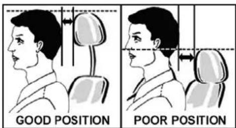
The driver, co-driver and middle seat of your vehicle are fitted with adjustable headrestraint. Headrestraint can help to protect you from whiplash and other injuries. For best protection adjust the top of the headrestraint as shown in the figure.
The headrestraint can be adjusted by using release button as shown in figure.
text_image
GOOD POSITION POOR POSITION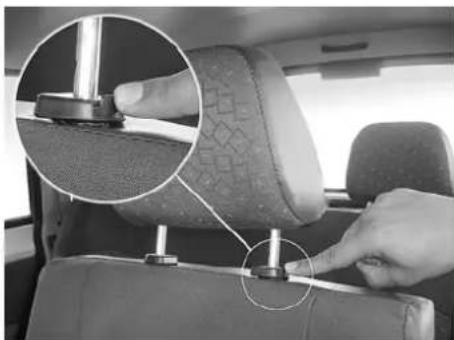
natural_image
Close-up of a car seatbelt with hands adjusting the seat, showing a magnified inset of the seat (no text or symbols visible)Release Button for Head rest height adjustment
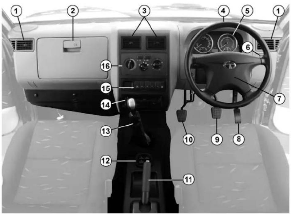
DRIVING CONTROLS
text_image
Diagram of a vehicle's interior dashboard with numbered labels pointing to key components such as steering wheel, dashboard, and steering wheel.Driving Controls - Sumo Gold
| 1. | A.C. Side Vents |
| 2. | Glove Box |
| 3. | A.C. Middle Vents |
| 4. | Steering Wheel |
| 5. | Instrument Cluster |
| 6. | Headlamp leveling Switch |
| 7. | Horn Pad |
| 8. | Accelerator Pedal |
| 9. | Brake Pedal |
| 10. | Clutch Pedal |
| 11. | Parking Brake |
| 12. | Power Window Switch |
| 13. | Gear Shifting Lever |
| 14. | Music System |
| 15. | Facia Switches |
| 16. | A.C. Controls |
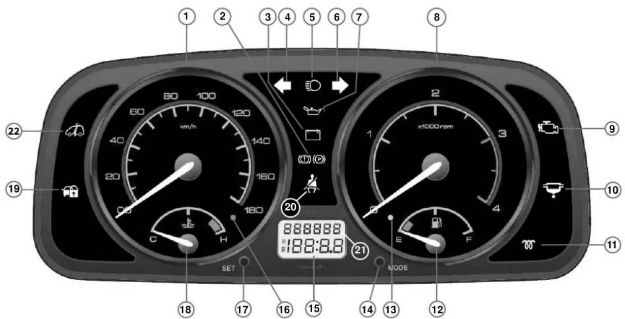
INSTRUMENT PANEL (CR-4 BS-IV)
text_image
1 2 3 4 5 6 7 8 9 20 2 x1000rpm 188:0.8 21 SET H C E F NODE 18 17 16 15 14 13 12 22 19 1All indicators may not be provided on some instrument cluster and may not be applicable to all models.
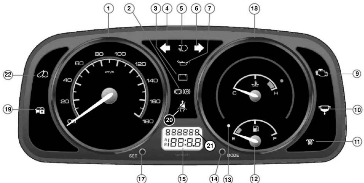
INSTRUMENT PANEL (4SPTC BS-III)
text_image
1 2 3 4 5 6 7 18 22 60 100 km/h 120 140 (D) (D) 20 888888 R I 188:8.8 21 E F SET MODE 11 9 10 17 15 14 13 12All indicators may not be provided on some instrument cluster and may not be applicable to all models.
| 1. | Speedometer |
| 2. | Brake Fluid Level Check/Parking Brake Indicator (Red) |
| 3. | Battery Charging Indicator (Red) |
| 4. | Direction Indicator LH (Green) |
| 5. | Head Lamp Main Beam Indicator (Blue) |
| 6. | Direction Indicator RH (Green) |
| 7. | Low Engine Oil Pressure Indicator (Red) |
| 8. | RPM meter |
| 9. | MIL Indicator (Amber) |
| 10. | Water In Fuel |
| 11. | Glow Plug Indicator RPM Meter (if fitted) |
| 12. | Fuel Gauge |
| 13. | Low Fuel warning Indicator |
| 14. | Mode Selector Knob (Odometer) |
| 15. | Trip Odometer |
| 16. | High Temperature Warning Indicator |
| 17. | Set Knob (Odometer) |
| 18. | Temperature Gauge |
| 19. | Immobilizer Warning - If fitted (Red) |
| 20. | Seat Belt Indicator (Red) |
| 21. | Cumulative Odometer |
| 22. | Service Indicator |
Immobiliser Warning
Indicator :

This system disables engine starting if original key is not used. The user has to use original key for authentication and unlocking the car. Refer to Immobiliser section for details.
Lamp Blink : Car is in immobilised condition when key is not inserted.
Lamp OFF : Normal condition (Authenticated user) and engine will start.
Lamp On : Problem with key / system. Show your car to TATA Authorised service centre.
Turn Signal:

Turn signal lamps can be operated only when the ignition supply is 'ON and by using the turn indicator switch on the combi switch. The direction indicator arrow (LHS) and (RHS) on the instrument cluster flashes along with external indicator lights as selected.
High Beam Indicator:
Symbol lights up when the headlamp high beam is 'ON'.

HANDLING INDICATORS
Low Oil Pressure
Indicator:

When the ignition key is turned to the 'IGN' position, symbol lights up and goes off as soon as the required engine oil pressure is developed after starting the engine.
If the low oil pressure indicator does not glow or remains 'ON' with the 'IGN' on and engine is running, it indicates a fault in the electrical circuit/lubrication system. Check & get the problem attended to at an Authorised Service outlet.
Battery Indicator:
Symbol lights up when the 'IGN' is turned 'ON' and should go 'OFF' after the engine starts.

NOTICE
If it remains 'ON' while the engine is running. It indicates that the battery is not getting charged. Switch off all unnecessary electrical equipment and get the problem attended to at an Authorised Service outlet.
Parking Brake Indicator cum Low Brake Fluid Warning Light :

This indicator has multiple functions as follows :
- It lights up when the parking brakes is applied and goes off when parking brake is released.
- It also lights up when brake fluid level is low.
- When ignition key is turned to "IGN" position, this indicator lights up and goes off when engine starts in normal condition. If it continuously ON while engine is running, get the problem attended to an Authorised Service Outlet.
Water In Fuel Indicator:

This indicator indicates excess water accumulation in the sedimenter. It turns 'ON' when ignition is turned 'ON' and goes 'OFF' in approximately three seconds. When this lamp remains 'ON', water needs to be drained from sedimenter immediately.
CAUTION
If water is not drained from sedimenter, it can cause serious damage to fuel injection system.
Seat Belt
Indicator:

The indicator initially flashes when the ignition is ON and seat belt is not fastened. It will continue to flash until the vehicle exceeds a speed of 20 kmph. After that, it will remain continuously ON accompanied by a buzzer that will buzz approximately for 100 seconds. After that, the buzzer goes OFF but the indicator continues to remain ON.
Glow plug Indicator (if fitted):

This indicator lights up when the 'IGN' is switched 'ON' and goes 'OFF' after a few moments automatically depending on the engine temperature, indicating readiness to crank the engine.
NOTICE
Do not crank the engine until this light goes 'OFF'. The duration of 'ON' time varies with engine block temperature and it glows for longer duration with a cold engine.
Service Indicator Lamp:

This symbol indicates the car's engine condition.
- It comes "ON" when ignition is switched "ON" and once engine is cranked, it goes "OFF".
- It remains "ON" if there is a problem in any of the EMS related / engine components.
If the Service indicator lamp remains "ON" when the engine is running, the engine's performance deteriorates marginally & sometimes significantly. Take your car to a TATA Authorized service centre.
Malfunction Indication Lamp (MIL):

This symbol comes ON when the ignition is turned "ON" and goes "OFF" once the engine is cranked.
NOTICE
This symbol will remain "ON" for any engine related fault, which may cause increase in emission levels of the car beyond the regulatory limit. Take your car to a TATA Authorized service centre.
On Board Diagnostic (OBD) System:
On board Diagnostics or OBD is an automotive term referring to a vehicle's self Diagnostic and reporting capability. The OBD system allows continuous diagnosis of the components of the vehicle correlated with emissions. This system warns the driver, by turning "ON" the Malfunction Indication lamp (MIL) on the instrument cluster, when a fault causes emission levels to increase.
The OBD system also has a diagnostic connector that can be interfaced with appropriate diagnostic tools, which makes it possible to read the fault codes stored in the Electronic Control Unit, together with a series of specific parameters for Engine operation and Diagnosis. This check can also be carried out by the traffic police.
HANDLING INDICATORS & GAUGES
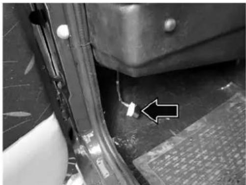
The diagnostic connector is located below the dashboard left hand side (co-driver's side) which is shown in the images
natural_image
Close-up of a mechanical component with a white arrow pointing to a small white mark on the side (no visible text or symbols)OBD-II Connector Location
NOTICE
In case the fault occurs and MIL on the instrument cluster comes ON, contact nearest TATA MOTORS authorized service center. After eliminating the inconvenience, to check the system completely, TATA MOTORS authorized service centers are obliged to run a bench test and if necessary, road tests which may also call for a long journey. The functioning of MIL lamp may also be checked by the traffic police using specific devices.
Odometer and Trip meter (on LCD):
The odometer records the total distance the vehicle has been driven. The trip meter can be used to measure the distance traveled on each trip or between fuel fillings. Keep track of the odometer reading & follow the maintenance schedule regularly for meeting service requirements.
Odometer, Trip meter and Illumination intensity control on instrument panel (LCD):
The instrument panel has an LCD to display the following:
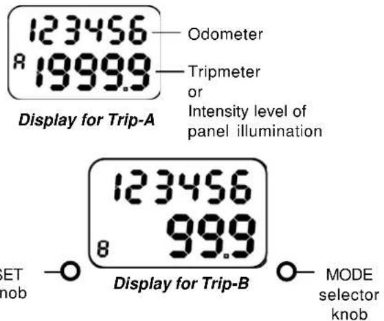
text_image
123456 Odometer R 19999 Tripmeter or Intensity level of panel illumination Display for Trip-A 123456 8 999 ET knob Display for Trip-B MODE selector knob- Main Odometer (Non- resettable) - Counts up to 999999 kms
- Trip meter A (Resettable) - Counts up to 1999.9 kms
- Trip meter B (Resettable) - Counts up to 1999.9 kms
- Intensity level of instrument panel illumination - Selection among preset levels.
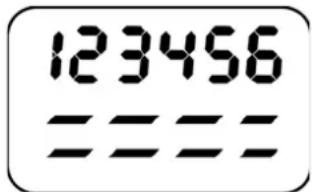
text_image
123456 ====Intensity Level Indicator
LCD has two line display. The first line displays the Odometer count.
The second line displays either of Trip meter A, Trip meter B, Intensity level of panel illumination. The selection and control of functions are done through 'MODE' and 'SET' push buttons (knobs) provided on either side of the LCD. The 'MODE' knob is used to select one of the Trip meter A, Trip meter B OR Intensity level of panel illumination. Switching among the above three functions can be done by pressing the knob.
The 'SET' knob is used to control the chosen function. Pressing the knob for a few seconds resets the chosen trip meter and varies the intensity level of instrument panel illumination.
The panel illumination intensity varies among preset levels as follows:
$$ \begin{array}{l} = \text { Min } \ = = = = \text { Max } \ \end{array} $$
This display returns to Trip meter A after a few seconds of intensity level selection, if left in this mode.
NOTICE
Main odometer and trip meter 'A' indication will remain on display even if the ignition key is removed.
Temperature gauge:
The gauge indicates the temperature of the engine coolant. The red zone at 'H' indicates temperature higher than the normal. Avoid driving, when the pointer is in the red zone. It indicates engine overheating, which may be due to insufficient coolant in the radiator or due to any other defect. At this stage take the car to the nearest Authorised Service outlet for necessary attention.

CAUTION
Never remove the radiator pressure cap from the radiator when the engine is hot. Do not restart the engine until the problem has been duly attended.
The speedometer: The speedometer indicates the vehicle speed in km/hr.
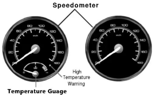
text_image
Speedometer High Temperature Warning Temperature GuageRPM meter (if provided) :
The meter indicates engine speed in revolutions per minute (rpm) Change gears at appropriate engine rpm and vehicle speed to get optimum fuel economy. The permitted engine rpm upper limit is the start of Red Zone on the dial.
Fuel Gauge:
The fuel gauge indicates the approximate fuel level in the tank. Refill the fuel tank at the earliest, before the needle touches the red band on the gauge. At this point, fuel level in tank is low and it is advised to get fuel filled immediately
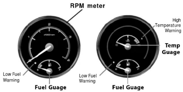
text_image
RPM meter 1 2 3 4 Low Fuel Warning Fuel Guage High Temperature Warning Temp Guage Low Fuel Warning Fuel GuageSteering lock cum ignition switch :
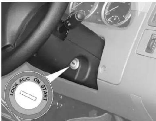
text_image
LOCK ACC ON STARTSteering Lock Cum Ignition Switch
Steering is provided with steering lock cum ignition switch
- To lock steering while parking the vehicle as safety against theft.
• To start and stop the engine. - To switch 'ON' and 'OFF' the electrical system other than listed below.
Horn, parking lamps, engine inspection lamp and hazard warning indicators are not connected through this switch and operate independently.
- To switch on and off the accessories only.
The switch is located on the steering column support and has the following key positions:
LOCK
Key can be inserted or taken out only in this position. Steering gets locked only after the key is withdrawn from the switch.
After withdrawing the key from the switch ensure that steering is locked by turning steering wheel clockwise and anticlockwise. To unlock the steering, insert the key into the switch and turn it clockwise. If any difficulty arises in unlocking turn the steering wheel a little clockwise or anticlockwise while turning the key.
ACC
By turning the key to 'ACC' position power supply to accessories is switched 'ON'.
ON
By turning the key to this position all remaining electrical systems become operative and lamps of battery charging indicator, low oil pressure will come 'ON'.
In 'ON' position, the glow plug controller switches 'ON' the glow plugs and glow indicator lights up. After a few seconds, depending on the ambient temperature, the indicator light only goes off indicating that the engine can be started. Glow plugs remain 'ON' for few seconds and switches 'OFF' automatically.
As a safety feature glow plugs are automatically switched 'OFF' after a lapse of certain time if the engine is not started to conserve battery.
In this case to start the engine repeat the operation by first going to 'ACC' or 'LOCK' position.
START
Turn the key further clockwise to start position (spring loaded) to operate starter motor. As soon as the engine starts release the ignition key, so that key can come back to 'ON' position and starter motor disengages and glow plug is switched 'OFF'. Vehicle is driven in this position. By turning the ignition key from 'ON' position to 'ACC' or 'LOCK' position engine can be stopped.
COMBI-SWITCH
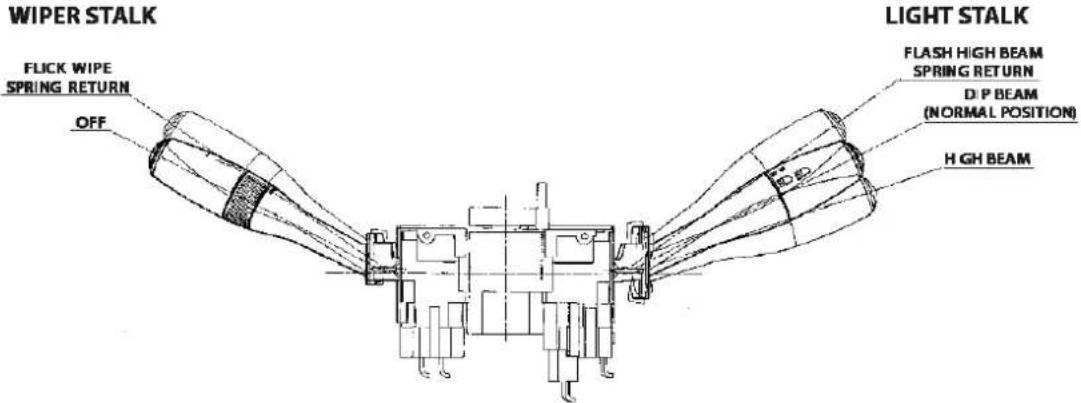
text_image
WIPER STALK FLICK WIPE SPRING RETURN OFF LIGHT STALK FLASH HIGH BEAM SPRING RETURN D/P BEAM (NORMAL POSITION) HIGH BEAM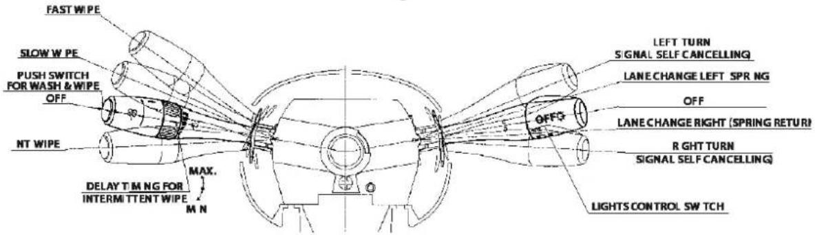
text_image
FAST W/PE SLOW W PE PUSH SWITCH FOR WASH & W/PE OFF NT W/PE MAX. DELAY T M NG FOR INTERMITTENT W/PE M N LEFT TURN SIGNAL SELF CANCELLING LANE CHANGE LEFT SPR NG OFF LANE CHANGE RIGHT (SPRING RETURN) RIGHT TURN SIGNAL SELF CANCELLING LIGHTS CONTROL SW TCHD. Intermittent wipe *
E. Pull up for windshield wipe (Flick Wipe Spring Return)
F. Press side knob for wash
* Rotate selector to set delay timing for intermittent wipe
LIGHTS CONTROL LEVER - RIGHT
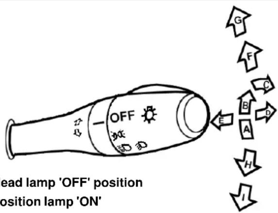
text_image
head lamp 'OFF' position position lamp 'ON'A. Head lamp 'OFF' position
B. Position lamp 'ON'
C. Position lamp & head lamp 'ON'
D. Push down the lever for high beam
E. Pull up the lever (spring return) for high beam flash
F. Lane change left (self cancelling)
G. Side Indicator - LH
H. Lane change right (self cancelling)
I. Side Indicator - RH
Music System with blue tooth and USB port (If installed):
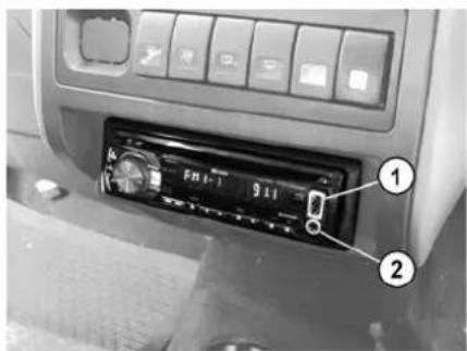
The music system with USB connector (1) and blue tooth connector (2) is fitted in the centre console. Two speakers are provided in the dashboard as well as two speakers are in the rear.
text_image
FMI-7 911 ① ②Music System with 1. USB Connector 2. Blue tooth Connector
Antenna :
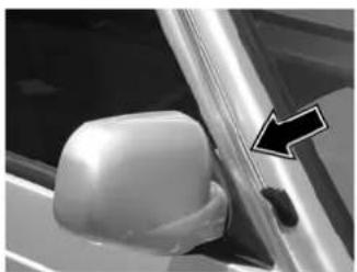
The Antenna is loacated on the RH side of front windshield glass on the A piller.
Please refer the music system User's Manual provided in the vehicle for understanding it's function.
natural_image
Close-up of a car's side mirror and door panel, with a black arrow pointing to a corner detail (no text or symbols visible)Antenna
natural_image
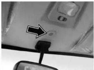
Close-up of a car's rearview mirror and dashboard showing a black arrow pointing to a circular component (no text or symbols visible)Micro phone
Micro phone :
Micro phone is located on roof between sunvisors and above inner rear view mirror.
Engine Compartment Lamp :
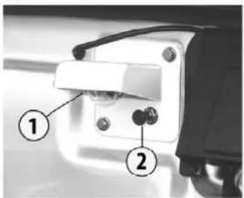
To operate engine compartment light, pull switch (2).
text_image
Diagram of a mechanical component with numbered parts labeled 1 and 2- Engine Compartment Lamp 2. ON/OFF Switch
HANDLING TAIL LAMP, REGISTRATION PLATE LAMP & HIGHMOUNTED STOP LAMP
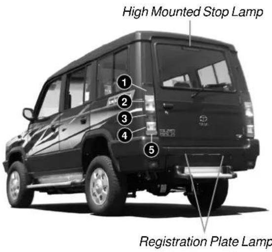
Tail Lamp :
The tail lamp assembly incorporates the following :
- Rear direction indicator
- Parking / Rear stop lamp
- Reverse light
- Reflex reflecor
- Fog lamp
Registration Plate Lamp :
Two concealed lamps are provided for illumination of the rear registration plate.
High Mounted Stop Lamp :
High mounted stop lamp is incorporated on the tail gate from inside and it glows whenever service brake is applied.
text_image
High Mounted Stop Lamp 1 2 3 4 5 Registration Plate LampInterior Lamps :
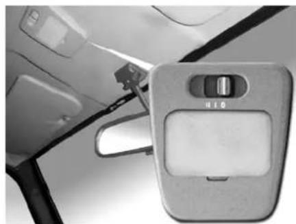
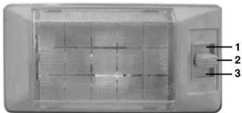
Two interior lamps are provided for convenience. While one lamp is situated near the inside rear view mirror (IRVM), the other is located just above the passenger compartment. The individual 'ON / OFF' switches are provided to operate these lamps.
Lamp positions Interior Roof lamp
| POSITION FUNCTION | |
| II | The lamp will remain ON at all times irrespective of whether any of the doors is open |
| I | The lamp will come ‘ON’ only when any of the five doors are opened (For GX version) |
| In this mode, the lamp will come ON only when driver’s door is opened (For EX version) | |
| 0 | The lamp will remain ‘OFF’ irrespective of whether any of the five doors are opened |
natural_image
Interior view of a car showing the side arm panel with a control switch (no text or symbols visible)Rooflamp
natural_image
Interior view of a transparent cylindrical device with internal grid structure and labeled ports (no readable text or symbols)- Lamp off
- Door control mode
- Lamp on
HANDLING HEADLAMP LEVELING SWITCH
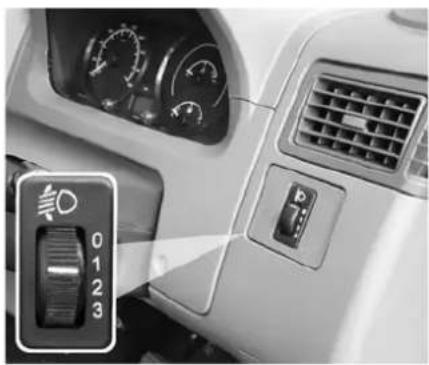
Headlamp Leveling Switch
A motorised headlamp leveling arrangement with the setting knob at the RH side of dash board.
As and when required headlamp leveling setting is done by roating the knob to select one of the level marked in the switch depending upon the loading of vehicle.
| Loading Condition Switch position / | Marks assigned. |
| Unladen + One person in Driver seat / Driver + Co-Driver /Driver + Co driver + all the Seats 0 farthest to rear occupied | |
| All the seats occupied / Laden (All seats occupied Luggage in boot space 1 to achieve permissible load on the rear axle. | |
| Driver + Evenly distributed load in the boot to 2 obtain permissible load on corresponding axle. |
Since the leveling switch takes care of focus patern under different load conditions; it is advisable to select the correct position before starting a trip (depending on load)
natural_image
Interior view of a car dashboard with air filters and a parking seat (no visible text or symbols)Headlamp Levelling Switch
ACCESSORY SWITCHES
There are six (6) operating switches provided on the centre console of your vehicle's dashboard, just above the Music System.
Rear Windshield Demister (unlatched switch) (if fitted)
Push the operating switch on the fascia to turn the demister "ON". The demister will switch off automatically after 15 minutes.
NOTICE
Clean the windshield glass carefully from inside to avoid any damage to demister heater element
Rear Fog lamp (unlatched switch) (if fitted)
The fog lamps are provided on rear bumper to improve the visibility and warning in foggy weather or during heavy rains.
The rear fog lamps can be switched on with parking lamp and front fog lamps 'ON' and can be remain 'ON' till the parking lamp is switched 'OFF'. The rear fog lamps can also be switched 'ON' even if only headlights are 'ON'.
NOTICE
Use only during foggy conditions or heavy rains if required.
Rear Windshield Wash and Wipe (unlatched switch) (if fitted)
Push and hold the switch knob for the operation of the wash function for the desired duration for rear visibility through glass.
The function indicator lights up when wash function is "ON". Along with wash fluid getting sprayed, the wiper also operates with a delay to wipe the glass surface through a timer control unit. On release of this switch, this function stops.
Rear Windshield Wiper (Latched switch) (if fitted)
To operate this function, push to switch 'ON' and again, push to switch 'OFF'. The function indicator lights up when the wiper function is 'ON'.
Front Fog lamp (Latched switch)(if fitted)
The fog lamps are provided on front bumper to improve the visibility in foggy weather or during heavy rains.
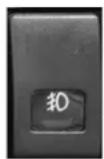
The front fog lamps can be switched 'ON' with parking lamp 'ON' and can be remain on till the parking lamp is switched 'OFF'.
NOTICE
Use only during foggy conditions or heavy rains if required.
Hazard Warning
Hazard warning is used in case of breakdown especially during night and vehicle has to be parked at the side of the road or vehicle being operated in adverse condition.
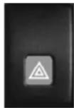
This can be operated without Ignition ON. Press hazard warning switch to switch ON. All outside turn signal lights and indicators on cluster will flash simultaneously to warn the other road users about hazardous condition of the vehicle. Depress the switch to switch OFF the hazard function.

CAUTION
Ensure that all turn signal indicators are working properly. Get it rectified in case of problem.
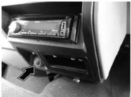
Power Socket :
A power socket is provided on the central console below music system. This can be used connecting loads upto 10A maximum. To use this socket, remove the cap first.
CAUTION
Always keep this socket covered with the cap when not in use.
natural_image
Interior view of a car infotainment device showing the front panel and rear vent (no visible text or symbols)Power Socket
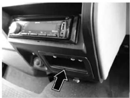
Mobile Holder :
A mobile holder is provided on the central console below music system and beside of power socket. Place your mobile inside the mobile holder for charging purpose while driving.
natural_image
Interior view of a car dashboard with a CD driver and a directional arrow pointing to the left side (no visible text or symbols)Mobile Holder
HANDLING GRAB HANDLE & GLOVE BOX WITH CUP HOLDER
Grab handles :
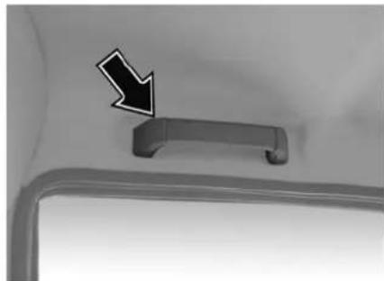
Grab handles are provided in the vehicle at various locations (Co-driver side, Middle passenger and third row passenger compartment) for comfortable positioning of passengers during journey.
natural_image
Close-up of a car door handle with a black arrow pointing to the handle (no text or symbols visible)Grab Handle
Glove Box with Cup Holder :
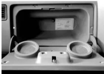
The glove box is located on the dash board in front of the codriver's seat. The glove box can be locked with the ignition key.
Cup holders are provided on the inner face of glove box flap.
CAUTION
Do not use the cup holders while the vehicle is in motion.
natural_image
Interior view of a vehicle rear compartment showing two circular ventricles and a small electronic device (no visible text or symbols)Glove Box with Cup Holder
Gear shift lever :
The different gear positions are marked on the knob. The 5 th gear (an overdrive) has been provided to obtain better fuel economy while driving on highways.

natural_image
Interior view of a car infotainment system showing a hand inserting a component into the dashboard (no visible text or symbols)Gear Shift Lever
Parking brake lever :
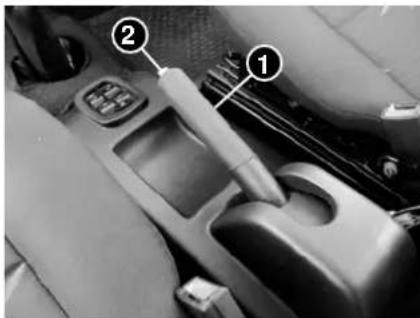
The parking brake is mounted on floor console between driver's seat and co-driver's seat.
To apply the parking brake, pull lever UP. To release it, pull the lever up slightly, press the release button and push the lever DOWN.
Ensure parking brake is released before driving the vehicle. Indication is given on instrument cluster.
text_image
Car interior gear shift lever with numbered labels pointing to key parts- Parking Brake Lever
- Release Button
HANDLING BONNET / FUEL FLAP OPENING & CLOSING
Bonnet opening and closing :
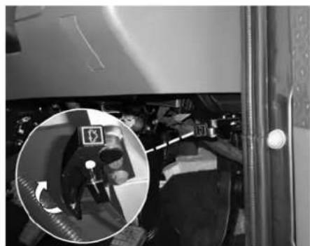
To open pull lever (1). This will release the bonnet lock. To open fully, lift the additional lock lever located on the bonnet centre with the help of finger. Use the bonnet stay rod to keep the bonnet open.
For closing the bonnet, disengage the stay rod, clamp it properly and press down the bonnet till it is fully shut.
Ensure that the bonnet is fully locked before driving off.
In case of failure of cable attached to lever (1) bonnet lock can be opened by inserting a screw driver from the top centre position of grill through a slot provided behind it on the sheet metal and by pressing the lock plate towards your left. Push upward the additional lock lever at your right and lift the bonnet while the lock plate is kept pressed with the help of screw driver.
Fuel filling Cap :
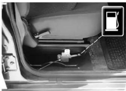
The fuel filling cap is located at the rear on the left hand side of the vehicle. The fuel filler lid can be opened by using a cable operated lever located on the right of the driver's seat. Simply push the lid back to its original position to lock it.
NOTICE
This feature is available only in few versions.
natural_image
Interior view of a vehicle showing a person using a device with a circular inset highlighting the camera (no visible text or symbols)Bonnet Opening Lever
natural_image
Interior view of a car showing fuel plug and attached components (no visible text or symbols)Fuel Lid Opening Lever
NOTICE
Remove the fuel filler cap slowly as the fuel inside may be under pressure and may spray out suddenly, causing injury.
To remove the fuel filler cap, turn it anti-clockwise. Turn the cap slowly to allow any residual pressure to escape.
In few version, mechanical remote fuel lid opener is used. The fuel lid is located on the left rear side of the vehicle.
HANDLING SPARE WHEEL
Spare Wheel
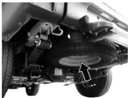
Spare wheel is mounted below the cab at rear.
Fitment of spare wheel :
- Place the spare wheel on ground below its location with outer side of the wheel rim facing upwards.
- Locate the retaining plate in the central hole of spare wheel.
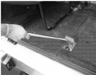
- Using the wheel spanner the spare wheel can be raised by rotating the wheel winch screw in anticlockwise direction.
- Align one of the wheel mounting screw hole with the locating pin on frame while raising the spare wheel.
- Continue to rotate the wheel winch screw in anticlockwise direction until spare wheel is raised completely.
natural_image
Close-up of a car's lower body showing tire, suspension components, and wheel assembly (no visible text or symbols)Spare wheel
natural_image
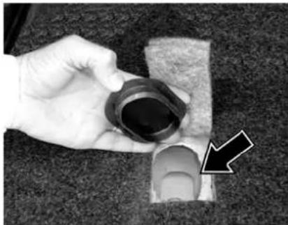
Hand holding a mechanical component with a black arrow pointing to it, placed on a textured surface (no text or symbols visible)Spare wheel winch grommet
natural_image
Close-up of a hand using a tool to adjust or install a metal component on a textured surface (no visible text or symbols)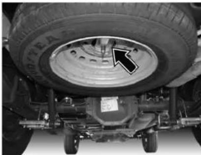
natural_image
Top-down view of a vehicle's undercarriage showing tire and wheel assembly (no text or symbols visible)Loosening/Tightening of wheel winch screw Spare Wheel Retaininmg Plate
Vehicle Jack & Tools
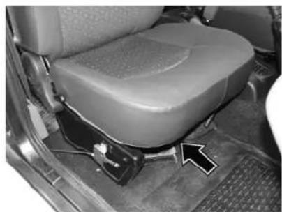
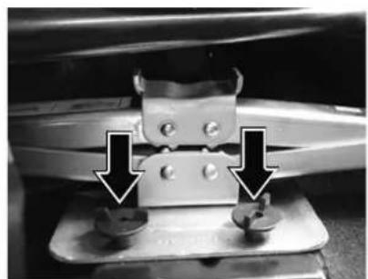
Vehicle tool bag, jack and handle is kept below driver's seat. Jack is mounted on floor over studs by wing nuts screwed on them.
natural_image
Interior view of a car seatbelt with a highlighted component (no text or symbols visible)Jack & tools location (Below driver's seat)
natural_image
Close-up of a mechanical clamp or bracket with two screws and two base nuts, showing alignment arrows (no text or symbols)Locking Wing Nuts
HANDLING CATALYTIC CONVERTOR & EGR SYSTEM
CATALYTIC CONVERTER : (if fitted)
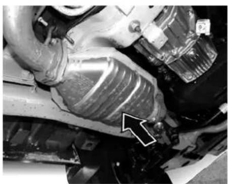
Your vehicle is fitted with Diesel Oxidation Catalytic Converter to reduce exhaust pollution. The two way Catalytic Converter has coating of precious metals which enables conversion of pollutants.
Care of the Catalytic Converter :
The Catalytic Converter does not require any special maintenance however, following precaution should be taken for the effective functioning of the converter and to avoid damage to the Converter.
It is mandatory to use Diesel fuel with sulphur content less than 0.25%. Use of any other diesel fuel can increase the pollutants.
WARNING
Avoid parking the vehicle over inflammable materials, such as dry leaves, grass etc., as the exhaust system is hot enough to initiate "FIRE".
TAKING CARE OF ENVIRONMENT :
Your vehicle is equipped with the EGR (Exhaust Gas Recirculation) System.
natural_image
Close-up of a mechanical component with a white arrow pointing to a specific part (no visible text or symbols)Catalytic Converter
EGR System
The 497SPTC engine has an Exhaust Gas Recirculation system comprising of EGR valve, EGR Tube, Vacuum hoses, Electroneumatic switch, Potentionmeter on FIP throttle lever, EGR control unit and associated electrical circuitry.
With this, controlled amount of exhaust gas is mixed in air intake of the engine, which helps in reducing harmful pollutants.
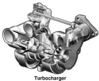
TURBOCHARGER :
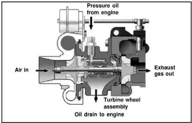
Turbocharger is an efficient supercharging device used in our engine. It makes use of thermal energy of engine exhaust gases to run a turbine which in turn drives a compressor to force air under pressure into the inlet manifold.
natural_image
Cutaway illustration of a turbocharger assembly showing internal components (no text or labels)Lubrication of Turbocharger
The rotor assembly of the turbocharger is supported by two floating lead bronze sleeve bearings in the bearing housing. These bearings are lubricated with the linest filtered and cooled oil from the lubrication system of the engine. There is a heat shield arrangement provided between the gas chamber of the turbine and the bearing housing to avoid heating of the bearings.
text_image
Pressure oil from engine Air in Turbine wheel assembly Oil drain to engine Exhaust gas outMaintenance of Turbocharger :
-
Tighten the following fasteners at PDI and thereafter at every 10,000 km.
-
Turbocharger mounting
-
Turbocharger hose connections and its mountings
-
Check intercooler fins for any dust accumulations and clean by compressed air at every 20,000 km. (if fitted)
-
It is advisable to run the engine at idle speed for about one minute, after starting and before stopping the engine. This ensures adequate lubricating oil supply to the turbocharger.
HANDLING POWER STEERING
POWER STEERING (When provided)
Power steering is fitted for lighter steering effort and easy manoeuvrability. The system consists of steering gear box, hydraulic pump and hydraulic reservoir suitably mounted and connected by piping. Pump drive is through belt from engine. Power assistance is available during normal functioning of the power steering system.
In case of any failure in hydraulic system, the steering can be operated mechanically with increased steering effort for bringing the vehicle to a repair station.
Procedure for oil filling and bleeding the power steering system. (Ensure that the reservoir is totally cleaned before starting the work.)
- Fill the reservoir nearly full. Crank the engine for 10 seconds without, if possible, allowing it to start. If the engine does start, shut off immediately. Check and refill the reservoir. Repeat atleast three times, each time checking and refilling the reservoir.
- Check for any leakage in the system and if noticed take corrective action.
-
Start the engine and steer the vehicle from full left to full right turn 3-4 times. Add fluid if necessary to maintain the level up to the filter top.
-
With the engine at steady speed check for bubble / foaming in the fluid. If present it indicates that air is getting sucked into the system.
Check the suction line / fittings and correct if necessary. - Once the system is bled properly and free from foaming, there should not be appreciable change in fluid level in the reservoir, when the engine is started / stop repeatedly. Top up or remove excess fluid so that the final level is at 'H' mark on dipstick.
- Now the system is ready for driving.
CAUTION
Do not allow the fluid level to drop significantly or run out of the reservoir during the above operation. This may induce air into the system.
Do not start the engine without fluid in the power steering system. This will result in serious damage to the pump.
NOTICE
Always use recommended brand of fluid from closed containers. Any dirty fluid poured in the system will result in damage to pump/gear.
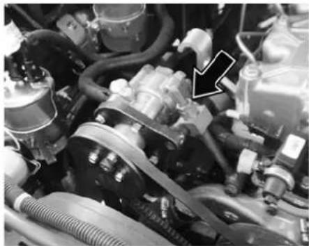
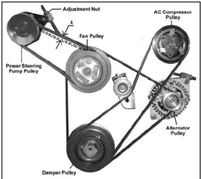
Power steering pump belt tension Check
Check the conditions of belts on the engine. Examine the edge of the belt for cracks or fraying.
Check the tension of the belt by pushing on it with your thumb Alternator/Power Steering belt as shown in Figure.
The belts should have deflection of 8 to 10 mm. (X)
If the belt tension is not proper, get it attended at the nearest Authorised service outlet.
natural_image
Close-up of an automotive engine bay with visible hoses, springs, and a black arrow pointing to a component (no text or symbols)Power Steering Pump Belt Adjustment Nut
text_image
Adjustment Nut X Fan Pulley AC Compressor Pulley Power Steering Pump Pulley Alternator Pulley Damper PulleyHANDLING AIR CONDITIONING
HEATING, VENTILATION & AIR CONDITIONING :
(if installed)
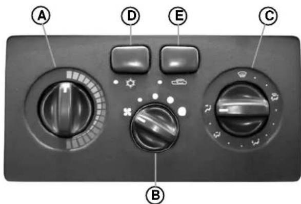
A. Temperature Control Knob :
The air temperature in the car can be controlled by operating the temperature control knob (A) at the left hand side of the control panel. The temperature can be increased by rotating the knob towards the red segment and decreased by rotating it towards the blue segment.
B. Blower Speed Regulation Knob :
The ventilation system has a three/four speed blower. The blower speeds can be regulated to any one of the following speeds by operating the knob (B) at the centre of the control panel.
- LOW • MEDIUM • HIGH • VERY HIGH
C. Air Direction Control Knob :
The air flow can be changed by turning the switch (C) to the desired direction.
| Towards face | |
| Towards face and feet | |
| Towards feet | |
| Towards feet and windshield (Recommended for clearing fogging on windshield) | |
| Air demist / defrost windshield (Recommended for clearing heavy fog and snow) |
text_image
A D E C BH.V.A.C. Controls
A. Temperature Control Knob
B. Blower Speed Regulation Knob
C. Air Direction Control Knob
D. AC ON / OFF Switch
E. Air Circulation Switch
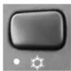
D. A.C. ON/OFF Switch :
The A.C. can be switched 'ON' by pressing(In case of HVAC) / rotating (In case of only A.C.) the switch (D) on the A.C. control panel provided the blower is 'ON' and the engine is running. The indicator lamp will show that the A.C. is 'ON'.
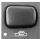
E. Air Circulation Switch :
- In HVAC version to put air circulation mode in recirculation, press switch 'E'. The indicator lamp will show air circulation is in recirculation.
- To put vehicle in Fresh mode release switch 'E'. Indicator lamp will be 'OFF'.
- In A.C. version, air circulation mode can be selected by pressing knob 'E'.
- In recirculation mode, air inside the vehicle is circulated again and again. In Fresh mode, air is taken from atmosphere and circulated in the vehicle. Recirculation mode can be used.
• While driving in dusty condition
- To avoid traffic pollution
- To get quick cooling/heating as required.
Whenever discomfort is felt switch air circulation mode to fresh.
NOTICE
- The A.C. can be switched 'ON' only if the blower is 'ON' and engine is running. When A.C. is switched 'ON' engine idling RPM increases marginally, to adjust to the A.C. compressor load. When desired temperature is achieved A.C. trips 'OFF' automatically.
- The A.C. compressor gets switched 'OFF' automatically when engine gets overheated. The A.C. is automatically switched 'ON' when the engine cools down.
Normal Cooling :
A.C. - ON
Knob 'B' - Desired speed position
Knob 'C' - Towards face
Switch 'E'- Suitably as explained
Quick Cooling :
If your car is left in the sun with window closed, inside temperature increases.
To achieve quick cooling effect, open the windows briefly while you operate the air conditioner, with air circulation switch is in Fresh mode, fan at higher speed and air direction towards 'FACE'. All vents to be opened completely.
HANDLING AIR CONDITIONING
Once temperature inside has come down sufficiently, close the windows and change air circulation suitably to fresh/recirculation.
Demisting :
In rainy season or in areas of high humidity, mist formation inside windshield glass is observed. To clear mist dehumidified air is passed on the windshield glass.
The position of control knobs should be adjusted as follows:
A.C. - ON
Knob 'B' - Desired speed position
Knob 'C' - Towards windshield

Knob 'A' (for vehicles fitted with HVAC) - at suitable temperature
Air circulation - at suitable position
NOTICE
When mist gets cleared switch the knob "C" position to Face mode. In high humidity areas, if cold air continues to flow over windshield, it may cause sudden fogging on outside surface of windshield.
Defrosting : (For vehicles fitted with HVAC unit)
In low temperature areas, to clear frost formation outside the windshield glass, this setting is used.
First start the engine - Maximum hot position & accelerate to warm up.Knob 'A'
Knob 'B' - Very High
Knob 'C' - Towards windshield

Switch 'E' - Fresh air mode condition
Once the windscreen has become clear, move the fan switch to desired speed.
NOTICE
Electric heater coil is provided for demisting of tail gate glass for deluxe versions.
Normal Heating : ( For vehicles fitted with HVAC )
Knob 'A' - Suitable temperature position
Knob 'B' - Suitable blower speed
Knob 'C' - Towards face & feet

A.C. - OFF
Air Circulation- Fresh switch
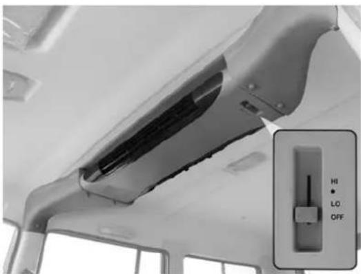
Roof A. C.
Where roof mounted air conditioner unit is installed, the blower switch has 4 positions "HIGH", "MED", "LOW" and "OFF". The switch is located on left hand side on the roof A.C Air flow direction can be adjusted by adjusting the air vents. The roof A.C. can be switched 'ON' provided the front A.C is 'ON'. However, the blower of the roof A.C unit can be operated independently.
natural_image
Interior view of a vehicle showing the hood and side panel with a control switch (no text or symbols visible)Roof AC
HANDLING PREPARING THE VEHICLE FOR DRIVE

natural_image
Interior view of a vehicle showing the hood and engine compartment with visible wiring (no text or symbols)Fuel Filler Cap
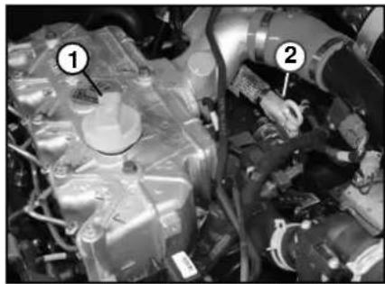
natural_image
Close-up of a mechanical assembly with numbered components (1 and 2), no visible text or symbols.- Engine Oil Filler Cap (CR-4)
- Dip Stick (CR-4)
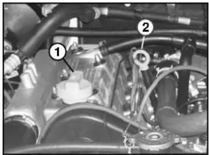
natural_image
Close-up of an engine bay with visible hoses and components (no text or symbols)- Engine Oil Filler Cap (4SPTC)
- Dip Stick (4SPTC)
Check the following regularly, particularly before starting on a long journey.
- Fuel level in tank
Top up if required with correct diesel fuel, secure cap and lock the flap.
- Engine oil level
Check engine oil level before starting the engine or at least 20 minutes after stopping the engine. Top up if oil level is less than
midway between upper and lower marks on the dipstick.
The oil level should not exceed the 'MAX' mark.
Use only the genuine company branded oils.
- Coolant level
With the engine cool, check the coolant in the auxiliary tank. The level should be between the "FULL" and "MIN" mark, top up with the recommended coolant. Bring the
level upto the 'FULL' mark. The level must not exceed the 'FULL' mark. If the coolant level drops within a short time after replenishing, there may be a leak in the system. Rectify the leakage and top up radiator also.
Use genuine company branded coolant.
If no leak can be found inspection should be carried out at an authorised service outlet.
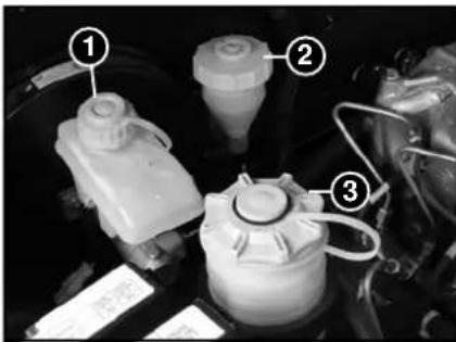
text_image
Labeled mechanical components in a vehicle engine, showing numbered parts with annotations- Brake Fluid Container 2. Clutch Fluid Container 3. Power Steering Container
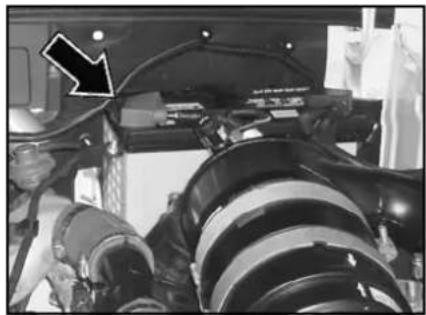
natural_image
Close-up of a vehicle's lower body frame with visible mechanical components and a black arrow pointing to a component (no text or symbols)Battery (CR-4) Battery (4SPTC)
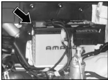
natural_image
Close-up of an automotive battery pack with visible wiring and components, no readable text or symbols present.NOTICE
Always use genuine radiator cap only of 1.0 kg / cm2 (14 psi), if required to be replaced.
-
Ensure battery electrolyte level is 10-12 mm above top of battery plates. Top up with distilled water if required (NOT ACID). Keep battery terminals clean and tight. Apply petroleum jelly / vaseline on terminals for protection against corrosion. Secure covers provided over terminals.
-
Check all lights, horn, gauges, switches and wiper for proper functioning.
-
Check condition and tension of fan belt. Adjust tension if necessary.
-
Check leakages of coolant, fuel and oil at all joints of hoses and pipes and rectify, if any. If coolant leakages is noticed, rectify the leakages and top up radiator also with recommended coolant.
-
Check level of brake fluid in plastic container. Top up if necessary. Do not overfill.
Use only genuine company branded brake fluid.
- Check level of clutch fluid in plastic container. Top up if necessary. Do not overfill as this would result in spillage during clutch operation.
Use only genuine company branded clutch fluid.
HANDLING PREPARING THE VEHICLE FOR DRIVE
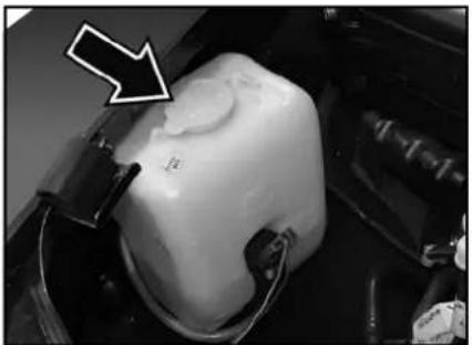
natural_image
Close-up of a white plastic object with a black arrow pointing to it, no visible text or symbolsWindshield Washer Container (CR-4)
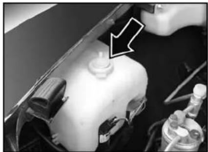
natural_image
Close-up of a car engine component with a black arrow pointing to a cylindrical component (no visible text or symbols)Windshield Washer Container (4SPTC)
- Check level of water in Windshield washer reservoir. Top up with clean water if required.
Use good quality cleaning solvent available in the market in the ratio as specified by its manufacturer.
- Check oil level in power steering hydraulic tank, where applicable.
- Check and correct tyre inflation pressure (In cold condition).
BEFORE DRIVING
CHECK
- Fuel level
- Coolant level
- Engine oil level
- Tyre pressure
- Brake and clutch fluid level
- Doors are firmly closed
ADJUST
- Driver seat
- Rear view mirrors
ENSURE
- Gear shift lever is in neutral position.
- All switches and lamps are working.
- Brake fail indicator is 'OFF'
- Fuel level indicated on fuel gauge is above reserve tank.
START THE ENGINE AND OBSERVE THAT :
- LOW OIL PRESSURE INDICATOR LIGHT GOES 'OFF'
- BATTERY CHARGING INDICATOR LIGHT GOES 'OFF'
- ENSURE THAT PARKING BRAKE IS RELEASED (INDICATOR LAMP 'OFF')
- VEHICLE IS NOW READY FOR A DRIVE.
- DO NOT ALLOW VEHICLE TO ROLL BACK ON GRADIENTS.
During running - in period :
i.e. first 2,000 km of operation :
Do not exceed the following vehicle speeds :
| Gear Min | Max | |
| 1st - 20 | ||
| 2nd 15 35 | ||
| 3rd 25 55 | ||
| 4th 35 75 | ||
| 5th 45 95 |
- Avoid rapid acceleration and prolonged high speed running of the engine.
- Avoid sudden braking.
- Retighten wheel nuts to 12-15 mkg. torque after first 100 km of running of a new vehicle and after every wheel change.
DRIVING INSTRUCTION DRIVING TIPS, BRAKING & FUEL ECONOMY
DRIVING TIPS
DRIVE SAFELY AND JUDICIOUSLY. REMEMBER SAFETY FIRST.
- Depress clutch pedal fully before shifting gears. This will ensure longer synchro cone life.
- For smooth starting of vehicle without jerks, synchronise release of clutch pedal with pressing of accelerator pedal.
- Start the vehicle in first gear only.
- Change gear at appropriate speed and do not lug the engine by too early shifting to higher gear at low speeds.
Recommended speeds for gear changes :
| Gear Speed in km/hr. | |
| 1st to 2nd 20 | |
| 2nd to 3rd 35 | |
| 3rd to 4th 60 | |
| 4th to 5th 80 | |
- Engage reverse gear, only when vehicle is stationary.
- Depress clutch pedal fully before engaging the reverse gear. Wait for a few seconds then engage the gear. If gear shifting does not occur, then release the clutch pedal, once again press the clutch pedal and engage the reverse gear.
BRAKING :
- While braking on turns apply brakes gently.
- Before driving down a long steep gradient, reduce vehicle speed by changing to lower gear.
Do not ride the brakes as they may overheat and their performance may be impaired. - Do not use half engaged clutch to hold the vehicle on up gradient as this will result in premature clutch failure.
• After driving through pockets of water, apply the brake a few
timesat low speed to get rid of moisture inside the brake drums.
- When it beings to rain, reduce vehicle speed and avoid sudden braking.
FUEL ECONOMY :
A. Drive smoothly, accelerate gradually and anticipate stops.
B. Best fuel consumption is obtained at low engine speeds in the highest possible gear without labouring the engine.
C. Driving with accelerator pedal fully depressed means using excessive fuel.
D. Do not allow the engine labour by too early high gear changes. Change to lower gear when engine no longer runs smoothly.
E. If possible, do not idle the engine for more than 5 minutes. Switch off the engine.
F. Do not ride the clutch. Do not use clutch pedal as foot rest.
G. Depending on traffic conditions, a constant speed should be maintained.
The vehicle uses more fuel, every time you speed up or slow down.
H. Hard braking, abrupt cornering and rapid acceleration use more fuel. Avoid these.
DRIVING IN ADVERSE CONDITION: Driving on Snowy or Icy Roads :
Select the lower gear. Gently release the clutch and apply the accelerator for a smooth start and to avoid wheel spin.
CAUTION
Use of snow tyres and / or tyre chain is recommended.
Maintain a safe distance between vehicles to avoid sudden braking and slow down by shifting down the gears.
Avoid sudden acceleration, braking or turning. Such sharp manoeuvres can cause loss of traction and thereby loss of vehicle control.
Driving on Sandy or Muddy Roads
The extent of muddy / sandy, conditions and the traction available is difficult to judge and the vehicle can get bogged down deeply. Operation should be done at slow speed only. If possible, get down and check the path conditions before proceeding.
In case the traction on the wheels is sufficient, you may be able to proceed, it is better to select the lower gear and proceed in the normal manner. To match your power and speed requirements, you can shift up in any of the 5 forward gears or the reverse gear.
NOTICE
You may choose to reduce the tyre pressure marginally for additional grip on loose surfaces, though with a slight loss of ground clearance.
- Try to maintain a constant engine speed and avoid sudden acceleration which can cause wheel spin and loss of traction, possibly leading to bogging down of the vehicle.
- If the vehicle gets stuck in loose sand, do not keep on accelerating as the wheel spin will only result in the wheels sinking deeper.
DRIVING INSTRUCTION DRIVING IN ADVERSE CONDITIONS
Driving Through Water liners and to regain original
natural_image
Side profile of a black SUV with silver accents, parked on a paved surface (no visible text or symbols)- Never venture to drive through water when it flows over guard stones.
• Engine may get seriously damaged if attempted to cross over through deep water. -
If at all the situation demands that you have to drive through water then;
-
Keep engine in fast idling and crawl the vehicle in low gear.
- After driving through water apply brakes several times to dry
braking.
Do not attempt to start the engine if vehicle gets flooded due to water.
- Tow the vehicle to a safe place.
• Take the vehicle to nearest AUTHORISED Workshop to check entry of water in cylinders. - It will also be necessary to replace lubricants of engine, gearbox, transfer case, front axle and rear axle if water has entered.
- Get the starter and alternator checked.
Driving on a Rainy Day
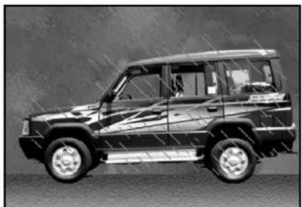
natural_image
Side view of a black SUV with silver wheels and white trim, parked on a paved surface (no visible text or symbols)- Check brakes, steering and windows.
- Check tyres for wear and tyre pressure.
- Check wiper blades for proper functioning.
- Avoid harsh braking and sharp turns. It may cause loss of control and lead to a skid.
- For slowing down, shift to lower gears and brake gently.
- Keep lights ON if visibility is poor.
DRIVING INSTRUCTION DRIVING
Night Driving Climbing Sharp Gradients
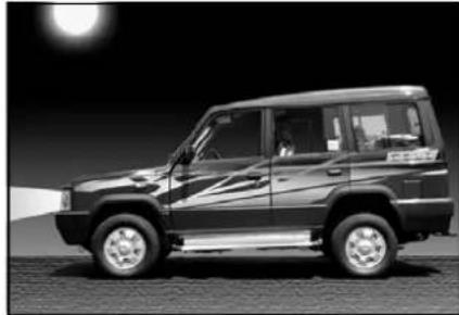
natural_image
Side view of a black SUV parked on pavement under a full moon (no visible text or symbols)- Dip the head lamp for oncoming traffic during night driving.
- Maintain a speed such that you can stop within illuminated distance of head lamps.
- Use head lamp main/dip beam to alert other road users on turns/cross roads etc.
- Use side indicators for lane change or turning.
- Put on hazard warning switch in case of hazardous parking or if your vehicle is disabled to warn the passing traffic.
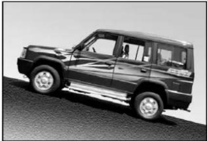
natural_image
Side view of a black SUV on a paved surface (no visible text or symbols)- Select the lower gear and start off smoothly. Apply power gently so there is no loss of traction by over-revving of the engine.
-
Choose as smooth a slope as possible and select the appropriate gear so that gear changing in the middle of the climb is not required. Changing gears in the middle of the climb can cause loss of momentum and engine stalling. Shifting to lower gear has to be done cautiously to avoid loss of traction.
-
Under no conditions should the vehicle be moved diagonally across a hill. The danger is in loss of traction and sideways slippage, possibly resulting in tipping over. If unavoidable, choose as mild an angle as possible and keep the vehicle moving.
- If the wheels start to slip within few feet of the end of the climb, motion can be maintained by swinging the steered wheels left and right, thereby providing increased grip.
- If the vehicle stalls or losses headway while climbing a steep hill, make a quick shift to reverse and allow the vehicle to move back with the control of engine compression.
DRIVING INSTRUCTION DRIVING IN ADVERSE CONDITIONS
Descending Sharp Gradients
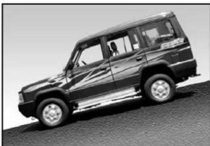
natural_image
Side view of a black SUV on a paved surface (no visible text or symbols)- Select the lower gear and depending on the severity of the gradient, shift into appropriate gear. Use engine braking judiciously without over-revving the engine.
- Brake application under such situations should be done very smoothly to avoid loss of control.
- Select appropriate gear so that gear changing or clutch disengagement is not involved while descending the gradient.
Towing the Vehicle
- For towing the vehicle, the best way is to use a recovery van.
• Alternatively use a rigid tow bar. - Avoid using flexible cable or rope as your vehicle may crash into towing vehicle when it stops suddenly.
- Switch 'ON' Hazard warning switch to warn the other road users.
- Keep the engine in idling so that power steering assistance is available. This will also built the vacuum for the brakes.
• In case of brake failure, use parking brake to control the vehicle.
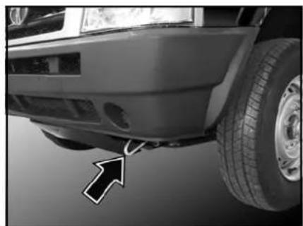
natural_image
Close-up of a car's front wheel and tire, showing a white arrow pointing to the side of the wheel (no text or symbols visible)Front Towing Hook
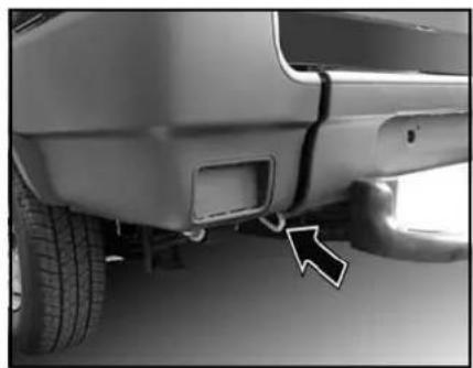
natural_image
Close-up of a car's side bumper with a black arrow pointing to a vehicle wheel (no text or symbols visible)Rear Towing Hook
DRIVING SAFETY
Seat Belt
Seat-belts are life saving equipment. Use of seat-belt reduces the chance of injury and severity of injury in case of an accident. It is strongly recommended that all the car occupants always wear seat-belts when car is in motion.
Influence of Alcohol / Drugs
Avoid driving under the influence of alcohol or drugs. Alcohol and drugs will severely affect your reflex actions. This will impair your control of the car and increase the risk of injury to yourself and others.
Mobile phones
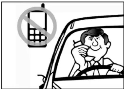
text_image
Cartoon illustration showing a man inside a car with a 'no phone' symbol, indicating no phone use or no usage.Avoid using mobile phones while driving a car. This could divert your attention from the road and result in an accident.
Fatigue 'Rest Revive survive'
Do not attempt driving when you feel tired, sleepy. Long distance driving can tire you very much and fatigue can dull your reflexes and judgment. Take rest and get refreshed at regular intervals.
Parking on slopes
Due care should be exercised while applying parking brakes on steep slopes. It is advisable to switch off the engine and shift gear lever in Low Forward Gear before parking the car facing uphill steep slope and in reverse gear when facing down hill.
DRIVING INSTRUCTION SAFETY CHECKS
SAFETY CHECKS
Windshield/wiper/windshield washer
Always keep windshield glass clean to avoid any distortion in visibility. Ensure proper working of wipers and condition of wiper blade. Ensure that windshield washer reservoir is full. Do not operate wiper alone when the windshield glass is dry, this would damage the windshield.
Headlights
Keep headlight lenses clean. Check for operation of headlamps in both high/low beam condition. Check for correct focusing of headlamps. Use only recommended type of bulbs. Do not use the high beam unless it is inevitable, as its dazzle may glare the driver of an oncoming car, thus causing an accident.
Side indicators / Hazard warning
Ensure that all side indicators/hazard warning lights are always in 72
working condition and they are used when required.
Horn
Ensure the horn is working properly. Horn provides safety to other road users by alerting your presence.
Brakes
Ensure brakes are working properly. Check brake fluid level in reservoir. Do not drive the car when brake warning lamp is 'ON'.
Tyres
Check the condition of tyres for any abnormalities. Maintain correct tyre pressure, it is very important particularly when subjected to extreme conditions, such as high speed, high load and high outside temperature. Do not use worn or bald tyres, especially on the front wheels.
First Aid Kit
A first aid kit is provided in your car. This is for use in case of minor injuries. It should be regularly checked and updated.
Documents
Always carry car registration papers, insurance, valid PUC certificate and driving licence with you.
Advance Warning Triangle
There is an advance warning triangle provided along with your vehicle. In case there is a breakdown and the vehicle is parked at the side of road, then the triangle is to be kept as per instructions given below :
Remove advance warning triangle from case and assemble.
Place the triangle on the road behind the vehicle when it stranded on the road. The triangle must be at least 50 meters behind the vehicle in the same lane of traffic.
Increase the distance to 150 meters on a highway or if a bad/hill top obscures the view.
ENGINE COMPARTMENT (CR-4)
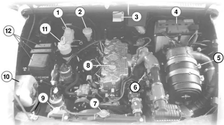
text_image
Labeled diagram of a car engine bay with numbered components for identification- Brake Fluid Reservoir
- Clutch Fluid Reservoir
- Engine Compartment Lamp
-
Battery
-
Air Filter
- Dip Stick
- Radiator Cap
-
Engine Oil Filler Cap
-
Engine Coolant Tank
- Windshield washer Fluid Container
- Power Steering Fluid Reservoir
- Fuse Box
ENGINE COMPARTMENT (4SPTC)
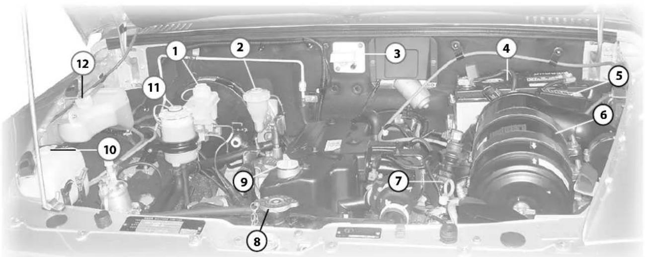
text_image
Labeled diagram of a car engine bay with numbered components for identification- Brake Fluid Reservoir
- Clutch Fluid Reservoir
- Engine Compartment Lamp
-
Battery
-
Fuse Box
- Air Filter
- Dip Stick
-
Radiator Cap
-
Engine Oil Filler Cap
- Windshield washer Fluid Container
- Power Steering Fluid Reservoir
- Engine Coolant Tank
Changing engine oil
Change engine oil in the crankcase at recommended interval. Engine oil should be drained while it is hot. Unscrew engine sump drain plug and allow oil to drain out fully.
Changing oil filter
Unscrew and remove engine oil filter with the help of special tool, if necessary. Engine oil filter is a spin-on type and cannot be re-used. Change engine oil filter with every oil change.
Always use genuine engine oil filter for replacement
Destroy the oil filter to avoid resale of the same by unscrupulous people. Fill the new oil filter with fresh engine oil. Smear a little engine oil on rubber gasket of new engine oil filter. Hand tighten the filter fully and tighten it a further half turn with a special tool. Do not overtighten engine oil filter as this may damage oil filter and oil may leak out.
Before filling in fresh oil in the engine, refill the sump drain plug using a new sealing washer. Tighten drain plug to 4 mkg torque.
Fill in specified quantity of fresh engine oil in the engine crankcase. Start engine and run for a few minutes. Stop the engine and re-check oil level after approx. 20
minutes. Top up if oil level is less than midway between upper and lower marks on the dipstick.
For Engine oil filling cap and dip stick, please refer respective Engine Compartment pages (Page 73 & 74)
Engine Air Filter
Periodically clean air filter element and replace it with a new one when air cleaner service indicator shows red band even after cleaning the air filter element.
Always use genuine air filter element.
Remove the cover and the filter element.
Clean it gently by tapping and rolling on a table. Clean the cover and air ducting.
Check the element for puncture and pin holes by a light source. If found okay refit the filter element and the cover.
Reset service indicator by pressing rubber cap, red band will disappear from service indicator.
On starting the engine, if service indicator continues to show red band, replace the paper filter element with new one and reset the service indicator.
For air filter, please refer respective Engine Compartment pages (Page 73 & 74)
Fuel & Filter Draining (CR-4):
Loosen drain plugs by 1-2 turn and drain out water and other sediments from fuel filter bowls depending on operating conditions to ensure that no water is allowed to enter the fuel system.
Priming Pump / Pear Pump (CR-4):
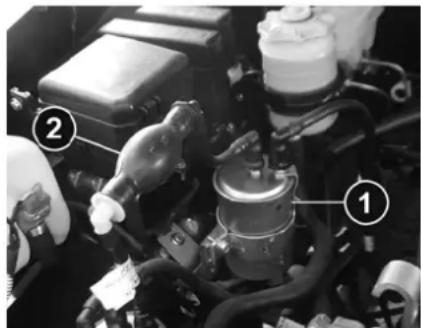
text_image
Black-and-white photo of an engine bay with numbered annotations pointing to components like engine, valve, and fuel.- Fuel filter 2. Priming Pump (CR-4)
This is used for priming the fuel manually after overhauling of the engine or after refitment of fuel lines OR after changing either fule filter OR sedimenter. Pump the fuel by means of priming pump / pear pump until all air in the fuel line removed. Before cranking the engine ensure that there is no air in the fuel system.

CAUTION
Do not loosen the HP lines of DICOR system for bleeding the air from fuel system.
Changing fuel filter element (4SPTC):
Unscrew drain plug and drain fuel from fuel bowls. Remove fuel filter with top cover from mounting bracket.
Unscrew fuel filter bowl mounting bolt and replace bowl with element.
Replace fuel tank side filter element at specified intervals and FIP side filter element.
Assemble fuel filter and fit it on mounting bracket.
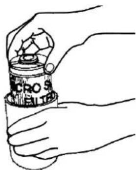
natural_image
Hand holding a container with a soccer ball, no visible text or symbolsChanging Fuel filter (4SPTC)
Priming fuel system (4SPTC):
Unscrew fuel lift pump plunger knob. Pull and push it 10-14 times (30-40 times if fuel tank has been completely emptied). Tighten fuel lift pump plunger knob. Start engine and check for smooth running.
If erratic fuel supply is still felt, check for air suction in fuel pipeline from fuel tank to FIP and rectify.

natural_image
Mechanical assembly with a valve and housing component, no visible text or symbolsPriming Fuel System (4SPTC)
VEHICLE MAINTENANCE BELT TENSION ADJUSTMENT
Fan belt tension adjustment
Check the conditions of belts on the engine. Examine the edge of the belt for cracks or fraying.
Check the tension of the belt by pushing on it with your thumb for A.C. compressor belt and Alternator / Power
Steering belt as shown in figure.
The belts should have deflection of 8 to 10 mm.
If the belt tension is not proper, get it attended at the nearest Authorised service outlet.
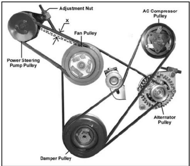
text_image
Adjustment Nut X Fan Pulley AC Compressor Pulley Power Steering Pump Pulley Damper Pulley Alternator PulleyBelt Arrangement - Engine with AC compressor and power steering pump
Bleeding clutch system
A dry friction, single disc, diaphragm type clutch has been fitted which is actuated hydraulically.
The procedure for bleeding the system is as follows :
a Ensure that fluid level in clutch fluid container is upto maximum level.
b. Remove dust cap from slave cylinder bleed screw and clean the screw thoroughly. Attach bleeding tube to bleed screw and place other end of tube in a clean glass jar containing sufficient clutch fluid to submerge tube end holding the jar just above the bleed screw level.
c. Pump clutch pedal twice or thrice slowly throughout its stroke and by holding clutch pedal in depressed condition, loosen bleed screw on slave cylinder, Watch for air bubbles in glass jar.
d. Retighten bleed screw on slave cylinder and repeat the process until air bubbles cease to appear at the end of tube in glass jar, allowing only fluid to flow.
e. After completing bleeding operation, ensure that bleed screw on slave cylinder is fully tightened. Replace dust cap on the bleed screw.
During bleeding process keep a watch on fluid level in container and top-up.
For Clutch Fluid Container location, please refer respective Engine Compartment pages (Page 73 & 74)
If engine overheating occurs, there could be a fault in the cooling system which may be on account of :
- Less coolant in the system or dirt/ scale having accumulated inside coolant passages, especially in the radiator core.
- Chocking of radiator passages due to foreign material or damages.
- Defective/stuck thermostat.
- Loose fan drive belt.
- Coolant leakage from system.
Always use genuine radiator cap of 1.0 kg/cm2 (14 psi), if required to be replaced. A proper radiator cap firmly fitted maintains pressure in the cooling system.
Prevention of rust formation :
Use genuine co-branded premixed coolant in the cooling system to prevent rust formation and freezing of coolant inside the crankcase passages.
Fill the engine coolant auxiliary tank upto 'FULL' mark.
Changing of coolant in the cooling system :
a. Drain the cooling system and flush it with clean water.
b. Pour the genuine co-branded coolant into the radiator until it is full.
c. Start the engine. Top up the radiator with coolant.
d. Fill the auxiliary tank upto 'FULL' mark.
e. Ensure no leakage in the system.
For Engine Coolant Tank location, please refer respective Engine Compartment pages (Page 73 & 74)
Brake system
The dual circuit service brake system operated through the tandem master cylinder is designed such that one circuit will continue to provide braking action if the other circuit fails. This vehicle is fitted with disc brakes at front and drum brakes at rear.
Stopping the vehicle after loss of the brake fluid in one circuit will require more pedal pressure and pedal travel than normal. Also stopping distance will be longer.
Service brakes are vacuum assisted. In case of failure of vacuum, the vehicle can still be stooped, however with a higher effort.
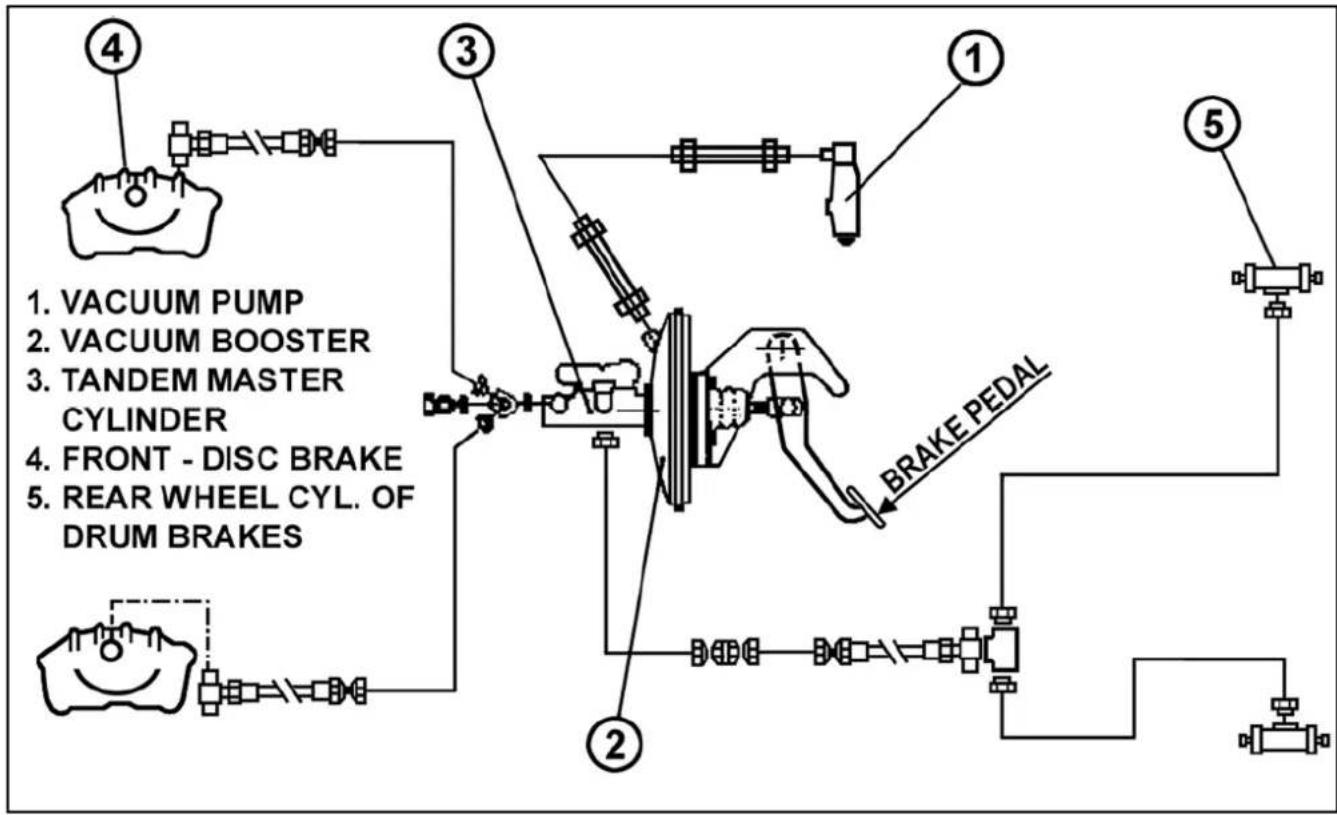
flowchart
graph TD
    A["1. VACUUM PUMP"] --> B["2. VACUUM BOOSTER"]
    B --> C["3. TANDEM MASTER CYLINDER"]
    C --> D["4. FRONT - DISC BRAKE"]
    D --> E["5. REAR WHEEL CYL. OF DRUM BRAKES"]
    E --> F["6. BRAKE PEDAL"]
    F --> G["7. Motor"]
    style A fill:#f9f,stroke:#333
    style B fill:#f9f,stroke:#333
    style C fill:#f9f,stroke:#333
    style D fill:#f9f,stroke:#333
    style E fill:#f9f,stroke:#333
    style F fill:#f9f,stroke:#333
    style G fill:#f9f,stroke:#333
The front wheels are fitted with disc brake and rear wheels are fitted with drum brakes. Both these brakes are self-adjusting, therefore need no adjustment. In case you find brake pedal going down excessively while applying the brake, please contact our authorised service outlet.
Adjustment of parking brake :
Ensure that all four rear brake shoes have been properly adjusted.
- Put chocks on front wheels.
- Jack up the rear axle.
- Loosen check nut (2). Pull parking brake lever upto second notch.
- Tighten the parking brake adjustment nut (1) till rear wheels start jamming and cannot be rotated.
- Release the parking brake and ensure that wheels are rotating freely., thentighten check nut (2). Operate parking brake a few times to ensure proper operation.
ENSURE THAT ON RELEASING THE PARKING BRAKE BOTH REAR WHEELS ARE FREE.
- Lower down the rear axle.
- Remove chocks from front wheels.
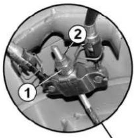
natural_image
Close-up of mechanical components with numbered annotations (1, 2), no readable text or symbols present.
natural_image
Interior view of a vehicle showing electrical wiring and a mechanical component (no visible text or symbols)- Parking Brake Adjustment Nut
- Check Nut
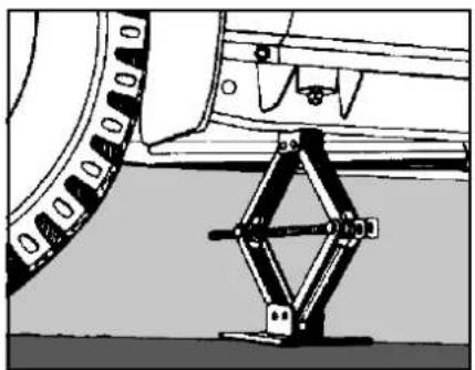
natural_image
Mechanical assembly diagram showing a car wheel and suspension bracket (no text or symbols)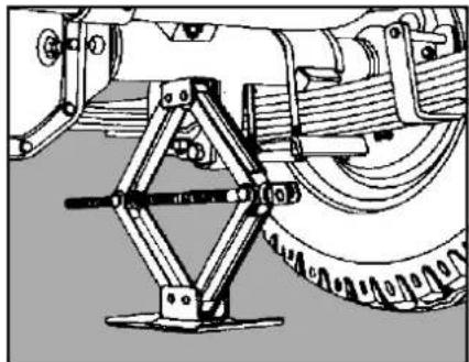
natural_image
Mechanical assembly diagram showing a vehicle suspension system with levers and wheels (no text or symbols)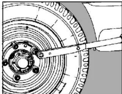
natural_image
Mechanical assembly diagram showing a rotating wheel with a central hub and a tool inserted (no text or symbols)Jack location at front Jack location at rear Tightening wheel nuts
Wheels and tyres
Always use only recommended size wheel rims and tyres. Use of rims and tyres not recommended by us may have adverse effect on vehicle safety and further more could infringe on motor vehicle regulations.
Wheel change
When changing wheels use the jack provided with the vehicle.
Jack should be placed below chassis long member behind front wheel for changing front tyres and before rear wheel as shown.
Wheel alignment
If uneven tyre wear is noticed, get the vehicle examine and
attended by TATA MOTORS authorised workshop. Periodically check and maintain correct tyre pressure to obtain longer tyre life.
Recommended tyre pressures : ( with cold tyres ) For 215/75 R15 LT Tyres (CR-4) Tubeless
| At For Ride | For Fuel Economy | |
| Front /Rear | 32 psi 35 psi |
For 215/75 R15 LT Tyres (4SPTC):
| At For Ride | For Fuel Economy | |
| Front /Rear | 32 psi 35 psi |
Check tyres for damage from time to time and remove any foreign bodies (nails/stones, metal chips etc.) embedded in treads.
While fitting wheels on the vehicle make sure that wheel bolts are free from dust, scratches, dirt, dents, etc.
Do not oil wheel bolts and nuts. Wipe off any adhering oil on bolts/nuts
Tightening torque of wheel nuts :12-15 mkg. Retighten wheel nuts after 100 km of every wheel change.
New tyres do not give maximum grip straightway and should therefore be run-in at moderate speed for the first 100 km. This will help to make the tyres last long.
To avoid damage to tyres and wheels, drive slowly over speed breakers / bumps / rough roads.
Wheel balancing
Wheels of your vehicle are balanced. The same should be maintained when repairing a tyre or tube and replacing the tyre or rim.
Repairing a tyre / tube
Mark suitably the tyre position (If original colour dot mark is not visible) with respect to valve stem hole to ensure that tyre is refitted in original location. Ensure that the balancing
weights are not disturbed during removal of tyres. Check the balance weight prior to removal of tyre, if found loose, mark its location on the rim and refit properly.
Replacing a tyre / rim.
When the tyre or rim is changed the wheel should be properly balanced on a machine after inflating to the specified value as per the following norms.
- Permissible imbalance for tyre with rim = 250 gm-cm max.
- Permissible balance weight for tyre with rim = 140 gm max.
- Relocate the tyre if the weight required to balance is more than 140 gm.
- Balance weights are available from 10 gm to 90 gm in steps of 10 gm and from 80 to 140 gm in steps of 20 gm.
- Do not use more than one balance weight on side.
Tyre rotation
Tyre rotation is recommended for achieving identical wear on each tyre. It is also advisable to change rotating direction to relieve tyres of continual one way rotation. Regular rotation of tyres also will prevent abnormal wear. The sketch indicates a suggested sequence of tyre rotation. Rotate tyres first at 12,000 km. then at every 8,000 km. or earlier depending on operation.
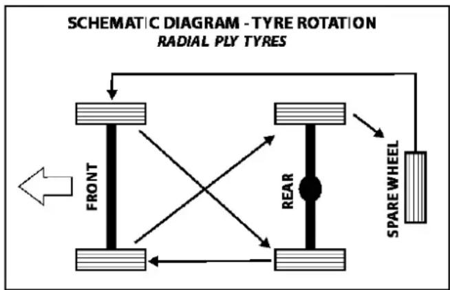
flowchart
graph TD
    A["FRONT"] --> B["SPARE WHEEL"]
    B --> C["REAR"]
    C --> D["SPARE WHEEL"]
    D --> E["FRONT"]
    style A fill:#f9f,stroke:#333
    style B fill:#ccf,stroke:#333
    style C fill:#cfc,stroke:#333
    style D fill:#fcc,stroke:#333
Headlamps
The head lamp provides two types of light beams; a high beam to give maximum light well ahead of vehicle, and a low beam which is shorter and lower so that it will not dazzle the oncoming drivers and can be use in low visibility area.
The head lamp also incorporates a parking lights.
The head lamps must be properly aligned in order to obtain maximum road safety, proper road illumination and reduced glare to oncoming traffic.
It is recommended to check alignment of headlamp beams periodically and whenever headlamp bulbs are replaced, by means of a headlamp aligner or with the help of a screen as shown in figure on the following page.
Adjusting head lamps focus with the help of screen
The vehicle should be parked 10 meters away from screen with its centre in line with central vertical line on screen, and screen at right angle to longitudinal axis of the vehicle. The vehicle should be in unloaded condition with no sag in suspension springs and all tyres equally inflated.
On the marked up screen as shown in figure, area above horizontal and inclined lines (shaded) is called 'Dark zone' and the area below it is called 'The illuminated zone'.
Each headlamp is aligned individually by masking the other headlamp. Headlamp is first adjusted for proper height of low beam by adjusting knob at its top. Light from low beam should fall below horizontal and inclined lines.
No light should fall above these lines i.e. in 'Dark zone'. Thereafter lateral adjustment is done by adjusting knob at bottom of headlamp so that contour of low beam coincides with contour formed by horizontal and inclined lines below 'Dark zone'.
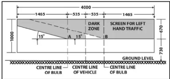
text_image
4000 1465 535 535 1465 1000 15° A 15° B DARK ZONE SCREEN FOR LEFT HAND TRAFFIC 730 GROUND LEVEL CENTRE LINE OF BULB CENTRE LINE OF VEHICLE CENTRE LINE OF BULBWhen properly adjusted, most brightly illuminated area will be just below the intersection point 'A' of these two lines.
The Second head lamp is adjusted in a similar manner without disturbing the position of the vehicle and the screen. Now switch 'ON' high beam. They will be symmetrical above points. 'A' and 'B' of intersection of vehicle lines and horizontal lines. It is possible that high beams may not be exactly symmetrical but for this reason headlamps should not be realigned.
Preferably, the alignment should be done in the dark.
No masking of headlamps with black paint is required. If done, this will reduce the intensity of light.
Head lamp focusing should be carried out in the level 'O' position (where head lamp leveling switch provided) of the switch only.
Head lamp bulb replacement
Raise the bonnet of the vehicle. Remove the rear protective cover. Pull out cable socket from bulb. Remove lock ring holding the bulb and remove the bulb.
Install new bulb, properly locating it in the housing. Fit back locking ring, cable socket and protective cover.
Realign headlamp beam after replacing bulb.
Do not clean the reflector as it will cause damage to mirror - finished surface. Do not replace bulb with dirty or oily hands, since oil will evaporate due to bulb heat and stain the reflector.
VEHICLE MAINTENANCEBULB SP
| DESCRIPTION LOCATION TYPE SPECIFICATIONS QTY. | |||||
| Headlights Headlamp Halogen P43t 12V 60 / 55 W 2 | |||||
| Turn indicator light Front BAU15 S | 12V 21 W | 2 | |||
| Tail lamp | BAU15 S | 12V | 21 W | 2 | |
| Stop lights / Tail lights | Tail lamp | BAY 15 S | 12V | 21 / 5 W | 2 |
| Parking lights | Head lamp | W 5W | 12 V | 5W | 2 |
| Registration number plate lights | Near number light | W 5W | 12 V | 5W | 2 |
| Reverse indicator lights | Tail lamp | BA15 S | 12 V | 21W | 2 |
| Side Repeater | Side Panels | W 5 W | 12 V | 5 W | 2 |
| Front Fog Lamps | Front Bumper | H 3 | 12 V | 55 W | 2 |
| Rear Fog Lamps | Tail lamp | BA 15 S | 12 V | 21 W | 2 |
| Roof Lamp | Cab Roof | 12 V | 10 W | 2 | |
| Engine Compartment Lamp | Engine Compartment | BA 15 S | 12 V | 21 W | 1 |
| TELL TALE SYMBOLS | |||||
| Turn indicators | Instrument Panel | T 5 | 12 V | 1.4 W | 2 |
| Oil Pressure | “ | T 5 | 12 V | 1.4 W | 1 |
| Battery | “ | T 10 | 12 V | 3 W | 1 |
| Low Brake fluid/Parking brake | “ | T 5 | 12 V | 1.4 W | 1 |
| Seat Belt Fasten | “ | T 5 | 12 V | 1.4 W | 1 |
| Door Ajar | “ | T 5 | 12 V | 1.4 W | 1 |
| High Beam | “ | T 5 | 12 V | 1.4 W | 1 |
| Diesel Preheat | “ | T 5 | 12 V | 1.4 W | 1 |
| Position Lamps | “ | T 5 | 12 V | 1.4 W | 1 |
| Immobiliser | “ | High Intensity LED | 12 V | 1 | |
| Fuel Reserve Indicator | “ | T 5 | 12 V | 1.4 W | 1 |
In order to protect the cable harness and other equipments from damage in case of short circuit and overloads, fuse links are provided in the fuse box.
In case of a fault in the electrical system check the respective fuse. The particulars of the consumers served by each fuse and amperage are printed on the fuse box cover. The fuse link can be identified for amperage by color codes :
- Fuse link - Red - 10 Amps
- Fuse link - Blue - 15 Amps
- Fuse link - light brown - 5 Amps
- Fuse link - Yellow - 20 Amps
- Fuse link - White - 25 Amps
- Fuse link - Green - 30 Amps
- Fuse link - Orange - 40 Amps
- Fuse Link - Trasparent - 80 Amps
While fitting fuse box cover ensure that cover knob rests in the slot provided inside the fuse box.
Spare fuse links are provided inside the fuse box.
Always use fuses of correct rating. Do not use wire in place of fuse.
Flasher with short circuit protection
If flasher circuit is short circuited or overloaded (more than 110 W) flasher will shut off. It can be reset by momentarily centering the indicator arm of combi switch. If flasher is shutting off or fuse is blowing off repeatedly the flasher circuit should be checked for short circuit. Check the flasher separately for its functioning.

natural_image
Close-up of mechanical components with a white arrow pointing to a specific part (no visible text or symbols)Fuses box in cabin (CR-4) (Below dashboard)
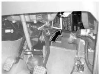
natural_image
Interior view of a vehicle showing mechanical components and a traffic light (no visible text or symbols)Fuses box in cabin (4SPTC) (Below dashboard)
Care and cleaning of the vehicle
When cleaning the interior / exterior of the vehicle, NEVER USE volatile solvents such as thinner, petrol or any other cleaning materials such as bleaches or strong household detergents. These materials may be poisonous or flammable and their improper use may cause personal injury or damage to the vehicle.
Cleaning of vehicle interior
- Floor mat
Dirt can be removed from the mat with water and mild soap. Use a brush to help loosen dirt. After dirt is loosened, wash the mat thoroughly with water and dry it in the shade.
- Seat belt
Clean the seat belts with a mild soap and water only. No bleach or dye should be used as this may weaken the belt fabric. The belts should be allowed to dry in the shade.
- Upholstery
Prepare a solution of soap or neutral detergent mixed with warm water. Apply solution with a sponge or soft cloth and let it soak for a few minutes to loosen dirt. Wipe the surface with a clean, damp cloth to remove
dirt and soap solution. If some dirt still remains on the surface, repeat the procedure
- Carpets
Remove dirt as much as possible by using a vacuum cleaner. Rub the stained area with clean cloth made damp with soap to absorb the stain and remove the soap. Repeat until the stain is removed.
You can use commercially available carpet cleaner. In this case, carefully follow the manufacturer's instructions and precautions.
Cleaning of Windows, Front & Rear Glass :
RFID TAG is pasted on front windshield from inside. It enables Electronic toll collection.

DO NOT TRY TO PEEL OFF RFID TAG
TML PART NO. 2816 5420 99 05 VENUS WINDSHIELD MOUNT AVI TAG
NOTICE
Do not attempt to rip or tamper the tag. It will disable the functionality of the tag.
VEHICLE MAINTENANCE CARE & CLEANING OF VEHICLE
Clean the windows inside and outside with commercially available glass cleaners.
This will remove the haze that builds up on the inside of windows. Use a soft cloth or paper towels to clean all glass and plastic surfaces.
Cleaning exterior of the vehicle
Dirt or any other foreign material on the painted surface may result in :
- Faded paint.
- Rust on body due to deteriorated paint film.
- Rust due to scratches
- Body rust due to contact with damp dirt trapped in the body.
Therefore it is important that your vehicle is always kept clean and free from dirt in order to maintain the paint in a good condition and to protect the entire body against corrosion.
Washing :
When washing the vehicle, follow the instructions given below.
- Flush underside of body and wheel housing with pressurised water to remove mud and debris. Use plenty of water to loosen and remove dirt.
- Remove dirt and mud from body exterior with running water. Use a soft sponge, brush with water. Do not use hard material which can scratch the paint.
- Wash the exterior with water, lightly rubbing with sponge or soft cloth. The sponge or cloth should frequently soaked in water.
CAUTION
When using commercial wash products precautions specified by the manufacturer should be observed. Do not use strong household detergents or soaps.
- Once dirt has been completely removed, wash off with running hose water.
- After rinsing, wipe the body lightly with wet chamois or cloth and allow the body to dry it in the shade.
Warning
After washing, check that the brakes are dry. If brakes are not dry, dry them by gently, repeatedly applying while driving at low speeds.
Washing the vehicle exterior
After washing the vehicle, waxing and polishing are recommended to protect and beautify the paint.
- Use only good quality waxes and polishes.
- When using waxes and polishes, the precautions specified by the manufacturers should be observed.
- Chrome plated parts should also be waxed.
Protection against corrosion :
The following cause corrosion :
- Moisture trapped in body cavities.
- Dirt and salts collected in hollows on the underside of the vehicle.
- Removal of paint and protective coatings from the exterior and underside of the vehicle.
Corrosion preventive measures have been incorporated in your vehicle. You can avoid corrosion of your vehicle by performing some simple periodic maintenance :
- Repair chips and scratches in the paint as soon as you discover them.
- Inspect and clean the drain holes in the bottom of the doors and body.
- Check the floor coverings for dampness. Carpets and floor mats remain damp for a long time, especially in winter. This can eventually cause the floor panels to corrode.
- Use a high pressure spray to clean the underside of your vehicle. This is especially important in areas near chemical and other industries.
- Have corrosion preventive coatings done on the underside of your vehicle using Tata Motors co-branded anti corrosive treatment.
FUEL, LUBRICANTS & COOLANTS FUEL
Fuel : High speed diesel conforming to IS 1460 OR EN 590 OR equivalent is recommended to be used as fuel.
At very low temperature fluidity of diesel may become insufficient due to paraffin separation. It is therefore, necessary to mix supplementary fuel with summer or winter grade diesel. The supplementary fuel to be used is kerosene or aviation turbine fuel.
Ratios for mixing of supplementary fuel and diesel are shown in table :
| Ambient Percentemperature upto ^ grade d | percentage | |
| Summer Supple diesel fuel | mentary | |
| upto 0 ^ 100 0 | ||
| 0 ^ to -10 ^ | 7 | 0 |
| -10 ^ to -15 ^ | 5 | 0 |
| Ambient Percentemperature upto ^ grade d | percentage | |
| Winter Supple diesel fuel | mentary | |
| upto -15 ^ | 100 0 | |
| -15 ^ to -20 ^ | 7 | 0 |
| -20 ^ and Below | 50 | 50 |
Care should be taken that diesel and supplementary fuel are thoroughly mixed before filling.
WARNING
Do not mix gasoline OR alcohol with diesel. This mixture can cause explosion.
NOTICE
Where oxidation catalytic converter is fitted. It is mandatory to use Diesel fuel with sulphur contents as under. Use of any other diesel fuel can increase the pollutants.
Sulphur Content : 0.035% (BS-IV) / 0.05% (BS-III)
CAUTION
Due to precise tolerance of diesel injection systems. It is extremely important that the fuel be kept clean and free of dirt or water. Dirt or water in the system can cause severe damage to Common Rail system
Do not add fuel additives with diesel.
Use low sulphur content fuel having a cloud point that is at least 10 degree below the lowest expected fuel temperature at which wax crystals begin to form in diesel.
Viscosity of the fuel must be kept above 1.0 centistokes to provide adequate fuel system lubrication at 40^ C.
Lubricants
Recommended lubricants conform to the following specifications :
| 1. SAE 15W40 to API CH4 - Engine oil (CR-4 / 4SPTC) |
| 2. 75W90 Synthetic GL-4 - Gearbox oils (BS-IV)80W90 with 7% Anglomol - Gearbox oils (BS-III) |
| 3. SAE 85W140 API GL-S - Rear axle and mechanical steering gear box oils |
| 4. ATF DEXTRON -IID - Power Steering Oil |
Please use only recommended brands for good performance.
The oil change periods recommended in maintenance schedule should be adhered to.
Use of reclaimed oil is not recommended.
Engine oil
Recommended grades of engine oil conforming to SAE API CH4 (For CR-4) / SAE API CF4 (For 4SPTC) specifications and range of ambient temperature at which these can be used are given below :
| Ambient temperature ^0 C Engine oil grade | |
| -10 and above SAE | 5W/40 |
| -20 TO above | SAE 10W/30 or SAE 5W/20 |
Hub bearing grease (Tata Motors axles & front hub).
Use Lithium base multipurpose grease.
Quantity 25 gms per hub. (Rear)
Brake and clutch fluid
Brake fluid conforming to IS : 8654/DOT 3 is recommended.
Spicer propeller shaft (where applicable)
Lubricate slip joint with Multipurpose grease - 2 grade grease.
Lubrication of steering spindle ball joint
Lubricate steering spindle ball joint with Moly Kote - BR 2 grease at every 10,000 km of operation.
Sliding spindle on steering column not be pulled beyond the stopper as it may damage the splines.
Coolants
Presence of dirt in coolant chokes up passages in radiator, cylinder head and crankcase, thereby causing overheating of engine.
To prevent rust formation and freezing of coolant inside the passages of radiator, crankcase and cylinder head use only branded premixed coolant.
Coolant should be drained and fresh premixed coolant filled every two years or 50,000 km., whichever is earlier.
FUEL, LUBRICANTS & COOLANTS
RECOMMENDED OILS, LUBRICANTS, COOLANTS & FILLING CAPACITY
PLEASE USE ONLY FOLLOWING GENUINE OILS, COOLANTS, LUBRICANTS, ANTI RUST & SOUND DEADENING COATS, WINDSCREEN SEALANT, ADHESIVES & FUEL ADDITIVES BRANDED BY TATA MOTORS FOR OPTIMUM PERFORMANCE
| ITEM COMPANY BRANDQTY | |||
| ENGINE OIL | CASTROLHPCL HP Milcy | Castrol GTD 15W/40Power 15 W/40 CH-4 | 5.5 Litres |
| COOLANT (Premixed) | SUNSTARCASTROL Castrol RadicoolHPCL HP Thanda Raja TCO | Golden Cruiser Premium 1400 M | 12 Litres (Approx) |
| GEAR BOX (G-76) | HPCLCASTROL CAST | HP Gear EP 75W90 (T) - BS-IVROL Syntro 75W90 GL4 - BS-IVExxon Mobil - Mobilube 1 SHC 75W90 - BS-IV80W90 with 7% ANGLOMOL - BS-III | 1.4 Litres |
| POWER STEERING OIL HPCL HP | ATF 1.6 LitresCASTROL CAST | ROL Transpower TQ | |
| REAR AXLE | HPCLCASTROL CAST | HP Gear Oil XP 85W140 GL5ROL Extreme Pressure 85W140 | 2.2 Litres (CR-4)1.9 Litres (4SPTC) |
| BRAKE / CLUTCH FLUID | SSCICASTROL CAST | Golden Cruiser TGBF DOT - 4ROL Universal Brake Fluid DOT - 4 | As required |
| WHEEL BEARING & CHASSISPropeller shaft joints, SlidingYokes, Vacuum Booster | HPCL | HP Multipurpose Grease-2 | As required |
| ANTI RUST TREATMENT& SOUND DEADENING | DINITROLWUERTH | DinitrolWuerth | —— |
| DIESEL ADDITIVE | IFTEX | Iftex Clean System D | 250 ml pack * |
* Add to Diesel as per the dosage recommended by M/s IFTEX
| ENGINE CR-4 (BS-IV) |
| Model : TATA 3.0 CR4 |
| Type : Turbo-charged,Intercooled, Direct injection diesel engine. |
| No. of cylinders : 4-inline |
| Bore / Stroke : 97 mm x 100 mm |
| Capacity : 2956 cc |
| Max. engine output : 60 - 62 kw at 3000 rpm as per MOST/ CMVR/TAP-115/116 |
| Max. torque : 250 N-m at 1000-2000 rpm as per MOST/CMVR/TAP-115/116 |
| Compression ratio : 17.5 : 1 |
| Firing order : 1-3-4-2 |
| Air filter : Dry ( Paper ) type |
| Oil filter : Spin - on type |
| Fuel filter : Single stage, fine filtration |
| Fuel injection pump : Common Rail 1600 bar |
| Timing : Electrically controlled |
| Governor : Electrically controlled |
| Engine oil capacity : Min. 5.5 litres |
| Weight of engine : 315 kg ( Dry ) |
| Radiator frontal area: 2205 sq. cm. |
| Capacity of cooling System : 12 Litres |
| ENGINE 4SPTC (BS-III) |
| Model : TATA 497 SPTC 43 |
| Type : Turbo-charged, Water cooled,Direct injection diesel engine. |
| No. of cylinders : 4-inline |
| Bore / Stroke : 97 mm x 100 mm |
| Capacity : 2956 cc |
| Max. engine output : 50 - 52 kw at 3000 rpm as perMOST/ CMVR/TAP-115/116 |
| Max. torque : 223 N-m at 1600-2200 rpm as perMOST/CMVR/TAP-115/116 |
| Compression ratio : 19 : 1 |
| Firing order : 1-3-4-2 |
| Air filter : Dry ( Paper ) type |
| Oil filter : Spin - on type |
| Fuel filter : Double stage, fine filtration |
| Fuel injection pump : Mechanical Rotary F.I.P. |
| Timing : With automatic advance |
| Governor : Centrifugal type variable speed. |
| Engine oil capacity : Min. 5.5 litres |
| Weight of engine : 315 kg ( Dry ) |
| Radiator frontal area: 2260 sq. cm. |
| Capacity of cooling system : 12 Litres |
TECHNICAL SPECIFICATION
| CLUTCH |
| Type : Single plate dry friction |
| diaphragm type |
| Outside diameter of : 260 mm - (For CR-4 - BS-IV)Clutch lining 240 mm - (For 4SPTC - BS-III) |
| Friction area : 603 sq. cm. (approx) - CR-4 |
| 527 sq. cm. (approx) - 4SPTC |
| GEAR BOX |
| Type : G-76-5/4.10 with overdrive |
| Synchronesh on all gears |
| No of gears : 5 forward, 1 Reverse |
| Gear ratios : Gear Ratio1 st 4.102nd 2.223 rd 1.374 th 1.005 th 0.82Rev. 3.75 |
| REAR AXLE |
| Type : Single reduction, salisbury typewith hypoid gears and Semi - floatingaxle shafts. |
| Ratio : 3.36 (CR-4) / 3.73 (4SPTC) |
| FRONT AXLE : Independently suspended | |
| STEERING : | |
| Type : Power Steering, Victa type steering | |
| Ratio : 18.2 :1 (EX / GX /FX) | |
| 32.5:1 to 36.5:1 (LX / CX) | |
| Steering wheel : 420 mm dia. (LX / CX) / | |
| 380 mm dia. (EX / GX / FX) | |
| BRAKES : | |
| Service brakes : Vacuum assisted independent hydraulic brakes on front and rear. Vacuum pump mounted on alternator. | |
| Front : 262 dia. disc brake | |
| Rear : 282 dia. auto adjusted drum brake | |
| Parking brake : Cable operated Mechanical linkages acting on rear wheels. | |
| Load conscious : Provided for rear brakes pressure reducing valve | |
| FRAME : | |
| Type : Ladder type cranked frame with boxed section long members and welded / bolted cross members | |
| Depth : 110 mm ( maximum ) | |
| Width : 60 mm | |
TECHNICAL SPECIFICATION
| SUSPENSION | |
| Front : Double wishbone type with coil springs. | |
| Rear : Parabolic leaf springs. | |
| Shock Absorber : Hydraulic double acting telescopic type at front and rear. | |
| Antiroll bar : At both front and rear. | |
| WHEELS AND TYRES | |
| Tyre : 215 / 75 R 15 LT Tubeless (CR-4)215 / 75 R 15 LT (4SPTC) | |
| Wheel rims : 5.5 J x 15 | |
| No. of wheels : Front - 2, Rear - 2, Spare -1 | |
| FUEL TANK CAPACITY : 65 litres | |
| ELECTRICAL SYSTEM | |
| System voltage : 12 volts , 80 Ah (CR-4)12 volts , MF 70Z (4SPTC) | |
| Alternator Capacity : CR-4 : 117Amps (GX/EX/LX)75 Amps (CX)4SPTC : 75 Amps (All )40 Amps (Optional-CX/LX) | |
| Battery : CR-4 - 12V, 75 Ah4SPTC - 12V, MF 70 Z |
| PERFORMANCE | |
| Max. speed at rated GVW : 120 km / hr | |
| Max gradeability at rated GVW : 32 % | |
| Grade Restartability : 32 % (CR-4)26 % (4SPTC) | |
| PASSENGER CAPACITY : | |
| Option I : Driver + 6 | |
| Option II : Driver + 8 | |
| Main Chassis Dimensions ; As per ISO : 612 in mm(Nominal) (Tolerances as per INTEREUROPE STVZO) | |
| Wheel base : 2425 | |
| Track front : 1496 | |
| Track rear : 1461 | |
| Overall Length : 4258 | |
| Max. width : 1700 | |
| Front Overhang : 827 | |
| Rear Overhang : 1006 over rear foot step | |
| Overall height (Unladen / laden) : 2010 / 1925 | |
| Min. turning circle dia. : 10.0 m | |
| Min. turning clearance circle dia. : 11.1 m | |
| Ground clearance : 182 (Unladen) |
TECHNICAL SPECIFICATION
| WEIGHT (kg) : (Tolerances as per INTEREUROPE STVZO) |
| Complete vehicle kerb : 1820 (FAW- 997 RAW- 823) weight as per ISO:1176 - For AC / HVAC(With spare wheel & tool): 1800 (FAW- 987,RAW- 813)- For Non-AC |
| Gross Vehicle weight : 2600 ( FAW 1080 ,,RAW 1520 ) |
| Max. Permissible FAW : 1100 |
| Max. Permissible RAW : 1560 |
SERVICE INSTRUCTIONS
- The vehicle has been built to give you thousands of kilometers of economical and trouble-free performance. This is however, possible only if this vehicle is systematically maintained and operated strictly according to the instructions contained in this book.
- The free services should be availed of, at the following km range within 18 months.
1 ^st Free Service At 1000 - 1,500 km or 1 month whichever is earlier
2 ^nd Free Service At 14,500 - 15,500 km or 12 months whichever is earlier
3 ^rd Free Service At 29,500 - 30,500 km or 24 months whichever is earlier
-
Besides the service schedule chart detailing the service operations to be performed Service Coupons (perforated) are incorporated. These coupons should be detached and sent to Customer Support, Passenger Car Division, Tata Motors, Pune - 410062 by the servicing dealer after the service is performed. The selling dealer should fill up details of chassis particulars on the inside cover page.
-
These services can be satisfactorily performed only by one of our Authorised Dealers'/TASC's/TASP's Workshops in India, irrespective of the dealer who sold the vehicle, provided the vehicle is sent to them at the kilometerages specified and that this service book is produced before them.
The vehicle is entitled to pre-delivery service with free labour. After the delivery of the vehicle, in the subsequent '4 free services' labour would be free but materials, if any would be charged for.
All services, other than the above, must be paid for both for materials and labours; material at prevailing rates for the quantity consumed and labour at our scheduled rates available with our Authorised Dealers/TASCs/TASPs.
- In the event of a schedule Service not performed within specified kilometers the respective coupons will be detached by the Authorised Dealer's Workshop when the vehicle is sent to them next. Should a major service have been missed, all the works listed for such service must be performed when the vehicle is taken next to one of our Authorised Dealer's/ TASC's/TASP's Workshop.
SERVICE INSTRUCTIONS
- It is an important condition of our sales policy that no warranty claims shall be entertained by us unless all services upto time of the claim arising have been performed on the vehicle by one of our Authorised Dealer's / TASC's/TASP's Workshops.
Failure to carry out the services listed in this book can cause considerable damage to the vehicle and inconvenience to you. It is, therefore, in your own interest to take your vehicle to one of our Authorised Dealer's, TASC's, TASP's, Workshop for servicing.
- All our Authorised Dealer's/TASC's Workshops have been equipped with special tools and are manned by technical personnel trained by us. Besides, they have adequate stocks of genuine spare parts for replacement purposes, should the need arise. Our Authorised Workshops are therefore in a position to render you any expert advice and service your vehicle may need. Please give them an opportunity to serve you, so that you may obtain economical and trouble free performance from your vehicle.
- For any technical advice concerning your vehicle, please contact the nearest Authorised Dealer.
SERVICE SCHEDULE
| SR. NO. | OPERATION | FREQUENCY (In km) | PDI | 1500 | 15000 | 30000 | 45000 | 60000 | 75000 | 90000 | 105000 |
| GENERAL | |||||||||||
| 1 | Wash the vehicle & Clean the condenser with compressed air. | Every Service | ● | ● | ● | ● | ● | ● | ● | ● | ● |
| 2 | Check & Top up Fluids if required: Brake/Clutch Fluid, Battery Electrolyte, Power Steering Oil Gear Box Oil, Transfer Case & Front Axle (4X4) / Rear Axle Oil | Every Service | ● | ● | ● | ● | ● | ● | ● | ● | ● |
| 3 | Check engine compartment for loose fasteners, low pressure fuel lines, coolant hoses,air hoses, vacuum hoses, hydraulic line connections for leakages if any, Attend if necessary. | Every Service | ● | ● | ● | ● | ● | ● | ● | ● | ● |
| 4 | Check Underbody for loose fasteners, hydraulic line connections, exhaust system / fuel pipes for damages / leakages if any. Attend if necessary | Every Service | ● | ● | ● | ● | ● | ● | ● | ● | ● |
| 5 | Apply grease on door latches door lock, door check stop, striker, bonnet opening lever & lock plate, tailgate hinges & door lock inner ratchet | Every 15000 km | ● | ● | ● | ● | ● | ● | ● | ||
| ENGINE (3.0 CR4) | |||||||||||
| 1 | Check coolant level. Top up if necessary 15000 km ● ● ● ● ● ● | ||||||||||
| 2 | Change coolant in cooling system 60000km ● | ||||||||||
| 3 | Change engine oil & oil filter cartridge with oil conforming to API CH4 and MB 228.3 specifications | 15000 km OR 1 year whichever is earlier | ● | ● | ● | ● | ● | ● | ● | ||
| 4 | Clean engine breather. | 15000 km | ● | ● | ● | ● | ● | ● | ● | ||
| 5 | Check all accessories drive belts. Adjust tension, if required. Change, if damaged. | 15000 km | ● | ● | ● | ● | ● | ● | ● | ||
| 7 | Drain water from sedimenter ( or whenever warning indicator glows). | 15000 km | ● | ● | ● | ● | ● | ● | ● | ||
| 8 | Change pre fuel filter cartridge and drain water. | 15000 km | ● | ● | ● | ● | ● | ● | ● | ||
| 9 | Change main fuel filter. | 45000 km | ● | ● | |||||||
| 10 | Cooling and heating : Check & rectify hoses for clog and damage. Check & rectify radiator & condenser fins blocking due to dirt / dust etc. * Every 15,000 km for dusty road. | 45000*km | ● | ● | |||||||
| 11 | Check and adjust intake stroke - exhaust valve clearance (Tapet setting) | 15000 km | ● | ● | ● | ● | ● | ● | ● | ||
| 12 | Check service indicator red band as per recommended procedure & replace element. if necessary. | 15000 km | ● | ● | ● | ● | ● | ● | ● |
SERVICE SCHEDULE
| SR. NO. | OPERATION | FREQUENCY (In km) | PDI | 1500 | 15000 | 30000 | 45000 | 60000 | 75000 | 90000 | 105000 |
| 13 | Replace air cleaner element 45000km • • | ||||||||||
| 14 | Inspect vacuum hose connection and rectify if necessary 15000 km • • • • • • | • | |||||||||
| 15 | Replace EVRV filters | 15000 km | • | • | • | • | • | • | • | ||
| 16 | Vacuum hoses for EVR, EGR, Turbo charger, Throttle (if applicable) to be replaced | 60000km | • | ||||||||
| ENGINE ( 4 SP TURBO) | |||||||||||
| 1. | Check service indicator red band as per recommended procedure & replace element if necessary. | Every Service | • | • | • | • | • | • | • | • | |
| 2. | Change engine Oil and Oil filter. Use APICF4+MB228.3 or Higher grade Engine Oil. Every 15000 km OR 1 Year whichever is earlier | 15000 km | • | • | • | • | • | • | • | ||
| 3. | Check All accessory Drive belts, adjust tension if required, change if damaged Replace every 2 year OR 45000 kms whichever is earlier | Every Service | • | • | • | • | • | • | • | • | |
| 4. | Drain water from fuel pre filter | Every Service | • | • | • | • | • | • | • | • | |
| 5. | Change fuel pre filter (cartridge) | 15000 km | • | • | • | • | • | • | • | ||
| 6. | Change secondary fuel filter (cartridge) | 30000km | • | • | • | ||||||
| 7. | Check & adjust valve clearance | 15000 km • • | • | • | • | • | • | ||||
| 8. | Replace air filter element (OR if RED band appears on Service Indicator) | 45000km | • | • | |||||||
| 9. | Clean breather | 30000km | • | • | • | ||||||
| 10. | Change vacuum hoses of Vacuum Modulator, Turbocharger, EGR valve & throttle valve OR 4 Years whichever is earlier | 60000km | • | ||||||||
| GEAR BOX | |||||||||||
| 1 | Change oil in gear box (First at 45000 km) | 90000 km | • | ||||||||
| 2 | Clean breather in gear box | Every Oil Change | • |
SERVICE SCHEDULE
| SR. NO. | OPERATION | FREQUENCY (In km) | PDI | 1500 | 15000 | 30000 | 45000 | 60000 | 75000 | 90000 | 105000 |
| PROPELLER SHAFT | |||||||||||
| 1 | Grease propeller shaft with grease gun (at slip joint - splines end) & Check Centre bracket mounting bolts for looseness. Tighten if necessary | 15000 km | • | • | • | • | • | • | • | ||
| AXLE | |||||||||||
| 1 | Change oil in axle (First at 15,000 KM, there after every 75,000 KM) | 75000 km | • | • | |||||||
| 2 | Change grease in rear hubs& adjust bearing play (only for TML axle) | 45000 km | • | • | |||||||
| 3 | Clean breather in Axle Every Service • • • • • • • • • | ||||||||||
| SUSPENSION & STEERING | |||||||||||
| 1 | Grease idler arm (seal type idler arm) 15000 km • • • • • • • | ||||||||||
| 2 | Wheel alignment & balancing. Inspect if abnormal condition noticed | 30000 km | • | • | • | ||||||
| 3 | Apply torque on front suspension bolts. | Every Service | • | • | • | • | • | • | • | • | • |
| 4 | Check condition of rubber bushes in the following & replace if necessary. 1) Top wishbone 2) Lower wishbone 3) Anti roll bars 4) Leaf Spring | 45000 km | • | • | |||||||
| 5 | Check shock absorber, its bushes, replace if necessary | 30000 km | • | • | • | ||||||
| 6 | Grease steering spindle and sleeve | 30000 km | • | • | • | ||||||
| 7 | Check & adjust front wheel bearing play & Change grease in front hubs | 45000 km | • | • | |||||||
| 8 | Check steering gearbox oil level & top-up, if necessary (only for mechanical steering) | 45000 km | • | • | |||||||
| 9 | Change oil in power steering system & change filter element | 75000 km | • | ||||||||
| 10 | All the suspension & steering ball joints to be checked for any rubber boot tear, attend if any. | Every Service | • | • | • | • | • | • | • | • | • |
| CLUTCH & BRAKES | |||||||||||
| 1 | Check parking brakes, adjust if necessary | 15000 km • • | • | • | • | • | • | ||||
| 2 | Check front brake pads & rear brake linings. Replace if necessary | 15000 km | • | • | • | • | • | • | • | ||
| 3 | Change Clutch & Brake Fluid (or 2 years whichever is earlier) | 30000 km | • | • | • |
SERVICE SCHEDULE
| SR. NO. | OPERATION | FREQUENCY (In km) | PDI | 1500 | 15000 | 30000 | 45000 | 60000 | 75000 | 90000 | 105000 |
| ELECTRICALS | |||||||||||
| 1 | Check headlamp focussing & functionir of other electrical equipment | 15000 km | • | • | • | • | • | • | • | ||
| 2 | Check speci& gravity of battery electrolyte | 30000km | • | • | • | ||||||
| HVAC | |||||||||||
| 1 | Check the HVAC system for satisfactory performance & attend if required | Every Service | • | • | • | • | • | • | • | • | • |
| WHEELS & TYRES | |||||||||||
| 1 Tyre rotation 15000 km • • • • • • | |||||||||||
* Under severe driving conditions, additional maintenance is required. Please Refer to "Additional Maintenance Schedule under severe driving conditions":
Precautions to be taken while cleaning engine compartment: It is recommended to use dry low pressure air. Do not use pressurised water.
ADDITIONAL MAINTENANCE SCHEDULE UNDER SEVERE DRIVING CONDITIONS :
A. Driving in conditions such as Patrolling, Taxi, Pickup Van, Vehicle Towing, with Trailer Towing B. Driving on Dusty / Sandy roads
C. More than 50% (in terms of kms) driving in heavy city traffic D. Frequently operating in mountainous area
| SR. O NO. | OPERATION INTERVAL CONDITION | |||||
| A | B | C | D | |||
| 1 | Change Engine Oil & Oil Filter | Every 7500km | ● | ● | ● | ● |
| 2 | Clean Air Filter Element | Every 7500km | ● | |||
| 3 | Replace Air Filter Element | 30000km | ● | |||
| 4 | Front and Rear Axle Oil Change | Change First at 15000km and thereafter at 45000km | ● | ● | ● | ● |
Chassis No. ....
| Recommended Odometer Service Date reading | Repair Servicing Dealer's Order Signature and km. No. Stamp | ||
| At km. | |||
| PDI * | |||
| 5,000* | |||
| 15,000* | |||
| 30,000* | |||
| 45,000 | |||
| 60,000 | |||
| 75,000 | |||
| 90,000 | |||
| 1,05,000 | |||
| 1,20,000 | |||
| 1,35,000 | |||
| Recommended Order Service Date | dometer reading | Repair Servicing Dealer's Order Signature and km. No. Stamp | |
| 1,50,000 | |||
| 1,65,000 | |||
| 1,80,000 | |||
| 1,95,000 | |||
| 2,10,000 | |||
| 2,25,000 | |||
| 2,40,000 | |||
| 2,55,000 | |||
| 2,70,000 | |||
| 2,85,000 | |||
| 3,00,000 | |||
RECORD OF REPAIRS CARRIED OUT
| Date | Odometer | Repair reading (km) Order No. Stamp | Particulars of Repair | Servicing Dealer's Signature & |
RECORD OF REPAIRS CARRIED OUT
| Date | Odometer | Repair reading (km) Order No. Stamp | Particulars of Repair | Servicing Dealer's Signature & |
ALBHABETICAL INDEX
A
Abbreviation 110
Accessory Switches 45
Adjustable Head Restraint 27
Aggregate Numbering 16
Air Conditioning 58
Alphabetical Index 109
Antenna 41
Anti-theft Device 18
B
Bonnet Opening & Closing 50
Brake Adjustment 82
Brake Clutch System Bleeding 79
Brake System 80
Braking 66
Bulb Specification 87
C
Catalytic Converter 54
Changing Engine Oil 75
Changing Oil Filter 75
Combi-Switch 39
Coolants 95
Cooling System 80
D
Dont's 13
Door Locking 19
Do's 10
Driver's & Co-driver's Seat 23
Driving Controls 28
Driving in Adverse Conditions 67
Driving Instruction 65
Driving Safety 71
E
EGR System 54
Engine Air Filter 76
Engine Compartment - 4SPTC 74
Engine Compartment - CR-4 73
Engine Compartment Lamp 41
Environment Protection 6
F
Fan Belt Tension Adjustment 78
Foreward 5
Fuel Filter & Priming 4SPTC 77
Fuel Filter & Priming CR-4 77
Fuel Economy 66
Fuel Filling Cap Opening 50
Fuel 92
Fuses 90
G
Gauges 34
Gear Shift lever 49
Glove Box with Cup Holder 48
Grab Handle 48
H
Head Lamp Adjustment 85
Head Lamp Bulb Replacement 86
Headlamp Leveling Switch 44
Headlamps 85
High Mounted Stop Lamp 42
ALBHABETICAL INDEX
|
Indicators 31
Inner Rear View Mirror 22
Instrument Panel 29
Interior Roof Lamps 43
K
Key 18
L
Lubricants 93
M
Manual Window Winding 19
Micro Phone 41
Middle Seat 24
Mobile Holder 47
Music System with USB & Blue Tooth 41
0
Outer Rear View Mirrors 22
P
Parking Brake 49
Power Socket 47
Power Steering 56
Power Windows 20
Preparing the vehicle for the drive 62
R
Recommended Oils, Lubricants 94
Record of Repairs Carried Out 107
Record of Service Performed 105
Registration Plate lamp 42
Replacing Tyre / Rim 84
Replacing Tyre / Tube 84
Roof AC 61
S
Safety Checks 72
Seat Belt 25
Seats at Rear 24
Service Schedule 101
Spare Wheel 52
Special Instructions 99
Steering Lock Cum Ignition Switch 37
Sun Visors 21
T
Tail Lamp 42
Technical Specification 95
Towing the Vehicle 70
Turbocharger 55
Tyre Pressure 83
Tyre Rotation 85
V
Vehicle Care 89
Vehicle Jack & Tools 53
W
Warranty - Terms & Conditions 8
Wheel Alignment 83
Wheel Balancing 84
Wheel Change 83
Wheels & Tyres 83
ABBREVIATION
| A/C Air Conditioning | |
| ACC Accessories | |
| Amp Ampere | |
| Br Branch | |
| Brg Bearing | |
| cc Cubic Centimeters | |
| Cm Centimeter | |
| Dia Diagonal | |
| EGR Exhaust Gas Recirculation | |
| FAW Front Axle Weight | |
| Fig Figure | |
| FIP Fuel Injection Pump | |
| gm Gram | |
| GVW Gross Vehicle Weight | |
| IGN Ignition | |
| Kg Kilogram | |
| Km Kilometer | |
| Km/h Kilometer per hour | |
| LH Left Hand | |
| Max Maximum | |
| MD Main Dealer | |
| Min Minimum | |
| mkg Meter | per Kilogram |
| mm | Millimeter |
| Mtg Mounting | |
| No Number | |
| Nm Newtonmeter | |
| PVBU | Passenger Vehicle Business Unit |
| PDI | Pre-delivery Inspection |
| PSI | Pounds per Square Inch |
| PUC Pollution Under Control | |
| RAW | Rear Axle Weight |
| RCSM | Regional Customer Support Manager |
| RH | Right Hand |
| RM Regional Manager | |
| RPM Revolution Per Minute | |
| Sec | Seconds |
| Sq.cm. | Square Centimeter |
| TASC | Tata Motors Authorised Service Centre |
| TASP | Tata Motors Authorised Service Point |
| V | Volts |
| W | Watts |
| Wt | Weight |

text_image
TATA MOTORS | SERVICE RESPONSIVE • RELIABLE • BEST VALUE
text_image
TATA MOTORS | SERVICE RESPONSIVE 24x7 ON-ROAD ASSISTANCE 1800 209 7979 TATA MOTORS | SERVICE RESPONSIVE DOORSTEP SERVICE MOBILE SERVICE TATA MOTORS | SERVICE RESPONSIVE TATA MOTORS | SERVICE RESPONSIVE ONLINE SERVICE APPOINTMENT AT A CLICK TATA MOTORS | SERVICE RESPONSIVE QUICK REPAIR REPAIR IN MINUTES TATA MOTORS | SERVICE RESPONSIVE SPEED-O-SERVICE FASTER SERVICE DELIVERY TATA MOTORS | SERVICE BEST VALUE TATA MOTORS | SERVICE BEST VALUE TATA MOTORS | SERVICE BEST VALUE TATA MOTORS | SERVICE BEST VALUE TATA MOTORS | SERVICE RELIEABLE EXTENDED WARRANTY UP TO 4 YEARS RAPID REPAIR MINOR BODY REPAIRS TOP ORIGINAL PARTS UNMATCHED QUALITY VALUE CARE MAINTERANCE PLANS TATA MOTORS | SERVICE RELIABLE DIAGNOSTIC EXPERT HIGH SKILLED TECHNICIAN TATA MOTORS | SERVICE RELIEABLE QUALITY SERVICE SERVICE QUALITY ASSURANCEHORIZONEXT

TATA MOTORS
Rely on us... always.
Call Us:1 800 209 7979
Mail Us: customercare@tatamotors.com
Visit Us: www.customercare.tatamotors.com
5511 5840 99 02
TATA MOTORS
Designed & Developed By : Content Creation & Publication, Customer Support-PVBU, Pune