
DV-700 - Logiciel de gestion réseau D-LINK - Free user manual and instructions
Find the device manual for free DV-700 D-LINK in PDF.

User questions about DV-700 D-LINK
0 question about this device. Answer the ones you know or ask your own.
Ask a new question about this device
Download the instructions for your Logiciel de gestion réseau in PDF format for free! Find your manual DV-700 - D-LINK and take your electronic device back in hand. On this page are published all the documents necessary for the use of your device. DV-700 by D-LINK.
USER MANUAL DV-700 D-LINK
Building Networks for People
Preface
D-Link reserves the right to revise this publication and to make changes in the content hereof without obligation to notify any person or organization of such revisions or changes. Information in this document may become obsolete as our services and websites develop and change.
Manual Revisions
| Revision Date Description | |
| 1.0 April 11, 2014 Initial release | |
| 1.1 April 24, 2015 Corrections | |
| 1.2 August 22, 2016 Modified for new software version | |
| 1.3 September 11, 2017 Added HA information | |
| 1.5 May 8, 2019 UI Update |
Trademarks
D-Link and the D-Link logo are trademarks or registered trademarks of D-Link Corporation or its subsidiaries in the United States or other countries. All other company or product names mentioned herein are trademarks or registered trademarks of their respective companies.
Copyright © 2019 D-Link Corporation.
All rights reserved. This publication may not be reproduced, in whole or in part, without prior expressed written permission from D-Link Corporation.
Table of Contents
Introduction 5
About This Document......6
Document Conventions....6
Available License 8
System Requirements 9
Understanding Basic D-View Concepts....10
D-View 7 Server....11
Probe 12
Sensor 13
Databases 14
High Availability....15
D-View 7 Setup and Configuration ....16
Installation (Single Server) 17
Installation (Multiple D-View 7 Servers, Single
MongoDB Server) 24
Upgrading From D-View 6 to 7....37
Changing from a Single to Multiple D-View 7
Servers 38
Activation ....51
Launching the D-View 7 Dashboard....53
Logging into the D-View 7 Dashboard ....54
Logging into the D-View 7 Dashboard Using
OpenID 55
Applying for an OpenID Account 55
Configuring D-View 7 to Work With OpenID......56
Dashboard....59
Dashboard Interface....60
Customized Dashboard....61
Customized Dashboard Widgets......62
Uninstallation....63
Inventory 65
Unmanaged....66
Managed....67
Device Details Overview....68
Device Details Sensors....69
Device Details Monitor Views....70
Device Details Logs....71
Device Details Settings....72
Monitor....78
Device View....79
Topology View 80
Rack View....86
Event View....88
Monitor Logs 89
Ping Helper 90
Maintenance 91
Batch Configuration....92
Firmware Management....93
Configuration Management....94
Task Management 97
File Management....98
Configuration Comparison 100
Report....101
Wired Traffic Reports 102
Syslog Reports 105
Top N Reports....108
System 111
License....112
Discovery & Probe Setting....114
User Management....115
Sensor Settings....117
Notification Center....118
System Logs....120
Trap Editor....121
About 122
Appendix A....123
MongoDB Database Upgrade....123
MongoDB Database Upgrade Check Results ..... 131
Appendix B 134
Adding a Remote Probe 134
Appendix C 138
Accessing D-View 7 using HTTPS....138
Appendix D....141
Uninstalling MongoDB Manually....141
Appendix E....144
Migrating and Deactivating D-View 7....144
Appendix F....148
RESTAPI Development Guide 148
Introduction
D-Link strives to provide easy-to-use devices and software for users. Networking is a core technology for data communication. Based on abundant experience and profound understanding on end-user network management requirements, D-Link introduces D-View 7. Network administrators can now efficiently manage and monitor, device configuration, fault tolerance, performance, and security of multiple networks and management switches with D-View 7, a Simple Network Management Protocol (SNMP) Network Management System.
This is a comprehensive standards-based management tool designed to centrally manage critical network characteristics such as availability, reliability and resilience in a consistent manner. D-View accommodates a wide range of devices including:
- Wireless AP
■ Wireless Controller
■ Unified AP
■ Unified Switch
■ Smart / Managed Switches
■ Other SNMP supported devices

This guide does not discuss network design, management concepts or provide detailed explanations of SNMP, MIB, RMON and associated concepts. We assume the reader is familiar with these networking concepts; hence variables defined in D-View menus are self-explanatory.
About This Document
Scope
Use this document to learn, use, and configure the different features of D-View 7.
Audience
This document is written for network managers, system administrators, and/or IT personnel who would need to work with D-View 7.
Document Conventions
Reader Alert Conventions
Reader alerts are used throughout this document to notify the reader of essential information. The following table explains the meaning of each alert.
| Reader Alert Meaning | |
 | Alerts to supplementary information that is not essential to the completion of the task at hand. |
 | Alerts to supplementary information. |
Style Conventions
The following table explains the meaning of each style convention used in this guide.
| Style Element Meaning | |
| Bold font Use for describing user interface | elements and characters that need to be typed into the interface.For example, Hierarchy Topology Workplace and type http://192.168.1.1. |
| Italic font Variables for which the reader must supply a specific value.For example: Filename.ext can refer to any valid file name. | |
| Courier New font Samples of code and file paths and names. | |
| Courier New Bold font A command that is typed at the command prompt. For example, ipconfig. | |
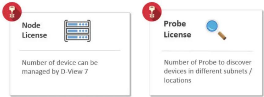
Available License
After installing D-View, the trial version is automatically activated and allows evaluation of the product with a full feature set with no expiration date. The trial version includes support for 25 nodes and 2 probes. Additional licenses can be purchased and added at any time. Added licenses are accumulated, and there is no expiration date on additional license. Licenses are sold in electronic packs for adding additional nodes, or additional probes. The two types of licenses are different and need to be purchased separately.
A node is any SNMP devices discovered in D-View 7. The node license determines how many devices the D-View 7 can manage.
A probe is the remote agent which communicates between the D-View 7 server and devices. The probe license determines how many probes a D-View 7 server can use to communicate with devices from different subnets.
An example for a need to purchase additional licenses would be;
1) A single location has 290 nodes that need to be monitored. In this example an additional 250 node license pack, and a 25 node license pack could be combined with the default free 25 node licenses to allow up to 300 nodes.
2) Four separate locations each have 5 nodes. In this example an additional 5 probe license pack could be combined with the default free 2 probe license to allow up to 7 probes, that could discover a total of 25 nodes (the default 25 node licenses included with D-View 7).
To find out more about how to activate additional licenses on the D-View 7 server, please see Activation on page 51.
To find out more about how to manage additional licenses on the D-View 7 server, please see License on page 112.
System Requirements
Server
• CPU Dual core, 3.0 GHz or above
• RAM 8 GB or above
- Hard disk 120 GB or above (depends on the number of devices managed)
'C' drive for core server
'D' drive for MongoDB database
- OS Windows 7 64-bit (English version, Professional Edition or above)
Windows 8 64-bit (English version, Professional Edition or above)
Windows 8.1 64-bit (English version, Professional Edition or above)
Windows 10 64-bit (English version, Professional Edition or above)
Windows Server 2008 R2 64-bit (English version, Standard Edition or above)
Windows Server 2012 64-bit (English version, Standard Edition or above)
Windows Server 2016 64-bit (English version, Standard or Datacenter Edition or above)
Probe
• CPU Single core, 2.0 GHz or above
• RAM 2 GB or above
• OS Windows XP 32 or 64-bit
Windows 7, 32 or 64-bit (English version)
Windows 8, 32 or 64-bit (English version)
Windows 8.1, 32 or 64-bit (English version)
Windows 10, 32 or 64-bit (English version)
Windows Server 2008 32 or 64-bit (English version, Standard Edition or above)
Windows Server 2008 R2 64-bit (English version, Standard Edition or above)
Windows Server 2012 64-bit (English version, Standard Edition or above)
Windows Server 2016 64-bit (English version, Standard or Datacenter Edition or above)
Client
• CPU Single Core 2.0 GHz or above
• RAM 2 GB or above
- Browser Chrome, Firefox, and IE 10 or above
Understanding Basic D-View Concepts
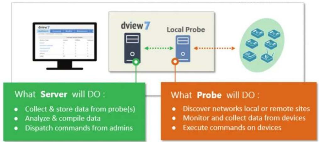
D-View 7 has been redesigned to utilize a more streamlined server and probe architecture. Each component has a fundamental role, and they work together to give network administrators a greater level of control and management ability over the network.
The D-View 7 server is responsible for collecting and storing data that it receives from various probes. It analyzes and compiles the data received and presents it in easy to understand graphs or data views. The server also acts a centralized command center, allowing network administrators to target specific devices or network segments and perform maintenance and administration without any complicated setup.
A probe is used to collect data from SNMP devices, issue command to devices, and communicate with core server. After installing D-View 7, it will have an embedded local probe but an administrator can install additional probes if needed. Probes allows administrators to effectively monitor parts of networks that would otherwise be unaccessible due to firewalls, NAT, or a complicated network environment what make devices hard to access through SNMP.
flowchart
graph TD
    A["dview7 Server"] --> B["Local Probe"]
    B --> C["Probe will DO"]
    D["What Server will DO :"] --> E["Collect & store data from probe(s)"]
    D --> F["Analyze & compile data"]
    D --> G["Dispatch commands from admins"]
    H["What Probe will DO :"] --> I["Discover networks local or remote sites"]
    H --> J["Monitor and collect data from devices"]
    H --> K["Execute commands on devices"]
D-View 7 Server
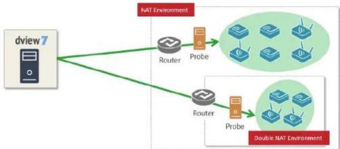
Utilizing the server-probe architecture enables D-View 7 to get a view of the overall network topology versus traditional network management systems. Deploying probes in network segments that would otherwise be inaccessible from the outside allows network administrators to gain full control of networked resources without having to reconfigure the network in a way that could potentially be not secure.
flowchart
graph TD
    A["dview 7"] --> B["Router"]
    A --> C["Probe"]
    B --> D["Double NAT Environment"]
    C --> D
    style A fill:#f9f,stroke:#333
    style D fill:#bbf,stroke:#333
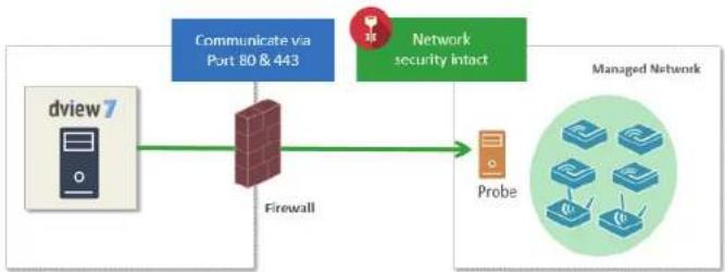
The server-probe architecture also facilitates a more secure networking environment by eliminating the need to have unnecessary ports open for each segment of the network that needs to be monitored. By deploying a probe within the desired network segment, certain ports such as SNMP, traps, or others that could potentially be exploited are no longer required to be exposed. D-View 7 leverages HTTP and HTTPS to communicate securely, using standardized communication protocols that leave network security policies intact.
flowchart
graph LR
    A["dview 7"] --> B["Firewall"]
    B --> C["Managed Network"]
    D["Communicate via Port 80 & 443"] --> B
    E["Network security intact"] --> C
    F["Probe"] --> C
When probes try to connect to the core server, they will try to use HTTPS first. Depending on how IIS has been set up, if HTTPS is enabled, then communication between the core server and probes will be in HTTPS. If IIS has not been set up, then a HTTP connection will be used instead.
Probe
D-View 7 probes are the primary component in connecting networking devices with the D-View 7 server. Probes run as a background process, performing network discovery for new devices, polling existing devices for statistics data, and acting as a staging point for forwarding data to the D-View server for networks behind a firewall or in a NAT environment.
Probes for D-View 7 are not limited to D-Link products, and will communicate with any network device that supports industry standard reporting protocols based on SNMP.
Deploying individual probes for a particular network segment helps to alleviate bandwidth constraints, as that data is collected by the probe before being forwarded to the D-View 7 server to be compiled and analyzed. This reduces network overhead by reducing the number of open connections, and the need to have all of the devices communicating directly with the server. Separating network devices into groups also becomes easier as identification based on a number of criteria can more easily be applied for a given network topology.
Probes are also responsible for executing commands received from the D-View 7 administrator on devices that are directly connected to the probe. Examples of this would be performing a reboot, managing event logs, or making changes to a configuration on a device.
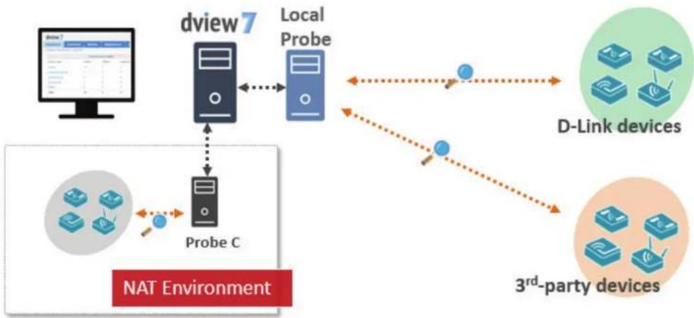
flowchart
graph TD
    A["Computer"] --> B["dview7"]
    B --> C["Local Probe"]
    C --> D["D-Link devices"]
    C --> E["3rd-party devices"]
    F["Probe C"] --> B
    G["NAT Environment"] --> F
    H["Mobile Devices"] --> F
    I["Mobile Devices"] --> E
    J["Mobile Devices"] --> E
Sensor
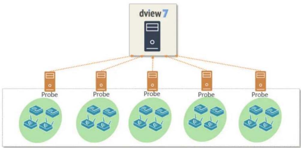
D-View 7 comes preconfigured with a number of sensors that can be used to gather network statistics. Sensors can also be customized down to the device level in order to give network administrators up-to-date information based on any number of criteria. Administrators can log into the D-View 7 server and use the sensor setup wizard to specify a metric such as CPU utilization, and then assign the sensor to any number of devices, groups, or whole network segments. Sensors will then be deployed to the device dashboard, and will gather the necessary information in real-time, updating at specified intervals, and storing the analyzed data for historical reporting.
Sensors can also be assigned to separate workspaces within D-View 7, allowing administrators to create different network environments based on access controls built into D-View 7. This will help to create different workspaces for different teams based on the same number of devices and network topology, but enable different teams to focus on what matters.
flowchart
graph TD
    A["dview7"] --> B["Probe"]
    A --> C["Probe"]
    A --> D["Probe"]
    A --> E["Probe"]
    A --> F["Probe"]
    B --> G["Rates"]
    C --> H["Rates"]
    D --> I["Rates"]
    E --> J["Rates"]
    F --> K["Rates"]
Databases
The D-View 7 backend is built on MongoDB, a document-oriented NoSQL database. MongoDB is made available under the GNU AGPL v3.0 license and the driver is based on Apache License v2.0. The aim of MongoDB is to provide a database that delivers high performance, high availability, and automatic scaling.
Some of the key features of MongoDB are;
- Support for embedded data models reduces I/O activity on database system.
- Indexes support faster queries and can include keys from embedded documents and arrays.
- Provide automatic failover.
- Provide data redundancy.
• Automatic sharding distributes data across a cluster of machines. - Replica sets can provide eventually-consistent reads for low-latency high throughput deployments.
To find out more information about MongoDB, please visit the main MongoDB website at http://www.mongodb.org
http://docs.mongodb.org/manual/administration/production-notes/

Note: For production environments, please ensure that D-View 7 and MongoDB are installed onto a 64-bit operating system.

mongoDB
High Availability
D-View 7 includes a High Availability (HA) deployment type, and this can be used to reduce the load on one server, while increasing the reliability of the system by being able to survive failures. Both D-View 7 and MongoDB can be installed in a HA deployment type, providing fault tolerance and allowing individual nodes to be taken offline without impacting the network.
D-View 7 can be installed in two HA deployment types:
- Single MongoDB instance with multiple D-View 7 instances
- Multiple MongoDB instances with multiple D-View 7 instances
The HA system works by using the in-built Windows Server Network Load Balancing (NLB) tool, and clients connect to the D-View 7 cluster using a cluster IP, which both hosts in the cluster respond to. The D-View 7 Core Server, D-View 7 License Agent server, D-View 7 Probe server, D-View 7 Probe File Server services are activated on the master server, and the slave servers only run the D-View 7 Core Server service. Both D-View 7 servers are pointed at a MongoDB instance, which can be installed on a single server or in a HA deployment type.
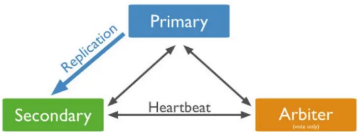
MongoDB can be deployed either as a single server or in a cluster. If deployed in the cluster mode, there is one primary server and multiple secondary servers, with an optional arbiter server. The primary server can read and write to the database, whereas the secondary servers can only read the database. In the event of a failure, the secondary server becomes the primary server, and if there are an even number of secondary servers, an arbiter server can be used to manage the election process.
flowchart
graph TD
    A["Primary"] -->|Replication| B(Secondary)
    B -->|Heartbeat| C(Arbiter)
    C -->|Feedback| A
    C -->|Feedback| B
If a HA deployment type is required for MongoDB, D-Link recommend that a primary and secondary MongoDB server are installed, along with an arbiter server. This does not require dedicated hardware, and can be installed on any host that is in the same subnet and is directly reachable using the local network.
D-View 7 Setup and Configuration
To install D-View 7, please make sure that the you meet the following requirements:
- You have the correct number of hosts for your deployment type (single server or multiple servers/HA deployment)
- The hosts meet the server requirements in the System Requirements section
- The hosts are connected to a network with Internet access
Additionally, the following components are also needed. If any of the below components are not present at the time of the D-View 7 installation, the installation wizard will install them.
• IIS
• .NET Framework 4.0
- Windows Firewall is enabled
- ASP, ASP.NET, ISAPI Extensions, and ISAPI Filters are installed
- MongoDB
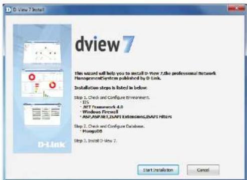
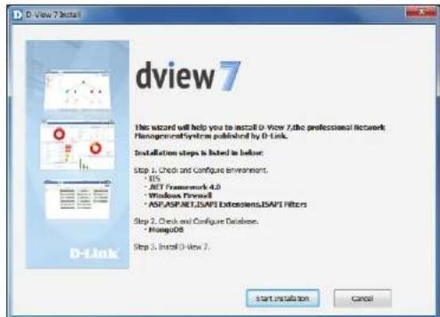
To begin the installation process, download the D-View 7 setup application from the D-View website. After the download has completed, double-click the setup application to begin.
The setup application installs all of the necessary components for trial mode. This has all of the features as a licensed D-View 7 server, but is limited to 25 nodes and 2 probes. To learn more about licensing and the activation, please refer to Activation on page 51.
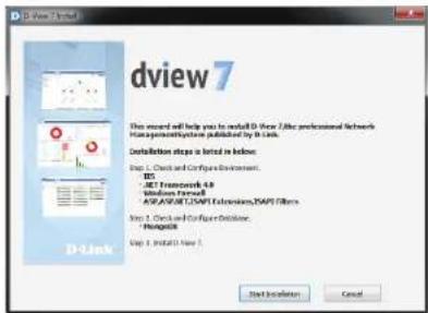
Installation (Single Server)
After double-clicking the setup application file, the installation wizard will start. Select the preferred language to install. Currently D-View 7 supports the following languages:
- English
- Simplified Chinese
• Traditional Chinese
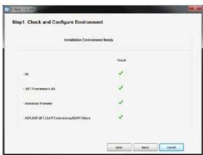
After selecting the preferred installation language, D-View 7 will check to make sure that the necessary components needed to run are installed and properly configured. Click Start Installation to continue.
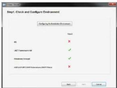
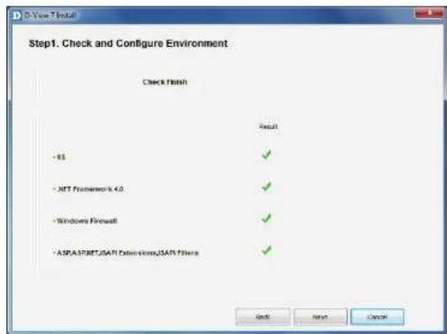
If D-View 7 detects that any components are not present or configured properly, it can attempt to download, install, and configure the missing components. Missing or improperly configured components will have a red X listed next to their name. Click Configuring the Installation Environment to have D-View attempt to fix any issues.
Installation
The D-View 7 setup application will display its current progress for each missing or not properly configured component.
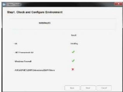
Depending on the speed of the network connection, or if an additional component is already installed but not configured properly, the setup application can take several minutes to complete. If an additional component is already installed, but needs to make changes that might impact other applications, the installation wizard will wait for user confirmation to continue.
Installation
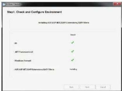
After the D-View 7 setup application has completed configuring the system environment, each additional component should have a green checkmark listed next to its name. Click Next to continue the installation process.
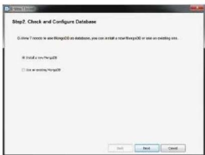
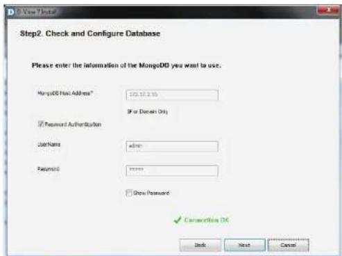
D-View 7 also requires MongoDB and can either download and install MongoDB, or use an existing MongoDB installation. To continue, choose to either Install a new MongoDB or Use an Existing MongoDB and then click Next.
Installation
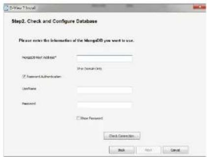
If D-View 7 will be installed using an existing MongoDB instance, enter the hostname or IP address of the database. An admin level account for the existing MongoDB database is also needed as the D-View 7 installation wizard will need to configure settings to operate properly. Enter the Username and Password and click Password Authentication to verify that the credentials are valid. Once the existing MongoDB credentials have been verified, click Next to continue.
Note: When using the MongoDB Tool to upgrade the database from version 2.6.5 to version 3.2.6 or later, leave the Password Authentication box unchecked.
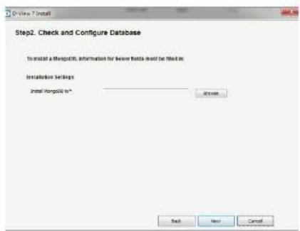
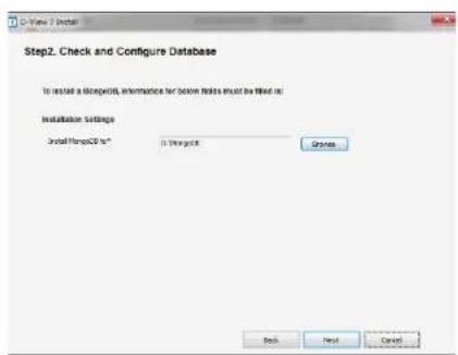
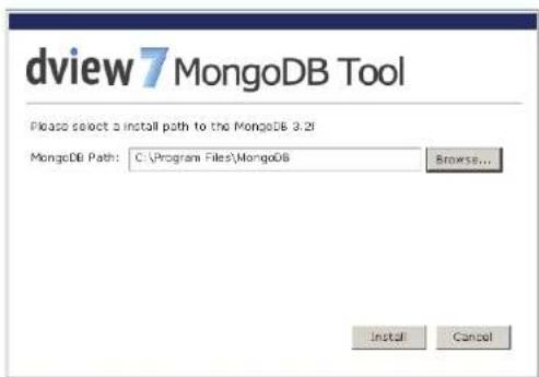
If D-View 7 will be installed with a new MongoDB instance, click Browse to navigate to the folder where the MongoDB application will be installed to.
Once the MongoDB installation path has been chosen, and the D-View 7 administrative credentials have been set, click Next to continue.
Installation
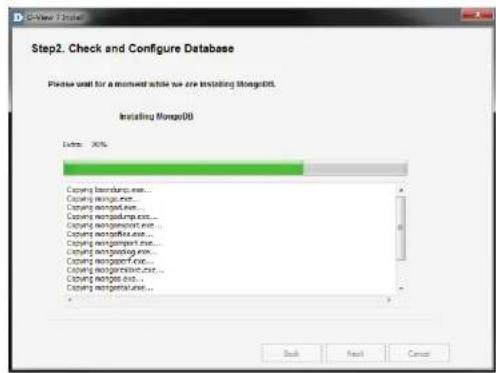
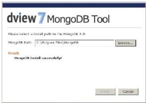
The D-View 7 setup application will continue the installation process by creating the necessary database with the credentials supplied. Depending on the speed of the network connection, or if additional components are needed, the setup application can take several minutes to complete the MongoDB installation process. If D-View 7 needs to make changes that might impact other applications, the installation wizard will wait for user confirmation to continue or not.
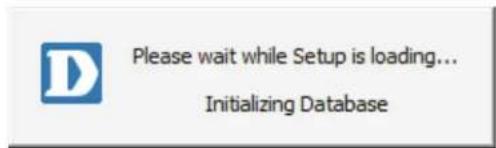
Once the D-View 7 setup application has completed the MongoDB installation, it will load the MongoDB service and initialize the D-View 7 database. Depending on whether D-View is using a new or existing database, the initialization process could take several minutes to complete.
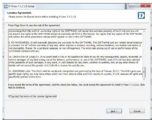
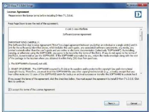
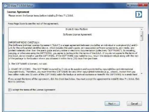
After the database has been successfully setup and started, the D-View 7 setup will continue. Accept the software license by checking off the license agreement button, and click Next when ready.
Installation
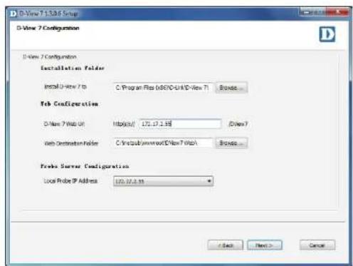
By default, the main D-View 7 application will install itself into the Program Files directory "C:\Program Files\D-Link\D-View 7". If a different installation path is desired, click Browse to navigate to the folder where the D-View 7 application will be installed to. Next, enter the default URL that users will use to access the D-View 7 application. This can be either a hostname such as domainname.com or an IP address such as 192.168.0.100.
The Web Destination Folder is usually "C:\inetpub\wwwroot\DView7 Web\". If a different path for the web site is desired, click Browse to navigate to the folder where the D-View 7 web files will be installed to.
A probe will also be set up for the current subnet that the D-View 7 server is attached to. From the drop down menu, select the correct IP address that the probe will use to determine which subnet to monitor. Click Next when ready.
D-View 7 installs shortcuts in the Windows start menu to provide access to the management panel and for uninstallation. If a different path for the shortcut is desired, enter the name of the folder where the D-View 7 shortcuts will be created. Click Install when ready.
The progress indicator will display how much time is left until the installation process is completed. Depending on the speed of the system, the setup application can take several minutes to complete the installation process.
Installation
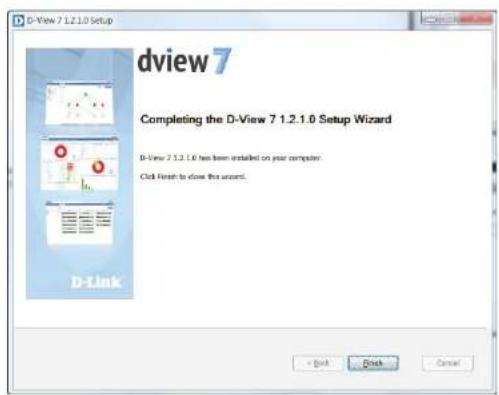
At the end of the installation process, the setup application will display a summary of all of the changes that were made to the system. Click Next to finalize the D-View 7 installation.
The D-View 7 setup is now complete. D-View 7 can now be accessed by typing in "http://
Note: Configure the Dependency between Core Server and MongoDB
When launching D-View service, please make sure the MongoDB service is started first before running the Core Server service. This configuration will create a dependency between Core Server and MongoDB ensuring that D-View can start correctly.
Installation (Multiple D-View 7 Servers, Single MongoDB Server)
Before beginning with the instructions, please make sure that you have at least two hosts on the same subnet and that are able to reach each other using ICMP ping. Also make sure that the Network Load Balancing (NLB) service is installed and active on both. These will become the D-View 7 servers. You will need at least one additional server for the MongoDB database.
Install MongoDB
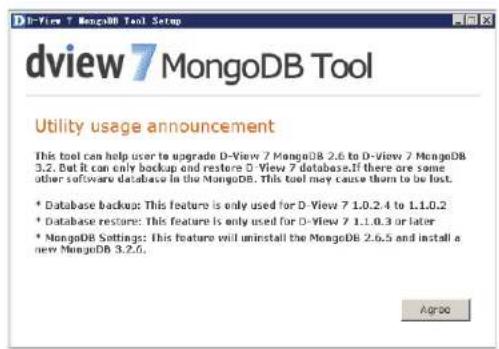
On the MongoDB host, run the MongoDB setup tool. Click Agree when presented with the Utility Usage Announcement, or close the program if you do not agree with the statement.
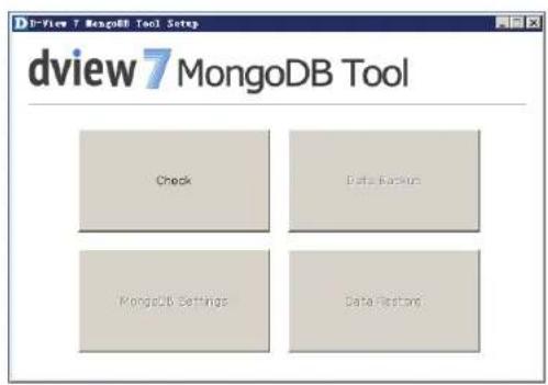
Click the Check button to check whether MongoDB is already installed on the server. If it has been installed, you will be asked if you want to restore a database. If it has not been installed, you will be asked to use the MongoDB Settings button to install MongoDB. Press Cancel to go back to the main screen.
Installation
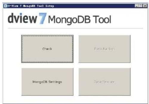
Click the MongoDB Setting button to install MongoDB.
Choose the path that you want to install MongoDB in and press Install to install MongoDB.
Installation
A confirmation message will be displayed when MongoDB has been installed successfully. Press Cancel to return to the main screen and close the tool.
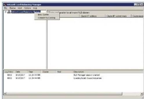
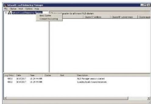
Set up Load Balancing
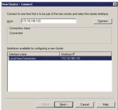
On node 1 in the D-View 7 cluster, open the Network Load Balancing Manager. Right Click "Network Load Balancing Cluster", and then click "New Cluster".
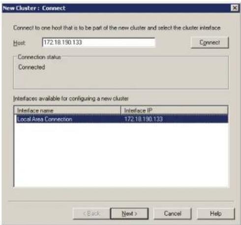
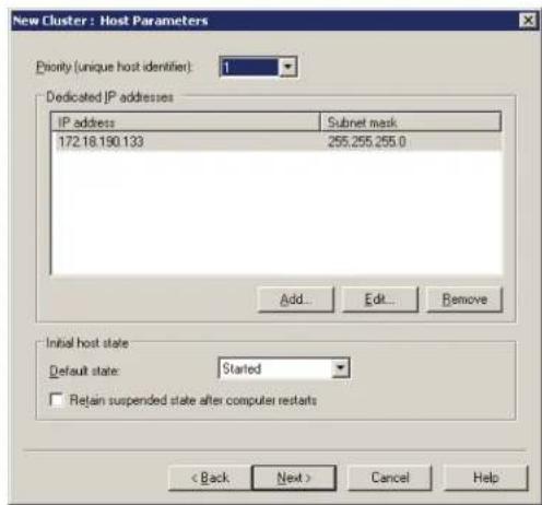
Input the node 1 IP address, and then click Connect. When the Connection status is "Connected", click Next to set the Host Parameters.
Installation
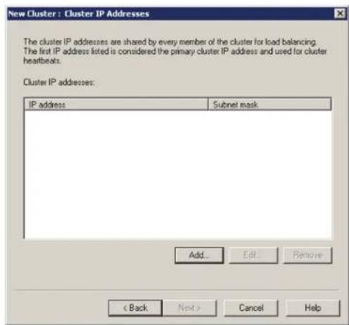
Set the priority of node 1. If the two D-View 7 servers are unequal in terms of performance, give the higher-powered server the lower priority. This will become the master server. Click Next to set the cluster IP addresses.

Click Add to add the virtual cluster IP address that the cluster will respond to. Ensure that this address is in the same subnet as the host addresses, and click next to set the Cluster parameters.

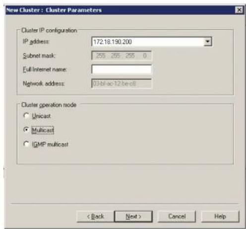
Installation

Set the Fully Qualified Domain Name (FQDN) name for the virtual cluster IP and choose Multicast as the cluster operation mode. Click Next to configure port rules.
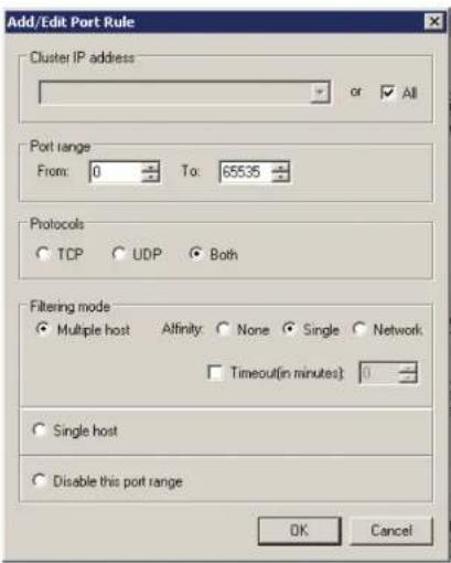
Installation
Click Add to add any port rules, and click Next to finish the node 1 cluster configuration.
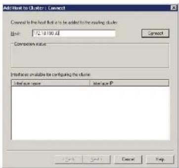
On the Network Load Balancing Manager screen, wait for the host state to change to Converged, and then right-click the cluster name and click "Add Host To Cluster".
![Network Load Balance Manager File Edit View Insert Help Network Load Balance Datasets W1973.0000 Log Entry Date Time Cluster Host Description 0008 2017/6/25 15:23:48 172.13.196... w074-4V6E... Update it supported [double disk for details ...] 0009 2017/6/25 15:23:48 172.13.196... w074-4V6E... End configuration change 0008 2017/6/25 15:24:48 172.13.196... w074-5Z9K... Begin configuration change 0008 2017/6/25 15:24:48 172.13.196... w074-5Z9K... Waiting for pending operation it 0009 2017/6/25 15:24:48 172.13.196... w074-5Z9K... Update it supported [double disk for details ...] 001 2017/6/25 15:24:48 172.13.196... w074-5Z9K... End configuration change](/content/2026/05/765026/images/97ef99311c2a88a835bc204ee5c9738cdf21199ec48a1a1e2404171484dd7b9f.jpg)
Installation
Enter the IP address of node 2, and follow the instructions for node 1 to add the node to the cluster.
When complete, open the Network Load Balancing Manager on node 2 and right-click the Network Load Balancing Clusters entry in the pane on the left. Click "Connect to Existing" and enter the node 1 IP address. Click Connect and when the Connection status is "Connected", click Finish to finish adding node 2 to the cluster. After this, it should be possible to reach the cluster using the virtual IP addresses assigned earlier in the instructions.
![Network Load Control Manager File Order Host Control Help □ Default Control Settings New Cluster Current To Setting Close configurations to access A/B channels Order name: Order IP address: Order IP device: Log Entity Date Time Delete Host Description 094 2017/02 15:29:3F 172.13.198... wVWESZPC%. Update to successed [double-click for details ...] 094 2017/02 15:29:3F 172.13.198... wVWESZPC%. End configuration change 094 2017/02 15:29:3F 172.13.198... wVWESZPC%. Begin configuration change 094 2017/02 15:29:3F 172.13.198... wVWESZPC%. Working for pending operation ? 094 2017/02 15:40:12 172.13.198... wVWESZPC%. Update to successed [double-click for details ...] 094 2017/02 15:40:12 172.13.198... wVWESZPC%. End configuration change](/content/2026/05/765026/images/bf4a6d80e005a304c9074fb290f303300291f1094bcc7813d31365380e566025.jpg)
Install D-View 7
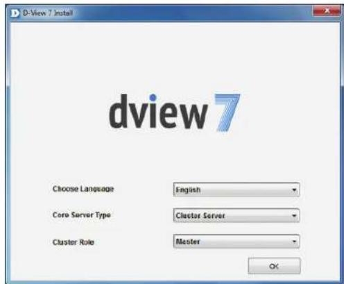
On node 1 in the D-View 7 cluster, run the D-View 7 installation package. Choose Cluster Server as the Core Server Type and choose Master as the Cluster Role. Click OK to continue.
On the next page, ensure that the requirements are met and click Start Installation to check and configure the environment.
Installation
The installer will check the the requirements have been met. If the result of all tests is successful, press Next to configure the database.

Enter the details of the MongoDB database set up earlier. The MongoDB Host Address is the IP address or domain name of the MongoDB host. Un-check the Password Authentication check-box, or if MongoDB was installed as part of a previous D-View 7 installation, enter the username of "admin" and password of "admin". Click Check Connection to test the connection with the MongoDB server, and click Next to display the licence agreement.
Installation
Click I accept the terms of the license Agreement if you accept the terms of the licence agreement, or press Cancel to exit the installer if you do not accept the terms. Press Next to configure the web URL and probe settings.
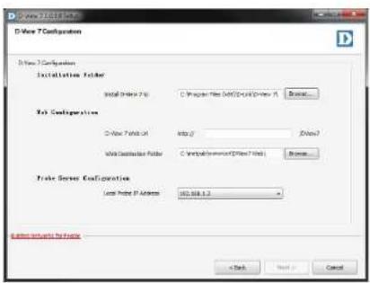
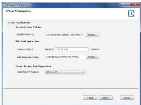
In the Installation Folder section, enter the path to install D-View 7 to, or click Browse... to select a location. In the Web Configuration section, enter the URL that will be used to access D-View 7, and choose the local folder where the web files will be stored. In the Probe Server Configuration section, choose the local probe IP address, and Press Next to choose a Start menu folder.
Installation
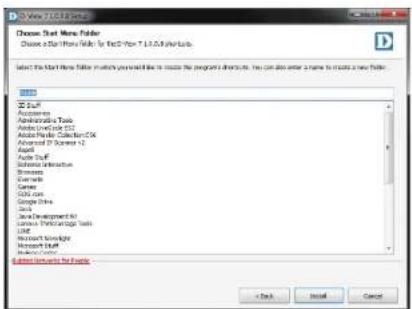
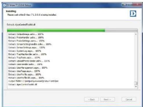
Enter the name of the Start menu folder, and press Install to install D-View 7.
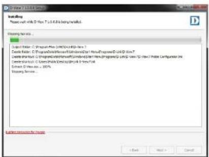
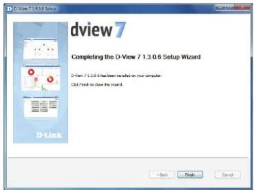
When the installation is complete, press Next to view the confirmation page.
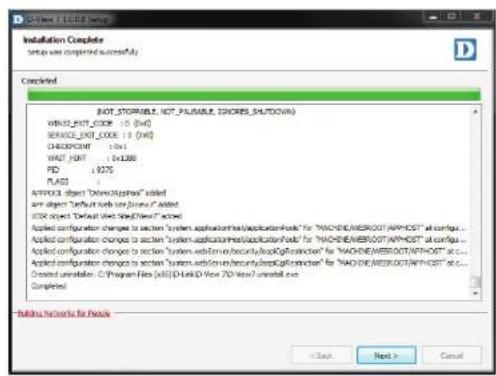
Installation
Press Finish to exit the installer.
On node 2 in the D-View 7 cluster, run the D-View 7 installation package, but choose Cluster Server as the Core Server Type and choose Slave as the Cluster Role. Follow the same instructions as node 1 to complete the installation.
Access the D-View 7 interface by accessing the following URL:
http://
https://
Replace
Upgrading From D-View 6 to 7
It is not possible to migrate the data from an existing D-View 6.0 installation to D-View 7 due to the new database technology introduced with D-View 7. D-View 7 uses a completely different design and architecture that allows network administrators to more easily manage end devices as well as streamline their workflow process.
If D-View 6 is currently installed on a network, a number of steps can be taken to ensure that deploying D-View 7 goes smoothly:
- Install D-View 7 on a new server.
- Collect the subnet information and SNMP communities from D-View 6.
- Configure the discovery network and SNMP communities in the D-View 7 and start to discover the network.

Note: Do not install D-View 6 and D-View 7 on the same server! Doing so will cause database and network conflicts.
Changing from a Single to Multiple D-View 7 Servers
These instructions allow you to migrate from a single D-View 7 server with a single MongoDB server, to multiple D-View 7 servers and a single MongoDB server. D-View 7 is uninstalled from the original D-View 7 server, and MongoDB remains on this server. This becomes the MongoDB host that two new D-View 7 servers connect to for the database.
Before beginning with the instructions, please make sure that in addition to the original D-View 7 server that is being upgraded, you have at least two more hosts on the same subnet. Please make sure that all servers are able to reach each other using ICMP ping and that the Network Load Balancing (NLB) service is installed and active on the two servers which will become the new D-View 7 servers.
Uninstall D-View 7

Note: when performing the uninstallation process, you will be asked if you want to uninstall MongoDB as well. Be sure that you choose No for this step, as this is required for the D-View 7 cluster to function.
Note: before uninstalling the original D-View 7 Core server, make sure to unbind the license first.
To uninstall D-View 7, please see Uninstallation on page 63. When uninstallation is complete, please proceed with the instructions below.

Set up Load Balancing
On node 1 in the D-View 7 cluster, open the Network Load Balancing Manager. Right Click "Network Load Balancing Cluster", and then click "New Cluster".
Input the node 1 IP address, and then click Connect. When the Connection status is "Connected", click Next to set the Host Parameters.
Installation
Set the priority of node 1. If the two D-View 7 servers are unequal in terms of performance, give the higher-powered server the lower priority. This will become the master server. Click Next to set the cluster IP addresses.
Click Add to add the virtual cluster IP address that the cluster will respond to. Ensure that this address is in the same subnet as the host addresses, and click next to set the Cluster parameters.
Installation
Set the Fully Qualified Domain Name (FQDN) name for the virtual cluster IP and choose Multicast as the cluster operation mode. Click Next to configure port rules.

Installation
Click Add to add any port rules, and click Next to finish the node 1 cluster configuration.

On the Network Load Balancing Manager screen, wait for the host state to change to Converged, and then right-click the cluster name and click "Add Host To Cluster".
![Network Load Balance Manager File Edit View Insert Help Network Load Balance Datasets W1973.0000 Log Entry Date Time Cluster Host Description 0008 2017/6/25 15:23:48 172.13.196... w074-4V6E... Update it supported [double disk for details ...] 0009 2017/6/25 15:23:48 172.13.196... w074-4V6E... End configuration change 0008 2017/6/25 15:24:48 172.13.196... w074-5Z9K... Begin configuration change 0008 2017/6/25 15:24:48 172.13.196... w074-5Z9K... Waiting for pending operation it 0009 2017/6/25 15:24:48 172.13.196... w074-5Z9K... Update it supported [double disk for details ...] 001 2017/6/25 15:24:48 172.13.196... w074-5Z9K... End configuration change](/content/2026/05/765026/images/346be2be15208f9066e85651685fa33e941fb4cd11a6194de60f57ceab2e47b6.jpg)
Installation
Enter the IP address of node 2, and follow the instructions for node 1 to add the node to the cluster.

When complete, open the Network Load Balancing Manager on node 2 and right-click the Network Load Balancing Clusters entry in the pane on the left. Click "Connect to Existing" and enter the node 1 IP address. Click Connect and when the Connection status is "Connected", click Finish to finish adding node 2 to the cluster. After this, it should be possible to reach the cluster using the virtual IP addresses assigned earlier in the instructions.
![Network Load Control Manager File Order Host Control Help □ Default Control Settings New Cluster Current To Setting Close configurations to access A/B channels Order name: Order IP address: Order IP device: Log Entity Date Time Delete Host Description 094 2017/02 15:29:3F 172.13.198... wVWESZPC%. Update to successed [double-click for details ...] 094 2017/02 15:29:3F 172.13.198... wVWESZPC%. End configuration change 094 2017/02 15:29:3F 172.13.198... wVWESZPC%. Begin configuration change 094 2017/02 15:29:3F 172.13.198... wVWESZPC%. Working for pending operation ? 094 2017/02 15:40:12 172.13.198... wVWESZPC%. Update to successed [double-click for details ...] 094 2017/02 15:40:12 172.13.198... wVWESZPC%. End configuration change](/content/2026/05/765026/images/d4ef810fe5512e287ba0a8c28e262ca44ec047a15da01f5eb2031d21b721e5a1.jpg)
Install D-View 7
On node 1 in the D-View 7 cluster, run the D-View 7 installation package. Choose Cluster Server as the Core Server Type and choose Master as the Cluster Role. Click OK to continue.

On the next page, ensure that the requirements are met and click Start Installation to check and configure the environment.
Installation
The installer will check the the requirements have been met. If the result of all tests is successful, press Next to configure the database.
Enter the details of the MongoDB database set up earlier. The MongoDB Host Address is the IP address or domain name of the MongoDB host. Un-check the Password Authentication check-box, or if MongoDB was installed as part of a previous D-View 7 installation, enter the username of "admin" and password of "admin". Click Check Connection to test the connection with the MongoDB server, and click Next to display the licence agreement.

Installation
Click I accept the terms of the license Agreement if you accept the terms of the licence agreement, or press Cancel to exit the installer if you do not accept the terms. Press Next to configure the web URL and probe settings.
In the Installation Folder section, enter the path to install D-View 7 to, or click Browse... to select a location. In the Web Configuration section, enter the URL that will be used to access D-View 7, and choose the local folder where the web files will be stored. In the Probe Server Configuration section, choose the local probe IP address, and Press Next to choose a Start menu folder.
Installation
Enter the name of the Start menu folder, and press Install to install D-View 7.

When the installation is complete, press Next to view the confirmation page.
Press Finish to exit the installer.
On node 2 in the D-View 7 cluster, run the D-View 7 installation package, but choose Cluster Server as the Core Server Type and choose Slave as the Cluster Role. Follow the same instructions as node 1 to complete the installation.
Access the D-View 7 interface by accessing the following URL:
http://
https://
Replace
Removing the Original D-View 7 Server IP From the Database
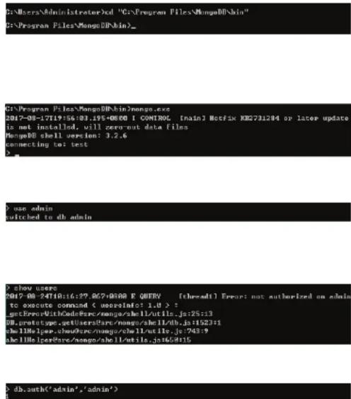
Open a command prompt on the MongoDB server by browsing to the Command Prompt entry in the Start menu.
Change to the MongoDB installation directory. In these instructions, this is "C:\Program Files\MongoDB\bin":
cd C:\Program Files\MongoDB\bin
Connect to the MongoDB database by running "mongo.exe". If you have any problems connecting, please make sure that the MongoDB service is started:
mongo.exe
Once you have logged in, switch to the admin database:
use admin
Enter "show users" to check the current database's users and check whether MongoDB is using authentication mode.
show users
If you get an "Error: not authorized message", enter the following to log-in as the admin user:
db.auth('admin','admin')
A result of "1" indicates that the command was successful.
Installation
Enter "use DView7" to switch to the DView7 database.
use DView7
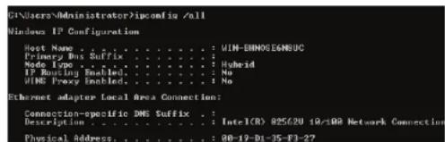
In another command window, run "ipconfig /all" to get the MongoDB server's IP and MAC address:
ipconfig /all
Use the physical address in the output to remove the reference in the MongoDB database:
db.Cor_ClusterInfo.remove({CoreMAC:'AA:BB:CC:DD:EE:FF'})


Activation
Activation of additional licenses can be completed either online or offline. The activation wizard can be started at any time by clicking on the Upgrade button located at the top of the D-View toolbar. Licenses can also be added from the License management page. To learn more about license management, please see License on page 112.
Clicking the Upgrade button will open the License activation wizard and will allow D-View to either be activated over the Internet, or activated using a license file that has been transferred from another system.
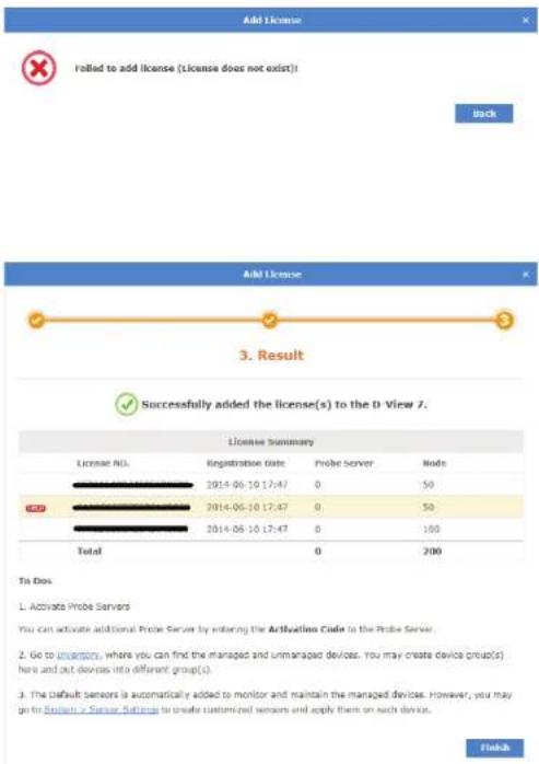
If activating over the Internet, enter the license key that was given with the purchased additional node or probe license pack. Multiple licenses can be activated at the same time by clicking on the "+" sign next to the license key field. The system will automatically recognize what type of license is being added and will verify it with D-Link's licensing servers. Once the license has been verified, the license key will be added to the license management page. To learn more about license management, please see License on page 112.
If offline activation is required, click Browse to navigate to the folder where the D-View 7 activation file is located. Click Next to continue.
Upgrade
Add License


Installation
If the license key entered or activation file used can not be verified with D-Link's activation servers, please check to ensure that the license key does not contain any invalid characters and that the MAC address of the system being used matches the MAC address that was used to register D-View.
Once the license key or activation file has been verified, the D-View 7 server will automatically adjust the number of available nodes or probes, depending on the license type. Licenses can be managed by clicking on System > License from the D-View 7 tool bar. For more information about licenses, please see License on page 112.
Launching the D-View 7 Dashboard
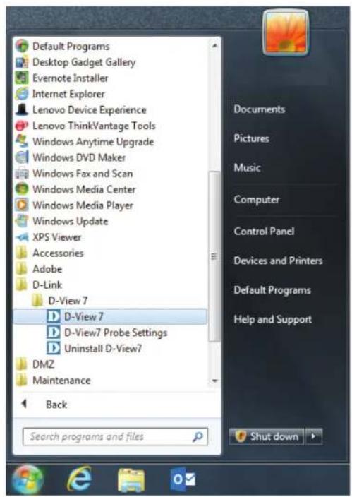
To start the D-View 7 dashboard click on Start > All Programs > D-Link > D-View 7 > D-View 7.
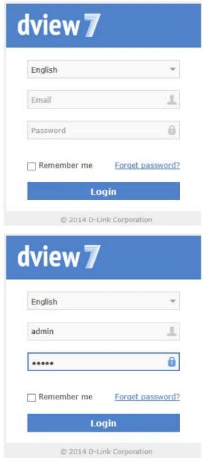
The default web browser will launch and present the login screen.
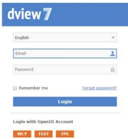
Logging into the D-View 7 Dashboard
To log into D-View 7 enter an email/username and password and then click Login.
The default login credentials for the administrator account are email: "admin" and password: "admin".
This password can be changed later from the User Profile > Security panel.
Logging into the D-View 7 Dashboard Using OpenID
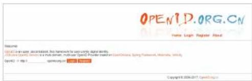
Alternatively, D-View 7 can also be accessed using an OpenID. Refer to the instructions below on how to set up an OpenID account and configure D-View 7 to allow logging in using OpenID.
In order to use the OpenID service, an OpenID provider is necessary. In this example, we use OpenID.org.cn as the provider. The process should be the same for all OpenID providers.
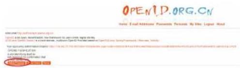
Applying for an OpenID Account
Visit the website of the OpenID provider of your preference and apply for an OpenID account. Throughout this example, we will be using http://openid.org.cn.
Complete the required fields with the necessary information and click Register to complete the registration process. Please not that the user name cannot contain numbers.
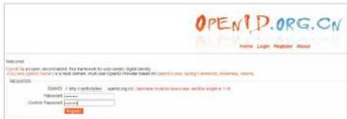
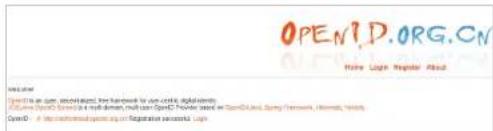
If everything was entered correctly, a message will appear confirming the registration was successful.
Configuring D-View 7 to Work With OpenID
Note: We recommend configuring the SMTP Server settings first before continuing. Refer to the System -> About page for more information on how to configure SMTP settings.
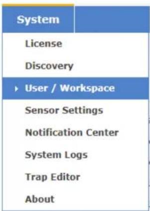
In the D-View 7 interface, navigate to the System > User / Workspace page and click OpenID Provider to configure the OpenID user information.
In the OpenID Provider window, complete the required fields and click OK. Refer to the descriptions below for more information on each field.
-Provider name: The name of the provider that is providing the OpenID service. In this example, the provider name is OpenID.org.cn.
-URL: The OpenID URL that was registered with the OpenID provider. In this example, this is the URL registered with openid.org.cn.
-Abbreviation: This is the abbreviated name for the OpenID account.
All Users Total Users 29 ( 2 27 0 0 )
New User OpenID Provider
Next, click New User. In this Create New User window, choose OpenID as the Account Source and enter a valid email address and name. An email will be sent to this address containing a hyperlink to active your OpenID account.
The email address and name fields are required.
When you receive the activation letter in your inbox, open it and click the hyperlink to active your OpenID account. (Please be aware that SMTP server for the D-View server should be configured first. For more information on configuring SMTP server, see System > About on page 120.)
Note that you must activate your account within 7 days of receiving the letters.
Clicking the link in the invitation letter will bring you the account activation window. Click the abbreviation of your OpenID account, in this example TPE. This will refer you to the OpenID account activation page.
Dashboard
On the OpenID login page, enter your registered OpenID login and password click Login. After successfully logging in, click Allow Forever. You will receive a confirmation window that your OpenID was successfully activated.
Click Go to Login to return to the D-View 7 login page.

Your account has been activated successfully
Go to Login
D-View 7 is now configured to allow logging in using your OpenID account.
Dashboard
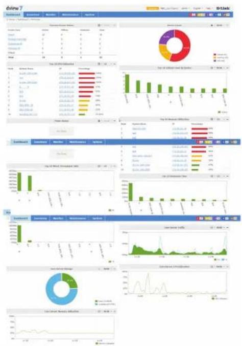
D-View's dashboard interface provides easy access to all views and tools from a single location. The dashboard is made up of a number of different widgets that can be created and rearranged based on the current users preferences.
By default, D-View will open the Overview dashboard. This dashboard contains a basic set of metrics that would be helpful to a network administrator. The widgets contained within the Overview dashboard can be rearranged by clicking and dragging a widget title bar.
D-View also has a Wireless dashboard, which contains widgets that are specific to the wireless capable devices that are present on the D-View managed network.
For more details on how to use and manage the Overview and Wireless dashboard, please see Dashboard Interface on page 60.
Dashboard Interface
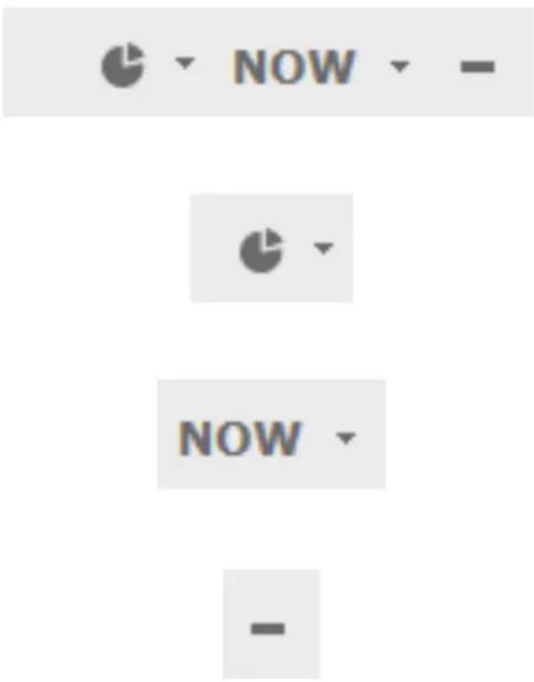
Each widget in the Overview and Wireless dashboard has three available options to help customize the displayed data by either changing the widget style, changing the time period for the data being displayed, or to completely minimize the widget from view.
To change the widget display type, click on the drop down option. This will allow the widget to switch between a visual graph mode, or a grid/table view that displays data only.
To change the time period for the data that is currently displayed, click on the drop down menu and select the time period desired. If the time period option is greyed out, the widget is only able to display the most current available data.
To hide the widget from view, click on the "-" sign. To expand the widget and show its data again, click on the "+" sign. At any point the widgets may be rearranged by clicking and dragging the title bar into the desired order.
Customized Dashboard
D-View allows for the creation of customized dashboards that contain a variety of different metrics. Dashboards are unique to the current workspace, so if more than one user shares a workspace, the newly created dashboard will be shared among the users. If it is necessary to separate dashboards between different users, the users must be in different workspaces. To find out more about setting up workspaces, please see User Management on page 115.
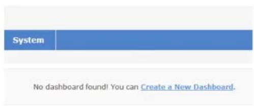
To begin creating a customized dashboard, hover over the Dashboard menu item, and click on Customized
If D-View has just been installed, or if this is a new workspace, the customized dashboard list will be empty. Click on the Create a New Dashboard link to start creating a new dashboard.
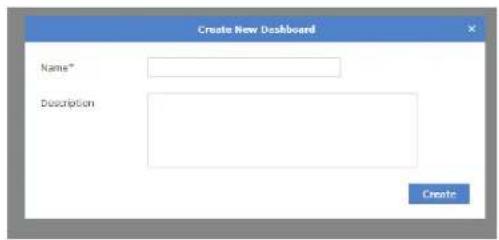
When the Create New Dashboard dialogue box opens, enter a unique name for the dashboard. An optional description for the dashboard may also be entered to help identify it. Click Create to save the dashboard to the current workspace.
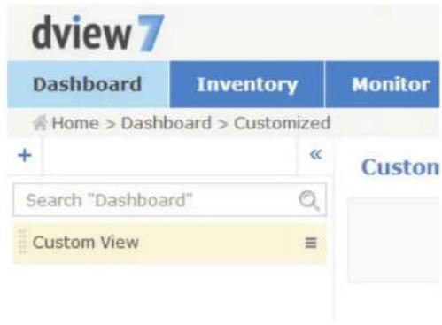
The newly created dashboard will appear in a column list on the left side of the browser. To add another customized dashboard, click on the "+" sign at the top of the dashboard list. To hide the dashboard list from view, click the "<<" sign at the top of the dashboard list. Dashboards may also be filtered by entering a part or the whole name of the dashboard into the search box.
The dashboard list can be reordered by clicking the left part of the dashboard name, and dragging the selected item either up or down in the list.
To rename or delete a dashboard, click on the drop down menu item located on the right part of the dashboard name.
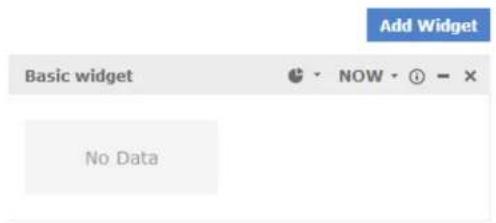
Customized Dashboard Widgets
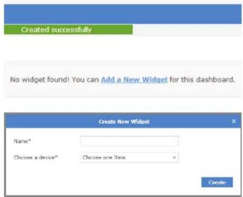
If this is a new dashboard, click on the Add a New Widget link to begin adding a new widget. If the dashboard has no widget, click the Add a New Widget link to create a new widget. If there is an existing widget, click on the Add Widget button located in the upper right of the Customized View to access the widget.
When the Create New Widget dialogue box opens, enter a unique name for the widget, and select the device that will provide the sensor data for the widget. The available types of sensors will change depending on the type of device that is selected. Some sensor options have additional options that must be specified before the widget can successfully be created. By default, the interval for the time period is set to 1 minute. Click Create to save the widget to the dashboard.
Once the widget has been saved, it will appear in the Custom View area. To rename a widget, click on the name in the widgets title bar.
To change the widget display type, click on the drop down option. This will allow the widget to switch between a visual graph mode, or a grid/table view that displays data only.
To change the time period for the data that is currently displayed, click on the drop down menu and select the time period desired. If the time period option is greyed out, the widget is only able to display the most current available data.
To display information about the device that the widget is associated with, hover over the information icon.
To hide the widget from view, click on the "-" sign. To expand the widget and show its data again, click on the "+" sign. At any point the widgets may be rearranged by clicking and dragging the title bar into the desired order.
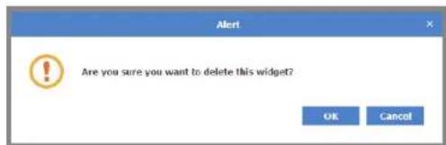
To delete the widget, click on the X icon. A confirmation dialogue box will open to confirm the widget deletion.
Uninstallation
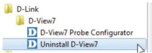
To uninstall the D-View 7 server, start the Uninstall D-View7 application by clicking on Start > D-Link > D-View7 > Uninstall D-View7 from the Windows Start menu.
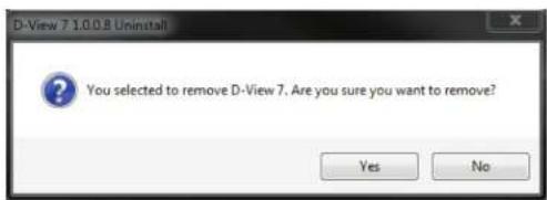
A pop-up prompt will confirm that D-View 7 will be removed from the system. Click Yes to continue or No to cancel.
The progress indicator will display how much time is left until the uninstallation process for the D-View 7 service is complete. Depending on the speed of the system, the uninstallation can take several minutes to complete the process. Click Next to continue.
Dashboard
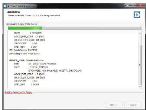
The D-View 7 probe service will also be uninstalled. The progress indicator will display how much time is left until the uninstallation process for the probe service is complete. Depending on the speed of the system, the uninstallation can take several minutes to complete the process.
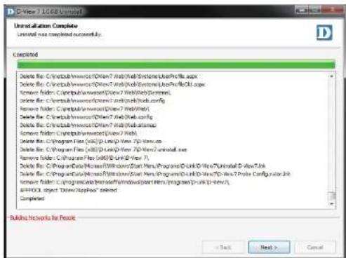
When the uninstallation is complete, click Next to continue.
![Uninstallation Complete Un installed was completed currently. Confirmed Delete file: C:\web\win\wcr\Other7\web\System\Users\ft6.xa Delete file: C:\web\win\wcr\Other7\web\System\Users\ft6.xa Remove folder: C:\web\win\wcr\Other7\web\System\s Delete file: C:\web\win\wcr\Other7\web\system Remove folder: C:\web\win\wcr\Other7\web\system Delete file: C:\web\win\wcr\Other7\web\system Delete file: C:\web\win\wcr\Other7\web\system Remove folder: C:\web\win\wcr\Other7\web/1.exe Delete file: C:\Program Files (200) [p1.p2.p3.1.1] Delete file: C:\Program Files (200) [p1.p2.p3.1.1.1.1.1.1.1.1.1.1.1.1.1.1.1.1.1.1.1.1.1.1.1.1.1.1.1.1.1.1.1.1.1.1.1.1.1.1.1.1.1.1.1.1.1.1.1.1.1.1. 200 Delete file: C:\Program Files (200) [p1.p2.p3.1.1] Delete file: C:\Program Files (200) [p1.p2.p3.1.1] Delete file: C:\Program Files (200) [p1.p2.p3.1.1] Delete file: C:\Program Files (200) [p1.p2.p3.1.1] Delete file: C:\Program Files (200) [p1.p2.p3.1.1] Delete file: D:\Program Files (200) [p1.p2.p3.1.1] Delete file: D:\Program Files (200) [p1.p2.p3.1.1] Delete file: D:\Program Files (200) [p1.p2.p3.1.1] Delete file: D:\Program Files (200) [p1.p2.p3.1.1] Delete file: D:\Program Files D:\Program Files (200) [p1.p2.p3.1] Delete file: D:\Program Files (200) [p1.p2.p3.1] Delete file: D:\Program Files (200) [p1.p2.p3.1] Delete file: D:\Program Files (200) [p1.p2.p3.1] Delete file: D:\Program Files (200) [p1.p2.p3.1] Delete file: D:\Program Files (200) [p1.P2.P3.] added Completed Building Networks for Focus < Back Next > Cancel](/content/2026/05/765026/images/964114efbedf1facfee2db1d31fff5d002b0351c965e08f3a6414ab0fecc3455.jpg)
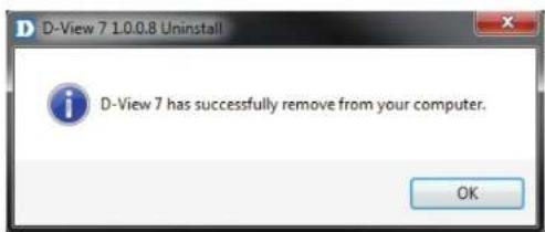
The D-View 7 application has been successfully removed. Click OK to complete the uninstallation process.
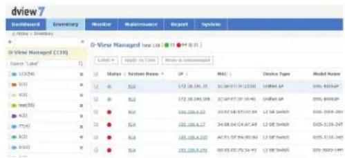
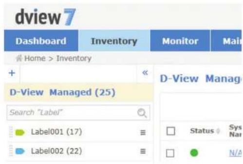
Inventory
The Inventory list shows hardware devices that are on the network and their relevant information such as IP address, Serial Numbers, and Firmware. The inventory list is separated into two major sections, managed and unmanaged. By default, the Inventory list will open the D-View Managed devices panel view. The managed device list can be further organized by applying labels to groups of devices. When a new device is added to the network, D-View will automatically add it to the unmanaged device list if it is discoverable. Devices that are in the managed list will be moved to the unmanaged list if they have been deleted from a specifically labelled group.
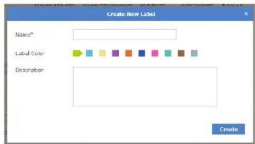
To create a new label click on the "+" sign in the upper left corner of the device list column. A popup window will open; enter a unique label name, assign a color to the label, and add a description to describe the label. Click Create to save the label to the device list. Labels are unique to the workspace that the user is currently in, and users in the same workspace will share labels.
The newly created inventory label will appear in a column list on the left side of the browser. To add another inventory label, click on the "+" sign at the top of the inventory label list. To hide the inventory label list from view, click the "<<" sign at the top of the inventory label list. Inventory labels may also be filtered by entering a part or the whole name of the inventory label into the search box.
The inventory label list can be reordered by clicking the left part of the label name, and dragging the selected item either up or down in the list.
To rename or delete an inventory label, click on the drop down menu item located on the right part of the inventory label name.
To add a device to a newly created inventory label, click on the D-View Managed link at the top of the inventory label list. In the D-View Managed panel, use the checkbox to select which devices to apply a label to and then click the Label drop down menu item to select the appropriate labels. Click Apply to save the selected label to the chosen devices.
Unmanaged
By default, newly discovered devices will appear in the Unmanaged device panel view.
To move devices from unmanaged to the managed device panel view, use the checkbox to select which devices to move, then click Move to Managed. To completely remove a device from D-View management, click on the Delete Device button.

Note: This will permanently remove the device and cannot be undone.
To export a list of all of the devices currently in the Unmanaged device panel view, click on Export to download a CSV file that can be imported into a spreadsheet application.
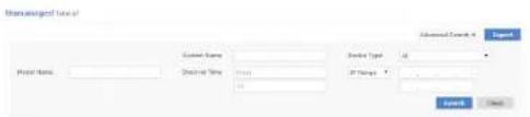
Devices may also be filtered by entering a keyword into the search box. Available search options will automatically appear under the search box. Select a field to filter the results by, or use the advanced search to filter devices using multiple criteria.
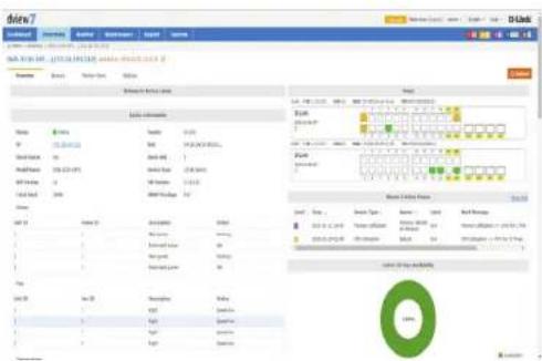
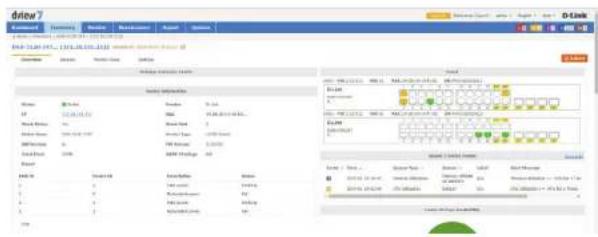
Select the system name to view detailed information about the device. The device information page shows hardware information, device availability, SNMP information, system information, port usage, recent events and system statistics, such as device uptime and CPU utilization. The device can also be rebooted using the Reboot button.
| Name of Mercreatic | Units Sold | Units / Units† | Pages | ||||||
| 1 | Balance Sheet* | PT | Mkt | Vendor Type | Model Rank† | F8 Number | Mkt Sales | Total Bookers | Household Size |
| 2 | Mkt | 173.10.19E-121 | Mkt | Unrated | Mkt | Mkt | Mkt | Mkt | 20.4-6.0 10-25 |
| 3 | Mkt | 173.10.19E-124 | Mkt | Unrated | Mkt | Mkt | Mkt | Mkt | 20.4-6.0 10-25 |
| 4 | Mkt | 173.10.19E-111 | Mkt | Unrated | Mkt | Mkt | Mkt | Mkt | 20.4-6.0 10-25 |
| 5 | Mkt | 173.10.19E-128 | Mkt | Unrated | Mkt | Mkt | Mkt | Mkt | 20.4-6.0 10-25 |
| 6 | Mkt | 173.10.19E-128 | Mkt | Unrated | Mkt | Mkt | Mkt | Mkt | 20.4-6.0 10-25 |
| 7 | Mkt | 173.10.19E-128 | Mkt | Unrated | Mkt | Mkt | Mkt | Mkt | 20.4-6.0 10-25 |
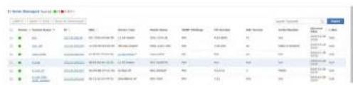
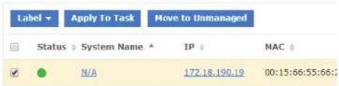
Managed
Devices that are in the Managed device panel view can be directly managed by selecting either the System Name, or IP Address of the device. The number of devices that are currently in the Managed devices list, as well as the number of online, and offline devices is displayed in both the Inventory List column, as well in the device panel view.
To move devices between managed and unmanaged, use the checkbox to select which devices to move, then click Move to Unmanaged. To add a device to an inventory label, use the checkbox to select which devices to apply a label to and then click the Label drop down menu item to select the appropriate labels. Clicking Apply to Task will add the selected devices to current existing task(s).
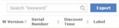
To export a list of all of the devices currently in the Managed device panel view, click on Export to download a CSV file that can be imported into a spreadsheet application.
Devices may also be filtered by entering a keyword into the search box. Available search options will automatically appear under the search box - select the field to filter the results by. The advance search will allow for multiple filtering criteria.
To reorder the current device panel view, click on the column title to sort by either ascending or descending.
To manage a device or view detailed information about the device, click on its corresponding System Name, or IP Address link.
The device information page shows hardware information, device availability, SNMP information, system information, port usage, recent events and system statistics, such as device uptime and CPU utilization. The device can also be rebooted using the Reboot button.
bar
| Category | Item 1 | Item 2 | Item 3 | Item 4 | Item 5 | Item 6 | Item 7 | Item 8 | Item 9 | Item 10 | Item 11 | Item 12 | |---|---|---|---|---|---|---|---|---|---|---|---|---| | A | 100 | 100 | 100 | 100 | 100 | 100 | 100 | 100 | 100 | 100 | 100 | 100 | | B | 50 | 50 | 50 | 50 | 50 | 50 | 50 | 50 | 50 | 50 | 50 | 50 | | C | 25 | 25 | 25 | 25 | 25 | 25 | 25 | 25 | 25 | 25 | 25 | 25 | | D | 100 | 100 | 100 | 100 | 100 | 100 | 100 | 100 | 100 | 100 | 100 | 100 | | E | 50 | 50 | 50 | 50 | 50 | 50 | 50 | 50 | 50 | 50 | 50 | 50 | | F | 25 | 25 | 25 | 25 | 25 | 25 | 25 | 25 | 25 | 25 | 25 | 25 | | G | 100 | 100 | 100 | 100 | 100 | 100 | 100 | 100 | 100 | 100 | 100 | 100 | | H | 50 | 50 | 50 | 50 | 50 | 50 | 50 | 50 | 50 | 50 | 50 | 50 | | I | 25 | 25 | 25 | 25 | 25 | 25 | 25 | 25 | 25 | 25 | 25 | 25 | | J | 100 | 100 | 100 | 100 | 100 | 100 | 100 | 100 | 100 | 100 | 100 | 100 | The values for Item A through Item J are estimated based on the provided data. The values for Item A to Item J are estimated based on the provided data. Values for Item A to Item J are estimated based on the provided data. The values for Item A to Item J are estimated based on the provided data. Values for Item A to Item J are estimated based on the provided data. The values for Item A to Item J are estimated based on the provided data. Values for Item A to Item J are estimated based on the provided data. Values for Item A to Item J are estimated based on the provided data. Values for Item A to Item J are estimated based on the provided data. Values for Item A to Item J are estimated based on the provided data. Values for Item A to Item J are estimated based on the provided data. Values for Item A to Item J are estimated based on the provided data. Values for Item A to Item J are estimated basedon the provided data series.D-View Managed Total 24 (●15 ●8 ●0)
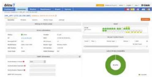
Device Details Overview
The device details overview gives a more complete dashboard view of a device. The default overview tab displays basic information that allows network administrators to get the information they need as quickly as possible.
The number and type of widgets, as well as available tabs displayed will depend on the type of devices.
Certain functions will also be available, such as the ability to Reboot a device, or configure additional settings.
By default widgets are not able to be edited, and will only display information that has been manually entered. To edit information for a widget click on the Edit icon. This will allow the user to add information to any of the editable fields for that widget.

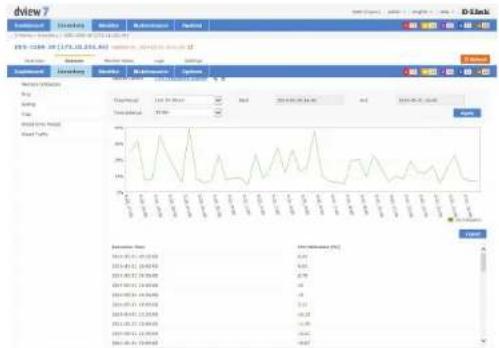
Device Details Sensors
Every class of device has its own default sensors that can be accessed from the device detail sensors tab. For example, wireless access points will have sensors for different types of metrics that relate to wireless clients, wireless traffic, or ping time. While routers and switches will have sensors that show metrics such as CPU utilization, wire speeds, and wired error packets.
Customized sensors can be setup and applied to any device that is in the D-View Managed inventory list. For more information on how to create new sensors, please refer to Sensor Settings on page 117.
line
| Date | Value | |---|---| | 2013-01-15 | 6.84 | | 2013-01-22 | 6.92 | | 2013-01-29 | 6.78 | | 2013-02-05 | 6.4 | | 2013-02-12 | 6.14 | | 2013-02-19 | 6.14 | | 2013-02-26 | 6.14 | | 2013-03-03 | 6.14 | | 2013-03-10 | 6.14 | | 2013-03-17 | 6.14 | | 2013-03-24 | 6.14 | | 2013-04-01 | 6.14 | | 2013-04-08 | 6.14 | | 2013-04-15 | 6.14 | | 2013-04-22 | 6.14 | | 2013-04-29 | 6.14 | | 2013-05-06 | 6.14 | | 2013-05-13 | 6.14 | | 2013-05-20 | 6.14 | | 2013-05-27 | 6.14 | | 2013-06-04 | 6.14 | | 2013-06-11 | 6.14 | | 2013-06-18 | 6.14 | | 2013-06-25 | 6.14 | | 2013-07-02 | 6.14 | | 2013-07-09 | 6.14 | | 2013-07-16 | 6.14 | | 2013-07-23 | 6.14 | | 2013-07-30 | 6.14 | | 2013-08-07 | 6.14 | | 2013-08-14 | 6.14 | | 2013-08-21 | 6.14 | | 2013-08-28 | 6.14 | | 2013-09-05 | 6.14 | | 2013-09-12 | 6.14 | | 2013-09-19 | 6.14 | | 2013-09-26 | 6.14 | | 2013-10-03 | 6.14 | | 2013-10-10 | 6.14 | | 2013-10-17 | 6.14 | | 2013-10-24 | 6.14 | | 2013-10-31 | 6.14 | | 2014-01-07 | 6.14 | | 2014-01-14 | 6.14 | | 2014-01-21 | 6.14 | | 2014-01-28 | 6.14 | | 2014-02-05 | 6.14 | | 2014-02-12 | 6.14 | | 2014-02-19 | 6.14 | | 2014-02-26 | 6.14 | | 2014-03-03 | 6.14 | | 2014-03-10 | 6.14 | | 2014-03-17 | 6.14 | | 2014-03-24 | 6.14 | | 2014-03-31 | 6.14 | | 2015-01-07 | 6.14 | | 2015-01-14 | 6.14 | | 2015-01-21 | 6.14 | | 2015-01-28 | 6.14 | | 2015-02-05 | 6.14 | | 2015-02-12 | 6.14 | | 2015-02-19 | 6.14 | | 2015-02-26 | 6.14 | | 2015-03-03 | 6.14 | | 2015-03-10 | 6.14 | | 2015-03-17 | 6.14 | | 2015-03-24 | 6.14 | | 2015-03-31 | 6.14 | | 2016-01-07 | 6.14 | | 2016-01-14 | 6.14 | | 2016-01-21 | 6.14 | | 2016-01-28 | 6.14 | | 2016-02-05 | 6.14 | | 2016-02-12 | 6.14 | | 2016-02-19 | 6.14 | | 2016-02-26 | 6.14 | | 2016-03-03 | 6.14 | | 2016-03-10 | 6.14 | | 2016-03-17 | 6.14 | | 2016-03-24 | 6.14 | | 2016-03-31 | 6.14 | | 2017-01-07 | 6.87 | | 2017-01-14 | nan | | Note: The data provided in the code is as follows: The values represent the percentage (%) for each month from January to December of the year (as of the date). The percentages are estimated based on the current date and are not explicitly labeled in the image.Device Details Monitor Views
The monitor views tab displays a list of all the topologies that the currently selected device is a part of. Clicking on the name link to a topology will open a new window with the topology view that includes the currently selected device.
![driew Backpage: Newbury Monitor Maintenance Report Search Search Engine: 2014.10.19(2014.08.20) 205_4P2: [172.18.19.209] <|vision_start|> Dominant Search Security Monitor Share Search Name * https://www.driew.com/ UHUA Search N/A 23 TEN Search Engine: 2014.10.19(2014.08.20)](/content/2026/05/765026/images/bb4a0f1837b5584d7851c2ec8b9778907f71e442600262e5aed0f67faf0cd9a1.jpg)
Topologies may also be filtered by name by entering a keyword into the search box.
The monitor view displays the name of the topology, the type of topology it is a part of, the date the topology was created, the number of devices that are associated with the topology, and if available a description of the topology.
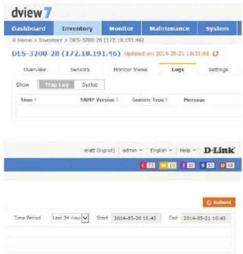
Device Details Logs
Devices that have support for local or remote logging will have a logs tab, which lists all of the events for that device. D-View 7 supports both the Trap and Syslog standards and can receive either if a remote networking device is configured properly.
The Logs view can be filtered by time period using the drop down menu. The events are listed in chronological order, starting with the name of the event, the SNMP version that was used by the remote device, the category of event for the message, and the message itself.
Devices that have notifications setup correctly will also have their events added to the D-View tool panel event notification area. These alerts are for all devices setup correctly and clicking on either Critical, Warning, Informative, System, or Unmanaged will allow the administrator to review and take action as necessary.
To configure a device to use D-View 7 as a Trap or Syslog server, click on the Settings tab and refer to Device Details Settings on page 72.
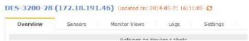
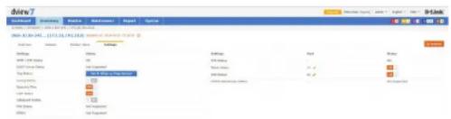
Device Details Settings
The Device Details Settings tab is available for devices that are able to receive configuration commands from the D-View 7 server. This will include classes of device such as managed switches, managed access points, and routers/firewall devices. Some of the options for the settings tab may change depending on the device.
Options for APs
SNTP / NTP Status: This option shows whether or not the device currently selected is configured to send status updates for NTP. To configure this option, use the management software for the device.
DHCP Server This option shows whether or not the device currently selected is Status: configured to send status updates for DHCP. To configure this option, use the management software for the device.
Trap Status: If the currently selected device is able to send Trap status to D-View and is not currently configured to do so, D-View 7 can attempt to configure the device. To do so, click on the "Set D-View as Trap Server" button. D-View 7 will attempt to make the necessary changes on the currently selected device and if successful, will change the interface to show that the option has been toggled on.
Syslog Status: If the currently selected device is able to send Syslog status to D-View and is not currently configured to do so, D-View 7 can attempt to configure the device. To do so, click on the "Set D-View as Syslog Server" button. D-View 7 will attempt to make the necessary changes on the currently selected device and if successful, will change the interface to show that the option has been toggled on.
Operation Mode: This shows the current operating state of the device. To configure this option, use the management software for the device.
DHCP Server Status Not Supported
Trap Status Set D-View as Trap Server
Syslog Status Set D-View as Syslog Server
Operation Mode Access Point
SSH Status: If the currently selected device supports remote SSH log in, the SSH service for the device can be controlled by D-View 7. Use the toggle to enable or disable the remote SSH service. If the status is reported as "Not Supported" the service may still be available, but status notifications may not be enabled. To enable status notifications for SSH, use the management software for the device. By default, SSH is set to port 22. If the SSH service is running on a non standard port, enter the correct port by clicking on the edit button and entering the correct port value.
Telnet Status: If the currently selected device supports remote Telnet log in, the Telnet service for the device can be controlled by D-View 7. Use the toggle to enable or disable the remote Telnet service. If the status is reported as "Not Supported" the service may still be available, but status notifications may not be enabled. To enable status notifications for Telnet, use the management software for the device. By default, Telnet is set to port 23. If the Telnet service is running on a non standard port, enter the correct port by clicking on the edit button and entering the correct port value.
Web Status: If the currently selected device supports remote Web log in, the status of the SSH service for the device can be controlled by D-View 7. Use the toggle to enable or disable the remote SSH service. If the status is reported as "Not Supported" the service may still be available, but status notifications are not enabled. To enable status notifications for SSH, use the management software for the device. By default, Web Status is set to port 80. If the remote Web log in service is running on a non standard port, enter the correct port by clicking on the edit button and entering the correct port value.
| Settings | Port | Shelco |
| SSH Status | - | OFF |
| Tehnet Status | 23 | USB |
| Web Status | 60 | USB |
| HTTPG Web Access Status | - | Not Supported |
| Settings | Port | Status |
| SSH Status | - | OFF |
| Telnet Status | 23 | TEL |
| Web Status | 80 | TEL |
| HTTPS Web Access Status | - | Not Supported |
| Settings | Port | Status |
| SSH Status | - | OFF |
| Telenet Status | 23 | ON |
| Web Status | 86 | ON |
| HTTPS Web Access Status | - | Not Supported |
HTTPS Web Access If the currently selected device supports remote Web log in through Status: HTTPS, the status of the SSH service for the device can be controlled by D-View 7. Use the toggle to enable or disable the remote SSH service. If the status is reported as "Not Supported" it means that D-View does not support configuring this model's HTTPS service. To enable status notifications for HTTPS, use the management software for the device. By default, HTTPS Web Status is set to port 443. If the remote secure web log in service is running on a non-standard port, enter the correct port by clicking on the edit button and entering the correct port value.
| SetMings | Perf | Status |
| DSH Status | - | ORF |
| Telenet Status | 22 | CD8 |
| Web Status | 86 | CD8 |
| HTTPS Web Access Status | - | Not Supported |
Inventory
| Options for Managed Switches | |||
| SNTP / NTP Status: | This option shows whether or not the device currently selected is configured to send status updates for NTP. To configure this option, use the management software for the device. | SNTP / NTP Status | OFF |
| DHCP Server Status: | This option shows whether or not the device currently selected is configured to send status updates for DHCP. To configure this option, use the management software for the device. | DHCP Server Status | Not Supported |
| Trap Status: | If the currently selected device is able to send Trap status to D-View and is not currently configured to do so, D-View 7 can attempt to configure the device. To do so, click on the "Set D-View as Trap Server" button. D-View 7 will attempt to make the necessary changes on the currently selected device and if successful, will change the interface to show that the option has been toggled on. | Trap Status | Set D-View as Trap Server |
| Syslog Status: | If the currently selected device is able to send Syslog status to D-View and is not currently configured to do so, D-View 7 can attempt to configure the device. To do so, click on the "Set D-View as Syslog Server" button. D-View 7 will attempt to make the necessary changes on the currently selected device and if successful, will change the interface to show that the option has been toggled on. | Syslog Status | Set D-View as Syslog Server |
| Spanning Tree: | If the selected managed switch supports the spanning tree protocol, D -View 7 can enable or disable the service. To enable the spanning tree protocol ensure that the on/off toggle is set to On. | Spanning Tree | ON III |
| LLDP Status: | If the selected managed switch supports status updates from the Link Layer Discovery Protocol, D -View 7 can enable or disable the service. To enable LLDP status updates ensure that the on/off toggle is set to On. | LLDP Status | ON III |
| Safeguard Engine: | If the selected managed switch supports D-Link's Safeguard Engine, D-View 7 can enable or disable the service. To enable Safeguard Engine updates ensure that the on/off toggle is set to On. | Safeguard Engine | ON III |
Inventory
POE Status: If the selected managed switch supports status updates for Power over Ethernet, D-View 7 can enable or disable the service. To enable PoE status updates ensure that the on/off toggle is set to On.
RMON: If the selected managed switch supports status updates for Remote Network Monitoring, D-View 7 can enable or disable the service. To enable RMON status updates ensure that the on/off toggle is set to On.
SSH Status: If the currently selected device supports remote SSH log in, information on the SSH service status will be displayed here. If the status is reported as "Not Supported" it means that D-View does not support configuring this model's SSH service. To enable SSH, see Batch Configuration on page 92. By default, SSH is set to port 22.
Telnet Status: If the currently selected device supports remote Telnet log in, the Telnet service for the device can be controlled by D-View 7. Use the toggle to enable or disable the remote Telnet service. If the status is reported as "Not Supported" it means that D-View does not support configuring this model's Telnet service. To enable status notifications for Telnet, use the management software for the device. By default, Telnet is set to port 23. If the Telnet service is running on a non standard port, enter the correct port by clicking on the edit button and entering the correct port value.
Web Status: If the currently selected device supports remote web log in, the status of the web service for the device can be controlled by D-View 7. Use the toggle to enable or disable the remote web service. If the status is reported as "Not Supported" it means that D-View does not support configuring this model's Web service. To enable status notifications for the web service, use the management software for the device. By default, Web Status is set to port 80. If the remote Web log in service is running on a non standard port, enter the correct port by clicking on the edit button and entering the correct port value.
| POE Status | Not Supported |
| RMON | N/A |
| Settings | Port | Status |
| SDH Status | - | DIP |
| Ticket Status | 23 | ON |
| Web Status | RE | ON |
| HTTPD Web Access Status | - | Not Supported |
| Settings | Port | Status |
| SSH Status | - | OFF |
| Telnet Status | 23 | ON |
| Web Status | 66 | ON |
| HTTPS Web Access Status | - | Not Supported |
| Settlinga | Port | Status |
| SSH Status | - | OTT |
| Telnet Status | 23 | ON |
| Web Status | 86 | ON |
| HTTPS Web Access Status | - | Not Supported |
HTTPS Web Access If the currently selected device supports remote Web log in through Status: HTTPS, the status of the SSH service for the device can be controlled by D-View 7. Use the toggle to enable or disable the remote SSH service. If the status is reported as "Not Supported" it means that D-View does not support configuring this model's HTTPS service. To enable status notifications for HTTPS, use the management software for the device. By default, HTTPS Web Status is set to port 443. If the remote secure web log in service is running on a non-standard port, enter the correct port by clicking on the edit button and entering the correct port value.
| Settings | Port | Status |
| SDH Status | - | GFF |
| Telnet Status | 23 | USB |
| Web Status | 80 | USB |
| HTTPS Web Access Status | - | Not Supported |
Monitor
The Monitor section contains various views that give network administrators a visual overview of different aspects of their network. The default view for Monitor is the Device View Switch tab. The Device View list all of the discovered devices by category. Topology view shows how devices are interconnected with the use of topology maps. Rack View can be used to simulate physical racks, and network stack layouts. Event View keeps a log of all received events by discovered devices in chronological order. Monitor Logs displays captured Trap and Syslog messages from devices on the network.
To learn more about Device View, please refer to Device View on page 79.
To learn more about Topology View, please refer to Topology View on page 80.
To learn more about Rack View, please refer to Rack View on page 86.
To learn more about Event View, please refer to Event View on page 88.
To learn more about Monitor Logs, please refer to Monitor Logs on page 89.
To learn more about the Ping Helper, please refer to Ping Helper on page 90.
Device View
The Device View section shows devices listed by type and gives more insight into certain aspects of each type of hardware than the inventory page. The default view for Monitor is the switch tab. For each category of device, the status, most recent event, and other relevant information such as IP, MAC address, and others is shown. Clicking on a devices name or IP address will open that device's detail page. Clicking on the link to the probe that it is attached to will open the probe's detail page.
To export a list of all of the devices currently in the Managed device panel view, click on Export to download a CSV file that can be imported into a spreadsheet application.
Devices may also be filtered by entering a keyword into the search box. Available search options will automatically appear under the search box, select the field to filter the results by. The advance search will allow for multiple filtering criteria.
To reorder the current device panel view, click on the column title to sort by either ascending or descending. For some categories of devices, the column list can be customized by clicking on the "+" at the end of the column list. From the drop down menu, select which columns to display and click Apply to save the changes.
To manage a device, click on its corresponding System Name, or IP Address link.
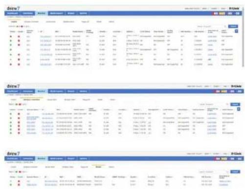
Topology View
The Topology View creates network maps based on the interconnecting devices that have been discovered by a probe on a subnet. The default Topology View is the initial probe that was installed on the D-View 7 server system. Additional probes, and subnets are listed in the probe list, located on the left side of the screen.
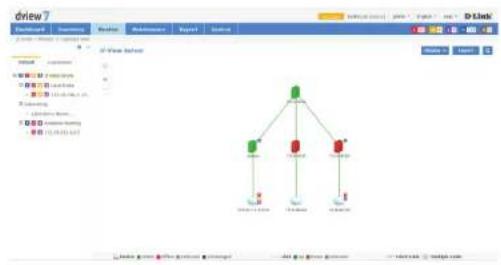
flowchart
graph TD
    A["Central Node"] --> B["Node 1"]
    A --> C["Node 2"]
    A --> D["Node 3"]
    B --> E["User Interface"]
    C --> F["User Interface"]
    D --> G["User Interface"]
Clicking on the gear icon will display a menu that can be used to toggle the display of certain event levels for the devices that are shown in the topology map. Click the "<<" icon to hide the topology list.
The Topology View always shows the Default tab, which contains the D-View 7 probe, its subnet, and all devices on the subnet that have been discovered. To customize the view, click on the Customized tab. To create a new topology, click on the "+" located at the upper left hand corner of the topology list.

This will open the Create New Topology wizard. To generate a topology, choose to either Automatically, or Manually generate a topology.
If Automatically generating a topology, choose a central switch, will be the starting point for the topology map. Next, select the number of hops that should be included in the topology map. A list of linked devices will be shown that will be used to create the topology map. Click Next to continue.
If Manually generating a topology, select the devices that should be used from the list of available devices. Click Next to continue.
Monitor
Enter a name for the topology map that will be shown in the topology list.
Choose a data source for the links. To use the default topology which can be modified later, choose Synchronization with system. To define a custom topology, choose User-defined. Optionally, enter a description to help identify the topology map.
Next, select the display type for the topology map. A star topology will show connections, starting from the central switch, moving outwards by the specified number of hops. A tree view reorients the same information in a top down view, starting with the central switch and moving downward by the specified number of hops.
The central device for display can also be changed by clicking on the drop down menu and selecting any listed device to be used as the starting point. Leaving the Auto option checked will create the map using the central switch that was selected in the previous step. Click Back to make any changes, or click Apply to save the new topology map.
Topology maps may also be filtered by entering a part or the whole name of the topology label into the search box.
The topology list can be reordered by clicking the left part of the name, and dragging the selected item either up or down in the list.
To rename or delete an topology map, click on the drop down menu item located on the right part of the topology name.
Navigating the topology map is done by left clicking anywhere on the map and dragging the map in the desired direction. Use the "+" or "-" controls to zoom in and out on the map. Clicking the target icon will zoom the map out and center it on the central switch for the current topology.
In the default topology view, the map layout can be changed from a top down tree, to a star view by going into the Edit mode by clicking the button in the upper-right of the topology map. In the Edit window, click the Auto Arrangement icon (图标) in the upper-left of the topology to change the layout.
Monitor
Hovering the mouse cursor over any device will open a pop up window that contains some basic information for that device, such as the devices IP address, MAC address, and recent events that originated from the device.
Hovering the mouse cursor over any link will open a pop up window that contains some basic information about the link, such as the link capacity, the ports connecting the link, sent and received traffic, and the date and time the information was updated.
In the customized topology view, it is also possible to edit the connections between devices. With a customized topology selected, click on the Edit button.

The top section of the topology map will change, displaying the edit functions available for the current topology map.

The Auto Arrangement button will open a pop up that enables changing the display type of the current topology map, as well as changing the central starting device.
The Edit Devices button will open a pop up that can be used to select new devices to be added, or to remove existing devices. To remove existing devices, uncheck the device and click Save. To add new devices, click All. The device list will refresh and display all available devices. Check which devices to add and click Save.
The Edit Lines button will open a pop up that can be used to change the type of line that is shown connecting devices. Click on any line between two devices and then click Edit Lines. The Link Type can be changed set to Normal Link, LACP Link or Logical Link, and the subnet type can also be set. Click OK to save any changes.
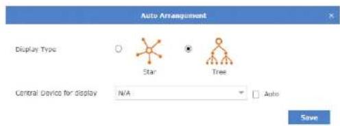
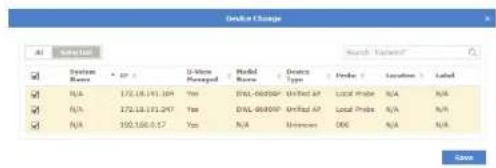
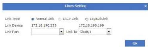
Monitor
Drawing new connections between devices is done by hovering over an existing device. A red dot will appear and the mouse cursor will change to a pencil cursor. Click and drag from the existing device to any other device to create the line.

A user-defined link has the highest priority in the topology. A user-defined topology will not be affected by the topology refreshing.
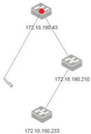
flowchart
graph TD
    A["Node 1"] -->|172.18.190.43| B["Node 2"]
    B -->|172.18.190.210| C["Node 3"]
    C -->|172.18.190.233| D["Node 4"]
To edit the newly created link, click the line and then click the Edit Lines icon.
Any existing line or device can also be deleted by clicking the desired link or device and then clicking the Delete icon.


To support a 3rd party device:
- If the 3rd party's information has been configured in the Customized Identified Device Model List (see About on page 122), and if the device supports LLDP, D-View 7 will automatically create a link with the device.
To do this, the information in the "Start Port Index" and "Port Count" fields needs to be identical with the device's SNMP MIB ifTable. These fields can be reached by going to the About page, clicking on the Customized Identified Device Model List tab, and pressing the Edit button in the Action column.
- If the 3rd party device cannot fulfill the criteria mentioned above, a link can be drawn manually in the Customized Topology view.
Rack View
The Rack View creates virtual racks that can simulate physical racks, or be used to group devices based on preference. Multiple racks are listed in the rack list, located on the left side of the screen.
To create a new rack group click on the "+" sign in the upper left corner of the rack group column. A pop up window will open; enter a unique rack group name, and add a description to describe the rack group. Click Create to save the rack group to the rack group list. Labels are unique to the workspace that the user is currently in, and users in the same workspace will share labels.
The newly created rack group will appear in a column list on the left side of the browser. To add another rack group, click on the "+" sign at the top of the rack group list. To hide the rack group list from view, click the "<>" sign at the top of the rack group list. Rack groups may also be filtered by entering a part or the whole name of the rack group into the search box.
The rack group list can be reordered by clicking the left part of the label name, and dragging the selected item either up or down in the list.
To rename or delete an rack group, click on the drop down menu item located on the right part of the rack group name.
![dview7 Database Parameters Name Maintenance System D-Link File Edit View Insert Help Help 2.24 (16.0) [1] [1] [1] New Year 2013 New Year 2012 New Year 2011 New Year 2010 New Year 2009 New Year 2008 New Year 2007 New Year 2006 New Year 2005 New Year 2004 New Year 2003 New Year 2002 New Year 2001 New Year 2000 New Year 1999 New Year 1998 New Year 1997 New Year 1996 New Year 1995 New Year 1994 New Year 1993 New Year 1992 New Year 1991 New Year 1990 New Year 1989 New Year 1988 New Year 1987 New Year 1986 New Year 1985 New Year 1984 New Year 1983 New Year 1982 New Year 1981 New Year 1980 New Year 1979 New Year 1978 New Year 1977 New Year 1976 New Year 1975 New Year 1974 New Year 1973 New Year 1972 New Year 1971 New Year 1970 New Year 1969 New Year 1968 New Year 1967 New Year 1966 New Year 1965 New Year 1964 New Year 1963 New Year 1962 New Year 1961 New Year 1960 New Year 1959 New Year 1958 New Year 1957 New Year 1956 New Year 1955 New Year 1954 New Year 1953 New Year 1952 New Year 1951 New Year 1950 New Year 1949 New Year 1948 New Year 1947 New Year 1946 New Year 1945 New Year 1944 New Year 1943 New Year 1942 New Year 1941 New Year 1940 New Year 1939 New Year 1938 New Year 1937 New Year 1936 New Year 1935 New Year 1934 New Year 1933 New Year 1932 New Year 1931 New Year 1930 New Year 1929 New Year 1928 New Year 1927 New Year 1926 New Year 1925 New Year 1924 New Year 1923 New Year 1922 New Year 1921 New Year 1920 New Year 1919 New Year 1918 New Year 1917 New Year 1916 New Year 1915 New Year 1914 New Year 1913 New Year 1912 New Year 1911 New Year 1910 New Year 1909 New Year 1908 New Year 1907 New Year 1906 New Year 1905 New Year 1904 New Year 1903 New Year 1902 New Year 1901](/content/2026/05/765026/images/cf27463395b169b3b6a1193bbce28aa60aadbc3b8dce76822aebceb4665e6615.jpg)
Monitor
To create a rack click the Add Rack button. This will add an empty rack to the rack view for the current rack group. The rack will be empty, and created with the default title of "New Rack" To change the rack title, click the title and enter the desired value. To add a device to the rack, click the "+" sign in the upper right corner of the virtual rack.
Clicking the "+" sign will open a pop up window with a list of available devices. Select the devices to add the to rack and click Add.
Newly added devices will be added into the rack. Devices can be moved between racks by clicking and dragging the desired device to any available rack.
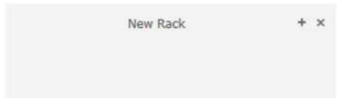
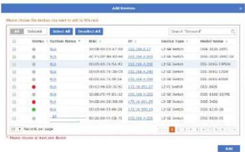
![New Rack local (172.18.19... DE3026-35add DXS-1210-2412... test [172.18.191... test [172.18.191... - UUI]](/content/2026/05/765026/images/abf9deb1943f0ef3b7e45bff29d6c30fe60f68827648b4651bfea402b5d61118.jpg)
Event View
The Event View shows a list of all received events from devices that have been discovered and all system events that have taken place on the D-View 7 server. By default, the Event View shows the Device tab, which list events for discovered devices. To show events for the D-View 7 server, click on the System tab.
Each tab in Event View has an Active Events section, as well as an Acknowledged Events section. New events will be stored in the Active Events section until they have been marked as acknowledged. To move between each section, click on either the Active Events button or Acknowledged Events button.
To archive events, use the check box to select the event. The Acknowledge button will appear in the upper left corner of the Event View window.
Events may also be filtered by entering a keyword into the search box. Available search options will automatically appear under the search box, select the field to filter the results by. The advance search will allow for multiple filtering criteria.
To export a list of all of the events for the currently selected section, click on the Export button which will download a CSV file that can be imported into a spreadsheet application.
While in the Device tab, clicking on the link to a source will open a new window with the detailed device view for that event.
Moving the mouse over the ellipsis ('...') at then end of an entry in the Event View will display more detailed information about the event.
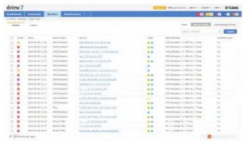
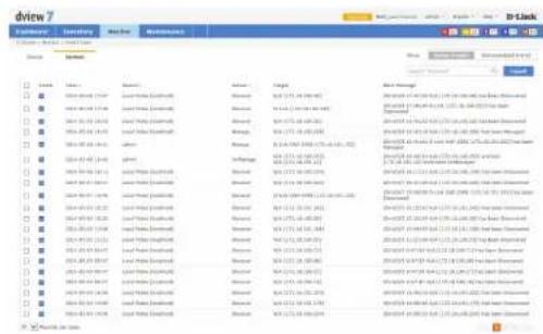
bar
dview7 | Category | Summary | Date/Year | Maintenance | Status | Description | |---|---|---|---|---|---| | Month 1 | January 2014 | 17:57 | January Sales (Excl.): | March | Month Management | | Month 2 | February 2014 | 18:39 | January Sales (Excl.): | March | 2014-01-01 16:40 PM - 12:15, 16:40 AM - 22:00 PM - 22:30 PM - 23:00 PM - 23:30 PM - 23:30 PM - 23:30 PM - 23:30 PM - 23:30 PM - 23:30 PM - 23:30 PM - 23:30 PM - 23:30 PM - 23:30 PM - 23:30 PM - 23:30 PM - 23:30 PM -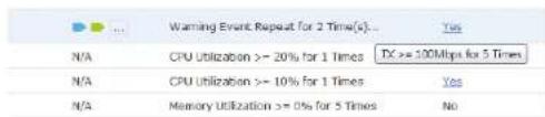
Monitor Logs
The Monitor Logs view shows a list of all received Trap and Syslog events from devices that have been discovered. By default, the Monitor Logs view shows the Trap Log tab, which list Trap events for discovered devices. To show Syslog events for discovered devices, click on the Syslog tab.
Events may also be filtered by entering a keyword into the search box. Available search options will automatically appear under the search box, select the field to filter the results by. The advance search will allow for multiple filtering criteria.
To export a list of all of the events for the currently selected section, click on the Export button, which will download a CSV file that can be imported into a spreadsheet application.
While in either tab, clicking on the link to a source will open a new window with the detailed device view for that event.
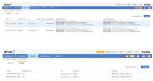
Ping Helper
The Ping Helper page is used to perform a ping test from either the local or remote probe. The IP address to be pinged, the number of pings and the packet size can be entered, and the results are shown in the bottom half of the window.
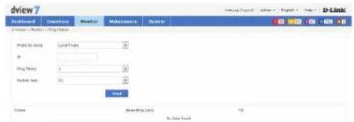
Maintenance
The Maintenance section contains Batch Configuration, Firmware Management, Configuration Management, File Management, Task Management and Configuration Comparison.
Batch Configuration contains a number of different templates that can be used to configure multiple devices at the same time. It is also possible to use the built-in Script Template editor to create customized templates that can be saved for later use.
Firmware Management is used to deploy firmware upgrades to multiple devices at the same time.
Configuration Management is used to backup and restore configurations for a single or multiple devices at the same time.
File Management is used to manage uploaded firmware and configuration files.
Task Management is used to view and manage currently running as well as historical task.
Configuration Comparison is used to compare two different configuration files and highlight the differences.
To learn more about Batch Configuration please refer to Batch Configuration on page 92.
To learn more about Firmware Management please refer to Firmware Management on page 93.
To learn more about Configuration Management please refer to Configuration Management on page 94.
To learn more about Task Management please refer to Task Management on page 97.
To learn more about File Management please refer to File Management on page 98.
To learn more about Configuration Comparison please refer to Configuration Comparison on page 100.
Batch Configuration
Groups of devices can be simultaneously configured or controlled using the Batch Configuration utility. There are a number of default configuration templates that can be used, which are sorted by the device type they are applicable to.
The default view for Batch Configuration is the Common Template section. The general configuration templates listed apply to a range of devices. To begin using a template. Click on the Create button. A pop up window will appear that will list the steps necessary to create a task that can either be run on a recurring basis, or one time only. The steps to complete task creation are outlined below:
- Set the configuration behavior. For example, the LLDP Status Configuration task has the option to either enable or disable the LLDP status setting on a device.
- Select the device(s) that the task will be assigned to.
- Set the name of the task. This will be the name that the task will be identified as on the device. Optionally, set a description and a schedule to run the task.
- Check to ensure that all of the details of the task are correct. If they are, click Submit to finalize the task. Otherwise, click Back to make any desired changes.
Customized batch configurations can also be created by using the Script Template function. To create a custom template, click on the Script Template tab and then click on the "+" sign at the top of the script template list. A pop up window will open where the custom script name, description, and custom commands can be entered. Basic guidelines for creating custom scripts can be found in the online help, which can be accessed by clicking on the button at the upper right corner of the command line input box.
Once a custom script has been successfully created, a new task for the custom script can be made by clicking on the Create button at the lower right corner of the Script Template view. The process for creating a new task is the same as the one used with the pre-made batch configuration templates found in the Config Template tab.
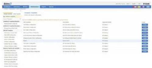
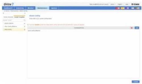
Firmware Management
The Firmware Management view is used to manage the deployment and tracking of firmware to devices on the network. The default view for Firmware Management shows a list of devices that have been remotely upgraded using D-View 7's firmware deployment feature. The list can be sorted and searched using the advance search function. Deploying new firmware to a single device or multiple devices can be accomplished by clicking the Firmware Upgrade button. A pop up window will open where the firmware binary and the target devices can be selected. Users can upload new firmware or use existing firmware has already been uploaded to D-View 7 to upgrade devices.

Note: Ensure that the firmware binary selected matches the type of device selected in the first step of the firmware deployment process. Selecting the wrong type of device will cause the process to not complete properly.
It is also important to follow any precautions listed on the firmware download page to ensure that the process completes without any issues.
After selecting the proper firmware binary and selecting the proper device to upload the firmware into, click Next. Set the task details that will be used to identify the job for that device. Optionally, set a description and a time to live for the job. The default expiration time for the firmware upgrade process is 1 hour. Click Next to continue.
Confirm all of the details are correct and click Submit to finalize the firmware upgrade process. Click Back to make any changes. The task will begin immediately and the status of the task can be found by going to the Task Management view under the Maintenance section. To find out more about Task Management, please see Task Management on page 97.
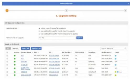
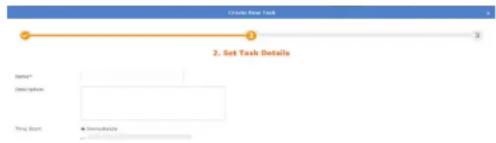
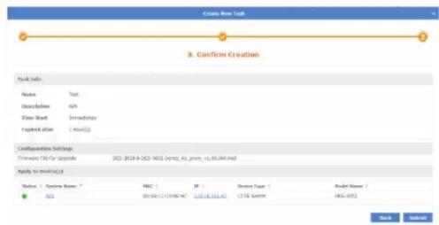
Configuration Management
The Configuration Management view is used to backup and restore configurations for a single or multiple devices at the same time. The default view for Configuration Management shows a list of previous backup or restore task that have been performed. The list can be sorted by any of the listed columns, and can be filtered using the advance search feature. The Export button will download a copy of all the jobs currently displayed.
To backup a single device or multiple device configuration, click on the Backup button.
A pop up window will open which can be used to select the device(s) that will have their configurations backed up. Click Next to continue.
Enter a name for the task that will be used by D-View 7's Task Management feature to track the backup process. Optionally, enter a description and the frequency of the backup job that will be performed. If necessary, the start time can also be delayed, or time to live can be adjusted to allow the backup job more time to complete. Click Next to continue.
Maintenance
Confirm all of the details are correct and click Submit to finalize the configuration backup process. Click Back to make any changes. The task will begin immediately and the status of the task can be found by going to the Task Management view under the Maintenance section. To find out more about Task Management, please see Task Management on page 97.
To begin the configuration restore process, click on the Restore button. A pop up window will open which can be used to select the source file for the configuration restore process. Choosing the System option will use a configuration file for a device that has been successfully backed up using the D-View 7 backup process. Choosing the System option allows for multiple devices to be restored at the same time, provided that the device has been successfully backed up using the D-View 7 backup process previously.
The Upload option will allow a single device to be restored, using a configuration file that has been generated for a specific device. Click Next to continue.
If the System option was chosen, select the device(s) that will have its configuration restored. The device list will show the last configuration backup that was successfully performed. Devices can be filtered by using the advance search feature. Click Next to continue.
![Create New Item 3. Confirm Creations Form Name: Name: Description: New Start: New Address: Page 10 (1) Name: Edit Type: Edit Date: Model Name: [ ] [ ] [ ] [ ] [ ] [ ] [ ] [ ] [ ] [ ] [ ] [ ] [ ] [ ] [ ] [ ] [ ] [ ] [ ] [ ] [ ] [ ] [ ] [ ] [ ] [ ] [ ] [ ] [ ] [ ] [ ] [ ] [ ] [ ] [ ] [ ] [ ] [ ] [ ] [ ] [ ] [ ] [ ] [ ] [ ] [ ] [ ] [ ] [ ] [ ] [ ] [ ], [ ], [ ], [ ], [ ], [ ], [ ], [ ], [ ], [ ], [ ], [ ], [ ], [ ], [ ], [ ], [ ], [ ], [ ], [ ], [ ], [ ], [ ], [ ], [ ], [ ], [ ], [ ], [ ], [ ], [ ], [ ], [ ], [ ], [ ]. [ ]. [ ]. [ ]. [ ]. [ ]. [ ]. [ ]. [ ]. [ ]. [ ]. [ ]. [ ]. [ ]. [ ]. [ ]. [ ]. [ ]. [ ]. [ ]. [ ]. [ ]. [ ]. [ ]. [ ]. [ ]. [ ]. [ ]. [ ]. [ ]. [ ]. [ ]. [ ]. [ ].](/content/2026/05/765026/images/07149772b117e8d78c4caf9f1d9063fa4ceeb21ccaa0ebb0ee93aa822fd9b7d2.jpg)
Enter a name for the task that will be used by D-View 7's Task Management feature to track the restore process. Optionally, enter a description or adjust the time to live to allow the restore job more time to complete. Click Next to continue.
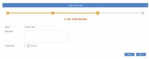
Confirm all of the details are correct and click Submit to finalize the configuration restore process. Click Back to make any changes. The task will begin immediately and the status of the task can be found by going to the Task Management view under the Maintenance section. To find out more about Task Management, please see Task Management on page 97.
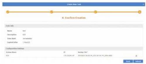
Task Management
The Task Management view is used to view and manage currently running as well as track tasks that have been previously run. The default view for Task Management shows a list of current tasks that are being performed, as well as tasks that occur on a recurring basis. The list can be sorted by any of the listed columns, and can be filtered using the advance search feature. The Export button will download a copy of all the jobs currently displayed.
The latest results for any job can be seen by clicking on the link listed in the Latest Result column. Details for the job can also be found by clicking on the Magnifying Glass icon. Clicking on the Pause icon will cause the job to suspend until the Play icon is clicked, resuming the job. The Trash icon will delete the job.
To view a list of previously completed tasks, click on the Historical tab. The Historical Task list can be sorted by any of the listed columns, and can be filtered using the advance search feature. The Export button will download a copy of all the jobs currently displayed.
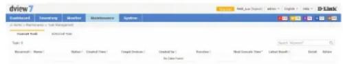


File Management
The File management page allows you to manage uploaded firmware and configuration files.
Here you can view a list of firmware and configuration files you have uploaded, upload new files, and compare configuration files.
You can directly choose two configuration files to compare by selecting the two configuration files you want to compare, then clicking on Compare File. For more information on File Comparison, see page 100.
The default view of the File Management tab displays the following information:
- Upload Time
■ File Type
File Name
■ File Size - Uploaded By
■ Related Devices
MD5
Status
■ Description
Under Action the following actions can be done:
- Download File
Edit Description - Delete File
| Dashboard | Inventory | Monitor | Maintenance | Report | System | ||
| #Home + Maintenance > File Management | |||||||
| Upload File | Backup File | Compare File | |||||
| Upload Time > | File Type | File Name : | File Size : | Uploaded by | Related Devices | HDS | |
| 2019-01-10 10:04 | Primerase File | DOS-3120 Series_AI3AZ_Hus_FW_v3.10.012 (2) NoD | PMS | admin | 0 | 63908887 | |
| 2019-01-10 10:02 | Primerase File | DOS-3120_Series_AI_Butox_2.0 0.510 NoD | PMS | admin | 0 | 3819594475 | |
| 2019-01-10 09:52 | Primerase File | DOS-3120_Series_AI_Butox_2.0 0.510 NoD | PMS | admin | 0 | 3819594475 | |
| 2019-01-09 18:27 | Primerase File | DOS-3120 Series_AI3AZ_Hus_FW_v3.10.012 (2) NoD | PMS | admin | 0 | 63908887 | |
| 2019-01-09 18:03 | Configuration File | 2019_01_04 19:07:31_17:18.13L13L12_DOS-3120-247Ct.fg | 32KB | admin | 0 | 49765767 | |
| 2019-01-09 17:49 | Configuration File | 2018_12_26 12:53:30_17:18.13L13L30_DOS-320D-247c.gf | 29KB | admin | 0 | 66845541 | |
| 2019-01-09 17:29 | Configuration File | 2019_01_05 17:29:31_17:18.13L13L30_DOS-320D-247c.gf | 29KB | admin | 0 | 2082543 | |
| 2019-01-09 15:39 | Configuration File | Document.txt | 2KB | admin | 0 | babio-vde | |
To upload a new firmware or configuration file, click on the Upload File button on the top left corner of the page and fill in the following information:
| File Type: | Choose from the drop down list which file type (firmware file or configuration file) you want to upload. |
| Description: | (optional) Description of file. |
| File to Upload: | Click on theUploadbutton to choose a file to upload from the local drive. |
Click Submit to finish.
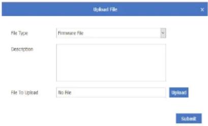
Configuration Comparison
The Configuration Comparison page allows you to compare two different configuration files and highlight the differences.
You can select files from either all devices or from a specific device. (You can also search for a specific device using the searchbox.) To select files from specified device, choose the corresponding radio button, then select the device from the drop down list.
The page is divided into two panels, with the panel on the left displaying one configuration file, and the panel on the right displaying another configuration file.
Specific configuration files can be selected from the drop down list at the top of each panel.
On the top right of each panel, you can do the following actions:
■ Reload Configuration File
■ Save As
- Restore to Device
Between the two panels, you are able to toggle locked scrolling and copy highlighted chunks of text between the two configuration files.
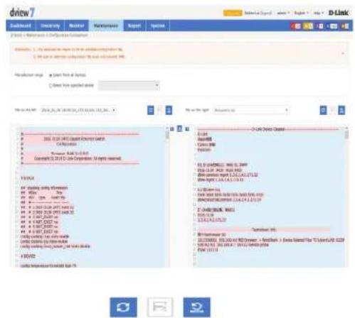
Report
The report feature is used to generate reports that will help you monitor system and network health as well as troubleshoot problems. Reports can be generated to run on an immediate one-time use or a scheduled basis, and can be customized by certain user-defined criteria. Generated reports can be formatted into graphs or tables and be downloaded for future use as PDFs.
Reports are separated into two types: Basic Reports and Advanced Reports.
Basic Reports contain Wired Traffic report types and syslog report types.
Advanced Reports contain Top N report types.
To learn more about Wired Traffic Reports please refer to Wired Traffic Reports on page 102.
To learn more about Syslog Reports please refer to Syslog Reports on page 105.
To learn more about Top N Reports please refer to Top N Reports on page 108.
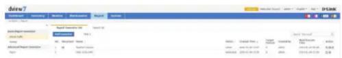
Wired Traffic Reports
Wired Traffic Reports page is used to issue reports monitoring wired traffic by port and by device.
By default the page will display two tabs. The Report Generator List tab displays a list of report generators. The Report List tab displays a list of previously generated reports.

The default view of the Report Generator tab displays the following information:
Number
■ Recurrent status
Name
Status
■ Time of Creation
■ Number of Targeted Devices
- Creator
■ Next Execution Time
Under Action the following actions can be done:
■ View Details of Generator
■ Pause Generator (If report is a recurrent report.)
- Delete Generator
To create a new report generator for wired traffic, click on the Add Generator button.
- Specify the name and description (optional) of the new report generator. Click Next to proceed.
- Specify the following information:
| Generate Type: | Select the radio button to indicate whether the report is generated once or on a recurrent basis. |
| Expired after: | Specify from drop down list the time that the report generator expires. |
| Report Frequency: | (Displayed only if Recurrent is chosen above.) Specify from the drop down menu whether the report is generated daily, weekly or monthly. |
| Generate on: | (Displayed only if Recurrent is chosen above.) Specify time to generate the report. |
| Time Interval: | (Displayed only if Recurrent is chosen above.) Choose from the drop down list the time interval to generate the report. |
| End On: | (Displayed only if Recurrent is chosen above.) Specify a date in which the report generator will stop or choose never to stop generating the report. |
| Time Period: | Specify from drop down list the time period. |
| Start: | Displays start time of report generation based on the time period chosen above. |
| End: | Displays end time of report generation based on the time period chosen above. |
| Time Interval: | Specify from drop down list the time interval |
| Display Mode: | Specify whether to display report as a table and/or chart. |
Click Next to proceed.
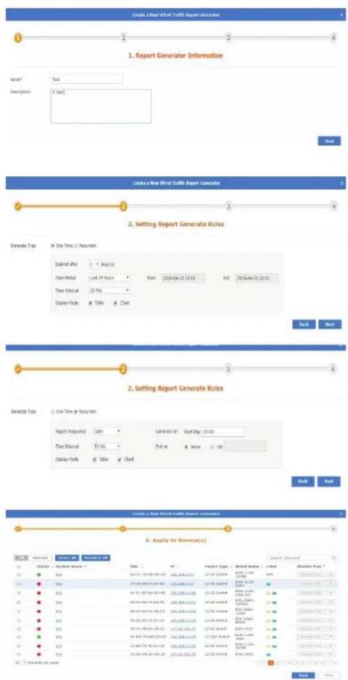
Report
-
Specify which systems and ports to monitor in order to generate a report. You can filter the systems shown via the keyword search box on the top right corner. Click Next to proceed.
-
Verify that the report generator info is correct and click on Submit to finish. The Report List can be further filtered through keywords by clicking on the keyword search box on the top right corner of the page.
The default view of the Report List tab displays the following information:
Number
Name
Generator
Date Generated
- Start Time
End Time
Time Interval
■ Display Mode
Under Action the following actions can be done:
■ Detailed view of Report
■ Download Report
- Delete Report
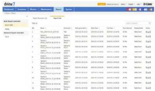
Syslog Reports page is used to issue reports monitoring systems' syslog.
By default the page will display two tabs. The Report Generator List tab displays a list of report generators. The Report List tab displays a list of previously generated reports.
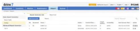
The default view of the Report Generator tab displays the following information:
Number
■ Recurrent status
Name
Status
■ Time of Creation
■ Number of Targeted Devices
- Creator
■ Next Execution Time
Under Action the following actions can be done:
■ View Details of Generator
■ Pause Generator (If report is a recurrent report.)
- Delete Generator
To create a new report generator, click on the Add Generator button.
- Specify the name and description (optional) of the new report generator. Click Next to proceed.
- Specify the following information:
| Generate Type: | Select the radio button to indicate whether the report is generated once or on a recurrent basis. |
| Report Frequency: | (Displayed only if Recurrent is chosen above.) Specify from drop down menu whether the report is generated daily, weekly or monthly. |
| Generate on: | (Displayed only if Recurrent is chosen above.) Specify time to generate the report. |
| End On: | (Displayed only if Recurrent is chosen above.) Specify a date in which the report generator will stop or choose never to stop generating the report. |
| Expired after: | Specify from the drop down list the time report generator expires. |
| Time Period: | Specify from the drop down list time period. |
| Start: | Displays start time of report generation based on the time period chosen above. |
| End: | Displays end time of report generation based on the time period chosen above. |
| Display Mode: | You can only display this report in table mode. |
Click Next to proceed.
- Specify which systems to monitor in order to generate a report. You can filter the systems shown via the keyword search box on the top right corner. Click Next to proceed.
- Verify that the report generator info is correct and click on Submit to finish.
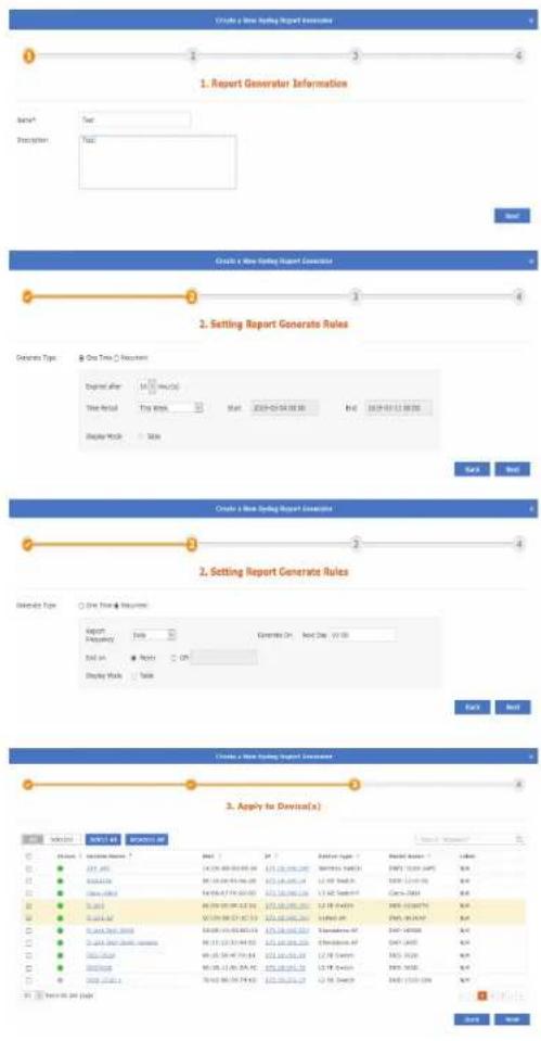
Report
The Report List can be further filtered through keywords by clicking on the keyword search box on the top right corner of the page.
The default view of the Report List tab displays the following information:
Number
Name
- Generator
Date Generated
- Start Time
End Time
■ Time Interval
■ Display Mode
Under Action the following actions can be done:
■ Detailed view of Report
■ Download Report
- Delete Report
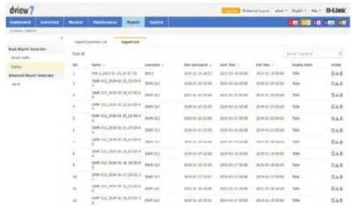
Top N Reports
Top N Reports page is used to issue reports monitoring various statistical information by device and ports.
By default the page will display two tabs. The Report Generator List tab displays a list of report generators. The Report List tab displays a list of previously generated reports.
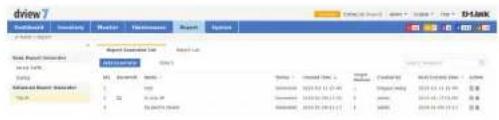
The default view of the Report Generator tab displays the following information:
Number
■ Recurrent status
Name
Status
■ Time of Creation
■ Number of Targeted Devices
- Creator
■ Next Execution Time
Under Action the following actions can be done:
■ View Details of Generator
■ Pause Generator (If report is a recurrent report.)
- Delete Generator
To create a new report generator, click on the Add Generator button.
- Specify the name and description (optional) of the new report generator. Click Next to proceed.
- Specify the following information:
| Generate Type: | Select the radio button to indicate whether the report is generated once or on a recurrent basis. |
| Expired after: | Specify from the drop down list the time the report generator expires. |
| Statistical Type: | Check off which type of statistics you want to monitor. |
| Report Frequency: | (Displayed only if Recurrent is chosen above.) Specify from the drop down menu whether the report is generated daily, weekly or monthly. |
| Generate On: | (Displayed only if Recurrent is chosen above.) Specify the time that the report will be generated. |
| End on: | (Displayed only if Recurrent is chosen above.) Specify a date in which the report generator will stop or choose never to stop generating the report. |
| Time Interval: | Choose from the drop down list the time interval during which the report will be generated. |
| Display Mode: | You can only display this report in table mode. |
Click Next to proceed.
- Specify a system to monitor in order to generate a report. You can filter the systems shown via the keyword search box on the top right corner. Click Next to proceed.
- Verify that the report generator information is correct and click on Submit to finish.
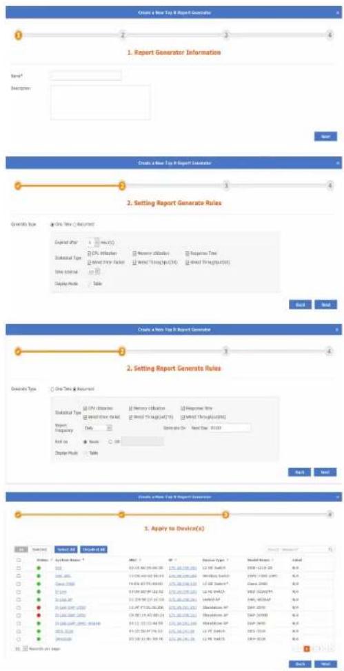
Report
The Report List can be further filtered through keywords by clicking on the keyword search box on the top right corner of the page..
The default view of the Report List tab displays the following information:
Number
Name
- Generator
Date Generated
- Start Time
End Time
■ Time Interval
■ Display Mode
Under Action the following actions can be done:
■ Detailed view of Report
■ Download Report
- Delete Report
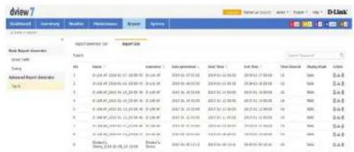
System
The System section contains License, Discovery, User / Workspace, Sensor Settings, Notification Center, System Logs, Trap Editor and About.
The License page is used to view and manage licenses for nodes as well as probes that are attached to the D-View 7 server.
The Discovery page is used to manage the discovery function of the different probes that are used to discover devices.
The User/Workspace page is used for account and workspace management.
The Sensor Settings page is used to create sensors that are used by devices to generate the data needed for the device dashboard widgets.
The Notification Center is used to generate notifications when a notification rule is matched. Notifications can be either emails or script execution.
The System Logs page is used to view system events that have taken place on the D-View 7 server.
The Trap Editor page is used to manage SNMP traps on the system.
The About page shows information related to D-View 7.
To learn more about License please refer to License on page 112.
To learn more about Discovery please refer to Discovery & Probe Setting on page 114.
To learn more about User/Workspace please refer to User Management on page 115.
To learn more about Sensor Settings please refer to Sensor Settings on page 117.
To learn more about the Notification Center please refer to Notification Center on page 118.
To learn more about System Logs please refer to System Logs on page 120.
To learn more about Trap Editor please refer to Trap Editor on page 121.
To learn more about About please refer to About on page 122.
License
The License view allows the D-View 7 administrator to perform activations for adding nodes or probes, as well as managing existing licenses. The License List Export button will download a copy of all the data for both probes and nodes. The Probe List Export button will download all of the information related to probes that are currently on the network.
To add a new license for either a probe or node, click on the Add License button. This will open a pop up window that will start the activation wizard. To find out more about the activation process, please see Activation on page 51.
To deactivate a license, click on the Deactivate License button. This will disassociate the D-View 7 licence with the server and deactivate D-View 7. This could be used to re-allocate licenses to another server, if a server move or replacement is required, or return the server to factory defaults. This cannot be reversed, and once D-View 7 is deactivated, it is not possible to use D-View 7 until it is reset or reinstalled.
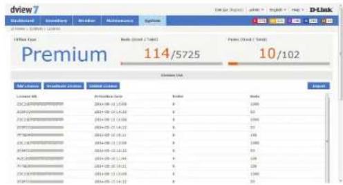

If you choose the Deactivate License option, all of the license(s) listed will be released at the same time. It is not possible to deactivate a single license number.
Click the I understand the risk and confirm to deactivate check box to confirm that you wish to go ahead with the licence deactivation. Once you have done this, you will be presented with 3 options: Export Database, Reset System and Logout. The Export Database option allows you to back up the database for use in a new installation of D-View 7. The Reset System option will reset D-View 7 and remove all configuration and device information from the server. The Logout option allows you to log out from the D-View 7 interface.
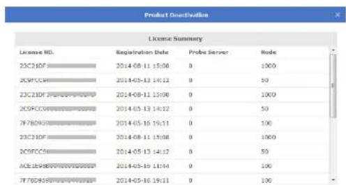
WARNING
The process CANNOT be reversed. Once you deactivated, you CANNOT use the D-View 7 anymore. You cannot use this system until you reset or re-install D-View 7. The license(s) listed above will be released at the same time. Are you sure you want to deactivate D-View 7?
□ I understand the risk and confirm to deactivate.

System
To unbind licences, click the Unbind License button. This will disassociate the D-View 7 licence with the server, but leave you with a trial version of D-View 7. This could be used to re-allocate licenses to another server, if a server move or replacement is required. Once this has been done, a dialog box will pop up, asking you to confirm the action. Click OK to confirm that you wish to unbind the licenses with the server.

If you choose the Unbind License option, and D-View 7 is returned to the trial version, if you have more than 25 managed nodes or more than 2 probes, D-View 7 will stop monitoring all devices until the extra nodes and probes are removed from the system.
Activating a probe is a two part process. To activate a probe, first add the additional probe license following the activation process outlined on 51. Next, click on the Add Probe button in the Probe Server List section of the License view. Enter a name to help identify the probe. Click Next to continue.
D-View 7 will automatically assign an available license code to the newly created probe. It will also issue an activation code that will need to be entered into the probe server to activate it.
Write down the activation code, and enter it into the remote probe server to finish the probe activation process. The probe will remain inactive on D-View 7 server until the activation code has been entered and has successfully connected back to the D-View 7 server.
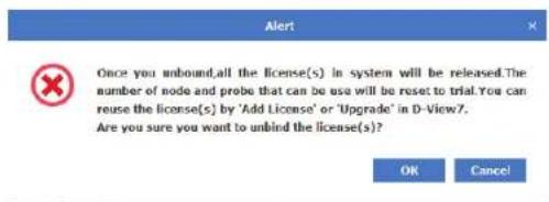
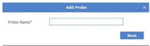
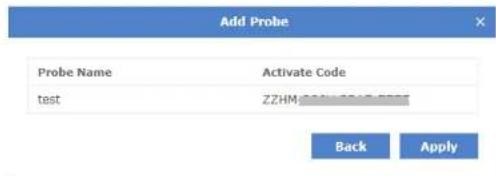
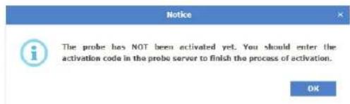
Discovery & Probe Setting
The Discovery view allows the D-View 7 administrator to monitor and manage active probes that are paired with the D-View 7 server. Each probe is listed in its own widget that gives details such as the probe availability, whether the probe is using HTTP or HTTPS to communicate with the central server, the name and IP address. The number of managed devices is also displayed, along with the last time the device information was updated, the next discovery time and the discover interval. The discovery rules are displayed below the probe summary information.
If the probe is offline, the Local Probe status icon will change to red and there will be an exclamation mark displayed next to the status icon. Hover over this with the mouse to display some troubleshooting information.

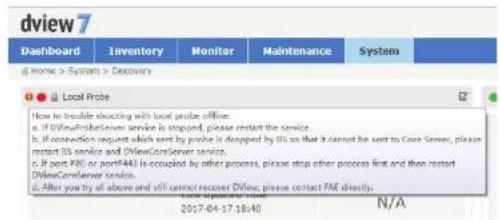
To make any changes to an existing probes setting, click on the Edit icon in the upper right corner of a probes widget. A pop up window will open that displays all of the available options and rules that have been set for the selected probe. Auto discovery must be set to On in order for the discovery rules to be effective. To add a new discovery rule, click on "+ Add Rule" which will expand the rule set by one line. Enter the SNMP version that will apply to the rule, the IP coverage (range, subnet or a list imported from a file), the Read Only and Read Write community values, and optionally an alias to help identify the rule.
If you choose to import a custom IP coverage list, please be aware that the file must be in .csv file format. Click on the red question mark icon next to the Import button for more instructions on the format of the file.
Click Add to save the rule. To finalize the changes to the probe, click the Save button.
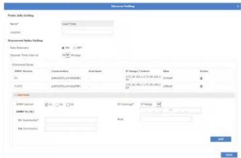
User Management
The User / Workspace view shows all of the user accounts and all of the available work spaces. By default, the User / Workspace list will show all the user accounts for all workspaces.
Users on the D-View 7 server can be assigned to a specific workspace, which can be configured to limit the amount of or type of devices that are available to those users.
To create a new workspace click on the "+" sign in the upper left corner of the workspace list column. A popup window will open; enter a unique workspace name, and add a description to describe the workspace. Click Next to continue. Select the devices that will be a part of the workspace. If the selected device has any devices it depends on, such as a wireless controller, make sure to add those as well. Click Next to continue. For each device, set the device privileges for the workspace. Privileges can be set on both the device and its modules. Click Submit to save the workspace to the workspace list.
The newly created workspace will appear in a column list on the left side of the browser. To hide the workspace list from view, click the "<<" sign at the top of the workspace list. Workspaces may also be filtered by entering a part or the whole name of the workspace name into the search box.
The workspace list can be reordered by clicking the left part of the workspace name, and dragging the selected item either up or down in the list.
To rename or delete a workspace, click on the drop down menu item located on the right part of the workspace name.
The Export button will download a copy of all the jobs currently displayed.
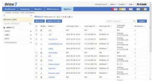
System
To add a new user to the D-View 7 Server, click on the New User button.
A pop up window will open. The Account Source can be set to Local or OpenID.
If an Account Source of Local is chosen, enter the user's email address, name, password, confirm the password, enter a description (optional) and choose an account type of Admin or User.
If the account is set to User, a Privilege box will appear that will allow the administrator to set the user account privileges. The account privileges are based on workspaces, so it is important to ensure that the workspace has the correct permissions for the devices that the user is going to be assigned to.
If an Account Source of OpenID is chosen, enter the user's email address, name, description (optional) and choose an account type of Admin or User.
Click Submit to save the newly created user account.
An activation email will be sent to the email address specified in the email address field.
There is no limit to the number of user accounts or workspaces on the D-View 7 server.
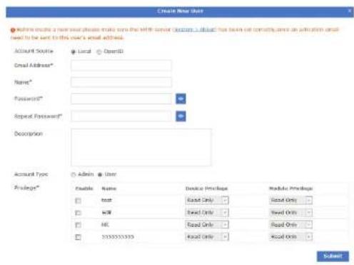
Sensor Settings
The Sensor Settings view shows a list of available sensors based on the type of data collected by the sensor. The sensors configured here will show up as a widget on the dashboard of a device that the sensor is assigned to. Certain sensors will not be applicable to specific types of devices (e.g. Wireless sensors for switches or other devices that have no wireless capability). To create a new sensor for a single device or multiple devices, select the sensor type based on the desired data to be collected, and click on the New Sensor button.
A pop up window will open. Enter a unique name that will be used to identify the sensor in the sensor list. Using the drop down menu, select a time interval for how often the sensor will collect data from the assigned device(s). Optionally, enter a description to help identify the sensor. Click Next to continue.
Sensors can be configured to send alerts based on certain thresholds. An administrator can also configure notifications to be sent when either an informative event, warning event, or critical event is detected on a device. Depending on the type of sensor, notifications can also be sent for certain types of devices (e.g. Wireless AP sensors can apply to a standalone AP, a managed AP, or a rogue AP). To configure a notification, first enable the event level desired. The hierarchy of event levels always goes from Info, to Warning, to Critical. To enable a Critical level event, Info and Warning must also be enabled. Next set the threshold level. For some sensors this will be a numerical value, for other sensors such as CPU Utilization it will be a percentage. Set the number of times the event must be detected. If an event is detected multiple times, the alert can also be escalated to a higher priority by enabling Escalation. Set escalation to On or Off, and set the number of times the event must be repeated before being escalated. Escalation can only be enabled if the higher priority alert level is also enabled. To reset all entered values, click the Reset button. Click Next to continue.
Select the device(s) that will be assigned to the new sensor. Devices can be filtered by using the advance search feature. Click Finish to save the new sensor. To view the new sensor, go to the Inventory View and find a device that the newly created sensor was assigned to. The sensor will appear as a new widget within the devices detailed dashboard view.
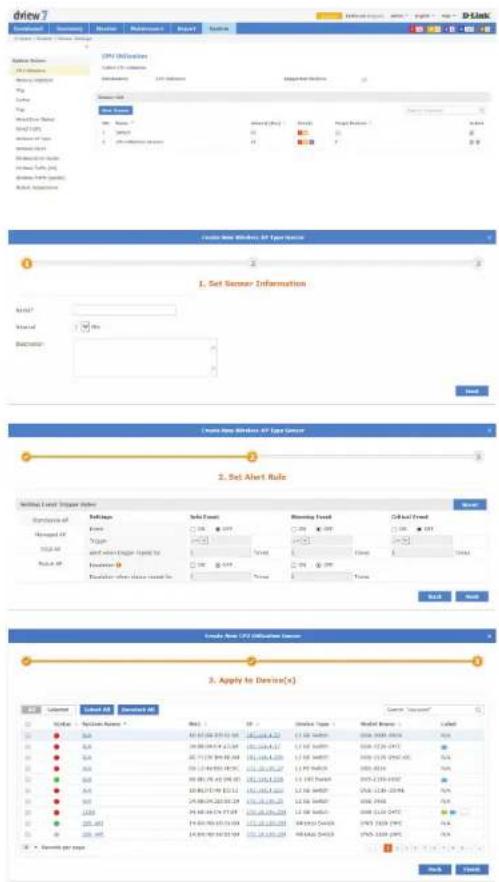
Notification Center
The Notification Center shows the notification rules that have been configured for devices in D-View 7. The name of the notification rule is entered, and then the sensor type, device and alert conditions are selected. These are the conditions that will trigger the alert. After this, the notification method is chosen. This can be an email notification or script execution.
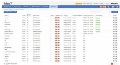
Click the Add Notification Rule button to add a notification rule. Enter the name of the rule and a description and press Next to continue.
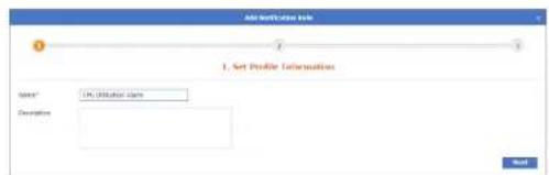
Choose the sensor type. This can be CPU Utilization, Memory Utilization, Ping, Syslog, Trap, Wired Error Packet, Wired Traffic, Wireless AP Type, Wireless Client, Wireless Error Packet, Wireless Traffic (bit), or Wireless Traffic (packet). Depending on the sensor type chosen, a sensor (or device probe) can also be chosen.
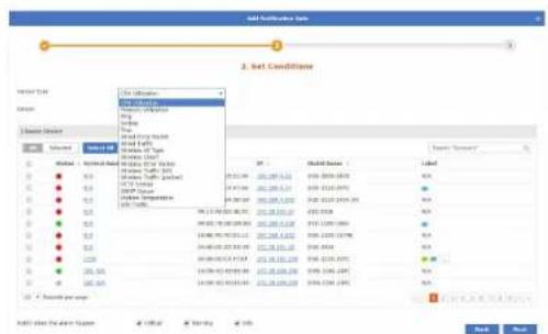
Select the devices to apply to notification rule to. This can be done in the choose device section of the window, and different devices will be displayed, depending on the sensor type chosen. Use the search feature to search for devices in the table, and use the Notify when the alarm happen tick boxes to choose the alert level to provide notifications on. Ensure that at least 1 device is selected, and click Next to continue.
System
Set the notification method. If the email notification is chosen, enter the email address to receive notifications and press Add to add the email address to the notification rule. If the execute script option is chosen, a command line window is displayed to enter the command that needs to be executed on the device being matched by the notification rule. Choose to apply the script to itself or other devices. If the email notification was chosen, press Finish, or if the execute script option was chosen, press Next to continue.
If the execute script option was chosen, use the choose device section of the window to choose the device to apply the command to. Ensure that at least 1 device is selected, and click Next to continue.
Enter the connection method (SSH or Telnet), the username and password required to connect to the device. Ensure that one set of credentials has been entered, and click Next to continue.
Optionally, enter an email address to receive the output from the script and press Add to add the email address to the notification rule. Click Finish to create the notification rule.
System Logs
The System Logs view shows a list of all events that have taken place on the D-View 7 server.
Events may be filtered by entering a keyword into the search box. Available search options will automatically appear under the search box, select the field to filter the results by. The advance search will allow for multiple filtering criteria.
To export a list of all of the events, click on Export to download a CSV file that can be imported into a spreadsheet application.
Trap Editor
The Trap Editor allows the D-View 7 administrator to manage the SNMP traps on the system. New traps can be added, traps can be deleted, and a description can be given to the traps, so that they can be more easily identified.
Click Add to add a new trap or click the Edit button next to an existing trap to display the Add Trap OID Description window. Enter the OID, OID description and select the OID type. This can be Trap OID or Binding Varialbe OID. Press Save when complete.
About
The About view shows the D-View 7 administrator details relevant to the D-View 7 server such as IP, MAC address, system uptime, and software version. By default, the About view shows the Supported Device Model List tab, which list all of the devices that the current version of D-View 7 that is installed is compatible with. To show customized identified devices, click on the Customized Identified Device Model List tab.
Devices may be filtered by entering a keyword into the search box. Available search options will automatically appear under the search box, select the field to filter the results by. The advance search will allow for multiple filtering criteria.
Devices in the Customized Identified Device Model List tab can be edited by clicking on the Edit icon. This will pop up a window that will allow the administrator to input custom values for the Device Type, Model Name, Hardware Version, and Vendor.
The About view also allows the administrator to set the email settings for D-View 7 server. To edit the email settings used, click on the Edit icon next to SMTP Server. This will pop up a window that will allow the administrator to set the proper hostname and credentials that D-View 7 will use to send emails.
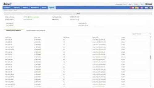
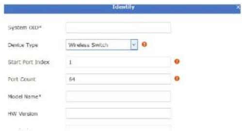
Appendix A MongoDB Database Upgrade
Introduction
This tool is used to upgrade MongoDB from version 2.6 to version 3.2. It can be downloaded from the http://dview.dlink.com/ website.
System Requirements
Please see System Requirements on page 9 for more information.
Procedure
-
Launch the D-View 7 MongoDB upgrade tool application.
-
Read the utility usage announcement on the first page and press Agree if you understand and wish to proceed with the upgrade. If not, close the window to exit the upgrade tool.
dview 7 MongoDB Tool
Utility usage announcement
This tool can help you to upgrade D-View 7 from MongoDB 2.6 to MongoDB 3.2. It can only back up and restore the D-View 7 database. If there are other databases in MongoDB, this tool may cause them to be lost.
* Database backup: This feature can only be used with D-View 7 version 1.0.2.4 to * Database restore: This feature can only be used with D-View 7 version 1.1.0.3 * MongoDB Settings: This feature will uninstall MongoDB 2.6.5 and install MongoDB 3.2.6.
Agree
- The main page displays the Check, Data Backup, MongoDB Settings, and Data Restore options. When running the tool for the first time, the Check button is the only button available, and the remaining buttons become available after the check tool has been run.
Click the Check button to check the MongoDB environment on the PC on which you are running the tool.
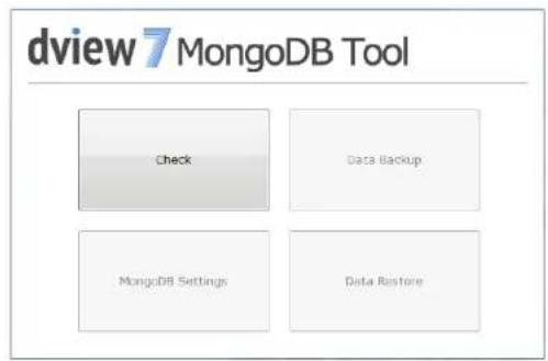
- After clicking the Check button, a confirmation screen will be displayed. Click Check to begin the check, or press Cancel to return to the main screen.
A status message will be displayed, depending on the outcome of the check. Look at MongoDB Database Upgrade Check Results on page 131 for more information. Correct any problems and re-run the upgrade tool, until all checks pass.
- Once the check has been completed successfully, the Data Backup button will be displayed. Click this to perform a backup of the database before performing the upgrade.
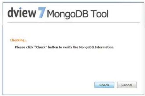
Appendix
- After clicking the Data Backup button, a window is displayed to choose the path of the backup. Enter the path manually or click Browse... to choose a path on the PC.
By default, a "Backup" folder will be created in the same folder as the upgrade tool. Press Backup to start the backup, or press Cancel to return to the main screen.
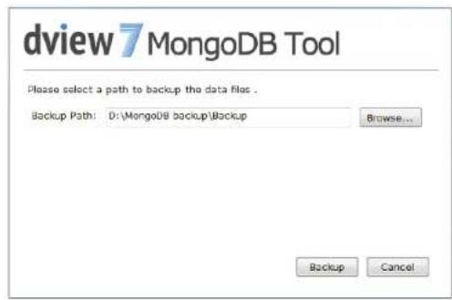
- A dialog box will be displayed with the output of the backup, and the backup will be put in the DView7 sub-folder of the folder selected above.
When complete, and if the backup is successful, press Cancel to return to the main screen.
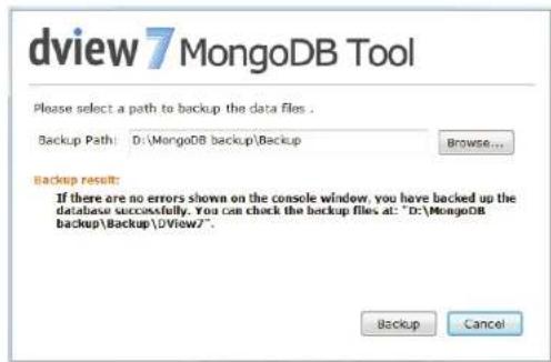
- On the main page, click the MongoDB Settings button to either upgrade the MongoDB, register a Windows service, or install MongoDB. A different option will be available, depending on the status of MongoDB on the PC on which you are running the tool.
i. If the Upgrade button is displayed:
Enter the path to the MongoDB installation or press Browse... to choose a path on the PC.
Note: make sure that you have backed-up your database using the backup option of this tool if you plan to upgrade the database of your existing installation. The original data folder will be emptied.
Tick the "Yes, I have backed-up the original database" box and press Upgrade to start the upgrade, or press Cancel to return to the main screen.
The status of the upgrade will be displayed below the installation path. When the upgrade is complete, press Cancel to return to the main screen.
ii. If the Register button is displayed:
Enter the path to the MongoDB "bin" folder or press Browse... to choose a path on the PC.
Press Register to register the Windows service, or press Cancel to return to the main screen.
When the service registration is complete, press Cancel to return to the main screen.
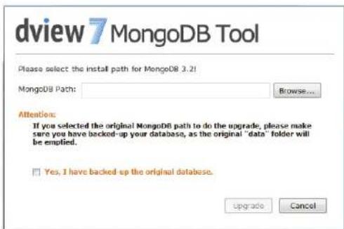
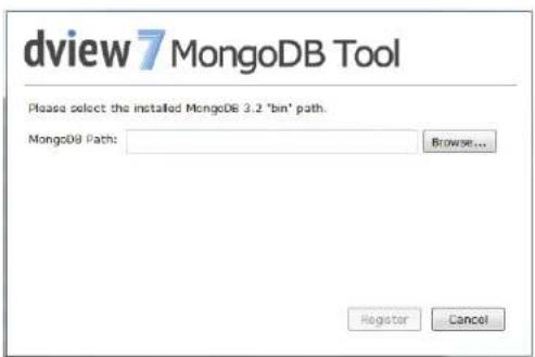
iii. If the Install button is displayed:
Enter the path for the MongoDB installation or press Browse... to choose a path on the PC.
Press Install to start the installation, or press Cancel to return to the main screen.
When the installation is complete, press Cancel to return to the main screen.
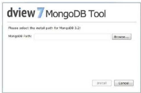
- If MongoDB is installed and registered as a Windows service, the Data Restore button will be displayed. Click this to restore the MongoDB 2.6 database backup taken at the beginning of the process to MongoDB 3.2.
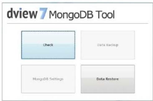
Appendix
- After clicking the Data Restore button, a window is displayed to choose the path of the backup files. Enter the path manually or click Browse... to choose a path on the PC.
Press Restore to start the restoration, or press Cancel to return to the main screen.
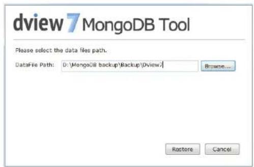
- A dialog box will be displayed with the output of the backup. The key word "done" will be displayed at the end of the output if the restoration was successful. If there was a problem with the process, read the troubleshooting section below for more information.
When complete, press Cancel to return to the main screen.
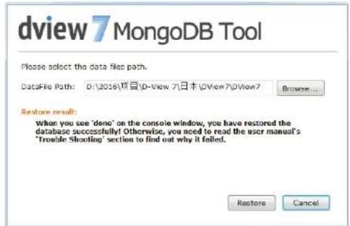
Troubleshooting
The following error messages may be displayed when using the MongoDB upgrade tool Data Backup or Data Restore options.
| Message Solution | |
| Failed: error connecting to db server: no reachable servers | 1. Try to start the MongoDB service in the Windows service manager.2. If the service cannot be started. Please check the “Mongo.config” at the MongoDB install “bin” path, e.g.: D:\MongoDB\bin.The contents of the “Mongo.config” should like follows:directoryperdb = truelogappend = truestorageEngine = wiredTigerwiredTigerDirectoryForIndexes = truewiredTigerCollectionBlockCompressor = zlibserviceName = MongoDBserviceDisplayName = MongoDBlogpath = D:\MongoDB\log.txtdbpath = D:\MongoDB\data3. When MongoDB service started, do the backup or restore again. |
| Failed: DView7.Bas_Template: error reading database: not authorized on DView7 to execute command {listCollections: 1, cursor: {batchSize: 0 }} | Open the “Mongo.config” in the MongoDB install “bin” path, e.g.: D:\MongoDB\bin.Search for the keyword “auth” in the file. If it exists with an entry of “auth = true”, remove it. If it does not exist:Run “cmd” as administratorEnter “sc stop MongoDB” and press EnterEnter “sc delete MongoDB” and press EnterClick the “Check” button to do the environment checkIf the “MongoDB Settings” button was enabled, click it to register the Windows service.Restart the MongoDB service in the Windows service manager.When MongoDB service started, do the backup or restore again. |
MongoDB Database Upgrade Check Results
| MongoDB Version | MongoDB Service Status | Result Button Status | |
| 2.6.5 Be registered as windows service named as “MongoDB” | You have already installed both MongoDB 2.6 and MongoDB 3.2 and MongoDB 2.6 is registered as a Windows service. You can use the "Database Backup" feature to back up the D-View 7 database and the "MongoDB Settings" feature to install, upgrade or register MongoDB 3.2. | Enabled:Data BackupMongoDB SettingsDisabled:Data Restore | |
| 2.6.5 Never | be registered as windows service; No service named “MongoDB” | You have already installed MongoDB 2.6, but it has not been registered as a Windows service. You can use the "MongoDB Settings" feature to upgrade it to MongoDB 3.2, register it as a Windows service, and then use the "Database Restore" feature to restore the backed up files to MongoDB 3.2. | Enabled:MongoDB SettingsDisabled:Data RestoreData Backup |
| 3.2.6 Be registered as windows service named as “MongoDB” | You have already installed MongoDB 3.2 and registered it as a Windows service. You can use the "Database Restore" feature to restore the backed up files to MongoDB 3.2. | Enabled:Data RestoreDisabled:Data BackupMongoDB Settings | |
| 3.2.6 Never | be registered as windows; No service named “MongoDB” | You have already installed MongoDB 3.2, but it has not been registered as a Windows service. You can use the "MongoDB Settings" feature to register it as a Windows service and use the "Database Restore" feature to restore the backed up files to MongoDB 3.2. | Enabled:MongoDB SettingsDisabled:Data BackupData Restore |
| 2.6.53.2.6 | 3.2.6 was registered as windows service named as “MongoDB” | You have already installed both MongoDB 2.6 and MongoDB 3.2 and MongoDB 3.2 is registered as a Windows service. You can use the "Database Restore" feature to restore the backed up files to MongoDB 3.2. | Enabled:Data RestoreDisabled:Data BackupMongoDB Settings |
| 2.6.53.2.6 | 2.6.5 was registered as windows service named as “MongoDB” | You have already installed both MongoDB 2.6 and MongoDB 3.2 and MongoDB 2.6 is registered as a Windows service. You can use the "Database Backup" feature to back up the D-View 7 database and the "MongoDB Settings" feature to install, upgrade or register MongoDB 3.2. | Enabled:Data BackupMongoDB SettingsDisabled:Data Restore |
| 2.6.53.2.6 | One of them was registered as windows service named as “MongoDB”, but the tool cannot analysis which one supply the service. | You have already installed both MongoDB 2.6 and MongoDB 3.2 and one of them is registered as a Windows service. Please uninstall the unregistered one first. | Enabled:NullDisabled:Data RestoreData BackupMongoDB Settings |
| 2.6.53.2.6 | Both them were not be registered as windows; No service named “MongoDB” | You have already installed MongoDB 2.6 and MongoDB 3.2, but they have not been registered as a Windows service. You can use the "MongoDB Settings" feature to register MongoDB 3.2 as a Windows service and use the "Database Restore" feature to restore the backed up files to MongoDB 3.2. | Enabled:MongoDB SettingsDisabled:Data RestoreData Backup |
| No 2.6.5No 3.2.6 | No “MongoDB” service | There is no MongoDB on this PC. You can use the "MongoDB Settings" feature to install MongoDB 3.2, register it as a Windows service, and then use the "Database Restore" feature to restore the backed up files to MongoDB 3.2. | Enabled:MongoDB SettingsDisabled:Data RestoreData Backup |
| No 2.6.5No 3.2.6 | There is a windows services named “MongoDB” | An unknown version MongoDB has been registered as a Windows service. This tool can only be used with the version of MongoDB installed by D-View 7 or this tool. | Enabled:NullDisabled:Data RestoreData BackupMongoDB Settings |
Appendix B Adding a Remote Probe
Introduction
This tool is used to install the probe software on a remote host. This is then added to D-View 7, to monitor devices that are not monitored directly by the probe software on the central D-View 7 host.
The tool can be downloaded from the http://dview.dlink.com/ website.
System Requirements
Please see System Requirements on page 9 for more information.
Installation Procedure
- Launch the D-View 7 probe installation application.
- Press Next on the welcome screen to start the installation process.
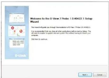
- Read the license agreement and tick the I accept the terms of the License Agreement tick box if you accept the licence agreement and wish to proceed with the installation. Press Next to continue or press Cancel to exit the tool.
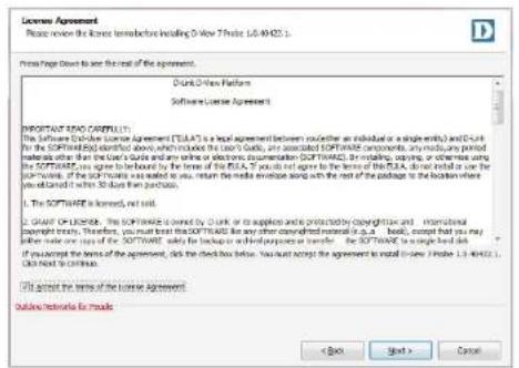
- Enter the installation path for the installation or press Browse to choose a folder on the local file system. The space required and the space available are displayed below the installation folder. Press Install to install the software or press Cancel to exit the tool.
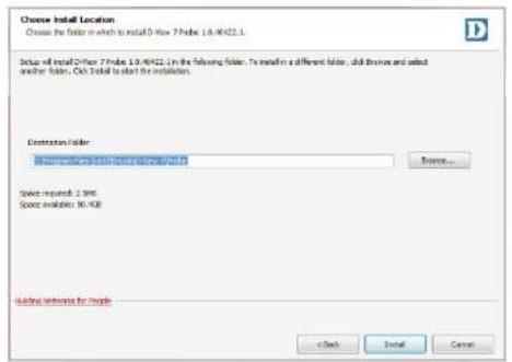
- When the installation has completed, a completion screen is displayed. Click the Run D-View 7 Probe tick box to run the software after exiting the installation tool, and press Finish to exit the tool.
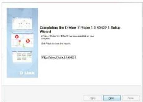
Probe Activation
Once the probe has been installed, it needs to be licensed and added to the central D-View 7 server. When the probe software is run for the first time, a wizard is displayed to configure the licensing and central server settings.
- In the Active Probe section of the window, enter the URL of the core server in the Core Server URL field. This can be a Fully Qualified Domain Name (FQDN) such as: http://dview.dlink.com.tw, or an IP address, such as: http://192.168.0.1. Enter the activation code in the Activation Code field. This is taken from the D-View 7 license page on the core server and is in the format XXXX-XXXX-XXXX-XXXX. See License on page 112 for more information.

If you use the same activation code of another probe, the new probe will replace the old probe, and the old probe will be removed from D-View 7. Probes can only be deactivated through the central D-View 7 interface.
Appendix
- In the Set Probe IP section of the window, select the local probe IP Address to be used with the probe software.
- In the Probe Status section of the window, the local probe status is displayed. Press the Start button to start the probe software, and press Stop to stop the probe software.
Probe Discovery
Access the Discovery page on the central server to set the probe discovery rules. See Discovery & Probe Setting on page 114 for more information.
Appendix C Accessing D-View 7 using HTTPS
Introduction
This is used to configure Microsoft Internet Information Services (IIS) to be accessible using HTTPS. This allows D-View 7 to be accessed either from the Internet or a local LAN using a secure connection.
System Requirements
In this example, IIS 7 is used, but the steps should be similar for any supported Windows Server operating system. Please see System Requirements on page 9 for more information.
In addition to the software requirements, a signed certificate is required. This can either be a self-signed certificate or a certificate signed by a certificate authority. For this example, a self-signed certificate is used, but the process should be similar for a certificate signed by a certificate authority.
The Microsoft URL Rewrite Module 2.0 for IIS 7(x64) software package is also required for this example. This can be downloaded from the Microsoft Download Center.
Installation Procedure
- Download and install the Microsoft URL Rewrite Module 2.0 for IIS 7(x64) package. Once this is complete, restart IIS by using the IIS Manager or by using the CLI. With the IIS Manager open and the server name selected in the Connections panel, you should see the URL Rewrite option displayed in the main window.
-
With the server name selected in the Connections panel, open the Server Certificates tool to launch the Server Certificates interface. In the Actions panel, select Create Self-Signed Certificate to launch the Create Self-Signed Certificate tool.
-
In the Create Self-Signed Certificate tool, specify a name for the certificate. Press OK to continue or Cancel to exit. This should now show up in the Server Certificates interface.
-
In the Connections panel, right-click the Default Web Site entry and select Edit Bindings. In the Site Bindings window, click the Add button and choose https as the Type. Choose the certificate created earlier in the SSL certificate field and press OK to continue or Cancel to exit. Press Close to exit the Site Bindings tool.
-
With the server name selected in the Connections panel, select the URL Rewrite tool and click Add Rule(s)... in the Actions panel which is displayed. In the Add Rule(s) window, under Inbound rules, select Blank rule and press OK to continue or Cancel to exit.
-
In the Edit Inbound Rule window, under Name, give the rule a name such as "HTTP to HTTPS redirect". In the Match URL section, under Pattern, enter a pattern such as "(.*)" (without the quotes).
![Create Self-Signed Certificate Specify Friendly Name Specify a file name for the certificate request. This information can be sent to a certificate authority for agree. Specify a friendly name for the certificate: [MT-CA9]](/content/2026/05/765026/images/cebf8f6b1af2ef077ee3f36e01c2dbbdc178d8eff4d5639e943b56cedbac697d.jpg)
Appendix
- In the Conditions section of the Edit Inbound Rule window, click Add... and enter a Condition input of "{HTTPS}". Under Pattern, enter a pattern of "^OFF\$" and press OK to continue or Cancel to exit.
- In the Action section of the Edit Inbound Rule window, under Action type, choose an Action type of Redirect. Under Action Properties, enter a Redirect URL of "https://{HTTP_HOST}/{R:1}" and a Redirect type of Found (302). In the Actions panel, press Apply to save the settings or Cancel to lose the settings.
- It should now be possible to access D-View 7 using HTTPS. Try accessing D-View 7 using a URL such as https://
/DView7/.
![Add Condition Condition input: [HTTPS] Check if input string: Matches the Pattern Pattern: ^OFF$ Test pattern... Ignore case OK Cancel](/content/2026/05/765026/images/900855469ef889cca1f73e6c2db002760c3552c8796fff9e625db9bd5d6de86a.jpg)
Appendix D Uninstalling MongoDB Manually
Introduction
Uninstalling MongoDB manually may be required if MongoDB is not removed as part of the uninstallation process, or if D-View 7 is installed in a high availability environment and MongoDB is installed on a different server to the D-View 7 server.
See Uninstallation on page 63 for more information on the uninstallation process.
System Requirements
Please see System Requirements on page 9 for more information.
Uninstallation Procedure
- On the server that MongoDB is installed on, go to: Start > All Programs > Accessories, and right-click Command Prompt and choose Run as administrator.
Appendix
-
Enter "sc stop MongoDB" (without the quotes) and press Enter.
-
Enter "sc delete MongoDB" and press Enter.
-
Go to: Start > Control Panel > Programs and Features, choose the MongoDB installation package and press Uninstall. Agree to the dialog box that is presented, asking if you want to uninstall MongoDB.

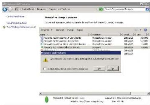
Appendix
- If you wish to uninstall the logs and data, go to the MongoDB installation folder and delete the log text file and data folder.
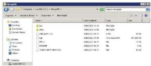
Appendix E
Migrating and Deactivating D-View 7
Introduction
Migrating and deactivating D-View 7 may be required if D-View 7 needs to be moved to another server.

If remote probes are in use, it may be necessary to re-install D-View 7 on a host with the same IP address, in order to avoid re-installing the probe software on each of the remote probes.
The instructions refer to the old server (the D-View 7 being migrated from) and the new server (the D-View 7 server being migrated to). The old server has a licensed, working copy of D-View 7 on it, and the new server is a clean install of the Operating System and has no version of D-View 7 on it.
System Requirements
These instructions are for D-View 7 version 1.2.1.0.
Please see System Requirements on page 9 for more information on the system requirements for D-View 7.
Migration and Deactivation Procedure
- In D-View 7 on the old server, go to: System > License and click Unbind Licence. Press OK when asked if you are sure you want to unbind the licenses. This will return D-View 7 to a trial version. See License on page 112 for more information on the License page.
Alert

Once you unbound, all the license(s) in system will be released. The number of node and probe that can be use will be reset to trial. You can reuse the license(s) by 'Add License' or 'Upgrade' in D-View7. Are you sure you want to unbind the license(s)?
OK
Cancel
- On the old server, go to: Start > All Programs > Accessories > Command Prompt. Change directory to the folder that MongoDB is installed in and run mongo.exe to try to connect to the database:
cd D:\MongoDB\bin mongo.exe
If there are any problems connecting to the database, ensure MongoDB is started by using the Windows Services manager.
-
If the database is running, type "use admin" to switch to the admin database.
-
Type "show users" to check whether you are authorized to use the admin database. If you get an "Error: not authorized message", enter the following to log-in as the admin user:
db.auth('admin','admin')
A result of "1" indicates that the command was successful.
- Enter "use DView7" to switch to the DView7 database.
- Enter the following to create a new user to perform the database backup:
db微信公众({ user:"dview", })
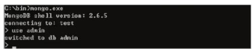

pwd:"dview",
roles:[{
    role:"readWrite",
    db:"DView7"
}]
})
- Exit the database session by typing "exit".
- Run the following command at the Windows command line, substituting your own values for the ones below:
mongodump.exe -h host -d dbName -o dir -u user -p pwd
The values are:
-h: The MongoDB host IP address, e.g.: 127.0.0.1
-d: The database instance which is to be backed up, e.g. DView7
-o: The path of the database backup. It should be created before the backup operation and should be different to the MongoDB installation path.
-u: The username of the database user created earlier
-p: The password of the database user created earlier
For example:
mongodb.exe -h 127.0.0.1 -d DView7 -o "D:\MongoDB backup" -u dview -p dview
-
Install D-View 7 on the new server. Once complete, if migrating to a new server with the same IP address, it may be necessary to deactivate the old server. This can be done by taking the old server offline or stopping the D-View 7 Core Server service.
-
On the new D-View 7 server, perform the steps above to create the "dview" user.
![].createUser( ... user:"dvieu", ... pod:"dvieu", ... rules:I( ... role:"readWrite", ... db:"DO ieu?"" ... ) ] ... >> Successfully added user: ( "user": "dvieu", "rules": 1 ( "role": "readWrite", "db": "Diseu?" ) 1](/content/2026/05/765026/images/c272d3a4e538d4071fdf064a7688c70964d3b32cced3966210b72b256520ceee.jpg)
- Run the following command at the Windows command line, substituting your own values for the ones below:
mongorestore.exe -h host -d dbName -o dir -u user -p pwd -drop
The values are:
-h: The MongoDB host IP address, e.g.: 127.0.0.1
-d: The database instance which is to be backed up, e.g. DView7
-o: The path of the database backup. Add the "DView7" folder to the original backup path to provide the full path to the backup made earlier
-u: The username of the database user created earlier
-p: The password of the database user created earlier
-drop: Drop the existing database so that the restore can be performed
For example:
mongorestore.exe -h 127.0.0.1 -d DView7 -o "D:\MongoDB backup\DView7" -u dview -p dview -drop
- In D-View 7 on the new server, go to: System > License > Add License and upload the license previously removed from the old server. See License on page 112 for more information on the License page.
Once the process is complete, ensure that the previous version of D-View 7 on the old server remains deactivated.
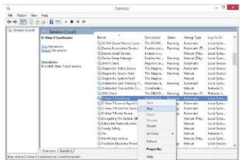
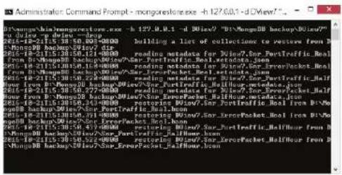
Appendix F RESTAPI Development Guide
Below is a guide to writing an custom API to retrieve and send information to and from D-View 7.
List of Return Status Codes
| Status Code Description |
| -1 Invalid Request |
| 0 Execute Success |
| 1 Unknown error |
| 101 API KEY invalid |
| 103 Invalid operation method |
| 105 Data format exception |
| 106 API KEY not activated |
| 107 The task does not exist or has been deleted |
| 108 The task type is not supported |
List of Action Commands
| Status Code Description | |
| getProbeInfoList Retrieve | the list of the activated probes |
| getProbeInfo Retrieve a unique probe's information | |
| getProbeDiscoverParaList | Retrieve a unique probe's discovery rules |
| setProbeInfo Update the probe's information | |
| delDiscoverParaList Delete | a unique probe's discovery rules |
| addDiscoverPara Add a new discovery rule to a unique probe | |
| getDeviceList | Retrieve devices' basic information |
| createTask | Create a supported task to devices |
| getTaskResultInfo Get the | task information and execute result |
| uploadFile Upload a file to | D-View 7 |
| createSnmpTask Create a | SNMP task to get a specific OID's value |
| getSnmpTaskResultInfo G | get the executed SNMP task's result usually been used with createSnmpTask API |
uploadFile API - Upload Device's Configuration File or Firmware File to D-View
Request URL:
- {D_View_7_Url}/api/json/Api.aspx?apiKey=NPXT7x2jll30A3kMFI4oAyeGxnPORAKQ&action=uploadFile
Request Method:
- Post
Parameters List
| Parameter Name | Required Type Description | ||
| apiKey Yes string | The REST API Key to access D-View 7 | ||
| action | Yes string Operation method | ||
| file | Yes | file | A file that is about to be uploaded |
Example of Data Return:
{
    "fileId": "5b1f6b6edf11a91fbcad7f44",
    "fileName": "uploadFile.cfg",
    "message": "SUCCESS",
    "status_code": 0
}
Returned Parameters List Description
| Parameter Name Type Description | |
| status_code int Return status code | |
| message string Return message | |
| fileId string Return the successfully uploaded file's ID; the ID will be used by the "createTask" API to create "Firmware Upgrade" task or "Configuration Restore" task | |
| fileName string Return the successfully uploaded file's name; the name will be used by the "createTask" API to create "Firmware Upgrade" task or "Configuration Restore" task |
Example of File Upload (in C#):
using System;
using System.Collections.Generic;
using System.Linq;
using System.Text;
using System.Net;
using System.IO;

namespace ConsoleApplication1
{
    class UpLoadFile
    {
    public string Name { set; get; }
    public string FileName { set; get; }
    public string Content_Type { set; get; }
    public byte[] Data { set; get; }
    }

class Program
Appendix
{
    /// <summary>
    /// Converting files into byte[] arrays
    /// </summary>
    /// <param name="fileName"></param>
    /// <returns></returns>
    private static byte[] FileContent(string fileName)
    {
    FileStream fs = new FileStream(fileName, FileMode.Open, FileAccess.Read);
    try
    {
    byte[] buffer = new byte[fs.Length];
    fs.Read(buffur, 0, (int)fs.Length);
    return buffer;
    }
    catch (Exception ex)
    {
    return null;
    }
    finally
    {
    if (fs != null)
    {
    fs.Close();
    }
    }
}

/// <summary>
/// Initiating a HTTP POST request, to upload the file
/// </summary>
Appendix
/// <param name="url">Request URL</param>
/// <param name="file">File</param>
/// <param name="endoding">Code Method</param>
/// <returns></returns>
public static string PostResponse(string url, UpLoadFile file, Encoding endoding)
{
    string boundary = "----" + DateTime.Now.Ticks.ToString("x");
    WebRequest request = (HttpWebRequest)WebRequest.Create(url);
    request.ContentType = "multipart/form-data; boundary=" + boundary;
    request.Method = "POST";
    request.KeepAlive = true;
    request.Expect = "";

    MemoryStream stream = new MemoryStream();
    byte[] line = Encoding.ASCII.GetBytes("--" + boundary + "\r\n");
    byte[] enterER = Encoding.ASCII.GetBytes("\\r\n");
    ///submit file
    if (file != null)
    {
    string fformat = "Content-Disposition:form-data; name=\"{0\";filename=\"{1\"\r\nContent-Type:{2}\r\n\r\n";
    stream.Write(line, 0, line.Length); //item separator
    string s = string.Format(fformat, file.Name, file.FileName, file.Content_Type);
    byte[] data = Encoding.UTF8.GetBytes(s);
    stream.Write(data, 0, data.Length);
    stream.Write(file.Data, 0, file.Data.Length);
    stream.Write(enterER, 0, enterER.Length); //add \r\n
    }

    byte[] foot_data = Encoding.UTF8.GetBytes("--" + boundary + "--\r\n"; //The final delimiter string of the item needs to be taken with--
    stream.Write(foot_data, 0, foot_data.Length);
request.ContentLength = stream.Length;
Stream requestStream = request.GetRequestStream(); // Write request data
stream.Position = 0L;
stream.CopyTo(requestStream); //
stream.Close();
requestStream.Close();
try
{
    HttpWebResponse response;
    try
    {
    response = (HttpWebResponse)request.GetResponse();
    try
    {
    using (var responseStream = response.GetResponseStream())
    using (var mstream = new MemoryStream())
    {
    responseStream.CopyTo(mstream);
    string message = endoding.GetString(mstream Approval());
    return message;
    }
    }
    catch (Exception ex)
    {
    throw ex;
    }
    }
    catch (WebException ex)
    {
    throw ex;
    }
}
catch (Exception ex)
Appendix
{
    throw ex;
}
static void Main(string[] args)
{
    UpLoadFile file = new UpLoadFile();
    file.Name = "C:\\Users\\Administrator\\Desktop\\DView7\\uploadFile.cfg";
    file.FileName = "uploadFile.cfg";
    file.Content_Type = "application/octet-stream";
    file.Data = FileContent(file.Name);

string msg = PostResponse("http://localhost:8080/api/json/Api.aspx?apiKey=NPXT7x2jll30A3kMFI4oAyeGxnPORAKQ&action=uploadFile", file, Encoding.UTF8);
}
Example of File Upload (in HTML):
<html>
<head>
<style>
form{width: 450px;}
div{padding:10px 10px;text-align: center;}
form div select,input,textarea{width: 250px;}
form div span{width: 100px;float:left;text-align:left;padding:0 20px;}
.btn{float: right;width: 120px;}
</style>
</head>
<body>
<form action="http://175.18.172.22/DView7/api/json/Api.aspx?apiKey=UpHkF7abCDEFGHGfzUqHvqAbXJOXXX&action=uploadFile" method="post" enctype="multipart/form-data">
    <div>
    <span>File Type</span>
    <select name="fileType">
    <option value="CFG" selected="selected">CFG</option>
    <option value="FW">FW</option>
    </select>
    </div>
    <div>
    <span>File Note</span>
    <textarea name="fileNote" maxlength="255" rows="3" cols="20"></textarea>
    </div>
    <div>
    <span>Select File</span>
    <input type="file" name="file"/>
    </div>
    <div>
    <input type="submit" value="Upload File" class="btn"/>
    </div>
    </form>
</body>
</html>

<!--
The action format is {DV7_WEB_URL}/api/json/Api.aspx?apiKey=UpHkF7abCDEFGHGfzUqHvqAbXJOXXX&action=uploadFile;
You need to modify the {DV7_WEB_URL} and apiKey based on your real test environment;-->
getProbeInfoList API - Get All Activated Probe Information List
Request URL:
- {D_View_7_Url}/api/json/Api.aspx?apiKey=NPXT7x2jll30A3kMFI4oAyeGxnPORAKQ&action=getProbeInfoList
Request Method:
- Get
Parameters List
| Parameter Name Required Type Description | ||
| apiKey Yes string The REST API Key to access D-View 7 | ||
| action Yes string Operation method | ||
Example of Data Return
{
    "data": [
    {
    "Active": true,
    "AutoDiscover": true,
    "Description": "",
    "IP": "localhost",
    "Interval": 1800,
    "Location": "",
    "MAC": "00:0C:29:61:0F:0F",
    "Name": "Local Probe",
    "Online": false,
    "PBID": "599d6187bcccccc25fc185780",
    "PBSN": "local",
    "Version": "1.0.6.1"
    },
    ]
}
Appendix
{
    "Active": true,
    "AutoDiscover": true,
    "Description": "",
    "IP": "172.18.190.254",
    "Interval": 1800,
    "Location": "",
    "MAC": "FC:45:96:32:5A:FC",
    "Name": "London",
    "Online": false,
    "PBID": "58f02daaa7c4a1212c43e6af",
    "PBSN": "BJAZ-ZKEZ-PJMZ-ZCYP",
    "Version": "1.0.5.3"
},
],
"message": "SUCCESS",
"status_code": 0
}
Returned Parameters List
| Parameter Name | Type | Writable Description | |
| status_code | int No | Returns | status code |
| message string | No | Returns | message |
| Name string | Yes | Probe | Name |
| Description string | Yes | Probe | description |
| Location | string | Yes | Probe location |
| Interval | int | Yes | The auto discover time interval, value List: 300, 900, 1800, 3600 (seconds) |
| AutoDiscover | bool | Yes | True: autoDiscover, false: disable autoDiscover |
| Active | bool | No True: activated, false: not active | |
| IP | string No | Probe server | IP address |
Appendix
| MAC string No Probe | be server | MAC address | |
| Online bool No Probe | connecting status | true: online, false: offline | |
| PBID string No Probe | unique ID | ||
| PBSN string No Probe | serial number | ||
| Version string No | Probe version | ||
getProbeInfo API - Get Probe Basic Information
Request URL:
- {D_View_7_Url}/api/json/Api.aspx?apiKey=NPXT7x2jll30A3kMFI4oAyeGxnPORAKQ&action=getProbeInfo&probeSN=local
Request Method:
- Get
Parameters List
| Parameter Name | Required Type | Description | |
| apiKey | Yes | string | The REST API Key to access D-View 7 |
| action | Yes | string | Operation method |
| probeSN | Yes | string | Probe association code |
Example of Data Return
{
    "data": [
    {
    "Active": true,
    "AutoDiscover": true,
    "Description": "",
    "IP": "localhost",
    "Interval": 1800,
    "Location": "",
Appendix
"MAC": "00:0C:29:61:0F:0F",
"Name": "Local Probe",
"Online": false,
"PBID": "599d6187b7c4a125fc185780",
"PBSN": "local",
"Version": "1.0.6.1"
}
],
"message": "SUCCESS",
"status_code": 0
}
Returned Parameters List
| Parameter Name | Type | Writable Description | |
| status_code | int No | Returns | status code |
| message string | No | Returns | message |
| Name string Yes | Probe Name | ||
| Description | string | Yes | Probe description |
| Location | string Yes | Probe Location | |
| Interval | int | Yes | The auto discover time interval, value List: 300,900,1800,3600, (unit in seconds) |
| AutoDiscover | bool | Yes | True: autoDiscover, false: disable autoDiscover |
| Active | bool | No True: activated, false: not active | |
| IP | string No | Probe server IP address | |
| MAC | string No | Probe server MAC address | |
| Online | bool | No Probe connecting status; true: online, false: offline | |
| PBID | string No | Probe unique ID | |
| PBSN string No Probe | be serial | number, th | e PBSN can be retrieved by calling the "getProbInfoList" API |
| Version string No | Probe version | ||
setProbeInfo API - Update Probe Information
Request URL:
- {D_View_7_Url}/api/json/Api.aspx?apiKey=NPXT7x2jll30A3kMFI4oAye
GxnPORAKQ&action=setProbeInfo&autoDiscover=true&interval=180
0&location=&name=local&pbid=599d6187b7c4a125fc185780
Request Method:
- Post
Parameters List
| Parameter Name | Required Type | Writable | Description | |
| apiKey | Yes | string | No | The REST API Key to access D-View 7 |
| action | Yes | string | No | Operation method |
| autoDiscover | Yes | bool | Yes | True: autoDiscover, False: disable autoDiscover |
| name | Yes | string | Yes | Probe Name (Local probe's name cannot be modified. Maximum length of name is 32 characters.) |
| location | Yes | string | Yes | Probe location (It can be set as empty. The maximum length that can be set is 32.) |
| interval Yes int Yes | The auto-disc | over time | interval, | value list: 300, 900, 1800, 3600 (seconds) |
| pbid Yes string No | Probe ID |
Example of Data Return
{
    "data": "",
    "message": "SUCCESS",
    "status_code": 0
}
Returned Parameters List
| Parameter Name Type Description | |
| status_code int Returns the status code | |
| message | string Returns the message |
getProbeDiscoverParaList API - Get the Probe's Discovery Rules List
Request URL:
- {D_View_7_Url}/api/json/Api.aspx?apiKey=NPXT7x2jll30A3kMFI4oAyeGxnPORAKQ&action=getProbeDiscoverParaList&probeSN=local
Request Method:
- Get
Parameters List
| Parameter Name | Required | Type Description | |
| apiKey | Yes | string | The REST API Key to access D-View 7 |
| action | Yes | string Operation method | |
| probeSN Yes string | Probe serial number | ||
Example of Data Return
{
    //Local Probe
    "data": [
    {
    "IPCoverageType": 0,
    "IPPara": "172.18.190.1-172.18.190.200",
    "IPVersion": 0,
    "Name": "mptest",
    "PBSN": "local",
    "SNMPConfig": [
    "public@private",
    ""
    ],
    "SNMPVersion": 1,
    "id": "23c557f6-3137-4caf-8f4c-dc70c1b32e70"
    }
    ],
    "message": "SUCCESS",
    "status_code": 0
    }

    {
    //Remote Probe
    "data": [
    {
    "IPCoverageType": 1,
    "IPPara": "192.168.4.0/24",
    "IPVersion": 0,
    "Name": "",
    }
}
Appendix
"PBSN": "TTZEZ-EETZ-CCKZ-DDKX",
"SNMPConfig": [
    "public@private",
    ""
],
"SNMPVersion": 3,
"id": "ae72a891-ebeb-4a6d-8678-9272fceb03b0"
},
{
"IPCoverageType": 1,
"IPPara": "192.168.0.1-192.168.1.254",
"IPVersion": 0,
"Name": "AliaTest",
"PBSN": "TTZEZ-EETZ-CCKZ-DDKX",
"SNMPConfig": [
    "ROωRW"
],
"SNMPVersion": 0,
"id": "5b4c693457c444434582b7287"
}
,"message": "SUCCESS",
"status_code": 0
Returned Parameters List
| Parameter Name | Type | Writable Description |
| status_code int No | Returns | the status code |
| message string No | Returns | the message |
| PBSN | string No | The probe's serial number that the discovery rules belong to. |
| id string No The discovery rule's unique ID | |||
| Name string Yes The discovery rule's name | |||
| SNMPVersion int Yes The discovery rule's SNMP version | |||
| SNMPConfig | array | Yes | The discovery rule's SNMP Communities; use the "ω" symbol to separate |
| IPCoverageType | int | Yes | The discovery rule's IP Coverage type |
| IPVersion | int | Yes | The discovery rule's IP address type |
| IPPara | string Yes | The discovery rule's IP range | |
"IPCoverageType" Values List
| Value | Description |
| 0 | IP Range |
| 1 | IP Subnet |
| 2 | Reserved |
| 3 | Import a CSV file to configure the IP addresses |
Note: Values 2 and 3 are currently not supported
"IPVersion" Values List
| Value | Description |
| 0 | IPV4 |
| 1 | IPV6 |
Note: IPV6 is currently not supported
Note: Values 2, 4, 5 are currently not supported
"SNMPVersion" Values List
| Value | Description |
| 0 | SNMPv1 |
| 1 SNMPv2 | |
| 2 SNMPv3 | |
| 3 SNMPv1v2 | |
| 4 SNMPv2v3 | |
| 5 SNMPv1v2v3 | |
addDiscoverParaList API - Add Probe Discovery Rule
Request URL:
- {D_View_7_Url}/api/json/Api.aspx?apiKey=NPXT7x2jll30A3kMFI4
oAyeGxnPORAKQ&action=addDiscoverPara&probeSn=local&ipCo
verageType=0&ipPara=172.18.190.1-172.18.190.200&ipVersion=0-
&name=discoverPara&roCommunity=public&rwCommunity=private&snmpVersion=1
Request Method:
- Post
Parameters List
| Parameter Name | Required Type | Description | |
| apiKey Yes string | The REST API Key to access D-View 7 | ||
| action Yes string | Operation method | ||
| probeSn Yes string | Probe serial number | ||
| ipCoverageType | Yes | int | The discovery rule's IP Coverage Type, 0: IP range, 1: IP subnet |
| ipPara Yes string | information, | IP range e.g.: 192.168.0.1-192.168.0.100, IP subnet e.g. 192.168.0.10/24 | |
| ipVersion Yes int IP | address version, 0: IPv4, only IPv4 is supported for the time being | ||
| name Yes string The | discovery rule's name | ||
| roCommunity Yes | string The discovery rule's SNMP read-only community | ||
| rwCommunity Yes | string The discovery rule's SNMP read/write community | ||
| snmpVersion Yes int SNMP version (SNMP V3 currently not supported) | |||
Example of Data Return
{
    "data": "",
    "message": "SUCCESS",
    "status_code": 0
}
Returned Parameters List
| Parameter Name | Type Description | |
| status_code | int | Returns the status code |
| message | string | Returns the message |
"IPCoverageType" Values List
| Value | Description |
| 0 | Set IP range |
| 1 | Set IP subnet mask |
"IPVersion" Values List
| Value Description | |
| 0 IPV4 | |
Note: IPV6 is currently not supported
"SNMPVersion" Values List
| Value Description | |
| 0 SNMPv1 | |
| 1 SNMPv2 | |
| 3 SNMPv1/v2 | |
Note: SNMPv3 is currently not supported
delDiscoverParaList API - Delete Probe Discovery Rule
Request URL:
- {D_View_7_Url}/api/json/Api.aspx?apiKey=NPXT7x2jll30A3kMFI4oAyeGxnPORAKQ&action=delDiscoverParaList&probeld=599d6187b7c4a125fc185780&probeSn=local&id s=23c557f6-3137-4caf-8f4c-dc70c1b32e70,23c557f6-3137-4caf-8f4c-dc70c1b32e70
Request Method:
- Post
Parameters List
| Parameter Name Required Type Description | |
| apiKey Yes string The REST API Key to access D-View 7 | |
| action Yes string Operation method | |
| probeSN Yes string | Probe serial number | |
| probeld Yes string | Probe ID | |
| ids Yes string The | discovery rule's ID(s) that needs to be deleted; to delete multiple discovery rules use a comma "," to separate; if the set is empty, it means that all the discovery rules under this probe will be deleted. | |
Example of Data Return
{
    "data": "",
    "message": "SUCCESS",
    "status_code": 0
}
Returned Parameters List
| Parameter Name Type Description | |
| status_code int Returns the status code | |
| message string Returns the message |
getDeviceList API - Get List of all D-View7 Managed and Identified Devices
Request URL:
-
Get all managed devices list:
{D_View_7_Url}/api/json/Api.aspx?apiKey=NPXT7x2jll30A
3kMFI4oAyeGxnPORAKQ&action=getDeviceList -
Get managed devices list by probe:
{D_View_7_Url}/api/json/Api.aspx?apiKey=NPXT7x2jll30A3kMFl4
oAyeGxnPORAKQ&action=getDeviceList&probeSn=local
3. Get managed devices list by IP range and probe:
{D_View_7_Url}/api/json/Api.aspx?apiKey=NPXT7x2jll30A3kMFl4oAyeGxnPORAKQ
&action=getDeviceList&probeSn=local&startIp=192.168.0.1&endlp=192.168.0.100
Request Method:
- Get
Parameters List
| Parameter Name Required Type Description | |||
| apiKey Yes string T | The REST API Key to access D-View | 7 | |
| action Yes string O | Operation method | ||
| probeSn No string | Filter the devices by probe. It can be null; it can be used in combination with startIp and endIp; it can also be used alone. | ||
| startIp No string F | Iter the devices by IP range. It can be null and needs to be used with endIp at the same time. | ||
| endlp | No string Filter the devices by IP | range. It can be null, and needs to be used with startIp at the same time. | |
Example of Data Return
{
    "data": [
    {
    "contact": "",
    "description": "DWS-3160-24PC Gigabit Ethernet Switch",
    }
}
Appendix
"devId": "59eebbccb7c4a15ae014592b",
"deviceType": "Wireless Switch",
"discoverTime": "/Date(1508813484921+0800)/",
"fwVersion": "1.00.038",
"hwVersion": "A1",
"ip": "172.18.190.209",
"location": "",
"mac": "14:D6:4D:60:E6:60",
"modelName": "DWS-3160-24PC",
"oid": "1.3.6.1.4.1.171.10.117.1.1",
"serialNumber": "R3B33C2000005",
"snmpPrivilege": "RO",
"status": 0,
"supportTaskKind": [
    "LLDPOn",
    "LLDPOff",
    "SyslogOff",
    "SyslogOn",
    "TelnetOff",
    "TelnetOn",
    "TelnetOff",
    "TelnetOn",
    "TrapOff",
    "TrapOn",
    "WebOff",
    "WebOn",
    "SpanningOff",
    "SpanningOn",
    "SafeguardOff",
    "SafeguardOn",
    "ConfigBackup",
    "ConfigRestore",
    "FirmwareUpgrade",
Appendix
"Reboot"
],
"sysName": "DGS-3120-24TC",
"vendor": "D-Link"
}
],
"message": "SUCCESS",
"status_code": 0
}
Returned Parameters List
| Parameter Name | Type Description | |
| status_code int | Returns the status code | |
| message string | Returns the message | |
| data array Return | the list of filtered devices | |
| snmpPrivilege string | D-View 7 SNMP pr | privilege for devices. RW: Read-Write Privilege, RO: Read-Only Privilege |
| status int Device's | online/offline status | 0: Online, 1: Offline,2: Unknown (means its attached probe has been disconnected from the D-View 7 core server.) |
| supportTaskKind | array | The device's supported task types: "LLDPOn","LLDPOff", "SyslogOff", "SyslogOn", "TelnetOff","TelnetOn", "TelnetOff", "TelnetOn","TrapOff", "TrapOn", "WebOff", "WebOn","SpanningOff", "SpanningOn", "SafeguardOff","SafeguardOn", "ConfigBackup", "ConfigRestore","FirmwareUpgrade", "Reboot". |
getTaskResultInfo API - Get the Created Task's Execution Result
Request URL:
- {D_View_7_Url}/api/json/Api.aspx?apiKey=NPXT7x2jll30A3kMFI4oAyeGxnPO RAKQ&action=getTaskResultInfo&taskId=5ab0c8a4b7c4a11db4594a1b
Request Method:
- Get
Parameters List
| Parameter Name | Required Type | Description |
| apiKey Yes string | The REST API | Key to access D-View 7 |
| action Yes string | Operation method | |
| taskId Yes string | The created task's ID can | be retrieved from running createTask API |
Example of Data Return
{
    "data": "5b4d8a7ab7c4a128d4ab9160",
    "message": "SUCCESS",
    "status_code": 0
}

{
    "data": {
    "createTime": "2018-06-10 22:47:49",
    "endTime": "2018-06-10 22:47:49",
    "startTime": "2018-06-10 22:47:49",
    "taskId": "5b1d3a15df11a92374e56184",
    "taskKind": "ConfigRestore",
Appendix
{
    "taskResult": "Failed",
    "taskResultDetail": [
    {
    "content": "Receive result timeout!",
    "devIP": "172.18.190.5",
    "devId": "58c8df15b7c4a14064a2abff",
    "devMac": "1C:7E:E5:29:ED:07",
    "status": "Failed"
    },
    {
    "content": "Receive result timeout!",
    "devIP": "172.18.190.233",
    "devId": "58c8df16b7c4a14064a2ac39",
    "devMac": "00:05:5D:8F:12:52",
    "status": "Failed"
    }
    ],
    "taskState": 3
},
"message": "SUCCESS",
"status_code": 0
}
Returned Parameters List
| Parameter Name Type Description | |
| status_code int Returns the status code | |
| message string Returns the message | |
| taskState int The task's current status, 0: Running, 1: Pause, 2: Task has been deleted, 3: Finished | |
| createTime string The task's creation time | |
| endTime string The task execution end time (it can be null) | |
| startTime string The task execution start time (it can be null) | |
| taskId string The task ID | |
| taskKind string The task type | |
| taskResult string The result | state of the task's execution (Failed to Deliver,Partially Delivered, Delivered, Partially Done, Delivering,Failed, Done) |
| taskResultDetail array The result of running Task Execution of each device | |
| devIP string Device IP | |
| devId string Device ID | |
| devMac string Device MAC | |
| content string Task execution result detailed information | |
| status string The result state of each device's task execution (Failedto Deliver, Partially Delivered, Delivered, Partially Done,Delivering, Failed, Done) | |
createTask API - Create Task to Modify a Device's Configuration
Request URL:
- Restore Configuration:
{D_View_7_Url}/api/json/Api.aspx?apiKey=NPXT7x2jll30A3kMFI4oAyeGxnPORA KQ&action=createTask&taskName=target1&taskKind=ConfigRestore&devId=58c8 df15b7c4a14064a2abff&fileId=5b1a4c50df11a9398c6b39f9&fileName=file.cfg
- Telnet On:
{D_View_7_Url}/api/json/Api.aspx?apiKey=6eSJcUi15qwrzN9ppLy5gE5h3Hue0IX3&action=createTask&taskName=Telnet_on&taskKind=TelnetOn&devId=59eeccccb7c4a15ae014592b&port=23
- LLDP Off:
{D_View_7_Url}/api/json/Api.aspx?apiKey=6eSJcUi15qwrzN9ppLy5gE5h3Hue0IX3&action=createTask&taskName=API_SystemConfig&askKind=SystemConfig&devId=59eeccccb7c4a15ae014592b&sysNa
me=DGS-3120-24TC&sysLocation=RD-Lab&sysContact=Tom
Request Method:
- Post
Parameters List
| Parameter Name | Required Type Description | ||
| apiKey Yes string | The REST API | Key to access D-View 7 | |
| action Yes string | Operation method | ||
| taskName Yes string | The name of the task | to be created | |
| taskKind Yes string | The type of the task | to be created. (For more information, please check the supported tasks type list) | |
| devId Yes string | The ID of the device which will execute the task; only one device can be set. | ||
| fileId | No | string The ID of the file which will be used to do the Configuration Restore or Firmware Upgrade task. The ID can be retrieved after calling the "UploadFile" API | |
| fileName | No | string | The name of the file which will be used to do the Configuration Restore or Firmware Upgrade task. File can be retrieved after calling the "UploadFile" API |
| port | No | int | The UDP port number; when a TelnetOn, SSHOn and WebOn task has been created, this parameter needs to be set a value. |
| sysName No string | The device's System | Name; when creating a SystemConfig Task, this parameter needs to be set a value. |
| sysLocation No string | The device's sysL | location; when creating a SystemConfig Task, this parameter need to be set a value. |
| sysContact No string | The device's sysC | contact; when creating a SystemConfig Task, this parameter need to be set a value. |
Example of Data Return
{
    "error_code": 0,
    "message":"SUCCESS",
    "data":"5b1a4cbfdf11a9398c6b3a00"
}
Returned Parameters List
| Parameter Name Type Description | |
| status_code int Returns status code | |
| message string Returns message | |
| data | string The probe's serial number that the discovery rules belong to |
List of Supported Task Types
| Parameter Name | Description |
| ConfigRestore | Restore the device's configuration. |
| FirmwareUpgrade | Upgrade the device's firmware. |
| SystemConfig | Update the System Name, System Location and System Contact value. |
| LLDPOff | Disable the LLDP feature. |
| LLDPOn Enable the | LLDP feature. |
| SyslogOff Disable the | the device's Syslog global status and delete all syslog host. |
| SyslogOn Enable the | the device's Syslog global status and create a host point to the D-View 7. |
| TelnetOff Disable the | the device's telnet. |
| TelnetOn Enable the | the device's telnet, configure a telnet UDP port. The UDP port by default is set as 23. |
| SSHOff Disable the | device's SSH. |
| SSHOn Enable the | device's SSH, configure a SSH UDP port. The UDP port by default is set as 22. |
| TrapOff Disable the | device's SNMP trap global status and delete all SNMP trap hosts. |
| TrapOn Enable the | device's SNMP trap global status and create a host point to the D-View 7. |
| WebOff Disable the | device's Web. |
| WebOn Enable the | device's Web, configure a Web port. The Web port by default is set as 80. |
| SpanningOff | Disable the device's STP. |
| SpanningOn | Enable the device's STP. |
| RmonOff Disable the | the device's RMON. |
| RmonOn | Enable the device's RMON. |
| SafeguardOff | Disable the device's Safeguard. |
| SafeguardOn | Enable the device's Safeguard. |
| WebHttpsOff | Disable the device's Web HTTPS. |
| WebHttpsOn Enable | the device's Web HTTPS, configure a Web HTTPS port. The web https port by default is set as 443. |
| Reboot Reboot the | device |
createSnmpTask API - create a customized snmp task to get a specific OID's value from device(s)
Request URL:
{D_View_7_Url}/api/json/Api.aspx?apiKey=NPXT7x2jll30A3kMFl4oAyeG
xnPORAKQ&action=createSnmpTask&oid=1.3.6.1.2.1.1.2.0&valueType=3
&devIds=58c8df15b7c4a14064a2abff,58c8df16b7c4a14064a2ac39
Request Method:
- Post
Parameters List
| Parameter Name | Required Type Description | ||
| apiKey Yes string | The REST API | Key to access D-View 7 | |
| action | Yes string | Operation method | |
| oid | Yes string | The specific OID which has been used to get its value | |
| valueType | Yes | int | Returns the OID value's data type. Only three types are supported for the time being: Number, Boolean, String |
| devIds Yes string | The device's | ID that is | designated to read a specific OID value. If there are multiple device IDs that need to be designated, separate them with a comma '', |
Example of Data Return
{
    "data": "5b1a4f1ddf11a9398c6b3a1a",
    "message": "SUCCESS",
    "status_code": 0
}
Returned Parameters List
| Parameter Name | Type Description | |
| status_code int R | Returns status code | |
| message string R | Returns message | |
| data string Returns the created task's ID | ||
List of valueType Parameters
| Value | Description |
| 1 | Number |
| 2 | Boolean |
| 3 | String |
getSnmpTaskResultInfo API - Get the customized snmp task's execution results
Request URL:
{D_View_7_Url}/api/json/Api.aspx?apiKey=NPXT7x2jll30A3kMFl4oAyeGxnPOR
AKQ&action=getSnmpTaskResultInfo&taskId=5b1a4f1ddf11a9398c6b3a1a
Request Method:
- Get
Parameters List
| Parameter Name | Required Type Description | |
| apiKey Yes string | The REST API | Key to access D-View 7 |
| action Yes string | Operation method | |
| taskId Yes string | Users can retrieve the SNMP task's ID from response information of the 'createSnmpTask' | |
Example of Data Return
{
    "data": [
    {
    "devId": "58c8df15b7c4a14064a2abff",
    "result": "Collecting Result..."
    },
    {
    "devId": "58c8df16b7c4a14064a2ac39",
    "result": "Collecting Result..."
    }
}
Appendix
],
"finished": false,
"message": "SUCCESS",
"status_code": 0
}
Returned Parameters List
| Parameter Name | Type Description | |
| status_code int R | Returns the status code | |
| message string R | Returns message | |
| finished bool The | execution status for the specific devices, true: Finished, false: Processing | |
| data array Returns | data of the result | |
| devId string The ID of the device that executed the task | ||
| result string The task's execution status or execution result | ||
instantlyDiscover API - Execute Online Probe Discovery Function Immediately
Request URL:
- {D_View_7_Url}/api/json/Api.aspx?apiKey=NPXT7x2jll30A3kMFl4oAyeGxn
PORAKQ&action=instantlyDiscover&pbid=599d6187b7c4a125fc185780
Request Method:
- Post
Parameters List
| Parameter Name | Required Type Writable Description | ||
| apiKey Yes string | No The REST | API Key used to access | D-View 7 |
| action Yes string | No Operation method | ||
| pbid Yes string | No Probe ID | ||
Example of Data Return
{
    "data": "",
    "message": "SUCCESS",
    "status_code": 0
}
Returned Parameters List
| Parameter Name | Type Description | |
| status_code | int | Returns status code |
| message | string | Returns message |