
GIST12BXA - Air-conditioner GREE - Free user manual and instructions
Find the device manual for free GIST12BXA GREE in PDF.


User questions about GIST12BXA GREE
0 question about this device. Answer the ones you know or ask your own.
Ask a new question about this device
Download the instructions for your Air-conditioner in PDF format for free! Find your manual GIST12BXA - GREE and take your electronic device back in hand. On this page are published all the documents necessary for the use of your device. GIST12BXA by GREE.
USER MANUAL GIST12BXA GREE
Thank you for choosing our product.
Please read this User's Manual carefully before operation and retain it for reference.
If you lost the User's Manual, please contact the Tool Box or visit www.gilman-group.com or send an email to Tool Box for the electronic version.
GIST09BXAE/GIST09BXAC
GIST12BXAE/GIST12BXAC
Content
Operation Notices
Precautions....1
Safety precautions for installing and relocating the unit 6
Maintenance
Emergency operation 7
Clean and maintenance....8
Installation Notice
Installation dimension diagram.... 19
Tools for installation 20
Selection of installation location 20
Requirements for electric connection 21
Installation
Installation of indoor unit.... 22
Installation of outdoor unit 28
Vacuum pumping 31
Leakage detection 31
Check after installation 32
Test and operation
Test operation 32
Screen Operation Guide
Parts name 33
Buttons on remote controller 34
Introduction for buttons on remote controller.... 35
Function introduction for combination buttons.... 39
Replacement of batteries in remote controller.... 40
Malfunction
Malfunction analysis 41
Attachment
Configuration of connection pipe.... 45
Pipe expanding method.... 47
This appliance is not intended for use by persons (including children) with reduced physical, sensory or mental capabilities, or lack of experience and knowledge, unless they have been given supervision or instruction concerning use of the appliance by a person responsible for their safety.
Children should be supervised to ensure that they do not operate the appliances inappropriately.
If it needs to install, move or maintain the air conditioner, please contact authorized dealer or local service center in advance. Air conditioner must be installed, moved or maintained by qualified personnel. Otherwise, it may cause serious damage or personal injury or death.
Explanation of Symbols

DANGER
Indicates a hazardous situation that, if not avoided, will result in death or serious injury.

WARNING
Indicates a hazardous situation that, if not avoided, could result in death or serious injury.

CAUTION
Indicates a hazardous situation that, if not avoided, may result in minor or moderate injury.


Indicates important but not hazard-related information, used to indicate risk of property damage.
Indicates a hazard that would be assigned a signal word WARNING or CAUTION.
Exception Clauses
Manufacturer will bear no responsibilities when personal injury or property loss is caused by the following reasons.
- Damage the product due to improper use or misuse of the product;
- Alter, change, maintain or use the product with other equipment without abiding by the instruction manual of manufacturer;
- After verification, the defect of product is directly caused by corrosive gas;
- After verification, defects are due to improper operation during transportation of product;
- Operate, repair, maintain the unit without abiding by instruction manual or related regulations;
- After verification, the problem or dispute is caused by the quality specification or performance of parts and components that produced by other manufacturers;
- The damage is caused by natural calamities, harsh environment or irresistible force.
WARNING
Operation and Maintenance
- This appliance can be used by children aged from 8 years and above and persons with reduced physical, sensory or mental capabilities or lack of experience and knowledge if they have been given supervision or instruction concerning use of the appliance in a safe way and understand the hazards involved.
Children should not operate the appliance.
• Cleaning and user maintenance shall not be made by children without supervision. - Do not connect air conditioner to multi-purpose socket. Otherwise, it may cause fire hazard.
- Disconnect power supply when cleaning air conditioner. Otherwise, it may cause electric shock.
- If the supply cord is damaged, it must be replaced by the manufacturer, its service agent or qualified personnel in order to avoid a hazard.
- Do not wash the air conditioner with water or liquid to avoid electric shock.
- Do not spray water on indoor unit. It may cause electric shock or malfunction.
• After removing the filter, do not touch fins to avoid injury. - Do not use fire or hair dryer to dry the filter to avoid deformation or fire hazard.
WARNING
- Maintenance must be performed by qualified personnel. Otherwise, it may cause personal injury or damage.
- Do not repair air conditioner by unauthorized personnel. It may cause electric shock or damage. Please contact dealer when you need to repair air conditioner.
- Do not extend fingers or objects into air inlet or air outlet. It may cause personal injury or damage.
- Do not block air outlet or air inlet. It may cause malfunction.
- Do not spill water on the remote controller, otherwise the remote controller may be broken.
- When below phenomenon occurs, please turn off air conditioner and disconnect power immediately, and then contact the dealer or qualified personnel for service.
• Power cord is overheating or damaged. - There's abnormal sound during operation.
• Circuit break trips off frequently.
• Air conditioner gives off burning smell. - Indoor unit is leaking.
- If the air conditioner operates under abnormal conditions, it may cause malfunction, electric shock or fire hazard.
- When turning on or turning off the unit by emergency operation switch, please press this switch with an insulating object other than metal.
- Do not step on top panel of outdoor unit, or put heavy objects. It may cause damage or personal injury.
WARNING
Attachment
• Installation must be performed by qualified personnel. Otherwise, it may cause personal injury or damage.
- Must fulfill the electric safety regulations requirement when installing the unit.
- According to the local safety regulations, installed with qualified power supply circuit and circuit break.
- Do install the circuit break. If not, it may cause malfunction.
- An all-pole disconnection switch having a contact separation of at least 3mm in all poles should be connected in fixed wiring.
- Including an circuit break with suitable capacity, please refer to the listed table. Air switch should be included magnet buckle and heating buckle function, it can protect the short-circuit and overload.
• Air Conditioner should be grounded properly. Incorrect grounding may cause electric shock.
- Don't use unqualified power cord.
- Make sure the power supply matches with the air conditioner requirement. Unstable power supply or incorrect wiring may result in electric shock, fire hazard or malfunction. Please install power supply cables proper before using the air conditioner.
- Connect the live wire properly, neutral wire and grounding wire of power socket.
- Be sure to cut off the power supply before proceeding any work related to electricity and safety.
WARNING
- Do not connect power before finishing installation.
- If the supply cord is damaged, it must be replaced by the manufacturer, its service agent or qualified personnel in order to avoid a hazard.
- The temperature of refrigerant circuit will be high, please keep the interconnection cable away from the copper tube.
- The appliance shall be installed in accordance with local wiring regulations.
- Installation must be performed in accordance with the requirement of NEC and CEC by authorized personnel only.
- The air conditioner is the first class electric appliance. It must be properly grounding with specialized grounding device by a qualified personnel. Please make sure it is always grounded effectively, otherwise it may cause electric shock.
- The yellow-green wire in air conditioner is grounding wire, which can't be used for other purposes.
- The grounding resistance should comply with local electric safety regulations.
- The appliance plug must be accessible.
- All wires of indoor unit and outdoor unit should be connected by a qualified personnel.
- If the power connection wire is insufficient length, please contact the supplier for a new one. Avoid extending the wire by yourself.
WARNING
- For the air conditioner plug, It should be accessible all the time.
- For the air conditioner without plug, an circuit break must be installed within in the line.
- If you need to relocate the air conditioner to another place, please can perform the work by qualified personnel. Otherwise, it may cause personal injury or damage.
- Select a location which is not accessible by children and far away from animals or plants. If it is unavoidable, please add the fence for safety purpose.
- The indoor unit should be installed firmly on the wall.
- Instructions for installation and operation are provided by the manufacturer.
Working temperature range
| Indoor side DB/WB(°C) | Outdoor side DB/WB(°C) | |
| Maximum cooling 32/ | 23 43/26 | |
| Maximum heating 27/- | 24/18 |
NOTICE:
- The operating temperature range (outdoor temperature) for cooling only unit is -15^ 43^ ; for heat pump unit is -15^ 43^ .
To ensure safety, please be mindful of the following precautions.
⚠ Warning
- When installing or relocating the unit, be sure to keep the refrigerant circuit free from air or substances other than the specified refrigerant.
Any presence of air or other foreign substance in the refrigerant circuit will cause system pressure rise or compressor rupture, resulting in injury.
- When installing or moving this unit, do not charge the refrigerant which is not comply with that on the nameplate or unqualified refrigerant.
Otherwise, it may cause abnormal operation, wrong action, mechanical malfunction or even series safety accident.
- When refrigerant needs to be recovered during relocating or repairing the unit, be sure that the unit is running in cooling mode. Then, fully close the valve at high pressure side (liquid valve). About 30-40 seconds later, fully close the valve at low pressure side (gas valve), immediately stop the unit and disconnect power. Please note that the time for refrigerant recovery should not exceed 1 minute.
If refrigerant recovery takes too much time, air may be sucked in and cause pressure rise or compressor rupture, resulting in injury.
- During refrigerant recovery, make sure that liquid valve and gas valve are fully closed and power is disconnected before detaching the connection pipe. If compressor starts running when stop valve is open and connection pipe is not yet connected, air will be sucked in and cause pressure rise or compressor rupture, resulting in injury.
- When installing the unit, make sure that connection pipe is securely connected before the compressor starts running.
If compressor starts running when stop valve is open and connection pipe is not yet connected, air will be sucked in and cause pressure rise or compressor rupture, resulting in injury.
- Prohibit installing the unit at the place where there may be leaked corrosive gas or flammable gas.
If there leaked gas around the unit, it may cause explosion and other accidents.
- Do not use extension cords for electrical connections. If the electric wire is not long enough, please contact an authorized local service center and ask for a proper electric wire.
Poor connections may lead to electric shock or fire.
- Use the specified types of wires for electrical connections between the indoor and outdoor units. Firmly clamp the wires so that their terminals receive no external stresses.
Electric wires with insufficient capacity, wrong wire connections and insecure wire terminals may cause electric shock or fire.
Emergency operation
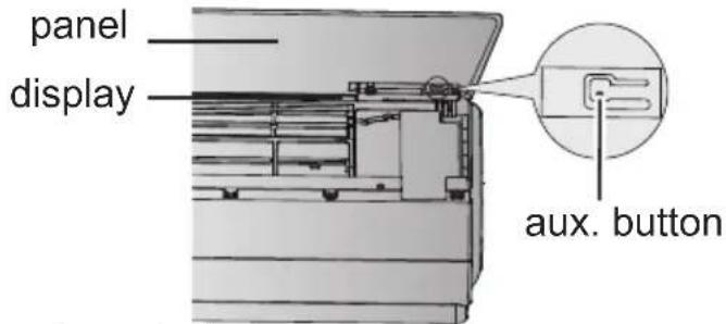
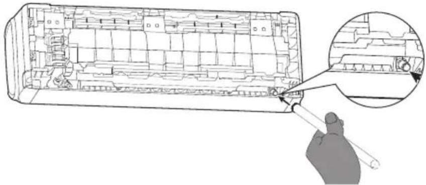
If remote controller is lost or damaged, please use aux. button to turn on or turn off the air conditioner. The operation in details is as below: As shown in the fig. Below.: 1. Open panel, 2. Press aux. button to turn on or turn off the air conditioner. When the air conditioner is turned on, it will operate under auto mode.
text_image
panel display aux. button
WARNING:
Use insulated object to press the auto button
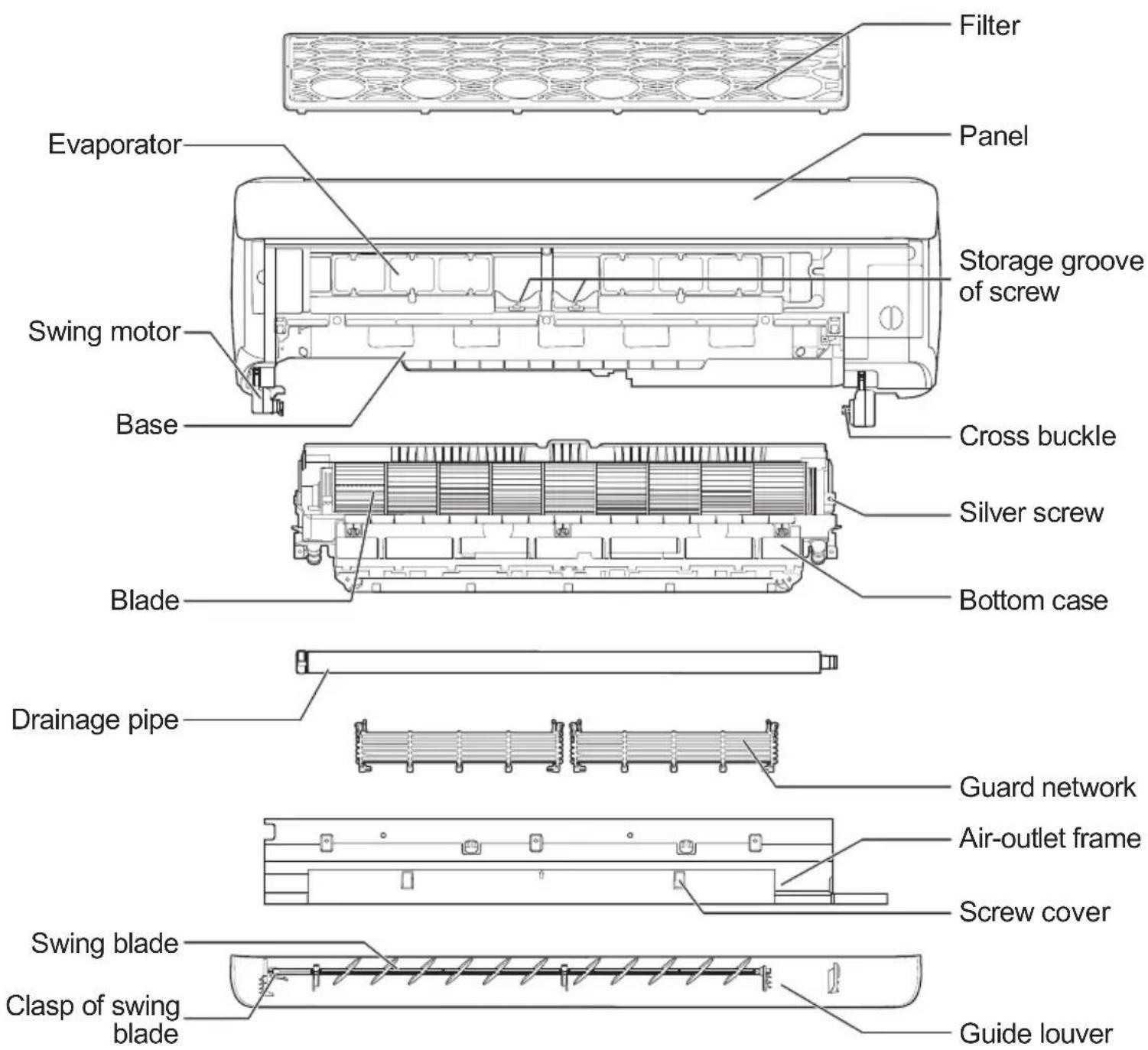
Schematic diagram of parts
text_image
Filter Evaporator Panel Storage groove of screw Swing motor Base Cross buckle Silver screw Bottom case Blade Drainage pipe Guard network Air-outlet frame Screw cover Swing blade Clasp of swing blade Guide louverClean and maintenance

Notices for clean
- When the unit has operated for a period of time and the display flashes to display "88" continuously, it indicates you should clean the air conditioner. When hold "button on the remote controller for 3s to enter into deep cleaning (power must be cut off for cleaning) under off status, the reminding status will disappear after turning on the unit. If you don't want to clean the air conditioner at the moment, press the combination buttons of "MODE+TEMP" to cancel this remind.
- Please select the clean procedure according to the actual operation environment or the degree of dirt of parts.

Warning

Please pull out the power plug
Before maintenance, please do cut off the power. Otherwise, it may cause electric shock or injury.

Prohibition
During the process of maintenance, please make sure the stand position is stable and reliable. Otherwise, it may cause injury.

Prohibition
Do not touch the aluminum fins with hand directly. Otherwise, it may cause injury.

Prohibition
During disassembly process, do not stand underneath the air conditioner.

Prohibition
Do not wash the electrical components with water.
Indoor unit clean

Caution
- Do not use volatile liquid (such as thinner, gasolin, etc.) to clean the air conditioner. Otherwise, the appearance of the air conditioner may be damaged.
- Please use clean and soft cloth to wipe the appearance of the air conditioner.
- Do not use liquid or corrosive detergent clean the appliance and do not splash water or other liquid onto it, otherwise, it may damage the plastic components, even cause electric shock.
Daily clean (appearance/filter clean)

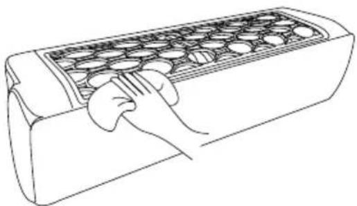
Wipe the appearance
When there's dust on the appearance of the unit, please wipe it with soft cloth; When the surface is dirty (such as grease), please immerse the cloth into warm water (45°C), twist it up and then wipe the surface. You can also dip a little neutral detergent when it's nessary.
natural_image
Line drawing of a hand using a tray with circular objects (no text or symbols)
Filter clean
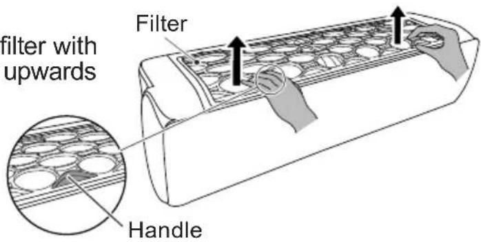
①Hold the handles at both sides of filter with both hands, and then pull the filter upwards to remove it.
text_image
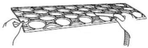
filter with upwards Filter Handle②Use clean water to wash it or dust catcher to clean it. If the filter is very dirty (such as grease), use warm water (45°C) dissolved with neutral detergent to clean it, and then put it at the shady place to dry it.
natural_image
Illustration of two hands holding a grid-like object with circular holes (no text or symbols)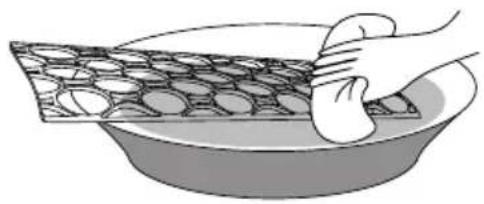
natural_image
Illustration of a hand holding a textured rectangular object over a bowl (no text or symbols)
Caution
Do not use hot water (more than 45^ C) to clean the filter to prevent color losing or deformation.
Do not dry the filter on the fire or use hair drier to dry the filter. Otherwise, it may cause fire or deformation.
Reminder
- User can select the clean period according to the actual circumstances and operation environment.
Deep clean (parts clean)

Guide louver clean
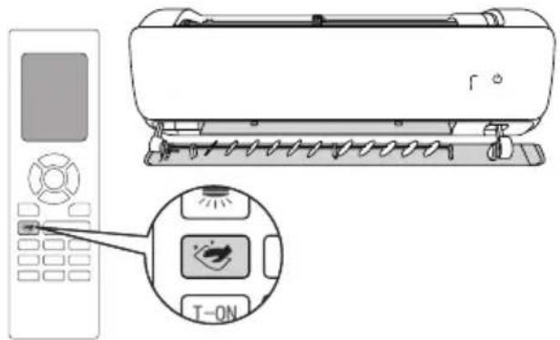
①Under standby status, press button for 3s, and the display flashes to display . Meanwhile, the guide louver will open automatically.
text_image
Diagram of a car air conditioner with control panel and T-ON button, showing brand logo and function icons②When the guide louver automatically rotates to the maximum position, will disappear. Cut off the power.
natural_image
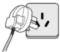
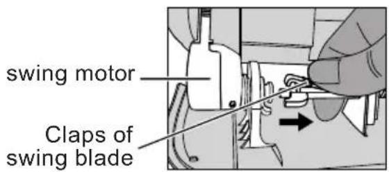
Illustration of a plug inserted into an electrical outlet with two wires (no text or symbols)③Press the clasp at the left side of the swing blade and pull it to the right side, and then it can separate with the swing motor.
text_image
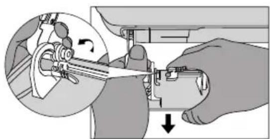
swing motor Claps of swing blade④Press the left side connection rod with left hand, hold the guide louver with the right hand, and then pull the guide louver outwards.
natural_image
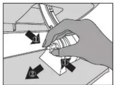
Illustration of hands operating a mechanical device with a magnified inset showing rotational motion (no text or symbols)⑤Press the cross clasp at the right side of guide louver with right hand, hold the guide louver with left hand and then draw out the guide louver to the left side.
text_image
Diagram showing a hand holding a small object with numbered arrows indicating steps or positions, possibly illustrating a procedure or process.⑥Immerse the cloth into the warm water (45°C), wring it out and then wipe the dirty part slightly. After that, dry it.
⑦When the installation is finished, energize the air conditioner again until the guide louver is reset automatically and then the unit can be operated.

Air-outlet frame clean

Caution
- The black screw is the removable screw. Prohibit disassembling the silver screw if necessary (except the silver screw of blade).
- Prevent the air-outlet frame dropping to avoid injury.
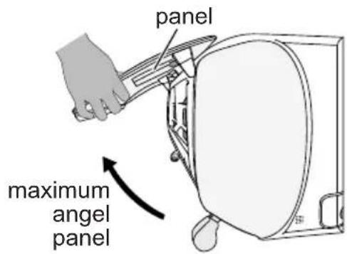
①Open the panel with both hands. When the panel is opened to the maximum angle (when a sound has been heard), the panel can be fixed.
text_image
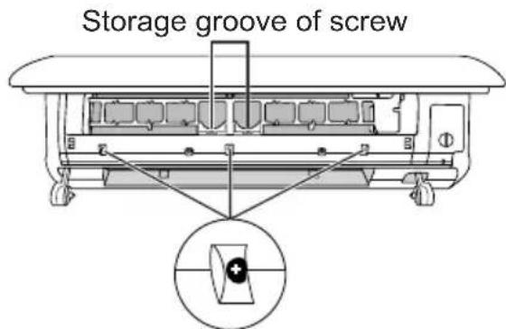
panel maximum angel panel②Use screwdriver to remove 3 black screws on the upper side of the air-outlet frame. After that, put the screws into the storage box of screw.
text_image
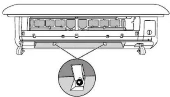
Storage groove of screw③Open the screw cover at the lower side of the air-outlet frame and then use screwdriver to remove 2 black screws.
natural_image
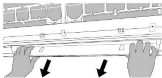
Diagram of a vehicle chassis with a magnified inset showing a close-up of the internal components (no text or symbols present)④Pull the air-outlet frame outwards according to the diagram as below and then remove it.
natural_image
Illustration of two hands adjusting a wall-mounted device with arrows indicating downward motion (no text or symbols)⑤Immerse the cloth into the warm water (less than 45^ C), wring it out and then use it to wipe the dirty part, and then dry it.

Bottom case and parts clean
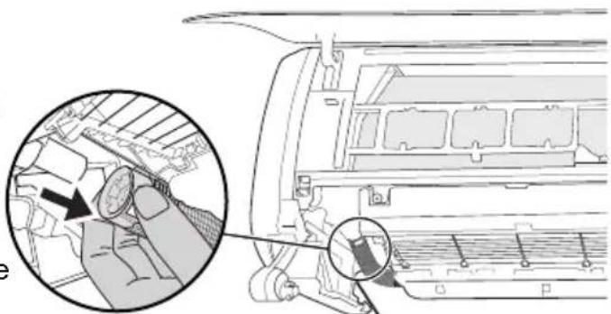
1. Pull out the drainage pipe
Press the beige locking spring at both ends of white drainage pipe simultaneously, and then pull the drainage pipe backwards.
Caution: There may be residual water drop in the drainage pipe. Please ensure drainage pipe outlet face upwards when then drainage pipe is removed.
natural_image
Diagram of a car air conditioner panel with a magnified inset showing the component detail (no text or symbols present)drainage pipe
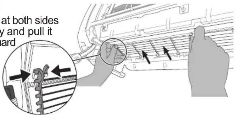
2. Remove the guard net
Press guard net spring fastener at both sides with both hands simultaneously and pull it upwards, and then remove the guard net.
text_image
at both sides y and pull it ard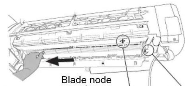
text_image
Blade node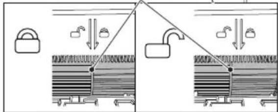
text_image
Diagram illustrating a mechanical or electrical system with lock, pulleys, and structural components, showing directional flow between components.Lock status Unlock status Fig.2
3. Remove blade
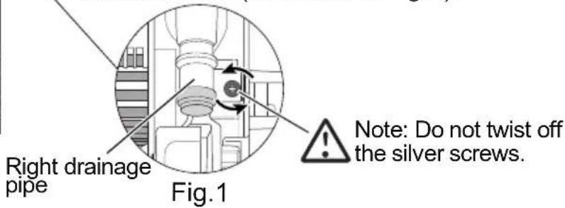
①Rotate the blade slightly and the find the silver screw at the right side of the blade. Use the screwdriver to loose the silver screw for 2-3 circles slowly in an anti-clockwise direction. (as shown in fig.1)
②Until the blade can slide to the left side to unlock status (as shown in fig.2).
text_image
Right drainage pipe Fig.1 Note: Do not twist off the silver screws.
Caution
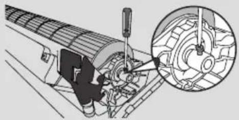
If the screw is removed carelessly when disassembling the blade, put the blade sub-assy on the ground flatly, rotate the screw into the axle sleeve of blade (2-3 circles clockwise), fix the blade sub-assy at the indoor unit and then fix the screw at the motor shaft. Tighten the screws as shown in the right figure (2-3 circles clockwise).
natural_image
Mechanical assembly diagram showing a motor and gear assembly with a magnified inset (no text or labels)Clean and maintenance
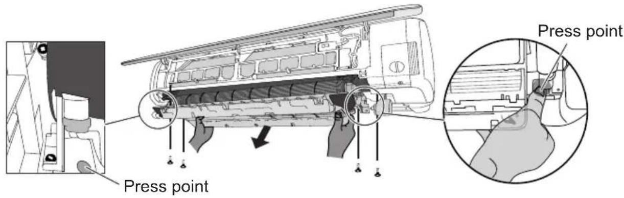
③Remove 4 black screws at both sides used for fixing the bottom case.
④Press the appointed positions at both sides with both thumbs (as shown in below figure), hold the bottom case with other four fingers and then lift it upwards, and then remove the bottom case of the air conditioner.
text_image
Press point Press point
Caution
When user has remove the bottom case, do not touch the evaporator to prevent scratching the fingers.
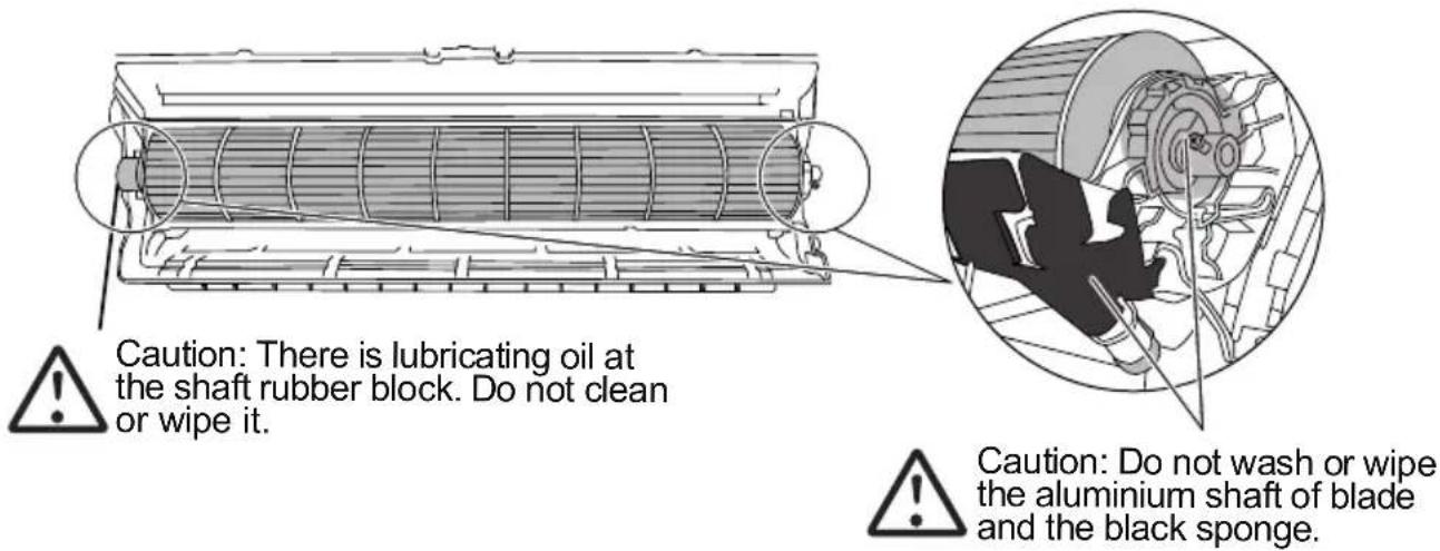
⑤Immerse the cloth into water (below 45^ C), wring it out and then wipe the dirty position of the unit. After that, dry the cloth.
text_image
Caution: There is lubricating oil at the shaft rubber block. Do not clean or wipe it. Caution: Do not wash or wipe the aluminium shaft of blade and the black sponge.Indoor unit installation

Caution
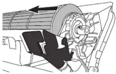
Before reinstall the bottom case when it has been cleaned, please check whether the blade has been pushed to the left side.
natural_image
Mechanical assembly diagram showing a motor with rotating components and a hand operating a belt (no text or symbols)1 Install bottom case
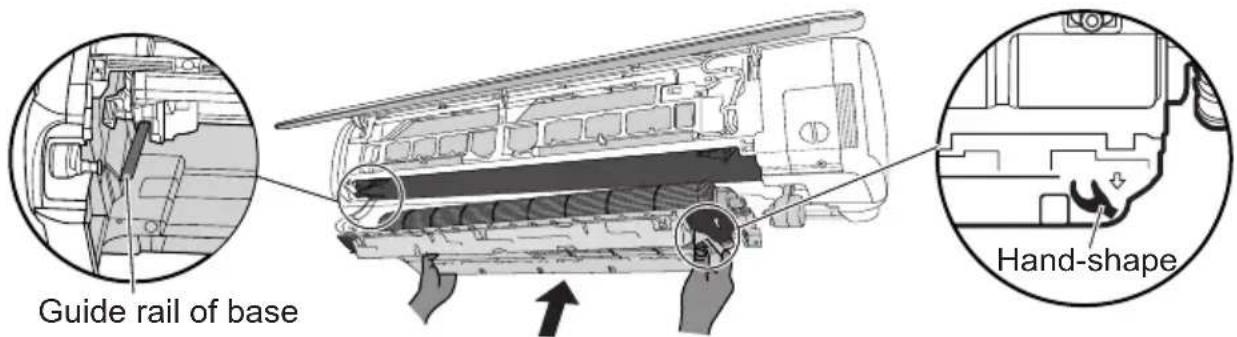
Hold the position with " " under the bottom case, push it upwards parallel along the guide rail of base and then check whether the both ends of bottom case is set into the tail of the guide rail of base for ensuring the installation.
text_image
Guide rail of base Hand-shape2 Fix the bottom case ① Check whether the
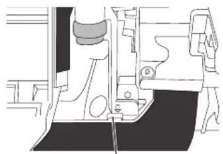
①Check whether the guide rail of bottom case is installed at the blocking position of base.
natural_image
Technical line drawing of a mechanical assembly (no text or symbols)Blocking position
②When the bottom case is assembled, take 4 screws from the storage box of screw at the middle of the front case and then use the screwdriver to fix these 4 screws at the bottom case.

text_image
case.3 Pull blade Hold the blue
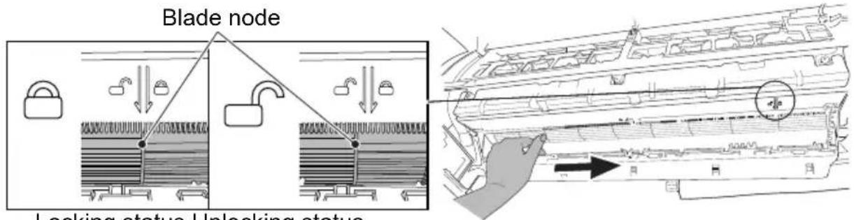
Hold the blade node to pull it to the right side until to the locking status.
text_image
Blade node Locking status Unlocking statusLocking status Unlocking status
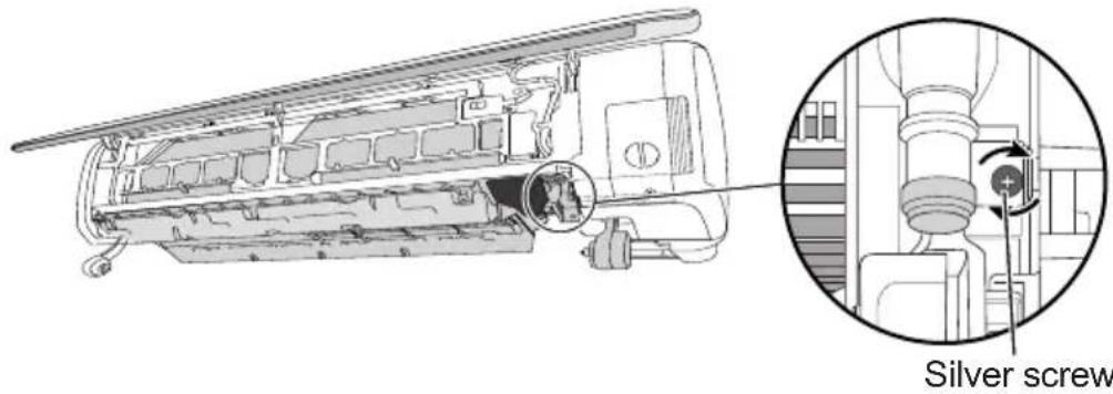
4 Tighten silver screw
Please make sure the blade is locked and then the silver screws of blade can be tightened clockwise.
text_image
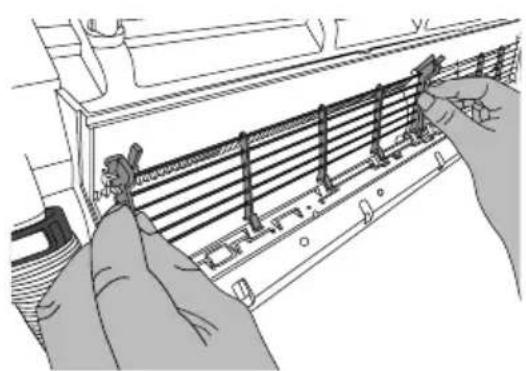
Silver screw5 Install guard net
Hold the guard net with both hands and then assemble the guard net according to the following figure.
natural_image
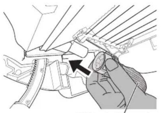
Illustration of hands installing or adjusting a ventilation grille on an air conditioner panel (no text or symbols visible)6 Install drainage pipe
Hold the joint of white drainage pipe with hand, install the drainage pipe to the direction of drainage outlet until you have head a sound.
natural_image
Illustration of a hand using a tool to adjust or install a mechanical component, with no visible text or symbols.White drainage pipe
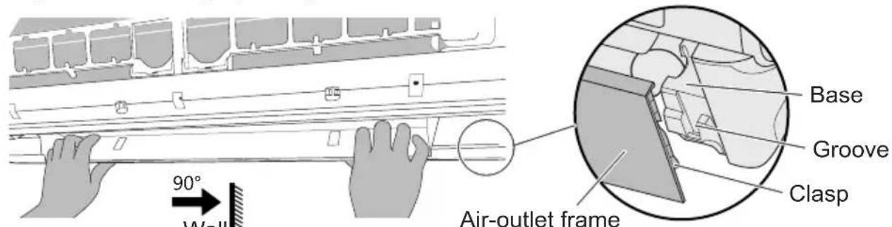
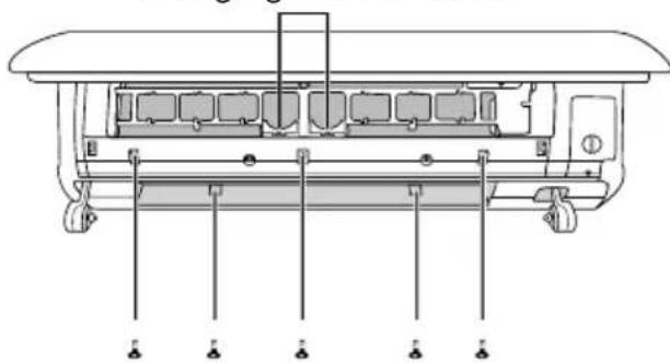
7 Install air-outlet frame
Insert the clasp at the back side of the air-outlet frame into the groove of the base (as shown in fig.3) until you have heard a sound.
text_image
90° Wall Air-outlet frame Base Groove ClaspFig.3
8 Tighten screws of air-outlet frame
①Take out 5 screws from the storage groove of screw and then fix the air-outlet frame with the screwdriver.
Storage groove of screw
natural_image
Technical line drawing of a mechanical device with internal components and mounting holes (no text or symbols)②Close the panel.
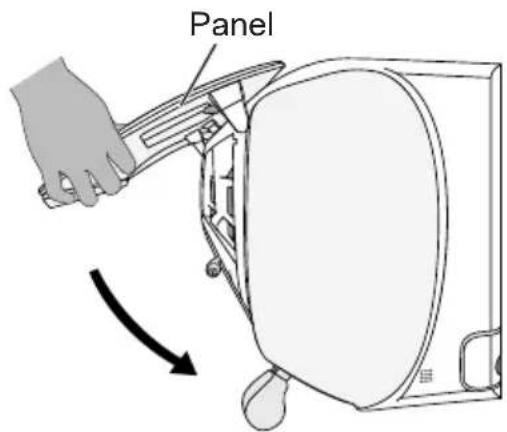
text_image
PanelClean and maintenance
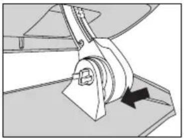
9 Install guide louver
①Hold the guide louver with the left hand, hold the connection rod with the right hand and then install the "cross groove" at the right side of the guide louver at the "cross clasp" of the connecting rod.
natural_image
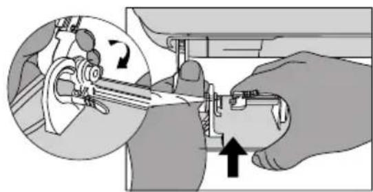
Mechanical assembly diagram showing a rotating component with a black arrow indicating motion direction (no text or symbols)②Hold the left side connection rod with left hand, hold the air louver with the right hand and then assemble the guide louver according to the direction as shown by the figure.
natural_image
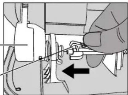
Illustration of a hand using a tool to adjust or install a mechanical component, showing a circular inset with an arrow indicating rotation (no text or symbols present)③Press the clasps of swing blade and pull it to the left side and then connect it with the swing motor.
Swing motor
Clasp of swing blade
natural_image
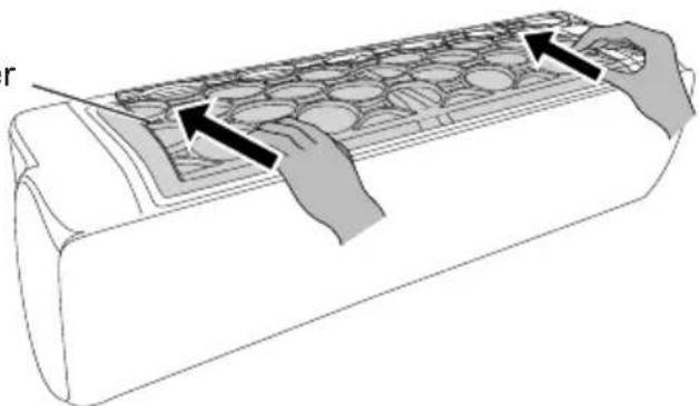
Diagram of a hand using a tool to adjust or install a mechanical component, with no visible text or symbols.10 Install filter
Filter
natural_image
Illustration of hands inserting a grid into a car air conditioner panel (no text or symbols)
Caution
- Maintenance should be conducted by the professional person.
- Because there will be water on the guide louver and other parts during clean operation, the unit will conduct the dry function when it's turned on for the first time. For the first startup, the guide louver will open to the first position and then display board will display □□→□□→□□. When the display is finished, the indoor unit will be turned on to blow wind. Meanwhile, the display board will countdown for a period of time. When the countdown is over, the unit will switch to operation at the mode set by the remote controller.
- Please make sure all disassembled screws are fixed well.
- If the indoor unit cannot work normally after power connected, please check the unit: ①Whether the guide louver is assembled well; ②whether the air-outlet frame is assembled well; ③whether the blade is tightened according to the requirement; ④Whether the air inlet is blocked by foreign objects.
Installation dimension diagram
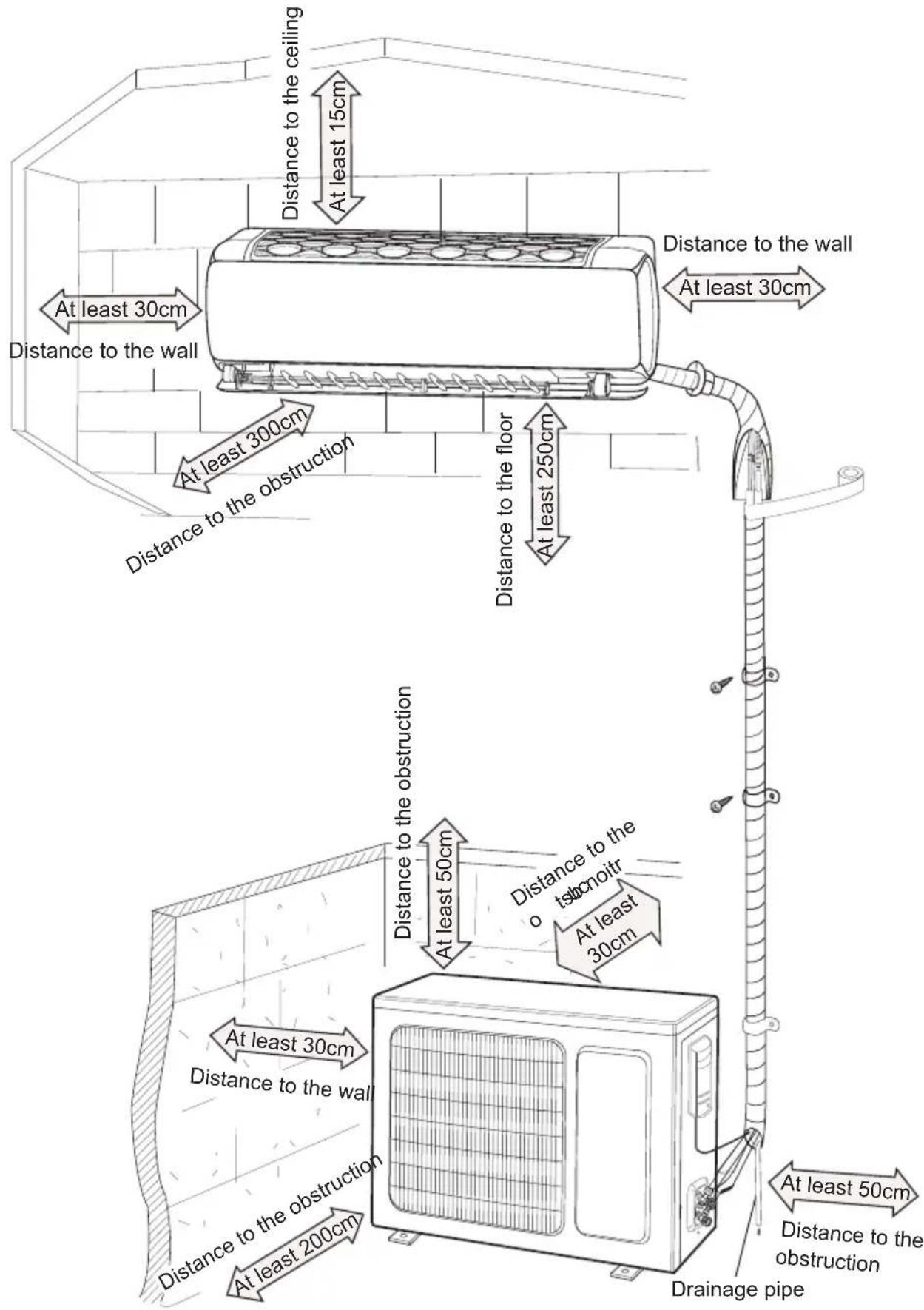
text_image
At least 30cm Distance to the wall At least 15cm Distance to the ceiling At least 30cm Distance to the obstruction At least 300cm Distance to the floor At least 250cm Distance to the wall At least 30cm At least 50cm At least 30cm Distance to the obstruction at least 50cm at least 200cm at least 30cm at least 50cm at least 200cm at least 30cm at least 50cm at least 200cm at least 30cm at least 50cm at least 200cm at least 30cm at least 50cm at least 200cm at least 30cm at least 50cm at least 30cm at least 50cm at least 200cm at least 30cm at least 50cm at least 200cm at least 30cm at least 50cm at least 200cm at least 30cm at least 50cm at least 200cm at least 30cm at less than 30cm at less than 30cm at less than 30cm at less than 30cm at less than 30cm at less than 30cm at less than 30cm at less than 30cm at less than 30cm at less than 30cm at less than 30cm at less than 30cm at less than 30 cm at less than 30 cm at less than 30 cm at less than 30 cm at less than 30 cm at less than 30 cm at less than 30 cm at less than 30 cm at less than 30 cm at less than 30 cm at less than 30 cm at less than 30 cm at less than 30 cm at less at least one or more on the floor at least one or more on the floor at least one or more on the floor at least one or more on the floor at least one or more on the floor at least one or more on the floor at least one or more on the floor at least one or more on the floor at least one or more on the floor at least one or more on the floor at least one or more on the floor at least one or more on the floor at last 15cm at last 250cmTools for installation
| 1 Level meter 2 Screw driver 3 Impact drill | ||
| 4 Drill head 5 Pipe expander 6 Torque wrench | ||
| 7 Open-end wrench 8 Pipe cutter 9 Leakage detector | ||
| 10 Vacuum pump 11 Pressure meter 12 Universal meter | ||
| 13 Inner hexagon spanner 14 Measuring tape | ||
Note:
- Please contact the local agent for installation.
- Don't use unqualified power cord.
Selection of installation location
Basic requirement
Installing the unit in the following places may cause malfunction. If it is unavoidable, please consult the local dealer or qualified personnel:
- The place with strong heat sources, vapors, flammable or explosive gas or volatile objects spread in the air.,
- The place with high-frequency devices (such as welding machine, medical equipment).
- The place near coast area.
- The place with oil or fumes in the air.
- The place with sulfureted gas.
- Other places with special circumstances.
- The appliance shall not be installed in the laundry.
- It's not allowed to be installed on the unstable or motive base structure (such as truck) or in the corrosive environment (such as chemical factory).
Indoor unit
- There should be no obstruction near air inlet and air outlet.
- Select a location where the condensation water can be dispersed easily and won't affect other people.
- Select a location which is convenient to connect the outdoor unit and near the power socket.
- Select a location which is out of reach for children.
- The location should be able to withstand the weight of indoor unit and won't increase noise and vibration.
- The appliance must be installed 2.5m above floor.
- Don't install the indoor unit right above the electric appliance.
- Please try your best to keep way from fluorescent lamp.
Outdoor unit
- Select a location where the noise and outflow air emitted by the outdoor unit will not affect neighborhood.
- The location should be well ventilated and dry, in which the outdoor unit won't be exposed directly to sunlight or strong wind.
- The location should be able to withstand the weight of outdoor unit.
- Make sure that the installation follows the requirement of installation dimension diagram.
- Select a location which is out of reach for children and far away from animals or plants. If it is unavoidable, please add the fence for safety purpose.
Requirements for electric connection
Safety precaution
- Must follow the electric safety regulations when installing the unit.
- According to the local safety regulations, use qualified power supply circuit and air switch.
- Make sure the power supply matches with the requirement of air conditioner. Unstable power supply or incorrect wiring or malfunction. Please install proper power supply cables before using the air conditioner.
- Properly connect the live wire, neutral wire and grounding wire of power socket.
- Be sure to cut off the power supply before proceeding any work related to electricity and safety.
- Do not put through the power before finishing installation.
- If the supply cord is damaged, it must be replaced by the manufacturer, its service agent or similarly qualified persons in order to avoid a hazard.
- The temperature of refrigerant circuit will be high, please keep the interconnection cable away from the copper tube.
- The appliance shall be installed in accordance with national wiring regulations.
Grounding requirement
- The air conditioner is the first class electric appliance. It must be properly grounding with specialized grounding device by a professional. Please make sure it is always grounded effectively, otherwise it may cause electric shock.
- The yellow-green wire in air conditioner is grounding wire, which can't be used for other purposes.
- The grounding resistance should comply with local electric safety regulations.
- The appliance must be positioned so that the plug is accessible.
- An all-pole disconnection switch having a contact separation of at least 3mm in all poles should be connected in fixed wiring. For models with a power plug, make sure the plug is within reach after installation.
- Including an air switch with suitable capacity, please note the following table. Air switch should be included magnet buckle and heating buckle function, it can protect the circuit-short and overload. (Caution: please do not use the fuse only for protect the circuit)
| Air-conditioner | Air switch capacity |
| 09K | 10A |
| 12K | 16A |
Installation of indoor unit
Step one: choosing installation location
Recommend the installation location to the client and then confirm it with the client.
Step two: install wall-mounting frame
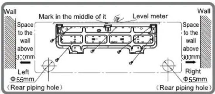
- Hang the wall-mounting frame on the wall; adjust it in horizontal position with the level meter and then point out the screw fixing holes on the wall.
- Drill the screw fixing holes on the wall with impact drill (the specification of drill head should be the same as the plastic expansion particle) and then fill the plastic expansion particles in the holes.
- Fix the wall-mounting frame on the wall with tapping screws (ST4.2X25TA) and then check if the frame is firmly installed by pulling the frame. If the plastic expansion particle is loose, please drill another fixing hole nearby.
Step three: open piping hole
- Choose the position of piping hole according to the direction of outlet pipe. The position of piping hole should be a little lower than the wall-mounted frame, shown as below.
text_image
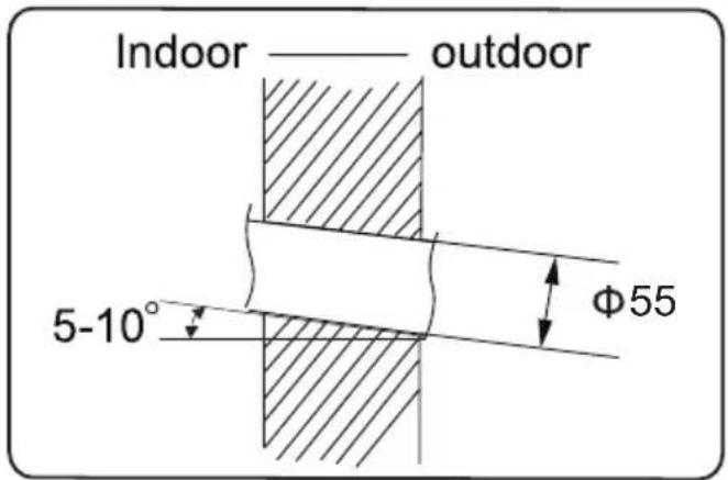
Wall Space to the wall above 300mm Left Φ55mm (Rear piping hole) Mark in the middle of it Level meter Wall Space to the wall above 300mm Right Φ55mm (Rear piping hole)- Open a piping hole with the diameter of 55 on the selected outlet pipe position. In order to drain smoothly, slant the piping hole on the wall slightly downward to the outdoor side with the gradient of 5 - 10^ .
Installation of indoor unit
Note:
- Pay attention to dust prevention and take relevant safety measures when opening the hole.
- The plastic expansion particles are not provided and should be bought locally.
text_image
Indoor —— outdoor 5-10° Φ55Step four: outlet pipe
text_image
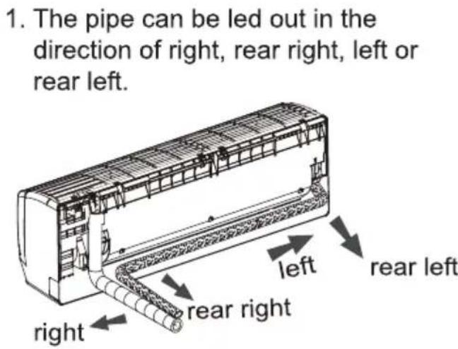
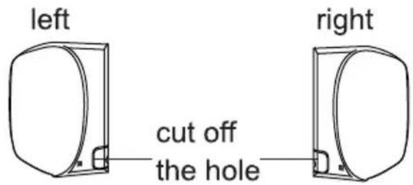
1. The pipe can be led out in the direction of right, rear right, left or rear left. left rear left rear right right- When select leading out the pipe from left or right, please cut off the corresponding hole on the bottom case.
text_image
left cut off the hole right- Selection of drainage outlet and drainage installation and disassembly guide
(1) Please determine the position of drainage outlet before installation the drainage pipe.
(2)Suggestion for selection of drainage outlet: there are no mandatory requirements for the direction of the drainage pipe. However, it's suggested to be same with the direction of liquid pipe and gas pipe. Therefore, you are suggested to select the drainage outlet which is close to the exit tube:
①Take out the drainage pipe from the carton box.

natural_image
Simple line drawing of a rectangular object with rounded ends and a small protrusion at the top (no text or symbols)Installation of indoor unit
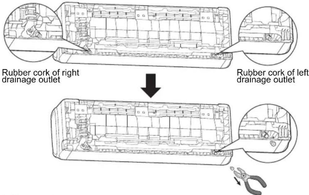
②Pull out the rubber stopper of drainage outlet with pliers or other tools.
text_image
Rubber cork of right drainage outlet Rubber cork of left drainage outlet(3) Install drainage pipe.
Hold the head of drainage pipe (20cm away from the drainage pipe outlet) with hand and install it along the direction of drainage outlet until you have head a sound.
natural_image
Technical line drawing of a mechanical component with an inset close-up view showing internal structure (no text or symbols)Step five: connect the pipe of indoor unit
-
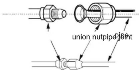
Aim the pipe joint at the corresponding bellmouth.
-
Pretighten the union nut with hand.
-
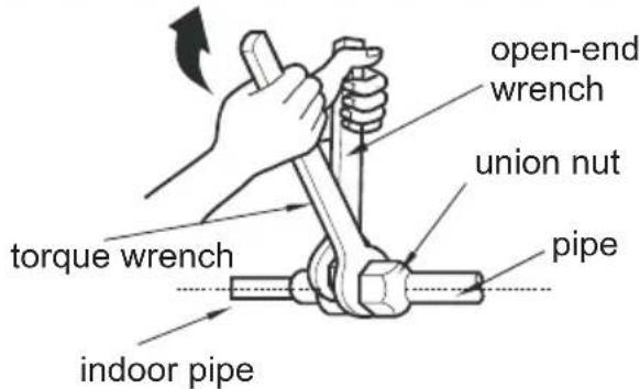
Adjust the torque force by referring to the following sheet. Place the open-end wrench on the pipe joint and place the torque wrench on the union nut. Tighten the union nut with torque wrench.
text_image
union nutpipe jointInstallation of indoor unit
text_image
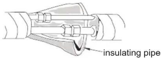
open-end wrench union nut torque wrench pipe indoor pipe- Wrap the indoor pipe and joint of connection pipe with insulating pipe, and then wrap it with tape.
| Hex nut diameter | Tightening torque (N ·m) |
| Φ 6 | 15~20 |
| Φ 9.52 | 30~40 |
| Φ 12 | 45~55 |
| Φ 16 | 60~65 |
| Φ 19 | 70~75 |
text_image
insulating pipeStep six: install drain hose
-
Connect the drain hose to the outlet pipe of indoor unit.
-
Bind the joint with tape. outlet pipe drain hose
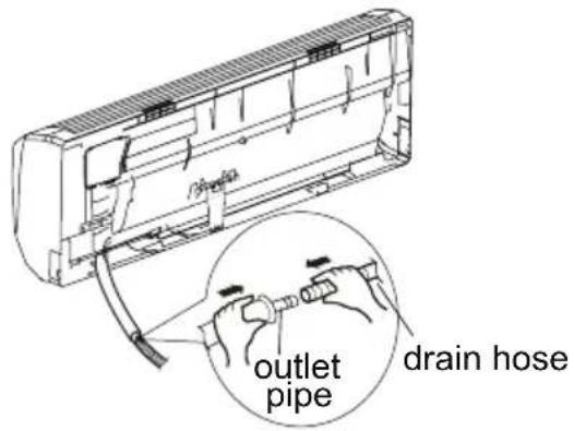
text_image
outlet pipe drain hoseNote:
- Add insulating pipe in the indoor drain hose in order to prevent condensation.
- The plastic expansion particles are not provided.
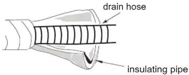
text_image
drain hose insulating pipeStep seven: connect wire of indoor unit
- Open the panel, remove the screw on the wiring cover and then take down the cover.
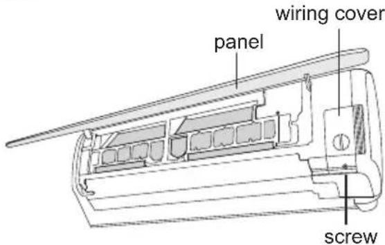
text_image
wiring cover panel screwInstallation of indoor unit
- Make the power connection wire go through the cable-cross hole at the back of indoor unit and then pull it out from the front side.
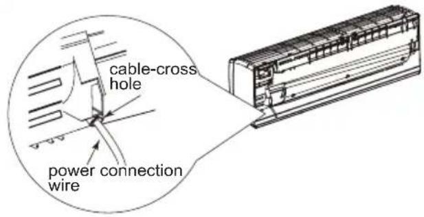
text_image
cable-cross hole power connection wire- Remove the wire clip; connect the power connection wire to the wiring terminal according to the color; tighten the screw and then fix the power connection wire with wire clip.
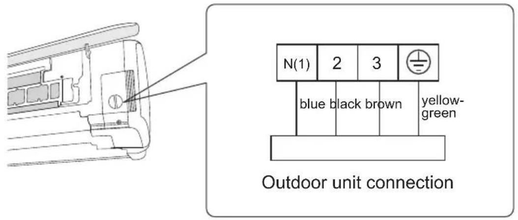
text_image
N(1) 2 3 blue black brown yellow- green Outdoor unit connection- Put wiring cover back and then tighten the screw.
- Close the panel.
Note:
- All wires of indoor unit and outdoor unit should be connected by a professional.
- If the length of power connection wire is insufficient, please contact the supplier for a new one. Avoid extending the wire by yourself.
- For the air conditioner with plug, the plug should be reachable after finishing installation.
- For the air conditioner without plug, an circuit break must be installed in the line. The circuit break should be all-pole parting and the contact parting distance should be more than 3mm.
Installation of indoor unit
Step eight: bind up pipe
- Bind up the connection pipe, power cord and drain hose with the band.
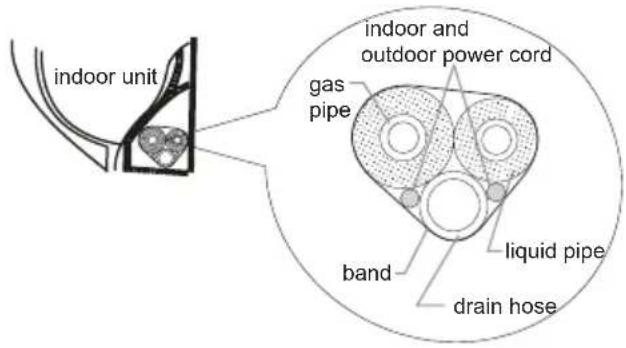
text_image
indoor unit gas pipe indoor and outdoor power cord liquid pipe band drain hose- Reserve a certain length of drain hose and power cord for installation when binding them. When binding to a certain degree, separate the indoor power and then separate the drain hose.
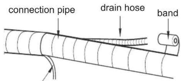
text_image
connection pipe drain hose bandindoor power cord
- Bind them evenly.
- The liquid pipe and gas pipe should be bound separately at the end.
Note:
- The power cord and control wire can't be crossed or winding.
- The drain hose should be bound at the bottom.
Step nine: hang the indoor unit
- Put the bound pipes in the wall pipe and then make them pass through the wall hole.
- Hang the indoor unit on the wall-mounting frame.
- Stuff the gap between pipes and wall hole with sealing gum.
- Fix the wall pipe.
- Check if the indoor unit is installed firmly and closed to the wall.
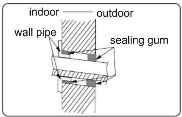
text_image
indoor —— outdoor wall pipe sealing gum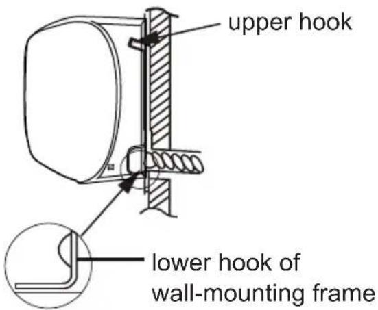
text_image
upper hook lower hook of wall-mounting frameNote:
- Do not bend the drain hose too excessively in order to prevent blocking.
Installation of outdoor unit
Step one: fix the support of outdoor unit (select it according to the actual installation situation)
- Select installation location according to the house structure.
- Fix the support of outdoor unit on the selected location with expansion screws.
Note:
• Take sufficient protective measures when installing the outdoor unit.
- Make sure the support can withstand at least four times of the unit weight.
- The outdoor unit should be installed at least 3cm above the floor in order to install drain joint. (for the model with heating tube, the installation height should be no less than 20cm.)
- For the unit with cooling capacity of 2300W \~5000W, 6 expansion screws are needed; for the unit with cooling capacity of 6000W \~8000W, 8 expansion screws are needed; for the unit with cooling capacity of 10000W \~16000W, 10 expansion screws are needed.
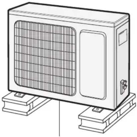
natural_image
Line drawing of a rectangular industrial air conditioner unit mounted on a base (no text or symbols)at least 3cm above the floor
Step two: install drain joint (Only for some models)
- Connect the outdoor drain joint into the hole on the chassis, as shown in the picture below.
- Connect the drain hose into the drain vent.
NOTE: As for the shape of drainage joint, please refer to the current product. Do not install the drainage joint in the severe cold area. Otherwise, it will be frosted and then cause malfunction.
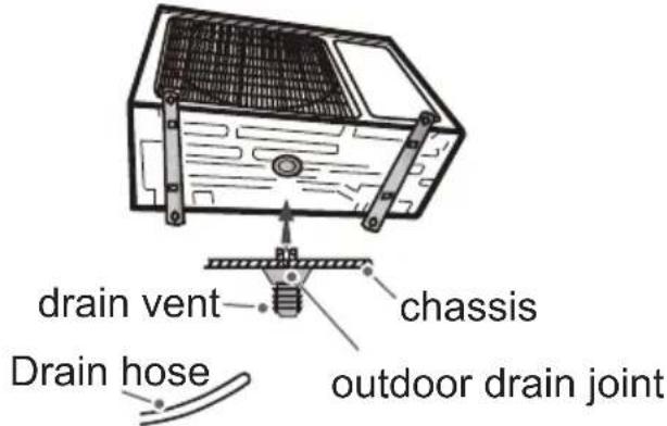
text_image
drain vent chassis Drain hose outdoor drain jointStep three: fix outdoor unit
- Place the outdoor unit on the support.
- Fix the foot holes of outdoor unit with bolts.
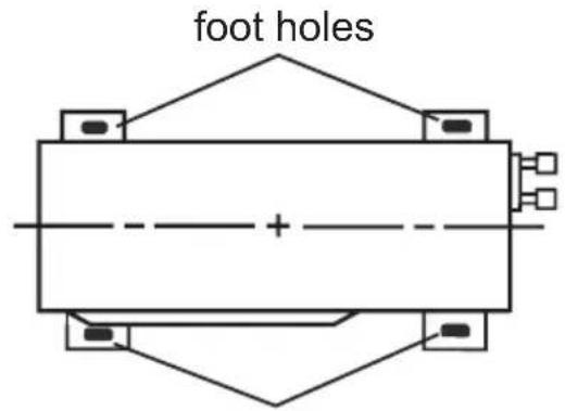
text_image
foot holesfoot holes
Installation of outdoor unit
Step four: connect indoor and outdoor pipes
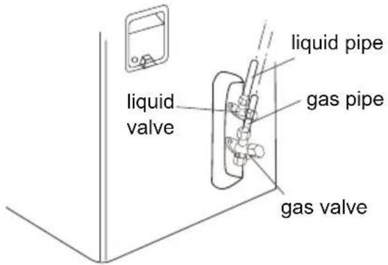
- Remove the screw cap of valve and aim the pipe joint at the bellmouth of pipe.
text_image
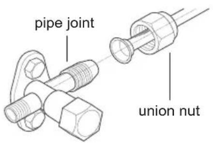
liquid pipe liquid valve gas pipe gas valve- Pretighten the union nut with hand.
text_image
pipe joint union nut- Tighten the union nut with torque wrench by referring to the sheet below.
| Hex nut diameter | Tightening torque (N·m) |
| Φ 6 | 15~20 |
| Φ 9.52 | 30~40 |
| Φ 12 | 45~55 |
| Φ 16 | 60~65 |
| Φ 19 | 70~75 |
Step five: connect outdoor electric wire
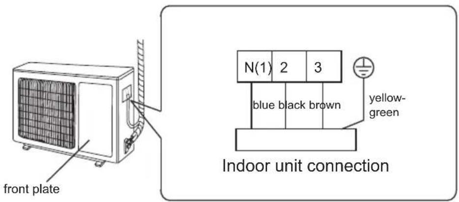
- Remove the wire clip or front plate; connect the power connection wire and signal control wire (only for cooling and heating unit) to the wiring terminal according to the color; fix them with screws.
text_image
front plate N(1) 2 3 blue black brown yellow- green Indoor unit connectionInstallation of outdoor unit
- Fix the power connection wire and signal control wire with wire clip (only for cooling and heating unit).
Note:
- After tighten the screw, pull the power cord slightly to check if it is firm.
- Never cut the power connection wire to prolong or shorten the distance.
Step six: neaten the pipes
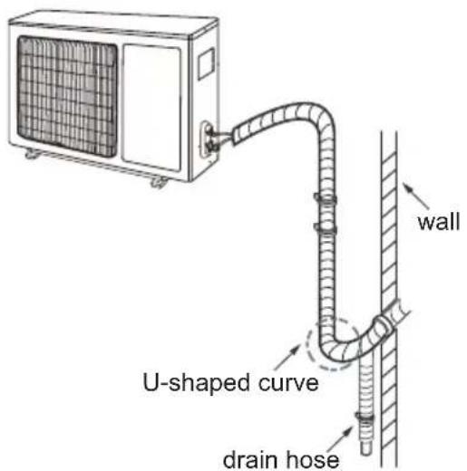
- The pipes should be placed along the wall, bent reasonably and hidden possibly. Min. semidiameter of bending the pipe is 10cm.
- If the outdoor unit is higher than the wall hole, you must set a U-shaped curve in the pipe before pipe goes into the room, in order to prevent rain from getting into the room.
text_image
wall U-shaped curve drain hoseNote:
- The through-wall height of drain hose shouldn't be higher than the outlet pipe hole of indoor unit.
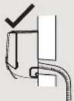
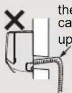
- The water outlet can't be placed in water in order to drain smoothly.
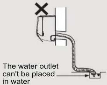
text_image
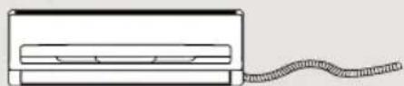
The water outlet can't be placed in water- Slant the drain hose slightly downwards. The drain hose can't be curved, raised and fluctuant, etc.
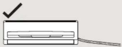
natural_image
Simple line drawing of a rectangular object with a checkmark and a diagonal line extending from it (no text or symbols)✗ The drain hose can't be fluctuant
natural_image
Simple line drawing of a rectangular device with a coiled cable extending from its side (no text or symbols)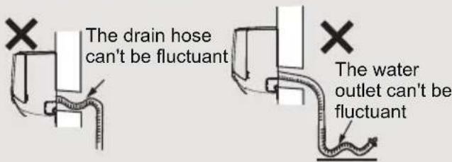
text_image
The drain hose can't be fluctuant The water outlet can't be fluctuantVacuum pumping
Use vacuum pump
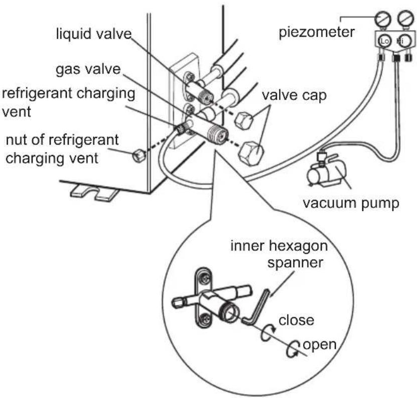
- Remove the valve caps on the liquid valve and gas valve and the nut of refrigerant charging vent.
- Connect the charging hose of piezometer to the refrigerant charging vent of gas valve and then connect the other charging hose to the vacuum pump.
- Open the piezometer completely and operate for 10-15min to check if the pressure of piezometer remains in -0.1MPa.
- Close the vacuum pump and maintain this status for 1-2min to check if the pressure of piezometer remains
in -0.1MPa. If the pressure decreases, there may be leakage.
- Remove the piezometer, open the valve core of liquid valve and gas valve completely with inner hexagon spanner.
- Tighten the screw caps of valves and refrigerant charging vent.
- Reinstall the handle.
text_image
liquid valve gas valve refrigerant charging vent nut of refrigerant charging vent piezometer valve cap vacuum pump inner hexagon spanner close openLeakage detection
- With leakage detector:
Check if there is leakage with leakage detector.
- With soap water:
If leakage detector is not available, please use soap water for leakage detection. Apply soap water at the suspected position and keep the soap water for more than 3min. If there are air bubbles coming out of this position, there's a leakage.
Check after installation
- Check according to the following requirement after finishing installation.
| Items to be checked Possible malfunction | |
| Has the unit been installed firmly? | The unit may drop, shake or emit noise. |
| Have you done the refrigerant leakage test? | It may cause insufficient cooling (heating) capacity. |
| Is heat insulation of pipeline sufficient? | It may cause condensation and water dripping. |
| Is water drained well? | It may cause condensation and water dripping. |
| Is the voltage of power supply according to the voltage marked on the nameplate? | It may cause malfunction or damaging the parts. |
| Is electric wiring and pipeline installed correctly? | It may cause malfunction or damaging the parts. |
| Is the unit grounded securely? It may cause electric leakage. | |
| Does the power cord follow the specification? | It may cause malfunction or damaging the parts. |
| Is there any obstruction in the air inlet and outlet? | It may cause insufficient cooling (heating) capacity. |
| The dust and sundries caused during installation are removed? | It may cause malfunction or damaging the parts. |
| The gas valve and liquid valve of connection pipe are open completely? | It may cause insufficient cooling (heating) capacity. |
| Is the inlet and outlet of piping hole been covered? | It may cause insufficient cooling (heating) capacity or waster electricity. |
Test operation
1. Preparation of test operation
• The client approves the air conditioner.
- Specify the important notes for air conditioner to the client.
2. Method of test operation
- Put through the power, press ON/OFF button on the remote controller to start operation.
- Press MODE button to select AUTO, COOL, DRY, FAN and HEAT to check whether the operation is normal or not.
- If the ambient temperature is lower than 16 €, the air conditioner can't start cooling.
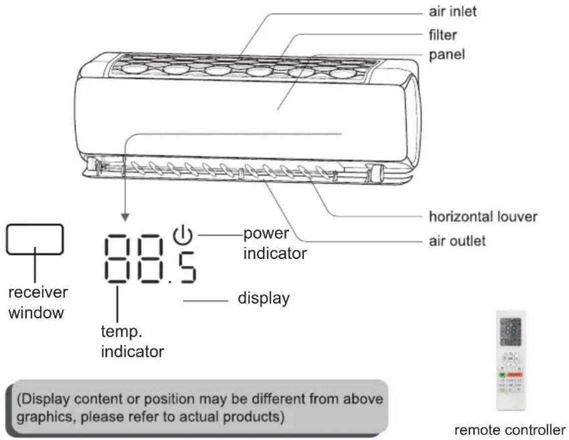
Indoor Unit
text_image
air inlet filter panel horizontal louver air outlet power indicator display temperature indicator receiver window Display content or position may be different from above graphics, please refer to actual products) remote controllerOutdoor Unit
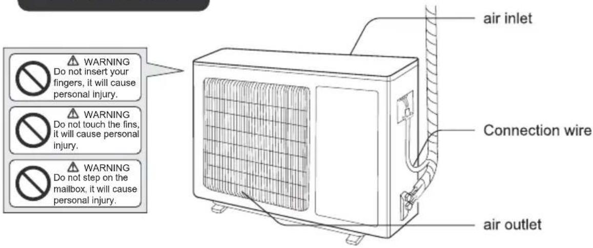
text_image
WARNING Do not insert your fingers, it will cause personal injury. WARNING Do not touch the fins, it will cause personal injury. WARNING Do not step on the mailbox, it will cause personal injury. air inlet Connection wire air outletNOTICE:
Actual product may be different from above graphics, please refer to actual products.
Buttons on remote controller
Note:
- This is a general use remote controller, it could be used for the air conditioners with multifunction; For some function, which the model doesn't have, if press the corresponding button on the remote controller that the unit will keep the original running status.
- After putting through the power, the air conditioner will give out a sound. Operation indicator "⏻" is ON (red indicator, the colour is varied for defferent models). After that, you can operate the air conditioner by using remote controller.
- Under on status, pressing the button on the remote controller, the signal icon "💡" on the display of remote controller will blink once and the air conditioner will give out a "di" sound, which means the signal has been sent to the air conditioner.

text_image
signal fan display FAN AUTO OPER oper display mode display 88.6 HOUR temperature display timer display SWING DISPLAY function display AUTO ▼/▲ button turbo button MODE TURBO FAN fan button mode button button button ON/OFF HOLD 3S T-ON CLOCK T-OFF t-off button clock button SLEEP TEMP QUIET quiet button sleep button LIGHT IFEEL WiFi light button wifi button i feel button| ON/OFF | Press this button to turn on the unit. Press this button again to turn off the unit. |
| FAN | Press this button can select fan speed, it can be selected circularly as below: Under dry mode, fan speed can't be adjusted. Under dry mode, fan speed can't be adjusted. |
| ▼/▲BUTTON | Press "▲" or "▼" button once increase or decrease set temperature 0.5°C.Holding "▲" or "▼" button, 2s later, set temperature on remote controller will change quickly. On releasing button after setting is finished, temperature indicator on indoor unit will change accordingly. |
| MODE | Press this button to select your required operation mode. *Note: Only for models with heating function. *Note: Only for models with heating function. |
| ≡ BUTTON | Press this button can select up & down swing angle. Fan blow angle can be selected circularly as below: When selecting "≡", air conditioner is blowing fan automatically. Horizontal louver will automatically swing up & down at maximum angle.When selecting "≡、≡、-≡、≡、≡", air conditioner is blowing fan at fixed position. Horizontal louver will stop at the fixed position.Hold "≡" button above 2s to set your required swing angle. When reaching your required angle, release the button. When selecting "≡", air conditioner is blowing fan automatically. Horizontal louver will automatically swing up & down at maximum angle.When selecting "≡、≡、-≡、≡、≡", air conditioner is blowing fan at fixed position. Horizontal louver will stop at the fixed position.Hold "≡" button above 2s to set your required swing angle. When reaching your required angle, release the button. |
| LIGHT | Press this button to turn off display light on indoor unit. "≡" icon on remote controller disappears. Press this button again to turn on display light. "≡" icon is displayed. |
| BUTTON | Press this button can select left & right swing angle. Fan blow angle can be selected circularly as below: Press this button continuously more than 2s, the main unit will swing back an forth from left to right, and then loosen the button, the unit will stop swinging and present position of guide louver will be kept immediately.Under swing left and right mode, when the status is switched from off to , if press this button again 2s later, status will switch to off status directly; if press this button again within 2s, the change of swing status will also depend on the circulation sequence state above.This function is only available for some model. Press this button continuously more than 2s, the main unit will swing back an forth from left to right, and then loosen the button, the unit will stop swinging and present position of guide louver will be kept immediately.Under swing left and right mode, when the status is switched from off to , if press this button again 2s later, status will switch to off status directly; if press this button again within 2s, the change of swing status will also depend on the circulation sequence state above.This function is only available for some model. |
| TURBO | Under COOL or HEAT mode, press this button to turn to quick COOL or quick HEAT mode. " ” icon is displayed on remote controller. Press this button again to exit turbo function and " ” icon will disappear.If start this function, the unit will run at super-high fan speed to cool or heat quickly so that the ambient temp. approaches the preset temp. as soon as possible. |
| QUIET | Press this button, the Quiet status is under the Auto Quiet mode (display "Auto") and Quiet mode (display "") and Quiet OFF (there is no signal displayed), after powered on, the Quiet OFF is defaulted. |
| SLEEP | Press this button, can select Sleep 1 (1), Sleep 2 (2), Sleep 3 (3) and cancel the Sleep, circulate between these, after electrified, Sleep Cancel is defaulted.Sleep 1 is Sleep mode 1, in Cool modes; sleep status after run for one hour, the main unit setting temperature will increase 1°C, two hours, setting temperature increased 2, then the unit will run at this setting temperature; In Heat mode: sleep status after run for one hour, the setting temperature will decrease 1°C, two hours, setting temperature will decrease 2°C, then the unit will run at this setting temperature.Sleep 2 is sleep mode 2, that is air conditioner will run according to the presetting a group of sleep temperature curve.Sleep 3-the sleep curve setting under Sleep mode by DIY; |
Introduction for buttons on remote controller
| SLEEP | (1)Under Sleep 3 mode, press "Turbo" button for a long time, remote controller enters into user individuation sleep setting status, at this time, the time of remote controller will display "1hour", the setting temperature "88" will display the corresponding temperature of last setting sleep curve and blink (The first entering will display according to the initial curve setting value of original factory);(2)Adjust "▲" and "▼" button, could change the corresponding setting temperature, after adjusted, press "Turbo" button for confirmation;(3)At this time, 1hour will be automatically increased at the timer position on the remote controller, (that are "2hours" or "3hours" or "8hours"), the place of setting temperature "88" will display the corresponding temperature of last setting sleep curve and blink;(4) Repeat the above step (2)~(3) operation, until 8 hours temperature setting finished, sleep,curve setting finished, at this time, the remote controller will resume the original timer display; temperature display will resume to original setting temperature.Sleep3- the sleep curve setting under Sleep mode by DIY could be inquired:The user could accord to sleep curve setting method to inquire the presetting sleep curve, enter into user individuation sleep setting status, but do not change the temperature, press "Turbo" button directly for confirmation. Note: In the above presetting or enquiry procedure, if continuously within 10s, there is no button pressed, the sleep curve setting within 10s, there is no button pressed, the sleep curve setting status will be automatically quit and resume to display the original displaying. In the presetting or enquiry procedure, press "ON/OFF" button, "Mode" button, "Sleep" button, the sleep curve setting or enquiry status will quit similarly. |
| TEMP | Press this button, could select displaying the indoor setting temperature or indoor ambient temperature. When the indoor unit firstly power on it will display the setting temperature, if the temperature's displaying status is changed from other status to " ", displays the ambient temperature, 3s later or within 3s, it receives other remote controller signal that will return to display the setting temperature. |
| I FEEL | Press this button to turn on I FEEL function. " " icon is displayed on remote controller. The unit automatically adjust temperature according to the sensed temperature. Press this button again to cancel I FEEL function. " " icon will disappear.Please put the remote controller near user when this function is set. Do not put the remote controller near the object of high temperature or low temperature in order to avoid detecting inaccurate ambient temperature.When I FEEL function is turned on, the remote controller should be put within the area where indoor unit can receive the signal sent by the remote controller. |
Introduction for buttons on remote controller
| T-ON/T-OFF | ·T-ON button"T-ON" button can set the time for timer on. After pressing this button, " 🔒 " icon disappears and the word "ON" on remote controller blinks. Press "▲" or "▼" button to adjust TIMER ON setting. After each pressing "▲" or "▼" button, TIMER ON setting will increase or decrease 1min. Hold "▲" or "▼" button, 2s later, the time will change quickly until reaching your required time. Press "T-ON" to confirm it. The word "ON" will stop blinking. " 🔒 " icon resumes displaying. Cancel TIMER ON: Under the condition that TIMER ON is started up, press "T-ON" button to cancel it.·T-OFF button"T-OFF" button can set the time for timer off. After pressing this button," 🔒 " icon disappears and the word "OFF" on remote controller blinks. Press "▲" or "▼" button to adjust TIMER OFF setting. After each pressing "▲" or "▼" button, TIMER OFF setting will increase or decrease 1min. Hold "▲" or "▼" button, 2s later, the time will change quickly until reaching your required time. Press "T-OFF" word "OFF" will stop blinking. " 🔒 " icon resumes displaying. Cancel TIMER OFF. Under the condition that TIMER OFF is started up, press "T-OFF" button to cancel it.Note:Under on and off status, you can set TIMER OFF or TIMER ON simultaneously. Before setting TIMER ON or TIMER OFF, please adjust the clock time. After starting up TIMER ON or TIMER OFF, set the constant circulating valid. After that, air conditioner will be turned on or turned off according to setting time. ON/OFF button has no effect on setting. If you don't need this function, please use remote controller to cancel it. |
| WiFi | Press " WIFI button to turn on or turn off WiFi function. When WiFi function is turned on, the " WiFi " icon will be displayed on remote controller; Under status of remote controller off, press " MODE " and " WiFi " buttons simultaneously for 1s, WiFi module will restore to factory default setting. |
| ·Under unit off, press this button and hold for 3s to open the air guide louver, 🔒 icon is displayed in indoor unit. When air guide louver is open to the maximum, and icon was disappear, you could clean the unit. Cancel this function: Press and hold for 3s to reset the air guide louver. If you press the power button directly, the unit will be turned on. | |
| CLOCK | Press CLOCK, 🔒 blinking. Within 5 seconds, pressing ▲ or▼ button adjusts the present time. Holding down either button above 2 seconds increases or decreases the time by 1 minute every 0.5 second and then by 10 minutes every 0.5 second. During blinking after setting, press CLOCK again to confirm the setting and then 🔒 will be constantly displayed. |
Function introduction for combination buttons
| Energy-saving function | Under cooling mode, press "TEMP" and "CLOCK" buttons simultaneously to start up or turn off energy-saving function. When energy-saving function is started up, "SE" will be shown on remote controller, and air conditioner will adjust the set temperature automatically according to ex-factory setting to reach to the best energy-saving effect. Press "TEMP" and "CLOCK" buttons simultaneously again to exit energy-saving function.Note:Under energy-saving function, fan speed is defaulted at auto speed and it can't be adjusted.Under energy-saving function, set temperature can't be adjusted. Press "TURBO" button and the remote controller won't send signal.Sleep function and energy-saving function can't operate at the same time. If energy-saving function has been set under cooling mode, press sleep button will cancel energy-saving function. If sleep function has been set under cooling mode, start up the energy-saving function will cancel sleep function. |
| Child lock function | Press "▲" and "▼" buttons simultaneously can turn on or turn off child lock function. When child lock function is started up, " 🔍 " icon will be displayed on remote controller. If operate remote controller, " 🔍 " icon will flash three times, while remote controller won't send signal. |
| Swtchover function for temperature display | After turning off the unit by remote controller, press "▼" button and "MODE" button simultaneously to switch between °C and °F. |
| Cancel filter-clean reminding | If the dual-8 nixie tube is fl ashing to display, it reminds the user to clean the filter. Press MODE and TEMP buttons simultaneously to cancel this reminding. |
| Auto clean function | Under unit off status, hold "MODE" and "FAN" buttons simultaneously for 5s to turn on or turn off the internal clean function. When the internal clean function is turned on, indoor unit displays "CL". (This function is applicable for some models)During the self-cleaning process of evaporator, the unit will perform fast cooling or fast heating. There may be some noise, which is the sound of flowing liquid or thermal expansion or cold shrinkage. The air conditioner may blow cool or warm air, which is a normal phenomenon. During cleaning, please make sure the room is well ventilated to avoid affecting the degree of comfort.Note:The self-cleaning function can only work under normal ambient temperature. If the room is dusty, clean once a month; if not, clean once every three months. After the self-cleaning function is turned on, you may leave the room. When self-cleaning is finished, the air condition will enter standby mode. |
Replacement of batteries in remote controller
NOTICE
- During operation, point the remote control signal sender at the receiving window on indoor unit.
- The distance between signal sender and receiving window should be no more than 8m, and there should be no obstacles between them.
- Signal may be interfered easily in the room where there is fluorescent lamp or wireless telephone; remote controller should be close to indoor unit during operation.
- Replace new batteries of the same model when replacement is required.
- When you don't use remote controller for a long time, please take out the batteries.
-
If the display on remote controller is fuzzy or there's no display, please replace batteries.
-
Press the back side of remote controller marked with "OPEN", as shown in the fig, and then push out the cover of battery box along the arrow direction.
- Replace two 7# (AAA 1.5V) dry batteries, and make sure the position of "+" polar and "-" polar are correct.
- Reinstall the cover of battery box.
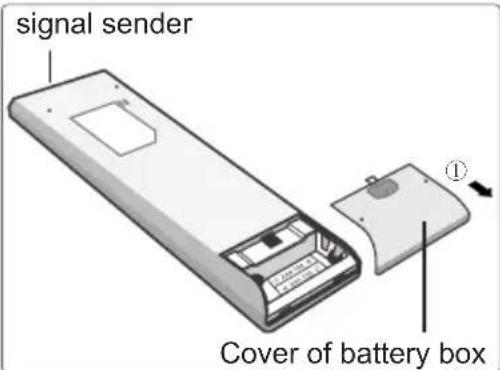
text_image
signal sender Cover of battery box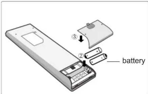
text_image
③ ② batteryMalfunction analysis
General phenomenon analysis
Please check below items before asking for maintenance. If the malfunction still can't be eliminated, please contact local dealer or qualified professionals.
| Phenomenon | Check items Solution | |
| Indoor unit can't receive remote controller's signal or remote controller has no action. | Whether it's interfered severely (such as static electricity, stable voltage)? | Pull out the plug. Reinsert the plug after about 3min, and then turn on the unit again. |
| Whether remote controller is within the signal receiving range? | Signal receiving range is 8m. | |
| Whether there are obstacles? | Remove obstacles. | |
| Whether remote controller is pointing at the receiving window? | Select proper angle and point the remote controller at the receiving window on indoor unit. | |
| Is sensitivity of remote controller low; fuzzy display and no display? | Check the batteries. If the power of batteries is too low, please replace them. | |
| No display when operating remote controller? | Check whether remote controller appears to be damaged. If yes, replace it. | |
| Fluorescent lamp in room? | Take the remote controller close to indoor unit.Turn off the fluorescent lamp and then try it again. |
| No air emitted from indoor unit | ● Air inlet or air outlet of indoor unit is blocked? | ● Eliminate obstacles. |
| ● Under heating mode, indoor temperature is reached to set temperature? | ● After reaching to set temperature, indoor unit will stop blowing out air. | |
| ● Heating mode is turned on just now? | ● In order to prevent blowing out cold air, indoor unit will be started after delaying for several minutes, which is a normal phenomenon. |
Malfunction analysis
| Phenomenon | Check items | Solution |
| Air conditioner can't operate | Power failure? | Wait until power recovery. |
| Is plug loose? | Reinsert the plug. | |
| Air switch trips off or fuse is burnt out? | Ask professional to replace air switch or fuse. | |
| Wiring has malfunction? | Ask professional to replace it. | |
| Unit has restarted immediately after stopping operation? | Wait for 3min, and then turn on the unit again. | |
| Whether the function setting for remote controller is correct? | Reset the function. | |
| Mist is emitted from indoor unit's air outlet | Indoor temperature and humidity is high? | Because indoor air is cooled rapidly. After a while, indoor temperature and humidity will be decrease and mist will disappear. |
| Set temperature can't be adjusted | Your required temperature exceeds the set temperature range? | Set temperature range: 16°C ~30°C .Set temperature range in HEAT mode: 8°C ~30°C . |
| Cooling (heating) effect is not good. | Voltage is too low? | Wait until the voltage resumes normal. |
| Filter is dirty? | Clean the filter. | |
| Set temperature is in proper range? | Adjust temperature to proper range. | |
| Door and window are open? | Close door and window. | |
| Odours are emitted | Whether there's odour source, such as furniture and cigarette, etc. | Eliminate the odour sourceClean the filter. |
Malfunction analysis
| Phenomenon | Check items Solution | |
| Air conditioner operates nor-mally suddenly | Whether there's interference, such as thunder, wireless devices, etc. | Disconnect power, put back power, and then turn on the unit again. |
| Outdoor unit has vapor | Heating mode is turned on? | During defrosting under heating mode, it may generate vapor, which is a normal phenomenon. |
| "Water flowing" noise | Air conditioner is turned on or turned off just now? | The noise is the sound of refrigerant flowing inside the unit, which is a normal phenomenon. |
| Cracking noise | Air conditioner is turned on or turned off just now? | This is the sound of friction caused by expansion and/or contraction of panel or other parts due to the change of temperature. |
Malfunction analysis
Error Code
- When air conditioner status is abnormal, temperature indicator on indoor unit will blink to display corresponding error code. Please refer to below list for identification of error code.
Error code
ES
Above indicator diagram is only for reference. Please refer to actual product for the actual indicator and position.
| Error code | Troubleshooting |
| E1,E5,E8 | It can be eliminated after restarting the unit. If not, please contact qualified professionals for service. |
| H3,H6 | |
| C5,E6 | Please contact qualified professionals for service. |
| F3,F4 | |
| F0,F1,F2 |
Note: If there're other error codes, please contact qualified professionals for service.

WARNING
■ When below phenomenon occurs, please turn off air conditioner and disconnect power immediately, and then contact the dealer or qualified professionals for service.
- Power cord is overheating or damaged.
- There's abnormal sound during operation.
• Air switch trips off frequently.
• Air conditioner gives off burning smell.
- Indoor unit is leaking.
■ Do not repair or refit the air conditioner by yourself.
■ If the air conditioner operates under abnormal conditions, it may cause malfunction, electric shock or fire hazard.
Configuration of connection pipe
- Standard length of connection pipe
- 5m, 7.5m, 8m.
- Min. length of connection pipe is 3m.
3.Max. length of connection pipe.
Max. length of connection pipe Unit: m
| Cooling capacity | Max. length of connec-tion pipe | Max. length Cooling capacity | of connec-tion pipe |
| 5000Btu/h (1465W) | 15 25 | 24000Btu/h (7032W) | |
| 7000Btu/h (2051W) | 15 30 | 28000Btu/h (8204W) | |
| 9000Btu/h (2637W) | 15 30 | 36000Btu/h (10548W) | |
| 12000Btu/h (3516W) | 20 30 | 42000Btu/h (12306W) | |
| 18000Btu/h (5274W) | 25 30 | 48000Btu/h (14064W) |
- The additional refrigerant oil and refrigerant charging required after prolonging connection pipe
- After the length of connection pipe is prolonged for 10m at the basis of standard length, you should add 5ml of refrigerant oil for each additional 5m of connection pipe.
- The calculation method of additional refrigerant charging amount (on the basis of liquid pipe):
Additional refrigerant charging amount = prolonged length of liquid pipe × additional refrigerant charging amount per meter
- Basing on the length of standard pipe, add refrigerant according to the requirement as shown in the table. The additional refrigerant charging amount per meter is different according to the diameter of liquid pipe. See the following sheet.
Configuration of connection pipe
Additional refrigerant charging amount for R22, R407C, R410A and R134a
| Diameter of connection pipe | Outdoor unit throttle | ||
| Liquid pipe(mm) | Gas pipe(mm) | Cooling only(g/m) | Cooling and heating(g/m) |
| Φ6 | Φ9.52 or Φ12 | 15 | 20 |
| Φ6 or Φ9.52 | Φ16 or Φ19 | 15 | 50 |
| Φ12 | Φ19 or Φ22.2 | 30 | 120 |
| Φ16 | Φ25.4 or Φ31.8 | 60 | 120 |
| Φ19 | - | 250 250 | |
| Φ22.2 | - | 350350 | |
Pipe expanding method
Note:
Improper pipe expanding is the main cause of refrigerant leakage. Please expand the pipe according to the following steps:
A: Cut the pipe
- Confirm the pipe length according to the distance of indoor unit and outdoor unit.
- Cut the required pipe with pipe cutter!
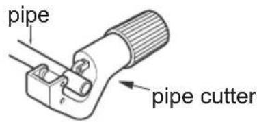
text_image
pipe pipe cutter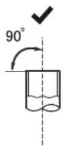
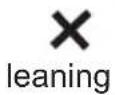
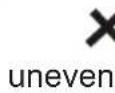


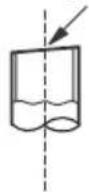
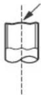
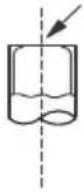
B: Remove the burrs
- Remove the burrs with shaper and prevent the burrs from getting into the pipe.

text_image
pipe shaper downwardsC: Put on suitable insulating pipe
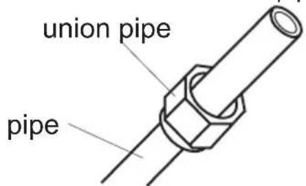
D: Put on the union nut
- Remove the union nut on the indoor connection pipe and outdoor valve; install the union nut on the pipe.
text_image
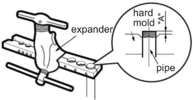
union pipe pipeE: Expand the port
- Expand the port with expander.
text_image
expander hard mold "A" pipeNote:
- "A" is different according to the diameter, please refer to the sheet below:
| Outer diameter (mm) | A(mm) | |
| Max | Min | |
| Φ6-6.35(1/4") | 1.3 | 0.7 |
| Φ9.52(3/8") | 1.6 | 1.0 |
| Φ12-12.7(1/2") | 1.8 | 1.0 |
| Φ15.8-16(5/8") | 2.4 | 2.2 |
F: Inspection
- Check the quality of expanding port. If there is any blemish, expand the port again according to the steps above.
smooth surface

natural_image
Pure diagram of a cylindrical object with internal flow arrows, no text or symbols presentimproper expanding

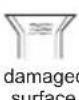


the length is equal
Please record the following product information
- Model
- Serial No.
• Name of the franchiser - Date of purchase
The continuous improvement of products, such as function is changed, without prior notice, if there are any questions, please contact customer service, Sorry for the inconvenience please forgiveness
ToolBox Customer Service Centre :
4/F, DCH Building, 20 Kai Cheung Road, Kowloon Bay, Hong Kong
Service E-mail: 8210service@gilman-group.com