Civic GX (2008) - Automotive Honda - Free user manual and instructions
Find the device manual for free Civic GX (2008) Honda in PDF.


User questions about Civic GX (2008) Honda
0 question about this device. Answer the ones you know or ask your own.
Ask a new question about this device
Download the instructions for your Automotive in PDF format for free! Find your manual Civic GX (2008) - Honda and take your electronic device back in hand. On this page are published all the documents necessary for the use of your device. Civic GX (2008) by Honda.
USER MANUAL Civic GX (2008) Honda
Congratulations! Your selection of a 2008 Honda Civic was a wise investment. It will give you years of driving pleasure.
One of the best ways to enhance the enjoyment of your new vehicle is to read this manual. In it, you will learn how to operate its driving controls and convenience items. Afterwards, keep this owner's manual in your vehicle so you can referto it at any time.
Several warranties protect your new vehicle. Read the warranty booklet thoroughly so you understand the coverages and are aware of your rights and responsibilities.
Maintaining your vehicle according to the maintenance minder shown in the instrument panel helps to keep your driving trouble-free while it preserves your investment. When your vehicle needs maintenance, keep in mind that your dealer's staff is specially trained in servicing the many systems unique to your vehicle. Your dealer is dedicated to your satisfaction and will be pleased to answer any questions and concerns.
As you read this manual, you will find information that is preceded by a syNOTIDE This
information is intended to help you avoid damage to your vehicle, other property, or the environment.
Main Menu
Introduction
California Proposition 65 Warning
WARNING: This product contains or emits chemicals known to the State of California to cause cancer and birth defects or other reproductive harm.
Event Data Recorders
This vehicle is equipped with one or more devices commonly referred to as event data recorders. These devices record front seat belt use, front passenger seat occupancy, airbag deployment data, and the failure of any airbag system component. This data belongs to the vehicle owner and may not be accessed by anyone else except as legally required or with the permission of the vehicle owner.
Service Diagnostic Recorders
This vehicle is equipped with service-related devices that record information about powertrain performance. The data can be used to verify emissions law requirements and/or help technicians diagnose and solve service problems. It may also be combined with data from other sources for research purposes, but it remains confidential.
ii
2008 Civic Coupe
Your safety, and the safety of others, is very important. And operating this vehicle safely is an important responsibility.
To help you make informed decisions about safety, we have provided operating procedures and other information on labels and in this manual. This information alerts you to potential hazards that could hurt you or others.
Of course, it is not practical or possible to warn you about all the hazards associated with operating or maintaining your vehicle. You must use your own good judgement.
You will find this important safety information in a variety of forms, including:
- Safety Labels – on the vehicle.
- Safety Messages — preceded by a safety alert symbol ⚠ and one of three signal words: DANGER WARNING CAUTION These signal words mean:

You WILL be KILLED or SERIOUSLY HURT if you don't follow instructions.

You CAN be KILLED or SERIOUSLY HURT if you don't follow instructions.

You CAN be HURT if you don't follow instructions.
- Safety Headings — such as Important Safety Reminders or Important Safety Precautions.
- Safety Section – such as Driver and Passenger Safety.
- Instructions — how to use this vehicle correctly and safely.
This entire book is filled with important safety information — please read it carefully.
iii
2008 Civic Coupe Online Reference Owner's Manual
Contents
Owner's Identification Form
Introduction ...... i
A Few Words About Safety .... iii
Your Vehicle at a Glance (main controls) 3
Driver and Passenger Safety (seat belts, SRS, and child protection) 5
Instruments and Controls (indicators, gauges, dashboard, and steering column) 53
Features (heating and cooling, audio, steering wheel, security, and cruise control) 113
Before Driving (fuel, vehicle break-in, and cargo loading) 185
Driving (engine and transmission operation) 201
Maintenance (minder, fluid checking, minor services, and vehicle storage).... 223
Taking Care of the Unexpected (flat tire, dead battery, overheating, and fuses) 269
Technical Information (vehicle specifications, tires, and emissions controls) 293
Warranty and Customer Relations (U.S. and Canada only) (warranty and contact information) ... 311
Authorized Manuals (U.S. only) (how to order) 315
Index I
Service Information Summary (fluid capacities and tire pressures)
Contents
A convenient reference to the sections in this manual.
Your Vehicle at a Glance
A quick reference to the main controls in your vehicle.
Driver and Passenger Safety
Important information about the proper use and care of your vehicle's seat belts, an overview of the supplemental restraint system, and valuable information on how to protect children with child restraints.
Instruments and Controls
Explains the purpose of each instrument panel indicator and gauge, and how to use the controls on the dashboard and steering column.
Features
How to operate the heating and air conditioning system, the audio system, and other convenience features.
Before Driving
What gasoline to use, how to break-in your new vehicle, and how to load luggage and other cargo.
Driving
The proper way to start the engine, shift the transmission, and park.
Maintenance
The maintenance minder shows you when you need to take your vehicle to the dealer for maintenance service. There is also a list of things to check and instructions on how to check them.
Taking Care of the Unexpected
This section covers several problems motorists sometimes experience, and details how to handle them.
Technical Information
ID numbers, dimensions, capacities, and technical information.
Warranty and Customer Relations
(U.S. and Canada only)
A summary of the warranties covering your new vehicle, and how to contact us for any reason. Refer to your warranty manual for detailed information.
Authorized Manuals (U.S. only)
How to order manuals and other technical literature.
Index
Service Information Summary
A summary of the information you need when you pull up to the fuel pump.
text_image
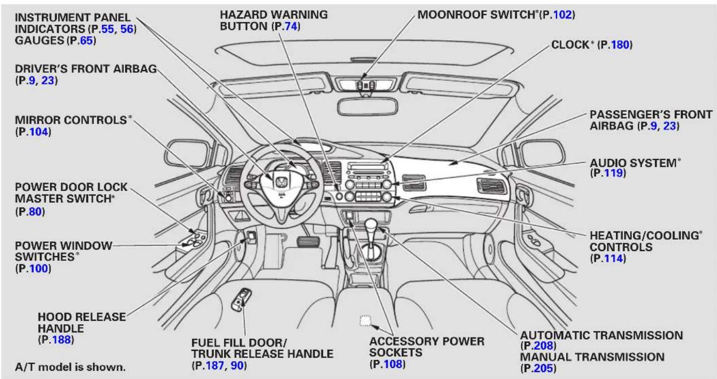
INSTRUMENT PANEL INDICATORS (P.55, 56) GAUGES (P.65) DRIVER'S FRONT AIRBAG (P.9, 23) MIRROR CONTROLS* (P.104) POWER DOOR LOCK MASTER SWITCH* (P.80) POWER WINDOW SWITCHES* (P.100) HOOD RELEASE HANDLE (P.188) A/T model is shown. HAZARD WARNING BUTTON (P.74) MOONROOF SWITCH*(P.102) CLOCK* (P.180) PASSENGER'S FRONT AIRBAG (P.9, 23) AUDIO SYSTEM* (P.119) HEATING/COOLING* CONTROLS (P.114) FUEL FILL DOOR/ TRUNK RELEASE HANDLE (P.187, 90) ACCESSORY POWER SOCKETS (P.108) AUTOMATIC TRANSMISSION (P.208) MANUAL TRANSMISSION (P.205)* If equipped:
Main Menu
Your Vehicle at a Glance
text_image
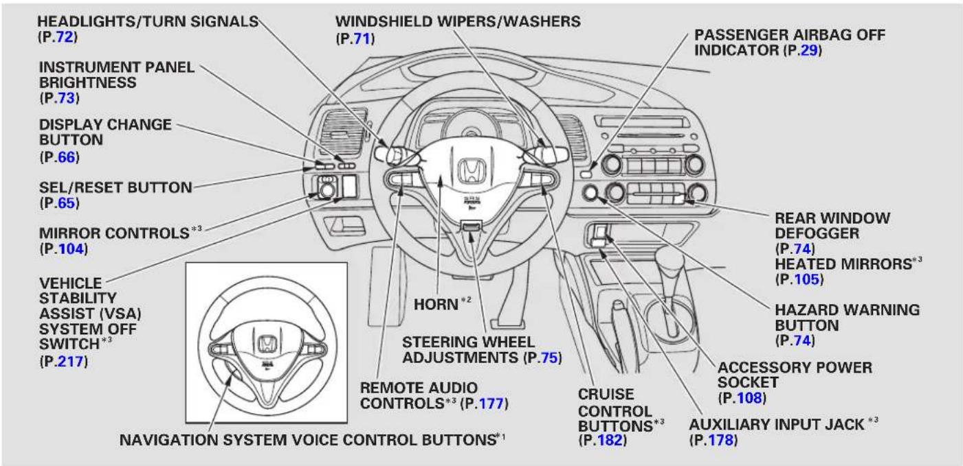
HEADLIGHTS/TURN SIGNALS (P.72) INSTRUMENT PANEL BRIGHTNESS (P.73) DISPLAY CHANGE BUTTON (P.66) SEL/RESET BUTTON (P.65) MIRROR CONTROLS*3 (P.104) VEHICLE STABILITY ASSIST (VSA) SYSTEM OFF SWITCH*3 (P.217) NAVIGATION SYSTEM VOICE CONTROL BUTTONS*1 WINDSHIELD WIPERS/WASHERS (P.71) PASSENGER AIRBAG OFF INDICATOR (P.29) HORN*2 STEERING WHEEL ADJUSTMENTS (P.75) REMOTE AUDIO CONTROLS*3 (P.177) CRUISE CONTROL BUTTONS*3 (P.182) REAR WINDOW DEFOGGER (P.74) HEATED MIRRORS*3 (P.105) HAZARD WARNING BUTTON (P.74) ACCESSORY POWER SOCKET (P.108) AUXILIARY INPUT JACK *3 (P.178)*1: Only on vehicles equipped with navigation system. Refer to the navigation system manual.
*2: To use the horn, press the center pad of the steering wheel.
*3: If equipped.
This section gives you important information about how to protect yourself and your passengers. It shows you how to use seat belts. It explains how your airbags work. And it tells you how to properly restrain infants and children in your vehicle.
Additional Information About Your Seat Belts 18
Seat Belt System Components... 18
Lap/Shoulder Belt.... 19
Automatic Seat Belt Tensioners.... 19
Seat Belt Maintenance 20
Additional Information About Your Airbags....21
Airbag System Components..... 21
How Your Front Airbags Work.... 23
How Your Side Airbags Work.... 26
ImportaHowSafetySPleCautionAirbags .7 Work....28
How the SRS Indicator Works... 28
How the Side Airbag Off Indicator Works.... 29
How the Passenger Airbag Off Indicator Works.... 29
Airbag Service.... 30
Protecting Children - General Guidelines.... 32
All Children Must Be
...Additional Safety Precautions.....16.....32
All Children Should Sit in a Back Seat 33
The Passenger's Front Airbag Can Pose Serious Risks ...... 33
If You Must Drive with Several Children 35
If a Child Requires Close Attention.... 35
...Additiona
Protecting Infants and Small Children 37
Protecting Infants.... 37
Protecting Small Children ..... 38
Selecting a Child Seat.... 39
Installing a Child Seat .... 40 With LATCH .... 41
With a Lap/Shoulder Belt ...... 43
With a Tether 45
Protecting Larger Children 46
Checking Seat Belt Fit 46
Using a Booster Seat.... 47
on WhafcyaFraLaugienChild Sit in Front.... 48
...Additional
Carbon Monoxide Hazard 50
Safety Labels 51
You'll find many safety recommendations throughout this section, and throughout this manual. There commands on the are the ones we consider to be the most important.
Always Wear Your Seat Belt
A seat belt is your best protection in all types of collisions. Airbags are designed to supplement seat belts, not replace them. So even though your vehicle is equipped with airbags, make sure you and your passengers always wear your seat belts, and wear them properly (see page) ^14
Restrain All Children
Children age 12 and under should ride properly restrained in a back spat gnet the front seat. Infants and small children should be res in a child seat. Larger children should use a booster seat and a lap/shoulder belt until they can use the belt properly without a booster seat (see pages 32 49
Be Aware of Airbag Hazards
While airbags can save lives, they can cause serious or fatal injuries to occupants who sit too close to them, or are not properly restrained. Infants, young children, and short adults are at the greatest risk. Be sure to follow all instructions and warnings in this manual.
Don't Drink and Drive
Alcohol and driving don't mix. Even one drink can reduce your ability to respond to changing conditions, and your reaction time gets worse with
every additional drink. So don't drink and drive, and don't let your friends drink and drive, either.
ControldYour Speed
Excessive speed is a major factor in crash injuries and deaths. Generally, the higher the speed, the greater the risk, but serious injuries can also occur at lower speeds. Never drive faster than is safe for current conditions, regardless of the maximum speed posted.
Keep Your Vehicle in Safe Condition
Having a tire blowout or a mechanical failure can be extremely hazardous. To reduce the possibility of such problems, check your tire pressures and condition frequently, and perform all regularly scheduled maintenance (see page 225
text_image
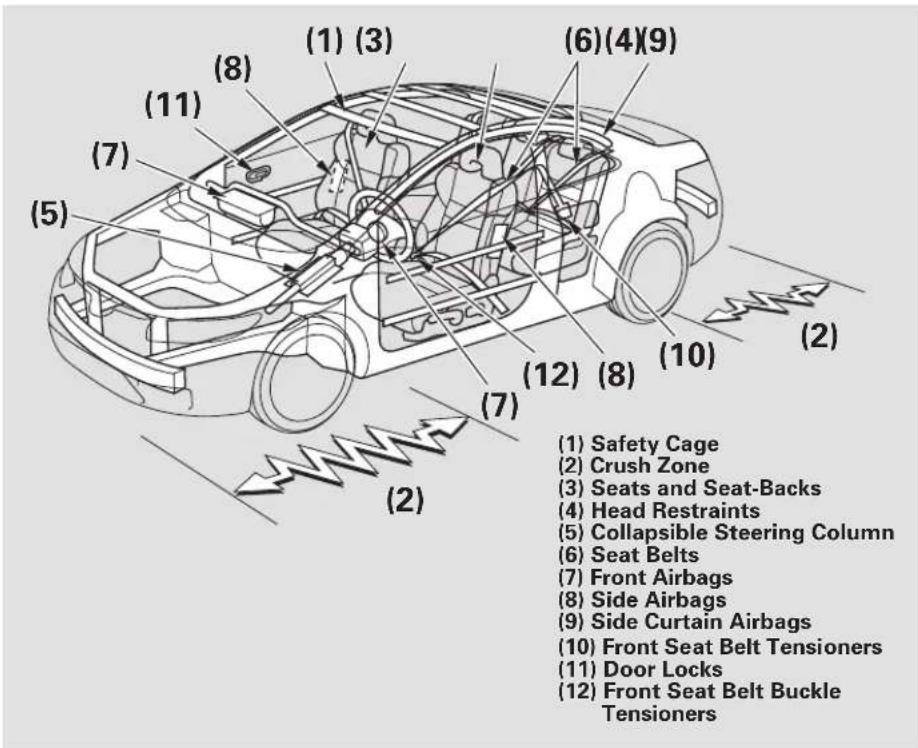
(1) Safety Cage (2) Crush Zone (3) Seats and Seat-Backs (4) Head Restraints (5) Collapsible Steering Column (6) Seat Belts (7) Front Airbags (8) Side Airbags (9) Side Curtain Airbags (10) Front Seat Belt Tensioners (11) Door Locks (12) Front Seat Belt Buckle TensionersYour vehicle is equipped with many features that work together to protect you and your passengers during a crash.
Some features do not require any action on your part. These include a strong steel framework that forms a safety cage around the passenger compartment, front and rear crush zones, a collapsible steering column, and tensioners that tighten the front seat belts in a crash.
However, you and your passengers can't take full advantage of these features unless you remain sitting in a proper position and always wear your seat belts. In fact, some safety features can contribute to injuries if they are not used properly.
The following pages explain how you cantake an active role in protect yourself and your passengers.
Seat Belts
Your vehicle is equipped with seat belts in all seating positions.
Your seat belt system also includes an indicator on the instrument panel and a beeper to remind you and your passengers to fasten your seat belts.
Why Wear Seat Belts
Seat belts are the single most e f f e c t i v e s a f e t y d e v i c e f o r a larger children. (Infants and smaller children must be properly restrained in child seats.)
Not wearing a seat belt properly increases the chance of serious injury or death in a crash, even though your vehicle has airbags.
In addition, most states and all Canadian provinces require you to wear seat belts.
WARNING
Not wearing a seat belt properly increases the chance of serious injury or death in a crash, even though your vehicle has airbags.
Be sure you and your passengers always wear seat belts and wear them properly.
dultsand
When properly worn, seat belts:
- Keep you connected to the vehicle so you can take advantage of the vehicle's built-in safety features.
-
Help protect you in almost every type of crash, including frontal, side, and rear impacts and rollovers.
-
Help keep you from being thrown against the inside of the vehicle and against other occupants.
- Keep you from being thrown out of the vehicle.
- Help keep you in a good position should the airbags ever deploy. A good position reduces the risk of injury from an inflating airbag and allows you to get the best advantage from the airbag.
Of course, seat belts cannot completely protect you in every crash. But in most cases, seat can reduce your risk of serious injury.
What You Should Do:
Always wear your seat belt, and make sure you wear it properly.
Airbags
natural_image
Line drawing of two identical backpacks viewed from the side, with no text or symbols present.Your vehicle has a supplemental restraint system (SRS) with front airbags to help protect the heads and chests of the driver and a front seat passenger during a moderate to severe frontal collision (see page 23 for more information on how your front airbags work).
natural_image
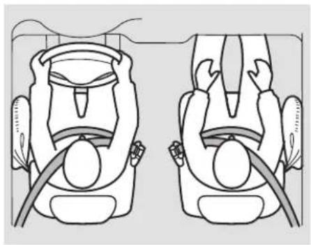
Top-down line drawing of two identical car seats with arms raised, showing seat positions and legs (no text or symbols)Your vehicle also has side airbags to help protect the upper torso of the driver or a front seat passenger during a moderate to severe side impact (see page 26 more information on how your side airbags work).
natural_image
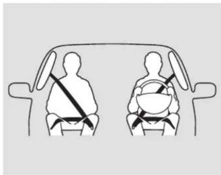
Diagram of a car showing two individuals seated in the back seat, each wearing a seatbelt and carrying a belt (no text or symbols present)In addition, your vehicle has side curtain airbags to help protect the heads of the driver, front passenger, and passengers in the outer rear seating positions during a moderate to severe side impact (see page 28 for more information on how your side curtain airbags work).
CONTINUED
The most important things you need to know about your airbags are:
- Airbags do not replace seat belts. They are designed to supplement the seat belts.
- Airbags offer no protection in rear impacts, or minor frontal or side collisions.
- Airbags can pose hazards. To do their job, airbags must inflate with tremendous force. So while airbags help save lives, they can cause minor injuries or more serious or even fatal injuries if occupants are not properly restrained or sitting properly.
What you should do Always wear your seat belt properly, and sit upright and as far back from the steering wheel as possible while allowing full control of the vehicle. A front passenger should move their seat as far back from the dashboard as possible.
The rest of this section gives more detailed information about how you can maximize your safety.
Remember, however, that no safety system can prevent all injuries or deaths that can occur in a severe crash, even when seat belts are properly worn and the airbags deploy.
The following pages provide instructions on how to properly protect the driver, adult passengers, and teenage children who are large enough and mature enough to drive or ride in the front.
See pages 32-36 important guidelines on how to properly protect infants, small children, and larger children who ride in your vehicle.
Close and Lock the Doors1. After everyone has entered the vehicle, be sure the doors are closed and locked.

Your vehicle has a door-open indicator on the
instrument panel to indicate when either door is not tightly closed.
Locking the doors reduces the chance of someone being thrown out of the vehicle during a crash, and it helps prevent passengers from accidentally opening a door and falling out.
Locking the doors also helps prevent an outsider from unexpectedly opening a door when you come to a stop.
See page for how to lock the doors, and page for how the door-open indicator works.
Some models have the auto door locking/unlocking feature. For more information, see page .81
- Adjust the Front Seats Introduction
natural_image
Illustration of a person seated in a car steering wheel, showing the wheel being held and indicated by an arrow (no text or symbols present)Driver and Passenger Safety
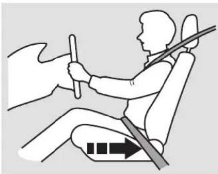
Adjust the driver's seat as far to the rear as possible while allowing you to maintain full control of the vehicle. Have a front passenger adjust their seat as far to the rear as possible.
CONTINUED
Protecting Adults and Teens
If you sit too close to the steering wheel or dashboard, you can be seriously injured by an inflating front airbag, or by striking the steering wheel or dashboard.
The National Highway Traffic Safety Administration and Transport Canada recommend that drivers allow at least 10 inches (25 cm) between the center of the steering wheel and the chest. In addition to adjusting the seat, you can adjust the steering wheel up and down, and in and out (see page).75
If you cannot get far enough away from the steering wheel and still reach the controls, we recommend that you investigate whether some type of adaptive equipment may help.
WARNING
Sitting too close to a front airbag can result in serious injury or death if the front airbags inflate.
Always sit as far back from the front airbags as possible.
Once your seat is adjusted correctly, rock it back and forth to make sure the seat is locked in position.
See page 102 how to adjust the front seats.
Adjust the Seat-Backs3.
natural_image
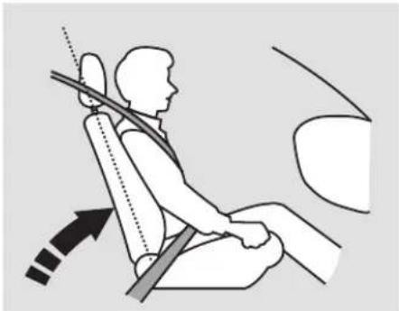
Illustration of a person seated in a car seat using a seatbelt, with no visible text or symbolsAdjust the driver's seat-back to a comfortable, upright position, leaving ample space between your chest and the airbag cover in the center of the steering wheel.
Passengers with adjustable seat-backs should also adjust their seat-back to a comfortable, upright position.
WARNING
Reclining the seat-back too far can result in serious injury or death in a crash.
Adjust the seat-back to an upright position, and sit well back in the seat.
Reclining a seat-back so that the shoulder part of the belt no longer rests against the occupant's chest reduces the protective capability of the belt. It also increases the chance of sliding under the belt in a crash and being seriously injured. The farther a seat-back is reclined, the greater the risk of injury.
See page for how to adjust the seat-backs.
Adjust the Head Restraints4.
natural_image
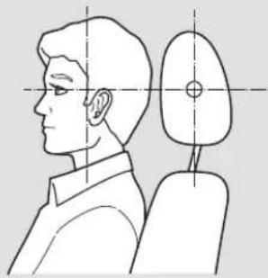
Side profile illustration of a person's head and neck with a side view showing anatomical alignment lines (no text or symbols)Adjust the driver's head restraint so the center of the back of your head rests against the center of the restraint.
Have passengers adjust their head restraints properly as well. Taller persons should adjust their restraint as high as possible.
▲WARNING
Improperly positioning head restraints reduces their effectiveness and you can be seriously injured in a crash.
Make sure head restraints are in place and positioned properly before driving.
Properly adjusted head restraints will help protect occupants from whiplash and other crash injuries.
See page 105 how to adjust the head restraints and how the driver's and front passenger's active head restraints work.
Protecting Adults and Teens
5. Fasten and Position the Seat Belts
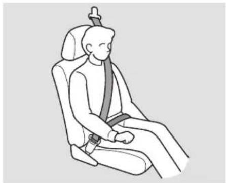
Insert the latch plate into the buckle, then tug on the belt to make sure the belt is securely latched. Check that the belt is not twisted, because a twisted belt can cause serious injuries in a crash.
natural_image
Line drawing of a person seated in a car seatbelt, no text or symbols presentPosition the lap part of the belt as low as possible across your hips, then pull up on the shoulder part of the belt so the lap part fits snugly. This lets your strong pelvic bones take the force of a crash and reduces the chance of internal injuries.
If necessary, pull up on the belt again to remove any slack, then check that the belt rests across the center of your chest and over your shoulder.
This spreads the forces of a crash over the strongest bones in your upper body.
WARNING
Improperly positioning the seat belts can cause serious injury or death in a crash.
Make sure all seat belts are properly positioned before driving.
Never place the shoulder portion of a lap/shoulder belt under your arm or behind your back. This could cause very serious injuries in a crash.
If a seat belt does not seem to work properly, it may not protect the occupant in a crash.
No one should sit in a seat with an inoperative seat belt. Using a seat belt that is not working properly can result in serious injury or death. Have your dealer check the belt as soon as possible.
See page for additional information about your seat belts and how to take care of them.
6. Maintain a Proper Sitting Position
After all occupants have adjusted their seats and head restraints, and put on their seat belts, it is very important that they continue to sit upright, well back in their seats, with their feet on the floor, until the vehicle is parked and the engine is off.
Sitting improperly can increase the chance of injury during a crash. For example, if an occupant slouches, lies down, turns sideways, sits forward, leans forward or sideways, or puts one or both feet up, the chance of injury during a crash is greatly increased.
In addition, an occupant who is out of position in the front seat can be seriously or fatally injured in a crash by striking interior parts of the vehicle or being struck by an inflating front airbag.
WARNING
Sitting improperly or out of position can result in serious injury or death in a crash.
Always sit upright, well back in the seat, with your feet on the floor.
Protecting Adults and Teens
Advice for Pregnant Women Addition/Wh Safety/Recautioner to sit
natural_image
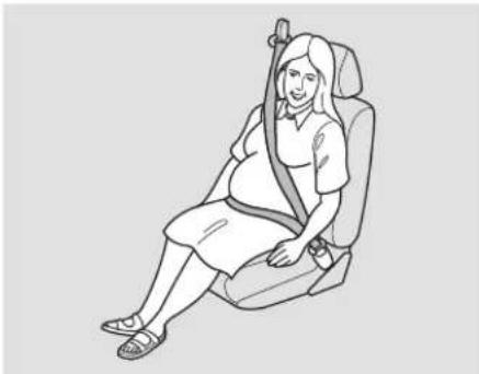
Line drawing of a pregnant woman seated in a car seat, wearing a seatbelt (no text or symbols)If you are pregnant, the best way to protect yourself and your unborn child when driving or riding in a vehicle is to always wear a seat belt, and keep the lap part of the belt as low as possible across the hips.
upright and adjust the seat as far back as possible while allowing full control of the vehicle. When riding as a front passenger, adjust the seat as far back as possible.
This will reduce the risk of injuries to both you and your unborn child that can be caused by a crash or an inflating front airbag.
Each time you have a checkup, ask your doctor if it's okay for you to drive.
- Two people should never use the same seat belt. If they do, they could be very seriously injured in a crash.
- Do not put any accessories on seat belts. Devices intended to improve occupant comfort or reposition the shoulder part of a seat belt can reduce the protective capability of the belt and increase the chance of serious injury in a crash.
- Do not place hard or sharp objects between yourself and a front airbag. Carrying hard or sharp objects on your lap, or driving with a pipe or other sharp object in your mouth, can result in injuries if your front airbag inflates.
- Keep your hands and arms away from the airbag covers. If your hands or arms are close to an airbag cover, they could be injured if the airbag inflates.
- Do not attach or place objects on the front airbag covers. Objects on the covers marked "SRS AIRBAG" could interfere with the proper operation of the airbags or be propelled inside the vehicle and hurt someone if the airbags inflate.
- Do not attach hard objects on or near a door. If a side airbag or a side curtain airbag inflates, a cup holder or other hard object attached on or near the door could be propelled inside the vehicle and hurt someone.
- Never let passengers ride on top of a folded-down rear seat. If they do, they could be very seriously injured in acrash.
Seat Belt System Components
Your seat belt system includes lap/shoulder belts in all five seating positions. The front seat belts are also equipped with automatic seat belt tensioners.
This system uses the same sensors as the front airbags to monitor whether the front seat belts are latched or unlatched, and how much weight is on the front passenger's seat (see pages 2012).

The seat belt system includes an indicator on the
instrument panel and a beeper to remind you and your passengers to fasten your seat belts.
This system monitors the front seat belts. If you turn the ignition switch to the ON (II) position before your seat belt is fastened, the beeper will sound and the indicator will flash. If your seat belt is not fastened before the beeper stops, the indicator will stop flashing but remain on.
If a front passenger does not fasten their seat belt, the indicator will come on about 6 seconds after the ignition switch is turned to the ON (II) position.
If either the driver or a front passenger does not fasten their seat belt while driving, the beeper will sound and the indicator will flash again at regular intervals.
When no one is sitting in the front passenger's seat, or a child or small adult is riding there, the indicator should not come on and the beeper should not sound.
If the indicator comes on or the beeper sounds when the driver's seat belt is latched and there is no front seat passenger and no items on the front seat, something may be interfering with the monitoring system. Look for and remove:
- Any items under the front passenger's seat.
- Any object(s) hanging on the seat or in the seat-back pocket.
- Any object(s) touching the rear of the seat-back.
If no obstructions are found, have your vehicle checked by a dealer.
Lap/Shoulder Belt Automatic Seat Bell Tensioners have an emergency
The lap and shoulder belt goes over your shoulder, across your chest, and across your hips.
To fasten the belt, insert the latch plate into the buckle, then tug on the belt to make sure the buckle is latched (see page 104 how to properly position the belt).
To unlock the belt, press the red PRESS button on the buckle the belt across your body so that it retracts completely. After exiting the vehicle, be sure the belt is out of the way and will not get closed in the door.
locking retractor. In normal driving, the retractor lets you move freely in your seat while it keeps some tension on the belt. During a collision or sudden stop, the retractor automatically locks the belt to help restrain your body.
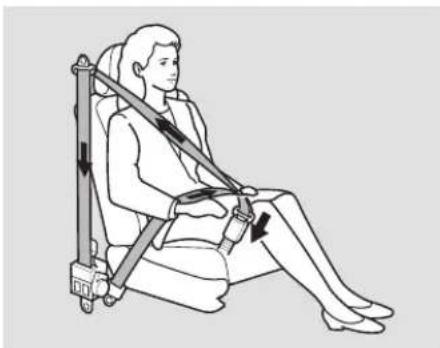
In addition, the lap/shoulder belts in all seating positions except the driver's have a lockable retractor Gthatchust be activated to secure a child seat (see page 13
If the shoulder part of the belt is pulled all the way out, the lockable retractor will activate. The belt will retract, but it will not allow the passenger to move freely.
To deactivate the lockable retractor, unlatch the buckle and let the seat belt fully retract. To refasten the seat belt, pull it out only as far as needed.
natural_image
Line drawing of a person seated in a chair using a seatbelt device (no text or symbols)For added protection, the front seat belts are equipped with automatic seat belt tensioners. When activated, the tensioners immediately tighten the belts to help hold the driver and a front passenger in position.
CONTINUED
The tensioners are designed to activate in any collision severe enough to cause the front airbags to deploy.
If a side airbag or side curtain airbag deploys during a side impact, the tensioner on that side of the vehicle will also deploy.
The tensioners can also be activated during a collision in which the front airbags durthisopase, the airbags would not be needed, but the additional restraint could be helpful.
When the tensioners are activated, the seat belts will remain tight until they are unbuckled.
Seat Belt Maintenance
For safety, you should check the condition of your seat belts regularly.
Pull each belt out fully, and look for frays, cuts, burns, and wear. Check that the latches work smoothly and the belts retract easily. If a belt does not retract easily, cleaning the belt may correct the problem (see page 251). Any belt that is not in good condition or working properly will not provide good protection and should be replaced as soon as possible.
Honda provides a limited warranty on seat belts. See your Honda Warranty Information booklet for details.
If a seat belt is worn during a crash, it must be replaced by your dealer. A belt that has been worn during a crash may not provide the same level of protection in a subsequent crash.
The dealer should also inspect the anchors for damage and replace them if needed. If the automatic seat belt tensioners activate during a crash, they must be replaced.
WARNING
Not checking or maintaining seat belts can result in serious injury or death if the seat belts do not work properly when needed.
Check your seat belts regularly and have any problem corrected as soon as possible.
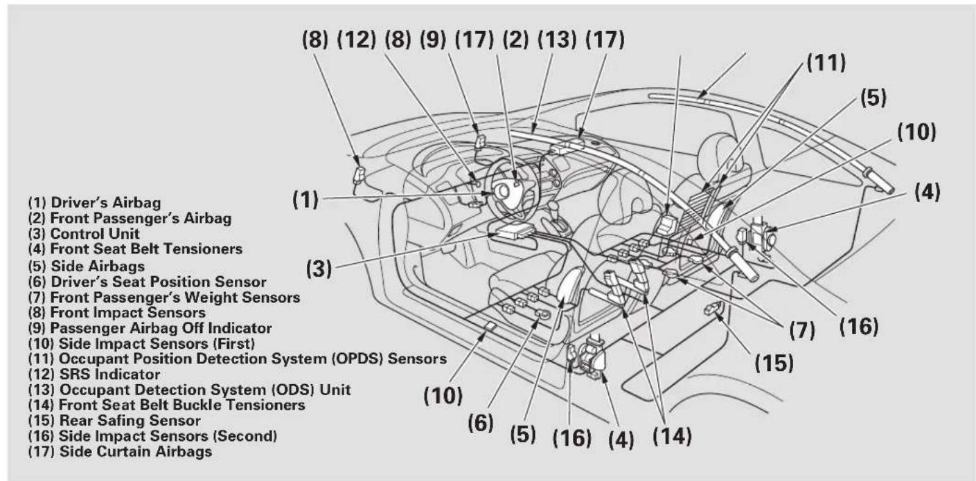
Airbag System Components
text_image
(1) Driver's Airbag (2) Front Passenger's Airbag (3) Control Unit (4) Front Seat Belt Tensioners (5) Side Airbags (6) Driver's Seat Position Sensor (7) Front Passenger's Weight Sensors (8) Front Impact Sensors (9) Passenger Airbag Off Indicator (10) Side Impact Sensors (First) (11) Occupant Position Detection System (OPDS) Sensors (12) SRS Indicator (13) Occupant Detection System (ODS) Unit (14) Front Seat Belt Buckle Tensioners (15) Rear Safing Sensor (16) Side Impact Sensors (Second) (17) Side Curtain AirbagsCONTINUED
Additional Information About Your Airbags
Your airbag system includes:
- Two SRS (supplemental restraint system) front airbags. The driver's airbag is stored in the center of the steering wheel; the front passenger's airbag is stored dashboard. Both are marked "SRS AIRBAG" (see page 23).
- Two side airbags, one for the driver and one for a front passenger. The airbags are stored in the outer edges of the seat-backs. Both are marked “SIDE AIRBAG” (see page26).
-
Two side curtain airbags, one for each side of the vehicle. The airbags are stored in the ceiling, above the side windows. The front and rear pillars are marked “SIDE CURTAIN AIRBAG” (see page 28).
• Automatic front seat belt tensioners (see page)19 -
Sensors that can detect a moderate to severe front impact or side impact.
- Sensors that can detect whether a dichth is in the passenger's side airbag path and signal the control unit to turn the airbag off (see page 27
- Sensors that can detect whether the driver's seat belt and the front passenger's seat belt are latched or unlatched (see page 18
-
A driver's seat position sensor that monitors the distance of the seat from the front airbag. If the seat is too far forward, the airbag will inflate with less force (see page 25).
-
Weight sensors that monitor the weight on the front passenger's seat. If the weight is about 65 lbs (29 kg) or less (the weight of an infant or small child), the passenger's front airbag will be turned off (see page 25
- A sophisticated electronic system that continually monitors and records information about the sensors, the control unit, the airbag activators, the seat belt tensioners, and driver and front passenger seat belt use when the ignition switch is in the ON (II) position.
-
An indicator on the instrument panel that alerts you to a possible problem with your airbags, sensors, or seat belt tensioners (see page 28
-
An indicator on the instrument panel that alerts you that the passenger's side airbag has been turned off (see page 29)
- An indicator on the dashboard that alerts you that the passenger's front airbag has been turned off (see page 2.9
- Emergency backup power in case your vehicle's electrical system is disconnected in a crash.
How Your Front Airbags Work
natural_image
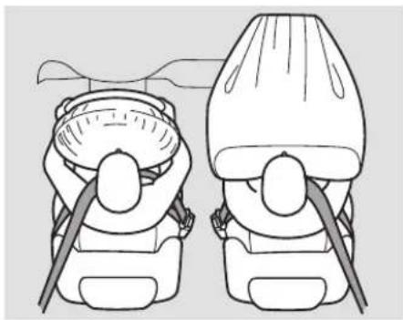
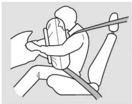
Illustration of a person seated in a car seat with a horizontal bar, no text or symbols presentIf you ever have a moderate to severe frontal collision, sensors will detect the vehicle's rapid deceleration.
If the rate of deceleration is high enough, the control unit will instantly inflate the driver's and front passenger's airbags, at the time and with the force needed.
During a frontal crash, your seat belt restrains your lower body and torso, and the front airbag helps protect your head and chest.
Although both airbags normally inflate within split second of each other, it is possible for only one airbag to deploy.
This can happen if the severity of a collision is at the margin, or threshold, that determines whether or not the airbags will deploy. In such cases, the seat belt will provide sufficient protection, and the supplemental protection offered by the airbag would be minimal.
Only the driver's airbag will deploy if there is no passenger in the front seat, or if the advanced airbag system has turned the passenger's airbag off (see page 25
CONTINUED
Additional Information About Your Airbags
natural_image
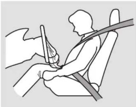
Line drawing of a person seated in a car seat using a seatbelt, no text or symbols presentAfter inflating, the front airbags immediately deflate, so they won't interfere with the driver's visibility, or the ability to steer or operate other controls.
The total time for inflation and deflation is one-tenth of a second, so fast that most occupants are not aware that the airbags deployed until they see them lying in their laps.
After a crash, you may see what looks like smoke. This is actually powder from the airbag's surface. Although the powder is not harmful, people with respiratory problems may experience some tempo discomfort. If this occurs, get out of the vehicle as soon as it is safe to do so.
Dual-Stage Airbags
Your front airbags are dual-stage airbags. This means they have two inflation stages that can be ignited sequentially or simultaneously, depending on crash severity.
In a crash, severatages
will ignite simultaneously to provide the quickest and greatest protection.
In a traslseconestage will
ignite first, then the second stage will ignite a split second later. This provides longer airbag inflation time with a little less force.
Dual-Threshold Airbags
Your front airbags are also dual-threshold airbags. Airbags with this feature have two deployment thresholds that depend on whether sensors detect the occupant is wearing a seat belt or not.
If the occupant's belt is ,not latched the airbag will deploy at a slightly lower threshold, because the occupant would need extra protection.
If the occupant's belt is ,fatched airbag will inflate at a slightly higher threshold, when the airbag would be needed to supplement the protection provided by the seat belt.
Advanced Airbags
Your front airbags are also advanced airbags. The main purpose of this feature is to help prevent airbag-caused injuries to short drivers and children who ride in front.
For both advanced airbags to work properly:
• Occupants must sit upright and wear their seat belts properly.
- Do not spill any liquids on or under the seats, cover the sensors, or put any objects or metal items under the front seats.
- Back-seat passengers should not put their feet under the front seats.
Failure to follow these instructions could damage the sensors or prevent them from working properly.
text_image
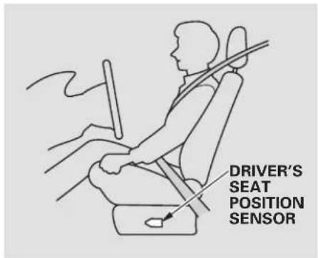
DRIVER'S SEAT POSITION SENSORThe driver's advanced front airbag system includes a seat position sensor under the seat. If the seat is too far forward, the airbag will inflate with less force, regardless of the severity of the impact.
If there is a problem with the sensor, the SRS indicator will come on, and the airbag will inflate in the normal manner regardless of the driver's seating position.
text_image
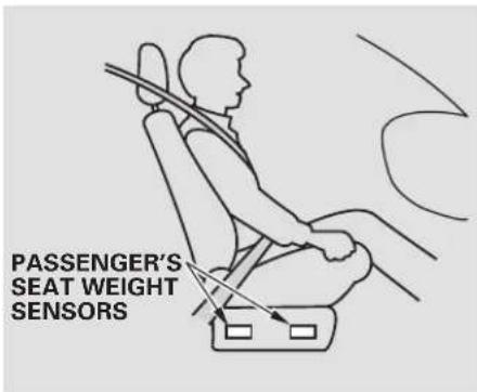
PASSENGER'S SEAT WEIGHT SENSORSThe passenger's advanced front airbag system has weight sensors under the seat. Although Honda does not encourage carrying an infant or small child in front, if the sensors detect the weight of an infant or small child (up to about 65 lbs or 29kg ), the system will automatically turn the passenger's front airbag off.
CONTINUED
Additional Information About Your Airbags
Be aware that objects placed on the passenger's seat can also cause the airbag to be turned off.
When the airbag is turned off, a "passenger airbag off" indicator in the center of the dashboard comes on (see page 29
If the weight sensors detect there is no passenger in the front seat, the airbag will be off. However, the passenger airbag off indicator will not come on.
To ensure that the passenger's advanced front airbag system will work properly, do not do anything that would increase or decrease the weight on the front passenger's seat. This includes:
- A rear passenger pushing or pulling on the back of the front passenger's seat.
- Moving the front seat forcibly back against cargo on the seat or floor behind it.
- Moving the front seat or seat-back forcibly back against the folded rear seat.
- Hanging heavy items on the front passenger seat, or placing heavy items in the seat-back pocket.
If your vehicle is equipped with the floor mats, makesure the floor matbehindthefrontpassen seat is positioned properly (see page 25E it is not, the mat may interfere with the proper operation of the sensors and operation of the seat.
How Your Side Airbags Work
natural_image
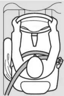
Line drawing of a medical device with a bulb and tubing (no text or symbols)If you ever have a moderate to severe side impact, sensors will detect rapid acceleration and signal the control unit to instantly inflate either the driver's or the passenger's side airbag.
Only one airbag will deploy during a side impact. If the impact is on the passenger's side, the passenger's side airbag will deploy even if there is no passenger.
To get the best protection from the side airbags, front seat occupants should wear their seat belts and sit upright and well back in their seats.
Side Airbag Cutoff System
Your vehicle has a side airbag cutoff system designed primarily to protect a child riding in the front passenger's seat.
Although Honda does not encourage children to ride in front, if position sensors detect a child has leaned into the side airbag's deployment path, the airbag will shut off.
The side air bag may also should short adult leans sideways, or a larger adult slouches and leans sideways into the airbag's deployment path.
Objects placed on the front passenger seat can also cause the side airbag to be shut off.
If the side airbag off indicator comes on (see page 29) have the passenger sit upright. Once the passenger is out of the airbag's deployment path, the system will turn the airbag back on, and the indicator will go out.
There will be some delay between the moment the passenger moves into or out of the airbag deployment path and when the indicator comes off for goes off.
A front seat passenger should not use a cushion or other object as a backrest. It may prevent the cutoff system from working properly.
Additional Information About Your Airbags
How Your Side Curtain Airbags Work
text_image
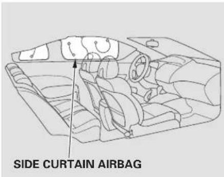
SIDE CURTAIN AIRBAGIn a moderate to severe side impact, sensors will detect rapid acceleration and signal the control unit to instantly inflate the side curtain airbag and activate the seat belt tensioner on the driver's or the passenger's side of the vehicle.
If the impact is on the passenger's side, the passenger's side curtain airbag will inflate even if there are no occupants on that side of the vehicle.
To get the best protection from the side curtain airbags, occupants should wear their seat belts and sit upright and well back in their seats.
How the SRS Indicator Works
The SRS indicator alerts you to a potential problem
with your airbags or seat belt tensioners.
When you turn the ignition switch to the ON (II) position, this indicator comes on briefly then goes off. This tells you the system is working properly.
If the indicator comes on at any other time, or does not come on at all, you should have the system checked by your dealer. For example:
- If the SRS indicator does not come on after you turn the ignition switch to the ON (II) position.
- If the indicator stays on after the engine starts.
- If the indicator comes on or flashes on and off while you'dri
If you see any of these indications, the airbags and seat belt tensioners may not work properly when you need them.
▲WARNING
Ignoring the SRS indicator can result in serious injury or death if the airbag systems or tensioners do not work properly.
Have your vehicle checked by a dealer as soon as possible if the SRS indicator alerts you to a possible problem.
How the Side Airbag Off Indicator Works
U.S.
Canada


This indicator alerts you that the passenger's side airbag has been automatically shut off. It does not mean there is a problem with your side airbags.
When you turn the ignition switch to the ON (II) position, the indicator should come on briefly and then go off (seepage). If it doesn on, stays on, or comes on while driving without a passenger in the front seat, have the system checked.
How the Passenger Airbag Off Indicator Works
text_image
PASSENGER AIRBAG OFF INDICATOR U.S. PASSENGER AIRBAG OFF Canada 2 OFFtcome
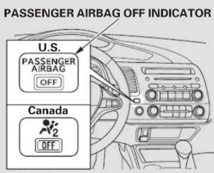
This indicator alerts you that the passenger's front airbag has been shut off because weight sensors detect about 65 lbs (29 kg) or less (the weight of an infant or small child) on the front passenger's seat. It does this problem with the airbag.
CONTINUED
Additional Information About Your Airbags
Be aware that objects placed on the front seat can cause the indicator to come on.
If no weight is detected on the front seat, the airbag will be automatically shut off. However, the indicator will not come on.
The passenger airbag off indicator may come on and off repeated the total weight on the seat is near the airbag cutoff threshold.
If an adult or teenage passenger is riding in front, move the seat as far to the rear as possible, and have the passenger sit upright and wear the seat belt properly.
If the indicator comes on with no front seat passenger and no objects on the seat, or with an adult riding there, something may be interfering with the weight sensors. Look for and remove:
- Any items under the front passenger's seat.
1 y Any object(s) hanging on the seat or in the seat-back pocket.
- Any object(s) touching the rear of the seat-back.
If no obstructions are found, have your vehicle checked by a dealer as soon as possible.
Airbag Service
Your airbag systems are virtually maintenance free, and there are no parts you can safely service. However, you must have your vehicle serviced if:
- An airbag ever inflates. Any airbag that has deployed must be replaced along with the control unit and other related parts. Any seat belt tensioner that activates must also be replaced.
Do not try to remove or replace any air bag by yourself. This m be done by an authorized dealer or a knowledgeable body shop.
- The SRS indicator alerts you to a problem. Take your vehicle to an authorized dealer as soon as possible. If you ignore this indication, your airbags may not operate properly.
- If your vehicle has a moderate to severe impact. Even if your airbags do not inflate, your dealer should inspect the driver's seat position sensor and the front passenger's weight sensors to make sure they are operating properly.
Additional Safety Precautions
- Don o tat tem p t t o d e a c airbags. Together, airbags and seat belts provide the best protection.
- Do not tamper with airbag components or wiring for any reason. Tampering could cause the airbags to deploy, possibly causing very serious injury.
-
Do not remove or modify a front seat without consulting your dealer. This could make the driver's seat position sensor or the front passenger's weight sensors ineffective. If it is necessary to remove or modify a front seat to accommodate a person with disabilities, first contact Honda Automobile Customer Service at (800) 999-1009.
-
Do not cover or replace front seat e back covers without consulting
your dealer. Improperly replacing or covering front seat-back covers can prevent your side airbags from inflating during a side impact. - Do not expose the front passenger's seat-back to liquid. If water or another liquid soaks into the seat-back, it can prevent the side airbag cutoff system from working properly.
Protecting Children General Guidelines
natural_image
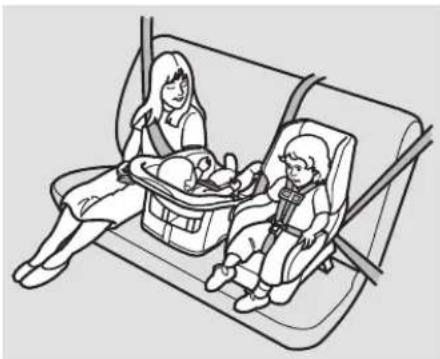
Illustration of a woman and child in a car seatbelt inside a vehicle (no text or symbols)Children depend on adults to protect them. However, despite their best intentions, many adults do not know how to protect child passengers.
If you have children, or ever need to drive with a child in your vehicle, be sure to read this section. It begins with important general guidelines, then presents special information for infants, small children, and larger children.
All Children Must Be Restrained
Each year, many children are injured or killed in vehicle crashes because they are either unrestrained or not properly restrained. In fact, vehicle accidents are the number one cause of the death of children ages 12 and under.
To reduce the number of child deaths and injuries, every state and Canadian province requires that infants and children be properly restrained when they ride in a vehicle.
Infants and small children must be restrained in an approved child seat that is properly secured to the vehicle (see pages 37 45
WARNING
Children who are unrestrained or improperly restrained can be seriously injured or killed in a crash.
Any child too small for a seat belt should be properly restrained in a child seat. A larger child should be properly restrained with a seat belt and use a booster seat if necessary.
Larger children must be restrained with a lap/shoulder belt and ride on a booster seat until the seat belt fits them properly (see pages 16 49
All Children Should Sit in a Back Seat
According to accident statistics, children of all ages and sizes are safer when they are restrained in a back seat.
The National Highway Traffic Safety Administration and Transport Canada recommend that all children age 12 and under be properly restrained in a back seat. Some states have laws restricting where children may ride.
Children who ride in back are less likely to be injured by striking interior vehicle parts during a collision or hard braking. Also, children cannot be injured by an inflating front airbag when they ride in the back.
The Passenger's Front Airbag Can Pose Serious Risks
Front airbags have been designed to help protect adults in a moderate to severe frontal collision. To do this, the passenger's front airbag is quite large, and it can inflate with enough force to cause very serious injuries.
Even though your vehicle has an advanced front airbag system that automatically turns the passenger's front airbag off (see page)25 please follow these guidelines:
Infants
Never put a rear-facing child seat in the front seat of a vehicle equipped with a passenger's front airbag. If the airbag inflates, it can hit the back of the child seat with enough force to kill or very seriously injure an infant.
Small Children
Placing a forward-facing child seat in the front seat of a vehicle equipped with a passenger's front airbag can be hazardous. If the vehicle seat is too far forward, or the child's head is thrown forward during a collision, an inflating front airbag can strike the child with enough force to kill or very seriously injure a small child.
Larger Children
Children who have outgrown child seats are also at risk of being injured or killed by an inflating passenger's front airbag. Whenever possible, larger children should sit in the back seat, on a booster seat if needed, and be properly restrained with a seat belt (see page for important information about protecting larger children).
CONTINUED
To remind you of the passenger's front airbag hazards, and that children must be properly restrained in a back seat, your vehicle has warning labels on the dashboard (U.S. models) and on the front visors. Please read and follow the instructions on these labels.
U.S. Models
SUN VISOR

AIRBAG WARNING
FLIP VISOR OVER
A WARNING
EVEN WITH ADVANCED AIR BAGS
- Children can be killed or seriously injured by the air beps - The back seat is the safest place for children - Never put a rear facing child seat in the front - Always use seat belts and child restraints - See owner's manual for more information about air beps
Canadian Models
SUN VISOR
CAUTION
TO AVOID SERIOUS INJURY:
FOR MAXIMUM SAFETY PROTECTION IN ALL TYPES OF CRASHES, YOU MUST ALWAYS WEAR YOUR SAFETY BELT
- DO NOT INSTALL REARWARD-FACING CHILD SEATS IN ANY FRONT PASSENGER SEAT POSITION.
- DO NOT SIT OR LEAN UNNECESSARILY CLOSE TO THE AIR BAG.
- DO NOT PLACE ANY OBJECTS OVER THE AIR BAG OR BETWEEN THE AIR BAG AND YOURSELF.
- SEE THE OWNER'S MANUAL FOR FURTHER INFORMATION AND EXPLANATIONS.
DASHBOARD
This Vehicle is Equipped with Advanced Air Bags
Even with Advanced Air Bags
Children can be killed or seriously injured by the air bag.
The back seat is the safest place for children.
Never put a rear-facing child seat in the front.
Always use seat belts and child restraints.
See owner's manual for more information about air bags.
To be removed by owner only.
PRECAUTIONS:
POUR EVITER DES BLESSURES GRAVES:
- POUR PROFITER D'UNE PROTECTION MAXIMALE LORS D'UNE COLLISION BOUCLEZ TOUJOURS VOTRE CEINTURE DE SECURITE.
• N'INSTALLEZ JAMAIS UN SIEGE POUR ENFANTS FAISANT FACE A L'ARRIERE SUR LE SIEGE DU PASSAGER AVANT.
• NE VOUS APPUYEZ PAS ET NE VOUS ASSOYEZ PAS PRES DU COUSSIN GONFLABLE.
- NE DEPOSEZ AUCUN OBJET SUR LE COUSSIN GONFLABLE OU ENTRE LE COUSSIN GONFLABLE ET VOUS.
- LISEZ LE GUIDE UTILISATEUR POUR DE PLUS AMPLES RENSEIGNEMENTS.
If You Must Drive with Several Children
Your vehicle has a back seat where children can be properly restrained. If you ever have to carry a group of children, and a child must ride in front:
- Place the largest child in the front seat, provided the child is large enough to wear the lap/shoulder belt properly (see page)46
- Move the vehicle seat as far to the rear as possible (see page 92)
- Have the child sit upright and well back in theseat (sed 15 page
- Make sure the seat belt is properly positioned and secured (see page 14).
If a Child Requires Close Attention
Many parents say they prefer to put an infant or a small child in the front passenger seat so they can watch the child, or because the child requires attention.
Placing a child in the front seat exposes the child to hazards in a frontal collision, and paying close attention to a child distracts the driver from the important tasks of driving, placing both of you at risk.
If a child requires close physical attention or frequent visual contact, we strongly recommend that another adult ride with the child in the back seat. The back seat is far safer for a child than the front.
Additional Safety Precautions
- Neverholdaninfantorchildor
your lap. If you are not wearing a seat belt in a crash, you could be thrown forward and crush the child against the dashboard or a seat-back. If you are wearing a seat belt, the child can be torn from your arms and be seriously hurt or killed. - Never put a seat belt over yourself and a child. During a crash, the belt could press deep into the child and cause serious or fatal injuries.
- Never let two children use the same seat belt. If they do, they could be very seriously injured in a crash.
CONTINUED
Protecting Children General Guidelines
• Make sure any unused seat belt that a child can reach is buckled, the lockable retractor is activated, and the belt is fully retracted and locked. If a child wraps a loose seat belt around their neck, they can be seriously or fatally injured. (See pages 431 for how to activate and deactivate the lockable retractor.)
- Do not leave children alone in a vehicle. Leaving children without adult supervision is illegal in most states and Canadian provinces, and can be very hazardous.
For example, infants and small children left in a vehicle on day can die from heatstroke. A child left alone with the key in the ignition switch can accidentally set the vehicle in motion, possibly injuring themselves or others.
- Lock both doors and the trunk when your vehicle is not in use. Children who play in vehicles can accidentally get trapped inside. Teach your children not to play in or around vehicles. Know how to operate the emergency trunk opener and decide if your children should be shown how to use this feature (seepage).
- Keep vehicle keys/remote transmitters out of the reach of children. Even very young children learn how to unlock vehicle doors, turn on the ignition switch, and open the trunk, which can lead to accidental injury or death.
Protecting Infants
natural_image
Line drawing of a car seatbelt mechanism (no text or symbols)Child Seat Type
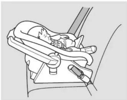
An infant must be properly restrained in a rear-facing, reclining child seat until the child reaches the seat maker's weight or height limit for the seat, and the child is at least one year old.
Only a rear-facing child seat provides proper support for a baby's head, neck, and back.
Two types of seats may be used: a seat designed exclusively for infants, or a convertible seat used in the rear-facing, reclining mode.
Do not put a rear-facing child seat in a forward-facing position. If placed facing forward, an infant could be very seriously injured during a frontal collision.
Rear-facing Child Seat Placement A rear-facing child seat can be placed in any seating position in the back seat, but not in the front. Never put a rear-facing child seat in the front seat.
If the passenger's front airbag inflates, it can hit the back of the child seat with enough force to kill or seriously injure an infant.
When properly installed, a rear-facing child seat may prevent the driver or a front passenger from moving their seat as far back as recommended, or from locking their seat-back in the desired position.
It can also interfere with proper operation of the passenger's advanced front airbag system.
CONTINUED
Protecting Infants and Small Children
In any of these situations, we strongly recommend that you install the child seat directly behind the front passenger's seat, move the seat as far forward as needed, and leave it unoccupied. Or, you may wish to get a smaller rear-facing child seat.
WARNING
Placing a rear-facing child seat in the front seat can result in serious injury or death during a collision.
Always place a rear-facing child seat in the back seat, not the front.
Protecting Small Children
natural_image
Line drawing of a child wearing a seatbelt and harness, seated in a car seat (no text or symbols)Child Seat Type
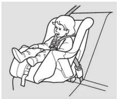
A child who is at least one year old, and who fits within the child seat maker's weight and height limits, should be restrained in a forward-facing, upright child seat.
Of the different seats available, we recommend those that have a five-point harness system as shown.
We also recommend that a small child use the child seat until the child reaches the weight or height limit for the seat.
Child Seat Placement
We strongly recommend placing a forward-facing child seat in a back seat, not the front.
Placing a forward-facing child seat in the front seat of a vehicle equipped with a passenger's airbag can be hazardous. If the vehicle seat is too far forward, or the child's head is thrown forward during a collision, an inflating airbag can strike the child with enough force to cause very serious or fatal injuries.
Even with advanced front airbags that automatically turn the passenger's front airbag off (see page 25), a back seat is the safest place for a small child.
If it is necessary to put a forward-facing child seat in the front, move the vehicle seat as far to the rear as possible, and be sure the child seat is firmly secured to the vehicle and the child is properly strapped in the seat.
WARNING
Placing a forward-facing child seat in the front seat can result in serious injury or death if the front airbag inflates.
If you must place a forward facing child seat in front, move the vehicle seat as far back as possible, and properly restrain the child.
Selecting a Child Seat
When buying a child seat, you need to choose either a conventional child seat, or one designed for use with the lower anchors and tethers for children (LATCH) system.
Conventional child seats must be secured to a vehicle with a seat belt, whereas LATCH-compatible seats are secured by attaching the seat to hardware built into the two outer seating positions in the back seat.
Since LATCH-compatible child seats are easier to install and reduce the possibility of improper installation, we recommend selecting this style.
In seating positions and vehicles not equipped with LATCH, a LATCH-compatible child seat can be installed using a seat belt.
Whatever type of seat you choose, to provide proper protection, a child seat should meet three requirements:
-
The child seat should meet U.S. or Canadian Motor Vehicle Safety Standard 213. Look for FMVSS 213 or CMVSS 213 on the box.
-
The child seat should be of the proper type and size to fit the child. Rear-facing for infants, forward-facing for small children.
CONTINUED
3. The child seat should fit the vehicle seating position (or positions) where it will be used.
Before purchasing a conventional child seat, or using a previously purchased one, we recommend that you test the seat in the specific vehicle seating position or positions where the seat will be used.
Installing a Child Seat
After selecting a proper child seat and a good place to install the seat, there are three main steps in installing the seat:
-
Properly secure the child seat to the vehicle All child seats must be secured to the vehicle with the lap part of a lap/shoulder belt or with the LATCH (lower anchors and tethers for children) system. A child whose seat is not properly secured to the vehicle can be endangered in a crash.
-
Make sure the child seat is firmly secured. After installing a child seat, push and pull the seat forward and from side-to-side to verify that it is secure.
A child seat secured with a seat belt should be installed as firmly as possible. However, it does not need to be “rock solid.” Some side-to-side
movement can be expected and should not reduce the child seat's effectiveness.
If the child seat is not secure, try installing it in a different seating position, or use a different style of child seat that can be firmly secured.
- Secure the child in the child seat. Make sure the child is properly strapped in the child seat according to the child seat maker's instructions. A child who is not properly secured in a child seat can be seriously injured in a crash.
The following pages provide guidelines on how to properly install a child seat. A forward-facing child seat is used in all examples, but the instructions are the same for rear-facing child seats.
Installing a Child Seat with LATCH
Your vehicle is equipped with LATCH (lower anchors and tethers for children) at the outer rear seats.
The lower anchors are located between the seat-back and seat bottom, and are to be used only with a child seat designed for use with LATCH.
The location of each lower anchor is indicated by a small button above the anchor point.
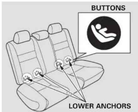
text_image
BUTTONS LOWER ANCHORSTo install a LATCH-compatible child seat:
- Move the seat belt buckle or tongue away from the lower anchors.
- Make sure there are no objects near the anchors that could prevent a secure connection between the child seat and the anchors.
text_image
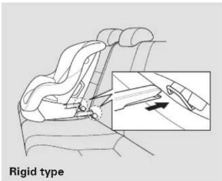
Rigid type- Place the child seat on the vehicle seat, then attach the seat to the lower anchors according to the child seat maker's instructions.
Some LATCH-compatible seats have a rigid-type connector as shown above.
CONTINUED
Installing a Child Seat
text_image
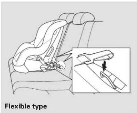
Flexible typeOther LATCH-compatible seats have a flexible-type connector as shown above.
- Whatever type you have, follow the child seat maker's instructions for adjusting or tightening the fit.
text_image
TETHER STRAP HOOK ANCHOR-
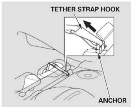
Adjust the head restraint to its lowest position. Route the tether strap over the head restraint, making sure the strap is not twisted.
-
Attach the tether strap hook to the tether anchor, then tighten the strap as instructed by the child seat maker.
-
Push and pull the child seat forward and from side-to-side to verify that it is secure.
Installing a Child Seat with a Lap/Shoulder Belt
When not using the LATCH system, all child seats must be secured to the vehicle with the lap part of a lap/shoulder belt.
In addition, the lap/shoulder belts in all seating positions except the driver's have a lockable retractor that must be activated to secure a child seat.
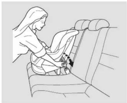
natural_image
Line drawing of a woman adjusting a seatbelt on a car cab (no text or symbols)- With the child seat in the desired seating position, route the belt through the child seat according to the seat maker's instructions, then insert the latch plate into the buckle.
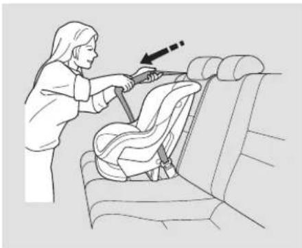
natural_image
Illustration of a person using a seatbelt to adjust the seat, with an arrow indicating the motion (no text or symbols present)To activate the lockable retractor, slowly pull the shoulder part of the belt all the way out until it stops, then let the belt feed back into the retractor.
- After the belt has retracted, tug on it. If the belt is locked, you will not be able to pull it out. If you can pull the belt out, it is not locked, a you will need to repeat these steps.
CONTINUED
Main Menu
Table Of Contents
Installing a Child Seat
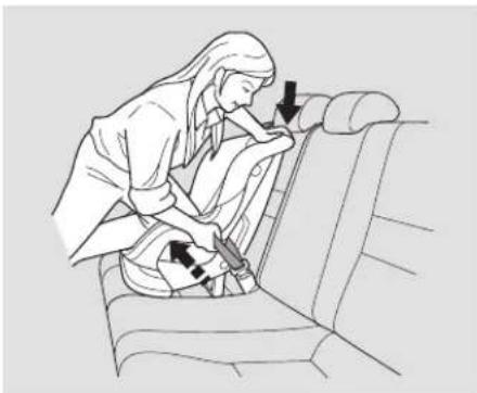
natural_image
Illustration of a person adjusting a seatbelt on a chair, with arrows indicating movement (no text or symbols)- After confirming that the belt is locked, grab the shoulder part of the belt near the buckle, and pull up to remove any slack from the lap part of the belt. Remember, if the lap part of the belt is not tight, the child seat will not be secure.
To remove slack, it may help to put weight on the child seat, or push on the back of the seat while pulling up on the belt.
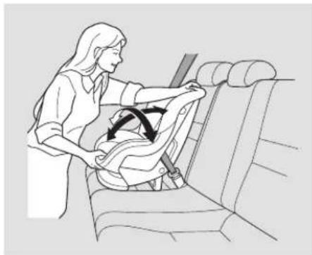
natural_image
Illustration of a woman assisting a baby in a car seatbelt, showing seatbelt insertion (no text or symbols)Push and pull the child seat forward and from side-to-side to verify that it is secure enough to stay upright during normal driving maneuvers. If the child seat is not secure, unlatch the belt, allow it to retract fully, then repeat these steps.
To deactivate the lockable retractor and remove a child seat, unlatch the buckle, unroute the seat belt, and let the belt fully retract.
Installing a Child Seat with a Tether
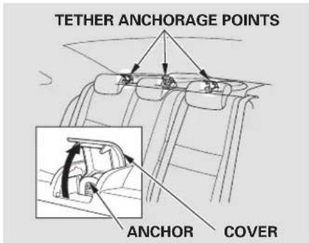
text_image
TETHER ANCHORAGE POINTS ANCHOR COVERA child seat with a tether can be installed in any seating position in the back seat, using one of the anchorage points shown above.
Since a tether can provide additional security to the lap/shoulder belt installation, we recommend using a tether whenever one is required or available.
Using an Anchor
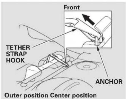
text_image
TETHER STRAP HOOK Front ANCHOR Outer position Center position-
After properly securing the child seat (see page 43 adjust the head restraint to its lowest position, then route the tether strap over the head restraint.
-
Lift the anchor cover, then attach the tether strap hook to the anchor, making sure the strap is not twisted.
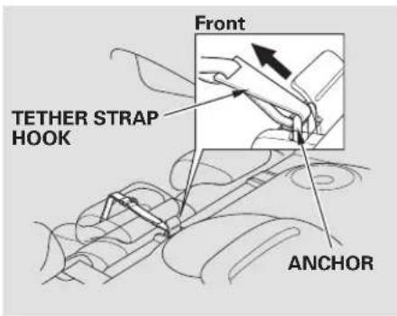
text_image
Front TETHER STRAP HOOK ANCHOR- Tighten the strap according to the seat maker's instructions.
Protecting Larger Children
When a child reaches the recommended weight or height limit for a forward-facing child seat, the child should sit in a back seat on a booster seat and wear a lap/shoulder belt.
The following pages give instructions on how to check proper seat belt fit, what kind of booster seat to use if one is needed, and important precautions for a child who must sit in front.
WARNING
Allowing a child age 12 or under to sit in front can result in injury or death if the passenger's front airbag inflates.
If a child must ride in front, move the vehicle seat as far back as possible, use a booster seat if needed, have the child sit up properly and wear the seat belt properly.
Checking Seat Belt Fit

natural_image
Line drawing of a person sitting on a chair, wearing a hooded shirt and shoes (no text or symbols)To determine if a lap/shoulder belt properly fits a child, have the child put on the seat belt, then ask yourself:
-
Does the child sit all the way back against the seat?
-
Do the child's knees bend comfortably over the edge of the seat?
-
Does the shoulder belt cross between the child's neck and arm?
- Is the lap part of the belt as low as possible, touching the child's thighs?
- Will the child be able to stay seated like this for the whole trip?
If you answer yes to all these questions, the child is ready to wear the lap/shoulder belt correctly. If you answer no to any question, the child needs to ride on a booster seat.
Using a Booster Seat
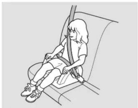
natural_image
Line drawing of a person seated in a car seatbelt, no text or symbols presentA child who has outgrown a forward-facing child seat should ride in a back seat and use a booster seat until the lap/shoulder belt fits them properly without the booster.
Some states and Canadian provinces also require children to use a booster seat until they reach a given age or weight (e.g., 6 years or 60 lbs). Be sure to check current laws in the states or provinces where you intend to drive.
Booster seats can be high-back or low-back. Whichever style you select, make sure the booster seat meets federal safety standards (see page 39) and that you follow the booster seat maker's instructions.
If a child who uses a booster seat must ride in front, move the vehicle seat as far back as possible, and be sure the child is wearing the seat belt properly.
CONTINUED
Protecting Larger Children
A child may continue using a booster seat until the tops of their ears are even with the top of the vehicle's or booster's seat-back. A child of this height should be tall enough to use the lap/shoulder belt without a booster seat.
When Can a Larger Child Sit in Front
The National Highway Traffic Safety Administration and Transport Canada recommend that all children age 12 and under be properly restrained in the back seat.
If the passenger's front airbag inflates in a moderate to severe frontal collision, the airbag can cause serious injuries to a child who is unrestrained, improperly restrained, sitting too close to the airbag, or out of position.
A side airbag also poses risks. If any part of a larger child's body is in the path of a deploying side airbag, the child could receive possibly serious injuries.
Of course, children vary widely. And while age may be one indicator of when a child can safely ride in front, there are other important factors you should consider.
Physical Size
Physically, a child must be large enough for the lap/shoulder belt to properly fit (see pages 14d). If the seat belt does not fit properly, with or without the child sitting on a booster seat, the child should not sit in front.
Maturity
To safely ride in front, a child must be able to follow the rules, including sitting properly, and wearing the seat belt properly throughout a ride.
If you decide that a child can safely ride up front, be sure to:
- Carefully read the owner's manual, and make sure you understand all seat belt instructions and all safety information.
- Move the vehicle seat to the rearmost position.
- Have the child sit up straight, back against the seat, and feet on or near the floor.
- Check that the child's seat belt is properly and securely positioned.
- Supervise the child. Even mature children sometimes need to be reminded to fasten the seat belts or sit properly.
Additional Safety Precautions
- Do not let a child wear a seat belt across the neck. This could result in serious neck injuries during a crash.
- Do not let a child put the shoulder part of a seat belt behind the back or under the arm. This could cause very serious injuries during a crash. It also increases the chance that the child will slide under the belt in a crash and be injured.
- Two children should never use the same seat belt. If they do, they could be very seriously injured in a crash.
- Do not put any accessories on a seat belt. Devices intended to improve a child's comfort or reposition the shoulder part of a seat belt can make the belt less effective and increase the chance of serious injury in a crash.
Your vehicle's exhaust contains carbon monoxide gas. Carbon monoxide should not enter the vehicle in normal driving if you maintain your vehicle properly and follow the information on this page.
Have the exhaust system inspected for leaks whenever:
- The vehicle is raised for an oil change.
- You notice a change in the sound of the exhaust.
- The vehicle was in an accident that may have damaged the underside.
WARNING
Carbon monoxide gas is toxic. Breathing it can cause unconsciousness and even kill you.
Avoid any enclosed areas or activities that expose you to carbon monoxide.
High levels of carbon monoxide can collect rapidly in enclosed areas, such as a garage. Do not run the engine with the garage door closed. Even with the door open, run the engine only long enough to move the vehicle out of the garage.
With the trunk open, airflow can pull exhaust gas into your vehicle's interior and create a hazardous condition. If you must drive with the trunk open, open all the windows and set the heating and cooling system as shown below.
If you must sit in your parked vehicle with the engine running, even in an unconfined area, adjust the heating and cooling system as follows:
- Select the fresh air mode.
- Select the mode.
- Turn the fan on high speed.
- Set the temperature control to a comfortable setting.
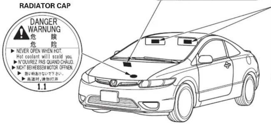
These labels are in the locations shown. They warn you of potential hazards that could cause serious injury or death. Read these labels carefully.
If a label comes off or becomes hard to read (except for the U.S. dashboard label which may be removed by the owner), contact your dealer for a replacement.
DASHBOARD
U.S. models only
This Vehicle is Equipped with Advanced Air Bags
Even with Advanced Air Bags
Children can be killed or seriously injured by the air bag. The back seat is the safest place for children. Never put a rear-facing child seat in the front. Always use seat belts and child restraints. See owner's manual for more information about air bags.
To be removed by owner only:
SUN VISOR
U.S. models
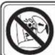
AIR BAG WARNING
FLIP VISOR OVER
A WARNING
EVEN WITH ADVANCED AIR BAGS
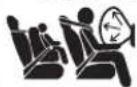
- Children can be killed or seriously injured by the air bags - The back seat is the safest place for children - Never put a rear-facing child seat in the front - Always use seat belts and child restraints - See owner's manual for more information about air bags
Canadian models
text_image
RADIATOR CAP DANGER WARNUNG 危 険 危 険 ▶ NEVER OPEN WHEN HOT. Hot coolant will scald you. ▶ N'OUVREZ PAS QUAND CHAUD. ▶ NICHT BEI HEISSEM MOTOR OFFNEN. ▶ 熬い時あけないで下さい。 ▶ 高温时,请勿打开 1.1CAUTION
TO AVOID SERIOUS INJURY: • FOR MAXIMUM SAFETY PROTECTION IN ALL TYPES OF CRASHES, YOU MUST ALWAYS WEAR YOUR SAFETY BELT. • DO NOT INSTALL REARWARD-FACING CHILD SEATS IN ANY FRONT PASSENGER SEAT POSITION. • DO NOT SF OR LEAN LINECESSARILY CLOSE TO THE AIR BAG. • DO NOT PLACE ANY OBJECTS OVER THE AIR BAG OR BETWEEN THE AIR BAG AND YOURSELF. • SEE THE OWNER'S MANUAL FOR PURISH INFORMATION AND EXPLANATIONS.
PRECAUTIONS: POUR EVITER DES BLESSURES GRAVES: • POUR PROFINTER D'UNE PROTECTION MAXIMAL FOURS D'une COLLISION BOUCLEZ TOUJOURS VOTRE CHINTURE DE SECURITE, • N'INSTALLEZ JAMAIS UN SIÈGE POUR ENFANTS FAISANT FACE A L'ARMIERE SUR LE SIÈGE DU PASSAGER AVANT. • NE VOUS APPLYEZ PAS ET NE VOUS ASSOYEZ PASSIFLES DU COUSSIN GONFLABLE • NE REPOS AUVER OUBET SUR LE COUSSIN GONFLABLE OU ENTRE LE COUSSIN GONFLABLE ET VOUS • LIIEZ LE GUIDE UTILISATEUR POUR DE PLUS AMPLES RENSEIGNEMENTS.
CONTINUED
Safety Labels
HOOD DOORJAMBS
WARNING
Accidental deployment can seriously hurt or kill you.
Follow Service Manual instructions carefully.
Canadian models
WARNING
Accidental deployment can seriously hurt or kill you. Follow Service Manual instructions carefully.
ATTENTION
● This car is equipped with side airbags in the front seats and side curtain airbags.
- Do not lean against the door.
- See owner's manual for more information.
Canadian models U.S. models
SIDE AIRBAG
● This car is equipped with side airbags in the front seats and side curtain airbags.
- Do not lean against the door.
- See owner's manual for more information.
COUSSIN GONFLABLE LATERAL
This section gives information about the controls and displays that contribute to the daily operation of your vehicle. All the essential controls are within easy reach.
Control Locations 54
Instrument Panel 55
Instrument Panel Indicators...... 57
Gauges 65
Auto Door Locking/Unlocking.. 81
Remote Transmitter 86
Trunk....90
Emergency Trunk Opener ...... 91
ay Scotland Button 66 92
Power Windows 100
MMtennr66f 102
Mirrors.... 104
Parking Brake 105
Interior Convenience Items...... 106
Beverage Holders 107
Console Compartment...... 107
Glove Box 107
Coat Hook.... 108
Accessory Power Sockets...... 108
Vanity Mirror 109
Sun Visor 110
Interior Lights.... 111
Ceiling Light.... 111
Spotlights.... 111
Courtesy Light 112
Main Menu
Table Of Contents
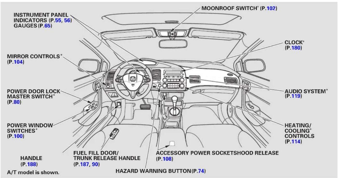
Control Locations
text_image
MOONROOF SWITCH* (P.102) INSTRUMENT PANEL INDICATORS (P.55, 56) GAUGES (P.65) MIRROR CONTROLS* (P.104) POWER DOOR LOCK MASTER SWITCH* (P.80) POWER WINDOW SWITCHES* (P.100) HANDLE (P.188) A/T model is shown. FUEL FILL DOOR/ TRUNK RELEASE HANDLE (P.187, 90) HAZARD WARNING BUTTON(P.74) CLOCK* (P.180) AUDIO SYSTEM* (P.119) HEATING/ COOLING* CONTROLS (P.114) ACCESSORY POWER SOCKETSHOOD RELEASE (P.108)* If equipped:
DX, DX-G(Canada), LX, EX, EX-L
text_image
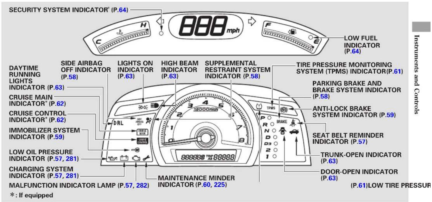
SECURITY SYSTEM INDICATOR® (P.64) 888 mph C H F LOW FUEL INDICATOR (P.64) DAYTIME RUNNING LIGHTS INDICATOR (P.58) SIDE AIRBAG OFF INDICATOR (P.63) LIGHTS ON INDICATOR (P.63) HIGH BEAM INDICATOR (P.63) SUPPLEMENTAL RESTRAINT SYSTEM INDICATOR (P.58) TIRE PRESSURE MONITORING SYSTEM (TPMS) INDICATOR(P.61) PARKING BRAKE AND BRAKE SYSTEM INDICATOR (P.58) CRUISE MAIN INDICATOR® (P.62) CRUISE CONTROL INDICATOR® (P.62) IMMOBILIZER SYSTEM INDICATOR (P.59) DRL SIDE AIRBAG OFF PHASE MIN. CHARGE CONTROL LOW OIL PRESSURE INDICATOR (P.57, 281) CHARGING SYSTEM INDICATOR (P.57, 281) MALFUNCTION INDICATOR LAMP (P.57, 282) MAINTENANCE MINDER INDICATOR (P.60, 225) TRUNK-OPEN INDICATOR (P.63) DOOR-OPEN INDICATOR (P.63) ( P.61 )LOW TIRE PRESSUR * : If equippedThe U.S. instrument panel is shown. Differences for Canadian models are noted in the text.
CONTINUED
Canadian DX-G model with M/T has the electric power steering (EPS) indicator (see page 60) next to the immobilizer system indicator.
Si
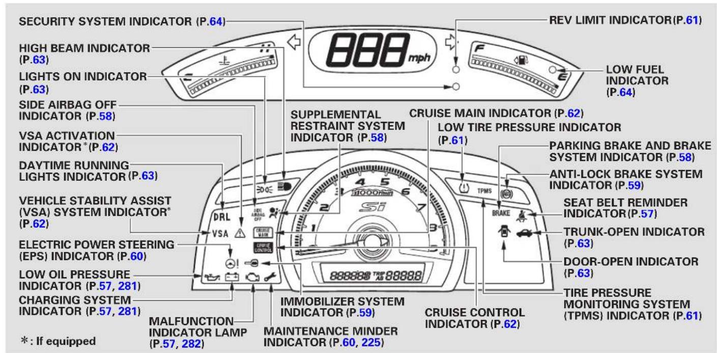
text_image
SECURITY SYSTEM INDICATOR (P.64) HIGH BEAM INDICATOR (P.63) LIGHTS ON INDICATOR (P.63) SIDE AIRBAG OFF INDICATOR (P.58) VSA ACTIVATION INDICATOR* (P.62) DAYTIME RUNNING LIGHTS INDICATOR (P.63) VEHICLE STABILITY ASSIST (VSA) SYSTEM INDICATOR* (P.62) ELECTRIC POWER STEERING (EPS) INDICATOR (P.60) LOW OIL PRESSURE INDICATOR (P.57, 281) CHARGING SYSTEM INDICATOR (P.57, 281) * : If equipped MALFUNCTION INDICATOR LAMP (P.57, 282) SUPPLEMENTAL RESTRAINT SYSTEM INDICATOR (P.58) CRUISE MAIN INDICATOR (P.62) LOW TIRE PRESSURE INDICATOR (P.61) PARKING BRAKE AND BRAKE SYSTEM INDICATOR (P.58) ANTI-LOCK BRAKE SYSTEM INDICATOR (P.59) SEAT BELT REMINDER INDICATOR (P.57) TRUNK-OPEN INDICATOR (P.63) DOOR-OPEN INDICATOR (P.63) TIRE PRESSURE MONITORING SYSTEM (TPMS) INDICATOR (P.61) IMMOBILIZER SYSTEM INDICATOR (P.59) MAINTENANCE MINDER INDICATOR (P.60, 225) CRUISE CONTROL INDICATOR (P.62)The U.S. instrument panel is shown. Differences for Canadian models are noted in the text.
The instrument panel has many indicators to give you important information about your vehicle.

Seat Belt Reminder Indicator
This indicator comes on when you turn the ignition switch to the ON (II) position. It reminds you and your passengers to fasten your seat belts. A beeper also sounds if you have not fastened your seat belt.
If you turn the ignition switch to the ON (II) position before fastening your seat belt, the beeper sounds and the indicator flashes. If you do not fasten your seat belt before the beeper stops, the indicator stops flashing but remains on.
If your front passenger does not fasten their seat belt, the indicator comes on about 6 seconds after the ignition switch is turned to the ON (II) position.
If either of you do not fasten your seat belt while driving, the beeper will sound and the indicator will flash again at regular intervals. For more information, see page 18

Charging System Indicator
If this indicator comes on when the engine is running, the battery is not being charged. For more information, see page 281

Low Oil Pressure Indicator
The engine can be severely damaged if this indicator flashes or stays on when the engine is running. For more information, see page281

Malfunction Indicator Lamp
See page 282
Instrument Panel Indicators
U.S. Canada
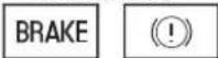
Parking Brake and Brake System Indicator
This indicator has two functions:
- It comes on when you turn the ignition switch to the ON (II) position. It is a reminder to check the parking brake. A beeper sounds if you drive with the parking brake not fully released. Driving with the parking brake not fully released can damage the brakes and tires.
- If it stays on after you have fully released the parking brake while the engine is running, or if it comes on while driving, there could be a problem with the brake system. For more information, see page 283

Supplemental Restraint System Indicator
This indicator comes on briefly when you turn the ignition switch to the ON (II) position. If it comes on at any other time, it indicates a potential problem with your front airbags. This indicator will also alert you to a potential problem with your side airbags, passenger's side airbag cutoff system, side curtain airbags, automatic seat belt tensioners, driver's seat position sensor, or the front passenger's weight sensors. For more information, see page .28
U.S. Canada
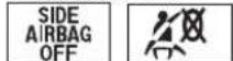
Side Airbag Off Indicator
This indicator comes on briefly when you turn the ignition switch to the ON (II) position. If it comes on at any other time, it indicates that the passenger's side airbag has automatically shut off. For more information, see page 29

Anti-lock Brake System (ABS) Indicator
This indicator normally comes on for a few seconds when you turn the ignition switch to the ON (II) position. If it comes on at any other time, there is a problem with the ABS. If this happens, have your vehicle checked at a dealer. With this indicator on, your vehicle still has normal braking ability but no anti-lock function. For more information, see page.

Immobilizer System Indicator
This indicator comes on briefly when you turn the ignition switch to the ON (II) position. It will then go off if you have inserted a properly-coded ignition key. If it is not a properly-coded key, the indicator will blink, and the engine's fuel system will be disabled (see page 77 249 250


Turn Signal and Hazard Warning Indicators
The left or right turn signal indicator blinks when you signal a lane change or turn. If an indicator does not blink or blinks rapidly, it usually means one of the turn signal bulbs is burned out (see pages and). Replace the bulb as soon as possible, since other drivers cannot see that you are signaling.214
When you press the hazard warning button, both turn signal indicators and all turn signals on the outside of the vehicle flash.
Instrument Panel Indicators

Electric Power Steering (EPS) Indicator
Si and Canadian DX-G with manual transmission models
This indicator normally comes on when you turn the ignition switch to the ON (II) position and goes off after the engine starts. If it comes on at any other time, there is a problem in the electric power steering system. If this happens, stop the vehicle in a safe place, and turn off the engine. Reset the system by restarting the engine. The indicator will not turn off immediately. If it does not go off after driving a short distance, or comes back on again while driving, take the vehicle to your dealer to have it checked. With the indicator on, the EPS may be off, making the vehicle harder to steer.
If you turn the steering wheel to the full left or right position repeatedly while stopping or driving at very low speed, you may feel slightly harder steering due to overheating of the steering gearbox.
Continuously driving under those conditions could damage the power steering system.

Maintenance Minder Indicator
This indicator comes on for a few seconds when you turn the ignition switch to the ON (II) position. It reminds youth at it ist i met o t a k your vehicle in for scheduled maintenance. The maintenance main items and sub items will be displayed in the information display. See page 225 for more information on the maintenance minder.
This indicator goes off when your dealer resets it after completing the required maintenance service.
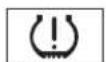
Low Tire Pressure Indicator
U.S. models only
This indicator normally comes on for a few seconds when you turn the ignition switch to the ON (II) position.
If it comes on while driving, it indicates that one or more of your vehicle's tires are significantly low on pressure.
If this happens, pull to the side of the road when it is safe, check which tire has lost the pressure, and determine the cause. If it is because of a flat tire, replace the flat tire with the compact spare (see page 27 and have the flat tire repaired as soon as possible. If two or more tires are underinflated, call a professional towing service (see page 29 or more information, see page .218
TPMS
Tire Pressure Monitoring System (TPMS) Indicator
U.S. models only
This indicator normally comes on for a few seconds when you turn the ignition switch to the ON (II) position.
If this indicator comes on and stays on at any other time, or if it does not come on when you turn the ignition switch to the ON (II) position, there is a problem with the TPMS. With this indicator on, the low tire pressure indicator will not come on when a tire loses pressure. Take the vehicle to your dealer to have the system checked.
Rev Limit Indicator
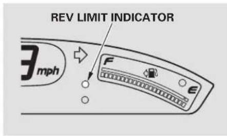
text_image
REV LIMIT INDICATOR 3 mphSi model only
This indicator shows you when the engine speed is near the tachometer's red zone. When the engine speed gets to near the red zone, the indicator blinks. If you exceed the maximum speed for the gear you are in, the indicator stays on, and you may feel the engine cut in and out due to the engine speed limiter (see page 207
To protect the engine from damage, never drive with the tachometer in its red zone.

Cruise Main Indicator
If equipped
This indicator comes on when you turn on the cruise control system by pressing the CRUISE button (see page 182

Cruise Control Indicator
If equipped
This indicator comes on when you set the cruise control. See page 182 for information on operating the cruise control.
VSA
(VSA) System Indicator
This indicator normally comes on for a few seconds when you turn the ignition switch to the ON (II) position.
If it comes on and stays on a other time, or if it does not come on when you turn the ignition switch to the ON (II) position, there is a problem with the VSA system. Take your vehicle to a dealer to have it checked. Without VSA, your vehicle still has normal driving ability, but will not have VSA traction and stability enhancement. See page 216 for more information on the VSA system.

VSA Activation Indicator Vehicle
This indicator has three functions:
- It comes on as a reminder that you have turned off the vehicle stability assist (VSA) system.
1 y
-
It flashes when VSA is active (see page 2.16
-
It comes on along with the VSA system indicator if there is a problem with the VSA system.
This indicator normally comes on for a few seconds when you turn the ignition switch to the ON (II) position. See page 216 more information on the VSA system.
DRL Daytime Running Lights Indicator
If this indicator comes on when you turn the ignition switch to the ON (II) position and release the parking brake, it means there is a problem with the DRL. There may also problem with the high beam headlights. Have your vehicle checked by your dealer.
High Beam Indicator
This indicator comes on with the high beam headlights. For more information, see page . 72
This indicator also comes on with reduced brightness when the daytime running lights (DRL) are on (see page 7.3
Trunk-open Indicator Lights On Indicator
This indicator comes on if the trunk lid is not closed tightly.
Door-open Indicator
This indicator comes on if either door is not closed tightly.
Washer Level Indicator
Canadian models only This indicator comes on when the washer fluid level is low. Add washer fluid when you see this indicator (see page 241
This indicator reminds you that the exterior lights are on. It comes on when the light switch is in either the 2005 or position. If you turn the ignition switch to the ACCESSORY (I) or LOCK (0) position without turning off the light switch, this indicator will stay on. A reminder chime will also sound when you open the driver's door.
Security System Indicator Low Fuel Indicator
Except Si Si
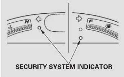
text_image
SECURITY SYSTEM INDICATORIf equipped
This indicator comes on when the security system is set. See page 181 for more information on the security system.
LOW FUEL INDICATOR
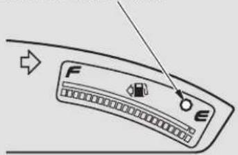
text_image
Diagram of a car air conditioner panel with labeled buttons F and E, showing directional arrow and control knobThis indicator is located in the fuel gauge. It comes on as a reminder that you must refuel soon.
When the indicator comes on, there are about 1.9 US gal (7.5 ℓ) off u el remaining in the tank.
When the reading reaches E, there is a very small amount of fuel in the tank.
Main Menu
Table Of Contents
Gauges
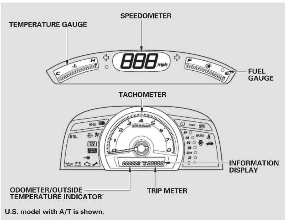
text_image
TEMPERATURE GAUGE SPEEDOMETER 888 mph FUEL GAUGE TACHOMETER DRL 2 3 4 5 6 1 7 8 888888 888888 ODOMETER/OUTSIDE TEMPERATURE INDICATOR* TRIP METER U.S. model with A/T is shown. INFORMATION DISPLAY* If equipped:
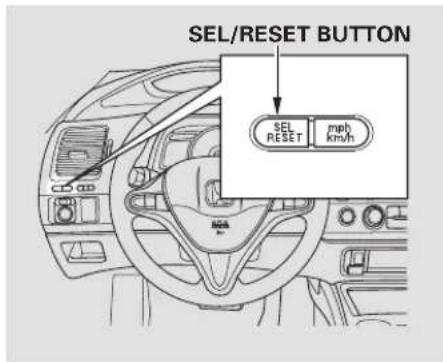
text_image
SEL/RESET BUTTON SEL RESET mph km/hTo switch the information display between the odometer, trip meter, and outside temperature (if equipped), and engine oil life and maintenance service items, press the SEL/RESET button repeatedly.
Gauges
Display Change Button Odometer Trip Meter
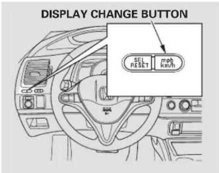
text_image
DISPLAY CHANGE BUTTON SEL RESET mph km/hPress and hold the display change button until you hear a beep. The speedometer, trip meter, and odometer readings switch between miles per hour (mph) and kilometers per hour (km/h).
This shows the total distance your vehicle has been driven. It measures miles or kilometers. It is illegal under U.S. federal law and Canadian provincial regulations to disconnect, reset, or alter the odometer with the intent to change the number of miles or kilometers indicated.
The odometer and the outside temperature indicator (if equipped) use the same display. To switch the display between them, press the SEL/RESET button repeatedly. When you turn the ignition switch to the ON (II) position, your last selection is displayed.
This meter shows the number of miles or kilometers driven since you last reset it.
There are two trip meters: Trip A and Trip B. Switch between these displays by pressing the SEL/RESET button repeatedly. Each trip meter works independently, so you can keep track of two different distances.
When you turn the ignition switch to the ON (II) position, what you last selected is displayed.
To reset a trip meter, display it, and then press and hold the SEL/RESET button until the number resets to "0.0."
Outside Temperature Indicator If equipped
This indicator displays the outside temperature in Fahrenheit (U.S. models) or Centigrade (Canadian models). To see the outside temperature, press and release the SEL/RESET button until the temperature is shown on the information display.
The temperature sensor is in the front bumper. Therefore, the temperature reading can be affected by heat reflection from the road surface, engine heat, and the exhaust from surrounding traffic. This can cause an incorrect temperature reading when your speed is under 19 mph (30 km/h).
The sensor delays the display update until it reaches the correct outside temperature. This may take several minutes.
If the outside temperature is incorrectly displayed, you can adjust it up to ±5^ F in U.S. models ( ±3^ C in Canadian models) warmer or cooler.
NOTE: The temperature must be stabilized before doing this procedure.
Select the outside temperature display, then press and hold the SEL/RESET button for 10 seconds. The following sequence will appear for 1 second each: 0, 1, 2, 3, 4, 5, -4, -3, -2, -1, 0 (U.S.) or 0, 1, 2, 3, 3, 2, 1, 0 (€ Canada).
When it reaches the desired value, release the SEL/RESET button. You should see the new outside temperature displayed.
In certain weather conditions, temperature readings near freezing (32°F, 0°C) could mean that ice is forming on the road surface.
5,5,
Gauges
Fuel Gauge Temperature Gauge Check Fuel Cap Message
This shows how much fuel you have. It may show slightly more or less than the actual amount.
NOTICE
Avoid driving with an extremely low fuel level. Running out of fuel could cause the engine to misfire, damaging the catalytic converter.
This shows the temperature of the engine's coolant. During normal operation, the reading should rise to about the middle of the gauge. In severe driving conditions, such as very hot weather or a long period of uphill driving, the reading may rise into the upper half of the g reaches the red (Hot) mark, pull safely to the side of the road. See page 270 instructions and precautions on checking the engine cooling system.
Your vehicle's onboard diagnostic system will detect a loose or missing fuel fill cap as an evaporative system leak. The first time a leak is detected a "CHECK FUEL CAP" message appears on the information display. Turn the engine off, and confirm the tuglefillcaptis installed. If it is, loosen it, then retighten it until it clicks at least once. The message should go off after several days of normal driving once you tighten or replace the fuel fill cap. To scroll to another display, press the SEL/RESET button. The "CHECK FUEL CAP" message will appear each time you restart the engine until the system turns the message off.
If the system still detects a leak in your vehicle's evaporative emissions system, the malfunction indicator lamp (MIL) comes on. If the fuel fill cap was not already tightened, turn the engine off, and check or retighten the fuel fill cap until it clicks at least once. The MIL should go off after several days of normal driving once the cap is tightened or replaced. If the MIL does not go off, have your vehicle inspected by a dealer. For more information, see page 282
Maintenance Minder
The information display in the instrument panel shows you the engine oil life and maintenance service items when the ignition switch is in the ON (II) position. This information helps to keep you aware of the periodic maintenance your vehicle needs for continued trouble-free driving. Refer to page 125 more information.
Main Menu
Table Of Contents
Controls Near the Steering Wheel
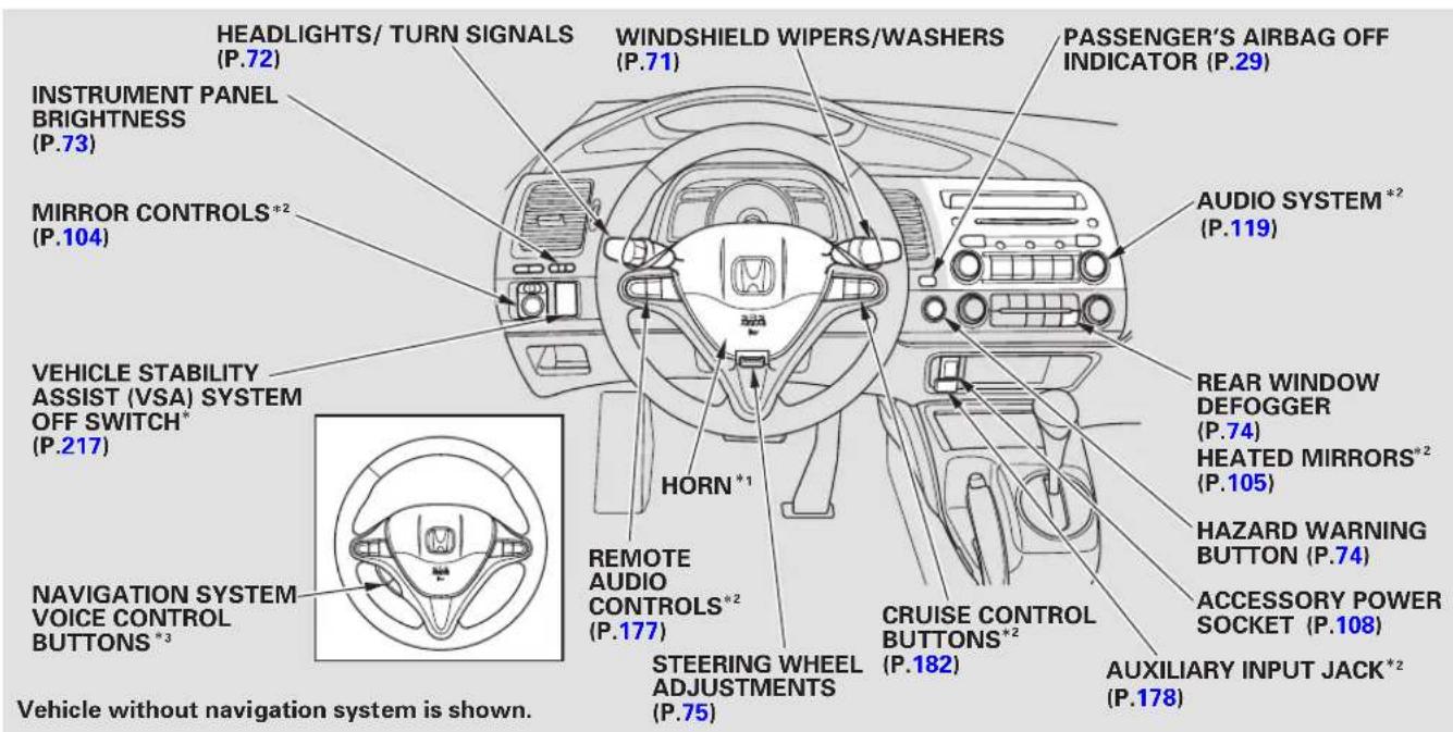
text_image
HEADLIGHTS/ TURN SIGNALS (P.72) INSTRUMENT PANEL BRIGHTNESS (P.73) MIRROR CONTROLS*2 (P.104) VEHICLE STABILITY ASSIST (VSA) SYSTEM OFF SWITCH* (P.217) NAVIGATION SYSTEM VOICE CONTROL BUTTONS*3 Vehicle without navigation system is shown. WINDSHIELD WIPERS/WASHERS (P.71) HORN*1 REMOTE AUDIO CONTROLS*2 (P.177) STEERING WHEEL ADJUSTMENTS (P.75) PASSENGER'S AIRBAG OFF INDICATOR (P.29) AUDIO SYSTEM*2 (P.119) REAR WINDOW DEFOGGER (P.74) HEATED MIRRORS*2 (P.105) HAZARD WARNING BUTTON (P.74) ACCESSORY POWER SOCKET (P.108) AUXILIARY INPUT JACK*2 (P.178)*1: To use the horn, press the center pad of the steering wheel.
*2: If equipped.
*3: Only on vehicles equipped with navigation system. Refer to the navigation system manual.
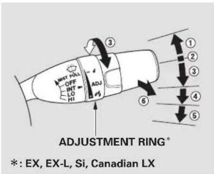
text_image
MEST PULL OFF INT LO HI 4 3 ADJ #2 6 ADJUSTMENT RING* *: EX, EX-L, Si, Canadian LX- MIST
- OFF
- INT Intermittent
- LO Low speed
- HI High speed
- Windshield washers
Push the right lever up or down to select a position.
MIST – The wipers run at high speed until you release the lever.
OFF - The wipers are not activated.
INT - The wipers operate every few seconds.
On EX, EX-L and Si models in the U.S., and LX, EX, EX-L and Si models in Canada
The length of the wiper interval is varied automatically according to the vehicle's speed.
Vary the delay by turning the adjustment ring. If you turn it to the shortest delay (position), the wipers change to low speed operation when the vehicle speed exceeds 12 mph (20km/h).
LO - The wipers run at low speed.
HI - The wipers run at high speed.
Windshield Washers—Pull the wiper control lever toward you, and hold it. The washers spray until you release the lever. The wipers run at low speed, then complete one more sweep after you release the lever.
Turn Signals and Headlights
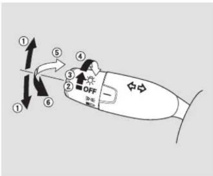
text_image
① ② OFF ③ ④ ⑤ ⑥- Turn signal
- Off
- Parking and indicator lights
- Headlights on
- High beams
- Flash high beams
Turn Signal— Push down on the lever to signal a left turn and up to signal a right turn. To signal a lane change, push lightly on the lever, and hold it. The lever will return to center when you release it or complete a turn.
Headlights On — Turning the switch to the “ 2005 ” position turns on the parking lights, taillights, instrument panel lights, side-marker lights, and rear license plate lights.
Turning the switch to the “≡D” position turns on the headlights.
If you leave the lights on with the key removed from the ignition switch, you will hear a reminder chime when you open the driver's door.
When the light switch is in the “” position, the lights on indicator comes on as a reminder.
This indicator stays on if you leave the lights on and turn the ignition switch to the ACCESSORY (I) or LOCK (0) position.
High Beams - Push the lever forward until you hear a click. The high beam indicator will come on (see page 63). Pull the lever back to return to the low beams.
To flash the high beams, pull the lever back lightly, then release it. The high beams will stay on as long as you hold the lever back.
Daytime Running Lights Instrument Panel Brightness
With the headlight switch off or in the position, the high beam headlights and the high beam indicator come on with reduced brightness when you turn the ignition switch to the ON (II) position and release the parking brake. They remain on until you turn the ignition switch off, even if you set the parking brake.
The headlights revert to normal operation when you turn them on with the switch.
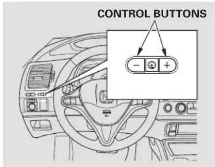
text_image
CONTROL BUTTONS - +The buttons under the left side vent control the brightness of the instrument panel. Push the or button to adjust the brightness.
Separate adjustments can be made when the headlights are on and off.
There are six brightness levels. When you push either button, the information display indicates the current level. You will hear a tone
when you reach the maximum or minimum brightness. The display returns to the odometer 5 seconds after you stop adjusting the brightness.
To reduce glare at night, the instrument panel illumination dims when you turn the light switch to the 2005 or position.
The center of each meter (upper and lower) illuminates with reduced brightness when you unlock and open the driver's door, and then goes back to the selected brightness when you turn the ignition switch to the ON (II) position.
If you insert the key but do not turn the ignition switch to the ON (II) position, the illumination turns off in about 10 seconds.
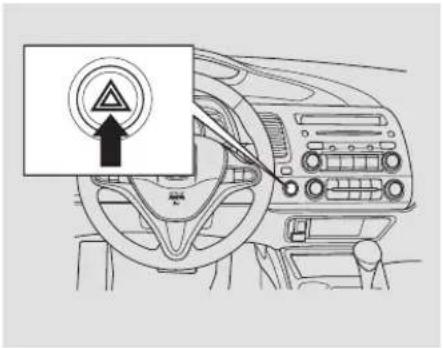
text_image
Diagram of car dashboard with warning sign and circular warning symbol in ChinesePush the button to turn on the hazard warning lights (four-way flashers). This causes all four outside turn signals and both turn indicators in the instrument panel to flash. Use the hazard warning lights if you need to park in a dangerous area near heavy traffic, or if your vehicle is disabled.
Rear Window DefoggerHazard Warning Button the rear window is clear and you have good visibility before starting to drive.
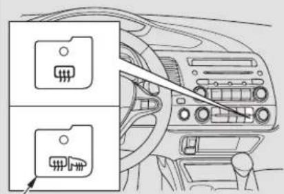
natural_image
Interior view of a car dashboard with two labeled switches (no text or symbols visible)U.S. EX-L, Canadian LX, EX, EX-L, Si
The rear window defogger will clear fog, frost, and thin ice from the window. Push the defogger button to turn it on and off. The indicator in the button comes on to show the defogger is on. If you do not turn it off, the defogger will shut itself off after about 15 minutes. It also shuts off when you turn off the ignition switch. You have to turn the defogger on again when you restart the vehicle.
The defogger and antenna wires on the inside of the rear window can be accidentally damaged. When cleaning the glass, always wipe side-to-side.
On U.S. EX-L, Canadian LX, EX, EX-L and Simodels
Pushing this button also turns the mirror heaters on or off. For more information, see page .105
Steering Wheel Adjustments
Make any steering wheel adjustments before you start driving.
▲WARNING
Adjusting the steering wheel position while driving may cause you to lose control of the vehicle and be seriously injured in a crash.
Adjust the steering wheel only when the vehicle is stopped.
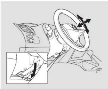
natural_image
Diagram of a car interior showing steering wheel, dashboard, and hand valve mechanism (no text or labels)- Push the lever under the steering column all the way down.
-
Move the steering wheel up or down, and in or out, so it points toward your chest, not toward your face. Make sure you can see the instrument panel gauges and indicators.
-
Push the lever up to lock the steering wheel in position.
- Make sure you have securely locked the steering wheel in place by trying to move it up, down, in, and out.
Keys and Locks
All EX, EX-L and Si models, and Canadian LX model
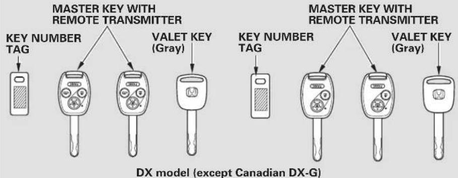
flowchart
graph TD
    A["Key NUMBER TAG"] --> B["Master Key with Remote Transmitter"]
    C["VALET KEY (Gray)"] --> D["Master Key with Remote Transmitter"]
    E["Key NUMBER TAG"] --> F["VALET KEY (Gray)"]
    G["Key NUMBER TAG"] --> H["VALET KEY (Gray)"]
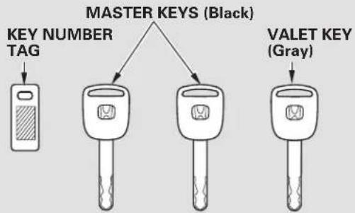
flowchart
graph TD
    A["KEY NUMBER TAG"] --> B["MASTER KEYS (Black)"]
    C["VALET KEY (Gray)"] --> D["MASTER KEYS (Black)"]
The master key fits all the locks on your vehicle. The valet key works only in the ignition and the driver's door lock*. You can keep the trunk and trunk release handle locked when you leave your vehicle and the valet key at a parking facility.
* On DX model (except Canadian DX-G), the passenger's door can also be locked or unlocked with the key.
You should have received a key number tag with your keys. You will need this key number if you ever have to get a lost key replaced. Use only Honda-approved key blanks.
These keys contain electronic circuits that are activated by the immobilizer system. They will not work to start the engine if the circuits are damaged.
- Protect the keys from direct sunlight, high temperature, and high humidity.
- Donotdropthekeysorset objects on them.
- Keep the keys away from liquids. If they get wet, dry them immediately with a soft cloth.
The valet key does not contain a battery. Do not try to take it apart.
On DX model (except Canadian DX-G) The keys do not contain batteries. Do not try to take them apart.
Immobilizer System
The immobilizer system protects your vehicle from theft. If an improperly-coded key (or other device) is used, the engine's fuel system is disabled.
When you turn the ignition switch to the ON (II) position, the immobilizer system indicator should come on briefly, then go off. If the indicator starts to blink, it means the system does not recognize the coding of the key. Turn the ignition switch to the LOCK (0) position, remove the key, reinsert it, and turn the ignition switch to the ON (II) position again.
The system may not recognize your key's coding if another immobilizer key or other metal object (i.e. key fob) is near the ignition switch when you insert the key.
If the system repeatedly does not recognize the coding of your key, contact your dealer.
Do not attempt to alter this system or add other devices to it. Electrical problems could result that may make your vehicle undrivable.
If you have lost your key and cannot start your engine, contact your dealer.
NOTICE
Always take the ignition key with you whenever you leave the vehicle alone.
CONTINUED
As required by the FCC: This device complies with Part 15 of the FCC rules. Operation is subject to the following two conditions: (1) This device may not cause harmful interference, and (2) this device must accept any interference received, including interference that may cause undesired operation.
Changes or modifications not expressly approved by the party responsible for compliance could void the user's authority to operate the equipment.
This device complies with Industry Canada Standard RSS-210. Operation is subject to the following two conditions: (1) this device may not cause interference, and (2) this device must accept any interference that may cause undesired operation of the device.
Ignition Switch
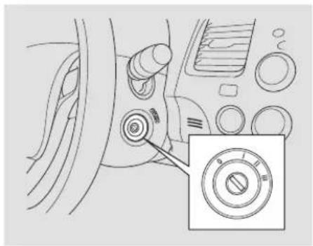
natural_image
Diagram of a car interior showing a dial indicator and a circular dial with an arrow pointing to it (no text or symbols present)The ignition switch has four positions: LOCK (0), ACCESSORY (I), ON (II), and START (III).
LOCK (0)— You can insert or remove the key only in this position. To turn the key, push it in slightly. If your vehicle has an automatic transmission, the shift lever must also be in park.
If the front wheels are turned, the anti-theft lock may make it difficult to turn the key. Firmly turn the steering wheel to the left or right as you turn the key.
ACCESSORY (I) — You can operate the audio system and the accessory power sockets in this position.
ON (II) – This is the normal key position when driving. Several of the indicators on the instrument panel come on as a test when you turn the ignition switch from the ACCESSORY (I) to the ON (II) position.
START (III) — Use this position only to start the engine. The switch returns to the ON (II) position when you let go of the key.
You will hear a reminder beeper if you leave the key in the ignition switch in the LOCK (0) or the ACCESSORY (I) position and open the driver's door. Removeth turn off the beeper.
If your vehicle has an automatic transmission, the shift lever must be in Park before you can remove the key from the ignition switch.
▲WARNING
Removing the key from the ignition switch while driving locks the steering. This can cause you to lose control of the vehicle.
Remove the key from the ignition switch only when parked.
Door Locks
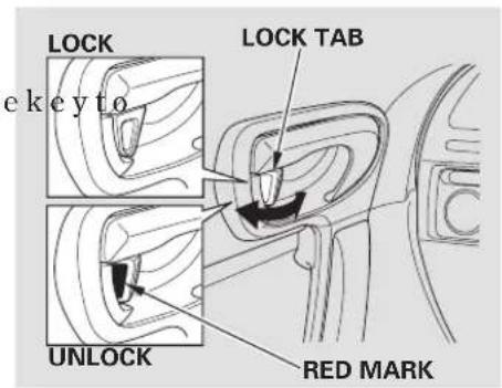
text_image
LOCK e k e y t o LOCK TAB UNLOCK RED MARKEach door has a lock tab next to the inside door handle. Pull out the tab to lock the door, and push it in to unlock.
When the door is unlocked, the red mark on the lock tab is shown.
On DX model except Canadian DX-G To lock the passenger's door when getting out of the vehicle, pull out the lock tab and close the door. To lock the driver's door, pull and hold the outside door handle then pull out the lock tab. Release the handle, then close the door.
Each door can be locked or unlocked with the ignition key.
Power Door Locks
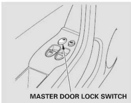
text_image
MASTER DOOR LOCK SWITCHOn LX, EX, EX-L and Simodelsin U.S., and DX-G, LX, EX, EX-L and Si models in Canada To lock the doors, push the top of the master door lock switch on either door, pull out the lock tab on the driver's door, or use the key in the outside lock on the driver's door.
Pushing the bottom of either master door lock switch unlocks both doors.
The lock tab on the passenger's door locks and unlocks only that door. Pushing in the driver's door lock tab only unlocks the driver's door. To unlock only the driver's door from the outside, turn the key and release it. If you turn it again doors unlock.
To lock the passenger's door when getting out of the vehicle, pull out the lock tab and close the door. To lock the driver's door, remove the key from the ignition switch and pull that the lock tab or push the top of the master switch, then close the door.
Lockout Prevention
If you forget and leave the key in the ignition switch, lockout prevention will not allow you to lock the driver's door. With either door open and the key in the ignition switch, locking with master door lock switch is disabled. If the driver's door is closed, the lock tab on the driver's door is not disabled. Pulling the driver's lock tab rearward will lock both doors. If you try to lock an open driver's door by pulling the lock tab rearward, the driver's door lock tab pops out and unlocks the driver's door.
Auto Door Locking/Unlocking Auto|Door Locking
On LX, EX, EX-L and Simodelsin the auto door locking feature has U.S., and DX-G, LX, EX, EX-L and Si three possible settings:
models in Canada Your vehicle has customizable settings for the doors to automatically lock and unlock. There are default settings for each of these features. You can turn off or change the settings for these features as described on the following pages.
When you customize the setting, make sure your vehicle is parked safely, the engine is off, and apply the parking brake. Make all settings before you start driving.
• The auto door locking is deactivated all the time.
• The doors lock whenever you move the shift lever out of the Park (P) position (A/T vehicles).
• The doors lock when the vehicle speed reaches 9 mph (15 km/h). This is the default setting.
To turn off the Auto Door Lock modes:
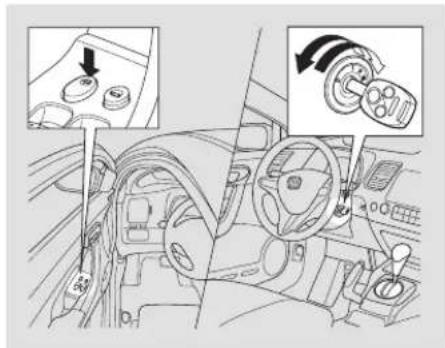
text_image
Diagram showing car interior control with directional arrows and component labels in Chinese- Make sure the shift lever is in the Park (P) position (A/T vehicles).
- Turn the ignition switch to the ON (II) position, and open the driver's door.
CONTINUED
Door Locks
- Push and hold the front of the master door lock switch on the driver's door until you hear a click (after about 5 seconds).
- Release the switch, and within 5 seconds, turn the ignition switch to the LOCK (0) position.
To program the Park Lock mode: Locks both doors when the shift lever is moved out of the Park (P) position (A/T vehicles only).
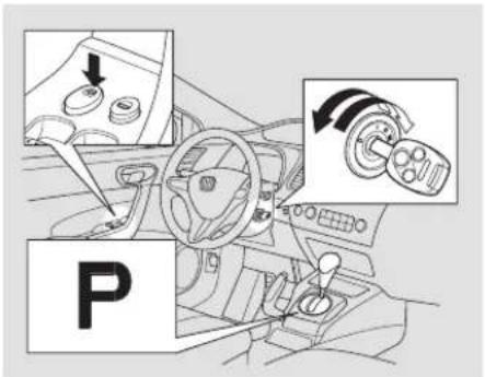
text_image
P- Make sure the shift lever is in the Park (P) position.
-
Turn the ignition switch to the ON (II) position, and make sure to close the driver's door.
-
Push and hold the front of the master door lock switch on the driver's door. You will hear a click. Keep holding the switch until you hear another click (after about 5 seconds).
- Release the switch, and within 5 seconds, turn the ignition switch to the LOCK (0) position.
To program the Drive Lock mode: Locks both doors when the vehicle's speed reaches about 9 mph (15 km/h).
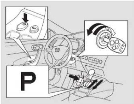
text_image
P- Make sure the shift lever is in the Park (P) position (A/T vehicles).
- Turn the ignition switch to the ON (II) position, and make sure to close the driver's door.
-
On A/T vehicles, push and hold the brake pedal, and move the shift lever out of the Park (P) position.
-
Push and hold the front of master door lock switch on the driver's door. You will hear a click. Keep holding the switch until you hear another click (after about 5 seconds).
- Release the switch, and within 5 seconds, turn the ignition switch to the ACCESSORY (I) position. On A/T vehicles, move the shift lever to the Park (P) position.
- Turn the ignition switch to the LOCK (0) position.
eAuto Door Unlocking
The auto door unlocking feature has five possible settings:
• The auto door unlocking is deactivated all the time.
- On A/T vehicles, the driver's door unlocks when you move the shift lever to the Park (P) position. This is the default setting.
- Both doors unlock when you move the shift lever to the Park (P) position (A/T vehicles).
- The driver's door unlocks whenever you turn the ignition switch to the ACCESSORY (I) position.
This is the default setting on M/T vehicles.
- Both doors unlock whenever you turn the ignition switch to the ACCESSORY (I) position.
CONTINUED
Door Locks
To turn off the Auto Door Unlock modes:
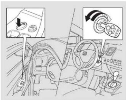
text_image
Diagram of car interior showing dashboard, steering wheel, and rotary dial with directional arrows indicating rotation or adjustment.- Make sure the shift lever is in the Park (P) position (A/T vehicles).
-
Turn the ignition switch to the ON (II) position, and open the driver's door.
-
Push and hold there are of the master door lock switch on the driver's door. You will hear a click, and after about 5 seconds, you will hear another click.
- Release the switch, and within 5 seconds, turn the ignition switch to the LOCK (0) position.
To program the Park Unlock mode: Unlocks the driver's door or both doors when the shift lever is moved into the Park (P) position (A/T vehicles only).
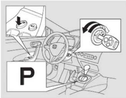
text_image
P- Make sure the shift lever is in the Park (P) position.
-
Turn the ignition switch to the ON (II) position, and make sure to close the driver's door.
-
Push and hold there are of the master door lock switch on the driver's door. You will hear a click. Continue to hold the switch:
-
Until you hear another click (after about 5 seconds) to activate driver's door unlock feature,
-
Or, until you hear two more clicks (after about 10 seconds) to activate both doors unlock feature
-
Release the switch, and within 5 seconds, turn the ignition switch to the LOCK (0) position.
To program the Ignition Switch Unlock mode:
Unlocks the driver's door or both doors when the ignition switch is moved out of the ON (II) position.
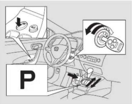
text_image
P- Make sure the shift lever is in the Park (P) position (A/T vehicles).
-
Turn the ignition switch to the ON (II) position, and make sure to close the driver's door.
-
On A/T vehicles, push and hold the brake pedal, then move the shift lever out of the Park (P) position.
-
Push and hold there are of the master door lock switch on the driver's door. You will hear a click. Continue to hold the switch:
-
Until you hear another click (after about 5 seconds) to activate driver's door unlock feature.
- Or, until you hear two more clicks (after about 10 seconds) to activate both doors unlock feature
CONTINUED
Door Locks, Remote Transmitter
- Release the switch, and within 5 seconds, turn the ignition switch to the ACCESSORY (I) position. On A/T vehicles, move the shift lever to the Park (P) position.
- Turn the ignition switch to the LOCK (0) position.
Even though your vehicle's battery is removed or goes dead, the system keeps the auto door lock/unlock setting which you selected.
Remote Transmitter
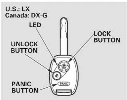
text_image
U.S.: LX Canada: DX-G LED UNLOCK BUTTON PANIC BUTTON LOCK BUTTON PANICU.S.:LX,EX,EX-L,Si Canada:DX-G,LX,EX,EX-L,Si LOCK - Press this button once to lock both doors. Some exterior lights will flash once. When you push LOCK twice within 5 seconds, you will hear a beep to verify that the doors are locked and that the security system (if equipped) has set. You cannot lock the doors if either door is not fully closed or the key is in the ignition switch.
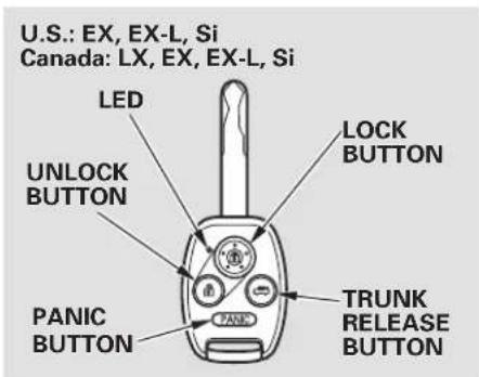
text_image
U.S.: EX, EX-L, Si Canada: LX, EX, EX-L, Si LED UNLOCK BUTTON PANIC BUTTON LOCK BUTTON TRUNK RELEASE BUTTONUNLOCK - Pressthisbuttononc to unlock the driver's door. Push it twice to unlock the passenger's door. Some exterior lights will flash twice each time you push the button.
The ceiling light and the door activated spotlights (if equipped) come on when you press the UNLOCK button if the lights are in the door activated position. If you do not open either door within 30 seconds, the light(s) will fade out. If you relock the doors with the remote transmitter before 30 seconds have elapsed, the light(s) will go off immediately.
If you do not open either door within 30 seconds, the doors automatically relock, and the security system (if equipped) sets. You cannot unlock it if the key is in the ignition switch.
EX, EX-L, Si and Canadian LX models TRUNK RELEASE — Press this button for about 1 second to open the trunk. You cannot open the trunk if the key is in the ignition switch.
PANIC — Press and hold this button for about 2 seconds to attract attention: the horn will sound and the exterior lights will flash for about 30 seconds. To cancel panic mode, press any other button on the remote transmitter, or turn the ignition switch to the ON (II) position.
Remote Transmitter Care
- Avoid dropping or throwing the transmitter.
- Protect the transmitter from extreme temperature.
- Do not immerse the transmitter in any liquid.
- If you lose a transmitter, the replacement needs to be reprogrammed by your dealer.
CONTINUED
Remote Transmitter
Replacing the Transmitter Battery
If it takes several pushes on the button to lock or unlock the doors, replace the battery as soon as possible.
Battery type: CR1616
To replace the battery:
- Remove the screw at the base of the transmitter with a small Phillips-head screwdriver.
NOTE: Be careful when removing this screw as the head of the screw can strip out.
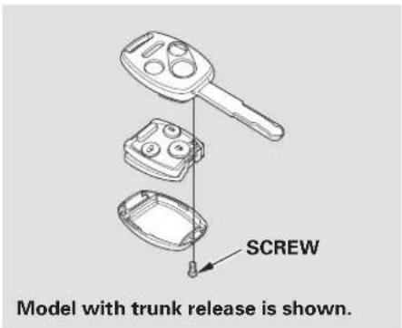
text_image
SCREW Model with trunk release is shown.- Separate the transmitter by prying its middle seam with your fingernail.
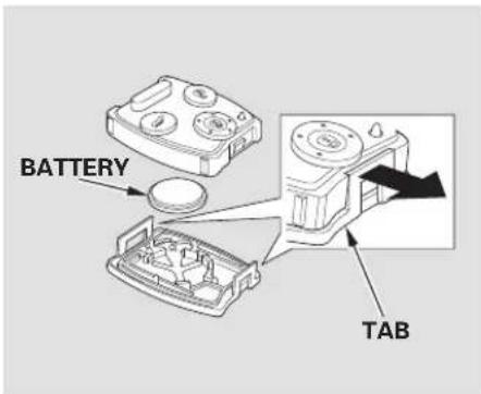
text_image
BATTERY TABInside the transmitter, separate the inner cover from the keypad by releasing the two tabs on the cover.
- Remove the old battery from the back of the inner cover, and insert a new battery into the back of the cover with the side facing down.
An improperly disposed of battery can be harmful to the environment and human health. Always confirm local regulations for battery disposal.
- Install the parts in reverse order.
As required by the FCC: This device complies with Part 15 of the FCC rules. Operation is subject to the following two conditions: (1) This device may not cause harmful interference, and (2) this device must accept any interference received, including interference that may cause undesired operation.
Changes or modifications not expressly approved by the party responsible for compliance could void the user's authority to operate the equipment.
This device complies with Industry Canada Standard RSS-210. Operation is subject to the following two conditions: (1) this device may not cause interference, and (2) this device must accept any interference that may cause undesired operation of the device.
Trunk
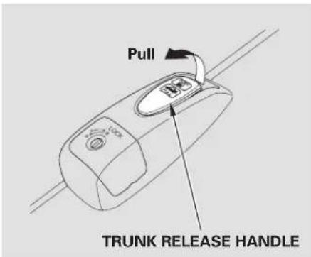
text_image
Pull TRUNK RELEASE HANDLEYoucanopenthetrunkintwo
- Pull the trunk release handle to the left of the driver's seat.
- On EX, EX-L, Si and Canadian LX models Press and hold the trunk release button on the remote transmitter.
U.S. DX and LX, Canadian DX and DX-G
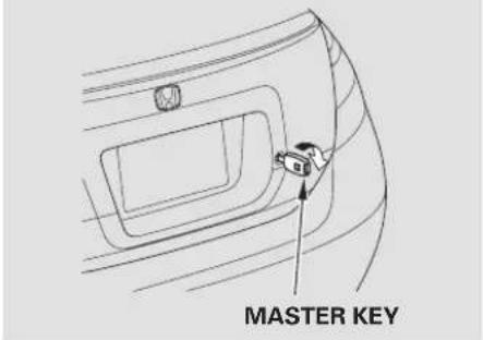
text_image
MASTER KEYw a d s U.S. DX and LX models, and Canadian DX and DX-G models U set h e m a s t e r k e y t o o p e n t h e trunk lock. The valet key does not work in this lock.
To close the trunk, press down on the trunk lid.
Keep the trunk lid closed at all times while driving to avoid damaging the lid, and to prevent exhaust gas from getting into the interior. See Carbon Monoxide Hazard on page 50
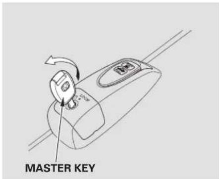
text_image
MASTER KEYTo protect items in the trunk when you need to give the key to someone else:
- Lock the trunk release handle with the master key.
- Give the person the valet key.
On EX, EX-L, Si and Canadian LX Even if the trunk release lever is locked with the master key, you can open the trunk with the remote transmitter.
Emergency Trunk Opener
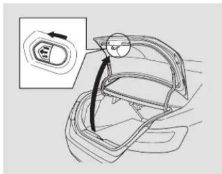
natural_image
Diagram of a car interior showing a gear shift and adjustment mechanism (no text or symbols)As a safety feature, your vehicle has a release lever on the trunk latch so the trunk can be opened from the inside. To open the trunk, push the release lever to the left.
Parents should decide if their children should be shown how to use this feature. For more information about child safety, see page .35
Seats
FrontSeatAdjustments
See pages for important safety information and warnings about how to properly position the seats and seat-backs.
Make all seat adjustments before you start driving.
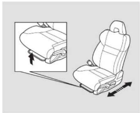
natural_image
Line drawing of a car seat assembly with a close-up inset showing the seat frame and seatbelt (no text or symbols)To adjust the seat forward or backward, pull up on the bar under the seat cushion's front edge. Move the seat to the desired position, and release the bar. Try to move to make sure it is locked in position.
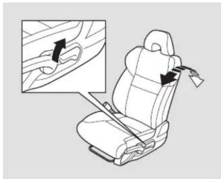
natural_image
Diagram of a car seat with a close-up inset showing the side view of the seat (no text or symbols present)To change the seat-back angle, pull up on the lever on the outside of the seat bottom.
Once a seat is adjusted correctly, rock it back and forth to make sure it is locked in position.
Driver's Seat Height Adjustment Armrest Rear Seat Access
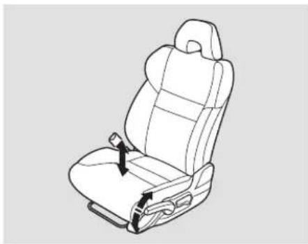
natural_image
Line drawing of a car seat with two black arrows indicating seatbelting points (no text or symbols)The height of your driver's seat is adjustable. To raise the seat bottom, repeatedly pull up the lever on the outside of the seat cushion. To lower the seat, push the lever down repeatedly.
Make all seat adjustments before you start driving.
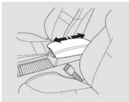
natural_image
Diagram of a car seatbelt mechanism with arrows indicating direction (no text or symbols)On all models except DX To use the console lid as an armrest, slide it to one of its three positions.
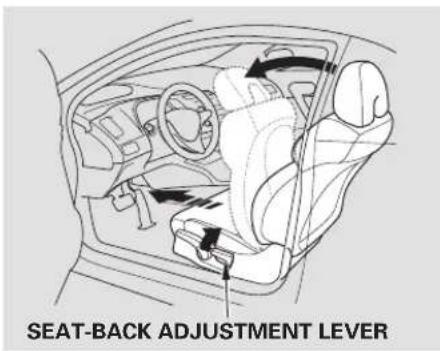
text_image
SEAT-BACK ADJUSTMENT LEVERDriver's Side
To get into the rear seat on the driver's side, open the door and pull up on the seat-back adjustment lever. The seat-back will tilt forward to allow easier entry to the rear seat.
CONTINUED
Main Menu
Table Of Contents
Seats
Passenger's Side
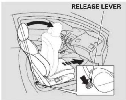
text_image
RELEASE LEVERTo get into the rear seat on the passenger's side, push downward on the release lever at the base of the seat-back or pull up on the seat-back adjustment lever. The seat-back will tilt forward to allow easier entry to the rear seat.
Except U.S. DX
When you push down the release lever or pull up the adjustment lever, the seat will also move forward. After a passenger gets into the back seat, push the seat-back to the upright position, and push the seat backwards until it latches. Make sure the seat is fully latched before sitting in it.
Head Restraints
See page 18 important safety information and a warning about improperly positioning head restraints.
Your vehicle is equipped with head restraints in all seating positions to help protect you and your passengers from whiplash and other injuries.
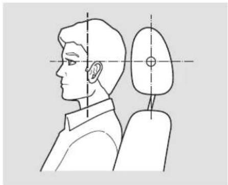
natural_image
Side profile illustration of a person with head and shoulder, showing anatomical alignment lines (no text or symbols)They are most effective when you adjust them so the center of the back of the occupant's head rests against the center of the restraint.
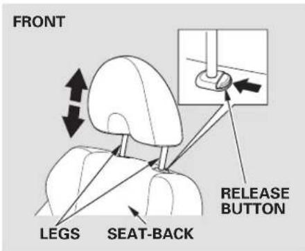
text_image
FRONT RELEASE BUTTON LEGS SEAT-BACKAdjusting the Head Restraint The head restraints adjust for height. You need both hands to adjust a restraint. Do not attempt to adj while driving. To raise it, pull upward. To lower the restraint, push the release button sideways, and push the restraint down.
CONTINUED
Seats
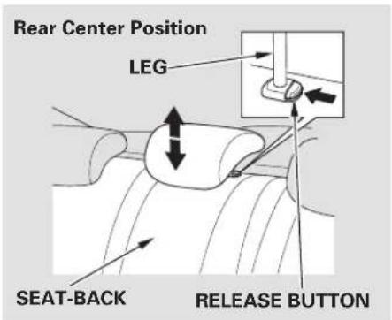
text_image
Rear Center Position LEG SEAT-BACK RELEASE BUTTONWhen a passenger is seated in the rear center seating position, the center head restraint should be adjusted up or down, to match the passenger's height.
Removing the Head Restraint
To remove a head restraint for cleaning or repair, pull it up as far as it will go. Push the release button, then pull the restraint out of the seat-back.
WARNING
Failure to reinstall the head restraints can result in severe injury during a crash.
Always replace the head restraints before driving.
When reinstalling a head restraint, put the legs back in place. Then adjust it to the appropriate height while pressing the release button.
Make sure the head restraint locks in position when you reinstall it.
Active Head Restraints
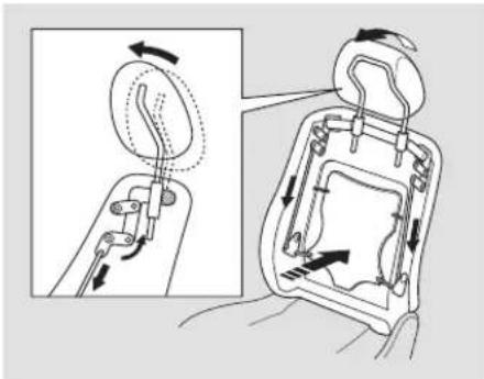
natural_image
Diagram showing mechanical assembly with arrows indicating motion, no text or symbols presentThe driver's and front passenger's seats have active head restraints. If the vehicle is struck severely from the rear, the occupant properly secured with the seat belt will be pushed against the seat-back and the head restraint will automatically move forward.
This reduces the distance between the restraint and the occupant's head. It also helps protect the occupants
against whiplash and injuries to the neck and upper spine.
After a collision, the activated restraint should return to its normal position.
If the restraints do not return to their normal position, or in the event of a severe collision, have the vehicle inspected by a Honda dealer.
For a head restraint system to work properly:
- Do not hang any items on the head restraints, or from the restraint legs.
- Do not place any object between an occupant and the seat-back.
• Install each restraint in its proper location. - Only use genuine Honda replacement head restraints.
Seats
Folding Rear Seat
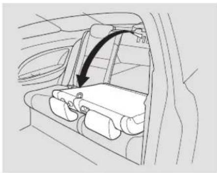
natural_image
Interior view of a car showing the rear seat, dashboard, and side panel with an arrow indicating direction (no text or symbols)The back of the rear seat folds down to give you direct access to the trunk. The seat-back can be released from inside the trunk.
On all models except DX and U.S. LX The left and right halves can be folded separately.
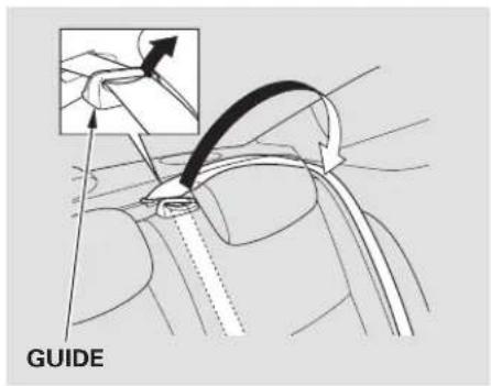
text_image
GUIDEWhen storing cargo, you can move there are centers shoulder be the way by removing the belt from the guide.
Remove any items from the seat before you folldown thesea
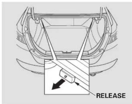
text_image
RELEASETo release the seat-back, pull the release of the trunk panel. Push the seat-back down, then let go of the release.
For 60/40 split rear fold-down seat models, a release is located on each side of the trunk.
For full rear fold-down seat models, the release is located on the driver's side of the trunk.
Make sure that the folded seat-back does not press against the front passenger's seat, as this could cause the weight sensors to work improperly.
If the rear head restraints get caught on the front seat backs and you cannot fold down the rear seat-back fully, you can remove the head restraints (see page)96 Make sure the removed head restraints are securely stored.
To lock the seat-back upright, push it firmly against the trunk panel. Make sure it is latched in place by pulling on the top of the seat.
Make sure all rear shoulder belts are positioned in front of the rear seat-back, and the center shoulder belt is re-positioned in the guide whenever the seat-back is in its upright position. Be sure there are no twists in any shoulder belt.
Do not put any heavy items on the seat-back when it is folded down.
Make sure all items in the trunk, or items extending through the opening into the back seat, are secured. Loose items scanfly forward and cause injury if you have to brake hard. See Capaging Cargo 197.
Never drive with the seat-back folded down and the trunk lid open. See Carbon Monoxide Hazard page 50
Power Windows
DRIVER'S WINDOW SWITCH
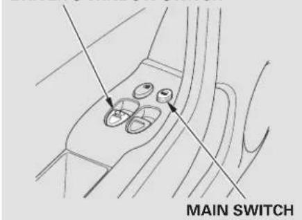
text_image
MAIN SWITCHIf equipped
Turn the ignition switch to the ON (II) position to raise or lower either window. To open a window, push the switch down and hold it. Rele switch when you want the window to stop. Pull back on the switch and hold it to close the window.
The windowsoperateforupto10 minutes after you turn off the ignition switch. Opening either door cancels this function.
WARNING
Closing a power window on someone's hands or fingers can cause serious injury.
Make sure your passengers are away from the windows before closing them.
The driver's armrest has a master power window control panel. To open the passenger's window, push down on the switch and hold it down until the window reaches the desired position. To close the window, pull back the window switch. Release the switch when the window gets to the position you want.
AUTO – To open the driver's window fully, push the window switch firmly down, then release it. The window automatically goes down all the way. To stop the window from going all the way down, pull back on the window switch briefly.
To close the driver's window fully, pull back the window switch firmly, then release it. The window automatically goes all the way up. To stop the window from going all the way up, push down on the window switch briefly.
To open or close the driver's window partially, push down or pull back on the window switch lightly and hold it. The window will stop when you release the switch.
When you push the MAIN switch in, the switch is OFF, and the passenger's window cannot be raised or lowered. To cancel this feature, push on the switch again to get it to pop out. Keep the MAIN switch off when you have children in th vehicle so they do not injure themselves by operating the window unintentionally.
AUTO REVERSE— If the driver's window runs into any obstacle while it is closing automatically, it will reverse direction, and then stop. To close the window, remove the obstacle, then use the window switch again.
Auto reverse stops sensing when the window is almost closed. You should always check that all passengers and objects are away from the window before closing it.
NOTE: Only on the driver's window, the auto reverse function is disabled when you continuously pull up the switch.
If your vehicle's battery is disconnected or goes dead, or the driver's window fuse is removed, the AUTO function could be disabled. If the power window system needs to be reset after reconnecting the battery or installing the fuse, do this:
-
Start the engine. Push down and hold the driver's window switch until the window is fully open.
-
Pull and hold the driver's window switch to close the window completely, then hold the switch for about 2 seconds.
If the power windows do not operate properly after resetting, have your vehicle checked by your dealer.
Moonroof
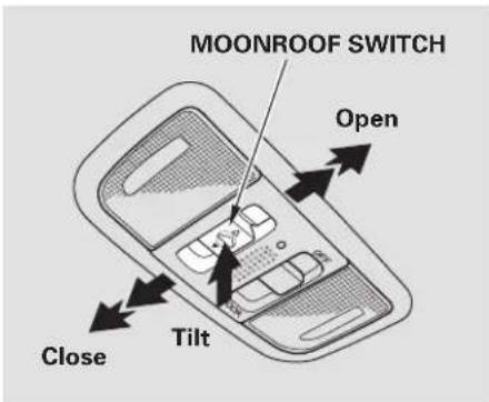
text_image
MOONROOF SWITCH Open Close TiltIf equipped The moonroof can be tilted up in the back for ventilation, or it can be slid back into the roof. Use the switch on the front ceiling to operate the moonroof. You must turn the ignition switch to the ON (II) position to operate the moonroof.
To tilt up the moonroof, push on the center of the moonroof switch. To stop the moonroof from tilting up fully, push the switch briefly.
To open the moonroof, pull back on the switch and hold it. Release the switch when the moonroof reaches the desired position. To close the moonroof, push the switch forward and hold it. Release the switch stop the operation.
WARNING
Opening or closing the moonroof on someone's hands or fingers can cause serious injury.
Make sure all hands and fingers are clear of the moonroof before opening or closing it.
AUTO – To open the moonroof fully, pull back the moonroof switch firmly, then release it. The moonroof automatically opens all the way. To stop the moonroof from opening, push the switch briefly.
To close the moonroof fully, firmly push the moonroof switch forward, then release it. The moonroof lautomatically closes all the way. To stop the moonroof from closing, push the switch briefly.
To open or close the moonroof partially, lightly pull the switch back or push it forward and hold it. The moonroof will stop when you release the switch.
AUTO REVERSE – If the moonroof runs into any obstacle while it is closing automatically, it will reverse direction and then stop. To close the moonroof, remove the obstacle, then use the moonroof switch again.
Auto reverse stops sensing when the moonroof is almost closed. You should always check that all passengers and objects are away from the moonroof before closing it.
The moonroof has a key-off delay. You can open and close the moonroof for up to 10 minutes after you turn off the ignition switch. The key-off delay cancels as soon as you open either door.
NOTICE
If you try to open the moonroof in below-f reezing temperatures, or when it is covered with snow or ice, you can damage the moonroof panel or motor.
Mirrors
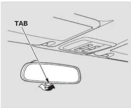
text_image
TABKeep the inside and outside mirrors clean and adjusted for best visibility. If equippe Be sure to adjust the mirrors before 1. Turn the you start driving. (II) pos
The inside mirror has day and night positions. The night position reduces glare from headlights behind you. Flip the tab on the bottom edge of the mirror to select the day or night position.
Adjusting the Power Mirrors
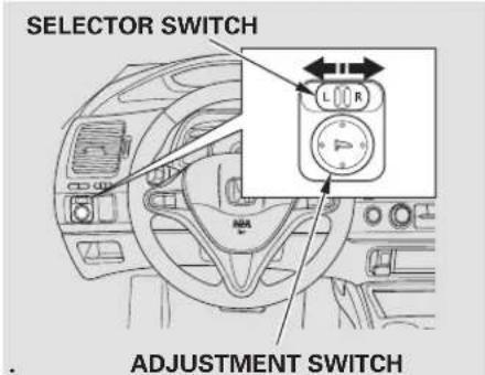
text_image
SELECTOR SWITCH L R ADJUSTMENT SWITCHIf equipped
-
Turn the ignition switch to the ON (II) position.
-
Move the selector switch to L (driver's side) or R (passenger's side).
-
Push the appropriate edge of the adjustment switch to move the mirror right, left, up, or down.
-
When you finish, move the selector switch to the center (off) position. This turns the adjustment switch off to keep your settings.
Power Mirror Heaters Parking Brake
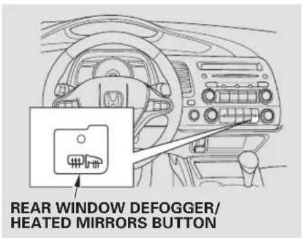
text_image
REAR WINDOW DEFOGGER/ HEATED MIRRORS BUTTONEX-L model in the U.S. LX, EX, EX-L and SimodelsinCa The outside mirrors are heated to remove fog and frost. With the ignition switch in the ON (II) position, turn on the heaters by pressing the rear window defogger button. The indicator in the button comes on a reminder. Pres button again to turn the heaters and the defogger off.
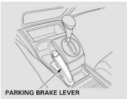
To apply the parking brake, pull the lever up fully. To release it, pull up slightly, push the button, and lower the lever. The parking brake indicator on the instrument panel should go out when the parking brake is fully released (see page 58).
NOTICE
Driving the vehicle with the parking brake applied can damage the rear brakes and axles. A beeper will sound if the vehicle is driven with the parking brake on.
Main Menu
Table Of Contents
Interior Convenience Items
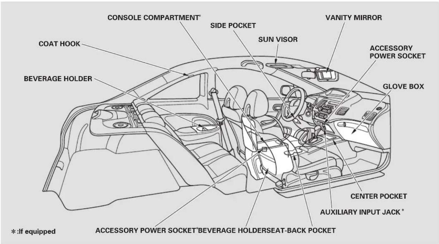
text_image
CONSOLE COMPARTMENT® SIDE POCKET VANITY MIRROR COAT HOOK BEVERAGE HOLDER SUN VISOR ACCESSORY POWER SOCKET GLOVE BOX CENTER POCKET AUXILIARY INPUT JACK* * :If equipped ACCESSORY POWER SOCKET*BEVERAGE HOLDERSEAT-BACK POCKET *:If equippedBeverage Holders Console Compartment Glove Box
Be careful when you are using the beverage holders. A spilled liquid that is very hot can scald you or your passengers. Spilled liquids can damage the upholstery, carpeting, and electrical components in the interior.
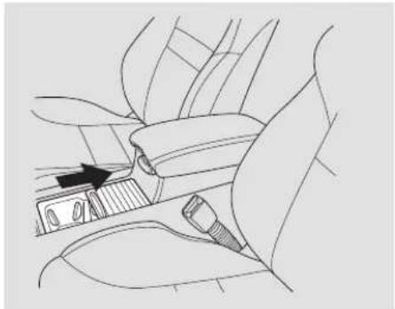
natural_image
Line drawing of car seatbelt and dashboard compartment showing a black arrow pointing to the dashboard (no text or symbols present)Open the front beverage holder by sliding the lid.
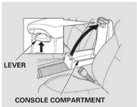
text_image
LEVER CONSOLE COMPARTMENTIf equipped
To open the console compartment, pull up on the lever, and lift the lid.
To close, lower the lid, and push it down until it latches.
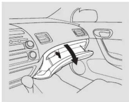
natural_image
Diagram of a car interior showing the intake manifold and airflow direction (no text or symbols)Open the glove box by pulling the handle to the left. Close it with a firm push.
CONTINUED
Interior Convenience Items
▲WARNING
An open glove box can cause serious injury to your passenger in a crash, even if the passenger is wearing the seat belt.
Always keep the glove box closed while driving.
Coat Hook Accessory Power Sockets
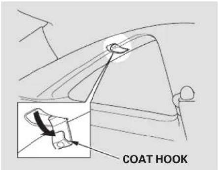
text_image
COAT HOOKTo use a coat hook, pull it down. Close it with a firm push.
Make sure the coat hook is closed when you are not using it. This hook is not designed for large or heavy items.
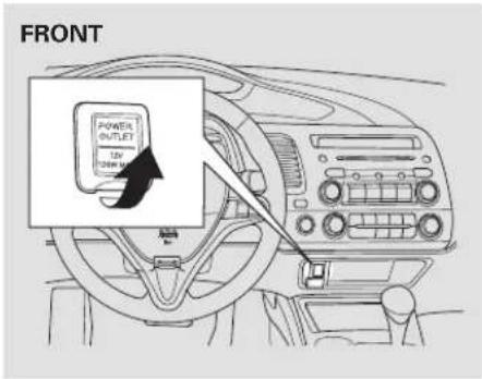
text_image
FRONT POWER OUTLET 12V Power MTo use an accessory power socket, pull up the cover.
This socket is intended to supply power for 12 volt DC accessories that are rated 120 watts or less (10 amps).
To use an accessory power socket, the ignition switch must be in the ACCESSORY (I) or ON (II) position.
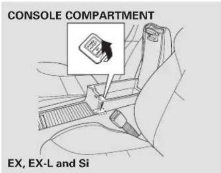
text_image
CONSOLE COMPARTMENT EX, EX-L and SiOn EX, EX-L and Si models Another accessory power socket is in the center console compartment.
None of the sockets will power an automotive type cigarette lighter element. When both sockets are being used, the combined power rating of the accessories should be 120 watts or less (10 amps).
Make sure to put the socket cover back in place to prevent any small foreign objects getting into the socket.
Vanity Mirror
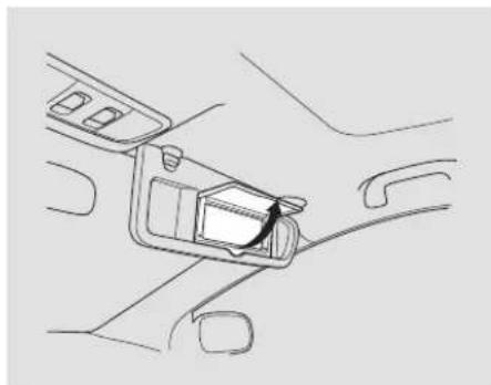
natural_image
Line drawing of a car interior showing the seatbelt and dashboard (no text or symbols)To use the vanity mirror on the back of the sun visor, pull up the cover.
Main Menu
Table Of Contents
Interior Convenience Items
Sun Visor
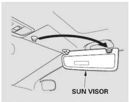
text_image
SUN VISORTo use the sun visor, pull it down. When using the sunvisor for the side window, remove the support rod from the clip, and swing it out.
Make sure you put the sun visor back in place when you are getting into or out of the vehicle.
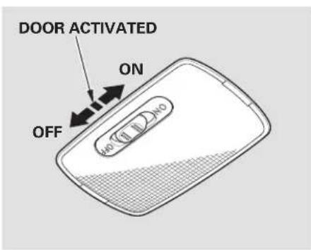
text_image
DOOR ACTIVATED ON OFF NO (10, 20) NoThe ceiling light has a three-position switch; ON, Door Activated, and OFF. In the Door Activated (center) position, the light comes on when you:
- Open either door.
- Unlock the doors with the key or the remote transmitter.
After both doors are closed tightly, the light dims slightly, then fades out in about 30 seconds.
The ceiling light (with the switch in the center position) comes on when you remove the key from the ignition switch. If you do not open a door, the light stays on, then fades out in about 30 seconds.
If you leave either door open without the key in the ignition switch, the ceiling light goes off after 3 minutes.
SpotlightsCeiling Light
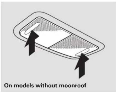
text_image
On models without moonroofTurn on a spotlight by pushing the lens. Push the lens again to turn it off. You can use the spotlights at all times.
CONTINUED
Main Menu
Table Of Contents
Interior Lights
On models with moonroof The spotlights have a two-position switch. In the DOOR position, the lights come on when you open either door. In the OFF position, the lights do not come on.
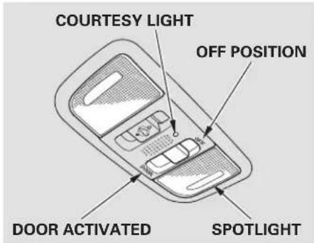
text_image
COURTESY LIGHT OFF POSITION DOOR ACTIVATED SPOTLIGHTThe spotlights (with the switch in the DOOR position) also come on when you unlock the door with the key or the remote transmitter, and when you remove the key from the ignition switch.
Courtesy Light
On models with moonroof The courtesy light between the spotlights comes on when you turn the parking lights on. To adjust its brightness, push the instrument panel brightness control buttons under the driver's side vent with the ignition switch in the ON (II) position.
The heating and air conditioning* systems in your vehicle provide a comfortable driving environment in all weather conditions.
*Air conditioning is optional on DX model.
The standard audio system has many features. This section describes those features and how to use them. (If you have an optional audio system, refer to the operating instructions that came with it.)
If equipped
Your vehicle has an anti-theft audio system that requires a code number to enable it.
U.S. LX, EX, EX-L and Si models
The security system helps to discourage vandalism and theft of your vehicle.
Navigation systems are optional on U.S. EX, EX-L and Si models only.
Vents, Heating, and A/C 114
Audio System 119
Audio System (Models without navigation system) 120
Playing the AM/FM Radio..... 121
Playing the XM ^® Satellite ....Radio
Playing a Disc.... 130
Disc Player Error Messages .... 136
Optional Disc Changer Error Messages . 137
Audio System (Models with navigation system) 138
Voice Control System...... 138
Playing the AM/FM Radio...... 138
Playing the XM ^® Satellite Radio 142
Playing a Disc.... 150
Disc Player Error Messages .... 158
Playing a PC Card.... 159
PC card Error Messages ...... 171
AM/FM Radio Reception...... 172
Protecting Your Discs...... 174
......Remote Audio Controls . 177
Auxiliary Input Jack.... 178
Radio Theft Protection...... 179
Setting the Clock 180
Security System 181
Cruise Control.... 182
(Optional). 125
ges.137
Main Menu
Table Of Contents
Vents, Heating, and A/C
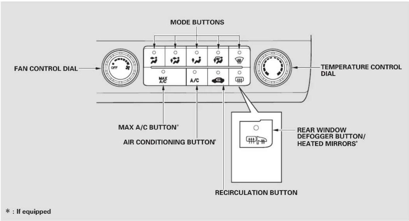
text_image
MODE BUTTONS FAN CONTROL DIAL MAX A/C A/C TEMPERATURE CONTROL DIAL MAX A/C BUTTON* AIR CONDITIONING BUTTON* REAR WINDOW DEFOGGER BUTTON/ HEATED MIRRORS* RECIRCULATION BUTTON * : If equippedFan Control Dial
Turn this dial to increase or decrease the fan speed and airflow.
Temperature Control Dial
Turning this dial clockwise increases the temperature of the airflow.
Air Conditioning (A/C) Button
If equipped
This button turns the air conditioning on and off. The indicator in the button is on the A/C is on.
MAX A/C Button
If equipped
MAX A/C The system automatically turns on the A/C and switches to recirculation mode. Air flows from the center and side vents in the dashboard. Pressing the ,C, or any of the mode buttons cancels MAX A/C.
Recirculation Button
When the recirculation indicator is on, air from the vehicle's interior is sent throughout the system again. When the indicator is off, air is brought in from the outside of the vehicle (fresh air mode).
The outside air intakes for the heating and cooling system are at the base of the windshield. Keep this area clear of leaves and other debris. h e n
The system should be left in air mode under almost all conditions. Keeping the system in recirculation mode, particularly with the A/C off, can cause the windows to fog up.
Switch to recirculation mode when driving through dusty or smoky conditions, then return to fresh air mode.
Rear Window Defogger Button 📄/ 📋
This button turns the rear window defogger off and on (see page 74).
On some models, this button also operates the heated outside mirrors (see page 105
Mode Control
Use the mode control buttons to select the vents air flows from. Some air will flow from the dashboard order vents in all modes.

Air flows from the center ner vents in the dashboard.

Airflow is divided between ts in the dashboard and the nts.
CONTINUED
+/- Air flows from the floor vents.
When you select, the system automatically switches to fresh air mode. If you switch the mode from or to the system keeps the A/C on. The A/C indicator will not come on if it was off to start with.
To turn off the A/C, press the A/C button to illuminate the indicator, then press it again to turn off the A/C.
When you switch to or mode from, the A/C turnsoff. Butifitwasontos with, the A/C stays on.
Airflow is divided between the floor vents and defroster vents at the base of the windshield.
Air flows from the defroster vents at the base of the windshield.
When you select on the system automatically switches to fresh air mode and turns on the A/C. You cannot turn the A/C off in this mode.
Ventilation
The flow-through ventilation system draws in outside air, circulates it through the interior, then exhausts it through vents near the rear window.
- Set the temperature to the lower limit.
- Make sure the A/C is off.
a3r Select and fresh air mode. - Set the fan to the desired speed.
Using the Heater
The heater uses engine coolant to warm the air. If the engine is cold, it will be several minutes before you feel warm air coming from the system.
1. Select. ↓
When you select, the system automatically switches to fresh air mode. If you switch the mode from or the system also automatically turns on the A/C. This helps prevent the windows from fogging up unintendedly. The A/C indicator will not come on if it was off to start with (see the first column on this page).
-
Set the fan to the desired speed.
-
Adjust the warmth of the air with the temperature control dial.
Air conditioning places an extra load on the engine. Watch the engine coolant temperature gauge (see page 68). If it moves near the red zone, turn off the A/C until the gauge reading returns to normal.
- Turn on the A/C by pressing the button. The indicator in the button comes on when a fan speed is selected.
- Make sure the temperature is set to maximum cool.
- Select
- If the outside air is humid, select recirculation mode. If the outside air is dry, select fresh air mode.
- Set the fan to the desired speed.
If the interior is very warm, you can cool it down more rapidly by partially opening the windows, turning on the air conditioning, and setting the fan to maximum speed in fresh air mode.
To cool the interior with MAX A/C:
-
Set the fan to the desired speed.
-
Select MAX A/C.
The system automatically turns on the A/C, selects, and switches to recirculation mode.
- Make sure the temperature is set to maximum cool.
Dehumidify the InteriorUsing the A/C Air conditioning, as it cools, removes moisture from the air. When used in combination with the heater, it makes the interior warm and dry and can prevent the windows from fogging up.
- Turn the fan on.
- Turn on the air conditioning.
- Select and fresh air mode.
- Adjust the temperature to your preference.
This setting is suitable for all driving conditions whenever the outside temperature is above 32^ F ( 0^ C).
To Defog and Defrost
To remove fog from the inside of the windows:
- Set the fan to the desired speed, or high for faster defrosting.
- Select. The system automatically switches to fresh air mode and turns on the A/C. The A/C indicator will not come on if it was off to start with.
- Adjust the temperature so the airflow feels warm.
- Select to help clear the rear window.
- To increase airflow to the windshield, close the corner vents.
When you switch to, from
or, the A/C stays on. This helps prevent the windows from rapidly fogging up when the air is suddenly routed away from the windshield. If you want to turn the A/C off, press and release the A/C button twice. The indicator in the button comes on and then go
To Remove Exterior Frost or Ice From the Windows
-
Select . The system automatically switches to fresh air mode and turns on the A/C. The A/C indicator does not come on if it was off to start with.
-
Select .

- Set the fan and temperature controls to maximum level.
To clear the windows faster, you can close the dashboard corner vents by rotating the wheel next to each vent. This sends more warm air to the windshield defroster vents. Once the windshield is clear, select fresh air mode to avoid fogging the windows.
For your safety, make sure you have a clear view through all the windows before driving.
To Turn Everything Off
Turning the fan speed control dial all the way to the left shuts the system off.
- Keep the system off for short periods only.
• To keep stale air and mustiness from collecting, you should have the fan running at all times.
An audio system is standard on all models except the U.S. DX. Read the appropriate pages (as shown below) to use your vehicle's audio system.
For vehicles without navigation system, see pages 120.137.
For vehicles with navigation system, see pages through.
Models without navigation system U.S. LX model Canadian DX, DX-G, and LX models
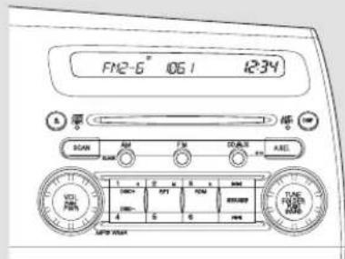
text_image
FM2-6" 1061 12:34 DCAM RUN FTR COOLATE AIRL 1 2 3 4 5 6 7 8 9 DCN SPT RPM 4 S MSP 1061 TUR PUM MSP 1061EX, EX-L and Si models
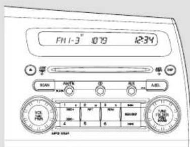
Models with navigation system U.S. EX, EX-L and Si models
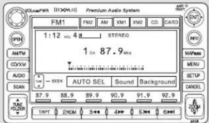
text_image
VOLUPEWR [11X0M] Premium Audio System FM1 FM2 AM XM1 XM2 CD CARD 1:12 vol. 4 L STEREO 1 CM 87.9 MHz AUTO SEL Sound Background TAPT PROM 3 >> 4 >> 5 >> 6 >>Audio System (Models without navigation system)
EX, EX-L and Si models Your audio system shows a welcome message on the display when you turn the ignition switch to the ACCESSORY (I) or the ON (II) position. You can see a message "WELCOME" on the display when your vehicle was new.
You can also customize this welcome message to your liking with the audio controls.
To Customize a Message You can setup to about 16 characters on the display.
To select a character:
-
Make sure the audio system is off.
-
then push the power/volume knob on the audio control panel. You will see the first letter blinking.
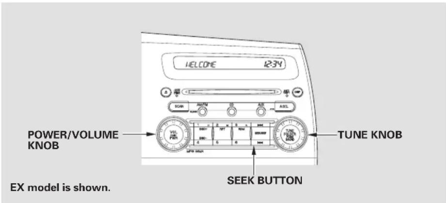
text_image
WELCOME 12:34 POWER/VOLUME KNOB EX model is shown. TUNE KNOB SEEK BUTTON- Turn the TUNE knob to change a letter.
- Push the top of the SEEK button to select the next segment, then turn the TUNE knob to select a letter. Repeat this procedure to set your message.
To change the letter, select the previous segment by pushing the bottom of the SEEK button.
The system will return to the audio display about 5 seconds after you stop selecting a letter. Push and hold th
Playing the AM/FM Radio
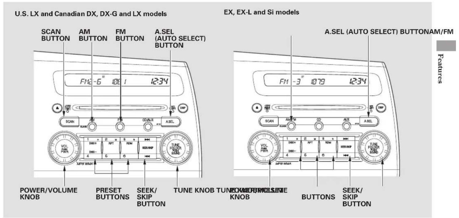
Audio System (Models without navigation system)
The ignition switch must be in the ACCESSORY (I) or ON (II) position. Turn the system on by pushing the power/volume knob or the AM or FM button (the AM/FM button on premium audio system). Adjust the volume by turning the power/volume knob.
The band and frequency that the radio was last tuned to are displayed. To change bands, press the AM or FM button (AM/FM button on premium audio system). On the FM band, ST will be displayed if the station is broadcasting in the Stereo reproduction in AM is not available.
To Select a Station
You can use any of five methods to find radio stations on the selected band: tune, seek, scan, the preset buttons, and auto select.
TUNE — Use the TUNE knob to tune the radio to a desired frequency. Turn the knob to the right to tune to a higher frequency, and turn it to the left to tune to a lower frequency.
SEEK — The seek function searches up and down from the current frequency to find a station with a strong signal. To activate it, press the on-side of the SEEK/SKIP button, then release it.
SCANTo PlayctheuAM/FMnRaklio all stations with strong signals on the selected band. To activate it, press the SCAN button, then release it. You will see SCAN in the display. The system will scan for a station with a strong signal. When it finds one, it will stop and play that station for about 10 seconds.
If you do nothing, the system will then scan for the next strong station and play it for 10 seconds. When it plays a station you want to listen to, press the SCAN button again.
Preset AUTO SELECT
(1 through 6) can store one frequency on AM, and two frequencies on FM.
- Select the desired band, AM or FM. FM1 and FM2 let you store two frequencies with each side of the preset button.
- Use the tune, seek, or scan function to tune the radio to a desired station.
- Pick a preset number (1 6), and hold it until you hear a beep.
- Repeat steps 1 through 3 to store a total of six stations on AM and twelve stations on FM.
— Backside of the button if you do not like the stations auto
traveling far from home and can no longer receive your preset stations, you can use the auto select feature to find stations in the local area.
Press the A. SEL button. You will see A. SEL flashing in the display, and the system goes into scan mode for several seconds. It stores the frequencies of six AM, and twelve FM stations in the preset buttons.
You will see a "0" displayed after pressing a preset button if auto select cannot find a strong station for every preset button.
select has stored, you can store other frequencies on the preset buttons as previously described.
To turn off auto select, press the A. SEL (auto select) button. This restores the presets you originally set.
For information on AM/FM radio frequencies and reception, see page 172.
Audio System (Models without navigation system)
Adjusting the Sound Press the TUNE (SOUND) knob repeatedly to display the BASS, TREBLE, FADER, BALANCE, SUBWOOFER (if equipped), and SVC (speed-sensitive volume compensation) settings.
BASS - Adjusts the bass.
TREBLE - Adjusts the treble.
FADE R - Adjusts the front-to-back strength of the sound.
BALANCE — Adjusts the side-to-side strength of the sound.
If equipped SUBWOOFER — Adjusts the strength of sound from the subwoofer speaker.
SVC - Adjusts the volume level based on the vehicle speed.
Each mode is shown in the dis it changes. Turn the TUNE knob to adjust the setting to your liking. When the level reaches the center, you will see "C" in the display.
The system will return to the audio display about 5 seconds after you stop adjusting a mode.
Speed-sensitive Volume Compensation (SVC) The SVC mode controls the volume based on vehicle speed. The faster you go, the louder the audio volume becomes. As you slow down, the audio volume decreases.
The SVC has four modes; SVC OFF, SVC LOW, SVC MID, and SVC HIGH. Turn the TUNE knob to adjust the setting to your liking. If you feel the sound is too loud,
choose low. If you feel the sound is too quiet, choose high.
pThis function is set to MID as the default setting when the vehicle leaves the factory.
Audio System Lighting You can use the instrument panel brightness control buttons to adjust the illumination of the audio system (see page 73). The audio system illuminates when the parking lights are on, even if the radio is off.
Playing the XM® Satellite Radio Optional on U.S. EX, EX-L and Si models
Your audio system is capable of receiving XM® Satellite Radio anywhere in the United States, except Hawaii and Alaska.
XM ^® is a registered trademark of XM Satellite Radio, Inc.
XM satellite radio receives signals from two satellites to produce clear, high-quality digital reception. It offers many channels in several categories. Along with a large selection of different types of music, XM satellite radio allows you to view channel and category selections in the display.
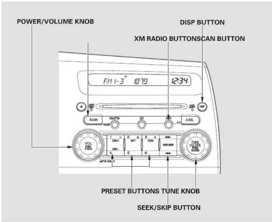
text_image
POWER/VOLUME KNOB DISP BUTTON XM RADIO BUTTONSCAN BUTTON FM 1-3 ST 1079 12:34 SCAN AM/FM CD AER A SEL VOL FWR PWR PRESET BUTTONS TUNE KNOB SEEK/SKIP BUTTON TUNE FODDER SOUND MPB WB.4Audio System (Models without navigation system)
Operating the XM Radio
To listen to XM radio, turn the ignition switch to the ACCESSORY (I) or the ON (II) position. Press the AUX button to select XM satellite radio mode. Adjust the volume by turning the knob. The last channel you listened to will show in the display.
MODE — To switch between channel mode and category mode, press and hold the DISP button until the mode changes. In channel mode, you can select all of the available channels. In category mode, such as Jazz, Rock, Classical, etc., you can select all of the channels within that category. Each time you press and release the DISP button, the display changes in the following sequence: Channel name, channel number, category, artist name, and music title.
You may experience periods when XM Radio does not transmit the artist's name and song title information. If this happens, there is nothing wrong with your system.
TUNE – Turn the TUNE knob to change channel selections. Turn the knob right for higher numbered channels and left for lower numbered channels. In the category mode, you can only select channels within that category.
SEEK/SKIP (CATEGORY) -
Press either side of the SEEK/SKIP button (or) to select another category.
SCAN - The scan function gives you a sampling of all channels while in the channel mode. In the category mode, only the channels within that category are scanned. To activate scan, press the SCAN button. The system plays each channel in numerical order for a few seconds, then selects the next channel. When you hear a channel you want to continue listening to, press the button again.
Preset - You can store up to 12 preset channels using each side of the preset button. Each side of the button stores one channel from the XM1 band and one channel from the XM2 band.
To store a channel:
-
Press the AUX button. Either XM1 or XM2 will show in the display.
-
Use the tune, seek, or scan function to tune to a desired channel.
In category mode, only channels within that category can be selected. In channel mode, all channels can be selected. - Pick a preset number you want for that channel. Press and hold the button until you hear a beep.
- Repeat steps 2 and 3 to store the first six channels.
- Press the AUX button again. Store the next six channels using steps 2 and 3.
Once a channel is stored, press and release the proper side of the preset button to tune to it.
XM Radio Display Messages
"LOADING" – XM is loading the audio or program information.
"OFF AIR" – The channel currently selected is no longer broadcasting.
"UPDATING" – The encryption code is being updated. Wait until the encryption code is fully updated. Channels 0 and 1 should still work normally.
“NO SIGNAL” – The signal is currently too weak. Move the vehicle to an area away from tall buildings, and with an unobstructed view of the southern horizon.
CONTINUED
Audio System (Models without navigation system)
“----”— The selected channel number does not exist, or is not part of your subscription, or this channel has no artist or title information at this time.
"ANTENNA" — There is a problem with the XM antenna. Please consult your dealer.
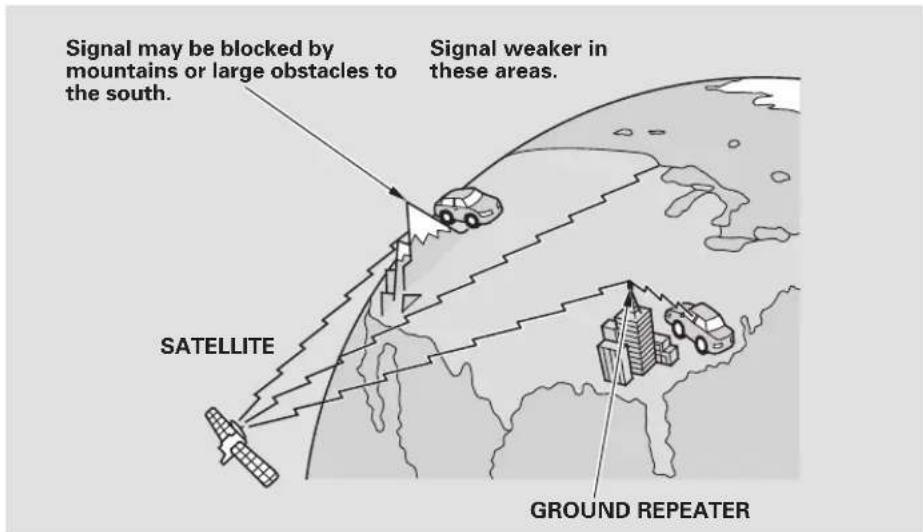
text_image
Signal may be blocked by mountains or large obstacles to the south. Signal weaker in these areas. SATELLITE GROUND REPEATERThe XM satellites are in orbit over the equator; therefore, objects south of the vehicle may cause satellite reception interruptions. To help compensate for this, ground-based repeaters are placed in major metropolitan areas.
Satellite signals are more likely to be blocked by tall buildings and mountains the farther north you travel from the equator. Carrying large items on a roof rack can also block the signal.
Depending on where you drive, you may experience reception problems. Interference can be caused by any of these conditions:
- Driving on the north side of an east/west mountain road.
- Driving on the north side of a large commercial truck on an east/west road.
- Driving in tunnels.
- Driving on a road beside a vertical wall, steep cliff, or hill to the south of you.
- Driving on the lower level of a multi-tiered road.
- Driving on a single lane road alongside dense trees taller than 50 ft. (15 m) to the south of you.
• Large items carried on a roof rack.
There may be other geographic situations that could affect XM radio reception.
As required by the FCC: Changes or modifications not expressly approved by the party responsible for compliance could void the user's authority to operate the equipment.
Receiving Satellite Radio Service If your XM Radio service has expired or you purchased your vehicle from a previous owner, you can listen to a sampling of the broadcasts available on XM Satellite Radio. With the ignition switch in the ACCESSORY (I) or ON (II) position, push the power/volume knob to turn on the audio system and press the AUX button. A variety of music types and styles will play.
If you decide to purchase XM satellite radio service, contact XM Radio at www.atmradio.com 1-800-852-9696. You will need to give them your radio I.D. number and your credit card number. To get your radio I.D. number, turn the TUNE
knob until "0" appears in the display. Your I.D. will appear in the display.
After you've registered with XM Radio, keep your audio system in the satellite radio mode while you wait for activation. This should take about 30 minutes.
While waiting for activation, make sure your vehicle remains in an open area with good reception. Once your audio system is activated, you'll be able to listen to XM radio broadcasts. XM Radio will continue to send an activation signal to your vehicle for at least 12 hours from the activation request. If the service has not been activated after 36 hours, contact XM Radio.
Playing a Disc
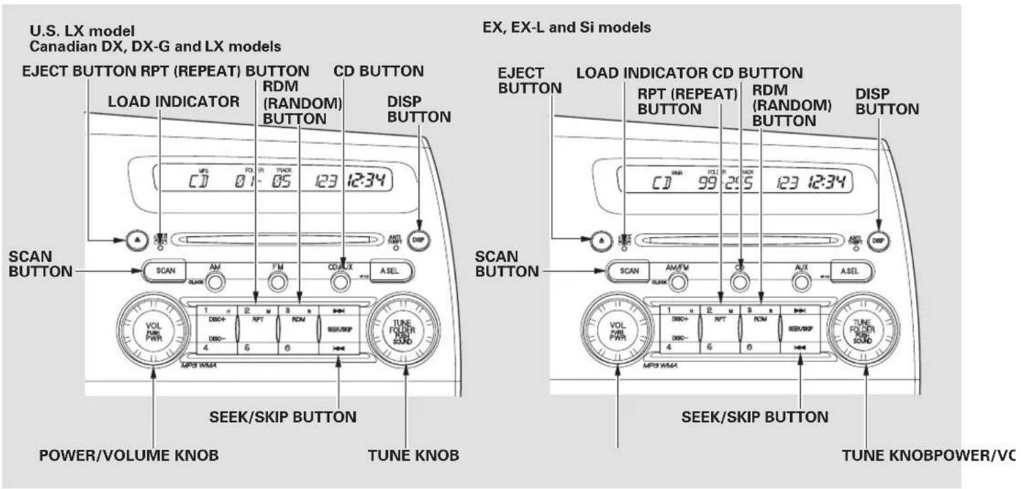
To Play a Disc
To load or play discs, the ignition switch must be in the ACCESSORY (I) or ON (II) position.
You operate the disc player with the same controls used for the radio. To select the disc player, press the CD/AUX button (the CD button on premium audio system). You will see "CD" in the display.
NOTICE
Do not use discs with adhesive labels. The label can curl up and cause the disc to jam in the unit.
This audio system can also play CD-Rs and CD-RWs compressed in MP3 or WMA formats. When playing a disc in MP3, you will see “MP3” in the display. In WMA format, “WMA” will appear in the display. You can select up to 255 folders or tracks.
NOTE:
If a file on an MP3 or WMA disc is protected by digital rights management (DRM), the audio unit displays FORMAT, and then skips to the next file.
Video CDs and DVD discs do not work in this unit.
The specifications of the compatible MP3 file are:
—Sampling frequency:
32/44.1/48 kHz (MPEG1)
24/22.05/16 kHz (MPEG2)
—Bit rate:
32/40/48/56/64/80/96/112/128/
160/192/224/256/320 kbps
(MPEG1)
8/16/24/32/40/48/56/64/80/96/
112/128/160 kbps (MPEG2)
—Compatible with variable bit rate and multi-session
—Maximum layers (including ROOT): 8 layers
The specifications of the compatible WMA file are:
—Sampling frequency: 22.05/32/44.1/48 kHz
—Bit rate:
48/64/80/96/128/160/192 kbps
- Compatible with variable bit rate and multi-session
- Maximum layers (including ROOT): 8 layers
To Load a Disc
Insert a disc about halfway into the disc slot. The drive will pull the disc in therestofthewaytoplayit. You operate the disc player with the same controls used for the radio. The number of the current track and the elapsed time are shown in the display. When playing a disc in MP3 or WMA, the numbers of the current folder and file, and the elapsed time are shown. The system will continuously play a disc until you change modes.
CONTINUED
Audio System (Models without navigation system)
You cannot load and play 3-inch (8-cm) discsin this system.
Text Data Display Function
Each time you press the DISP button, the display shows you the text data on a disc, if the disc was recorded with text data.
You can see the album, artist, and track name in the display. If a disc is recorded in MP3 or WMA, you can see the folder and file name, and the album, artist, and track tag.
With the folder name, you will see the FOLDER indicator in the display. The TRACK indicator is shown with the file or track name.
The display shows up to about 16 characters of selected text data (the folder name, filename, etc.) text data has more than 16 characters, you will see the first 15 characters and the indicator in
the display. Press and hold the DISP button until the next 16 characters are shown.
You will also see some text data under these conditions:
- When a new folder, file, or track is selected.
- When you change the audio mode to play a disc with text data or in MP3 or WMA.
- When you insert a disc, and the system begins to play.
When playing a CD-DA with text data, the album and track name are shown in the display. With a MP3 or WMA, the display shows the folder and file name. If the
To Change or Select Tracks/Files Use the SEEK/SKIP button while a disc is playing to select passages and change tracks (files in MP3/WMA mode).
SEEK/SKIP — Each time you press and release the ▶▶| side of the SEEK/SKIP button, the player skips forward to the beginning of the next track (file in MP3 or WMA mode). Press and release the ◀◀ side to skip backward to the beginning of the current track. Press itagaintoskiptothebeginning of the previous track.
To move rapidly within a track, press and hold the on-side of the iSEEK/SKIP button.
In MP3 or WMA mode
FOLDER SELECTION- To
select a different folder, turn the TUNE knob to move to the beginning of the next folder. Turn the knob to the right until it clicks once to skip to the next folder, and to the left to move to the beginning of the previous folder. Turning the TUNE knob more than two clicks skips several folders.
REPEAT (TRACK/FILE
REPEAT) – To continuously replay a track (files in MP3 or WMA mode), press and release the RPT button. You will see RPT in the display. Press and hold the RPT button for 2 seconds to turn it off.
In MP3 or WMA mode
FOLDER-REPEAT - This feature, when activated, replays all files on the selected folder in the order they are compressed. To activate folder repeat, press the RPT button twice. You will hear a beep and see F-RPT in the display. The system continuously replays the current folder. Press the RPT button again to turn it off. Pressing the RDM button, or selecting a different folder with the TUNE knob also turns off the repeat feature.
Each time you press and release the RPT button, the mode changes from file repeat to folder repeat, then to normal playing.
RANDOM (Random within a disc/folder) — This feature plays the tracks within a disc (the files within a folder in MP3 or WMA mode) in random order. To activate random play, press and release the RDM button. In MP3 or WMA mode, press the RDM button repeatedly to select RDM (within a folder random play). You will see RDM in the display. Press the RDM button for 2 seconds to return to normal play.
In MP3 or WMA mode
FOLDER-RANDOM—This
feature, when activated, plays all files in each folder in random order. To activate folder random, press the RDM button 2 times. You will hear a beep and see F-RDM in the display. The system will then select and play files randomly. This continues until you deactivate folder random by pressing the RDM button again, or by selecting a different folder with the TUNE knob.
Each time you press and release the RDM button, the mode changes from folder random play to random play (within a folder random play), then to normal playing.
CONTINUED
Audio System (Models without navigation system)
The scan function samples all tracks (files in MP3 or WMA) on the disc in the order they are recorded on the disc. To activate scan, press the SCAN button. In MP3 or WMA mode, press the SCAN button repeatedly to select SCAN. You will see SCAN in the display. You will get a 10 second sampling of each file on the disc. Press the SCAN button again to get out of scan mode and play the last track/file sampled.
Pressing either side of the SEEK/SKIP button also turns off the scan feature.
In MP3 or WMA mode F-SCAN (FOLDER SCAN)—This feature, when activated, samples the first file of each folder on the disc. To activate folder scan, press the SCAN button twice. You will see F-SCAN in the display.
The system plays the first file in the first folder for about 10 seconds. If you do nothing, the system will then play the first files in the remaining folders for 10 seconds each. After playing the first file of the last folder, the system plays normally.
Pressing either side of the SEEK/SKIP button, selecting a different folder with the TUNE knob, or pressing the SCAN button, also turns off the folder scan.
Each time you press and release the SCAN button, the mode changes from folder scan to scan, then to normal playing.
To Stop Playing a DiscSCAN (TRACK/F Press the eject button ( ▲ ) to remove the disc. If you eject the disc, but do not remove it from the slot, the system will automatically reload it after 10 seconds and put it in pause mode. To begin playing, press the CD button.
You can also eject the disc when the ignition switch is off.
To play the radio when a disc is playing, press the AM or FM button (the AM/FM button or XM button on models that are XM radio capable). Press the CD button again to switch back to the disc player.
If you turn the system off while a disc is playing, either with the power/volume knob or by turning off the ignition switch, the disc will stay in the drive. When you turn the system back on, the disc will begin playing where it left off.
Operating the Optional Disc Changer
An optional six or eight disc changer is available for your vehicle. This disc changer uses the same controls used for the in-dash disc player or the radio.
Load the desired discs in the magazine, and load the magazine in the changer according to the instructions that came with the unit.
To select the disc changer, press the CD button. The disc and track numbers will be displayed. To select a different disc, use the preset 4 (DISC) or the preset 1 (DISC) + on the preset button. To select the previous disc, press the preset 4 (DISC -), or the preset 1 (DISC +) to select the next disc in sequence.
If you select an empty slot in the magazine, the changer will search for the next available disc to load and play.
Protecting Discs
For information on how to handle and protect compact discs, see page .174
Audio System (Models without navigation system)
Disc Player Error Messages
The chart on the right explain error messages you may see in the display while playing a disc.
If you see an error message in the display while playing a disc, press the eject button. After ejecting the disc, check it for damage or deformation. If there is no damage, insert the disc again. For the additional information on damaged discs, see page .175
If there is still a problem, the error message will appear again. Press the eject button, and pull out the disc.
Insert a different disc. If the new disc plays, there is a problem with the first disc. If the error message cycle repeats and you cannot clear it, take your vehicle to a dealer.
| s t ErrorMessage | SolutionCause | |
| UNSUPPORTFORMAT | Track/File format not supported | Current track will skipped. The next supported track or file plays automatically. |
| BAD DISCPLEASE CHECKOWNERSMANUALPUSH EJECT | Mechanical Error | Press the cjcct button and pull out the disc(s).Check the disc for serious damage, signs of deformation, excessive scratches, and/or dirt (see page 175). Insert the disc again. If the code does not disappear, or the disc(s) cannot be removed, consult your dealer. Do not try to force the disc out of the player. |
| BAD DISCPLEASE CHECKOWNERSMANUAL | TOC ErrorFOCUS Error |
The ejected disc will not be reloaded automatically.
Audio System (Models without navigation system)
Optional Disc Changer Error Messages
The chart on the right explain error messages you may see in the display while playing a disc.
If you see an error message in the display while playing a disc, press the eject button. After ejecting the disc, check it for damage or deformation. If there is no damage, insert the disc again.
For the additional information on damaged discs, see page .175
If there is still a problem, the error message will appear again. Press the eject button, and pull out the disc.
Insert a different disc. If the new disc plays, there is a problem with the first disc. If the error message cycle repeats and you cannot clear it, take your vehicle to a dealer.
| Error s t Message | SolutionCause | |
| CIC DISC ERROR | FOCUS Error | Press the magazine eject button, and pull the magazine out. If the message does not disappear or the magazine cannot be pulled out, see your dealer. |
| CIC NO DISC | No disc in the disc magazine | Insert disc. |
| CIC MECH ERROR | Mechanical Error | Press the magazine eject button, pull the magazine out, check for an error message, then insert the magazine again. If the message does not disappear, or the magazine cannot be pulled out, see your dealer. |
| CIC EJECT | No disc magazine in the disc changer | Insert disc magazine. |
| CIC HEAT ERROR | High Temperature | Will disappear when the temperature returns to normal. |
Audio System (Models with navigation system)
Voice Control System Playing the AM/FM Radio
In addition to the standard audio controls, the audio system in your vehicle can be operated using the voice control system. See the navigation section in your Quick Start Guide for an overview of this system, and the Navigation System Manual for complete details.
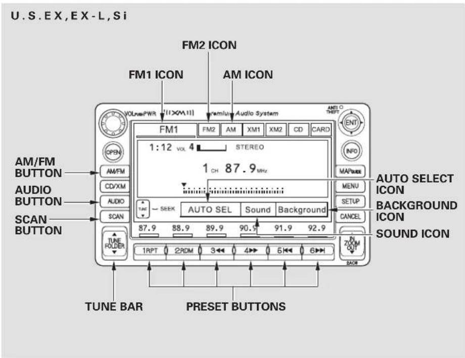
text_image
U.S. EX,EX-L,Si FM2 ICON FM1 ICON AM ICON VOLUME PWR [1XMM] premium Audio System 1:12 VOL 4 STEREO 1 CH 87.9 MHz AM/FM BUTTON AM/FM CD/XM AUDIO AUDIO SCAN SCAN BUTTON AUTO SELECT ICON AUDIO BUTTON AUDIO BUTTON AUDIO RESET AUTO SEL Sound Background AUTO SELECT ICON BACKGROUND ICON SOUND ICON TUNE FOLDER 1RPT 2ROM 3 4 5 6 2ACR TUNE BAR PRESET BUTTONSTo Play the AM/FM Radio To Select The ignition switch must be in the ACCESSORY (I) or ON (II) position. Turn the system on by pushing the power/volume knob or the AM/FM button. Adjust the volume by turning the power/volume knob.
Pushing the AUDIO button will also turn on the system.
You can also operate the audio system without using the control icons on the audio screen. Use the control buttons on the left side of the screen. The status bar appears on the bottom of the screen each time you operate any of the control buttons. On the navigation screen, you can also see audio information by touching the AUDIO INFO icon on the lower of the screen.
a Stationl and frequency that the radio was last tuned to are displayed. To change bands, press the AM/FM button, or touch the desired band icon (FM1, FM2, AM, XM1, or XM2). On the FM band, STEREO will be displayed if the station is broadcasting in stereo. Stereo reproduction on AM is not available.
For information on XM radio, see page 142
You can use any of five methods to find radio stations on the selected band: tune, seek, scan, the preset buttons, and auto select.
TUNE – Use the TUNE bar to tune the radio to a desired frequency. Press the side of the bar to tune to a higher frequency, and press the ▼ side to tune to a lower frequency.
Press and hold the ⬆ side of the TUNE bar until you hear two beeps to change the frequency rapidly. Release the bar when the display reaches the desired frequency.
CONTINUED
Audio System (Models with navigation system)
SEEK — The seek function searches up and down from the current frequency to find a station with a strong signal. To activate it, press and hold the ▲ or ▼ side of the TUNE bar until you hear a beep, then release it.
SCAN — The scan function samples all stations with strong signals on the selected band. To activate it, press the SCAN button, then release it. You will see SCAN in the display. The system will scan for a station with a strong signal. When it finds one, it will stop and play that station for about 10 seconds.
If you do nothing, the system will then scan for the next strong station and play it for 10 seconds. Wh plays a station you want to listen to, press the SCAN button again.
Preset - Each preset button can store one frequency on AM and two frequencies on FM.
- Select the desired band, AM or FM. FM1 and FM2 let you store two frequencies with each preset button.
- Use the tune, seek, or scan function to tune the radio to a desired station.
- Pick a preset button, and hold it until you hear a beep.
- Repeat steps 1 through 3 to store a total of six stations on AM and twelve stations on FM.
Each preset button's frequency is shown on the bottom of the audio display.
AUTO SELECT— If you are traveling far from home and can no longer receive your preset stations, you can use the auto select feature to find stations in the local area.
Press the AUDIO button to view the audio control icons, then press the AUTO SEL icon. You will see AUTO SEL flashing in the display, and the system goes into scan mode for several seconds. It stores the frequencies of six AM, and twelve FM stations in the preset buttons.
You will see a "0" displayed after pressing a preset button if auto select cannot find a strong station for every preset button.
If you do not like the stations auto select has stored, you can store other frequencies on the preset buttons as previously described.
To turn off auto select, press the AUTO SEL icon. This restores the presets you originally set.
For information on AM/FM radio frequencies and reception, see page .172
Main Menu
Table Of Contents
Audio System (Models with navigation system)
Playing the XM®Satellite Radio
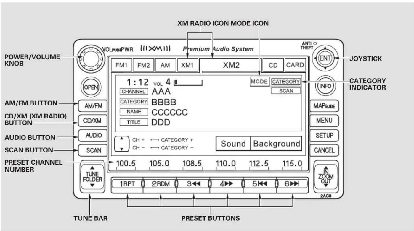
text_image
XM RADIO ICON MODE ICON POWER/VOLUME KNOB AM/FM BUTTON CD/XM (XM RADIO) BUTTON AUDIO BUTTON SCAN BUTTON PRESET CHANNEL NUMBER TUNE FOLDER TUNE BAR PRESET BUTTONS VOLPushPWR (11XM11) Premium Audio System FM1 FM2 AM XM1 XM2 1:12 VOL 4 III CHANNEL AAA CATEGORY BBBBB NAME CCCCCC TITLE DDD MODE CATEGORY SCAN CH + - CATEGORY + CH - - CATEGORY - Sound Background 100.5 105.0 108.5 110.0 112.5 115.0 1RPT 2RDM 3 4 5 6 2AC8 ANTIO THEFT ENT JOYSTICK INFO CATEGORY INDICATOR MAPGUIDE MENU SETUP CANCEL N ZOOM OUTYour audio system is capable of receiving XM® Satellite Radio anywhere in the United States, except Hawaii and Alaska.
XM ^® is a registered trademark of XM Satellite Radio, Inc.
XM radio receives signals from two satellites to produce clear, high-quality digital reception. It offers many channels in several categories. Along with a large selection of different types of music, XM radio allows you to view channel and category selections in the display. When you press and hold the AUDIO button, the display also shows all XM information.
Operating the XM Radio MODE To listen to XM radio, turn the ignition switch to the ACCESSORY (I) or the ON (II) position. Press the CD/XM button to select XM satellite radio. Adjust the volume by turning the knob. The last channel you listened to will show in the display.
You can also change to the XM radio while you are listening to an FM station, AM station, disc, pc card, etc., by touching the XM1 or XM2 icon on the audio display.
You can also operate the radio using the control buttons on the left side of the screen. The status bar appears on the bottom of the screen each time you press any of the control buttons. On the navigation screen, you can also see the audio information by touching the AUDIO INFO icon on the lower of the screen.
- To switch between channel mode and category mode, touch the MODE icon. In channel mode, you can select all of the available channels. In category mode, such as Jazz, Rock, Classical, etc., you can select all of the channels within that category. Each time you touch and release the MODE icon, the display changes between the channel mode and the category mode.
CONTINUED
Audio System (Models with navigation system)
text_image
FM1 FM2 AM XM1 XM2 CD CARD 1:12 VOL 4 MODE CATEGORY CHANNEL AAA CATEGORY BBBBB NAME CCCCCC TITLE DDD CH + - CATEGORY + CH - - CATEGORY - Sound Background 100.5 105.0 108.6 110.0 112.6 115.0On the audio display, you will see the selected CHANNEL (number), CATEGORY, NAME (artist name), and TITLE (music title).
You may experience periods when XM Radio does not transmit the artist's name and song title information. If this happens, there is nothing wrong with your system.
— Press the TUNE bar to change channel selections. Press
▲ for higher numbered channels and for lower numbered channels. In the category mode, you can only select channels within that category.
CATEGORY — Press and hold either side of the TUNE bar (or) until you hear a beep to select another category.
SCAN – The scan function gives you a sampling of all channels while in the channel mode. In the category mode, only the channels within that category are scanned. To activate scan, press the SCAN button or touch the SCAN icon on the screen. The system plays each channel in numerical order for a few seconds, then selects the next channel. When you hear a channel you want to listen to, press the button or touch the icon again.
PresetTUNEuc an store upto 12 preset channels using each preset button or preset icons on the screen. Each preset button or icon stores one channel from the XM1 band and one channel from the XM2 band.
To store a channel:
-
Press the XM button. Either XM1 or XM2 will show in the display.
-
Use the tune, seek, or scan function to tune to a desired channel.
In category mode, only channels within that category can be selected. In channel mode, all channels can be selected.
-
Pick the preset button (icon) you want for that channel. Press and hold the button (icon) until you hear a beep.
-
Repeat steps 2 and 3 to store the first six channels.
- Press the XM button again or touch the other XM icon (XM1 or XM2) on the audio display. Store the next six channels using steps 2 and 3.
Once a channel is stored, press and release the proper preset button (icon) to tune to it. Each preset button's channel is shown on the bottom of the audio display.
"LOADING" - XM is loading the audio or program information.
"OFF AIR" – The channel currently selected is no longer broadcasting.
“UPDATING” – The encryption code is being updated. Wait until the encryption code is fully updated. Channels 0 and 1 should still work normally.
"NO SIGNAL" XMLRadignDisplay Messa currently too weak. Move the vehicle to an area away from tall buildings, and with an unobstructed view of the southern horizon.
“----”— The selected channel number does not exist or is not part of your subscription.
"NO INFO" – This channel has no artist or title information at this time.
“ANTENNA” — There is a problem with the XM antenna. Please consult your dealer.
CONTINUED
Main Menu
Table Of Contents
Audio System (Models with navigation system)
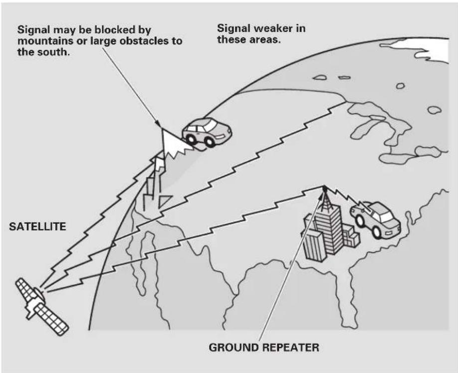
text_image
Signal may be blocked by mountains or large obstacles to the south. Signal weaker in these areas. SATELLITE GROUND REPEATERThe XM satellites are in orbit over the equator; therefore, objects south of the vehicle may cause satellite reception interruptions. To help compensate for this, ground-based repeaters are placed in major metropolitan areas.
Satellite signals are more likely to be blocked by tall buildings and mountains the farther north you travel from the equator. Carrying large items on a roof rack can also block the signal.
Depending on where you drive, you may experience reception problems. Interference can be caused by any of these conditions:
- Driving on the north side of an east/west mountain road.
- Driving on the north side of a large commercial truck on an east/west road.
- Driving in tunnels.
- Driving on a road beside a vertical wall, steep cliff, or hill to the south of you.
- Driving on the lower level of a multi-tiered road.
- Driving on a single lane road alongside dense trees taller than 50 ft. (15 m) to the south of you.
• Large items carried on a roof rack.
There may be other geographic situations that could affect XM radio reception.
As required by the FCC: Changes or modifications not expressly approved by the party responsible for compliance could void the user's authority to operate the equipment.
Receiving Satellite Radio Service If your XM Radio service has expired or you purchased your vehicle from a previous owner, you can listen to a sampling of the broadcasts available on XM Satellite Radio. With the ignition switch in the ACCESSORY (I) or ON (II) position, push the power/volume knob to turn on the audio system and press the CD/XM button. A variety of music types and styles will play.
If you decide to purchase XM Satellite Radio service, contact XM Radio at www.atmradio.com 1-800-852-9696. You will need to give them your radio I.D. number and your credit card number. To get your radio I.D. number, press the TUNE
bar until "0" appears in the display. Your I.D. will appear in the display.
After you've registered with XM Radio, keep your audio system in the satellite radio mode while you wait for activation. This should take about 30 minutes.
While waiting for activation, make sure your vehicle remains in an open area with good reception. Once your audio system is activated, you'll be able to listen to XM radio broadcasts. XM Radio will continue to send an activation signal to your vehicle for at least 12 hours from the activation request. If the service has not been activated after 36 hours, contact XM Radio.
Audio System (Models with navigation system)
Adjusting the Sound
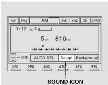
text_image
FM1 FM2 AM XM1 XM2 CD CARD 1:12 VOL 4 5 CH 810 kHz SOUND ICONYou can adjust the sound on the navigation screen. To adjust the sound, push the AUDIO button, then enter the sound grid by touching the SOUND icon on the display.
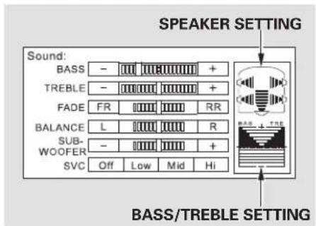
text_image
SPEAKER SETTING Sound: BASS - + TREBLE - + FADE FR RR BALANCE L R SUB- WOOFER - + SVC Off Low Mid Hi BASS/TREBLE SETTINGBASS – Adjusts the bass. TREBLE – Adjusts the treble. To adjust the treble and bass, touch + or on each side of the treble or bass adjustment bar. The adjustment bar on the right lower display shows you the current setting.
FADER – Adjusts the front-to-back strength of the sound. To adjust the front/rear fader, touch the FR or icon.
BALANCE — Adjusts the side-to-side strength of the sound. To adjust the left/right balance, touch the L or R icon.
SUBWOOFER — Adjusts the strength of sound from the subwoofer speaker. To adjust the sound strength, touch or □ on each side of the adjustment bar.
The right upper display shows you the current setting of the sound strength coming from each speaker.
SVC (speed-sensitive volume compensation) – The SVC mode controls the volume based on vehicle speed. The faster you go, the louder the audio volume becomes. As you slow down, the audio volume decreases. Touch the appropriate icon (Low, Mid, Hi, Off) to select the Rmode.
This function is set to MID as the default setting when the vehicle leaves the factory. If you feel the sound is too loud, choose low. If you feel the sound is too quiet, choose Hi.
You can also select the icon with the joystick. Move it up and down to move the highlighting and scroll through lists. Select the icon, then move the joystick to left or right to change the setting.
The system will return to the audio display about 5 seconds after you stop adjusting a mode.
Screen Mode
You can select the background screen to display the sound level. There are three screen modes: level (the sound level is shown with the vertical bars), spectrum analysis (the sound level appears as ripples of water), and off. Each time you touch the background icon, the display changes.
Audio System Lighting
You can use the instrument panel brightness control buttons to adjust the illumination of the audio system (see page 73). The audio system illuminates when the parking lights are on, even if the radio is off.
Main Menu
Table Of Contents
Audio System (Models with navigation system)
Playing a Disc
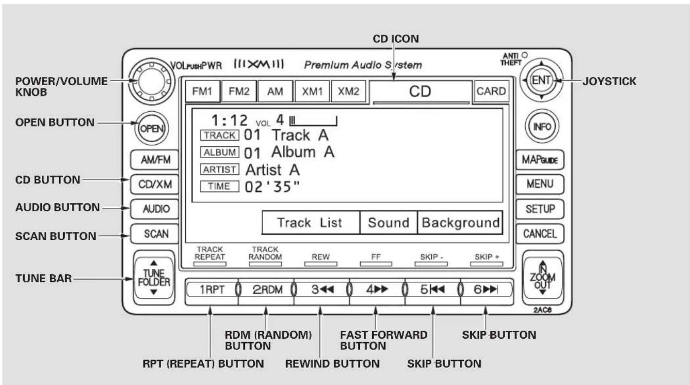
text_image
CD ICON VOLPushPWR [11XM11] Premium Audio System POWER/VOLUME KNOB OPEN BUTTON AM/FM CD/XM AUDIO BUTTON AUDIO SCAN BUTTON SCAN TUNE FOLDER TUNE BAR RPT (REPEAT) BUTTON RDM (RANDOM) BUTTON REWIND BUTTON FAST FORWARD BUTTON SKIP BUTTON SKIP BUTTON 1:12 VOL 4 III TRACK 01 Track A ALBUM 01 Album A ARTIST Artist A TIME 02 '35" Track List Sound Background TRACK REPEAT TRACK RANDOM REW FF SKIP - SKIP + 1RPT 2RDM 3 4 5 6 2AC8 MOA GUIDE MENU SETUP CANCEL ZOOM OUT JOYSTICK INFO MAPGUE 2AC8To Play a Disc
You operate the disc player with the same controls used for the radio. To load or play discs, the ignition switch must be in the ACCESSORY (I) or ON (II) position.
NOTICE
Do not use discs with adhesive labels. The label can curl up and cause the disc to jam in the unit.
This audio system can also play CD-Rs and CD-RW s c o m p r e s s e d or WMA formats. When playing a disc in MP3, you will see “MP3” on the screen. In WMA format, “WMA” will appear on the screen. You can select up to 99 folders and play up to 999 tracks. If the disc has a complex structure, it takes a while to read the disc before the system begins to play it.
Video CDs and DVD discs do not work in this unit.
The specifications for compatible MP3 files are:
—Sampling frequency:
32/44.1/48 kHz (MPEG1)
24/22.05/16 kHz (MPEG2)
—Bit rate:
32/40/48/56/64/80/96/112/128/
160/192/224/256/320 kbps
(MPEG1)
8/16/24/32/40/48/56/64/80/96/
112/128/160 kbps (MPEG2)
n-MC compatible with variable bit rate and multi-session
—Maximum layers (including ROOT): 8 layers
The specifications for compatible WMA files are:
—Sampling frequency: 22.05/32/44.1/48 kHz
—Bit rate:
32/40/48/64/80/96/128/160/
192 kbps
- Compatible with variable bit rate and multi-session
—Maximum layers (including ROOT): 8 layers
NOTE: If a file on an MP3 or WMA disc is protected by digital rights management (DRM), the audio unit displays CD FORMAT, and then skips to the next file.
CONTINUED
Main Menu
Table Of Contents
Audio System (Models with navigation system)
To Load a Disc
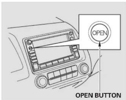
text_image
OPEN OPEN BUTTONThe disc player is behind the navigation screen. To use the disc player, press the OPEN button beside the screen. The screen folds back, and the disc player appears.
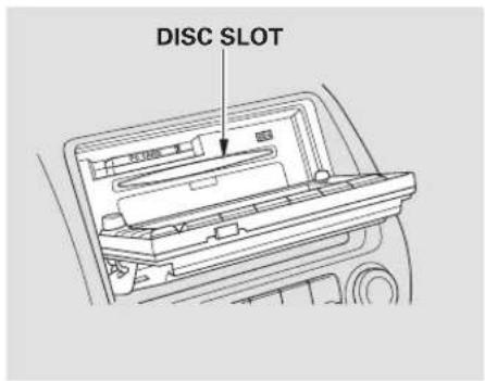
text_image
DISC SLOTInsert a disc about halfway into the disc slot. The drive will pull the disc in the rest of the way and begin to play it.
You cannot load and play 3-inch (8-cm) discsinthissystem.
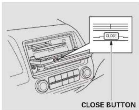
text_image
CLOSE BUTTONTo return the screen to the upright position, press the CLOSE button on the edge of the screen panel. Do not use the folded screen as a tray. If you put a cup, for example, on the screen, the liquid inside the cup may spill on the screen when you go over a bump.
Push the AUDIO button beside the screen to show the audio display and operate the disc player.
You can also operate the audio system without using the control icons on the audio screen. Press the CD button. The status bar appears on the bottom of the screen. On the navigation screen, you can see the audio information whenever you touch the AUDIO INFO icon on the lower portion of the screen.
When playing a CD recorded with text data, the track, album, and artist name are shown on the audio display. When playing a disc in MP3 or WMA, the folder number and name, the file number and name, the artist name, and the elapsed time are shown. The system will continuously play a disc until you change modes. If the disc was not recorded with text data, it will not be displayed.
To Change or Select Tracks/Files
PRESET BUTTON'S FUNCTION
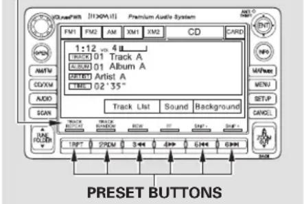
text_image
1:12 - 4 L TRACK 01 Track A E S E D 01 Album A D E T E Artist A L E C 02°35" Track List Sound Background LINE FOLD TRACK BEET TRACK BEET BEET STP SHP PRESET BUTTONSYou can use the preset buttons while a disc is playing to select passages and change tracks (files in MP3 or WMA mode). Each preset button's function is shown on the bottom of the screen.
You can also select an icon with the joystick. Move it to left, right, up, or down to change the highlighting and scroll through lists. Then press the ENT on the top of the joystick to select the icon.
SKIP — Each time you press and release (preset 6), the player skips forward to the beginning of the next track (file in MP3 or WMA mode). Press and release
◀◀ (preset 5), to skip backward to the beginning of the current track. Press it again to skip to the beginning of the previous track.
FF/REW - To move rapidly within a track/file, press and hold ▶ (preset 4) or (preset 3).
CONTINUED
Audio System (Models with navigation system)
In MP3 or WMA mode
FOLDER SELECTION - To
select a different folder, press either side of the TUNE bar to move to the beginning of the next folder. Press the ▶de of the TUNE bar to skip to the next folder, and the ▼side to move to the beginning of the previous folder.
TRACK REPEAT (FILE
REPEAT) — To continuously replay a track (file in MP3 or WMA mode), press and release the RPT button (preset 1). You will see TRACK REPEAT in the display. Press and hold the RPT button for 2 seconds to turn it off.
In MP3 or WMA mode
FOLDER REPEAT— This feature, when activated, replays all files on the selected folder in the order they are compressed. To activate folder repeat, press and hold the RPT button (preset 1). You will see FOLDER REPEAT in the display. The system continuously replays the current folder. Press the RPT button again to turn it off. Pressing the RDM button or selecting a different folder with the TUNE bar also turns off folder repeat.
TRACK RANDOM (Random within a disc/folder) - This feature playst hetrackswit (the files within a folder) in random order. To activate track random, press and release the RDM button (preset 2). You will see TRACK RANDOM in the display. Press and hold the RDM button for 2 seconds to return to normal play.
In MP3 or WMA mode
FOLDER RANDOM - This feature, when activated, plays all files in each folder in random order, rather than in the order they are compressed. To activate folder random, press the RDM button (preset 2) twice. You will see FOLDER RANDOM in the display. The system then selects and plays files randomly. This continues until you deactivate folder random by pressing the RDM button again, or if you select a different folder with the TUNE bar.
inadisc
SCAN (TRACK/FILE SCAN) — The scan function samples all tracks (files in MP3 or WMA) in the order they were recorded. To activate scan, press and release the SCAN button. You will see TRACK SCAN in the display. You will get a 10 second sampling of each track/file on the disc. Press and hold the SCAN button for 2 seconds to get out of scan mode and play the last track/file sampled.
Pressing either SKIP button (preset 5 or 6) also turns off scan.
In MP3 or WMA mode FOLDER SCAN— This feature, when activated, samples all the first files in each folder on the disc in order. To activate folder scan, press and hold the SCAN button. You will see FOLDER SCAN in the display.
The system plays the first file in each folder for about 10 seconds. If you do nothing, the system then plays the first file in each folder for 10 seconds each. After playing the first file of the last folder, the system goes to normal playing.
Pressing either SKIP button (preset 5 or 6), or selecting a different folder with the TUNE bar, or pressing the SCAN button, also turns off folder scan.
Using a Track List
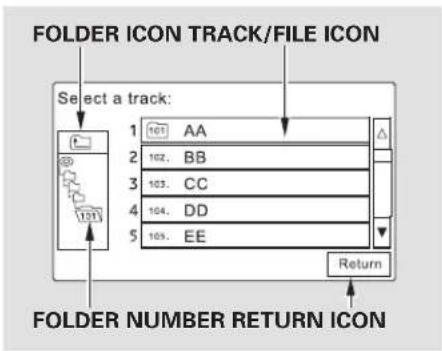
flowchart
graph TD
    A["Select a track:"] --> B["1 101 AA"]
    A --> C["2 102 BB"]
    A --> D["3 103 CC"]
    A --> E["4 104 DD"]
    A --> F["5 105 EE"]
    G["FOLDER NUMBER RETURN ICON"] --> H["Return"]
You can also select a track/file directly from a track list on the audio display. Press the AUDIO button to show the audio display, then touch the Track List icon. The track list menu appears on the display.
CONTINUED
Audio System (Models with navigation system)
When playing a CD recorded with text data, each track name is shown on the audio display. With a disc recorded in MP3 or WMA, the folder number and the location are also displayed.
If the disc was not recorded with text data, only the track number is shown.
To scroll through the display, touch the ▲ or ▼ icon on the side of the screen. Togobacktotheprev display, touch the Return icon on the screen.
Select the desired track/file by touching the icon on the display. The selected icon will be highlighted in blue. The system begins to play the selected track/file. With a disc in MP3 or WMA, touch the folder icon on the upper left of the screen to move to the parent folder. The current folder is highlighted in blue.
To Stop Playing a Disc
To play the radio when a disc is playing, press the AM/FM button or touch the FM1, FM2, AM, XM1, or XM2 icon. If a PC card is in the audio unit, touch the CARD icon to play the PC card. Press the CD button again or touch the CD icon to switch back to the disc player.
If you turn the system off while a disc is playing, either with the power/volume knob or by turning off the ignition switch, the disc will stay in the drive. When you turn the system back on, the disc will begin playing where it left off.
Removing a Disc
To remove a disc from the audio unit, fold back the screen by pressing the OPEN button (see page 152). Press the disc eject button ( ) to remove the disc. If you eject the disc, but do not remove it from the slot, the system will automatically reload it after 10 seconds and put it in pause mode. To begin playing, press the CD button.
To return the screen to the upright position, press the CLOSE button.
You cannot close the screen if a disc is partially inserted into its slot.
You can also eject the disc when the ignition switch is off.
Operating the Optional Disc Changer
An optional six or eight disc changer is available for your vehicle. This disc changer uses the same controls used for the in-dash disc player or the radio.
Load the desired discs in the magazine, and load the magazine in the changer according to the instructions that came with the unit.
To select the disc changer, press the CD/AUX button. The disc and track numbers will be displayed. To select a different disc, use either side of the TUNE bar. To select the previous disc, press the ▲ side. To select the next disc, press the side.
If you select an empty slot in the magazine, the changer will search for the next available disc to load and play.
Protecting Discs
For information on how to handle and protect discs, see page 174.
Audio System (Models with navigation system)
Disc Player Error Messages
The chart on the right explain error messages you may see in the display while playing a disc.
If you see an error message in the display while playing a disc, press the eject button. After ejecting the disc, check it for damage or deformation. If there is no damage, insert the disc again. For the additional information on damaged discs, see page .175
If there is still a problem, the error message will appear again. Press the eject button, and pull out the disc.
Insert a different disc. If the new disc plays, there is a problem with the first disc. If the error message cycle repeats and you cannot clear it, take your vehicle to a dealer.
| s t Error Message | Cause Solution | |
| CD DISC ERROR | FOCUS Error | Press the eject button, and pull out the disc.Check if it is inserted correctly in the disc player.Make sure the disc is not scratched or damaged (see page 175). |
| CD MECH ERROR | Mechanical Error | Press the eject button, and pull out the disc.Check the disc for damage or deformation (see page 175).If the disc cannot be pulled out, or the error message does not disappear after the disc is ejected, see your dealer. |
| CD DISC | TOC Error | Press the eject button, and pull out the disc.Check the disc for damage or deformation (see page 175). |
| CD HEAT ERROR | High Temperature | Will disappear when the temperature returns to normal. |
Playing a PC Card
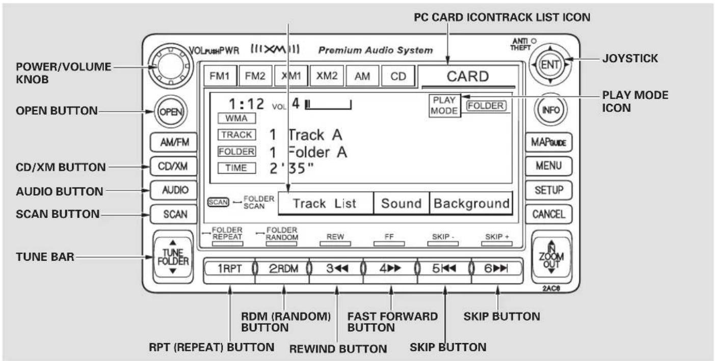
text_image
PC CARD ICONTRACK LIST ICON POWER/VOLUME KNOB OPEN BUTTON CD/XM BUTTON AUDIO BUTTON SCAN BUTTON TUNE BAR VOL/ Push PWR (11XM1) Premium Audio System FM1 FM2 XM1 XM2 AM CD CARD 1:12 VOL 4 WMA TRACK FOLDER TIME 1 Track A 1 Folder A 2 '35" PLAY MODE FOLDER SCAN FOLDER SCAN Track List Sound Background FOLDER REPEAT FOLDER RANDOM REW FF SKIP - SKIP + 1RPT 2RDM 3 4 5 6 2AC8 RPM (RANDOM) BUTTON FAST FORWARD BUTTON SKIP BUTTON RPT (REPEAT) BUTTON REWIND BUTTON SKIP BUTTONAudio System (Models with navigation system)
To Play a PC card
You operate the PC card player with the same controls used for the radio and the disc player. To load or play a card, the ignition switch must be in the ACCESSORY (I) or ON (II) position.
The PC card player reads and plays cards in MP3 or WMA formats. Depending on the format, the screen will indicate “MP3” or “WMA” when a card is playing. The card limit of the player is 99 folders and 999 tracks. If the card has a complex structure, it takes some time for the system to begin playing it.
Based on PCMCIA 2.1/JEIDA 4.2, the recommended PC cards for the PC card reader are:
CompactFlash
Flash ATA
SD memory card
Always use the recommended memory card with the appropriate adapter (if an adapter is needed). Some memory cards will not work in this unit.
NOTE:
- When you insert a PC card into the slot, make sure you put it in straight. If you cannot insert it, remove it, and insert again.
- Do not keep PC cards in the vehicle. Direct sunlight and high heat will damage them.
• To avoid damaging the card reader, do not insert hard disc drive cards into the PC card slot. - You cannot close the screen (move it to the upright position) until the PC card is inserted all the way into its slot or removed.
- Never insert foreign objects into the PC card slot.
The specifications for compatible MP3 files are:
—Sampling frequency:
32/44.1/48 kHz (MPEG1)
24/22.05/16 kHz (MPEG2)
—Bit rate:
32/40/48/56/64/80/96/112/128/
160/192/224/256/320 kbps
(MPEG1)
8/16/24/32/40/48/56/64/80/96/
112/128/160 kbps (MPEG2)
- Compatible with variable bit rate and multi-session
-Maximum layers (including ROOT): 8 layers
The specifications for compatible WMA files are:
—Sampling frequency: 32/44.1/48 kHz
—Bit rate:
48/64/80/96/128/160/192 kbps
- Compatible with variable bit rate and multi-session
- Maximum layers (including ROOT): 8 layers
In WMA format, DRM (digital rights management) files cannot be played. If the system finds a DRM file, it skips that file and plays the next available folder or file.
Loading a PC Card
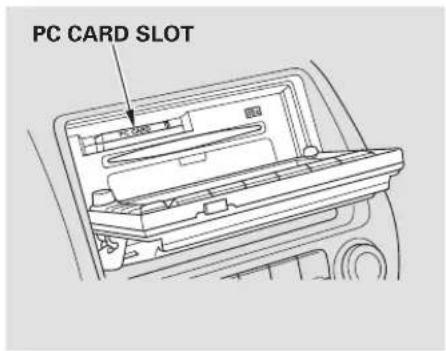
text_image
PC CARD SLOTThe PC card slot is behind the navigation screen. To use the PC card player, press the OPEN button beside the screen. The screen folds back, and the PC card slot appears.
Insert a PC card straight into the slot. The drive will read the PC card and begin to play it.
Return the screen to the upright position by pressing the CLOSE button on the edge of the screen panel.
Push the AUDIO button beside the screen to show the audio display and operate the PC card player.
You can also operate the audio system without using the control icons on the audio screen. Press any of the appropriate control buttons. The status bar appears on the bottom of the screen. On the navigation screen, you can see the audio information whenever you touch the AUDIO INFO icon on the screen.
CONTINUED
Audio System (Models with navigation system)
There are three play modes: F To Select a Play Mode
Artist, and Album. Touch the PLAY MODE icon, then choose one of the modes by touching its icon. When a mode is selected, it is highlighted in blue.
- Folder mode playstracks in the order they were added to the card.
- Artist mode playstracks in alphabetical order, by artist and song title.
- Album mode plays albums (folders) in alphabetical order.
If play mode information was not included in the track when they were added to the card, it will not be displayed on the screen.
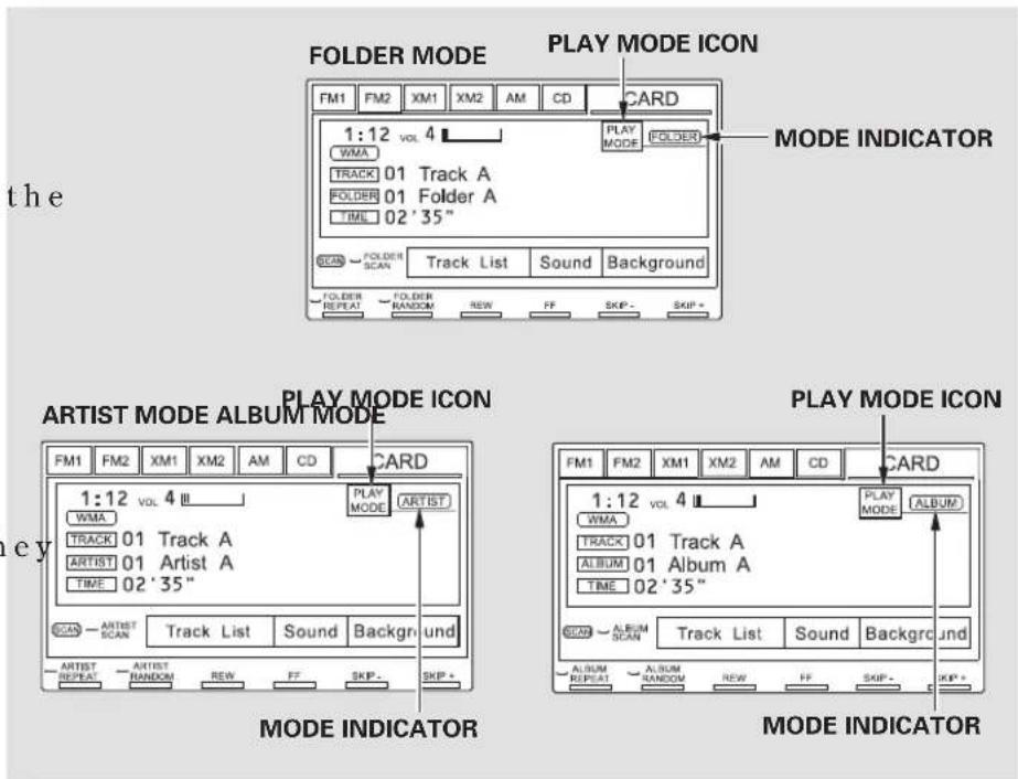
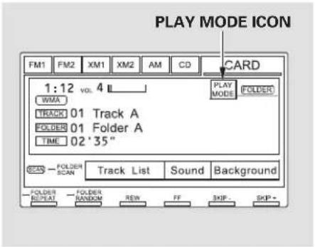
text_image
PLAY MODE ICON FM1 FM2 XM1 XM2 AM CD CARD 1:12 vol. 4 WMA TRACK 01 Track A FOLDER 01 Folder A TIME 02'35" SCAN FOLDER SCAN Track List Sound Background FOLDER REPEAT FOLDER RANDOM REM FF SKIP SKIP -To select a play mode, push the AUDIO button to show the audio display, then touch the PLAY MODE icon on the display.
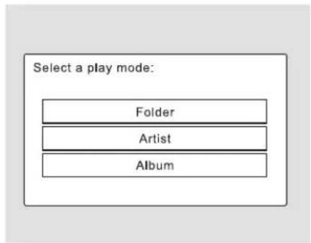
flowchart
graph TD
    A["Select a play mode:"] --> B["Folder"]
    A --> C["Artist"]
    A --> D["Album"]
Select the desired mode by touching the appropriate icon, or move the joystick, then press the ENT.
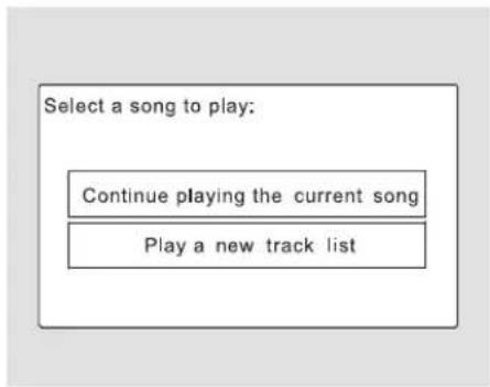
text_image
Select a song to play: Continue playing the current song Play a new track listAfter you select the play mode, the display changes to the selectable playing menu. If you select "Continue playing the Current Song," the system goes into the selected play mode after playing the current file.
CONTINUED
Audio System (Models with navigation system)
If you select "Play a New Track List," the system goes into the selected play mode immediately and begins to play the files in order to the new list.
To go back to the previous screen, pressthe CANCELbuttononth rightsideofthescreen.Toexi play mode screens, press the AUDIO button.
To Change or Select Tracks/Files
PRESET BUTTON'S FUNCTION
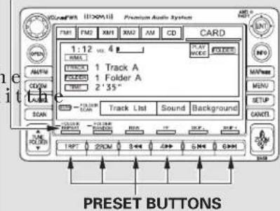
text_image
CNC#FRA 1100mA13 Premium Audio System FM1 FM2 XM1 XM2 AM CD CARD 1:12 vs. 4 1 Track A 1 Folder A 2'35" Track List Sound Background PRESET BUTTONSYou can use the preset buttons while a card is playing to select or change files. Each preset button's function is shown on the bottom of these
Icons the screencan also be selected with the joystick. Move the joystick left or right and up or down until the icon is highlighted, then press the ENT on the top of the joystick to select the icon.
reen.
SKIP — Each time you press and release (preset 6), the player skips forward to the beginning of the next file. Press and release
◀◀ (preset 5), to skip backward to the beginning of the current file. Press it again to skip to the beginning of the previous file.
FF/REW - To move rapidly within a file, press and hold ▶ (preset 4) or (preset 3).
FOLDER SELECTION— To select a different folder, press either side of the TUNE bar to move to the beginning of the next folder. Press the side of the TUNE bar to skip to the next folder, and the side to move to the beginning of the previous folder.
TRACK REPEAT (FILE
REPEAT) – To continuously replay a file, press and release the RPT button (preset 1). You will see TRACK REPEAT in the display. Press the RPT button again to turn it off.
FOLDER/ARTIST/ALBUM
REPEAT – This feature, when activated, replays all the files on the selected folder/artist/album in the order they are recorded or listed. To activate each repeat mode, press and hold the RPT button (preset 1) for 2 seconds. You will see FOLDER REPEAT, ARTIST REPEAT or ALBUM REPEAT in the display. The system continuously replays the current folder/artist/album. Press and hold the RPT button for 2 seconds again to turn it off. Pressing the RDM button, or selecting a different folder/artist/album with the TUNE bar also turns off the repeat feature.
TRACK RANDOM (Random
within a folder)—This feature plays the files within a folder in random order. To activate track random, press and release the RDM button (preset 2). You will see TRACK RANDOM in the display. Press and hold the RDM button for 2 seconds to return to normal play.
FOLDER/ARTIST/ALBUM
RANDOM – This feature, when activated, plays all files in each folder/artist/album in random order, rather than in the order they are recorded or listed. To activate each random play, press the RDM button (preset 2) 2 times. You will see FOLDER RANDOM, ARTIST RANDOM or ALBUM RANDOM in the display.
CONTINUED
Audio System (Models with navigation system)
The system then selects and plays files randomly. This continues until you deactivate each random play by pressing the RDM button again, or you select a different folder/artist/album with the TUNE bar.
SCAN — The scan function samples all files on the PC card in the order they are recorded. To activate scan, press and release the SCAN button. You will see TRACK SCAN in the display. You will get a 10 second sampling of each file on the PC card. Press and hold the SCAN button for 2 seconds to get out of scan mode and play the last file sampled.
Pressing either of the SKIP buttons (preset 5 or 6) also turns off the scan feature.
FOLDER/ARTIST/ALBUM SCAN – This feature, when activated, samples the first file in each folder/artist/album on the PC card in order. To activate each scan feature, press and hold the SCAN button until you hear a beep. You will see FOLDER SCAN, ARTIST SCAN or ALBUM SCAN in the display.
The system plays the first file in the folder for about 10 seconds. If you do nothing, the system plays the first file in each folder, in order, for 10 seconds each. After playing the first file of the last folder/artist/album, the system returns to normal play.
Pressing either of the SKIP buttons (preset 5 or 6), selecting a different folder/artist/album with the TUNE bar, or pressing the SCAN button, also turns off the scan feature.
Using a Track List
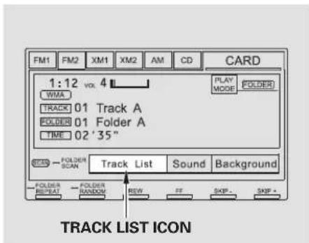
text_image
FM1 FM2 XM1 XM2 AM CD CARD 1:12 vol. 4 WMA TRACK 01 Track A FOLDER 01 Folder A TIME 02 '35" PLAY MODE FOLDER STERS FOLDER SCAN Track List Sound Background FOLDER REPEAT FOLDER RANDOM REW FF SKIP - SKIP + TRACK LIST ICONYou can also select a file directly from a track list on the audio display. Press the AUDIO button to show the audio display, then touch the Track List icon. The track list menu appears on the display.
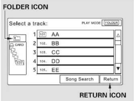
text_image
FOLDER ICON Select a track: PLAY MODE FOLDER 1 101 AA 2 102. BB 3 103. CC 4 104. DD 5 105. EE Song Search Return RETURN ICONTo scroll through the display, touch the ▲ or ▼ con on the side of the screen. Togoback to the pre display, touch the Return icon.
To play a file, touch its icon on the screen. In folder mode, touch the folder icon on the upper left of the screen to move to the parent folder. The current folder is highlighted in blue.
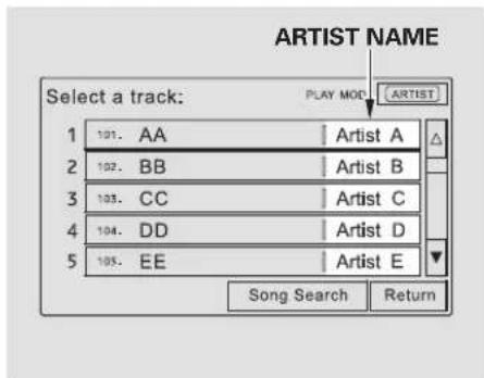
text_image
Select a track: PLAY MOD ARTIST NAME 1 101. AA Artist A 2 102. BB Artist B 3 103. CC Artist C 4 104. DD Artist D 5 105. EE Artist E Song Search ReturnIn artist mode, the artist name is also displayed on the right side of each is selectable icon. Select the desired file.
CONTINUED
Audio System (Models with navigation system)
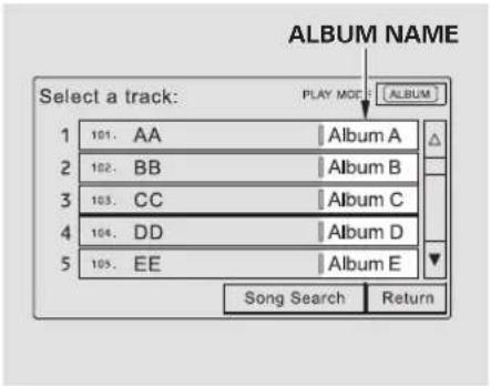
text_image
ALBUM NAME Select a track: PLAY MODE 1 101. AA Album A 2 102. BB Album B 3 103. CC Album C 4 104. DD Album D 5 105. EE Album E Song Search ReturnIn album mode, the album name is also displayed on the right side of each selectable icon. Select the desired file.
Song Search Function
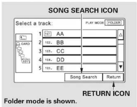
text_image
SONG SEARCH ICON Select a track: PLAY MODE (FOLDER) 1 101 AA 2 102 BB 3 103 CC 4 104 DD 5 105 EE Song Search Return RETURN ICON Folder mode is shown.When you select "Song Search" from the track list display, the song search menu appears.
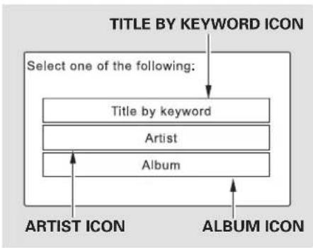
flowchart
graph TD
    A["TITLE BY KEYWORD ICON"] --> B["Select one of the following:"]
    B --> C["Title by keyword"]
    C --> D["Artist"]
    D --> E["Album"]
    E --> F["ARTIST ICON"]
    E --> G["ALBUM ICON"]
You can then select any of three modes to search a file: Title by Keyword, Artist, and Album.
Searching for a Song Title by Keyword
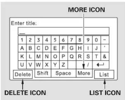
text_image
MORE ICON Enter title: 1 2 3 4 5 6 7 8 9 0 - A B C D E F G H I J * K L M N O P Q R S T & U V W X Y Z / ← Delete Shift Space More List DELETE ICON LIST ICONIn Title by Keyword mode, enter the title name, or any keyword, by touching the letter icons on the screen. Press the List icon to begin the song search. If you press the CANCELbuttononthescreen display returns to the mode menu without doing a search.
To cancel the selected letter, select the letter and touch the Delete icon. To select more characters, touch the More icon. The other character list will be shown.
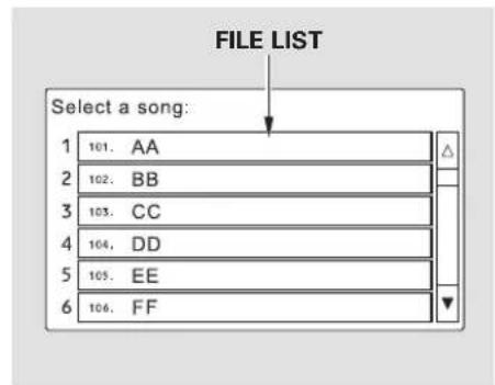
text_image
FILE LIST Select a song: 1 101. AA 2 102. BB 3 103. CC 4 104. DD 5 105. EE 6 106. FFAfter the system searches for a song, na file dist is displayed. To scroll through the list, touch the or ▼ icon on the side of the screen. Select the desired file by touching the appropriate icon, or moving the joystick and pressing the ENT.
Searching for a Song by Artist Name
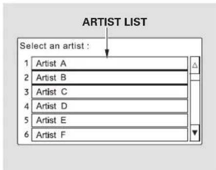
text_image
ARTIST LIST Select an artist : 1 Artist A 2 Artist B 3 Artist C 4 Artist D 5 Artist E 6 Artist FSelect the Artist icon, and the artist list appears. Select the desired artist, and the artist's file list is displayed.
CONTINUED
Audio System (Models with navigation system)
Searching for a Song by Album Name
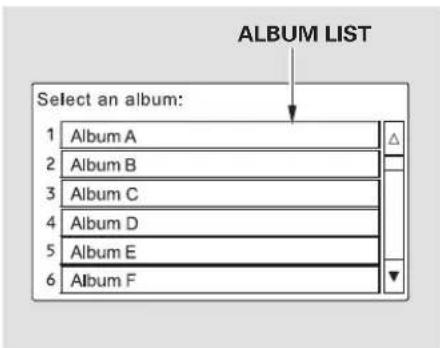
text_image
ALBUM LIST Select an album: 1 Album A 2 Album B 3 Album C 4 Album D 5 Album E 6 Album FSelect the Album icon, and the album list appears. Select the desired album, and its song list is displayed. You can then select the desired song from the list.
To Stop Playing a PC card
To play the radio when a PC card is playing, press the AM/FM button or touch the FM1, FM2, AM, XM1, or XM2 icon. If a disc is in the audio unit, press the CD button or touch the C D i c o n t o p l a y t h e d i s c. T the CARD icon to switch back to the PC card player.
If you turn the system off while a PC card is playing, either with the power/volume knob or by turning off the ignition switch, the card will stay in the drive. When you turn the system back on, the card will begin playing where it left off.
When you leave the vehicle, always remove the PC card from the audio unit.
Removing a PC Card
To remove a PC card from the audio unit, fold back the screen by pressing the OPEN button (see page 152). Press the eject button ( ▲ ) to remove the card. If you do not remove it from the slot, you cannot return the screen to the upright position.
To return the screen to the upright position, press the CLOSE button.
You can also eject a card when the ignition switch is off.
Audio System (Models with navigation system)
PC Card Error Messages
If you see an error message in the display while playing a PC card, find the solution in the chart to the If you cannot clear the error message, take your vehicle to your dealer.
| Error Message | Solution |
| r i g lFLE ERROR | The system cannot read the file(s). Check the files in the disc. There is a possibility that the files have been damaged. |
| NO MUSIC | It appears when the PC card is empty or there are no MP3 or WMA files in the P C card. Sav ethe MP3 or WMA files in the P C card. |
| MEDIA ERROR | It appears when the unsupported PC card is inserted. The system supports CompactFlash card, Flash ATA card, and SanDisk memory Card Adapter. |
card.
AM/FM Radio Reception
The radio can receive the complete AM and FM bands. Those bands cover these frequencies:
AM band: 530 to 1,710 kHz FM band: 87.7 to 107.9 MHz
Radio stations on the AM band are assigned frequencies at least 10 kHz apart (530, 540, 550). Stations on the FM band are assigned frequencies at least 0.2 MHz apart (87.9, 88.1, 88.3).
Stations must use these exact frequencies. It is fairly common for stations to round-off the frequency in their advertising, so your radio could display a frequency of 100.9 even though the announcer may identify the station as “FM101.”
Radio ReceptionRadio Frequencies How well the radio receives stations is dependent on many factors, such as the distance from the station's transmitter, nearby large objects, and atmospheric conditions.
A radio station's signal gets weaker as you get farther away from its transmitter. If you are listening to an AM station, you will notice the sound volume becoming weaker, and the station drifting in and out. I listen to an FM station, you will see the stereo indicator flickering off and on as the signal weakens. Eventually, the stereo indicator will go off and the sound will fade completely as you get out of range of the station's signal.
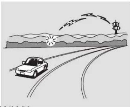
natural_image
Illustration of a car driving on a curved road with wind turbines and trees in the background (no text or symbols)Driving very near the transmitter of a station that is broadcasting on a frequency close to the frequency of the station you are listening to can also affect your radio's reception. You may temporarily hear both stations, or hearonlythestatio are close to.
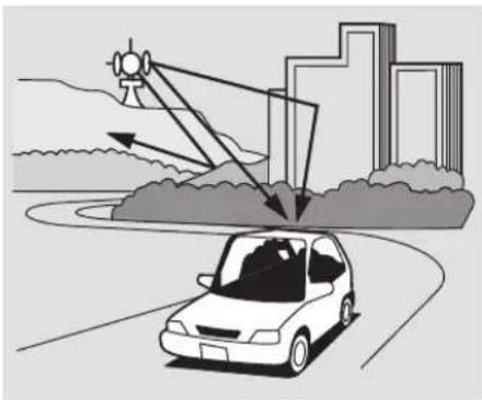
natural_image
Illustration of a car driving on a road with a city skyline and radar dish in the background (no text or symbols)Radio signals, especially on the FM band, are deflected by large objects such as buildings and hills. Your radio then receives both the direct signal from the station's transmitter, and the deflected signal. This causes the sound to distort or flutter. This is a main cause of poor radio reception in city driving.
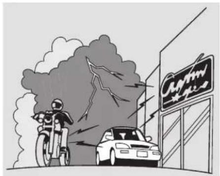
text_image
Cartoon illustration showing a motorcycle accident near a car, with a building sign reading 'Sunny Way' in the background.Radio reception can be affected by atmospheric conditions such as thunderstorms, high humidity, and even sunspots. You may be able to receive a distant radio station one day and not receive it the next day because of a change in conditions.
Electrical interference from passing vehicles and stationary sources can cause temporary reception problems.
As required by the FCC: Changes or modifications not expressly approved by the party responsible for compliance could void the user's authority to operate the equipment.
Protecting Your Discs
General Information Protecting Discs
- When using CD-R or CD-RW discs, use only high quality discs labeled for audio use.
- When recording a CD-R or CD-RW, the recording must be closed for it to be used by the system.
- Play only standard round discs. Odd-shaped discs may jam in the drive or cause other problems
- Handle your discs properly to prevent damage and skipping.
NOTICE
Do not use discs with adhesive labels. The label can curl up and cause the disc to jam in the unit.
When a disc is not being played, store it in its case to protect it from dust and other contamination. To prevent warpage, keep discs out of direct sunlight and extreme heat.
eTo clean a disc, use a clean soft cloth. Wipe across the disc from the center to the outside edge.
A new disc may be rough on the inner and outer edges. The small plastic pieces causing this roughness can flake off and fall on the recording surface of the disc, causing skipping or other problems. Remove these pieces by rubbing the inner and outer edges with the side of a pencil or pen.
Never try to insert foreign objects in the system or the magazine.
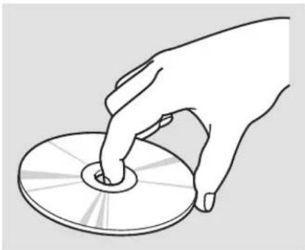
natural_image
Line drawing of a hand holding a CD or DVD disc (no text or symbols)Handle a disc by its edges; never touch either surface. Do not place stabilizer rings or labels on the disc. These, along with contamination from fingerprints, liquids, and felt-tip pens, can cause the disc to not play properly, or possibly jam in the drive.
Additional Information of Recommended Discs
The in-dash disc player/changer has a sophisticated and delicate mechanism. If you insert a damaged disc as indicated in this section, it may be comestuck inside and damage the audio unit.
Examples of these discs are shown to the right:
- Bubbled, wrinkled, labelled, and excessively thick discs
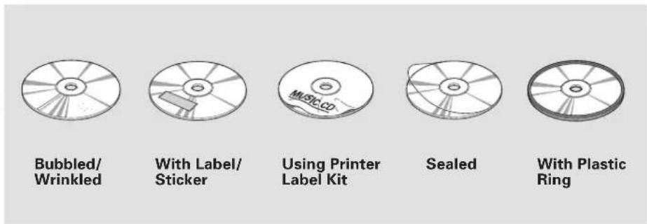
- Damaged discs Poor quality discs
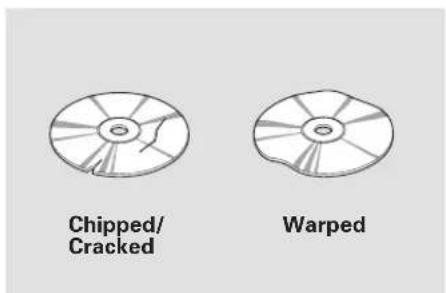
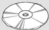
Burrs
CONTINUED
Protecting Your Discs
4. Small, irregular shaped discs
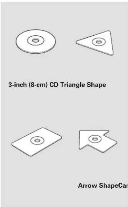
text_image
3-inch (8-cm) CD Triangle Shape Arrow ShapeCarDiscs with scratches, dirty discs
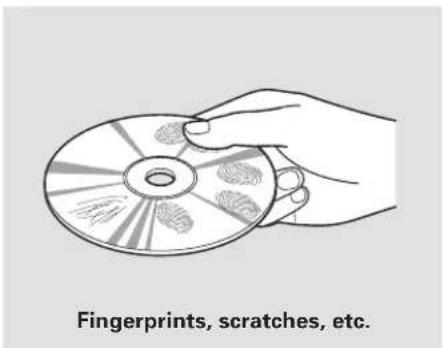
text_image
Fingerprints, scratches, etc.- CD-R or CD-RW may not play due to the recording conditions.
• Scratches and fingerprints on the discs may cause the sound to skip.
- Recommended discs are printed with the following logo.

• Audio unit may not play the following formats.

- This audio unit cannot play a Dual-disc®.
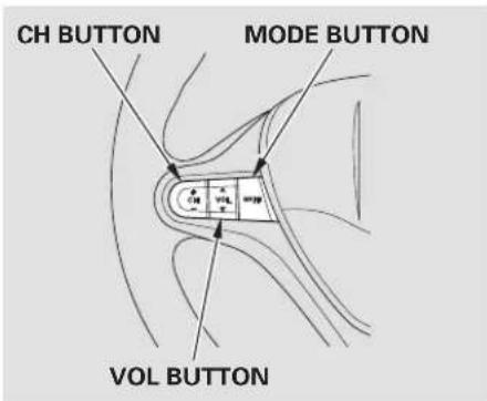
text_image
CH BUTTON MODE BUTTON VOL BUTTONIf equipped Three controls for the audio system are mounted in the steering wheel hub. These let you control basic functions without removing your hand from the wheel.
The VOL button adjusts the volume up (▲) or down (▼). Press the top or bottom of the button, hold it until the desired volume is reached, then release it.
The MODE button changes the mode. Pressing the button repeatedly selects FM1, FM2, AM, disc (if a disc is loaded), or a PC card (if it is loaded). On models with satellite radio system, you can also select XM radio.
If you are listening to the radio, use the CH button to change stations. Each time you press and release the top (+) of the button, the system goes to the next preset station on the band you are listening to. Press and release the bottom () to go the previous station.
To activate the seek function, press and hold the top (+) or bottom (−) of the CH button until you hear a beep. The system searches up or down from the current frequency to find a station with a strong signal.
If you are playing a disc, the system skips to the beginning of the next track (file in MP3 or WMA format) each time you press the top (+) of the CH button. Press the bottom (-) to return to the beginning of the current track or file. Press it twice to return to the previous track or file.
You will see the track/file number and the elapsed time. If the disc has text data or is compressed in MP3 or WMA, you can also see any other information (track title, file name, folder name, etc.).
ackto
CONTINUED
Remote Audio Controls, Auxiliary Input Jack
If you are playing a PC card, press the top (÷) of the CH button to advance to the next file. Press the bottom( ) to go back to the previous file.
In MP3 or WMA mode, you can use the seek function to select folders. Press and hold the top (+) of the CH button until you hear a beep, to skip forward to the first file of the next folder. Press the bottom (-) to skip backward to the previous folder.
Auxiliary Input Jack
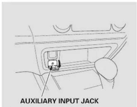
text_image
AUXILIARY INPUT JACKIf equipped The auxiliary input jack is underneath the accessory power socket on the front panel. The system will accept auxiliary input from standard audio accessories.
When a compatible audio unit is connected to the jack, press the AUX or CD/AUX button to select it.
On models with audio system Your vehicle's audio system will disable itself if it is disconnected from electrical power for any reason. To make it work again, you must enter a specific digit code using the preset buttons (icon on vehicle's with navigation system). Because there are hundreds of number combinations possible from specific digits, making the system work without knowing the exact code is nearly impossible.
You should have received a lists your audio system's code and serial numbers. It is best to store this card in a safe place at home. In addition, you should write the audio system's serial number in this owner's manual.
If you lose the card, you must obtain the code number from a dealer. To do this, you will need the system's serial number.
If your vehicle's battery is disconnected or goes dead, or the radio fuse is removed, the audio system will disable itself. If this happens, you will see "ENTER CODE" in the frequency display the next time y out run on the system. Use the preset buttons (icons on vehicles with navigation system) to enter the code. The code is on the radio code card included in your owner's manual kit. When it is entered correctly, the radio will start playing. r d t h a t If you make a mistake entering the code, do not start over; complete the sequence, then enter the correct code. You have 10 tries to enter the correct code. If you are unsuccessful in 10 attempts, you must then leave the system on for 1 hour before trying again.
The system will retain your AM and FM presets even if power is disconnected.
On models without navigation system To set the time, press the CLOCK (AM, AM/FM) button until the displayed time begins to blink, then release the button.
Change the hours by pressing the H (preset 1) button until the numbers advance to the desired time. Change the minutes by pressing the M (preset 2) button until the numbers advance to the desired time.
Press the CLOCK (AM, AM/FM) button again to enter the set time.
You can quickly set the time to the nearest hour. If the displayed time is before the half hour, pressing the CLOCK (AM, AM/FM) button until you hear a beep, then pressing the R (preset 3) button sets the clock back to the previous hour. If the displayed time is after the half hour, the clock sets forward to the beginning of the next hour.
U.S. LX, and Canadian DX, DX-G and LX models
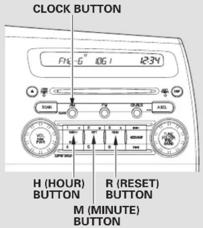
text_image
CLOCK BUTTON FNC-6 10G 1 12:34 SCAN R A B C D E F G H (HOUR) BUTTON M (MINUTE) BUTTON R (RESET) BUTTON VOL ON PAN ON ON ON ON ON ON ON ON ON ON ON ON ON ON ONFor example: 1:06 will reset to 1:00 1:52 will reset to 2:00
On models with navigation system The navigation system receives signals from the global positioning system (GPS), and the displayed
EX, EX-L and Si models
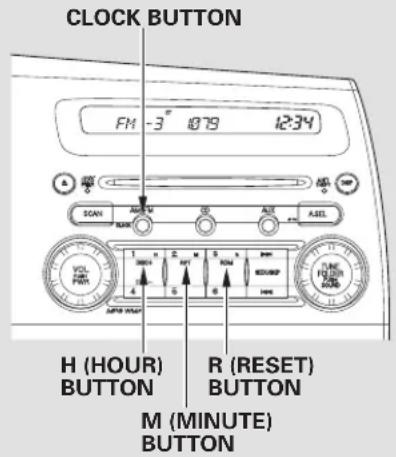
text_image
CLOCK BUTTON FM -3 10'79 12:34 SCAN AIR M DO ALR AEL H (HOUR) BUTTON R (RESET) BUTTON M (MINUTE) BUTTONtime is updated automatically by the GPS. Refer to the navigation system manual for how to adjust the time.
If equipped
The security system helps to protect your vehicle and valuables from theft. The horn sounds and a combination of headlights, parking lights, side marker lights, and taillights flashes if someone attempts to break into your vehicle or remove the radio alarm continues for 2 minutes, then the system resets. To reset an alarming system before the 2 minutes have elapsed, unlock the driver's door with the key or the remote transmitter.
The security system automatically sets 15 seconds after you lock the doors, hood, and trunk. For the system to activate, you must lock the doors from the outside with the key, lock tab, door lock switch, or remote transmitter. The security system indicator on the instrument panel starts blinking immediately to show you the system is setting itself.
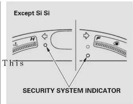
text_image
Except Si Si This SECURITY SYSTEM INDICATOROnce the security system is set, opening either door without using the key or the remote transmitter, the hood, or the trunk will cause the system to alarm. It also alarms if the audio unit is removed from the dashboard or the wiring is cut.
With the system set, you can still open the trunk with the master key (U.S. LX model) or the remote transmitter (U.S. EX, EX-L and Si models) without triggering the alarm.
The alarm will sound if the trunk lock is forced, or the trunk is opened with the trunk release handle or the emergency trunk opener.
The security system will not set if the hood, trunk, or either door is not fully closed. If the system will not set, check the door and trunk open indicators on the instrument panel (see page 64), to see if the doors and the trunk are fully closed. Since it is not part of the monitor display, manually check the hood.
NOTE: Use the remote transmitter to quickly check that the hood, the trunk, and both doors are closed. Push the lock button twice within 5 seconds. There should be an audible confirmation beep.
Do not attempt to alter this system or add other devices to it.
Cruise Control
If equipped
Cruise control allows you to maintain a set speed above 25 mph (40 without keeping your foot on the accelerator pedal. It should be used for cruising on straight, open highways. It is not recommended for city driving, winding roads, slippery roads, heavy rain, or bad weather.
WARNING
Improper use of the cruise control can lead to a crash.
Use the cruise control only when traveling on open highways in good weather.
CRUISE BUTTON RES/ACCEL
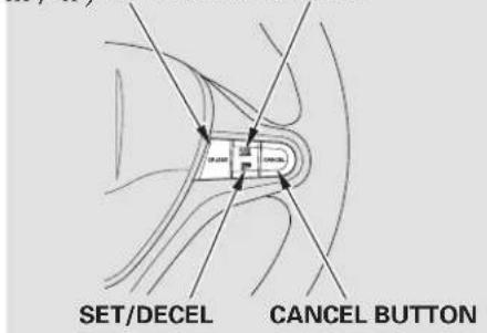
text_image
SET/DECEL CANCEL BUTTON- Push the CRUISE button on the steering wheel. The CRUISE MAIN indicator on the instrument panel comes on.
Thecruise control system lefton, even when it is not in
- Accelerate to the desired cruising speed above 25 mph (40 km
3. Using a Guide to the SET/
DECELbuttononthesteering wheel. The CRUISE CONTROL indicator on the instrument panel comes on to show the system is now activated.
Cruise control may not hold the set speed when you are going up and down hills. If your vehicle speed increases going down a hill, use the brakes to slow down. This will cancel the cruise control. To resumeth speed, press the RES/ACCEL button. The CRUISE CONTROL indicator on the instrument panel will come back on.
When climbing a steep hill, the automatic transmission may cause own shift to hold the setspeed
(h).
Changing the Set Speed
You can increase the set cruising speed in any of these ways:
- Press and hold the RES/ACCEL button. When you reach the desired cruising speed, release the button.
- Push on the accelerator pedal until you reach the desired cruising speed, then press the SET/DECEL button.
- To increase the speed in very small amounts, tap the RES/ACCEL button. Each time you do this, your vehicle speeds up about 1 mph (1.6 km/h).
You can decrease the set cruising speed in any of these ways:
- Press and hold the SET/DECEL button. Release the button when you reach the desired speed.
- To slow down in very small amounts, tap the SET/DECEL button. Each time you do this, your vehicle will slow down about 1 mph (1.6 km/h).
- Tap the brake or clutch pedal lightly with your foot. The CRUISE CONTROL indicator on the instrument panel goes out. When the vehicle slows to the desired speed, press the SET/DECEL button.
Even with the cruise control turned on, you can still use the accelerator pedal to speed up for passing. After completing the pass, take your foot off the accelerator pedal. The vehicle will return to the set cruising speed.
Resting your foot on the brake or clutch pedal causes the cruise control to cancel.
Cancelling Cruise Control Resuming the Set Speed
You can cancel cruise control in any of these ways:
- Tap the brake or clutch pedal.
- Push the CANCEL button on the steering wheel.
- Push the CRUISE button on the steering wheel.
When you push the CANCEL button, or tap the brake or clutch pedal, the system remembers the previously set cruising speed. To return to that speed, accelerate to above 25 mph (40 km/h) and then press and release the RES/ACCEL button. The CRUISE CONTROL indicator comes on, and the vehicle accelerates to the same cruising speed as before.
Pressing the CRUISE button turns the system off and erases the previous cruising speed.
Before you begin driving your vehicle, you should know what gasoline to use and how to check the levels of important fluids. You also need to know how to properly store luggage or packages. The information in this section will help you. If you plan to add any accessories to your vehicle, please read the information in this section first.
Break-in Period 186
Fuel Recommendation.... 186
Service Station Procedures ..... 187
Refueling.... 187
Opening and Closing the Hood 188
Oil Check 189
Engine Coolant Check 191
Fuel Economy 192
Accessories and Modifications .... 195
Carrying Cargo 197
Break-in Period Fuel Recommendation
Help assure your vehicle's future reliability and performance by paying extra attention to how you drive during the first 600 miles (1,000 km). During this period:
- Avoid full-throttle starts and rapid acceleration.
- Do not change the oil until the scheduled maintenance time.
- Avoid hard braking for the 200 miles (300 km).
You should also follow these recommendations with an overhauled or exchanged engine, or when the brakes are replaced.
All models except Si
Your vehicle is designed to operate on unleaded gasoline with a pump octane number of 87 or higher. Use of a lower octane gasoline can cause a persistent, heavy, metallic rapping noise that can lead to engine damage.
Si model only
Your vehicle is designed to operate on premium unleaded gasoline with a pump octane number of 91 or higher. Use of a lower octane gasoli cause occasional metallic knocking noises in the engine and will result in decreased engine performance. Use of a gasoline with a pump octane number less than 87 can lead to engine damage.
We recommend using quality gasolines containing detergent additives that help prevent fuel system and engine deposits.
In addition, in order to maintain good performance, fuel economy, and emissions control, we strongly recommend, in areas where it is available, the use of gasoline that does NOT contain manganese-based fuel additives such as MMT.
Use of gasoline with these additives may adversely affect performance, and cause the malfunction indicator lamp on your instrument panel to come on. If this happens, contact your authorized dealer for service.
Some gasoline today is blended with oxygenates such as ethanol or MTBE. Your vehicle is designed to operate on oxygenated gasoline containing up to 10% ethanol by volume and up to 15% MTBE by volume. Do not use gasoline containing methanol.
If you notice any undesirable operating symptoms, try another service station or switch to another brand of gasoline.
For further important fuel-related information, please refer to your Quick Start Guide.
On Si model
You may hear a knocking noise from the engine if you drive the vehicle at low engine speed (below about 1,000 rpm) in a higher gear. To stop this, raise the engine speed by shifting to a lower gear.
Refueling
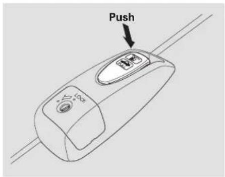
text_image
Push- Park with the driver's side closest to the service station pump.
- Open the fuel fill door by pushing on the handle to the left of the driver's seat.
WARNING
Gasoline is highly flammable and explosive. You can be burned or seriously injured when handling fuel.
- Stop the engine, and keep heat, sparks, and flame away.
- Handle fuel only outdoors.
- Wipe up spills immediately.
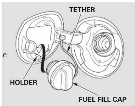
text_image
TETHER e HOLDER FUEL FILL CAPCONTINUED
Service Station Procedures
- Remove the fuel fill cap slowly. You may hear a hissing sound as pressure inside the tank escapes. The fuel fill cap is attached to the fuel filler with a tether. Place the cap in the holder on the fuel fill door.
- Stop filling the tank after the fuel nozzle automatically clicks off. Do not try to "top off" the tank. Leave some room for the fuel to expand with temperature changes.
If the fuel nozzle keeps clicking off even though the tank is not full, there may be a problem with your vehicle's fuel vapor recovery system. The system helps keep fuel vapor from going into the atmosphere. Try filling at another pump. If this does not fix the problem, consult your dealer.
- Screw the fuel fill cap back on until it clicks at least once. If you do not properly tighten the cap, the malfunction indicator lamp may come on (see 282ge) will also see a "CHECK FUEL CAP" message on the information display.
- Push the fuel fill door closed until it latches.
Opening and Closing the Hood
HOOD RELEASE HANDLE
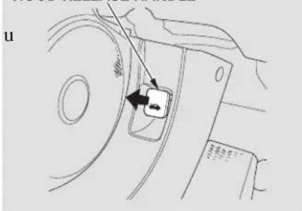
text_image
u- Park the vehicle, and set the parking brake. Pull the hood release handle under the lower left corner of the dashboard. The hood will pop up slightly.
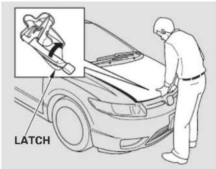
text_image
LATCH- Put your fingers under the front edge of the hood near the center. Slide your hand to the left until you feel the hood latch handle. Push this handle up to release it. Lift up the hood.
If the hood latch handle moves stiffly, or if you can open the hood without lifting the handle, the mechanism should be cleaned and lubricated.

text_image
GRIP SUPPORT ROD CLIP- Holding the grip, pull the support rod out of its clip. Insert the end into the designated hole pointed by an arrow in the hood.
To close the hood, lift it up slightly to remove the support rod from the hole. Put the support rod back into its holding clip. Lower the hood to about a foot (30 cm) above the fender, then let it drop. Make sure it is securely latched.
Oil Check
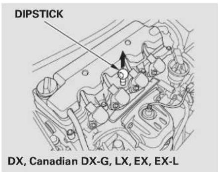
text_image
DIPSTICK DX, Canadian DX-G, LX, EX, EX-LWait a few minutes after turning the engine off before you check the oil.
- Remove the dipstick (orange handle).
- Wipe off the dipstick with a clean cloth or paper towel.
- Insert the dipstick all the way back into its hole.
CONTINUED
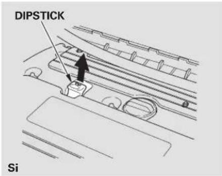
text_image
DIPSTICK Si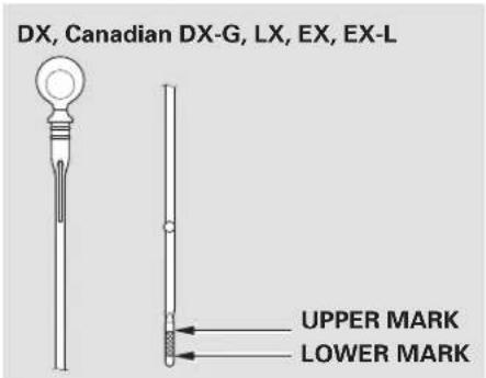
text_image
DX, Canadian DX-G, LX, EX, EX-L UPPER MARK LOWER MARK- Remove the dipstick again, and check the level. It should be between the upper and lower marks.

text_image
Si UPPER MARK LOWER MARKIf it is near or below the lower mark, see Anding Engine Oil 234
Engine Coolant Check
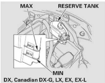
text_image
MAX RESERVE TANK MAX MIN DX, Canadian DX-G, LX, EX, EX-LLook at the coolant level in the radiator reserve tank. Make sure it is between the MAX and MIN lines. If it is below the MIN line, see Adding Engine Coolant on page 138 information on adding the proper coolant.
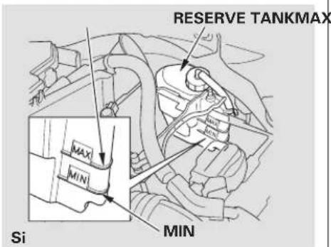
text_image
RESERVE TANKMAX MAX MIN Si MINRefer to Owner's Maintenance Checks on page 23 Information about checking other items on your vehicle.
Actual Mileage and EPA Fuel Economy Estimates Comparison. Fuel economy is not a fixed number. It varies based on driving conditions, driving habits and vehicle condition. Therefore, it is not possible for one set of estimates to predict fuel economy precisely for all drivers in all environments.
The EPA fuel economy estimates shown in the example to there are a useful tool for comparison when buying a vehicle. EPA estimates include:
City MPG - Represents urban driving in a vehicle in light traffic. A range of miles per gallon achieved is also provided.
Highway MPG – Represents a mixture of rural and interstate driving, in a warmed-up vehicle, typical of longer trips in free-flowing traffic. A range of miles per gallon
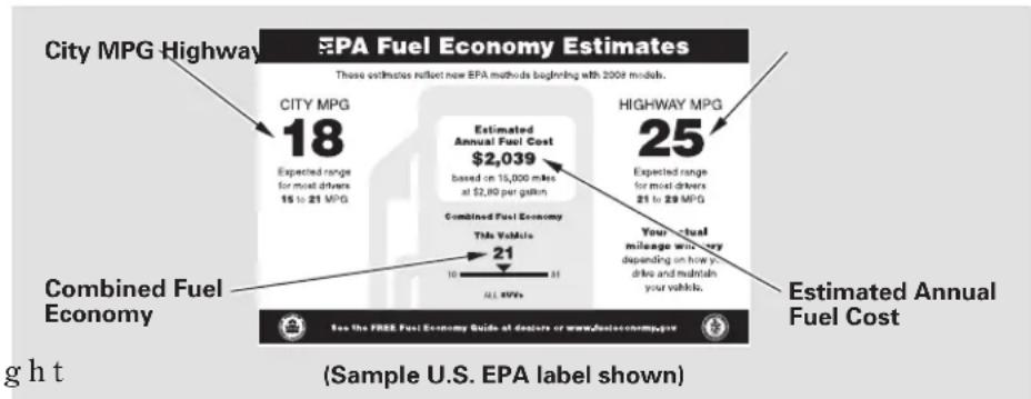
other
| Category | Value | | -------- | ----- | | City MPG Highway | 18 | | Estimated Annual Fuel Cost | $2,039 | | Combined Fuel Economy | 21 | | Estimated Annual Fuel Cost (Highway) | 25 | The Total Vehicle: 10,000 miles at $2.80 per gallon. |achieved is also provided.
Combined Fuel Economy – Represents a combination of city and highway driving. The scale represents the range of combined fuel economy for other vehicles in the class.
Estimated Annual Fuel Cost Provides an estimated annual fuel cost, based on 15,000 miles (20,000 km) per year multiplied by the cost per gallon (based on EPA fuelco data) divided by the combined fuel economy.
For more information on fuel economy ratings and factors that affect fuel economy, visit www.fueleconomy.gov (Canada: Visit vehicles.gc.ca)
Fuel Economy Factors Use the recommended viscosity
The following factors can lower your vehicle's fuel economy:
- Aggressive driving (hard acceleration and braking)
- Excessive idling, accelerating and braking in stop-and-go traffic
- Cold engine operation (engines are more efficient when w a up)
- Driving with a heavy load or the air conditioner running
- Improperly inflated tires
Improving Fuel Economy
Vehicle Maintenance
A properly maintained vehicle maximizes fuel economy. Poor maintenance can significantly reduce fuel economy. Always maintain your vehicle according to the maintenance messages displayed on the information display (see Owner's Maintenance Checks on page 230 For example:
motor oil, displaying the API Certification Seal (see page 234).
- Maintain proper tire inflation
- An under-inflated tire increases "rolling resistance," which reduces mfuel economy.
- Avoid carrying excess weight in your vehicle— It puts a heavier load on the engine, increasing fuel consumption.
- Keep your vehicle clean – In particular, a build-up of snow or mud on your vehicle's underside adds weight and rolling resistance. Frequent cleaning helps your fuel economy.
Drive Efficiently
- Drive moderately – Rapid acceleration, abrupt cornering, and hard braking increase fuel consumption.
- Observe the speed limit – Aerodynamic drag has a big effect on fuel mileage at speeds above 45 mph (75 km/h). Reduce your speed and you reduce the drag. Trailers, car top carriers, roof racks and bike racks are also big contributors to increased drag.
- Always drive in the highest gear possible — If your vehicle has a manual transmission, you can boost your fuel economy by up shifting as early as possible.
- Avoid excessive idling – Idling results in 0 miles per gallon.
CONTINUED
Fuel Economy
- Minimize the use of the air conditioning system – The A/C puts an extra load on the engine which makes it use more fuel. Use the fresh-air ventilation when possible.
- Plan and combine trips— Combine several short trips into one. A warmed-up engine is more fuel efficient than a cold one.
Calculating Fuel Economy
Measuring Techniques Direct calculation is the recommended source of information about your actual fuel economy. Using frequency of fill-ups or taking fuel gauge readings are NOT accurate measures of fuel economy. Fuel economy may improve over the first several thousand miles.
Checking Your Fuel Economy
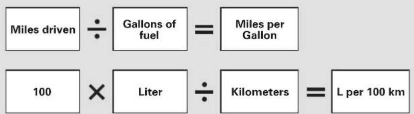
text_image
Miles driven ÷ Gallons of fuel = Miles per Gallon 100 × Liter ÷ Kilometers = L per 100 km1) Fill the fuel tank until the nozzle automatically clicks off.
2) Reset trip counter to zero.
3) Record the total gallons (liters) needed to refill.
4) Follow one of the simple calculations above.
Modifying your vehicle, or installing some non-Honda accessories, can make your vehicle unsafe. Before you make any modifications or add any accessories, besuretor of following information.
Accessories
Your dealer has Honda accessories that allow you to personalize your vehicle, or improve its performance. These accessories have been designed and approved for your vehicle, and are covered by warranty.
Although non-Honda accessories may fit on your vehicle, they may not meet factory specifications, and could adversely affect your vehicle's handling and stability.
WARNING
Improper accessories or modifications can affect your vehicle's handling, stability, and performance, and cause a crash in which you can be hurt or killed.
Follow all instructions in this owner's manual regarding accessories and modifications.
When properly installed, cellular phones, alarms, two-way radios, and low-powered audio systems should not interfere with your vehicle's computer controlled systems, such as your airbags, anti-lock brakes, and tire pressure monitoring system (if equipped).
Before installing any accessory:
- Make sure the accessory does not obscure any lights, or interfere with proper vehicle operation or performance.
- Be sure electronic accessories do not overload electrical circuits (see page 284) or interfere with the proper operation of your vehicle.
- Before installing any electronic accessory, have the installer contact your dealer for assistance. If possible, have your dealer inspect the final installation.
- Do not install accessories on the side pillars or across the rear windows. Accessories installed in these areas may interfere with proper operation of the side curtain airbags.
Modifying Your Vehicle
Removing parts from your vehicle, or replacing components with non-Honda components could seriously affect your vehicle's handling, stability, and reliability.
Some examples are:
- Lowering the vehicle with a non-Honda suspension kit that significantly reduces ground clearance can allow the undercarriage to hit speed bumps or other raised objects, which could cause the airbags to deploy.
- Raising your vehicle with a non-Honda suspension kit can affect the handling and stability.
- Non-Honda wheels, because they are a universal design, can cause excessive stress on suspension components and will not be compatible with the tire pressure monitoring system (TPMS) *
* If equipped:
- Larger or smaller wheels and tires can interfere with the operation of your vehicle's anti-lock brakes and other systems.
- Modifying your steering wheel or any other part of your vehicle's safety features can make the systems ineffective.
If you plan to modify your vehicle, consult your dealer.
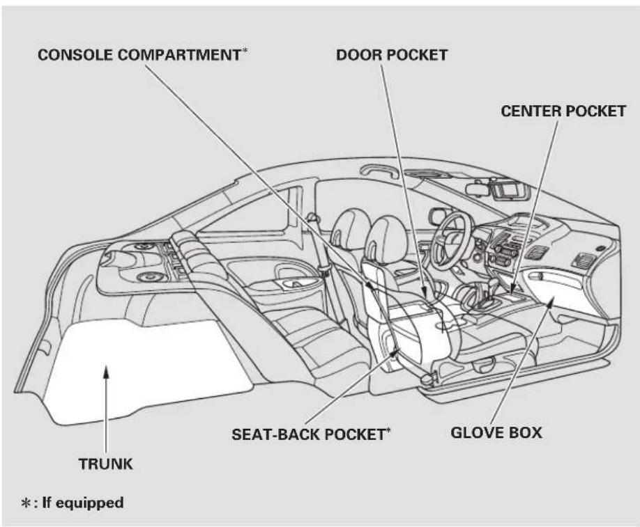
text_image
CONSOLE COMPARTMENT* DOOR POCKET CENTER POCKET TRUNK SEAT-BACK POCKET* GLOVE BOX *: If equippedYour vehicle has several convenient storage areas:
- Glove box
• Door and seat-back pockets - Console compartment
- Center pocket
- Trunk, including the rear seats when folded down
However, carrying too much cargo, or improperly storing it, can affect your vehicle's handling, stability, stopping distance, and tires, and make it unsafe. Before carrying any type of cargo, be sure to read the following pages.
Load Limits
The maximum load for your vehicle is 850 lbs (385 kg) for U.S. models and 395 kg for Canadian models.
See Tire And Loading Information label attached to the driver's doorjamb.
Label Example
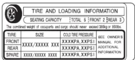
text_image
TIRE AND LOADING INFORMATION SEATING CAPACITY :TOTAL 5 :FRONT 2 :REAR 3 The combined weight of occupants and cargo should never exceed 385kg or 850lbs. TIRE SIZE COLD TIRE PRESSURE SEE OWNER'S FRONT XXXX/XXXXX XXX XXXXKPA,XXPSI MANUAL FOR REAR XXXXKPA,XXPSI_ADDITIONAL SPARE XXXX/XXXXX XXX XXXXKPA,XXPSI_INFORMATIONThis figure includes the total weight of all occupants, cargo, and accessories, and the tongue load if you are towing a trailer.
WARNING
Overloading or improper loading can affect handling and stability and cause a crash in which you can be hurt or killed.
Follow all load limits and other loading guidelines in this manual.
Steps for Determining Correct Load Limit —
(1)Locate the statement “The combined weight of occupants and cargo should never exceed XXX kg or XXX lbs.” on your vehicle’s placard.
(2) Determine the combined weight of the driver and passengers that will be riding in your vehicle.
(3)Subtract the combined weight of the driver and passengers from XXX kg or XXX lbs.
$$ (1, 4 0 0 - 7 5 0 (5 \times 1 5 0) = 6 5 0 \text { lbs. }) $$
(4)The resulting figure equals the available amount of cargo and luggage load capacity. For example, if the “XXX” amount equals 1,400 lbs. and there will be five 150 lb. passengers in your vehicle, the amount of available cargo and luggage load capacity is 650 lbs.
(5) Determine the combined weight of luggage and cargo being loaded on the vehicle. That weight may not safely exceed the available cargo and luggage load capacity calculated in Step 4.
(6)If your vehicle will be towing a trailer, load from your trailer will be transferred to your vehicle. Consult this manual to determine how this reduces the available cargo and luggage load capacity of your vehicle.
| Example 1 |  Max Load (850 lbs) Cargo Weight Weight(150 lbs x 2 = 300 lbs) (550 lbs) Max Load (850 lbs) Cargo Weight Weight(150 lbs x 2 = 300 lbs) (550 lbs) | ||
| Example 2 |  Max Load (850 lbs) Passenger Weight Cargo Weight(150 lbs x 4 = 600 lbs) (250 lbs) Max Load (850 lbs) Passenger Weight Cargo Weight(150 lbs x 4 = 600 lbs) (250 lbs) | ||
| Example 3 |  Max Load (850 lbs) Passenger Weight Cargo Weight(150 lbs x 5 = 750 lbs) (100 lbs) Max Load (850 lbs) Passenger Weight Cargo Weight(150 lbs x 5 = 750 lbs) (100 lbs) | ||
In addition, the total weight of the vehicle, all occupants, accessories, cargo, and trailer tongue load must not exceed the Gross Vehicle Weight Rating (GVWR) or the Gross Axle Weight Rating (GAWR). Both are on a label on the driver's doorjamb.
Carrying Items in the Passenger Compartment
- Store or secure all items that could be thrown around and hurt someone during a crash.
- Do not put any items on top of the rear shelf. They can block your view and be thrown around the vehicle during a crash.
- Be sure items placed on the floor behind the front seats cannot roll under the seats and interfere with the driver's ability to operate the pedals, the proper operation of the seats, or the proper operation of the sensors under the seats.
Also, keep all cargo below the bottom of the windows. If it is higher, it could interfere with the proper operation of the side curtain airbags.
- Keep the glove box closed while driving. If it is open, a passenger could injure their knees during a crash or sudden stop.
Carrying Cargo in the Trunk
- Distribute cargo evenly on the floor of the trunk, placing the heaviest items on the bottom and as far forward as possible.
- If you carry large items that prevent you from closing the trunk lid, exhaust gas can enter the passenger area. To avoid the possibility of carbon monoxide poisoning, follow the instructions on page .50
- If you fold down the back seat, tie down items that could be thrown about the vehicle during a crash or sudden stop.
Cargo Net
Optional
The cargo net can be used to help hold down items stored in the trunk.
This section gives you tips on starting the engine under various conditions, and how to operate the manual and automatic transmissions. It also includes important information on parking your vehicle, the braking system, the vehicle stability assist (VSA) system, and the tire pressure monitoring system (TPMS).
Driving Guidelines 202
Preparing to Drive 203
Starting the Engine.... 204
Manual Transmission.... 205
......Automatic
Parking 212
Braking System...... 213
.....Anti-lock E
Vehicle Stability Assist (VSA)
System...... 216
Tire Pressure Monitoring System (TPMS) 218
Towing a Trailer 221

Driving Guidelines
Si model
Your vehicle is designed to give you optimum handling and performance on well-maintained roads. As part of this design, your vehicle has a minimum of ground clearance and very low-profile tires.
- Use caution if you ever drive your vehicle on very rough orru roads. You could damage the suspension and underbody by bottoming out. Going too fast over parking lot "speed bumps" can also cause damage.
tted
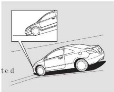
natural_image
Line drawing of a sedan on a road with an inset showing the side view of the car (no text or symbols)- Curbs and steep inclines could damage the front and rear bumpers. Low curbs that do not affect the average vehicle may be high enough to hit the bumper on your vehicle. The front or rear bumper may scrape when trying to drive onto an incline, such as a steep driveway or trailer ramps.
- Because of the low-profile tires fitted to your vehicle, the alloy wheels are closer to the ground. Driving over a pothole or road debris at too high a speed can seriously damage a wheel. Slow down under these conditions.
You should do the following and adjustments before you drive your vehicle.
- Make sure all windows, mirrors, and outside lights are clean and unobstructed. Remove frost, snow, or ice.
- Check that the hood is fully closed.
- Check that the trunk is fully closed.
- Visually check the tires. If a tire looks low, use a gauge to check its pressure.
beCheck that any items you may be carrying are stored properly or fastened down securely.
- Check the seat adjustment (see page)92
- Check the adjustment of the inside and outside mirrors (see page 104
- Check the steering wheel adjustment (see page)75
-
Make sure the doors are securely closed and locked.
-
Fasten your seat belt. Check that your passengers have fastened their seat belts (see page 14)
- When you start the engine, check the gauges and indicators in the instrument panel (see page 55
Starting the Engine
- Apply the parking brake.
- In cold weather, turn off all electrical accessories to reduce the drain on the battery.
- Manual transmission:
Press the clutch pedal down all the way. The START (III) position does not function unless the clutch pedal is pressed.
Automatic transmission: Make sure the shift lever is in Park. Press on the brake pedal. - Without touching the accelerator pedal, turn the ignition key to the START (III) position. Do not hold the key in the START (III) position for more than 15 seconds at a time. If the engine does not start right away, pause for at least 10 seconds before trying again.
NOTICE
The immobilizer system protects your vehicle from theft. If an improperly-coded key (or other device) is used, the engine's fuel system is disabled. For more information, see page 77.
- If the engine does not start within 15 seconds, or starts but stalls right away, repeat step 4 with the accelerator pedal pressed halfway down. If the engine starts, release pressure on the accelerator pedal so the engine does not race.
- If the engine fails to start, press the accelerator pedal all the way down, and hold it there while starting to clear flooding. If the engine still does not start, return to step 5.
NOTICE
The engine is harder to start in cold weather. Also, the thinner air found at altitudes above 8,000 feet (2,400 meters) adds to this problem.
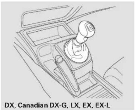
natural_image
Line drawing of a car gear shift lever with labeled components (no text or symbols on the diagram itself)The manual transmission is synchronized in all forward gears for smooth operation. It has a lockout so you cannot shift directly from fifth reverse.
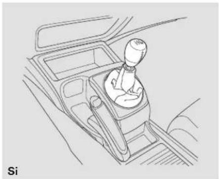
natural_image
Line drawing of a car interior showing a person seated in a gear shift (no text or symbols)On vehicles with 6-speed manual transmission, the lockout system prevents you from shifting directly to from any forward gear to reverse while the vehicle is moving at a certain speed (see page 207
When shifting up or down, make sure you push the clutch pedal down all the way, shift to the next gear, and let the pedal up gradually. When you are not shifting, do not rest your foot on the clutch pedal. This can
cause your clutch to wear out faster.
Come to a full stop before you shift into reverse. You can damage the transmission by trying to shift into reverse with the vehicle moving. Push down the clutch pedal, and pause for a few seconds before shifting into reverse, or shift into one of the forward gears for a moment. This stops the gears so they won't "grind."
On Si model
Note: The engine can be damaged if you inadvertently downshift into the wrong gear (for example, going from third gear at high rpms to second gear instead of upshifting to fourth gear; the engine speed limiter will not work in this situation).
CONTINUED
Manual Transmission
When slowing down, you can get extra braking from the engine by shifting to a lower gear. This extra braking can help you maintain a safe speed and prevent your brakes from overheating while going down a steep hill. Before downshifting, make sure the engine speed will not go into the tachometer's red zone in the lower gear.
▲WARNING
Rapid slowing or speeding up can cause loss of control on slippery surfaces. If you crash, you can be injured.
Use extra care when driving on slippery surfaces.
On Si model
Your vehicle is equipped with an aluminum shift lever. If you leave the vehicle parked outside for a long
time on a hot day, be careful before moving the shift lever. Because of the heat, the shift lever may be extremely hot. If the outside temperature is low, the shift lever feels cold.
Recommended Shift Points
Drive in the highest gear that lets the engine run and accelerate smoothly. This will give you good fuel economy and effective emissions control. The following shift points are recommended:
On models with 5-speed manual transmission
| Shift up | Normal acceleration |
| 1st to 2nd | 15 mph (24 km/h) |
| 2nd to 3rd | 27 mph (43 km/h) |
| 3rd to 4th | 39 mph (63 km/h) |
| 4th to 5th | 53 mph (85 km/h) |
On models with 6-speed manual transmission
| Shift up | Normal acceleration |
| 1st to 2nd | 17 mph (27 km/h) |
| 2nd to 3rd | 29 mph (47 km/h) |
| 3rd to 4th | 37 mph (60 km/h) |
| 4th to 5th | 43 mph (69 km/h) |
| 5th to 6th | 49 mph (79 km/h) |
Engine Speed Limiter Reverse Lockout
If you exceed the maximum speed for the gear you are in, the engine speed will enter into the tachometer's red zone. If this occurs, you may feel the engine cut in and out. This is caused by a limiter in the engine's computer controls. The engine will run normally when you reduce the rpm below the red zone.
Before downshifting, make sure the engine will not go into the tachometer's red zone.
On Si model
Your vehicle has a rev limit indicator to show you when the engine speed is near the tachometer's red zone (see page 61
6-speed manual transmission The manual transmission has lockout so you cannot accidentally shift from any forward gear to reverse while the vehicle is moving at a certain speed. If you cannot shift to reverse when the vehicle is stopped, do the following.
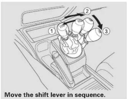
text_image
Move the shift lever in sequence.-
With the clutch pedal pressed, move the shift lever to the first/second gear side of the neutral gate, then shift to reverse.
-
If you are still unable to shift to reverse, apply the parking brake, and turn the ignition key to the ACCESSORY (I) or LOCK (0) position.
- Press the clutch pedal, and shift to reverse.
- With the clutch pedal still pressed, start the engine.
If you need to use this procedure to shift to reverse, your vehicle may be developing a problem. Have the vehicle checked by your dealer.
Automatic Transmission
Shift Lever Position Indicators Shifting The "D" indicator comes on for a These indicators on the instrument panel show which position the shift lever is in.
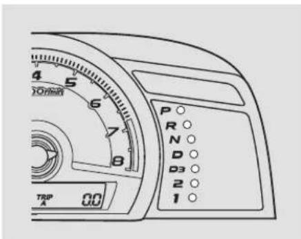
text_image
4 5 6 7 8 TRIP A 00 P R N D D3 2 1few seconds when you turn the ignition switch to the ON (II) position. If it flashes while driving (in any shift position), it indicates a possible problem in the transmission.
If the malfunction indicator lamp comes on along with the "D" indicator, there is a problem with the automatic transmission control system. Avoid rapid acceleration, and have the transmission checked by your dealer as soon as possible.
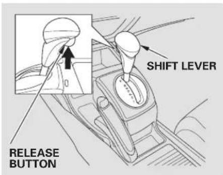
text_image
SHIFT LEVER RELEASE BUTTONTo shift from Park to any position, press firmly on the brake pedal, presst therelease button on the f of the shift lever, then move the lever. You cannot shift out of Park when the ignition switch is in the LOCK (0) or ACCESSORY (I) position.
| To shift from: | Do this: |
| P to R | Press the brake pedal, and press the shift lever release button. |
| R to PN to RD3 to 22 to 1 | Press the shift lever release button. |
| 1 to 22 to D3D3 to DD to ND to D2N to DR to N | Move the shift lever. |
Park (P) — This position mechanically locks the transmission. Use Park whenever you are turning off or starting the engine. To shift out of Park, you must press on the brake pedal and have your foot off the accelerator pedal. Press the release button on the front of the shift to move it.
If you have done all of the above and still cannot move the lever out of Park, see Shift Lock Release page 211
To avoid transmission damage, come to a complete stop before shifting into Park. You must also press the release button to shift into Park. The shift lever must be in Park before you can remove the key from the ignition switch.
Reverse (R)—Press the brake pedal and press the release button on the front of the shift lever to shift from Park to reverse. To shift from reverse to neutral, come to a complete stop, and then shift the release button before shifting into reverse from neutral.
Neutral (N) — Use neutral if you need to restart a stalled engine, or if it is necessary to stop briefly with the engine idling. Shift to the Park position if you need to leave your vehicle for any reason. Press on the brake pedal when you are moving the shift lever from neutral to another gear.
Drive (D) — Use this position for your normal driving. The transmission automatically selects a suitable gear (1 through 5) for your speed and acceleration. You may notice the transmission shifting up at higher engine speeds when the engine is cold. This helps the engine warm up faster.
CONTINUED
Automatic Transmission
3 —This position is similar to D, except only the first three gears are selected. Use D3 to provide engine braking when going down a steep hill. D3 can also keep the transmission from cycling between third and fourth gears in stop-and-go driving.
Second (2) — To shift to second, press therelease button on the front of the shift lever. This position locks the transmission in second gear. It does not downshift to first gear when you come to a stop.
Use second gear:
- For more power when climbing.
• To increase engine braking when going down steep hills. - For starting out on a slippery surface or in deep snow.
• To help reduce wheel spin.
First (1)— To shift from second to first, press the release button on the front of the shift lever. This position locks the transmission in first gear. By upshifting and downshifting through 1, 2, D3, and D, you can operate the transmission much like a manual transmission without a clutch pedal.
Engine Speed LimiterDrive (D) If you exceed the maximum speed for the gear you are in, the engine speed will enter into the tachometer's red zone. If this occurs, you may feel the engine cut in and out. This is caused by a limiter in the engine's computer controls. The engine will run normally when you reduce the rpm below the red zone.
Shift Lock Release
Do this if pushing on the brake pedal and pressing the release button does not shift the transmission out of Park:
- Set the parking brake.
- Remove the key from the ignition switch.
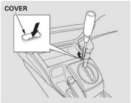
text_image
COVER- Put a cloth on the edge of the shift lock release slot cover. Using a small flat-tipped screwdriver or a
metal fingernail file, carefully pry on the edge of the cover to remove it.
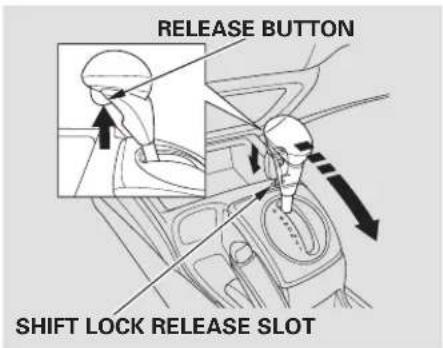
text_image
RELEASE BUTTON SHIFT LOCK RELEASE SLOT- Insert the key in the shift lock release slot.
-
Push down on the key while you press therelease button on the front of the shift lever and move the shift lever out of Park to neutral.
the -
Remove the key from the shift lock release slot, then install the cover. Make sure the notch on the cover is on the rear. Return the key to the ignition switch, press the brake pedal, and restart the engine.
If you need to use the shift lock release, it means your vehicle is developing a problem. Have it checked by your dealer.
Parking
Always use the parking brake when you park your vehicle. Make sure the parking brake is set firmly, or your vehicle may roll if it is parked on an incline.
If your vehicle has an automatic transmission, set the parking brake before you put the transmission in Park. This keeps the vehicle from moving and putting pressure on the parking mechanism in the transmission.
Parking Tips
- Make sure the moonroof (if equipped) and the windows are closed.
- Turn off the lights.
- Place any packages, valuables, etc., in the trunk or take them with you.
- Lock the doors.
On vehicles with security system Check the indicator on the instrument panel to verify that the security system is set.
- Never park over dry leaves, tall grass, or other flammable materials. The hot three way catalytic converter could cause these materials to catch on fire.
- If the vehicle is facing uphill, turn the front wheels away from the curb. If your vehicle has a manual transmission, put it in first gear.
- If the vehicle is facing downhill, turn the front wheels toward the curb. If your vehicle has a manual transmission, put it in reverse gear.
- Make sure the parking brake is fully released before driving away. Driving with the parking brake partially set can overheat or damage the rear brakes.
NOTICE
Never install a sunshade between the upper and lower meters on the instrument panel. If you do, you could cause heat damage to the upper meter on a very hot day.
Your vehicle is equipped with front disc brakes. The brakes on the rear wheels may be disc or drum, depending on the model. A power assist helps reduce the effort needed on the brake pedal. The anti-lock brake system (ABS) helps you retain steering control when braking very hard.
On vehicles with vehicle stability assist (VSA) system, the emergency brake assist system increases the stopping force when you depress the brake pedal hard in an emergency situation.
Resting your foot on the pedal keeps the brakes applied lightly, builds up heat, and reduces their effectiveness and reduces brake pad life. In addition, fuel economy can be reduced. It also keeps your brake lights on all the time, confusing drivers behind you.
Constant application of the brakes when going down a long hill builds up heat and reduces their effectiveness. Use the engine to assist the brakes by taking your foot off the accelerator and downshifting to a lower gear.
Check the brakes after driving through deep water. Apply the brakes moderately to see if they feel normal. If not, apply them gently and frequently until they do. Be extra cautious in your driving.
Braking System Design
The hydraulic system that operates the brakes has two separate circuits. Each circuit works diagonally across the vehicle (the left-front brake is connected with the right-rear brake, etc.). If one circuit should develop a problem, you will still have braking at two wheels.
Brake Pad Wear Indicators
If the brake pads need replacing, you will hear a distinctive, metallic screeching sound when you apply the brake pedal. If you do not have the brake pads replaced, they will screech all the time. It is normal for the brakes to occasionally squeal or squeak when you apply them.
The anti-lock brake system (ABS) helps prevent the wheels from locking up, and helps you retain steering control by pumping the brakes rapidly, much faster than a person can do it.
The electronic brake distribution (EBD) system, which is part of the ABS, also balances the front-to-rear braking distribution according to vehicle loading.
You should never pump the brake pedal. Let the ABS work for you by always keeping firm, steady pressure on the brake pedal. This is sometimes referred to as “stomp and steer.”
You will feel a pulsation in the brake pedal when the ABS activates, and you may hear some noise. This is normal: it is the ABS rapidly pumping the brakes. O n dry pavement, you will need to press on the brake pedal very hard be ABS activates. However, you may feel the ABS activate immediately if you are trying to stop on snow or ice.

ABS Indicator
If this indicator comes on, the anti-lock function of the braking system has shut down. The brakes still work like a conventional system, but without anti-lock. You should have your dealer inspect your vehicle as soon as possible.
If the indicator comes on while driving, test the brakes as instructed on page 283
If the ABS indicator and the brake system indicator come on together, and the parking brake is fully released, the EBD system may also be shut down.
Test your brakes as instructed on page 283he brakes feel normal, drive slowly and have your vehicle repaired by your dealer as soon as possible. Avoid sudden hard braking which could cause the rear wheels to lock up and possibly lead to a loss of control.
On vehicles with VSA system The VSA indicator will come on along with the ABS indicator
Important Safety Reminders ABS does not reduce the time or distance it takes to stop the vehicle. It only helps with the steering control during braking.
ABS will not prevent a skid that results from changing direction abruptly, such as trying to take a corner too fast or making a sudden lane change. Always drive at a safe speed for the road and weather conditions.
ABS cannot prevent a loss of stability. Always steer moderately when you are braking hard. Severe or sharp steering wheel movement can still cause your vehicle to veer into oncoming traffic or off the road.
A vehicle with ABS may require a longer distance to stop on loose or uneven surfaces, such as gravel or snow, than a vehicle without anti-lock.
Standard on U.S. Si model Optional on Canadian Si model The vehicle stability assist (VSA) system helps to stabilize the vehicle during cornering if the vehicle turns more or less than desired. It also assists you in maintaining traction while accelerating on loose or slippery road surfaces. It does this by regulating the engine's output and by selectively applying the brakes.
When VSA activates, you may notice that the engine does not respond to the accelerator in the same way it does at other times. There may also be some noise from the VSA hydraulic system. You will also see the VSA activation indicator blink.
The VSA system cannot enhance the vehicle's driving stability in all situations and does not control your vehicle's entire braking system. It is still your responsibility to drive and corner at reasonable speeds and to leave a sufficient margin of safety.

VSA Activation Indicator
When VSA activates, you will see the VSA Activation indicator blinks.

Vehicle Stability Assist (VSA) System Indicator
If this indicator comes on while driving, pull to the side of the road when it is safe, and turn off the engine. Reset the system by restarting the engine. If the VSA system indicator stays on or comes back on while driving, have the VSA system inspected by your dealer.
If the indicator does not come on when the ignition switch is turned to the ON (II) position, there may be a problem with the VSA system. Have your dealer inspect your vehicle as soon as possible.
If the low tire pressure indicator or TPMS indicator comes on, the VSA system automatically turns on even if the VSA system is turned off by pressing the VSA OFF switch (see page 2.17 this happens, you cannot turn the VSA system off by pressing the VSA off switch again.
Without VSA, your vehicle will have normal braking and cornering ability, but it will not have VSA traction and stability enhancement.
VSA Off Switch VSA and Tire Size
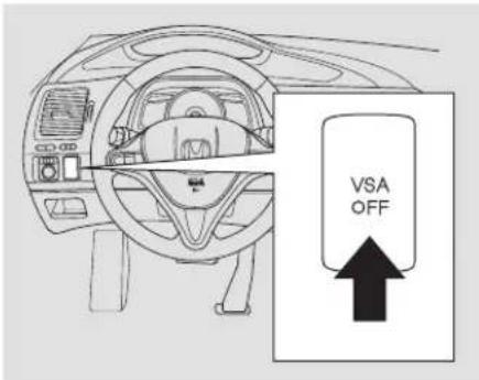
text_image
VSA OFFThis switch is under the left vent. Press it to turn the VSA system on and off.
When VSA is off, the VSA activation indicator comes on as a reminder.
sVSA is turned on every time you start the engine, even if you turned it off the last time you drove the vehicle.
In certain unusual conditions when your vehicle gets stuck in shallow mud or fresh snow, it may be easier to free it with the VSA temporarily switched off. When the VSA system is off, the traction control system is also off. You should only attack free your vehicle with the VSA off if you are not able to free it when the VSA is on.
Immediately after freeing your vehicle, be sure to switch the VSA on again. We do not recommend driving your vehicle with the VSA and traction control systems switched off.
Driving with varying tire or wheel sizes may cause the VSA to malfunction. When replacing tires, make sure they are of the same size and type as your original tires (see page 262
If you install winter tires, make sure they are the same size as those that were originally supplied with your vehicle. Exercise the same caution during winter driving as you would if your vehicle was not equipped with VSA.
U.S. models only
Your vehicle is equipped with a tire pressure monitoring system (TPMS) that turns on every time you start the engine and monitors the pressure in your tires while driving.
Each tire has its own pressure sensor (not including the spare tire). If the air pressure of a tire becomes significantly low while driving, the sensor in that tire immediately sends a signal that causes the low tire pressure indicator to come on.

Low Tire Pressure Indicator
When the low tire pressure indicator is on, one or more of your tires is significantly underinflated. You should stop and check your tires as soon as possible, and inflate them to the proper pressure as indicated on the vehicle's tire information placard.
If you think you can safely drive a short distance to a service station, proceed slowly, and inflate the tire to the recommended pressure shown on the driver's doorjamb.
If the tire is flat, or if the tire pressure is too low to continue driving, replace the tire with the compact spare tire (see page 271
If you cannot make the low tire pressure indicator go out after inflating the tires to the specified values, have your dealer check the system as soon as possible.
Driving on a significantly under-inflated tire causes the tire to overheat and can lead to tire failure. Under-inflation also reduces fuel efficiency and tire tread life, and may affect the vehicle's handling and stopping ability.
Because tire pressure varies by temperature and other conditions, the low tire pressure indicator may come on unexpectedly.
For example, if you check and fill your tires in a warm area, then drive in extremely cold weather, the tire pressure will be lower than measured and could be underinflated and cause the low tire pressure indicator to come on. Or, if you check and adjust your tire pressure in cooler conditions, and drive into extremely hot conditions, the tire may become overinflated. H the low tire pressure indicator will not come on if the tires are overinflated.
Refer to page 255r tire inflation guidelines.
Although your tire pressure is monitored, you must manually check the tire pressures monthly.
Each tire, including the spare, should be checked monthly when cold, and set to the recommended inflation pressure as specified on the tire
information label and in the owner's manual (see page 257
TPMS
Tire Pressure Monitoring System (TPMS) Indicator
This indicator comes on and stays on if there is a problem with the tire pressure monitoring system.
If this happens, the system will shut off and demo longer monitor tire pressures. Have the system checked by your dealer as soon as possible.
If the low tire pressure indicator or TPMS indicator comes on, the VSA system automatically turns on even if the VSA system is turned off by pressing the VSA OFF switch (see page 2.1) this happens, you cannot turn the VSA system off by pressing the VSA off switch again.
When you restart the vehicle with the compact spare tire, the TPM indicator may also come on and stay on after driving several miles (kilometers).
Changing a Tire with TPMS
If you have a flat tire, the low tire pressure indicator will come on. Replace the flat tire with the compact spare tire (see page 271
Each wheel (except the compact spare tire wheel) is equipped for tire pressure sensor mounted inside the tire behind the valve stem. You must use TPMS specific wheels. It is recommended that you always have your tires serviced by your dealer or qualified technician.
After you replace the flat tire with the compact spare tire, the pressure indicator stays on. This is normal; the system is not monitoring the spare tire pressure. Manually check the spare tire pressure to be sure it is correct. After several miles (kilometers) driving with the compact spare tire, the TPMS indicator comes on and the low tire pressure indicator goes off.
The low tire pressure indicator or the TPMS indicator will go off, after several miles (kilometers) driving, when you replace the spare tire with the specified regular tire equipped with the tire pressure monitor sensor.
Never raise a puncture-repairing agent in a flat tire. If used, you will have to replace the tire pressure sensor. Have the flattirerepaired by dealer as soon as possible.
wtire
As required by the FCC:
This device complies with Part 15 of the FCC rules. Operation is subject to the following two conditions: (1) This device may not cause harmful interference, and (2) this device must accept any interference received, including interference that may cause undesired operation.
Changes or modifications not expressly approved by the party responsible for compliance could void the user's authority to operate the equipment.
This device complies with Industry Canada Standard RSS-210.
Operation is subject to the following two conditions: (1) this device may not cause interference, and (2) this device must accept any interference that may cause undesired operation of the device.
Main Menu
Table Of Contents
Towing a Trailer
Your vehicle is not designed to tow a trailer. Attempting to do so can void your warranties.
Towing Your Vehicle
Your vehicle is not designed to be towed behind a motor home. If your vehicle needs to be towed in an emergency, see page .290
2008 Civic Coupe
Main Menu
Table Of Contents
This section explains why it is important to keep your vehicle well maintained and how to follow basic maintenance safety precautions.
This section also includes instructions on how to read the maintenance minder messages on the information display, and instructions for simple maintenance tasks you may want to take care of yourself.
If you have the skills and tools to perform more complex maintenance tasks on your vehicle, you may want to purchase the service manual. See page 245 information on how to obtain a copy, or see your dealer.
Maintenance Safety....224 ....Maintenanc
Fluid Locations.... 232
Adding Engine Oil....234 Recommended Engine Oil....234 Synthetic Oil....235 Engine Oil Additives....235
Changing the Engine Oil and Filter 236
Engine Coolant 238
Windshield Washers....241 ....Auto
Manual Transmission Fluid ..... 243
Brake and Clutch Fluid.... 244 Power Steering Fluid.... 245
Lights 246
Cleaning the Seat Belts 251
Floor Mats 252
Dust and Pollen Filter 253
Wiper Blades 253
Tires....255
Checking the Battery....265
Vehicle Storage....267
Maintenance Safety
All service items not detailed in this section should be performed by a certified technician or other qualified mechanic.
Important Safety Precautions
To eliminate potential hazards, read the instructions before you begin, and make sure you have the tools and skills required.
- Make sure your vehicle is parked on level ground, the parking brake is set, and the engine is off.
- To clean parts, use a commercially available degreaser or parts cleaner, not gasoline.
• To reduce the possibility of fire or explosion, keep cigarettes, sparks, and flames away from the battery and all fuel-related parts. - Wear eye protection and protective clothing when working with the battery or compressed air.
WARNING
Improperly maintaining this vehicle, or failing to correct a problem before driving can cause a crash in which you can be seriously hurt or killed.
Always follow the inspection and maintenance recommendations and schedules in this owner's manual.
Potential Vehicle Hazards
- Carbon Monoxide poison from engine exhaust. Be sure there is adequate ventilation whenever you operate the engine.
- Burns from hot parts. Let the engine and exhaust system cool down before touching any parts.
- Injury from moving parts. Do not run the engine unless instructed to do so.
WARNING
Failure to properly follow maintenance instructions and precautions can cause you to be seriously hurt or killed.
Always follow the procedures and precautions in this owner's manual.
Some of the most important safety precautions are given here. However, we cannot warn you of every conceivable hazard that can arise in performing maintenance. Only you can decide whether or not you should perform a given task.
Your vehicle displays engine oil life and maintenance service items on the information display to show you when you should have your dealer perform engine oil replacement and indicated maintenance service.
Based on the engine operating conditions and accumulated engine revolutions, the onboard computer in your vehicle calculates the remaining engine oil life and displays it as a percentage.
Engine Oil Life Indicator
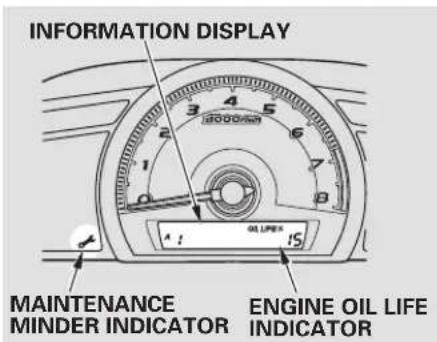
text_image
INFORMATION DISPLAY MAINTENANCE MINDER INDICATOR ENGINE OIL LIFE INDICATORTo see the current engine oil life, turn the ignition switch to the ON (II) position, then push and release the SEL/RESET button repeatedly until the engine oil life indicator appears (see page).65
The remaining engine oil life is displayed on the information display according to this table:
* 1:DX and Canadian DX-G
*2:LX, EX, EX-L, and Si
CONTINUED
Maintenance Minder
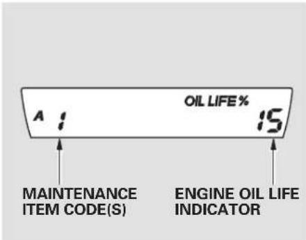
text_image
A : 15 OIL LIFE % MAINTENANCE ITEM CODE(S) ENGINE OIL LIFE INDICATORIf the remaining engine oil life is 15 to 6 percent, you will see the engine oil life indicator every time you turn the ignition switch to the ON (II) position. The maintenance minder indicator will also come on, and the maintenance item code(s) for other scheduled maintenance items needing service will be displayed next to the engine oil life indicator.
The 15 and 10 percent oil life indicators remind you that your vehicle will soon be due for scheduled maintenance.
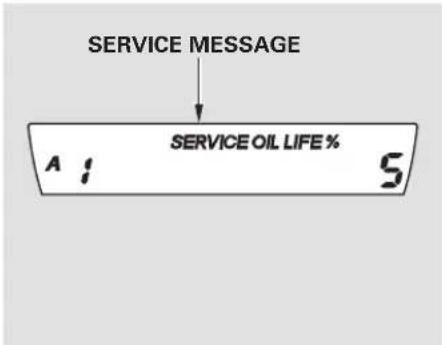
text_image
SERVICE MESSAGE SERVICE OIL LIFE % A : 5When the remaining engine oil life is 5 to 1 percent, you will see a "SERVICE" message along with the same maintenance item code(s), every time you turn the ignition switch to the ON (II) position.
The maintenance item code or codes indicate the main and sub items required at the time of the oil change (see page 231
You can switch the display to the odometer, the trip meter, and the outside temperature indicator (if equipped) by pushing the SEL/RESET button on the dashboard repeatedly.
When the engine oil life is 1 percent, the maintenance minder indicator () comes on every time you turn the ignition switch to the ON (II) position, then it goes out if you switch the information display.
When you see this message, have the indicated maintenance performed by your dealer as soon as possible.
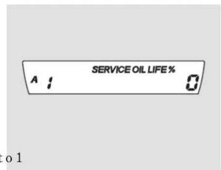
text_image
SERVICE OIL LIFE % A : 0 o 1When the remaining engine oil life is 0 percent, the engine oil life indicator will blink. The display comes on every time y out run the igni switch to the ON (II) position. The maintenance minder indicator ( ) also comes on and remains on in the instrument panel. When you see this message, immediately have the indicated maintenance done by your dealer.
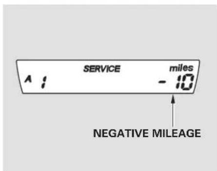
text_image
SERVICE - 10 miles A : NEGATIVE MILEAGEIf you do not perform the indicated maintenance, negative mileage is displayed and begins to blink after the vehicle has been driven 10 miles (10 km) or more.
Negative mileage means your vehicle has passed the maintenance required point.
Immediately have the indicated maintenance done by your dealer.
CONTINUED
Maintenance Minder
You can change the information display from the engine oil life display to the odometer, the trip meter, or the outside temperature (if equipped) every time you press and release the SEL/RESET button.
When the engine oil life is 0 percent or negative mileage, the maintenance minder indicator ( )e main s oneven if you change the information display.
Immediately have the service performed, and make sure to reset the display as described on the following.
Maintenance Main Items and Sub Items
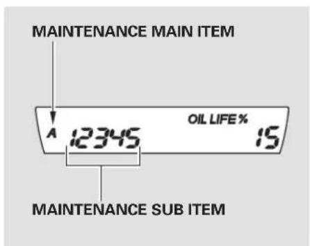
text_image
MAINTENANCE MAIN ITEM A 12345 OIL LIFE % 15 MAINTENANCE SUB ITEMAll maintenance items displayed on the information display are in code. For an explanation of these maintenance codes, see page.
Resetting the Engine Oil Life Display
Your dealer will reset the display after completing the required maintenance service. You will see "OIL LIFE 100%" on the information display the next time you turn the ignition switch to the ON (II) position.
If maintenance service is done by someone other than your dealer, reset the maintenance minder as follows:
-
Turn the ignition switch to the ON (II) position.
-
Press the SEL/RESET button repeatedly until the engine oil life indicator is displayed.
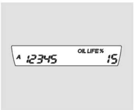
text_image
A 12345 OIL LIFE % 15- Press the SEL/RESET button for about 10 seconds. The engine oil life and the maintenance item code(s) will blink.
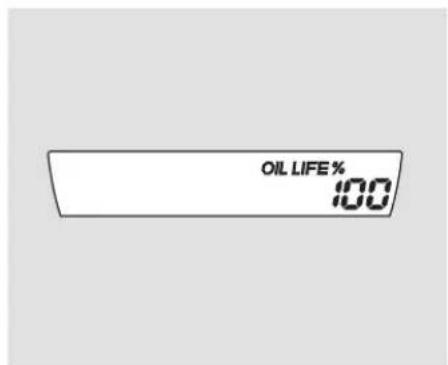
text_image
OIL LIFE % 100- Press the SEL/RESET button for more than 5 seconds. The maintenance item code(s) will disappear, and the engine oil life will reset to "100."
Important Maintenance Precautions
If you have the required service done but do not reset the display, or reset the display without doing the service, the system will not show the proper maintenance intervals. This can lead to serious mechanical problems because you will no longer have an accurate record of when maintenance is needed.
Your authorized Honda dealer knows your vehicle best and can provide competent, efficient service.
CONTINUED
Maintenance Minder
However, service at a dealer is not mandatory to keep your warranties in effect. Maintenance may be done by any qualified service facility or person who is skilled in this type of automotive service. Make sure to have the service facility or person reset the display as previously described. Keep all receipts as proof of completion, and have the person who does the work fill out the maintenance record. Check your warranty booklet for more information.
We recommend using Honda parts and fluids whenever you have maintenance done. These are manufactured to the same high quality standards as the original components, so you can be confident of their performance and durability.
U.S. Vehicles: Maintenance, replacement, or repair of emissions control devices and systems may be done by any automotive repair establishment or individual using parts that are “certified” to EPA standards.
According to state and federal regulations, failure to perform maintenance on the items marked with will not void your emissions warranties. However, all maintenance services should be performed in accordance with the intervals indicated by the information display.
Owner's Maintenance Checks You should check the following items at the specified intervals. If you are unsure of how to perform any check, turn to the appropriate page listed.
- Engine oil level Check every time you fill the fuel tank. See page 189
- Engine coolant level Check the radiator reserve tank every time you fill the fuel tank. See page 191.
- Automatic transmission Check the fluid level monthly. See page 242.
- Brakes Check the fluid level monthly. See page 244
- Tires Check the tire pressure monthly. Examine the tread for wear and foreign objects. See page 255.
- Lights Check the operation of the headlights, parking lights, taillights, high-mount brake light, and license plate lights monthly. See page 246
| Symbol Symbol Maintenance Main Items | |
| A | Replace engine oil* |
| B | Replace engine oil* and oil filterInspect front and rear brakesCheck parking brake adjustmentVisually inspect these items:Tie rod ends, steering gear box, and bootsSuspension componentsDriveshaft bootsBrake hoses and line (including ABS)All fluid levels and condition of fluidsExhaust system*Fuel lines and connections# |
* : If the message "SERVICE" does not appear more than 12 months after the display is reset, change the engine oil every year.
: See information on maintenance and emissions warranty in the center column on page 230
NOTE: • Independent of the maintenance minder indicator in the information display, replace the brake fluid every 3 years.
- Inspect idle speed every 160,000 miles (256,000 km).
- Adjust the valves during services A, B, 1, 2, or 3 only if they are noisy.
| Maintenance Sub Items | |
| 1 | Rotate tires |
| 2 | Replace air cleaner elementIf you drive in dusty conditions, replace every 15,000 miles (24,000 km).Replace dust and pollen filterIf you drive primarily in urban areas that have high concentrations of soot in the air from industry and from diesel-powered vehicles, replace every 15,000 miles (24,000 km).Inspect drive belt |
| 3 | Replace transmission fluid |
| 4 | Replace spark plugsInspect valve clearance |
| 5 | Replace engine coolant |
Main Menu
Table Of Contents
Fluid Locations
DX, Canadian DX-G, LX, EX, and EX-L models
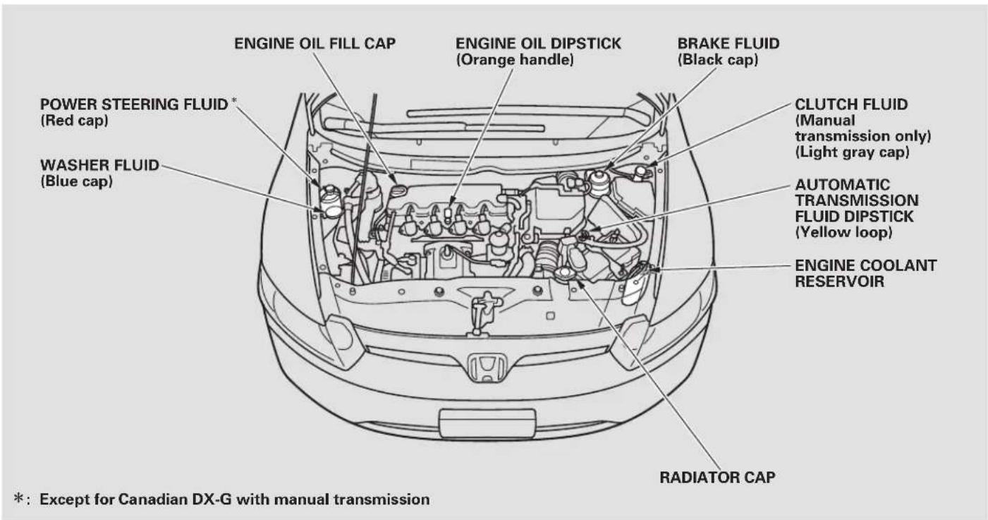
text_image
ENGINE OIL FILL CAP ENGINE OIL DIPSTICK (Orange handle) BRAKE FLUID (Black cap) POWER STEERING FLUID* (Red cap) WASHER FLUID (Blue cap) CLUTCH FLUID (Manual transmission only) (Light gray cap) AUTOMATIC TRANSMISSION FLUID DIPSTICK (Yellow loop) ENGINE COOLANT RESERVOIR RADIATOR CAP *: Except for Canadian DX-G with manual transmissionSi model
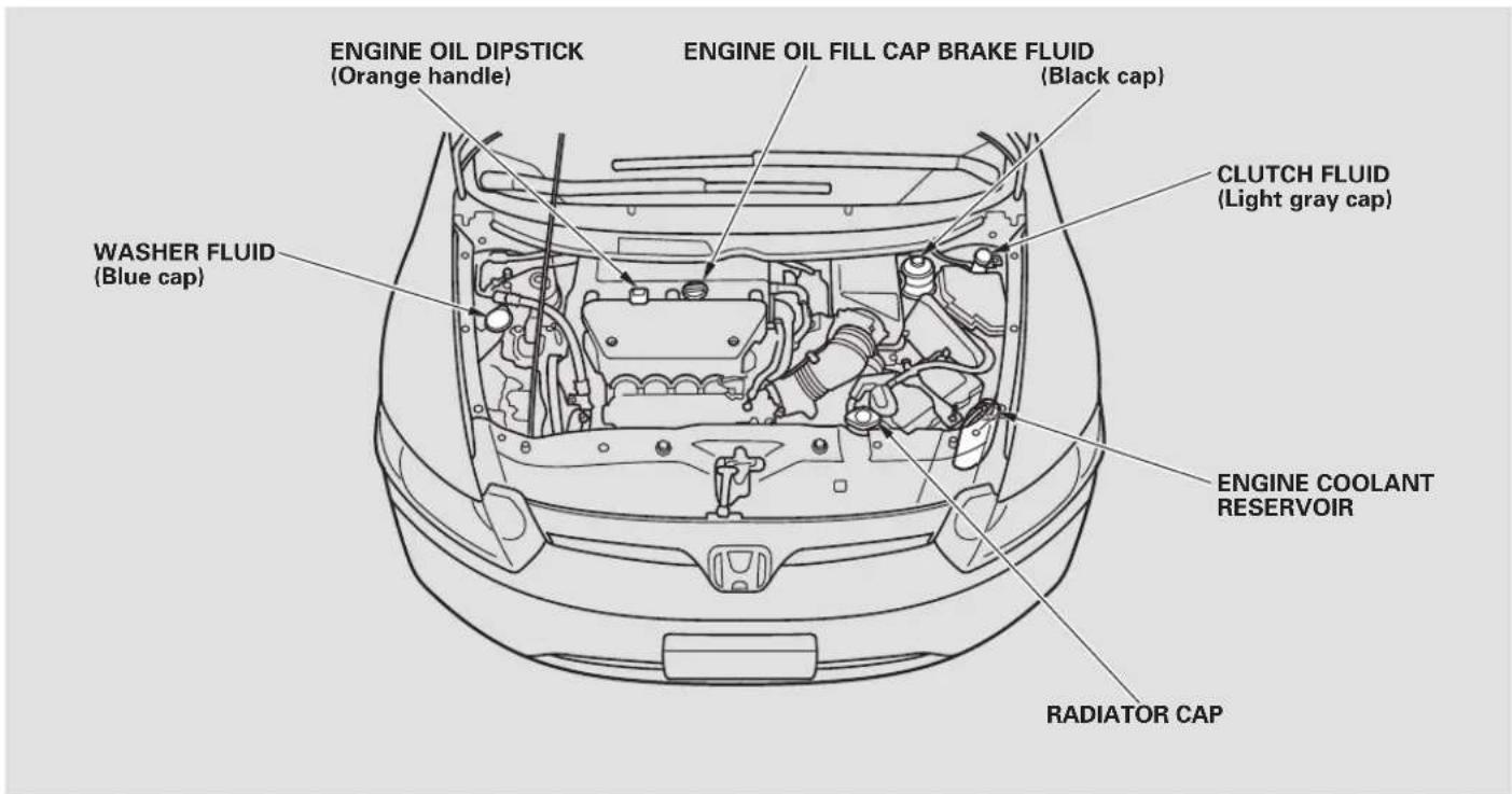
text_image
ENGINE OIL DIPSTICK (Orange handle) ENGINE OIL FILL CAP BRAKE FLUID (Black cap) CLUTCH FLUID (Light gray cap) WASHER FLUID (Blue cap) ENGINE COOLANT RESERVOIR RADIATOR CAPENGINE OIL FILL CAP ENGINE OIL FILL CAP
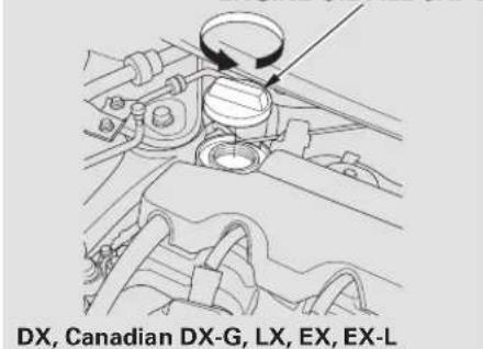
text_image
DX, Canadian DX-G, LX, EX, EX-LUnscrew and remove the engine oil fill cap on the valve cover. Pour in the oil slowly and carefully so you do not spill any. Clean up any spills immediately. Spilled oil could damage components in the engine compartment.
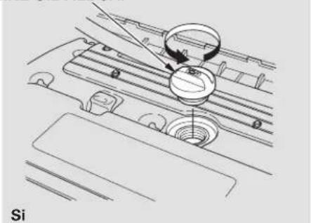
natural_image
Technical diagram of a car intake manifold with a circular component and a pointer, labeled 'Si' (no text or symbols on the diagram itself)Reinstall the engine oil fill cap, and tighten it securely. Wait a few minutes, and recheck the oil level on the engine oil dipstick. Do not fill above the upper mark; you could damage the engine.
Recommended Engine Oil Oil is a major contributor to your engine's performance and longevity. Always use a premium-grade detergent oil displaying the API Certification Seal. This seal indicates the oil is energy conserving, and that it meets the American Petroleum Institute's latest requirements. It is highly recommended that you use Honda Motor Oil in your vehicle for optimum engine protection.
API CERTIFICATION SEAL

text_image
AMERICAN PETROLEUM INSTITUTE FOR GASOLINE ENGINES CERTIFIEDMake sure the API Certification Seal says "For Gasoline Engines."
The oil viscosity or weight is provided on the container's label.
DX, Canadian DX-G, LX, EX, and EX-L models:
Honda Motor Oil is the preferred 5W-20 lubricant for your vehicle. 5W-20 oil is formulated for year-round protection of your vehicle, to improve cold weather starting and fuel economy.
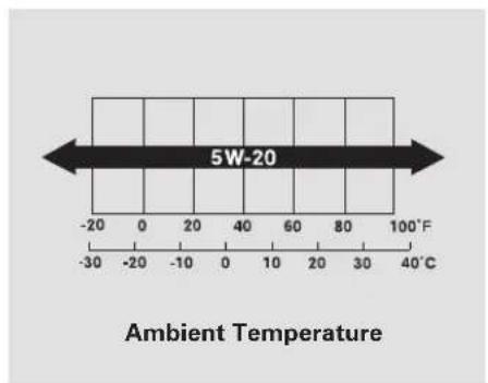
text_image
5W-20 Ambient TemperatureSi model:
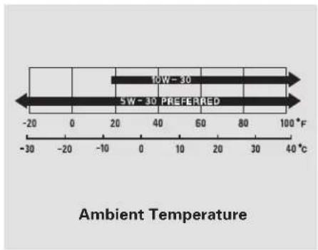
text_image
10W - 30 SW - 30 PREFERRED Ambient TemperatureAn oil with a viscosity of 5W-30 is preferred for improved fuel economy and year-round protection in your vehicle. You may use a 10W-30 oil if the temperature in your area never goes below 20^ F ( 7^ C).
Synthetic Oil
You may use a synthetic motor oil if it meets the same requirements given for a conventional motor oil: it displays the API certification seal, and it is the proper weight. You must follow the oil and filter change intervals shown on the information display.
Engine Oil Additives
Your vehicle does not require any oil additives. Additives may adversely affect the engine or transmission performance and durability.
Changing the Engine Oil and Filter
Always change the oil and filter according to the maintenance messages shown on the information display. The oil and filter collect contaminants that can damage your engine if they are not removed regularly.
Changing the oil and filter requires special tools and access from underneath the vehicle. The vehicle should be raised on a service station-type hydraulic lift for this service. Unless you have the knowledge and proper equipment, you should have this maintenance done by a skilled technician.
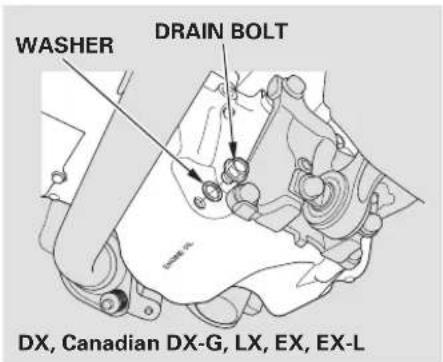
text_image
WASHER DRAIN BOLT DX, Canadian DX-G, LX, EX, EX-L- Run the engine until it reaches normal operating temperature, then shut it off.
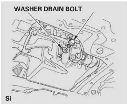
text_image
WASHER DRAIN BOLT SiOpen the hood, and remove the engine oil fill cap. Remove the oil drain bolt and washer from the bottom of the engine. Drain the oil into an appropriate container.
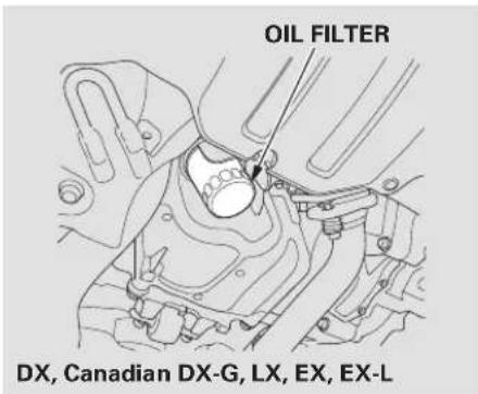
text_image
OIL FILTER DX, Canadian DX-G, LX, EX, EX-L- Remove the oil filter, and let the remaining oil drain. A special wrench (available from your dealer) is required.
Make sure the oil filter gasket is not stuck to the engine block. If it is, remove it before installing a new oil filter.
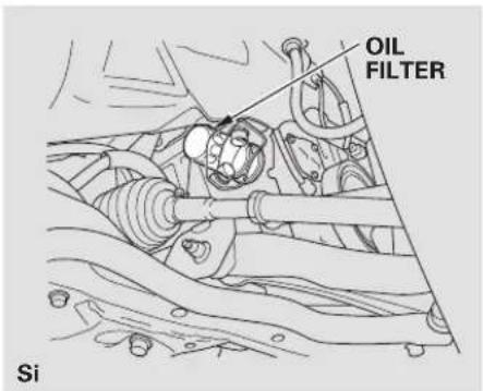
text_image
OIL FILTER SiInstall a new oil filter according to the instructions that come with it.
Make sure to clean off any dirt and dust on the connecting surface of a new oil filter.
-
Put a new washer on the drain bolt, then reinstall the drain bolt. Tighten the drain bolt to: 29 lbf·ft (39 N·m, 4.0 kgf·m)
-
Refill the engine with the recommended oil. Engine oil change capacity (including filter):
DX, Canadian DX-G, LX, EX, EX-L 3.9 US qt (3.7)
Si 4.6 US qt (4.4ℓ)
-
Replace the engine oil fill cap. Start the engine. The oil pressure indicator should go out within 5 seconds. If it does not, turn off the engine, and check your work.
-
Let the engine run for several minutes, then check the drain bolt and oil filter for leaks.
CONTINUED
Changing the Engine Oil and Filter, Engine Coolant
- Adding Enging's Godlantsit for several minutes, then check the oil level on the dipstick. If necessary, add more oil.
NOTICE
Improper disposal of engine oil can be harmful to the environment. If you change your own oil, please dispose of the used oil properly. Put it in a sealed container and take it to a recycling center. Do not discard it in a trash bin or dump it on the ground.
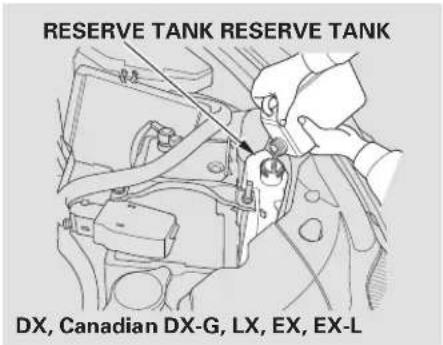
text_image
RESERVE TANK RESERVE TANK DX, Canadian DX-G, LX, EX, EX-LIf the coolant level in the reserve tank is at or below the MIN line, add coolant to bring it up to the MAX line. Inspect the cooling system for leaks.
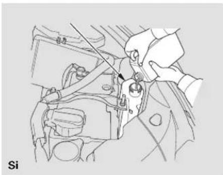
natural_image
Line drawing of a car engine component being adjusted for a tool, no text or symbols presentAlways use Honda Long-life Anti-freeze/Coolant Type 2. This coolant is pre-mixed with 50 percent antifreeze and 50 percent water. Never add straight antifreeze or plain water.
If Honda antifreeze/coolant is not available, you may use another major-brand non-silicate coolant as a temporary replacement. M is a high-quality coolant recommended for aluminum engines. Continued use of any non-Honda coolant can result in corrosion, causing the cooling system to malfunction or fail. Have the cooling system flushed and refilled with Honda antifreeze/coolant as soon as possible.
If the reserve tank is completely empty, you should also check the coolant level in the radiator.
WARNING
Removing the radiator cap while the engine is hot can cause the coolant to spray out, seriously scalding you.
Always let the engine and radiator cool down before removing the radiator cap.
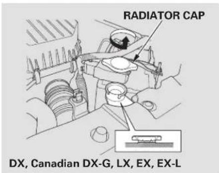
text_image
RADIATOR CAP DX, Canadian DX-G, LX, EX, EX-L- Make sure the engine and radiator are cool.
- Relieve any pressure in the cooling system by turning the radiator cap counterclockwise, without pressing down.
CONTINUED
Engine Coolant
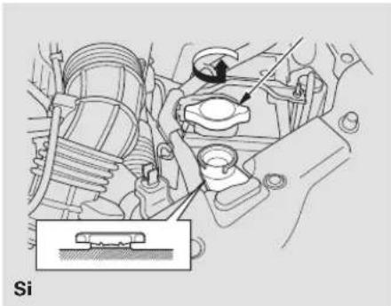
natural_image
Mechanical assembly diagram showing engine components and a labeled component 'Si' (no text or symbols beyond label)- Remove the radiator cap by pushing down and turning counterclockwise.
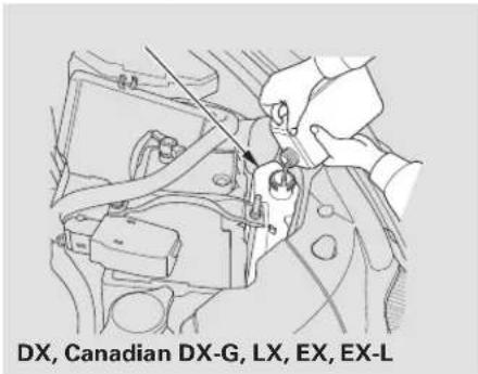
text_image
DX, Canadian DX-G, LX, EX, EX-LThe coolant level should be up to the base of the filler neck. Add coolant if it is low.
Pour the coolants slowly an carefully so you do not spill any. Clean up any spill immediately; it could damage components in the engine compartment.
- Put the radiator cap back on, and tighten it fully.
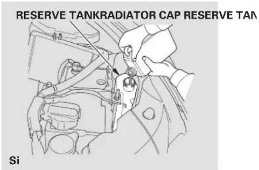
text_image
RESERVE TANKRADIATOR CAP RESERVE TAN Si- Pour coolant into the reserve tank. Fill it to halfway between the MAX and MIN marks. Put the cap back on the reserve tank.
Do not add any rust inhibitors or other additives to your vehicle's cooling system. They may not be compatible with the coolant or engine components.
Check the fluid level in the windshield washer reservoir at least monthly during normal use.
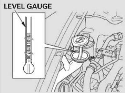
text_image
LEVEL GAUGEDX, Canadian DX-G, LX, EX, EX-L
Check the fluid level by removing the cap and looking at the level gauge.
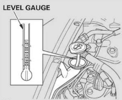
text_image
LEVEL GAUGESi
On Canadian models: The low washer level indicator comes on when the level is low (see page 63
Fill the reservoir with a good-quality windshield washer fluid. This increases the cleaning capability and prevents freezing in cold weather.
When you refill the reservoir, clean the edges of the windshield wiper blades with windshield washer fluid on a clean cloth. This will help to condition the blade edges.
NOTICE
Do not use engine antifreeze or a vinegar/water solution in the windshield washer reservoir. Antifreeze can damage your vehicle's paint, while a vinegar/water solution can damage the windshield washer pump. Use only commercially-available windshield washer fluid.
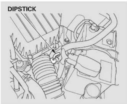
text_image
DIPSTICKCheck the fluid level with the engine at normal operating temperature.
- Park the vehicle on level ground. Start the engine, let it run until the radiator fan comes on, then shut off the engine. For accurate results, wait about 60 seconds (but no longer than 90 seconds) before doing step 2.
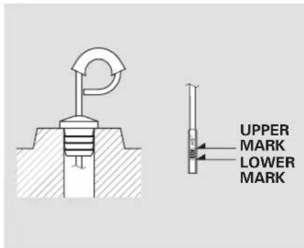
text_image
UPPER MARK LOWER MARK- Remove the dipstick (yellow loop) from the transmission, and wipe it with a clean cloth.
- Insert the dipstick all the way into the transmission securely as shown in the illustration.
-
Remove the dipstick, and check the fluid level. It should be between the upper and lower marks.
-
If the level is below the lower mark, add fluid into the dipstick hole to bring it to the level between the upper and lower marks.
Pour the fluid slowly and carefully so you do not spill any. Clean up any spill immediately; it could damage components in the engine compartment.
Always use Honda ATF-Z1 (automatic transmission fluid).
- Insert the dipstick all the way back into the transmission securely as shown in the illustration.
The transmission should be drained and refilled with new fluid according to the maintenance minder (see page 225).
If you are not sure how to add fluid, contact your dealer.
Automatic Transmission Fluid, Manual Transmission Fluid
NOTICE
Use only Honda Genuine ATF-Z1 (Automatic Transmission Fluid). Do not mix with other transmission fluids. Using transmission fluid other than Honda Genuine ATF-Z1 may cause deterioration in transmission operation and durability, and could result in damage to the transmission. Damage resulting from the use of transmission fluid other than Honda Genuine ATF-Z1 is not covered by the Honda new vehicle warranty.
Manual Transmission Fluid

text_image
FILLER BOLT Correct Level DX, Canadian DX-G, LX, EX, EX-LCheck the fluid level with the transmission at normal operating temperature and the vehicle sitting on level ground. Remove the transmission filler bolt, and carefully feel inside the bolt hole with your finger. The fluid level should be up to the edge of the bolt hole. If it is not, add Honda Manual Transmission Fluid (MTF) until it starts to run out of the hole. Reinstall the filler bolt, and tighten it securely.
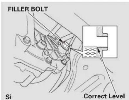
text_image
FILLER BOLT Si Correct LevelIf Honda MTF is not available, you may use an SAE 10W-30 or 10W-40 viscosity motor oil with the API Certification seal that says "FOR GASOLINE ENGINES" as a temporary replacement. However, motor oil does not contain the proper additives, and continued use can cause stiffer shifting. Replace as soon as it is convenient.
CONTINUED
Manual Transmission Fluid, Brake and Clutch Fluid
The transmission should be drained and refilled with new fluid according to the maintenance minder (see page 225).
If you are not sure how to check and add fluid, contact your dealer.
Check the brake fluid level in the reservoirs monthly.
Replace the brake fluid according to the maintenance minder (see page 225).
Always use Honda Heavy Duty Brake Fluid DOT 3. If it is not available, you should use only DOT 3 or DOT 4 fluid, from a sealed container, as a temporary replacement.
Using any non-Honda brake fluid can cause corrosion and decrease the life of the system. Have the brake system flushed and refilled with Honda Heavy Duty Brake Fluid DOT 3 as soon as possible.
Brake fluid marked DOT 5 is not compatible with your vehicle's braking system and can cause extensive damage.
Brake SystemBrake and Clutch Fluid
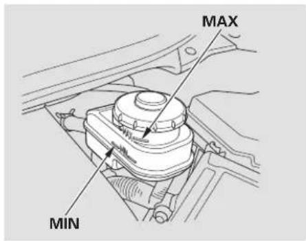
text_image
MAX MINThe fluid level should be between the MIN and MAX marksonthesis of the reservoir. If the level is at or below the MIN mark, your brake system needs attention. Have the brake system inspected for leaks or worn brake pads.
Manual Transmission only
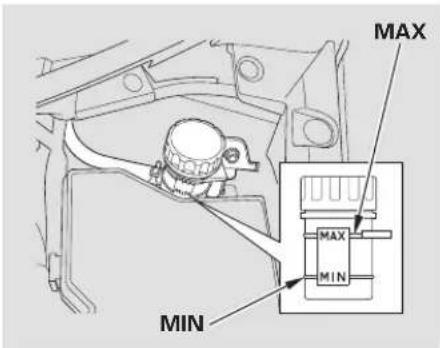
text_image
MAX MAX MINThe fluid level should be between the MIN and MAX mark so th of the reservoir. If it is not, add brake fluid to bring it up to that level. Use the same fluid specified for the brake system.
A low fluid level can indicate a leak in the clutch system. Have this system inspected as soon as possible.
Power Steering FluidClutch Fluid
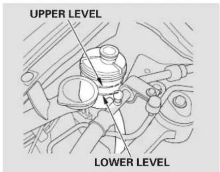
text_image
UPPER LEVEL LOWER LEVELAll models except Si and Canadian DX-G with manual transmission
Glick the level on the side of the reservoir when the engine is cold. The fluid should be between the UPPER LEVEL and LOWER LEVEL. If not add power steering fluid to the UPPER LEVEL mark.
Pour the fluid slowly and carefully so you do not spill any. Clean up any spill immediately; it could damage components in the engine compartment.
Always use Honda Power Steering Fluid. You may use another power steering fluid as an emergency replacement, but have the power steering system flushed and refilled with Honda PSF as soon as possible.
A low power steering fluid level can indicate a leak in the system. Check the fluid level frequently, and have the system inspected as soon as possible.
NOTICE
Turning the steering wheel to full left or right lock and holding it there can damage the power steering pump.
Lights
Headlight Aiming Replacing a Headlight Bulb
The head lights were proper when your vehicle was new. If you regularly carry heavy items in the trunk, readjustment may be required. Adjustments should be done dealer or other qualified technician.
Your vehicle has halogen headlight bulbs. When replacing a bulb, handle it by its base, and protect the glass from contact with your skin or hard objects. If you touch the glass, clean it with denatured alcohol and a clean cloth.
NOTICE
Halogen headlight bulbs get very hot when lit. Oil, perspiration, or a scratch on the glass can cause the bulb to overheat and shatter.
High Beam Headlight
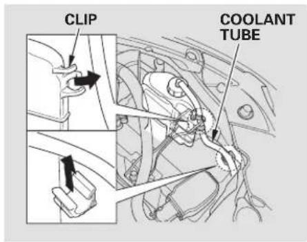
text_image
CLIP COOLANT TUBE- Open the hood.
To change a bulb on the driver's side, remove the coolant tube from the two clips, then remove the reserve tank from its holder by pulling it straight up.
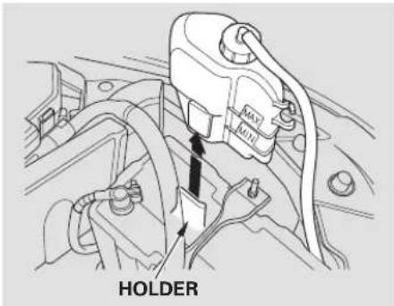
text_image
HOLDER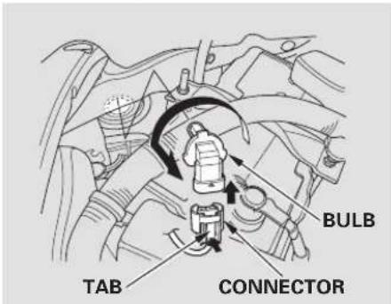
text_image
BULB TAB CONNECTOR- Remove the electrical connector from the bulb by pushing on the tab to unlock it, then slide the connector off the bulb.
-
Remove the bulb by turning it about one-quarter turn counterclockwise.
-
Insert the new bulb into the hole, and turn it one-quarter turn clockwise to lock it in place.
- Push the electrical connector back onto the bulb. Make sure it is on all the way.
- Turn on the headlights to test the new bulb.
- (Driver's side)
Put the tube back in the clips and install the reserve tank back in place, making sure its bottom tab is in the holder.
CONTINUED
Lights
Low Beam Headlight
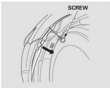
text_image
SCREW- To change the driver's side bulb, start the engine, turn the steering wheel all the way to the right, and turn off the engine. To change the passenger's side bulb, turn the steering wheel to the left.
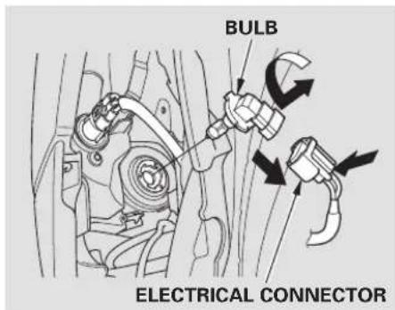
text_image
BULB ELECTRICAL CONNECTOR- Use a Phillips-head screwdriver to remove the screw from the inner fender, and pull the inner fender cover back.
-
Remove the electrical connector from the bulb by pushing on the tab to unlock it, then slide the connector off the bulb.
-
Remove the bulb from the headlight assembly by turning it one-quarter turn counterclockwise.
-
Insert the new bulb into the hole, and turn it one-quarter turn clockwise to lock it in place.
-
Push the electrical connector back onto the bulb. Make sure it is on all the way.
-
Turn on the headlights to test the new bulb.
-
Reinstall the inner fender cover. Then reinstall the screw and tighten it securely.
Replacing the Front Side Marker/Parking/Turn Signal Light Bulb
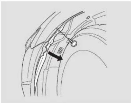
natural_image
Technical line drawing of a mechanical component with a highlighted section and arrow (no text or symbols)- To change the driver's side bulb, start the engine, turn the steering wheel all the way to the right, and turn off the engine. To change the passenger's side bulb, turn the steering wheel to the left.
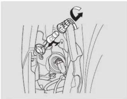
natural_image
Mechanical assembly diagram showing a lever mechanism with no visible text or symbols-
Use a Phillips-head screwdriver to remove the screw from the inner fender, and pull the inner fender cover back.
-
Remove the socket from the headlight assembly by turning it one-quarter turn counterclockwise.
-
Remove the bulb from the socket by pushing the bulb in and turning it counterclockwise until it unlocks.
- Install the new bulb in the socket. Turn it clockwise to lock it in place.
- Insert the socket back into the headlight assembly. Turn it clockwise to lock it in place.
- Turn on the lights to make sure the new bulb is working.
- Reinstall the inner fender cover. Then reinstall the screw and tighten it securely.
Lights
Replacing Rear Bulbs
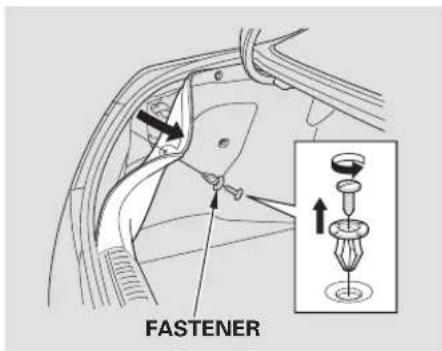
text_image
FASTENER- Open the trunk.
Remove the screw in the center of the fastener on the side of the trunk lining. Pull the lining back.
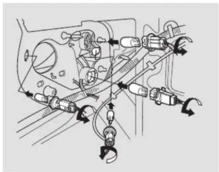
natural_image
Mechanical assembly diagram showing interconnected components with directional arrows (no text or labels)Determine which of the four bulbs is burned out: stop/tail-light, backup light, side marker light, or turn signal light.
-
Remove the socket by turning it one-quarter turn counterclockwise.
-
Pull the bulb straight out of its socket. Push the new bulb straight into the socket until it bottoms.
-
Reinstall the socket into the light assembly by turning it clockwise until it locks.
-
Turn on the lights to make sure the new bulb is working.
-
Reinstall the trunk lining. Make sure it is installed under the edge of the trunk seal.
-
Put the fastener into the hole on the side of the trunk lining. Reinstall the screw.
Replacing a High-mount Brake Light Bulb
On DX, Canadian DX-G, and LX models
-
Open the trunk, then remove the holding clips from the cover, and remove the cover.
-
Remove the socket from the light assembly by turning it one-quarter turn counterclockwise.
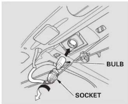
text_image
BULB SOCKET-
Pull the bulb straight out of its socket. Push the new bulb straight into the socket until it bottoms.
-
Reinstall the socket. Turn it clockwise until it locks. Make sure the new bulb is working.
-
Reinstall the cover, and tighten its holding clips securely.
Cleaning the Seat Belts
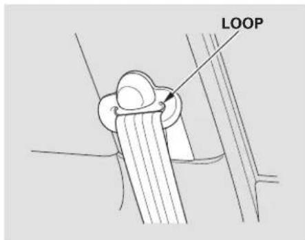
text_image
LOOPIf your seat belts get dirty, use a soft brush with a mixture of mild soap and warm water to clean them. Do not use bleach, dye, or cleaning solvents. Let the belts air-dry before you use the vehicle.
CONTINUED
Cleaning the Seat Belts, Floor Mats
Dirt build-up in the loops of the seat belt anchors can cause the belts to retract slowly. Wipe the insides of the loops with a clean cloth dampened in mild soap and warm water or isopropyl alcohol.
Floor Mats
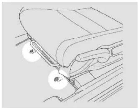
natural_image
Line drawing of a vehicle's seat and wheel assembly (no text or symbols)If equipped
The driver's floor mat that came with your vehicle hooks over the floor mat anchors. This keeps the floor mat from sliding forward and possibly interfering with the pedals.
If you remove a floor mat, make sure to re-anchor it when you put it in your vehicle.
If you use a non-Honda floor mat, make sure it fits properly and that it can be used with the floor mat anchors. Do not put additional floor mats on top of the anchored mat.
On models with A/C
This filter removes the dust and pollenthatisbroughtinfro outside through the heating and cooling system.
Have your dealer replace the filter when this service is indicated by a maintenance message on the information display. It should be replaced every 15,000 miles (24,000 km) if you drive primarily in urban areas that have high concentrations of soot in the air, or if the flow from the heating and cooling system becomes less than usual.
Wiper BladesDust and Pollen Filter
Check the condition of the wiper blades at least every six months. Replace them if you find signs of cracking in the rubber, areas that are getting hard, or if they leave streaks and unwiped areas when used.
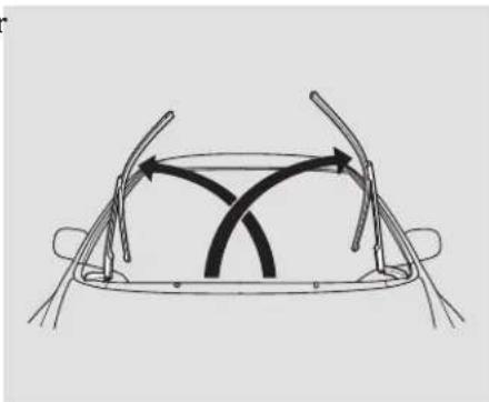
natural_image
Diagram of a car's side view showing steering wheel and curved arrows indicating motion (no text or symbols)To replace a wiper blade:
- Raise each wiper arm off the windshield, lifting the driver's side first, then the passenger's side.
NOTICE
Do not open the hood when the wiper arms are raised, or you will damage the hood and wiper arms.
CONTINUED
Main Menu
Table Of Contents
Wiper Blades
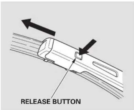
text_image
RELEASE BUTTON- Disconnect the blade assembly from the wiper arm by push the release button. Then slide the blade assembly out of the wiper arm.
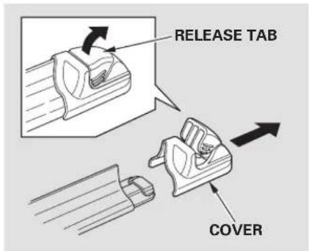
text_image
RELEASE TAB COVERPull up the cover release tab on i n gth end of the blade assembly, then remove the cover.
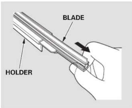
text_image
BLADE HOLDERSlide the blade out of the holder.
- Align the slots in the new blade with the retaining edges on the holder, then slide the blade onto the holder. Keep about 1 inch of the holder extended from the blade assembly so you can reinstall the cover.
- Reinstall the cover onto the blade assembly.
- Slide the wiper blade assembly onto the wiper arm. Make sure it locks in place.
- Lower the wiper arm down against the windshield, the passenger's side first, then the driver's side.
To safely operate your vehicle, your tires must be the proper type and size, in good condition with adequate tread, and correctly inflated.
The following pages give more detailed information on how to take care of your tires and what to do when they need to be replaced.
▲WARNING
Using tires that are excessively worn or improperly inflated can cause a crash in which you can be seriously hurt or killed.
Follow all instructions in this owner's manual regarding tire inflation and maintenance.
Inflation GuidelinesTires
Keeping the tires properly inflated provides the best combination of handling, tread life, and riding comfort.
- Underinflated tires wear unevenly, adversely affect handling and fuel economy, and are more likely to fail from being overheated.
• Overinflated tires can make your vehicleridemoreharshly, more prone to damage from road hazards, and wear unevenly.
CONTINUED
Tires
We recommend that you visually check your tires every day. If you think a tire might be low, check it immediately with a tire gauge.
The tire pressure monitoring system (TPMS) warns you when a tire pressure is low. See page 1218 more information.
Even though your vehicle is equipped with TPMS, we recommend that you visually check your tires every day.
Use a gauge to measure the air pressure in each tire at least once a month. Even tires that are in good condition may lose 1 to 2 psi (10 to 20 kPa, 0.1 to 0.2 kgf/cm ^2 ) per month. Remember to check the spare tire at the same time.
Check the air pressures when the tires are cold. This means the vehicle has been parked for at least 3 hours, or driven less than 1 mile (1.6 km). Add or release air, if needed, to match the recommended cold tire pressures on this page.
If you check air pressures when the tires are hot [driven for several miles (kilometers)], you will see readings 4 to 6 psi (30 to 40 kPa, 0.3 to 0.4 kgf/cm²) higher than the cold readings. This is normal. Do not let air out to match the recommended cold air pressure. The tire will be underinflated.
You should get your own tire pressure gauge and use it whenever you check your tire pressures. This will make it easier for you to tell if a pressure loss is due to a tire problem and not due to a variation between gauges.
While tubeless tires have some ability to self-seal if they are punctured, you should look closely for punctures if a tire starts losing pressure.
Recommended Tire Pressures
The following charts show the recommended cold tire pressures for most normal driving conditions.
DX and Canadian DX-G with automatic transmission
| Tire Size Cold Tire Pressure | |
| Front/Rear | |
| P195/65R15 89H | 32 psi (220 kPa, 2.2 kgf/cm ^2 ) |
Canadian DX-G with manual transmission
| Tire Size Cold Tire Pressure | |
| Front/Rear | |
| P195/65R15 89S | 32 psi (220 kPa, 2.2 kgf/cm ^2 ) |
LX, EX, EX-L
| Tire Size Cold Tire Pressure | |
| Front/Rear | |
| P205/55R16 89H | 32 psi (220 kPa, 2.2 kgf/cm ^2 ) |
Si
| Tire Size Cold Tire Pressure | |
| Front/Rear | |
| P215/45R17 87V | 32 psi (220 kPa, 2.2 kgf/cm ^2 ) |
Optional Summer Tire for Si
| Tire Size Cold Tire Pressure | |
| 215/45ZR17 91W | 32 psi (220 kPa, 2.2 kgf/cm ^2 ) |
The compact spare tire pres 60 psi (420 kPa, 4.2 kgf/cm²)
For convenience, the recommended tire sizes and cold tire pressures are on a label on the driver's doorjamb. For additional information about your tires, see page 299
High Speed Driving
Si model only
We strongly recommend that you do not drive faster than the posted speed limits and conditions allow. If you ever drive in a sanctioned
competitive event at sustained high speeds (over 118 mph or 190 km/h), be sure to adjust the cold tire pressures a s s h o w n b e l o w. If you not, excessive heat can build up and cause sudden tire failure.
Tire Size·Cold Tire Pressure for High Speed Driving
Si model only
P215/45R17 87V
ureis:
Front/Rear:
35 psi (240 kPa, 2.4 kgf/cm²)
When you return to normal speed driving, be sure to readjust the tire pressure for normal driving. You should wait until the tires are cold before adjusting the tire pressure.
Except Si model
Tire pressure for high speed driving is the same as for normal driving.
Tires
Tire Inspection Tire Service Life Every time you check inflation, you should also examine the tires for damage, foreign objects, and wear.
You should look for:
- Bumps or bulges in the tread or side of the tire. Replace the tire if you find either of these seconds
- Cuts, splits, or cracks in the side of the tire. Replace the tire if you can see fabric or cord.
• Excessive tread wear.
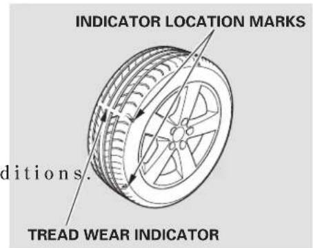
text_image
INDICATOR LOCATION MARKS ditions. TREAD WEAR INDICATORYour tires have wear indicators molded into the tread. When the tread wears down, you will see a 1/2 inch (12.7 mm) wide band across the tread. This shows there is less than 1/16 inch (1.6 mm) of tread left on the tire.
A tire this worn gives very little traction on wet roads. You should replace the tire if you can see three or more tread wear indicators.
The service life of your tires is dependent on many factors, including, but not limited to, driving habits, road conditions, vehicle loading, inflation pressure, maintenance history, speed, and environmental conditions (even when the tires are not in use).
In addition to your regular inspections and inflation pressure maintenance, it is recommended that you have annual inspections performed once the tires reach five years old. It is also recommended that all tires, including the spare, be removed from service after 10 years from the date of manufacture, regardless of their condition or state of wear.
The last four digits of the TIN (tire identification number) are found on the sidewall of the tire and indicate the date of manufacture (See Tire Labeling on page 801
Tire Maintenance
In addition to proper inflation, correct wheel alignment helps to decrease tire wear. If you find a tire is worn unevenly, have your dealer check the wheel alignment.
Have your dealer check the tires if you feel a consistent vibration while driving. A tire should always be rebalanced if it is removed from the wheel. When you have new tires installed, make sure they are balanced. This increases riding comfort and tire life. For best results, have the installer perform a dynamic balance.
NOTICE
For vehicles equipped with aluminum wheels:
Improper wheel weights can damage your vehicle's aluminum wheels. Use only Honda wheel weights for balancing.
Tires
Tire Rotation
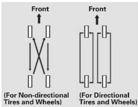
text_image
Front (For Non-directional Tires and Wheels) Front (For Directional Tires and Wheels)To help increase tire life and distribute wear more evenly, rotate the tires according to the maintenance messages displayed on the information display. Move the tires to the positions shown in the illustration each time they are rotated. If you purchase directional tires, rotate only front-to-back.
When the tires are rotated, make sure the air pressures are checked.
Tire Wear
Si model only
The tires that came on your vehicle were designed and constructed to provide superior grip during acceleration, braking, and cornering.
As a trade-off, they will wear more rapidly than tires used on ordinary passenger vehicles. Because of the vehicle's weight distribution, and the fact that the front wheels are the driving wheels, you can expect them to wear more rapidly than the rear tires.
The mile age you can expect from your vehicle tiresisthesameas comparable mid-and rear-engine sports cars, and it will vary greatly with your driving habits.
If you drive moderately, the front tires could last more than 10,000 miles (16,000 km). However, the mileage will be substantially less if you tend to drive your vehicle at the upper limits of its capabilities.
You should carefully inspect your vehicle's tires for wear, damage, and proper inflation every 7,500 miles (12,000 km).
Replacing Tires and Wheels
Replace your tires with radial tires of the same size, load range, speed rating, and maximum cold tire pressure rating (as shown on the tire's sidewall).
Mixing radial and bias-ply tires on your vehicle can reduce braking ability, traction, and steering accuracy. Using tires of a different size or construction can cause the ABS and vehicle stability assist system (VSA) to work inconsistently.
The ABS and VSA system (if equipped) work by comparing the speed of each wheel. When replacing tires, use the same size originally supplied with the vehicle. Tire size and construction can affect wheel speed and may cause the system to activate.
It is best to replace all four tires at the same time. If that is not possible or necessary, replace the two front tires or two rear tires as a pair. Replacing just one tire can seriously affect your vehicle's handling.
If you ever replace a wheel, make sure that the wheel's specifications match those of the original wheels.
On vehicles with TPMS
Also be sure you use only TPMS specific wheels. If you do not, the tire pressure monitoring system will not work.
Replacement wheels are available at your dealer.
WARNING
ssible
Installing improper tires on your vehicle can affect handling and stability. This can cause a crash in which you can be seriously hurt or killed.
Always use the size and type of tires recommended in this owner's manual.
Tires
Wheels:
DX and Canadian DX-G 15×6 J
LX, EX, EX-L 16×61/2J
Si 17×7J
Tires:
DX and Canadian DX-G with automatic transmission P195/65R15 89H
Canadian DX-G with manual transmission P195/65R15 89S
LX, EX, EX-L P205/55R16 89H
Si
P215/45R17 87V (all season tire) Optional 215/45ZR17 91W (summer tire)
See page 209 information about DOT Tire Quality Grading, and page 301 for tire size and labeling information.
Winter DrivingWheel and Tire Specificat Tires marked “M + S” or “All Season” on the sidewall have an all- weather tread design suitable for most winter driving conditions.
For the best performance in snowy or icy conditions, you should install snow tires or tire chains. They may be required by local laws under certain conditions.
Summer Tires
Si model only If your vehicle is equipped with summer tires, be aware that these tires are not designed for winter driving conditions. For more information, consult your dealer.
If you mount snow tires on your vehicle, make sure they are radial tires of the same size and load range as original tires. Mount snow tires on all four wheels. The traction provided by snow tires on dry roads may below than your origin. Check with the tire dealer for maximum speed recommendations.
Tire ChainsSnow Tires
Mount tire chains on your tires when required by driving conditions or local laws. Install them only on the front tires.
When installing chains, follow the manufacturer's instructions, and mount them as tight as you can. Make sure they are not contacting the brake lines or suspension. Drive slowly with them installed. If you hear them coming into contact with the body or chassis, stop and investigate. Remove them as soon as you begin driving on cleared
Because your vehicle has limited tire clearance, Honda strongly recommends using the chains listed below, made by Security Chain Company (SCC).
Cable-type: SCC Radial Chain CH2311T
roads.
CONTINUED
Tires
NOTICE
Traction devices that are the wrong size or improperly installed can damage your vehicle's brake lines, suspension, body, and wheels. Stop driving if they are hitting any part of the vehicle.
WARNING
Using the wrong chains, or not properly installing chains, can damage the brake lines and cause a crash in which you can be seriously injured or killed.
Follow all instructions in this owner's manual regarding the selection and use of tire chains.
Wheels
Clean the wheels as you would the rest of the exterior. Wash them with the same solution, and rinse the thoroughly.
If equipped
Aluminum alloy wheels have a protective clear-coat that keeps the aluminum from corroding and tarnishing. Cleaning the wheels with harsh chemicals (including some commercial wheel cleaners) or a stiff brush can damage the clear-coat. To clean the wheels, use a mild detergent and a soft brush or sponge.
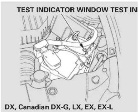
text_image
TEST INDICATOR WINDOW TEST IN DX, Canadian DX-G, LX, EX, EX-LCheck the condition of the battery monthly by looking at the tets indicator window. The label on the battery explains the test indicator's colors.
The location of the test indicator window varies between manufacturers.
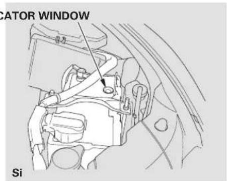
text_image
ICATOR WINDOW SiCheck the terminals for corrosion (a twhite or yellowish powder). To remove it, cover the terminals with a solution of baking soda and water. It will bubble up and turn brown. When this stops, wash it off with plain water. Dry off the battery with a cloth or paper towel. Coat the terminals with grease to help prevent further corrosion.
If additional battery maintenance is needed, see your dealer or a qualified technician.
WARNING: Battery posts, terminals, and related accessories contain lead and lead compounds. Wash your hands after handling.
CONTINUED
Checking the Battery
If you need to connect the battery to a charger, disconnect both cables to prevent damaging your vehicle's electrical system. Always disconnect the negative (-)cable first, and reconnect it last.
WARNING
The battery gives off explosive hydrogen gas during normal operation.
A spark or flame can cause the battery to explode with enough force to kill or seriously hurt you.
Wear protective clothing and a face shield, or have a skilled technician do the battery maintenance.
If your vehicle's battery is disconnected or goes dead, the audio system may disable itself. The next time y out run non ther radio, you will see "ENTER CODE" in the frequency display. Use the preset buttons to enter the code (see page 179).
On vehicles with navigation system The navigation system will also disable itself. Then next time you turn on the ignition switch, the system will require you to enter a PIN before it can be used. Refer to the navigation system manual.
If you need to park your vehicle for an extended period (more than 1 month), there are several things you should do to prepare it for storage. Proper preparation helps prevent deterioration and makes it easier to get your vehicle back on the road. If possible, store your vehicle indoors.
- Fill the fuel tank.
- Wash and dry the exterior completely.
- Clean the interior. Makes carpeting, floor mats, etc., are completely dry.
-
Leave the parking brake off. Put the transmission in reverse (manual) or Park (automatic).
-
Block the rear wheels.
- If the vehicle is to be stored for a longer period, it should be supported on jackstands so the tires are off the ground.
- Leave one window open slightly (if the vehicle is being stored indoors).
- Disconnect the battery.
-
Support the front wiper blade earme with a folded towel or rag so they do not touch the windshield.
• To minimize sticking, apply a silicone spray lubricant to all door and trunk seals. Also, apply a vehicle body wax to the painted surfaces that mate with the door and trunk seals.
ted -
Cover the vehicle with a “breathable” cover, one made from a porous material such as cotton. Non-porous materials, such as plastic sheeting, trap moisture, which can damage the paint.
- If possible, periodically run the engine until it reaches full operating temperature (the cooling fans cycle on and off twice). Preferably, do this once a month.
Main Menu
Table Of Contents
This section covers the more common problems that motorists experience with their vehicles. It gives you information about how to safely evaluate the problem and what to do to correct it. If the problem has stranded you on the side of the road, you may be able to get going again. If not, you will also find instructions on getting your vehicle towed.
Compact Spare Tire.... 270
Changing a Flat Tire 271
If the Engine Won't Start...... 275
Jump Starting 277
If the Engine Overheats 279
Low Oil Pressure Indicator ..... 281
Charging System Indicator...... 281
Malfunction Indicator Lamp ...... 282
Brake System Indicator 283
Fuses 284
Fuse Locations 288
Emergency Towing 290
Compact Spare Tire
Use the compact spare tire as a temporary replacement only. Get your regular tire repaired or replaced, and put it back on your vehicle as soon as you can.
Check the inflation pressure of the compact spare tire every time you check the other tires. It should be inflated to:
60 psi (420 kPa, 4.2 kgf/cm²)
Follow these precautions:
• Never exceed 50 mph (80 km/h).
- This tire gives a harsher ride and less traction on some road surfaces. Use greater caution while driving.
- Do not mount tire chains on the compact spare tire.
- Do not use your compact spare tire on another vehicle unless it is the same make and model.
On Si model
- Do not use a compact spare tire mounted on a front wheel; it will damage the limited slip differential (see page 271
All U.S. models
- The low tire pressure indicator comes on and stays on after you replace the flat tire with the compact spare tire. After several miles (kilometers) driving with the compact spare tire, the TPMS indicator comes on and the low tire pressure indicator goes off.
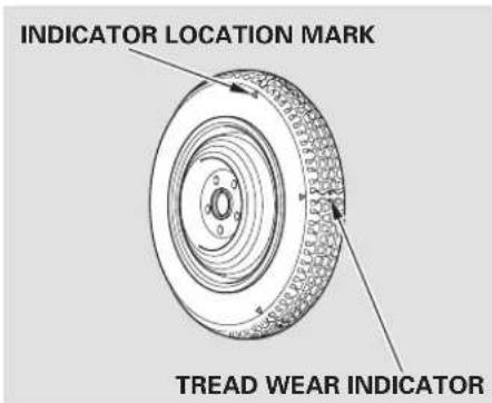
text_image
INDICATOR LOCATION MARK TREAD WEAR INDICATORReplace the tire when you can see the tread wear indicator bars. The replacement should be the same size and design tire, mounted on the same wheel. The spare tire is not designed to be mounted on a regular wheel, and the spare wheel is not designed for mounting a regular tire.
If you have a flat tire while driving, stop in a safe place to change it. Drive slowly along the shoulder until you get to an exit or an area that is far away from the traffic lanes.
The compact spare tire is sm than a standard tire, and it will affect the vehicle's handling. Drive cautiously when the spare is mounted on your vehicle.
On Si model only Thesized difference may also damage to the differential, so do not mount the compact spare on the front. If either front tire goes flat, removethereartireonthats side, mount the compact spare tire on the rear, then mount the rear tire on the front.
▲WARNING
The vehicle can easily roll off the jack, seriously injuring anyone underneath.
a 11 Follow the directions for changing a tire exactly, and never get under the vehicle when it is supported only by the jack.
cla Park the vehicle on firm, level, and non-slippery ground. Put the transmission in Park (automatic) or reverse (manual). Apply the a mparking brake.
- Turn on the hazard warning lights, and turn the ignition switch to the LOCK (0) position. Have all passengers get out of the vehicle while you change the tire.
JACK TOOL CASE
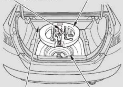
natural_image
Technical line drawing of a car engine bay with internal components and directional arrows (no text or labels)SPARE TIRETRUNK FLOO
- Open the trunk. Raise the trunk floor by lifting up on the back edge.
- Take the tool kit case out of the trunk.
- Unscrew the wing bolt, and take the spare tire out of its well.
CONTINUED
Main Menu
Table Of Contents
Changing a Flat Tire
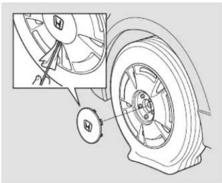
natural_image
Technical line drawing of a car wheel assembly with mounting bracket and tire (no text or symbols)- Canadian DX-G model Remove the center cap from the wheel with the extension.
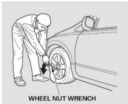
text_image
WHEEL NUT WRENCHLoosen each wheel nut 1/2 turn with the wheel nut wrench.
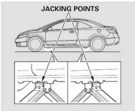
text_image
JACKING POINTSPlacethejackunderthejackir point nearest the tire you need to change. Turn the end bracket clockwise until the top of the jack contacts the jacking point. Make sure the jacking point tab is restinginthejacknotch.

text_image
WHEEL NUT WRENCH EXTENSIONUse the extension and the wheel nut wrench as shown to raise the vehicle until the flat tire is off the ground.
- Remove the wheel nuts, then remove the flat tire. Handle the wheel nuts carefully; they may be hot from driving. Place the flat tire on the ground with the outside surface facing up.
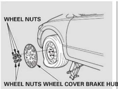
text_image
WHEEL NUTS WHEEL NUTS WHEEL COVER BRAKE HUBDX, and U.S. LX models Do not attempt to forcibly pry the wheel cover off with a screwdriver or other tool. The wheel cover cannot be removed without first removing the wheel nuts.
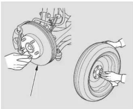
natural_image
Technical illustration of a car tire assembly with hands adjusting components (no text or symbols)- Before mounting the spare tire, wipe any dirt off the mounting surface of the wheel and hub with a clean cloth. Wipe the hub carefully; it may be hot from driving.
CONTINUED
Changing a Flat Tire
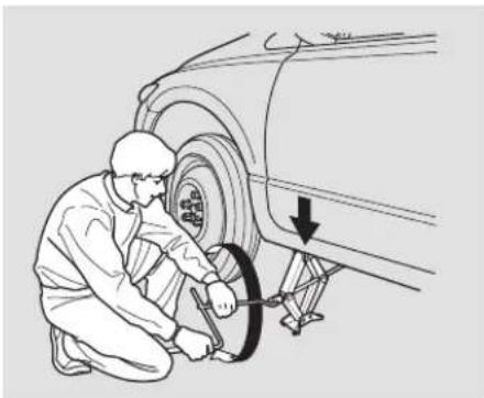
natural_image
Mechanic using a tire to lift a car wheel, with a downward arrow indicating the motion (no text or symbols present)- Put on the spare tire. Put the wheel nuts back on finger-tight, then tighten them in a crisscross pattern with the wheel nut wrench until the wheel is firmly against the hub. Do not try to tighten the wheel nuts fully.
- Lower the vehicle to the ground, and remove the jack.
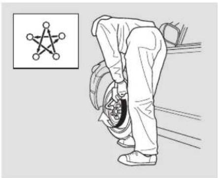
natural_image
Illustration of a person climbing a tire with a star symbol inset (no text or symbols on the diagram itself)- Tighten the wheel nuts securely in the same crisscross pattern. Have the wheel nut torque checked at the nearest automotive service facility.
Tighten the wheel nuts to: 80 lbf·ft (108 N·m, 11 kgf·m)
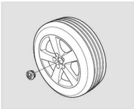
natural_image
Technical line drawing of a car wheel with a small attached component (no text or symbols)- On EX, EX-L and Si models in the U.S., and LX, EX, EX-L and Si models in Canada Remove the center cap from the flat tire.
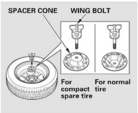
text_image
SPACER CONE WING BOLT For compact spare tire For normal tire- Place the flat tire face down in the spare tire well.
- Remove the spacer cone from the wing bolt, turn it over, and put it back on the bolt.
- Secure the flattire by scre the wing bolt back into its hole.
- Store the jack and tools in the tool kit case. Place the tool kit case in the center of the flat tire.
WARNING
Loose items can fly around the interior in a crash and cou seriously injure the occupants.
Store the wheel, jack, and tools securely before driving.
- Store the wheel cover or center cap in the trunk. Make sure it does not get scratched or damaged.
- Lower the trunk floor, then close the trunk lid.
- On all U.S. models Your vehicle's original tire has a tire pressure monitoring system w i nsensor. To replace a tire, refer to Changing a Tire with TPMS (see page £20
If the Engine Won't Start
Diagnosing why the engine won't start falls into two areas, depending don what you hear when you turn the ignition switch to the START (III) position:
- You hear nothing, or almost nothing. The engine's starter motor does not operate at all, or operates very slowly.
- You can hear the starter motor operating normally, or the starter motor sounds like it is spinning faster than normal, but the engine does not start up and run.
Nothing Happens or the Starter Motor Operates Very Slowly
When you turn the ignition switch to the START (III) position, you do not hear the normal noise of the engine trying to start. You may hear a clicking sound, a series of clicks, or nothing at all.
Check these things:
- Check the transmission interlock. If you have a manual transmission, the clutch pedal must be pushed all the way to the floor or the starter will not operate. With an automatic transmission, it must be in Park or neutral.
- Turn the ignition switch to the ON (II) position. Turn on the headlights, and check their brightness. If the headlights are very dim or do not come on at all, the battery is discharged. See Jump Starting on page .277
- Turn the ignition switch to the START (III) position. If the headlights do not dim, check the condition of the fuses. If the fuses are OK, there is probably something wrong with the electrical circuit for the ignition switch or starter motor. You will need a qualified technician to determine the problem. See Emergency Towing on page 290
If the headlights dim noticeably or go out when you try to start the engine, either the battery is discharged or the connections are corroded. Check the condition of the battery and terminal connections (see page 265ou can then try jump starting the vehicle from a booster battery (see page 277).
The Starter Operates Normally In this case, the starter motor's speed sounds normal, or even faster than normal, when you turn the ignition switch to the START (III) position, but the engine does not run.
- Are you using a properly coded key? An improperly coded key will cause the immobilizer system indicator in the instrument panel to blink rapidly (see page 77).
- Are you using the proper starting procedure? Refer to Starting the Engine on page 204
- Do you have fuel? Check the fuel gauge; the low fuel indicator may not be working.
- There may be an electrical problem, such as no power to the fuel pump. Check all the fuses (see page 284
If you find nothing wrong, you will need a qualified technician to find the problem. See Emergency
Towing on page 290
Although this seems like a simple procedure, you should take several precautions.
▲WARNING
A battery can explode if you do not follow the correct procedure, seriously injuring anyone nearby.
Keep all sparks, open flames, and smoking materials away from the battery.
You cannot start your vehicle with an automatic transmission by pushing or pulling it.
To jump start your vehicle:
- Open the hood, and check the physical condition of the battery. In very cold weather, check the condition of the electrolyte. If it seems slushy or frozen, do not try jump starting until it thaws.
NOTICE
If a battery sits in extreme cold, the electrolyte inside can f reeze. Attempting to jump start with a frozen battery can cause it to rupture.
- Turn off all the electrical accessories: heater, A/C, audio system, lights, etc. Put the transmission in neutral (manual) or Park (automatic), and set the parking brake.
DX, Canadian DX-G, LX, EX, EX-L
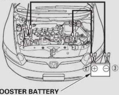
text_image
BOOSTER BATTERY ③The numbers in the illustrations show you the order to connect the jumper cables.
CONTINUED
Jump Starting
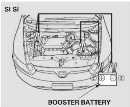
text_image
Si Si BOOSTER BATTERY- Connect one jumper cable to the positive ()+terminal on your battery. Connect the other end to the positive (+) terminal on the booster battery.
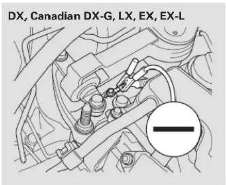
text_image
DX, Canadian DX-G, LX, EX, EX-L- Connect the second jumper cable to the negative (−) terminal on the booster battery. Connect the other end to the grounding strap as shown. Do not connect this jumper cable to any other part of the engine.
- If the booster battery is in another vehicle, have an assistant start that vehicle and run it at a fast idle.
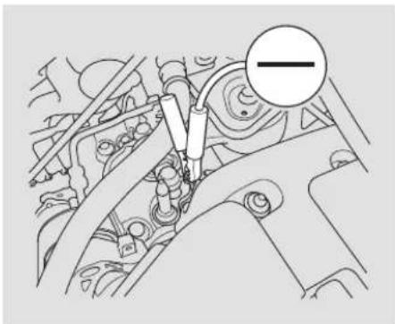
natural_image
Technical diagram of a mechanical assembly with no visible text or symbols-
Start the vehicle. If the starter motor still operates slowly, check that the jumper cables have good metal-to-metal contact.
-
Once your vehicle is running, disconnect the negative cable from your vehicle, then from the booster battery. Disconnect the positive cable from your vehicle, then from the booster battery.
Keep the ends of the jumper cables away from each other and any metal on the vehicle until everything is disconnected. Otherwise, you may cause an electrical short.
If the Engine Overheats
The reading of the vehicle's temperature gauge should stay in the midrange. If it climbs to the red mark, you should determine the reason (hot day, driving up a steep hill, etc.).
If the vehicle overheats, you should take immediate action. The only indication may be the temperature gauge climbing to or above the red mark. Or you may see steam or spray coming from under the hood.
NOTICE
Driving with the temperature gauge reading at the red mark can cause serious damage to the engine.
WARNING
Steam and spray from an overheated engine can seriously scald you.
Do not open the hood if steam is coming out.
-
Safely pull to the side of the road. Put the transmission in neutral (manual) or Park (automatic), and set the parking brake. Turn off all accessories, and turn on the hazard warning indicators.
-
If you see steam and/or spray coming from under the hood, turn off the engine. Wait until you see no more signs of steam or spray, then open the hood.
CONTINUED
- If you do not see steam or spray, leave the engine running and watch the temperature gauge. If the high heat is due to overloading, the engine should start to cool down almost immediately. If it does, wait until the temperature gauge comes down to the midpoint, then continue driving.
- If the temperature gauge stays at the red mark, turn off the engine.
- Look for any obvious coolant leaks, such as a split radiator hose. Everything is still extremely hot, so use caution. If you find a leak, it must be repaired before you continue driving (see Emergency Towingon page 290
-
If you don't find an obvious leak, check the coolant level in the radiator reserve tank (see page 191). Add coolant if the level is below the MIN mark.
-
If there was no coolant in the reserve tank, you may need to add coolant to the radiator. Let the engine cool down until the reading reaches the middle of the temperature gauge, or lower, before checking the radiator.
WARNING
Removing the radiator cap while the engine is hot can cause the coolant to spray out, seriously scalding you.
Always let the engine and radiator cool down before removing the radiator cap.
-
Using gloves or a large heavy cloth, turn the radiator cap counterclockwise, without pushing down, to the first stop. After the pressure releases, push down on the cap, and turn it until it comes off.
-
Start the engine, and set the temperature control dial to maximum heat. Add coolant to the radiator up to the base of the filler neck. If you do not have the proper coolant mixture available, you can add plain water. Remember to have the cooling system drained and refilled with the proper mixture as soon as you can.
- Put the radiator cap back on tightly. Run the engine, and check the temperature gauge. If it goes back to the red mark, the engine needs repair (see Emergency Towing on page 290
- If the temperature stays normal, check the coolant level in the radiator reserve tank. If it has gone down, add coolant to the MAX mark. Put the cap back on tightly.
Low Oil Pressure Indicator Charging System Indicofthe road, and shut
This indicator should never come on when the engine is
running. If it starts flashing or stays on, the oil pressure has dropped very low or lost pressure. Serious engine damage is possible, and you should take immediate action.
Running the engine with low oil pressure can cause serious mechanical damage almost immediately. Turn off the engine as soon as you can safely get the vehicle stopped.
2. Let the vehicle sit for a minute. Open the hood, and check the oil level (see page 189) an engine very low on oil can lose pressure during cornering and other driving maneuvers.
3. If necessary, add oil to bring the level back to the full mark on the dipstick (see page 234
4. Start the engine, and watch the oil pressure indicator. If it does not go out within 10 seconds, turn off the engine. There is a mechanical problem that needs to be repaired before you can continue driving (see Emergency Towing 290).

NOTICE

If the charging system indicator comes on brightly
when the engine is running, the battery is not being charged.
Immediately turn off all electrical accessories. Try not to use other electrically operated controls such as the power windows. Keep the engine running; starting the engine will discharge the battery rapidly.
Go to a service station or garage where you can get technical assistance.

If the indicator comes on while driving, it means one
of the engine's emissions control systems may have a problem. Even though you may feel no difference in your vehicle's performance, it can reduce your fuel economy and cause increased emissions. Continued operation may cause serious damage.
If you have recently refueled your vehicle, the indicator coming on could be due to a loose or missing fuel fill cap. You will also see a “CHECK FUEL CAP” message on the information display. Tighten the cap until it clicks at least once. Tightening the cap will not turn the indicator off immediately; it can take several days of normal driving.
If the indicator comes on repeatedly, even though it may turn off as you continue driving, have your vehicle checked by the dealer as soon as possible.
NOTICE
If you keep driving with the malfunction indicator lamp on, you can damage your vehicle's emissions controls and engine. Those repairs may not be covered by your vehicle's warranties.
If your vehicle has an automatic transmission, the malfunction indicator lamp may also come on with the “D” indicator.
Readiness Codes Emissions Testing Your vehicle has certain “readiness codes” that are part of the on-board diagnostics for the emissions systems. In some states, part of the emissions testing is to make sure
these codes are set. If they are not set, the test cannot be completed.
If the battery in your vehicle has been disconnected or gone dead, these codes may be erased. It can take several days of driving under various conditions to set the codes again.
To check if they are set, turn the ignition switch to the ON (II) position, without starting the engine. The malfunction indicator lamp will come on for 20 seconds. If it then goes off, the readiness codes are set. If it blinks five times, the readiness codes are not set. If possible, do not take your vehicle for an emissions test until the readiness codes are set. Refer to for more information (see page 308).
The brake system indicator normally comes on when
you turn the ignition switch to the ON (II) position and as a reminder to check the parking brake. It will stay on if you do not fully release the parking brake.
If the brake system indicator comes on while driving, the brake fluid level is probably low. Press lightly on the brake pedal to see if it feels normal. If it does, check the brake fluid level then next time you stop a station (see page 244
If the fluid level is low, take your vehicle to a dealer, and have the brake system inspected for leaks or worn brake pads.


However, if the brake pedal does not feel normal, you should take immediate action. A problem in one part of the system's dual circuit design will still give you braking at two wheels. You will feel the brake pedal go down much farther before the vehicle begins to slow down, and you will have to press harder on the pedal.
Slow down by shifting to a lower gear, and pull to the side of the road when it is safe. Because of the long distance needed to stop, it is hazardous to drive the vehicle. You should have it towed and repaired as soon as possible (see Emergency Towing on page 290
If you must drive the vehicle a short distance in this condition, drive slowly and carefully.
If the ABS indicator and the VSA system indicator (if equipped) come on with the brake system indicator, have your vehicle inspected by your dealer immediately.
Main Menu
Table Of Contents
Fuses
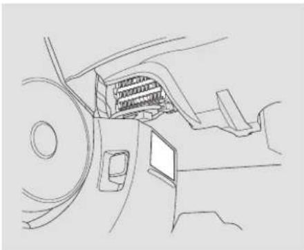
natural_image
Line drawing of a mechanical component with internal structure and mounting holes (no text or symbols)The vehicle's fuses are contained in two fuse boxes.
The interior fuse box is on the driver's lower left side.
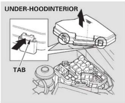
text_image
UNDER-HOODINTERIOR TABThe under-hood fuse box is in the engine compartment on the driver's side, next to the brake fluid reservoir. To open it, push the tabs as shown.
Checking and Replacing Fuses If something electrical in your vehicle stops working, check for a blown fuse first. Determine from the chart on pages 2881289 the diagram on the fuse box lid, which fuse or fuses control that device. Check those fuses first, but check all the fuses before deciding that a blown fuse is the cause. Replace any blown fuses, and check if the device works.
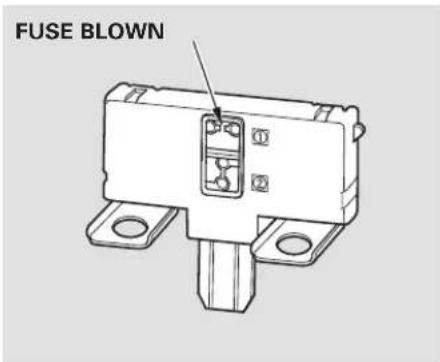
text_image
FUSE BLOWNTurn the ignition switch to the LOCK (0) position. Make sure the headlights and all other accessories are off.
2. Remove the cover from the fuse box.
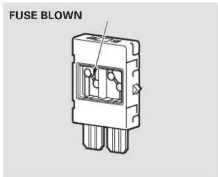
text_image
FUSE BLOWNCheck each of the large fuses in the under-hood fuse box by looking through the top at the wire inside. Removing these fuses requires a Phillips-head screw-driver.
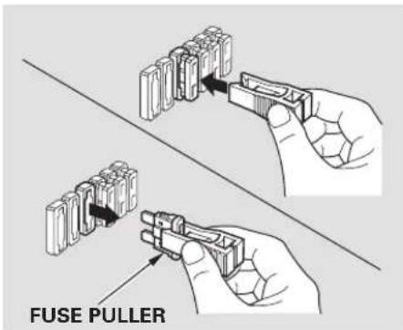
text_image
FUSE PULLER4.3 Check the smaller fuses in the under-hood fuse box and all the fuses in the interior fuse box by pulling out each one with the fuse puller provided on the back of under-hood fuse box cover.
CONTINUED
Fuses
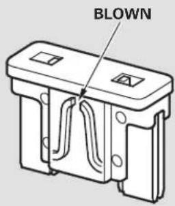
text_image
BLOWN- Look for a blown wire inside the fuse. If it is blown, replace it with one of the spare refuses of the rating or lower.
If you cannot drive the vehicle without fixing the problem, and you do not have a spare fuse, take a fuse of the same rating or a lower rating from one of the other circuits. Make sure you can do with out that temporarily (such as the accessory power socket or radio).
If you replace the blown fuse with a spare fuse that has a lower rating, it might blow out again. This does not indicate anything wrong. Replace the fuse with one of the correct rating as soon as you can.
same
NOTICE
Replacing a fuse with one that has a higher rating greatly increases the chances of damaging the electrical system if you do not have a replacement fuse with the proper rating for the circuit, install one with a lower rating.
- If the replacement fuse of the same rating blows in a short time, there is probably a serious electrical problem in your vehicle. Leave the blown fuse in that circuit and have your vehicle checked by a qualified technician.
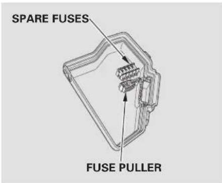
text_image
SPARE FUSES FUSE PULLERYour vehicle has spare fuses on the back of the under-hood fuse box cover.
All models except DX
If the driver's power window fuse is removed, the AUTO function of the driver's window will be disabled. You should reset the AUTO feature, (see page 101
If the radio fuse is removed, the audio system may disable itself. The next time y out turn nontheradio, you will see "ENTER CODE" in the frequency display. Use the preset buttons to enter the five-digit code (see page 179).
When the audio system is disabled, the clock setting in the audio system will be canceled. You will need to reset the clock (see page 180
Fuse Locations
UNDER-HOOD FUSE BOX
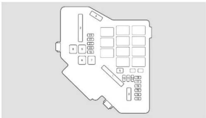
text_image
Diagram of a vehicle rear panel with numbered compartments and control buttons| No. | Amps. | Circuits Protected |
| 1 | 100 A | Main Fuse |
| (70 A) | EPS ^2 | |
| 2 | 60 A | Option |
| 50 A | Ignition Switch Main | |
| 3 | 30 A | ABS/VSA Motor |
| 30 A | ABS/VSA F/S | |
| 40 A ^a1 | ||
| 4 | 50 A | Headlight Main |
| 40 A | Power Window Main |
| No. | Amps. Circuits Protected | |
| 5 | — | Not Used |
| 6 | 20 A | Fan Motor |
| 7 | 30 A | Main Fan Motor (A/T) |
| 20 A | Main Fan Motor (M/T) | |
| 8 | 40 A | Rcar Dcfroster |
| 9 | 40 A | Blower |
| 10 | 10 A | Hazard |
| 11 | 15 A | FI |
| 12 | 15 A | Stop, Horn |
| 13 | — | Not Used |
| 14 | — | Not Used |
| 15 | 7.5 A | Oil Level Sensor |
| 16 | — | Not Used |
| 17 | (15 A) | Audio Amp ^** |
| 18 | 15 A | Ignition Coil |
| 19 | 15 A | FI Main |
| 20 | 7.5 A | MG Clutch |
| 21 | 15 A | DBW |
| 22 | 7.5 A | Interior Light |
| 23 | 10 A | Back Up |
* Si model with VSA1 :
*2: If equipped
INTERIOR FUSE BOX
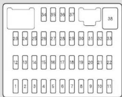
text_image
34 35 36 37 23 24 25 26 27 28 29 30 31 32 33 12 13 14 15 16 17 18 19 20 21 22 1 2 3 4 5 6 7 8 9 10 11| No. Amps. No. AmpSicindustPilototected | ||
| 1 | 7.5 A | Power Window |
| 2 | 15 A | Fuel Pump |
| 3 | 10 A | IG1 ACG |
| 4 | 7.5 A | ABS/VSA |
| 5 | (15 A) | Heated Seats* |
| 6 | (20 A) | Front Fog Lights* |
| 7 | 7.5 A | TPMS* |
| 8 | - | Not Used |
| 9 | 7.5 A | ODS (Occupant Detection System) |
| 10 | 7.5 A | Mctcr |
| 11 | 10 A | SRS |
| 12 | 10 A | Right Headlight High Beam |
| 13 | 10 A | Left Headlight High Beam |
| 14 | 7.5 A | Small Lights (Interior) |
| 15 | 7.5 A | Small Lights (Exterior) |
| 16 | 10 A | Right Headlight Low Beam |
| No. | Circuits | ProtectedAmps. |
| 17 | 10 A | Left Headlight Low Beam |
| 18 | 20 A | Headlight High Beam Main |
| 19 | 15 A | Small Lights Main |
| 20 | - | Not Used |
| 21 | 20 A | Headlight Low Beam Main |
| 22 | - | Not Used |
| 23 | - | Not Used |
| 24 | (20 A) | Moonroof* |
| 25 | 20 A | Door Lock |
| 26 | 20 A | Driver's Power Window |
| 27 | (20 A) | HAC Option |
| 28 | (15 A) | Rear Accessory Socket * |
| 29 | 15 A | Accessory |
| 30 | 20 A | Front Passenger's Power Window |
| 31 | - | Not Used |
| 32 | - | Not Uscd |
| 33 | - | Not Uscd |
| 34 | - | Not Used |
| 35 | 7.5 A | Accessory, Radio |
| 36 | 10 A | IG2 HAC |
| 37 | 7.5 A | Daytime Running Lights |
| 38 | 30 A | Front Wiper |
* : If equipped
Emergency Towing
If your vehicle needs to be towed, call a professional towing service or organization. Never tow your vehicle with just a rope or chain. It is very dangerous.
There are twoway stotow your vehicle:
Flat-bed Equipment – The operator loads your vehicle on the back of a truck. This is the best way to transport your vehicle.
Wheel-lift Equipment - The tow truck uses two pivoting arms that go under the front tires and lift them off the ground. The rear tires remain on the ground. This is an acceptable way to tow your vehicle.
If, due to damage, your vehicle must be towed with the front wheels on the ground, do this:
Manual transmission:
- Release the parking brake.
- Shift the transmission to neutral.
- Leave the ignition switch in the ACCESSORY (I) position so the steering wheel does not lock.
Automatic transmission:
- Start the engine.
- Press on the brake pedal. Move the shift lever through all its positions.
- Shift to D position for 5 seconds, then to N.
- Turn off the engine.
- Release the parking brake.
- Leave the ignition switch in the ACCESSORY (I) position so the steering wheel does not lock.
NOTICE
Improper towing preparation will damage the transmission. Follow the above procedure exactly. If you cannot shift the transmission or start the engine (automatic transmission), your vehicle must be transported with the front wheels off the ground.
With the front wheels on the ground, do not tow the vehicle more than 50 miles (80 km), and keep the speed below 35 mph (55 km/h).
Do not tie down the vehicle at an angle that would allow the towing cables to contact the vehicle's front bumper. To avoid possible damage, protect the front bumper with tape.
If your vehicle is equipped with a front spoiler, remove it before towing so it is not damaged.
NOTICE
Trying to lift or tow your vehicle by the bumpers will cause serious damage. The bumpers are not designed to support the vehicle's weight.
NOTICE
The steering system can be damaged if the steering wheel is locked. Leave the ignition switch in the ACCESSORY (I) position, and make sure the steering wheel turns f reely before you begin towing.
Main Menu
Table Of Contents
The diagrams in this section you the dimensions and capacities of your vehicle and the locations of the identification numbers. It also includes information you should know about your vehicle's tires and emissions control systems.
gIdentification Numbers...... 294
Specifications 296
DOT Tire Quality Grading (U.S. Vehicles) 299
Uniform Tire Quality
Emissions Controls.... 305
The Clean Air Act 305
Crankcase Emissions Control System.... 305
Evaporative Emissions Control
.299System....305
Onboard Refueling Vapor Recovery.... 305
Exhaust Emissions Controls .... 306
PGM-FI System 306
Ignition Timing Control System.... 306
Exhaust Gas Recirculation (EGR)System.... 306
Three Way Catalytic Converter.... 306
Replacement Parts.... 306
Three Way Catalytic Converter... 307
Emissions Testing 308
Identification Numbers
Your vehicle has several identifying numbers located in various places.
The vehicle identification number (VIN) is the 17-digit number your dealer uses to register your vehicle for warranty purposes. It is also necessary for licensing and insuring your vehicle. The easiest place to find the VIN is on a plate fastened to the top of the dashboard. You can see it by looking through the windshield on the driver's side. It is also on the certification label attached to the driver's doorjamb, and is stamped on the engine compartment bulkhead. The VIN is also provided in bar code on the certification label.
To access the VIN in the engine compartment, slide the lid on the back of the engine compartment. Make sure to close the lid before closing the hood.
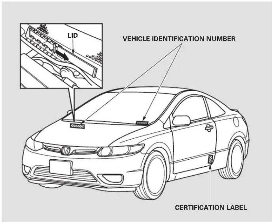
text_image
LID VEHICLE IDENTIFICATION NUMBER CERTIFICATION LABELThe engine number is stamped into the engine block. It is on the front.
The transmission number is on a label on top of the transmission.
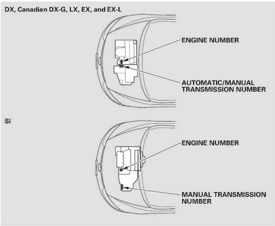
text_image
DX, Canadian DX-G, LX, EX, and EX-L ENGINE NUMBER AUTOMATIC/MANUAL TRANSMISSION NUMBER Si ENGINE NUMBER MANUAL TRANSMISSION NUMBERSpecifications
Dimensions Engine
| Length | 174.8 in (4,440 mm) | |
| Width | 68.9 in (1,751 mm) | |
| Height | 53.5 in (1,358 mm) | |
| Wheelbase | 104.3 in (2,650 mm) | |
| Track | Front | 59.0 in (1,499 mm) |
| Rear | 59.9 in (1,522 mm)* ^1 60.2 in (1,528 mm)* ^2 | |
*1 : LX, Canadian DX-G (M/T), EX, EX-L
*2 : DX, Canadian DX-G (A/T)
Seating Capacities
| Total | 5 |
| Front | 2 |
| Rear 3 |
Weights
| Gross vehicle weight rating | See the certification label attached to the driver's doorjamb. |
| Type | Water cooled 4-strokeSOHC VTEC ^*1 ,DOHC i-VTEC ^*2 4-cylinder gasoline engine |
| BorexStroke | 3.19 x 3.44 in (81.0 x 87.3 mm) ^*1 3.39 x 3.39 in (86 x 86 ^m m |
| Displacement | 110 cu-in (1,799 cm ^3 ) ^*1 122 cu-in (1,998 cm ^3 ) ^*2 |
| Compression ratio | 10.5 ^*1 11.0 ^*2 |
| Spark plugs ^*1 | NGK: IZFR6K-11SDENSO: SKJ20DR-M11S |
| Spark plugs ^*2 | NGK: IFR7G-11KSDENSO: SK22PR-M11S |
*1: DX, Canadian DX-G, LX, EX, EX-L
*2: Si
Capacities
| Fuel tank | Approx. 13.2 US gal (50 ) | |
| Engine coolant | Change ^+1 A/T | 1.45 US gal (5.5 ) ^+3 |
| M/T | 1.37 US gal (5.2 ) ^+3 | |
| 1.19 US gal (4.5 ) ^*4 | ||
| Total A/T | 1.88 US gal (7.1 ) ^*3 | |
| M/T | 1.72 US gal (6.5 ) ^*3 | |
| 1.80 US gal (6.8 ) ^*4 | ||
| Engine oil | Change ^+2 Including filter | 3.9 US qt (3.7 ) ^*3 |
| 4.6 US qt (4.4 ) ^*4 | ||
| Without filter | 3.7 US qt (3.5 ) ^*3 | |
| 4.4 US qt (4.2 ) ^*4 | ||
| Total | 4.8 US qt (4.5 ) ^*3 | |
| 5.8 US qt (5.5 ) ^*4 | ||
| Manual transmission fluid | Change | 1.5 US qt (1.4 ) ^*3 |
| 1.6 US qt (1.5 ) ^*4 | ||
| Total | 1.7 US qt (1.6 ) ^*3 | |
| 1.8 US qt (1.7 ) ^*4 | ||
| Automatic transmission fluid | Change | 2.5 US qt (2.4 ) |
| Total | 6.2 US qt (5.9 ) | |
| Windshield washer reservoir | U.S. Vehicles | 2.6 US qt (2.5 ) |
| Canada Vehicles | 4.8 US qt (4.5 ) | |
*1: Including the coolant in the reserve tank and that remaining in the engine
Reserve tank capacity: 0.11 US gal (0.4)
*2: Excluding the oil remaining in the engine
*3 : U.S.: DX, LX, EX, EX-L Canada: DX, DX-G, LX, EX, EX-L
*4: Si
Air Conditioning
| Refrigerant type | HFC-134a (R-134a) |
| Charge quantity | 14.1 -15.9 oz (400 450 g) |
| Lubricant oil type | SP-10 |
Lights
| Headlights (HI) | -60 W(1883) |
| Headlights (LO) | 12 V - 51 W(HB4) |
| Front turn signal/Side marker/Parking light | 12 V - 28/8 W |
| Rear turn signal lights | 12 V - 21 W |
| Stop/Taillights | 12 V - 21/5 W |
| Rear side marker lights | 12 V - 3 CP |
| Back-up lights | 12 V - 18 W |
| High-mount brake light* | 12 V - 21 W |
| License plate lights | 12 V - 3 CP |
| Ceiling light | 12 V - 8 W |
| Spotlights | 12 V - 8 W |
| Trunk light | 12 V - 5 W |
* : U.S. DX and LX
Canada: DX, DX-G, LX
EX, EX-L, Si: Replacement of the light should be done by your dealer.
Specifications
Battery
| 12 V 36 AH/5 HR *112 V - 38 AH/5 HR *2, *312 V - 45 AH/20 HR *1- 47 AH/20 HR*2V |
*1: U.S.: DX, LX, EX, EX-L
*2: Canada: DX, DX-G, LX, EX, EX-L
*3: Si
Fuses
| Interior | See page 289 or the fuse label attached to the dashboard. |
| Under-hood | See page 288 or the fuse box cover. |
Alignment
| Toe-in | Front | 0.00 in (0.0 mm) |
| Rear | 0.08 in (2.0 mm) | |
| Camber | Front | 0^ |
| Rear | -0^45' *_1 -1^30' *_2 | |
| Caster 7^ | Front |
*1: LX, Canadian DX-G (M/T), EX, EX-L
*2: DX, Canadian DX-G (A/T)
Tires
| Size | Front/Rear | P195/65R15 89HC*capacity |
| P195/65R15 89S *2 | ||
| P205/55R16 89H *3 | ||
| P215/45R17 87V *4 | ||
| 215/45ZR17 91W *5 | ||
| Spare | T125/70D15 95M *8 | |
| T135/80R16 101M *7 | ||
| T125/70D16 96M *8 | ||
| Pressure | Front/Rear | 32 psi (220 kPa, 2.2 kgf/cm2) |
| Spare | 60 psi (420 kPa, 4.2 kgf/cm2) |
*1: U.S.: DX
Canada: DX, DX-G with automatic transmission
*2: Canada: DX-G with manual transmission
*3: LX, EX, EX-L
*4: Si (all season tires)
*5: Optional for Si (summer tires)
*6: U.S.: DX, LX, EX, EX-L Canada: DX, DX-G, LX, EX, EX-L
*7: U.S.: Si Canada: Si with VSA
*8: Canada: Si without VSA
The tires on your vehicle meet all U.S. Federal Safety Requirements. All tires are also graded for treadwear, traction, and temperature performance according to Department of Transportation (DOT) standards. The following explains these gradings.
Uniform Tire Quality Grading Quality grades can be found where applicable on the tire sidewall between tread shoulder and maximum section width. For example:
Treadwear 200 Traction AA Temperature A
All passenger car tires must conform to Federal Safety Requirements in addition to these grades.
Treadwear Traction
The treadwear grade is a comparative rating based on the wear rate of the tire when tested under controlled conditions on a specified government test course. For example, a tire graded 150 would wear one and one-half (1 1/2) times as well on the government course as a tire graded 100. The relative performance of tires depends upon the actual conditions of their use, however, and may depart significantly from the norm due to variations in driving habits, service practices and differences in road characteristics and climate.
The traction grades, from highest to lowest, are AA, A, B, and C. Those grades represent the tire's ability to stop on wet pavement as measured under controlled conditions on specified government test surfaces of asphalt and concrete. A tire marked C may have poor traction performance.
Warning: The traction grade assigned to this is based on straight-ahead braking traction tests, and does not include acceleration, cornering, hydroplaning, or peak traction characteristics.
Temperature
The temperature grades are A (the highest), B, and C, representing the tire's resistance to the generation of heat and its ability to dissipate heat when tested under controlled conditions on a specified indoor laboratory test wheel. Sustained high temperature can cause the material of the tire to degenerate and reduce tire life, and excessive temperature can lead to sudden tire failure. The grade C corresponds to a level of performance which all passenger car tires must meet under the Federal Motor Vehicle Safety Standard No. 109. Grades B and A represent higher levels of performance on the laboratory test wheel than the minimum required by law.
Warning: The temperature grade for this tire is established for a tire that is properly inflated and not overloaded. Excessive speed, underinflation, or excessive loading, either separately or in combination, can cause heat buildup and possible tire failure.
The tires that came on your vehicle have a number of markings. Those you should be aware of are described below.
Tire Labeling Example
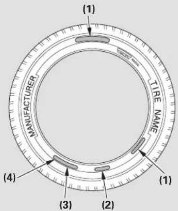
text_image
(1) MANUFACTURER TIRE NAME (4) (3) (2) (1)(1) Tire Size
(2) Tire Identification Number (TIN)
(3) Maximum Tire Pressure
(4) Maximum Tire Load
Tire Size
Whenever tires are replaced, they should be replaced with tires of the same size. Following is an example of tire size with an explanation of what each component means.
P205/55R16 89H
P - Vehicle type (Pindicat passenger vehicle).
205 - Tire width in millimeters.
55 - Aspect ratio (the tire's section height as a percentage of its width).
R - Tire construction code (R indicates radial).
16 - Rim diameter in inches.
89 — Load index (a numerical code associated with the maximum load the tire can carry).
H — Speed symbol (an alphabetical code indicating the maximum speed rating).
Tire Identification Number (TIN)
The tire identification number (TIN) is a group of numbers and letters that look like the following example. TIN is located on the sidewall of the tire.
DOT B97R FW6X 2202
DOT - This indicates that the tire meets all requirements of the U.S. Department of Transportation.
B97R - Manufacturer's identification mark.
CONTINUED
Main Menu
Table Of Contents
Tire Labeling
FW6X - Tire type code.
2202 - Date of manufacture. Year Week
Maximum Tire Pressure
Max Press - The maximum air pressure the tire can hold.
Maximum Tire Load
Max Load - The maximum load the tire can carry at maximum air pressure.
U.S. models only
Each tire, including the spare (if provided), should be checked monthly when cold and inflated to the inflation pressure recommended by the vehicle manufacturer on the vehicle placard or tire inflation pressure label.
(If your vehicle has tires of a different size than the size indicated on the vehicle placard or tire inflation pressure label, you should determine the proper tire inflation pressure for those tires.)
As an added safety feature, your vehicle has been equipped with a tire pressure monitoring system (TPMS) that illuminates a low tire pressure telltale
when one or more of your tires is significantly under-inflated.
Accordingly, when the low tire pressure telltale illuminates, you should stop and check your tires as soon as possible, and inflate them to the proper pressure.
Driving on a significantly under-inflated tire causes the tire to overheat and can lead to tire failure. Under-inflation also reduces fuel efficiency and tire tread life, and may affect the vehicle's handling and stopping ability.
Please note that the TPMS is not a substitute for proper tire maintenance, and it is the driver's responsibility to maintain correct tire pressure, even if under-inflation has not reached the level to trigger illumination of the TPMS low tire pressure telltale.
CONTINUED
Tire Pressure Monitoring System (TPMS)-Required Federal Explanation
Your vehicle has also been equipped with a TPMS malfunction indicator to indicate when the system is not operating properly. The TPMS malfunction indicator is provided by a separate telltale, which displays the symbol “TPMS” when illuminated.
When the malfunction indicator is illuminated,

the system may not be able to detect or signal low tire pressure as intended.
TPMS malfunctions may occur for a variety of reasons, including the installation of replacement or alternate tires or wheels on the vehicle that prevent the TPMS from functioning properly.
Always check the TPMS malfunction telltale after replacing one or more tires or wheels on your vehicle to ensure that the replacement or alternate tires and wheels allow the TPMS to continue to function properly.
The burning of gasoline in your vehicle's engine produces several by-products. Some of these are carbon monoxide (CO), oxides of nitrogen (NOx), and hydrocarbons (HC). Gasoline evaporating from the tank also produces hydrocarbons. Controlling the production of NOx, CO, and HC is important to the environment. Under certain conditions of sunlight and climate, NOx and HC react to form photochemical “smog.” Carbon monoxide does not contribute to smog creation, but it is a poisonous gas.
The Clean Air Act
The United States Clean Air Act sets standards for automobile emissions. It also requires that automobile manufacturers explain to owners how their emissions controls work and what to do to maintain them. This section summarizes how the emissions controls work.
* In Canada, Honda vehicles comply with the Canadian emission requirements, as specified in an agreement with Environment Canada, at the time they are manufactured.
Crankcase Emissions Control System
Your vehicle has a positive crankcase ventilation system. This keeps gasses that build up in the engine's crankcase from going into the atmosphere. The positive crankcase ventilation valve routes them from the crankcase back to the
intake manifold. They are then drawn into the engine and burned.
Evaporative Emissions Control System
As gasoline evaporates in the fuel tank, an evaporative emissions control canister filled with charcoal adsorbs the vapor. It is stored in this canister while the engine is off. After the engine is started and warmed up, the vapor is drawn into the engine and burned during driving.
Onboard Refueling Vapor Recovery
The onboard refueling vapor recovery (ORVR) system captures the fuel vapors during refueling. The vapors are adsorbed in a canister filled with activated carbon. While driving, the fuel vapors are drawn into the engine and burned off.
Emissions Controls
Exhaust Emissions Controls
The exhaust emissions controls include three or four systems: PGM-FI, ignition timing control, exhaust gas recirculation (DX, LX, EX and EX-L), and three way catalytic converter. These systems work together to control the engine's combustion and minimize the amount of HC, CO, and NOx that comes out the tailpipe. The exhaust emissions control systems are separate from the crankcase and evaporative emissions control systems.
PGM-FI System
The PGM-FI system uses sequential multiport fuel injection. It has three subsystems: air intake, engine control, and fuel control. The powertrain control module (PCM) in automatic transmission vehicles or the engine control module (ECM) in manual transmission vehicles uses various sensors to determine how much air is going into the engine. It then controls how much fuel to inject under all operating conditions.
Ignition Timing Control System
This system constantly adjusts the ignition timing, reducing the amount of HC, CO, and NOx produced.
Exhaust Gas Recirculation (EGR)
System
On DX, LX, EX and EX-L models The exhaust gas recirculation (EGR) system takes some of the exhaust gas and routes it back into the intake manifold. Adding exhaust gas to the air/fuel mixture reduces the amount of NOx produced when the fuel is burned.
Three Way Catalytic Converter
The three way catalytic converter is in the exhaust system. Through chemical reactions, it converts HC, CO, and NOx in the engine's exhaust to carbon dioxide (CO 2 ), nitrogen (N 2 ), and water vapor.
Replacement Parts
The emissions control systems are designed and certified to work together in reducing emissions to levels that comply with the Clean Air Act. To make sure the emissions remain low, you should use only new Honda replacement parts or their equivalent for repairs. Using lower quality parts may increase the emissions from your vehicle.
The emissions control systems are covered by warranties separate from the rest of your vehicle. Read your warranty manual for more information.
DX, Canadian DX-G, LX, EX, EX-L
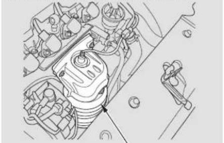
natural_image
Technical line drawing of a car engine compartment with no visible text or symbolsTHREE WAY CATALYTIC CONVERTER
The three way catalytic converter contains precious metals that serve as catalysts, promoting chemical reactions to convert the exhaust gasses without affecting the metals. The catalytic converter is referred to as a three-way catalyst, since it acts on HC, CO, and NOx. A replacement unit must be an original Honda part or its equivalent.
The three way catalytic converter must operate at a high temperature
Si model
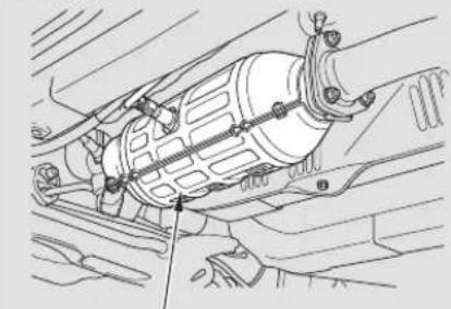
natural_image
Technical line drawing of a mechanical assembly with no visible text or symbolsTHREE WAY CATALYTIC CONVERTER
for the chemical reactions to take place. It can set on fire any combustible materials that come near it. Park your vehicle away from high grass, dry leaves, or other flammables.
A defective three way catalytic converter contributes to air pollution, and can impair your engine's performance. Follow these guidelines to protect your vehicle's three way catalytic converter.
• Always use unleaded gasoline. Even a small amount of leaded gasoline can contaminate the catalyst metals, making the three way catalytic converter ineffective.
- Keep the engine well maintained.
- Have your vehicle diagnosed and repaired if it is misfiring, back-firing, stalling, or otherwise not running properly.
Emissions Testing
Testing of Readiness Codes If you take your vehicle for an emissions test shortly after the battery has been disconnected or gone dead, it may not pass the test. This is because of certain “readiness codes” that must be set in the on-board diagnostics for the emissions systems. These codes are erased when the battery is disconnected, and set again only after several days of driving under a variety of conditions.
If the testing facility determines that the readiness codes are not set, you will be requested to return at a later date to complete the test. If you must get the vehicle retested within the next two or three days, you can condition the vehicle for retesting by doing the following.
- Make sure the gas tank is nearly, but not completely, full (around 3/4).
- Make sure the vehicle has been parked with the engine off for 6 hours or more.
-
Make sure the ambient temperature is between 40^ and 95^ F.
-
Without touching the accelerator pedal, start the engine, and let it idle for 20 seconds.
- Keep the vehicle in Park (automatic transmission) or neutral (manual transmission). Increase the engine speed to 2,000 rpm, and hold it there until the temperature gauge rises to at least 1/4 of the scale (about 3 min ut
-
Without touching the accelerator pedal, let the engine idle for 20 seconds.
-
Select a nearby lightly traveled major highway where you can maintain a speed of 50 to 60 mph (80 to 97 km/h) for at least 20 minutes. Drive on the highway in D (automatic) or 5th (manual). Do not use the cruise control. Traffic allows, drive for 90 seconds without moving the accelerator pedal. (Vehicle speed may vary slightly; this is okay.) If you cannot do this for a continuous 90 seconds because of traffic conditions, drive for at least 30 seconds, then repeat it two more times (for a total of 90 seconds).
Then drive in city/suburban traffic for at least 10 minutes. When traffic conditions allow, let the vehicle coast for several seconds without using the accelerator pedal or the brake Wpedal.
- Make sure the vehicle has been parked with the engine off for 30 minutes.
If the testing facility determines the readiness codes are still not set, see your dealer.
Main Menu
Table Of Contents
Customer Service Information..... 312
Warranty Coverages 313
Reporting Safety Defects (U.S. Vehicles) 314
Authorized Manuals 315
Honda dealership personnel are trained professionals. They should be able to answer all your questions. If you encounter a problem that your dealership does not solve to your satisfaction, please discuss it with the dealership's management. The service manager or general manager can help. Almost all problems are solved in this way.
If you are dissatisfied with the decision made by the dealership's management, contact your Honda Customer Service Office.
U.S. Owners:
American Honda Motor Co., Inc.
Automobile Customer Service
Mail Stop 500-2N-7A
1919 Torrance Boulevard
Torrance, California 90501-2746
Tel: (800) 999-1009
Canadian Owners:
Customer Relations
Honda Canada Inc.
715 Milner Avenue
Toronto, ON
M1B 2K8
Tel: 1-888-9-HONDA-9
Fax: Toll-free 1-877-939-0909
Toronto (416) 287-4776
In Puerto Rico and the U.S. Virgin Islands:
Bella International
P.O. Box 190816
San Juan, PR 00919-0816
Tel: (787) 620-7546
When you call or write, please give us this information:
- Vehicle identification number (see page 294)
- Name and address of the dealer who services your vehicle
- Date of purchase
- Mileage on your vehicle
- Your name, address, and telephone number
• A detailed description of the problem
- Name of the dealer who sold the vehicle to you
U.S. Owners
Your new vehicle is covered by these warranties:
New Vehicle Limited Warranty — covers your new vehicle, except for the battery, emissions control systems, and accessories against defects in materials and workmanship.
Emissions Control Systems Defects Warranty and Emissions
Performance Warranty – these two warranties cover your vehicle's emissions control systems. Time, mileage, and coverage are conditional. Please read your warranty booklet for exact information.
Original Equipment Battery Limited Warranty – this warranty gives up to 100 % credit toward a replacement battery.
Seat Belt Limited Warranty—a seat belt that fails to function properly is covered by a limited warranty. Please read your warranty booklet for details.
Rust Perforation Limited Warranty — all exterior body panels are covered for rust-through from the inside for the specified time period with no mileage limit.
Accessory Limited Warranty—Honda accessories are covered under this warranty. Time and mileage limits depend on the type of accessory and other factors. Please read your warranty booklet for details.
Replacement Parts Limited
Warranty — covers all Honda replacement parts against defects in materials and workmanship.
Replacement Battery Limited Warranty — provides prorated coverage for a replacement battery purchased from your dealer.
Replacement Muffler Lifetime Limited Warranty – provides coverage for a long as the purchase of the muffler owns the vehicle.
Restrictions and exclusions apply to all these warranties. Please read the 2008 Honda warranty information booklet that came with your vehicle for precise information on warranty coverages. Your vehicle's original tires are covered by their manufacturer. Tire warranty information is in a separate booklet.
Canadian Owners
Please refer to the 2008 warranty manual that came with your vehicle.
If you believe that your vehicle has a defect which could cause a crash or could cause injury or death, you should immediately inform the National Highway Traffic Safety Administration (NHTSA) in addition to notifying American Honda Motor Co., Inc.
If NHTSA receives similar complaints, it may open an investigation, and if it finds that a safety defect exists in a group of vehicles, it may order a recall and remedy campaign. However, NHTSA cannot become involved in individual problems between you, your dealer, or American Honda Motor Co., Inc.
To contact NHTSA, you may call the Vehicle Safety Hotlinetoll-free 1-888-327-4236 (TTY: 1-800-424-9153); go to http://www.safercar.gov; or write to: Administrator, NHTSA, 1200 New Jersey Avenue, SE., Washington, DC 20590. You can also obtain other information about motor vehicle safety from http://www.safercar.gov
Purchasing Factory Authorized Manuals (U.S. only) Service Manual:
The publications shown below can be purchased from Helm Incorporated. You can order by phone or online:
• Call Helm Inc. at 1-800-782-4356 (credit card orders only)
- Go online at www.helminc.com
If you are interested in other years or models, contact Helm Inc. at 1-800-782-4356.
| Publication Form Number | Form Description |
| 61SNA05 | 2008 Honda Civic 2/4 door Service Manual |
| 61SNA05EL | 2006-2008 Honda Civic 2/4 door Electrical Troubleshooting Manual |
| 61SNA30 | 2006-2008 Model Series Honda Civic 2/4 door Body Repair Manual |
| 31SVA621 | 2008 Honda Civic 2-door Owner's Manual |
| 31SNA810 | 2008 Honda Civic Navigation System Manual |
| 31SNAM20 | 2008 Honda Civic Honda Service History |
| 31SVAQ20 | 2008 Honda Civic 2-door Quick Start Guide |
| HON-R | Order Form for Previous Years Indicate Year and Model Desired |
Covers maintenance and recommended procedures for repair to engine and chassis components. It is written for the journeyman mechanic, but it is simple enough for most mechanically inclined owners to understand.
Electrical Troubleshooting Manual:
Complements the Service Manual by providing in-depth troubleshooting information for each electrical circuit in your vehicle.
Body Repair Manual:
Describes the procedures involved in the replacement of damaged body parts.
Main Menu
2008 Civic Coupe
A
Accessories and Modifications .... 195
ACCESSORY (Ignition Key Position) 78
Accessory Power Sockets...... 108
Adding Engine Coolant 238
Additives, Engine Oil.... 235
Adjusting the Steering Wheel...... 75
Advice for Pregnant Women...... 16
Airbag (SRS) 9,21
Air Conditioning System.... 114 Usage .... 117
Air Pressure, Tires 255, 257
Alcohol in Gasoline.... 187
Antifreeze 238
Anti-lock Brakes (ABS) Indicator.... 59, 214
Operation 214
Anti-theft, Audio System...... 179
Anti-theft Steering Column Lock....78
Audio System 119
Auto Door Locking/Unlocking..... 81
Automatic Seat Belt Tensioners .... 19
Automatic Speed Control...... 182
Automatic Transmission...... 208
Capacity, Fluid 297
Checking Fluid Level 242
Shifting 208
Shift Lever Position Indicators.... 208
Shift Lever Positions.... 209
Shift Lock Release.... 211
B
Battery
Charging System Indicator.... 57, 281
Jump Starting 277
Maintenance.... 265
Specifications 298
Before Driving 185
Belts, Seat 8, 18
Beverage Holders.... 107
Booster Seats 47
Brakes
Anti-lock System (ABS) ...... 214
Break-in, New Linings ...... 186
Bulb Replacement 250
Fluid 244
Parking.... 105
System Design 213
System Indicator...... 58, 283
Wear Indicators 213
Braking System...... 213
Break-in, New Vehicle 186
Brightness Control, Instruments... 73
Brights, Headlights 72
Bulb Replacement
Back-up Lights 250
Brake Lights.... 250
Front Parking Lights.... 249
Front Side Marker Lights...... 249
Headlights 246
High-mount Brake Light ...... 251
Specifications 297
Turn Signal Lights.... 249
Bulbs, Halogen 246
C
Capacities Chart.... 297
Carbon Monoxide Hazard 50
Carrying Cargo 197
CONTINUED
Index
CAUTION, Explanation of ...... ii
CD Care 174
CD Changer 135, 157
CD Changer Error Messages ..... 137
CD Player 130, 150
CD Player Error Messages.. 136, 158
Ceiling Light.... 111
Certification Label 294
Chains, Tires 263
Changing a Flat Tire 271
Changing Oil
How to 236
When to.... 225
Charging System Indicator .... 57, 281
Check Fuel Cap Message...... 68
Checklist, Before Driving...... 203
Child Safety 32
Booster Seats 47
Child Seats.... 39
Important Safety Reminders ...... 32, 35
Infants 37
Large Children 46
LATCH.... 41
Risks with Airbags.... 33
Small Children.... 38
Tethers.... 45
Warning Labels.... 51
Where Should a Child Sit?...... 33
Child Seats
Installing 40
Lower Anchors 41
Selecting 39
Tether Anchor Points 45
Cleaning
Seat Belts 251
Clock 180
Clutch Fluid 245
CO in the Exhaust 305
Coat Hook 108
Cold Weather, Starting in 204
Compact Spare Tire 270
Console Compartment 107
Consumer Information...... 312
Controls, Instruments and...... 53
Coolant
Adding.... 238
Checking.... 191
Proper Solution 238
Temperature Gauge 68
Crankcase Emissions Control
System....305
Cruise Control Indicator 62
Cruise Control Operation ...... 182
Cup Holders.... 107
Customer Service Information..... 312
D
DANGER, Explanation of...... ii
Dashboard 3,54
Daytime Running Lights....73
Daytime Running Lights
Indicator 63
Dead Battery 277
Defects, Reporting Safety...... 314
Defogger, Rear Window 74
Defrosting the Windows...... 118
Dimensions.... 296
Dimming the Headlights 72
Dipstick
Automatic Transmission...... 242
Engine Oil.... 189
Directional Signals.... 72
Disc Brake Wear Indicators...... 213
Disc Care 174
Disc Player 130, 150
Display Change Button...... 66
Disposal of Used Oil.... 238
Doors
Auto Door Locking/Unlocking.. 81
Locking and Unlocking.... 79
Power Door Locks 80
DOT Tire Quality Grading* ...... 299
Downshifting, Manual
Tran
Driver and Passenger Safety...... 5
Driving 201
Economy 192
Dust and Pollen Filter 253
E
Economy, Fuel 192
Emergencies.... 269
......Batte
Brake System Indicator 283
Changing a Flat Tire 271
Charging System Indicator ..... 281
Checking the Fuses...... 284
Hazard Warning Flashers ..... 74
Jump Starting 277
Low Oil Pressure Indicator ..... 281
Malfunction Indicator Lamp .... 282
Overheated Engine 279
Towing 290
Emergency Brake.... 105
Emergency Flashers 74
Emergency Towing 290
Emergency Trunk Opener 91
Emissions Controls.... 305
iEssisions Testing 308
Engine
Adding Engine Coolant...... 238
Coolant Temperature Gauge ..... 68
If It Won't Start 275
Malfunction Indicator
Lamp 57,282
Oil Life Indicator...... 225
Oil Pressure Indicator...... 57, 281
Oil, Synthetic.... 235
, JuOilp WlaartiKind to Use27.7...... 234
Overheating 279
Specifications 296
Speed Limiter 207, 210
Starting....204
Ethanol in Gasoline 187
.Evap
Exhaust Fumes 50
Expectant Mothers, Use of Seat
Belts by 16
F
Fan Control.... 115
Features...... 113
Filling the Fuel Tank.... 187
Filters
Dust and Pollen 253
Oil 236
Flashers, Hazard Warning...... 74
Flat Tire, Changing a 271
Fluids
......Automatic
Brake 244
Clutch 245
Manual Transmission 243
Power Steering.... 245
Windshield Washer 241
FM Stereo Radio
Reception.... 172
Folding Rear Seat 98
fiveEwaysDashControls...305....74
CONTINUED
Index
Front Airbags 9,23
Front Seat ....Adj Airbags....9,23
Fuel.... 186
Check Fuel Cap Message...... 68
Economy 192
Fill Door and Cap.... 187
Gauge 68
Low Fuel Indicator 64
Octane Requirement 186
Oxygenated 187
Tank, Refueling 187
Fuse Locations 288
Fuses, Checking the.... 284
G
Gas Mileage, Improving...... 192
Gasoline 186
Gauge 68
Low Fuel Indicator 64
Octane Requirement 186
Tank, Refueling 187
Gas Station Procedures...... 187
Gauges
Engine Coolant Temperature .... 68
stingFu92....68
Gearshift Lever Positions
Manual Transmission 206
Glove Box 107
Gross Axle Weight Rating (GAWR) 199
Gross Vehicle Weight Rating (GVWR) 199
H
Halogen Headlight Bulbs...... 246
Hazard Warning Flashers...... 74
Headlights Aiming.... 246
Daytime Running Lights.... 73
High Beam Indicator...... 63
Reminder Beeper.... 72
Replacing Halogen Bulbs ...... 246
Turning on 72
Head Restraints 95
Heated Mirrors 105
Heating and Cooling.... 114
High Altitude, Starting at...... 204
High Beam Lever.... 72
High-mount Brake Light...... 251
Hood, Opening and Closing the... 188
HotTransmission....208.....4,70
Hydraulic Clutch 244
I
Identification Number, Vehicle.... 294
If the Engine Overheats 279
If the Engine Wont Start...... 275
Ignition
Keys.... 76
Switch 78
Timing Control System...... 306
Immobilizer System.... 77
Important Safety Precautions ...... 6
Indicators ABS (Anti-Lock Brake).... 59
Brake (Parking and Brake System) 58
Charging System 57,281
Cruise Control.... 62
DRL (Daytime Running Lights)....63
Indicators
EPS 60
High Beam.... 63
Key (Immobilizer System) ..... 59
Lights ON 63
Low Fuel 64
Low Oil Pressure 57,281
Low Tire Pressure...... 61, 218
Maintenance Minder...... 60, 225
Malfunction Lamp 282
REV Limit 61
Security System 64
Side Airbag Off 58
SRS 58
TPMS 61,219
Trunk Open 63
Turn Signal and Hazard Warning 59
Washer Level 63
Indicators, Instrument
Panel.... 55, 57
Infant Restraint 37
Infant Seats
Installing 40
Tether Anchor Points 45
Inflation, Proper Tire 255
Information Display 65
Inside Mirror 104
Inspection, Tire 258
Installing a Child Seat 40
Instrument Panel 3,54
Instrument Panel Brightness ..... 73
Instrument and Controls.... 53
Interior Lights.... 111
Introduction...... i
J
Jacking up the Vehicle 272
Jack, Tire 271
Jump Starting 277
K
Keys....76
L
Label, Certification 294
Lane Change, Signaling 72
Lap/Shoulder Belts 14, 19
LATCH System...... 41
Lights
Bulb Replacement 246
Indicators.... 55, 57
Parking 72
Turn Signal 72
Load Limits.... 198
LOCK (Ignition Key Position) ..... 78
Locks
Anti-theft Steering Column ..... 78
Fuel Fill Door 187
Power Door 80
Trunk 90
Low Coolant Level.... 191
Low Fuel Indicator 64
Low Oil Pressure Indicator .... 57, 281
Lower Anchors.... 41
Lower Gear, Downshifting to a.... 205
Lubricant Specifications Chart .... 297
Luggage, Storing (Cargo) ...... 197
CONTINUED
Index
M
Maintenance 223
Items 228, 231
Minder 225
Minder Indicator...... 60, 225
Owner's Maintenance ....Che
Safety 224
Malfunction Indicator Lamp .. 57, 282
Manual Transmission.... 205
Checking Fluid Level 243
Shifting 205
Manual Transmission Fluid ...... 243
Mats, Floor 252
Meters, Gauges.... 65
Methanol in Gasoline 187
Mirrors, Adjusting 104
Modifying Your Vehicle...... 196
Moonroof 102
MP3....131, 151, 160
N
Neutral Gear Position.... 209
New Vehicle Break-in 186
Normal Shift Speeds...... 206
NOTICE, Explanation of...... i
Numbers, Identification...... 294
0
Octane Requirement, Gasoline.... 186
O2Bometer 66
Odometer, Trip 66
Oil Change, How to .... 236
Change, When to 225
Checking Engine 189
Pressure Indicator 57, 281
Selecting Proper Viscosity Chart 235
ON (Ignition Key Position) 78
Onboard Refueling Vapor Recovery 305
Outside Mirrors 104
Overheating, Engine 279
Owner's Maintenance Checks..... 230
Oxygenated Fuels.... 187
P
Panel Brightness Control 73
Park Gear Position.... 209
Parking 212
Parking Brake 105
Parking Brake and Brake System Indicator.... 58, 283
Parking Lights 72, 249
Parking Over Things that Burn.... 212, 307
PC Card.... 159
PC Card Error Messages...... 171
PGM-FI System.... 306
Playing a Disc.... 130, 150
Playing a PC Card.... 159
Pollen Filter 253
Power Door Locks....80
Power Socket Locations ..... 106, 108
Power Steering Fluid.... 245
Power Windows.... 100
Pregnancy, Using Seat Belts ...... 16
Preparing to Drive 203
Protecting Adults and Teens.... 11 Additional Safety Precautions.... 16
Advice for Pregnant Women..... 16
Protecting Children 32
General Guideline 32
Installing a Child Seat 40
Protecting Infants 37
Protecting Larger Children...... 46
Protecting Small Children ..... 38
Selecting a Child Seat.... 39
Using Child Seats with Tethers.... 45
Using LATCH 41
R
Radiator Overheating.... 279
Radio/Disc Sound System...... 120
Radio/Disc/PC Card Sound System.... 138
Recommended Tire Pressures .... 257
Radio Theft Protection...... 179
Readiness Codes...... 282, 308
Rear Lights, Bulb Replacement.... 250
Rear Seat Access 93
Rear Seat, Folding 98
Rear View Mirror.... 104
Rear Window Defogger 74
Reclining the Seat-backs.... 92
Recommended Shift Speeds ..... 206
Refueling.... 187
Reminder Indicators...... 55, 57
Remote Transmitter 86
Replacement Information Dust and Pollen Filter ...... 253
Engine Oil and Filter 236
Fuses 284
Light Bulbs 246
Maintenance Minder 225
Spark Plugs.... 296
Tires and Wheels...... 262
Wiper Blades 253
Replacing Seat Belts After a Crash 20
Reporting Safety Defects* ...... 314
Reserve Tank, Engine Coolant.... 191, 238
Restraint, Child 32
Reverse Gear Position.... 209
Reverse Lockout.... 207
Rotation, Tire 260
S
Safety Belts.... 8, 18
Safety Defects, Reporting* ...... 314
Safety Features....7 Airbags....9
Seat Belts 8
Safety Labels, Location of .... 51
Safety Messages ...... ii
Seat Belts....8,18 Additional Information....18
Automatic Seat Belt Tensioners.... 19
Cleaning 251
Lap/Shoulder Belt.... 14, 19
Maintenance....20
Reminder Indicator and Beeper.... 18, 57
System Components.... 18
Use During Pregnancy...... 16
Wearing a Lap/Shoulder Belt 14, 19
Seating Capacities.... 296
Seats 92
CONTINUED
Index
Seats, Folding Rear.... 98
Security System 181
Selecting a Child Seat.... 39
Serial Number 294
Service Intervals 225
Service Manual ^* 315
Service Station Procedures ..... 187
Speed Limiter 207, 210
SRS, Additional Information...... 21
Additional Safety Precautions.... 31
Airbag Service 30
Airbag System Components..... 21
How the Passenger Airbag Off Indicator Works.... 29
theHolthe.S180 Airbag Off Indicator Works....29
How the SRS Indicator Works... 28
How Your Front Airbags Work....23
How Your Side Airbags Work.... 26
How Your Side Curtain Airbags Work....28
SRS Indicator.... 28, 58
START (Ignition Key Position) ..... 78
Starting the Engine.... 204
In Cold Weather at High Altitude 204
With a Dead Battery 277
Steam Coming from Engine...... 279
Steering Wheel Adjustments 75
Anti-theft Column Lock 78
Steering Wheel Buttons...... 177, 182
Stereo Sound System 119
Storing Your Vehicle 267
Supplemental Restraint System.... 9, 21
Servicing 30
SRS Indicator...... 28, 58
System Components...... 21
SVC....124, 148
Synthetic Oil 235
T
Taillights, Changing Bulbs...... 250
Taking Care of the Unexpected .. 269
Technical Descriptions DOT Tire Quality Grading* ..... 299
Emissions Control Systems..... 305
Oxygenated Fuels.... 187
Three Way Catalytic Converter.... 306, 307
Temperature Gauge 68
Tether Anchor Points...... 45
Theft Protection, Radio...... 179
Three Way Catalytic Converter.... 306, 307
Tilt the Steering Wheel.... 75
| ......Time, Setting Tree Changing ...... 271 | |
| Tire Chains...... 263 | TowingA Trailer...... 221 |
| Tire, How to Change a Flat...... 271 | Emergency Wrecker...... 290 |
| Tire Pressure MonitoringSystem (TPMS)...... 218 | TransmissionChecking Fluid Level,Automatic...... 242 |
| Tires...... 255 | Checking Fluid Level,Manual...... 243 |
| Air Pressure...... 255, 257 | Fluid Selection...... 242, 243 |
| Chains...... 263 | Identification Number...... 295 |
| Checking Wear...... 258 | Shifting the Automatic...... 208 |
| Compact Spare...... 270 | Shifting the Manual...... 205 |
| DOT Tire Quality Grading...... 299 | Treadwear*...... 299 |
| Inflation...... 255 | Treadwear Indicators...... 258 |
| Inspection...... 258 | Trip Meter...... 66 |
| Labeling...... 301 | Trunk...... 90 |
| Low Tire PressureIndicator...... 61, 218 | Emergency Opener...... 91 |
| Maintenance...... 259 | Opening...... 90 |
| Replacing...... 261 | Open Indicator...... 63 |
| Rotating...... 260 | Turn Signals...... 72 |
| Service Life...... 258 | |
| Snow...... 263 | U |
| Specifications...... 298 | |
| Summer Tires...... 257, 262 | |
| TPMS...... 218 | |
| Wear...... 260 | Unexpected, Taking Careof the...... 269 |
| Wheels...... 264 | |
Uniform Tire Quality Grading* ... 299
Unleaded Gasoline.... 186
Used Oil, How to Dispose of ..... 238
Using a Booster Seat 47
V
Vanity Mirror 109
Vehicle Capacity Load 198
Vehicle Dimensions.... 296
Vehicle Identification Number..... 294
Vehicle Storage 267
Ventilation 116
VIN 294
Viscosity, Oil.... 235
W
WARNING, Explanation of ...... ii
Warning Button, Hazard...... 74
Warning Labels, Location of ..... 51
Warranty Coverages 313
CONTINUED
Main Menu
Index
Washer, Windshield
Checking the Fluid Level ...... 241
Indicator 63
Operation 71
Wheels
Adjusting the Steering 75
Alignment and Balance 259
Compact Spare 270
Replacing 261
Wrench, Nut...... 272
Windows
Operating the Power 100
Rear, Defogger 74
Windshield
Cleaning 71
Defroster 118
Washers 71
Wipers, Windshield
Changing Blades 253
Operation 71
WMA.... 131, 151, 161
Worn Tires 258
Wrecker, Emergency Towing..... 290
* : U.S. only
X
Main Menu
2008 Civic Coupe
Gasoline: Automatic Transmission Fluid:
DX, Canadian DX-G, LX, EX, EX-L:
Unleaded gasoline, pump octane number of 87 or higher.
Si:
Premium unleaded gasoline, pump octane number of 91 or higher.
Fuel Tank Capacity:
13.2 US gal (50 ℓ)
Recommended Engine Oil:
API Premium grade 5W-20 detergent oil (see page 235
Oil change capacity (including filter):
3.9 US qt (3.7 ℓ)
Si:
API Premium grade 5W-30 detergent oil (see page 235 Oil change capacity (including filter):
4.6 US qt (4.4 ℓ)
Honda ATF-Z1 (Automatic Transmission Fluid) (see page 242).
Manual Transmission Fluid:
Honda Manual Transmission Fluid preferred, or an SAE 10W-30 or 10W-40 motor oil as a temporary replacement (see page 243).
Capacity (including differential): DX, Canadian DX-G, LX, EX, EX-L: 1.5 US qt (1.4ℓ)
Si:
1.6 US qt (1.5ℓ)
Power Steering Fluid:
All models except Si and Canadian DX-G (M/T):
Honda Power Steering Fluid preferred, or another brand of power steering fluid as a temporary replacement. Do not use ATF (see page 245
Brake Fluid:
Honda Heavy Duty Brake Fluid DOT 3 preferred, or a DOT 3 or DOT 4 brake fluid as a temporary replacement (see page244
Tire Pressure (measured cold): DX, Canadian DX-G
Front/Rear:
32 psi (220 kPa, 2.2 kgf/cm²)
LX, EX, EX-L
Front/Rear:
32 psi (220 kPa, 2.2 kgf/cm²)
SiDX, Canadian DX-G, LX, EX, EX-L:
Front/Rear:
32 psi (220 kPa, 2.2 kgf/cm²)
Spare Tire:
60 psi (420 kPa, 4.2 kgf/cm²)
Main Menu
Owner's Identification
OWNER
ADDRESS STREET
CITY STATE/PROVINCE ZIP CODE/
POSTAL CODE
V. I. N.
DELIVERY DATE ____ (Date sold to original retail purchaser)
DEALER NAME DEALER NO. ____ ____
ADDRESS STREET
CITY STATE/PROVINCE ZIP CODE/
POSTAL CODE
OWNER'S SIGNATURE
DEALER'S SIGNATURE
This owner's manual should be considered a permanent part of the vehicle and should remain with the vehicle when it is sold.
This owner's manual covers all models of the Civic 2-door. You may find descriptions of equipment and features that are not on your particular model.
The information and specifications included in this publication were in effect at the time of approval for printing. Honda Motor Co., Ltd. reserves the right, however, to discontinue or change specifications or design at any time without notice and without incurring any obligation whatsoever.