
VG-99 - Musical instrument ROLAND - Free user manual and instructions
Find the device manual for free VG-99 ROLAND in PDF.


User questions about VG-99 ROLAND
0 question about this device. Answer the ones you know or ask your own.
Ask a new question about this device
Download the instructions for your Musical instrument in PDF format for free! Find your manual VG-99 - ROLAND and take your electronic device back in hand. On this page are published all the documents necessary for the use of your device. VG-99 by ROLAND.
USER MANUAL VG-99 ROLAND
Thank you, and congratulations on your choice of the Roland VG-99.
Before using this unit, carefully read the sections entitled: "USING THE UNIT SAFELY" (p. 2–3), and "IMPORTANT NOTES" (p. 4–5). These sections provide important information concerning the proper operation of the unit. Additionally, in order to feel assured that you have gained a good grasp of every feature provided by your new unit, Handbook and Owner's manual should be read in its entirety. The manual should be saved and kept on hand as a convenient reference.

text_image
Roland V-Guitar System POWER MICHVALUE CATEGORY OUTPUT LEVEL MR. SOURCE D BEAM USER CATEGORY ROCK 001 V-Guitar Pacrol Pascor Pascor Pascor Pascor Pascor RV-99 V-Guitar Ribbon CONTROLLER OPTION FILTER AVGAINABLE P2 P2 P3 P4 P5 NEXT PAGE OPTION TO MIND SYSTEM BLOGAL TUNDS A B COLDEN GUITAR FULL FX A/B FX DELENT AMP MIXER BALANCE CHAIN CONTROL AVESIVE RATCH LEVEL NAME KEY/BPM MASTER VELENSK 1 2 3 4 5 1 2 DIRECT PATCH CONTROL.USING THE UNIT SAFELY
INSTRUCTIONS FOR THE PREVENTION OF FIRE, ELECTRIC SHOCK, OR INJURY TO PERSONS
About ⚠️ WARNING and ⚠️ CAUTION Notices
 | Used for instructions intended to alert the user to the risk of death or severe injury should the unit be used improperly. |
 | Used for instructions intended to alert the user to the risk of injury or material damage should the unit be used improperly.* Material damage refers to damage or other adverse effects caused with respect to the home and all its furnishings, as well to domestic animals or pets. |
About the Symbols
| [1000] | The △ symbol alerts the user to important instructions or warnings. The specific meaning of the symbol is determined by the design contained within the triangle. In the case of the symbol at left, it is used for general cautions, warnings, or alerts to danger. |
| [264X] | The ⊗ symbol alerts the user to items that must never be carried out (are forbidden). The specific thing that must not be done is indicated by the design contained within the circle. In the case of the symbol at left, it means that the unit must never be disassembled. |
| [293X] | The ● symbol alerts the user to things that must be carried out. The specific thing that must be done is indicated by the design contained within the circle. In the case of the symbol at left, it means that the power-cord plug must be unplugged from the outlet. |
ALWAYS OBSERVE THE FOLLOWING
WARNING
- Before using this unit, make sure to read the instructions below, and the Owner's Manual.

- Do not open (or modify in any way) the unit or its AC adaptor.

- Do not attempt to repair the unit, or replace parts within it (except when this manual provides specific instructions directing you to do so). Refer all servicing to your retailer, the nearest Roland Service Center, or an authorized Roland distributor, as listed on the "Information" page.

- Never use or store the unit in places that are:
- Subject to temperature extremes (e.g., direct sunlight in an enclosed vehicle, near a heating duct, on top of heat-generating equipment); or are

- Damp (e.g., baths, washrooms, on wet floors); or are

- Humid; or are
- Exposed to rain; or are
- Dusty; or are
- Subject to high levels of vibration.
- This unit should be used only with a rack-mount adaptor (RAD-99) or stand (PDS-10) that is recommended by Roland. (p. 98)

- When using the unit with a stand (PDS-10) recommended by Roland, the stand must be carefully placed so it is level and sure to remain stable. If not using a stand, you still need to make sure that any location you choose for placing the unit provides a level surface that will properly support the unit, and keep it from wobbling.

! WARNING
- Be sure to use only the AC adaptor supplied with the unit. Also, make sure the line voltage at the installation matches the input voltage specified on the AC adaptor's body. Other AC adaptors may use a different polarity, or be designed for a different voltage, so their use could result in damage, malfunction, or electric shock.

- Connect only the specified device (FC-300) to the RRC2 IN connector (which provide a supply of power).

- Use only the attached power-supply cord. Also, the supplied power cord must not be used with any other device.

- Do not excessively twist or bend the power cord, nor place heavy objects on it. Doing so can damage the cord, producing severed elements and short circuits. Damaged cords are fire and shock hazards!

- This unit, either alone or in combination with an amplifier and headphones or speakers, may be capable of producing sound levels that could cause permanent hearing loss. Do not operate for a long period of time at a high volume level, or at a level that is uncomfortable. If you experience any hearing loss or ringing in the ears, you should immediately stop using the unit, and consult an audiologist.

- Do not allow any objects (e.g., flammable material, coins, pins); or liquids of any kind (water, soft drinks, etc.) to penetrate the unit.


WARNING
- Immediately turn the power off, remove the AC adaptor from the outlet, and request servicing by your retailer, the nearest Roland Service Center, or an authorized Roland distributor, as listed on the "Information" page when:

- The AC adaptor, the power-supply cord, or the plug has been damaged; or
• If smoke or unusual odor occurs - Objects have fallen into, or liquid has been spilled onto the unit; or
- The unit has been exposed to rain (or otherwise has become wet); or
- The unit does not appear to operate normally or exhibits a marked change in performance.
- In households with small children, an adult should provide supervision until the child is capable of following all the rules essential for the safe operation of the unit.

- Protect the unit from strong impact. (Do not drop it!)

- Do not force the unit's power-supply cord to share an outlet with an unreasonable number of other devices. Be especially careful when using extension cords—the total power used by all devices you have connected to the extension cord's outlet must never exceed the power rating (watts/amperes) for the extension cord. Excessive loads can cause the insulation on the cord to heat up and eventually melt through.

- Before using the unit in a foreign country, consult with your retailer, the nearest Roland Service Center, or an authorized Roland distributor, as listed on the "Information" page.

- DO NOT play a CD-ROM disc on a conventional audio CD player. The resulting sound may be of a level that could cause permanent hearing loss. Damage to speakers or other system components may result.

CAUTION
- The unit and the AC adaptor should be located so their location or position does not interfere with their proper ventilation.

- This VG-99 for use only with Roland rack-mount adaptor RAD-99 or Stand PDS-10. Use with other rack-mount adaptors or stands are capable of resulting in instability causing possible injury.

- Always grasp only the plug on the AC adaptor cord when plugging into, or unplugging from, an outlet or this unit.

CAUTION
- At regular intervals, you should unplug the AC adaptor and clean it by using a dry cloth to wipe all dust and other accumulations away from its prongs. Also, disconnect the power plug from the power outlet whenever the unit is to remain unused for an extended period of time. Any accumulation of dust between the power plug and the power outlet can result in poor insulation and lead to fire.

- Try to prevent cords and cables from becoming entangled. Also, all cords and cables should be placed so they are out of the reach of children.

- Never climb on top of, nor place heavy objects on the unit.

- Never handle the AC adaptor or its plugs with wet hands when plugging into, or unplugging from, an outlet or this unit.

- If you need to move the instrument, take note of the precautions listed below. It should be handled carefully, all the while keeping it level. Make sure to have a firm grip, to protect yourself from injury and the instrument from damage.

- Check to make sure the screws or the attached knob bolts securing the unit to the stand have not become loose. Fasten them again securely whenever you notice any loosening.
- Disconnect the power cord.
- Disconnect all cords coming from external devices.
- Before cleaning the unit, turn off the power and unplug the AC adaptor from the outlet (p. 24).

- Whenever you suspect the possibility of lightning in your area, disconnect the AC adaptor from the outlet.

- Keep any screws you may remove and the included screws in a safe place out of children's reach, so there is no chance of them being swallowed accidentally.

In addition to the items listed under "USING THE UNIT SAFELY" on page 2-3, please read and observe the following:
Power Supply
- Do not connect this unit to same electrical outlet that is being used by an electrical appliance that is controlled by an inverter (such as a refrigerator, washing machine, microwave oven, or air conditioner), or that contains a motor. Depending on the way in which the electrical appliance is used, power supply noise may cause this unit to malfunction or may produce audible noise. If it is not practical to use a separate electrical outlet, connect a power supply noise filter between this unit and the electrical outlet.
- The AC adaptor will begin to generate heat after long hours of consecutive use. This is normal, and is not a cause for concern.
- Before connecting this unit to other devices, turn off the power to all units. This will help prevent malfunctions and/or damage to speakers or other devices.
Placement
- Using the unit near power amplifiers (or other equipment containing large power transformers) may induce hum. To alleviate the problem, change the orientation of this unit; or move it farther away from the source of interference.
- This device may interfere with radio and television reception. Do not use this device in the vicinity of such receivers.
- Noise may be produced if wireless communications devices, such as cell phones, are operated in the vicinity of this unit. Such noise could occur when receiving or initiating a call, or while conversing. Should you experience such problems, you should relocate such wireless devices so they are at a greater distance from this unit, or switch them off.
- Do not expose the unit to direct sunlight, place it near devices that radiate heat, leave it inside an enclosed vehicle, or otherwise subject it to temperature extremes. Excessive heat can deform or discolor the unit.
-
When moved from one location to another where the temperature and/or humidity is very different, water droplets (condensation) may form inside the unit. Damage or malfunction may result if you attempt to use the unit in this condition. Therefore, before using the unit, you must allow it to stand for several hours, until the condensation has completely evaporated.
-
Depending on the material and temperature of the surface on which you place the unit, its rubber feet may discolor or mar the surface.
You can place a piece of felt or cloth under the rubber feet to prevent this from happening. If you do so, please make sure that the unit will not slip or move accidentally.
Maintenance
- For everyday cleaning wipe the unit with a soft, dry cloth or one that has been slightly dampened with water. To remove stubborn dirt, use a cloth impregnated with a mild, non-abrasive detergent. Afterwards, be sure to wipe the unit thoroughly with a soft, dry cloth.
- Never use benzine, thinners, alcohol or solvents of any kind, to avoid the possibility of discoloration and/or deformation.
Repairs and Data
- Please be aware that all data contained in the unit's memory may be lost when the unit is sent for repairs. Important data should always be backed up on a another MIDI device (e.g., a sequencer), or written down on paper (when possible). During repairs, due care is taken to avoid the loss of data. However, in certain cases (such as when circuitry related to memory itself is out of order), we regret that it may not be possible to restore the data, and Roland assumes no liability concerning such loss of data.
Additional Precautions
- Please be aware that the contents of memory can be irretrievably lost as a result of a malfunction, or the improper operation of the unit. To protect yourself against the risk of loosing important data, we recommend that you periodically save a backup copy of important data you have stored in the unit's memory in another MIDI device (e.g., a sequencer).
- Unfortunately, it may be impossible to restore the contents of data that was stored in another MIDI device (e.g., a sequencer). once it has been lost. Roland Corporation assumes no liability concerning such loss of data.
- Use a reasonable amount of care when using the unit's buttons, sliders, or other controls; and when using its jacks and connectors. Rough handling can lead to malfunctions.
- Never strike or apply strong pressure to the display.
- When connecting / disconnecting all cables, grasp the connector itself—never pull on the cable. This way you will avoid causing shorts, or damage to the cable's internal elements.
- To avoid disturbing your neighbors, try to keep the unit's volume at reasonable levels. You may prefer to use headphones, so you do not need to be concerned about those around you (especially when it is late at night).
- When you need to transport the unit, package it in the box (including padding) that it came in, if possible. Otherwise, you will need to use equivalent packaging materials.
- Use only the specified expression pedal (Roland EV-5, BOSS FV-500L/500H with a connection cable (stereo 1/4" phone – stereo 1/4" phone); sold separately). By connecting any other expression pedals, you risk causing malfunction and/or damage to the unit.
- Some connection cables contain resistors. Do not use cables that incorporate resistors for connecting to this unit. The use of such cables can cause the sound level to be extremely low, or impossible to hear. For information on cable specifications, contact the manufacturer of the cable.
- Unauthorized duplication, reproduction, hiring, and lending prohibited.
- The usable range of D Beam controller will become extremely small when used under strong direct sunlight. Please be aware of this when using the D Beam controller outside.
- The sensitivity of the D Beam controller will change depending on the amount of light in the vicinity of the unit. If it does not function as you expect, adjust the sensitivity as appropriate for the brightness of your location.
- Avoid touching or scratching the shiny underside (encoded surface) of the disc. Damaged or dirty CD-ROM discs may not be read properly. Keep your discs clean using a commercially available CD cleaner.
- In the interest of product improvement, the specifications, appearance of this unit and/or contents of this package are subject to change without prior notice.
- While under most conditions, a computer similar to the above will permit normal operation of the VG-99, Roland cannot guarantee compatibility solely on these factors. This is due to numerous variables that may influence the processing environment, such as differences in motherboard design and the particular combination of other devices involved.
Printing Conventions and icons in This Manual
| Text or numerals enclosed in square brackets [ ] | Indicate buttons. [WRITE] WRITE button |
 | Indicates information that you should be aware of when using the VG-99. |
 | Indicates supplementary information about an operation. |
 | Indicates information about a convenient operation. |
 (p.**) (p.**) | Indicates a reference page. |
Main Features....11
Names of Things and What They Do....12
Top Panel 12
Rear Panel....14
Chapter 1 Outputting Sounds....15
Installing the Divided Pickup....15
Before Connecting 15
Making the Connections....16
Turning On the Power....19
About the Play Screen 19
About the Information in the Display (Basic Operation) 20
Adjusting the Volume 20
Setting the Device (Amp) Connected to MAIN OUT (Output Select) 20
Inputting the Divided Pickup Settings (GK Settings)....21
Tuning the Guitar (TUNER) 22
Switching Tones (Patch) 23
About the Patch Numbers 23
Switching with the PATCH/VALUE Dial 24
Turning Off the Power....24
Chapter 2 Creating Sounds....25
Setting the COSM GUITAR Tone....25
Setting the Alternate Tuning....26
Setting AB LINK....26
Setting TUNING....27
Setting BEND 27
Setting 12-STRING....28
Setting USER TUNING 29
Setting DETUNE 29
Setting HARMONY 30
Setting the COSM AMP Tone 30
Setting the Effects 31
POLY FX (Poly Effect) 31
FX (Effects) 31
Rearranging the Effect and Amp Connection Sequence (CHAIN).... 32
Specifying the tempo and key of the song to be played 32
Setting the Tempo 32
Setting the Key....33
Mixing the Normal Pickup Sound 33
Setting the Volume Balance....33
Setting the Point at Which the COSM Guitar is Connected.... 34
Mixing Two Tones (MIXER) 35
Setting the Volume and Panning for Each Channel 35
Setting the Mix Balance 35
Setting the Delay and Reverb (DELAY/REVERB).... 35
Using Picking Dynamics to Control the Mix Between the Two Channels (DYNAMIC) ... 36
Setting the Overall Patch Volume Level (PATCH LEVEL) 36
Adjusting the Overall Patch Tone (TOTAL EQ) 36
Setting the Output Signal and Level (OUTPUT).... 37
Naming a Patch (PATCH NAME) 37
Saving a Patch (WRITE) 38
Chapter 3 Creating Your Own Effect Types (CUSTOMIZE)......39
Customizing the Preamp....39
Customizing the Speaker 40
Customizing the Overdrive/Distortion....40
Customizing Pedal Wah....41
Chapter 4 Global Device Settings (SYSTEM) ....42
Inputting the Divided Pickup Settings....42
Selecting the Settings 42
Naming GK Settings (GK NAME)......42
Selecting the Divided Pickup Type 43
Inputting the Guitar's Scale 43
Matching the Divided Pickup and Normal Pickup Phase.... 43
Setting the Direction for the Installed Divided Pickup 44
Setting the DOWN/S1, UP/S2 Switch Arrangement.... 44
Setting the Gap Between the Pickup and the Bridge (PICKUP BRIDGE) 44
Adjusting the Sensitivity for Each String 45
Setting Whether or Not the Divided Pickup Is Used (GK CONNCT) 45
Using Different Guitar Settings in Each Patch (SET MODE)...... 46
Determining the Function of the GK Volume Control and DOWN/S1, UP/S2 Switches (GK FUNC) 46
Adjusting Overall Tone According to the Environment (GLOBAL/OUTPUT SELECT) ...... 46
Selecting the Settings 46
Naming the Settings (GLOBAL NAME)...... 47
Setting the Types of Connected Devices (OUTPUT SELECT).... 47
Adjusting the Overall Tone (GLOBAL EQ) 48
Controlling the Overall Effect of the Noise Suppressor (Total NS).... 48
Controlling the Overall Reverb Level (Total REVERB).... 49
Setting the Sounds Output from SUB OUT (SUB OUT LEVEL).... 49
Setting the GK VOLUME Control and Switch and the Pedal Function (SYSTEM CONTROL ASSIGN) .. 49
Having Values from an External Pedal, GK VOLUME Control,
or Other Controller Carried Over When Patches are Called Up (ASSIGN HOLD) 50
Limiting the Patches That Can Be Switched (PATCH EXTENT) 50
Adjusting the Screen's Contrast 51
Setting the Output Signal and Level (SYSTEM OUTPUT).... 51
Chapter 5 Using the VG-99 in Combination with an FC-300 .....52
Connecting with the RRC2 IN Connector....52
Settings Related to the FC-300 52
Settings for Control of the FC-300 52
Setting the Operation When Patches Are Switched.... 53
Activating the VG-99's Tuner from the FC-300 (QUICK TUNER) 53
Setting the FC-300 Amp Control....54
Chapter 6 Using MIDI....55
About MIDI 55
What You Can Do Using MIDI 55
Main Types of MIDI Messages Handled by the VG-99....56
About the MIDI Implementation....57
Exchanging MIDI Messages 57
About MIDI Channels 57
Bank Select and Program Change....58
Setting the MIDI-Related Functions 58
Syncing to the MIDI CLOCK from an External Device 64
Playing an External Synthesizer Sound Module (GUITAR TO MIDI)....64
Setting the GUITAR TO MIDI Function (System Parameters).... 65
Setting the GUITAR TO MIDI Function (Patch Parameters).... 67
Chapter 7 Using the VG-99 Connected to a Computer Via USB.....71
Before Using the USB Connection....71
Switching the Driver Mode 72
Setting the USB Functions....73
Setting the Digital Audio Signal Input and Output....73
Setting the Direct Monitor 74
Recording the VG-99's Output with a Computer....75
Using the VG-99 to Add Effects to Audio Playback from a Computer....75
Chapter 8 Other Functions....76
Changing the Tone in Real Time with the D Beam and Ribbon Controllers.... 76
Adjusting the D Beam (CALIBRATION)....76
Disabling the D Beam (DISABLE) 77
Controlling Sounds by Hand Motion or the Guitar Neck (D Beam Controller)....77
Adjusting the Ribbon Controller (CALIBRATION).... 78
Controlling the Sounds with the Movement of Your Fingertip (Ribbon Controller) ..... 79
Holding Sounds for Extended Periods (FREEZE)....79
Changing the Pitch as with a Tremolo Arm (T-ARM)....80
Adding Nuance to the Sound (FILTER) 81
Changing the Sounds with the Knobs as You Play (DIRECT EDIT) 82
Using the Switches, Pedals, and MIDI to Control the Sounds (CONTROL ASSIGN)...... 82
Activating the Virtual Expression Pedal at the Start of Operations (Internal Pedal System) 86
One Touch Call Up of Favorite Patches (DIRECT PATCH)...... 87
Setting DIRECT PATCH 87
Managing the Patches 87
Copying the Current Patch to a Different Patch (PATCH COPY)...... 87
Exchanging the Current Patch with a Different Patch (PATCH EXCHANGE) 88
Initializing User Patches (PATCH INITIALIZE)....88
Copying Settings Between Channel A and Channel B (A/B COPY) 89
Exchanging the Channel A and Channel B Settings (A/B EXCHANGE) 89
Partially Copying Parameters in a Different Patch (MODULE COPY) 89
Partially Initializing Patch Parameters (MODULE INITIALIZE)....89
Separating Patches into Groups (CATEGORY) 90
Using CATEGORY to Call Up Patches 90
Setting Patch Categories....91
Naming User Categories (CATEGORY NAME) 91
Storing Your Preferred Settings Individually (FAVORITE SETTINGS) 92
What are Favorite Settings? 92
Calling Up Favorite Settings....92
Changing Tone Settings 93
Saving Changed Tones....93
Naming Favorite Settings (FAVORITE NAME).... 94
Searching for Patches That Use the Same Favorite Settings 95
Controlling Video Images with Your Guitar (V-LINK)....96
What is V-LINK? 96
Connecting the V-LINK Device 96
Switching V-LINK On and Off....96
Setting V-LINK 96
Using the VG-99 on a Stand....98
Using the VG-99 Mounted in a Rack....99
Restoring the VG-99 to its Original Factory Condition (FACTORY RESET).... 100
Chapter 9 Parameters Guide....101
COSM GUITAR 101
Modeling Type List....101
ALTERNATE TUNING....116
POLY FX (Poly Effect)....118
FX (Effects)....120
Using the HOLD (Hold Delay) 125
PHASER....127
FLANGER 128
TREML (Tremolo) 128
PAN....128
T.WAH (Touch Wah)....129
AUTO WAH 129
OCTAVE....129
PITCH SHIFT (Pitch Shifter) 130
HARMONIST 130
Creating Harmonist Scales (User Scale)....131
PEDAL BEND....132
2x2 CHORUS 132
ROTARY....133
UNI-V 133
VIB (Vibrato)....133
SLICER....134
HUMANIZER....134
SLOW GEAR....135
DEFRET 135
FEEDBACKER....135
RING MOD (Ring Modulator) 136
ANTI FB (Anti-feedback)....136
ADV.COMP (Advanced Compressor).... 136
LIMITR (Limiter)....137
SUB EQ (Sub Equalizer) 137
SUB DELAY (Sub Delay) 138
COSM AMP 140
MIXER....146
MIXER A, B (MIXER CHANNEL A, B) 146
PATCH LEVEL....146
TOTAL EQ (Total Equalizer)....146
OUTPUT 147
DELAY....148
MASTER 150
GK VOL (GK Volume) 150
GK S1, S2 (DOWN/S1, UP/S2 Switch).... 150
PANEL CTL1/CTL2 (Control Button 1/2) 151
D BEAM....151
RIBBON 153
EXP PEDAL (Expression Pedal)....154
CTL3, CTL4 (Control3, Control4) 154
FC-300 CONTROL 155
ASSIGN 1-16....155
DIRECT EDIT F1–F6....156
GUITAR TO MIDI 164
SYSTEM 166
Parameters That Can Be Assigned to Separate Controllers.... 168
V-LINK PATCH 174
V-LINK SYSTEM....176
GLOBAL 177
TUNER....178
Contents
Chapter 10 Appendices ....179
MIDI Implementation Chart....179
Signal Flow 183
Specifications....184
VG-99 Software System Requirements 185
For Windows 185
For Mac OS....185
Error Messages....186
Troubleshooting....186
Problems with Sounds....186
Other Problems....188
Preset Patch List....189
Index....193
Checking the Package Contents
The VG-99 comes with the following items. After opening the package, please check all items. If any items are missing, please contact the retailer from whom this product was purchased.
VG-99

text_image
Roland VG-99 AIDA□USB cable
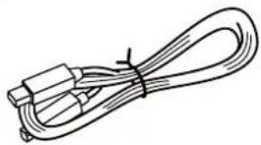
natural_image
Line drawing of a coiled cable with two connectors (no text or symbols)□ AC adaptor (PSB-1U)
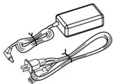
natural_image
Line drawing of a battery pack connected to two cables (no text or symbols)□ RRC2 cable
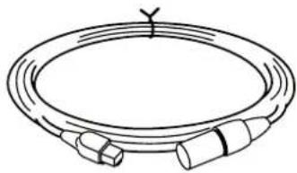
natural_image
Simple line drawing of a coiled cable or hose with connectors (no text or symbols)□ Knob bolt x 4

☐GK cable (5 m)
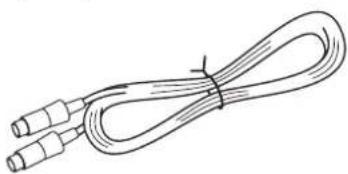
natural_image
Line drawing of a coiled cable with two connectors (no text or symbols)□ VG-99 Software CD-ROM
□ Owner's Manual (this manual)
Ultimate guitar modeling system provides unlimited possibilities in creating sounds
The VG-99 is the culmination of Roland's COSM technology based guitar modeling systems. Featuring advanced software supported by the very latest custom DSP chips, the instrument also offers a large-sized high-contrast LCD, top-quality AD/DA converters, balanced XLR output connectors, digital output connectors, USB connector, and other features that all add up to a truly pro-spec system.
About COSM
(Composite Object Sound Modeling)
Composite Object Sound Modeling—or "COSM" for short—is BOSS/Roland's innovative and powerful technology that's used to digitally recreate the sound of classic musical instruments and effects. COSM analyzes the many factors that make up the original sound—including its electrical and physical characteristics—and creates a digital model that accurately reproduces the original.
Two complete sound creation systems
The VG-99 features two separate guitar and COSM amp systems. You can use two different types of modeled guitars simultaneously and create different amp sounds to use with each guitar. What's more, the VG-99 comes equipped with two effects systems featuring a huge selection of BOSS effects, including COSM effects. This all enables you to achieve the perfect processing for each individual guitar.
Equipped with D-Beam, ribbon, and other new realtime controllers
The VG-99 now enables new and heretofore unimaginable forms of musical expression, including new ways of using the guitar's neck and your hands. Of course, you can still connect expression pedals and control switches as well, just as with previous V-Guitar systems.
Console style accommodates a variety of usage environments
The VG-99 can be set up in a number of different ways to suit the needs of the user—as a desktop unit for recording or when using computer input, attached to its stand (optional) and set up right by the performer, or placed in a rack with the (optional) rack mount adaptor.
Combine with the FC-300 to create the perfect live system
Connecting a Roland FC-300 MIDI Foot Controller (optional) to the VG-99 allows you to switch tones and carry out other tasks using the FC-300's multiple foot pedals for easy hands-free operation. These units also feature an RRC2 connector, allowing you to connect the VG-99 and FC-300 with a single cable. This RRC2 function enables two-way communications between the devices, while further acting as a power supply to the FC-300, thus reducing the number of cables used to connect the devices.
Includes pitch/MIDI conversion function
The VG-99 can convert and output guitar performance data as MIDI information, allowing you to connect a synthesizer sound module or similar device and use the setup as a guitar synthesizer.
Features V-LINK function
This function enables you to use performance data and pedal operations in controlling video.
V-LINK
V-LINK is a function that allows music and images to be performed together. By using MIDI to connect two or more V-LINK compatible devices, you can easily enjoy a wide range of visual effects that are linked to the expressive elements of a music performance.
Top Panel
text_image
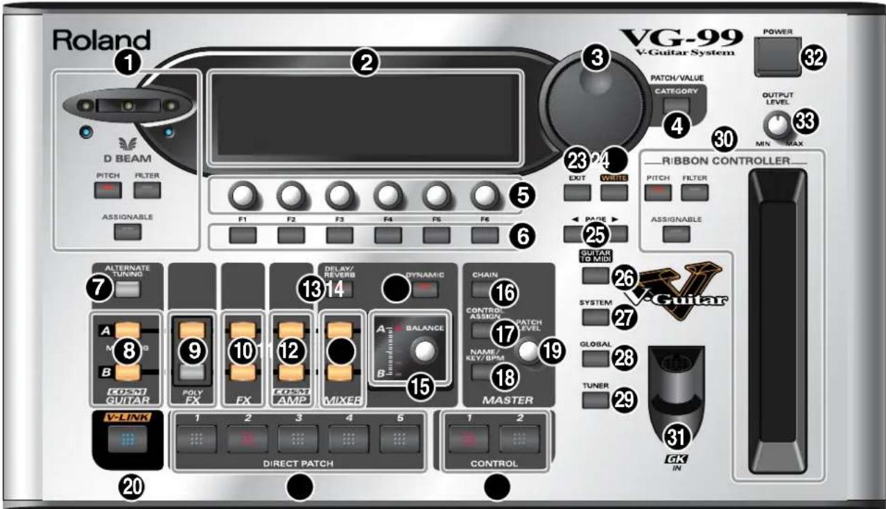
Roland D BEAM PITCH FILTER ASSIGNABLE F1 F2 F3 F4 F5 F6 VG-99 V-Guitar System POWER 32 PATCH/VALUE CATEGORY 4 OUTPUT LEVEL MIN MAX 30 23 24 EXIT WAVE RIBBON CONTROLLER PITCH FILTER ASSIGNABLE 7 ALTERNATE TUNING A M B GOSM GUITAR V-LINK 1 2 3 4 5 DIRECT PATCH 1 2 CONTROL 16 DELAY/ REVERB 13 14 DYNAMIC 17 CHAIN CONTROL/ ASSIGN PATCH LEVEL NAME/ KEY/BPM 18 MASTER 29 TUNER 26 SYSTEM 27 GLOBAL 28 GV-Guitar 31 GK IN1. D BEAM
Switches the D Beam on and off. You can add a variety of effects to your sounds by moving your hand or the guitar neck within the range of the beam. (p. 76)
- PITCH Button
In addition to changing the pitch of the guitar, this can be used for the Freeze function, which continuously holds the guitar's tone.
- FILTER Button
This changes the guitar's tone.
- ASSIGNABLE Button
Use this to assign different parameters and functions to the D-Beam and change the tone in real time.
2. LCD
Various information regarding the VG-99 is indicated here.
3. PATCH/VALUE Dial
Used to switch patches and change settings values.
4. CATEGORY Button
Used to select and change categories.
5. FUNCTION Knob
Changes the value of the setting for the parameter indicated in the LCD.
6. FUNCTION Buttons
Used to select the parameters indicated in the LCD.
7. ALTERNATE TUNING Button
Sets the Alternate Tuning function. (p. 26)
8. MODELING TYPE Buttons
These set the COSM guitar type and tone. (p. 25)
9. POLY FX (Poly Effects) Buttons
These set the poly effects. (p. 31)
10. FX (Effects) Buttons
These set the effects. (p. 31)
11. COSM AMP Buttons
Used to make settings for the COSM amp. (p. 30)
12. MIXER Buttons
Used to make settings for the mixer. (p. 35)
13. DELAY/REVERB Button
Used to make settings for the mixer section's delay and reverb. (p. 35)
14. DYNAMIC Button
Used for setting the dynamics. (p. 36)
15. BALANCE Knob
Sets the mix balance. (p. 35)
16. CHAIN Button
Used to make settings for the effect and COSM guitar/COSM amp connection sequence. (p. 34)
17. CONTROL ASSIGN Button
This sets the functions assigned to pedals and switches. (p. 82)
18. NAME/KEY/BPM Button
Used to specify patch names and the tempo and key for songs to be played. (p. 32)
19. PATCH LEVEL Knob
Adjusts the volume of a patch.
20. V-LINK Button
This switches the V-LINK function on and off. (p. 96)
21. DIRECT PATCH Buttons
Use these to directly call up the patches you have assigned to them. (p. 87)
22. CONTROL Buttons
You can assign and control a variety of different functions with these buttons. (p. 82)
23. EXIT Button
Used to return previous screens and to undo operations.
24. WRITE Button
Use for storing settings in patches and executing operations. (p. 38) (p. 87)
25. PAGE Buttons
This switches the screens displayed in the LCD.
26. GUITAR TO MIDI Button
This sets the GUITAR TO MIDI function (the function that converts what is played on the guitar into MIDI signals). (p. 64)
27. SYSTEM Button
Used for making settings related to the VG-99's operating environment. (p. 42)
28. GLOBAL Button
This sets the GLOBAL function (which affects the tone of all patches). (p. 46)
29. TUNER Button
This turns the tuning function on. (p. 22)
30. RIBBON CONTROLLER
This allows you to change the tone by sliding your finger along the ribbon. (p. 77)
You can switch a variety of effects on and off directly with the three buttons.
- PITCH Button
Changes the guitar's pitch.
- FILTER Button
Alters the brightness of the sound.
- ASSIGNABLE Button
Use this to assign different parameters and functions to the ribbon controller and change the tone in real time. (p. 82)
31. GK IN Connector
Connect the GK cable here.
32. POWER Switch
Switches the power on and off. (p. 19) (p. 24)
33. OUTPUT LEVEL Knob
This adjusts the volume level for the MAIN OUT jacks and headphone jack.
MEMO
About the Illumination of Buttons
When a button is lit, it indicates that the function for that button is switched on.
* The corresponding DIRECT PATCH button (1–5) lights when a Direct Patch (1–5) is selected.
Rear Panel
text_image
Roland VG-99 V-Guitar System ① ② ③ ④ ⑤ ⑦ ⑧ ⑨ ⑩ ⑪ ⑫ ⑬ ⑭ ⑮ ⑯ ⑰ ⑱ ⑲ ⑳ ⑪ ⑫ ⑬ ⑭ ⑮ ⑯ ⑰ ⑱ ⑲ ⑳ ⑮ ⑯ ⑰ ⑱ ⑲ ⑳ ⑮ ⑯ ⑰ ⑱ ⑲ VG-99 INPUT OUTPUT R SUB OUT R NO PRON PHONES DIGITAL EXP CTL 3.4 USB RRC2 IN OUT MIDI IN GUITAR GUITAR USB ROLAND R SUB OUT 1: END 2: HOT 3: COLD FOR PC-300 R MIDI IN VEG-991. Security Slot ( )
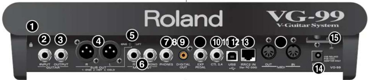
Connect a commercially available anti-theft security cable here.
http://www.kensington.com/
2. GUITAR INPUT Jack
Use this jack when directly inputting a normal guitar.
3. GUITAR OUTPUT Jack
This outputs sounds from normal guitars connected to a GK-3 and unaltered signals from the GUITAR INPUT jack.
4. SUB OUT Connectors L, R
These balanced output jacks use XLR type connectors.
* The SUB OUT L and R connectors are unaffected by the OUTPUT LEVEL knob settings; output is constant at a fixed output level (+4 dBu).
5. GND LIFT Switch
You can disconnect the SUB OUT connectors' No. 1 pin from the VG-99's ground.
Switch this to LIFT if a ground loop or similar problem is causing output of hum or noise. Normally, this is set to GND.
6. MAIN OUT Jacks L/MONO, R
These are unbalanced phone jack outputs. Use these to connect to amps, mixers, and similar equipment.
7. PHONES Jack
Connect headphones here.
8. DIGITAL OUT Connector
Digital audio signals are output here. (p. 37) (p. 147)
9. EXP PEDAL (EXPRESSION PEDAL) Jack
Connect an optional expression pedal (such as a Roland EV-5) here. (p. 16)
* The VG-99 is set at the factory so that the pedal is automatically enabled to function as a foot volume.
10. CTL3,4 (CONTROL 3,4) Jack
An optional footswitch (such as an FS-6) can be connected here. (p. 16)
* The patch up/down function is assigned to this jack at the factory.
11. USB Connector
Use a USB cable to connect a computer to this connector and enable exchange of data between the VG-99 and the computer. (p. 71)
12. RRC2 IN Connector
Accepts connection of an FC-300 (optional).
This connector supplies power to the FC-300 and provides for two-way communications with it. (p. 52)
* The RRC2 IN connector is for use exclusively with the FC-300. It cannot be used with other devices.
13. MIDI OUT, IN Connector
Connect an external MIDI device here to transmit and receive MIDI messages to and from the device. (p. 58)
14. DC IN (AC Adaptor) Jack
Connect the included AC adaptor here.
To prevent damaging the VG-99, please be sure not to use any AC adaptor other than the one included with the VG-99.
15. Cord Hook
Fasten the AC adaptor cord using this hook to prevent the cord from being disconnected accidentally. (p. 17)
* Disconnecting the C adaptor while the VG-99 is in use may result in corruption of important data.
Installing the Divided Pickup
First install the GK-3 divided pickup (optional) on the guitar to be used. For installation instructions, refer to the GK-3 Owner's Manual.
NOTE
The GK-3 cannot be used with the following guitars (the pickup will not function properly even when installed).
• 12-string guitars, pedal steel guitars, and guitars with other than six strings
- Nylon-stringed or gut-stringed guitars and guitars using any non-steel strings
- Bass guitars
- Other guitars whose construction does not provide adequate space to properly attach the GK-3
About the GK-3's GK Volume Control
With the VG-99, you can assign various different functions to the GK-3's GK volume control. p. 82
You may not be able to control the VG-99's volume level with the GK volume control another parameter is assigned to the GK volume control.
About the GK-3's Select Switches
As the VG-99 allows you to set the balance between the COSM guitar and the normal guitar volume in each individual patch, we recommend that MIX be the basic function used for the select switch. Also note that if a parameter other than volume is assigned as the GK volume control function, the GK-3's select switch will stop functioning normally.
Before Connecting
To perform with the VG-99, first set up the following devices.
- A guitar on which the GK-3 has been installed or equipped with internal GK function
• Guitar amp/speaker or headphones
Performing can be made even more convenient using the following devices:
• MIDI foot controller (Roland FC-300; optional)
- Expression pedal (Roland EV-5 or BOSS FV-500L/500H with a connection cable (stereo 1/4" phone – stereo 1/4" phone); optional)
- Pedal switch (BOSS FS-5U or FS-6; optional)
Making the Connections
Top Panel
text_image
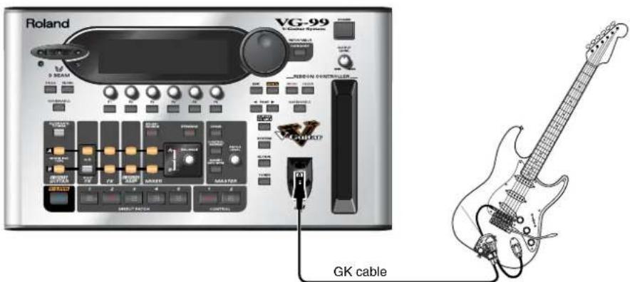
Roland VG-99 3-Beam RUBON CONTROLLER GK cableGuitar with GK-3 / GK-2A / other GK-Compatible guitar
Rear Panel
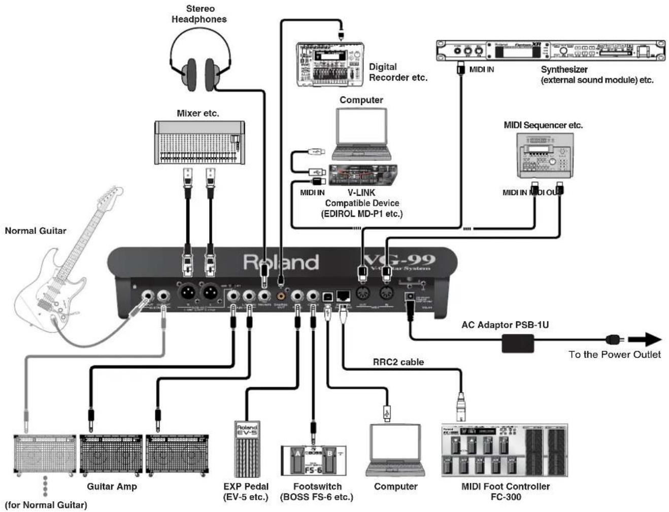
flowchart
graph TD
    A["Normal Guitar"] --> B["Guitar Amp"]
    A --> C["Exp Pedal (EV-5 etc.)"]
    A --> D["Footswitch (BOSS FS-6 etc.)"]
    A --> E["Computer"]
    A --> F["MIDI Foot Controller FC-300"]
    B --> G["Guitar Amp"]
    C --> H["Exp Pedal (EV-5 etc.)"]
    D --> I["Footswitch (BOSS FS-6 etc.)"]
    E --> J["Computer"]
    F --> K["MIDI Foot Controller FC-300"]
    L["Normal Guitar"] --> M["Guitar Amp"]
    N["Stereo Headphones"] --> O["Mixer etc."]
    P["Digital Recorder etc."] --> Q["MIDI IN"]
    R["Computer"] --> S["MIDI IN"]
    T["AC Adaptor PSB-1U"] --> U["To the Power Outlet"]
    V["V-Link Compatible Device (EDIROL MD-P1 etc.)"] --> W["MIDI IN"]
    X["Synthesizer (external sound module) etc."] --> Y["MIDI IN"]
    Z["MIDI Sequencer etc."] --> AA["MIDI IN"]
    AB["VOG-99"] --> AC["VOG-99 System"]
* The GK cable is a locking cable. When disconnecting the cable, do not pull on it with undue force, but instead release the lock and gently disconnect the cable. You can disconnect the cable simply and easily by holding down the locking portion with your finger and gently pulling on the plug.
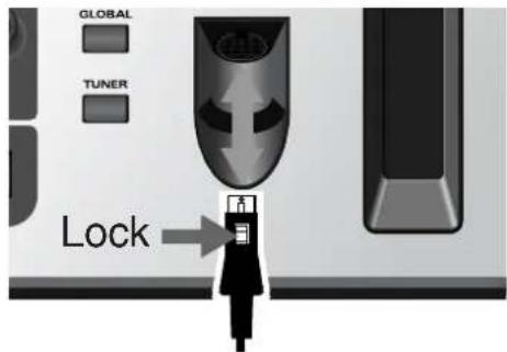
text_image
GLOBAL TUNER Lock* To prevent malfunction and/or damage to speakers or other devices, always turn down the volume, and turn off the power on all devices before making any connections.
* Place the AC adaptor so the side with the indicator (see illustration) faces upwards and the side with textual information faces downwards.
* The indicator will light when you plug the AC adaptor into an AC outlet.
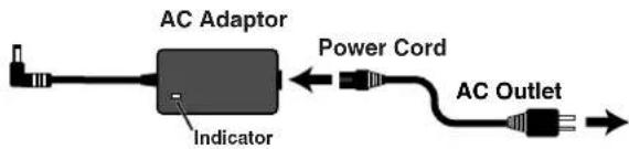
text_image
AC Adaptor Power Cord Indicator AC Outlet* To prevent the inadvertent disruption of power to your unit (should the plug be pulled out accidentally), and to avoid applying undue stress to the AC adaptor jack, anchor the power cord using the cord hook, as shown in the illustration.
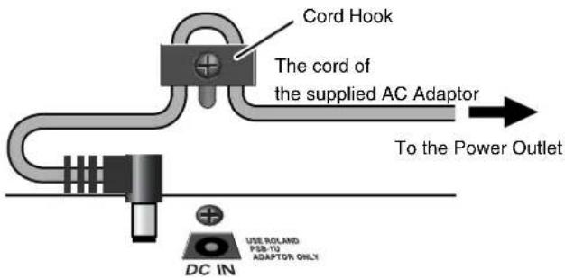
text_image
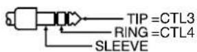
Cord Hook The cord of the supplied AC Adaptor To the Power Outlet DC IN USE ROLLAND PSB-10 ADAPTOR ONLY* Wiring diagrams for CTL3, 4 jack is shown below. Make connections after first checking the wiring diagrams of other equipment you intend to connect.
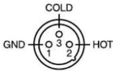
* This instrument is equipped with balanced type jack (XLR=SUB OUT). Wiring diagrams for this jacks is shown below. Make connections after first checking the wiring diagrams of other equipment you intend to connect.
* Use only the specified expression pedal (Roland EV-5, BOSS FS-500L/500H with a connection cable (stereo 1/4" phone – stereo 1/4" phone); sold separately). By connecting any other expression pedals, you risk causing malfunction and/or damage to the unit.
* Depending on the circumstances of a particular setup, you may experience a discomforting sensation, or perceive that the surface feels gritty to the touch when you touch this device, microphones connected to it, or the metal portions of other objects, such as guitars. This is due to an infinitesimal electrical charge, which is absolutely harmless. However, if you are concerned about this, connect the ground terminal (see figure) with an external ground. When the unit is grounded, a slight hum may occur, depending on the particulars of your installation. If you are unsure of the connection method, contact the nearest Roland Service Center, or an authorized Roland distributor, as listed on the "Information" page.

Unsuitable places for connection
• Water pipes (may result in shock or electrocution)
• Gas pipes (may result in fire or explosion)
- Telephone-line ground or lightning rod (may be dangerous in the event of lightning)
* When connection cables with resistors are used, the volume level of equipment connected to the GUITAR INPUT may be low. If this happens, use connection cables that do not contain resistors.
* Never connect anything other than the FC-300's RRC2 OUT connector to the VG-99's RRC2 IN connector. Connecting to a LAN or other devices that use modular jacks of the same size and shape (RJ45) may result in damage to the VG-99 and/or the connected device.
* If using a commercially available ethernet cable as the RRC2 connecting cable, be sure that the cable meets the following specifications:
• Category 5 (Cat5) or above
• Maximum length of 15 meters
• Cable designed for straight-through connections
Crossover cables cannot be used.
* Do not subject the ethernet cable to stress or physical shock.
* Carefully connect the RRC2 cable all the way in—until it is firmly connected to the RRC2 IN connector.
Chapter 1 Outputting Sounds
* When outputting in mono, connect a cable only to the MAIN OUT L/MONO jack.
* You cannot use COSM GUITAR or POLY FX with signals input via GUITAR IN. The GT-PRO's internal FX, COSM AMP, MIXER, and other settings can be used fully in two channels.
* When connecting an expression pedal to the EXP PEDAL jack, use the pedal with the minimum level at the MIN position.
* When connecting an FS-6 footswitch (optional) to the CTL3/4 jack, set the MODE switch and POLARITY switch as shown below.
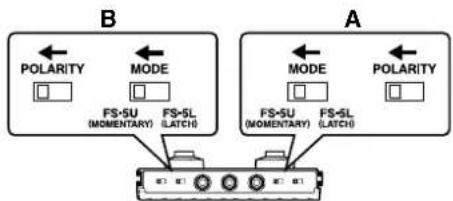
flowchart
graph TD
    subgraph A
        direction TB
        A1["POLARITY"] --> A2["FS-SU (MOMENTARY)"]
        A2 --> A3["FS-SL (LATCH)"]
        A3 --> A4["FS-SU (MOMENTARY)"]
        A4 --> A5["FS-SL (LATCH)"]
        A5 --> A6["POLARITY"]
    end
    subgraph B
        direction TB
        B1["POLARITY"] --> B2["FS-SU (MOMENTARY)"]
        B2 --> B3["FS-SL (LATCH)"]
        B3 --> B4["FS-SU (MOMENTARY)"]
        B4 --> B5["FS-SL (LATCH)"]
        B5 --> B6["POLARITY"]
    end
BOSS FS-6
* When connecting an FS-5U footswitch (optional) to the CTL3/4 jack, set the POLARITY switch as shown below.
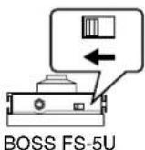
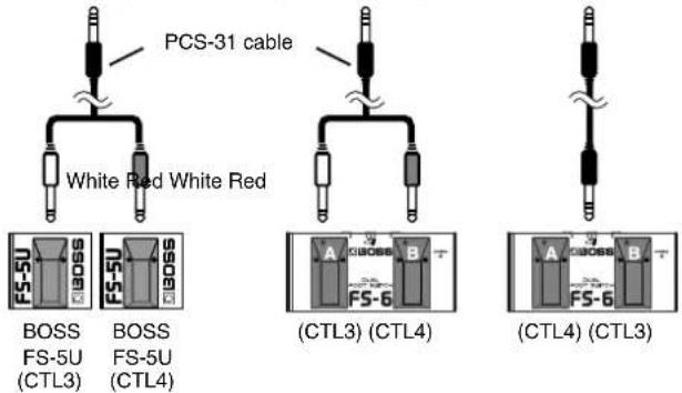
* You can connect two FS-5Us using the special Roland PCS-31 connection cable (optional).
* When an FS-6 is connected to the CTL3,4 jack with an optional connection cable (stereo 1/4" phone – stereo 1/4" phone), pedal switch B operates according to the CONTROL 3 settings, and pedal switch A operates according to the CONTROL 4 settings.
To CTL3,4 jack To CTL3,4 jack To CTL3,4 jack
text_image
PCS-31 cable White Red White Red BOSS BOSS FS-5U FS-5U (CTL3) (CTL4) (CTL3) (CTL4) (CTL4) (CTL3)cf.
- When using the VG-99 with an expression pedal connected to the EXP PEDAL jack, make the settings described on p. 154.
- When using the VG-99 with a footswitch connected to the CTL3/4 jack, make the settings described on p. 154.
Turning On the Power
Once the connections have been completed p. 16, turn on power to your various devices in the order specified. By turning on devices in the wrong order, you risk causing malfunction and/or damage to speakers and other devices.
* This unit is equipped with a protection circuit. A brief interval (a few seconds) after power up is required before the unit will operate normally.
* Always make sure to have the volume level turned down before switching on power. Even with the volume all the way down, you may still hear some sound when the power is switched on, but this is normal, and does not indicate a malfunction.
* Turning on devices in the wrong sequence may result in malfunction and/or damage to speakers and other devices.
1. Switch on the POWER switch on the VG-99's top panel.
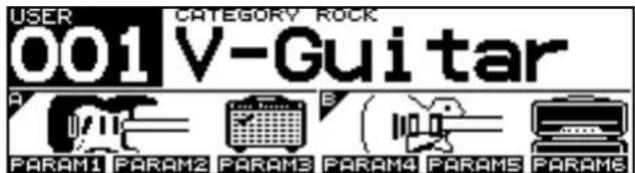
The display changes as described below, and after several seconds the VG-99 is ready for normal performance. This screen is called the "Play screen."
text_image
USER CATEGORY ROCK 001 V-Guitar PARAM1 PARAM2 PARAM3 PARAM4 PARAM5 PARAM6Unless special note is made otherwise, the operations described in this manual are carried out with the Play screen displayed.
* When the power to the VG-99 is turned on, the patch selected at the time the power was last turned off is called up.
* The explanations in this manual include illustrations that depict what should typically be shown by the display. Note, however, that your unit may incorporate a newer, enhanced version of the system (e.g., includes newer sounds), so what you actually see in the display may not always match what appears in the manual.
2. Turn on the power to the guitar amp or mixer.
* Raise amp volume levels only after turning on the power to all the devices.
About the Play Screen
The VG-99 has a variety of Play screen variations, each providing different information about the current state of the VG-99.
You can switch the information shown in the Play screen by pressing
PAGE []◀. ▶
Screen 1:
The first nine characters of the patch name are displayed in large type; also shown are icons for the guitars and amps in both channels.

text_image
USER CATEGORY ROCK 001 V-Guitar PARAM1 PARAM2 PARAM3 PARAM4 PARAM5 PARAM6Screen 2:
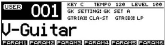
All sixteen characters of the patch name are displayed.
text_image
USER 001 KEY C TEMPO 120 LEVEL 100 GK SETTING: GK SET A GTR(A): CLA-ST GTR(B): LP V-Guitar PARAM1 PARAM2 PARAM3 PARAM4 PARAM5 PARAM6Screen 3:
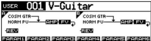
The effects used, as well as their connection sequence (CHAIN) in both channels are indicated.
text_image
USER 001 V-Guitar A COSM GTR NORM PU -REV B COSM GTR NORM PU -REV PARAM1 PARAM2 PARAM3 PARAM4 PARAM5 PARAM6Screen 4:
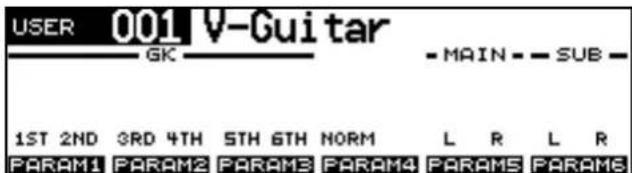
The screen shows level meters for the GK IN strings 1–6, normal pickup, MAIN OUT, and SUB OUT levels.
text_image
USER 001 V-Guitar GK - MAIN - SUB - 1ST 2ND 3RD 4TH 5TH 6TH NORM L R L R PARAM1 PARAM2 PARAM3 PARAM4 PARAM5 PARAM6TIP
By assigning parameters to the F1–F6 knobs, as described in "Changing the Sounds with the Knobs as You Play (DIRECT EDIT)" (p. 82), you can use them to control values while in the Play screen. Additionally, you can display a popup for the assigned parameters and their values by pressing the [F1]–[F6] buttons.
About the Information in the Display (Basic Operation)
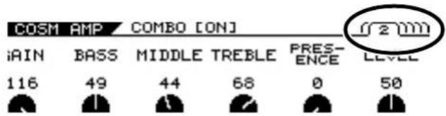
Some screens may contain parameters spanning multiple pages. The page number is indicated at the upper right of the screen.
text_image
COSM AMP COMBO [ON] iAIN BASS MIDDLE TREBLE PRES-ENCE LEVEL 116 49 44 68 0 50-
Use PAGE [ ] to switch pages.
-
Use [F1]–[F6] or the F1–F6 knobs to change the values.
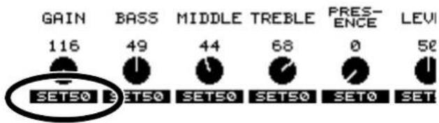
TIP
Pressing a FUNCTION button while SET** appears in the lower part of the screen sets the corresponding function to the indicated value of **.
text_image
GAIN 116 BASS 49 MIDDLE 44 TREBLE 68 PRES- ENCE 0 LEVI SET50 SET50 SET50 SET50 SET0 SETAdjusting the Volume
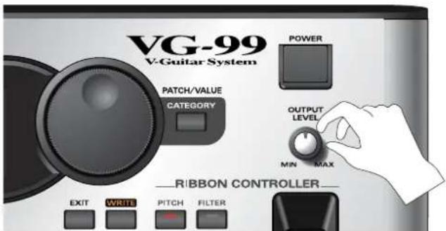
Turn the OUTPUT LEVEL knob to set the volume to a suitable level.
text_image
VG-99 V-Guitar System POWER PATCH/VALUE CATEGORY OUTPUT LEVEL MIN MAX RIBBON CONTROLLER EXIT WRITE PITCH FILTER* The output from the SUB OUT connector (XLR type) remains constant, regardless of the OUTPUT LEVEL knob setting.
* You can adjust the volume level by assigning this function to the expression pedal or GK-3 GK volume control. For details, see "Using the Switches, Pedals, and MIDI to Control the Sounds (CONTROL ASSIGN)" (p. 82).
Setting the Device (Amp) Connected to MAIN OUT (Output Select)
Use this procedure to set the type of device connected to the MAIN OUT jacks.
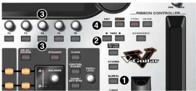
text_image
3 F2 F3 F4 F5 F6 DELAY/ REVERD DYNAMIC CHAIN A3 BALANCE CONTROL AIRBOR PATCH LEVEL NAME/ KEY/BPM NEXT MAX Ribbon CONTROLLER EXIT WIREP PITCH FILTER PAGE ASSIGNABLE GUITAR TO MDD SYSTEM GLOBAL TUNB V4Guitar- Press [GLOBAL].
The Global screen is displayed.
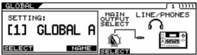
text_image
GLOBAL SETTING: [1] GLOBAL A SELECT NAME MAIN OUTPUT SELECT LINE/PHONES SELECT SELECT- Press PAGE [] to go to Page 1.
- Press [F4] (SELECT) or turn the F4 knob to set the type of device to be connected to the MAIN OUT jacks.
| Value | Explanation |
| JC-120 | Use this setting when connecting to Roland's JC-120 guitar amp. |
| SMALL AMP | Use this setting when connecting to a small guitar amp. |
| COMBO AMP | Use this setting when connecting to the guitar input of a combo amp other than the JC-120 guitar amp (where the amp and speaker or speakers are combined in a single unit).* Depending on your guitar amp, you may be able to obtain good results with the JC-120 setting. |
| STACK AMP | Use this setting when connecting to the guitar input of a stack-type guitar amp (where the amp and speaker or speakers are separated). |
| JC-120 Return | Use this setting when connecting to the RETURN of a JC-120. |
| COMBO Return | Use this setting when connecting to the RETURN of a combo amp. |
| STACK Return | Use this setting when connecting to the RETURN of a stack amp or the input of a rack mounted power amp.Set to STACK Return also when using a guitar power amp and speaker cabinet combination. |
| LINE/PHONES | Use this setting when using headphones or when connecting to a multi-track recorder for recording. |
| Value | Explanation |
| JC-120 | Use this setting when connecting to Roland's JC-120 guitar amp. |
| SMALL AMP | Use this setting when connecting to a small guitar amp. |
| COMBO AMP | Use this setting when connecting to the guitar input of a combo amp other than the JC-120 guitar amp (where the amp and speaker or speakers are combined in a single unit).* Depending on your guitar amp, you may be able to obtain good results with the JC-120 setting. |
| STACK AMP | Use this setting when connecting to the guitar input of a stack-type guitar amp (where the amp and speaker or speakers are separated). |
| JC-120 Return | Use this setting when connecting to the RETURN of a JC-120. |
| COMBO Return | Use this setting when connecting to the RETURN of a combo amp. |
| STACK Return | Use this setting when connecting to the RETURN of a stack amp or the input of a rack mounted power amp.Set to STACK Return also when using a guitar power amp and speaker cabinet combination. |
| LINE/PHONES | Use this setting when using headphones or when connecting to a multi-track recorder for recording. |
- Press [EXIT] to return to the Play screen.
Inputting the Divided Pickup Settings (GK Settings)
The VG-99's sound characteristics vary greatly depending on how the divided pickup is installed. To ensure consistent conditions for optimal sound production, be sure to make the settings affecting the divided pickup (the GK settings). With these settings appropriately made, the VG-99 can then operate under optimal conditions.
* For information on parameters not described in this chapter, refer to "GK SETTING" (p. 166).
MEMO
When using more than one guitar with the VG-99, you can save the settings for each guitar separately.
NOTE
The GK settings are extremely important to getting good tones from the VG-99. Be sure to input the settings correctly.
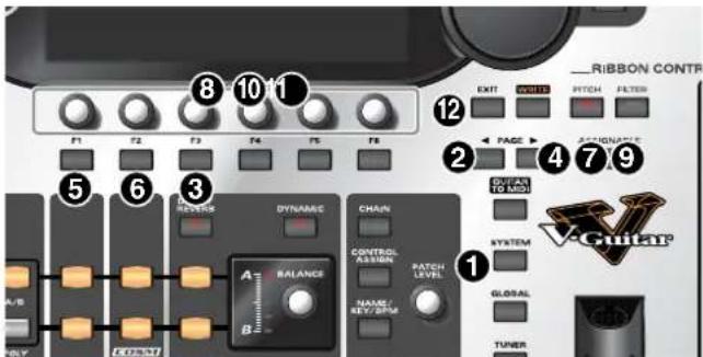
text_image
Ribbon Contr F1 F2 F3 F4 F5 F6 8 10 1 12 EXIT WAIT PITCH FILTER PAGE APPROVATE 2 3 4 7 9 OVER TO MIDI DYNAMIC CHAIN CONTROL ASSIGN PATCH LEVEL SYSTEM A/B A BALANCE B NAME/REV/BPM GLOBAL TUNER V-Guitar1. Press [SYSTEM].
The System screen is displayed
![ROLAND VG-99 - Press [SYSTEM]. - 1](/content/2026/05/763494/images/220e5e5c5369eb387c8fffb904797cd52e2331be45f1e8106a1497173e18e2d3.jpg)
text_image
SYSTEM CONTRAST LCD DIRECT GK CTL FC-300 MIDI FC-3002. Press PAGE [] to go to Page 1.
3. Press [F3] (GK).
The GK Settings screen is displayed.
![ROLAND VG-99 - Press [F3] (GK). - 1](/content/2026/05/763494/images/c813fb3a5fe0292d309da494bbb1cfcd01b06764408286315b0c473b4e066aa2.jpg)
text_image
SYSTEM GK SETTING / [1]GK SET A 1 (M) GK CONNECT AUTO SET MODE SYSTEM SELECT GKFUNC SELECT SETTING: [1] GK SET A SELECT NAME4. Press PAGE [][] to go to Page 2.
5. Select the divided pickup type.
Use the F1 knob to set the type of divided pickup installed in the guitar you are using.
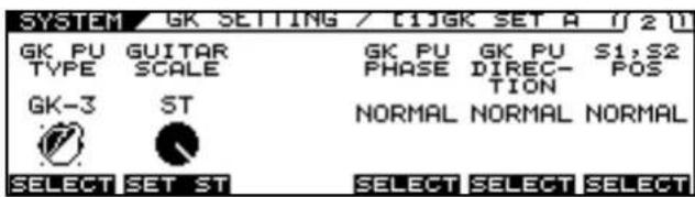
text_image
SYSTEM GK SETTING / [1]GK SET A 1 2 3 GK PU GUITAR GK PU GK PU S1,S2 TYPE SCALE PHASE DIREC- POS GK-3 ST NORMAL NORMAL NORMAL SELECT SET ST SELECT SELECT SELECT| Settings | Explanation |
| GK-3 | Specifics the GK-3. |
| GK-2A Specifies the GK-2A or GK-2. | |
| PIEZO | This is suited to piezo pickups that have a flat response. |
| PIEZO F | This is suited to piezo pickups made by Fishman Transducers. |
| PIEZO G | This is suited to piezo pickups made by Graph Tech Guitar Labs. |
| PIEZO L | This is suited to piezo pickups made by L.R. Baggs. |
| PIEZO R | This is suited to piezo pickups made by RMC Pickup Co. |
* If you're not sure which piezo type parameter is appropriate, choose the parameter for the piezo type that sounds the most natural as you play.
* Piezo pickups are a type of pickup that are installed at the guitar's bridge and use piezoelectric elements to determine the string vibrations.
* Selecting PIEZO F, PIEZO G, PIEZO L, or PIEZO R for GK PU TYPE lets you further adjust the sound quality of the low and high frequency ranges. For detailed information, refer to "Selecting the Divided Pickup Type" (p. 43).
6. Set the scale length.
Use the F3 knob to set the scale length (the distance from the bridge to the nut) of the guitar you are using. Select the closest value within the 620-660 mm range. 648 mm is corresponds to the ST setting, 628 mm to the LP setting.
7. Press PAGE [ ] to go to Page 3.
8. Input the gap between the pickup and the bridge.
Set the clearance from the center of the divided pickup to the bridge's saddle.
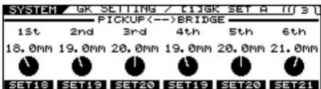
text_image
SYSTEM GK SETTING / [C]JK SET A [F] S 1st 2nd 3rd 4th 5th 6th 18.0mm 19.0mm 20.0mm 19.0mm 20.0mm 21.0mm SET18 SET19 SET20 SET19 SET20 SET21* This setting is not required when the GK PU TYPE is set to piezo type parameter.
Chapter 1 Outputting Sounds
9. Press PAGE [] to go to Page 4.
| SYSTEM | GK | SETTING | / [1]GK SET A | [1]4 |
| F1 | SENS | 1st | ∅ 65 | ...... |
| F2 | SENS | 2nd | ∅ 65 | ...... |
| F3 | SENS | 3rd | ∅ 65 | ...... |
| F4 | SENS | 4th | ∅ 65 | ...... |
| F5 | SENS | 5th | ∅ 65 | ...... |
| F6 | SENS | 6th | ∅ 65 | ...... |
10. Rotate the F1–F6 knobs to adjust the divided pickup sensitivity for each string.
First play the sixth string with the maximum force to be used during actual performance, and as you play the string, set the sensitivity with the F1 knob until the meter registers at a point just before it crosses beyond the maximum level. Set the sensitivity for the fifth through first strings in the same manner.
* If the level meter registers in excess of the maximum level, it means the level is set too high. Lower the sensitivity setting.
* Depending on the guitar you are using, the level meter may move to the maximum level even when the sensitivity is set to the minimum setting. If this occurs, adjust the clearance separating the divided pickup and the strings so the distance is slightly greater than specified.
11. Check the volume balance of the six strings.
Play the sixth through first strings with the normal amount of force; if any string sounds particularly loud, lower the sensitivity setting for that string, and keep adjusting until the differences in the strings' volume levels are minimal.
12. Press [EXIT] several times to return to the Play screen.
* Making these settings is necessary whenever you install the divided pickup on a new or different guitar and when the divided pickup height is changed. Once the settings are completed properly, they are saved when the power is turned off. Afterwards, you need not make the settings each time you play the instrument.
cf.
For more information on other parameters in the GK Settings, refer to "GK SETTING" (p. 166).
Tuning the Guitar (TUNER)
Tune the guitar using the VG-99's tuner function.
* To get the best tone quality from the VG-99, make sure the tuning is accurate.
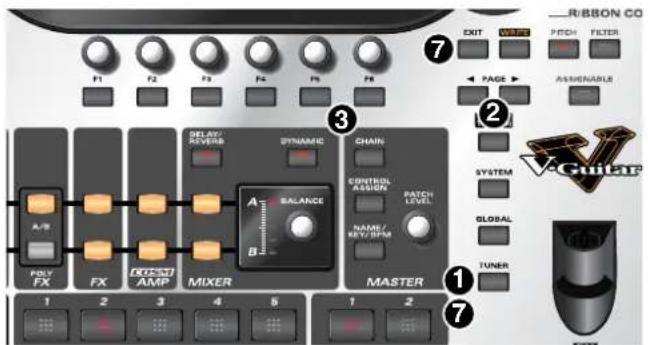
text_image
R-BYON CO EXIT OUTLET PITCH FILTER PAGE ASSIMINABLE F1 F2 F3 F4 F5 F6 ⑦ ② A/B POLY FX FX CONTROL AMP MIVER ELEX/ DIVERSAL DYNAMIC CHAIN A BALANCE B CONTROL ASSIGER PATCH LEVEL NAME/ KEY/BPM MATERIAL SYSTEM GLOBAL TUNER ① ⑦ 1 2 3 4 5 1 21. Press [TUNER].
The tuner function is switched on.
2. Set the following with the PAGE [ ] ▶ buttons.
| TUNER | Explanation |
| MULTI MODE | You can play and tune six strings simultaneously. |
| SINGLE MODE | You can play one individual string to tune that string. |
3. Press the function button ([F5] [F6]) corresponding to the function you want to set, then rotate the knobs to select the value for the setting.
If you do not want to change these settings, proceed to Step 4.
• [F5] (PITCH: 435 Hz–445 Hz)
This sets the reference pitch.
* With the factory settings, this is set to 440 Hz.
* This reference pitch is referenced by effects controlled by the KEY parameter.
TERM
What is the Reference Pitch?
This is the frequency at A4 (the note played with the A key at the middle of the piano keyboard) played by the instrument (e.g. piano) used as the reference for tuning for performances.
• [F6] (MUTE OFF, MUTE ON)
This setting determines whether sounds from the output jacks are output or not while tuning is in progress.
| TUNER | Explanation |
| MUTE OFF | Sounds are output during tuning. |
| MUTE ON | Sounds are not output during tuning.* With the factory settings, this is set to MUTE ON. |
-
Play a single note, open, on the string being tuned.
-
Tune the string until the name of the string is shown in the display.
When you choose the MULTI MODE
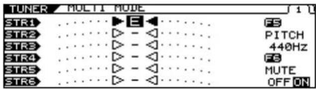
text_image
TUNER MULTI MODE STR1 ....► E ...... STR2 ....► - ◀ ...... STR3 ....► - ◀ ...... STR4 ....► - ◀ ...... STR5 ....► - ◀ ...... STR6 ....► - ◀ ...... FS PITCH 440Hz FS MUTE OFF ONWhen you choose the SINGLE MODE
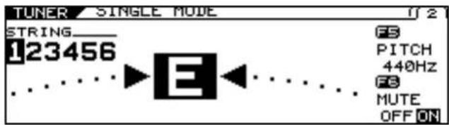
text_image
TUNER SINGLE MODE STRING_ 123456 F5 PITCH 440Hz F8 MUTE OFF ON- Keep checking the screen, tuning until the center indicator lights up.
Repeat Steps 3-5 to tune all the strings.
* When tuning a guitar equipped with a tremolo arm, you may find that when one string is in tune, other strings may not be. If this occurs, first tune the string until its name is indicated in the display, then continue to fine tune each string a number times until the tuning is correct.
- When you have finished tuning, press [TUNER] or [EXIT].
This completes the preparations for playing the instrument. Now try playing some sounds.
Switching Tones (Patch)
What is a patch?
The VG-99 provides 400 memory locations where settings determining the sound, including those for COSM guitars, COSM amps, and effects, as well as settings for a variety of other parameters are stored.
Each one of these is called a patch.
Each time you switch a patch, you can instantly change to a different tone.
About the Patch Numbers
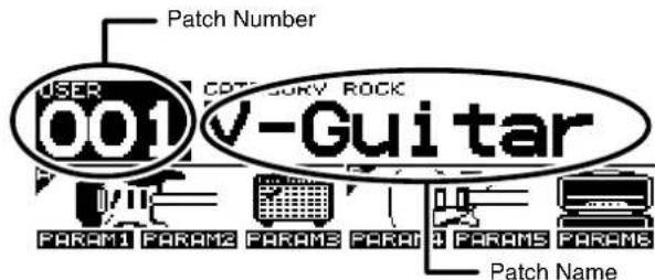
Patch numbers (bank numbers) and patch names are indicated in the Play screen as shown below.
text_image
Patch Number USER 001 CATEGORY ROCK V-Guitar PARAM1 PARAM2 PARAM3 PARAM4 PARAM5 PARAM6 Patch NamePatches are categorized into User patches and Preset patches.
User Patches
These include 200 preprogrammed patches. You can freely change the tones and save the your changes.
Preset Patches
Included here are 200 preprogrammed patches. Although you can make changes to these tones, you cannot save these changes in a Preset Patch. If you want to save a changed tone, save it as a User patch.
Chapter 1 Outputting Sounds
Switching with the PATCH/VALUE Dial
You can switch patches consecutively with the PATCH/VALUE Dial.
- Confirm that the Play screen is displayed.
If a screen other than the Play screen is shown, press [EXIT] several times until the Play screen appears.
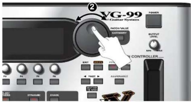
- Rotate the PATCH/VALUE dial to switch the patches.
text_image
VG-99 V-Guitar System POWER PATCH/VALUE CATEGORY OUTPUT LEVEL MINI MAX V CONTROLLER EXIT WRITE PITCH PAGE ASSIGNABLE PLAY/ VERB DYNAMIC CHAINTurn the dial to the right (clockwise) to switch to the next patch number, or to the left (counterclockwise) to switch to the previous patch number.
Turning Off the Power
- Confirm the following before turning off the power.
- Are the volume levels for the VG-99 and connected amp and other devices turned down completely?
-
Turn off the power to the guitar amp (power amp).
-
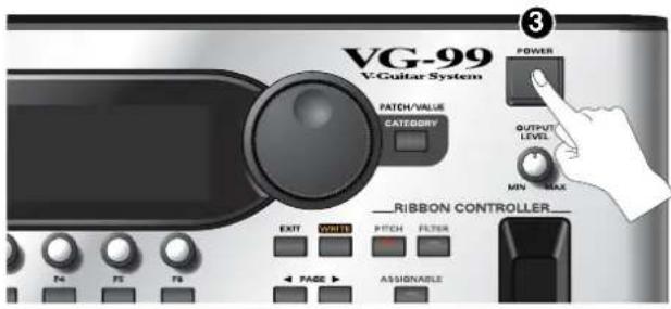
Press [POWER] to turn off the VG-99's power.
text_image
VG-99 V-Guitar System PATCH/VALUE CATEGORY Ribbon Controller EXIT PITCH FILTER PAGE ASSIGNABLE POWER OUTPUT LEVELS MIN MAXNOTE
The message "NOW SHUTDOWN..." appears when the power is switched off. The VG-99's current settings are saved to memory at this time. Do not disconnect the AC adaptor until this message is no longer displayed.
Chapter 2 Creating Sounds
First, let's take a look at how the VG-99 is organized internally.
● COSM Guitars
You can use COSM modeling to create the tones of a variety of different guitars. Available sounds include not just electric and acoustic guitar tones, but extend beyond to include the sounds of synthesizers and other instruments and even non-existent, imaginary guitars. Since the created sounds are based on the signals sent by the GK-3 for each individual string, the system allows you to play these sounds while still retaining all the flavor created by the unique playing techniques and picking nuances that the guitar offers.
The VG-99 allows you to make settings for two different COSM guitar types at the same time, enabling you to instantly switch what amounts to two actual guitars and create sounds in which two guitars seem to be playing at the same time.
MEMO
You can use the Alternate Tuning function to change the pitch of each COSM guitar string individually.
● Poly Effects
These are original VG effects that can be applied independently to each string. You can choose which of the two COSM guitars the effects are applied to.
- COSM Amps
Since this technology models the guitar amp circuitry and speaker characteristics, the modeled amps simulate exactly the behavior of the actual amps, even in the way distortion is added and the way the tone controls work.
You can configure preamps and speaker cabinets as you like—you can even model the amp's studio miking. The VG-99 produces two independent COSM amp systems at the same time, which allows you to process each of the two COSM guitars through a different amp.
- Effects
The VG-99 is equipped with two BOSS GT-PRO class multi-effects systems. You can apply effects separately to each of the two COSM guitars.
- Mixer
In addition to having full freedom in mixing the sounds from the two COSM guitars, you can also output the two guitars separately to MAIN OUT and SUB OUT. The Dynamifunction further allows you to use the force of your picking attack to switch between the two guitar sounds or for many other functions. Furthermore, the mixer section also includes delay/reverb and an equalizer, enabling you to adjust the overall tone of the patches.
Setting the COSM GUITAR Tone
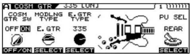
- Press [MODELING TYPE].
- Press PAGE [] several times to display Page 1.
text_image
A COSM GTR 335 LUNJ 1 mm COSM GTR SW MODLNG TYPE E.GTR TYPE OFF ON E.GTR 335 PU SEL REAR OFF/ON SELECT SELECT SELECT- Use [F1] (ON/OFF) or the F1 knob to switch the COSM GUITAR ON/OFF setting.
- Use [F2] (SELECT) or the F2 knob to select the Modeling type.
-
Use [F3] (SELECT) or the F3 knob to select the COSM GUITAR type.
-
Press PAGE [ ]
text_image
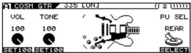
COSM GTR 335 LUNJ VOL TONE PU SEL 100 100 REAR SET100 SET100 SELECT* Each press of PAGE [] takes you to the next screen in which parameter settings are made.
- Adjust the desired parameter with [F1]–[F6] or the F1–F6 knobs.
- Adjust the parameters until you achieve the sound you want.

For detailed information about each of the parameters, refer to "COSM GUITAR" (p. 101).
- If you want to save the edited settings, perform the Write procedure (p. 38).
* If you do not want to save, press [EXIT] to return to the Play screen.
Setting the Alternate Tuning
About Alternate Tuning
The Alternate Tuning feature allows you to change the tuning of a COSM guitar without changing the actual pitch of the guitar's strings. To accomplish this, the VG-99 analyzes the pitch of the signals transmitted by the divided pickup for each individual string while keeping best possible sound quality.
Alternate Tuning includes the following five functions.
TUNING
Use this to convert the tuning to open tunings such as OPEN-D and OPEN-G, raise or lower all of the strings an octave, and achieve various other tunings.
BEND
You can use a pedal to have pitches change from the current tuning to the set tuning in a continuous transition, just as with a string bender or pedal steel guitar.
12-STRING
This changes the sound of a regular six-string guitar to that of a twelve-string guitar.
This function also gives you the freedom to set the pitch and volume of each secondary string independently, enabling you to create 12-string guitar models with entirely original tunings.
DETUNE
This allows you to set a subtle shift in the pitch of each individual string.
HARMONY
This analyzes the pitch of each string, then converts the pitches into harmonies matched to the key.
These functions can be set for each of the two COSM guitars A and B individually, meaning you can now play six-string and twelve-string guitars simultaneously, produce twin twin leads by creating harmonies on your own, achieve fat unison sounds, and come up with sounds never before possible, all with a single VG-99.
Additionally, the VG-99 includes an AB LINK function, which allows you to set the TUNING and BEND for the two COSM guitars (A and B) simultaneously for even quicker settings.
MEMO
The pitches output with GUITAR TO MIDI (the MIDI Note messages) change according to the Channel A Alternate Tuning settings (TUNING, BEND, HARMO).
* The Channel B Alternate Tuning settings have no bearing on these output pitches.
* If the pitch output with GUITAR TO MIDI (the MIDI Note messages) is excessively low (or high) due to the influence of the Channel A Alternate Tuning settings, the pitch is then automatically set one octave higher (or lower).
Setting AB LINK
Setting AB LINK to ON allows you to use the same TUNING and BEND settings for COSM GUITAR [A] and COSM GUITAR [B]. When this is set to OFF, you can use different settings for COSM GUITAR [A] and COSM GUITAR [B].
1. Press [ALTERNATE TUNING].
2. Press PAGE [] to display Page 1.
![ROLAND VG-99 - Press PAGE [] to display Page 1. - 1](/content/2026/05/763494/images/ae5a33667f7b9d9e4086e52b08315dae6e0b610231edea34e41654328a0e6055.jpg)
text_image
ALT TUNING AB LINK off A B TUNING OFF ON OPEN-E OFF ON OPEN-D BEND OFF ON A/B TYPE EDIT3. Switch AB LINK on or off with [F1] (OFF/ON) or the F1 knob.
cf.
For detailed information on all the parameters, refer to "ALTERNATE TUNING" (p. 116).
Setting TUNING
- Press [ALTERNATE TUNING].
- Press PAGE [] to display Page 1.
text_image
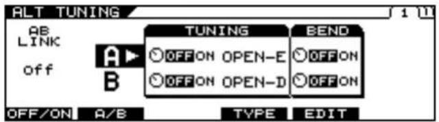
ALT TUNING AB LINK off A B TUNING OFF ON OPEN-E OFF ON OPEN-D BEND OFF ON A/B TYPE EDIT- Select A or B with [F2] (A/B) or the F2 knob.
* You cannot select this when AB LINK is on.
4. Switch the function on or off with the F3 knob.
5. Select the tuning TYPE with [F4] (TYPE) or the F4 knob.
TIP
You can set original user tunings when USER is selected for TYPE. (p. 29)
- Press [F3] (USER).
- Set the desired parameter with [F1]-[F6] or with the F1-F6 knobs.
-
Press [EXIT].
-
If you want to save the edited settings, perform the Write procedure (p. 38).
* If you do not want to save, press [EXIT] to return to the Play screen.
cf.
For detailed information on all the parameters, refer to "ALTERNATE TUNING" (p. 116).
Setting BEND
- Press [ALTERNATE TUNING].
- Press PAGE [] to display Page 1.
text_image
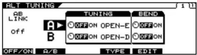
ALT TUNING AB LINK off A B TUNING OFF ON OPEN-E OFF ON OPEN-D BEND OFF ON A/B TYPE EDIT- Select A or B with [F2] (A/B) or the F2 knob.
* You cannot select this when AB LINK is on.
- Switch the function on or off with the F5 knob.
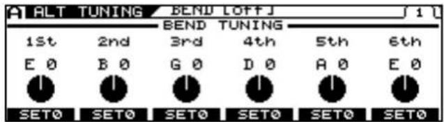
- Press [F5] (EDIT).
text_image
ALT TUNING BEND LOFFJ 1 L 1st 2nd BEND TUNING 5th 6th E 0 B 0 G 0 D 0 A 0 E 0 SET0 SET0 SET0 SET0 SET0 SET0- Set the pitches you want the strings to bend to with the F1-F6 knobs.
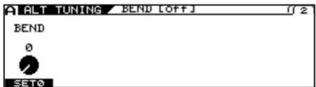
- Press PAGE [] to display Page 2.
text_image
ALT TUNING BEND [OFF] 2 BEND 0 SET0- Confirm the change in pitch with the F1 knob.
- With Control Assign, set BEND as the target parameter for the pedal being used to control the pitch.
cf.
For detailed information on Control Assign, refer to "Using the Switches, Pedals, and MIDI to Control the Sounds (CONTROL ASSIGN)" (p. 82).
TIP
Example of BEND Parameter Settings
By making the parameter settings shown below, you can achieve a string bender-like effect which smoothly raises the pitch of the second string a whole step.
Values Set for the Alternate Tuning Parameter [ALT TUNING]
AB LINK = ON
BEND SW = ON
BEND TUNING 1st = E 0
BEND TUNING 2nd = D, +2
BEND TUNING 3rd = G 0
BEND TUNING 4th = D 0
BEND TUNING 5th = A 0
BEND TUNING 6th = E 0
Values Set for the Control Assign Parameter [CONTROL ASSIGN]
SOURCE = FC-300 EXP 1 or RIBBON POS
(Set the RIBBON CONTROLLER's ASSIGNABLE setting to ON.)
SW = ON
TARGET PARAMETER = ALT TUNE/[A]BEND/BEND
10. If you want to save the edited settings, perform the Write procedure (p. 38).
* If you do not want to save, press [EXIT] to return to the Play screen.
* Although parameter assignments set with Control Assign are saved with the Write procedure, the BEND parameter values in Step 8 are not saved.
cf.
For detailed information on all the parameters, refer to "ALTERNATE TUNING" (p. 116).
Setting 12-STRING
- Press [ALTERNATE TUNING].
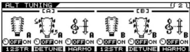
- Press PAGE [ ] to go to Page 2.
text_image
ALT TUNING [A] [B] OFF ON 12STR DETUNE HARMO OFF ON 12STR DETUNE HARMO- Switch the function on or off with the F1 or F4 knob.
* You can make separate 12 STRING settings for COSM GUITAR [A] and COSM GUITAR [B].
4. If making detailed parameter settings for 12 STRINGS, press [F1] (12STR) or [F4] (12STR).
5. Press PAGE [ ] to display the parameter you want to set.
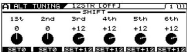
text_image
ALT TUNING 12STR [OFF] 1 m SHIFT 1st 2nd 3rd 4th 5th 6th 0 0 +12 +12 +12 +12 SET0 SET0 SET+12 SET+12 SET+12 SET+12- Set the desired parameter with [F1]–[F6] or with the F1–F6 knobs.
- If you want to save the edited settings, perform the Write procedure (p. 38).
* If you do not want to save, press [EXIT] to return to the Play screen.
cf.
For detailed information on all the parameters, refer to "ALTERNATE TUNING" (p. 116).
Setting USER TUNING
- Press [ALTERNATE TUNING].
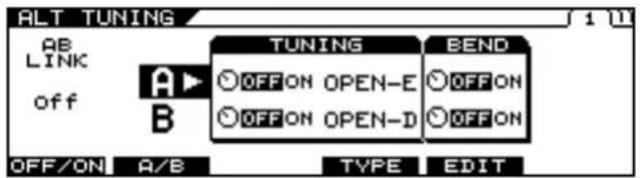
- Press PAGE [] to display Page 1.
text_image
ALT TUNING AB LINK off A B TUNING OFF ON OPEN-E OFF ON OPEN-D BEND OFF ON A/B TYPE EDIT- Select A or B with [F2] (A/B) or the F2 knob.
* You cannot select this when AB LINK is on.
- Switch the function on or off with the F3 knob.
- Use [F4] (TYPE) or the F4 knob to select USER.
- Press [F3] (USER).
The USER TUNING screen appears.
- Set the desired key of string with [F1]–[F6] or with the F1–F6 knobs.
- If you want to save the edited settings, perform the Write procedure (p. 38).
* If you do not want to save, press [EXIT] to return to the Play screen.
cf.
For detailed information on all the parameters, refer to "ALTERNATE TUNING" (p. 116).
Setting DETUNE
- Press [ALTERNATE TUNING].
- Press PAGE [ ] to go to Page 2.
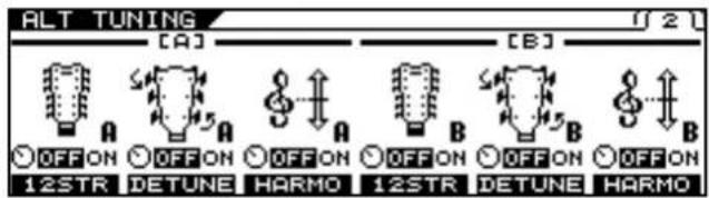
text_image
ALT TUNING [A] [B] OFF ON OFF ON OFF ON OFF ON OFF ON OFF ON 12STR DETUNE HARMO 12STR DETUNE HARMO- Switch the function on or off with the F2 or F5 knob.
- If making detailed parameter settings for DETUNE, press [F2] (DETUNE) or [F5] (DETUNE).
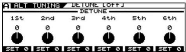
text_image
ALT TUNING / DETUNE [OFF] 1st 2nd 3rd 4th 5th 6th 0 0 0 0 0 0 SET 0 SET 0 SET 0 SET 0 SET 0 SET 0- Set the desired parameter with [F1]–[F6] or with the F1–F6 knobs.
- If you want to save the edited settings, perform the Write procedure (p. 38).
* If you do not want to save, press [EXIT] to return to the Play screen.
cf.
For detailed information on all the parameters, refer to "ALTERNATE TUNING" (p. 116).
Setting HARMONY
- Press [ALTERNATE TUNING].
- Press PAGE [] to go to Page 2.
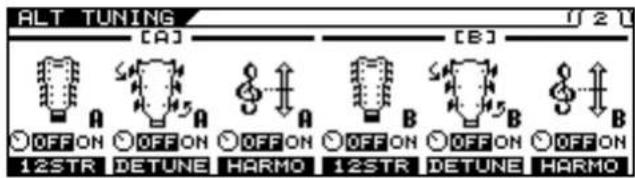
text_image
ALT TUNING [A] [B] OFF ON 12STR OFF ON DETUNE HARMO OFF ON 12STR OFF ON DETUNE HARMO- Switch the function on or off with the F3 or F6 knob.
- If making detailed parameter settings for HARMONY, press [F3] (HARMO) or [F6] (HARMO).
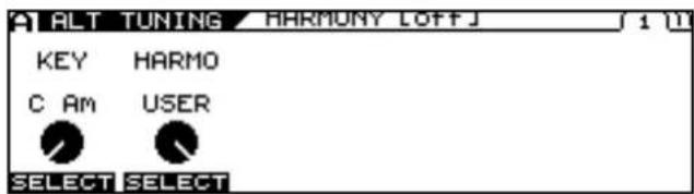
text_image
ALT TUNING HARMONY LOFFJ 1 (1) KEY HARMO C AM USER SELECT SELECT- Set the desired parameter with [F1] (SELECT), [F2] (SELECT) or with the F1–F2 knobs.
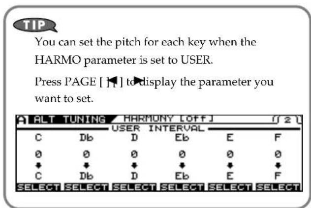
text_image
TIP You can set the pitch for each key when the HARMO parameter is set to USER. Press PAGE [ ] to display the parameter you want to set. ALT TUNING HARMONY [OFF] 1/2 C Db D Eb E F 0 0 0 0 0 0 ↓ ↓ ↓ ↓ ↓ ↓ C Db D Eb E F SELECT SELECT SELECT SELECT SELECT SELECT- If you want to save the edited settings, perform the Write procedure (p. 38).
* If you do not want to save, press [EXIT] to return to the Play screen.
cf.
For detailed information on all the parameters, refer to "ALTERNATE TUNING" (p. 116).
Setting the COSM AMP Tone
- Press [COSM AMP].
- Press PAGE [] several times to display Page 1.
- Use [F1] (ON/OFF) or the F1 knob to switch the COSM AMP ON/OFF setting.
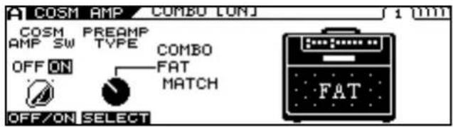
text_image
COSM AMP COMBO LUNJ COSM PREAMP AMP SW TYPE COMBO OFF ON FAT MATCH OFF/ON SELECT FAT- Use [F2] (SELECT) or the F2 knob to select the COSM AMP type.
- Press PAGE [ ]
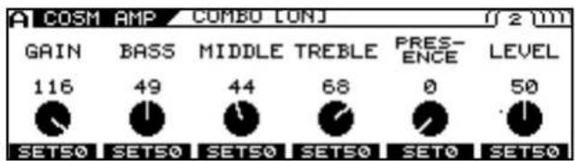
text_image
A COSM AMP COMBO CONJ 2 mm GAIN BASS MIDDLE TREBLE PRES- ENCE LEVEL 116 49 44 68 0 50 SET50 SET50 SET50 SET50 SET0 SET50* Each press of PAGE [] takes you to the next screen in which parameter settings are made.
- Adjust the desired parameter with [F1]–[F6] or the F1–F6 knobs.
- Adjust the parameters until you achieve the sound you want.
cf.
For detailed information on all the parameters, refer to "COSM AMP" (p. 140).
- If you want to save the edited settings, perform the Write procedure (p. 38).
* If you do not need to save the settings, press [EXIT] to return to the Play screen.
Setting the Effects
POLY FX (Poly Effect)
* You can use POLY FX in only one channel at a time (A or B).
- Press [POLY FX] for the channel, either A or B, in which you want to use it.
- Press PAGE [] several times to display Page 1.
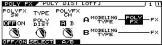
text_image
POLY FX / POLY DIST OFF POLYFX SW TYPE POLYFX CH OFF ON POLY DIST A B A MODELING TYPE POLY FX B MODELING TYPE FX OFF/ON SELECT A/B-
Switch the function on or off with the [F1] (ON/OFF) or the F1 knob.
-
Select the POLYFX TYPE with [F2] (SELECT) or the F2 knob.
-
Using [F3] (A/B) or the F3 knob, switch the channel to the one in which POLY FX is to be used.
-
Press PAGE [ ]
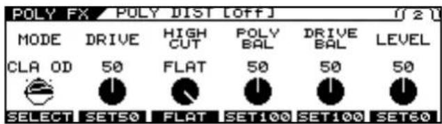
text_image
POLY FX / POLY DIST [OFF] 02 MODE DRIVE HIGH POLY DRIVE LEVEL CLA OD 50 CUT 50 BAL 50 SELECT SET50 FLAT SET100 SET100 SET60* Each press of PAGE I] takes you to the settings screen for the next parameter.
-
Set the desired parameter with [F1]–[F6] or with the F1–F6 knobs.
-
Adjust the parameters until you achieve the desired sound.
cf.
For detailed information on all the parameters, refer to "POLY FX (Poly Effect)" (p. 118).
- If you want to save the edited settings, perform the Write procedure (p. 38).
* If not saving the values, press [EXIT] to return to the Play screen.
FX (Effects)
Here's how to make settings for the effects.
- Press [FX].
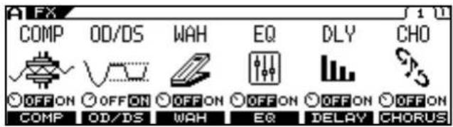
text_image
FX COMP OD/DS WAH EQ DLY CHO OFF ON OFF ON OFF ON OFF ON OFF ON OFF ON COMP OD/DS WAH EQ DELAY CHORUS- Switch the individual effects on or off with the [F1]–[F6] (ON/OFF).
* Each press of PAGE [ ] [ ] takes you to another effect screen in which parameter settings are made.
TIP
All effects that are on can be alternately switched off (indicator unlit) and on (indicator lit) together by pressing [FX].
-
Press [F1]–[F6] to select the effect you want to edit.
-
Adjust the desired parameter with [F1]–[F6] or the F1–F6 knobs.
* Each press of PAGE [] takes you to the settings screen for the next parameter.
- Adjust the parameters until you achieve the sound you want.
cf.
For detailed information on all the parameters, refer to "FX (Effects)" (p. 120).
- If you want to save the edited settings, perform the Write procedure (p. 38).
* If you do not need to save the settings, press [EXIT] to return to the Play screen.
Rearranging the Effect and Amp Connection Sequence (CHAIN)
You can freely set the order in which the effects and COSM amps are connected.
1. Press [CHAIN].
The Chain screen is displayed.
![ROLAND VG-99 - Press [CHAIN]. - 1](/content/2026/05/763494/images/dac2db96b13b6a7b13b9956ca3e754d84f084ac8bdf678aec18787c9d6b6a79f.jpg)
text_image
CHAIN NORMAL PU COSM GTR Lch Rch OFF-OFF-OFF-OFF-OFF-OFF-OFF-OFF-OFF-OFF M1 CMP WAH DSTAMP EQ NS FV M2 DLYCHOREV A/B SEL SEL +MOVE MOVE → OFF/ON* If the effects and COSM amps are off, OFF is indicated.
- Select the channel for which you want to change the connection sequence with [F1] (A/B).
- Press [F2] (SEL) [F3] (SEL) to select the effect, COSM guitar, or COSM amp to be shifted in the sequence.
The output level for the selected effect is indicated in the upper right of the screen.
- Press [F4] (←MOVE) [F5] (MOVE→) to move to the position in the sequence you want the shifted item inserted.
- To make any additional changes in the connection sequence, repeat Steps 2–4.
* You can also switch effects, COSM guitars, and COSM amps on and off while setting the connection sequence. Pressing [F6] while the effect, COSM guitar, or COSM amp is selected switches the function's ON/OFF setting.
- Press [EXIT] to return to the Play screen.
- If you want to save the edited settings, perform the Write procedure (p. 38).
Specifying the tempo and key of the song to be played
Here's how to specify the tempo and key of a song you'll be playing. Set these when you want to specify a delay time or rate that suits a song's tempo (specifying it in terms of the note length) and when using the HARMONY function.
Setting the Tempo
1. Press [NAME/KEY/BPM].
![ROLAND VG-99 - Press [NAME/KEY/BPM]. - 1](/content/2026/05/763494/images/03b73f5d205f2554f856ce3b441ba975b403978b44967fb030d5bcb102883fdd.jpg)
text_image
NAME/KEY/BPM NAME KEY BPM FC-300 C:\> ABCDEF C+---B AMP CTL NAME KEY BPM AMPCTL TX PC2. Press [F3] (BPM).
![ROLAND VG-99 - Press [F3] (BPM). - 1](/content/2026/05/763494/images/d216db62bff9ac2673d4d9c72a0cbcfcbbba5427baf7c22e54420faa6ada8864.jpg)
text_image
NAME/KEY/BPM BPM BPM 120 TAP- Tap [F1] (TAP) in time with the song tempo (quarter notes), or adjust the tempo with the F1 knob.
* If you want to control a patch parameter with the adjusted tempo, set the corresponding effect parameter to BPM -BPM.
TERM
BPM stands for "beats per minute," and represents the number of quarter notes played in one minute.
cf.
If you want to use the MIDI SYNC function, the SYNC CLOCK parameter must be set to AUTO (USB), AUTO (MIDI), or AUTO (RRC2). For detailed information, refer to "Syncing to the MIDI CLOCK from an External Device" (p. 64).
MEMO
To use Tap Input Press [F5] (TAP) at least two times, at quarter note intervals of the desired tempo. The tempo will be calculated automatically, and set to the interval at which you pressed the button.
- If you want to save the edited settings, perform the Write procedure (p. 38).
* If you do not want to save, press [EXIT] to return to the Play screen.
Setting the Key
- Press [NAME/KEY/BPM].
- Press [F2] (KEY).
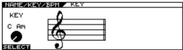
text_image
NAME/KEY/BPM KEY KEY C Am SELECT- Set the song's key with [F1] (SELECT) or the F1 knob.
* The Alternate Tuning HARMONY and FX MOD 1/2 HARMONIST functions operate in accordance with the key set here.
- If you want to save the edited settings, perform the Write procedure (p. 38).
* If you do not want to save, press [EXIT] to return to the Play screen.
Mixing the Normal Pickup Sound
Creating Sounds Combining the Normal and GK Inputs. It is possible to combine the sound of the COSM guitars and the normal guitar pickups at the same time.
Setting the Volume Balance
- Press [COSM GUITAR].
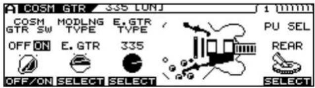
text_image
A COSM GTR 335 LUNJ 1 mm COSM GTR SW MODLNG TYPE E.GTR TYPE OFF ON E.GTR 335 PU SEL REAR OFF/ON SELECT SELECT SELECT- Set the COSM GTR SW to ON with [F1] or with the F1 knob.
MEMO
The sounds from the normal pickup and COSM guitar are not played when COSM GTR SW is set to OFF.
- Press PAGE [ ] several times to move to the screen for setting the volume balance.
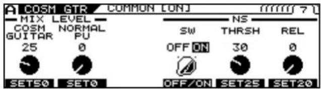
text_image
A COSM GTR COMMON LONJ MIX LEVEL COSM NORMAL GUITAR PU 25 0 SET50 SET0 SW THRESH REL OFF ON 30 0 OFF/ON SET25 SET20- Use the F1 and F2 knobs to set the balance between the COSM guitar sound and the normal pickup sound.
F1 Knob
Adjusts the COSM guitar's volume level. When POLY FX is set to ON, it adjusts the volume level of the signal after it has passed through POLY FX.
F2 Knob
This adjusts the volume of the normal pickup.
When the COSM guitar is connected in CHAIN at a point other than the beginning of the effects chain, you can adjust the volume of the sounds that have passed though effects from the beginning of the chain up to the point where the guitar is connected.
- If you want to save the edited settings, perform the Write procedure (p. 38).
* If you do not want to save, press [EXIT] to return to the Play screen.
Setting the Point at Which the COSM Guitar is Connected
1. Press [CHAIN].
![ROLAND VG-99 - Press [CHAIN]. - 1](/content/2026/05/763494/images/03782bee6b6dfc45704568648e3e3ce885315b6426b7810170b37e80afb97ce3.jpg)
text_image
CHAIN NORMAL PU COSM GTR Lch Rch OFF-OFF-OFF-OFF-OFF-OFF-OFF-OFF-OFF-OFF M1 CMP WAH DSTAMP EQ NS FV M2 DLYCHOREV A/B SEL SEL +MOVE MOVE → OFF/ON- Use [F2] (SEL) and [F3] (SEL) to select the arrow indicating the connection point.
- Use [F4] (←MOVE) and [F5] (MOVE→) to shift the COSM guitar's connection point.
![ROLAND VG-99 - Press [CHAIN]. - 2](/content/2026/05/763494/images/84b445a325039fd21ca0b96d681681de93da0aeff54ee31105c04a50ed6f10f2.jpg)
text_image
CHAIN Lch NORMAL PU Rch COSM GTR OFF OFF OFF OFF OFF OFF CMP M1 WAHDSTAMP EQ NS FV M2 DLYCHOREV A/B SEL SEL > ←MOVE MOVE → OFF/ON- If you want to save the edited settings, perform the Write procedure (p. 38).
* If you do not need to save the settings, press [EXIT] to return to the Play screen.
Normal Pickup Sound
When you are using the CHAIN function and the COSM guitar is connected at a point other than the beginning of the chain, the normal pickup sound that is mixed using the BALANCE knob is the sound processed from the beginning of the effects chain. Using this function, you can combine the following two methods to create sounds.
- Sounds that include COMPRESSOR, WAH, AMP, etc., with the normal pickup sound
- Sounds that have only spacial effects applied to the COSM section's synthesizer or other source.
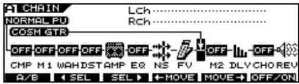
text_image
A CHAIN Lch NORMAL PU Rch COSM GTR OFF OFF OFF OFF OFF CMP M1 WAHD STAMP EQ NS FV M2 DLY CHOREV A/B ← SEL SEL → ← MOVE MOVE → OFF/ONWhen the volume of (1) above is to be controlled independently, the level of effects before the COSM guitar should be assigned to the GK volume control of the GK-3 or to a similar controller. (p. 82)
TIP
If you want to use only the normal pickup sound without using the COSM GUITAR or POLY FX, set the COSM guitar as shown below.
COSM GTR SW = ON
MIX LEVEL
COSM GUITAR = 0
NORMAL PU = 100
Mixing Two Tones (MIXER)
cf.
For detailed about the block diagram, refer to "Signal Flow" (p. 183).
Setting the Volume and Panning for Each Channel
- Press [MIXER].
- Press PAGE [] to display Page 1.
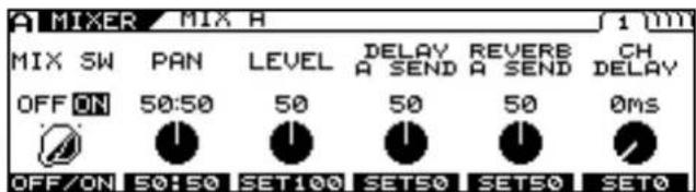
text_image
A MIXER MIX H 1 00m MIX SW PAN LEVEL DELAY REVERB CH OFF ON 50:50 50 A SEND A SEND DELAY OFF/ON 50:50 SET100 SET50 SET50 SET0Make the settings for each channel on this page.
* Page 2 and later pages contain the mixer section's common settings.
- Set the volume and panning with [F1]–[F6] or with the F1–F6 knobs.
- If you want to save the edited settings, perform the Write procedure (p. 38).
* If not saving the settings, press [EXIT] to return to the Play screen.
TIP
When mixing two channels, you can produce a more realistic twin guitar tone by setting a channel delay in one of the channels, thus causing the two guitar sounds to be output at different times.
cf.
For detailed information on all the parameters, refer to "MIXER" (p. 146).
Setting the Mix Balance
You can set the balance in the mix of Channel A and Channel B with the BALANCE knob. Soon after the knob is turned, the balance value pops up in the screen.
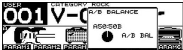
text_image
USER CATEGORY ROCK 001 V-0 A/B BALANCE A50:50B A/B BAL PARAM1 PARAM2 PARAM PARAM6* You can also adjust this parameter in Page 2 of the Mixer screen.
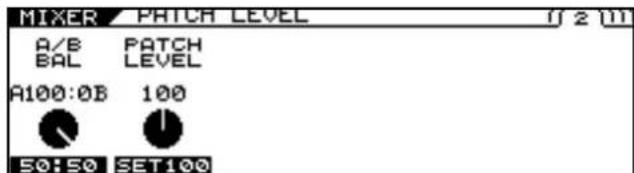
text_image
MIXER PATCH LEVEL 2 (1) A/B PATCH BAL LEVEL A100:0B 100 50:50 SET100* This knob is disabled when the Dynamic function is switched on.
Setting the Delay and Reverb (DELAY/REVERB)
This sets the mixer section's delay and reverb.
-
Press [DELAY/REVERB].
-
Press PAGE [] to display Page 1.
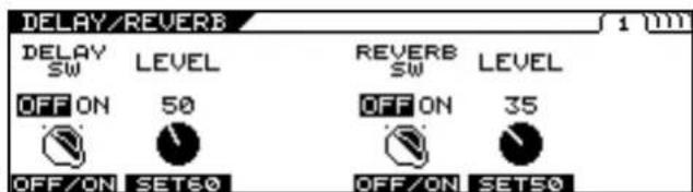
text_image
DELAY/REVERB DELAY SW OFF ON 50 OFF/ON SET60 REVERB SW OFF ON 35 OFF/ON SET50 1 mm- Switch the delay on or off with [F1] (OFF/ON); switch the reverb on or off with [F4] (OFF/ON).
- Set the parameters with [F1]–[F6] or with the F1–F6 knobs.
* Each press of PAGE [] takes you to the settings screen for the next parameter.
- Adjust the parameters until you achieve the desired sound.
- If you want to save the edited settings, perform the Write procedure (p. 38).
* If not saving the values, press [EXIT] to return to the Play screen.
cf.
For detailed information on all the parameters, refer to "DELAY/REVERB" (p. 148).
Using Picking Dynamics to Control the Mix Between the Two Channels (DYNAMIC)
You can control the mix between the two channels according to how strongly the strings are picked.
- Press [DYNAMIC].
- Press PAGE [] to display Page 1.
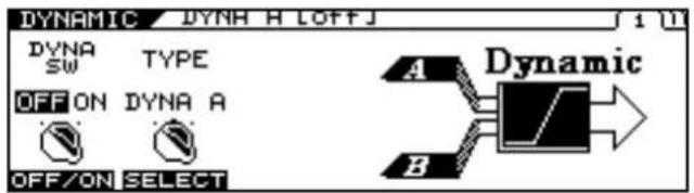
text_image
DYNAMIC DYNH H LOFFJ DYNA SW TYPE OFF ON DYNA A OFF/ON SELECT A Dynamic B- Switch the Dynamic function on or off with [F1] (OFF/ON).
- Select the Dynamic function type.
- Press PAGE [ ] to display Page 2.

text_image
DYNAMIC DYNH H LOFFJ F1 LOWER LEV 0 F2 LOWER RNG 20 F3 UPPER LEV 100 F4 UPPER RNG 80 F5 RELEASE 60 B A B IN...- Set the parameters with the F1–F5 knobs.

For detailed information on all the parameters, refer to "DYNAMIC" (p. 149).
Setting the Overall Patch Volume Level (PATCH LEVEL)
You can set the overall patch volume level with the PATCH LEVEL knob. Soon after the knob is turned, the patch level settings value pops up in the screen.
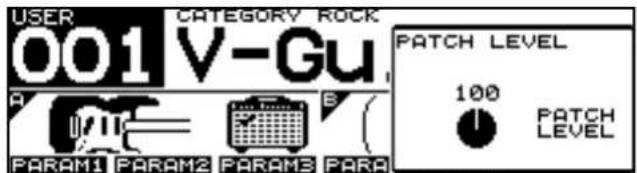
text_image
USER 001 V-Gu CATEGORY ROCK PATCH LEVEL 100 PATCH LEVEL PARAM1 PARAM2 PARAM3 PARA* You can also adjust this parameter in Page 2 of the Mixer screen.
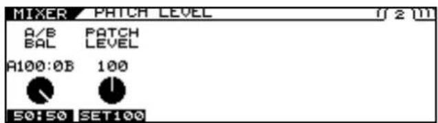
text_image
MIXER PATCH LEVEL 0 2 m A/B PATCH BAL LEVEL A100:0B 100 50:50 SET100Adjusting the Overall Patch Tone (TOTAL EQ)
You can make separate settings in each individual patch for the overall tone after sounds have passed through the mixer.
- Press [MIXER].
- Press PAGE [ ] to display Page 3 or 4.
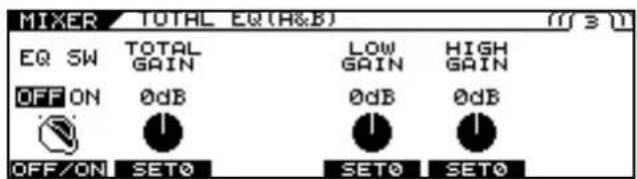
text_image
MIXER TOTAL EQ(A&B) (1) 3 (1) EQ SW TOTAL GAIN LOW GAIN HIGH GAIN OFF ON 0dB 0dB 0dB OFF/ON SET0 SET0 SET0- Switch the EQ on or off with [F1] (ON/OFF) on Page 3.
- Set the tonal quality with [F1]–[F6] or with the F1–F6 knobs.
- If you want to save the edited settings, perform the Write procedure (p. 38).
* If not saving the settings, press [EXIT] to return to the Play screen.

For detailed information on all the parameters, refer to "TOTAL EQ (Total Equalizer)" (p. 146).
Setting the Output Signal and Level (OUTPUT)
This sets the signals and levels output for each of the VG-99's output jacks and connectors.
-
Press [MIXER].
-
Press PAGE [] to display Page 5.
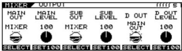
text_image
MIXER OUTPUT MAIN OUT MAIN LEVEL SUB OUT SUB LEVEL D OUT OUT LEVEL MIXER 100 MIXER 100 MAIN OUT 100 SELECT SET100 SELECT SET100 SELECT SET100- Set the signal and level output to MAIN OUT, SUB OUT, and DIGITAL OUT with [F1]–[F6] or with the F1–F6 knobs.
cf.
For detailed information on the parameters that can be set, refer to "OUTPUT" (p. 147).
- If you want to save the edited settings, perform the Write procedure (p. 38).
* If not saving the settings, press [EXIT] to return to the Play screen.
MEMO
You can also set the output signal and level for the entire system.
- Press [SYSTEM].
- Press PAGE [] [◀] to ▶ display Page 2.
- Press [F1].
- Set the OUTPUT MODE parameter to SYSTEM with [F1] or the F1 knob.
The value in the MIXER screen is disregarded, and instead the SYSTEM value <> is applied.
Naming a Patch (PATCH NAME)
You can give names to the patches you create.
- Press [NAME/KEY/BPM].
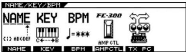
text_image
NAME/KEY/BPM NAME KEY BPM FC-300 C12 ABCDEF C←→B =*** AMP CTL TX PC NAME KEY BPM AMPCTL- Press [F1] (NAME).
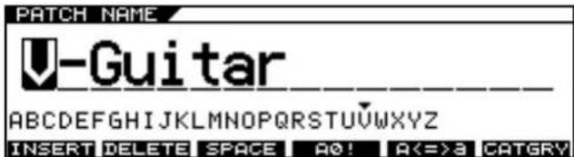
text_image
PATCH NAME Guitar ABCDEFGHIJKLMNOPQRSTUVWXYZ INSERT DELETE SPACE A0! A<=3 CATGRY- Press PAGE [ ] to move the cursor to the position at which you want to change a character.
- Select the character with the PATCH/VALUE dial.
As you continue to rotate the PATCH/VALUE dial, the character guide automatically switches from uppercase letters to lowercase letters, numerals, and symbols.
You can use the following convenient operations by pressing [F1]-[F6].
| Function Button | Description |
| [F1] (INSERT) | Inserts a blank space at the cursor position. |
| [F2] (DELETE) | Deletes the character and shifts the characters that follow to the left. |
| [F3] (SPACE) Inserts a blank space at the cursor position. | |
| [F4] (A0!) | Switches between letters, numerals, and symbols. |
| [F5] (A<=>a) | Switches between uppercase and lower-case letters. |
| [F6] (CATGRY) | Sets the category for the current patch. Refer to “Setting Patch Categories” (p. 91) |
- Repeat Steps 3 and 4 to complete the patch name.
- If you want to save the edited settings, perform the Write procedure (p. 38).
* If not saving the settings, press [EXIT] to return to the Play screen.
Saving a Patch (WRITE)
The settings made to change a sound are temporary; when you switch to a different patch, the settings revert to the values in effect before the changes were made.
If you want to save the changes in the settings, carry out the Write procedure. If you do not want to save your changes, press EXIT to return to the Play screen.
1. Press [WRITE].
The Write screen appears.
![ROLAND VG-99 - Press [WRITE]. - 1](/content/2026/05/763494/images/368ceeeaffb290d4b7c0cd3e76dc8d0b48bea42aa676fd2142b0cfa55870f0a8.jpg)
text_image
WRITE PATCH WRITE WRITE TO 001:V-Guitar YES: [WRITE] NO : [EXIT] NAME2. Rotate the PATCH/VALUE dial to select the save-destination patch number.
3. To save the patch, press [WRITE].
"NOW WRITING..." is displayed while the patch is being saved, and then the Play screen returns to the display.
![ROLAND VG-99 - To save the patch, press [WRITE]. - 1](/content/2026/05/763494/images/9753c86b1b6faa98c2c50970f1b783865263a4688abecb02e4e9a7d30aaf7f41.jpg)
text_image
WRITE PITCH WRITE 1 (1) WRI MESSAGE NOW WRITING...* If you do not want to save, press [EXIT] to return to the Play screen.
Chapter 3 Creating Your Own Effect Types (CUSTOMIZE)
The Customize function allows you to make even more detailed changes to settings for COSM AMP (Preamp section, Speaker section), Overdrive/Distortion, and Pedal Wah, just like designing your own original effects processors.
Customizing the Preamp
1. Press [COSM AMP].
The COSM AMP Edit screen appears.
2. Press PAGE [] to display Page 1.
![ROLAND VG-99 - Press PAGE [] to display Page 1. - 1](/content/2026/05/763494/images/ded23644de64d7a34c70d927d9d44375d67ec02582e0ac80d7d0c90187910430.jpg)
text_image
A COSM AMP COMBO LONJ COSM PREAMP COMBO AMP SW TYPE FAT OFF ON MATCH OFF/ON SELECT FAT3. Select CUSTOM as the PREAMP TYPE with [F2] (SELECT) or the F2 knob.
![ROLAND VG-99 - Select CUSTOM as the PREAMP TYPE with [F2] (SELECT) or the F2 knob. - 1](/content/2026/05/763494/images/6d965e0cd7dcd650420272386b0dbe9f29f11818a9bad70f71ac246a9aace8bd.jpg)
text_image
A COSM AMP LUNJ COSM PREAMP AMP SW TYPE OFF ON CUSTOM OFF/ON SELECT CUSTOM4. Press PAGE [ ] to display Page 2.
![ROLAND VG-99 - Press PAGE [ ] to display Page 2. - 1](/content/2026/05/763494/images/ee4f7f9197e9b267aff77d9abd390f053f0088d4eafb4cca3ca2c5d9a19e6a4c.jpg)
text_image
A COSM AMP LUNJ CUSTOM PREAMP CUSTOM TYPE JC CLEAN SELECT5. Select the basic preamp type to customize with [F1] (SELECT) or the F1 knob.
6. Press PAGE [] to display Page 3.
![ROLAND VG-99 - Press PAGE [] to display Page 3. - 1](/content/2026/05/763494/images/e1875859764ce5f0d3f4d1c426af14936bf218dd5de2fa0baf2ccc4c330a1cf4.jpg)
text_image
A COSM AMP LUNJ BOTTOM EDGE CUSTOM PREAMP BASS FREQ TREBLE FREQ LOW HIGH 0 0 0 0 0 0 SET0 SET0 SET0 SET0 SET0 SET07. Adjust the desired parameter with [F1]–[F6] or with the F1–F6 knobs.
If there are other parameters you want to adjust, press PAGE [▶].
8. Repeat Steps 5–7 as needed.
9. If you want to save the edited settings, perform the Write procedure (p. 38).
* If not saving the settings, press [EXIT] to return to the Play screen.
cf.
For detailed information on all the parameters, refer to "CUSTOM" (p. 143).
Chapter 3 Creating Your Own Effect Types (CUSTOMIZE)
Customizing the Speaker
* You cannot customize the speaker when BASS AMP VINTAGE or BASS AMP MODERN is selected with PREAMP TYPE.
- Press [COSM AMP].
The COSM AMP Edit screen appears.
- Press PAGE [ ] to display the Speaker Type selection screen.
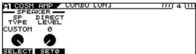
text_image
COSM AMP COMBO LUNJ SPEAKER SP DIRECT TYPE LEVEL CUSTOM 0 SELECT SET0-
Select CUSTOM as the SP TYPE with [F1] (SELECT) or the F1 knob.
-
Press PAGE [ ] to display the speaker customization screen.
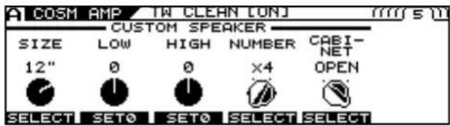
text_image
A COSM AMP TW CLEAN LUNJ mm SE CUSTOM SPEAKER SIZE LOW HIGH NUMBER CABI- 12" 0 0 x4 OPEN SELECT SET0 SET0 SELECT SELECT-
Adjust the desired parameter with [F1]–[F5] or with the F1–F5 knobs.
-
If you want to save the edited settings, perform the Write procedure (p. 38).
* If not saving the settings, press [EXIT] to return to the Play screen.
cf.
For detailed information on all the parameters, refer to "COSM AMP" (p. 140).
Customizing the Overdrive/ Distortion
- Press [FX].
The FX Edit screen appears.
- Press PAGE [] to display Page 1.
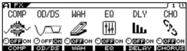
text_image
FX COMP OD/DS WAH EQ DLY CHO OFF ON OFF ON OFF ON OFF ON OFF ON OFF ON COMP OD/DS WAH EQ DELAY CHORUS- Press [F2] (OD/DS).

text_image
FX OD/DS:CUSTOM[ON] OD/DS SW TYPE OFF ON CUSTOM OFF/ON SELECT OverDrive/ Distortion-
Select CUSTOM as the OD/DS TYPE with [F2] (SELECT) or the F2 knob.
-
Press PAGE [] to display Page 2.
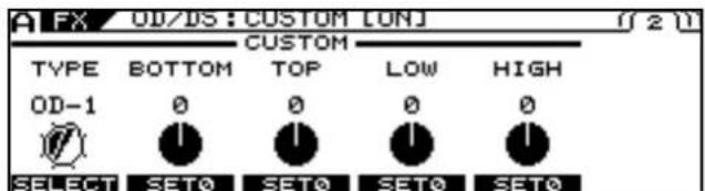
text_image
FX OD/DS: CUSTOM [ON] TYPE BOTTOM TOP LOW HIGH OD-1 0 0 0 0 SELECT SETO SETO SETO SETO-
Select the basic type with [F1] (SELECT) or the F1 knob.
-
Adjust the desired parameter with [F1]–[F5] or with the F1–F5 knobs.
If there are other parameters you want to adjust, press PAGE [▶].
-
Repeat Steps 6 and 7 as needed.
-
If you want to save the edited settings, perform the Write procedure (p. 38).
* If not saving the settings, press [EXIT] to return to the Play screen.
cf.
For detailed information on all the parameters, refer to "CUSTOM" (p. 121).
Customizing Pedal Wah
- Press [FX].
The FX Edit screen appears.
- Press PAGE [] to display Page 1.
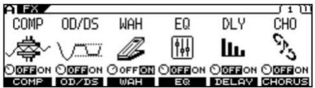
text_image
COMP OD/DS WAH EQ DLY CHO OFF ON OFF ON OFF ON OFF ON OFF ON OFF ON COMP OD/DS WAH EQ DELAY CHORUS- Press [F3] (WAH).
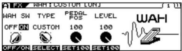
text_image
A FX WAH: CUSTOM LUNJ 1 10 WAH SW TYPE PEDAL POS LEVEL OFF ON CUSTOM 100 100 OFF/ON SELECT SET100 SET100 WAH-
Select CUSTOM as the WAH TYPE with [F2] (SELECT) or the F2 knob.
-
Press PAGE [] to display Page 2.
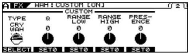
text_image
A FX WHH: CUSTOM LONJ TYPE CRY WAH 0 0 0 0 SELECT SET0 SET0 SET0 SET0 CUSTOM RANGE LOW 0 0 0 RANGE HIGH 0 0 0 PRES- ENCE 12-
Select the basic type with [F1] (SELECT) or the F1 knob.
-
Adjust the desired parameter with [F1]–[F5] or with the F1–F5 knobs.
If there are other parameters you want to adjust, press PAGE [▶].
-
Repeat Steps 6 and 7 as needed.
-
If you want to save the edited settings, perform the Write procedure (p. 38).
* If not saving the settings, press [EXIT] to return to the Play screen.

For detailed information on all the parameters, refer to "WAH" (p. 122).
Chapter 4 Global Device Settings (SYSTEM)
* The parameters described in this section are saved without the Write procedure being performed.
Inputting the Divided Pickup Settings
To ensure optimal conditions for producing sounds with the VG-99, making the correct settings affecting the Divided pickup (the GK settings) is required.
After you have finished inputting the various settings, press [EXIT] one or more times to return to the Play screen.
Selecting the Settings
The VG-99 can store ten separate sets of GK settings. If you are playing more than one guitar using the VG-99, you can store separate settings for each one, allowing you to be ready in moments with the necessary settings when the guitars are switched.
- Press [SYSTEM].
- Press PAGE [] to display Page 1.
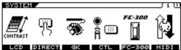
text_image
SYSTEM CONTRAST LCD DIRECT GK CTL FC-300 MIDI FC-300- Press [F3] (GK) to display the GK SETTING screen.
- Press PAGE [] to display Page 1.
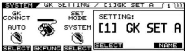
text_image
SYSTEM GK SETTING / [1]GK SET A 1 (M) GK CONNECT AUTO SET MODE SYSTEM SELECT GKFUNC SELECT SETTING: [1] GK SET A SELECT NAME- Press [F4] (SELECT) or turn the F4 knob to select the GK setting (1–10).
This specifies the setting to be stored as the GK setting.
* Pressing [EXIT] at this point and returning to the Play screen enables the selected GK setting.
* When PATCH is selected for the SET MODE parameter, the GK settings specified in each patch take priority. For detailed information, refer to "Using Different Guitar Settings in Each Patch (SET MODE)" (p. 46).
The following section describes parameters related to the GK settings.
After you have finished inputting the various settings, press [EXIT] one or more times to return to the Play screen.
Naming GK Settings (GK NAME)
You can give names to each of the GK settings.
- Follow Steps 1–5 in "Selecting the Settings" (p. 42) to select the GK SETTING.
- Press PAGE [] to display Page 1.
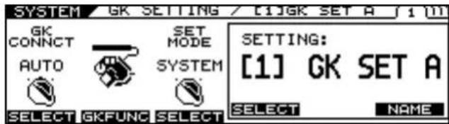
text_image
SYSTEM GK SETTING / [1]GK SET A 1 m GK CONNECT AUTO SET MODE SYSTEM SELECT GKFUNC SELECT SETTING: [1] GK SET A SELECT NAME- Press [F6] (NAME).
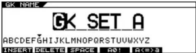
text_image
GK NAME GK SET A ABCDEFGHIJKLMNOPQRSTUVWXYZ INSERT DELETE SPACE A0! A<=3- Set the name using PAGE [ ] , [ ] - [F5], and the PATCH/VALUE dial.
| Function Button | Explanation |
| [F1] (INSERT) | Insert a space at the cursor location. |
| [F2] (DELETE) | Delete a character. The characters that follow get shifted to the left. |
| [F3] (SPACE) Input a space at the cursor location. | |
| [F4] (A0!) | Switch between uppercase letters and lowercase letters. |
| [F5] (A<=>a) | Switch between uppercase letters, lowercase letters, numbers, and characters. |
* Press [EXIT] one or more times to return to the previous screen.
Selecting the Divided Pickup Type
- Follow Steps 1–5 in "Selecting the Settings" (p. 42) to select the GK SETTING.
- Press PAGE [][] to display Page 2.
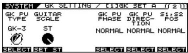
text_image
SYSTEM GK SETTING / [1]GK SET A 1/2 GK PU GUITAR GK PU GK PU S1,S2 TYPE SCALE PHASE DIREC- POS GK-3 ST TION NORMAL NORMAL NORMAL SELECT SET ST SELECT SELECT SELECT- Use F1 (SELECT) or the F1 knob to select the pickup type.
| Settings | Explanation |
| GK-3 | Specifies the GK-3. |
| GK-2A Specifies the GK-2A or GK-2. | |
| PIEZO | This is suited to piezo pickups that have a flat response. |
| PIEZO F | This is suited to piezo pickups made by Fishman Transducers. |
| PIEZO G | This is suited to piezo pickups made by Graph Tech Guitar Labs. |
| PIEZO L | This is suited to piezo pickups made by L.R. Baggs. |
| PIEZO R | This is suited to piezo pickups made by RMC Pickup Co. |
* If you're not sure which piezo type parameter is appropriate, choose the parameter for the piezo type that sounds the most natural as you play.
* Piezo pickups are a type of pickup that are installed at the guitar's bridge and use piezo electric elements to determine the string vibrations.
Selecting PIEZO F, PIEZO G, PIEZO L, or PIEZO R for GK PU TYPE lets you further adjust the sound quality of the low and high frequency ranges. Adjust them as required.
- Press PAGE [ ] three times to display Page 5.
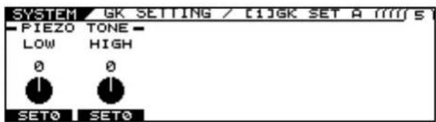
text_image
SYSTEM GK SETTING / [1]GK SET A [1]M/S PIEZO TONE LOW HIGH 0 0 SET0 SET0- Use the F1 (LOW) and F2 (HIGH) knobs to adjust the sound quality of the low and high frequency ranges.
| Parameter/Range | Explanation |
| LOW | |
| -10-0-+10 Adjusts | the low frequency range tone. |
| HIGH | |
| -10-0-+10 Adjusts | the high frequency range tone. |
Inputting the Guitar's Scale
Set the scale length (the distance from the bridge to the nut).
- Follow Steps 1–5 in "Selecting the Settings" (p. 42) to select the GK SETTING.
- Press PAGE [][] to display Page 2.
- Use the F3 knob to set the scale length of the guitar you are using. Presets include 648 mm (ST) and 628 mm (LP).
| Settings | Explanation |
| 620–660 mm,ST(648 mm),LP(628 mm) | Specifies the scale of your guitar. |
Matching the Divided Pickup and Normal Pickup Phase
Certain peculiarities in the sound may appear when the COSM guitar and normal pickup sounds are mixed. If this occurs, adjust this parameter and switch the COSM guitar's phase.
- Follow Steps 1–5 in "Selecting the Settings" (p. 42) to select the GK SETTING.
- Press PAGE [][] to display Page 2.
- Use [F4] (SELECT) or the F4 knob to select the phase.
| Settings | Explanation |
| NORMAL | Leave the phase unchanged. |
| REVRSE Invert the phase. | |
Setting the Direction for the Installed Divided Pickup
* Make this setting if the divided pickup has been installed with the first-string end and sixth-string end reversed.
- Follow Steps 1–5 in "Selecting the Settings" (p. 42) to select the GK SETTING.
- Press PAGE [ ] to display Page 2.
- Use [F5] (SELECT) or the F5 knob to select the pickup direction.
| Settings | Explanation |
| NORMAL | The cable extends from the 6th string side. Ordinarily, you should use this setting. |
| REVRSE The cable extends from the 1st string side. | |
Setting the DOWN/S1, UP/S2 Switch Arrangement
On some guitars with the Divided pickup built in, the positions of the DOWN/S1 and UP/S2 switches are reversed from those of the Divided pickup. Set this so that the functions match.
- Follow Steps 1–5 in "Selecting the Settings" (p. 42) to select the GK SETTING.
- Press PAGE [ ] to display Page 2.
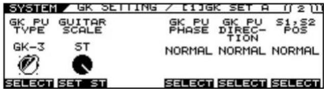
text_image
SYSTEM GK SETTING / [1]GK SET A 1/2 GK PU GUITAR GK PU GK PU S1,S2 TYPE SCALE PHASE DIREC- POS GK-3 ST NORMAL NORMAL NORMAL SELECT SET ST SELECT SELECT SELECT- Use [F6] (SELECT) or the F6 knob to select the arrangement.
| Settings | Explanation |
| NORMAL | The switches will not be reversed. |
| REVRSE | The DOWN/S1 switch and UP/S2 switch will be reversed. |
Setting the Gap Between the Pickup and the Bridge (PICKUP BRIDGE)
Set the clearance from the center of the Divided pickup to the bridge's saddle for each string.
* This setting is not required when the GK PU TYPE is set to piezo type parameter.
- Follow Steps 1–5 in "Selecting the Settings" (p. 42) to select the GK SETTING.
- Press PAGE [ ] to display Page 3.
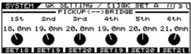
text_image
SYSTEM GK SETTING / [1]GK SET A [1]3 PICKUP<-->BRIDGE 1st 2nd 3rd 4th 5th 6th 18.0mm 19.0mm 20.0mm 19.0mm 20.0mm 21.0mm SET18 SET19 SET20 SET19 SET20 SET21- Rotate the F1–F6 knobs to set the clearance for strings 1–6.
| Settings | Explanation |
| 10.0–30.0 mm | Specify the distance between the center of the Divided pickup and the center of each bridge saddle.The setting is disregarded when the GK PU TYPE is set to piezo type parameter. |
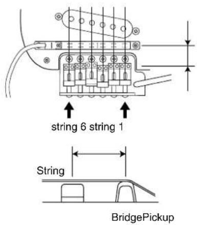
text_image
string 6 string 1 String BridgePickupAdjusting the Sensitivity for Each String
Adjust the Divided pickup sensitivity for each string.
-
Follow Steps 1–5 in "Selecting the Settings" (p. 42) to select the GK SETTING.
-
Press PAGE [ ] to display Page 4.
| SYSTEM | GK | SETTING | / [1]GK SET A | [1]4 |
| F1 | SENS | 1st | ∅ 65 | ...... |
| F2 | SENS | 2nd | ∅ 65 | ...... |
| F3 | SENS | 3rd | ∅ 65 | ...... |
| F4 | SENS | 4th | ∅ 65 | ...... |
| F5 | SENS | 5th | ∅ 65 | ...... |
| F6 | SENS | 6th | ∅ 65 | ...... |
- Rotate the F1–F6 knobs to adjust the sensitivity.
Play each open string with the maximum force you'd use in an actual performance, and set the sensitivity such that the meter registers a level just before reaching the maximum level.
* If the large segments at the right end of the level meter appear, it means the level is set too high. Lower the sensitivity setting.
* Pressing |F1|–|F6| initializes each string's value to 65.
* Depending on the guitar you use, the level meter may move to the maximum level even when the sensitivity is set to the minimum setting. If this occurs, adjust the clearance separating the divided pickup and the strings so the distance is slightly greater than specified.
- Play the sixth through first strings with the normal amount of force; if any strings sounds particularly loud, lower the sensitivity setting for that string, and keep adjusting until the differences in the strings' volume levels are minimal.
| Settings | Explanation |
| 0-100 | Adjust the input sensitivity of each Divided pickup. |
Setting Whether or Not the Divided Pickup Is Used (GK CONNECT)
The VG-99 comes equipped with a function that automatically determines whether or not a GK connection exists and switches the internal settings accordingly. This makes it possible for you to all functions other than a COSM guitar (COSM amp, effects, tuner, etc.) when you've connected only to the GUITAR INPUT.
-
Follow Steps 1–3 in "Selecting the Settings" (p. 42) to display the GK SETTING screen.
-
Press PAGE [] to display Page 1.
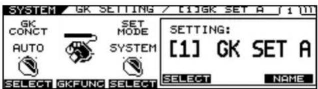
text_image
SYSTEM GK SETTING / [1]GK SET A 1 m GK CONCT AUTO SET MODE SYSTEM SELECT GKFUNC SELECT SETTING: [1] GK SET A SELECT NAME- Use [F1] (SELECT) or the F1 knob to select the setting.
| Settings | Explanation |
| AUTO | The presence of a GK connection is detected automatically and the internal settings are switched accordingly. |
| ON | Settings appropriate for a GK connection are always used. |
| OFF | Settings appropriate for a GUITAR INPUT connection are always used. |
* You should ordinarily use AUTO (the default setting). In cases where the auto-detect function does not operate correctly, (for example, when you are using a Divided pickup other than the GK-3), pickup, use [F2] or the F2 dial to change the setting.
Using Different Guitar Settings in Each Patch (SET MODE)
This setting determines whether the VG-99 uses a single global GK setting or if the GK settings can be specified individually for each patch.
- Follow Steps 1–3 in "Selecting the Settings" (p. 42) to display the GK SETTING screen.
- Press PAGE [] to display Page 1.
- Use [F3] (SELECT) or the F3 knob to select the setting.
| Settings | Explanation |
| SYSTEM | The GK SETTING set here is used globally for the entire VG-99.This is the default factory setting. |
| PATCH | The GK Settings can be specified individually for each patch.Use this setting when switching among multiple guitars as you perform. |
Determining the Function of the GK Volume Control and DOWN/S1, UP/S2 Switches (GK FUNC)
This sets the function for the GK-3's GK Volume and DOWN/S1, UP/S2 switches.
- Follow Steps 1–3 in "Selecting the Settings" (p. 42) to display the GK SETTING screen.
- Press PAGE [] to display Page 1.
- Press [F2] (GKFUNC).
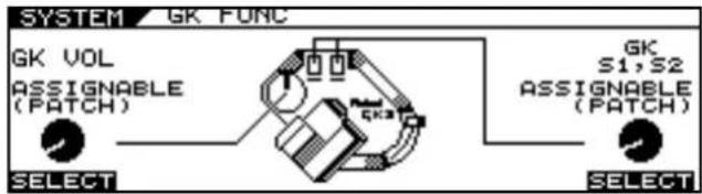
text_image
SYSTEM GK FUNC GK VOL ASSIGNABLE (PATCH) SELECT GK S1,S2 ASSIGNABLE (PATCH) SELECT- Set the parameter you want to assign with [F1] (SELECT), [F6] (SELECT) or the F1, F6 knob.
cf.
For detailed information on the parameters that can be assigned, refer to "GK VOL (GK Volume)" (p. 166) and "GK S1, S2 (GK S1, S2 Switch)" (p. 166).
* When assigning functions to each patch for GK Volume, DOWN/S1 and UP/S2, set Control Assign to ASSIGNABLE (PATCH). With other settings, the assignment settings in the patches are disregarded.
* This is the same setting as that set with GK VOL or GK S1, S2 in [SYSTEM] (CTL).
Adjusting Overall Tone According to the Environment (GLOBAL/OUTPUT SELECT)
The VG-99 includes a function for adjusting the overall tone produced by the device. This is referred to as the Global function. You can use the Global function to adjust the overall sound of the VG-99 to suit the equipment being used or environment you are in without altering the individual patches.
Selecting the Settings
The VG-99 can store ten separate Global function settings (1–10).
After you have finished inputting the various settings, press [EXIT] one or more times to return to the Play screen.
- Press [GLOBAL].
- Press PAGE [] to display Page 1.
The Global screen appears.
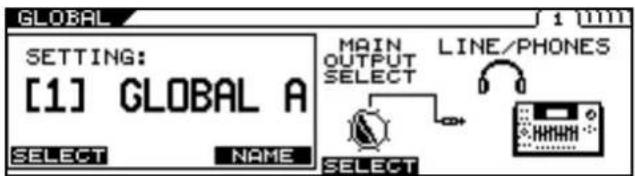
text_image
SETTING: [1] GLOBAL A SELECT NAME MAIN OUTPUT SELECT LINE/PHONES SELECT- Select any setting 1–10 with [F1] (SELECT) or the F1 knob.
Naming the Settings (GLOBAL NAME)
You can assign up to ten user names, each containing up to eight characters. For example, you could create names that suggest the gear used in a certain setting or a place where you perform.
- Follow Steps 1–3 in "Selecting the Settings" (p. 46) to select the SETTING.
- Press PAGE [] to display Page 1.
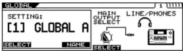
text_image
GLOBAL SETTING: [1] GLOBAL A SELECT NAME SELECT MAIN OUTPUT SELECT LINE/PHONES SELECT- Press [F3] (NAME).
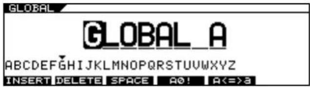
text_image
GLOBAL GLOBAL_A ABCDEFGHIJKLMNOPQRSTUVWXYZ INSERT DELETE SPACE A0! A<=3- Set the name using PAGE [ ] and [F1]–[F5].
| Function Button | Explanation |
| [F1] (INSERT) | Insert a space at the cursor location. |
| [F2] (DELETE) | Delete a character. The characters that follow get shifted to the left. |
| [F3] (SPACE) Input a space at the cursor location. | |
| [F4] (A0!) | Switch between uppercase letters and lowercase letters. |
| [F5] (A<=a) | Switch between uppercase letters, lowercase letters, numbers, and characters. |
Setting the Types of Connected Devices (OUTPUT SELECT)
You can match the VG-99's output response to that of the connected device. Making this setting helps keep differences in sound qualities respective to the connected device to a minimum.
- Follow Steps 1–3 in "Selecting the Settings" (p. 46) to select the SETTING.
- Press PAGE [] to display Page 1.
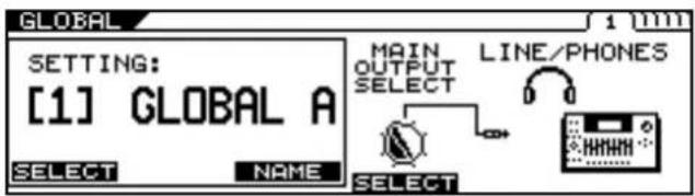
text_image
GLOBAL SETTING: [1] GLOBAL A SELECT NAME SELECT MAIN OUTPUT SELECT LINE/PHONES SELECT- Use [F4] (OUTPUT SELECT) or the F4 knob to set the type of device to be connected to the MAIN OUT jacks.
| Value | Explanation |
| JC-120 | Use this setting when connecting to Roland's JC-120 guitar amp. |
| SMALL AMP | Use this setting when connecting to a small guitar amp. |
| COMBO AMP | Use this setting when connecting to the guitar input of a combo amp other than the JC-120 guitar amp (where the amp and speaker or speakers are combined in a single unit).* Depending on your guitar amp, you may be able to obtain good results with the JC-120 setting. |
| STACK AMP | Use this setting when connecting to the guitar input of a stack-type guitar amp (where the amp and speaker or speakers are separated). |
| JC-120 Return | Use this setting when connecting to the RETURN of a JC-120. |
| COMBO Return | Use this setting when connecting to the RETURN with a combo amp. |
| STACK Return | Use this setting when connecting to the RETURN of a stack amp or the INPUT of a rack mounted power amp.Set to STACK Return also when using a guitar power amp and speaker cabinet combination. |
| LINE/PHONES | Use this setting when using headphones or when connecting to a multi-track recorder for recording.* When using COSM Speaker cabinets, use the LINE/PHONES setting. |
Adjusting the Overall Tone (GLOBAL EQ)
Both MAIN OUT and SUB OUT feature four-band EQs.
MEMO
EQ (MAIN) is applied to the output from MAIN OUT; EQ (SUB) is applied to the output from SUB OUT.
- Follow Steps 1–3 in "Selecting the Settings" (p. 46) to select the SETTING.
- Press PAGE [ ] to display Page 2-5.
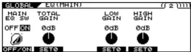
text_image
GLOBAL EQ(MAIN) 2 NM MAIN TOTAL LOW HIGH EQ SW GAIN GAIN OFF ON 0dB 0dB 0dB OFF/ON SET0 SET0 SET0- Use [F1] - [F6] or the F1 - F6 knobs to adjust the tone.
| Parameter/ Range | Explanation |
| MAIN EQ (Main Equalizer),SUB EQ (Sub Equalizer) | |
| A four-band equalizer with high and low ranges is provided. The sound processed by the effect can be boosted by frequency range before it is output. | |
| MAIN EQ SW (Main Equalizer Switch),SUB EQ SW (Sub Equalizer Switch) | |
| OFF, ON | Turns the EQ effect on/off. |
| TOTAL GAIN | |
| -12–+12dB | Adjusts the volume before the equalizer. |
| LOW GAIN | |
| -12–+12dB | Adjusts the low frequency range tone. |
| HIGH GAIN | |
| -12–+12dB | Adjusts the high frequency range tone. |
| LOW MID FREQ (Low Middle Frequency) | |
| 20Hz–10.0kHz | Specifies the center of the frequency range that will be adjusted by the LOW MID GAIN. |
| LOW MID Q (Low Middle Q) | |
| 0.5–16 | Adjusts the width of the area affected by the EQ centered at the LOW MID FREQ.Higher values will narrow the area. |
| LOW MID GAIN (Low Middle Gain) | |
| -12–+12dB | Adjusts the low-middle frequency range tone. |
| HIGH MID FREQ (High Middle Frequency) | |
| 20Hz–10.0kHz | Specifies the center of the frequency range that will be adjusted by the HIGH MID GAIN. |
| HIGH MID Q (High Middle Q) | |
| 0.5–16 | Adjusts the width of the area affected by the EQ centered at the HIGH MID FREQ.Higher values will narrow the area. |
| HIGH MID GAIN (High Middle Gain) | |
| -12–+12dB | Adjusts the high-middle frequency range tone. |
Controlling the Overall Effect of the Noise Suppressor (Total NS)
This controls the overall threshold value for the noise suppressor settings in the individual patches. This is an effective tool when guitars are changed during performances and for making adjustments in response to noise levels at the performance venue. This is an overall setting and does not alter the individual patch settings.
- Follow Steps 1–3 in "Selecting the Settings" (p. 46) to select the SETTING.
- Press PAGE [] to display Page 6.
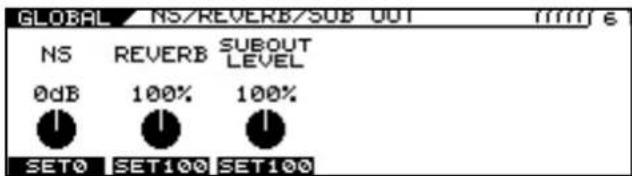
text_image
GLOBAL / NS/REVERB/SUB OUT mm/16 NS REVERB SUBOUT 0dB 100% 100% SET0 SET100 SET100- Adjust the level with the F1 knob.
This adjusts the noise suppressor threshold levels set in each patch.
-20 dB - +20 dB
* This adjustment has no effect on patches in which the noise suppressor is off.
* To use the levels set in the individual patches, set this to 0 dB.
Controlling the Overall Reverb Level (Total REVERB)
This controls the overall reverb level settings in the individual patches. This is effective for adjusting to the acoustics of the performance venue. This setting does not affect the individual patch settings.
- Follow Steps 1–3 in "Selecting the Settings" (p. 46) to select the SETTING.
- Press PAGE [] to display Page 6.
text_image
GLOBAL NS/REVERB/SUB OUT mm/m² € NS REVERB SUBOUT LEVEL 0dB 100% 100% SET0 SET100 SET100- Adjust the level with the F2 knob.
This adjusts the reverb level set in each patch. 0–200%
* This adjustment has no effect on patches in which reverb is switched off.
* To use the levels set in the individual patches, set this to 100%.
Setting the Sounds Output from SUB OUT (SUB OUT LEVEL)
This setting selects which signals are output from the SUB OUT jacks.
- Follow Steps 1–3 in "Selecting the Settings" (p. 46) to select the SETTING.
- Press PAGE [] to display Page 6.
text_image
GLOBAL / NS/REVERB/SUB OUT mmrf € NS REVERB SUBOUT 0dB 100% 100% SET0 SET100 SET100- Adjust the setting with the F3 knob.
This adjusts the output level set in each patch. 0–200%
* To use the levels set in the individual patches, set this to 100%.
Setting the GK VOLUME Control and Switch and the Pedal Function (SYSTEM CONTROL ASSIGN)
- Press [SYSTEM].
- Press PAGE [] to display Page 1.
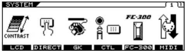
text_image
SYSTEM CONTRAST LCD DIRECT GK CTL FC-300 MIDI FC-300- Press [F4] (CTL).
- Press PAGE [] to display Page 1.
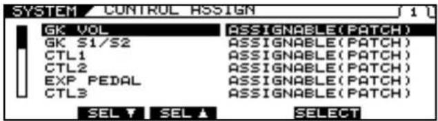
text_image
SYSTEM / CONTROL ASSIGN GK VOL GK S1/S2 CTL1 CTL2 EXP PEDAL CTL3 ASSIGNABLE(PATCH) ASSIGNABLE(PATCH) ASSIGNABLE(PATCH) ASSIGNABLE(PATCH) ASSIGNABLE(PATCH) SELECT SEL ▼ SEL ▲ SELECT- Select any setting from GK VOL to FC-300 CTL8 with [F2] (SEL) or [F3] (SEL) or the F2 or F3 knobs, then use [F5] (SELECT) or the F5 knob to select the function you want to assign.
MEMO
If you want to be able to assign the functions for the controllers on an individual patch basis, set Control Assign to ASSIGNABLE (PATCH). With Control Assign set to ASSIGNABLE (PATCH), the unit operates in accordance with the assignments set in each patch, as described in "Using the Switches, Pedals, and MIDI to Control the Sounds (CONTROL ASSIGN)" (p. 82).
* With other settings, the assignment settings in the patches are disregarded.
cf.
For information on assigned controllers, refer to "Controller" (p. 167); for more on assignable parameters, refer to "Parameters That Can Be Assigned to Separate Controllers" (p. 168).
Having Values from an External Pedal, GK VOLUME Control, or Other Controller Carried Over When Patches are Called Up (ASSIGN HOLD)
This setting determines whether or not the current settings for each controller (the expression pedals, the FC-300's expression pedals, control pedals or other controllers) are applied to the patch when patches are switched.
* Assign Hold is not performed when the SW MODE parameter in Control Assign Source is set to LATCH. (LATCH toggles between the minimum and maximum value each time the switch is pressed.)
1. Press [SYSTEM].
2. Press PAGE [] to display Page 1.
![ROLAND VG-99 - Press PAGE [] to display Page 1. - 1](/content/2026/05/763494/images/ad2e4bbf3e5a81b2432e26a90ffde2ec61ef3a2923a59765d07754123e83e4ee.jpg)
text_image
SYSTEM CONTRAST LCD DIRECT GK CTL FC-300 MIDI FC-3003. Press [F4] (CTL).
4. Press PAGE [] to display Page 2. The ASSIGN HOLD screen appears.
![ROLAND VG-99 - Press PAGE [] to display Page 2. The ASSIGN HOLD screen appears. - 1](/content/2026/05/763494/images/441662dce6a21dc3b18da8c96d44d1400daf17de79323093a8a5d9053d1fc1a7.jpg)
text_image
SYSTEM HASSIGN HOLD 12 ASSIGN HOLD OFF ON OFF ON5. Select ON or OFF for the Assign Hold function with [F1] (OFF/ON) or the F1 knob.
| Settings | Explanation |
| ON | Current values of controllers are applied when patches are called up. |
| OFF | Stored values (at the time of Patch Write) of controllers are used when patches are called up. (Current controller values ignored.) |
Limiting the Patches That Can Be Switched (PATCH EXTENT)
Setting upper and lower limits for the patches that can be switched allows you to select only the patches you need.
1. Press [SYSTEM].
2. Press PAGE [] to display Page 2.
![ROLAND VG-99 - Press PAGE [] to display Page 2. - 1](/content/2026/05/763494/images/5a92a8b2ce07ca5e88d4972d60da30424d5a6c3470b7ce688e290473f703e7eb.jpg)
text_image
SYSTEM OUTPUT USB V-LINK CATEGORY NAME C:\> ABCDEF CATGRY CALIB MISC3. Press [F6] (MISC).
![ROLAND VG-99 - Press [F6] (MISC). - 1](/content/2026/05/763494/images/fa7851ff95733bc760438a3a76d4655e6bd6331e8acac15db7c76abbba356c10.jpg)
text_image
SYSTEM / PATCH EXTENT FROM 001:U-Guitar TO 400:70' sStack FROM TO4. Press [F3] (FROM).
5. Set the lower limit of the patch selection with the PATCH/VALUE dial and [F3] (FROM) or the F3 knob.
6. Press [F4] (TO).
7. Set the upper limit of the patch selection with the PATCH/VALUE dial and [F4] (TO) or the F4 knob.
* These settings are enabled in the following situations.
- When the PATCH/VALUE dial is turned
- When patches are switched with the control switches or other controls
- When SYSTEM CONTROL ASSIGN (p. 49) is used to assign PATCH SELECT INC or PATCH SELECT DEC to the FC-300's control switches or expression pedal switches
These settings have no effect on other FC-300 operations or operations using an external MIDI device.
Adjusting the Screen's Contrast
The text and icons in the LCD screen may be difficult to make out sometimes, such as immediately after the VG-99 is turned on or after extended use. The conditions at the place where you are using the VG-99 can also affect visibility. Should you run into this problem, try adjusting the contrast.
- Press [SYSTEM].
- Press PAGE [] to display Page 1.
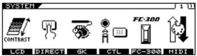
text_image
SYSTEM CONTRAST LCD DIRECT GK CTL FC-300 MIDI FC-300- Press [F1] (LCD).
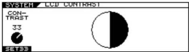
pie
SYSTEM LCD CONTRAST | Category | Value | |---|---| | CON-TRAST | 33 | | SET33 | |- Turn the F1 knob to adjust the contrast.
Setting the Output Signal and Level (SYSTEM OUTPUT)
This sets the signals and levels output for each of the VG-99's output jacks and connectors (MAIN OUT, SUB OUT, and DIGITAL OUT).
- Press [SYSTEM].
- Press PAGE [][] to display Page 2.
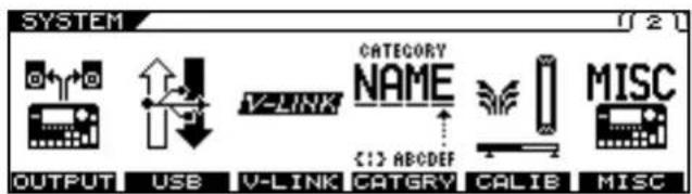
text_image
SYSTEM OUTPUT USB V-LINK CATEGORY NAME C:\> ABCDEF CATGRY CALIB MISC- Press [F1] (OUTPUT).
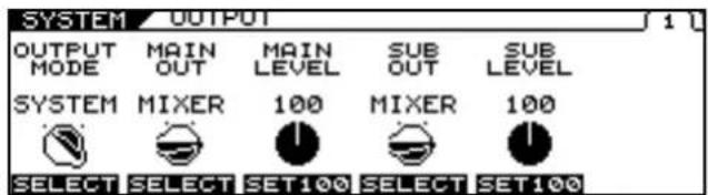
text_image
SYSTEM OUTPUT OUTPUT MODE MAIN OUT MAIN LEVEL SUB OUT SUB LEVEL SYSTEM MIXER 100 MIXER 100 SELECT SELECT SET100 SELECT SET100- Set the OUTPUT MODE parameter to SYSTEM with [F1] (SELECT) or with the F1 knob.
* If set to PATCH, the values set under "Setting the Output Signal and Level (OUTPUT)" (p. 37) are enabled. The value in the MIXER screen is disregarded, and instead the value <> is applied.
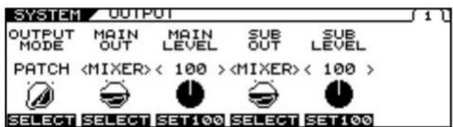
text_image
SYSTEM OUTPUT OUTPUT MODE MAIN OUT MAIN LEVEL SUB OUT SUB LEVEL PATCH- Set the signal and level output to each output with PAGE [ ] or with the F1-F6 knobs.
cf.
For detailed information on the parameters that can be set, refer to "OUTPUT" (p. 172).
Chapter 5 Using the VG-99 in
Combination with an FC-300
With an FC-300 (optional) connected to the VG-99, you can perform the following operations:
- Switch patches
- Have patch names be shown in the FC-300's display
• Control tones with the FC-300's pedals (Control Assign)
• Show the VG-99's tuner in the FC-300's display when the TUNER function is used - Switch the FC-300's Amp Control on and off
Connecting with the RRC2 IN Connector
Connect the VG-99 and FC-300 using the RRC2 cable included with the unit.
TERM
What is RRC2?
RRC2 is a Roland protocol that provides for the supply of power and two-way data communications over a single cable. Devices can also be connected using a commercially available ethernet cable instead of the included RRC2 cable.
NOTE
- Be sure to connect the RRC2 OUT connector to a device with an RRC2 IN connector. Use of the connection with LAN or other devices may cause generation of heat and damage to the equipment.
- Carefully connect the RRC2 cable the way in—until it is firmly to the RRC2 IN connector.
- Do not subject the RRC2 cable to stress or physical shock.
- If using commercially available ethernet cable as the RRC2 connecting cable, be sure that the cable meets the following specifications:
• Category 5 (Cat5) or above
• Maximum length of 15 meters - Cable designed for straight-through connection.
* Ethernet cables designed for crossover connections cannot be used.
Settings Related to the FC-300
If connecting the VG-99 with an FC-300 using an RRC2 cable, make the settings below as needed.
Settings for Control of the FC-300
This sets the method for controlling the FC-300.
1. Press [SYSTEM].
2. Press PAGE [] to display Page 1.
![ROLAND VG-99 - Press PAGE [] to display Page 1. - 1](/content/2026/05/763494/images/bf5d8ef1f526dfefd87884696e1355b9590db49b8eeb7bc558ebe35c8d15e39c.jpg)
text_image
SYSTEM CONTRAST LCD DIRECT GK CTL FC-300 MIDI FC-3003. Press [F5] (FC-300).
![ROLAND VG-99 - Press [F5] (FC-300). - 1](/content/2026/05/763494/images/2c4c015003e5d2be596bc1484c9fcc1015af066a4b6ad6bc1e7bcc646935ee0b.jpg)
text_image
SYSTEM FC-300 SYS EX BANK QUICK FC-300 MODE CHANGE TUNER OFF ON IMME OFF DIATE OFF ON OFF/ON SELECT SELECT4. Set the SYS EX MODE with [F1] (OFF/ON) or with the F1 knob.
| Available Settings | Description |
| ON | When connected to the VG-99, the FC-300 automatically changes to Exclusive mode and functions in accordance with the settings made with the VG-99. This is the setting normally selected. You can control the FC-300 even without matching the VG-99's and FC-300's Device IDs.Connecting an FC-300 automatically switches the FC-300 to Exclusive mode. Normally, you should select this setting. |
| OFF | Select OFF when using the FC-300 in a mode other than System Exclusive mode.The mode does not switch automatically. |
* The FC-300 will not respond unless you return to the Play screen.
Setting the Operation When Patches Are Switched
This sets the timing at which patches are switched when you press
[M] petals on the FC-300.
-
Press [SYSTEM].
-
Press PAGE [] to display Page 1.
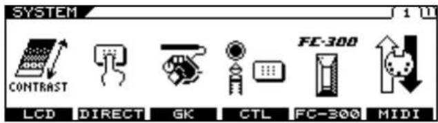
text_image
SYSTEM CONTRAST LCD DIRECT GK CTL FC-300 MIDI FC-300- Press [F5] (FC-300).
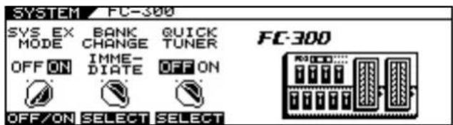
text_image
SYSTEM FC-300 SYS EX BANK QUICK MODE CHANGE TUNER OFF ON IMME- OFF ON DIATE OFF ON OFF/ON SELECT SELECT FC-300- Set BANK CHANGE with [F2] (SELECT) or with the F2 knob.
| Available Settings | Description |
| IMMEDIATE | The patch changes immediately when the FC-300's [ ] pedals are pressed. |
| WAIT NUM | Even after the FC-300's [ ] pedals are pressed, the patch does not change until the NUM-BER is set. |
* The FC-300 will not respond unless you return to the Play screen.
Activating the VG-99's Tuner from the FC-300 (QUICK TUNER)
You can use the FC-300's number pedals to switch the Tuner function on and off.
* The Quick Tuner function is enabled only in the Play screen.
* The Quick Tuner function is enabled only when the FC-300's MODE is set to SYS EX.
- Press [SYSTEM].
- Press PAGE [] to display Page 1.
- Press [F5] (FC-300).
- Set QUICK TUNER with [F3] (SELECT) or with the F3 knob.
| Available Settings | Description |
| OFF | The QUICK TUNER function is not operational. |
| ON The QUICK TUNER | function is operational.The TUNER function is alternately switched on and off each time the currently selected number pedal is pressed. |
Setting the FC-300 Amp Control
This switches the FC-300's AMP CTL 1 and AMP CTL 2 parameters on and off.
When the guitar amp's channel switch jack is connected to the FC-300's AMP CONTROL 1 jack (or AMP CONTROL 2 jack), you can then switch the guitar amp channels with the VG-99's AMP CTL1 (or AMP CTL2) parameter.
- Use the PATCH/VALUE dial to select the patch you want to set.
- Press [NAME/KEY/BPM].
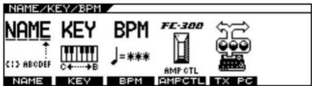
text_image
NAME/KEY/BPM NAME KEY BPM FE-300 C:\> ABCDEF C+---B AMP CTL TX PC NAME KEY BPM AMPCTL- Press [F4] (AMPCTL).
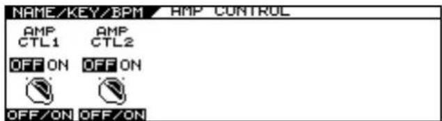
text_image
NAME/KEY/BPM / AMP CONTROL AMP AMP CTL1 CTL2 OFF ON OFF ON OFF/ON OFF/ON- Use [F1] and [F2] or the F1 and F2 knobs to set AMP CTL1 and AMP CTL2 to ON or OFF.
| Available Settings | Description |
| OFF | The FC-300's AMP CTL1 and AMP CTL2 parameters are set to OFF. |
| ON | The FC-300's AMP CTL1 and AMP CTL2 parameters are set to ON. |
About MIDI
MIDI, an abbreviation for Musical Instrument Digital Interface, is a universal standard that enables musical instruments to exchange musical performance data, messages concerning changes in the sounds, and other information. Any device that conforms to the MIDI specifications can communicate (to the extent that is relevant to both devices) with any other MIDI device, even those that were made by a different manufacturer or that belong to a different category of instrument.
Under the MIDI specifications, performance data produced by such actions as playing a keyboard or pressing a pedal is handled as MIDI messages.
What You Can Do Using MIDI
Using MIDI, you can carry out the following operations with the VG-99.
If using the VG-99 with an FC-300 connected, also refer to "Chapter 5 Using the VG-99 in Combination with an FC-300" (p. 52).
* Use of MIDI requires that the MIDI channels of connected devices be matched.
Data cannot be transmitted to or received from other MIDI devices unless the MIDI channels are set correctly.
Operating from the VG-99
Outputting Program Change Messages
When a patch is selected with the VG-99, the VG-99 simultaneously transmits a Program Change message corresponding to the selected number. The external MIDI device switches its settings in response to the received Program Change message.
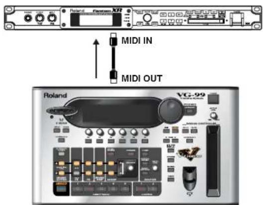
text_image
Roland XT7 MIDI IN MIDI OUT Roland VG-99Outputting Control Change Messages
Data describing the action of an external device (expression pedal or footswitch) connected to the VG-99 is output as Control Change messages. These messages can be used for such tasks as adjusting external MIDI devices' parameters.
Outputting Performance Data
The guitar's performance data can be output as Note messages and Bend messages, allowing you to perform through synthesizer sound modules and other devices connected to the VG-99. For more detailed information, refer to "Playing an External Synthesizer Sound Module (GUITAR TO MIDI)" (p. 64).
Transmitting Data
You can use Exclusive messages to transmit settings for effect sounds and other data stored in the VG-99 to other MIDI devices. This allows you to give another VG-99 the identical settings and to save effect sound settings to MIDI sequencers and other such devices.
Controlling the VG-99 from an External MIDI Device
Switching Patch Numbers
The VG-99's patches switch immediately in response to Program Change messages received from external MIDI devices.
MEMO
You can set the correspondence between MIDI Program Change messages and the VG-99's patches with the "RX PC MAP (RECEIVE PROGRAM CHANGE MAP)" (p.
61). Set this to ensure correspondence of the VG-99's effect sounds with those of other MIDI devices.
The connections shown in the diagram below are used when playing your guitar backed by an automatic sequencer performance. The VG-99's patches change automatically when a Program number is entered with the performance data at the point where you want the VG-99's patches to change.
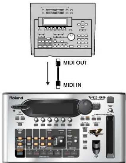
text_image
MIDI OUT MIDI IN Roland VC-99Receiving Control Change Messages
MEMO
The VG-99 can receive Control Change messages to control specified parameters while a performance is in progress. Set the parameters to be controlled with “Using the Switches, Pedals, and MIDI to Control the Sounds (CONTROL ASSIGN)” (p. 82).
Receiving Data
The VG-99 can receive data transmitted from other VG-99's and data saved to MIDI sequencers.
Main Types of MIDI Messages Handled by the VG-99
In order to be able to convey the full range of expression that is possible during performance, MIDI provides for different types of MIDI messages. MIDI messages can be categorized broadly into two groups; messages handled on an individual MIDI channel basis (Channel messages), and those handled independently of MIDI channels (System messages).
Channel Messages
These are messages used for conveying the events that take place during performance. Normally, you can control most performances using only these messages. The action controlled with each MIDI message is determined by the receiving device's settings.
Program Change Messages
These message are generally used for switching sounds; sounds are switched with Program Change numbers 1–128. Furthermore, with the VG-99, you can also use Control Change Bank Select messages together with the Program Change messages, allowing you to switch 400 different patch numbers.
Control Change Messages
Control Change messages are used for enhancing performance expression. Functions are distinguished from one another with Control numbers; the particular functions that can be controlled varies with the MIDI device. With the VG-99, you can control specified parameters.
Note On Messages
These messages convey to the device the pitches and volumes at which sounds are played.
Note Off Messages
These messages instruct the device to stop sounds currently being played.
Bend Messages
These messages are sent to produce continuous changes in the pitch.
System Messages
System messages include Exclusive messages, messages required for synchronized performances, and messages designed to prevent problems with operation.
Exclusive Messages
Exclusive messages are used for handling sounds unique to a particular device and other such messages. Basically, you can exchange messages between devices of the same type from the same manufacturer. Using Exclusive messages, you can store parameter settings to sequencers and transmit parameter settings to other VG-99s.
To exchange Exclusive messages, the Device ID numbers for each of the instruments must match.
About the MIDI Implementation
While the use of MIDI allows various devices to communicate with each other, this does not mean that it enables exchanges of all information. The data that can be exchanged between any two connected devices is limited to the messages common to both devices.
Therefore, MIDI device owner's manuals always contain a MIDI Implementation chart, which allows the user to determine quickly what MIDI messages the particular device supports. Comparing the MIDI Implementation charts for each device allows you to confirm what information can be exchanged and how to accomplish this. Since these charts are uniform in size, you can overlay the charts for the transmitting and receiving devices when checking the information.
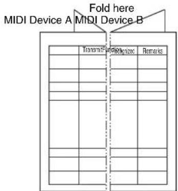
text_image
MIDI Device A MIDI Device B Fold here Transm-Fundiogenize RemarksA separate publication titled "MIDI Implementation" is also available. It provides complete details concerning the way MIDI has been implemented on this unit. If you should require this publication (such as when you intend to carry out byte-level programming), please access the Roland web site. http://www.oland.com/
Exchanging MIDI Messages
This section provides a simple description of how MIDI messages are exchanged.
About MIDI Connectors
MIDI messages are exchanged via the connectors described below. Connect MIDI cables to these connectors according to the use.
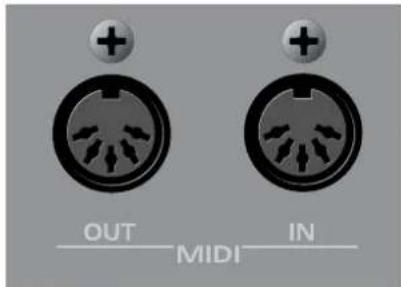
text_image
OUT MIDI IN| MIDI Connector | Description |
| MIDI IN | Messages from other MIDI devices are received here. |
| MIDI OUT Messages from the VG-99 are transmitted here. | |
About MIDI Channels
MIDI allows various different messages to be sent separately to multiple MIDI devices over a single MIDI cable. This is possible thanks to the concept of MIDI channels.
MIDI channels use an approach similar to that of television channels. Switching channels on the TV allows the viewer to watch programs from a variety of broadcasters. This is because information is transferred over the channel to which both the transmitter and receiver are tuned.
text_image
Broadcasting Station A Broadcasting Station B Broadcasting Station C TV information from many different broadcasting station is sent through an antenna. Select the channel of the broadcasting station you wish to watch.MIDI includes channels numbered 1–16; MIDI messages are transmitted to (receiving) instruments set to the same channel as the transmitting device's.
Bank Select and Program Change
Bank Select and Program Change are MIDI messages generally used for switching patches.
Normally, patches are switched using Program Change messages. However, if Program Changes alone are used, you'll only be able to select up to a maximum of 128 different patches. Because of this, some devices also employ the Bank Select, expanding the number of selectable patches.
Patches for these devices are assigned numbers combining Bank Select MSB, LSB numbers 0–127 and Program numbers 1–128.
* The VG-99 disregards the Bank Select LSB.
Setting the MIDI-Related Functions
This section describes the VG-99's MIDI-related functions. Set these according to how they are to be used.
1. Press [SYSTEM].
The System screen appears.
2. Press PAGE [] to display Page 1.
![ROLAND VG-99 - Press PAGE [] to display Page 1. - 1](/content/2026/05/763494/images/11999937a5aa5ecf8c93893e3465245116eb89b65dbbe048a02f2e434a0d2799.jpg)
text_image
SYSTEM CONTRAST LCD DIRECT GK CTL FC-300 MIDI FC-3003. Press [F6] (MIDI).
The MIDI settings screen appears.
The following section describes the settings used with MIDI.
MIDI Channel
This sets the channel used for transmitting and receiving MIDI messages corresponding to the VG-99's patches and operations. Also refer to "Playing an External Synthesizer Sound Module (GUITAR TO MIDI)" (p. 64) if you are using the GUITAR TO MIDI function, and refer to "Controlling Video Images with Your Guitar (V-LINK)" (p. 96) if you are using the V-LINK function.
-
Follow Steps 1–3 in "Setting the MIDI-Related Functions" (p. 58) to display the MIDI screen.
-
Press PAGE [] to display Page 1.
-
Rotate the F1 knob to set the MIDI channel (1-16).
MEMO
Be sure not to set the same MIDI channel as the channel used for the GUITAR TO MIDI or V-LINK functions.
MIDI Omni Mode
When set to MIDI Omni mode, the VG-99 receives messages on all MIDI channels, regardless of the MIDI channel settings. You can use Omni mode whenever you do not need to use specific MIDI channels in controlling the VG-99.
-
Follow Steps 1–3 in "Setting the MIDI-Related Functions" (p. 58) to display the MIDI screen.
-
Press PAGE [] to display Page 1.
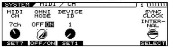
text_image
SYSTEM / MIDI / CH 1 (1000) MIDI CH OMNI MODE DEVICE ID SYNC CLOCK INTER- NAL 7ch OFF ON 1 SET7 OFF/ON SET1 SELECT- Set Omni mode on or off with [F2] or the F2 knob.
MEMO
Even with Omni mode set to ON, the only Exclusive messages received will be those carrying the Device ID set for Device ID.
MEMO
Omni mode is set to ON at the factory.
MIDI Device ID
This sets the Device ID to be used for the transmission and reception of Exclusive messages.
MEMO
Device ID is set to 1 at the factory.
-
Follow Steps 1–3 in "Setting the MIDI-Related Functions" (p. 58) to display the MIDI screen.
-
Press PAGE [] to display Page 1.
-
Rotate the F3 knob to set the Device ID (1–32).
SYNC CLOCK
You can synchronize the VG-99 to the MIDI Clock (tempo) transmitted from a MIDI sequencer or other external MIDI device.
- Follow Steps 1–3 in "Setting the MIDI-Related Functions" (p. 58) to display the MIDI screen.
- Press PAGE [] to display Page 1.
- Use [F6] (SELECT) or the F6 knob to select the MIDI Clock to use as the tempo reference.

For detailed information on the parameters that can be set, refer to "Syncing to the MIDI CLOCK from an External Device" (p. 64).
MIDI ROUTING
Set the VG-99's control signal path.
The VG-99 features three types of connectors for data input and output: the MIDI connectors (IN/OUT), a USB connector, and the RRC2 IN connector. When connecting the VG-99 to devices other than the FC-300, you need to consider the routing of the control signals.
Check the display as you set the necessary connections.
You can make the settings for MIDI IN and OUT on Page 2, for the USB connector on Page 3, and for the RRC2 IN connector on Page 4.
-
Follow Steps 1–3 in "Setting the MIDI-Related Functions" (p. 58) to display the MIDI screen.
-
Press PAGE []◀] to display Pages 2-4.
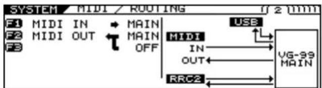
text_image
SYSTEM MIDI / ROUTING 1 2 (mm) F1 MIDI IN * MAIN F2 MIDI OUT * MAIN F3 OFF MIDI IN OUT RRC2 USB VG-99 MAIN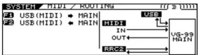
text_image
SYSTEM MIDI / ROUTING F1 USB(MIDI) * MAIN F2 USB(MIDI) * MAIN USB MIDI IN OUT RRC2 VG-99 MAIN
text_image
SYSTEM MIDI / ROUTING 4 mm F1 RRC2 MAIN F2 RRC2 MAIN F3 OFF MIDI USB IN VG-99 OUT OUT RRC2 MAIN- Set the connections with [F1]–[F3] or the F1–F3 knobs.
Chapter 6 Using MIDI
MIDI PC OUT
This setting determines whether or not Program Change messages are output when the VG-99's patches are switched.
-
Follow Steps 1–3 in "Setting the MIDI-Related Functions" (p. 58) to display the MIDI screen.
-
Press PAGE [ ] to display Page 5.
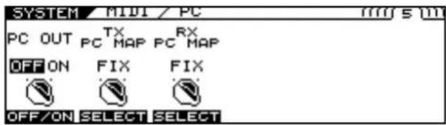
text_image
SYSTEM / MIDI / PC PC OUT TX RX PC MAP PC MAP OFF ON FIX FIX OFF/ON SELECT SELECT- Set PC OUT ON/OFF with [F1] or the F1 knob.
MEMO
When outputting Program Change messages, the VG-99 simultaneously outputs MIDI Bank Select messages.
TX PC MAP (TRANSMIT PROGRAM CHANGE MAP)
This setting determines the sequence of Program Change messages output when the VG-99's patches are changed.
You can select whether to output Program Change messages set for the patches in advance or the Program Change messages programmed in each patch.
-
Follow Steps 1–3 in "Setting the MIDI-Related Functions" (p. 58) to display the MIDI screen.
-
Press PAGE [ ][ ] to display Page 5.
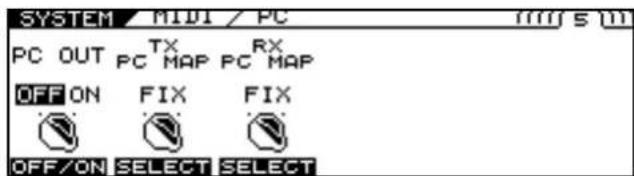
text_image
SYSTEM / MIDI / PC PC OUT TX RX PC MAP PC MAP OFF ON FIX FIX OFF/ON SELECT SELECT- Use [F2] or the F2 knob to set whether or not the Transmit Program channel is used.
| Available Settings | Description |
| FIX | Regardless of the patch settings, Program Change messages predetermined for each patch number are output. |
| PROG | The Program Change messages programmed in each patch are output. |
The table below shows the correspondence between the patches and Program Change messages when TX PC MAP is set to FIX.
| Patch Number | Bank Select Program Number | |
| 001 | 0 | 1 |
| ::: | ||
| 100 0 100 | ||
| 101 1 1 | ||
| ::: | ||
| 200 1 100 | ||
| 201 2 1 | ||
| ::: | ||
| 400 3 100 | ||
Setting the TX PC MAP
To set Program Change messages to be transmitted with individual patches, make the settings described below.
MEMO
Patch parameters are settings made individually for each patch. The Write procedure (p. 38) is required to save changes in the settings.
- Select the patch to which you want to assign the predetermined Program Change message to be transmitted.
- Press [NAME/KEY/BPM].
- Press [F5] (TX PC).
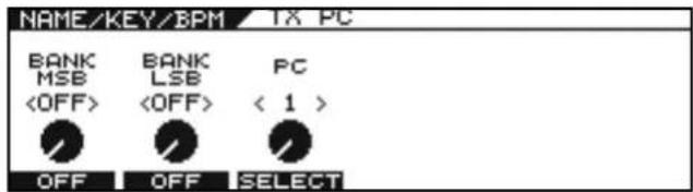
text_image
NAME/KEY/BPM TX PC BANK MSB- Use [F1] – [F3] or F1 – F3 knob to set the Program Change Number and the Bank Select.
- If you want to save the edited settings, perform the Write procedure (p. 38).
* If not saving the settings, press [EXIT] to return to the Play screen.
RX PC MAP (RECEIVE PROGRAM CHANGE MAP)
You can select whether to use a fixed or freely set correspondence between program numbers received and the patches switched to when the VG-99's patches are switched by Program Change messages transmitted by an external MIDI device.
- Follow Steps 1–3 in "Setting the MIDI-Related Functions" (p. 58) to display the MIDI screen.
- Press PAGE [ ] to display Page 5.
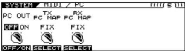
text_image
SYSTEM / MIDI / PC PC OUT TX RX PC MAP PC MAP OFF ON FIX FIX OFF/ON SELECT SELECT- Use [F3] or the F3 knob to set whether or not the Receive Program Change Map is used.
| Available Settings | Description |
| FIX | The VG-99 switches to the patches predetermined for the corresponding received Program Change messages, regardless of the Receive Program Change Map settings. |
| PROG | The VG-99 switches to the patches set in the Receive Program Change Map. |
- To change the patch assigned to a received Program Number, press [LEFT] [RIGHT] to display Page 6.
The RX PC MAP screen appears.
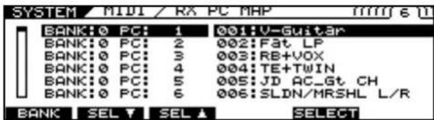
text_image
SYSTEM / MIDI / RX PC MAP BANK:0 PC: 1 001:V-Guitar BANK:0 PC: 2 002:Fat LP BANK:0 PC: 3 003:RB+VOX BANK:0 PC: 4 004:TE+TWIN BANK:0 PC: 5 005:JD AC_Gt CH BANK:0 PC: 6 006:SLDN/MRSHL L/R BANK SEL SEL SELECT- Assign the patch to a received Program Number.
• [F1] (BANK)/F1 Knob
Selects the Bank number.
• [F2] (SEL) or [F3] (SEL) / F2▲r F3 Knob
Selects the Program number.
• [F5] (SELECT)/F5 Knob
Selects the patch.
When the combination of the Bank number and Program number selected with F1, F2, and F3 is received, the VG-99 switches to the patch selected with F5.
Chapter 6 Using MIDI
The table below shows the correspondence between the factory default Program change Map and the Program Change messages received when RX PC MAP is set to FIX.
| Bank Select | Program Number | Patch Number |
| 0 | 1 001 | |
| :::: | ||
| 0 128 128 | ||
| 1 1 101 | ||
| :::: | ||
| 2 | 128 328 | |
| 3 1 301 | ||
| :::: | ||
| 3 100 400 |
* When setting "OMNI MODE" (p. 170) to OFF, be sure to match "MIDI CH (MIDI Channel)" (p. 170) to the external MIDI device's transmit channel beforehand.
Setting the MIDI Output Control Change Number
This sets the Control Change numbers output when the VG-99's pedals and external pedals or the FC-300's pedals and external pedals are operated.
-
Follow Steps 1–3 in "Setting the MIDI-Related Functions" (p. 58) to display the MIDI screen.
-
Press PAGE [ ] to display Page 7.
The TX CC screen appears.
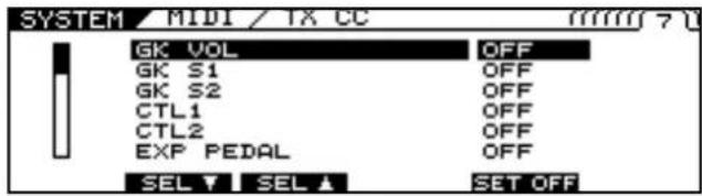
text_image
SYSTEM / MIDI / TX CC GK VOL GK S1 GK S2 CTL1 CTL2 EXP PEDAL SEL ↑ SEL ↑ OFF OFF OFF OFF OFF OFF SET OFF-
Use [F2] (SEL) or [F3] (SEL), the F2 or F3 knobs to select the controller you want to set.
-
Use [F5] or the F5 knob to assign the Control Change number to be transmitted when the controller is adjusted.
When the controller selected with F2 or F3 is operated, the Control Change message selected with F5 is transmitted.
* Control Changes message cannot be output if OFF is selected.
Bulk Dump
With the VG-99, you can use Exclusive messages to set another VG-99 to the same settings or to save effect sound settings to MIDI sequencers and other such devices.
This transmission of data is referred to as bulk dump.
Data that can be transmitted is described below.
| Displayed | Data Transmitted |
| ALL | All transmittable data (SYSTEM, GK SETTING, GLOBAL, PATCH 001-200, FAVORITE SETTING) |
| SYSTEM SYSTEM | parameters. |
| GK SETTING Settings | contents for GK SETTING |
| GLOBAL GLOBAL | function settings |
| PATCH Settings for | patch numbers 001-200 |
| FAVORITE SETTING | Settings content in FAVORITE SETTINGS 01-10 for all effects |
How to Transmit the Data
When Saving Data to a MIDI Sequencer
Connect the devices as shown below, then place the MIDI sequencer in standby mode, so it is ready to receive Exclusive messages.
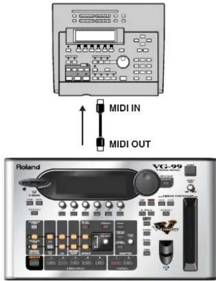
text_image
MIDI IN MIDI OUT Roland VQ-99MEMO
For information on how to operate the sequencer you are using, refer to the owner's manual that came with it.
When Transmitting Data to Another VG-99
Connect the devices as shown below, then match the Device IDs for the transmitting and receiving devices.
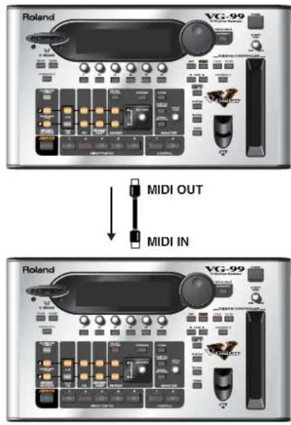
text_image
Roland VG-99 MIDI OUT MIDI IN Roland VG-99-
Follow Steps 1–3 in "Setting the MIDI-Related Functions" (p. 58) to display the MIDI screen.
-
Press PAGE [ ] to display Page 8.
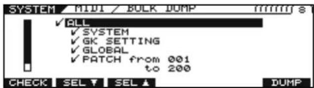
text_image
SYSTEM MIDI / BULK DUMP ✓ ALL ✓ SYSTEM ✓ GK SETTING ✓ GLOBAL ✓ PATCH from 001 to 200 CHECK SEL ✓ SEL ▲ DUMP-
Use [F2] (SEL) or [F3] (SEL) to select the data you want to transmit.
-
Press [F1] (CHECK).
Only the types of data with a check mark are transmitted.
MEMO
When selecting PATCH FROM/TO, you can use the PATCH/VALUE dial to specify the range of patch numbers to be transmitted
-
Repeat Steps 2 and 3 as needed.
-
Press [F6] (DUMP).
Transmission begins. Once the transmission is complete, you're returned to the screen you were in prior to transmission.
MEMO
You can cancel the procedure in progress by pressing [EXIT].
Bulk Load
Reception of VG-99 data saved to MIDI sequencers and other devices is referred to as bulk load.
When Receiving Data Saved to a MIDI Sequencer
- Connect the devices as shown below. Set the VG-99's Device ID to the same one used when the data was transmitted to the MIDI sequencer.
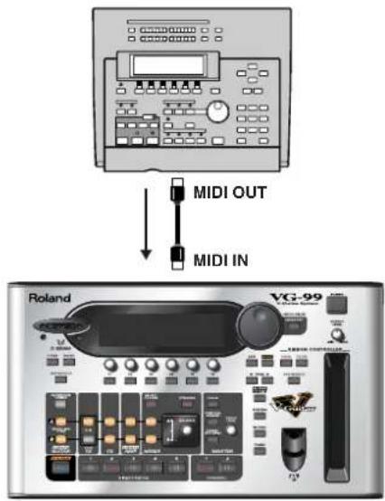
text_image
MIDI OUT MIDI IN Roland VG-99- Transmit the bulk data from the MIDI sequencer.
The message "SYSTEM EXCLUSIVE MESSAGE RECEIVING..." is displayed while the data is being received. Once the reception is complete, you're returned to the screen you were in prior to reception. In this state, the VG-99 can then receive further data.
MEMO
If the message "MIDI BUFFER FULL" appears, check the connections and reduce the tempo of the transmitting MIDI device.
Syncing to the MIDI CLOCK from an External Device
- Follow Steps 1–3 in "Setting the MIDI-Related Functions" (p. 58) to display the MIDI screen.
- Press PAGE [] to display Page 1.
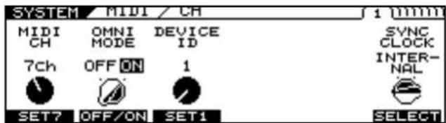
text_image
SYSTEM / MIDI / CH 1 (mm) MIDI CH OMNI MODE DEVICE ID SYNC CLOCK INTER- NAL 7ch OFF ON 1 SET7 OFF/ON SET1 SELECT- Use [F6] (SELECT) or the F6 knob to select the synchronizing signal.
This specifies the setting to be stored as the SYNC CLOCK setting.
- INTERNAL
The VG-99 operates independently.
- AUTO (USB)
The VG-99 is synchronized to the MIDI Clock received via USB. However, operations are automatically synchronized to the VG-99's internal Clock if the VG-99 is unable to receive the external Clock.
- AUTO (MIDI)
The VG-99 is synchronized to the MIDI Clock received via MIDI. However, operations are automatically synchronized to the VG-99's internal Clock if the VG-99 is unable to receive the external Clock.
- AUTO (RRC2)
The VG-99 is synchronized to the MIDI Clock received via RRC2. However, operations are automatically synchronized to the VG-99's internal Clock if the VG-99 is unable to receive the external Clock.
Playing an External Synthesizer Sound Module (GUITAR TO MIDI)
The VG-99 can convert performance data to MIDI Note and Bend messages and output these messages. Using this function allows you to record performances to sequencers and play sounds through external sequencer sound modules.
The GUITAR TO MIDI function features system parameters, whose settings affect the overall functionality of the device, and patch parameters, which are set on an individual patch basis.
About MIDI messages Output with Guitar to MIDI
The following MIDI messages are output with Guitar to MIDI.
Program Change Messages
These messages convey information about a patch change.
Control Change Messages
These messages describe any changes made using the panel knobs or by operating pedals.
Note On Messages
These messages convey to the device the pitches and volumes at which sounds are played.
Note Off Messages
These messages instruct the device to stop sounds currently being played.
Bend Messages
These messages are sent to produce continuous changes in the pitch.
MEMO
Pitches output with GUITAR TO MIDI (the MIDI Note messages) are affected by the Channel A Alternate Tuning settings (TUNING, BEND, HARMO) and the D Beam/ribbon controller settings (T-ARM).
* The Channel B Alternate Tuning settings have no bearing on these output pitches.
* If the pitch output with GUITAR TO MIDI (the MIDI Note messages) is excessively low (or high) due to the influence of the Channel A Alternate Tuning settings, the pitch is then automatically set one octave higher (or lower).
Setting the GUITAR TO MIDI Function (System Parameters)
These procedures are used for making settings for the device as a whole. Changes are saved at the same time they are changed. The Write procedure is not required.
After entering these parameters, press [EXIT] several times to return to the Play screen.
Switching the GUITAR TO MIDI Function On and Off
1. Press [GUITAR TO MIDI].
The GUITAR TO MIDI screen appears.
![ROLAND VG-99 - Press [GUITAR TO MIDI]. - 1](/content/2026/05/763494/images/769ef6a5eb8d528289eeec3360aa93d702f88ef2e421444f9696530eb647a66e.jpg)
text_image
GTR TO MIDI LOFFJ GTR TO MIDI OFF ON OFF/ON P.2 P.3 P.4 PATCH SYSTEM2. Set GTR TO MIDI to ON with [F1] (OFF/ON) or the F1 knob.
Setting this to OFF prevents the output of all MIDI messages related to the GUITAR TO MIDI function.
Selecting the Controller Used to Control the Hold Function (HOLD CTL)
1. Press [GUITAR TO MIDI].
The GUITAR TO MIDI screen appears.
![ROLAND VG-99 - Press [GUITAR TO MIDI]. - 1](/content/2026/05/763494/images/d9273924c5f1ed633d8bf3d7a67787922d3955bb0337a275ee4beca4ed6eb012.jpg)
text_image
GTR TO MIDI GTR TO MIDI OFF ON OFF/ON P.2 P.3 P.4 PATCH SYSTEM2. Press [F5] (SYSTEM).
![ROLAND VG-99 - Press [F5] (SYSTEM). - 1](/content/2026/05/763494/images/71f3f912ffd592dfb7408ef282d66cb2fc8ab63f7662fcb73177ec4edba76f91.jpg)
text_image
GTR TO MIDI / SYSTEM LOFF HOLD BEND BASIC PC CTL THIN CH MASK CTL3 OFF ON 1ch OFF ON SELECT OFF/ON SELECT OFF/ON3. Use [F1] (SELECT) or the F1 knob to select the controller you want to set.
| HOLD CTL Controller | |
| GK S1, S2 GK-3 DOWN | /S1, UP/S2 switch |
| CTL 1-4 | VG-99's CONTROL 1, 2 buttons or foot switch connected to CTL 3,4 jack |
| FC-300 CTL1-8 | FC-300's CTL 1, 2 pedals or foot switch connected to CTL jacks 3-8 |
MEMO
Controllers to which HOLD CTL is assigned are enabled simultaneously with parameters set in the SYSTEM CONTROL ASSIGN settings (p. 167). Set CONTROL ASSIGN to OFF if you want to use only the Hold function.
cf.
You can select the way the Hold function operates. For more details, refer to "Selecting How the Hold Functions (HOLD TYPE)" (p. 69).
Thinning Out Bend Messages (BEND THIN)
Vibrato, slides, and other such data in guitar performances are output as Pitch Bend messages. For this reason, the receiving MIDI device may encounter problems with operation when Pitch Bend messages containing large amounts of data are included.
You can use the BEND THIN function to thin out the Pitch Bend messages and control the volume of MIDI data.
- Follow Steps 1–2 in "Selecting the Controller Used to Control the Hold Function (HOLD CTL)" (p. 65) to display the GTR TO MIDI screen.
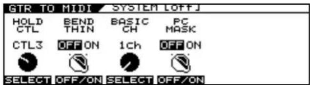
text_image
GTR TO MIDI / SYSTEM OFFJ HOLD BEND BASIC PC CTL THIN CH MASK CTL3 OFF ON 1ch OFF ON SELECT OFF/ON SELECT OFF/ON- Set the function to ON with [F2] (OFF/ON) or the F2 knob.
Select OFF when you do not want to reduce the amount of data transmitted in the Pitch Bend messages.
Setting the MIDI Transmit Channel (BASIC CH)
This sets the MIDI channel used for output of string performance data from the VG-99.
Set the MIDI channels according to the POLY/MONO mode as shown below.
- When set to POLY mode
The performance data for all of the strings is transmitted over the basic channel. - When set to MONO mode
1st string: Transmitted over the basic channel.
2nd string: Transmitted over the channel number one higher than the basic channel.
:
6th string: Transmitted over the channel number five higher than the basic channel.
cf.
For more details about the mode, refer to "Setting the Transmission Mode (MODE)" (p. 67).
- Follow Steps 1–2 in "Selecting the Controller Used to Control the Hold Function (HOLD CTL)" (p. 65) to display the GTR TO MIDI screen.
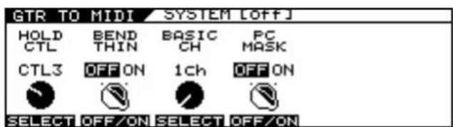
text_image
GTR TO MIDI SYSTEM LOFFJ HOLD BEND BASIC PC CTL THIN CH MASK CTL3 OFF ON 1ch OFF ON SELECT OFF/ON SELECT OFF/ON- Set the channel with [F3] (SELECT) or the F3 knob.
Preventing Transmission of Program Change Messages (PC MASK)
You can prevent transmission of Program Change messages that can be set in "Outputting Program Change Messages
Simultaneously When Switching Patches (PC)" (p. 70).
* This does not affect such Program Changes as those set in "MIDI PC OUT" (p. 60).
- Follow Steps 1–2 in "Selecting the Controller Used to Control the Hold Function (HOLD CTL)" (p. 65) to display the GTR TO MIDI screen.
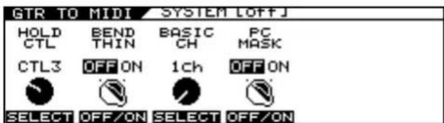
text_image
GTR TO MIDI SYSTEM LOFFJ HOLD BEND BASIC PC CTL THIN CH MASK CTL3 OFF ON 1ch OFF ON SELECT OFF/ON SELECT OFF/ON- Set the function to ON with [F4] (OFF/ON) or the F4 knob.
When PC MASK is set to ON, the Program Change messages set with the PC parameter (p. 70) in GUITAR TO MIDI are not transmitted.
Setting the GUITAR TO MIDI Function (Patch Parameters)
MEMO
Patch parameters are settings made individually for each patch. The Write procedure is required to save changes in the settings. Carry out the Write procedure as needed.
Setting the Transmission Mode (MODE)
1. Press [GUITAR TO MIDI].
The GTR TO MIDI screen appears.
![ROLAND VG-99 - Press [GUITAR TO MIDI]. - 1](/content/2026/05/763494/images/057b9c92ed0e7f4782fbb45ca56227f6f818613f2b425c09027fa5bfdbec3693.jpg)
text_image
GTR TO MIDI [Off] GTR TO MIDI OFF ON OFF/ON P.2 P.3 P.4 PATCH SYSTEM2. Press [F3] (PATCH).
3. Press PAGE [] to display Page 1.
![ROLAND VG-99 - Press PAGE [] to display Page 1. - 1](/content/2026/05/763494/images/125c8744a9d44c2885947c789b10f2919d9b342e2964b9392f1e6173504a45f8.jpg)
text_image
GTR TO MIDI PHATCH OFF MODE PLAY CHRO- HOLD FEEL MATIC TYPE MONO FEEL1 OFF HOLD1 SELECT SELECT SELECT SELECT4. Set the mode with [F1] (SELECT) or the F1 knob.
• MONO (MONO Mode)
![ROLAND VG-99 - Set the mode with [F1] (SELECT) or the F1 knob. - 1](/content/2026/05/763494/images/a9e4f67a4c331e283287791f1307362a0930d913bfbb8df881fe669a96bb0d91.jpg)
text_image
GTR TO MIDI / PHITCH LOFF MODE PLAY CHRO- HOLD FEEL MATIC TYPE MONO FEEL1 OFF HOLD1 SELECT SELECT SELECT SELECTIn this mode, one channel per string is used, thus using a total of six channels.
Since each string uses a different MIDI channel, you can select a different tone for each string, using string bending or continuously varying the pitch on a specific string; however, this requires use of a multitimbral sound module.
- POLY (POLY Mode)
![ROLAND VG-99 - Set the mode with [F1] (SELECT) or the F1 knob. - 2](/content/2026/05/763494/images/4789b21c7ec30c427438b74e9b02bf7170c8562c0764dfc4ed914d51fed31a77.jpg)
text_image
GTR TO MIDI / PHATCH LOFFJ MODE PLAY CHRO- HOLD FEEL MATIC TYPE POLY FEEL1 OFF HOLD1 SELECT SELECT SELECT SELECTIn this mode, the messages for all six strings are transmitted over a single channel.
While transmitting the MIDI messages for all of the strings over one channel does simplify the settings needed for the sound module and reduces the number of MIDI channels
used, it does impose certain limitations; for example, permitting only one tone to be selected for all of the strings.
MEMO
All patches are set to MONO mode at the factory.
MEMO
When chords are played in POLY mode, pitch bends change in semitone increments, while vibrato cannot be used. Pitch bends work normally in POLY Mode when playing single notes.
Adjusting the Feel Produced in Playing the Guitar (PLAY FEEL)
This selects the response of the synth sound relative to the picking dynamics.
Changing this setting depending on the performance style used with the guitar or the tone allows you to express dynamics more naturally.
1. Follow Steps 1–2 in "Setting the Transmission Mode (MODE)" (p. 67) to display the GTR TO MIDI screen.
2. Press PAGE [] to display Page 1.
![ROLAND VG-99 - Press PAGE [] to display Page 1. - 1](/content/2026/05/763494/images/93aa3feb3ff3a76f6113a1726adc7c3721da3ada95ac6c5b53f490a736cf1051.jpg)
text_image
GTR TO MIDI / PATCH LOFF MODE PLAY CHRO- HOLD FEEL MATIC TYPE MONO FEEL1 OFF HOLD1 SELECT SELECT SELECT SELECT3. Adjust the setting with [F2] (SELECT) or the F2 knob.
• FEEL1-FEEL4
FEEL1 is the mode that gives sounds the broadest variation in volume based on the picking dynamics. As the setting number is increased, it becomes easier to produce high volume sounds even with weaker picking.
This allows you to play with consistent volume, whether you tap the strings or use rough picking.
• NO DYNA
In this mode, sounds are played at a fixed volume regardless of the picking strength.
• STRUM
This suppresses the output of sounds from weaker picking. This setting allows you to prevent undesired sounds produced when playing rhythm or due to incidental contact with strings from incorrect picking.
Changing the Pitch in Semitone Units (CHROMATIC)
When using string bending or other such techniques to gradually change the pitch with the guitar or bass, you can set the VG-99 so that the pitch of the MIDI messages being output changes in semitone increments.
1. Follow Steps 1–2 in "Setting the Transmission Mode (MODE)" (p. 67) to display the GTR TO MIDI screen.
2. Press PAGE [] to display Page 1.
![ROLAND VG-99 - Press PAGE [] to display Page 1. - 1](/content/2026/05/763494/images/c15af2d700c8d9e97bb812a573c828b703a986b421d1b36a86c6bc4471d87f1b.jpg)
text_image
GTR TO MIDI PHITCH LOFF J 1 (mm) MODE PLAY CHRO- HOLD FEEL MATIC TYPE MONO FEEL1 OFF HOLD1 SELECT SELECT SELECT SELECT3. Adjust the setting with [F3] (SELECT) or the F3 knob.
• OFF
Normal Pitch Bend messages are output. The pitch varies continuously in keeping with the string bending or vibrato.
- TYPE 1
When the pitch changes, this setting applies the results of the pitch change information without stopping the note that is playing.
This produces a unique effect, whereby there is no attack sound when the pitches change, similar to slurring on a recorder.
- TYPE 2
When the pitch changes, the VG-99 retriggers (replays) the sound at the changed pitch, producing pitch changes only at the semitone increments.
As a result, the attack sound plays each time the pitch changes. The attenuation of the string vibration following the moment the string is played is reflected in the gradual fading of the retriggered sound.
- TYPE 3
As with TYPE 2, sounds are retriggered at the changed pitch, expressing the pitch changes only in semitones.
However, instead of reflecting the attenuation of the string vibration, the retriggered sound is the same as that when the string was initially played.
Selecting How the Hold Functions (HOLD TYPE)
This selects the Hold function type when the controller set with the HOLD CTL parameter (p. 65) is adjusted.
-
Follow Steps 1–2 in "Setting the Transmission Mode (MODE)" (p. 67) to display the GTR TO MIDI screen.
-
Press PAGE [] to display Page 1.
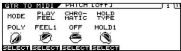
text_image
GTR TO MIDI PHITCH LOFFJ 10 MODE PLAY CHRO- HOLD FEEL MATIC TYPE POLY FEEL1 OFF HOLD1 SELECT SELECT SELECT SELECT-
Use [F1] (SELECT) or the F1 knob to select MONO.
-
Adjust the setting with [F4] (SELECT) or the F4 knob.
• HOLD 1
The Note On messages are held when the Hold function is switched on with the controller.
If the Hold function remains on as you continue to play the strings, each successive Note On message is held, and when a Note message is already being played from the same string, the previous Note message is cancelled, and the next Note On message is held. This allows you to prevent any interruption in the sounds, even sounds from releasing the strings over the frets.
• HOLD 2
The Note On messages are held when the Hold function is switched on with the controller.
However, subsequent Note On messages are not output if you continue to play the instrument with the Hold effect left on.
• HOLD 3
The Note On messages are held when the Hold function is switched on with the controller.
If the Hold function remains on as you continue to play the strings, Note On messages for strings other than the one already being held can be output, but they are not held.
Outputting Control Changes by Operating the Controllers (CC)
You can operate the panel knobs and pedals to output Control Change messages.
There are two different settings.
-
Follow Steps 1–2 in "Setting the Transmission Mode (MODE)" (p. 67) to display the GTR TO MIDI screen.
-
Press PAGE [ ] to display Page 2.

text_image
GTR TO MIDI PHATCH / CC LOFFJ 1/2/11 SRC 1 CC SRC 2 CC GK VOL OFF GK VOL OFF SELECT SELECT SELECT SELECT- Use [F1] (SELECT) or the F1 knob, or [F4] (SELECT) or the F4 knob, to select the controller you want to set.
| SRC | Controller |
| GK VOL | GK-3 Volume knob |
| GK S1 GK-3 DOWN/S1 | Switch |
| GK S2 GK-3 UP/S2 Switch | |
| CTL1 Control Button 1 | |
| CTL2 Control Button 2 | |
| EXP PEDAL External Expression Pedal | |
| CTL3 External Footswitch 3 | |
| CTL4 External Footswitch 4 | |
| D BEAM V D BEAM Height | |
| D BEAM H D BEAM Left-Right | |
| RIBBON ACT Ribbon Controller Touch | |
| RIBBON POS Ribbon Controller Touch Position | |
| FC-300 EXP1 FC-300's EXP PEDAL 1 | |
| FC-300 EXPSW1 FC-300's EXP PEDAL SW1 | |
| FC-300 EXP2 FC-300's EXP PEDAL 2 | |
| FC-300 EXPSW2 FC-300's EXP PEDAL SW2 | |
| FC-300 CTL1 FC-300's CTL1 | |
| FC-300 CTL2 FC-300's CTL2 | |
| FC-300 E3/C3 | FC-300's External Expression Pedal 3, External Footswitch 3 |
| FC-300 CTL4 FC-300's | External Footswitch 4 |
| FC-300 E4/C5 | FC-300's External Expression Pedal 4, External Footswitch 5 |
| FC-300 CTL6 FC-300's | External Footswitch 6 |
| FC-300 E5/C7 | FC-300's External Expression Pedal 5, External Footswitch 7 |
| FC-300 CTL8 FC-300's | External Footswitch 8 |
- Use [F2] (SELECT) or the F2 knob, or [F5] (SELECT) or the F5 knob, to select the Control Change number you want to output.
Off, CC #1—#31, CC #64—#95
Chapter 6 Using MIDI
MEMO
The MIDI channel over which the messages are output in POLY mode is only the basic channel. In MONO mode, the messages are output over the six channels spanning from the basic channel up to the channel numbered five above the basic channel.
Outputting Program Change Messages Simultaneously When Switching Patches (PC)
This sets the Program Change messages that are output when the VG-99's patches are switched.
* Program Change messages are not output while PC MASK (p. 66) is set to ON.
-
Follow Steps 1–2 in "Setting the Transmission Mode (MODE)" (p. 67) to display the GTR TO MIDI screen.
-
Press PAGE []◀] to display Pages 3–5.
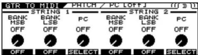
text_image
GTR TO MIDI / PHTCH / PC LOFFJ (M) 3 (M) BANK MSB OFF STRING 1 BANK LSB OFF PC OFF STRING 2 BANK MSB OFF BANK LSB OFF PC OFF OFF OFF SELECT OFF OFF SELECTWhen MODE (p. 67) is set to MONO, you can make settings individually for each of the six strings of STRING 1–6.
- Make the settings with [F1]–[F6] or the F1–F6 knobs.
Set the following parameters.
| BANK MSB | Explanation |
| OFF, 0–127 | This sets the Bank Select (MSB). |
| BANK LSB | Explanation |
| OFF, 0–127 | This sets the Bank Select (LSB). |
| PC | Explanation |
| OFF, 1-128 | This sets the Program Number. |
- If you want to save the edited settings, perform the Write procedure (p. 38).
* If you do not want to save, press [EXIT] to return to the Play screen.
MEMO
The MIDI channel over which the messages are output in POLY mode is only the basic channel. In MONO mode, the messages are output over the six channels spanning from the basic channel up to the channel numbered five above the basic channel.
Chapter 7 Using the VG-99 Connected to a Computer Via USB
Before Using the USB Connection
By using USB with the VG-99, you'll be able to exchange digital audio signals and MIDI messages with your computer.
Installing and Setting the USB Driver
Use of the VG-99's USB functionality requires that the USB driver first be installed on the computer.
The dedicated VG-99 driver is contained on the "VG-99 Software CD-ROM" included with the VG-99.
As the program and procedures used in installing the driver vary according to the operating environment, carefully read the following Readme file contained on the "VG-99 Software CD-ROM" before use.
| Using OS | Contained location |
| Windows XP | \Driver\XP\Readme_E.htm |
| Windows Vista | \Driver\Vista\Readme_E.htm |
| Mac OS X | \Driver\Readme_E.htm |
What is a USB Driver?
A USB driver is software that acts as a go-between in transferring data between computer applications (such as recording software and sequencer software) and the USB device when the computer and USB device are connected using a USB cable.
The USB driver transmits data from the applications to the USB device, and conversely, passes messages from the USB device to the applications.
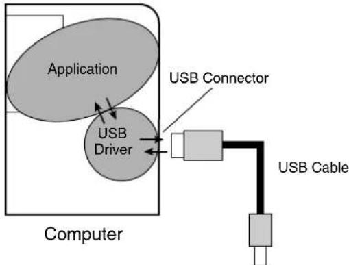
flowchart
graph TD
    A["Application"] --> B["USB Driver"]
    B --> C["USB Connector"]
    C --> D["USB Cable"]
    style A fill:#ccc,stroke:#333
    style B fill:#ccc,stroke:#333
    style C fill:#ccc,stroke:#333
    style D fill:#ccc,stroke:#333
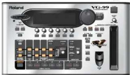
text_image
Roland VG-99 VGT-99 VGT-99 VGT-99 VGT-99 VGT-99 VGT-99 VGT-99 VGT-99 VGT-99 VGT-99 VGT-99 VGT-99 VGT-99 VGT-99 VGT-99 VGT-99 VGT-99VG-99
Chapter 7 Using the VG-99 Connected to a Computer Via USB
About the Included Software
In addition to the USB drivers, the included "VG-99 Software CD-ROM" also contains special software that can be used when the VG-99 is connected with a computer. The CD-ROM contains different versions for use with Windows and Macintosh operating systems.
VG-99 Editor
You can use this to make settings for the VG-99 from your computer. You can also save tone setting (patch) data you have created as files on the computer.
VG-99 Librarian
You can manage the VG-99's settings and patches all together using your computer.
Driver Mode
The VG-99 features two operational modes, one which uses the special driver contained on the included CD-ROM, and one in which the OS's (Windows/Mac OS) standard driver is used.
Using the specialized driver, you can record, play back, and edit audio with high-quality sound and stable timing.
It also allows you to control the VG-99 using MIDI messages.
Switching the Driver Mode
-
Press [SYSTEM].
-
Press PAGE [ ] to go to Page 2.
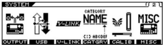
text_image
SYSTEM OUTPUT USB V-LINK CATEGORY NAME <1> ABCDEF CATGRY CALIB MISC-
Press [F2] (USB).
-
Press PAGE [] to go to Page 2.
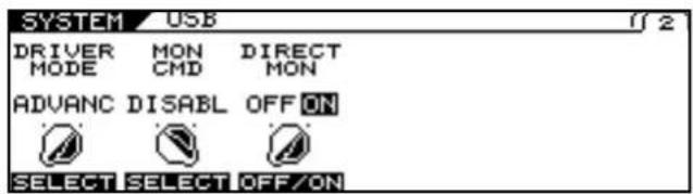
text_image
SYSTEM USB DRIVER MON DIRECT MODE CMD MON ADVANC DISABLE OFF ON SELECT SELECT OFF/ON- Set the DRIVER MODE with [F1] (SELECT) or the F1 knob.
| Setting Explanation | |
| STNDRD | This mode uses the OS's standard USB driver. |
| ADVANC | This mode uses the dedicated driver contained on the CD-ROM. |
* When using VG-99 Editor/Librarian, set this to ADVANC.
* The message "PLEASE RESTART" appears when DRIVER MODE is switched.
- Press [EXIT] one or more times to return to the Play screen.
* If you have not yet installed the driver for the mode you have set, turn off the power to the VG-99 in this condition and install the driver.
-
Quit all sequencer software and other applications on the computer that are using the VG-99.
-
Turn on the power to the VG-99 again.
* The functions of a mode won't become available until after the power has been turned off, then on again.
About MIDI in Standard Driver Mode
You cannot use MIDI when STNDRD is selected as the driver mode. If you want to use MIDI with the USB connection, set the VG-99 to the advanced driver mode.
Setting the USB Functions
The following section describes the VG-99's USB-related functions. Make these settings in accordance with how you plan to use the VG-99.
Setting the Digital Audio Signal Input and Output
1. Press [SYSTEM].
2. Press PAGE [ ] to go to Page 2.
![ROLAND VG-99 - Press PAGE [ ] to go to Page 2. - 1](/content/2026/05/763494/images/c6f999f847e5b3644f6b6ec423fd214c098d6bf0babe4594b25e1d811902ccf4.jpg)
text_image
SYSTEM OUTPUT USB V-LINK CATEGORY NAME < :> ABCDEF CATGRY CALIB MISC3. Press [F2] (USB).
4. Press PAGE [] to go to Page 1.
![ROLAND VG-99 - Press PAGE [] to go to Page 1. - 1](/content/2026/05/763494/images/de6878833af571cecb6ef208a11a8a75f3c408b81b59e500d48456ba4e373ca3.jpg)
text_image
SYSTEM / USB USB IN MAIN & SUB IN LEVEL 100 USB OUT MAIN OUT 100 OUT LEVEL SELECT SET100 SELECT SET1005. Change the setting's value with [F1]–[F4] or the F1–F4 knobs.
6. Press [EXIT] one or more times to return to the Play screen.
| Parameter/ Range | Explanation |
| USB IN | |
| This sets the point at which digital audio signals received via USB (from your computer) are connected within the VG-99.* Do not connect at a point before the point set with the USB OUT parameter. For more on the connection points, refer to “Signal Flow” (p. 183).* If the USB IN parameter is set to COSM GTR A, COSM GTR B, or NORMAL PU, the setting automatically changes to MAIN & SUB the next time the VG-99 is powered up. If you plan to use COSM GTR A, COSM GTR B, or NORMAL PU, make the setting each time you turn on the power to the VG-99. | |
| OFF | The signals are not connected at any point. |
| COSM GTR A The signals are connected at the point where the COSM GUITAR A is output.The audio output from the computer, instead of the COSM guitar sounds played by the connected guitar, is input to the effects.* POLY FX are not applied. | |
| Parameter/ Range | Explanation |
| COSM GTR B | The signals are connected at the point where the COSM GUITAR B is output.The audio output from the computer, instead of the COSM guitar sounds played by the connected guitar, is input to the effects.* POLY FX are not applied. |
| NORMAL PU | The signals are connected at the normal pickup input.The audio output from the computer, instead of the normal sounds played by the connected guitar, is input to the effects. |
| MAIN OUT The signals | are connected at the point where MAIN OUT is output.The signals from the VG-99's MAIN OUT and the audio output from the computer are mixed and output. |
| SUB OUT The signals are connected at the point where SUB OUT is output.The signals from the VG-99's SUB OUT and the audio output from the computer are mixed and output. | |
| MAIN&SUB The signals are connected at the point where both MAIN OUT and SUB OUT are output. Each of the signals from the VG-99's MAIN OUT and the audio output from the computer are mixed, SUB OUT and the audio output from the computer are mixed from the output. | |
| IN LEVEL | |
| 0–200 | Adjusts the volume level of the digital audio received via USB (from the computer). |
| USB OUT | |
| This sets the point internally within the VG-99 from which signals are output via USB (to the computer). | |
| COSM GTR A The output | put from COSM GUITAR A is output. |
| COSM GTR B The output | put from COSM GUITAR B is output. |
| NORMAL PU The normal pickup input is output. | |
| CH A The output from Channel A is output. | |
| CH B The output from Channel B is output. | |
| MIXER (DRY) The signals that have been mixed with the mixer, but before application of DELAY/ REVERB, are output. | |
| MIXER The signals that have been mixed with the mixer and have DELAY/REVERB applied are output. | |
| MAIN OUT The same signals as those from MAIN OUT are output. | |
| SUB OUT The same signals as those from SUB OUT are output. | |
| OUT LEVEL | |
| 0–200 | Adjusts the volume level of the digital audio output via USB (to the computer). |
Chapter 7 Using the VG-99 Connected to a Computer Via USB
Setting the Direct Monitor
- Press [SYSTEM].
- Press PAGE [ ] to go to Page 2.
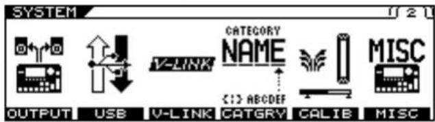
text_image
SYSTEM OUTPUT USB V-LINK CATEGORY NAME <1> ABCDEF CATGRY CALIB MISC- Press [F2] (USB).
- Press PAGE [] to go to Page 2.
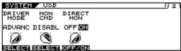
text_image
SYSTEM USB DRIVER MON DIRECT MODE CMD MON ADVANC DISABLE OFF ON SELECT SELECT OFF/ON- Change the setting's value with [F2] (SELECT), [F3] (OFF/ON) or the F2, F3 knobs.

For more information on signal paths set by the Direct Monitor parameter settings, refer to "Signal Flow" (p. 183).
- Press [EXIT] one or more times to return to the Play screen.
| Parameter/Range | Explanation |
| MON CMD (Monitor Command) | |
| This setting determines whether or not the command (the Direct Monitor command) controlling the Direct Monitor (described later) setting is enabled. | |
| DISABLE The Direct Monitor | monitor command is disabled, maintaining the Direct Monitor mode set by the VG-99. |
| ENABLE The Direct Monitor | monitor command is enabled, allowing the Direct Monitor mode to be switched from an external device. |
| DIRECT MON (Direct Monitor) | |
| Switches the output of the VG-99 sound to the PHONES jack, MAIN OUT jacks, or SUB OUT jacks. | |
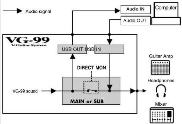 | |
| OFF Set this to Off if transmitting audio data internally through a computer (Thru). | |
| ON The VG-99 sound is output. Set this to On when using the VG-99 as a standalone device, without connecting to a computer (only USB IN input sound will be output if this is set to Off). | |
| * This setting cannot be saved. It is set to ON when the power is turned on.* If you are using the special driver, you can control DIRECT MON On/Off from ASIO 2.0-compatible application. | |
Recording the VG-99's Output with a Computer
In the computer application, set the audio input port to the VG-99.
You can freely set the point at which signals are sent to the computer with "USB OUT" (p. 73)
For example, by selecting COSM GTR A or COSM GTR B, you can listen to the performance with the effects applied, while recording it without the effects.
* If passing audio data through the software you're using, switch the direct monitor off.
Using the VG-99 to Add Effects to Audio Playback from a Computer
In the computer application, set the audio output port to the VG-99.
You can use the VG-99 to apply effects to the audio data played by the computer, then record the data again with the computer.
Use this process when, for example, you want to add effects to existing audio data.
* Set the software so audio is not passed through it.
-
Press [SYSTEM].
-
Press PAGE [][] to go to Page 2.
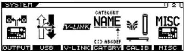
text_image
SYSTEM OUTPUT USE V-LINK CATEGORY NAME C:12 ABCDEF CATGRY CALIE MISC-
Press [F2] (USB).
-
Press PAGE [] to go to Page 1.

text_image
SYSTEM / USB USB IN MAIN & SUB IN LEVEL 100 USB OUT MAIN OUT 100 OUT LEVEL SELECT SET100 SELECT SET100- Use [F1] or the F1 knob to set the point within the VG at which you want the connection to be made.
Here, set either COSM GTR A, COSM GTR B, or NORMAL PU.
cf.
For more information about the USB IN parameter settings, refer to "Setting the Digital Audio Signal Input and Output" (p. 73).
-
Use [F2] or the F2 knob to adjust the level of the digital audio from the USB (computer).
-
Press [EXIT] one or more times to return to the Play screen.
Chapter 8 Other Functions
Changing the Tone in Real Time with the D Beam and Ribbon Controllers
Adjusting the D Beam (CALIBRATION)
The sensitivity of the D Beam controller can vary depending on the amount of light in the vicinity of the controller and the object (e.g., hand, guitar neck) used to operate it. Perform this adjustment so you can control the tone in the intended range.
1. Press [SYSTEM].
2. Press PAGE [][] to go to Page 2.
![ROLAND VG-99 - Press PAGE [][] to go to Page 2. - 1](/content/2026/05/763494/images/b49b6771fb8ffca88b15ae0c75574f5dc5db0f2ad3027208430dbeb7d98a087e.jpg)
text_image
SYSTEM OUTPUT USB V-LINK CATEGORY NAME MISC V-LINK < :> ABCDEF CATGRY CALIB MISC3. Press [F5] (CALIB).
4. Press PAGE [] to go to Page 1.
![ROLAND VG-99 - Press PAGE [] to go to Page 1. - 1](/content/2026/05/763494/images/113146f1620035410eaa430d32c98e5ef2a19c7688929cc07d185263a0b7c043.jpg)
text_image
SYSTEM D BEAM CALIB D BEAM MIN D BEAM MAX CTL VAL D BEAM DISAB 0 OFF ON SETMIN SETMAX OFF/ON5. Set the beam's responsive range as you actually operate the D Beam controller.
- First, hold the object you will use to activate the controller (your hand, guitar neck, etc.) at the point farthest from the VG-99 in the range you want the controller to respond, and press [F1] (SetMIN).
- Next, hold the object at the closest point in the range you want the controller to respond, and press [F4] (SetMAX).
6. Press [EXIT] several times to return to the Play screen.
NOTE
- The D Beam controller's response may also vary with the stage lighting used. Confirm operation of the controller by testing its onstage under the actual illumination.
- If the set range is too narrow or if the positioning is not suitable, the message "OUT OF RANGE! SET AGAIN." appears. To keep this message from appearing, change the range or position and recalibrate.
- The controller may not function properly with spot lights or other such lighting shining directly on it.
MEMO
- Be sure to adjust the CALIBRATION directly above the D Beam controller.
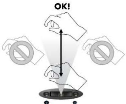
text_image
OK!- When the message "MISSING THE TARGET!" appears, it indicates that the calibration is not being performed correctly.
- The CALIBRATION setting is a system parameter, so the Write procedure is not required.
Disabling the D Beam (DISABLE)
You can disable the D Beam controller for the entire device.
If you are using the VG-99 rack-mounted or otherwise not using the D Beam controller, we recommend disabling the D Beam controller by setting D BEAM DISAB to OFF.
- Press [SYSTEM].
- Press PAGE [ ] to go to Page 2.
- Press [F5] (CALIB).
- Press PAGE [] to go to Page 1.
The D BEAM CALIB screen appears.
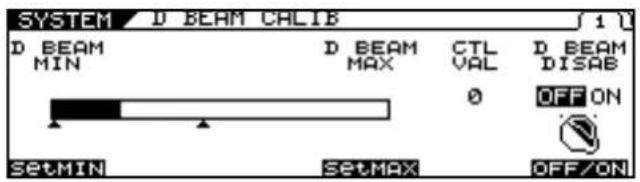
text_image
SYSTEM D BEAM CALIB D BEAM MIN D BEAM MAX CTL VAL D BEAM DISAB 0 OFF ON SETMIN SETMAX OFF/ON- Switch the controller on or off with [F6] (OFF/ON).
| Available Settings | Explanation |
| OFF | The D Beam is enabled. |
| ON | The D Beam is disabled.* Pressing the D BEAM [PITCH], [FILTER], or [ASSIGNABLE] button to switch the D Beam controller on will have no effect. |
- Press [EXIT] several times to return to the Play screen.
MEMO
The DISABLE setting is a system parameter, so the Write procedure is not required.
Controlling Sounds by Hand Motion or the Guitar Neck (D Beam Controller)
The D Beam controller allows you to change the sounds played by moving your hand or guitar neck over it. You can apply various effects to the sound by changing the functions assigned to this controller.
MEMO
Before using the D Beam controller, you need to adjust its sensitivity "Adjusting the D Beam (CALIBRATION)" (p. 76).
- Press the D BEAM [PITCH], [FILTER], or [ASSIGNABLE] button to switch the D Beam controller on.
MEMO
The D Beam controller ON/OFF setting is a patch parameter. Carry out the Write procedure as required. (p. 38)
| Available Settings | Explanation |
| PITCH | You can use the T-Arm function to control the guitar's pitch, and the Freeze function to hold guitar sounds.* The PITCH effect is applied only to COSM guitars. Use this with the COSM guitar volume raised. (p. 33) |
| FILTER | You can change the tone using the D Beam controller. |
| ASSIGNABLE | The D Beam controller controls the function assigned to it. You can assign a variety of functions to the controller. |
cf.
For instructions on how to set these functions and tones, please read "Using the Switches, Pedals, and MIDI to Control the Sounds (CONTROL ASSIGN)" (p. 82).
- While you play the guitar to produce sound, place your hand or guitar neck above the D Beam controller and move it slowly up and down.
MEMO
Use of the D Beam ASSIGNABLE setting also enables detection horizontally (left to right).
- The effect is applied to the sound in accordance with the function assigned to the D Beam controller.
The blue indicator under the D Beam controller lights while the D Beam effect is being applied.
Chapter 8 Other Functions
- To turn off the D Beam controller, press the button you pressed in Step 1 again so the indicator goes off.
Effective Range of the D Beam Controller
The D Beam controller's effective range is shown in the figure below. Moving your hand outside this effective range produces no effect.
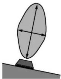
natural_image
Simple diagram of a tilted elliptical object with directional arrows, resting on a flat surface (no text or symbols)NOTE
The effective range of the D Beam controller will be extremely limited when used under strong, direct sunlight. Please be aware of this when using the D Beam controller outdoors.
NOTE
The sensitivity of the D Beam controller can vary depending on the amount of light in the vicinity of the unit. If it does not function as you expect, adjust the D Beam.(p. 76)
MEMO
The parameter values set by holding your hand or other object over the D Beam controller change as shown below.
| D BEAM vertical movements | Explanation |
| Closer to the D Beam The value approaches the MAX value. | |
| Farther from the D Beam | The value approaches the MIN value. |
| D BEAM horizontal movements | Explanation |
| To the right of the D Beam | The value approaches the MAX value. |
| To the left of the D Beam | The value approaches the MIN value. |
Adjusting the Ribbon Controller (CALIBRATION)
While the ribbon controller has been adjusted at the factory for optimum performance, the responsive range may vary with the width of the finger used to activate the controller.
If this occurs, use the procedure below to readjust the range.
-
Press [SYSTEM].
-
Press PAGE [ ] to go to Page 2.

text_image
SYSTEM OUTPUT USB V-LINK CATEGORY NAME C:\> ABCDEF CATGRY CALIB MISC-
Press [F5] (CALIB).
-
Press PAGE [] to go to Page 2.
The RIBBON CALIB screen appears.
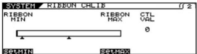
text_image
SYSTEM RIBBON CALIB RIBBON MIN RIBBON MAX CTL VAL 0 SETMIN SETMAX- Set the responsive range as you actually operate the ribbon controller.
- First, while holding your finger against the near end of the ribbon controller, press [F1] (SetMIN).
- Next, hold your finger against the far end and press [F4] (SetMAX).
NOTE
If the message "OUT OF RANGE! SET AGAIN." is displayed, carry out the calibration process once more. If the message continues to appear even after the calibration is correctly performed, it may indicate damage or malfunction. Consult your Roland dealer or contact Roland Service.
- Press [EXIT] several times to return to the Play screen.
MEMO
The CALIBRATION setting is a system parameter, so the Write procedure is not required.
Controlling the Sounds with the Movement of Your Fingertip (Ribbon Controller)
The ribbon controller allows you to change sounds by "scratching" or tracing your finger along the ribbon. You can apply various effects to the sound by changing the functions assigned to this controller.
- Press the RIBBON CONTROLLER [PITCH], [FILTER], or [ASSIGNABLE] button to switch on the ribbon controller.
| Available Settings | Explanation |
| PITCH | You can use the T-Arm function to control the guitar's pitch, and the Freeze function to hold guitar sounds.* The PITCH effect is applied only to COSM guitars. Use this with the COSM guitar volume raised. (p. 33) |
| FILTER | You can change the tone using the ribbon controller. |
| ASSIGNABLE | The ribbon controller controls the function assigned to it. You can assign a variety of functions to the controller. |
cf.
For more on how to set functions and tones, please read "Using the Switches, Pedals, and MIDI to Control the Sounds (CONTROL ASSIGN)" (p. 82).
-
While you play the guitar to produce sound, scratch your finger along the ribbon controller.
-
The effect is applied to the sound in accordance with the function assigned to the ribbon controller.
-
To turn off the ribbon controller, press the button you pressed in Step 1 again so the indicator goes off.
MEMO
The setting switching the ribbon controller on and off is a patch parameter. Carry out the Write procedure as required.
NOTE
A light touch is sufficient when operating the ribbon controller. Never press the ribbon controller forcefully or with a hard object or a pointed object.
Holding Sounds for Extended Periods (FREEZE)
You can press the D BEAM [PITCH] button to use the FREEZE effect, which allows you to hold sounds indefinitely.
-
Press [CONTROL ASSIGN]
-
Press PAGE [ ] to go to Page 2.
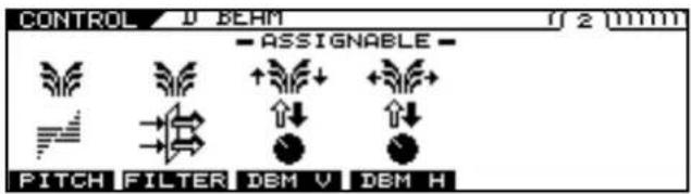
text_image
CONTROL U BEAM 2 mm - ASSIGNABLE - PITCH FILTER DEM V DEM H-
Press [F1] (PITCH).
-
Select FREEZE with [F1] (SELECT) or the F1 knob.
The D BEAM FREEZE screen appears.
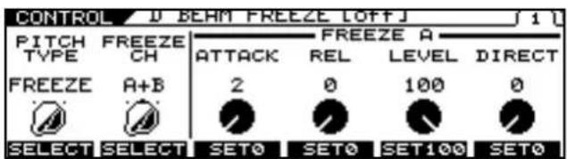
text_image
CONTROL D BEAM FREEZE LOFFJ 1 PITCH FREEZE FREEZE A TYPE CH ATTACK REL LEVEL DIRECT FREEZE A+B 2 0 100 0 SELECT SELECT SET0 SET0 SET100 SET0-
Use [F2] (SELECT) or the F2 knob to select the channel with the sounds you want to freeze.
-
Set each of the FREEZE parameters on Page 1 or Page 2
cf.
For more detailed information on the parameters that can be set, refer to (p. 151).
-
Press [EXIT] several times to return to the Play screen.
-
Press the D BEAM [PITCH] button, causing the indicator to light.
-
Play the guitar, and while the sounds are playing, cut across the D Beam with your hand or guitar neck.
-
The FREEZE function switches on and the same sound continues to hold, while the D Beam controller's blue indicator lights up.
-
To switch FREEZE off, swipe your hand or guitar neck across the D Beam controller's beam.
* With D BEAM:FREEZE:SW set as the target in Control Assign, you can control the FREEZE effect ON/OFF using an external
Chapter 8 Other Functions
pedal, MIDI device, or any of a variety of other controllers.
Changing the Pitch as with a Tremolo Arm (T-ARM)
You can press the D BEAM or RIBBON CONTROLLER [PITCH] button to use T-ARM, which changes the pitch of the COSM guitar like a tremolo arm.
1. Press [CONTROL ASSIGN]
- Press PAGE [ ] to go to Page 2 for the D Beam, or Page 3 for the ribbon controller.
![ROLAND VG-99 - Press [CONTROL ASSIGN] - 1](/content/2026/05/763494/images/da5c2047b536ec1f6b96987e91fa18e4ce38e30fd4d8962e39b4dcb06fb02b6b.jpg)
text_image
CONTROL U BEAM - ASSIGNABLE - PITCH FILTER DEM V DEM H![ROLAND VG-99 - Press [CONTROL ASSIGN] - 2](/content/2026/05/763494/images/1be75ca95a3c892e9cba721f6739390f6e185de8753fc0d55f92517e943e3229.jpg)
text_image
CONTROL RIBBON - ASSIGNABLE - POS ACT PITCH FILTER RB POS RB ACT- Press [F1] (PITCH).
- Press PAGE [] to go to Page 1.
- Select T-ARM with [F1] (SELECT) or the F1 knob.
The D BEAM T-ARM or the RIBBON T-ARM screen appears.
* This step is not necessary if you are using the ribbon controller. In this case, proceed to Step 5.
![ROLAND VG-99 - Press [CONTROL ASSIGN] - 3](/content/2026/05/763494/images/aa4e685f724bc91a7ab8531106e5432adb3687e07a33db2620aaab9f2280b8d3.jpg)
text_image
CONTROL / D BEAM T-ARM LOFF J PITCH TYPE T-ARM T-ARM A+B TYPE S-TYPE DOWN MIN 0 +50 SELECT SELECT SELECT SET0 SET+50![ROLAND VG-99 - Press [CONTROL ASSIGN] - 4](/content/2026/05/763494/images/3f1d4efe592345c9382aedb0e913eea92354a90bd33433333f33563ec986e299.jpg)
text_image
CONTROL RIBBON T-ARM LOFFJ T-ARM CH TYPE DOWN MIN DOWN A+B S-TYPE 0 +50 SELECT SELECT SET0 SET+50- Use [F2] (SELECT) or the F2 knob in the D Beam screen or [F1] (SELECT) or the F1 knob in the Ribbon Controller screen to select the channel to which you want to apply the effect.
- Set each of the T-ARM parameters on Page 1 or Page 2
cf.
For more detailed information on the parameters that can be set, refer to "PITCH" (p. 151), (p. 153).
- Press [EXIT] several times to return to the Play screen.
- Press the D BEAM or RIBBON CONTROLLER [PITCH] button, causing the indicator to light.
- Use the D Beam or ribbon controller like a tremolo arm to change the pitch.
* With D BEAM:T-ARM:SW or RIBBON:T-ARM:SW and "BEAM:T-ARM:CONTROL and RIBBON:T-ARM:CONTROL set as the target in Control Assign, you can control the T-ARM effect using an external pedal, MIDI device, or any of a variety of other controllers.
Adding Nuance to the Sound (FILTER)
You can press the D BEAM or RIBBON CONTROLLER [FILTER] button to apply the FILTER effect and add nuance to the tone in Channel A or B, or both channels.
1. Press [CONTROL ASSIGN]
- Press PAGE [ ] to go to Page 2 for the D Beam, or Page 3 for the ribbon controller.
![ROLAND VG-99 - Press [CONTROL ASSIGN] - 1](/content/2026/05/763494/images/89c5705571785e50d20dc03503dafc062fee1d5c52c276f7c18e73830323b140.jpg)
text_image
CONTROL U BEAM ASSIGNABLE PITCH FILTER DEM V DEM H CONTROL RIBBON ASSIGNABLE POS ACT PITCH FILTER RB POS RB ACT-
Press [F2] (FILTER).
-
Press PAGE [] to go to Page 1.
The D BEAM FILTER or the RIBBON FILTER screen appears.
![ROLAND VG-99 - Press [CONTROL ASSIGN] - 2](/content/2026/05/763494/images/11b60a4199836093123a35ba907afece5f9eb191588fa031bd70c3f6d18df081.jpg)
text_image
CONTROL / D BEAM FILTER LOFFJ FILTER CH TYPE FREQ MIN FREQ MAX RESO LEVEL A+B LPF 100 0 0 50 SELECT SELECT SET0 SET100 SET0 SET50 CONTROL / RIBBON FILTER LOFFJ FILTER CH TYPE FREQ MIN FREQ MAX RESO LEVEL A+B LPF 100 0 0 50 SELECT SELECT SET0 SET100 SET0 SET50-
Use [F1] (SELECT) or the F1 knob to select the channel to which you want the effect to be applied.
-
Set each of the FILTER parameters on Page 1.
cf.
For more detailed information on the parameters that can be set, refer to "FILTER" (p. 152), (p. 153).
-
Press [EXIT] several times to return to the Play screen.
-
Press the D BEAM or RIBBON CONTROLLER [FILTER] button, causing the indicator to light.
-
Use the D Beam or ribbon controller to apply the filter and add nuance to the sound.
* With D BEAM:FILTER:SW or RIBBON:FILTER:SW and D BEAM:FILTER:CONTROL and RIBBON:FILTER:CONTROL set as the target in Control Assign, you can control FILTER:CONTROL using an external pedal, MIDI device, or any of a variety of other controllers.
Changing the Sounds with the Knobs as You Play (DIRECT EDIT)
You can assign parameters to the F1-F6 knobs to control the parameters as you play.
Additionally, you can check (display) the assigned parameters by pressing [F1]–[F6].
1. Press [CONTROL ASSIGN]
2. Press PAGE [] to go to the last page.
![ROLAND VG-99 - Press PAGE [] to go to the last page. - 1](/content/2026/05/763494/images/d4aeba1a8865e7f2ecb3e14fcfc86357d4d345e8abe014a3adb06ee3a67af553.jpg)
text_image
CONTROL ASSIGN 13-16 13 14 15 16 ASSIGN F1-F83. Press [F6] (F1–F6) to enter the DIRECT EDIT screen.
The DIRECT EDIT screen appears.
![ROLAND VG-99 - Press [F6] (F1–F6) to enter the DIRECT EDIT screen. - 1](/content/2026/05/763494/images/2cac68fae456be8cf566a358b666783ab9f08649376909c1f11bd7a38040b3e5.jpg)
text_image
CONTROL DIRECT EDIT 10 F1 F2 TARGET PARAMETER TARGET PARAMETER F1 [A]COSM GUITAR F4 [A]COSM GUITAR F2 E.GTR F5 E.GTR F3 E.GTR TYPE F8 PU SEL- Press Page [ ] to go to the page for the knob you want to set.
- Use the [F1]–[F6] or F1–F6 knobs to select the parameters you want to assign to the knob.
- If you want to save the edited settings, perform the Write procedure (p. 38).
* If not saving the settings, press |EXIT| to return to the Play screen.
Using the Switches, Pedals, and MIDI to Control the Sounds (CONTROL ASSIGN)
These settings are made when parameters are to be controlled with the GK-3 VOLUME knob or DOWN/S1, UP/S2 switches, the VG-99's CONTROL buttons, an external pedal or other connected controller, or a connected MIDI device.
In addition to settings already assigned to controllers, the VG-99 also features sixteen prepared general-purpose control assigns that let you freely assign settings to controllers as you like.
* If you intend to control the parameters of effects and the like, be sure to set the effect to ON beforehand.
* For more detailed information on the parameters, refer to "CONTROL ASSIGN" (p. 150),
* Enabling the settings requires setting each of the controller assignments to ASSIGNABLE in the SYSTEM CONTROL ASSIGN screen. For detailed information, refer to "Setting the GK VOLUME Control and Switch and the Pedal Function (SYSTEM CONTROL ASSIGN)" (p. 49).
1. Press [CONTROL ASSIGN]
2. Select the controller you want to set with PAGE [ ] and [F1]–[F6].
The various controllers' setting screens appear.
* The following section describes the controllers you can set.
![ROLAND VG-99 - Select the controller you want to set with PAGE [ ] and [F1]–[F6]. - 1](/content/2026/05/763494/images/de4b50fc99ce5b26738684055e949c6fc05c5ae178cc887a9ec013258235cca6.jpg)
text_image
CONTROL GK/PANEL Volume GK S1,S2 PANEL 1 2 GK VOL S1,S2 CTL1 CTL2| Displayed screen | Controller | |
| GK VOL | GK VOL | Settings for the volume knob on the GK-3. |
| S1, S2 | GK S1, S2 | Settings for the switches on the GK-3. |
| CTL1 | CONTROL1 | Settings for the CONTROL 1 Button on the VG-99's top panel. |
| CTL2 | CONTROL2 | Settings for the CONTROL 2 Button on the VG-99's top panel. |
![ROLAND VG-99 - Select the controller you want to set with PAGE [ ] and [F1]–[F6]. - 2](/content/2026/05/763494/images/edf4a99585a2592eb37fd4db205d905bad613150ec3c0af487eedaeecde38a00.jpg)
text_image
CONTROL J BEAM - ASSIGNABLE - PITCH FILTER DEM V DEM H| Displayed screen | Controller | |
| PITCH | D BEAM T-ARM/D BEAM FREEZE | Control of TREMOLO ARM/FREEZE with the D Beam controller |
| FILTER | D BEAM FILTER | Control of FILTER with the D Beam controller |
| DBM V | D BEAM V | D Beam controller vertical sensor |
| DBM H | D BEAM H | D Beam controller horizontal sensor |
![ROLAND VG-99 - Select the controller you want to set with PAGE [ ] and [F1]–[F6]. - 3](/content/2026/05/763494/images/0e04323a66fe9471ab36e2580f89ea25948a0ef0ad88a141c3e1b4f302c83fc2.jpg)
text_image
CONTROL RIBBUN ASSIGNABLE POS ACT PITCH FILTER RB POS RB ACT| Displayed screen | Controller | |
| PITCH | RIBBON T-ARM | Control of PITCH with the TREM-OLO ARM. |
| FILTER | RIBBON FILTER | Control of FILTER with the Ribbon controller |
| RB POS | RIBBON POS | Ribbon controller position sensor |
| RB ACT | RIBBON ACT | Ribbon controller touch sensor |
![ROLAND VG-99 - Select the controller you want to set with PAGE [ ] and [F1]–[F6]. - 4](/content/2026/05/763494/images/9fc3ad58ab839ffac16fb8e4b28118f679dca0ec293b26e138dc915f0378b2de.jpg)
text_image
CONTROL REHR PANEL EXP CTL3 CTL4 EXP CTL3 CTL4| Displayed screen | Controller | |
| EXP | EXP PEDAL | Settings for the expression pedal connected to the EXP PEDAL jack on the VG-99's rear panel. |
| CTL3 | CTL3 | Settings for the footswitch connected to the CTL3 jack on the VG-99's rear panel. |
| CTL4 | CTL4 | Settings for the footswitch connected to the CTL4 jack on the VG-99's rear panel. |
![ROLAND VG-99 - Select the controller you want to set with PAGE [ ] and [F1]–[F6]. - 5](/content/2026/05/763494/images/4f4996de73426aea2a103a2d0380eea9ce3a0306e412357889213d0967456d70.jpg)
text_image
CONTROL FC-300 mm 5 mm EXP1 EXPSW1 EXP2 EXPSW2 CTL1 CTL2| Displayed screen | Controller | |
| EXP1 | FC EXP1 | Settings for the expression pedal 1 on the FC-300 connected to the VG-99. |
| EXPSW1 | FC EXPSW1 | Settings for the expression pedal switch 1 on the FC-300 connected to the VG-99. |
| EXP2 | FC EXP2 | Settings for the expression pedal 2 on the FC-300 connected to the VG-99. |
| EXSW2 | FC EXPSW2 | Settings for the expression pedal switch 2 on the FC-300 connected to the VG-99. |
| CTL1 | FC CTL1 | Settings for the CTL1 on the FC-300 connected to the VG-99. |
| CTL2 | FC CTL2 | Settings for the CTL2 on the FC-300 connected to the VG-99. |
![ROLAND VG-99 - Select the controller you want to set with PAGE [ ] and [F1]–[F6]. - 6](/content/2026/05/763494/images/cf4c7cf9f3ac8578a24fed83a3ad4d7462e17af4e680af8c0c7181cb0430750f.jpg)
text_image
CONTROL FC-300 mm 16 EXP3 E3/C3 CTL3 CTL4 E4/C5 CTL6 CTL7 E5/C7 CTL8 EXP4 E4/C5 EXP5 CTL8 CTL8 CTL8 CTL8 CTL8 CTL8| Displayed screen | Controller | |
| E3/C3 | FC E3/C3 | Settings for the expression pedal 3 or footswitch 3 connected to the FC-300's rear panel. |
| CTL4 | FC CTL4 | Settings for the footswitch 4 connected to the FC-300's rear panel. |
| E4/C5 | FC E4/C5 | Settings for the expression pedal 4 or footswitch 5 connected to the FC-300's rear panel. |
| CTL6 | FC CTL6 | Settings for the footswitch 6 connected to the FC-300's rear panel. |
| E5/C7 | FC E5/C7 | Settings for the expression pedal 5 or footswitch 7 connected to the FC-300's rear panel. |
| CTL8 | FC CTL8 | Settings for the footswitch 8 connected to the FC-300's rear panel. |
Chapter 8 Other Functions

text_image
CONTROL ASSIGN 1-6 1 2 3 4 5 6 ASGN 1 ASGN 2 ASGN 3 ASGN 4 ASGN 5 ASGN 6 CONTROL ASSIGN 13-16 13 14 15 16 ASSIGN F1-F6| Displayed screen | Controller | |
| ASGN 1:ASGN16 | ASSIGN1:ASSIGN16 | Settings for general purpose assigns you can set freely as controllers for MIDI messages and other controllers in addition to those described above. |
| F1-F6 | DIRECT EDIT | Settings for the function knobs arranged below the VG-99's LCD. |
3. Select the function you want to assign with PAGE [ ], [F1]-[F6], and the F1-F6 knobs.
TIP
You can assign two different functions to one controller. For example, you can assign separate functions to the GK VOL (1) and GK VOL (2) displayed in the screen.
cf.
For more on PITCH and FILTER of the D BEAM controller, refer to "Controlling Sounds by Hand Motion or the Guitar Neck (D Beam Controller)" (p. 77). For more on PITCH and FILTER of the Ribbon controller, refer to "Controlling the Sounds with the Movement of Your Fingertip (Ribbon Controller)" (p. 79).
The following section describes the parameters you can set on each page.
* The screen shown in the example is for ASSIGN1.
Page 1, 3
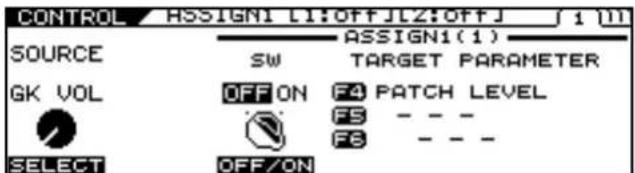
text_image
CONTROL ASSIGN1 [1:OFF] [2:OFF] 1 (M) SOURCE SW TARGET PARAMETER GK VOL OFF ON F4 PATCH LEVEL SELECT OFF/ON F5 - - F6 - - -F1: SOURCE (ASSIGN1-16 only)
This selects the controller assigned to the function.
F3: SW (ON/OFF)
Setting this to ON enables the controller.
F4-F6: TARGET PARAMETER
Use these to select the parameter you want to assign.
You can quickly locate and select the desired parameter by first narrowing down the parameter type with F4, then using F5 and then F6 to reach the right parameter.
cf.
For more details on the parameters, refer to "CONTROL ASSIGN" (p. 150).
Page 2,4
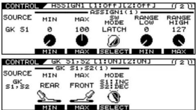
text_image
CONTROL ASSIGN1 [1:off] [2:off] (2) SOURCE MIN MAX SW RANGE RANGE GK S1 0 100 MODE LOW HIGH MIN MAX SELECT MIN MAX CONTROL GK S1,S2 [1:ON] [2:ON] (2) SOURCE GK S1,S2 MIN MAX MODE REAR FRONT S1 INC MIN MAX SELECT MIN MAX SELECTF2: MIN
This sets the minimum value for the target's controllable range.
F3: MAX
This sets the maximum value for the target's controllable range.
F4: SW MODE (only when a switch type controller is selected for SOURCE)
This specifies how the switches function.
| Available Settings | Explanation |
| MOMENT | The parameter switches to the maximum value only while the switch is held down, and switches to the minimum value when the switch is released. |
| LATCH | The value alternately switches between maximum and minimum each time the switch is pressed. |
F4: MODE (GK S1, S2 only)
This specifies how the switches function.
* Combinations of the actions below are possible.
S1: DEC / S2: INC
S1: INC / S2: DEC
S1: MIN / S2: MAX
S1: MAX / S2: MIN
| Available Settings | Explanation |
| INC | The value increases. |
| DEC | The value decreases. |
| MIN | The value is set to the minimum. |
| MAX | The value is set to the maximum. |
F5: RANGE LOW (only when an expression pedal or other controller that changes values in a continuous, non-discrete way is set as the source)
This sets the minimum for the range in which the value of the setting can be changed.
F6: RANGE HIGH (only when an expression pedal or other controller that changes values in a continuous, non-discrete way is set as the source)
This sets the maximum for the range in which the value of the setting can be changed.
About the Range of Targets' Change
The target's value changes between MIN (the minimum value) and MAX (the maximum value).
When a foot switch or other controller that switches settings on and off is used, OFF sets the minimum value and ON sets the maximum value.
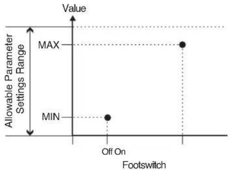
scatter
| Footswitch | Value | | ---------- | ----- | | Off On | MAX | | Off On | MIN |When an expression pedal or other controller that changes values in a consecutive manner is used, the value changes within the range between MIN and MAX.
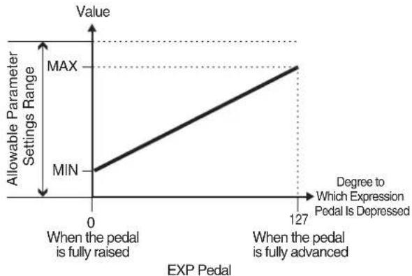
line
| EXP Pedal | Value | | --------- | ----- | | 0 | MIN | | 127 | MAX |When an expression pedal or other controller that changes values in a consecutive manner is used to control a two-value (On/Off) parameter, the controller functions as shown below.
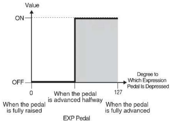
bar
| Time Point | Value | | :--- | :--- | | When the pedal is fully raised | OFF | | When the pedal is advanced halfway | ON | | 127 | Off | | Degree to Which Expression Pedal Is Depressed | Value | |---|---| | When the pedal is fully raised | OFF | | When the pedal is advanced halfway | ON | | 127 | Off |About the Range of Controllers' Change
This sets the operational range (range in which the value actually changes) for an expression pedal, or similar controller that changes the value of a setting in a continuous fashion, when it has been set as the source.
If the controller adjustment moves beyond the enabled range of operation, the value of the setting remains at the maximum value or minimum value, without changing any further.
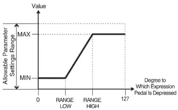
line
| Degree to Which Expression Pedal Is Depressed | Value | | --------------------------------------------- | ----- | | 0 | MIN | | RANGELow | MAX | | RANGELHIGH | MAX | | 127 | MAX |4. If you want to save the edited settings, perform the Write procedure (p. 38).
* If you do not want to save, press |EXIT| to return to the Play screen.
Activating the Virtual Expression Pedal at the Start of Operations (Internal Pedal System)
The VG-99 features a function called Internal Pedal system. This function assigns specified parameters to a virtual expression pedal (the internal pedal), providing an effect automatically that changes volume and tone in real time just the way an expression pedal functions.
The Internal Pedal system features the following two functions, allowing you to set Source for each assign 1-16 (p. 84) of the Control Assign (p. 82).
- Internal Pedal
- Wave Pedal
* When the Internal Pedal or the Wave Pedal is used, set the ASSIGN SW MODE to MOMENT.
Internal Pedal
With the trigger you have set, the assumed expression pedal starts working. If you have set INTERNAL PEDAL to SOURCE, set the TRIGGR parameter (p. 156).
cf.
For more detailed information on the parameters that can be set using INTERNAL PEDAL, refer to "TRIGGR (Trigger)" (p. 156), "TIME" (p. 156), and "CURVE" (p. 156).
Wave Pedal
This changes the parameter selected as a target in a certain cycle with the assumed expression pedal. When you have set WAVE PEDAL for SOURCE, the RATE parameter (p. 156) and FORM parameter (p. 156) should be set.
cf.
For more detailed information on the parameters that can be set using WAVE PEDAL, refer to “RATE” (p. 156) and “FORM” (p. 156).
One Touch Call Up of Favorite Patches (DIRECT PATCH)
You can assign your favorite patches to the [DIRECT PATCH 1] - [DIRECT PATCH 5] buttons, then call up these patches just by pressing the buttons.
Setting DIRECT PATCH
- Press [SYSTEM].
- Press PAGE [] to go to Page 1.
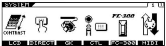
text_image
SYSTEM CONTRAST LCD DIRECT GK CTL FC-300 MIDI FC-300- Press [F2] (DIRECT).
The DIRECT PATCH screen appears.
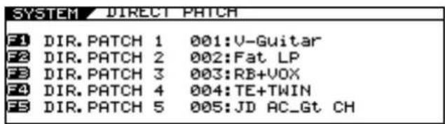
text_image
SYSTEM DIRECT PATCH F1 DIR.PATCH 1 001:V-Guitar F2 DIR.PATCH 2 002:Fat LP F3 DIR.PATCH 3 003:RB+VOX F4 DIR.PATCH 4 004:TE+TWIN F5 DIR.PATCH 5 005:JD AC_Gt CH- Use the F1–F5 knobs to select the patches to be assigned to [DIRECT PATCH 1]–[DIRECT PATCH 5].
The numbers correspond, with DIR. PATCH 1 assigned with the F1 knob, DIR. PATCH 2 assigned with the F2 knob, and so on.
- Press [EXIT] several times to return to the Play screen.
Managing the Patches
Copying the Current Patch to a Different Patch (PATCH COPY)
- Press [WRITE].
The PATCH WRITE screen appears.
"WRITE TO" is displayed, and the write-destination patch number and name are indicated.
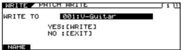
text_image
WRITE / PATCH WRITE WRITE TO 001:V-Guitar YES: [WRITE] NO : [EXIT] NAME- Use the PATCH/VALUE dial to select the copydestination patch.
- Press [WRITE] again.
The message "NOW WRITING..." is displayed as the patch is copied, and the VG-99 changes to the copy-destination patch number.
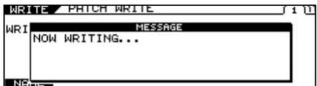
text_image
WRITE / PATCH WRITE WRI MESSAGE NOW WRITING... NAME* If you are not saving the settings, press [EXIT] to return to the Play screen.
Exchanging the Current Patch with a Different Patch (PATCH EXCHANGE)
This exchanges the user patch with the different patch.
* You cannot exchange tones in preset patches.
- Confirm that a User patch is selected.
- Press [WRITE].
- Press PAGE [ ] to go to Page 2.
"EXCHANGE" is displayed.
The exchange-destination patch number and name are indicated.
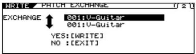
text_image
WRITE PATCH EXCHANGE EXCHANGE ↑ 001:V-Guitar 001:V-Guitar YES: [WRITE] NO : [EXIT]- Use the PATCH/VALUE dial to select the exchange-destination patch.
- Press [WRITE] again.
The message "NOW EXCHANGING..." is displayed as the current patch and the selected patch are exchanged, and the VG-99 changes to the exchange-destination patch number.
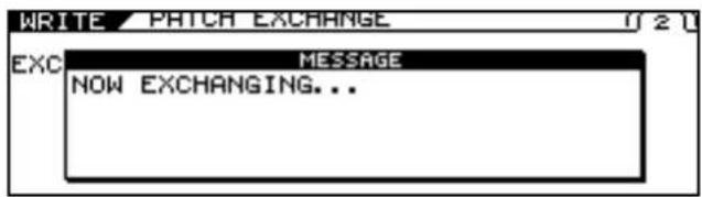
text_image
WRITE PITCH EXCHANGE EXC MESSAGE NOW EXCHANGING...* If you do not want to exchange the patches, press [EXIT] to return to the Play screen.
Initializing User Patches (PATCH INITIALIZE)
You can set user patches to their initial conditions, with all effects switched off.
This is convenient when you want to create a patch from scratch.
* You cannot initialize preset patches.
- Confirm that a User patch is selected.
- Press [WRITE].
- Press PAGE [] to go to Page 3.
The PATCH INITIALIZE screen appears.
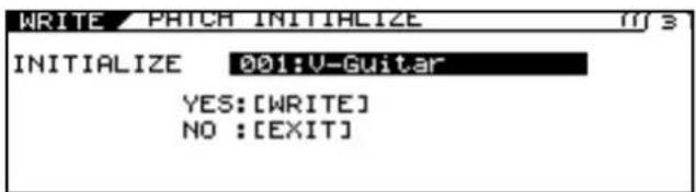
text_image
WRITE PATCH INITIALIZE INITIALIZE 001:V-Guitar YES: [WRITE] NO : [EXIT]"INITIALIZE" is displayed, and the number and name of the patch to be initialized are indicated.
- Use the PATCH/VALUE dial to select the patch you want to initialize.
- Press [WRITE] again.
The message "NOW INITIALIZING..." is displayed as the VG-99 switches to the patch to be initialized, then the Play screen returns.
text_image
WRITE PATCH INITIALIZE INI MESSAGE NOW INITIALIZING...* If you do not want to initialize the patch, press [EXIT] to return to the Play screen.
Copying Settings Between Channel A and Channel B (A/B COPY)
- Go to the settings screen for the parameters whose settings you want to copy.
- Press PAGE [ ] several times to go to the last page.
- Use [F1] (SELECT) or the F1 knob to select A/B COPY.
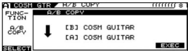
text_image
A COSM GTR H/B COPY FUNCTION A/B COPY ↓ [B] COSM GUITAR [A] COSM GUITAR SELECT EXEC- Press [F6] (EXEC) to copy the settings.
- If you want to save the edited settings, perform the Write procedure (p. 38).
* If you do not want to save, press [EXIT] to return to the Play screen.
Exchanging the Channel A and Channel B Settings (A/B EXCHANGE)
- Go to the settings screen for the parameters whose settings you want to exchange.
- Press PAGE [ ] several times to go to the last page.
- Use [F1] (SELECT) or the F1 knob to select A/B EXCHNG.
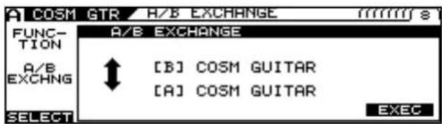
text_image
A COSM GTR H/B EXCHANGE FUNC- TION A/B EXCHANGE A/B EXCHNG [ B ] COSM GUITAR [A ] COSM GUITAR SELECT EXEC- Press [F6] (EXEC) to exchange the settings.
- If you want to save the edited settings, perform the Write procedure (p. 38).
* If you do not want to save, press |EXIT| to return to the Play screen.
Partially Copying Parameters in a Different Patch (MODULE COPY)
You can copy and reuse portions of patch parameters (such as COSM amps, effects, and other modules).
- Go to the settings screen for the parameters whose settings you want to copy.
- Press PAGE [ ] several times to go to the last page.
- Use [F1] (SELECT) or the F1 knob to select MODULE COPY.
The MODULE COPY screen appears.
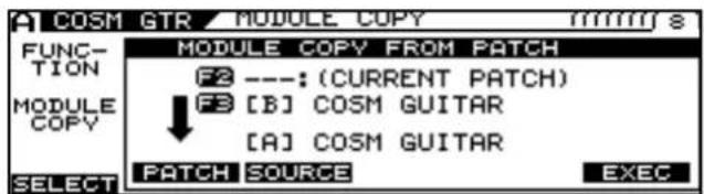
text_image
A COSM GTR MODULE COPY FUNCTION MODULE COPY FROM PATCH F2 ---: (CURRENT PATCH) F3 [B] COSM GUITAR [A] COSM GUITAR SELECT PATCH SOURCE EXEC- Use [F2] (PATCH) or the F2 knob and [F3] (SOURCE) or the F3 knob to select the copy source.
- Press [F6] (EXEC) to copy the settings.
- If you want to save the edited settings, perform the Write procedure (p. 38).
* If you do not want to save, press [EXIT] to return to the Play screen.
Partially Initializing Patch Parameters (MODULE INITIALIZE)
- Go to the settings screen for the parameter whose settings you want to initialize.
- Press PAGE [ ] several times to go to the last page.
- Use [F1] (SELECT) or the F1 knob to select MODULE INIT.
The MODULE INITIALIZE screen appears.
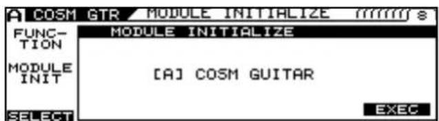
text_image
A COSM GTR MODULE INITIALIZE mmmm s FUNC- TION MODULE INIT [A] COSM GUITAR SELECT EXEC- Press [F6] (EXEC) to initialize the settings.
- If you want to save the edited settings, perform the Write procedure (p. 38).
* If you do not want to save, press [EXIT] to return to the Play screen.
Chapter 8 Other Functions
The following parameters can be handled as modules.
• ALTERNATE TUNING
• COSM GUITAR
- POLY FX
• Overall FX for Channel A and B
• Each of the effects in FX
• COSM AMP
• MIXER section DELAY and REVERB
• MIXER section DYNAMIC
Separating Patches into Groups (CATEGORY)
The VG-99 includes a function that allows you to categorize patches into a number of different groups. This is called the CATEGORY function. Specifying the category for each patch makes searching for patches more convenient. The CATEGORY function also features ten user categories you can name however you like.
Using CATEGORY to Call Up Patches
-
Confirm that the Play screen is displayed.
-
Press [CATEGORY].
The Category screen appears.

text_image
CATEGORY USER 9 USER 10 ROCK METAL CLEAN JAZZ SEL ▼ SEL ▲ SET ▼ SEL ▲ PATCH 001:V-Guitar 002:Fat LP 003:RB+VOX 004:TE+TWIN 015:HOTEL CA 021:CHICKENThe categories and the patches in these categories are shown in list format.
-
Use [F1] (SEL) and [F2] (SEL) of the F1 and F2 knobs to select the category.
-
Use the PATCH/VALUE dial or [F3] (SEL), [F4] (SEL) to select a patch.
-
Press [CATEGORY] again.
The VG-99 switches to the selected patch.
MEMO
If no operation if performed within a set period of time, the display returns to the Play screen.
Setting Patch Categories
You can assign categories to patches and separate them into groups.
- From the PLAY screen, use the PATCH/VALUE dial to select the patch you want to include in a category.
- Press [NAME/KEY/BPM].
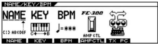
text_image
NAME/KEY/BPM NAME KEY BPM FC-300 C:\> ABCDEF C+---B =*** AMP CTL NAME KEY BPM AMPCTL TX PC- Press [F1] (NAME).
The Name settings screen appears.
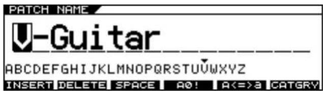
text_image
PATCH NAME -Guitar ABCDEFGHIJKLMNOPQRSTUVWXYZ INSERT DELETE SPACE A0! A<=3 CATGRY- Press [F6] (CATGRY).
The Category settings popup appears.
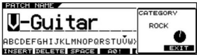
text_image
PATCH NAME Guitar CATEGORY ROCK INSERT DELETE SPACE A0!-
Use the F6 knob to select the category.
-
Press [EXIT].
The category is assigned to the patch.
- If you want to save the edited settings, perform the Write procedure (p. 38).
* If you do not want to save, press [EXIT] to return to the Play screen.
Naming User Categories (CATEGORY NAME)
- Confirm that the Play screen is displayed.
-
Press [SYSTEM].
-
Press PAGE [ ] to go to Page 2.
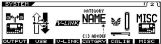
text_image
SYSTEM OUTPUT USB V-LINK CATEGORY NAME C:\> ABCDEF CATGRY CALIE MISC- Press [F4] (CATGRY).
The Category Name settings screen appears.
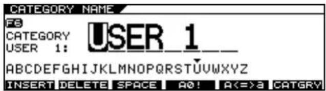
text_image
CATEGORY NAME FS CATEGORY USER 1_ USER 1: ABCDEFGHIJKLMNOPQRSTUVWXYZ INSERT DELETE SPACE A0! A<=3 CATGRY- Use [F6] or the F6 knob to select User Category with the name you want to change.
- Press PAGE [ ] to move the cursor to the position with the character you want to change.
- Select the character with the PATCH/VALUE dial.
As you continue to rotate the PATCH/VALUE dial, the character guide automatically switches from uppercase letters to lowercase letters, numerals, and symbols.
You can carry out the following operations by pressing [F1]-[F6].
| Buttons | Functions |
| [F1] (INSERT) | Inserts a blank space at the cursor position. |
| [F2] (DELETE) | Deletes the character and shifts the following characters to the left. |
| [F3] (SPACE) | Enters a blank space at the cursor position. |
| [F4] (A0!) | Switches between letters, numerals, and symbols. |
| [F5] (A<=>a) | Switches between uppercase and lowercase letters. |
| [F6] (CATGRY) | Select the user category you want to name. |
- Repeat Steps 6 and 7 to complete the category name.
- Press [EXIT] several times to return to the Play screen.
* Category names are system parameters. They are saved at the time they are entered, even without the Write procedure.
Storing Your Preferred Settings Individually (FAVORITE SETTINGS)
What are Favorite Settings?
The VG-99 includes a function that, apart from the patches, stores the settings you like for each effects processor. These are called Favorite Settings.
By storing the settings you like for each of a variety of effects processors, you can then easily create sounds simply by combining these settings.
Furthermore, creating patches using the Favorite Settings vastly simplifies editing when multiple similar tones are used.
For example, if you beforehand select the same Favorite Settings for a multiple number of patches, you'll later be able to implement changes in all those patches at once simply by editing the Favorite settings.
Calling Up Favorite Settings
Here is an example using the compressor effect.
-
Press [FX].
-
Press PAGE [] to go to Page 1.
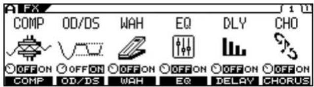
text_image
FX COMP OD/DS WAH EQ DLY CHO OFF ON OFF ON OFF ON OFF ON OFF ON OFF ON COMP OD/DS WAH EQ DELAY CHORUS- Press [F1] (COMP).
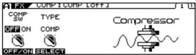
text_image
FX COMP:COMP [OFF] COMP SW TYPE OFF ON COMP OFF/ON SELECT Compressor-
Press PAGE [ ] to display the last page (in this case, Page 3).
-
Use [F1] (SELECT) or the F1 knob to select FAVORITE.
The Favorite Settings selection screen appears.
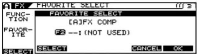
text_image
A FX FAVORITE SELECT FUNCTION FAVOR- ITE FAVORITE SELECT [A]FX COMP F2 --: (NOT USED) SELECT SELECT CANCEL OK-
Use [F2] (SELECT) or the F2 knob to select your preferred setting.
-
When you have made your choice, press [F6] (OK); to cancel the procedure, press [F5] (CANCEL) or press [EXIT] several times to return to the Play screen.
-
If you want to save the edited settings, perform the Write procedure (p. 38).
* If you do not want to save, press [EXIT] to return to the Play screen.
Changing Tone Settings
This procedure changes the tones in patches using the Favorite Settings. The method below can also be used to edit the Favorite Settings themselves.
Here is an example using the compressor effect.
-
Press [FX].
-
Press PAGE [] to go to Page 1.
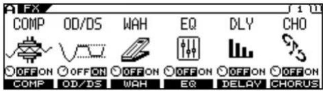
text_image
FX COMP OD/DS WAH EQ DLY CHO OFF ON OFF ON OFF ON OFF ON OFF ON OFF ON COMP OD/DS WAH EQ DELAY CHORUS- Press [F1] (COMP).
The number and name of the currently selected Favorite Settings are displayed.
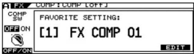
text_image
COMP SW OFF ON OFF/ON FAVORITE SETTING: [1] FX COMP 01 EDIT- Press [F6] (EDIT).
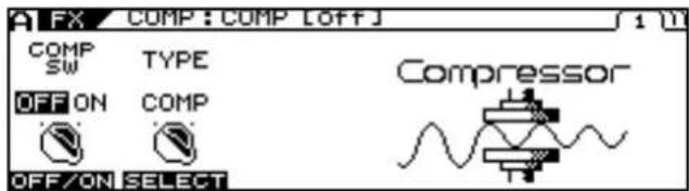
text_image
FX COMP:COMP [OFF] COMP SW TYPE OFF ON COMP OFF/ON SELECT Compressor-
Use [F1]–[F4] or the F1–F4 knobs to adjust the desired parameters on Pages 1 and 2.
-
To store the content of the settings, carry out the steps described below.
Saving Changed Tones
There are two methods you can use to save changed tones.
Saving to Patches
- Press [WRITE].
The PATCH WRITE screen appears.
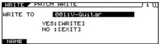
text_image
WRITE / PATCH WRITE WRITE TO 001:V-Guitar YES: [WRITE] NO : [EXIT] NAME-
Use the PATCH/VALUE dial to select the save-destination patch.
-
Press [WRITE].
text_image
WRITE / PATCH WRITE WRI MESSAGE NOW WRITING... NAME"NOW WRITING..." is displayed as the patch is being saved, and then the Play screen returns to the display.
NOTE
Saving tones with this process undoes the link between the patch and the Favorite Settings. Afterwards, any changes to tones with Favorite Settings used earlier will not be reflected in the tone for this patch.
Chapter 8 Other Functions
Saving to the Favorite Settings
The following describes an example with the status indicated in the Compressor edit screen in Step 4 of "Changing Tone Settings" (p. 93).
-
Press PAGE [] to display the last page (in this case, Page 3).
-
Rotate the F1 (SELECT) knob to select FAVORITE WRITE.
The Favorite Settings save screen appears.
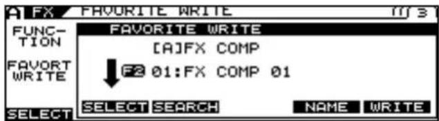
text_image
A FX FAVORITE WRITE FUNCTION FAVORT WRITE FAVORITE WRITE [A]FX COMP ↓ F2 01:FX COMP 01 SELECT SELECT SEARCH NAME WRITE- Rotate the F2 (SELECT) knob to select the write destination.
MEMO
At this point, you can press [F3] (SEARCH) to display a list of patches using the write-destination Favorite Settings. For more detailed information, refer to "Searching for Patches That Use the Same Favorite Settings" (p. 95).
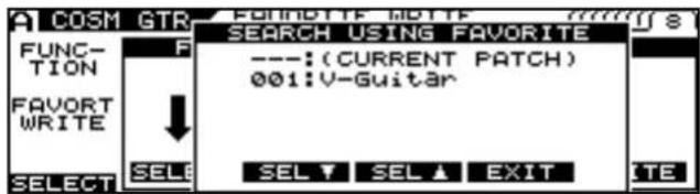
text_image
COSM GTR FUNCTION FAVORT WRITE SELECT SELECT SELL SELL ▼ SEL ▲ SELL ▲ EXIT SEARCH USING FAVORITE ---: (CURRENT PATCH) 001: V-Guitar- Press [F6] (WRITE) to save the settings.
"NOW WRITING..." is displayed as the Favorite Settings are being saved, and the number and name of the currently selected Favorite Settings are displayed.
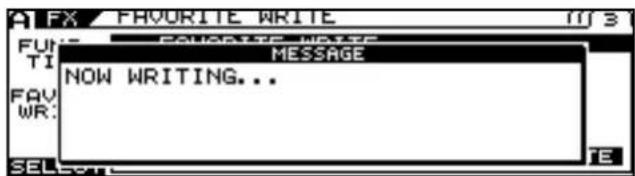
text_image
FUR: TIME FAV: WR: MESSAGE NOW WRITING...- Press [EXIT] several times to return to the Play screen.
NOTE
This procedure only saves information to the Favorite Settings. Nothing is saved to the patches. To save parameters to patches, carry out the Write procedure. (p. 38)
Naming Favorite Settings (FAVORITE NAME)
When storing Favorite Settings, you can also give the settings names. Carry out the following procedure in Step 2 of "Saving to the Favorite Settings" (p. 94).
- Press [F5] (NAME).
The Name edit screen appears.
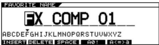
text_image
FAVORITE NAME FX COMP 01 ABCDEFGHIJKLMNOPQRSTUVWXYZ INSERT DELETE SPACE A0! A<=3-
Press PAGE [ ] to move the cursor to the position with the character you want to enter.
-
Select the character with the PATCH/VALUE dial.
As you continue to rotate the PATCH/VALUE dial, the character guide automatically switches from uppercase letters to lowercase letters, numerals, and symbols.
You can carry out the following operations by pressing [F1]–[F5].
| Buttons | Functions |
| [F1] (INSERT) | Inserts a blank space at the cursor position. |
| [F2] (DELETE) | Deletes the character and shifts the following characters to the left. |
| [F3] (SPACE) | Enters a blank space at the cursor position. |
| [F4] (A0!) | Switches between letters, numerals, and symbols. |
| [F5] (A<=>a) | Switches between uppercase and lowercase letters. |
-
Repeat Steps 2 and 3 to complete the Favorite Setting name.
-
When you have finished editing the name, press [EXIT].
The Favorite Settings save screen returns to the display.
-
Press [F6] (WRITE); the settings are saved.
-
Press [EXIT] several times to return to the Play screen.
Searching for Patches That Use the Same Favorite Settings
Here is an example using the compressor effect.
- Press [FX].
- Press PAGE [] to go to Page 1.
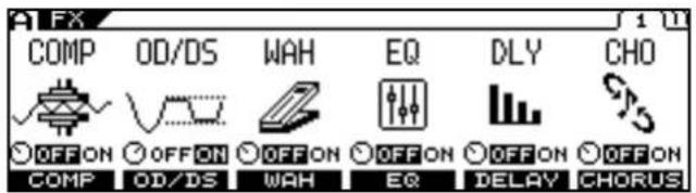
text_image
FX COMP OD/DS WAH EQ DLY CHO OFF ON OFF ON OFF ON OFF ON OFF ON OFF ON COMP OD/DS WAH EQ DELAY CHORUS- Press [F1] (COMP).
The number and name of the currently selected Favorite Settings are displayed.
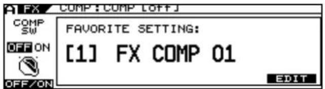
text_image
COMP SW OFF ON OFF/ON FAVORITE SETTING: [1] FX COMP 01 EDITIf not using the Favorite Settings, proceed to Step 4.
- Press [F6] (EDIT).
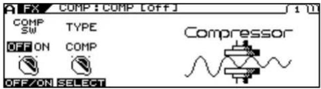
text_image
FX COMP : COMP [Off] COMP SW TYPE OFF ON COMP OFF/ON SELECT Compressor- Press PAGE [ ] to display the last page (in this case, Page 3).
- Use [F1] (SELECT) or the F1 knob to select FAVORITE WRITE.
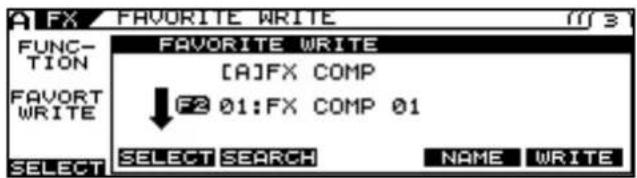
text_image
A FX FAVORITE WRITE FUNCTION FAVORT WRITE FAVORITE WRITE [A]FX COMP ↓ F2 01:FX COMP 01 SELECT SELECT SEARCH NAME WRITE-
Rotate F2 (SELECT) to select the Favorite Settings you want to search for.
-
Press [F3] (SEARCH).
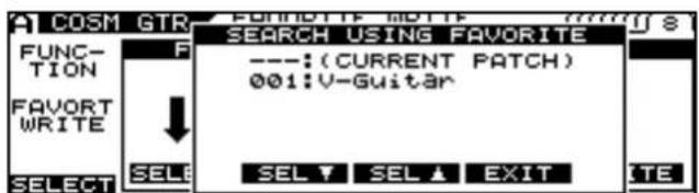
text_image
CASM GTR FUNCTION FAVORT WRITE SELECT SELECT SELL SELL ▼ SEL ▲ EXIT SEARCH USING FAVORITE ---: (CURRENT PATCH) 001: V-Guitar SELECTA list of patches using the selected Favorite Setting is displayed.
- You can scroll through the list using [F3] and [F4] or the F3 and F4 knobs.
- Press [F5] (EXIT).
The list disappears from the screen.
- Press [EXIT] several times to return to the Play screen.
Controlling Video Images with Your Guitar (V-LINK)
The VG-99 features the V-LINK function.
With the VG-99 connected to another V-LINK compatible device, you can use your guitar performance to control playback of video images.
What is V-LINK?
V-LINK is a function that synchronizes the performance of music and video.
Connecting V-LINK compatible devices to each other via MIDI makes it simple to enjoy using a variety of video effects linked with what you express in your performances.
For example, combining the VG-99 with the EDIROL motion dive. tokyo performance package lets you do the following.
- Set the required information for motion dive. tokyo performance package performances.
- Switch motion dive. tokyo performance package video images (palettes/clips) and control the video brightness and hue.
- Enjoy synchronized performances of music and video.
TIP
Be sure also to read the owner's manual for the connected V-LINK compatible device.
Connecting the V-LINK Device
Connect the VG-99's MIDI OUT connector to the V-LINK compatible device.
NOTE
When connecting these and other devices, turn down the volume completely on all the devices and turn off their power before connecting to prevent malfunction and damage to speakers and other equipment.
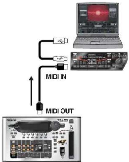
flowchart
graph TD
    A["OUTPUT"] --> B["MIDI OUT"]
    B --> C["MIDI IN"]
    C --> D["Laptop"]
Switching V-LINK On and Off
- Connect the VG-99's MIDI OUT connector to the V-LINK compatible device.
- Turn on the power to the device to start it up.
- Press [V-LINK].
V-LINK is switched on, and [V-LINK] lights up.
The function set in "Setting V-LINK" (p. 96) is enabled, allowing you to control the video images and have them linked with the performance on the VG-99.
MEMO
Even with the V-LINK on, the still usual function operates.
MEMO
Depending on the settings in "MIDI ROUTING" (p. 59), signals may not be output from MIDI OUT. In such cases, V-LINK signals are not output either.
- Press [V-LINK] once more.
The [V-LINK] light goes off, and the V-LINK function is switched off.
MEMO
When the V-LINK function is switched off, all V-LINK-related MIDI messages are no longer output.
Setting V-LINK
Making the Palette and Clip Settings (PALETTE/CLIP)
This sets the Program Change messages transmitted when patches are switched.
You can set different Program Changes in Channel A and Channel B.
-
Press [SYSTEM].
-
Press PAGE [ ] to go to Page 2.
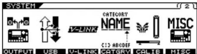
text_image
SYSTEM OUTPUT USB V-LINK CATEGORY NAME <1> ABCDEF CALIE MISC- Press [F3] (V-LINK).
The V-LINK screen appears.
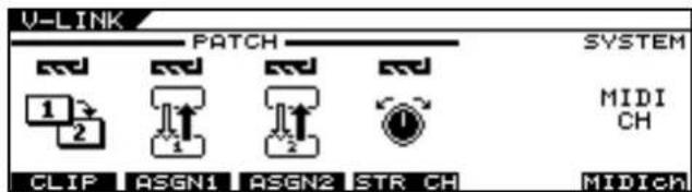
text_image
V-LINK PATCH SYSTEM 1 2 MIDI CH CLIP ASGN1 ASGN2 STR CH MIDICH4. Press [F1] (CLIP).
The PATCH/CLIP screen appears.
![ROLAND VG-99 - Press [F1] (CLIP). - 1](/content/2026/05/763494/images/061cb6d34e15b035031aecc2b6b1b14ac3b7c833a5d92e46640069584e9ada3d.jpg)
text_image
V-LINK / PATCH / CLIP A ch PAL-ETTE CLIP 1 1 SELECT SELECT B ch PAL-ETTE CLIP 1 2 SELECT SELECT- Use [F1] and [F2] or the F1 or F2 knobs to set the palette and clip for V-LINK Channel A; set the palette and clip for V-LINK Channel B with [F4] and [F5] or the F4 or F5 knobs.
| Parameter | Available Setting | V-LINK Function | Transmitted MIDI Messages |
| PALETTE | OFF, 1–32 Ch | Changing the palette. | CC00 (Bank Select): 00H–1FH |
| CLIP OFF, 1–32 | Changing the | clip. | Program Change: 00H–1FH |
Setting the String Channel (STRING CH)
This setting determines which of the V-LINK device's channels is used in controlling the note messages output when a string is played. This can be set individually for each string.
- Follow Steps 1–3 in "Making the Palette and Clip Settings (PALETTE/CLIP)" (p. 96) to display the V-LINK screen.
- Press [F4] (STR CH) to select the channel to be controlled with each string.
| STRING CH 1st-6th | Explanation |
| OFF | No channel is controlled. |
| A CH Channel A | of the V-LINK compatible device is controlled. |
| B CH Channel B | of the V-LINK compatible device is controlled. |
| C CH MIDI Note | plug-in is controlled. |
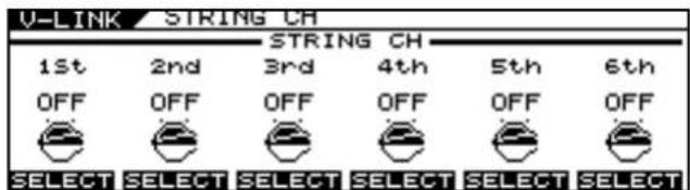
text_image
V-LINK / STRING CH 1st 2nd 3rd 4th 5th 6th OFF OFF OFF OFF OFF OFF SELECT SELECT SELECT SELECT SELECT SELECTMEMO
Some V-LINK compatible models such as the EDIROL
DV-7PR allow only Channel A to be used.
MEMO
Note messages output with the V-LINK function are affected by the parameters set in "Playing an External Synthesizer Sound Module (GUITAR TO MIDI)" (p. 64) as well as the STRING CH settings.
Setting the Assign (ASSIGN1-2)
These settings are necessary for controlling video using the guitar's performance data and messages from the VG-99's controllers. You can make up to two types of settings.
-
Follow Steps 1–3 in "Making the Palette and Clip Settings (PALETTE/CLIP)" (p. 96) to display the V-LINK screen.
-
Press [F2] (ASGN1) or [F3] (ASGN2) to select Assign 1 or Assign 2.
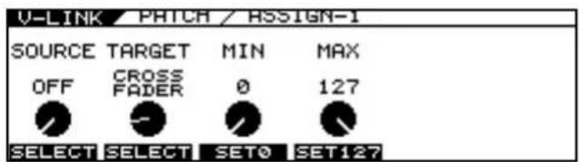
text_image
V-LINK / PATCH / ASSIGN-1 SOURCE TARGET MIN MAX OFF CROSS 0 127 FADER SELECT SELECT SET0 SET127- Use [F1] (SELECT) or the F1 knob to set the source to be used in operating the target.
- Use [F2] (SELECT) or the F2 knob to set the target.
cf.
For more on the source and target parameters, refer to "V-LINK PATCH" (p. 174).
- Rotate the F3 knob to set the minimum value for the TARGET parameter's control range.
- Rotate the F4 knob to set the maximum value for the TARGET parameter's control range.
- If you want to save the edited settings, perform the Write procedure (p. 38).
* If you do not want to save, press [EXIT] to return to the Play screen.
Using the VG-99 on a Stand
You can use the VG-99 while attached to a PDS-10 stand (optional).
- Turn the VG-99 over and remove the screws from the bottom panel.
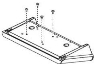
natural_image
Technical line drawing of a rectangular electronic component with mounting holes and mounting screws (no text or symbols)- Attach the mounting plate as shown in the figure, using the screws removed in Step 1 or the knob nuts included with the kit.
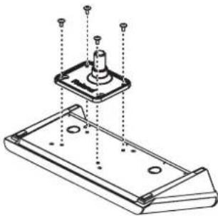
natural_image
Technical line drawing of a mechanical assembly with mounting holes and a central component (no text or symbols)- Attach the VG-99 to the stand.
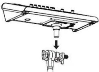
natural_image
Mechanical assembly diagram showing a component being inserted into a housing (no text or symbols present)MEMO
For instructions on how to assemble the PDS-10 and attach the mounting plate, refer to the Owner's Manual that came with the PDS-10.
NOTE
• To prevent the PDS-10 stand from falling, use the attached cable ties to wind all cables around the stand, as shown in the figure below.
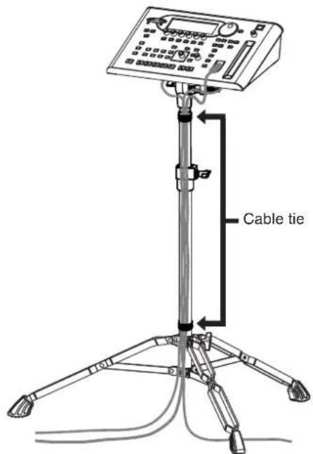
text_image
Cable tie- Use the screws (M5 x 10) included with the VG-99 to attach the PDS-10 mounting plate. Use of other screws may damage the device internally or cause the unit to be inadequately secured.
- When turning the unit over, place some newspapers, magazines, or other such material under the four corners or at both ends to prevent damage to the buttons, dials, and other controls. Also, try to orient the unit so no buttons or controls are damaged.
- When turning the unit upside-down, handle with care to avoid dropping it, or allowing it to fall or tip over.
- When removing the screws, be sure to keep them out of the reach of children to prevent smaller children from accidentally swallowing them.
• Take care not to allow hands and fingers to become pinched when attaching and removing the units.
Using the VG-99 Mounted in a Rack
By employing the separately available RAD-99 rack mount adaptor, you can use the VG-99 in a rack-mounted configuration.
- Turn the VG-99 over and remove the screws from the bottom panel.
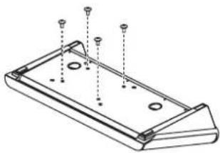
natural_image
Technical line drawing of a rectangular electronic component with mounting holes and mounting screws (no text or symbols)- Attach the RAD-99 as shown in the figure, using the screws removed in Step 1 or the knob nuts included with the kit.
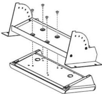
natural_image
Technical line drawing of two metal structural components with mounting holes and bolted joints (no text or symbols)- Mount the VG-99 in the rack.
Use screws (in four places) to securely affix the unit to the rack.
* Use the screws included with the rack.
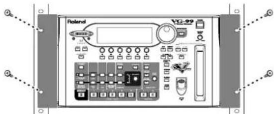
text_image
Roland VG-99MEMO
For instructions on how to assemble the RAD-99 and adjust the angle of attachment, refer to the RAD-99 Owner's Manual.
NOTE
- Use the screws (M5 x 10) included with the VG-99 to attach the RAD-99. Use of other screws may damage the device internally or cause the unit to be inadequately secured.
- When turning the unit over, place some newspapers, magazines, or other such material under the four corners or at both ends to prevent damage to the buttons, dials, and other controls. Also, try to orient the unit so no buttons or controls are damaged.
- When turning the unit upside-down, handle with care to avoid dropping it, or allowing it to fall or tip over.
- When removing the screws, be sure to keep them out of the reach of children to prevent smaller children from accidentally swallowing them.
• Take care not to allow hands and fingers to become pinched when attaching and removing the units.
Restoring the VG-99 to its Original Factory Condition (FACTORY RESET)
- Press [SYSTEM].
- Press PAGE [] to display Page 3.
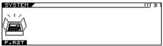
text_image
SYSTEM FIRST- Press [F1] (F.RST).
The FACTORY RESET screen appears.
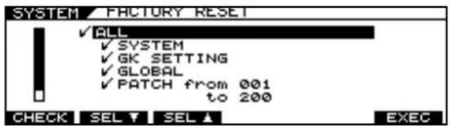
text_image
SYSTEM FACTORY RESET ✓ ALL ✓ SYSTEM ✓ GK SETTING ✓ GLOBAL ✓ PATCH from 001 to 200 CHECK SEL ▼ SEL ▲ EXEC- Select the parameters you want to restore to the original factory condition.
| Available Settings | Explanation |
| ALL | All data |
| SYSTEM | System Parameter |
| GK SETTING | Content of GK settings |
| GLOBAL | Content of settings for Global function |
| PATCH | Content of settings for PATCH 001-200 |
| FAVORITE SETTING | Content of settings for FAVORITE SET-TINGS 01-10 for all effects |
- Press [F6] (EXEC).
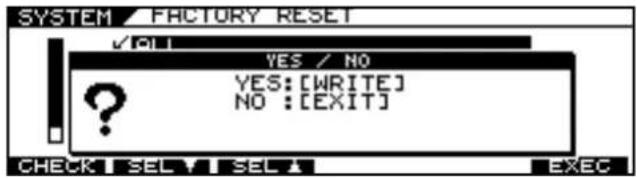
text_image
SYSTEM FACTORY RESET ✓ ALL YES / NO YES: [WRITE] NO : [EXIT] CHECK SEL SEL EXEC- To execute Factory Reset, press [WRITE].
* To cancel Factory Reset, press [EXIT].
text_image
SYSTEM FACTORY RESET MESSAGE FACTORY RESET...When Factory Reset is completed, the display returns to the Play screen.
In this chapter you will find detailed descriptions for each of the VG-99's parameters used to control them.
The trademarks listed in this document are trademarks of their respective owners, which are separate companies from Roland. Those companies are not affiliated with Roland and have not licensed or authorized Roland's VG-99. Their marks are used solely to identify the equipment whose sound is simulated by Roland's VG-99.
COSM GUITAR
By making settings for the various elements that make up the tone of a guitar, you can create a wide variety of sounds. You can set actual guitar parameters, such as pickup, body, and the pitch of each string.
| Parameter/Range | Explanation |
| COSM GTR SW (COSM Guitar Switch) | |
| OFF, ON | Turns the COSM guitar on/off. |
| MODLNG TYPE | |
| E. GTR | Select the electric guitar type. |
| AC Select the acoustic guitar type. | |
| BASS Select the bass guitar type. | |
| SYNTH Select the synthesizer sound type. | |
| E. GTR TYPE/AC TYPE/BASS TYPE/SYNTH TYPE | |
| refer to Type List | Select the COSM guitar from each modeling type.* The parameters that can be set will depend on the type. For details on the parameters, refer to the corresponding item. |
Modeling Type List
E. GTR (Electric Guitar) (p. 103)
| Parameter/Range | Explanation |
| CLA-ST (Classic ST) | The sound of a Fender Stratocaster.Simulates the installation of three single-coil pickups (passive type). |
| MOD-ST (Modern ST) The | sound of a Stratocaster type guitar.Simulates the installation of the EMG's three single-coil pickups (active type). |
| TE (Telecaster) The sound | of a Fender Telecaster.A particular characteristic of the sound is the boosted high end when the volume is turned down. |
| LP (Les Paul) The sound of | a Gibson Les Paul Standard.Simulates the installation of two humbucking pickups (passive type). |
| P-90 The sound of a Gibson | Les Paul Junior.This provides two single-coil pickups of the type used on fixed-neck guitars and affectionately known as soap-bar or dog-ear pickups. |
| LIPS (Lipstick) The sound | of a Danelectro 56-U3.This provides two single-coil pickups, and characterized by an external case reminiscent of a tube of lipstick. |
| RICK (Rickenbacker) The sound | of a Rickenbacker 360.Semi-hollow body guitar with two unique single-coil pickups. |
| 335 The sound of a Gibson | ES-335 DOT.Typical semi-acoustic guitar with two humbucking pickups. |
| L4 The sound of a Gibson | L-4 CES.Acoustic body guitar suited for jazz. Equipped with two humbucking pickups and strung with flat wound strings. |
| VARI (Variable Guitar) | This allows you to design your own guitar: you can use up to two pickups of your choice, selecting from double-coil, single-coil, piezo, and acoustic. If you use double-coil or single-coil type pickups, you may freely adjust the location of the pickups. This lets you make settings for the pickup, body, and the pitch of each string to specify the sound of the guitar. |
AC (Acoustic Guitar) (p. 105)
| Parameter/Range | Explanation |
| STEEL(Steel String Guitar) | The sound of steel strings. |
| NYLON(Nylon String Guitar) | The sound of nylon strings. |
| SITAR The sound of a Coral electric sitar. The settings adjust the sitar's characteristic buzzing sound and tone. | |
| BANJO This models a general banjo strung with five strings. | |
| RESO (Resonator) This models a Dobro-type resonator guitar. | |
| VARI (Variable Guitar) | This lets you make settings for the pickup, body, and the pitch of each string to specify the sound of the guitar. |
BASS (Bass Guitar) (p. 109)
| Parameter/Range | Explanation |
| JB (Jazz Bass) | The sound of a Fender Jazz Bass. |
| PB (Precision Bass) The sound of a Fender Precision Bass. | |
SYNTH (Synthesizer) (p. 110)
| Parameter/ Range | Explanation |
| GR-300 | This models the Roland GR-300, the famed analog polyphonic guitar synthesizer of yesteryear. With the HEXA-DISTORTION effect and pitch-shifting six-string sawtooth wave generation from the instrument's HEXA VCO and VCF (variable frequency filter) brings out all the nuance from guitar performance, yet with the tone of an analog synthesizer. |
| BOWED This Instrument represents stringed musical instruments played with a bow. | |
| DUAL | This Instrument takes the string vibration that is input and adds both distortion and portions which have the pitch glided. |
| FILTER BASS This Instrument is like a bass whose sound is passed through a filter. | |
| PIPE This Instrument produces sounds like a soft woodwind lead instrument. | |
| SOLO This is a soft lead Instrument. | |
| PWM (Pulse-width Modulation) | This Instrument represents the pulse-width modulation (PWM) of an analog synthesizer. The pulse width of the waveform produced by the vibrating string is varied cyclically to create a characteristic sound. |
| CRYSTL (Crystal) This is an Instrument providing a metallic luster. | |
| ORGAN | This is a Long Tone Instrument suitable for playing solo parts or slow songs. Like an organ, you should balance out the volume levels for the three parameters (FEET 16, 8, 4) to create just the sound you're after. |
| BRASS This instrument detects the pitch of the electric guitar and creates a synthesizer sound. | |
| WAVE (Wave Synth) | This algorithm creates synth sounds by directly processing the string signal from the Divided pickup. It allows a natural feeling of playability. |
E.GTR (Electric Guitar)
Setting the parameter of electric guitar.
CLA-ST/MOD-ST
| Parameter/Range | Explanation |
| PU SEL (Pickup Select) | |
| REAR | Use the rear pickup. |
| R+C Use both center and rear pickups. | |
| CENTER Use the center pickup. | |
| C+F Use both front and center pickups. | |
| FRONT Use the front pickup. | |
| VOL (Volume) | |
| 0-100 | Sets the volume. With a setting of 0, there will be no sound. |
| TONE | |
| 0-100 | Adjusts the tone. The standard value is 100; lowering the value creates a softer tone. |
TE/LP/P90/RICK/335/L4
| Parameter/Range | Explanation |
| PU SEL (Pickup Select) | |
| REAR | Use the rear pickup. |
| R+F Use both rear and front pickups. | |
| FRONT Use the front pickup. | |
| VOL (Volume) | |
| 0–100 | Sets the volume. With a setting of 0, there will be no sound. |
| TONE | |
| 0–100 | Adjusts the tone. The standard value is 100; lowering the value creates a softer tone. |
LIPS
| Parameter/Range | Explanation |
| PU SEL (Pickup Select) | |
| REAR Use the rear pickup. | |
| R+C Use both center and rear pickups. | |
| CENTER Use the center pickup. | |
| C+F Use both front and center pickups. | |
| FRONT Use the front pickup. | |
| ALL Use all pickups. | |
| VOL (Volume) | |
| 0–100 | Sets the volume. With a setting of 0, there will be no sound. |
| TONE | |
| 0–100 Adjusts the tone. | The standard value is 100;lowering the value creates a softer tone. |
VARI
| Parameter/Range | Explanation |
| PU SEL (Pickup Select) | |
| REAR | Use the rear pickup. |
| R+F Use both rear and front pickups. | |
| FRONT Use the front pickup. | |
| VOL (Volume) | |
| 0-100 | Sets the volume. With a setting of 0, there will be no sound. |
| TONE | |
| 0-100 | Adjusts the tone. The standard value is 100; lowering the value creates a softer tone. |
| STRING | |
| ROUND | Selects the sound of round wound strings. |
| FLAT Selects the sound of flat wound strings. | |
| VOL CURVE (Volume Curve) | |
| Sets the curve for the change in volume with the VOL parameter. | |
| A, B | 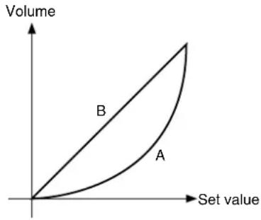 |
| TYPE | |
| SINGLE | Single-coil pickup. |
| DOUBLE Double-coil pickup. | |
| PIEZO Piezo pickup. | |
| AC A hypothetical pickup ideal for picking up the sound of an acoustic guitar. | |
| POS (Position) | |
| 5-320mm | Specifies the distance from the bridge at which the pickup is placed. Larger values will produce the effect of the pickup being further from the bridge.* The angle effect is not applied when PIEZO or AC is selected as the string type. |
| ANGLE | |
| -315–+315mm | This simulates the angle of the pickup relative to the strings. The setting indicates the distance from the POS setting that the sixth string will be located. With positive (+) settings, the sixth string will be further from the bridge. With negative (-) values, the sixth string will be closer to the bridge. With a setting of 0, the pickup will be perpendicular with the strings.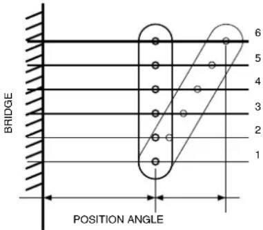 *The angle effect is not applied when PIEZO or AC is selected as the string type.* Angle settings which would exceed the range of the Position setting (5–320 mm) will have no effect. For example, if the Position is set to 100 mm, and valid range of the Angle setting will be -95–+220 mm. *The angle effect is not applied when PIEZO or AC is selected as the string type.* Angle settings which would exceed the range of the Position setting (5–320 mm) will have no effect. For example, if the Position is set to 100 mm, and valid range of the Angle setting will be -95–+220 mm. |
| PHASE | |
| When pickups FRONT and REAR are mixed, this setting determines the phase of pickup REAR relative to pickup FRONT.This is valid only when two pickups are being used.* The phase setting that is part of the pickup FRONT parameters is the same as the corresponding parameter for pickup REAR. Modifying one of them will cause the other parameter to change correspondingly. | |
| IN | It will have the same phase as pickup FRONT. |
| OUT It will be mixed in | opposite phase. |
E. GTR Common Parameters
Besides the other COSM E.GTR parameters, the VG-99 also includes the following shared parameters.
| Parameter/Range | Explanation |
| EQ (Equalizer) | |
| A four-band equalizer with high and low ranges is provided. The sound processed by the effect can be boosted by frequency range before it is output. | |
| EQ SW (Equalizer Switch) | |
| OFF, ON | Turns the EQ effect on/off. |
| TOTAL GAIN | |
| -12–+12dB | Adjusts the volume before the equalizer. |
| LOW GAIN | |
| -12–+12dB | Adjusts the low frequency range tone. |
| HIGH GAIN | |
| -12–+12dB | Adjusts the high frequency range tone. |
| LOW MID FREQ (Low Middle Frequency) | |
| 20Hz–10.0kHz | Specifies the center of the frequency range that will be adjusted by the LOW MID GAIN. |
| LOW MID Q (Low Middle Q) | |
| 0.5–16 | Adjusts the width of the area affected by the EQ centered at the LOW MID FREQ. Higher values will narrow the area. |
| LOW MID GAIN (Low Middle Gain) | |
| -12–+12dB | Adjusts the low-middle frequency range tone. |
| HIGH MID FREQ (High Middle Frequency) | |
| 20Hz–10.0kHz | Specifies the center of the frequency range that will be adjusted by the HIGH MID GAIN |
| HIGH MID Q (High Middle Q) | |
| 0.5–16 Adjusts the width of the area affected by the EQ centered at the HIGH MID FREQ. Higher values will narrow the area. | |
| HIGH MID GAIN (High Middle Gain) | |
| -12–+12dB | Adjusts the high-middle frequency range tone. |
| Parameter/Range | Explanation |
| STRING PAN 1st-6th | |
| 0:100-100:0 | This sets the left/right pan of each string.* The pan effect is cancelled if a monaural effect or COSM amp is connected after the COSM guitar. |
| STRING LEVEL 1st-6th | |
| 0-100 Specifies the output level of each string. | |
| MIX LEVEL | |
| COSM GUITAR | |
| 0–100 | Specifies the level of the COSM guitar. |
| NORMAL PU (Normal Pickup) | |
| 0–100 | Adjusts the volume of the normal pickup. |
| Parameter/Range | Explanation |
| NS (Noise Suppressor) | |
| This effect reduces the noise and hum picked up by guitar pickups. Since it suppresses the noise in synchronization with the envelope of the guitar sound (the way in which the guitar sound decays over time), it has very little effect on the guitar sound, and does not harm the natural character of the sound. | |
| SW (Noise Suppressor Switch) | |
| OFF, ON | Turns the NS effect on/off. |
| THRSH (Threshold) | |
| 0–100 | Adjust this parameter as appropriate for the volume of the noise. If the noise level is high, a higher setting is appropriate. If the noise level is low, a lower setting is appropriate. Adjust this value until the decay of the guitar sound is as natural as possible. |
| REL (Release) | |
| 0–100 Adjusts the amount | unt of time from the point at which application of the noise suppressor begins to when the volume is fully attenuated. |
AC (Acoustic Guitar)
Setting the parameter of acoustic guitar.
STEEL
| Parameter/Range | Explanation |
| BODY TYPE | |
| Selects the type of resonating body. | |
| MA28 | The sound of a Martin D-28.Older model known for its exquisitely balanced sound. |
| TRP-0 The sound of a M | Martin 000-28.This model features a full low-end resonance and crisp, distinct contour. |
| GB45 The sound of a Gibson J-45.This vintage model features a unique, seasoned tone with good response. | |
| GB SML | The sound of a Gibson B-25.Featuring a compact body, this vintage model is often used in blues. |
| GLD 40 The sound of a Gulid D-40.This model features warm resonance from the body along with a delicate string resonance. | |
| BODY | |
| 0–100 | Adjusts the body resonance. Raising the value produces more of a sense of the guitar body in the sound. Lower the value in conditions where feedback is prone to occur. |
| TONE | |
| -50–+50 Adjusts the tone of the body. The standard value is 0; raising the value boosts the high range. | |
| LEVEL | |
| 0–100 Adjusts the volume of the body. With a setting of 0, there will be no sound. | |
NYLON SITAR
| Parameter/Range | Explanation |
| BODY | |
| 0–100 | Adjusts the body resonance. Raising the value produces more of a sense of the guitar body in the sound. Lower the value in conditions where feedback is prone to occur.* The body resonance is monophonic. This means that if this Body parameter is set to 100, the panning of each string will have less effect. |
| ATTACK | |
| 0–100 | Specifies the strength of the attack when you pluck the string strongly. As this setting is increased, the attack will be sharper, and the sound will be crisper. |
| TONE | |
| -50–+50 | Adjusts the tone of the body. The standard value is 0; raising the value boosts the high range. |
| LEVEL | |
| 0–100 | Adjusts the volume of the body. With a setting of 0, there will be no sound. |
| Parameter/ Range | Explanation |
| PU (Pickup) | |
| FRONT | Use the front pickup. |
| R+F Use both front and | rear pickups. |
| REAR Use the rear pick up. | |
| PIEZO Piezo pickup. | |
| SENS (Sensitivity) | |
| 0-100 | Adjusts the input sensitivity. |
| BODY | |
| 0-100 | Adjusts the body resonation. Raising the value produces more of a sense of the guitar body in the sound. Lower the value in conditions where feedback is prone to occur. |
| COLOR | |
| 0-100 | Adjusts the overall tone quality of the sitar. |
| DECAY | |
| 0-100 | Adjusts the time it takes following the attack for the tone to change. |
| BUZZ | |
| 0-100 | Adjusts the amount of characteristic buzz produced by the buzz bridge when the strings make contact with it. |
| ATTACK LEVEL | |
| 0-100 | Adjusts the volume level of the attack. |
| TONE | |
| -50-+50 Adjusts the tone of the body. The standard value is 0; raising the value boosts the high range. | |
| LEVEL | |
| 0-100 Adjusts the volume of the body. With a setting of 0, there will be no sound. | |
BANJO
| Parameter/Range | Explanation |
| ATTACK | |
| 0–100 Specifies the strength of the attack when you pluck the string strongly. As this setting is increased, the attack will be sharper, and the sound will be crisper. | |
| RESO (Resonation) | |
| 0–100 Adjusts the body | resonation. The resonation increases as the value is raised. |
| TONE | |
| -50–+50 Adjusts the tone | of the body. The standard value is 0; raising the value boosts the high range. |
| LEVEL | |
| 0–100 Adjusts the volume | of the body. With a setting of 0, there will be no sound. |
RESO
| Parameter/Range | Explanation |
| SUSTAIN | |
| You can specify how the resulting volume will be affected by changes (loud/soft dynamics) in the guitar string vibrations that are input. | |
| 0–100 | Adjusts the range (time) over which low-level signals are boosted. Larger values will result in longer sustain. |
| RESO (Resonation) | |
| 0–100 | Adjusts the body resonation. The resonation increases as the value is raised. |
| TONE | |
| -50–+50 | Adjusts the tone of the body. The standard value is 0; raising the value boosts the high range. |
| LEVEL | |
| 0–100 | Adjusts the volume of the body. With a setting of 0, there will be no sound. |
VARI
| Parameter/Range | Explanation |
| BODY TYPE | |
| Selects the type of acoustic body. | |
| FLAT The body of an acoustic guitar with a flat top and back. | |
| ROUND | The body of a flat top acoustic guitar with a round back made of resin. |
| f-HOLE | An f-hole body with an arched top and back. This is suitable for simulating semi-acoustic or full acoustic electric guitars. |
| METAL A metal body with a single round cone resonator. This is suitable for bottle-neck (slide) playing, etc. | |
| BANJO This models a general banjo strung with five strings. Changing the size will produce an effect as if the tuning were changed. | |
| SIZE | |
| -50–+50 | Specifies the size of the body. This modifies the resonant frequency to simulate changes in body size. A setting of 0 will produce a normal resonance. |
| RESO (Resonation) | |
| 0–100 Adjusts the body | resonation. The resonation increases as the value is raised. |
| ATTACK | |
| 0–100 Specifies the strength of the attack when you pluck the string strongly. As this setting is increased, the attack will be sharper, and the sound will be crisper.* The effect is easier to discern with chords than with single notes. | |
| Parameter/Range | Explanation |
| BODY | |
| 0–100 | Adjusts the body resonation. Raising the value produces more of a sense of the guitar body in the sound. Lower the value in conditions where feedback is prone to occur.* The body resonance is monophonic. This means that if this Body parameter is set to 100, the panning of each string will have less effect.* To produce the sound of a solid body, set ATTACK and BODY to 0. |
| LOW CUT | |
| THRU, 55–800Hz | Specifies the cutoff frequency of the low-cut filter for the bypass sound. |
| LEVEL | |
| 0–100 | Adjusts the volume. With a setting of 0, there will be no sound. |
| PU TYPE (Pickup Type) | |
| PIEZO | Piezo pickup. |
| MIC A hypothetical mic | ideal for picking up the sound of an acoustic guitar. |
| PU TONE (Pickup Tone) | |
| -50→+50 | Adjusts the tone. |
| PU LEVEL (Pickup Level) | |
| 0–100 | Adjusts the volume. With a setting of 0, there will be no sound. |
AC Common Parameters
Besides the other COSM AC parameters, the VG-99 also includes the following shared parameters.
| Parameter/Range | Explanation |
| EQ (Equalizer) | |
| A four-band equalizer with high and low ranges is provided. The sound processed by the effect can be boosted by frequency range before it is output. | |
| EQ SW (Equalizer Switch) | |
| OFF, ON | Turns the EQ effect on/off. |
| TOTAL GAIN | |
| -12–+12dB | Adjusts the volume before the equalizer. |
| LOW GAIN | |
| -12–+12dB | Adjusts the low frequency range tone. |
| HIGH GAIN | |
| -12–+12dB | Adjusts the high frequency range tone. |
| LOW MID FREQ (Low Middle Frequency) | |
| 20Hz–10.0kHz | Specifies the center of the frequency range that will be adjusted by the LOW MID GAIN. |
| LOW MID Q (Low Middle Q) | |
| 0.5–16 | Adjusts the width of the area affected by the EQ centered at the LOW MID FREQ. Higher values will narrow the area. |
| LOW MID GAIN (Low Middle Gain) | |
| -12–+12dB | Adjusts the low-middle frequency range tone. |
| HIGH MID FREQ (High Middle Frequency) | |
| 20Hz–10.0kHz | Specifies the center of the frequency range that will be adjusted by the HIGH MID GAIN. |
| HIGH MID Q (High Middle Q) | |
| 0.5–16 Adjusts the width of the area affected by the EQ centered at the HIGH MID FREQ. Higher values will narrow the area. | |
| HIGH MID GAIN (High Middle Gain) | |
| -12–+12dB | Adjusts the high-middle frequency range tone. |
| Parameter/Range | Explanation |
| STRING PAN 1st-6th | |
| 100:0–100:0 | This sets the left/right pan of each string.* You cannot adjust the STRING PAN parameter when AC TYPE is set to STEEL.* The pan effect is cancelled if a monaural effect or COSM amp is connected after the COSM guitar. |
| STRING LEVEL 1st-6th | |
| 0–100 Specifies the output level of each string. | |
| Parameter/Range | Explanation |
| MIX LEVEL | |
| COSM GUITAR | |
| 0–100 | Specifies the level of the COSM guitar. |
| NORMAL PU (Normal Pickup) | |
| 0–100 | Adjusts the volume of the normal pickup. |
| Parameter/Range | Explanation |
| NS (Noise Suppressor) | |
| This effect reduces the noise and hum picked up by guitar pickups. Since it suppresses the noise in synchronization with the envelope of the guitar sound (the way in which the guitar sound decays over time), it has very little effect on the guitar sound, and does not harm the natural character of the sound. | |
| SW (Noise Suppressor Switch) | |
| OFF, ON | Turns the NS effect on/off. |
| THRSH (Threshold) | |
| 0–100 | Adjust this parameter as appropriate for the volume of the noise. If the noise level is high, a higher setting is appropriate. If the noise level is low, a lower setting is appropriate. Adjust this value until the decay of the guitar sound is as natural as possible. |
| REL (Release) | |
| 0–100 | Adjusts the amount of time from the point at which application of the noise suppressor begins to when the volume is fully attenuated. |
BASS (Bass Guitar)
Setting the parameter of bass guitar.
JB
| Parameter/Range | Explanation |
| REAR VOL (Rear Volume) | |
| 0–100 | Sets the volume of the rear pickup. With a setting of 0, there will be no sound. |
| FRONT VOL (Front Volume) | |
| 0–100 | Sets the volume of the front pickup. With a setting of 0, there will be no sound. |
| MASTER VOL (Master Volume) | |
| 0–100 | Sets the overall bass volume level. With a setting of 0, there will be no sound. |
| TONE | |
| 0–100 | Adjusts the tone. |
PB
| Parameter/Range | Explanation |
| VOL (Volume) | |
| 0–100 Sets the volume. | With a setting of 0, there will be no sound. |
| TONE | |
| 0–100 Adjusts the tone. | |
BASS Common Parameters
Besides the other COSM BASS parameters, the VG-99 also includes the following shared parameters.
| Parameter/Range | Explanation |
| EQ (Equalizer) | |
| A four-band equalizer with high and low ranges is provided. The sound processed by the effect can be boosted by frequency range before it is output. | |
| EQ SW (Equalizer Switch) | |
| OFF, ON | Turns the EQ effect on/off. |
| TOTAL GAIN | |
| -12–+12dB | Adjusts the volume before the equalizer. |
| LOW GAIN | |
| -12–+12dB | Adjusts the low frequency range tone. |
| HIGH GAIN | |
| -12–+12dB | Adjusts the high frequency range tone. |
| LOW MID FREQ (Low Middle Frequency) | |
| 20Hz–10.0kHz | Specifies the center of the frequency range that will be adjusted by the LOW MID GAIN. |
| LOW MID Q (Low Middle Q) | |
| 0.5–16 | Adjusts the width of the area affected by the EQ centered at the LOW MID FREQ. Higher values will narrow the area. |
| LOW MID GAIN (Low Middle Gain) | |
| -12–+12dB | Adjusts the low-middle frequency range tone. |
| HIGH MID FREQ (High Middle Frequency) | |
| 20Hz–10.0kHz | Specifies the center of the frequency range that will be adjusted by the HIGH MID GAIN. |
| HIGH MID Q (High Middle Q) | |
| 0.5–16 Adjusts the width of the area affected by the EQ centered at the HIGH MID FREQ. Higher values will narrow the area. | |
| HIGH MID GAIN (High Middle Gain) | |
| -12–+12dB | Adjusts the high-middle frequency range tone. |
| Parameter/Range | Explanation |
| STRING PAN 1st-6th | |
| 100:0–100:0 | This sets the left/right pan of each string.*The pan effect is cancelled if a monaural effect or COSM amp is connected after the COSM guitar. |
| STRING LEVEL 1st-6th | |
| 0–100 Specifies the output level of each string. | |
| MIX LEVEL | |
| COSM GUITAR | |
| 0–100 | Specifies the level of the COSM guitar. |
| NORMAL PU (Normal Pickup) | |
| 0–100 | Adjusts the volume of the normal pickup. |
| Parameter/Range | Explanation |
| NS (Noise Suppressor) | |
| This effect reduces the noise and hum picked up by guitar pickups. Since it suppresses the noise in synchronization with the envelope of the guitar sound (the way in which the guitar sound decays over time), it has very little effect on the guitar sound, and does not harm the natural character of the sound. | |
| SW (Noise Suppressor Switch) | |
| OFF, ON | Turns the NS effect on/off. |
| THRSH (Threshold) | |
| 0–100 | Adjust this parameter as appropriate for the volume of the noise. If the noise level is high, a higher setting is appropriate. If the noise level is low, a lower setting is appropriate. Adjust this value until the decay of the guitar sound is as natural as possible. |
| REL (Release) | |
| 0–100 Adjusts the amount | unt of time from the point at which application of the noise suppressor begins to when the volume is fully attenuated. |
SYNTH (Synthesizer)
Setting the parameter of synthesizer sound.
GR-300
| Parameter/Range | Explanation |
| MODE | |
| This setting determines whether the HEXA-VCO (sawtooth wave) or the HEXA-DISTORTION (rectangular wave) is played, or if both are played. | |
| VCO The HEXA-VCO sound is played. | |
| V+D The HEXA-VCO and HEXA-DISTORTION sounds are played simultaneously. | |
| DIST The HEXA-DISTORTION sound is played. | |
| LEVEL | |
| 0-100 | Sets the volume. With a setting of 0, there will be no sound. |
| COMP (Compression) | |
| OFF, ON | When this is set to ON, the HEXA-VCO's decay time is extended.When ENV MOD SW is set to ON, the VCF (variable frequency filter) decay time is also extended* The HEXA-DISTORTION decay time is not extended. |
| CUTOFF FREQ (Cutoff Frequency) | |
| 0-100 | Adjusts the cutoff frequency, setting the brightness (hardness) of the sound. The sound gets brighter (harder) as the value is raised. |
| RESO (Resonance) | |
| 0-100 | Adjusts the resonance (distinctiveness of the sound). As the value is increased, sounds in the frequency range near the cutoff frequency are boosted, making the sound more distinctive and unique. |
| ENV MOD (Envelope Modulation) | |
| This automatically changes the VCF cutoff frequency according to the amplitude of the string vibration. This allows you to change the tone with a wah-like effect each time you pick a string. | |
| SW (Switch) | |
| OFF | Envelope modulation is not used. |
| ON This causes the VCF cutoff frequency to change from a high to low frequency each time the string is picked.This produces a wah-like effect, with the sound going from low frequencies to high.TIPSetting the cutoff frequency to an extremely high value makes the effect difficult to discern. | |
| INV As opposed to the ON setting, this allows you to have the VCF cutoff frequency change from a low to high frequency each time the string is picked.This produces a reverse wah-like effect, with the sound going from high frequencies to low.TIPSetting the cutoff frequency to a relatively high value makes the effect easier to discern.SENS (Sensitivity) | |
| 0-100 | Adjusts the input sensitivity for the envelope modulation function. As the value is raised, the change from the envelope modulation broadens with even weaker picking.TIPConfirm the change in the tone as you make the adjustment. Try setting the value near 0, then gradually raise it as you pick a string. Setting the attack time to 0 makes the changes easier to confirm. |
| ATTACK | |
| 0-100 | Adjusts the attack time for the change in the envelope modulation produced by picking. Raising the value slows the attack for this change. |
| PITCH A/PITCH A FINE,PITCH B/PITCH B FINE | |
| These adjust the amount of pitch shift.* This is enabled when the PITCH SW parameter is set to anything other than OFF.* The final amount of shift in the pitch is the sum of the pitch shift set with PITCH and PITCH FINE. | |
| PITCH APITCH B-12-+12 | This sets the amount of shift in pitch from the original sound in semitone increments. A setting of -12 lowers the pitch one octave, while +12 raises the pitch one octave. |
| PITCH A FINEPITCH B FINE-50-+50 | This finely adjusts the pitch. A setting of -50 lowers the pitch one semitone; +50 raises the pitch by one semitone.You can use this FINE setting effectively in the DUET feature that follows. |
| PITCH SW (Pitch Switch) | |
| This setting allows you to switch on and off the pitch shift, which enables the pitch of the HEXA-VCO sound to shift in response to the pitch of the sound caused by the string's vibration.* PITCH SHIFT is applied only to the HEXA-VCO, not the HEXA-DISTORTION. Set MODE to VCO or V+D when using the pitch shift function. | |
| OFF | The pitch of the original source sound is unchanged. |
| A The shift in pitch set | with PITCH A andPITCH A FINE is applied. |
| B The shift in pitch set | with PITCH B andPITCH B FINE is applied. |
| DUET | |
| OFF, ON | When DUET is set to ON, then in addition to the HEXA-VCO, a sawtooth wave is played at the same pitches as the source sound, adding greater breadth to the sound.TIPSetting HEXA-VCO pitch shifts to values such as PITCH+/-12 (up or down an octave), +/-7 (perfect fifth), or +/-5 (perfect fourth) produces a thicker sound like that from a synthesizer.You can add further depth to the sound by setting PITCH FINE to +/-5, thus slightly shifting the pitch of the HEXA-VCO. |
 | Explanation |
 | |
 | |
 | |
 | Turns the SWEEP function on/off.   |
 | |
 |  |
 | |
 |  |
 | |
 | |
 | |
 |     |
 | |
 |  |
 | |
 |  |
* With the GR-300 selected as the COSM guitar, expression of sounds may become unstable when the Alternate Tuning 12STR is set to ON or when pitches are shifted excessively.
BOWED/PIPE DUAL
| Parameter/Range | Explanation |
| FILTER CUTOFF | |
| 0–100 | Adjusts the cutoff frequency, setting the brightness (hardness) of the sound. The sound gets brighter (harder) as the value is raised. |
| FILTER RESO (Filter Resonance) | |
| 0–100 | Adjusts the resonance (distinctiveness of the sound). As the value is increased, sounds in the frequency range near the cutoff frequency are boosted, making the sound more distinctive and unique. |
| TOUCH SENS (Touch Sensitivity) | |
| 0–100 | This sets the sensitivity when the filter is shifted according to the picking. The shifting of the filter caused by the picking increases as the value is raised. When the value is set to 0, the filter remains set, with no movement. |
| POWER BEND | |
| A higher setting results in a darker sound. At the same time, the tone and volume also change with respect to fluctuations in pitch produced by using a tremolo bar or other techniques. | |
| 0–100 | The higher the value, the more strained the sound becomes. |
| POWER BEND Q | |
| 0–100 | The higher the value, the more the sound will consist of mainly the harmonic components, thus creating a sound that exhibits almost no attack. |
| SUSTAIN | |
| 0–100 Adjusts the range | (time) over which low-level signals are boosted. Larger values will result in longer sustain. |
| Parameter/Range | Explanation |
| FILTER CUTOFF | |
| 0–100 | Adjusts the cutoff frequency, setting the brightness (hardness) of the sound. The sound gets brighter (harder) as the value is raised. |
| FILTER RESO (Filter Resonance) | |
| 0–100 | Adjusts the resonance (distinctiveness of the sound). As the value is increased, sounds in the frequency range near the cutoff frequency are boosted, making the sound more distinctive and unique. |
| TOUCH SENS (Touch Sensitivity) | |
| 0–100 | This sets the sensitivity when the filter is shifted according to the picking. The shifting of the filter caused by the picking increases as the value is raised. When the value is set to 0, the filter remains set, with no movement. |
| GLIDE SENS (Glide Sensitivity) | |
| Picking dynamics can affect the amount of pitch change over time. This is known as the Glide effect.With softly played notes for which no attack can be detected, a glide effect may not be obtainable. | |
| 0–100 | This sets the sensitivity for the glide effect. |
| GLIDE TIME | |
| 0–100 This sets the speed of the glide. Larger values result in longer glides.* GLIDE TIME is no longer applied once GLIDE SENS decreases. | |
| SUSTAIN | |
| 0–100 | Adjusts the range (time) over which low-level signals are boosted. Larger values will result in longer sustain. |
FILTER BASS SOLO
| Parameter/Range | Explanation |
| FILTER CUTOFF | |
| 0–100 | Adjusts the cutoff frequency, setting the brightness (hardness) of the sound. The sound gets brighter (harder) as the value is raised. |
| FILTER RESO (Filter Resonance) | |
| 0–100 | Adjusts the resonance (distinctiveness of the sound). As the value is increased, sounds in the frequency range near the cutoff frequency are boosted, making the sound more distinctive and unique. |
| TOUCH SENS (Touch Sensitivity) | |
| 0–100 | This sets the sensitivity when the filter is shifted according to the picking. The shifting of the filter caused by the picking increases as the value is raised. When the value is set to 0, the filter remains set, with no movement. |
| FILTER DECAY | |
| 0–100 | This sets the speed at which the filter stops. The speed increases as the value of the setting is reduced.*The decay effect cannot be obtained if the TOUCH SENS value is too low. |
| COLOR | |
| 0–100 | Adjusts the strength of the low range. As the value is increased, the low range will become stronger. |
| Parameter/Range | Explanation |
| FILTER CUTOFF | |
| 0–100 | Adjusts the cutoff frequency, setting the brightness (hardness) of the sound. The sound gets brighter (harder) as the value is raised. |
| FILTER RESO (Filter Resonance) | |
| 0–100 | Adjusts the resonance (distinctiveness of the sound). As the value is increased, sounds in the frequency range near the cutoff frequency are boosted, making the sound more distinctive and unique. |
| TOUCH SENS (Touch Sensitivity) | |
| 0–100 | This sets the sensitivity when the filter is shifted according to the picking. The shifting of the filter caused by the picking increases as the value is raised. When the value is set to 0, the filter remains set, with no movement. |
| COLOR | |
| 0–100 | Adjusts the amount of harmonics in the sound when the guitar strings are played with greater force. The harmonic components become more prominent as the value is raised.TIPTo make adjustment easier, set FILTER CUTOFF to 100 and FILTER RESO and TOUCH SENS to 0, then gradually increase the COLOR setting as you play the guitar. |
| SUSTAIN | |
| 0–100 | Adjusts the range (time) over which low-level signals are boosted. Larger values will result in longer sustain. |
PWM
| Parameter/Range | Explanation |
| FILTER CUTOFF | |
| 0–100 | Adjusts the cutoff frequency, setting the brightness (hardness) of the sound. The sound gets brighter (harder) as the value is raised. |
| FILTER RESO (Filter Resonance) | |
| 0–100 | Adjusts the resonance (distinctiveness of the sound). As the value is increased, sounds in the frequency range near the cutoff frequency are boosted, making the sound more distinctive and unique. |
| TOUCH SENS (Touch Sensitivity) | |
| 0–100 | This sets the sensitivity when the filter is shifted according to the picking. The shifting of the filter caused by the picking increases as the value is raised. When the value is set to 0, the filter remains set, with no movement. |
| PWM DEPTH | |
| 0–100 | This sets the depth to which the waveform's pulse width is varied. Higher values result in deeper undulations. |
| PWM RATE | |
| 0–100 | This sets the speed at which the filter stops. The speed increases as the value of the setting is reduced. |
| SUSTAIN | |
| 0–100 | Adjusts the range (time) over which low-level signals are boosted. Larger values will result in longer sustain. |
CRYSTL
| Parameter/Range | Explanation |
| ATTACK LENGTH | |
| 0–100 This sets the decay | time for the attack portion of the sound. A smaller setting results in a shorter attack. |
| MOD TUNE (Modulation Tune) | |
| 0–100 This sets the tuning | g for the modulation applied to the attack. |
| MOD DEPTH (Modulation Depth) | |
| 0–100 | This sets the depth of the modulation applied to the attack. Larger values result in deeper undulations. |
| ATTACK LEVEL | |
| 0–100 | This sets the volume level of the attack portion. |
| BODY LEVEL | |
| 0–100 This sets the volume | me level for the sustained portion of the sound. |
| SUSTAIN | |
| 0–100 Adjusts the range | (time) over which low-level signals are boosted. Larger values will result in longer sustain. |
ORGAN
| Parameter/Range | Explanation |
| FEET 16' | |
| 0–100 | This is a Long Tone one octave lower than the guitar. |
| FEET 8' | |
| 0–100 | This is a Long Tone at the same pitch as the guitar. |
| FEET 4' | |
| 0–100 | This is a Long Tone one octave higher than the guitar. |
| SUSTAIN | |
| 0–100 | Adjusts the range (time) over which low-level signals are boosted. Larger values will result in longer sustain. |
BRASS
| Parameter/ Range | Explanation |
| FILTER CUTOFF | |
| 0–100 | Adjusts the cutoff frequency, setting the brightness (hardness) of the sound. The sound gets brighter (harder) as the value is raised. |
| FILTER RESO (Filter Resonance) | |
| 0–100 | Adjusts the resonance (distinctiveness of the sound). As the value is increased, sounds in the frequency range near the cutoff frequency are boosted, making the sound more distinctive and unique. |
| TOUCH SENS (Touch Sensitivity) | |
| 0–100 | This sets the sensitivity when the filter is shifted according to the picking. The shifting of the filter caused by the picking increases as the value is raised. When the value is set to 0, the filter remains set, with no movement. |
| SUSTAIN | |
| 0–100 Adjusts the range | (time) over which low-level signals are boosted. Larger values will result in longer sustain. |
WAVE SYNTH Common Parameters
| Parameter/Range | Explanation |
| WAVE SHAPE | |
| Selects the wave type on which the synth sound is based. | |
| SAW | Creates a synth sound with a sawtooth waveform. |
| SQUARE | Creates a synth sound with a square waveform. |
| WAVE SENS (Wave Sensitivity) | |
| 0–100 | This adjusts the input sensitivity to be used for detecting when a string has been played. Adjusting this parameter allows you to suppress erroneous processing of volume and tone changes after a string is played. |
| WAVE ATTACK | |
| 0–100 | Adjusts the time it takes for the synth sound to rise after a string is plucked. When it is set to a lower value, the sound will rise quickly. When it is set higher, the sound will rise slowly. |
| WAVE DECAY | |
| 0–100 | Adjusts the time it takes for the synth sound to decay. The synth sound decays more quickly when this parameter is set to a lower value. Setting a higher value increases the decay time. |
| WAVE LEVEL | |
| 0–100 | Adjusts the volume of the synth sound. |
| CUTOFF | |
| 0–100 Adjusts the cutoff frequency at which the filter cuts off the sound's harmonic components.This parameter determines the sound that will result after the filter has stopped varying due to FILTER DEPTH. | |
| RESO (Resonance) | |
| 0–100 | Adjusts the resonance (distinctiveness of the sound). As the value is increased, sounds in the frequency range near the cutoff frequency are boosted, making the sound more distinctive and unique. |
| FILTER TYPE | |
| -12 dB, -24 dB Selects the curve of attenuation in the filter.The -24 dB setting has very steep filtering characteristics. | |
| FILTER ATTACK | |
| 0–100 | Sets the filter attack time. |
| FILTER DECAY | |
| 0–100 Sets the filter decay time. | |
| FILTER DEPTH | |
| -50–+50 Adjusts the depth of the filter's change.When set to a positive value, the VCF cutoff frequency shifts from a high value to a low value. When set to a negative value, the VCF cutoff frequency shifts from a low value to a high value. | |
Besides the other COSM SYNTH parameters, the VG-99 also includes the following shared parameters.
| Parameter/Range | Explanation |
| EQ (Equalizer) | |
| A four-band equalizer with high and low ranges is provided. The sound processed by the effect can be boosted by frequency range before it is output. | |
| EQ SW (Equalizer Switch) | |
| OFF, ON | Turns the EQ effect on/off. |
| TOTAL GAIN | |
| -12–+12dB | Adjusts the volume before the equalizer. |
| LOW GAIN | |
| -12–+12dB | Adjusts the low frequency range tone. |
| HIGH GAIN | |
| -12–+12dB | Adjusts the high frequency range tone. |
| LOW MID FREQ (Low Middle Frequency) | |
| 20Hz–10.0kHz | Specifies the center of the frequency range that will be adjusted by the LOW MID GAIN. |
| LOW MID Q (Low Middle Q) | |
| 0.5–16 | Adjusts the width of the area affected by the EQ centered at the LOW MID FREQ.Higher values will narrow the area. |
| LOW MID GAIN (Low Middle Gain) | |
| -12–+12dB | Adjusts the low-middle frequency range tone. |
| HIGH MID FREQ (High Middle Frequency) | |
| 20Hz–10.0kHz | Specifies the center of the frequency range that will be adjusted by the HIGH MID GAIN. |
| HIGH MID Q (High Middle Q) | |
| 0.5–16 | Adjusts the width of the area affected by the EQ centered at the HIGH MID FREQ.Higher values will narrow the area. |
| HIGH MID GAIN (High Middle Gain) | |
| -12–+12dB | Adjusts the high-middle frequency range tone. |
| Parameter/Range | Explanation |
| STRING PAN 1st-6th | |
| 100:0–0:100 This sets the left/right pan of each string.* The pan effect is cancelled if a monaural effect or COSM amp is connected after the COSM guitar. | |
| STRING LEVEL 1st-6th | |
| 0–100 Specifies the output level of each string. | |
| Parameter/Range | Explanation |
| MIX LEVEL | |
| COSM GUITAR | |
| 0–100 Specifies the level of the COSM guitar. | |
| NORMAL PU (Normal Pickup) | |
| 0–100 Adjusts the volume of the normal pickup. | |
ALTERNATE TUNING
With the Alternate Tuning function, you can convert the pitch of each individual string of a COSM guitar, without changing the guitar's actual tuning.
Alternate Tuning includes the five following functions.
• TUNING
• BEND
- 12-STRING
• DETUNE
• HARMONY
You can use all of these functions simultaneously, in any combination.
TUNING
This shifts the tuning of each string in semitone increments.
With the guitar left with the standard tuning (EADGBE), you can convert the tuning to an open tuning such as OPEN-D or OPEN-G, raise or lower all of the strings an octave, and achieve various other tunings, all without changing the guitar's actual tuning.
When the type set in TUNING is something other than a preset tuning, you can also create your own tunings as you like for each individual patch with the USER tunings.
Using the TUNING function allows you to change tunings instantly during songs, without having to change instruments, and perform using tunings that are easier to play in, without changing the string tension.
BEND
You can produce a pitch bend effect on any individual string or combination of strings.
This features lets you make separate settings for the amount of bend for each individual string, just as with a string bender or pedal steel guitar. This is mainly used with Control Assign.
12-STRING
This changes the sound of a regular six-string guitar to that of a twelve-string guitar featuring secondary strings. For each individual string, you can set the shift in pitch for the secondary string relative to the respective main string, the amount of delay, and the volume.
DETUNE
This allows you to subtly shift the pitch of each individual string.
When playing sounds from both COSM GUITAR [A] and [B], switching DETUNE to ON in one of the channels to slightly alter the pitch produces an effect resembling double tracking, creating a sound with greater breadth and depth.
HARMONY
This analyzes the pitch of each string and adjusts the amount of shift in the pitch to convert the pitches into harmonies matched to the key. You can create and use the harmonies you like in each individual patch with the USER TYPE function.
* With the GR-300 selected as the COSM guitar, expression of sounds may become unstable when the Alternate Tuning 12STR is set to ON or when pitches are shifted excessively.
| Parameter/Range | Explanation |
| AB LINK | |
| OFF, ON | This setting switches the AB LINK on and off.When AB LINK is on, you can use the same settings for the functions below on both COSM GUITAR [A] and COSM GUITAR [B].TUNINGBENDWhen set to OFF, you can use set COSM GUITAR [A] differently than COSM GUITAR [B].Unless you particularly want to change the TUNING or BEND settings for COSM GUITAR [A] and COSM GUITAR [B], leaving AB LINK set to ON is normally more convenient. |
| A/B | |
| A, B | This selects the channel used in setting Alternate Tuning.* You cannot set this when AB LINK is on. |
| TUNING | |
| SW | |
| OFF, ON | This setting switches TUNING function on and off. |
| TYPE | |
| You can create and use your own original harmonies in each individual patch with the USER TYPE function. | |
| OPEN-D | This tuning produces a D chord when the strings are played open. |
| OPEN-E This tuning produces an E chord when the strings are played open. | |
| OPEN-G This tuning produces a G chord when the strings are played open. | |
| OPEN-A This tuning produces an A chord when the strings are played open. | |
| DROP-D This tuning drops the note only on the 6th string (D). | |
| D-MODAL Also referred to as DADGAD, this tuning drops the 6th, 2nd, and 1st strings one note, lending the sounds an exotic air. | |
| -1 STEP This tuning lowers the strings one semitone (half-step).All strings are lowered a semitone (corresponding to one fret). | |
| -2 STEP | This tuning lowers the strings one whole step. All strings are lowered a whole step (corresponding to two frets). |
| BARITONE This tuning lowers all strings a perfect fourth (five frets), making it well suited for heavy phrasing. | |
| NASHVL | With this tuning, the 6th, 5th, 4th, and 3rd strings are raised an octave, just like having only the secondary string for these string pairs on a twelve-string guitar. |
| -1 OCT This tuning lowers all the strings one octave. | |
| -2 OCT This tuning raises all the strings one octave. | |
| USER | This assigns the tuning set in USER TUNING. |
| USER TUNING 1st-6th | |
| -24-+24 | This sets the amount of shift for each individual string. |
| BEND | |
| SW | |
| OFF, ON | This setting switches BEND function on and off. |
| BEND TUNING 1st-6th | |
| -24-+24 | This sets the amount of pitch shift in each string when the bend is set to 100.The amount of shift from the current pitch is set in semitone increments. |
| BEND | |
| 0-100 | When set to 0, bending causes no shift in the pitch; when set to 100, the strings' pitches are shifted by the amount set in 1st-6th.Normally, this pitch bend is set to 0, and the setting 0-100 assigned with Control Assign is used.* This setting cannot be saved to patches. This is reset to 0 when patches are switched. |
| 12STR (12-String) | |
| SW | |
| OFF, ON | This setting switches 12STR function on and off. |
| SHIFT 1st-6th | |
| -24-+24 This sets the amount the pitch that each secondary string is shifted relative to the respective main string in semitone increments. | |
| FINE 1st-6th | |
| -50-+50 | This sets the amount the pitch that each secondary string is shifted relative to the respective main string in one cent (1/100 of a semitone) increments. |
| LEVEL 1st-6th | |
| 0-100 Adjusts the volume level for each secondary string. | |
| DELAY 1st-6th | |
| 0-100ms Adjusts the time the sound of each secondary string is delayed relative to the respective main string.TIPWith conventional twelve-string guitars, the 1st and 2nd secondary strings are tuned to the same pitch as the main strings, while the 3rd through 6th are tuned one octave higher.Slightly raising the FINE settings and adding a little delay produces a more realistic twelve-string sound. | |
| DETUNE | |
| SW | |
| OFF, ON | This setting switches DETUNE function on and off. |
| Parameter/Range | Explanation |
| 1st-6th | |
| -50-+50 | This sets the shift in pitch in one cent (1/100 of a half-step) units. TIP When playing both COSM GUITAR [A] and COSM GUITAR [B], slightly detuning produces an effect resembling double tracking (a recording technique whereby the same phrase is recorded twice on separate tracks), creating a sound with greater breadth and depth. Using PAN in the MIXER section to pan A to the left and B to the right further emphasizes the effect. |
| HARMO (Harmony) | |
| SW | |
| OFF, ON | This setting switches HARMO function on and off. |
| KEY | |
| C Am-B G#m | Specify the key of the song you are playing. TIP This KEY parameter is the same as the Key setting in the [NAME/KEY/BPM] section (p. 163) and FX MOD1, 2 HARMONIST. Altering either one changes the key. |
| HARMO (Harmony) | |
| -2oct-TONIC-+2oct, USER | This sets the pitch for the harmony interval relative to the input sound. When this is set to USER, you can set this to the desired harmony in USER INTERVAL. |
| USER INTERVAL C-B | |
| -24-+24 | This sets the output pitch relative to the input pitch for the selected key. |
Creating Harmony Scales (User Scale)
When HARMO is set to any value from -2oct to +2oct, and the harmony does not sound the way you intend, use a User scale. You can set the corresponding pitches to be output for each input pitch.
- Set HARMO to USER in the Harmony screen.
- Press PAGE [ ] to display Page 2. The User Interval screen appears.
| ALT TUNING HARMONY LOFFJ 1721 | |||||
| USER INTERVAL | |||||
| C | Db | D | Eb | E | F |
| 0 | 0 | 0 | 0 | 0 | 0 |
| ↓ | ↓ | ↓ | ↓ | ↓ | ↓ |
| C | Db | D | Eb | E | F |
| SELECT SELECT SELECT SELECT SELECT SELECT | |||||
- Use PAGE [ ][F1]-[F6], and the F1-F6 knob to set the amount of pitch shift for each voice.
POLY FX (Poly Effect)
| Parameter/Range | Explanation |
| POLYFX SW (Poly Effect Switch) | |
| OFF, ON | Turns the poly effect on/off. |
| TYPE | |
| POLY COMPPOLY DISTPOLY OCTAVEPOLY SG | Select the poly effect type.* The parameters that can be set differ with each type. Refer to each of the parameters cited later. |
| POLYFX CH (Poly Effect Channel) | |
| A, B | This selects the channel to which the POLY FX are applied. |
POLY COMP (Poly Compressor)
The compressor is an effect that attenuates loud input levels and boosts soft input levels, thus evening out the volume to create sustain without distortion.
| Parameter/Range | Explanation |
| COMP TYPE | |
| Select the compressor type. | |
| COMP The effect will function as a compressor. | |
| LIMITR The effect will function as a limiter. | |
| SUSTAIN (COMP TYPE = COMP) | |
| 0-100 | Adjusts the range (time) over which low-level signals are boosted. Larger values will result in longer sustain. |
| ATTACK (COMP TYPE = COMP) | |
| 0-100 | Adjusts the strength of the picking attack. Larger values will result in a sharper attack, creating a more clearly defined sound. |
| THRSH (COMP TYPE = LIMITR) | |
| 0-100 | Adjusts the level to match the signals input from the guitar. Signal levels are suppressed when the signals input are in excess of the set level. |
| REL (COMP TYPE = LIMITR) | |
| 0-100 | Adjusts the amount of time from the point at which the signals fall below the threshold level to when the effect is no longer applied. |
| TONE | |
| -50-+50 Adjusts the tone. | |
| LEVEL | |
| 0-100 | Adjusts the volume. |
| COMP BAL (Compression Balance) | |
| 0-100 | Adjusts the balance of the input levels for the 2nd-6th strings based on the 1st string's input level. When this is set to 100, all of the strings are input at the same level. The level of the 2nd through 6th strings decreases as the value is lowered. |
POLY DIST (Poly Distortion)
You can individually distort the sound of each string to get a sound that can be played chordally without breaking up.
| Parameter/Range | Explanation |
| MODE | |
| Selects the type of distortion. | |
| CLA OD A classical overdrive sound is obtained. | |
| TURBO OD Allows you to obtain a rich effect just like distortion, without losing the subtle nuance of the overdrive. | |
| DS1 Allows you to obtain a standard distortion sound. | |
| DS2 Allows you to obtain a distortion sound with a rich middle. | |
| FUZZ This produces a basic fuzz sound. | |
| DRIVE | |
| 0–100 | This sets the degree of sound distortion. |
| HIGH-CUT | |
| 700Hz–11.0kHz, FLAT | Adjusts the tone of the distorted sound. |
| POLY BAL (Poly Balance) | |
| 0–100 | Adjusts the degree of distortion for chordal playing. |
| DRIVE BAL (Drive Balance) | |
| 0–100 | Adjusts the degree of distortion between low and high strings, to even out the volume balance. |
| LEVEL | |
| 0–100 | Adjusts the output level that is raised by being distorted. |
POLY OCTAVE (Poly Octave)
This supports playing technique related to octaves.
* When 12STR (p. 116) in ALTERNATE TUNING is switched on, noise may occur in the octave sound.
| Parameter/ Range | Explanation |
| -1OCTAVE LEVEL 1st-6th | |
| 0-100 | This adds sound one octave lower than the original sound. |
| +1OCTAVE LEVEL 1st-6th | |
| 0-100 | This adds sound two octaves lower than the original sound. |
| DIRECT LEVEL 1st-6th | |
| 0-100 | Adjusts the level of the original sound. |
POLY SG (Poly Slow Gear)
This produces a volume-swell effect ("violin-like" sound).
| Parameter/Range | Explanation |
| RISE TIME | |
| 0–100 | Adjusts the time needed for the volume to reach its maximum from the moment you begin picking. |
| SENS (Sensitivity) | |
| 0–100 | Adjusts the sensitivity. |
FX (Effects)
COMP (Compressor)
This is an effect that produces a long sustain by evening out the volume level of the input signal. You can switch it to a limiter to suppress only the sound peaks and prevent distortion.
| Parameter/Range | Explanation |
| COMP SW | |
| OFF, ON Turns the CO | MP effect on/off. |
| TYPE | |
| Select the compressor type. | |
| COMP The effect will function as a compressor. | |
| LIMITR The effect will function as a limiter. | |
| SUSTAIN (TYPE = COMP) | |
| 0–100 | Adjusts the range (time) over which low-level signals are boosted. Larger values will result in longer sustain. |
| ATTACK (TYPE = COMP) | |
| 0–100 | Adjusts the strength of the picking attack when the strings are played. Higher values result in s sharper attack, creating a more clearly defined sound. |
| THRSH (TYPE = LIMITER) | |
| 0–100 Adjust this as appropriate for the input signal from your guitar. When the input signal level exceeds this threshold level, limiting will be applied. | |
| REL (TYPE = LIMITER) | |
| 0–100 Adjusts the time from when the signal level drops below the threshold until when limiting is removed. | |
| TONE | |
| -50–+50 | Adjusts the tone. |
| LEVEL | |
| 0–100 | Adjusts the volume. |
OD/DS (Overdrive/Distortion)
This effect distorts the sound to create long sustain. It provides 30 types of distortion and custom settings.
| Parameter/ Range | Explanation |
| OD/DS SW | |
| OFF, ON | Turns the OD/DS effect on/off. |
| TYPE | |
| Selects the type of distortion. | |
| BOOST This is a booster | that works very well with COSM amps. |
| BLUES OD This is a crunch | sound of the BOSS BD-2. |
| CRUNCH A lustrous crunch | sound with an added element of amp distortion. |
| NATURAL OD This is an overdrive sound that provides distortion with a natural feeling. | |
| TURBO OD This is the high-gain overdrive sound of the BOSS OD-2. | |
| FAT OD This is a mellow overdrive sound. | |
| OD-1 This is the sound of the BOSS OD-1. | |
| T SCREAM This models an Ibanez TS-808. | |
| WARM OD Overdrive with special mid range tone. | |
| DIST This gives a basic traditional distortion sound. | |
| MILD DS This is a distortion sound that provides a mild distortion. | |
| DRIVE DS This is a powerful distortion sound. | |
| RAT | This models a Proco RAT. |
| GUV DS | This models an Marshall GUV' NOR. |
| DST+ This models an MXR DISTORTION+. | |
| SOLID DS | This is a distortion sound featuring an edge effect. |
| MID DS | This distortion sound features a boosted midrange. |
| STACK A fat sound with an added element of a stack amp's distortion. | |
| MODERN DS | Sound of a large high gain amp. |
| POWER DS Sound of Overdrive through a stack amp. | |
| R-MAN | This models a ROCKMAN. |
| METAL ZONE | This is the sound of the BOSS MT-2. |
| HEAVY METAL | This creates a heavier distortion sound. |
| LEAD | Produces a distortion sound with both the smoothness of an overdrive along with a deep distortion. |
| LOUD | This is a distortion sound with a boosted low end. |
| SHARP | This is a distortion sound with a boosted high end. |
| MECHANICAL | This distortion sound boosts the low and high ends, yielding a mechanical-sounding distortion. |
| '60S FUZZ | This models a FUZZFACE. |
| OCT FUZZ This models | an ACETONE FUZZ. |
| MUFF FUZZ This models | s an Electro-Harmonix Big Muff . |
| CUSTOM Custom OD/ | DS |
| DRIVE | |
| 0-120 | Adjusts the depth of distortion. |
| BOTTOM | |
| -50-+50 | Adjusts the tone for the low frequency range. Turning this to the left (counterclock-wise) produces a sound with the low end cut; turning it to the right boosts the low end in the sound. |
| TONE | |
| -50-+50 | Adjusts the tone. |
| EFFECT LEVEL | |
| 0-100 | Adjusts the volume of the overdrive/distortion sound. |
| DIRECT LEVEL | |
| 0-100 | Adjusts the volume of the direct sound. |
| Parameter/ Range | Explanation |
| CUSTOM *1 | |
| TYPE | |
| This selects the basic sound when the TYPE parameter is set to CUSTOM. | |
| OD-1 This is the sound of the BOSS OD-1. | |
| OD-2 OD-2 This is a overdrive sound with high gain. | |
| CRUNCH This is a crunch sound. | |
| DS-1 This gives a basic, traditional distortion sound. | |
| DS-2 This creates a heavier distortion sound. | |
| METAL1 This is a metal sound with a characteristic midrange. | |
| METAL2 This gives a heavy metal sound. | |
| FUZZ This gives a basic, traditional fuzz sound. | |
| BOTTOM | |
| -50–+50 | This controls the input sound's low-frequency range and adjusts the amount of distortion in the low-frequency range. |
| TOP | |
| -50–+50 | This controls the input sound's low-frequency range and adjusts the amount of distortion in the high-frequency range. |
| LOW | |
| -50–+50 Adjusts the low-range tones after distortion is applied. | |
| HIGH | |
| -50–+50 | Adjusts the high-range tones after distortion is applied. |
*1 Setting available when TYPE is set to CUSTOM.
WAH
You can control the wah effect in real time by adjusting the EXP pedal connected to the EXP PEDAL jack or FC-300 EXP pedal.
| Parameter/ Range | Explanation |
| WAH SW | |
| OFF, ON | Turns the WAH effect on/off. |
| TYPE | |
| Selects the type of wah. | |
| CRY WAH This models | the sound of the CRY BABY wah pedal popular in the '70s. |
| VO WAH This models | the sound of the VOX V846. |
| FAT WAH This a wah | sound featuring a bold tone. |
| LIGHT WAH This wah | has a refined sound with no unusual characteristics. |
| 7STR WAH This expanded | wed wah features a variable range compatible with seven-string and baritone guitars. |
| RESO WAH This completely original effect offers enhancements on the characteristic resonances produced by analog synth filters. | |
| CUSTOM Custom wah | |
| PEDAL POS (Pedal Position) | |
| 0-100 Adjusts the position of the wah pedal.* This expanded wah features a variable range compatible with seven-string and baritone guitars. | |
| LEVEL | |
| 0-100 Adjusts the volume. | |
| Parameter/ Range | Explanation |
| CUSTOM *1 | |
| TYPE | |
| This selects the basic sound when the TYPE parameter is set to CUSTOM. | |
| CRY WAH This models | the sound of the CRY BABY wah pedal popular in the '70s. |
| VO WAH This models | the sound of the VOX V846. |
| FAT WAH This a wah sound featuring a bold tone. | |
| LIGHT WAH This wah | has a refined smooth sound. |
| 7STR WAH Wah featuring a broader range of variations for the seven-string guitar. | |
| Q | |
| -50-+50 | Adjusts the amount of characteristic effect applied to the wah tone. |
| RANGE LOW | |
| -50-+50 | Selects the tone produced when the pedal is back. |
| RANGE HIGH | |
| -50-+50 | Selects the tone produced when the pedal is forward. |
| PRESENCE | |
| -50-+50 | Adjusts the tonal quality of the wah effect. |
*1 Setting available when TYPE is set to CUSTOM.
EQ (Equalizer)
This adjusts the tone as a sub equalizer. A parametric type is adopted for the high-middle and low-middle range.
| Parameter/Range | Explanation |
| EQ SW (Equalizer Switch) | |
| OFF, ON | Turns the EQ effect on/off. |
| TOTAL GAIN | |
| -20–+20dB | Adjusts the overall volume level of the equalizer. |
| LOW GAIN | |
| -20–+20dB | Adjusts the low frequency range tone. |
| HIGH GAIN | |
| -20–+20dB | Adjusts the high frequency range tone. |
| LOW MID FREQ (Low Middle Frequency) | |
| 20Hz–10.0kHz | Specifies the center of the frequency range that will be adjusted by the LOW MID GAIN. |
| LOW MID Q (Low Middle Q) | |
| 0.5–16 Adjusts the width of the area affected by the EQ centered at the LOW MID FREQ. Higher values will narrow the area. | |
| LOW MID GAIN (Low Middle Gain) | |
| -20–+20dB Adjusts the low-middle frequency range tone. | |
| HIGH MID FREQ (High Middle Frequency) | |
| 20Hz–10.0kHz | Specifies the center of the frequency range that will be adjusted by the HIGH MID GAIN. |
| HIGH MID Q (High Middle Q) | |
| 0.5–16 | Adjusts the width of the area affected by the EQ centered at the HIGH MID FREQ. Higher values will narrow the area. |
| HIGH MID GAIN (High Middle Gain) | |
| -20–+20dB | Adjusts the high-middle frequency range tone. |
| LOW CUT (Low Cut Filter) | |
| FLAT, 55 Hz–800 Hz | This lets you cut the low-end component below the set frequency to create a clear, distinct low end, thereby bringing out the high end of the effect. When FLAT is selected, the low cut filter will have no effect. |
| HIGH CUT (High Cut Filter) | |
| 700 Hz–11kHz, FLAT | This allows you to get a mild effect sound by cutting the high-end component above the set frequency. When it is set to FLAT, the high cut filter is off or has no effect. |
DELAY
This effect adds delayed sound to the direct sound, giving more body to the sound or for creating special effects.
| Parameter/Range | Explanation |
| DELAY SW | |
| OFF, ON | Turns the DELAY effect on/off. |
| DELAY TYPE | |
| Selects the type of delay. | |
| SINGLE This is a simple monaural delay. | |
PAN This delay is specifically for stereo output.This allows you to obtain the tap delay effect that divides the delay time, then deliver them to L and R channels. | |
| STEREO | The direct sound is output from the left channel, and the effect sound is output from the right channel. |
| DUAL-S (Dual Series) | This is a delay comprising two different delays connected in series. Each delay time can be set in a range from 1 ms to 900 ms.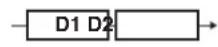 D1: Delay 1D2: Delay 2 D1: Delay 1D2: Delay 2 |
| DUAL-P (Dual Parallel) | This is a delay comprising two delays connected in parallel. Each delay time can be set in a range from 1 ms to 900 ms.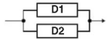 |
| DUAL-L/R | This is a delay with individual settings available for the left and right channels. Delay 1 goes to the left channel, Delay 2 to the right.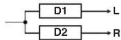 |
| REVRSE | This produces an effect where the sound is played back in reverse. |
| ANALOG This gives a mild analog delay sound. The delay time can be set within the range of 1 to 1800 ms | |
| TAPE | This setting provides the characteristic wa-vering sound of the tape echo. The delay time can be set within the range of 1 to 1800 ms. |
WARP This simultaneously controls the delay sound's feedback level and volume to produce a totally unreal delay.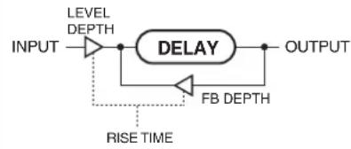 | |
| MOD (Modulate) | This delay adds a pleasant wavering effect to the sound. |
| HOLD Up to 2.8 seconds | s of performance content is recorded, then played back repeatedly. You can also layer this as you perform something else, then record these together (over-dub), allowing you to produce what is called sound-on-sound or looping. |
| * For more detail the operation, refer to “Using the HOLD (Hold Delay)” (p. 125).* If you switch patches with the TYPE set to either DUAL-S, DUAL-P, or DUAL L/R and then begin to play immediately after the patches change, you may be unable to attain the intended effect in the first portion of what you perform.* The stereo effect is cancelled if a monaural effect or COSM amp is connected after a stereo delay effect. | |
DELAY Common Parameters
| Parameter/Range | Explanation |
| DELAY TIME | |
| 1 ms–1800 ms,BPMBPMo | This determines the delay time. |
| When set to BPM, the value of each parameter will be set according to the value of the BPM (p. 163) specified for each patch. This makes it easier to achieve effect sound settings that match the tempo of the song.* If, due to the tempo, the time is longer than the range of allowable settings, it is then synchronized to a period either 1/2 or 1/4 of that time.* When TYPE is set to DUAL-S, DUAL-P, or DUAL-L/R, the delay time can be set to any value from 1 to 900 ms.* After setting DELAY TIME to BPM (–) if you tap [F1] (TAP), the BPM value will change to match the timing of your tapping. | |
| FEEDBACK | |
| 0–100 | This sets the amount of delay sound returned to the input.A higher value will increase the number of the delay repeats.TERMFeedback is returning a delay signal to the input. |
| HIGH CUT (High Cut Filter) | |
| 700 Hz–11 kHz, FLAT | This allows you to get a mild effect sound by cutting the high-end component above the set frequency. When it is set to FLAT, the high cut filter is off or has no effect. |
| EFFECT LEVEL | |
| 0–120 | Adjusts the volume of the delay sound. |
| DIRECT LEVEL | |
| 0–100 | Adjusts the volume of the direct sound. |
PAN
| Parameter/Range | Explanation |
| TAP TIME TYPE=PAN *1 | |
| 0%-100% | Adjusts the delay time of the left channel delay. This setting adjusts the L channel delay time relative to the R channel delay time (considered as 100%). |
DUAL-S, DUAL-P, DUAL-L/R
| Parameter/Range | Explanation |
| DELAY1 TIME | |
| 1 ms–900 ms,BPMBPM。 | This determines the delay time. |
| When set to BPM, the value of each parameter will be set according to the value of the BPM (p. 163) specified for each patch. This makes it easier to achieve effect sound settings that match the tempo of the song.* If, due to the tempo, the time is longer than the range of allowable settings, it is then synchronized to a period either 1/2 or 1/4 of that time.* After setting DELAY TIME to BPM (–), if you tap [F1] (TAP), the BPM value will change to match the timing of your tapping. | |
| DELAY1 FEEDBACK | |
| 0–100 | Adjusts the amount of feedback of the Delay1. A higher value will increase the number of the delay repeats. |
| DELAY HI-CUT (Delay 1 High Cut Filter) | |
| 700 Hz–11 kHz, FLAT | This sets the frequency at which the high cut filter of the Delay1 begins to take effect. When it is set to FLAT, the high cut filter is off or has no effect. |
| DELAY1 LEVEL | |
| 0–120 | Adjusts the volume of the Delay1. |
| DELAY2 TIME | |
| 1 ms–900 ms,BPMBPM。 | This determines the delay time of the Delay2. |
| DELAY2 FEEDBACK | |
| 0–100 | Adjusts the amount of feedback of the Delay2. |
| DELAY2 FEEDBACK (Delay 2 High Cut Filter) | |
| 700 Hz–11 kHz, FLAT | This sets the frequency at which the high cut filter of the Delay2 begins to take effect. When it is set to FLAT, the high cut filter is off or has no effect. |
| DELAY2 LEVEL | |
| 0–120 | Adjusts the volume of the Delay2. |
WARP
| Parameter/Range | Explanation |
| WARP SW | |
| OFF, ON | Turns the WARP effect on/off.MEMOThis parameter is assigned to the footswitch (CTL 1/2, CTL 3/4) and/or FC-300's CTL pedal. |
| RISE TIME | |
| 0–100 Adjusts how rapidly the warped delay sound rises. | |
| FEEDBACK DEPTH | |
| 0–100 Adjusts the feedback level of the warped delay sound. | |
| LEVEL DEPTH | |
| 0–100 Adjusts the volume of the warped delay sound. | |
MOD
| Parameter/Range | Explanation |
| MOD RATE (Modulation Rate) | |
| 0–100 | Adjusts the modulation rate of the delay sound. |
| MOD DEPTH (Modulation Depth) | |
| 0–100 | Adjusts the modulation depth of the delay sound. |
Using the HOLD (Hold Delay)
* Recording and playback of performances and other operations are carried out with pedals while Hold is in effect. Connect external pedals (footswitches) or an FC-300.
- Referring to "Using the Switches, Pedals, and MIDI to Control the Sounds (CONTROL ASSIGN)" (p. 82), assign the following functions to the connected external pedals (footswitches) or FC-300 CTL pedals.
| Controller | TARGET PARAMETER SW MODE | |
| CTL3, etc | [A] FX (or [B] FX)DELAY (HOLD)REC | LATCH |
| CTL4, etc [A] FX | (or [B] FX)DELAY (HOLD)STOP | --- |
- Set TYPE to HOLD in the Delay screen.
- Press the pedal to which REC is assigned. Recording starts when you press the pedal.
- Press the pedal to which REC is assigned again to stop recording.
* The maximum recording time is 2.8 seconds. If the recording time exceeds 2.8 seconds, the recording stops automatically, and the recorded content is then played back.
* An oscillating sound may be audible with extremely short recording times.
- When layering recordings, repeat Steps 4 and 5.
* The recorded content is cleared when the TYPE or patch is switched to a different setting or when the power is turned off.
- To return to recording standby, press the pedal to which STOP is assigned. The unit returns to recording standby.
* When playback is stopped, the recorded content is erased.
* You can also set REC SW MODE to MOMENT.
If you use this setting, be sure to keep the pedal held down during recording.
CHORUS
In this effect, a slightly detuned sound is added to the original sound to add depth and breadth.
| Parameter/ Range | Explanation |
| CHORUS SW | |
| OFF, ON | Turns the CHORUS effect on/off. |
| CHORUS MODE | |
| Selection for the chorus mode. | |
| MONO This chorus effect outputs the same sound from both L channel and R channel. | |
| ST1 (Stereo1) This is a stereo chorus effect that adds different chorus sounds to L channel and R channel. | |
| ST2 (Stereo2) This stereo chorus uses spatial synthesis, with the direct sound output in the L channel and the effect sound output in the R channel. | |
| RATE | |
| 0–100,BPMBPM | Adjusts the rate of the chorus effect. |
| When set to BPM, the value of each parameter will be set according to the value of the BPM (p. 163) specified for each patch. This makes it easier to achieve effect sound settings that match the tempo of the song.* If, due to the tempo, the time is longer than the range of allowable settings, it is then synchronized to a period either 1/2 or 1/4 of that time. | |
| DEPTH | |
| 0–100 | Adjusts the depth of the chorus effect.TIPTo use it for doubling effect, set the value to 0. |
| PRE DELAY | |
| 0.0 ms–40.0 ms | Adjusts the time needed for the effect sound to be output after the direct sound has been output. By setting a longer pre delay time, you can obtain an effect that sounds like more than one sound is being played at the same time (doubling effect). |
| LOW CUT (Low Cut Filter) | |
| FLAT, 55 Hz–800 Hz | This lets you cut the low-end component below the set frequency to create a clear, distinct low end, thereby bringing out the high end of the effect. When FLAT is selected, the low cut filter will have no effect. |
| HIGH CUT (High Cut Filter) | |
| 700 Hz–11 kHz, FLAT | This allows you to get a mild effect sound by cutting the high-end component above the set frequency. When FLAT is selected, the high cut filter will have no effect. |
| EFFECT LEVEL | |
| 0–100 | Adjusts the volume of the effect sound. |
| Parameter/ Range | Explanation |
| CHORUS SW | |
| OFF, ON | Turns the CHORUS effect on/off. |
| CHORUS MODE | |
| Selection for the chorus mode. | |
| MONO This chorus effect | ect outputs the same sound from both L channel and R channel. |
| ST1 (Stereo1) This is a stereo chorus effect that adds different chorus sounds to L channel and R channel. | |
| ST2 (Stereo2) This stereo chorus uses spatial synthesis, with the direct sound output in the L channel and the effect sound output in the R channel. | |
| RATE | |
| 0–100,BPM→BPM | Adjusts the rate of the chorus effect. |
| When set to BPM, the value of each parameter will be set according to the value of the BPM (p. 163) specified for each patch. This makes it easier to achieve effect sound settings that match the tempo of the song.* If, due to the tempo, the time is longer than the range of allowable settings, it is then synchronized to a period either 1/2 or 1/4 of that time. | |
| DEPTH | |
| 0-100 | Adjusts the depth of the chorus effect. TIP To use it for doubling effect, set the value to 0. |
| PRE DELAY | |
| 0.0 ms–40.0 ms | Adjusts the time needed for the effect sound to be output after the direct sound has been output. By setting a longer pre delay time, you can obtain an effect that sounds like more than one sound is being played at the same time (doubling effect). |
| LOW CUT (Low Cut Filter) | |
| FLAT, 55 Hz–800 Hz | This lets you cut the low-end component below the set frequency to create a clear, distinct low end, thereby bringing out the high end of the effect. When FLAT is selected, the low cut filter will have no effect. |
| HIGH CUT (High Cut Filter) | |
| 700 Hz–11 kHz, FLAT | This allows you to get a mild effect sound by cutting the high-end component above the set frequency. When FLAT is selected, the high cut filter will have no effect. |
| EFFECT LEVEL | |
| 0–100 | Adjusts the volume of the effect sound. |
REVERB
This effect adds reverberation to the sound.
| Parameter/ Range | Explanation |
| REVERB SW | |
| OFF, ON | Turns the REVERB effect on/off. |
| TYPE | |
| This selects the reverb type. Various different simulations of space are offered. | |
| AMB (Ambience) Simulates an ambience mic (off-mic, placed at a distance from the sound source) used in recording and other applications. Rather than emphasizing the reverberation, this re-verb is used to produce a sense of openness and depth. | |
| ROOM Simulates the reverberation in a small room. Provides warm reverberations. | |
| HALL1 Simulates the reverberation in a concert hall. Provides clear and spacious reverberations. | |
| HALL2 Simulates the reverberation in a concert hall. Provides warm reverberations. | |
| PLATE Simulates plate reverberation (a reverb unit that uses the vibration of a metallic plate). Provides a metallic sound with a distinct upper range. | |
| SPRING This simulates the sound of a guitar amp's built-in spring reverb. | |
| MOD (Modulate) This reverb adds the wavering sound found in hall reverb to provide an extremely pleasant reverb sound. | |
| REVERB TIME | |
| 0.1 s–10.0 s | Adjusts the length (time) of reverberation. |
| PRE DELAY | |
| 0 ms–100 ms | Adjusts the time until the reverb sound appears. |
| LOW CUT (Low Cut Filter) | |
| FLAT, 55 Hz–800 Hz This lets you cut the low-end component below the set frequency to create a clear, distinct low end, thereby bringing out the high end of the effect. When FLAT is selected, the low cut filter will have no effect. | |
| High Cut (High Cut Filter) | |
| 700 Hz–11 kHz, FLAT | This allows you to get a mild effect sound by cutting the high-end component above the set frequency. When FLAT is selected, the high cut filter will have no effect. |
| DENSTY (Density) | |
| 0–10 | Adjusts the density of the reverb sound. |
| EFFECT LEVEL | |
| 0–100 | Adjusts the volume of the reverb sound. |
| DIRECT LEVEL | |
| 0–100 | Adjusts the volume of the direct sound. |
MOD1, MOD2
With MOD1 and MOD2, you can select the effect to be used from the following.
You can select the same effect for MOD1 and MOD2.
| MOD TYPE | |||
| MOD1 MOD2 Common | PHASER Phaser (p. 127) | ||
| FLANGR Flanger (p. 128) | |||
| TREML Tremolo (p. 128) | |||
| PAN Pan (p. 128) | |||
| T.WAH Touch Wah (p. 129) | |||
| AUTO WAH Auto Wah (p. 129) | |||
| OCTAVE Octave (p. 129) | |||
| PITCH SHIFT Pitch Shifter (p. 130) | |||
| HARMONIST Harmonist (p. 130) | |||
| PEDAL BEND Pedal Bend (p. 132) | |||
| 2x2 CHORUS | 2x2 Chorus | (p. 132) | |
| ROTARY Rotary (p. 133) | |||
| UNI-V | Uni-V | (p. 133) | |
| VIB | Vibrato (p. 133) | ||
| SLICER Slicer | (p. 134) | ||
| HUMANIZER Humanizer (p. 134) | |||
| SLOW GEAR | Slow Gear (p. 135) | ||
| DEFRET | Defretter | (p. 135) | |
| FEEDBACKER | Feedbacker | (p. 135) | |
| RING MOD | Ring Modulator | (p. 136) | |
| ANTI FB | Anti Feedback | (p. 136) | |
| ADV.COMP | Advanced Compressor | (p. 136) | |
| LIMITR | Limiter | (p. 137) | |
| SUB EQ | Sub Equalizer | (p. 137) | |
| SUB DELAY | Sub Delay | (p. 138) | |
| Parameter/Range | Explanation |
| MOD1 SW, MOD2 SW (MODE Switch) | |
| OFF, ON Turns the MOD-1 (MOD-2) effect on/off. | |
| MOD 1 TYPE, MOD 2 TYPE (MODE Type) | |
| see above | Selects the effect to be used. |
PHASER
By adding varied-phase portions to the direct sound, the phaser effect gives a whooshing, swirling character to the sound.
| Parameter/Range | Explanation |
| TYPE | |
| Selects the number of stages that the phaser effect will use. | |
| 4STG | This is a four-phase effect. A light phaser effect is obtained. |
| 8STG | This is an eight-phase effect. It is a popular phaser effect. |
| 12STG | This is a twelve-phase effect. A deep phase effect is obtained. |
| BI-PHS | This is the phaser with two phase shift circuits connected in series. |
| RATE | |
| 0–100,BPM ▶ -BPM ⬆ | This sets the rate of the phaser effect. |
| When set to BPM, the value of each parameter will be set according to the value of the BPM (p. 163) specified for each patch. This makes it easier to achieve effect sound settings that match the tempo of the song.* If, due to the tempo, the time is longer than the range of allowable settings, it is then synchronized to a period either 1/2 or 1/4 of that time. | |
| DEPTH | |
| 0–100 | Determines the depth of the rotation effect. |
| MANUAL | |
| 0–100 | Adjusts the center frequency of the rotation effect. |
| RESO (Resonance) | |
| 0–100 | Determines the amount of resonance (feedback).Increasing the value will emphasize the effect, creating a more unusual sound. |
| STEP RATE | |
| Off, 0–100,BPM ▶ -BPM ⬆ | This sets the cycle of the step function that changes the rotation. When it is set to a higher value, the change will be finer. Set this to Off when not using the Step function. |
| When set to BPM, the value of each parameter will be set according to the value of the BPM (p. 163) specified for each patch. This makes it easier to achieve effect sound settings that match the tempo of the song.* If, due to the tempo, the time is longer than the range of allowable settings, it is then synchronized to a period either 1/2 or 1/4 of that time. | |
| EFFECT LEVEL | |
| 0–100 | Adjusts the volume of the phaser. |
| DIRECT LEVEL | |
| 0–100 | Adjusts the volume of the direct sound. |
FLANGER
The flanging effect gives a twisting, jet-airplane-like character to the sound.
| Parameter/Range | Explanation |
| RATE | |
| 0–100,BPM –BPM | This sets the rate of the flanging effect. |
| When set to BPM, the value of each parameter will be set according to the value of the BPM (p. 163) specified for each patch. This makes it easier to achieve effect sound settings that match the tempo of the song.* If, due to the tempo, the time is longer than the range of allowable settings, it is then synchronized to a period either 1/2 or 1/4 of that time. | |
| DEPTH | |
| 0–100 | Determines the depth of the flanging effect. |
| MANUAL | |
| 0 –100 | Adjusts the center frequency at which to apply the effect. |
| RESO (Resonance) | |
| 0–100 | Determines the amount of resonance (feedback).Increasing the value will emphasize the effect, creating a more unusual sound. |
| SEPARATION | |
| 0–100 | Adjusts the diffusion. The diffusion increases as the value increases. |
| LOW CUT (Low Cut Filter) | |
| FLAT, 55 Hz–800 Hz | This lets you cut the low-end component below the set frequency to create a clear, distinct low end, thereby bringing out the high end of the effect. When FLAT is selected, the low cut filter will have no effect. |
| EFFECT LEVEL | |
| 0–100 | Adjusts the volume of the flanger. |
| DIRECT LEVEL | |
| 0–100 | Adjusts the volume of the direct sound. |
TREML (Tremolo)
Tremolo is an effect that creates a cyclic change in volume.
| Parameter/Range | Explanation |
| WAVE SHAPE | |
| 0–100 | Adjusts the curve for the volume change. Raising the value makes the changes occur more rapidly. |
| RATE | |
| 0–100,BPM –BPM 🌐 | Adjusts the frequency (speed) of the change. |
| When set to BPM, the value of each parameter will be set according to the value of the BPM (p. 163) specified for each patch. This makes it easier to achieve effect sound settings that match the tempo of the song.* If, due to the tempo, the time is longer than the range of allowable settings, it is then synchronized to a period either 1/2 or 1/4 of that time. | |
| DEPTH | |
| 0–100 | Adjusts the depth of the effect. |
PAN
With the volume level of the left and right sides alternately changing, when playing sound in stereo, you can get an effect that makes the guitar sound appear to fly back and forth between the speakers.
| Parameter/Range | Explanation |
| WAVE SHAPE | |
| 0–100 | Adjusts the curve for the volume change. Raising the value makes the changes occur more rapidly. |
| RATE | |
| 0–100,BPM→BPM | Adjusts the frequency (speed) of the change. |
| When set to BPM, the value of each parameter will be set according to the value of the BPM (p. 163) specified for each patch. This makes it easier to achieve effect sound settings that match the tempo of the song.* If, due to the tempo, the time is longer than the range of allowable settings, it is then synchronized to a period either 1/2 or 1/4 of that time. | |
| DEPTH | |
| 0–100 | Adjusts the depth of the effect. |
* The pan effect is cancelled if a monaural effect or COSM amp is connected after the COSM guitar.
T.WAH (Touch Wah)
You can produce a wah effect with the filter changing in response to the guitar level.
| Parameter/Range | Explanation |
| MODE | |
| Selects the wah mode. | |
| LPF(Low Pass Filter) | This creates a wah effect over a wide frequency range. |
| BPF(Band Pass Filter) | This creates a wah effect in a narrow frequency range. |
| POLARITY | |
| Selects the direction in which the filter will change in response to the input. | |
| UP The frequency of the filter will rise. | |
| DOWN The frequency of the filter will fall. | |
| SENS (Sensitivity) | |
| 0–100 | Adjusts the sensitivity at which the filter will change in the direction determined by the polarity setting.Higher values will result in a stronger response. With a setting of 0, the strength of picking will have no effect. |
| FREQ (Frequency) | |
| 0–100 | Adjusts the center frequency of the Wah effect. |
| PEAK | |
| Higher values will produce a stronger tone which emphasizes the wah effect more. | |
| 0–100 Adjusts the way in which the wah effect applies to the area around the center frequency. With a value of 50 a standard wah sound will be produced. | |
| LEVEL | |
| 0–100 Adjusts the volume of the effect sound. | |
| DIRECT LEVEL | |
| 0–100 Adjusts the volume of the direct sound. | |
AUTO WAH
This changes the filtering over a periodic cycle, providing an automatic wah effect.
| Parameter/Range | Explanation |
| MODE | |
| Selects the wah mode. | |
| LPF(Low Pass Filter) | This creates a wah effect over a wide frequency range. |
| BPF(Band Pass Filter) | This creates a wah effect in a narrow frequency range. |
| FREQ (Frequency) | |
| 0–100 Adjusts the center | frequency of the Wah effect. |
| PEAK | |
| Parameter/Range | Explanation |
| 0–100 | Adjusts the amount of wah effect applied in the range near the reference frequency. Higher values will produce a stronger tone which emphasizes the wah effect more. With a value of 50 a standard wah sound will be produced. |
| RATE | |
| 0–100,BPM –BPM 🌐 | Adjusts the frequency (speed) of the change. |
| When set to BPM, the value of each parameter will be set according to the value of the BPM (p. 163) specified for each patch. This makes it easier to achieve effect sound settings that match the tempo of the song.* If, due to the tempo, the time is longer than the range of allowable settings, it is then synchronized to a period either 1/2 or 1/4 of that time. | |
| DEPTH | |
| 0–100 | Adjusts the depth of the effect. |
| LEVEL | |
| 0–100 | Adjusts the volume of the effect sound. |
| DIRECT LEVEL | |
| 0–100 | Adjusts the volume of the direct sound. |
OCTAVE
This adds a note one octave lower, creating a richer sound.
* Because of the need to analyze the pitch, chords (two or more sounds played simultaneously) cannot be played.
| Parameter/Range | Explanation |
| RANGE | |
| This selects the register to which the effect is applied. | |
| RANGE1 B1 (corresponds to the sound of an open 7th string) to E6 (corresponds to the 1st string played at the 24th fret) | |
| RANGE2 B1 (corresponds to the sound of an open 7th string) to E5 (corresponds to the 1st string played at the 12th fret) | |
| RANGE3 B1 (corresponds to the sound of an open 7th string) to E4 (corresponds to the sound of an open 1st string) | |
| RANGE4 B1 (corresponds to the sound of an open 7th string) to E3 (corresponds to the 4th string played at the 2nd fret) | |
| OCTAVE LEVEL | |
| 0–100 | Adjusts the volume of the sound one octave below. |
| DIRECT LEVEL | |
| 0–100 | Adjusts the volume of the direct sound. |
PITCH SHIFT (Pitch Shifter)
This effect changes the pitch of the original sound (up or down) within a range of two octaves.
| Parameter/Range | Explanation |
| VOICE | |
| Selects the number of voices for the pitch shift sound. | |
| 1VOICE One-voice pitch-shifted sound output in monaural. | |
| 2MONO Two-voice pitch-shifted sound (PS1, PS2) output in monaural. | |
| 2ST (2Stereo) Two-voice pitch-shifted sound (PS1, PS2) output through left and right channels. | |
| LEVEL1, LEVEL2 *1 | |
| 0–100 | Adjusts the volume of the pitch shift sound |
| DIRECT LEVEL | |
| 0–100 | Adjusts the volume of the direct sound. |
| PITCH SHIFT1, PITCH SHIFT2 | |
| MODE1, MODE2 *1 | |
| Selection for the pitch shifter mode. | |
| FAST, MEDIUM, SLOW | A chord can be input with a normal pitch shifter. The response is slower in the order of FAST, MEDIUM and SLOW, but the modulation is lessened in the same order. |
| MONO MONO is used | for inputting single notes.* You may be unable to produce the intended effect when playing chords (two or more notes played simultaneously). |
| PITCH 1, PITCH2 *1 | |
| -24–+24 Adjusts the amount of pitch shift (the amount of interval) in semitone steps. | |
| FINE1, FINE2 *1 | |
| -50–+50 Make fine adjustments to the interval.The amount of the change in the Fine 100 is equivalent to that of the Pitch 1. | |
| PRE DELAY1, PRE DELAY2 *1 | |
| 0 ms –300 ms,BPMBPM | Adjusts the time from when the direct sound is heard until the pitch shifted sounds are inputted. Normally you can leave this set at 0ms. |
| When set to BPM, the value of each parameter will be set according to the value of the BPM (p. 163) specified for each patch. This makes it easier to achieve effect sound settings that match the tempo of the song.* If, due to the tempo, the time is longer than the range of allowable settings, it is then synchronized to a period either 1/2 or 1/4 of that time. | |
| FEEDBACK1 | |
| 0–100 Adjusts the feedback | ack amount of the pitch shift sound. |
*1 With VOICE set to 2MONO or 2ST, you can select two sounds.
HARMONIST
Harmonist is an effect where the amount of shifting is adjusted according to an analysis of the guitar input, allowing you to create harmonics based on diatonic scales.
* Because of the need to analyze the pitch, chords (two or more sounds played simultaneously) cannot be played.
* You cannot use the Harmonist effect with audio input via USB IN.
| Parameter/Range | Explanation |
| KEY | |
| C (Am)–B (G#m) | Specify the key of the song you are playing. By specifying the key, you can create harmonies that fit the key of the song.TIPThis KEY parameter is the same as the Key setting in the [NAME/KEY/BPM] section (p. 163) and FX MOD1, 2 HARMONIST. Altering either one changes the key. |
The key setting corresponds to the key of the song (#,b) as follows.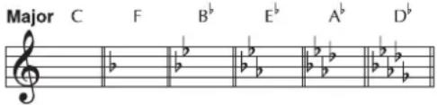 Minor Am Dm Gm Cm Fm B'm Minor Am Dm Gm Cm Fm B'm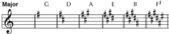 Minor Em Bm F ^‡ m C ^‡ m G ^‡ m D ^‡ m Minor Em Bm F ^‡ m C ^‡ m G ^‡ m D ^‡ m | |
| VOICE | |
| Selects the number of voices for the pitch shift sound. | |
| 1VOICE One-voice pitch-shifted sound output in monaural. | |
| 2MONO Two-voice pitch-shifted sound (PS1, PS2) output in monaural. | |
| 2ST (2Stereo) Two-voice pitch-shifted sound (PS1, PS2) output through left and right channels. | |
| FEEDBACK1 | |
| 0–100 | Adjusts the feedback amount of the harmonist sound. |
| DIRECT LEVEL | |
| 0–100 | Adjusts the volume of the direct sound. |
| HARMONY1, HARMONY2 *1 | |
| HARM1, HARM2 (Harmony) *1 | |
| This determines the pitch of the sound added to the input sound, when you are making a harmony. | |
| -2 oct–+2 oct, USER | It allows you to set it by up to 2 octaves higher or lower than the input sound. When the scale is set to USER, this parameter sets the user scale number to be used. |
| PRE DELAY1, PRE DELAY2 *1 | |
| 0 ms–300 ms, BPM –BPM ↓ | Adjusts the time from when the direct sound is heard until the harmonist sounds are heard. Normally you can leave this set at 0ms. |
| When set to BPM, the value of each parameter will be set according to the value of the BPM (p. 163) specified for each patch. This makes it easier to achieve effect sound settings that match the tempo of the song.* If, due to the tempo, the time is longer than the range of allowable settings, it is then synchronized to a period either 1/2 or 1/4 of that time. | |
| LEVEL1, LEVEL2 *1 | |
| 0–100 | Adjusts the volume of the harmony sound. |
| VOICE1 INTERVAL C-B, VOICE2 INTERVAL C-B *2 | |
| -24–+24 | Sets the output pitch for the set key relative to the input pitch. |
*1 HARM1 and HARM2 are set individually.
*2 VOICE1 INTERVAL (VOICE2 INTERVAL) is enabled when HARM1 (HARM2) is set to USER.
Creating Harmonist Scales (User Scale)
When HARM is set to any value from -2oct to +2oct, and the harmony does not sound the way you intend, use a User scale. You can set the corresponding pitches to be output for each input pitch.
- Set HARM1 (or HARM2) to USER in the Harmonist screen.
- Select VOICE1 INTERVAL (or VOICE2 INTERVAL) with PAGE [ ]
The Voice Interval screen appears.
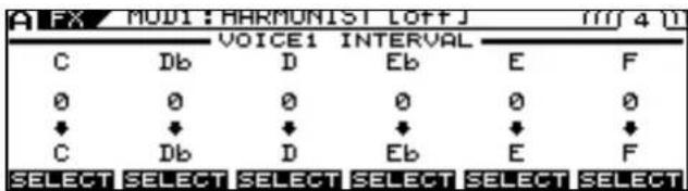
text_image
A FX MOD1: HARMUNIST LOFFJ m7 4 (I) VOICE1 INTERVAL C Db D Eb E F 0 0 0 0 0 0 ↓ ↓ ↓ ↓ ↓ ↓ C Db D Eb E F SELECT SELECT SELECT SELECT SELECT SELECT- Use PAGE [ ][F1][F6], and the F1-F6 knob to set the amount of pitch shift for each voice.
PEDAL BEND
This lets you use the pedal to get a pitch bend effect.
* Because of the need to analyze the pitch, chords (two or more sounds played simultaneously) cannot be played.
cf.
"Chapter 5 Using the VG-99 in Combination with an FC-300" (p. 52)
| Parameter/Range | Explanation |
| PITCH MIN (Pitch Minimum) | |
| -24–+24 This sets the pitch at the point where the expression pedal is fully lifted. | |
| PITCH MAX (Pitch Maximum) | |
| -24–+24 This sets the pitch at the point where the expression pedal is all the way down. | |
| PEDAL POS (Pedal Position) | |
| 0–100 Adjusts the pedal position for pedal bend.* This parameter is used after it's been assigned to an expression pedal or similar controller. | |
| EFFECT LEVEL | |
| 0–100 | Adjusts the volume of the pitch bend sound. |
| DIRECT LEVEL | |
| 0–100 | Adjusts the volume of the direct sound. |
2x2 CHORUS
Frequency band division is employed to produce two different choruses, one for low frequencies and one for higher frequencies, for both the left and right channels (for a total of four). This allows you to achieve a more natural chorus sound.
| Parameter/Range | Explanation |
| X-OVER FREQ (Crossover Frequency) | |
| 100 Hz-4.00 kHz | This sets the frequency dividing the low-and high-frequency ranges. |
| LOW RATE | |
| 0-100,BPM-BPM | Adjust the speed of the chorus effect for the low frequency range. |
| When set to BPM, the value of each parameter will be set according to the value of the BPM (p. 163) specified for each patch. This makes it easier to achieve effect sound settings that match the tempo of the song.* If, due to the tempo, the time is longer than the range of allowable settings, it is then synchronized to a period either 1/2 or 1/4 of that time. | |
| LOW DEPTH | |
| 0-100 | Adjust the depth of the chorus effect for the low frequency range. If you wish to use this as a doubling effect, use a setting of 0. |
| LOW PREDLY (Low Pre Delay) | |
| 0.0 ms-40.0 ms | Adjusts the delay of the effect sound in the low-frequency range.Extending the pre-delay will produce the sensation of multiple sounds (doubling effect). |
| LOW LEVEL | |
| 0-100 | Adjusts the volume of the effect sound in the low-frequency range. |
| HIGH RATE | |
| 0-100,BPM-BPM | Adjust the speed of the chorus effect for the high frequency range. |
| When set to BPM, the value of each parameter will be set according to the value of the BPM (p. 163) specified for each patch. This makes it easier to achieve effect sound settings that match the tempo of the song.* If, due to the tempo, the time is longer than the range of allowable settings, it is then synchronized to a period either 1/2 or 1/4 of that time. | |
| HIGH DEPTH | |
| 0-100 | Adjust the depth of the chorus effect for the high frequency range. If you wish to use this as a doubling effect, use a setting of 0. |
| HIGH PREDLY (High Pre Delay) | |
| 0.0 ms-40.0 ms | Adjusts the delay of the effect sound in the high-frequency range.Extending the pre-delay will produce the sensation of multiple sounds (doubling effect). |
| HIGH LEVEL | |
| 0-100 | Adjusts the volume of the effect sound in the high-frequency range. |
ROTARY
This produces an effect like the sound of a rotary speaker.
| Parameter/ Range | Explanation |
| SPEED | |
| SLOW, FAST | This parameter changes the simulated speaker's rotating speed (Slow or Fast). |
| RATE SLOW | |
| 0–100,BPM→BPM | This parameter adjusts the speed of rotation when set to Slow. |
| RATE FAST | |
| 0–100,BPM→BPM | This parameter adjusts the speed of rotation when set to Fast. |
| When the Rate (Slow) or Rate (Fast) set to BPM, the value of each parameter will be set according to the value of the BPM (p. 163) specified for each patch. This makes it easier to achieve effect sound settings that match the tempo of the song.* If, due to the tempo, the time is longer than the range of allowable settings, it is then synchronized to a period either 1/2 or 1/4 of that time. | |
| RISE TIME | |
| 0–100 | This parameter adjusts the time it takes for the rotation speed to change when switched from Slow to Fast. |
| FALL TIME | |
| 0–100 | This parameter adjusts the time it takes for the rotation speed to change when switched from Fast to Slow. |
| DEPTH | |
| 0–100 | This parameter adjusts the amount of depth in the rotary effect. |
UNI-V
This models the sound of the Uni-vibe.
Although the same type of effect as a phaser, its characteristic feature is a unique twisting effect, which you can't get from an ordinary phaser.
| Parameter/ Range | Explanation |
| RATE | |
| 0-100, BPM -BPM | Adjusts the rate of the Uni-V effect. |
| When set to BPM, the value of each parameter will be set according to the value of the BPM (p. 163) specified for each patch. This makes it easier to achieve effect sound settings that match the tempo of the song.* If, due to the tempo, the time is longer than the range of allowable settings, it is then synchronized to a period either 1/2 or 1/4 of that time. | |
| DEPTH | |
| 0-100 | Adjusts the depth of the Uni-V effect. |
| LEVEL | |
| 0-100 | Adjusts the volume. |
VIB (Vibrato)
This effect creates vibrato by slightly modulating the pitch.
| Parameter/ Range | Explanation |
| RATE | |
| 0–100, BPM→BPM | Adjusts the rate of the vibrato. |
| When set to BPM, the value of each parameter will be set according to the value of the BPM (p. 163) specified for each patch. This makes it easier to achieve effect sound settings that match the tempo of the song.* If, due to the tempo, the time is longer than the range of allowable settings, it is then synchronized to a period either 1/2 or 1/4 of that time. | |
| DEPTH | |
| 0–100 | Adjusts the depth of the vibrato. |
| RISE TIME | |
| 0–100 | This sets the time passing from the moment the trigger is turned on until the set vibrato is obtained.* When a patch with TRIG set to ON is called up, the effect obtained is identical to what happens when TRIG is switched from OFF to ON. If you want the vibrato effect to be produced immediately after the patches are switched, set RISE TIME to 0. |
| TRIG (Trigger) | |
| OFF, ON | This selects on/off of the vibrato. It is assumed that this parameter will be assigned to the footswitch. (p. 49) |
SLICER
This consecutively interrupts the sound to create the impression that a rhythm backing phrase is being played.
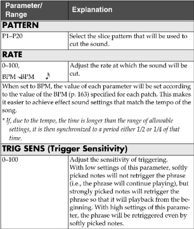 |
HUMANIZER
This can create human vowel-like sounds.
| Parameter/Range | Explanation |
| MODE | |
| This sets the mode that switches the vowels. | |
| PICK (Picking) It changes from vowel 1 to vowel 2 along with the picking. The time spent for the change is adjusted with the rate. | |
| AUTO By adjusting the rate and depth, two vowels (Vowel 1 and Vowel 2) can be switched automatically. | |
| RANDOM Five vowels (A, E, I, O, U) are called out at random by adjusting the rate and depth. | |
| VOWEL1 *1 | |
| A, E, I, O, U | Selects the first vowel. |
| VOWEL2 *1 | |
| A, E, I, O, U | Selects the second vowel. |
| SENS (Sensitivity) *2 | |
| 0–100 | Adjusts the sensitivity of the humanizer. When it is set to a lower value, no effect of the humanizer is obtained with weaker picking, while stronger picking produces the effect.When it is set to a higher value, the effect of the humanizer can be obtained whether the picking is weak or strong. |
| RATE | |
| 0–100,BPM→BPM | Adjusts the cycle for changing the two vowels. |
| When set to BPM, the value of each parameter will be set according to the value of the BPM (p. 163) specified for each patch. This makes it easier to achieve effect sound settings that match the tempo of the song.* If, due to the tempo, the time is longer than the range of allowable settings, it is then synchronized to a period either 1/2 or 1/4 of that time. | |
| MANUAL *3 | |
| 0–100 | This determines the point where the two vowels are switched. When it is set to 50, vowel 1 and vowel 2 are switched in the same length of time. When it is set to lower than 50, the time for vowel 1 is shorter. When it is set to higher than 50, the time for vowel 1 is longer. |
| DEPTH | |
| 0–100 | Adjusts the depth of the effect. |
| LEVEL | |
| 0–100 | Adjusts the volume. |
*1 Setting available with MODE set to PICK or AUTO.
*2 Setting available with MODE set to PICK.
*3 Setting available with MODE set to AUTO.
SLOW GEAR
This produces a volume-swell effect ("violin-like" sound).
| Parameter/Range | Explanation |
| SENS (Sensitivity) | |
| 0–100 | Adjusts the sensitivity. |
| RISE TIME | |
| 0–100 | Adjusts the time needed for the volume to reach its maximum from the moment you begin picking. |
DEFRET
This simulates a fretless guitar.
| Parameter/ Range | Explanation |
| TONE | |
| -50–+50 | Adjusts the amount of blurring between the notes. |
| SENS (Sensitivity) | |
| 0–100 | This controls the input sensitivity of the defretter. |
| ATTACK | |
| 0–100 | Adjusts the attack of the picking sound. |
| DEPTH | |
| 0–100 | This controls the volume of the harmonics. |
| RESO (Resonance) | |
| 0–100 | Adds a characteristically resonant quality to the sound. |
| EFFECT LEVEL | |
| 0–100 Adjust the volume | of the defretter sound. |
| DIRECT LEVEL | |
| 0–100 Adjust the volume | of the direct sound. |
FEEDBACKER
This allows you to use feedback playing techniques.
* Note that the notes you want to apply feedback to must be played singly and cleanly.
* You can use the footswitch to switch the effect on and off. For more details, refer to p. 49.
| Parameter/ Range | Explanation |
| MODE | |
| OSC (Oscillator) | An artificial feedback sound will be created internally.When OSC is selected, the effect is activated after a single note is played and the note stabilizes. A feedback effect is created when the effect switches on; the feedback disappears when the OSC effect switches off. |
| NATURAL Analyzes the pitch of the guitar sound being input, and then creates a feedback sound. | |
| RISE TIME *1 | |
| 0-100 | This determines the time needed for the volume of the feedback sound to reach its maximum from the moment the effect is turned on. |
| RISE TIME+ *1 | |
| 0-100 | This determines the time needed for the volume of the one octave higher feedback sound to reach its maximum from the moment the effect is turned on. |
| FB LEVEL (Feedback Level) | |
| 0-100 | Adjusts the volume of the feedback sound. |
| FB LEVEL+ (Feedback Level+) *1 | |
| 0-100 | Adjusts the volume of the one octave higher feedback sound. |
| VIB RATE (Vibrato Rate) *1 | |
| 0-100,BPM BPM | Adjusts the rate of the vibrato when the feedbacker is on. |
| When set to BPM, the value of each parameter will be set according to the value of the BPM (p. 163) specified for each patch. This makes it easier to achieve effect sound settings that match the tempo of the song.* If, due to the tempo, the time is longer than the range of allowable settings, it is then synchronized to a period either 1/2 or 1/4 of that time. | |
| VIB DEPTH (Vibrato Depth) *1 | |
| 0-100 | Adjusts the depth of the vibrato when the feedbacker is on. |
*1 Setting available with MODE set to OSC.
RING MOD (Ring Modulator)
This creates a bell-like sound by ring-modulating the guitar sound with the signal from the internal oscillator. The sound can be unmusical and lack distinctive pitches.
| Parameter/Range | Explanation |
| MODE | |
| This selects the mode for the ring modulator. | |
| NORMAL This is a normal ring modulator. | |
| INTELLIGENT By ring | modulating the input signal, a bell like sound is created. The intelligent ring modulator changes the oscillation frequency according to the pitch of the input sound and therefore produces a sound with the sense of pitch, which is quite different from Normal. This effect does not give a satisfactory result if the pitch of the guitar sound is not correctly detected. So, you must use single notes, not chords. |
| FREQ (Frequency) | |
| 0–100 | Adjusts the frequency of the internal oscillator. |
| EFFECT LEVEL | |
| 0–100 | Adjusts the volume of the effect sound. |
| DIRECT LEVEL | |
| 0–100 | Adjusts the volume of the direct sound. |
ANTI FB (Anti-feedback)
This prevents the acoustic feedback that can be produced by the body resonances of a guitar.
| Parameter/Range | Explanation |
| FREQ1-3 (Frequency 1-3) | |
| 0-100 Set the fixed frequency point at which feedback will be cancelled.You can set up to three cancellation points. | |
| DEPTH1-3 | |
| 0-100 Adjusts the degree of the anti-feedback at each of the three cancellation points. | |
ADV.COMP (Advanced Compressor)
This is an effect that produces a long sustain by evening out the volume level of the input signal. You can also use it as a limiter to suppress only the sound peaks and prevent distortion.
| Parameter/Range | Explanation |
| TYPE | |
| Selects the compressor type. | |
| BOSS COMP This models a BOSS CS-3. | |
| HIBAND This is a compressor that adds an even stronger effect in the high end. | |
| LIGHT This is a compressor with a light effect. | |
| D-COMP This models a MXR DynaComp. | |
| ORANGE This is modeled on the sound of the Dan Armstrong ORANGE SQUEEZER. | |
| FAT When applied heavily, this compressor effect provides a fat tone with a boosted midrange. | |
| MILD When applied heavily, this compressor effect produces a sweet tone with the high end cut. | |
| STEREO COMP This selects a stereo compressor. | |
| SUSTAIN | |
| 0–100 | Adjusts the range (time) over which low-level signals are boosted. Larger values will result in longer sustain. |
| ATTACK | |
| 0–100 Adjusts the strength of the picking attack. Larger values will result in a sharper attack, creating a more clearly defined sound. | |
| TONE | |
| -50–+50 Adjusts the tone. | |
| LEVEL | |
| 0–100 Adjusts the volume. | |
LIMITR (Limiter)
The limiter attenuates loud input levels to prevent distortion.
| Parameter/Range | Explanation |
| TYPE | |
| Selects the limiter type. | |
| BOSS LIMITR This selects a stereo limiter. | |
| RACK 160D This models a dbx 160X. | |
| VTG RACK U This models a UREI 1178. | |
| ATTACK | |
| 0–100 | Adjusts the strength of the picking attack when the strings are played. Higher values result in s sharper attack, creating a more clearly defined sound. |
| THRSH (Threshold) | |
| 0–100 | Adjust this as appropriate for the input signal from your guitar. When the input signal level exceeds this threshold level, limiting will be applied. |
| RATIO | |
| 1: 1–∞: 1 | This selects the compression ratio used with signals in excess of the threshold level. |
| REL (Release) | |
| 0–100 | Adjusts the time from when the signal level drops below the threshold until when limiting is removed. |
| LEVEL | |
| 0–100 Adjusts the volume. | |
SUB EQ (Sub Equalizer)
This adjusts the tone as a sub equalizer. A parametric type is adopted for the high-middle and low-middle range.
| Parameter/ Range | Explanation |
| TOTAL GAIN | |
| -12–+12dB | Adjusts the overall EQ volume. |
| LOW GAIN | |
| -12–+12dB | Adjusts the low frequency range tone. |
| HIGH GAIN | |
| -12–+12dB | Adjusts the high frequency range tone. |
| LOW MID FREQ (Low Middle Frequency) | |
| 20Hz–10.0kHz | Specifies the center of the frequency range that will be adjusted by the LOW MID GAIN. |
| LOW MID Q (Low Middle Q) | |
| 0.5–16 | Adjusts the width of the area affected by the EQ centered at the LOW MID FREQ. Higher values will narrow the area. |
| LOW MID GAIN (Low Middle Gain) | |
| -12–+12dB | Adjusts the low-middle frequency range tone. |
| HIGH MID FREQ (High Middle Frequency) | |
| 20Hz–10.0kHz | Specifies the center of the frequency range that will be adjusted by the HIGH MID GAIN. |
| HIGH MID Q (High Middle Q) | |
| 0.5–16 Adjusts the width of the area affected by the EQ centered at the HIGH MID FREQ. Higher values will narrow the area. | |
| HIGH MID GAIN (High Middle Gain) | |
| -12–+12dB | Adjusts the high-middle frequency range tone. |
| LOW CUT (Low Cut Filter) | |
| FLAT, 55 Hz–800 Hz | This lets you cut the low-end component below the set frequency to create a clear, distinct low end, thereby bringing out the high end of the effect. When FLAT is selected, the low cut filter will have no effect. |
| HIGH CUT (High Cut Filter) | |
| 700 Hz–11 kHz, FLAT | This allows you to get a mild effect sound by cutting the high-end component above the set frequency. When it is set to FLAT, the high cut filter is off or has no effect. |
SUB DELAY (Sub Delay)
This is a delay with the maximum delay time of 400 ms. This effect is useful for making the sound fatter.
| Parameter/ Range | Explanation |
| DELAY TIME | |
| 1 ms-400 ms, BPMBPM | Adjusts the delay time. |
| When set to BPM, the value of each parameter will be set according to the value of the BPM (p. 163) specified for each patch. This makes it easier to achieve effect sound settings that match the tempo of the song.* If, due to the tempo, the time is longer than the range of allowable settings, it is then synchronized to a period either 1/2 or 1/4 of that time.* After setting DELAY TIME to BPM (-) if you tap [F1] (TAP), the BPM value will change to match the timing of your tapping. | |
| FEEDBACK | |
| 0-100 | Adjusts the volume that is returned to the input.Feedback refers to returning the delayed signal back into the input of the delay. Higher settings will result in more delay repeats. |
| EFFECT LEVEL | |
| 0-120 | Adjusts the volume of delay sound. |
This effect reduces the noise and hum picked up by guitar pickups. Since it suppresses the noise in synchronization with the envelope of the guitar sound (the way in which the guitar sound decays over time), it has very little effect on the guitar sound, and does not harm the natural character of the sound.
* Please connect the noise suppressor in the signal path prior to the reverberation type effect. This setup will prevent an natural break of the reverberation type effect.
| Parameter/Range | Explanation |
| NS SW (Noise Suppressor Switch) | |
| OFF, ON | Turns the NS effect on/off. |
| THRSH (Threshold) | |
| 0-100 | Adjust this parameter as appropriate for the volume of the noise. If the noise level is high, a higher setting is appropriate. If the noise level is low, a lower setting is appropriate. Adjust this value until the decay of the guitar sound is as natural as possible.* High settings for the threshold parameter may result in there being no sound when you play with your guitar volume turned down. |
| REL (Release) | |
| 0-100 Adjusts the amount | unt of time from the point at which application of the noise suppressor begins to when the volume is fully attenuated. |
| DETECT | |
| This controls the noise suppressor based on the volume level for the point specified in Detect. | |
| INPUT Volume of the C | OSM guitar and normal pickup |
| NS IN (NS Input) Noise | suppressor input volume. |
FV (Foot Volume)
This is a volume control effect.
Normally, this is controlled with the expression pedal connected to the EXP PEDAL jack or the FC-300's EXP pedal.
* When making the settings determining each pedal's foot volume operations, refer to "Setting the GK VOLUME Control and Switch and the Pedal Function (SYSTEM CONTROL ASSIGN)" (p. 49), "Settings Related to the FC-300" (p. 52).
| Parameter/Range | Explanation |
| LEVEL | |
| 0–100 | Adjusts the volume. |
| VOL CURVE (Volume Curve) | |
| You can select how the actual volume changes relative to the amount the pedal is pressed. | |
| SLOW1, SLOW2,NORMAL, FAST | 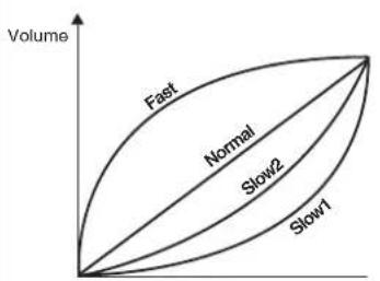 When the pedal when the pedalis fully raised is fully advancedEXP Pedal When the pedal when the pedalis fully raised is fully advancedEXP Pedal |
NOTE
You may be unable to properly obtain the foot volume effect if "FEEDBACKER" (p. 135) is connected at a point after FV in the effects chain (p. 32).
COSM AMP
COSM technology simulates different preamp characteristics, speaker sizes, and cabinet shapes.
* You can make separate settings for Channel A and Channel B.
| Parameter/Range | Explanation |
| COSM AMP SW (COSM AMP Switch) | |
| OFF, ON | Turns the COSM AMP effect on/off. |
| PREAMP TYPE | |
| refer to Preamp Type List | This sets the type of the guitar preamp. |
Preamp Type List
| Type | Explanation |
| JC CLEAN (p. 141) | |
| JC-120 | This is the sound of the Roland JC-120. |
| WARM CLEAN This gives a mellow, clean sound. | |
| JAZZ COMBO This is a sound suited to jazz. | |
| FULL RANGE This is a sound with flat response. Good for acoustic guitar | |
| BRIGHT CLEAN A bright, clean tone. | |
| TW CLEAN (p. 141) | |
| CLEAN TWIN This models a Fender Twin Reverb. | |
| PRO CRUNCH This models a Fender Pro Reverb. | |
| TWEED This models a Fender Bassman 4 x 10” Combo. | |
| WARM CRUNCH This gives a mellow, crunch sound. | |
| CRUNCH (p. 141) | |
| CRUNCH | This is a crunch sound that can produce natural distortion. |
| BLUES This is a sound suited to blues. | |
| WILD CRUNCH This is a crunch sound with wild distortion. | |
| STACK CRUNCH This is a crunch sound with high gain. | |
| COMBO (p. 141) | |
| VO DRIVE | This models the drive sound of a VOX AC-30TB. |
| VO LEAD This models the lead sound of the VOX AC-30TB. | |
| VO CLEAN This model is the clean sound of the VOX AC-30TB. | |
| MATCH DRIVE This models the sound input to left input on a Matchless D/C-30. | |
| FAT MATCH This models the sound of a Matchless with a modified high gain. | |
| MATCH LEAD | This models the sound input to right input on a Matchless D/C-30. |
| Type | Explanation |
| BG LEAD (p. 141) | |
| BG LEAD | This models the lead sound of the MESA/Boogie combo amp. |
| BG DRIVE | This models a MESA/Boogie with TREBLE SHIFT SW on. |
| BG RHYTHM | This models the rhythm channel of a MESA/Boogie. |
| SMOOTH DRIVE | This is a smooth drive sound. |
| MILD DRIVE | This is a mellow drive sound. |
| MS STACK (p. 141) | |
| MS1959 (I) | This models the sound input to Input I on a Marshall 1959. |
| MS1959 (II) | This models the sound input to Input II on a Marshall 1959. |
| MS1959 (I+II) | This models the sound of a Marshall 1959 with Inputs I and II connected in parallel. |
| MS HI-GAIN | This models the sound of a Marshall with a modified midrange boost. |
| POWER STACK This provides the sound of a stack amp with active type tone circuitry. | |
| R-FIER (p. 141) | |
| CLEAN | Models the sound of the Channel 1 CLEAN Mode on the MESA/Boogie DUAL Rectifier. |
| RAW | Models the sound of the Channel 2 RAW Mode on the MESA/Boogie DUAL Rectifier. |
| VINTAGE 1 | Models the sound of the Channel 2 VINTAGE Mode on the MESA/Boogie DUAL Rectifier. |
| MODERN 1 | Models the sound of the Channel 2 MODERN Mode on the MESA/Boogie DUAL Rectifier. |
| VINTAGE 2 | Models the sound of the Channel 3 VINTAGE Mode on the MESA/Boogie DUAL Rectifier. |
| MODERN 2 | Models the sound of the Channel 3 MODERN Mode on the MESA/Boogie DUAL Rectifier. |
| T-AMP (p. 141) | |
| CLEAN | This models a Hughes & Kettner Triamp AMP1. |
| CRUNCH This models | a Hughes & Kettner Triamp AMP2. |
| LEAD | This models a Hughes & Kettner Triamp AMP3. |
| EDGE LEAD | A sharp lead sound. |
| HI-GAIN (p. 141) | |
| SLDN | This models a Soldano SLO-100. |
| DRIVE STACK | This is a drive sound with high gain. |
| LEAD STACK | This is a lead sound with high gain. |
| HEAVY LEAD | A powerful lead sound featuring extreme distortion. |
| METAL (p. 141) | |
| 5150 DRIVE | This models the lead channel of a Peavey EVH 5150. |
| METAL STACK This is | a drive sound suited to metal. |
| METAL LEAD This is a | lead sound suited to metal. |
| CUSTOM (p. 143) | |
| CUSTOM | Custom amp |
| BASS AMP (p. 144) | |
| VINTAGE | Models the Ampeg B-15. |
| MODERN Models the S | SWR SM-400. |
JC CLEAN / TW CLEAN / CRUNCH / COMBO / BG LEAD / MS STACK / R-FIER / T-AMP / HI-GAIN / METAL
| Parameter/ Range | Explanation |
| GAIN | |
| 0-120 | Adjusts the distortion of the amp. |
| BASS | |
| 0-100 | Adjusts the tone for the low frequency range. |
| MIDDLE | |
| 0-100 | Adjusts the tone for the middle frequency range. |
| TREBLE | |
| 0-100 | Adjusts the tone for the high frequency range. |
| PRESENCE | |
| 0-100 | Adjusts the tone for the ultra high frequency range. |
| LEVEL | |
| 0-100 | Adjusts the volume of the entire preamp.* Be careful not to raise the Level setting too high. |
| BRIGHT | |
| Turns the bright setting on/off. *1 | |
| OFF Bright is not used. | |
| ON Bright is switched on to create a lighter and crisper tone. | |
| GAIN SW | |
| LOW, MIDDLE, HIGH | Provides for selection from three levels of distortion: LOW, MIDDLE, and HIGH. Distortion will successively increase for settings of LOW, MIDDLE and HIGH.* The sound of each Type is created on the basis that the Gain is set to MIDDLE. So, normally set it to MIDDLE. |
| SOLO SW | |
| OFF, ON Pressing [SOL | O] switches the tone to one suitable for solos. |
| SOLO LEVEL | |
| 0-100 | Adjusts the volume level when the Solo switch is ON. |
*1 The BRIGHT parameter setting is only partially available with some JC CLEAN, CRUNCH, or BASS AMP settings in PREAMP TYPE.
| Parameter/Range | Explanation |
| SP TYPE (Speaker Type) | |
| Select the speaker type. | |
| OFF This turns off the speaker simulator. | |
| ORIG This is the built-in speaker of the amp you selected with PREAMP TYPE. | |
| 1x8” This is a compact open-back speaker cabinet with one 8-inch speaker. | |
| 1x10” This is a compact open-back speaker cabinet with one 10-inch speaker. | |
| 1X12” This is a compact open-back speaker cabinet with one 12-inch speaker. | |
| 2X12” This is a general open-back speaker cabinet with two 12-inch speakers. | |
| 4X10” This is an optimal speaker cabinet for a large enclosed amp with four 10-inch speakers. | |
| 4X12” This is an optimal speaker cabinet for a large enclosed amp with four 12-inch speakers. | |
| 8X12” This is a double stack of two cabinets, each with four 12-inch speakers. | |
| CUSTOM Custom speaker | |
| DIRECT LEVEL | |
| 0-100 | Adjusts the volume of the direct sound. |
| MIC TYPE | |
| This setting selects the simulated mic type. | |
| DYN57 This is the sound of the SHURE SM-57.General dynamic mic used for instruments and vocals. Optimal for use in miking guitar amps. | |
| DYN421 This is the sound of the SENNHEISER MD-421.Dynamic mic with extended low end. | |
| CND451 This is the sound of the AKG C451B.Small condenser mic for use with instruments. | |
| CND87 This is the sound of the NEUMANN U87.Condenser mic with flat response. | |
| FLAT Simulates a mic with perfectly flat response.Produces a sonic image close to that of listening to the sound directly from the speakers (on site). | |
| MIC DIS (Mic Distance) | |
| Simulates the distance between the mic and speaker. | |
| Off MIC This setting points the mic away from the speaker. | |
| On MIC Provides conditions whereby the mic is directed more towards the speaker. | |
| Parameter/Range | Explanation |
| MIC POS (Mic Position) | |
| This simulates the microphone position. | |
| CENTER Simulates the | condition that the micro-phone is set in the middle of the speaker cone. |
| 1–10cm Simulates the | condition that the micro-phone is moved away from the center of the speaker cone. |
| MIC LEVEL | |
| 0–100 | Adjusts the volume of the microphone. |
| Parameter/Range | Explanation |
| CUSTOM SPEAKER *1 | |
| SIZE | |
| 5”-15” | Selects the size of speaker. |
| LOW | |
| -10-+10 | Adjusts the speaker section's low-frequency tone. |
| HIGH | |
| -10-+10 | Adjusts the speaker section's high-frequen-cy tone. |
| NUMBER | |
| x1, x2, x4, x8 Sets the number of speakers. | |
| CABINET | |
| Selects the speaker cabinet type. | |
| OPEN This is an open-backed cabinet. | |
| CLOSE This type of cabinet features an enclosed rear panel. | |
*1 Setting available when SP TYPE is set to CUSTOM.
CUSTOM
| Parameter/Range | Explanation |
| CUSTOM TYPE | |
| Selects the basic type of preamp. | |
| JC CLEAN This is the sound of the Roland JC-120. | |
| TW CLEAN This models | a Fender Twin Reverb. |
| CRUNCH This is a crunch | sound that can produce natural distortion. |
| VO DRIVE This models | the drive sound of a VOX AC-30TB. |
| BG LEAD This models | the lead sound of the MESA/Boogie combo amp. |
| MS HI-GAIN This models | the sound of a Marshall with a modified midrange boost. |
| MODERN STACK Models | the sound of the Channel 2 MODERN Mode on the MESA/Boogie DUAL Rectifier. |
| BOTTOM | |
| -50–+50 | This controls the input sound's low-frequency range and adjusts the amount of distortion in the low-frequency range. |
| EDGE | |
| -50–+50 | This controls the input sound's high-frequency range and adjusts the amount of distortion in the high-frequency range. |
| BASS FREQ (Bass Frequency) | |
| -50–+50 | Adjusts the frequency affected by the BASS parameter. |
| TREBLE FREQ (Treble Frequency) | |
| -50–+50 | Adjusts the frequency affected by the TRE-BLE parameter. |
| LOW | |
| -50–+50 | Adjusts the preamp section's low-frequency tone. |
| HIGH | |
| -50–+50 Adjusts the preamp section's high-frequency tone. | |
| GAIN | |
| 0–120 | Adjusts the distortion of the amp. |
| BASS | |
| 0–100 Adjusts the tone for the low frequency range. | |
| MIDDLE | |
| 0–100 | Adjusts the tone for the middle frequency range. |
| TREBLE | |
| 0–100 Adjusts the tone for the high frequency range. | |
| PRESENCE | |
| 0–100 Adjusts the tone for the ultra high frequency range. | |
| Parameter/Range | Explanation |
| LEVEL | |
| 0-100 | Adjusts the volume of the entire preamp.* Be careful not to raise the Level setting too high. |
| BRIGHT | |
| Turns the bright setting on/off. *1 | |
| OFF Bright is not used. | |
| ON Bright is switched on to create a lighter and crisper tone. | |
| GAIN SW | |
| LOW, MIDDLE, HIGH | Provides for selection from three levels of distortion: LOW, MIDDLE, and HIGH. Distortion will successively increase for settings of LOW, MIDDLE and HIGH.* The sound of each Type is created on the basis that the Gain is set to MIDDLE. So, normally set it to MIDDLE. |
| SOLO SW | |
| OFF, ON | Pressing [SOLO] switches the tone to one suitable for solos. |
| SOLO LEVEL | |
| 0-100 | Adjusts the volume level when the Solo switch is ON. |
| SP TYPE (Speaker Type) | |
| Select the speaker type. | |
| OFF This turns off the speaker simulator. | |
| ORIG This is the built-in speaker of the amp you selected with PREAMP TYPE. | |
| 1x8" This is a compact open-back speaker cabinet with one 8-inch speaker. | |
| 1x10" This is a compact open-back speaker cabinet with one 10-inch speaker. | |
| 1X12" This is a compact open-back speaker cabinet with one 12-inch speaker. | |
| 2X12" This is a general open-back speaker cabinet with two 12-inch speakers. | |
| 4X10" This is an optimal speaker cabinet for a large enclosed amp with four 10-inch speakers. | |
| 4X12" This is an optimal speaker cabinet for a large enclosed amp with four 12-inch speakers. | |
| 8X12" This is a double stack of two cabinets, each with four 12-inch speakers. | |
| CUSTOM Custom speaker | |
| DIRECT LEVEL | |
| 0-100 | Adjusts the volume of the direct sound. |
*1 The BRIGHT parameter setting is only partially available with some JC CLEAN, CRUNCH, or BASS AMP settings in PREAMP TYPE.
| Parameter/Range | Explanation |
| MIC TYPE | |
| This setting selects the simulated mic type. | |
| DYN57 This is the sound | d of the SHURE SM-57.General dynamic mic used for instruments and vocals. Optimal for use in miking guitar amps. |
| DYN421 This is the sound | d of the SENNHEISER MD-421.Dynamic mic with extended low end. |
| CND451 This is the sound | d of the AKG C451B.Small condenser mic for use with instruments. |
| CND87 This is the sound | d of the NEUMANN U87.Condenser mic with flat response. |
| FLAT Simulates a mic with perfectly flat response.Produces a sonic image close to that of listening to the sound directly from the speakers (on site). | |
| MIC DIS (Mic Distance) | |
| Simulates the distance between the mic and speaker. | |
| Off MIC This setting points the mic away from the speaker. | |
| On MIC Provides conditions whereby the mic is directed more towards the speaker. | |
| MIC POS (Mic Position) | |
| This simulates the microphone position. | |
| CENTER Simulates the condition that the microphone is set in the middle of the speaker cone. | |
| 1–10cm Simulates the condition that the microphone is moved away from the center of the speaker cone. | |
| MIC LEVEL | |
| 0–100 | Adjusts the volume of the microphone. |
| Parameter/Range | Explanation |
| CUSTOM SPEAKER *1 | |
| SIZE | |
| 5”–15” Selects the size of speaker. | |
| LOW | |
| -10–+10 | Adjusts the speaker section’s low-frequency tone. |
| HIGH | |
| -10–+10 Adjusts the speaker section’s high-frequen-cy tone. | |
| NUMBER | |
| x1, x2, x4, x8 Sets the number of speakers. | |
| CABINET | |
| Selects the speaker cabinet type. | |
| OPEN This is an open-backed cabinet. | |
| CLOSE This type of cabinet features an enclosed rear panel. | |
*1 Setting available when SP TYPE is set to CUSTOM.
BASS AMP VINTAGE
| Parameter/Range | Explanation |
| GAIN | |
| 0–100 | Adjusts the distortion of the amp. |
| BASS | |
| -50–+50 | Adjusts the tone for the low frequency range. |
| MIDDLE | |
| -50–+50 | Adjusts the tone for the middle frequency range. |
| MIDDLE FREQ (Middle Frequency) | |
| 220Hz, 800Hz, 3.0kHz | This control adjusts the center frequency of the frequency range adjusted with the Middle control. |
| TREBLE | |
| -50–+50 | Adjusts the tone for the high frequency range. |
| LEVEL | |
| 0–100 | Adjusts the volume of the entire preamp.* Be careful not to raise the Level setting too high. |
| BRIGHT | |
| Turns the bright setting on/off. | |
| OFF Bright is not used. | |
| ON Bright is switched on to create a lighter and crisper tone. | |
| RESPONSE | |
| BASS, FLAT | This controls the overall amp characteristics. Select the position corresponding to the characteristics for one of the two types of sound. |
| SP TYPE (Speaker Type) | |
| Select the speaker type. | |
| OFF This turns off the speaker simulator. | |
| ORIG This is the built-in speaker of the amp you selected with PREAMP TYPE. | |
| 1x15" Models the Trace Elliot 1518. | |
| 1x18" Models the SWR Big Ben. | |
| 2x15" Models the Acoustic 402. | |
| 4x10" Models the SWR Goliath. | |
| 8x10" Models the Ampeg 810F. | |
| MIC POS (Mic Position) | |
| This simulates the microphone position. | |
| CENTER Simulates the condition that the microphone is set in the middle of the speaker cone. | |
| 1–10cm Simulates the condition that the microphone is moved away from the center of the speaker cone. | |
| MIC LEVEL | |
| 0–100 Adjusts the volume of the microphone. | |
| DIRECT LEVEL | |
| 0–100 Adjusts the volume of the direct sound. | |
BASS AMP MODERN
| Parameter/Range | Explanation |
| GAIN | |
| 0–100 | Adjusts the distortion of the amp. |
| BASS | |
| -50–+50 | Adjusts the tone for the low frequency range. |
| MIDDLE | |
| -50–+50 | Adjusts the tone for the middle frequency range. |
| MIDDLE FREQ (Middle Frequency) | |
| 220Hz, 800Hz, 3.0kHz | This control adjusts the center frequency of the frequency range adjusted with the Middle control. |
| TREBLE | |
| -50–+50 | Adjusts the tone for the high frequency range. |
| LEVEL | |
| 0–100 | Adjusts the volume of the entire preamp.* Be careful not to raise the Level setting too high. |
| ENHANCER | |
| 0–100 | This controls the clarity and presence of the sound. |
| SP TYPE (Speaker Type) | |
| Select the speaker type. | |
| OFF This turns off the speaker simulator. | |
| ORIG This is the built-in speaker of the amp you selected with PREAMP TYPE. | |
| 1x15" Models the Trace Elliot 1518. | |
| 1x18" Models the SWR Big Ben. | |
| 2x15" Models the Acoustic 402. | |
| 4x10" Models the SWR Goliath. | |
| 8x10" Models the Ampeg 810E. | |
| MIC POS (Mic Position) | |
| This simulates the microphone position. | |
| CENTER Simulates the condition that the microphone is set in the middle of the speaker cone. | |
| 1–10cm Simulates the condition that the microphone is moved away from the center of the speaker cone. | |
| MIC LEVEL | |
| 0–100 | Adjusts the volume of the microphone. |
| DIRECT LEVEL | |
| 0–100 Adjusts the volume of the direct sound. | |
MIXER
MIXER
This mixes the signals in Channel A and Channel B.
MIXER A, B (MIXER CHANNEL A, B)
| Parameter/Range | Explanation |
| MIX SW (Mix Switch) | |
| OFF, ON | This setting switches mixing of Channel A (or Channel B) on and off. The sounds in the respective channel are not mixed when this is set to OFF. |
| PAN | |
| 100:0–0:100 | This sets the panning for Channel A (or Channel B). |
| LEVEL | |
| 0–100 | This sets the Channel A (or Channel B) volume level. |
| DELAY A SEND, DELAY B SEND | |
| 0–100 | Adjusts the send level from Channel A (or Channel B) to the mixer's delay. |
| REVERB A SEND, REVERB B SEND | |
| 0–100 | Adjusts the send level from Channel A (or Channel B) to the mixer's reverb. |
| CH DELAY (Channel Delay) | |
| 0–50ms Adjusts the time | that the overall sound in Channel A (or B) is delayed.Although this is normally set to 0 ms, you can produce greater breadth along with a chorus effect by setting a difference in the time the sounds are played relative to the sounds from Channel B. |
PATCH LEVEL
| Parameter/Range | Explanation |
| A/B BAL (A/B Balance) | |
| A0:100B–A100:0B Adjusts the volume balance of Channel A and Channel B. You can set this parameter in the Mixer screen or with the BALANCE knob.This parameter is disabled when DYNAM-IC is on. | |
| PATCH LEVEL | |
| 0–200 Adjusts the overall patch volume. | |
TOTAL EQ (Total Equalizer)
This adjusts the tone of the mixed signals from Channel A and Channel B.
Parametric EQ is used for the low-middle and high-middle frequency ranges.
| Parameter/Range | Explanation |
| EQ SW (Equalizer Switch) | |
| OFF, ON | Turns the EQ effect on/off. |
| TOTAL GAIN | |
| -12–+12dB | Adjusts the volume before the equalizer. |
| LOW GAIN | |
| -12–+12dB | Adjusts the low frequency range tone. |
| HIGH GAIN | |
| -12–+12dB | Adjusts the high frequency range tone. |
| LOW MID FREQ (Low Middle Frequency) | |
| 20Hz–10.0kHz | Specifies the center of the frequency range that will be adjusted by the LOW MID GAIN. |
| LOW MID Q (Low Middle Q) | |
| 0.5–16 | Adjusts the width of the area affected by the EQ centered at the LOW MID FREQ. Higher values will narrow the area. |
| LOW MID GAIN (Low Middle Gain) | |
| -12–+12dB Adjusts the low-middle frequency range tone. | |
| HIGH MID FREQ (High Middle Frequency) | |
| 20Hz–10.0kHz | Specifies the center of the frequency range that will be adjusted by the HIGH MID GAIN. |
| HIGH MID Q (High Middle Q) | |
| 0.5–16 Adjusts the width of the area affected by the EQ centered at the HIGH MID FREQ. Higher values will narrow the area. | |
| HIGH MID GAIN (High Middle Gain) | |
| -12–+12dB | Adjusts the high-middle frequency range tone. |
OUTPUT
This setting determines which signals are output at each output and the level at which they are output.
| Parameter/Range | Explanation |
| MAIN OUT | |
| This switches the signals output from the MAIN OUT. | |
| CH A This outputs Channel A.This output also reflects the mixer's MIX SW, PAN, LEVEL, and A/B BAL settings. | |
| CH B This outputs Channel B.This output also reflects the mixer's MIX SW, PAN, LEVEL, and A/B BAL settings. | |
| MIXER (DRY) This outputs the post-A/B mix signals before application of DELAY/REVERB. | |
| MIXER This outputs the post-A/B mix signals after application of DELAY/REVERB and TOTAL EQ. | |
| MAIN LEVEL | |
| 0–200 | Adjusts the volume the output to the MAIN OUT. |
| SUB OUT | |
| This switches the signals output from the SUB OUT. | |
| CH A This outputs Channel A.This output also reflects the mixer's MIX SW, PAN, LEVEL, and A/B BAL settings. | |
| CH B This outputs Channel B.This output also reflects the mixer's MIX SW, PAN, LEVEL, and A/B BAL settings. | |
| MIXER (DRY) This outputs the post-A/B mix signals before application of DELAY/REVERB. | |
| MIXER This outputsthe post-A/B mix signals after application of DELAY/REVERB and TOTAL EQ. | |
| SUB LEVEL | |
| 0–200 Adjusts the volume the output to the SUB OUT. | |
| Parameter/Range | Explanation |
| D OUT (Digital Output) | |
| This switches the signals output from the DIGITAL OUT. | |
| COSM GTR A | This outputs the sounds from COSM GTR A. |
| COSM GTR B This outputs the sounds from COSM GTR B. | |
| NORMAL PU This outputs the sounds from the normal pickup. | |
| CH A This outputs Channel A.This output also reflects the mixer's MIX SW, PAN, LEVEL, and A/B BAL settings. | |
| CH B This outputs Channel B.This output also reflects the mixer's MIX SW, PAN, LEVEL, and A/B BAL settings. | |
| MIXER (DRY) This outputs the post-A/B mix signals before application of DELAY/REVERB. | |
| MIXER This outputs the post-A/B mix signals after application of DELAY/REVERB and TOTAL EQ. | |
| MAIN OUT This outputs the same signals as those from MAIN OUT. | |
| SUB OUT This outputs the same signals as those from SUB OUT. | |
| D OUT LEVEL (Digital Output Level) | |
| 0–200 | Adjusts the volume the output to the DIGITAL OUT. |
* The parameters enabled (MAIN OUT, MAIN LEVEL, SUB OUT, SUB LEVEL, D OUT, D OUT LEVEL) change according to the settings in "OUTPUT MODE" (p. 172) in the SYSTEM screen. When disabled, the value <> is given.
DELAY/REVERB
You can apply delay and reverb jointly to Channel A and Channel B.
DELAY/REVERB Signal Flow
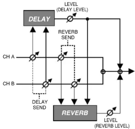
flowchart
graph TD
    A["DELAY"] --> B["LEVEL (DELAY LEVEL)"]
    C["CH A"] --> D["REVERB SEND"]
    E["CH B"] --> F["REVERB"]
    D --> G["LEVEL (REVERB LEVEL)"]
    F --> H["LEVEL (REVERB LEVEL)"]
    I["DELAY SEND"] --> J["LEVEL (REVERB LEVEL)"]
    K["LEVEL (REVERB LEVEL)"] --> L["REVERB"]
    M["LEVEL (REVERB LEVEL)"] --> N["LEVEL (REVERB LEVEL)"]
DELAY
| Parameter/Range | Explanation |
| DELAY SW (Delay Switch) | |
| OFF, ON | Turns the DELAY effect on/off.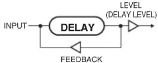 |
| TIME | |
| 1–1800 ms,BPM BPM | This determines the delay time. |
| When set to BPM, the value of each parameter will be set according to the value of the BPM (p. 163) specified for each patch. This makes it easier to achieve effect sound settings that match the tempo of the song.* If, due to the tempo, the time is longer than the range of allowable settings, it is then synchronized to a period either 1/2 or 1/4 of that time.* After setting DELAY TIME to BPM (–) if you tap [F2](TAP), the BPM value will change to match the timing of your tapping. | |
| FEED BACK | |
| 0–100 | Adjusts the amount of feedback. |
| Feedback is returning a delay signal to the input. A higher value will increase the number of the delay repeats. | |
| HIGH CUT (High Cut Filter) | |
| 700 Hz–11.0 kHz,FLAT | This sets the frequency at which the high cut filter begins to take effect. |
| This allows you to get a mild effect sound by cutting the high-end component above the set frequency. When it is set to FLAT, the high cut filter is off or has no effect. | |
| LEVEL | |
| 0–120 | Adjusts the volume of the direct sound. |
REVERB
| Parameter/ Range | Explanation |
| REVERB SW (Reverb Switch) | |
| OFF, ON | Turns the REVERB effect on/off. |
| TYPE | |
| This selects the reverb type. Various different simulations of space are offered. | |
| AMB (AMBIENCE) Simulates an ambience mic (off-mic, placed at a distance from the sound source) used in recording and other applications. Rather than emphasizing the reverberation, this re-verb is used to produce a sense of openness and depth. | |
| ROOM Simulates the reverberation in a small room.Provides warm reverberations. | |
| HALL1 Simulates the reverberation in a concert hall.Provides clear and spacious reverberations. | |
| HALL2 Simulates the reverberation in a concert hall.Provides warm reverberations. | |
| PLATE Simulates plate reverberation (a reverb unit that uses the vibration of a metallic plate).Provides a metallic sound with a distinct upper range. | |
| TIME | |
| 0.1 s–10.0 s | Adjusts the length (time) of reverberation. |
| PRE DELAY | |
| 0 ms–100 ms Adjusts the time until the reverb sound ap-pears. | |
| LOW CUT (Low Cut Filter) | |
| FLAT, 55 Hz–800 Hz This sets the frequency at which the low cut filter begins to take effect.This lets you cut the low-end component be-low the set frequency to create a clear, dis-tinct low end, thereby bringing out the high end of the effect. When Flat is selected, the low cut filter will have no effect. | |
| HIGH CUT (High Cut Filter) | |
| 700 Hz–11 kHz, FLAT This sets the frequency at which the high cut filter begins to take effect.This allows you to get a mild effect sound by cutting the high-end component above the set frequency. When Flat is selected, the high cut filter will have no effect. | |
| DENS (Density) | |
| 0–10 | Adjusts the density of the reverb sound. |
| LEVEL | |
| 0–100 Adjusts the volume of the reverb sound. | |
DYNAMIC
This function allows you use your picking dynamics to control the volume of the mix of the two channels. The volume and balance of the channels change according to the dynamics each time you pick the strings. You can set the point at which the volume changes in the settings screen as you check the dynamics level shown by the meter.
MEMO
The A/B BAL setting is disabled when DYNAMIC is switched on.
| Parameter/Range | Explanation |
| DYNA SW (Dynamic Switch) | |
| OFF, ON | This setting switches DYNAMIC on and off. |
| TYPE | |
| This sets the DYNAMIC type.This setting determines the channel for which the volume is controlled with the picking dynamics. | |
| DYNA A Channel A's volume level is controlled.The volume in Channel B is fixed. | |
| DYNA B Channel B's volume level is controlled.The volume in Channel A is fixed. | |
| DYNA BAL(DYNA Balance) | The volume levels of both Channel A and Channel B (the balance) is controlled. |
| LOWER LEV (Lower Level) | |
| 0–100 | Adjusts the volume of the sounds played softly. *1You can adjust the A level when DYNA A is used and the B level when DYNA B is used. |
| LOWER BAL (Lower Balance) | |
| 0:100–100:0 | Adjusts the balance between Channel A and B when sounds are played softly. *2 |
| LOWER RNG (Lower Range) | |
| 0–99 | This sets the point at which the strength of the picking begins to change from the soft sound's volume (or balance) to the louder sounds' volume (or balance).When the volume is below the set point, the volume (or balance) switches to that set in either LOWER LEV or LOWER BAL in accordance with the TYPE setting. |
| UPPER LEV (Upper Level) | |
| 0–100 | Adjusts the volume of the sounds played loudly. *1You can adjust the A level when DYNA A is used and the B level when DYNA B is used. |
| UPPER BAL (Upper Balance) | |
| 0:100–100:0 | Adjusts the balance between Channel A and B when sounds are played loudly. *2 |
| UPPER RNG (Upper Range) | |
| 1–100 | This sets the point at which the strength of the picking begins to change from the loud sound's volume (or balance) to the softer sounds' volume (or balance).When the volume is above the set point, the volume (or balance) switches to that set in either LOWER LEV or LOWER BAL in accordance with the TYPE setting. |
| Parameter/Range | Explanation |
| RELEASE | |
| 0–100 | This adjust the rate of the response when the input level drops. |
*1 Setting available when TYPE is set to DYNA A or DYNA B.
*2 Setting available when TYPE is set to DYNA BAL.
TIP
With DYNAMIC, when a new note is detected, the peak level at the instant the string is picked (i.e., the picking dynamics) is held momentarily, and control of the channel volume or balance is based on that value.
The picking dynamics controls the sound as described below.
- When the level is at or below the LOWER RNG setting, the picking controls the volume or balance of the softer sounds set in LOWER LEV (when TYPE is set to DYNA A or DYNA B) or LOWER BAL (when TYPE is set to DYNA BAL).
- When the level is at or above the UPPER RNG setting, the picking controls the volume or balance of the louder sounds set in UPPER LEV (when TYPE is set to DYNA A or DYNA B) or UPPER BAL (when TYPE is set to DYNA BAL).
- When the level is between these settings, the picking controls the volume or balance between the softer sounds and louder sounds described above (continuously changing the level according to the dynamics).
Changes made to the above parameters are indicated in the graph in the settings screen.
When TYPE is set to DYNA A or DYNA B
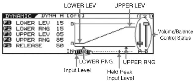
text_image
DYNAMIC DYNH H LOF J F1 LOWER LEV 15 F2 LOWER RNG 15 F3 UPPER LEV 85 F4 UPPER RNG 85 F5 RELEASE 50 LOWER LEV UPPER LEV Volume/Balance Control Status IN IN IN LOWER RNG UPPER RNG Input Level Held Peak Input LevelWhen TYPE is set to DYNA BAL
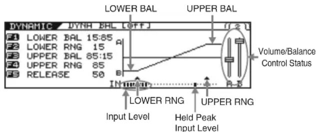
text_image
DYNAMIC DYNH BAL OFFJ F1 LOWER BAL 15:85 F2 LOWER RNG 15 F3 UPPER BAL 85:15 F4 UPPER RNG 85 F5 RELEASE 50 LOWER BAL UPPER BAL Volume/Balance Control Status IN MUN LOWER RNG UPPER RNG Input Level Held Peak Input LevelChanges made to the above parameters are indicated in the graph in the settings screen.
The input level and held peak input level are indicated beneath the graph display. Making these settings is easier by actually picking the strings as you watch the meter and adjust the LOWER RNG and UPPER RNG settings.
In addition, you can confirm the volume/balance control status with the fader displayed to the right of the graph.
MASTER
CONTROL ASSIGN
Adjust these settings if you would like to use a pedal connected to the VG-99, or an external MIDI device (control source) to control parameters as you play.
You can set two parameters as targets to each control source.
* Turn on the COSM guitar, COSM amp, and effect that contains the parameter you wish to control.
GK VOL (GK Volume)
| Parameter/Range | Explanation |
| SW (Switch) | |
| OFF, ON | This setting switches GK VOL on and off. |
| TARGET PARAMETER | |
| This selects the parameter to be changed.Refer to “TARGET PARAMETER” (p. 157). | |
| MIN (Minimum) | |
| This sets the minimum value for the range in which the parameter can change.The value differs depending on the parameter assigned for TARGET PARAMETER. | |
| MAX (Maximum) | |
| This sets the maximum value for the range in which the parameter can change.The value differs depending on the parameter assigned for TARGET PARAMETER. | |
| RANGE LOW, RANGE HIGH | |
| Low: 0–126High: 1–127 | You can set the controllable range for target parameters within the GK Volume’s operational range. Target parameters are controlled within the range set with RANGE LOW and RANGE HIGH. You should normally set RANGE LOW to 0 and RANGE HIGH to 127. |
GK S1, S2
(DOWN/S1, UP/S2 Switch)
| Parameter/Range | Explanation |
| SW (Switch) | |
| OFF, ON | This setting determines whether control using DOWN/S1 and UP/S2 is switched on or off. |
| TARGET PARAMETER | |
| This selects the parameter to be changed.Refer to “TARGET PARAMETER” (p. 157). | |
| MIN (Minimum) | |
| This sets the minimum value for the range in which the parameter can change.The value differs depending on the parameter assigned for TARGET PARAMETER. | |
| MAX (Maximum) | |
| This sets the maximum value for the range in which the parameter can change.The value differs depending on the parameter assigned for TARGET PARAMETER. | |
| MODE | |
| Specify how the value will change in response to an operation.* When the DOWN/S1, UP/S2 POSI of the GK SETTING is set to REVRSE position, the function of DOWN/S1, UP/S2 will be reversed.* When KEY/BPM/AMPCTL:BPM TAP, FX-DELAY(HOLD)-REC, or FX-DELAY(HOLD)-STOP is set for the TARGET PARAMETER, control is available regardless of whether DOWN/S1 or UP/S2 is pressed. In this case, the MODE setting is disabled. | |
| S1: DECS2: INC | S1 will decrease the value, and S2 will increase it. |
| S1: INCS2: DEC | S2 will decrease the value, and S1 will increase it. |
| S1: MINS2: MAX | The value will be at MIN when S1 is pressed.The value will be at MAX when S2 is pressed. |
| S1: MAXS2: MIN | The value will be at MAX when S1 is pressed.The value will be at MIN when S2 is pressed. |
PANEL CTL1/CTL2 (Control Button 1/2)
| Parameter/Range | Explanation |
| SW (Switch) | |
| OFF, ON | This setting switches CONTROL button on and off. |
| TARGET PARAMETER | |
| This selects the parameter to be changed.Refer to “TARGET PARAMETER” (p. 157). | |
| MIN (Minimum) | |
| This sets the minimum value for the range in which the parameter can change.The value differs depending on the parameter assigned for TARGET PARAMETER. | |
| MAX (Maximum) | |
| This sets the maximum value for the range in which the parameter can change.The value differs depending on the parameter assigned for TARGET PARAMETER.* While you can set two different target parameters each to CTL1 and CTL2, the CTL1 and CTL2 buttons light when the value set in MAX for the first parameter set to either one is reached. | |
| SW MODE (Switch Mode) | |
| This sets the behavior of the value each time the switch is operated. | |
| MOMENT The setting is normally OFF (minimum value), switching to ON (maximum value) while the CONTROL button is held down. | |
| LATCH The setting alternately switches to OFF (minimum value) and ON (maximum value) each time the CONTROL button is pressed. | |
D BEAM
PITCH
| Parameter/Range | Explanation |
| PITCH TYPE | |
| This selects the effect applied when [PITCH] is pressed. | |
| T-ARM This feature changes the pitch of the COSM guitar as a tremolo arm does. Use of a tremolo arm can be simulated by holding your guitar neck or hand over the D BEAM controller. | |
| FREEZE This continuously holds the sound of the COSM guitar.You can switch the FREEZE effect on and off by holding your guitar neck or hand over the D BEAM controller. | |
| Parameter/Range | Explanation |
| T-ARM CH (Tremolo Arm Channel) | |
| This selects the channel to which the tremolo T-ARM is applied. | |
| A T-ARM is applied only to Channel A. | |
| B T-ARM is applied only to Channel B. | |
| A+B T-ARM is applied to both Channel A and B. | |
| TYPE | |
| This selects the T-ARM type. | |
| S-TYPE This simulates the characteristics of a synchronized-type tremolo arm on the Fender Stratocaster. | |
| B-TYPE This simulates a Bigsby-type tremolo arm on the Gibson or the Rickenbacker. | |
| F-TYPE This simulates the characteristics of a Floyd Rose's locking-type tremolo arm. | |
| TRANS This simulates how a Trans-tremolo type arm changes the pitch of all the strings equally. | |
| DOWN MIN (Down Minimum) | |
| -50–+50 (S-TYPE, B-TYPE, F-TYPE) | This sets the pitch when T-ARM is first activated (the minimum value).Setting a negative value causes the pitch to rise, while positive values produce lowered pitches. |
| -24–+24 (TRANS) | |
| DOWN MAX (Down Maximum) | |
| -50–+50 (S-TYPE, B-TYPE, F-TYPE) | This sets the pitch when T-ARM is most fully applied (the maximum value).Setting a negative value causes the pitch to rise, while positive values produce lowered pitches. |
| -24–+24 (TRANS) | |
| FREEZE CH (Freeze Channel) | |
| This selects the channel to which the FREEZE effect is applied. | |
| A FREEZE is applied only to Channel A. | |
| B FREEZE is applied only to Channel B. | |
| A+B | FREEZE is applied to both Channel A and B. |
| ATTACK | |
| 0–100 | This sets the attack time for the FREEZE sound when FREEZE is switched on. Raising the value increases the attack time. |
| REL (Release) | |
| 0–100 | This sets the time for the FREEZE sound to be released when FREEZE is switched off. Raising the value increases the attack time. |
| LEVEL | |
| 0–100 | This sets the volume level of the freeze sound. The volume increases as the value is raised. |
| DIRECT | |
| 0–100 | This sets the volume level of the direct sound. The volume increases as the value is raised. |
FILTER
This passes only portions of the sound's frequency ranges, giving the sound a unique tone. You can add different types of expression to the sound by changing the frequencies (pitches) that are passed.
| Parameter/Range | Explanation |
| FILTER CH (Filter Channel) | |
| This selects the channel to which the filter is applied. | |
| A The filter is applied only to Channel A. | |
| B The filter is applied only to Channel B. | |
| A+B | The filter is applied to both Channel A and B. |
| TYPE | |
| This selects the filter type. | |
| LPF This filter passes only the low frequencies. | |
| BPF This filter passes frequencies only in the specified range. | |
| HPF This filter passes only the high frequencies. | |
| FREQ MIN (Frequency Minimum) | |
| 0–100 | This sets the frequency when the filter is first activated. Higher frequencies are set as the value is raised. |
| FREQ MAX (Frequency Maximum) | |
| 0–100 This sets the frequency when the filter is most fully applied (the maximum value).Higher frequencies are set as the value is raised. | |
| RESO (Resonance) | |
| 0–100 Adjusts the amount of filter resonance (distinctiveness of the sound) used. Raising the value strengthens the characteristic coloring of the tone. | |
| Parameter/Range | Explanation |
| LEVEL | |
| 0–100 | Adjusts the volume level. Raising the value increases the volume. |
ASSIGNABLE
| Parameter/Range | Explanation |
| SW (Switch) | |
| OFF, ON | This setting switches D BEAM ASSIGN-ABLE on and off. |
| TARGET PARAMETER | |
| This selects the parameter to be changed.Refer to “TARGET PARAMETER” (p. 157). | |
| MIN (Minimum) | |
| This sets the minimum value for the range in which the parameter can change.The value differs depending on the parameter assigned for TARGET PARAMETER. | |
| MAX (Maximum) | |
| This sets the minimum value for the range in which the parameter can change.The value differs depending on the parameter assigned for TARGET PARAMETER. | |
| RANGE LOW, RANGE HIGH | |
| Low: 0–126High: 1–127 | You can set the range for control of target parameters within the D BEAM controller’s response range. Target parameters are controlled within the range set with RANGE LOW and RANGE HIGH. You should normally set RANGE LOW to 0 and RANGE HIGH to 127. |
RIBBON
PITCH
| Parameter/Range | Explanation |
| T-ARM CH (Tremolo Arm Channel) | |
| This selects the channel to which the tremolo T-ARM is applied. | |
| A T-ARM is applied only to Channel A. | |
| B T-ARM is applied only to Channel B. | |
| A+B T-ARM is applied to both Channel A and B. | |
| TYPE | |
| This selects the T-ARM type. | |
| S-TYPE This simulates | the Tremolo arm on a Strat-type guitar |
| B-TYPE This simulates | a Bigsby-type tremolo arm. |
| F-TYPE This simulates | the characteristics of a Floyd Rose-type tremolo arm. |
| TRANS | This simulates how a Trans-tremolo type arm changes the pitch of all the strings equally. |
| DOWN MIN (Down Minimum) | |
| -50–+50(S-TYPE, B-TYPE, F-TYPE) | This sets the pitch when the RIBBON CONTROLLER is pressed at the end closest to the front. Setting a negative value raises the pitch, while setting a positive value lowers the pitch. |
| -24–+24(TRANS) | |
| DOWN MAX (Down Maximum) | |
| -50–+50(S-TYPE, B-TYPE, F-TYPE) | This sets the pitch when the RIBBON CONTROLLER is pressed at the end farthest from the front. Setting a negative value raises the pitch, while setting a positive value lowers the pitch. |
| -24–+24(TRANS) | |
FILTER
This passes only portions of the sound's frequency ranges, giving the sound a unique tone. You can add different types of expression to the sound by changing the frequencies (pitches) that are passed.
| Parameter/Range | Explanation |
| FILTER CH (Filter Channel) | |
| This selects the channel to which the filter is applied. | |
| A The filter is applied only to Channel A. | |
| B The filter is applied only to Channel B. | |
| A+B | The filter is applied to both Channel A and B. |
| TYPE | |
| This selects the filter type. | |
| LPF This filter passes only the low frequencies. | |
| BPF This filter passes frequencies only in the specified range. | |
| HPF This filter passes only the high frequencies. | |
| FREQ MIN (Frequency Minimum) | |
| 0–100 This sets the frequency when the RIBBON CONTROLLER is touched at the end closest to the front (the minimum value). Raising the value increases the set frequency. | |
| Parameter/Range | Explanation |
| FREQ MAX (Frequency Maximum) | |
| 0–100 | This sets the frequency when the RIBBON CONTROLLER is touched at the end away from the front (the maximum value). Raising the value increases the set frequency. |
| RESO (Resonance) | |
| 0–100 | Adjusts the amount of filter resonance (distinctiveness of the sound) used. Raising the value strengthens the characteristic coloring of the tone. |
| LEVEL | |
| 0–100 | Adjusts the volume level. Raising the value increases the volume. |
ASSIGNABLE
| Parameter/Range | Explanation |
| SW (Switch) | |
| OFF, ON | This setting switches RIBBON ASSIGN-ABLE on and off. |
| TARGET PARAMETER | |
| This selects the parameter to be changed.Refer to “TARGET PARAMETER” (p. 157). | |
| MIN (Minimum) | |
| This sets the minimum value for the range in which the parameter can change.The value differs depending on the parameter assigned for TARGET PARAMETER. | |
| MAX (Maximum) | |
| This sets the minimum value for the range in which the parameter can change.The value differs depending on the parameter assigned for TARGET PARAMETER. | |
| RANGE LOW, RANGE HIGH | |
| Low: 0–126High: 1–127 | You can set the range for control of target parameters within the RIBBON CONTROLLER’s response range. Target parameters are controlled within the range set with RANGE LOW and RANGE HIGH. You should normally set RANGE LOW to 0 and RANGE HIGH to 127. |
EXP PEDAL (Expression Pedal)
| Parameter/Range | Explanation |
| SW (Switch) | |
| OFF, ON | This setting determines whether control using an expression pedal connected to the EXP PEDAL jack is switched on or off. |
| TARGET PARAMETER | |
| This selects the parameter to be changed.Refer to “TARGET PARAMETER” (p. 157). | |
| MIN (Minimum) | |
| This sets the minimum value for the range in which the parameter can change.The value differs depending on the parameter assigned for TARGET PARAMETER. | |
| MAX (Maximum) | |
| This sets the minimum value for the range in which the parameter can change.The value differs depending on the parameter assigned for TARGET PARAMETER. | |
| RANGE LOW, RANGE HIGH | |
| Low: 0–126High: 1–127 | You can set the range for control of target parameters within an expression pedal’s response range. Target parameters are controlled within the range set with RANGE LOW and RANGE HIGH. You should normally set RANGE LOW to 0 and RANGE HIGH to 127. |
CTL3, CTL4 (Control3, Control4)
| Parameter/Range | Explanation |
| SW (Switch) | |
| OFF, ON | This setting determines whether control using a footswitch connected to the CTL3, CTL4 jack is switched on or off. |
| TARGET PARAMETER | |
| This selects the parameter to be changed.Refer to “TARGET PARAMETER” (p. 157). | |
| MIN (Minimum) | |
| This sets the minimum value for the range in which the parameter can change.The value differs depending on the parameter assigned for TARGET PARAMETER. | |
| MAX (Maximum) | |
| This sets the minimum value for the range in which the parameter can change.The value differs depending on the parameter assigned for TARGET PARAMETER. | |
| SW MODE (Switch Mode) | |
| This sets the behavior of the value each time the switch is operated. | |
| MOMENT The setting is normally OFF (minimum value), switching to ON (maximum value) while the footswitch is held down. | |
| LATCH The setting alternately switches to OFF (minimum value) and ON (maximum value) each time the footswitch is pressed. | |
FC-300 CONTROL
The controllers (sources) controlling targets when a FC-300 is connected are shown below.
| Source | Explanation |
| FC-300 EXP1 *1 | FC-300 expression pedal1 |
| FC-300 EXPSW1 *2 FC- | 300 expression pedal switch1 |
| FC-300 EXP2 *1 FC-300 | expression pedal2 |
| FC-300 EXPSW2 *2 FC- | 300 expression pedal switch2 |
| FC-300 CTL1 *2 FC-300 | control pedal1 |
| FC-300 CTL2 *2 FC-300 | control pedal2 |
| FC-300 E3/C3 *3 FC-300 | external expression pedal3/external footswitch3 |
| FC-300 CTL4 *2 FC-300 | external footswitch4 |
| FC-300 E4/C5 *3 FC-300 | external expression pedal4/external footswitch5 |
| FC-300 CTL6 *2 FC-300 | external footswitch6 |
| FC-300 E5/C7 *3 FC-300 | external expression pedal5/external footswitch7 |
| FC-300 CTL8 *2 FC-300 | external footswitch8 |
*1 The types of parameters that can be set are the same as those described in "EXP PEDAL (Expression Pedal)" (p. 154).
*2 The types of parameters that can be set are the same as those described in "CTL3, CTL4 (Control3, Control4)" (p. 154).
*3 When an expression pedal is connected, the types of parameters that can be set are the same as those described in “EXP PEDAL (Expression Pedal)” (p. 154); when a footswitch is connected, the types of parameters that can be set are the same as those described in “CTL3, CTL4 (Control3, Control4)” (p. 154).
ASSIGN 1-16
You can freely assign functions to the VG-99's and FC-300's controllers.
| Parameter/Range | Explanation |
| SOURCE | |
| This selects the controller to which the function is assigned. | |
| GK VOL GK-3 GK volume knob | |
| GK S1 GK-3 DOWN/S1 switch | |
| GK S2 GK-3 UP/S2 switch | |
| CTL1 Control button1 | |
| CTL2 Control button2 | |
| EXP PEDAL Expression pedal connected to the EXP PEDAL jack | |
| D BEAM V D BEAM vertical movements | |
| D BEAM H D BEAM horizontal movements | |
| RIBBON ACT RIBBON CONTROLLER touch | |
| RIBBON POS RIBBON CONTROLLER position | |
| CTL3 Footswitch connected to the CTL3,4 jack (jack tip) | |
| CTL4 Footswitch connected to the CTL3,4 jack (jack ring) | |
| FC-300 EXP1 FC-300 expression pedal1 | |
| FC-300 EXPSW1 FC-300 expression pedal switch1 | |
| FC-300 EXP2 FC-300 expression pedal2 | |
| FC-300 EXPSW2 FC-300 expression pedal switch2 | |
| FC-300 CTL1 | FC-300 control pedal1 |
| FC-300 CTL2 | FC-300 control pedal2 |
| FC-300 E3/C3 | FC-300 external expression pedal3/external footswitch3 |
| FC-300 CTL4 | FC-300 external footswitch4 |
| FC-300 E4/C5 | FC-300 external expression pedal4/external footswitch5 |
| FC-300 CTL6 | FC-300 external footswitch6 |
| FC-300 E5/C7 | FC-300 external expression pedal5/external footswitch7 |
| FC-300 CTL8 | FC-300 external footswitch8 |
| INTRNL PEDAL | Internal pedal |
| WAVE PEDAL | Wave pedal |
| INPUT LEVEL | Input level |
| CC | Control change |
| SW (Switch) | |
| OFF, ON | This setting switches the VG-99's and FC-300's controllers on and off. |
| TARGET PARAMETER | |
| This selects the parameter to be changed.Refer to “TARGET PARAMETER” (p. 157). | |
| MIN (Minimum) | |
| This sets the minimum value for the range in which the parameter can change.The value differs depending on the parameter assigned for TARGET PARAMETER. | |
| MAX (Maximum) | |
| This sets the minimum value for the range in which the parameter can change.The value differs depending on the parameter assigned for TARGET PARAMETER. | |
| SW MODE (Switch Mode) | |
| This sets the behavior of the value each time the switch is operated. | |
| MOMENT The setting is normally OFF (minimum value), switching to ON (maximum value) while the footswitch is held down. | |
| LATCH The setting alternately switches to OFF (minimum value) and ON (maximum value) each time the footswitch is pressed. | |
| RANGE LOW, RANGE HIGH | |
| Low: 0–126High: 1–127 | You can set the controllable range for target parameters within the source's operational range. Target parameters are controlled within the range set with RANGE LOW and RANGE HIGH. You should normally set RANGE LOW to 0 and RANGE HIGH to 127. |
| TRIGGR (Trigger) | |
| This sets the trigger that activates the internal pedal. *1 | |
| PATCH CHANGE Functions when patches are switched. | |
| GK VOL Functions when the divided pickup's volume knob is adjusted. | |
| GK S1, S2 Functions when the divided pickup's DOWN/S1 or UP/S2 switch position is changed. | |
| CTL1-CTL4 Functions when the CTL 1, 2 buttons or foot switch connected to CTL 3,4 jack are operated. | |
| EXP PEDAL Functions when the expression pedal connected to EXP PEDAL jack are operated. | |
| D BEAM V, H Functions when the vertical or horizontal position is detected by the D Beam controller. | |
| RIBBON ACT, POS Functions when the ribbon controller is operated by touch or when the position is detected. | |
| FC-300 EXP1, EXP2 Functions when the FC-300's EXP PEDAL 1 or 2 is operated. | |
| FC-300 CTL1, CTL2 Functions when the FC-300's CTL1 or CTL2 is operated. | |
| FC-300 E3/C3, CTL4, E4/C5, CTL6, E5/C7, CTL8 | Functions when a pedal connected to the FC-300's E3/C3, CTL4, E4/C5, CTL6, E5/C7, or CTL8 jacks is operated. |
| TIME | |
| 0–100 Adjusts the amount of time for the internal pedal to shift from the fully released position (pedal toe raised) to the fully depressed position (pedal toe pressed down). *1 | |
| Parameter/ Range | Explanation |
| CURVE | |
| This selects one of the three types that determines how the internal pedal should change. *1 | |
| LINEAR SLOW RISE FAST RISE | |
| RATE | |
| 0-100 | This determines the time spend for one cycle of the wave pedal. *2 |
| FORM | |
| This selects one of the three types that determines how the wave pedal should change. *2 | |
| SAW TRI SIN | |
| INPUT SENS | |
| 0-100 | This adjusts the input sensitivity when INPUT LEVEL is selected for SOURCE. *3 |
*1 The TRIGGR, TIME, and CURVE parameters are enabled when the SOURCE parameter is set to INTRNL PEDAL.
*2 The RATE and FORM parameters are enabled when the SOURCE parameter is set to WAVE PEDAL.
*3 The INPUT SENS parameter is enabled when the SOURCE parameter is set to INPUT LEVEL.
DIRECT EDIT F1-F6
| Parameter/Range | Explanation |
| This assigns functions to the function buttons operable in the Play screen and the [F1]–[F6] or F1–F6 knobs. | |
| TARGET PARAMETER | |
| This selects the parameter to be changed.Refer to “TARGET PARAMETER” (p. 157). | |
TARGET PARAMETER
| Parameter (F4) | Parameter (F5) | Parameter (F6) |
| KEY/BPM/AMPCTL | - | KEY |
| BPM | ||
| BPM TAP | ||
| FC AMP CTL1 | ||
| FC AMP CTL2 | ||
| V-LINK SW | ||
| D BEAM | SELECT - | |
| PITCH TYPE - | ||
| T-ARM | SW | |
| CONTROL | ||
| T-ARM CH | ||
| TYPE | ||
| T-ARM (S/B/F) | DOWN MIN | |
| DOWN MAX | ||
| T-ARM (TRANS) | DOWN MIN | |
| DOWN MAX | ||
| FREEZE | SW | |
| FREEZE CH | ||
| FREEZE (A) FREEZE (B) | ATTACK | |
| REL | ||
| LEVEL | ||
| DIRECT | ||
| FILTER | SW | |
| CONTROL | ||
| FILTER CH | ||
| TYPE | ||
| FREQ MIN | ||
| FREQ MAX | ||
| RESO | ||
| LEVEL | ||
| RIBBON | SELECT - | |
| T-ARM | SW | |
| CONTROL | ||
| T-ARM CH | ||
| TYPE | ||
| T-ARM (S/B/F) | DOWN MIN | |
| DOWN MAX | ||
| T-ARM (TRANS) | DOWN MIN | |
| DOWN MAX | ||
| FILTER | SW | |
| CONTROL | ||
| FILTER CH | ||
| TYPE | ||
| FREQ MIN | ||
| FREQ MAX | ||
| RESO | ||
| LEVEL |
| Parameter (F4) | Parameter (F5) Parameter (F6) | |
| ALT TUNE | AB LINK - | |
| [A] TUNING/[B] TUNING | TUNING SW | |
| TYPE | ||
| [A] BEND/[B] BEND | BEND SW | |
| BEND | ||
| [A] 12STRING/[B] 12STRING | 12STRING SW | |
| SHIFT 1st-6th | ||
| FINE 1st-6th | ||
| LEVEL 1st-6th | ||
| DELAY 1st-6th | ||
| [A] DETUNE/[B] DETUNE | DETUNE SW | |
| 1st-6th | ||
| [A] HARMONY/[B] HARMONY | HARMO SW | |
| HARMO | ||
| [A] COSM GTR/[B] COSM GTR | COMMON | COSM GTR SW |
| MODELING TYPE | ||
| E.GTR | E.GTR TYPE | |
| PU SEL | ||
| VOL | ||
| TONE | ||
| E.GTR VARI | STRING | |
| VOL CURVE | ||
| PHASE | ||
| E.GTR REAR PU | TYPE | |
| POS | ||
| ANGLE | ||
| E.GTR FRONT PU | TYPE | |
| POS | ||
| ANGLE | ||
| AC TYPE - | ||
| AC STEEL | BODY TYPE | |
| BODY | ||
| TONE | ||
| LEVEL | ||
| AC NYLON | BODY | |
| ATTACK | ||
| TONE | ||
| LEVEL | ||
| AC SITAR | PU SEL | |
| SENS | ||
| BODY | ||
| COLOR | ||
| DECAY | ||
| BUZZ | ||
| ATTACK LEVEL | ||
| TONE | ||
| LEVEL | ||
| AC BANJO | ATTACK | |
| RESO | ||
| TONE | ||
| LEVEL | ||
| Parameter (F4) | Parameter (F5) | Parameter (F6) |
| [A] COSM GTR/[B] COSM GTR | AC RESO | SUSTAIN |
| RESO | ||
| TONE | ||
| LEVEL | ||
| AC VARI | BODY TYPE | |
| SIZE | ||
| RESO | ||
| ATTACK | ||
| BODY | ||
| LOW CUT | ||
| LEVEL | ||
| PU TYPE | ||
| PU TONE | ||
| PU LEVEL | ||
| BASS | BASS TYPE | |
| REAR VOL | ||
| FRONT VOL | ||
| (MASTER) VOL | ||
| TONE | ||
| SYNTH TYPE - | ||
| SYNTH GR-300 | MODE | |
| LEVEL | ||
| COMP | ||
| CUTOFF FREQ | ||
| RESO | ||
| ENV MOD SW | ||
| SENS | ||
| ATTACK | ||
| PITCH A | ||
| FINE A | ||
| PITCH SW | ||
| PITCH B | ||
| FINE B | ||
| DUET | ||
| SWEEP SW | ||
| SWEEP RISE | ||
| SWEEP FALL | ||
| VIBRATO SW | ||
| VIBRATO RATE | ||
| VIBRATO DEPTH | ||
| SYNTH BOWED | FILTER CUTOFF | |
| FILTER RESO | ||
| TOUCH SENS | ||
| POWER BEND | ||
| POWER BEND Q | ||
| SUSTAIN | ||
| SYNTH DUAL | FILTER CUTOFF | |
| FILTER RESO | ||
| TOUCH SENS | ||
| GLIDE SENS | ||
| GLIDE TIME | ||
| SUSTAIN | ||
| Parameter (F4) | Parameter (F5) | Parameter (F6) |
| [A] COSM GTR/[B] COSM GTR | SYNTH FILTBASS | FILTER CUTOFF |
| FILTER RESO | ||
| TOUCH SENS | ||
| FILTER DECAY | ||
| COLOR | ||
| SYNTH PIPE | FILTER CUTOFF | |
| FILTER RESO | ||
| TOUCH SENS | ||
| POWER BEND | ||
| POWER BEND Q | ||
| SUSTAIN | ||
| SYNTH SOLO | FILTER CUTOFF | |
| FILTER RESO | ||
| TOUCH SENS | ||
| COLOR | ||
| SUSTAIN | ||
| SYNTH PWM | FILTER CUTOFF | |
| FILTER RESO | ||
| TOUCH SENS | ||
| PWM DEPTH | ||
| PWM RATE | ||
| SUSTAIN | ||
| SYNTH CRYSTAL | ATTACK LENGTH | |
| MOD TUNE | ||
| MOD DEPTH | ||
| ATTACK LEVEL | ||
| BODY LEVEL | ||
| SUSTAIN | ||
| SYNTH ORGAN | FEET 16 | |
| FEET 8 | ||
| FEET 4 | ||
| SUSTAIN | ||
| SYNTH BRASS | FILTER CUTOFF | |
| FILTER RESO | ||
| TOUCH SENS | ||
| SUSTAIN | ||
| SYNTH WAVE | WAVE SHAPE | |
| WAVE SENS | ||
| WAVE ATTACK | ||
| WAVE DECAY | ||
| WAVE LEVEL | ||
| CUTOFF | ||
| RESO | ||
| FILTER TYPE | ||
| FILTER ATTACK | ||
| FILTER DECAY | ||
| FILTER DEPTH | ||
| [A] COSM GTR/[B] COSM GTR | EQ | EQ SW |
| LOW GAIN | ||
| HIGH GAIN | ||
| LOW MID FREQ | ||
| LOW MID Q | ||
| LOW MID GAIN | ||
| HIGH MID FREQ | ||
| HIGH MID Q | ||
| HIGH MID GAIN | ||
| TOTAL GAIN | ||
| STRING PAN 1st-6th | ||
| STRING LEVEL 1st-6th | ||
| MIX LEVEL | COSM GUTTAR | |
| NORMAL PU | ||
| NS | SW | |
| THRSH | ||
| REL | ||
| POLY FX | COMMON | POLY FX SW |
| TYPE | ||
| POLY FX CH | ||
| POLY COMP | COMP TYPE | |
| SUSTAIN | ||
| ATTACK | ||
| THRSH | ||
| REL | ||
| TONE | ||
| LEVEL | ||
| COMP BAL | ||
| POLY DIST | MODE | |
| DRIVE | ||
| HIGH CUT | ||
| POLY BAL | ||
| DRIVE BAL | ||
| LEVEL | ||
| POLY OCTAVE | -1OCT 1st-6th | |
| -2OCT 1st-6th | ||
| DIRECT 1st-6th | ||
| POLY SLOW GEAR | RISE TIME | |
| SENS | ||
| [A] FX/[B] FX COMP | COMP SW | |
| TYPE | ||
| SUSTAIN | ||
| ATTACK | ||
| THRSH | ||
| REL | ||
| TONE | ||
| LEVEL |
| Parameter (F4) | Parameter (F5) Parameter (F6) | |
| [A] FX/[B] FX | OD/DS | OD/DS SW |
| TYPE | ||
| DRIVE | ||
| BOTTOM | ||
| TONE | ||
| EFFECT LEVEL | ||
| DIRECT LEVEL | ||
| OD/DS (CUSTOM) | TYPE | |
| BOTTOM | ||
| TOP | ||
| LOW | ||
| HIGH | ||
| WAH | WAH SW | |
| TYPE | ||
| PEDAL POS | ||
| LEVEL | ||
| WAH (CUSTOM) | TYPE | |
| Q | ||
| RANGE LOW | ||
| RANGE HIGH | ||
| PRESENCE | ||
| EQ | EQ SW | |
| LOW GAIN | ||
| HIGH GAIN | ||
| LOW MID FREQ | ||
| LOW MID Q | ||
| LOW MID GAIN | ||
| HIGH MID FREQ | ||
| HIGH MID Q | ||
| HIGH MID GAIN | ||
| LOW CUT | ||
| HIGH CUT | ||
| TOTAL GAIN | ||
| DELAY | DELAY SW | |
| TYPE | ||
| DELAY TIME | ||
| TAP TIME | ||
| FEEDBACK | ||
| HIGH CUT | ||
| EFFECT LEVEL | ||
| DIRECT LEVEL | ||
| DELAY (DELAY1)/DELAY (DELAY2) | TIME | |
| FEEDBACK | ||
| HIGH CUT | ||
| LEVEL | ||
| DELAY (WARP) | WARP SW | |
| RISE TIME | ||
| FB DEPTH | ||
| LEVEL DEPTH | ||
| DELAY (MOD) | MOD RATE | |
| MOD DEPTH | ||
| [A] FX/[B] FX | DELAY (HOLD) | REC |
| STOP | ||
| CHORUS | CHORUS SW | |
| CHORUS MODE | ||
| RATE | ||
| DEPTH | ||
| PREDELAY | ||
| LOW CUT | ||
| HIGH CUT | ||
| EFFECT LEVEL | ||
| REVERB | REVERB SW | |
| TYPE | ||
| REVERB TIME | ||
| PREDELAY | ||
| LOW CUT | ||
| HIGH CUT | ||
| DENS | ||
| EFFECT LEVEL | ||
| DIRECT LEVEL | ||
| MOD1/MOD2 | MOD SW | |
| MOD TYPE | ||
| MOD1 PHASER/MOD2 PHASER | TYPE | |
| RATE | ||
| DEPTH | ||
| MANUAL | ||
| RESO | ||
| STEP RATE | ||
| EFFECT LEVEL | ||
| DIRECT LEVEL | ||
| MOD1 FLANGER/MOD2 FLANGER | RATE | |
| DEPTH | ||
| MANUAL | ||
| RESO | ||
| SEPARATION | ||
| LOW CUT | ||
| EFFECT LEVEL | ||
| DIRECT LEVEL | ||
| MOD1 TREMOLO/MOD2 TREMOLO | WAVE SHAPE | |
| RATE | ||
| DEPTH | ||
| MOD1 PAN/MOD2 PAN | WAVE SHAPE | |
| RATE | ||
| DEPTH | ||
| MOD1 T.WAH/MOD2 T.WAH | MODE | |
| POLARITY | ||
| SENS | ||
| FREQ | ||
| PEAK | ||
| LEVEL | ||
| DIRECT LEVEL | ||
| Parameter (F4) | Parameter (F5) Parameter (F6) | |
| [A] FX/[B] FX | MOD1 A.WAH/MOD2 A.WAH | MODE |
| FREQ | ||
| PEAK | ||
| RATE | ||
| DEPTH | ||
| LEVEL | ||
| DIRECT LEVEL | ||
| MOD1 OCTAVE/MOD2 OCTAVE | RANGE | |
| OCTAVE LEVEL | ||
| DIRECT LEVEL | ||
| MOD1 P.SHIFT/MOD2 P.SHIFT | VOICE | |
| MODE1, 2 | ||
| PITCH1, 2 | ||
| FINE1, 2 | ||
| PREDELAY1, 2 | ||
| LEVEL1, 2 | ||
| FEEDBACK1 | ||
| DIRECT LEVEL | ||
| MOD1 HARMONIST/MOD2 HARMONIST | VOICE | |
| HARM1, 2 | ||
| PREDELAY1, 2 | ||
| LEVEL1, 2 | ||
| FEEDBACK1 | ||
| DIRECT LEVEL | ||
| MOD1 PDL BEND/MOD2 PDL BEND | PITCH MIN | |
| PITCH MAX | ||
| PEDAL POS | ||
| EFFECT LEVEL | ||
| DIRECT LEVEL | ||
| MOD1 2X2CHORUS/MOD2 2X2CHORUS | X-OVER FREQ | |
| LOW RATE | ||
| LOW DEPTH | ||
| LOW PREDELAY | ||
| LOW LEVEL | ||
| HIGH RATE | ||
| HIGH DEPTH | ||
| HIGH PREDELAY | ||
| HIGH LEVEL | ||
| MOD1 ROTARY/MOD2 ROTARY | SPEED | |
| RATE SLOW | ||
| RATE FAST | ||
| RISE TIME | ||
| FALL TIME | ||
| DEPTH | ||
| MOD1 UNI-V/MOD2 UNI-V | RATE | |
| DEPTH | ||
| LEVEL | ||
| MOD1 VIBRATO/MOD2 VIBRATO | RATE | |
| DEPTH | ||
| TRIG | ||
| RISE TIME | ||
| [A] FX/[B] FX | MOD1 SLICER/MOD2 SLICER | PATTERN |
| RATE | ||
| TRIG SENS | ||
| MOD1 HUMANIZER/MOD2 HUMANIZER | MODE | |
| VOWEL1, 2 | ||
| SENS | ||
| RATE | ||
| DEPTH | ||
| MANUAL | ||
| LEVEL | ||
| MOD1 SLOW GEAR/MOD2 SLOW GEAR | SENS | |
| RISE TIME | ||
| MOD1 DEFRETTER/MOD2 DEFRETTER | TONE | |
| SENS | ||
| ATTACK | ||
| DEPTH | ||
| RESO | ||
| EFFECT LEVEL | ||
| DIRECT LEVEL | ||
| MOD1 FEEDBACK/MOD2 FEEDBACK | MODE | |
| RISE TIME | ||
| RISE TIME+ | ||
| FB LEVEL | ||
| FB LEVEL+ | ||
| VIB RATE | ||
| VIB DEPTH | ||
| MOD1 RING MOD/MOD2 RING MOD | MODE | |
| FREQ | ||
| EFFECT LEVEL | ||
| DIRECT LEVEL | ||
| MOD1 ANTI-FB/MOD2 ANTI-FB | FREQ1, 2, 3 | |
| DEPTH1, 2, 3 | ||
| MOD1 ADV COMP/MOD2 ADV COMP | TYPE | |
| SUSTAIN | ||
| ATTACK | ||
| TONE | ||
| LEVEL | ||
| MOD1 LIMITER/MOD2 LIMITER | TYPE | |
| ATTACK | ||
| THRSH | ||
| RATIO | ||
| REL | ||
| LEVEL | ||
| Parameter (F4) | Parameter (F5) Parameter (F6) | |
| [A] FX/[B] FX | MOD1 SUB EQ/ MOD2 SUB EQ | LOW GAIN |
| HIGH GAIN | ||
| LOW MID FREQ | ||
| LOW MID Q | ||
| LOW MID GAIN | ||
| HIGH MID FREQ | ||
| HIGH MID Q | ||
| HIGH MID GAIN | ||
| LOW CUT | ||
| HIGH CUT | ||
| TOTAL GAIN | ||
| MOD1 SUB DELAY/ MOD2 SUB DELAY | DELAY TIME | |
| FEEDBACK | ||
| EFFECT LEVEL | ||
| NS | NS SW | |
| THRSH | ||
| REL | ||
| DETECT | ||
| FV | LEVEL | |
| VOL CURVE | ||
| [A] COSM AMP/ [B] COSM AMP | COMMON | COSM AMP SW |
| PREAMP TYPE | ||
| PREAMP | GAIN | |
| BASS | ||
| MIDDLE | ||
| TREBLE | ||
| PRESENCE | ||
| LEVEL | ||
| BRIGHT | ||
| GAIN SW | ||
| PREAMP (SOLO) | SW | |
| LEVEL | ||
| SPEAKER | SP TYPE | |
| MIC TYPE | ||
| MIC DIS | ||
| MIC POS | ||
| MIC LEVEL | ||
| DIRECT LEVEL | ||
| PREAMP (CUSTOM) | CUSTOM TYPE | |
| BOTTOM | ||
| EDGE | ||
| BASS FREQ | ||
| TREBLE FREQ | ||
| LOW | ||
| HIGH | ||
| SPEAKER (CUSTOM) | SIZE | |
| LOW | ||
| HIGH | ||
| NUMBER | ||
| CABINET | ||
| Parameter (F4) | Parameter (F5) | Parameter (F6) |
| [A] COSM AMP/[B] COSM AMP | BASS AMP | GAIN |
| BASS | ||
| MIDDLE | ||
| TREBLE | ||
| LEVEL | ||
| BRIGHT | ||
| MIDDLE FREQ | ||
| RESPONSE | ||
| ENHANCER | ||
| BASS AMP SP | SP TYPE | |
| MIC POS | ||
| MIC LEVEL | ||
| DIRECT LEVEL | ||
| DELAY/REVERB | DELAY | DELAY SW |
| TIME | ||
| FEEDBACK | ||
| HIGH CUT | ||
| LEVEL | ||
| REVERB | REVERB SW | |
| TYPE | ||
| TIME | ||
| PREDELAY | ||
| LOW CUT | ||
| HIGH CUT | ||
| DENS | ||
| LEVEL | ||
| DYNAMIC - | DYNA SW | |
| TYPE | ||
| LOWER RNG | ||
| UPPER RNG | ||
| A LOWER LEV | ||
| A UPPER LEV | ||
| B LOWER LEV | ||
| B UPPER LEV | ||
| LOWER BAL | ||
| UPPER BAL | ||
| RELEASE | ||
| [A] MIXER/[B] MIXER | - | MIX SW |
| PAN | ||
| LEVEL | ||
| DELAY A SEND/DELAY B SEND | ||
| REVERB A SEND/REVERB B SEND | ||
| CH DELAY | ||
| Parameter (F4) | Parameter (F5) | Parameter (F6) |
| MIXER (A&B) | TOTAL EQ (A&B) | EQ SW |
| LOW GAIN | ||
| HIGH GAIN | ||
| LOW MID FREQ | ||
| LOW MID Q | ||
| LOW MID GAIN | ||
| HIGH MID FREQ | ||
| HIGH MID Q | ||
| HIGH MID GAIN | ||
| TOTAL GAIN | ||
| OUTPUT | MAIN OUT | |
| MAIN LEVEL | ||
| SUB OUT | ||
| SUB LEVEL | ||
| D OUT | ||
| D OUT LEVEL | ||
| A/B BALANCE -- | ||
| PATCH LEVEL -- |
NAME/KEY/BPM
PATCH NAME
| Parameter/Range | Explanation |
| PATCH NAME | |
| This sets the Patch name. | |
| INSERT Insert a space at the cursor location. | |
| DELETE Delete a character. The characters that follow get shifted to the left. | |
| SPACE Input a space at the cursor location. | |
| A0! Switch between uppercase letters, numbers, and characters. | |
| A<=a Switch between uppercase letters and lowercase letters. | |
| CATEGORY Sets the category for the current patch. Refer to “Separating Patches into Groups (CATEGORY)” (p. 90) | |
CATEGORY
| Parameter/Range | Explanation |
| CATEGORY | |
| USER 1–10 ELECTRIC ACOUSTIC BASS SYNTH ROCK JAZZ ETHNIC DYNAMIC RIBBON | This selects the Category name.* You can set USER1–USER10 in SYSTEM (p. 91). |
KEY
| Parameter/Range | Explanation |
| KEY | |
| C (Am)–B (G#m) | This sets the key for the COSM guitar and FX HARMONIST. |
The key setting corresponds to the key of the song (#, b) as follows.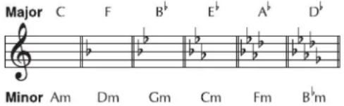 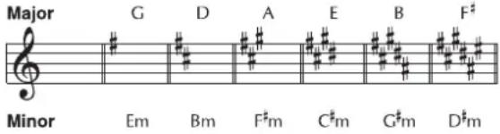 | |
BPM
| Parameter/Range | Explanation |
| BPM | |
| 40–250 | Adjust the BPM value for each patch. |
Control with the Master BPM
You can tap input the BPM with [F1].
AMP CONTROL
| Parameter/Range | Explanation |
| AMP CTL1, AMP CTL2 | |
| OFF, ON | This setting switches the FC-300's AMP CTL 1 and AMP CTL 2 parameters on and off. |
TX PC (Transmit Program Change)
| Parameter/Range | Explanation |
| You can assign whatever Program Change numbers you want to patches.* This setting is enabled when the SYSTEM MIDI TX PC MAP is set to PROG (p. 171). | |
| BANK MSB | |
| OFF, 1–127 | This sets the Bank Select (MSB) to be output. |
| BANK LSB | |
| OFF, 1–127 | This sets the Bank Select (LSB) to be output. |
| PC (Program Change) | |
| 1–128 | This sets the Program Change to be output. |
PATCH LEVEL
| Parameter/Range | Explanation |
| PATCH LEVEL | |
| 0–200 | Adjusts the volume the patch.* This parameter is the same as “PATCH LEVEL” (p. 146) in MIXER. |
GUITAR TO MIDI
| Parameter/Range | Explanation |
| GTR TO MIDI | |
| OFF, ON | This switches the GUITAR TO MIDI function on and off. Setting this to OFF prevents output of all GUITAR TO MIDI-related MIDI messages. |
PATCH
These parameters are set for each individual patch with the GUITAR TO MIDI function.
| Parameter/Range | Explanation |
| MODE | |
| This sets the transmission mode for the MIDI messages. | |
| MONO In this mode, one channel per string is used, thus using a total of six channels.Since each string uses a different MIDI channel, you can select a different tone for each string, using string bending or continuously varying the pitch on a specific string; however, this requires use of a multitimbral sound module. | |
| POLY In this mode, the messages for all six strings are transmitted over a single channel.While transmitting the MIDI messages for all of the strings over one channel does simplify the settings needed for the sound module and reduces the number of MIDI channels used, it does impose certain limitations; for example, permitting only one tone to be selected for all of the strings. | |
| PLAY FEEL | |
| This selects the feeling produced in playing the guitar, allowing you to choose picking with fingers or a pick to provide more natural dynamic expression. | |
| FEEL1-4 FEEL1 is the mode that gives sounds the broadest variation in volume based on the picking dynamics. As the setting number is increased, it becomes easier to produce high volume sounds even with weaker picking.This allows you to play with consistent volume, whether you tap the strings or use rough picking. In general, use higher setting numbers for softer picking, fingerpicking or tapping. | |
| NO DYNA In this mode, sounds are played at a fixed volume regardless of the picking strength. | |
| STRUM This suppresses the output of sounds from weaker picking.This setting allows you to prevent undesired sounds produced when playing rhythm or due to incidental contact with strings from incorrect picking. | |
| Parameter/Range | Explanation |
| CHROMATIC | |
| This sets the VG-99 so that if you play bends or slides, the unit will not send pitch bend message but instead will play the notes in half steps. | |
| OFF Normal Pitch Bend messages are output.The pitch varies continuously in keeping with the string bending or vibrato. | |
| TYPE1 When the pitch changes, this setting applies the results of the pitch change information without stopping the note that is playing. This produces a unique effect, whereby there is no attack sound when the pitches change, similar to slurring on a clarinet or a saxophone. | |
| TYPE2 When the pitch changes, the VG-99 retriggers (replays) the sound at the changed pitch, producing pitch changes only at the semitone increments.As a result, the attack of the new note starts at the current volume of the string, not the original volume. | |
| TYPE3 As with CHROMATIC TYPE 2, sounds are retriggered at the changed pitch, expressing the pitch changes only in semitones.However, instead of reflecting the attenuation of the string vibration, the retriggered sound is the same as that when the string was initially played. | |
| HOLD TYPE | |
| This selects the way the Hold function works. | |
| HOLD1 Note On messages are held when the Hold function is switched on with the controller. If the Hold function remains on as you continue to play the strings, each successive Note On message is held, and when a Note message is already being played from the same string,the previous Note message is cancelled, and the next Note On message is held. This allows you to prevent any interruption in the sounds, even sounds from releasing the strings over the frets. | |
| HOLD2 Note On messages are held when the Hold function is switched on with the controller. However, subsequent Note On messages are not output if you continue to play the instrument with the Hold effect left on. | |
| HOLD3 Note On messages are held when the Hold function is switched on with the controller. If the Hold function remains on as you continue to play the strings, Note On messages for strings other than the one already being held can be output, but they are not held. | |
| CC (Control Change) | |
| You can output the actions of the controllers specified with SRC as Control Change messages.You can make two types of settings, 1 and 2. | |
| SRC (Source) | |
| GK VOL | GK-3 GK volume knob |
| GK S1 GK-3 DOWN/S1 switch | |
| GK S2 GK-3 UP/S2 switch | |
| CTL1 Control button1 | |
| CTL2 Control button2 | |
| EXP PEDAL Expression | pedal connected to the EXP PEDAL jack |
| CTL3 Footswitch connected to the CTL3,4 jack (jack tip) | |
| CTL4 Footswitch connected to the CTL3,4 jack (jack ring) | |
| D BEAM V D BEAM vertical movements | |
| D BEAM H D BEAM horizontal movements | |
| RIBBON ACT RIBBON | CONTROLLER touch |
| RIBBON POS RIBBON | CONTROLLER position |
| FC-300 EXP1 FC-300 expression pedal1 | |
| FC-300 EXPSW1 FC-300 expression pedal switch1 | |
| FC-300 EXP2 FC-300 expression pedal2 | |
| FC-300 EXPSW2 FC-300 expression pedal switch2 | |
| FC-300 CTL1 FC-300 control pedal1 | |
| FC-300 CTL2 FC-300 control pedal2 | |
| FC-300 E3/C3 FC-300 external expression pedal3/external footswitch3 | |
| FC-300 CTL4 FC-300 external footswitch4 | |
| FC-300 E4/C5 FC-300 external expression pedal4/external footswitch5 | |
| FC-300 CTL6 FC-300 external footswitch6 | |
| FC-300 E5/C7 FC-300 external expression pedal5/external footswitch7 | |
| FC-300 CTL8 FC-300 external footswitch8 | |
| CC (Control Change) | |
| OFF, #1–#31, #64–#95 This sets the Control Change number to be output.* When the MONO/POLY setting is set to POLY, messages are output only over the basic channel; when this is set to MONO, the messages are output over the six channels starting from the basic channel. | |
| TX PC STRING 1–6(Transmit Program Change String 1–6) | |
| This sets the Program Change messages for each string that are output when the VG-99's patches are switched. | |
| BANK MSB | |
| OFF, 1–127 This sets the Bank Select (MSB). | |
| BANK LSB | |
| OFF, 1–127 | This sets the Bank Select (LSB). |
| PC (Program Change) | |
| OFF, 1–128 | This sets the Program Number. |
SYSTEM
These parameters are applied to the entire VG-99 in the GUITAR TO MIDI function.
| Parameter/Range | Explanation |
| HOLD CTL (Hold Control) | |
| This setting determines the controller used for the HOLD function. | |
| GK S1, S2 GK-3 DOWN | /S1, UP/S2 switch |
| CTL1, 2 Control button1, 2 | |
| CTL3 Footswitch connected to the CTL3,4 jack | |
| FC-300 CTL1,2 | FC-300 control pedal1, 2 |
| FC-300 CTL3-8 | FC-300 external footswitch3-8 |
| BEND THIN | |
| OFF, ON | Setting this to ON thins out the Pitch Bend messages and reduces the volume of MIDI data. |
| BASIC CH (Basic Channel) | |
| 1-11 | This sets the MIDI transmit channel used for the GUITAR TO MIDI function. |
| PC MASK (Program Change Mask) | |
| OFF, ON | When set to ON, the Bank Select messages and Program Change messages used for the GUITAR TO MIDI function are not transmitted when patches are changed. |
SYSTEM
LCD CONTRAST
| Parameter/Range | Explanation |
| CONTRAST | |
| 1-50 | Setting up the VG-99 in certain positions may make the display difficult to read. If this occurs, adjust the display contrast (legibility). |
DIRECT PATCH
| Parameter/ Range | Explanation |
| DIRECT PATCH | |
| DIR.PATCH 1-5 | This sets the desired [DIRECT PATCH 1]-[DIRECT PATCH 5]. |
*1 Setting available when GK PU TYPE is set to PIEZO F, PIEZO G, PIEZO L, or PIEZO R.
GK SETTING
| Parameter/Range | Explanation |
| GK CONNECT (GK Connect) | |
| AUTO | This automatically determines the GK connection and switches the internal settings. When the GK connection is in use, the GUITAR INPUT connection is disabled. |
| OFF Use this setting if you normally use the connection for GUITAR INPUT. | |
| ON Use this setting if you are normally using a GK connection. | |
| GK FUNC (GK Function) | |
| GK VOL (GK Volume) | |
| This selects the function assigned to GK VOL. cf. For more on the functions assigned, refer to the GK VOL column in “Parameters That Can Be Assigned to Separate Controllers” (p. 168). | |
| GK S1, S2 (GK S1, S2 Switch) | |
| This selects the functions assigned to GK S1, S2. cf. For more on the functions assigned, refer to the GK S1, S2 column in “Parameters That Can Be Assigned to Separate Controllers” (p. 168). | |
| SET MODE | |
| This setting allows you to select whether one GK SETTING is used globally for the entire VG-99 or if different GK SETTINGS are specified for each patch individually. | |
| SYSTEM The GK SETTING set here is used globally for the entire VG-99. This is the default factory setting. | |
| PATCH GK SETTINGS are specified for each patch individually. Carry out the Write procedure after making changes to the settings in each patch. Use this setting when performing with multiple guitars, switching the instrument depending on the patch used. | |
| SETTING1-10 | |
| 1-10 | This selects the GK SETTING to be set. |
| NAME | |
| This sets the name for the GK SETTING (up to eight characters). | |
| INSERT Insert a space at the cursor location. | |
| DELETE Delete a character. The characters that follow get shifted to the left. | |
| SPACE Input a space at the cursor location. | |
| A0! Switch between uppercase letters, numbers, and characters. | |
| A<=a Switch between uppercase letters and lowercase letters. | |
| GK PU TYPE (GK Pickup Type) | |
| GK-3 | Specifies the GK-3. |
| GK-2A Specifies the GK-2A or GK-2. | |
| PIEZO This is suited to | piezo pickups that have a flat response. |
| PIEZO F This is suited to | piezo pickups made by Fishman Transducers. |
| PIEZO G This is suited to | piezo pickups made by Graph Tech Guitar Labs. |
| PIEZO L This is suited to | piezo pickups made by L.R. Baggs. |
| PIEZO R This is suited to | piezo pickups made by RMC Pickup Co. |
| GUITAR SCALE | |
| 620–660mm,ST (648mm),LP (628mm) | This sets the scale length for your guitar. |
| GK PU PHASE (GK Pickup Phase) | |
| This sets the phase for the divided pickup and normal pickup.Set this to NORMAL, and if the low-frequency range is cut, set this to INVERS.TIPMixing the divided pickup sound and normal pickup sound (p. 33) makes it easier to determine the phase. | |
| NORMAL The phase is | left unchanged. |
| INVERS The phase is inverted. | |
| GK PU DIRECTION (GK Pickup Direction) | |
| This sets the direction for the divided pickup's installation. | |
| NORMAL Positioned such that the cable exits near the 6th string. | |
| REVRSE Positioned such that the cable exits near the 1st string. | |
| S1, S2 POS (S1, S2 Position) | |
| This exchanges the function for the GK-3's or GK-2A's DOWN/S1, UP/S2 switches. | |
| NORMAL The switches are left unchanged. | |
| REVRSE The DOWN/S1 switch and UP/S2 switch are exchanged. | |
| PICKUP× BRIDGE 1st–6th | |
| 10.0–30.0mm | This sets the distance of the gap between each Divided pickup and the bridge.The setting is disregarded when the GK PU TYPE is set to piezo type parameter. |
| SENS 1st–6th | |
| 0–100 | This sets the input sensitivity for each string. |
| LOW *1 | |
| -10–0–+10 | Adjusts the low frequency range tone. |
| HIGH *1 | |
| -10–0–+10 | Adjusts the high frequency range tone. |
CONTROL ASSIGN
| Parameter/Range | Explanation |
| Controller | |
| You can freely assign functions to the VG-99's and FC-300's controllers. | |
| GK VOL GK-3 GK volume knob | |
| GK S1, S2 GK-3 DOWN/S1, UP/S2 switch | |
| CTL1 Control button1 | |
| CTL2 Control button2 | |
| EXP PEDAL Expression pedal connected to the EXP PEDAL jack | |
| CTL3 Footswitch connected to the CTL3,4 jack (jack tip) | |
| CTL4 Footswitch connected to the CTL3,4 jack (jack ring) | |
| FC-300 EXP1 FC-300 expression pedal1 | |
| FC-300 EXP SW1 FC-300 expression pedal switch1 | |
| FC-300 EXP2 FC-300 expression pedal2 | |
| FC-300 EXP SW2 FC-300 expression pedal switch2 | |
| FC-300 CTL1 FC-300 control pedal1 | |
| FC-300 CTL2 FC-300 control pedal2 | |
| FC-300 E3/C3 FC-300 external expression pedal3/external footswitch3 | |
| FC-300 CTL4 FC-300 external footswitch4 | |
| FC-300 E4/C5 FC-300 external expression pedal4/external footswitch5 | |
| FC-300 CTL6 FC-300 external footswitch6 | |
| FC-300 E5/C7 FC-300 external expression pedal5/external footswitch7 | |
| FC-300 CTL8 FC-300 external footswitch8 | |
| ASSIGN HOLD | |
| This setting determines whether or not the values (positions) of the D BEAM (H) or RIBBON CONTROLLER or the FC-300's expression pedals or control pedals or other controllers are to be reflected in the sound as soon as a patch is called up. | |
| ON When a patch is called up, the controller values (positions) are applied, producing a sound that reflects the controller settings. | |
| OFF | When a patch is changed, the sound set in the patch is played, regardless of the controller values (positions). |
Parameters That Can Be Assigned to Separate Controllers
CTL1-4, FC-300 EXP SW1/EXP SW2, FC-300 CTL1, 2, 4, 6, 8
FC-300 EXP3/CTL3, EXP4/CTL5, EXP5/CTL7
GK \1, \2
GK VOL, EXP PEDAL, FC-300 EXP1/EXP2
| Parameter | Explanation | ||||
| Parameters for which √ is indicated can be assigned to the controllers shown here. | |||||
| OFF No function is | assigned. | √ | √ | √ | √ |
| ASSIGNABLE (PATCH) | Functions according to the Control Assign settings in each individual patch. | √ | √ | √ | √ |
| PATCH LEVEL 0-100 | Provides control of the patch level. | √ | √ | ||
| PATCH LEVEL 0-200 | √ | √ | |||
| AB BALANCE | Provides control of the balance of the volume in Channel A and Channel B. | √ | √ | ||
| FOOT VOLUME [A&B] | Provides simultaneous control of the foot volume in Channel A and Channel B. | √ | √ | ||
| FOOT VOLUME [A] | Provides control of the foot volume in Channel A or Channel B. | √ | √ | ||
| FOOT VOLUME [B] | √ | √ | |||
| WAH Provides control of the pedal wah when the pedal wah is switched on. | √ | √ | |||
| GUITAR VOLUME [A&B] | Provides simultaneous control of the COSM guitar volume in Channel A and Channel B. | √ | √ | ||
| GUITAR VOLUME [A] | Provides control of the COSM guitar volume in Channel A or Channel B. | √ | √ | ||
| GUITAR VOLUME [B] | √ | √ | |||
| GUITAR TONE [A&B] | Provides simultaneous control of the COSM guitar tone in Channel A and Channel B. | √ | √ | ||
| GUITAR TONE [A] | Provides control of the COSM guitar tone in Channel A or Channel B. | √ | √ | ||
| GUITAR TONE [B] | √ | √ | |||
| MIXER LEVEL [A&B] | Provides simultaneous control of the mixer volume level in Channel A and Channel B. | √ | √ | ||
| MIXER LEVEL [A] | Provides control of the mixer volume level in Channel A or Channel B. | √ | √ | ||
| MIXER LEVEL [B] | √ | √ | |||
| PATCH SEL DEC/INC | When set to INC, patch numbers increase when patches are switched; setting this to DEC causes the VG-99 to switch to lower patch numbers when patches are switched. | √ | |||
CTL1-4, FC-300 EXP SW1/EXP SW2, FC-300 CTL1, 2, 4, 6, 8
FC-300 EXP3/CTL3, EXP4/CTL5, EXP5/CTL7
GK S1, S2
GK VOL, EXP PEDAL, FC-300 EXP1/EXP2
| Parameter | Explanation | ||||
| PU SEL [A&B] | Allows you to switch the pick-ups in Channel A and Channel B simultaneously. | √ | |||
| PU SEL [A] | Allows you to switch the pick-ups in Channel A or Channel B. | √ | |||
| PU SEL [B] | √ | ||||
| S1:TUNER/S2:BPM TAP | The TUNER screen is switched with S1. S2 can be used for tap input of the BPM parameter. | √ | |||
| PATCH LEVEL DEC/INC | Provides control of the patch level. | √ | |||
| AB BALANCE toA/toB | Provides control of the volume balance between Channel A and Channel B. The level from Channel A is increased with S1; the level from Channel B is increased with S2. | √ | |||
| MIDI START/ STOP | Transmits Start and Stop for transmission of MIDI Realtime messages. | √ | √ | √ | |
| MMC PLAY/ STOP | Transmits Play and Stop for transmission of MIDI Machine Control. | √ | √ | √ | |
| FC-300 AMP CTL 1/2 | Provides control of the FC-300's AMP CONTROL1 and AMP CONTROL2 jacks. This allows switching of the channels for guitar amps connected to these jacks. | √ | |||
| PATCH SELECT INC | Switches to higher patch numbers when patches are switched. | √ | √ | ||
| PATCH SELECT DEC | Switches to lower patch numbers when patches are switched. | √ | √ | ||
| PU SEL toFRONT [A&B] | Switches the Channel A and Channel B pickups towards the front. | √ | √ | ||
| PU SEL toREAR [A&B] | Switches the Channel A and Channel B pickups towards the rear. | √ | √ | ||
| PU SEL toFRONT [A] | Switches the Channel A pickup towards the front. | √ | √ | ||
| PU SEL toREAR [A] | Switches the Channel A pickup towards the rear. | √ | √ | ||
| PU SEL toFRONT [B] | Switches the Channel B pickup towards the front. | √ | √ | ||
| PU SEL toREAR [B] | Switches the Channel B pickup towards the rear. | √ | √ | ||
| TUNER ON/OFF | Switches the TUNER screen. | √ | √ | ||
| BPM TAP | Allow tap input for the BPM parameter. | √ | √ | ||
| PATCH LEVEL INC | Increases the patch level. | √ | √ |
| CTL1-4, FC-300 EXP SW1/EXP SW2,FC-300 CTL1, 2, 4, 6, 8 | ||||
| FC-300 EXP3/CTL3, EXP4/CTL5, EXP5/CTL7 | ||||
| GK S1, S2 | ||||
| GK VOL, EXP PEDAL, FC-300 EXP1/EXP2 | ||||
| Parameter | Explanation | |||
| PATCH LEVELDEC | Decreases the patch level. | √ | √ | |
| AB BALANCetoB | Increases the volume level in Channel B in the balance between Channel A and Channel B. | √ | √ | |
| AB BALANCetoA | Increases the volume level in Channel A in the balance between Channel A and Channel B. | √ | √ | |
| FC-300AMP CTL 1 | Switches to the channel assigned for the guitar amp connected the FC-300's AMP CONTROL1 jack. | √ | √ | |
| FC-300AMP CTL 2 | Switches to the channel assigned for the guitar amp connected the FC-300's AMP CONTROL2 jack. | √ | √ | |
FC-300
| Parameter/Range | Explanation |
| SYS EX MODE (System Exclusive Mode) | |
| This sets the FC-300's control method. | |
| ON When connected to | the VG-99, the FC-300 automatically changes to System Exclusive mode and operates in accordance with the settings made with the VG-99. This is the setting you should normally select.MEMOYou can control the FC-300 even without matching the VG-99's and FC-300's Device IDs. |
| OFF Select OFF when controlling the FC-300's with the FC-300 (manually). | |
| BANK CHANGE | |
| This sets the timing with which tones switch when patches are changed with the FC-300. | |
| IMMEDIATE The tone | changes immediately when the FC-300's ▼ pedals are pressed. |
| WAIT NUM | Even after the FC-300's ▼ pedals are pressed, the tone does not change until the NUMBER is set. |
| QUICK TUNER | |
| This enables use of the FC-300's number pedals to switch the Tuner function on and off.The Quick Tuner function is enabled only when the FC-300's MODE is set to SYS EX. | |
| OFF The QUICK TUNER | R function is not operational. |
| ON The QUICK TUNER | function is operational.The TUNER function is alternately switched on and off each time the currently selected number pedal is pressed. |
MIDI
| Parameter/Range | Explanation |
| MIDI CH (MIDI Channel) | |
| 1-16ch | This sets the channel used for transmitting and receiving MIDI messages.When controlling another synthesizer sound module using the GUITAR TO MIDI function, also refer to “GUITAR TO MIDI” (p. 164). |
| OMNI MODE | |
| OFF, ON | When MIDI OMNI MODE is set to ON, messages are received on all MIDI channels, regardless of the MIDI channel settings. |
| DEVICE ID | |
| 1-32 | This sets the Device ID used for transmission and reception of Exclusive messages. |
| SYNC CLOCK | |
| This setting determines the basis used for synchronizing the timing for effect modulation rates and other time-based parameters. | |
| INTERNAL Operations | are synchronized to the VG-99’s internal Clock. |
| AUTO (USB) Operations | are synchronized to the MIDIClock received via USB. However, operations are automatically synchronized to the VG-99’s internal Clock if the VG-99 is unable to receive the external Clock. |
| AUTO (MIDI) Operations | are synchronized to the MIDIClock received via MIDI. However, operations are automatically synchronized to the VG-99’s internal Clock if the VG-99 is unable to receive the external Clock. |
| AUTO (RRC2) Operations | are synchronized to the MIDIClock received via the RRC2 connector.However, operations are automatically synchronized to the VG-99’s internal Clock if the VG-99 is unable to receive the external Clock. |
| ROUTING | |
| MIDI IN→ | |
| This sets the routing of signals arriving at the MIDI IN connector. | |
| OFF Only VG-99 Exclusive messages are received via MIDI IN. | |
| MAIN Signals received | at MIDI IN are transmitted to the VG-99’s internal section. |
| Parameter/Range | Explanation |
| MIDI OUT← | |
| This sets the routing of signals at the MIDI OUT connector. | |
| OFF Only Bulk Dump | data is output from MIDI OUT. |
| MAIN Signals from the | VG-99 are output. |
| USB MIDI signals received via USB are output. | |
| MIDI The MIDI signals | received at MIDI IN are output from MIDI OUT (thru).When other signals also are set to be output simultaneously from MIDI OUT, the signals are mixed and then output together (merge). |
| RRC2 The MIDI signals | received at through RRC2 are output from MIDI OUT (thru).When other signals also are set to be output simultaneously from MIDI OUT, the signals are mixed and then output together (merge). |
| USB (MIDI)→ | |
| This sets the routing of signals received via USB. | |
| OFF Only VG-99 Exclusive messages are received via USB. | |
| MAIN Signals received via USB are transmitted to the VG-99's internal section. | |
| USB (MIDI)← | |
| This sets the routing of signals output from the USB connector. | |
| OFF Only Bulk Dump | data is output from USB. |
| MAIN MIDI signals from the VG-99 are output. | |
| MIDI MIDI signals received at MIDI IN are output. | |
| RRC2 MIDI signals received through RRC2 are output. | |
| RRC2→ | |
| This sets the routing of signals received via RRC. | |
| OFF Only VG-99 Exclusive messages are received via RRC2. | |
| MAIN Signals received at the RRC2 connector are transmitted to the VG-99's internal section. | |
| RRC2← | |
| This sets the routing of signals output from the RRC2 connector. | |
| OFF Only Bulk Dump | data is output from the RRC2 connector. |
| MAIN MIDI signals from the VG-99 are output. | |
| USB MIDI signals received via USB are output. | |
| MIDI MIDI signals received at MIDI IN are output from the RRC2 connector (thru). When other signals also are set to be output simultaneously from the RRC2 connector, the signals are mixed and then output together (merge). | |
| PC (Program Change) | |
| PC OUT (Program Change Out) | |
| OFF, ON | This setting determines whether or not Program Change messages are output when the VG-99's patches are switched.Program Change messages are output when this is set to ON. |
| TX PC MAP (Transmit Program Change Map) | |
| This setting determines the sequence of Program Change messages output when the VG-99's patches are changed. | |
| FIX Regardless of the patch settings, ProgramChange messages predetermined for each patch number are output. | |
| PROG The Program Change messages programmed in each patch are output. | |
| RX PC MAP (Receive Program Change Map) | |
| You can select whether to use a fixed or freely set correspondence between program numbers received and the patches switched to when the VG-99's patches are switched by Program Change messages transmitted by an external MIDI device. | |
| FIX The VG-99 switches to the patches predetermined for the corresponding received Program Change messages, regardless of the Receive Program Change Map settings. | |
| PROG The VG-99's switches to the patches set in the Receive Program Change Map. | |
| RX PC MAP (Receive Program Change Map) | |
| You can edit the correspondence between the Program Change numbers received and the patches that are switched to. | |
| [F1] (BANK) Selects the Bank number. | |
| [F2] [F3] (SEL)/F2, F3 knob | Selects the Program number. |
| [F5] (SELECT)/F5 knob | Selects the patch.When the combination of the Bank number and Program number selected with F1, F2, and F3 is received, the VG-99 switches to the patch selected with F5. |
| TX CC (Transmit Control Change) | |
| This sets the Control Change numbers output when the VG-99's pedals and external pedals or the FC-300's pedals and external pedals are operated. | |
| [F2] [F3] (SEL)/F2, F3 knob | Selects the controller. |
| [F5] (SET OFF)/F5 knob | When the controller selected with F2 or F3 is operated, the Control Change message selected with F5 is transmitted. |
| Parameter/Range | Explanation |
| BULK DUMP | |
| With the VG-99, you can use Exclusive messages to set another VG-99 to the same settings or to save effect sound settings to MIDI sequencers and other such devices. | |
| ALL All transmittable data (SYSTEM, GK SETTING, GLOBAL, PATCH 001–200, FAVOR-ITE SETTING) | |
| SYSTEM SYSTEM parameters. | |
| GK SETTING Settings content for GK SETTING | |
| GLOBAL GLOBAL function settings | |
| PATCH Settings for patch numbers 001–200 | |
| FAVORITE SETTING Settings content in FAVORITE SETTINGS 01–10 for all effects | |
OUTPUT
| Parameter/Range | Explanation |
| OUTPUT MODE | |
| SYSTEM | The values set in the SYSTEM parameters MAIN OUT, MAIN LEVEL, SUB OUT, SUB LEVEL, D OUT, and D OUT LEVEL are enabled. |
| PATCH The values set | in MAIN OUT, MAIN LEVEL, SUB OUT, SUB LEVEL, D OUT, D OUT LEVEL for each patch are enabled. |
| MAIN OUT | |
| This switches the signals output to MAIN OUT. | |
| CH A This outputs Channel A. | The mixer's MIX SW, PAN, LEVEL, and A/B BAL are also reflected here. |
| CH B This outputs Channel B. | The mixer's MIX SW, PAN, LEVEL, and A/B BAL are also reflected here. |
| MIXER (DRY) This outputs the post-A/B mix signals before application of DELAY/REVERB. | |
| MIXER This outputs the post-A/B mix signals after application of DELAY/REVERB and TOTAL EQ. | |
| MAIN LEVEL | |
| 0–200 | Adjusts the level to MAIN LEVEL. |
| SUB OUT | |
| This switches the signals output to SUB OUT. | |
| CH A This outputs Channel A. | The mixer's MIX SW, PAN, LEVEL, and A/B BAL are also reflected here. |
| CH B This outputs Channel B. | The mixer's MIX SW, PAN, LEVEL, and A/B BAL are also reflected here. |
| MIXER (DRY) This outputs the post-A/B mix signals before application of DELAY/REVERB. | |
| MIXER This outputsthe post-A/B mix signals after application of DELAY/REVERB and TOTAL EQ. | |
| SUB LEVEL | |
| 0–200 Adjusts the level to SUB OUT LEVEL. | |
| Parameter/Range | Explanation |
| D OUT (Digital Out) | |
| This switches the signals output from DIGITAL OUT. | |
| COSM GTR A This outputs the sounds from COSM GTR A. | |
| COSM GTR B This outputs the sounds from COSM GTR B. | |
| NORMAL PU This outputs the sounds from the normal pickup. | |
| CH A This outputs Channel A.This output also reflects the mixer's MIX SW, PAN, LEVEL, and A/B BAL settings. | |
| CH B This outputs Channel B.This output also reflects the mixer's MIX SW, PAN, LEVEL, and A/B BAL settings. | |
| MIXER (DRY) This outputs the post-A/B mix signals before application of DELAY/REVERB. | |
| MIXER This outputs the post-A/B mix signals after application of DELAY/REVERB and TOTAL EQ. | |
| MAIN OUT This outputs the same signals as those from MAIN OUT. | |
| SUB OUT This outputs the same signals as those from SUB OUT. | |
| D OUT LEVEL (Digital Out Level) | |
| 0–200 | Adjusts the level to DIGITAL OUT. |
* The parameters enabled (MAIN OUT, MAIN LEVEL, SUB OUT, SUB LEVEL, D OUT, D OUT LEVEL) change according to the OUTPUT MODE settings.
When they are disabled, the value < is given.
USB
| Parameter/Range | Explanation |
| USB IN | |
| This sets the point at which digital audio signals received via USB (from your computer) are connected within the VG-99.* Do not connect at a point before the point set with the USB OUT parameter. For more on the connection points, refer to “Signal Flow” (p. 183).* If the USB IN parameter is set to COSM GTR A, COSM GTR B, or NORMAL PU, the setting automatically changes to MAIN & SUB the next time the VG-99 is powered up. If you plan to use COSM GTR A, COSM GTR B, or NORMAL PU, make the setting each time you turn on the power to the VG-99. | |
| OFF | The signals are not connected at any point. |
| COSM GTR A The signals are connected at the point where the COSM GUITAR A is output.The audio output from the computer, instead of the COSM guitar sounds played by the connected guitar, is input to the effects.* POLY FX are not applied. | |
| COSM GTR B The signals are connected at the point where the COSM GUITAR B is output.The audio output from the computer, instead of the COSM guitar sounds played by the connected guitar, is input to the effects.* POLY FX are not applied. | |
| NORMAL PU | The signals are connected at the normal pickup input.The audio output from the computer, instead of the normal sounds played by the connected guitar, is input to the effects. |
| MAIN OUT The signals are connected at the point where MAIN OUT is output.The signals from the VG-99's MAIN OUT and the audio output from the computer are mixed and output. | |
| SUB OUT The signals are connected at the point where SUB OUT is output.The signals from the VG-99's SUB OUT and the audio output from the computer are mixed and output. | |
| MAIN&SUB The signals are connected at the point where both MAIN OUT and SUB OUT are output. Each of the signals from the VG-99's MAIN OUT and the audio output from the computer are mixed, SUB OUT and the audio output from the computer are mixed from the output. | |
| IN LEVEL | |
| 0–200 | Adjusts the volume level of the digital audio received via USB (from the computer). |
| USB OUT | |
| This sets the point internally within the VG-99 from which signals are output via USB (to the computer). | |
| COSM GTR A | The output from COSM GUITAR A is output. |
| COSM GTR B | The output from COSM GUITAR B is output. |
| Parameter/Range | Explanation |
| NORMAL PU | The normal pickup input is output. |
| CH A The output from | Channel A is output. |
| CH B The output from | Channel B is output. |
| MIXER (DRY) The signals that have been mixed with the mixer, but before application of DELAY/ REVERB, are output. | |
| MIXER The signals that have been mixed with the mixer and have DELAY/REVERB applied are output. | |
| MAIN OUT The same signals as those from MAIN OUT are output. | |
| SUB OUT The same signals as those from SUB OUT are output. | |
| OUT LEVEL | |
| 0-200 | Adjusts the volume level of the digital audio output via USB (to the computer). |
| DRIVER MODE | |
| This setting determines which operational mode is used, the mode using the special driver contained on the included CD-ROM (ADVANC) or the mode using the OS's (Windows/Mac OS) standard driver (STANDRD).* Changing the settings for this parameter requires you to turn off the power to the VG-99 and then turn it on again.For more detailed information, refer to “Switching the Driver Mode” (p. 72). | |
| STANDRD | This mode uses the OS's standard USB driver. |
| ADVANC This mode uses the special driver contained on the included CD-ROMThe mode using this driver allows you to record, play back, and edit audio with high-quality sound and stable timing. | |
| MON CMD (Monitor Command) | |
| This setting determines whether or not the command (the Direct Monitor command) controlling the Direct Monitor (described later) setting is enabled. | |
| DISABL The Direct Monitor command is disabled,maintaining the Direct Monitor mode set by the VG-99. | |
| ENABLE The Direct Monitor command is enabled, allowing the Direct Monitor mode to be switched from an external device. | |
| DIRECT MON (Direct Monitor) | |
| Switches the output of the VG-99 sound to the PHONES jack, MAIN OUT jacks, or SUB OUT jacks. | |
| OFF Set this to Off if transmitting audio data internally through a computer (Thru). | |
| ON The VG-99 sound is output. Set this to On when using the VG-99 as a standalone device, without connecting to a computer (only USB IN input sound will be output if this is set to Off). | |
| * This setting cannot be saved. It is set to ON when the power is turned on.* If you are using the special driver, you can control DIRECT MON On/Off from ASIO 2.0-compatible application. | |
V-LINK
V-LINK PATCH
CLIP
| Parameter/Range | Explanation |
| This sets the Program Change messages transmitted when patches are switched.You can set different Program Changes in Channel A and Channel B. The clips (video images) on the receiving device are switched by these Program Change messages. | |
| A ch/B ch PALETTE | |
| OFF, 1–32 | This sets the Bank Select number (CC#0, #32). |
| A ch/B ch CLIP | |
| OFF, 1–32 | This sets the Program Change numbers. |
ASSIGN 1-2
| Parameter/Range | Explanation |
| These settings are necessary for controlling video using the guitar's performance data and messages from the VG-99's controllers. You can make up to two types of settings. | |
| SOURCE | |
| OFF | The V-LINK function is not assigned. |
| BEND Pitch bend messages | |
| VELO Velocity messages | |
| GK VOL GK-3 GK volume knob | |
| GK S1 GK-3 DOWN/S1 switch | |
| GK S2 GK-3 UP/S2 switch | |
| CTL1 Control button1 | |
| CTL2 Control button2 | |
| EXP PEDAL Expression pedal connected to the EXP PEDAL jack | |
| CTL3 Footswitch connected to the CTL3,4 jack (jack tip) | |
| CTL4 Footswitch connected to the CTL3,4 jack (jack ring) | |
| D BEAM V D BEAM vertical movements | |
| D BEAM H D BEAM horizontal movements | |
| RIBBON RIBBON CONTROLLER | |
| FC-300 EXP1 FC-300 expression pedal1 | |
| FC-300 EXPSW1 FC-300 expression pedal switch1 | |
| FC-300 EXP2 FC-300 expression pedal2 | |
| FC-300 EXPSW2 FC-300 expression pedal switch2 | |
| FC-300 CTL1 FC-300 control pedal1 | |
| FC-300 CTL2 FC-300 control pedal2 | |
| FC-300 E3/C3 FC-300 external expression pedal3/external footswitch3 | |
| FC-300 CTL4 FC-300 external footswitch4 | |
| FC-300 E4/C5 FC-300 external expression pedal4/external footswitch5 | |
| Parameter/Range | Explanation |
| FC-300 CTL6 FC-300 external footswitch6 | |
| FC-300 E5/C7 FC-300 external expression pedal5/external footswitch7 | |
| FC-300 CTL8 FC-300 external footswitch8 | |
| INTRNL PEDAL Internal pedal | |
| WAVE PEDAL Wave pedal | |
| TARGET | |
| Used in the motion dive .tokyo performance package. | |
| COLOR EQ-FG Color foreground | |
| COLOR EQ-BG Color background | |
| SCRTCH SW | Scratch switch |
| SPEED KNOB | Speed knob |
| TOTAL FADER | Total fader |
| CROSS FADER Cross fader | |
| BPM SYNC | BPM sync switch |
| CLIP LOOP | Clip loop switch |
| ASSIGN KNOB | Assignable knob |
| FADE TIME | Fade time switch |
| VISUAL KNOB | Visual plug-in control knob |
| AB SW | A/B switch |
| TAP SW | Tap switch |
| TOTAL SELECT | Total select |
| FX SELECT | Effect select |
| PLAY POS | Play position |
| LOOP START | Loop start position |
| LOOP END | Loop end position |
| LAYER MODE | Layer mode select |
| DV-7PR | |
| PLAY SPEED | Play speed |
| DISLV TIME Dissolve time(time elapsed in switching video images) | |
| T BAR | T bar |
| COLOR Cb Color cb (Color difference signal) | |
| COLOR Cr Color cr (Color difference signal) | |
| BRIGHTNESS | Brightness |
| VFX 1 | Visual effects1 |
| VFX 2 | Visual effects2 |
| VFX 3 | Visual effects3 |
| VFX 4 | Visual effects4 |
| OUTPUT FADE | Output fade |
| DUAL STREAM | Dual stream |
| MIN (Minimum) *1 | |
| 0–127 | Sets the lower limit in the range the parameter changes. |
| MAX (Maximum) *1 | |
| 0–127 | Sets the upper limit in the range the parameter changes. |
| TRIGGR (Trigger) *2 | |
| Sets the point at which the virtual expression pedal's action begins. | |
| PATCH CHANGE Functions when patches are switched. | |
| GK VOL Functions when the divided pickup's volume knob is adjusted. | |
| GK S1, S2 Functions when the divided pickup's DOWN/S1 or UP/S2 switch position is changed. | |
| CTL1-CTL4 Functions when the CTL 1, 2 buttons or foot switch connected to CTL 3,4 jack are operated. | |
| EXP PEDAL Functions when the expression pedal connected to EXP PEDAL jack are operated. | |
| D BEAM V, H Functions when the vertical or horizontal position is detected by the D Beam controller. | |
| RIBBON ACT, POS Functions when the ribbon controller is operated by touch or when the position is detected. | |
| FC-300 EXP1, EXP2 Functions when the FC-300's EXP PEDAL 1 or 2 is operated. | |
| FC-300 CTL1, CTL2 Functions when the FC-300's CTL1 or CTL2 is operated. | |
| FC-300 E3/C3, CTL4, E4/C5, CTL6, E5/C7, CTL8 | Functions when a pedal connected to the FC-300's E3/C3, CTL4, E4/C5, CTL6, E5/C7, or CTL8 jacks is operated. |
| TIME *2 | |
| 0-100 Adjusts the amount of time for the virtual expression pedal to shift from the fully released position (pedal toe raised) to the fully depressed position (pedal toe pressed down). | |
| CURVE *2 | |
| This selects one of the three types that determines how the assumed expression pedal changes. | |
LINEAR SLOW RISE FAST RISE | |
| RATE *3 | |
| 0-100 | This determines the time spend for one cycle of the assumed expression pedal. |
| FORM *3 | |
| This selects one of the three types that determines how the assumed expression pedal should change. | |
*1 You cannot set the MIN or MAX parameters when the TARGET parameter is set to one of the functions below. The MIN parameter is fixed at 0, and the MAX parameter is fixed at 127.
- SCRTCH SW
- BPM SYNC
- CLIP LOOP
• AB SW
• TAP SW - DUAL STREAM
*2 The TRIGGR, TIME, and CURVE parameters are enabled when the SOURCE parameter is set to INTRNL PEDAL.
*3 The RATE and FORM parameters are enabled when the SOURCE parameter is set to WAVE PEDAL.
MEMO
Although the target names indicated refer to EDIROL DV-7PR and motion dive .tokyo, it is Control Change messages that are actually transmitted.
For more on the correspondence between the target names and Control Change numbers, refer to p. 181.
MEMO
For more detailed information on the EDIROL DV-7PR and motion dive .tokyo performance package, refer to the Owner's Manuals for each product.
STRING CH (String Channel)
| Parameter/Range | Explanation |
| 1st-6th | |
| Selects the channel to be controlled with each string. | |
| OFF No channel is controlled. | |
| A CH Channel A of the V-LINK compatible device is controlled. | |
| B CH Channel B of the V-LINK compatible device is controlled. | |
| C CH MIDI Note plug-in is controlled. | |
MEMO
Some V-LINK compatible equipments such as the EDIROL DV-7PR allow use only of A CH.
V-LINK SYSTEM
MIDI CH (MIDI Channel)
| Parameter/ Range | Explanation |
| This sets the MIDI receive channel for the V-LINK compatible device connected to the VG-99. | |
| MIDI A CH (MIDI A Channel) | |
| 1–16ch | Sets the MIDI channel for Channel A of the V-LINK compatible device. |
| MIDI B CH (MIDI B Channel) | |
| 1–16ch | Sets the MIDI channel for Channel B of the V-LINK compatible device. |
| MIDI C CH (MIDI B Channel) | |
| 1–16ch | Specifies the MIDI channel that will control MIDI note plug-in. |
MEMO
- The V-LINK screen's MIDI CH parameter is a system parameter.
- When a V-LINK compatible device is connected to the VG-99, set this parameter so that the V-LINK compatible device's MIDI channel and the MIDI channel used by the VG-99 are not the same.
- The MIDI channels set here are output as System Exclusive messages when the VG-99's power is turned on and when the V-LINK function is switched on.
- Some V-LINK compatible equipments such as the EDIROL DV-7PR allow use only of MIDI A CH.
CATEGORY NAME
| Parameter/ Range | Explanation |
| CATEGORY NAME | |
| This sets the Category name. | |
| INSERT Insert a space at the cursor location. | |
| DELETE Delete a character. The characters that follow get shifted to the left. | |
| SPACE Input a space at the cursor location. | |
| A0! Switch between uppercase letters, numbers, and characters. | |
| A<=>a Switch between uppercase letters and lowercase letters. | |
| CATGRY Select the user category you want to name. | |
D BEAM CALIB (D BEAM Calibration)
| Parameter/ Range | Explanation |
| D BEAM DISAB (D BEAM Disable) | |
| You can disable the D BEAM controller for the entire device. | |
| OFF The D BEAM is enabled. | |
| ON The D BEAM is disabled. | * Pressing the D BEAM [PITCH], [FILTER], or [ASSIGNABLE] button to switch the D BEAM controller on will have no effect. |
PATCH EXTENT
| Parameter/Range | Explanation |
| PATCH EXTENT | |
| You can set upper and lower limits to define the range of patches that can be switched. | |
| FROM | Set the lower limits to define the range of patches. |
| TO Set the upper limits | to define the range of patches. |
FACTORY RESET
| Parameter/Range | Explanation |
| FACTORY RESET | |
| This restores the VG-99 to the settings it had when it was shipped from the factory. | |
| ALL All data | |
| SYSTEM Content of the settings for the SYSTEM parameters, HARMONIST scales, AUTO RIFF phrases, preamps and speakers, overdrive/distortion and wah custom edit parameters | |
| GK SETTING Content of the settings for GK SETTING | |
| GLOBAL GLOBAL function settings | |
| PATCH Settings for patch numbers 001–200 | |
| FAVORITE SETTING | Content of the settings in FAVORITE SETTINGS 01–10 for all effects |
GLOBAL
| Parameter/Range | Explanation |
| MAIN OUTPUT SELECT | |
| This selects the type of device to be connected. | |
| JC-120 Set this when connecting a Roland JC-120 guitar amp. | |
| SMALL AMP Use this setting when connecting a compact guitar amp. | |
| COMBO AMP Set this when connecting to the guitar input for a combo-type guitar amp (combining amp and speakers in a single unit) other than a JC-120.* You may find that setting this to JC-120 may produce good results with your guitar amp. | |
| STACK AMP | Use this setting when connecting to the guitar input for a stack-type guitar amp (in which the amp and speakers are separated) |
| JC-120 RETURN Set this when connecting to the JC-120's RETURN. | |
| COMBO RETURN Set this when connecting to the RETURN on another combo-type amp. | |
| STACK RETURN Set this when connecting to the RETURN on a stack-type amp. Set STACK RETURN even when using a power amp for the guitar in combination with a speaker cabinet. | |
| LINE/PHONES Use this setting when using headphones or when recording with the VG-99 connected to a multitrack recorder.* Use the LINE/PHONES setting if you are using a speaker simulator. | |
EQ MAIN (Equalizer Main), EQ SUB (Equalizer Sub)
| Parameter/Range | Explanation |
| MAIN EQ (Main Equalizer),SUB EQ (Sub Equalizer) | |
| A four-band equalizer with high and low ranges is provided. The sound processed by the effect can be boosted by frequency range before it is output. | |
| MEMOEQ (MAIN) is applied to the output from MAIN OUT; EQ (SUB) is applied to the output from SUB OUT. | |
| MAIN EQ SW (Main Equalizer Switch),SUB EQ SW (Sub Equalizer Switch) | |
| OFF, ON | Turns the EQ effect on/off. |
| TOTAL GAIN | |
| -12–+12dB | Adjusts the volume before the equalizer. |
| LOW GAIN | |
| -12–+12dB | Adjusts the low frequency range tone. |
| Parameter/Range | Explanation |
| HIGH GAIN | |
| -12–+12dB | Adjusts the high frequency range tone. |
| LOW MID FREQ (Low Middle Frequency) | |
| 20Hz–10.0kHz | Specifies the center of the frequency range that will be adjusted by the LOW MID GAIN. |
| LOW MID Q (Low Middle Q) | |
| 0.5–16 | Adjusts the width of the area affected by the EQ centered at the LOW MID FREQ.Higher values will narrow the area. |
| LOW MID GAIN (Low Middle Gain) | |
| -12–+12dB | Adjusts the low-middle frequency range tone. |
| HIGH MID FREQ (High Middle Frequency) | |
| 20Hz–10.0kHz | Specifies the center of the frequency range that will be adjusted by the HIGH MID GAIN. |
| HIGH MID Q (High Middle Q) | |
| 0.5–16 | Adjusts the width of the area affected by the EQ centered at the HIGH MID FREQ.Higher values will narrow the area. |
| HIGH MID GAIN (High Middle Gain) | |
| -12–+12dB | Adjusts the high-middle frequency range tone. |
| Parameter/Range | Explanation |
| NS (Noise Suppressor) | |
| -20–20dB This controls | the global threshold level for the noise suppressor settings in each patch. This feature is effective when you connect a different guitar or for adjusting for changes in noise levels in the performance venue. It does not affect the settings in each individual patch.MEMOTo use the settings contained in the individual patches, set this to 0 dB. |
REVERB
| Parameter/Range | Explanation |
| REVERB | |
| 0–200% | This controls the global reverb level for the reverb settings in each patch. Adjusting this reverb level is effective for adjusting to the acoustics of the performance space. It does not affect the settings in each individual patch.MEMOTo use the settings contained in the individual patches, set this to 100%. |
SUB OUT LEVEL
| Parameter/Range | Explanation |
| SUB OUT LEVEL | |
| 0–200% | This controls the global output level from the SUB OUT connectors. It does not affect the settings in each individual patch.MEMOTo use line level (+4 dBu) as the output level, set this to 100%. |
TUNER
MULTI MODE, SINGLE MODE
| Parameter/ Range | Explanation |
| PITCH | |
| 435–445Hz | This sets the reference pitch. |
| MUTE | |
| This setting selects whether or not the tuning sound is output from the connected device (such as an amp). | |
| OFF The tuning sound is not output. | |
| ON The tuning sound is output. | |
MIDI Implementation Chart
| Function... | Transmitted Recognized Remarks | |||
| Basic Channel | Default Changed | 1-161-16 | 1-161-16 | Memorized |
| Mode | Default Messages Altered | x x********** | x x | |
| Note Number | True Voice | x********** | x********** | |
| Velocity | Note ON Note OFF | x x | x x | |
| After Touch | Key's Ch's | x x | x x | |
| Pitch Bend | x | x | ||
| Control Change | 0 1-31 32 33-63 64-95 | o o o x o *1 | *1 *1 *1 *1 | Bank Select MSB Bank Select LSB |
| Program Change | True # | o 0-127 | *1 0-127 | |
| System Exclusive | o | o | ||
| Common | Song Position Song Select Tune Request | x x x | x x x | |
| System Realtime | Clock Commands | x o *2 | o x *1 | |
| AUX Messages | Local ON/OFF All Notes OFF All Sound OFF Reset All Controller Active Sense System Reset | x x x x x o x | x x x x x o x | |
| Notes | *1 O X is selectable.*2 MIDI START/STOP can be set with SYSTEM - CONTROL ASSIGN. | |||
Mode 1: OMNI ON, POLY
Mode 3: OMNI OFF, POLY
Mode 2: OMNI ON, MONO
Mode 4: OMNI OFF, MONO
o: Yes
x: No
V-Guitar System
Date : May. 31, 2007
Model VG-99 MIDI Implementation Chart (GUITAR TO MIDI Section)
Version: 1.00
| Function... | Transmitted Recognized Remarks | |||
| Basic Channel | Default Changed | 1-111-11 | xx | Memorized |
| Mode | Default Messages Altered | Mode 3, 4 (M=6)x********** | Mode 3, 4 (M=6)x | Memorized |
| Note Number | True Voice | 00-127 | x********** | |
| Velocity | Note ON Note OFF | o x *2 | xx | |
| After Touch | Key's Ch's | xx | xx | |
| Pitch Bend | o *3 | x | ||
| Control Change | 0, 321 - 3133 - 6364 - 956, 3898, 99100, 101 | o *1o *1xo *1o x o | xxxxxxxx | Bank SelectData EntryNRPN LSB, MSBRPN LSB, MSB |
| Program Change | True # | o *10 - 127 | x********** | |
| System Exclusive | x | x | ||
| Common | Song Position Song Select Tune Request | xxx | xxx | |
| System Realtime | Clock Commands | xx | xx | |
| AUX Messages | Local ON/OFF All Notes OFF All Sound OFF Reset All Controller Active Sense System Reset | xxxxxxo x | xxxxx | |
| Notes | *1 O X is selectable.*2 Note On is always transmitted with 9nH kkH 00H.*3 Can be set with the CHROMATIC parameter. | |||
Mode 1: OMNI ON, POLY
Mode 2: OMNI ON, MONO
o: Yes
Mode 3: OMNI OFF, POLY
Mode 4: OMNI OFF, MONO
x: No
V-Guitar System
Date : May. 31, 2007
Model VG-99
MIDI Implementation Chart (V-LINK Section)
Version : 1.00
| Function... | Transmitted Recognized Remarks | |||
| Basic Channel | Default Changed | 1-16 1-16 | x x | Memorized |
| Mode | Default Messages Altered | x x********** | x x | |
| Note Number | True Voice | o *1 0-127 | x********** | |
| Velocity | Note ON Note OFF | o x *2 | x x | |
| After Touch | Key's Ch's | x x | x x | |
| Pitch Bend | x | x | ||
| Control Change | 0, 32 1 3 8 10 11 64 65 71 72 73 74 81 83 85 86 91 92 93 94 | o *1, *3 o *1, *3 o *1, *3 o *1, *3 o *1, *3 o *1, *3 o *1, *3 o *1, *3 o *1, *3 o *1, *3 o *1, *3 o *1, *3 o *1, *3 o *1, *3 o *1, *3 o *1, *3 o *1, *3 o *1, 0 - 31 | x x x x x x x x x x x x x x x x x x x x x x x x x x x x x x x x x x x x x x x x x x x x x x x x x x x x x x x x x x x x x x x x x x x x x x x x x x x x x x x x x x x x x x x x x x x x x x x x x x x x x | Bank Select Modulation Balance MSB Pan MSB Expression MSB Hold-1 Portamento Resonance Release Attack Cutoff General Purpose 6 General Purpose 8 Reverb Effects Depth 2 Effects Depth 3 Effects Depth 4 |
| Program Change | True # | o *1, *3 0 - 31 | x********** | |
| System Exclusive | o | x | ||
| Common | Song Position Song Select Tune Request | x x x | x x x | |
| System Realtime | Clock Commands | x x | x x | |
| AUX Messages | Local ON/OFF All Notes OFF All Sound OFF Reset All Controller Active Sense System Reset | x x x o o x | x x x x x x | |
| Notes | *1 O X is selectable.*2 The Note OFF messages (9nH kkH 00H) are always transmitted.*3 For correspondences with this device's parameters, refer to the "V-LINK Correspondence Table." | |||
Mode 1: OMNI ON, POLY
Mode 2: OMNI ON, MONO
o: Yes
Mode 3: OMNI OFF, POLY
Mode 4: OMNI OFF, MONO
x: No
V-LINK Correspondence Table
| V-LINK Function | Transmitted MIDI Message Transmitted Channel | |
| These are used with models such as the DV-7PR or the motion dive .tokyo performance package. | ||
| PALETTE 1–32 (Palette Change) | CC 0 (Bank Select MSB): 0–31CC 32 (Bank Select LSB): 0 | ch.A / ch.B |
| CLIP 1–32 (Clip Change) Program Change: 0–31 | ch.A / ch.B | |
| These are used with the motion dive .tokyo performance package. | ||
| COLOR EQ–FG CC 1 (Modulation) | ch.A & ch.B | |
| COLOR EQ–BG CC 71 (Resonance) | ch.A & ch.B | |
| SCRTCH SW | CC 3 (---) | ch.A & ch.B |
| SPEED KNOB CC 8 (Balance) | ch.A & ch.B | |
| TOTAL FADER | CC 10 (Panpot) | ch.A |
| CROSS FADER CC 11 (Expression) | ch.A | |
| BPM SYNC CC 64 (Hold 1) | ch.A & ch.B | |
| CLIP LOOP CC 65 (Portamento) | ch.A & ch.B | |
| ASSIGN KNOB CC 72 (Release) | ch.A & ch.B | |
| FADE TIME CC 73 (Attack) | ch.A | |
| VISUAL KNOB CC 74 (Cutoff) | ch.A | |
| AB SW CC 81 (General Purpose 6) | ch.A | |
| TAP SW CC 83 (General Purpose 8) | ch.A | |
| TOTAL SELECT CC 85 (---) | ch.A | |
| FX SELECT CC 86 (---) | ch.A | |
| PLAY POS CC 91 (Reverb) | ch.A & ch.B | |
| LOOP START CC 92 (Tremolo) | ch.A & ch.B | |
| LOOP END | CC 93 (Chorus) | ch.A & ch.B |
| LAYER MODE | CC 94 (Celeste) | ch.A |
| These are used with models such as the DV-7PR. | ||
| PLAY SPEED | CC 8 (Balance) | ch.A |
| DISLV TIME | CC 73 (Attack) | ch.A |
| T BAR | CC 11 (Expression) | ch.A |
| COLOR Cb | CC 1 (Modulation) | ch.A |
| COLOR Cr | CC 71 (Resonance) | ch.A |
| BRIGHTNESS CC 74 (Cutoff) | ch.A | |
| VFX 1 | CC 72 (Release) | ch.A |
| VFX 2 | CC 91 (Reverb) | ch.A |
| VFX 3 | CC 92 (Tremolo) | ch.A |
| VFX 4 | CC 93 (Chorus) | ch.A |
| OUTPUT FADE | CC 10 (Panpot) | ch.A |
| DUAL STREAM | CC 64 (Hold 1) | ch.A |
Signal Flow
Audio Signal
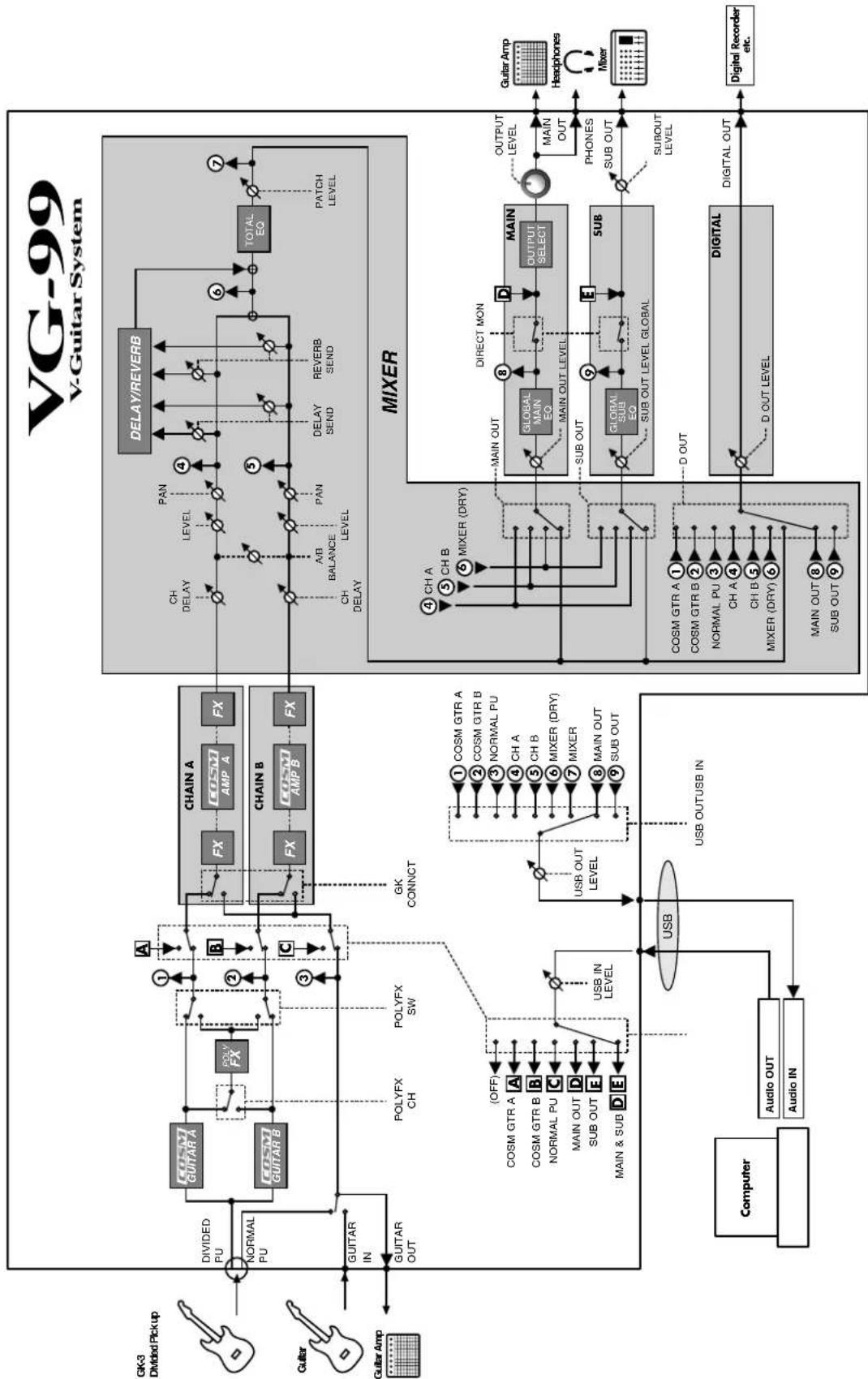
flowchart
```mermaid
graph TD
    subgraph_V_Guitar_System["VG-99 V-Guitar System"]
        direction TB
        A["GK3 Divided Pickup"] --> B["NORMAL PU"]
        C["Guitar"] --> D["GUITAR IN"]
        E["Guitar Amp"] --> F["GUITAR OUT"]
    end

    subgraph_MIXER["MIXER"]
        G["Computer"] --> H["Audio OUT"]
        H --> I["Audio IN"]
        J["DISCUPT"] --> K["USB IN LEVEL"]
        L["DISCUPT"] --> M["USB OUT LEVEL"]
        N["DISCUPT"] --> O["USB OUT USB IN"]
    end

    subgraph_Digital["MDigital"]
        P["Computer"] --> Q["Audio OUT"]
        Q --> R["Audio IN"]
        S["DISCUPT"] --> T["USB OUT USB IN"]
        U["DISCUPT"] --> V["USB OUT USB IN"]
        W["DISCUPT"] --> X["DISCUPT"]
        Y["DISCUPT"] --> Z["DISCUPT"]
    end

    subgraph_Channel_A["Channel A"]
        AA["COSM GTR A"] --> AB["COSM GUITAR A"]
        AC["COSM GUITAR B"] --> AD["COSM GUITAR B"]
        AE["COSM GTR A"] --> AF["COSM GTR B"]
        AG["COSM GTR B"] --> AH["COSM GUITAR B"]
        AI["COSM GTR A"] --> AJ["COSM GTR B"]
        AK["COSM GTR B"] --> AL["COSM GUITAR B"]
        AM["COSM GTR A"] --> AN["COSM GTR B"]
        AO["COSM GTR B"] --> AP["COSM GUITAR B"]
        AQ["COSM GTR A"] --> AR["COSM GTR B"]
        AS["COSM GTR B"] --> AT["COSM GUITAR B"]
        AU["COSM GTR A"] --> AV["COSM GTR B"]
        AW["COSM GTR B"] --> AX["COSM GUITAR B"]
        AY["COSM GTR A"] --> AZ["COSM GTR B"]
        BA["COSM GTR B"] --> BB["COSM GUITAR B"]
        BC["COSM GTR A"] --> BD["COSM GTR B"]
        BE["COSM GTR B"] --> BF["COSM GUITAR B"]
        BG["COSM GTR A"] --> BH["COSM GTR B"]
        BI["COSM GTR B"] --> BJ["COSM GUITAR B"]
        BK["COSM GTR A"] --> BL["COSM GTR B"]
        BM["COSM GTR B"] --> BN["COSM GUITAR B"]
        BO["COSM GTR A"] --> BP["COSM GTR B"]
        BQ["COSM GTR B"] --> BR["COSM GUITAR B"]
        BS["COSM GTR A"] --> BT["COSM GTR B"]
        BU["COSM GTR B"] --> BV["COSM GUITAR B"]
        BW["COSM GTR A"] --> BX["COSM GTR B"]
        BYC["COSM GTR B"] --> BZ["COSM GUITAR B"]
        CA["COSM GTR A"] --> CB["COSM GTR B"]
        CC["COSM GTR B"] --> CD["COSM GUITAR B"]
        DE["DISCUPT"] --> DF["DISCUPT"]
    end

    subgraph_Channel_B["Channel B"]
        GA["CASAM AMP A"] --> GH["CASAM AMP B"]
    end

    subgraph_Channel_C["Channel C"]
        BICC["CASAM AMP A"] --> BICC["CASAM AMP B"]
    end

    subgraph_Channel_D["Channel D"]
        BJCC["CASAM AMP A"] --> BKCC["CASAM AMP B"]
    end

    subgraph_Channel_E["Channel E"]
        BLCC["CASAM AMP A"] --> BLCC["CASAM AMP B"]
    end

    subgraph_Channel_F["Channel F"]
        BHCC["CASAM AMP A"] --> BICC[BX/CX/BX/SW/SW/SW/SW/SW/SW/SW/SW/SW/SW/SW/SW/SW/SW/SW/SW/SW/SW/SW/SW/SW/SW/SW/SW/SW/SW/SW/SW/SW/SW/SW/SW/SW/SW/SW/SW/SW/SW/SW/SW/SW/SW/SW/SW/SW/SW/SW/SW/SW/SW/Sw
    end

    subgraph Channel_G fill:#f9f,stroke:#333
    end

    subgraph Channel_H fill:#ccf,stroke:#333
    end

    subgraph Channel_Link fill:#cfc,stroke:#333
    end

    subgraph Channel_Oink fill:#fcc,stroke:#333
    end

    subgraph Channel_Pink fill:#ffc,stroke:#333
    end

    subgraph Channel_Rink fill:#fcc,stroke:#333
    end

    subgraph Channel_Sink fill:#fcc,stroke:#333
    end

    subgraph Channel_Talkink | Subfield
    subgraph Channel_Umpink | Subfield
    end

    subgraph Channel_Xink | Subfield
    end

    subgraph Channel_York | Subfield
    end

    subgraph Channel_Zork | Subfield
    end

    subgraph Channel_Xylink | Subfield
    end

    subgraph Channel_XTink | Subfield
    end

    subgraph Channel_XUlink | Subfield
    end

    subgraph Channel_XUOut | Subfield
    end

    subgraph Channel_XUOut_Rink | Subfield
    end

    subgraph Channel_XUOut_Sink | Subfield
    end

    subgraph Channel_XUOut_Talkink | Subfield
    end

    subgraph Channel_XUOut_Rink_Rink | Subfield
    end

    subgraph Channel_XUOut_Sink_Rink | Subfield
    end

    subgraph Channel_XUOut_Rink_Rink | Subfield
    end

    subgraph Channel_XUOut_Sink_Rink_Rink | Subfield
    end

    subgraph Channel_XUOut_Rink_Rink_Rink | Subfield
    end

    subgraph Channel_XUOut_Sink_Rink_Rink | Subfield
    end

    subgraph Channel_XUOut_Rink_Rink_Rink | Subfield
    end

    subgraph Channel_XUOut_Sink_Rink_Rink | Subfield
    end

    subgraph Channel_XUOut_Rink_Rink_Rink | Subfield
    end

    subgraph Channel_XUOut_Sunk | Subfield
    end

    subgraph Channel_XUOut_Rink_Rink_Rink | Subfield
    end

    subgraph Channel_XUOut_Sunk_Rink | Subfield
    end

    subgraph Channel_XUOut_Rink_Rink_Rink | Subfield
    end

    subgraph Channel_XUOut_Sunk_Rink | Subfield
    end

    subgraph Channel_XUOut_Rink_Rink_Rink | Subfield
    end

    subgraph Channel_XUOut_Sunk_Rink | Subfield
    end

    subgraph Channel_XUOut_Rink_Rink_Rink | Subfield |
    end

    subgraph Channel_XUOut_Sunk_Rink | Subfield
    end

    subgraph Channel_XUOut_Rink_Rink | Subfield
    end

    subgraph Channel_XUOut_Sunk_Rink | Subfield
    end

    subgraph Channel_XUOut_Rink_Rink | Subfield
    end

    subgraph Channel_XUOut_Sunk_Rink | Subfield
    end

    subgraph Channel_XUOut_Rink_Rink | Subfield
    end

    subgraph Channel_XUOut_Sunk_Rink | Subfield
    end

    subgraph Channel_XUOUT_Sunk_Rink | Subfield
    end

    subgraph Channel_XUOUT_Rink_Rink | Subfield
    end

    subgraph Channel_XUOUT_Sunk_Rink | Subfield
    end

    subgraph Channel_XUOUT_Sunk_Rink | Subfield
    end

    subgraph Channel_XUOUT_Sunk_Rink | Subfield
    end

    subgraph Channel_XUOUT_Sunk_Rink | Subfield
    end

    subgraph Channel_XUOUT_Sunk_Rink | Subfield
    end

    subgraph Channel_XUOUT_Sunk_Rink | Subfield
    end

end
Specifications
VG-99: V-Guitar System
AD Conversion
24 bits + AF method
DA Conversion
24 bits
Sampling Frequency
44.1 kHz
Program Memories
400: 200 (User) + 200 (Preset)
Nominal Input Level
GUITAR INPUT: -10 dBu
Input Impedance
GUITAR INPUT: 2.2 M ohms
Nominal Output Level
MAIN OUT: -10 dBu
SUB OUT (XLR): +4 dBu
GUITAR OUT: -10 dBu
Output Impedance
MAIN OUT: 1 k ohm
SUB OUT (XLR): 600 ohms
Dynamic Range
100 dB or greater (IHF-A)
Controls
[Top Panel]
OUTPUT LEVEL knob
Function knobs x 6 (F1–F6)
BALANCE knob
PATCH LEVEL knob
V-LINK button
DIRECT PATCH buttons x 5 (1–5)
CONTROL buttons x 2 (1, 2)
COSM GUITAR MODELING TYPE buttons x 2 (A, B)
COSM GUITAR ALTERNATE TUNING button
POLY FX A/B buttons x 2 (A, B)
FX buttons x 2 (A, B)
COSM AMP buttons x 2 (A, B)
MIXER buttons x 2 (A, B)
DELAY/REVERB button
DYNAMIC button
CHAIN button
CONTROL ASSIGN button
NAME/KEY/BPM button
Function buttons x 6 (F1–F6)
EXIT button
WRITE button
PAGE buttons x 2 (Left, Right)
GUITAR TO MIDI button
SYSTEM button
GLOBAL button
TUNER button
CATEGORY button
PATCH/VALUE dial
Power switch
D BEAM
D Beam Controller
PITCH button
FILTER button
ASSIGNABLE button
RIBBON CONTROLLER
Ribbon Controller
PITCH button
FILTER button
ASSIGNABLE button
[Rear Panel]
Ground Lift switch (SUB OUT)
Display
240x64 dots graphic LCD (with backlit)
Connectors
[Top Panel]
GK IN connector (13-pin DIN type)
[Rear Panel]
GUITAR INPUT jack (1/4" phone type)
GUITAR OUTPUT jack (1/4" phone type)
SUB OUT jacks x 2 (L, R) (XLR type)
MAIN OUT jacks x 2 (L/MONO, R) (1/4" phone type)
PHONES jack (Stereo 1/4" phone type)
DIGITAL OUT jack (Coaxial type, conforms to IEC60958-3)
EXP PEDAL jack (1/4" TRS phone type)
CTL 3,4 jack (1/4" TRS phone type)
USB connector (B type)
RRC2 IN connector (RJ45 type)
MIDI connectors x 2 (IN, OUT) (5-pin DIN type)
DC IN jack
Power Supply
AC Adaptor (PSB-1U)
Current Draw
1.3 A
Dimensions
2.1 kg / 4 lbs 11 oz (excluding AC Adaptor)
Accessories
Owner's Manual
GK cable (5 m)
USB cable
RRC2 cable
VG-99 Software CD-ROM
AC adaptor (PSB-1U)
Knob Bolt x 4
Options
Divided Pickup: GK-3
MIDI Foot Controller: FC-300
Footswitch: BOSS FS-5U
Dual Footswitch: BOSS FS-6
Expression Pedal: EV-5, BOSS FV-500L/500H
GK Cable: GKC-10/5/3
Unit Selector: US-20
GK Parallel Box: GKP-4
Rack Mount Adaptor: RAD-99
Pad Stand: PDS-10
Footswitch Cable: PCS-31
* 0 dBu = 0.775 V rms
* In the interest of product improvement, the specifications and/or appearance of this unit are subject to change without prior notice.
VG-99 Software System Requirements
For Windows
Operating System
- Microsoft Windows XP
- Microsoft Windows Vista
CPU/Clock
- Pentium/Celeron, Intel-compatible processor 1 GHz or higher
RAM
- 512 MBytes or more
Free space required on hard disk
- 190 MBytes or more
Display resolution/Color depth
- 1024 x 768 or higher / 65,536 colors (16 bit High Color) or more
For Mac OS
Operating System
• Mac OS X 10.4.3 or later
CPU/Clock
• PowerPC G4, G5/1 GHz or higher
- Intel processor
RAM
- 512 MBytes or more
Free space required on hard disk
- 190 MBytes or more
Display resolution/Color depth
- 1024 x 768 or higher / 32,000 colors or more
NOTE
Although Roland has tested numerous configurations, and has determined that on average, a computer system similar to that described above will permit normal operation of the VG-99 Editor and VG-99 Librarian, Roland cannot guarantee that a given computer can be used satisfactorily with the VG-99 Editor and VG-99 Librarian based solely on the fact that it meets the above requirements. This is because there are too many other variables that may influence the processing environment, including differences in motherboard design and the particular combination of other devices involved.
Error Messages
If there has been a mistake in an operation or if the operation is not executed properly, an error message will appear in the display.
Please follow the instructions indicated in the message to resolve the issue.
"DATA WRITE ERROR"
● Writing to the memory for storage of user data failed.
The unit may be damaged. Consult the nearest Roland service center.
"MIDI BUFFER FULL"
"RRC2 BUFFER FULL"
"USB BUFFER FULL"
● The data cannot be processed correctly due to the high volume of MIDI messages.
- Reduce the volume of MIDI messages transmitted to the VG-99.
"MIDI OFFLINE"
"RRC2 OFFLINE"
"USB OFFLINE"
● Transmissions from the connected device have been interrupted. This message also appears when the power to the connected device has been turned off. It does not indicate damage.
○ Check to make sure no cable is disconnected and that there are no shorts.
"OUT OF RANGE! SET AGAIN"
● The D Beam controller or ribbon controller cannot be calibrated.
○ If using the D Beam controller, change the range or position and recalibrate to keep this message from appearing.
○ If using the ribbon controller, confirm the calibration by carrying out the procedure once more.
If the message continues to appear even after the calibration is correctly performed, it may indicate damage or malfunction. Consult your Roland dealer or contact Roland Service.
"USB DEVICE ERROR"
- Initialization of the VG-99's internal USB device failed. USB cannot be used.
The unit may be damaged. Consult the nearest Roland service center.
Troubleshooting
If the VG-99 is not producing sounds or if you think it is not operating properly, first check the following points. If checking these points fails to resolve the problem, consult your dealer or the nearest Roland service center.
MEMO
For more on the USB drivers and problems when using the drivers, refer to the following file contained on the VG-99 Software CD-ROM.
| OS | Location |
| Windows XP \Driver\XP\Readme_E.htm | |
| Windows Vista \Driver\Vista\Readme_E.htm | |
| Mac OS X /Driver/Readme_E.htm | |
Problems with Sounds
No sound/Low volume
☐ Is there a short in any connecting cable?
→ Try replacing the connecting cable.
☐ Are the VG-99 and other devices connected properly?
→ Check the connections with the other devices (p. 16).
☐ Is the power to the connected amp or mixer not turned on, or is the volume turned down?
→ Check the settings for the connected device.
☐ Is the OUTPUT LEVEL knob turned down completely?
→ Adjust the knob to an appropriate setting (p. 20).
Is the tuner on?
→ The direct sound is not output when the tuner is on if the volume setting during tuning is set to MUTE ON (p. 22).
☐ Is the [SYSTEM] - GK - GK CONNECT set properly?
→ If a Divided pickup is connected: set [SYSTEM] - GK - GK CONNECT to ON (if AUTO does not function well).
→ If a Divided pickup is not connected: set [SYSTEM] - GK - GK CONNECT to OFF.
☐ Is [COSM GUITAR A] or [COSM GUITAR B] switched on?
→ No sounds from the Divided pickup will be played if [COSM GUITAR] is switched off. Switch on the [COSM GUITAR].
☐ Is [A/B BALANCE] set correctly?
→ Set [A/B BALANCE] for the channel in which sounds are being played.
□ Is each effect set correctly?
→ Use the "Meter function" (p. 34) in [CHAIN] to confirm the output level of each effect. If the meter for any effect is not fluctuating, check the settings for that effect.
☐ Are volume parameters such as GUITAR:VOLUME, FV:LEVEL, and PATCH LEVEL set to the assigned targets?
→ Operate these in accordance with the sources.
☐ Are the OUTPUT settings properly made?
→ Check the output settings for [SYSTEM] - OUTPUT and [MIXER] - OUTPUT.
☐ If there are no sounds through USB, are the [SYSTEM] - USB settings correct?
→ Adjust the settings to the appropriate values (p. 73) (p. 173).
☐ If there are no sounds through USB, is [SYSTEM] - GK SETTING correctly set?
→ When GK CONNCT is set to OFF (or if the divided pickup is not connected), audio input via USB may not be output. Be sure to set the appropriate value (p. 166).
☐ Is the [SYSTEM] - USB - DIRECT MON (p. 173) switched off?
→ Set this to ON.
Low volume for device connected to INPUT
☐ Could you be using an audio cable that incorporates a resistor?
→ Use only connecting cables (such as one from the Roland PCS Series) that don't contain a resistor.
Oscillating sound audible
☐ Are any gain values or volume-related parameter values in the effect settings set too high?
→ Lower the values.
☐ Is [SYSTEM] - USB - USB IN (p. 173) set to anything other than OFF?
→ When set to anything other than OFF, the software settings may cause looping of the audio signals.
If this occurs, you can use any of the following methods to avoid the problem.
- Stop playback with the software, or set Soft Thru to OFF.
- Switch off the software's audio input.
- Change the [SYSTEM] - USB - USB IN setting to OFF.
No stereo effect produced
☐ Do you have a monaural effect or COSM amp connected after the stereo effect (STRING PAN, CHORUS, etc.)?
→ Passing the signal through a monaural effect or COSM amp cancels the stereo effect. Press [CHAIN] to confirm the effect connection sequence (p. 34).
Cannot change parameters with knobs or PATCH/VALUE dial
☐ Are you using INTERNAL PEDAL (p. 155) with Control Assign?
→ When INTERNAL PEDAL or WAVE PEDAL is used for the assign source, the effect parameters set as the assign targets change automatically.
If you want to change parameters with the knobs or PATCH/VALUE dial, first switch off Control Assign and cancel the INTERNAL PEDAL setting.
☐ Is the source in Control Assign set to INPUT LEVEL (p.155)?
→ When the assign source is set to INPUT LEVEL, the effect parameters set as the assign targets automatically change according to the input level from the guitar (the performance dynamics).
If you want to change parameters with the knobs or PATCH/VALUE dial, first switch off Control Assign.
Other Problems
Unable to save SYSTEM/USB USB IN settings
→ If the USB IN parameter is set to COSM GTR A, COSM GTR B, or NORMAL PU, then MAIN & SUB will be set the next time the VG-99 is powered up. If you plan to use COSM GTR A, COSM GTR B, or NORMAL PU, remake this setting each time you turn on the power to the VG-99 (p. 173).
Patches not switching
☐ Is some screen other than the Play screen shown in the display?
→ With the VG-99, you cannot switch patches in any screen other than the Play screen. Press [EXIT] one or more times to return to the Play screen (p. 19).
☐ Is [SYSTEM] - MISC - PATCH EXTENT set correctly?
→ The range of patches that can be selected is limited by the PATCH EXTENT setting. Be sure to set this correctly.
Unable to control parameters set with Assign as expected
Are the effects switched off?
→ Check to make sure the effects incorporating the parameters being controlled are on.
☐ Is the patch set to anything other than ASSIGNABLE (PATCH) in [SYSTEM] - CONTROL ASSIGN?
→ Even with the patch's [CONTROL ASSIGN] setting made, the settings made in [SYSTEM] - CONTROL ASSIGN are given priority.
To enable the settings in the patch, set the controllers under [SYSTEM] - CONTROL ASSIGN to ASSIGNABLE (PATCH).
Are the MIDI channels matched?
→ When carrying out operations using MIDI, check to confirm that both devices are set to the same MIDI channel (p. 58).
☐ Are the controller numbers (CC#) matched?
→ Check to confirm that the controller numbers you are using are the same (p. 62).
MIDI messages not being transmitted/received
☐ Could there be a short in the MIDI cable?
→ Try replacing the MIDI cable.
Are the VG-99 and the external MIDI device connected properly?
→ Check the connection with the external MIDI device.
Are the MIDI channels matched?
→ Check to confirm that both devices are set to the same MIDI channel (p. 58).
Are the Device ID matched?
→ Check to confirm that both devices are set to the same Device ID (p. 59).
☐ If you are transmitting from the VG-99, have the settings for transmission been made?
→ Check the Program Change message transmission ON/OFF setting (p. 60) and the settings for the controller number to be transmitted (p. 62).
Parameters Indicated with Angle Brackets
→ When a parameter appears in angle brackets (< >), it indicates the parameter is currently disabled. System parameters take priority over the patch parameters shown below; depending on the settings, these patch parameters may be disabled. Please confirm the settings for the corresponding system parameters.
| Disabled Patch Parameters | Corresponding System Parameters |
| [CONTROL ASSIGN](p. 82) | [SYSTEM] - CONTROL ASSIGN(p. 49) |
| [MIXER] - OUTPUT(p. 37) | [SYSTEM] - OUTPUT - OUTPUTMODE (p. 51) |
| [NAME/KEY/BPM] - TXPC (p. 60) | [SYSTEM] - MIDI - TX PC MAP(p. 61) |
| Patch # | Patch Name Category | Ch A Ch B | ||||||
| Modeling Type | Guitar Type Amp Type | Modeling Type | Guitar Type Amp Type | |||||
| 001 ST | TWIN ROCK E.GTR | R CLA-ST TW | CLEAN | TWEED E.GTR CL | LA-ST TW CLEAN PRO CRUNCH | |||
| 002 Fat | LP ROCK E.GTR | LP MS STACK | MS1959 | (I+II) E.GTR LP MS | STACK MS1959 (I) | |||
| 003 Strat | at+LP ROCK E.GTR | CLA-ST T-AMP | EDGE | LEAD E.GTR LP | MS STACK MS1959 (I) | |||
| 004 | Acoustic | ACOUSTIC | AC | STEEL | --- | --- | --- | --- |
| 005 | Sevilla NYLON | ACOUSTIC | AC | NYLON | --- | AC | NYLON | --- |
| 006 | D-Beam Whammy | ROCK | E.GTR | LP | CRUNCH STACK CRUNCH | E.GTR | LP | CRUNCH STACK CRUNCH |
| 007 | DADGAD 12String | ALT.TUNE | AC | VARI | JC CLEAN FULL RANGE | AC | STEEL | JC CLEAN FULL RANGE |
| 008 | 2nd St Bend | ALT.TUNE | E.GTR | TE | TW CLEAN TWEED | E.GTR | TE | TW CLEAN TWEED |
| 009 | Freeze+Lead | OTHERS | E.GTR | LP | CRUNCH STACK CRUNCH | E.GTR | CLA-ST | JC CLEAN FULL RANGE |
| 010 | LP+GR300 | SYNTH | SYNTH | GR-300 | --- | E.GTR | LP | MS STACK MS1959 (I) |
| 011 | BRUTAL BARI | METAL | E.GTR | LP | MS STACK MS HI-GAIN | E.GTR | LP | METAL METAL STACK |
| 012 | Ribbon Rhythm | OTHERS | AC | STEEL | --- | E.GTR | RICK | JC CLEAN BRIGHT CLEAN |
| 013 | Jazz combo | JAZZ | E.GTR | L4 | JC CLEAN JAZZ COMBO | --- | --- | --- |
| 014 | Sitar&Pad | SYNTH | AC | SITAR | JC CLEAN JC-120 | SYNTH | BOWED | --- |
| 015 | TRACER | BASS | BASS | JB | BASS AMP MODERN | --- | --- | --- |
| 016 | G RESONATOR | ACOUSTIC | AC | RESO | COMBO VO CLEAN | AC | RESO | --- |
| 017 | RB+VOX | ROCK | E.GTR | RICK | COMBO VO CLEAN | E.GTR | RICK | COMBO VO CLEAN |
| 018 | TE+TWIN | ROCK | E.GTR | TE | TW CLEAN TWEED | E.GTR | TE | TW CLEAN PRO CRUNCH |
| 019 | JD AC_Gt CH | ACOUSTIC | AC | STEEL | JC CLEAN FULL RANGE | AC | STEEL | JC CLEAN FULL RANGE |
| 020 | SLDN/MRSHL L/R | METAL | E.GTR | LP | HI-GAIN SLDN | E.GTR | CLA-ST | MS STACK MS HI-GAIN |
| 021 | BIG KLEEN | CLEAN | E.GTR | CLA-ST | TW CLEAN CLEAN TWIN | E.GTR | CLA-ST | JC CLEAN JC-120 |
| 022 | Classic NYLON | ACOUSTIC | AC | NYLON | JC CLEAN FULL RANGE | AC | NYLON | JC CLEAN FULL RANGE |
| 023 | HOTEL CA | ROCK | E.GTR | LP | JC CLEAN BRIGHT CLEAN | E.GTR | LP | MS STACK MS1959 (I) |
| 024 | Shredder* | METAL | E.GTR | LP | MS STACK MS1959 (I) | E.GTR | VARI | III-GAIN SLDN |
| 025 | 5th's Rule! | SYNTH | E.GTR | CLA-ST | COMBO MATCH LEAD | SYNTH | GR-300 | --- |
| 026 | Arming Gt | OTHERS | E.GTR | VARI | MS STACK MS HI-GAIN | --- | --- | --- |
| 027 | Holds Clean | CLEAN | E.GTR | VARI | JC CLEAN BRIGHT CLEAN | E.GTR | VARI | JC CLEAN BRIGHT CLEAN |
| 028 | CHICKEN | ROCK | E.GTR | TE | JC CLEAN JC-120 | E.GTR | TE | BG LEAD BG RHYTHM |
| 029 | AcousticFusion | CLEAN | AC | NYLON | --- | AC | VARI | JC CLEAN FULL RANGE |
| 030 | CC-TOP | ROCK | E.GTR | P-90 | CRUNCH CRUNCH | E.GTR | CLA-ST | TW CLEAN WARM CRUNCH |
| 031 | All E Moving | EFFECTS | E.GTR | LIPS | JC CLEAN FULL RANGE | E.GTR | CLA-ST | JC CLEAN FULL RANGE |
| 032 | ORE GUNS | SYNTH | SYNTH | ORGAN | TW CLEAN PRO CRUNCH | SYNTH | ORGAN | TW CLEAN CLEAN TWIN |
| 033 | Dano Buzz | OTHERS | AC | SITAR | JC CLEAN JC-120 | AC | SITAR | JC CLEAN JC-120 |
| 034 | DUELIN B | ACOUSTIC | AC | BANJO | JC CLEAN BRIGHT CLEAN | AC | RESO | JC CLEAN FULL RANGE |
| 035 | OpenC&P90 | ALT.TUNE | E.GTR | P-90 | COMBO MATCH DRIVE | --- | --- | --- |
| 036 | BRIDGE SHRED | METAL | E.GTR | LP | MS STACK MS HI-GAIN | E.GTR | LP | METAL 5150 DRIVE |
| 037 | GR-300 Solo | SYNTH | SYNTH | GR-300 | JC CLEAN FULL RANGE | SYNTH | GR-300 | JC CLEAN FULL RANGE |
| 038 | BROWN SHUGA | OTHERS | E.GTR | TE | COMBO VO DRIVE | E.GTR | CLA-ST | TW CLEAN CLEAN TWIN |
| 039 | Solid Hi Gain | ROCK | E.GTR | VARI | HI-GAIN LEAD STACK | E.GTR | MOD-ST | JC CLEAN JC-120 |
| 040 | Dyna AG | ACOUSTIC | E.GTR | TE | JC CLEAN JC-120 | AC | STEEL | --- |
| 041 | Sitari | EFFECTS | AC | SITAR | --- | SYNTH | PWM | --- |
| 042 | BFcln:BFlead A:B | CLEAN | E.GTR | VARI | COMBO FAT MATCH | E.GTR | MOD-ST | COMBO MATCH LEAD |
| 043 | Synthy | SYNTH | SYNTH | GR-300 | JC CLEAN FULL RANGE | --- | --- | --- |
| 044 | Poly Dist +GR | OTHERS | SYNTH | GR-300 | --- | E.GTR | MOD-ST | JC CLEAN JC-120 |
| 045 | StratEdge | ROCK | E.GTR | MOD-ST | MS STACK MS1959 (I) | --- | --- | --- |
| 046 | InTheMetalZone | METAL | E.GTR | LP | JC CLEAN FULL RANGE | E.GTR | LP | JC CLEAN FULL RANGE |
| 047 | HIGH VOLTAGE | ROCK | E.GTR | LP | MS STACK MS1959 (I) | E.GTR | P-90 | COMBO VO DRIVE |
| 048 | A:PB+12 B:PB-2 | EFFECTS | E.GTR | LP | HI-GAIN DRIVE STACK | E.GTR | LP | HI-GAIN DRIVE STACK |
| 049 | 2VirtualNylons | ACOUSTIC | AC | NYLON | --- | AC | NYLON | JC CLEAN FULL RANGE |
| 050 | GR-300 OctUnizon | SYNTH | SYNTH | GR-300 | --- | SYNTH | GR-300 | --- |
| 051 | Crusher METAL E.G | R CLA-ST T- | AMP ED | GE LEAD E.GTR LP | R-FIER MODERN 2 | |||
| 052 | Jazzy 335/L4 JAZZ E.G | T R 335 JC CLE | AN JAZZ | COMBO E.GTR L4 | JC CLEAN JAZZ | COMBO | ||
| 053 | D-BeamLead+^^^12 | ROCK | E.GTR | LP | MS STACK MS1959 (I) | E.GTR | P-90 | CRUNCH STACK CRUNCH |
| 054 | 8/8 QuadSlices | EFFECTS | SYNTH | DUAL | MS STACK MS1959 (II) | SYNTH | BRASS | CRUNCH STACK CRUNCH |
| 055 | MODALSITAR | OTHERS | AC | SITAR | -- | -- | -- | -- |
| 056 | FoxyPurpl | METAL | E.GTR | VARI | MS STACK MS1959 (I) | E.GTR | CLA-ST | MS STACK MS1959 (I) |
| 057 | Open ToP | ALT.TUNE | AC | RESO | JC CLEAN BRIGHT CLEAN | AC | RESO | JC CLEAN WARM CLEAN |
| 058 | VG StringOrch | SYNTH | E.GTR | VARI | JC CLEAN WARM CLEAN | SYNTH | GR-300 | -- |
| 059 | AND NASH | ACOUSTIC | AC | STEEL | JC CLEAN JC-120 | -- | -- | -- |
| 060 | Bass+12StrSplit | OTHERS | AC | STEEL | JC CLEAN FULL RANGE | BASS | JB | JC CLEAN WARM CLEAN |
| 061 | Bell&Slice | EFFECTS | SYNTH | CRYSTL | -- | E.GTR | LIPS | -- |
| 062 | SoftStrat | CLEAN | E.GTR | VARI | JC CLEAN BRIGHT CLEAN | -- | -- | -- |
| 063 | Stereo Crunch | ROCK | E.GTR | P-90 | COMBO VO DRIVE | E.GTR | TE | COMBO MATCH DRIVE |
| 064 | PdlWah JC:MS A:B | ROCK | E.GTR | MOD-ST | JC CLEAN JC-120 | E.GTR | LP | HI-GAIN DRIVE STACK |
| 065 | GR-300 9thStack | SYNTH | SYNTH | GR-300 | -- | SYNTH | GR-300 | -- |
| 066 | Double 12 | ACOUSTIC | AC | STEEL | -- | AC | STEEL | -- |
| 067 | Doom Metal | METAL | E.GTR | LP | HI-GAIN SLDN | E.GTR | LP | MS STACK MS1959 (I) |
| 068 | GUIT*N BASS | OTHERS | BASS | PB | BASS AMP MODERN | E.GTR | CLA-ST | JC CLEAN JC-120 |
| 069 | Paragliding | EFFECTS | E.GTR | CLA-ST | JC CLEAN FULL RANGE | SYNTH | BOWED | JC CLEAN BRIGHT CLEAN |
| 070 | RobinVibe | ROCK | E.GTR | CLA-ST | MS STACK MS1959 (I+II) | -- | -- | -- |
| 071 | Ac12st | ACOUSTIC | AC | STEEL | JC CLEAN FULL RANGE | -- | -- | -- |
| 072 | OctaveOrch | SYNTH | SYNTH | GR-300 | BG LEAD BG RHYTHM | SYNTH | BRASS | BG LEAD SMOOTH DRIVE |
| 073 | D-BagDrp* | METAL | E.GTR | LP | T-AMP LEAD | E.GTR | VARI | HI-GAIN SLDN |
| 074 | Strange Bend | ALT.TUNE | E.GTR | LIPS | JC CLEAN WARM CLEAN | E.GTR | CLA-ST | JC CLEAN WARM CLEAN |
| 075 | DynaBoogie | OTHERS | E.GTR | VARI | R-FIER MODERN 2 | E.GTR | VARI | BG LEAD BG DRIVE |
| 076 | YeR BLues | JAZZ | AC | VARI | JC CLEAN JC-120 | E.GTR | L4 | JC CLEAN JC-120 |
| 077 | Bluesy335 | ROCK | E.GTR | 335 | COMBO FAT MATCH | -- | -- | -- |
| 078 | GT Fantasia Bend | EFFECTS | E.GTR | MOD-ST | JC CLEAN JC-120 | AC | STEEL | -- |
| 079 | 12STRING STRUM | CLEAN | E.GTR | LIPS | JC CLEAN JC-120 | AC | STEEL | -- |
| 080 | ResoPWMWavePedal | SYNTH | SYNTH | WAVE | JC CLEAN FULL RANGE | SYNTH | PWM | BG LEAD BG RHYTHM |
| 081 | PinkEcho | METAL | E.GTR | MOD-ST | MS STACK MS1959 (I) | -- | -- | -- |
| 082 | LO Synth | OTHERS | SYNTH | GR-300 | JC CLEAN FULL RANGE | SYNTH | WAVE | JC CLEAN FULL RANGE |
| 083 | BIGFOOT | EFFECTS | SYNTH | GR-300 | MS STACK MS1959 (I+II) | -- | -- | -- |
| 084 | VariDS | Metal A&B | METAL | E.GTR | VARI | METAL 5150 DRIVE | E.GTR | VARI | METAL METAL LEAD |
| 085 | CRIMSON SYNTH | SYNTH | SYNTH | GR-300 | -- | -- | -- | -- |
| 086 | AG+Mandolin | ACOUSTIC | AC | VARI | -- | AC | STEEL | -- |
| 087 | Liquid Guitar | EFFECTS | E.GTR | LIPS | JC CLEAN FULL RANGE | SYNTH | DUAL | JC CLEAN FULL RANGE |
| 088 | DynaDistortion | OTHERS | E.GTR | CLA-ST | MS STACK MS1959 (I) | AC | STEEL | -- |
| 089 | TL Soul Cln | CLEAN | E.GTR | TE | TW CLEAN TWEED | -- | -- | -- |
| 090 | Frippertonics | OTHERS | SYNTH | GR-300 | T-AMP CLEAN | E.GTR | LP | BG LEAD MILD DRIVE |
| 091 | JAZZ CHORUS | JAZZ | E.GTR | 335 | JC CLEAN JAZZ COMBO | -- | -- | -- |
| 092 | DEZTRUKT | METAL | E.GTR | LP | METAL METAL STACK | -- | -- | -- |
| 093 | PolyGuitar | SYNTH | SYNTH | GR-300 | -- | E.GTR | VARI | -- |
| 094 | FVolumeSwells+DD | EFFECTS | E.GTR | MOD-ST | JC CLEAN JC-120 | E.GTR | VARI | JC CLEAN BRIGHT CLEAN |
| 095 | DuelingBanjo/AcG | ACOUSTIC | AC | BANJO | -- | AC | STEEL | -- |
| 096 | CTL Lead&Freeze | OTHERS | E.GTR | CLA-ST | MS STACK MS1959 (I) | E.GTR | CLA-ST | TW CLEAN CLEAN TWIN |
| 097 | Ambi ST | ROCK | E.GTR | CLA-ST | TW CLEAN TWEED | E.GTR | CLA-ST | TW CLEAN TWEED |
| 098 | CrystalSitarPad | SYNTH | AC | SITAR | -- | SYNTH | CRYSTL | -- |
| 099 | BASS FEST | BASS | BASS | JB | METAL 5150 DRIVE | BASS | JB | BASS AMP VINTAGE |
| 100 | PHstep:RTs/f A:B | CLEAN | E.GTR | 335 | JC CLEAN JC-120 | E.GTR | 335 | JC CLEAN JC-120 |
| 101 1- | NoteTechnoGTR EFFECTS SYNTH ORGAN JC CLEAN WARM CLEAN SYNTH BOWED --- | |||||||
| 102 | DoubleTubeheads | METAL | E.GTR | CLA-ST | T-AMP EDGE LEAD | E.GTR | LP | R-FIER MODERN 2 |
| 103 | Gut+Syn | ACOUSTIC | AC | NYLON | --- | SYNTH | WAVE | --- |
| 104 | Down Tune w/Drop | ALT.TUNE | E.GTR | VARI | METAL METAL LEAD | E.GTR | LP | METAL METAL STACK |
| 105 | PolyBowedOrch | SYNTH | E.GTR | VARI | --- | SYNTH | BOWED | --- |
| 106 | ClnFreeze | OTHERS | E.GTR | LP | TW CLEAN CLEAN TWIN | --- | --- | --- |
| 107 | OCTIVITY | ALT.TUNE | E.GTR | CLA-ST | METAL METAL STACK | --- | --- | --- |
| 108 | Clean St Lead | ROCK | E.GTR | CLA-ST | TW CLEAN PRO CRUNCH | --- | --- | --- |
| 109 | SpAce3750 | EFFECTS | SYNTH | PWM | R-FIER CLEAN | SYNTH | PWM | CRUNCH CRUNCH |
| 110 | JazzGtr/Ac.Bass | JAZZ | E.GTR | L4 | JC CLEAN JAZZ COMBO | BASS | JB | BASS AMP VINTAGE |
| 111 | RunDevil | METAL | E.GTR | VARI | MS STACK MS1959 (I) | --- | --- | --- |
| 112 | PiezoPad | CLEAN | E.GTR | VARI | --- | AC | VARI | --- |
| 113 | 7ChrdDist | ROCK | E.GTR | 335 | --- | --- | --- | --- |
| 114 | BIG TWEI.VER | ACOUSTIC | AC | STEEL | --- | AC | STEEL | --- |
| 115 | GR 300+UP | SYNTH | SYNTH | GR-300 | T-AMP LEAD | SYNTH | GR-300 | COMBO VO CLEAN |
| 116 | MAX Modulation | EFFECTS | E.GTR | LIPS | JC CLEAN FULL RANGE | AC | STEEL | JC CLEAN FULL RANGE |
| 117 | 12STGmg | ALT.TUNE | E.GTR | CLA-ST | R-FIER MODERN 1 | AC | STEEL | JC CLEAN WARM CLEAN |
| 118 | TurnOnFxW.DBeam | ROCK | E.GTR | CLA-ST | T-AMP EDGE LEAD | E.GTR | CLA-ST | MS STACK MS1959 (I) |
| 119 | NECK PU LEAD | METAL | E.GTR | LP | HI-GAIN SLDN | E.GTR | CLA-ST | MS STACK MS HI-GAIN |
| 120 | Con Ukulele | ACOUSTIC | AC | NYLON | --- | --- | --- | --- |
| 121 | A=JazzGT B=Synth | JAZZ | E.GTR | LP | TW CLEAN CLEAN TWIN | SYNTH | BRASS | --- |
| 122 | BluesHarp | OTHERS | SYNTH | SOLO | TW CLEAN TWEED | --- | --- | --- |
| 123 | GRWaveSynthPad | SYNTH | SYNTH | WAVE | --- | SYNTH | GR-300 | --- |
| 124 | J-Bass+PiezoBass | BASS | BASS | JB | BASS AMP MODERN | E.GTR | VARI | JC CLEAN FULL RANGE |
| 125 | Soundtrack | EFFECTS | SYNTH | GR-300 | --- | E.GTR | CLA-ST | HI-GAIN LEAD STACK |
| 126 | NORDIC COWBOYS! | ROCK | E.GTR | TE | TW CLEAN CLEAN TWIN | E.GTR | CLA-ST | TW CLEAN PRO CRUNCH |
| 127 | DynaClean | OTHERS | SYNTH | PIPE | --- | E.GTR | CLA-ST | --- |
| 128 | 5-STRNG BANJO | OTHERS | AC | BANJO | --- | --- | --- | --- |
| 129 | Z DADGAD | ALT.TUNE | E.GTR | LIPS | TW CLEAN TWEED | --- | --- | --- |
| 130 | Organ! | SYNTH | SYNTH | ORGAN | TW CLEAN TWEED | SYNTH | ORGAN | TW CLEAN TWEED |
| 131 | FunkCaster | CLEAN | E.GTR | TE | JC CLEAN BRIGHT CLEAN | E.GTR | TE | JC CLEAN BRIGHT CLEAN |
| 132 | 6/8 TwinSlices | EFFECTS | SYNTH | DUAL | MS STACK MS1959 (II) | SYNTH | BRASS | CRUNCH STACK CRUNCH |
| 133 | Trogdor | METAL | E.GTR | LP | HI-GAIN HEAVY LEAD | --- | --- | --- |
| 134 | BIG BALLAD SOULO | ROCK | E.GTR | LP | METAL 5150 DRIVE | E.GTR | LP | HI-GAIN SLDN |
| 135 | Baritones | ALT.TUNE | E.GTR | CLA-ST | JC CLEAN FULL RANGE | E.GTR | LIPS | --- |
| 136 | BIN BIN | EFFECTS | E.GTR | P-90 | R-FIER MODERN 1 | E.GTR | L4 | METAL METAL STACK |
| 137 | Rotary Gt+Bs | OTHERS | E.GTR | 335 | CRUNCH CRUNCH | E.GTR | 335 | BASS AMP VINTAGE |
| 138 | AG&Pad | ACOUSTIC | SYNTH | BRASS | --- | AC | STEEL | --- |
| 139 | St+12st AG | CLEAN | E.GTR | CLA-ST | JC CLEAN JC-120 | AC | STEEL | --- |
| 140 | PowerMan | METAL | E.GTR | VARI | METAL 5150 DRIVE | --- | --- | --- |
| 141 | GR-Heaven | EFFECTS | SYNTH | DUAL | JC CLEAN FULL RANGE | SYNTH | BRASS | JC CLEAN FULL RANGE |
| 142 | Reincarnation | OTHERS | AC | SITAR | JC CLEAN FULL RANGE | AC | SITAR | JC CLEAN FULL RANGE |
| 143 | Rockabily | ROCK | E.GTR | LIPS | TW CLEAN TWEED | --- | --- | --- |
| 144 | Aurelius | SYNTH | SYNTH | PIPE | --- | E.GTR | LIPS | --- |
| 145 | InstaBass | BASS | BASS | JB | BASS AMP MODERN | --- | --- | --- |
| 146 | Concert Hall | ACOUSTIC | AC | NYLON | JC CLEAN FULL RANGE | --- | --- | --- |
| 147 | SmoothHollowLead | CLEAN | E.GTR | 335 | JC CLEAN JAZZ COMBO | AC | VARI | JC CLEAN JAZZ COMBO |
| 148 | Spaced Out | EFFECTS | AC | SITAR | JC CLEAN FULL RANGE | AC | SITAR | JC CLEAN FULL RANGE |
| 149 | LA-Lead | ROCK | E.GTR | LP | HI-GAIN HEAVY LEAD | E.GTR | LP | HI-GAIN SLDN |
| 150 | OpG Ac12+Sitar | ALT.TUNE | AC | STEEL | JC CLEAN FULL RANGE | AC | SITAR | JC CLEAN FULL RANGE |
| 151 | Space Sitar OTHERS AC | SITAR JC CLEAN | FULL RANGE AC SIT | AR JC CLEAN BRIGHT CLEAN | ||||
| 152 | T WahCI:TWahCrA:B CLEAN | E.GTR CLA-ST TW | CLEAN CLEAN T | WIN E.GTR MOD-ST TW | CLEAN | PRO CRUNCH | ||
| 153 | IN THA 70'S | EFFECTS | SYNTH | FILTER BASS | -- | E.GTR | P-90 | BG LEAD BG DRIVE |
| 154 | SouthernDual | ALT. TUNE | E.GTR | TE | TW CLEAN TWEED | E.GTR | P-90 | CRUNCH BLUES |
| 155 | SynFifths C1&2+5 | SYNTH | SYNTH | GR-300 | -- | SYNTH | PIPE | -- |
| 156 | Everlong | METAL | AC | STEEL | JC CLEAN BRIGHT CLEAN | E.GTR | TE | METAL METAL STACK |
| 157 | ClassicZZ | METAL | E.GTR | TE | MS STACK MS1959 (I) | -- | -- | -- |
| 158 | STRATUS | ROCK | E.GTR | CLA-ST | MS STACK MS1959 (I+II) | -- | -- | -- |
| 159 | DADGAD CTL | ACOUSTIC | E.GTR | LIPS | COMBO VO DRIVE | AC | STEEL | -- |
| 160 | Ribbon Slide | OTHERS | E.GTR | CLA-ST | I-AMP EDGE LEAD | E.GTR | LP | MS STACK MS1959 (I) |
| 161 | StringOrch | EFFECTS | E.GTR | VARI | JC CLEAN WARM CLEAN | SYNTH | GR-300 | -- |
| 162 | Floydish | SYNTH | SYNTH | GR-300 | JC CLEAN FULL RANGE | SYNTH | BRASS | TW CLEAN PRO CRUNCH |
| 163 | PoliceClean | CLEAN | E.GTR | MOD-ST | TW CLEAN CLEAN TWIN | -- | -- | -- |
| 164 | PINK WALL | ROCK | E.GTR | VARI | COMBO MATCH LEAD | E.GTR | VARI | COMBO MATCH LEAD |
| 165 | Creamy LP+ES | ROCK | E.GTR | LP | CUSTOM | E.GTR | 335 | CRUNCH STACK CRUNCH |
| 166 | Harmonist+3 A&B | ALT. TUNE | E.GTR | MOD-ST | COMBO MATCH LEAD | E.GTR | LP | BG LEAD SMOOTH DRIVE |
| 167 | Sweep Synth | OTHERS | SYNTH | WAVE | -- | E.GTR | LP | T-AMP LEAD |
| 168 | Pedal PH | EFFECTS | E.GTR | MOD-ST | JC CLEAN JC-120 | E.GTR | LP | HI-GAIN DRIVE STACK |
| 169 | HeavySynthBass | SYNTH | SYNTH | GR-300 | -- | SYNTH | FILTER BASS | -- |
| 170 | Rick 12st Stereo | CLEAN | E.GTR | RICK | COMBO MATCH DRIVE | E.GTR | RICK | TW CLEAN CLEAN TWIN |
| 171 | Bootzilla Bass | BASS | BASS | JB | JC CLEAN FULL RANGE | SYNTH | FILTER BASS | JC CLEAN FULL RANGE |
| 172 | ROCK LEAD | METAL | E.GTR | LP | HI-GAIN LEAD STACK | -- | -- | -- |
| 173 | DistSynth | OTHERS | SYNTH | GR-300 | R-FIER VINTAGE 1 | SYNTH | BRASS | BG LEAD SMOOTH DRIVE |
| 174 | 2GT Crunch | ROCK | E.GTR | TE | TW CLEAN TWEED | E.GTR | RICK | COMBO VO DRIVE |
| 175 | Step Phaser | EFFECTS | E.GTR | MOD-ST | JC CLEAN JC-120 | E.GTR | CLA-ST | JC CLEAN BRIGHT CLEAN |
| 176 | OCT TWIN GUITAR | ROCK | E.GTR | LP | R-FIER VINTAGE 1 | E.GTR | CLA-ST | BG LEAD BG LEAD |
| 177 | HYSTERIA | CLEAN | E.GTR | RICK | JC CLEAN BRIGHT CLEAN | E.GTR | CLA-ST | JC CLEAN JC-120 |
| 178 | D-BeamWah | OTHERS | E.GTR | LP | TW CLEAN CLEAN TWIN | -- | -- | -- |
| 179 | Stereo Strings | ALT. TUNE | E.GTR | CLA-ST | JC CLEAN BRIGHT CLEAN | E.GTR | CLA-ST | JC CLEAN BRIGHT CLEAN |
| 180 | CLASSIC CRUNCH | ROCK | E.GTR | LP | T-AMP LEAD | E.GTR | LP | HI-GAIN DRIVE STACK |
| 181 | SEARCH N'DESTROY | METAL | E.GTR | LP | R-FIER MODERN 2 | E.GTR | LP | R-FIER MODERN 1 |
| 182 | Poly Comp 12st | ACOUSTIC | E.GTR | RICK | JC CLEAN JC-120 | BASS | PB | BASS AMP MODERN |
| 183 | Voxy P90+Strat | ROCK | E.GTR | P-90 | COMBO VO LEAD | E.GTR | CLA-ST | CRUNCH STACK CRUNCH |
| 184 | CR + GR | SYNTH | SYNTH | CRYSTAL | -- | SYNTH | GR-300 | -- |
| 185 | AC 6+12 SIR | ACOUSTIC | AC | STEEL | JC CLEAN FULL RANGE | AC | VARI | JC CLEAN FULL RANGE |
| 186 | Tele B-Bender < | ALT. TUNE | E.GTR | TE | TW CLEAN PRO CRUNCH | E.GTR | TE | JC CLEAN FULL RANGE |
| 187 | LIZZY 3RD'S | OTHERS | E.GTR | LP | MS STACK MS HI-GAIN | E.GTR | CLA-ST | HI-GAIN LEAD STACK |
| 188 | MoreThanARockMan | ROCK | E.GTR | LP | MS STACK MS HI-GAIN | E.GTR | LP | MS STACK MS HI-GAIN |
| 189 | Scorps | METAL | E.GTR | LP | MS STACK MS HI-GAIN | -- | -- | -- |
| 190 | Crazy Diamond | EFFECTS | E.GTR | CLA-ST | MS STACK MS1959 (I+II) | E.GTR | CLA-ST | JC CLEAN FULL RANGE |
| 191 | 70's BASS | BASS | BASS | JB | BASS AMP MODERN | BASS | PB | BASS AMP VINTAGE |
| 192 | SunshineGang | CLEAN | E.GTR | CLA-ST | TW CLEAN CLEAN TWIN | E.GTR | MOD-ST | JC CLEAN BRIGHT CLEAN |
| 193 | Real Mandolin | ACOUSTIC | AC | VARI | -- | -- | -- | -- |
| 194 | Late70sCrunch+CE | ROCK | E.GTR | MOD-ST | T-AMP EDGE LEAD | E.GTR | LP | T-AMP EDGE LEAD |
| 195 | 2050 | METAL | E.GTR | CLA-ST | HI-GAIN HEAVY LEAD | -- | -- | -- |
| 196 | Morphing CTL | OTHERS | E.GTR | TE | CRUNCH CRUNCH | E.GTR | TE | TW CLEAN CLEAN TWIN |
| 197 | NASHVILLE | ALL. TUNE | E.GTR | LIPS | TW CLEAN TWEED | -- | -- | -- |
| 198 | PhunkyTouch | CLEAN | E.GTR | VARI | JC CLEAN BRIGHT CLEAN | E.GTR | VARI | JC CLEAN BRIGHT CLEAN |
| 199 | Sharp+Stratty | ROCK | E.GTR | CLA-ST | CUSTOM | E.GTR | CLA-ST | T-AMP EDGE LEAD |
| 200 | 70'sStack | ROCK | E.GTR | 335 | MS STACK MS1959 (I) | E.GTR | 335 | BG LEAD SMOOTH DRIVE |
Symbols
+1OCTAVE LEVEL 119
-1OCTAVE LEVEL 119
Numerics
12STR 117
12-STRING 26, 28, 116
1st–6th 117, 175
2x2 CHORUS 127, 132
335 103
A
A ch/B ch CLIP 174
A ch/B ch PALETTE 174
A/B 116
A/B BAL 146
A/B COPY 89
A/B EXCHANGE 89
AB LINK 26,116
AC 102,105
AC TYPE 101
Acoustic Guitar 105
ADV.COMP 127,136
Alternate Tuning 26
ALTERNATE TUNING Button 12
AMP CONTROL 163
AMP CTL1 163
AMP CTL2 163
ANGLE 104
ANTI FB 127, 136
ASSIGN 82,150
BASS 102, 109, 141, 143–145
BASS AMP 141
BASS AMP MODERN 145
BASS AMP VINTAGE 144
BASS FREQ 143
Bass Guitar 109
BASS TYPE 101
BEND 26-27,116-117
BEND THIN 165
BEND TUNING 1st–6th ...... 117
BG LEAD 140-141
BODY 105-107
BODY LEVEL 114
BODY TYPE 105, 107
BOTTOM 121, 143
BOWED/PIPE 112
BPM 163
BRASS 114
BRIGHT 141, 143–144
BULK DUMP 171
Bulk Dump 62
Bulk Load 63
BUZZ 106
C
CABINET 142, 144
CALIBRATION 76,78
CATEGORY 90,163
CATEGORY Button 12
CATEGORY NAME 91
CC 69,165
CH DELAY 146
CHAIN 32
CHAIN Button 13
CHORUS 126
CHORUS MODE 126
CHORUS SW 126
CHROMATIC 164
CLA-ST 103
CLIP 174
COLOR 106,113
COMBO 140-141
COMP 110, 120
COMP BAL 118
COMP SW 120
COMP TYPE 118
Compressor 120
Connection 16
connection point 34
CONTRAST 166
Contrast 51
CONTROL ASSIGN 82, 150, 167
CONTROL ASSIGN Button 13
CONTROL Buttons 13
Controller 167
Cord Hook 14
COSM 11
COSM AMP 30,140
COSM AMP Buttons 12
COSM AMP SW 140
COSM Amps 25
COSM GTR SW 101
COSM GUITAR 101, 105, 108, 110, 115
COSM Guitars 25
CRUNCH 140-141
CRYSTL 114
CTL3 154
CTL3,4 Jack 14
CTL4 154
Index
CURVE 156,175
CUSTOM 121-122, 141
CUSTOM SPEAKER 142, 144
CUSTOM TYPE 143
CUSTOMIZE 39
CUTOFF 115
CUTOFF FREQ 110
D
D BEAM 12, 151
D BEAM CALIB 176
D Beam Controller 77
D BEAM DISAB 176
D OUT 147, 172
D OUT LEVEL 147, 172
DC IN Jack 14
DECAY 106
DEFRET 127,135
DELAY 123, 148
DELAY 1st–6th 117
DELAY A SEND 146
DELAY B SEND 146
DELAY HI-CUT 124
DELAY SW 123, 148
DELAY TIME 124, 138
DELAY TYPE 123
DELAY/REVERB 35,148
DELAY/REVERB Button 12
DELAY1 FEEDBACK 124
DELAY1 LEVEL 124
DELAY1 TIME 124
DELAY2 FEEDBACK 124
DELAY2 LEVEL 124
DELAY2 TIME 124
DENS 148
DENSTY 126
DEPTH 111, 126–129, 133–135
DEPTH1-3 136
DETECT 138
DETUNE 26, 29, 116–117
DEVICE ID 170
DIGITAL OUT Connector 14
DIRECT 152
DIRECT EDIT 82
DIRECT EDIT F1-F6 156
DIRECT LEVEL 119, 121, 124, 126–130, 132, 135–136, 142–145
DIRECT MON 74,173
Direct Monitor 74
DIRECT PATCH 87,166
DIRECT PATCH Button 13
Direction for the Installed Divided Pickup 44
DISABLE 77
Divided Pickup Settings 42
Divided Pickup Type 43
DOWN MAX 151, 153
DOWN MIN 151, 153
DOWN/S1, UP/S2 Switch Arrangement 44
DRIVE 118,121
DRIVE BAL 118
DRIVER MODE 173
Driver Mode 72
DUAL 112
DUAL-L 124
DUAL-P 124
DUAL-S 124
DUET 111
DV-7PR 174
DYNA SW 149
DYNAMIC 36,149
DYNAMIC Button 12
E
E. GTR 101
E. GTR TYPE 101
E.GTR 103
EDGE 143
EFFECT LEVEL ... 121, 124, 126–128, 132, 135–136, 138
Effects 25, 31, 120
Electric Guitar 103
ENHANCER 145
ENV MOD 110
EQ 104, 108–109, 115, 123
EQ MAIN 177
EQ SUB 177
EQ SW 104, 108–109, 115, 123, 146
Equalizer 123
Error Messages 186
EXIT Button 13
EXP PEDAL 154
EXP PEDAL Jack 14
F
FACTORY RESET 100, 176
FALL 111
FALL TIME 133
FAVORITE NAME 94
FAVORITE SETTINGS 92
FB LEVEL 135
FC-300 52,169
FC-300 Amp Control 54
FC-300 CONTROL 155
FEED BACK 148
FEEDBACK 124, 138
FEEDBACK DEPTH 125
FEEDBACK1 130
FEEDBACKER 127,135
FEET 16' 114
FEET 4 114
FEET 8' 114
FILTER 81, 152–153
FILTER ATTACK 115
FILTER BASS 113
FILTER CH 152-153
FILTER CUTOFF 112-114
FILTER DECAY 113, 115
FILTER DEPTH 115
FILTER RESO 112-114
FILTER TYPE 115
FINE 1st-6th 117
FINE1 130
FINE2 130
FLANGER 128
FLANGR 127
Foot Volume 139
FORM 156, 175
FREEZE 79
FREEZE CH 152
FREQ 129,136
FREQ MAX 152-153
FREQ MIN 152-153
FREQ1-3 136
Fretless Guitar 135
FRONT VOL 109
FUNCTION Buttons 12
FUNCTION Knob 12
FV 139
FX 31,120
FX Buttons 12
G
GAIN 141, 143–145
GAIN SW 141, 143
Gap 44
CATEGORY NAME 176
GK CONNCT 45,166
GK FUNC 46,166
GK IN Connector 13
GK NAME 42
GK PU DIRECTION 167
GK PU PHASE 167
GK PU TYPE 167
GK S1, S2 166
GK SETTING 166
GK Settings 21
GK VOL 150,166
GLIDE SENS 112
GLIDE TIME 112
GLOBAL 177
GLOBAL Button 13
GLOBAL EQ 48
GLOBAL NAME 47
GLOBAL/OUTPUT SELECT 46
GND LIFT Switch 14
GR-300 110
GTR TO MIDI 164
GUITAR INPUT Jack 14
GUITAR OUTPUT Jack 14
GUITAR SCALE 167
GUITAR TO MIDI 64,164
GUITAR TO MIDI Button 13
Guitar's Scale 43
H
HARM1 131
HARM2 131
HARMO 117
HARMONIST 127, 130
Harmonist Scale 131
HARMONY 26,30,116
Harmony Scale 117
HARMONY1 131
HARMONY2 131
HI-GAIN 140-141
HIGH 121, 142–144
HIGH CUT 123-124, 126, 137, 148
High Cut 126
HIGH DEPTH 132
HIGH GAIN ...... 104, 108–109, 115, 123, 137, 146, 177
HIGH LEVEL 132
HIGH MID FREQ ... 104, 108–109, 115, 123, 137, 146, 177
HIGH MID GAIN .. 104, 108–109, 115, 123, 137, 146, 177
HIGH MID Q ..... 104, 108–109, 115, 123, 137, 146, 177
HIGH PREDLY 132
HIGH RATE 132
HIGH-CUT 118
HOLD CTL 165
Hold Delay 125
HOLD TYPE 69,164
HUMANIZER 127, 134
|
IN LEVEL 73,173
Internal Pedal 86
Internal Pedal System 86
J
JB 109
JC CLEAN 140-141
K
KEY 117, 130, 163
Key 33
L
L4 103
LCD 12,51
LCD CONTRAST 166
LEVEL 105–107, 110, 118, 120,
122, 129, 133–134, 136–137
139, 141, 143–146, 148, 152–153
LEVEL 1st-6th 117
LEVEL DEPTH 125
LEVEL1 130-131
LEVEL2 130-131
LIMITR 127, 137
LINE/PHONES 47
LIPS 103
LOW 121, 142–144
LOW CUT 107, 123, 126, 128, 137, 148
LOW DEPTH 132
Index
LOW GAIN ...... 104, 108–109, 115, 123, 137, 146, 177
LOW LEVEL 132
LOW MID FREQ . 104, 108–109, 115, 123, 137, 146, 177
LOW MID GAIN . 104, 108–109, 115, 123, 137, 146, 177
LOW MID Q ...... 104, 108–109, 115, 123, 137, 146, 177
LOW PREDLY 132
LOW RATE 132
LOWER BAL 149
LOWER LEV 149
LOWER RNG 149
LP 103
M
MAIN EQ 177
MAIN EQ SW 177
MAIN LEVEL 147, 172
MAIN OUT 147,172
MAIN OUT Jacks L/MONO, R 14
MAIN OUTPUT SELECT 177
MANUAL 127-128, 134
MASTER 150
MASTER VOL 109
MAX 150-154, 156, 174
METAL 141
MIC DIS 142, 144
MIC LEVEL 142, 144–145
MIC POS 142, 144–145
MIC TYPE 142, 144
MIDDLE 141, 143–145
MIDDLE FREQ 144-145
MIDI 55,170
MIDI A CH 176
MIDI B CH 176
MIDI C CH 176
MIDI CH 170, 176
MIDI Device ID 59
MIDI IN→ 170
MIDI Omni Mode 59
MIDI OUT, IN Connector 14
MIDI OUT← 170
MIDI PC OUT 60
MIN 150-154, 174
Mix Balance 35
MIX LEVEL 105, 108, 110, 115
MIX SW 146
MIXER 35,146
Mixer 25
MIXER A 146
MIXER B 146
MIXER Buttons 12
MOD 125
MOD 1 TYPE 127
MOD 2 TYPE 127
MOD DEPTH 114, 125
MOD RATE 125
MOD TUNE 114
MOD1 127
MOD1 SW 127
MOD2 127
MOD2 SW 127
MODE 110, 118, 129, 134–136, 150, 164
MODE1 130
MODE2 130
MODELING TYPE Buttons 12
MODLNG TYPE 101
MOD-ST 103
MODULE COPY 89
MODULE INITIALIZE 89
MON CMD 74,173
MS STACK 140-141
MULTI MODE 23,178
MUTE 178
N
NAME
CATEGORY 91,176
FAVORITE 94
GK 42,166
GLOBAL 47
PATCH 37,163
NAME/KEY/BPM 163
NAME/KEY/BPM Button 13
Noise Suppressor 138
Normal Pickup Phase 43
Normal Pickup Sound 30, 34
NORMAL PU 105, 108, 110, 115
NOW SHUTDOWN.... 24
NS 105, 108, 110, 138, 177
NS SW 138
NUMBER 142, 144
NYLON 106
0
OCTAVE 127, 129
OCTAVE LEVEL 129
OD/DS 120
OD/DS SW 120
OMNI MODE 170
ORGAN 114
OUT LEVEL 73,173
OUTPUT 147,172
OUTPUT LEVEL Knob 13
OUTPUT SELECT 47
Output Select 20
Output Signal and Level 37
Overdrive/Distortion 40,120
P
P90 103
PAGE Button 13
PAN 124, 127–128, 146
PANEL CTL1/CTL2 151
PATCH 164
COPY 87
EXCHANGE 88
EXTENT 50,176
INITIALIZE 88
LEVEL 146, 163
NAME 37,163
Patch 23
PATCH LEVEL Knob 13
Patch Numbers 23
Patch Volume Level 36
PATCH/VALUE Dial 12, 24
PATTERN 134
PC 70,163,165,171
PC MASK 165
PC OUT 171
PEAK 129
PEDAL BEND 127, 132
PEDAL POS 122, 132
Pedal Wah 41
PHASE 104
PHASER 127
PHONES Jack 14
PICKUP↔BRIDGE 1st–6th .... 167
PITCH 151, 153, 178
PITCH 1 130
PITCH A 111
PITCH A FINE 111
PITCH B 111
PITCH B FINE 111
PITCH MAX 132
PITCH MIN 132
PITCH SHIFT 127, 130
PITCH SHIFT1 130
PITCH SHIFT2 130
PITCH SW 111
PITCH TYPE 151
PITCH2 130
PLAY FEEL 164
Play Screen 19
POLARITY 129
POLY BAL 118
POLY COMP 118
Poly Compressor 118
POLY DIST 118
Poly Distortion 118
Poly Effect 31, 118
Poly Effects 25
POLY FX 31,118
POLY FX Buttons 12
POLY OCTAVE 119
Poly Octave 119
POLY SG 119
Poly Slow Gear 119
POLYFX CH 118
POLYFX SW 118
POS 103
POWER BEND 112
POWER BEND Q 112
POWER Switch 13
PRE DELAY 126,148
PRE DELAY1 130-131
PRE DELAY2 130-131
PREAMP TYPE 140
PRESENCE 122, 141, 143
Preset Patches 23
PU 106
PU LEVEL 107
PU SEL 103
PU TONE 107
PU TYPE 107
PWM 114
PWM DEPTH 114
PWM RATE 114
Q
Q 122
QUICK TUNER 53,169
R
Rack 99
RANGE 129
RANGE HIGH 122, 150, 152–154, 156
RANGE LOW 122, 150, 152–154, 156
RATE 111, 126–129, 133–134, 156, 175
RATE FAST 133
RATE SLOW 133
RATIO 137
REAR VOL 109
Reference Pitch 22
REL 105, 108, 110, 118, 120, 137–138, 152
Related to the FC-300 52
RELEASE 149
RESO 106-107, 110, 115, 127-128, 135, 152-153
RESPONSE 144
REVERB 126, 148, 177
REVERB A SEND 146
REVERB B SEND 146
REVERB SW 126,148
REVERB TIME 126
R-FIER 140-141
RIBBON 153
Ribbon Controller 79
RICK 103
RING MOD 127,136
RISE 111
RISE TIME 119, 125, 133, 135
RISE TIME+ 135
ROTARY 127,133
ROUTING 170
RRC2 IN Connector 14,52
RRC2← 170
RRC2→ 170
RX PC MAP 61, 171
s
S1, S2 POS 167
Saving a Patch 38
Security Slot 14
SENS 106, 111, 119, 129, 134–135
Index
SENS 1st–6th .... 167
Sensitivity for Each String 45
SEPARATION 128
SEQ 123
SET MODE 46,166
SETTING1-10 166
SHIFT 1st–6th ...... 117
Signal Flow 183
SINGLE MODE 23,178
SITAR 106
SIZE 107,142,144
SLICER 127, 134
SLOW GEAR 127, 135
SOLO 113
SOLO LEVEL 141, 143
SOLO SW 141, 143
SOURCE 174
SP TYPE 142-145
Speaker 40
Specifications 184
SPEED 133
SRC 165
Stand 98
STEEL 105
STEP RATE 127
STRING 103
STRING CH 175
STRING LEVEL 1st-6th ...... 104, 108-109, 115
STRING PAN 1st–6th ...... 104, 108–109, 115
SUB DELAY 127,138
SUB EQ 127,177
SUB EQ SW 177
SUB LEVEL 147, 172
SUB OUT 147,172
SUB OUT Connectors L, R 14
SUB OUT LEVEL 49,178
SUSTAIN 107, 112–114, 118, 120, 136
SW 105, 108, 110–111, 116–117, 150–154
SW MODE 151, 154, 156
SWEEP 111
SYNC CLOCK 59,170
SYNTH 102, 110
SYNTH TYPE 101
Synthesizer 110
SYS EX MODE 169
SYSTEM 42,165-166
SYSTEM Button 13
SYSTEM CONTROL ASSIGN 49
SYSTEM OUTPUT 51
T
T.WAH 127,129
T-AMP 140-141
TAP TIME 124
TARGET 174
TARGET PARAMETER 150-154, 156-157
T-ARM 80
T-ARM CH 151, 153
TE 103
Tempo 32
THRSH 105, 108, 110, 118, 120, 137–138
TIME 148, 156, 175
TONE ...... 103, 105–107, 109, 118, 120–121, 135–136
TOP 121
TOTAL EQ 36,146
TOTAL GAIN ..... 104, 108–109, 115, 123, 137, 146, 177
Total NS 48
Total REVERB 49
TOUCH SENS 112-114
TOUCH WAH 129
TREBLE 141, 143–145
TREBLE FREQ 143
TREML 127
TREMOLO 128
TRIG 133
TRIG SENS 134
TRIGGR 156, 175
Troubleshooting 186
TUNER 22,178
TUNER Button 13
TUNING 26-27,116
TW 129
TW CLEAN 140-141
TX CC 171
TX PC 163
TX PC MAP 60,171
TX PC STRING 1-6 165
TYPE .... 103, 116, 118, 120–122, 126–127, 136–137, 148–149, 151–153
U
UNI-V 127,133
UPPER BAL 149
UPPER LEV 149
UPPER RNG 149
USB 71,173
USB (MIDI)← 170
USB (MIDI)→ 170
USB Connector 14
USB Driver 71
USB IN 73,173
USB OUT 73,173
USER INTERVAL C-B 117
User Patches 23
User Scale 117, 131
USER TUNING 29
USER TUNING 1st–6th ...... 117
V
VARI 103, 107
VG-99 Editor 72
VG-99 Librarian 72
VG-99 Software System Requirements 185
VIB 127,133
VIB DEPTH 135
VIB RATE 135
VIBRATO 111, 133
V-LINK 11,96,174
V-LINK Button 13
V-LINK PATCH 174
V-LINK SYSTEM 176
VOICE 130
VOICE1 INTERVAL C-B 131
VOICE2 INTERVAL C-B 131
VOL 103,109
VOL CURVE 103, 139
Volume 20
Volume Balance 33
Volume-swell Effect 135
VOWEL1 134
VOWEL2 134
W
WAH 122
WAH SW 122
WARP 125
WARP SW 125
WAVE 115
WAVE ATTACK 115
WAVE DECAY 115
WAVE LEVEL 115
Wave Pedal 86
WAVE SENS 115
WAVE SHAPE 115, 128
WRITE Button 13
X
X-OVER FREQ 132
This symbol indicates that in EU countries, this product must be collected separately from household waste, as defined in each region. Products bearing this symbol must not be discarded together with household waste.

* Microsoft and Windows are registered trademarks of Microsoft Corporation.
* Windows Vista is a trademark of Microsoft Corporation.
* Windows® is known officially as: "Microsoft® Windows® operating system."
* Apple and Macintosh are registered trademarks of Apple Inc.
* Mac OS is a trademark of Apple Inc.
* Pentium and Celeron are registered trademarks of Intel Corporation.
* PowerPC is a registered trademark of International Business Machines Corporation.
* All product names mentioned in this document are trademarks or registered trademarks of their respective owners.
For the U.K.
IMPORTANT: THE WIRES IN THIS MAINS LEAD ARE COLOURED IN ACCORDANCE WITH THE FOLLOWING CODE.
BLUE: NEUTRAL
BROWN: LIVE
As the colours of the wires in the mains lead of this apparatus may not correspond with the coloured markings identifying the terminals in your plug, proceed as follows:
The wire which is coloured BLUE must be connected to the terminal which is marked with the letter N or coloured BLACK. The wire which is coloured BROWN must be connected to the terminal which is marked with the letter L or coloured RED. Under no circumstances must either of the above wires be connected to the earth terminal of a three pin plug.

-For EU Countries
This product complies with the requirements of EMC Directive 2004/108/EC.
For the USA
FEDERAL COMMUNICATIONS COMMISSION RADIO FREQUENCY INTERFERENCE STATEMENT
This equipment has been tested and found to comply with the limits for a Class B digital device, pursuant to Part 15 of the FCC Rules. These limits are designed to provide reasonable protection against harmful interference in a residential installation. This equipment generates, uses, and can radiate radio frequency energy and, if not installed and used in accordance with the instructions, may cause harmful interference to radio communications. However, there is no guarantee that interference will not occur in a particular installation. If this equipment does cause harmful interference to radio or television reception, which can be determined by turning the equipment off and on, the user is encouraged to try to correct the interference by one or more of the following measures:
– Reorient or relocate the receiving antenna.
– Increase the separation between the equipment and receiver.
- Connect the equipment into an outlet on a circuit different from that to which the receiver is connected.
- Consult the dealer or an experienced radio/TV technician for help.
This device complies with Part 15 of the FCC Rules. Operation is subject to the following two conditions:
(1) this device may not cause harmful interference, and
(2) this device must accept any interference received, including interference that may cause undesired operation.
Unauthorized changes or modification to this system can void the users authority to operate this equipment.
This equipment requires shielded interface cables in order to meet FCC class B Limit.
For Canada
NOTICE
This Class B digital apparatus meets all requirements of the Canadian Interference-Causing Equipment Regulations.
AVIS
DECLARATION OF CONFORMITY Compliance Information Statement
Model Name : VG-99
Type of Equipment : Guitar Effector
Responsible Party : Roland Corporation U.S.
Address : 5100 S.Eastern Avenue, Los Angeles, CA 90040-2938
Telephone : (323) 890-3700
AFRICA
EGYPT
Al Fanny Trading Office
9, EBN Hagar Al Askalany
Street,
ARD E1 Golf, Heliopolis,
Cairo 11341, EGYPT
TEL: (022)-418-5531
REUNION
Royal Cape Park, Unit 24
Londonderry Road, Ottery 7800
Cape Town, SOUTH AFRICA
TEL: (021) 799 4900
ASIA
CHINA
Roland Shanghai Electronics
Co Ltd
5E. No.1500 Pingliang Road
Shanghai 200090 CHINA
Shanghai 20090, CIP TEL: (021) 5580-0800
Roland Shanghai Electronics
Co., Ltd.
(BEIJING OFFICE)
10F. No.18 3 Section Anhuaxili
Chaoyang District Beijing
100011 CHINA
TEL: (010) 6426-5050
HONG KONG
Tom Lee Music Co., Ltd.
Service Division
22-32 Pun Shan Street, Tsuen
Wan. New Territories
HONG KONG
TEL: 2415 0911
Parsons
8th Floor, Railway Plaza, 39
Chatham Road South, T.S.T.
Kowloon, HONG KONG
TEL: 2333 1863
INDIA
Rivera Digitec (India) Pvt. Ltd.
411, Nirman Kendra
Mahalaxmi Flats Compound
Off. Dr. Edwin Moses Road,
Mumbai-400011, INDIA
TEL: (022) 2493 9051
INDONESIA
PT Citra IntiRama
Suoi Nhac Company, Ltd
370 Cach Mang Thang Tam St.
Dist.3, Ho Chi Minh City,
VIET NAM
TEL: 9316540
PHILIPPINES
G.A. Yupangco & Co. Inc.
339 Gil J. Puyat Avenue
Makati, Metro Manila 1200,
PHILIPPINES
TEL: (02) 899 9801
SINGAPORE
SWEE LEE MUSIC
COMPANY PTE. LTD.
150 Sims Drive.
SINGAPORE 387381
TEL: 6846-3676
TAIWAN
ROLAND TAIWAN
ENTERPRISE CO., LTD.
Room 5, 9fl. No. 112 Chung
Shan N.Road Sec.2, Taipei,
TAIWAN, R.O.C.
TEL: (02) 2561 3339
THAILAND
Theera Music Co., Ltd.
100-108 Soi Verng
Nakornkasem, New
Road, Sumpantawongse,
Bangkok 10100 THAILAND
TEL: (02) 224-8821
AUSTRALIA/ NEW ZEALAND
AUSTRALIA/
NEW ZEALAND
Roland Corporation
Australia Pty., Ltd.
38 Campbell Avenue
Dee Why West. NSW 2099
AUSTRALIA
For Australia
Tel: (02) 9982 8266
For New Zealand
Tel: (09) 3098 715
CENTRAL/LATIN AMERICA
ARGENTINA
Instrumentos Musicales S.A.
Av.Santa Fe 2055
(1123) Buenos Aires
ARGENTINA
TEL: (011) 4508-2700
BARBADOS
A&B Music Supplies LTD
12 Webster Industrial Park
Wildey, St. Michael, Barbados
TEL: (246)430-1100
BRAZIL
Roland Brasil Ltda.
Rua San Jose, 780 Sala B
Parque Industrial San Jose
Cotia - Sao Paulo - SP, BRAZII
TEL: (011) 4615 5666
CHILE
Comercial Fancy II S.A.
Rut.: 96.919.420-1
Nataniel Cox #739
Santiago - Centro, CHILE
TEL: (02) 688-9540
COLOMBIA
Centro Musical Ltda.
Cra 43 B No 25 A 41 Bododega 9
Medellin, Colombia
TEL: (574)3812529
COSTA RICA
JUAN Bansbach Instrumentos
Musicales
Boulevard Andrews, Albrook,
Panama City, REP. DE
PANAMA
TEL: 315-0101
PARAGUAY
Distribuidora De
Instrumentos Musicales
J.E. Olear y ESQ. Manduvira
Asuncion PARAGUAY
TEL: (595) 21 492147
PERU
Audionet
155, New National Road