
XNP-6400RW - Security Camera Wisenet - Free user manual and instructions
Find the device manual for free XNP-6400RW Wisenet in PDF.


| Product Type | Network PTZ Security Camera |
| Model | XNP-6400RW |
| Brand | Wisenet |
| Resolution | 2 Megapixels (1920 x 1080) |
| Lens | 4.44-142.6mm optical zoom (32x) |
| Infrared Range | Up to 150 meters |
| Pan/Tilt Range | 360° endless pan, -15° to 90° tilt |
| Dimensions (Diameter x Height) | 272 x 495 mm |
| Weight | Approx. 4.5 kg |
| Power Supply | PoE+ (IEEE 802.3at) or 24V AC |
| Power Consumption | Max. 25W |
| Weather Rating | IP66 (dust and water resistant) |
| Operating Temperature | -40°C to 55°C |
| Storage | MicroSD slot (up to 256GB) |
| Compression | H.265, H.264, MJPEG |
| Main Functions | PTZ control, Smart IR, Defog, Motion detection, Tampering alarm, WiseStream II |
| Security | HTTPS, IP filtering, Digest authentication, Secure boot |
| Care and Cleaning | Clean dome with soft dry cloth; avoid abrasive cleaners |
| Spare Parts & Repairability | Contact Wisenet support; limited field-replaceable parts (e.g., SD card) |
| Included Accessories | Mounting bracket, screws, template, quick guide |
| Compliance | CE, FCC, UL listed |
Frequently Asked Questions - XNP-6400RW Wisenet
User questions about XNP-6400RW Wisenet
0 question about this device. Answer the ones you know or ask your own.
Ask a new question about this device
Download the instructions for your Security Camera in PDF format for free! Find your manual XNP-6400RW - Wisenet and take your electronic device back in hand. On this page are published all the documents necessary for the use of your device. XNP-6400RW by Wisenet.
USER MANUAL XNP-6400RW Wisenet
©2020Hanwha TechwinCo., Ltd. All rights reserved.
Trademark
Each of trademarks herein is registered. The name of this product and other trademarks mentioned in this manual are the registered trademark of their respective company.
Restriction
Copyright of this document is reserved. Under no circumstances, this document shall be reproduced, distributed or changed, partially or wholly, without formal authorization.
Disclaimer
Hanwha Tochwin makes the best to verify the integrity and correctness of the contents in this document, but no formal guarantee shall be provided. Use of this document and the subsequent results shall be entirely on the user's own responsibility. Hanwha Tochwin reserves the right to change the contents of this document without prior notice.
❖ Design and specifications are subject to change without prior notice.
The initial administrator ID is "admin" and the password should be set when logging in for the first time.
Please change your password every three months to safely protect personal information and to prevent the damage of the information theft.
Please, take note that it's a user's responsibility for the security and any other problems caused by mismanaging a password.
IMPORTANT SAFETY INSTRUCTIONS
- Read these instructions.
- Keep these instructions.
- Heed all warnings.
- Follow all instructions.
- Do not use this apparatus near water.
- Clean the contaminated area on the product surface with a soft, dry cloth or a clamp cloth. (Do not use a detergent or cosmetic products that contain alcohol, solvents or surfactants or oil constituents as they may deform or cause damage to the product.)
- Do not block any ventilation openings, Install in accordance with the manufacturer's instructions.
- Do not install near any heat sources such as radiators, heat registers, stoves, or other apparatus (including amplifiers) that produce heat.
- Do not defeat the safety purpose of the polarized or grounding-type plug. A polarized plug has two blades with one wider than the other. A grounding type plug has two blades and a third grounding prong. The wide blade or the third prong are provided for your safety. If the provided plug does not fit into your outlet, consult an electrician for replacement of the obsolete outlet.
- Protect the power cord from being walked on or pinched particularly at plugs, convenience receptacles, and the point where they exit from the apparatus.
- Only use attachments/ accessories specified by the manufacturer.
- Use only with the cart, stand, tripod, bracket, or table specified by the manufacturer, or sold with the apparatus. When a cart is used, use caution when moving the cart/ apparatus combination to avoid injury from tip-over.
- Unplug this apparatus during lighting storms or when unused for long periods of time.
- Refer all servicing to qualified service personnel. Servicing is required when the apparatus has been damaged in any way, such as power-supply cord or plug is damaged, liquid has been spilled or objects have fallen into the apparatus, the apparatus has been exposed to rain or moisture, does not operate normally, or has been dropped.
- This product is intended to be supplied by a Listed Power Supply Unit marked "Class 2" or "LPS" and rated from PoE(55 Vdc), 0.77 A.
- This product is intended to be supplied by isolation power.
- If you use excessive force when installing the product, the camera may be damaged and malfunction. If you forcibly install the product using non-compliant tools, the product may be damaged.
- Do not install the product in a place where chemical substances or oil mist exists or may be generated. As edible oils such as soybean oil may damage or warp the product, do not install the product in the kitchen or near the kitchen table. This may cause damage to the product.
- When installing the product, be careful not to allow the surface of the product to be stained with chemical substance. Some chemical solvents such as cleaner or adhesives may cause serious damage to the product's surface.
- If you install/disassemble the product in a manner that has not been recommended, the production functions/performance may not be guaranteed. Install the product by referring to "Installation & connection" in the user manual.
- Installing or using the product in water can cause serious damage to the product.
- If your product works normal, the degree of preset precision is 0.1°. In the case of reboot due to outage, firmware upgrade, etc., its tolerance might have to be adjusted after checking for any changes in Preset setup.
WARNING
TO REDUCE THE RISK OF FIRE OR ELECTRIC SHOCK, DO NOT EXPOSE THIS PRODUCT TO RAIN OR MOISTURE. DO NOT INSERT ANY METALLIC OBJECT THROUGH THE VENTILATION GRILLS OR OTHER OPENINGS ON THE EQUIPMENT.
Apparatus shall not be exposed to dripping or splashing and that no objects filled with liquids, such as vases, shall be placed on the apparatus.
To prevent injury, this apparatus must be securely attached to the Wall/ceiling in accordance with the installation instructions.
Pan/Tilt/Zoom motors and slip ring are warranted for one year under continuous operation.
CAUTION

CAUTION
RISK OF ELECTRIC SHOCK. DO NOT OPEN

CAUTION : TO REDUCE THE RISK OF ELECTRIC SHOCK. DO NOT REMOVE COVER (OR BACK). NO USER SERVICEABLE PARTS INSIDE. REFER SERVICING TO QUALIFIED SERVICE PERSONNEL.
EXPLANATION OF GRAPHICAL SYMBOLS

The lightning flash with arrowhead symbol, within an equilateral triangle, is intended to alert the user to the presence of “dangerous voltage” within the product’s enclosure that may be of sufficient magnitude to constitute a risk of electric shock to persons.

The exclamation point within an equilateral triangle is intended to alert the user to the presence of important operating and maintenance (servicing) instructions in the literature accompanying the product.
overview
Class I construction
An apparatus with CLASS I construction shall be connected to a MAINS socket outlet with a protective earthing connection.
Battery
Batteries(battery pack or batteries installed) shall not be exposed to excessive heat such as sunshine, fire or the like.
The battery cannot be replaced.
Disconnection Device
Disconnect the main plug from the apparatus, if it's defected. And please call a repair man in your location.
When used outside of the U.S., it may be used HAR code with fittings of an approved agency is employed.
CAUTION
RISK OF EXPLOSION IF BATTERY IS REPLACED BY AN INCORRECT TYPE. DISPOSE OF USED BATTERIES ACCORDING TO THE INSTRUCTIONS.
ATTENTION
IL Y A RISQUE D'EXPLOSION SI LA BATTERIE EST REMPLACÉE PAR UNE BATTERIE DE TYPE INCORRECT.
METTRE AU REBUT LES BATTERIES USAGÉES CONFORMÉMENT AUX INSTRUCTIONS.
CAUTION
These servicing instructions are for use by qualified service personnel only.
To reduce the risk of electric shock do not perform any servicing other than that contained in the operating instructions unless you are qualified to do so.
Please use the input power with just one camera and other devices must not be connected.
The ITE is to be connected only to PoE networks without routing to the outside plant.
The wired LAN hub providing power over the Ethernet (PoE) in accordance with IEEE 802.3bt shall be a UL Listed device with the output evaluated as a Limited Power Source as defined in UL60950-1 or PS2 as defined in UL62368-1.
Unit is intended for installation in a Network Environment 0 as defined in IEC TR 62102. As such, associated Ethernet wiring shall be limited to inside the building.
Please read the following recommended safety precautions carefully.
- Do not place this apparatus on an uneven surface.
- Do not install on a surface where it is exposed to direct sunlight, near heating equipment or heavy cold area.
- Do not place this apparatus near conductive material.
- Do not attempt to service this apparatus yourself.
- Do not place a glass of water on the product.
- Do not install near any magnetic sources.
- Do not block any ventilation openings.
- Do not place heavy items on the product.
- Please wear protective gloves when installing/removing the camera. The high temperature of the product surface may cause a burn.
- When connecting the HPoE injector to the external Internet, use either one of network cable port (LAN) or fiber optic port (SFP) but not both.
User's Manual is a guidance book for how to use the products.
The meaning of the symbols are shown below.
- Reference : In case of providing information for helping of product's usages
- Notice: If there's any possibility to occur any damages for the goods and human caused by not following the instruction
※ Please read this manual for the safety before using of goods and keep it in the safe place.
We do not guarantee the quality of third-party products (e.g. lenses, accessories) that you separately purchase.
WARNING
To Prevent damage which may caused by IR LED, don't stare at operating lamp.
For below models only.
XNP-9300RW
XNP-8300RW
XNP-6400RW
| Risk Group 1 |
| WARNING IR emitted from this product.Do not stare at operating lamp. |
| Product tested against IEC 62471 |
CONTENTS
OVERVIEW

3 Important Safety Instructions
6 Recommended PC Specifications
6 Recommended Micro SD/SDHC/SDXC Memory Card Specifications
6 NAS recommended specs
7 What's Included
7 Optional Accessories for Installation
8 At a Glance
10 Installation
17 Powering and networking
INSTALLATION & CONNECTION

WEB VIEWER

23 Connecting to the Camera
24 Password setting
24 Login
24 Camera Web Viewer Setup
APPENDIX
25 Troubleshooting

NETWORK CONNECTION AND
SETUP

18 Connecting the Camera Directly to Local Area Networking
18 Connecting the Camera Directly to a DHCP Based DSL/Cable Modem
19 Using Device Manager
19 Automatically searching camera
19 Configuring IP address
20 Manually registering camera
20 Automatically configuring IP
21 Port Range Forward (Port Mapping) Setup
22 Connecting to the Camera from a Shared Local PC
22 Connecting to the Camera from a Remote PC via the Internet
overview
RECOMMENDED PC SPECIFICATIONS
• CPU : Intel(R) Core(TM) i7 3.4 GHz or higher
• RAM : 8G or higher
• Supported OS : MS Windows 8.1, 10, Mac OS X 10.13
- Recommended browser: Google Chrome
• Supported browsers: MS Explore11, MS Edge, Mozilla Firefox (Window 64bit only), Apple Safari (Mac OSX only)
• VGA : PCIe 256MB GDDR3 video graphics card or higher
※ Some functions may be restricted even in supported browsers.
RECOMMENDED MICRO SD/SDHC/SDXC MEMORY CARD SPECIFICATIONS
- Recommended capacity: 16GB to 1TB (MLC type required)
• Recommended Manufacturers : SanDisk, Transcend
• Product Type : High endurance - The compatibility varies depending on the card manufacturers and types.

- Micro SD card can support up to 1 TB if two slots are used. Each slot supports up to 512 GB, and one slot cannot support 1 TB by itself.
NAS RECOMMENDED SPECS
- Recommended capacity: 200GB or higher is recommended.
- For this camera, you are recommended to use a NAS with the following manufacturer's specs. Recommended products : QNAP NAS, Synology NAS
WHAT'S INCLUDED
Please check if your camera and accessories are all included in the product package. (As for each sales country, accessories are not the same.)
| Appearance Item Name Quantity Description | |||
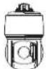 | Main Body | 1 | |
 | Quick Guide(Optional) | 1 | |
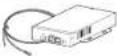 | HPoE Injector 1 Connects power supply and network | ||
 | Power cord 1 Connects to HPoE injector | ||
 | Cap Installer 1 Used to connect the network cable | ||
| [5KBH] | Brushing clip 1 | Used as a means of preventing cable bushing from being separated or falling apart from the hole. | |
 | Cable Bushing | 1 | Extra cable bushing for network cable installation. |
OPTIONAL ACCESSORIES FOR INSTALLATION
You can purchase appropriate optional accessories available.
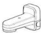
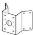
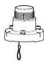
| Wall & Pole Mount | Corner Mount | Hanging Mount | * This mount can be used after being attached to hanging mount |
| SBP-156WMW | SBP-156KMW | SBP-156HMW | SBP-300LMW (Parapet Mount)SBP-300CMW (Ceiling Mount)SBP-300WMW (Wall Mount)SBP-300WMW1 (Wall Mount)SBP-300PMW (Pole Mount)SBP-300KMW (Corner Mount) |
AT A GLANCE
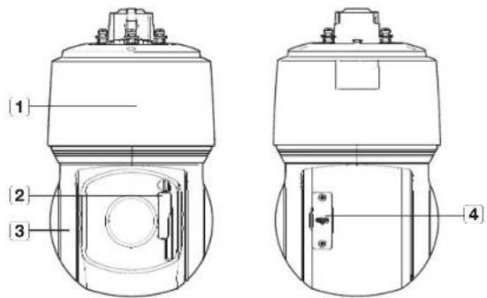
Appearance
text_image
Technical diagram of a mechanical device with labeled parts 1, 2, and 3, showing cross-sectional views.| Item Description | |
| 1 Main cover | Protects the internal PTZ mechanism from the direct sunlight, rain or external impact. |
| 2 Windshield wiper | Used for wiping off raindrops or snow dripping on the window.Do not adjust the wiper manually by hand. After power is turned on, hosting will be completed and the wiper will move to its default position. |
| 3 Shield cover | Shield cover for the lens and unit protection. |
| 4 Micro SD Card cover | Covers micro SD card slots and the Reset button. You can open it using a Torx driver. |
Inside

text_image
Technical diagram of a mechanical device with labeled parts, showing front and side views with numbered annotations.| Item Description | |
| 1 IR LED These infrared LED's are controlled by the illumination sensor. | |
| 2 Lens Lens for the camera. | |
| 3 Illumination Sensor Detects In coming light to control the IR LED. | |
| 4 Reset button | The button restores all camera settings to the factory default.Press and hold for about 5 seconds to reboot the system.!! If you reset the camera, the network settings will be adjusted so that DHCP can be enabled. If there is no DHCP server in the network, you must run the Device Manager program to change the basic network settings such as IP address, Subnet mask, Gateway, etc., before you can connect to the network. |
| 5 Micro SD Card slot Compartment for the Micro SD card. |
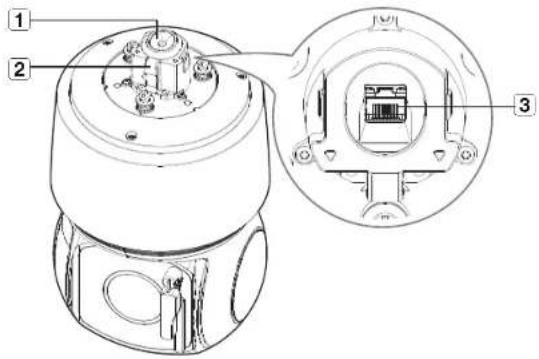
Mounting surface
text_image
Technical diagram of a mechanical device with labeled parts and cross-sectional view| Item Description | |
| 1 Cable bushing A waterproof rubber cap, which allows a network cable to go through it. | |
| 2 Safety wire hook | Hang this hook on the safety wire of the mount when installing this product to prevent it from falling. |
| 3 HPoE port | A port that connects to the HPoE injector and network cable for power and network connection. |
INSTALLATION
This camera is waterproof and in compliance with the IP66 spec, but the jack connected to the external cable is not. You are recommended to install this product below the edge of eaves to prevent the cable from being externally exposed.
Precautions before installation
Ensure you read out the following instructions before installing the camera:
- Select an installation site that can hold at least 5 times the camera's weight.
- Stuck-in or peeled-off cables can cause damage to the product or a fire.
- For safety purposes, keep anyone else away from the installation site.
And put aside personal belongings from the site, just in case. - If the product is installed with excessive force, it may cause damage to the camera due to malfunction. Forcing assembly using non-compliant tools may damage the product.
Inserting a Micro SD card
- Unfasten two screws on the Micro SD card cover by turning them counterclockwise using the Torx screwdriver.
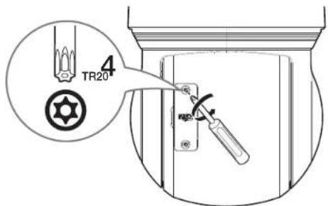
text_image
4 TR20- Disconnect the power cable from the camera before inserting the Micro SD card.
- When it rains or the humidity is high, insertion or ejection of a Micro SD card is not recommended.
- When installing/removing the Micro SD card, make sure you put the product body on a flat ground before working on it in order to prevent accidents due to loss or drop of any parts.
- Do not remove the screws.
10 installation & connection
- Pull up the Micro SD card cover and push the Micro SD card to the arrow direction as shown in the figure.
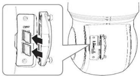
text_image
caserDo not forcefully insert it in the reverse direction. It might damage your Micro SD cars and your product.
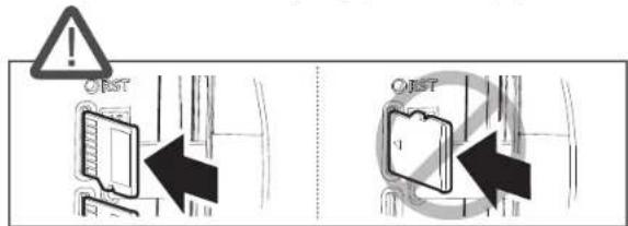
text_image
O R O R- Assemble the camera in the reverse order of disassembly after the Micro SD card is inserted.
Tighten the screws when assembling the Micro SO card cover to prevent moisture penetration.
Removing a Micro SD card
Gently press down on the exposed end of the Micro SD card as shown in the diagram to eject the Micro SD card from the slot.
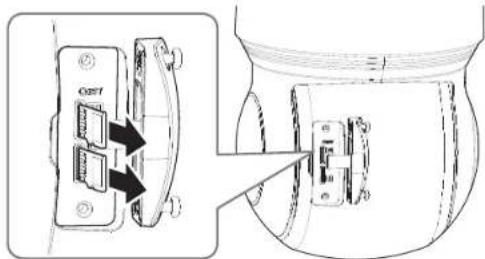
text_image
Technical diagram showing a device with labeled components and directional arrows indicating assembly or connection.Before removing the Micro SD card, in
- If you turn off the camera or remove the Micro SD card that contains data from the product, the data may be lost or damaged
Preparing & Installing Camera Mount
For installation guidelines for mounts, refer to the installation manual that is enclosed with the mount.
- See "Optional Accessories for Installation" for the appearance of each mount (unbundled), (page 7)
Getting ready for network cable installation
- Remove the cable bushing.
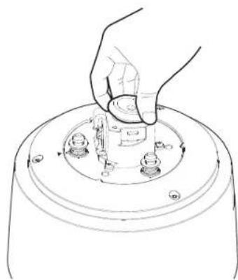
natural_image
Line drawing of a hand pressing down on a circular mechanical component (no text or symbols)- Pull off the extruded part of the removed cable bushing.
- Use the cap installer to route the network cable through the cable bushing.
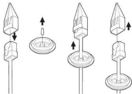
natural_image
Four technical diagrams showing a mechanical component with arrows indicating motion, no text or symbols present.- If the cable bushing is torn, use the extra cable bushing provided.
installation & connection
- For waterproof protection, pull down the cable below the cable bushing as shown in the figure below.
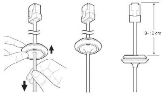
text_image
Technical diagram showing three-step assembly of a mechanical component with directional arrows and a 9–10 cm dimension label.Installing using wall & pole mount
Power on the HPoE injector only after installation is complete. Supplying power while the installation is in progress may cause fire or damage the product.
- Hang the safety wire of the wall & pole mount on the safety wire hook of the product.
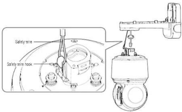
text_image
Safety wire Safety wire hook- Connect the network cable to the HPoE port.
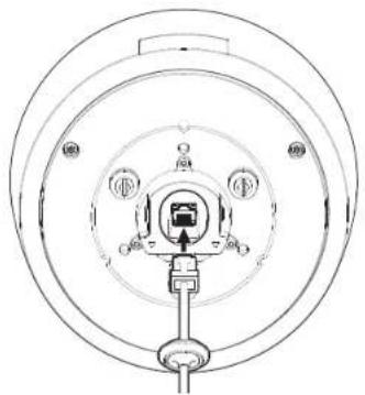
natural_image
Technical line drawing of a circular mechanical or electrical component with internal components and mounting bracket (no text or symbols)- Plug the cable bushing of the network cable in the hole. When plugging it in, press the whole bushing area evenly so that it is properly plugged in.

natural_image
Line drawing of hands operating a mechanical device with a knob and base (no text or symbols)The length and width of the cable bushing are different. Check the shape and plug it in the right direction.
12 installation & connection
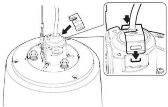
- Install the bushing clip.
Let the arrow mark on the clip point in the direction of the safety wire hook, and click each side into place one at a time.
natural_image
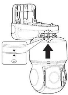
Technical diagram of a mechanical assembly with an inset showing a close-up of a component detail (no text or symbols present)- After aligning the installation direction guides of the camera and wall & pole mount, push the main cover upward and turn it counterclockwise until it is secured.
natural_image
Technical line drawing of a mechanical device with no visible text or symbols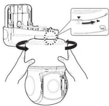
text_image
Diagram illustrating a mechanical device with rotating components and directional arrows, likely illustrating a motion or assembly process.- Tightly fasten the 3 mounting screws on the inside of the Wall & Pole Mount.
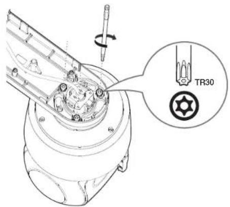
text_image
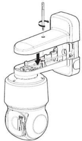
TR30- Join the top cover of the wall & pole mount.
natural_image
Technical line drawing of a mechanical device with internal components and a tool (no text or symbols)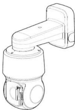
natural_image
Line drawing of a mechanical sensor or camera component with no visible text or symbolsinstallation & connection
Installing with hanging mount
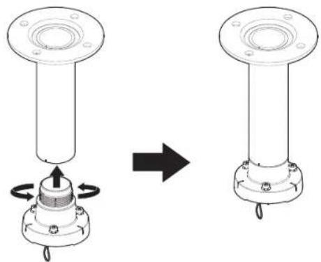
If you use hanging mount, you can install the camera onto any mount other than the official product mount.
- Install the hanging mount by turning it counterclockwise into the installed mount.
natural_image
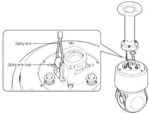
Diagram showing a mechanical assembly before and after rotation, with no text or symbols present.- Hang the safety wire of the hanging mount on the safety wire hook of the product.
text_image
Safety wire Safety wire hook14 installation & connection
- Connect the network cable to the HPoE port.
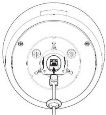
natural_image
Technical line drawing of a circular mechanical or electrical component with internal components and mounting holes (no text or symbols)- Plug the cable bushing of the network cable in the hole. When plugging it in, press the whole bushing area evenly so that it is properly plugged in.
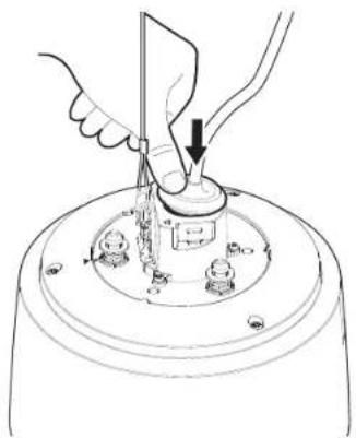
natural_image
Line drawing of hands operating a mechanical device with a tool, no text or symbols presentThe length and width of the cable bushing are different. Check the shape and plug it in the right direction.
- Install the bushing clip.
Let the arrow mark on the clip point in the direction of the safety wire hook, and click each side into place one at a time.
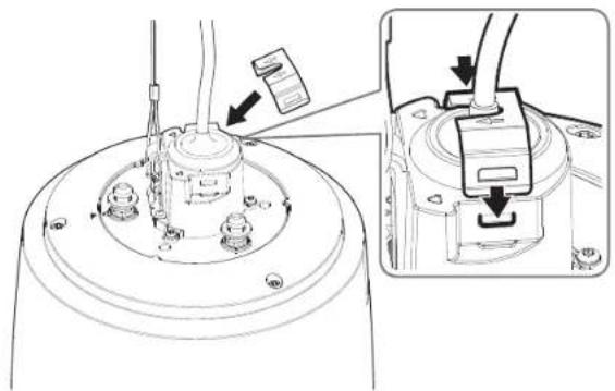
natural_image
Technical diagram of a mechanical assembly with an inset showing a close-up of a component detail (no text or symbols present)- After aligning the installation direction guides of the hanging mount, push the main cover upward and turn it counterclockwise until it is secured.
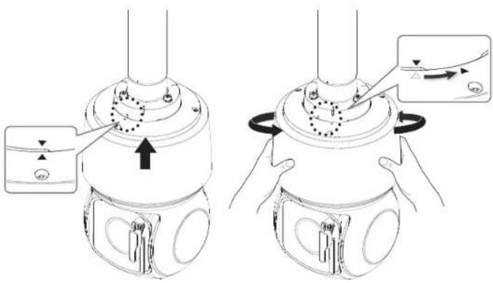
text_image
Technical diagram showing two mechanical components with directional arrows and labeled parts, likely illustrating a step-by-step assembly or adjustment.- Tightly fasten the 3 mounting screws on the top side of the Hanging Mount.
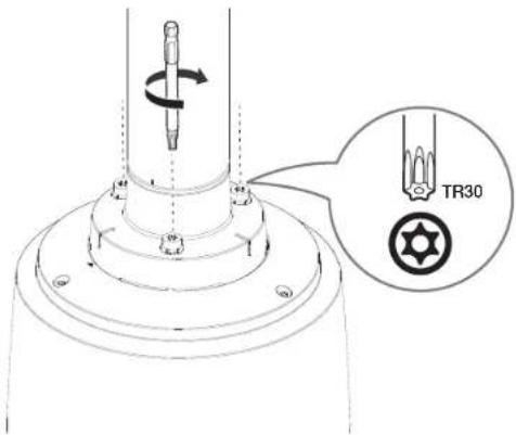
text_image
TR30■ The hanging mount combined with another mount
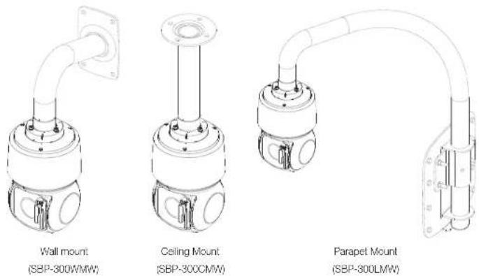
text_image
Wall mount (SBP-300WMW) Ceiling Mount (SBP-300CMW) Parapet Mount (SBP-300LMW)installation & connection
Replacing the rubber of wiper blade
If the rubber part of your wiper blade is worn and not cleaning the window properly, you can replace the rubber part.
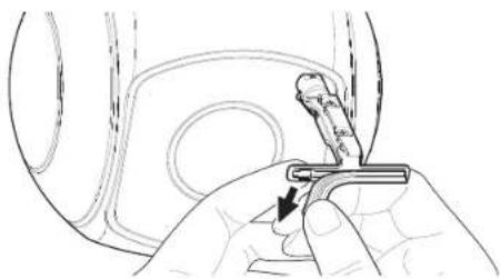
- Lift up the wiper.
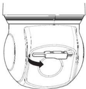
natural_image
Diagram of a toilet with a handle and circular vent, showing internal components (no text or labels)- Pull the wiper blade back.
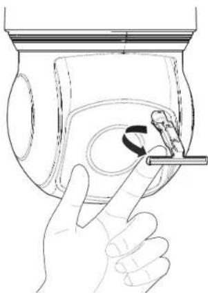
natural_image
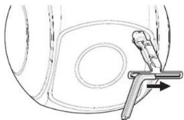
Line drawing of a hand inserting a small object into a container with a tool (no text or symbols)- Remove the rubber part by pulling it back.
natural_image
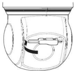
Hand holding a small mechanical component with a tool, no visible text or symbols- Insert the rubber replacement in the joint groove by sliding it in the direction of the arrow.
natural_image
Diagram of a mechanical component with a lever and circular feature, no text or symbols present- Turn the wiper blade back to its original position and put it down slowly.
natural_image
Diagram of a mechanical device inside a container with a curved arrow indicating direction (no text or symbols)16 installation & connection
POWERING AND NETWORKING
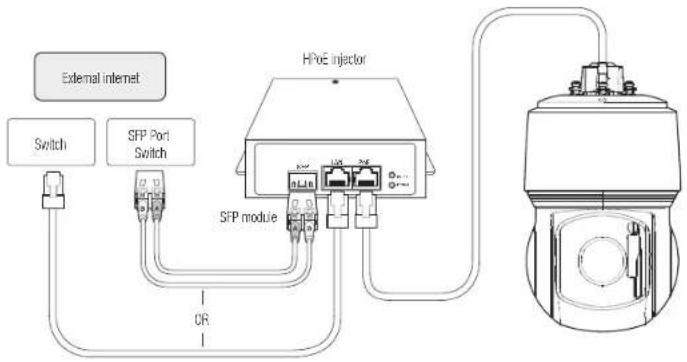
Connect the HPoE injector with the HPoE port of the camera.
text_image
External Internet Switch SFP Port Switch HPOE injector SFP module OR
- The product cannot be used at -40°C or below ambient temperature.
- The product may not be defrosted depending on the installation area at -40°C.
- After the product is left alone under a low temperature environment, it will take up to 2 hours to normally operate.
- If the product is turned on after being exposed to -20°C or below environment for some time, reset the time.
- Use the provided HPcE injector when connecting power and network.
- Use only either one of network cable or fiber optic cable for connection.
Network Cable Specification
| Item Contents Remark | ||
| Connector RJ45 (10^100BASE-T) | ||
| Ethernet 10/100BASE-T | ||
| Cable UTP Category Se | ||
| Max Distance 100M DC Resistance | ≤ 0.125 Ω/m | |
| HPoE Support HPoE |

- Use an STP cable to increase the protection from thunderstroke damage.
SFP port Specification
| Support SFP Voltage 3.3 V Typical | |
| Support SFP Current 300 mA Max. | |
| Support SFP Cage | Standard mini-SFP Cage(for 6.5 mm pitch SFP) |
| Support SFP Port Type | LC Type |
| Required SFP Speed | 1250 Mbps(For 1000 Mbps Ethernet) |
| Required SFP's BER(Bt Error Rate) | Max 10^-3 |
| Transmission Method(Optical) | Mode Depends on SFP Module |
| Optical Mode(Long/Short Wave) | Mode Depends on SFP Module |
| Cable Insertion Loss(dB) | Mode Depends on SFP Module |

- The connection/disconnection of the SFP module must be made only after the HPoE injector is turned off.
- A kink in the optical cable may disrupt the connection for communication.
- Do not directly look at the optical cable. It can damage your eyes.
network connection and setup
You can set up the network settings according to your network configurations.
CONNECTING THE CAMERA DIRECTLY TO LOCAL AREA NETWORKING
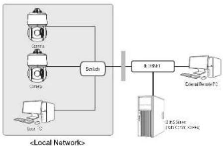
Connecting to the camera from a local PC in the LAN
- Launch an Internet browser on the local PC.
- Enter the IP address of the camera in the address bar of the browser.
flowchart
graph TD
    A["Local Network"] --> B["Switch"]
    B --> C["I-MS Server\nExternal Remote PC"]
    C --> D["External Remote PC"]
    A --> E["Camera"]
    A --> F["Camera"]
    A --> G["Local PC"]
    style A fill:#f9f,stroke:#333
    style B fill:#ccf,stroke:#333
    style C fill:#cfc,stroke:#333
    style D fill:#fcc,stroke:#333
    style E fill:#cff,stroke:#333
    style F fill:#ffc,stroke:#333
    style G fill:#cfc,stroke:#333
A remote PC in an external Internet out of the LAN network may not be able to connect to the camera installed in the intranet if the port-forwarding is not properly set or a firewall is set.
In this case, to resolve the problem, contact your network administrator.
- By factory default, the IP address will be assigned from the DHCP server automatically.
If there is no DHCP server available, the IP address will be set to 192.168.1.100.
To change the IP address, use the Device Manager
For further details on Device Manager use, refer to "Using Device Manager". (Page 19)
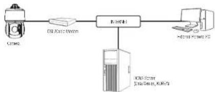
CONNECTING THE CAMERA DIRECTLY TO A DHCP BASED DSL/CABLE MODEM
flowchart
graph LR
    A["Computer"] --> B["Data Center"]
    B --> C["Network"]
    C --> D["External Power PC"]
    C --> E["DCB Server, Junction 6.0, 10.0kV"]
- Connect the user PC directly with the network camera.
- Run the Device Manager and change the IP address of the camera so that you can use the web browser on your desktop to connect to the Internet.
- Use the Internet browser to connect to the web viewer.
- Move to [Setup] page.
- Move to [Network] – [DDNS] and configure the DDNS settings.
- Move to [Basic] - [IP & Port], and set the IP type to [DHCP].
- Connect the camera, which was removed from your PC, directly to the modem.
- Restart the camera.
For information on how to set DONS, refer to the online help of Web Viewer.
■ For information on how to set the IP format, refer to the online help of Web Viewer.
USING DEVICE MANAGER

- Device manager program can be downloaded from
-- menu at Hanwha Techwin website (http://www.hanwha-security.com). - More instructions of Device Manager can be found at
menu of the main page.
AUTOMATICALLY SEARCHING CAMERA
If a camera is connected to the same network of the PC where device manager is installed, you can find network camera by using search function.
- Click
at the main page of device manager. - Check the camera from the list.
- Check MAC address at the sticker attached to the camera.
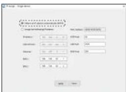
CONFIGURING IP ADDRESS
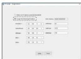
If you want to change camera network setting,
Configuring Static IP
Manually insert and configure IP address & port information.
- Click the camera from the list that you want the change the IP setting.
- Click
at the main page of device manager. - Select
.
- IP information of the camera will be displayed as previously set.
- Fill in IP & Port related categories.
text_image
Form 1: Design □ Name of test parameters (e.g. test) □ Number of test parameters (e.g. test) □ Number of test parameters (e.g. test) □ Number of test parameters (e.g. test) □ Number of test parameters (e.g. test) □ Number of test parameters (e.g. test) □ Number of test parameters (e.g. test) □ Number of test parameters (e.g. test) □ Number of test parameters (e.g. test) □ Number of test parameters (e.g. test) □ Number Of Test Parameters □ Number Of Test Parameters □ Number Of Test Parameters □ Number Of Test Parameters □ Number Of Test Parameters □ Number Of Test Parameters □ Number Of Test Parameters □ Number Of Test Parameters □ Number Of Test Parameters □ Number Of Test Parameters □ Number Of Test Parameters □ Number Of Test Parameters □ Number Of Test Parameters □ Number Of Test Parameters □ Number Of Test Parameters □ Number Of Test Parameters □ Number Of Test Parameters □ Number Of test □ Number Of test □ Number Of test □ Number Of test □ Number Of test □ Number Of test □ Number Of test □ Number Of test □ Number Of test □ Number Of test □ Number Of test □ Number Of test □ Number Of test □ Number Of test □ Number Of test □ Number Of test □ Number Of test □ Number Of test □ Number Of test □ Number Of test □ Number Of tests □ Number Of tests □ Number Of tests □ Number Of tests □ Number Of tests □ Number Of tests □ Number Of tests □ Number Of tests □ Number Of tests □ Number Of tests □ Number Of tests □ Number Of tests □ Number Of tests □ Number Of tests □ Number Of tests □ Number Of tests □ Number Of tests □ Number Of tests □ Number Of tests □ Number Of tests □ Number Of test □ Number Of test □ Number Of test □ Number Of test □ Number Of test □ Number Of test □ Number Of test □ Number Of test □ Number Of test □ Number Of test □ Number Of test □ Number of tests □ Number of tests □ Number of tests □ Number of tests □ Number of tests □ Number of tests □ Number of tests □ Number of tests □ Number of tests □ Number of tests □ Number of tests □ Number of tests □ Number of tests □ Number of tests □ Number of tests □ Number of tests □ Number of tests □ Number of tests □ Number of tests □ Number of tests □ Number of test □ Number of test □ Number of test □ Number of test □ Number of test □ Number of test □ Number of test □ Number of test □ Number of test □ Number of test □ Number of test □ Number of test □ Number of test □ Number of test □ Number of test □ Number of test □ Number of test □ Number of test □ Number of test □ Number of test □ Number of tests □ number of testsIf not using a Broadband Router
For setting
- HTTP Port: Used to access the camera using the Internet browser, defaulted to 80.
- RTSP Port: A port that controls real-time streaming. The initial value is 554.
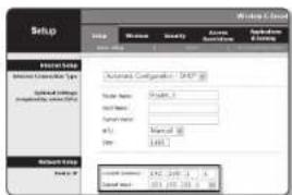
If using a Broadband Router
-
IP Address: Enter an address falling in the IP range provided by the Broadband Router.
ex) 192.168.1.2-254, 192.168.0.2-254, 192.168.XXX.2-254 -
Subnet Mask: The
of the Broadband Router will be the of the camera. - Gateway: The
of the Broadband Router will be the of the camera.
text_image
Setup Setup Windows Security Active Configuration Operation Options Internal Setup Internal Connection Type System Settings Parameters: System1 System2 System3 System4 System5 System6 System7 System8 System9 System10 System11 System12 System13 System14 System15 System16 System17 System18 System19 System20 System21 System22 System23 System24 System25 System26 System27 System28 System29 System30 System31 System32 System33 System34 System35 System36 System37 System38 System39 System40 System41 System42 System43 System44 System45 System46 System47 System48 System49 System50 System51 System52 System53 System54 System55 System56 System57 System58 System59 System60 System61 System62 System63 System64 System65 System66 System67 System68 System69 System70 System71 System72 System73 System74 System75 System76 System77 System78 System79 System80 System81 System82 System83 System84 System85 System86 System87 System88 System89 System90 System91 System92 System93 System94 System95 System96 System97 System98 System99 System100
- The settings may differ depending on the connected Broadband Router model. For more information, refer to the user manual of the applicable router.
- For more information about port forwarding of the broadband router, refer to "Port Range Forward (Port Mapping) Setup" (Page 21)
If the Broadband Router has more than one camera connected
Configure the IP related settings and the Port related settings distinctly with each other.
exi
| Category Camera #1 Camera #2 | |||
| IP related settings | IP Address | 192.168.1.100 | 192.168.1.101 |
| Subnet Mask | 255.255.255.0 | 255.255.255.0 | |
| Gateway | 192.168.1.1 | 192.168.1.1 | |
| Port related settings | HTTP Port | 8080 | 8081 |
| RTSP Port | 554 | 555 | |

- If the
exi http://AP address: HTTP Port
http://192.168.1.100:8080
- Click [Apply] Button.
- If the success message is displayed, click [OK].
network connection and setup
Configuring Dynamic IP
Receive IP address from DHCP
• Example of the Dynamic IP environment
- If a Broadband Router, with cameras connected, is assigned an IP address by the DHCP server
- If connecting the camera directly to modem using the DHCP protocols
- If IPs are assigned by the internal DHCP server via the LAN
- Click the camera from the list that you want to change the IP setting.
- Click
at the main page of device manager. - Select
- Click [Apply] button.
- If the success message is displayed, click [OK].
text_image
Log20 - Log20 Parameters: 100.000 - 100.000 Simulation: 100.000 - 100.000 Name: 100.000 - 100.000 M1: 10.000 - 1.0 M2: 10.000 - 1.0 Log20 - Log20 Log20 - Log20 Log20 - Log20 Log20 - Log20 Log20 - Log20 Log20 - Log20 Log20 - Log20 Log20 - Log20 Log20 - Log20 Log20 - Log20 Log20 - Log20 Log20 - Log20 Log20 - Log20 Log19 - Log19 Log19 - Log19 Log19 - Log19 Log19 - Log19 Log19 - Log19 Log19 - Log19 Log19 - Log19 Log19 - Log19 Log19 - Log19 Log19 - Log19 Log19 - Log19 Log19 - Log19 Log19 - Log19 Log18 - Log18 Log18 - Log18 Log18 - Log18 Log18 - Log18 Log18 - Log18 Log18 - Log18 Log18 - Log18 Log18 - Log18 Log18 - Log18 Log18 - Log18 Log18 - Log18 Log18 - Log18 Log18 - Log18 Log17 - Log17 Log17 - Log17 Log17 - Log17 Log17 - Log17 Log17 - Log17 Log17 - Log17 Log17 - Log17 Log17 - Log17 Log17 - Log17 Log17 - Log17 Log16 - Log16 Log16 - Log16 Log16 - Log16 Log16 - Log16 Log16 - Log16 Log16 - Log16 Log16 - Log16 Log16 - Log16 Log16 - Log16 Log16 - Log16 Log16 - Log16 Log15 - Log15 Log15 - Log15 Log15 - Log15 Log15 - Log15 Log15 - Log15 Log15 - Log15 Log15 - Log15 Log15 - Log15 Log14 - Log14 Log14 - Log14 Log14 - Log14 Log14 - Log14 Log14 - Log14 Log14 - Log14 Log14 - Log14 Log13 - Log13 Log13 - Log13 Log13 - Log13 Log13 - Log13 Log13 - Log13 Log13 - Log13 Log13 - Log13 Log12 - Log12 Log12 - Log12 Log12 - Log12 Log12 - Log12 Log12 - Log12 Log12 - Log12 Log12 - Log12 Log12 - Log12 Log12 - Log12 Log12 - Log12MANUALLY REGISTERING CAMERA
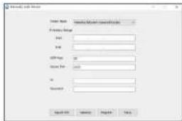
If the camera cannot be found using search function, the camera can be registered remotely by manually inserting IP information, if the camera is connected to external network.
- Click
- at the main page of device manager. - Insert the range of IP address that you search.
- Select the
of the camera that you register, and insert HTTP port, ID, and password. - Click [Register] button.
- Check if camera is registered.
- Check MAC address at the sticker attached to the camera.
text_image
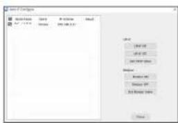
File Path Name: Path Name: ID: ID: ID: Name: OK Cancel Apply HelpAUTOMATICALLY CONFIGURING IP
- Click the camera from the list that you want to automatically configure the IP.
- Click <+ > at the main page of device manager. • Equipment Setting menu appears.
- At the menu, click
. - Click [Close] button.
text_image
Name of Compounds File Edit View Insert Help Add: 100% Add: 100% Add: 100% Add: 100% Add: 100% Add: 100% Add: 100% Add: 100% Add: 100% Add: 100% Add: 100% Add: 100% Add: 100% Add: 100% Add: 100% Add: 100% Add: 100% Add: Not Added Add: Not Added Add: Not Added Add: Not Added Add: Not Added Add: Not Added Add: Not Added Add: Not Added Add: Not Added Add: Not Added Add: Not Added Add: Not Added Add: Not Added Add: Not Added Add: Not Added Add: Not Added Add: Not Added Add: Not Added Add: Not Added Add: Not Added Add: Not AddedPORT RANGE FORWARD (PORT MAPPING) SETUP
If you have installed a Broadband Router with a camera connected, you must set the port range forwarding on the Broadband Router so that a remote PC can access the camera in it.
Manual Port Range Forwarding
- From the Setup menu of the Broadband Router, select
- . For setting the port range forward for a third-party Broadband Router, refer to the user guide of that Broadband Router. - Select
and for each connected camera to the Broadband Router. The number of each port to be configured to the IP router should be set according to the port number designated in - - on the camera web viewer. - When done, click [Save Settings]. Your settings will be saved.
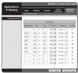
Port forwarding setting is an example of setting CISCO IP router.
- The settings may differ depending on the connected Broadband Router model. For more information, refer to the user manual of the applicable router.
Setting up Port Range Forward for several network cameras
- You can set a rule of Port Forwarding on the Broadband Router device through its configuration web page.
- A user can change each port using the camera setting screen.
When Camera1 and Camera2 are connected to a router :
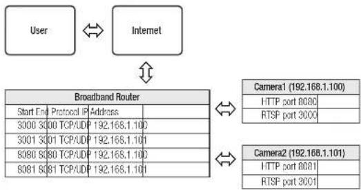
flowchart
graph TD
    A["User"] <--> B["Internet"]
    B --> C["Broadband Router"]
    C --> D["Camera1 (192.168.1.100)"]
    C --> E["RTSP port 3000"]
    C --> F["Camera2 (192.168.1.101)"]
    C --> G["RTSP port 3001"]
    C --> H["HTTP port 8080"]
    C --> I["3000 300 TCP/UDP 192.168.1.100"]
    C --> J["3001 3001 TCP/UDP 192.168.1.101"]
    C --> K["8080 80 TCP/UDP 192.168.1.100"]
    C --> L["8081 80 TCP/UDP 192.168.1.101"]
- Port forwarding can be done without additional router setup if the router supports the UPnP (Universal Plug and Play) function. After connecting the network camera, select the checkbox from the menu
CONNECTING TO THE CAMERA FROM A SHARED LOCAL PC
- Run device manager. It will scan for connected cameras and display them as a list.
- Double-click a camera to access. The Internet browser starts and connects to the camera.
- Access to the camera can also be gained by typing the camera's IP address in the address bar of the Internet browser.
CONNECTING TO THE CAMERA FROM A REMOTE PC VIA THE INTERNET
On a remote computer that is not in the Broadband Router's network cluster is not allowed, users can access cameras within a Broadband Router's network by using the camera's DDNS URL.
- Before you can access a camera in the Broadband Router network, you should have set the port range forward for the Broadband Router.
- From the remote PC, launch the internet browser and type the DDNS URL address of the camera, or the IP address of the Broadband Router in the address bar. ex) http://ddns.hanwina-security.com/ID
To use Wisenet DDNS, sign up at the Wisenet DDNS homepage (http://cdns.hanwha-security.com) and register the product at [My DDNS]>Register Product.
CONNECTING TO THE CAMERA
Normally, you would
-
Launch the Internet browser.
-
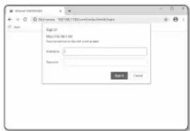
Type the IP address of the camera in the address bar.
ex) • IP address (IPv4) : 192.168.1.100 →
http://192.168.1.100
- the Login dialog should appear.
• IP address (IPv6) : 2001:230:abcd: ffff:0000:0000:ffff:1111
→ http://[2001:230:abcd:ffff:0000:0000:ffff:1111] - the Login
dialog should appear.
text_image
User Interface Name: HKEY1001325.com/Conductors\Apache Login Password: Password CancelIf the HTTP port is other than 80
-
Launch the Internet browser.
-
Type the IP address and HTTP port number of the camera in the address bar.
ex) IP address : 192.168.1.100:HTTP Port number(8080)
→ http://192.168.1.100:8080 - the Login dialog should appear.
Using URL
-
Launch the Internet browser.
-
Type the DDNS URL of the camera in the address bar.
ex) URL address : http://ddns.hanwha-security.com/ID
- the Login dialog should appear.

■ Network connection is disabled in the LAN only environment.
Connecting via UPnP
-
Run the client or operating system in support of the UPnP protocol.
-
Click the camera name for search.
In the Windows operating system, click the camera name searched from the network menu.
- The login window is displayed.
Connecting via Bonjour
- Run the client or operating system in support of the Bonjour protocol.
- Click the camera name for search.
In the Mac operating system, click the camera name searched from the Bonjour tab of Safari.
- The login window is displayed.
To check the DDNS address
If the camera is connected directly to the DHCP cable modem, DSL modem, or PPPoE modem, the IP address of your network will be changed each time you try to connect to the ISP (Internet Service Provider) server.
If this is the case, you will not be informed of the IP address changed by DDNS.
Once you register a dynamic IP-based device with the DDNS server, you can easily check the changed IP when you try to access the device.
To register your device to the
first, and then set the Web Viewer's
PASSWORD SETTING
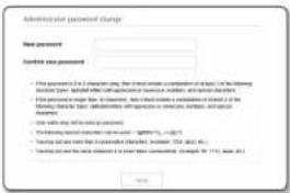
When you access the product for the first time, you must register the login password.

- For a new password with 8 to 9 digits, you must use at least 3 of the following: uppercase/lovercase letters, numbers and special characters. For a password with 10 to 15 digits, you must use at least 2 types of those mentioned.
-Special characters that are allowed. : \~!©4%^*| -1 = |||.?/
- For higher security, you are not recommended to repeat the same characters or consecutive keyboard inputs for your passwords.
- if you lost your password, you can press the [RESET] button to initialize the product. So, don't lose your password by using a memo pad or memorizing it.
text_image
Administration password change New password Home new password • This password is in a financial card, then first make a combination of 100% of the following: (if any other information can be available) or if any other information can be available. For all information. this password is required to be accepted, but it should be repeated with a link to the (if any other information can be available) or if any other information can be available. For all information. this password is not allowed to be accepted. The password is not allowed to be accepted. The password is not allowed to be accepted. The password is not allowed to be accepted. The password is not allowed to be accepted. The password is not allowed to be accepted. The password is not allowed to be accepted. The password is not allowed to be accepted. The password is not allowed to be accepted. The password is not allowed to be accepted. The password is not allowed to be accepted. < img src="box123458760000000000000000000000000000000000000000000000000000000000000000000000000000000000000000000000000000 < img src="box1234587600000000000000000000000000000000000000000000000000000000LOGIN
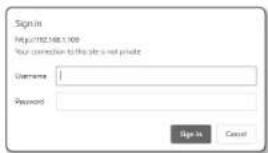
Whenever you access the camera, the login window appears. Enter the User ID and password to access the camera.
- Enter "admin" in the
input box. The administrator ID, "admin", is fixed and can not be changed. - Enter the password in the
input field. - Click [Sign in]. If you have logged in successfully, you will the Live Viewer screen.
- When you access the camera web viewer, pay special attention to the security by checking whether the image data is encrypted.
text_image
Sign In http://82.568.1.00/ Your connection to this site is not private Username: Password: Sign In Cancel
- You will experience the best video quality if the screen size is 100%. Reducing the ratio may cut the image on the borders.
CAMERA WEB VIEWER SETUP
- Click the [Setup ( * ] icon.
- The Settings window appears.
- You can configure settings for the camera's basic information, video, audio, network, event, analysis, and system over the network.
- Click
to view detailed descriptions of each function.
TROUBLESHOOTING
| PROBLEM SOLUTION | |
| No video is displayed when accessing the plug-in free webviewer on Safari via HTTPS. | On the authentication popup window prompted when initially accessing https, click "View Authentication Certificate" and select the "Always trust when connecting to the designated webviewer IP" check box.If the webviewer continues failing to display a video after you select "Next" on the message window below, press the command key + Ω to exit the Safari browser, access again and follow the procedures stated above. |
| I can't access the camera from a web browser. | Check to make sure that the camera's Network settings are appropriate.Check to make sure that all network cables have been connected properly.If connected using DHCP, verify that the camera is able to acquire dynamic IP addresses without any problem.If the camera is connected to a Broadband Router, verify that port forwarding is properly configured. |
| Viewer got disconnected during monitoring. | Connected Viewers become disconnected upon any change to camera or network configurations.Check all network connections. |
| The camera connected to the network is not detected in the Device Manager program. | Turn off the firewall settings on your PC and then search the camera again. |
| Images overlap. | Check whether two or more cameras are set to a single multicast address instead of different addresses. If a single address is used for multiple cameras, the images may overlap. |
| No image appears. | If the transmission method is set to multicast, check whether there is a router that supports multicast in the LAN the camera is connected to. |
| PROBLEM SOLUTION | |
| of, but no notification e-mail reaches me even when an analysis event had occurred. | · Verify the settings in the following sequence:A. Checksettings.B. Theshould be set to.C. Check if theoption ofmenu is checked to use. |
| Cannot record into the Micro SD card. | · Check if the Micro SD card is defective.· When replacing the Micro SD card, it must be done while the power is disconnected from the product. |
| Micro SD card is inserted but the camera does not operate properly. | · Check if the Micro SD card is inserted in the proper direction. Operation of Micro SD card that is formatted by other devices is not guaranteed with this camera unit.· Format the Micro SD card again in→→menu. |
| Cannot record in the NAS. | · Confirm that the information registered in the NAS is correct. |
| It reports that NAS setting has failed. | · Confirm that the IP address of the NAS is valid.· Confirm that the ID/password of the NAS is valid.· Confirm that you can access the folder designated as the default folder using the ID of the NAS.· Confirm that the NAS SMB/CIFS items are unchecked.· Confirm that the NAS IP address and the camera IP address are in the same format ex) The NAS & camera subnet mask initial value is 255.255.255.0. If the IP address is 192.168.20.32 then the NAS IP address should be in the range of 192.168.20.1~192.168.20.255.· Check whether you tried to excess as another user without formatting the default folder saved or used.· Confirm that you used recommended NAS equipment. |

Any changes or modifications in construction of this device which are not expressly approved by the party responsible for compliance could void the user's authority to operate the equipment.
This device complies with part 15 of the FCC Rules. Operation is subject to the following two conditions: (1) This device may not cause harmful interference, and (2) this device must accept any interference received, including interference that may cause undesired operation.
This equipment has been tested and found to comply with the limits for a Class A digital device, pursuant to part 16 of the FCC Rules. These limits are designed to provide reasonable protection against harmful interference when the equipment is operated in a commercial environment. This equipment generates, uses, and can radiate radio frequency energy and, if not installed and used in accordance with the instruction manual, may cause harmful interference to radio communications. Operation of this equipment in a residential area is likely to cause harmful interference in which case the user will be required to correct the interference at his own expense.
- Reorient or relocate the receiving antenna.
- Increase the separation between the equipment and receiver.
- Connect the equipment into an outlet on a circuit different from that to which the receiver is connected.
- Consult the dealer or an experienced radio/TV technician for help.

Hanwha Techwin cares for the environment at all product manufacturing stages, and is taking measures to provide customers with more environmentally friendly products.
The Eco mark represents Hanwha Techwin's devotion to creating environmentally friendly products, and indicates that the product satisfies the EU ReHS Directive.
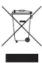
Correct Disposal of This Product (Waste Electrical & Electronic Equipment)
(Applicable in the European Union and other European countries with separate collection systems)
This marking on the product, accessories or literature indicates that the product and its electronic accessories (e.g. charger, headset, USB cable) should not be disposed of with other household waste at the end of their working life. To prevent possible harm to the environment or human health from uncontrolled waste disposal, please separate these items from other types of waste and recycle them responsibly to promote the sustainable reuse of material resources.
Household users should contact either the retailer where they purchased this product, or their local government office, for details of where and how they can take these items for environmentally safe recycling.
Business users should contact their supplier and check the terms and conditions of the purchase contract. This product and its electronic accessories should not be mixed with other commercial wastes for disposal.

Correct disposal of batteries in this product
(Applicable in the European Union and other European countries with separate battery return systems.)
This marking on the battery, manual or packaging indicates that the batteries in this product should not be disposed of with other household waste at the end of their working life. Where marked, the chemical symbols Hg, Cd or Pb indicate that the battery contains mercury, cadmium or lead above the reference levels in EC Directive 2006/66. If batteries are not properly disposed of, these substances can cause harm to human health or the environment.
To protect natural resources and to promote material reuse, please separate batteries from other types of waste and recycle them through your local, free battery return system.

Hanwha
Techwin