Digital Sentry DSSRV2-040 - Security Camera Pelco - Free user manual and instructions
Find the device manual for free Digital Sentry DSSRV2-040 Pelco in PDF.


User questions about Digital Sentry DSSRV2-040 Pelco
0 question about this device. Answer the ones you know or ask your own.
Ask a new question about this device
Download the instructions for your Security Camera in PDF format for free! Find your manual Digital Sentry DSSRV2-040 - Pelco and take your electronic device back in hand. On this page are published all the documents necessary for the use of your device. Digital Sentry DSSRV2-040 by Pelco.
USER MANUAL Digital Sentry DSSRV2-040 Pelco
Locking Shared Setup Options....11
Application Settings 12
Manage Systems 16
System List....18
Connecting to a System 19
Adding Custom Fields 20
Updating Your Password 21
Filtering the Systems 21
Hiding the System List....21
Showing the System List....22
Troubleshooting the Systems....22
Working with Tours 23
Create a New Tour....23
Run and Pause a Tour 24
Alarm Popup 25
Playing Back Current Alarms 25
Configuring the Alarm Page Settings 26
Enabling Beep On Alarm 27
Exporting Pop-Up Alarms 28
Digital Sentry Reports....29
Updating DS ControlPoint Software....30
Configuring Analog Outputs 31
Live 32
Full Screen 33
Quick Review 34
Manual Record 34
Snapshot 35
Camera Groups 35
Printing Images from Video Panes 35
Entering a Motion Mask for Sarix Cameras....35
Video Pane Borders....36
Removing Video from a Window 36
Manage OSD Settings 36
Image Adjustments 37
Enable On-Screen Pan/Tilt/Zoom....37
Enable Digital Zoom 37
PTZ Controls 37
Alarm Page 37
Pause Notification 37
Search 38
Live and Playback Video Search....38
Non-DS Camera Search 38
DS Camera Search 40
DS Servers and DX8100 Series Systems Scan 42
Authenticate Samples 42
Filter Samples 42
Alarm Search 43
Acknowledging Serial Alarms 43
Installing the AlarmClear Service to Monitor COM1 Port....44
Monitoring Another COM Port 44
Configuring VideoServer 44
Configuring DS ControlPoint 44
Advanced Search (DS DataPoint) 45
Thumbnail Search 46
Export 47
Exporting to a Non-CD/DVD Location 47
Exporting to a CD/DVD 48
Export a Single Image 48
PTZ Cameras 49
Enable and Disable PTZ 49
PTZ Controls 50
Camera Lens 50
Pan/Tilt Movement and Speed 51
Camera Presets 51
Pattern 52
Auxiliary 52
Preset Favorites 52
Appendixes 53
Appendix A: DS ControlPoint Feature Set for DS and DX Series Products 53
Appendix B: Using a KBD300A Keyboard with DS ControlPoint 55
Editing ControlPointCache.xml 55
Installing the KBD300A Keyboard 55
Controlling DS ControlPoint with the KBD300A 57
KBD300A Operating Functions 58
Appendix C: Using a KBD5000 Keyboard with DS ControlPoint 59
Installing the KBD5000 59
Controlling DS ControlPoint with the KBD5000 59
KBD5000 Features 60
KBD5000 Operating Functions....61
List of Illustrations
1 Navigation Pane for Live Page 10
2 Setup Page 11
3 General Settings Dialog Box....12
4 Bandwidth Settings Dialog Box 13
5 Throttle Assistant 13
6 Sync Settings Dialog Box 14
7 Import Complete Dialog Box....14
8 Export Settings Dialog Box....15
9 Connection Management Page 16
10 Add System Tab 16
11 System Drop-Down Menu 19
12 Edit System Tab 19
13 Add or Edit System Settings Dialog Box 20
14 Password Update Dialog Box 21
15 Filtering the System List....21
16 Diagnostics Tab....22
17 Edit Tour Page....23
18 Add Tour Item Tab....24
19 Resume Tour and Pause Tour Icons 24
20 Playing Back Current Alarms 25
21 Alarm Popup Screen 26
22 Beep On Alarm Tab 27
23 Export Pop-Up Alarms Screen. 28
24 Digital Sentry Reporting Dialog Box 29
25 Selecting Existing Systems....29
26 Configuring System Report Settings Dialog Box 30
27 Create Report Dialog Box 30
28 Analog Output Screen....31
29 Live Page....32
30 Customizing Recording 34
31 Create Group Tab 35
32 On-Screen Display Settings Window 36
33 Search Tab 38
34 Non-DS Camera Search Page 39
35 Playback Bar 40
36 DS Camera Search Page 40
37 Search Using Calendar or Plus/Minus Buttons 41
38 DS Camera Search Using Start and End Time Boxes 41
39 Scanning the Network for Systems 42
40 Alarm Search 43
41 Alarm Search Screen 43
42 Advanced Search Tab 45
43 Thumbnail Search Screen 46
44 Detailed View of Thumbnail Search Screen. 47
45 Non-CD/DVD Export Format 47
46 Export Formats 48
47 Live Page with PTZ-Enabled Video 49
48 PTZ-Enabled Video with PTZ Controls Tab 50
49 Lens Controls on PTZ Controls Tab 50
50 Directional Controls on PTZ Controls Tab....51
51 Preset Controls on PTZ Controls Tab 51
52 Pattern Controls on PTZ Controls Tab....52
53 Auxiliary Controls on PTZ Controls Tab 52
54 RS-422 Connections 55
55 Selecting the Device Manager 56
56 USB Serial Port (COM1) Properties Dialog Box 57
57 Advanced Settings for COM1 Dialog Box....57
58 KBD5000 Features 60
Description
Digital Sentry® DS ControlPoint is an intuitive graphical user interface that allows users to monitor and manage any combination of analog or IP devices through a common digital video security application.
A DS ControlPoint supported system is a video matrix solution supporting multiple monitors that allows any data output (such as transaction data from a cash register or point of sale device, alarm data from a video analytics application, or alarm notifications) to be shown in any DS ControlPoint video pane.
DS ControlPoint allows users to monitor video from Pelco DX Series digital video recorders (DVRs) and hybrid video recorders (HVRs), providing investment protection for customers with existing DX equipment who are looking to benefit from today's HD and megapixel camera offerings.
The DS ControlPoint installation file can be downloaded from the following Pelco Web site: http://www.pelco.com.

WARNINGS:
- Do not run the DS ControlPoint software as a regular monitoring utility on a server or combination component. Reserve a dedicated client computer for this purpose.
- Do not activate any system lock or screensaver features while running the DS ControlPoint software. These features can interfere with certain Digital Sentry processes.
The procedure for installing the DS ControlPoint software is as follows:
- If the file was downloaded from the Web site, unzip the downloaded file.
NOTE: Be sure to record the location of the unzipped files, as you will need these files during the update procedure.
- Launch (double-click) the "setup" file; the welcome page appears.
- Click the Next button.
- Click the Install button in the "Ready to Install the Program" message. When the installation is complete, a DS ControlPoint startup icon appears on the desktop and the installation program closes.
- Click the DS ControlPoint icon on the desktop to launch DS ControlPoint.
NOTES:
- A user name and password prompt does not appear when DS ControlPoint is initially launched.
- The Connection Management page appears for initial installations of DS ControlPoint.
- The Live page appears for DS ControlPoint upgrades.
The DS ControlPoint client window consists of four major pages:

Setup: Allows you to manage systems and create tours.
Live: Allows you to view live video.

Search: Allows you to search for recorded video.

Help: Allows you to search for user operation instructions.
Each of these sections is accessible using the icons located in the upper-left corner of the navigation pane.
Any page can be "undocked" so that it can be viewed while simultaneously viewing other pages. This is accomplished by clicking the Undock Tab icon or right-click the system list and select Undock Tab from the list.
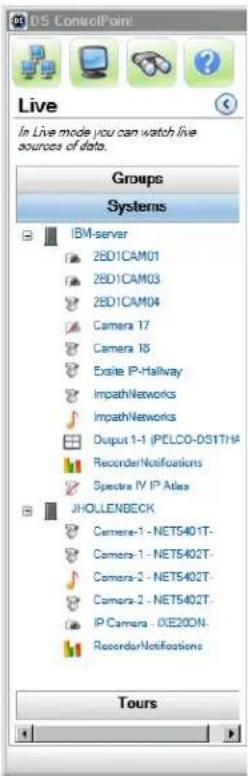
The navigation pane on the left side of the DS ControlPoint window (refer to Figure 1) is always accessible except when full-screen mode is selected.
The navigation pane contains the following sections:
Groups: Contains groups of digital video management systems (DVMS).
Systems: Allows you to view all cameras and other sources associated with connected DVMS.
Tours: Allows you to create and run automated tours of camera views.
The navigation pane allows you to view camera groups, camera names, and configured tours. You can minimize the navigation pane by clicking the left arrow button; this hides the entire pane except for the four page icons. To view the entire pane again, click the right arrow button. To view camera properties, right-click on the desired camera in the system tree.
text_image
DS ControlPoint Live In Live mode you can watch live sources of data. Groups Systems IBM-server 2BD1CAM01 2BD1CAM03 2BD1CAM04 Camera 17 Camera 18 Exsite IP-Hallway ImpathNetworks ImpathNetworks Output 1-1 (PELCO-DS1TH) Recorder/Notifications Spectra IV IP Atlas JHOLLENBECK Camera-1 - NET5401T- Camera-1 - NET5402T- Camera-2 - NET5402T- Camera-2 - NET5402T- IP Camera - 0XE20CN- Recorder/Notifications ToursFigure 1. Navigation Pane for Live Page
SETUP
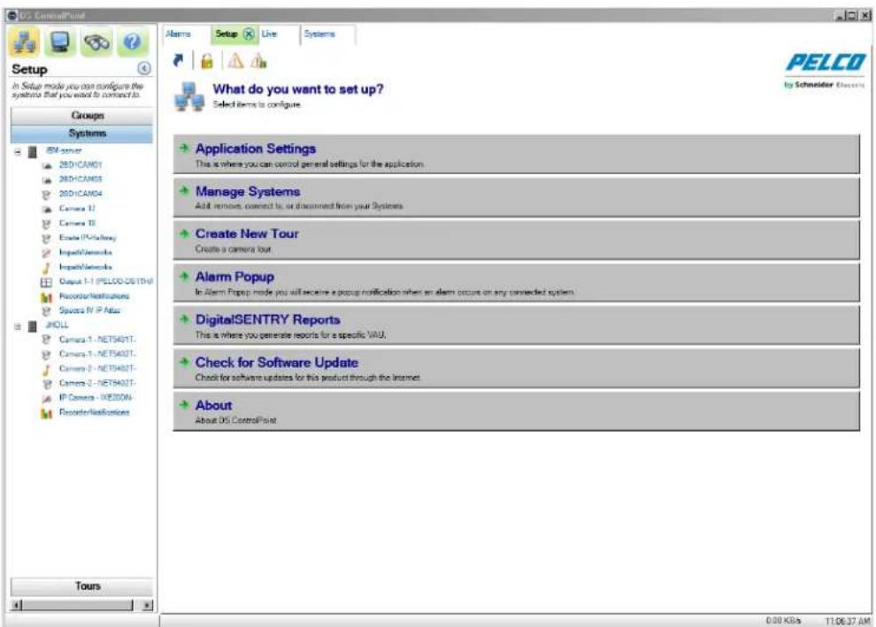
The Setup page (refer to Figure 2) contains the following options when you click the Setup icon located in the top-left corner of the window or the Setup tab.
Application Settings: Allows you to select general settings for the application.
Manage Systems: Allows you to add, remove, and connect to the Digital Sentry and Pelco DX Series video recorders.
NOTE: The user logon and password for any video recorder using DS ControlPoint must be the same as the DS ControlPoint user logon and password.
Create New Tour: Allows you to create automated tours of camera views.
Alarm Popup: Allows you to receive a pop-up notification when an alarm occurs on any connected system.
Digital Sentry Reports: Allows you to view several types of reports.
Check for Software Update: Allows you to check for DS ControlPoint software updates through the Internet.
About: Displays the DS ControlPoint version number and other version information.
text_image
Setup In Setup mode you can configure the system that you want to continue to. Groups Systems IBM server 2801/CAM01 2801/CAM03 2801/CAM04 Camera 12 Camera TI Create IP-Pathway Import/Networks Import/Networks Output 1-1 (PELCO-DS17W) Recorder/Instructions Splice IV IP Atlas JHOLL Camera 1 - NET5402T- Camera 1 - NET5402T- Camera 2 - NET5402T- Camera 2 - NET5402T- IP Camera - WES300N- Recorder/Instructions Tours Alarms Setup Live Systems What do you want to set up? Select items to configure Application Settings This is where you can control general settings for the application. Manage Systems Add remote, connect to, or disconnect from your Systems Create New Tour Create a camera bus Alarm Popup In Alarm Popup mode you will become a popup notification when an alarm occurs on any connected system. DigitalSENTRY Reports This is where you generate reports for a specific VAU. Check for Software Update Check for software updates for this product through the Internet. About About OS ControlPoint PELCO by Schneider ElectronicsFigure 2. Setup Page
LOCKING SHARED SETUP OPTIONS
To lock setup options:
- Click the lock icon [icon to be inserted here] beneath the options tabs. The Lock Setup Password window appears.
- Enter and confirm your password.
- Click OK. The Setup Protection Enabled window appears.
- Click OK.
- Click the lock icon and enter your password to unlock the setup options.
APPLICATION SETTINGS
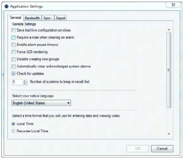
When you click Application Settings in the Setup page, the Application Settings dialog box appears (refer to Figure 3). This dialog box allows you to control your general, bandwidth, and synchronization settings for the application.
General: Allows you to save the last live configuration when the application is closed. You can also require a note when clearing an alarm, enable an alarm pause timeout, select your native language, and select the time format to enter data and to view video.
text_image
Application Settings General Bandwidth Sync Export General Settings Save last live configuration on close Require a note when clearing an alarm Enable alarm pause timeout Force GDI rendering Disable creating new groups Automatically clear acknowledged system alarmo Check for updates 5 Number of systems to keep in recall list Select your native language English (United States) Select a time format that you will use for entering data and viewing video Local Time Recorder Local Time OK CancelFigure 3. General Settings Dialog Box
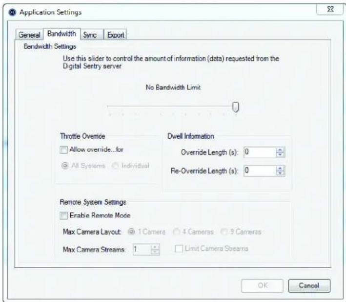
Bandwidth: Allows you to control the amount of information (data) requested from the DVR. When a server reaches the allowed bandwidth set by the administrator, it blocks additional read attempts and moves them into a queue to be processed once bandwidth use reaches an acceptable level.
If an administrator sets a bandwidth limit, a throttle override with dwell information can be set up. This will allow users to override the current bandwidth restriction, if necessary, for a designated period of time. The following settings must be configured for the override:
• Bandwidth Limit: Using the slider, set the amount of information requested from the Digital Sentry server.
- Throttle Override: Select "Allow override...for" all systems or an individual system.
- Dwell Information: Set the override length of time (in seconds) for the bandwidth throttle override. Set the re-override length of time (in seconds) a user must wait before attempting another override.
- Remote System Settings: This allows the administrator to limit the number of camera layouts or camera streams from DS ControlPoint.
text_image
Application Settings General Bandwidth Sync Export Bandwidth Settings Use this slider to control the amount of information (data) requested from the Digital Sentry server No Bandwidth Limit Throttle Override Allow override...for All Systems Individual Dwell Information Override Length (s): 0 Re-Override Length (s): 0 Remote System Settings Enable Remote Mode Max Camera Layout: 1 Camera 4 Cameras 9 Cameras Max Camera Streams: 1 Limit Camera Streams OK CancelFigure 4. Bandwidth Settings Dialog Box
Once these options have been configured, you can open the ThrottleAssistant by typing "B" on the keyboard (refer to Figure 5). The settings configured in the Bandwidth Settings dialog box appear in the ThrottleAssistant dialog box.
- If Individual was selected under Throttle Override, a list of connected systems will appear under "Available for Override."
- If All Systems was selected under Throttle Override, All Systems will be the only item to appear under "Available for Override."
The Countdown will begin with the override seconds and then will count down the refresh seconds.

text_image
ThrottleAssistant IP Address System Name Countdown Available for Override All Systems 0 Override Length: 30 Re-Override Time 50 Apply Ok CancelFigure 5. Throttle Assistant
NOTE: You can only set a bandwidth throttle on connected systems. If you select All Systems and one or more of those systems are not connected, you will receive a warning that the bandwidth throttle could not be overridden on the unconnected systems.
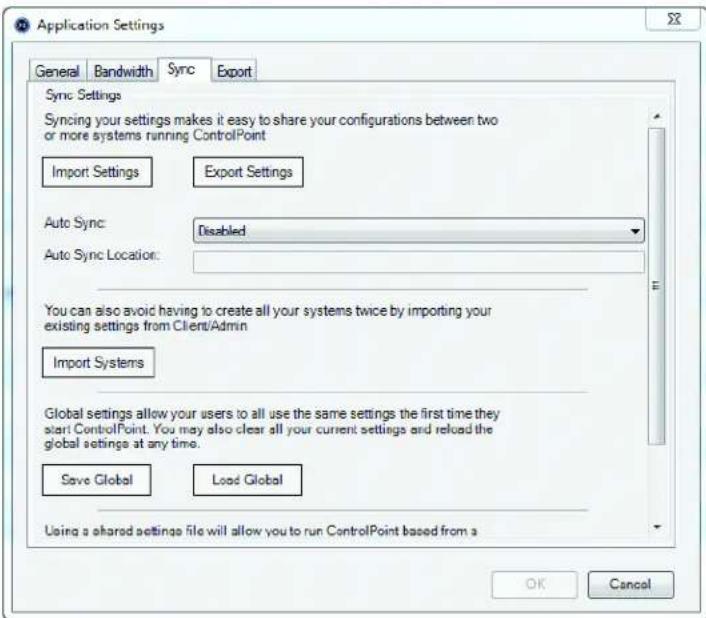
Sync: Allows you to synchronize your import and export settings, which makes it easy to share your configurations between two or more systems running DS ControlPoint. You can import existing settings from DSAdmin to avoid recreating your system settings. You can also use global settings when DS ControlPoint is first started, or you can clear your current settings and reload the global settings.
text_image
Application Settings General Bandwidth Sync Export Sync Settings Syncing your settings makes it easy to share your configurations between two or more systems running ControlPoint Import Settings Export Settings Auto Sync: Disabled Auto Sync Location: You can also avoid having to create all your systems twice by importing your existing settings from Client/Admin Import Systems Global settings allow your users to all use the same settings the first time they start ControlPoint. You may also clear all your current settings and reload the global settings at any time. Save Global Load Global Using a shared settings file will allow you to run ControlPoint based from a OK CancelFigure 6. Sync Settings Dialog Box
Using Auto Sync: The Auto Sync function allows the CP or XML file to be enabled at the following settings:
- On Start Up of ControlPoint
• H o u r l y
• Daily - Weekly
• Monthly
Using Auto Sync
- Determine the location of the file (Ex. C:\ControlPoint Files\CPSettings.cp.
- Configure your auto sync setting.
- Click OK.
- Export the CP file.
- In order to disable the auto sync setting, delete the .cp or .xml file.
To import systems:
- Click the Application Settings tab in the Setup page. The Application Settings dialog box appears (refer to Figure 6 on page 14).
- Click the Sync button. The Sync Settings section appears.
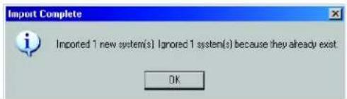
- Click the Import Systems button. An Import Complete dialog box appears showing the number of systems that are imported and the number of existing systems that are ignored (refer to Figure 7).
- Click the OK button to close the dialog box.
text_image
Import Complete Imported 1 new system(s) I ignored 1 system(s) because they already exist OKFigure 7. Import Complete Dialog Box
To change to global settings:
- Click Application Settings in the Setup page. The Application Settings dialog box appears (refer to Figure 6 on page 14).
- Click the Sync button. The Sync Settings page appears.
- Choose one of the following global settings options:
- Click the Save Global button to automatically open global settings the first time you open DS ControlPoint.
- Click the Load Global button and restart DS ControlPoint to change from personal settings to global settings.
To import settings:
- Click Application Settings in the Setup page. The Application Settings dialog box appears (refer to Figure 6 on page 14).
- Click the Sync button. The Sync Settings page appears.
- Click the Import Settings button.
- Click the Enable box.
- Select the exported settings file.
- Click the Open button.
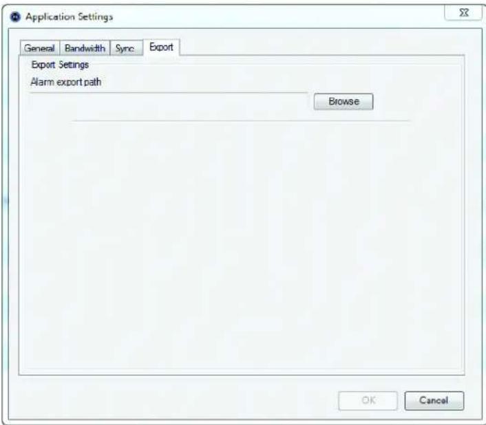
Export: Allows you to save and export pop-up alarm information.
- Click the Application Settings tab in the Setup page. The Application Settings dialog box appears (refer to Figure 6 on page 14).
- Click the Export button. The Export section appears.
text_image
Application Settings General Bandwidth Sync Export Export Settings Alarm export path Browse OK CancelFigure 8. Export Settings Dialog Box
- Enter the desired alarm export path in the Alarm export path window.
- Click the OK button to export your pop-up alarm settings to the selected folder.
MANAGE SYSTEMS
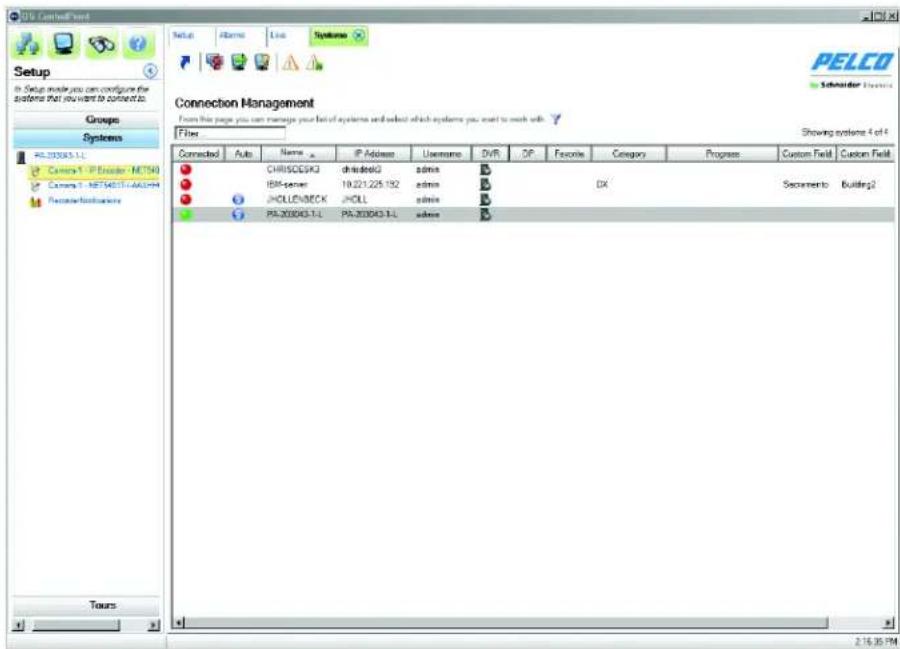
When you click Manage Systems in the Setup page, the Connection Management page appears (refer to Figure 9). This page allows you to add and connect to systems. It also displays information about the DVMS connected to the client computer.
text_image
Setup In Setup mode you can configure the system that should be configured. Groups Systems PL-200043-LL Custom Y - IP Encoder - METH Cavens Y - NET54011-AAGCM PrcsorTesticians Connections Management From this page you can manage your list of systems and select which systems you want to work with Filter Showing systems 4 of 4 Connected Auto Name IP AddressUsername DVR DP Favorites Category Progress Custom Field Custom Field ● CHIRISCDSK chiridiskG admin B ● IBM-server 19.221.225.182 admin B DX Secamento Building2 ● JHOLLON/BECK JHOLL admin B ● PA-200043-LL PA-200043-LL admin B Tours 2:16:35 PMFigure 9. Connection Management Page
Numerous systems can be managed by administrators. For example, 30 guards configure their systems with different setups (that is, different buildings, cameras, and tours). As a system administrator, you can add those 30 systems to your Connection Management page and view each system as needed. This means that administrators can view live video, recorded video, and alarms remotely at any time. You can also add custom fields to each system, discover available systems, and recall systems that have been connected to recently.
To add a DVMS to the list:
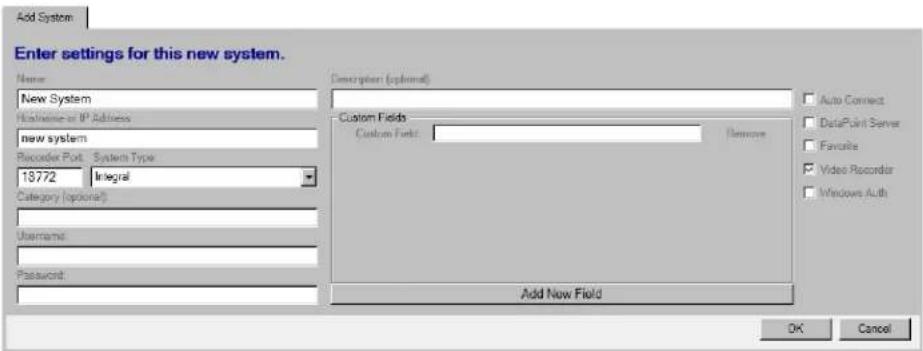
- Click the Add System button 📋, or right-click and select Add System from the menu. This opens the Add System tab, which allows you to add systems to the system list.
text_image
Add System Enter settings for this new system. Name New System Customs or IP Address new system Recorder Port System Type 18772 Integral Category (optional) Username: Password: Description (optional) Custom Fields Custom Field: Remove Add New Field Auto Connect DataPoint Server Favorite Video Recorder Windows Auth OK CancelFigure 10. Add System Tab
- On the Add System tab, type the computer name of the DVMS, a host name or IP address, the video recorder network port, the system type, and an optional category. The default video recorder network ports are as follows:
• 18772 for DS
• 9001 for DX4100/DX4500/DX4600/DX4700/DX4800
• 9002 for DX8000/DX8100
- Type the required user name and password.
NOTE: The user name and password must be identical to the user name and password as the video recorder system to which DS ControlPoint is being connected.
-
Type an optional description of the system in the Description text box.
-
Type a custom field in the Custom Field text box. You can add additional custom fields by clicking the Add New Field button, or you can remove custom fields by clicking the Remove button located next to the Custom Field text box. These custom fields will appear as new columns for the respective system.
-
If you want to connect automatically to the system every time DS ControlPoint starts, select the Auto Connect check box.
-
If you want to identify the system as a favorite that can be sorted at the top of the system list with other favorite systems, select the Favorite check box.
-
If the system is a DVMS video recorder, select the Video Recorder check box.
-
If the system is configured for transactional data, such as video analytics, or data from other sources, such as cash registers or ATMs, select the DataPoint Server check box.
-
If you want the system to pass information to Microsoft ® Windows® Active Directory, select the Windows Authentication check box.
NOTE: Active Directory is not required for Windows authentication. It can also be authenticated with local users and groups on a DVR.
-
When configuration of the system is complete, click the OK button to add it to the list of configured systems on the Connection Management page.
-
Repeat these steps for each system.
To find available systems on your local network:
- Click the Discover Systems icon, or right-click and select Discover Systems from the menu. This opens the Discover Systems tab, which allows you to find available systems on the local network.
- Select the appropriate system from the System Type drop down menu.
- Click the Scan Network for Systems button. Available systems will appear.
- Select the systems you wish add.
- Click the Add Selected Systems button.
To recall recently connected systems:
- Click the Recall List button (icon to be added), or right-click and select Recall List from the menu. This opens the Recall List tab, which displays recently connected systems.
SYSTEM LIST
The list of configured systems on the Connection Management page can be sorted by clicking any column title. The following columns are included:
Connected: Indicates whether the system is connected (green), disconnected (red), or attempting connection (yellow).
Auto: Indicates that the system is configured for automatic connection when DS ControlPoint starts.
Name: Lists the name entered for the system during configuration.
IP Address: Lists the IP address or host name entered for the system during configuration.
Username: Lists the name entered for the user during configuration.
DVR: Indicates that the system was identified as a video recorder during configuration.
DP: Indicates that the system was identified as a DataPoint Server during configuration.
Favorite: Indicates that the system was identified as a favorite system during configuration.
Category: Lists the optional category entered for the system during configuration.
Progress: Indicated the status of system connections. A progress bar appears when you are connecting to a system.
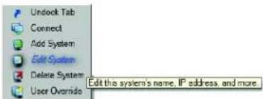
To connect to a system, click the Connect icon (refer to Table A on page 18) or right-click the system name, and then select Connect from the list.
To edit the information about a system, click the Edit System icon or right-click the system name, and then select Edit System from the list.
To delete a system from the list, click the Delete System icon or right-click the system name, and then select Delete system from the list.
Table A. System Icons
 | Connect Connect to a system. |
 | Add System Add a system to the list of available systems. |
 | Update Password Update the password of the logged in user. |
 | Edit System Edit the system settings (system name, IP address, and so on). |
| [ST6H] | Delete System Remove the system from your System Management list. |
 | User Override Override the saved user for each system with the new credentials provided. |
| [H5ZS] | Discover Systems Display a list of all systems on the network. |
 | Recall List Show systems that have been connected to recently. |
 | System Report Start a system report of selected systems. |
NOTE: The Edit System and Delete System functions are available only for systems that are not currently connected. Select Disconnect before editing or deleting a system.
CONNECTING TO A SYSTEM
You have several options to connect to a system that lacks the appropriate user name and password.
To connect using Connect:
- Select a disconnected system in the Connection Management page.
- Click the Connect icon or double-click the disconnected system. The User Name and Password dialog box appears.

NOTE: This dialog box appears only if the user name and password are not defined during system configuration.
- Type the correct user name or password, or both.
- Click the OK button. The system is connected and the red dot under the Connected column turns green.
NOTE: To keep the system connected each time you open DS ControlPoint, select Auto Connect in the Edit System or Add System tab. To connect using Edit System:
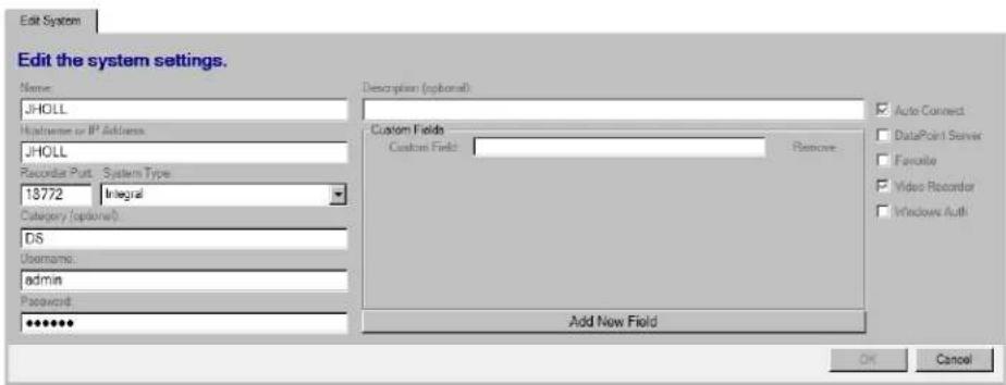
- Click the Edit System icon

. The Edit System tab appears (refer to Figure 12 on page 19). You can also right-click a disconnected from the system drop-down menu.
text_image
Unlock Tab Connect Add System Edit System Delete System User Override Edit this system's name, IP address, and more.Figure 11. System Drop-Down Menu
- Type the correct user name or password, or both.
text_image
Edit the system settings. Name: JHOLL Username or IP Address: JHOLL Recorder Put - System Type 13772 Integral Category (optional): DS Username: admin Password: ******** Description (optional) Custom Fields Custom Field: Remove: Add New Field Auto Connect DataPoint Server Favorite Video Recorder Windows Auth OK CancelFigure 12. Edit System Tab
- Click the OK button. The system is connected and the red dot under the Connected column turns green.
ADDING CUSTOM FIELDS
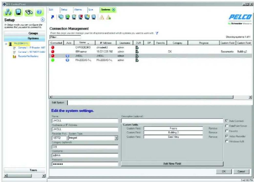
You can add custom fields for each system. For example, you might want to list a site location such as an address, a city, or a building. These custom fields will appear as columns in the Connection Management page.
- Click the Edit System button

or the Add System button 📄. The Edit System or Add System tab appears in the Connection
Management page (refer to Figure 13).
- Type a custom field in the Custom Field text box.
- Click the Add New Field button for each additional custom field. You can also delete a custom field by clicking the Remove button located next the Custom Field text box.
- Click the OK button to save your settings and close the Edit System or Add System tab.
text_image
PELCO Schneider Electric Setup In Setup mode you can configure the systems that you want to connect to. Groups Systems PA-203043-1-L Camera 1 - IP Encoder - NET Camera 1 - NET5401T-FAA Records/Facifactors Connections Management From this page you can manage your list of systems and select which systems you want to work with Filter Showing systems 4 of 1 Connected Auto Name IP Address Username DVR DP Favorite Category Progress Custom Field Custom Field CHRISDESK3 chrsdesk3 admin DX IBM-parvar 10.221.225.192 admin DX JHOLL JHOLL admin PA-203043-1-L PA-203043-1-L admin Edit System Edit the system settings. Name: JHOLL Hardware or IP Address: JHOLL Recorder Part - System Type: 18772 Integral Category (optional) DS Username: admin Password: ****** Description (optional): Custom Fields Custom Field: Fresens Remove Custom Field: Building 2 Remove Custom Field: East Wing Remove Add New Field Auto Connect DataPoint Server F quinto Video Recorder Windows Auth Tours OK Cancel 3:42:56 PMFigure 13. Add or Edit System Settings Dialog Box
UPDATING YOUR PASSWORD
- Click the appropriate system.
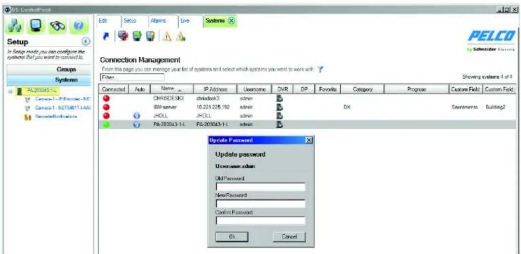
- Click the Update Password icon 📄. The Update Password dialog box appears (refer to Figure 14 on page 21).
- Type the old password, the new password, and then confirm the new password.
- Click the OK button to close the dialog box.
text_image
OS ControlPoint Edit Setup Alarms Live Systems Setup In Setup mode you can configure the systems that you want to connect it. Groups Systems PA-203043-1-L Camera-1 - IP Encoder - NET Camera-1 - HCT54017.AAA RecordConfigurations PELCO Schneider Electronics Connection Management From this page you can manage your list of systems and select which systems you want to work with Filter Showing systems 4 of 4 Connected Auto Name IP Address Username DVR DP Favorite Category Progress Custom Field Custom Field CHIRISDESK3 chrdask3 admin IBM server 10.221.225.192 admin DX Sacramento Building2 JHOLL JHOLL admin PA-203043-1-L PA-203043-1-L admin Update Password Update password Username:admin Old Password New Password Confirm Password OK CancelFigure 14. Password Update Dialog Box
FILTERING THE SYSTEMS
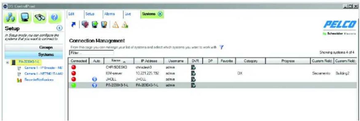
You can use a filter to show or hide systems. This is a useful tool when you have hundreds of systems to manage. You can filter the systems by name, IP address, or user name. For example, you can filter any system name beginning with DX.
- Highlight "Filter..." in the System Filter box.
- Type all or part of the name or IP address. Only those systems designated in the filter will appear.
- Right-click in the System Filter box to display the available filters.
- Click a filter to select it or to cancel the selection.
text_image
PELCO by Schneider Electric Setup in Setup mode you can configure the systems that you want to connect to. Groups Systems PA-203043-1-L Camera-1 - IP Encoder - NE Camera-1 - NET540 (T-IAA) Recorded Notifications Connection Management From this page you can manage your list of systems and select which systems you want to work with Filter... Showing systems 4 of 4 Connected Auto Name IP Address Username DVR DP Favorite Category Progress Custom Field Custom Field: CHRISOESK3 chriadevsk3 admin D IBM-server 10.221.225.192 admin D DX Secamento Building2 JHOLL JHOLL admin D PA-203043-1-L PA-203043-1-L admin DFigure 15. Filtering the System List
- Highlight the text in the Filter box.
- Press Delete on your keyboard. All the systems are now visible.
TROUBLESHOOTING THE SYSTEMS
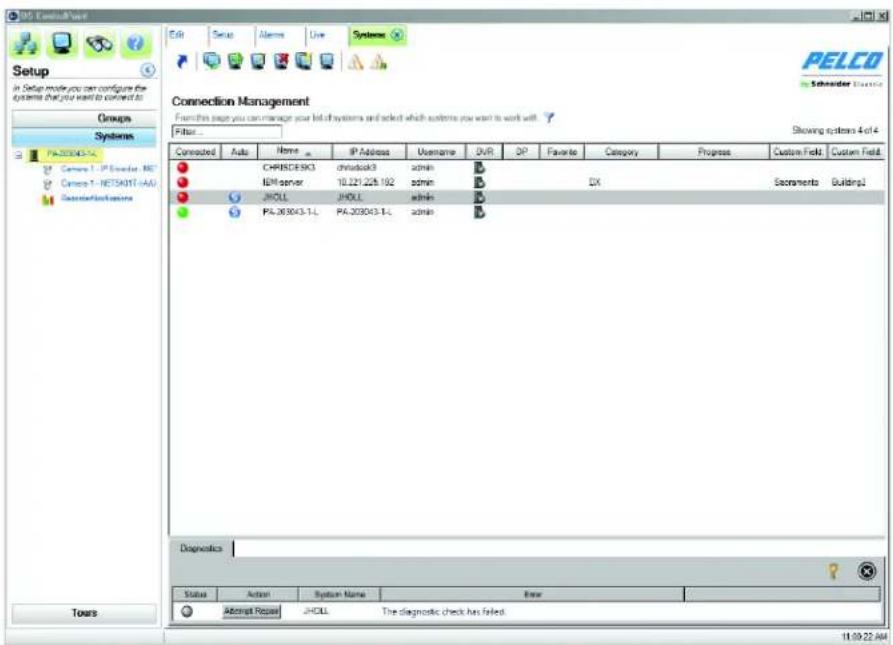
DS ControlPoint provides you with a diagnostics tool to search for network or software service issues and to reestablish network connections.
- Right-click a system that has lost connection to the network, or highlight the system and then click the Diagnostics icon. The Diagnostics tab appears (refer to Figure 16). Both the Connected icon and the Status icon appear gray.
- Click the Attempt Repair button. When the connection to the server is established, the Attempt Repair button changes to Repaired and the Status icon turns green.
- Click the Connect icon or double-click the server. The Connected icon turns green and the network connection is reestablished.
- Click the Close button to close the Diagnostics tab.
text_image
Setup in Setup mode you can configure the systems that you want to connect to Groups Systems PA-203043-1L Camera 1 - PS Encoder - RS Camera 1 - NETS401T - AAS Outperform systems Connected Auto Name IP Address Username DVR DP Favorite Category Progress Custom Field Custom Field CHRISCESK3 chludack3 admin B IEM server 10.221.228.192 admin B DX Sacramento Buildings1 JHOLL JHOLL admin B PL-203043-1L PA-203043-1L admin B Diagnostics Status Action System Name Error Automatic Reset JHOLL The diagnostic check has failed 11:00:22:04Figure 16. Diagnostics Tab
WORKING WITH TOURS
Creating tours allows you to configure different groups of cameras and sequence through those tour groups. The system cycles through the tour items based on a defined dwell time.
CREATE A NEW TOUR
To create a tour of cameras:
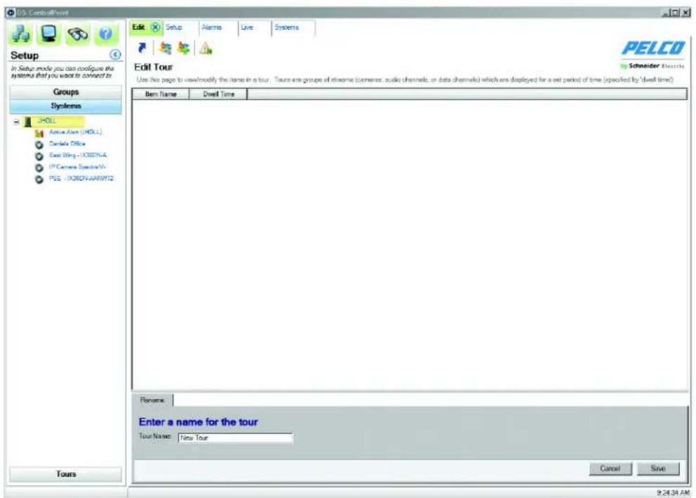
- On the main Setup page (refer to Figure 2 on page 11), click Create New Tour to open the Edit Tour page. You can also right-click the Tours button on the navigation pane. The Edit Tour page allows you to configure an automated tour of cameras.
text_image
PDL ControlTour Setup In Setup mode you can configure the systems that you want to connect to Groups Systems JHOL Active Air (JHOL) Cartela Office East Wing - JHON-4 JP Camera Spectra V- PEG - JHON-ARW12 Tours Edit Tour Use this page to view/modify the items in a tour. Tours are groups of remote (camera, audio channels, or data channels) which are displayed for a set period of time (specified by 'dwell time') Item Name Dwell Time Rename Enter a name for the tour Tour Name: New Tour Cancel Save PELCO Schneider Electric 9:24:34 AMFigure 17. Edit Tour Page
- On the Rename tab, type a name in the Tour Name text box, and then click Save.
-
Click the Tours button in the navigation pane to list all previously created tours (refer to Figure 18 on page 24).
-
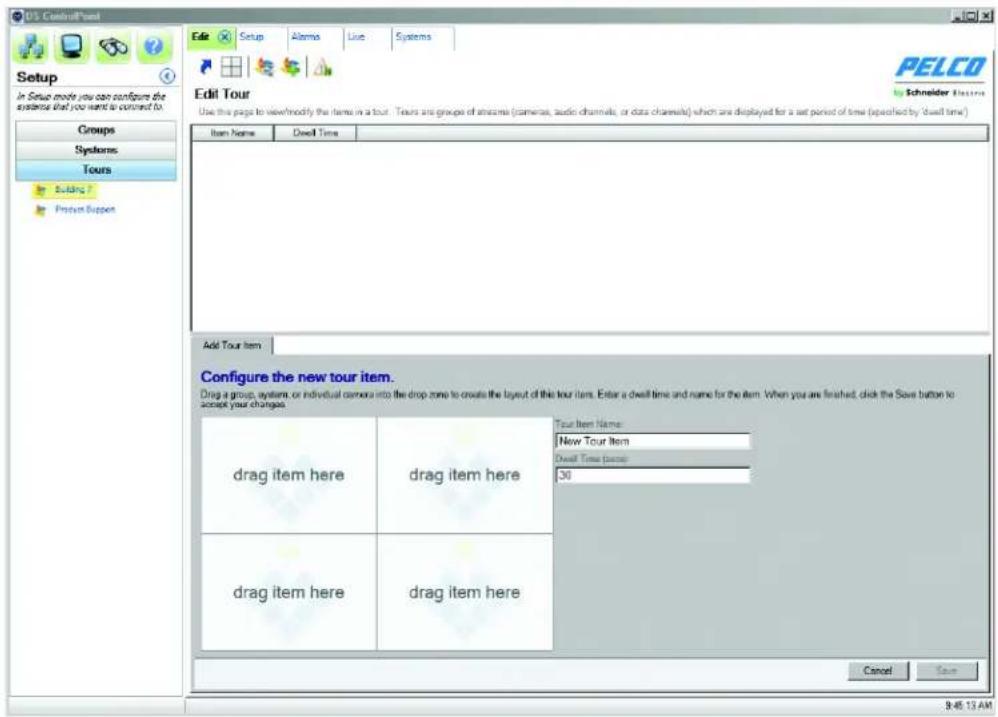
Select the tour, and click the Add Tour Item icon. This opens the Add Tour Item tab.
text_image
PES ControlPoint Setup In Setup mode you can configure the system that you want to connect to Groups Systems Tours Building ? Product Support Edit Setup Alarms Live Systems Edit Tour Use this page to view:modify the items in a tour. Tours are groups of anzame (camera, audio channels, or data channels) which are displayed for a set period of time (specified by 'dwell time') Item Name Dwell Time Add Tour Item Configure the new tour item. Drag a group, system, or individual camera into the drop zone to create the layout of this tour item. Enter a dwell time and name for the item. When you are finished, click the Save button to accept your charges. drag item here drag item here Tour Item Name: New Tour Item Dwell Time (paste): 30 drag item here drag item here Cancel Save 9:45:13 AMFigure 18. Add Tour Item Tab
- Type a name for the first tour item in the Tour Item Name text box. In the Dwell Time text box, type the amount of time (in seconds) that you want the tour item to be displayed.
- Select the Systems section of the navigation pane and expand the tree until you see the cameras and other sources that you want to include in the tour. Drag and drop the cameras or sources into the video panes on the Add Tour Item tab.
- When the tour item is configured as desired, click the Save button.
- To add additional tour items, click Add Tour Item and repeat steps 3 through 6.
Run and Pause a Tour
To run a tour:
- Select the Tours section of the navigation pane.
- Right-click the tour name and select Run from the menu.
To pause and resume a tour:
-
Click the Pause Tour icon (refer to Figure 19).
-
Click the Resume Tour icon. Alternatively, select the Tour tab, right-click the tour name, and select Run from the menu.

Figure 19. Resume Tour and Pause Tour Icons
ALARM POPUP
If you are assigned Alarm Activity rights in DSAdmin, Digital Sentry immediately notifies you when an alarm event occurs. Alarms are sorted by the time they occurred in descending order (from oldest to newest).
PLAYING BACK CURRENT ALARMS
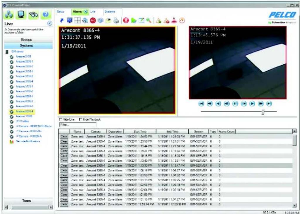
You can play back video associated with an alarm event by clicking the event notification. The alarms will populate the video screens depending on the layout. For example, if the video screen layout is 4 x 4 and 18 cameras are available, only the first 16 cameras will be displayed in the video panes. If there are three or fewer cameras in the zone associated with the alarm event, live video is displayed simultaneously with the recorded alarm event.
text_image
PELCO Schneider Electric Live Groups Systems IOM Server Arecont 2105 Arecont 2025-1 Arecont 2075-2 Arecont 3105-1 Arecont 3105-2 Arecont 3105-4 Arecont 5105-1 Arecont 5105-2 Arecont 8365-1 Arecont 8365-2 Arecont 8365-3 Arecont 8365-4 Arecont 1005 IP10 Alte IP Camera - MSOC10-1E Muts IP Camera - MSOC20u IP Camera - MSOCNA Reconstructed Data Tours Name Camors Description Start Time End Time System WayType Frame Count Clear Zone test Arecont 8365-4 Zone Alarm 1/19/2011 1:24.82 PM 1/19/2011 1:25.03 PM IBM-SERVER 0 0 Clear Zone test Arecont 8365-4 Zone Alarm 1/19/2011 1:23.50 PM 1/19/2011 1:24.01 PM IBM-SERVER 0 0 Clear Zone test Arecont 8365-4 Zone Alarm 1/19/2011 1:23.44 PM 1/19/2011 1:23.58 PM IBM-SERVER 0 0 Clear Zone test Arecont 8365-4 Zone Alarm 1/19/2011 1:19.21 PM 1/19/2011 1:19.34 PM IBM-SERVER 0 0 Clear Zone test Arecont 8365-4 Zone Alarm 1/19/2011 1:19.16 PM 1/19/2011 1:19.28 PM IBM-SERVER 0 0 Clear Zone test Arecont 8365-4 Zone Alarm 1/19/2011 1:13.40 PM 1/19/2011 1:13.51 PM IBM-SERVER 0 0 Clear Zone test Arecont 8365-4 Zone Alarm 1/19/2011 1:13.33 PM 1/19/2011 1:13.47 PM IBM-SERVER 0 0 Clear Zone test Arecont 8365-4 Zone Alarm 1/19/2011 1:06.16 PM 1/19/2011 1:06.27 PM IBM-SERVER 0 0 Clear Zone test Arecont 8365-4 Zone Alarm 1/19/2011 1:03.50 PM 1/19/2011 1:04.02 PM IBM-SERVER 0 0 Clear Zone test Arecont 8365-4 Zone Alarm 1/19/2011 1:03.13 PM 1/19/2011 1:03.25 PM IBM-SERVER 0 0 Clear Zone test Arecont 8365-4 Zone Alarm 1/19/2011 1:02.58 PM 1/19/2011 1:03.10 PM IBM-SERVER 0 0 Clear Zone test Arecont 8365-4 Zone Alarm 1/19/2011 1:02.64 PM 1/19/2011 1:02.78 PM IBM-SERVER 0 0 Clear Zone test Arecont 8365-4 Zone Alarm 1/19/2011 1:01.59 PM IBM-SERVER 0 0 Clear Zone test Arecont 8365-4 Zone Alarm 1/19/2011 1:01.75 PM 1/19/2011 1:01.77 PM IBM-SERVER 0 0 Clear Zone test Arecont 8365-4 Zone Alarm 1/19/2011 1:25.94 PM 1/19/2011 1:25.96 PM IBM-SERVER 0 0 Hide Live Hide Playback Filter_Figure 20. Playing Back Current Alarms
CONFIGURING THE ALARM PAGE SETTINGS
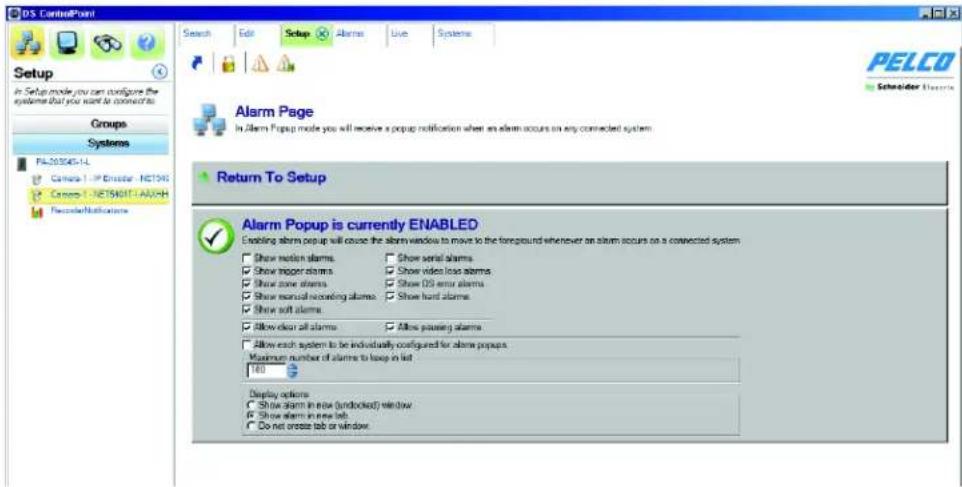
Alarm Popup allows you to receive a pop-up notification when an alarm occurs on any connected system. When Alarm Popup is enabled, the alarm window moves to the foreground indicating that an alarm event has occurred on a connected system.
The Alarm Popup screen allows you to select the type of alarms you want to display, such as motion and zone. You can also select the location in which you want the alarms to display, such as in an undocked window or in a new tab. Finally, you can configure each system individually for alarm pop-ups and select the number of alarms to keep in the list. Click Return to Setup to return to the Setup page.
text_image
PDL ControlPoint Setup In Setup mode you can configure the systems that you want to connect to. Groups Systems PL-203045-LL Camera 1 - Emitter - NETOS Camera 1 - NETS901T-AAVHH Recover/Instructions Search Edit Setup Alarms Live Systems PELCO Schneider Electric Alarm Page In Alarm Popup mode you will receive a popup notification when an alarm occurs on any connected system. Return To Setup Alarm Popup is currently ENABLED Enabling alarm popup will choose the alarm window to move to the foreground whenever an alarm occurs on a connected system Show latch alarms Show serial alarms Show packet alarms Show video loss alarms Show zone alarms Show OS error alarms Show rearload noiseing alarms Show hard alarms Show soft alarms Allow clean all alarms Allow passing alarms Allow each system to be individually configured for alarm popup Maximum number of alarms to loop in lat 180 Display options Show alarm in new (undlocked) window Show alarm in new lat. Do not rotate tab or windowFigure 21. Alarm Popup Screen
ENABLING BEEP ON ALARM
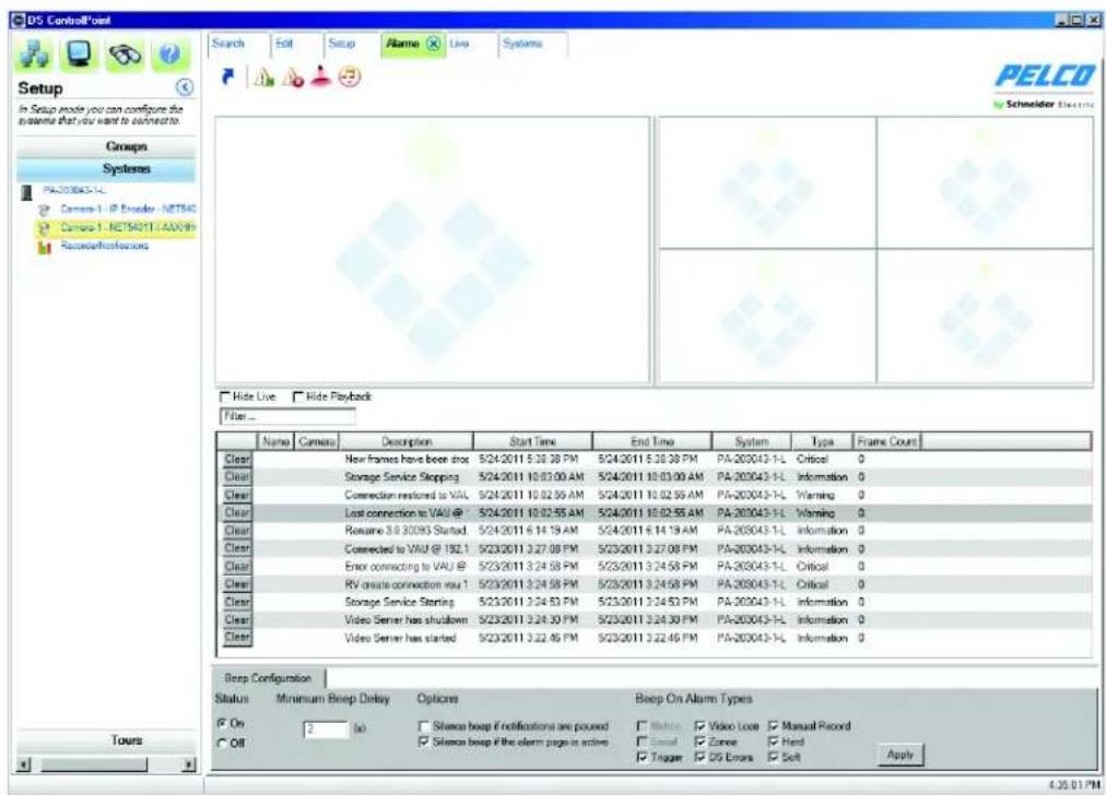
You can configure Beep On Alarm to make an audible sound when an alarm is received. This feature is disabled by default.
- Click the Alarms tab. The Alarms page opens.
- Click the Beep On Alarm icon . The Beep On Alarm tab appears.
text_image
DS Control load Search Edit Setup Abame Live Systems PELCO Schneider Electric Setup In Setup mode you can configure the systems that you want to connect to. Groups Systems PA-203043-1-L Camera-1 - IP Encoder - NET540 Camera-1 - NET54011-4AX69 Receivations Hide Live Hide Playback Filter... Name Camera Description Start Time End Time System Type Frame Count Clear New frames have been shot 5/24/2011 5:38:38 PM 5/24/2011 5:38:38 PM PA-203043-1-L Critical 0 Clear Storage Service Stopping 5/24/2011 10:03:00 AM 5/24/2011 10:03:00 AM PA-203043-1-L Information 0 Clear Correction restored to VAU 5/24/2011 10:02:55 AM 5/24/2011 10:02:55 AM PA-203043-1-L Warning 0 Clear Lost connection to VAU @ 7 5/24/2011 10:02:55 AM 5/24/2011 10:02:55 AM PA-203043-1-L Warning 0 Clear Rename 3.8 30093 Startout 5/24/2011 6:14:19 AM 5/24/2011 6:14:19 AM PA-203043-1-L Information 0 Clear Corrected to VAU @ 192.1 5/23/2011 3:27:08 PM 5/23/2011 3:27:08 PM PA-203043-1-L Information 0 Clear Error connecting to VAU @ 5/23/2011 3:24:58 PM 5/23/2011 3:24:58 PM PA-203043-1-L Critical 0 Clear RV create connection user 1 5/23/2011 3:24:58 PM 5/23/2011 3:24:58 PM PA-203043-1-L Critical 0 Clear Storage Service Sterling 5/23/2011 3:24:53 PM 5/23/2011 3:24:53 PM PA-203043-1-L Information 0 Clear Video Server has shutdown 5/23/2011 3:24:30 PM 5/23/2011 3:24:30 PM PA-203043-1-L Information 0 Clear Video Server has started 5/23/2011 3:22:46 PM 5/23/2011 3:22:46 PM PA-203043-1-L Information 0 Beep Configuration: Status Minimum Beep Delay Options Beep On Alarm Types On 2(x) Silence beep if notifications are poured Risker Video Lock Manual Record Off Silence beep if the alarm page is active Small Zone/Hard Tingue DS Errors Soft Apply Apply 4.35.01 PMFigure 22. Beep On Alarm Tab
- Click the On button in the Status section of the Beep On Alarm tab.
- Choose the minimum beep delay, silence beep option, and the alarm types.
- Click the Apply button. The Beep On Alarm status tab closes and the Beep On Alarm icon changes to enabled.
EXPORTING POP-UP ALARMS
You can save and export pop-up alarm information.
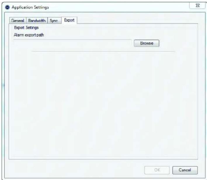
- Click the Application Settings tab. The Application Settings screen opens.
text_image
Application Settings General Bandwidth Sync Export Export Settings Alarm export path Browse OK CancelFigure 23. Export Pop-Up Alarms Screen
- Click the Export button.
- Enter the destination to which you want the pop-up alarms report sent in the Alarm export path field.
- Click the OK button.
- Go to the destination you've selected to view the Pop-up Alarm Export Report.
NOTE: Once a destination has been entered in the Alarm export path field, it cannot be deleted from that field in the Application Settings screen.
Deleting an Export Destination
- Click the Browse button to the right of the Alarm export path. The Save As screen appears.
- Delete the information in the File name field.
- Click the Save button, then close the Save As screen.
DIGITAL SENTRY REPORTS
Several types of reports can be viewed from DS ControlPoint:
Camera Usage Report: Displays recording activity (per camera and per day) in terms of the amount of disk space used for storage.
Activity Report: Displays the user or administrator activity by date/time, user name, object, IP address, activity type, or description, and identifies the DS machine name.
Zone Report: Shows how zone alarms are configured.
Configuration Report: Displays all configuration changes for cameras, camera groups, zones, users, and other configuration parameters.
Snap Shot Report: Shows only a camera snap shot and the camera name, in HTML format.
Reports can be viewed using a browser or they can be printed.
To generate a report:
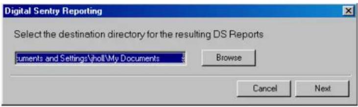
- Select the Digital Sentry Reports tab located on the Setup page (refer to Figure 2 on page 11). The Digital Sentry Reporting dialog box appears.
text_image
Digital Sentry Reporting Select the destination directory for the resulting DS Reports Documents and Settings\joll\My Documents Browse Cancel NextFigure 24. Digital Sentry Reporting Dialog Box
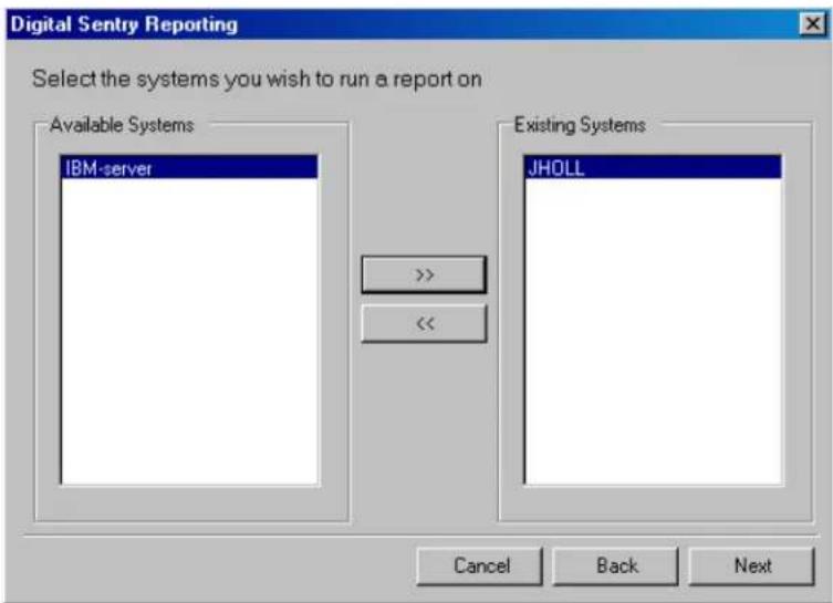
- Click the Browse button to select the directory location for the DS report, and then click the Next button. A dialog box appears that instructs you to select the system(s) on which to run a report (refer to Figure 25).
- Select a system(s) from the Available Systems list and click the Add button (>>) to add it to the Existing Systems list.
text_image
Digital Sentry Reporting Select the systems you wish to run a report on Available Systems IBM-server Existing Systems JHOLL << Cancel Back NextFigure 25. Selecting Existing Systems
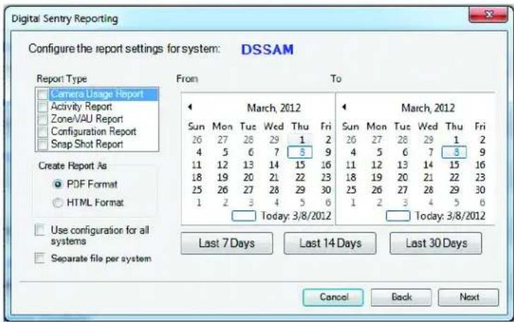
- Click the Next button. A dialog box appears to configure the report settings for the system.
text_image
Digital Sentry Reporting Configure the report settings for system: DSSAM Report Type Camera Usage Report Activity Report Zone/VALU Report Configuration Report Snap Shot Report Create Report As PDF Format HTML Format Use configuration for all systems Separate file per system From To March, 2012 Sun Mon Tue Wed Thu Fri 26 27 28 29 1 2 4 5 6 7 5 9 11 12 13 14 15 16 18 19 20 21 22 23 25 26 27 28 29 30 1 2 3 4 5 6 Today: 3/8/2012 March, 2012 Sun Mon Tue Wed Thu Fri 26 27 28 29 1 2 4 5 6 7 5 9 11 12 13 14 15 16 18 19 20 21 22 23 25 26 27 28 29 30 1 2 3 4 5 6 Today: 3/8/2012 Last 7 Days Last 14 Days Last 30 Days Cancel Back NextFigure 26. Configuring System Report Settings Dialog Box
- Select the report type(s) from the drop-down list.
- Select the report format: PDF or HTML.
- Select "Use configuration for all systems" if you want to reserve these settings for future reports.
- Select "Separate file per system" if you want multiple reports to be generated as separate files instead of being consolidated into one.
- Select the time period for the report using the From and To calendars or by selecting the Last 7 Days, Last 14 Days, or Last 30 days button.
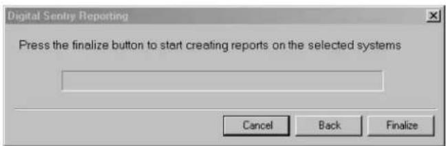
- Click the Next button. A dialog box appears to generate the report.
text_image
Digital Sentry Reporting Press the finalize button to start creating reports on the selected systems Cancel Back FinalizeFigure 27. Create Report Dialog Box
- Click the Finalize button. The report will appear in the directory location that you set up in step 2.
- Click the Close button to close the Digital Sentry Reporting dialog box.
UPDATING DS CONTROLPOINT SOFTWARE
To determine if you require a DS ControlPoint software update:
- Click the "Check for Software Update" tab in the Setup page. A "Confirm check for Software Update" dialog box appears.
- Click the Yes button. A DS Update dialog box appears.
NOTE: You must be connected to the Internet to perform this function.
- Click the ControlPoint box, and then click the Next button.
- Type the location in the Save Path box or click the Browse button for a download location, and then click the Next button.
- Once the software download is complete, click the Finish button.
- Open and install the downloaded DS ControlPoint software.
CONFIGURING ANALOG OUTPUTS
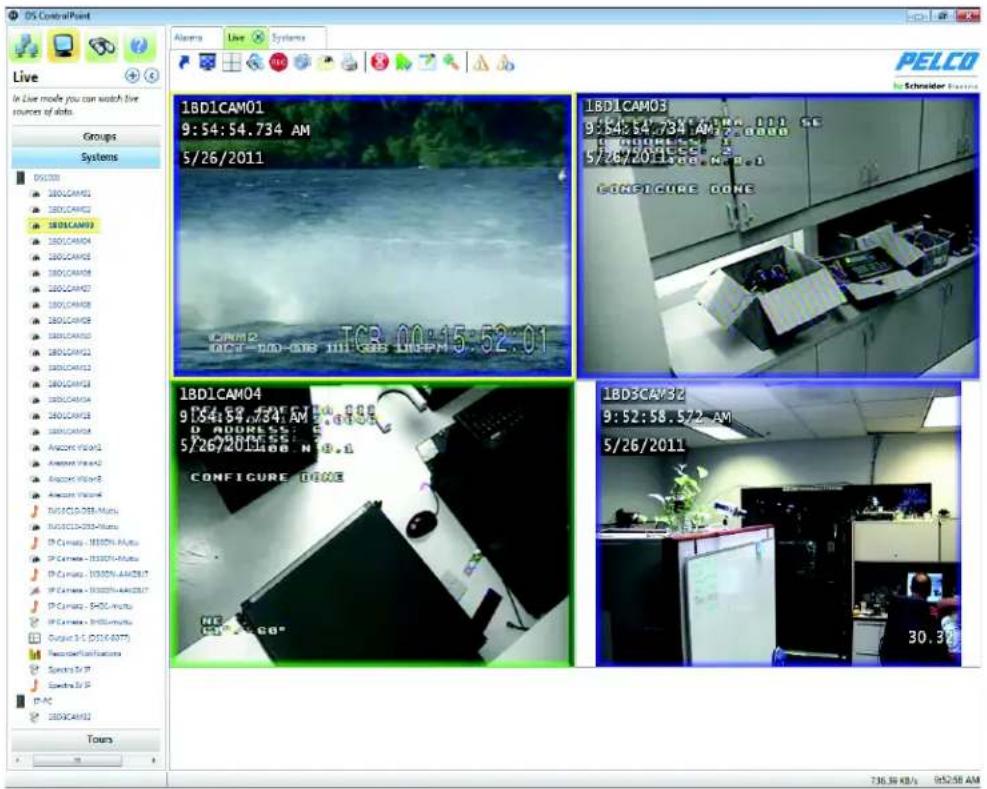
Analog outputs are visible in the Systems tree after connecting to a system in DS ControlPoint. Only analog cameras located on the same board and capture card as the analog output can be viewed through the output.
text_image
OS Control Point Live In Live mode you can watch live sources of shots. Groups Systems 05/1/2011 1BD1CAM01 9:54:54.734 AM 5/26/2011 1BD1CAM03 9:54:54.734 AM 2.0000 5/26/2011 500 MHz CONFIGURE DONE 1BD1CAM04 9:54:54.734 AM 2.0000 5/26/2011 500 MHz CONFIGURE DONE 1BD3CAV32 9:52:58.572 AM 5/26/2011 30.30 Tours 736.36 KB/s 052:58 AMFigure 28. Analog Output Screen
To configure analog outputs in DS ControlPoint:
- Double-click an analog output in the Systems tree to open a new analog output tab titled Mon <#>, which will connect the system to a specific monitor.
- Drag and drop video in the video pane to automatically update the analog monitor.
- Click one of the icons above the video pane to change layouts, remove video, or perform other actions.
NOTES:
- A system must have its analog outputs configured inside DSAdmin.
- Layouts are currently restricted to 1 x 1, 2 x 2, 3 x 3, or 4 x 4 for analog outputs modified through DS ControlPoint.
- Users without the appropriate permissions will not be able to view or modify analog outputs.
Live
The Live page allows you to view live video in any of 22 configurations. To choose a configuration, click the Layout icon and select the configuration from the menu. To close the configuration menu, press the
To view video or data in a video pane:
- Select the Systems section of the navigation pane.
- Right-click on a system to expand the tree until you see the appropriate camera.
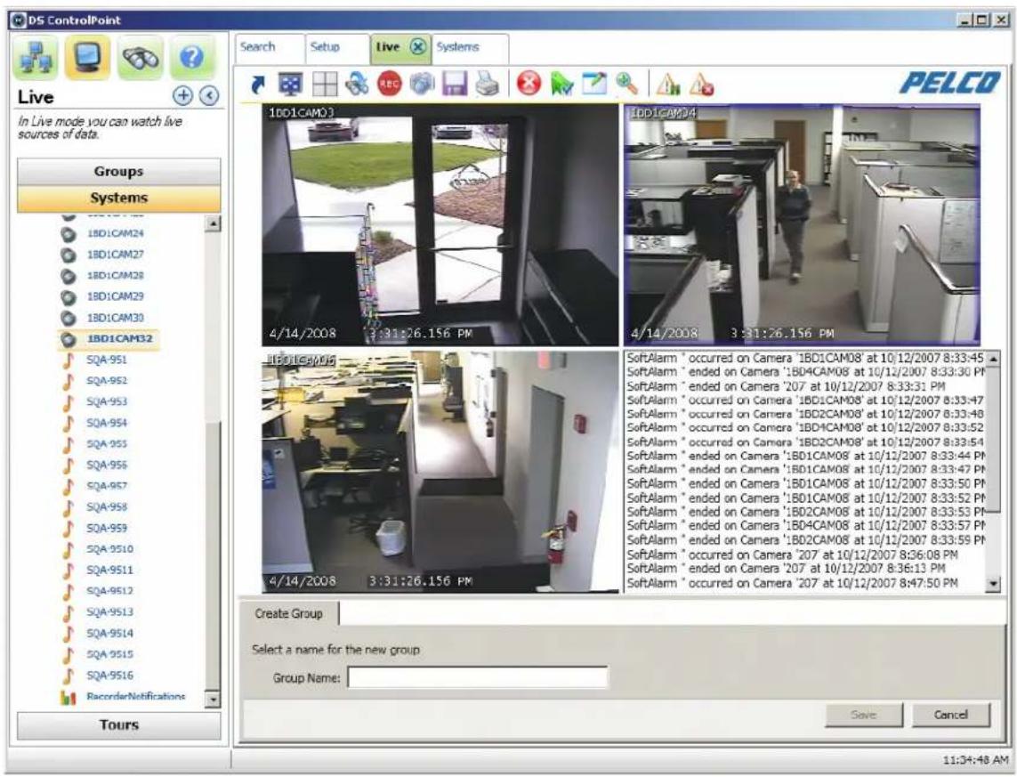
- Drag and drop the camera or device name into any of the video panes (refer to Figure 29).
NOTE: When you drag a DS DataPoint device into a video pane, a menu appears that allows you to select a data format to display. The data format options vary depending on the type of device selected.
- Repeat these steps until video or data from all the desired cameras and devices is displayed in the video panes.
NOTE: Multiple cameras may be selected by pressing CTRL+Select or Shift+Select using the keyboard.
text_image
DS ControlPoint Live In Live mode you can watch live sources of data. Groups Systems 1BD1CAM23 1BD1CAM04 4/14/2008 3:31:26.156 PM 4/14/2008 3:31:26.156 PM SoftAlarm * occurred on Camera 'IBD1CAM08' at 10/12/2007 8:33:45 SoftAlarm * ended on Camera 'IBD4CAM08' at 10/12/2007 8:33:30 PM SoftAlarm * ended on Camera '207 at 10/12/2007 8:33:31 PM SoftAlarm * occurred on Camera 'IBD1CAM08' at 10/12/2007 8:33:47 SoftAlarm * occurred on Camera 'IBD2CAM08' at 10/12/2007 8:33:48 SoftAlarm * occurred on Camera 'IBD1CAM08' at 10/12/2007 8:33:52 SoftAlarm * occurred on Camera 'IBD2CAM08' at 10/12/2007 8:33:54 SoftAlarm * ended on Camera 'IBD1CAM08' at 10/12/2007 8:33:44 PM SoftAlarm * ended on Camera 'IBD1CAM08' at 10/12/2007 8:33:47 PM SoftAlarm * ended on Camera 'IBD1CAM08' at 10/12/2007 8:33:50 PM SoftAlarm * ended on Camera 'IBD1CAM08' at 10/12/2007 8:33:52 PM SoftAlarm * ended on Camera 'IBD2CAM08' at 10/12/2007 8:33:53 PM SoftAlarm * ended on Camera 'IBD4CAM08' at 10/12/2007 8:33:57 PM SoftAlarm * ended on Camera 'IBD2CAM08' at 10/12/2007 8:33:59 PM SoftAlarm * occurred on Camera '207 at 10/12/2007 8:36:08 PM SoftAlarm * ended on Camera '207 at 10/12/2007 8:36:13 PM SoftAlarm * occurred on Camera '207 at 10/12/2007 8:47:50 PM Create Group Select a name for the new group Group Name: Save Cancel Tours PELCOFigure 29. Live Page
NOTE: If the device placed into a video pane is a PTZ camera, refer to PTZ Cameras on page 49 for information on controlling the features for pan/tilt/zoom.
Clicking any one of the video panes causes all of the following Live page icons to appear.
Table B. Live Page Icons
 | Full Screen | Enter full-screen mode and remove the window border. |
 | Layout Select a video pane configuration. | |
| [BYHC] | Quick Review Review the last few minutes of recorded video | |
 | Manual Record Manually stop/start recording on a camera. | |
 | Snapshot | Export the current still image from the selected Live/Playback video. |
 | Create Group | Store the selected list of displayed streams as a group. |
 | Print Print an image of the current view. | |
 | Remove Stop viewing or listening to the selected stream. | |
 | Manage On-Screen Display (OSD) Settings | Configure information displayed in the video pane for the selected items. |
 | Image Adjustments | Adjust brightness, contrast, and inverse display options. |
 | Enable On-Screen Pan/Tilt/Zoom | Start using on-screen pan/tilt/zoom on the selected cameraNOTE: Appears for PTZ cameras only. |
 | Enable Digital Zoom | Begin using digital zoom on the selected video pane.NOTE: Appears for PTZ cameras only. |
 | PTZ Controls | Show keyboard-style pan/tilt/zoom controls.NOTE: Appears for PTZ cameras only. |
 | Alarm Page View alarms received from connected recorders. | |
 | Pause Notification | Overrides the current alarm display option and prevents the forced display of the alarm page. |
FULL SCREEN
Clicking the Full Screen icon enlarges the configuration window to full-screen mode; the video configuration now occupies the entire viewing field of the video monitor. To exit full-screen mode, either right-click anywhere on the page and select "Exit Full Screen" from the menu, or press the
QUICK REVIEW
To view video recently recorded from the cameras displayed in the video panes, click the Quick Review icon 📋 and select the amount of video you want to view from the list. You can quickly view video recorded in several increments ranging from the last minute to the last 90 minutes.
When you select the increment, recorded video for the entire time range is played back starting from the beginning of the increment. The status bar in the bottom-right corner of the screen indicates the progress of the video. You can control playback of the recorded video using the nine buttons at the bottom of the screen; to view the function of a button, place your mouse pointer over the button. Also, click the status bar or drag the slider left or right to quickly move through the video.
To return to viewing live video, click the Live tab at the top of the window.
NOTE: For information about exporting recorded video, authenticating video, or filtering samples, refer to Live and Playback Video Search on page 38.
MANUAL RECORD
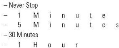
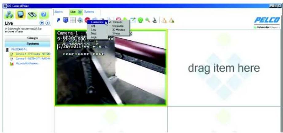
You can create a customized recording resolution and time frame by clicking the Manual Record icon REC. Use the following options to create your customized recording solution:
- Recording Resolution

- Recording Time
text_image
- Never Stop - 1 M i n u t e - 5 M i n u t e s - 30 Minutes - 1 H o u rSelecting a low recording frame rate allows you to save recording space. Recording at a higher resolution allows you to increase the quality of the video recording. An example of a customized recording resolution might be in a college classroom. When the class begins, the recorder might be set to a high frame rate and a certain recording time. When the class ends, the frame rate and recording time would be set back to the original settings. This would result in saving space on your hard drive.
text_image
DS CentralPoint Live In Live modify you can watch live resources of data Groups Systems PA-203643-1s Camera 1 - IP Encoder - NET540 Camera 1 - NET54017-ANALYH Reactor/Alumetrics Camera-1 - 9:55-253.900 15/267/201186.N.E.U.1 CONFIGURE DONE drag item hereFigure 30. Customizing Recording
SNAPSHOT
To export a current still image from a selected live or playback video:

- Click the Snapshot icon
The Snapshot Preview dialog box appears. - Select a file type from drop down list: PNG (default), BMP, GIF, JPEG, and TIFF.
- Select a file name for the snapshot.
- Click the Save Path button to select a location to save the snapshot.
- Select "Keep Open after Save?" if you want the Snapshot Preview screen to remain open.
- Select "Add note?" if you want to add a note to the snapshot.
- Click the Save button to save the snapshot to the desired location.
NOTE: When you click the Refresh button, the snapshot will show the latest scene in the live or playback video.
CAMERA GROUPS
Any combination of cameras in a video pane configuration can be saved as a camera group. To save and view cameras as a camera group:
- Drop the cameras into the video panes and click the Create Group icon cameras in the video panes.

. The Create Group tab allows you to save a combination of
- On the Create Group tab (refer to Figure 31), type a name for the group in the Group Name text box, and click the Save button. The camera group now appears in the Groups section of the navigation pane under Local Groups.
- To view the camera group, right-click on the camera group name in the tree and select View Live from the menu. Alternatively, you can click and drag the group name into the video panes.
NOTES:
- Camera groups configured directly through DSAdmin also appear in the Groups section of the navigation pane. They can be found in the System Groups portion of the tree.
- Camera properties and the ability to pause and unpause notifications are also accessible when you right-click on a camera in the camera tree.

text_image
Create Group Select a name for the new group: Group Name: Or: Update existing group: test Cancel SaveFigure 31. Create Group Tab
PRINTING IMAGES FROM VIDEO PANES
To print camera images displayed in the video panes, click the Print icon 📄. On the Print tab, you can select options to include the OSD text (Text Overlay) and to fit the images to the paper (Best Fit). You can also preview the print job. To print the images, click the Print button.
ENTERING A MOTION MASK FOR SARIX CAMERAS
Motion masking is available for Sarix cameras.
- Right-click in the image.
- Select the Configure Motion Settings option. The Configure Motion Settings page appears.
- Click and drag in the image to select the area to be masked.
- Click the Save button, then the Close button.
NOTE: The system requires 15 minutes to recognize the motion masking setting.
VIDEO PANE BORDERS
Video panes displaying video that is currently being recorded are surrounded by colored borders, which indicate the current recording mode: time-lapse (green), motion (blue), alarm (red), or motion (purple). When you click a video pane to modify it, the window is also surrounded by a yellow border.
REMOVING VIDEO FROM A WINDOW
To stop and remove video from one of the configuration windows, click in the desired window to highlight it with a yellow border, and then click the Remove icon. You can also right-click in the desired window and select Remove from the menu.
MANAGE OSD SETTINGS
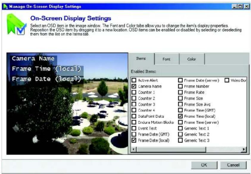
To display text in a video pane, click the Manage OSD Settings icon 📄, or right-click the window and select Manage OSD Settings from the menu. This opens the On-Screen Display Settings window (refer to Figure 32). The On-Screen Display Settings window allows you to configure text items displayed in video panes.
text_image
Manage On-Screen Display Settings On-Screen Display Settings Select an OSD item in the image window. The Font and Color tabs allow you to change the item's display properties. Reposition the OSD item by dragging it to a new location. OSD items can be enabled or disabled by selecting or deselecting them from the list on the items tab. Camera Name Frame Time (local) Frame Date (local) Items Font Color Enabled Items: Active Alert Camera Name Counter 1 Counter 2 Counter 3 Counter 4 DataPoint Data Endura Motion Blocks Event Text Frame Date (GMT) Frame Date (local) Frame Date (server) Frame Number Frame Rate Frame Size Frame Size Avg Frame Time (GMT) Frame Time (local) Frame Time (server) Generic Text 1 Generic Text 2 Generic Text 3 OK CancelFigure 32. On-Screen Display Settings Window
NOTE: Many of the text options available on the Items tab have different functions based on their definitions on the server generating the information.
The Items tab allows you to select the text that you want to display (for example: camera names, Active Alert ellipses and counters). When you select a text item, it appears in the video pane. Click and drag the item to any location in the window.
The Font tab allows you to change the text font. Select the text item in the video pane, enter a Font Size, and choose a font from the drop-down list.
The Color tab allows you to change the text's color, shadow, and background. Select the text item and choose a color from the wheel, or move the sliders on the black-and-white bars.
IMAGE ADJUSTMENTS
To adjust the brightness and contrast of displayed video:
- Select one or more windows that are currently displaying video.
- Click the Image Adjustments icon 📄, or right-click the windows and select Image Adjustments from the menu. This opens the Image Adjustments tab.
- Using the slider, adjust the brightness and contrast of the desired video. You can also select the Inverse check box to display a negative of the video.
- When finished, click the Apply button.
ENABLE ON-SCREEN PAN/TILT/ZOOM
The Enable On-Screen Pan/Tilt/Zoom feature is only available on cameras that support PTZ. Click in the video screen of a camera that supports PTZ to begin using this feature.
ENABLE DIGITAL ZOOM
The Enable Digital Zoom feature allows you to zoom in and out of an area in the selected video pane (the window surrounded by a yellow border).
To zoom, perform the following steps:
- Click the Enable Digital Zoom icon
- Position the mouse pointer over the area of the video you want to zoom.
- Use the mouse wheel to zoom in and out.
- Click the Enable Digital Zoom icon a second time to end zooming and return to the default view.

PTZ CONTROLS
Click the PTZ Controls icon to show keyboard-style pan/tilt/zoom controls. This icon is only available for cameras that support PTZ.
ALARM PAGE
Click the Alarm Page icon to view alarms received from connected recorders.
PAUSE NOTIFICATION
Click the Pause Notification icon ⚠️ to override the current alarm display option and to prevent the forced display of the alarm page.
Search
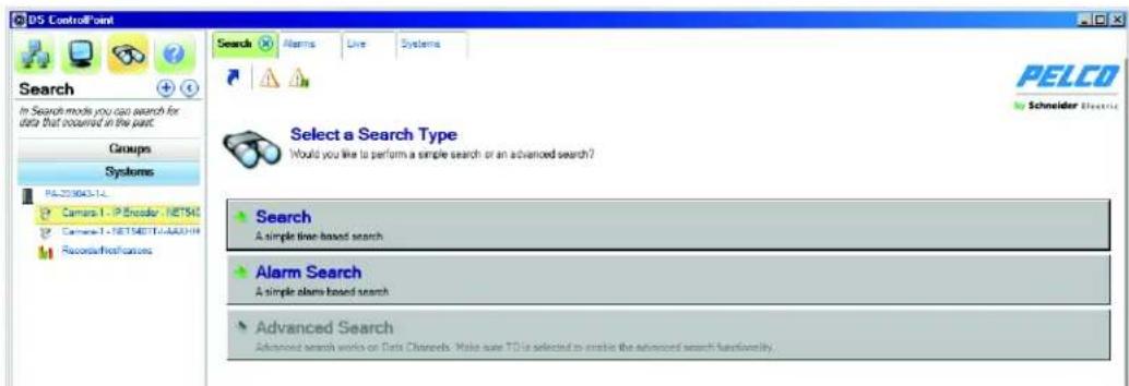
The Search tab allows you to search for recorded video on specific cameras.
text_image
PDS ControlPoint Search In Search modes you can search for data that occurred in the past. Groups Systems PA20360314 Camera 1 - IP Encoder, NETS40 Camera 1 - NETS40TCAUDCH RecordFirstCursors Select a Search Type Would you like to perform a simple search or an advanced search? Search A simple time-based search Alarm Search A simple alarm based search Advanced Search Advanced search works on Data Channels. Make sure TO be selected to enable the advanced search functionality.Figure 33. Search Tab
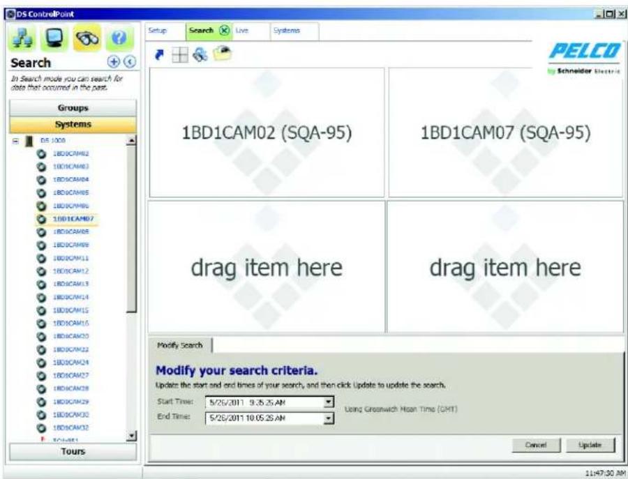
What is displayed on the Search tab depends on the camera type: either a non-DS camera or a DS camera. If the video of a non-DS camera is selected to be searched, the Search page will look similar to Figure 34.

WARNING: Video search requests may utilize large amounts of memory resulting in degraded and unpredictable system behavior. Pelco recommends using a single search tab, and carefully selecting the smallest number of cameras and shortest timeline when using ControlPoint.
LIVE AND PLAYBACK VIDEO SEARCH
NON-DS CAMERA SEARCH
Perform the following steps to search recorded video on a non-DS camera:
- Click the Search icon to open the Modify Search tab.
- Drag and drop cameras from the navigation pane into the video panes.
- Enter the Start Time and End Time for the search, and then click the Next button.
text_image
DS ControlPoint Search In Search mode you can search for date that occurred in the past. Groups Systems 1BD1CAM02 (SQA-95) 1BD1CAM07 (SQA-95) drag item here drag item here Modify Search Modify your search criteria. Update the start and end times of your search, and then click Update to update the search. Start Time: 5/25/2011 9:35:25 AM End Time: 5/25/2011 10:05:25 AM Using Greenwich Mean Time (GMT) Cancel Update 11:47:30 AMFigure 34. Non-DS Camera Search Page
Recorded video from the selected cameras and time range is played back starting from the beginning of the increment. The status bar in the bottom-right corner of the window indicates the progress of the video. You can control the video playback parameters with the Playback Bar. The Playback Bar, located at the top of the window, consists of nine buttons (refer to Figure 35). To view the function of a button, place your mouse pointer over the button. Also, click the status bar or drag the slider left or right to quickly move through the video.

Figure 35. Playback Bar
NOTE: The function of the scrubbing/playback slider is different for DS and DX products. For DS products, video continuously changes in the video frame as the slider is moved. For DX products, the video does not visibly change as the slider is moved. Once the slider has stopped moving, the video will change to match the stopping point of the slider.
DS CAMERA SEARCH
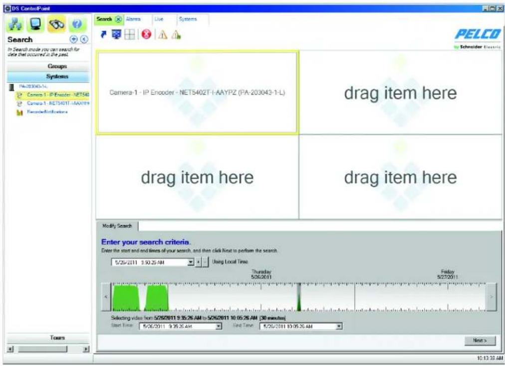
If the video of a DS camera is to be searched and a DS camera has been selected and dropped into one of the video panes, the Search page will look similar to Figure 36.
Perform the following steps to search for recorded video on a DS camera:
-
Click the Search icon to open the Modify Search tab.
-
Drag a DS camera from the navigation pane into a video pane. The Modify Search tab changes to a graph.
NOTE: You can double-click in a streaming video pane to change from a 2 x 2 layout to a single layout. Double-click the video pane again to return to a 2 x 2 layout.
text_image
DS ControlPoint Search Alarms Live Systems Groups Systems PA-203040-14 Camera-1 - IP Encoder - NET540 Camera-1 - NET540T1 - AAYPZ (PA-203043-1-L) drag item here drag item here drag item here Modify Search Enter your search criteria. Enter the start and end times of your search, and then click Next to perform the search 5/25/2011 9:30:25 AM Using Local Time Thursday 5/26/2011 Friday 5/27/2011 Selected video from 5/26/2011 9:35:26 AM to 5/26/2011 10:05:26 AM (30 minutes) Start Time 5/26/2011 9:35:25 AM End Time 5/26/2011 10:05:26 AM Next > Tours 10:13:38 AMFigure 36. DS Camera Search Page
The search grid for DS cameras (refer to Figure 37 on page 41) is a representation of video frames. A maximum of 400,000 video frames can be represented by the grid. Use the mouse pointer to select a range of grid marks, which will indicate (by gray highlight) the range of video frames to be searched.
There are four colors for the peaks and ridges within the search grid, and each color represents one of the following video states:
Red: Alarm video
Blue: Motion video
Yellow: Event video
Green: All other video
Use the following methods to enter your search criteria:
- Use the mouse wheel or the Plus (+) and Minus (−) buttons located in the Modify Search tab to zoom in and out the graph.
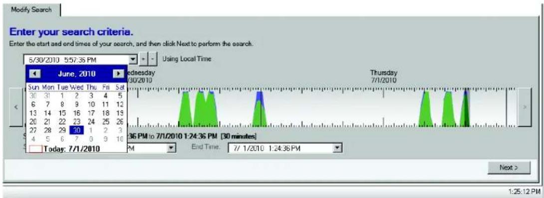
- Click the arrows located on the left and right sides of the graph to cycle through the time range of the video frames (refer to Figure 37).
- Click the date and time drop-down calendar to adjust the date and time of the search.
text_image
Modify Search Enter your search criteria. Enter the start and end times of your search, and then click Next to perform the search. 5/30/2010 5:57:35 PM Using Local Time June, 2010 Wednesday 5/30/2010 Thursday 7/1/2010 Sun Mon Tue Wed Thu Fri Sat 30 31 1 2 3 4 5 6 7 8 9 10 11 12 13 14 15 16 17 18 19 20 21 22 23 24 25 26 27 28 29 30 1 2 3 4 5 6 7 8 9 10 Today: 7/1/2010 36 PM to 7/1/2010 1:24:36 PM [30 minutes] PM End Time: 7/1/2010 1:24:36 PM Next > 1:25:12 PMFigure 37. Search Using Calendar or Plus/Minus Buttons
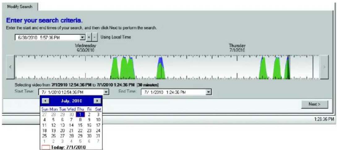
- You can also click the Start Time and End Time drop down calendars below the graph to adjust the date for the search. The time can also be adjusted by highlighting and typing in the desired start and end time.
text_image
Modify Search Enter your search criteria. Enter the start and end times of your search, and then click Next to perform the search. 6/30/2010 5:57:36 PM Using Local Time Wednesday 6/30/2010 Thursday 7/1/2010 Selecting video from: 7/1/2010 12:54:36 PM to 7/1/2010 1:24:36 PM [30 minutes] Start Time: 7/ 1/2010 12:54:36 PM End Time: 7/ 1/2010 1:24:36 PM July, 2010 Sun Mon Tue Wed Thu Fri Set 27 28 29 30 1 2 3 4 5 6 7 8 9 10 11 12 13 14 15 16 17 18 19 20 21 22 23 24 25 26 27 28 29 30 31 1 2 3 4 5 6 7 Today: 7/1/2010 Next > 1:28:36 PMFigure 38. DS Camera Search Using Start and End Time Boxes
DS SERVERS AND DX8100 SERIES SYSTEMS SCAN
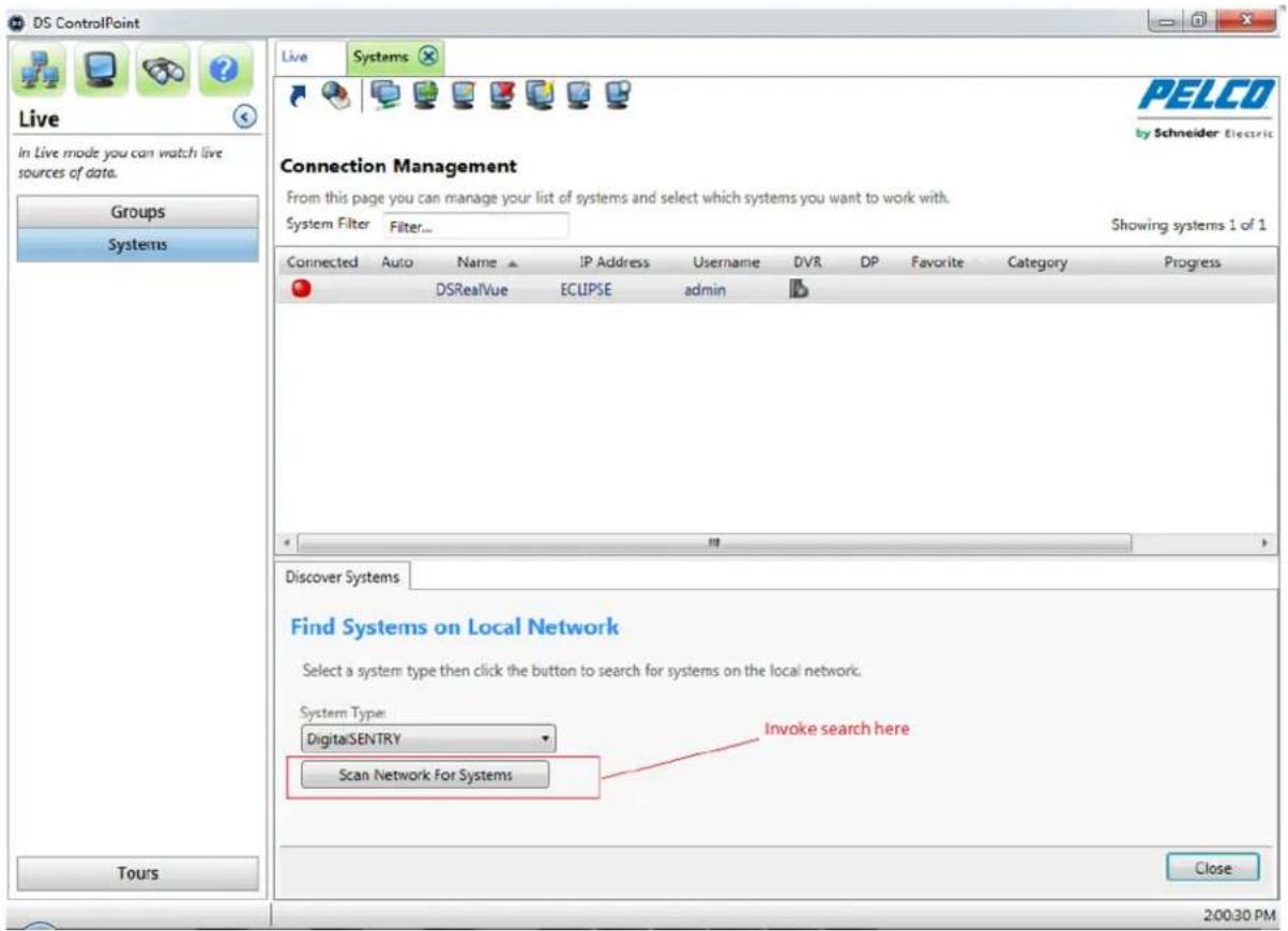
You can scan for DS servers and DX8100 series systems.
- Click the Systems tab. The Connection Management page appears.
- Right-click the Systems tab, then select the Discover System option from the drop-down menu. The Discover Systems tab appears.
- Click the Scan Network for Systems button. All available systems will display.
text_image
DS ControlPoint Live In Live mode you can watch live sources of data. Groups Systems Live Systems PELCO by Schneider Electric Connection Management From this page you can manage your list of systems and select which systems you want to work with. System Filter Filter... Showing systems 1 of 1 Connected Auto Name IP Address Username DVR DP Favorite Category Progress DSRealVue ECLIPSE admin Discover Systems Find Systems on Local Network Select a system type then click the button to search for systems on the local network. System Type: DigitalSENTRY Scan Network For Systems Invoke search here Tours Close 200:30 PMFigure 39. Scanning the Network for Systems
- Select the system(s) you want to add to your systems list, then click the Close button.
AUTHENTICATE SAMPLES
To verify that the video displayed has not been corrupted, click the Authenticate Samples icon ☑. A progress bar indicates how much time is required to complete the authentication. To end the process before it is complete, click the Cancel button.
FILTER SAMPLES
To search for video that displays only motion or alarm, click the Filter Samples icon , select Motion or Alarm, and then click the OK button.
ALARM SEARCH
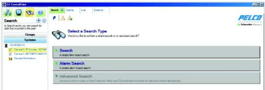
The Alarm Search page allows you to perform simple alarm-based searches.
text_image
DS ControlPoint Search In Search mode you can search for data that occurred in the past. Groups Systems PA:201043.1-L Camera-1 - IP Encoder - NET540 Camera-1 - NET540T 1-2AAXHH Syncable/Notifications Search A simple time-based search Alarm Search A simple alarm-based search Advanced Search Advanced search audio on Data Channels. Make sure TD is selected to enable the advanced search functionalityFigure 40. Alarm Search
To search for alarm-based events:
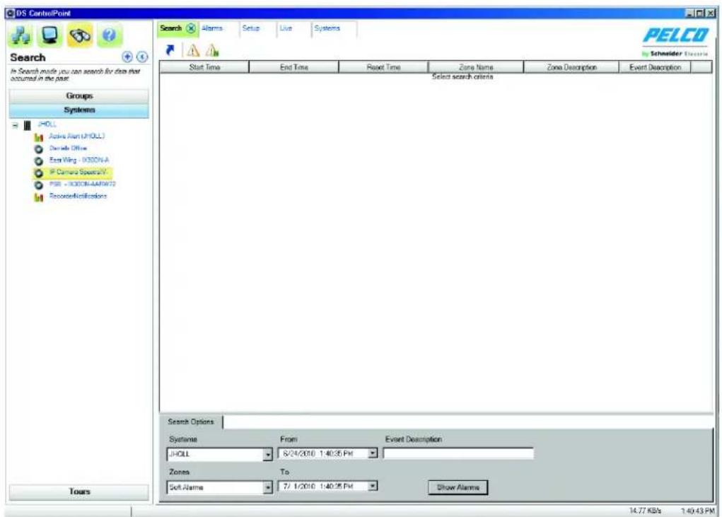
- Select the Search icon, and then click Alarm Search. A Search Options screen appears (refer to Figure 41).
- Set the alarm duration by selecting the date and time from the From and To lists.
- Type a description in the Event Description box.
- Click the Show Alarms button. A list of event alarms appears for the specified time frame.
text_image
DS ControlPoint Search Alarms Setup Live Systems PELCO Schneider Electronics Start Time End Time Reset Time Zone Name Zone Description Event Description Groups Systems JHOLL Active Arm (JHOLL) Device Office Era Wing - 0300N.A Camera Special Y PSB - 0300N-AARW22 Secorifications Toars Select search criteria Search Options Systems From Event Description JHOLL 8/24/2010 1:40:35 PM Zones To Soft Alarms 7/1/2010 1:40:35 PM Show Alarms 14.77 KB/s 1:40:43 PMFigure 41. Alarm Search Screen
- Click the "X" on the Search tab to close the Alarm Search screen and return to the Setup page.
ACKNOWLEDGING SERIAL ALARMS
All alarms are acknowledged in Digital Sentry when an acknowledge ASCII string is sent from the access control system. If the Pelco ASCII command set is used, the acknowledge string is an iA command. The AlarmClear service must be installed.
INSTALLING THE ALARMCLEAR SERVICE TO MONITOR COM1 PORT
- Go to the Files directory.
- Copy all of the files into a permanent location (from which the service will run).
- Run the alarmclear.cmd to execute the alarmclearbystring.sql against the database.
- Run the alarmautoClear.cmd to install the AlarmClear service.
NOTES:
- You must be logged on with administrator permissions to perform this installation.
- If there is an error, edit the alarmautoClear.cmd file and verify that the path to installutil.exe is valid.
-
The user name is ".\DSServiceUser" and the password is the DSServiceUser's password.
-
Go to the Services tab and start the DigitalSentry Serial Alarm Clear Service.
-
If running x64 then run AlarmAutoClear64.reg, otherwise run the 32 version.
MONITORING ANOTHER COM PORT
- Stop the Digital Sentry Serial Alarm Clear Service.
- Open regedit, and then go to HKEY_LOCAL_MACHINE\Software\Integral Technologies, Inc.\DigitalSentry\AlarmAutoClear.
- Change the options to the port to be monitored.
- Restart the service.
CONFIGURING VIDEOSERVER
- Open DSAdmin.
- Add a Zone. The name must be a two-digit number (for example, 20).
- Click the Serial Input tab for the zone, and then add the text. (for example, 20Ea).
- Save the zone.
- Click the VAU.
- Click the Serial Ports tab.
- Add a COM port to the "Assigned COM ports" list. You must use a different COM port than the one assigned to the AlarmClear service.
- Click Interface Type, and then select Monitor.
- If necessary, select the check box to ensure that it is active.
- Open the Alarm Text tab and add a line item (for example, 20Ea).
- Restart the VideoServer.
CONFIGURING DS CONTROLPOINT
-
- From the Setup menu, select Application Settings, and then select General.
- Select "Automatically clear acknowledged system alarms."
- Click "Save."
NOTES:
- When an ASCII string of "XXEa" comes in (for example, on COM1), the zone alarm is triggered through VideoServer.
- When an ASCII string of "XXla" comes in (for example, on COM2), the service will intercept this command and clear the alarm in the database.
- When CP recognizes that the alarm being displayed has been cleared, it will remove the item from the alarm page.
ADVANCED SEARCH (DS DataPoint)
DS DataPoint is an application integrated with DS ControlPoint that allows you to receive and analyze transactional data (TD), such as video analytics, and information from devices, such as cash registers and ATMs.
NOTE: To use DS DataPoint, you must be connected to a DVMS with DS DataPoint software installed. When you add the system using DS ControlPoint, you must select the DS DataPoint Server check box (refer to Figure 10 on page 16). All systems identified as DS DataPoint Servers contain a DS DataPoint icon in the DP column of the Connection Management page.
To run an advanced search, complete the following steps:
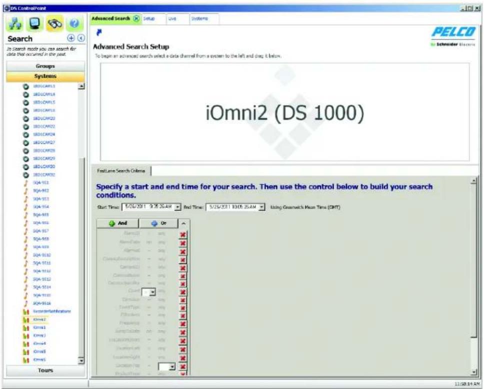
- Click the Search icon, and then click the Advanced Search button. This opens the Advanced Search Setup window (refer to Figure 42). The Advanced Search tab allows you to search for data and video from integrated devices or video analytics events.
NOTE: To view Sarix analytic alarms with continuous recording, click the Enable Analytics box on the General tab in DSAdmin for the desired camera.
-
Drag a data channel from the navigation pane into the output window. This opens a tab related to the type of data channel selected:
-
For Active Alert searches, enter a time/date range, event time, event type, and camera name. Enter a severity range, whether you want alarmed events, an object type, and zone information.
- For Fastlane scale searches, enter a time/date range, and then select a series of occurrences. To do this, click the Any option beside each desired parameter and select a transaction. Then click the equal sign (=) and select an operator. Click the Add button to add parameters, or click the Or button to add separate occurrences.
-
For iOmniscient searches, enter a time/date range, event time, event type, and camera name. Then enter alarmed events, count range, side of area, and direction.
-
Click the Next button.
text_image
iOmni2 (DS 1000) Start Time: 5/26/2011 9:35:35 AM Bad Time: 5/26/2011 10:05:25 AM Using Gearwick Mean Time (CMT) And Or Name: 1.00 Name: 1.00 Aligned: 1.00 Construction: 1.00 Design: 1.00 Construction: 1.00 Construction: 1.00 Count: 1.00 Duration: 1.00 Draw Type: 1.00 Fileless: 1.00 Presence: 1.00 Jump Puzzle: 1.00 HCA#N#P#N#N: 1.00 Location: 1.00 Location: 1.00 Location: 1.00 Production: 1.00 11:58:19 AMFigure 42. Advanced Search Tab
A results window opens, which contains a list of events that meet the search criteria. To view video of the event (if applicable), click the View Associated Video icon, or right-click the result and select View Associated Video from the menu.
NOTE: The options available in the drop-down menus vary widely depending on your device configuration. For information about configuring devices, refer to the manufacturer's documentation.
THUMBNAIL SEARCH
The system has been upgraded to allow thumbnail screens to be displayed below the graph in the Search tab. These thumbnails represent the same time line as represented in the graph. Moving the graph updates the thumbnails according to the time line of the graph.
- Open the Search tab and select Advanced Search.
- Drag a DS camera to a search pane to display the thumbnails.
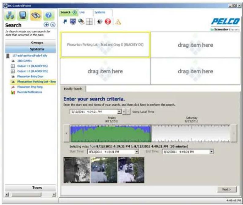
text_image
PES ControlPoint Search In Search mode you can search for data that occurred in the past. Groups Systems 15th adi-f and find adi-f lily 2001 CARS Output 1-1 (BLACKEY-OS) Output 1-2 (BLACKEY-OS) Pleasanton Entry Door Pleasanton Parking Lot - Box Pleasanton Ring Ring Recorder Notifications Toys Search Live Systems PELCO by Schneider Electricis Pleasanton Parking Lot - Brad and Greg 0 (BLACKEY-OS) drag item here drag item here drag item here Modify Search Enter your search criteria. Enter the start and end times of your search, and then click Next to perform the search. 0/12/2011 4:34:21 PM using Local Time Friday R/12/2011 Saturday 8/13/2011 Selecting video from 8/12/2011 4:19:21 PM to 8/12/2011 4:49:21 PM [30 minutes] Start Time: 8/12/2011 4:19:21 PM End Time: 8/12/2011 4:49:21 PM Next > 4:49:46 PMFigure 43. Thumbnail Search Screen
- Drag and select a time line range for the desired search.
- Place your pointer over any thumbnail to display the timestamp of that thumbnail.
NOTE: For increased granularity of the thumbnails, you can select a smaller time line.
Thumbnail search works with continuous- or motion-based recording. Thumbnails are generated based on the time span of the selected time line divided by the number of thumbnails that can be displayed (depending on your screen resolution). The first i-frame for each divided section appears as a thumbnail. For example, if your search window displays six thumbnails, the search results window will display the first i-frame for each of the six sections of the time line. The thumbnail display correlates with the selected area on the color range bar.
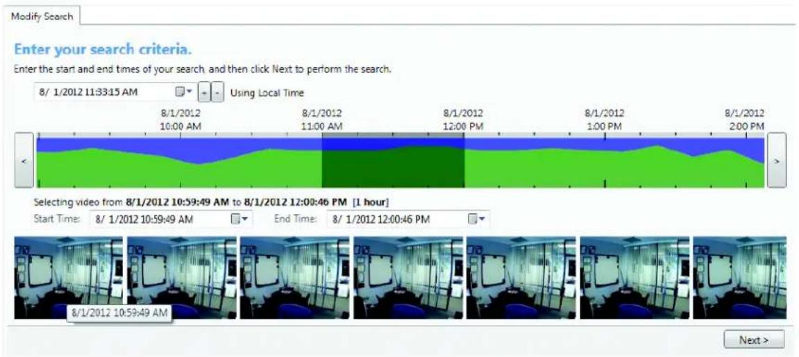
text_image
Modify Search Enter your search criteria. Enter the start and end times of your search and then click Next to perform the search. 8/1/2012 11:33:15 AM Using Local Time 8/1/2012 10:00 AM 8/1/2012 11:00 AM 8/1/2012 12:00 PM 8/1/2012 1:00 PM 8/1/2012 2:00 PM Selecting video from 8/1/2012 10:59:49 AM to 8/1/2012 12:00:46 PM [1 hour] Start Time: 8/1/2012 10:59:49 AM End Time: 8/1/2012 12:00:46 PM 8/1/2012 10:59:49 AM Next >Figure 44. Detailed View of Thumbnail Search Screen
EXPORT
DS ControlPoint allows you to export both recorded video and individual captured images to the client computer's hard drive or other connected media.
Table C. Search Page Icons
| Modify Search | |
| Export | |
| Authenticate Samples | |
| Filter Samples |
EXPORTING TO A NON-CD/DVD LOCATION
To export video included from a search result to a location on your hard drive (non-CD/DVD), complete the following steps:
- Click the Export icon (refer to Table C).
- On the Export tab, select Video and click the Next button.
- Select XPA (if not selected) and click the Next button.
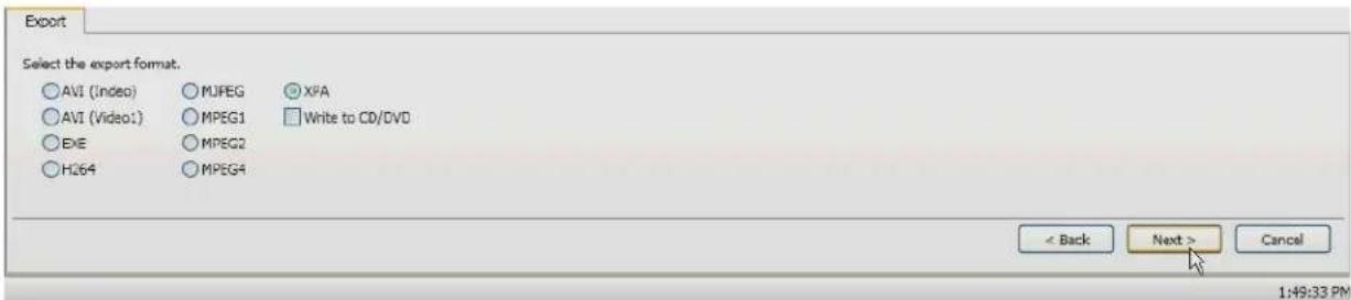
text_image
Export Select the export format. AVI (Indeo) MJPEG XPA AVI (Video1) MPEG1 Write to CD/DVD EXE MPEG2 H264 MPEG4 < Back Next > Cancel 1:49:33 PMFigure 45. Non-CD/DVD Export Format
- Click the Browse button to select the name and location for the export file, and then click the Next button.
- Select the streams to export. In this tab, you can select Select All or Clear All, and then click the Next button.
- Use the status bar slider to select the beginning of the search result that you want to export, and then click the Next button.
- Use the status bar slider to select the end of the search result that you want to export, and then click the Next button.
The export begins and the status bar shows the progress of the export. Once the export is completed, the search option screen will reappear.
NOTE: When connected to a DX product, the AVI export format does not function.
EXPORTING TO A CD/DVD
NOTE: Before exporting to a CD/DVD, make sure you install the Microsoft ^ Windows ^ Feature Pack for Storage 1.0, which includes Image Mastering API version 2.0 (IMAPI2). To install the feature pack, go to TechTip.
To export video included from a search result to a CD/DVD, complete the following steps:
- Click the Export icon (refer to Figure 46).
-
On the Export tab, select Video and click the Next button.
-
Select the export format and click the Next button. You can select AVI (Indeo), AVI (Video1), EXE (self-extracting executable), H264, MJPEG, MPEG1, MPEG2, MPEG4, or XPA.
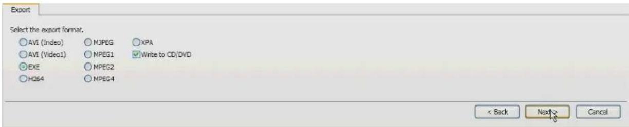
text_image
Export Select the export format. AVI (Indeo) MJPEG XPA AVI (Video1) MPEG1 Write to CD/DVD EXE MPEG2 H264 MPEG4 < Back Next > CancelFigure 46. Export Formats
- Select "Write to CD/DVD," and click the Next button.
- Click the Browse button to select the name and location for the export file, and then click the Next button.
- Select the streams to export. In this tab, you can select Select All or Clear All, and then click the Next button.
- Use the status bar slider to select the beginning of the search result that you want to export, and then click the Next button.
- Use the status bar slider to select the end of the search result that you want to export, and then click the Next button.
NOTE: If there is no CD or DVD in the disc drive, a message will appear asking if you would like to retry writing to the CD/DVD.
The export begins and the status bar shows the progress of the export. Once the export is completed, the search option screen will reappear.
EXPORT A SINGLE IMAGE
- Click the Export icon.
- Select Image and click the Next button.
- Use the status bar slider to display the image.
- Select Include Video Text Overlay and Best Fit, if desired.
- Click the OK button to display the Save As window.
- Type a file name, select the location where you want to save the file, and click the Save button.
DS ControlPoint provides features for pan/tilt/zoom (PTZ) cameras that allow you to control and configure PTZ-enabled cameras (by way of presets) through the viewing area.
NOTE: To control PTZ functions on Digital Sentry systems when connected through DS ControlPoint, you must be assigned the Configuration Manager permission. This permission must be assigned using DSAdmin. For more information, refer to the Integral Digital Sentry Operation/Configuration manual.
To view video or data from a PTZ camera in a video pane:
- From the Live page, click the Layout icon and select the configuration from the menu. To close the configuration menu, press the
key. - Select the Systems section of the navigation pane, and expand the tree until you see the appropriate PTZ-enabled camera.
- Drag the camera to a video pane. The PTZ icons appear with the displayed video.
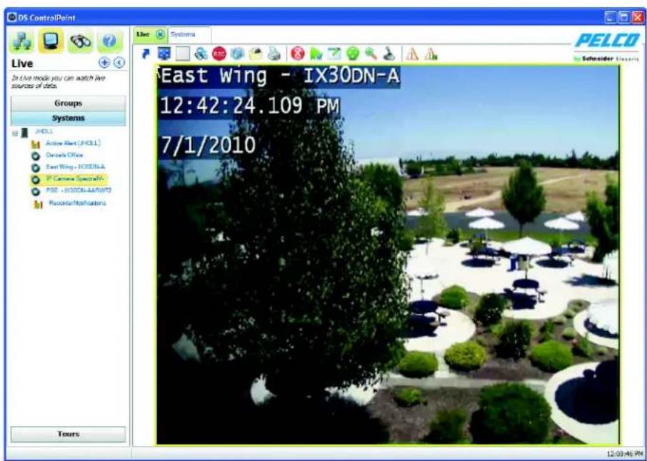
text_image
Live In Live mode you can watch live sources of data. Groups Systems JHLL Active Rent (JHLL) Details Office East Wing - IX30DN-A IP Camera SpecialW PSE - 10000A-A/NWFS Recorded Notifications Tours East Wing - IX30DN-A 12:42:24.109 PM 7/1/2010 12:03:46 PM PELCO Schneider ElectronicsFigure 47. Live Page with PTZ-Enabled Video
- If necessary, repeat these steps until video or data from all desired PTZ-enabled cameras are displayed in the video panes.
ENABLE AND DISABLE PTZ
The Enable PTZ feature allows you to use your mouse to control the pan, tilt, and zoom functionality of a PTZ camera. To enable PTZ, perform the following steps:
-
Click the Enable PTZ icon . The icon turns red.
-
Position the mouse pointer on the video, and then click and hold the left mouse button until the pointer changes to an arrow. Move the mouse to pan and tilt the camera, which changes the view as the camera moves.
-
To zoom the camera, move the mouse pointer until it changes to a spyglass. Then click and hold the mouse button to zoom in (+ spyglass) and out (− spyglass).
-
To disable PTZ, click the red PTZ icon

PTZ CONTROLS
Click the PTZ Controls icon to display the PTZ Control tab below the PTZ video frame (refer to Figure 48). The PTZ Controls tab provides tools for more precise control of the PTZ-enabled cameras that are currently displaying video.
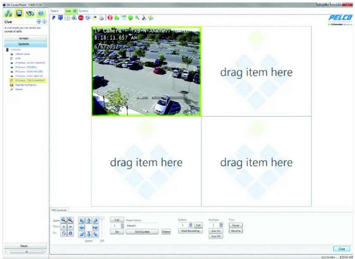
text_image
Live Groups Systems Electrons Analog Vccles BSTBI IP Camera - B100N-ADAVOCB IP Camera - B100N1 IP Camera - B100C-AAL185 IP Camera - B100C-ABAY190 IP Camera - TSB-N-ADAVOCB Reconstructionators Sources IPZ Controls Zoom Focus Sls Call Reset Name: 1 PressC1 Set Add/Update Delete Pattern: 1 Call 1 Aux Copy: Aux On Aux Off Turns Spread: 100 8:20:42 AM UP Camera X8-N-AAWXV7 8:18:11.657 AM 6/6/2012 drag item here drag item here drag item here CloseFigure 48. PTZ-Enabled Video with PTZ Controls Tab
CAMERA LENS
Lens controls adjust the zoom, focus, and iris of PTZ-enabled cameras.
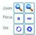
Figure 49. Lens Controls on PTZ Controls Tab
To control the zoom, focus, and iris:
Zoom: Click the plus (+) and minus (−) buttons to zoom in and zoom out of the currently displayed video frame (if the camera has zoom capability).
Focus: Click the Focus buttons to adjust the sharpness of the currently displayed video frame.
Iris: Click the Iris buttons to adjust the opening of the camera iris, which increases or decreases the brightness and contrast of the displayed video.
PAN/TILT MOVEMENT AND SPEED
Pan/tilt movement and speed can be adjusted using the directional buttons and slider.
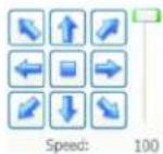
Figure 50. Directional Controls on PTZ Controls Tab
To adjust the pan/tilt:
- Click a directional button to move the camera in the direction indicated by the arrow.
- Click the middle button to center the camera.
- Click and hold the middle button to control the camera direction (similar to joystick control).
- Move the speed adjustment slider up and down to increase or decrease the pan/tilt speed.
NOTE: PTZ speed cannot be adjusted when cameras are connected to a DX4100, DX4500, or DX4600 unit.
CAMERA PRESETS
Preset controls configure the camera view to predesignated viewing areas. Once configured, the camera instantly moves to the predesignated view with a click of a button (refer to Figure 51). Preset control features are as follows:
Call: Click this button to move the camera to the predesignated view, as displayed in the Preset Name box.
Up/Down Arrows: Click this button to scroll through the preset numbers. If a number has already been assigned to a name, the name appears in the Preset Name box.
Set: Click this button to save the preset name and number to a view.
Preset Names: Click this button to configure a name to a specified number for a desired view. If a name has already been assigned to a number, the name appears in this box.
Add/Update: Click this button to change configured preset information: camera view, preset name, and number.
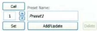
Figure 51. Preset Controls on PTZ Controls Tab
To configure and call up camera presets:
- Use the directional buttons to move the camera to the view you want to save as a preset.
- Type a name for the preset (for example: Preset 1) in the Preset Names box.
- Use the up and down arrows to display the desired number for the Preset Name.
- Click the Set button to save the preset name and number to the desired view.
- Click the Call button to move the camera to the predesignated view.
PATTERN
Patterns allow you to run a PTZ camera through an automated tour of camera presets.
To configure a pattern:
- Click the up and down arrows to display the desired number for the Pattern.
- Click the Start Recording button (refer to Figure 52).
- Call each of the presets that you want to include in the pattern, as described in Camera Presets on page 51.
NOTE: You can also pan, tilt, and zoom using the PTZ controls.
-
Click the Stop Recording button.
-
Click the Call button to run the pattern.

Figure 52. Pattern Controls on PTZ Controls Tab
AUXILIARY
The Aux On and Aux Off buttons (refer to Figure 53) allow you to control auxiliary functions of a PTZ camera, such as alarms and wipers.
To control auxiliary functions:
- Click the up and down arrows to display the auxiliary number. The function controlled by each auxiliary number varies by camera; refer to the camera's documentation for details.
- To activate the auxiliary function, click Aux On.
- To deactivate the auxiliary function, click Aux Off.
NOTE: The PTZ tour has Pause/Resume functionality.
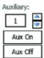
Figure 53. Auxiliary Controls on PTZ Controls Tab
PRESET FAVORITES
Click the Preset Favorites icon to display a list of the saved Preset Names and their corresponding numbers. Click the icon a second time to close the window.
APPENDIX A: DS CONTROLPOINT FEATURE SET FOR DS AND DX SERIES PRODUCTS
Table D. Supported Feature Set (1 of 2)
| SUPPORTED FEATURE SET DS DX8000/DX8100 DX4700/DX4800 DX4500/DX4600 DX4100 | |||||
| Connections | |||||
| Log on to single system • • • • • | |||||
| Log on to multiple systems • • • • • | |||||
| Get camera names • • • • • | |||||
| Same-user login from multiple clients | • | — | — | — | |
| Live | |||||
| Single and multiple cameras | • • • • • | ||||
| View OSD items (camera name, time, and so forth) | • | • | • | • | |
| PTZ | • • • • | (Speed setting does not apply) | •(Speed setting does not apply) | ||
| Digital zoom | • • • • • | ||||
| Motion borders | • • • • • | ||||
| Alarm borders | • • • • • | ||||
| Manual record borders | • • • • • | ||||
| Continuous record borders | • • • • • | ||||
| Audio playback | • | — | — | — | — |
| Support server local time | • • • • • | ||||
| Support GMT time | • • • • • | ||||
| Support client time | • • • • • | ||||
| Groups | |||||
| Local groups | • • • • • | ||||
| System groups | • | — | — | — | — |
| Tours | |||||
| Tours | • | • | • | • | • |
| Search | |||||
| Audio playback | • | — | — | — | — |
| Multiple search tabs | • | — | — | — | — |
| Motion borders | • | — | — | — | — |
| Alarm borders | • | — | — | — | — |
| Manual record borders | • | — | — | — | — |
| Continuous record borders | • | — | — | — | — |
| Authentication | • | — | — | — | — |
| Included samples filter | • | — | — | — | — |
| Smart search | • | — | — | — | — |
Table D. Supported Feature Set (2 of 2)
| SUPPORTED FEATURE SET | DS | DX8000/DX8100 | DX4700/DX4800 | DX4500/DX4600 | DX4100 |
| View OSD items (camera name, time, and so forth) | • | • | • | ||
| Quick review • • • • • | |||||
| Digital zoom • • • • • | |||||
| Play every frame • | |||||
| Multispeed playback | • | 8X maximum | 8X maximum | 6X maximum | 6X maximum |
| Support server local time | • • • • • | ||||
| Support GMT time | • • • • • | ||||
| Support client time | • • • • • | ||||
| Presearch grid | • | — | — | — | — |
| Export | |||||
| Native compression support | • • • • • | ||||
| Audio playback | • | — | — | — | — |
| Standalone Media playback • • • | • • | ||||
| AVI EXE XPA | • | ||||
| Miscellaneous | |||||
| Simultaneous live and search tabs | • • • • • | ||||
| KBD300A | • • • • • | ||||
| KDB5000 | • | — | — | — | — |
| Popup on alarm | • • • • • | ||||
| DSConneX | |||||
| Manual recording | • • • | — | — | ||
| Recorder events | • | — | — | — | — |
APPENDIX B: USING A KBD300A KEYBOARD WITH DS CONTROLPOINT
Pelco's KBD300A keyboards can be used to control certain functions of the DS ControlPoint software. To use a KBD300A with DS ControlPoint, your hardware and software must meet the following minimum requirements:
• KBD300A version 5.7 or later
• DS ControlPoint version 6.7.1.99 or later
- KBDKIT with power supply
• PV140 RS-422 to RS-232 converter
• Available serial port (COM1) on the computer running DS ControlPoint
The Belkin converter that is supplied with the KBD300USBKIT does not contain a Microsoft® Windows® driver, and should not be used to automatically connect to any DS ControlPoint installation unless the ControlPointCache.xml file has been edited, or unless a PV140 RS-422 to RS-232 interface converter and power supply is connected to COM1 on a compatible PC, laptop, or server.
EDITING CONTROLPOINTCACHE.XML
- Open the ControlPointCache.xml file located in the %appdata% directory on the PC to which DSControlPoint has been installed
- Change "COM1" in the
COM1 string to the port the USB connection will be on.
INSTALLING THE KBD300A KEYBOARD
The KBD300A keyboard is wired directly to a maximum of 16 receivers. You can communicate using Pelco P or Pelco D protocol. Direct Mode installation/operation is not the same as CM6700 mode or CM6800 mode installation/operation.
NOTE: A remote keyboard wiring kit (KBDKIT or KBDKIT-X) is required to use the keyboard in Direct Mode. The KBDKIT consists of two RJ-45 wall blocks and a 120 VAC to 12 VAC transformer. The KBDKIT-X is for 230 VAC. Only one wall block is required for this application.
Use one of the following setup options to install the KBD300A keyboard.
Setup Option 1: RS-422 Connections
To connect the KBD300A and PV140 converter to the computer running DS ControlPoint:
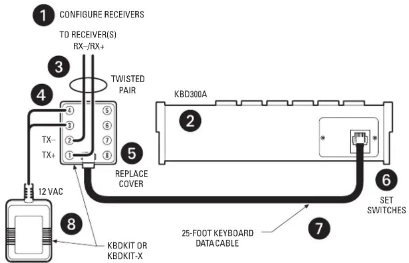
text_image
1 CONFIGURE RECEIVERS TO RECEIVER(S) RX-/RX+ 3 TWISTED PAIR TX- TX+ 12 VAC 8 KBDKIT OR KBDKIT-X 5 REPLACE COVER KBD300A 2 SET SWITCHES 6 7 25-FOOT KEYBOARD DATACABLEFigure 54. RS-422 Connections
- Make sure all receivers are configured to communicate using either Pelco P or Pelco D protocol, and ensure that each receiver has a unique address. Refer to your receiver manual for switch settings.
-
Decide on a suitable location for the keyboard and wall block. The keyboard must be within 7.6 meters (25 feet) of the wall block. The wall block must be within 1.8 meters (6 feet) of the nearest suitable electrical outlet.
-
Remove the cover from the KBDKIT or KBDKIT-X wall block.
- Connect the transmission wires from the receiver (Spectra ^® or Esprit ^® system) to the wall block.
a. Connect RX+ from the receiver/driver to TX+ (terminal 1) on the wall block.
b. Connect RX—from the receiver/driver to TX—(terminal 2) on the wall block.
NOTE: Communication to the keyboards is RS-422. The maximum cable distance for RS-422 communication over a 24-gauge wire is 1,219 meters (4,000 feet). It is recommended that you use shielded twisted pair cable that meets or exceeds the basic requirements for EIA RS-422 applications.
- At the wall block, wire the transformer to pins 3 and 4. Polarity is not important.
- Replace the cover on the wall block. A double-sided sticky pad is provided to mount the wall block. Secure the wall block to a suitable surface.
- Set the keyboard DIP switches to the Pelco D or Pelco P protocol. For DIP switch settings, refer to the KBD300A Operation manual.
- Connect the keyboard data cable.
- Connect the KBDKIT or KBDKIT-X transformer to a suitable outlet. The LED display shows number 1, which is the default camera number
- Test for proper operation (refer to the programming and operation sections of the KBD300A Universal Keyboard Installation/Operation manual).
Setup Option 2: Using the USB Adapter
- Select the Device Manager under Computer Management.
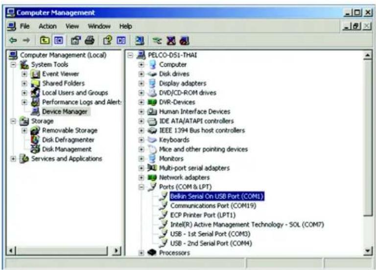
text_image
Computer Management File Action View Window Help Computer Management (Local) System Tools Event Viewer Shared Folders Local Users and Groups Performance Logs and Alert: Device Manager Storage Removable Storage Disk Defragmenter Disk Management Services and Applications PELCO-DS1-THAI Computer Disk drives Display adapters DVD/CD-ROM drives DVR-Devices Human Interface Devices IDE ATA/ATAPI controllers IEEE 1394 Bus host controllers Keyboards Mice and other pointing devices Monitors Multi-port serial adapters Network adapters Ports (COM & LPT) Bellin Serial On USB Port (COM1) Communications Port (COM19) ECP Printer Port (LPT1) Intel(R) Active Management Technology - SOL (COM7) USB - 1st Serial Port (COM3) USB - 2nd Serial Port (COM4) ProcessorsFigure 55. Selecting the Device Manager
- Right-click USB Serial Port, and then select Properties. The USB Serial Port (COM1) Properties dialog box appears (refer to Figure 56).
NOTE: The USB brand name should appear in the Ports list if it is installed correctly. Refer to the USB manufacturer for driver compatibility with Microsoft® Windows®.
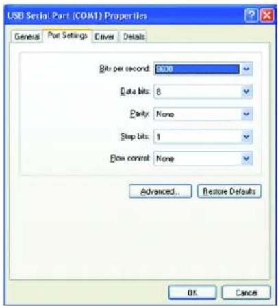
text_image
USD Serial Part (COM1) Properties General Port Settings Driver Details Bits per second: 600 Data bits: 8 parity: None Stop bits: 1 Flow control: None Advanced... Restore Defaults OK CancelFigure 56. USB Serial Port (COM1) Properties Dialog Box
- Configure the port settings, and then click the Advanced button. The "Advanced Settings for the COM1" dialog box appears.
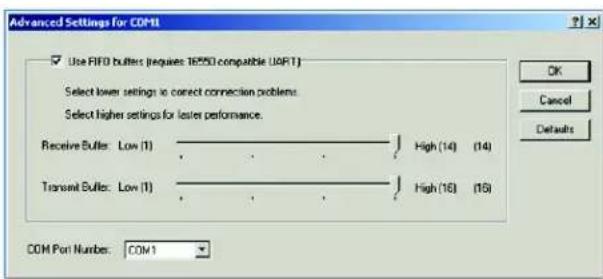
text_image
Advanced Settings for COM1 Use FIFO buffer (requires 16550 compatible UART) Select lower settings to correct connection problems. Select higher settings for less performance. Receive Buffer: Low (1) High (14) (14) Transient Buffer: Low (1) High (16) (16) COM Port Numbers: COM1 OK Cancel DefaultsFigure 57. Advanced Settings for COM1 Dialog Box
- Change the COM Port Number for the USB port to COM1, and then click the OK button.
- Click the OK button in the USB Serial Port (COM1) Properties dialog box to complete the steps.
NOTES:
- Set the KBD300A dip switches #7 and #8 to ON for ASCII Mode.
- Set the port settings to the following:
-Baud:9600
-8 data bits
- Odd parity
-1 stop bit
CONTROLLING DS CONTROLPOINT WITH THE KBD300A
DS ControlPoint automatically detects the KBD300A on startup. To use the KBD300A to control DS ControlPoint functionality:
- Open DS ControlPoint.
- Connect to a system.
- Select Live view.
KBD300A OPERATING FUNCTIONS
The following DS ControlPoint functions can be controlled using the KBD300A:
Table E. KBD300A and DS ControlPoint Functions
| Keyboard Function Corresponding DS Controlpoint Function | |
| SHIFT+ZOOM Full-screen mode | |
| SHIFT+F2/OFF View video in a 1 x 1 configuration | |
| SHIFT+F3/MOM View video in a 2 x 2 configuration | |
| SHIFT+AUX ON View video in a 3 x 3 configuration | |
| SHIFT+AUX OFF View video in a 4 x 4 configuration | |
| ACK Enter PTZ mode | |
| ACK+joystick Control pan, tilt, and zoom in a selected video pane | |
| NEAR and FAR Focus control | |
| OPEN and CLOSE Iris control | |
| Keypad and PRESET Call camera preset | |
| CAM | Enter video pane navigation mode |
| CAM+joystick | Navigate video panes |
| MON | Associate a selected camera to a selected video pane |
| MON+keypad | Associate a camera to a specific video pane (numbered left to right, top to bottom) |
| 1 + hold PRESET | Programs a preset 1 |
| 1 + PRESET | Calls up preset 1 |
| 1 + hold PATTERN | Programs a pattern 1 |
| 1 + PATTERN | Calls up pattern 1 |
| NEXT | Calls up the next camera |
| PREV | Calls up the previous camera |
APPENDIX C: USING A KBD5000 KEYBOARD WITH DS CONTROLPOINT
Pelco's KBD5000 keyboard can be used to control certain functions of the DS ControlPoint software. The KBD5000 is configured with three control modules that are installed in receptacles on the keyboard base. Refer to the KBD5000 Operation manual for detailed information.
NOTES:
- You must install DS ControlPoint version 7.0.41 or later.
- Windows virtually assigns a COM port so no Windows configuration is required.
- If required, contact Pelco Product Support (1-800-289-9100) to download the latest version of DS ControlPoint.
The following three modules are included with the KBD5000 base:
- A variable speed, vector-solving joystick with keys for lens, iris, and focus control. The barrel-type joystick provides precise pan and tilt control of fixed speed and variable speed positioning systems. Twisting the joystick zooms the lens in and out.
- A jog dial and shuttle ring for playback and menu navigation. The jog/shuttle contains four illuminated function keys. The color of each key corresponds to the color of its icon displayed on the monitors linked to the user interface. This intuitive color-coded design lets users navigate the on-screen menus without looking down to read keyboard text labels.
- A keypad for camera and monitor control. Keys can be used to select cameras and monitors and the number of cameras to view.
INSTALLING THE KBD5000
- Attach the USB Type B-to-Type A cable from the USB connector on the rear of the KBD5000 to the USB connector on the computer.
- Connect the power supply cord to the rear of the keyboard, and tighten the connector barrel.
- Connect the other end of the power cord to a power supply. When power is applied, lights on the module illuminate.
CONTROLLING DS CONTROLPOINT WITH THE KBD5000
DS ControlPoint automatically detects the KBD5000 on startup. To use the KBD5000 to control DS ControlPoint functionality:
- Open DS ControlPoint by clicking the DS ControlPoint icon on your desktop or by locating the software in the Start menu.
- Connect to a system in the Setup page.
- Click the Live tab.
NOTE: If your sites are not autoconnect, you will need to use your mouse to connect to your sites.
KBD5000 FEATURES
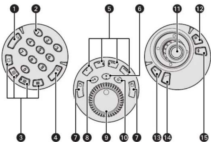
text_image
Diagram of a circular device with numbered components, likely illustrating a mechanical or electronic assembly.Figure 58. KBD5000 Features
1 Camera Selection
2 Keypad (numbers 0 to 9)
3 Multiple View
4 Monitor Selection
5 Dyn1 and Dyn2: Configures and calls patterns
Dyn3 and Dyn4: Configures and calls presets
6 Quick Review
7 Next/Previous Cameras
8 Play/Pause Video
9 Jog/Shuttle
10 Live Playback Mode
11 Joystick with Trigger
12 Iris (Open/Close)
13 Help
14 Aux (Auxiliary): Not used with DS ControlPoint
15 Focus (Near/Far)
KBD5000 OPERATING FUNCTIONS
The KBD5000 keyboard performs best in live and playback modes.
Table F. KBD5000 Menu Operations (1 of 2)
| Joystick Module | |
| Key Description | |
 | Joystick: Used in conjunction with the Iris and Focus buttons. |
 | Joystick trigger: Activates and exits PTZ mode. |
[tton:  | Changes the light settings.In PTZ mode, press the Iris button, and then turn the joystick left or right to adjust the iris. |
 | Focus button:Adjust the focus: In PTZ mode, press the Focus button, and then turn the joystick left or right to adjust the focus.Zoom In/Out: In PTZ mode, turn the joystick left or right without the Iris/Focus key illuminated. |
 | Help button: Displays or hides the KBD5000 online Help. |
 | Alphanumeric keypad: In PTZ mode, the entered number can be a pattern or preset. In navigation mode, the entered number can be a camera, monitor, channel, time, or volume. |
 | Camera selection button: Calls up the Select Camera dialog box with a list of cameras. |
  | Multiple view buttons: Changes the currently selected video pane to one of the following screen layouts: 1 x 1, 2 x 2, 3 x 3, and 4 x 4 layouts. All other layouts must be configured with the mouse. |
| Jog/Shuttle Module | |
| Key Description | |
 | Next/previous camera buttons:Press the right or left menu buttons to cycle to the next or previous camera. |
 | Shuttle (outer ring): Turn the shuttle to the left to rewind video at a variable speed. Turn the shuttle to the right to forward video at a variable speed. |
 | Jog (inner dial): Turn the Jog left to step the video back. Turn the Jog right to step the video forward. |
 | Dyn1 and Dyn2: Configures and calls patterns.1. Enter PTZ mode (Jsel).2. Press a number, and then press Dyn1 (green).3. Move the joystick to create the pattern.4. Press the same number, and then press Dyn2 (red) to save and start the pattern.When a pattern is saved, you can call it up by pressing a number, and then pressing Dyn2. |
 | Dyn3 and Dyn4: Configures and calls patterns.1. Enter PTZ mode (Jsel).2. Navigate to your preset destination.3. Press a number, and then press Dyn3 (green) to save the preset.When a preset is saved, you can call it up by pressing a number, and then pressing Dyn4 (red). |
 | Play/pause video button: Plays or pauses recorded video.Press the Play/Pause button to play a recorded video. Press the Play/Pause button again to pause recorded video. |
Table F. KBD5000 Menu Operations (2 of 2)
| Joystick Module | |
| Key Description | |
 | Quick review:• Searches for all the current live streams for the last 60 seconds.• Guides you to the Search tab.• Removes a stream. Move to the stream and then press O (zero) and the CAM button. |
 | Live Mode: Enters Live mode and guides you to the Live tab. |
 | CAM/MON (camera/monitor):1. From Live mode, press the Camera button.2. Highlight a camera.3. Press the MON button to display the stream.4. Press O (zero) plus CAM to remove the camera. |
WARRANTY STATEMENT
For information about Pelco's product warranty and thereto related information, refer to www.pelco.com/warranty.

This equipment contains electrical or electronic components that must be recycled properly to comply with Directive 2002/96/EC of the European Union regarding the disposal of waste electrical and electronic equipment (WEEE). Contact your local dealer for procedures for recycling this equipment.
REVISION HISTORY
Manual # Date Comments
| C3674M 10/08 Original version. | ||
| C3674M-A | 3/09 | Added Appendix B. Also added patterns and auxiliary sections to PTZ Controls. |
| C3674M-B | 11/09 | Added Language Settings, Time Format, Alarm Popup, Bandwidth Control, and Digital Sentry Reports information. Also revised the Export section of Table B. |
| C3674M-C | 2/10 | Revised document to ensure that all final changes are included. The -B version may not reflect current information. |
| C3674M-D 3/10 Added new Recording and Exporting features. Updated the supported feature set table. | ||
| C3674M-E 5/10 Added new Alarm Search section, Alarm Popup options, and Snapshot section. | ||
| C3674M-F | 7/10 | Modified the Setup page to combine the general settings under the Application Settings tab. Also added a new Configuring Analog Outputs section. |
| C3674M-G | 10/10 | Added an Import Systems feature in Application Settings. Added information on managing numerous systems by the administrator in Connecting to a System. Added a Windows Authentication tab to the Add Systems tab. Modified information under Alarm Popup. Added new features to Digital Sentry Reporting. Updated the Live Page icons table. Modified the Supported Features table for PTZ. |
| C3674M-H | 1/11 | Added instructions on creating and listing custom fields in the Connection Management page. Also modified the General and Sync settings in the Application Settings dialog box, added a Troubleshooting section, and modified Appendix A. |
| C3674M-I | 5/11 | Added new features to Application Settings. Updated the Create Group icon. Added KBD5000 to the Appendix. Updated screen shots with the new Pelco logo. |
C3674M-J 8/12 Added new features throughout, based on the 7.3.54 release. Updated Warranty.
C3674M-K 3/14 Added warning statement to the Search section.
Pelco, the Pelco logo, and other trademarks associated with Pelco products referred to in this publication are trademarks of Pelco, Inc. or its affiliates.
ONVIF and the ONVIF logo are trademarks of ONVIF Inc. All other product names and services are the property of their respective companies.
Product specifications and availability are subject to change without notice.
© Copyright 2014, Pelco, Inc.
All rights reserved.

by Schneider Electric