Altea-715 - Speaker DAS Audio - Free user manual and instructions
Find the device manual for free Altea-715 DAS Audio in PDF.


User questions about Altea-715 DAS Audio
0 question about this device. Answer the ones you know or ask your own.
Ask a new question about this device
Download the instructions for your Speaker in PDF format for free! Find your manual Altea-715 - DAS Audio and take your electronic device back in hand. On this page are published all the documents necessary for the use of your device. Altea-715 by DAS Audio.
USER MANUAL Altea-715 DAS Audio
SAFETY PRECAUTIONS 3
WARRANTY 4
DECLARATION OF CONFORMITY 5
INTRODUCTION 6
CONFIGURATIONS 7 - 8
2× ALTEA-412 (ALTEA-415) + 1× ALTEA-718
2× ALTEA-712 (ALTEA-715) + 2× ALTEA-718
LINE DRAWINGS 9
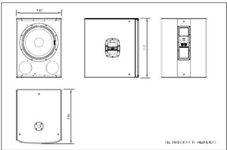
SPECIFICATIONS 10
RIGGING SYSTEM 11 - 12
Cajas acústicas pasivas / Passive loudspeaker enclosures
Keep these instructions.
Heed all warnings. Follow all instructions.
The exclamation point inside an equilateral triangle indicates the existence of internal components whose substitution may affect safety.
The specifications can be found on the rear label of the product.
The appliance should be flown only from the rigging points and by qualified personnel. Do not suspend the box from the handles.
Do not expose this device to rain or moisture. Do not place any objects containing liquids, such as bottles or glasses, on the top of the unit. Do not splash liquids on the unit. IP-20 equipment.
This symbol on the product indicates that this product should not be treated as household waste. Instead it shall be handed over to the applicable collection point for the recycling of electrical and electronic equipment.
Working temperature ranges from -25°C to 45°C. The maximum relative humidity of 95%.
The outer wiring connected to the device requires installation by an instructed person or the use of a flexible cable already prepared.
Note that the two Speakon input connectors are wired in parallel to provide easy parallel connection of several enclosures.
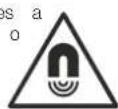
Do not place loudspeakers in proximity to devices sensitive to magnetic fields such as television monitors or data storage magnetic material.
For enclosures with tripod socket, the maximum safety height from floor to bottom of enclosure when mounting on a TRD-2 tripod, with legs spread 55cm from the central pole, is:
ALTEA-412---->115 cm
ALTEA-712---->115 cm
ALTEA-415---->105 cm
ALTEA-715 >105 cm
No user serviceable parts inside. Refer all servicing to qualified service personnel. Servicing is required when the apparatus has been damaged in any way, such as power-supply cord or plug is damaged, liquid has been spilled or objects have fallen into the apparatus, the apparatus has been exposed to rain or moisture, does not operate normally or has been dropped.
Clean only with a dry cloth. Do not use any solvent based cleaners.
GARANTÍA
All our products are warranted against any manufacturing defect for a period of 2 years from date of purchase.
The warranty excludes damage from incorrect use of the product.
All warranty repairs must be exclusively undertaken by the factory or any of its authorised service centers.
To claim a warranty repair, do not open or intend to repair the product.
Return the damaged unit, at shippers risk and freight prepaid, to the nearest service center with a copy of the purchase invoice.

DAS Audio Group, S.L.
Declares that :ALTEA-412/ALTEA-415/ALTEA-712/ALTEA-715/ALTEA-718
Abide by essential objectives relating Directives:
In accordance with Harmonized European Norms:
- EN 60065:2014.- Audio, video and similar electronic apparatus. Safety requirements.
- EN 50581:2012.- Technical documentation for the assessment of electrical and electronic products with respect to the restriction of hazardous substances.
INTRODUCTION
The altea series inherits the exceptional sound quality and rugged build that have made DAS professional systems an international sound reinforcement standard. Designed from "real world" experience, they offer users outstanding performance, absolute reliability, and unparalleled convenience. Whether it is in a high-profile venue or on the stage of a major event, the altea series will provide the power and definition needed to make your performance a success.
Features
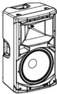
ALTEA-412 / ALTEA-712
natural_image
Technical line drawing of a speaker or electronic device with no visible text or symbols- Two-way full-range system
- 12" bass loudspeaker
- Compression driver with high tech polymer diaphragm
- Symmetrical enclosure design for stage monitor use
- 4 handles
- Built-in rigging points (eyebolt based)
- Stand mountable; 35mm tripod socket
The ALTEA-412 is a 2-way passive full-range loudspeaker (300 W _rms ) that utilizes a 12" low frequency transducer and a 1" exit compression driver. The multi-angle cabinet is constructed of polypropylene. Four handles and a 35mm tripod socket are provided.
The ALTEA-712 is a 2-way passive full-range loudspeaker (500 W _in ) that utilizes a 12" low frequency transducer and a 1" exit compression driver. The multi-angle cabinet is constructed of polypropylene. Four handles and a 35mm tripod socket are provided.
natural_image
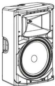
Technical line drawing of a speaker or audio device housing with no visible text or symbolsALTEA-415 / ALTEA-715
- Two-way full-range system
- 15" bass loudspeaker
- Compression driver with high tech polymer diaphragm
- Symmetrical enclosure design for stage monitor use
- 4 handles
- Built-in rigging points (eyebolt based)
- Stand mountable; 35mm tripod socket
The ALTEA-415 is a 2-way passive full-range loudspeaker (350 W _rm ) that utilizes a 15" low frequency transducer and a 1" exit compression driver. The multi-angle cabinet is constructed of polypropylene. Four handles and a 35mm tripod socket are provided.
The ALTEA-715 is a 2-way passive full-range loudspeaker (500 W _rms ) that utilizes a 15" low frequency transducer and a 1" exit compression driver. The multi-angle cabinet is constructed of polypropylene. Four handles and a 35mm tripod socket are provided.
natural_image
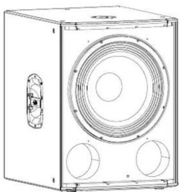
Line drawing of a speaker chamber with two circular ventricles and a side-mounted speaker grille (no text or symbols)ALTEA-718
- Companion subwoofer system
- High efficiency 18" loudspeaker
- Compact Birch plywood enclosure
- Pole mount socket for satellite systems
The ALTEA-718 is powerful subwoofer system designed to provide extended bass response for the Altea full-range cabinets. At the heart of the system is a DAS 18FW bass loudspeaker. This loudspeaker incorporates a FEM optimized high-efficiency speaker design and an extended 3 voice coil for long excursion. Cooling is assured thanks to the 18FW's vented pole piece and abundant apertures in the speaker's back plate keeping power compression to a minimum while providing high acoustic output over extended periods.
The compact Birch plywood cabinet is protected with a tough ISO-flex outer coating for long years of use in portable systems.
CONFIGURATIONS
Configuration example with 2x ALTEA-412 (ALTEA-415) + 1x ALTEA-718
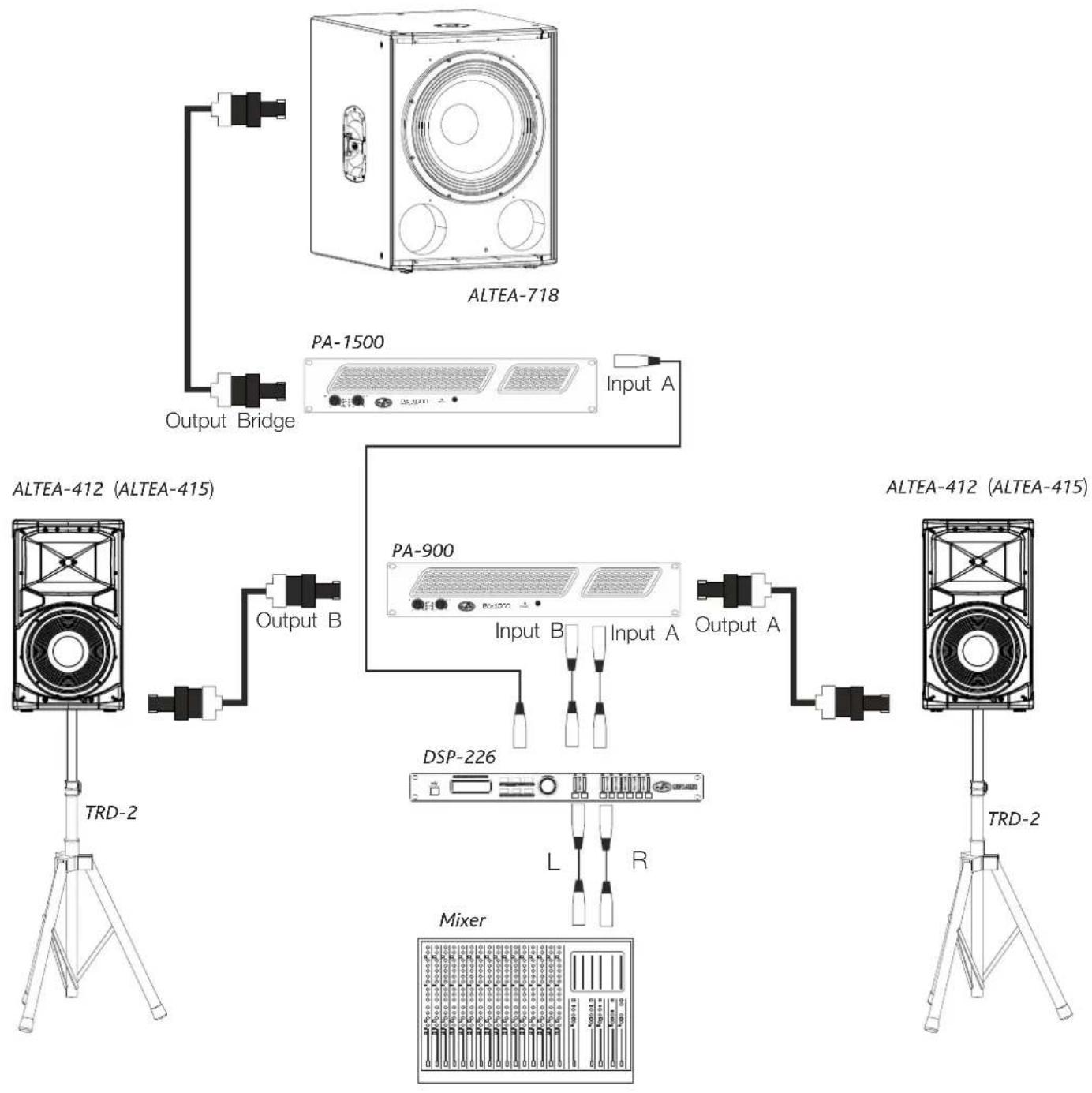
flowchart
graph TD
    A["ALTEA-718"] --> B["PA-1500"]
    B --> C["Input A"]
    C --> D["ALTEA-412 (ALTEA-415)"]
    D --> E["Output B"]
    E --> F["TRD-2"]
    D --> G["PA-900"]
    G --> H["Input B"]
    H --> I["DSP-226"]
    I --> J["Mixer"]
    J --> K["TRD-2"]
    style A fill:#f9f,stroke:#333
    style D fill:#ccf,stroke:#333
    style E fill:#cfc,stroke:#333
    style G fill:#fcc,stroke:#333
    style I fill:#cff,stroke:#333
    style J fill:#ffc,stroke:#333
    style K fill:#fcc,stroke:#333
CONFIGURATIONS (cont'd)
Configuration example with 2x ALTEA-712 (ALTEA-715) + 2x ALTEA-718
ALTEA-712 (ALTEA-715)
ALTEA-712 (ALTEA-715)
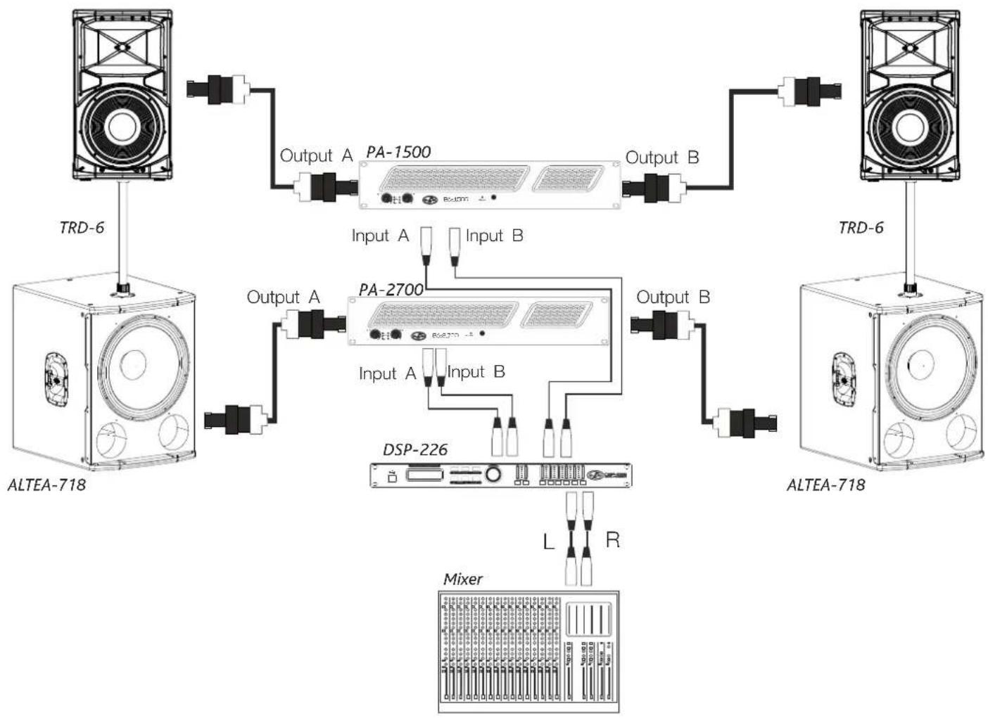
flowchart
graph TD
    A["Speaker 1: TRD-6"] --> B["PA-1500"]
    B --> C["Output A"]
    C --> D["ALTEA-718"]
    D --> E["Output A"]
    E --> F["PA-2700"]
    F --> G["DSP-226"]
    G --> H["Mixer"]
    H --> I["L"]
    H --> J["R"]
    F --> K["Input A Input B"]
    F --> L["Input A Input B"]
    F --> M["Output B"]
    M --> N["TRD-6"]
    N --> O["Speaker 2: ALTEA-718"]
ALTEA-412 / ALTEA-712
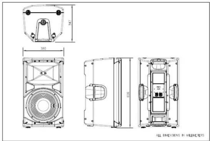
text_image
347 360 656 ALL DIMENSIONS IN MILLIMETERSALTEA-415 / ALTEA-715
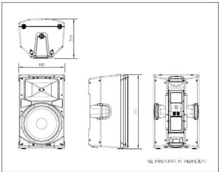
text_image
440 779 711 ALL DIMENSIONS IN MILLIMETERSALTEA-718
text_image
540 710 640 ALL DIMENSIONS IN MILLIMETERSSPECIFICATIONS
| Model | ALTEA-412 | ALTEA-415 | ALTEA-712 | ALTEA-715 | ALTEA-718 |
| Peak Power Handling (-10 dB)RMS Power Handling (1) | 1200 W300 W | 1400 W350 W | 2000 W500 W | 2000 W500 W | 2400 W600 W |
| Frequency Range (-10 dB)HF Horn Coverage Angles(-6dB)On-axis Sensitivity 1 W / 1m | 68 Hz - 20 kHz90° x 60°96 dB SPL | 63 Hz - 20 kHz90° x 60°96 dB SPL | 65 Hz - 20 kHz90° x 60°98 dB SPL | 60 Hz - 20 kHz90° x 60°99 dB SPL | 45 Hz - 138 Hz98 dB SPL |
| Rated Maximum Peak SPLNominal Impedance | 127 dB8 ohms | 128 dB8 ohms | 131 dB8 ohms | 132 dB8 ohms | 134 dB8 ohms |
| Transducers/Replacement Parts | LF: 12MI / GM-12MIHF: M-32 / GM-M32PolypropyleneBlack / Textured2x NL4 Speakon | LF: 15MI / GM-15MIHF: M-32 / GM-M32PolypropyleneBlack / Textured2x NL4 Speakon | LF: 12F / GM-12FHF: M-28 / M-28PolypropyleneBlack / Textured2x NL4 Speakon | LF: 15FV / GM-15FVHF: M-28 / M-28PolypropyleneBlack / Textured2x NL4 Speakon | LF: 18FW / GM-18FWBirch PlywoodBlack / ISO-Flex Paint2x NL4 Speakon |
| Enclosure MaterialColor/FinishConnectors | 650 x 380 x 346 mm25.59 x 14.96 x 13.82 in16.4 kg (36.1 lb) | 710 x 440 x 380 mm28 x 17.3 x 15 in17.5 kg (38.1 lb) | 650 x 380 x 346 mm25.59 x 14.96 x 13.62 in17.4 kg (38.3 lb) | 710 x 440 x 380 mm28 x 17.3 x 15 in18.8 kg (41.4 lb) | 710 x 540 x 647 mm28 x 21.3 x 25.5 in39 kg (85.8) |
| Dimensions (H x W x D)Weight | ANL-1 Eye BoltTRD-2 Speaker StandTRD-6 Pole MountFUN-AL712AX-112-5 | ANL-1 Eye BoltTRD-2 Speaker StandTRD-6 Pole MountFUN-AL715AX-112-5 | ANL-1 Eye BoltTRD-2 Speaker StandTRD-6 Pole MountFUN-AL712AX-112-5 | ANL-1 Eye BoltTRD-2 Speaker StandTRD-6 Pole MountFUN-AL715AX-112-5 | TRD-6 Pole Mount |
Notes: (1) Based on a 2 hour test continuously applying 6 dB crest factor pink noise (IEC shaped).
DAS Audio Group, S.L. continuously strives to enhance its products through investigation and development. All specifications are subject to change without prior notice.
RIGGING
Warnings
This manual contains needed information for flying DAS Audio cabinets, description of the elements and safety precautions. To perform any operations related to flying the system, read the present document first, and act on the warnings and advice given. The goal is to allow the user to become familiar with the mechanical elements required to fly the acoustic system, as well as the safety measures to be taken during set-up and teardown.
Only experienced installers with adequate knowledge of the equipment and local safety regulations should fly speaker boxes. It is the user's responsibility to ensure that the systems to be flown (including flying accessories) comply with state and local regulations.
The working load limits in this manual are the results of tests by independent laboratories. It is the user's responsibility to stay within safe limits. It is the user's responsibility to follow and comply with safety factors, resistance values, periodical supervisions and warnings given in this manual. Product improvement by means of research and development is on going at DAS. Specifications are subject to change without notice.
It is common practice to apply 5:1 safety factors for enclosures and static elements. For slings and elements exposed to material fatigue due to friction and load variation the following ratios must be met; 5:1 for steel cable slings, 4:1 for steel chain slings and 7:1 polyester slings. Thus, an element with a breaking load limit of 1000 kg may be statically loaded with 200 kg (5:1 safety factor) and dynamically loaded with 142 kg (7:1 safety factor).
When flying a system, the working load must be lower than the resistance of each individual flying point in the enclosure, as well as each box. Hanging hardware should be regularly inspected and suspect units replaced if in doubt. This is important to avoid injury and absolutely no risks should be taken in this respect. It is highly recommended that you implement an inspection and maintenance program on flying elements, including reports to be filled out by the personnel that will carry out the inspections. Local regulations may exist that, in case of accident, may require you to present evidence of inspection reports and corrective actions after defects were found.
Absolutely no risks should be taken with regards to public safety. When flying enclosures from ceiling support structures, extreme care should be taken to assure the load bearing capabilities of the structures so that the installation is absolutely safe. Do not fly enclosures from unsafe structures. Consult a certified professional if needed. All flying accessories that are not supplied by DAS Audio are the user's responsibility. Use at your own risk.
Introduction
Altea series models feature 2x M8 nuts on the top panel. There are 4x M8 nuts at the rear panel.
Flying with eyebolts is very economical and safe, and it is recommended for installations where the boxes are not fixed permanently.
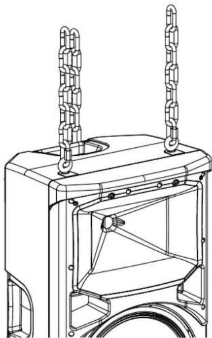
The illustration shows the internal metal hardware of an enclosure with eyebolt flying.
natural_image
Technical line drawing of a mechanical device with two vertical connectors and a central frame (no text or symbols)Flying with eyebolts
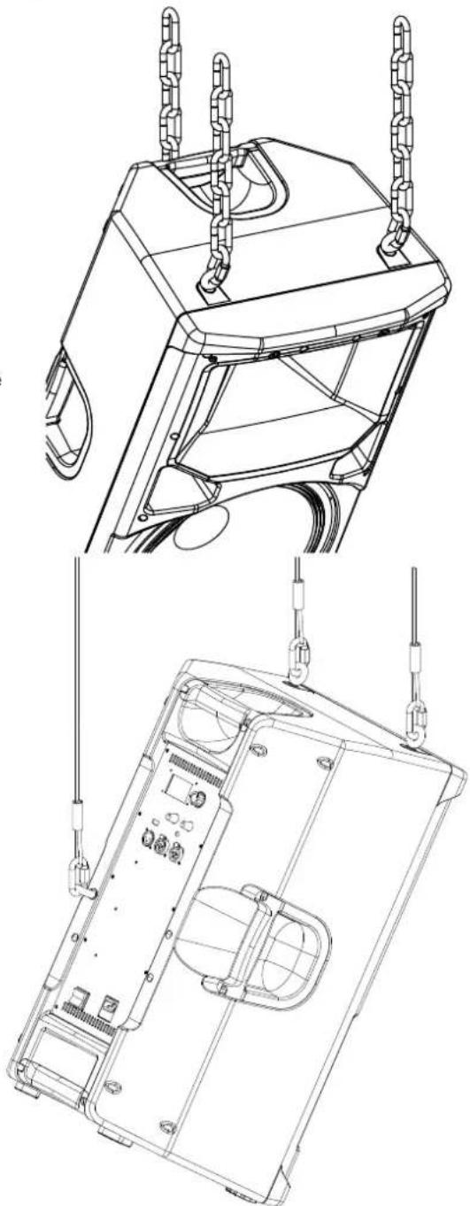
Each rigging point has 30 kg (66 lb) working load limit. Then choose the slings or chains of required load resistance and length, bearing in mind that the length difference between the front and back slings or chains will determine the vertical orientation. Alternatively, the back bottom eyebolt points can be used to provide vertical orientation.
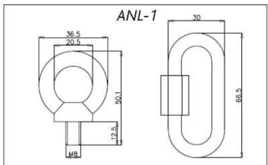
The ANL-1 set is an optional set of four eyebolts and four carabiners. (Dimensions are in millimeters).
text_image
ANL-1 36.5 20.5 50.1 12.5 M8 30 66.5Each ANL-1 eyebolt has a rated working load of 140 kg. (308 lb). Each ANL-1 carabiner has a working load of 910 kg (2002 lb). If using other hardware, make sure it is rated to handle the required load.
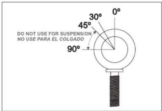
When using eyebolts it is important to bear in mind that the rated working load is only true for a load applied in the plane of the eye, and is significantly reduced for other angles. The drawing illustrates the concept. The table shows the variation of the working load as a function of the load angle. In the case of the ANL-1 eyebolt, this means that the 30 kg working load becomes 9 kg at 45 degrees. Do not use eyebolt flying if the load angle is higher than 45 degrees.
| 0 Degrees | 30 Degrees 45 | Degrees | More than 45 Degrees | |
| % Working load | 100% | 65% | 30% | 25% |
text_image
DO NOT USE FOR SUSPENSION NO USE PARA EL COLGADOThe following illustrations show different views on eyebolt flying for a single box. The length of the back cables or chains determines the vertical angle of the box.
natural_image
Technical line drawing of a mechanical device with suspended chains and internal components (no text or symbols)Wall mounting bracket
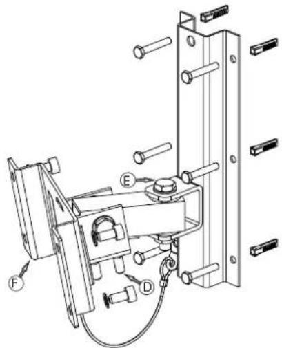
The AX-112-5 is a wall mounting bracket designed for various models (WLL=25kgf).
The AX-112-5 bracket has been designed to be wall mounted in the vertical position only. Any other position is a safety hazard.
Wall plugs provided are to be used in brick walls only. For other wall materials, source the suitable wall plug before use.
DAS Audio Group is not responsible for use other than the recommended. Use only the screws and wall plugs supplied on surfaces that will provide sufficient support. Do not use on surfaces such as plaster, and gypsum.
Contact a licensed rigger if there is any doubt.
text_image
Technical diagram of a mechanical assembly with labeled components F, D, and EAX-112-5
Mounting instructions
1.- Mark the 6 holes on the wall using the template provided on right-hand side of this page.
2.- Drill the six holes and insert the wall plugs.
3.- Set the bracket into position and tighten 5 of the 6 hexagonal-headed screws.
4.- Affix an end of the cable to the bracket using the sixth hexagonal-headed screw.
5.- Screw (F) to the enclosure using 4 hexagon socket head cap screws and 4 Grower (lock) washers.
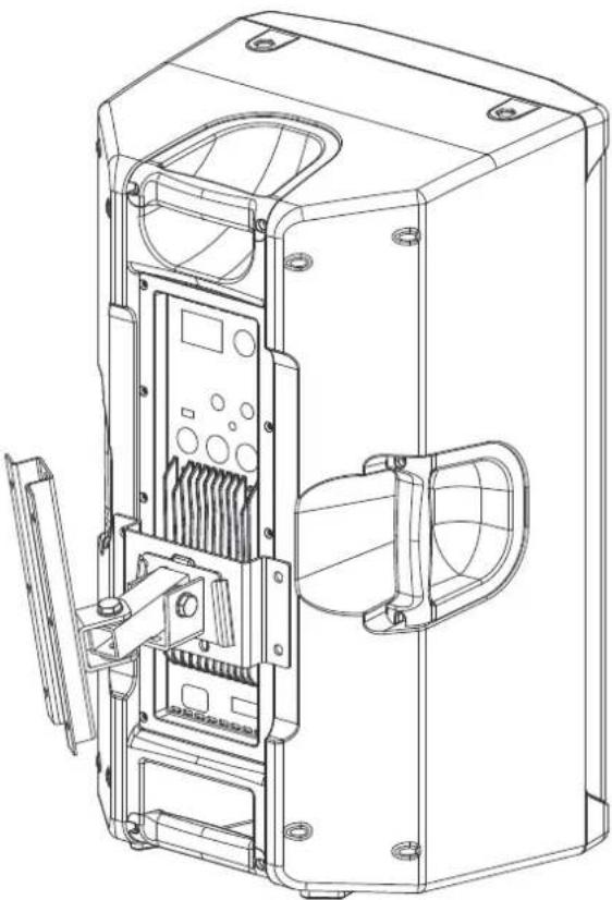
6.- Lift the enclosure and slide it down so that (F) fits into the bracket.
7.- Aim the enclosure as needed and proceed to secure it by tightening screws (D) with the suitable Allen (hex) wrench and tighten screw (E).
8.- Affix the free end of the cable to the hole in (F).
natural_image
Technical line drawing of a mechanical device housing with internal components and mounting holes (no text or symbols)
text_image
D.A.S.www.dasaudio.com
DAS Audio Group, S.L.
C/. Islas Baleares, 24
46988 Fuente del Jarro
Valencia, SPAIN
Tel. +34 96 134 0860
DAS Audio of America, INC.
6900 NW 52th Street
Miami, FL 33166 - U.S.A.
TOLL FREE: 1 888 DAS 4 USA
DAS Audio Asia PTE. LTD.
3 Temasek Avenue, Centennial
Tower #34-36
Singapore 039190
Tel. +65 6549 7760
DAS do Brasil LTDA.
Rua Dos Andradas, 382 SL