VM-632LCD-2 - Monitor Vicon - Free user manual and instructions
Find the device manual for free VM-632LCD-2 Vicon in PDF.


User questions about VM-632LCD-2 Vicon
0 question about this device. Answer the ones you know or ask your own.
Ask a new question about this device
Download the instructions for your Monitor in PDF format for free! Find your manual VM-632LCD-2 - Vicon and take your electronic device back in hand. On this page are published all the documents necessary for the use of your device. VM-632LCD-2 by Vicon.
USER MANUAL VM-632LCD-2 Vicon
Vicon Industries Inc. does not warrant that the functions contained in this equipment will meet your requirements or that the operation will be entirely error free or perform precisely as described in the documentation. This system has not been designed to be used in life-critical situations and must not be used for this purpose.



Copyright © 2010 Vicon Industries Inc. All rights reserved. Product specifications subject to change without notice.
VICON INDUSTRIES INC., 89 ARKAY DRIVE, HAUPPAUGE, NEW YORK 11788 TEL: 631-952-CCTV (2288) FAX: 631-951-CCTV (2288) TOLL FREE: 800-645-9116 24-Hour Technical Support: 800-34-VICON (800-348-4266) UK: 44/(0) 1489-566300 WEB: www.vicon-cctv.com

Dear Valued Customer:
Thank you for selecting Vicon systems and products for your video needs.
Since Vicon's beginning in 1967, our only business has been the design, engineering, and production of the highest quality video systems and equipment for use in a wide variety of security, safety, control, surveillance, and communication applications.
We stand behind the quality and dependability of every product with an industry leading Beneficial Use warranty.
If you are not satisfied with a Vicon product or service, I would like to know. Your complete satisfaction is the mission of every Vicon employee.
Sincerely,
text_image
GermanyKenneth M. Darby President
CONTENTS
SAFETY INSTRUCTION 2\~3
CAUTIONS 4
FCC RF INTERFERENCE STATEMENT 5
CONNECTING WITH EXTERNAL EQUIPMENT 6
REMOTE FUNCTIONS 7
CONTROLS AND FUNCTIONS 8 \~ 15
MOUNTING GUIDE 16
D-SUB CONNECTOR PIN ASSIGNMENTS 17
POWER MANAGEMENT 18
SPECIFICATIONS 19
TROUBLE SHOOTING GUIDE 20
This Monitor was
Manufactured by ISO 9001
Certified Factory
Important Safeguards – Indoor Use
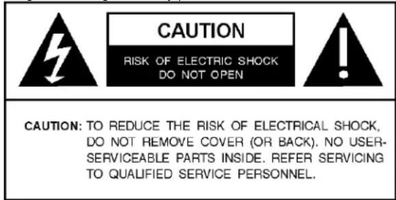
GRAPHIC SYMBOL EXPLANATION
The lightening bolt symbol alerts the user to the presence of dangerous voltage that may present the risk of electric shock.
text_image
CAUTION RISK OF ELECTRIC SHOCK DO NOT OPEN CAUTION: TO REDUCE THE RISK OF ELECTRICAL SHOCK, DO NOT REMOVE COVER (OR BACK). NO USER- SERVICEABLE PARTS INSIDE. REFER SERVICING TO QUALIFIED SERVICE PERSONNEL.The exclamation point symbol alerts the user to the presence of important operating and maintenance instructions.
WARNING
To reduce a risk of fire or electric shock, do not expose this product to rain or moisture.
- Read Instructions - Read all safety and operating instructions before the product is operated.
- Retain Instructions - Retain all safety and operating instructions for future reference.
- Heed Warnings - Pay attention to all product warnings.
- Follow Instructions - Follow all operating instructions.
- Cleaning -(Do not use caustic, abrasive or aerosol cleaners)
a) For units that CAN BE DISCONNECTED from the power source, use a damp cloth for cleaning.
b) For units that CANNOT BE DISCONNECTED from the power source, use a damp cloth for cleaning and do not allow moisture or liquids to enter vents.
6. Attachments - Use only UL Listed Vicon recommended attachments to prevent unit damage and personal injury.
7. Water and Moisture - Use only products designed for outdoor environments where they will be exposed to water or moisture.
8. Accessories - Do not place the unit on an unstable surface to avoid falling. Use only UL Listed Vicon recommended mounting accessories.
9. Ventilation - Do not block ventilating slots and openings as they ensure reliable operation. Do not place the unit near a heat source or into an enclosure unless recommended by Vicon.
10. Grounding - Only products equipped with a 3-prong grounded plug should be inserted into a grounded power outlet. Contact an electrician to replace an obsolete outlet. Do not force a plug into a non-grounded outlet.
11. Power Cord Protection - Power supply cords should not be routed in trafficked areas or in tight spaces where they will be pinched or used to bear weight. Allow some slack in the cord where it enters the unit.
- Lightning - Disconnect the product from its power source and cable system when possible to prevent damage due to lightning and power-line surges.
- Power Lines - Do not locate outside cables over power or utility lines where they can fall and make direct contact. Contact with power lines can be fatal.
- Overloading - Do not overload wall outlets and extension cords to prevent risk of fire and electric shock.
- Object and Liquid Entry - Never probe through, or spill liquid into, enclosure openings to prevent risk of fire or electric shock.
- Servicing - Refer all servicing to qualified service personnel.
- Damage Requiring Service - Obtain service when:
a) The power-supply cord or plug is damaged.
b) Objects have fallen or liquid has been spilled into the product.
c) The product is not designed for outdoor use and has been exposed to water or moisture.
d) The product does not operate per the operating instructions. Perform Vicon recommended adjustments, modifications and troubleshooting only to avoid unit damage and personal injury.
e) The product has been dropped.
f) The product shows a significant change in performance.
- Replacement Parts - Use only Vicon specified replacement parts or an approved equivalent to prevent unit damage and injury.
- Safety Check - Request safety checks to be performed following repair or maintenance to verify proper operation.
- ESD Precaution - Take all normal electrostatic discharge precautions to avoid component damage during installation and operation.
- For 230 VAC Devices Only - When the disconnect device is not incorporated in the equipment or when the plug on the power supply is intended to serve as the disconnect device, follow the guidelines below:
a) For permanently connected 230 VAC units, a readily accessible disconnect device must be incorporated into the site wiring.
b) For 230 VAC units with a plug, the outlet must be installed near the unit and be easily accessible.
21. Lithium Batteries Only:
WARNING
Fire and burn hazard. Do not recharge, disassemble, heat above 212^ F or incinerate. Keep battery out of reach of children and in original package until ready to use. Dispose of used batteries promptly.
Risk of explosion if battery is replaced by incorrect type. Dispose of used batteries according to the instructions.
Important Safeguards – Indoor Use (Cont)
- For Rack-Mounted Units Only – The following precautions apply to all rack-mounted units.
a) Elevated Operating Ambient - If installed in a closed or multi-unit rack assembly, the operating ambient temperature of the rack environment may be greater than room ambient. Therefore, consideration should be given to installing the equipment in an environment compatible with the maximum ambient temperature (Tma) specified by the manufacturer.
b) Reduced Air Flow - Installation of the equipment in a rack should be such that the amount of air flow required for safe operation of the equipment is not compromised.
c) Mechanical Loading - Mounting of the equipment in the rack should be such that a hazardous condition is not achieved due to uneven mechanical loading.
d) Circuit Overloading - Consideration should be given to the connection of the equipment to the supply circuit and the effect that overloading of the circuits might have on overcurrent protection and supply wiring. Appropriate consideration of equipment nameplate ratings should be used when addressing this concern.
e) Reliable Earthing - Reliable earthing of rack-mounted equipment should be maintained. Particular attention should be given to supply connections other than direct connections to the branch circuit (e.g. use of power strips).
CAUTIONS
CAUTION
The power supply cord is used as the main disconnect device, ensure that the socket-outlet is located/installed near the equipment and is easily accessible.
ATTENTION
POWER SUPPLY CORD IS USED AS MAIN POWER DISCONNECT DEVICE IN THIS PRODUCT. UNPLUG THIS PRODUCT FROM THE WALL OUTLET BEFORE REMOVING THE BACK COVER AND SERVICING
EMISSION CHARACTERISTICS TESTED BY SEMKO
THIS PRODUCT HAS BEEN TESTED AND HAS SHOWN COMPLIANCE WITH THE NATIONAL SPECIFICATIONS SUCH AS SWEDISH MPR 1990.10.(MPR II)
Removal of the back cover should be carried out only by qualified personnel.
DO NOT USE IN HOSTILE ENVIRONMENTS▶
To prevent shock or fire hazard, do not expose the unit to rain or moisture.
This unit is designed to be used in the office or home. Do not subject the unit to vibrations, dust of corrosive gases.
KEEP IN A WELL VENTILATED PLACE▶
Ventilation holes are provided on the cabinet to prevent the temperature from rising.
Do not cover the unit or place anything on the top of unit.
AVOID HEAT▶
Avoid placing the unit in direct sunshine or near a heating appliance.
TO ELIMINATE EYE FATIGUE▶
Do not use the unit against a bright back ground and where sunlight or other light sources will shine directly on the monitor.
BE CARE▶ FUL OF HEAVY OBJECT
Neither the monitor itself nor any other heavy object should rest on the power cord.
Damage to a power cord can cause fire or electrical shock.
FCC Notice
Note: Complies with Federal Communications Commission Rules & Regulations Part 15, Subpart B for a Class A digital device.
WARNING
This equipment generates and uses radio frequency energy and if not installed and used properly, that is, in strict accordance with the manufacturer's instruction, may cause interference to radio and television reception. It has been type tested and found to comply with the limits for a Class A computing device in accordance with the specification in subpart B of part 15 of the FCC rules, which are designed to provide reasonable protection against such interference in a commercial installation. However, there is no guarantee that interference will not occur in a particular installation. If this equipment does cause interference to radio and television reception, which can be determined by turning equipment off and on, the user is encouraged to try and correct the interference by one or more of the following measures:
- Reorient the receiving antenna.
- Relocate the equipment with respect to the receiver.
- Relocate the equipment away from the receiver.
- Plug the equipment into a different electrical outlet so that the equipment and receiver are on different branch circuits.
If necessary, the user should consult the dealer or an experienced radio/television technician for additional suggestions.
The user may find the following booklet prepared by the Federal Communications Commission helpful:
"Interference Handbook, Bulletin CIB-2"
This booklet is available from the U.S. Government Printing Office, Superintendent of Documents, Mailstop SSOP, Washington, D.C. 20402-9328, ISBN 0-16-045542-1.

Warning: Power must be removed from this unit before removing circuit modules or cables.

Caution: This unit contains circuit cards with integrated circuit devices that can be damaged by static discharge. Take all necessary precautions to prevent static discharge
CONNECTING WITH EXTERNAL EQUIPMENT
text_image
1 → 2 → 3 → 4 → 5 → 6 → 7 → ← 9 8 → ← 10REMOTE FUNCTIONS
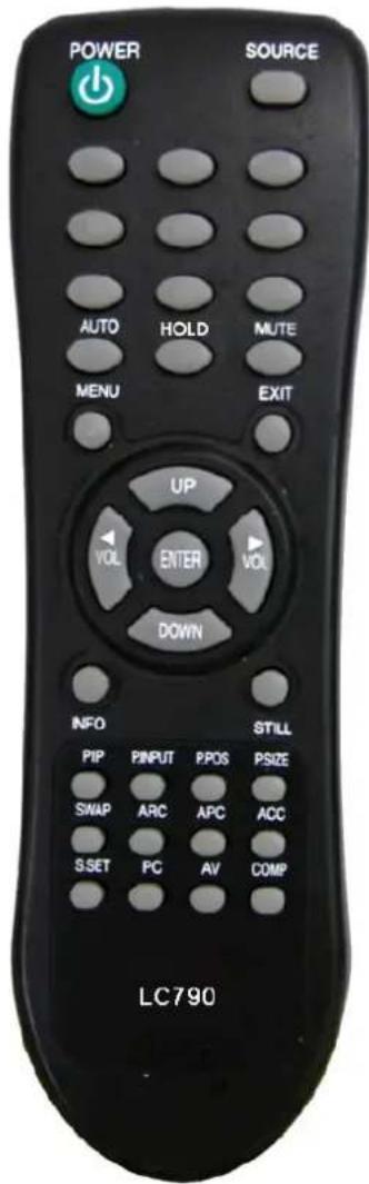
C. REMOTE CONTROLLER(Optional)
1. POWER( ⏻ )
Turns the power ON or OFF. There will be a few seconds delay before the display appears.
2. SOURCE
Selects an input source.
3. AUTO
Auto geometry adjustment in the RGB PC source.
4. HOLD
Stops the Trigger & Auto switching functions.
5. MUTE
Mutes the sound.
6. MENU
Activates and exits the On Screen Display.
7. EXIT
Exits the On Screen Display.
8. VOL(◀ & ▶)
Increases or decreases the level of audio volume.
9. UP/DOWN
Moves upwards or downwards in the OSD menu.
10. ENTER
Enters an OSD submenu or accepts your selection.
11. INFO
Displays the information about input source.
12. STILL
Pauses the picture.
13. PIP (Picture In Picture)
Activates the PIP mode.
14. P. INPUT
Changes the source of sub-picture in the PIP mode.
15. P.POS
Changes the position of sub-picture in the PIP mode.
16. P.SIZE
Changes the sizes of sub and main pictures in the PIP mode.
17. SWAP
Alternates between sub and main pictures in the PIP mode.
18. ARC (Aspect Ratio Control)
Selects a screen ratio.
19. APC (Auto Picture Control)
Selects a picture mode.
20. ACC (Auto Color Control)
Selects a color mode.
21. S.SET
Selects the source of sound between main and sub pictures in the PIP mode.
22. PC
Selects a PC mode(PC, DVI & HDMI).
23. AV
Selects an AV mode(AV1, AV2 & S-Video).
24. COMP
Selects the Component mode.
text_image
POWER SOURCE AUTO HOLD MUTE MENU EXIT UP VOL ENTER VOL DOWN INFO STILL PIP PINPUT PPOS PSIZE SWAP ARC APC ACC SSET PC AV COMP LC790CONTROLS AND FUNCTIONS
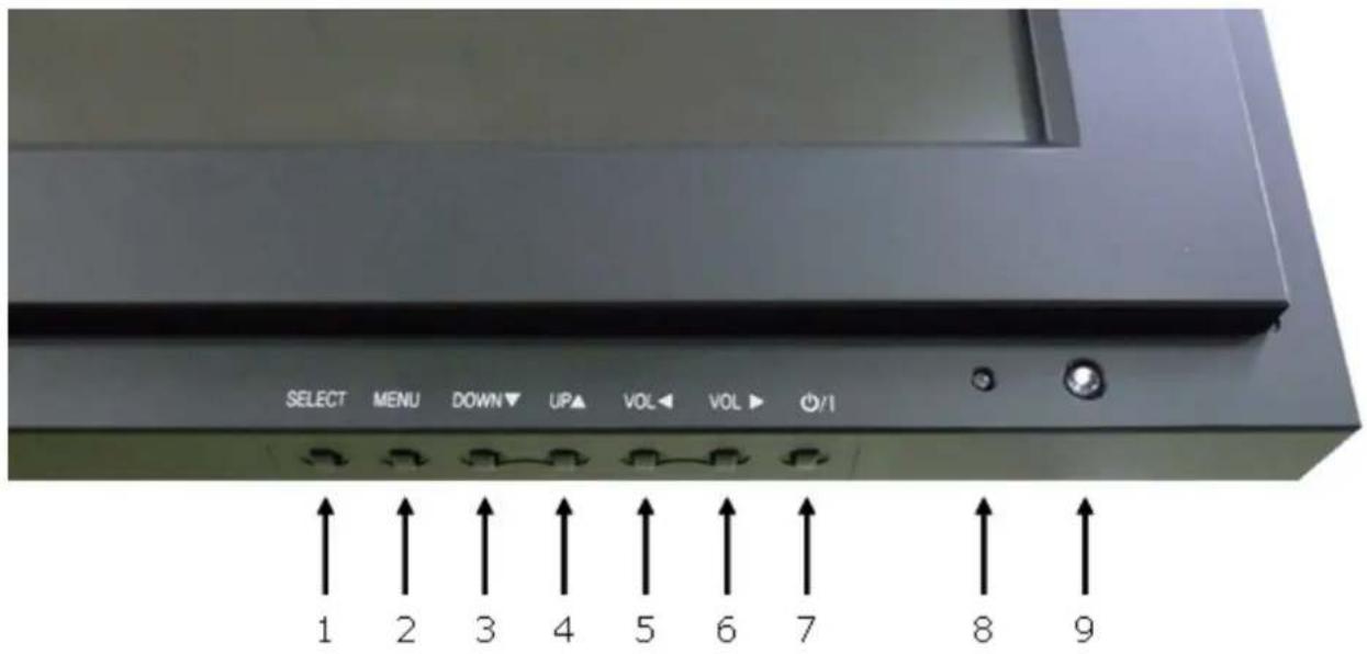
D. FRONT KEY CONTROL
text_image
SELECT MENU DOWN ▼ UP▲ VOL VOL ▶ O/I 1 2 3 4 5 6 7 8 91. SELECT
Selects an input source.
Enters a submenu or accepts your selection in the OSD menu.
2. MENU
Activates and exits the On Screen Display.
This button can also be used to move previous menu or status.
3 & 4. DOWN▼ & UP▲
These buttons allow user to enter the sub-menu of the activated function.
The up(▲) button is HOLD function and stop the Trigger & Auto switching functions.
5 & 6. VOL ◀ & VOL ▶
Adjust the volume and menu settings.
7. POWER ON/OFF( I )
Turns the power ON or OFF. There will be a few seconds delay before the display appears.
8. POWER LED
The power LED lights with green when the power is turned ON.
The power is turned off by pressing the power switch again and the power LED goes to Red.
9. IR Sensor
Remote controller sensor.
CONTROLS AND FUNCTIONS
OSD MENU DESCRIPTION
All picture, sound settings and setup for the monitor can be adjusted in the OSD menu.
(On Screen Display)
To adjust the OSD screen:
- Press the Menu button to enter the OSD menu.
- Press the ▲/▼ buttons to select the desired option. The selected option is highlighted.
- Press the ▶ button to enter the submenu for adjusting items.
- Change the value you wish to adjust by using the ▲/▼ buttons.
- Press the ◀ button to exit the submenu for adjusting items.
- Press the Menu button to exit the OSD menu.
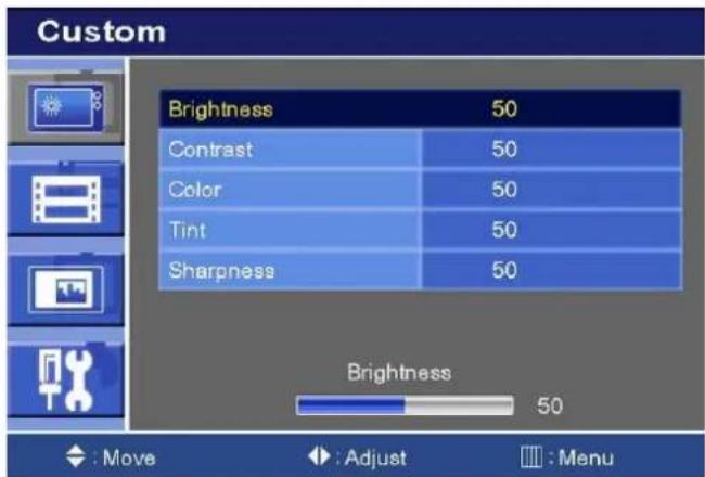
A. Custom
text_image
Custom Brightness 50 Contrast 50 Color 50 Tint 50 Sharpness 50 Brightness 50 : Move : Adjust : Menu| Option Function Value | ||
| Brightness Adjusts brightness of the screen. 0 ~ 100. | ||
| Contrast Adjusts intensity of the image. 0 ~ 100. | ||
| Color ^1) | Adjusts color of the picture. | 0 ~ 100. |
| Tint ^2) | Adjusts tint of the picture. | 0 ~ 100. |
| Sharpness ^1) | Adjusts sharpness of the picture. 0 | ~ 100. |
1) Unavailable in RGB PC, DVI and HDMI.
2) Unavailable in PAL system.
CONTROLS AND FUNCTIONS
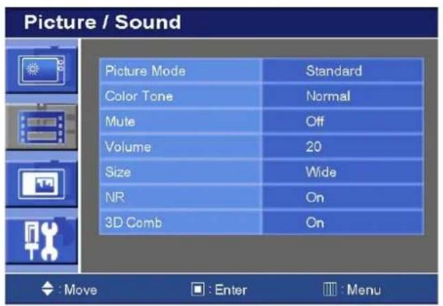
B. Picture/Sound
text_image
Picture / Sound Picture Mode Standard Color Tone Normal Mute Off Volume 20 Size Wide NR On 3D Comb On : Move : Enter : Menu
text_image
Picture / Sound Picture Mode Middle Color Tone Normal Mute Off Volume 20 Size Wide PC : Move : Enter :Menu| Option Function Value | |
| Picture Mode Sets picture mode. See table below. | |
| Color Tone Sets color tone. See table below. | |
| Mute Mutes speaker sound. Off or On. | |
| Volume Adjust the level of audio volume. 0 ~ 100. | |
| Size Display picture size. See table below. | |
| NR ^1) Reduces noise of the picture. On or Off. | |
| 3D Comb ^1) Activates the 3D comb filter. On or Off. | |
| PC ^2) See table below. | |
1) Unavailable in RGB PC, DVI and HDMI.
2) Only available in RGB PC.
Picture Mode
| Custom Applies user selected values(Brightness, Contrast, Tint and Sharpness). | |
| Dynamic | Provides enhanced contrast and sharpness. |
| Standard Provides standard contrast and sharpness. | |
| Movie | Is recommended for viewing film-based content. |
| Mild | Reduces contras and sharpness. |
CONTROLS AND FUNCTIONS
Color Tone
| Custom1) To manually adjust the color tones(Red, Green and Blue). |
| Cool Gives the white color a bluish tint. |
| Normal Gives the white color a neutral tint. |
| Warm Gives the white color a reddish tint. |
1) Unavailable in AV1 and AV2.
Size
| Wide Sets the image size to wide. | |
| Panorama1) Sets the image to panorama. | |
| Zoom11) Expands the image size about 2 times in upward and downward direction. | |
| Zoom21) Expands the image size about 1.5 times in upward and downward direction. | |
| 4:3 Sets the image size to 4:3. |
1) Unavailable in RGB PC, DVI and HDMI.
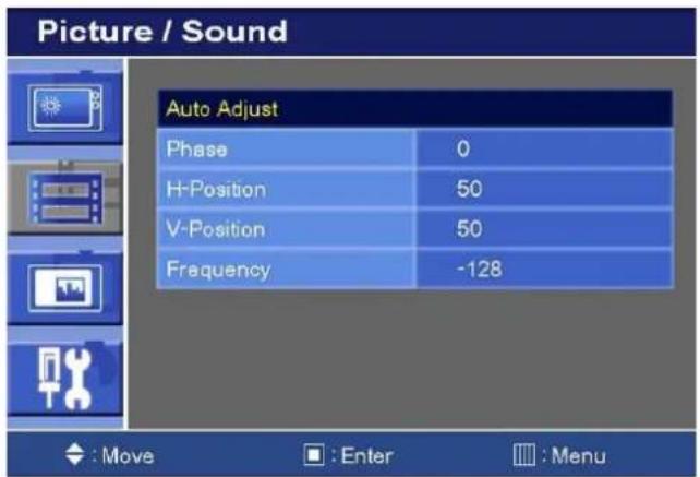
PC
text_image
Picture / Sound Auto Adjust Phase 0 H-Position 50 V-Position 50 Frequency -128 : Move : Enter : Menu| Option Function Value | ||
| Auto Adjust Auto geometry adjustment. | ||
| Phase Adjusts the number of horizontal picture elements. 0 ~ 100. | ||
| H-Position Adjusts the horizontally picture position. 0 ~ 100. | ||
| V-Position Adjusts the vertically picture position. 0 ~ 100. | ||
| Frequency | Adjusts the vertical noise of screen image. | 0 ~ 100. |
CONTROLS AND FUNCTIONS
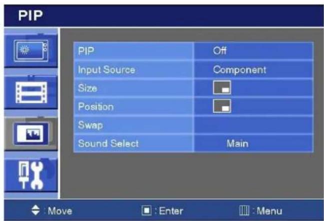
C. PIP
text_image
PIP PIP Off Input Source Component Size Position Swap Sound Select Main : Move : Enter : Menu| Option Function Value | ||
| PIP Activates the PIP feature. Off or On. | ||
| Input Source Selects the input source for the PIP area. See table below. | ||
| Size | Enables 3 screen size.4:3 side by corner, 4:3 side by 4:3,and full screen side by side. | |
| Position | Selects the position of PIP screen. Right of Bottom, Rightof Top, Left of Top and, Left of Bottom. | |
| Swap Alternates between the main and sub picture | ||
| Sound Select Selects the sound source from either the Main or PIP Main or Sub. | ||
Input Source
| Main | Sub | |
| Available combination | AV1, AV2 or S-Video Component, | HDMI, DVI or PC. |
| Component, HDMI, DVI or PC | AV1, AV2 or S-Video. | |
| Jnavailable combination | AV1, AV2 or S-Video AV1, AV2 or | S-Video |
| Component, HDMI, DVI or PC | Component, HDMI, DVI or PC. |
CONTROLS AND FUNCTIONS
D. Setup
text_image
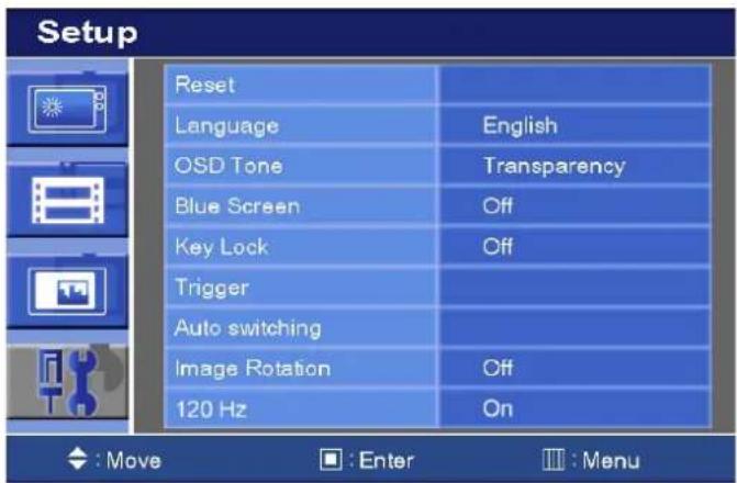
Setup Reset Language English OSD Tone Transparency Blue Screen Off Key Lock Off Trigger Auto switching Image Rotation Off 120 Hz On ◆: Move ■: Enter ■: Menu| Option Function Value | ||
| Reset | Resets the monitor settings to their factory default. | |
| Language Sets the language of the OSD menu. | English, French, Deutsch, Italian, Spanish, Portuguese or Nederland. | |
| OSD Tone | Changes background of monitor menus (e.g. input source & information). | Transparency or Blue. |
| Blue Screen | Displays a blue screen if the monitor receives no signal. | Off or On. |
| Key Lock ^1) | Locks all buttons of the monitor.Note: Use remote controller to unlock. | Off or On. |
| Trigger See table | below. | |
| Auto Switching See table below. | ||
| Image Rotation ^2) | Activates the Image Rotation function. Off or On. | |
| 120 Hz Activates | the 120Hz function On or Off. | |
1) How to unlock
① On the front key: Press the SOURCE/SELECT and MENU button at the same time over 3 seconds.
② On the Remote Controller: The Remote Controller operates well because the Key Lock function is only allowed for the front key of this product.
2) The displayed image is slightly moved to prevent image persistence when the Image Rotation function is On.
※ Image persistence
When an LCD panel is continuously displaying the same image(graphic) for a long period of time, a trace of the image can remain visibly. Image persistence is not a product defect, and all LCD products are subject to image persistence.
CONTROLS AND FUNCTIONS
3) 120 ~Hz
The 120Hz feature eliminates motion blur and improves image quality in the fast- moving images.
NOTICE: When watching moving images on a computer or a DVR through this monitor using a PC-RGB, DVI or HDMI input, you can see blurred images on the edge of icons and pop-up windows but, this is not a defect. The blur may appear on the fixed images such as another icon and pop-up window because the 120Hz feature is focused on fast moving images to enhance the quality of moving image.
Trigger
text_image
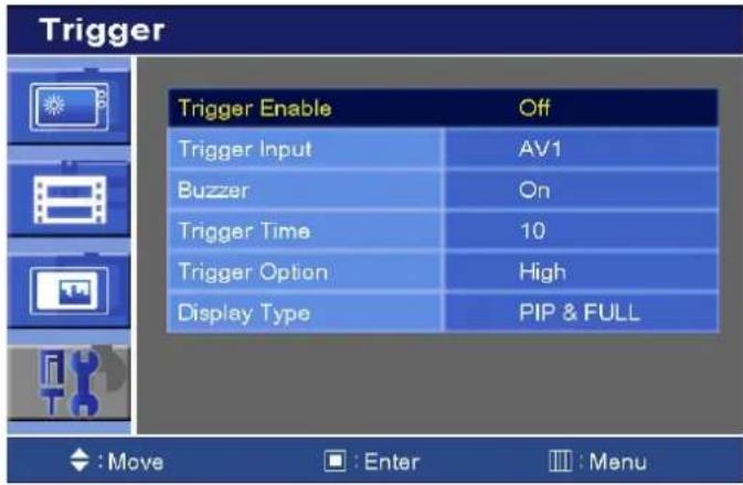
Trigger Trigger Enable Off Trigger Input AV1 Buzzer On Trigger Time 10 Trigger Option High Display Type PIP & FULL : Move : Enter : Menu| Option Function Value | ||
| Trigger Enable | Activates the trigger feature. Off or On. | |
| Trigger Input Selects the input source for the Trigger. | AV1, AV2, RGB PC or HDMI. | |
| Buzzer | Activates an audible signal when the monitor receives an trigger signal. | On or Off. |
| Trigger Time | Selects the amount of time, in seconds, that the monitor displays the trigger Input image. | 3 ~ 100. |
| Trigger Option Selects the type of physical trigger input. See table below. | ||
| Display Type | Selects the mode in which the monitor displays the Trigger Input. The monitor takes one of the following actions:- PIP & FULL: Displays the Trigger Input in the PIP of the current video input source.Note: The main video source must support the Trigger Input source as a PIP option. See section “Input Source” in “C. PIP”.- FULL: Switches the display to show the Trigger Input in the full screen. | PIP & FULL or FULL. |
CONTROLS AND FUNCTIONS
| N/C( Normally Closed):The Trigger function is activated whenthe trigger cable is opened. |
| N/O(Normally Opened):The Trigger function is activated whenthe trigger cable is closed. |
| High:The Trigger function is activated whenthe trigger signal is DC 2~5[V]. |
| Low:The Trigger function is activated whenthe trigger signal is DC 0~0.6[V].Note: In this case, trigger port has highstatus electrically, so the trigger cablehas to have ground(or earth) status tobe activated. |
Auto Switching
text_image
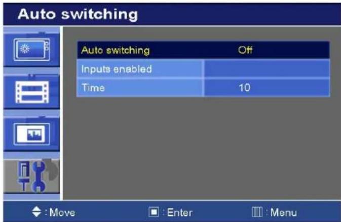
Auto switching Auto switching Off Inputs enabled Time 10 : Move : Enter :Menu| Option Function Value | ||
| Auto Switching | Activates the Auto Switching feature. | Off or On. |
| Input Enable | Opens another menu and you can select the input sources to include in the Auto Switching cycle. | AV1, AV2, RGB PC and HDMI. |
| Time | Selects the amount of time, in seconds, that the monitor displays each selected input source. | 3 ~ 100. |
MOUNTING GUIDE
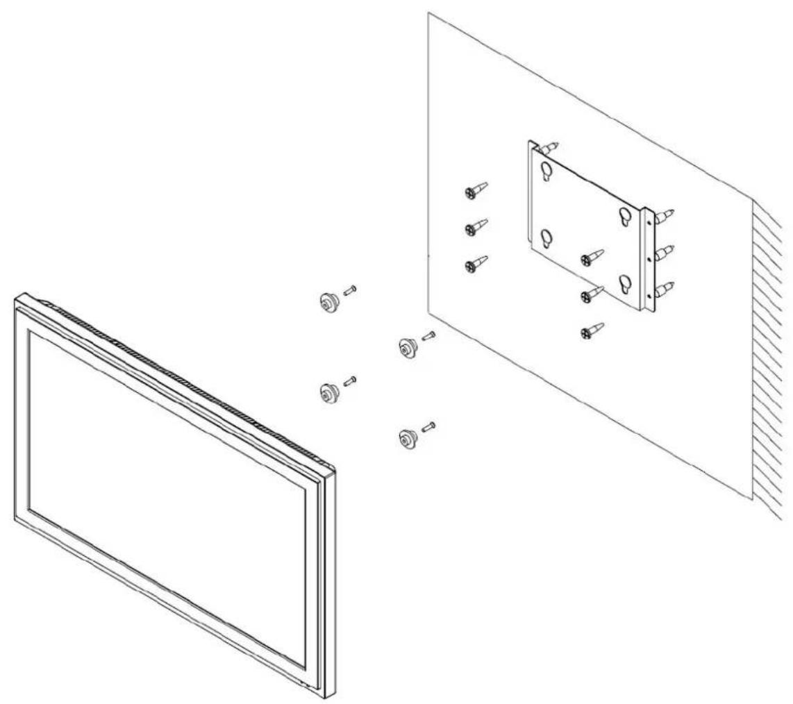
Wall mounting (Optional)
The LCD monitor is suitable for wall mounting by using the “VESA 200” standard wall mount (not included in the delivery).
natural_image
Technical line drawing showing a front panel and a wall-mounted component with screw holes (no text or symbols)D-SUB CONNECTOR
PIN ASSIGNMENTS
▶ PIN ASSIGNMENTS
- Power cord
- User's manual
- PC cable
- Trigger cable (Option)
- Stereo cable (Option)
- Remote controller (Option)
- Batteries (Option)
- Wall mount (Option)
POWER MANAGEMENT
This monitor features a power management system to “power down” upon receipt of the VESA DPMS(The display power management signaling) from a VESA DPMS video card.
The VESA DPMS-compliant video card performs this signaling system through not sending horizontal, vertical, or sync signal.
This monitor enters an appropriate mode through identifying each of the three modes of the signaling system.
POWER CONSUMPTION: 150W.
LED INDICATOR
The power management feature of the monitor is comprised of four stages: On(Green), Standby, Suspend, Active off(Red on/off 1 sec) and Unsupported mode(Green).
| MODE LED COLOR MONITOR OPERATION | ||
| ON | GREEN | Normal Operation |
| STANDBY | RED ON/OFF1 SEC | Screen blanks after preset idle timeAnd some electronic circuits or allCircuitry in the monitor shut down. |
| SUSPEND | ||
| ACTIV OFF | ||
| UNSUPPORTES MODE | GREEN | Normal operation but the on screenDisplay will show error massage |
| POWER OFF | RED | Not Operation |
SPECIFICATIONS
| 32" | |
| LCD-Type | 32" Diagonal AM-TFT(Active-Matrix) |
| Pixel pitch(mm) : 0.36375(H) x 0.36375(V) | |
| BRIGHTNESS: 500cd/ m^2 (Typical) | |
| CONTRAST RATIO: 1300:1(Typical) | |
| VIEWING ANGLE: 178°/178°(H/V) | |
| RESPONSE TIME: 6msec(G-to-G, typical) | |
| RESOLUTION (H x V) | 1920X1080 @120Hz |
| FREQUENCY | HORIZONTAL: 31~80KHz, VERTICAL: 56~75Hz |
| INPUT SIGNAL | VIDEO(2ch input 1.0Vp-p, 75Ω terminated, loop-through out) |
| S-VIDEO(1ch input (Y/C), loop-through out) | |
| COMPONENT(Y,Pb,Pr, Sound L/R) | |
| DVI D(Digital Video Interface) | |
| HDMI(High Definition Multimedia Interface) | |
| PC RGB | |
| AV(composite) Sound in/Out | |
| PC Stereo Sound | |
| Audio Out | |
| ACTIVE SCREEN SIZE | 801.31mm(31.55") diagonal |
| PACKING DIMENSIONS(W x H x D) | 875mm X 280mm X 635 mm (34.45" X 11.02" X 25") |
| WEIGHT | Net Weight : 21 kg (46.3 lbs) |
| Gross Weight : 25 kg (55.11 lbs) | |
| ELECTRICAL RATINGS | AC100~240V,50/60Hz (Auto Switching) |
▶▶ NOTE : Technical specifications are subject to change without notice.
TROUBLESHOOTING GUIDE
| TROUBLE | TROUBLESHOOTING TIP |
| No image on display screen | 1. Check that power cord of the Monitor have been connected securely into wall outlet or grounded extension cable or strip.2. Power switch should be in the ON position and LED is lit.3. Check that the Brightness and/or the Contrast adjustments of the Display have not been turned down to minimum levels. |
| "Going to Sleep" message on screen | 1. The signal cable should be completely connected to the video card/computer.2. The video card should be completely seated in its slot and the computer is switched ON. |
| Display image is not centered, too small or too large in PC mode | Push the down key in front side or Auto key in remote controller. |
| Vertical or Horizontal noise is present in the picture | Adjust Clock and Phase in the OSD. |
WEEE Symbols
Correct Disposal of This Product (Waste Electrical & Electronic Equipment) (Applicable in the European Union and other European countries with separate collection system
This marking shown on the product or its literature, indicates that it should not be disposed with other household wastes at the end of its working life. To prevent possible harm to the environment or human health from uncontrolled waste disposal, please separate this from other types of wastes and recycle it responsibly to promote the sustainable reuse of material resources. Household users should contact either the retailer where they purchased this product, or their local government office, for details of where and how they can take this item for environmentally safe recycling. Business users should contact their supplier and check the terms and conditions of the purchase contract. This product should not be mixed with other commercial wastes for disposal.

Vicon Standard Equipment Warranty
Vicon Industries Inc. (the "Company") warrants your equipment to be free from defects in material and workmanship under Normal Use from the date of original retail purchase for a period of three years, with the following exceptions:
- VCRs, all models: Labor and video heads warranted for 120 days from date of original retail purchase. All other parts warranted for one year from date of original retail purchase.
- Video monitor CRT (cathode ray tube) and LCD monitors, all models: One year from date of original retail purchase.
- Uninterruptible Power Supplies: Two years from date of original retail purchase.
- VDR-408 and VDR-416 Recorder Series: One year from date of original retail purchase.
- V5616MUX: One year from date of original retail purchase.
- S10-CH: 18 months from date of original retail purchase.
- Normal Use excludes prolonged use of lens and pan-and-tilt motors, gear heads, and gears due to continuous use of "autopan" or "tour" modes of operation. Such continuous operation is outside the scope of this warranty.
- Vicon Security Management Systems (SMS) All Models: All hardware is warranted for two years from date of original retail purchase.
- Any product sold as "special" or not listed in Vicon's commercial price list: One year from date of original retail purchase.
Date of retail purchase is the date original end-user takes possession of the equipment, or, at the sole discretion of the Company, the date the equipment first becomes operational by the original end-user.
The sole remedy under this Warranty is that defective equipment be repaired or (at the Company's option) replaced, at Company repair centers, provided the equipment has been authorized for return by the Company, and the return shipment is prepaid in accordance with policy.
The Company will not be obligated to repair or replace equipment showing abuse or damage, or to parts which in the judgment of the Company are not defective, or any equipment which may have been tampered with, altered, misused, or been subject to unauthorized repair.
Software supplied either separately or in hardware is furnished on an "As ls" basis. Vicon does not warrant that such software shall be error (bug) free. Software support via telephone, if provided at no cost, may be discontinued at any time without notice at Vicon's sole discretion. Vicon reserves the right to make changes to its software in any of its products at any time and without notice.
This Warranty is in lieu of all other conditions and warranties express or implied as to the Goods, including any warranty of merchantability or fitness and the remedy specified in this Warranty is in lieu of all other remedies available to the Purchaser.
No one is authorized to assume any liability on behalf of the Company, or impose any obligations on it in connection with the sale of any Goods, other than that which is specified above. In no event will the Company be liable for indirect, special, incidental, consequential, or other damages, whether arising from interrupted equipment operation, loss of data, replacement of equipment or software, costs or repairs undertaken by the Purchaser, or other causes.
This warranty applies to all sales made by the Company or its dealers and shall be governed by the laws of New York State without regard to its conflict of laws principles. This Warranty shall be enforceable against the Company only in the courts located in the State of New York.
The form of this Warranty is effective August 1, 2009.
THE TERMS OF THIS WARRANTY APPLY ONLY TO SALES MADE WHILE THIS WARRANTY IS IN EFFECT. THIS WARRANTY SHALL BE OF NO EFFECT IF AT THE TIME OF SALE A DIFFERENT WARRANTY IS POSTED ON THE COMPANY'S WEBSITE, WWW.VICON-CCTV.COM. IN THAT EVENT, THE TERMS OF THE POSTED WARRANTY SHALL APPLY EXCLUSIVELY.
Vicon Industries Inc.
Corporate Headquarters
89 Arkay Drive
Hauppauge, New York 11788
631-952-CCTV (2288) 800-645-9116
Fax: 631-951-CCTV (2288)
Vicon Europe
Headquarters
Brunel Way
Fareham, PO15 5TX
United Kingdom
+44 (0) 1489 566300
Fax: +44 (0) 1489 566322
Vicon Germany
Kornstieg 3
D-24537 Neumuenster
Unit 5, 17/F, Metropole Square
2 On Yiu Street, Shatin
New Territories,
Hong Kong
(852) 2145-7118
Fax: (852) 2145-7117
Internet Address: www.vicon-cctv.com