Crystal NT-4040R - Security Camera NUUO - Free user manual and instructions
Find the device manual for free Crystal NT-4040R NUUO in PDF.


User questions about Crystal NT-4040R NUUO
0 question about this device. Answer the ones you know or ask your own.
Ask a new question about this device
Download the instructions for your Security Camera in PDF format for free! Find your manual Crystal NT-4040R - NUUO and take your electronic device back in hand. On this page are published all the documents necessary for the use of your device. Crystal NT-4040R by NUUO.
USER MANUAL Crystal NT-4040R NUUO
1. Installation....4
1.1 Installation Process ....4
1.2 LED Status Definitions ...... 15
2. Settings....17
2.1 Camera Setup....18
2.1.1 Add Cameras by Camera Search....18
2.1.2 Add Cameras Manually....19
2.1.3 Modify Camera Information 21
2.1.4 Modify Camera Parameters 21
2.1.5 Set up Lens Settings....21
2.1.6 Set up 2nd Stream 22
2.1.7 View Camera Status 24
2.2 Recording & Event Setup....25
2.2.1 Recording Mode Setup 25
2.2.2 Recording Schedule / Event Setup 26
2.2.3 Camera Events and Responding Actions Setup ....30
2.2.4 I/O Box Input and Responding Action Setup......32
2.2.5 System Events and Responding Actions Setup.....32
2.2.6 SMTP Server Setup....34
2.2.7 Add Event Contacts 35
2.3 RAID & File Settings 35
2.3.1 Create a RAID Volume 35
2.3.2 View RAID Volume Status....37
2.3.3 View Disk Drive Information 38
2.3.4 Modify RAID Volume 39
2.3.5 Delete a RAID Volume....41
2.3.6 Format....42
2.4 Auto Backup 42
2.4.1 Set up Backup Schedule....43
2.4.2 Set up Backup Server 43
2.5 Network Setup....45
2.5.1 View Network Status....45
2.5.2 Network Settings....45
2.5.3 Auto Port-Forwarding 47
2.5.4 Network Service Setup....48
2.5.5 Main server/Sub server Configuration ..... 49
2.6 Management....51
2.6.1 View the List of Users .....51
2.6.2 Create New Users....51
2.6.3 Modify User Information....52
2.6.4 Change a User's Password 53
2.6.5 Delete Users 53
2.6.6 Import/Export User Account 53
2.6.7 Online License Activation....54
2.6.8 Offline License Activation....55
2.6.9 Online License transfer....58
2.6.10 Offline license transfer 58
2.6.11 View the Event Log....60
2.6.12 Save Unit Configuration 62
2.6.13 Load Unit Configuration / Default Settings.....62
2.7 System 63
2.7.1 View System Information 63
2.7.2 Smart Fan Control 64
2.7.3 UPS Setup 65
2.7.4 Upgrade the System 65
2.7.5 Upgrade Notification 66
2.7.6 System Date and Time Setup....67
2.7.7 Local Display....68
2.7.8 Restart the Unit....70
2.7.9 Shut Down the Unit 70
3. I/O 72
3.1 Introduction ......72
3.1.1 System Introduction 72
3.1.2 HW Installation 72
3.1.3 Software Installation - SCB-C31....73
3.1.4 Software Installation - SCB-C24/26/28 74
3.2 Software Setup 76
3.2.1 Add I/O Box....76
3.2.2 Modify I/O Box Information .....77
3.2.3 I/O Pin Setting 77
3.3 Relative Configuration and Application 78
3.3.1 Record on Input Trigger....78
3.3.2 Input and Responding Actions....78
3.3.3 I/O Control Panel in Live View 78
- External Storage 79
4.1 Create a Volume on DAS....79
4.2 Create an External Storage....79
4.3 Create an External Storage on iSCSI....80
- Log out....82
- Remote PC System Requirements....83
- Troubleshooting 84
7.1 Replace a Failed Disk Drive....84
7.2 Respond to a Critical RAID Volume 84
7.3 Respond to a File System Error RAID Volume......84
7.4 Install ActiveX....84
7.5 Cannot Log in to the Unit with Internet Explorer......85
Appendix - RAID System....86
Introduction to RAID 86
RAID 0 - Stripe....86
RAID 1 - Mirror 87
RAID 5 - Block Striping with Distributed Parity .....88
RAID 10 - Mirror / Stripe....88
Choosing a RAID Level 89
Appendix - Camera Integration....91
Camera Support List 91
1. Installation
1.1 Installation Process
Step 1: Unpack the Unit
This package contains the following items:
■ The unit
■ Quick Start Guide
■ Screws for disk drives
■ Key
■ Power cord
■ Warranty card
■ CD with Install Wizard, NuClient and Offline License Tool application, user manual, and quick start guide
|  | The electronic components within the unit can be damaged by Electrostatic Discharg (ESD). Please take precautions at all times when handling the unit or its sub-assemblies. |
|  | To configure the unit, you must install the software onto a desktop/ laptop running Windows XP-SP3 32bit, Windows 7 32/64bit, Mac OS X v10.6/10.7 |
Unit front/rear view
(NT-4040:Tower)
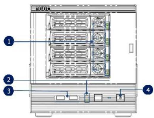
text_image
Technical diagram of a server rack with labeled components including drive bays and ports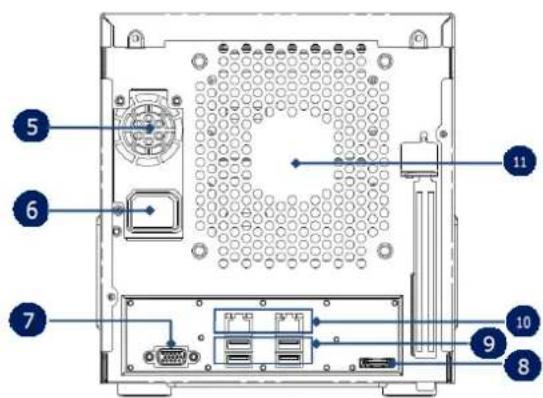
text_image
Diagram of a computer chassis with numbered components for identification(NT-4040R: 4 bay rackmount)

text_image
nuuo 1 2 10 8 6 5 7 9 11 4| 1. Key Lock | 7. VGA |
| 2. LED Indicators: Power, LAN1-2, HDD1-4 | 8. eSATA Connector |
| 3. USB x2 | 9. USB x 4 |
| 4. Power Button | 10. Gigabit LAN x 2 |
| 5. PSU Cooling Fan | 11. Main Cooling Fan |
| 6. Power Connector |
(NT-8040R: 8 bay rackmount)
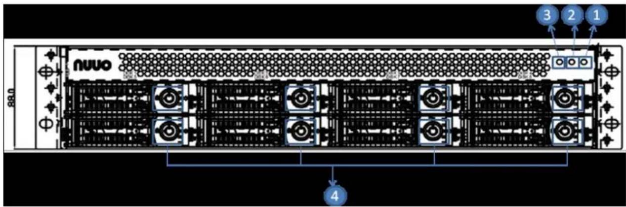
text_image
3 2 1 nuuo 4 0.88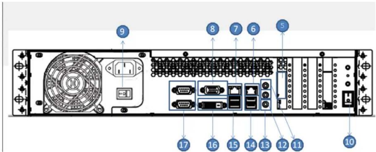
text_image
9 8 7 6 5 17 16 15 14 13 12 11 10| 1. LED Indicators: LAN2 | 10. Power bottom |
| 2. LED Indicators: LAN1 | 11. Line-in |
| 3. LED Indicators: Power | 12. Line-out |
| 4. Key lock | 13. Microphone in |
| 5. eSATA Connector | 14. USB 3.0 x2 |
| 6. Lan 2 | 15. USB 2.0 x2 |
| 7. Lan 1 | 16. DVI |
| 8. VGA | 17. COM port |
| 9. Power supply switch |
(NT-8040RP: 8 bay rackmount with redundant power)
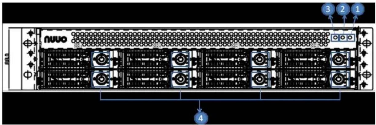
text_image
3 2 1 nuvo 4 88.0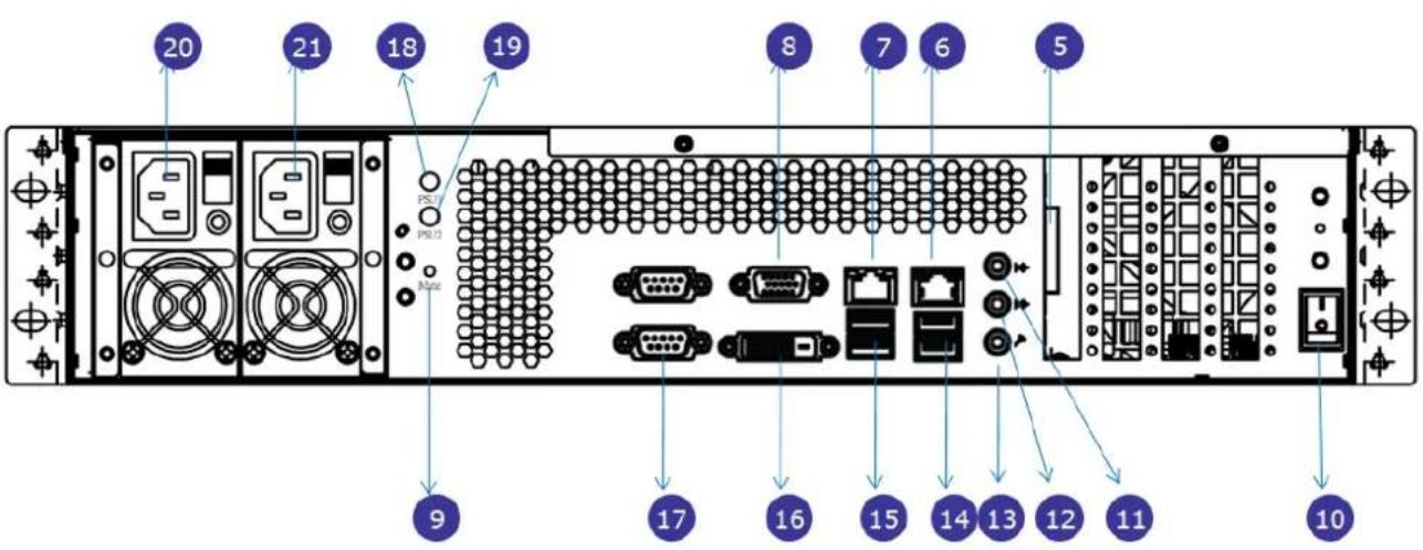
text_image
20 21 18 19 PSU PSU None 8 7 6 5 9 17 16 15 14 13 12 11 10| 1. LED Indicators: LAN2 | 12. Line-out |
| 2. LED Indicators: LAN1 | 13. Microphone in |
| 3. LED Indicators: Power | 14. USB 3.0 x2 |
| 4. Key lock | 15. USB 2.0 x2 |
| 5. eSATA Connector | 16. DVI |
| 6. Lan 2 | 17. COM port |
| 7. Lan 1 | 18. LED Indicators: PSU1 |
| 8. VGA | 19. LED Indicators: PSU2 |
| 9. Power supply mute bottom | 20. PSU1 |
| 10. Power bottom | 21. PSU2 |
| 11. Line-in |
Step 2: Install Hard Drives
Refer to compatibility list and install HDDs. For optimal performance consideration, install disks with the same model and storage capacity. The available RAID level depends on the amount of disks installed.
- Open the lid on the front of the unit enclosure.
- Pull a HDD tray from the enclosure. See the front view figure.
- Carefully lock the disks into the HDD tray with screws. 3 screws for each disk. We recommend locking the screws on the bottom of the disk, instead of the side of tray. Put the HDD tray back once you finished.
Step 3: Connect to the Network
- Attach one end of the network cable to the RJ45 network connection. See the rear view figure.
- Attach the other end of the network cable to your Ethernet hub or switch.

If there are multiple networks at your facility, note the network to which you connect the unit. You will need this information during the setup process. Please also enable the DHCP function within the network, as the unit will retrieve an IP address through DHCP by default.
Step 4: Connect the Power
- Attach the power cord to the power source.
- Connect the power cord to the back of the unit enclosure. See the rear view figure.
- On the front of the unit, press the power button. See the front view figure.
It takes about a minute for the unit to fully power up. Once it is powered up, the Power Status LED turns blue. See the front view figure.
Step 5: Install the Software
- Insert the CD into your CDROM.
- Double-click Setup.exe to begin installation.
- Follow the instruction of Setup.exe, and click the Finish button to close
the installer.
Step 6: Set up the Unit
The software Installation Wizard performs the setup procedures on the unit. After the procedure, you can begin using it.
- Go to Start > NUUO Titan Series > NUUO Install Wizard.
-
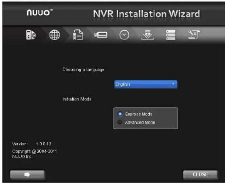
This program will show the default language setting and initiation mode.
-
Choose your preferred language and initiation mode, and then click the button.
text_image
NUVO™ NVR Installation Wizard Choosing a language English Initiation Mode Express Mode Advanced Mode Version: 1.0.0.12 Copyright @ 2004-2011 NUVO Inc. CLOSE- Express Mode: you don't need to set up the network settings and RAID level.
- Advanced Mode: configure all settings manually: network, license, camera, Date/Time, upgrade notification, and RAID level
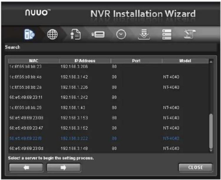
- The Installation Wizard program starts searching for all the units on the internet currently. Choose one of them, and then click the button.
text_image
NUVO™ NVR Installation Wizard Search MAC IP Address Port Model 1:c:6f:65.b8.bb:23 192.168.3.206 80 1:c:6f:65.b8.bb:4a 192.168.3.142 90 NT-4040 1:c:6f:65.b8.bb:2a 192.168.1.226 80 NT-4040 50:e5:49:69:23:11 192.168.1.242 90 1:c:6f:65.b8.bb:29 192.168.1.43 80 NT-4040 50:e5:49:69:23:03 192.168.3.153 80 NT-4040 50:e5:49:69:23:47 192.168.3.152 80 NT-4040 50:e5:49:69:22:19 192.168.3.222 80 NT-4040 60:e5:49:69:23:0d 192.168.3.148 80 NT-4040 Select a server to begin the setting process. CLOSE- Type in the password, and then click the OK button.
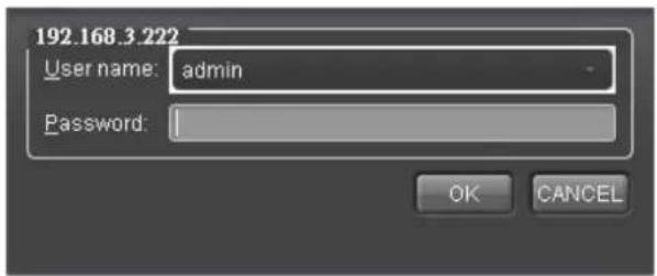
text_image
192.168.3.222 User name: admin Password: OK CANCEL
The default Administrator password is "admin".
- Name this server and select the network type, and then click the button.
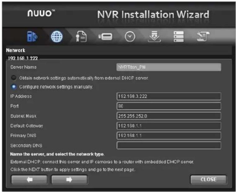
text_image
nuuo™ NVR Installation Wizard Network 192.168.3.222 Server Name NVRTitan_PM Obtain network settings automatically from external DHCP server Configure network settings manually. IP Address 192.168.3.222 Port 80 Subnet Mask 255.255.252.0 Default Gateway 192.168.1.1 Primary DNS 192.168.1.1 Secondary DNS Name the server, and select the network type. External DHCP: connect this server and IP cameras to a router with embedded DHCP server. Click the NEXT button to apply settings and go to the next page. CLOSE- Obtain network settings automatically from external DHCP server: apply all settings which are automatically generated by the DHCP server, such as IP, subnet mask, gateway, and DNS.
- Configure network settings manually: configure the preferred settings one by one.
- Activate camera license to have more channel capacity, and click the button.
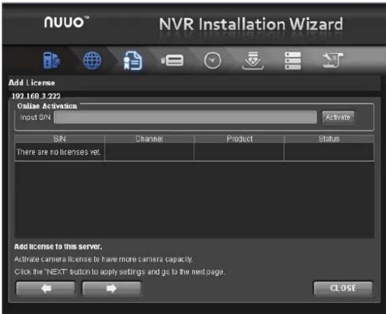
text_image
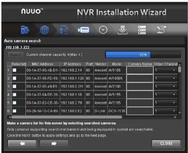
NUVO™ NVR Installation Wizard Add License 192.168.3.222 Online Activation Input S/N Activate S/N Channel Product Status There are no licenses yet. Add license to this server. Activate camera license to have more camera capacity. Click the "NEXT" button to apply settings and go to the next page. CLOSE- Add cameras for this server. There are two ways of adding cameras,
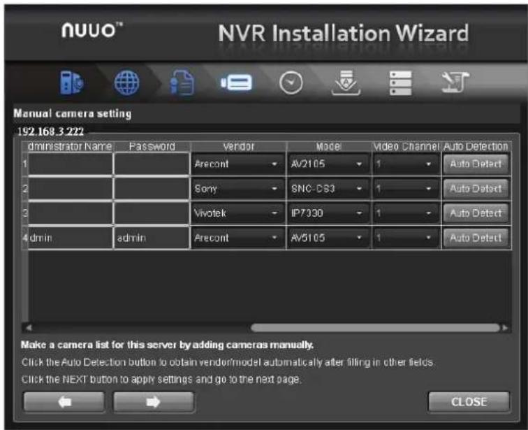
selecting the searched cameras and manually configuring the cameras. Click the button after completing camera list.
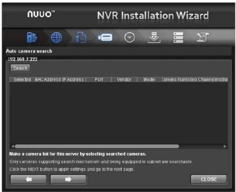
text_image
NUUO™ NVR Installation Wizard Auto camera search 192.168.3.222 Search Selected MAC Address IP Address Port Vendor Model Camera Nam Video Channel Infra Make a camera list for this server by selecting searched cameras. Only cameras supporting search mechanism and being equipped in subnet are searchable. Click the NEXT button to apply settings and go to the next page. CLOSEClick the Search button.
text_image
NUUO™ NVR Installation Wizard Auto camera search 192.158.3.222 Search Current channel capacity: 4(Max: 4) 80% Selected MAC Address IP Address Fort Vendor Model Camera Name Video Channel 1 ■ 00-1A-07-0C-4E-D1- 192.168.2.14 90 Arecont AV5105 1 2 ■ 00-1A-07-0E-FD-58- 192.168.1.126 80 Arecont AV10005 1 3 ■ 00-1A-07-0C-49-B1- 192.168.0.211 80 Arecont AV2100 1 4 ■ 00-1A-07-04-DF-26- 192.168.1.16 80 Arecont AV5155 1 5 ■ 00-1A-07-02-CE-30- 192.168.2.79 80 Arecont AV2105 1 6 ■ 00-2B-5A-1D-C4-98- 192.168.0.62 80 D-Link DCS-1130 1 Make a camera list for this server by selecting searched cameras. Only cameras supporting search mechanism and being equipped in subnet are searchable. Click the NEXT button to apply settings and go to the next page. CLOSESelect camera and type the camera name, username and password.
text_image
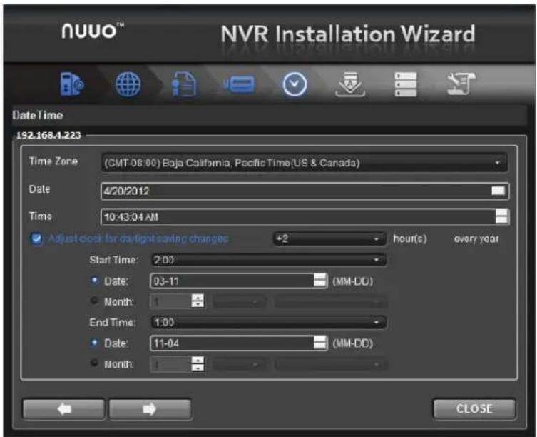
nuuo™ NVR Installation Wizard Manual camera setting 192.168.3 222 Administrator Name Password Vendor Model Video Channel Auto Detection 1 Arecont Av2105 1 Auto Detect 2 Sony SONC-CS3 1 Auto Detect 3 Vivotek IP7330 1 Auto Detect 4 admin adults Arecont Av5105 1 Auto Detect Make a camera list for this server by adding cameras manually. Click the Auto Detection button to obtain vendor/model automatically after filling in other fields. Click the NEXT button to apply settings and go to the next page. CLOSEAdd cameras manually.
- Set up the time zone, date, and time, and adjust daylight saving changes if needed. Once daylight saving function is enabled, the time change will activate automatically every year based on the recurrence you set. Click the button.
text_image
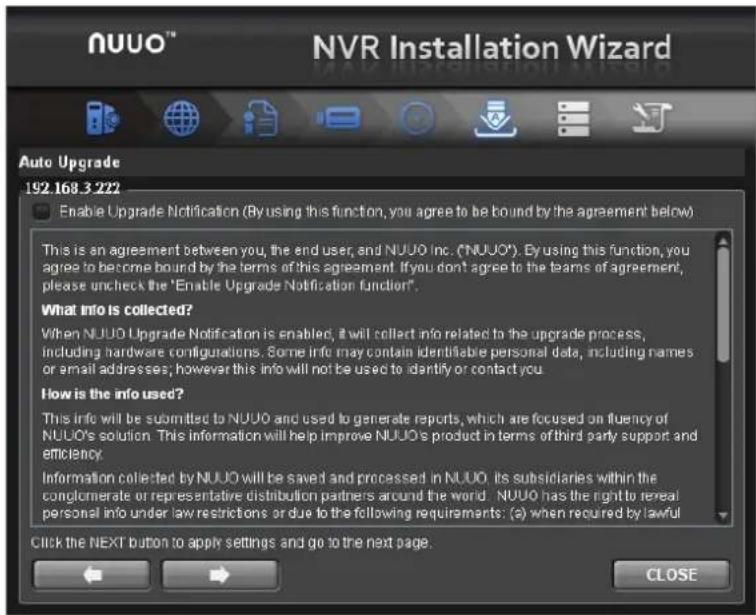
NUUO™ NVR Installation Wizard Date Time 192.168.4.223 Time Zone (GMT-08:00) Baja California, Pacific Time(US & Canada) Date 4/20/2012 Time 10:43:04 AM Adjust clock for daylight saving changes +2 hour(s) every year Start Time: 2:00 Date: 03-11 (MM-DD) Month: 1 End Time: 1:00 Date: 11-04 (MM-DD) Month: 1 CLOSE- Check "Enable Upgrade Notification" box if you want to receive notification when there is a newer FW version. Click the button.
text_image
NUUO™ NVR Installation Wizard Auto Upgrade 192.168.3 222 Enable Upgrade Notification (By using this function, you agree to be bound by the agreement below) This is an agreement between you, the end user, and NUUO Inc. ("NUUO"). By using this function, you agree to become bound by the terms of this agreement. If you don't agree to the teams of agreement, please uncheck the "Enable Upgrade Notification function". What info is collected? When NUUO Upgrade Notification is enabled, it will collect info related to the upgrade process, including hardware configurations. Some info may contain identifiable personal data, including names or email addresses; however this info will not be used to identify or contact you. How is the info used? This info will be submitted to NUUO and used to generate reports, which are focused on fluency of NUUO's solution. This information will help improve NUUO's product in terms of third party support and efficiency. Information collected by NUUO will be saved and processed in NUUO. Its subsidiaries within the conglomerate or representative distribution partners around the world. NUUO has the right to reveal personal info under law restrictions or due to the following requirements: (a) when required by lawful Click the NEXT button to apply settings and go to the next page. CLOSE- Follow the following instruction and select the RAID type you want to create. Click the button.
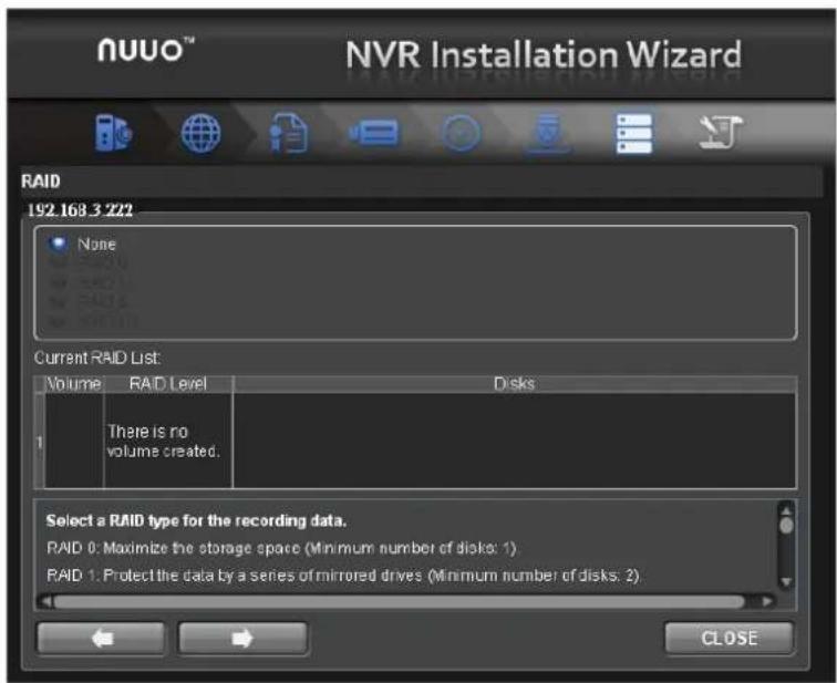
text_image
NUVO™ NVR Installation Wizard RAID 192.168.3 222 None Current RAID List: Volume RAID Level Disks 1 There is no volumes created. Select a RAID type for the recording data. RAID 0: Maximize the storage space (Minimum number of disks: 1) RAID 1: Protect the data by a series of mirrored drives (Minimum number of disks: 2) CLOSE- Review your settings. If the settings are correct, click the Finish button to exit the settings procedure and activate the system.
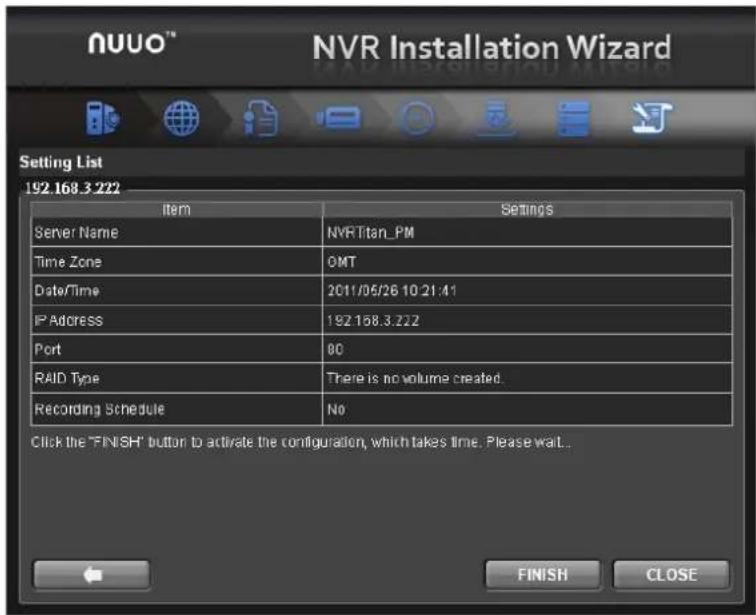
text_image
NUVO™ NVR Installation Wizard Setting List 192.168.3.222 Item Settings Server Name NVR Titan_PM Time Zone OMT Date/Time 2011/05/26 10:21:41 IP Address 192.168.3.222 Port 80 RAID Type There is no volume created. Recording Schedule N0 Click the "FINISH" button to activate the configuration, which takes time. Please wait... FINISH CLOSE
Once the "FINISH" button is clicked, the unit will start working. In order to ensure the stability of the unit, never pull any disks out when the system is running.
1.2 LED Status Definitions
NT-4040R
| Function | LED Status |
| Power Status | ■ Power-on: blue■ Power-off: dark |
| HDD Status (top) | ■ Power-on: blue■ Power-off: dark |
| HDD Activity Status(bottom) | ■ Healthy: blue with blinking■ No disk: dark |
| Ethernet Status | ■ Linking: blue■ Accessing: blue with blinking■ No linking: dark |
NT-8040R
| Function | LED Status | Remark |
| Power Status(front) | ■ Power-on: blue■ Power-off: dark■ Power standby(power-on, butTitan not operate): blink slowly | |
| HDD Status(front; HDD Tray) | ■ Power-on: blue■ Power-off: Dark■ Access: blink (Blue) | Two LEDs on HDD trayLED1: power and access indicatorLED2: reserved, no status |
| Ethernet Statusx2(front) | ■ Connected: blue■ Accessing: blue with blinking | Two LED, one for LAN1status and the other onefor LAN2 status |
| Ethernet Activityx2(rear) | ■ Link Rate indicator (Left side)1) Green =1000M2) Orange=100M3) Dark=10M or no link■ Link status indicator(Right side)1) Accessing: Green withblinking | 2 LEDs for each Ethernet port |
2. Settings
After setting up the unit, log in to the system by entering its IP address in the browser (Internet Explorer 8 and later, Safari 5.1 7534.48.3, and Firefox 7.0.1). When connecting, choose your language, enter the user name and password, and then begin using this system.
Take IE as the demonstration browser of this manual.
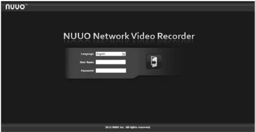
text_image
NUUO™ NUUO Network Video Recorder Language English User Name Password 2011 NUUO Inc. All rights reserved.There are four main functions of this unit: Settings, NuClient, Help Page, and Logout button. They will be shown on the top of the page. Currently, NuClient is supported on IE and Firefox only.
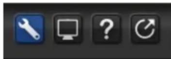
natural_image
Four black square icons representing tools and applications: wrench, monitor, question mark, and refresh symbol (no text or labels)Current firmware version and free storage capacity are shown above the function list.
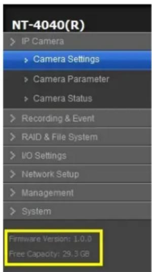
text_image
NT-4040(R) IP Camera Camera Settings Camera Parameter Camera Status Recording & Event RAID & File System I/O Settings Network Setup Management System Firmware Version: 1.0.0 Free Capacity: 29.3 GB2.1 Camera Setup
2.1.1 Add Cameras by Camera Search
The function enables user to automatically search and add cameras in the same network. There are two search mechanisms, one is UPnP, another is camera search tool. Before searching UPnP cameras, make sure that the cameras possess UPnP function. Refer to camera support list.
- Log in to the unit.
- Click IP Camera/ Camera Settings.
- Click the Camera Search tab.
- Click the Search button.
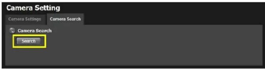
text_image
Camera Setting Camera Settings Camera Search Camera Search Search- The system will list all the currently available cameras. The inserted cameras are shown in blue. Click the ✦ icon to add a camera into your camera list.
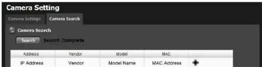
text_image
Camera Setting Camera Settings Camera Search Camera Search Search Search Complete Address Vendor Model MAC IP Address Vendor Model Name MAC Address +- After clicking the ✝ icon, the camera setting page will pop up. Click the item to which you want to add a camera.
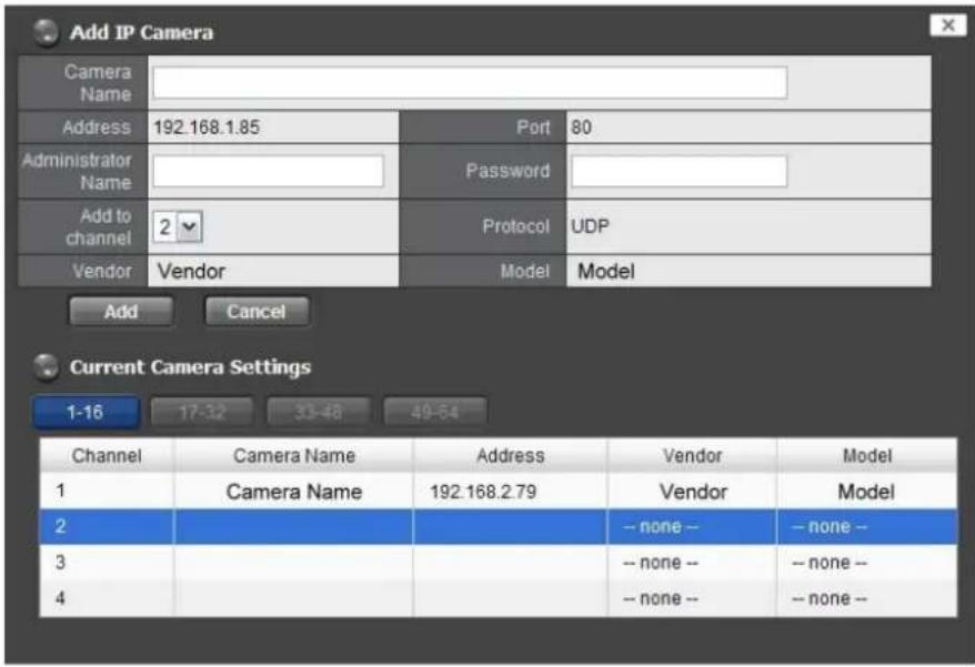
text_image
Add IP Camera Camera Name Address 192.168.1.85 Port 80 Administrator Name Password Add to channel 2 Protocol UDP Vendor Vendor Model Model Add Cancel Current Camera Settings 1-16 17-32 33-48 49-54 Channel Camera Name Address Vendor Model 1 Camera Name 192.168.2.79 Vendor Model 2 -- none -- none -- 3 -- none -- none -- 4 -- none -- none --- Insert the camera name, user name, and password.

To have better compatibility between camera and system, please make sure the privilege of camera credential is admin-level.
- Click the Add button to add it.
- After clicking the Add button, the updated camera list will be displayed in the Camera Setting tab.
| Camera List | |||||
| 1-16 | 17-32 | 33-48 | 49-64 | ||
| No. | Camera Name | Address | Port | Vendor | Model |
| 1 | Camera Name | 192 168 2.79 | 80 | Vendor | Model |
| 2 | Camera Name | 192 168 1.85 | 80 | Vendor | Model |
| 3 | 80 | – none – | – none – | ||
| 4 | 80 | – none – | – none – | ||
2.1.2 Add Cameras Manually
- Log in to the unit.
- Click IP Camera / Camera Settings.
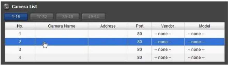
- Click the Camera Settings tab, and the camera list will be displayed on the bottom of the page.
- Click on the camera list for the channel you want to add and enter the camera's information.
text_image
Camera List 1-16 17-32 33-48 49-64 No. Camera Name Address Port Vendor Model 1 80 -- none -- none -- 2 80 -- none -- none -- 3 80 -- none -- none -- 4 80 -- none -- none --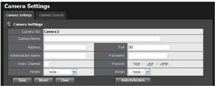
text_image
Camera Settings Camera Settings Camera Search Camera Settings Camera No. Camera 2 Camera Name Address Port 80 Administrator Name Password Video Channel Protocol TCP UDP HTTP Vendor -- none -- Model -- none -- Save Reset Clear Auto Detection- Camera name: The name of the camera.
- Address: The IP address.
- Port: The transmission port.
- Administrator Name: Login username.
- Password: Login password.
- Camera Channel: Select the number of analog cameras supported by one video server or select the number of IP cameras possessing multiple lens/channels.
- Protocol: Data transmission protocol.
• Vendor: Camera vendor name.
● Model: Camera model name.

To have better compatibility between camera and system, please make sure the privilege of camera credential is admin-level.
5. Click the Save button.
- Save: Save the information of this camera.
- Reset: Return to the latest saved settings of the selected camera.
- Clear: Set all the settings to default value.
- Auto Detection: After inserting IP address, port, username, and password, click this button to automatically detect other camera information, including Channel, Protocol, Vendor, and Model.
2.1.3 Modify Camera Information
- Log in to the unit.
- Click IP Camera / Camera Settings.
- Click the Camera Settings tab.
- Click the camera which you want to modify.
- Modify the information of this camera.
- Click the Save button.
- Use the same method to replace a camera if needed.
2.1.4 Modify Camera Parameters
- Log in to the unit.
- Click IP Camera / Camera Parameters.
- Click the Camera Parameter tab.
- Click the camera which you want to modify on the camera list.
- Modify the information of this camera.
- Click the Save button.
text_image
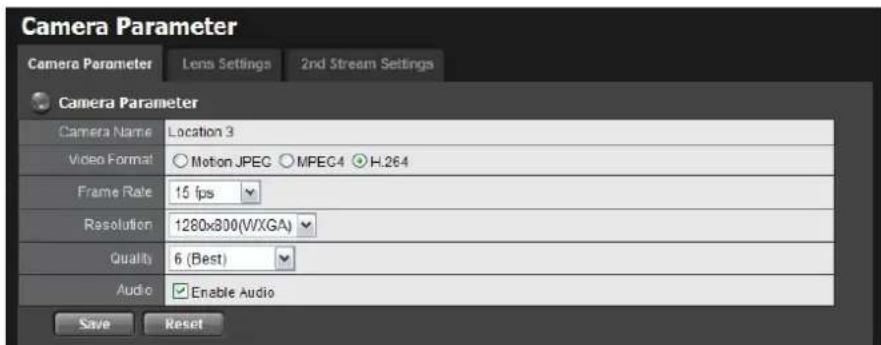
Camera Parameter Camera Parameter Lens Settings 2nd Stream Settings Camera Parameter Camera Name Location 3 Video Format Motion JPEG MPEC4 H.264 Frame Rate 15 fps Resolution 1280x800(WXGA) Quality 6 (Best) Audio Enable Audio Save Reset- Camera Name: The name of the camera.
- Video Format: Choose the type of format which this camera supports.
- Frame rate: Select the frame rate of the camera.
● Resolution: Select the resolution of the camera.
● Quality: Select the image quality of the camera.
● Audio: Check the Enable Audio option to view and enable audio recording.
2.1.5 Set up Lens Settings
- Log in to the unit.
-
Click IP Camera / Camera Parameters.
-
Click the Lens Settings tab.
- Click the camera which you want to modify in the camera list.
- Modify the information of this camera.
- Click the Save button.
text_image
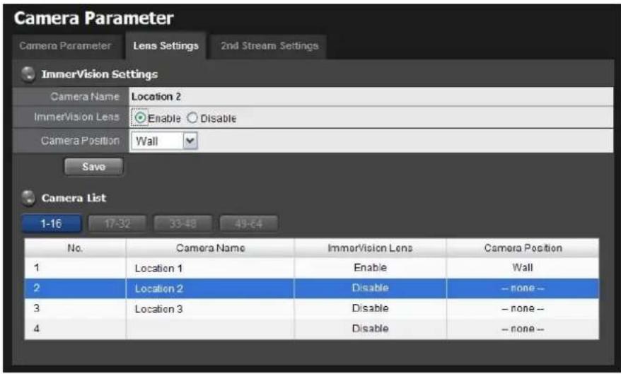
Camera Parameter Camera Parameter Lens Settings 2nd Stream Settings ImmerVision Settings Camera Name Location 2 ImmerVision Lens Enable Disable Camera Position Wall Save Camera List 1-16 17-32 33-48 49-64 No. Camera Name ImmorVision Lens Camera Position 1 Location 1 Enable Wall 2 Location 2 Disable - none - 3 Location 3 Disable - none - 4 Disable - none -- Camera Name: The name of the camera.
- Lens type: There are two types of lens currently, ImmerVision and Vivotek (FE8171V). You are not allowed to select type so far, type depends on camera model.
ImmerVision Lens: Enable the option if ImmerVision lens is installed. VIVOTEK Fisheye camera: If you choose VIVOTEK fisheye camera, the lens type will be VIVOTEK and the status is enabled.
- Camera Position: Select the position of the camera.

If users enable the lens while lens is not installed correctly or not even installed, a warning message will pop up as a notification if users are trying to operate lens on liveview page.
2.1.6 Set up 2nd Stream
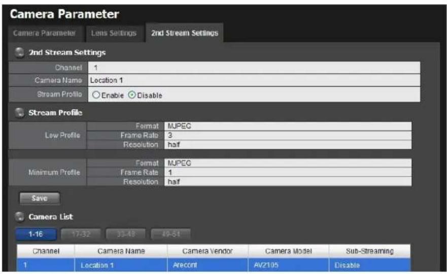
Stream profile is designed for mobile client and lower fps live stream display. Without stream profile integration, users cannot watch live video on mobile client nor select lower fps stream on liveview. Further, for performance consideration, we fix the resolution and framerate for each brand/series. Refer to camera support list.
-
Log in to the unit.
-
Click IP Camera / Camera Parameters.
- Click the 2nd Stream Settings tab.
text_image
Camera Parameter Camera Parameter Lens Settings 2nd Stream Settings 2nd Stream Settings Channel 1 Camera Name Location 1 Stream Profile Enable Disable Stream Profile Low Profile Format MJPEG Frame Rate 3 Resolution half Minimum Profile Format MJPEG Frame Rate 1 Resolution half Save Camera List 1-16 17-32 33-48 49-51 Channel Camera Name Camera Vendor Camera Model Sub-Streaming 1 Location 1 Arecont AV2105 Disable- Stream Profile: The default status is Disable. If you want mobile client user to access to this camera, you can select Enable, and click Save button in the middle of the page.
- Low Profile: The stream profile, under 300kbps, is designed for mobile client single-view.
- Minimum Profile: The stream profile, under 100 kbps, is designed for mobile client multi-view.
text_image
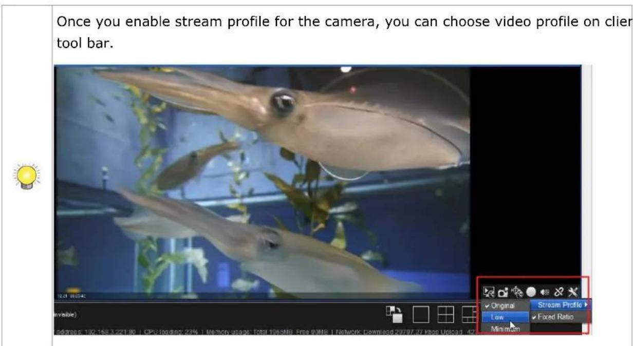
Once you enable stream profile for the camera, you can choose video profile on client tool bar. Invisible) Address: 182.168.3.221.80 | CPU loading: 23% | Memory usage: Total 1956MB Free 90MB | Network Download 23797.27 kbps Upload 42 Original Stream Profile Low Fixed Ratio Min mom2.1.7 View Camera Status
- Log in to the unit.
- Click IP Camera / Camera Status.
text_image
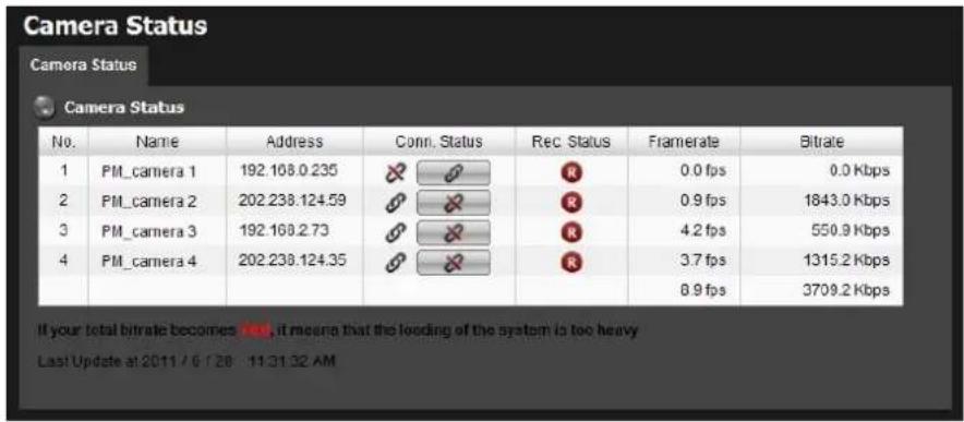
Camera Status Camera Status Camera Status No. Name Address Conn. Status Rec. Status Framerate Bitrate 1 PM_camera 1 192.168.0.235 R 0.0 fps 0.0 Kbps 2 PM_camera 2 202.238.124.59 R 0.9 fps 1843.0 Kbps 3 PM_camera 3 192.168.2.73 R 4.2 fps 550.9 Kbps 4 PM_camera 4 202.238.124.35 R 3.7 fps 1315.2 Kbps 8.9 fps 3709.2 Kbps If your total bitrate becomes red, it means that the loading of the system is too heavy Last Update at 2011/6/28 11:31:32 AM- Conn. Status: The status of the connection. Click the Connect or Disconnect button to change the connection status.
| Status | Icon | |
| Connection Status | Connected | |
| Connection Status | Disconnected | |
| Connection Status | Connecting | |
| Connection Button | Connected: Normal | |
| Connected: Over | ||
| Connection Button | Disconnected: Normal | |
| Disconnected: Over |
- Rec. Status: The set recording schedule of this camera in this time.
| Status | Icon | |
| Recording Status | No Recording | |
| Recording Status | Always Recording - Recording |  |
| Recording Status | Always Recording - Stopped |  |
| Recording Status | Schedule Recording - Recording |  |
| Recording Status | Schedule Recording - Stopped |  |
| Recording Status | Manual Recording - Recording |  |
| Recording Status | Manual Recording - Stopped |  |
- Framerate: The frame rate of this camera.
- Bitrate: The transmission bit rate of this camera.

If your total bitrate becomes red, it means that the loading of the system is too heavy.
2.2 Recording & Event Setup
2.2.1 Recording Mode Setup
- Log in to the unit.
- Click Recording & Event / Recording settings.
- Click the Recording Mode tab.
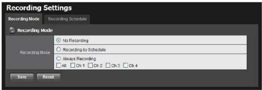
- If selecting Always Recording, the chosen cameras will begin to record immediately.
text_image
Recording Settings Recording Mode Recording Schedule Recording Mode Recording Mode ○ No Recording ○ Recording by Schedule ○ Always Recording □ All □ Ch 1 □ Ch 2 □ Ch 3 □ Ch 4 Save Reset- No Recording: Turn off the recording.
● Recording by Schedule: Recording by schedule.
● Always Recording: Permanently turn on the chosen cameras.
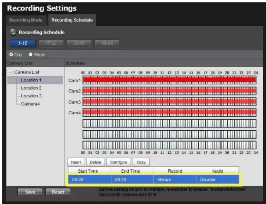
2.2.2 Recording Schedule / Event Setup
Instead of Always Recording, you can begin the recording by setting the Recording Schedule.
- Log in to the unit.
- Click Recording & Event / Recording Settings.
- Click the Recording Schedule tab.
-
Check the Day or Week mode.
-
Day: Schedule the recording to turn the recorder on and off at the same time every day according to your setting.
-
Week: Schedule the recording for each day of the week differently.
-
Click the schedule of the camera which needs to be modified.
- Click the column at the bottom of the page.
text_image
Recording Settings Recording Mode Recording Schedule Recording Schedule 1-16 17:32 33:48 49:54 Day Week Camera List Schedule Camera List Location 1 Location 2 Location 3 Camera4 Cam1 Cam2 Cam3 Cam4 00 01 02 03 04 05 06 07 08 09 10 11 12 13 14 15 16 17 18 19 20 21 22 23 24 Insert Delete Configure Copy Start Time End Time Record Audio 00:00 24:00 Always Disable Before setting record on motion, remember to enable "motion detection" function in camera web first. Save Reset- Insert: Insert new schedules.
- Delete: Delete the selected schedule.
- Configure: Modify the schedule and recording mode settings.
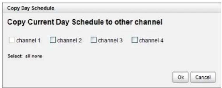
- Copy: Copy current Day Schedule to other channel(s); copy current
Week Schedule to other day(s) of a week or to other channel(s).
text_image
Copy Day Schedule Copy Current Day Schedule to other channel channel 1 channel 2 channel 3 channel 4 Select: all none Ok Cancel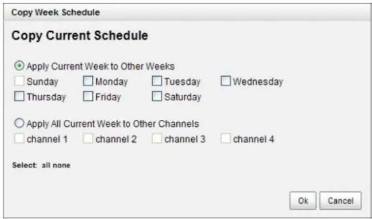
text_image
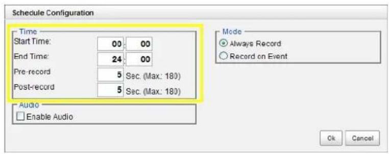
Copy Week Schedule Copy Current Schedule Apply Current Week to Other Weeks Sunday Monday Tuesday Wednesday Thursday Friday Saturday Apply All Current Week to Other Channels channel 1 channel 2 channel 3 channel 4 Select: all none Ok Cancel- The default setting of the camera's recording schedule is from 00:00 to 24:00. If you want to modify the time slot, click the Configure button to modify the default settings first.
text_image
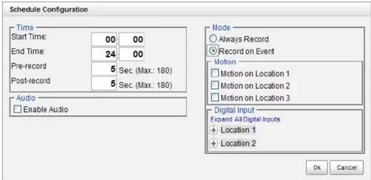
Schedule Configuration Time Start Time: 00 00 End Time: 24 00 Pre-record 5 Sec. (Max: 180) Post-record 5 Sec. (Max: 180) Audio Enable Audio Mode Always Record Record on Event Ok Cancel- Choose the recording mode.
text_image
Schedule Configuration Time Start Time: 00 00 End Time: 24 00 Pre-record 5 Sec. (Max.: 180) Post-record 5 Sec. (Max.: 180) Audio Enable Audio Mode Always Record Record on Event Motion Motion on Location 1 Motion on Location 2 Motion on Location 3 Digital Input Expand All Digital Inputs Location 1 Location 2 Ok Cancer● Always Record: Always record.
- Record on Event: Record when events triggered. The event can be triggered by Motion or Digital input.

When setting the event Motion, please first ensure that the motion detection function of the camera has been enabled.
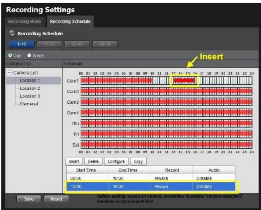
- If you want to add another new schedule, click the Insert button to add a new one.
text_image
Recording Settings Recording Mode Recording Schedule Recording Schedule 1-16 17-32 33-49 43-54 Day Week Camera List Schedule Cam1 Cam2 Cam3 Cam4 Thu Fri Sat 00 01 02 03 04 05 06 07 08 09 10 11 12 13 14 15 16 17 18 19 20 21 22 23 24 Cam1 Cam2 Cam3 Cam4 Thu Fri Sat Insert Delete Configure Copy Start Time End Time Record Audio 00:00 10:00 Always Disable 13:00 16:00 Always Disable Before setting record on motion, remember to enable "motion detection" function in camera web first. Save Reset- Click the Save button.

When changing the motion detection settings of a camera, make sure to disconnect your unit and that camera first. Once you have finished, re-connecting them will
update the settings in your unit.

When setting an event, Motion or Digital input can be triggered from other cameras. This means that if the system detects motion or digital input from other cameras or I/O Box, the camera will begin recording.

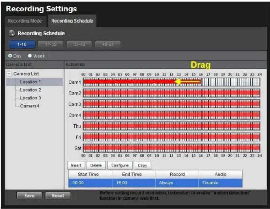
There is another way to set the schedule. If you want to change the recording time length, drag the end of the time bar from 24:00 back to the length you wish, and drag the beginning of the time bar to the point at which you would like it to comment recording. (You may also click the Insert button to add new schedules.)
text_image
Recording Settings Recording Mode Recording Schedule Recording Schedule 1-16 17-32 33-40 49-54 Day Week Camera List Schedule Drag Camera List Location 1 Location 2 Location 3 Camera4 Cam1 Cam2 Cam3 Cam4 Thu Fri Sat 00 01 02 03 04 05 06 07 08 09 10 11 12 13 14 15 16 17 18 19 20 21 22 23 24 Insert Delete Configure Copy Start Time End Time Record Audio 00:00 16:00 Always Disable Before sending record on motion, remember to enable "motion detection" function in camera web first. Save Reset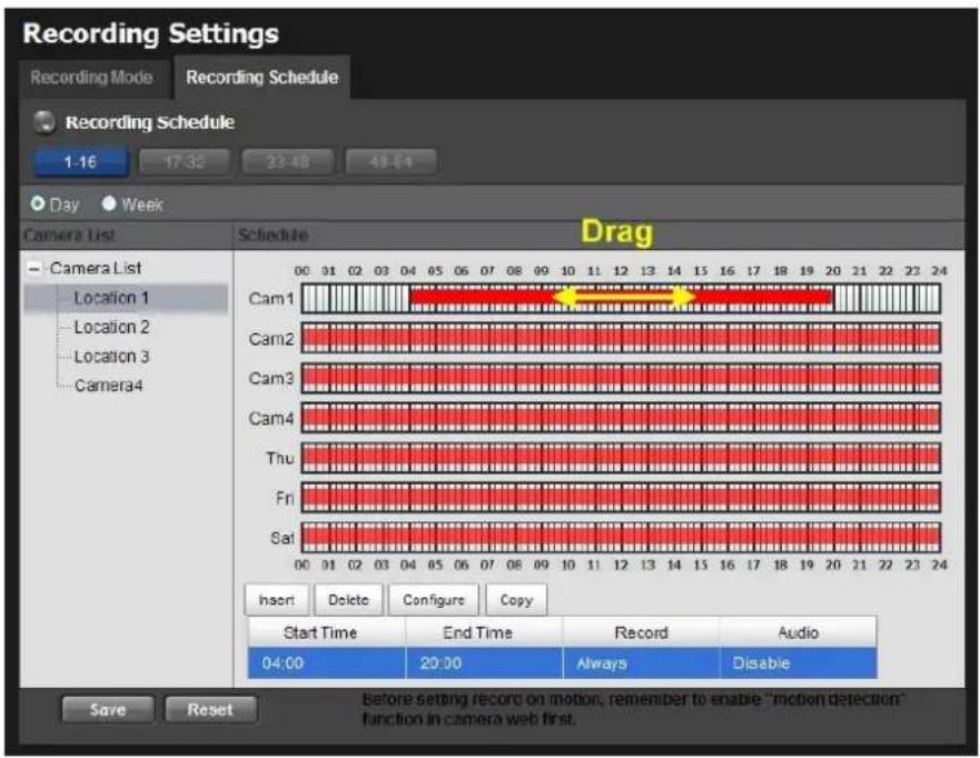
text_image
Recording Settings Recording Mode Recording Schedule Recording Schedule 1-16 17:32 33:48 49:54 Day Week Camera List Schedule Drag Camera List Location 1 Location 2 Location 3 Camera4 Cam1 Cam2 Cam3 Cam4 Thu Fri Sat Insert Delete Configure Copy Start Time End Time Record Audio 04:00 20:00 Always Disable Before setting record on motion, remember to enable "motion detection" function in camera web first.2.2.3 Camera Events and Responding Actions Setup
- Log in to the unit.
- Click Recording & Event / Event & Action Management.
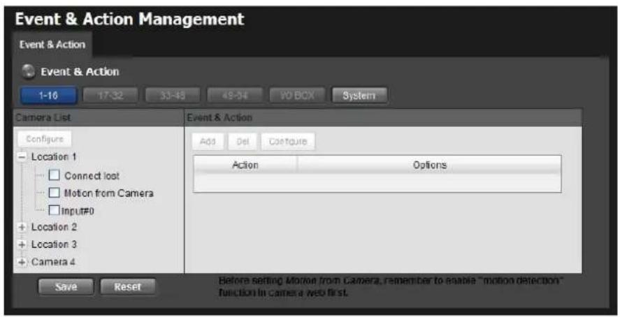
- Choose the camera, and then select one of the events. The event list depends on camera its own ability.
text_image
Event & Action Management Event & Action Event & Action 1-16 17:32 33:43 49:54 VO BOX System Camera List Configure Location 1 Connect lost Motion from Camera Input#0 Location 2 Location 3 Camera 4 Event & Action Add Del Configure Action Options Before setting Motion from Camera, remember to enable "motion detection" function in comes a web first. Save Reset- Connect lost: When a connection between the camera and this unit is lost, the system will trigger an action.
- Motion from Camera: When video motion is detected, the camera triggers an action.
- Input: Any external input can trigger an action.

When setting the event Motion from Camera, make sure to set up the camera's motion detection function first. Besides, event log will be recorded only if event is selected on this page.
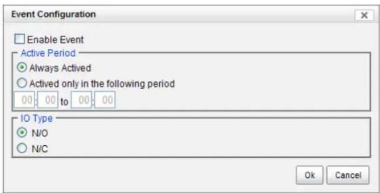
- Click the Configure button to enable the event and select the active period.
text_image
Event Configuration Enable Event Active Period Always Activived Activated only in the following period 00 00 to 00 00 IO Type N/O N/C Ok Cancel● Always Active: The selected event is always active.
● Active only in the following period: The selected event is only active in the designated time, which able to cover two days e.g. from 18:00 to 09:00.
- I/O Type: Check one of the options of I/O type. N/O means normal open, while N/C means normal close.
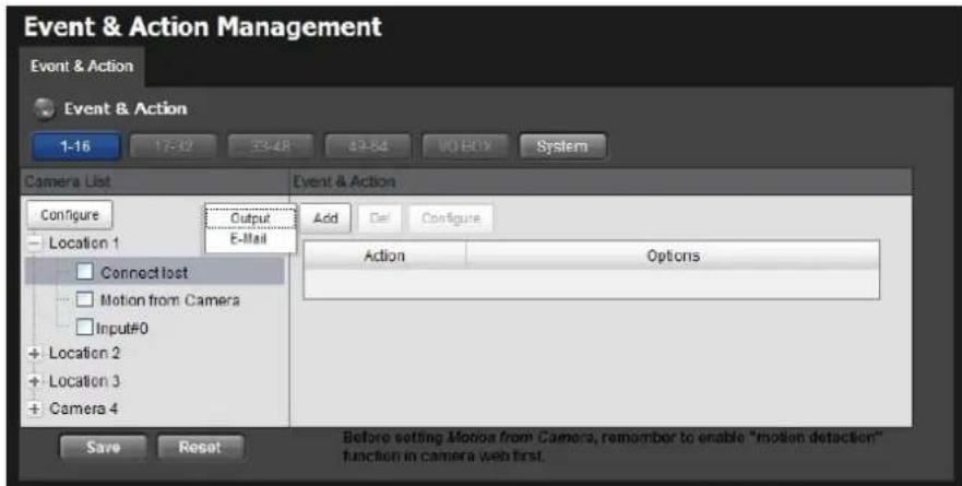
- Click the Add button to set up the responding actions of this event.
text_image
Event & Action Management Event & Action Event & Action 1-16 17-32 33-48 49-64 VIO BOX System Camera List Configure Output Add Del Configure Location 1 E-Mail Connect lost Motion from Camera Input#0 + Location 2 + Location 3 + Camera 4 Action Options Save Reset Before setting Motion from Camera, remember to enable "motion detection" function in camera web first.- Output: When an event occurs, the system will send an output signal to other connected devices.
-
E-Mail: When an event occurs, the system will send e-mail notifications. Make sure to add an e-mail address first.
-
Click the action, and then click the Configure button to modify the details of that action if necessary.
-
Click the Save button.

After selecting camera events, the event information will display on the screen when it's triggered.
2.2.4 I/O Box Input and Responding Action Setup
-
Log in to the unit.
-
Click Recording & Event / Event & Action Management.
-
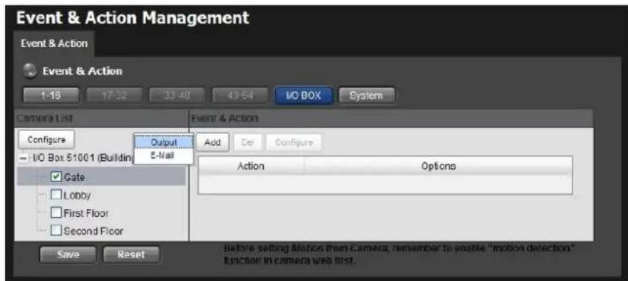
Select an input of I/O Box from list.
-
Click the Add button to set up the responding actions of this event.
-
Click the action, and then click the Configure button to modify the details of that action if necessary.
text_image
Event & Action Management Event & Action Event & Action 1-15 17:32 33:48 49:64 I/O BOX System Camera List Configure Output E-Mail I/O Box 51001 (Building) Gate Lobby First Floor Second Floor Event & Action Add Ce Configure Action Options Save Reset Before setting Motion from Camera, remember to enable "motion detection" function in camera web list.- Output: When an input is triggered, the system will send an output signal to other connected devices.
- E-Mail: When an input is triggered, the system will send e-mail notifications. Make sure to add an e-mail address first.
- Click the Save button.
2.2.5 System Events and Responding Actions Setup
-
Log in to the unit.
-
Click Recording & Event / Event & Action Management.
-
Click the Event & Action tab.
-
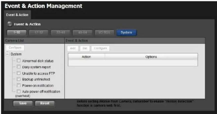
Click System to unfold the list of system events, and then select one of the
five events.
text_image
Event & Action Management Event & Action Event & Action 1-10 17:32 33:43 49:64 US BOX System Camera List Configure System Abnormal disk status Daily system report Unable to access FTP Backup unfinished Power-on notification Auto power-off notification (overheat) Event & Action Add Del Configure Action Options Save Reset Before setting Motion from Camera, remember to enable "motion detection" function in camera web first.- Abnormal disk status: When there is no enough disk space for recording or when disk is abnormal for accessing, the system will trigger an action.
● Daily system report: Enable users to know the system information, HDD usage, and Disk status everyday through E-mail without accessing to the unit to check. - Unable to access FTP: The action will be triggered when the connection between the unit and FTP server is lost.
- Backup unfinished: If there is any file which the system didn't complete the backup process, the file(s) name will be listed and send out through E-mail after finishing the last file of this backup schedule.
● Power-on notification: Record the time as power was turning on. -
Auto power-off notification (overheat): Turn off the system power automatically to protect the unit from damage when it's overheated.
-
Click the Add button to set up the responding actions of this event. Follow the steps in the previous section.
-
Click the Save button.
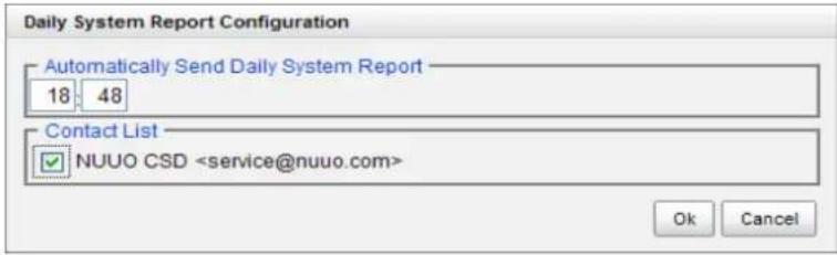
| E-Mail is the only one action to the eventDaily system report, Unable to access FTP, Backup unfinished, Power-on notification and Auto power-off notification (overheat). In addition to select a contact, remember to insert the tir of sending daily system report. |
text_image
Daily System Report Configuration Automatically Send Daily System Report 18 48 Contact List NUUO CSD2.2.6 SMTP Server Setup
- Log in to the unit.
- Click Recording & Event / E-Mail.
- Click the SMTP Server tab.
text_image
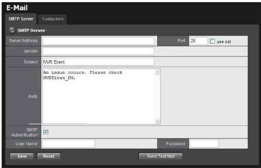
E-Mail SMTP Server Contactors SMTP Server Server Address Port 25(use ssl) Sender Subject NVR Event An issue occurs. Please check NVRTitan_PM. Body SMTP Authentication User Name Password Save Roset Send Test Mail- Server Address: SMTP (Simple Mail Transport Protocol) server IP address.
- Port: SMTP port.
- Sender: Sender information.
- Subject: The subject of the mail.
● Body: E-Mail content. - SMTP Authentication: Before sending out an E-Mail, enter the user name and password for SMTP authentication.
- Username
-
Password
-
Click the Send Test Mail button and the system will send a test mail to the sender. Check it after testing.
-
Click the Save button.
2.2.7 Add Event Contacts
- Log in to the unit.
- Click Recording & Event / E-Mail.
- Click the Contactors tab.
text_image
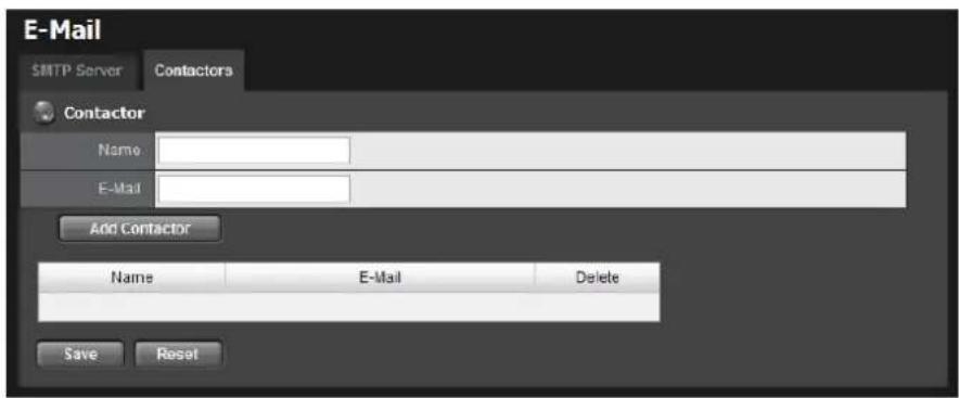
E-Mail SMTP Server Contactors Contactor Name: E-Mail Add Contactor Name E-Mail Delete Save Reset- Add Contactor: Add this new contact into the contact list.
- Reset: Return to the latest saved settings of the contact list.
-
Save: Save this time modification of the contact list.
-
Insert the name of a new contact.
- Insert the e-mail address of this new contact.
- Click the Add Contactor button.
- Click the Save button to save this modification of the contact list.
2.3 RAID & File Settings
2.3.1 Create a RAID Volume
In this system, the term RAID volume refers to one or more disk drives working together as a RAID logical drive. You must create a RAID volume before starting to record.

The maximum volume size to create RAID on Titan NVR is 16TB. Please make sure every volume you are going to add as a external storage is under 16TB.

NT-8040R and NT-8040RP are 8 bay models. If your internal storage is over 16TB (f example, you use 3TB hard disk for all 8 bays, it will be 24 TB for internal storage), please create 2 volume for internal storage.
- Log in to the unit.
- Click RAID & File System / RAID Management.
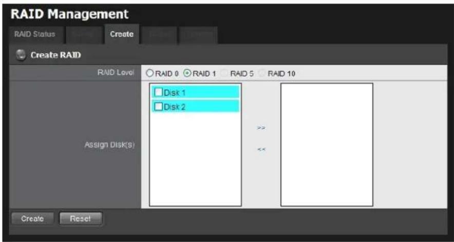
- Click the Create tab.
text_image
RAID Management RAID Status Create Create RAID RAID Level RAID 0 RAID 1 RAID 5 RAID 10 Assign Disk(s) Disk 1 Disk 2 >> <><- Choose the RAID level you prefer for your disk array.
- Check boxes of disks and click the >> button to assign disk drives for this volume.
- Click the Create button.
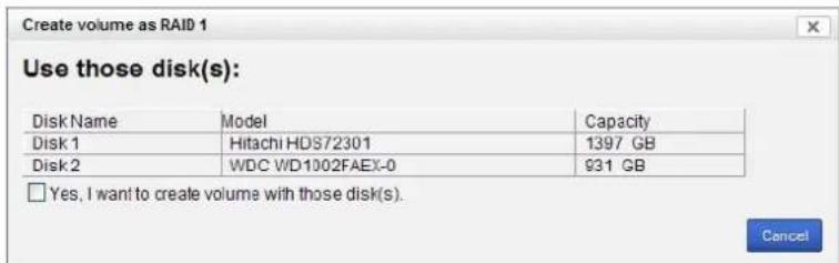
- A confirmation dialog pops up. Check the Yes, I want to create volume with those disk(s) box, and click the Yes, create it button.
text_image
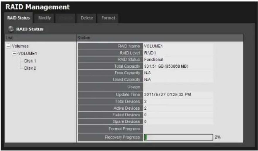
Create volume as RAID 1 Use those disk(s): Disk Name Model Capacity Disk 1 Hitachi HDS72301 1397 GB Disk 2 WDC WD1002FAEX-0 931 GB □ Yes, I want to create volume with those disk(s). Cancel- Creating RAID volume takes a while, depending on the size of disks and the RAID level you choose. You can start recording during RAID creation.
text_image
RAID Management RAID Status Modify Cancel Delete Format RAID Status List Status Volumes VOLUME1 Disk 1 Disk 2 RAID Name VOLUME1 RAID Level RAID1 RAID Status Functional Total Capacity 931.51 GB (953868 MB) Free Capacity N/A Used Capacity N/A Usage Update Time 2011/5/27 01:25:33 PM Total Devices 2 Active Devices 2 Failed Devices 0 Spare Devices 0 Format Progress Recovery Progress 2%
The RAID Volume will be functional on another unit if all disks of this volume are moved to the unit.

After setting RAID level, you are not allowed to change neither the RAID level nor the number of disks containing in this volume.

If you choose Express Mode when using the Installation Wizard, the disk(s) will be set to RAID 1 (2 bay) or RAID 5 (4 bay) automatically unless the number of disks is enough for this RAID level.
2.3.2 View RAID Volume Status
RAID status refers to the disk drives on your unit and how they are arranged into a RAID volume.
- Log in to the unit.
- Click RAID & File System / RAID Management.
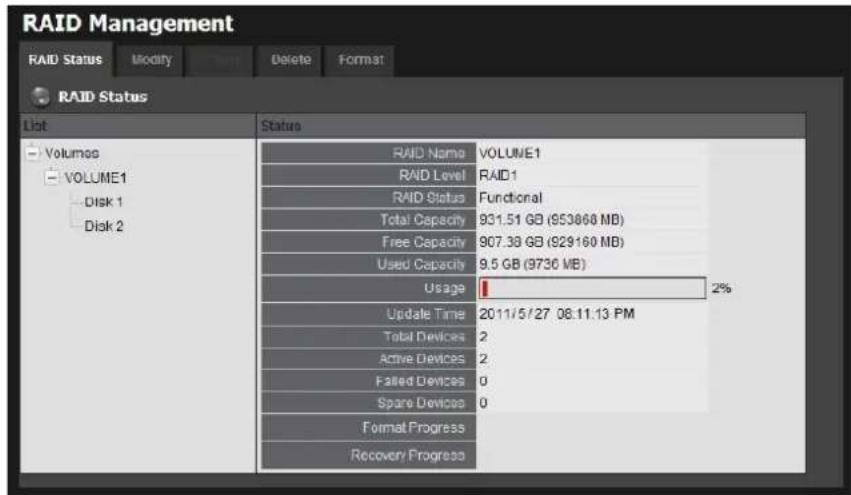
- Click the RAID Status tab to view the status of your RAID Volume.
text_image
RAID Management RAID Status Modify Delete Format RAID Status List Volumes VOLUME1 Disk 1 Disk 2 Status RAID Name VOLUME1 RAID Level RAID1 RAID Status Functional Total Capacity 931.51 GB (953068 MB) Free Capacity 907.38 GB (929160 MB) Used Capacity 9.5 GB (9730 MB) Usage 2% Update Time 2011/5/27 08:11:13 PM Total Devices 2 Active Devices 2 Failed Devices 0 Sparse Devices 0 Format Progress Recovery Progress● RAID Name: Name of your RAID, automatically assigned when it was created.
● RAID Level: RAID 0, 1, 5, or 10, specified when it was created.
- RAID Status: Functional is normal. Critical means there are some problems on RAID volume, but the recording status is normal. Offline means that no volume is found, so recording is stopped and you cannot access your data either. File system error means that RAID volume is existed but not mounted, so recording is stopped and you cannot access your data either.
● Capacity: Total, free, used data capacity of the RAID volume.
- Update Time: The time of volume created/updated.
● Devices: Total number of disks and the number of active, failed, spare disks.
- Format Progress: The status of RAID format
● Recovery Progress: The status of RAID recovery
2.3.3 View Disk Drive Information
- Log in to the unit.
- Click RAID & File System / RAID Management.
- Click the RAID Status tab.
- Click on a disk directly to view the information.
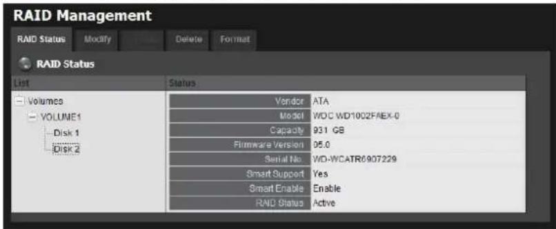
text_image
RAID Management RAID Status Modify Delete Format RAID Status List Status Volumes VOLUME1 Vendor ATA Model WDC WD1002FAEX-0 Capacity 931 GB Firmware Version 05.0 Serial No.WD-WCATR6907229 Smart Support Yes Smart Enable Enable RAND Status Active2.3.4 Modify RAID Volume
This function is designed for replacing a broken hard drive with a new one, instead of modifying RAID level.
In the condition of critical RAID status, it's a warning to show that one of disks of this RAID volume may be damaged. Even though it's no impact on the recording function, you'd better to replace a new disk to make sure the volume with data protection mechanism.
| This function is not applied to RAID 0, since there is no data protection mechanism t its nature. | |
| In case of any unexpected damage, we recommend users to unplug running HDD by this method, which can be viewed as security hard drive remove. |
- Log in to the unit.
- Click RAID & File System / RAID Management.
- Click the Modify tab.
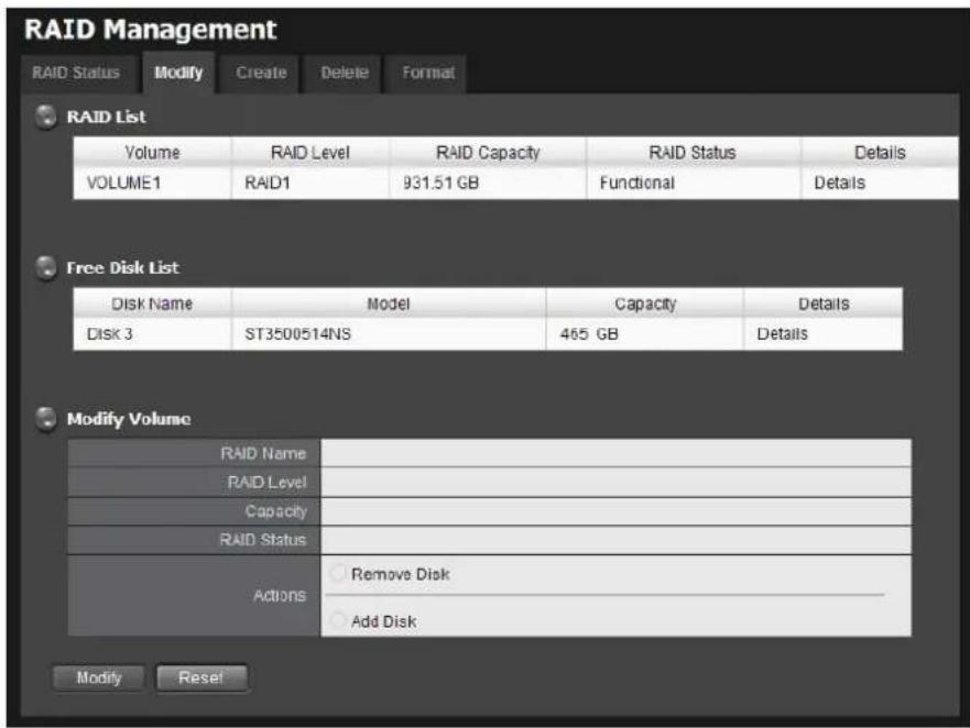
text_image
RAID Management RAID Status Modify Create Delete Format RAID List Volume RAID Level RAID Capacity RAID Status Details VOLUME1 RAID1 931.51 GB Functional Details Free Disk List Disk Name Model Capacity Details Disk 3 ST3500514NS 465 GB Details Modify Volume RAID Name RAID Level Capacity RAID Status Actions Remove Disk Add Disk Modify Reset- Click on the volume you want to modify. The information of this volume will be displayed under the Modify Volume section.
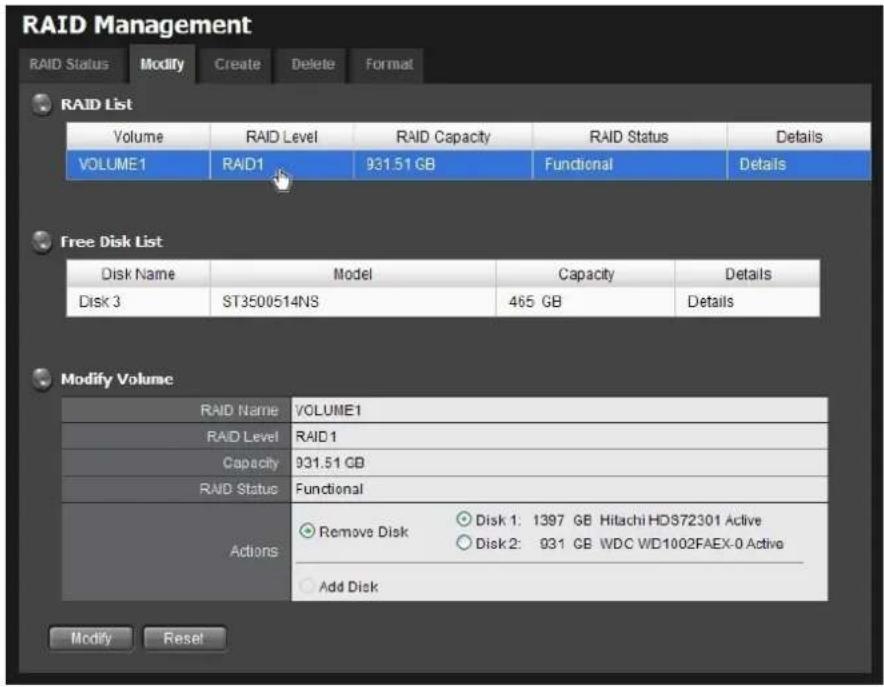
text_image
RAID Management RAID Status Modify Create Delete Format RAID List Volume RAID Level RAID Capacity RAID Status Details VOLUME1 RAID 931.51 GB Functional Details Free Disk List Disk Name Model Capacity Details Disk 3 ST3500514NS 465 GB Details Modify Volume RAID Name VOLUME1 RAID Level RAID 1 Capacity 931.51 GB RAID Status Functional Actions Remove Disk Disk 1: 1397 GB Hitachi HD372301 Active Disk 2: 931 GB WDC WD1002FAEX-0 Active Add Disk Modify Reset- After removing the damaged disk. Add a free disk to replace the damaged, and click the Modify button.
- A confirmation dialog pops up. Check the Yes, I want to modify this volume box, and click the Yes, modify it button.
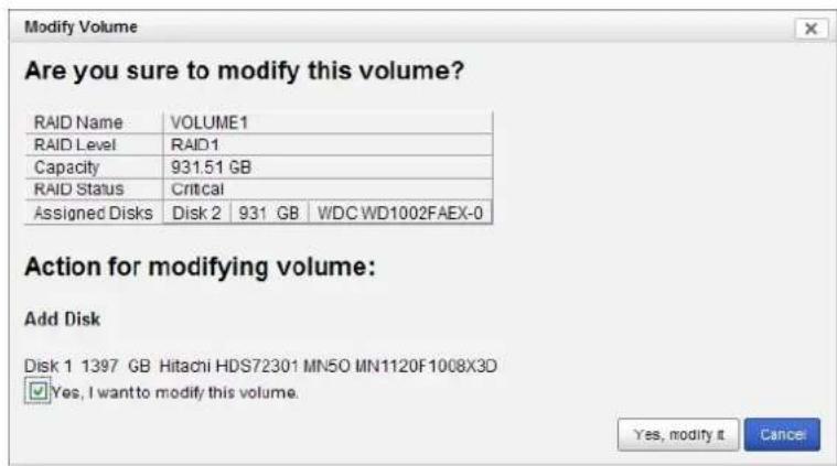
text_image
Modify Volume Are you sure to modify this volume? RAID Name VOLUME1 RAID Level RAID1 Capacity 931.51 GB RAID Status Critical Assigned Disks Disk 2 931 GB WDC WD1002FAEX-0 Action for modifying volume: Add Disk Disk 1 1397 GB Hitachi HDS72301 MN5O MN1120F1008X3D ✓ Yes, I want to modify this volume. Yes, modify it Cancel- Modifying RAID volume takes a while, depending on the size of disks you choose. Recording won't be stopped during the modification, and the data of this RAID volume is fully accessible.
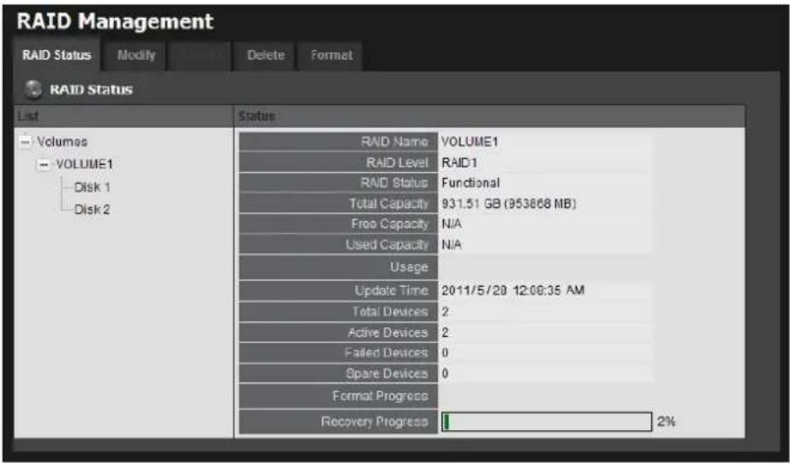
text_image
RAID Management RAID Status Modify Delete Format RAID Status List Status Volumes VOLUME1 Disk 1 Disk 2 RAID Name VOLUME1 RAID Level RAID1 RAID Status Functional Total Capacity 931.51 GB (953868 MB) Free Capacity N/A Used Capacity N/A Usage Update Time 2011/5/28 12:08:35 AM Total Devices 2 Active Devices 2 Failed Devices 0 Spare Devices 0 Format Progress Recovery Progress 2%2.3.5 Delete a RAID Volume
- Log in to the unit.
- Click RAID & File System / RAID Management.
- Click the Delete tab.
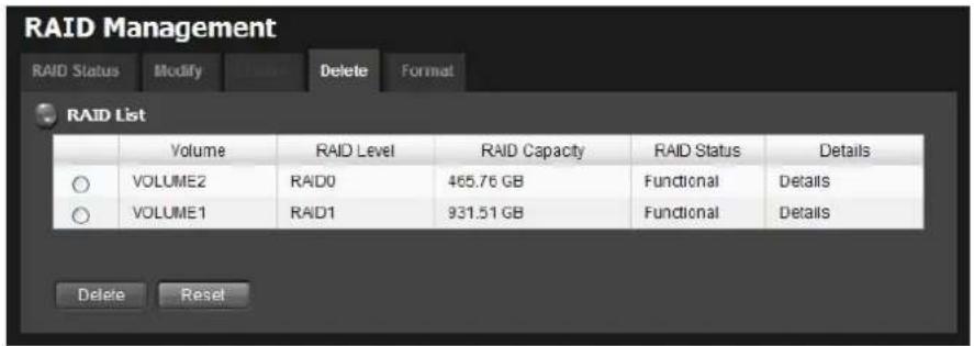
text_image
RAID Management RAID Status Modify Delete Format RAID List Volume RAID Level RAID Capacity RAID Status Details VOLUME2 RAID0 465.76 GB Functional Details VOLUME1 RAID1 931.51 GB Functional Details Delete Reset- Click the option button beside the RAID Volume you want to delete.
- Click the Delete button.
- A confirmation dialog pops up. Check the Yes, I want to delete this volume box, and click the Yes, delete it button.
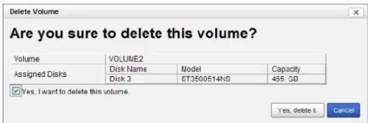
text_image
Delete Volume Are you sure to delete this volume? Volume VOLUME2 Assigned Disks Disk Name Model Capacity Disk 3 ST3500514NS 455 GB Yes, I want to delete this volume. Yes, delete it Cancel- System will restart automatically after RAID volume is deleted

When you delete a RAID Volume, all the folders in the RAID volume and all the data saved in the folders will be deleted. Backup any important data before deleting a RAID Volume.
2.3.6 Format
Neither pressing reset button nor loading default setting, the data of RAID volume won't be deleted, which implies that format is the only way to clean the RAID information from disks.
- Log in to the unit.
- Click RAID & File System / RAID Management.
- Click the Format tab.
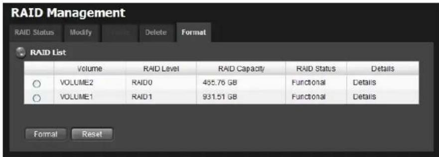
text_image
RAID Management RAID Status Modify Delete Format RAID List Volume RAID Level RAID Capacity RAID Status Details VOLUME2 RAID0 465.76 GB Functional Details VOLUME1 RAID1 931.51 GB Functional Details Format Reset- Click the option button beside the RAID Volume you want to format.
- Click the Format button.
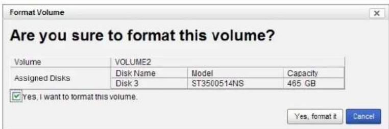
- A confirmation dialog pops up. Check the Yes, I want to format this volume box, and click the Yes, format it button.
text_image
Format Volume Are you sure to format this volume? Volume VOLUME2 Assigned Disks Disk Name Model Capacity Disk 3 ST3500514NS 465 GB ✓ Yes, I want to format this volume. Yes, format it Cancel- System will restart automatically after volume format is complete.
2.4 Auto Backup
This feature enables you to automatically backup the recorded video of the previous date to FTP site. There are two steps to enable the function, one is
Set up Backup Schedule, another is Set up Backup Server.
2.4.1 Set up Backup Schedule
- Log in to the unit.
- Click RAID & File System / Auto Backup Management.
- Click the Backup Schedule tab.
- Set up backup schedule, select the backup channels, and check the Enable option to enable Auto Backup.

text_image
Auto Backup Management Backup Schedule Backup Server Backup Schedule Auto Backup Enable Daily Backup Time 23:59 Start Time 09:00 End Time 18:00 Camera select: all/none ✓ Ch 1 ✓ Ch 2 ✓ Ch 3 ✓ Ch 4 Current Event Settings Unable to access FTP disability Backup unfinished disability Save Reset● Auto Backup: Check the Enable option to enable this function.
● Daily Backup Time: The daily scheduled time to start backup process.
- Start Time: The start time of recorded video of the previous date.
● End Time: The end time of recorded video of the previous date.
- Camera: Select the channel(s) to backup.
- Current Event Settings shows the condition of the events of auto backup – enable or disable. Follow the steps of System Events and Responding Actions Setup to configure the event & action.

The system backups recorded video files one by one. If the connection between the unit and FTP server is normal, but some problems of FTP causes the system unable to write files on FTP, the system would try each file three times before starting to back the next file. If the connection is lost, the system would wait for the connection, so if file would be skipped.
2.4.2 Set up Backup Server
-
Log in to the unit.
-
Click RAID & File System / Auto Backup Management.
-
Click the Backup Server tab.
-
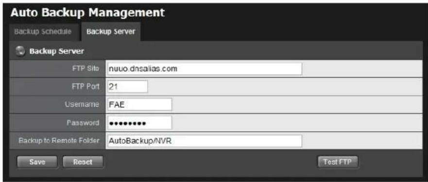
Set up the FTP server and create a folder for backup files. The folder format is "FolderName", "FolderName/SubFolderName", and so on.
For example: AutoBackup/NVR
text_image
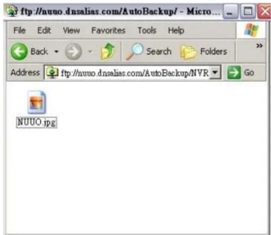
Auto Backup Management Backup Schedule Backup Server Backup Server FTP Site:nuuo.dnsalias.com FTP Port 21 Username FAE Password **** Backup to Remote Folder AutoBackup/NVR Save Reset Test FTP- After setting up all the information, click the Test FTP button and the system will create a folder to FTP. Check it after testing. In this case, the route of the tested file will be:
ftp://nuuo.dnsalias.com/AutoBackup/NVR/TitanNVR_ComputerName
text_image
ftp://nuuo.dnsalias.com/AutoBackup/ - Micro... File Edit View Favorites Tools Help Back Search Folders Address ftp://nuuo.dnsalias.com/AutoBackup/NVR Go NUUO.jpg- Click the Save button.
 | Make sure the FTP account with privileges of administrator who is able to upload, rewrite, delete files, and create new folder. Besides, make sure the FTP server has enough space for auto backup. |
 | To avoid the failure of auto backup, please check the normality of FTP server regular |
(e.g., enough space for video, system conditions.)
2.5 Network Setup
2.5.1 View Network Status
- Log in to the unit.
- Click Network Setup / Network Setup.
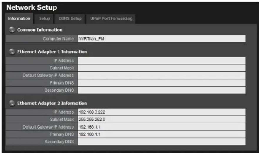
- Click the Information tab to view the unit's network information.
text_image
Network Setup Information Setup DDNS Setup UPnP Port Forwarding Common Information Computer Name NVRTitan_PM Ethernet Adapter 1 Information IP Address Subnet Mask Default Gateway IP Address Primary DNS Secondary DNS Ethernet Adapter 2 Information IP Address 192.168.3.222 Subnet Mask 255.255.252.0 Default Gateway IP Address 192.168.1.1 Primary DNS 192.168.1.1 Secondary DNS2.5.2 Network Settings
- Log in to the unit.
- Click Network Setup / Network Setup.
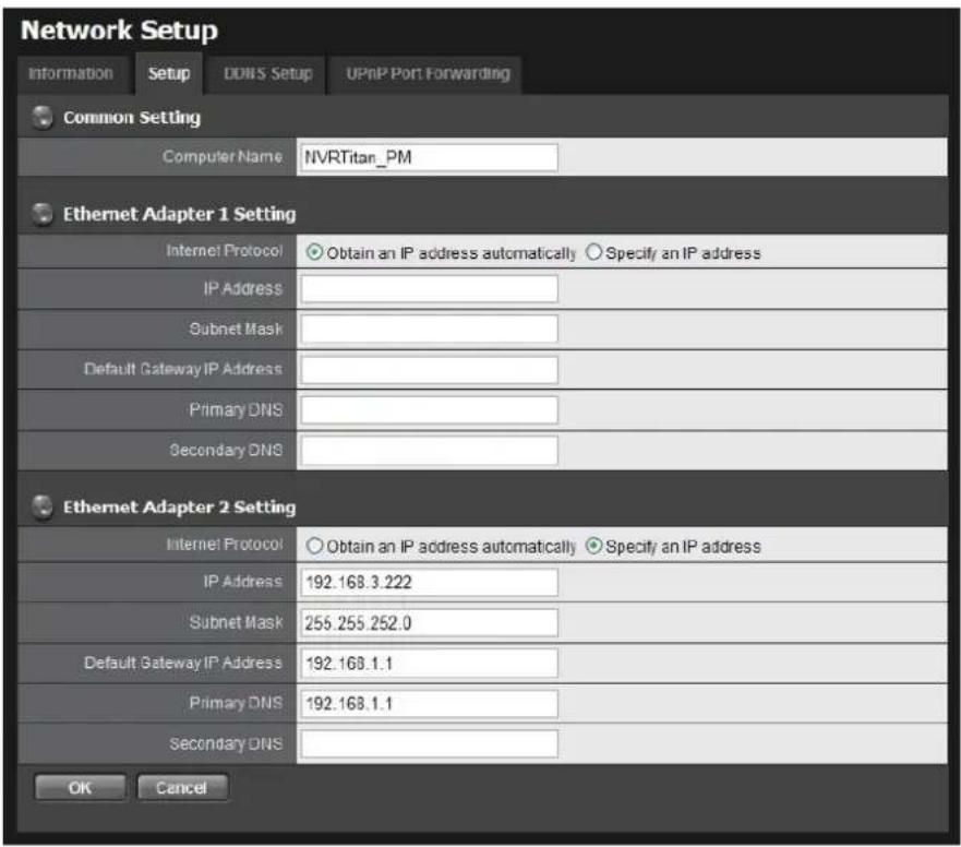
- Click the Setup tab to set up the network settings of your unit.
text_image
Network Setup Information Setup DDNS Setup UPnP Port Forwarding Common Setting Computer Name NVRTitan_PM Ethernet Adapter 1 Setting Internet Protocol Obtain an IP address automatically Specify an IP address IP Address Subnet Mask Default Gateway IP Address Primary DNS Secondary DNS Ethernet Adapter 2 Setting Internet Protocol Obtain an IP address automatically Specify an IP address IP Address 192.168.3.222 Subnet Mask 255.255.252.0 Default Gateway IP Address 192.168.1.1 Primary DNS 192.168.1.1 Secondary DNS OK Cancel- Server Name: Name your unit.

Because of the internal data modifications required, it takes a few seconds to change the name of your unit. Log in again after configuration activated.
●
- Internet Protocol: Choose to obtain an IP address from external DHCP server automatically, or configure the IP address manually.
- IP Address: IP address of this unit.
- Subnet Mask: Subnet mask address.
- Default Gateway IP Address: Gateway IP address.
● Primary DNS: Primary DNS (Domain Name System) address.
• Secondary DNS: Secondary DNS address.
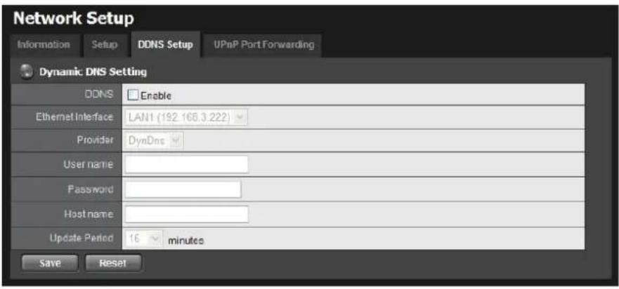
- Click the DDNS Setup tab to enable Dynamic Domain Name Server function, allowing you to connect unit with dynamic IP address.
text_image
Network Setup Information Setup DONS Setup UPnP Port Forwarding Dynamic DNS Setting DDNS Enable Ethernet Interface LAN1 (192 168 3 222) Provider DynDns User name Password Host name Update Period 16 minutes Save Reset2.5.3 Auto Port-Forwarding
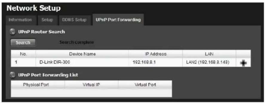
This function is designed for saving time in port configuration on router if users want to access the unit (in LAN) from WAN. Once enabling UPnP Service on router, users can do port-forwarding for web server (default: 80) and streaming server (default: 5250) automatically.
- Log in to the unit.
- Click Network Setup / Network Setup.
- Click the UPnP Port-Forwarding tab.
- Click the Search button, and the searched routers will be listed. Also, the list may indicate which LAN of the unit searches this router.
text_image
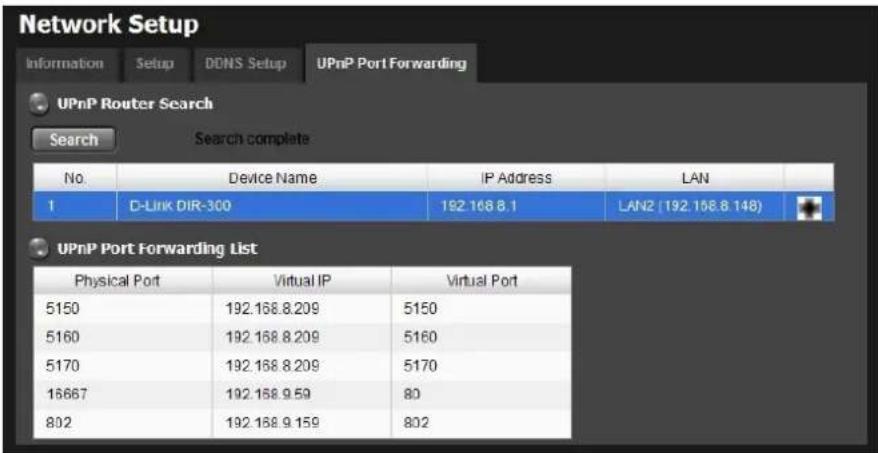
Network Setup Information Setup DDNS Setup UPnP Port Forwarding UPnP Router Search Search Search complete No. Device Name IP Address LAN 1 D-Link DIR-300 192.168.8.1 LAN2 (192.168.8.143) UPnP Port Forwarding List Physical Port Virtual IP Virtual Port- Select the searched router, and all UPnP ports configured on this router will show under the UPnP Port Forwarding List.
text_image
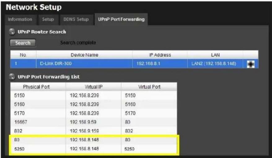
Network Setup Information Setup DONS Setup UPnP Port Forwarding UPnP Router Search Search Search complete No. Device Name IP Address LAN 1 D-Link DIR-300 192.168.8.1 LAN2 (192.168.8.148) UPnP Port Forwarding List Physical Port Virtual IP Virtual Port 5150 192.168.8.209 5150 5160 192.168.8.209 5160 5170 192.168.8.209 5170 16667 192.168.9.59 80 802 192.168.9.159 802- After selecting one of searched routers, click the ✦ icon to set up port-forwarding to this router automatically. You will find ports of web server and streaming server are listed.
text_image
Network Setup Information Setup DONS Setup UPnP Port Forwarding UPnP Router Search Search Search complete No Device Name IP Address LAN 1 D-Link DIR-300 192.168.8.1 LANZ (192.168.8.148) UPnP Port Forwarding List Physical Port Virtual IP Virtual Port 5150 192.168.8.209 5150 5160 192.168.8.209 5160 5170 192.168.8.209 5170 16667 192.168.9.59 80 802 192.168.9.159 802 80 192.168.8.148 80 5250 192.168.8.148 5250
For security reason, the privilege of UPnP port-forwarding is LOWER than port-forwarding configured on router. Therefore, if the ports have been used on router, we are unable to know before finding out access failure.

UPnP port-forwarding is for temporarily use only. Most of UPnP router will clean up a UPnP ports after router reboots. Furthermore, for some routers, if the port you want to add has already been used for other devices in the same way (UPnP port forwarding), this “enable” action will cover over the settings.
2.5.4 Network Service Setup
- Log in to the unit.
-
Click Network Setup / Network Service.
-
Click the Network Service tab.
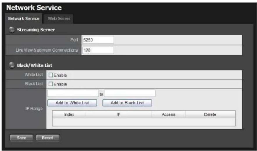
- Set up port and maximum connections of client and click the Save button.
text_image
Network Service Network Service Web Server Streaming Server Port 5250 Live View Maximum Connections 128 Black/White List White List Enable Black List Enable IP Range to Add to White List Add to Black List Index IP Access Delete Save Reset- Streaming Server
Port: Live/playback streaming transmission port. (default: 5250)
Live View Maximum Connections: Maximum connections from remote access. (max: 256 connections; default: 64)
- Black/White List
White List: Only IP addresses from the allowed list are allowed to log in.
Black List: IP addresses from the blocked list will be unable to log in.

One connection means that one user connects to one camera. 4 users connect to a server with "16" Live View Maximum Connections, and the average connection for each user is 4, rather than 16.
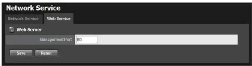
5. Click the Web Server tab.
text_image
Network Service Network Service Web Service Web Server ManagementPort 80 Save Reset6. Set up a port for this unit and click the Save button
2.5.5 Main server/Sub server Configuration
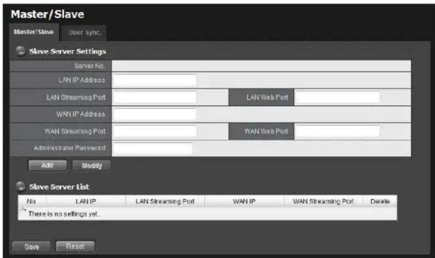
This is a basic structure of management server and client. By adding Sub servers in one main server, and configure same user account to main server/sub server, user can get the camera list of sub servers when accessing main server with NuClient. Follow the steps to build up the connection between main server and sub servers.
- Log in to the unit.
- Click Network Setup / Main server / Sub server.
- Click the Main server/Sub server tab.
text_image
Master/Slave Master/Slave User Sync. Slave Server Settings Server No. LAN IP Address LAN Streaming Port LAN Web Port WAN IP Address WAN Streaming Port WAN Web Port Administrator Password Add Modify Slave Server List No LAN IP LAN Streaming Port WAN IP WAN Streaming Port Delete There is no settings yet... Save Reset- Type the LAN/WAN IP and port, administrator password and click the Add button.
- Repeat the previous step to add more sub servers.
- Click the Save button to apply the settings.
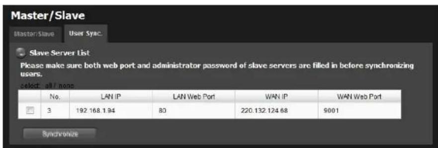
- Click the User Sync. tab.
text_image
Master/Slave Master/Slave User Sync. Slave Server List Please make sure both web port and administrator password of slave servers are filled in before synchronizing users. select: all / none No. LAN IP LAN Web Port WAN IP WAN Web Port 3 192 168 1.94 80 220.132.124 68 9001 Synchronize- Select the sub servers with their web port and administrator password being filled in correctly on the page of main server/sub servers, and click the Synchronize button to sync the user accounts of main server to sub servers.

The action is synchronizing user "accounts". If the user accounts are existed on sub servers, which privilege settings will be kept; if the user accounts are new to sub servers, which privileges are as default.

There is another way to create same user account on multiple servers, please check section Import/Export User Account for details.
2.6 Management
2.6.1 View the List of Users
- Open Internet Explorer and login the unit.
- Click Management/ User Management.
- Click the Create New Users tab.
- The list will be displayed on the bottom of the page.
| User List | |||||||
| No. | Name | Group | Channel Access | PTZ | IO | E-Map | Backup Data |
| 1 | building_1 | power user | 1,2,3,4 | O | O | O | O |
| 2 | building_2 | user | 1,2 | O | O | O | O |
| 3 | building_3 | guestuser | 1,2,3,4 | X | X | X | X |
2.6.2 Create New Users
- Open Internet Explorer and login the unit.
- Click Management/ User Management.
- Click the Create New Users tab.
text_image
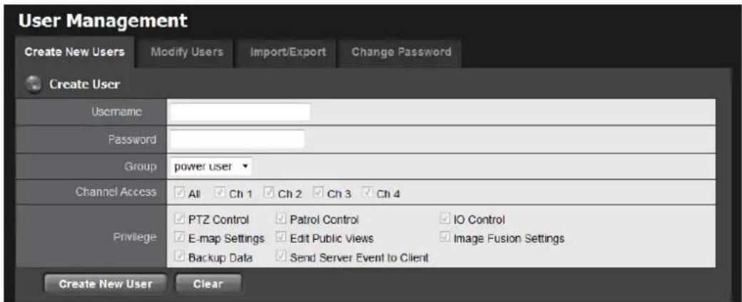
User Management Create New Users Modify Users Import/Export Change Password Create User Username Password Group power User Channel Access All Ch 1 Ch 2 Ch 3 Ch 4 Privilege PTZ Control Patrol Control IO Control E-map Settings Edit Public Views Image Fusion Settings Backup Data Send Server Event to Client Create New User Clear- Insert the username of this new user.
-
Insert the password of this new user.
-
Choose the group of this user.
● Power user: Power user can do all the settings and operation except the Network Settings, RAID Settings, and Management function.
- User: User just can change his/her password and operate client functions.
- Guest user: User can operation client function only.
- Select the cameras which this user can access.
- Manage the privilege for this user.
- Click the Create New User button to finish it.
| The Administrator will be the only user who can use all of the functions. There is a default administrator account in the system, and you cannot create neither another "Administrator" account, nor another username named "admin". |
2.6.3 Modify User Information
- Log in to the unit.
- Click Management / User Management.
- Click the Modify Users tab.
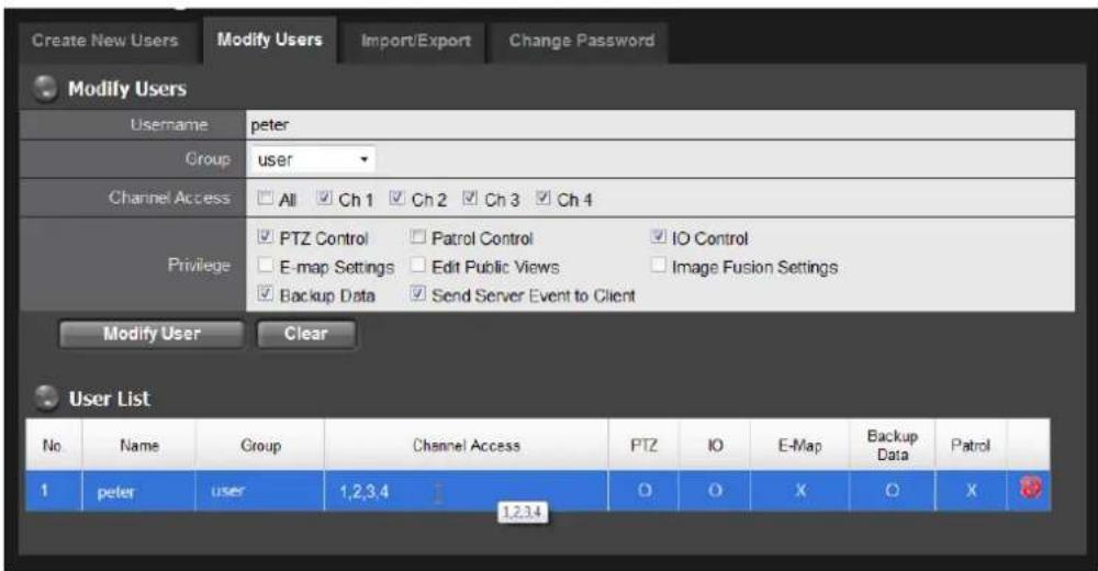
- Click one of the users in the User List on the bottom of this page.
text_image
Create New Users Modify Users Import/Export Change Password Modify Users Username peter Group user Channel Access All Ch 1 Ch 2 Ch 3 Ch 4 Privilege PTZ Control Patrol Control IO Control E-map Settings Edit Public Views Image Fusion Settings Backup Data Send Server Event to Client Modify User Clear User List No. Name Group Channel Access PTZ IO E-Map Backup Data Patrol 1 peter user 1,2,3,4 1,2,3,4 O O X O X- Change the group of this user.
- Select the cameras which this user can access.
- Manage the privilege for this user.
- Click the Modify User button to finish it.
2.6.4 Change a User's Password
- Log in to the unit.
- Click Management / User Management.
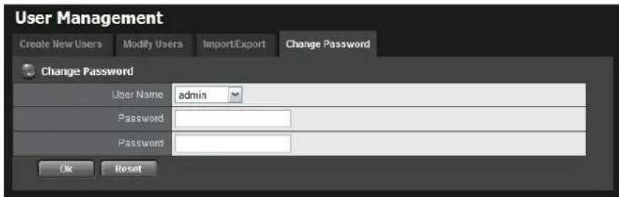
- Click the Change Password tab.
text_image
User Management Create New Users Modify Users Import/Export Change Password Change Password User Name admin Password Password Ok Reset- Choose the user.
- Enter a new password.
- Enter this new password again.
- Click the OK button.
2.6.5 Delete Users
Except for the administrator, you can delete any users with the following steps.
- Log in to the unit.
- Click Management / User Management.
- Click the Modify Users tab.
- Click the Delete icon of the user you want to delete.
| No. | Name | Group | Channel Access | PTZ | IO | E-Map | Backup Data |
| 1 | building_1 | power user | 1,2,3,4 | 0 | O | 0 | O |
| 2 | building_2 | user | 1,2 | 0 | O | 0 | O |
| 3 | building_3 | guestuser | 1,2,3,4 | X | X | X | X |
- In the confirmation box, click the OK button.
2.6.6 Import/Export User Account
For large-scale projects, the locations are equipped with a lot of cameras and are under surveillance by many users. Since it's possible for users being assigned to check videos from multiple servers, adding same user accounts in
multiple servers is unavoidable, which takes time definitely. In this case, we design an easier way to manage user accounts. Please refer to Main server/Sub server Configuration, or follow the steps below.
- Log in to the unit.
- Click Management / User Management.
- Click the Import / Export tab.
text_image
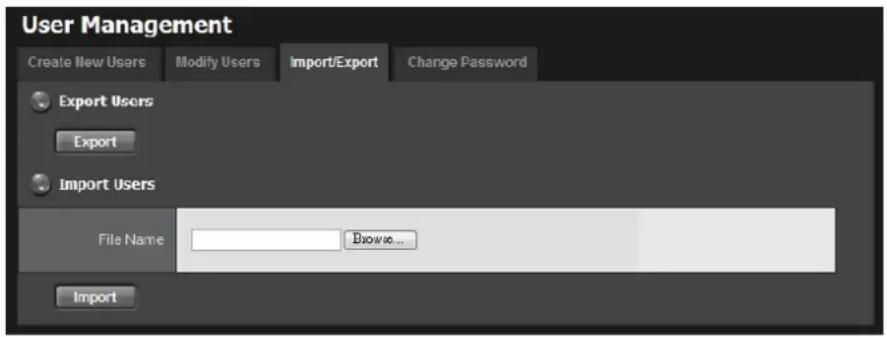
User Management Create New Users Modify Users Import/Export Change Password Export Users Export Import Users File Name Browse... Import- For exporting user account, click the Export button to export current user account and privilege.
- For importing user account, browse an user.cfg file and click the Import button to load user account and privilege.
| If the userCarlton(username) is existed in this server, the user privilege WON'T be covered when importing an user.cfg with same user accountCarlton. |
| When importing an user.cfg exported from a “less-channel” server to a “more-channel” server, 16ch and 32ch for example, which total numbers of channel access are different, in this case, only 16ch will be checked after importing .cfg. However, if the user account belongs to “power user”, all privileges are defaulted checked even the number of channel access of original server is less than this server |
2.6.7 Online License Activation
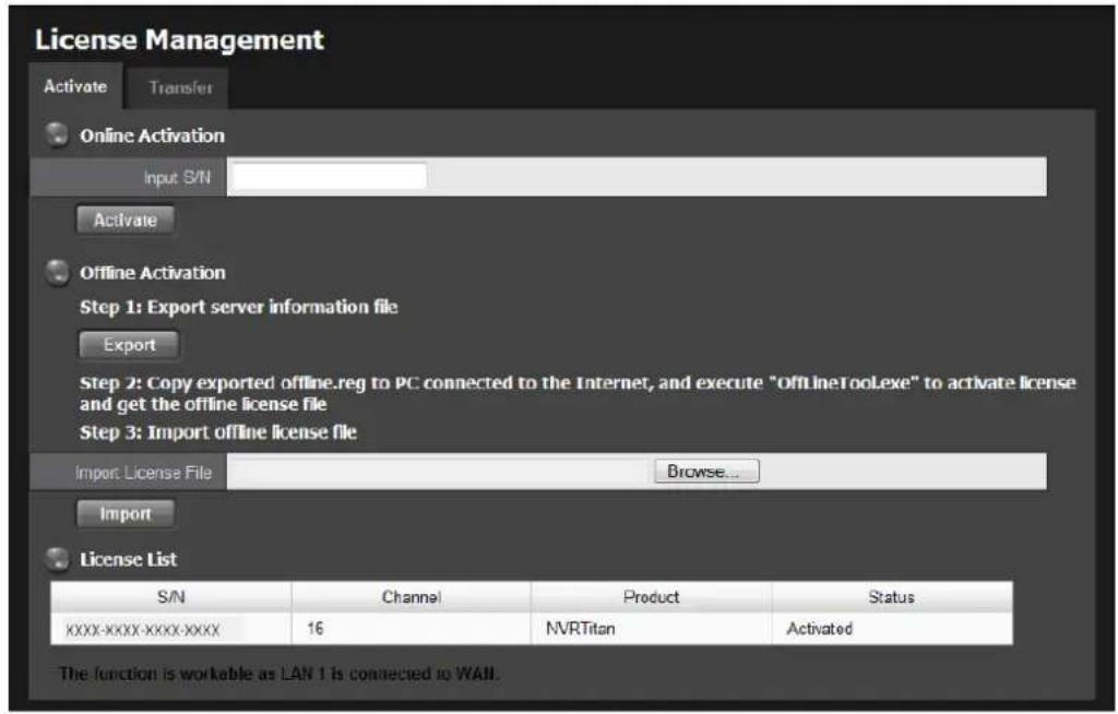
Activate a camera license to have more camera capacity. There are two ways to activate license, online and offline.
- Log in to the unit.
- Click Management / License Management.
text_image
License Management Activate Transfer Online Activation Input S/N Activate Offline Activation Step 1: Export server information file Export Step 2: Copy exported offline.reg to PC connected to the Internet, and execute "OfflineTooLexe" to activate license and get the offline license file Step 3: Import offline license file Import License File Browse... Import License List S/N Channel Product Status XXXX-XXXX-XXXX-XXXX 16 NVRTitan Activated The function is workable as LAN 1 is connected to WALL.- Input serial number on Online Activation column, and click the Activate button.
- The license will be updated in License List if activated successfully. System will reboot automatically.
| S/N | Channel | Product | Status |
| xxxx-xxxx-xxxx-xxxx | 16 | NVRTitan | Activated |
| xxxx-xxxx-xxxx-xxxx | 12 | NVRTitan | Activated |
2.6.8 Offline License Activation
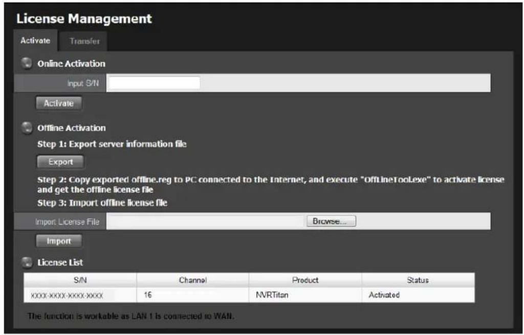
If the device is set up in Intranet (Local LAN) without Internet connection, there is another way to activate license.
- Log in to the unit.
- Click Management / License Management.
text_image
License Management Activate Transfer Online Activation Input S/N Activate Offline Activation Step 1: Export server information file Export Step 2: Copy exported offline.reg to PC connected to the Internet, and execute "OfflineTooLexe" to activate license and get the offline license file Step 3: Import offline license file Import License File Browse... Import License List S/N Channel Product Status XXXX-XXXX-XXXX-XXXX 16 NVRTitan Activated The function is workable as LAN 1 is connected to WAN.- Click the Export button under Offline Activation column to export the information of this unit.
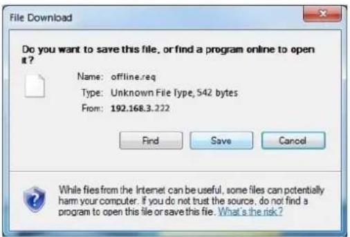
- Download dialog pops up. Save the request file and take it to other PC which is connected to the Internet.
Furthermore, the PC should be installed OffLineTool.exe which can be found from Titan NVR toolkit.
text_image
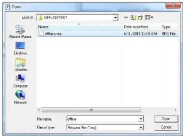
File Download Do you want to save this file, or find a program online to open it? Name: offline.req Type: Unknown File Type, 542 bytes From: 192.168.3.222 Find Save Cancel While files from the Internet can be useful, some files can potentially harm your computer. If you do not trust the source, do not find a program to open this file or save this file. What's the risk?- Execute the OffLineTool.exe in that PC with Internet connection, and select the request file offline.req.
text_image
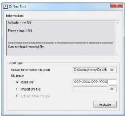
Open Look in: OFFLINETEST Name: Date modified Type offline.req 6/3 /2011 11:18 AM REQ File Recent Place Desktop Libraries Computer Network File name: offline Files of type: Request File (*.req) Open Cancel- Input the serial number, click the Activate button, and save the .dll file offline_license.dll.
text_image
Offline Tool Information: Activate new SN. Please input SN: ------------------------ Can not load request file. Input type Server Information file path: C:\Users\jimmy\Desktop\ SN input ● Input SN: XXXX-XXXX-XXXX-XXXX# ○ Import SN file: ● Activate from dangle Activate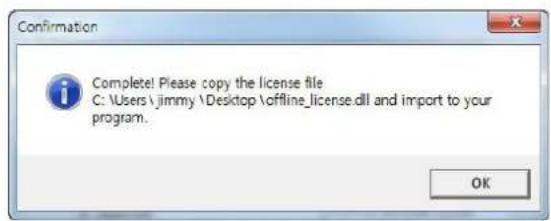
text_image
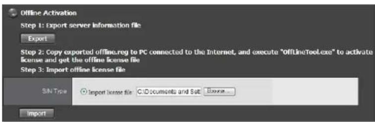
Confirmation Complete! Please copy the license file C:\Users\jimmy\Desktop\offline_license.dll and import to your program. OK- Import the license file to the unit.
text_image
Offline Activation Step 1: Export server information file Export Step 2: Copy exported offline.reg to PC connected to the Internet, and execute "OfflineTool.exe" to activate license and get the offline license file Step 3: Import offline license file SIN Type Import license file C:\Documents and Sati Browse... Import- The license will be updated in License List if activated successfully. System will reboot automatically.
| License List | |||
| S/N | Channel | Product | Status |
| xxxx-xxxx-xxxx-xxxx | 16 | NVRTitan | Activated |
| xxxx-xxxx-xxxx-xxxx | 12 | NVRTitan | Activated |
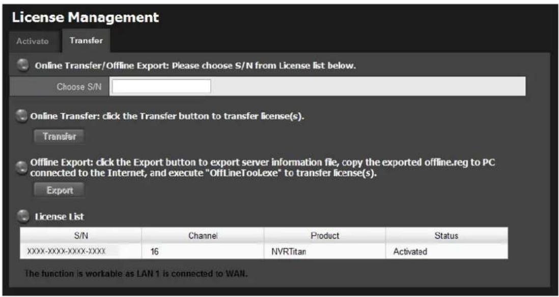
2.6.9 Online License transfer
There are two ways to Transfer license-- online and offline.
- Log in to the unit.
- Click Management / License Management/ Transfer tab.
text_image
License Management Activato Transfer Online Transfer/Offline Export: Please choose S/N from License list below. Choose S/N Online Transfer: click the Transfer button to transfer license(s). Transfer Offline Export: click the Export button to export server information file, copy the exported offline.reg to PC connected to the Internet, and execute "OffLineToolLexe" to transfer license(s). Export License List S/N Channel Product Status XXXX-XXXX-XXXX-XXXX 16 NVRTitan Activated The function is workable as LAN 1 is connected to WAN.- Select the license you want to transfer from License List. The chosen S/N will be shown on "Choose S/N" box.
- On Online Transfer part, click the Transfer button.
- The license will be transferred in License List if transfer successfully. System will reboot automatically.
| S/N | Channel | Product | Status |
| xxxx-xxxx-xxxx-xxxx | 16 | NVRTitan | Activated |
| xxxx-xxxx-xxxx-xxxx | 12 | NVRTitan | Activated |
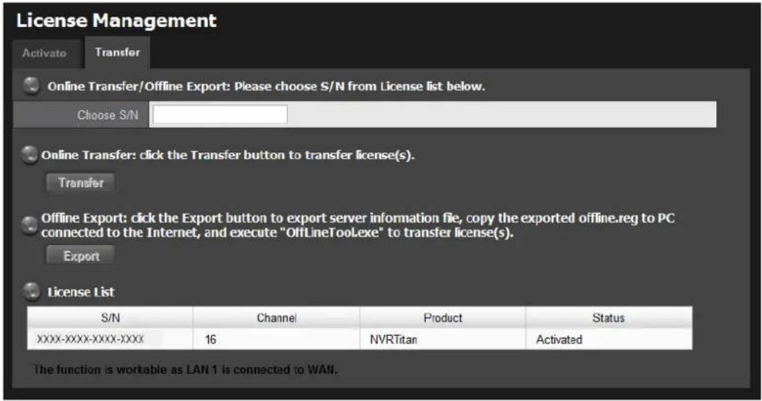
2.6.10 Offline license transfer
- Log in to the unit.
- Click Management / License Management/ Transfer tab.
text_image
License Management Activato Transfer Online Transfer/Offline Export: Please choose S/N from License list below. Choose S/N Online Transfer: click the Transfer button to transfer license(s). Transfer Offline Export: click the Export button to export server information file, copy the exported offline.reg to PC connected to the Internet, and execute "OfflineToolExe" to transfer license(s). Export License List S/N Channel Product Status XXXX-XXXX-XXXX-XXXX 16 NVRTitan Activated The function is workable as LAN 1 is connected to WAN.- Select the license you want to transfer from License List. The chosen S/N will be shown on "Choose S/N" box.
- On Offline Transfer part, click the Export button.
- Download dialog pops up. You will download one system information file: "OffLineTool.reg"
- Save "OffLineTool.reg" and take it to another PC which is connected to the Internet.
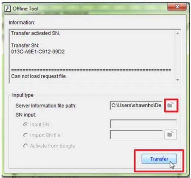
Furthermore, the PC should be installed Offline License Tool which can be found from Titan NVR toolkit.
- Launch Offline License Tool, and choose the file path of "OffLineTool.reg".
- Click "Transfer".
text_image
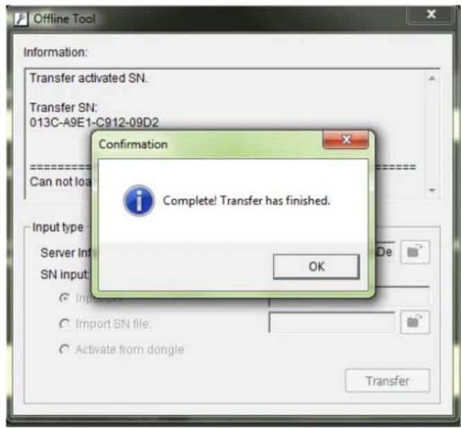
Offline Tool Information: Transfer activated SN. Transfer SN: 013C-A9E1-C912-09D2 Can not load request file. Input type Server Information file path: C:\Users\shawnho\De SN input: Input SN: Import SN file: Activate from dongie Transfer- Confirmation message will popup and the offline transfer is finished.
text_image
Offline Tool Information: Transfer activated SN. Transfer SN: 013C-A9E1-C912-09D2 Confirmation Complete! Transfer has finished. OK Input type Server In SN Input Import SN file: Activate from dongle Transfer
If user only finish step 1 to 4 (only click "Export" on license manage page, but not take the "OffLineTool.reg" to another computer, then transfer online), this license will still be transferred from the original Titan, but can't be used by anther Titan.
2.6.11 View the Event Log
- Log in to the unit.
- Click Management / Log System to find the event list of your unit.
| Date / Time | Level | Message |
| 2011/06/21 (Tue) 10:21:24 | info | VOLUME1 is ready |
| 2011/06/21 (Tue) 10:21:24 | info | RAID info of Disk2: level 1, uuid 7d11854c:b01fc8aa 1402527e:d5afe8fb, 2 device(s) |
| 2011/06/21 (Tue) 10:21:24 | info | Disk2 is found |
| 2011/06/21 (Tue) 10:21:24 | info | RAID info of Disk1: level 1, uuid 7d11854c:b81fc8aa 1402527e:d5afe8fb, 2 device(s) |
| 2011/06/21 (Tue) 10:21:24 | info | Enable smart fan |
| 2011/06/21 (Tue) 10:21:24 | info | Disk1 is found |
| 2011/06/21 (Tue) 10:21:23 | info | Storage service starts |
| 2011/06/21 (Tue) 10:21:22 | info | Start LAN eth 1 with static IP 192.168.3.222 |
| 2011/06/21 (Tue) 10:21:14 | info | System is booting |
| 2011/06/21 (Tue) 10:20:46 | info | System is shutting down |
| 2011/06/21 (Tue) 10:20:39 | info | System upgrade is finished |
| 2011/06/21 (Tue) 10:20:38 | info | Disable smart fan |
| 2011/06/21 (Tue) 10:20:05 | info | Disable smart fan |
| 2011/06/21 (Tue) 10:19:58 | info | Start upgrading system |
text_image
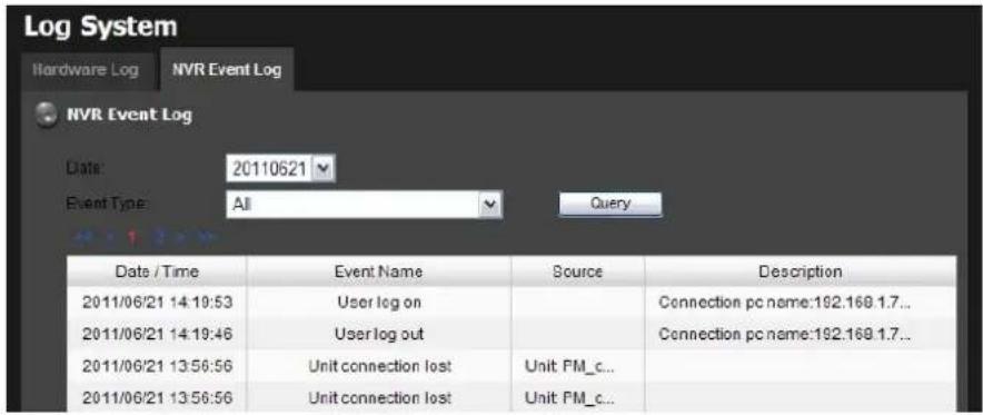
Log System Hardware Log NVR Event Log NVR Event Log Date: 20110621 Event Type: All Query... Date / Time Event Name Source Description 2011/06/21 14:19:53 User log on Connection pc name:192.168.1.7... 2011/06/21 14:19:46 User log out Connection pc name:192.168.1.7... 2011/06/21 13:56:56 Unit connection lost Unit FM_c... 2011/06/21 13:56:56 Unit connection lost Unit FM_c...There are two kinds of event which will be listed on this page.
- Hardware Log: The log information of the operations to your unit, such as reboot or shutdown.
- NVR Event Log: The log information of event, recording, backup, export, I/O, etc. Refer to the figure below for details.
| All |
| Service started |
| Service stopped |
| Disk abnormal |
| DDNS updated |
| Recycle event log started |
| Recycle event log stopped |
| Recycle event log fail |
| Motion started |
| Motion stopped |
| Recording on manual started |
| Recording on manual stopped |
| Recording on schedule started |
| Recording on schedule stopped |
| Auto backup started |
| Auto backup stopped |
| Auto backup failed |
| Manual backup started |
| Manual backup stopped |
| Manual backup failed |
| Export started |
| Export stopped |
| Export fail |
| Input signal on |
| Input signal off |
| Output signal on |
| Output signal off |
| Unit connection lost |
| User log on |
| User log out |

The camera Log will be recorded only if event is selected on Event & Action
2.6.12 Save Unit Configuration
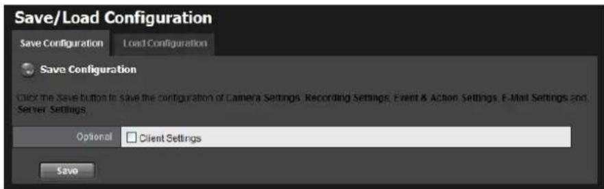
Save configuration can let you save the settings of this unit. These settings can be applied to other units, which will let you set other units more easily.
- Log in to the unit.
- Click Management / Save / Load Configuration.
- Click the Save Configuration tab.
text_image
Save/Load Configuration Save Configuration Load Configuration Save Configuration Click the Save button to save the configuration of Camera Settings, Recording Settings, Event & Action Settings, E-Mail Settings and Server Settings Optional Client Settings Save- Check the box of Client Settings if you want to keep the configuration.
- Click the OK button.
- The configuration file will be generated into the chosen folder.
2.6.13 Load Unit Configuration / Default Settings
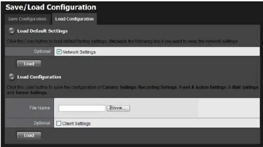
Load configuration can let you apply another unit's settings to the current unit; Load Default Settings will revert all of the unit's settings back to the default factory settings.
- Click Management / Save / Load Configuration.
- Click the Load Configuration tab.
text_image
Save/Load Configuration Save Configuration Load Configuration Load Default Settings Click the Load button to load default factory settings. Uncheck the following box if you want to keep the network settings Optional Network Settings Load Load Configuration Click the Load button to save the configuration of Camera Settings, Recording Settings, Event & Action Settings, E-Mail Settings and Server Settings. File Name Browse... Optional Client Settings Load-
Follow the direction to Load Default Settings or Load Configuration. For the former, uncheck the box of Network Settings to keep the current IP address; for the latter, check the box of Client Settings if you want to restore the configuration.
-
Click the Load button.
-
A confirmation dialog pops up. Click the OK button to begin to load the settings into your unit.
 | If the saved configuration is without client settings, selecting loading configuration with client settings will lead you get the default. The original client settings (if any) are covered and untraceable. |
 | User account and privilege will be kept even if loading default settings, while camera settings, recording schedule, event & action settings, E-mail setting and server settings won't be.RAID informationwill always be kept whether loading default settings or loading configuration. |
 | If you select to load default IP, system may guide you to the defaulted IP. However, the guiding mechanism is failed, please try Installation Wizard. |
2.7 System
2.7.1 View System Information
- Log in to the unit.
- Click System / System Information.
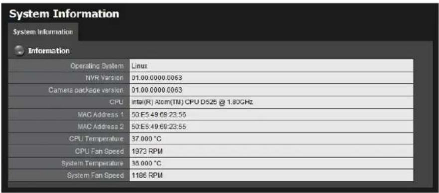
text_image
System Information System Information Information Operating System Linux NVR Version 01.00.0000.0063 Camera package version 01.00.0000.0063 CPU Intel(R) Atom(TM) CPU D525 @ 1.80GHz MAC Address 1 50 E5 49 69:23:56 MAC Address 2 50 E5 49 69:23:55 CPU Temperature 37.000 °C CPU Fan Speed 1973 RPM System Temperature 38.000 °C System Fan Speed 1186 RPMThe system information includes the following items.
- Operating System: Embedded Linux
• NVR Version: NVR system version
● Camera package version: Camera package version - CPU: CPU model number
- MAC Address 1: First MAC address of this unit
- MAC Address 2: Second MAC address of this unit
- CPU Temperature
- CPU Fan Speed
• System Temperature - System Fan Speed
2.7.2 Smart Fan Control
- Log in to the unit.
- Click System / System Settings.
- Click the Fan Control tab.
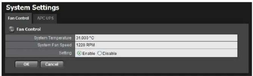
text_image
System Settings Fan Control APC UPS Fan Control System Temperature 31.000 °C System Fan Speed 1220 RPM Setting Enable Disable OK Cancel- Check the Enable or Disable option.
- Click the OK button.
2.7.3 UPS Setup
This feature enables you to tell your unit how long to run on APC Uninterruptable Power Supply (UPS) battery power and when to shutdown, after power failure.
- Attach the APC UPS to one of the unit's USB ports.
- Log in to the unit.
- Click System / Settings.
- Click the APU UPS tab.
- Check one of the options:
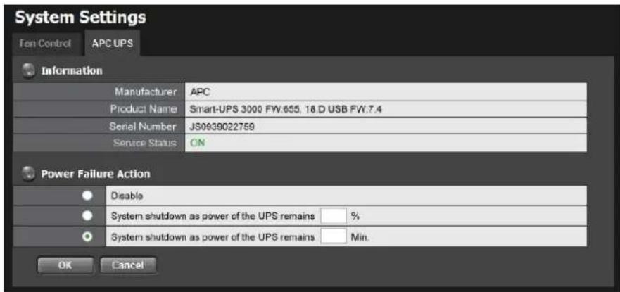
text_image
System Settings Ten Control APC UPS Information Manufacturer APC Product Name Smart-UPS 3000 FW:655. 18.D USB FW:7.4 Serial Number JS0939022759 Service Status ON Power Failure Action Disable System shutdown as power of the UPS remains %. System shutdown as power of the UPS remains Min. OK Cancel● Disable: Run until the UPS battery is depleted
- System shutdown as power of the UPS remains ____ %: Run until the UPS battery remains this percentage.
- System shutdown as power of the UPS remains __ min.: Run until the UPS battery remains the certain period of time.
-
Fill in the specific value if you choose the last two options.
-
Click the OK button.
2.7.4 Upgrade the System
- Log in to the unit.
- Click System / Upgrade.
- Click the Firmware Upgrade tab.
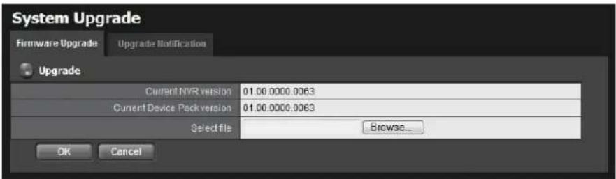
text_image
System Upgrade Firmware Upgrade Upgrade Notification Upgrade Current NVR version 01.00.0000.0063 Current Device Pack version 01.00.0000.0063 Select file Browse... OK Cancel-
Browse the FW for upgrading and click the OK button.
-
A confirmation dialog pops up. Click the OK button to start upgrade process.
-
After upgrade, the system will restart. You need to re-access the unit again after this.

The FW upgrade includes Titan server FW upgrade and device pack upgrade. You can only upgrade camera device pack to add camera in device pack new version without upgrade Titan FW after version v1.3 and device pack v2.0.
2.7.5 Upgrade Notification
Enable this function to allow us to notify you automatically when there are firmware updates (Recommended). This will help keep your system up to date. The updater will also collect info from your system that will be used for future system improvements.
- Log in to the unit.
- Click System / Upgrade.
- Click the Upgrade Notification tab.
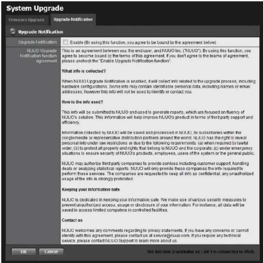
text_image
System Upgrade Firmware Upgrade Upgrade Notification Upgrade Notification Upgrade Notification NUUO Upgrade Notification function agreement Enable (By using this function, you agree to be bound by the agreement below) This is an agreement between you, the end user, and NUUO Inc. ("NUUO"). By using this function, you agree to become bound by the terms of this agreement. If you don't agree to the teams of agreement, please uncheck the "Enable Upgrade Notification function". What info is collected? When NUUO Upgrade Notification is enabled, it will collect info related to the upgrade process, including hardware configurations. Some info may contain identifiable personal data, including names or email addresses; however this info will not be used to identify or contact you. How is the info used? This info will be submitted to NUUO and used to generate reports, which are focused on fluency of NUUO's solution. This information will help improve NUUO's product in terms of third party support and efficiency. Information collected by NUUO will be saved and processed in NUUO, its subsidiaries within the conglomerate or representative distribution partners around the world. NUUO has the right to reveal personal info under law restrictions or due to the following requirements: (a) when required by lawful order; (b) to protect all property and rights that belong to NUUO and the corporate; (c) under emergency situations to ensure security of NUUO's products, employees, users of the system or the general public. NUUO may authorize third party companies to provide services including customer support, handling deals or analyzing statistical reports. NUUO will only provide these companies the info required to perform these services. The companies are requested to keep all info as confidential, any unauthorized usage of the info is strongly prohibited. Keeping your information safe NUUO is dedicated in keeping your information safe. We make use of various security measures to prevent unauthorized access, usage or disclosure of your information. For instance, all data will be saved in access limited computers in controlled facilities. Contact us NUUO welcomes any comments regarding to privacy statements. If you have any concerns or cannot identify with this agreement, please contact us at service@nuuo.com. If you require any technical service, please contact NUUO Support to learn more about us. OK Cancel The function is workable as LAN 1 is connected to WAI.- Check the option if you agree to be bound by the agreement.
- Click the OK button.

The function only works as LAN 1 is connected to WAN, or our FW management serv is unable to detect the current version of your systems.
2.7.6 System Date and Time Setup
Setup system date and time manually, or enable NTP (Network time) to synchronize time with external NTP server automatically.
In addition, you can set daylight saving start time and end time, and the system will start daylight saving time modification every year base on your configuration.
- Open Internet Explorer and log in to the unit.
- Click System / Date/Time.
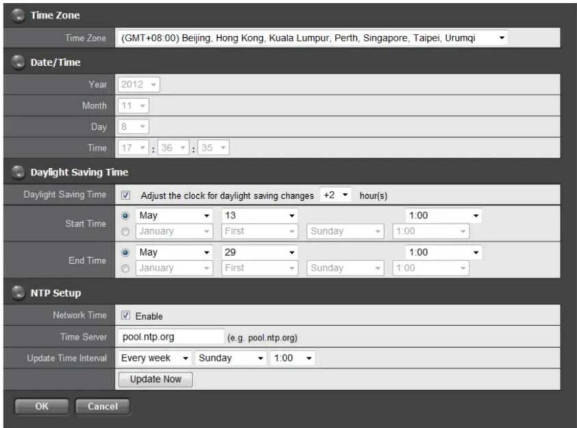
text_image
Time Zone Time Zone (GMT+08:00) Beijing, Hong Kong, Kuala Lumpur, Perth, Singapore, Taipei, Urumqi Date/Time Year 2012 Month 11 Day 8 Time 17 : 36 : 35 Daylight Saving Time Daylight Saving Time ✓ Adjust the clock for daylight saving changes +2 hour(s) Start Time ○ May 13 1:00 ○ January First Sunday 1:00 End Time ○ May 29 1:00 ○ January First Sunday 1:00 NTP Setup Network Time ✓ Enable Time Server pool.ntp.org (e.g. pool.ntp.org) Update Time Interval Every week Sunday 1:00 Update Now OK Cancel-
Choose the time zone.
-
Configure the year, month, day and time manually, or enable Network Time to synchronize time automatically. When Network Time enabled, the date/time settings will be grayed out.
-
Assign time server and update interval if choosing Network Time. You can also click "Update Now" to update date/ time right away.
-
Check the Adjust clock for daylight saving changes option and select the time change of daylight saving time in your location. Choose the start time and end time of recurrence.
-
Click the OK button, restarting system to activate the changes.
| System will restart after date time modification, including date/ time setting, dayligh saving time, and NTP time update. |
2.7.7 Local Display
Titan NVR supports VGA out by connecting the D-SUB of the unit with a screen to watch live videos. You can do some operations on the monitor, such as switching grid layout and enabling auto scan, but you have to configure the settings on web. Please follow the steps to set up local display.
- Log in to the unit.
- Click System / Local Display.
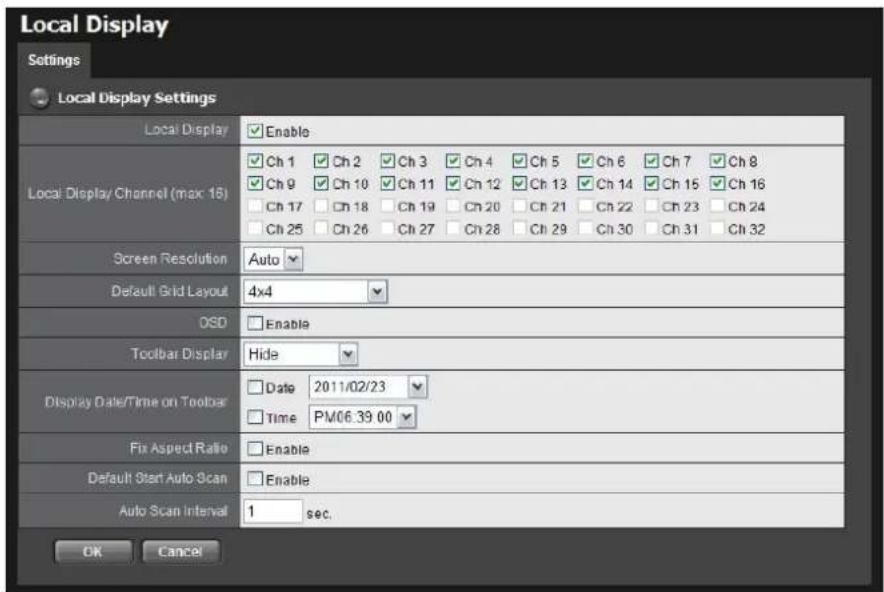
text_image
Local Display Settings Local Display Settings Local Display Enable Ch 1 Ch 2 Ch 3 Ch 4 Ch 5 Ch 6 Ch 7 Ch 8 Ch 9 Ch 10 Ch 11 Ch 12 Ch 13 Ch 14 Ch 15 Ch 16 Ch 17 Ch 18 Ch 19 Ch 20 Ch 21 Ch 22 Ch 23 Ch 24 Ch 25 Ch 26 Ch 27 Ch 28 Ch 29 Ch 30 Ch 31 Ch 32 Screen Resolution Auto Default Grid Layout 4x4 OSD Enable Toolbar Display Hide Display Date/Time on Toolbar Date 2011/02/23 Time PM06.39.00 Fix Aspect Ratio Enable Default Start Auto Scan Enable Auto Scan Interval 1 sec. OK Cancel- Local Display: Check the box to enable local display. (default: checked)
- Local Display Channel (max: 16): Select the channel you want to display. (default: 4 ch)
- Screen Resolution: Choose the resolution of screen display; the selections of resolutions will be shown when connecting with a screen. (default: auto; "auto" implies the best resolution system detects)
- Default Grid Layout: Choose the defaulted layout. (default: 2x2)
- OSD: Check the box to enable OSD of camera name. (default: checked)
- Toolbar Display: Choose to hide the toolbar or always show it on the screen. If you choose "Hide", toolbar can still be shown when moving the cursor. (default: hide)
- Display Date/Time on Toolbar: Check the boxes to display date/time on toolbar and change the formats if necessary. (default: checked)
● Fix Aspect Ratio: Check the box to make all videos fix the aspect ratio. (default: unchecked) -
Default Start Auto Scan: Check the box to enable auto scan when liveviewing. (default: unchecked)
● Auto Scan Interval: The time interval of auto scan. (default: 5 sec.) -
Click the OK button.
2.7.8 Restart the Unit
- Log in to the unit.
- Click System / Reboot/Shutdown.
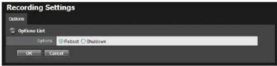
text_image
Recording Settings Options Options List Options Reboot Shutdown OK Cancel- Check the Reboot option.
- Click the OK button.
- A confirmation dialog pops up. Click the OK button to reboot the unit.

During system restart, none of your files will be accessible from your desktops/laptops.
2.7.9 Shut Down the Unit
The only time you need to shut down the unit is to replace the disk drive cooling fan or the power supply. During and after the shutdown, none of your files will be accessible from your desktops/laptops. There are two ways to shutdown the unit.
- Shutdown by Software
- Log in to the unit.
- Click System / Reboot / Shutdown.
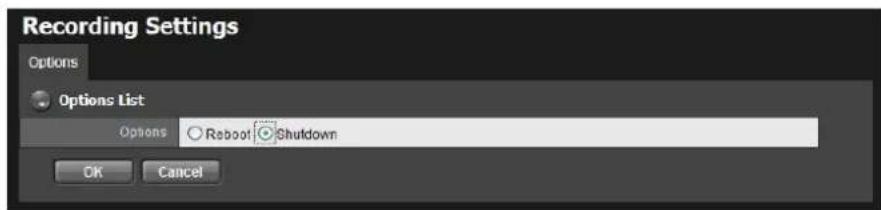
text_image
Recording Settings Options Options List Options Reboot Shutdown OK Cancel- Check the Shutdown option.
- Click the OK button.
- A confirmation dialog pops up. Click the OK button to shutdown the unit.
- Direct Shutdown
Press the power button and hold it for 5 seconds to force to cut off the
power directly.
3. I/O
3.1 Introduction
3.1.1 System Introduction
NUUO provides remote I/O solution for NVRmini/NVRmini 2/Titan NVR by connecting SCB-C31 with NUUO I/O Box SCB-C24/26/28. Refer to the below architecture, I/O device is connected directly with I/O Box, and input/output signal delivered in RS485 format are converted to Ethernet through SCB-C31. NVRmini/NVRmini 2/Titan NVR can use the signals to do more sophisticated setup, such as starting recording when input triggered, triggering output as an event happened, and much more.
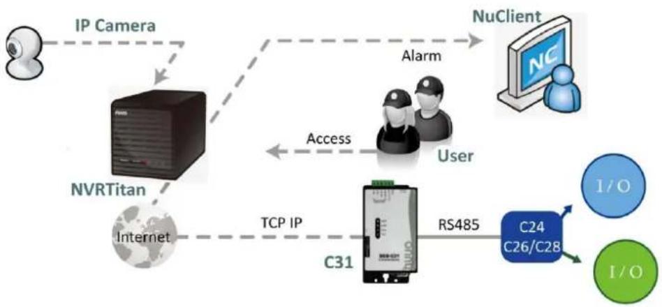
flowchart
graph TD
    A["User"] -->|IP Camera| B["NVRTitan"]
    B -->|TCP/IP| C["C31"]
    C -->|RS485| D["C24 C26/C28"]
    D --> E["I/O"]
    D --> F["I/O"]
    G["NuClient"] -->|Alarm| B
    G -->|Access| C
    H["Internet"] --> B
3.1.2 HW Installation
SCB-C24/26/28 must work with SCB-C31 (Ethernet-RS485 converter).
Further, the C31 Box cannot be used for POS and converter at the same time, and one C31 Box can be paired with one NVR unit only. Please follow the steps below to configure the devices.
Step 1: Check the system switch of SCB-C31 is switched to OFF-OFF position.
Step 2: Connect SCB-C31 with power source.
Step 3: Connect SCB-C31 with internet by RJ45 LAN cable.
Step 4: Connect I/O Box with power source.
Step 5: Connect SCB-C31 and I/O Box with cable, positive connection (TX+/D+ and DATA+) and negative connection (TX-/D- and DATA-). Take SCB-C31 with I/O Box SCB-C24 for example as below.
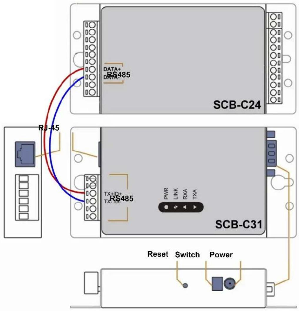
text_image
DATA+ DATA- RS485 SCB-C24 RJ-45 RS485 TX+D+ TX-10- PWR LINK RXA TXA SCB-C31 Reset Switch Power
Multiple I/O Boxes can be connected to a single SCB-C31. However, series connection of I/O boxes is forbidden. Furthermore, the default ID for each I/O Box is the same. Please follow the direction to setup I/O Box one by one.
3.1.3 Software Installation - SCB-C31
Step 1: Open Internet Explorer to setup SCB-C31. The default IP address is 192.168.1.1.

text_image
Server Page - Microsoft Internet Explorer File Edit View Favorites Tools Web Address 192.168.1.1 GoStep 2: Setup IP address and port.
1. Static IP Address
- Server Listening Port: The default port is 4000, which is not the port for setting page, but for signal transmission.
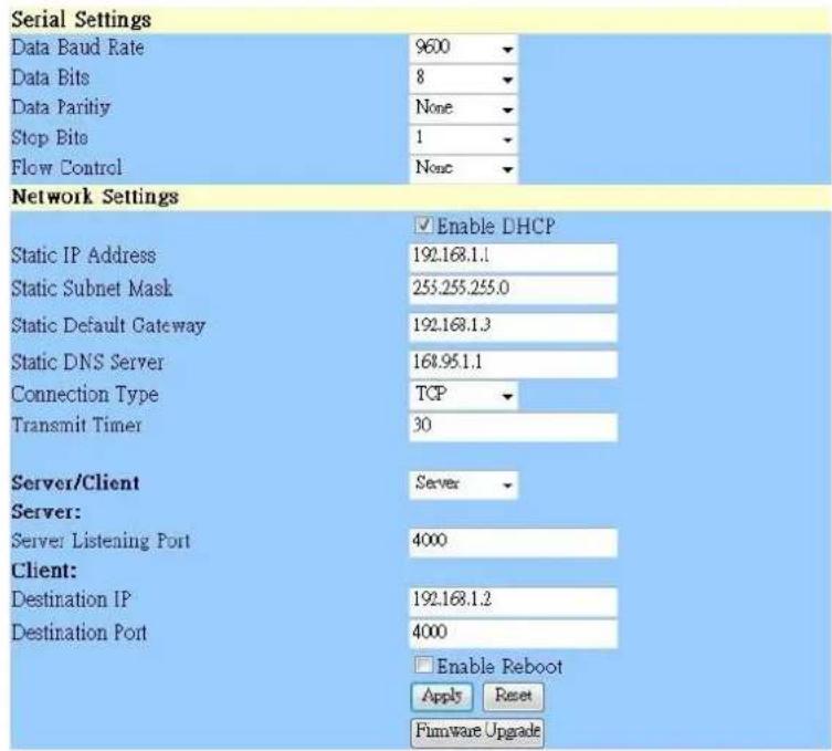
text_image
Serial Settings Data Baud Rate 9600 Data Bits 8 Data Parity None Stop Bits 1 Flow Control None Network Settings ✓ Enable DHCP Static IP Address 192.168.1.1 Static Subnet Mask 255.255.255.0 Static Default Gateway 192.168.1.3 Static DNS Server 168.95.1.1 Connection Type TCP Transmit Timer 30 Server/Client Server Server: Server Listening Port 4000 Client: Destination IP 192.168.1.2 Destination Port 4000 □ Enable Reboot Apply Reset Firmware UpgradeStep 3: Click the Apply button to activate configuration.

Due to the stability of data transmission, one SCB-C31 can be paired with one NVR unit only.
3.1.4 Software Installation - SCB-C24/26/28
The default ID of I/O Box is identical. To avoid the conflict between Boxes, please connect only one Box with SCB-C31 and execute the setup application to change the ID from the default value (1).
- Execute IOConfig.exe, type in the IP address and port of SCB-C31, and click the Scan button.
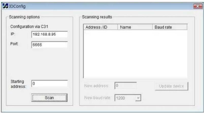
text_image
IOConfig Scanning options Configuration via C31 IP: 192.168.8.95 Port: 6666 Starting address: 0 Scan Scanning results Address / ID Name Baud rate New address: 0 Update device New baud rate: 1200
IOConfig.exe starts scanning the ID from 0 to 255, and it may take around a minute to finish scan.
- When the I/O Box is discovered, click on the item and change the ID from the New Address field. Click the Update device button to activate the settings.
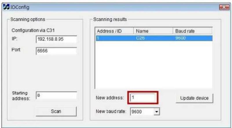
text_image
IOConfig Scanning options Configuration via C31 IP: 192.168.8.95 Port: 6666 Starting address: 8 Scan Scanning results Address / ID Name Baud rate 1 C2b 9600 New address: 1 Update device New baud rate: 9600- Scan again to make sure the configuration is validated. In this case, we changed the ID to 10, so we can modify the number of "Starting address" to 10 to save the searching time.
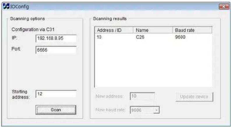
text_image
IOConfig Scanning options Configuration via C31 IP: 192.168.8.95 Port: 6666 Starting address: 12 Scan Scanning results Address / ID Name Baud rate 10 C26 9600 New address: 10 Update device New baud rate: 9600- Refer to the HW Installation section to connect other I/O Box and repeat the steps 1 through 3 above to configure more I/O Boxes.
3.2 Software Setup
3.2.1 Add I/O Box
- Log in to the unit.
- Click POS & I/O / I/O Settings / I/O Box Settings.
- Enter the information of I/O box.
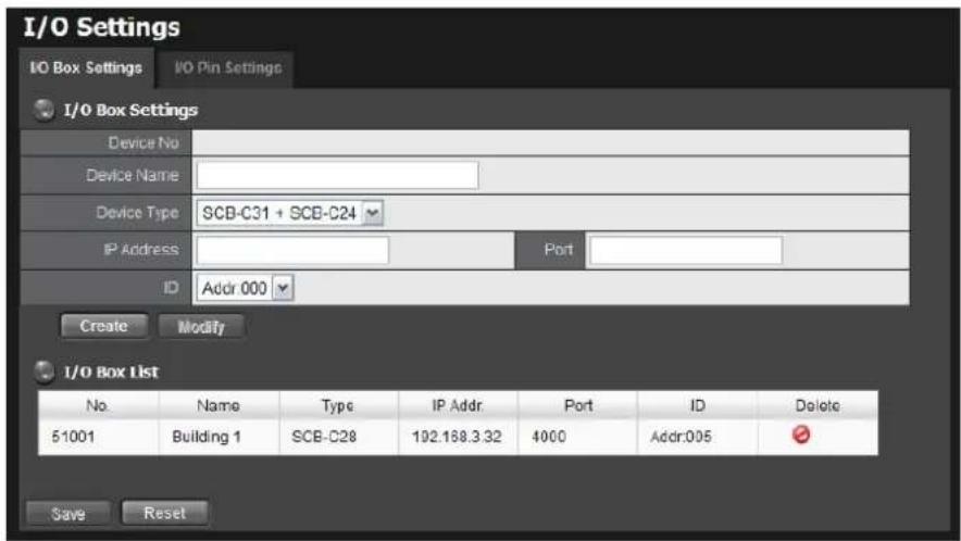
text_image
I/O Settings I/O Box Settings I/O Pin Settings I/O Box Settings Device No Device Name Device Type SCB-C31 + SCB-C24 IP Address Port ID Addr 000 Create Modify I/O Box List No. Name Type IP Addr Port ID Delete 51001 Building 1 SCB-C28 192.168.3.32 4000 Addr.005 Save Reset● Device No: The unique ID system distributes in sequence automatically.
● Device Name: The name of the I/O box.
● Device Type: The types of I/O box, including SCB-C24, SCB-C26, and SCB-C28.
IP Address: The IP Address of SCB-C31.
- Port: The transmission port of SCB-C31.
- ID: The ID of the I/O box.
- Click the Create button, and the information will be updated in I/O Box List.
- Repeat steps 3 and 4 to add more I/O boxes in the list.
- Click the Save button to activate the settings. Meanwhile, system will distribute an unique ID to each device.
3.2.2 Modify I/O Box Information
- Log in to the unit.
- Click POS & I/O / I/O Settings / I/O Box Settings.
- Click the I/O box which you want to modify from the list.
- Modify the information of this I/O box, and click the Modify button.
- Click the Save button to activate the settings.
3.2.3 I/O Pin Setting
- Log in to the unit.
- Click POS & I/O / I/O Settings / I/O Pin Settings.
- All input and output pins are shown in this page, including the ones from cameras and I/O boxes.
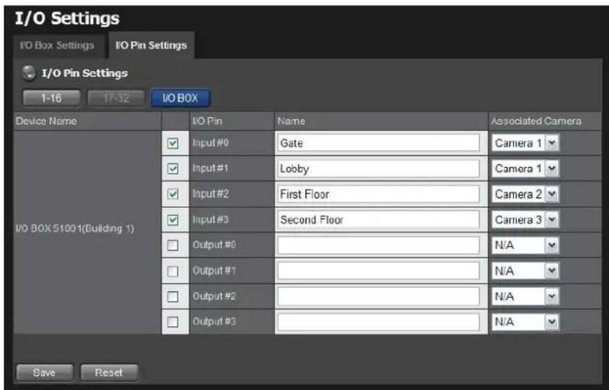
text_image
I/O Settings I/O Box Settings I/O Pin Settings I/O Pin Settings 1-16 17-32 I/O BOX Device Name I/O Pin Name Associated Camera I/O BOX 51001(Building 1) Input #0 Gate Camera 1 Input #1 Lobby Camera 1 Input #2 First Floor Camera 2 Input #3 Second Floor Camera 3 Output #0 N/A Output #1 N/A Output #2 N/A Output #3 N/A Save Reset● Device Name: The name of the I/O box.
- I/O Pin: Check the box to enable a pin. (default: checked)
- Name: The name of the I/O pin.
● Associated Camera: You may assign one camera to each digital input
device. DI's included with IP cameras will keep its own camera as default associated camera.
4. Click the Save button.

If the box of I/O pin is unchecked, this pin won't be shown on relative application pages. In other words, you cannot do any setting/operation with this pin. See details in next section.
3.3 Relative Configuration and Application
3.3.1 Record on Input Trigger
Refer to Recording Schedule / Event Setup.
3.3.2 Input and Responding Actions
Refer to I/O Box Input and Responding Action Setup.
3.3.3 I/O Control Panel in Live View
Refer to NuClient user manual for details.
4. External Storage
4.1 Create a Volume on DAS
The current compatible DAS is AXUS FiT Series. We don't guarantee the quality of other DAS models. Please refer to the manual of AXUS FiT Series to create a single volume on DAS.

We are unable to create a volume on external storage in Titan NVR setting page, so NOT skip this step before connecting to Titan NVR.

The maximum volume size to create RAID on Titan NVR is 16T. Please make sure every volume you are going to add as a external storage is under 16T.
4.2 Create an External Storage
- Log in to the unit.
- Click RAID & File System / RAID Management.
- You will find External SATA Disk displayed in Disk List.
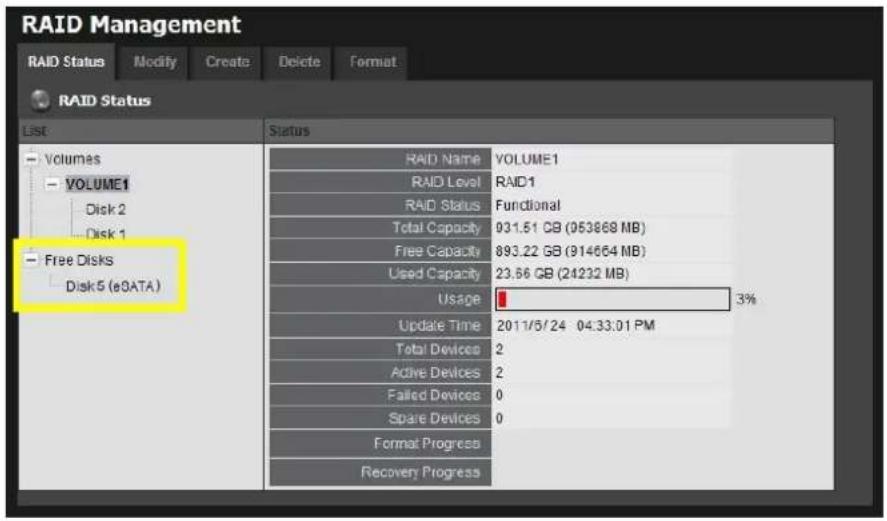
text_image
RAID Management RAID Status Modify Create Delete Format RAID Status List Status Volumes VOLUME1 VOLUME1 Disk 2 Disk 1 Free Disks Disk 5 (eDATA) RAID Name VOLUME1 RAID Level RAID1 RAID Status Functional Total Capacity 931.51 GB (953868 MB) Free Capacity 893.22 GB (914664 MB) Used Capacity 23.66 GB (24232 MB) Usage 3% Update Time 2011/5/24 04:33:01 PM Total Devices 2 Active Devices 2 Failed Devices 0 Share Devices 0 Format Progress Recovery Progress- Click on the eSATA disk directly to check the disk drive information.
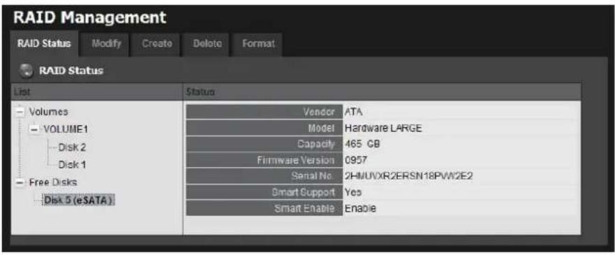
text_image
RAID Management RAID Status Modify Create Delete Format RAID Status List Status Volumes Vehicle ATA VOLUME1 Model Hardware LARGE Disk 2 Capacity 465 GB Disk 1 Firmware Version 0957 Free Disks Serial No 2HMUVXR2ERSN18PVW2E2 Disk 5 (eSATA) Smart Support Yes Smart Enable Enable- Refer to the section of Create a RAID Volume to create a volume for it. You can either create a volume with eSATA and embedded disk(s), or create an isolate volume with eSATA disk only.
4.3 Create an External Storage on iSCSI
- Log in to the unit.
- Click RAID & File System / iSCSI initiator
- Fill in the IP address and port (default 3260) for iSCSI, and click "Discover"
- You will see the iSCSI you discovered.
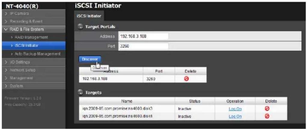
text_image
NT-4040(R) IP Camera Recording & Event RAD & File System RAID Management iSCSI Initiator Auto Backup Management ID Settings Network Setup Management System iSCSI Initiator iSCSI Initiator Target Portals Address 192.168.3.188 Port 3260 Discover Div Over Address Port Delete 192.168.3.188 3260 Targets Name Status Operation Delete ign 2009-05.com.promise.ns4600 disk3 Inactive Log On ign 2009-05.com.promise.ns4600 disk4 Inactive Log On- Log on each disk on Target. If you have set password on iSCSI, choose CHAP to log on. If not, choose "None".
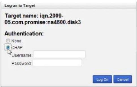
text_image
Log on to Target Target name: iqn.2009- 05.com.promise:ns4600.disk3 Authentication: None CHAP Username: Password: Log On Cancel- After log on the disk, choose RAID Management, you will see the iSCSI disk on Free disks.
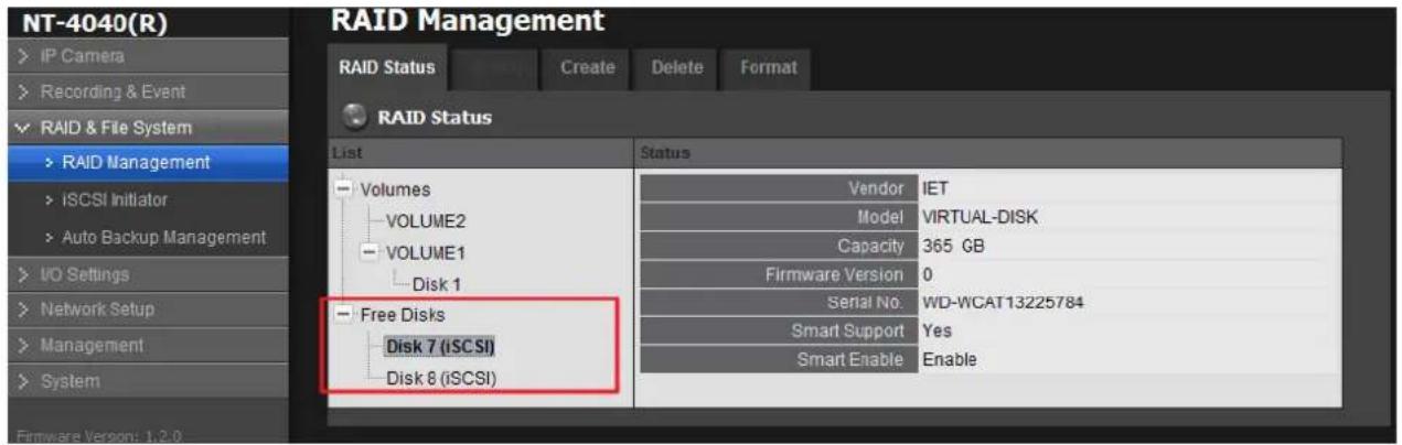
text_image
NT-4040(R) IP Camera Recording & Event RAID & File System RAID Management iSCSI Initiator Auto Backup Management I/O Settings Network Setup Management System RAID Status List Status Volumes VOLUME2 VOLUME1 Disk 1 Free Disks Disk 7 (iSCSI) Disk 8 (iSCSI) Vendor IET Model VIRTUAL-DISK Capacity 365 GB Firmware Version 0 Serial No. WD-WCAT13225784 Smart Support Yes Smart Enable Enable- Refer to the section of Create a RAID Volume to create a volume for it. You can only create a volume with purely iSCSI disk.
We suggest user use more HD to create one volume. Not use one HD to divide to m than 2 volume.
If you log off the disk which has been created as a RAID, it may destroy the current recording file.
5. Log out
Click the Logout button on the top of the page to log out of the system. If there is no action in 10 minutes, the system will log out automatically to avoid unauthorized access.
6. Remote PC System Requirements
| Remote PC Minimum Requirements | ||
| CPU | Intel Core 2 Duo, 2.6GHz | |
| Display Card | OpenGL 2.0 and later | |
| OS Supported | Windows XP 32 bit | Windows 7 32/64 bit Mac 10.6/10.7 |
| RAM | 1GB | 2GB |
| User Interface | 1. HTTP Web browser - Internet Explorer 8 and later and Firefox 7.0.12. NUUO client application program | |
7. Troubleshooting
7.1 Replace a Failed Disk Drive
If a disk drive fails, the Disk Status LED becomes orange. If the disk drive belongs to a RAID Volume, the Volume goes Critical or Offline, depending on RAID level. See Check RAID Volume Status for details.
Replace the failed disk drive with a new disk drive of the same or slightly greater capacity. You do not have to power down the unit. Refer to Modify RAID Volume to remove the failed disk and replace it with a new one.
7.2 Respond to a Critical RAID Volume
How the unit responding to a Critical RAID Volume depends on the RAID level of your Volume:
- For RAID 1, 5, and 10 volumes, you must replace the failed disk drive with a new one. The RAID Volume will begin rebuilding itself when you install the new disk drive. See Replace a Failed Disk Drive for details.
- RAID 0 volumes go offline after a disk drive failure. A RAID 0 Volume cannot be recovery. All data of the volume is lost.
7.3 Respond to a File System Error RAID Volume
When encountering file system error, you are unable to keep the data anymore. It's likely due to abnormal usage and disk damage. In this case, if you want to keep recording, we suggest replacing new disks, or try the following methods.
- Format this volume, and check if the status becomes functional. If yes, you can start recording. If it doesn't, try the second method.
- Delete this volume, and create volume again to see if the status is functional.
7.4 Install ActiveX
If you cannot see the complete page of the system when using Internet Explorer, it may be because the ActiveX installation process is not completed.
-
Log in to the unit.
-
Click the NuClient button on the top right.
- The browser will ask whether to install ActiveX.
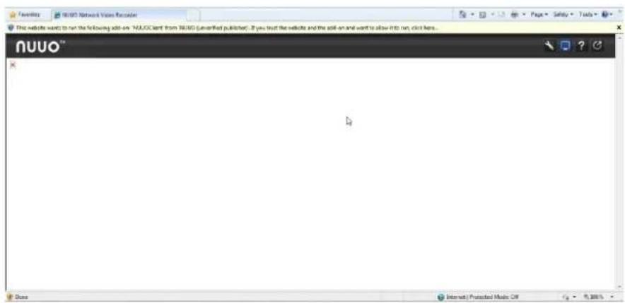
text_image
NuUO™ Dove Internet Protected Music Off © 2015- Click the Run button on popup dialog to begin the installation process.
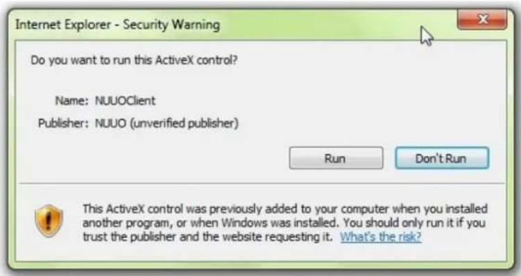
text_image
Internet Explorer - Security Warning Do you want to run this ActiveX control? Name: NUUOClient Publisher: NUUO (unverified publisher) Run Don't Run This ActiveX control was previously added to your computer when you installed another program, or when Windows was installed. You should only run it if you trust the publisher and the website requesting it. What's the risk?7.5 Cannot Log in to the Unit with Internet Explorer
- Check the settings of your antivirus software.
- Change to appropriate settings or turn off this antivirus software.
Please visit NUUO wiki for more information. http://support.nuuo.com/mediawiki/index.php/Main_Page
Appendix – RAID System
Introduction to RAID
RAID (Redundant Array of Independent Disks) allows multiple disk drives to be combined together into a RAID Volume. You will create a RAID Volume on your unit when you perform the setup procedure.
The benefits of a RAID can include:
- Higher data transfer rates for increased server performance
- Increased overall storage capacity for a single Volume
● Data redundancy/fault tolerance for ensuring continuous system operation in the event of a disk drive failure
Different RAID levels use different organizational models and have varying benefits. The following outline breaks down the properties for each RAID level supported on this unit:
RAID 0 - Stripe
When a RAID Volume is striped, the read and write blocks of data are interleaved between the sectors of multiple disk drives. Performance is increased, since the workload is balanced between drives or “members” that form the RAID Volume. Identical drives are recommended for performance as well as data storage efficiency.
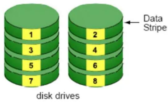
text_image
1 3 5 7 data Stripe 4 6 8 disk drivesThe RAID Volume's data capacity equals the capacity of the smallest disk drive times the number of disk drives. For example, one 100 GB and three 120 GB drives will form a 400 GB (4 x 100 GB) RAID Volume instead of 460 GB.
If disk drives of different capacities are used, there will also be unused capacity on the larger drives.
Because RAID 0 does not offer Fault Tolerance, meaning that you cannot recover your data after a disk drive failure, we do not recommend a RAID 0 Volume for your unit.
RAID 0 Volumes on this unit consist of one or more disk drives.
RAID 1 - Mirror
When a RAID Volume is mirrored, identical data is written to a pair of disk drives, while reads are performed in parallel. The reads are performed using elevator seek and load balancing techniques where the workload is distributed in the most efficient manner. Whichever drive is not busy and is positioned closer to the data will be accessed first.
With RAID 1, if one disk drive fails or has errors, the other mirrored disk drive continues to function. This is called Fault Tolerance. Moreover, if a spare disk drive is present, the spare drive will be used as the replacement drive and data will begin to be mirrored to it from the remaining good drive.
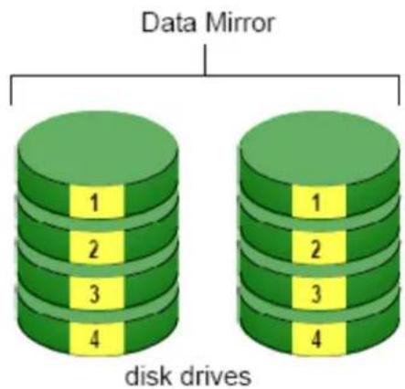
text_image
Data Mirror 1 2 3 4 disk drives 1 2 3 4The RAID Volume's data capacity equals the smaller disk drive. For example, a 100 GB disk drive and a 120 GB disk drive have a combined capacity of 100 GB in a mirrored RAID Volume.
If disk drives of different capacities are used, there will also be unused capacity on the larger drive.
RAID 1 Volumes on this unit consist of two disk drives.
If you want a mirrored RAID Volume with more than two disk drives, see RAID 10 - Mirror / Stripe for details.
RAID 5 - Block Striping with Distributed Parity
RAID 5 organizes block data and parity data across the disk drives. Generally, RAID level 5 tends to exhibit lower random write performance due to the heavy workload of parity recalculation for each I/O. RAID 5 works well for file, database, application and web servers.
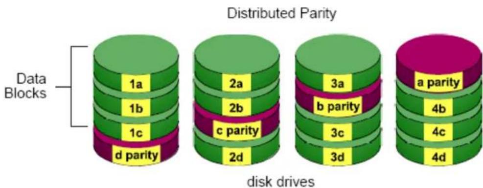
text_image
Distributed Parity Data Blocks 1a 1b 1c d parity 2a 2b c parity 2d 3a b parity 3c 3d 4a parity 4b 4c 4d disk drivesThe capacity of a RAID 5 Volume equals the smallest disk drive times the number of disk drives, minus one. Hence, a RAID 5 Volume with four 100 GB disk drives will have a capacity of 300 GB. A RAID Volume with two 120 GB disk drives and one 100 GB disk drive will have a capacity of 200 GB.
RAID 5 is generally considered to be the most versatile RAID level.
RAID 5 requires a minimum of three disk drives.
RAID 10 - Mirror / Stripe
Mirror/Stripe combines both of the RAID 0 and RAID 1 types. RAID 10 can increase performance by reading and writing data in parallel while protecting data with duplication. At least four disk drives are needed for RAID 10 to be installed. With a four-disk-drive RAID Volume, one drive pair is mirrored together then striped over a second drive pair.
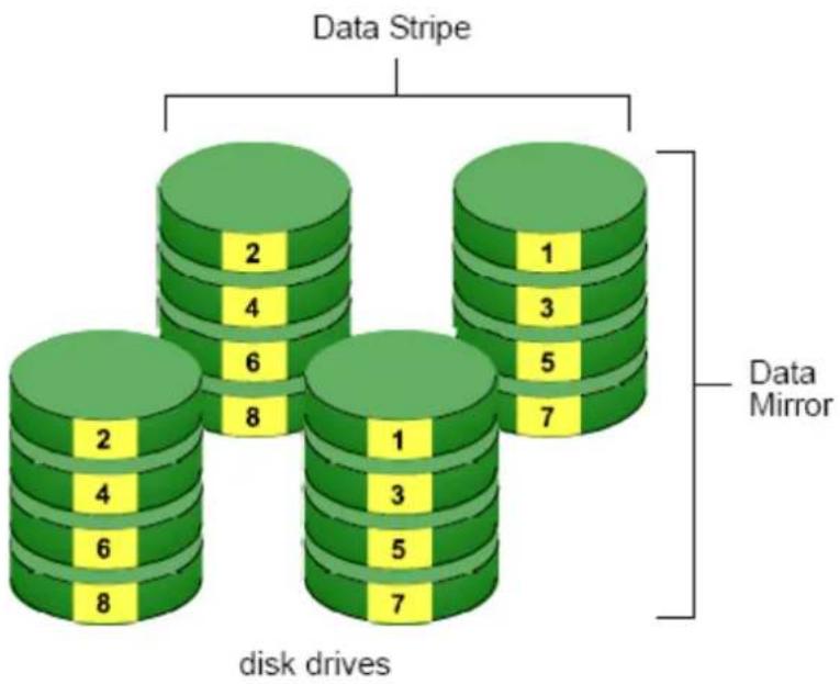
text_image
Data Stripe 2 4 6 8 1 3 5 7 Data Mirror 2 4 6 8 5 7 disk drivesThe data capacity RAID 10 Volume equals the capacity of the smallest disk drive times the number of disk drives, divided by two.
In some cases, RAID 10 offers double fault tolerance, depending on which disk drives fail.
RAID 10 Volumes on this unit consist of four disk drives.
Because all of the available disk drives are used for the RAID Volume, you cannot set up a spare drive with RAID 10.
Choosing a RAID Level
There are several issues to consider when choosing the RAID level. The following summarizes some advantages, disadvantages and applications for each choice.
RAID 0
| Advantage | Disadvantage |
| ● Implements a striped disk RAID Volume, the data is broken down into blocks and each block is written to a separate disk drive● I/O performance is greatly | ● Not a true RAID because it is not fault tolerant● The failure of just one drive will result in all data in a RAID Volume |
| improved by spreading the I/O load across many channels and drives● No parity calculation overhead is involved | being lost● Should not be used in mission critical environments |
RAID 1
| Advantage | Disadvantage |
| ● Simplest RAID storage subsystem design● Can increase read performance by processing data requests in parallel since the same data resides on two different drives | ● Very high disk overhead - uses only 50% of total capacity |
RAID 5
| Advantage | Disadvantage |
| High Read data transaction rateMedium Write data transaction rateGood aggregate transfer rateMost versatile RAID level | Disk failure has a medium impact on throughput |
RAID 10
| Advantage | Disadvantage |
| ● Implemented as a mirrored RAID● Volume whose segments are RAID 0 RAID Volumes● High I/O rates are achieved thanks to multiple stripe segments | ● Very high disk overhead – uses only 50% of total capacity |
Appendix – Camera Integration
Camera Support List
Any information about camera integration, including camera model and its spec, please refer to NUUO website:
http://www.nuuo.com/product.php?id=12
Add: C Block, 18 Sihyuan St. Jhongjheng District, Taiwan (ROC)
TEL: +886-2-2362-2260
E-mail: service@nuuo.com