
WAP7205 - Wi-Fi repeater ZYXEL - Free user manual and instructions
Find the device manual for free WAP7205 ZYXEL in PDF.


| Product Type | AC1300 Gigabit Ethernet MoCA Extender (Wi-Fi Repeater) |
| Wireless Standard | IEEE 802.11a/b/g/n/ac |
| Frequency Bands | 2.4 GHz and 5 GHz (simultaneous dual-band) |
| Maximum Wireless Data Rate | Up to 300 Mbps (2.4 GHz) + 867 Mbps (5 GHz) total 1167 Mbps (AC1300) |
| MoCA Standard | MoCA 2.0 (backward compatible with MoCA 1.1), up to 1 Gbps MAC throughput |
| Ethernet Ports | 2 x 10/100/1000 Mbps Gigabit Ethernet (LAN) |
| Coaxial Port | 1 x MoCA coaxial port (F-type connector) |
| Wireless Security | WPA2-PSK, WPA2 (with RADIUS), WPA-PSK compatible, MAC address filtering, WPS (Push Button and PIN) |
| Number of SSIDs | Up to 4 per band (8 total) |
| Management | Web-based configurator (HTTP/HTTPS), SNMP, WPS button, reset button |
| LED Indicators | Power, WiFi 2.4G, WiFi 5G, MoCA, LAN1, LAN2 |
| Dimensions (W x D x H) | Approx. 180 x 120 x 35 mm (estimated) |
| Weight | Approx. 300 g (estimated) |
| Power Supply | 12V DC, 1A (external power adapter) |
| Power Consumption | < 8 W (network standby), < 0.5 W (off mode) |
| Mounting | Wall-mountable (screws and anchors included) |
| Operating Temperature | 0°C to 40°C (32°F to 104°F) |
| Operating Humidity | 10% to 90% (non-condensing) |
| Default Login | Web address: http://zyxelsetup (Windows) / http://zyxelsetup.local (Mac); User: admin; Password: label behind ZYXEL logo plate |
| Reset to Factory Defaults | Press and hold RESET button for > 5 seconds |
| Firmware Upgrade | Via web configurator; download from support.zyxel.com |
| Warranty | Limited warranty (check region for duration) |
Frequently Asked Questions - WAP7205 ZYXEL
User questions about WAP7205 ZYXEL
0 question about this device. Answer the ones you know or ask your own.
Ask a new question about this device
Download the instructions for your Wi-Fi repeater in PDF format for free! Find your manual WAP7205 - ZYXEL and take your electronic device back in hand. On this page are published all the documents necessary for the use of your device. WAP7205 by ZYXEL.
USER MANUAL WAP7205 ZYXEL
AC1300 Gigabit Ethernet MoCA Extender
Default Login Details
| Web Address http://zyxelsetup (Windows)http://zyxelsetup.local (Mac) |
| LAN IP Address http://(DHCP-assigned IP) |
| User Name admin |
| Password (see the label behind theZYXEL logo plate for defaultkey) |
Version 1.00 Edition 1, 09/2017
bar
| Category | Value | | -------- | ----- | | Blue Bar | 100 | | Blue Bar | 150 | | Blue Bar | 200 | | Blue Bar | 250 | | Blue Bar | 300 | | Blue Bar | 350 | | Blue Bar | 400 | | Blue Bar | 450 | | Blue Bar | 500 | | Blue Bar | 550 | | Blue Bar | 600 | | Blue Bar | 650 | | Blue Bar | 700 | | Blue Bar | 750 | | Blue Bar | 800 | | Blue Bar | 850 | | Blue Bar | 900 | | Blue Bar | 950 | | Blue Bar | 1000 | | White Bar | 100 | | White Bar | 150 | | White Bar | 200 | | White Bar | 250 | | White Bar | 300 | | White Bar | 350 | | White Bar | 400 | | White Bar | 450 | | White Bar | 500 | | White Bar | 550 | | White Bar | 600 | | White Bar | 650 | | White Bar | 700 | | White Bar | 750 | | White Bar | 800 | | White Bar | 850 | | White Bar | 900 | | White Bar | 950 | | White Bar | 1000 |IMPORTANT!
READ CAREFULLY BEFORE USE.
KEEP THIS GUIDE FOR FUTURE REFERENCE.
Screenshots and graphics in this book may differ slightly from your product due to differences in your product firmware or your computer operating system. Every effort has been made to ensure that the information in this manual is accurate.
Related Documentation
- Quick Start Guide
The Quick Start Guide shows how to connect WAP7205 and access the web configurator.
- More Information
Go to support.zyxel.com to find other information on the WAP7205.

Contents Overview
User's Guide 8
Introducing the WAP7205 9
Introducing the Web Configurator 13
Dashboard 18
Easy123 Wizard Setup 21
Tutorials 23
Technical Reference 33
Monitor 34
Wireless LAN 39
LAN 55
MoCA 59
SNMP 63
Maintenance 66
Troubleshooting 73
Table of Contents
Contents Overview ....3
Table of Contents......4
Part I: User's Guide....8
Chapter 1 Introducing the WAP7205....9
1.1 Overview 9
1.2 Securing the WAP7205 9
1.3 LEDs 10
1.4 Resetting the WAP7205 11
1.4.1 RESET Button 11
1.5 WPS Button 11
1.6 Wall Mounting 12
Chapter 2 Introducing the Web Configurator ....13
2.1 Overview 13
2.2 Accessing the Web Configurator .... 13
2.2.1 Login Screen 13
2.3 Navigating the Web Configurator .... 15
2.3.1 Title Bar 15
2.3.2 Navigation Panel 16
Chapter 3 Dashboard....18
3.1 Dashboard Screen 18
Chapter 4 Easy123 Wizard Setup....21
4.1 Overview 21
4.2 Accessing the Wizard 21
4.3 Using the Wizard 21
Chapter 5 Tutorials ......23
5.1 Overview 23
5.2 Connecting to the WAP7205's Wi-Fi Network Using WPS 23
5.2.1 Push Button Configuration (PBC) 23
5.2.2 PIN Configuration 24
5.3 Connecting to the WAP7205's Wi-Fi Network Using SSID (No WPS) 25
5.3.1 Configuring Wireless Security on the WAP7205 26
5.3.2 Configuring Your Notebook 27
5.4 Using Multiple SSIDs on the WAP7205 29
5.4.1 Configuring Security Settings of Multiple SSIDs 30
Part II: Technical Reference 33
Chapter 6 Monitor....34
6.1 Overview 34
6.2 What You Can Do 34
6.3 Log 34
6.4 Packet Statistics 35
6.5 WLAN 2.4G Station Status 36
6.6 WLAN 5G Station Status .... 37
Chapter 7 Wireless LAN ....39
7.1 Overview 39
7.2 What You Can Do 39
7.3 What You Should Know 40
7.3.1 Wireless Security Overview 40
7.4 General Wireless LAN Screen 41
7.5 Wireless Security 43
7.5.1 No Security 44
7.5.2 WPA2-PSK 44
7.5.3 WPA2 45
7.6 More AP Screen 47
7.6.1 More AP Edit 48
7.7 MAC Filter 49
7.8 Wireless LAN Advanced Screen 50
7.9 Quality of Service (QoS) Screen 51
7.10 WPS Screen 52
7.11 WPS Station Screen 53
7.12 Scheduling Screen 53
Chapter 8 LAN ....55
8.1 Overview 55
8.2 What You Can Do 55
8.3 What You Need To Know 55
8.3.1 IP Alias 56
8.4 LAN IP Screen 56
8.5 IP Alias Screen 57
Chapter 9
MoCA....59
9.1 Overview 59
9.2 What You Can Do 59
9.3 MoCA Screen 60
9.4 MoCA Monitor Screen 61
Chapter 10
SNMP 63
10.1 Overview 63
10.2 SNMP Screen 64
Chapter 11
Maintenance 66
11.1 Overview 66
11.2 What You Can Do 66
11.3 General Screen 66
11.4 Account Screen 67
11.4.1 Edit a User's Account 67
11.5 Configuration Backup/Restore Screen 68
11.6 Restart Screen 69
11.7 Language Screen 70
11.8 Diagnostic Screens 70
11.8.1 Ping Screen 70
11.8.2 TraceRoute Screen 71
11.8.3 Nslookup Screen 72
Chapter 12
Troubleshooting....73
12.1 Power, Hardware Connections, and LEDs 73
12.2 WAP7205 Access and Login 74
12.3 Internet Access 75
12.4 Resetting the WAP7205 to Its Factory Defaults 76
12.5 Wireless Problems 76
12.6 MoCA Network 77
Table of Contents
Appendix A Customer Support 78
Appendix B Legal Information 84
Index 89
PART I
User's Guide
CHAPTER 1
Introducing the WAP7205
1.1 Overview
The WAP7205 extends the range of your existing wired network without additional wiring, providing easy network access to mobile users. You can set up a wireless network with other IEEE 802.11a/b/g/n/ac compatible devices. The WAP7205 is able to function both 2.4GHz and 5GHz networks at the same time.
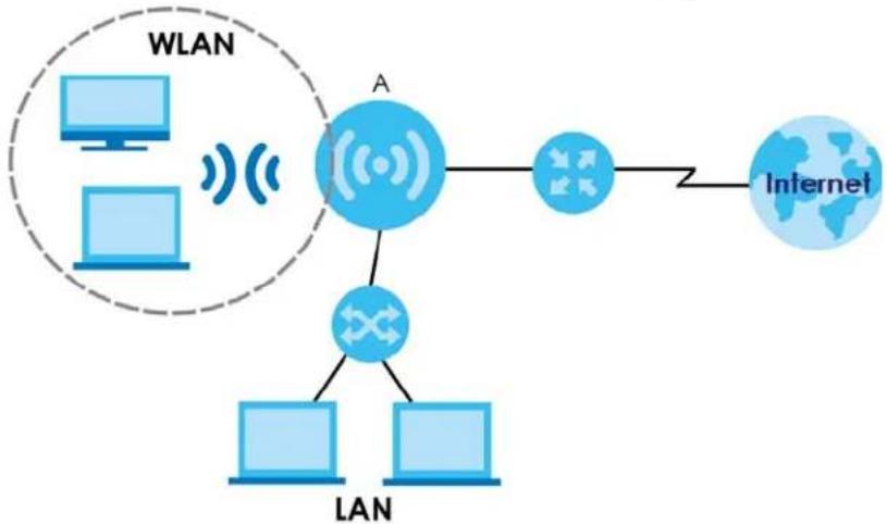
You can create the following connections using the WAP7205:
• LAN. You can connect network devices via the Ethernet port of the WAP7205 (A) so that they can communicate with each other and access the Internet.
- WLAN. Wireless clients can connect to the WAP7205 (A) to access network resources.
flowchart
graph TD
    A["Internet"] --> B["Network Node A"]
    B --> C["Network Node A"]
    C --> D["LAN"]
    D --> E["LAN"]
    F["WLAN"] --> G["Computer 1"]
    F --> H["Computer 2"]
    F --> I["Computer 3"]
    style A fill:#cce5ff,stroke:#333
    style B fill:#cce5ff,stroke:#333
    style C fill:#cce5ff,stroke:#333
    style D fill:#cce5ff,stroke:#333
    style E fill:#cce5ff,stroke:#333
    style F fill:#cce5ff,stroke:#333
    style G fill:#cce5ff,stroke:#333
The WAP7205 also comes with one coaxial port that supports MoCA (Multimedia over Coax Alliance) technology (see Chapter 9 on page 59).
Use a (supported) web browser to manage the WAP7205.
1.2 Securing the WAP7205
Do the following things regularly to make the WAP7205 more secure and to manage the WAP7205 more effectively.
- Change the password. Use a password that's not easy to guess and that consists of different types of characters, such as numbers and letters.
- Write down the password and put it in a safe place.
- Back up the configuration (and make sure you know how to restore it). Restoring an earlier working configuration may be useful if the device becomes unstable or even crashes. If you forget your password, you will have to reset the WAP7205 to its factory default settings. If you backed up an earlier configuration file, you would not have to totally re-configure the WAP7205. You could simply restore your last configuration.
1.3 LEDs
The following sections describes the LEDs on the WAP7205.
The following figure is the front panel of the WAP7205. Use the LEDs to determine if the WAP7205 is behaving normally or if there are some problems on your network.
Figure 1 WAP7205 Front Panel and Rear Panel
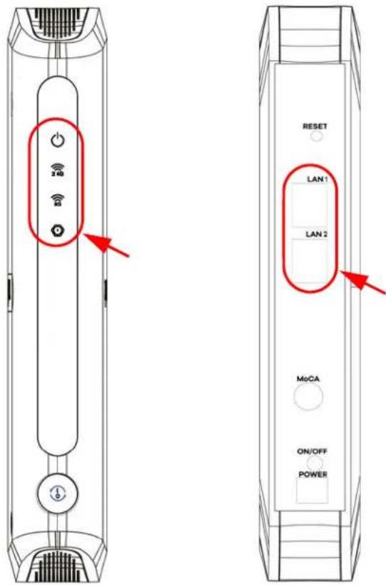
The following table describes the behavior of the lights on the WAP7205.
Table 1 WAP7205 LEDs
| LIGHTS ICON | COLOR | STATUS DES | CRIPTION | |
| POWER White | On The W | AP7205 is on | and receiving power. | |
| Blinking The | WAP7205 is in the process of starting up or default restoring. | |||
| Off The WAP | 7205 is not receiving power. | |||
Table 1 WAP7205 LEDs
| LIGHTS ICON | COLOR | STATUS DESCRIPTION | |
| WiFi 2.4G WiFi 5G |   | White On The WAP7205's wireless LAN is ready. | |
| Amber | Blinking | ||
| The WAP7205 is negotiating a WPS connection with a wireless device. | |||
| Process completed, WPS connection failed or WPS is disabled. | |||
MoCA White Or  | MoCA port is connected and the WAP7205 detects another MoCA device. | ||
| LAN1~2 Green | On This port has a successful link to an Ethernet network. | ||
1.4 Resetting the WAP7205
If you forget your password or IP address, or you cannot access the Web Configurator, press the RESET button for more than 5 seconds to reload the factory-default configuration file. This means that you will lose all configurations that you had previously saved, the password will be reset to the default key on the label behind the ZYXEL logo plate.
1.4.1 RESET Button
1 Make sure the power LED is on.
2 Press and hold the RESET button. After 5 seconds, the power LED begins flashing.
3 Release the RESET button. The WAP7205 reloads factory defaults and begins to reboot.
1.5 WPS Button
Your WAP7205 supports WiFi Protected Setup (WPS), which is an easy way to set up a secure wireless network. WPS is an industry standard specification, defined by the Wi-Fi Alliance.
WPS allows you to quickly set up a wireless network with strong security, without having to configure security settings manually. Each WPS connection works between two devices. Both devices must support WPS (check each device's documentation to make sure).
Depending on the devices you have, you can either press a button (recommended) on the device itself, or in its configuration utility or enter a PIN (a unique Personal Identification Number that allows one device to authenticate the other) in each of the two devices. When WPS is activated on a device, it has two minutes to find another device that also has WPS activated. Then, the two devices connect and set up a secure network by themselves.
1.6 Wall Mounting
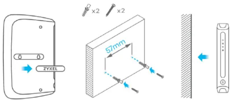
You may need screw anchors if mounting on a concrete or brick wall.
Table 2 Wall Mounting Information
| Distance between holes 5.7 cm | |
| M4 Screws Two | |
| Screw anchors (optional) Two |
1 Select a position free of obstructions on a wall strong enough to hold the weight of the device.
2 Mark two holes on the wall at the appropriate distance apart for the screws.
Be careful to avoid damaging pipes or cables located inside the wall when drilling holes for the screws.
3 If using screw anchors, drill two holes for the screw anchors into the wall. Push the anchors into the full depth of the holes, then insert the screws into the anchors. Do not insert the screws all the way in - leave a small gap of about 0.5 cm.
4 If not using screw anchors, use a screwdriver to insert the screws into the wall. Do not insert the screws all the way in - leave a gap of about 0.5 cm.
5 Make sure the screws are fastened well enough to hold the weight of the WAP7205 with the connection cables.
6 Remove the cover of the wall mounting holes. Align the holes on the back of the WAP7205 with the screws on the wall. Hang the WAP7205 on the screws.
CHAPTER 2
Introducing the Web
Configurator
2.1 Overview
This chapter describes how to access the WAP7205 Web Configurator and provides an overview of its screens.
The Web Configurator is an HTML-based management interface that allows easy setup and management of the WAP7205 via Internet browser. Use Internet Explorer 8.0 and later or Safari 2.0 or later versions. The recommended screen resolution is 1024 by 768 pixels.
In order to use the Web Configurator you need to allow:
- Web browser pop-up windows from your device. Web pop-up blocking is enabled by default in Windows XP SP (Service Pack) 2.
- JavaScripts (enabled by default).
- Java permissions (enabled by default).
2.2 Accessing the Web Configurator
1 Make sure your WAP7205 hardware is properly connected. See the Quick Start Guide.
2 Open a web browser such as Internet Explorer.
3 Type "http://zyxelsetup" (for Windows) or "http://zyxelsetup.local" (for Mac) as the web address in your web browser.
The WAP7205 is a DHCP client by default. Alternatively, check the connected gateway for the WAP7205's current IP address. Make sure your computer's IP address is in the same subnet as the WAP7205's IP address. Type "http://(DHCP-assigned IP)" as the web address in your web browser.
2.2.1 Login Screen
The Web Configurator initially displays the following login screen.
Figure 2 Login screen
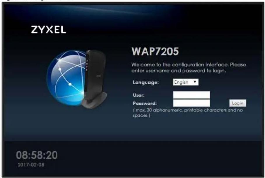
The following table describes the labels in this screen.
Table 3 Login screen
| LABEL DESCRIPTION | |
| Language Select the language you want to use to configure the Web Configurator. | |
| User Type “admin” (default) as the user name. | |
| Password | Type the default key on the label behind the ZYXEL logo plate as the password. Click Login. |
| This shows the time (hh:mm) and date (yyyy:mm:dd) of the timezone you select in the Maintenance > Time screen (see Section 12.5 on page 71). The time is in 24-hour format, for example 15:00 is 3:00 PM. | |
Note: The management session automatically times out when the time period set in the Administrator Inactivity Timer field expires (default five minutes; go to Section 11.3 on page 66 to change this). Simply log back into the WAP7205 if this happens.
Right after you log in, the Dashboard screen is displayed. See Chapter 3 on page 18 for more information about the Dashboard screen.
2.3 Navigating the Web Configurator
The following summarizes how to navigate the web configurator from the Dashboard screen.
Figure 3 Status Screen of the Web Configurator
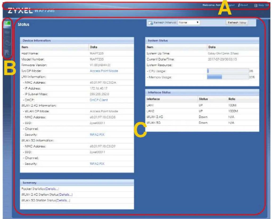
As illustrated above, the Web Configurator screen is divided into these parts:
• A - title bar
• B - navigation panel
• C - main window
2.3.1 Title Bar
The title bar provides some useful links that always appear over the screens below, regardless of how deep into the Web Configurator you navigate.
Figure 4 Title Bar

The icons provide the following functions.
Table 4 Title Bar: Web Configurator Icons
| LABEL DESCRIPTION | |
| Logout Click this at any time to exit the Web Configurator. | |
| About Click this icon to view copyright and a link for related product information. | |
| Easy123 | Click this icon to open the wizard to give a name and password to identify your WAP7205 in the WiFi network. See Chapter 6 on page 33. |
2.3.2 Navigation Panel
Use the menu items on the navigation panel to open screens to configure WAP7205 features.
The following table describes the icons shown in the navigation panel.
Table 5 Navigation Panel Menu Icons
| ICON DESCRIPTION | |
 | Click this icon to see the Status page. The information in this screen depends on the device mode you select. |
 | Click this icon to see the Monitor navigation menu. |
| [TWSW] | Click this icon to see the Configuration navigation menu. |
 | Click this icon to see the Maintenance navigation menu. |
The following tables describe each menu item.
Table 6 Navigation Panel
| LINK TAB FUNCTION | ||
| Dashboard | This screen shows the WAP7205's general device, system and interface status information. Use this screen to access the summary statistics tables. | |
| MONITOR | ||
| Log | View Log | Use this screen to view the list of activities recorded by your WAP7205. |
| Log Setting | Use this screen to specify which logs to display in the View Log screen. | |
| Packet Statistics Packet Statistics | Use this screen to view port status and packet specific statistics. | |
| WLAN 2.4G Station Status | Association List | Use this screen to view the details about the devices connected to your WAP7205, using the 2.4G wireless connection. |
| WLAN 5G Station Status | Association List | Use this screen to view the details about the devices connected to your WAP7205, using the 5G wireless connection. |
| CONFIGURATION | ||
| Network | ||
Table 6 Navigation Panel
| LINK | TAB | FUNCTION |
| Wireless LAN 2.4 and Wireless LAN 5G | General | Use this screen to configure general wireless LAN and wireless security settings. |
| More AP | Use this screen to enable and configure multiple wireless networks on the WAP7205. | |
| MAC Filter | Use the MAC filter screen to configure the WAP7205 to block access to devices or block the devices from accessing the WAP7205. | |
| Advanced This screen allows you to configure advanced wireless settings. | ||
| QoS | Use this screen to configure WiFi Multimedia Quality of Service (WMM QoS). WMM QoS allows you to prioritize wireless traffic according to the delivery requirements of individual services. | |
| WPS Use this screen to configure WPS. | ||
| WPS Station Use this screen to add a wireless station using WPS. | ||
| Scheduling | Use this screen to schedule the times the Wireless LAN is enabled. | |
| LAN | IP | Use this screen to configure LAN IP address and subnet mask. |
| IP Alias | Use this screen to have the WAP7205 apply IP alias to create LAN subnets. | |
| MoCA | MoCA | Use this screen to set the MoCA Privacy, and enable multimedia and home networking over coaxial cabling. |
| Monitor Use this screen to view the MoCA connection status and information about the connected MoCA device(s). | ||
| Management | ||
| Remote MGMT | SNMP Use this screen to configure the WAP7205 SNMP settings. | |
| MAINTENANCE | ||
| General | General | Use this screen to view and change administrative settings such as system and domain names. |
| Account | User Account | Use this screen to change the password of your WAP7205. |
| Backup/Restore | Backup/Restore | Use this screen to backup and restore the configuration or reset your WAP7205 to the factory defaults. |
| Restart | System Restart | This screen allows you to reboot the WAP7205 without turning the power off. |
| Language | Language | This screen allows you to select the language you prefer. |
| Diagnostic | Ping | Use this screen to ping an IP address. |
| TraceRoute | Use this screen to trace the route packets take to a host. | |
| Nslookup | Use this screen to perform an nslookup (name server lookup). | |
CHAPTER 3 Dashboard
The Dashboard screens display when you log into the WAP7205, or click Dashboard in the navigation menu.
Use the Dashboard screen to look at the current status of the device, system resources, and interfaces. The Dashboard screens also provide detailed information about system statistics, associated wireless clients, and logs.
3.1 Dashboard Screen
Use this screen to get a quick view of system, Ethernet, WLAN and other information regarding your WAP7205.
Click Dashboard. The following screen displays.
Figure 5 The Dashboard Screen
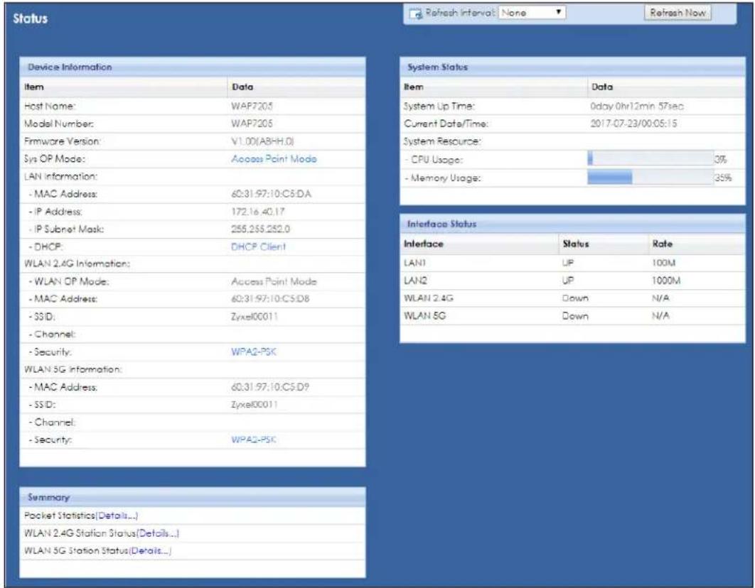
The following table describes the labels in this screen.
Table 7 The Dashboard Screen
| LABEL DESCRIPTION | |
| Refresh Interval | Select a number of seconds or None from the drop-down list box to refresh all screen statistics automatically at the end of every time interval or to not refresh the screen statistics. |
| Refresh Now Click this button to refresh the status screen statistics. | |
| Device Information | |
| Host Name | This is the System Name to enter in the Maintenance > General screen for identification purposes. |
| Model Number This is the WAP7205's model name. | |
| Firmware Version This is the firmware version and the date created. | |
| Sys OP Mode This is the device mode to which the WAP7205 is set - Access Point Mode. | |
| LAN Information | |
| MAC Address This shows the LAN Ethernet adapter MAC Address of your device. | |
| IP Address This shows the LAN port's IPv4 address. | |
| IP Subnet Mask This shows the LAN port's subnet mask. | |
| DHCP | This shows the LAN port's DHCP role - Client or None. |
| WLAN 2.4G Information | |
| WLAN OP Mode | This is the device mode to which the WAP7205's 2.4GHz wireless LAN is set - Access Point Mode. |
| MAC Address This shows the wireless adapter MAC Address of your device. | |
| SSID This shows a descriptive name used to identify the WAP7205 in the wireless LAN. | |
| Channel | This shows the channel number which the WAP7205 is currently using over the wireless LAN. |
| Security This shows the level of wireless security the WAP7205 is using. | |
| WLAN 5G Information | |
| MAC Address This shows the wireless adapter MAC Address of your device. | |
| SSID This shows a descriptive name used to identify the WAP7205 in the wireless LAN. | |
| Channel | This shows the channel number which the WAP7205 is currently using over the wireless LAN. |
| Security This shows the level of wireless security the WAP7205 is using. | |
| Summary | |
| Packet Statistics | Click Details... to go to the Monitor > Packet Statistics screen (Section 6.4 on page 35). Use this screen to view port status and packet specific statistics. |
| WLAN 2.4G Station Status | Click Details... to go to the Monitor > WLAN Station Status screen (Section 6.5 on page 36). Use this screen to view the 2.4GHz wireless stations that are currently associated to the WAP7205. |
| WLAN 5G Station Status | Click Details... to go to the Monitor > WLAN Station Status screen (Section 6.6 on page 37). Use this screen to view the 5GHz wireless stations that are currently associated to the WAP7205. |
| System Status | |
| Item | This column shows the type of data the WAP7205 is recording. |
| Data | This column shows the actual data recorded by the WAP7205. |
| System Up Time | This is the total time the WAP7205 has been on. |
| Current Date/Time | This field displays your WAP7205's present date and time. |
| System Resource | |
| CPU Usage | This displays what percentage of the WAP7205's processing ability is currently used. When this percentage is close to 100%, the WAP7205 is running at full load, and the throughput is not going to improve anymore. If you want some applications to have more throughput, you should turn off other applications (for example, using bandwidth management. |
| Memory Usage | This shows what percentage of the heap memory the WAP7205 is using. |
Table 7 The Dashboard Screen
| LABEL DESCRIPTION | |
| Interface Status | |
| Interface | This displays the WAP7205 port types. The port types are: LAN and WLAN. |
| Status | For the LAN ports, this field displays Down (line is down) or Up (line is up or connected). For the WLAN, it displays Up when the WLAN is enabled or Down when the WLAN is disabled. |
| Rate | For the LAN ports, this displays the port speed or N/A when the line is disconnected. For the WLAN, it displays the maximum transmission rate when the WLAN is enabled and N/A when the WLAN is disabled. |
CHAPTER 4
Easy123 Wizard Setup
4.1 Overview
This chapter provides information on the Wizard setup screens in the Web Configurator. The Web Configurator Wizard setup helps you configure your device.
4.2 Accessing the Wizard
1 Launch your web browser and type "http://zyxelsetup" (for Windows) or "http://zyxelsetup.local" (for Mac) as the website address. See Section 2.2 on page 13 for detailed information.
Note: The wizard appears when the WAP7205 is accessed for the first time or when you reset the WAP7205 to its default factory settings.
2 The wizard screen opens.
Note: If you have already configured the wizard screens and want to open it again, click the Easy123 icon ( ) on the upper right corner of any Web Configurator screen.
4.3 Using the Wizard
After you access the WAP7205 Web Configurator, click Easy 123 to begin the Wizard setup, located in the Title Bar.
Figure 6 Wizard Setup Screen
![eaZy 123 Setup [Skip Setup] ① MoCA Detection We couldn't detect a MoCA connection. Please make sure to connect an additional MoCA Ethernet adapter to your Internet router or gateway! Detect Again ② Wireless Network Wireless Name (SSID): Zyxel00011 Wireless Password (WPA2): Set your Wi-Fi password here Edit 5 GHz wireless network Your 5 GHz (11cc) wireless name will be the same as 2.4G by default. Check 'Edit 5 GHz wireless network: it you would like to make it different from its default setting. ③ Apply Settings Apply IMPORTANT! Please write down all information that you've input here, so that you can refer to it in the future. When you're ready to apply this setup, click on "Apply" Zylea Communications (C) 2017](/content/2026/05/763139/images/85ded3a43bc9f958036ee31638fe63075c6bdfdc7fd9c49702f3fbabbf8202e7.jpg)
The following table describes the labels in this screen.
Table 8 Wizard Setup Screen
| LABEL DESCRIPTION | |
| MoCA Detection This shows d | etails of the connection between other MoCA devices and your WAP7205. Otherwise, check the physical connection and click Detect Again. |
| Wireless Network Use this step to configure your WAP7205 wireless network. | |
| Wireless Name (SSID) | Enter a descriptive name used to identify your WAP7205 in the wireless network. |
| Wireless Password (WPA2) | Enter the password that lets you connect to the WAP7205 wireless network. Your password should be in a string of ASCII characters between 8 and 63 or hexadecimal characters between 8 and 64. |
| Edit 5 GHz wireless network | Click this to view and/or change your 5Ghz wireless network SSID and password. |
| Apply Settings | Click Apply to save your settings to the WAP7205. |
| Skip Setup Click this to skip the Wizard setup and go to the Dashboard screen. | |
CHAPTER 5 Tutorials
5.1 Overview
This chapter provides tutorials for your WAP7205 as follows:
- Connecting to the WAP7205's Wi-Fi Network Using WPS
- Connecting to the WAP7205's Wi-Fi Network Using SSID (No WPS)
• Using Multiple SSIDs on the WAP7205
5.2 Connecting to the WAP7205's Wi-Fi Network Using WPS
This section gives you an example of how to set up a wireless network using WPS. This example uses the WAP7205 as the AP and a WPS-enabled Android smartphone as the wireless client.
There are two WPS methods for creating a secure connection. This tutorial shows you how to do both.
- Push Button Configuration (PBC) - create a secure wireless network simply by pressing a button. See Section 5.2.1 on page 23. This is the easier method.
- PIN Configuration - create a secure wireless network simply by entering a wireless client's PIN (Personal Identification Number) in the WAP7205's interface. See Section 5.2.2 on page 24. This is the more secure method, since one device can authenticate the other.
5.2.1 Push Button Configuration (PBC)
1 Make sure that your WAP7205 is turned on and that it is within range of your wireless client.
2 WPS is enabled by default on the WAP7205. If not, log into WAP7205's Web Configurator and turn it on in the Network > Wireless LAN 2.4G or 5G > WPS screen. You can either press the WPS button on the WAP7205's panel or press the Push Button button in the Network > Wireless LAN 2.4G or 5G > WPS Station screen.
3 Go to your phone settings and turn on Wi-Fi. Open the Wi-Fi networks list and tap WPS Push Button or the WPS icon ( ).
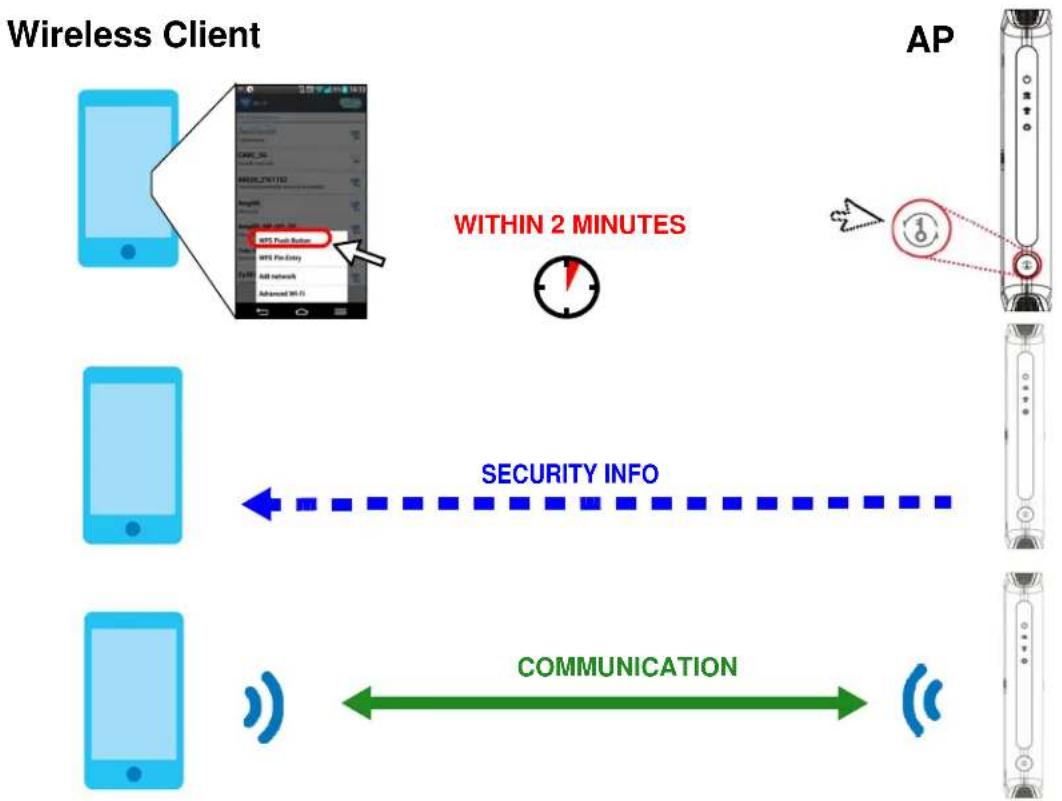
Note: It doesn't matter which button is pressed first. You must press the second button within two minutes of pressing the first one.
The WAP7205 sends the proper configuration settings to the wireless client. This may take up to two minutes. Then the wireless client is able to communicate with the WAP7205 securely.
The following figure shows you how to set up wireless network and security by pressing a button on both WAP7205 and wireless client (the Android smartphone in this example).
Figure 7 Example WPS Process: PBC Method
flowchart
graph TD
    A["Wireless Client"] --> B["AP"]
    B --> C["AP"]
    C --> D["SECURITY INFO"]
    D --> E["COMMUNICATION"]
    E --> F["AP"]
    style A fill:#cce5ff,stroke:#333
    style B fill:#ffcccc,stroke:#333
    style C fill:#ffffff,stroke:#333
    style D fill:#ffffff,stroke:#333
    style E fill:#ffffff,stroke:#333
    style F fill:#ffffff,stroke:#333
5.2.2 PIN Configuration
When you use the PIN configuration method, you need to check the client's PIN number and use the WAP7205's configuration interface.
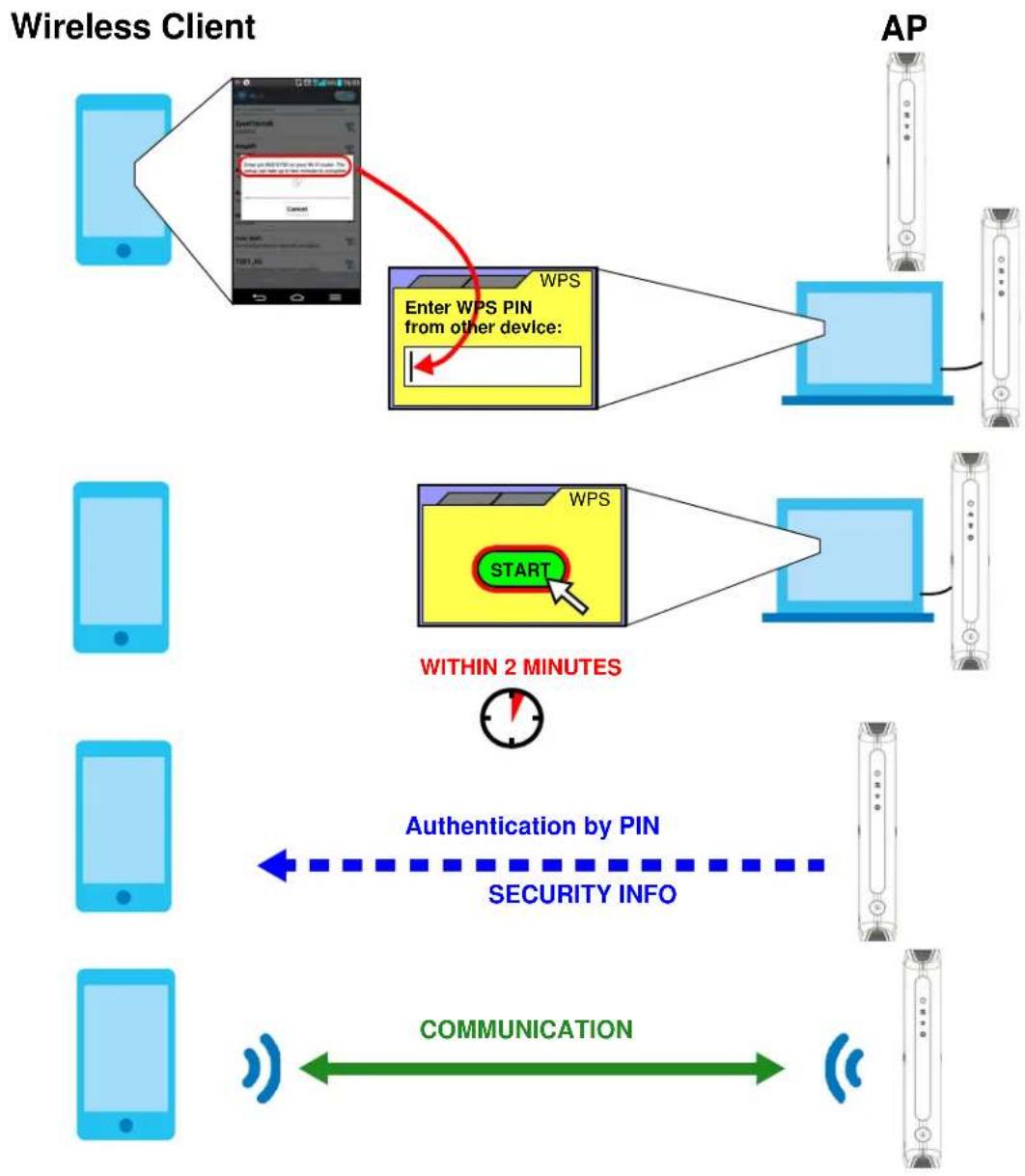
1 Go to your phone settings and turn on Wi-Fi. Open the Wi-Fi networks list and tap WPS PIN Entry to get a PIN number.
2 Enter the client's PIN number to the PIN field in the Network > Wireless LAN 2.4G or 5G > WPS Station screen on the WAP7205.
3 Click the Start button (or button next to the PIN field) on the WAP7205's WPS Station screen within two minutes.
The WAP7205 authenticates the wireless client and sends the proper configuration settings to the wireless client. This may take up to two minutes. Then the wireless client is able to communicate with the WAP7205 securely.
The following figure shows you how to set up wireless network and security on the WAP7205 and wireless client (the Android smartphone in this example) by using PIN method.
Figure 8 Example WPS Process: PIN Method
flowchart
graph TD
    A["AP"] --> B["Wireless Client"]
    B --> C["AP"]
    C --> D["Wireless Client"]
    D --> E["AP"]
    E --> F["Wireless Client"]
    F --> G["AP"]
    G --> H["Wireless Client"]
    H --> I["AP"]
    I --> J["Wireless Client"]
    J --> K["AP"]
    K --> L["Wireless Client"]
    L --> M["AP"]
    M --> N["Wireless Client"]
    N --> O["AP"]
    O --> P["Wireless Client"]
    P --> Q["AP"]
    Q --> R["Wireless Client"]
    R --> S["AP"]
    S --> T["Wireless Client"]
    T --> U["AP"]
    U --> V["Wireless Client"]
    V --> W["AP"]
    W --> X["Wireless Client"]
    X --> Y["AP"]
    Y --> Z["Wireless Client"]
    Z --> AA["AP"]
    AA --> AB["Wireless Client"]
    AB --> AC["AP"]
    AC --> AD["Wireless Client"]
    AD --> AE["AP"]
    AE --> AF["Wireless Client"]
    AF --> AG["AP"]
    AG --> AH["Wireless Client"]
    AH --> AI["AP"]
    AI --> AJ["Wireless Client"]
    AJ --> AK["AP"]
    AK --> AL["Wireless Client"]
    AL --> AM["AP"]
    AM --> AN["Wireless Client"]
    AN --> AO["AP"]
    AO --> AP["Wireless Client"]
    AP --> AQ["AP"]
    AQ --> AR["Wireless Client"]
    AR --> AS["AP"]
    AS --> AT["Wireless Client"]
    AT --> AU["AP"]
    AU --> AV["Wireless Client"]
    AV --> AW["AP"]
    AW --> AX["Wireless Client"]
    AX --> AY["AP"]
    AY --> AZ["Wireless Client"]
    AZ --> BA["AP"]
    BA --> BB["Wireless Client"]
    BB --> BC["AP"]
    BC --> BD["Wireless Client"]
    BD --> BE["AP"]
    BE --> BF["Wireless Client"]
    BF --> BG["AP"]
    BG --> BH["Wireless Client"]
    BH --> BI["AP"]
    BI --> BJ["Wireless Client"]
    BJ --> BK["AP"]
    BK --> BL["Wireless Client"]
    BL --> BM["AP"]
    BM --> BN["Wireless Client"]
    BN --> BO["AP"]
    BO --> BP["Wireless Client"]
    BP --> BQ["AP"]
    BQ --> BR["Wireless Client"]
    BR --> BS["AP"]
    BS --> BT["Wireless Client"]
    BT --> BU["AP"]
    BU --> BV["Wireless Client"]
    BV --> BW["AP"]
    BW --> BX["Wireless Client"]
    BX --> BY["AP"]
    BY --> BZ["Wireless Client"]
5.3 Connecting to the WAP7205's Wi-Fi Network Using SSID (No WPS)
In this example, we change the WAP7205's wireless settings, and then manually select the WAP7205's new SSID and enter the Wi-Fi key to connect a wireless client to the WAP7205.
5.3.1 Configuring Wireless Security on the WAP7205
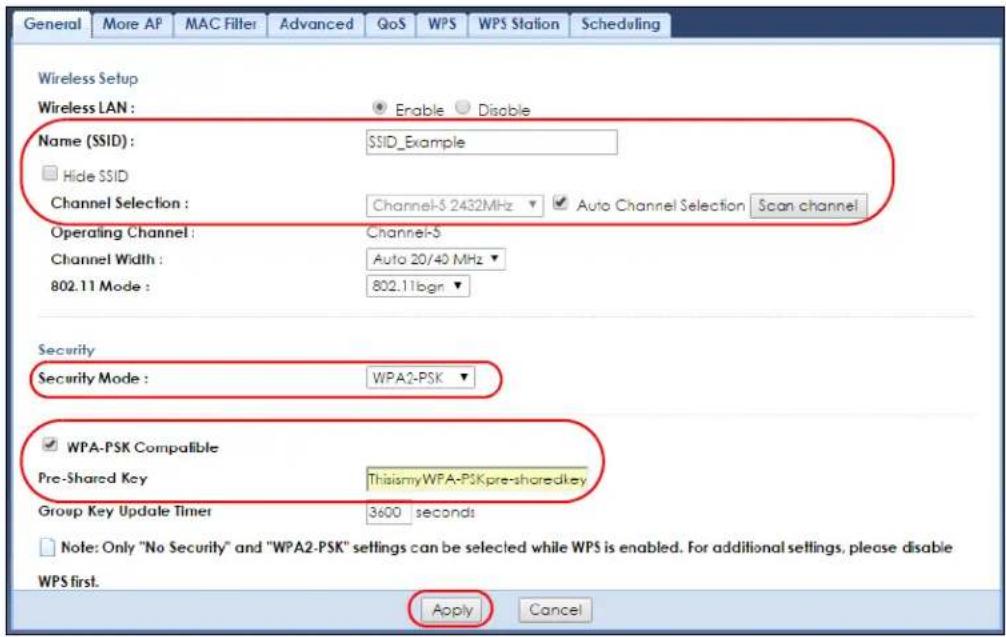
This section shows you how to configure wireless security settings with the following parameters on your WAP7205.
| Frequency Band 2.4 GHz | |
| SSID SSID_Example | |
| Channel Auto | |
| Security WPA2-PSK | (Pre-Shared Key: ThisismyWPA-PSKpre-sharedkey) |
Follow the steps below to configure the wireless settings on your WAP7205.
The instructions require that your hardware is connected (see the Quick Start Guide) and you are logged into the Web Configurator through your LAN connection (see Section 5.2 on page 41).
1 Open the Wireless LAN 2.4G > General screen in the WAP7205's Web Configurator.
2 Enter SSID_Example as the SSID and select Auto Channel Selection to have the WAP7205 scans for and select an available channel automatically.
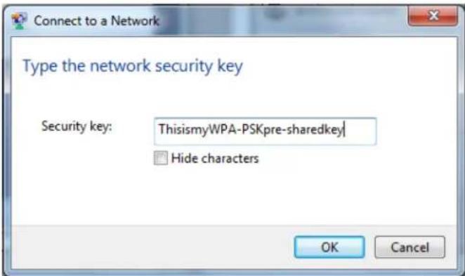
3 Set security mode to WPA2-PSK and enter ThisismyWPA-PSKpre-sharedkey in the Pre-Shared Key field. Select WPA-PSK Compatible to allow wireless devices using WPA-PSK security mode to connect to the WAP7205. Click Apply.
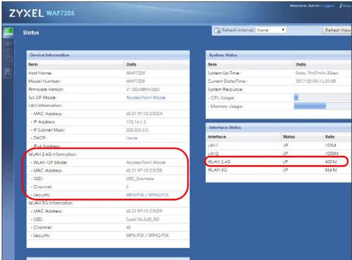
4 Open the Status screen. Verify your wireless and wireless security settings under Device Information and check if the WLAN connection is up under Interface Status.
5.3.2 Configuring Your Notebook
Note: In this example, we use a Windows 7 laptop that has a built-in wireless adapter as the wireless client.
1 The WAP7205 supports IEEE 802.11b, IEEE 802.11g, IEEE 802.11n, IEEE 802.11a, IEEE 802.11an and IEEE 802.11ac wireless clients. Make sure that your notebook or computer's wireless adapter supports one of these standards.
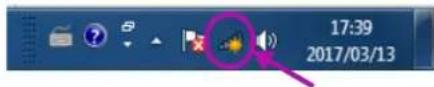
2 Click the Wi-Fi icon in your computer's system tray.
3 The Wireless Network Connection screen displays. Click the refresh button to update the list of the available wireless APs within range.
4 Select SSID_Example and click Connect.
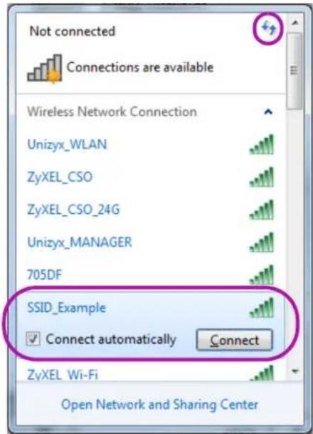
5 The following screen displays if WPS is enabled on the WAP7205 but you didn't press the WPS button. Click Connect using as security key instead.
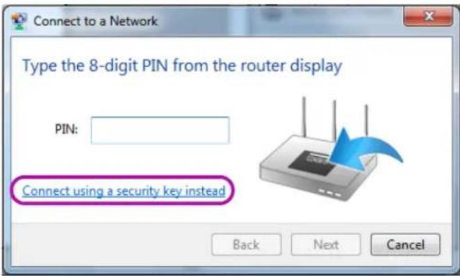
6 Type the security key in the following screen. Click OK.
7 Check the status of your wireless connection in the screen below.
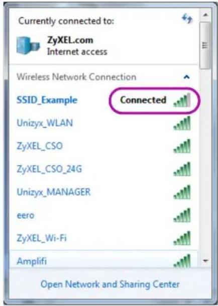
8 If the wireless client keeps trying to connect to or acquiring an IP address from the WAP7205, make sure you entered the correct security key.
If the connection has limited or no connectivity, make sure the WAP7205 is connected to a router with the DHCP server enabled.
If your connection is successful, open your Internet browser and enter http://www.zyxel.com or the URL of any other web site in the address bar. If you are able to access the web site, your wireless connection is successfully configured.
5.4 Using Multiple SSIDs on the WAP7205
You can configure more than one SSID on a WAP7205. This allows you to configure multiple independent wireless networks on the WAP7205 as if there were multiple APs (virtual APs). Each virtual AP has its own SSID, wireless security type and MAC filtering settings. That is, each SSID on the WAP7205 represents a different access point/wireless network to wireless clients in the network.
Clients can associate only with the SSIDs for which they have the correct security settings. Clients using different SSIDs can access the Internet and the wired network behind the WAP7205 (such as a printer), but they cannot listen to each other's traffic.
For example, you may set up three wireless networks (A, B and C) in your office. A is for workers, B is for guests and C is specific to a VoIP device in the meeting room.

flowchart
graph TD
    subgraph_User_A["SSI D_Worker A"]
        A1["Computer"] -->|Wireless Signal| Node
        Node -->|Signal| Internet
    end
    subgraph_User_B["SSI D_Guest B"]
        B1["Mobile Device"] -->|Wireless Signal| Node
        Node -->|Signal| Internet
    end
    subgraph_User_C["SSI D_VoIP C"]
        C1["Computer"] -->|Wireless Signal| Node
        Node -->|Signal| Internet
    end
5.4.1 Configuring Security Settings of Multiple SSIDs
This example shows you how to configure the SSIDs with the following parameters on your WAP7205 (in access point mode).
| SSID SECURITY TYPE KEY | INTRA-BSS TRAFFIC BLOCKING | MAC FILTERING | |
| SSID_Worker WPA2-PSKWPA Compatible | DoNotStealMyWirelessNetwork No Disable | ||
| SSID_Guest WPA2-PSKWPA Compatible | keyexample123 No Disable | ||
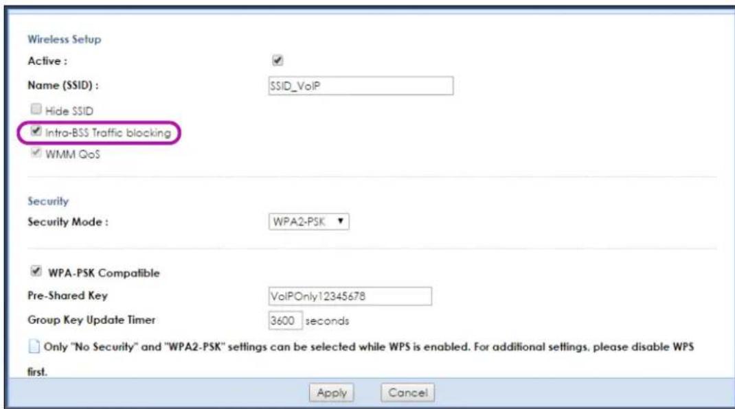
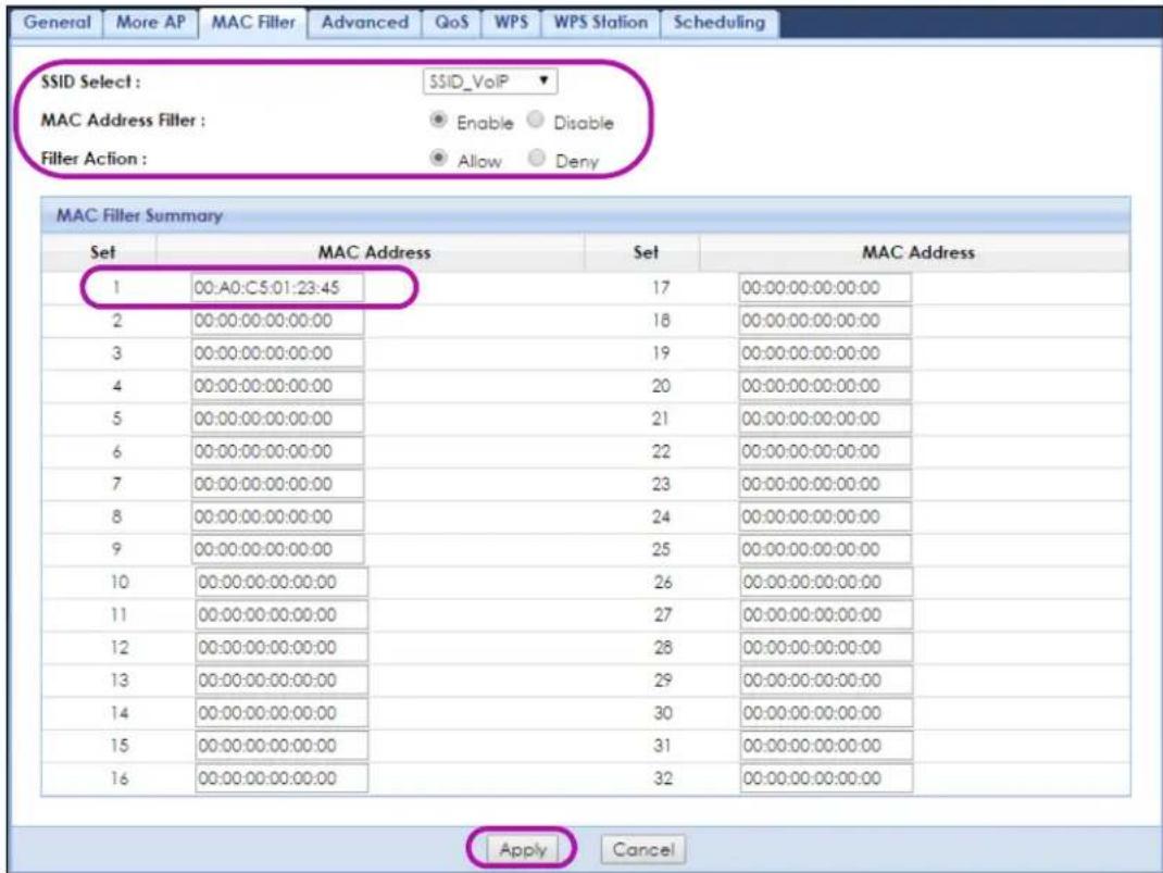
| SSID_VoIP WPA2-PSKWPA Compatible | VoIPOnly12345678 Yes Allow | 00:A0:C5:01:23:45 |
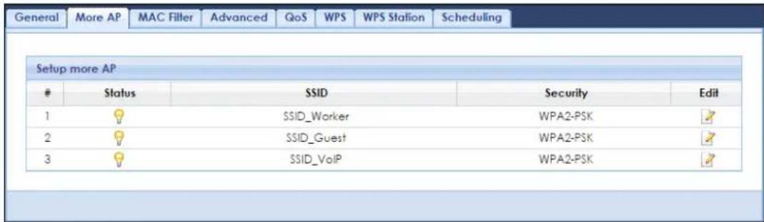
1 Go to Configuration > Network > Wireless LAN 2.4G or 5G > More AP. Configure the screen as follows. In this example, you select Intra-BSS Traffic blocking for SSID_VolP but disable Intra-BSS Traffic blocking for SSID_Worker and SSID_Guest to allow wireless clients in the same wireless network to communicate with each other. Click Apply.
2 Click the MAC Filter tab to configure MAC filtering for the SSID_VoIP wireless network. Select SSID_VoIP from the SSID Select drop-down list, enable MAC address filtering and select Allow in the Filter Action field. Enter the VoIP device's MAC address in the MAC Address field and click Apply to allow only the VoIP device to associate with the WAP7205 using this SSID.
PART II
Technical Reference
CHAPTER 6 Monitor
6.1 Overview
This chapter discusses read-only information related to the device state of the WAP7205.
Note: To access the Monitor screens, you can also click the links in the Summary table of the Status screen to view the packets sent/received as well as the status of clients connected to the WAP7205.
6.2 What You Can Do
- Use the Log screen (Section 6.3 on page 34) to view the logs for the categories such as system maintenance, system errors, and so on.
- use the Packet Statistics screen (Section 6.4 on page 35) to view port status, packet specific statistics, the "system up time" and so on.
- Use the WLAN 2.4G Station Status screen (Section 6.5 on page 36) to view the wireless stations that are currently associated to the WAP7205.
- Use the WLAN 5G Station Status screen (Section 6.6 on page 37) to view the wireless stations that are currently associated to the WAP7205.
6.3 Log
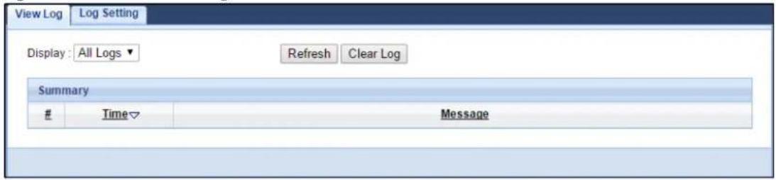
Use the View Log screen to see the logged messages for the WAP7205.
Log entries in red indicate system error logs. The log wraps around and deletes the old entries after it fills.
Click Monitor > Log.
Figure 9 Monitor > View Log
The following table describes the labels in this screen.
Table 9 Monitor > Log
| LABEL DESCRIPTION | |
| Display | Select what logs you want to see from the Display drop list. The log choices depend on your settings in the Log Setting screen. |
| Refresh | Click Refresh to renew the log screen. |
| Clear Log | Click Clear Log to delete all the logs. |
| # | This field is a sequential value and is not associated with a specific entry. |
| Time This field displays | the time the log was recorded. |
| Message This field states | the reason for the log. |
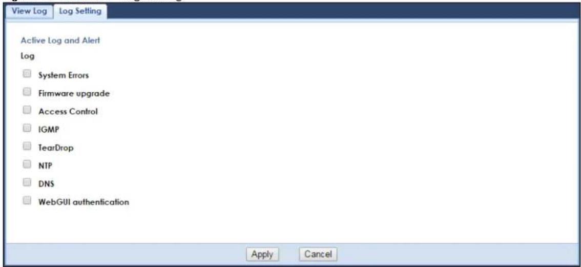
You can configure which logs to display in the View Log screen. Go to the Log Setting screen and select the logs you wish to display. Click Apply to save your settings. Click Cancel to start the screen afresh.
Figure 10 Monitor > Log Setting
6.4 Packet Statistics
Click the Packet Statistics (Details...) hyperlink in the Dashboard screen or Monitor > Packet Statistics. Read-only information here includes port status, packet specific statistics and the "system up time". The Poll Interval(s) field is configurable and is used for refreshing the screen.
Figure 11 Monitor > Packet Statistics
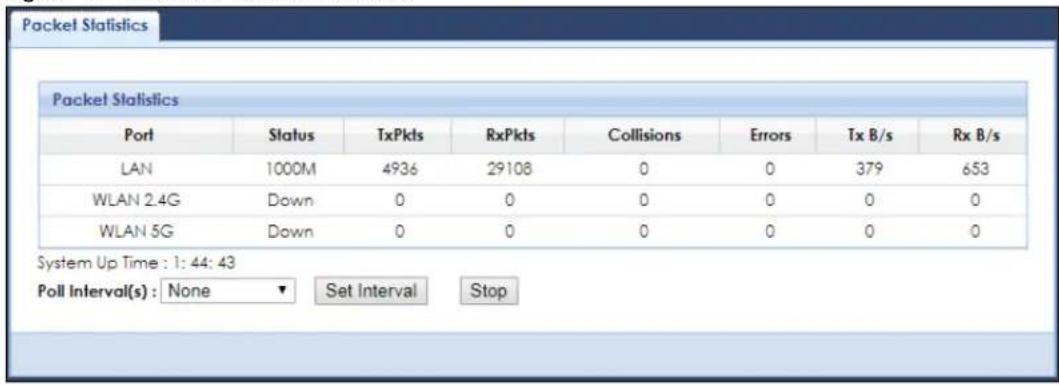
The following table describes the labels in this screen.
Table 10 Monitor > Packet Statistics
| LABEL DESCRIPTION | |
| Port This is the WAP7205's interface type. | |
| Status | For the LAN port, this displays the port speed orDownwhen the line is disconnected.For the WLAN, it displays the maximum transmission rate when the WLAN is enabled andDownwhen the WLAN is disabled. |
| TxPkts This is the number of transmitted packets on this port. | |
| RxPkts This is the number of received packets on this port. | |
| Collisions This is the number of collisions on this port. | |
| Errors This is the number of received errors on this port. | |
| Tx B/s | This displays the transmission speed in bytes per second on this port. |
| Rx B/s | This displays the reception speed in bytes per second on this port. |
| System Up Time This is the total time the WAP7205 has been on. | |
| Poll Interval(s) | Enter the time interval in seconds for refreshing statistics in this field. |
| Set Interval | Click this button to apply the new poll interval you entered in thePoll Interval(s)field. |
| Stop | ClickStopto stop refreshing statistics. |
6.5 WLAN 2.4G Station Status
Click the WLAN 2.4G Station Status (Details...) hyperlink in the Dashboard screen or Monitor > WLAN 2.4G Station Status. View the 2.4G wireless stations that are currently associated to the WAP7205 in the Association List. Association means that a wireless client (for example, your network or computer with a wireless network card) has connected successfully to the WAP7205 using the same SSID, channel and security settings.
Figure 12 Monitor > WLAN 2.4G Station Status
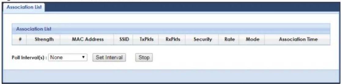
The following table describes the labels in this screen.
Table 11 Monitor > WLAN 2.4G Station Status
| LABEL DESCRIPTION | |
| # | This is the index number of an associated wireless station. |
| Strength This field displays the station's wireless connection signal strength. | |
| MAC Address | This field displays the MAC address of an associated wireless station. |
| SSID | This field displays the name of the WAP7205's wireless network to which the station is connected. |
| TxPkts | This field displays the number of packets transmitted by the station through the wireless connection. |
| RxPkts | This field displays the number of packets received by the station through the wireless connection. |
| Security | This field displays which secure encryption method is being used by the station to connect to the network. |
| Rate This field displays the wireless station's transmission rate. | |
| Mode | This field displays the wireless standard supported by the wireless station. |
| Association Time | This field displays the time a wireless station first associated with the WAP7205's 2.4G wireless network. |
| Poll Interval(s) | Enter the time interval in seconds for refreshing this screen in this field. |
| Set Interval | Click this button to apply the new poll interval you entered in the Poll Interval(s) field. |
| Stop | Click Stop to stop refreshing the screen. |
6.6 WLAN 5G Station Status
Click the WLAN 5G Station Status (Details...) hyperlink in the Dashboard screen or Monitor > WLAN 5G Station Status. View the 5G wireless stations that are currently associated to the WAP7205 in the Association List. Association means that a wireless client (for example, your network or computer with a wireless network card) has connected successfully to the WAP7205 using the same SSID, channel and security settings.
Figure 13 Monitor > WLAN 5G Station Status
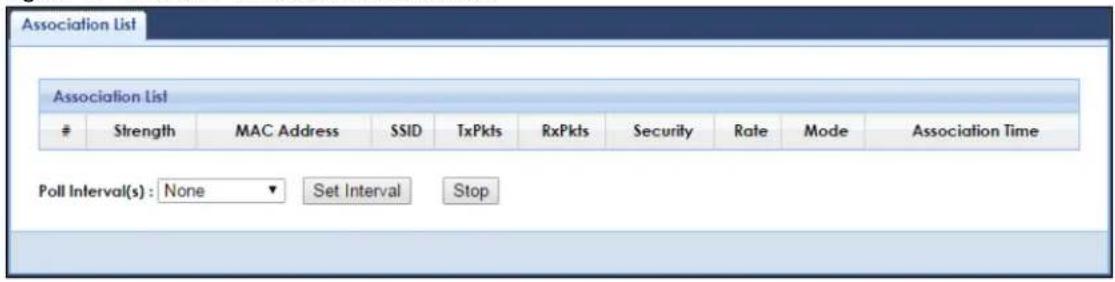
The following table describes the labels in this screen.
Table 12 Monitor > WLAN 5G Station Status
| LABEL DESCRIPTION | |
| # | This is the index number of an associated wireless station. |
| Strength This field displays the station's wireless connection signal strength. | |
| MAC Address | This field displays the MAC address of an associated wireless station. |
| SSID | This field displays the name of the WAP7205's wireless network to which the station is connected. |
| TxPkts | This field displays the number of packets transmitted by the station through the wireless connection. |
| RxPkts | This field displays the number of packets received by the station through the wireless connection. |
| Security | This field displays which secure encryption method is being used by the station to connect to the network. |
| Rate This field displays the wireless station's transmission rate. | |
| Mode | This field displays the wireless standard supported by the wireless station. |
| Association Time | This field displays the time a wireless station first associated with the WAP7205's 5G wireless network. |
| Poll Interval(s) | Enter the time interval in seconds for refreshing this screen in this field. |
| Set Interval | Click this button to apply the new poll interval you entered in the Poll Interval(s) field. |
| Stop | Click Stop to stop refreshing the screen. |
CHAPTER 7
Wireless LAN
7.1 Overview
This chapter discusses how to configure the wireless network settings in your WAP7205.
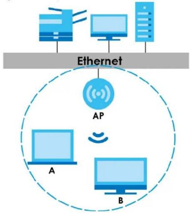
The following figure provides an example of a wireless network.
Figure 14 Example of a Wireless Network
flowchart
graph TD
    A["Desktop"] -->|Ethernet| B["AP"]
    C["Desktop"] -->|Ethernet| B
    D["Desktop"] -->|Ethernet| B
    E["Desktop"] -->|Ethernet| B
    F["Desktop"] -->|Ethernet| B
    G["Desktop"] -->|Ethernet| B
    H["Desktop"] -->|Ethernet| B
    I["Desktop"] -->|Ethernet| B
    J["Desktop"] -->|Ethernet| B
    K["Desktop"] -->|Ethernet| B
    L["Desktop"] -->|Ethernet| B
    M["Desktop"] -->|Ethernet| B
    N["Desktop"] -->|Ethernet| B
    O["Desktop"] -->|Ethernet| B
    P["Desktop"] -->|Ethernet| B
    Q["Desktop"] -->|Ethernet| B
    R["Desktop"] -->|Ethernet| B
    S["Desktop"] -->|Ethernet| B
    T["Desktop"] -->|Ethernet| B
    U["Desktop"] -->|Ethernet| B
    V["Desktop"] -->|Ethernet| B
    W["Desktop"] -->|Ethernet| B
    X["Desktop"] -->|Ethernet| B
    Y["Desktop"] -->|Ethernet| B
    Z["Desktop"] -->|Ethernet| B
The wireless network is the part in the blue circle. In this wireless network, devices A and B are called wireless clients. The wireless clients use the access point (AP) to interact with other devices (such as the printer) or with the Internet. Your WAP7205 is the AP.
7.2 What You Can Do
- Use the General screen (Section 7.4 on page 41) to turn the wireless connection on or off, enter the SSID, select the channel, and configure wireless security between the WAP7205 and the wireless clients.
-
Use the More AP screen (Section 7.4 on page 41) to enable and configure multiple wireless networks on the WAP7205.
-
Use the MAC Filter screen (Section 7.7 on page 49) to allow or deny wireless stations based on their MAC addresses from connecting to the WAP7205.
- Use the Advanced screen (Section 7.8 on page 50) to configure wireless advanced features, such as set the RTS/CTS Threshold and HT physical mode.
- Use the QoS screen (Section 7.9 on page 51) to enable WiFi MultiMedia Quality of Service (WMMQoS). This allows the WAP7205 to automatically set priority levels to services, such as e-mail, VoIP, chat, and so on.
- Use the WPS screen (Section 7.10 on page 52) to quickly set up a wireless network with strong security, without having to configure security settings manually.
- Use the WPS Station screen (Section 7.11 on page 53) to add a wireless station using WPS.
- Use the Scheduling screen (Section 7.12 on page 53) to set the times your wireless LAN is turned on and off.
7.3 What You Should Know
Every wireless network must follow these basic guidelines.
- Every wireless client in the same wireless network must use the same SSID.
The SSID is the name of the wireless network. It stands for Service Set IDentity. - If two wireless networks overlap, they should use different channels.
Like radio stations or television channels, each wireless network uses a specific channel, or frequency, to send and receive information. - Every wireless client in the same wireless network must use security compatible with the AP.
Security stops unauthorized devices from using the wireless network. It can also protect the information that is sent in the wireless network.
7.3.1 Wireless Security Overview
The following sections introduce different types of wireless security you can set up in the wireless network.
7.3.1.1 SSID
Normally, the AP acts like a beacon and regularly broadcasts the SSID in the area. You can hide the SSID instead, in which case the AP does not broadcast the SSID. In addition, you should change the default SSID to something that is difficult to guess.
This type of security is fairly weak, however, because there are ways for unauthorized devices to get the SSID. In addition, unauthorized devices can still see the information that is sent in the wireless network.
7.3.1.2 MAC Address Filter
Every wireless client has a unique identification number, called a MAC address. ^1 A MAC address is usually written using twelve hexadecimal characters ^2 ; for example, 00A0C5000002 or 00:A0:C5:00:00:02.
To get the MAC address for each wireless client, see the appropriate User's Guide or other documentation.
You can use the MAC address filter to tell the AP which wireless clients are allowed or not allowed to use the wireless network. If a wireless client is allowed to use the wireless network, it still has to have the correct settings (SSID, channel, and security). If a wireless client is not allowed to use the wireless network, it does not matter if it has the correct settings.
This type of security does not protect the information that is sent in the wireless network. Furthermore, there are ways for unauthorized devices to get the MAC address of an authorized wireless client. Then, they can use that MAC address to use the wireless network.
7.3.1.3 WPS
WiFi Protected Setup (WPS) is an industry standard specification, defined by the Wi-Fi Alliance. WPS allows you to quickly set up a wireless network with strong security, without having to configure security settings manually. Depending on the devices in your network, you can either press a button (on the device itself) or enter a PIN (Personal Identification Number) in the devices. Then, they connect and set up a secure network by themselves.
7.4 General Wireless LAN Screen
Use this screen to enable or disable the WLAN, enter the SSID, select the channel and configure wireless security settings.
Note: If you are configuring the WAP7205 from a computer connected to the wireless LAN and you change the WAP7205's SSID, channel or security settings, you will lose your wireless connection when you press Apply to confirm. You must then change the wireless settings of your computer to match the WAP7205's new settings.
Click Network > Wireless LAN 2.4G or 5G to open the General screen.
Figure 15 Network > Wireless LAN 2.4G or 5G > General
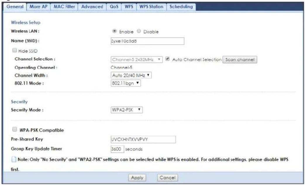
The following table describes the general wireless LAN labels in this screen.
Table 13 Network > Wireless LAN 2.4G or 5G > General
| LABEL DESCRIPTION | |
| Wireless Setup | |
| Wireless LAN Select | to enable or disable the wireless LAN. This is turned on by default. |
| Name (SSID) | The SSID (Service Set IDentity) identifies the Service Set with which a wireless client is associated.Enter a descriptive name (up to 32 printable characters found on a typical English language keyboard) for the wireless LAN. |
| Hide SSID | Select this check box to hide the SSID in the outgoing beacon frame so a wireless client cannot obtain the SSID through scanning using a site survey tool. |
| Channel Selection | Set the operating frequency/channel depending on your particular region.Select a channel from the drop-down list box. The options vary depending on the frequency band and the country you are in.This option is only available ifAuto Channel Selectionis disabled. |
| Auto Channel Selection | Select the check box to have the WAP7205 automatically scan for and select a channel which is not used by another device. |
| Operating Channel | This displays the channel the WAP7205 is currently using. |
Table 13 Network > Wireless LAN 2.4G or 5G > General
| LABEL DESCRIPTION | |
| Channel Width Select the wireless channel width used by WAP7205. | |
| A standard 20 MHz channel offers transfer speeds of up to 150Mbps whereas a 40 MHz channel uses two standard channels and offers speeds of up to 300Mbps.Because not all devices support 40 MHz channels, selectAuto 20/40 MHz or Auto 20/40/80 MHzto allow the WAP7205 to adjust the channel bandwidth automatically.40 MHz (channel bonding or dual channel) bonds two adjacent radio channels to increase throughput. A 80 MHz channel consists of two adjacent 40 MHz channels. The wireless clients must also support40 MHz or80 MHz. It is often better to use the 20 MHz setting in a location where the environment hinders the wireless signal.Select20 MHz if you want to lessen radio interference with other wireless devices in your neighborhood or the wireless clients do not support channel bonding. | |
| 802.11 Mode | 2.4 GHz is the frequency used by IEEE 802.11b/g/n wireless clients. 5 GHz is the frequency used by IEEE 802.11ac/a/n wireless clients.You can select from the following:802.11b: allows either IEEE 802.11b or IEEE 802.11g compliant WLAN devices to associate with the WAP7205. In this mode, all wireless devices can only transmit at the data rates supported by IEEE 802.11b.802.11g: allows IEEE 802.11g compliant WLAN devices to associate with the Device. IEEE 802.11b compliant WLAN devices can associate with the WAP7205 only when they use the short preamble type.802.11bg: allows either IEEE 802.11b or IEEE 802.11g compliant WLAN devices to associate with the WAP7205. The WAP7205 adjusts the transmission rate automatically according to the wireless standard supported by the wireless devices.802.11n: allows IEEE 802.11n compliant WLAN devices to associate with the WAP7205. This can increase transmission rates, although IEEE 802.11b or IEEE 802.11g clients will not be able to connect to the WAP7205. I802.11gn: allows either IEEE 802.11g or IEEE 802.11n compliant WLAN devices to associate with the WAP7205. The transmission rate of your WAP7205 might be reduced.802.11bgn: allows IEEE802.11b, IEEE802.11g and IEEE802.11n compliant WLAN devices to associate with the WAP7205. The transmission rate of your WAP7205 might be reduced.802.11a: allows only IEEE 802.11a compliant WLAN devices to associate with the WAP7205.802.11a/n: allows both IEEE802.11a and IEEE802.11n compliant WLAN devices to associate with the WAP7205. The transmission rate of your WAP7205 might be reduced.802.11a/an/ac: allows both IEEE802.11a, IEEE802.11n and IEEE802.11ac compliant WLAN devices to associate with the WAP7205. |
| Security | |
| Security Mode | SelectWPA2-PSKorWPA2to add security on this wireless network. The wireless clients which want to associate to this network must have same wireless security settings as this device. After you select to use a security, additional options appears in this screen. SeeSection 7.5 on page 43for detailed information on different security modes. Or you can selectNo Securityto allow any client to associate this network without authentication.Note: If the WPS function is enabled (default), onlyNo Securityand WPA2-PSKare available in this field. |
| Apply | ClickApplyto save your changes back to the WAP7205. |
| Cancel | ClickCancelto reload the previous configuration for this screen. |
7.5 Wireless Security
The screen varies depending on what you select in the Security Mode field.
7.5.1 No Security
Select No Security to allow wireless clients to communicate with the access points without any data encryption.
Note: If you do not enable any wireless security on your WAP7205, your network is accessible to any wireless networking device that is within range.
Figure 16 Network > Wireless LAN 2.4G or 5G > Security: No Security
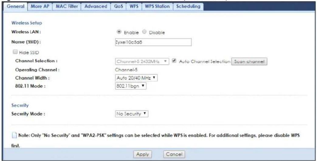
The following table describes the labels in this screen.
Table 14 Network > Wireless LAN 2.4G or 5G > Security: No Security
| LABEL DESCRIPTION | |
| Security Mode | ChooseNo Securityfrom the drop-down list box. |
| Apply | ClickApplyto save your changes back to the WAP7205. |
| Cancel | ClickCancelto reload the previous configuration for this screen. |
7.5.2 WPA2-PSK
Select WPA2-PSK from the Security Mode list.
Figure 17 Network > Wireless LAN 2.4G or 5G > Security: WPA2-PSK
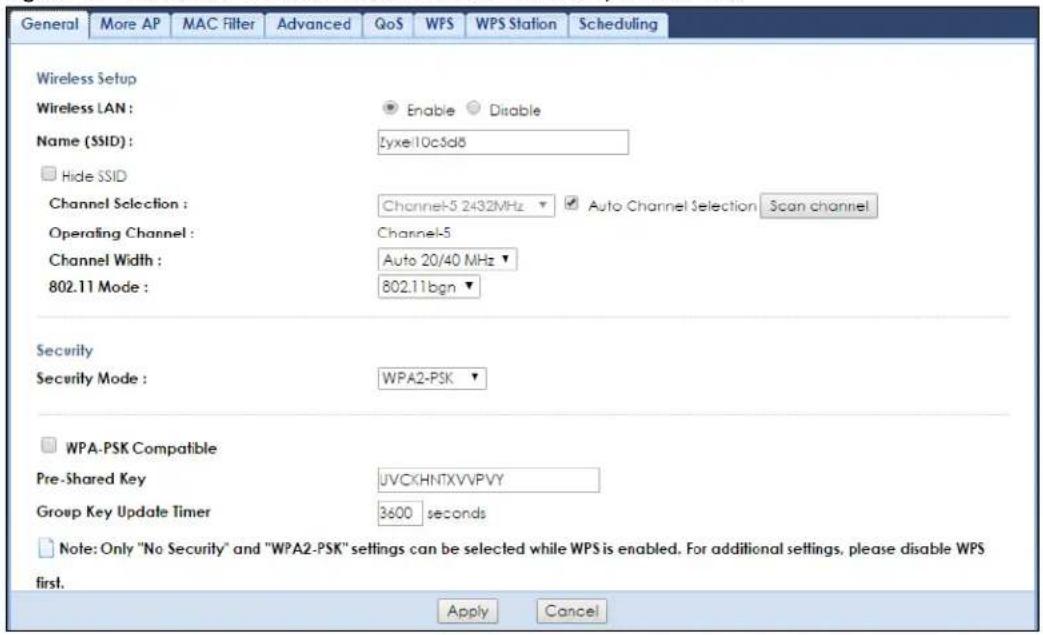
The following table describes the labels in this screen.
Table 15 Network > Wireless LAN 2.4G or 5G > Security: WPA2-PSK
| LABEL DESCRIPTION | |
| Security Mode | Select WPA2-PSK to enable data encryption. |
| WPA-PSK Compatible | Check this field to allow wireless devices using WPA-PSK security mode to connect to your WAP7205 even when the WAP7205 is using WPA2-PSK. |
| Pre-Shared Key | WPA2-PSK uses a simple common password for authentication.Type a pre-shared key from 8 to 63 case-sensitive keyboard characters. |
| Group Key Update Timer | The Group Key Update Timer is the rate at which the AP sends a new group key out to all clients. |
| Apply | Click Apply to save your changes back to the WAP7205. |
| Cancel | Click Cancel to reload the previous configuration for this screen. |
7.5.3 WPA2
Select WPA2 from the Security Mode list.
Note: WPA2 is not available if you enable WPS before you configure WPA2 in the Wireless LAN 2.4G or 5G > General screen.
Figure 18 Network > Wireless LAN 2.4G or 5G > General: WPA2
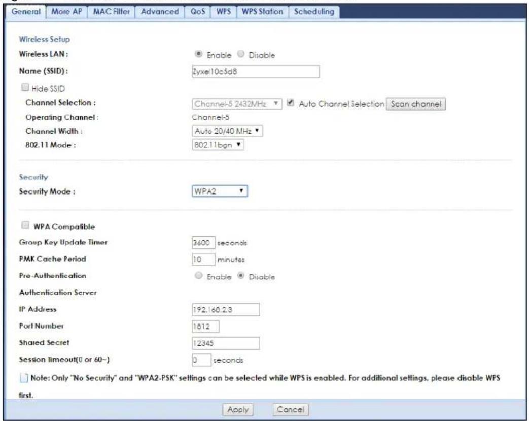
The following table describes the labels in this screen.
Table 16 Network > Wireless LAN 2.4G or 5G > General: WPA2
| LABEL DESCRIPTION | |
| Security Mode | Select WPA2 to enable data encryption. |
| WPA Compatible | Check this field to allow wireless devices using WPA security mode to connect to your WAP7205 even when the WAP7205 is using WPA2. |
| Group Key Update Timer | The Group Key Update Timer is the rate at which the RADIUS server sends a new group key out to all clients. |
| PMK Cache Period | Specify how often wireless clients have to resend usernames and passwords in order to stay connected. Enter a time interval between 10 and 999999 minutes.Note: If wireless client authentication is done using a RADIUS server, the reauthentication timer on the RADIUS server has priority. |
| Pre-Authentication | Pre-authentication enables fast roaming by allowing the wireless client (already connecting to an AP) to perform IEEE 802.1x authentication with another AP before connecting to it.Select Enable to turn on preauthentication in WAP2. Otherwise, select Disable. |
| Authentication Server | |
| IP Address | Enter the IP address of the external authentication server in dotted decimal notation. |
| Port Number | Enter the port number of the external authentication server.You need not change this value unless your network administrator instructs you to do so with additional information. |
Table 16 Network > Wireless LAN 2.4G or 5G > General: WPA2
| LABEL DESCRIPTION | |
| Shared Secret | Enter a password as the key to be shared between the external authentication server and the WAP7205.The key must be the same on the external authentication server and your WAP7205. The key is not sent over the network. |
| Session Timeout | The WAP7205 automatically disconnects a wireless client from the wireless and wired networks after a period of inactivity. The wireless client needs to send the username and password again before it can use the wireless and wired networks again. Some wireless clients may prompt users for a username and password; other clients may use saved login credentials. In either case, there is usually a short delay while the wireless client logs in to the wireless network again.Enter the time in seconds from 0 to 9999. |
| Apply | Click Apply to save your changes back to the WAP7205. |
| Cancel | Click Cancel to reload the previous configuration for this screen. |
7.6 More AP Screen
This screen allows you to enable and configure multiple wireless networks on the WAP7205.
You can configure up to four SSIDs to enable multiple BSSs (Basic Service Sets) on the WAP7205. This allows you to use one access point to provide several BSSs simultaneously. You can then assign varying security types to different SSIDs. Wireless clients can use different SSIDs to associate with the same access point.
Click Network > Wireless LAN 2.4G or 5G > More AP to open the More AP screen.
Figure 19 Network > Wireless LAN 2.4G or 5G > More AP
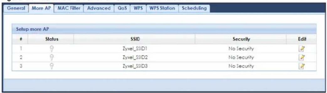
The following table describes the labels in this screen.
Table 17 Network > Wireless LAN 2.4G or 5G > More AP
| LABEL DESCRIPTION | |
| # This is the index number of each SSID profile. | |
| Status | This shows whether the SSID profile is active (a yellow lightbulb) or not (a grey lightbulb). |
| SSID | An SSID profile is the set of parameters relating to one of the WAP7205's BSSs. The SSID (Service Set Identifier) identifies the Service Set with which a wireless device is associated.This field displays the name of the wireless profile on the network. When a wireless client scans for an AP to associate with, this is the name that is broadcast and displayed in the wireless client utility. |
Table 17 Network > Wireless LAN 2.4G or 5G > More AP
| LABEL DESCRIPTION | |
| Security This field indicates the SSID profile's security mode. | |
| Edit | Click the Edit icon to configure the SSID profile. |
7.6.1 More AP Edit
Use this screen to edit an SSID profile. Click the Edit icon next to an SSID in the More AP screen. The following screen displays.
Figure 20 Network > Wireless LAN 2.4G or 5G > More AP: Edit
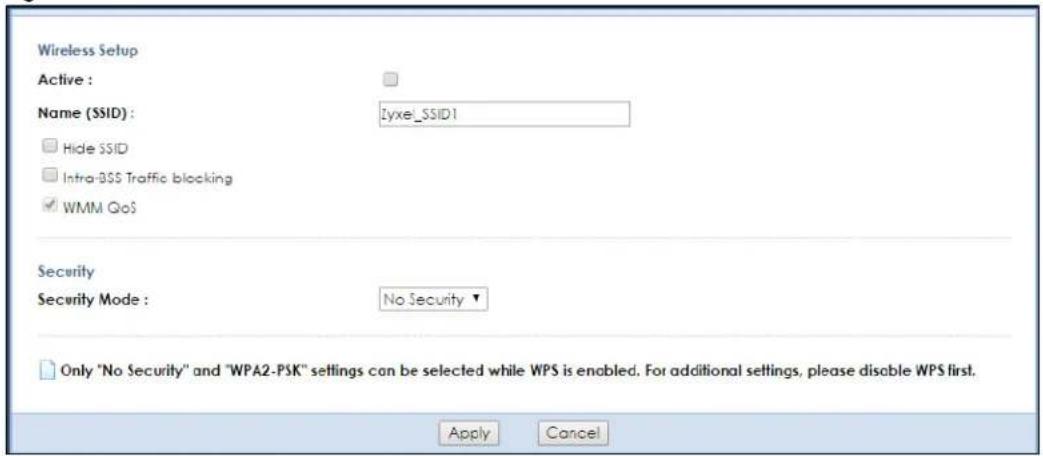
The following table describes the labels in this screen.
Table 18 Network > Wireless LAN 2.4G or 5G > More AP: Edit
| LABEL DESCRIPTION | |
| Active Select this to | activate the SSID profile. |
| Name (SSID) | The SSID (Service Set IDentity) identifies the Service Set with which a wireless client is associated.Enter a descriptive name (up to 32 printable characters found on a typical English language keyboard) for the wireless LAN. |
| Hide SSID | Select this check box to hide the SSID in the outgoing beacon frame so a client cannot obtain the SSID through scanning using a site survey tool. |
| Intra-BSS Traffic blocking | A Basic Service Set (BSS) exists when all communications between wireless clients or between a wireless client and a wired network client go through one access point (AP). Intra-BSS traffic is traffic between wireless clients in the BSS. When Intra-BSS traffic is enabled, wireless clients can access the wired network and communicate with each other. When Intra-BSS traffic is disabled, wireless clients can still access the wired network but cannot communicate with each other.Select Enable to prevent crossover traffic from within the same SSID on the WAP7205. |
| WMM QoS | Check this to have the WAP7205 automatically give a service a priority level according to the ToS value in the IP header of packets it sends. WMM QoS (WiFi MultiMedia Quality of Service) gives high priority to voice and video, which makes them run more smoothly. |
Table 18 Network > Wireless LAN 2.4G or 5G > More AP: Edit
| LABEL DESCRIPTION | |
| Security Mode | Select WPA2-PSK or WPA2 to add security on this wireless network. The wireless clients which want to associate to this network must have same wireless security settings as this device. After you select to use a security, additional options appears in this screen. See Section 7.5 on page 43 for detailed information on different security modes. Or you can select No Security to allow any client to associate this network without authentication.Note: If the WPS function is enabled (default), only No Security and WPA2-PSK are available in this field. |
| Apply | Click Apply to save your changes back to the WAP7205. |
| Cancel | Click Cancel to reload the previous configuration for this screen. |
7.7 MAC Filter
The MAC filter screen allows you to configure the WAP7205 to give exclusive access to devices (Allow) or exclude devices from accessing the WAP7205 (Deny). Every Ethernet device has a unique MAC (Media Access Control) address. The MAC address is assigned at the factory and consists of six pairs of hexadecimal characters, for example, 00:A0:C5:00:00:02. You need to know the MAC address of the devices to configure this screen.
To change your WAP7205's MAC filter settings, click Network > Wireless LAN 2.4G or 5G > MAC Filter. The screen appears as shown.
Figure 21 Network > Wireless LAN 2.4G or 5G > MAC Filter
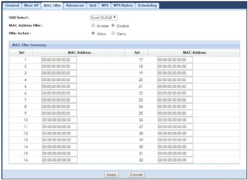
The following table describes the labels in this screen.
Table 19 Network > Wireless LAN 2.4G or 5G > MAC Filter
| LABEL DESCRIPTION | |
| SSID Select Select the SSID for which you want to configure MAC filtering. | |
| MAC Address Filter | Select to turn on (Enable) or off (Disable) MAC address filtering. |
| Filter Action | Define the filter action for the list of MAC addresses in the MAC Filter Summary table.Select Allow to permit access to the WAP7205, MAC addresses not listed will be denied access to the WAP7205.Select Deny to block access to the WAP7205, MAC addresses not listed will be allowed to access the WAP7205. |
| MAC Filter Summary | |
| Set This is the index number of the MAC address. | |
| MAC Address | Enter the MAC address of the wireless station that are allowed or denied access to the WAP7205. |
| Apply | Click Apply to save your changes back to the WAP7205. |
| Cancel | Click Cancel to reload the previous configuration for this screen. |
7.8 Wireless LAN Advanced Screen
Use this screen to allow wireless advanced features, such as the output power, and RTS/CTS Threshold.
Click Network > Wireless LAN 2.4G or 5G > Advanced. The screen appears as shown.
Figure 22 Network > Wireless LAN 2.4G or 5G > Advanced
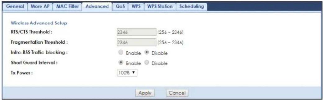
The following table describes the labels in this screen.
Table 20 Network > Wireless LAN 2.4G or 5G > Advanced
| LABEL DESCRIPTION | |
| RTS/CTS Threshold | Data with its frame size larger than this value will perform the RTS (Request To Send)/CTS (Clear To Send) handshake.Note: If you select 802.11n, 802.11gn or 802.11bgn in the Wireless LAN 2.4G or 5G>General screen, this field is not configurable and the WAP7205 automatically changes to use the maximum value. |
Table 20 Network > Wireless LAN 2.4G or 5G > Advanced
| LABEL DESCRIPTION | |
| Fragmentation Threshold | The threshold (number of bytes) for the fragmentation boundary for directed messages. It is the maximum data fragment size that can be sent.Note: If you select 802.11n, 802.11gn or 802.11bgn in the Wireless LAN 2.4G or 5G>General screen, this field is not configurable and the WAP7205 automatically changes to use the maximum value. |
| Intra-BSS Traffic blocking | A Basic Service Set (BSS) exists when all communications between wireless clients or between a wireless client and a wired network client go through one access point (AP).Intra-BSS traffic is traffic between wireless clients in the BSS. When Intra-BSS traffic is enabled, wireless clients can access the wired network and communicate with each other. When Intra-BSS traffic is disabled, wireless clients can still access the wired network but cannot communicate with each other.Select Enable to prevent crossover traffic from within the same SSID on the WAP7205. |
| Short Guard Interval | Select Enable to use Short GI (Guard Interval).The guard interval is the gap introduced between data transmission from users in order to reduce interference. Reducing the interval increases data transfer rates but also increases interference. Increasing the interval reduces data transfer rates but also reduces interference. |
| Tx Power | Set the output power of the WAP7205 in this field. If there is a high density of APs in an area, decrease the output power of the WAP7205 to reduce interference with other APs. Select one of the following 100%, 90%, 75%, 50%, 25% or 10%. |
| Apply | Click Apply to save your changes back to the WAP7205. |
| Cancel | Click Cancel to reload the previous configuration for this screen. |
7.9 Quality of Service (QoS) Screen
The QoS screen allows you to automatically give a service (such as VoIP and video) a priority level.
Click Network > Wireless LAN 2.4G or 5G > QoS. The following screen appears.
Figure 23 Network > Wireless LAN 2.4G or 5G > QoS
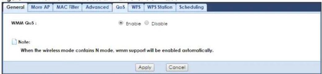
The following table describes the labels in this screen.
Table 21 Network > Wireless LAN 2.4G or 5G > QoS
| LABEL DESCRIPTION | |
| WMM QoS | Select Enable to have the WAP7205 automatically give a service a priority level according to the ToS value in the IP header of packets it sends. WMM QoS (WiFi MultiMedia Quality of Service) gives high priority to voice and video, which makes them run more smoothly. |
| Apply | Click Apply to save your changes to the WAP7205. |
| Cancel | Click Cancel to reload the previous configuration for this screen. |
7.10 WPS Screen
Use this screen to enable/disable WPS, view or generate a new PIN number and check current WPS status. To open this screen, click Network > Wireless LAN 2.4G or 5G > WPS.
Note: With WPS, wireless clients can only connect to the wireless network using the first SSID on the WAP7205.
Figure 24 Network > Wireless LAN 2.4G or 5G > WPS
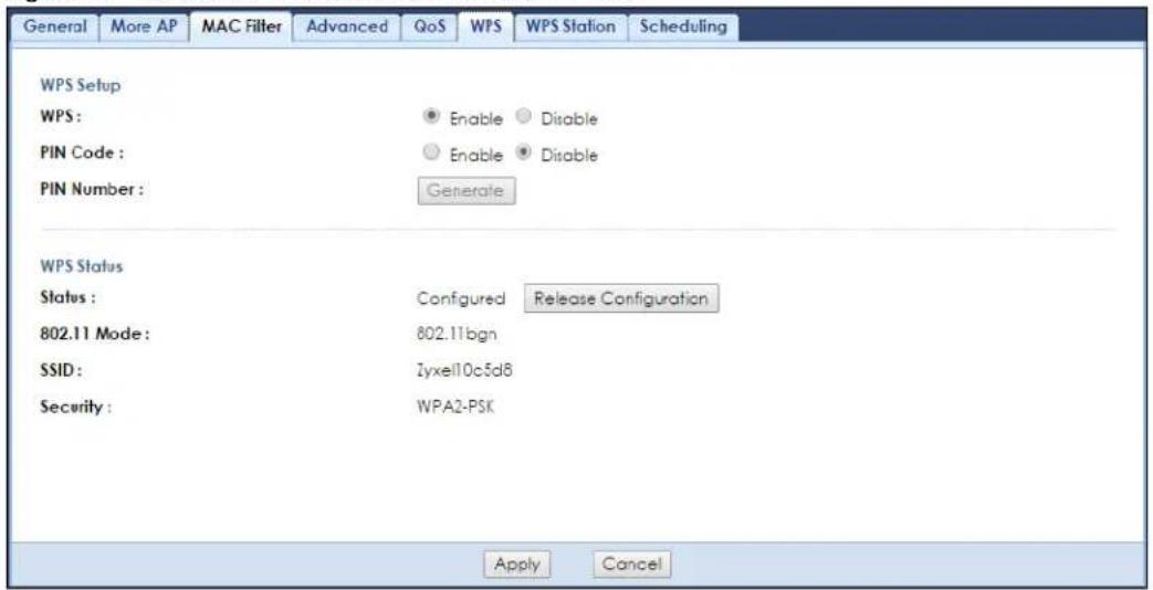
The following table describes the labels in this screen.
Table 22 Network > Wireless LAN 2.4G or 5G > WPS
| LABEL DESCRIPTION | |
| WPS Setup | |
| WPS | Select Enable to turn on the WPS feature. Otherwise, select Disable. |
| PIN Code | Select Enable and click Apply to allow the PIN Configuration method. If you select Disable, you cannot create a new PIN number. |
| PIN Number This is the WPS PIN (Personal Identification Number) of the WAP7205.The PIN is not necessary when you use WPS push-button method.Click Generate to generate a new PIN number. | |
| WPS Status | |
| Status | This displays Configured when the WAP7205 has connected to a wireless network using WPS or when WPS is enabled and wireless or wireless security settings have been changed. The current wireless and wireless security settings also appear in the screen.This displays Unconfigured if WPS is disabled and there are no wireless or wireless security changes on the WAP7205 or you click Release_Configuration to remove the configured wireless and wireless security settings. |
| Release Configuration | This button is only available when the WPS status displays Configured.Click this button to remove all configured wireless and wireless security settings for WPS connections on the WAP7205. |
| 802.11 Mode | This is the 802.11 mode used. Only compliant WLAN devices can associate with the WAP7205. |
| SSID | This is the name of the wireless network (the WAP7205's first SSID). |
Table 22 Network > Wireless LAN 2.4G or 5G > WPS
| LABEL DESCRIPTION | |
| Security | This is the type of wireless security employed by the network. |
| Apply | ClickApplyto save your changes back to the WAP7205. |
| Cancel | ClickCancelto reload the previous configuration for this screen. |
7.11 WPS Station Screen
Use this screen when you want to add a wireless station using WPS. To open this screen, click Network > Wireless LAN 2.4G or 5G > WPS Station.
Figure 25 Network > Wireless LAN 2.4G or 5G > WPS Station
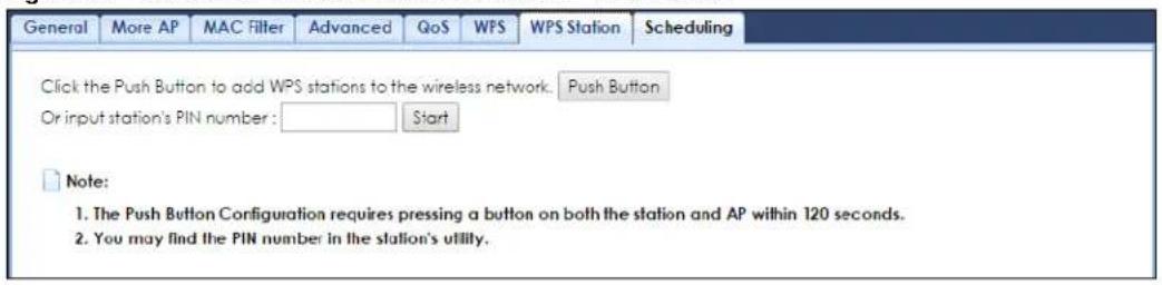
The following table describes the labels in this screen.
Table 23 Network > Wireless LAN 2.4G or 5G > WPS Station
| LABEL DESCRIPTION | |
| Push Button | Use this button when you use the PBC (Push Button Configuration) method to configure wireless station's wireless settings.Click this to start WPS-aware wireless station scanning and the wireless security information synchronization. |
| Or input station's PIN number | Use this button when you use the PIN Configuration method to configure wireless station's wireless settings.Type the same PIN number generated in the wireless station's utility. Then click Start to associate to each other and perform the wireless security information synchronization. |
7.12 Scheduling Screen
Use this screen to set the times your wireless LAN is turned on and off. Wireless LAN scheduling is disabled by default. The wireless LAN can be scheduled to turn on or off on certain days and at certain times. To open this screen, click Network > Wireless LAN 2.4G or 5G > Scheduling.
Figure 26 Network > Wireless LAN 2.4G or 5G > Scheduling
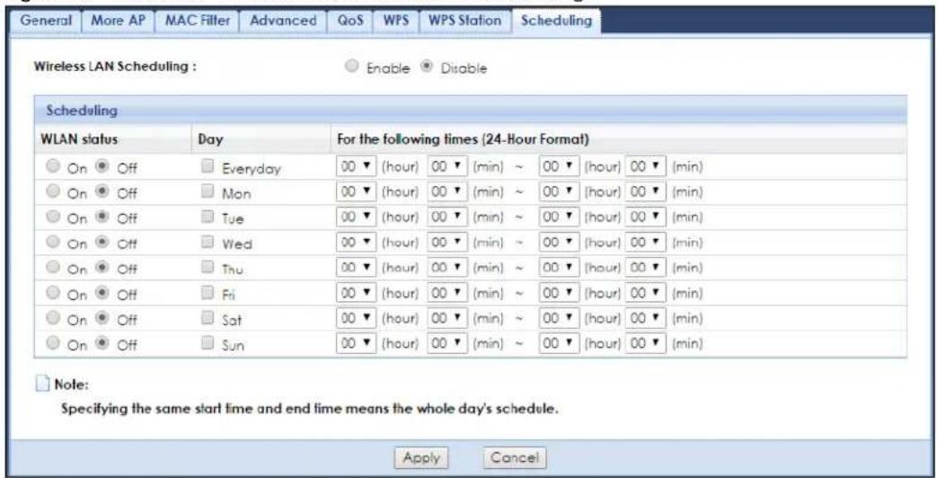
The following table describes the labels in this screen.
Table 24 Network > Wireless LAN 2.4G or 5G > Scheduling
| LABEL DESCRIPTION | |
| Wireless LAN Scheduling | Select Enable to activate the wireless LAN scheduling feature. Select Disable to turn it off. |
| Scheduling | |
| WLAN Status | Select On or Off to specify whether the Wireless LAN is turned on or off. This field works in conjunction with the Day and For the following times fields. |
| Day | Select Everyday or the specific days to turn the Wireless LAN on or off. If you select Everyday you can not select any specific days. This field works in conjunction with the For the following times field. |
| For the following times (24-Hour Format) | Select a begin time using the first set of hour and minute (min) drop down boxes and select an end time using the second set of hour and minute (min) drop down boxes. If you have chosen On earlier for the WLAN Status the Wireless LAN will turn on between the two times you enter in these fields. If you have chosen Off earlier for the WLAN Status the Wireless LAN will turn off between the two times you enter in these fields. |
| Apply | Click Apply to save your changes back to the WAP7205. |
| Cancel | Click Cancel to reload the previous configuration for this screen. |
CHAPTER 8 LAN
8.1 Overview
This chapter describes how to configure LAN settings.
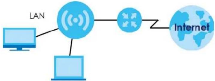
A Local Area Network (LAN) is a shared communication system to which many computers are attached. A LAN is a computer network limited to the immediate area, usually the same building or floor of a building. The LAN screens can help you configure the manage IP address, and partition your physical network into logical networks.
Figure 27 LAN Example
flowchart
graph LR
    A["Computer"] --> B["Central Network"]
    C["Computer"] --> B
    B --> D["Internet"]
    B --> E["Satellite (Wire)"]
    B --> F["Global Connection"]
The LAN screens can help you manage IP addresses.
8.2 What You Can Do
- Use the IP screen (Section 8.4 on page 56) to change the IP address for your WAP7205 and DNS server information.
- Use the IP Alias screen (Section 8.5 on page 57) to have the WAP7205 apply IP alias to create LAN subnets.
8.3 What You Need To Know
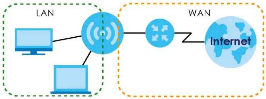
There are two separate IP networks, one inside the LAN network and the other outside the WAN network as shown next.
Figure 28 LAN and WAN IP Addresses
flowchart
graph LR
    subgraph LAN
        A["Computer"] --> B((Semi-Satellite))
        C["Computer"] --> B
    end
    subgraph WAN
        D["Internet"] -->|WAN| B
    end
8.3.1 IP Alias
IP alias allows you to partition a physical network into different logical networks over the same Ethernet interface. The WAP7205 supports three logical LAN interfaces via its single physical Ethernet interface with the WAP7205 itself as the gateway for each LAN network.
8.4 LAN IP Screen
Use this screen to change the IP address for your WAP7205. Click Network > LAN > IP.
Figure 29 Network > LAN > IP (Access Point or Universal Repeater)
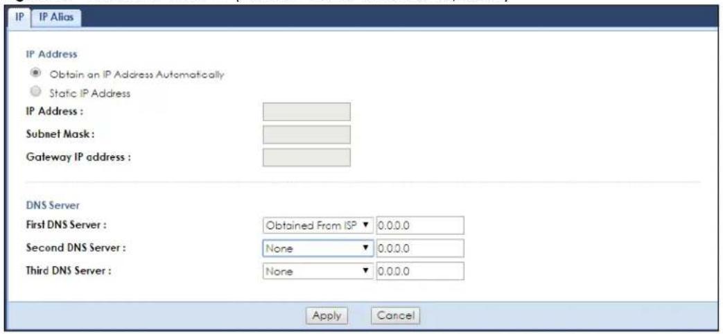
The following table describes the labels in this screen.
Table 25 Network > LAN > IP
| LABEL DESCRIPTION | |
| Obtain an IP Address Automatically | Click this to deploy the WAP7205 as a DHCP client in the network.When you enable this, the WAP7205 gets its IP address from the network's DHCP server (for example, your ISP or router). Users connected to the WAP7205 can now access the network (i.e., the Internet if the IP address is given by the ISP or a router with Internet access).The Web Configurator may no longer be accessible unless you know the IP address assigned by the DHCP server to the WAP7205.Also when you select this, you cannot enter an IP address for your WAP7205 in the field below. |
| Static IP Address | Click this if you want to specify the IP address of your WAP7205. Or if your ISP or network administrator gave you a static IP address to access the network or the Internet. |
| IP Address | Type the IP address in dotted decimal notation. If you change the IP address you will have to log in again with the new IP address. |
| Subnet Mask | The subnet mask specifies the network number portion of an IP address. |
| Gateway IP Address | Enter a gateway IP address (if your ISP or network administrator gave you one) in this field. |
| DNS Server | |
| First DNS ServerSecond DNS Server | Select Obtained From ISP if your ISP or router to which the WAP7205 connects dynamically assigns DNS server information (and the WAP7205's IP address). The field to the right displays the (read-only) DNS server IP address that the ISP assigns.Select User-Defined if you have the IP address of a DNS server. Enter the DNS server's IP address in the field to the right.Select None if you do not want to configure DNS servers. If you do not configure a DNS server, you must know the IP address of a computer in order to access it. |
| Apply | Click Apply to save your changes back to the WAP7205. |
| Cancel | Click Cancel to reload the previous configuration for this screen. |
8.5 IP Alias Screen
Use this screen to have the WAP7205 apply IP alias to create LAN subnets. Click LAN > IP Alias.
Figure 30 Network > LAN > IP Alias
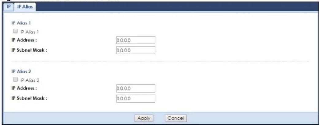
The following table describes the labels in this screen.
Table 26 Network > LAN > IP Alias
| LABEL DESCRIPTION | |
| IP Alias 1, 2 Check this to enable IP alias. | |
| IP Address | Type the IP alias address of your WAP7205 in dotted decimal notation. |
| IP Subnet Mask | The subnet mask specifies the network number portion of an IP address. |
| Apply | Click Apply to save your changes back to the WAP7205. |
| Cancel | Click Cancel to reload the previous configuration for this screen. |
CHAPTER 9 MoCA
9.1 Overview
MoCA (Multimedia over Coax Alliance) is an industry standard organization, which created a standard for transferring data and multimedia content over the existing coaxial wires in your home. Data communication and audio/video streaming are allowed at the same time. The WAP7205 (A) automatically sets up a MoCA network when multiple MoCA devices (nodes) are powered on and connected with a coaxial cable.
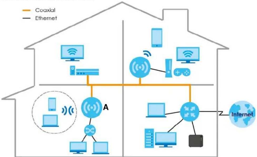
flowchart
graph TD
    subgraph Home_House
        A["House"] --> B["Central Network"]
        B --> C["Coaxial"]
        B --> D["Ethernet"]
        B --> E["Internet"]
    end
    subgraph Home_Districting
        F["Smartphone"] --> G["Server"]
        H["Smart TV"] --> I["Monitor"]
        J["Smart Phone"] --> K["Remote Device"]
        L["Smart Laptop"] --> M["Desktop"]
        N["Smart Computer"] --> O["Mobile Device"]
        P["Smart Radio"] --> Q["Radio System"]
        R["Smart Phone"] --> S["Desktop"]
        T["Smart Tablet"] --> U["Smart Laptop"]
    end
    subgraph Internet_Districting
        V["Internet"] --> W["Z"]
    end
    style Home_House fill:#f9f,stroke:#333
    style Internet_Districting fill:#bbf,stroke:#333
The WAP7205 supports MoCA 2.0 and is backward compatible with MoCA 1.1. The MoCA 1.1 technology provides 175 Mbps net throughputs (270 Mbps PHY rate) and operates in the 500 to 1500 MHz frequency range. MoCA 2.0 in turbo mode offers actual data rates of up to 1 Gbps MAC throughputs and operates in the 500 to 1650 MHz operating frequency range. MoCA 2.0 also supports improved packet error rate (PER) and two new power saving modes: Standby (reduced power) and Sleep (minimum power).
9.2 What You Can Do
- Use the MoCA screen (Section 9.3 on page 60) to set the MoCA Privacy, and enable multimedia and home networking over coaxial cabling.
- Use the MoCA > Monitor screen (Section 9.3 on page 60) to view the MoCA network status and information about the connected MoCA devices (nodes).
9.3 MoCA Screen
Use this screen to change the MoCA settings for your WAP7205. Click Network > MoCA.
Figure 31 Network > MoCA
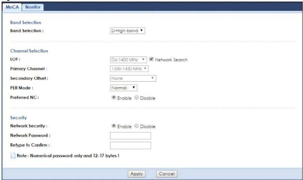
The following table describes the labels in this screen.
Table 27 Network > MoCA
| LABEL DESCRIPTION | |
| Band Selection | In MoCA frequency band plans, there are bands A, B, C1, C2, C3, C4, D, E, F, G, and H. The extended band D in MoCA 2.0 is between 1125 MHz and 1675 MHz. Two sub-bands (D-Low and D-High) are defined within the extended band D.Sub-band D-Low (DL): 1125 to 1225 MHz edge to edge (100 MHz wide)Sub-band D-High (DH): 1350 to 1675 MHz edge to edge (325 MHz wide)At the time of writing, the WAP7205 supports the sub-band D-High only. |
| LOF | Last Operational Frequency (LOF) is the last RF channel center frequency which a MoCA device (node) will automatically turn to when it is last in the linkup state.The center frequency of a channel is a central frequency in the middle of the upper cutoff and lower cutoff frequencies.If you clear theAuto Channel Selectioncheck box, manually select an operating frequency from the drop-down list. |
| Network Search Select the check box to enable auto scan for the operating frequency. | |
| Primary Channel | Select the first operating frequency range if you clear theAuto Channel Selectioncheck box.The field options vary depending on the center frequency you select in theLOFfield. |
| Secondary Offset | Select the second operating frequency range if you clear the Auto Channel Selection check box.Select None if you don't want to specify a second channel.Select Above to have the WAP7205 use a frequency higher than the upper edge of the selected primary channel.Select Below to have the WAP7205 use a frequency less than the lower edge of the selected primary channel. |
| PER Mode | The Packet Error Rate (PER) indicates the ratio between the total number of incorrectly received data packets and the total number of transmitted data packets. The total number of transmitted packets is at least 100,000,000 when the PER mode is NPER (Normal PER) and at least 10,000,000,000 when the PER mode is VLPER (Very Low PER). In very low PER mode, the physical data rate will be decreased in order to achieve a lower packet error rate.Select Normal to set the PER mode to NPER. Otherwise, select Very Low to set the PER mode to VLPER. |
| Preferred NC | The Network Coordinator (NC) is a node that performs the following functions in a MoCA network: beacon generation, MAP (Medium Allocation Plan) generation, admission of new MoCA nodes to the network, privacy key generation and distribution, and LMO (Link Maintenance Operation) scheduling. The NC is dynamically selected from all the MoCA nodes in the network. There is only one NC in a MoCA network and the rest of the MoCA nodes in the MoCA network are clients.Select Enable to configure the WAP7205 as a preferred network coordinator. The preferred NC has an advantage in the NC selection. |
| Network Security | Select Enable to turn on MoCA privacy. If this is enabled, all MoCA devices connected via coaxial cables must use the same password. |
| Network Password | Enter the password for the MoCA network. All packets in the MoCA network are encrypted except for beacons. |
| Retype to Confirm | Enter the password again for confirmation. |
| Apply | Click Apply to save your changes back to the WAP7205. |
| Cancel | Click Cancel to reload the previous configuration for this screen. |
9.4 MoCA Monitor Screen
Use this screen to view the MoCA network status and information about the connected MoCA devices (nodes). Click Network > MoCA > Monitor.
Figure 32 Network > MoCA > Monitor
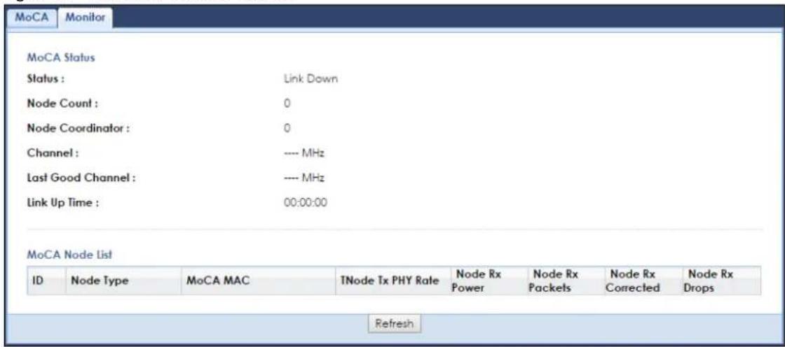
The following table describes the labels in this screen.
Table 28 Network > MoCA > Monitor
| LABEL DESCRIPTION | |
| Status | This shows the MoCA network status. It displays Link Up if the WAP7205 joins the MoCA network successfully. Otherwise, it displays Link Down. |
| Node Count | This shows the number of the nodes (including the WAP7205) present in the MoCA network. |
| Node Coordinator | This shows the ID number of the network coordinator in the MoCA network. |
| Channel This shows the frequency at which the WAP7205 is operating. | |
| Last Good Channel | This shows the last RF channel center frequency you configured in the MoCA screen. |
| Link Up Time This displays how long the connection with other MoCA node(s) has been up. | |
| ID This shows the ID number of the node in the MoCA network. | |
| Node Type This shows whether the MoCA node is acting as a MoCA client or NC. | |
| MoCA MAC This shows the MAC address of the MoCA node. | |
| TNode Tx PHY Rate | This shows the PHY rate in Mbps for the broadcast packets transmitted from the MoCA node. Greatest Common Density (GCD) is a signaling method used by a MoCA node when transmitting information to multiple recipients. |
| Node Rx Power This shows the MoCA node's power consumption (in dBm) of receiving. | |
| Node Rx Packets This shows the number of packets received by the MoCA node. | |
| Node Rx Corrected | This shows the number of packets corrected and received by the MoCA node. |
| Node Rx Drops This shows the number of packets dropped by the MoCA node. | |
| Refresh Click this button to renew the screen. | |
CHAPTER 10 SNMP
10.1 Overview
This chapter explains how to configure the SNMP settings on the WAP7205.
Simple Network Management Protocol is a protocol used for exchanging management information between network devices. Your WAP7205 supports SNMP agent functionality, which allows a manager station to manage and monitor the WAP7205 through the network. The WAP7205 supports SNMP version one (SNMPv1) and version two (SNMPv2c). The next figure illustrates an SNMP management operation.
Figure 33 SNMP Management Model
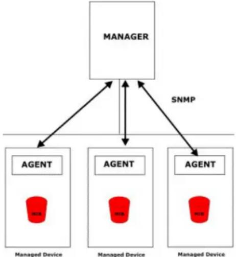
flowchart
graph TD
    A["MANAGER"] --> B["AGENT"]
    A --> C["AGENT"]
    A --> D["AGENT"]
    B --> E["Managed Device"]
    C --> F["Managed Device"]
    D --> G["Managed Device"]
    B <--> H["SNMP"]
    C <--> H
    D <--> H
An SNMP managed network consists of two main types of component: agents and a manager.
An agent is a management software module that resides in a managed device (the WAP7205). An agent translates the local management information from the managed device into a form compatible with SNMP. The manager is the console through which network administrators perform network management functions. It executes applications that control and monitor managed devices.
The managed devices contain object variables/managed objects that define each piece of information to be collected about a device. Examples of variables include such as number of packets received, node port status etc. A Management Information Base (MIB) is a collection of managed objects. SNMP allows a manager and agents to communicate for the purpose of accessing these objects.
SNMP itself is a simple request/response protocol based on the manager/agent model. The manager issues a request and the agent returns responses using the following protocol operations:
- Get - Allows the manager to retrieve an object variable from the agent.
- GetNext - Allows the manager to retrieve the next object variable from a table or list within an agent. In SNMPv1, when a manager wants to retrieve all elements of a table from an agent, it initiates a Get operation, followed by a series of GetNext operations.
- Set - Allows the manager to set values for object variables within an agent.
- Trap - Used by the agent to inform the manager of some events.
10.2 SNMP Screen
Click Management > Remote MGMT > SNMP to open the following screen. Use this screen to configure the WAP7205 SNMP settings.
Figure 34 Management > Remote MGMT > SNMP
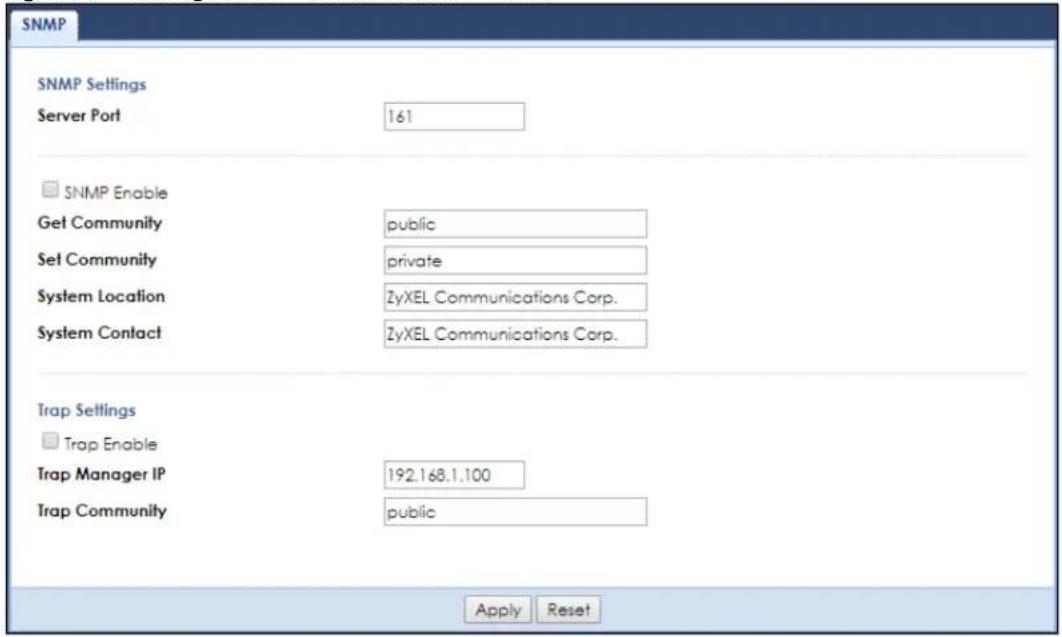
The following table describes the fields in this screen.
Table 29 Management > Remote MGMT > SNMP
| LABEL DESCRIPTION | |
| Server Port | The SNMP agent listens on port 161 by default. If you change the SNMP server port to a different number on the WAP7205, for example 8161, then you must notify people who need to access the WAP7205 SNMP agent to use the same port. |
| SNMP Enable | Select this option to let the WAP7205 act as an SNMP agent, which allows a manager station to manage and monitor the WAP7205 through the network. Otherwise, deselect it to turn this feature off. |
| Get Community | Enter the Get Community, which is the password for the incoming Get and GetNext requests from the management station. |
| Set Community | Enter the Set community, which is the password for incoming Set requests from the management station. |
| System Location Enter | the SNMP system location. |
| System Contact Enter | the SNMP system contact. |
| Trap Enable | Select this to have the WAP7205 send an SNMP trap to the specified IP address when it receives the event. Otherwise, deselect to disable this feature. |
| Trap Manager IP Type | the IP address of the station to which your SNMP traps are sent. |
| Trap Community | Enter the Trap Community, which is the password sent with each trap to the SNMP manager. The default is public and allows all requests. |
| Apply Click this to save your changes back to the WAP7205. | |
| Reset Click this to restore your previously saved settings. | |
CHAPTER 11
Maintenance
11.1 Overview
This chapter provides information on the Maintenance screens.
11.2 What You Can Do
- Use the General screen (Section 11.3 on page 66) to set the system name, the domain name and the timeout period of the management session.
- Use the Account screen (Section 11.4 on page 67) to change your WAP7205's system password.
- Use the Backup/Restore screen (Section 11.5 on page 68) to view information related to factory defaults, backup configuration, and restoring configuration.
- Use the Restart screen (Section 11.6 on page 69) to reboot the WAP7205 without turning the power off.
- Use the Language screen (Section 11.7 on page 70) to change the language for the Web Configurator.
- Use the Diagnostic screen (Section 11.8 on page 70) to display information to help you identify problems with the WAP7205.
11.3 General Screen
Use this screen to set the system and domain names and the timeout period of the management session. Click Maintenance > General. The following screen displays.
Figure 35 Maintenance > General
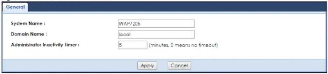
The following table describes the labels in this screen.
Table 30 Maintenance > General
| LABEL DESCRIPTION | |
| System Name | Enter a unique name to identify the WAP7205 in an Ethernet network. |
| Domain Name Enter the domain name you wish to give to the WAP7205. | |
| Administrator Inactivity Timer | Type how many minutes a management session can be left idle before the session times out. The default is 5 minutes. After it times out you have to log in with your password again. Very long idle timeouts may have security risks. A value of "0" means a management session never times out, no matter how long it has been left idle (not recommended). |
| Apply | Click Apply to save your changes back to the WAP7205. |
| Cancel | Click Cancel to reload the previous configuration for this screen. |
11.4 Account Screen
It is strongly recommended that you change the password of the user account.
If you forget your login account password (or IP address), you will need to reset the device. See Section 1.4 on page 11 and Section 11.5 on page 68 for details
Click Maintenance > Account.
Figure 36 Maintenance > Account

The following table describes the labels in this screen.
Table 31 Maintenance > Account
| LABEL DESCRIPTION | |
| # This the index number of the entry | |
| User Name This field displays the user name. | |
| Group This field displays the user's login account type. | |
| Modify | Click the Edit icon to go to the screen where you can edit the account. |
11.4.1 Edit a User's Account
Use this screen to edit a user's account. Click the Edit icon next to the user account you want to edit. The Account Setup screen displays as shown.
Figure 37 Maintenance > Account: Edit
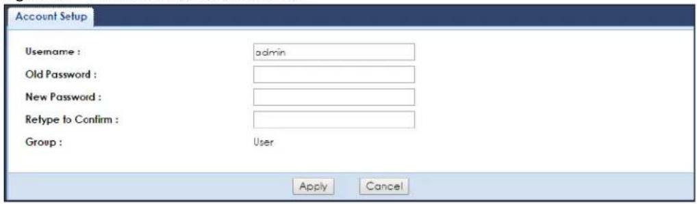
The following table describes the labels in this screen.
Table 32 Maintenance > Account: Edit
| LABEL DESCRIPTION | |
| Username | Enter a descriptive name for the user account. The user name can be made up of up to 15 alphanumeric characters (0-9, A-Z, a-z, -,_) with no spaces. |
| Old Password | Type the default password or the existing password you use to access the system in this field. |
| New Password | Type your new system password (up to 30 characters). Note that as you type a password, the screen displays an asterisk (*) for each character you type. |
| Retype to Confirm Type | the new password again in this field. |
| Group This is the user's | account type.The web configurator screens and privileges vary depending on which account type you use to log in. |
| Apply | Click Apply to save your changes back to the WAP7205. |
| Cancel | Click Cancel to reload the previous configuration for this screen. |
11.5 Configuration Backup/Restore Screen
Backup configuration allows you to back up (save) the WAP7205's current configuration to a file on your computer. Once your WAP7205 is configured and functioning properly, it is highly recommended that you back up your configuration file before making configuration changes. The backup configuration file will be useful in case you need to return to your previous settings.
Restore configuration allows you to upload a new or previously saved configuration file from your computer to your WAP7205.
Click Maintenance > Backup/Restore. Information related to factory defaults, backup configuration, and restoring configuration appears as shown next.
Figure 38 Maintenance > Backup/Restore
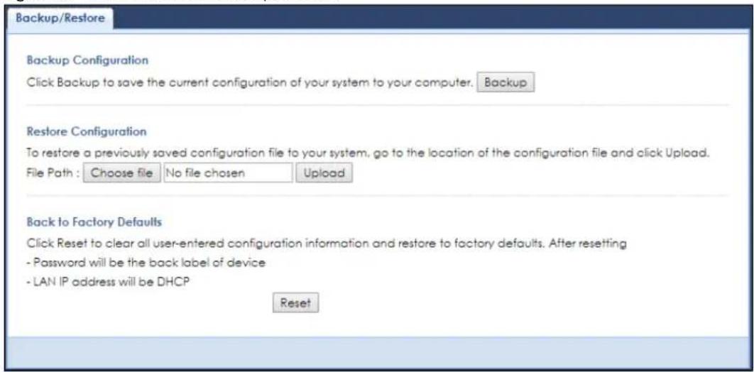
The following table describes the labels in this screen.
Table 33 Maintenance > Backup/Restore
| LABEL DESCRIPTION | |
| Backup | Click Backup to save the WAP7205's current configuration to your computer. |
| File Path | Type in the location of the file you want to upload in this field or click Choose file to find it. |
| Choose file | Click Choose file to find the file you want to upload. |
| Upload Click Upload to begin the upload process.Note: Do not turn off the WAP7205 while configuration file upload is in progress.After you click Upload, you must then wait one minute before logging into the WAP7205 again. The WAP7205 automatically restarts in this time causing a temporary network disconnect. | |
| Reset | Pressing the Reset button in this section clears all user-entered configuration information and returns the WAP7205 to its factory defaults.You can also press the RESET button on the rear panel to reset the factory defaults of your WAP7205. Refer to the chapter about introducing the Web Configurator for more information on the RESET button. |
Note: If you uploaded the default configuration file you may need to change the IP address of your computer to be in the same subnet as that of the WAP7205 IP address.
11.6 Restart Screen
System restart allows you to reboot the WAP7205 without turning the power off.
Click Maintenance > Restart to open the following screen.
Figure 39 Maintenance > Restart

Click Restart to have the WAP7205 reboot. This does not affect the WAP7205's configuration.
11.7 Language Screen
Use this screen to change the language for the Web Configurator.
Select the language you prefer and click Apply. The Web Configurator language changes after a while without restarting the WAP7205.
Figure 40 Maintenance > Language

11.8 Diagnostic Screens
The Diagnostic screens display information to help you identify problems with the EWAP7205.
11.8.1 Ping Screen
Use this screen to ping an IP address. Click Maintenance > Diagnostic > Ping to open the following screen.
Figure 41 Maintenance > Diagnostic > Ping
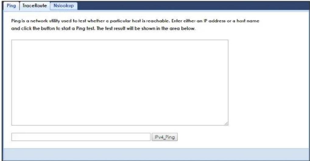
The following table describes the labels in this screen.
Table 34 Maintenance > Diagnostic > Ping
| LABEL DESCRIPTION | |
| Type the URL or IP address of a computer to which you want to perform Ping in order to test a connection. | |
| IPv4_Ping Click the | button to ping the IP address that you entered. |
11.8.2 TraceRoute Screen
Use this screen to trace the route packets take to a host. Click Maintenance > Diagnostic > TraceRoute to open the following screen.
Figure 42 Maintenance > Diagnostic > TraceRoute
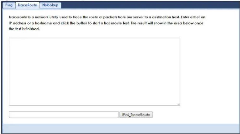
The following table describes the labels in this screen.
Table 35 Maintenance > Diagnostic > TraceRoute
| LABEL DESCRIPTION | |
| Type the URL or IP address of a computer for which you want to perform traceroute in order to test a connection. | |
| IPv4_TraceRoute | Click this button to perform the traceroute function. This determines the path a packet takes to the specified computer. |
11.8.3 Nslookup Screen
Use this screen to perform an nslookup (name server lookup). Nslookup queries the DNS to resolve an IP address into a host name and vice-versa. Click Maintenance > Diagnostic > Nslookup to open the following screen.
Figure 43 Maintenance > Diagnostic > Nslookup
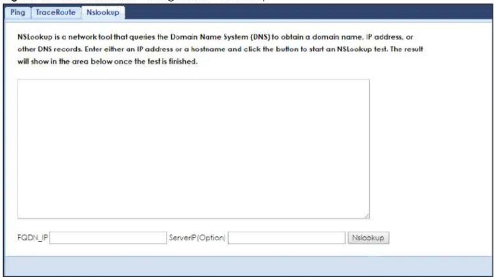
The following table describes the labels in this screen.
Table 36 Maintenance > Diagnostic > Nslookup
| LABEL DESCRIPTION | |
| FQDN_IP | Type a domain name or IP address in this field for the name server lookup. |
| Server IP | Enter the IP address of the server the WAP7205 uses to translate the specified domain name or IP address. |
| Nslookup | Click this button to perform a DNS lookup on the IP address or domain name you entered. |
CHAPTER 12
Troubleshooting
This chapter offers some suggestions to solve problems you might encounter. The potential problems are divided into the following categories.
• Power, Hardware Connections, and LEDs
• WAP7205 Access and Login
- Internet Access
- Resetting the WAP7205 to Its Factory Defaults
- Wireless Problems
- MoCA Network
12.1 Power, Hardware Connections, and LEDs
The WAP7205 does not turn on. None of the LEDs turn on.
1 Make sure the WAP7205 is plugged in to an appropriate power source. Make sure the power source is turned on.
2 Disconnect and re-connect the WAP7205.
3 Remove the WAP7205 from the outlet. Then connect an electrical device that you know works into the same power outlet. This checks the status of the power outlet.
4 If the problem continues, contact the vendor.
One of the LEDs does not behave as expected.
1 Make sure you understand the normal behavior of the LED. See Section 1.3 on page 10.
2 Make sure you understand how the LEDs are enabled or disabled. See Section 1.3 on page 10.
3 Check the hardware connections. See the Quick Start Guide.
4 Inspect your cables for damage. Contact the vendor to replace any damaged cables.
5 Disconnect and re-connect the WAP7205.
6 If the problem continues, contact the vendor.
12.2 WAP7205 Access and Login
I forgot the password.
1 The default password is on the label behind the ZYXEL logo plate.
2 If this does not work, you have to reset the device to its factory defaults. See Section 12.4 on page 76.
I cannot see or access the Login screen in the Web Configurator.
1 Make sure you are using the correct address.
- The default web address (URL) of the WAP7205 is http://zyxelsetup (for Windows) or http://zyxelsetup.local (for Mac).
2 Check the hardware connections, and make sure the LEDs are behaving as expected. See the Quick Start Guide.
3 Make sure your Internet browser does not block pop-up windows and has JavaScript and Java enabled.
4 Reset the device to its factory defaults, and try to access the WAP7205 with the default address.
5 If the problem continues, contact the network administrator or vendor, or try one of the advanced suggestions.
Advanced Suggestions
- If your computer is connected wirelessly, use a computer that is connected to a LAN/ETHERNET port.
I can see the Login screen, but I cannot log in to the WAP7205.
1 Make sure you have entered the password correctly. The default password is on the label behind the ZYXEL logo plate.
2 This can happen when you fail to log out properly from your last session. Try logging in again after 5 minutes.
3 Disconnect and re-connect the WAP7205.
4 If this does not work, you have to reset the device to its factory defaults. See Section 12.4 on page 76.
12.3 Internet Access
I cannot access the Internet.
1 Check the hardware connections, and make sure the LEDs are behaving as expected. See the Quick Start Guide.
2 Try to connect directly to the gateway. If you can access the Internet, check that the WAP7205 has connected to the gateway by checking the Status screen. See Section 3.1 on page 18.
3 If you are trying to access the Internet wirelessly, make sure the wireless settings in the wireless client are the same as the settings in the WAP7205.
4 Disconnect all the cables from your device, and follow the directions in the Quick Start Guide again.
5 If the problem continues, contact the network administrator or vendor.
I cannot access the Internet anymore. I had access to the Internet (with the WAP7205), but my Internet connection is not available anymore.
1 Check the hardware connections, and make sure the LEDs are behaving as expected. See the Quick Start Guide and Section 1.3 on page 10.
2 Reboot the WAP7205.
3 Try to connect directly to the gateway. If you can access the Internet, check that the WAP7205 has connected to the gateway by checking the Status screen. See Section 3.1 on page 18.
4 If the problem continues, contact the network administrator or vendor.
The Internet connection is slow or intermittent.
1 There might be a lot of traffic on the network. Look at the LEDs, and check Section 1.3 on page 10. If the WAP7205 is sending or receiving a lot of information, try closing some programs that use the Internet, especially peer-to-peer applications.
2 Check the signal strength. If the signal strength is low, try moving the WAP7205 closer to the AP if possible, and look around to see if there are any devices that might be interfering with the wireless network (for example, microwaves, other wireless networks, and so on).
3 Reboot the WAP7205.
4 If the problem continues, contact the network administrator or vendor, or try one of the advanced suggestions.
12.4 Resetting the WAP7205 to Its Factory Defaults
If you reset the WAP7205, you lose all of the changes you have made. The WAP7205 re-loads its default settings, and the password resets to the default key on the label behind the ZYXEL logo plate. You have to make all of your changes again.
You will lose all of your changes when you reset the WAP7205 to its factory defaults.
To reset the WAP7205,
1 Make sure the power LED is on.
2 Press the RESET button for longer than 5 seconds, the Power LED begins to blink, to set the WAP7205 back to its factory-default configuration.
OR
3 Click Maintenance > Backup/Restore and then click Reset.
If the WAP7205 restarts automatically, wait for the WAP7205 to finish restarting, and log in to the Web Configurator. The password is in the device label.
If the WAP7205 does not restart automatically, disconnect and reconnect the WAP7205. Then, follow the directions above again.
12.5 Wireless Problems
I cannot access the WAP7205 or ping any computer from the WLAN.
1 Make sure the wireless LAN is enabled on the WAP7205.
2 Make sure the wireless adapter on the wireless client is working properly.
3 Make sure the wireless adapter installed on your computer is IEEE 802.11 compatible and supports the same wireless standard as the WAP7205.
4 Make sure your computer (with a wireless adapter installed) is within the transmission range of the WAP7205.
5 Check that both the WAP7205 and your wireless station are using the same wireless and wireless security settings.
6 Make sure traffic between the WLAN and the LAN is not blocked by the MAC Address List of the WAP7205. See Section 7.7 on page 49.
12.6 MoCA Network
The WAP7205 cannot set up a MoCA network with other MoCA devices.
1 Make sure all the MoCA devices are turned on and connected using the same coaxial wiring.
2 Make sure all the MoCA devices are operating at the same channel frequency.
3 If you enable MoCA network security on the WAP7205, make sure other MoCA devices also use the same password.
APPENDIX A
Customer Support
In the event of problems that cannot be solved by using this manual, you should contact your vendor. If you cannot contact your vendor, then contact a Zyxel office for the region in which you bought the device.
See http://www.zyxel.com/homepage.shtml and also
http://www.zyxel.com/about_zyxel/zyxel_worldwide.shtml for the latest information.
Please have the following information ready when you contact an office.
Required Information
- Product model and serial number.
- Warranty Information.
- Date that you received your device.
- Brief description of the problem and the steps you took to solve it.
Corporate Headquarters (Worldwide)
Taiwan
• Zyxel Communications Corporation
- http://www.zyxel.com
Asia
China
• Zyxel Communications (Shanghai) Corp.
Zyxel Communications (Beijing) Corp.
Zyxel Communications (Tianjin) Corp.
- http://www.zyxel.cn
India
• Zyxel Technology India Pvt Ltd
- http://www.zyxel.in
Kazakhstan
• Zy x el Kazakhstan
- http://www.zyxel.kz
Korea
• Zyxel Korea Corp.
- http://www.zyxel.kr
Malaysia
• Zyxel Malaysia Sdn Bhd.
- http://www.zyxel.com.my
Pakistan
• Zyxel Pakistan (Pvt.) Ltd.
- http://www.zyxel.com.pk
Philippines
• Zyxel Philippines
- http://www.zyxel.com.ph
Singapore
• Zyxel Singapore Pte Ltd.
- http://www.zyxel.com.sg
Taiwan
• Zyxel Communications Corporation
- http://www.zyxel.com/tw/zh/
Thailand
• Zyxel Thailand Co., Ltd
- http://www.zyxel.co.th
Vietnam
• Zyxel Communications Corporation-Vietnam Office
- http://www.zyxel.com/vn/vi
Europe
Austria
• Zyxel Communications Brasil Ltda.
- https://www.zyxel.com/br/pt/
Ecuador
• Zyxel Communication Corporation
- http://www.zyxel.com/ec/es/
Middle East
Israel
• Zyxel Communication Corporation
- http://il.zyxel.com/homepage.shtml
Middle East
• Zyxel Communication Corporation
- http://www.zyxel.com/me/en/
North America
USA
• Zyxel Communications, Inc. - North America Headquarters
- http://www.zyxel.com/us/en/
Oceania
Australia
• Zyxel Communications Corporation
- http://www.zyxel.com/au/en/
Africa
South Africa
• Nology (Pty) Ltd.
- http://www.zyxel.co.za
APPENDIX B
Legal Information
Copyright
Copyright © 2017 by Zyxel Communications Corporation.
The contents of this publication may not be reproduced in any part or as a whole, transcribed, stored in a retrieval system, translated into any language, or transmitted in any form or by any means, electronic, mechanical, magnetic, optical, chemical, photocopying, manual, or otherwise, without the prior written permission of Zyxel Communications Corporation.
Published by Zyxel Communications Corporation. All rights reserved.
Disclaimer
Zyxel does not assume any liability arising out of the application or use of any products, or software described herein. Neither does it convey any license under its patent rights nor the patent rights of others. Zyxel further reserves the right to make changes in any products described herein without notice. This publication is subject to change without notice.
Regulatory Notice and Statement
UNITED STATES of AMERICA

The following information applies if you use the product within USA area.
FCC EMC Statement
• The device complies with Part 15 of FCC rules. Operation is subject to the following two conditions:
(1) This device may not cause harmful interference, and
(2) This device must accept any interference received, including interference that may cause undesired operation.
- Changes or modifications not expressly approved by the party responsible for compliance could void the user's authority to operate the device.
- This product has been tested and complies with the specifications for a Class B digital device, pursuant to Part 15 of the FCC Rules. These limits are designed to provide reasonable protection against harmful interference in a residential installation. This device generates, uses, and can radiate radio frequency energy and, if not installed and used according to the instructions, may cause harmful interference to radio communications. However, there is no guarantee that interference will not occur in a particular installation.
- If this device does cause harmful interference to radio or television reception, which is found by turning the device off and on, the user is encouraged to try to correct the interference by one or more of the following measures:
• Reorient or relocate the receiving antenna
- Increase the separation between the devices
- Connect the equipment to an outlet other than the receiver's
- Consult a dealer or an experienced radio/TV technician for assistance
The following information applies if you use the product with RF function within USA area.
FCC Radiation Exposure Statement
• This device complies with FCC RF radiation exposure limits set forth for an uncontrolled environment.
- This transmitter must be at least 20 cm from the user and must not be co-located or operating in conjunction with any other antenna or transmitter.
- Operations in the 5.15-5.25GHz band are restricted to indoor usage only.
CANADA
The following information applies if you use the product within Canada area.
Industry Canada ICES statement
CAN ICES-3 (B)/NMB-3(B)
Industry Canada RSS-GEN & RSS-247 statement
- This device complies with Industry Canada license-exempt RSS standard(s). Operation is subject to the following two conditions: (1) this device may not cause interference, and (2) this device must accept any interference, including interference that may cause undesired operation of the device.
- This radio transmitter (2468C-WAP7205) has been approved by Industry Canada to operate with the antenna types listed below with the maximum permissible gain and required antenna impedance for each antenna type indicated. Antenna types not included in this list, having a gain greater than the maximum gain indicated for that type, are strictly prohibited for use with this device.
Antenna Information
| TYPE MANUFACTURER GAIN CONNECTOR | |||
| Internal Single Band Honglin 2.4G: 4.2 dBi | 5G: 4.6 dBi | IPEX | |
If the product with 5G wireless function operating in 5150-5250 MHz and 5725-5850 MHz, the following attention must be paid,
- The device for operation in the band 5150-5250 MHz is only for indoor use to reduce the potential for harmful interference to co-channel mobile satellite systems.
- For devices with detachable antenna(s), the maximum antenna gain permitted for devices in the band 5725-5850 MHz shall be such that the equipment still complies with the e.i.r.p. limits specified for point-to-point and non-point-to-point operation as appropriate; and
- The worst-case tilt angle(s) necessary to remain compliant with the e.i.r.p. elevation mask requirement set forth in Section 6.2.2(3) of RSS 247 shall be clearly indicated.
If the product with 5G wireless function operating in 5250-5350 MHz and 5470-5725 MHz, the following attention must be paid.
Industry Canada radiation exposure statement
This device complies with IC radiation exposure limits set forth for an uncontrolled environment. This device should be installed and operated with a minimum distance of 20 cm between the radiator and your body.
List of national codes
| COUNTRY | ISO 3166 2 LETTER CODE | COUNTRY | ISO 3166 2 LETTER CODE |
| Austria AT Liechtenstein LI | |||
| Belgium BE Lithuania LT | |||
| Bulgaria BG Luxembourg LU | |||
| Croatia HR Malta | MT | ||
| Cyprus | CY | Netherlands | NL |
| Czech Republic | CZ Norway NO | ||
| Denmark | DK | Poland | PL |
| Estonia | EE Portugal | PT | |
| Finland | FI | Romania RO | |
| France | FR Serbia | RS | |
| Germany | DE Slovakia | SK | |
| Greece GR Slovenia | SI | ||
| Hungary | HU | Spain | ES |
| Iceland | IS | Switzerland | CH |
| Ireland | IE | Sweden SE | |
| Italy | IT | Turkey | TR |
| Latvia | LV United Kingdom | GB |
Safety Warnings
- Do not use this product near water, for example, in a wet basement or near a swimming pool.
- Do not expose your device to dampness, dust or corrosive liquids.
- Do not store things on the device.
- Do not obstruct the device ventilation slots as insufficient airflow may harm your device. For example, do not place the device in an enclosed space such as a box or on a very soft surface such as a bed or sofa.
- Do not install, use, or service this device during a thunderstorm. There is a remote risk of electric shock from lightning.
- Connect ONLY suitable accessories to the device.
- Do not open the device or unit. Opening or removing covers can expose you to dangerous high voltage points or other risks. ONLY qualified service personnel should service or disassemble this device. Please contact your vendor for further information.
- Make sure to connect the cables to the correct ports.
- Place connecting cables carefully so that no one will step on them or stumble over them.
• Always disconnect all cables from this device before servicing or disassembling.
- Do not remove the plug and connect it to a power outlet by itself; always attach the plug to the power adaptor first before connecting it to a power outlet.
- Do not allow anything to rest on the power adaptor or cord and do NOT place the product where anyone can walk on the power adaptor or cord.
- Please use the provided or designated connection cables/power cables/ adaptors. Connect it to the right supply voltage (for example, 110V AC in North America or 230V AC in Europe). If the power adaptor or cord is damaged, it might cause electrocution. Remove it from the device and the power source, repairing the power adapter or cord is prohibited. Contact your local vendor to order a new one.
- Do not use the device outside, and make sure all the connections are indoors. There is a remote risk of electric shock from lightning.
- CAUTION: Risk of explosion if battery is replaced by an incorrect type, dispose of used batteries according to the instruction. Dispose them at the applicable collection point for the recycling of electrical and electronic devices. For detailed information about recycling of this product, please contact your local city office, your household waste disposal service or the store where you purchased the product.
- The following warning statements apply, where the disconnect device is not incorporated in the device or where the plug on the power supply cord is intended to serve as the disconnect device,
- For permanently connected devices, a readily accessible disconnect device shall be incorporated external to the device;
- For pluggable devices, the socket-outlet shall be installed near the device and shall be easily accessible.
Environment Statement
ErP (Energy-related Products)
Zyxel products put on the EU market in compliance with the requirement of the European Parliament and the Council published Directive 2009/125/EC establishing a framework for the setting of ecodesign requirements for energy-related products (recast), so called as "ErP Directive (Energy-related Products directive) as well as ecodesign requirement laid down in applicable implementing measures, power consumption has satisfied regulation requirements which are:
• Network standby power consumption < 8W, and/or
- Off mode power consumption < 0.5 W ,and/or
- Standby mode power consumption < 0.5W .
(Wireless setting, please refer to "Wireless" chapter for more detail.)
European Union - Disposal and Recycling Information
The symbol below means that according to local regulations your product and/or its battery shall be disposed of separately from domestic waste. If this product is end of life, take it to a recycling station designated by local authorities. At the time of disposal, the separate collection of your product and/or its battery will help save natural resources and ensure that the environment is sustainable development.
Various symbols are used in this product to ensure correct usage, to prevent danger to the user and others, and to prevent property damage. The meaning of these symbols are described below. It is important that you read these descriptions thoroughly and fully understand the contents.
Explanation of the Symbols
| SYMBOL EXPLANATION | |
 | Alternating current (AC):AC is an electric current in which the flow of electric charge periodically reverses direction. |
 | Direct current (DC):DC if the unidirectional flow or movement of electric charge carriers. |
 | Earth; ground:A wiring terminal intended for connection of a Protective Earthing Conductor. |
 | Class II equipment:The method of protection against electric shock in the case of class II equipment is either double insulation or reinforced insulation. |
Viewing Certifications
Go to http://www.zyxel.com to view this product's documentation and certifications.
Zyxel Limited Warranty
Zyxel warrants to the original end user (purchaser) that this product is free from any defects in material or workmanship for a specific period (the Warranty Period) from the date of purchase. The Warranty Period varies by region. Check with your vendor and/or the authorized Zyxel local distributor for details about the Warranty Period of this product. During the warranty period, and upon proof of purchase, should the product have indications of failure due to faulty workmanship and/or materials, Zyxel will, at its discretion, repair or replace the defective products or components without charge for either parts or labor, and to whatever extent it shall deem necessary to restore the product or components to proper operating condition. Any replacement will consist of a new or re-manufactured functionally equivalent product of equal or higher value, and will be solely at the discretion of Zyxel. This warranty shall not apply if the product has been modified, misused, tampered with, damaged by an act of God, or subjected to abnormal working conditions.
Note
Repair or replacement, as provided under this warranty, is the exclusive remedy of the purchaser. This warranty is in lieu of all other warranties, express or implied, including any implied warranty of merchantability or fitness for a particular use or purpose. Zyxel shall in no event be held liable for indirect or consequential damages of any kind to the purchaser.
To obtain the services of this warranty, contact your vendor. You may also refer to the warranty policy for the region in which you bought the device at http://www.zyxel.com/web/support_warranty_info.php.
Registration
Register your product online to receive e-mail notices of firmware upgrades and information at www.zyxel.com for global products, or at www.us.zyxel.com for North American products.
Open Source Licenses
This product contains in part some tree software distributed under GPL license terms and/or GPL like licenses. Open source licenses are provided with the firmware package. You can download the latest firmware at www.zyxel.com. To obtain the source code covered under those Licenses, please contact support@zyxel.com.tw to get it.
Index
C
certifications 86
viewing 88
channel 40
Configuration
restore 69, 71, 72
contact information 78
copyright 84
CPU usage 19
customer support 78
LAN setup 55
Language 69
LED
POWER 10
Link type 20
Local Area Network 55
Log 34
logout
Web Configurator 16
D
disclaimer 84
F
firmware version 19
G
General wireless LAN screen 41, 47
|
IP Address 58
IP alias 56
L
LAN 55
LAN overview 55
M
MAC 49
MAC address 40
MAC address filter 40
MAC address filtering 49
MAC filter 49
Management Information Base (MIB) 63
managing the device
good habits 9
Media access control 49
Memory usage 19
MoCA 59
data rates 59
frequency band plans 60
Last Operational Frequency 60
LOF 60
NC 61
Network Coordinator 61
node 62
overview 59
packet error rate 59, 61
password 61
PER 59
PER mode 61
power saving modes 59
privacy 61
settings 60
version 59
Multimedia over Coax Alliance 59
0
Operating Channel 19
P
Packet Error Rate 61
PER 59
PER mode
NPER 61
VLPER 61
port speed 20
Q
Quality of Service (QoS) 51
R
reset the device 11
Restore configuration 69, 71, 72
Roaming 50
RTS/CTS Threshold 40, 50
s
Scheduling 53
Service Set 42
Service Set IDentification 42
Service Set IDentity. See SSID.
Simple Network Management Protocol, see SNMP
SNMP 63
agents 63
Get 63
GetNext 64
Manager 63
managers 63
MIB 63
network components 63
Set 64
Trap 64
SSID 19, 40, 42
Status Screens
Ethernet 18
system statistics 18
WLAN 18
Subnet Mask 58
Summary
Packet statistics 35
Wireless station status 36
System General Setup 66
System restart 69
W
warranty 88
note 88
Web Configurator
how to access 13
Overview 13
WEP Encryption 45, 46
Wireless association list 36
wireless channel 76
wireless LAN 76
wireless LAN scheduling 53
Wireless network
basic guidelines 39
channel 40
example 39
MAC address filter 40
overview 39
security 40
SSID 40
Wireless security 40
overview 40
type 40
wireless security
troubleshooting 76
Wireless tutorial 23
WPS 23
Wizard setup 21
WPS button 11

- Related Documentation
- Contents Overview
- User's Guide 8
- Technical Reference 33
- Table of Contents
- Part II: Technical Reference 33
- Chapter 6 Monitor....34
- Chapter 7 Wireless LAN ....39
- Chapter 8 LAN ....55
- Chapter 9
- MoCA....59
- Chapter 10
- SNMP 63
- Chapter 11
- Maintenance 66
- Chapter 12
- Troubleshooting....73
- PART I
- User's Guide
- CHAPTER 1
- Introducing the WAP7205
- Overview
- Securing the WAP7205
- LEDs
- Resetting the WAP7205
- RESET Button
- WPS Button
- Wall Mounting
- Be careful to avoid damaging pipes or cables located inside the wall when drilling holes for the screws.
- CHAPTER 2
- Introducing the Web
- Configurator
- Overview
- Accessing the Web Configurator
- Login Screen
- Navigating the Web Configurator
- Title Bar
- Navigation Panel
- CHAPTER 3 Dashboard
- Dashboard Screen
- CHAPTER 4
- Easy123 Wizard Setup
- Overview
- Accessing the Wizard
- Using the Wizard
- CHAPTER 5 Tutorials
- Overview
- Connecting to the WAP7205's Wi-Fi Network Using WPS
- Push Button Configuration (PBC)
- PIN Configuration
- Connecting to the WAP7205's Wi-Fi Network Using SSID (No WPS)
- Configuring Wireless Security on the WAP7205
- Configuring Your Notebook
- Using Multiple SSIDs on the WAP7205
- Configuring Security Settings of Multiple SSIDs
- Status SSID Security Edit
- PART II
- Technical Reference
- CHAPTER 6 Monitor
- Overview
- What You Can Do
- Log
- Time Message
- Packet Statistics
- WLAN 2.4G Station Status
- Strength MAC Address SSID TxPkts RxPkts Security Rate Mode Association Time
- WLAN 5G Station Status
- CHAPTER 7
- Wireless LAN
- Overview
- What You Can Do
- What You Should Know
- Wireless Security Overview
- SSID
- MAC Address Filter
- WPS
- General Wireless LAN Screen
- Wireless Security
- No Security
- WPA2-PSK
- WPA2
- More AP Screen
- More AP Edit
- MAC Filter
- Wireless LAN Advanced Screen
- Quality of Service (QoS) Screen
- WPS Screen
- WPS Station Screen
- Scheduling Screen
- CHAPTER 8 LAN
- Overview
- What You Can Do
- What You Need To Know
- IP Alias
- LAN IP Screen
- IP Alias Screen
- CHAPTER 9 MoCA
- Overview
- What You Can Do
- MoCA Screen
- MoCA Monitor Screen
- CHAPTER 10 SNMP
- Overview
- SNMP Screen
- Maintenance
- Overview
- What You Can Do
- General Screen
- Account Screen
- User Name Group Modify
- Edit a User's Account
- Configuration Backup/Restore Screen
- Restart Screen
- Language Screen
- Diagnostic Screens
- Ping Screen
- TraceRoute Screen
- Nslookup Screen
- Troubleshooting
- Power, Hardware Connections, and LEDs
- WAP7205 Access and Login
- I forgot the password.
- I cannot see or access the Login screen in the Web Configurator.
- Advanced Suggestions
- I can see the Login screen, but I cannot log in to the WAP7205.
- Internet Access
- I cannot access the Internet.
- The Internet connection is slow or intermittent.
- Resetting the WAP7205 to Its Factory Defaults
- Wireless Problems
- MoCA Network
- APPENDIX A
- Customer Support
- Required Information
- Corporate Headquarters (Worldwide)
- Taiwan
- Asia
- China
- India
- Kazakhstan
- Korea
- Malaysia
- Pakistan
- Philippines
- Singapore
- Thailand
- Vietnam
- Europe
- Austria
- Ecuador
- Middle East
- Israel
- North America
- USA
- Oceania
- Australia
- Africa
- South Africa
- APPENDIX B
- Legal Information
- Copyright
- Disclaimer
- Regulatory Notice and Statement
- UNITED STATES of AMERICA
- FCC EMC Statement
- FCC Radiation Exposure Statement
- CANADA
- Industry Canada ICES statement
- Industry Canada RSS-GEN & RSS-247 statement
- Industry Canada radiation exposure statement
- Safety Warnings
- Environment Statement
- ErP (Energy-related Products)
- European Union - Disposal and Recycling Information
- Viewing Certifications
- Zyxel Limited Warranty
- Note
- Registration
- Open Source Licenses
- Index
- C
- D
- F
- G
- |
- L
- M
- 0
- P
- Q
- R
- s
- W
Brand : ZYXEL
Model : WAP7205
Category : Wi-Fi repeater