
AL1715 - Screen ACER - Free user manual and instructions
Find the device manual for free AL1715 ACER in PDF.


User questions about AL1715 ACER
0 question about this device. Answer the ones you know or ask your own.
Ask a new question about this device
Download the instructions for your Screen in PDF format for free! Find your manual AL1715 - ACER and take your electronic device back in hand. On this page are published all the documents necessary for the use of your device. AL1715 by ACER.
USER MANUAL AL1715 ACER
SAFETY PRECAUTIONS 2
SPECIAL NOTES ON LCD MONITORS ---- 3
CONNECTOR PIN ASSIGNMENT 19
Before operating the monitor, please read this manual thoroughly. This manual should be retained for future reference.
FCC Class B Radio Frequency Interference Statement WARNING: (FOR FCC CERTIFIED MODELS)
NOTE: This equipment has been tested and found to comply with the limits for a Class B digital device, pursuant to Part 15 of the FCC Rules. These limits are designed to provide reasonable protection against harmful interference in a residential installation. This equipment generates, uses and can radiate radio frequency energy, and if not installed and used in accordance with the instructions, may cause harmful interference to radio communications. However, there is no guarantee that interference will not occur in a particular installation. If this equipment does cause harmful interference to radio or television reception, which can be determined by turning the equipment off and on, the user is encouraged to try to correct the interference by one or more of the following measures:
- Reorient or relocate the receiving antenna.
- Increase the separation between the equipment and receiver.
- Connect the equipment into an outlet on a circuit different from that to which the receiver is connected.
- Consult the dealer or an experienced radio/TV technician for help.
NOTICE:
- The changes or modifications not expressly approved by the party responsible for compliance could void the user's authority to operate the equipment.
- Shielded interface cables and AC power cord, if any, must be used in order to comply with the emission limits.
- The manufacturer is not responsible for any radio or TV interference caused by unauthorized modification to this equipment. It is the responsibilities of the user to correct such interference.
As an ENERGY STAR ^® Partner our company International has determined that this product meets the ENERGY STAR ^® guidelines for energy efficiency.
WARNING:
To prevent fire or shock hazard, do not expose the monitor to rain or moisture. Dangerously high voltages are present inside the monitor. Do not open the cabinet. Refer servicing to qualified personnel only.
PRECAUTIONS
- Do not use the monitor near water, e.g. near a bathtub, washbowl, kitchen sink, laundry tub, swimming pool or in a wet basement.
- Do not place the monitor on an unstable cart, stand, or table. If the monitor falls, it can injure a person and cause serious damage to the appliance. Use only a cart or stand recommended by the manufacturer or sold with the monitor. If you mount the monitor on a wall or shelf, use a mounting kit approved by the manufacturer and follow the kit instructions.
- Slots and openings in the back and bottom of the cabinet are provided for ventilation. To ensure reliable operation of the monitor and to protect it from overheating, be sure these openings are not blocked or covered. Do not place the monitor on a bed, sofa, rug, or similar surface. Do not place the monitor near or over a radiator or heat register. Do not place the monitor in a bookcase or cabinet unless proper ventilation is provided.
- The monitor should be operated only from the type of power source indicated on the label. If you are not sure of the type of power supplied to your home, consult your dealer or local power company.
- The monitor is equipped with a three-pronged grounded plug, a plug with a third (grounding) pin. This plug will fit only into a grounded power outlet as a safety feature. If your outlet does not accommodate the three-wire plug, have an electrician install the correct outlet, or ground the appliance safely. Do not defeat the safety purpose of the grounded plug.
- Unplug the unit during a lightening storm or when it will not be used for long period of time. This will protect the monitor from damage due to power surges.
- Do not overload power strips and extension cords. Overloading can result in fire or electric shock.
- Never push any object into the slot on the monitor cabinet. It could short circuit parts causing a fire or electric shock. Never spill liquids on the monitor.
- Do not attempt to service the monitor by yourself; opening or removing covers can expose you to dangerous voltages and other hazards. Please refer all servicing to qualified service personnel.
- To ensure satisfactory operation, use the monitor only with UL listed computers which have appropriate configured receptacles marked between 100 - 240V AC, Min. 5A.
- The wall socket shall be installed near the equipment and shall be easily accessible.
- For use only with the attached power adapter (Output 12Vdc) which have UL, CSA listed license
SPECIAL NOTES ON LCD MONITORS
The following symptoms are normal with LCD monitor and do not indicate a problem.
NOTES
- Due to the nature of the fluorescent light, the screen may flicker during initial use. Turn off the Power Switch and then turn it on again to make sure the flicker disappears.
- You may find slightly uneven brightness on the screen depending on the desktop pattern you use.
- The LCD screen has effective pixels of 99.99% or more. It may include blemishes of 0.01% or less such as a missing pixel or a pixel lit all of the time.
- Due to the nature of the LCD screen, an afterimage of the previous screen may remain after switching the image, when the same image is displayed for hours. In this case, the screen is recovered slowly by changing the image or turning off the Power Switch for hours.
• 43.2cm(17") TFT Color LCD Monitor
- Crisp, Clear Display for Windows
• Recommended Resolutions: 1280 X 1024 @60Hz
- EPA ENERGY STAR
• Dual Input (DVI + Analog) (Only Dual-Input Model)
- Ergonomic Design (TCO'99 Approved)
• Space Saving, Compact Case Design
CHECKING THE CONTENTS OF THE PACKAGE
The product package should include the following items:
- LCD Monitor
- Owner's Manual
- Power Cord
- External Adapter
- 15-pin D-Sub Cable
- DVI Cable (only Dual-Input Model)
- Audio Cable
INSTALLATION INSTRUCTIONS
POWERCORD
Power Source:
-
Make sure that the power cord is the correct type required in your area.
-
This LCD monitor has an External universal power supply that allows operation in either 100/120V AC or 220/240V AC voltage area (No user adjustment is required.)
-
Connect the AC-power cord into your LCD monitor's DC-power-input. The AC-power cord may be connected to either a wall power outlet or the power outlet socket on your PC, depending on the type of power cord supplied with your LCD monitor.
NOTES
A certified power supply cord has to be used with this equipment. The relevant national installation and/or equipment regulations shall be considered. A certified power supply cord not lighter than ordinary polyvinyl chloride flexible cord according to IEC 60227 (designation H05VV-F 3G 0.75mm ^2 or H05VVH2-F2 3G 0.75mm ^2 ) shall be used. Alternative a flexible cord be of synthetic rubber according to IEC 60245 (designation H05RR-F 3G 0.75mm ^2 ) shall be used.
CONTROLS AND CONNECTORS
CABLE CONNECTIONS
Turn off your computer before performing the procedure below.
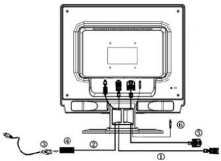
- Connect the power adapter dc cable to the DC-In port on the back of the monitor.
- Connect one end of the 15-pin D-Sub cable to the back of the monitor and connect the other end to the computer's D-Sub port.
- (only Dual-Input Model) Connect one end of the 24-pin DVI cable to the back of the monitor and connect the other end to the computer's DVI port.
- Connect the audio cable between the monitor's audio input and the PC's audio output (green port).
- Plug the power cable of your monitor into a nearby outlet. Plug the other end of the power cord into the power adapter.
- Turn on your monitor and computer.
text_image
Technical diagram of a monitor with labeled ports and wiring connectionsFigure 1 Connecting Cables
| 1. | D-SUB Cable 4. External Adapter | ||
| 2. | DC-Jack Power Cable 5. DVI Cable | ||
| 3. | AC Power Cord 6. Audio cable |
ADJUSTING THE VIEWING ANGLE
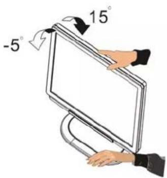
- For optimal viewing it is recommended to look at the full face of the monitor, then adjust the monitor's angle to your own preference.
- Hold the stand so you do not topple the monitor when you change the monitor's angle.
- You are able to adjust the monitor's angle from -5^ to 15^ .
text_image
-5° 15°Figure 2
NOTES
- Do not touch the LCD screen when you change the angle. It may cause damage or break the LCD screen.
- Careful attention is required not to catch your fingers or hands when you change the angle.
OPERATING INSTRUCTIONS
GENERAL INSTRUCTIONS
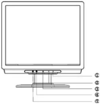
Press the power button to turn the monitor on or off. The other control buttons are located at front panel of the monitor (See Figure 3). By changing these settings, the picture can be adjusted to your personal preferences.
- The power cord should be connected.
- Connect the video cable from the monitor to the video card.
- Press the power button to turn on the monitor position. The power indicator will light up.
text_image
Diagram of a computer monitor with labeled parts numbered 1 to 5Figure 3 External Control Button
EXTERNAL CONTROLS
| 1. | >/ Volume 4. | #/MENU/ENTER | |
| 2. | < / Volume 5. | #/Auto Adjust Key/Exit | |
| 3. | #/Power Key /LED |
FRONT PANEL CONTROL
• /Power Button:
Press this button to turn the monitor ON or OFF, And display the monitor's state.
• Power Indicator:
Blue — Power On mode.
Orange — Power saving.
Light blue — Off mode.
• /MENU / ENTER :
Activate OSD menu when OSD is OFF or activate/de-activate adjustment function when OSD is ON or Exit OSD menu when in Volume Adjust OSD status.
-
Activates the volume control when the OSD is OFF or navigate through adjustment icons when OSD is ON or adjust a function when function is activated.
• > /Volume:
Activates the volume control when the OSD is OFF or navigate through adjustment icons when OSD is ON or adjust a function when function is activated.
• A/Auto Adjust button / Exit:
1. When OSD menu is in active status, this button will act as EXIT-KEY (EXIT OSD menu).
2. When OSD menu is in off status, press this button for 2 seconds to activate the Auto Adjustment function.
The Auto Adjustment function is used to set the HPos, VPos, Clock and Focus.
NOTES
- Do not install the monitor in a location near heat sources such as radiators or air ducts, or in a place subject to direct sunlight, or excessive dust or mechanical vibration or shock.
- Save the original shipping carton and packing materials, as they will come in handy if you ever have to ship your monitor.
- For maximum protection, repackage your monitor as it was originally packed at the factory.
- To keep the monitor looking new, periodically clean it with a soft cloth. Stubborn stains may be removed with a cloth lightly dampened with a mild detergent solution. Never use strong solvents such as thinner, benzene, or abrasive cleaners, since these will damage the cabinet. As a safety precaution, always unplug the monitor before cleaning it.
HOW TO ADJUST A SETTING
1. Press the MENU-button to activate the OSD window.
2. Press < or > to select the desired function.
3. Press the MENU-button to select the function that you want to adjust.
4. Press < or > to change the settings of the current function.
5. To exit and save, select the exit function. If you want to adjust any other function, repeat steps 2-4.

text_image
Exit
Enter
Contrast 50
Brightness 50
I. Analog-Only Model

text_image
Exit
Enter
Contrast 50
Brightness 50
II. Dual-Input Model, Analog Signal Input

text_image
Exit
Enter
Contrast 50
Brightness 50
III. Dual-Input Model, Digital Signal Input
ADJUSTING THE PICTURE
The descriptions for function control LEDS
text_image
Exit Enter Contrast 50 Brightness 50text_image
Exit Enter Contrast 50 Brightness 50text_image
Exit Enter Contrast 50 Brightness 50| Main Menu Icon | Sub Menu Icon | Sub Menu Item | Description |
 | Contrast | Adjusts the contrast between the foreground and background of the screen image. | |
| Brightness | Adjusts the background brightness of the screen image. | ||
 | Focus | Adjusts picture Focus (available in Analog mode only). | |
| Clock | Adjusts picture Clock (available in Analog mode only). | ||
 | H. Position | Adjust picture Focus (available in Analog mode only). | |
| V. Position | Adjust picture Clock (available in Analog mode only). | ||
 | N/A | Warm Set the color temperature to warm white. | |
| N/A | Cool Set the color temperature to cool white. | ||
| R | User /Red | Adjusts Red/Green/Blue intensity. | |
| G | User/Green | ||
| B | User/Blue | ||
 | N/A | English | Multi-language selection. |
| N/A | ### | ||
| N/A | Deutsch | ||
| N/A | Français | ||
| N/A | Español | ||
| N/A | Italiano | ||
| N/A | ### | ||
| N/A | ### | ||
 | H. Position Adjust the horizontal position of the OSD. | ||
| V. Position Adjust the vertical position of the OSD. | |||
| OSDTimeout | Adjust the OSD timeout. | ||
 (only Analog-input Model) (only Analog-input Model) | N/A | Auto Config | Auto Adjust the H/V Position, Focus and Clock of picture. |
 (only Dual-Input Model) (only Dual-Input Model) | N/A | Analog Select input signal from analog (D-Sub) | |
| N/A | Digital Select input signal from digital (DVI) | ||
 | N/A | Information | Show the resolution, H/V frequency and input port of current iput timing. |
 | N/A | Reset | Clear each old status of Auto-configuration and set the color temperature to Cool. |
| N/A | Exit Save user | adjustment and OSD disappear. | |
HOW TO OPTIMIZE THE DOS-MODE
PLUG AND PLAY
Plug & Play DDC1/2B Feature
This monitor is equipped with VESA DDC1/2B capabilities according to the VESA DDC STANDARD. It allows the monitor to inform the host system of its identity and, depending on the level of DDC used, communicate additional information about its display capabilities. The communication channel is defined in two levels, DDC1 and DDC2B. The DDC1 is a unidirectional data channel from the display to the host that continuously transmits EDID information. The DDC2B is a bidirectional data channel based on the I²C protocol. The host can request EDID information over the DDC2B channel.
THIS MONITOR WILL APPEAR TO BE NON-FUNCTIONAL IF THERE IS NO VIDEO INPUT SIGNAL. IN ORDER FOR THIS MONITOR TO OPERATE PROPERLY, THERE MUST BE A VIDEO INPUT SIGNAL.
This monitor meets the Green monitor standards as set by the Video Electronics Standards Association (VESA) and/or the United States Environmental Protection Agency (EPA) and The Swedish Confederation Employees (NUTEK). This feature is designed to conserve electrical energy by reducing power consumption when there is no video-input signal present. When there is no video input signal this monitor, following a time-out period, will automatically switch to an OFF mode. This reduces the monitor's internal power supply consumption. After the video input signal is restored, full power is restored and the display is automatically redrawn. The appearance is similar to a "Screen Saver" feature except the display is completely off. The display is restored by pressing a key on the keyboard, or clicking the mouse.
The accessory power cord for the Northern American region is the wallet plug with NEMA 5-15 style and is UL listed and CSA labeled. The voltage rating for the power cord shall be 125 volts AC. Supplied with units intended for connection to power outlet of personal computer: Please use a cord set consisting of a minimum No. 18 AWG, type SJT or SVT three conductors flexible cord. One end terminates with a grounding type attachment plug, rated 10A, 250V, CEE-22 male configuration. The other end terminates with a molded-on type connector body, rated 10A, 250V, having standard CEE-22 female configuration. Please note that power supply cord needs to use VDE 0602, 0625, 0821 approval power cord in European counties. TECHNICAL SUPPORT (FAQ)
| Problem & Question Possible Solution | |
| Power LED is not on *Check if the Power Switch is in the ON position*Power Cord should be connected | |
| No Plug & Play *Check if the PC system is Plug & Play compatible*Check if the Video Card is Plug & Play compatible*Check if the D-15 plug pin of Video Cable is bent | |
| Picture is fuzzy *Adjust the Contrast and Brightness Controls. | |
| Picture bounces or a wave pattern is present in the picture | *Move electrical devices that may cause electrical interference. |
| The power LED is ON (light blue) but there's no video or no picture. | *Computer Power Switch should be in the ON position.*Computer Video Card should be snugly seated in its slot*Make sure monitor's video cable is properly connected to the computer.*Inspect monitor's video cable and make sure none of the pins are bent.*Make sure computer is operational by hitting the CAPS LOCK key on the keyboard while observing the CAPS LOCK LED. The LED should either turn ON or OFF after hitting the CAPS LOCK key. |
| Missing one of the primary colors (RED, GREEN, or BLUE) | *Inspect the monitor's video cable and make sure that none of the pins are bent. |
| Screen image is not centered or sized properly. | *Adjust pixel frequency (CLOCK) and FOCUS or press hot-key (AUTO) |
| Picture has color defects (white does not look white) | *Adjust RGB color or select color temperature |
| Horizontal or vertical disturbances on the screen | *Use win 95/98 shut-down mode Adjust CLOCK and FOCUS or perform hot-key (AUTO-key). |
CLOCK (pixel frequency) controls the number of pixels scanned by one horizontal sweep. If the frequency is not correct, the screen shows vertical stripes and the picture has not correct width. FOCUS adjusts the phase of the pixel clock signal. With a wrong phase adjustment the picture has horizontal disturbances in light picture. For FOCUS and CLOCK adjustment use "dot-pattern" or win 95/98 shut-down mode pattern.
ERROR MESSAGE & POSSIBLE SOLUTION
CABLE NOT CONNECTED :
1. Check that the signal-cable is properly connected, If the connector is loose, tighten the connector's screws. 2. Check the signal -cable connection pins for damage.
INPUT NOT SUPPORT :
Your computer has been set to unsuitable display mode, set the computer to display mode given in the following table(See page 18).
APPENDIX
SPECIFICATIONS
| LCD Panel Size 43.2cmPixel pitch 0.264mm(Response time 16 ms) | Driving system | TFT Color LCD |
| m(17.0") | ||
| H)x 0.264mm(V) | ||
| Brightness | ^2 (Typical)260cd/m | |
| Contrast | 450:1(Typical) | |
| Viewable | 140° (H) 140° (V)angle | |
| Tr+Tf)Tr=4ms/Tf | =12ms | |
| H-Frequency 30KHz- | R,G,B Analog Interface | |
| Digital interface(Dual-Input Model) | ||
| 83KHz | ||
| V-Frequency | 55-75Hz | |
| Display Colors 16.2M Colors | ||
| Dot Clock | 165MHz | |
| Max. Resolution | 1280 x 1024 @75Hz | |
| Plug & Play | VESA DDC1/2BTM | |
| EPA ENERGY STAR® | ON Mode | ≤45W |
| OFF Mode | ≤3W | |
| Input Connector | D-Sub 15pin | |
| DVI-D 24pin (Dual-Input Model) | ||
| Input Video Signal | Analog:0.7Vp-p(standard),75 OHM, Positive | |
| Digital signal (Dual-Input Model) | ||
| Maximum Screen Size | Horizontal : 337.92mmVertical : 270.34mm | |
| Power Source | 100~264VAC,47~63Hz | |
| Environmental Considerations | Operating Temp: 5° to 50°CStorage Temp.: -20° to 65°COperating Humidity: 10% to 85% | |
| Dimensions | 377(W)×391(H)×154(D)mm | |
| Weight (N. W.) | 5.0kg Unit (net) | |
Video
| External Controls: Functions • Contrast | Switch | • Auto Adjust Key• </Volume• >/ Volume• Power Button• MENU/ Exit |
| Contrast | • Brightness• Focus• Clock• H.Position• V.Position• Input signal Selection (Dual model only)• Language• Auto configuration (Analog model only)• (Warm) Color• (Cool)Color• RGB Color temperature• Reset• OSD position . timeout• Display information• Exit | |
| Power Consumption ( Maximum ) 45 | Watts | |
| Audio Output Rated Power 1.5W rms (P | Per channel) | |
| Regulatory Compliance CUL, FCC, VC | CI, CCC, MPR II, CE, TÜV/GS, TCO'99, UL, ISO13406-2 | |
Preset Display Modes
| STANDARD | RESOLUTION | HORIZONTAL FREQUENCY(KHz) | VERTICAL FREQUENCY(Hz) | |
| VESA | VGA | 640 × 480 31 | 469 59.940 | |
| 640 × 480 37 | 500 75.000 | |||
| SVGA | 800 × 600 37 | 879 60.317 | ||
| 800 × 600 46 | 875 75.000 | |||
| XGA | 1024 × 768 48 | .363 | 60.004 | |
| 1024 × 768 56 | .476 70.069 | |||
| 1024 × 768 | 60.023 | 75.029 | ||
| SXGA | 1280 × 1024 64 | .000 60.000 | ||
| 1280 × 1024 80 | .000 75.000 | |||
| IBM | DOS | 720 × 400 | 31.469 | 70.087 |
| MAC | XGA | 1024 × 768 | 48.780 60.001 | |
| 1024 × 768 60 | .241 74.927 | |||
CONNECTOR PIN ASSIGNMENT

text_image
1 6 11 15 5 1015 - Pin Color Display Signal Cable
| PIN NO. | DESCRIPTION | PIN NO. | DESCRIPTION |
| 1. Red | 9. +5V | ||
| 2. | Green | 10. | Logic Gr |
| 3. | Blue | 11. | Monitor Gr |
| 4. Monitor Ground 12. DDC-Serial Data | |||
| 5. | DDC-return | 13. | H-Sync |
| 6. | R-Ground | 14. | V-Sync |
| 7. | G-Ground | 15. | DDC-Serial |
| 8. | B-Ground | ||
found round Clock (Dual-Input Model) 
text_image
1 9 17 8 16 26| Pin | Meaning | Pin | Meaning | Pin | Meaning |
| 1. | TMDS Data2- | 9. | TMDS Data1- | 17. | TMDS Data0- |
| 2. | TMDS Data2+ | 10. | TMDS Data1+ | 18. | TMDS Data0+ |
| 3. | TMDS Data 2/4 Shield | 11. | TMDS Data 1/3 Shield | 19. | TMDS Data 0/5 Shield |
| 4. | TMDS Data4- | 12. | TMDS Data3- | 20. | TMDS Data5- |
| 5. | TMDS Data4+ | 13. | TMDS Data3+ | 21. | TMDS Data5+ |
| 6. | DDC Clock 14. | +5V | Power 22. | TMDS Clock Shield | |
| 7. | DDC Data | 15. | GND(return for +5V hsync.vsync) | 23. | TMDS Clock+ |
| 8. | Analogue Vertical Sync | 16. | Hot Plug Detect | 24. | DDC TMDS Clock- |