
G700 TXi - Uncategorized GARMIN - Free user manual and instructions
Find the device manual for free G700 TXi GARMIN in PDF.

| Product Type | Aviation display system (PFD/MFD/EIS) |
| Display Sizes Available | GDU 1060 (10"), GDU 700P (7" portrait), GDU 700L (7" landscape) |
| Display Technology | Multi-touch capacitive color display |
| Control Interface | Touchscreen, dual concentric knobs, bezel keys |
| Power Input | Aircraft electrical system (28 VDC typical) |
| Backup Battery | Internal backup battery (optional, configurable) |
| SD Card Slots | 2 slots per unit (FAT32, 8-32 GB) |
| Connectivity | Bluetooth, Wi-Fi, Flight Stream 510, Connext |
| Database Types | Navigation, Terrain, Obstacles, Charts (FliteCharts/ChartView), SafeTaxi, Airport Directory, Basemap, IGRF |
| Synthetic Vision (SVT) | 3D terrain, obstacles, runways, traffic depiction |
| Weather Awareness | SiriusXM, FIS-B, Connext, Stormscope, airborne weather radar (GWX) |
| Traffic Awareness | ADS-B, TIS-A, TAS/TCAS I/II |
| Terrain Awareness | TAWS-B, Terrain-FLTA, HTAWS (helicopter) |
| Autopilot Integration | GFC 600, GPSS, Flight Director, altitude preselect |
| Emergency Modes | Smart Glide, Emergency Descent Mode (EDM) |
| Engine Indication (EIS) | Reciprocating and turbine engine parameters, lean assist |
| Dimensions (typical bezel) | GDU 1060: 10.4" x 6.2" x 2.6" (approx.); GDU 700: 7.25" x 5.75" x 2.5" (approx.) |
| Weight | GDU 1060: ~4.5 lbs; GDU 700: ~2.5 lbs (approximate) |
| Operating Temperature | -20°C to +55°C (avionics grade) |
| Cleaning Instructions | Use soft, non-abrasive cloth; avoid ammonia-based cleaners |
| Regulatory Compliance | FCC Part 15, TSO, certified for IFR/VFR |
Frequently Asked Questions - G700 TXi GARMIN
User questions about G700 TXi GARMIN
0 question about this device. Answer the ones you know or ask your own.
Ask a new question about this device
Download the instructions for your Uncategorized in PDF format for free! Find your manual G700 TXi - GARMIN and take your electronic device back in hand. On this page are published all the documents necessary for the use of your device. G700 TXi by GARMIN.
USER MANUAL G700 TXi GARMIN
natural_image
Interior cockpit view of an aircraft showing multiple flight monitors and control panels under a cloudy sky (no visible text or symbols)© 2017 - 2021
Garmin International, Inc., or its subsidiaries
All Rights Reserved
Except as expressly provided herein, no part of this manual may be reproduced, copied, transmitted, disseminated, downloaded or stored in any storage medium, for any purpose without the express prior written consent of Garmin. Garmin hereby grants permission to download a single copy of this manual and of any revision to this manual onto a hard drive or other electronic storage medium to be viewed and to print one copy of this manual or of any revision hereto, provided that such electronic or printed copy of this manual or revision must contain the complete text of this copyright notice and provided further that any unauthorized commercial distribution of this manual or any revision hereto is strictly prohibited.
This manual reflects the operation of system software v3.30. Some differences in operation may be observed when comparing the information in this manual to later software versions.
SkyWatch ^® and Stormscope ^® are registered trademarks of L-3 Communications.
© 2021 SiriusXM® Satellite Radio, Sirius, SXM and all related marks and logos are trademarks of SiriusXM Radio Inc. All other marks and logos are property of their respective owners. All rights reserved.
Garmin ^® , FliteCharts ^® , and SafeTaxi ^® are registered trademarks of Garmin International or its subsidiaries. Connext ^™ , Garmin Pilot ^™ , G5 ^™ , GDU ^™ , GTN ^™ , Smart Airspace ^™ , and Smart Glide ^™ are trademarks of Garmin International or its subsidiaries. These trademarks may not be used without the express permission of Garmin.
The Bluetooth ^® word mark and logos are registered trademarks owned by Bluetooth SIG, Inc. and any use of such marks by Garmin is under license. Other trademarks and trade names are those of their respective owners.
© 2021 SD ^® is a registered trademark of SD-3C, LLC. All rights reserved.
Iridium ^® is a registered trademark of Iridium Communications, Inc. All rights reserved.
The term Wi-Fi ^® is a registered trademark of the Wi-Fi Alliance ^® .
Mac ^® , Macintosh ^® , and macOS ^® are registered trademarks of Apple Inc.
For information regarding the Aviation Limited Warranty, refer to Garmin's website.
For aviation product support, visit flyGarmin.com.
SOFTWARE LICENSE AGREEMENT
BY USING THE DEVICE, COMPONENT OR SYSTEM MANUFACTURED OR SOLD BY GARMIN ("THE GARMIN PRODUCT"), YOU AGREE TO BE BOUND BY THE TERMS AND CONDITIONS OF THE FOLLOWING SOFTWARE LICENSE AGREEMENT. PLEASE READ THIS AGREEMENT
CAREFULLY. Garmin Ltd. and its subsidiaries ("Garmin") grants you a limited license to use the software embedded in the Garmin Product (the "Software") in binary executable form in the normal operation of the Garmin Product. Title, ownership rights, and intellectual property rights in and to the Software remain with Garmin and/or its third-party providers. You acknowledge that the Software is the property of Garmin and/or its third-party providers and is protected under the United States of America copyright laws and international copyright treaties. You further acknowledge that the structure, organization, and code of the Software are valuable trade secrets of Garmin and/or its third-party providers and that the Software in source code form remains a valuable trade secret of Garmin and/or its third-party providers. You agree not to reproduce, decompile, disassemble, modify, reverse assemble, reverse engineer, or reduce to human readable form the Software or any part thereof or create any derivative works based on the Software. You agree not to export or re-export the Software to any country in violation of the export control laws of the United States of America.
1 SYSTEM DESCRIPTION 1-1
Overview 1-2
1.1 Unit Configurations 1-4
1.2 Display Features 1-7
Pilot Interface ....1-9
1.3 Unit Power 1-9
1.3.1 Power Off Options 1-9
1.4 SD Card Slot 1-10
1.5 Touchscreen 1-12
1.5.1 Keys 1-13
1.5.2 Menus 1-14
1.5.3 Tabs 1-15
1.5.4 Keypads 1-16
1.6 Control Knobs 1-17
1.6.1 Knob Function Indicators 1-19
1.6.2 Screen Captures 1-20
1.7 Color Conventions 1-21
Databases 1-22
1.8 Database Effective Cycles 1-23
1.9 Remote Database Confirmation 1-24
1.9.1 Database Conflicts 1-24
1.10 Active and Standby Databases 1-25
1.11 Manual Updates 1-25
1.11.1 Database Update Page 1-25
1.12 Automatic Updates 1-27
1.13 Database Concierge 1-28
1.14 Database SYNC 1-30
1.15 Chart Streaming 1-31
Connectivity 1-32
1.16 Flight Stream 510 Setup 1-32
1.17 Bluetooth Setup 1-33
1.17.1 Managing Paired Devices 1-33
1.18 Wi-Fi Setup 1-34
1.18.1 Connecting to Wi-Fi 1-34
1.18.2 Viewing Wi-Fi Information 1-35
Pilot Settings 1-36
1.19 Display Brightness Control 1-36
1.19.1 Automatic Brightness Control 1-36
1.19.2 Manual Brightness Control 1-36
1.20 System Status Page 1-37
1.21 Click Volume 1-37
1.22 Clock 1-37
1.23 Weather Display Shortcut 1-38
1.24 Unit Selections 1-38
Crew Profiles 1-39
1.25 Crew Profile Settings 1-39
1.26 Crew Profile Management 1-41
1.26.1 Create a New Profile 1-42
1.26.2 Import a Profile 1-42
Table of Contents
1.26.3 Export a Profile 1-43
1.26.4 Delete a Profile 1-43
1.26.5 Add a Crew Profile to a Full Profile List 1-43
1.26.6 Rename a Profile 1-43
1.26.7 Reset Profile Settings 1-43
1.26.8 Activate a Profile 1-44
System Messages 1-45
1.27 Alerts Types 1-45
1.27.1 Warnings & Cautions 1-45
1.27.2 System & Function Advisories 1-45
1.27.3 Alert Annunciations 1-46
1.27.4 Pop-up Alerts 1-47
1.27.5 Aural Alerts 1-51
1.28 Advisories 1-52
1.28.1 Audio Advisories 1-53
1.28.2 Battery Advisories 1-53
1.28.3 Database Advisories 1-54
1.28.4 Emergency Descent Mode Advisories 1-55
1.28.5 Engine System Advisories 1-56
1.28.6 Terrain Advisories 1-57
1.28.7 Traffic System Advisories 1-58
1.28.8 Satellite Service Advisories 1-59
1.28.9 PFD Advisories 1-59
1.28.10 System Hardware Advisories 1-62
1.28.11 Weather Service Advisories 1-63
1.29 LRU Failure Annunciations 1-64
1.29.1 PFD Failure Annunciations 1-64
1.29.2 EIS Failure Annunciations 1-65
1.30 GDU Failure Annunciations 1-65
1.30.1 Fan Failure Annunciation, GDU 700( ) 1-65
1.31 ADS-B Status 1-66
Logs 1-68
1.32 Flight Data Logging 1-68
1.32.1 Exporting to SD Card 1-70
1.32.2 Streaming to Garmin Pilot 1-72
1.33 Exceedance Logging 1-73
1.33.1 Exceedance Alerts 1-75
1.33.2 Exceedance Details 1-76
1.33.3 Exporting to SD Card 1-76
Compatible Equipment 1-77
1.34 Line Replaceable Units 1-77
1.34.1 LRU Status 1-78
1.34.2 Integrated Standby Instrument 1-78
1.34.3 Standby Instruments 1-79
1.34.4 PFD Controller 1-81
1.34.5 Backup Battery 1-82
1.34.6 ADC & AHRS 1-82
1.34.7 PFD Adapter 1-83
1.34.8 Autopilot 1-83
1.34.9 Weather & Music 1-86
1.34.10 Engine Monitoring 1-89
1.34.11 Magnetometer 1-90
1.34.12 Navigation/FMS 1-91
1.34.13 Temperature Probe 1-91
1.34.14 Radar Altimeter 1-92
1.34.15 Traffic 1-93
2 PRIMARY FLIGHT DISPLAY 2-1
PFD Setup 2-3
2.1 Synchronization Options 2-5
2.2 Reference Bugs and Controls 2-6
Flight Instruments 2-9
2.3 Attitude Indicator 2-11
2.3.1 Attitude Sync 2-13
2.4 Extreme Attitude Indications 2-14
2.5 VNAV Guidance Indications 2-16
2.6 Airspeed Indicator 2-18
2.6.1 Reference Markings 2-20
2.6.2 Reference Speeds 2-21
2.6.3 Fast/Slow Indicator 2-22
2.7 Barometric Altimeter 2-22
2.7.1 Adjusting Barometric Pressure 2-25
2.7.2 Adjusting Selected Altitude 2-26
2.7.3 Temperature Compensation Minimums 2-27
2.7.4 MDA/DH Alerting 2-28
2.7.5 BARO Alerting 2-29
2.8 VSI 2-31
2.8.1 Selected Vertical Speed 2-33
2.9 Horizontal Situation Indicator 2-34
2.9.1 Setting the Heading Bug 2-36
2.9.2 HSI Annunciations 2-37
2.10 CDI 2-40
2.10.1 Course Pointer Types 2-41
2.10.2 Cross Track Error Indication 2-41
2.10.3 CDI Source Selection 2-42
2.10.4 Selected Course with VOR/LOC 2-43
2.10.5 Selected Course with GPS 2-43
2.10.6 Automatic Source Selection 2-44
2.10.7 Auto-Slewing 2-45
2.11 LDI 2-46
2.11.1 Reverse Sensing Correction 2-46
2.12 VDI 2-47
2.12.1 VNAV Deviation Indications 2-48
2.13 CDI/VDI Preview 2-49
Supplemental Flight Data 2-52
2.14 Bearing Pointers 2-52
2.15 GPS NAV Status Field 2-54
2.16 Relative Wind Data 2-55
2.17 Temp/DALT Display 2-56
Table of Contents
2.18 DME Display 2-57
2.19 Marker Beacon Symbols 2-58
2.20 Radar Altitude 2-59
2.20.1 RA Test 2-60
2.21 AGL Display 2-61
2.22 GPS Roll Indicator 2-62
2.23 G-meter 2-63
2.24 Clock/Timer 2-64
3 ADVANCED FEATURES 3-1
HSI Map 3-2
3.1 HSI Map Overlays 3-4
3.1.1 Overlay Status Icons 3-6
Map Display, GDU 700L 3-7
3.2 GDU 700L Map Overlays 3-10
3.2.1 Overlay Controls 3-11
3.2.2 Overlay Status Icons 3-12
SVT 3-13
3.3 SVT Setup 3-13
3.4 SVT Features 3-14
3.4.1 Pitch Scale Expansion 3-15
3.4.2 Zero-Pitch Line 3-15
3.4.3 Flight Path Marker 3-16
3.4.4 SVT Terrain and Obstacles 3-17
3.4.5 SVT Runways 3-19
3.4.6 SVT Traffic 3-19
3.4.7 Selectable Display Features 3-20
3.4.8 G500(H) TXi (H)SVT Enablement 3-21
Automatic Flight Control System 3-22
3.5 GPSS 3-22
3.5.1 GPSS Mode Icons 3-23
3.6 Flight Director 3-24
3.6.1 Command Cues 3-24
3.6.2 IAS & VS Bug Indications 3-26
3.7 Altitude Preselect Functions 3-28
3.7.1 Arming Altitude Capture 3-28
3.7.2 Enabling Vertical Speed Control 3-28
3.8 Low Bank Mode 3-29
3.9 Servo Heading Reference 3-29
3.10 AFCS Mode Annunciations 3-30
3.10.1 AFCS Basic Mode Annunciations 3-30
3.10.2 AFCS Lateral & Vertical Mode Annunciations 3-31
3.10.3 AFCS Alert Annunciations 3-32
3.11 Autopilot Preflight Test 3-35
Aerobatic Flight 3-36
3.12 Aerobatic Enablement 3-36
4 MULTI-FUNCTION DISPLAY 4-1
MFD Setup 4-3
4.1 Nearest Airport Criteria 4-4
4.2 MFD Display Size Options 4-4
4.2.1 MFD 40/60% Resize 4-4
4.2.2 MFD Full/Split Screen 4-4
Map 4-5
4.3 Map Interactions 4-8
4.4 Map Views 4-11
4.5 Map Overlays 4-12
4.5.1 Overlay Controls 4-12
4.5.2 Overlay Status Icons 4-15
4.6 Map Detail 4-16
4.7 Map Setup 4-17
4.7.1 Map Selections 4-18
4.7.2 Aviation Selections 4-25
4.7.3 Smart Airspace 4-27
4.7.4 SafeTaxi 4-28
4.7.5 Land Selections 4-30
4.7.6 Traffic Selections 4-31
4.7.7 Weather Selections 4-31
Charts 4-32
4.8 Chart Setup 4-33
4.9 Chart Selection 4-35
4.10 Aircraft Position Icon 4-36
Active Flight Plan 4-37
4.11 Edit Data Fields 4-38
4.12 Collapse All Airways 4-39
4.13 Flight Plan Map Indications 4-40
4.14 VNAV Guidance Indications 4-43
Waypoints 4-46
4.15 Waypoint Information 4-46
4.16 Waypoint Selection 4-49
4.16.1 Waypoint Autofill 4-49
4.16.2 Search Tabs 4-49
4.17 Remote Radio Frequency Entry 4-51
SiriusXM Audio Entertainment 4-52
4.18 SiriusXM Audio Activation 4-53
4.19 Browse Music Channels 4-53
4.19.1 Audio Category Selection 4-53
4.19.2 Direct Channel Tuning 4-54
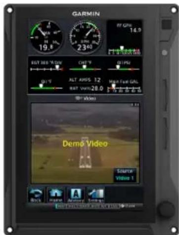
External Video 4-55
4.20 SD Video Setup 4-56
4.20.1 Settings Key 4-56
5 WEATHER AWARENESS 5-1
Weather Display 5-2
5.1 Weather Products 5-3
Datalink Weather 5-5
5.2 Weather Page Interactions 5-6
5.3 Weather Map Views 5-8
5.4 WX Display/Map Settings 5-9
5.5 Weather Product Age 5-10
5.6 Precipitation 5-11
Table of Contents
5.6.1 Connext PRECIP 5-12
5.6.2 FIS-B NEXRAD 5-12
5.6.3 SiriusXM NEXRAD 5-14
5.7 Echo Tops 5-15
5.8 Clouds 5-15
5.8.1 Cloud Tops 5-15
5.8.2 IR Satellite 5-16
5.9 Lightning 5-16
5.10 METARs & TAFs 5-17
5.11 Cell Movement 5-18
5.12 AIRMETs 5-19
5.12.1 Textual AIRMETs 5-19
5.12.2 Graphical AIRMETs 5-20
5.13 Center Weather Advisory 5-22
5.14 SIGMETs 5-22
5.15 County Warnings 5-23
5.16 Cyclone/Hurricane Track 5-23
5.17 AIREP/PIREPs 5-24
5.18 Surface Analysis 5-25
5.19 City Forecast 5-25
5.20 Winds Aloft 5-26
5.21 Icing 5-27
5.22 Turbulence 5-29
5.23 Freezing Levels 5-30
5.24 TFRs 5-31
5.25 SiriusXM Weather 5-32
5.25.1 SiriusXM Weather Setup 5-33
5.25.2 Activating Services 5-34
5.25.3 SiriusXM Weather Products 5-34
5.26 FIS-B Weather 5-35
5.26.1 FIS-B Data Transmission Limitations 5-35
5.26.2 FIS-B Weather Setup 5-37
5.26.3 Raw Text Reports 5-38
5.26.4 FIS-B Ground Reception Status 5-38
5.27 Connext Weather 5-39
5.27.1 Activating Connext Services 5-39
5.27.2 Deactivating Connext Unit Registration 5-40
5.27.3 Connext Weather Product Age 5-40
5.27.4 Connext Weather Setup 5-41
5.27.5 Connext Data Requests 5-42
5.28 Stormscope Page 5-44
5.29 Stormscope Setup 5-45
5.29.1 Stormscope Modes & Symbols 5-45
5.29.2 Views 5-46
5.30 Weather Radar Page 5-47
5.31 Weather Radar Setup 5-49
5.31.1 Sector Scan 5-49
Stormscope 5-44
Airborne Weather Radar 5-47
5.31.2 Stabilization 5-50
5.31.3 WATCH 5-50
5.31.4 Weather Alert 5-51
5.31.5 Altitude Compensated Tilt 5-51
5.31.6 Turbulence Detection 5-52
5.31.7 Ground Clutter Suppression 5-52
5.32 Radar Modes 5-53
5.32.1 Mode Key 5-53
5.33 Radar Controls 5-56
5.33.1 Show Bearing/Tilt 5-56
5.33.2 Bearing 5-56
5.33.3 Tilt 5-57
5.33.4 Scan 5-58
5.33.5 Gain 5-59
5.34 Radar Alerts 5-60
6.1 Traffic Page 6-3
6.2 Traffic Setup 6-6
6.2.1 Traffic Test 6-6
6.2.2 Altitude Filtering 6-7
Traffic Types 6-8
6.3 TIS-A 6-8
6.3.1 TIS-A Setup Selections 6-8
6.3.2 TIS-A Traffic Symbols 6-9
6.3.3 TIS-A Status Indications 6-9
6.4 TAS/TCAS I 6-10
6.4.1 TAS/TCAS I Setup Selections 6-10
6.4.2 TAS/TCAS I Traffic Symbols 6-10
6.4.3 TAS/TCAS I Status Indications 6-11
6.5 TCAS II 6-12
6.5.1 TCAS II Status Indications 6-12
6.5.2 TCAS II Annunciations 6-13
6.5.3 TCAS II Traffic Symbols 6-15
6.5.4 TCAS II with ADS-B 6-15
6.6 ADS-B 6-16
6.6.1 ADS-B Setup Selections 6-16
6.6.2 ADS-B Traffic Symbols 6-17
6.6.3 ADS-B Traffic Applications 6-18
6.6.4 Motion Vectors 6-19
6.6.5 ADS-B Status Indications 6-19
6.6.6 ADS-B Traffic Interactions 6-20
6.7 Traffic Alerts 6-21
7 TERRAIN AWARENESS 7-1
Terrain Configurations 7-2
7.1 GPS Altitude for Terrain 7-2
7.1.1 GSL Altitude & Indicated Altitude 7-3
7.2 Database Limitations 7-4
Terrain Display 7-5
Table of Contents
7.3 Terrain Page 7-5
7.4 Terrain Setup 7-7
7.5 Terrain Proximity 7-8
7.5.1 Terrain Elevation Depictions 7-9
7.5.2 Obstacle Elevation Depictions 7-11
Terrain Alerting 7-13
7.6 Alert Types 7-13
7.6.1 Alerting Thresholds 7-15
7.6.2 Alert Inhibit, TAWS & Terrain-FLTA 7-18
7.7 Terrain-FLTA 7-19
7.7.1 Reduced Protection Mode 7-19
7.7.2 Terrain-FLTA Alerts 7-20
7.8 TAWS-B 7-23
7.8.1 TAWS-B Alerts 7-23
7.9 External TAWS/HTAWS 7-27
7.9.1 TAWS-A 7-28
7.9.2 TAWS-A Alerts 7-29
8 FUEL & ENGINE INDICATION SYSTEM 8-1
Reciprocating Engines 8-2
8.1 EIS Display 8-2
8.2 EIS Setup 8-4
8.3 EIS Functions 8-6
8.3.1 Gauge Types 8-8
8.3.2 Markings & Indications 8-10
8.3.3 CHT/EGT Bar Graphs 8-14
8.3.4 Lean Assist Mode 8-15
8.3.5 Selectable User Fields 8-19
8.4 Configuration Report 8-20
Turbine Engines 8-21
8.5 EIS Display 8-21
8.6 EIS Setup 8-23
8.7 EIS Functions 8-25
8.7.1 Gauge Types 8-26
8.7.2 Markings & Indications 8-28
8.7.3 Text Lamps 8-32
8.7.4 Gauge Insets 8-33
8.7.5 Timers 8-34
8.7.6 Selectable User Fields 8-38
8.8 Configuration Report 8-39
Fuel 8-40
8.9 Fuel Gauges 8-40
8.9.1 Gauge-driven Discretes 8-41
8.9.2 Gauge Markings 8-41
8.9.3 Selectable Fuel Gauges 8-42
8.10 Fuel Alerting 8-43
8.10.1 Fuel Quantity Alert Indications 8-43
8.10.2 Fuel Imbalance Indications 8-43
8.11 Fuel Computer 8-45
8.11.1 Preset Fuel Quantities 8-46
8.11.2 Fuel Capacity Setup Options 8-47
8.11.3 Fuel Flow Calibration 8-48
Advanced EIS Configurations 8-49
8.12 Fuel Balance Monitoring 8-49
8.12.1 Fuel Imbalance Alerting 8-50
8.13 Automatic Ignition 8-51
8.14 Automatic Starting 8-52
8.15 Gauge-driven Outputs 8-53
EIS Operations 8-54
8.16 Record Keeping 8-54
8.17 Flight Operations 8-55
8.17.1 Initial Setup 8-56
8.17.2 Preflight 8-58
8.17.3 En Route 8-58
8.17.4 Post Flight 8-58
Engine Advisories & Alerts 8-59
8.18 Engine Advisories 8-59
8.19 Engine Alerts 8-60
9 ABNORMAL OPERATIONS 9-1
Backup Instruments 9-2
9.1 Display Backup 9-2
9.1.1 Standby PFD Display Options 9-3
9.1.2 Composite Display Backup Mode 9-4
9.2 Backup Battery 9-9
9.2.1 Battery Status Indications 9-11
9.2.2 Battery Alerts 9-13
9.3 AHRS & ADC Failures 9-14
9.3.1 AHRS & ADC Sensor Selection 9-15
9.3.2 AHRS Operating In Reversionary Mode 9-17
9.3.3 GPS Failure 9-17
9.3.4 AHRS Alerts 9-18
9.3.5 Miscompare & No Compare 9-21
9.4 HSI Failure Modes 9-23
9.4.1 GPS Failure 9-25
9.4.2 Backup GPS 9-26
Emergency Modes 9-27
9.5 Smart Glide 9-29
9.5.1 Activate Smart Glide 9-30
9.5.2 Active Mode Indications 9-31
9.5.3 View Smart Glide Status Information 9-34
9.5.4 Monitor COM Standby Frequency 9-38
9.5.5 Deactivate Smart Glide 9-38
9.5.6 View Smart Glide Information on Map 9-39
9.6 Emergency Descent 9-41
9.6.1 EDM Activation 9-41
9.6.2 EDM Inhibit 9-44
9.6.3 EDM Override 9-46
9.6.4 EDM Active Discrete Output 9-47
9.6.5 EDM Failures 9-47
Table of Contents
10 QUALIFICATION ....10-1
10.1 Glove Qualification 10-1
11 GLOSSARY 11-1

WARNING
Do not use terrain avoidance displays as the sole source of information for maintaining separation from terrain and obstacles. Garmin obtains terrain and obstacle data from third party sources and cannot independently verify the accuracy of the information.

WARNING
Always refer to current aeronautical charts and NOTAMs for verification of displayed aeronautical information. Displayed aeronautical data may not incorporate the latest NOTAM information.

WARNING
Do not use geometric altitude for compliance with air traffic control altitude requirements. The primary barometric altimeter must be used for compliance with all air traffic control altitude regulations, requirements, instructions, and clearances.

WARNING
Do not use basemap information (land and water data) as the sole means of navigation. Basemap data is intended only to supplement other approved navigation data sources and should be considered only an aid to enhance situational awareness.

WARNING
Do not rely solely upon the display of traffic information to accurately depict all of the traffic within range of the aircraft. Due to lack of equipment, poor signal reception, and/or inaccurate information from aircraft or ground stations, traffic may be present that is not represented on the display.

WARNING
Do not use datalink weather information for maneuvering in, near, or around areas of hazardous weather. Information contained within datalink weather products may not accurately depict current weather conditions.

WARNING
Do not use the indicated datalink weather product age to determine the age of the weather information shown by the datalink weather product. Due to time delays inherent in gathering and processing weather data for datalink transmission, the weather information shown by the datalink weather product may be older than the indicated weather product age.

WARNING
Always refer to current aeronautical charts for appropriate minimum clearance altitudes. The displayed MSAs are only advisory in nature and should not be relied upon as the sole source of obstacle and terrain avoidance information.

WARNING
Do not use GPS to navigate to any active waypoint identified as a "NON WGS84 WPT" by a system message. "NON WGS84 WPT" waypoints are derived from an unknown map reference datum that may be incompatible with the map reference datum used by GPS (known as WGS84) and may be positioned in error as displayed.

WARNING
Do not rely solely upon the display of traffic information for collision avoidance maneuvering. The traffic display does not provide collision avoidance resolution advisories and does not under any circumstances or conditions relieve the pilot's responsibility to see and avoid other aircraft.

WARNING
Do not rely on the accuracy of attitude and heading indications in geographic areas where variation in the earth's magnetic field exists. This includes: North of 72° North latitude at all longitudes; South of 70° South latitude at all longitudes; North of 65° North latitude between longitude 75° W. and 120° W. (Northern Canada); North of 70° North latitude between longitude 70° W. and 128° W. (Northern Canada); North of 70° North latitude between longitude 85° E. and 114° E. (Northern Russia); South of 55° South latitude between longitude 120° E. and 165° E. (Region south of Australia and New Zealand).

WARNING
Do not rely solely upon datalink services to provide TFR information. Always confirm TFR information through official sources such as Flight Service Stations or Air Traffic Control.

WARNING
Do not rely on information from a lightning detection system display as the sole basis for hazardous weather avoidance. Range limitations and interference may cause the system to display inaccurate or incomplete information. Refer to documentation from the lightning detection system manufacturer for detailed information about the system.

WARNING
Use appropriate primary systems for navigation, and for terrain, obstacle, and traffic avoidance. Garmin SVT is intended as an aid to situational awareness only and may not provide either the accuracy or reliability upon which to solely base decisions and/or plan maneuvers to avoid terrain, obstacles, or traffic.

WARNING
Do not use the Garmin SVT runway depiction as the sole means for determining the proximity of the aircraft to the runway or for maintaining the proper approach path angle during landing.

WARNING
Do not use TAWS information for primary terrain or obstacle avoidance. TAWS is intended only to enhance situational awareness.

WARNING
Do not rely solely on VNAV guidance when navigating horizontally and vertically around user-defined airports. It is the pilot's responsibility to ensure separation from terrain and obstacles during an approach to a user-defined airport.

WARNING
Be aware that this product, its packaging, and its components contain chemicals known to the State of California to cause cancer, birth defects, or reproductive harm. This notice is being provided in accordance with California's Proposition 65. If you have any questions or would like additional information, please refer to our website at www.garmin.com/prop65.

CAUTION
Ensure that any unit Repairs are made by an authorized Garmin service center. Unauthorized repairs or modifications could void both the warranty and affect the airworthiness of the aircraft.

CAUTION
Do not clean display surfaces with abrasive cloths or cleaners containing ammonia. They will harm the anti-reflective coating.

NOTE
Foreign materials (i.e., moisture, objects) that come into contact with the touchscreen can prevent the unit from responding to touch commands. To restore functionality, wipe the screen dry and/or remove interfering objects.

NOTE
Intruder aircraft at or below 500 ft AGL may not appear on the Garmin SVT display or may appear as a partial symbol.

NOTE
All visual depictions contained within this document, including screen images of the system panel and displays, are subject to change and may not reflect the most current system and aviation databases. Depictions of equipment may differ slightly from the actual equipment.

NOTE
The United States government operates the Global Positioning System and is solely responsible for its accuracy and maintenance. The GPS system is subject to changes which could affect the accuracy and performance of all GPS equipment. Portions of the system utilize GPS as a precision electronic NAVAID. Therefore, as with all NAVAIDs, information presented by the system can be misused or misinterpreted and, therefore, become unsafe.

NOTE
This device complies with part 15 of the FCC Rules. Operation is subject to the following two conditions: (1) this device may not cause harmful interference, and (2) this device must accept any interference received, including interference that may cause undesired operation.

NOTE
Interference from GPS repeaters operating inside nearby hangars can cause an intermittent loss of attitude and heading displays while the aircraft is on the ground. Moving the aircraft more than 100 yards away from the source of the interference should alleviate the condition.

NOTE
Use of polarized eye wear may cause the flight displays to appear dim or blank.

NOTE
Operating the system in the vicinity of metal buildings, metal structures, or electromagnetic fields can cause sensor differences that may result in nuisance miscompare annunciations during start up, shut down, or while taxiing. If one or more of the sensed values are unavailable, the annunciation indicates no comparison is possible.

NOTE
The system responds to a terminal procedure based on data coded within that procedure in the Navigation Database. Differences in system operation may be observed among similar types of procedures due to differences in the Navigation Database coding specific to each procedure.

NOTE
The FAA has asked Garmin to remind pilots who fly with Garmin database-dependent avionics of the following:
- It is the pilot's responsibility to remain familiar with all FAA regulatory and advisory guidance and information related to the use of databases in the National Airspace System.
- Garmin equipment will only recognize and use databases that are obtained from Garmin or Jeppesen. Databases obtained from Garmin or Jeppesen that have a Type 2 LOA from the FAA are assured compliance with all data quality requirements (DQRs). A copy of the Type 2 LOA is available for each applicable database and can be viewed at flyGarmin.com by selecting "Aviation Database Declarations."
- Use of a current Garmin or Jeppesen database in your Garmin equipment is required for compliance with established FAA regulatory guidance, but does not constitute authorization to fly any and all terminal procedures that may be presented by the system. It is the pilot's responsibility to operate in accordance with established AFM(S) and regulatory guidance or limitations as applicable to the pilot, the aircraft, and installed equipment.

NOTE
The pilot/operator must review and be familiar with Garmin's database exclusion list as discussed in SAIB CE-14-04 to determine what data may be incomplete. The database exclusion list can be viewed at flyGarmin.com by selecting "Database Exclusions List."

NOTE
The pilot/operator must have access to Garmin and Jeppesen database alerts and consider their impact on the intended aircraft operation. The database alerts can be viewed at flyGarmin.com by selecting "Aviation Database Alerts."

NOTE
If the pilot/operator wants or needs to adjust the database, contact Garmin Product Support.

NOTE
Garmin requests the flight crew report any observed discrepancies related to database information. These discrepancies could come in the form of an incorrect procedure; incorrectly identified terrain, obstacles and fixes; or any other displayed item used for navigation or communication in the air or on the ground. VisilyGarmin.com and select "Aviation Data Error Report."

NOTE
When using autopilot to fly an approach with vertical guidance, the autopilot will not level the aircraft at the MDA/DH even if the MDA/DH is set in the altitude preselect.

NOTE
Information obtained solely through FIS-B does not replace a thorough preflight briefing. NOTAMs received via FIS-B uplink may not be a complete listing. Active NOTAMs are removed from the FIS-B data stream 30 days after issuance. FIS-B uplink is not an FAA approved source for NOTAMs.

NOTE
When using Stormscope, there are several atmospheric phenomena in addition to nearby thunderstorms that can cause isolated discharge points in the strike display mode. However, clusters of two or more discharge points in the strike display mode do indicate thunderstorm activity if these points reappear after the screen has been cleared.

NOTE
The navigation databases used in Garmin navigation systems contain Special Procedures. Prior to flying these procedures, pilots must have specific FAA authorization, training, and possession of the corresponding current, and legitimately-sourced chart (approach plate, etc.). Inclusion of the Special Procedure in the navigation database DOES NOT imply specific FAA authorization to fly the procedure.
Record of Revision
| REVISION DATE CHANGE DESCRIPTION | |
| A 05.19.17 Initial Release. | |
| B 01.16.18 Production Release. | |
| C 01.18.18 Minor edits. | |
| D 01.24.18 Minor edits. | |
| E 08.17.18 Updates for software v2.20. | |
| F 10.16.18 Updates for software v2.30. | |
| G 03.14.19 Updates for software v3.00. | |
| H 05.21.19 Updates for software v3.01. | |
| J 10.15.20 Updates for software v3.12. | |
| K 06.21.21 Updates for software v3.21. | |
| L 07.23.21 Updates for software v3.30. |
Available for Download
Electronic Pilot's Guide
A version of this guide saved in Adobe Acrobat. Available for viewing on your computer or portable device.
Upgrade Supplement
Details document changes for software enhancements.
Go to garmin.com/manuals.
Layout
| SECTION TITLE | |
| 1 | System Description |
| 2 | Primary Flight Display |
| 3 | Advanced Features |
| 4 | Multi-Function Display |
| 5 | Weather Awareness |
| 6 | Traffic Awareness |
| 7 | Terrain Awareness |
| 8 | Fuel & Engine Indication System |
| 9 | Abnormal Operations |
| 10 | Qualification |
| 11 | Glossary |
The layout and design of this guide is intended to provide clear, concise sections written in the logical order of a pilot's flight instrument and systems scan.
Special Notations
This guide uses the following message types when applicable.

WARNING
Indicates when serious injury or death will occur.

CAUTION
Indicates when equipment damage is possible.

NOTE
Emphasizes a point about a specific feature, function, or operation.
Insets
These boxes may include a list of features or application functions, references to additional information, or a useful pilot's tip.
Reference Manuals
| DOCUMENT P/N | |
| GDL 69/69A SiriusXM Satellite Radio Activation Instructions 190-00355-04 | |
| GTN Xi Series Pilot's Guide 190-02327-03 | |
Reference Websites
| WEBSITE ADDRESS | |
| Aviation Limited Warranty | https://www.garmin.com/en-US/legal/aviation-limited-warranty |
| Database Concierge | Go to http://www.flygarmin.com/support and select Database Management. |
| ADS-B Academy https://www.garmin.com/us/intheair/ads-b | |
| Connext http://www.garmin.com/connext | |
1 System Description
OVERVIEW
1.1 Unit Configurations ...... 1-4
1.2 Display Features....1-7
PILOT INTERFACE
1.3 Unit Power 1-9
1.4 SD Card Slot.... 1-10
1.5 Touchscreen 1-12
1.6 Control Knobs 1-17
1.7 Color Conventions....1-21
DATABASES
1.8 Database Effective Cycles 1-23
1.9 Remote Database Confirmation....1-24
1.10 Active and Standby Databases 1-25
1.11 Manual Updates 1-25
1.12 Automatic Updates.... 1-27
1.13 Database Concierge 1-28
1.14 Database SYNC 1-30
1.15 Chart Streaming 1-31
CONNECTIVITY
1.16 Flight Stream 510 Setup 1-32
1.17 Bluetooth Setup 1-33
1.18 Wi-Fi Setup....1-34
PILOT SETTINGS
1.19 Display Brightness Control 1-36
1.20 Sys tem Status Page....1-37
1.21 Click Volume 1-37
1.22 Clock....1-37
1.23 Weather Display Shortcut 1-38
1.24 Unit Selections....1-38
CREW PROFILES
1.25 Crew Profile Settings 1-39
1.26 Crew Profile Management....1-41
SYSTEM MESSAGES
1.27 Alerts Types....1-45
1.28 Advisories....1-52
1.29 LRU Failure Annunciations 1-64
1.30 GDU Failure Annunciations....1-65
1.31 ADS-B Status 1-66
LOGS
1.32 Flight Data Logging 1-68
1.33 Exceedance Logging 1-73
COMPATIBLE EQUIPMENT
1.34 Line Replaceable Units 1-77
Overview
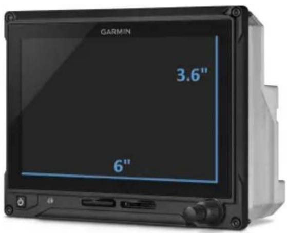
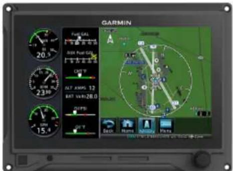
The G500(H)/G600/G700 TXi is a display and sensor system available in three display options.
GDU 1060 10" display
GDU 700P 7" portrait display
GDU 700L 7" landscape display
GDU 1060

GDU 700P

GDU 700L
Garmin Display Units
Bezel
Ledges provide hand stability when performing data entry and making selections.
Touchscreen
Multi-touch display provides controls for unit operation.
SD Card Slot
Each unit has two SD card slots. The purpose of each slot depends on the display type.
Power Key
Powers the unit on or off. Allows manual transition into display backup mode.
Photocell
Measures cockpit ambient light level to automatically adjust display brightness for day and night.
Inner & Outer Knobs
All units have a multi-purpose dual concentric knob near the bottom of the bezel. GDU 1060 has two, one on each side. Inner and outer knob functionality differs according to display features.
1.1 Unit Configurations
Depending on system specifics one or more of the following functions may apply.
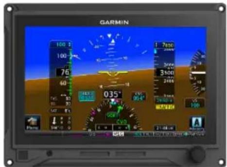
- Primary Flight Display (PFD): provides attitude, heading, air data, and navigation information to the pilot
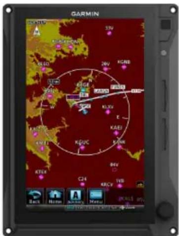
- Multi-Function Display (MFD): provides pilot awareness of factors that may affect the overall conduct of a flight
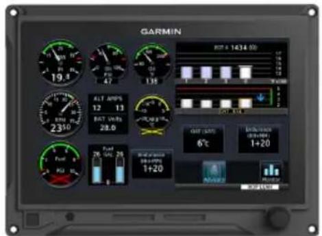
• Engine Indication System (EIS): provides engine and airframe operating parameters to the pilot
GDU 1060 PFD/MFD, EIS OPTION
GDU 1060 provides an MFD or PFD/MFD display with an optional EIS function.
Each function is designated to a portion of the display.
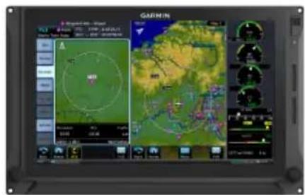
When configured as an MFD, the system can display two MFDs, or you can expand one MFD to fill the screen.
When configured as a PFD/MFD, the MFD can be selectively hidden or shown. When hidden, the PFD expands into the MFD space.
If configured as a PFD/MFD or MFD with EIS, the EIS function is always visible on either the left or right edge of the display.

PFD Only PFD/EIS


MFD (40%)/PFD (60%)

MFD/PFD/EIS
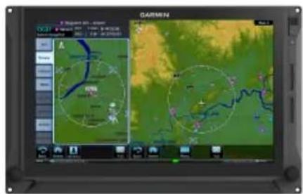
MFD/MFD MFD/MFD/EIS
GDU 700P PFD, MFD, EIS, MFD/EIS
GDU 700P provides a single PFD, MFD, EIS, or, in single-engine piston EIS, a combined MFD/EIS function. In some installations, it provides backup PFD or EIS information in the event that the primary PFD or EIS display fails or malfunctions.
When configured as an MFD/EIS display, engine instruments are dedicated to 40% of the screen. The remaining screen portion displays all configured MFD options using a pilot-selectable menu.
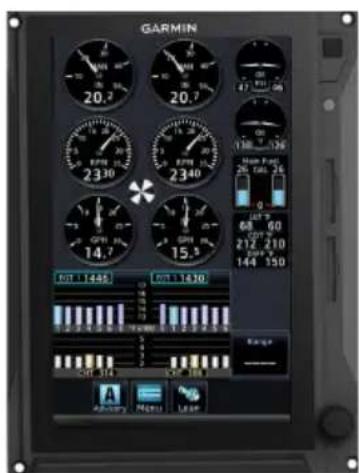
EIS Only PFD Only

MFD Only EIS/MFD
1
GDU 700L PFD, EIS, OR MFD/EIS
The GDU 700L provides a single PFD, piston EIS, or in single-engine piston EIS, MFD/EIS combined function.
When configured as an MFD/EIS display, engine instruments are dedicated to 40% of the screen. The remaining screen portion displays all configured MFD options using a pilot-selectable menu.
Piston EIS Only PFD Only
Single Engine Piston EIS/MFD
1.2 Display Features
PRIMARY FLIGHT DISPLAY
GDU 700()/1060
- Attitude
- Airspeed
- Altitude
- Vertical Speed
- Turn Coordinator
• G-meter ^5
• HSI
• HSI Map ^3 - Clock
• Lateral and Vertical Deviation Indicators
- Datalink Weather Display ^1
- Radar Altimeter ^1
- Autopilot Annunciations ^1
- Flight Director ^1
- Synthetic Vision ^1
- Flight Path Marker ^1
- System Advisories
- Safety Monitors ^1
- GPS NAV Status
- Display Backup ^1,3
- Terrain Avoidance ^1
- Smart Glide ^4,6
MULTI-FUNCTION DISPLAY
GDU 700P/1060 ^2
- Navigation Map
- Traffic ^1
- Terrain
- Charts
- Flight Plan
-
Weather ^1
-
Waypoint Info
- Music Services ^1
- Terrain Avoidance ^1
- Engine Data ^1
-
Remote Database Confirmation ^4,6
-
Remote Radio Tuning ^4,5
- Smart Glide ^4,6
- System Advisories
- Video ^1
ENGINE INDICATION SYSTEM ^1
GDU 700()/1060 ^2,4
• Fuel Qty (Main, Aux)
- RPM/Tach
- Propeller Sync Display
• Automatic Starting ^5
• Automatic Ignition
- Manifold Pressure
- Oil Pressure
- Oil Temperature
- Shaft Horsepower ^3
- Percent Power
• OAT ^5
- Fuel Flow
- Fuel Pressure
- Fuel Calculations
- Cylinder Operating Temperatures (CHT, EGT)
• TIT -
Lean Assist Mode
• Carburetor Air Temperature
• Intercooler Temperatures (IAT, CDT, Difference) -
Amps/Volts
- User Selectable Fields
- User Adjustable Advisories
- Torque ^3
- Turbine Temperature ^3
- Vacuum/Pressure
• Flight Control Trim Position
Pilot Interface
1.3 Unit Power
The GDU receives power directly from the aircraft's electrical system. To ensure safe operation, continuous built-in test features exercise the unit's processor, memory, external inputs, and outputs.
Upon power-up, the bezel key backlight momentarily illuminates. System failure annunciations typically disappear within the first 30 seconds after power-up.
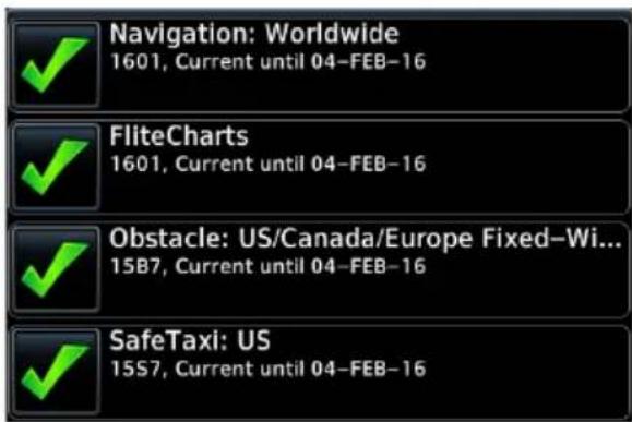
On MFD: The database start-up page presents the unit software version, the name and status of all installed databases, and controls for selecting a crew profile (if multiple profiles are available).
For information about crew profile selection and activation, read section 1.26.8.
1.3.1 Power Off Options

WARNING
Never attempt to power off the unit while airborne unless operational procedures dictate.
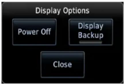
Pushing the Power key once opens a pop-up menu. Selectable display options allow you to:
- Power off unit
- Close the menu (cancels shutdown)
- Change operating mode to display backup (if available)

Pushing and holding the Power key for 4 seconds powers off the unit without safeguards. Shutdown occurs once the timer reaches zero.
1.4 SD Card Slot

NOTE
Do not remove or insert an SD card while in flight. Always verify the system is powered off before inserting or removing an SD card.
Determine which card slot is appropriate for the task.
| TASK | SD CARD SLOT | |
| GDU 1060 GDU 700P GDU 700L | ||
| Exporting data logs Top Top Left | ||
| Saving system configurations | Top Top Left | |
| Transferring crew profiles Top Top Left | ||
| Capturing screen images ^1 | Top Top Left | |
| Upgrading software ^4 | Top Top Left | |
| Enabling Flight Stream 510 connectivity ^2 | Bottom Bottom Right | |
| Updating databases ^3 | Top or bottom Top or bottom Left or right | |
^1 Screen images save to the bottom/right card when the top/left card is unavailable.
^2 Install Flight Stream 510 in a GTN, if available.
^3 While either slot may be used, the bottom/left slot has a faster transfer rate and is recommended for all database-related tasks.
^4 An installer unlock card must be present in the bottom/right card slot to perform a software update.
For Mac Users
Do not use macOS to format Flight Stream 510 if you plan to use Flight Stream 510 as a media storage device for updating databases.
In the event there is a file corruption problem with the SD card (including the Wireless Transceiver when used as a database storage device), it may be necessary to reformat the card. This can cause an issue when formatting the SD card using macOS, where the newly formatted card will not be recognized by the avionics system. When using a Macintosh computer to format the SD card, or Wireless Transceiver, Garmin recommends using the SD Memory Card Formatter application available as a download from SDcard.org. When running the application, use the Quick Format option.
INSERT AN SD CARD
When inserting an SD card:
- Verify unit power if off and the slot is empty.
- Hold card in the proper orientation.
• GDU 1060/700P: label faces left edge of display screen
• GDU 700L: label faces top edge of display screen
- Ensure back edge of card is flush with display bezel after insertion.
EJECT AN SD CARD
- Power off the unit.
- Release the spring latch by pressing lightly on exposed edge of card.
1.5 Touchscreen
A multi-touch color display provides on-screen controls for unit operation.
GESTURES
| TAP | Touching the screen briefly with a single finger. Use this gesture for: |
 | Opening a page or menuActivating a command key or data entry fieldDisplaying map feature informationSelecting an option within an application |
| TAP AND HOLD | Certain momentary controls (e.g., directional arrow keys) provide a secondary tap and hold function.Tap the key and hold your finger in place until the desired action occurs. |
 | Use this gesture for:Scrolling with arrow keysEnabling Caps LockIncreasing/decreasing values continuously |
| SWIPE | A smooth motion that involves touching an object, then sliding your finger across the screen and lifting up. Use this gesture for: |
 | Viewing and scrolling listsPanning across a map or chart displayZooming HSI map or rotorcraft PFD VFR map display (upward and downward swipes only) |
| FLICK | Swiping the screen in a quick upward or downward motion. Information moves at a fast speed (faster than by holding the arrow key), then slows to a stop. |
 | Use this gesture for:Scrolling an item list |
| PINCH & STRETCH | Touch any map or chart with two fingers at the same time, then bring the fingers close together (pinch) or spread them apart (stretch). Just remember: stretch to zoom in and pinch to zoom out. Use this gesture for:Magnifying map featuresIdentifying multiple objects in close proximityReading details on a chartMagnifying a video image |
 |
1.5.1 Keys
COMMON COMMANDS

Displays Advisories page. Blinking icon indicates unread system advisories.

Inputs specified value.

Displays context menus. Scrolls


Returns to previous page. Scro


Cancels current function without inputting data.

Indicates corresponding item is selected (e.g., database update)

Adjusts MFD and PFD display sizes between 40% and 60% ^1

Switches display to full screen 1

Switches from full PFD to split MFD and PFD ^1

Switches from full MFD to split dual MFDs ^1
^1 GDU 1060 only.
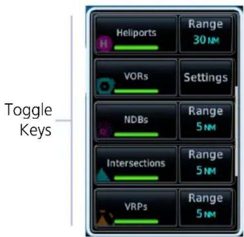
FUNCTION KEYS
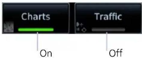
Toggle keys turn a specific function on or off. The current state of the function is indicated below the key label.
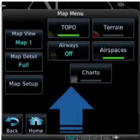
1.5.2 Menus
Menus group related controls into an expandable pane, allowing access to multiple functions on a single page. Depending on the number of available functions, a menu may comprise more than one pane.
SLIDE OVER MENUS
These menus slide out from the bottom or sides of the display when an object or menu item is selected on the underlying page.
Underlying Page Hidden
Tapping the underlying page closes the menu.
LISTS

Scrollable lists group control keys related to a single function (e.g., selectable range options). When scrolling, all keys in the list are inactive.
Scroll Bar
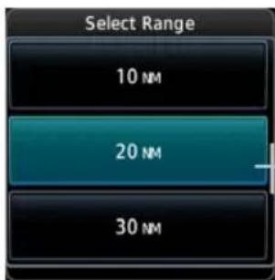
Popup lists open to the default or previously selected value.
Default or Current Setting
1.5.3 Tabs
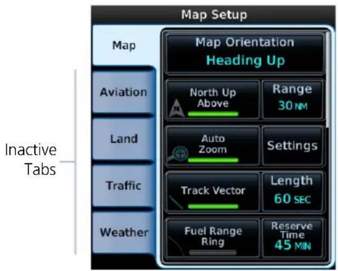
Tabs group information into individual panes. Content includes scrolling lists, data fields, function keys, or a combination of controls.
Tabs are located along the left side or bottom edge of a pane.
Lists containing a combination of controls typically appear within a tab and open to the first list item.
Toggle keys either enable or disable list items. In some cases, Settings or Range keys provide access to selectable setting options.
1.5.4 Keypads
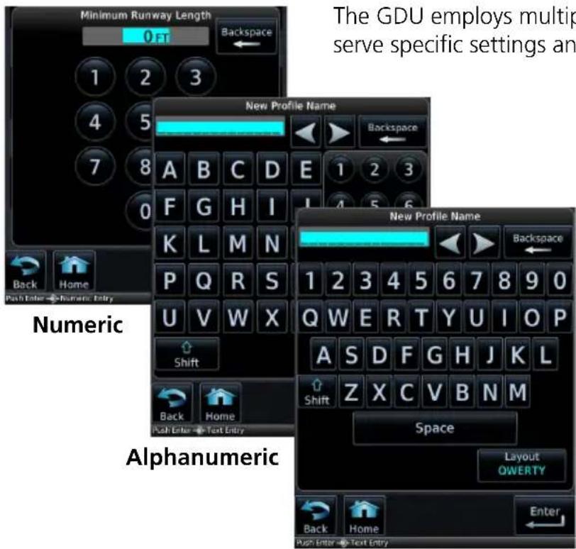
The GDU employs multiple keypad types to serve specific settings and functions.
Tapping Layout changes the format between ABCDE and QWERTY.
QWERTY
1.6 Control Knobs
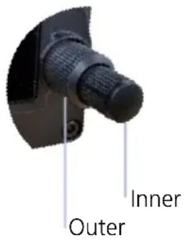
Inner and outer knobs offer an alternative method for selecting and modifying data without the use of touch keys.
GDU 1060: The dual-concentric knobs control the adjacent PFD or MFD display by default.
PFD KNOB FUNCTIONS
| Outer Knob | Selecting reference controlsCursor placement and initial field/page selectionsMoving cursor forward or backward within data field |
| Inner Knob (Turn) | Selecting reference valuesInputting dataModifying individual characters in data entry field |
| Inner Knob (Push) | Entering current or specified numerical valueSynchronizing PFD reference to its current valueAlternating between standard and pilot set barometric pressure |
MFD KNOB FUNCTIONS
| Outer Knob | Selecting a page shortcutCursor placement and initial field/page selectionsMoving cursor forward or backward within data field |
| Inner Knob (Turn) | Inputting dataModifying individual characters in data entry fieldZoomingControlling weather radar range |
| Inner Knob (Push) | Entering a specified numerical value |
| Inner Knob (Push and Hold) | Switch between MFD and PFD control functions |
EIS KNOB FUNCTIONS
| Outer Knob | Cursor placement and initial field/page selectionsMoving cursor forward or backward within data field |
| Inner Knob (Turn) | Inputting dataModifying individual characters in data entry field |
| Inner Knob (Push) | Entering a specified numerical value |
Dual-knob PFD Control
For convenience, you may use both knobs to control the PFD. Pushing and holding the inner knob adjacent to the MFD toggles focus between MFD and PFD control functions. MFD control via touchscreen is still available. This feature is particularly useful if your cockpit configuration makes it difficult to access the PFD knob.
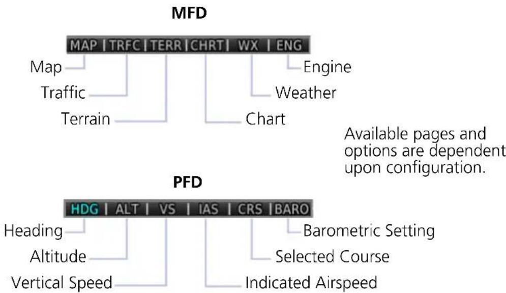
1.6.1 Knob Function Indicators
A locater bar works in conjunction with the outer knob providing quick access to the indicated MFD page and/or PFD bug.
flowchart
graph TD
    A["MFD"] --> B["MAP | TRFC | TERR | CHRT | WX | ENG"]
    A --> C["Map"]
    A --> D["Traffic"]
    A --> E["Terrain"]
    A --> F["Chart"]
    G["PFD"] --> H["HDG | ALT | VS | IAS | CRS | BARO"]
    G --> I["Heading"]
    G --> J["Altitude"]
    G --> K["Vertical Speed"]
    G --> L["Barometric Setting"]
    G --> M["Selected Course"]
    G --> N["Indicated Airspeed"]
    style A fill:#f9f,stroke:#333
    style G fill:#ccf,stroke:#333
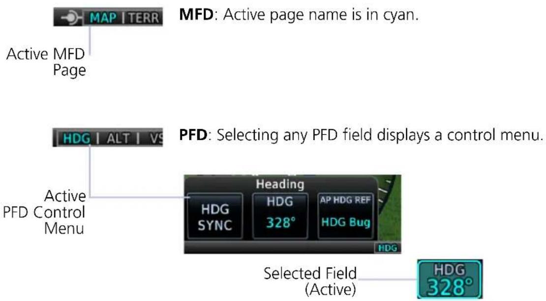
Turning the outer knob clockwise or counter-clockwise moves the locater through displayed menu options. Changes in the current screen configuration may result in a change of menu options. When the knob adjacent to the MFD is controlling the PFD, its locater bar displays PFD menu options.
Additional icons located to the left or right of the bar indicate available knob functions for the associated display.
1.6.2 Screen Captures
Save images to an SD card at any time using a screen capture. Images automatically save to the "print" folder in the SD card root directory.

- Verify unit power is off.
- Insert an SD card into the top or left card slot.
- Power on the unit and go to the page of interest.
- Push and hold the right inner knob.
- With knob depressed, push and release the Power key.
A camera icon momentarily shows in the annunciator bar indicating a successful screen capture. To view saved images, remove the SD card and open the "print" folder on a computer.
1.7 Color Conventions

Red
- Warning conditions
- Operating limits
Yellow

- Cautionary conditions
• Conditional operating ranges
Green

- Safe operating conditions
• Normal operating ranges
• VOR/localizer data - Engaged modes
White

- Scales and markings
• Current data and values - Armed modes
Magenta

- GPS data
• Active flight plan legs - VNAV data
Cyan

- Pilot-selectable controls (e.g., references, AFCS alert annunciations)
- Glide range and best glide airport indications
Gray

- Missing or expired data
• Product unavailable
Blue

Sky
- Water

Brown
- Ground
Databases

NOTE
The GDU supports SD cards in the FAT32 format only, with capacities ranging between 8 GB and 32 GB.
Databases are stored in the internal memory of each display. To view update cycles, or to purchase individual databases or database packages, go to flyGarmin.com.
The TXi system offers three methods for loading and updating databases:
- Load databases via SD card. The card can be removed after loading.
- Transfer databases from a GTN or another GDU using Database SYNC.
- Transfer databases from a mobile device using Database Concierge and a Flight Stream 510 wireless datacard.
SUPPORTED DATABASES
| Airport Directory Airport facility and FBO information | |
| Basemap | Bodies of water, geopolitical boundary, and road information |
| ChartView1 | Jeppesen terminal procedures |
| FliteCharts AeroNav terminal procedures | |
| IGRF2,3 | Internal ADAHRS and external AHRS correct for variations in the earth's magnetic field by applying calculations derived from the IGRF database |
| Navigation | Airport, NAVAID, waypoint, and airspace information (Garmin or Jeppesen) |
| Obstacles Obstacle and wire data | |
| SafeTaxi Airport surface diagrams | |
| Terrain Terrain elevation data | |
^1 Optional third party database.
^2 When updated, the database is packaged with the Navigation database. Not available for individual download.
^3 For magnetic field model version and part number information, refer to the AHRS section of the External LRUs page.
For information regarding third party databases, go to jeppesen.com.
1.8 Database Effective Cycles
FEATURE REQUIREMENTS
• External or internal GPS navigator for system to determine database effectiveness OR
• Flight Stream 510 wireless datacard
• Garmin Pilot app on a mobile device
FEATURE LIMITATIONS
• EIS units do not support database functionality
Most databases expire at regular intervals. Exceptions include Basemap and Terrain, which neither expire nor update on a regular schedule. IGRF updates occur approximately every five years. Failure to update a database can lead to errors in heading information.
| DATABASE EFFECTIVE STATUS | |
| Databases with no effective date | Effective upon releaseTransfer occurs prior to database verification at system start-upNo automatic transfer if Flight Stream 510 is presentIncludes Basemap and TerrainNo pilot confirmation or restart required |
| Databases with specified effective dates | Effective during a specific periodGDU determines database status using the current date and time from GPSAutomatic activation occurs on the effective date |
| Navigation | 1613, Expires 05-JAN-17 |
| Basemap | 16M1 |
| Obstacle/HOT | 16B6, Expires 05-JAN-17 |
| Terrain | 15T1 |
| SafeTaxi | 16S6, Expires 05-JAN-17 |
| FliteCharts | 1613, Expires 05-JAN-17 |
| Airport Directory | 16D6, Expires 05-JAN-17 |
| SafeTaxi | 16S4, Eff. 21-JUL-16 to 15-SEP-16 |
| FliteCharts | 1606, Eff. 26-MAY-16 to 23-JUN-16 |
| Airport Directory | 16D4, Eff. 21-JUL-16 to 15-SEP-16 |
| Terrain | Database Not Found |
On MFD: The database start-up page lists all currently installed databases. Review this list for current database types, cycle numbers, and expiration dates.
Yellow text denotes when a database is:
- Not available
• Installed before its effective date
• Missing date information
• Past its expiration date
Pilot PFD Navigation database expires on 15-SEP-16
Expired database notifications indicate as system advisories.
1.9 Remote Database Confirmation
FEATURE REQUIREMENTS
• TXi software v3.30 or later
• GTN Xi series navigator with software v20.20 or later
• SD cards containing databases must be removed from the unit
If configured with a GTN Xi series navigator, database information for each configured GDU in the system is sent to the primary GTN Xi for pilot acknowledgment. The MFD automatically advances from the database start-up page once it is determined that no database issues exist.
If a database is corrupt or missing, the unit will display its database list and indicate the database in question. Confirmation via the primary GTN Xi will still occur for all other configured LRUs if their databases are present and not corrupt.
If an SD card containing databases is installed in the unit, remote database confirmation is not available. Tap Continue to advance to the next page.
Remote database confirmation is a function of GTN Xi. For more information regarding functionality, consult GTN Xi Series Pilot's Guide.
1.9.1 Database Conflicts
FEATURE LIMITATIONS
• Applicable to GTN Xi/GDU TXi installations only
Conflicts occur when a database is corrupt or missing. In such cases, remote database confirmation via the primary GTN Xi is no longer available for the unit.
When a conflict occurs:
- The database list displays on the MFD database start-up page ^1
• The database name appears in yellow on both GDU and the primary GTN Xi
Resolve database conflicts when they occur. Expired or mismatched databases are managed from GTN Xi series navigator.
1.10 Active and Standby Databases
The GDU uses two types of databases: active and standby. Active databases are in use by the system. Standby databases have not reached the effective date. During normal operation, information about all active and standby databases are viewable on the associated tab.
On MFD, tabs are located on System Status page. They are located on Databases page of the PFD (GDU 700() only).
| TAB DISPLAYS | |
| ACTIVE • Information about databases currently in use | |
| STANDBY | Information about databases that are not yet effectiveIf a standby database is not available, the “No standby databases found” message displays in the Standby tab |
1.11 Manual Updates
FEATURE LIMITATIONS
• The Database Update page is available only when the aircraft is on ground
1.11.1 Database Update Page
This page presents a list of all available databases. It is accessible at any time for review purposes or manual database transfers.

To access the page, tap Update.
On MFD, this key resides in the System Status menu.
GDU 700() only: On PFD, it resides on the Databases page.
DATABASE SOURCE INDICATION
Connext Icon A Connext icon indicates when a

Obstacle: US/Canada/Europe 18B3, Current until 19-JUL-18
database is from Garmin Pilot via wireless transfer.
No indication means the database is either from an SD card or the unit's internal standby queue.
SELECT ALL DATABASES
Select applicable database(s) for transfer. If all listed databases require updating, choose
Select All.
Tapping Select None deselects all databases.
By default, this page displays only the databases recommended for update.

A message informs when no recommended databases are available.

After all selections are made, initiate the update process by tapping Start. GDU automatically restarts once all updates are complete.
SHOW ALL DATABASES
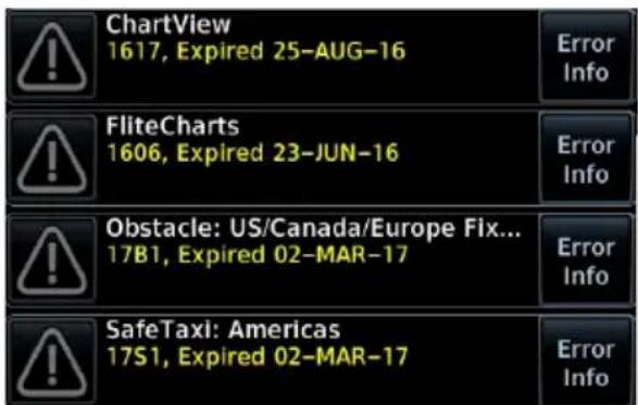
Tapping Show All displays a complete list of all databases, including ones that are not yet effective or that may be older than the currently active database(s).
For more details about a specific database, tap Error Info.
1.12 Automatic Updates
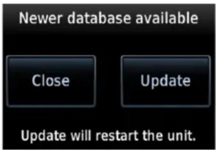
Automatic updates occur when...
- A newer database is detected on the SD card or in the internal standby queue
- A newer database is within its effective dates
• The aircraft is on ground
When a newer database is available, follow the on-screen prompts to complete the update process. PFD issues a pop-up notification only on the GDU 700(). MFD automatically redirects to the Database Update page.
A status page displays a progress bar and the name of each database as it uploads to the GDU. Terrain and chart databases may require up to 5 minutes each for transfer. Total transfer time depends on the SD card type.
The unit automatically restarts once the update is complete. The update is indicated in the list of currently installed databases.
INSTALL OR UPDATE A DATABASE USING AN SD CARD
- Download a database onto an SD card.
- Insert the SD card with the most recent database(s) into the top/right card slot.
- Power on the GDU.
Selecting Update opens the Database Update page. A list displays the newest databases recommended for update.
All newer databases (effective and expired) transfer from the SD card to the internal standby queue.
Overwriting SD card database files
When database files are loaded to the SD card, any previously loaded database files of the same type residing on the SD card will be overwritten. This includes loading a database of a different coverage area or data cycle than that currently residing on the SD card.
BASEMAP, CHARTVIEW, AND TERRAIN UPDATES
These databases automatically transfer from an SD card without any prompting or progress indications. They do not require pilot confirmation or a unit restart.
1.13 Database Concierge
FEATURE REQUIREMENTS
• Flight Stream 510 wireless datacard
• Garmin Pilot app on a mobile device

Database Concierge allows wireless transfer of databases from a mobile device.
A pilot selects and downloads databases inside the Garmin Pilot app. Transfers occur once Flight Stream 510 establishes a wireless connection inside the aircraft.
Database Concierge Transfer Function
- Provides automatic updates for databases with effective dates
- Preloads databases that are not yet effective by placing them in the internal standby queue
• Supports Database SYNC with capable Garmin avionics
• Displays database type, cycle, effective date, and transfer progress - Allows manual operation via Start key
- Requires pilot confirmation
TRANSFER A DATABASE USING DATABASE CONCIERGE
- Purchase database(s) from flyGarmin.com.
- Open Garmin Pilot and follow the download instructions.
- Install Flight Stream 510 into the GDU. If the system contains a GTN, install the datacard into that unit instead.
- Connect to Wi-Fi.
- Follow the on-screen prompts.
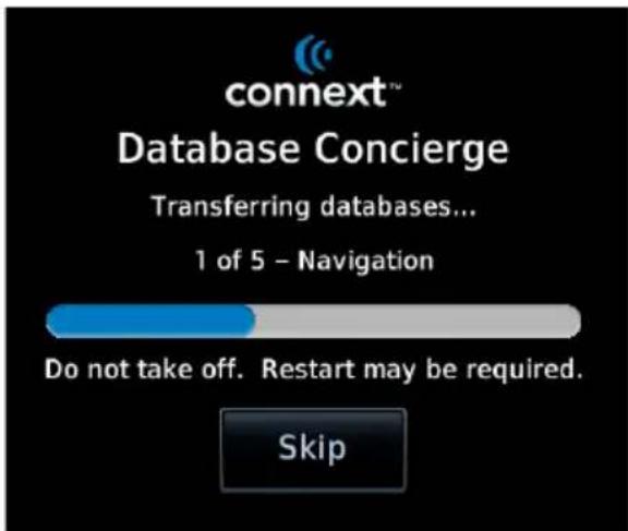
Database Concierge transfers databases from the app to Flight Stream 510. A progress bar shows when this process is complete.
GDU either updates or preloads databases based on their effective date. A second progress bar indicates upload status. The unit automatically restarts upon database activation.
Tapping Skip cancels any unfinished wireless transfers and initiates the update process.
GDU activates any databases that completed transfer before the interruption. Previously selected databases on an SD card or in the internal standby update as well. The message "Transfers interrupted" displays if no databases are available.
1.14 Database SYNC
FEATURE LIMITATIONS
• Not applicable to Terrain database
• Functionality not available for EIS-only configurations
Database SYNC minimizes database maintenance by synchronizing active and standby databases across all configured LRUs. Once a standby database becomes effective, each LRU automatically generates an update prompt.
Database SYNC Transfer Function
- Enables automatic database synchronization across all capable Garmin avionics (e.g., GTN or G500/G600 legacy flight displays)
• Includes active and standby databases - Informs you that enabling Database SYNC may overwrite any databases currently in standby
- Prompts unit restart if a new database is effective and the aircraft is on ground
For information regarding database packages, and individual database purchases, visit flyGarmin.com.
TOGGLE DATABASE SYNC ON OR OFF
Toggling the function off disables Chart Streaming (if enabled).
From the 700P/1060 MFD Home page:
Tap System > System Status > Menu > Database SYNC.
From the 700L MFD Home page:
Tap System > System Status > Database Information > Menu > Database SYNC.
From the 700() PFD:
Tap Menu > System > PFD Setup > Database SYNC.
1.15 Chart Streaming
FEATURE LIMITATIONS
• Available only when Database SYNC is active and a current chart database is available
Chart Streaming allows streaming of individual charts on an as-needed basis until database sync is complete. A typical chart database may take up to one hour to synchronize across multiple LRUs.
Toggling the function off has no affect on Database SYNC.
Chart Streaming Transfer Function
- Enables automatic streaming of individual charts from the newest chart database
• LRUs with chart streaming enabled display the most current chart information - Current charts display on MFD Charts page; chart overlays are available for display on Map page
• Chart database effective date displays on Charts page when chart expires
• Available for both ChartView and FliteCharts
Connectivity

Data logs transfer via Bluetooth wireless technology. Databases transfer over Wi-Fi.
FEATURE REQUIREMENTS
• Flight Stream 510 wireless datacard (installed in GTN, if available)
FEATURE LIMITATIONS
- GDU allows pairing of up to 13 Bluetooth enabled devices, with two simultaneous device connections
• Auto reconnect function is not available for Android devices
• GDU does not support Flight Stream 510 Phone/SMS and flight plan transfer functionality
1.16 Flight Stream 510 Setup
Setup page features allow you to:
• View Flight Stream 510 product information
- Enable database updates
• Pair and manage Bluetooth enabled devices
• View and edit Bluetooth enabled device name and Wi-Fi information
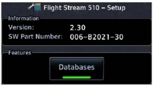
Refer to the Information window when contacting customer service regarding Flight Stream 510.
Product information includes:
- Software version
- Part number
DATABASES
This feature allows automatic import of available database updates via Database Concierge.
1.17 Bluetooth Setup
Depending on display type, Bluetooth device management options may reside on the Flight Stream page or on a dedicated setup page. Pairing occurs only when the Bluetooth Setup menu is opened.

Bluetooth Setup information includes:
• Current Bluetooth device name
- MAC address
- Pairing mode status
BLUETOOTH NAME
This key allows you to enter the name of the Bluetooth enabled device.
PFD only displays: Use the control knobs to enter the device name. Keypad entry is not available.
EIS only displays: The device name is set up using Garmin Pilot. Manual data entry is not required.
1.17.1 Managing Paired Devices

To view a list of all paired devices and their connection status, tap Manage Paired Devices.
AUTO RECONNECT
This key enables automatic connection between the GDU and the paired device when the two are within range.
REMOVE
Removing a device from the list means it is no longer paired with the GDU. This action requires pilot confirmation.
Be sure to remove pairing on both devices before attempting to pair them again.
1.18 Wi-Fi Setup

Wi-Fi setup information includes:
- Wi-Fi SSID
- Wi-Fi password
• MAC address of both Wi-Fi module and connected device (available only after launching Garmin Pilot)
1.18.1 Connecting to Wi-Fi
Enter the required SSID and password using the provided setup keys.
PFD only units: Use control knobs for SSID and password entry. Keypad entry is not available.
1.18.2 Viewing Wi-Fi Information

Tapping WiFi Info opens an information page.
WI-FI INFO STATUS
Wi-Fi connection status annunciates on the key label when this page is not active.

Flight Stream 510 requires power up.

Wi-Fi is active, but the GDU is waiting to connect with a paired device.

System detects a connection between the GDU and a paired device.

Flight Stream 510 requires Garmin Pilot to be opened in order for database transfer to commence.

This page is accessible from the Database Update and start-up pages. Information includes:
- Database Concierge connection status
• Connected device name
• Database update availability and instructions
• Wi-Fi SSID and password
Pilot Settings
1.19 Display Brightness Control
Turboprop Aircraft
Depending on installation, display brightness control may transition between lighting bus and photocell during engine start.
When you engage the start switch, display brightness control switches to photocell. When you disengage the switch, or after 60 seconds, brightness control returns to the dimmer bus.
Depending on configuration, display brightness is controlled using inputs from the built in photocell, aircraft dimmer bus, or both. Installer configured curves determine the amount of change in brightness that occurs in response to a control adjustment
If brightness control is not satisfactory, contact a Garmin dealer to adjust the lighting curves.
1.19.1 Automatic Brightness Control
Dimming is limited to prevent on screen indications from becoming unreadable. The built in photocell automatically controls display brightness based on ambient light levels.
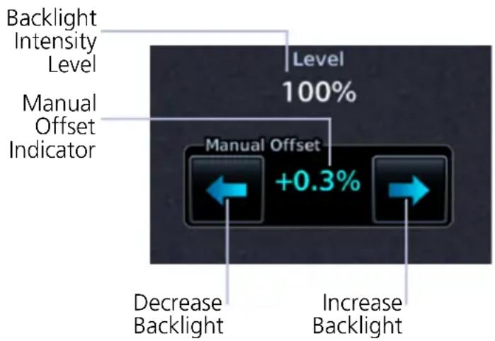
During automatic control, the pilot may still adjust brightness using the manual offset controls in the System Backlight page.
The GDU retains manual offset settings over power cycles.
1.19.2 Manual Brightness Control
Optionally, the TXi system is configurable to use an aircraft dimming bus for display brightness control. Upon reaching minimum input level, display brightness reverts to the photocell. This prevents the display from going black in the event of a dimmer input failure.
1.20 System Status Page
The System Status page displays information specific to the GDU and its databases. Refer to this page when contacting customer service. Information includes:
- Serial number • System ID
- Main software version • Database information
VIEW COPYRIGHTS

Tapping this key displays copyright information for all installed databases.
1.21 Click Volume
bar
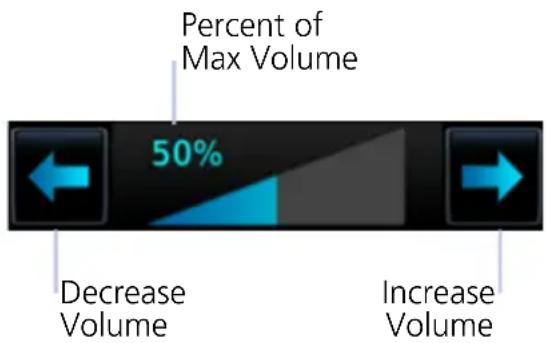
| Category | Value | | ---------------- | ----- | | Percent of Max Volume | 50% | | Decrease Volume | | | Increase Volume | |If the GDU is wired for audio output, set the click volume to the preferred level.
Volume displays as a percentage of the maximum volume, with 0% being muted and 100% being maximum volume.
1.22 Clock
Specify the time format and local offset.
If a 12 hour or 24 hour clock is selected, tap Local Offset, then specify the appropriate offset value from UTC.
Options include 12 hour, 24 hour, and UTC.
1.23 Weather Display Shortcut
A knob shortcut option is available when there are two or more active weather sources. Select a weather service and verify shortcut operation. Depending on configuration, available shortcut options may include:
- Connext Weather
- FIS-B Weather
- Radar
- SiriusXM Weather • Stormscope
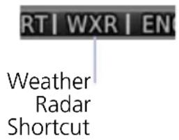
Selecting Radar changes the weather shortcut indicator to reflect the weather radar option is active.
1.24 Unit Selections

NOTE
Engine gauge, airspeed, and altimeter units are not pilot selectable. Interfaced equipment may contain unit settings independent of the TXi system.
The System Units page displays a list of TXi system wide unit settings. Selections are synchronized across all configured GDUs.
SPECIFY UNIT TYPE
- Review the current unit selections.
- Tap the applicable parameter key.
- Select a unit type.
| DISPLAY SETTINGS | ||
| PFD MFD EIS | 1 | |
| • BARO Pressure• Distance• NAV Angle• Temperature• Wind Speed | • Altitude• Distance• NAV Angle• Temperature | • Distance• Fuel Computer ^2 • Temperature |
^1 Engine gauge units are not adjustable. ^2 These units are not synchronized with other displays.
Crew Profiles
FEATURE REQUIREMENTS
• MFD for creating crew profiles, modifications, and deletions
The Manage Crew Profile option allows you to:
- Save TXi system wide and display specific settings
• Create individual profiles for aircraft operated by multiple pilots
• Transfer profiles between aircraft
1.25 Crew Profile Settings
Crew profile settings include both system wide and display specific settings. Specific display profile settings include the pilot adjustable parameters for each configured display.
^1 Lean mode is not applicable to turboprop installations.
| SYSTEM & DISPLAY PROFILE SETTINGS | ||
| DISPLAY FUNCTION SETTING | ||
| SYSTEM | UnitsNearest Airport CriteriaClick volumeChart StreamingRecently used waypoint listsWeather knob shortcutBacklight manual offsetDatabase SYNC | |
| PFD | Synthetic Vision | All |
| HSI | HSI MapMap overlaysBearing pointers | |
| Setup | Wind FieldClock/TimerMenu TimeoutCDI/VDI PreviewBARO SYNCAirspeed reference bug status | |
| MFD | Map | All |
| Traffic | Motion vectorAltitude filter (ABV/BLW/NRM/UNR) | |
| Terrain | ViewLayers | |
| Flight Plan | Column data fields | |
| Datalink weather products(SXM, FIS-B, Connext) | Map orientationLayersLegend on/offFIS-B on/offMap view configurations | |
| Stormscope | ViewMode | |
| Music | Preset group selectionMusic category selection | |
| Engine | EIS Lean Mode (ROP/LOP/TIT)Engine advisories (on/off states, thresholds) | |
| System | Time format (UTC/local)Weather knob shortcutOutside Air Temperature units | |
| EIS | Engine | EIS Lean Mode (ROP/LOP/TIT) ^1 Engine advisories (on/off states, thresholds) |
1.26 Crew Profile Management
FEATURE LIMITATIONS
The system stores a maximum of ten profiles. This includes nine user generated profiles and one default profile. Both New Profile and Import Profile functions are unavailable when this limit is reached. It is recommended to have all GDUs online when managing crew profiles. Profile synchronization is delayed for any LRU not online at the time a profile change occurs.

Profile management functions are provided in a fly-out menu on the Manage Crew Profiles page. Available options are based on current profile selection.
From the MFD Home page:
Tap System > Crew Profile.
Setting modifications are automatically stored within the active crew profile. If no user generated profile is active, all adjustments are saved to the Default profile.
1.26.1 Create a New Profile
A profile name is required to complete operation.
- Tap New Profile, enter desired profile name.
- Tapping Create and Activate activates new profile and adds it to list.

1.26.2 Import a Profile

- Insert an SD card containing a new profile.
- Tap Import Profile.
- Select profile to import.

If an imported profile has the same name as the existing entry, it is possible to overwrite the existing entry or cancel request.

If the imported profile has the same name as the active profile, the overwrite option is not given. Acknowledge the message, then activate a different profile and try again.

If the SD card does not contain importable profiles, acknowledge the message and replace the SD card.
1.26.3 Export a Profile
The export function writes a selected profile onto an SD card. This function overwrites any profile on the SD card with the same name. Available options are based on current profile selection.
1.26.4 Delete a Profile
The delete function removes a selected profile from all configured units.
- Select a profile from the list.
- Tap Delete.
1.26.5 Add a Crew Profile to a Full Profile List
- Delete an existing entry from the profile list.
- Create or import the new profile.
1.26.6 Rename a Profile

- Select a profile from the list.
- Tap Rename.
- Enter a new profile name using the keypad. If the name is already in use, acknowledge the message and enter a different profile name.
1.26.7 Reset Profile Settings
The reset function returns all settings for a crew to their factory default values.
- Select a profile from the list.
- Tap Reset Profile.
- Confirm the request.
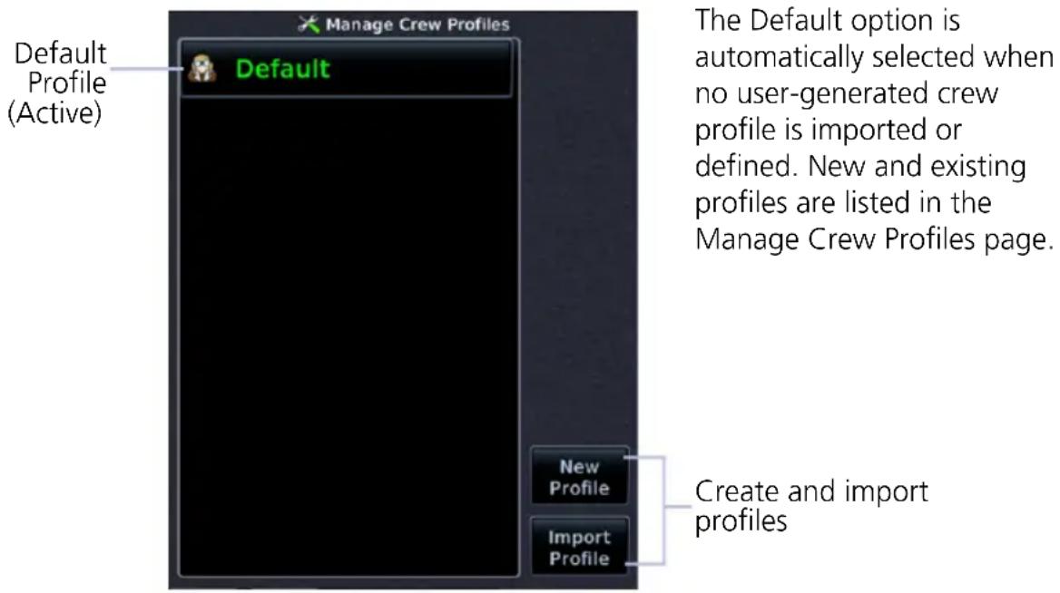
1.26.8 Activate a Profile
You may activate a crew profile from the Manage Crew Profiles page or from a pop-up list on the database start-up page (if multiple profiles are available).
If only one profile exists, the profile is activated automatically upon unit power up.

Once activated, the profile name turns green (active). All inactive profiles display in white text.
ACTIVATE FROM THE MANAGE CREW PROFILES PAGE
From the MFD Home page:
- Tap System > Crew Profile.
- Select a profile from the list.
- Tap Activate.
ACTIVATE FROM THE DATABASE START-UP PAGE
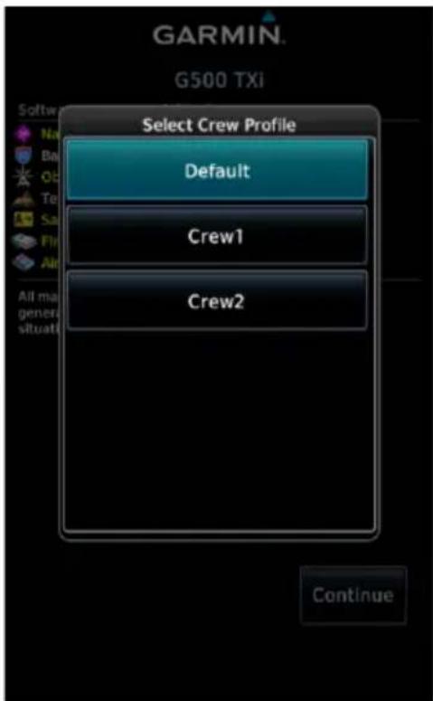
Select Crew Profile Pop-up (GDU 700P MFD)
If multiple profiles exist, a pop-up list allows you to select a profile during power up. Default profiles are selected automatically.
Tapping Continue activates the selection and closes the pop-up.
Installations with a GTN Xi Series Navigator:
The pop-up list does not display if only one profile exists and database confirmation is performed remotely via GTN Xi. The MFD automatically advances to the next page (e.g., EIS start-up page, MFD Home page) once it is determined that no database issues exist.
System Messages
1.27 Alerts Types
The unit generates messages in response to various conditions that may occur. These abbreviated messages include:
- Warnings
- Cautions
• Function and mode advisories
1.27.1 Warnings & Cautions
Warnings require immediate attention. A caution indicates the presence of an abnormal condition that may require pilot action. A warning may follow a caution if no attempt is made to correct the condition (e.g., altering the aircraft's path to avoid the alerted terrain or obstacle).
1.27.2 System & Function Advisories
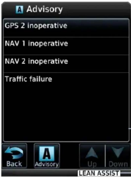
Advisories provide status and operating information.
System advisories display on a dedicated page or slide over window. Depending on the number of advisories, this list may be scrollable.
Function or mode specific advisories appear as unobstructed annunciations on the associated display.
System Advisory Window
Mode Advisory Annunciation
1.27.3 Alert Annunciations
Alert annunciations are abbreviated messages that indicate an alerted function or mode. The color of the annunciation depends on the alert type.
| ALERT COLORS |
| WARNING |
| CAUTION |
| ADVISORY |
- Warnings display in white text on red background
- Cautions display in black text on amber background
• Function or mode specific advisories display in black text on white background
When an alert is triggered, the annunciation flashes by alternating text and background colors. It turns solid after five seconds. All annunciations remain active (solid) until the condition is resolved or no longer a threat.
GDU 700(): Engine annunciations flash indefinitely unless acknowledged by the pilot.
ANNUNCIATION LOCATION
The location of the annunciation varies according to display and function. On the PFD, alerts annunciate to the right of the HSI. On the MFD, they annunciate in the lower right corner of the page. PFD alerts show on all configured PFD units in the TXi system.
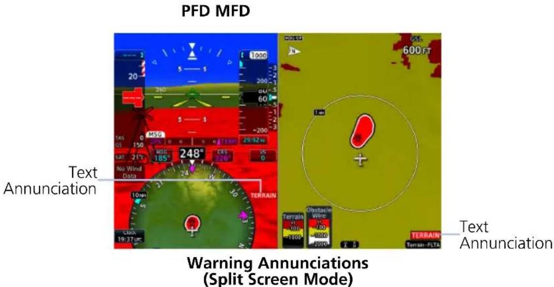

Informational advisories pertaining to EIS modes and functions appear in the annunciator bar along the bottom of the screen.
The EIS can be configured with the aircraft's caution and warning system to provide engine alert annunciations. For more about engine alerts, refer to section 8.19.
1.27.4 Pop-up Alerts
If a warning or caution relating to terrain, traffic, or the backup battery occurs, a pop-up window may display over the MFD. These pop-ups only appear if the alerted function's associated MFD page is not active.
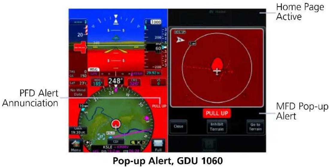
GDU 1060: If the PFD is in full screen mode during an alert, a flashing page access key (Terrain or Traffic) replaces the MFD key.
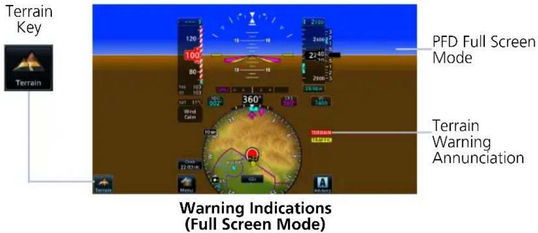
Pop-up Alert Priority
In the event of simultaneous alerts, pop-up windows display in the following order:
- Terrain alerts
- Traffic alerts
- Battery alerts
Each pop-up alert contains:
- Enlarged view of the alerted threat location
- Alert annunciation
- Alert inhibit information, if applicable
• Control key for closing the pop-up window - Direct access key to associated MFD page
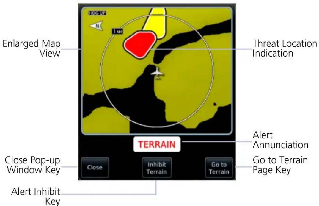
Terrain Pop-up Alert Layout
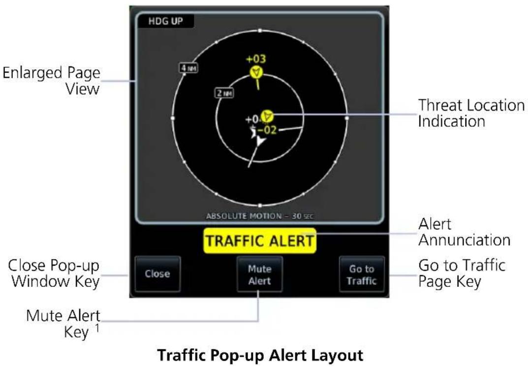
To open the indicated MFD page, tap Go to
To acknowledge the alert and return to previous page view, tap Close.
For information about the terrain alert inhibit function, read Alert Inhibit, TAWS & Terrain-FLTA in section 7. For information about the traffic alert mute function, read section 1.27.5.
BATTERY POP-UP ALERTS
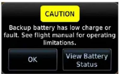
GDU 700P/1060
These pop-ups alert to backup battery status. Available options are dependent on unit and alert type.
Tapping OK acknowledges the alert and closes the pop-up.
GDU 700P/1060: The View Battery Status key provides direct access to the External LRU page.
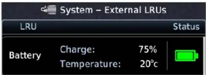
Battery charge and temperature status display at the top of the LRU list.
GDU 700L: On PFD, battery pop-up alerts display in one of two locations depending on the state of the battery and the aircraft.
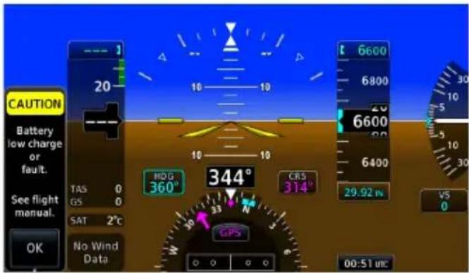
Vertical Pop-up Alert
Cautions display vertically along the left side of the screen.
These alerts may occur in flight. They do not display when the PFD menu is open.

Horizontal Pop-up Alert
Loss of aircraft power alerts display horizontally in front of the HSI.
This alert occurs only on ground. It displays whether or not the menu is open.
1.27.5 Aural Alerts
Some alerts are accompanied by an aural voice message. Voice gender is configured during installation. To determine which alerts provide aural indications, refer to the applicable alerts table.
MUTE ALERT
FEATURE LIMITATIONS
• Available only with GTX 345 and ADS-B software v3.20 or later

Tapping Mute Alert silences the active traffic alert. This key is available on the traffic alert pop-up.
The mute alert function is applicable only to the active aural alert. It does not mute future alerts.
1.28 Advisories
Advisories are system-related messages that display across all connected GDUs in the TXi system. The alert includes the ID relative to the display.
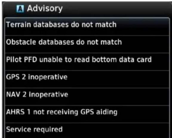
- Most recent advisories are at the top of list
• View-once advisories remain in queue until viewed by the pilot - Persistent (or conditional) advisories remain active until the indicated condition is resolved
- Acknowledging an advisory on one GDU automatically acknowledges the message across all TXi units
All advisories are logged in the unit's internal storage. This log may be viewed in configuration mode and exported to an SD card.
ADVISORY KEY

Tapping the Advisory key once displays the advisory list. Tapping it again acknowledges all active advisories and closes the list.
• Flashes in navigation bar when a new advisory is present
• Turns solid once all active advisories are acknowledged
• No longer displays after all active advisories are cleared
1.28.1 Audio Advisories
Contact the dealer for all audio related issues.
ADVISORY CONDITION
| Audio inoperative. | A failure occurred with audio device. |
| An audio clip does not play. | |
| Communication with audio device is lost. |
1.28.2 Battery Advisories
ADVISORY CONDITION CORRECTIVE ACTION
| Battery capacity test failure. | Service required.Acknowledge pop-up alert.Contact dealer for support. | |
| Annual capacity test overdue. | Testing required.Acknowledge pop-up alert.Contact dealer for support. | |
| Battery communication is lost. | Service required.Acknowledge pop-up alert.Contact dealer for support. | |
| A battery fault is present. | Service required.Acknowledge pop-up alert.Contact dealer for support. | |
| Battery power output failure. | Service required.Acknowledge pop-up alert.Contact dealer for support. | |
| The indicated GDU is operating in battery mode. | Ensure that the aircraft is in a safe state. Correct the issue to restore electrical power to the GDU. |
1.28.3 Database Advisories
ADVISORY CONDITION CORRECTIVE ACTION
| AHRS 1/2 magnetic model database needs update. | AHRS 1/2 magnetic field model database is out of date. Occurs only when the aircraft is on ground. | Update IGRF database according to instructions in the "Databases" section. |
| The indicated database is approaching expiration (PFD-only displays). | If available, load the next cycle of database into standby. | |
| The indicated database is expired (PFD-only displays). | Update indicated database, if necessary. | |
| The indicated database is unavailable or corrupt. | Re-download and install the indicated database on the GDU. Contact a Garmin dealer for support. | |
| Two or more TXi GDUs have a different version of the indicated database. | Update the indicated database. For information about all installed databases, go to the System Status page. | |
| The indicated database is corrupt (PFD-only displays). | Re-download and install the indicated database, Contact a Garmin dealer for support. | |
| The indicated database is unavailable (PFD-only displays). | ||
| Chart database expires on. | The charts database is approaching expiration. | If available, load the next cycle of the charts database into standby. |
| The charts database is expired Appears only on units with an MFD. | Update the database if necessary for operation. | |
| Charts database verification failure. | Re-download and install the indicated database. Contact a Garmin dealer for support. | |
| Chart database unavailable. | The configured charts database is unavailable (MFD displays). | Re-download and install the indicated database, Contact a Garmin dealer for support. |
ADVISORY CONDITION CORRECTIVE ACTION
| Chart streaming unavailable. Using installed chart database. | Chart streaming is not available. The GDU reverted to the currently installed charts. | Open the System Status page and check database synchronization status. If the problem persists, contact a Garmin dealer for support. |
| Database SYNC in progress. View System Status page for more info. | Database synchronization is in progress. | Wait for database synchronization to complete. Restart the GDU before attempting to use new databases. |
1.28.4 Emergency Descent Mode Advisories
ADVISORY CONDITION CORRECTIVE ACTION
| Emergency Descent Mode ACTIVATE switch inoperative. | EDM switch inoperative. | Contact a Garmin dealer for service. |
| Emergency Descent Mode automatic activation unavailable. Service required. | EDM cabin pressurization is enabled on GDU, but GMC 605 is not providing cabin pressure altitude. | |
| Emergency Descent Mode unavailable. Service required. | EDM is enabled on GDU, but not supported by GMC 605. | |
| Emergency Descent Mode automatic activation is inhibited. | Auto EDM toggle key in the PFD Setup menu is off. | Enable the Auto EDM function. On PFD: Tap Menu > Auto EDM. |
1.28.5 Engine System Advisories
ADVISORY CONDITION CORRECTIVE ACTION
| advisory (e.g., High Oil Temperature, Low Battery Voltage). | The indicated engine parameter exceeds pilot-specified value. | Verify that parameter is within the operating limitations defined in the POH. | |
| EGT Difference advisory.1 | Pilot-specified EGT Diff is exceeded by one or more engines. | ||
| CHT Cooling advisory.1 | A cylinder's cooling rate is faster than pilot-specified CHT cooling rate. | ||
| Low EST Fuel Remaining advisory. | Estimated fuel on board is below pilot-specified limit. | ||
| Low Endurance advisory. | Remaining flight endurance is below pilot-specified limit. | ||
| Automatic Ignition unavailable.2 | System is unable to activate automatic ignition (in-flight only). | Monitor engine status and environmental conditions and activate igniters manually in accordance with the POH. Contact dealer for service. | |
| Service required. | The system or unit requires service. Appears only when the aircraft is on ground. | Contact dealer for service. | |
| Service required. Automatic Starting inhibited due toinvalid.3 | The indicated input or output is not functioning. Automatic starting is inhibited as a result. | Contact dealer for service. |
^1 Piston installations only. ^2 Turbine installations with automatic ignition enabled.
^5 Turbine installations with automatic starting enabled.
1.28.6 Terrain Advisories
ADVISORY CONDITION CORRECTIVE ACTION
| Service TAWS. Invalid config. | Terrain/TAWS alerting configuration is invalid. | Contact a Garmin dealer for support. |
| Fixed-Wing/Rotorcraft mismatch. The GDU's aircraft setting conflicts with the current external TAWS configuration. | ||
| SVT could not be enabled. | The SVT feature cannot be unlocked with the current SD card. | Verify that the SVT feature unlock card is inserted in the GDU. If necessary, contact a Garmin dealer for support. |
| SVT has been successfully enabled. Restart all GDUs to complete enablement. | The SVT feature is enabled during the current power cycle. | To complete feature enablement, restart all configured GDUs. |
| Terrain database resolution does not support the current terrain alerting configuration (rotorcraft only). | Download and install the 2.9 arc-second Terrain database. | |
| SVT Disabled | Outside terrain database coverage area. | Contact a Garmin dealer for database options. |
| Terrain/SVT Free Trial Flight time remaining: XX HRS | Terrain Settings Menu displays the flight hours remaining in the SVT free trial period. | If SVT is desired, do one of the following:Contact a Garmin dealer to complete feature enablement within the 11 hour free trial periodVisitflyGarmin.comand purchase the feature enablement |
1.28.7 Traffic System Advisories
The following advisories pertain to various traffic system failures.
ADVISORY CONDITION CORRECTIVE ACTION
| 1090ES traffic receiver fault. | ADS-B LRU reports that it is unable to receive 1090 Extended Squitter traffic. | Service required. Contact dealer for support. |
| ADS traffic alerting function inoperative. | The ADS-B LRU reports a traffic alerting failure. | Service required. Contact dealer for support. |
| ADS traffic function inoperative. | The ADS-B LRU reports a failure with the ADS-B Traffic input. | Service required. Contact dealer for support. |
| TAS/TCAS function inoperative. | TAS/TCAS device reports a traffic failure. | Reset the TCAS device. Contact dealer for support. |
| Communication with the TAS/TCAS device is lost. | ||
| TAS/TCAS system in standby. | The TAS/TCAS device is in standby mode for longer than 60 seconds while airborne. | If traffic alerts are desired, enable the operating mode of the traffic device. |
| Traffic/FIS-B functions inoperative. | The ADS-B LRU reports a critical fault and is inoperative. | Service required. Contact dealer for support. |
| Communication with the ADS-B LRU is lost. | Service required. Contact dealer for support. | |
| UAT fault. | The UAT LRU reports a low battery or fan fault. | Service required. Contact dealer for support. |
| UAT traffic/data receiver fault. | The ADS-B LRU reports that it is unable to receive UAT traffic and FIS-B data. | Service required. Contact dealer for service. |
| TCAS RA display unavailable on VSI. Expand <GDU> to full screen mode to restore.1 | The GDU is operating in display backup mode, and the current VSI format is not able to display RAs. | Change the VSI type by expanding the PFD using the FULL key. |
^1 TCAS II equipped aircraft only.
1.28.8 Satellite Service Advisories
The following advisories pertain to various satellite service conditions and failures. For support regarding all satellite service advisories, contact a Garmin dealer.
ADVISORY CONDITION
| Connext weather receiver inoperative. | Communication with the GSR 56 is lost. The satellite weather service is in operative. |
| Connext weather service not registered. | GSR 56 weather service requires registration for operation. |
| SiriusXM receiver inoperative. | SiriusXM receiver failure. |
| Communication with the GDL 69/69A is lost. |
1.28.9 PFD Advisories
The following advisories pertain to various conditions and devices associated with the PFD.
ADVISORY CONDITION CORRECTIVE ACTION
| ADC 1/2 error correction inoperative. | The indicated ADC reports that airspeed error correction is unavailable. | Contact dealer for service. |
| The indicated ADC reports that altitude error correction (i.e., SSEC) is unavailable. | ||
| < GDU> ADS-B in traffic does not match configuration. | The primary ADS-B traffic source is not available. GDU is relying on data from backup source. | Contact a Garmin dealer for support. |
| AHRS 1/2 not receiving GPS aiding. | The indicated AHRS is not receiving GPS data from any source. | Ensure that the navigator(s) is on and receiving a GPS signal.Check the AFMS for limitations.Contact dealer for service. |
ADVISORY CONDITION CORRECTIVE ACTION
| The indicated GDU is not receiving temperature or pressure altitude data. Applicable to rotorcraft only. | Refer to airspeed limitations placard for applicable V_NE . | |
| The unit is in demonstration mode. | To exit demo mode: Cycle power to the GDU. If the problem persists, contact dealer for service. Operating the GDU in demo mode during flight is prohibited. | |
| GPS 1/2 inoperative. | The indicated GPS source failed. | Ensure that the navigator(s) is on and receiving a GPS signal. Switch to an alternate navigation source. Contact dealer for service. |
| Communication with the indicated GPS is lost. | ||
| NAV 1/2 inoperative. | The indicated NAV source is failed, or input data is not received. | Switch to an alternate navigation source. |
| The indicated LRU reports an internal fault and requires service. Appears only when the aircraft is on ground. | Contact dealer for service. | |
| Reset altitude preselector to enable VPATH descent. | TOD ahead. Vertical deviation is available and the selected altitude is < 75 ft below current altitude. Appears only for aircraft equipped with GFC 600. | Lower the selected altitude to at least 75 ft below the current aircraft altitude. |
| The GDU cannot read LED calibration data, or the data is corrupt. Sunlight readability may be degraded. Appears only when the aircraft is on ground. | Contact dealer for service. |
ADVISORY CONDITION CORRECTIVE ACTION
| controller unavailable. | Communication with GCU 485 is lost. Appears only when the aircraft is on ground. | Operate the indicated GDU using the touchscreen controls. | |
| Service required. | The system or unit requires service.Appears only when the aircraft is on ground. | Contact dealer for service. | |
| Service soon. | The system or unit detects an internal fault but continues to function.Appears only when the aircraft is on ground. | Contact dealer for service. | |
1.28.10 System Hardware Advisories
ADVISORY CONDITION CORRECTIVE ACTION
| The indicated key is stuck on GCU 485. | Push the indicated key again. If the key remains stuck, use the corresponding touchscreen controls. Contact dealer for service. | |
| The indicated knob is stuck on GCU 485. | Push the indicated knob again. If the knob remains stuck, use the corresponding touchscreen controls. Contact dealer for service. | |
| The unit detects multiple stuck controls on the GCU 485. | Use the touchscreen controls for all manual operations. Contact dealer for service. | |
| The indicated GDU detects a cooling fan fault.PFD/MFD coloration may be incorrect.The backlight may dim to reduce power and heat. | Extended operation at high temperatures is not recommended as damage to the unit may occur.Contact dealer for service. | |
| Unit temperature exceeds the over temperature threshold. | Decrease cabin temperature and increase cabin airflow near the GDU. If the problem persists, contact the dealer for service. | |
| The indicated GDU knob(s) is stuck. | Use the touchscreen controls for all manual operations. | |
| Electronic Stability Protection failed. | Garmin Mode Controller signals an ESP system fault. | Consult the pilot's guide for the Garmin Mode Controller. |
ADVISORY CONDITION CORRECTIVE ACTION
| The SD card in the indicated slot is unreadable or corrupt (i.e., data is unavailable). | Reformat the SD card using an external computer.Re-insert the SD card in the slot.If the problem persists, contact the dealer for service. | |
| The SD card is missing from the indicated slot. | Re-insert the SD card in the slot. | |
| User ejects Flight Stream 510 wireless datacard. Network connection lost. | Restart GDU to reconnect. |
1.28.11 Weather Service Advisories
ADVISORY CONDITION CORRECTIVE ACTION
| Possible severe weather ahead. Check Weather Radar. | Weather alert detected within +/- 10 degrees of the aircraft heading. This advisory does not appear when the Weather Radar page is active on any TXi unit. | To view information about severe weather in the current flight path, open the Weather Radar page. |
| Stormscope inoperative. | The GDU is not receiving data from the Stormscope unit. | Consult the appropriate third-party documentation. |
| Stormscope reports a failure status. | ||
| Weather radar needs service. | Weather radar reports a degraded or inoperative condition exists. Appears only when the aircraft is on ground. | Contact dealer for service. |
| Weather radar inoperative. | The unit is not receiving weather radar data. | Contact dealer for service. |
1.29 LRU Failure Annunciations
LRU fail annunciations are designed to be immediately recognizable. If an LRU failure occurs, a red or amber "X" appears over the associated flight instrument(s) or data field(s). For additional information regarding pilot responses to LRU failures, consult the AFMS.
The annunciation color is determined by instrument type.
- Red "X" displays over primary flight instruments and data fields
- Amber "X" displays over non-primary flight instruments
1.29.1 PFD Failure Annunciations
During power-up, certain flight instruments are invalid until the associated equipment completes initialization. Data fields (e.g., TAS, GS, SAT) display only dashes when the input source is not available.
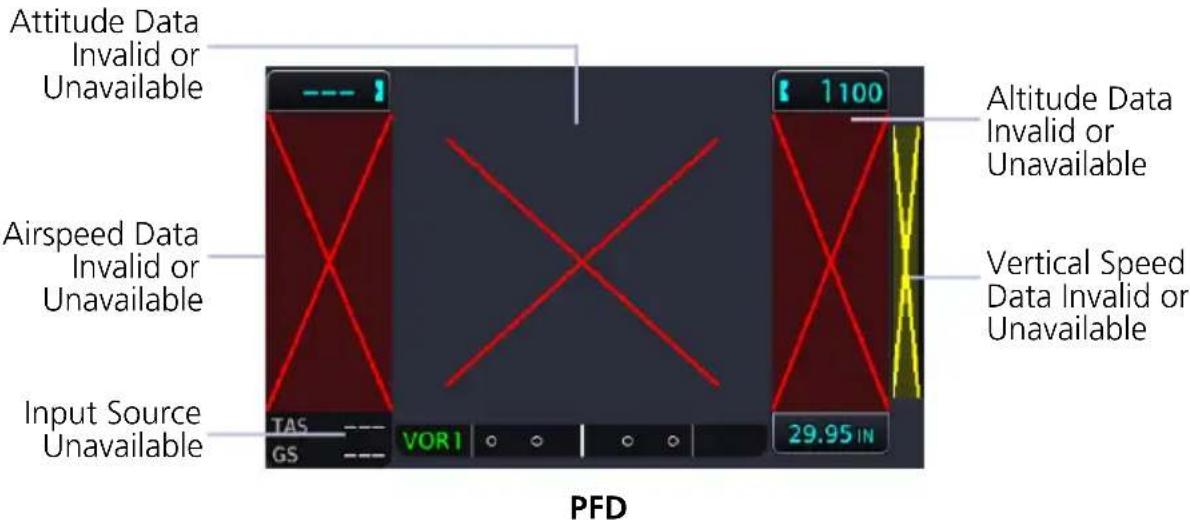
If an instrument remains flagged after one minute, check the status of the associated LRU, then contact a Garmin dealer for additional support. For Garmin LRUs, go to the External LRUs page and note any failed LRUs.
INDICATOR ANNUNCIATION AND CONDITION
| Airspeed | Annunciation: Red "X"Condition: Display is not receiving airspeed data from ADC. |
| Altitude | Annunciation: Red "X"Condition: Display is not receiving altitude data from ADC. |
| Attitude | Annunciation: Red "X"Condition: Display is not receiving attitude and heading information from the AHRS. |
| Vertical Speed | Annunciation: Amber "X"Condition: Display is not receiving vertical speed data from ADC. |
| HDG FAIL | Annunciation: Red rectangle with white text "HDG FAIL"Condition: AHRS indicates that the magnetic heading value is invalid. |
1.29.2 EIS Failure Annunciations
An LRU failure annunciates on the EIS when instrument sensory data become invalid or unavailable.
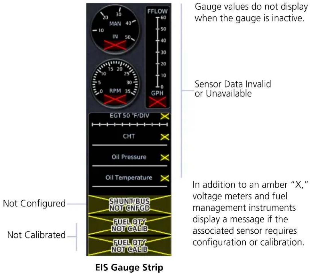
1.30 GDU Failure Annunciations
1.30.1 Fan Failure Annunciation, GDU 700()
ANNUNCIATION ALERT TYPE & CONDITION
| FAN FAIL | Alert Type: Caution |
| Condition | |
| GDU internal cooling fan failure for >10 seconds. |
1.31 ADS-B Status
FEATURE REQUIREMENTS
• Universal Access Transceiver (GDL 88, GNX 375, GTX 345)
View last uplink time and GPS source information from the ADS-B Status page. You may access this page one of two ways.
From the Home page:
- Tap System > External LRUs.
- Scroll to the UAT device.
- Select More Info.
From the Weather page:
Tap FIS-B Weather > Menu > Datalink Status.
UPLINK TIME
| TEXT COLOR | MINUTES SINCE LAST UPLINK |
| Green < 5 | |
| Yellow | 5 to 15 |
| >15 |
This field displays the number of minutes since last uplink. Digital values may change color depending on duration.
">15" displays when the time exceeds 15 minutes.
Dashes indicate when valid uplink data is unavailable (e.g., the device is offline).
FIS-B WEATHER
View the status of FIS-B weather products. For additional details, tap the appropriate key.
Raw Text Reports Radio Stations

View raw textual data for a FIS-B product.

Monitor FIS-B ground station transmission status and reception completeness for certain FIS-B products.
TRAFFIC APPLICATION STATUS
View the status of all three traffic applications: • AIRB • SURF • ATAS (airborne alerts)
| ANNUNCIATION DESCRIPTION | |
| On | Application is running. Required ownership data is available and meets the performance criteria. |
| Available to Run | Application is configured. Required input data is available and meets the performance criteria. |
| Unavailable to Run | Required input data is not available due to a failure (e.g., aircraft surveillance application process failed). |
| Unavailable - Fault | Required input data is available, but does not meet the performance criteria or is not available due to non-computed data conditions. |
Logs
1.32 Flight Data Logging

The data logging function is capable of storing approximately 100 hours of flight data in the unit's internal memory. This information is available for export to an SD card for later analysis.
FEATURE REQUIREMENTS
• SD card for external data logging
• Flight Stream 510 wireless datacard for data streaming
FEATURE LIMITATIONS
• Engine exceedance logs are available only for turbine aircraft
• External data logging stops when the SD card is full
Data Logging Function
- Generates log files automatically upon unit power-up
- Records various parameters related to aircraft flight instruments, engine indications, and configuration
- Streams logged flight and engine data to Garmin Pilot when Flight Stream 510 is present
- Writes logged data to an SD card if one is present in the top/left slot
• Overwrites oldest files when the internal log reaches capacity - Saves files in the .csv format and stores them in the "data_log" folder
FILE NAMING CONVENTIONS
Log file names provide a useful reference to aid data analysis. They include:
- Log start date and time
- Identifier of the nearest waypoint at the indicated start time
log_YYMMDD_HHMMSS_WPT.csv

flowchart
graph LR
    A["Year Month Day"] --> B["Hour Minute Second"]
    B --> C["Nearest Waypoint Identifier (at start of log)"]
Files with the name "log_000101_0000XX____.csv" do not contain a valid date and time stamp. These logs may include data recorded during installation.
Data Logging at a Glance
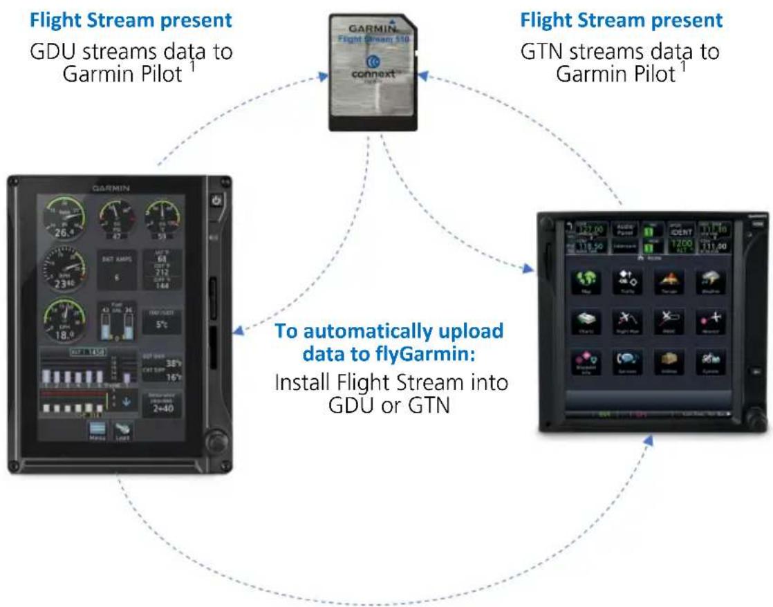
flowchart
graph TD
    A["Flight Stream present\nGDU streams data to Garmin Pilot¹"] --> B["GARMIN\nFlight Stream 510\nconnext®"]
    C["To automatically upload data to flyGarmin:\nInstall Flight Stream into GDU or GTN"] --> B
    D["Flight Stream present\nGTN streams data to Garmin Pilot¹"] --> B
    B --> E["Final Display with GPS icons"]
    style A fill:#f9f,stroke:#333
    style C fill:#ccf,stroke:#333
    style D fill:#cfc,stroke:#333
Upon power up, the GDU...
- Begins logging flight and engine data automatically
• Stores the data in its internal memory - Writes the data to an SD card (if present in top/left slot) ^2
If Flight Stream is present in GTN
• GDU transfers logs to GTN, which then streams the data to Garmin Pilot
• GTN is the preferred location for Flight Stream installation
What happens if there's a power interruption?
Data logging stops if power is lost. All data recorded up to that point remains stored in the internal memory. Data is not recorded for the duration of the outage. When GDU reboots, logging automatically resumes with a new log file.
In a multi-GDU system, we recommend placing an SD card in each GDU to provide continuous data logging in the event of a GDU outage.
1.32.1 Exporting to SD Card

NOTE
Do not eject the SD card while the export function is in progress. Wait until the Export Data Log key is available before ejecting the card.
flowchart
graph TD
    A["Home"] --> B["System"]
    B --> C["Logs"]
Exportable parameters are dependent on aircraft type.
- Insert an SD card into top/left slot.
- Power on GDU.
- Go to the Logs page.
- Tap Export Data Log.
Exporting Logs: 89%
Export in Progress
During export, the Export Data Log key is unavailable (gray), and displays the export progress percentage. It becomes available once export is complete.
What if I forget to insert my SD card before flight?
Internal flight and engine data logging occurs regardless of whether an SD card is present. After your flight, you may insert a card and download log files using the Export Data Log command.
With the aircraft safely on ground:
- Power off unit.
- Insert card.
- Power on unit.
- Tap System > Logs > Export Data Log.
Wait for the export to complete before ejecting the SD card.
Once the files are exported onto SD card, you may transfer the log files to your personal logbook on flyGarmin.com.
Duration varies depending on the number of files present. For lengthy transfers, it may be necessary to run the engine or operate on ground power until the export is complete.
TRANSFER SD CARD DATA TO YOUR ONLINE LOGBOOK
The Logbook tab on flyGarmin.com provides functions for creating and viewing multiple logbook entries.
flyGarmin Navigation Tabs
| HOME | DEVICES | GARMIN PILOT | LOGBOOK | TRAINING | SUPPORT |
To create a logbook and upload data:
- Sign in to your flyGarmin.com account.
- Select Logbook > Setup.
- Select Add Aircraft Type.
- Provide all necessary aircraft type details, then select Save Aircraft Type.
- Provide all necessary settings and pilot information, then select Save Settings.
To upload flight logs to an existing logbook entry:
- Select Logbook > Entries > Upload Flight Logs.
- Select and upload the log files according to the on-screen instructions.
1.32.2 Streaming to Garmin Pilot

The unit automatically streams logged flight data to the Garmin Pilot app when Flight Stream 510 is present and paired to a supported tablet or phone.

flowchart
graph TD
    A["Garmin Pilot App"] -->|Your portable device downloads the data upon connecting to Flight Stream 510.| B[" tablet device"]
    B --> C[" flyGarmin.com "]
    C --> D[" logged flight and engine data streams to Garmin Pilot. "]
    D --> A
    style A fill:#f9f,stroke:#333
    style B fill:#ccf,stroke:#333
    style C fill:#cfc,stroke:#333
    style D fill:#fcc,stroke:#333
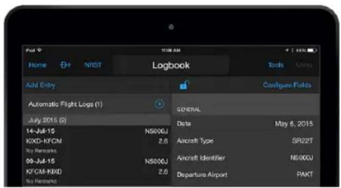
This includes any previous flights not already downloaded.
What happens if I forget to bring my tablet on the flight?
No need to worry. During flight, GDU records log data to the internal storage and SD card (if present). The next time you fly with your tablet, the data will stream to Garmin Pilot. This includes all previously recorded flights. The device downloads the data upon connecting to Flight Stream 510.
1.33 Exceedance Logging

Unlike flight data logging, which records parameters at a specific rate, exceedance logs record information about a specific gauge when its value exceeds a threshold.
FEATURE REQUIREMENTS
• Turboprop EIS enablement
OR
• Fixed wing aircraft with variable V_NE
FEATURE LIMITATIONS
• Engine exceedances apply to turboprop aircraft only
- Exceedance viewer can acknowledge entries on only one GDU at a time
Not all gauges have exceedance logging. Availability varies depending on airframe and engine.
Exceedance Recording Function
- Generates an exceedance file after a gauge parameter exceeds its maximum allowable time at an elevated level
- Engine exceedances record in-depth data about the exceeded gauge, and contextual details about other parameters during that time
- Advisories notify 30 seconds after the exceedance ends (during flight), and once the aircraft is on ground
- Entries are available for viewing on the dedicated summary page
Exceedances are installer configured to match the aircraft limitations in the POH. Pilots are responsible for knowing and respecting all aircraft and engine limitations.
Exceedance Gauges
- Torque
- Prop RPM
- NG/N1
• Turbine Engine Temperature - Oil Temperature
- Oil Pressure
- Fuel Pressure
Many engine gauges have a maximum allowable time limit that the parameter may operate at an elevated level. This "grace period" is indicated on the gauge's associated countdown timer. Log entries do not generate until after this timer expires.
The duration of the exceedance is the amount of time that the indicated parameter exceeds the limit, which includes the grace period time.
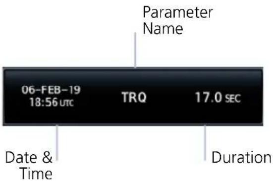
Each log entry includes the parameter name, and the date, time, and duration of the exceedance.
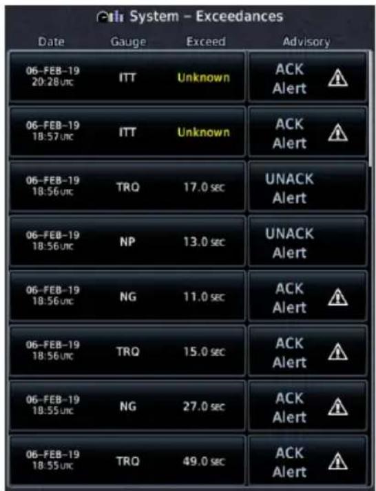
Exceedances Summary Page
INCOMPLETE ENTRIES

If GDU loses power while recording an exceedance, the system marks the duration as "Unknown."
Incomplete log files contain data recorded up until the time of the interruption. Some fields are not available due to the GDU not having knowledge of parameters at the end of the exceedance.
1.33.1 Exceedance Alerts

An advisory informs that an exceedance alert is available for viewing in the data log. These alerts occur 30 seconds after the exceedance ends and upon landing. Notifications persist until all exceedances are acknowledged.
ACK Alert UNACK Alert

Tapping this key acknowledges the corresponding alert. An alert symbol indicates the advisory condition requires attention.

Tapping this key unacknowledges the corresponding alert. Unacknowledged entries rise to the top of the summary page.
ACKNOWLEDGE AN EXCEEDANCE ALERT
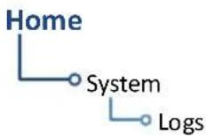
To view and acknowledge the exceedance advisory:
- Go to the Logs page.
- Tap Exceedances.
- Review the list of alert entries.
- Tap ACK for each unacknowledged entry.
1.33.2 Exceedance Details
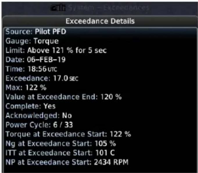
Select an exceedance file to view gauge details.
Duration and highest value are useful for determining whether maintenance actions are required.
The provided values of other engine parameters may be useful when determining if an exceedance resulted from sensor testing or failure.
Exceedance Log Data
• Gauge and exceeded parameter
• Date & time of occurrence
- Duration (total amount of time the parameter exceeded the limit, which includes the grace period time)
- Highest gauge value
- Power cycle
- Max parameter value during exceedance period
• Parameter value at end of exceedance
- Value of other engine parameters at beginning of exceedance
• Any interruptions (e.g., power loss)
• Completeness of data
- Alert state (i.e., acknowledged or unacknowledged)
The GDU uses an internal circular log to store exceedances entries for 100 power cycles that have had an exceedance. The user should periodically export the exceedance log to SD card.
If date and time parameters are not available (e.g., during engine start when the navigator has yet to acquire a GPS signal), use the power cycle parameter value to narrow down the time of occurrence.
1.33.3 Exporting to SD Card
Exportable parameters are dependent on aircraft type.
- Insert an SD card into top/left slot.
- Power on GDU.
- Go to the Logs page.
- Tap Export Data Log.
Compatible Equipment
1.34 Line Replaceable Units
SYSTEM REQUIRED LRUs (PFD)
| ADAHRS or ADC with AHRS |
| GMU 44/44B |
| GTP 59 |
| Garmin GPS navigator |
SYSTEM OPTIONAL LRUs
| Backup GPS antenna |
| GAD 43/43e adapter |
| GBB 54 battery |
| GCU 485 PFD controller |
| GEA 110 engine airframe interface ^1 |
| GEA 71 engine airframe interface ^2 |
OPTIONAL INTERFACES
| ADF |
| Airborne weather radar |
| Autopilot/flight director |
| DME |
| G5 |
| GDL 69/69A SiriusXM datalink |
| GDL 88/GTX 345 ADS-B transceiver |
| GI 275 |
| GSR 56 satellite datalink |
| GTX 330 or GTX 335 mode S transponder (TIS-A) |
| Radar altimeter |
| Stormscope |
| TAS/TCAS/TCAS II |
| VHF NAV and glideslope receiver |
The TXi system consists of multiple LRUs, which are installed behind the instrument panel or in a separate avionics bay. Their modular design aids system maintenance and unit replacement.
Optional LRUs may include compatible equipment from either Garmin or a third party manufacturer.
Some LRUs provide features that require registration and/or enablement prior to activation.
1.34.1 LRU Status
Devices that interface to the system via Ethernet display product information on the System Status page. Some interfaced equipment provide controls for product registration, enablement or viewing detailed status information. For additional information, touch More Info.

The device is configured and communicating properly

The device is not available and is not configured or it is not communicating properly
1.34.2 Integrated Standby Instrument
PISTON AIRCRAFT ONLY
An integrated standby instrument configuration consists of two GDU 700Ps, each with separate AHRS/ADC sensors. One display serves as the PFD, the other as EIS, MFD, or MFD/EIS. When activated, the display backup switch forces both displays into their display backup mode of operation.
The GBB 54 backup battery provides power to the PFD and sensors in the event of primary aircraft power failure. Both displays monitor and compare independent attitude, altitude, and airspeed data. The EIS, MFD, or MFD/EIS automatically displays its backup primary flight information when:
- Either display detects a miscompare between attitude, altitude, or airspeed parameters.
- Communication between displays is lost.
- The display backup toggle switch is active.
This configuration provides the following functionality, which satisfies the backup instrumentation requirements.
The MFD, EIS, or MFD/EIS behaves as follows:
• An MFD will transition to a full-screen PFD display
• An EIS will transition to a split-screen PFD/EIS display
• An MFD/EIS will transition to a split-screen PFD/EIS display
1.34.3 Standby Instruments
Except for installations limited to VFR, PFD installations require standby attitude, altitude, and airspeed instruments. Several types of standby instruments are acceptable, including individual analog instruments and certain electronic standby indicators.
G5 STANDBY ATTITUDE INSTRUMENT
FEATURE LIMITATIONS
• Available functionality dependent upon installation and configuration settings
- G5 standby (not part of GFC 500 system) synchronization functionality (an optional capability) requires installation of GAD 29B adapter
| GFC 500 G5 FUNCTION | |
| Present | Backup autopilot control and GPS couplingStandby attitude display |
| Not present | Standby attitude display |
G5 is an optional electronic flight instrument capable of operating as a standalone flight display or as a fully integrated standby instrument.
G5 Standby Instrument Features
- Mirrors GDU control settings for Barometric Correction and Selected Course
G5 Features when Installed with GFC 500 system
- Automatic synchronization of the following PFD controls: Selected Airspeed, Selected Altitude, Selected Heading, and Selected Vertical Speed
- Mirrors GDU control settings for Barometric Correction and Selected Course
• Displays CDI navigation source selection data received from the GDU
To initiate synchronization, set the G5 barometric pressure setting to match corresponding control setting on the GDU. Both units remain in sync until the barometric pressure setting is manually adjusted on G5.
Synchronization occurs after a short delay. The duration of this delay varies depending on which unit is attempting to sync.
| CONDITION SYNCING OCCURS... | |
| Pilot adjusts barometric setting on G5 to match corresponding correction control setting on GDU. | After 5 seconds |
| Pilot adjusts barometric correction control setting on GDU to match corresponding setting on G5. | After 1 minute |
GI 275 STANDBY ATTITUDE INSTRUMENT
FEATURE LIMITATIONS
• Available functionality dependent upon installation and configuration settings
FEATURE LIMITATIONS
• GI 275 must be configured as a Full Time ADI, Standby ADI, or Standby ADI as Primary HSI
GI 275 is a multifunction indicator capable of operating as a PFD, HSI, EIS, MFD, radar altimeter display, and/or autopilot interface. When a GI 275 configured as a standby attitude instrument (ADI) detects a fault, the unit exclusively behaves as a primary attitude instrument until the fault is resolved. Alternatively, the crew can select reversionary operation modes via panel-mounted switches.
ADI CONFIGURATIONS & FUNCTIONS
| Basic • Standby attitude | |
| 3-in-1 | • Standby attitude |
| • Standby airspeed | |
| • Standby altitude | |
| 4-in-1 | • Standby attitude |
| • Standby airspeed | |
| • Standby altitude | |
| • Magnetic heading | |
Depending on configuration, the GI 275 ADI may have functions in addition to the basic standby attitude display.
GI 275 Standby Instrument Features
- May be configured to mirror GDU control settings for Barometric Correction and Selected Course.
1.34.4 PFD Controller
FEATURE LIMITATIONS
• Applicable to PFD only
- Selecting a data field does not automatically open control menu
An optional GCU 485 PFD controller provides dedicated PFD controls. Although control of PFD functions is available using the GDU knobs and touchscreen, the PFD controller provides dedicated knobs for heading, altitude, vertical speed, airspeed, and BARO setting. Dedicated keys are provided for CDI source selection, GPSS emulation mode, altitude capture arming, and vertical speed mode engagement. If configured, the PFD controller is used to control a Standby PFD.
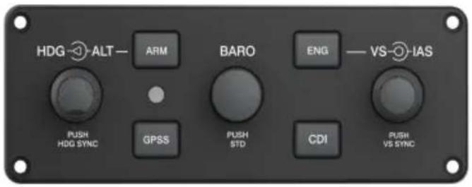

natural_image
Close-up of a metallic industrial sensor or regulator component with a black connector and mounting bracket (no visible text or symbols)GCU 485 Features
- Control knobs offer alternative ways to adjust reference bugs and barometric settings
- Push button configuration depends on the interfacing autopilot: CDI, GPSS, ARM, and ENG
- Lighting may be controlled by the aircraft lighting or the internal photocell (dependent upon configuration)
PFD CONTROLLER OPTIONS
| ALT Sets the selected altitude bug. | |
| HDG Sets the selected heading bug. | |
| BARO | Sets the selected barometric pressure value. Pushing the knob reverts the setting to standard. |
| IAS Sets the selected indicated airspeed. | |
| VS Sets the selected vertical speed. | |
| ARM Arms the autopilot altitude capture function. | |
| CDI Changes the NAV source for the CDI. | |
| ENG Engages the autopilot vertical speed mode. | |
| GPSS Engages or disengages GPSS mode. | |
1.34.5 Backup Battery
An optional GBB 54 backup battery provides emergency power to a GDU display, integrated ADAHRS, and a single GEA 110. The backup battery is mounted remotely and provides power when aircraft power is unavailable. This allows for continued PFD, MFD, and EIS functionality when aircraft electrical power is lost.
| LRU DISPLAY FUNCTION | ||
| GBB 54Alternate emergency power source for GDU 700( ). | PFD | Battery availability and charge/discharge status |
| MFD | ||
| EIS | ||
1.34.6 ADC & AHRS
The ADC and AHRS sense air data and aircraft attitude for display and use by other systems. AHRS units have a magnetometer interface for determining magnetic heading. ADC units have an OAT probe interface for measuring outside air temperature.
| LRU DISPLAY FUNCTION | ||
| GDC 72GDC 74ADC | PFD | Air temperatureAirspeedAltitudeVertical speed |
| GSU 75/75BIntegrated ADAHRS | PFD | ADCAir temperatureAirspeedAltitudeVertical speedAHRSAttitudeHeadingRate of turnSlip/skid/yaw |
| GRS 77GRS 79AHRS | PFD | AttitudeHeadingRate of turnSlip/skid |
1.34.7 PFD Adapter
AUTOPILOT INTERFACE
| LRU DISPLAY FUNCTION | ||
| GAD 43Adapter | PFD | Analog attitude, heading,and yaw data for certain autopilots1 |
| GAD 43eEnhanced Adapter | PFD | Altitude preselectVS controlYaw damperDMENAVADF RAD ALT |
^1 Requires GRS 77/GRS 79/GSU 75 or internal ADAHRS.
1.34.8 Autopilot
AUTOPILOT ALTITUDE PRESELECT/VERTICAL SPEED
| LRU DISPLAY FUNCTION | ||
| Collins:APS-65( ) | PFD | Selected altitude sync |
| Honeywell(Bendix King):KAP 100/150KFC 150KFC 200/250KFC 275/325 | Altitude capture armedannunciationAltitude capture engagedannunciationSelected altitude syncSelected VS sync^1 VS engaged annunciation ^1 | |
| S-TEC:55X60-26560 PSS | Selected altitude syncSelected VS sync | |
^1 KAP 150 and KFC 150/275/325 only.
AUTOPILOT EXTERNAL FLIGHT DIRECTOR
| LRU DISPLAY FUNCTION | |
| Bendix: M-4D | |
| Century: IV 41 2000 | |
| Cessna: 300B IFCS/400B IFCS/800B IFCS 1000 IFCS | |
| Collins: APS-65 AP-106/107 | PFD External flight director |
| Honeywell (Bendix King): KFC 150/200/250 KFC 225/275/325 KFC 300 | |
| S-TEC: 55 55X 60-2/65 1500/2100 | |
| Sperry: SPZ-200/500 | |
| LRU DISPLAY FUNCTION | ||
| Avidyne:DFC90 | PFD | Mode annunciationsBug syncFlight Director |
| Garmin:GFC 500GFC 600 | PFD | Electronic Stability and Protection annunciations1,2Overspeed/underspeed protection annunciations3Mode annunciations4Bug sync5Flight Director |
^1 ESP roll engagement limits display differently between autopilots.
^2 Available only when ESP is enabled and AP is disengaged.
^5 Available only when AP is engaged and aircraft exceeds minimum or maximum engagement speed.
^4 Track mode annunciation available only on GFC 500.
^5 Includes value display and control for ALT, HDG, IAS, and VS. BARO sync, CDI source selection, and Selected Course sync output to primary attitude indicator when interfaced with G5 Electronic Flight Instrument.
1.34.9 Weather & Music
| LRU DISPLAY FUNCTION | ||
| GDL 69/69A SXMGarmin SiriusXM receiver for weather.Overlays weather products on MFD and HSI Map. | PFD | Weather Products• NEXRAD• SXM Lightning• TFRs |
| MFD | Weather Products1Map Page:• NEXRAD• Cloud Tops• Echo Tops• SXM Lightning• METARs• Storm Cells• TFRsWeather Page:• AIREP• NEXRAD• City Forecast• Cloud Tops• County Warnings• Cyclone• Echo Tops• Winds Aloft• Surface Pressure• SXM Lightning• Storm Cells• METARs• AIRMETs• SIGMETs• TFRs• PIREPs• Freezing Levels• Turbulence Forecast• Icing Forecast | |
| GDL 69A SXMGarmin SiriusXM receiver for entertainment. | MFD | Entertainment ServicesSiriusXM Radio |
| GDL 88GTX 345GNX 375Datalink traffic and weather. | PFD Traffic ServicesMFD | ADS-BTIS-BWeather ServicesFIS-B |
| GSR 56Garmin (Iridium) Satellite Receiver for Connext weather.Overlays weather products on MFD and HSI Map. | PFD | Weather ProductsLightningPrecipTFRs |
| MFD | Weather ProductsMap Page:PrecipIR SatelliteLightningMETARsWeather Page:PrecipIR SatelliteWinds AloftLightningMETARs/TAFsAIRMETsSIGMETsTFRsPIREPs | |
| WX-500Depicts Stormscope data on MFD and HSI Map. | PFD | Lightning strikes |
| MFD | ||
| Garmin:GWX 68GWX 70GWX 75Provides airborne weather radar information.6 | MFD | Ground, standby, test, and weather modesHorizontal and vertical profilesRoll/trimStabilizationSector scanAltitude compensated tilt2,3High resolution color scale3Tilt limit (vertical sector scan)WATCH shadingTarget alertRangeTilt angleBearing angleGainGWX 70/75 Features4Turbulence DetectionGround Clutter Suppression |
| Honeywell(Bendix King)4:RDS 81 (RS 811A)RDS 82 (RS 181A)RDR 2000 (ART 2000)RDR 2100 (ART 2100)Third-party weather radar.6 | Ground, standby, test, and weather modesHorizontal profileVertical profile5Roll/trimStabilizationRangeTilt angleBearing angle5Gain (ground mode) | |
^1 Product availability dependent upon subscription. ^2 GWX 70 only. ^3 GWX 75 only.
^4 Requires purchase of an enablement card. ^5 Feature dependent on radar.
^b Not available on GDU 700() EIS/MFD configurations.
1.34.10 Engine Monitoring
RECIPROCATING ENGINES
| LRU DISPLAY FUNCTION | ||
| GEA 110Garmin Engine Adapter.Monitors engine, fuel,and electrical systems forpiston engine aircraft. | EIS | Manifold PressureRPMPercent PowerFuel FlowOil PressureOil TemperatureEGTCHTTITIATFuel QuantityVoltsAmpsEngine DataVacuum/PressureFlight Control Trim Position |
TURBINE ENGINES
| LRU DISPLAY FUNCTION | ||
| GEA 71BGEA 71B EnhancedGEA 71CGarmin Engine Adapter.Monitors engine, fuel,and electrical systems forturbine aircraft. | EIS. | Propeller RPMGas Producer RPMTorqueShaft HorsepowerPercent PowerEngine TemperatureFuel FlowFuel PressureFuel TemperatureFuel QuantityIATOAT ^1 Oil PressureOil TemperatureVoltsAmpsEngine DataVacuum/PressureFlight Control Trim Position |
^1 Available with TXi software v3.21 and later.
1.34.11 Magnetometer
| LRU DISPLAY FUNCTION | ||
| GMU 44/44BProvides magnetic information to the AHRS. | PFD | HeadingCompass |
1.34.12 Navigation/FMS
| LRU DISPLAY FUNCTION | ||
| GPS 175 | PFD | ILSAVOR ^1 LOC ^1 GPS positionGS ^1 |
| GPS 400W | ||
| GPS 500W | ||
| GNC 355 | ||
| GNC 420W | MFD | GPS position |
| GNS 430W | ||
| GNS 480 | ||
| GNS 530W | ||
| GNX 375 | ||
| GTN 625 | ||
| GTN 625Xi | ||
| GTN 635 | ||
| GTN 635Xi | ||
| GTN 650 | ||
| GTN 650Xi | ||
| GTN 725 | ||
| GTN 725Xi | ||
| GTN 750 | ||
| GTN 750Xi | ||
^1 Feature requires a NAV radio source.
1.34.13 Temperature Probe
| LRU DISPLAY FUNCTION | ||
| GTP 59 | PFD | Outside air temperature |
| EIS | ||
| Airframe Temperature Probe | EIS | Outside air temperature used for setting engine power |
1.34.14 Radar Altimeter
| LRU DISPLAY FUNCTION | ||
| Garmin:GRA 55/5500 | PFD | Radar altitude(next to altitude tape) |
| Collins:RAC-870ALT-50AALT-55B | ||
| FreeFlight:RA-4500 | ||
| Honeywell(Bendix King):KRA 10/10AKRA 405/405B | ||
| Sperry:AA-100AA-100AAA-200 | ||
1.34.15 Traffic
| LRU DISPLAY FUNCTION | ||
| GTX 33 | PFD | TIS-A |
| GTX 330 | MFD | |
| GTX 335 | ||
| GTX 345 | ||
| Garmin: | ||
| GTS 800 | PFD TAS/TCAS I | |
| GTS 820 | ||
| GTS 825 | ||
| GTS 850 | ||
| GTS 855 | ||
| GTS 8000 PFD/MFD TCAS II | ||
| Avidyne (Ryan): | ||
| TAS 6XX (9900BX) | MFD TAS/TCAS I | |
| Honeywell(Bendix King): | ||
| KTA 810 | ||
| KMH 820 | ||
| KTA 910 | ||
| KMH 920 | ||
| L3 Communications(Goodrich): | ||
| SKY497 | ||
| SKY899 | ||
| GDL 88 | PFD | ADS-B |
| GNX 375 | MFD | |
| GTX 345 | ||
| Third-party TCAS II PFD/MFD TCAS II | ||
INTENTIONALLY LEFT BLANK
2 Primary Flight Display
PFD SETUP
2.1 Synchronization Options....2-5
2.2 Reference Bugs and Controls....2-6
FLIGHT INSTRUMENTS
2.3 Attitude Indicator 2-11
2.4 Extreme Attitude Indications.... 2-14
2.5 VNAV Guidance Indications 2-16
2.6 Airspeed Indicator 2-18
2.7 Barometric Altimeter 2-22
2.8 VSI 2-31
2.9 Horizontal Situation Indicator 2-34
2.10 CDI....2-40
2.11 LDI 2-46
2.12 VDI....2-47
2.13 CDI/VDI Preview 2-49
SUPPLEMENTAL FLIGHT DATA
2.14 Bearing Pointers 2-52
2.15 GPS NAV Status Field....2-54
2.16 Relative Wind Data 2-55
2.17 Temp/DALT Display....2-56
2.18 DME Display 2-57
2.19 Marker Beacon Symbols ....2-58
2.20 Radar Altitude 2-59
2.21 AGL Display....2-61
2.22 GPS Roll Indicator 2-62
2.23 G-meter 2-63
2.24 Clock/Timer 2-64

The PFD menu provides access to various controls, sub-menus, and setup options.
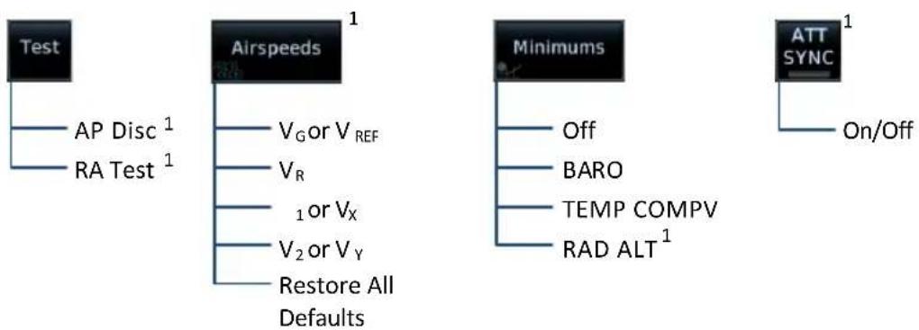
flowchart
graph TD
    A["Test"] --> B["AP Disc 1"]
    A --> C["RA Test 1"]
    D["Airspeeds 1"] --> E["V_G or V_REF"]
    D --> F["V_R"]
    D --> G["1 or V_X"]
    D --> H["V_2 or V_Y"]
    D --> I["Restore All Defaults"]
    J["Minimums"] --> K["Off"]
    J --> L["BARO"]
    J --> M["TEMP COMPV"]
    J --> N["RAD ALT 1"]
    O["ATT SYNC 1"] --> P["On/Off"]
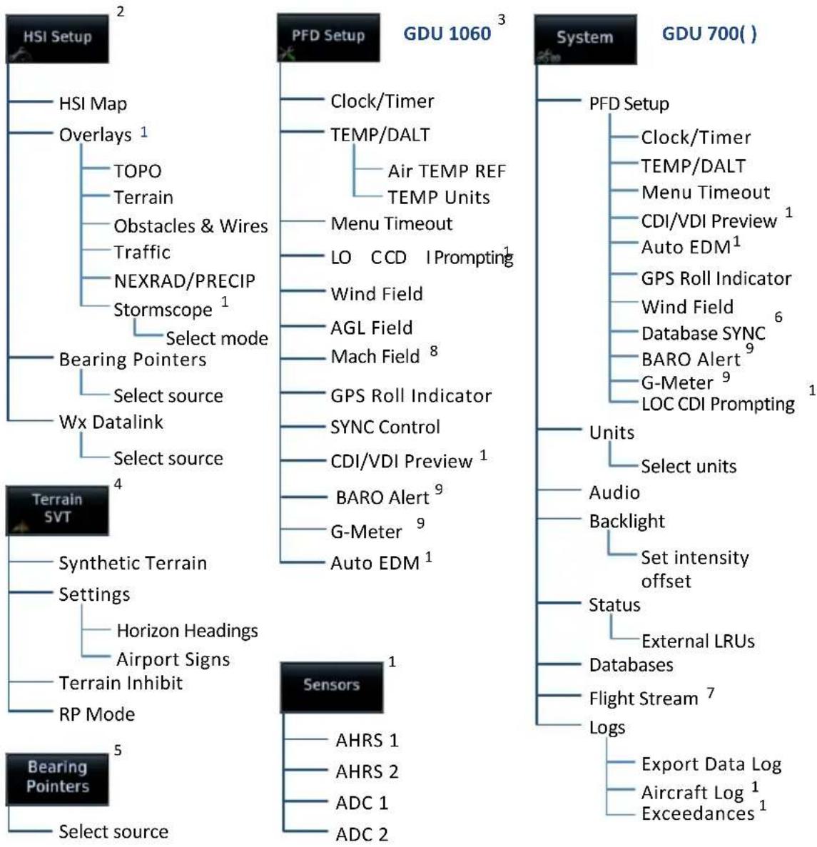
flowchart
graph TD
    A["HSI Setup"] --> B["HSI Map"]
    A --> C["Overlays 1"]
    C --> D["TOPO"]
    C --> E["Terrain"]
    C --> F["Obstacles & Wires"]
    C --> G["Traffic"]
    C --> H["NEXRAD/PRECIP"]
    C --> I["Stormscope 1"]
    I --> J["Select mode"]
    J --> K["Bearing Pointers"]
    K --> L["Select source"]
    L --> M["Wx Datalink"]
    M --> N["Select source"]
    N --> O["Terrain SVT"]
    O --> P["Synthetic Terrain"]
    P --> Q["Settings"]
    Q --> R["Horizon Headings"]
    Q --> S["Airport Signs"]
    Q --> T["Terrain Inhibit"]
    Q --> U["RP Mode"]
    U --> V["Bearing Pointers"]
    V --> W["Select source"]

    A --> X["PFD Setup"]
    X --> Y["GDU 1060 3"]
    Y --> Z["Clock/Timer"]
    Y --> AA["TEMP/DALT"]
    AA --> AB["Air TEMP REF"]
    AA --> AC["TEMP Units"]
    Y --> AD["Menu Timeout"]
    AD --> AE["LO CCD Prompting 1"]
    AD --> AF["Wind Field"]
    AF --> AG["AGL Field"]
    AG --> AH["Mach Field 8"]
    AH --> AI["GPS Roll Indicator"]
    AI --> AJ["SYNC Control"]
    AJ --> AK["CDI/VDI Preview 1"]
    AK --> AL["BARO Alert 9"]
    AL --> AM["G-Meter 9"]
    AM --> AN["Auto EDM 1"]

    A --> AO["System"]
    AO --> AP["GDU 700( )"]
    AP --> AQ["PFD Setup"]
    AQ --> AR["Clock/Timer"]
    AQ --> AS["TEMP/DALT"]
    AQ --> AT["Menu Timeout"]
    AQ --> AU["CDI/VDI Preview 1"]
    AQ --> AV["Auto EDM 1"]
    AQ --> AW["GPS Roll Indicator"]
    AW --> AX["Wind Field 6"]
    AX --> AY["Database SYNC 6"]
    AY --> AZ["BARO Alert 9"]
    AZ --> BA["G-Meter 9"]
    BA --> BB["LOC CDI Prompting 1"]

    AO --> BC["Units"]
    BC --> BD["Select units"]
    BC --> BE["Audio"]
    BE --> BF["Backlight"]
    BF --> BG["Set intensity offset"]

    AO --> BH["Status"]
    BH --> BI["External LRUs"]
    BH --> BJ["Databases"]
    BJ --> BK["Flight Stream 7"]
    BK --> BL["Logs"]

    AO --> BM["Export Data Log"]
    BM --> BN["Aircraft Log 1"]
    BN --> BO["Exceedances 1"]
^1 Dependent upon unit configuration. ^2 Not available on GDU 700L PFD.
^3 Units, audio, backlight, status, and database options are located in the System page of the MFD.
^4 Menu functions pertain to the specified terrain function. ^5 GDU 700L only.
^b In multi-PFD systems, a SYNC Control page access key replaces Database SYNC. Options are dependent upon display type. ^7 Feature requires Flight Stream 510 wireless datacard.
^8 Available when configured for M_MO . ^9 Available with TXi software v3.21 and later.
PFD Setup
For GDU 700(), setup selections are accessible from the System Menu key.
| PFD SYSTEM SELECTIONS, GDU 700( ) | |
| PFD Setup | Access CDI/VDI Preview, Auto EDM,LOC CDI Prompting, and Wind Field functionsAccess synchronization options (BARO, CDI, and DB)Control clock/timerControl Outside Air Temp/Density Altitude displayToggle Wind Field on or offSet menu display timeoutControl Database SYNCToggle AGL Field on or offToggle Mach Field on or offToggle GPS Roll Indicator on or offEnable altimeter setting visual prompt (BARO Alert)for a specified transition altitude ^1 Access G-Meter Setup menu options (Display G-Meter,Reset Min/Max) ^1 |
| Units | Except where noted, unit selections synchronize across all configured GDUs. Certain LRUs may contain unit settings independent of the TXi system.NAV Angle BARO PressureTemperature DistanceWind SpeedAltitude unit settings do not affect the altitude tape. |
| Audio Set click vol ume | |
| Backlight Adjust display brightness | |
| Status | View unit and software informationCheck status of all configured LRUs |
| Databases | View information about active and standby databasesPerform a manual database update |
| Flight Stream Access Bluetooth Setup and Wi-Fi Setup menus | |
Logs • Access data, aircraft, and exceedance logs
^1 Available with TXi software v3.21 and later.
For GDU 1060, setup selections are available on the System page of the MFD.
| PFD SETUP SELECTIONS, GDU 1060 | |
| Clock/Timer • Control clock/timer | |
| TEMP/DALT | • Control Outside Air Temp/Density Altitude display• Specify air temperature units and reference type |
| Menu Timeout • Set menu display timeout | |
| LOC CDIPrompting | • Allow prompts for switching the CDI source from GPS to LOC2,3 |
| Wind Field • Control wind field function | |
| CDI/VDIPreview | • Enable preview indicators for VDI Glidepath/Glideslope deviation, and VOR/LOC course and deviation1 |
| Auto EDM • Enable automatic EDM4 | |
| SYNC Control • Access synchronization options (BARO, CDI)5 | |
| DatabaseSYNC | • View information about active and standby databases• Perform a manual database update |
| AGL Field • Display GPS height above terrain (AGL) | |
| Mach Field • Display Mach number when speed exceeds 0.4 Mach6 | |
| GPS RollIndicator | • Display GPS navigator's roll steering command7 |
| BARO Alert | • Enable altimeter setting visual prompt (BARO Alert) for a specified transition altitude8 |
| G-Meter | • Access G-Meter Setup menu options (Display G-Meter, Reset Min/Max)8 |
^1 Available only when a configured GTN is present.
2 Available only when a configured GPS/NAV navigator (GTN 650/750 or GNS 430/530) is present.
^3 For installations with a GFC 600 or GFC 500 autopilot: LOC CDI prompting is suppressed when the autopilot is armed to capture the localizer. The TXi CDI source automatically switches from GPS to LOC once the autopilot couples to the localizer.
4 Available only with GFC 600 installation and cabin altitude threshold configured.
^5 Available for systems with multiple sources. ^6 Available when M_MO value is configured.
^7 Indicator is hidden when flight director is active. ^8 Available with TXi software v3.21 and later.
2.1 Synchronization Options
FEATURE LIMITATIONS
• Multi-PFD systems only
• SYNC Control availability dependent upon configuration

Selecting SYNC Control opens a pop-up menu. Selected functions synchronize across all TXi PFDs.
GDU 1060: The database synchronization option resides on the MFD System Status page.
BARO • Synchronizes the current barometric pressure value 1
CDI SRC • Synchronizes the selected CDI source 2
DB
- Initiates the database synchronization function
- GDU 700() only
^1 Option not available if BARO synchronization function is configured as always on.
^2 Option not available if CDI synchronization function is configured as always on.
2.2 Reference Bugs and Controls
PFD Controls
- Airspeed
- Altitude
• Barometric Correction - Heading
- Vertical Speed
- Selected Course
The PFD relies on touchscreen and control knob interactions for instrument and course adjustments.
Only one control is active at a time. Control automatically reverts to heading 10 seconds after the last entry is made.
Additional information shown is determined in menu and setup, including synthetic vision depictions and HSI Map overlays.
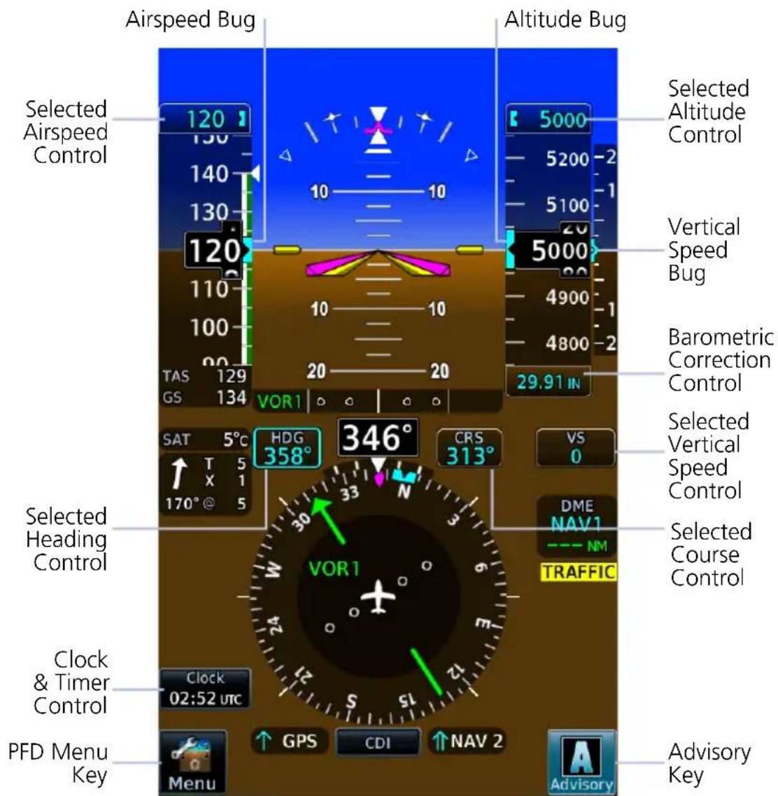
Reference Bugs & Controls
SETTING A REFERENCE BUG
Selecting any control opens a dedicated menu. Available options are dependent upon system configuration.
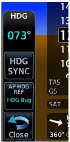
GDU 700L
On GDU 700L: Menu slides out from the left side of the screen.
On GDU 700P/1060: Menu slides up from the bottom of the screen.
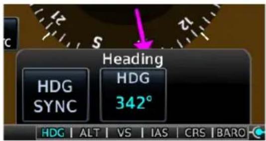
GDU 700P/1060
There are three methods for operating PFD controls:
1. Touch and Turn
Touch the control to move knob focus to that control, then:
• turn inner knob to change the selected value
OR
- push knob to synchronize with the current value
2. Turn and Turn
Turn outer knob to move knob focus to the desired control, then:
• turn inner knob to change the selected value
OR
- push knob to synchronize with the current value
3. Touch and Touch (GDU 700P/1060)
Touch the control and use the keys provided in the associated context menu.
• Center key opens a keypad for numeric entries
• Additional controls reside on the left and right
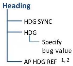
flowchart
graph TD
    A["Heading"] --> B["HDG SYNC"]
    A --> C["HDG"]
    C --> D["Specify bug value"]
    C --> E["AP HDG REF 1,2"]
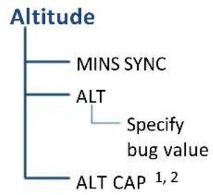
flowchart
graph TD
    A["Altitude"] --> B["MINS SYNC"]
    A --> C["ALT"]
    C --> D["Specify bug value"]
    C --> E["ALT CAP 1, 2"]
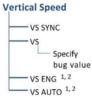
flowchart
graph TD
    A["Vertical Speed"] --> B["VS SYNC"]
    A --> C["VS"]
    C --> D["Specify bug value"]
    C --> E["VS ENG 1,2"]
    C --> F["VS AUTO 1,2"]
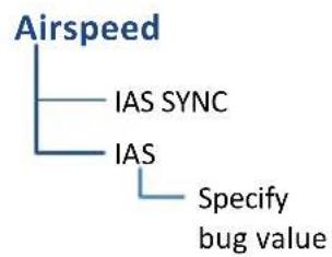
flowchart
graph TD
    A["Airspeed"] --> B["IAS SYNC"]
    A --> C["IAS"]
    C --> D["Specify bug value"]
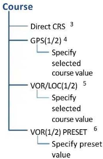
flowchart
graph TD
    A["Course"] --> B["Direct CRS 3"]
    A --> C["GPS(1/2) 4"]
    C --> D["Specify selected course value"]
    A --> E["VOR/LOC(1/2) 5"]
    E --> F["Specify selected course value"]
    A --> G["VOR(1/2) PRESET 6"]
    G --> H["Specify preset value"]
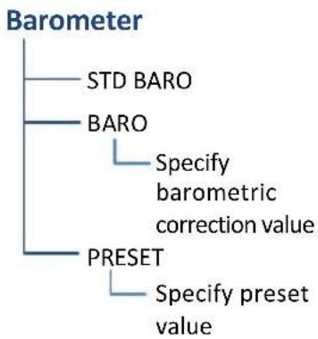
flowchart
graph TD
    A["Barometer"] --> B["STD BARO"]
    A --> C["BARO"]
    C --> D["Specify barometric correction value"]
    A --> E["PRESET"]
    E --> F["Specify preset value"]
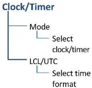
flowchart
graph TD
    A["Clock/Timer"] --> B["Mode"]
    B --> C["Select clock/timer"]
    B --> D["LCL/UTC"]
    D --> E["Select time format"]
Reference Controls & Menu Options
^1 Requires an autopilot. ^2 Not applicable to all autopilots. ^3 Requires an active GPS source.
^4 Available during OBS mode only. ^5 Available only when VOR/LOC is the active CDI source.
^6 Preset course functionality not available when GDU 620 is present (multi-PFD systems only).
Flight Instruments
Supplemental Flight Data
• GPS Navigation Status
• DME
- Radar Altitude
- Wind
- Clock/Timer
The top portion of the display provides attitude and air data.
The lower portion provides a horizontal situation indicator and supplemental flight data fields.
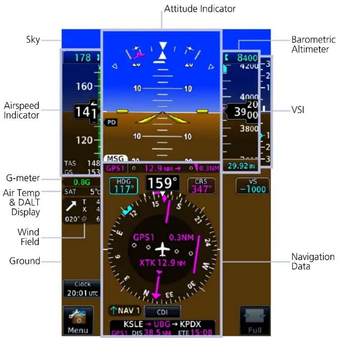
PFD Portrait Layout
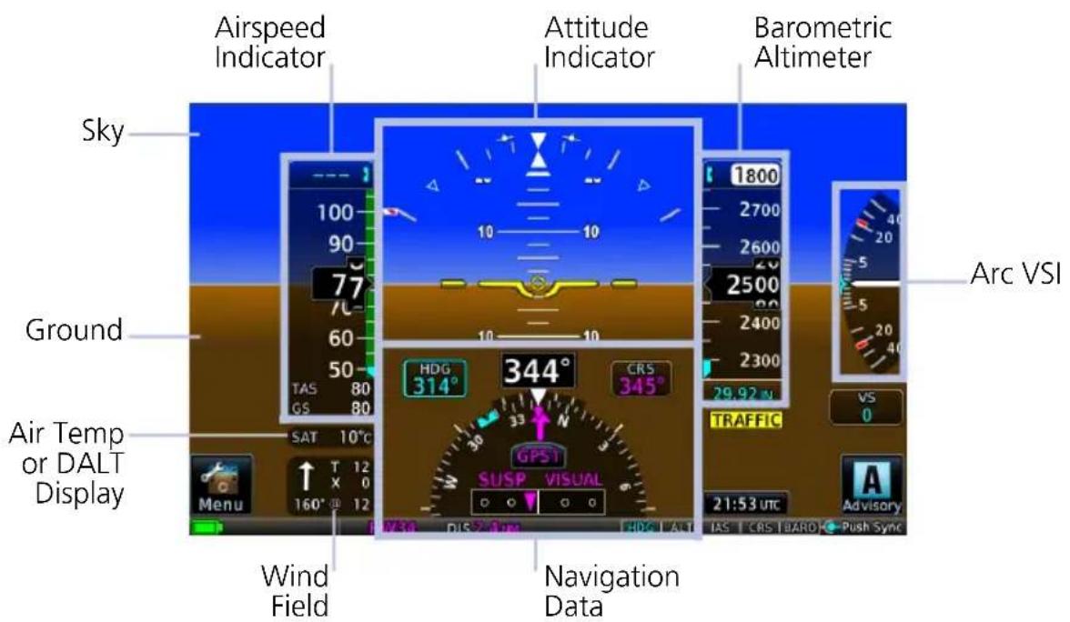
PFD Landscape Layout, Rotorcraft
2.3 Attitude Indicator
The attitude indicator provides a virtual representation of the ground and sky.
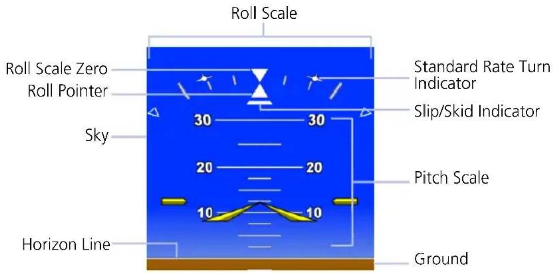
ROLL POINTER

natural_image
Abstract blue background with white geometric shapes and arrows (no text or symbols)Fixed Pointer

natural_image
Blue background with white triangular symbols and numbers, no readable text or labelsSky Pointer
The roll pointer indicates angle of bank at varying degrees on the roll scale.
Pointer type is configured at installation as either fixed or sky.
• Major tick marks: 30^ and 60^
• Minor tick marks: 10^ , 20^ , and 45^
STANDARD RATE TURN INDICATORS
Standard Rate Turn Indicators
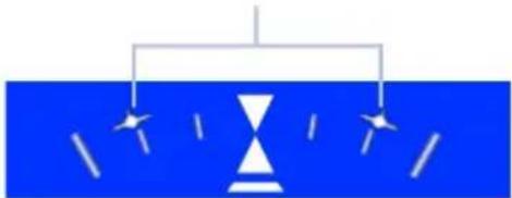
natural_image
Simple diagram of a hourglass with arrows indicating direction (no text or symbols)• Show the required bank angle needed to maintain a standard rate turn
• Dynamically change position based on True Airspeed
- Remain at 30° when TAS is at or above 210 kts
Standard rate turn indicators are removed when:
- TAS is invalid
• TAS is less than 60 kts
• Aircraft is on the ground
SLIP SKID INDICATOR
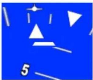
natural_image
Abstract blue background with white geometric shapes and a starburst (no text or symbols)- Moves laterally away from roll pointer center (max 7° side-slip indication)
- Alignment with roll pointer denotes coordinated flight
- If attitude data becomes invalid, slip/skid indicator is removed
PITCH SCALE
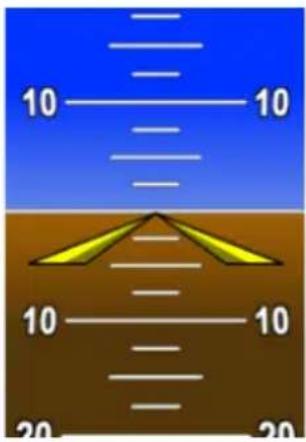
- Markings range between -90^ and 90^ angles
• Major pitch graduations occur every 5° with SVT and 10° without SVT
• Each minor pitch mark is 5^ from 25^ nose down to 45^ nose up - Precision pitch marks are at each 2.5° from 20° nose up to nose down attitude
AIRCRAFT SYMBOL

Fixed Wing

Rotorcraft
Depending on aircraft type, aircraft symbol is either fixed wing or rotorcraft.
Symbol type is dependent upon configuration. For requirements, consult the POH.
AWARENESS BANDS
Ground Awareness Band Sky Awareness Band
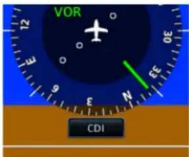
Appears when current pitch attitude causes the sky presentation to completely fill the display.
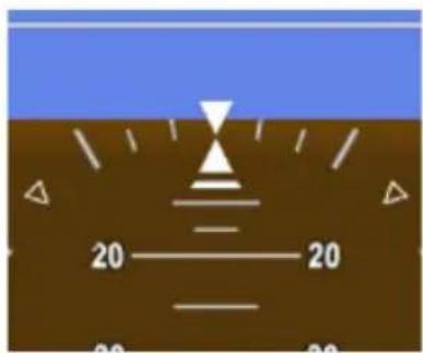
Appears when current pitch attitude causes the ground presentation to completely fill the display.
2.3.1 Attitude Sync
ROTORCRAFT ONLY

FEATURE LIMITATIONS
• Availability dependent upon configuration
Function disables when:
• Current pitch and horizon line differ by more than +/-8°
• Attitude data is invalid
ATT SYNC KEY

- Synchronizes aircraft symbol to the horizon line for all configured GDUs
• Reference marks provide an absolute pitch reference
• Useful during pitch up or pitch down maneuvers

natural_image
Pure diagram of a yellow valve or connector on a brown base with blue background (no text or symbols)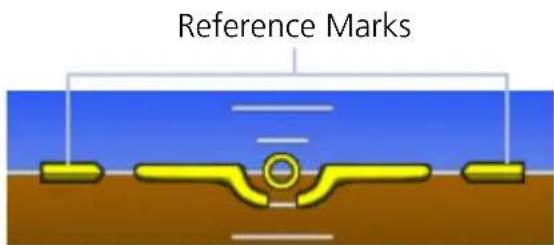
Attitude Sync OnAttitude Sync Off
2.4 Extreme Attitude Indications
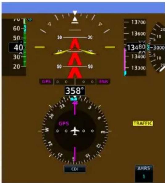
Extreme Pitch
To aid in recovery from extreme pitch attitude, red chevrons are shown between major pitch marks from 80° nose down to 30° nose down, and from 80° nose up to 50° nose up. Red chevrons always point toward 0° pitch.
The PFD employs an extreme attitude declutter mode to improve instrument scan and facilitate aircraft recovery from extreme attitudes.
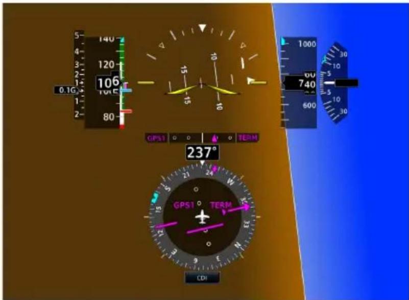
Extreme Roll
The PFD declutters if pitch exceeds 20^ nose down or 30^ nose up, or if bank angle exceeds 65^ . When decluttered, HSI Map reverts to a standard HSI depiction until the PFD exits extreme attitude declutter mode.
The HSI Map option is accessible from the PFD menu. For information about this advanced feature, read HSI Map in section 3.
Data removed during extreme attitudes
- Open menus and keyboards • Fast/Slow indicator
• GS • CDI source selection key
• TAS • PFD Menu key
• Air temperature • PFD Full key (GDU 1060 only)
• Flight director command bars • Standard rate turn indicators - Marker beacon annunciation • GPS height above terrain (AGL)
• Vertical deviation indicator • Wind field - Clock/timer • Selected heading
- Selected Altitude control • Selected course
• Vertical Speed control • Barometric pressure setting - Selected IAS • DME
- Bearing pointer information field(s) • Advisory key
• GPS navigation status
AHRS(1/2) KEY

- Allows pilot to change the current AHRS source while extreme attitude decluttering is in effect
- Replaces PFD Menu key during extreme attitudes
2.5 VNAV Guidance Indications

WARNING
Do not rely solely on VNAV guidance when navigating horizontally and vertically around user-defined airports. It is the pilot's responsibility to ensure separation from terrain and obstacles during an approach to a user-defined airport.
FEATURE REQUIREMENTS
- Configured GTN (v6.50 and later)
- Valid VNAV data
• GFC 500/600 for autopilot VNAV mode status annunciation
The vertical navigation (VNAV) feature provides vertical profile guidance during the descent phase of flight. Guidance is based on altitude constraints associated with lateral waypoints in the active flight plan.
VNAV Guidance Function
- Presents vertical path guidance along the descent as either a line joining two waypoints with specified altitudes or a desired linear vertical path (i.e., the vertical angle from the specified waypoint or altitude)
• Integrates vertical waypoints into the active flight plan
• Supports both manual and autopilot coupling
VNAV PFD INDICATIONS
VNAV data received from the navigator display as magenta indications on the PFD.
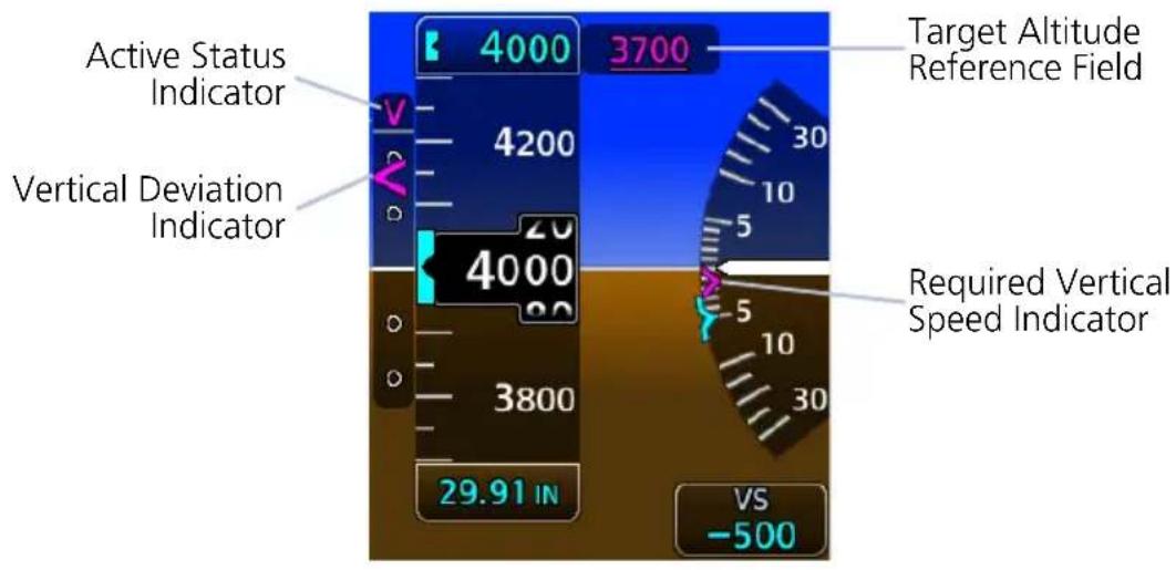
INDICATOR VNAV DATA
| Barometric Altimeter | • Target altitude reference field• Modified selected altitude knob increments |
| VSI • Required vertical speed indication | |
| VDI • VNAV source and vertical deviation indications | |
| AFCS Status Box | • VNAV mode annunciation (requires Garmin autopilot) |
2.6 Airspeed Indicator
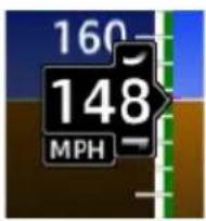
Airspeed indicator is configured at installation to meet the requirements of the AFM/POH. Available units:
knots (default), kilometers per hour, and statute miles per hour.
Supports ten custom airspeed tape markings with installer configurable labels.
For required airspeed limitations and markings, refer to the aircraft AFM/POH.
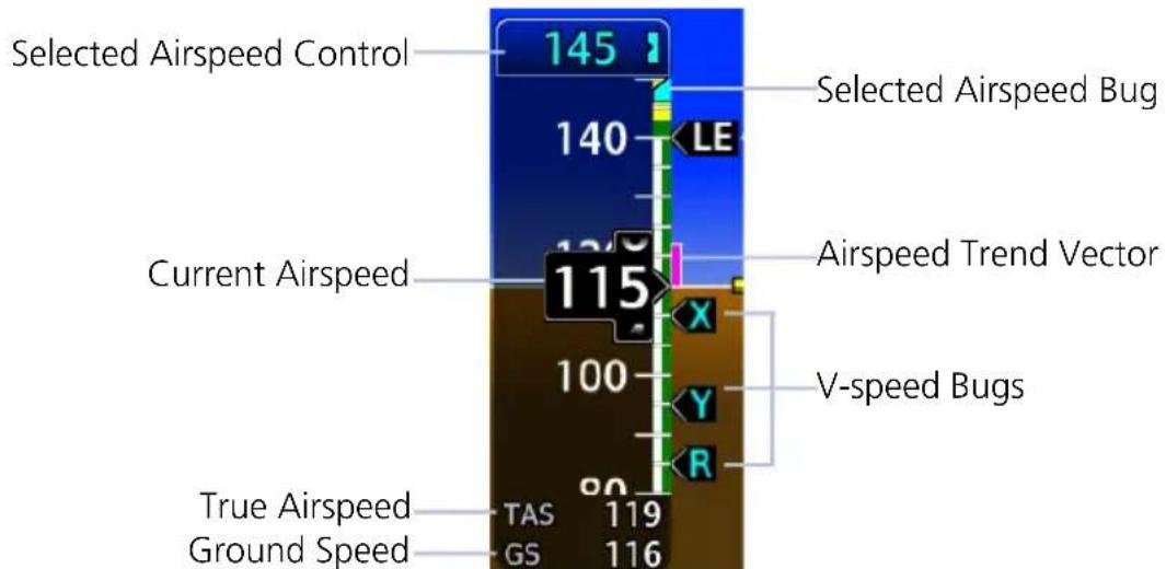
bar
| Airspeed Type | Value | | -------------------------- | ----- | | Selected Airspeed Control | 145 | | Current Airspeed | 115 | | True Airspeed | 119 | | Ground Speed | 116 |IAS, Fixed Wing
Airspeed Indicator Function
- Provides indicated airspeed, true airspeed, and ground speed
- Provides Mach numbers above Mach 0.4 when M_MO is set. Mach indicator is hidden below Mach 0.4
- A fixed pointer, with rolling number gauge, indicates current airspeed on a moving tape
• Actual airspeed tape colors and markings vary by installation - Data fields display true airspeed, ground speed, and, for some configurations, Mach
• As airspeed increases, tape scrolls down
AIRSPEED CONTROLS & INDICATIONS
| Selected Airspeed | Sets airspeed bug on tape if configuredBoth the bug and its digital value display in cyanAutomatically synchronizes across all connected TXi PFDsNot selectable during EDM selected data lockout (both field and bug turn gray) |
| Airspeed Trend Vector | Magenta trend vector at the right of the airspeed tape6 second prediction of airspeed based on current accelerationRemoved if airspeed remains constant or if any data necessary to calculate airspeed is not available due to a system failure |
| Speed Range Strip | Multi-colored strip at the right of the moving tapeActual colors and patterns vary according to aircraft type |
| Selected Airspeed Bug | Set using the selected airspeed controlPresent on the right, inboard side of the tape if configuredParks at the top or bottom of the tape when selected airspeed is outside the visible rangeChanges from cyan to gray during EDM selected data lockout |
2.6.1 Reference Markings
FIXED WING
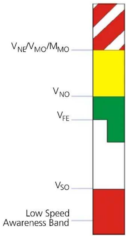
bar_stacked
| Category | Value | | -------- | ----- | | V_NE/V_MO/M_MO | 100 | | V_NO | 80 | | V_FE | 60 | | V_SO | 40 | | Low Speed Awareness Band | 20 |The V_NE/V_MO barber pole and V_NO yellow range are configurable as fixed values or variable values that change with altitude. M_MO may be configured when a variable V_NE/V_MO is configured.
For configurations with multiple variable V_NE/V_MO/M_MO or V_NO values, the bottom of the indicating range and alerting parameters extend to the lowest airspeed based on calculations.
For fixed wing installations, exceeding a variable V_NE/V_MO/M_MO value creates an airspeed exceedance entry.
A white triangle reference marking is configured for airframes that are placarded with approach flap speed limitations.
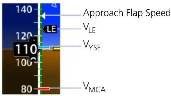
ROTORCRAFT
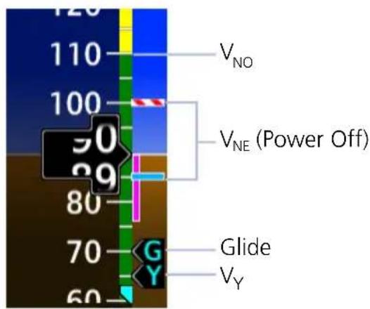
Two types of markings are available for denoting maximum auto rotation speed ( V_NE power off). This option is configured during installation.
Variable V_NE is based on values in the airspeed limitations placard.
OVERSPEED INDICATIONS

bar
| Category | Value | |---|---| | M | 0.459 | | TAS | 274 | | GS | 274 |Current airspeed and Mach values turn yellow when the trend vector enters the overspeed range.
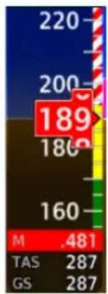
heatmap
| Category | Value | |---|---| | M | .481 | | TAS | 287 | | GS | 287 |Indicator backgrounds turn red when current airspeed exceeds V_NE/V_MO/M_MO .
2.6.2 Reference Speeds
Selectable airspeed reference bugs are available for both fixed wing aircraft and rotorcraft. On/off controls reside in the Airspeeds page of the PFD menu.
Fixed wing Reference Speeds:
Glide or V_REF
V_Y or V2 V
x or V1 V
R
Rotorcraft Reference Speeds:
Glide V
Y
V_X , V_Y , V_R and Glide default values are set during the installation process. V-speeds can be set for an individual flight, but will default back to install presets after a power cycle. When active (on), the V-speeds are displayed at their appropriate locations on the right of the airspeed tape.
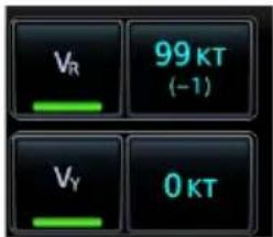
A positive or negative value indicates the difference between the currently selected V-speed and its default value.
Tapping Restore All Defaults resets all V-speeds to their default values.
2.6.3 Fast/Slow Indicator
PC-12 AIRCRAFT ONLY

The Fast/Slow indication displays on left edge of the PFD. The indicator shows when indicated airspeeds are less than 150 KIAS. For details on operation, consult the POH/AFM.
2.7 Barometric Altimeter
FEATURE LIMITATIONS
• 20 ft (20 m) digital resolution
• Range: -1,000 to 99,000 ft (-305 to 30,175 m)
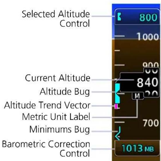
Barometric altitude is displayed on a moving tape with a fixed pointer and digital readout.
Units are either feet or meters depending on configuration. A metric unit label displays for metric altitudes.
Altimeter tape limits are configured to match aircraft performance. For more information, consult the AFM/POH.
ALTIMETER CONTROLS & INDICATIONS
| Selected Altitude | Sets altitude bug on altimeter when configuredBug automatically synchronizes across PFDsIf barometric minimums is set, selected altitude may be set to same value as barometric minimumsDetermines visual and aural alerts for approaching and deviating from selected altitude.Not selectable during EDM selected data lockout (both field and bug turn gray)Provides source data for the range to altitude arc display on MFD map (GDU 1060 only)Controls altitude preselect mode for various autopilotsBug is removed upon system startup or by rotating control knob to a value <-1,000 ft |
| Altitude Trend Vector | Magenta trend vector at the left of the altitude tape6 second prediction of altitude based on current vertical speedAbsent if aircraft altitude remains constant or if data needed for rate calculation is not available due to a system failure |
| Barometric Correction Control | Displays in cyan digits at the bottom of altimeter tapePilot can select units to display in inches of mercury (in Hg), Hectopascals (hPa), or Millibars (Mb)Digits display in yellow when pilot and co-pilot TXi PFD settings differ by more than 0.03 in HgBarometric Pressure Setting to 29.92 in. / 1013 Mb setting when STD BARO is selected |
| Minimums Bug | Displays as a colored bracket for selected MDA/DH minimums set on the altimeter tapeBug is parked to the top or bottom of altimeter tape when value is outside current visible rangeCyan bracket denotes BARO or RAD ALT minimums altitudeMagenta bracket denotes TEMP COMP minimums altitudeWhite bracket denotes close proximity above minimums altitudeYellow bracket denotes below minimumsTriggers “Minimums, Minimums” aural alert at MDA/DHs |
ALTIMETER CONTROLS & INDICATIONS
Altitude Bug
- Set using the Selected Altitude
- A portion of the bug displays at the top or bottom of the altitude tape if selected Altitude Bug is out of visible range
- Bug width is 100 units wide, depicting (+/-) 50 unit increments
• Turns gray during EDM selected data lockout
TARGET ALTITUDE REFERENCE FIELD
The location of this field varies depending on PFD layout.

GDU 1060/700L (Full Screen View)

GDU 700P GDU 700L (Menu Open) GDU 1060 (MFD/PFD/EIS)
Magenta bars indicate target altitude type. The position of the target altitude value (above or below a single bar, or between two bars) denotes where the aircraft should be relative to the displayed altitude.

At or above target altitude

At target altitude

At or below target altitude
2.7.1 Adjusting Barometric Pressure

Controls for adjusting barometric pressure reside in the Barometer control menu.
| STD BARO | Toggles between standard barometric pressure and the pilot specified value |
| BARO | Allows entry of selected barometric pressure valueAvailable only when STD BARO is inactive |
| PRESET | Allows entry of destination barometric pressure while the aircraft is above transition level (FL 180)Preset does not affect altimeter readoutTransitioning from standard to preset sets the altimeter to the preset valueAvailable only when STD BARO is active |

When STD BARO is active:
- The barometric setting field below the altimeter annunciates STD
- The barometer preset value may be changed
- Changes to the preset value are displayed in a pop-up field above the barometric setting field
SET BAROMETRIC PRESSURE
- Tap the barometric setting field or turn the PFD control knob to select the field.
- Push the inner control knob or tap the STD BARO key to select standard barometric pressure or pilot-selected barometric pressure.
- If STD BARO is active, turn the inner knob or tap the PRESET key to set the barometer preset value.
- If STD BARO is not active, turn the inner knob or tap the BARO key to set the barometer current value.
2.7.2 Adjusting Selected Altitude
FEATURE REQUIREMENTS
The MINS SYNC function is available only when the following conditions are met.
- Minimums source is configured as barometric altimeter or temperature compensated barometric altimeter
• BARO source key is active
• A valid minimums altitude setting

Adjustments to the selected altitude value cause the alert function to reset.
MINS SYNC • Synchronizes altimeter bug to the MDA/DH setting
ALT
- Allows entry of a selected altitude value
• Inner knob adjustments are in 100 ft increments
SELECTED ALTITUDE ALERTING
Visual and aural indications alert when the aircraft is approaching the selected altitude.
| DISTANCE FROM SELECTED ALTITUDE | INDICATION1 |
| 1,000 ft | Flashing black text on white backgroundOptional aural tone2 |
| 200 ft | Flashing cyan text on black backgroundOptional aural tone2 |
| 0 ftAltitude deviates more than ±200 ft from selected altitude | Flashing yellow text on black backgroundAural tone |
^1 Alert duration: five seconds. ^2 Aural tone dependent upon configuration.
DISABLE ALTITUDE BUG

Turn inner knob counterclockwise until the selected altitude value is < -1,000 ft. Values less than -1,000 display as a series of dashes.
2.7.3 Temperature Compensation Minimums
FEATURE REQUIREMENTS
- The TEMP COMP minimums function is available only when a destination airport is present on the external navigator
• Cycling power to the GDU clears all minimums data
GTNs and TXi displays use only one destination airport temperature for calculating compensated altitudes. Changing the temperature on one of these units automatically recalculates the value across all connected GTNs and GDUs.
TEMP COMP KEY

• Calculates compensated altitude for the destination airport
• Indicates temperature compensated minimums on altitude tape
• Synchronizes destination temperature between GDU and GTN
Selecting this key when a destination airport temperature is not available automatically opens the TEMP at DEST keypad. Specify a temperature value to enable the function.
MINIMUMS BUG INDICATION

Compensating the approach minimums bug determines the location of the minimums reference on the altimeter. It does not adjust barometric altitude.
When temperature compensation is active, the minimums bug and numeric value turn magenta.
Set Temperature Compensated Minimums:

-
Tap Altitude. Specify the minimums altitude value.
-
Tap TEMP at DEST. Specify the destination airport's current temperature.

GDU automatically calculates the compensated value. By default, this field displays the compensated minimums altitude.
Loading a different destination airport into the flight plan causes GDU to recalculate the compensated altitude based on the elevation of the new destination airport.
Primary Flight Display
If the destination airport is lost (e.g., the pilot clears the flight plan on the navigator):
• Temperature compensation is unavailable
• Minimums altitude source type switches from TEMP COMP to BARO
To resume temperature compensation, reselect TEMP COMP after loading a new destination airport into the navigator.
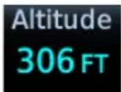
Both TEMP COMP and BARO share the minimums altitude function. Switching between these two source types does not alter the specified altitude value.
2.7.4 MDA/DH Alerting
MDA and DH alerts are based on barometric altitude or optional radar altitude. Alerting is inhibited while the aircraft is on the ground. The radar altimeter option is only available in aircraft with a compatible radar altimeter interfaced to the TXi system.
Both radar altitude and barometric minimums settings are lost following a unit power cycle. Controls for setting MDA and DH alerting behavior reside in the Minimums menu.
| CONDITION ALERT INDICATION | |
| Initial MDA/DH | When the MDA/DH is initially set:Cyan altitude value with bracket pointer displays at the bottom of the altimeter tapeBARO or RAD ALT minimums remain boxed until the MDA/DH altitude is visible on the altimeter tapeMinimums display “RA” when using RAD ALT settings Once MDA/DH altitude is within altitude tape display range, the boxed value is removed and the cyan minimums bug begins tracking with the altimeter tape. |
| Within 100 ft of MDA/DH | Bug turns white |
| Reaching MDA/DH | Bug turns yellowRA value turns yellow.Aural alert: “Minimums, minimums” |
As the aircraft descends, the bug changes color to reflect the current altitude above minimums. Alerting is armed once the aircraft is >150 ft above min altitude.
• White at 50 ft above min
• Cyan at 150 ft above min
RA value turns white once the aircraft is on ground (i.e., system detects weight on wheels; TAS is < 50 kt).
2.7.5 BARO Alerting
FEATURE REQUIREMENTS
• TXi software v3.21 or later
Enable this function to receive altimeter setting prompts when reaching a specified transition altitude, or when inadvertently setting the incorrect selected baro mode (STD BARO vs. non-STD BARO).

When an alert is triggered, the altimeter setting (selected baro) value flashes.
BARO alerts are a useful reminder to set the standard baro value, or to input the local baro value.

Controls for setting BARO alerting behavior reside in the PFD Setup menu.
Alert Toggles the alerting function on or off.
Transition Altitude Allows entry of a numeric transition altitude.
ENABLE BARO ALERTING
- Tap Menu > PFD Setup > BARO Alert > Alert.
- Select Transition Altitude and enter a transition altitude.
Once enabled, altimeter setting prompts trigger when the barometrical altitude is valid and any of the following conditions are true.
Condition 1 Condition 2
- Aircraft climbs through the transition altitude plus 280 ft
-
STD BARO is inactive
-
Aircraft descends through the transition altitude minus 280 ft
- STD BARO is active
Condition 3 Condition 4
- Aircraft is 280 ft or lower below the transition altitude
-
Baro mode is STD BARO
-
Aircraft is 280 ft or higher above the transition altitude
• Baro mode is other than STD BARO
Primary Flight Display
Alerting is stopped when a change is made to the BARO altimeter setting (i.e., STD BARO is toggled on/off) and either of the following conditions are true.
- Aircraft descends through an altitude 200 ft above the transition altitude
• STD BARO is inactive
Or
- Aircraft ascends through an altitude 200 ft below the transition altitude
- STD BARO is active
DISABLE BARO ALERTING
Tap Menu > PFD Setup > BARO Alert, and toggle Alert off.
2.8 VSI
Vertical speed data displays on either a standard or arc style indicator. Format is dependent on unit type (portrait or landscape) and installer configuration.
Arc VSI Standard VSI
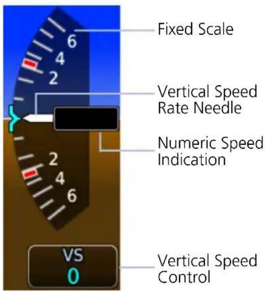
Moving needle indicates current vertical speed on a fixed scale.
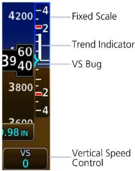
Trend indicator replaces needle, pointer, or indications.
AUTOMATIC FORMAT CHANGES
The arc format changes to standard when alternating between full and split views (arc during full PFD, standard during split). This occurs in the following display configurations.
GDU 1060 MFD/PFD/EIS or MFD/PFD (60%/40%)
GDU 700L PFD/menu open
TCAS II RAs
FEATURE REQUIREMENTS
• Installed GTS 8000 or compatible ARINC 429 TCAS II unit
• GDU 1060 with 60% PFD or 700L PFD
- Standard style VSI
The TCAS II uses transponder replies to determine relative altitude, range, and bearing of any air traffic control radar beacon system (ATCRBS) or Mode S equipped aircraft with altitude reporting. Based on the information TCAS II determines the level of advisory. The TCAS II will not issue RAs for ATCRBS aircraft that reply with only Mode A information.
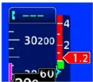
When the TCAS II LRU issues an RA, the VSI displays red no-fly bands to indicate areas to avoid.
A green band indicates the desired climb/descent rate.
NUMERIC SPEED INDICATION
GDU 1060/700L: A numeric field displaying current vertical speed is available on both standard and arc VSIs. The type of field depends on indicator format and, in the case of arc VSI, aircraft type.
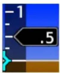
Standard VSI: This field replaces the trend indicator and moves up or down as the vertical speed changes. It displays only in expanded layouts.
GDU 1060: full screen PFD, split MFD/PFD, and split PFD/EIS GDU 700L: full screen PFD

Arc VSI: Field behavior is dependent upon aircraft type: For rotorcraft, a stationary field appears when vertical speed exceeds +/- 300 fpm (1.5 mps). For fixed wing aircraft, the digital value is always present.
VERTICAL SPEED RANGE
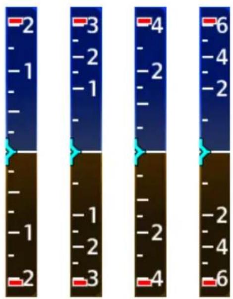
bar
| Value | |---| | -2 | | -1 | | -1 | | -1 | | -1 | | -1 | | -1 | | -2 | | -3 | | -1 | | -2 | | -3 | | -4 | | -2 | | -4 | | -4 | | -6 |Fixed Scale Range Options
Vertical speed range is dependent upon aircraft performance. Both range and units are configured at installation.
Available range types include:
+/- 2,000 FPM
+/- 3,000 FPM
+/- 4,000 FPM
+/- 6,000 FPM
Metric:
+/- 15 MPS
+/- 9 MPS
+/- 21 MPS
+/- 30 MPS
REQUIRED VERTICAL SPEED INDICATION

When receiving VNAV data from the navigator, a magenta chevron indicates the rate of descent needed to reach target altitude.
2.8.1 Selected Vertical Speed

Controls for setting the vertical speed bug reside in the VS control menu. Selected VS bug limits are determined by the visible tape range.
VS SYNC Synchronizes selected VS bug to current vertical speed.
VS Allows entry of a numeric vertical speed.
2.9 Horizontal Situation Indicator
The HSI displays a rotating compass card in a heading-up orientation. Letters indicate the cardinal points with numeric labels every 30^ . Major tick marks are placed at 10^ intervals and minor tick marks are at 5^ intervals. The HSI displays:
• Digital reading of the current heading
• A magenta diamond representing current track
• Turn rate, course deviation, bearing, and navigation source information
HSI layout varies according to display type.
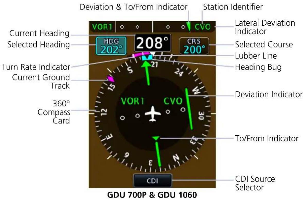
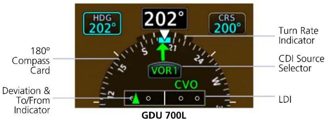
HSI CONTROLS & INDICATIONS
| Turn Rate Indicator | Lubber line serves as apex for the turn rate indicator, displaying aircraft centerline and direction straight aheadTick marks closest to the lubber line depict half-standard rate turns and tick marks furthest away denote a standard rate turn6 second prediction of heading based on present turn rateIf aircraft turn rates are greater than 4° per second, an arrowhead appears at the end of the vector and a heading prediction is no longer valid |
| Lateral Deviation Indicator | Lateral movement of symbols indicate course deviationGPS flight phase, navigation source, OBS status, and message annunciator display on deviation indicator borders |
| Current Ground Track | Magenta diamond moves on compass card indicating aircraft current track over ground |
| Current Heading | Heading displays true north or magnetic values by selecting NAV Angle units from the System Units menu |
| To/From Indicator | Rotates with the course pointer on the standard HSI depicted as an upright or inverted triangleDisplays only when an active navigation source is received (GPS or VOR)Color scheme is uniform with GPS and VOR/LOC source selectionsUpward pointing symbol indicates to, downward pointing symbol indicates from |
| Station Identifier | For VOR/LOC sources, the HSI displays the decoded Morse code station identifier on the right side of the CDI lateral deviation indicatorStation Identifiers display at the center of the HSI when HSI map overlays are selected off |
| Heading Bug | Cyan bug on the compass card corresponds to the selected headingSelected heading is adjustable using the PFD knobs or touchscreen controls |
2.9.1 Setting the Heading Bug
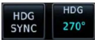
Controls for setting the heading bug are located in the Selected Heading control menu.
GDU 700L: Set the heading bug using the inner control knob.
HDG SYNC Synchronizes heading bug to current heading.
HDG ^1
Allows entry of a numeric heading.
^1 Touch key not available on GDU 700L.
SELECTED HEADING REFERENCE
FEATURE REQUIREMENTS
• TXi software v3.21 or later
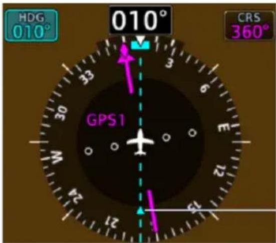
A dashed line extends from the selected heading bug to the opposite end of the compass. A pointer indicates direction.
The selected heading reference remains visible for 5 seconds following the last change in selected heading.
Selected Heading Reference
The selected heading reference (or tail) provides situational awareness during course intercepts.
OFF SCALE INDICATIONS
GDU 700L ONLY

It is possible for the heading bug position to be out of view on the 180° compass card. When this occurs:
- Heading bug parks on the side nearest to its actual position (a partial bug is visible at the bottom of the screen)
• Down arrow indicates direction
2.9.2 HSI Annunciations
HSI annunciations display on the HSI compass card and around the lateral deviation indicator. They include:
• GPS flight phase
- CDI source
• VOR/LOC station Morse Code identifier (when VOR is active)
- Navigator modes and messages
• Cross track error (if CDI deflects beyond full scale)
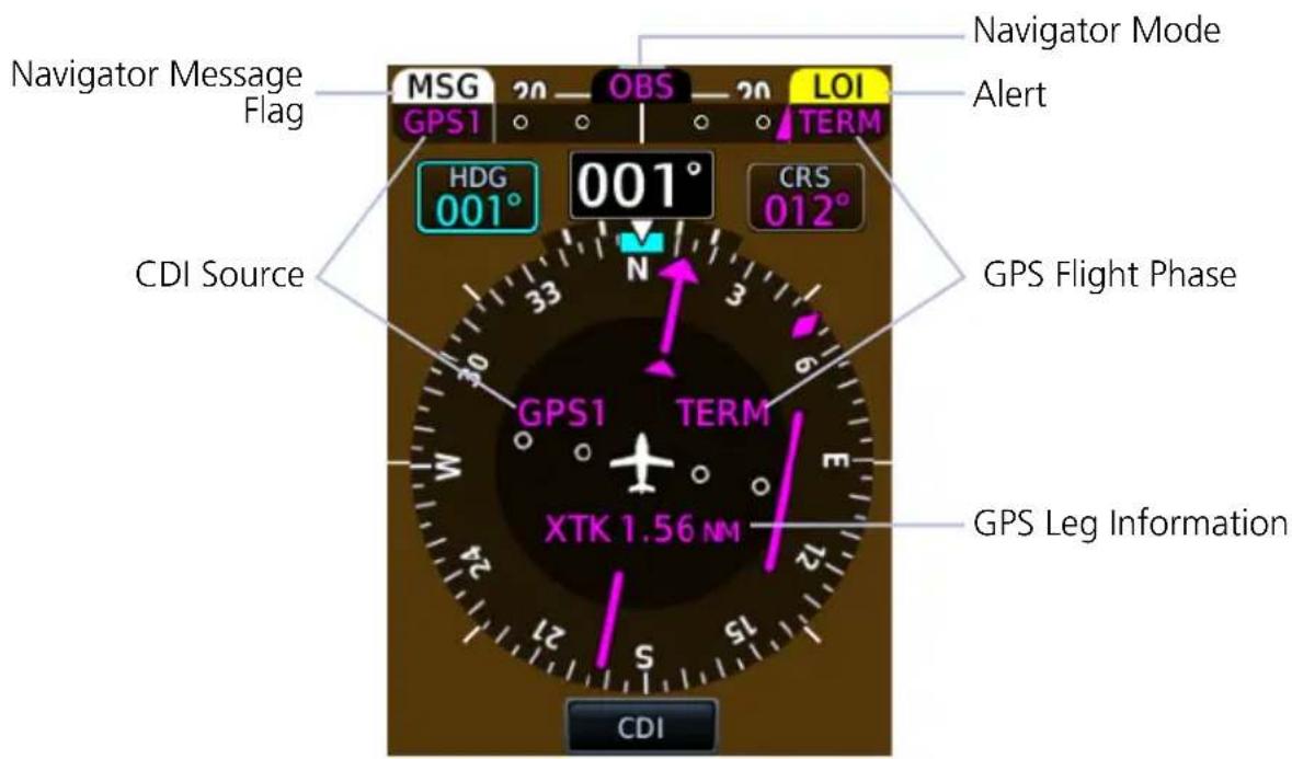
NAVIGATOR ANNUNCIATIONS
| WPT | Waypoint AlertBlinking text depicts arrival at a waypointAppears within the Lateral Deviation Indicator |
 | GPS Waypoint Sequencing SuspendedAppears above the Lateral Deviation Indicator |
 | Loss of GPS Integrity AlertGPS integrity is insufficient for the current phase of flightGPS information is not present or is invalid for navigation useAppears above the CDI Lateral Deviation Indicator |
 | Message FlagBlinking text signals a message is queued in the navigatorAppears above the CDI Lateral Deviation Indicator |
 | Omnibearing Selector ActiveAppears above the CDI Lateral Deviation Indicator |
 | CDI SourceDisplays current CDI source information |
 | Appears within the CDI Lateral Deviation Indicator/Center of HSI |
 |
GPS FLIGHT PHASE ANNUNCIATIONS
GPS flight phase annunciations appear in the following locations.
• CDI lateral deviation indicator
• Center of the HSI
Phase of flight annunciations are a direct indication of the current CDI behavior for the selected navigation source. Not all annunciations are available for every navigator.
These annunciations typically display in magenta. The color changes to yellow when cautionary conditions exist.
0.3NM
0.3 nm CDI scale
1NM
1.0 nm CDI scale
DPRT
Terminal level with departure procedure as the active navigation
DR
Dead reckoning (CDI not available)
ENR
En route
HDG LEG
Navigator provides heading information only (CDI not available)
LNAV
Lateral Navigation Approach
LNAV+V
Lateral Navigation Approach with advisory vertical guidance provided. LNAV+V uses published LNAV minimums.
LVNAV
Lateral and Vertical Navigation Approach
LP
Localizer Performance Approach
LP +V
Localizer Performance Approach with advisory vertical guidance provided. LP +V uses published LP minimums.
LPV
Localizer Performance with Vertical guidance approach.
MAPR
Missed Approach
OCN
Oceanic
TERM
Terminal
VISUAL
Visual Approach
2.10 CDI
FEATURE LIMITATIONS
- CDI angular limits are ± 10^ when the navigation source is VOR or LOC
The CDI is located in the center of the standard HSI compass card, and is duplicated using a sliding lateral deviation indicator above the HSI. Control knob selection of CRS can set the course pointer, while the CDI source is VOR/LOC or GPS course when OBS mode is active.
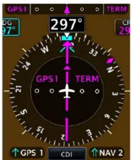
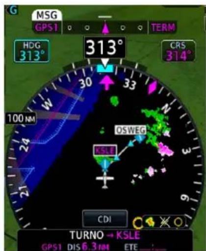
CDI Above HSI MapStandard HSI
The CDI is capable of displaying up to four sources of navigation depending on external navigator and navigation radio configuration. The CDI does not display if course deviation data are invalid.
2.10.1 Course Pointer Types
Course pointer type varies between single or double line arrows depending on the active CDI source. Arrow tips point in the direction of the selected course or GPS desired track.
ICON SOURCE ICON SOURCE
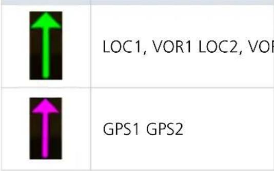
| ↑ | |
| ↑ |
COURSE POINTER PREVIEW

A dashed gray arrow indicates the VOR/LOC preview selected course. This pointer displays when the CDI/VDI Preview function is active.
For more about CDI/VDI preview indications, read section 2.13.
2.10.2 Cross Track Error Indication
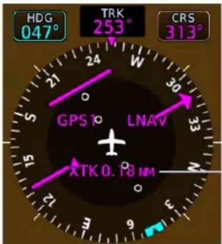
The GPS navigator determines CDI scaling. A cross track error displays if the CDI exceeds the full scale deviation value during GPS navigation.
Cross Track Error Annunciation
2.10.3 CDI Source Selection

The CDI key toggles between two sources or opens a source selection menu to select between more than two sources.


On GDU 700L: Source selections display on the CDI key.
For systems with a GTN that has a GTN CDI key, the CDI source may be switched between GPS and VOR from a PFD or with the GTN CDI key.
CDI SOURCE SYNC
When CDI SRC sync is on or the system is configured to always sync, the CDI source selected on any PFD is automatically selected on all PFDs in the system.
In a system with two or more navigation units available as CDI sources (GPS/VOR 1 and GPS/VOR 2) and CDI SRC sync off, the CDI source can be selected on each PFD independently.
SOURCE SELECTION ALERT
The CDI key flashes to alert the pilot when a change in source selection is necessary. Conditions include:
- Localizer or ILS approach is active on the GPS navigator
• Active waypoint is the final approach fix - Localizer deviation is less than full scale deflection
- Localizer approach course is within 20^ of GPS track
2.10.4 Selected Course with VOR/LOC
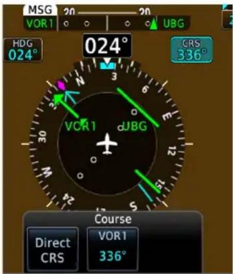
Selecting a VOR/LOC source activates the Selected Course control. All course indications and annunciations turn green.
Selecting Direct CRS centers the VOR CDI needle and sets a direct-to-fix course.
2.10.5 Selected Course with GPS
FEATURE LIMITATIONS
- In multi-PFD systems, preset course functionality is not available when GDU 620 is present
When a GPS source is selected, the Selected Course field displays course values in magenta. This function provides the preset course for VLOC guidance upon switching from GPS to VOR or LOC.
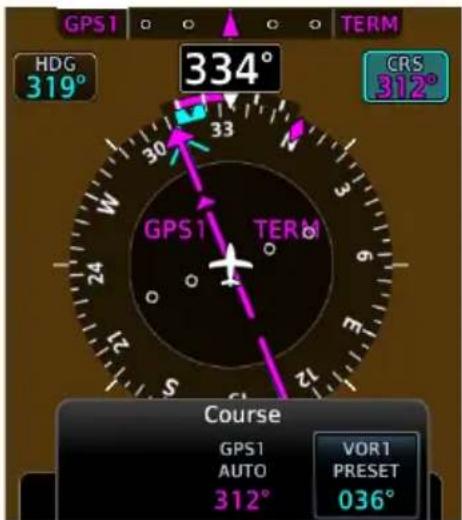
Selecting VOR(1/2) PRESET allows the pilot to preset VOR course selected course entries. Access this function by tapping the preset key and entering the value on the numeric keypad or by turning the inner control knob on the PFD.
GPS AUTO displays the automatic course computed by the navigator. There is no touch key available. Selected GPS course cannot be changed during non-OBS GPS operation.
2.10.6 Automatic Source Selection
FEATURE REQUIREMENTS
- Integrated GPS and NAV radio source (GTN 650/750 or GNS 430/530) for VOR/LOC to GPS auto-switch functionality during missed approaches
• GTN 650/750 for GPS to LOC auto-switch functionality during localizer approach
FEATURE LIMITATIONS
- In multi-PFD systems, the missed approach auto-switch function disables when GDU 620 is present
The system automatically changes the navigation source during the following conditions.
CONDITION CDI RESPONSE
| Missed approach procedure activates | Navigation source automatically switches from VOR/LOC to GPS. |
| Autopilot captures the localizer | Navigation source automatically switches from GPS to LOC.1 |
| Localizer approach without autopilot | Navigation source automatically switches from GPS to LOC.2 |
^1 GFC 600 autopilot only.
^2 GPS to localizer auto-switching is available without autopilot when CDI SRC synchronization function is configured as always on and the CDI key on GTN is enabled. In this configuration, the pilot-selectable CDI SRC option is absent from the SYNC Control pop-up menu.
Localizer auto-switching is available without an autopilot when:
• the CDI synchronization installer setting on GDU is configured as always on
• the CDI key installer setting on GTN is configured as enabled
In this configuration, the CDI SRC option is absent from the PFD Setup menu's SYNC Control options.
Auto-switch functionality requires the appropriate configuration of GDU and GTN. If the CDI source option is not available on GTN, or if the option is absent from both GTN and GDU, it means that CDI sources can desynchronize. Contact the installer to configure your system to allow localizer auto-switching.
2.10.7 Auto-Slewing
FEATURE LIMITATIONS
• In multi-PFD systems, auto-slew functionality is not available when GDU 620 is present
When changing the CDI source from GPS to LOC, the system auto-slews the selected course to the localizer course if:
• A localizer-based approach exists in current flight plan of GPS navigator
• A localizer frequency is active in navigator (LOC, BC, SDF, ILS, LDA)
When a LOC BC approach is activated, the course pointer slews to the LOC front course to provide appropriate back course HSI needle indications.
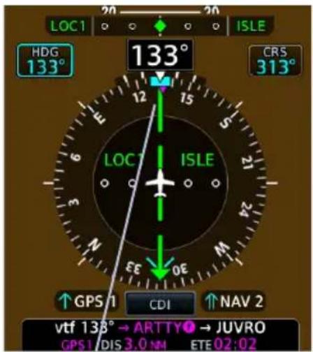
Course Selection and Pointer Auto-Slewed to 313°
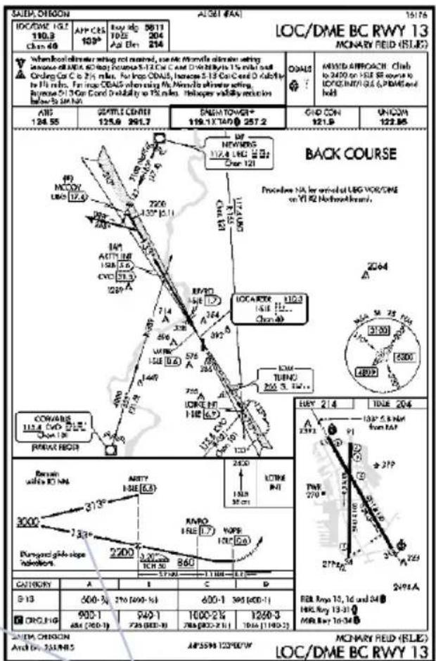
Final Inbound Approach Course 133°
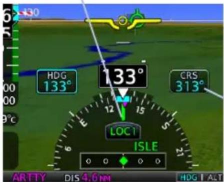
2.11 LDI
Deviation indicators move left or right along the CDI scale to portray aircraft position relative to the selected course.
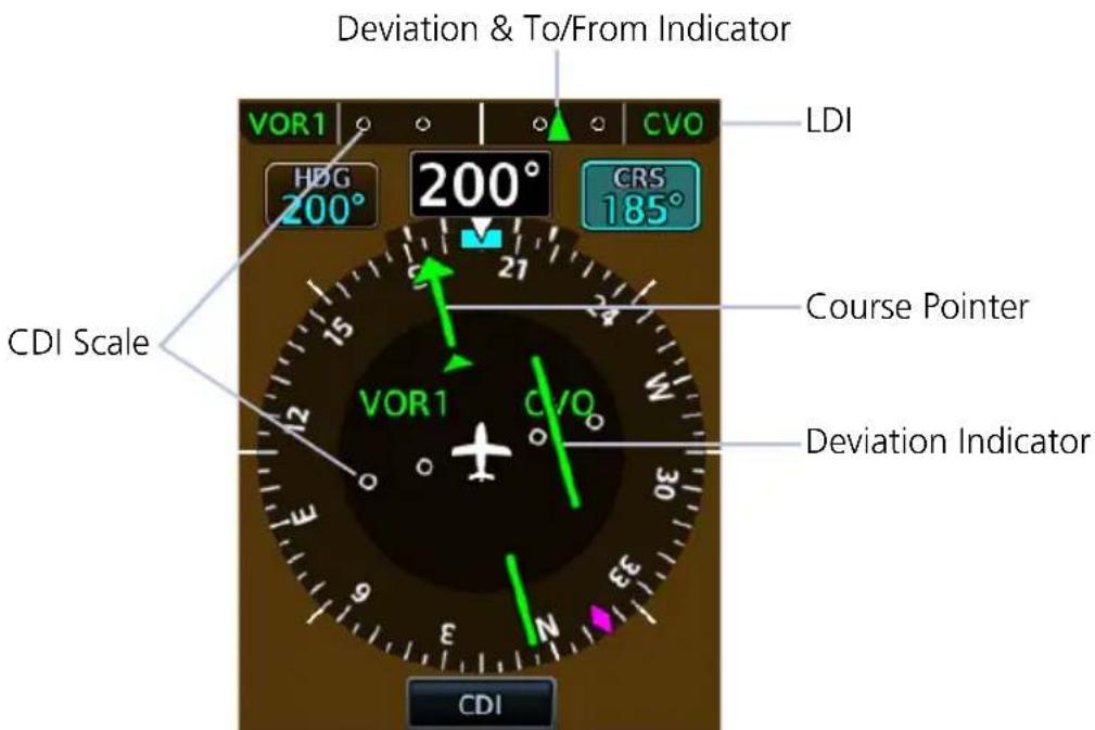
2.11.1 Reverse Sensing Correction
The lateral deviation indicator incorporates an automatic reverse sensing correction. When the aircraft heading is more than 107^ left or right from the selected course, the lateral deviation indicator will reverse CDI indications and the to/from pointer.
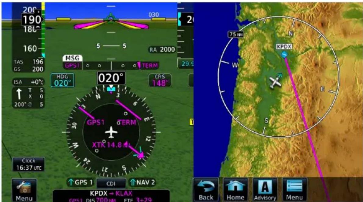
2.12 VDI
The VDI displays to the left of the altitude tape when:
• The aircraft is in an ILS or GPS approach with vertical guidance
• The GDU is receiving VNAV vertical guidance from the GTN
Status annunciations replace VDI indications when data is invalid or not available.

ILS Glideslope
For ILS glideslope indications, the VDI is a green diamond. An ILS glideslope indication appears if the current heading is within 107° of the selected course. This prevents the glideslope from displaying during localizer backcourse approaches.

No GS
Annunciates if a localizer frequency is tuned and there is no glideslope signal.

GPS Glidepath
GPS glidepath vertical guidance is similar to glideslope indications. A magenta diamond glidepath indication displays for GPS approaches supporting vertical guidance (LNAV+V, L/VNAV, LPV, LP +V, VISUAL).

No GP
Annunciates if GPS glidepath data becomes invalid while the VDI is displayed.
2.12.1 VNAV Deviation Indications
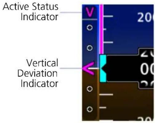
VNAV deviation guidance displays when:
- CDI source is GPS and the navigator is providing valid VNAV deviation data
- CDI source is VOR/LOC, the navigator is providing valid VNAV deviation data, and a VNAV mode is armed or active on the autopilot
These indications are absent when deviation data is invalid.
MAXIMUM DEFLECTION INDICATIONS
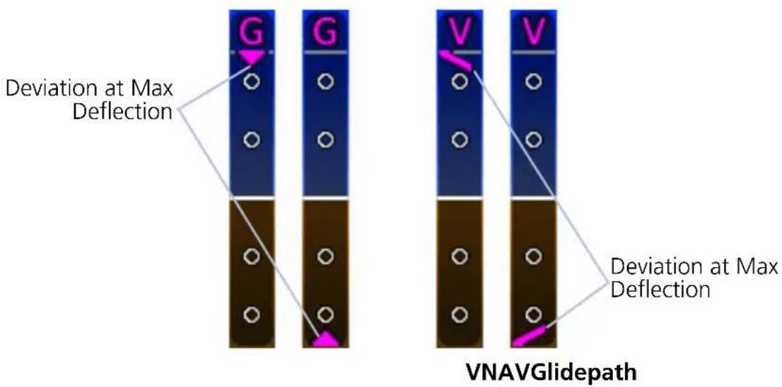
2.13 CDI/VDI Preview
FEATURE REQUIREMENTS
• A configured GTN

A preview option provides advance indications of approach lateral and/or vertical deviations, allowing the pilot to anticipate changes and make smooth transitions during approach. By default, this function is active.
All preview indications and annunciations are gray.
Approach Preview Data
- CDI Source ^1
• CDI VOR/LOC Deviation ^2
• HSI Map VOR/LOC Course
• VDI Glidepath/Glideslope
• VOR/LOC Course
• VOR/LOC Morse Code ID
^1 Only if Morse code is not available. ^2 Includes LOC backcourse deviation.
VDI PREVIEW
For ILS and GPS approaches, the VDI provides a preview of glideslope or glidepath deviation.
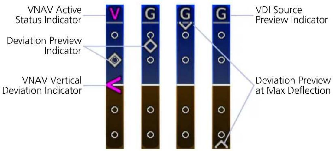
CDI PREVIEW
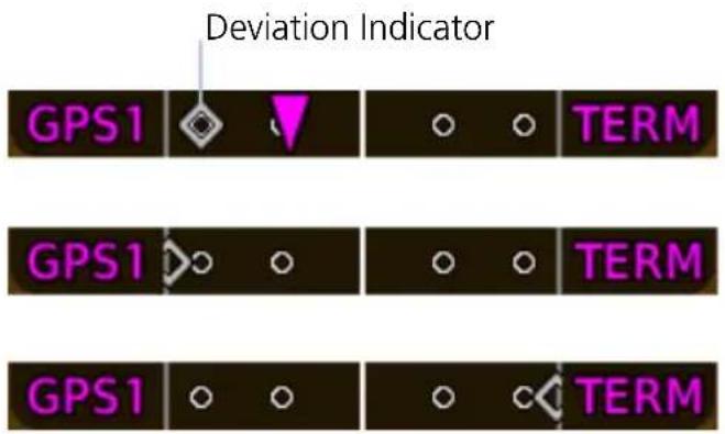
LDI
For VOR or ILS approaches, the CDI provides a preview of VOR or localizer deviation.
GDU 1060 & GDU 700P:
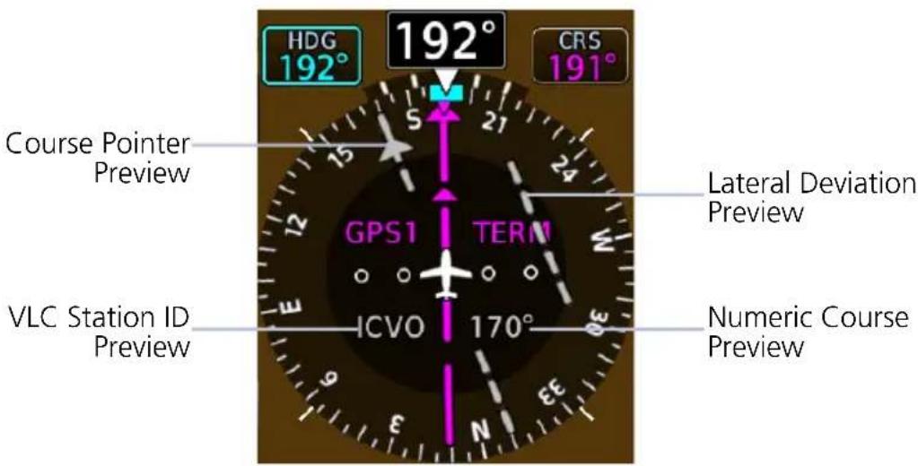
HSI
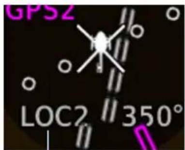
CDI Source Preview
If a station ID is not available, the CDI source annunciates in its place (e.g., VOR, LOC).
To change the course preview:
- Open the Course control menu.
- Select VOR/LOC PRESET.
- Specify a new preset value.
GDU 700L:
Preview data include a course pointer and lateral deviation indicator.
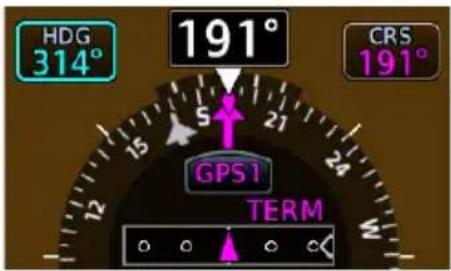
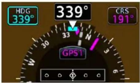
Supplemental Flight Data
2.14 Bearing Pointers
FEATURE LIMITATIONS
Bearing pointers are mutually exclusive with the HSI Map. They do not display when HSI Map is active.
Selecting a bearing pointer does not necessarily make it visible. Bearing pointers are absent when:
• GDU does not receive valid data from the selected source
• NAV radio is not receiving tuned VOR station
• NAV radio is tuned to a Localizer frequency
• GPS is bearing source and active waypoint is not selected
• ADF is selected and signal is not received
• HSI Map function is on
ICON BEARING
| 1 | |
| 2 |
Two selectable bearing pointers are available for the display of VOR, GPS, or ADF data.
Arrow tips point to signal source in relation to the current aircraft heading.
Pointers do not override CDI features.
Bearing Information Fields
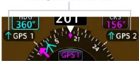
GDU 700L
Bearing information fields indicate bearing type and navigation source. They display to the left and right of the compass card.
SET BEARING POINTERS
- Turn off HSI Map if necessary.
- Navigate to the Bearing Pointers page.
- Select a bearing navigation source for the active pointer(s).
The GDU retains all pointer selections during a unit power cycle.
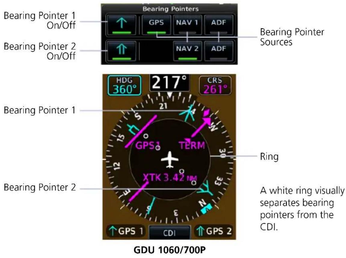
2.15 GPS NAV Status Field
FEATURE LIMITATIONS
From and next waypoints may be removed when the number of characters in a full route exceeds the allowable space.
A GPS NAV status field displays at the bottom of the PFD when the GPS navigator associated with the selected CDI source has an active valid leg. Information is based on calculations by the GPS navigator. Annunciations and window width vary according to GDU type.
GDU 700P/1060:
• From, to, and next waypoints
• Leg and waypoint types
• Identifier, distance, and ETE of active waypoint

GDU 700L:
• Active waypoint identifier and distance
• GPS message status

ACTIVE LEG GPS NAVIGATION STATUS FIELD SYMBOLS

IAF Arc Left


FAF


MAP


MAHP Right Arrow


Parallel Track Direct To


Arc Right
2.16 Relative Wind Data
Wind Data
• Wind direction and speed
- Headwind (H)
- Tailwind (T)
- Crosswind (X)
The system computes current wind conditions during flight and displays the data in a dedicated field.
Status annunciations replace wind data when conditions are calm or the configured data source is invalid or not available. Wind data displays when ground speed is 30 knots and higher.
A white arrow indicates wind direction relative to the aircraft's heading. The numeric display of the wind direction is dependent on the NAV Angle system unit setting.
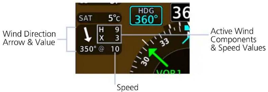
WIND STATUS ANNUNCIATIONS

Calculated winds are less than or equal to 2.5 kts.

GPS track or TAS data are invalid or unavailable.
2.17 Temp/DALT Display
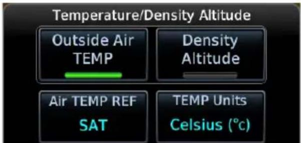
A dedicated field displays outside air temperature or density altitude based on pilot selection. These reference values are mutually exclusive. Selecting one automatically turns off the other.
Outside Air TEMP Density Altitude

Displays the pilot selected air temperature reference.
Units are available in °C or °F.
Options include:
• Static Air Temperature
• Total Air Temperature
• Temperature difference from ISA

Displays pressure altitude corrected for nonstandard temperature.
Units display in increments of ten, and are in feet or meters depending on altitude tape configuration.
2.18 DME Display
When the GDU is configured with a GAD 43e and interfaced with a DME receiver, a selectable DME information window is available for display. Information includes the DME source (NAV1, NAV2, EXT, or HOLD) and distance.
When a DME signal is invalid, “--NM” replaces the distance.
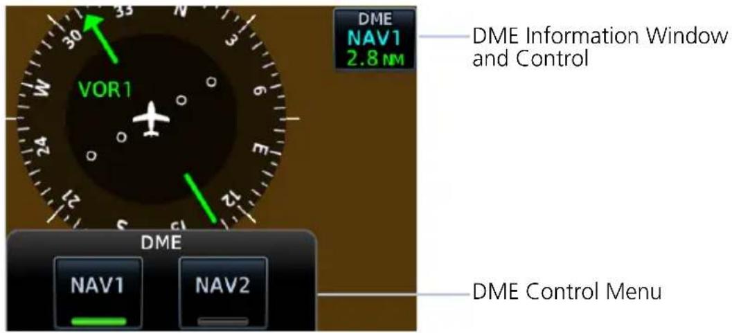

DME HOLD activates/deactivates the DME tuning hold function and can be selected for either DME NAV 1 or DME NAV 2.
Switching between NAV1 and NAV2 automatically cancels the function. Not all installations have the DME HOLD function.
2.19 Marker Beacon Symbols
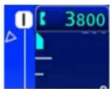
Inner Marker Symbol
Marker beacon symbols display left of the altitude tape when interfaced to a marker beacon receiver.
All marker beacon light and audio tests are performed through controls on the associated audio panel.
| SYMBOL MARKER TYPE | |
 | Inner |
 | Middle |
 | Outer |
2.20 Radar Altitude
When interfaced with a radar altimeter, GDU indicates radar height to left of the altitude tape. An altitude field automatically appears when the aircraft is at or below 2,500 ft AGL or within operating range of the installed RA unit (generally 2,500 ft AGL).
Brown and white hash marks depict a ground awareness band on the altimeter tape. When the radar altimeter readout is 0 ft, the ground band will level with the altitude pointer.
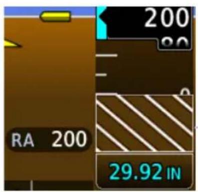
As the aircraft climbs, the ground band moves down the tape in equal amounts to the indicated RAD ALT value.
Ground Band
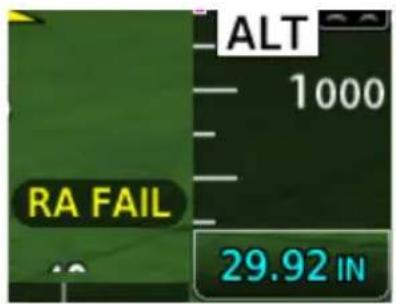
If the radar altimeter fails, the message "RA FAIL" annunciates in place of the current radar value.
Audio Alert (Rotorcraft Only)

Depending on configuration, an audio alert is active when the radar altimeter indicates the aircraft is descending below 100 ft.
2.20.1 RA Test
FEATURE LIMITATIONS
• Self-test functionality is not available on all radar altimeters
• Sequence duration is approximately 12-20 seconds
- For test values and unit limitations, consult the appropriate third party radar altimeter documentation

A test function verifies communication between the GDU and the radar altimeter.
During the test sequence:
• Ground awareness band displays on the altimeter tape
• RA readout field displays a test altitude value (e.g., 50 ft AGL)
To suspend the test, deselect RA Test or exit the Test menu.
2.21 AGL Display
FEATURE LIMITATIONS
GPS height above terrain value not available for display above 2,500 ft AGL.
For systems without a radar altimeter, GDU allows you to display GPS height above terrain to the left of the altitude tape. Units are either feet or meters depending on configuration.
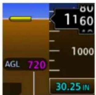
Altitude Field
To toggle the altitude field on or off, open the PFD Setup menu and tap AGL Field.

The altitude value is absent when the aircraft exceeds 2,500 ft AGL. It returns once the aircraft is at or below 2,500 ft AGL.

If GPS fails, or if terrain elevation is unavailable or invalid, the message “AGL FAIL” annunciates in place of the current GPS altitude value.
2.22 GPS Roll Indicator
A magenta GPS Roll Indicator adjacent to the roll pointer provides roll steering guidance during GPS navigation. The GPS navigator's roll steering command is used to drive the indicator whenever valid AHRS roll, GPS deviation, and GPS roll steering values are available and the flight director is inactive.
GPS Roll Indicator - Fixed View
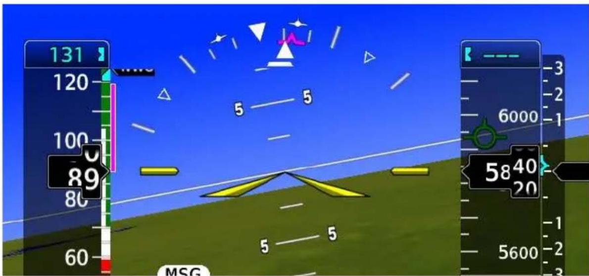
GPS Roll Indicator - Sky View
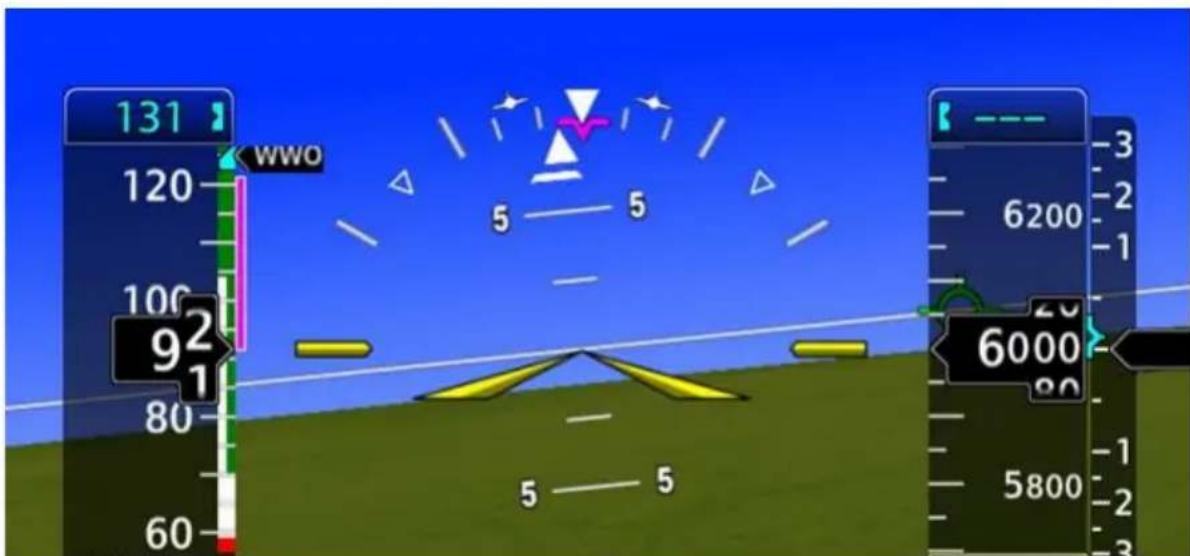
2.23 G-meter
FEATURE REQUIREMENTS
• TXi software v3.21 or later
An optional G-meter indicates acceleration (G-force) along the aircraft's vertical axis. This information can be valuable during turbulence or aerobatic maneuvers.
Instrument format is dependent upon screen layout. In expanded layouts, the G-meter appears as a fixed vertical tape to the left of the airspeed indicator.
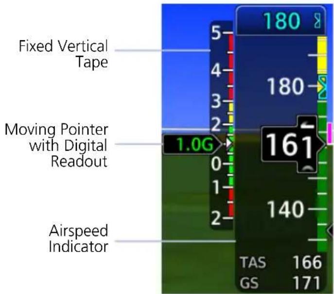
Graduations, markings, and white markers show the attained extremes for the current flight.
A moving pointer and digital readout display the two digit g-force value in the color of the currently active marking.
Markings are installer configurable.
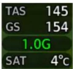
In spatially constrained layouts, the digital readout is below the airspeed tape. Attained minimum and maximum acceleration values are viewable in the G-Meter Setup menu.
G-METER SETUP OPTIONS

Enable the G-meter from the associated setup menu. Tap Menu > PFD Setup > G-Meter > Display G-Meter.
From here, you can reset the attained minimum and maximum acceleration values by tapping Reset Min/Max.
During a power cycle, GDU retains the display setting, but not the indicated minimum and maximum acceleration values.
2.24 Clock/Timer

A generic timer counts up in an H:MM:SS format. There are no aural alerts or pilot advisories associated with this feature. Turning the clock/timer function off removes the control key from the instrument display.
Mode Toggles between Clock and Timer.
Start/Stop Pauses timer.
Reset
Resets timer to zero. Count resumes when the timer is reset during operation.
3 Advanced Features
HSI MAP
3.1 HSI Map Overlays 3-4
MAP DISPLAY, GDU 700L
3.2 GDU 700L Map Overlays 3-10
SVT
3.3 SVT Setup....3-13
3.4 SVT Features.... 3-14
Tapping HSI Map places a map within the HSI. This key resides in the PFD menu.
FEATURE REQUIREMENTS
- Valid GPS position and magnetic heading
• FIS-B, Iridium transceiver, or SiriusXM receiver (weather overlays only)
• Active weather subscription (Connext and SiriusXM only)
• WX-500 receiver (Stormscope only) - Valid VNAV data (ATK waypoints)
FEATURE LIMITATIONS
• GDU 700P/1060 only
HSI MAP INTERACTIONS
• Map interactions are zoom only. Pan functionality is not available
• Overlays declutter at a predefined map range for specified data depictions
WHEN HSI MAP IS ACTIVE
- Standard HSI view expands to incorporate a basemap and selected overlay
• Map overlays replace standard HSI indications
• HSI display enlarges to a 270° compass card view to accommodate the map
• CDI and annunciations are removed
• CDI indications appear only on the LDI
• Status icons indicate active map overlays - Bearing pointers do not display
- HSI reverts to a standard depiction in the absence of a valid magnetic heading or GPS source
Data depicted when HSI Map is active
- GPS flight plan
• TFRs - Range to altitude arc
• Airspace boundaries and altitudes
• Runway and SafeTaxi detail
- Terrain alerts, if configured
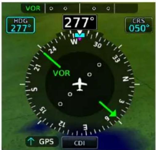
Standard HSI
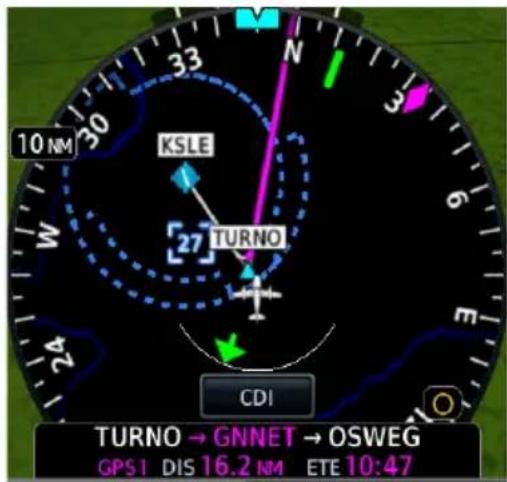
HSI Map
HSI ARC
When a heading bug, track indicator, course preview pointer, or course pointer moves to a position on the HSI circle behind or below other PFD controls, indicators depict on a miniature arc, representative of the hidden portion of the HSI circle.
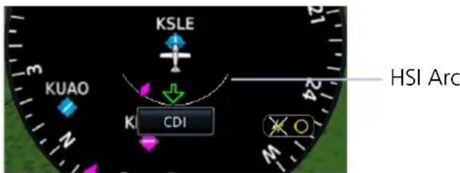
CDI
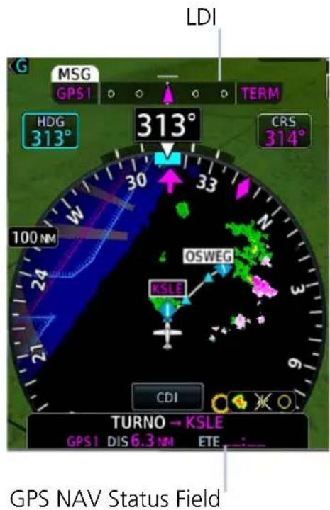
LDI indications include:
- CDI source
- Course deviation
• GPS phase of flight
• Course deviation preview - Navigator message annunciations
- To/from
• VLOC station identifier
• Waypoint arrival annunciation
3.1 HSI Map Overlays
TOPO
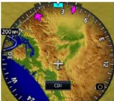
- Topographic map depicting terrain elevation using a color scale similar to Sectional Charts
TERRAIN
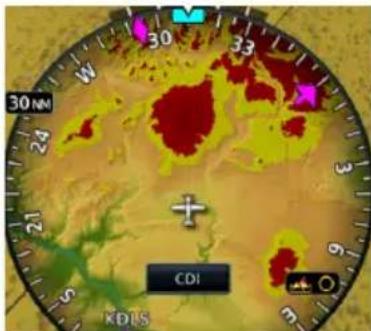
- Terrain map depicting terrain elevation relative to aircraft altitude
• Uses the same color scale as the dedicated Terrain page - NEXRAD weather overlay is disabled to prevent confusion of depicting radar and terrain data with similar colors
OBSTACLES AND WIRES
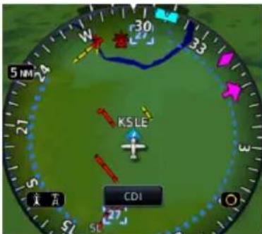
- Depicts obstacle and wire elevations relative to aircraft altitude
- Uses the same color scale as the dedicated Terrain page
• Data removed when viewing range is >5 nm
TRAFFIC
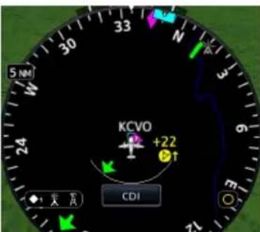
• Displays traffic using a NORMAL altitude filter
• Data removed when viewing range is >20 nm
NEXRAD/PRECIP & TFRS
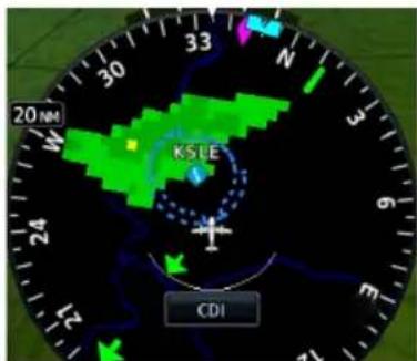
• Overlays NEXRAD/PRECIP datalink weather from ADS-B ^5 , SiriusXM, or Garmin Connext ^1,2 as selected in the HSI Setup menu
- Precipitation intensity displays in accordance with NEXRAD/PRECIP legend viewable on the dedicated weather page
- Weather and TFR product age display on HSI Setup Menu
STORMSCOPE
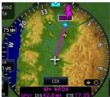
• Overlays Stormscope strike or cell data on map ^3
• Data is removed after 4 minutes
LIGHTNING
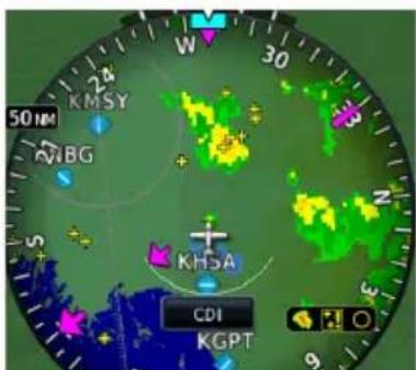
- Depicts SiriusXM, FIS-B, or Connext lightning strike information on the basemap ^1,4
3.1.1 Overlay Status Icons
Icons represent the presence of overlay data. For real time products (e.g., TFRs, NEXRAD/PRECIP), these icons indicate the recency of data.
The absence of an overlay icon means one of two possible conditions:
- Overlay is not present at the current zoom level.
- Overlay control is off.

Obstacles overlay data is active on the display.

Power line overlay data is active on the display.

TFR overlay is active.

Terrain overlay is active on the display.

Traffic system is active and displaying information.

NEXRAD or PRECIP overlay is active and displaying received information.

Lightning overlay is active and displaying SiriusXM, FIS-B, or Connext lightning information.

Stormscope overlay is active and displaying lightning strikes.
FAULT INDICATION

A fault icon means overlay data is not available, not received, or has failed (where relevant).
OLD DATA

An old data icon means overlay data is not current, but remains displayed.
Map Display, GDU 700L

ROTORCRAFT ONLY

Tapping Map overlays a full screen map on the PFD.
FEATURE LIMITATIONS
- GDU 700L only
• Map display feature must be configured as available
MAP INTERACTIONS
• Map interactions are single-finger zoom controlled
• Pan functionality is not available
• Overlays declutter at a predefined map range
WHEN MAP IS ACTIVE
• VFR style moving map with 360° compass card replaces standard PFD layout
• Road and city information display in support of VFR operations
- Airspeed, altitude, BARO correction, and ground speed values display within a selectable attitude indicator key
- Display automatically returns to full screen PFD in the event of extreme attitudes
• PFD Menu key changes to accommodate only the map display
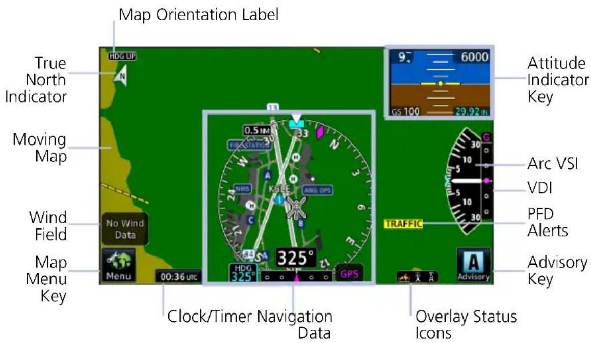
GDU 700L PFD Map Features
Data depicted when PFD Map is active
• Full compass card view
• Lubber line and heading bug
• Current ground track
- Selected Heading control and current heading field
• Selected BARO control
- Reduced attitude display
- Arc VSI (if configured)
- Wind field
- Clock/timer
• Autopilot annunciations
• Active fix and distance to active fix (if available from the navigator)
ATTITUDE INDICATOR KEY
To return to full screen PFD, tap the attitude indicator key. This key displays a reduced attitude depiction and instrument data fields. It resides in the upper right corner of the display when full screen map is active. Data fields are display only.
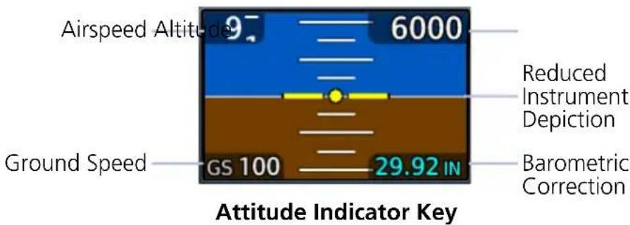
360° COMPASS CARD
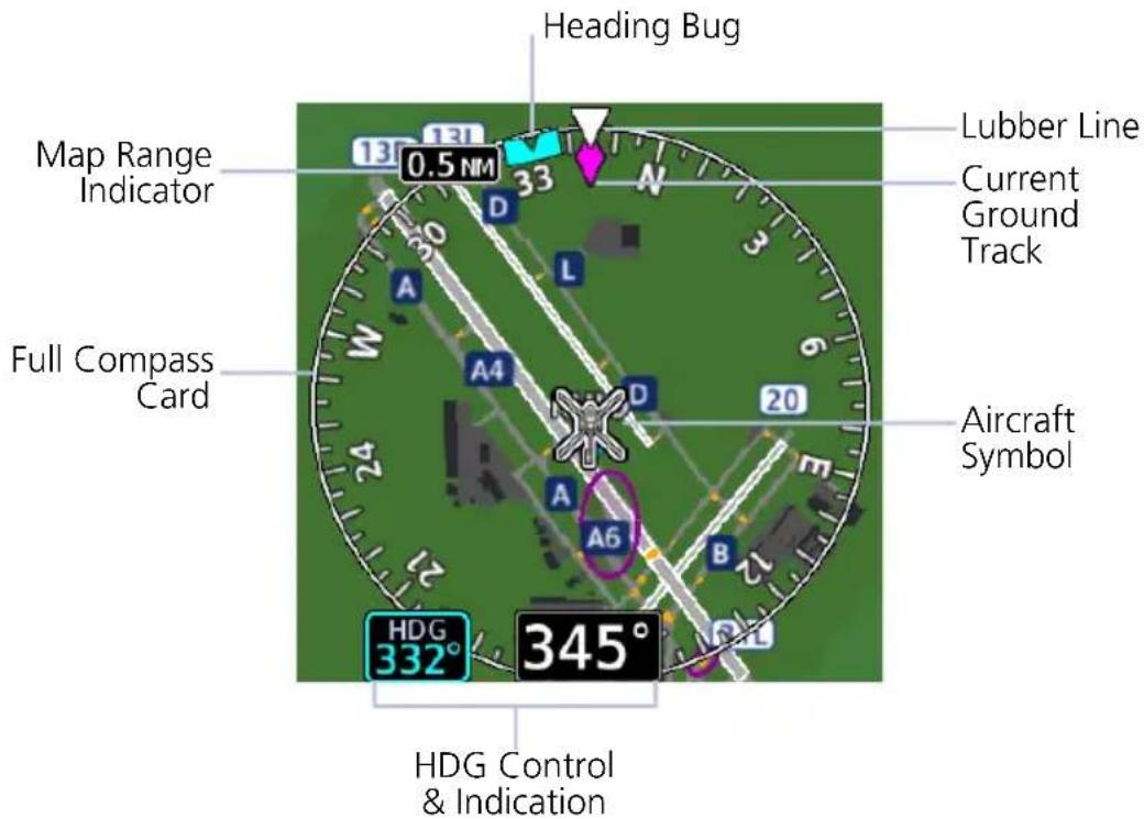
3.2 GDU 700L Map Overlays

Tapping Menu while the map is active opens an overlay menu. Overlay selections display in a dedicated menu.
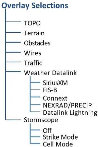
flowchart
graph TD
    A["Overlay Selections"] --> B["TOPO"]
    A --> C["Terrain"]
    A --> D["Obstacles"]
    A --> E["Wires"]
    A --> F["Traffic"]
    A --> G["Weather Datalink"]
    G --> H["SiriusXM"]
    G --> I["FIS-B"]
    G --> J["Connext"]
    G --> K["NEXRAD/PRECIP"]
    G --> L["Datalink Lightning"]
    A --> M["Stormscope"]
    M --> N["Off"]
    M --> O["Strike Mode"]
    M --> P["Cell Mode"]
3.2.1 Overlay Controls

Control keys enable the specified overlay function only and do not activate interfaced equipment. Overlay keys remain active even in the absence of required data.
| GDU 700L MAP OVERLAYS | |
| TOPO | Overlays topographical data and ground elevation scaleDepictions are similar to a VFR sectional |
| Terrain | Overlays terrain map dataColor shading depicts terrain elevation relative to the aircraft's altitude |
| Obstacles & Wires | Depicts obstacle and wire elevations relative to aircraft altitudeUses the same color scale as the dedicated terrain pageData removed when viewing range is >5 nm |
| Traffic | Overlays traffic informationFilter selection on Traffic page determines altitude rangeOptional |
| NEXRAD/PRECIP & TFRs | Overlays NEXRAD/PRECIP datalink weather from ADS-B, SiriusXM, or Garmin Connext as selected in the Overlay menuPrecipitation intensity displays in accordance with NEXRAD/PRECIP legend viewable on the dedicated weather pageWeather and TFR product age display |
| Stormscope | Overlays Stormscope strike or cell dataData is removed after 4 minutes |
3.2.2 Overlay Status Icons
Icons indicate which overlays are present at the current map range. A crossed out icon means the overlay is active, but data is unavailable due to a failure, test, or standby condition (where relevant).
The absence of an overlay icon means one of two possible conditions:
- Overlay not present at the current detail level or zoom setting.
- Overlay control is off.

Obstacle Power Line


Stormscope Traffic


Terrain Data not available

SVT

NOTE
Synthetic terrain aids pilot awareness of terrain and obstacles in front of the aircraft. It does not replace primary flight instruments.
FEATURE REQUIREMENTS
• Valid attitude and magnetic heading
• Valid 3-D GPS position
- Valid terrain and obstacle databases
• Feature enablement to continue service beyond the free trial period
FEATURE LIMITATIONS
- Loss of any required data, including temporary loss of GPS, causes SVT to be removed until data is restored
- Depicts only terrain contours and obstacles from the associated databases. Optional depictions (e.g., airport signs, aircraft heading) are dependent upon pilot selections. Power line depictions are not available
• SVT terrain alerting functionality is not compliant with TSO-C151c - Aural and visual alerting functions are in accordance with appendix H.2 of AC 20-167A
3.3 SVT Setup

SVT setup selections are accessible via the Terrain/SVT key.
Synthetic Terrain Activate SVT function.
Settings Activate horizon heading markings and airport signs.
Terrain Inhibit Deactivate Terrain aural and visual alerts.
3.4 SVT Features

NOTE
GDUs with PFD functionality have a 10-hour free trial of SVT. A timer in the Terrain/SVT menu indicates current trial status. For details on how to enable SVT once the trial expires, refer to section 3.4.8.
SVT presents a forward looking view of the terrain, obstacles, and traffic surrounding the aircraft. This optional feature offers a visual enhancement to the PFD.
SVT Features
PFD MFD
- Terrain Alerting
- Obstacle Alerting
- SVT Alert Inhibit
- Flight Path Marker
- Zero Pitch Line
- Arc-second Grid Lines
• Horizon Heading Marks - Traffic Display
- Airport Signs
-
Runway Display
• 3-D Alert Symbols -
Terrain Alerting
- Obstacle Alerting
- SVT Field of View
• SVT Alert Inhibit Controls
3.4.1 Pitch Scale Expansion
When SVT is active, the pitch scale expands to display fewer degrees of pitch. This change in scale is necessary to maintain an accurate representation of terrain.
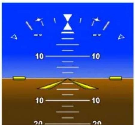
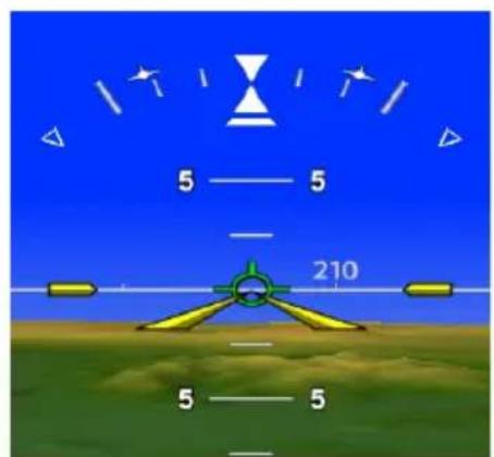
Default Pitch Scale Pitch Scale with SVT
3.4.2 Zero-Pitch Line
This horizontal reference line spans the width of the PFD. It is useful when quickly determining whether the aircraft's current altitude is above or below the approaching terrain.
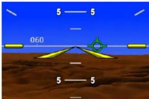
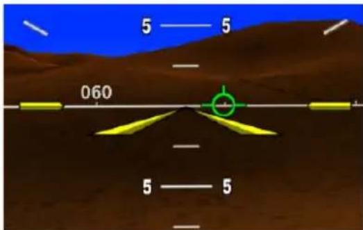
Zero-Pitch Line Above Mountains Zero-Pitch Line Below Mountains
3.4.3 Flight Path Marker

WARNING
Do not use the Flight Path Marker as a flight director.
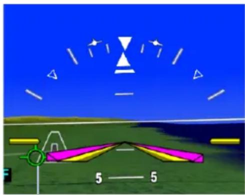
natural_image
Illustration of a helicopter on a grassy field under a blue sky, with no visible text or symbols.Flight Path Marker
The flight path marker displays the aircraft's projected path relative to runways, traffic, terrain, and obstacles.
It indicates the aircraft's current lateral and vertical path, accounting for wind speed and direction relative to the 3-dimensional terrain depiction.
The flight path marker displays when SVT is enabled and active, and ground speed is greater than 30 knots. This is useful when assessing potential conflicts with terrain, obstacles, and traffic.
Displayed terrain or obstacles in the aircraft's flight path depicted extending above the FPM indicate a possible conflict.
3.4.4 SVT Terrain and Obstacles
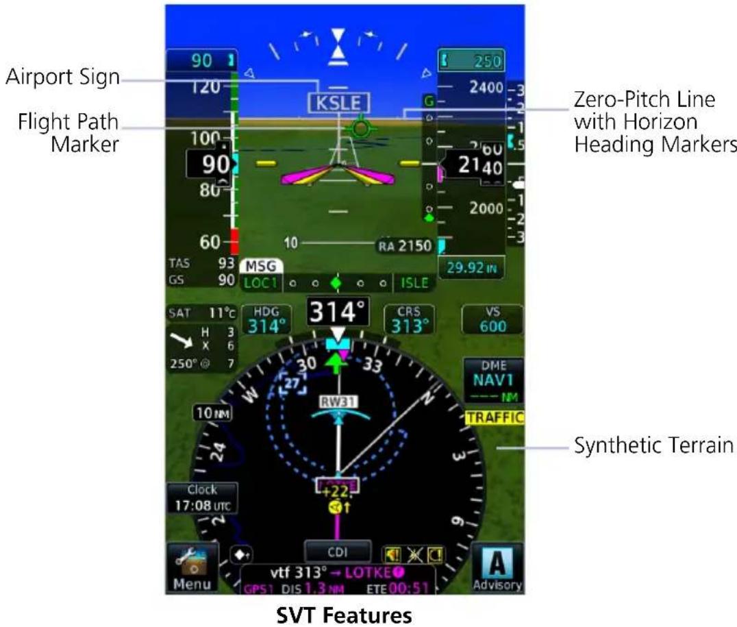
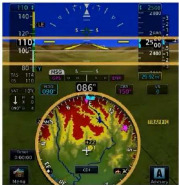
Depicts terrain in front of the aircraft. Color palette indicates terrain and obstacles at varying elevations.
This imagery derives from the aircraft's attitude, heading, GPS 3-D position, and terrain and obstacle databases.

Two-dimensional symbols represent an obstacle's relative height above terrain and distance from the aircraft.
- Includes towers, power lines, and wind turbines
- Obstacles never obstruct instrumentation
- Size varies according to aircraft proximity
TERRAIN AND OBSTACLE ALERTS
When interfaced to a GTN with TAWS-A, TAWS-B or HTAWS enabled, or when TXi Terrain FLTA or TAWS-B is enabled, terrain and obstacle alerts include alert depictions in SVT.
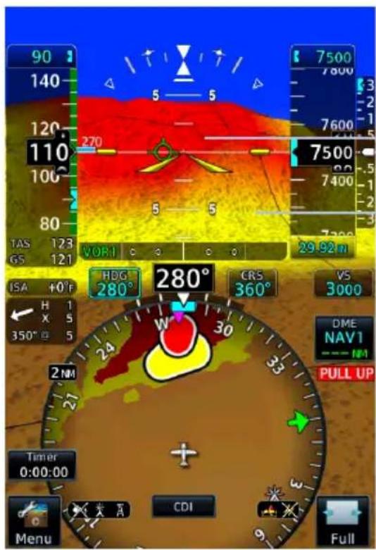
In the event of a terrain or obstacle alert, SVT shading changes to red or yellow, reflecting alert status.
SVT Warning Shade
SVT Caution Shade
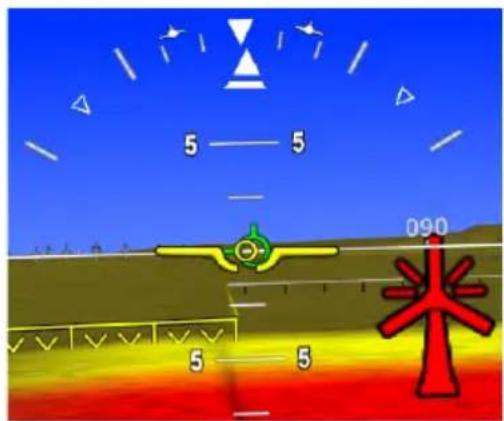
Alerted ObstaclesAlerted Terrain
3.4.5 SVT Runways
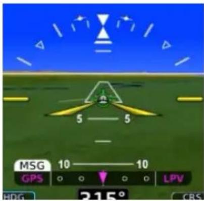
Runway depictions provide improved awareness of runway location with respect to surrounding terrain. Runway thresholds correspond to their correct elevation with respect to terrain.
Runways oriented within 45^ of aircraft heading are represented in white, others in gray.
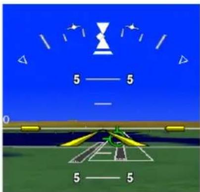
The runway is brighter with a white box outline when a runway approach is active. This improves recognition of the intended runway.
Detail is added as the aircraft becomes closer to the runway. This includes runway numbers and centerlines. Taxiways are not shown in SVT.
3.4.6 SVT Traffic
Detected intruders display in their relative location as determined by the aircraft traffic systems. Traffic in 3-D appears larger when closer, and smaller when further away. Intruders above the zero pitch line are above the aircraft's altitude and intruders below are lower.
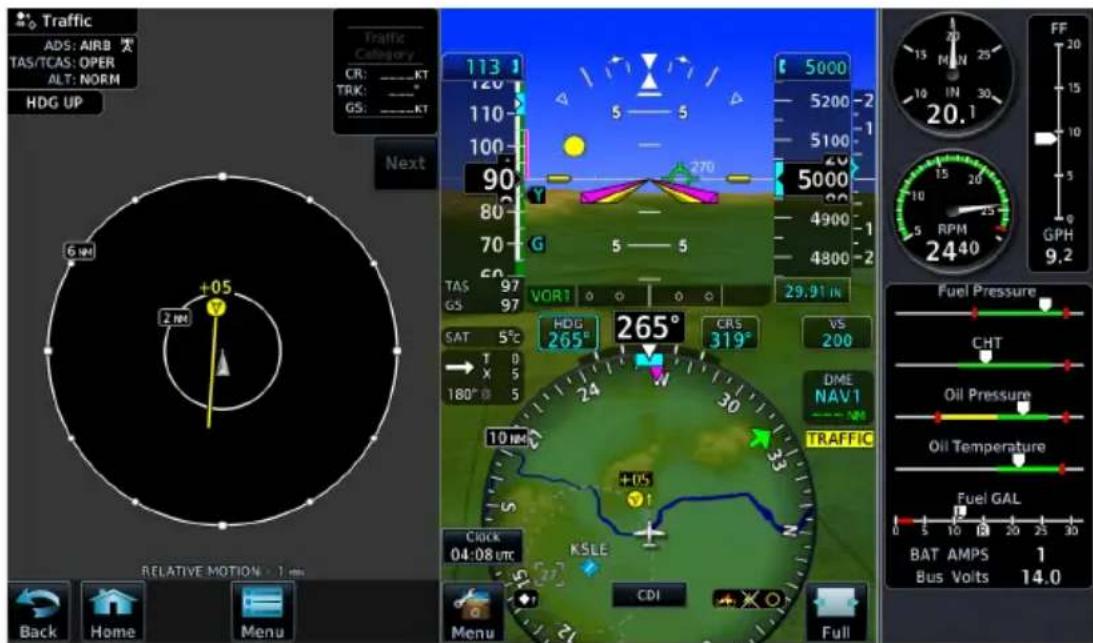
SVT Traffic Display
A white diamond indicates proximate traffic. A yellow circle indicates alerted traffic.
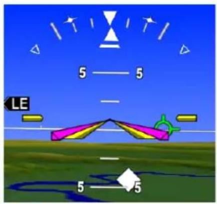
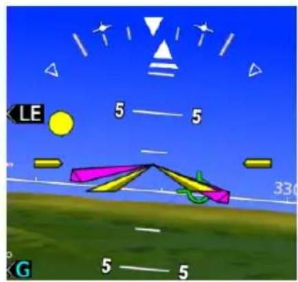
natural_image
Game scene with colored panels, arrows, and geometric shapes on a blue sky (no readable text or symbols)Proximity Advisory Traffic Advisory
3.4.7 Selectable Display Features
Pilot selectable display features provide additional indications in synthetic vision.
HORIZON HEADINGS
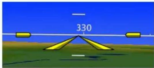
Horizon heading marks synchronize with the HSI. Tick marks and compass heading display in 30° increments on the zero-pitch line. These markings are not visible behind the altimeter and airspeed indicator.
AIRPORT SIGNS
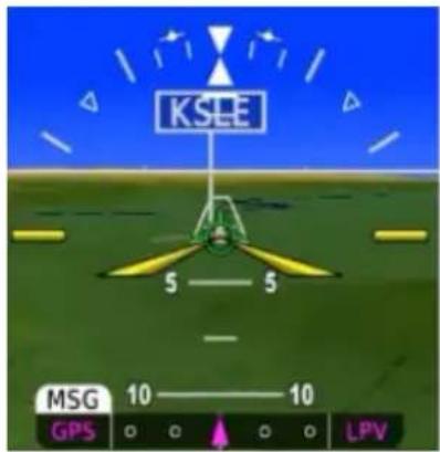
Signs denote airport location and ID. These indications are useful when flying into an unfamiliar airport.
The type of indication is dependent on the aircraft's approach distance.
To reduce clutter, signs for private airports display only if the airport is in the active flight plan.
RANGE FROM AIRPORT
SVT AIRPORT INDICATION
15 nm Signpost and frame only.
8 nm Identifier annunciates within frame.
4.5 nm No indication (runway visible).
SVT FIELD OF VIEW (MFD)
FEATURE LIMITATIONS
• Available only on GDU 1060
• Displays only when the Synthetic Terrain function is active
SVT Field of View
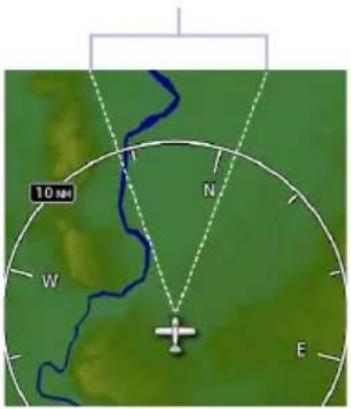
On MFD:
The Map page offers a depiction of the PFD's lateral view.
Terrain and traffic within this V-shaped indicator are visible in synthetic vision.
3.4.8 G500(H) TXi (H)SVT Enablement
For convenience, (H)SVT enablement is available for download at flyGarmin.com. This process is similar to downloading databases and does not require a visit to the dealer.
You must be the aircraft account holder to download this feature. Contact your Garmin dealer for assistance.
To add (H)SVT to your TXi system:
- Sign in to your flyGarmin.com account.
- Select the Devices tab, then locate your aircraft and G500(H) TXi unit.
- Scroll to the "Feature Enablements" section. Select Buy Enablement and then complete the checkout process.
- Insert a blank SD card into the computer/card adapter. Complete the onscreen prompts to create an enablement card.
- Place the enablement card in the top/left slot of the TXi PFD.
- Power up all configured GDUs.
- Activate (H)SVT if necessary.
Enablement occurs upon system startup. While this process is quick, use of a ground power unit or running the engine may be advised depending on the aircraft.
Automatic Flight Control System
AFCS Interface Functions
GPSS
- Flight director
• Mode annunciations
- Half-bank mode
- Altitude capture
• Lateral/vertical deviations - VS preselect
- Servo heading reference
3.5 GPSS
GPSS provides roll command signals from the navigator to the autopilot in order to:
• Make smooth transitions when passing waypoints
• Fly curved leg types (e.g., procedure turns and holding patterns)
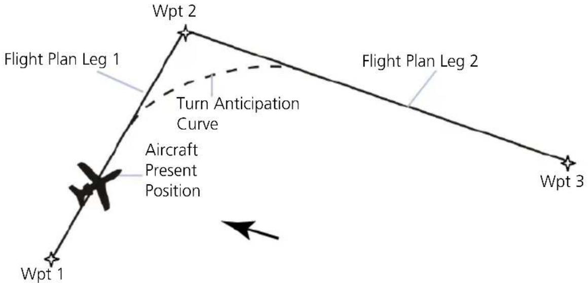
flowchart
graph TD
    A["Wpt 1"] --> B["Aircraft Present Position"]
    B --> C["Turn Anticipation Curve"]
    C --> D["Wpt 2"]
    D --> E["Flight Plan Leg 1"]
    E --> F["Wpt 3"]
    style A fill:#f9f,stroke:#333
    style B fill:#ccf,stroke:#333
    style C fill:#cfc,stroke:#333
    style D fill:#fcc,stroke:#333
    style E fill:#cff,stroke:#333
    style F fill:#ffc,stroke:#333
GPSS Turn Anticipation
If the autopilot is capable of receiving GPSS Roll Steering information and when navigating using GPS guidance, data is transmitted through a digital communications bus from the GDU to the autopilot. In dual GPS installations, the PFD sends Roll Steering information for the currently-selected GPS source. For these autopilots there is no pilot action required to use GPSS.
For autopilots that are not GPSS Roll Steering capable, the GDU converts GPSS turn commands into a heading error signal for the autopilot. When autopilot is operated in HDG mode and GPSS is selected on the PFD, the autopilot flies the turn commands from the GPS navigator selected on PFD 1. An additional touchscreen button is provided on the selected heading popup window for toggling the autopilot heading reference between GPSS and selected heading. After setting the heading bug, "GPSS" displays in selected heading field.
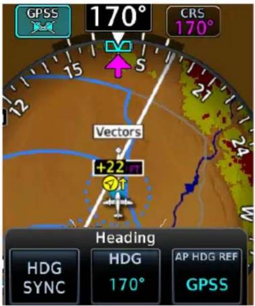
The AP HDG REF key is present if an autopilot is interfaced with the GDU and is configured to use GPSS emulation.
This key changes the autopilot's heading reference between HDG bug and GPSS.
When GPSS is selected:
• Heading bug changes from solid to a cyan outline
- Selection key annunciates a GPSS label
The heading bug may still be adjusted by the pilot as a visual reference without affecting GPSS to the autopilot.
3.5.1 GPSS Mode Icons

Roll steering function is active, but no commands are sent.

GDU is sending roll steering commands to autopilot (pilot side only).

GDU is sending roll steering commands to autopilot (copilot side or second PFD only).

GDU is sending selected HDG commands without GPSS.

Heading bug on HSI is solid.
3.6 Flight Director
FEATURE REQUIREMENTS
• Autopilot flight director commands interfaced to the TXi system
FEATURE LIMITATIONS
Pilot controls for flight director functions are not available on GDU. They are available only on the autopilot/flight director controller.
The TXi system limits the distance the flight director commands may deviate from the aircraft attitude icon. If the pitch command provided by the flight director is greater than that allowed by the display, then the command bars will display at the maximum distance allowed by the PFD. As the aircraft pitch changes to satisfy the command bars, the bars will continue display at the maximum distance from the aircraft attitude symbol until the aircraft pitch deviation is within the command display limit.
3.6.1 Command Cues
Flight director displays commands from the external flight director on the PFD. Depending on aircraft type, these commands display as either single cue (fixed wing) or dual cue (rotorcraft).
Single Cue Dual Cue
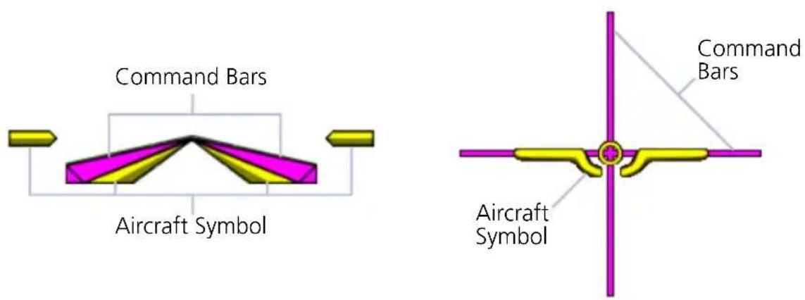
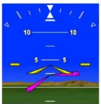
Descend Left Command
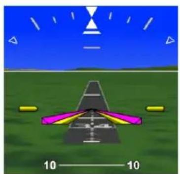
natural_image
3D-rendered aircraft on a grassy field with sky and scale indicators (no text or symbols)Aircraft at Commanded Attitude
Command bars represent pitch and roll guidance.
CONDITION COMMAND INDICATION
| Commanded pitch is greater than GDU maximum allowable limit. | Command bars display at maximum allowable limit. |
| Aircraft pitch exceeds -20°/+30°. | Command bars and annunciations declutter. |
| Aircraft roll exceeds ±65°. | |
| Attitude information becomes invalid or unavailable. | Command bars do not display. |
AFCS ENGAGED INDICATION
For some autopilots, single cue command bars alternate between hollow and solid to show autopilot status.
AFCS Engaged AFCS Not Engaged
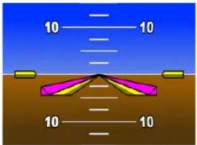
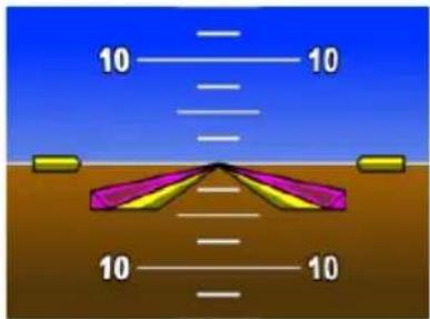
Command bars are hollow.Command bars
3.6.2 IAS & VS Bug Indications
FIXED WING AIRCRAFT ONLY
FEATURE REQUIREMENTS
• TXi software v3.21 or later
FEATURE LIMITATIONS
• Applicable to GFC 500/600 and DFC90 autopilots only
Indicated airspeed and vertical speed bugs may be hollow or solid depending on the state of the corresponding flight director mode.
INDICATED AIRSPEED BUG INDICATIONS
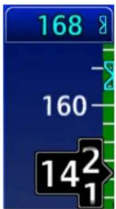
The airspeed bug is hollow when IAS flight director mode is inactive.

Flight director mode is HDG.
Flight Director IAS Mode Inactive

The bug turns solid and automatically changes to the current airspeed value when IAS flight director mode is activated.

Flight director mode is IAS.
Flight Director IAS Mode Active
VERTICAL SPEED BUG INDICATIONS

The vertical airspeed bug is hollow when VS flight director mode is inactive.


Flight director mode is ALT.
Flight Director VS Mode Inactive

The bug turns solid and automatically changes to the current vertical speed when VS flight director mode is activated.
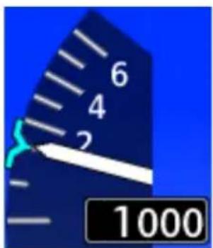

Flight director mode is VS.
Flight Director VS Mode Active
3.7 Altitude Preselect Functions
FEATURE LIMITATIONS
• Mode availability is dependent upon autopilot type
3.7.1 Arming Altitude Capture
Depending on the autopilot and flight director interface, GDU provides altitude preselect capabilities. This allows autopilot to capture a preselected altitude.
If arming is required, ALT CAP arms the altitude capture function and sets the altitude bug.

- Specify altitude value.
- Set ALT CAP to "ARMED."
An optional ARM key is available on the GCU 485 control panel.
If the autopilot does not support altitude preselect functionality, then the selected altitude selected field acts as an altitude alerter. For more about the selected altitude and altitude alerting functions, refer to section 2.7.
3.7.2 Enabling Vertical Speed Control
Depending on the autopilot and flight director interface, GDU provides vertical speed commands to autopilots.

- Specify vertical speed value.
- Set VS ENG to ENGAGED.

VS key label changes to reflect mode status.
"AUTO" indicates the autopilot is actively scheduling vertical speed.
3.8 Low Bank Mode
FEATURE REQUIREMENTS
• PFD
• GFC 600 with low bank mode support
This feature is intended for aircraft that operate at high altitude or that would otherwise require low bank autopilot support (e.g., multi-engine aircraft experiencing engine failure during takeoff).
When crossing the altitude threshold, low bank mode will automatically activate in aircraft configured with low bank support. You may also activate or deactivate low bank mode manually using the installed external switch.
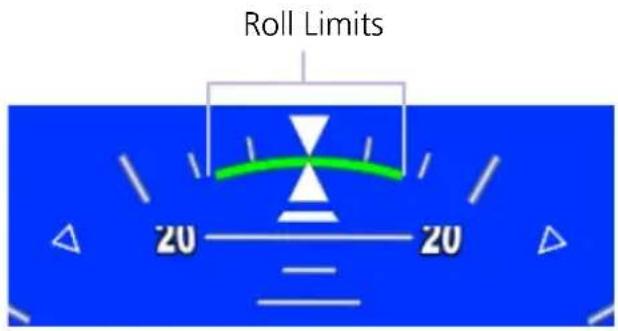
A green arc appears on the roll scale to indicate the roll limits.
Actual roll limits are determined by the autopilot and based on airframe type.
3.9 Servo Heading Reference
ROTORCRAFT ONLY

FEATURE REQUIREMENTS
PFD
GFC 600H
For rotorcraft, the option to beep heading using the yaw beep switch is available while hovering. This displays as the servo heading reference bug on the HSI and as a numeric value in a field adjacent to the HSI.
Servo Heading Reference Bug
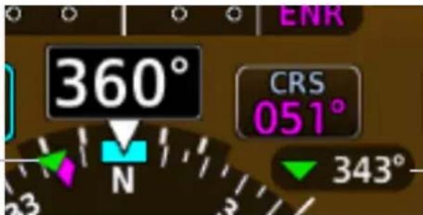
Servo Heading Reference
3.10 AFCS Mode Annunciations
FEATURE LIMITATIONS
• Applicable to GFC 500/600, KFC 225/275/325, DFC90
Autopilot mode status annunciates in a box along the top edge of the PFD.
• Green indicates active status
• White indicates armed mode
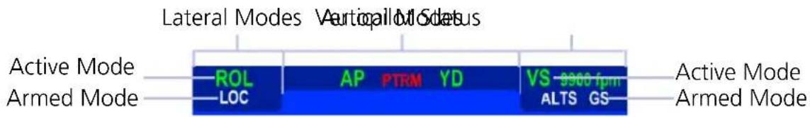
AFCS Status Box
For details about DFC90 autopilot operation and applicable mode annunciations, refer to Avidyne DFC90 Digital Autopilot Pilot Guide.
3.10.1 AFCS Basic Mode Annunciations
ROTORCRAFT ONLY FIXED WING & ROTORCRAFT

Attitude Retention Autopilot


Flight Director Coupled Yaw Dam


Force Trim Release Control Wheel Steering

Pitch, Roll, and Yaw
3.10.2 AFCS Lateral & Vertical Mode Annunciations
| VERTICAL MODE ANNUNCIATIONS | LATERAL MODE ANNUNCIATIONS | ||
| ALT Altitude Hold BC Backcourse Navigation | |||
| ALTS Selected Altitude Capture | GPS | GPS Approach | |
| APR Approach GPS Navigation | |||
| GA Go Around HDG Heading | |||
| GP Glidepath LVL Level Hold | |||
| GS Glideslope | LOC | Localizer Approach | |
| IAS Indicated Airspeed | Localizer Navigation | ||
| LVL | Level Hold | NAV | Navigation |
| PIT Pitch Hold | ROL Roll Hold | ||
| VNAV | Vertical Navigation | VAPP | VOR Approach 1 |
| VPTH | Vertical Path | VOR | VOR Navigation |
| VS | Vertical Speed | ||
^1 GFC 600 only.
3.10.3 AFCS Alert Annunciations
| GFC 500/600 ALERTS, FIXED WING | |
| PFT | Preflight test in progress. |
| PFT | Preflight test failure. |
| AFCS | Autopilot failure. |
| AP | Autopilot is automatically disengaged. |
| AP | Autopilot is manually disengaged. ^1 |
| PTRM | Pitch trim failure. Autopilot may remain engaged.If autopilot disengages, re-engagement cannot occur until after the problem is resolved. May be red or yellow. |
| ↑ELE | Mistrim condition requiring nose up elevator trim. |
| ↓ELE | Mistrim condition requiring nose down elevator trim. |
| ←AIL | Mistrim condition requiring roll trim to the left. |
| AIL→ | Mistrim condition requiring roll trim to the right. |
| ←RUD | Mistrim condition requiring rudder trim to the left. |
| RUD→ | Mistrim condition requiring rudder trim to the right. |
| MAXSPD | Overspeed protection is active. |
| MINSPD | Underspeed protection is active. |
| YAW | Yaw damper failure. May be red or yellow. |
| RB OFF | Rudder bias is manually disabled. ^2 |
| RB FAIL | Rudder bias system is inoperative. ^2 |
| R ENG | Low power detected on right engine.Rudder bias system is active. ^2 |
| L ENG | Low power detected on left engine.Rudder bias system is active. ^2 |
| GLIDE | Smart Glide is active. Appears during IAS vertical mode. ^3,5 |
| EDM | Emergency Descent Mode is active. |
| EDM | Emergency Descent Mode is inhibited or in override mode. |
| ESP | Electronic Stability and Protection is active. ^3,4 |
^1 Annunciation flashes for 5 seconds, then turns off. ^2 GFC 600 twin-engine aircraft only. ^3 GFC 600 only.
^4 Available with TXi software v3.21 and later. ^5 Available with TXi software v3.30 and later.
ACKNOWLEDGE GFC 500 AFCS ALERTS
FEATURE REQUIREMENTS
• TXi software v3.30 or later
FEATURE LIMITATIONS
• Applicable only to GFC 500 with GI 275
A cyan border indicates when GFC 500 AFCS alert annunciations require pilot acknowledgment.
Examples:


Acknowledgeable AFCS Alert Annunciations
You can acknowledge AFCS alert annunciations one of two ways:
- Tap the indicated alert annunciation(s) in the AFCS status box.
OR
- Push the control knob.
| GFC 600H ALERTS, ROTORCRAFT | |
| PFT | Preflight test failure. |
| FCS | HFCS failure. May be flashing or solid. |
| PRY | Servo failure. |
| PRY | Out of detent. |
| PRY | Out of detent >30 seconds.1 |
| PRY | Servo is disengaging.1 |
| CPLD | HFCS Flight Director is disengaging.1 |
| MAXSPD | Overspeed protection is active. |
| LOWSPD | Underspeed protection is active. |
| YAW | Yaw damper failure. May be red or yellow. |

Normal IAS Operating Mode
Underspeed Protection Active

Autopilot maintains airspeed at the current bug value. This value annunciates with the active vertical mode.
3.11 Autopilot Preflight Test

WARNING
Do not use a third party autopilot if it does not disengage normally during the preflight test.
FEATURE LIMITATIONS
• AP DISC availability is dependent upon unit configuration
If the system detects a malfunction in the AHRS, "ATTITUDE" annunciates on the PFD and the autopilot disconnects. For more information, refer to the autopilot operating instructions.
The GAD 43e uses AHRS attitude output to generate analog signal information for an installed ADI-gyro based autopilot system. Should an error occur within the GAD 43e or AHRS output, the autopilot will disengage. Test the autopilot disconnect before each flight.
TEST THE AUTOPILOT DISCONNECT
- Power up all avionics. Allow time for self-test completion.
- Engage autopilot.
- Select Test from the PFD Menu.
- Tap AP DISC.
- Verify autopilot disconnects.
Aerobatic Flight
3.12 Aerobatic Enablement
FEATURE REQUIREMENTS
• GSU 75
• TXi software v3.21 or later
• Purchased Aerobatic feature enabled on GDU
With the aerobatic feature enabled, the PFD continues to display attitude during high acceleration and roll rates.
Enabling the aerobatic feature does not alter extreme attitude indications. Exceeding the limits of the AHRS still results in a red "X" failure annunciation on the PFD. If this should occur, fly the aircraft straight and level and allow the AHRS time to recover.
For more about extreme attitude indications, refer to section 2.4.
4 Multi-Function Display
MFD SETUP
4.1 Nearest Airport Criteria....4-4
4.2 MFD Display Size Options 4-4
MAP
4.3 Map Interactions 4-8
4.4 Map Views .... 4-11
4.5 Map Overlays 4-12
4.6 Map Detail 4-16
4.7 Map Setup 4-17
CHARTS
4.8 Chart Setup....4-33
4.9 Chart Selection 4-35
4.10 Aircraft Position Icon 4-36
ACTIVE FLIGHT PLAN
4.11 Edit Data Fields....4-38
4.12 Collapse All Airwa ys 4-39
4.13 Flight Plan Map Indications 4-40
4.14 VNAV Guidance Indications 4-43
WAYPOINTS
4.15 Waypoint Information 4-46
4.16 Waypoint Selection....4-49
4.17 Remote Radio Frequency Entry 4-51
SIRIUSXM AUDIO ENTERTAINMENT
4.18 SiriusXM Audio Activation 4-53
4.19 Browse Music Channels....4-53
EXTERNAL VIDEO
4.20 SD Video Setup 4-56
Menu selections vary based on features and optional equipment installed with Garmin avionics.
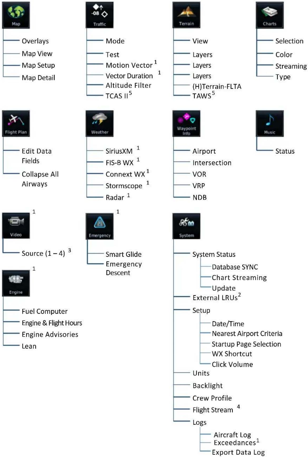
MFD Setup
| MFD SYSTEM SELECTIONS | |
| System Status | View unit, software, and database informationCheck standby database availabilityAccess Database SYNC, Chart Streaming, and manual database update functions |
| External LRUs | Check status of all configured LRUs |
| Setup | Select the MFD startup page and visibilitySet nearest airport criteriaSet the clock and click volumeCreate Weather page shortcut |
| Units | Specify units of measure for displayed data. Selections synchronize across all configured GDUs. Certain LRUs may contain unit settings independent of the TXi system.DistanceTemperatureAltitudeNAV Angle |
| Backlight | Adjust display brightness |
| Crew Profile | Access crew profile management function |
| Flight Stream | Access Bluetooth Setup and Wi-Fi Setup menus |
| Aircraft Log | View engine and airframe cycle counters |
| Exceedances | View and acknowledge exceedance advisoriesAvailability dependent upon unit configuration |
| Export Data Log | Save logged dat a to SD card |
4.1 Nearest Airport Criteria
Filtering criteria includes settings for minimum runway length and hard or soft runway surface options. Selections determine which airports are available when using the nearest airport search feature.
RUNWAY SURFACE MINIMUM RUNWAY LENGTH
Aircraft runway surface selection:
Any
- Hard/Soft
- Hard Only
- Water
Specify the shortest distance required for takeoff and landing.
In the AFM/POH, this is typically the distance given for sea level and the coldest air temperature.
4.2 MFD Display Size Options
4.2.1 MFD 40/60% Resize
FEATURE LIMITATIONS
• GDU 1060 PFD/MFD and MFD/MFD units only
• Availability dependent upon configuration
• Accessible from the MFD Home page only

The Resize key allows you to change the size of the MFD. This option resides on the MFD Home page.
Tapping the key once expands the MFD from its default 40% screen area to 60%. Tapping it again returns the MFD to 40% area.
4.2.2 MFD Full/Split Screen
FEATURE LIMITATIONS
• GDU 1060 MFD/MFD and MFD/MFD/EIS units only

Tapping Full changes the size of one MFD to fill both MFD display areas.

Tapping Split restores the dual MFD view.
Map

To increase situational awareness, the Map page depicts the aircraft's current position relative to land, aeronautical, weather, and traffic information.
FEATURE REQUIREMENTS
• Active GPS source (aircraft position symbol)
• FIS-B, Iridium transceiver, or SiriusXM receiver (weather data)
• GDL 69, GDL 88, GNX 375, GTX 345, or GSR 56, with appropriate weather service subscription (NEXRAD overlay)
• Active weather subscription (Connext and SiriusXM only)
- Valid charts database (ChartView, FliteCharts) with effective database cycle, and aircraft to be airborne
• GWX 68, GWX 70, or GWX 75 (airborne weather radar overlay)
• WX-series Stormscope receiver (lightning data)
• TIS/TAS/TCAS I/TCAS II traffic device (traffic data)
FEATURE LIMITATIONS
- Onboard weather radar not available for GDU 700() EIS/MFD configuration
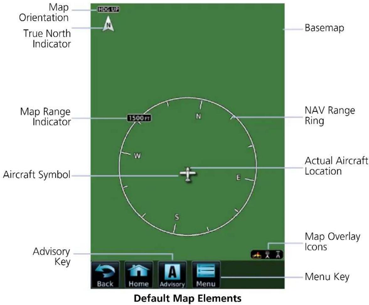
MAP OBJECTS
| Aircraft Symbol | Depicts current aircraft position and orientation. Tip represents actual aircraft location Symbol type is dependent upon configuration Absent if GPS source is not available |
| Basemap | Presents a graphical depiction of land and water data. Basemap is always depicted. |
| Page Orientation Label | Three orientations: North Up orients map to north. Heading Up orients map to current aircraft heading. Track Up orients map to current aircraft GPS track. |
| North Indicator | Indicates True north. Tap to orient the map North Up. |
| Map Range Indicator | Displays current map range in upper left quadrant of range ring (i.e., distance from the aircraft to range ring). Distance is associated with settings in the map setup menu. |
| NAV Range Ring | Displays current direction of travel on a rotating compass. Absent during map interactions (i.e., pan mode). Orientation: Magnetic north |
| Map Overlay Icons | Indicates status of overlays at the current map range. Includes: lightning, obstacles, power lines, precipitation, Stormscope, terrain, and traffic |
Menu Key Accesses map overlay controls and pilot selectable settings.
FEATURE LABELS
To maintain readability, map feature labels remain uniform at all zoom levels.
TRAFFIC UNITS
System Units page selections do not affect the display of traffic on the Map page.

If altitude system units are set to meters, the traffic overlay icon will change, serving as a reminder that traffic altitude values remain in feet.
LAND AND WATER DEPICTIONS
Land and water data are for general reference only. Data accuracy is not suitable for use as a primary navigation source. The information is intended to supplement and not replace official government charts and notices.
DATA DRAWING ORDER
The electronic map draws data in order of priority, from highest (1) to lowest (39), with higher priority features drawn atop those of lower priority.
LEVEL FEATURE LEVEL FEATURE
| 1 Traffic 21 PIREP |
| 2 Ownership 22 AIREP |
| 3 Flight Plan 23 City Forecast |
| 4 TAWS FLTA 24 Surface Conditions |
| 5 Fuel Range Ring 25 Airspace |
| 6 Weather Radar 26 Waypoints |
| 7 Charts 27 Airways |
| 8 Stormscope 28 Reference Grid |
9 Point Obstacles 29 Turbulence
| 10 | Line Obstacles |
| 11 | TFR |
| 12 | Freezing Level |
| 13 | Cell Movement |
| 14 | Lightning |
| 15 | METAR |
| 16 | Winds Aloft |
| 17 | SIGMET |
| 18 | AIRMET |
| 19 | Cyclone |
| 20 | County Warning |
| ulence | |
| 30 | Icing |
| 31 | Radar Coverage |
| 32 | Echo Tops |
| 33 | NEXRAD |
| 34 | Cloud Tops |
| 35 | SafeTaxi |
| 36 | Runways |
| 37 | Terrain |
| 38 | Basemap |
| 39 | Topo |
4.3 Map Interactions
Typical map interactions include zoom, pan, and object selection.
PAN & ZOOM
Panning allows movement of the map in any direction without change to the current zoom setting. Zooming adjusts the current magnification level between pilot specified range parameters.
OBJECT SELECTION
Tapping any object or location on the map displays a map pointer and an information banner.
MAP POINTER

This symbol indicates point of contact on the map. A gray circle highlights any selected waypoint or obstacle.
INFO BANNER
Available information and controls are dependent upon object or location type and proximity to other objects.
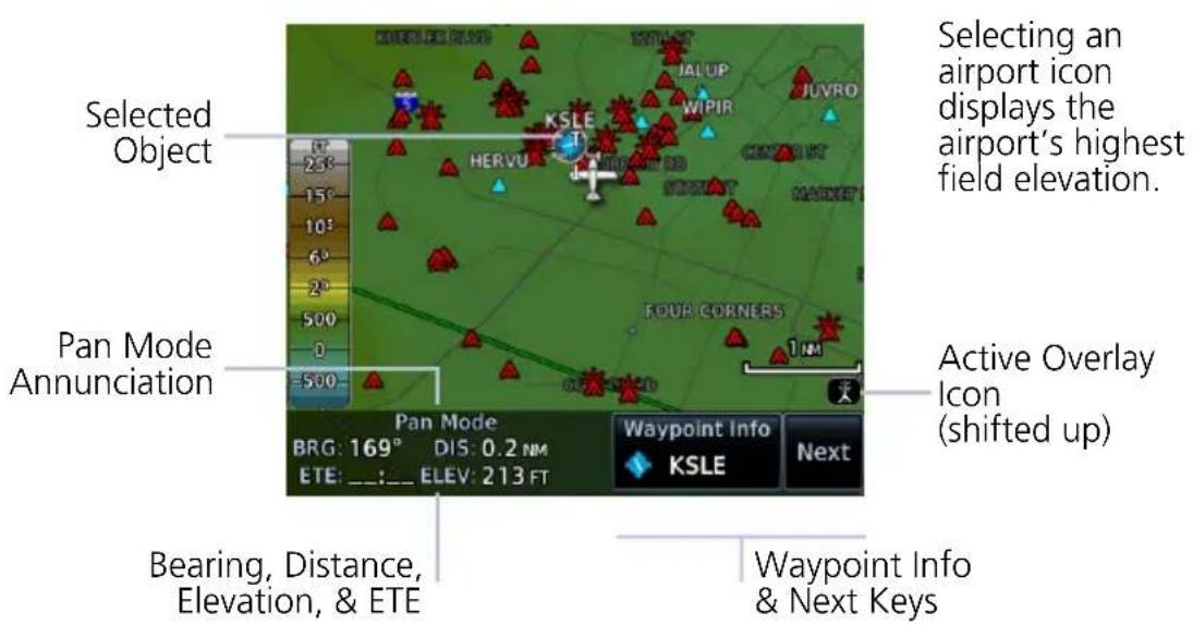
Info Banner Features
• Pan mode annunciation
- Bearing, distance, and estimated time en route from current aircraft position to map pointer
- Location elevation
• Next key for stacked objects
• Maximum altitude AGL and MSL for obstacles
• Information page access key for the selected waypoint, airspace, airport, airport surface hot spot, or TFR
MAP SCALE
FEATURE REQUIREMENTS
• TXi software v3.21 or later
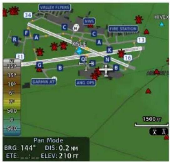
A scale replaces the NAV Range Ring during map interactions, minimizing clutter on the map. This scale depicts half of the current map range (i.e., half of the distance from the aircraft to range ring).

The ring returns once you exit pan mode. To exit pan mode:
- tap the Back key, or
- leave and then reopen the map application
STACKED OBJECTS

To move the selector through each object in proximity of the map pointer, select an object and tap Next.
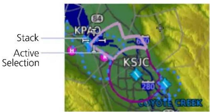
Overlapping objects may be difficult to identify at a given zoom level.
AIRSPACE INFO
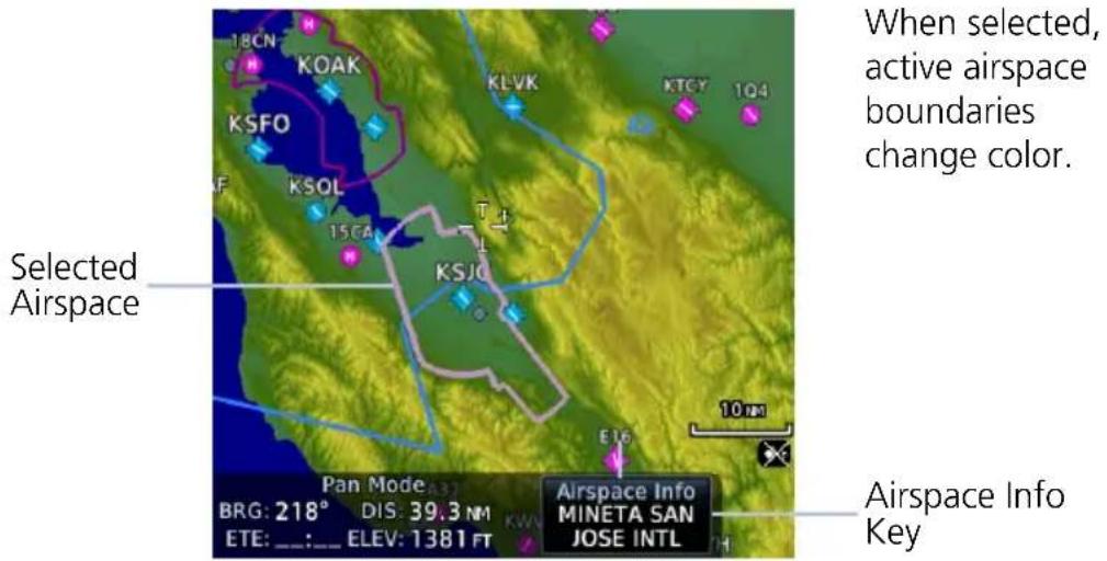
Airspace Info Page Features
Airspace info pages have the same basic layout as waypoint info pages.
The upper portion contains specific data of the selected airspace.
The remainder of the page displays the active airspace boundary and a map of the surrounding area. Data includes:
• Airspace status and type
• ATC entity responsible for the airspace, if applicable
• Floor and ceiling altitudes
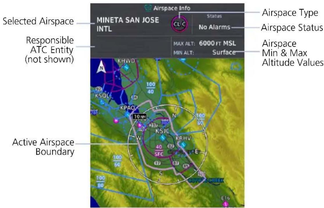
4.4 Map Views

The Map View key in the Map Menu may be used to select a user-configurable map view.
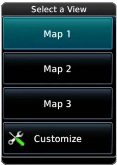
Three different map views may be individually configured. All settings configured in the map menu and map setup menu are saved.
Views may be reconfigured at any time. Any changes to a view configuration are immediately shown on any MFD in the system using that view.
Selecting any view loads previously saved view settings.
Tap the Customize key to change a view name or reset both the name and all menu settings to their default values.
4.5 Map Overlays
Overlay Selections
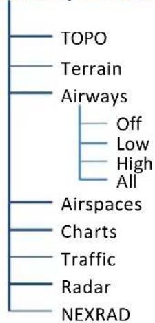
flowchart
graph TD
    A["TOPO"] --> B["Terrain"]
    B --> C["Airways"]
    C --> D["Off"]
    C --> E["Low"]
    C --> F["High"]
    C --> G["All"]
    C --> H["Airspaces"]
    H --> I["Charts"]
    I --> J["Traffic"]
    J --> K["Radar"]
    K --> L["NEXRAD"]
Various map overlay selections may be configured. The following overlay functions are mutually exclusive. Enabling one automatically disables the other.
• NEXRAD, terrain, and weather radar overlays
• Stormscope and SXM lightning
• Cloud tops and echo tops
• Charts and SafeTaxi
4.5.1 Overlay Controls

Control keys enable the specified overlay function only and do not activate interfaced equipment. Overlay keys remain active even in the absence of required data.
TOPO
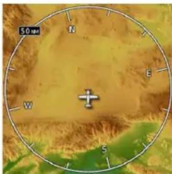
natural_image
Topographic map view showing a compass rose with latitude and longitude grid, no textual labels or annotations• Overlays topographical data and ground elevation scale
• Depictions are similar to a VFR sectional
TERRAIN
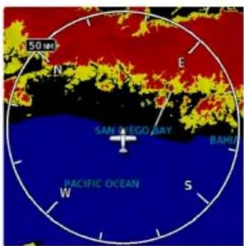
• Overlays terrain map data
- Color shading depicts terrain elevation relative to the aircraft's altitude
AIRWAYS
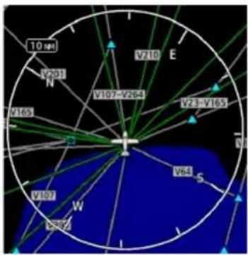
• Overlays the selected airway type(s) with identifier labels
- Options include: low, high, all, or off (none)
- High altitude airways are green, low altitude airways are gray
AIRSPACES
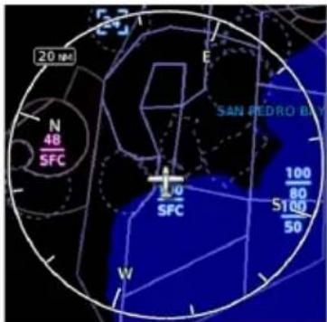
• Overlays airspace boundaries with altitude labels
CHARTS
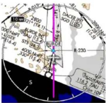
• Overlays geo-referenced chart information
- Approach chart for the active flight plan in the navigator
- Airport surface chart if nearest airport is within 200 nm and no approach is active
- Arrival and departure chart overlays are not available
- Depicts planview area only; excludes inset information (e.g., missed approach procedure view)
- Optional
TRAFFIC
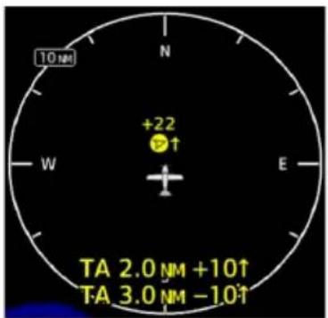
• Overlays traffic information
- Filter selection on Traffic page determines altitude range
- Optional
RADAR
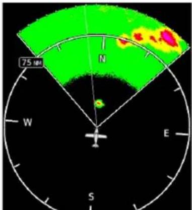
radar
| Direction | Value | | :--- | :--- | | N | High | | E | Medium | | S | Low | | W | Medium |• Overlays airborne weather radar information
- Depictions are identical to those on Weather Radar page
• Excludes WATCH shading
- Optional
NEXRAD
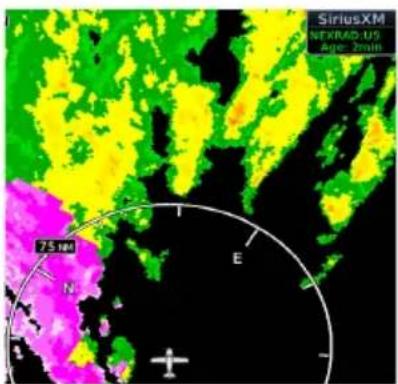
• Overlays datalink precipitation weather information, including product age
- Optional
4.5.2 Overlay Status Icons
Icons indicate which overlays are present at the current map range. A crossed out icon means the overlay is active, but data is unavailable due to a failure, test, or standby condition (where relevant).
The absence of an overlay icon means one of two possible conditions:
- Overlay not present at the current detail level or zoom setting.
- Overlay control is off.

Obstacle Power Line


Stormscope Traffic


Terrain Data not available

4.6 Map Detail

Select the level of detail on the map.
Changes to the map detail level take effect immediately.
| FEATURE | MAP DETAIL LEVEL | |||
| FULL HIGH MED. LOW | ||||
| Small Cities | ● | |||
| Medium Cities | ● | |||
| Large Cities | ● | |||
| Freeways | ● | |||
| Highways | ● | |||
| Roads | ● | |||
| Railroads | ● | |||
| Basemap Labels | ● | |||
| VORs | ● | ● | ||
| NDBs | ● | ● | ||
| Line Obstacles | ● | ● | ||
| Point Obstacles | ● | ● | ||
| Airspaces that are not prohibited or restricted | ● | ● | ||
| Waypoints | ● ● | ● | ||
| SafeTaxi | ● ● | ● | ||
| Prohibited Airspaces | ● ● | ● | ||
4.7 Map Setup
Map Setup
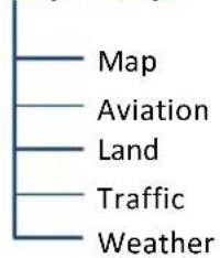
Overlay data controls are located in the Map Setup menu. Changes to an overlay setting take effect immediately. Selections are organized into five groups.
RESTORE DEFAULTS

Located in the bottom of each list. This key restores all original factory settings for the active group tab.
4.7.1 Map Selections
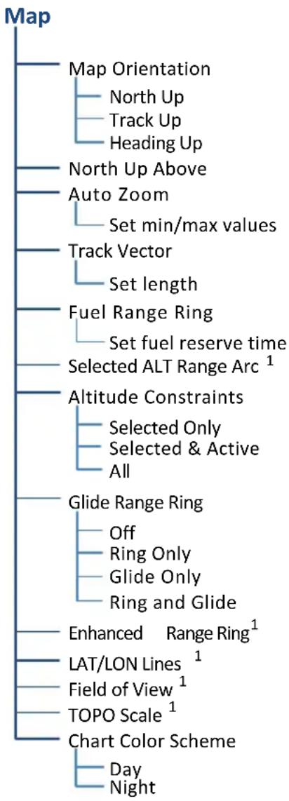
flowchart
graph TD
    A["Map"] --> B["Map Orientation"]
    B --> C["North Up"]
    B --> D["Track Up"]
    B --> E["Heading Up"]
    A --> F["North Up Above"]
    A --> G["Auto Zoom"]
    G --> H["Set min/max values"]
    A --> I["Track Vector"]
    I --> J["Set length"]
    A --> K["Fuel Range Ring"]
    K --> L["Set fuel reserve time"]
    A --> M["Selected ALT Range Arc¹"]
    A --> N["Altitude Constraints"]
    N --> O["Selected Only"]
    N --> P["Selected & Active"]
    N --> Q["All"]
    A --> R["Glide Range Ring"]
    R --> S["Off"]
    R --> T["Ring Only"]
    R --> U["Glide Only"]
    R --> V["Ring and Glide"]
    A --> W["Enhanced Range Ring¹"]
    W --> X["LAT/LON Lines¹"]
    W --> Y["Field of View¹"]
    W --> Z["TOPO Scale¹"]
    A --> AA["Chart Color Scheme"]
    AA --> AB["Day"]
    AA --> AC["Night"]
^1 On/off functionality only.
All Map tab selections provide on/off and range setting options unless otherwise noted.
Shared Map Settings
Changes to the following map settings also take effect on the configured datalink weather app(s). You may adjust these settings from the appropriate Map Setup tab.
- North Up Above range setting and LAT/LON Lines (Map tab)
- Runway Extensions and waypoint display range settings (Aviation tab)
- Road Detail, City Detail, State/Province Borders, and River/Lake Detail (Land tab)
^1 Requires EIS. ^2 Systems with at least one PFD. ^3 GDU 1060 only.
| MapOrientation | Specifies map display orientationLabel above North indicator shows current orientation |
| North Up Above | Specifies range at which the map orientation changes to North Up |
| Auto Zoom | Automatically adjusts page to display the next waypoint in flight plan at the closest possible map rangePresents SafeTaxi data while aircraft is on groundAutomatic functionality is overridden during manual zoom interactions. It resumes when:Another waypoint is in sequenceAircraft transitions from on ground to airborneAuto zoom range matches manual override rangeSet minimum and maximum values to best meet operational needs |
| Track Vector | Indicates current ground trackEnd of arrow represents aircraft position at the specified time interval |
| Fuel Range Ring | Estimates the remaining range at the current fuel consumption rate and ground speed1Calculations are based on the pilot specified fuel quantity in the fuel computerDashed green circle indicates selected range to reserve fuelSolid yellow circle indicates total endurance range |
| Selected ALT Range Arc | Represents location at which the aircraft is expected to reach selected altitude2 |
| Altitude Constraints | Displays altitude constraint labels within the flight plan |
| Glide Range Ring | Identifies map region within estimated gliding distance and/or best glide airportOptions: Ring Only, Glide Only, Ring and Glide |
| Enhanced Range Ring | Provides a more precise indication of distance between the aircraft and map objectsFixed range value at half the distance of NAV range ring |
| LAT/LON Lines• | Displays latitude and longitude lines |
| Field of View | Depicts lateral terrain view presented in SVT3Synthetic Terrain function on PFD must be active for indication to display |
| TOPO Scale• | Displays a topographical elevation scale |
| Chart Color Scheme | Changes chart overlay color for day or night view |
Enhanced Range RingFuel Range Ring
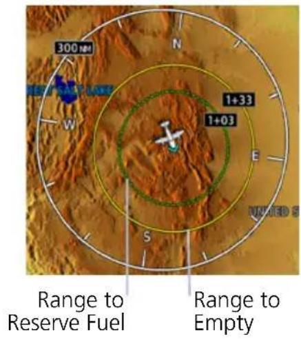
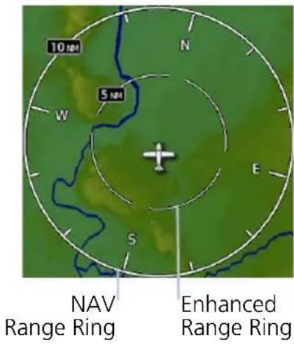
Field of View (GDU 1060 Only)
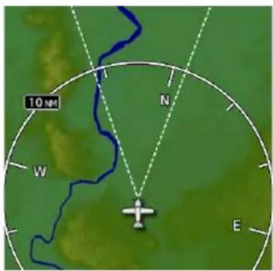
Selected ALT Range Arc
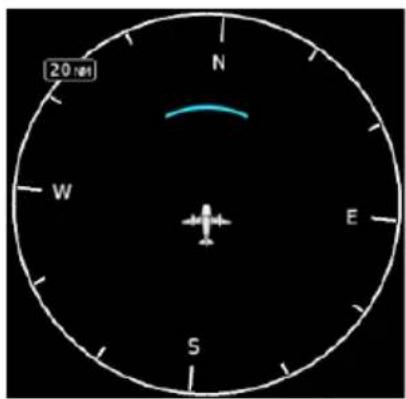
TOPO Scale Track Vector
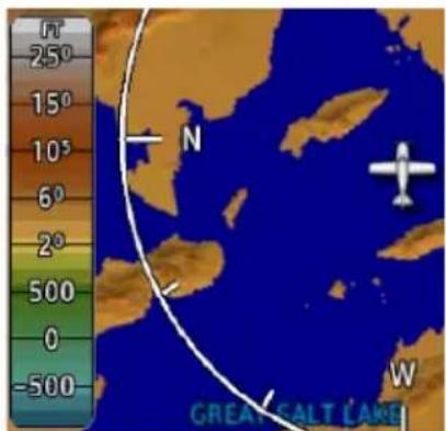
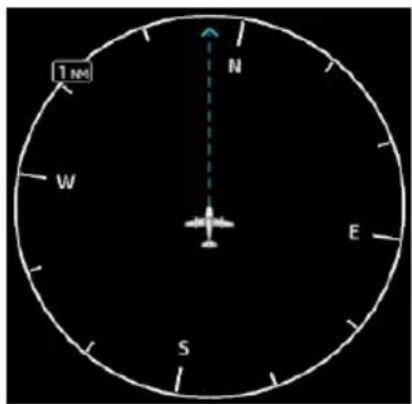
When choosing map scales:
- Consider which map scales or zoom levels to use to achieve the desired level of detail and map information.
- Generally, use smaller map scales or zoom levels in and around terminal areas and whenever precise navigation is required (e.g., airway or radial intercepts).
- During cruise flight, map scale settings often increase to balance navigation, situational awareness, and decision making.
Map Orientation sets the map page to either North Up, Track Up, or Heading Up. North Up is useful when zoomed out to view the entire route or a frontal system on a NEXRAD display.
Using the North Up Above feature causes the screen to switch at certain zoom levels. This is useful as a shortcut to quickly increase situational awareness.
Track vector length options display as a dashed line and arrow extending from the aircraft icon, showing current track and distance the aircraft will travel in the selected time.
If the track vector is placed over a point on the map, and no data is entered into the system, the GDU indicates a wind-corrected GPS track to that point. This is useful for intercepting airways and radials, making small but positive lateral corrections during approaches, and in setting up for arrivals in the terminal area.
GLIDE RANGE RING
FIXED WING AIRCRAFT ONLY
FEATURE REQUIREMENTS
• GTN Xi series navigator (host) configured for Glide Range Ring
• Datalink winds or compatible PFD (Glide Range Ring wind compensation)
- For best glide performance, the aircraft must be configured in accordance with POH guidance
FEATURE LIMITATIONS
Glide Range Ring is a function of the GTN Xi seres navigator. GDU does not calculate glide range, nor does it determine best glide airports; it only displays this data when received from GTN Xi. For more about this feature, consult GTN Xi Pilot's Guide.
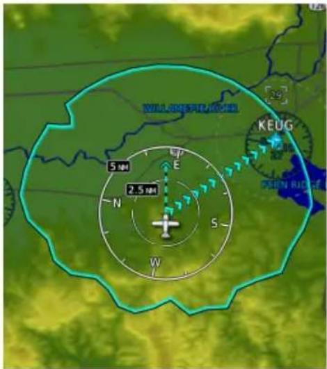
Identifies map region and features within gliding distance. A cyan border indicates where the projected glide descent reaches 50 ft above terrain.
Calculations are performed by the host GTN Xi navigator.
The Glide Range Ring is an estimate based on the best glide speed and glide ratio published for the aircraft. For more information, consult the AFM/POH.
This overlay receives wind information from the ADAHRS if present. It does not require an ADAHRS unit for operation.
Glide Range Ring Options
Off
Ring Only
Glide Only
Ring and Glide
The Glide Range Ring depicts the estimated glide range down to 50 ft AGL. It does not show beyond 50 ft AGL where the aircraft reaches the ground.
Data updates occur approximately every 5 seconds.
Ring Only Ring and Glide
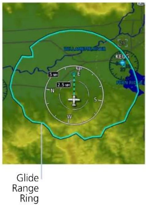
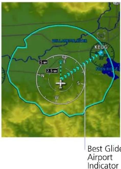
Enable Glide Range Ring to stay aware of all airports within gliding distance. This is extremely helpful should you experience engine failure.
Glide Only
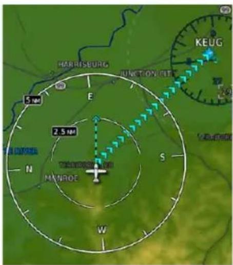
Best Glide Airport Indicator
Cyan arrows point toward the best glide airport at any given time. Best glide airport selection is based on distance from current location, runway length, and weather (if available). Airports beyond the range ring are not considered for routing.
To enable, tap Glide Range Ring and select Ring and Glide or Glide Only.

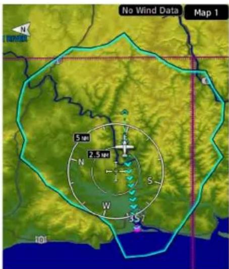
"No Wind Data" Indicator
This indication appears when FMS winds and datalink winds aloft are either unavailable or invalid.
The Glide Range Ring does not adjust to account for current winds when the indicator is present.
No Wind Data
4.7.2 Aviation Selections
Aviation
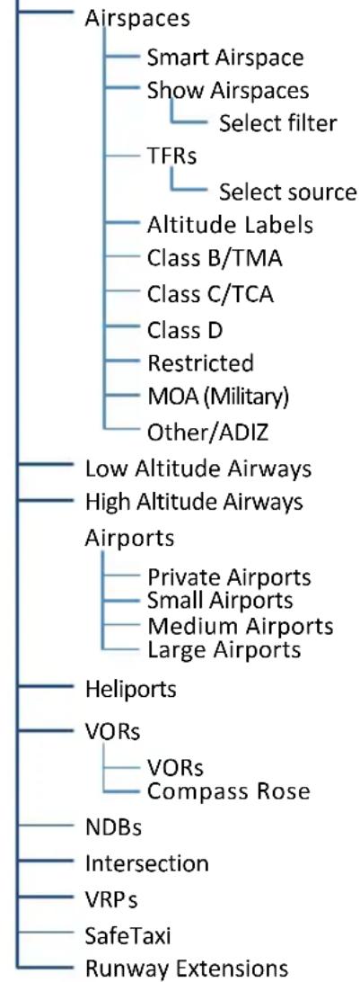
flowchart
graph TD
    A["Airspaces"] --> B["Smart Airspace"]
    A --> C["Show Airspaces"]
    C --> D["Select filter"]
    C --> E["TFRs"]
    E --> F["Select source"]
    E --> G["Altitude Labels"]
    G --> H["Class B/TMA"]
    G --> I["Class C/TCA"]
    G --> J["Class D"]
    G --> K["Restricted"]
    G --> L["MOA (Military)"]
    G --> M["Other/ADIZ"]
    N["Low Altitude Airways"] --> O["High Altitude Airways"]
    P["Airports"] --> Q["Private Airports"]
    P --> R["Small Airports"]
    P --> S["Medium Airports"]
    P --> T["Large Airports"]
    U["Heliports"] --> V["VORs"]
    V --> W["VORs Compass Rose"]
    X["NDBs"] --> Y["Intersection"]
    Z["VRPs"] --> AA["SafeTaxi"]
    AB["Runway Extensions"] --> AC["End"]
Setup options allow the customization of aeronautical information.
- Filter airspace data according to altitude
- Select a TFR source
- Specify airway types and range values
- Customize the display of SafeTaxi and waypoint data
- Display runway extensions for a destination airport
With the exception of TFRs, all Aviation tab selections provide on/off and range setting options.
The runway feature extends the runway's centerline out 5 NM from the runway threshold. This is useful when setting up for a visual approach, especially at airports with parallel runways or low visibility.
AVIATION DATA SYMBOLS

Non-towered, non-serviced airport ^1

Non-towered, serviced airport ^1

Towered, non-serviced airport ^1

Towered, serviced airport ^1

Soft surface, non-serviced airport

Soft surface, serviced airport

Restricted (private) airport Unknown airport


Heliport ILS/DME or DME only


Intersection LOM


NDB TACAN


VOR VOR/DME


VORTAC VRP


User Airport User Waypoint


Runway extension ATK

4.7.3 Smart Airspace
Garmin's Smart Airspace feature automatically de-emphasizes non-pertinent airspace away from the aircraft's current altitude.
| SMART AIRSPACE CRITERIA | |
| AIRCRAFTALTITUDE | AIRSPACE PROXIMITYTO AIRCRAFT1 |
| Sea level >1,000 ft | |
| >10,000 ft 2,000 ft | |
An airspace boundary turns gray when its vertical proximity to the aircraft is >1,000 ft. This range increases linearly to 2,000 ft as the aircraft ascends to 10,000 ft.
^1 Vertical distance above and below aircraft altitude.
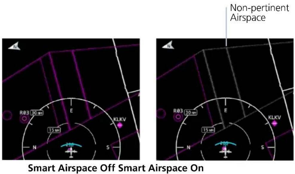
AIRSPACE DATA SYMBOLS
 | Class B Altitude Label (ceiling/floor) |  | Class C/TCA |
 | Class C Altitude Label (ceiling/floor) |  | Class D |
 | Class D Altitude Label (ceiling only) |  | Restricted |
 | TFR MOA |  | |
 | Class B/TMA Other/ADIZ |  |
4.7.4 SafeTaxi
During flight, SafeTaxi database is mutually exclusive with chart databases. SafeTaxi and hot spot data display only when the Charts overlay is off.
SafeTaxi Features
• Airport diagram overlay that includes hot spot information
• Aircraft position relative to taxiways, runways, and airport landmarks
• Automatically overrides Charts overlay function during ground operations
- Pilot selectable range options
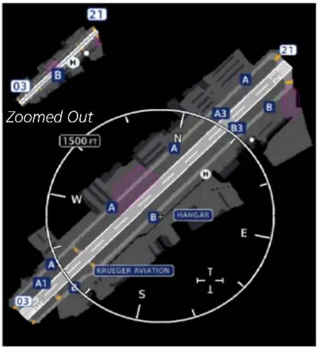
Zoomed In
SafeTaxi provides greater map detail and higher image resolution at lower zoom levels.
Feature labels denote:
- Runways
- Taxiways
- Airport landmarks
SAFETAXI DATA SYMBOLS

Runway Taxiway


Helipad Construction Area


Airport Beacon Unpaved Parking
HOT SPOTS
SafeTaxi hot spots identify locations on an airport surface where positional confusion or runway incursions are likely to occur. These known problem areas require heightened attention by pilots.
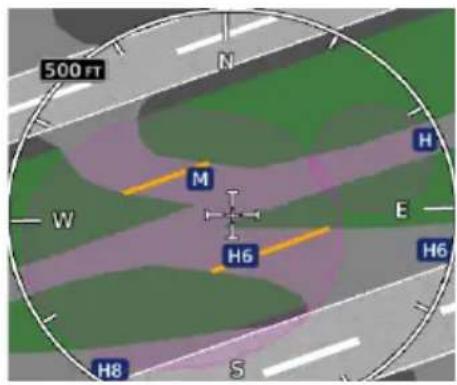
The following airport features may be deemed hot spots by aviation authorities.
• Intersecting taxiways and runways
• Complex ramp areas
• Directional limitations
- Limited wing-tip clearance
• Overflight risk
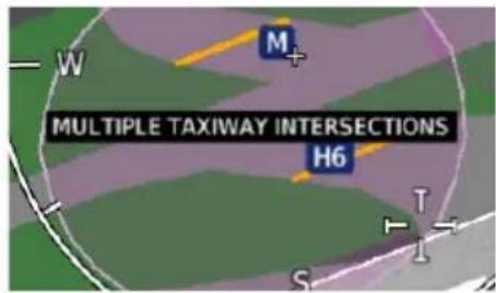
Selecting the border of a hot spot displays a brief summary of the indicated hazard and an information key.

Tap Hot Spot Info to view additional location details and potential hazard information. Numbering corresponds to a list on the airport diagram.

CONSTRUCTION SPOTS
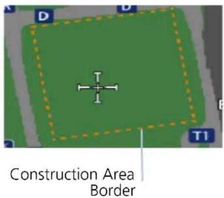
There are no expanded detail keys or notes associated with construction areas.
4.7.5 Land Selections
Land
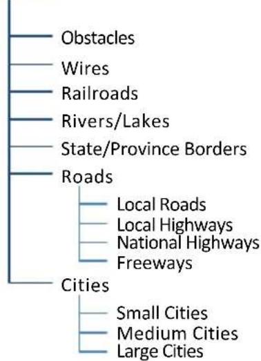
flowchart
graph TD
    A["Obstacles"] --> B["Railroads"]
    C["Wires"] --> D["Rivers/Lakes"]
    E["Roads"] --> F["Local Roads"]
    E --> G["Local Highways"]
    E --> H["National Highways"]
    E --> I["Freeways"]
    J["Cities"] --> K["Small Cities"]
    J --> L["Medium Cities"]
    J --> M["Large Cities"]
Selections include on/off and range setting options for all land features.
LAND DATA SYMBOLS

Railroad National Highway


River/Lake Freeway


State/Province Border Small City

Local Road Medium City


Local Highway Large City

4.7.6 Traffic Selections
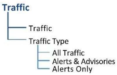
flowchart
graph TD
    A["Traffic"] --> B["Traffic"]
    A --> C["Traffic Type"]
    C --> D["All Traffic"]
    C --> E["Alerts & Advisories"]
    C --> F["Alerts Only"]
Filter traffic data according to type. Other selections include on/off and range setting options.
4.7.7 Weather Selections
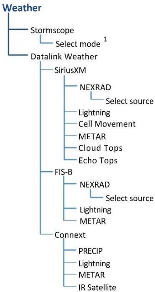
flowchart
graph TD
    A["Weather"] --> B["Stormscope"]
    A --> C["Datalink Weather"]
    C --> D["SiriusXM"]
    C --> E["FIS-B"]
    C --> F["Connext"]
    D --> G["NEXRAD"]
    G --> H["Select source"]
    D --> I["Lightning"]
    I --> J["Cell Movement"]
    I --> K["METAR"]
    I --> L["Cloud Tops"]
    I --> M["Echo Tops"]
    E --> N["NEXRAD"]
    N --> O["Select source"]
    E --> P["Lightning"]
    P --> Q["METAR"]
    F --> R["PRECIP"]
    F --> S["Lightning"]
    F --> T["METAR"]
    F --> U["IR Satellite"]
Setup options are available for all active weather services.
- Alternate between lightning display modes (Stormscope only)
- Specify a datalink weather source
- Toggle individual weather products on/off
Charts

The Charts page provides terminal procedures and airport surface diagrams.
FEATURE REQUIREMENTS
• A current and valid chart database
FEATURE LIMITATIONS
- Geo-referencing is not available for some arrival and departure charts
- FliteCharts and ChartView databases are optional and mutually exclusive
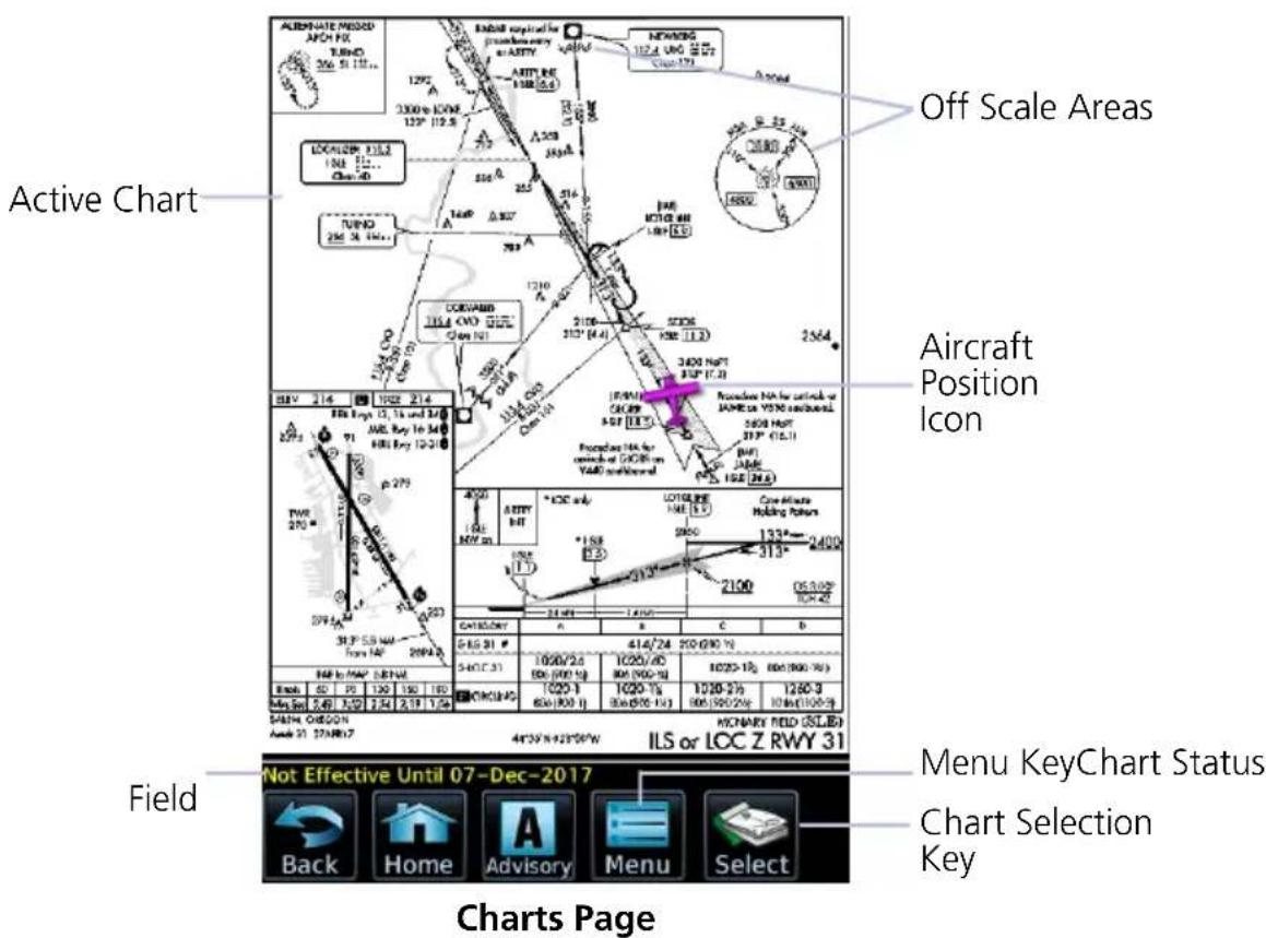
CHART STATUS
Active chart status displays in the lower left corner of the Charts page.
Getting Newer Charts
Charts Changed
Expired 28-Apr-2016
Not Effective Until 31-Mar-2016
Charts are in the process up updating.
Charts are up to date.
Database is out of date.
Database is installed before it is current.
4.8 Chart Setup
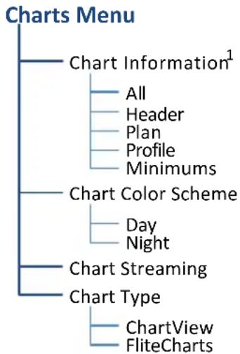
flowchart
graph TD
    A["Charts Menu"] --> B["Chart Information¹"]
    B --> C["All"]
    B --> D["Header"]
    B --> E["Plan"]
    B --> F["Profile"]
    B --> G["Minimums"]
    A --> H["Chart Color Scheme"]
    H --> I["Day"]
    H --> J["Night"]
    A --> K["Chart Streaming"]
    A --> L["Chart Type"]
    L --> M["ChartView"]
    L --> N["FliteCharts"]
Chart setup selections reside in the Charts menu.
^1 ChartView only.
| Chart Information | Displays individual sections of a chart in the ChartView database only. Options include:AllHeaderPlanviewProfileMinimums |
| Chart Color Scheme | Toggles chart color scheme between day and night modes.Day mode displays black on white backgroundNight mode displays inverse white on black background |
| Chart Streaming | Enables automatic streaming of individual charts to the GDU during database synchronizationStreams from the newest chart databaseCharts from the previously loaded database remain available for displayToggling this function off does not affect Database SYNCNo restart required |
| Chart Type | Toggles chart database type between FliteCharts and ChartViewSelections must be made on the groundRestart required for changes to take effect |
CHARTVIEW INFORMATION SECTIONS
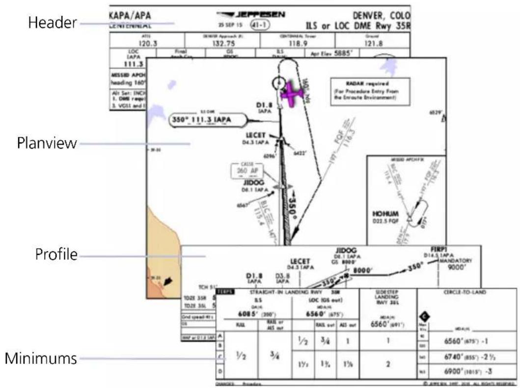
4.9 Chart Selection

To open a menu, tap Select.
Enter an airport identifier and choose from the available chart types.
CHART TYPES
| Information | Airport surface charts, alternate minimums, rate of climb and descent tables, inoperative components or visual aids tables, hot spots, land and hold-short operations, and other destination specific flight data. |
| Departure | Departure route descriptions, including takeoff minimums and obstacle notes. |
| Arrival | Arrival procedure instructions.Arrival charts are listed in alphabetical order. |
| Approach | All approach charts associated with the selected airport.Charts are listed according to level of precision and approach type. Runways are listed in numerical order. |
AUTOMATIC CHART SELECTION
Automatic chart selection occurs every time the Charts page is opened. The type of chart selected is determined by aircraft status and content from the active flight plan. This function does not override manual chart selections unless a change occurs during one of the following conditions.
CONDITION CHART DISPLAY DEFAULT
| No flight plan or destination airport is present. | Nearest airport diagram. |
| Aircraft is on the ground. | Nearest airport diagram (regardless of flight plan). |
| Flight plan is present, but approach is not loaded. | Airport surface chart for previous airport in flight plan. |
| Approach is loaded in the selected GPS navigator. | Applicable approach chart. |
| No charts are available for a selected airport. | “Chart not available for [airport ID].” |
4.10 Aircraft Position Icon
FEATURE REQUIREMENTS
• Aircraft position is fully within chart boundaries
- FliteCharts or ChartView is active (airborne maneuvers only)
• SafeTaxi is active (ground maneuvers only)
FEATURE LIMITATIONS
• SIDs and STARs do not support the display of aircraft position
• Not available for arrival and departure charts
• Displays only within the planview area of geo-referenced approach charts
Aircraft position displays on airport diagrams and approach charts when the current position is known.
POSITION UNAVAILABLE INDICATION

A fault icon displays in the lower right-hand page corner when:
• Aircraft position data is not available
- Backup GPS is in use
- Selected chart does not contain geo-referenced data
• Selected chart layer is not All or Planview
OFF SCALE AREAS
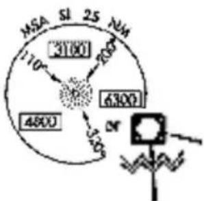
Some charts contain supplemental information within the planview. These areas are considered off scale as they are not geographically accurate.
Aircraft position depictions in off scale areas should be judged relative to the geo-referenced information within the planview only.
Active Flight Plan

Current flight plan information received from a Garmin navigator displays as a scrolling list on the Active Flight Plan page.
FEATURE REQUIREMENTS
• External GPS navigator
- Configured GTN, v6.50 or later (VNAV constraint data)
• Active flight plan
FEATURE LIMITATIONS
- Create, edit, and delete functionality not available on GDU. Any alterations to a flight plan must be performed using the external navigator
• Displays up to 100 waypoints for an active flight plan
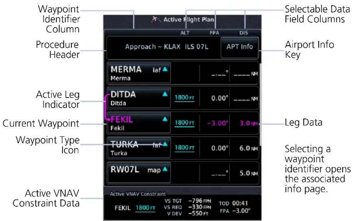
Active Flight Plan Page
AIRPORT INFO

For convenience, airport information is directly accessible from the procedure header. This includes airports specified in active approaches, arrivals, and departures.
ACTIVE VNAV CONSTRAINT WINDOW
VNAV Constraint Data
ALT - Altitude Constraints VS TGT - Vertical Speed Target VS REQ - Vertical Speed Required V DEV - Vertical Deviation TOD/BOD - Top/Bottom of Descent FPA - Flight Path Angle
VS TGT and FPA are pilot-specified values received from the GTN. All other constraint values are based on VNAV calculations.
The TOD field may change to display BOD once the top of descent value counts down to zero.
4.11 Edit Data Fields
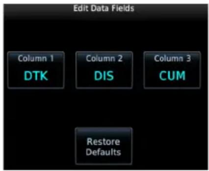
To select a flight plan data column, tap Edit Data Fields. Columns are arranged in numerical order (1 - 3).
To restore columns to default display settings, tap Restore Defaults.
Data Field Selections
ALT - Altitude Constraint CUM - Cumulative Distance DIS - Distance DTK - Desired Track ETA - Est. Time of Arrival ETE - Est. Time En Route FPA - Flight Path Angle
Selections are identical for each column. By default, flight plan information fields display: Column 1: DTK Column 2: DIS Column 3: CUM
4.12 Collapse All Airways
Airways automatically display as flight plan legs. A single airway may contain numerous legs. Airways without an active leg collapse for simplification. This does not affect airway legs shown on the external navigator(s).
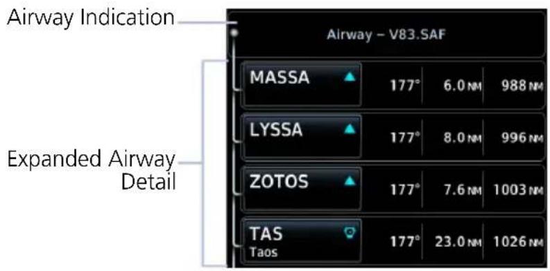
All airways begin with an indicator field and end with an exit identifier.

To hide all waypoints along an airway, but not the airway's exit waypoint, tap Collapse All Airways.
4.13 Flight Plan Map Indications
FLIGHT PLAN LEG STATUS
| LEG STATUS COLOR |
| Active Magenta |
| Next & Future White |
| Past or Inactive Gray |
Active, next, and previous flight plan legs overlay on the Map page and HSI Map. These indications are display only.
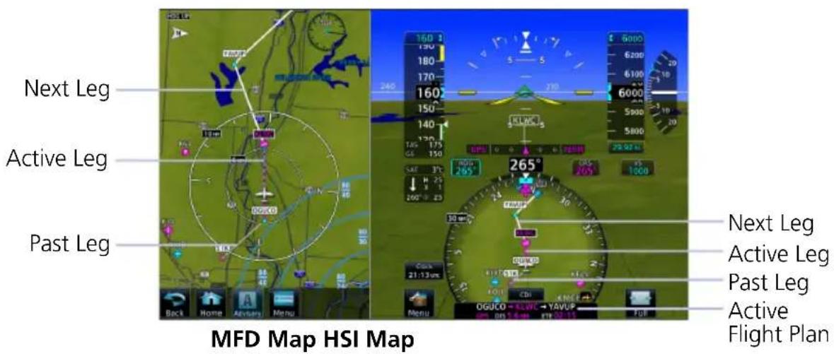
ALONG TRACK WAYPOINT IDENTIFIER LABELS

The along track waypoint (ATK) icon represents a temporary lateral position (or checkpoint) relative to an existing waypoint in the flight plan.
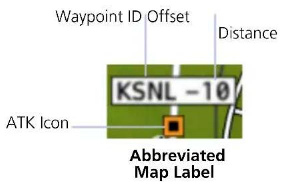
Identifier labels on the Map page denote the adjacent waypoint's ID and offset distance from the specified ATK.
Selecting an ATK displays its bearing and distance in the info banner.
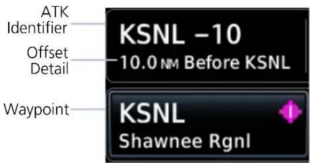
Unlike waypoints, ATKs indicate a temporary route fix in the flight plan. The GDU receives this data from the navigator, not a database.
Active Flight Plan Page
Enabling the altitude constraint function in the Map Setup menu adds a VNAV altitude reference to the flight plan. The ATK serves as a lateral checkpoint when the feature is off.
ALTITUDE CONSTRAINT LABELS
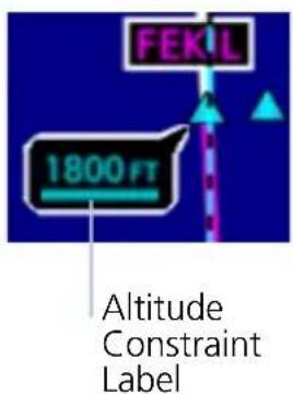
Altitude constraint data display as text labels on the Map page. Units are typically feet or meters depending on current altitude setting in the Units page. They display as flight level altitudes if specified as such on the navigator.
If excessive labels are cluttering the map, this feature may be turned off.
USER AIRPORT ICON

A dedicated icon indicates user created airport waypoints received from the external GPS navigator.
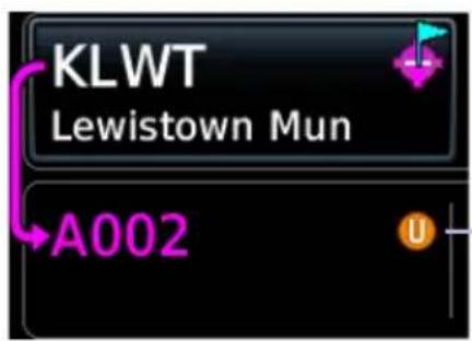
User airport indications display on both the Active Flight Plan and Map pages.
Identifier Type Icon
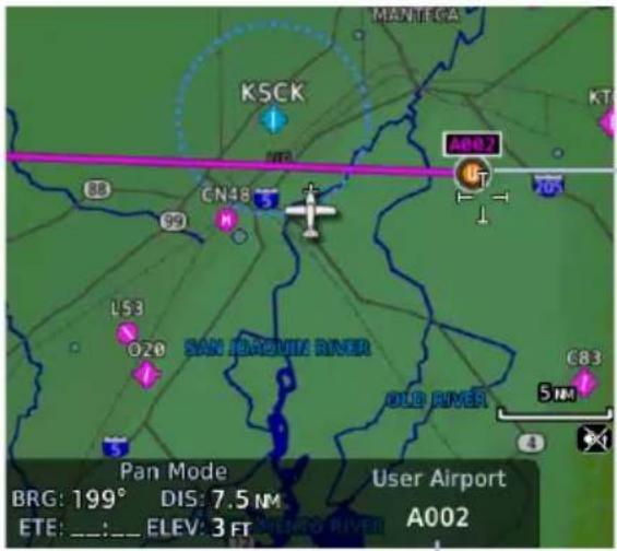
Selected User Airport
User Identifier
When selected, the user identifier annunciates in the info banner.
4.14 VNAV Guidance Indications

WARNING
Do not rely solely on VNAV guidance when navigating horizontally and vertically around user-defined airports. It is the pilot's responsibility to ensure separation from terrain and obstacles during an approach to a user-defined airport.
ALTITUDE CONSTRAINT INDICATIONS
| COLOR DEFINITIONS | |
| White Altitude is for reference only. | |
| Cyan | GTN honors the constraint for vertical guidance when the VNAV function is active. |
When the VNAV function is active on GTN, altitudes may be accompanied by one or two altitude restriction bars. The position of the value (above or below the bar, or between two bars) denotes the required aircraft altitude relative to that constraint.
Dual values annunciate when the aircraft needs to cross between two altitudes. Constraint values display in MSL or flight level (FL). Constraints at airports may be specified as MSL or AGL.
Examples:
Cross at or Above 5,000 ft

Cross at 5,000 ft
Cross at or Below 5,000 ft

Cross Between 5,000 ft and 6,000 ft

| ALTITUDE TYPES | |
 | Database ConstraintAltitude is retrieved from the navigation database and designated for use in determining vertical guidance. |
 | Pilot-specified ConstraintPencil icon indicates manual designation or manual data entry. |
 | Invalid Altitude ConstraintGTN cannot use the altitude to determine vertical guidance. |
 | Estimated Crossing AltitudeFor reference only.System calculated estimate of aircraft altitude as it passes over the navigation point. Absence of bar(s) indicates it is not a potential constraint. |
 | Published Reference AltitudeFor reference only.Altitude is retrieved from the navigation database, but not for use in determining vertical guidance. Bar above and/or below the value indicates constraint type. |
Altitude Constraint Data Priority
GDU receives constraint data from the GTN and displays it in the ALT column of the active flight plan. GTN prioritizes the data for each navigation point in the following order:
- GTN honored constraints (includes invalid constraints)
- Reference-only estimated crossing altitudes
- Published reference altitudes
- Empty (no altitude data)
INVALID ALTITUDE CONSTRAINTS
An altitude constraint is invalid if:
• Meeting the constraint requires the aircraft to climb
- Meeting the constraint requires the aircraft to exceed the maximum flight path angle (6° downward) or maximum vertical speed (-4,000 fpm)
• It results in a TOD behind the aircraft's current position
- It is within a leg type that does not support altitude constraints
• It is added to a waypoint past the FAF
Waypoints

Dedicated information pages provide waypoint search functions and details not available on the Map page.
4.15 Waypoint Information
FEATURE REQUIREMENTS
• Viewing NOTAMs requires ChartView or FIS-B
FEATURE LIMITATIONS
• 2-D maps provide zoom functionality only (panning is not available)
• FIS-B transmits distant and FDC NOTAMs within 100 nm of radio station position
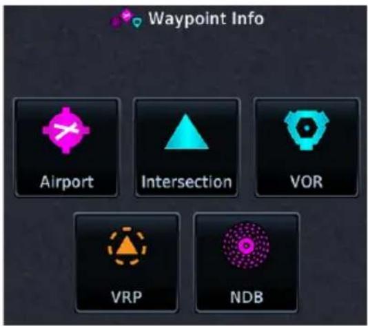
Waypoints are organized into five groups:
- Airports
- Intersection
- VOR
- VRP
- NDB
The Airport page is a great place to start while performing an approach brief, checking weather, or considering a diversion.
Intersection, VOR, VRP, and NDB information pages have a uniform layout.
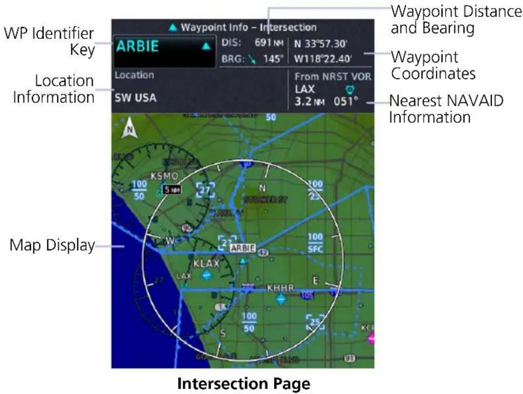
COMMON PAGE FEATURES
All waypoint information pages share the following features.
Data fields:
• Distance and bearing from current aircraft position
• Latitude and longitude
• Applicable country and/or region (e.g., "SW USA")
- 2-D map of the surrounding area (Map views display on Preview and Runways tabs of the Airports page)
• Identifier and type icon
Controls:
• Waypoint Identifier key with access to multiple search tab
WAYPOINT SPECIFIC PAGE FEATURES
The following features are unique to the corresponding waypoint.
Airport
Selectable tabs:
Info: Airport location, elevation, time zone, airport charts, and fuel availability.

To open the specified airport chart, tap View Charts.
Preview: SafeTaxi depiction of airport and surrounding area.

Runway: Identifiers, size, surface type, traffic pattern direction, and PCL frequency.

To open a list of available runways, tap Runways.
Frequencies: Available communication and localizer frequencies. The "c" symbol denotes frequencies that function as the CTAF. If available, for additional frequency information, tap "More Information."
Weather Data: METARs, city forecast, and TAF weather information for an airport.
NOTAMs: Applicable distant and FDC NOTAMs.
Airport Directory: Airport arrival information including local information based on AC-U-KWIK or AOPA data.

Intersection
Data fields:
From NRST VOR: identifier, type icon, bearing, and distance

Very High Frequency Omni-directional Range
Data fields:
- Frequency
• To NRST APT: identifier, type icon, bearing, and distance - Station Declination
- VOR Class

Visual Reporting Point
Data fields:
To NRST APT: identifier, type icon, bearing, and distance
Non-Directional Beacon
Data fields:
- Frequency
• To NRST APT: identifier, type icon, bearing, and distance - Marker Description
4.16 Waypoint Selection

The WP Identifier key provides access to different waypoint search options. Enter a specific identifier or select one from the available search tabs.
4.16.1 Waypoint Autofill
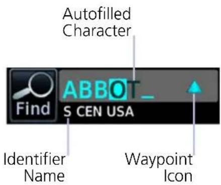
The autofill function assigns alphanumeric values into search entry fields.
Autofill characters are cyan and display from cursor position to the right of the field.
Characters autofill based on the first alphabetical match in the navigation database. Matching entries typically change with the addition of a each typed character. "No matches found" and "Duplicate found" annunciate when applicable.
4.16.2 Search Tabs

The Find key provides access to multiple search tabs. Each tab displays a list of identifiers based on specific criteria.
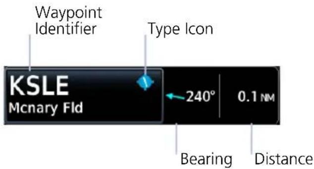
Each entry includes general information about the associated waypoint.
RECENT
Lists up to 20 of the most recently viewed waypoints.
NEAREST
Lists up to 25 waypoints within a 200 nm radius.

Tap Filter and select from the available filter options. Only waypoints belonging to the selected class appear in the list. To list all classes, select All.
FLIGHT PLAN
Lists all waypoints contained in the active flight plan.
SEARCH NAME
Search Facility Name MCNARY
Lists all airports, NDBs, and VORs associated with the specified facility name. Tap the key and enter the facility's name.
SEARCH CITY
Search City Name SALEM
Lists all airports, NDBs, and VORs found in proximity of the specified city. Tap the key and enter the city's name.
4.17 Remote Radio Frequency Entry
FEATURE REQUIREMENTS
• GTN Xi series navigator
• TXi software v3.21 or later
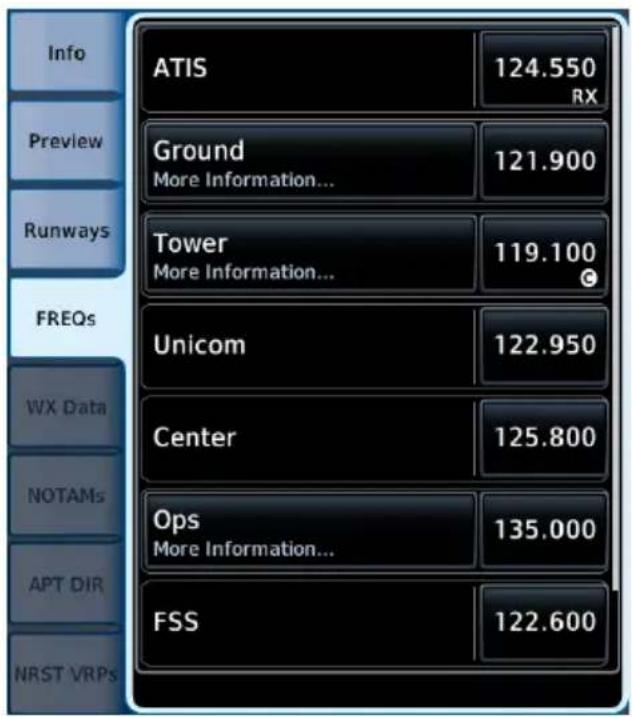
Frequencies Tab
When connected to a GTN Xi navigator, radio frequencies are automatically available for remote radio entry.
You can load active or standby frequency values to a GTN Xi COM or NAV radio from a search tab or waypoint information page (e.g., Airport, VOR).
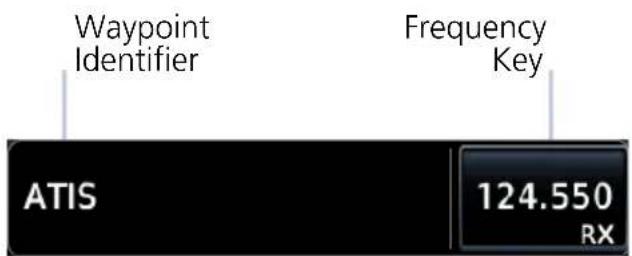
Selecting a frequency from one of these locations opens a pop-up.
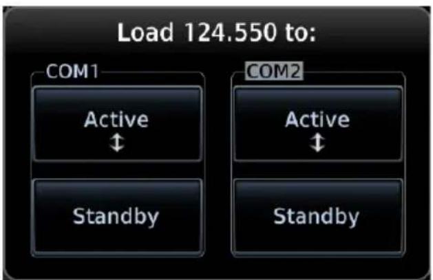
flowchart
graph TD
    A["Load 124.550 to:"] --> B["COM1"]
    B --> C["Active ↑"]
    B --> D["Standby"]
    E["COM2"] --> F["Active ↑"]
    E --> G["Standby"]
Select the Active or Standby key for the appropriate radio. The frequency transfers to the selected radio.
In the event of a failure, a pop-up informs you that frequency transfer did not occur.
COM 2 and NAV 2 are available in dual GTN Xi installations only.
SiriusXM Audio Entertainment

The Music page provides controls for tuning and presetting satellite radio music channels.
FEATURE REQUIREMENTS
• Active SiriusXM Satellite Radio subscription
• Audio Radio and/or Data Radio ID
- Configured GDL 69/69A interface
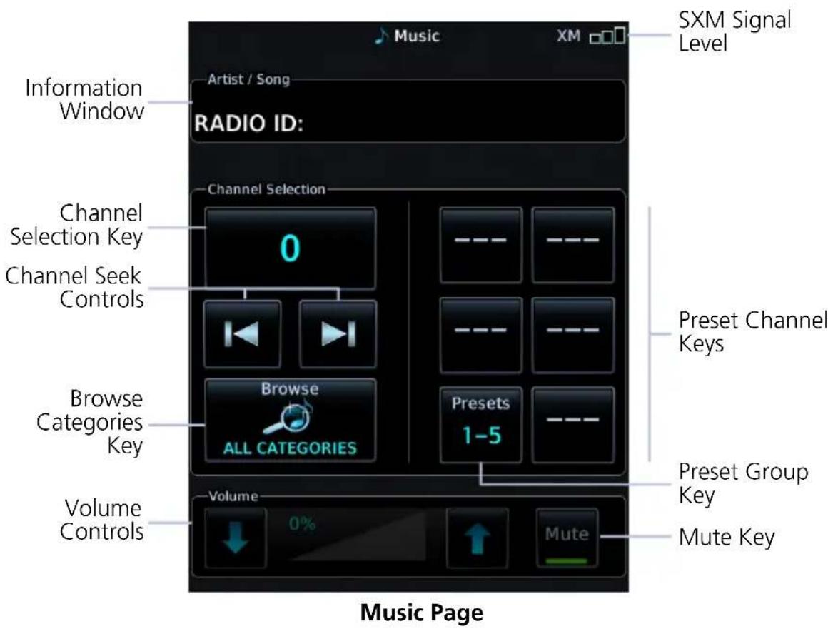
RADIO VOLUME
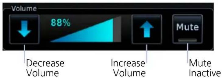
Directional keys allow volume adjustments.
Mute toggles radio audio output on or off.
4.18 SiriusXM Audio Activation

The GDL 69/69A Status page provides information necessary for activating SiriusXM Satellite Radio services. To access this page, navigate to the External LRUs list, or tap Status.
For information, refer to GDL 69/69A SiriusXM Satellite Radio Activation Instructions. For subscription activation instructions, visit https://www.siriusxm.com/sxmaviation.
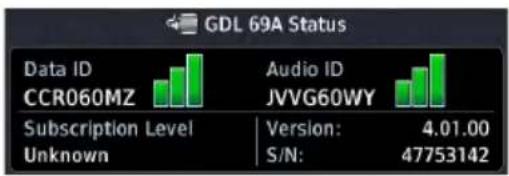
If the Audio Radio ID and/or Data Radio ID do not display during GDL 69 operation, contact a Garmin dealer.
4.19 Browse Music Channels
SiriusXM Radio Options
- Channels 0 to 999
- Categories 0 to 63
Music provides both numeric entry and channel seek functionality.
4.19.1 Audio Category Selection

To filter the list of available channels according to a specific music type, tap Category.
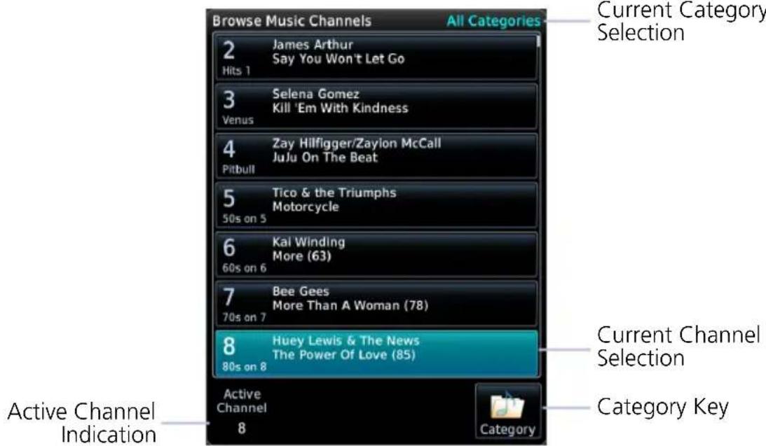
4.19.2 Direct Channel Tuning

To enter a specific radio channel by number, tap Channel.
ASSIGNING CHANNEL PRESETS
Quick Tuning Options
- Six preset groups
- Up to three preset channels per group
For quick tuning, use presets to store multiple channels in the unit's memory.
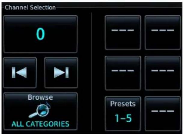
Assign a Channel Preset
- Select a channel.
- Tap Presets until desired preset group displays.
- Tap and hold any preset key for three seconds.
Select a Preset
- Select a preset group.
- Tap any preset key.
External Video

The Video app displays live video from up to four mounted cameras.
FEATURE REQUIREMENTS
• Composite or HD video camera input
• Purchased External Video feature enabled on GDU
SD Display (Control Window Active) HD Display
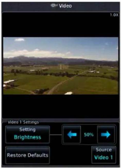

natural_image
Exterior view of an aircraft on a rooftop with hangar and flagpole, captured via video camera (no signage)For GDU 1060 with dual MFDs, external video can be viewed on only one MFD at a time.
INPUT SOURCES
| FORMAT LIMIT | |
| SD | 2 |
| HD | 2 |
Two inputs are available for each video format. If an input source is not available, "No Video Input Signal" annunciates in place of a live image.

Camera designations are configured during installation.
PAN & ZOOM

Zooming magnifies the live image up to 10x its range. Zoom settings apply only to the active camera display. Panning allows movement of the zoomed image in any direction.
4.20 SD Video Setup
SD Display Settings
- Brightness
- Contrast
- Saturation
Selectable display settings are available for SD video only. HD display settings are configured at installation.
4.20.1 Settings Key

To open a control window, tap Settings.

To return to normal display mode, tap Full.
SETTINGS ADJUSTMENT
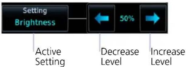
flowchart
graph LR
    A["Setting Brightness"] --> B["50% Change"]
    B --> C["Decrease Level"]
    C --> D["Increase Level"]
    style A fill:#f9f,stroke:#333
    style B fill:#ccf,stroke:#333
    style C fill:#cfc,stroke:#333
    style D fill:#fcc,stroke:#333
Directional keys allow adjustment of the active setting. Setting values are adjustable for each SD source.
RESTORE DEFAULTS

- Restores the active video display settings configured at installation
- Requires pilot confirmation
5 Weather Awareness
WEATHER DISPLAY
5.1 Weather Products....5-3
DATALINK WEATHER
5.2 Weather Page Interactions....5-6
5.3 Weather Map Views 5-8
5.4 WX Display/Map Settings.... 5-9
5.5 Weather Product Age 5-10
5.6 Precipitation 5-11
5.7 Echo Tops....5-15
5.8 Clouds.... 5-15
5.9 Lightning....5-16
5.10 METARs & TAFs 5-17
5.11 Cell Movement....5-18
5.12 AIRMETs....5-19
5.13 Center Weather Advisory....5-22
5.14 SIGMETs....5-22
5.15 County Warnings 5-23
5.16 Cyclo ne/Hurricane Track 5-23
5.17 AIREP/PIREPs....5-24
5.18 Surface Analysis....5-25
5.19 City Forecast....5-25
5.20 Winds Aloft 5-26
5.21 Icing 5-27
5.22 Turbulence 5-29
5.23 Freezing Levels 5-30
5.24 TFRs 5-31
5.25 SiriusXM Weather....5-32
5.26 FIS-B Weather....5-35
5.27 Connext Weather 5-39
STORMSCOPE
5.28 Stormscope Page....5-44
5.29 Stormscope Setup 5-45
AIRBORNE WEATHER RADAR
5.30 Weather Radar Page....5-47
5.31 Weather Radar Setup 5-49
5.32 Radar Modes 5-53
5.33 Radar Controls 5-56
5.34 Radar Alerts....5-60
Weather Display

Weather data displays as overlays on the dedicated weather page, Map page, and HSI Map. Available functions depend on the active weather source(s).
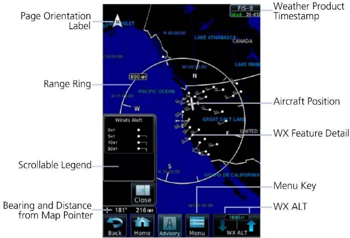
Common Weather Elements
5.1 Weather Products
| WEATHER PRODUCT | WEATHER DISPLAY | ||||
| MFD WX PAGE | MFD WX POP-UP TEXT | HSI MAP | MFD MAP PAGE | WAYPT INFO (ARPT) | |
| AIRMET (Textual) X, C X, C | |||||
| AIRMET (Graphical) F, X, C F, X, C | |||||
| Cell Movement/SCIT X X X | |||||
| Center Weather Advisory | F | F | |||
| City Forecast X X X | |||||
| Cloud Top/IR Satellite F, X, C | X, C | ||||
| County Warnings | X X | ||||
| Cyclone Track | X | ||||
| Echo Tops | X X | ||||
| Freezing Levels/Zero Degree Isotherm | X | ||||
| Icing Potential/SLD | F, X | ||||
| Lightning (Datalink) | F, X, C | F, X, C | F, X, C | ||
| Lightning (Stormscope) | S | S | S | ||
| METAR w/Decoding | F, X, C | F, X, C | F, X, C | F, X, C | |
| NEXRAD/PRECIP | F, X, C | F, X, C | F, X, C | ||
| NOTAMS | F | ||||
| AIREP | X X | ||||
| PIREP | F, X, C | F, X, C | |||
| SIGMET | F, X, C | F, X, C | |||
| Surface Analysis | X | ||||
| TAF | F, X, C F, X, C | F, X | |||
| Temps Aloft | F | ||||
| TFR F, X, C F, X, C F, X, C | F, X, C | ||||
| Turbulence F, X | |||||
| Weather Radar (on-board) ^1 | W | W | |||
| Winds Aloft F, X, C | |||||
^1 Not available on GDU 700() MFD/EIS.
LEGEND
Connext Product C
FIS-B Product F
On-board WX Radar Equipment W
SiriusXM Product X
Stormscope Product S
Datalink Weather

WARNING
Do not rely solely on datalink weather for weather information. Datalink weather provides a snapshot in time. It may not accurately reflect the current weather situation.

NOTE
Datalink weather is not intended to replace weather briefings or in-flight weather reports from AFSS or ATC.
FEATURE REQUIREMENTS
• FIS-B, GSR 56 transceiver, GDL 69/69A, or GDL 69/69A SXM receiver
Datalink weather services are available through FIS-B Weather, SiriusXM Weather, and Connext WX that transmit from a ground station or satellite.
5.2 Weather Page Interactions
ALTITUDE ADJUSTMENT KEYS
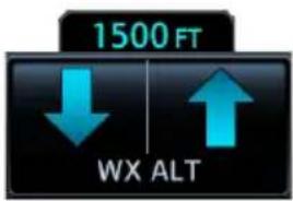
Plus and minus keys adjust altitude in increments for altitude-based weather products. Selectable altitude values vary by weather service and product. Includes:
- Icing • Turbulence • Winds Aloft
WEATHER ICONS
Tapping any weather icon displays an information banner. When applicable, a pop-up window displays additional data.
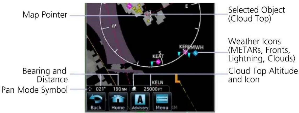
WX Info Banner Features
- Pan mode symbol
- Bearing and distance to map pointer from aircraft's current position
• Cloud Top altitudes - Pan location
• Report data
AIRPORT ICONS

Tapping an airport icon displays information about local weather conditions.
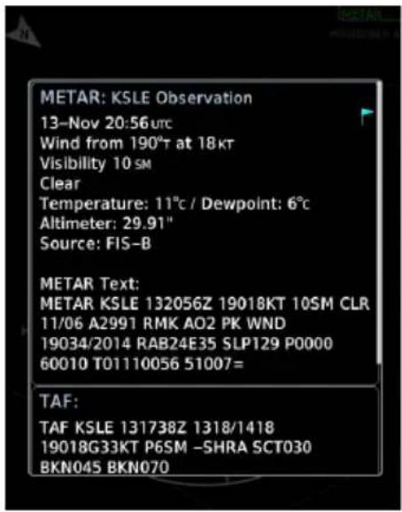
PRODUCT LEGENDS
A scrollable legend provides relevant product colors and symbols via the datalink weather menu page. Definitions are organized by product function.
To view a product legend, tap the Menu key and select Legend.
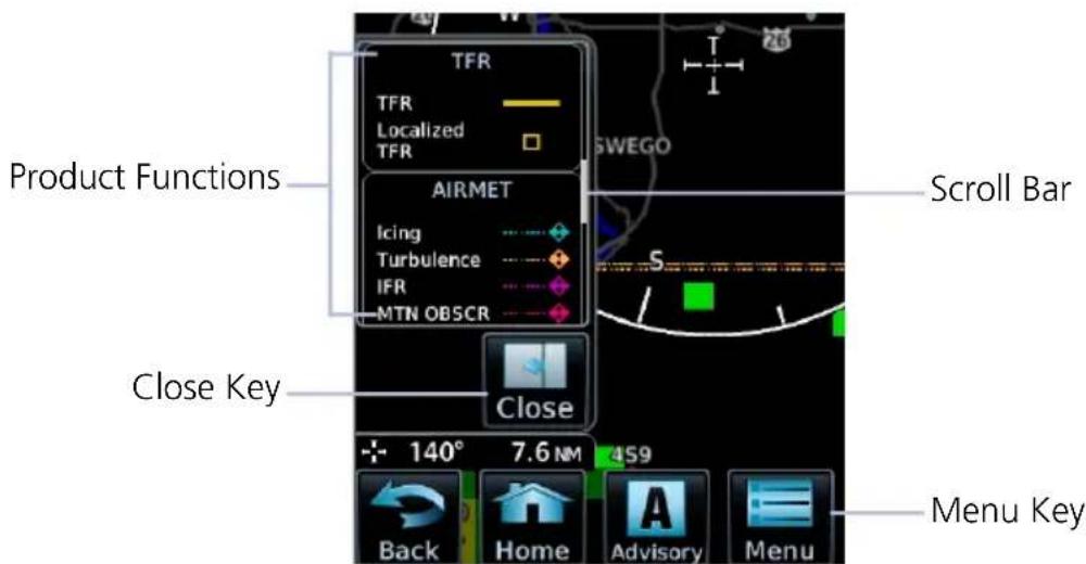
5.3 Weather Map Views

The Map View key in a weather menu may be used to select a user-configured view.

Three different views may be individually configured for each weather product. All settings configured in the weather product's menu are saved.
View configurations may be changed at any time.
Selecting any view loads previously saved view settings.
Tap Customize to change a view name or reset both the name and all menu settings to their default values.
5.4 WX Display/Map Settings
FEATURE LIMITATIONS
Shared map settings are per MFD instance, meaning that if you have a GDU 1060 with MFD 1 and MFD 2, each MFD has its own map settings. These settings are shared only with the datalink weather apps on that specific MFD. Map settings are not shared across multiple MFDs.
Several weather map display settings are based on selections made in the setup menu of the primary Map application.
From the Home page:
Tap Map > Menu > Map Setup, and select the appropriate tab. Applicable map settings are as follows:
Map Tab Aviation Tab Land Tab
Settings:
• North Up Above range
- LAT/LON Lines
Settings:
- Runway Extensions
- Airport Range
- Intersection Range
- NDB Range
• VOR Range - VRP Range
- User Waypoint Range
Settings:
- Road Detail
- City Detail
• State/Province Borders - River/Lake Detail
Changes to these map settings take effect immediately on the configured datalink weather app(s).
Map Settings and Multiple Map Views
Shared map settings are independent of map views. Map settings will transfer to a datalink weather app regardless of which map views you select.
5.5 Weather Product Age

NOTE
Data contained within a composite weather product may be older than its weather product age and should never be considered current.
A timestamp identifies the approximate time of data collection for each weather product. For quick reference, the age of each active weather product is calculated and shown in a color-coded side bar on the Weather and Map pages.
TIMESTAMP COLOR DEFINITIONS
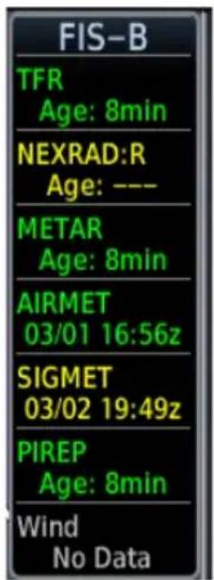
Green
Weather product is considered current. Its age is newer than half its expiration time.
Tapping the Timestamp window displays time for all green colored weather products.
Yellow
Weather product is considered stale. Its age is older than half its expiration time.
A weather product may be yellow when its issue date and time occurs in the future by more than the complete expiration time for the requested weather product. (e.g., some TFRs).
Gray
Weather product data is one of the following:
- Expired
- Not received
• Not supported at the selected altitude
"No Data" or "ALT UNAVBL" displays next to the weather product title.
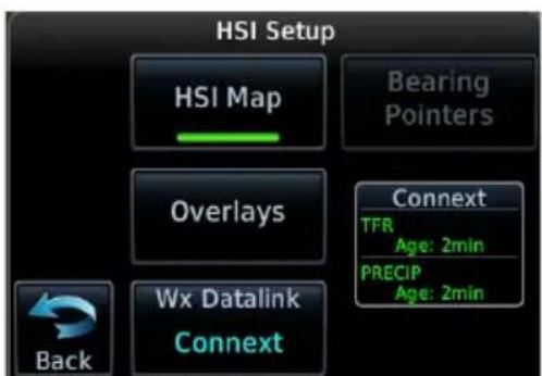
On PFD:
Timestamps for NEXRAD/PRECIP, lightning, and TFR products display in the HSI Setup menu.
5.6 Precipitation
AVAILABLE WITH: FIS-B | SIRIUSXM | CONNEXT

WARNING
Never use NEXRAD weather for maneuvering in, near, or around areas of hazardous weather. NEXRAD images are snapshots of past weather data. They are not safe for use as real time depictions of nearby weather activity.
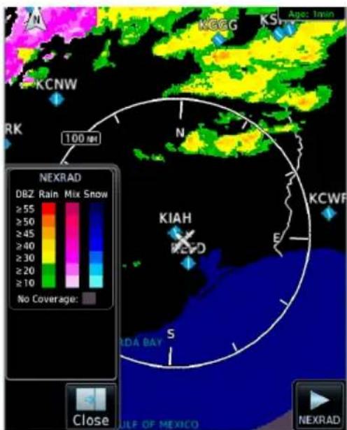
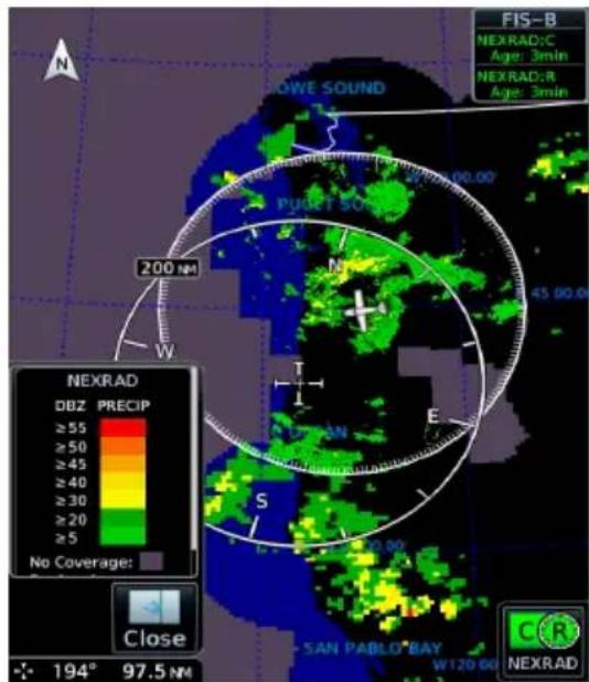
NEXRAD weather radar displays a mosaic of precipitation data, colored according to reflectivity. Composite reflectivity images depict the highest radar energy received from multiple antenna tilt angles at various altitudes. Base reflectivity images depict radar returns from the lowest antenna tilt angle.
The precipitation intensity level reflected by each pixel represents the highest level of composite radar reflectivity data sampled in that location.
A clear understanding of ground-based Doppler weather radar capabilities will allow you to interpret the NEXRAD weather imagery in the safest way possible. The National Oceanic and Atmospheric Administration hosts a description of the technology on its website: https://www.weather.gov/jetstream/doppler_intro
RADAR DATA ANIMATIONS

To depict trending weather movements over time, an animation function stitches the last three to six received radar images together in sequence, from oldest to newest, and replays them on a continuous loop. Play and stop controls are active when three or more NEXRAD images are available for playback.

5.6.1 Connext PRECIP
Precipitation products are available for areas around the world. For current coverage areas and product information, visit www.garmin.com/connext.
5.6.2 FIS-B NEXRAD
FIS-B NEXRAD is uplinked to the aircraft as two separate weather products: CONUS and Regional NEXRAD. Both products display individually or simultaneously, separated by a white hash-marked boundary. CONUS and Regional NEXRAD are selectable separately via the NEXRAD button on the bottom right of the weather map. FIS-B NEXRAD does not differentiate between liquid and frozen precipitation types.
REGIONAL
FIS-B Regional NEXRAD is a high-resolution weather image with a limited range, centered around each broadcasting ground station. The (high resolution) Regional NEXRAD pixels are 1.5 minutes (1.5 nautical miles = 2.78 km) wide by 1 minute (1 nautical miles = 1.852 km) tall. Each weather pixel varies with latitude. Above 60° latitude, pixel block widths double to 3 minutes/nautical mile for regional maps.
Depending on the locations of received FIS-B ground stations, Regional NEXRAD coverage can extend more than 250 nm around an aircraft's position. Aircraft flying at higher altitudes typically receive data from more ground stations than aircraft flying at low altitudes.
CONUS
FIS-B CONUS NEXRAD is a large, low-resolution weather image for the entire continental U.S. CONUS NEXRAD pixels are 7.5 minutes (7.5 nm = 13.89 km) wide by 5 minutes (5 nautical miles = 9.26 km) wide.
FIS-B Weather Display
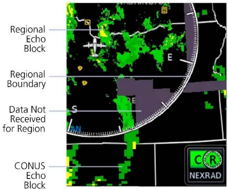
Missing Data Indications
A semi-transparent mask indicates regions where data may be missing or incomplete. Color is dependent upon the presence of topographical data.
The mask is purple when there is no underlying topographical data, such as on the FIS-B weather display, or on Map when the TOPO overlay is off.
MFD Map Display
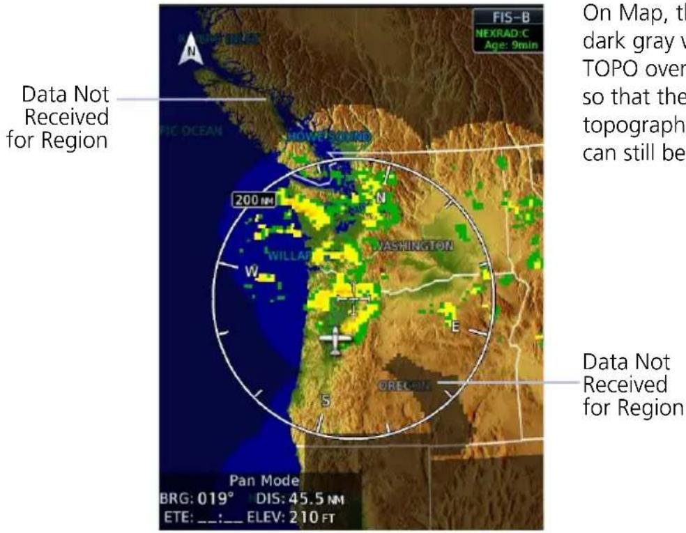
On Map, the mask is dark gray when the TOPO overlay is on, so that the underlying topographical features can still be interpreted.
5.6.3 SiriusXM NEXRAD
SiriusXM offers NEXRAD radar imagery from CONUS and non-CONUS sources. Weather menu options are Composite and Base.

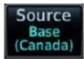
Depending on the SXM service and installed GDL hardware, radar base reflectivity imaging may have broader coverage within North America or be limited to only Canada.
Source Options:
Composite (CONUS) Base
Composite reflectivity image of radar for the conterminous U.S.
Base reflectivity image. Coverage and availability are dependent upon subscription.
Precipitation above 52^ N may display as mixed precipitation regardless of actual precipitation type. Precipitation of an unknown type always displays as rain.
5.7 Echo Tops
AVAILABLE WITH: SIRIUSXM
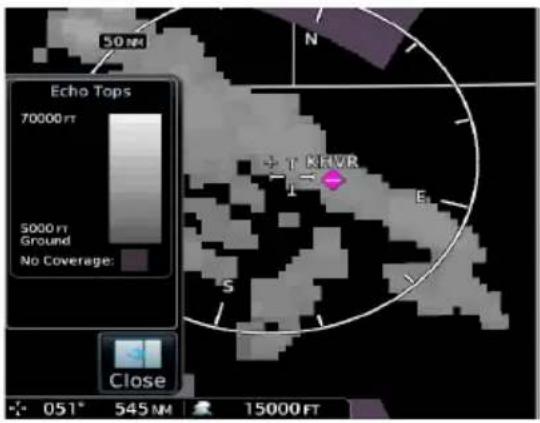
Depicts the location, elevation, and direction of NEXRAD radar echoes. This information is useful for gauging storm intensity in a relative sense. A higher radar echo means a stronger storm updraft.
Due to similarities in color schemes, this product is mutually exclusive with Cloud Tops.
5.8 Clouds
5.8.1 Cloud Tops
AVAILABLE WITH: FIS-B | SIRIUSXM
Indicates the altitude of the highest visible portions of a cloud at the time of measurement.
SXM cloud top altitude data is estimated from IR satellite imagery.
FIS-B cloud top data is generated by a computer model and has limited accuracy compared to actual conditions.
Due to similarities in color schemes, this product is mutually exclusive with Echo Tops.
5.8.2 IR Satellite
AVAILABLE WITH: CONNEXT
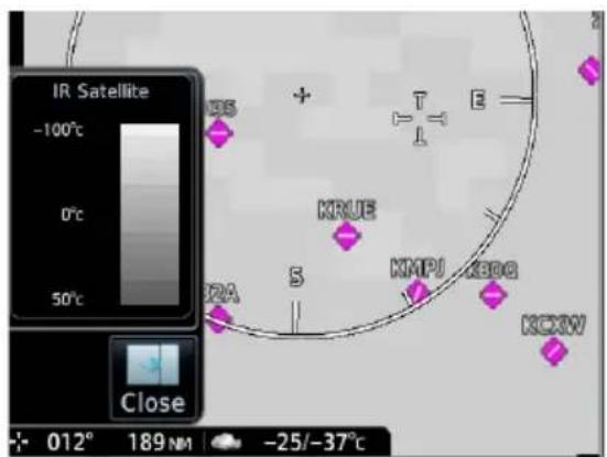
Infrared Satellite weather information is available for North America and Europe.
• Lighter grays depict colder temperatures
• Darker grays depict warmer temperatures
5.9 Lightning
AVAILABLE WITH: FIS-B | SIRIUSXM | CONNEXT
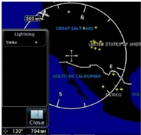
SiriusXM Weather:
SXM displays a yellow cross icon to indicate a strike event occurring within a two kilometer region. Strike location is an estimate of its center.
Unlike Stormscope, the icon does not change shape or color as data ages.
Connext Weather:
Only cloud-to-ground strikes are reported through the Connext weather service.
FIS-B Weather:
Lightning strikes display as a bolt or cluster of bolts. The bolt color indicates the strike polarity.
5.10 METARs & TAFs
AVAILABLE WITH: FIS-B | SIRIUSXM | CONNEXT
METAR and TAF reports provide information on current and forecast conditions. Colored METAR flags display for all TXi weather sources when a METAR reporting station is matched with a corresponding TXi navigation database identifier. When selected, the METAR is decoded and shows above the original METAR text. METARs are provided only in areas covered by the navigation database currently loaded.
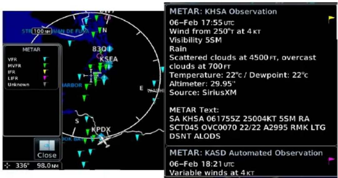
METAR SYMBOLS

VFR
Ceiling greater than 3,000 ft AGL and visibility greater than five miles.

Marginal VFR
Ceiling 1,000 to 3,000 ft AGL and/or visibility three to five miles.

IFR
Ceiling 500 to 1,000 ft AGL and/or visibility one to three miles.

Low IFR
Ceiling below 500 ft AGL and/or visibility less than one mile.

Unknown
Ceiling and/or visibility data unavailable.
5.11 Cell Movement
AVAILABLE WITH: SIRIUSXM
Information derived from NEXRAD displays the location of storm cells within a strong storm. Cell direction, speed, and storm top altitude is provided with a corresponding visual storm cell vector (arrow) indication.
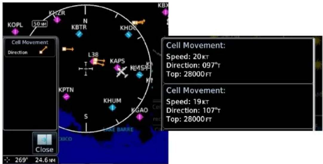
5.12 AIRMETs
5.12.1 Textual AIRMETs
AVAILABLE WITH: SIRIUSXM | CONNEXT
The AIRMET overlay draws the geographical boundaries of received AIRMETS on the dedicated weather page. AIRMETS include advisories of weather that may be particularly hazardous to single engine, light aircraft and VFR pilots. Tap an AIRMET graphic area to view the detailed AIRMET report text.
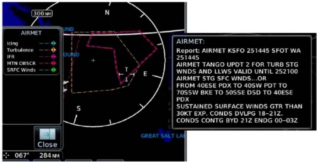
AIRMET TYPES
| Icing Areas of moderate airframe icing including areal extent | |
| Turbulence Areas of moderate turbulence including vertical extent | |
| IFR | Weather conditions with ceilings <1,000 ft and/or visibility <3 mi |
| MTN OBSR | Widespread mountain obscuration due to clouds, precipitation, smoke, haze, mist, or fog |
| Surface Winds | Sustained surface winds >30 kt and/or potential non-convective wind sheer below 2,000 ft AGL |
5.12.2 Graphical AIRMETs
AVAILABLE WITH: FIS-B
Graphical AIRMETs (G-AIRMETs) display more weather phenomena than textual AIRMETs, while eliminating the need to interpret raw text.
Tapping a G-AIRMET displays textual details. Updates occur four times daily.
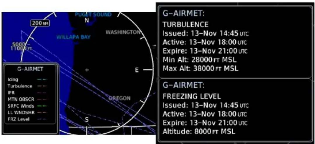
Filtering options allow you to mitigate page clutter. Forecast and filter selections are accessible from the FIS-B Weather menu.
Forecast Settings:
Off Current (Auto) All Forecasts
Disables automatic functionality. Filter options not available.
Displays active graphical records based on the current UTC.
Function automatically switches from 0 hr to 3 hr forecasts.
Displays the most recent, non-expired graphical records.
Forecast periods include 0 hr, 3 hr, and 6 hr.
G-AIRMET FILTERS
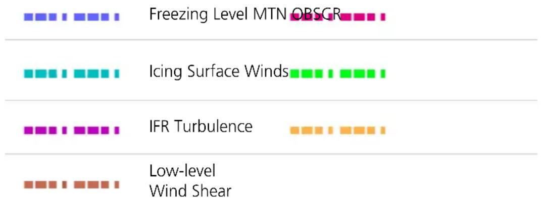
bar
| Weather Condition | Value | | ------------------------- | ----- | | Freezing Level MTN OBSGR | 1 | | Icing Surface Winds | 1 | | IFR Turbulence | 1 | | Low-level Wind Shear | 1 |To view graphical AIRMETs:
- Home > Weather > FIS-B Weather > Menu.
- Toggle G-AIRMET on.
- Tap Settings.
- Select between Current (Auto) and All Forecasts.
- Select one or more filters.
- Return to the FIS-B Weather page.
- Select any G-AIRMET line to view details.
5.13 Center Weather Advisory
AVAILABLE WITH: FIS-B
These advisories communicate en route and terminal weather conditions expected to occur within the next two hours. Information is valid for up to 2 hours.
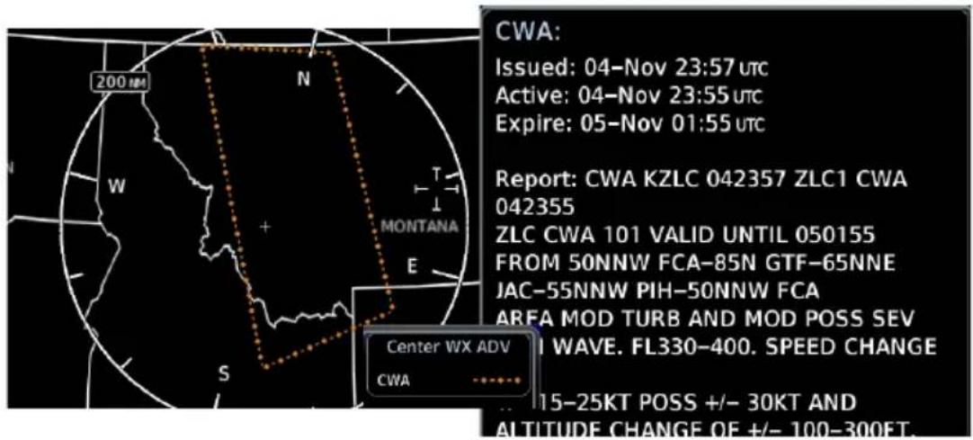
5.14 SIGMETs
AVAILABLE WITH: FIS-B | SIRIUSXM | CONNEXT
The SIGMET overlay draws the geographical boundaries of received SIGMETs on the dedicated weather page. Convective and non-convective SIGNificant METerological Information combine in a textual report and display graphically for the observed or forecast region. The SIGMET text displays when the graphical SIGMET is selected. Touch the graphical depiction for additional information.
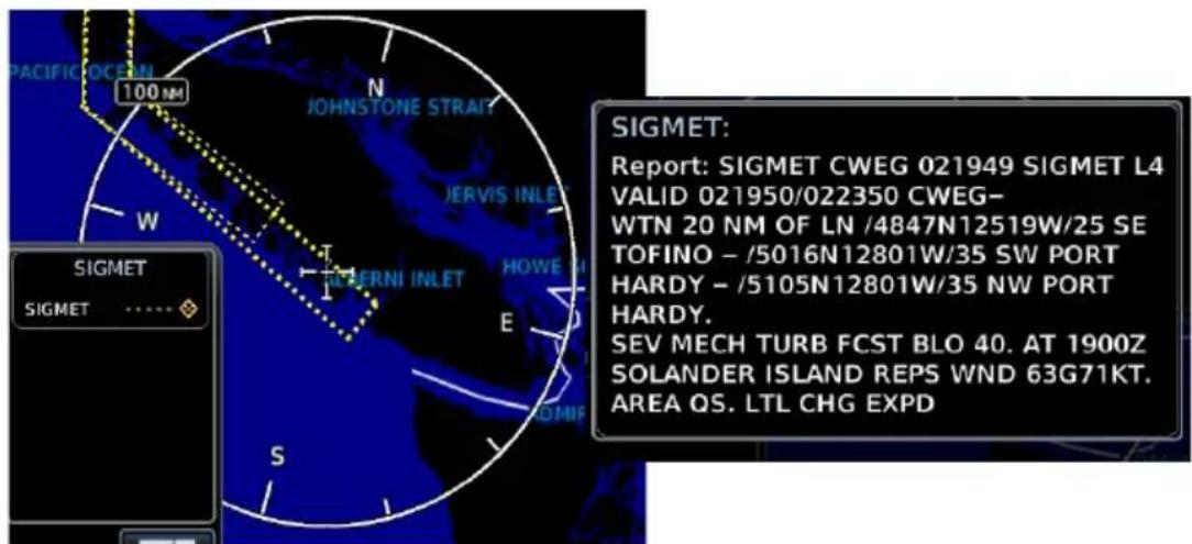
5.15 County Warnings
AVAILABLE WITH: SIRIUSXM
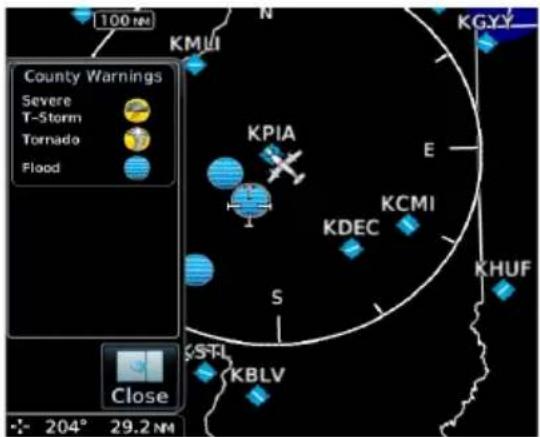
County warnings are provided for the counties within the continental United States. Specific public awareness and protection alerts such as fires and natural disasters are included with warnings for tornadoes, thunderstorms, floods and flash floods.
Filtering options include Severe T-Storm, Tornado, and Flooding.
5.16 Cyclone/Hurricane Track
AVAILABLE WITH: SIRIUSXM
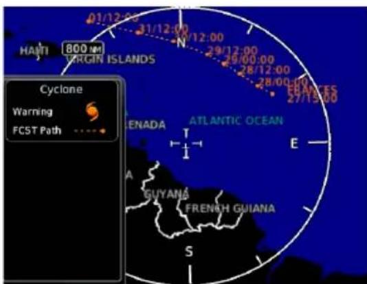
Provides hurricane and tropical storm information, showing location, forecast track and track errors as issued by the National Hurricane Center.
5.17 AIREP/PIREPs
AVAILABLE WITH: FIS-B | SIRIUSXM | CONNEXT
AIREPs are routine, automated reports of in-flight weather conditions such as wind and temperature. AIREPs display with a green map icon. Selecting the icon displays a report window.
PIREPs are pilot-generated weather reports that may contain non-forecast adverse weather conditions, such as low in-flight visibility, icing conditions, wind shear, and turbulence. PIREPs are issued as either Routine(UA) or Urgent (UUA). Routine display with a blue map icon and urgent display with an amber icon. Selecting either icon displays a report window.
![KEKA 100 N KGUS PIREP Urgent Routine AIREP All AIREPs N KMFD KSGH KCMH E KLFY VGG S AIREP: Position: N 41°13.20' W098°12.60' Time: 17:10 UTC Wind Direction: 314°T Wind Speed: 37KT Altitude: 36000 FT Temperature: -51°C Report: ARP UAL71 4122N 09821W 1710 F360 MS51 314/037KT TB SMTH= PIREP: Location: OLU 15 NM 360° Time: 18:08 UTC [ Age: 4 mins ] Urgent: No AC Type: P28B Altitude: 10500 FT Remarks: TOPS | BLDUPS 110](/content/2026/05/762716/images/9983834142706b98d797d90f4607384b8e5199403f24454f921870b308c39afd.jpg)
5.18 Surface Analysis
AVAILABLE WITH: SIRIUSXM
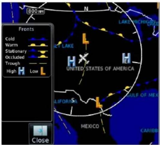
Displays weather fronts, high (H) and low (L) pressure centers, and isobars.
Forecast Period Options:
- Current • 12 hour • 24 hour
• 36 hour • 48 hour
5.19 City Forecast
AVAILABLE WITH: SIRIUSXM
Four-day forecasts for major U.S. cities, including daily forecast high and low temperatures, chance of precipitation, and sky conditions.
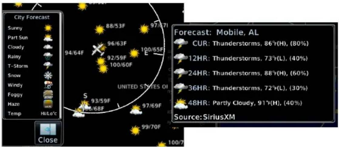
5.20 Winds Aloft
AVAILABLE WITH: FIS-B | SIRIUSXM | CONNEXT
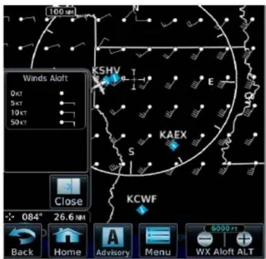
Indicates wind speed and direction, and temperature forecast for the specified altitude.
The wind barb extends outward from the reporting location dot in the direction of wind origination.
Reporting altitudes vary depending on the weather provider.
FIS-B Winds & Temperatures Aloft:
FIS-B wind forecasts also provide temperature data for the selected altitude. These forecasts update every 12 hours.
Altitude Range:
FIS-B SIRIUSXM & CONNEXT
| 1,000 ft | Surface to 45,000 ft(at 3,000 ft intervals) |
| 1,500 ft | |
| 2,000 ft | |
| 3,000 ft | SiriusXM data not availableat 45,000 ft |
| 6,000 ft | |
| 9,000 ft | |
| 12,000 ft | |
| 15,000 ft | |
| 18,000 ft | |
| 24,000 ft | |
| 30,000 ft | |
| 34,000 ft | |
| 39,000 ft | |
| 45,000 ft | |
| 53,000 ft |
Not all altitudes provide winds and temperatures aloft forecasts for all regions.
5.21 Icing
AVAILABLE WITH:
FIS-B | SIRIUSXM

NOTE
Due to the incremental and overlapping nature of the FIS broadcast, timestamps, regional coverage, and map data availability may vary with altitude for computer generated FIS-B icing forecasts.
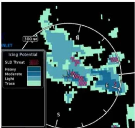
The Icing potential shows a graphic view of the current icing conditions. SLD threat areas are depicted as black and pink blocks over the icing colors.
Directional keys allow you to adjust the reporting altitude within product-specific limits.
FIS-B SIRIUSXM
| Timestamp shows: | Valid time in UTC | Time of data compilation |
| Altitude Range: | 2,000 to 24,000 ft (at 2,000 ft intervals) | 1,000 ft3,000 ft6,000 ft9,000 to 30,000 ft (at 3,000 ft intervals) |
ICING CATEGORIES
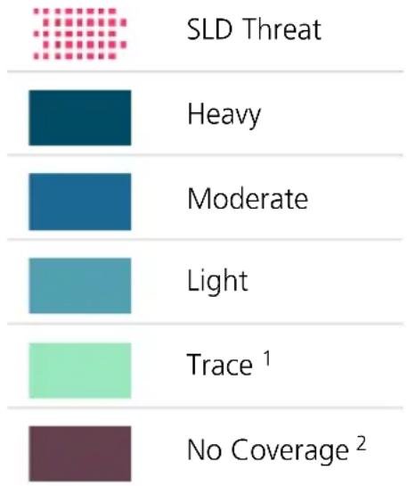
bar
| Category | Value | |---|---| | SLD Threat | | | Heavy | | | Moderate | | | Light | | | Trace¹ | | | No Coverage² | |Categories vary depending on the configured weather source.
Icing potential is not a forecast, but a presentation of icing potential at the time of analysis. Supercooled Large Droplet (SLD) icing conditions are characterized by the presence of relatively large, super cooled water droplets indicative of freezing drizzle and freezing rain aloft.
5.22 Turbulence
AVAILABLE WITH:
FIS-B | SIRIUSXM

NOTE
Due to the incremental and overlapping nature of the FIS broadcast, timestamps, regional coverage, and map data availability may vary with altitude for FIS-B turbulence forecasts.
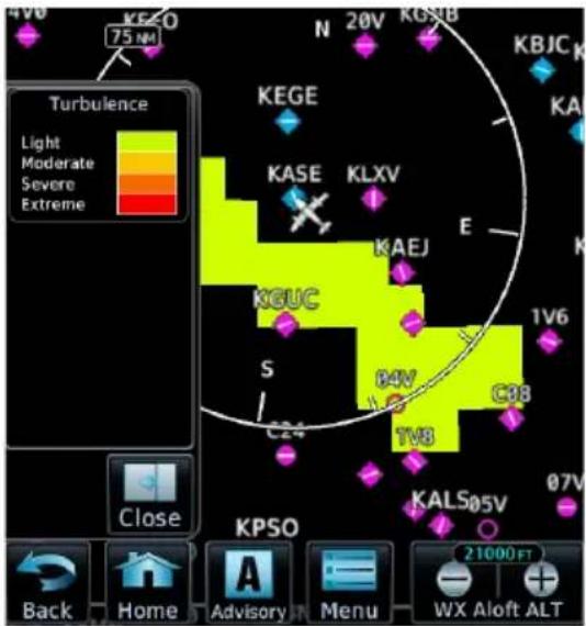
Turbulence data identifies the potential for erratic movement of high-altitude air mass associated winds. This information is intended to supplement AIRMETs and SIGMETs.
Turbulence is classified as light, moderate, severe or extreme.
Directional keys allow you to adjust the reporting altitude within product-specific limits.
FIS-B SIRIUSXM
| Timestamp shows: | Valid time in UTC | Time of data compilation |
| Altitude Range: | 2,000 to 24,000 ft (at 2,000 ft intervals) | 21,000 to 45,000 ft (at 3,000 ft intervals) |
Data may not be available for all regions at all altitudes.
5.23 Freezing Levels
AVAILABLE WITH:
FIS-B | SIRIUSXM
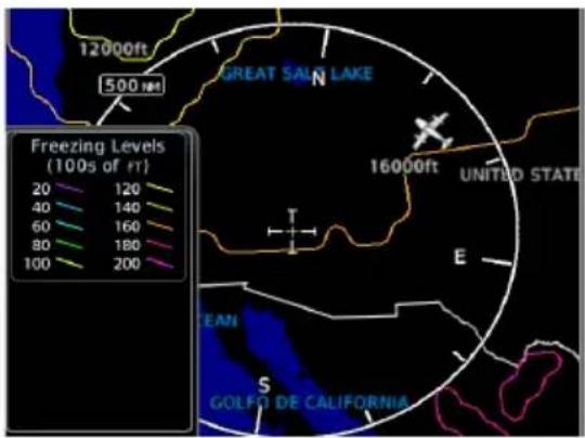
Color-coded contour lines indicate the altitude of the freezing level.
FIS-B freezing levels display as a G-AIRMET. Updates occur four times daily.
5.24 TFRs
AVAILABLE WITH: FIS-B | SIRIUSXM | CONNEXT

WARNING
Do not exclusively use datalink services for TFR information. TFR depictions on GDU may not be a complete listing and may vary between cockpit devices. Always confirm TFR information with official sources such as Flight Service Stations or Air Traffic Control.
TFRs identify areas of airspace where aircraft are temporarily restricted from operating. They are routinely issued for occurrences such as dignitary visits, military activities, and forest fires.
Tapping a TFR displays textual details.
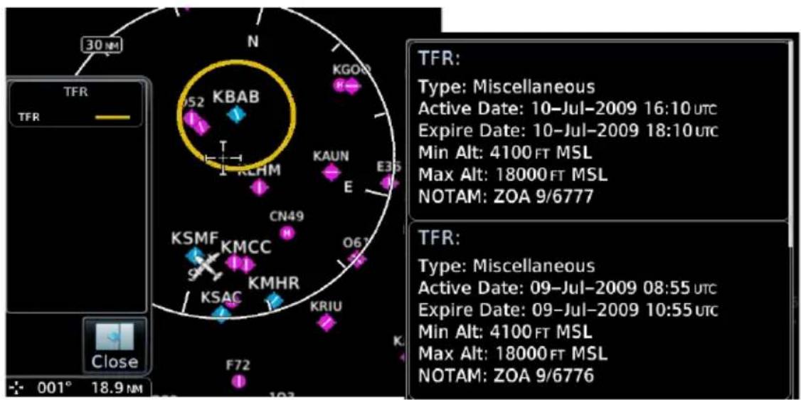
FIS-B Weather:
Latest TFR data transmit every 10 to 20 minutes.
For FIS-B datalink weather, TFRs and NOTAMs that do not include geographical locations are viewable from the FIS-B Raw Text Reports page.
5.25 SiriusXM Weather
SiriusXM satellites deliver high bandwidth (S-band) data to provide high-resolution images. Available data is received within a few minutes after the aircraft satellite receiver comes into view of the SiriusXM satellite network.
FEATURE REQUIREMENTS
• Active SiriusXM Aviation Weather subscription
- Data Radio ID
- Configured GDL 69/69A interface
FEATURE LIMITATIONS
- For Icing Potential, Winds Aloft (U.S.), and Turbulence, the valid time displays instead of product age
- For Freezing Level and Winds Aloft (Canada), the generation time displays instead of valid time
5.25.1 SiriusXM Weather Setup
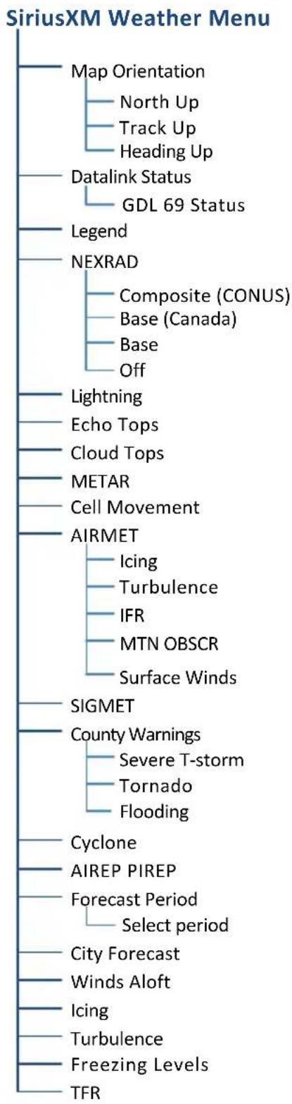
flowchart
graph TD
    A["SiriusXM Weather Menu"] --> B["Map Orientation"]
    B --> C["North Up"]
    B --> D["Track Up"]
    B --> E["Heading Up"]
    B --> F["Datalink Status"]
    F --> G["GDL 69 Status"]
    B --> H["Legend"]
    H --> I["NEXRAD"]
    I --> J["Composite (CONUS)"]
    I --> K["Base (Canada)"]
    I --> L["Base"]
    I --> M["Off"]
    B --> N["Lightning"]
    B --> O["Echo Tops"]
    B --> P["Cloud Tops"]
    B --> Q["METAR"]
    B --> R["Cell Movement"]
    B --> S["AIRMET"]
    S --> T["Icing"]
    S --> U["Turbulence"]
    S --> V["IFR"]
    S --> W["MTN OBSCR"]
    S --> X["Surface Winds"]
    S --> Y["SIGMET"]
    Y --> Z["County Warnings"]
    Z --> AA["Severe T-storm"]
    Z --> AB["Tornado"]
    Z --> AC["Flooding"]
    Y --> AD["Cyclone"]
    Y --> AE["AIREP PIREP"]
    Y --> AF["Forecast Period"]
    AF --> AG["Select period"]
    Y --> AH["City Forecast"]
    AH --> AI["Winds Aloft"]
    AH --> AJ["Icing"]
    AH --> AK["Turbulence"]
    AH --> AL["Freezing Levels"]
    AH --> AM["TFR"]
5.25.2 Activating Services
Before SiriusXM Weather is accessed, service must be activated by the SiriusXM customer service. This is accomplished by providing either one or two coded IDs, SiriusXM Satellite Weather (data) and SiriusXM Satellite Radio (audio). The coded IDs are used to send an activation signal, which allows the use of weather and entertainment products received by the GDL 69/69A.
For subscription activation instructions, visit siriusxm.com.
To complete activation:
- Contact SiriusXM using the customer service phone number listed on the website.
- Provide the customer service agent with your Data ID and Audio ID.
- Position aircraft within satellite reception area and power unit.
- Tap Weather > SiriusXM Weather > Menu > Datalink Status.
- Verify activation. Status page displays Data ID, Subscription Level, and weather product listings.
- Tap Menu > Lock activation > OK.
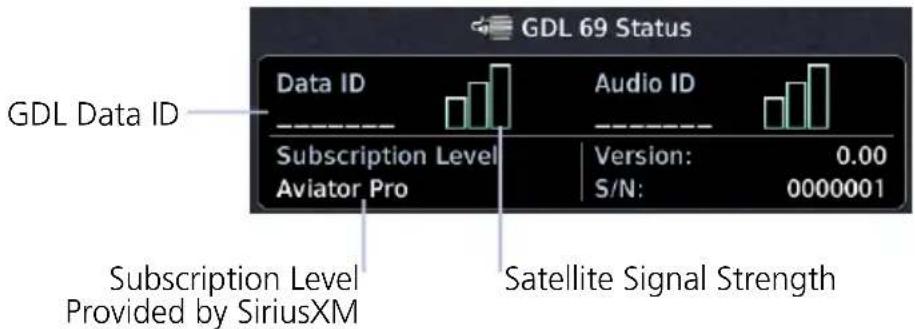
GDL 69 Status Page
5.25.3 SiriusXM Weather Products
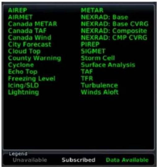
When SiriusXM weather services are not activated:
- All weather product boxes are cleared on the GDL 69 Status page
- A yellow "Activation Required" message appears at the center of the page
Service Class refers to the groupings of weather products available for subscription.
5.26 FIS-B Weather
No pilot action is required to receive FIS-B weather information.
FEATURE REQUIREMENTS
• UAT receiver (GDL 88, GNX 375, GTX 345)
FIS-B weather products include:
- NEXRAD • Cloud Tops • Lightning
- Icing
- Turbulence
- Winds/Temps Aloft
• METAR • PIREP • SIGMET
• Center WX Advisory • G-AIRMET • TFR
The FAA provides FIS-B as a Surveillance and Broadcast Service operating on the UAT (978 MHz) frequency band. FIS-B uses a network of FAA-operated ground-based transceivers to transmit weather datalink information to the aircraft's receiver on a scheduled continuous basis.
The Flight Information Service-Broadcast (FIS-B) Weather service is freely available for aircraft equipped with a capable datalink universal access transceiver (UAT). Ground stations provide uninterrupted services for the majority of the contiguous U.S., Hawaii, Guam, Puerto Rico, and parts of Alaska. No weather subscription service is required. For the latest FAA ground station coverage information, visit: www.faa.gov/nextgen/programs/adsb/
FIS-B weather product update and transmission intervals are published in the SBS Description Document associated with TSO-C157b. This information is available electronically at the FAA's Regulatory and Guidance Library: https://rgl.faa.gov/
5.26.1 FIS-B Data Transmission Limitations
FIS-B broadcasts provide weather data in a repeating cycle which may take several minutes to completely transmit all available weather data. Therefore, not all weather data may be immediately present upon initial FIS-B signal acquisition.
LINE OF SIGHT RECEPTION
To receive FIS-B weather information, the aircraft's datalink receiver must be within range and line-of-sight of an operating ground-based transceiver. Reception may be affected by altitude, terrain, and other factors. Per the FAA, much of the United States has FIS-B in airborne coverage at and above 3,000 feet AGL. Terminal coverage is available at altitudes below 3,000 feet AGL and is available when flying near approximately 235 major U.S. airports. Surface coverage allows FIS-B ground reception at approximately 36 major U.S. airports.
PER FAA TSO-C157B
FIS-B information may be used for pilot planning decisions focused on updating the pilot's awareness of the dynamic flight environment; including avoiding areas of inclement weather that are beyond visual range and pilot near-term decisions where poor visibility precludes visual acquisition of inclement weather. FIS-B weather and NAS status information may be used as follows:
a. To promote pilot awareness of ownership location with respect to reported weather, including hazardous meteorological conditions; NAS status indicators to enhance pilot planning decisions; and pilot near-term decision-making.
b. To cue the pilot to communicate with Air Traffic Control, Flight Service Station specialist, operator dispatch, or airline operations control center for general and mission critical meteorological information, NAS status conditions, or both. FIS-B information, including weather information, NOTAMs, and TFR areas, are intended for the sole purpose of assisting in long-/near-term planning and decision making. The system lacks sufficient resolution and updating capability necessary for aerial maneuvering associated with immediate decisions. In extreme scenarios, the oldest weather radar data on the display can be up to 15 to 20 minutes older than the display's age indication for that weather radar data. Therefore, do not attempt to use FIS-B weather information to maneuver the aircraft at minimum safe distances from hazardous weather. FIS-B information must not be used in lieu of a standard preflight briefing.
c. [Displaying FIS-B weather using GDL 88, GNX 375, or GTX 345 Class 1 transceivers] FIS-B uplink is a subscription-free FIS broadcast managed by FAA SBS. It provides an FAA approved source for METAR, TAF, WINDS, PIREPs, NEXRAD, AIRMET, SIGMET, and TFR information, and is subject to the broadcast range limits for these products. FIS-B uplink is not an FAA approved source for NOTAMs.
NOTAM 30-DAY LIMITATION
NOTAMs received via FIS-B may not be a complete listing. Active NOTAMs are removed from the FIS-B data stream 30 days after issuance. Before flight, review all necessary aeronautical and meteorological information from official sources. For more information, consult AC 00-63.
5.26.2 FIS-B Weather Setup
FIS-B Weather Menu
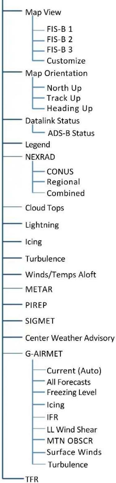
flowchart
graph TD
    A["Map View"] --> B["FIS-B 1"]
    A --> C["FIS-B 2"]
    A --> D["FIS-B 3"]
    A --> E["Customize"]
    F["Map Orientation"] --> G["North Up"]
    F --> H["Track Up"]
    F --> I["Heading Up"]
    J["Datalink Status"] --> K["ADS-B Status"]
    L["Legend"] --> M["NEXRAD"]
    N["Cloud Tops"] --> O["Lightning"]
    P["Icing"] --> Q["Turbulence"]
    R["Winds/Temps Aloft"] --> S["METAR"]
    T["PIREP"] --> U["SIGMET"]
    V["Center Weather Advisory"] --> W["G-AIRMET"]
    X["TFR"] --> Y["Current (Auto)"]
    X --> Z["All Forecasts"]
    X --> AA["Freezing Level"]
    X --> AB["Icing"]
    X --> AC["IFR"]
    X --> AD["LL Wind Shear"]
    X --> AE["MTN OBSCR"]
    X --> AF["Surface Winds"]
    X --> AG["Turbulence"]
5.26.3 Raw Text Reports
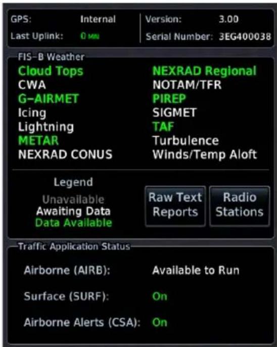
Access FIS-B textual data by tapping the Raw Text Reports key on the ADS-B Status page. Select a FIS-B datalink textual product to view the latest uploaded data.
To display raw text reports from the FIS-B Weather menu, tap Datalink Status > Raw Text Reports.
5.26.4 FIS-B Ground Reception Status
FIS-B ground station transmission status may be monitored when the UAT transceiver is powered and the FIS-B weather option is selected. A current report lists completeness of NOTAM-TFR, G-AIRMET, CWA, and SIGMET data for all received ground stations.
For the received ground station, the station range field indicates complete/incomplete status only for those products within the ground station's range.
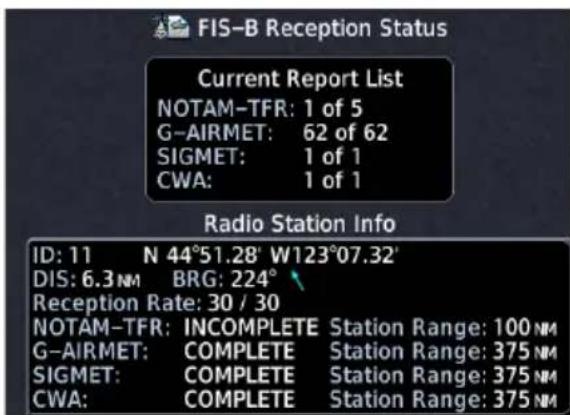
To access the FIS-B Reception Status page from the FIS-B Weather menu, tap Datalink Status > Radio Stations.
5.27 Connext Weather

Garmin provides Connext datalink, on-demand weather products through the Iridium satellite system via a GSR 56 transceiver and L-band frequencies. An Iridium satellite data subscription service is required for worldwide Connext weather coverage.
FEATURE REQUIREMENTS
• GSR 56 transceiver
- Data plan
Connext Weather coverage is available throughout most of Europe, Canada, and the U.S. Additional radar coverage areas are added continuously. For the latest radar coverage information, visit:
https://fly.garmin.com/fly-garmin/connext/worldwide-weather/
Various world-wide weather subscription package options provide weather reporting for most of Europe, Canada, Australia, and the U.S.
5.27.1 Activating Connext Services
To access Connext Weather, visit flyGarmin.com and create a Connext Satellite Services account. Be ready to provide the GDU ID, airframe information (model, tail number), and Iridium serial number. Garmin will issue an access code for entry on the Connext Registration page. If access code and system ID are correct, the airframe registration details will display.
To complete activation:
- Move aircraft within satellite range and power unit.
- Go to MFD home page.
- Tap Weather > Connext Weather > Menu > Connext Settings > Datalink Status > Connext Registration > Access Code.
- Enter the required code, then tap Register to complete the process.
5.27.2 Deactivating Connex Unit Registration
Specific GDU Connext registration can be deactivated in order for the unit to no longer make requests to Connext. This does not cancel the subscription. While viewing the Connext Registration display page, tap Access Code.
Enter an invalid access code to deactivate the Connext registration. Weather requests will now fail and the system will no longer link to the Connext account.
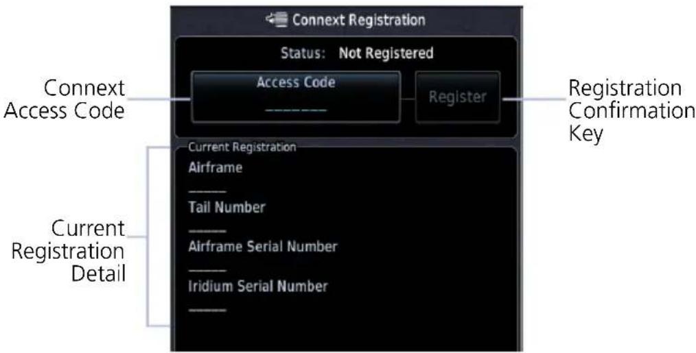
Connext Registration Page
5.27.3 Connext Weather Product Age
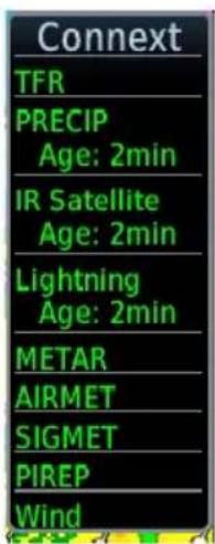
Connext weather product requests are pilot controlled. Weather products are refreshed at intervals that are defined and controlled by Connext and its data vendors.
Weather product age is based on the time difference between when the data was assembled by Connext and current GPS time. Weather products expire at intervals based on each product. When the data expires, it is removed from the display. This ensures that displayed data is consistent with what is currently provided by Connext Satellite Radio services.
5.27.4 Connext Weather Setup
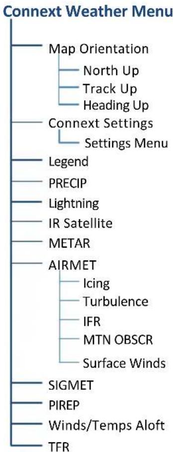
flowchart
graph TD
    A["Connect Weather Menu"] --> B["Map Orientation"]
    A --> C["North Up"]
    A --> D["Track Up"]
    A --> E["Heading Up"]
    A --> F["Connext Settings"]
    F --> G["Settings Menu"]
    F --> H["Legend"]
    F --> I["PRECIP"]
    F --> J["Lightning"]
    F --> K["IR Satellite"]
    F --> L["METAR"]
    F --> M["AIRMET"]
    M --> N["Icing"]
    M --> O["Turbulence"]
    M --> P["IFR"]
    M --> Q["MTN OBSCR"]
    M --> R["Surface Winds"]
    M --> S["SIGMET"]
    M --> T["PIREP"]
    M --> U["Winds/Temps Aloft"]
    M --> V["TFR"]
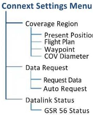
flowchart
graph TD
    A["Coverage Region"] --> B["Present Position"]
    A --> C["Flight Plan"]
    A --> D["Waypoint"]
    A --> E["COV Diameter"]
    F["Data Request"] --> G["Request Data"]
    F --> H["Auto Request"]
    I["Datalink Status"] --> J["GSR 56 Status"]
5.27.5 Connext Data Requests
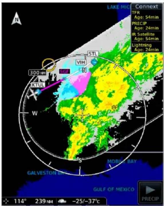
Connext weather data may be updated on an on-request basis. This feature allows the pilot to download selected weather products for a specific waypoint, flight plan, or destination, and the time frame.
Access is via the Connext Settings menu.
Coverage Boundary

The pilot can update Connext weather data at any time regardless of predetermined automatic update frequency.
CONNEXT WEATHER REQUEST CONTROLS
| Present Position | Request weather information around aircraft's present position. COV diameter determines extent of request. |
| Destination | Request weather information for the destination airport. |
| Flight Plan | Request weather information for the active fight plan route. |
| Distance | Enter requested weather information for a specified distance along the active flight plan.Range: 10 nm to 500 nm |
| Waypoint | Request weather information for a specified waypoint. |
| COV Diameter | Define the diameter of coverage.Range: 10 nm to 500 nm |
| Request Data | Request weather data at any time. Reset Auto Request timer (if active) for next request interval. |
| Auto Request | Select the automatic weather request period.Options: Off, 5 min, 10 min |
| Datalink Status | View Iridium satellite datalink status and signal strength. |
Stormscope

Stormscope lightning data display on a dedicated weather page or as overlays on Map page and HSI Map.
5.28 Stormscope Page

WARNING
Do not exclusively use the lightning detection system for weather avoidance. The system may display inaccurate or incomplete information. Refer to the lightning detection system documentation for additional information.
FEATURE REQUIREMENTS
• WX-500 Stormscope Weather Mapping Sensor
FEATURE LIMITATIONS
- Stormscope lightning information cannot display concurrently with a datalink lightning weather product (SiriusXM, Connex, or FIS-B)
Stormscope Features
• Passive weather avoidance system
- Detects electrical discharges from thunderstorms within 200 nm of current position
- Plots strike count and relative bearing location every two seconds
• Heading and distance from aircraft
- Arc and 360^ viewing options
For more information, consult the WX-500 pilot's guide.
5.29 Stormscope Setup
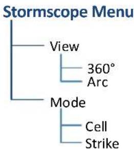
flowchart
graph TD
    A["Stormscope Menu"] --> B["View"]
    A --> C["Mode"]
    B --> D["360° Arc"]
    C --> E["Cell Strike"]
Setup options reside in the setup menu.
Changes in mode selection on the Stormscope page reflect across all lightning overlays (Map page, HSI Map).
5.29.1 Stormscope Modes & Symbols
CELL
Cell mode identifies cluster of electrical activity, grouping individual strikes together. Use Cell mode during heavy storm activity to identify where storm cells are located.
STRIKE
Strike mode plots discharge points in relation to where the individual discharges are detected. Strike mode displays the initial strikes associated with a building thunderstorm in relation to where it's detected.
| SYMBOL TIME SINCE STRIKE (SECONDS) | |
 | Less than 6(lightning bolt indicates initial strike) |
 | Less than 60 |
 | Less than 120 |
 | Less than 180 |
STRIKE RATE
Strike Rate reports the approximate number of strikes per minute for a given view range. Refer here when trying to determine if storm cells are building or decaying.
Mode: Strike | Rate: 47
Strikes occur at a higher rate as a storm matures. They are less frequent as the storm dissipates.

To reset the rate value, clear the page of all strikes.
5.29.2 Views
Stormscope provides both arc and 360° views of lightning data.
ARC VIEW
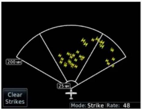
Strike Mode Cell Mode
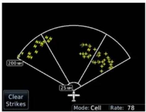
360^ VIEW
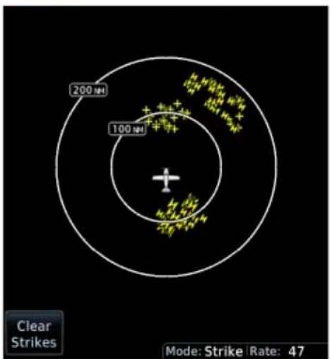
Strike Mode Cell Mode
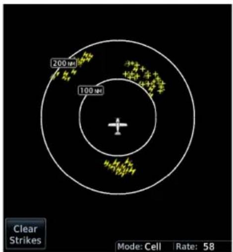
Airborne Weather Radar
Weather radar data display on a dedicated weather page or as overlays on the Map page.
5.30 Weather Radar Page

WARNING
Use weather radar to avoid severe weather, not to enter it.
FEATURE REQUIREMENTS
• GDU 1060 or full screen MFD on GDU 700P
FEATURE LIMITATIONS
• Available modes and intensity levels depend on the installed radar type
• Not available on GDU 700() EIS/MFD
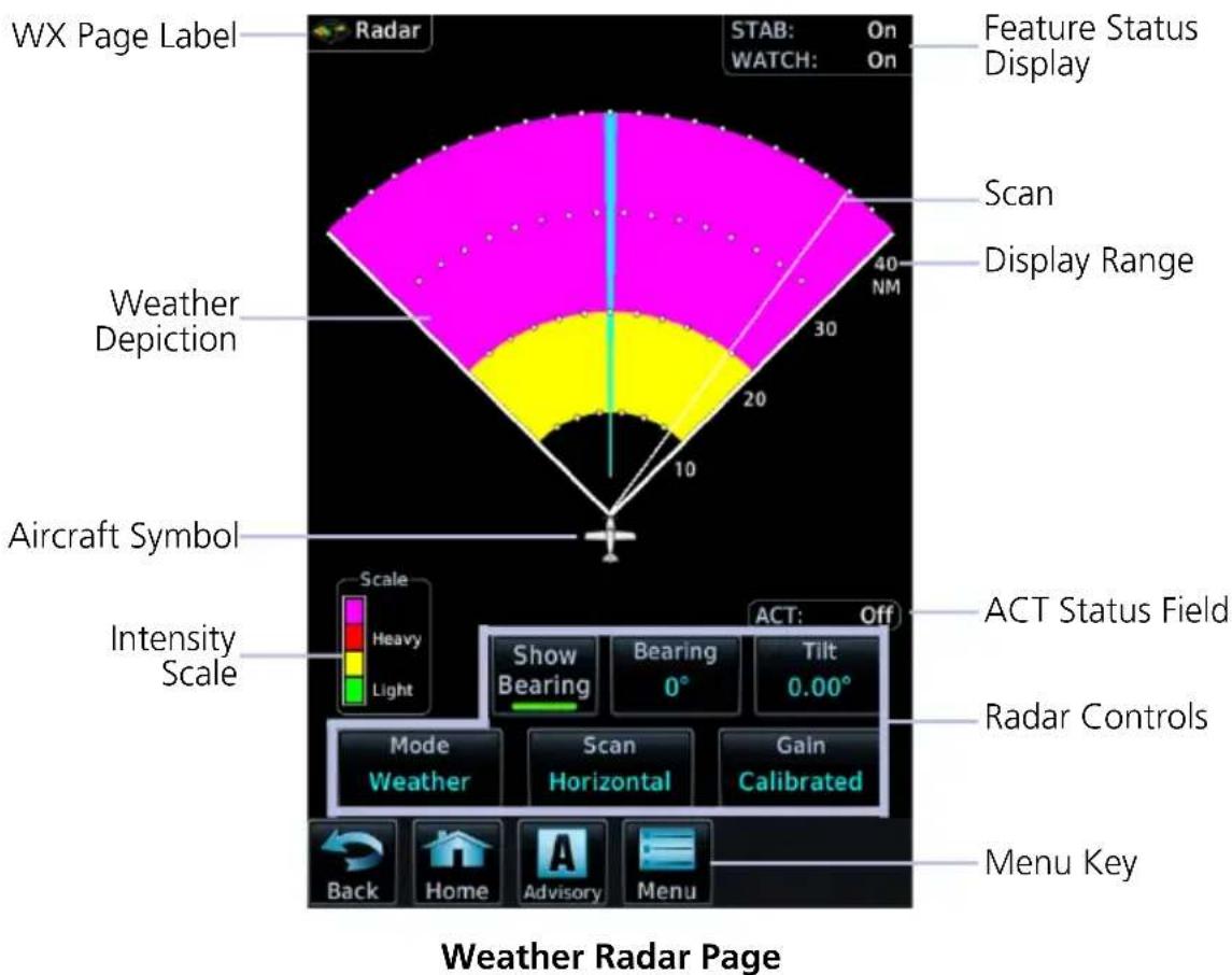
RADAR UNITS
Distances on the Weather Radar page display in nautical miles.
DISPLAY ADJUSTMENTS
To change radar display range, adjust the inner control knob.
To adjust tilt and bearing angle, tap and drag the line indicator as necessary, or use the associated control keys.
INTENSITY SCALE
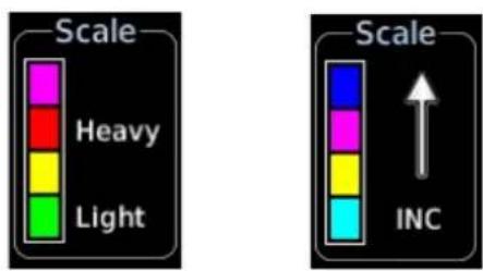
Weather Ground
Each operating mode uses a unique color palette to depict increasing intensity levels.
WARM-UP COUNTDOWN TIMER
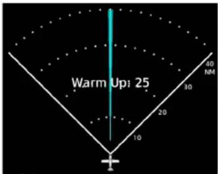
A warm-up period initiates upon power up (GWX 68 only). Duration varies depending on how long the radar is off. The radar begins transmitting once warm-up is complete.
5.31 Weather Radar Setup
Radar Menu
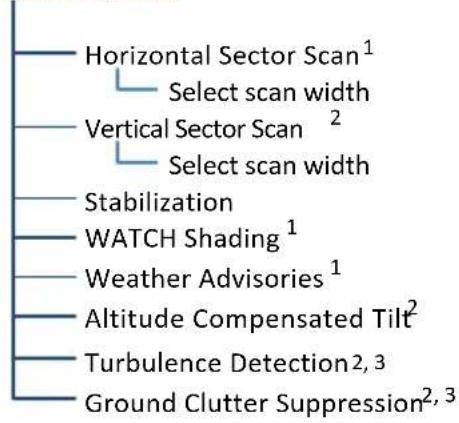
flowchart
graph TD
    A["Horizontal Sector Scan¹"] --> B["Select scan width"]
    C["Vertical Sector Scan²"] --> D["Select scan width"]
    E["Stabilization"] --> F["WATCH Shading¹"]
    G["Weather Advisories¹"] --> H["Altitude Compensated Tilt²"]
    I["Turbulence Detection²,³"] --> J["Ground Clutter Suppression²,³"]
Available setup options are dependent upon configuration.
With the exception of Sector Scan, all selections are on/off only.
^1 Not available for third-party radars. ^2 GWX 70/75 only. ^3 Requires feature enablement.
5.31.1 Sector Scan
The sector scan option focuses the scan on a smaller segment of the radar sweep. This is useful when monitoring priority weather targets.
| SCAN INCREMENTS |
| Horizontal 20°, 40°, 60°, 90°, Full |
| Vertical 10°, 20°, 30°, Full |
| The 90° horizontal scan option is available only for radars with extended scan capabilities (120° sweep). |
Increments vary according to scan type.
Horizontal sector scans center on the bearing line, vertical sector scans center on the tilt line.
5.31.2 Stabilization
This feature helps stabilize the antenna so the scan is parallel to the ground when active. When off, the antenna scan is relative to the aircraft lateral axis. Status displays in the upper right corner of the Radar page.
5.31.3 WATCH
FEATURE LIMITATIONS
• Not available for third party radars
Use WATCH to determine areas of inaccuracies in displayed intensity from attenuation while in horizontal scan mode. Adjust tilt to determine the extent of attenuation in a shaded area. WATCH only displays in horizontal scans.
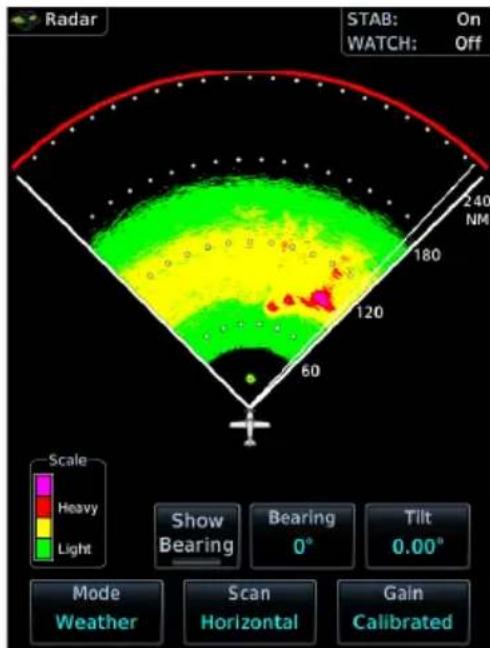
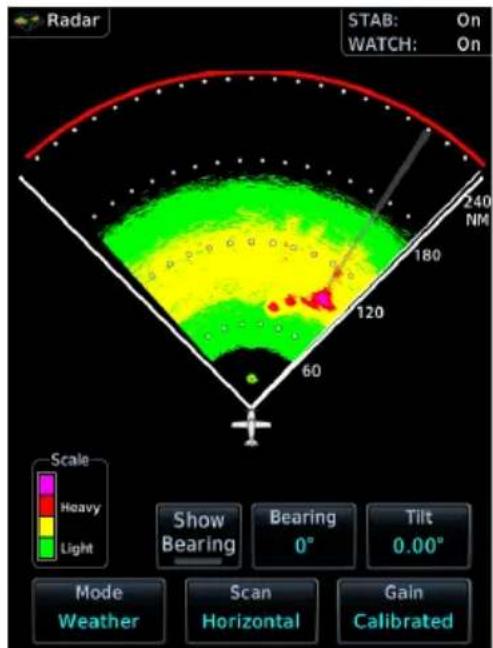
WATCH OnWATCH Off
5.31.4 Weather Alert
FEATURE LIMITATIONS
• Not available for third party radars
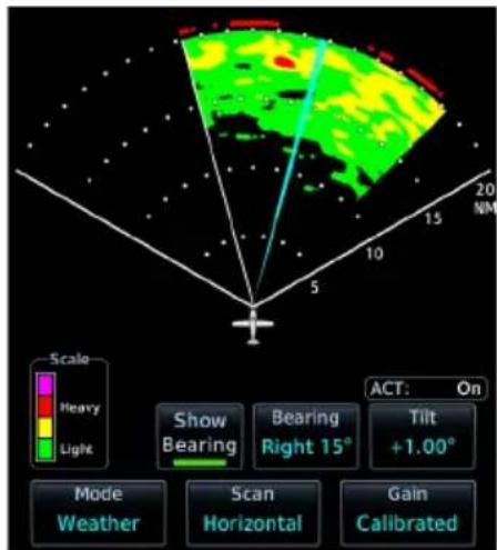
These alerts indicate the presence of heavy precipitation beyond the current display range (80 nm to 320 nm from current position).
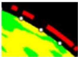
natural_image
Abstract color gradient with red, green, and yellow hues against black background (no text or symbols)Red bands on the outer range ring display at the approximate azimuth of severe weather targets.
If the antenna tilt is adjusted too low, a weather alert is generated by ground returns. If a weather alert is detected within ±10 degrees of the aircraft heading, an advisory displays on the MFD in the advisory window.
5.31.5 Altitude Compensated Tilt
FEATURE LIMITATIONS
- GWX 70/75 only

This feature adjusts the tilt to compensate for altitude changes as the aircraft climbs and descends. Status displays above the radar controls.
5.31.6 Turbulence Detection
FEATURE REQUIREMENTS
• Purchased GWX Turbulence Detection feature enabled on GDU
FEATURE LIMITATIONS
- GWX 70/75 only
This feature detects and displays severe turbulence. Status reports as inactive when:
• Current scan range is greater than 160 nm
• Radar is not in weather mode
• Vertical scan is active
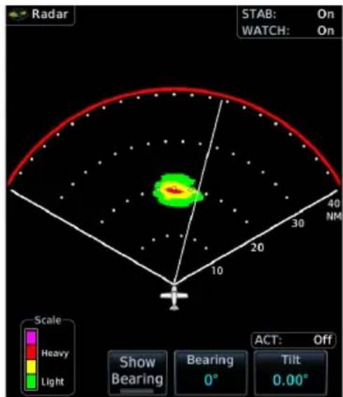
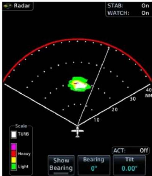
Turbulence OnTurbulence Off
5.31.7 Ground Clutter Suppression
FEATURE REQUIREMENTS
• Purchased GWX Ground Clutter Suppression feature enabled on GDU
FEATURE LIMITATIONS
• GWX 70/75 only
• Not available for vertical scans
This feature reduces the amount of returns of highly reflective objects on the ground, while maintaining the intensity and size of weather returns.
5.32 Radar Modes

WARNING
Do not transmit when personnel or objects are within 11 feet of the antenna.

CAUTION
Place radar in standby mode before taxiing to prevent damage to the radar assembly.
5.32.1 Mode Key

Tapping this key opens a list of available mode options.
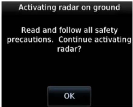
A confirmation pop-up alerts the pilot when attempting to scan while on the ground.
STANDBY
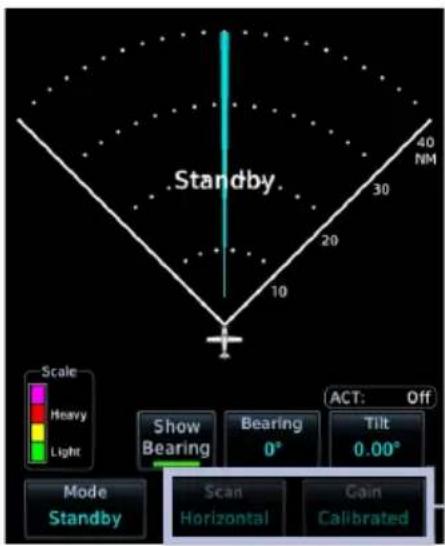
• Parks the antenna at the centerline
- Scan and Gain controls are inactive
• Automatic standby occurs during power up and landing
Inactive
TEST
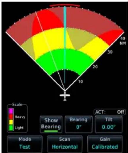
- Places transmitter in standby as the display simulates a radar sweep
- Test data verifies communication between the weather radar and display
- Radar pulses do not transmit from the antenna during this mode
GROUND
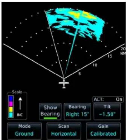
- Presents a depiction of terrain similar to that of a topographical map
- Useful when trying to verify aircraft position
| GROUND MAP MODE COLOR | GROUND TARGET INTENSITY LEVELS | |
| GWX RADAR INTENSITY | THIRD-PARTY RADAR LEVEL | |
| Black 0 dB 0 | ||
| Light Blue > 0 dBZ to < 9 dBZ 1 | ||
| Yellow 9 dBZ to < 18 dBZ 2 | ||
| Magenta 18 dBZ to < 27 dBZ 3 and above | ||
| Blue 27 dBZ and greater Not used | ||
WEATHER
• Presents an airborne depiction of precipitation
- Colors represent approximate rainfall intensity and rates for weather radar targets
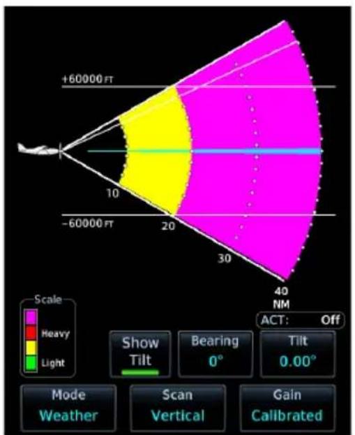
GWX 68/70 GWX 75
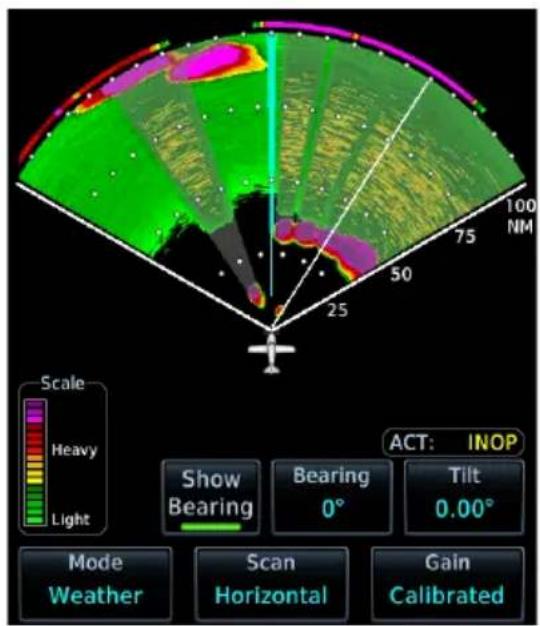
| WEATHER MODE COLOR | GWX 68/70/75 RADAR | THIRD-PARTY RADAR | |
| APPROXIMATE INTENSITY | APPROXIMATE RAINFALL RATE (IN/HR) | RADAR RETURN LEVEL 1 | |
| Black < 23 dBZ < .01 | 0 | ||
| Green 23 dBZ to < 33 dBZ .01 to < 0.1 | 1 | ||
| Yellow 33 dBZ to < 41 dBZ 0.1 to < 0.5 | 2 | ||
| Red 41 dBZ to < 49 dBZ 0.5 to < 2.0 | 3 | ||
| Magenta 49 dBZ and greater 2.0 and greater | 4 | ||
| White Turbulence Detection ^2 | |||
^1 Consult the appropriate third-party radar documentation. ^2 GWX 70 and GWX 75 radar only.
5.33 Radar Controls
Weather Radar Page
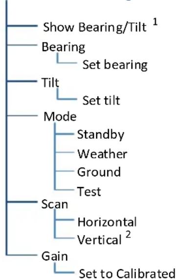
flowchart
graph TD
    A["Show Bearing/Tilt"] --> B["Bearing"]
    B --> C["Set bearing"]
    C --> D["Tilt"]
    D --> E["Set tilt"]
    E --> F["Mode"]
    F --> G["Standby"]
    F --> H["Weather"]
    F --> I["Ground"]
    F --> J["Test"]
    F --> K["Scan"]
    K --> L["Horizontal"]
    K --> M["Vertical²"]
    K --> N["Gain"]
    N --> O["Set to Calibrated"]
Some radars allow independent sweeps when connected to multiple displays.
^1 Dependent upon scan type selection. ^2 Not available for RS 181 and RS 811 radars.
5.33.1 Show Bearing/Tilt
Displays the tilt or bearing line depending on current scan selection. This feature is useful when making horizontal or vertical scan adjustments.
5.33.2 Bearing
FEATURE LIMITATIONS
• Not available on RS 181 and RS 811 radars

Directional keys allow fine adjustment of the bearing line angle. This method is optional to tapping and dragging.
5.33.3 Tilt
Use antenna tilt to locate the top and bottom of storm cells and to increase intensity of ground target returns. One degree of tilt equals 100 feet of altitude per nautical mile. In areas of multiple heavy cells, use the vertical scan feature along with antenna tilt to examine the cells. Avoid shadowed areas behind targets.
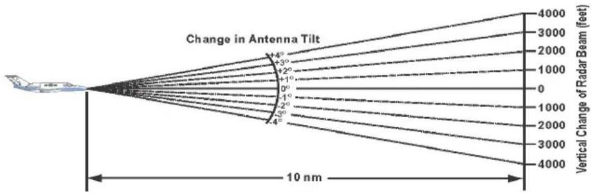
line
| Angle Change (degrees) | Vertical Change of Radar Beam (feet) | | ---------------------- | ------------------------------------ | | +4° | 4000 | | +3° | 3000 | | +2° | 2000 | | +1° | 1000 | | 0° | 0 | | -1° | 1000 | | -2° | 2000 | | -3° | 3000 | | -4° | 4000 |
A typical tilt setup adjusts the bottom of the radar beam to 4^ below parallel with the ground. To adjust the antenna tilt for this typical setup:
-
Fly the aircraft level.
-
Adjust antenna tilt so ground returns display at a distance equal to the aircraft's current altitude (AGL) divided by 1,000.
When flying at altitudes between 2,000 and 30,000 ft AGL with the typical tilt setup, avoid target returns at 5 nm. These may be either weather or ground returns that are 2,000 ft or less below the aircraft. Raise the antenna tilt 4° to separate ground returns from weather returns in flat terrain. Return the antenna to the previous setting after a few sweeps of the radar. Set the display range to 60 nm for aircraft flying at 15,000 ft or lower. Monitor ground returns for possible threats.
If flying above 29,000 ft with the typical tilt setup, be cautious of targets 30 nm or closer. This may indicate a thunderstorm that the aircraft cannot fly over safely.
5.33.4 Scan
FEATURE LIMITATIONS
• RS 181 and RS 811 radars do not support vertical scan functionality
Horizontal scans provide a visual depiction of weather in front of the aircraft. Vertical scans focus the radar on a particular vertical target.
HORIZONTAL
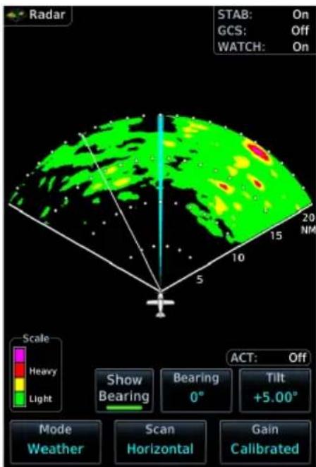
For bearing line visibility, tap Show Bearing.
To adjust the horizontal scan bearing:
- Tap and drag the bearing line left or right
Or
- Adjust the angle using the Bearing control
To adjust vertical angle for the horizontal scan, tap Tilt and then adjust the angle using directional keys.
VERTICAL
When vertically scanning with stabilization on, the physical area that the radar is sweeping may not match the displayed vertical scan. This occurs when the aircraft pitch is not at 0^ . To compensate, the GDU does not draw the unscanned portion.
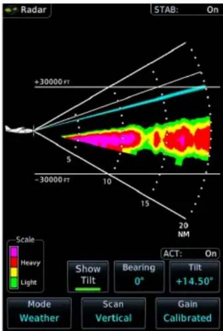
For tilt line visibility, tap Show Tilt.
To adjust the tilt of vertical scan:
- Tap and drag the tilt line up or down
Or
- Adjust the angle using the Tilt control
To adjust horizontal angle for the vertical scan, tap Bearing and then adjust the angle using directional keys.
5.33.5 Gain

NOTE
Precipitation intensity may not be accurate if the gain is changed.
FEATURE LIMITATIONS
• For third party radars, this control is active only during ground mode
This feature controls the sensitivity of the radar receiver. Adjustments to receiver sensitivity automatically change the intensity of radar targets.
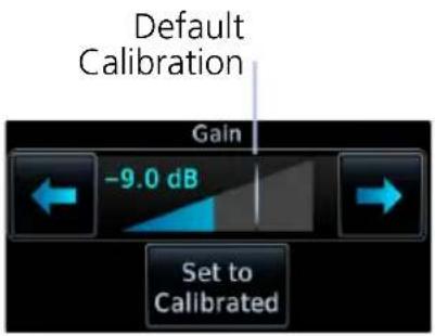
Directional keys allow sensitivity adjustments.
Tapping Set to Calibrated restores the calibrated gain setting and returns intensity depictions to their actual colors.
5.34 Radar Alerts
A caution message alerts the pilot of a weather radar failure. Scan depictions on Weather Radar and Map pages do not display.
Weather radar overlay detail is absent from the Map page if heading input is lost.
ANNUNCIATION ALERT TYPE & CONDITION
| RADAR FAULT | Alert Type: Caution |
| Condition: | |
| Data contains a fault unrelated to attitude. | |
| RADAR FAIL | Alert Type: Caution (GWX only) |
| Condition: | |
| Weather radar product status is timed out. | |
| RADAR CONTROLS DISAGREE | Alert Type: Caution (Third-party radars only) |
| Condition: | |
| Radar's actual state does not match the commanded state. | |
| RADAR ACTIVE | Alert Type: Caution (GWX 70/75 and third-party radars) |
| Condition: | |
| Radar is in standby, but remains active due to another interfacing controller. |
6 Traffic Awareness
TRAFFIC DISPLAY
6.1 Traffic Page 6-3
6.2 Traffic Setup....6-6
TRAFFIC TYPES
6.3 TIS-A 6-8
6.4 TAS/TCASI 6-10
6.5 TCAS II 6-12
6.6 ADS-B 6-16
6.7 Traffic Alerts....6-21
Traffic Display
FEATURE LIMITATIONS
- Symbols depicted depend on traffic source (e.g., TIS-A, TAS, ADS-B)
- Intruding aircraft without altitude reporting capabilities do not display altitude separation data or climb/descent indications
• Available display ranges and vector types depend on traffic source
Collision avoidance and traffic surveillance data display on the Traffic page or as overlays on the Map page and HSI Map. Synthetic vision traffic depictions display on PFD when SVT is enabled.
Available Traffic Sources
• TIS-A
• TAS/TCAS I
• ADS-B with or without TCAS
• TCAS II
The availability of functions, alerting features, and options depend on the traffic system source.
ADS-B controls are accessible from the Traffic menu. Controls for other traffic systems are located on the Traffic page.
6.1 Traffic Page
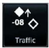
The Traffic page displays intruding traffic in relation to the current position and altitude of the aircraft without clutter from other data.
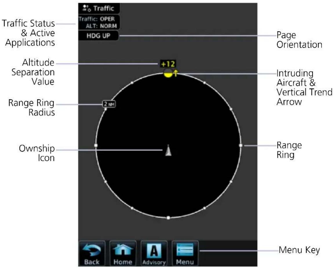
Traffic Page Features
| TRAFFIC DISPLAY OBJECTS | |
| Ownship Icon | Depicts current aircraft positionNose of the ownership is the actual ownership locationUnlike the configured aircraft symbol on map displays, ownership icon is always a directional arrow |
| Page Orientation Label | Orientations:1. Heading up (HDG UP) during normal operation.2. Track up (TRK UP) if there is no valid heading. |
| Range Rings | Ranges vary according to traffic system typeOuter ring represents selected range |
| Altitude Separation Value | Indicates when an intruder is above or below the ownership.Value placement is based on intruder location.Above traffic symbol if intruder is aboveBelow symbol if intruder is belowPlus or minus sign denotes higher or lower altitude |
| Vertical Trend Arrow | Active when an intruder is climbing or descending at a vertical speed greater than 500 fpm |
| Intruding Aircraft Symbol | Color may be cyan or white depending on configuration.Actual intruder location varies according to symbol type.Tip of directional symbolsCenter of non-directional symbols |
INVALID ALTITUDE DEPICTIONS
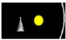
If an intruder does not have a valid altitude, its symbol displays without the altitude tag.
OFF SCALE TRAFFIC ALERTS
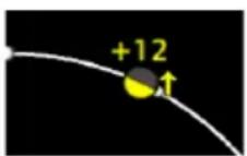
Off scale (out of range) traffic alerts are depicted as half yellow symbols on the outermost range ring at the correct bearing.
TRAFFIC OVERLAY STATUS ICONS
ICON DESCRIPTION

Map is displaying traffic.

Map is not displaying traffic.
Overlay icons indicate the status of displayed traffic on HSI Map, Rotorcraft PFD VFR Map, and the MFD Map page.
TRAFFIC UNITS
PARAMETER UNITS
Altitude ft
Distance nm
Traffic units are always uniform.
System Units page selections do not affect the traffic display.
ALT IN FT
If the system units for altitude are set to meters, an annunciation reminds the pilot that all displayed altitude values remain in feet.
6.2 Traffic Setup
Traffic settings are synchronized between all MFDs.
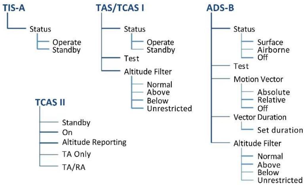
flowchart
graph TD
    A["TIS-A"] --> B["Status"]
    B --> C["Operate Standby"]
    A --> D["TAS/TCAS I"]
    D --> E["Status"]
    E --> F["Operate Standby"]
    D --> G["Test"]
    G --> H["Altitude Filter"]
    H --> I["Normal Above Below Unrestricted"]
    A --> J["TCAS II"]
    J --> K["Standby On Altitude Reporting"]
    J --> L["TA Only TA/RA"]
    A --> M["ADS-B"]
    M --> N["Status"]
    N --> O["Surface Airborne Off"]
    M --> P["Test"]
    P --> Q["Motion Vector"]
    Q --> R["Absolute Relative Off"]
    M --> S["Vector Duration"]
    S --> T["Set duration"]
    M --> U["Altitude Filter"]
    U --> V["Normal Above Below Unrestricted"]
6.2.1 Traffic Test
FEATURE LIMITATIONS
• ADS-B, TAS, and TCAS applications only
• Available only when the aircraft is on ground (i.e., standby mode)
• Test pattern depiction is dependent upon the active traffic system
TEST KEY
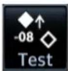
The test function displays a test pattern on the Traffic page. For ADS-B, this option is accessible via the Traffic menu.
The system automatically returns to normal operating mode once the test is complete.
6.2.2 Altitude Filtering
FEATURE LIMITATIONS
• ADS-B, TAS, and TCAS applications only
Pilot selectable filters limit the display of traffic to a specific altitude range relative to the altitude of the ownership.
Filter selections apply to both the Traffic page and the traffic overlay on the Map page.
| SELECTION ALTITUDE RANGE |
| Normal -2,700 ft to 2,700 ft |
| Above -2,700 ft to 9,900 ft |
| Below -9,900 ft to 2,700 ft |
| Unrestricted -9,900 ft to 9,900 ft |
On a standalone PFD, HSI Map always presents traffic at the Normal filter setting. On GDU 1060 with PFD and MFD, it uses the same filter selections on MFD.
Traffic Types
6.3 TIS-A
FEATURE REQUIREMENTS
• Aircraft location is within the service volume of a Mode S terminal radar site
• TIS-capable Mode S transponder is interfaced to the GDU
FEATURE LIMITATIONS
For information about TIS-A functions and limitations, consult the AIM.
TIS-A Features
- 2-D graphical depiction of proximate traffic based on data received from terminal radars
- Track vector depicts intruder trajectory over the ground
• Vertical coverage: +3,500/-3,000 ft from ownership
• Eight intruder maximum within an 8 nm radius
• Five second update cycle
• Normal and standby mode options
6.3.1 TIS-A Setup Selections
Status
Select operating mode. Options are Operate and Standby.
6.3.2 TIS-A Traffic Symbols
Traffic information is for advisory use only. The pilot is responsible for identifying and avoiding traffic.

Non-threat Traffic

Traffic Advisory (TA)

TA Off-scale
6.3.3 TIS-A Status Indications
| ANNUNCIATION DESCRIPTION | |
| Data Failed | GDU receives data from the transponder, but a failure exists in the data stream. |
| Failed Transponder failure. | |
| No Data GDU is not receiving valid data from the transponder. | |
| TA X.X NM ±XX ↑ | System cannot determine TA bearing. Intruder depiction not available. Annunciation includes:Distance in nautical milesAltitude separation in hundreds of feetAltitude trend arrow (climbing/descending) |
| TA OFF SCALE TA is | outside the selected display range. |
| Traffic Coast x SEC Intruder depictions are more than six seconds old. | |
| Traffic Removed | Intruder depictions are more than 12 seconds old. Traffic symbols no longer display. |
| Unavailable | Transponder not receiving TIS-A data from ground station. |
6.4 TAS/TCAS I
TAS/TCAS I Features
• Airborne traffic system independent of ground radar
• 2-D graphical depiction of traffic relative to aircraft position and altitude
6.4.1 TAS/TCAS I Setup Selections
| Status | Select operating mode. Options are Operate and Standby. | |
| Test | Initiate a test of the traffic system. | |
| Altitude Filter | Select filter range. Options include: | |
| Normal | Above | |
| Below | Unrestricted | |
6.4.2 TAS/TCAS I Traffic Symbols
Traffic information is for advisory use only. The pilot is responsible for identifying and avoiding traffic conflict.

Other Traffic

Proximity Advisory

Traffic Advisory

TA Off-scale
6.4.3 TAS/TCAS I Status Indications
| ANNUNCIATION DESCRIPTION | |
| Data Failed | GDU receives traffic data, but the TAS unit is reporting a failure. |
| Failed Traffic data failure. | |
| No Data GDU is not receiving valid data from the TAS unit. | |
| TA X.X NM ±XX ↑ | System cannot determine TA bearing. Intruder depiction not available. Annunciation includes:Distance in nautical milesAltitude separation in hundreds of feetAltitude trend arrow (climbing/descending) |
6.5 TCAS II

WARNING
Traffic information shown on system displays is provided as an aid in visually acquiring traffic. Traffic avoidance maneuvers are based upon TCAS II Resolution Advisories, ATC guidance, or positive visual acquisition of conflicting traffic.

NOTE
If the installed TCAS II traffic system is not a GTS 8000, refer to the applicable documentation for system-specific information.
FEATURE REQUIREMENTS
• GTS 8000 or third-party TCAS II system
TCAS II Features
• Monitors nearby airspace for aircraft flying with operating transponders
- Issues TAs to assist in visual identification of traffic
- Issues RAs to provide recommended vertical guidance maneuvers to resolve traffic conflicts
6.5.1 TCAS II Status Indications
| SELECTION | MFD TRAFFIC PAGE TCAS STATUS |
| TCAS II Self-Test Initiated (TEST) | TEST |
| Traffic and Resolution Advisory (TA/RA) | TA/RA |
| Traffic Advisory Only | TA ONLY |
| TCAS II Standby | STBY |
| TCAS II Failed | FAIL |
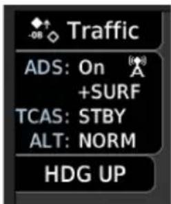
TCAS II status is shown in the MFD Traffic page data window.
6.5.2 TCAS II Annunciations
| SELECTION PFD ANNUNCIATIONS | |
| TCAS II Self-Test Initiated (TEST) | TCAS TEST |
| Traffic Advisory Only | TA ONLY |
| TCAS II Standby | TCAS STBY |
| TCAS II Failed | TCAS FAIL |
| TCAS Resolution Advisories Unavailable | TCAS VS RA FAIL |
| Traffic and Resolution Advisory (TA/RA) | TRAFFIC |
| RA Display Unavailable(Expand the PFD display area to resolve) | VS RA N/A |
TCAS annunciations will appear on the right side of the PFD. Information annunciations are in black text on white backgrounds. Caution annunciations are in black text with yellow backgrounds. Warning annunciations are in white text with red backgrounds.
When the TCAS II unit issues a TA or RA, "TRAFFIC" appears and flashes for 5 seconds, and remains until no TAs or RAs are detected.
• RA "TRAFFIC" annunciations are white text with red backgrounds
• TA "TRAFFIC" annunciations are black text with yellow backgrounds
- If a TA and RA occur simultaneously, only the red and white RA "TRAFFIC" annunciation displays
If the GDU is not displaying the Traffic page, the system displays a traffic alert pop-up.
- During a TA event, the system issues a single "Traffic, Traffic" voice alert each time the system detects a new TA threat
- During an RA event, voice alert(s) provide vertical guidance to resolve the traffic conflict
• The VSI displays a range of vertical speeds to fly to or avoid as applicable
• Additional voice alerts occur if the RA status changes and when the aircraft is clear of the conflict
If the traffic system cannot determine the bearing of a traffic or RA, the alert displays as a traffic alert banner.
RA X.X ± XX
Warning Banner
- Displays when the system is unable to determine the bearing of an RA and extreme pilot vigilance is required
- Banner indicates distance in nm and altitude separation in hundreds of feet
- If altitude trend is available, the banner indicates altitude trend up
for climbing and down for descending traffic
TA X.X ± XX
Caution Banner
- Displays when the system is unable to determine the bearing of a TA and pilot vigilance is required
- Banner indicates distance in nm and altitude separation in hundreds of feet
- If altitude trend is available, the banner indicates altitude trend up
for climbing and down for descending traffic
6.5.3 TCAS II Traffic Symbols
Traffic information is for advisory use only. The pilot is responsible for identifying and avoiding traffic conflict. TCAS II categorizes detected traffic into four groups of increasing collision threat potential. Lowest threat is OT and the highest is RA.

OT
Other non-threatening traffic.

PA
Traffic is not currently a threat, but is within 6 nm and ±1,200 ft of the own-aircraft altitude.

TA
Indicates traffic is within 20-48 seconds of a potential collision area.

Off-scale TA
Traffic is beyond the selected map range and the system displays a half-TA symbol at the edge of the map at the approximate relative bearing of the TA traffic. If TA traffic subsequently meets the criteria for an RA, the system issues an RA.

RA
Indicates traffic is within 15-35 seconds of a potential collision area.

Off-scale RA
If RA traffic is beyond the selected map range, the system displays a half-RA symbol at the edge of the map positioned at the approximate relative bearing to the RA traffic.
6.5.4 TCAS II with ADS-B

NOTE
Aircraft that are surveilled by ADS-B In only will not trigger a TCAS resolution advisory.
TCAS II interrogates Mode-S transponder data while automatically receiving ADS-B position and velocity information directly from a comparably equipped aircraft target. For preciseness, the system correlates between two data sources and the system displays the traffic information for the source determined to be the most accurate. Traffic that is not correlated (i.e., only detected by one system but not the other) is also displays for the flight crew. This may occur, for example, if another aircraft is beyond the surveillance range of the TCAS II, but it is still receiving position and velocity information from other ADS-B equipped aircraft. The traffic correlation feature improves the accuracy of the traffic displayed, while reducing the occurrence of displaying a single target twice.
6.6 ADS-B
ADS-B Features
- Runway and taxiway depiction during SURF mode (< 2 nm range scale)
- Selectable traffic icons display intruder and vector information
- Customizable motion vectors (type, duration)
• Airborne and surface mode options - On-scene mode option (rotorcraft only)
6.6.1 ADS-B Setup Selections
| ADS-B Status | Enable automatic mode selection. System selects between Surface and Airborne depending on the state of the aircraft.Selecting Off disables the function. | |
| Test | Initiate a test of the traffic system. | |
| Motion Vector | Select motion vector type. Selecting Off removes all motion vectors from the display. | |
| Absolute | Relative | |
| Off | ||
| Vector Duration | Select the amount of time represented by the endpoint. Options range from 0 seconds to 5 minutes.A longer duration results in a longer vector. | |
| Altitude Filter | Select filter range. Options include: | |
| Normal | Above | |
| Below | Unrestricted | |
6.6.2 ADS-B Traffic Symbols
Traffic Information is for advisory use only. The pilot is responsible for identifying and avoiding traffic conflict.

Basic Directional Proximate Directional


Basic Non-directional Proximate Non-directional


Basic Off-scale Selected

Proximate Off-scale Selected

Directional (On-Ground)

Non-directional Alerted

Non-directional (On-Ground)

Off-scale Non-directional Alerted Traffic

Proximate Directional (On-Ground)

Directional Alerted Traffic

Proximate Non-directional (On-Ground)

Off-scale Directional Alerted Traffic

Directional Surface Vehicle

Non-directional Surface Vehicle
6.6.3 ADS-B Traffic Applications
FEATURE LIMITATIONS
- On-scene mode functionality is available only for rotorcraft
| MODE FEATURES | |
| AIRB | Airborne traffic applicationActive in the en route environment (>5 nm and >1,500 ft above the nearest airport) |
| SURF | Airborne and ground traffic applicationActive on ground or within the terminal environment (<5 nm and <1,500 ft above field elevation)Runway and taxiway depictions when the zoom scale is <2 nm (Traffic page only)Ground vehicle depictions |
| On-scene | Rotorcraft nuisance alert suppression optionReduces alerts caused by proximity rotorcraft operating in a scene environment (e.g., EMS landing zone, news gathering events)Mode activation and control by way of navigatorLook-ahead time: 3 secondsTraffic alarm vertical threshold: 200 ftIncremental protected traffic volume: 1,000 ft |
6.6.4 Motion Vectors
FEATURE LIMITATIONS
• Motion vectors display on the Traffic page only
A motion vector is a line extending from the nose of an intruder icon. Its orientation represents the intruder's direction and movement. A yellow vector indicates when traffic meets intruding TA criteria (i.e., closing rate, distance, vertical separation).
| MOTION VECTOR TYPES | |
| Absolute | Cyan or white vector depending on configurationDepicts intruder ground trackCalculations based on intruder direction and ground speedEndpoint depicts intruder's position over the ground at the end of the selected durationAirborne and ground functionality |
| Relative | Green vectorDepicts intruder movement relative to the ownershipCalculations based on track and ground speed of both intruder and ownershipEndpoint depicts intruder's location relative to the ownership at the end of the selected durationAirborne functionality only"Relative Motion - Unavailable" annunciates during ground operations |
6.6.5 ADS-B Status Indications
| ANNUNCIATION DESCRIPTION | |
| Absolute Motion - XX SEC/MIN | Active motion vector type is absolute. |
| Failed ADS data failure. | |
| No Data GDU is not receiving valid traffic data. | |
| No GPS Position ADS-B LRU detects that GPS unit is initializing. | |
| Relative Motion - XX SEC/MIN | Active motion vector type is relative. |
| Relative Motion - UNAVAILABLE | Aircraft is not airborne and the active motion vector type is relative. |
| Unavailable Necessary traffic data | not available. |
6.6.6 ADS-B Traffic Interactions
Selected Traffic Information
- Registration/call sign
- Vehicle type
- Closure rate
- Track
- Ground speed
• AIRB/SURF eligibility
Selecting a traffic symbol displays information about the aircraft in the upper right corner of the page.
Selections remain active through altitude filtering, zoom scale, and page changes.
Tapping Next repeatedly steps through multiple symbols spaced closely together.
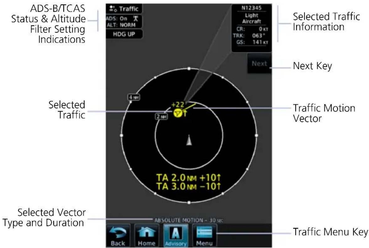
ADS-B Traffic Features
6.7 Traffic Alerts
Traffic alerts occur anytime there is an increase in the number of traffic advisories. They remain active until the area is clear of all TAs.
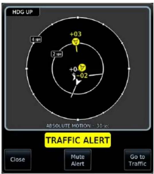
Traffic alerts appear as textual annunciations on the PFD, and as a pop-up window on the MFD, when applicable.
Aural traffic alerts are not a function of the GDU.

MFD Pop-up PFD Annunciation
| ANNUNCIATION | ALERT TYPE, POP-UP, CONDITIONS, & VOICE MESSAGE | |
| TRAFFIC | Alert Type: CautionPop-up Alert: Yes | |
| Condition Voice Message | ||
| The traffic system reports a traffic advisory. | Message content depends on current traffic system configuration. | |
For installations with GTX 345 and ADS-B software v3.20 or later, tapping the Mute Alert key silences the active traffic alert voice message. This function is applicable only to the active aural alert (does not mute future alerts). For more information, read section 1.27.5.
INTENTIONALLY LEFT BLANK
7 Terrain Awareness
TERRAIN CONFIGURATIONS
7.1 GPS Altitude for Terrain....7-2
7.2 Database Limitations 7-4
TERRAIN DISPLAY
7.3 Terrain Page 7-5
7.4 Terrain Setup....7-7
7.5 Terrain Proximity....7-8
TERRAIN ALERTING
7.6 Alert Types 7-13
7.7 Terrain-FLTA 7-19
7.8 TAWS-B....7-23
7.9 External TAWS/HTAWS....7-27
Terrain Configurations
Available Terrain Configurations
• (H)Terrain Proximity
• (H)Terrain-FLTA
- TAWS-B
• External TAWS/HTAWS
- TAWS-A
Terrain, obstacle, and wire data display as overlays on the Terrain page, Map page, and HSI Map. Alerting functions are dependent upon the aircraft type and configured terrain alerting options.
Terrain controls are accessible from the Terrain menu. Map overlay keys are accessible from the associated map menu.
EXTERNAL TAWS
Depending on system configuration, the GDU may be capable of remotely indicating TAWS information from the navigator.
7.1 GPS Altitude for Terrain
FEATURE REQUIREMENTS
GPS altitude is derived from satellite measurements. To acquire an accurate 3-D fix (latitude, longitude, altitude), a minimum of four operating satellites must be in view of the GPS receiver antenna.
The terrain system uses GPS altitude and position data to:
- Create a 2-D image of surrounding terrain and obstacles relative to the aircraft's position and altitude
- Calculate the aircraft's flight path in relation to surrounding terrain and obstacles
• Predict hazardous terrain conditions and issue alerts
7.1.1 GSL Altitude & Indicated Altitude
The GDU converts GPS altitude data to GSL altitude (i.e., the geometric altitude relative to MSL) for use in terrain functions. All Terrain page depictions and elevation indications are in GSL.
Variations between GSL altitude and the aircraft's corrected barometric altitude (or indicated altitude) are common. As a result, Terrain page altitude data may differ from current altimeter readings. Both GSL altitude and indicated altitude represent height above MSL, but differ in accuracy and reliability.
GSL Altitude Indicated Altitude
• Highly accurate and reliable geometric altitude source
- Does not require local altimeter settings to determine height above MSL
• Not subject to pressure and temperature variations
- Affected primarily by satellite geometry
• Barometric altitude source corrected for pressure variations
- Requires frequent altimeter setting adjustment to determine height above MSL
- Subject to local atmospheric conditions
- Affected by variations in pressure, temperature, and lapse rate
7.2 Database Limitations

NOTE
Garmin cross-validates terrain and obstacle data in accordance with TSO-C151c.
However, the information should never be considered all-inclusive. Database inaccuracies or omissions may exist.
Terrain and obstacle data are not available when the aircraft is operating outside of the installed database coverage area.
Garmin obtains terrain and obstacle data from government sources and cannot independently verify the accuracy and completeness of the information. Pilots must familiarize themselves with the appropriate charts and other data for safe flight.
DATABASE COVERAGE LIMITATIONS
| Terrain | Not available north of 89° N latitude and south of 89° S latitude |
| Obstacle | Coverage areas vary according to database typePower line indications for the contiguous United States and small parts of Canada and MexicoRegional definitions may change without noticeMay not contain uncharted obstaclesMay include power lines or only HOT lines depending on database type1 |
^1 HOT lines are power lines that share location with other obstacles identified by the FAA.
Terrain Display

Unlike the Map page and HSI Map, the Terrain page does not provide controls for toggling overlays on or off.
7.3 Terrain Page

WARNING
Do not use Terrain and obstacle data to navigate or maneuver around terrain. They are an aid to situational awareness only.
FEATURE REQUIREMENTS
All terrain functions require the following components to operate properly.
- Valid 3-D GPS position for terrain and obstacle data display
- Valid terrain/obstacle database
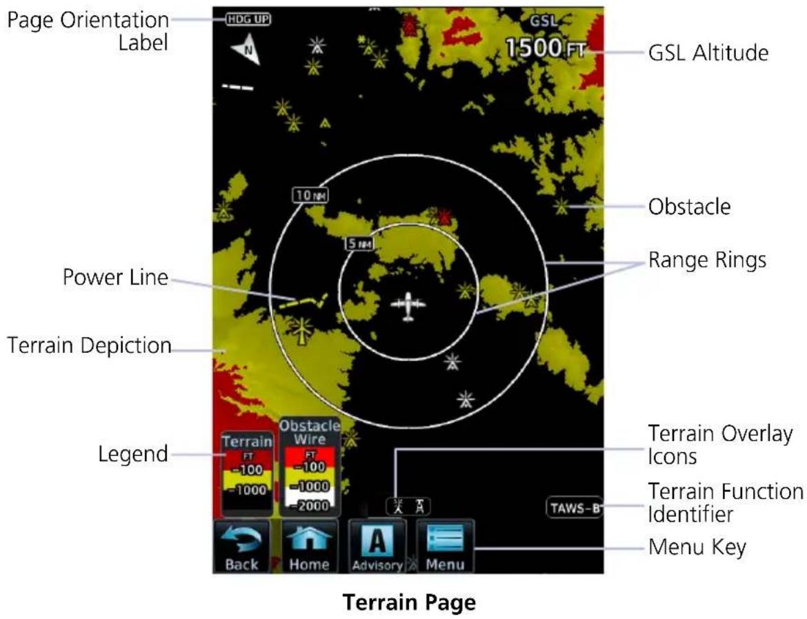
| TERRAIN DISPLAY OBJECTS | |
| Page Orientation Label | Normally, Heading Up orientation.Changes to Track Up in the event of a heading failure. |
| GSL Altitude | Displays current GPS height above mean sea level. Pilot selectable units are available on the System Units page. |
| Legend | Displays color designations for terrain and obstacle relative altitude ranges. |
| Terrain Function Identifier | Indicates the active terrain function. Includes: TAWS-A, TAWS-B,(H)Terrain-FLTA, Terrain Proximity TAWS-A, TAWS-B,(H)Terrain-FLTA, Terrain Proximity |
| Terrain Overlay Icon | Indicates when power lines or obstacles are present at the current zoom scale. Automatic removal of obstacle and power line data occurs at range scales greater than 10 nm. Automatic removal of obstacle and power line data occurs at range scales greater than 10 nm. |
| Menu Key | Provides access to pilot selectable settings, self-test, and alert inhibit functions. |
AUTOMATIC ZOOM
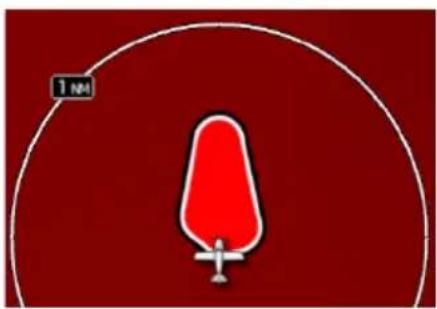
In the event an alert occurs, the page automatically zooms to provide the best depiction of that alerted terrain, obstacle, or power line.
7.4 Terrain Setup
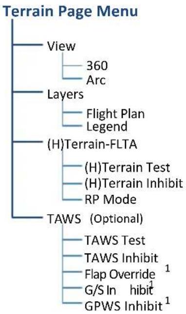
flowchart
graph TD
    A["Terrain Page Menu"] --> B["View"]
    A --> C["Layers"]
    A --> D["(H)Terrain-FLTA"]
    A --> E["TAWS (Optional)"]
    B --> F["360"]
    B --> G["Arc"]
    C --> H["Flight Plan"]
    C --> I["Legend"]
    D --> J["(H)Terrain Test"]
    D --> K["(H)Terrain Inhibit"]
    D --> L["RP Mode"]
    E --> M["TAWS Test"]
    E --> N["TAWS Inhibit"]
    E --> O["Flap Override 1"]
    E --> P["G/S In hibit 1"]
    E --> Q["GPWS Inhibit 1"]
Tap Menu to access pilot selectable terrain settings, including self test and alert inhibit functions.
^1 TAWS-A only.
SELECTION FUNCTION
| View | 360 | Changes view format to a 360° ring encircling the aircraft (default view) |
| Arc | Changes view format to a forward-looking 120° arc | |
| Layers | Flight Plan | Toggles the active flight plan display over terrain map on or off |
| Legend | Toggles the Terrain and Obstacle/Wire legend on or off | |
| (H)Terrain FLTA | (H)Terrain Test | Performs terrain alerting system testVerifies the validity of required databases |
| (H)Terrain Inhibit | Inhibits the FLTA aural and visual alerts | |
| RP Mode 1 | Reduces alerting thresholds for low-level operations |
SELECTION FUNCTION
| Flap Override | Overrides flap-based FIT alerting while other FIT alert functions remain in effectInhibits nuisance FIT alerts where flap extension is not desired | |
| TAWS-A | G/S Inhibit | Inhibits glideslope or glidepath alerts depending on current stateUse to prevent glideslope/glidepath deviation alerts (e.g., when flying a localizer backcourse approach)Active only for a single approach |
| GPWS Inhibit | Inhibits GPWS audible and visual alerts (i.e., EDR, ECR, FIT, and NCR) | |
| TAWS-A & B | TAWS Test | Performs TAWS alerting system testVerifies the validity of required databases |
| TAWS Inhibit | Inhibits the PDA/FLTA audible and visual alerts |
^1 Rotorcraft only.
7.5 Terrain Proximity
FEATURE LIMITATIONS
- Terrain and obstacle depictions are relative to aircraft altitude
- Obstacle depictions are dependent upon database
- Setup does not provide visual or aural alerts
Terrain Proximity Features
• Non-TSO C151c certified terrain display system
- 2-D graphical representation of surrounding terrain, obstacles, and power lines relative to aircraft position and altitude
- Declutter automatically removes obstacle and power line data at large ranges
• Continuous monitoring of database validity, GPS and hardware status
- Displays when higher level terrain functions are active
7.5.1 Terrain Elevation Depictions
Color shading depicts terrain elevations relative to the aircraft's position and altitude. Colors automatically adjust as the aircraft's altitude changes.
TERRAIN DEPICTIONS, FIXED WING
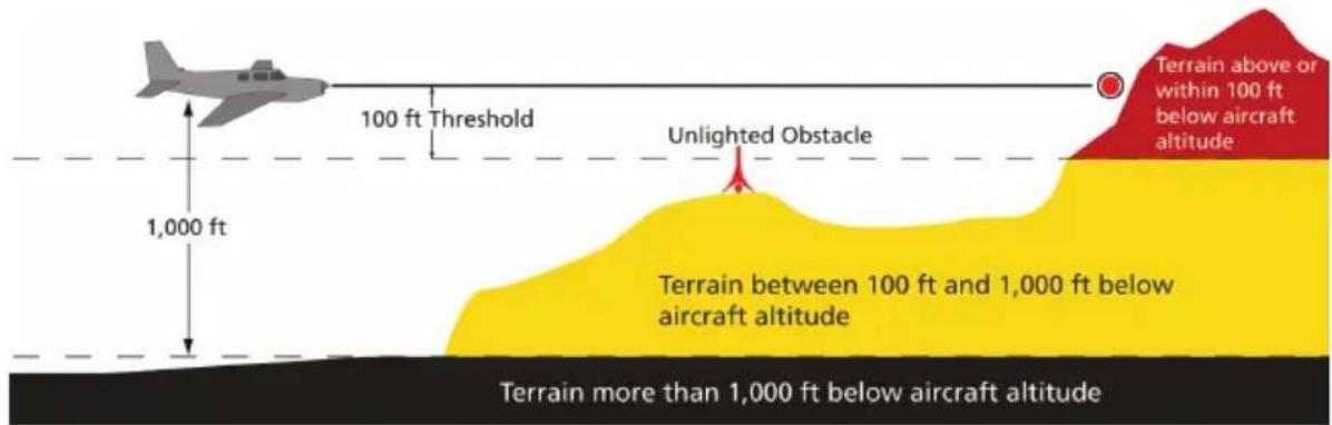
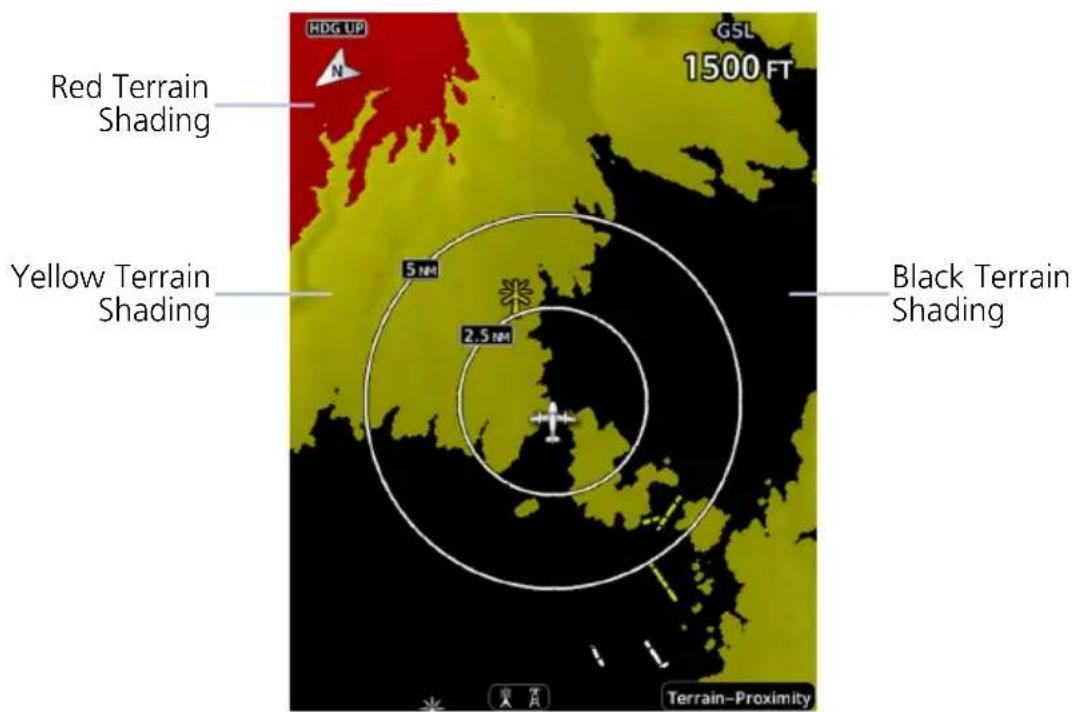
TERRAIN DEPICTIONS, ROTORCRAFT

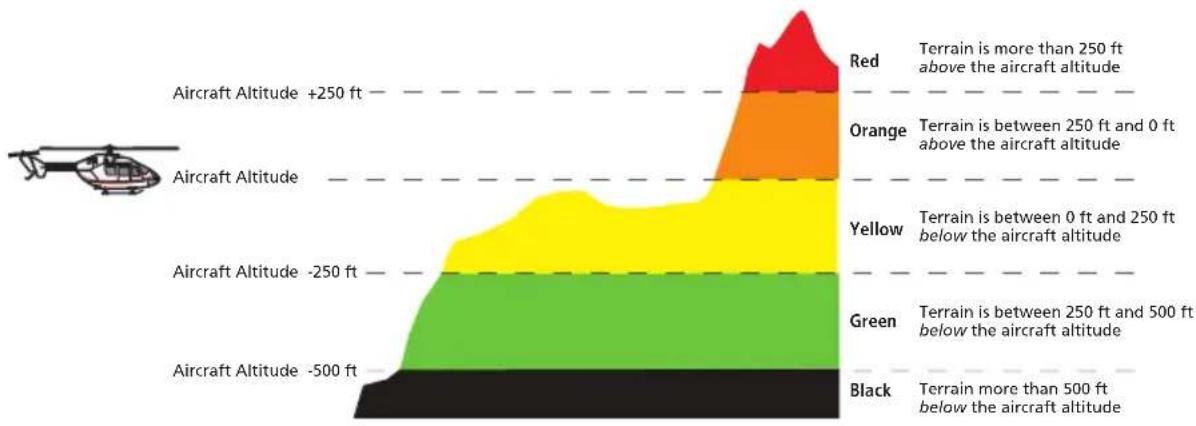
bar_stacked
| Altitude Range | Color | Terrain Range | |---|---|---| | Red | Grey | >250 ft above | | Orange | Orange | 250 ft and 0 ft above | | Yellow | Yellow | 0 ft below | | Green | Green | 250 ft and 500 ft below | | Black | Black | >500 ft below | Aircraft Altitude +250 ft Aircraft Altitude Aircraft Altitude -250 ft Aircraft Altitude -500 ft Aircraft Altitude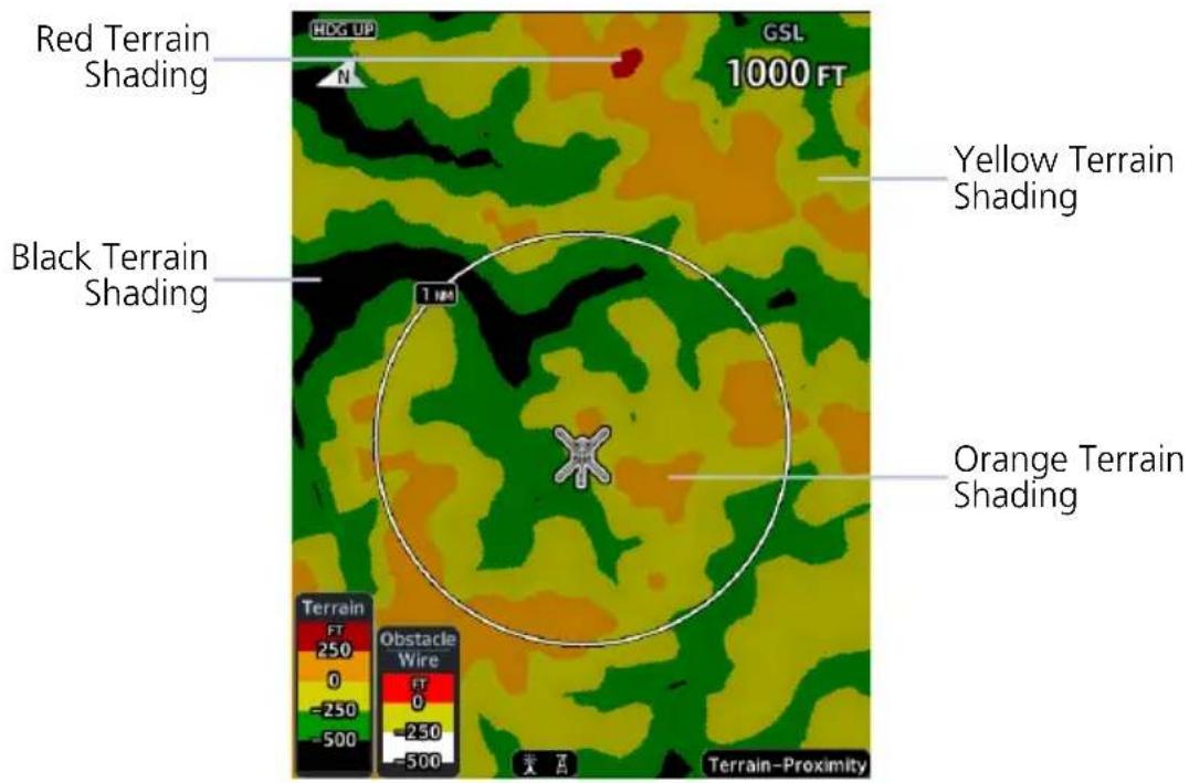
7.5.2 Obstacle Elevation Depictions
FEATURE LIMITATIONS
- Fixed wing aircraft: obstacles more than 2,000 ft below current altitude do not display
- Rotorcraft: obstacles more than 500 ft below current altitude do not display
• Power line depictions in synthetic vision are currently not available
TOWER OBSTACLES
| UNLIGHTED OBSTACLE | LIGHTED OBSTACLE | OBSTACLE LOCATION | |||
| <1,000' AGL | >1,000' AGL | <1,000' AGL | >1,000' AGL | FIXED WING ROTORCRAFT | |
 |  |  |  | Red obstacle is above or within 100 ft below current altitude. | Red obstacle is at or above current altitude. |
 |  |  |  | Yellow obstacle is between 100 ft and 1,000 ft below current altitude. | Yellow obstacle is within 250 ft below current altitude. |
 |  |  |  | White obstacle is between 1,000 ft and 2,000 ft below current altitude. | White obstacle more than 250 ft below current altitude. |
WIND TURBINE OBSTACLES
| UNLIGHTED WIND TURBINE OBSTACLE | LIGHTED WIND TURBINE OBSTACLE | WIND TURBINE OBSTACLE LOCATION | |
| FIXED WING ROTORCRAFT | |||
 |  | Red obstacle is above or within 100 ft below current altitude. | Red obstacle is at or above current altitude. |
 |  | Yellow obstacle is between 100 ft and 1,000 ft below current altitude. | Yellow obstacle is within 250 ft below current altitude. |
 |  | White obstacle is more than 1,000 ft below current altitude. | White obstacle more than 250 ft below current altitude. |
POWER LINE OBSTACLES
| OBSTACLE POWER LINE OBSTACLE LOCATION | |
 | Red power line is above or within 100 ft below current altitude. |
 | Yellow power line is between 100 ft and 1,000 ft below current altitude. |
 | White power line is between 1,000 ft and 2,000 ft below current altitude. |
OBSTACLE GROUPS
With the exception of power lines, obstacles within close proximity of each other may display as a group.

• Asterisk indicates that the obstacle belongs to a group
• Relative altitude of the highest obstacle determines color
• Depiction is of the most immediate threat
Terrain Alerting
The behavior of an alerting function is determined at installation. Installer configurable settings allow:
- Alert suppression for specific runway types
• Gender selection for voice messages
• Volume level
7.6 Alert Types
TERRAIN-FLTA
- Imminent Impact
- Reduced Clearance
TAWS-A
- Imminent Impact
- Reduced Clearance
- Premature Descent
• Excessive Descent Rate
• Excessive Closure Rate - Negative Climb Rate
- Flight Into Terrain
- Excessive Below Glideslope/Glidepath Deviation
TAWS-B
- Imminent Impact
- Reduced Clearance
- Premature Descent
• Excessive Descent Rate - Negative Climb Rate
Available alerting functions depend on the installed terrain system.
| ALERT TYPE CONDITION | |
| Imminent Impact1 | Aircraft reaches the minimum clearance altitude of any obstacle (IOI), terrain (ITI), or power line (ILI) in the projected flight path. |
| Reduced Clearance1 | Aircraft's vertical flight path is projected to be within the minimum clearance altitude of an obstacle (ROC), terrain (RTC), or power line (RLC). |
| Premature Descent2 | Aircraft is significantly below the normal approach path for the nearest runway. Altitude is <700 ft above terrain Distance from destination airport is 15 nm or less |
| Excessive Descent Rate | Aircraft descends toward terrain at an excessive rate. |
| Excessive Closure Rate3 | Aircraft closes upon terrain at a rate excessive for gear and flaps in the landing configuration. |
| Negative Climb Rate | Aircraft loses altitude following takeoff. Altitude is <700 ft above terrain Distance from departure airport is 2 nm or less Deviation from departure heading is <110° |
| Flight Into Terrain | Aircraft is too low with respect to terrain. Based on landing gear status, flap position, and ground speed. |
| Excessive Below Glideslope or Glidepath Deviation | Aircraft is significantly below the glidepath for the selected approach. Active only after departure and when the following conditions are met. Altitude is <1,000 ft AGL Gear is configured for landing ILS, LPV, LNAV/VNAV, or LNAV+V approach is active and the unit is indicating vertical navigation |
^1 Alerting inhibited <200 ft AGL within 0.5 nm of approach runway or <125 ft AGL within 1.0 nm of runway threshold.
2 Alerting inhibited within 0.5 nm of approach runway or <125 ft AGL within 1.0 nm of runway threshold. Alerting thresholds for final descent are based on current position, speed, and flight path data.
^3 Alerting inhibited within 5 nm of nearest airport, except when FLTA is not available. In such cases, "TAWS N/A" or "TAWS FAIL" annunciates and ECR alerting remains active until landing.
7.6.1 Alerting Thresholds
| FLIGHT PHASE | MINIMUM CLEARANCE ALTITUDE | |
| LEVEL FLIGHT DESCENDING | ||
| En Route 700 ft 500 ft | ||
| Terminal 350 ft 300 ft | ||
| Approach 150 ft 100 ft | ||
| Departure 100 ft 100 ft | ||
EDR THRESHOLDS
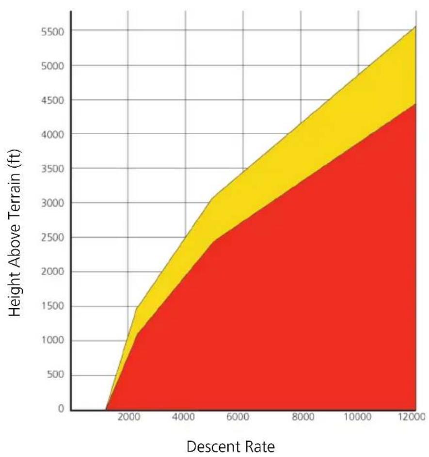
area
| Descent Rate | Height Above Terrain (ft) | | ------------ | ------------------------- | | 0 | 0 | | 2000 | 1500 | | 4000 | 2500 | | 6000 | 3500 | | 8000 | 4500 | | 10000 | 5500 | | 12000 | 6500 |Sink Rate "Pull Up"

PDA THRESHOLD
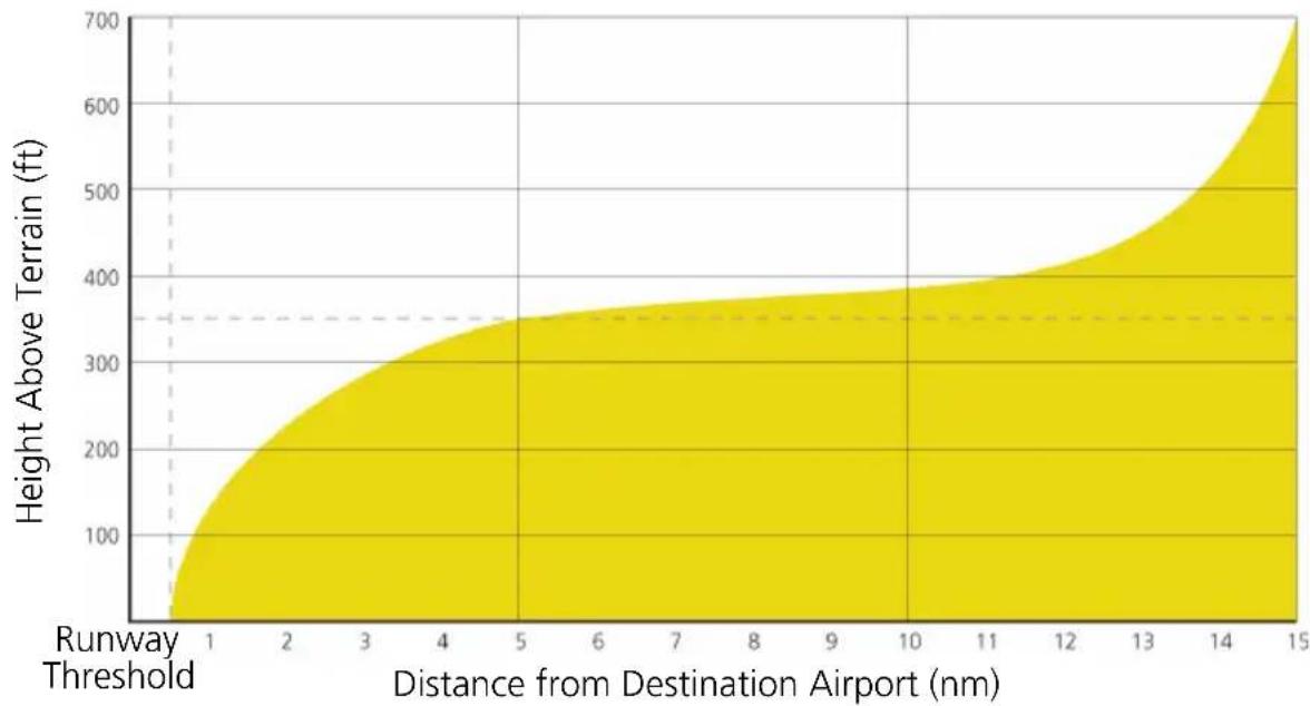
area
| Distance from Destination Airport (nm) | Height Above Terrain (ft) | | --------------------------------------- | ------------------------- | | 1 | 0 | | 2 | 100 | | 3 | 200 | | 4 | 250 | | 5 | 300 | | 6 | 350 | | 7 | 375 | | 8 | 380 | | 9 | 385 | | 10 | 390 | | 11 | 400 | | 12 | 425 | | 13 | 475 | | 14 | 550 | | 15 | 700 |Alerting Area

NER THRESHOLDS
Alert triggers: altitude loss, sink rate
Height Above Terrain (ft)Height
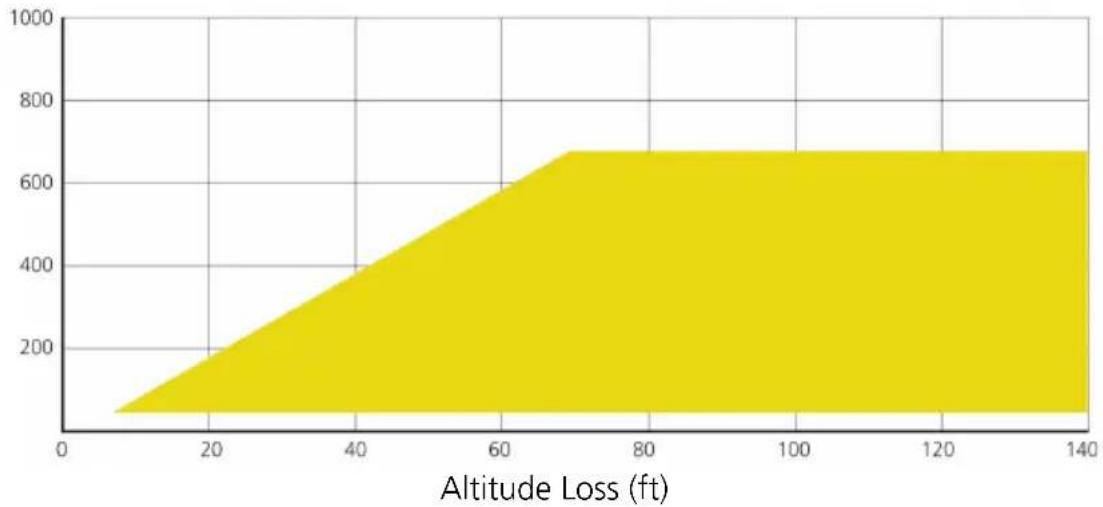
area
| Altitude Loss (ft) | Value | | ------------------ | ----- | | 0 | 0 | | 20 | 200 | | 40 | 400 | | 60 | 600 | | 80 | 650 | | 100 | 650 | | 120 | 650 | | 140 | 650 |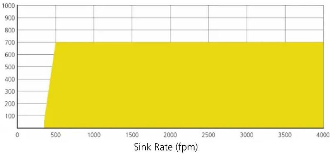
area
| Sink Rate (fpm) | Value | | --------------- | ----- | | 0 | 0 | | 500 | 700 | | 4000 | 700 |"Don't Sink"

7.6.2 Alert Inhibit, TAWS & Terrain-FLTA

The Terrain Inhibit control is accessible via the terrain pop-up alert or Terrain page menu.

NOTE
Always use discretion when inhibiting TAWS or Terrain-FLTA alerts. Re-activate the alert function when appropriate.
| TERRAIN INHIBIT FUNCTIONS | |
| INHIBIT | Manually inhibits TAWS or Terrain-FLTA aural and visual alerts for low altitude approaches or rotorcraft operation. |
| AUTOMATIC INHIBIT | Automatically inhibits TAWS and Terrain-FLTA alerts when the aircraft meets the following approach criteria.TAWS: • GPS/SBAS approach• Position inside FAFTAWS & • Altitude <200 ft above TERRAIN-FLTA: runway elevation• Position <0.5 nm of approach end or between each runway end |
TAWS-A INHIBIT ANNUNCIATIONS
Terrain Page
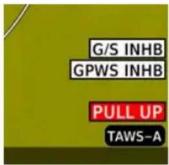
TAWS-A alert inhibit annunciations appear at the bottom right of the display.
- "FLAP OVRD" does not annunciate if GPWS Inhibit is already active, as both functions inhibit FIT alerts.
- A plus sign indicates multiple alerts (e.g., "TAWS INHB+")
7.7 Terrain-FLTA
Terrain-FLTA Features
• Non-TSO C151c certified terrain alerting system
- Aural and visual alerts for potential flight path conflicts involving terrain, obstacles, or power lines
• FLTA functions: RTC, RLC, ROC, ITI, ILI, and IOI
- Terrain depictions and display overlays
• Cautions and warnings indicate alert severity and threat type
• Textual annunciations on PFD and MFD
• Pop-up alerts on MFD
- Threat location indication on map displays (Map page, HSI Map, Terrain page) and SVT
- Self-test and alert inhibit functionality. FLTA is active whether synthetic vision is on or off
- Reduced protection mode (rotorcraft only)
7.7.1 Reduced Protection Mode
ROTORCRAFT ONLY

FEATURE LIMITATIONS
- Alerting times are significantly less than during normal operating mode
During reduced protection mode, alerting times are significantly less than during normal operating mode. Use this function only when terrain is within sight.

PFD Annunciation

MFD Annunciation
- Allows rotorcraft-configured systems to operate using reduced terrain alerting system thresholds
- Suppresses caution alerts during low level operations and off airport landings while providing warning alert protection from terrain and obstacles
7.7.2 Terrain-FLTA Alerts
| ANNUNCIATION | ALERT TYPE, POP-UP, CONDITIONS, & VOICE MESSAGE | |
| TER FAIL | Alert Type: CautionPop-up Alert: N/A | |
| Condition Voice Message | ||
| Terrain reports a system failure. | "Terrain System Failure" | |
| The database is missing or corrupt. | ||
| TER INHB | Alert Type: AdvisoryPop-up Alert: N/A | |
| Condition Voice Message | ||
| The terrain system reports that alert inhibit mode is active. | N/A | |
| TER N/A | Alert Type: CautionPop-up Alert: N/A | |
| Condition Voice Message | ||
| No certified GPS position. | "Terrain System Not Available" | |
| Degraded GPS signal. | ||
| Aircraft is outside of the terrain database regional coverage. | ||
| Voice Message Only | Alert Type: AdvisoryPop-up Alert: N/A | |
| Condition Voice Message | ||
| Terrain system is transitioning from unavailable to available. | "Terrain System Available" | |
| TERRAIN | Alert Type: WarningPop-up Alert: Yes | |
| Condition Voice Message | ||
| Reduced Required Terrain Clearance | "Warning, Terrain, Terrain" | |
| Imminent Terrain Impact | ||
| Alert Type: CautionPop-up Alert: Yes | ||
| Condition Voice Message | ||
| Reduced Required Terrain Clearance | "Caution, Terrain, Terrain" | |
| Imminent Terrain Impact | ||
| TER TEST | Alert Type: AdvisoryPop-up Alert: N/ACondition: Terrain system test is in progress. | |
| Voice Message Only | Alert Type: AdvisoryPop-up Alert: N/A | |
| Condition Voice Message | ||
| Terrain system test is okay. | "Terrain System Test Okay" | |
| OBSTACLE | Alert Type: WarningPop-up Alert: Yes | |
| Condition Voice Message | ||
| Reduced Obstacle Clearance | "Warning, Obstacle, Obstacle" | |
| Imminent Obstacle Impact | ||
| Alert Type: CautionPop-up Alert: Yes | ||
| Condition Voice Message | ||
| Reduced Obstacle Clearance | "Caution, Obstacle, Obstacle" | |
| Imminent Obstacle Impact | ||
| WIRE | Alert Type: WarningPop-up Alert: Yes | |
| Condition Voice Message | ||
| Reduced Line Clearance | "Warning, Wire, Wire" | |
| Imminent Line Impact | ||
| Alert Type: CautionPop-up Alert: Yes | ||
| Condition Voice Message | ||
| Reduced Line Clearance | "Caution, Wire, Wire" | |
| Imminent Line Impact | ||
7.8 TAWS-B
FEATURE REQUIREMENTS
- Valid 3-D GPS position
• TAWS-B feature enablement
• External annunciator for displaying alert information (non-PFD GDUs only)
TAWS-B Features
• Optional TSO C151c Class B terrain alerting system
- All Terrain-FLTA functions plus: premature descent, excessive descent rate, negative climb rate, and altitude voice callout (500 ft) alerts
7.8.1 TAWS-B Alerts
| ANNUNCIATION | ALERT TYPE, POP-UP, CONDITIONS, & VOICE MESSAGE | |
| PULL UP | Alert Type:WarningPop-up Alert: Yes | |
| Condition Voice Message | ||
| Reduced Required Terrain Clearance | “Terrain, Terrain; Pull Up, Pull Up”Or“Terrain Ahead, Pull Up; Terrain Ahead, Pull Up” | |
| Imminent Terrain Impact | ||
| Reduced Obstacle Clearance | “Obstacle, Obstacle; Pull Up, Pull Up”Or“Obstacle Ahead, Pull Up; Obstacle Ahead, Pull Up” | |
| Imminent Obstacle Impact | ||
| Reduced Line Clearance | “Wire Ahead, Pull Up; Wire Ahead, Pull Up”Or“Wire, Wire; Pull Up, Pull Up” | |
| Imminent Line Impact | ||
| Excessive Descent Rate “Pull Up” | ||
| TAWS FAIL | Alert Type: CautionPop-up Alert: N/A | |
| Condition Voice Message | ||
| An internal TAWS-B audio failure exists. | "TAWS System Failure" | |
| A necessary database is missing or corrupt. | ||
| Internal terrain alerting configuration is invalid. | ||
| TAWS-B reports a system failure. | ||
| TAWS INHB | Alert Type: AdvisoryPop-up Alert: N/ACondition: TAWS-B reports inhibit mode active | |
| TAWS N/A | Alert Type: CautionPop-up Alert: N/A | |
| Condition Voice Message | ||
| The GDU is using backup GPS. | "TAWS Not Available" | |
| The navigation solution is degraded or the aircraft is beyond the database coverage area. TAWS-B reports that the system is not available. | ||
| Voice Message Only | Alert Type: AdvisoryPop-up Alert: N/A | |
| Condition Voice Message | ||
| GPS signal integrity returns or the aircraft is back within the database coverage area. TAWS transitions from unavailable to available. | "TAWS Available" | |
| TAWS TEST | Alert Type: AdvisoryPop-up Alert: N/ACondition: TAWS-B system test is in progress | |
| Voice Message Only | Alert Type: AdvisoryPop-up Alert: N/A | |
| Condition Voice Message | ||
| Internal TAWS-B system test is okay. | “TAWS System Test Okay” | |
| Voice Message Only | Alert Type: AdvisoryPop-up Alert: N/A | |
| Condition Voice Message | ||
| Aircraft is descending through 500 ft AGL. | “Five Hundred” | |
| TERRAIN | Alert Type: CautionPop-up Alert: Yes | |
| Condition Voice Message | ||
| Reduced Required Terrain Clearance | “Caution, Terrain; Caution, Terrain”Or“Terrain Ahead; Terrain Ahead” | |
| Imminent Terrain Impact | ||
| Excessive Descent Rate “Sink Rate” | ||
| Premature Descent Alert “Too Low, Terrain” | ||
| Negative Climb Rate | “Don’t Sink”Or“Too Low, Terrain” | |
| OBSTACLE | Alert Type: CautionPop-up Alert: Yes | |
| Condition Voice Message | ||
| Reduced Obstacle Clearance | "Caution, Obstacle; Caution, Obstacle"Or"Obstacle Ahead; Obstacle Ahead" | |
| Imminent Obstacle Impact | ||
| WIRE | Alert Type: CautionPop-up Alert: Yes | |
| Condition Voice Message | ||
| Reduced Line Clearance "Caution, Wire; Caution, Wire"Or"Wire Ahead; Wire Ahead" | ||
| Imminent Line Impact | ||
7.9 External TAWS/HTAWS
FEATURE REQUIREMENTS
• TAWS/HTAWS function provided by a source external to the GDU
FEATURE LIMITATIONS
• TAWS/HTAWS controls are available only on the external TAWS/HTAWS device
Garmin External TAWS/HTAWS function
- Terrain function relies on an external Garmin GPS device for all TAWS/HTAWS data ^1
- GDU determines terrain map coloration based on the external GPS position and GPS altitude
- On PFD: Changes in CDI source selection have no effect on TAWS/HTAWS alerting functions
^1 For more information, refer to the applicable GNS 500W series or GTN series pilot's guide and/or addendum.
| TAWS/HTAWS SOURCE | TXI FEATURES |
| GTN | • TAWS/HTAWS alert depictions on the Terrain page, Map page, and in synthetic vision• Terrain depictions and display overlays• Textual annunciations on PFD• Pop-up alerts on MFD |
| GNS | • Terrain depictions and display overlays• Textual annunciations on PFD |
| Third Party TAWS | • GDU display provides only Terrain Proximity functionality |
7.9.1 TAWS-A
FEATURE REQUIREMENTS
- Valid 3-D GPS position
• GTN with TAWS-A feature enablement - Valid flap and landing gear status inputs into the GTN
• Valid radar altimeter
• External annunciator for displaying alert information (non-PFD GDUs only)
TAWS-A Features
- Optional TSO C151c Class A terrain alerting system
- All Terrain-FLTA functions plus: premature descent, excessive descent rate, negative climb rate, excessive glideslope/glidepath deviation, flap override, flight into terrain, and altitude voice callout (500 ft) alerts
- Terrain depictions and display overlays
• Textual annunciations on PFD
• Pop-up alerts on MFD
On PFD: Changes in CDI source selection have no effect on TAWS alerting functions. For more information, refer to the applicable GTN series pilot's guide.
7.9.2 TAWS-A Alerts
| ANNUNCIATION | ALERT TYPE, POP-UP, CONDITIONS, & VOICE MESSAGE | |
| PULL UP | Alert Type:WarningPop-up Alert: Yes | |
| Condition Voice Message | ||
| Reduced Required Terrain Clearance | “Terrain, Terrain; Pull Up, Pull Up”Or“Terrain Ahead, Pull Up; Terrain Ahead, Pull Up” | |
| Imminent Terrain Impact | ||
| Reduced Obstacle Clearance | “Obstacle, Obstacle; Pull Up, Pull Up”Or“Obstacle Ahead, Pull Up; Obstacle Ahead, Pull Up” | |
| Imminent Obstacle Impact | ||
| Reduced Line Clearance | “Wire Ahead, Pull Up; Wire Ahead, Pull Up”Or“Wire, Wire; Pull Up, Pull Up” | |
| Imminent Line Impact | ||
| Excessive Descent Rate | “Pull Up” | |
| Excessive Closure Rate | ||
| TAWS FAIL | Alert Type:CautionPop-up Alert:N/A | |
| Condition Voice Message | ||
| An internal TAWS-A audio failure exists. | “TAWS System Failure” | |
| A necessary database is missing or corrupt. | ||
| Internal terrain alerting configuration is invalid. | ||
| TAWS-A reports a system failure. | ||
| TAWS INHB | Alert Type: AdvisoryPop-up Alert: N/ACondition: TAWS-A reports inhibit mode active | |
| TAWS N/A | Alert Type: CautionPop-up Alert: N/A | |
| Condition Voice Message | ||
| The GDU is using backup GPS. | “TAWS Not Available” | |
| The navigation solution is degraded or the aircraft is beyond the database coverage area. TAWS-A reports that the system is not available. | ||
| Voice Message Only | Alert Type: AdvisoryPop-up Alert: N/A | |
| Condition Voice Message | ||
| GPS signal integrity returns or the aircraft is back within the database coverage area. TAWS transitions from unavailable to available. | “TAWS Available” | |
| TAWS TEST | Alert Type: AdvisoryPop-up Alert: N/ACondition: TAWS-A system test is in progress | |
| Voice Message Only | Alert Type: AdvisoryPop-up Alert: N/A | |
| Condition Voice Message | ||
| Internal TAWS-A system test is okay. | “TAWS System Test Okay” | |
| Voice Message Only | Alert Type: AdvisoryPop-up Alert: N/A | |
| Condition Voice Message | ||
| Aircraft is descending through 500 ft AGL. | "Five Hundred" | |
| TERRAIN | Alert Type: CautionPop-up Alert: Yes | |
| Condition Voice Message | ||
| Reduced Required Terrain Clearance | "Caution, Terrain; Caution, Terrain"Or"Terrain Ahead; Terrain Ahead" | |
| Imminent Terrain Impact | ||
| Excessive Descent Rate "Sink Rate" | ||
| Excessive Closure Rate "Terrain, Terrain" | ||
| Flight Into Terrain (High Speed or Takeoff) | "Too Low, Terrain" | |
| Flight Into Terrain (Flaps) | "Too Low, Flaps" | |
| Flight Into Terrain (Gear) | "Too Low, Gear" | |
| Premature Descent Alert "Too Low, Terrain" | ||
| Negative Climb Rate | "Don't Sink"Or"Too Low, Terrain" | |
| OBSTACLE | Alert Type: CautionPop-up Alert: Yes | |
| Condition Voice Message | ||
| Reduced Obstacle Clearance | "Caution, Obstacle; Caution, Obstacle"Or"Obstacle Ahead; Obstacle Ahead" | |
| Imminent Obstacle Impact | ||
| WIRE | Alert Type: CautionPop-up Alert: Yes | |
| Condition Voice Message | ||
| Reduced Line Clearance "Caution, Wire; Caution, Wire"Or"Wire Ahead; Wire Ahead" | ||
| Imminent Line Impact | ||
| GLIDESLOPE | Alert Type: CautionPop-up Alert: Yes | |
| Condition Voice Message | ||
| Glideslope Deviation "Glideslope" | ||
| GPWS FAIL | Alert Type: CautionPop-up Alert: N/A | |
| Condition Voice Message | ||
| Incorrect TAWS configuration | "GPWS System Failure" | |
| Radar altimeter unavailable | ||
| GPS position unavailable or degraded | ||
| Internal TAWS-A audio failure exists | ||
| GPWS N/A | Alert Type: CautionPop-up Alert: N/A | |
| Condition Voice Message | ||
| GPWS not available | N/A | |
| Incorrect TAWS configuration | ||
| Radar altimeter unavailable | ||
| GPS position unavailable or degraded | ||
| Internal TAWS-A audio failure exists | ||
| G/S INHB | Alert Type: AdvisoryPop-up Alert: N/ACondition: TAWS-A reports glideslope inhibit mode active | |
| FLAP OVRD | Alert Type: AdvisoryPop-up Alert: N/ACondition: TAWS-A reports flap override mode active | |
INTENTIONALLY LEFT BLANK
8 Fuel & Engine Indication System
RECIPROCATING ENGINES
8.1 EIS Display 8-2
8.2 EIS Setup 8-4
8.3 EIS Functions 8-6
8.4 Configuration Report....8-20
TURBINE ENGINES
8.5 EIS Display 8-21
8.6 EIS Setup 8-23
8.7 EIS Functions 8-25
8.8 Configuration Report.... 8-39
FUEL
8.9 Fuel Gauges 8-40
8.10 Fuel Alerting....8-43
8.11 Fuel Computer 8-45
ADVANCED EIS CONFIGURATIONS
8.12 Fuel Balance Monitoring 8-49
8.13 Automatic Ignition....8-51
8.14 Automatic Starting 8-52
8.15 Gauge-driven Outputs 8-53
EIS OPERATIONS
8.16 Record Keeping 8-54
8.17 Flight Operations 8-55
ENGINE ADVISORIES & ALERTS
8.18 Engine Advisories 8-59
8.19 Engine Alerts 8-60
Reciprocating Engines
8.1 EIS Display

The EIS displays engine, electrical, and fuel information using parameter specific indicator types (e.g., analog indicators, digital data fields, bar graphs, horizontal and vertical bar indicators).
These instruments replace traditional analog gauges used for starting the engine and monitoring performance. For limitations, consult the AFM or POH.
Layout varies according to:
- Display type
• Number of engines in aircraft
• Number and type of installed sensors
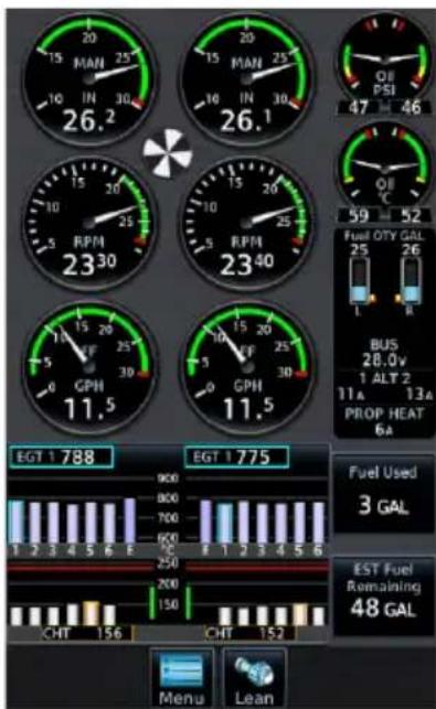
GDU 700P (Multi-engine)
GDU 700L and GDU 700P present engine instrumentation on a full-screen dedicated display when configured for EIS.
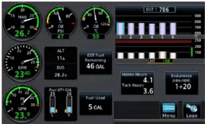
GDU 700L (Single Engine)
40% 60%
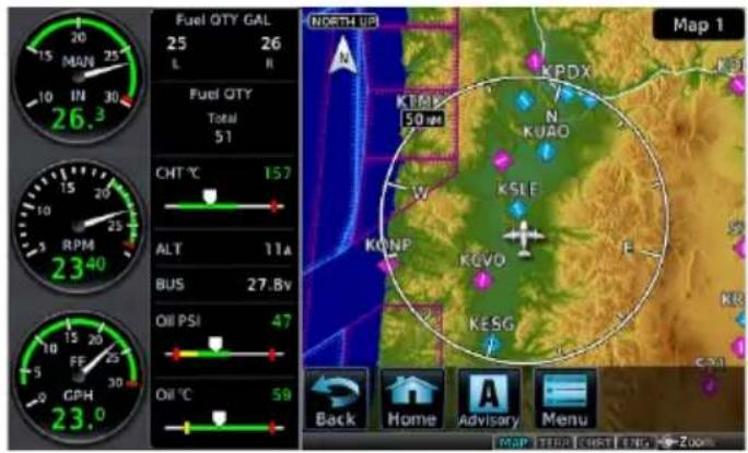
GDU 700L with the EIS/MFD layout presents a split view of required engine instrumentation with an MFD function. This configuration supports single-engine aircraft.
GDU 700L with EIS/MFD
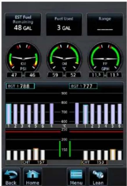
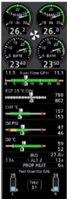
GDU 1060 presents two views of engine instrumentation: a pilot selectable Engine page on the MFD, and a vertical gauge strip which is always present.
Engine Page Gauge Strip
| Engine Page | Gauges depicting oil temperature, oil pressure, and fuel flowPilot selectable user fieldsGraphical depiction of engine CHT/EGT/TIT values ^1 Menu access keyLean Assist mode function key |
| Gauge Strip | Unobstructed compact view of engine informationResides at the left or right edge of the display ^2 No selectable features |
^1 Primary EGT and TIT dependent upon aircraft type. ^2 Location dependent upon configuration.
8.2 EIS Setup
Engine Menu
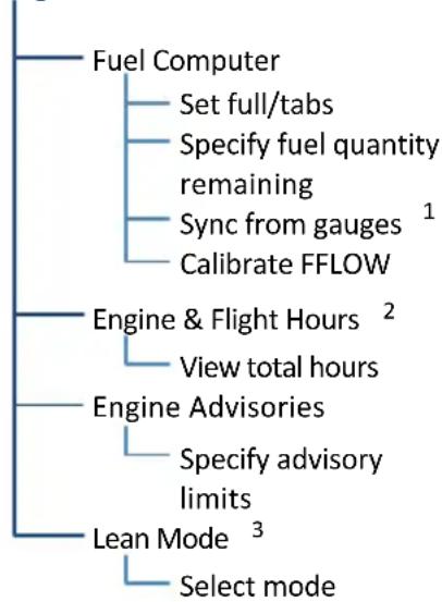
flowchart
graph TD
    A["Fuel Computer"] --> B["Set full/tabs"]
    A --> C["Specify fuel quantity remaining"]
    A --> D["Sync from gauges 1"]
    A --> E["Calibrate FFLOW"]
    F["Engine & Flight Hours 2"] --> G["View total hours"]
    H["Engine Advisories"] --> I["Specify advisory limits"]
    J["Lean Mode 3"] --> K["Select mode"]
The Menu key provides access to the fuel computer, engine and flight hours, engine advisories, and lean modes.
On GDU 700( ), controls for customizing system settings also reside here.
GDU 700() setup functions are accessible from the System menu. On GDU 1060, they reside on the MFD System page.
System GDU 700()
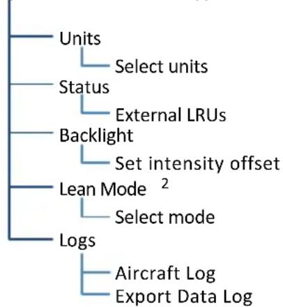
flowchart
graph TD
    A["Units"] --> B["Select units"]
    C["Status"] --> D["External LRUs"]
    E["Backlight"] --> F["Set intensity offset"]
    G["Lean Mode 2"] --> H["Select mode"]
    I["Logs"] --> J["Aircraft Log\nExport Data Log"]
System Page
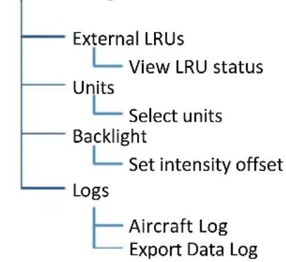
flowchart
graph TD
    A["External LRUs"] --> B["View LRU status"]
    C["Units"] --> D["Select units"]
    E["Backlight"] --> F["Set intensity offset"]
    G["Logs"] --> H["Aircraft Log"]
    G --> I["Export Data Log"]
^1 Available with TXi software v3.21 and later. ^2 This page is informational only.
^3 Mode selections dependent upon aircraft configuration.
EIS SETUP SELECTIONS
| Units | Specify units of measure for fuel computer and pilot selectable gauges. Selections synchronize across all configured GDUs.1 | |
| Distance | Temperature | |
| Fuel Computer | ||
| Status | View unit and software informationCheck status of all configured LRUs | |
| Backlight • Adjust display brightness | ||
| Aircraft Log | View engine and airframe cycle counters | |
| Export Data Log | Save logged data to SD card | |
| Lean Mode2 | Select Lean Mode from popup menuOptions dependent upon configured engine type | |
^1 Engine gauge units are not adjustable. ^2 On GDU 1060, this function is accessible from the Engine menu.
8.3 EIS Functions
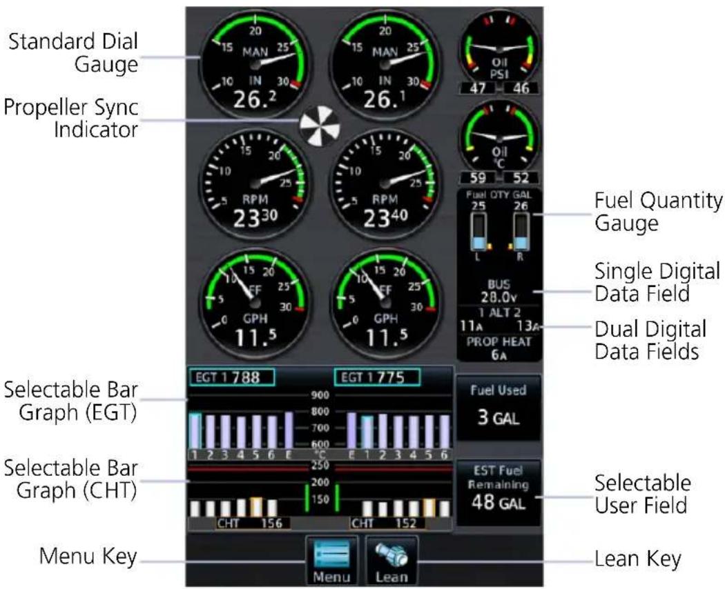
Common EIS Display Elements
^1 Limits are configured according to system design or the AFM/POH. They are not pilot selectable.
^2 Primary EGT and TIT indications are dependent upon aircraft type.
| Standard Dial Gauges | Display a graphical presentation and digital readout of the specified value.1 |
| Digital Data Fields | Display a digital readout from the associated sensor.1Includes single or dual input values depending on system configuration. Placement corresponds to engine location. |
| Bar Graphs | Provide digital EGT/TIT and CHT cylinder readings.2CHT and EGT digital values are selectable by cylinderAfter 10 seconds, CHT values default to the hottest cylinder on each engine |
| Fuel Quantity Gauges | Display fuel amounts for the specified fuel tanks.3 |
| Horizontal and Vertical Bar Indicators | Display instrument information on a single horizontal or vertical bar. Includes single or dual pointers depending on engine type. May include digital readout fields depending on display layout. |
| Prop Sync Indicator | Provides a visual reference for synchronizing multi-engine RPM. This indicator uses inputs received from the left and right engine tachometer to show a comparison of the matched RPM and the propeller phase angles between two engines.If RPM for both engines is the same, indicator remains stationaryIf RPM varies between engines, the indicator rotates in direction of the faster engineThe speed at which the indicator rotates is determined by the RPM differential between the two engines. |
| Selectable User Field | Opens a menu of the selectable data fields available for display. The type of parameters available for selection is determined during installation.A white border differentiates selectable user fields from non-selectable digital data fields. |
| Lean/Monitor Key | Enables or disables Lean Assist mode.To enable mode and change the name on the key label, tap LeanTo exit mode and return the graph to its normal temperature monitoring mode, tap MonitorLean Assist mode is required for all engine leaning operations. |
^3 Fuel gauges are configured and calibrated during installation.
8.3.1 Gauge Types
Gauge labels are customizable to match aircraft configuration. Labeling presented in the following table may differ from actual labeling on the unit.
LABEL UNITS FUNCTION
| RPM RPM • Engine tachometer | ||
| MAN inHg, psi • Engine manifold pressure | ||
| PWR % • Percent power | 1 | |
| Fuel or Fuel Pressure | psi, bar | • Fuel pressure |
| FF | gph, lt/hr, PPH, kg/hr | • Fuel flow |
| CARB or CARB Temperature | °C, °F | • Carburetor air temperature• Blue arc indicates temperature range where carburetor icing is likely to occur (-15 to 5°C) |
| Oil or Oil Pressure | psi, HPa, bar | • Oil pressure |
| Oil or Oil Temperature | °C, °F | • Oil temperature |
| CHT °C, °F | • Cylinder head temperature for hottest cylinder (bar indicator) ^2 | |
| • Graphical representation of CHT for each cylinder^3 • Hottest cylinder and cooling rate indications• Selectable temperature values on full EIS layouts^4 | ||
| CT | °C, °F | • Coolant Temperature^5 |
| EGT | °C, °F | • Graphical representation of exhaust gas temperature for each cylinder^3 • Peak EGT• Selectable temperature values^6,7 |
| • Average exhaust gas temperature for engine (Primary EGT) ^8 | ||
| TIT | °C, °F | • Turbine inlet temperature |
| IAT | °C, °F | • Inlet air temperature |
| CDT | °C, °F | • Compressor discharge temperature |
| IAT CDT Diff | °C, °F | • IAT, CDT, and IAT/CDT temperature differential |
LABEL UNITS FUNCTION
| Fuel or Main Fuel | lb, lt, gal, kg | • Current fuel quantity in main tanks |
| Tip Fuel | lb, lt, gal, kg | • Current fuel quantity in tip tanks |
| Aux Fuel | lb, lt, gal, kg | • Current fuel quantity in auxiliary tanks |
| Bus Volts V • Bus voltage | ||
| Bat Volts V • Battery vo | Itage | |
| ALT AMPS or ALT % | A, % | • Alternator load |
| BAT Amps A • Battery load | ||
| Vac or Vacuum in Hg, PSI • Vacuum/Pressure | ||
| Rudder or Rudder Trim | ° (degrees) | • Rudder Trim |
^1 Cirrus aircraft only. ^2 EIS gauge strip only.
^3 Due to limited space, not all cylinders display on EIS/MFD layouts.
^4 GDU 700() or GDU 1060 Engine page. ^5 Replaces CHT when coolant temperature sensor is configured.
^6 Graph labels are dependent upon aircraft configuration (e.g., “E” indicates Primary EGT; “T” indicates TIT).
^7 EIS gauge strip presents Primary EGT (if installed) or hottest of the individual EGTs.
^8 Range and units are dependent upon configuration.
STANDARD DIAL GAUGES
Standard round gauges completely replace mechanical gauges and may include additional features such as digital readouts and dynamic gauge markings. Labels vary based on configuration.
Tachometer Oil Pressure
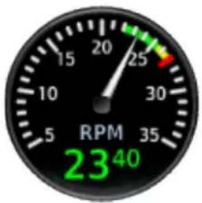
gauge
| RPM Value | |-----------| | 23^40 |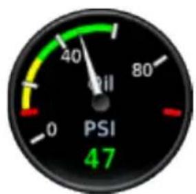
gauge
| Current Value | | ------------- | | 47 |For aircraft equipped with a starting vibrator, tachometer RPM readings are not accurate during engine cranking. For aircraft that measure engine RPM using P lead sensors, the readings may momentarily fluctuate when selecting operation on a single magneto.
BAR GAUGES
These gauges may display a digital value to the right of the bar indicator.

8.3.2 Markings & Indications

NOTE
It is the responsibility of the pilot in command to know and abide by all published limitations and operating ranges in the POH/AFM.
DYNAMIC GAUGE MARKINGS
FEATURE LIMITATIONS
The dynamic gauge feature relies on the installer to configure specific aircraft/engine data. It is possible that not all operating limitations are entered into the EIS system. Multi-engine and time delayed dynamic markings are available only with TXi software v3.21 and later.
The EIS system is useful for managing engine and aircraft systems within safe operating limits. Dynamic gauges further assist you by presenting only the gauge limits and markings appropriate for the current aircraft conditions. This allows for easier gauge interpretation as well as increased safety and efficiency.
Dynamic gauge range markings change to accommodate non-safe range and alerting parameters. For example, manifold pressure gauge markings may change based on altitude.
Non-safe ranges may include time delays for conditions with time dependent limitations.
Marking Sets
Dynamic markings modify the standard gauge by showing only the pertinent information during a particular flight situation.
Dynamic Markings (Example)
Standard 20,000 ft
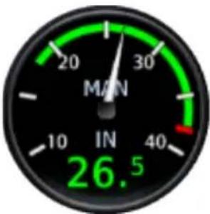
gauge
| Metric | Value | |--------|-------| | IN | 26.5 | | M/N | 30 |Configured by the installer to match the existing manifold pressure gauge in the aircraft.
If for any reason the system cannot determine the correct markings to show, the gauge defaults to the standard set.
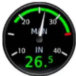
gauge
| Metric | Value | |--------|-------| | IN | 26.5 | | MIN | 30 |Markings adjust to match the maximum manifold pressure for the pressure altitude.
In this example, the maximum manifold pressure decreases as the pressure altitude increases.
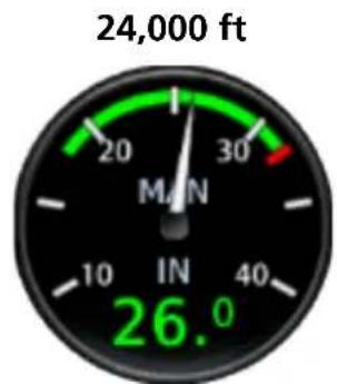
Markings dynamically adjust as pressure altitude thresholds are reached.
Unlike analog gauges, which require you to memorize limitations or interpret multiple markings, dynamic gauges present only the limitations applicable to specific situations or flight conditions.
For multi-engine aircraft, the system is configured such that left and right engine gauges have identical markings. The manner in which markings display is determined by the system for each engine independently. As a result, each engine gauge may show different markings based on its current parameters.
Twin Engine Dynamic Markings (Example)
Dual Pointer Dial Gauge
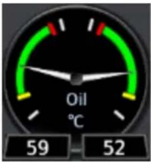
Dual Bar Gauge
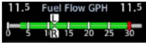
Color Indications
Gauge range indications are color coded in accordance with their specified operating limits. Units of measure, limits, and gauge colors are configured during installation.
• Amber radial line or arc denotes a caution range
• Red minimum/maximum line or arc denotes a limitation
When an indication is within a colored gauge range, the color of the digital readout with be the same as the range.
RANGE INDICATIONS & ALERTING
Alert Suppression
The following gauges do not alert when the tachometer indicates less than 100 RPM and the aircraft is on ground.
- Fuel flow
- Fuel pressure
- Manifold pressure
- Oil pressure
To alert the pilot, engine gauges change appearance when a parameter is within a caution or warning alert band. Alerting range indications remain active while the gauge is within the alerted range.
For alerting purposes, gauges are split into two groups: engine power and engine performance. Alerting functions differ for each group.
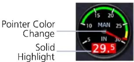
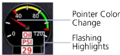
Power Gauge Performance Gauge
| GROUP GAUGE FUNCTION | ||
| Engine Power | Manifold Pressure Tachometer Fuel Flow | Pointer changes color to reflect non-safe operating status.Readout field turns solid amber or red depending on alert type. |
| Engine Performance | Oil Pressure ^1 Oil Temperature Primary EGT CHT CDT Amps/Volts Fuel Pressure Fuel Quantity | Pointer changes color to reflect non-safe operating status.Gauge label, readout field, and units (if displayed) flash amber or red depending on alert type.ACK key flashes (GDU 700( ) only).All flashing indications turn solid once the pilot acknowledges the alert. ^2 |
^1 To minimize the number of nuisance alerts, oil pressure gauges do not flash when within the caution band.
^2 Alerts automatically acknowledge after 10 seconds on GDU 1060.
8.3.3 CHT/EGT Bar Graphs
The EIS graphically displays CHT and EGT data for each cylinder.
Each bar graph contains the following components.
• Dynamic chart depicting cylinder temperature status
• Digital temperature reading of the highlighted cylinder
- Limit markings
Tapping a graph manually advances the selector to the next temperature value (e.g., CHT, EGT, Primary EGT, or TIT).
- CHT selections revert to auto mode after 10 seconds of inactivity
• EGT values are not selectable during lean assist operations
The size of each graph varies according to aircraft type (i.e., single or twin engine aircraft), the number of cylinders per engine, and gauge configuration (i.e., TIT or primary EGT). Graduations are scaled and sized during installation.
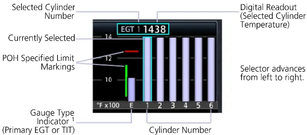
bar
| Category | Value | |---|---| | Selected Cylinder Number | 14 | | Digital Readout (Selected Cylinder Temperature) | 1438 | | Currently Selected | 12 | | POH Specified Limit Markings | 10 | | Gauge Type Indicator¹ (Primary EGT or TIT) | 1 | | Cylinder Number | 6 | F x100 E 1 2 3 4 5 6 | Selector advances from left to right.^1 Presence and type dependent upon configuration.
CHT/EGT GRAPH INDICATIONS
 | Cyan CHT/EGT Highlight | Currently selected cylinder |
 | Orange CHT Highlight | Hottest cylinder (automatically selected) |
 | Single Blue CHT Arrow | CHT is cooling at a rate faster than 30°F (16.7°C) per minute |
 | Double Blue CHT Arrow | CHT is cooling at a rate faster than 60°F (33.3°C) per minute |
8.3.4 Lean Assist Mode
FEATURE REQUIREMENTS
- For specific engine leaning procedures and temperature targets, consult the AFM
FEATURE LIMITATIONS
- Lean mode availability is dependent upon aircraft configuration and engine instrumentation
Selectable lean modes allow you to identify peak EGT/TIT temperatures and temperature differential values associated with the leaning process.
Available mode selections are listed in the Lean Mode menu.
LEAN MODE KEY

Tapping the Lean key once places the EIS in Lean Assist mode.
To return to normal operating mode, tap Monitor.
When Lean Assist mode is active:
• EGT graph features are not selectable
• Engine menu is not available
• Monitor key displays in the navigation bar
• Mode type annunciates at the bottom of the display
PEAK TEMPERATURE INDICATIONS
During Lean Assist mode, the system waits for the EGT or TIT to peak, and then decrease by a minimum of 6^ F. When this occurs:
- The corresponding temperature bar on the graph turns white.
- A white saddle indicates the maximum temperature value recorded for the sensor. In cases where the system waits for the last engine cylinder to peak, violet saddles indicate the maximum temperature of all other peaked cylinders.
- The "PEAK" annunciation and temperature value display in white at the top of the graph. After three seconds, this field reverts to the current operating temperature.
- A numeric field displays the difference between the peak and current operating temperatures. This value changes to reflect all subsequent temperature fluctuations. A negative value denotes an operating temperature lower than the maximum recorded value. A positive value denotes a temperature increase greater than the previously detected peak.
- Saddle position and deviation values automatically adjust to reflect any increases in peak temperature.
ROP Lean
ANNUNCIATION MODE FUNCTION
| ROP LEAN | Rich of Peak Lean | • Indicates the first engine cylinder to reach peak EGT during the leaning process |
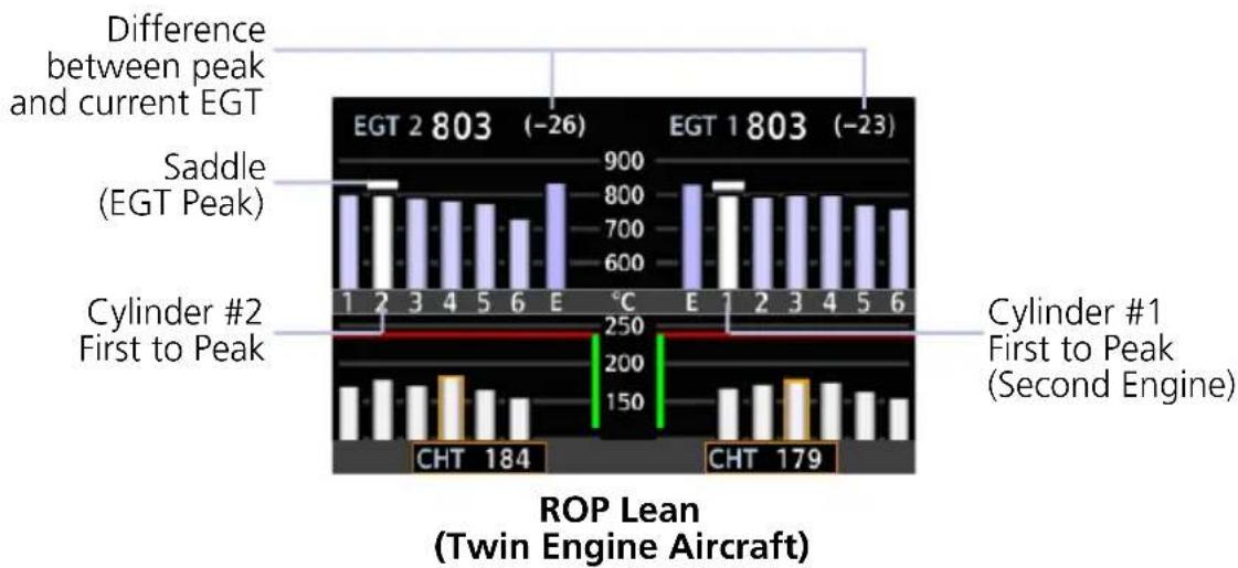
LOP Lean
ANNUNCIATION MODE FUNCTION
| LOP LEAN | Lean of Peak Lean | Indicates the last engine cylinder to reach peak EGT during the leaning process |
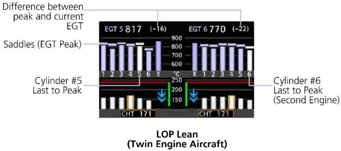
bar
| Aircraft Type | EGT Value | Difference (EGT Peak) | Difference (EGT Peak) | |---|---|---|---| | EGT 5 | 817 | -16 | -22 | | EGT 6 | 770 | -22 | -22 | | CHT | 171 | -250 | -150 | | CHT | 171 | -200 | -150 | The chart displays 'Difference between peak and current EGT' above the bars, 'Saddles (EGT Peak)' above it, 'Cylinder #5 Last to Peak' below it, and 'Cylinder #6 Last to Peak (Second Engine)' below it. The label 'LOP Lean (Twin Engine Aircraft)' indicates the aircraft type.EGT Lean
ANNUNCIATION MODE FUNCTION
| EGT LEAN | Primary EGT Lean | Indicates the peak temperature of the primary EGT during the leaning processAvailable only when Primary EGT is the configured gauge type |
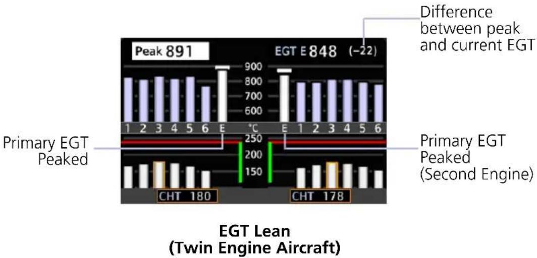
bar
| Model | Temperature (°C) | | :--- | :--- | | Peak E848 (-22) | 891 | | CHT 180 | 180 | | CHT 178 | 178 | Difference between peak and current EGTTIT Lean
TIT leaning is available for turbocharged aircraft configured for single or dual TIT measurements.
ANNUNCIATION MODE FUNCTION
| TIT LEAN | Turbine Inlet Temperature Lean | Indicates the peak TIT during the leaning processAvailable only on single turbocharger aircraft |
| TIT 1 LEAN | Turbine Inlet Temperature Lean First Peak | Indicates the first temperature sensor to reach peak TITAvailable only on single engine aircraft equipped with dual turbochargersFunction resembles ROP Lean |
| TIT 2 LEAN | Turbine Inlet Temperature Lean Second Peak | Indicates the second temperature sensor to reach peak TITAvailable only on single engine aircraft equipped with dual turbochargersFunction resembles LOP Lean |
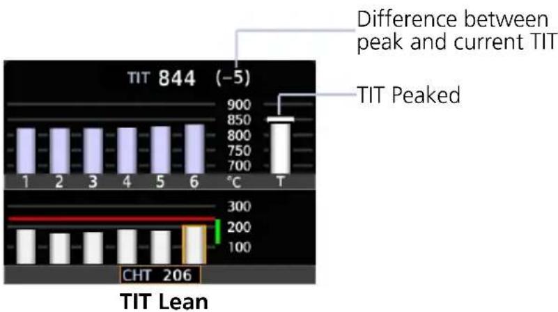
bar
| Temperature (°C) | Difference between peak and current TIT | |---|---| | 1 | 900 | | 2 | 850 | | 3 | 800 | | 4 | 750 | | 5 | 700 | | 6 | 650 | | T | 600 | | CHT | 206 | TIT Lean (-5) - Difference between peak and current TIT Peaked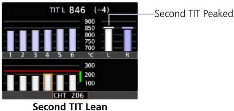
bar
TIT L 846 (-4) Second TIT Peaked | Temperature | Value | | :--- | :--- | | 1 | 850 | | 2 | 850 | | 3 | 850 | | 4 | 850 | | 5 | 850 | | 6 | 850 | | °C | 900 | | L | 850 | | R | 850 | | CHT | 206 | Second TIT Lean8.3.5 Selectable User Fields
These fields allow you to select engine and fuel parameters for display on the EIS. Available user fields and selectable parameters are determined during installation.
Tapping any user field opens a list of available engine parameters and their current values. Selecting a parameter displays its value on the EIS and closes the menu.
• Fields may be modified to display alternate data at any time
• Several parameter units are pilot adjustable
| EST Fuel RemainingEstimated amount of total fuel remaining1,3 | Outside Air TEMP (ISA)Degrees deviation from the International Standard Atmosphere model4 |
| Fuel UsedTotal fuel used since last update to estimated fuel remaining quantity1,3 | Outside Air TEMP (SAT)Outside static air temperature4 |
| RangeTotal range based on remaining fuel and current ground speed1,3 | Outside Air TEMP (TAT)Outside total air temperature4 |
| Endurance (HH+MM)Fuel endurance time in hours+minutes1 | Outside Air TEMP (EIS)Outside air temperature as measured by the EIS OAT sensor7 |
| Fuel at DestinationEstimated fuel amount at current flight plan destination1,2,3 | CHT DIFFDifference between hottest and coldest CHT for each engine6 |
| Endurance at DESTRemaining fuel endurance time (hours+minutes) at destination1,2 | EGT DIFFDifference between hottest and coldest EGT for each engine6 |
| Flight/Hobbs/Tach HoursTotal flight, Hobbs, and tach hours5 | EfficiencyFuel efficiency3 |
Percent Power
Percent of maximum rated engine power calculated from manifold pressure, RPM, fuel flow, and outside air temperature
8.4 Configuration Report
A report detailing all system configuration details, including the different dynamic marking states for each individual gauge, can be provided by your dealer. This information is unique to the aircraft and its configuration.
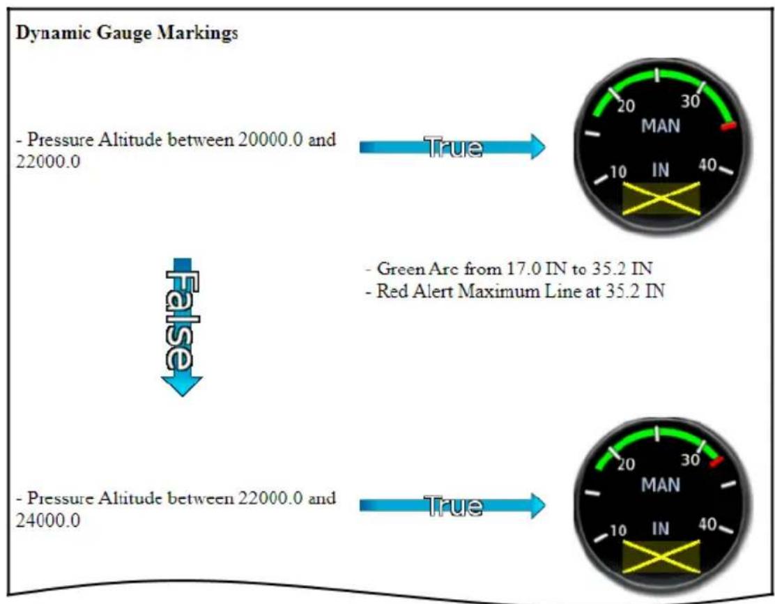
Configuration Report
Use this report to familiarize yourself with the different marking states that are possible with each gauge. To obtain a report, contact your dealer for assistance.
Turbine Engines
8.5 EIS Display

The EIS displays engine, electrical, and fuel information using parameter specific indicator types (e.g., analog indicators, digital data fields, dynamic markings, horizontal and vertical bar indicators).
FEATURE REQUIREMENTS
• GDU 700P configured for turboprop EIS only
• GDU 1060 with turboprop EIS display
• TXi software v3.21 or later (twin turboprop layouts)
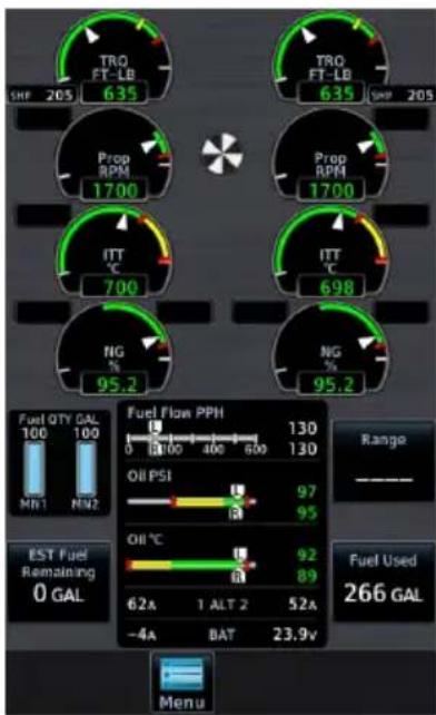
These instruments replace traditional analog gauges used for starting the engine and monitoring performance. For limitations, consult the AFM or POH.
Layout varies according to:
- Display type
• Number of engines in aircraft
• Number and type of installed sensors
GDU 700P presents engine instrumentation on a full-screen dedicated display when configured for EIS.
GDU 700P (Twin Turbine)
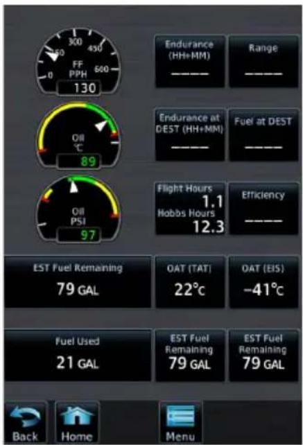
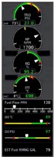
gauge
| Indicator | Value | | :--- | :--- | | SHF | 731 | | TRO PSI | 27.0 | | NP RPM | 1700 | | NG % | 95.2 | | ITT °C | 698 | | OAT | 8°C | | Fuel Flow PPH | 130 | | Oil °C | 89 | | Oil PSI | 97 | | EST Fuel RMNG GAL | 79 |GDU 1060 presents two views of engine instrumentation:
• a pilot selectable Engine page on the MFD
- an always present vertical gauge strip (single engine aircraft only)
Engine Page Gauge Strip
| Engine Page | Expanded information for select configured gaugesPilot selectable user fieldsMenu access key |
| Gauge Strip2 | Unobstructed compact view of primary engine informationResides at the left or right edge of the display1No selectable features |
^1 Location dependent upon configuration. ^2 Single engine aircraft only.
8.6 EIS Setup
Engine Menu
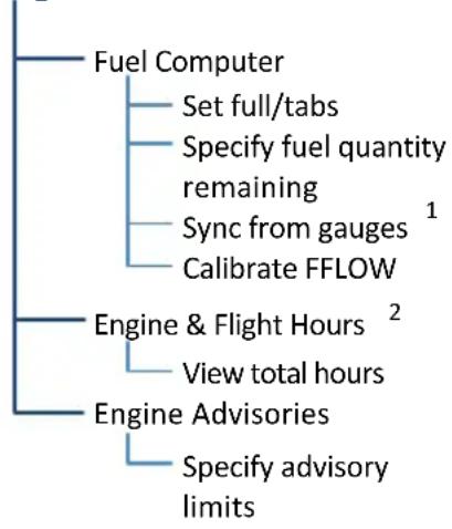
flowchart
graph TD
    A["Fuel Computer"] --> B["Set full/tabs"]
    A --> C["Specify fuel quantity remaining"]
    C --> D["Sync from gauges 1"]
    C --> E["Calibrate FFLOW"]
    F["Engine & Flight Hours 2"] --> G["View total hours"]
    H["Engine Advisories"] --> I["Specify advisory limits"]
The Menu key provides access to the fuel computer, engine and flight hours, and engine advisories. On GDU 700P, controls for customizing system settings also reside here.
GDU 700P setup functions are accessible from the System menu. On GDU 1060, they reside on the MFD System page.
System
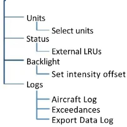
flowchart
graph TD
    A["Units"] --> B["Select units"]
    C["Status"] --> D["External LRUs"]
    E["Backlight"] --> F["Set intensity offset"]
    G["Logs"] --> H["Aircraft Log"]
    G --> I["Exceedances"]
    G --> J["Export Data Log"]
System Page
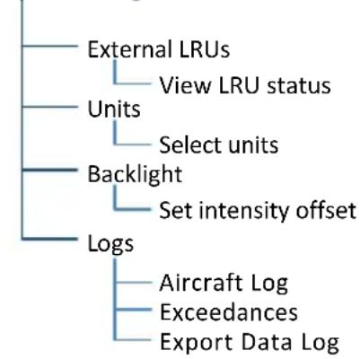
flowchart
graph TD
    A["External LRUs"] --> B["View LRU status"]
    C["Units"] --> D["Select units"]
    E["Backlight"] --> F["Set intensity offset"]
    G["Logs"] --> H["Aircraft Log"]
    G --> I["Exceedances"]
    G --> J["Export Data Log"]
^1 Available with TXi software v3.21 and later. ^2 This page is informational only.
EIS SETUP SELECTIONS
| Units | Specify units of measure for fuel computer and pilot selectable gauges. Selections synchronize across all configured GDUs.1 | |
| Distance | Temperature | |
| Fuel Computer | ||
| Status | View unit and software informationCheck status of all configured LRUs | |
| Backlight • Adjust display brightness | ||
| Aircraft Log | View engine and airframe cycle counters | |
| Exceedances | View and acknowledge exceedance advisories | |
| Export Data Log | Save logged data to SD card | |
^1 Engine gauge units are not adjustable.
8.7 EIS Functions
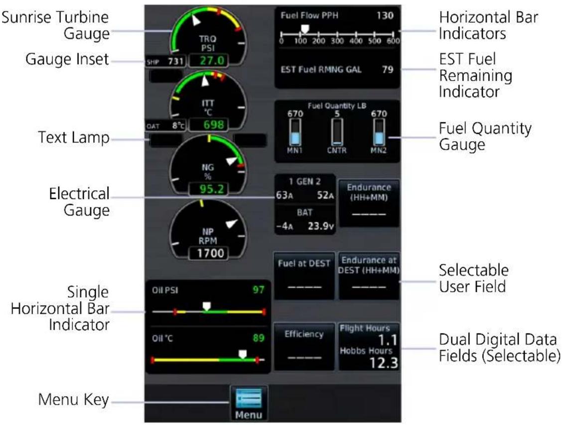
Common EIS Display Elements
| Sunrise Turbine Gauges | Display a graphical presentation and digital readout of the specified value. If configured, these gauges may be accompanied by a text lamp and/or gauge inset.1 |
| Digital Data Fields | Display a digital readout from the associated sensor.1 Includes single or dual input values depending on system configuration. |
| Fuel Quantity Gauges | Display fuel amounts for the specified fuel tanks.2 |
| Horizontal and Vertical Bar Indicators | Display instrument information on a single horizontal or vertical bar. Includes single or dual pointers depending on engine type. May include digital readout fields depending on display layout. |
| Selectable User Field | Opens a menu of the selectable data fields available for display. The type of parameters available for selection is determined during installation. A gray border differentiates selectable user fields from non-selectable digital data fields. |
^1 Limits are configured according to system design or the AFM/POH. They are not pilot selectable.
^2 Fuel gauges are configured and calibrated during installation.
8.7.1 Gauge Types
Gauge labels are customizable to match aircraft configuration. Labeling presented in the following table may differ from actual labeling on the unit.
| LABEL1 | UNITS FUNCTION | |
| NG %, RPM • | Engine gas producer speed | |
| NP %, RPM • | Propeller RPM | |
| TRQ %, psi, ft-lb • | Engine torque | |
| Engine TEMP °C, °F | • Turbine engine temperature• Typically inter turbine temp (ITT) or exhaust gas temp | |
| IAT °C, °F • | Inlet air temperature | |
| Fuel or Fuel Pressure | psi, bar | • Fuel pressure |
| FF | gph, lt/hr, PPH, kg/hr | • Fuel flow |
| Oil or Oil Pressure | psi, HPa, bar | • Oil pressure |
| Oil or Oil Temperature | °C, °F | • Oil temperature |
| Fuel or Main Fuel | lb, lt, gal, kg | • Current fuel quantity in main tanks |
| EST Fuel RMNG | lb, lt, gal, kg | • Estimated fuel based on pilot entered value and fuel flow |
| Tip Fuel lb, lt, gal, kg • | Current fuel quantity in tip tanks | |
| Aux Fuel | lb, lt, gal, kg | • Current fuel quantity in auxiliary tanks |
| Bus Volts | V | • Bus voltage |
| Bat Volts | V | • Battery voltage |
| ALT/Gen AMPS or ALT/Gen % | A, % | • Alternator/generator load |
| BAT Amps | A | • Battery load |
| Vac or Vacuum | in Hg, PSI | • Vacuum/Pressure |
| Rudder or Rudder Trim | ° (degrees) | • Rudder Trim |
^1 Actual gauge labels are dependent upon installer setup.
SUNRISE TURBINE GAUGES
These truncated round gauges have fewer graduations, similar to typical mechanical turbine gauges. Labels may vary based on configuration.
Gas Generator Turbine Speed (N1, NG)
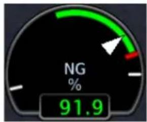
gauge
| Metric | Value | |--------|-------| | Current | 91.9 |• RPM or % RPM values
Engine Temperature
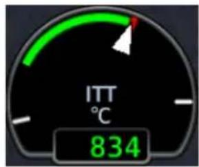
- Units are °F or °C
Torque Propeller RPM
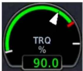
gauge
| Metric | Value | |--------|-------| | TRQ | 90.0 |- Units are %, ft-lb, or psi - RPM or % RPM values
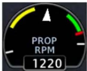
gauge
| Metric | Value | |--------|-------| | Current | 1220 |Propeller RPM Minimum Threshold
Depending on aircraft, sensor type, and configuration, this gauge may be configured with a minimum threshold value. During start and shutdown, RPM values below this threshold display as a series of dashes (---). Values above the threshold display as normal.
BAR GAUGES
Bar gauges also display a digital value to the right of the bar indicator.

8.7.2 Markings & Indications

NOTE
It is the responsibility of the pilot in command to know and abide by all published limitations and operating ranges in the POH/AFM.
DYNAMIC GAUGE MARKINGS
FEATURE LIMITATIONS
The dynamic gauge feature relies on the installer to configure specific aircraft/engine data. It is possible that not all operating limitations are entered into the EIS system. Multi-engine and time delayed dynamic markings are available only with TXi software v3.21 and later.
The EIS system is useful for managing engine and aircraft systems within safe operating limits. Dynamic gauges further assist you by presenting only the gauge limits and markings appropriate for the current aircraft conditions. This allows for easier gauge interpretation as well as increased safety and efficiency.
Dynamic gauge range markings change to accommodate non-safe range and alerting parameters. For example, torque gauge markings change based on propeller RPM, while temperature markings change based on engine operating conditions.
Non-safe ranges may include time delays for conditions with time dependent limitations.
Marking Sets
Dynamic markings modify the standard gauge by showing only the pertinent information during a particular flight situation or other configured condition.
Dynamic Markings (Example)
Standard Starting (Condition)
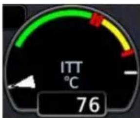
Configured by the installer to match the existing ITT gauge in the aircraft.
If for any reason the system cannot determine the correct markings to show, the gauge defaults to the standard set.
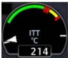
Once the system determines that the engine is starting, the gauge changes to show the starting temperature limits.
In this example, the absolute maximum temperature is absent and the highest red line limit indicates starting maximum temperature.
Running (Condition)
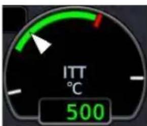
Once the system determines that the engine is running, the gauge changes to show the cruise red line limit.
Starting limit indications are absent.
Unlike analog gauges, which require you to memorize limitations or interpret multiple markings, dynamic gauges present only the limitations applicable to specific situations or flight conditions.
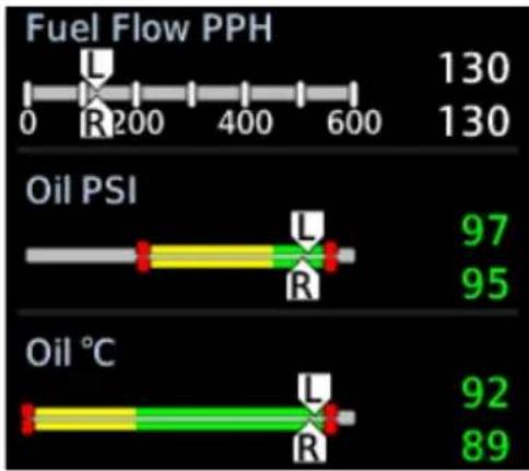
bar
Fuel Flow PPH | Category | Value | |---|---| | Fuel Flow PPH (130) | 130 | | Oil PSI (97) | 95 | | Oil PSI (92) | 95 | | Oil °C (92) | 89 | Legend: U (blue), R (red/green bars). The R values are marked with 'R' on the bars.Dual Bar Gauges
For multi-engine aircraft, the system is configured such that left and right engine gauges have identical markings. The manner in which markings display is determined by the system for each engine independently. As a result, each engine gauge may show different markings based on its current parameters.
Color Indications
Colors are in accordance with their specified operating limits. Units of measure, limits, and gauge colors are configured during installation.
• Amber radial line or arc denotes a caution range
• Red minimum/maximum line or arc denotes a limitation
RANGE INDICATIONS & ALERTING
Alert Suppression
To avoid nuisance alerts while the parameters are in typical ranges for the engine state, flashing is suppressed for fuel pressure, oil pressure, and oil temp when the engine is off or starting.
To alert the pilot, engine gauge display markings (bands, radials, limitations) change appearance when a parameter is within a caution or warning alert band. Alerting range indications remain active while the gauge is within the alerted range.
Warning Caution

Dynamic Gauge
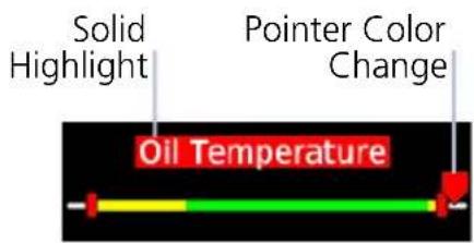
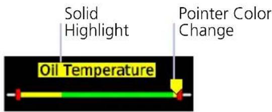
Horizontal Bar Indicator
8.7.3 Text Lamps
Text lamps are available for the following sunrise gauges:
- Torque
• ITT
• NG
NP - Fuel Flow
- Oil Temperature
- Oil Pressure
If configured, sunrise gauges may be accompanied by a text lamp. These windows display a single abbreviated message when the related system is in operation.
Text lamps reside at the upper outside edge of the gauge. For multi-engine aircraft, left/right location corresponds to the location of the associated engine:
• on the left for left engine gauges
• on the right for right engine gauges

Text color and behavior (i.e., solid or flashing) are dependent upon configuration.
Starter lamps may display a timer.
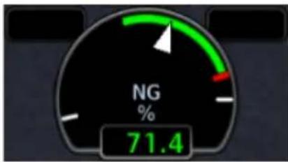
gauge
| Metric | Value | |--------|-------| | % | 71.4 |When the system is inactive, the window is empty.
TEXT MEANING
| START Starter on |
| IGN Ignition on |
| BETA Reverse thrust |
| BLEED Bleed Valve Closed |
| INSEP Inertial Separator Open |
Text color and behavior (i.e., solid or flashing) are dependent upon configuration.
When the starter lamp is configured, GDU uses the photocell for display brightness during engine start. This is to ensure EIS visibility as power is drawn to start the engine.
8.7.4 Gauge Insets
FEATURE LIMITATIONS
• OAT gauge insets available with TXi software v3.21 and later
Gauge insets are available for the following sunrise gauges:
- Torque
- NG/N1
• NP - Fuel Flow
• Engine Temperature
If configured, sunrise gauges may be accompanied by a gauge inset. These windows display a digital readout of secondary information related to the primary gauge for reference.
Gauge insets reside at the bottom inside edge of the gauge.
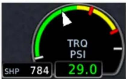
gauge
| Metric | Value | |--------|-------| | SHP | 784 | | TRQ PSI| 29.0 |Depending on configuration, these insets may provide various supplemental data, such as calculated engine power or OAT.
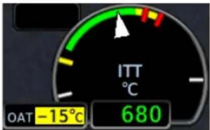
A caution indication alerts you when the temperature is below a threshold. If connected to the Pitot heat system, this indication can be configured to provide a reminder to turn on the probe heat during potential icing conditions.
Always follow AFM/POH procedures when responding to potential icing conditions.
| TEXT MEANING | |
| %PWR Percent power | |
| ISA | Difference from Standard Air Temperature |
| OAT Outside Air Temperature | |
| SAT Static Air Temperature | |
| SHP Shaft horsepower | |
| TAT Total Air Temperature | |
8.7.5 Timers
FEATURE LIMITATIONS
- Timer type, quantity, and availability are dependent upon configuration
• Maximum allowable exceedance time (or grace period) dependent upon configuration
Timers are available for the following gauges:
- Torque
- Prop RPM
- NG/N1
• Turbine Engine Temperature - Oil Temperature
- Oil Pressure
- Fuel Pressure
Timers indicate the amount of time remaining in the allowable grace period for operation above a limit.
If configured, timers reside at the bottom right of the gauge, adjacent to the parameter field. For multi-engine aircraft, they reside at the bottom inside edge of the gauge:
• on the right for left engine gauges
• on the left for right engine gauges
A single gauge may contain multiple timers running simultaneously.
Timer fields always display the parameter with the shortest time remaining. The other timers continue to count down.
If a timer expires, the system generates an exceedance log entry for the parameter. Timer exceedances are viewable in the System Logs.
Timer Types
EIS provides two types of timers:
- Exceedance
• Engine start/cooldown
EXCEEDANCE TIMERS
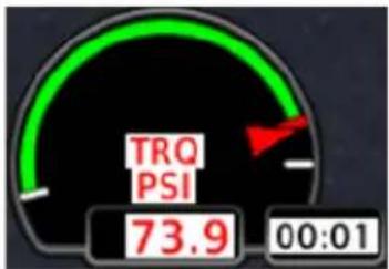
gauge
| Metric | Value | |--------|-------| | TRQ PSI | 73.9 | | 00:01 | 00:01 |Exceedance timers indicate the maximum allowable time that the parameter can operate at an elevated level. This grace period is configured by the installer during initial setup. Depending on the parameter type, the time limit may be based on aircraft or engine manufacturer specifications.
Exceedance Timer Behaviors
- Timer begins counting once the indicated parameter exceeds its threshold
- Timers reset/disappear if the parameter falls below the threshold prior to expiration
- Exceedance recording begins when the timer expires (i.e., once grace period ends)
- Exceedances without a grace period cause the system to record a log entry upon going above the threshold and does not display a timer
Exceedance timers are very useful for recording temperature exceedances during engine starts. For more information about exceedance logging, refer to section 1.33.
Within Range Above Threshold
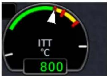
Timer does not display during normal operating conditions
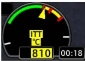
Timer displays once the parameter exceeds threshold. Automatic countdown begins.
Approaching Time Limit Warning/Expired
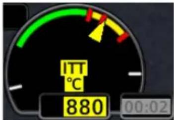
Timer begins to flash during the last 5 seconds of the configured grace period.
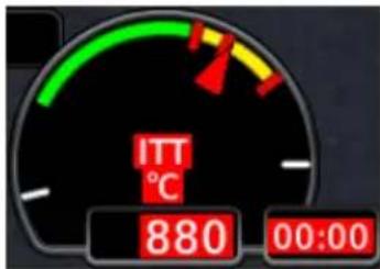
Timer changes color once it reaches zero. It flashes in unison with the alerted gauge pointer, value, and label, indicating a warning condition. Exceedance recording begins.
While the timer counts down, attempt to remedy the exceeding parameter by managing aircraft systems or reducing engine power.
The exceedance timer feature is useful for managing engine and aircraft systems within safe operating limits. The feature relies on the installer to configure specific aircraft/engine data and it is possible not all operating limitations are entered into the EIS system.
The pilot in command is responsible to know and abide by all published limitations and operating ranges in the POH/AFM.

• Availability dependent upon configuration
- Start timer counts up from zero when the starter engages
- Starter cooldown timer changes to blue and counts down from zero if the starter engages then disengages without a successful engine start
- May display as a text lamp with a sunrise gauge or as a user-selectable field on the MFD Engine page (depending on configuration)
On MFD: The start timer is available as a user select gauge on the Engine page.

When the starter is active:
- Label changes to show that the starter is "Engaged"
- Timer begins counting up from zero to indicate the amount of time that the starter has been active
When the starter is inactive, the gauge displays underscores.
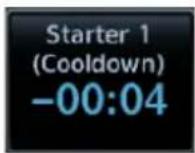
When the starter switches from active to inactive, but the engine is off:
- Timer text turns blue and the label changes to show the starter is in "Cooldown"
- Timer counts down from zero (negative value) to indicate the time since the starter was turned off

When the starter goes from active to inactive, and the engine is in the RUNNING or STARTING state, the annunciation changes to "Ready."
8.7.6 Selectable User Fields
These fields allows selection of engine and fuel parameters for display on the EIS. Available user fields and selectable parameters are determined during installation.
Tapping any user field opens a list of available engine parameters and their current values. Selecting a parameter displays its value on the EIS and closes the menu.
• Fields may be modified to display alternate data at any time
• Several parameter units are pilot adjustable
| EST Fuel RemainingEstimated amount of total fuel remaining1,3 | Outside Air TEMP (ISA)Degrees deviation from the International Standard Atmosphere model4 |
| Fuel UsedTotal fuel used since last update to estimated fuel remaining quantity1,3 | Outside Air TEMP (SAT)Outside static air temperature4 |
| RangeTotal range based on remaining fuel and current ground speed1,3 | Outside Air TEMP (TAT)Outside total air temperature4 |
| Endurance (HH+MM)Fuel endurance time in hours+minutes1 | Outside Air TEMP (EIS)Outside air temperature as measured by the EIS OAT sensor8 |
| Fuel at DestinationEstimated fuel amount at current flight plan destination1,2,3 | Cabin Altitude/RateCabin altitude and calculated cabin rate6,7 |
| Endurance at DESTRemaining fuel endurance time (hours+minutes) at destination1,2 | Shaft Horse-powerEngine shaft horsepower |
| Flight/Hobbs HoursTotal flight and Hobbs hours5 | EfficiencyFuel efficiency3 |
| % PowerEngine percent power |
^1 Values are based on fuel computer calculations. ^2 Requires an active flight plan from the navigator.
^3 Parameter units are pilot selectable. ^4 Units are independent of PFD units.
^5 Hobbs hours accumulate when an engine is running. Flight hours accumulate when the aircraft is in air.
^6 Units are dependent upon configuration.
^7 Requires cabin altitude data from GFC 600. Rate calculations performed by GDU.
^8 Available with TXi software v3.21 and later.
8.8 Configuration Report
A report detailing all system configuration details, including the different dynamic marking states for each individual gauge, can be provided by your dealer. This information is unique to the aircraft and its configuration.
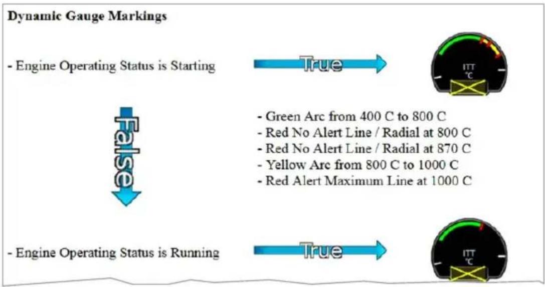
flowchart
graph TD
    A["- Engine Operating Status is Starting"] --> B["True"]
    C["- Green Arc from 400 C to 800 C"] --> D["- Red No Alert Line / Radial at 800 C"]
    D --> E["- Red No Alert Line / Radial at 870 C"]
    E --> F["- Yellow Arc from 800 C to 1000 C"]
    F --> G["- Red Alert Maximum Line at 1000 C"]
    H["- Engine Operating Status is Running"] --> I["True"]
    J["ITT °C"] --> K["ITT °C"]
Configuration Report
Use this report to familiarize yourself with the different marking states that are possible with each gauge. To obtain a report, contact your dealer for assistance.
Fuel
8.9 Fuel Gauges
Fuel gauges display the quantity of fuel available in the fuel tanks. There are three basic types of fuel gauge: slider, vertical bar, and digital. The type of gauge depends on GDU and aircraft configuration.
Slider gauges are horizontal bars with one or two moving pointers to indicate fuel quantities. On slider gauges with two pointers, the pointers are labeled to identify the tank locations. Slider gauges may be configured with or without additional digital readouts.
Digital gauges have up to three simple digital readouts to indicate fuel quantities. Two digital gauges may be combined to provide up to six indicators in a single gauge. On the narrow bar gauges available for turbine aircraft using the alternate 11-indicator layout, the digital gauge is limited to two indicators.
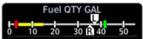
Slider Gauge

Digital Gauge
Vertical bar gauges have up to three filled vertical bars to indicate fuel quantities, with digital readouts above the bars. Two vertical bar gauges may be combined to provide up to six indicators in a single gauge.
TOTAL FUEL ON BOARD INDICATION
FEATURE REQUIREMENTS
• TXi software v3.21 or later
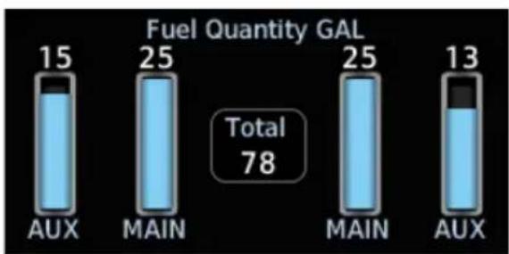
bar
Fuel Quantity GAL | Category | Fuel Quantity GAL | |---|---| | AUX | 15 | | MAIN | 25 | | MAIN | 25 | | AUX | 13 | Total 78Fuel gauges may be configured to display the sum of all fuel tank quantities as an additional readout.
8.9.1 Gauge-driven Discretes
When configured by the installer, the system can send a discrete signal to other aircraft systems based on gauge values or ranges.
8.9.2 Gauge Markings
A label at the top of each gauge indicates the type of gauge (Fuel QTY) and units of measurement (GAL, LB, LT, or KG). In addition, each fuel tank indicator in a gauge may be customized with a custom tank label up to four characters long. The fuel tank indicators can be arranged in any order. Gauges can also be configured with range markings.
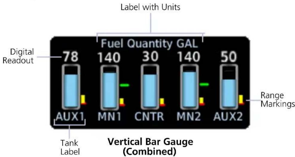
bar
| Label | Fuel Quantity GAL | | :--- | :--- | | Digital Readout | 78 | | Tank Label | 140 | | Vertical Bar Gauge (Combined) | 30 | | Label with Units | 140 | | Label with Units | 50 | | Range Markings | - |8.9.3 Selectable Fuel Gauges
For aircraft with four fuel tanks but only two selectable fuel quantity signals, selectable fuel gauges are available. Selectable gauges may be either vertical bar or digital types.
Vertical bar selectable gauges display the current fuel quantities for selected tanks and the last known fuel quantities for unselected tanks simultaneously. Unselected tank indicators have gray fill color to indicate that the last known fuel quantity is being displayed, and the digital readout is replaced by a dashed line after ten seconds. If a selectable fuel tank has not been selected since the system was started, the indicator will be filled with gray hash marks to indicate that fuel quantity for that tank has not yet been initialized.
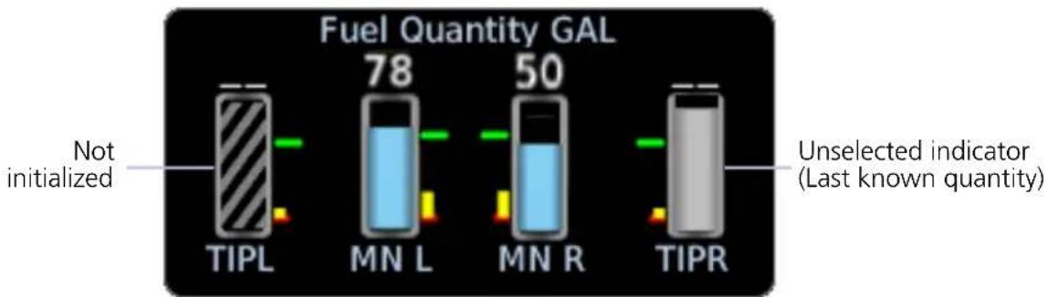
bar
Fuel Quantity GAL | Fuel Type | Fuel Quantity GAL (gAL) | | :--- | :--- | | TIPL | Not initialized | | MN L | 78 | | MN R | 50 | | TIPR | Unselected indicator (Last known quantity)Selectable Vertical Bar Gauge
Digital selectable gauges display only the fuel quantities for the currently selected fuel tanks. The digital indicator tank labels change to either MAIN or AUX depending on which tanks are selected. When an indicator is set to an AUX tank, the tank label will be highlighted.

Selectable Digital Gauge
8.10 Fuel Alerting
8.10.1 Fuel Quantity Alert Indications
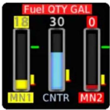
bar
Fuel QTY GAL | Battery Type | Fuel Quality (QTY GAL) | | :--- | :--- | | MN1 | 18 | | CNTR | 30 | | MN2 | 0 |Gauges with yellow caution range and red minimum alert markings display visual alerts when fuel quantities are within the markings. The gauge label, affected tank label, and digital readout are highlighted in the active range color.
On vertical bar gauges, the fill color also changes to the range color.
When the gauge enters the range, these visual indicators flash until the condition is acknowledged. Any future range alerts for the same fuel tank and condition do not flash again for the remainder of the flight (i.e., until after the fuel computer is reset).
GDU 1060 PFD/MFD/EIS: Unless configured for external acknowledge switches, alerts are automatically acknowledged after 10 seconds.
8.10.2 Fuel Imbalance Indications
FEATURE LIMITATIONS
- "BALANCE ON" indications available only for installations that incorporate an automatic fuel balancing capability
Fuel gauges can be configured to provide visual indications of fuel imbalance. Alerts result from a detected fuel quantity imbalance. Such alerts could also occur due to other factors, such as fuel quantity sensor failures or extended flight maneuvers in non-level flight.
When the system detects a fuel imbalance condition:
• a colored line indication links the affected tanks
- tank label color changes to yellow or red depending on the exceeded threshold
- "IMBALANCE" or "IMBAL" annunciates depending on gauge type
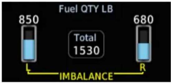
bar
Fuel QTY LB | Category | Value | |---|---| | Total | 1530 | | L Battery | 850 | | R Battery | 680 |Imbalance Caution Indications
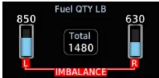
bar
Fuel QTY LB | Category | Value | |---|---| | Total | 1480 | | L | 850 | | R | 630 | IMBALANCEImbalance Warning Indications
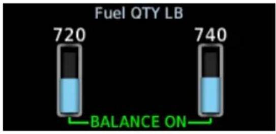
Balance On Indications
For installations that incorporate an automatic fuel balancing capability, a green "BALANCE ON" annunciation and line indication display when automatic fuel balancing is active.
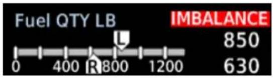

On slider gauges, annunciations appear on the side of the gauge adjacent to the lighter tank.
Indicators flash upon initial detection of an imbalance. They remain flashing until the condition is acknowledged.
For turbine aircraft using the alternate 11-indicator layout, colored boxes outline both digital fuel readouts on narrow strip gauges.
GDU 1060 PFD/MFD/EIS: Unless configured for external acknowledge switches, alerts are automatically acknowledged after 10 seconds. Upon acknowledgment, visual indications remain until the imbalance is corrected.
For more about the fuel imbalance alerting function, refer to section 8.12.1.
8.11 Fuel Computer

CAUTION
Ensure that estimated fuel quantity values in the fuel computer are accurate before flight. Fuel quantity gauge indications may not provide the accuracy required for determination of on board fuel during flight.
The fuel computer calculates and displays fuel parameter values when a flight plan is active in a connected and compatible navigator. Calculations are based on GPS ground speed, the pilot specified destination airport, estimated fuel remaining, and inputs received from the engine fuel flow sensor. Fuel parameters are available for display on the EIS in a selectable user field. They include:
- Aircraft endurance • Efficiency
• Endurance at destination • Fuel at destination - Fuel used
- Range
| Opens a keypad for specifying the estimated fuel remaining value. The fuel computer bases its calculations on the value entered here. | |
| EST Fuel Remaining | To account for added fuel and maintain accurate fuel flow measurements over time, always update this value upon refueling.This keypad provides additional controls for specifying preset fuel values. |
| Calibrate FFLOW | Opens the Fuel Flow Calibration page. Controls for calibrating the fuel flow meter reside here.This key remains inactive until a new value is entered for EST Fuel Remaining. |
Points About Estimated Fuel Remaining Data
- Based on estimated fuel remaining value entered by the pilot
- Initial value automatically reduced based on current fuel flow
• Not limited to the capacity of the aircraft fuel system - Sync from Gauges ^1 , Full, and Tab preset keys aid in fuel data entry
Fuel range rings are a pilot-selectable map overlay indicating an estimate of remaining flight distance based on fuel onboard, fuel consumption rates, and current ground speed. The map depicts two separate rings: an outer yellow ring displaying total endurance range, and an inner dashed green ring displaying range to reserve fuel. These rings offer the pilot additional situational awareness regarding fuel remaining and endurance.
8.11.1 Preset Fuel Quantities
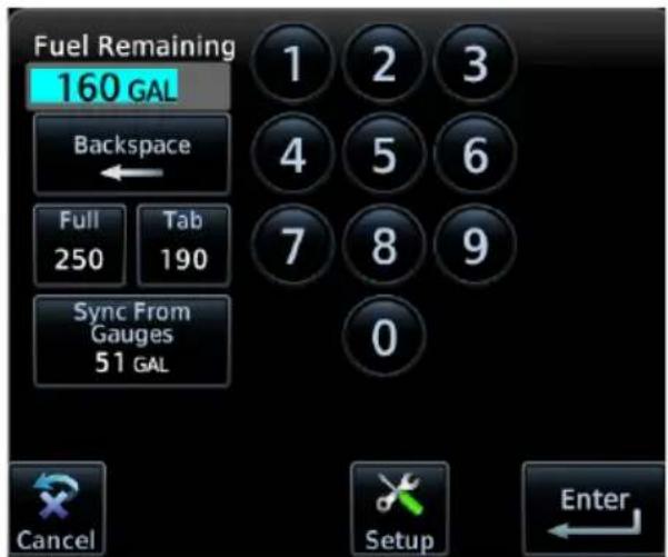
The fuel computer stores preset fuel amounts for estimated full and tab amounts. For the operating limitations of a specific aircraft, consult the POH.
Full Sets the fuel remaining value to the specified full amount.
Tab Sets the fuel remaining value to the specified tab amount.
Sync from Gauges Performs a summation of all configured fuel tanks and inputs the amount as the fuel remaining value. ^1
Setup Opens the Fuel Capacity Setup menu.
^1 Available with TXi software v3.21 and later.
In certain installations, fuel temperature is used to adjust the fuel quantity for non-standard temperatures. To determine if temperature compensation is configured in the aircraft, consult the AFMS.
SYNC FROM GAUGES
FEATURE REQUIREMENTS
• TXi software v3.21 or later

This function provides a convenient way to set the Fuel on Board value during preflight setup of the EIS.
The pilot is responsible for determining the amount of fuel on board and verifying the input value entered into the fuel computer.
8.11.2 Fuel Capacity Setup Options

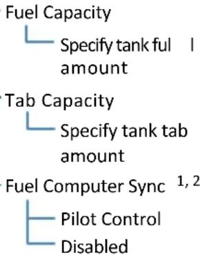
Setup options allow you to customize features on the fuel computer.
From here you can:
- Specify tank full and tab amounts
- Enable the Sync from Gauges function
Fuel Capacity Specify the tank full amount.
Tab Capacity Specify a tank tab amount.
Fuel Computer Sync
Select Pilot Control to add the Sync from Gauges option to the fuel computer. To remove this option, select Disabled. ^1, 2
^1 Available with TXi software v3.21 and later.
^2 Unavailable if fuel computer units do not match the configured fuel gauge units.
Fuel Computer Sync option availability is dependent upon fuel computer unit selection. If the fuel computer units do not match the configured fuel gauge units, the Fuel Computer Sync key is unavailable. Fuel computer units are set on the System Units page.
8.11.3 Fuel Flow Calibration
A calibration function compares the estimated fuel used amount (calculated by the system) with the actual fuel used amount (determined by the pilot upon refueling). The system calculates a fuel flow correction factor based on these inputs. This adjustment value is applied to future fuel flow calculations.
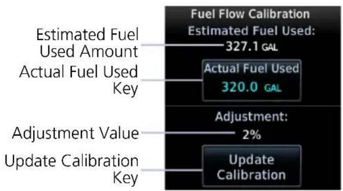
other
| Category | Value | | ------------------------- | --------- | | Estimated Fuel Used | 327.1 GAL | | Actual Fuel Used | 320.0 GAL | | Adjustment Value | 2% | | Update Calibration | |Calibrating the fuel flow meter helps ensure the accuracy of all fuel computer calculations.
| Actual Fuel Used | Allows you to specify the actual amount of fuel used since the last adjustment to the EST Fuel Remaining quantity. |
| Update Calibration | Updates the current calibration value. Confirming the request re-calibrates the fuel flow meter and saves the new calibration value. |
Advanced EIS Configurations
8.12 Fuel Balance Monitoring
FEATURE REQUIREMENTS
• Engine adapter installed (GEA 110 or GEA 71x)
• Installer configuration
FEATURE LIMITATIONS
• Not compatible with selectable fuel gauges
Out of balance fuel loads can trigger visual indications on the affected fuel gauges and activate other aircraft systems.
The fuel imbalance system can monitor up to three pairs of fuel tanks and left and right fuel totals. The system installer can configure these settings for each pair:
• Imbalance monitoring on or off
• Left- and right-heavy discrete outputs
• Maximum imbalance threshold
• Activation threshold
• Activation time delay
• Discrete inhibit signal input
• Fuel imbalance discrete outputs on or off
The system is activated when a monitored pair is out of balance by more than its activation threshold for longer than its time delay. When this occurs:
• Fuel gauges provide a visual indication.
- If the imbalance is less than the maximum imbalance threshold, installer configured aircraft systems are activated.
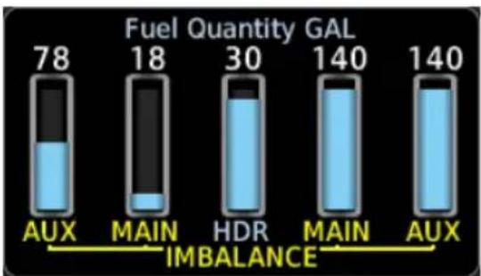
bar
Fuel Quantity GAL | Category | Fuel Quantity GAL | |---|---| | AUX | 78 | | MAIN | 18 | | HDR | 30 | | MAIN | 140 | | AUX | 140 | IMBALANCE indicated between MAIN and AUX.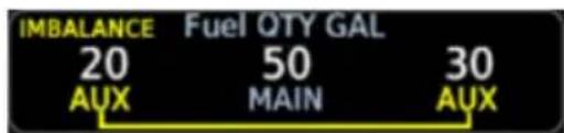
Vertical Bar Gauge Imbalance Digital Gauge Imbalance
Fuel transfer pumps, external annunciators, or other aircraft systems can be activated based on a separately configurable balancing threshold, allowing automatic fuel balancing to be performed before a full imbalance occurs. The installer can also configure a switch or other signal to inhibit the activation of these aircraft systems by the fuel imbalance monitor.
8.12.1 Fuel Imbalance Alerting
FEATURE LIMITATIONS
- 60 second timer availability dependent upon aircraft type and installer configuration
The heavy wing discrete can be configured to activate prior to reaching an imbalance threshold. If configured, a 60 second timer begins counting down once the difference in tank quantities reaches a predefined range. This delay between state transitions helps prevent inadvertent activation when turbulence or aircraft maneuvers may cause temporary fuel shifts (e.g., fuel sloshing, noise in fuel signals).
An alert annunciates once the timer expires. The type of alert is dependent upon the difference between left and right tank quantities.
FUEL IMBALANCE ANNUNCIATIONS
BALANCE ON
• Fuel imbalance amount is below limit
• Automatic fuel balancing system is active
- System attempts to restore balance until the difference in left and right tank quantities is less than or equal to the deactivation threshold
IMBALANCE
• Fuel imbalance amount is at caution threshold
• Automatic fuel balancing system (if installed) is active
- Consult AFMS emergency procedures for details
IMBALANCE
• Fuel imbalance amount is at critical level
• Automatic fuel balancing system is off
- Consult AFMS emergency procedures for details
8.13 Automatic Ignition
TURBINE AIRCRAFT ONLY

NOTE
Always monitor engine and igniter status. Control ignition manually if necessary.
FEATURE REQUIREMENTS
• GDU 700P/1060 only
• Engine adapter installed (GEA 71x)
• Applicable sensor interfaces configured
• Installer configuration
FEATURE LIMITATIONS
The auto ignition feature does not trigger a unique indicator on the GDU. If an ignition text lamp is configured, the ignition indicator will be shown, but does not indicate if the system was activated by the auto ignition system.
This feature automatically switches turbine engine ignition systems on and off based on engine parameters and/or aircraft configuration.
Engine ignition systems that can be switched on and off with an external input can be triggered by a signal from the GDU based on installation-specific configurations.
If a trigger parameter is not available, the automatic ignition feature is disabled and an advisory is displayed. If a parameter becomes unavailable on the ground, a "Service Required" advisory will be displayed. When the aircraft is in the air and the feature is disabled, an "Automatic Ignition Unavailable" advisory will be displayed.
Activation and deactivation conditions are configured separately, and may include multiple AND/OR conditions. Trigger parameters include ITT, NG, NP, torque, condition lever position, and air/ground state. Conditions may also include a delay time.
Example 1:
Auto ignition is switched on when ITT is less than 500^ C AND the condition lever is not in cutoff/feather.
Example 2:
Auto ignition is switched off when ITT is more than 500^ C for more than 10 seconds.
8.14 Automatic Starting
TURBINE AIRCRAFT ONLY

NOTE
Always respond to starting issues (e.g., hot starts, hung starts) as directed in the POH. In the case of an EIS malfunction, maintenance is recommended to troubleshoot the associated components and connections.
FEATURE REQUIREMENTS
• TXi software v3.21 or later
• Installer configuration
For approved installations that require an automatic starting system, GDU outputs can be interfaced with aircraft engine start relays to facilitate engine starting.
GDU monitors inputs, applies logic and delays, then sets discrete outputs to the necessary state to control or signal other LRUs (typically non-Garmin) in the engine starting system.
An "Automatic Starting Inhibited" advisory alerts you when the automatic starting feature is inhibited by a problem with the system.
Three engine states are used in the starting process.
Starting Starter Cut-off Reset
Pilot engages starter via switch or button press. Start sequence begins.
NG is greater than or equal to 50%.
Or
60 second timer expires while in the "Starting" state.
Pilot disengages starter via switch or button press. System responds by depowering the starter relay(s).
Always control and monitor the start sequence as directed by the POH.
8.15 Gauge-driven Outputs
FEATURE REQUIREMENTS
• Engine adapter installed (GEA 110 or GEA 71x)
• Installer configuration
Gauge-driven outputs are available for the following gauges:
• ITT
- Torque
- Propeller RPM
- NG
- Manifold Pressure
- Fuel Flow
- Oil Pressure
- Oil Temperature
- Vacuum Pressure
- Alt/Gen Amps
- Alt/Gen Volts
- Bus Volts
- Battery Amps
- Battery Volts
- Fuel Quantity
- Engine Power
• Flight Control Trim Position
This feature sends a discrete signal to other aircraft systems based on gauge values or ranges.
Gauge-driven outputs are available with a GDU that is not configured as an EIS. This feature does not require the gauge which drives an output to be displayed.
A single gauge can drive multiple outputs of different configurations.
An output may be triggered when:
- A gauge is at or above, below, or between configured values.
- A parameter is within green, yellow, or red ranges.
EIS Operations
8.16 Record Keeping

NOTE
Do not reboot the GDU during flight unless operational procedures dictate. Doing so may register an additional engine or airframe cycle. Contact a Garmin dealer to adjust counters to match other tracking records.
Counter Types
• Hobbs and flight hours
• Tach hours (piston only)
• Takeoffs and landings
- Starts and shutdowns (turbine only, based on engine data)
Counters record various cycle data, such as takeoffs and landings, Hobbs and flight hours, and tach hours(piston only). These fields always display the counter type with the higher value. For example, if the number of starts is higher than the number of shutdowns, then the number of starts displays.
Counter values are viewable in the System Logs.
ENGINE & AIRFRAME CYCLE COUNTERS
Types include: Takeoffs and Landings; Starts and Shutdowns (based on engine data)
Turbine engine components are life limited by hours of operation and the number of cycles. In the past, aircraft operators would typically record the number of flight hours and operations in a paper logbook. The GDU records this information automatically.
• Takeoffs/landings increment based on GPS, air data, or the weight on wheels discrete
• System records parameters separately on individual counters
- Higher counter value always displays (e.g., if the number of starts is higher than the number of shutdowns, the field displays the number of starts)

GDU stores and displays the information in the aircraft log.
Home > System > Logs > Aircraft Logs
ENGINE AND FLIGHT HOURS
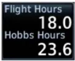
The system records Hobbs, tach (piston only), and flight hours. These parameters may display as a user-selectable field. They are also viewable in the aircraft log.
| Flight Hours | 18.0 | Hobbs Hours | 23.6 |
| L Tach Hours | 23.1 | R Tach Hours | 23.0 |
For twin piston engine aircraft, dual tach timers are available.
For convenience, these counters also display at startup.
8.17 Flight Operations
| PHASE OF FLIGHT OPERATION | |
| Initial Setup | Customize system settingsSet fuel full and tab capacity levelsSet engine advisoriesCalibrate fuel flowTest external master caution and master warning switches (if applicable) |
| Preflight • Add fuel | |
| En Route | Lean the engine1Monitor gauges |
| Post Flight | Record Hobbs and flight hoursRecord tach hours (piston only)Record aircraft log and exceedance data2 |
^1 Reciprocating engine only. ^2 Turbine engine only.
8.17.1 Initial Setup
FEATURE REQUIREMENTS
• TXi software v3.21 or later
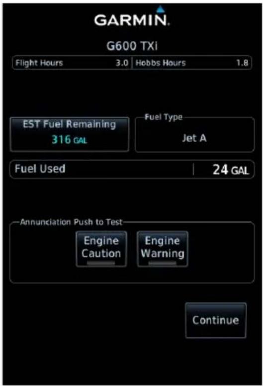
EIS Start-up Page (GDU 1060 MFD)
During power up, the EIS start-up page provides access to initial EIS setup and post flight functions. From here you can:
- Record Hobbs, tach (piston only), and flight hours
• Perform fuel computer calculations
• View fuel type and the amount of fuel used - Test external caution/warning switches (if applicable)
Tapping Continue advances to the Home page.
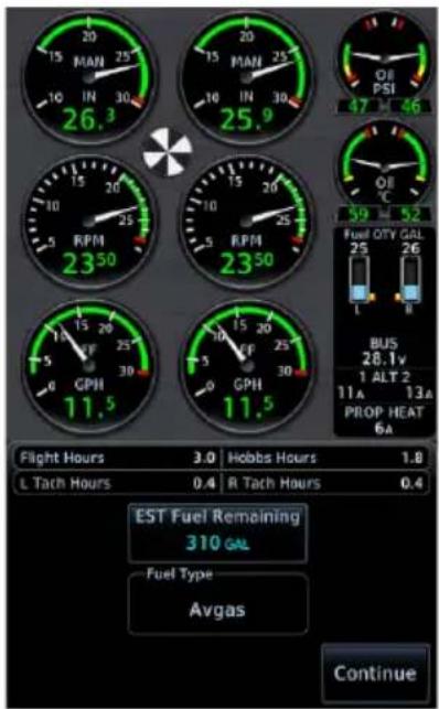
GDU 700P GDU 700L
GDU 700(): Depending on configuration, EIS start-up functions may display on a dedicated page or in a slide over menu.
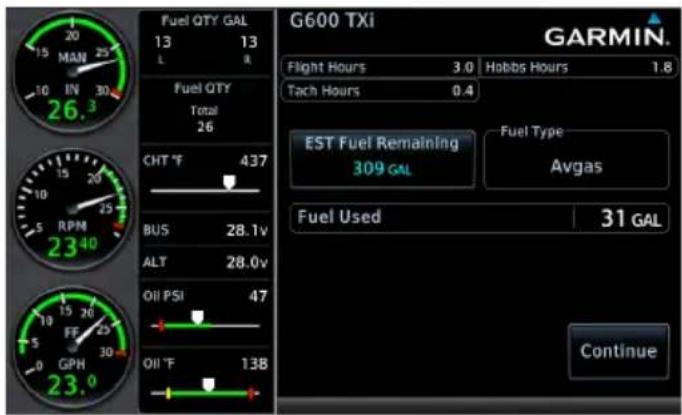
CUSTOMIZE SYSTEM SETTINGS
Specify all necessary EIS settings. Customization options reside in either the System page (GDU 1060) or the System menu (GDU 700()).
SET FUEL FULL AND TAB CAPACITY
Specify estimated fuel full and tab values using the controls in the fuel computer.
SET ENGINE ADVISORIES
Specify engine advisory parameters and limit values.
CALIBRATE FUEL FLOW

NOTE
If the calculated adjustment factor exceeds the 10 percent fuel flow calibration limit, contact your dealer for support.
Calibrate fuel flow using the controls provided in the fuel computer. Re-calibration is recommended following the first flight or any time there is a significant difference between the estimated remaining fuel quantity and the actual amount of fuel in the tanks.
- Fuel aircraft to a known level (i.e., the bottom of the tabs inside each fuel filler port).
- Tap EST Fuel Remaining and enter the amount of fuel on board.
NOTE: This value must be at least 5 liters (2 gallons) greater than the previous estimated fuel on board amount.
- Burn no less than 10 percent of usable fuel. Burning more than 10 percent will yield a more accurate calibration.
- Refuel to the previously entered level.
- Tap EST Fuel Remaining and enter the amount of fuel on board.
- Tap Calibrate FFlow and enter the amount of actual fuel used. Note the adjustment value.
- Tap Update Calibration.
- Confirm the request.
- Acknowledge the pop-up message.
8.17.2 Preflight
ADD FUEL
Update the remaining fuel quantity whenever fuel is added to the aircraft.
- Fuel the aircraft.
- Enter the appropriate fuel amount using the fuel computer.
8.17.3 En Route
LEAN THE ENGINE, PISTON ONLY
- Select the preferred leaning function from the Lean Mode menu.
- Tap Lean.
- Monitor the temperatures graph for reference peak events and lean the mixture accordingly.
MONITOR GAUGES
Monitor all gauges. Dynamic gauge limitations may change based on flight conditions.
MONITOR FOR ENGINE EXCEEDANCE ADVISORIES, TURBINE ONLY
Acknowledge any exceedance advisories occurring in flight and upon landing.
Always operate the aircraft in accordance with the POH.
8.17.4 Post Flight
RECORD AIRCRAFT LOG DATA
Document total Hobbs, tach (piston only), and flight time. If configured, record the number of engine and flight cycles. This information is necessary for logging and maintenance purposes.
EXPORT DATA LOGS
Export flight data and (for turbine) engine exceedance logs to an SD card for later analysis.
Engine Advisories & Alerts
APPLICABLE TO PISTON & TURBINE AIRCRAFT
8.18 Engine Advisories
You can specify values at which the system will advise of certain engine parameters. The system issues an advisory message when an engine gauge exceeds its specified value. These messages are acknowledged in the same manner as system advisories.
Available selections are based on aircraft configuration.
- Low Endurance ^1
- CHT Cooling Rate ^2
- Low Estimate Fuel Remaining ^1
- EGT Differential ^2
• High/Low Oil Temperature • High CHT ^2
• High/Low Battery Voltage • High TIT ^2
• High/Low Bus Voltage
^1 Actual amounts are based on fuel computer calculations and an active flight plan.
^2 Reciprocating engine only.
8.19 Engine Alerts

NOTE
Engine warnings require immediate action.
ACKNOWLEDGE ALERT KEY

• Flashes yellow and black when an engine caution is present
• Flashes red and white when an engine warning is present
• Engine alerts display as textual annunciations on the PFD
• Disappears once alert is acknowledged
Tapping the ACK key acknowledges the condition and suppresses all flashing alert indications (i.e., annunciation, gauge). It does not remove the annunciation from the display. Alert annunciations and non-safe range indications remain active (solid) for as long as the gauge is within the alerted range.
GDU 1060 PFD/EIS gauge strip: Unless configured for external acknowledge switches, engine cautions and warnings automatically acknowledge after 10 seconds. For more information, read External Engine Alert Acknowledgment in this section.
ANNUNCIATION ALERT TYPE, CONDITIONS, AND NOTES
| ENGINE | Alert Type: Warning | |
| Condition Note | ||
| An engine parameter indicates a red alerting range (low or high). | Requires immediate action. | |
| Alert Type: Caution | ||
| Condition | ||
| An engine parameter indicates a yellow alerting range (low or high). | ||
REMOTE ENGINE ANNUNCIATIONS
Engine alerts annunciate on the PFD when GDU 700()/1060 is connected to a separate GDU configured for EIS.
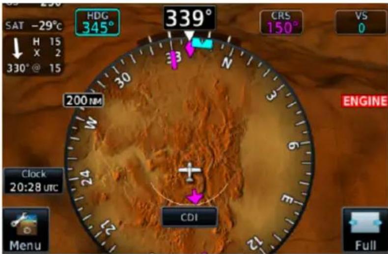
Engine Annunciator on PFD
EXTERNAL ENGINE ALERT LAMPS
An external lamp is required if the only EIS display is installed outside the pilot's primary field of view. This lamp illuminates any time an engine alert is active. It turns off once the alert is acknowledged.
EXTERNAL ENGINE ALERT ACKNOWLEDGMENT
FEATURE REQUIREMENTS
• TXi software v3.21 or later
Depending on configuration, the system may allow you to acknowledge engine caution and warning annunciations remotely via dedicated aircraft switches. This feature replaces the onscreen Acknowledge Alert key, eliminating the need to acknowledge an engine alert in multiple locations (e.g., on GDU and on the aircraft caution/warning panel).
Annunciation Push-To-Test Options
Test keys allow you to confirm that the external master caution and master warning switches are functioning properly outside of actual alerting conditions. During unit power up, these toggle keys are available on the EIS start-up page.


Test keys are temporarily unavailable as the unit initializes. A status message informs you that the system is powering up.
After approximately 10 seconds, the keys are available for selection.
Following start-up, you can test the aircraft switches at any time from the Engine menu.
GDU 1060: From the Home page, tap Engine > Menu > Lamp Test, and select the appropriate test key.
GDU 700(): Tap Menu > Lamp Test, and select the appropriate test key.
To test the external engine alert acknowledgment function:
- Tap Engine Caution and Engine Warning.
- Observe that the external alert lamps illuminate.
- Acknowledge each alert indication by pressing the appropriate aircraft switch. Doing so cycles the corresponding outputs.
- Observe that the color of the associated message on EIS changes to indicate acknowledgment.
9 Abnormal Operations
BACKUP INSTRUMENTS
9.1 Display Backup 9-2
9.2 Backup Battery 9-9
9.3 AHRS & ADC Failures....9-14
9.4 HSI Failure Modes....9-23
EMERGENCY MODES
9.5 Smart Glide 9-29
9.6 Emergency Descent 9-41
Backup Instruments
9.1 Display Backup
FEATURE LIMITATIONS
• Applicable to pilot side units only
- Only pilot or center units trigger backup mode when offline
• Not available in single TXi display installations
• Display backup mode supports a limited set of EIS gauges
- Not available on GDU 700P configured as twin-engine turboprop EIS (includes standby PFD)
Display backup mode occurs under these three conditions
- Loss of communication with a GDU that displays EIS or PFD data
- Pilot activation through on-screen selection or toggle switch
- AHRS or ADC fault caused by miscompare or missing data (this only triggers backup mode when the unit is configured as a standby PFD)
Display backup mode attempts to match the configuration of the lost primary display unit. When transitioning, priority is given to the display of primary gauges. In some cases, menu items and lean controls are disabled in this mode. Any flight control trim gauges appear in display backup mode.
An optional external toggle switch allows manual activation of backup mode.
TCAS II RAS
When a GDU 1060 is in display backup mode and providing PFD/MFD/EIS functions, the format of the PFD narrows and the VSI is too small to depict RA bands.
To view TCAS II RAs, tap Full on the PFD to expand it to 80%.
9.1.1 Standby PFD Display Options
FEATURE REQUIREMENTS
Additional standby PFD functionality is available in installations that include:
- Dual external ADAHRS sensors: one external ADAHRS; one internal AHRS connected to an ADC
- Two pilot side GDU 700P units: one configured as a dedicated PFD, the other configured as either MFD, EIS, or MFD/EIS
• Non-PFD GDU configured as standby PFD
During display backup, the standby PFD allows you the option of continuing backup PFD mode or returning to the unit's previous display mode (MFD, EIS, or MFD/EIS). This option is available only if display backup is triggered by an AHRS or ADC data miscompare or by pilot activation.
DISPLAY BACKUP KEY
This key remains available during display backup for as long as the GDUs are in communication with each other. It is not available during display backup if only the standby PFD is operational.

To return the standby PFD to its previous display mode:
- Push the Power key.
- Deselect Display Backup.
9.1.2 Composite Display Backup Mode
When a GDU 700P enters a PFD/EIS composite display backup mode, certain aspects of the normal PFD layout change to accommodate the display of EIS data.
PFD when in composite display backup mode:
• A limited, 90° field of view HSI replaces the Standard HSI or HSI Map
• CDI source selection key replaces air temperature and wind data fields
- Attitude background defaults to a blue over brown artificial horizon display (non-SVT)
Removed from display in composite mode:
• Air temperature field
- Clock/timer field
- Wind data fields
- PFD Menu key
- Advisory key
Unchanged from display in composite mode:
- Airspeed
- Barometric altitude
- Attitude
Unavailable PFD functions operating in composite mode:
• Changing airspeed references
- Setting BARO or RA Minimums
• Selection of AHRS or ADC sources
• Manual adjustment of backlight levels
• Viewing external LRU status
Managing EIS Failure in Twin-engine Turboprop Aircraft
Twin turboprop EIS layouts are available on GDU 700P. ^1 If you experience an EIS failure on GDU 700P and your aircraft is equipped with multiple GDUs, you can open the Engine page on the GDU 1060 or GDU 700P MFD to view EIS information.
^1 Requires TXi software v3.21 or later.
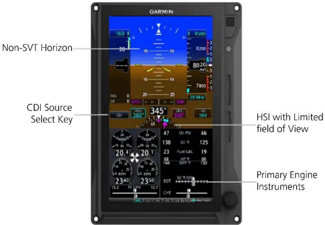
GDU 700P Composite Display in Backup Mode - Reciprocating Engines
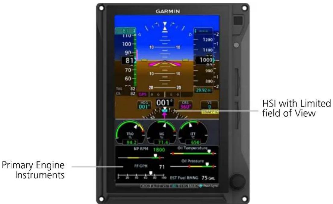
GDU 700P Composite Display in Backup Mode - Single Engine Turboprop
DISPLAY BACKUP MODES
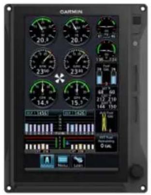
Normal Mode EIS
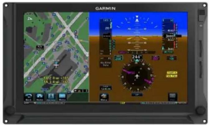
PFD/MFD

natural_image
Front view of a black DARTIN tablet device with control buttons and a small display (no visible text or symbols on the device body)Display Failure
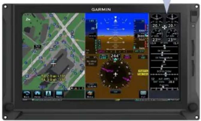
Backup Display Mode
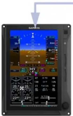
Backup Display Mode

natural_image
Front view of a Garmin tablet device with black screen and control buttons (no readable text or symbols on screen)Display Failure
EIS GAUGE REVERSION
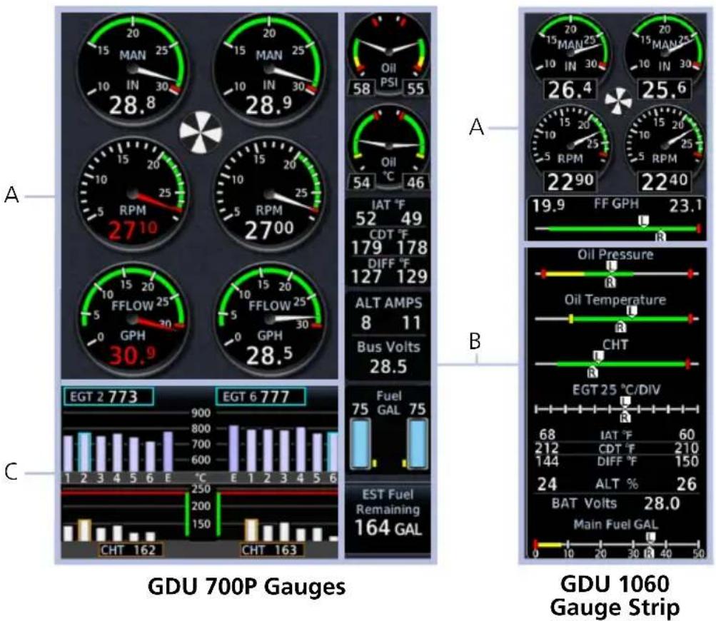
| A Gauges display with little or no change. | |
| B | Gauges transfer depending on priority and open gauge slots. |
| C | Gauges simplify and transfer, depending on available display area. |
TURBOPROP GAUGE AREAS
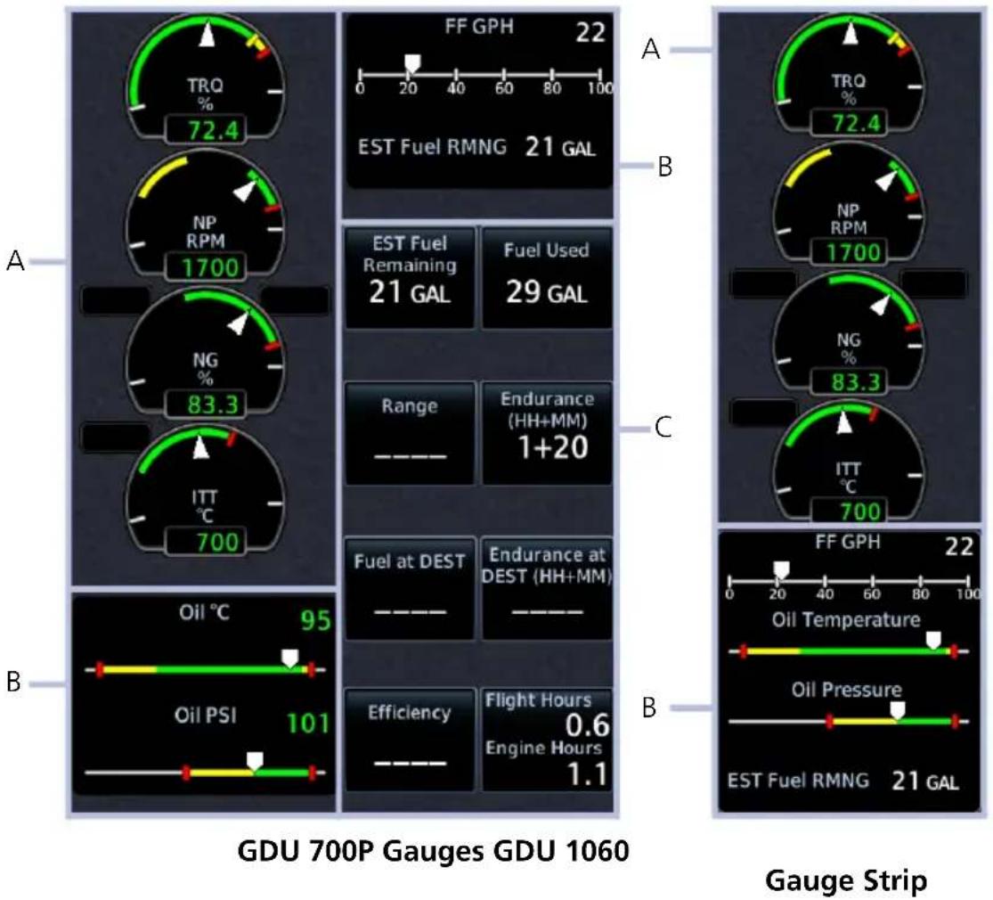
gauge
| Metric | Value | |--------|-------| | TRQ % | 72.4 | | NP RPM | 1700 | | NG % | 83.3 | | ITT °C | 700 | | Oil PSI | 101 | | Efficiency | 0.6 | | Endurance at DEST (HH+MM) | 1+20 | | Range | — — | | Endurance at DEST (HH+MM) | — — | | Energy Hours | 1.1 | | FF GPH | 22 | | EST Fuel RMNG | 21 GAL | | NF Fuel Remaining | 21 GAL | | NF RPM | 1700 | | NF Gas Use | 83.3 | | NF Gas Use Duration | 700 | | Oil Pressure | — — | | Oil Temperature | — — | | FF GPH | 22 | | EST Fuel RMNG | 21 GAL | GDU 700P Gauges GDU 1060| A | Gauges display with little or no change. |
| B | Gauges transfer depending on priority and open gauge slots. |
| C | Does not transfer to display backup. |
9.2 Backup Battery
FEATURE LIMITATIONS
• Applicable to GDU 700() only
- During backup battery mode, display brightness is set for minimum sunlight readability
Battery Supported LRUs
- Backup GPS
- GDU 700()
- GEA 110
• GMU 44
GTP 59 - Integrated ADAHRS
GBB 54 Features
• Lithium-ion battery unit
- Integrated heater ensures performance in low temperatures
• Charged by GDU during normal operations
• Status indications denote battery state and availability
- Pop-up alerts with estimated time remaining
• System advisories with timer display
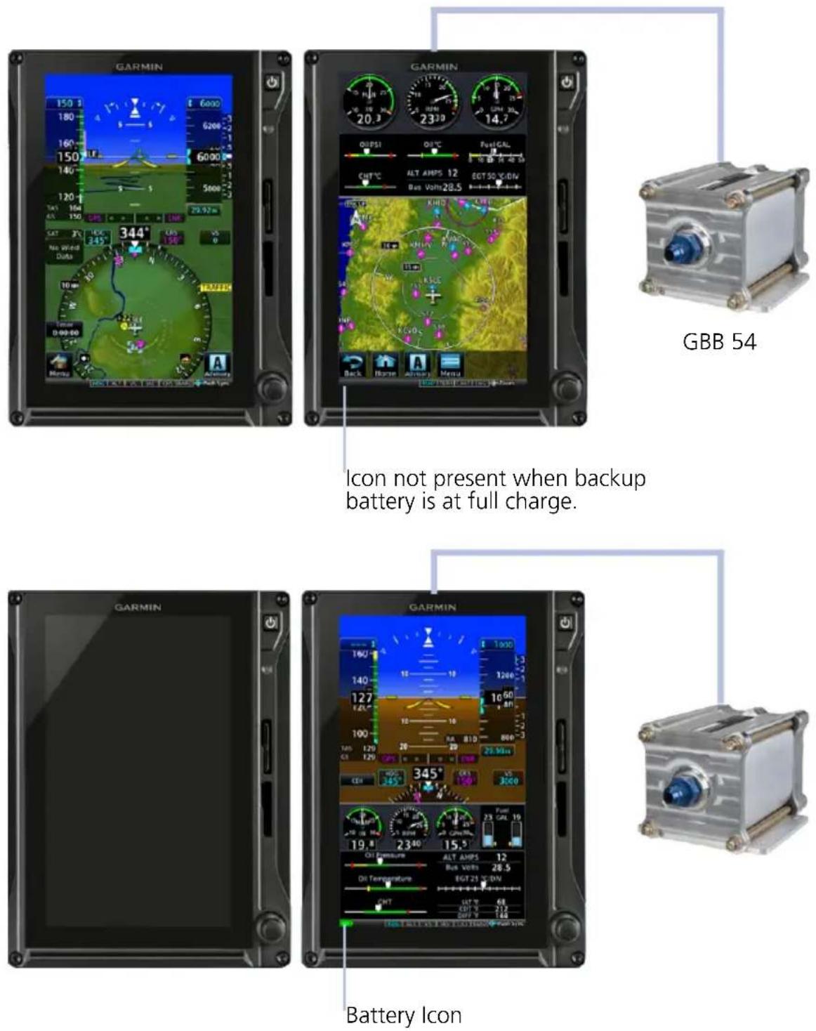
Icon not present when backup battery is at full charge.
GBB 54 Backup Battery
9.2.1 Battery Status Indications
Status indications include a battery icon and timers.
BATTERY ICON
- Displays when the GBB 54 is powering the GDU, battery charge state is insufficient, or a battery fault exists
• Displays in the annunciator bar and on External LRUs page - Removed when the battery is at full charge
| ICON STATE CONDITION | ||
| Absent1 | Charged | · Backup battery at full charge (>30 minutes) and available for use. |
 | Charging/Warming Up | · Battery has less than 30 minutes remaining charge.2· Battery temperature is below -20°C.2,3 |
 | Discharging | · GDU on backup battery power. 15 to 30 minutes remaining. |
 | Discharging/Caution | · GDU on backup battery power. 0 to 15 minutes remaining. |
 | Discharging/Warning | · GDU on backup battery power for longer than 30 minutes. Loss of power may be imminent.4· Charge state uncertain (i.e., GDU switches to backup battery power before battery reaches full charge). |
 | Unavailable/Error | · Battery error. Backup battery power is unavailable.· Capacity test is overdue. |
BATTERY TIMERS
Battery timers alert the pilot of:
• Transitions from aircraft power to backup battery power
• Total time on battery power
| TIMER ALERT TYPE CONDITION | ||
| Elapsed time on battery power (count-up) | Advisory Aircraft is in flight. | |
| 60 second countdown Pop-up | Aircraft is on ground or in an unknown state. | |
Automatic Unit Shutdown
To prevent battery depletion, the unit automatically powers off once the 60 second countdown timer expires.

Tapping Stay On cancels the automatic shutdown sequence, allowing the unit to continue operation on backup battery power.
9.2.2 Battery Alerts
Caution messages alerting to backup battery status may display while in flight. On GDU 700L, these alerts are shortened to accommodate space limitations.
ANNUNCIATION ALERT TYPE & CONDITION
Backup battery in use. Estimated time remaining: 15 minutes.
Alert Type: Caution
Pop-up Alert: Yes
Condition
GDU on backup battery power, discharging for 15 minutes.
Alert Type: Caution
Pop-up Alert: Yes
Condition
Backup battery has low charge or fault. See flight manual for operating limitations.
Battery is charging. Estimated charge is below 30 minutes.
GDU detects a battery fault or warning state.
Loss of communication.
Battery power output failure.
Capacity test failure or testing overdue.
9.3 AHRS & ADC Failures
The AHRS uses aiding data from the GPS navigator, air data computer, and magnetometer to provide accurate attitude data. Failure of these inputs may cause attitude data to become unavailable. Additional annunciations indicate current alignment and calibration status.
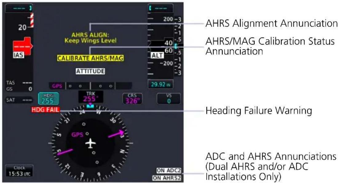
In dual AHRS/ADC installations, use the onside AHRS/ADC during normal operations and the offside AHRS/ADC only when necessary. Under normal conditions, sensor assignment should be as follows.
Pilot PFD: AHRS 1, ADC 1
Co-pilot PFD: AHRS 2, ADC 2
Standby PFD (pilot side): AHRS 2, ADC 2
9.3.1 AHRS & ADC Sensor Selection
The pilot is provided AHRS/ADC source selection controls when dual ADC or AHRS sensors are configured.
SELECT SENSORS ON PILOT/CO-PILOT PFD
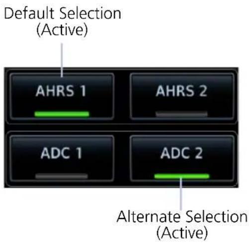
AHRS and ADC selection keys reside on the Sensors page of the PFD menu.
Alternate attitude or air data sources annunciate on the PFD. Default selections do not annunciate.
ON ADC2
SELECT SENSORS ON A STANDBY TXI PFD
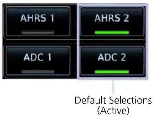
By default, the pilot side standby PFD uses ADC 2 and AHRS 2 data when the unit transitions to backup PFD mode. This occurs during any one of the following conditions.
• Primary PFD failure
- Miscompare state
- No compare state
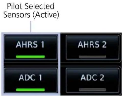
Standby PFD allows you to specify alternate data sources if the default selections are not preferred.

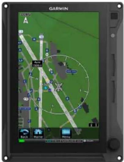
MFD (Standby PFD)PFD

natural_image
Front view of a black Garmin tablet device with control panel and buttons (no readable text or symbols)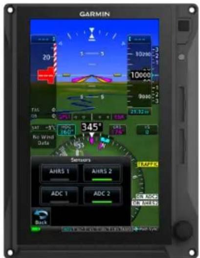
Display Failure Sensor Options Available
During backup PFD mode, sensor select options remain available.
Standby PFD Sensor Options
AHRS/ADC SENSOR SELECTION ANNUNCIATIONS
| ANNUNCIATION DISPLAY DESCRIPTION | ||
| SINGLE TXI PFD | ||
| “ON ADC 2” or “ON AHRS 2” (black text on white) | Pilot’s PFD | Pilot selected ADC 2 or AHRS 2 as the sensor source. |
| TWO TXI PFDS | ||
| “ON ADC 1” or “ON AHRS 1” (black text on yellow) | Standby PFD (pilot side) | GDU is in display backup mode. |
| Co-pilot’s PFD | Pilot changed sensor source from the default setting. | |
| “ON ADC 2” or “ON AHRS 2” (black text on yellow) | Pilot’s PFD | |
| “ON ADC 2” or “ON AHRS 2” (black text on white) | Standby PFD (pilot side) | Sensor source is the default setting (sensor 2). |
9.3.2 AHRS Operating In Reversionary Mode
A failure of the air data input has no effect on AHRS output, while AHRS is operating in normal mode. If the air data input fails, while the AHRS is operating in backup No-GPS mode, PFD attitude and heading data are invalid.
9.3.3 GPS Failure
Two GPS inputs may be provided to the AHRS. If GPS information from one of the inputs fails, the AHRS uses the remaining GPS input, and an advisory message informs the pilot. If both GPS inputs fail, the AHRS continues to provide attitude and heading information to the PFD as long as true airspeed data is available and valid.
9.3.4 AHRS Alerts
ANNUNCIATION ALERT TYPE & CONDITION
| HDG FAIL | Alert Type: Warning |
| Condition | |
| Invalid heading. | |
| AHRS ALIGN: Keep Wings Level | Alert Type: Caution |
| Condition | |
| AHRS is aligning. Appears during AHRS initialization. | |
| AHRS NOT READY, DO NOT TAKE OFF | Alert Type: Caution |
| Condition | |
| AHRS is not initialized. Appears prior to AHRS initialization on the ground. | |
| AHRS NOT READY, KEEP WINGS LEVEL | Alert Type: Caution |
| Condition | |
| AHRS is not initialized. Appears prior to AHRS initialization in the air. | |
| CALIBRATE AHRS/MAG | Alert Type: Caution |
| Condition | |
| AHRS calibration is incomplete. | |
| Service required. Contact a Garmin dealer for support. | |
| MAG ANOM | Alert Type: Caution |
| Condition | |
| AHRS detects a magnetic anomaly. |
ANNUNCIATION ALERT TYPE & CONDITION
| ON ADC <#> | Alert Type: Caution (Dual TXi PFD only) |
| Condition | |
| PFD is using opposite-side ADC data. | |
| Alert Type: Advisory (Single TXi PFD only) | |
| Condition | |
| PFD is using ADC data from ADC 2. | |
| Alert Type: Advisory (Dual TXi PFD only-Standby PFD only) | |
| Condition | |
| PFD is using ADC data from ADC 2. | |
| ON AHRS <#> | Alert Type: Caution (Dual TXi PFD only) |
| Condition | |
| PFD is using opposite-side AHRS data. | |
| Alert Type: Advisory (Single TXi PFD only) | |
| Condition | |
| PFD is using AHRS data from AHRS 2. | |
| ON AHRS <#> | Alert Type: Advisory (Dual TXi PFD only-Standby PFD only) |
| Condition | |
| PFD is using AHRS data from AHRS 2. | |
| ATTITUDE | Alert Type: Caution |
| Condition | |
| Flight dynamics monitor detects a possible discrepancy in AHRS outputs. |
LRU FAILURE EFFECT ON AHRS OPERATION
| LRU CONDITION AHRS OUTPUT | ||
| ADC | ADC input fails during normal mode. | Valid attitude and heading information (no interruption). |
| ADC input fails while AHRS is in NO-GPS mode. | Attitude and heading fails. | |
| GPS Navigator | GPS inputs fail. AHRS continues to operate in No-GPS mode (ADC and magnetometer required). | Valid attitude and heading information (no interruption). |
| Magnetometer | Magnetometer input fails while aircraft is on the ground. AHRS transitions to back-up mode without magnetometer. | Valid attitude information (no interruption). Heading displays using GPS track data. |
| Magnetometer input fails while aircraft is in the air. AHRS transitions to no magnetometer mode. | Valid attitude information (no interruption). Invalid heading information. Display enters reversionary track mode. | |
| GPS and Magnetometer | Magnetometer and GPS inputs fail. | Attitude and heading fails. |
9.3.5 Miscompare & No Compare
AHRS/ADC SENSOR COMPARISON
The GDU continuously monitors and compares sensor data when more than one AHRS or ADC is present. A miscompare state occurs when the difference between two or more sensor outputs is above the predefined threshold.
| MISCOMPARE THRESHOLDS | ||
| PARAMETER CONDITION VALUE | ||
| Altitude All 200 feet | ||
| Heading1 | All 6° | |
| Indicated Airspeed | Both <35 kts Inhibited | |
| Either or both ≥35 kts, and both <80 kts | 10 kts | |
| Either ≥80 kts 7 kts | ||
| Lateral Acceleration All 0.2G | ||
| Normal Acceleration All 0.2G | ||
| Pitch Attitude All 5° | ||
| Pitch Attitude Rate All 1° | ||
| Roll All 6° | ||
| Roll Rate All 3° | ||
^1 Depends upon configuration.
MISCOMPARE ANNUNCIATIONS
Miscompares generate a caution annunciation over the affected PFD instrument(s).
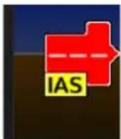
Indicated airspeed, "IAS" annunciates below the airspeed pointer.
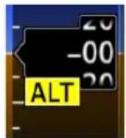
Altitude, "ALT" annunciates below the barometric altitude pointer.

Pitch and/or roll, "ATTITUDE" displays on the pitch scale.
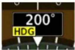
Heading, "HDG" annunciates below the current heading.
In addition to miscompare monitors, the GDU provides an independent flight dynamics monitor that compares computed cross heading, vertical accelerations, and roll angles against reported values generated by the AHRS. If there is a disagreement between the flight dynamics monitor and the AHRS parameters, the “ATTITUDE” caution annunciates.
NO COMPARE ANNUNCIATIONS
A no compare monitor determines when data to the second ADC or AHRS source is unable to be used for comparison.
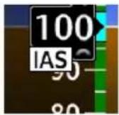

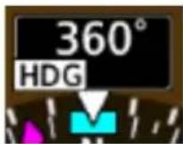
No compares generate an advisory annunciation over the affected instrument(s) driven by ADC and AHRS units.

9.4 HSI Failure Modes

NOTE
TAWS/terrain alerting is unavailable in the absence of a certified GPS source.
The HSI continues to display limited navigation information during magnetometer and GPS failures. If the magnetometer input fails, the AHRS transitions to backup No-Magnetometer mode and continues to output valid attitude information.
If the aircraft is airborne, the PFD heading output reverts to GPS track. Magnetic heading is replaced by GPS track information and HSI compass card orients to GPS track. The following TXi system conditions exist:
- SVT turns off and automatically re-enables when heading is restored
• Map orientations change from HDG UP to TRACK UP - When heading is restored orientations change back to HDG up
- When heading fails heading bug remains
- GDU continues driving autopilot heading error output using track in place of heading
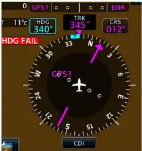
HSI with Magnetometer Failure
"HDG FAIL" annunciates when there is an AHRS heading data failure.
If the magnetometer fails, the HSI compass card indicates GPS track. The numeric heading value turns magenta to indicate GPS track is displayed.
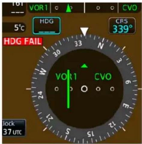
HSI with GPS and Magnetometer Failures
If both the magnetometer and GPS units fail:
• HSI reverts to a non-directional CDI
- Numeric heading display is removed
• Use the selected course control to manually control OBS
9.4.1 GPS Failure

WARNING
Do not use projected position data as the only means of navigation.
When dead reckoning mode is active on the GPS navigator:
• System flags all external outputs dependent on GPS position data
- Map page reports "No GPS Position"; overlays are not available
• DR Mode annunciates on HSI, replacing ENR or OCN
• Traffic and Stormscope data continue to display on their respective pages
- Charts are available for display on the dedicated MFD page, but the ownership is no longer geo-referenced on the chart
- Terrain functionality not available
- CDI not available
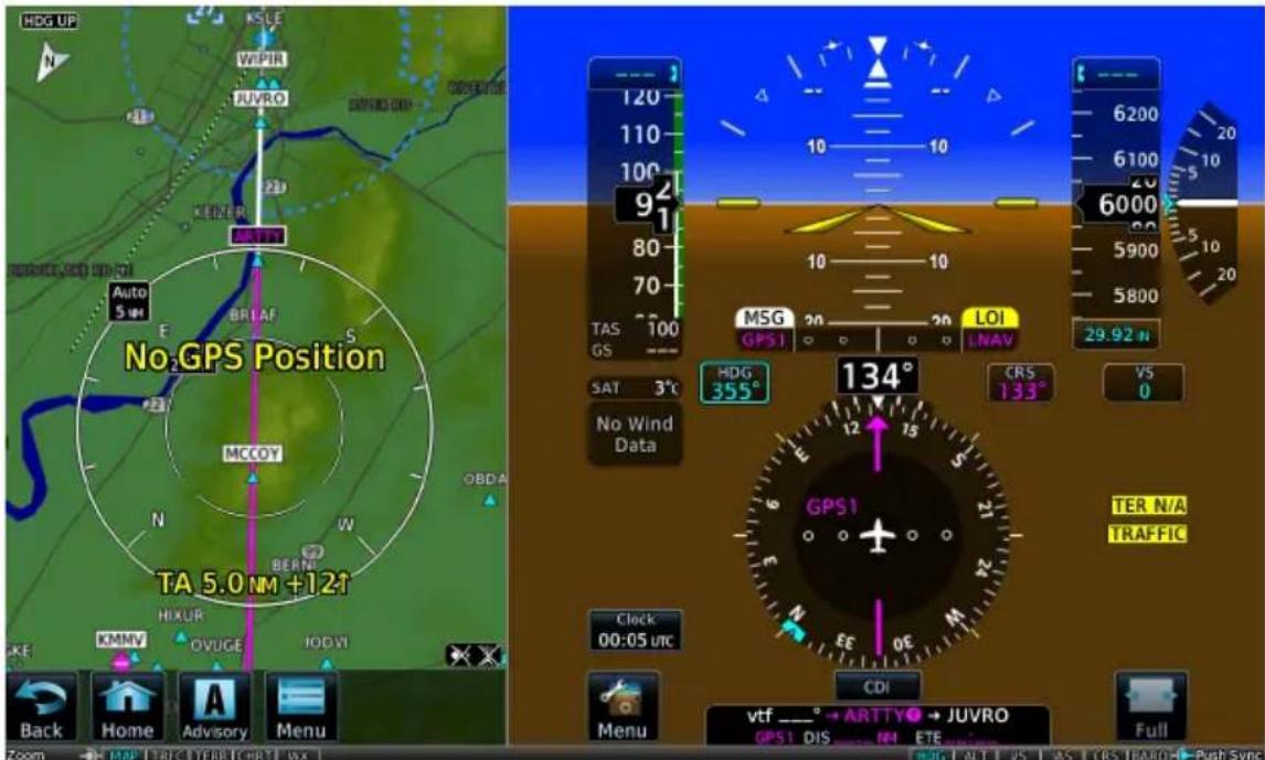
Dead Reckoning
9.4.2 Backup GPS
Each GDU is equipped with a backup GPS receiver. When the optional Garmin backup GPS antenna is connected, and if all the certified GPS sources are lost, the system provides 2-D GPS position information from the backup GPS. No pilot action is required to enable the use of backup GPS data.
Only one GDU in a multi-GDU installation requires a connected backup GPS antenna. The system automatically cross-fills backup GPS data between GDUs.
Backup GPS data is used only to provide non-safety critical functions and only after the failure of all certified GPS position sources. Backup GPS data is only provided when a valid GPS position is received from an airborne certified GPS source that is subsequently lost. The system always utilizes time from the backup GPS when no other source is available, even prior to receipt of GPS time from a certified GPS source.
Backup GPS data provides:
- Ownership position on the moving map
- GPS track display
• Waypoint bearing/distance information - Ground speed
• Wind calculations
When backup GPS is in use:
- Yellow "BACKUP GPS" annunciation displays on all geo-referenced maps
• Navigation using backup GPS is not provided
• Map overlays for Stormscope, traffic, terrain, and obstacles are disabled
• Traffic page continues to display data from TIS-A and TCAS sources
Functions inhibited with backup GPS:
- Bearing pointer on Waypoint Info page
• Chart geo-referencing
• SVT
• GPS altitude displays
• GPS navigation status field
• TAWS/terrain alerting - Terrain page display
Emergency Modes

Emergency modes are available to assist you in the event of engine failure or a loss of cabin pressure.

NOTE
While emergency features can assist in workload reduction, it is the responsibility of the pilot in command to know and follow all published POH/AFM normal and emergency procedures.
MFD Emergency Page
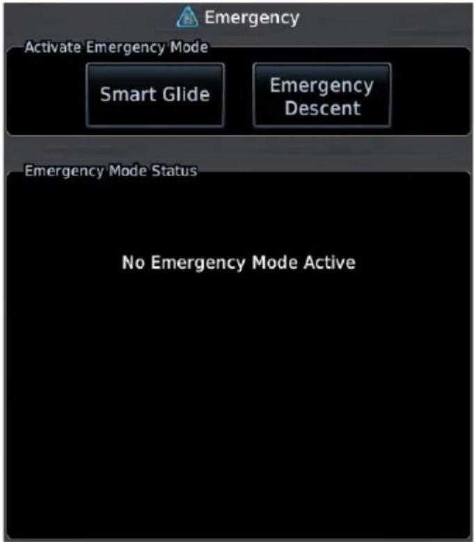
Emergency modes are accessible via the Emergency page. Available options are dependent upon configuration.
A status window displays information related to the active emergency mode.
Contact a Garmin dealer to see if emergency features are available for your aircraft.
EMERGENCY MODES AT A GLANCE
| Smart Glide Emergency Descent Mode | ||
| Emergency Condition | engine failure cabin depressurization, fire | |
| Pilot Assumption | coherent hypoxic | 1 |
| Mode Activation | manual automatic | 2 or manual |
| Active Vertical Mode^3 | IAS to V_G | IAS to V_MO (fast) |
| Active Lateral Mode^3 | GPS or ROL at wings level HDG | |
Controlling LRU GTN Xi GDU TXi (PFD)
^1 Pilots experiencing hypoxia may be incoherent or unconscious.
^2 Mode activation may occur automatically depending on configuration.
^3 Automatic flight director mode change available only with GFC 500/600.
9.5 Smart Glide

In the event of engine failure or partial power loss, this feature allows you to quickly locate and plot a direct course to the most suitable airport within glide range, avoiding terrain and obstacles along the way.

WARNING
Do not rely solely upon Smart Glide for navigation, airspeed and altitude management, or landing field selection. It is the pilot's responsibility to navigate, manage airspeed and altitude, and determine the best field for landing.

NOTE
Smart Glide is not an autonomous landing system. It indicates the latest appropriate time for the pilot to take control of the aircraft by issuing visual and aural "Maneuver and Land" alerts. It is the pilot's responsibility to disengage the autopilot (if present) and safely fly the approach and landing.
FEATURE REQUIREMENTS
• TXi software v3.30 or later
• GTN Xi series navigator with Smart Glide enabled (function host)
Smart Glide is a function of GTN Xi. For more information regarding functionality, consult GTN Xi Series Pilot's Guide.
9.5.1 Activate Smart Glide

NOTE
Contact a Garmin dealer if your installation does not provide access to emergency features.
FEATURE LIMITATIONS
- Activation options are dependent upon installer configuration
WHERE TO FIND IT

flowchart
graph TD
    A["Home"] --> B["Emergency"]
    B --> C["Smart Glide"]
Activate Smart Glide when engine failure occurs. The Smart Glide activation key resides on the Emergency page.
From the MFD Home page:
Tap Emergency > Smart Glide.
MFD Emergency Page
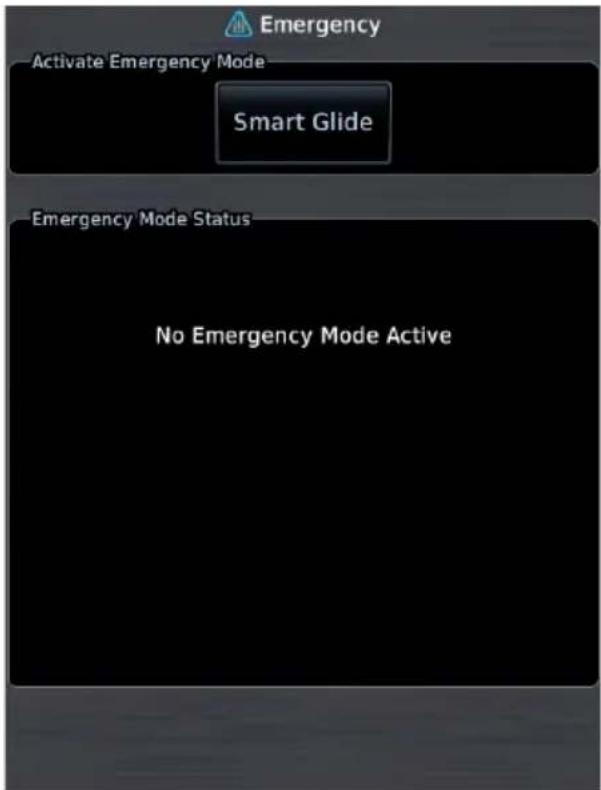
A message in the Emergency Mode Status window informs you that no emergency modes are active.
You may activate Smart Glide from any configured GTN Xi series navigator or MFD TXi series display unit. For information about all available means of activation, consult GTN Xi Series Pilot's Guide.
9.5.2 Active Mode Indications
Upon activation, Smart Glide calculates the glide route to a suitable destination airport and displays the information on the Emergency page.
Smart Glide Active, Calculating Route Active Route & Longest Runway Information
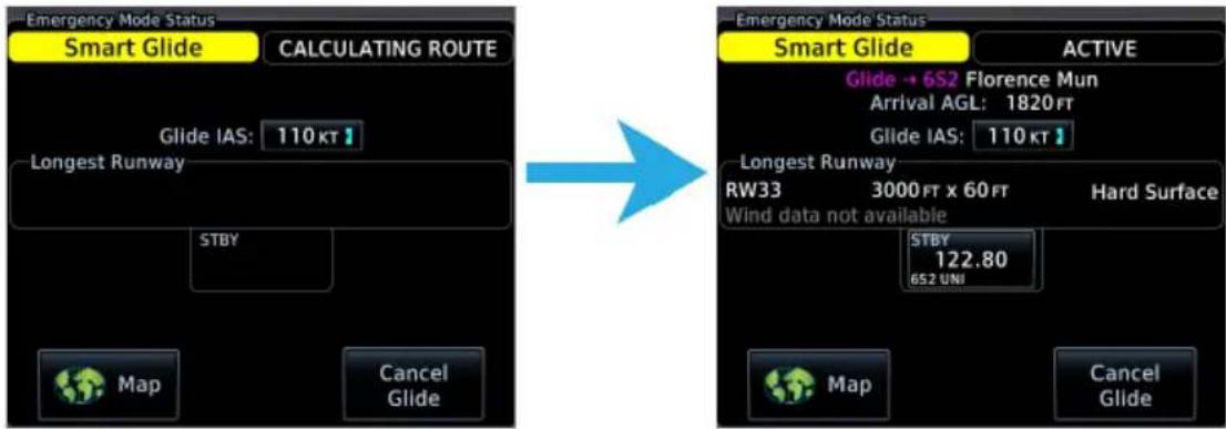
Active mode indications and overlays appear on the MFD and PFD. A status information window is accessible when the Emergency page is not in use.
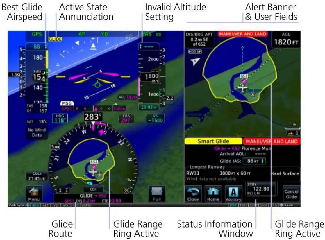

On MFD:
Smart Glide replaces the active flight plan with a new direct course.
On Map, the yellow Smart Glide Range Ring reflects the measured glide ratio based on real-time data rather than the configured POH ratio.
Full Screen MFD
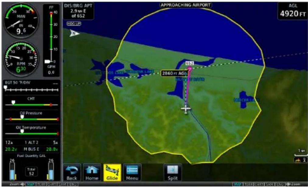
Map features automatically declutter and TOPO and Terrain overlays turn on if not already active. Map features revert to their previous settings when you cancel Smart Glide.
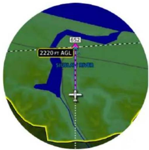
Active flight plan leg indication depicts a direct course to the center of the airport. Runway Extensions turn on if not already active.
An altitude label indicates the estimated arrival AGL for the airport.

Glide key replaces the Advisory key when the status information window is not in use.
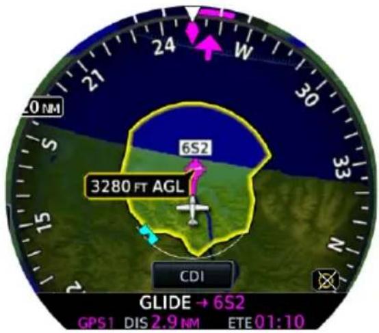
On PFD:
The active route changes to a new direct course. Active flight plan leg indication depicts a direct course to the center of the airport.
Smart Glide Range Ring overlays on HSI Map.
The CDI switches to GPS ^1 .

Full screen PFD
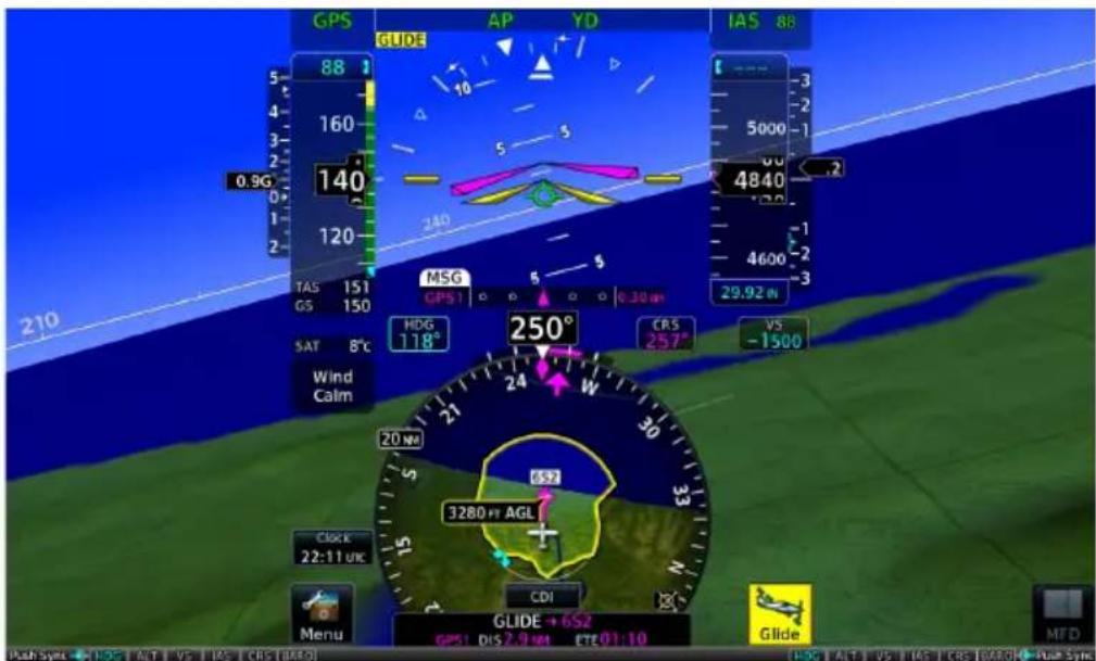
Glide key replaces the Advisory key when the status information window is not in use (full PFD only).
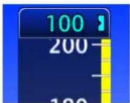
Selected airspeed control sets to the V_G of the GTN Xi series navigator.

Selected altitude value sets to invalid, displaying a series of dashes.

When GFC 600 is present, the "GLIDE" active status indication appears below the autopilot mode annunciation bar during IAS vertical mode.
^1 The GPS transmitting active Smart Glide status has priority.
9.5.3 View Smart Glide Status Information
Tapping Glide displays active route and longest runway details, the configured best glide speed for the aircraft, and available control options. This information is also accessible via the Emergency icon on the Home page.

When Smart Glide is active, this key replaces the Advisory key in the control bar.

Advisory key returns once the Emergency page/window opens or when you cancel Smart Glide.
Smart Glide Status Information Window
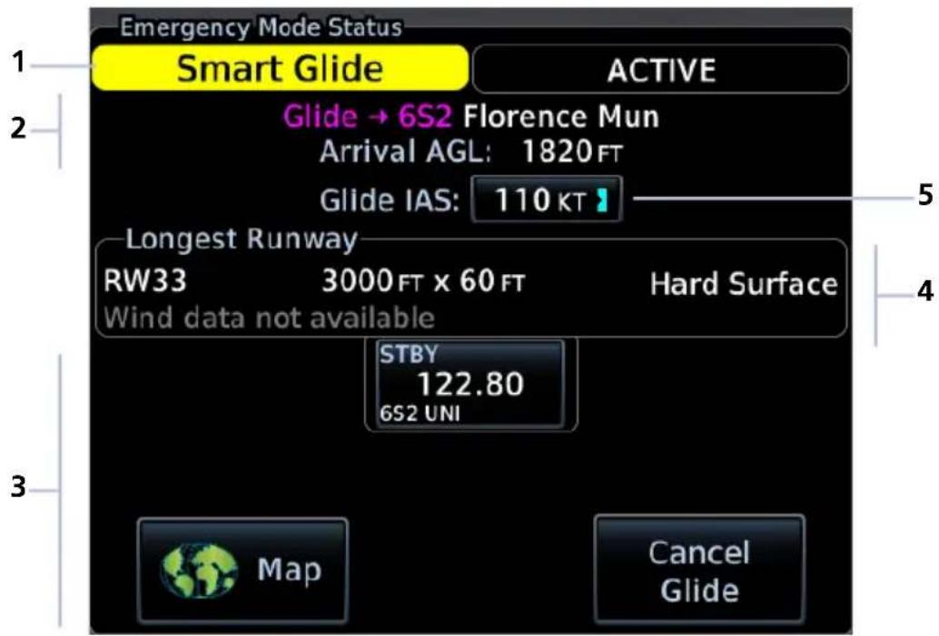
| 1 Mode Status Banner 4 Longest Runway Information | |||
| 2 Active Route Display | 5 | Best Glide Speed Reference Indicator & Control | |
| 3 Smart Glide Controls | |||
ACTIVE ROUTE DISPLAY
Glide → 6S2 Florence Mun Arrival AGL: 1820 FT
Shows the active direct route for gliding to the destination airport. Information includes:
• Active airport identifier
- Airport name
• Estimated arrival AGL
Active Flight Plan, MFD
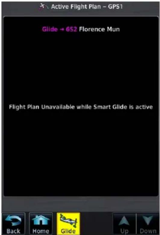
Active route identifiers also appear along the top of the active flight plan and in the GPS NAV status field of the PFD.
GPS NAV Status & HSI Map, PFD
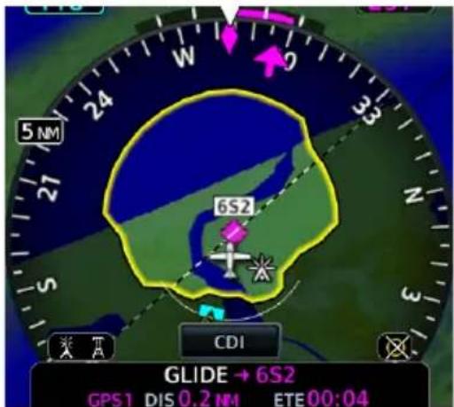
Upon activation, Smart Glide replaces the active flight plan with a new direct course. A message informs you that the flight plan is unavailable while Smart Glide is active.
Arrival AGL (or extra altitude) is the aircraft's estimated height above ground level when crossing the center of the airport.
LONGEST RUNWAY INFORMATION

NOTE
Wind data displays for airports without weather reporting if another airport with valid weather data is within 5 nm. The pilot is responsible for determining current wind direction and intensity.
View details about the destination runway.
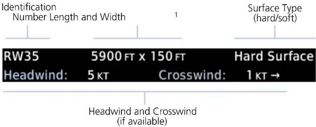

Headwind data field changes color to indicate when tailwind conditions exist.
Advisory wind data received via datalink could be up to 90 minutes old.
"Wind data not available" Indication
This message displays in the absence of valid wind data.
Wind data not available
^1 Runway length is always listed first followed by the runway width.
BEST GLIDE SPEED REFERENCE INDICATOR & CONTROL

Indicates the airspeed expected to follow the calculated glide route. Best glide speed is configured in the host navigator and may differ from PFD settings.
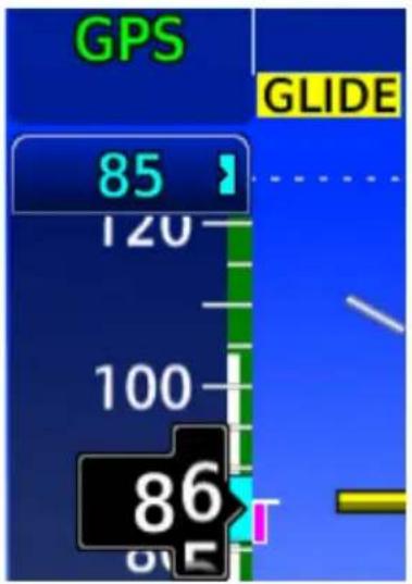
On units with a PFD, this reference field is selectable. Tapping it resets the airspeed reference control to the indicated Glide IAS value. This may be necessary if the selected airspeed is manually changed after activating Smart Glide.
On units without a PFD, this field is read only.


Mismatch (yellow)
Glide IAS target airspeed and airspeed bug values do not match.

Synced (black)
Glide IAS and airspeed bug are in sync.
SMART GLIDE CONTROLS
Emergency Smart Glide Page
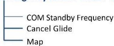
Available control options allow you to:
- Load the destination CTAF or tower frequency to a GTN Xi COM radio
- Cancel Smart Glide
• View Smart Glide information on Map
9.5.4 Monitor COM Standby Frequency

Monitor the COM standby frequency tuned in the host navigator. Information includes the station identifier and airport CTAF or tower frequency.
Tapping this key allows you to load the frequency to a GTN Xi COM radio.
For more about this feature, read Remote Radio Frequency Entry in section 4.
9.5.5 Deactivate Smart Glide

You may deactivate Smart Glide at any time by tapping Cancel Glide.

A pop-up message requests confirmation.
Tapping OK confirms the request.
Tapping Back closes the pop-up without deactivating Smart Glide.
Upon deactivation:
• Map features revert to their previous settings
• Active Flight Plan restores and activates the previous flight plan route
- Aural message "Smart Glide canceled" alerts flight crew of deactivation
- Autopilot (if present) remains in its current active modes or reverts to ROL lateral mode
9.5.6 View Smart Glide Information on Map

The Map key provides direct access to the moving map. Map shows a graphical representation of the active direct-to course for the suggested airport. Shading denotes areas estimated to be unreachable on glide.
Smart Glide Map Features
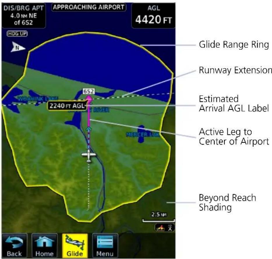
Tapping Glide opens the Smart Glide status information window.
An alert banner displays textual warning, caution, and advisory annunciations. User fields indicating the aircraft's present AGL and its distance/bearing from the destination airport display on a solid black background for greater visibility. They appear in the upper corners of each configured map display as shown.
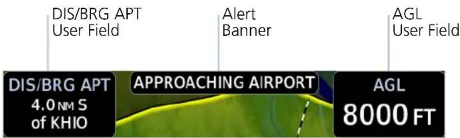
Other map features declutter to remove unnecessary controls and overlays.
Smart Glide Inactive Smart Glide Active
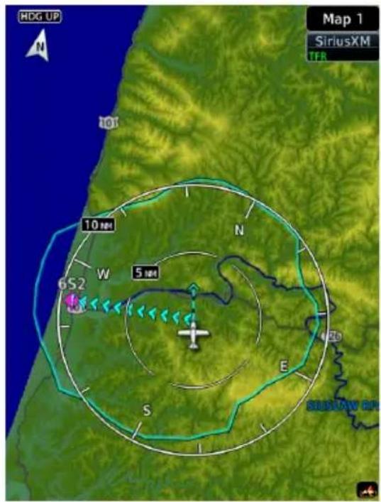
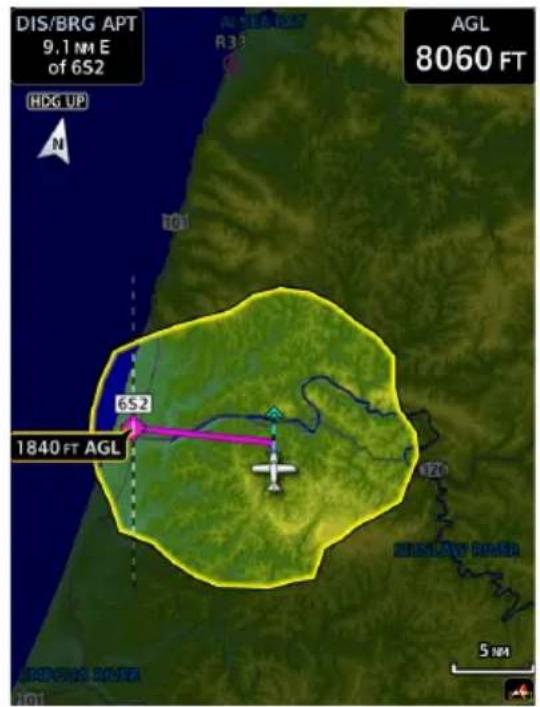
Data depicted during Smart Glide
• Active glide route
• AGL and DIS/BRG APT user fields
- Airports
- Alert banner
• Estimated Arrival AGL label
- Glide Range Ring
METARs
- Runway Extensions
- Terrain overlay
- TOPO overlay
Data removed during Smart Glide
- Airways
• Best Glide Airport indicator - Charts overlay
- Fuel Range Ring
• Heliports - Intersections
• METAR product timestamp - NAV Range Ring
- TOPO scale
9.6 Emergency Descent

Emergency Descent Mode (EDM) assists pilots of pressurized aircraft in the event of cabin depressurization.
FEATURE REQUIREMENTS
• GDU 700()/1060 PFD
• GFC 600 autopilot configured for EDM
• EDM must be armed in order for activation to occur
FEATURE LIMITATIONS
Availability and the manner in which activation occurs (manual or automatic) are dependent upon configuration.
9.6.1 EDM Activation
MFD Emergency Page
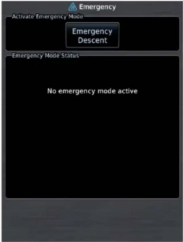
If configured for cabin pressure monitoring, the system monitors cabin pressure once EDM is armed. EDM is considered armed when:
- Autopilot is active
• Aircraft is above 15,000 ft MSL
Once armed, activation may occur manually or automatically.
MANUAL ACTIVATION
WHERE TO FIND IT
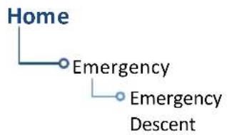
flowchart
graph TD
    A["Home"] --> B["Emergency"]
    B --> C["Emergency Descent"]
You can activate EDM one of two ways:
From the MFD Home page:
Tap Emergency > Emergency Descent.
From a dedicated external switch:
Enable the dedicated switch (if configured).
AUTOMATIC ACTIVATION
If the aircraft experiences decompression and cabin altitude increases beyond the threshold configured for the aircraft, the system automatically triggers EDM.
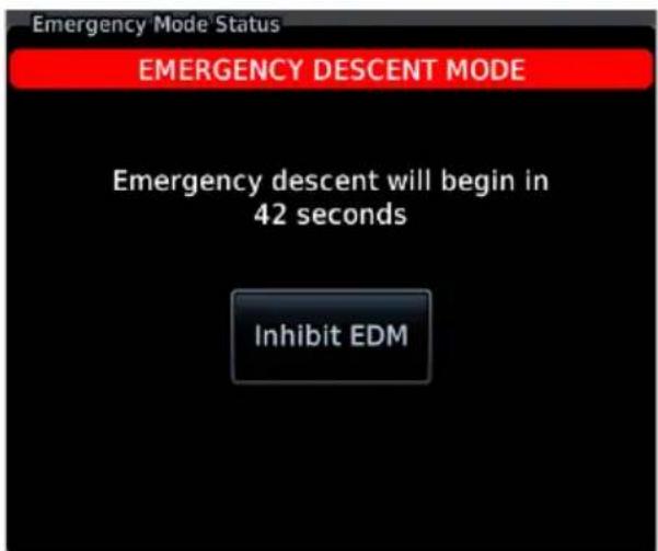
Upon Activation
The status window displays a warning message and timer.
Emergency descent occurs once the timer expires. This delay can range from 10 to 60 seconds.
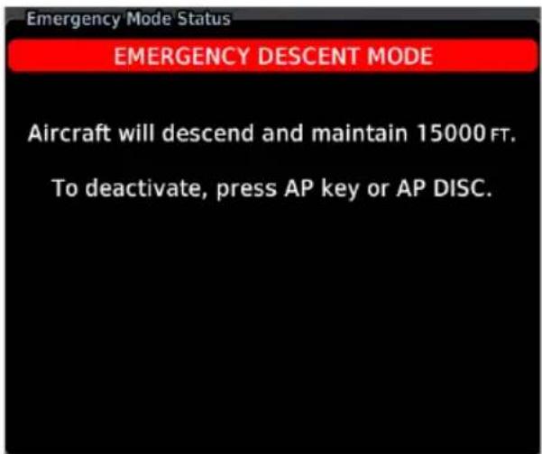
If manually activated, you may skip the delay and activate EDM immediately by pressing the emergency descent switch or Emergency Descent key a second time.
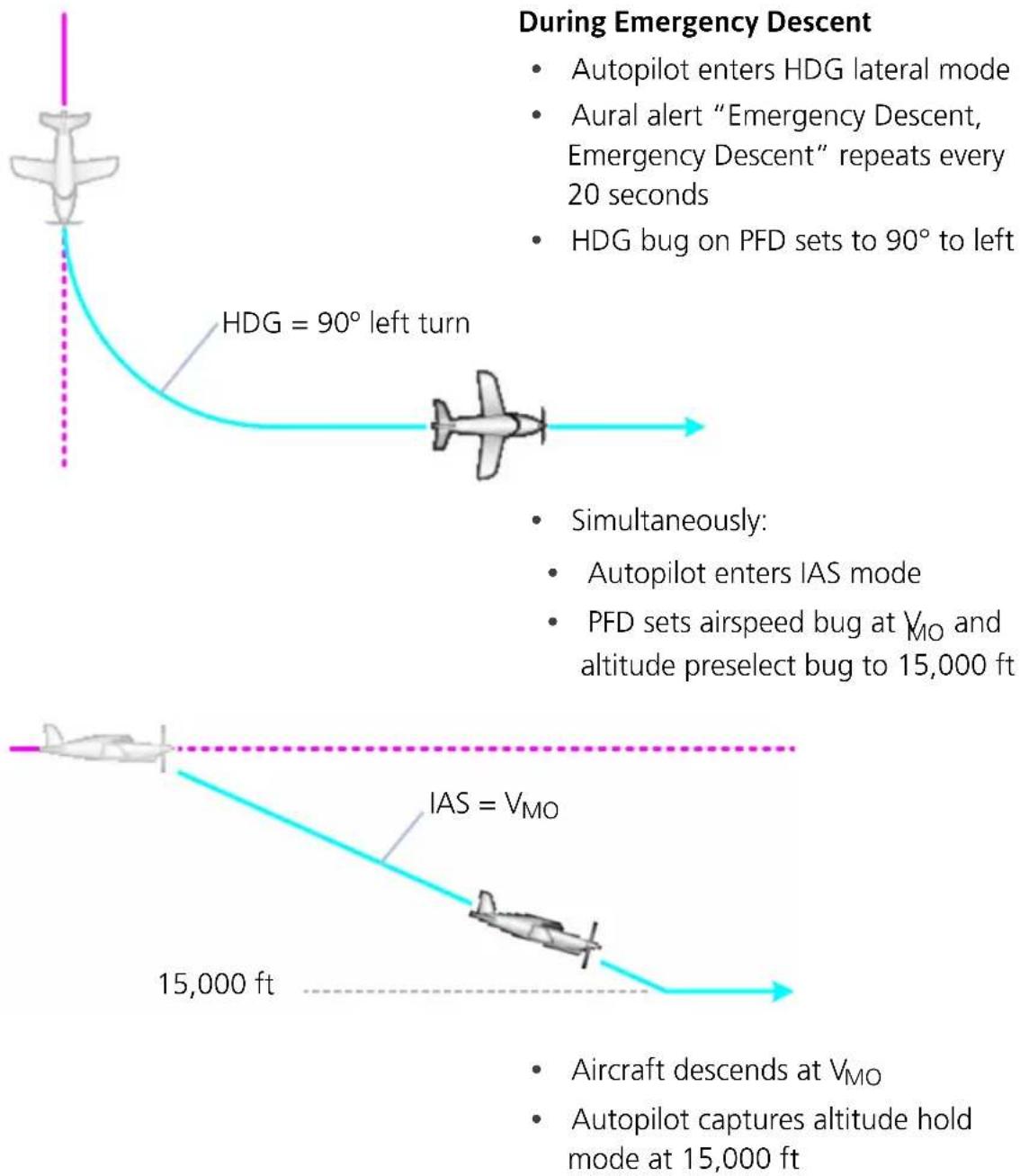
flowchart
graph TD
    A["Airplane"] --> B["HDG = 90° left turn"]
    B --> C["In cockpit"]
    C --> D["Simultaneously: Autopilot enters IAS mode; PFD sets airspeed bug at VMO and altitude preselect bug to 15,000 ft"]
    D --> E["IAS = VMO"]
    E --> F["15,000 ft"]
    F --> G["Aircraft descends at VMO; Autopilot captures altitude hold mode at 15,000 ft"]
    style A fill:#f9f,stroke:#333
    style B fill:#ccf,stroke:#333
    style C fill:#cfc,stroke:#333
    style D fill:#fcc,stroke:#333
    style E fill:#cff,stroke:#333
    style F fill:#ffc,stroke:#333
    style G fill:#fcc,stroke:#333
If available, the pilot may reduce power and deploy speed brakes to increase the rate of descent and reduce the time needed to reach a lower altitude. Ensure that all actions are in accordance with the POH.
EDM ACTIVE INDICATIONS
| ANNUNCIATION STATE | |
| EDM | Active |
| EDM | Override orInhibit Mode |
During EDM, airspeed and altitude bugs are locked and unchangeable. The active state annunciates in the upper left corner of the PFD.
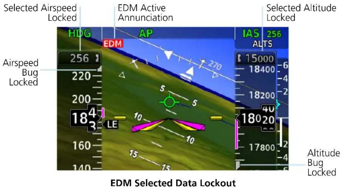
9.6.2 EDM Inhibit
Tapping Inhibit EDM prevents automatic activation once the delay timer expires. During inhibit mode:
• Automatic activation remains inhibited for a duration of 5 minutes
- An advisory message with timer counts down the remaining minutes/seconds
• Inhibit state annunciation appears beneath the AFCS status box
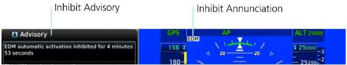

Once the 5 minute inhibit timer expires, the same pop-up warning appears regardless of whether EDM was triggered automatically or by the pilot.
EDM Pop-up Warning, PFD
| IF THEN | |
| Pilot triggers EDM and then chooses to inhibit. | Automatic activation remains enabled. |
| EDM is triggered automatically and the pilot chooses to inhibit. | Manual activation remains available for as long as the aircraft is above 15,000 ft and the autopilot is engaged.1 |
| The 5 minute inhibit timer expires and activation conditions are still present. | EDM automatically triggers again. |
| Pilot loses consciousness after choosing to inhibit the function. | Once the 5 minute inhibit timer expires, EDM automatically activates in order to bring the aircraft to a safer altitude. |
^1 Dependent upon configuration.
9.6.3 EDM Override
To deactivate EDM, disengage the autopilot. You may do this multiple ways:
• On PFD: Tap Menu > Test > AP Disconnect.
• On GMC 605: Push the AP bezel key.
• On the yoke: Push the AP DISC button.
Activating autopilot will override EDM and return the autopilot to normal operation. In this state:
• EDM does not automatically reactivate until arming conditions are cleared
- An advisory message alerts you to re-pressurize the cabin and reset the autopilot
• Override state annunciation appears beneath the AFCS status box
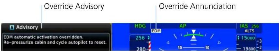
AUTO EDM

This key allows you to manually enable or disable automatic activation. During system power up, this function is active by default.
When the function is off, manual activation of EDM is still available.
To reset EDM automatic activation following an override:
- Descend below 15,000 ft.
- Disengage and then re-engage the autopilot.
OR
- Open the PFD Setup menu.
- Toggle Auto EDM off and on.
Disabling the Auto EDM function may be desired if current cabin conditions are causing erroneous activation of EDM. This can occur when:
• Cabin altitude is above the configured threshold
• GDU reports incorrect cabin altitude
9.6.4 EDM Active Discrete Output
Active Discrete Output & Engine Torque Control
On the Socata TBM 850, the discrete output may be connected to the engine torque limiter. In such case, turning on EDM would energize the torque limiter circuit, resulting in overtorque protection while the aircraft is in emergency descent mode.
This capability is dependent upon installation and should not be relied upon to maintain the engine within torque limits.
It is the full responsibility of the pilot-in-command to operate the aircraft and engine within the limitations defined in the POH/AFM.
PFD provides a discrete output that allows synchronization of EDM with other systems in the aircraft.
- When EDM is on, the discrete output is active.
- When EDM is off, the output is inactive.
Use of the active discrete output is airframe and installation specific.
9.6.5 EDM Failures
ANNUNCIATION ALERT TYPE & CONDITION
| EMERGENCY DESCENT MODE UNAVAILABLE. SERVICE REQUIRED. | Alert Type: Advisory |
| Condition | |
| EDM is disabled. TXi and GFC 600 V_NE configurations do not match. |
INTENTIONALLY LEFT BLANK
10 Qualification

NOTE
The procedures described in this section are not authorized for completion during flight. All tasks must be performed while the aircraft is on the ground.
10.1 Glove Qualification
The touchscreen uses capacitive touch technology to sense the proximity of skin to the display. A glove creates a barrier between the skin and the display glass, potentially reducing the ability of the display to detect touches.
This procedure qualifies a specific glove for use with the touchscreen. Due to differences in finger size, glove size, and touchscreen between the GDU 700() and GDU 1060 units, the qualification procedure is specific to the pilot/glove and GDU combination. Multiple units must be evaluated individually.
GLOVE SELECTION CONSIDERATIONS
• Thinner gloves perform better than thicker gloves.
- Leather gloves, and gloves designed specifically for use with capacitive touchscreen devices, are often found to be acceptable.
- To improve touchscreen sensitivity while wearing gloves, use the pad of your finger instead of the tip during touch interactions.
- Checklist 1 contains the tasks required to qualify a glove.
- Checklist 2 contains tasks that are not required to qualify a glove, but may limit how some functions are accessed while wearing a glove.
GLOVE QUALIFICATION STEPS
Complete only the tasks for the capabilities relevant to the installed GDU(s).
- Sit in the pilot's seat.
- Start the GDU in normal mode.
- Perform the tasks listed in each checklist, tapping each key with a non-gloved finger. It is not necessary to record any results for this step.
- Repeat step 3 using a gloved hand.
-
For each task, determine whether the touchscreen response is the same or worse than without the glove.
-
Record the results in the applicable column. Items that may cause the operation to be worse include, but are not limited to:
• Multiple attempts to select a key
• Unintentional selection of adjacent key(s)
• Excessive force on the touchscreen to select a key
- If all applicable tasks produce the same response with and without a glove, the pilot may use the glove in flight.
GLOVE QUALIFICATION PROCEDURE
Pilot: ____
Glove Description: ____
Circle the applicable TXi GDU and system function(s).
1060 700L 700P / PFD MFD EIS
CHECKLIST 1 REQUIRED TASKS
| TASK | OPERATION WITH GLOVE (CIRCLE ONE) | |
| PFD | ||
| Change the current CDI source. Same Worse | ||
| Tap HDG Same Worse | ||
| Change AP HDG REF setting. Same Worse | ||
| Close control menu. Same Worse | ||
| Tap Barometric Setting Control Same Worse | ||
| Toggle STD BARO key on and off. Same Worse | ||
| Close Same Worse | ||
| Menu Same Worse | ||
| Minimums Same Worse | ||
| BARO Same Worse | ||
| Type a minimums altitude value. Same Worse | ||
| Enter Same Worse | ||
| Back | Same Worse | |
| HSI Setup | Same Worse | |
| Bearing Pointers | Same Worse | |
| Toggle Bearing Pointer 1 on and off. | Same Worse | |
| Back | Same Worse | |
| PFD Setup | Same Worse | |
| Clock/Timer | Same Worse | |
| Enable clock/timer. | Same Worse | |
| Exit PFD Setup. | Same Worse | |
| Close menu. Same Worse | ||
| Clock/Timer Control Same Worse | ||
| Enable timer mode (if necessary). Same Worse | ||
| Start and stop timer. Same Worse | ||
| Close control menu. Same Worse | ||
| Advisory Same Worse | ||
| Close advisory panel. Same Worse | ||
| MFD | ||
| Home Same Worse | ||
| Waypoint Info Same Worse | ||
| Airport Same Worse | ||
| Tap WP Identifier key. Same Worse | ||
| Type a new airport identifier. | Same Worse | |
| Enter | Same Worse | |
| Add each of the following waypoints in the same manner. | ||
| KPRC | Same Worse | |
| LOTKE | Same Worse | |
| EIS | ||
| For GDUs with integrated EIS only. | ||
| Home Same Worse | ||
| Engine | Same Worse | |
| Advance selector through each EGT/TIT cylinder. | Same Worse | |
| Toggle Lean Mode key on and off. | Same Worse | |
| Menu | Same Worse | |
| Engine Advisories | Same Worse | |
| Type a temperature value for the High Oil TEMP advisory. | Same Worse | |
| Enter Same Worse | ||
| Return temperature value to its previous setting. | Same Worse | |
| Back Same Worse | ||
| Engine & Flight Hours Same Worse | ||
| Back Same Worse | ||
| Exit menu. Same Worse | ||
CHECKLIST 2 NON-REQUIRED TASKS
| TASK | OPERATION WITH GLOVE (CIRCLE ONE) | |
| PFD | ||
| Menu Same Worse | ||
| HSI Setup Same Worse | ||
| Enable HSI Map. Same Worse | ||
| Exit menu. Same Worse | ||
| With one finger on the map, swipe up to zoom in, swipe down to zoom out. | Same Worse | |
| MFD | ||
| Open the Map page. Same Worse | ||
| With two fingers on the map, stretch to zoom in, pinch to zoom out. | Same Worse | |
| With one finger on the map, swipe in any direction to pan. | Same Worse | |
| Menu Same Worse | ||
| Map Setup Same Worse | ||
| Drag to the bottom of the Map tab list. Same Worse | ||
| LAT/LON Lines Same Worse | ||
| Exit menu. Same Worse | ||
| EIS | ||
| None. | ||
11 Glossary
A
ACT Altitude Compensated Tilt
ADAHRS Air Data/Attitude & Heading Reference System
ADC Air Data Computer
ADF Automatic Direction Finding Equipment
ADI Attitude and Direction Indicator
ADIZ Air Defense Identification Zone
ADS-B Automatic Dependent Surveillance Broadcast
AFCS Automatic Flight Control System
AFM Aircraft Flight Manual
AFMS Aircraft Flight Manual Supplement
AGL Above Ground Level
AHRS Attitude Heading Reference System
AIM Airman's Information Manual
AIRB Basic Airborne Application
ALT Altitude Hold
AP Autopilot
ATC Air Traffic Control
ATCRBS Air Traffic Control Radar Beacon System
ATK Along Track
C
CAT Carburetor Air Temperature
CDI Course Deviation Indicator
CDU Control and Display Unit
CHT Cylinder Head Temperature
CRS Course
CTAF Common Traffic Advisory Frequency
CWA Center Weather Advisory
D
DG Directional Gyro
DH Decision Height
DME Distance Measuring Equipment
E
EDM Emergency Descent Mode
ECR Excessive Closure Rate
EDR Excessive Descent Rate
EGT Exhaust Gas Temperature
EIS Engine Indication System
ENR En Route
ESP Electronic Stability and Protection
F
FAF Final Approach Fix
FDC Flight Data Center
FIS-B Flight Information Services Broadcast
FIT Flight Into Terrain
FLTA Forward Looking Terrain Avoidance
FMS Flight Management System
FPM Feet Per Minute
FS Flight Stream
G
GCS Ground Clutter Suppression
GDC Garmin Air Data Computer
GDL Garmin Data Link
GDU Garmin Display Unit
GEA Garmin Engine and Airframe
GFC Garmin Flight Controller
GP Glidepath
GPS Global Positioning System
GPSS Global Positioning System Steering
GPWS Ground Proximity Warning System
GRS Garmin Reference System
GS Glideslope
GSL Geometric Sea Level
GSU Garmin Sensing Unit
GTP Garmin Temperature Probe
GWX Garmin Weather Radar
H
HDG Heading
HOT Hazardous Obstacle Transmission
HSI Horizontal Situation Indicator
HTAWS Helicopter Terrain Awareness and Warning System
|
IAF Initial Approach Fix
IAS Indicated Airspeed
IAT Induction Air Temperature
IFR Instrument Flight Rules
IGRF International Geomagnetic Reference Field
ILI Imminent Line Impact
ILS Instrument Landing System
ITT Interstage Turbine Temperature
IOI Imminent Obstacle Impact
ISA International Standard Atmosphere
ITI Imminent Terrain Impact
K
KIAS Knots Indicated Airspeed
L
LDI Lateral Deviation Indicator LOA Letter of Authorization LOC Localizer LRU Line Replaceable Unit
M
MAP Missed Approach Point MAHP Missed Approach Holding Point MDA Minimum Descent Altitude METAR Meteorological Terminal Aviation Routine Weather Report MFD Multi-Function Display MGT Measured Gas Temperature MOA Military Operations Area MSL Mean Sea Level
N
NAVAID Navigation Aid NCR Negative Climb Rate NDB Non-Directional Beacon NEXRAD Next-Generation Radar NRST Nearest
0
OAT Outside Air Temperature OBS Omni Bearing Selector OCN Oceanic
P
PCL Pilot Controlled Lighting PDA Premature Descent Alert
PFD Primary Flight Display PVT Position, Velocity, and Time
R
RLC Reduced Line Clearance
ROC Reduced Required Obstacle Clearance
RTC Reduced Required Terrain Clearance
S
SAT Static Air Temperature
SBAS Satellite-Based Augmentation System
SD Secure Datacard
SSID Service Set Identifier
SURF Surface Situation Awareness
SVT Synthetic Vision Technology
SXM SiriusXM Weather
T
TA Traffic Advisory
TAF Terminal Aerodrome Forecast
TAS Traffic Advisory System
TAT Total Air Temperature
TAWS Terrain Awareness and Warning System
TCAD Traffic Alert and Collision Avoidance Devices
TCAS Traffic Alert and Collision Avoidance System
TERM Terminal
TFR Temporary Flight Restriction
TIS Traffic Information Service
TIT Turbine Inlet Temperature
TSO Technical Standard Order
U
UTC Universal Time Coordinated
V
VDI Vertical Deviation Indicator
VFR Visual Flight Rules
VLOC VOR/Localizer
VNAV Vertical Navigation
VOR Very High Frequency Omni-directional Range
VRP Visual Reporting Point
VS Vertical Speed
VSI Vertical Speed Indicator
W
WAAS Wide Area Augmentation System
WATCH Weather Attenuated Color Highlight
WP Waypoint
GARMIN®
- © 2017 - 2021
- Garmin International, Inc., or its subsidiaries
- All Rights Reserved
- SOFTWARE LICENSE AGREEMENT
- SYSTEM DESCRIPTION 1-1
- Overview 1-2
- Pilot Interface ....1-9
- Databases 1-22
- Connectivity 1-32
- Pilot Settings 1-36
- Crew Profiles 1-39
- Table of Contents
- System Messages 1-45
- Logs 1-68
- Compatible Equipment 1-77
- PRIMARY FLIGHT DISPLAY 2-1
- PFD Setup 2-3
- Flight Instruments 2-9
- Supplemental Flight Data 2-52
- ADVANCED FEATURES 3-1
- Automatic Flight Control System 3-22
- MULTI-FUNCTION DISPLAY 4-1
- Map 4-5
- Charts 4-32
- Active Flight Plan 4-37
- Waypoints 4-46
- SiriusXM Audio Entertainment 4-52
- External Video 4-55
- WEATHER AWARENESS 5-1
- Weather Display 5-2
- Datalink Weather 5-5
- Stormscope 5-44
- Airborne Weather Radar 5-47
- Traffic Types 6-8
- TERRAIN AWARENESS 7-1
- Terrain Configurations 7-2
- Terrain Alerting 7-13
- FUEL & ENGINE INDICATION SYSTEM 8-1
- Reciprocating Engines 8-2
- Turbine Engines 8-21
- Fuel 8-40
- Advanced EIS Configurations 8-49
- EIS Operations 8-54
- Engine Advisories & Alerts 8-59
- ABNORMAL OPERATIONS 9-1
- Backup Instruments 9-2
- Emergency Modes 9-27
- WARNING
- CAUTION
- NOTE
- Record of Revision
- Available for Download
- Electronic Pilot's Guide
- Upgrade Supplement
- Layout
- Special Notations
- Insets
- System Description
- OVERVIEW
- PILOT INTERFACE
- DATABASES
- CONNECTIVITY
- PILOT SETTINGS
- CREW PROFILES
- SYSTEM MESSAGES
- LOGS
- COMPATIBLE EQUIPMENT
- Bezel
- Touchscreen
- SD Card Slot
- Power Key
- Photocell
- Inner & Outer Knobs
- Unit Configurations
- GDU 1060 PFD/MFD, EIS OPTION
- GDU 700P PFD, MFD, EIS, MFD/EIS
- GDU 700L PFD, EIS, OR MFD/EIS
- Display Features
- PRIMARY FLIGHT DISPLAY
- GDU 700()/1060
- MULTI-FUNCTION DISPLAY
- GDU 700P/1060 2
- ENGINE INDICATION SYSTEM 1
- GDU 700()/1060 2,4
- Unit Power
- Power Off Options
- SD Card Slot
- For Mac Users
- INSERT AN SD CARD
- EJECT AN SD CARD
- Touchscreen
- Keys
- COMMON COMMANDS
- FUNCTION KEYS
- Menus
- SLIDE OVER MENUS
- LISTS
- Tabs
- Keypads
- Control Knobs
- EIS KNOB FUNCTIONS
- Dual-knob PFD Control
- Knob Function Indicators
- Screen Captures
- Color Conventions
- Red
- Yellow
- Green
- White
- Magenta
- Cyan
- Gray
- Blue
- Brown
- Database Effective Cycles
- FEATURE REQUIREMENTS
- FEATURE LIMITATIONS
- Remote Database Confirmation
- Database Conflicts
- Active and Standby Databases
- Manual Updates
- Database Update Page
- DATABASE SOURCE INDICATION
- SELECT ALL DATABASES
- Select All.
- SHOW ALL DATABASES
- Automatic Updates
- Automatic updates occur when...
- INSTALL OR UPDATE A DATABASE USING AN SD CARD
- Overwriting SD card database files
- BASEMAP, CHARTVIEW, AND TERRAIN UPDATES
- Database Concierge
- Database Concierge Transfer Function
- TRANSFER A DATABASE USING DATABASE CONCIERGE
- Database SYNC
- Database SYNC Transfer Function
- TOGGLE DATABASE SYNC ON OR OFF
- Chart Streaming
- Chart Streaming Transfer Function
- Flight Stream 510 Setup
- Bluetooth Setup
- BLUETOOTH NAME
- Managing Paired Devices
- AUTO RECONNECT
- REMOVE
- Wi-Fi Setup
- Connecting to Wi-Fi
- Viewing Wi-Fi Information
- WI-FI INFO STATUS
- Display Brightness Control
- Turboprop Aircraft
- Automatic Brightness Control
- Manual Brightness Control
- System Status Page
- VIEW COPYRIGHTS
- Click Volume
- Clock
- Weather Display Shortcut
- Unit Selections
- SPECIFY UNIT TYPE
- Crew Profile Settings
- Crew Profile Management
- From the MFD Home page:
- Create a New Profile
- Import a Profile
- Export a Profile
- Delete a Profile
- Add a Crew Profile to a Full Profile List
- Rename a Profile
- Reset Profile Settings
- Activate a Profile
- ACTIVATE FROM THE MANAGE CREW PROFILES PAGE
- ACTIVATE FROM THE DATABASE START-UP PAGE
- Installations with a GTN Xi Series Navigator:
- Alerts Types
- Warnings & Cautions
- System & Function Advisories
- Alert Annunciations
- ANNUNCIATION LOCATION
- Pop-up Alerts
- Pop-up Alert Priority
- BATTERY POP-UP ALERTS
- Aural Alerts
- MUTE ALERT
- Advisories
- ADVISORY KEY
- Audio Advisories
- Battery Advisories
- Database Advisories
- Emergency Descent Mode Advisories
- Engine System Advisories
- Terrain Advisories
- Traffic System Advisories
- Satellite Service Advisories
- PFD Advisories
- System Hardware Advisories
- Weather Service Advisories
- LRU Failure Annunciations
- PFD Failure Annunciations
- EIS Failure Annunciations
- GDU Failure Annunciations
- Fan Failure Annunciation, GDU 700()
- ADS-B Status
- From the Home page:
- UPLINK TIME
- FIS-B WEATHER
- Raw Text Reports Radio Stations
- TRAFFIC APPLICATION STATUS
- Flight Data Logging
- Data Logging Function
- FILE NAMING CONVENTIONS
- Data Logging at a Glance
- Upon power up, the GDU...
- If Flight Stream is present in GTN
- What happens if there's a power interruption?
- Exporting to SD Card
- What if I forget to insert my SD card before flight?
- TRANSFER SD CARD DATA TO YOUR ONLINE LOGBOOK
- To create a logbook and upload data:
- To upload flight logs to an existing logbook entry:
- Streaming to Garmin Pilot
- What happens if I forget to bring my tablet on the flight?
- Exceedance Logging
- Exceedance Recording Function
- Exceedance Gauges
- INCOMPLETE ENTRIES
- Exceedance Alerts
- ACK Alert UNACK Alert
- ACKNOWLEDGE AN EXCEEDANCE ALERT
- Exceedance Details
- Exceedance Log Data
- Exporting to SD Card
- Line Replaceable Units
- LRU Status
- Integrated Standby Instrument
- PISTON AIRCRAFT ONLY
- Standby Instruments
- G5 STANDBY ATTITUDE INSTRUMENT
- G5 Standby Instrument Features
- G5 Features when Installed with GFC 500 system
- GI 275 STANDBY ATTITUDE INSTRUMENT
- GI 275 Standby Instrument Features
- PFD Controller
- GCU 485 Features
- Backup Battery
- ADC & AHRS
- PFD Adapter
- AUTOPILOT INTERFACE
- Autopilot
- AUTOPILOT ALTITUDE PRESELECT/VERTICAL SPEED
- Weather & Music
- Engine Monitoring
- RECIPROCATING ENGINES
- TURBINE ENGINES
- Magnetometer
- Navigation/FMS
- Temperature Probe
- Radar Altimeter
- Primary Flight Display
- PFD SETUP
- FLIGHT INSTRUMENTS
- SUPPLEMENTAL FLIGHT DATA
- Synchronization Options
- DB
- Reference Bugs and Controls
- PFD Controls
- SETTING A REFERENCE BUG
- Touch and Turn
- OR
- Turn and Turn
- Touch and Touch (GDU 700P/1060)
- Reference Controls & Menu Options
- Attitude Indicator
- ROLL POINTER
- STANDARD RATE TURN INDICATORS
- Standard rate turn indicators are removed when:
- SLIP SKID INDICATOR
- PITCH SCALE
- AIRCRAFT SYMBOL
- AWARENESS BANDS
- Attitude Sync
- ROTORCRAFT ONLY
- ATT SYNC KEY
- Extreme Attitude Indications
- Data removed during extreme attitudes
- AHRS(1/2) KEY
- VNAV Guidance Indications
- VNAV Guidance Function
- VNAV PFD INDICATIONS
- Airspeed Indicator
- Airspeed Indicator Function
- Reference Markings
- FIXED WING
- ROTORCRAFT
- OVERSPEED INDICATIONS
- Reference Speeds
- Fixed wing Reference Speeds:
- Rotorcraft Reference Speeds:
- Fast/Slow Indicator
- PC-12 AIRCRAFT ONLY
- Barometric Altimeter
- ALTIMETER CONTROLS & INDICATIONS
- Altitude Bug
- TARGET ALTITUDE REFERENCE FIELD
- Adjusting Barometric Pressure
- SET BAROMETRIC PRESSURE
- Adjusting Selected Altitude
- SELECTED ALTITUDE ALERTING
- DISABLE ALTITUDE BUG
- Temperature Compensation Minimums
- TEMP COMP KEY
- MINIMUMS BUG INDICATION
- Set Temperature Compensated Minimums:
- MDA/DH Alerting
- BARO Alerting
- ENABLE BARO ALERTING
- Condition 1 Condition 2
- Condition 3 Condition 4
- DISABLE BARO ALERTING
- VSI
- AUTOMATIC FORMAT CHANGES
- TCAS II RAs
- NUMERIC SPEED INDICATION
- VERTICAL SPEED RANGE
- REQUIRED VERTICAL SPEED INDICATION
- Selected Vertical Speed
- Horizontal Situation Indicator
- Setting the Heading Bug
- SELECTED HEADING REFERENCE
- OFF SCALE INDICATIONS
- GDU 700L ONLY
- HSI Annunciations
- NAVIGATOR ANNUNCIATIONS
- GPS FLIGHT PHASE ANNUNCIATIONS
- CDI
- Course Pointer Types
- COURSE POINTER PREVIEW
- Cross Track Error Indication
- CDI Source Selection
- CDI SOURCE SYNC
- SOURCE SELECTION ALERT
- Selected Course with VOR/LOC
- Selected Course with GPS
- Automatic Source Selection
- Auto-Slewing
- LDI
- Reverse Sensing Correction
- VDI
- No GS
- No GP
- VNAV Deviation Indications
- MAXIMUM DEFLECTION INDICATIONS
- CDI/VDI Preview
- Approach Preview Data
- VDI PREVIEW
- CDI PREVIEW
- GDU 1060 & GDU 700P:
- To change the course preview:
- GDU 700L:
- Bearing Pointers
- SET BEARING POINTERS
- GPS NAV Status Field
- GDU 700P/1060:
- ACTIVE LEG GPS NAVIGATION STATUS FIELD SYMBOLS
- Relative Wind Data
- Wind Data
- WIND STATUS ANNUNCIATIONS
- Temp/DALT Display
- Outside Air TEMP Density Altitude
- DME Display
- Marker Beacon Symbols
- Radar Altitude
- Audio Alert (Rotorcraft Only)
- RA Test
- During the test sequence:
- AGL Display
- GPS Roll Indicator
- G-meter
- G-METER SETUP OPTIONS
- Clock/Timer
- Advanced Features
- HSI MAP
- MAP DISPLAY, GDU 700L
- SVT
- HSI MAP INTERACTIONS
- WHEN HSI MAP IS ACTIVE
- Data depicted when HSI Map is active
- HSI ARC
- CDI
- HSI Map Overlays
- TOPO
- TERRAIN
- OBSTACLES AND WIRES
- TRAFFIC
- NEXRAD/PRECIP & TFRS
- STORMSCOPE
- LIGHTNING
- Overlay Status Icons
- FAULT INDICATION
- OLD DATA
- MAP INTERACTIONS
- WHEN MAP IS ACTIVE
- Data depicted when PFD Map is active
- ATTITUDE INDICATOR KEY
- GDU 700L Map Overlays
- Overlay Controls
- Overlay Status Icons
- SVT Setup
- SVT Features
- SVT Features
- PFD MFD
- Pitch Scale Expansion
- Zero-Pitch Line
- Flight Path Marker
- SVT Terrain and Obstacles
- TERRAIN AND OBSTACLE ALERTS
- SVT Runways
- SVT Traffic
- Selectable Display Features
- HORIZON HEADINGS
- AIRPORT SIGNS
- RANGE FROM AIRPORT
- SVT AIRPORT INDICATION
- SVT FIELD OF VIEW (MFD)
- On MFD:
- G500(H) TXi (H)SVT Enablement
- To add (H)SVT to your TXi system:
- Automatic Flight Control System
- AFCS Interface Functions
- GPSS
- GPSS Mode Icons
- Flight Director
- Command Cues
- AFCS ENGAGED INDICATION
- IAS & VS Bug Indications
- FIXED WING AIRCRAFT ONLY
- INDICATED AIRSPEED BUG INDICATIONS
- VERTICAL SPEED BUG INDICATIONS
- Altitude Preselect Functions
- Arming Altitude Capture
- Enabling Vertical Speed Control
- Low Bank Mode
- Servo Heading Reference
- AFCS Mode Annunciations
- AFCS Basic Mode Annunciations
- ROTORCRAFT ONLY FIXED WING & ROTORCRAFT
- AFCS Lateral & Vertical Mode Annunciations
- AFCS Alert Annunciations
- ACKNOWLEDGE GFC 500 AFCS ALERTS
- Acknowledgeable AFCS Alert Annunciations
- Autopilot Preflight Test
- TEST THE AUTOPILOT DISCONNECT
- Aerobatic Flight
- Aerobatic Enablement
- Multi-Function Display
- MFD SETUP
- MAP
- CHARTS
- ACTIVE FLIGHT PLAN
- WAYPOINTS
- SIRIUSXM AUDIO ENTERTAINMENT
- EXTERNAL VIDEO
- Nearest Airport Criteria
- RUNWAY SURFACE MINIMUM RUNWAY LENGTH
- MFD Display Size Options
- MFD 40/60% Resize
- MFD Full/Split Screen
- FEATURE LABELS
- TRAFFIC UNITS
- LAND AND WATER DEPICTIONS
- DATA DRAWING ORDER
- Map Interactions
- PAN & ZOOM
- OBJECT SELECTION
- MAP POINTER
- INFO BANNER
- Info Banner Features
- MAP SCALE
- STACKED OBJECTS
- AIRSPACE INFO
- Airspace Info Page Features
- Map Views
- Map Overlays
- Overlay Controls
- AIRWAYS
- AIRSPACES
- RADAR
- NEXRAD
- Overlay Status Icons
- Map Detail
- Map Setup
- RESTORE DEFAULTS
- Map Selections
- Shared Map Settings
- When choosing map scales:
- GLIDE RANGE RING
- Glide Range Ring Options
- Best Glide Airport Indicator
- "No Wind Data" Indicator
- Aviation Selections
- AVIATION DATA SYMBOLS
- Smart Airspace
- SafeTaxi
- SafeTaxi Features
- SAFETAXI DATA SYMBOLS
- HOT SPOTS
- CONSTRUCTION SPOTS
- Land Selections
- LAND DATA SYMBOLS
- Traffic Selections
- Weather Selections
- CHART STATUS
- Chart Setup
- Chart Selection
- AUTOMATIC CHART SELECTION
- Aircraft Position Icon
- POSITION UNAVAILABLE INDICATION
- OFF SCALE AREAS
- AIRPORT INFO
- ACTIVE VNAV CONSTRAINT WINDOW
- VNAV Constraint Data
- Edit Data Fields
- Data Field Selections
- Collapse All Airways
- Flight Plan Map Indications
- FLIGHT PLAN LEG STATUS
- ALONG TRACK WAYPOINT IDENTIFIER LABELS
- ALTITUDE CONSTRAINT LABELS
- USER AIRPORT ICON
- VNAV Guidance Indications
- ALTITUDE CONSTRAINT INDICATIONS
- Altitude Constraint Data Priority
- INVALID ALTITUDE CONSTRAINTS
- Waypoint Information
- COMMON PAGE FEATURES
- WAYPOINT SPECIFIC PAGE FEATURES
- Airport
- Intersection
- Very High Frequency Omni-directional Range
- Visual Reporting Point
- Non-Directional Beacon
- Waypoint Selection
- Waypoint Autofill
- Search Tabs
- RECENT
- NEAREST
- FLIGHT PLAN
- SEARCH NAME
- SEARCH CITY
- Remote Radio Frequency Entry
- SiriusXM Audio Activation
- Browse Music Channels
- SiriusXM Radio Options
- Audio Category Selection
- Direct Channel Tuning
- ASSIGNING CHANNEL PRESETS
- Quick Tuning Options
- Assign a Channel Preset
- Select a Preset
- INPUT SOURCES
- SD Video Setup
- SD Display Settings
- Settings Key
- SETTINGS ADJUSTMENT
- Weather Awareness
- WEATHER DISPLAY
- DATALINK WEATHER
- AIRBORNE WEATHER RADAR
- Weather Products
- LEGEND
- Weather Page Interactions
- ALTITUDE ADJUSTMENT KEYS
- WEATHER ICONS
- WX Info Banner Features
- AIRPORT ICONS
- PRODUCT LEGENDS
- Weather Map Views
- WX Display/Map Settings
- Map Tab Aviation Tab Land Tab
- Settings:
- Map Settings and Multiple Map Views
- Weather Product Age
- TIMESTAMP COLOR DEFINITIONS
- On PFD:
- Precipitation
- RADAR DATA ANIMATIONS
- Connext PRECIP
- FIS-B NEXRAD
- REGIONAL
- CONUS
- Missing Data Indications
- SiriusXM NEXRAD
- Source Options:
- Composite (CONUS) Base
- Echo Tops
- Clouds
- Cloud Tops
- IR Satellite
- AVAILABLE WITH: CONNEXT
- Lightning
- SiriusXM Weather:
- Connext Weather:
- FIS-B Weather:
- METARs & TAFs
- AVAILABLE WITH: FIS-B | SIRIUSXM | CONNEXT
- METAR SYMBOLS
- VFR
- Marginal VFR
- IFR
- Low IFR
- Unknown
- Cell Movement
- AVAILABLE WITH: SIRIUSXM
- AIRMETs
- Textual AIRMETs
- Graphical AIRMETs
- AVAILABLE WITH: FIS-B
- Forecast Settings:
- Off Current (Auto) All Forecasts
- G-AIRMET FILTERS
- To view graphical AIRMETs:
- Center Weather Advisory
- SIGMETs
- County Warnings
- Cyclone/Hurricane Track
- AIREP/PIREPs
- Surface Analysis
- Forecast Period Options:
- City Forecast
- Winds Aloft
- FIS-B Winds & Temperatures Aloft:
- Altitude Range:
- Icing
- ICING CATEGORIES
- Turbulence
- Freezing Levels
- TFRs
- SiriusXM Weather
- SiriusXM Weather Setup
- Activating Services
- To complete activation:
- SiriusXM Weather Products
- FIS-B Weather
- FIS-B Data Transmission Limitations
- LINE OF SIGHT RECEPTION
- PER FAA TSO-C157B
- NOTAM 30-DAY LIMITATION
- FIS-B Weather Setup
- Raw Text Reports
- FIS-B Ground Reception Status
- Connext Weather
- Activating Connext Services
- Deactivating Connex Unit Registration
- Connext Weather Product Age
- Connext Weather Setup
- Connext Data Requests
- Stormscope Page
- Stormscope Features
- Stormscope Setup
- Stormscope Modes & Symbols
- CELL
- STRIKE
- STRIKE RATE
- Mode: Strike | Rate: 47
- Views
- Weather Radar Page
- RADAR UNITS
- DISPLAY ADJUSTMENTS
- INTENSITY SCALE
- WARM-UP COUNTDOWN TIMER
- Weather Radar Setup
- Sector Scan
- Stabilization
- WATCH
- Weather Alert
- Altitude Compensated Tilt
- Turbulence Detection
- Ground Clutter Suppression
- Radar Modes
- Mode Key
- STANDBY
- TEST
- GROUND
- WEATHER
- Radar Controls
- Show Bearing/Tilt
- Bearing
- Tilt
- Scan
- HORIZONTAL
- VERTICAL
- Gain
- Radar Alerts
- Traffic Awareness
- TRAFFIC DISPLAY
- TRAFFIC TYPES
- Available Traffic Sources
- Traffic Page
- INVALID ALTITUDE DEPICTIONS
- OFF SCALE TRAFFIC ALERTS
- TRAFFIC OVERLAY STATUS ICONS
- ICON DESCRIPTION
- PARAMETER UNITS
- ALT IN FT
- Traffic Setup
- Traffic Test
- TEST KEY
- Altitude Filtering
- TIS-A
- TIS-A Features
- TIS-A Setup Selections
- Status
- TIS-A Traffic Symbols
- TIS-A Status Indications
- TAS/TCAS I
- TAS/TCAS I Features
- TAS/TCAS I Setup Selections
- TAS/TCAS I Traffic Symbols
- TAS/TCAS I Status Indications
- TCAS II
- TCAS II Features
- TCAS II Status Indications
- TCAS II Annunciations
- Warning Banner
- Caution Banner
- TCAS II Traffic Symbols
- OT
- PA
- TA
- Off-scale TA
- RA
- Off-scale RA
- TCAS II with ADS-B
- ADS-B
- ADS-B Features
- ADS-B Setup Selections
- ADS-B Traffic Symbols
- ADS-B Traffic Applications
- Motion Vectors
- ADS-B Status Indications
- ADS-B Traffic Interactions
- Selected Traffic Information
- Traffic Alerts
- Terrain Awareness
- TERRAIN CONFIGURATIONS
- TERRAIN DISPLAY
- TERRAIN ALERTING
- Available Terrain Configurations
- EXTERNAL TAWS
- GPS Altitude for Terrain
- GSL Altitude & Indicated Altitude
- GSL Altitude Indicated Altitude
- Database Limitations
- Terrain Page
- AUTOMATIC ZOOM
- Terrain Setup
- Terrain Proximity
- Terrain Proximity Features
- Terrain Elevation Depictions
- Obstacle Elevation Depictions
- POWER LINE OBSTACLES
- OBSTACLE GROUPS
- Alert Types
- TERRAIN-FLTA
- TAWS-A
- TAWS-B
- Alerting Thresholds
- NER THRESHOLDS
- Alert Inhibit, TAWS & Terrain-FLTA
- TAWS-A INHIBIT ANNUNCIATIONS
- Terrain-FLTA
- Terrain-FLTA Features
- Reduced Protection Mode
- Terrain-FLTA Alerts
- TAWS-B
- TAWS-B Features
- TAWS-B Alerts
- External TAWS/HTAWS
- Garmin External TAWS/HTAWS function
- TAWS-A
- TAWS-A Features
- TAWS-A Alerts
- Fuel & Engine Indication System
- FUEL
- ADVANCED EIS CONFIGURATIONS
- EIS OPERATIONS
- ENGINE ADVISORIES & ALERTS
- EIS Display
- EIS Setup
- EIS Functions
- Gauge Types
- STANDARD DIAL GAUGES
- BAR GAUGES
- Markings & Indications
- DYNAMIC GAUGE MARKINGS
- Marking Sets
- Dynamic Markings (Example)
- Twin Engine Dynamic Markings (Example)
- Dual Pointer Dial Gauge
- Color Indications
- RANGE INDICATIONS & ALERTING
- Alert Suppression
- CHT/EGT Bar Graphs
- Lean Assist Mode
- LEAN MODE KEY
- PEAK TEMPERATURE INDICATIONS
- ROP Lean
- LOP Lean
- EGT Lean
- TIT Lean
- Selectable User Fields
- Percent Power
- Configuration Report
- EIS Display
- EIS Setup
- EIS Functions
- Gauge Types
- SUNRISE TURBINE GAUGES
- Propeller RPM Minimum Threshold
- Markings & Indications
- Standard Starting (Condition)
- Running (Condition)
- Text Lamps
- Text lamps are available for the following sunrise gauges:
- Gauge Insets
- Gauge insets are available for the following sunrise gauges:
- Timers
- Timers are available for the following gauges:
- Timer Types
- EXCEEDANCE TIMERS
- Exceedance Timer Behaviors
- Selectable User Fields
- Configuration Report
- Fuel Gauges
- TOTAL FUEL ON BOARD INDICATION
- Gauge-driven Discretes
- Gauge Markings
- Selectable Fuel Gauges
- Fuel Alerting
- Fuel Quantity Alert Indications
- Fuel Imbalance Indications
- Fuel Computer
- Points About Estimated Fuel Remaining Data
- Preset Fuel Quantities
- SYNC FROM GAUGES
- Fuel Capacity Setup Options
- Fuel Flow Calibration
- Fuel Balance Monitoring
- Fuel Imbalance Alerting
- FUEL IMBALANCE ANNUNCIATIONS
- BALANCE ON
- IMBALANCE
- Automatic Ignition
- TURBINE AIRCRAFT ONLY
- Automatic Starting
- Starting Starter Cut-off Reset
- Gauge-driven Outputs
- Gauge-driven outputs are available for the following gauges:
- Record Keeping
- Counter Types
- ENGINE & AIRFRAME CYCLE COUNTERS
- ENGINE AND FLIGHT HOURS
- Flight Operations
- Initial Setup
- CUSTOMIZE SYSTEM SETTINGS
- SET FUEL FULL AND TAB CAPACITY
- SET ENGINE ADVISORIES
- CALIBRATE FUEL FLOW
- Preflight
- ADD FUEL
- En Route
- LEAN THE ENGINE, PISTON ONLY
- MONITOR GAUGES
- MONITOR FOR ENGINE EXCEEDANCE ADVISORIES, TURBINE ONLY
- Post Flight
- RECORD AIRCRAFT LOG DATA
- EXPORT DATA LOGS
- APPLICABLE TO PISTON & TURBINE AIRCRAFT
- Engine Advisories
- Engine Alerts
- ACKNOWLEDGE ALERT KEY
- REMOTE ENGINE ANNUNCIATIONS
- EXTERNAL ENGINE ALERT LAMPS
- EXTERNAL ENGINE ALERT ACKNOWLEDGMENT
- Annunciation Push-To-Test Options
- To test the external engine alert acknowledgment function:
- Abnormal Operations
- BACKUP INSTRUMENTS
- EMERGENCY MODES
- Display Backup
- Display backup mode occurs under these three conditions
- Standby PFD Display Options
- DISPLAY BACKUP KEY
- Composite Display Backup Mode
- PFD when in composite display backup mode:
- Removed from display in composite mode:
- Unchanged from display in composite mode:
- Unavailable PFD functions operating in composite mode:
- Managing EIS Failure in Twin-engine Turboprop Aircraft
- Backup Battery
- Battery Supported LRUs
- GBB 54 Features
- Battery Status Indications
- BATTERY ICON
- BATTERY TIMERS
- Automatic Unit Shutdown
- Battery Alerts
- ANNUNCIATION ALERT TYPE & CONDITION
- Condition
- AHRS & ADC Failures
- AHRS & ADC Sensor Selection
- SELECT SENSORS ON PILOT/CO-PILOT PFD
- SELECT SENSORS ON A STANDBY TXI PFD
- AHRS/ADC SENSOR SELECTION ANNUNCIATIONS
- AHRS Operating In Reversionary Mode
- GPS Failure
- AHRS Alerts
- LRU FAILURE EFFECT ON AHRS OPERATION
- Miscompare & No Compare
- AHRS/ADC SENSOR COMPARISON
- MISCOMPARE ANNUNCIATIONS
- NO COMPARE ANNUNCIATIONS
- HSI Failure Modes
- GPS Failure
- When dead reckoning mode is active on the GPS navigator:
- Backup GPS
- Backup GPS data provides:
- When backup GPS is in use:
- Functions inhibited with backup GPS:
- Smart Glide
- Activate Smart Glide
- Active Mode Indications
- View Smart Glide Status Information
- ACTIVE ROUTE DISPLAY
- Glide → 6S2 Florence Mun Arrival AGL: 1820 FT
- LONGEST RUNWAY INFORMATION
- "Wind data not available" Indication
- Wind data not available
- BEST GLIDE SPEED REFERENCE INDICATOR & CONTROL
- Mismatch (yellow)
- Synced (black)
- SMART GLIDE CONTROLS
- Emergency Smart Glide Page
- Monitor COM Standby Frequency
- Deactivate Smart Glide
- Upon deactivation:
- View Smart Glide Information on Map
- Data depicted during Smart Glide
- Data removed during Smart Glide
- Emergency Descent
- EDM Activation
- MANUAL ACTIVATION
- AUTOMATIC ACTIVATION
- Upon Activation
- EDM ACTIVE INDICATIONS
- EDM Inhibit
- EDM Override
- AUTO EDM
- EDM Active Discrete Output
- Active Discrete Output & Engine Torque Control
- EDM Failures
- Qualification
- Glove Qualification
- GLOVE SELECTION CONSIDERATIONS
- GLOVE QUALIFICATION STEPS
- GLOVE QUALIFICATION PROCEDURE
- Glossary
- A
- C
- D
- E
- F
- G
- H
- |
- K
- L
- M
- N
- 0
- P
- R
- S
- T
- U
- V
- W
- GARMIN®
Brand : GARMIN
Model : G700 TXi
Category : Uncategorized