
C1116-4P - Router CISCO - Free user manual and instructions
Find the device manual for free C1116-4P CISCO in PDF.


User questions about C1116-4P CISCO
0 question about this device. Answer the ones you know or ask your own.
Ask a new question about this device
Download the instructions for your Router in PDF format for free! Find your manual C1116-4P - CISCO and take your electronic device back in hand. On this page are published all the documents necessary for the use of your device. C1116-4P by CISCO.
USER MANUAL C1116-4P CISCO
natural_image
Rooftop solar panel array in front of a modern city skyline at sunset (no text or symbols visible)Cisco 1100 Series Software Configuration Guide, Cisco IOS XE Everest 16.6.2
First Published: 2017-03-06
Last Modified: 2017-10-10
Americas Headquarters
Cisco Systems, Inc.
170 West Tasman Drive
San Jose, CA 95134-1706
USA
http://www.cisco.com
Tel: 408 526-4000
800 553-NETS (6387)
Fax: 408 527-0883
Text Part Number:
© 2017 Cisco Systems, Inc. All rights reserved.

natural_image
City skyline with modern skyscrapers under a bright sky, no visible text or signageCONTENTS
CHAPTER 1
Overview 1
Introduction 1
Sections in this Document 2
CHAPTER 2
Using Cisco IOS XE Software 5
Accessing the CLI Using a Router Console 5
Accessing the CLI Using a Directly-Connected Console 5
Connecting to the Console Port 5
Using the Console Interface 6
Using SSH to Access Console 6
Accessing the CLI from a Remote Console Using Telnet 7
Preparing to Connect to the Router Console Using Telnet 7
Using Telnet to Access a Console Interface 8
Accessing the CLI from a Remote Console Using a Modem 8
Accessing the CLI from a Micro USB Serial Console Port 9
Keyboard Shortcuts 9
Using the History Buffer to Recall Commands 9
Understanding Command Modes 10
Understanding Diagnostic Mode 12
Getting Help 12
Finding Command Options: Example 13
Using the no and default Forms of Commands 17
Using the factory reset Commands 17
Saving Configuration Changes 17
Managing Configuration Files 18
Filtering Output from the show and more Commands 18
Powering Off a Router 19
Finding Support Information for Platforms and Cisco Software Images 19
Using Cisco Feature Navigator 19
Using Software Advisor 19
Using Software Release Notes 19
CLI Session Management 20
Information About CLI Session Management 20
Changing the CLI Session Timeout 20
Locking a CLI Session 20
CHAPTER 3
Smart Licensing 23
Smart Licensing Client 23
Prerequisites for Cisco Smart Licensing Client 23
Restrictions for Cisco Smart Licensing Client 23
Information About Cisco Smart Licensing Client 23
Cisco Smart Licensing - An Overview 23
Transitioning from CSL to Smart Licensing 24
Cisco One Suites 24
How to Activate Cisco Smart Licensing Client 24
Enable Smart Licensing 24
Smart License Disable 25
Device Registration 26
Troubleshooting for Cisco Smart Licensing Client 27
Configuration Examples for Cisco Smart Licensing Client 28
Example: Displays summary information about all licenses 28
Example: Enabling Smart Licensing 28
CHAPTER 4
Console Port, Telnet, SSH Handling, and Reset 29
Restrictions and Notes for Console Port, Telnet, and SSH 29
Console Port Overview 29
Console Port Handling Overview 30
Telnet and SSH Overview 30
Reset Overview 30
Configuring a Console Port Transport Map 30
Viewing Console Port, SSH, and Telnet Handling Configurations 32
Configuring Console Port for Modem Connection 33
CHAPTER 5
Installing the Software 37
Installing the Software 37
ROMMON Images 38
Provisioning Files 38
File Systems 38
Autogenerated File Directories and Files 39
Flash Storage 40
Configuring the Configuration Register for Autoboot 40
Crypto Throughput Licensing 41
Unlicensed Feature: Example 42
LED Indicators 43
Related Documentation 43
How to Install and Upgrade the Software 43
Managing and Configuring a Router to Run Using a Consolidated Package 43
Managing and Configuring a Consolidated Package Using copy and boot Commands 44
Configuring a Router to Boot the Consolidated Package via TFTP Using the boot Command: Example 45
Managing and Configuring a Router to Run Using Individual Packages 50
Installing Subpackages from a Consolidated Package 50
Installing Subpackages from a Consolidated Package on a Flash Drive 57
How to Install and Upgrade the Software for Cisco IOS XE Everest Release 16.6 58
Upgrading to Cisco IOS XE Everest 16.6.2 Release 58
CHAPTER 6
Basic Router Configuration 59
Default Configuration 59
Configuring Global Parameters 61
Configuring Gigabit Ethernet Interfaces 62
Configuring a Loopback Interface 63
Configuring Module Interfaces 64
Enabling Cisco Discovery Protocol 64
Configuring Command-Line Access 65
Configuring Static Routes 66
Configuring Dynamic Routes 68
Configuring Routing Information Protocol 68
Configuring Enhanced Interior Gateway Routing Protocol 72
CHAPTER 7
Configuring VDSL2 and ADSL2/2+ for Cisco C1100 Series Integrated Service Routers 75
DSL Feature Specifications 76
Configuring DSL 77
Configuring ADSL 78
Configuring Auto Mode 78
Configuring ADSL1 and ADSL2/2+ Annex A and Annex M Mode 78
Configuring VDSL2 80
DSL Interface Configuration Examples 80
Features Supported in xDSL 81
ATM Conditional Debug Support 81
ATM OAM Loopback Mode Detection 81
ATM Oversubscription for DSL 81
ATM Routed Bridge Encapsulation (RBE)Concept 83
Default Route on a PPP Virtual Access Interface 83
Dynamic Bandwidth Change for ATM PVCs 83
Enabling ATM Dynamic Bandwidth 84
Disabling ATM Dynamic Bandwidth 85
How the ATM Dynamic Bandwidth Feature Works 85
Upgrading the Firmware on DSL Interface 87
IP to ATM CoS, Per-VC WFQ and CBWFQ QoS: PPPoE QoS Markings of .1P Bits in S
(AOL) 92
Low Latency Queucing 92
Modular QoS CLI (MQC) Unconditional Packet Discard 92
MQC Policy Map Support on Configured VC Range ATM 93
Multilink PPP (MLPPP) bundling 93
PPPoE Enhancement with RFC 4638 93
PPPoEoA over ATM AAL5Mux 93
PPP Over ATM (IETF-Compliant) 93
PPPoE Specification Conformance with PADT Message 94
QoS on Dialer 94
QoS: PPPoE QoS Markings of .1P Bits 94
RBE Client Side Encapsulation with QoS 94
VC Bundling 94
Show and Debug Commands 95
Module Specific Show Commands 99
Packet Flow Specific to ATM PVC Related Show and Debug Commands 106
Collecting DSL Training Logs 108
Sample Configurations 111
Sample MLPPP Configurations and Show Commands 111
Sample PPPoA Configuration 113
Sample PPPoEoA Configuration 114
CHAPTER 8
Wireless Device Overview 115
Wireless Connectivity for Cisco 1100 Series ISR 116
Module Management 116
Slot and Subslots for WLAN 116
Supported WiFi Cards 117
Implementing Modules on Your Router 118
Accessing Your Module Through a Console Connection 118
Deactivating a Module 119
Deactivating Modules and Interfaces in Different Command Modes 119
Reactivating a Module 120
Access Points 120
Configuring and Deploying the Access Point 121
The Controller Discovery Process 121
Deploying the Access Point on the Wireless Network 123
Checking the Wireless LAN LED 123
Miscellaneous Usage and Configuration Guidelines 125
Important Information for Controller-Based Deployments 125
Deploying Cisco Mobility Express 125
Pre-Requisites for Deploying Mobility Express Solution 125
Connecting Mobility Express Capable Access Point to the Network 126
Determining image on the Access Point 127
Converting Access Point from CAPWAP to Cisco Mobility Express 130
Converting Access Point from Cisco Mobility Express to CAPWAP 132
Configuring Cisco Mobility Express controller 133
CLI Setup Wizard 133
Over-the-Air Setup Wizard 134
Network Plug and Play 136
Introduction 136
Pre-Requisites 136
APIC-EM Discovery Options 137
Configuring APIC-EM / Network PnP Server 137
Site Pre-Provisioning Workflow 137
Importing Cisco Mobility Express Configuration File to Network PnP 138
Creating a Project 141
Adding Cisco Mobility Express Capable Access Point to the Project and Associating the Controller Configuration 147
APIC-EM Network Plug and Play Deployment Options with Cisco Mobility Express 152
APIC-EM controller in Private Cloud 153
Cloud Plug and Play Connect Redirect to APIC-EM Controller 154
Cloud Plug and Play Device Redirect Provisioning Workflow 157
Obtain a Smart Account 157
Create APIC-EM Controller Profile 163
Adding Cisco Mobility Express capable Access Point to the Devices List 165
Connecting Cisco Mobility Access Points 176
Using internal DHCP server on Cisco Mobility Express 176
Creating a DHCP Scope 176
Configuring Cisco Mobility Express for Site Survey 179
Introduction 179
Configuring Mobility Express for Site Survey Using CLI 180
Creating Wireless Networks 183
Creating Employee WLANs 183
Creating Employee WLAN with WPA2 Personal 183
Creating Employee WLAN using WPA2 Enterprise with External Radius Server 184
Creating Employee WLAN with WPA2 Enterprise and Authentication Server as AP 184
Creating Employee WLAN with WPA2 Enterprise/External RADIUS and MAC Filtering 185
Creating Guest WLANs 185
Creating Guest WLAN with Captive Portal on CMX Connect 186
Creating Guest WLAN with Internal Splash Page 186
Creating Guest WLAN with External Splash Page 188
Internal Splash Page for Web Authentication 189
Using Default Internal Guest Portal 189
Using Customized Internal Guest Portal 190
Managing WLAN Users 190
Adding MAC for Local MAC Filtering on WLANs 191
Managing Services with Cisco Mobility Express 192
Application Visibility and Control 192
Enabling Application Visibility on WLAN 192
Enabling Application Control on WLAN 192
Adding Application Control from Network Summary Page 192
Adding Application Control from Applications Page 193
iOS Optimized WiFi Connectivity and Fast Lane 193
Configuring Optimized WiFi Connectivity 193
Configuring Fast Lane 195
Cisco Mobility Express with CMX Cloud 196
Cisco CMX Cloud 196
Cisco CMX Cloud Solution Compatibility Matrix 196
Minimum Requirements for Cisco CMX Cloud Deployment 196
Enabling CMX Cloud Service on Mobility Express for Presence Analytics 197
Configuring Site on CMX Cloud for Presence Analytics 197
Managing the Cisco Mobility Express Deployment 198
Managing Access Points 198
Master AP Failover and Electing a New Master 200
Master AP Failover 200
Electing a new Master Access Point 200
CHAPTER 9
Cisco Fourth-Generation LTE Advanced on Cisco 1100 Series Integrated Services Router (ISR) 203
Finding Feature Information 203
Overview of Cisco 4G LTE Advanced 204
Prerequisites for Configuring Cisco 4G LTE Advanced 206
Restrictions for Configuring Cisco 4G LTE Advanced 206
Features not Supported in 4G LTE Advanced 207
Cisco 4G LTE-Advanced Features 207
4G GPS and NMEA 207
Example: Connecting to a Server Hosting a GPS Application 208
Dual SIM Card 209
Auto SIM 209
Short Message Service (SMS) Capabilities 209
Using a SIM Card 210
Data Account Provisioning 211
IP Multimedia Subsystem Profiles 211
4G LTE-Advanced LEDs 211
Configuring Cisco 4G LTE Advanced 212
Verifying Modem Signal Strength and Service Availability 213
Creating, Modifying, or Deleting Modem Data Profiles 213
Usage Guidelines for Creating, Modifying, or Deleting Data Profiles 214
Configuration Examples 215
Multiple PDN Contexts 216
Configuration Examples 216
Configuring a SIM for Data Calls 220
Locking and Unlocking a SIM Card Using a PIN Code 220
Changing the PIN Code 220
Verifying the Security Information of a Modem 220
Configuring Automatic Authentication for a Locked SIM 221
Configuring an Encrypted PIN for a SIM 222
Applying a Modem Profile in a SIM Configuration 224
Data Call Setup 224
Configuring the Cellular Interface 224
Configuring DDR 226
Enabling 4G GPS and NMEA Data Streaming 227
Configuring 4G SMS Messaging 229
Configuring Modem DM Log Collection 231
Example 233
Enabling Modem Crashdump Collection 233
Displaying Modem Log Error and Dump Information 234
Configuration Examples for Cisco 4G LTE Advanced 235
Verifying the 4G LTE Advanced Router Information 236
Configuration Examples for 3G and 4G Serviceability Enhancement 239
Example: Sample Output for the show cellular logs dm-log Command 239
Example: Sample Output for the show cellular logs modem-crashdump Command 239
Configuration Examples for 4G LTE Advanced 240
Example: Basic Cellular Interface Configuration: Cisco 4G LTE Advanced 240
Example: GRE Tunnel over Cellular Interface Configuration 240
Example: 4G LTE Advanced as Backup with NAT and IPSec 240
Example: SIM Configuration 242
Locking the SIM Card 242
Unlocking the SIM Card 243
Automatic SIM Authentication 243
Changing the PIN Code 244
Configuring an Encrypted PIN 245
Upgrading the Modem Firmware 245
Upgrading the Modem Firmware Manually With CLI 246
EM74xx Manual Modem Firmware Upgrade: Example 246
Configuring dm-log to Utility Flash: Example 248
SNMP MIBs 248
SNMP 4G LTE Advanced Configuration: Example 249
Troubleshooting 250
Verifying Data Call Setup 250
Checking Signal Strength 250
Verifying Service Availability 251
Successful Call Setup 255
Modem Troubleshooting Using Integrated Modem DM Logging 255
Modem Settings for North America and Carriers Operating on 700 MHz Band 255
Changing Modem Settings 256
Electronic Serial Number (ESN) 256
Additional References 256
CHAPTER 10
Configuring Ethernet Switch Ports 261
Configuring VLANs 261
Configuring VTP 262
Configuring 802.1x Authentication 263
Configuring Spanning Tree Protocol 264
Configuring MAC Address Table Manipulation 265
Configuring Switch Port Analyzer 266
Configuring IGMP Snooping 267
Configuring HSRP 267
Configuring VRRP 268
CHAPTER 11
Slot and Subslot Configuration 271
Configuring the Interfaces 271
Configuring the Interfaces: Example 271
Viewing a List of All Interfaces: Example 271
Viewing Information About an Interface: Example 272
CHAPTER 12
Online Insertion and Removal 273
Soft OIR Procedures 273
CHAPTER 13
Process Health Monitoring 275
Monitoring Control Plane Resources 275
Avoiding Problems Through Regular Monitoring 275
Cisco IOS Process Resources 275
Overall Control Plane Resources 277
Monitoring Hardware Using Alarms 279
Router Design and Monitoring Hardware 279
BootFlash Disk Monitoring 279
Approaches for Monitoring Hardware Alarms 279
Viewing the Console or Syslog for Alarm Messages 279
Enabling the logging alarm Command 279
Examples of Alarm Messages 280
Reviewing and Analyzing Alarm Messages 281
Network Management System Alerts a Network Administrator when an Alarm is
Reported Through SNMP 281
CHAPTER 14
System Messages 283
Information About Process Management 283
How to Find Error Message Details 283
CHAPTER 15
Environmental Monitoring and PoE Management 291
Environmental Monitoring 291
Environmental Monitoring and Reporting Functions 291
Environmental Monitoring Functions 292
Environmental Reporting Functions 293
Managing PoE 298
Monitoring Your Power Supply 298
Enabling Cisco Discovery Protocol 299
Additional References 299
Technical Assistance 300
CHAPTER 16
Configuring SFP Auto-Failover 301
Enabling Auto-Detect 301
Configuring Auto-Detect 301
Configuring the Primary and Secondary Media 302
CHAPTER 17
Configuring Cellular IPv6 Address 305
Cellular IPv6 Address 305
IPv6 Unicast Routing 305
Link-Lock Address 306
Global Address 306
Configuring Cellular IPv6 Address 306
CHAPTER 18
Dying Gasp Through SNMP, Syslog, and Ethernet OAM 309
Prerequisites for Dying Gasp Support 309
Restrictions for Dying Gasp Support 309
Information About Dying Gasp Through SNMP, Syslog and Ethernet OAM 310
Dying Gasp 310
How to Configure Dying Gasp Through SNMP, Syslog and Ethernet OAM 310
Dying Gasp Trap Support for Different SNMP Server Host/Port Configurations 310
Environmental Settings on the Network Management Server 310
Message Displayed on the Peer Router on Receiving Dying Gasp Notification 311
Displaying SNMP Configuration for Receiving Dying Gasp Notification 311
Configuration Examples for Dying Gasp Through SNMP, Syslog and Ethernet OAM 312
Example: Configuring SNMP Community Strings on a Router 312
Example: Configuring SNMP-Server Host Details on the Router Console 312
Feature Information for Dying Gasp Support 312
CHAPTER 19
Troubleshooting 315
Before Contacting Cisco or Your Reseller 315
ADSL Troubleshooting 316
SHDSL Troubleshooting 316
VDSL2 Troubleshooting 316
show interfaces Troubleshooting Command 317
ATM Troubleshooting Commands 319
ping atm interface Command 319
show atm interface Command 320
debug atm Commands 321
Guidelines for Using Debug Commands 321
debug atm errors Command 321
debug atm events Command 321
debug atm packet Command 322
Software Upgrade Methods 323
Recovering a Lost Password 324
Change the Configuration Register 324
Reset the Router 326
Reset the Password and Save Your Changes 327
Reset the Configuration Register Value 328
References 328

text_image
CHAPTER 1Overview
This chapter contains the following sections:
- Introduction, page 1
• Sections in this Document, page 2
Introduction
The Cisco 1100 Series ISRs are fixed branch routers based on the Cisco IOS XE Everest 16.6.2 operating system, multi-core Data Plane.
The two types of platforms supported on Cisco 1100 Series ISRs are 8-port and 4-port platforms.
The 8-port platforms are high-performance managed service provider and enterprise platforms having:
• 8-port integrated front panel switch ports
- Optional POE on LAN daughter card with support up to 4PoE/2PoE+ ports
• Optional WLAN support -802.11ac WAVE 2
• 4G LTE-Advanced support with carrier aggregation
Sections in this Document
Table 1: Sections in this Document
| DescriptionSection | |
| Overview, on page 1 | Provides a high-level description of the router and describes the main internal processes of the router. |
| Using Cisco IOS XE Software, on page 5 | Describes the basics of using Cisco IOS XE software with the router. |
| Smart Licensing, on page 23 | Describes the Smart Licensing feature simplifies the Cisco software experience and helps you to understand how Cisco software is used across your network. |
| Console Port, Telnet, SSH Handling, and Reset, page 29 | Describes software features that are common across Cisco IOS XE platforms. |
| Installing the Software, on page 37 | Contains important information about filesystems, packages, licensing, and installing software. |
| Basic Router Configuration, on page 59 | Describes the basic tasks required to configure a router. |
| Configuring VDSL2 and ADSL2/2+ for Cisco 1 Series Integrated Service Routers | Describes the software features and configuration information for VDSL2 and ADSL2/2+. |
| Wireless Device Configuration | Describes the important tasks to be performed to connect to wireless devices. |
| 4G LTE-Advanced on Cisco 1100 ISR | Describes the software features and configuration information for Cisco 4G LTE-Advanced on .. |
| Configuring Ethernet Switch Ports, on page 261 | Describes the configuration tasks for Ethernet switch ports on Cisci 1100 ISR. |
| Describes the slot and subslot configuration.Slot and Subslo | |
| Online Insertion and Removal, on page 273 | Describes how you can start, stop, and reload a module. |
| Process Health Monitoring, on page 275 | Provides information about managing and monitoring the health of various components of the router. |
| Provides information about syslog messages.System Message | |
| Environmental Monitoring and PoE Management, on page 291 | Describes the environmental monitoring features on a router. |
| Configuring SFP Auto-Failover, on page 301 | Describes the steps to configure Auto Detect, Primary and Secondary Media. |
| Configuring Cellular IPv6 Address, on page 305 | Describes the steps to configure cellular IPv6 address. |
| Dying Gasp Through SNMP, Syslog, and Ethernet OAM , on page 309 | Describes Dying Gasp as one of the methods to communicate during failure, which indicates that an unrecoverable condition has occurred. |
| Troubleshooting, on page 315 | Describes troubleshooting topics such a ADSL, VDSL2 and so on. |
Sections in this Document
CHAPTER 2
Using Cisco IOS XE Software
This chapter contains the following sections:
- Accessing the CLI Using a Router Console, page 5
Accessing the CLI Using a Router Console
Cisco 1100 series routers have console port with modem support.
The following sections describe the main methods of accessing the router:
- Accessing the CLI Using a Directly-Connected Console, on page 5
• Using SSH to Access Console, on page 6 - Accessing the CLI from a Remote Console Using Telnet, on page 7
- Accessing the CLI from a Remote Console Using a Modem, on page 8
Accessing the CLI Using a Directly-Connected Console
The CON port is an EIA/TIA-232 asynchronous, serial connection with no-flow control and an RJ-45 connection. The CON port is located on the front panel of the chassis.
The following sections describe the procedure to access the control interface:
Connecting to the Console Port
Procedure
Step 1 Configure your terminal emulation software with the following settings:
• 9600 bits per second (bps)
- 8 data bits
Using SSH to Access Console
Using Cisco10S XE Software
• No parity
• No flow control
Step 2 Connect to the CON port using the RJ-45-to-RJ-45 cable and the RJ-45-to-DB-25 DTE adapter or the RJ-45-to-DB-9 DTE adapter (labeled Terminal).
Using the Console Interface
Procedure
Step 1 Enter the following command:
Router > enable
Step 2 (Go to Step 3 if the enable password has not been configured.) At the password prompt, enter your system password:
Password: enablepass
When your password is accepted, the privileged EXEC mode prompt is displayed.
第12条の文
You now have access to the CLI in privileged EXEC mode and you can enter the necessary commands to complete your desired tasks.
Step 3 If you enter the setup command, see "Using Cisco Setup Command Facility" in the "Initial Configuration" section of the Hardware Installation Guide for the Cisco 1100 Series Integrated Services Router.
Step 4 To exit the console session, enter the quit command:
fouterf quit
Using CSSU to Access Console
Step 3 Generate an SSH key to be used with SSH:
xxx_lab(config)# crypto key generate rsa
The name for the keys will be: xxx_lab.xxx.cisco.com Choose the size of the key modulus in the range
of 360 to 4096 for your General Purpose Keys. Choosing a key modulus greater than 512 may take a few minutes.
How many bits in the modulus [512]: 1024 % Generating 1024 bit RSA keys, keys will be non-exportable...
[OK] (elapsed time was 0 seconds)
xxx_lab(config)#
Step 4 By default, the vtys? transport is Telnet. In this case, Telnet is disabled and only SSH is supported:
xxx_lab(config)#line vty 0 4
xxx_lab(config-line)#transport input SSH
Step 5 Create a username for SSH authentication and enable login authentication:
xxx_lab(config)# username jsmith privilege 15 secret 0 p@ss3456
xxx_lab(config)#line vty 0 4
xxx_lab(config-line)# login local
Step 6 Verify remote connection to the device using SSH.
Accessing the CLI from a Remote Console Using Telnet
The following topics describe the procedure to access the CLI from a remote console using Telnet:
Preparing to Connect to the Router Console Using Telnet
To access the router remotely using Telnet from a TCP/IP network, configure the router to support virtual terminal lines using the line vty global configuration command. Configure the virtual terminal lines to require users to log in and specify a password.
See the Cisco IOS Terminal Services Command Reference document for more information about the line vty global configuration command.
To prevent disabling login on a line, specify a password with the password command when you configure the login command.
If you are using authentication, authorization, and accounting (AAA), configure the login authentication command. To prevent disabling login on a line for AAA authentication when you configure a list with t login authentication command, you must also configure that list using the aaa authentication login global configuration command.
For more information about AAA services, see the Cisco IOS XE Security Configuration Guide: Secure Connectivity and the Cisco IOS Security Command Reference documents. For more information about the login line-configuration command, see the Cisco IOS Terminal Services Command Reference document.
In addition, before you make a Telnet connection to the router, you must have a valid hostname for the or have an IP address configured on the router. For more information about the requirements for connect to the router using Telnet, information about customizing your Telnet services, and using Telnet key sequence see the Cisco IOS Configuration Fundamentals Configuration Guide.
Using Telnet to Access a Console Interface
Procedure
Step 1 From your terminal or PC, enter one of the following commands:
- connect host [port] [keyword]
• telnet host [port] [keyword]
Here, host is the router hostname or IP address, port is a decimal port number (23 is the default), and keyword is a supported keyword. For more information about these commands, see the Cisco IOS Terminal Services Command Reference document.
Note If you are using an access server, specify a valid port number, such as telnet 172.20.52.40 2004, in addition to the hostname or IP address.
The following example shows how to use the telnet command to connect to a router named router:
unix_host1 telnet router
Trying 172.20.52.40...
Connected to 172,20,52,40.
Escape character is ""|".
unix host% connect
Step 2 Enter your login password:
User Access Verification
Password: mypassword
Note If no password has been configured, press
Return.
Step 3 From user EXEC mode, enter the enable command:
Router> enable
Step 4 At the password prompt, enter your system password:
Password: enablepass
Step 5 When the enable password is accepted, the privileged EXEC mode prompt is displayed:
和日本語
Accessing the CLI from a Micro USB Serial Console Port
The router provides an additional mechanism for configuring the system: a micro USB serial console that supports remote administration of the router using a micro USB-compliant cable. See the "Connecting to Console Terminal or Modem" section in the Hardware Installation Guide for the Cisco 1100 Series Integ Services Router.
Keyboard Shortcuts
Commands are not case sensitive. You can abbreviate commands and parameters if the abbreviations cont enough letters to be different from any other currently available commands or parameters.
The following table lists the keyboard shortcuts for entering and editing commands.
Table 2: Keyboard Shortcuts
| PurposeKey Name | |
| Ctrl-B or the Left Arrow key ^1 | Move the cursor back one character. |
| Ctrl-F or the Right Arrow key ^1 | Move the cursor forward one character. |
| Ctrl-A | Move the cursor to the beginning of the command line. |
| Move the cursor to the end of the command line.Ctrl-I | |
| Move the cursor back one word.Esc B | |
| Move the cursor forward one word.Esc F |
Using the History Buffer to Recall Commands
The history buffer stores the last 20 commands you entered. History substitution allows you to access the commands without retyping them, by using special abbreviated commands.
The following table lists the history substitution commands.
Table 3: History Substitution Commands
| PurposeCommand | |
| Ctrl-P or the Up Arrow ^1 key | Recalls commands in the history buffer, beginning with the most recent command. Repeat the key sequence to recall successively older commands. |
PurposeCommand
Ctrl-N or the Down Arrow key
Returns to more recent commands in the history buffer after recalling commands with Ctrl-P or the Up Arrow key.
Router# show history
While in EXEC mode, lists the last few commands you entered.
^1 The arrow keys function only on ANSI-compatible terminals such as VT100s.
Understanding Command Modes
The command modes available in Cisco IOS XE are the same as those available in traditional Cisco IOS. U the CLI to access Cisco IOS XE software. Because the CLI is divided into many different modes, the comma available to you at any given time depend on the mode that you are currently in. Entering a question mark (?) at the CLI prompt allows you to obtain a list of commands available for each command mode.
When you log in to the CLI, you are in user EXEC mode. User EXEC mode contains only a limited subs of commands. To have access to all commands, you must enter privileged EXEC mode, normally by using password. From privileged EXEC mode, you can issue any EXEC command—user or privileged mode—or you can enter global configuration mode. Most EXEC commands are one-time commands. For example, show commands show important status information, and clear commands clear counters or interfaces. The EXEC commands are not saved when the software reboots.
Configuration modes allow you to make changes to the running configuration. If you later save the running configuration to the startup configuration, these changed commands are stored when the software is rebooted. To enter specific configuration modes, you must start at global configuration mode. From global configuration mode, you can enter interface configuration mode and a variety of other modes, such as protocol-specific modes.
ROM monitor mode is a separate mode used when the Cisco IOS XE software cannot load properly. If a software image is not found when the software boots or if the configuration file is corrupted at startup, the software might enter ROM monitor mode.
The following table describes how to access and exit various common command modes of the Cisco IOS X software. It also shows examples of the prompts displayed for each mode.
Table 4: Accessing and Exiting Command Modes
| Exit MethodPromptAccess MethodCor | |||
| User EXEC | Log in. | Router> | Use the logout command. |
| Privileged EXEC | Router#From user EXEC use the enable command. | ffnodereturn to user EXEC mode, use the disable command. | |
Exit MethodPromptAccess Method
| Global configuration | Router(config)#From privileged EXEPrivileged mode, use theconfigure terminalcommand. | Toleged or end command. |
| Interface configuration | Router(config-if)#From global configuration mode, specify an interface using aninterface command. | Configuration mode, use theexitcommand.To return to privileged EXEC mode, use theendcommand. |
| Diagnostic | Router(diag)#The router if failure of the Cisco IOS accesses diagnostic mode in the following scenarios:In some cases, diagnostic mode will be reached when the Cisco IOS process or processes fail. In most scenarios, however, the router will reload.A user-configured access policy is configured using thetransport-mapcommand that directs a user into diagnostic mode.A break signal (Ctrl-C,Ctrl-Shift-6, or the send break command) is entered and the router is configured to go to diagnostic mode when the break signal is received. | Process is the reason for entering diagnostic mode, the Cisco IOS problem must be resolved and the router rebooted to get out of diagnostic mode.If the router is in diagnostic mode because of a transport-map configuration, access the router through another port or by using a method that is configured to connect to the Cisco IOS CLI. |
Exit MethodPromptAccess MethodCor
ROM monitor
rommon#>From privileged TEXEGt ROM monitor
mode, use the reload
EXEC command. Press
the Break key during the
first 60 seconds while the
system is booting.
mode, manually boot a valid image or perform a reset with autoboot set so that a valid image is loaded.
Understanding Diagnostic Mode
The router boots up or accesses diagnostic mode in the following scenarios:
- The IOS process or processes fail, in some scenarios. In other scenarios, the system resets when the IO process or processes fail.
- A user-configured access policy was configured using the transport-map command that directs the user into the diagnostic mode.
- A send break signal (Ctrl-C or Ctrl-Shift-6) was entered while accessing the router, and the router was configured to enter diagnostic mode when a break signal was sent.
In the diagnostic mode, a subset of the commands that are available in user EXEC mode are made available to the users. Among other things, these commands can be used to:
- Inspect various states on the router, including the IOS state.
- Replace or roll back the configuration.
- Provide methods of restarting the IOS or other processes.
- Reboot hardware, such as the entire router, a module, or possibly other hardware components.
- Transfer files into or off of the router using remote access methods such as FTP, TFTP, and SCP.
The diagnostic mode provides a more comprehensive user interface for troubleshooting than previous routers, which relied on limited access methods during failures, such as ROMMON, to diagnose and troubleshoot Cisco IOS problems. The diagnostic mode commands can work when the Cisco IOS process is not working properly. These commands are also available in privileged EXEC mode on the router when the router is working normally.
Getting Help
Entering a question mark (?) at the CLI prompt displays a list of commands available for each command mode. You can also get a list of keywords and arguments associated with any command by using the context-sensitive help feature.
To get help that is specific to a command mode, a command, a keyword, or an argument, use one of the following commands.
| PurposeCommand | |
| help | Provides a brief description of the help system in any command mode. |
| abbreviated-command-entry? | Provides a list of commands that begin with a particular character string.Note There is no space between the command and the question mark. |
| Completes a partial command name.abbreviated-command | |
| ? | Lists all the commands that are available for a particular command mode. |
| command ? | Lists the keywords or arguments that you must enter next on the command line.Note There is a space between the command and the question mark. |
Finding Command Options: Example
This section provides information about how to display the syntax for a command. The syntax can consi optional or required keywords and arguments. To display keywords and arguments for a command, enter question mark (?) at the configuration prompt or after entering a part of a command followed by a space. The Cisco IOS XE software displays a list and brief descriptions of the available keywords and arguments. F example, if you are in global configuration mode and want to see all the keywords and arguments for the arap command, you should type arap ?.
The
The following table shows examples of using the question mark (?) to assist you in entering commands.
Table 5: Finding Command Options
| Router> enablePassword: <password>Router# |
| Router# configure terminal |
| Enter configuration commands, one per line. End with CNTL/Z. |
| Router(config)# |
| Router(config)# interface GigabitEthernet? <0-0> GigabitEthernet interface number |
| Router(config)# interface GigabitEthernet 0/? |
| <0-5> Port Adapter number |
| Router (config)# interface GigabitEthernet 0/0/? |
| <0-63> GigabitEthernet interface number |
| Router (config)# interface GigabitEthernet 0/0/0? |
| <0-71> |
| Router(config-if)# |
CommentCommand
Enter the enable command and password to access privileged EXEC commands. You are in privileged EXEC mode when the prompt changes to a “ # ” from the “ >”, for example, Router> to Router#
Enter the configure terminal privileged EXEC command to enter global configuration mode. You are in global configuration mode when the prompt changes to Router (config)#
Enter interface configuration mode by specifying the interface that you want to configure, using the interface GigabitEthernet global configuration command.
Enter ? to display what you must enter next on the command line.
When the
You are in interface configuration mode when the prompt changes to Router(config-if)#
Enter ? to display a list of all the interface configuration commands available for the interface. This example shows only some of the available interface configuration commands.
| CommentCommand | |
| Router(config-if)# ?Interface configuration commands:··ip Interface InternetProtocol config commandskeepalive Enable keepalivelan-name LAN Name command11c2 LLC2 InterfaceSubcommandsload-interval Specify interval for load calculationfor an interfacelocaddr-priority Assign a priority grouplogging Configure logging forinterfaceloopback Configure internalloopback on aninterfacemac-address Manually set interfaceMAC addressmls mls router sub/interface commandsmpoa MPOA interfaceconfiguration commandsmtu Set the interfaceMaximum Transmission Unit(MTU)netbios Use a defined NETBIOSaccess listor enablename-cachingno Negate a command or setits defaultsnrzi-encoding Enable use of NRZIencodingntp Configure NTP..Router(config-if)# |
Enter the command that you want to configure for the interface. This example uses the ip command.
Enter ? to display what you must enter next on the command line. This example shows only some of the available interface IP configuration commands.
| CommentCommand | |
| Router(config-if)# ip ?Interface IP configuration subcommands:access-group Specify access controlfor packetsaccounting Enable IP accounting on this interfaceaddress Set the IP address of aninterface authentication authentication sub commandsbandwidth-percent Set EIGRP bandwidth limitbroadcast-address Set the broadcast address of an interfacecgmp Enable/disable CGMP directed-broadcast Enable forwarding of directed broadcastsdvmrp DVMRP interface commandshello-interval Configures IP-EIGRP hello intervalhelper-address Specify a destination address for UDP broadcastshold-time Configures IP-EIGRP hold time. . .Router(config-if)# ip | |
| Router(config-if)# ip address ?A.B.C.D IP address negotiated IP Address negotiated over PPPRouter(config-if)# ip address | Enter the command that you want to configure for the interface. This example uses the ip address command.Enter ? to display what you must enter next on the command line. In this example, you must enter an IP address or the negotiated keyword.A carriage return (,) is not displayed.Therefore, you must enter additional keywords or arguments to complete the command. |
| Router(config-if)# ip address 172.16.0.1 ?A.B.C.D IP subnet maskRouter(config-if)# ip address 172.16.0.1 | Enter the keyword or argument that you want to use. This example uses the 172.16.0.1 IP address.Enter ? to display what you must enter next on the command line. In this example, you must enter an IP subnet mask.is not displayed. Therefore, you must enter additional keywords or arguments to complete the command. |
| Router(config-if)# ip address 172.16.0.1 255.255.255.0 ?secondary Make this IP address a secondary address | |
| Router(config-if)# ip address 172.16.0.1 255.255.255.0 | Enter the IP subnet mask. This example uses the 255.255.255.0 IP subnet mask.Enter ? to display what you must enter next on the command line. In this example, you can enter the secondary keyword, or you can press Enter.is displayed. Press Enter to complete the command, or enter another keyword. |
| Router(config-if)# ip address 172.16.0.1255.255.255.0Router(config-if)# | Press Enter to complete the command. |
Using the no and default Forms of Commands
Almost every configuration command has a no form. In general, use the no form to disable a function. Use the command without the no keyword to re-enable a disabled function or to enable a function that is disabled by default. For example, IP routing is enabled by default. To disable IP routing, use the no ip routing command; to re-enable IP routing, use the ip routing command. The Cisco IOS software command reference publications provide the complete syntax for the configuration commands and describe what the no form of a command does.
Many CLI commands also have a default form. By issuing the
Using the factory reset Commands
The factory reset commands are used to remove all the customer specific data on a router/switch that has been added. The data can be configuration, log files, boot variables, core files, and so on.
The factory-reset all command erases the bootflash, nvram, rommon variables, licenses, and logs.
Router#factory-reset all
The factory reset operation is irreversible for all operations. Are you sure? [confirm] *Enter*
*May 12 09:55:45.831: \$SYS-5-RELOAD: Reload requested by Exec. Reload Reason: Factory Reset.
***Return to ROMMON Prompt
Saving Configuration Changes
Use the copy running-config startup-config command to save your configuration changes to the startup configuration so that the changes will not be lost if the software reloads or a power outage occurs. For e
Router# copy running-config startup-config
Building configuration...
It may take a few minutes to save the configuration. After the configuration has been saved, the following output is displayed:
[OK]
和正中
This task saves the configuration to the NVRAM.
Managing Configuration Files
The startup configuration file is stored in the nvram: file system and the running configuration files are stored in the system: file system. This configuration file storage setup is also used on several other Cisco router platforms.
As a matter of routine maintenance on any Cisco router, users should back up the startup configuration file by copying the startup configuration file from NVRAM to one of the router's other file systems and, additionally, to a network server. Backing up the startup configuration file provides an easy method of recovering the startup configuration file if the startup configuration file in NVRAM becomes unusable for any reason.
The copy command can be used to back up startup configuration files.
For more detailed information on managing configuration files, see the "Managing Configuration Files" section in the Cisco IOS XE Configuration Fundamentals Configuration Guide.
Filtering Output from the show and more Commands
You can search and filter the output of show and more commands. This functionality is useful if you need to sort through large amounts of output or if you want to exclude output that you need not see.
To use this functionality, enter a show or more command followed by the "pipe" character ( | ); one of the keywords begin, include, or exclude; and a regular expression on which you want to search or filter (the expression is case sensitive);
show command | [append | begin | exclude | include | redirect | section | tee ] regular-expression
The output matches certain lines of information in the configuration file.
Example
Powering Off a Router
Before You Begin
Before you turn off the power supply, ensure that the chassis is grounded and you perform a soft shutdown. To perform a soft shutdown and then power off a router, perform the following steps.
Procedure
Step 1 Ensure that the configuration register is configured to drop to ROMMON. See Configuring the Configuration Register for Autoboot, on page 40.
Step 2 Enter the reload command to halt the system: Router# reload
System configuration has been modified. Save? [yes/no]: Proceed with reload? [confirm]
Step 3 After the ROMMON prompt is displayed, move the router's power supply switch to the Off position.
Finding Support Information for Platforms and Cisco Software Images
The Cisco IOS XE software is packaged in feature sets consisting of software images that support specific platforms. The group of feature sets that are available for a specific platform depends on which Cisco so images are included in a release. To identify the set of software images available in a specific release of find out if a feature is available in a given Cisco IOS XE software image, you can use Cisco Feature Navigator or see the Release Notes for Cisco IOS XE.
Using Cisco Feature Navigator
Use Cisco Feature Navigator to find information about platform support and software image support. Cisco Feature Navigator is a tool that enables you to determine which Cisco IOS XE software images support specific software release, feature set, or platform. To use the navigator tool, an account on Cisco.com is required.
Using Software Advisor
Cisco maintains the Software Advisor tool. See Tools and Resources. Use the Software Advisor tool to see if a feature is supported in a Cisco IOS XE release, to locate the software document for that feature, or check the minimum software requirements of Cisco IOS XE software with the hardware installed on your router. You must be a registered user on Cisco.com to access this tool.
Using Software Release Notes
See the Release Notes document for the Cisco 4000 Series for information about the following:
• Memory recommendations
- Open and resolved severity 1 and 2 caveats
Release notes are intended to be release-specific for the most current release, and the information provided in these documents may not be cumulative in providing information about features that first appeared in previous releases. For cumulative feature information, refer to the Cisco Feature Navigator at: http://www.cisco.com/go/cfn/.
CLI Session Management
An inactivity timeout is configurable and can be enforced. Session locking provides protection from two use: overwriting changes that the other has made. To prevent an internal process from using all the available capacity, some spare capacity is reserved for CLI session access. For example, this allows a user to remote access a router.
Information About CLI Session Management
An inactivity timeout is configurable and can be enforced. Session locking provides protection from two use: overwriting changes that each other has made. To prevent an internal process from using all the available capacity, some spare capacity is reserved for CLI session access. For example, this allows a user to remote access the router.
Changing the CLI Session Timeout
Procedure
Step 1 configure terminal Enters global configuration mode
Step 2 line console 0
Step 3 session-timeout minutes
The value of minutes sets the amount of time that the CLI waits before timing out. Setting the CLI session timeout increases the security of a CLI session. Specify a value of 0 for minutes to disable session timeout.
Step 4 show line console 0
Verifies the value to which the session timeout has been set, which is shown as the value for "Idle Session".
Locking a CLI Session
Before You Begin
To configure a temporary password on a CLI session, use the lock command in EXEC mode. Before you can use the lock command, you need to configure the line using the lockable command. In this example the line is configured as lockable, and then the lock command is used and a temporary password is assigned.
Procedure
Step 1 Router# configure terminal Enters global configuration mode.
Step 2 Enter the line upon which you want to be able to use the lock command. Router(config)# line console 0
Step 3 Router(config)# lockable Enables the line to be locked.
Step 4 Router(config)# exit
Step 5 Router# lock
The system prompts you for a password, which you must enter twice.
Password:
CLI Session Management

text_image
CHAPTER 3Smart Licensing
This chapter contains the following sections:
• Smart Licensing Client, page 23
Smart Licensing Client
Smart Licensing Client feature is a standardized licensing platform that simplifies the Cisco software experience and helps you to understand how Cisco software is used across your network. Smart Licensing is the next generation licensing platform for all Cisco software products.
Prerequisites for Cisco Smart Licensing Client
- Ensure that Call Home is not disabled before using the Smart Licensing Client feature.
Restrictions for Cisco Smart Licensing Client
the customers order and communicates with Cisco Cloud License Service through Smart Call Home transport media to complete the products registration and authorization on desired performance and technology level.
The Smart Licensing feature is aimed at giving users an experience of a single, standardized licensing soluti for all Cisco products.
Transitioning from CSL to Smart Licensing
In the Smart Licensing Model, customers can activate licensed objects without the use of a special software key or upgrade license file. The customers simply activate the new functionality using the appropriate product commands and configurations and the functionality is activated. A software reboot may or may not be required depending on the product capabilities and requirements.
Similarly, downgrading or removing an advanced feature, performance, or functionality would require a removal of the configuration or command.
Once either of these actions has been taken, the change in license state is noted by the Smart Software Mar upon next synchronization and an appropriate action is then taken.
Cisco One Suites
Cisco ONE Suites is a new way for customers to purchase infrastructure software. Cisco ONE offers a simplified purchasing model, centered on common customer scenarios in the data center, wide area network, and local access networks. To know more about Cisco One Suites, please refer to Cisco ONE Suites.
How to Activate Cisco Smart Licensing Client
Enable Smart Licensing
Procedure
| PurposeCommand or Action | |
| Step 1 | Enables privileged EXEC mode.enable |
| Example: | • Enter your password if prompted. |
| Device> enable | |
| Step 2 | Enters global configuration mode.configure terminal |
| Example: | |
| Device# configure terminal | |
| Step 3 | Activates Smart Licensing on the device.license smart enabl |
| Example: | Note When you enable Smart Licensing, the Cisco Software License (CSL) and all licensing calls pass through the Smart Agent. |
| Device# license smart enable |
PurposeCommand or Action
For the ‘no’ case, if Smart Licensing is already registered, the Smart Agent performs the "license smart deregister" operation that deactivates Smart Licensing.
Step 4
Exits the global configuration mode.exit
Example:
Device# exit
Step 5
Saves the running configuration to NVRAM.write memor
Example:
Device# write memory
Step 6
(Optional) Displays summary information about all licenses.
Example:
Device# show license all
Smart License Disable
Procedure
PurposeCommand or Action
Step 1
Enables privileged EXEC mode.enable
Example:
- Enter your password if prompted.
Device> enable
Step 2
Enters global configuration mode.configure terminal
Example:
Device# configure terminal
Step 3
Deactivates Smart Licensing on the device.no license smar
Example:
Device(config)# no license smart enable
PurposeCommand or Action
| Note | When you enable Smart Licensing, the Cisco Software License (CSL) and all licensing calls pass through the Smart Agent. For the ‘no’ case, if Smart Licensing is already registered, the Smart Agent performs the "license smart deregister" operation that deactivates Smart Licensing. Reload the device to activate the CSL on the device. |
Step 4
Exits the global configuration mode.exit
Example:
Device(config)# exit
Step 5
Saves the running configuration to NVRAM.write memory
Example:
Device# write memory
Step 6
(Optional) Restarts the device to enable the new feature set.
Example:
Note Reload the device if you have not reloaded the device after configuring the Cisco One Suites.
Device# reload
Step 7
(Optional) Displays summary information about all licenses.
Example:
Device# show license all
Device Registration
Procedure
PurposeCommand or Action
Step 1
Enables privileged EXEC mode.enable
Example:
- Enter your password if prompted.
Device> enable
PurposeCommand or Action
Step 2 license smart register idtoken idtok Registers the device with the back-end server. Token id force] can be obtained from your virtual a/c in the Smart Licensing server.
Example:
Device# license smart register idtoken 123
- force: To forcefully register your device irrespective of either the device is registered or not.
Note The device supplies the token ID to the Cisco server, which sends back a "Device Certificate" that is valid for 365 days.
Step 3 Deregisters the device from the backend server.license sm
Example:
Device# license smart deregister
Step 4 license smart renew [ID | auth] (Optional) Manually renews the ID certification or authorization.
Example:
Device# license smart renew ID
Troubleshooting for Cisco Smart Licensing Client
You can troubleshoot Smart Licensing enabling issues using the following commands on the device:
• show version
• show running-config
• show license summary
• show license all
• show license tech support
• show license status
- debug smart_lic error
- debug smart_lic trace
Configuration Examples for Cisco Smart Licensing Client
Example: Displays summary information about all licenses
The following example shows how to use the show license all command to display summary information about all licenses.
Device#show license all Smart Licensing Status
Smart Licensing is ENABLED
Registration:
Status: REGISTERED
Smart Account: BU Production Test
Virtual Account: ISR1K/TSN-DT
Export-Controlled Functionality: Allowed
Initial Registration: SUCCEEDED on Nov 06 21:28:40 2017 UTC
Last Renewal Attempt: None
Next Renewal Attempt: May 05 21:28:40 2018 UTC
Registration Expires: Nov 06 21:23:17 2018 UTC
License Authorization: Status: AUTHORIZED on Nov 06 21:28:55 2017 UTC Last Communication Attempt: SUCCESS on Nov 06 21:28:55 2017 UTC Next Communication Attempt: Dec 06 21:28:54 2017 UTC Communication Deadline: Feb 04 21:23:32 2018 UTC
License Conversion:
Automatic Conversion Enabled: True
Status: Not started
License Usage
Cisco 1100 Series with 8 LAN Ports, AppX License (ISR_1100_8P_Application):
Description: Cisco 1100 Series with 8 LAN Ports, AppX License
Count: 1
Version: 1.0
Status: AUTHORIZED
Cisco 1100 Series with 8 LAN Ports, Security License (ISR_1100_8P_Security): Description: Cisco 1100 Series with 8 LAN Ports, Security License Count: 1 Version: 1.0 Status: AUTHORIZED
Product Information
====================
UDI: PID:C1111-8P,SN:FGL212693FD
Agent Version
Smart Agent for Licensing: 3.1.2_rel/28
Component Versions: SA:(1_3_dev)1.0.15, SI:(dev22)1.2.1, CH:(rel5)1.0.3, PK:(dev18)1.0.3
Example: Enabling Smart Licensing
Use the license smart enable command to confirm if Smart Licensing is enabled.

text_image
CHAPTER 4Console Port, Telnet, SSH Handling, and Reset
This chapter contains the following sections:
• Restrictions and Notes for Console Port, Telnet, and SSH, page 29
• Console Port Overview, page 29
• Console Port Handling Overview, page 30
• Telnet and SSH Overview, page 30
- Reset Overview, page 30
- Configuring a Console Port Transport Map, page 30
• Viewing Console Port, SSH, and Telnet Handling Configurations, page 32
- Configuring Console Port for Modem Connection, page 33
Restrictions and Notes for Console Port, Telnet, and SSH
- Configuring the diagnostic and wait banners is optional, but recommended. The banners are especially useful as indicators to users about the status of their Telnet or SSH attempts.
Console Port Overview
The console port on the router is an EIA/TIA-232 asynchronous, serial connection with no flow control and an RJ-45 connector. The console port is used to access the router and is located on the front panel of the Route Processor.
For information on accessing the router using the console port, see Using Cisco IOS XE Software, on page 5.
Console Port Handling Overview
If you are using the console port to access the router, you are automatically directed to the Cisco IOS command-line interface (CLI).
If you are trying to access the router through the console port and send a break signal (by entering Ctrl-C or Ctrl-Shift-6, or by entering the send break command at the Telnet prompt) before connecting to the CLI, you are directed to a diagnostic mode if the non-RPIOS subpackages are accessible. These settings can be changed by configuring a transport map for the console port and applying that transport map to the console interface.
Telnet and SSH Overview
Telnet and SSH on the router can be configured and handled like Telnet and SSH on other Cisco platforms. For information on traditional Telnet, see the line command in the Cisco IOS Terminal Services Command Reference, Release 12.2 document.
For information on configuring traditional SSH, see the "Configuring Secure Shell" chapter in the Cisco IOS Terminal Services Command Reference, Release 12.2 document.
Reset Overview
The Reset button present in Cisco 1100 Series ISRs is enabled for its functionality. This feature helps in the quick recovery of desktop routers. Use this feature to recover your Cisco 1100 Series ISR that is hung or stuck. Press the Reset button and boot the preconfigured "golden.bin" image and "golden.cfg" configuration.
The Reset button can be actuated only during the hardware initialization stage, after power-on, or at the relief command. The Reset button can not be used once the router gets into the Rommon mode or the IOS mode
Note Configure a fallback image with the name "golden.bin" (bootflash:); and a fallback configuration with the name "golden.cfg" (bootflash: or nvram:).
Configuring a Console Port Transport Map
This task describes how to configure a transport map for a console port interface on the router.
Procedure
PurposeCommand or Action
Step 1
Enables privileged EXEC mode.enable
Enter your password if prompted.
Example:
Router> enable
PurposeCommand or Action
Step 2 Enters global configuration mode.configure terminal
Example:
Router# configure terminal
Step 3 transport-map type console creates and names a transport map for handling console connections, and enters transport map configuration mode.
Example:
Router(config)# transport-map type console consolehandler
Step 4 connection wait [allow Specifies how a console connection will be handled using [interruptible] | none [disconnect]] this transport map.
Example:
Router(config-tmap)# connection wait none
- allow interruptible—The console connection waits for a Cisco IOS VTY line to become available, and also allows users to enter diagnostic mode by interrupting a console connection that is waiting for a Cisco IOS VTY line to become available. This is the default setting.
Note Users can interrupt a waiting connection by entering Ctrl-C or Ctrl-Shift-6.
- none—The console connection immediately enters diagnostic mode.
Step 5 (Optional) banner [diagnostic | wait(Optional) Creates a banner message that will be seen by banner-message users entering diagnostic mode or waiting for the Cisco IOS VTY line because of the console transport map example: configuration.
Router(config-tmap)# banner diagnostic X Enter TEXT message. End with the character 'X'. --Welcome to Diagnostic Mode-- X Router(config-tmap)#
- diagnostic—Creates a banner message seen by users directed to diagnostic mode because of the console transport map configuration.
Note Users can interrupt a waiting connection by entering Ctrl-C or Ctrl-Shift-6.
- wait—Creates a banner message seen by users waiting for Cisco IOS VTY to become available.
- banner-message—Banner message, which begins and ends with the same delimiting character.
Step 6 exit Exits transport map configuration mode to re-enter global configuration mode.
Example:
Router(config-tmap)# exit
PurposeCommand or Action
Step 7 transport type console console-line-number input transport-map-name
Applies the settings defined in the transport map to the console interface.
The transport-map-name for this command must match the transport-map-name defined in the transport-map type console command.
Example:
Router(config)# transport type console 0 input consolehandler
Examples
The following example shows how to create a transport map to set console port access policies and attach console port 0:
Router(config)# transport-map type console consolehandler
Router(config-tmap)# connection wait allow interruptible
Router(config-tmap)# banner diagnostic X
Enter TEXT message. End with the character 'X'.
--Welcome to diagnostic mode--
X
Router(config-tmap)# banner wait X
Enter TEXT message. End with the character 'X'.
Waiting for IOS vty line
X
Router(config-tmap)# exit
Router(config)# transport type console 0 input consolehandler
Viewing Console Port, SSH, and Telnet Handling Configurations
Use the following commands to view console port, SSH, and Telnet handling configurations:
• show transport-map
• show platform software configuration access policy
Use the show transport-map command to view transport map configurations.
show transport-map [all | name transport-map-name | type [console]]
This command can be used either in user EXEC mode or privileged EXEC mode.
Example
The following example shows transport maps that are configured on the router: console port (consolehandler):
Router# show transport-map allTransport Map: Name: consolehandler Type: Console Transport
Connection: Wait option: Wait Allow Interruptable Wait banner:
Waiting for the IOS CLI bshell banner: Welcome to Diagnostic Mode
Router# show transport-map type consoleTransport Map: Name: consolehandler
REVIEW DRAFT - CISCO CONFIDENTIAL
Type: Console Transport
Connection:
Wait option: Wait Allow Interruptable Wait banner:
Waiting for the IOS CLI Bshell banner: Welcome to Diagnostic Mode
Router# show transport-map type persistent sshTransport Map: Name: consolehandler Type: Console Transport
Connection:
Wait option: Wait Allow Interruptable Wait banner:
Waiting for the IOS CLI Bshell banner: Welcome to Diagnostic Mode
Use the show platform software configuration access policy command to view the current configurations for handling the incoming console port, SSH, and Telnet connections. The output of this command provides the current wait policy for each type of connection (Telnet, SSH, and console), as well as information on currently configured banners.
Unlike the show transport-map command, the show platform software configuration access policy command is available in diagnostic mode so that it can be entered in scenarios where you need transport configuration information, but cannot access the Cisco IOS CLI.
Example
The following example shows the show platform software configuration access policy command.
Router# show platform software configuration access policyThe current access-policies
Method : telnet
Rule : wait with interrupt Shell banner:
Welcome to Diagnostic Mode
Wait banner :
Waiting for IOS Process
Rule : wait with interrupt Shell banner:
Wait banner :
Configuring Console Port for Modem Connection
Cisco 1100 Series router supports connecting a modem to the router console port for EXEC dial in connc. When a modem is connected to the console port, a remote user can dial in to the router and configure configure a modem on the console port, perform these steps:
Procedure
Step 1 Connect the RJ-45 end of the adapter cable to the console port on the router.
Step 2 Use the show line command to determine the async interface of the console port:
Router# show line
Router#show line
Tty Line Typ Tx/Rx A Modem Roty AccO AccI Uses Noise Overruns Int
* 0 0 CTY - - - - - 0 0 0/0 -
866 866 VTY - - - - - 0 0 0/0 -
867 867 VTY - - - - - 0 0 0/0 -
868 868 VTY - - - - - 0 0 0/0 -
869 869 VTY - - - - - 0 0 0/0 -
870 870 VTY - - - - - 0 0 0/0 -
Step 3 Use the following commands to configure the router console line::
Router(config)# line con 0
Router(config-line)#modem inOut
Router(config-line)#modem autoconfigure type usr_sportster
Router(config-line)#speed 115200 [Speed to be set according to the modem manual]
Router(config-line)#stopbits 1 [Stopbits to be set according to the modem manual]
Router(config-line)#transport input all
Router(config-line)#flowcontrol hardware [flowcontrol to be set according to the modem manual]
Router(config-line)#password cisco
Router(config-line)#login
Router(config-line)#end
Router(config)#enable password lab
Step 4 Use the reverse telnet method on the modem to verify the modem connectivity and configuration string:
Router(config)#int loopback 0
Router(config-if)#ip add 1.1.1.1 255.255.255.0
Router(config-if)#end
Router#telnet 1.1.1.1 2001
Trying 1.1.1.1, 2001 ... Open

User Access Verification

Password: <enter the password given under line configuration>

at <<=== Modem command
OK <<=== This OK indicates that the modem is connected successfully to the console port.
Step 5 Use an analog phone to verify that the phone line is active and functions properly. Then, connect the analog phone line to the modem.
Step 6 Initialize an EXEC modem call to the router from another device (PC) to test the modem connection.
Step 7 When the connection is established, the dial in client is prompted for a password. Enter the correct password Note: This password should match the one that is configured on the console port line.
Configuring Console Port for Modem Connection
Installing the Software
This chapter contains the following sections:
• Installing the Software, page 37
• ROMMON Images, page 38
• Provisioning Files, page 38
- File Systems, page 38
- Autogenerated File Directories and Files, page 39
- Flash Storage, page 40
- Configuring the Configuration Register for Autoboot, page 40
• Crypto Throughput Licensing, page 41
- Unlicensed Feature: Example, page 42
• LED Indicators, page 43
• Related Documentation, page 43
• How to Install and Upgrade the Software, page 43
- Managing and Configuring a Router to Run Using Individual Packages, page 50
• How to Install and Upgrade the Software for Cisco IOS XE Everest Release 16.6, page 58
Installing the Software
Installing software on the router involves installing a consolidated package (bootable image). This consists of a bundle of subpackages (modular software units), with each subpackage controlling a different set of functions.
These are the two main methods to install the software:
- Managing and Configuring a Router to Run Using Consolidated Packages —This method allows for individual upgrade of subpackages and generally has reduced boot times compared to the method be Use this method if you want to individually upgrade a module's software.
ROMMON Images
Installing the Software
- Managing and Configuring a Router to Run Using Individual Packages —This a simple method that is similar to a typical Cisco router image installation and management that is supported across Cisco routers.
It is better to upgrade software in a planned period of maintenance when an interruption in service is acceptable. The router needs to be rebooted for a software upgrade to take effect.
ROMMON Images
A ROMMON image is a software package used by ROM Monitor (ROMMON) software on a router. The software package is separate from the consolidated package normally used to boot the router. For more information on ROMMON, see the "ROM Monitor Overview and Basic Procedures" section in the Cisco 1100 Series ISR Hardware and Installation Guide.
An independent ROMMON image (software package) may occasionally be released and the router can be upgraded with the new ROMMON software. For detailed instructions, see the documentation that accompanies the ROMMON image.

Note
A new version of the ROMMON image is not necessarily released at the same time as a consolidated package for a router.
Provisioning Files
This section provides background information about the files and processes used in Managing and Configuring a Router to Run Using Individual Packages, on page 50.
The consolidated package on a router consists of a collection of subpackages and a provisioning file titled packages.conf. To run the software, the usual method used is to boot the consolidated package, which is copied into memory, expanded, mounted, and run within memory. The provisioning file's name can be renamed but subpackage file's names cannot be renamed. The provisioning file and subpackage files must be kept in the same directory. The provisioning file does not work properly if any individual subpackage file is contained within a different directory.
Table 6: Router File Systems
| DescriptionFile System | |
| Boot flash memory file system.bootflash: | |
| Alias to the boot flash memory file system above.flash: | |
| Cisco Networking Services file directory.cns: | |
| nvram: | Router NVRAM. You can copy the startup configuration to NVRAM or from NVRAM. |
| File system for Onboard Failure Logging (OBFL) files.obfl: | |
| System memory file system, which includes the running configuration.system: | |
| Archive file system.tar: | |
| Temporary system files file system.tmpsys: | |
| usb0: | The Universal Serial Bus (USB) flash drive file systems.Note The USB flash drive file system is visible only if a USB drive is installed in usb0: port. |
Use the ? help option, or use the copy command in command reference guides, if you find a file system that is not listed in the table above.
Autogenerated File Directories and Files
This section discusses the autogenerated files and directories that can be created, and how the files in th directories can be managed.
Table 7: Autogenerated Files
| DescriptionFile or Directory | |
| crashinfo files | Crashinfo files may appear in the bootflash: file system. These files provide descriptive information of a crash and may be useful fo tuning or troubleshooting purposes. However, the files are not part of router operations, and can be erased without impacting the functioning of the router |
| core directory | The storage area for .core files. If this directory is erased, it will automatically regenerate itself at bootup. The .core files in this directory can be erased without impacting any router functionality, but the directory itself should not be erased. |
DescriptionFile or Directory
lost+found directory
This directory is created on bootup if a system check is performed. Its appearance is completely normal and does not indicate any issues with the router.
tracelogs directory
The storage area for trace files.
Trace files are useful for troubleshooting. If the Cisco IOS process fails, for instance, users or troubleshooting personnel can access trace files using diagnostic mode to gather information related to the Cisco IOS failure.
Trace files, however, are not a part of router operations, and can be erased without impacting the router's performance.
Important Notes About Autogenerated Directories
Important information about autogenerated directories include:
- Autogenerated files on the bootflash: directory should not be deleted, renamed, moved, or altered in any way unless directed by Cisco customer support.
Note Altering autogenerating files on the bootflash: may have unpredictable consequences for system performance.
- Crashinfo, core, and trace files can be deleted.
Flash Storage
Subpackages are installed to local media storage, such as flash. For flash storage, use the dir bootflash: command to list the file names.
Flash storage is required for successful operation of a router. Note
Configuring the Configuration Register for Autoboot
The configuration register can be used to change router behavior. This includes controlling how the router boots. Set the configuration register to 0x0 to boot into ROM, by using one of the following commands:
- In Cisco IOS configuration mode, use the config-reg 0x0 command.
- From the ROMMON prompt, use the confreg 0x0 command.
For more information about the configuration register, see Use of the Configuration Register on All Cisco Routers and Configuring a Router to Boot the Consolidated Package via TFTP Using the boot Command: Example, on page 45.
Note Setting the configuration register to 0x2102 will set the router to autoboot the Cisco IOS XE software.
Note The console baud rate is set to 9600 after changing the confreg to 0x2102 or 0x0. If you cannot establish a console session after setting confreg, or garbage output appears, change the setting on your terminal emulation software to 9600.
Crypto Throughput Licensing
The Cisco 1100 series routers currently support two levels of crypto throughput licensing. The default cry throughput level is 50 Mbps.
• The licensed level for Cisco 1111-8P SKU is 250 Mbps.
- The licensed level for Cisco 1111-4P SKU is 150 Mbps.
The following example is for the Cisco 1111-4P SKU:
Verify the current crypto throughput level
Router#sh platform hardware throughput crypto The current crypto level is 50000 kb/s <---- This indicates the current crypto throughput. Make changes to the existing crypto throughput level
Router(config)#platform hardware throughput crypto ? 150000 throughput in kbps 50000 throughput in kbps
Router(config)#platform hardware throughput crypto 150000 Feature Name:throughput
PLEASE READ THE FOLLOWING TERMS CAREFULLY. INSTALLING THE LICENSE OR LICENSE KEY PROVIDED FOR ANY CISCO PRODUCT FEATURE OR USING SUCH PRODUCT FEATURE CONSTITUTES YOUR FULL ACCEPTANCE OF THE FOLLOWING TERMS. YOU MUST NOT PROCEED FURTHER IF YOU ARE NOT WILLING TO BE BOUND BY ALL THE TERMS SET FORTH HEREIN.
Use of this product feature requires an additional license from Cisco, together with an additional payment. You may use this product feature on an evaluation basis, without payment to Cisco, for 60 days. Your use of the product, including during the 60 day evaluation period, is subject to the Cisco end user license agreement http://www.cisco.com/en/US/docs/general/warranty/English/EU1KEN_.html If you use the product feature beyond the 60 day evaluation period, you must submit the appropriate payment to Cisco for the license. After the 60 day evaluation period, your use of the product feature will be governed solely by the Cisco end user license agreement (link above), together with any supplements relating to such product feature. The above applies even if the evaluation license is not automatically terminated and you do not receive any notice of the expiration of the evaluation period. It is your responsibility to determine when the evaluation period is complete and you are required to make payment to Cisco for your use of the product feature beyond the evaluation period.
Your acceptance of this agreement for the software features on one
product shall be deemed your acceptance with respect to all such software on all Cisco products you purchase which includes the same software. (The foregoing notwithstanding, you must purchase a license for each software feature you use past the 60 days evaluation period, so that if you enable a software feature on 1000 devices, you must purchase 1000 licenses for use past the 60 day evaluation period.)
Activation of the software command line interface will be evidence of your acceptance of this agreement.
ACCEPT? (yes/[no]): yes
*Jul 14 08:12:41.898: LICENSE=6-EULA ACCEPTED: EULA for feature throughput 1.0 has been accepted. UDI=C1111-8P:FGL212694M3; StoreIndex=3:Built-In License Storage The config will take effect on next reboot
Check the show license feature, throughput license at this point would not be enabled.
Router#sh license feature
Feature name Enforcement Evaluation Subscription Enabled RightToUse
appxk9 yes yes no
no yes
securityk9 yes yes no yes
yes
ipbasek9 no no no no
no
FoundationSuiteK9 yes yes no no
yes
throughput yes yes no No<--    yes
internal_service    yes no no no
no
Save the configuration
Router#wr mem
Building configuration...
[OK]
Reload the router
Router#reload
Proceed with reload? [confirm]
Verify the new crypto throughput level
Router#sh platform hardware throughput crypto
The current crypto level is 150000 kb/s.
Verify if the throughput license is enabled
Router#sh license feature
Feature name Enforcement Evaluation Subscription Enabled RightToUse
appxk9 yes yes no
no yes
securityk9 yes yes no yes
yes
ipbasek9 no no no no
no
FoundationSuiteK9 yes yes no no
yes
throughput    yes yes no yes<--
yes
internal_service    yes no no no
no
Unlicensed Feature: Example
If you try to use a feature that is part of a package that is not enabled, an error message is displayed.
In the following example, the crypto map command is called during configuration and an error message is displayed. This is because, the feature associated with crypto map is part of the securityk9 package and the securityk9 package is not enabled.
Router# configure terminal
Enter configuration commands, one per line. End with CNTL/Z.
Router(config)#crypto map
^
% Invalid input detected at '^1' marker.
Use the show license feature command to view the license features that are enabled. In the following example, the securityk9 and the uck9 packages are not enabled.
ipbasek9 is provided by default.Note
Router# show license feature
Feature name Enforcement Evaluation Subscription Enabled RightToUse appxk9 yes yes no yes yes
uck9 yes yes no no yes
securityk9 yes yes no no yes
ipbasek9 no no no yes
LED Indicators
For information on LEDs on the router, see "LED Indicators" in the "Overview" section of the Hardware Installation Guide for the Cisco 1100 Series Integrated Services Routers.
Related Documentation
For further information on software licenses, see Software Activation on Cisco Integrated Services Routers and Cisco Integrated Service Routers G2.
For further information on obtaining and installing feature licenses, see Configuring the Cisco IOS Software Activation Feature.
How to Install and Upgrade the Software
To install or upgrade the software, use one of the following methods to use the software from a consolidated package or an individual package.
Managing and Configuring a Router to Run Using a Consolidated Package
Note Do not use these procedures if you also need to install any optional subpackages or plan to upgrade individual subpackages. See Managing and Configuring a Router to Run Using Individual Packages, on page 50.
- Managing and Configuring a Consolidated Package Using copy and boot Commands, on page 44
Managing and Configuring a Consolidated Package Using copy and boot Commands
Installing the Software
- Configuring a Router to Boot the Consolidated Package via TFTP Using the boot Command: Example, on page 45
Managing and Configuring a Consolidated Package Using copy and boot Commands
To upgrade a consolidated package, copy the consolidated package to the bootflash: directory on the router using the copy command. After making this copy of the consolidated package, configure the router to boot using the consolidated package file.
The following example shows the consolidated package file being copied to the bootflash: file system via TFTP. The config register is then set to boot using boot system commands, and the boot system commands instruct the router to boot using the consolidated package stored in the bootflash: file system. The new configuration is then saved using the copy running-config startup-config command, and the system is then reloaded to complete the process.
| Router# dir bootflash: | |||||
| Directory of bootflash:/ | |||||
| 11 | drwx | 16384 | Jun 13 2017 14:13:26 +00:00 | lost+found | |
| 105249 | drwx | 4096 | Jul 12 2017 15:48:19 +00:00 | .installer | |
| 48577 | drwx | 4096 | Jun 13 2017 14:16:31 +00:00 | core | |
| 56673 | drwx | 4096 | Jul 12 2017 18:42:01 +00:00 | ,prat_sync | |
| 145729 | drwx | 4096 | Jun 13 2017 14:14:47 +00:00 | ,rollback_timer | |
| 12 | -rw- | 0 | Jun 13 2017 14:14:58 +00:00 | tracelogs.44i | |
| 348129 | drwx | 8192 | Jul 12 2017 19:47:16 +00:00 | tracelogs | |
| 13 | -rw- | 3D | Jul 12 2017 18:42:01 +00:00 | throughput_monitor_params | |
| 14 | -rw- | 35 | Jun 13 2017 15:32:49 +00:00 | prep-tech-time | |
| 15 | -rw- | 134096 | Jun 13 2017 15:32:50 +00:00 | pnp-tech-discovery-summary | |
| 16 | -rw- | 2425808 | Jul 12 2017 17:18:59 +00:00 | ||
C1100-ROEON-20170621-SecureBoot-Aikido-SSA.php 6650826752 bytes total (5914554368 bytes free)
Router# copy tftp: bootflash:Address or name of remote host ( )? 172.18.40.4
Accessing tftp://172.18.40.4/user5/c1100.bin...
Loading user3/c1100.bin from 172.18.40.4 (via GigabitEthernet0/0/0):
[OK - 379357675 bytes]
Router# dir bootflash:
Directory of bootflash:
boot-start-marker
boot system flash bootflash:cl100.bin boot-end-marker
Router# copy run start
Destination filename [startup-config]? Building configuration...
[OK]
Router# reload
Configuring a Router to Boot the Consolidated Package via TFTP Using the boot Command: Example
Router# configure terminal
Enter configuration commands, one per line. End with CNTL/Z.
Router(config)#boot system tftp://172.18.40.4/
Router(config)#config-register 0x2102
Router(config)#exit
Router# show run | include boot
boot-start-marker
boot system tftp /
boot-end-marker
diagnostic bootup level minimal
Router#
Router# copy running-config startup-config
Destination filename [startup-config]? Building configuration...
[OK]
Router# reload
The following license(s) are transitioning, expiring or have expired.
Features with expired licenses may not work after Reload.
Feature: internal service, Status: expiring, Period Left: 270 wks 2 days
Proceed with reload? [confirm]
*Jul 12 19:56:22.981: \$SYS-5-RELOAD: Reload requested by console. Reload Reason: Reload
Command.UEFI firmware (version MARVELL devel-17.1.0 built at 01:11:40 on Jun 22 2017)
Armada Platform Init
Board is TSN-P2H
Comphy-0: SGMII2 3.125 Gbps
Comphy-1: SGMII3 1.25 Gbps
Comphy-2: USB3_HOST0 5 Gbps
Comphy-3: USB3_HOST1 5 Gbps
Comphy-4: SGMII0 1.25 Gbps
Comphy-5: PCIE2 5 Gbps
UtmiPhy: stage: Check PLL.. Passed
UTMI PHY 0 initialized to USB Host0
UtmiPhy: stage: Check PLL.. Passed
UTMI PHY 1 initialized to USB Host1
Successfully installed controller 0 at 0xF2701000
Successfully installed controller 1 at 0xF2701100
Successfully installed controller 2 at 0xF2211000
PciEmulation: Skip SD/MMC device with index 0
Successfully installed protocol interfaces
Y[=3hfsw ext4 volume mount: success, blocksize 4096
fsw ext4 volume mount: success, blocksize 4096
fsw_ext4_volume_mount: success, blocksize 4096
fsw_ext4_volume_mount: success, blocksize 4096
fsw_ext4_volume_mount: success, blocksize 4096
fsw ext4 volume mount: success, blocksize 4096
fsw_ext4_volume_mount: success, blocksize 4096
fsw ext4 volume mount: success, blocksize 4096
fsw_ext4_volume_mount: success, blocksize 4096
fsw ext4 volume mount: success, blocksize 4096
fsw_ext4_volume_mount: success, blocksize 4096
fsw_ext4_volume_mount: success, blocksize 4096
fsw_ext4_volume_mount: success, blocksize 4096
fsw_ext4_volume_mount: success, blocksize 4096
fsw_ext4_volume_mount: success, blocksize 4096

Starting ROMMON...
Rom image verified correctly

System Bootstrap, Version 12.2[16.6(1r)RC3], DEVELOPMENT SOFTWARE
Copyright (c) 1994-2017 by cisco Systems, Inc.
Compiled at Wed Jun 21 21:09:42 2017 by user2

!!! DEBUG CPLD Version Installed. For INTERNAL USE ONLY !!!

Current image running: Boot ROM1

Last reset cause: LocalSoft
C1111-8PLTEEAME platform with 4194304 Kbytes of main memory

IP_ADDRESS: 172.18.42.231
IP_SUBNET_MASK: 255.255.255.0
DEFAULT_GATEWAY: 172.18.42.1
TFTP_SERVER: 172.18.40.4
TFTP_FILE: user5/c1100.bin
TFTP_MACADDR: D4:8C:B5:83:A3:6C
ETHER_PORT: 0

Unable to get TFTP file size - Using maximum size of 1073741824 b
Package header rev 3 structure detected
IsoSize = 344424448
Calculating SHA-1 hash...Validate package: SHA-1 hash:
    calculated 5361A704:82F2A7F9:200C5D02:1209D89B:14A7FAFB
    expected 5361A704:82F2A7F9:200C5D02:1209D89B:14A7FAFB
RSA Signed DEVELOPMENT Image Signature Verification Successful
Image validated
DXE 809 ms
BDS 1153 ms
BDS 21 ms
Total Time = 1984 ms
Starting OS kernel...
Restricted Rights Legend
Use, duplication, or disclosure by the Government is subject to restrictions as set forth in subparagraph (c) of the Commercial Computer Software - Restricted Rights clause at FAR sec. 52.227-19 and subparagraph (c) (1) (ii) of the Rights in Technical Data and Computer Software clause at DFARS sec. 252.227-7013.
cisco Systems, Inc.
170 West Tasman Drive
San Jose, California 95134-1706
Cisco IOS Software [Fuji], ISR Software (ARMV8EB_LINUX_IOSD-UNIVERSALK9_IAS-M), Experimental Version 16.7.20170621:131015 [polaris_dev-/scratch/user5/tsn_0620 104]
Copyright (c) 1986-2017 by Cisco Systems, Inc.
Compiled Wed 21-Jun-17 09:12 by user5
Cisco IOS-XE software, Copyright (c) 2005-2017 by cisco Systems, Inc. All rights reserved. Certain components of Cisco IOS-XE software are licensed under the GNU General Public License ("GPL") Version 2.0. The software code licensed under GPL Version 2.0 is free software that comes with ABSOLUTELY NO WARRANTY. You can redistribute and/or modify such GPL code under the terms of GPL Version 2.0. For more details, see the documentation or "License Notice" file accompanying the IOS-XE software, or the applicable URL provided on the flyer accompanying the IOS-XE software.
This product contains cryptographic features and is subject to United States and local country laws governing import, export, transfer and use. Delivery of Cisco cryptographic products does not imply third-party authority to import, export, distribute or use encryption. Importers, exporters, distributors and users are responsible for compliance with U.S. and local country laws. By using this product you agree to comply with applicable laws and regulations. If you are unable to comply with U.S. and local laws, return this product immediately.
A summary of U.S. laws governing Cisco cryptographic products may be found at: http://www.cisco.com/wwl/export/crypto/tool/stqrg.html
If you require further assistance please contact us by sending email to export@cisco.com.
cisco C1111-8PLTEEAWE (1RU) processor with 1463766K/6147K bytes of memory. Processor board ID FGL21071SK5 1 Virtual Ethernet interface 11 Gigabit Ethernet interfaces 2 Cellular interfaces 32768K bytes of non-volatile configuration memory. 4194304K bytes of physical memory. 6598655K bytes of flash memory at bootflash:. OK bytes of WebUI ODM Files at webui:
%INIT: waited 0 seconds for NVRAM to be available
Press RETURN to get started!
*Jul 12 20:02:38.716: \$SMART LIC-6-AGENT READY: Smart Agent for Licensing is initialized
*Jul 12 20:02:39.070: %IOS_LICENSE_IMAGE_APPLICATION-6-LICENSE_LEVEL: Module name = esg
Next reboot level = ipbasek9 and License = No valid license found
*Jul 12 20:02:40.781: %ISR_THROUGHPUT-6-CRYPTO: Crypto level has been set to 50000 kbps
*Jul 12 20:02:46.668: %SPANTREE-5-EXTENDED_SYSID: Extended SysId enabled for type vlan
*Jul 12 20:02:46.855: in NSH init
*Jul 12 20:02:47.097: %LINK-3-UPDOWN: Interface Lsmpi0, changed state to up
*Jul 12 20:02:47.098: \$LINK-3-UPDOWN: Interface EOBC0, changed state to up
*Jul 12 20:02:47.098: %LINK-3-UPDOWN: Interface LIINO, changed state to up
*Jul 12 20:02:47.142: aaa proxy process: dmiauthd mgipc init failed
*Jul 12 20:02:47.171: %PNP-6-PNP_DISCOVERY_STOPPED: PnP Discovery stopped (Startup Config Present)
*Jul 12 20:01:43.752: %IOSXE-3-PLATFORM: R0/0: kernel: [ 105.413908] cpld_ioctl (line 1307): ioctl not implemented: type=122 number=180
*Jul 12 20:01:59.696: %IOSXE-1-PLATFORM: R0/0: kernel: [ 121.345752] moka_fpga_open
*Jul 12 20:02:42.243: %CMLIB-6-THROUGHPUT_VALUE: R0/0: cmand: Throughput license found, throughput set to 50000 kbps
*Jul 12 20:02:48.098: %LINEPROTO-5-UPDOWN: Line protocol on Interface Vlanl, changed state to down
*Jul 12 20:02:48.098: %LINEPROTO-5-UPDOWN: Line protocol on Interface Lsmpi0, changed state to up
*Jul 12 20:02:48.099: %LINEPROTO-5-UPDOWN: Line protocol on Interface EOBC0, changed state to up
*Jul 12 20:02:48.099: %LINEPROTO-5-UPDOWN: Line protocol on Interface LIINO, changed state to up
*Jul 12 20:02:52.867: %CRYPTO_ENGINE-5-KEY_ADDITION: A key named TP-self-signed-3241146330 has been generated or imported
*Jul 12 20:02:56.210: %SYS-2-PRIVCFG_DECRYPT: Successfully apply the private config file
*Jul 12 20:02:56.298: %SYS-5-CONFIG_I: Configured from memory by console
*Jul 12 20:02:56.311: %IOSXE_OIR-6-REMSPA: SPA removed from subslot 0/0, interfaces disabled
*Jul 12 20:02:56.311: %IOSXE_OIR-6-REMSPA: SPA removed from subslot 0/1, interfaces disabled
*Jul 12 20:02:56.311: %IOSXE_OIR-6-REMSPA: SPA removed from subslot 0/2, interfaces disabled
*Jul 12 20:02:56.311: %IOSXE_OIR-6-REMSPA: SPA removed from subslot 0/3, interfaces disabled
*Jul 12 20:02:56.325: %SPA_OIR-6-OFFLINECARD: SPA (C1111-2x1GE) offline in subslot 0/0
*Jul 12 20:02:56.338: %SPA_OIR-6-OFFLINECARD: SPA (C1111-ES-8) offline in subslot 0/1
*Jul 12 20:02:56.339: %CELLWAN-2-MODEM_DOWN: Modem in NIM slot 0/2 is DOWN
*Jul 12 20:02:56.339: %CELLWAN-2-MODEM_DOWN: Modem in NIM slot 0/2 is DOWN
*Jul 12 20:02:56.340: %SPA_OIR-6-OFFLINECARD: SPA (C1111-LTE) offline in subslot 0/2
*Jul 12 20:02:56.340: %SPA_OIR-6-OFFLINECARD: SPA (ISR-AP1100AC-E) offline in subslot 0/3
*Jul 12 20:02:56.343: %IOSXE_OIR-6-INSCARD: Card (fp) inserted in slot F0
*Jul 12 20:02:58.205: %SYS-5-RESTART: System restarted --
Cisco IOS Software [Fuji], ISR Software (ARMV8EB_LINUX_IOSD-UNIVERSALK9_IAS-M), Experimental Version 16.7.20170621:131015 [polaris_dev-/scratch/user5/tsn_0620_104]
Copyright (c) 1986-2017 by Cisco Systems, Inc.
Compiled Wed 21-Jun-17 09:12 by user5
*Jul 12 20:02:58.252: %SSH-5-ENABLED: SSH 1.99 has been enabled
*Jul 12 20:02:58.464: %CRYPTO_ENGINE-5-KEY_ADDITION: A key named TP-self-signed-3241146330.server has been generated or imported
*Jul 12 20:03:01.059: %SYS-6-BOOTTIME: Time taken to reboot after reload = 400 seconds
*Jul 12 20:03:07.272: %CRYPTO_ENGINE-5-KEY_ADDITION: A key named CISCO_IDEVID_SUDI has been generated or imported
*Jul 12 20:03:12.073: %SPA_OIR-6-ONLINECARD: SPA (C1111-ES-8) online in subslot 0/1
*Jul 12 20:03:12.140: %LINK-3-UPDOWN: Interface Cellular0/2/0, changed state to down
*Jul 12 20:03:12.141: %LINK-3-UPDOWN: Interface Cellular0/2/1, changed state to down
*Jul 12 20:03:12.286: %SPA_OIR-6-ONLINECARD: SPA (C1111-LTE) online in subslot 0/2
*Jul 12 20:03:12.342: new extended attributes received from icmd(slot 0 bay 3 board 0)
*Jul 12 20:03:12.349: %SPA_OIR-6-ONLINECARD: SPA (C1111-2x1GE) online in subslot 0/0
*Jul 12 20:03:12.774: %SPA_OIR-6-ONLINECARD: SPA (ISR-AP1100AC-E) online in subslot 0/3
*Jul 12 20:03:13.927: %LINK-3-UPDOWN: Interface GigabitEthernet0/1/0, changed state to down
*Jul 12 20:03:13.961: %LINK-3-UPDOWN: Interface GigabitEthernet0/1/1, changed state to down
*Jul 12 20:03:13.981: %LINK-3-UPDOWN: Interface GigabitEthernet0/1/2, changed state to down
*Jul 12 20:03:14.005: %LINK-3-UPDOWN: Interface GigabitEthernet0/1/3, changed state to down
*Jul 12 20:03:14.021: %LINK-3-UPDOWN: Interface GigabitEthernet0/1/4, changed state to down
*Jul 12 20:03:14.033: %LINK-3-UPDOWN: Interface GigabitEthernet0/1/5, changed state to down
*Jul 12 20:03:14.041: %LINK-3-UPDOWN: Interface GigabitEthernet0/1/6, changed state to down
*Jul 12 20:03:14.045: %LINK-3-UPDOWN: Interface GigabitEthernet0/1/7, changed state to down
*Jul 12 20:03:14.055: %LINK-3-UPDOWN: Interface Wlan-GigabitEthernet0/1/8, changed state to down
*Jul 12 20:03:14.297: %LINK-3-UPDOWN: Interface GigabitEthernet0/0/0, changed state to down
*Jul 12 20:03:14.323: %LINK-3-UPDOWN: Interface GigabitEthernet0/0/1, changed state to down
*Jul 12 20:03:17.613: %LINK-3-UPDOWN: Interface Wlan-GigabitEthernet0/1/8, changed state to up
*Jul 12 20:03:18.613: %LINEPROTO-5-UPDOWN: Line protocol on Interface Wlan-GigabitEthernet0/1/8, changed state to up
*Jul 12 20:03:18.621: %LINEPROTO-5-UPDOWN: Line protocol on Interface Vlanl, changed state to up
*Jul 12 20:03:18.961: %LINK-3-UPDOWN: Interface GigabitEthernet0/0/0, changed state to up
*Jul 12 20:03:19.962: %LINEPROTO-5-UPDOWN: Line protocol on Interface GigabitEthernet0/0/0, changed state to up
*Jul 12 20:03:40.876: %IOSXE-3-PLATFORM: R0/0; ngiolite; Modem VID/PID; 1199_907l
*Jul 12 20:03:40.880: %IOSXE-3-PLATFORM: R0/0; ngiolite; Modem is in connected state
*Jul 12 20:04:06.349: %CELLWAN-5-SIM_DETECT_START:[CellularO/2/0]: SIM presence detection starts !!
*Jul 12 20:04:08.976: %CELLWAN-5-SIM_DETECT_COMPLETE:[CellularO/2/0]: SIM presence detection has completed !!
*Jul 12 20:04:09.228: %CELLWAN-2-SIM_NOT_PRESENT:[CellularO/2/0]: SIM is not present in NIM SIM Slot.
*Jul 12 20:05:14.464: %CELLWAN-2-MODEM_UP; Modem in NIM slot 0/2 is now UP
*Jul 12 20:05:14.665: %CELLWAN-2-MODEM_RADIO; CellularO/2/0 Modem radio has been turned on

Router>
Router>enable

Router#show version
Cisco IOS XE Software, Version 16.06.02
Cisco IOS Software [Everest], ISR Software (ARMV8EB_LINUX_IOSD-UNIVERSALK9_IAS-M), Version 16.6.2, RELEASE SOFTWARE (fcz)
Technical Support:http://www.cisco.com/techsupport
Copyright (c) 1986-2017 by Cisco Systems, Inc.
Compiled Wed 01-Nov-17 03:00 by mcpre
Cisco IOS-XE software, Copyright (c) 2005-2017 by cisco Systems, Inc. All rights reserved. Certain components of Cisco IOS-XE software are licensed under the GNU General Public License ("GPL") Version 2.0. The software code licensed under GPL Version 2.0 is free software that comes with ABSOLUTELY NO WARRANTY. You can redistribute and/or modify such GPL code under the terms of GPL Version 2.0. For more details, see the documentation or "License Notice" file accompanying the IOS-XE software, or the applicable URL provided on the flyer accompanying the IOS-XE software.
ROM: IOS-XE ROMMON
Router uptime is 3 minutes Uptime for this control processor is 5 minutes System returned to ROM by Reload Command System image file is "usb0:c1100-universalk9_ias.16.06.02.SPA.bin" Last reload reason: Reload Command
This product contains cryptographic features and is subject to United States and local country laws governing import, export, transfer and use. Delivery of Cisco cryptographic products does not imply third-party authority to import, export, distribute or use encryption. Importers, exporters, distributors and users are responsible for compliance with U.S. and local country laws. By using this product you agree to comply with applicable laws and regulations. If you are unable to comply with U.S. and local laws, return this product immediately.
A summary of U.S. laws governing Cisco cryptographic products may be found at: http://www.cisco.com/wwl/export/crypto/tool/stqrg.html
If you require further assistance please contact us by sending email to export@cisco.com.
Suite License Information for Module:'esg'
Suite Suite Current Type Suite Next reboot
FoundationSuiteK9 None None None securityk9 appxk9
Technology Package License Information:
Technology Technology-package Technology-package Current Type Next reboot
appxk9 None None None securityk9 None None None ipbase ipbasek9 None ipbasek9
cisco C1111-8PLTELAWN (1RU) processor with 1464345K/6147K bytes of memory. Processor board ID FGL212392WT 8 Virtual Ethernet interfaces 11 Gigabit Ethernet interfaces 2 Cellular interfaces 32768K bytes of non-volatile configuration memory. 4194304K bytes of physical memory. 6762495K bytes of flash memory at bootflash:. 7855044K bytes of USB flash at usb0:. OK bytes of WebUI ODM Files at webui:.
Configuration register is 0x2100
Router#
Managing and Configuring a Router to Run Using Individual Packages
To choose between running individual packages or a consolidated package, see Installing the Software, on page 37
Installing Subpackages from a Consolidated Package
Perform the following procedure to obtain the consolidated package from a TFTP server.
Another variation of this procedure obtains the consolidated package from a USB flash drive. This is describ in Installing Subpackages from a Consolidated Package on a Flash Drive, on page 57.
Before You Begin
Copy the consolidated package to the TFTP server.
Procedure
| PurposeCommand | ||
| Step 1 | show versionExample:Router# show versionCisco IOS XE Software, Version 16.06.02Cisco IOS Software [Everest], ISR Software (ARMV8EB_LINUX_IOSD-UNIVERSALK9_IAS-M), Version 16.6.2, RELEASE SOFTWARE (fc2)Technical Support: http://www.cisco.com/techsupportCopyright (c) 1986-2017 by Cisco Systems, Inc.Compiled Wed 01-Nov-17 03:00 by mcpreCisco IOS-XE software, Copyright (c) 2005-2017 by cisco Systems, Inc.All rights reserved. Certain components of Cisco IOS-XE software are licensed under the GNU General Public License ("GPL") Version 2.0. The software code licensed under GPL Version 2.0 is free software that comes with ABSOLUTELY NO WARRANTY. You can redistribute and/or modify such GPL code under the terms of GPL Version 2.0. For more details, see the documentation or "License Notice" file accompanying the IOS-XE software,or the applicable URL provided on the flyer accompanying the IOS-XE software.ROM: IOS-XE ROMMONRouter uptime is 3 minutesUptime for this control processor is 5 minutesSystem returned to ROM by Reload CommandSystem image file is "usb0:c1100-universalk9_ias.16.06.02.SPA.bin"Last reload reason: Reload CommandThis product contains cryptographic features and is subject to United States and local country laws governing import, export, transfer and use. Delivery of Cisco cryptographic products does not imply third-party authority to import, export, distribute or use encryption.Importers, exporters, distributors and users are responsible for | Shows the vers running on the ro later be compa version of softv installed. |
| PurposeCom | ||
| compliance with U.S. and local country laws. By using this product you agree to comply with applicable laws and regulations. If you are unable to comply with U.S. and local laws, return this product immediately.A summary of U.S. laws governing Cisco cryptographic products may be found at: http://www.cisco.com/wwl/export/crypto/tool/stqrg.htmlIf you require further assistance please contact us by sending email to export@cisco.com.Suite License Information for Module:'esg'Suite Suite Current Type Suite Next rebootFoundationSuiteK9 None None None securityk9 appxk9Technology Package License Information: Technology Technology-package Technology-package Current Type Next rebootappxk9 None None None securityk9 None None None ipbase ipbasek9 None ipbasek9cisco C1111-8PLTELAWN (1RU) processor with 1464345K/6147K bytes of memory. Processor board ID FGL212392WT8 Virtual Ethernet interfaces11 Gigabit Ethernet interfaces2 Cellular interfaces32768K bytes of non-volatile configuration memory.4194304K bytes of physical memory.6762495K bytes of flash memory at bootflash:.7855044K bytes of USB flash at usb0:.OK bytes of WebUI ODM Files at webui:.Configuration register is 0x2100Router#. | ||
| Step 2 | dir bootflash:Example:Router# dir bootflash: | Displays the software and present. |
| Step 3 | Example:Router# show platformChassis type: C1100 | Displays thePurposeCommand |
| Step 4 | mkdir bootflash: URL-to-directory-nameExample:Router# mkdir bootflash:mydir | Creates a directo expanded softwYou can use th the image to n |
| Step 5 | request platform software package expand file URL-to-consolidated-package to URL-to-directory-nameExample:Router# request platform software package expand file bootflash:c1100-universalk9-ias.bin to bootflash:mydir | Expands the so from the TFTP (URL-to-consoli into the directo the image (URL-to-director was created in |
| Step 6 | reloadExample:Router# reloadrommon > | Enables ROMM which allows th consolidated file |
| Step 7 | boot URL-to-directory-name/packages.confExample:rommon 1 > boot bootflash:mydir/packages.conf | Boots the cons by specifying tl of the provision packages.conf. |
| Step 8 | show version installedExample:Router# show version installedPackage: Provisioning File, version: n/a, status: active | Displays the ve newly installed |
Examples
The initial part of the example shows the consolidated package, c1100.bin, being copied to the TFTP server. This is a prerequisite step. The remaining part of the example shows the consolidated file, packages.conf, being booted.
Router# copy tftp:c1100.bin bootflash:
Address or name of remote host []? 172.18.40.4
Destination filename [c1100.bin]?
Accessing tftp://172.18.40.4/user5/cl100.bin...
Loading user5/c1100.bin from 172.18.40.4 (via GigabitEthernet0/0/0):
[OK - 379357675 bytes]
379357675 bytes copied in 382.880 secs (990800 bytes/sec)
Router# show version
Cisco IOS XE Software, Version 16.06.02
Cisco IOS Software [Everest], ISR Software (ARMV8EB_LINUX_IOSD-UNIVERSALK9_IAS-M), Version 16.6.2, RELEASE SOFTWARE (fc2)
Technical Support: http://www.cisco.com/techsupport
Copyright (c) 1986-2017 by Cisco Systems, Inc.
Compiled Wed 01-Nov-17 03:00 by mcpre
Cisco IOS-XE software, Copyright (c) 2005-2017 by cisco Systems, Inc. All rights reserved. Certain components of Cisco IOS-XE software are licensed under the GNU General Public License ("GPL") Version 2.0. The software code licensed under GPL Version 2.0 is free software that comes with ABSOLUTELY NO WARRANTY. You can redistribute and/or modify such GPL code under the terms of GPL Version 2.0. For more details, see the documentation or "License Notice" file accompanying the IOS-XE software, or the applicable URL provided on the flyer accompanying the IOS-XE software.
ROM: IOS-XE ROMMON
Router uptime is 3 minutes Uptime for this control processor is 5 minutes System returned to ROM by Reload Command System image file is "usb0:cl100-universalk9_ias.16.06.02.SPA.bin" Last reload reason: Reload Command
This product contains cryptographic features and is subject to United States and local country laws governing import, export, transfer and use. Delivery of Cisco cryptographic products does not imply third-party authority to import, export, distribute or use encryption. Importers, exporters, distributors and users are responsible for compliance with U.S. and local country laws. By using this product you agree to comply with applicable laws and regulations. If you are unable to comply with U.S. and local laws, return this product immediately.
A summary of U.S. laws governing Cisco cryptographic products may be found at: http://www.cisco.com/wwl/export/crypto/tool/stqrg.html
If you require further assistance please contact us by sending email to export@cisco.com.
Suite License Information for Module:'esg'
Suite Suite Current Type Suite Next reboot
FoundationSuiteK9 None None None securityk9 appxk9
Technology Package License Information:
Technology Technology-package Technology-package Current Type Next reboot
appxk9 None None None securityk9 None None None ipbase ipbasek9 None ipbasek9
cisco C1111-8PLTELAWN (1RU) processor with 1464345K/6147K bytes of memory. Processor board ID FGL212392WT 8 Virtual Ethernet interfaces 11 Gigabit Ethernet interfaces 2 Cellular interfaces 32768K bytes of non-volatile configuration memory. 4194304K bytes of physical memory. 6762495K bytes of flash memory at bootflash:.. 7855044K bytes of USB flash at usb0:.. OK bytes of WebUI ODM Files at webui:.
Configuration register is 0x2100
Router#
Router# dir bootflash:
Directory of bootflash:/
Directory of bootflash:/
| 11 | drwx | 16384 | Jun 13 2017 14:13:26 +00:00 | lost+found |
| 105249 | drwx | 4096 | Jul 12 2017 15:48:19 +00:00 | .installer |
| 48577 | drwx | 4096 | Jun 13 2017 14:16:31 +00:00 | core |
| 56673 | drwx | 4096 | Jun 13 2017 14:14:40 +00:00 | .prst_sync |
| 145729 | drwx | 4096 | Jun 13 2017 14:14:47 +00:00 | .rollback_timer |
| 12 | -rw- | 0 | Jun 13 2017 14:14:58 +00:00 | tracelogs.a4i |
| 348129 | drwx | 4096 | Jul 12 2017 15:53:50 +00:00 | tracelogs |
| 13 | -rw- | 30 | Jul 12 2017 15:49:42 +00:00 | throughput_monitor_params |
| 14 | -rw- | 35 | Jun 13 2017 15:32:49 +00:00 | pnp-tech-time |
| 15 | -rw- | 134096 | Jun 13 2017 15:32:50 +00:00 | pnp-tech-discovery-summary |
6650826752 bytes total (6297722880 bytes free)
Router# show platform
Chassis type: C1111-8PLTELAWN
Slot Type State Insert time (ago)
0 C1111-8PLTELAWN ok 00:04:56
0/0 C1111-2x1GE ok 00:02:41
0/1 C1111-ES-8 ok 00:02:40
0/2 C1111-LTE ok 00:02:41
0/3 ISR-AP1100AC-N ok 00:02:41
R0 C1111-8PLTELAWN ok, active 00:04:56
F0 C1111-8PLTELAWN ok, active 00:04:56
P0 PWR-12V ok 00:04:30
Slot CPLD Version Firmware Version
0 17100501 16.6(1r)RC3
R0 17100501 16.6(1r)RC3
F0 17100501 16.6(1r)RC3
Router#
Router# mkdir bootflash:c1100.dir1
Create directory filename [cl100.dirl]? Created dir bootflash:/cl100.dirl
Router# request platform software package expand file bootflash:c1100.bin to bootflash:c1100.dir1
Jul 12 20:18:28.059 RPO/0: %INSTALL-5-OPERATION_START_INFO: Started expand package
bootflash:c1100.bin
Verifying parameters
Expanding superpackage bootflash:c1100.bin
Validating package type
*Jul 12 20:18:28.029: %IOSXE-5-PLATFORM: R0/0: Jul 12 20:18:28 packtool:
%INSTALL-5-OPERATION_START_INFO: Started expand package bootflash:c1100.binCopying package files
SUCCESS: Finished expanding all-in-one software package.
Jul 12 20:19:57.041 RP0/0: %INSTALL-5-OPERATION_COMPLETED_INFO: Completed expand package
bootflash:c1100.bin
Router# reload
Proceed with reload? [confirm]
*Jul 13 19:39:06.354: %SYS-5-RELOAD: Reload requested by console.Reload Reason: Reload
Command.
rommon 1 > boot bootflash:c1100.dir/packages.conf
Located packages.conf
Package header rev 3 structure detected
IsoSize = 0
Calculating SHA-1 hash...Validate package: SHA-1 hash:
    calculated 9E5196BD:ED7FB430:538521E5:90175EED:B3AD33B7
    expected 9E5196BD:ED7FB430:538521E5:90175EED:B3AD33B7
RSA Signed DEVELOPMENT Image Signature Verification Successful
Image validated
DXE 809 ms
BDS 1153 ms
BDS 21 ms
Total Time = 1984 ms
.....
Router# show version installed
Package: Provisioning File, version: n/a, status: active
    Role: provisioning file
    File: bootflash:c1100.dir/packages.conf, on: RPO
    Built: n/a, by: n/a
    File SHA1 checksum: a02d73087737lac9c033e90444094bb441adc8e5

Package: mono-universalk9_ias, version: 2017-06-21_09.16_user5, status: active
    Role: rp_base
    File: bootflash:c1100.dir/c1100-mono-universalk9_ias.2017-06-21_09.16_user5.SSA.pkg, on: RPO
    Built: 2017-06-21_09.16, by: user5
    File SHA1 checksum: 1e44c63d734c574b986c9332clbad8580f55e992

Package: rpboot, version: 2017-06-21_09.16_user5, status: active
    Role: rp_boot
    File: bootflash:c1100.dir/c1100-rpboot.2017-06-21_09.16_user5.SSA.pkg, on: RPO
    Built: 2017-06-21_09.16, by: user5
    File SHA1 checksum: n/a

Package: firmware_c1100_gfast, version: 2017-06-21_09.16_user5, status: active
    Role: firmware_c1100_gfast
    File: bootflash:c1100.dir/c1100-firmware_c1100_gfast.2017-06-21_09.16_user5.SSA.pkg, on: RPO/0
    Built: 2017-06-21_09.16, by: user5
    File SHA1 checksum: 996bc2d56bdb9d4e13f45a613db1bc41d0b6d291

Package: firmware_c1100_vadsl, version: 2017-06-21_09.16_user5, status: active
    Role: firmware_c1100_vadsl
    File: bootflash:c1100.dir/c1100-firmware_c1100_vadsl.2017-06-21_09.16_user5.SSA.pkg, on: RPO/0
    Built: 2017-06-21_09.16, by: user5
    File SHA1 checksum: a2a7daf772c30fc4cec5befac29ff320d8d47152

Package: mono-universalk9_ias, version: 2017-06-21_09.16_user5, status: active
    Role: rp_daemons
    File: bootflash:c1100.dir/c1100-mono-universalk9_ias.2017-06-21_09.16_user5.SSA.pkg, on: RPO/0
    Built: 2017-06-21_09.16, by: user5
    File SHA1 checksum: 1e44c63d734c574b986c9332clbad8580f55e992

Package: mono-universalk9_ias, version: 2017-06-21_09.16_user5, status: active
    Role: rp_iosd
    File: bootflash:c1100.dir/c1100-mono-universalk9_ias.2017-06-21_09.16_user5.SSA.pkg, on: RPO/0
    Built: 2017-06-21_09.16, by: user5
    File SHA1 checksum: 1e44c63d734e574b986c9332clbad8580f55e992

Package: mono-universalk9_ias, version: 2017-06-21_09.16_user5, status: active
    Role: rp_security
    File: bootflash:c1100.dir/c1100-mono-universalk9_ias.2017-06-21_09.16_user5.SSA.pkg, on: RPO/0
    Built: 2017-06-21_09.16, by: user5
    File SHA1 checksum: 1e44c63d734d574b986c9332clbad8580f55e992
Package: mono-universalk9_ias, version: 2017-06-21_09.16_user5, status: active
Role: rp_webui
File: bootflash:c1100.dir/c1100-mono-universalk9_ias.2017-06-21_09.16_user5.SSA.pkg, on: RP0/0
Built: 2017-06-21_09.16, by: user5
File SHA1 checksum: 1e44c63d734c574b986c9332c1bad8580f55e992

Package: firmware_c1100_gfast, version: 2017-06-21_09.16_user5, status: n/a
Role: firmware_c1100_gfast
File: bootflash:c1100.dir/c1100-firmware_c1100_gfast.2017-06-21_09.16_user5.SSA.pkg, on: RP0/1
Built: 2017-06-21_09.16, by: user5
File SHA1 checksum: 996bc2d56bdb9d4e13f45a613db1bc41d0b6d291

Package: firmware_c1100_vadsl, version: 2017-06-21_09.16_user5, status: n/a
Role: firmware_c1100_vadsl
File: bootflash:c1100.dir/c1100-firmware_c1100_vadsl.2017-06-21_09.16_user5.SSA.pkg, on: RP0/1
Built: 2017-06-21_09.16, by: user5
File SHA1 checksum: a2a7daf772c30fc4cec5befac29ff320d8d47152

Package: mono-universalk9_ias, version: 2017-06-21_09.16_user5, status: n/a
Role: rp_daemons
File: bootflash:c1100.dir/c1100-mono-universalk9_ias.2017-06-21_09.16_user5.SSA.pkg, on: RP0/1
Built: 2017-06-21_09.16, by: user5
File SHA1 checksum: 1e44c63d734c574b986c9332c1bad8580f55e992
Package: mono-universalk9_ias, version: 2017-06-21_09.16_user5, status: n/a
Role: rp_security
File: bootflash:c1100.dir/c1100-mono-universalk9_ias.2017-06-21_09.16_user5.SSA.pkg, on: RP0/1
Built: 2017-06-21_09.16, by: user5
File SHA1 checksum: 1e44c63d734c578b986c9332c1bad8580f55e992

Package: mono-universalk9_ias, version: 2017-06-21_09.16_user5, status: n/a
Role: rp_webui
File: bootflash:c1100.dir/c1100-mono-universalk9_ias.2017-06-21_09.16_user5.SSA.pkg, on: RP0/1
Built: 2017-06-21_09.16, by: user5
File SHA1 checksum: 1e44c63d734c577b986c9332c1bad8580f55e992

Package: mono-universalk9_ias, version: 2017-06-21_09.16_user5, status: n/a
Role: rp_base
File: bootflash:c1100.dir/c1100-mono-universalk9_ias.2017-06-21_09.16_user5.SSA.pkg, on: RP1
Built: 2017-06-21_09.16, by: user5
File SHA1 checksum: 1e44c63d734c578b986c9332c1bad8580f55e992

Package: rpboot, version: 2017-06-21_09.16_user5, status: n/a
Role: rp_boot
File: bootflash:c1100.dir/c1100-rpboot.2017-06-21_09.16_user5.SSA.pkg, on: RP1
Built: 2017-06-21_09.16, by: user5
File SHA1 checksum: n/a

Package: firmware_c1100_gfast, version: 2017-06-21_09.16_user5, status: n/a
Role: firmware_c1100_gfast
File: bootflash:c1100.dir/c1100-firmware_c1100_gfast.2017-06-21_09.16_user5.SSA.pkg, on:RP1/0
Built: 2017-06-21_09.16, by: user5
File SHAI checksum: 996bc2d56bdb9d4e13f45a613dblbc4ldb6d29l

Package: firmware_c1100_vadsl, version: 2017-06-21_09.16_user5, status: n/a
Role: firmware_c1100_vadsl
File: bootflash:c110D.dir/c11O-firmware_c1LDO_vadsl.20I7-06-2I_09.16_user5.SSA.pkg, on:
RPJ/
Built: 2017-06-21_09.16, by: user5
File SHA1 checksum: a2a7daf772c30fc4cec5befac29ff320d8d47152

Package: mono-universalk9_ias, version: 2017-06-21_09.16_user5, status: n/a
Package: mono-universalk9_ias, version: 2017-06-21_09.16_user5, status: active
Role: cc
File: bootflash:c1100.dir/c1100-mono-universalk9_ias.2017-06-21_09.16_user5.SSA.pkg, on: SIP0/0
Built: 2017-06-21_09.16, by: user5
File SHA1 checksum: 1e44c63d734c574b986c9332c1bad8580f55e992

Package: mono-universalk9_ias, version: 2017-06-21_09.16_user5, status: active
Role: cc
File: bootflash:c1100.dir/c1100-mono-universalk9_ias.2017-06-21_09.16_user5.SSA.pkg, on: SIP0/1
Built: 2017-06-21_09.16, by: user5
File SHA1 checksum: 1e44c63d734c574b986c9332c1bad8580f55e992

Package: cc, version: unknown, status: active
Role: cc
File: unknown, on: SIP0/2
Built: unknown, by: unknown
File SHA1 checksum: unknown

Package: cc, version: unknown, status: active
Role: cc
File: unknown, on: SIP0/3
Built: unknown, by: unknown
File SHA1 checksum: unknown

Package: cc, version: unknown, status: n/a
Role: cc
File: unknown, on: SIP0/4
Built: unknown, by: unknown
File SHA1 checksum: unknown

Package: cc, version: unknown, status: n/a
Role: cc
File: unknown, on: SIP0/5
Built: unknown, by: unknown
File SHA1 checksum: unknown

Package: mono-universalk9_ias, version: 2017-06-21_09.16_user5, status: n/a
Role: cc_spa
File: bootflash:c1100.dir/c1100-mono-universalk9_ias.2017-06-21_09.16_user5.SSA.pkg, on: SIP1
Built: 2017-06-21_09.16, by: user5
File SHA1 checksum: 1e44c63d734c574b986c9332c1bad8580f55e992

Package: mono-universalk9_ias, version: 2017-06-21_09.15_user5, status: n/a
Role: cc_spa
File: bootflash:c1100.dir/c1100-mono-universalk9_ias.2017-06-21_09.16_user5.SSA.pkg, on: SIP2
Built: 2017-06-21_09.16, by: user5
File SHA1 checksum: 1e44c63d734c574b986c9332c1bad8580f55e992
Installing Subpackages from a Consolidated Package on a Flash Drive
The steps for installing subpackages from a consolidated package on a USB flash drive are similar to the described in Installing Subpackages from a Consolidated Package, on page 50
Procedure
Step 1 show version
Step 2 dir usbn:
Step 3 show platform
Step 4 mkdir bootflash:URL-to-directory-name
Step 5 request platform software package expand fileusbn: package-name to URL-to-directory-name
Step 6 reload
Step 7 boot URL-to-directory-name/packages.conf
Step 8 show version installed
How to Install and Upgrade the Software for Cisco IOS XE Everest Release 16.6
To install or upgrade the software, use one of the following methods to use the software from a consolidated package or an individual package.
Upgrading to Cisco IOS XE Everest 16.6.2 Release
Upgrading the device to Cisco IOS XE Everest 16.6.2 release for the first time uses the same procedures a specified in the earlier section. In addition, Cisco IOS XE Everest 16.6.2 release requires a minimum ROMMC version. When the device boots up with Cisco IOS XE Everest image for the first time, the device checks installed version of the ROMMON, and upgrades if the system is running an older version. During the upgra do not power cycle the device. The system automatically power cycles the device after the new ROMMON is installed. After the installation, the system will boot up with the Cisco IOS XE image as normal.

Note
When the device boots up for first time and if the device requires an upgrade, the entire boot process may take several minutes. This process will be longer than a normal boot due to the ROMMON upgrade.
The following example illustrates the boot process of a consolidated package:
Not supported for C1100 in this release since C1100 is shipped with the minimum Rommon version.

text_image
CHAPTER 6Basic Router Configuration
This chapter contains the following sections:
• Default Configuration, page 59
- Configuring Global Parameters, page 61
- Configuring Gigabit Ethernet Interfaces, page 62
- Configuring a Loopback Interface, page 63
- Configuring Module Interfaces, page 64
• Enabling Cisco Discovery Protocol, page 64
- Configuring Command-Line Access, page 65
- Configuring Static Routes, page 66
- Configuring Dynamic Routes, page 68
Default Configuration
boot-end-marker
!
!
!
no aaa new-model
!
!
!
!
!
!
!
!
!
!
subscriber templating
!
!
multilink bundle-name authenticated
!
!
!
crypto pki trustpoint TP-self-signed-4175586959
enrollment selfsigned
subject-name cn=IOS-Self-Signed-Certificate-4175586959
revocation-check none
rsakeypair TP-self-signed-4175586959
!
!
crypto pki certificate chain TP-self-signed-4175586959
!
!
license udi pid C1111-8PLTELA sn FGL212694ML
!
diagnostic bootup level minimal
spanning-tree extend system-id
!
!
redundancy
mode none
!
controller Cellular 0/2/0
lte modem link-recovery disable
!
!
vlan internal allocation policy ascending
!
!
!
!
!
!
interface GigabitEthernet0/0/0
no ip address
shutdown
negotiation auto
!
interface GigabitEthernet0/0/1
no ip address
shutdown
negotiation auto
!
interface GigabitEthernet0/1/0
!
interface GigabitEthernet0/1/1
!
interface GigabitEthernet0/1/2
!
interface GigabitEthernet0/1/3
!
interface GigabitEthernet0/1/4
!
interface GigabitEthernet0/1/5
!
interface GigabitEthernet0/1/6
!
interface GigabitEthernet0/1/7
!
interface Cellular0/2/0
    ip address negotiated
    ipv6 enable
!
interface Cellular0/2/1
    no ip address
    shutdown
!
interface Vlan1
    no ip address
!
ip forward-protocol nd
ip http server
ip http authentication local
ip http secure-server
!
!
!
!
!
!
control-plane
!
!
line con 0
    transport input none
    stopbits 1
line vty 0 4
    login
!
wsma agent exec
!
wsma agent config
!
wsma agent filesys
!
wsma agent notify
!
end
Configuring Global Parameters
To configure the global parameters for your router, follow these steps.
Procedure
| PurposeCommand or Action | ||
| Step 1 | configure terminalExample:Router> enableRouter# configure terminalRouter(config)# | Enters global configuration mode when using the console port.Use the following to connect to the router with a remote terminal:telnet router-name or addressLogin: login-idPassword: *******Router> enable |
| Step 2 | hostname nameExample:Router(config)# hostname Router | Specifies the name for the router. |
| Step 3 | enable password passwordExample:Router(config)# enable password cr1ny5ho | Specifies a password to prevent unauthorized access to the router.Note In this form of the command, password is not encrypted. |
| Step 4 | no ip domain-lookupExample:Router(config)# no ipdomain-lookup | Disables the router from translating unfamiliar words (typos) into IP addresses.For complete information on global parameter commands, see the Cisco IOS Release Configuration Guide documentation set. |
Configuring Gigabit Ethernet Interfaces
To manually define onboard Gigabit Ethernet interfaces, follow these steps, beginning from global configuration mode.
Procedure
| PurposeCommand or Action | ||
| Step 1 | interface slot/bay/portExample:Router(config)# interface 0/0/1 | Enters the configuration mode for an interface on the router. |
| Step 2 | ip address ip-address maskExample:Router(config-if)# ip address 192.168.12.2 255.255.255.0 | Sets the IP address and subnet mask for the specified interface. Use this Step if you are configuring an IPv4 address. |
| Step 3 | ipv6 address ipv6-address/prefixExample:Router(config-if)# ipv6 address 2001.db8::ffff:1/128 | Sets the IPv6 address and prefix for the specified interface. Use this step instead of Step 2, if you are configuring an IPv6 address. |
| Step 4 | no shutdownExample:Router(config-if)# no shutdown | Enables the interface and changes its state from administratively down to administratively up. |
| Step 5 | exitExample:Router(config-if)# exit | Exits the configuration mode of interface and returns to the global configuration mode. |
Configuring a Loopback Interface
Before You Begin
The loopback interface acts as a placeholder for the static IP address and provides default routing inform. To configure a loopback interface, follow these steps.
Procedure
| PurposeCommand or Action | ||
| Step 1 | interface type numberExample:Router(config)# interface Loopback | Enters configuration mode on the loopback interface. |
| Step 2 | (Option 1) ip address ip-address maskExample:Router(config-if)# ip address10.108.1.1 255.255.255.0 | Sets the IP address and subnet mask on the loopback interface. (If you are configuring an IPv6 address, use the ipv6 address ipv6-address/prefix command described below. |
| Step 3 | (Option 2) ipv6 addressipv6-address/prefixExample:Router(config-if)#2001:db8::ffff:1/128 | Sets the IPv6 address and prefix on the loopback interface. |
| Step 4 | exitExample:Router(config-if)# exit | Exits configuration mode for the loopback interface and returns to global configuration mode. |
The loopback interface in this sample configuration is used to support Network Address Translation (NAT) on the virtual-template interface. This configuration example shows the loopback interface configured on the Gigabit Ethernet interface with an IP address of 192.0.2.0/16, which acts as a static IP address. The loopback interface points back to virtual-template1, which has a negotiated IP address.
!
interface loopback 0
ip address 192.10.2.3 255.255.0.0 (static IP address)
ip nat outside
!
interface Virtual-Template1
ip unnumbered loopback0
no ip directed-broadcast
ip nat outside
Verifying Loopback Interface Configuration
Enter the show interface loopback command. You should see an output similar to the following example:
Router# show interface loopback 0
Loopback0 is up, line protocol is up
Hardware is Loopback
Internet address is 192.0.2.0/16
MTU 1514 bytes, BW 8000000 Kbit, DLY 5000 usec,
reliability 255/255, txload 1/255, rxload 1/255
Encapsulation LOOPBACK, loopback not set
Last input never, output never, output hang never
Last clearing of "show interface" counters never
Queueing strategy: fifo
Output queue 0/0, 0 drops; input queue 0/75, 0 drops
5 minute input rate 0 bits/sec, 0 packets/sec
5 minute output rate 0 bits/sec, 0 packets/sec
0 packets input, 0 bytes, 0 no buffer
Received 0 broadcasts, 0 runts, 0 giants, 0 throttles
0 input errors, 0 CRC, 0 frame, 0 overrun, 0 ignored, 0 abort
0 packets output, 0 bytes, 0 underruns
0 output errors, 0 collisions, 0 interface resets
0 output buffer failures, 0 output buffers swapped out
Alternatively, use the ping command to verify the loopback interface, as shown in the following example:
Router# ping 192.0.2.0
Type escape sequence to abort.
Sending 5, 100-byte ICMP Echos to 192.0.2.0, timeout is 2 seconds:
!!!!!
Success rate is 100 percent (5/5), round-trip min/avg/max = 1/2/4 ms
Configuring Module Interfaces
For detailed information about configuring service modules, see the Wireless Device Overview chapter and the Cisco Fourth-Generation LTE-Advanced chapter.
Enabling Cisco Discovery Protocol
Cisco Discovery Protocol (CDP) is enabled by default on the router.
For more information on using CDP, see Cisco Discovery Protocol Configuration Guide, Cisco IOS XE Release 3S.
Configuring Command-Line Access
To configure parameters to control access to the router, follow these steps.
Procedure
| PurposeCommand or Action | ||
| Step 1 | line [aux | console | tty | vty] line-number | Enables line configuration mode, and specifies the type of line.The example provided here specifies a console terminal for access. |
| Example:Router(config)# line console 0 | ||
| Step 2 | password passwordExample:Router(config-line)# password5dr4Hepw3 | Specifies a unique password for the console terminal line. |
| Step 3 | Example:Router(config-line)# login | Enables password checking at terminal session login.log |
| Step 4 | exec-timeout minutes [seconds]Example:Router(config-line)# exec-timeout5 30Router(config-line)# | Sets the interval during which the EXEC command interpreter waits until user input is detected. The default is 10 minutes. Optionally, adds seconds to the interval value.The example provided here shows a timeout of 5 minutes and 30 seconds. Entering a timeout of 0 0 specifies never to time out. |
| Step 5 | exitExample:Router(config-line)# exit | Exits line configuration mode to re-enter global configuration mode. |
| Step 6 | line [aux | console | tty | vty] line-numberExample:Router(config)# line vty 0 4Router(config-line)# | Specifies a virtual terminal for remote console access. |
| Step 7 | password passwordExample:Router(config-line)# password aldf2ad1 | Specifies a unique password for the virtual terminal line. |
| Step 8 | loginExample:Router(config-line)# login | Enables password checking at the virtual terminal session login. |
| Step 9 | endExample:Router(config-line)# end | Exits line configuration mode, and returns to privileged EXEC mode. |
Example
The following configuration shows the command-line access commands.
You do not have to input the commands marked default. These commands appear automatically in the configuration file that is generated when you use the show running-config command.
!
line console 0
exec-timeout 10 0
password 4youreyesonly
login
transport input none (default)
stopbits 1 (default)
line vty 0 4
password secret
login
!
Configuring Static Routes
Static routes provide fixed routing paths through the network. They are manually configured on the router. I the network topology changes, the static route must be updated with a new route. Static routes are private routes unless they are redistributed by a routing protocol.
To configure static routes, follow these steps.
Procedure
| PurposeCommand or Action | ||
| Step 1 | (Option 1) ip route prefix mask {ip-address | interface-type interface-number [ip-address]}Example:Router(config)# ip route 192.10.2.3255.255.0.0 10.10.10.2 | Specifies a static route for the IP packets.(If you are configuring an IPv6 address, use the ipv6 route command described below.) |
| Step 2 | (Option 2) ipv6 route prefix/mask {ipv6-address | interface-type interface-number [ipv6-address]}Example:Router(config)# ipv6 route 2001:db8:2::/642001:db8:3::0 | Specifies a static route for the IP packets. |
| Step 3 | endExample:Router(config)# end | Exits global configuration mode and enters privileged EXEC mode. |
In the following configuration example, the static route sends out all IP packets with a destination IP ad of 192.168.1.0 and a subnet mask of 255.255.255.0 on the Gigabit Ethernet interface to another device v an IP address of 10.10.10.2. Specifically, the packets are sent to the configured PVC.
You do not have to enter the command marked default. This command appears automatically in the configuration file generated when you use the running-config command.
!
ip classless (default)
ip route 2001:db8:2::/64 2001:db8:3::0
Verifying Configuration
To verify that you have configured static routing correctly, enter the show ip route command (or show ipv6 route command) and look for static routes marked with the letter S.
When you use an IPv4 address, you should see verification output similar to the following:
Router# show ip route
Codes: C - connected, S - static, R - RIP, M - mobile, B - BGP
D - EIGRP, EX - EIGRP external, O - OSPF, IA - OSPF inter area
N1 - OSPF NSSA external type 1, N2 - OSPF NSSA external type 2
E1 - OSPF external type 1, E2 - OSPF external type 2
i - IS-IS, su - IS-IS summary, L1 - IS-IS level-1, L2 - IS-IS level-2
ia - IS-IS inter area, * - candidate default, U - per-user static route
o - ODR, P - periodic downloaded static route
Gateway of last resort is not set
10.0.0.0/24 is subnetted, 1 subnets
C 10.108.1.0 is directly connected, Loopback0
S* 0.0.0.0/0 is directly connected, FastEthernet0
When you use an IPv6 address, you should see verification output similar to the following:
Router# show ipv6 route
IPv6 Routing Table - default - 5 entries
Codes: C - Connected, L - Local, S - Static, U - Per-user Static route
B - BGP, R - RIP, H - NHRP, I1 - ISIS L1
I2 - ISIS L2, IA - ISIS interarea, IS - ISIS summary, D - EIGRP
EX - EIGRP external, ND - ND Default, NDp - ND Prefix, DCE -
Destination
NDr - Redirect, O - OSPF Intra, OI - OSPF Inter, OE1 - OSPF ext 1
OE2 - OSPF ext 2, ON1 - OSPF NSSA ext 1, ON2 - OSPF NSSA ext 2
ls - LISP site, ld - LISP dyn-EID, a - Application
C 2001:DB8:3::/64 [0/0]
via GigabitEthernet0/0/2, directly connected
S 2001:DB8:2::/64 [1/0]
via 2001:DB8:3::1
Configuring Dynamic Routes
In dynamic routing, the network protocol adjusts the path automatically, based on network traffic or topology. Changes in dynamic routes are shared with other routers in the network.
A router can use IP routing protocols, such as Routing Information Protocol (RIP) or Enhanced Interior Gateway Routing Protocol (EIGRP), to learn about routes dynamically.
Configuring Routing Information Protocol
To configure the RIP on a router, follow these steps.
Procedure
| PurposeCommand or Action | ||
| Step 1 | router ripExample:Router (config)# router rip | Enters router configuration mode, and enables RIP on the router. |
| Step 2 | version {1 | 2}Example:Router (config-router)# version 2 | Specifies use of RIP version 1 or 2. |
| Step 3 | network ip-addressExample:Router (config-router)# network 192.168.1.1Router (config-router)# network 10.10.7.1 | Specifies a list of networks on which RIP is to be applied, using the address of the network of each directly connected network. |
| Step 4 | no auto-summaryExample:Router (config-router)# no auto-summary | Disables automatic summarization of subnet routes into network-level routes. This allows subprefix routing information to pass across classful network boundaries. |
| Step 5 | endExample:Router (config-router)# end | Exits router configuration mode, and enters privileged EXEC mode. |
The following configuration example shows RIP Version 2 enabled in IP networks 10.0.0.0 and 192.168.1 To see this configuration, use the show running-config command from privileged EXEC mode.
!
Router# show running-config
Building configuration...

Current configuration : 5980 bytes
!
! Last configuration change at 13:56:48 PST Fri Nov 3 2017 by admin
!
version 16.6
service timestamps debug datetime msec
service timestamps log datetime msec
service call-home
platform gfp utilization monitor load 80
no platform punt-keepalive disable-kernel-core
platform shell
!
hostname Router
!
boot-start-marker
boot system tftp /auto/tftp-sjc-users5/c1100-universalk9_ias.16.06.02.SPA.bin 223.255.254.254
boot-end-marker
!
!
vrf definition VRF-example
description VRF-example
!
no logging console
!
aaa new-model
!
!
aaa login success-track-conf-time 1
!
!
!
aaa session-id common
!
transport-map type persistent webui tsn_sol
server
secure-server
!
clock timezone PST -23 0
call-home
contact-email-addr dsfdsfds@cisco.com
profile "ewrewtrwrewr"
destination address email cisco@cisco.com
!
ipv6 unicast-routing
ipv6 dhcp pool 234324
!
!
!
!
!
!
!
subscriber templating
!
multilink bundle-name authenticated
passthru-domain-list 34324
match 3r4324
passthru-domain-list ewtrewr
match asfdkdslkf.com
!
!
!
crypto pki trustpoint TP-self-signed-2994767669
enrollment selfsigned
subject-name cn-IOS-Self-Signed-Certificate-2994767669
revocation-check none
rsakeypair TP-self-signed-2994767669
!
crypto pki trustpoint TP-self-signed-3039537782
enrollment selfsigned
subject-name cn-IOS-Self-Signed-Certificate-3039537782
revocation-check none
rsakeypair TP-self-signed-3039537782
!
!
crypto pki certificate chain TP-self-signed-2994767669
crypto pki certificate chain TP-self-signed-3039537782
!
!
license udi pid C1111-8PLTELAWN sn FGL212392WT
!
redundancy
mode none
!
controller Cellular 0/2/0
lte modem link-recovery disable
!
!
vlan internal allocation policy ascending
!
!
!
!
!
interface Loopback3
no ip address
!
interface Loopback50
ip address 5.5.5.5 255.255.255.255
!
interface Loopback100
no ip address
!
interface Loopback544534
no ip address
!
interface Loopback32432532
no ip address
!
interface Port-channel2
no ip address
no negotiation auto
!
interface GigabitEthernet0/0/0
description Interface for WebUI access
ip address 192.168.1.46 255.255.255.0
negotiation auto
spanning-tree portfast disable
!
interface GigabitEthernet0/0/1
description Interface for TFTP
ip address 15.15.15.1 255.255.255.0
negotiation auto
spanning-tree portfast disable
!
interface GigabitEthernet0/1/0
spanning-tree portfast disable
!
interface GigabitEthernet0/1/1
!
interface GigabitEthernet0/1/2

!
interface GigabitEthernet0/1/3
!
interface GigabitEthernet0/1/4
!
interface GigabitEthernet0/1/5
!
interface GigabitEthernet0/1/6
!
interface GigabitEthernet0/1/7
!
interface Wlan-GigabitEthernet0/1/8
!
interface Cellular0/2/0
pulse-time 1
!
interface Cellular0/2/1
no ip address

!
interface Vlan1
ip address 10.10.10.1 255.255.255.0
!
router rip
version 2
network 10.0.0.0
network 192.168.1.0
!
!
address-family ipv4 unicast autonomous-system 44
!
af-interface GigabitEthernet0/0/0
no split-horizon
exit-af-interface
!
topology base
exit-af-topology
exit-address-family
!
!
control-plane
!
banner login ^CTSN_WebUI^C
!
line con 0
transport input none
stopbits 1
line vty 0 4
exec-timeout 0 0
transport input telnet ssh
transport output all
line vty 5 15
transport input all
transport output all
!
wsma agent exec
!
wsma agent config
!
wsma agent filesys
!
wsma agent notify
!
end
Router#
Verifying Configuration
To verify that you have configured RIP correctly, enter the show ip route command and look for RIP routes marked with the letter R. You should see an output similar to the one shown in the following example:
Router# show ip route
Codes: C - connected, S - static, R - RIP, M - mobile, B - BGP
D - EIGRP, EX - EIGRP external, O - OSPF, IA - OSPF inter area
N1 - OSPF NSSA external type 1, N2 - OSPF NSSA external type 2
E1 - OSPF external type 1, E2 - OSPF external type 2
i - IS-IS, su - IS-IS summary, L1 - IS-IS level-1, L2 - IS-IS level-2
ia - IS-IS inter area, * - candidate default, U - per-user static route
o - ODR, P - periodic downloaded static route
Gateway of last resort is not set
10.0.0.0/24 is subnetted, 1 subnets
C 10.108.1.0 is directly connected, Loopback0
R 3.0.0.0/8 [120/1] via 2.2.2.1, 00:00:02, Ethernet0/0/0
Configuring Enhanced Interior Gateway Routing Protocol
To configure Enhanced Interior Gateway Routing Protocol (EIGRP), follow these steps.
Procedure
| PurposeCommand or Action | ||
| Step 1 | router eigrp as-numberExample:Router(config)# router eigrp 109 | Enters router configuration mode, and enables EIGRP on the router. The autonomous-system number identifies the route to other EIGRP routers and is used to tag the EIGRP information. |
| Step 2 | network ip-addressExample:Router(config)# network192.168.1.0Router(config)# network10.10.12.115 | Specifies a list of networks on which EIGRP is to be applied, using the IP address of the network of directly connected networks. |
| Step 3 | endExample:Router(config-router)# end | Exits router configuration mode, and enters privileged EXEC mode. |
Example
The following configuration example shows the EIGRP routing protocol enabled in IP networks 192.168.1 and 10.10.12.115. The EIGRP autonomous system number is 109. To see this configuration, use the show running-config command.
Router# show running-config
.
.
.
!
router eigrp 109
network 192.168.1.0
network 10.10.12.115
!
.
.
.
Verifying Configuration
To verify that you have configured IP EIGRP correctly, enter the show ip route command, and look for EIGRP routes marked by the letter D. You should see verification output similar to the following:
Router# show ip route
Codes: C - connected, S - static, R - RIP, M - mobile, B - BGP
D - EIGRP, EX - EIGRP external, O - OSPF, IA - OSPF inter area
N1 - OSPF NSSA external type 1, N2 - OSPF NSSA external type 2
E1 - OSPF external type 1, E2 - OSPF external type 2
i - IS-IS, su - IS-IS summary, L1 - IS-IS level-1, L2 - IS-IS level-2
ia - IS-IS inter area, * - candidate default, U - per-user static route
o - ODR, P - periodic downloaded static route
Gateway of last resort is not set
10.0.0.0/24 is subnetted, 1 subnets
C 10.108.1.0 is directly connected, Loopback0
D 3.0.0.0/8 [90/409600] via 2.2.2.1, 00:00:02, Ethernet0/0
Configuring Enhanced Interior Gateway Routing Protocol
CHAPTER 7
Configuring VDSL2 and ADSL2/2+ for Cisco C1100 Series Integrated Service Routers
VDSL2 and ADSL2/2+ CiscoC1100 Series Integrated Services Router provide highly reliable WAN connections for remote sites. These interfaces offer cost-effective virtualized WAN connections in both point-to-point and point-to-multipoint designs.
Organization needs high speed digital data transmission to operate between their data equipment and central office, usually located at the telecom service provider premises. The Cisco multimode VDSL2 and ADSL1/2/2+ provides 1-port (2-pair) multimode VDSL2 and ADSL2+ WAN connectivity. This connectivity in combination with Cisco C1100 Series Integrated Service Routers, provides high-speed digital data transmission between customer premises equipment (CPE) and the central office.
This capability enables service providers and resellers to offer additional services, such as business-class security, voice, video, and data; differentiated classes of service (QoS), and managed network access over existing telephony infrastructure. These value-added features, along with the flexible manageability and reliability of Cisco IOS Software, provide the mission-critical networking features that businesses expect.
The following table describes the VDSL2 and ADSL2/2+ Variants:
DescriptionProduct Number
1-port (2-pair) VDSL2/ADSL2+ over POTSC1117-4P - A
• VDSL2 over POTS Band Plans
• VDSL2 profiles: 8a, 8b, 8c, 8d, 12a, 12b, 17a
- Vectoring
- ADSL1/2/2+ Annex A, ADSL2 Annex L, non-optimized ADSL2/2+ Annex M
C1117-4PM - Annex M
1-port (2-pair) VDSL2/ADSL2+ over POTS with Annex M
• VDSL2 over POTS Band Plans
DescriptionProduct Number
°VDSL2 profiles: 8a, 8b, 8c, 8d, 12a, 12b, 17a
- Vectoring
• Optimized ADSL2/2+ Annex M
• ADSL/ADSL2/2+ Annex A
1-port (1-pair) VDSL2/ADSL2+ over ISDNC1116-4P - Anne
- ADSL1/2/2+ Annex B, non-optimized ADSL2/2+ Annex J
• VDSL2 over ISDN Band Plans (8a to 17a) with Vectoring
For more information on DSLAM interoperability, refer to the Cisco Multimode VDSL2 and ADSL2/2 Network Interface Module Data Sheet.
• DSL Feature Specifications, page 76
- Configuring DSL, page 77
- Features Supported in xDSL, page 81
• Show and Debug Commands, page 95
• Sample Configurations, page 111
DSL Feature Specifications
Table 8: DSL Feature Specifications
Multimode DSL (VDSL2 and ADSL2/2+)
- Broadcom chipset
• One RJ-14 VDSL2 interface - Independent module firmware subpackage loading
• Dying gasp - Support for double-ended line testing (DELT) diagnostics mode
Table 9: VDSL2 Feature Specifications
| VDSL2 | ITU G.993.2 (VDSL2) and ITU G.993.5 (VDSL2)997 and 998 band plansVDSL2 profiles: 8a, 8b, 8c, 8d, 12a, 12b, and 17aVectoringU0 band support (25 to 276 kHz)Ethernet packet transfer mode (PTM) based only on IEEE 802.3ah 64/65 octet encapsulation |
Table 10: ADSL2/2+ Feature Specifications
| ADSL2/2+ | · ADSL over POTS with Annex A and Annex BITU G. 992.1 (ADSL), G.992.3 (ADSL2), andG.992.5 (ADSL2+)· ADSL over POTS with Annex M (extendedupstream bandwidth) G.992.3 (ADSL2) andG.992.5 (ADSL2+)· G.994.1 ITU G.hs· Reach-extended ADSL2 (G.922.3) Annex L forincreased performance on loop lengths greaterthan 16,000 feet from central office· T1.413 ANSI ADSL DMT issue 2 compliance· DSL Forum TR-067, and TR-100 conformity· Impulse noise protection (INP) and extendedINP· Downstream power backoff (DPBO)· Asynchronous transfer mode (ATM) only· Maximum 8 PVCs per interface |
Configuring DSL
Cisco C1100 Series Integrated Services Routers (ISRs) support asymmetric digital subscriber line (ADSL) 1/2/2+ and very high speed digital subscriber line 2 (VDSL2) transmission modes, also called multimode.
Configuring ADSL
Perform the below mentioned steps to configure DSL controller.
Configuring Auto Mode
Procedure
| PurposeCommand or Action | ||
| Step 1 | Example:router> enable | Enables privileged EXEC mode.enable |
| Step 2 | Example:router# configure terminal | Enters global configuration mode.configure termin |
| Step 3 | controller VDSL slot/subslot/portExample:router(config-controller)# controller vDSL 0/3/0 | Enters configuration mode for the VDSL controller. |
| Step 4 | operating mode autoExample:router(config-controller)# operating mode auto | Configures the auto operating mode, which is the default configuration. |
| Step 5 | Example:router(config-controller)# end | Exits controller configuration mode.end |
Configuring ADSL1 and ADSL2/2+ Annex A and Annex M Mode
Procedure
| PurposeCommand or Action | ||
| Step 1 | Example:router> enable | Enables privileged EXEC modc.enable |
PurposeCommand or Action
Step 2
Enters global configuration mode.configure terminal
Example:
router# configure terminal
Step 3
controller VDSL slot/subslot/port Enters configuration mode for the VDSL controller.
Example:
router(config-controller)# controller vdsl 0/3/0
Step 4
operating mode {ads11 | adsl2Configures the operating mode.
annex a | annex m | adsl2+ annex a | annex m} • ADSL1—Configures operation in ITU G.992.1 Annex A full-rate mode.
Example:
router(config-controller)# operating mode adsl2+ annex m
- ADSL2—Configures operation in ADSL2 operating mode-ITU G.992.3 Annex A, Annex L, and Annex M. If an Annex operating mode is not chosen, Annex A, Annex L, and Annex M are enabled. The final mode is decided by negotiation with the DSL access multiplexer (DSLAM).
- ADSL2+—Configures operation in ADSL2+ mode-ITU G.992.5 Annex A and AnnexM. If an Annex A operating mode is not chosen, both Annex and Annex M is enabled. The final mode is decided by negotiation with DSLAM.
- Annex A and M—(Optional) If the annex option is not specified, both Annex A and Annex M are enabled. The final mode is decided by negotiation with the Digital Synchronous Line Access Multiplexer (DSLAM).
Step 5
Exits controller configuration mode.end
Example:
router(config-controller)# end
Configuring VDSL2
Procedure
| PurposeCommand or Action | ||
| Step 1 | Example:router> enable | Enables privileged EXEC mode.enable |
| Step 2 | Example:router# configure terminal | Enters global configuration mode.configure terminal |
| Step 3 | controller VDSL slot/subslot/portExample:router(config-controller)# controller vds1 0/3/0 | Enters configuration mode for the VDSL controller. |
| Step 4 | operating mode modeExample:router(config-controller)# operating mode vds12 | Configures the operating mode. The operating mode is VDSL2. Enables 8a through 17a profile. |
| Step 5 | Example:router(config-controller)# end | Exits controller configuration mode.end |
DSL Interface Configuration Examples
In Cisco IOS XE, ATM PVCs can be configured under ATM sub-interfaces only. PVC configuration is not allowed under the main ATM interface. You can configure 8 point to point sub-interfaces either with one PVC configured under each point to point sub-interface or single multi-point sub-interface.
You do not need to configure the tx-ring-limit command in the CCISO Series Integrated Services Routers, if you are migrating from classic Cisco and Usingtx-ring-limit command to reduce the latency. Because the DSL modules buffers have been fine tuned for the optimal performance and latency.
The following example shows how to configure ATM interface:
interface ATM0/3/0
no ip address
no atm oversubscribe
no atm enable-ilmi-trap
no shut

interface ATM0/3/0.1 point-to-point
ip address 71.71.71.1 255.255.255.0
no atm enable-ilmi-trap
pvc 1/77
vbr-rt 400 400
The following example shows how to configure Ethernet interface.
interface Ethernet0/3/0
ip address 75.75.75.1 255.255.255.0
load-interval 30
no negotiation auto
If the trained mode is VDSL2 or VDSL2+, the TC mode should be in Packet Transfer Mode (PTM). In case, the PTM Ethernet interface is in the up state. All other upper layer parameters such as PPP, IP, and so on should be configured under the Ethernet interface. If the trained mode is ADSL, ADSL2, or ADSL2+ TC mode should be ATM and all the upper layer parameters should be configured under the ATM Perm Virtual Circuit (PVC). If you change the operating mode between ADSL and VDSL, you need not to re the router in order to activate the corresponding Ethernet or ATM interfaces. In case of PTM mode, che with your ISP if they are expecting Dot1q tag configuration on the CPE. ISP should provide Dot1q tag
Router(config)#interface Ethernet0.835
Router(config-subif)#encapsulation dot1Q 835
Router(config-subif)#pppoe-client dial-pool-member 1
Features Supported in xDSL
ATM Conditional Debug Support
Most ATM debugging commands are implemented either at the system level or at the interface level. The ATM Conditional Debug Support feature allows debugging to be limited specifically to an ATM interface to a virtual channel identifier (VCI), or to a virtual path identifier/virtual channel identifier (VPI/VCI) pair through use of the debug condition interface command.
For more information on configuring ATM conditional debug support feature, see the ATM Conditional Debug Support document.
ATM OAM Loopback Mode Detection
The Loopback Mode Detection Through OAM feature allows you to enable automatic detection of when peer ATM interface is in loopback mode. When loopback is detected on an interface where end-to-end F Operation, Administration, and Maintenance (OAM) is enabled, the impacted permanent virtual circuit (PV) is moved to a DOWN state, and traffic is suspended. When the loopback condition in the peer ATM in is removed, the PVC is moved back to an UP state.
For more information on configuring ATM OAM Loopback Mode Detection, see the Loopback Mode Detection through OAM document.
ATM Oversubscription for DSL
The ATM Oversubscription for DSL feature enables users to improve network utilization of otherwise underutilized shared networks by leveraging statistical multiplexing on ATM networks. Instead of supporting
only unconditional reservation of network bandwidth to VBR PVCs, the Router offers PVC oversubscription to statistically guarantee bandwidth to VBR PVCs.
In Cisco IOS XE Release 3.14.0S or later, the ATM Oversubscription feature enables you to specify the amount of oversubscription (oversubscription factor) equal to twice the line rate. Following are the features of oversubscription:
- Oversubscription is allowed on VBR-rt and VBR-nrt.
- Under no over subscription condition, PVCs can be configured up to line rate. For example, if the line rate is 1000 Kbps. The SCR or PCR of a VBR PVC cannot be more than 1000 Kbps if there are no PVCs. If there is a CBR PVC with PCR of 500Kbps, then the maximum SCR or PCR allowed on the VBR PVC is 500 Kbps.
- When over-subscription is enabled, multiple VBR-rt or VBR-nrt PVCs are allowed to be configured even if the sum of their SCRs exceeds the actual bandwidth available over the physical line. Suppose oversubscription is enabled and over subscription factor of 2 is set for a line rate of 1000k sum of SC of VBR-rt and VBR-nrt can be less than or equal to 2000k, this is excluding CBR PVCs bandwidth.
- If the user configures VBR-rt or VBR-nrt more than the configured oversubscription factor then PVC will be configured for the bandwidth available. If there is no oversubscription bandwidth left then VC will be downgraded to UBR. For example for line rate of 1000k, with oversubscription factor 2: PVC1 is vbr-rt 400k 400k, PVC2 is vbr-nrt 1600k 1600k and PVC3 is vbr-rt 500k 500k. In this case the PV and PVC2 will be configured to given pcr and scr, PVC3 will be downgraded to UBR class.
- If there is no bandwidth left, then some PVCs may be downgraded to UBR class.
- PCR & SCR of VBR PVC can never exceed the line rate even if there is enough available bandwidth for the configured PCR and SCR.
Oversubscription of the ATM interfaces is enabled by default and is subject to infinite oversubscription factor which is not supported on DSL NIM. User must enable oversubscription factor.
The following configuration enables the oversubscription 2. The only oversubscription factor supported is 2.
Router (config) #interface atm 0/3/0
Router(config-if)#atm oversubscription factor 2
Router(config-if)#exit
To disable oversubscription of the interface, use the no atm oversubscribe command.
For example, the following configuration disables oversubscription of the ATM 0/1/0 interface:
Router (config) #interface atm 0/3/0
Router(config-if)#no atm oversubscribe
Router(config-if)#exit
Example:
Below is the example for the sum of pvc rates less than the line rate of 1561kbps.
Router#show atm pvc
VCD / Peak Av/Min Burst Interface Name VPI VCI Type Encaps SC Kbps Kbps Cells St
| 0/3/0.1 2 | 0 32 PVC SNAP CBR 300 UP(C) CBR 300 |
| 0/3/0.2 3 | 0 33 PVC SNAP CBR 100 UP(C) CBR 100 |
| 0/3/0.3 4 | 0 34 PVC SNAP VBR 400 200 10 UP(C) VBR 400 200 10 |
| 0/3/0.4 5 | 0 35 PVC SNAP VBR 600 300 10 UP(C) VBR 600 300 10 |
| 0/3/0.5 6 | 0 36 PVC SNAP VBR 300 150 10 UP(C) VBR 300 150 10 |
| 0/3/0.6 7 | 0 37 PVC SNAP VBR 700 450 10 UP(C) VBR 700 450 10 |
| 0/3/0.7 8 | 0 38 PVC SNAP UBR 1561 UP(C) UBR 0 |
| 0/3/0.8 1 | 0 39 PVC SNAP UBR 1000 UP(C) UBR 1000 |
When line rate gets downgraded to 294 kbps, CBR and VBR PVC rates gets adjusted dynamically as be
Router#show atm pvc
| VCD / Peak Av/Min Burst | |
| Interface Name VPI VCI Type Encaps SC Kbps Kbps Cells St | |
| 0/3/0.1 2 | 0 32 PVC SNAP CBR 294 UP(C) CBR 300 |
| 0/3/0.2 3 | 0 33 PVC SNAP UBR 294 UP(C) CBR 100 |
| 0/3/0.3 4 | 0 34 PVC SNAP VBR 294 200 10 UP(C) VBR 400 200 10 |
| 0/3/0.4 5 | 0 35 PVC SNAP VBR 294 294 1 UP(C) VBR 600 300 10 |
| 0/3/0.5 6 | 0 36 PVC SNAP VBR 94 94 1 UP(C) VBR 300 150 10 |
| 0/3/0.6 7 | 0 37 PVC SNAP UBR 294 UP(C) VBR 700 450 10 |
| 0/3/0.7 8 | 0 38 PVC SNAP UBR 294 UP(C) UBR 0 |
| 0/3/0.8 1 | 0 39 PVC SNAP UBR 294 UP(C) UBR 1000 |
ATM Routed Bridge Encapsulation (RBE)Concept
ATM routed bridge encapsulation (RBE) is used to route IP over bridged RFC 1483 Ethernet traffic from stub-bridged LAN.
For more information on configuring ATM RBE, see the Providing Connectivity Using ATM Routed Bridge Encapsulation over PVCs document.
Default Route on a PPP Virtual Access Interface
If a Virtual-Template (VT) interface is configured to obtain its IP address by IPCP, the dynamically created Virtual-Access (VA) interface gets the IP address after PPP negotiation. Since the Virtual-access is created dynamically, we cannot configure mappings on the dynamic interface. Also, there is no way to configure static route through the virtual-access interface; we need to insert a default route via the next-hop address the virtual-access and this is achieved using "ppp ipcp route default".
For more information on the usage of the command, see the ppp ipcp default route command document.
Dynamic Bandwidth Change for ATM PVCs
The ATM Dynamic Bandwidth for ATM PVCs over DSL feature provides the ability to configure Cisco IOS-XE software to automatically adjust PVC bandwidth in response to changes in the total available inte bandwidth. This feature eliminates the manual intervention every time DSL line rate changes, and allows available bandwidth to be used effectively at all times.
It is recommended to enable ATM Dynamic Bandwidth feature on ATM interfaces. For more information or enabling the ATM Dynamic Bandwidth feature, refer the section "Enabling ATM Dynamic Bandwidth".
Note
- When there is a change in line condition or DSL line flaps, ATM interface Bandwidth gets updated after line condition is stable. PVC Service Class bandwidth and Multilink Bundle bandwidth (if MLPPP is configured) gets adjusted dynamically. As a result, traffic flows according to the adjusted bundle bandwidth.
- When "bandwidth x" is configured under dialer and there is a change in line condition or DSL line flaps, ATM interface Bandwidth gets updated after line condition is stable. PVC Service Class bandwidth gets adjusted dynamically, but Multilink Bundle bandwidth (if MLPPP is configured) does not get updated dynamically because of fixed dialer bandwidth configuration. Because of this, throughput might not be achieved as expected. It is recommended not to configure "bandwidth x" under dialer interface for MLP ATM configurations to be in sync with ATM interface/Service Class bandwidth.
Enabling ATM Dynamic Bandwidth
By default ATM dynamic bandwidth feature is enabled. If ATM dynamic bandwidth is disabled, perform the below steps to enable the feature:
Router#conf t
Enter configuration commands, one per line. End with CNTL/Z.
Router(config)#int atm0/3/0
Router(config-if)#atm bandwidth dynamic
Router(config-if)#end
Router#
Sample configuration:
!
interface ATM0/3/0
no ip address
load-interval 30
no atm enable-ilmi-trap
!
Show atm pvc output with atm dynamic bandwidth enabled.
Example 1:
Router#show atm pvc
VCD / Peak Av/Min Burst
Interface Name VPI VCI Type Encaps SC Kbps Kbps Cells St
0/1/0.1 1 8 37 PVC MUX UBR 1045 UP
(C) UBR 0
Router#
Example 2:
Router#show atm pvc
VCD / Peak Av/Min Burst
Interface Name VPI VCI Type Encaps SC Kbps Kbps Cells St
0/3/0.1 2 0 32 PVC SNAP CBR 294 UP
(C) CBR 300
(C) is the configured rates.Note
In example 2, CBR PVC was configured with PCR as 300 kbps. Due to line rate change, PCR rate has dynamically changed to 294 kbps.
Disabling ATM Dynamic Bandwidth
Router#conf t
Enter configuration commands, one per line. End with CNTL/Z.
Router(config)#int atm0/3/0
Router(config-if)#no atm bandwidth dynamic
Router(config-if)#end
Router#
Router#sh run int atm0/3/0
Building configuration...
Current configuration : 110 bytes
!
interface ATM0/3/0
no ip address
load-interval 30
no atm bandwidth dynamic
no atm enable-ilmi-trap
end
Router#
Show atm pvc output with atm dynamic bandwidth feature disabled:
Router#show atm pvc | sec 0/3/0
0/1/0.1 1 8 37 PVC MUX UBR 1045 UP
Router#
How the ATM Dynamic Bandwidth Feature Works
When the total available bandwidth on a DSL interface changes, all of the PVCs configured under the A sub-interface(s) are re-created.
If necessary and applicable for a particular PVC based on its service class, new values are applied for the following parameters when PVCs are re-created:
• PCR—peak cell rate
• SCR—sustainable cell rate
The following steps are performed by the Cisco IOS-XE software to determine what value should be ass to a parameter when a PVC is re-created in response to a change in total available bandwidth:
- A value is calculated for the parameter. The calculation takes into account the configured value for parameter, the active value for the parameter (if it is different from the configured value), and the in total available bandwidth.
- The calculated value is compared to the configured value of the parameter and to the maximum available cell rate, and a new value is determined. The new value is applied when the PVC is re-created.
The following sections describe how the new parameter values are determined when a PVC is re-created supported QoS classes:
CBR PVCs
When the total available bandwidth changes, PVCs configured with CBR service class are recreated as follows:
- If the configured PCR value is less than the calculated PCR value, the PVC is recreated with the config PCR value.
- If the configured PCR value is greater than the calculated PCR value, the PVC is recreated with the calculated value with no change in class.
- If there is no bandwidth left for the CBR PVC, then CBR PVCs will be downgraded to UBR class w a PCR value equal to the maximum available rate.
VBR PVCs
When the total available bandwidth changes, PVCs configured with VBR service class are re-created as follows:
- If the configured PCR value is less than the calculated PCR value, the PVC is recreated with the config PCR value.
- If the configured PCR value is greater than the calculated PCR value, the PVC is recreated with a new PCR value. The new PCR value will be the lower of the following values:
• The calculated PCR value
• The maximum available cell rate
- If the configured SCR value is less than the calculated PCR value, the PVC is re-created with the configured SCR value.
- If the configured SCR value is greater than the calculated PCR value, the PVC is recreated with a new SCR value. The new SCR value will be the lower of the following values:
• The calculated PCR value
• The maximum available cell rate
UBR PVCs
When the total available bandwidth changes, PVCs configured with UBR service class are re-created as follows:
- If the PCR configuration is set to the default, the PVC is re-created with a PCR value equal to the n line rate.
- If the configured PCR value is less than the calculated PCR value, the PVC is re-created with the configured PCR value.
- If the configured PCR value is greater than the calculated PCR value, the PVC is recreated with a new PCR value. The new PCR value will be the lower of the following values:
• The calculated PCR value
°New line rate
Example:
Below is the example for the sum of pve rates less than the line rate of 1561kbps.
Router#show atm pvc
Peak Av/Min Burst
Interface Name VPI VCI Type Encaps SC Kbps Kbps Cells St
0/3/0.1 2 0 32 PVC SNAP CBR 100 UP
(C) CBR 300
0/3/0.2 3 0 33 PVC SNAP CER 100 UP
(2) CIR 200
0737013 4 0 34 PCL SNAP VBB 400 200 10 46) VBB 400 200 10
0/3/0.45 0.35 PVC SNAP VBR 600 300 10 UP
(C) VBR 600 300 10
0/3/0.5 6 0.16 PVC SNAP VER 100 150 10 UP
63 VBR 300 150 10
67) 1988 700 450 10
0/3/0.7 8 0.38 PVC SNAP GBN 1561 UP
(C) UBR 0
0/3/0.8 1 0 39 PVC SNAP UBR 1000 UP
(c) (III 1002
When line rate gets downgraded to 687kbps, CBR and VBR PVC rates gets adjusted dynamically as below.
Router!show atm pvc
VCD / Peak Av/Min Burst
Interface Name VPI VCI Type Encaps SC Kbps Kbps Cells St
0/3/0.1.2 0.32 PVC SNAP CBA 300 UP
(C) CBR 300
0/3/0.2 3 0 33 PVC SNAP CBR 100 UP
(C) CBR 100
0/3/0.3 4 0 34 PVC SNAP VBR 287 200 10 UP
(二) VBR 400 200 10
0/3/0.45 0 35 PVC SNAP VBR H7 H7 1 UP
(C) VER 820 300 10 0/3/0 5 6 7 36 PSC JNAR JBR 687 JPR
(C) VBR 300 150 10
0/3/0.67 0 37 PVC SNAP UBR 687 UP
(C) VER 700 450 10
0/3/0.7 8 0 38 PVC SNAP UBR 687 UP
(C) (JER)
073/0.8 1 0 37 PVC SNAP OBR 687 OP
(二) UBR 2000
Upgrading the Firmware on DSL Interface
Upgrading the Firmware on DSL Interface
Configuring VDSL2 and ADSL2/2> for Cisco C1 100 Series Integrated Service Routers
- Copy the firmware subpackage to the folder bootflash:mydir/.
- Issue request platform software package install rp 0 file bootflash:/mydiv/
. - Reload the hardware module subslot to boot the module with the new firmware.
- Verify that the module is booted up with the new firmware using the show platform software subslot 0/3 module firmware command.
Procedure
| Command or Action | Purpose | |
| Step 1 | copy Cisco IOS XE image into bootflash: mydir. | Creates a directory to save the expanded software image. |
| Example:Router#: akdir bootflash:mydir | You can use the same name as the image to name the directory. | |
| Step 2 | request platform software package expand file bootflash:/mydir/Expands the platform software package to super package. | Expands the platform software package to super package. |
| Example:Router#: request platform software package expand file bootflash:/mydir/cl100-universalk9.03.14.00.S.155-1.S-std.SPA.bin | ||
| Step 3 | reload. | Enables ROMMON mode, which allows the software in the super package file to be activated. |
| Example:Router#: reloadrommon > | ||
| Step 4 | boot bootflash:mydir/ /packages.conf. | Boots the super package by specifying the path and name of the provisioning file: |
| Example:rommon 1 > boot bootflash:mydir/packages.conf |
| PurposeCommand or Action | ||
| Step 7 | hw-module subslot x/y reload to boot the module with the new firmExample:Router#hw-module subslot 0/3 reload | Reloads the hardware module subslot and boots the module with the new firmware. |
| Step 8 | show platform software subslot 0/3 module firmware to verify that module is booted up with the new firmware.Example:Router# show platform software subslot 0/3 module firmware Pe | Displays the version of the newly installed firmware. |
The following example shows how to perform firmware upgrade in a router module:
Routermkdir bootflash:mydir
Create directory filename [mydir]?
Created dir bootflash:/mydir
Router#c
Router#copy bootflash:cl100-universalk9.03.14.00.S.155-1.S-std.SPA.bin bootflash:mydir/Destination filename [mydir/cl100-universalk9.03.14.00.S.155-1.S-std.SPA.bin]?
Copy in progress...CCCCCCCCCCCCCCCCCCCCCCCCCCCCCCCCCCCCCCCCCCCCCCCCCCCCCCCCCCCCCCCCCCCCCCCCCCCCCCCCCCCCCCCCCCCCCCCCCCCCCCCCCCCCCCCCCCCCCCCCCCCCCCCCCCCCCCCCCCCCCCCCCCCCCCCCCCCCCCCCCCCCCCCCCCCCCCCCCCCCCCCCCCCCCCCCCCCCCCCCCCCCCCCCCCCCCCCCCCCCCCCCCCCCCCCCCCCCCCCCCCCCCCCCCCCCCCCCCCCCCCCCCCCCCCCCCCCCCCCCCCCCCCCCCCCCCCCCCCCCCCCCCCCCCCCCCCCCCCCCCCCCCCCCCCCCCCCCCCCCCCCCCCCCCCCCCCCCCCCCCCCCCCCCCCCCCCCCCCCCCCCCCCCCCCCCCCCCCCCCCCCCCCCCCCCCCCCCCCCCCCCCCCCCCCCCCCCCCCC
CCCCCCCCCCCCCCCCCCCCCCCCCCCCCCCCCCCCCCCCCCCCCCCCCCCCCCCCCCCCCCCCCCCCCCCCCCCCCCCCCCCCCCCCCCCCCCCCCCCCCCCCCCCCCCCCCCCCCCCCCCCCCCCCCCCCCCCCCCCCCCCCCCCCCCCCCCCCCCCCCCCCCCCCCCCCCCCCCCCCCCCCCCCCCCCCCCCCCCCCCCCCCCCCCCCCCCCCCCCCCCCCCCCCCCCCCCCCCCCCCCCCCCCCCCCCCCCCCCCCCCCCCCCCCCCCCCCCCCCCCCCCCCCCCCCCCCCCCCCCCCCCCCCCCCCCCCCCCCCCCCCCCCCCCCCCCCCCCCCCCCCCCCCCCCCCCCCCCCCCCCCCCCCCCCCCCCCCCCCCCCCCCCCCCCCCCCCCCCCCCCC
Router#
Router#
Router#dir bootflash:mydir
Directory of bootflash:/mydir/
632738 -rw- 425288648 Dec 12 2014 09:16:42 +00:00
c1100-universalk9.03.14.00.S.155-1.S-std.SPA.bin
7451738112 bytes total (474025984 bytes free)
Router#
Router#request platform software package
expand file bootflash:/mydir/c1100-universalk9.03.14.00.S.155-1.S-std.SPA.bin
Verifying parameters
Validating package type
Copying package files
SUCCESS: Finished expanding all-in-one software package.
Router#reload
System configuration has been modified. Save? [yes/no]: yes
Building configuration...
[OK]
Proceed with reload? [confirm]
Rom image verified correctly
System Bootstrap, Version C900-1100-20170915-SDR52-Micron-Toshiba, DEVELOPMENT SOFTWARE
Copyright (c) 1994-2017 by cisco Systems, Inc.
Current image running: Boot ROM1
Last reset cause: LocalSoft
C1111-8PLTEEAWR platform with 4194304 Kbytes of main memory
rommon 1 boot bootflash:mydir/packages.conf
File size is 0x000028f1 Located mydir/packages.conf Image size 10481 inode num 632741, bks
cnt 3 blk size 8*512 # File size is 0x150ae3cc Located mydir/
c1100-universalk9.03.14.00.S.155-1.S-std. SPA.pkg Image size 353035212 inode num 356929, bks cnt 86191 blk size B*512
# Boot image size = 353035212 (0x150ae3cc) bytes Package header rev 1 structure detected Calculating SHA-1 hash...done validate_package: SHA-1 hash: calculated 8e966678:8afb08f4:8a88bb8f:fe591121:8bddf4b3 expected 8e966678:8afb08f4:8a88bb8f:fe591121:8bddf4b3 RSA Signed RELEASE Image Signature Verification Successful. Package Load Test Latency : 3799 msec Image validated Dec 12 09:28:50.338 R0/0: %FLASH_CHECK-3-DISK_QUOTA: Flash disk quota exceeded [free space is 61864 kB] - Please clean up files on bootflash.
Technical Support: http://www.cisco.com/techsupport Copyright (c) 1986-2014 by Cisco Systems, Inc. Compiled Thu 20-Nov-14 18:28 by mcpre Cisco IOS-XE software, Copyright (c) 2005-2014 by Cisco Systems, Inc. All rights reserved. Certain components of Cisco IOS-XE software are licensed under the GNU General Public License ("GPL") Version 2.0. The software code licensed under GPL Version 2.0 is free software that comes with ABSOLUTELY NO WARRANTY. You can redistribute and/or modify such GPL code under the terms of GPL Version 2.0. For more details, see the documentation or "License Notice" file accompanying the IOS-XE software, or the applicable URL provided on the flyer accompanying the IOS-XE software. This product contains cryptographic features and is subject to United States and local country laws governing import, export, transfer and use. Delivery of Cisco cryptographic products does not imply third-party authority to import, export, distribute or use encryption. Importers, exporters, distributors and users are responsible for compliance with U.S. and local country laws. By using this product you agree to comply with applicable laws and regulations. If you are unable to comply with U.S. and local laws, return this product immediately. A summary of U.S. laws governing Cisco cryptographic products may be found at:
Router>
Router>en
Password:
Router#
Router show controller vds1 0/3/0
Controller VDSL 0/3/0 is UP
Daemon Status: UP
XTU-R (DS) XTU-C (US)
Chip Vendor ID: 'BDCM' 'BDCM'
Chip Vendor Specific: 0x0000 0xA3A3
Chip Vendor Country: 0xB500 0xB500
Modem Vendor ID: 'CSCO' 'BDCM'
Modem Vendor Specific: 0x4602 0x0000
Modem Vendor Country: 0xB500 0xB500
Serial Number Near: C1117-4P16.6.201707
Serial Number Far:
Modem Version Near: 16.6.20170704:13462
Modem Version Far: 0xa3a3
Modem Status: TC Sync (Showtime!)
DSL Config Mode: AUTO
Trained Mode: G.992.5 (ADSL2+) Annex A
TC Mode: ATM
Selftest Result: 0x00
DELT configuration: disabled
DELT state: not running
Failed full inits: 0
Short inits: 0
Failed short inits: 0
Modem FW Version: 4.14L.04
Modem PHY Version: A2pv6F039t.d26d
Line 0:
XTU-R (DS) XTU-C (US)
Trellis: ON ON
SRA: disabled disabled
SRA count: 0 0
Bit swap: enabled enabled
Bit swap count: 0 325
Line Attenuation: 1.0 dB 3.2 dB
Signal Attenuation: 1.9 dB 2.7 dB
Noise Margin: 12.5 dB 11.4 dB
Attainable Rate: 27580 kbits/s 1257 kbits/s
Actual Power: 6.3 dBm 12.0 dBm
Total FECC: 0 0
Total ES: 0 0
Total SES: 0 0
Total LOSS: 0 0
Total UAS: 81 81
Total LPRS: 0 0
Total LOFS: 0 0
Total LOLS: 0 0
DS Channel1
DS Channel0
US Channel1
US Channel0
Speed (kbps): NA 25004 NA 1111
SRA Previous Speed: NA 0 NA 0
Previous Speed: NA 0 NA 0
Total Cells: NA 120724290 NA 5356209
User Cells: NA 0 NA 0
Reed-Solomon EC: NA 0 NA 0
CRC Errors: NA 0 NA 0
Header Errors: NA 0 NA 0
Interleave (ms): NA 7.00 NA 5.41
Actual INP: NA 1.29 NA 1.56
Training Log : Stopped
Training Log Filename : flash:vdsllog.bin
Router#
Router#
Router# copy bootflash: cl100-firmware_cl100_vads12017-07-07_23.01.SSA.pkg
bootflash:mydir/ Destination filename
[mydir/c1100-firmware_c1100_vadsl2017-07-07_23.01.SSA.pkg]?
Copy in progress...CCCCCCCCCCCCCCCCCCCCCCCCCCCCCCCCCCCCCCCCCCCCCCCCCCCCCCCCCCCCCCCCCCCCCCCCCCCCCCCCCCCCCCCCCCCCCCCCCCCCCCCCCCCCCCCCCCCCCCCCCCCCCCCCCCCCCCCCCCCCCCCCCCCCCCCCCCCCCCCCCCCCCCCCCCCCCCCCCCCCCCCCCCCCCCCCCCCCCCCCCCCCCCCCCCCCCCCCCCCCCCCCCCCCCCCCCCCCCCCCCCCCCCCCCCCCCCCCCCCCCCCCCCCCCCCCCCCCCCCCCCCCCCCCCCCCCCCCCCCCCCCCCCCCCCCCCCCCCCCCCCCCCCCCCCCCCCCCCCCCCCCCCCCCCCCCCCCCCCCCCCCCCCCCCCCCCCCCCCCCCCCCCCCCCCCCCCCCCCCCCCCCCCCCCCCCCCCCCCCCCCCCCCCCCCCCCCCCCCCCC
CCCCCCCCCCCCCCCCCCCCCCCCCCCCCC 6640604 bytes copied in 1.365 secs (4864911
bytes/sec)
Router#
Router#request platform software package install rp 0 file
bootflash: c1100-firmware_c1100_vads12017-07-07_23.01_.SSA.pkg
--- Starting local lock acquisition on R0 --- Finished local lock acquisition on R
--- Starting file path checking --- Finished file path checking --- Starting image file
verification
--- Checking image file names Locating image files and validating name syntax Found Verifying image file locations Inspecting image file types Processing image file constraints Creating candidate provisioning file Finished image file verification --- Starting candidate package set construction --- Verifying existing software set Processing candidate provisioning file Constructing working set for candidate package set Constructing working set for running package set Checking command output Constructing merge of running and candidate packages Checking if resulting candidate package set would be complete Finished candidate package set construction --- Starting ISSU compatibility verification --- Verifying image type compatibility Checking IPC compatibility with running software Checking candidate package set infrastructure compatibility Checking infrastructure compatibility with running software Checking package specific compatibility Finished ISSU compatibility verification --- Starting impact testing --- Checking operational impact of change Finished impact testing --- Starting list of software package changes --- Old files list: Removed c1100-firmware_c1100_vadal2017-07-07_23.01_.SSA.pkg New files list: Added c1100-firmware_c1100_vadal2017-07-07_23.01_.SSA_39n.SSA.pkg Finished list of software package changes --- Starting commit of software changes --- Updating provisioning rollback files Creating pending provisioning file Committing provisioning file Finished commit of software changes --- Starting analysis of software changes --- Finished analysis of software changes --- Starting update running software --- Blocking peer synchronization of operating information Creating the command set placeholder directory Finding latest command set Finding latest command shortlist lookup file Finding latest command shortlist file Router#
Router#
Router#show platform software subslot 0/3 module firmware
Avg Load info
1.83 1.78 1.44 3/45 607
Kernel distribution info
Linux version 3.4.11-rt19 (sapanwar@blr-atg-001) (gcc version 4.6.2 (Buildroot 2011.11))
#3 SMP PREEMPT Fri Nov 7 09:26:19 IST 2014
Module firmware versions
Modem Fw Version: 4.14L.04
Modem Phy Version: A2pv6F039t.d24o_rcl
Boot Loader: Secondary
Version: 1.1
Modem Up time
OD OH 25M 38S
Router#
IP to ATM CoS, Per-VC WFQ and CBWFQ QoS: PPPoE QoS Markings of .1P Bits in S (AOL)
IP to ATM CoS support for a single ATM VC allows network managers to use existing features, such as committed access rate (CAR) or policy-based routing (PBR), to classify and mark different IP traffic by modifying the IP Precedence field in the IP version 4 (IPv4) packet header. Subsequently, Weighted Random Early Detection (WRED) or distributed WRED (DWRED) can be configured on a per-VC basis so that the IP traffic is subject to different drop probabilities (and therefore priorities) as IP traffic coming into a router competes for bandwidth on a particular VC.
For more information, see the Configuring IP to ATM CoS document.
Low Latency Queueing
Low Latency Queuing (LLQ) allows delay-sensitive data such as voice to be dequeued and sent first (before packets in other queues are dequeued), giving delay-sensitive data preferential treatment over other traffic. The priority command is used to allow delay-sensitive data to be dequeued and sent first. LLQ enables use of a single priority queue within which individual classes of traffic can be placed. For more details on configuring LLQ, see the following documents:
Low Latency Queueing with Priority Percentage Support
Configuring Low Latency Queueing
Modular QoS CLI (MQC) Unconditional Packet Discard
The Modular QoS CLI (MQC) Unconditional Packet Discard feature allows customers to classify traffic matching certain criteria and then configure the system to unconditionally discard any packets matching that criteria. The Modular QoS CLI (MQC) Unconditional Packet Discard feature is configured using the Modular Quality of Service Command-Line Interface (MQC) feature. Packets are unconditionally discarded by using the new drop command within the MQC.
For more information on configuring Modular QOS CLI unconditional packet discard feature, see the Modular QoS CLI Unconditional Packet Discard document.
MQC Policy Map Support on Configured VC Range ATM
The Modular Quality of Service Command Line Interface (MQC) Policy Map support on Configured VC Range ATM feature extends the functionality for policy maps on a single ATM VC to the ATM VC ra
For more information on configuring MQC Policy Map Support on Configured VC Range ATM, see the MQC Policy Map on Configured VC Range ATM document.
Multilink PPP (MLPPP) bundling
This feature describes how to configure Multilink PPP over broadband interfaces. Configuring Multilink P over broadband includes configuring Multilink PPP over ATM (MLPoA), Multilink PPP over Ethernet (MLPoE), Multilink PPP over Ethernet over ATM (MLPoEoA), and so on.
For more information on Multilink PPP bundles and to configure Multilink PPP minimum links, Bundling and Multilink PPP support on multiple VC's, see the following documents:
Configuring Multilink PPP Connections for Broadband and Serial Topologies
ATM Multilink PPP Support on Multiple VCs
PPPoE Enhancement with RFC 4638
The PPP over Ethernet Client feature provides PPP over Ethernet (PPPoE) client support on routers on cus premises.
For more information on configuring PPP over Ethernet feature, see the PPP over Ethernet Client document.
PPPoEoA over ATM AAL5Mux
The PPPoEoA over ATM AAL5MUX feature enables PPP over Ethernet (PPPoE) over ATM adaptation 15 (AAL5)-multiplexed permanent virtual circuits (PVCs), reducing logical link control (LLC) and Subnetwo Access Protocol (SNAP) encapsulation bandwidth usage and thereby improving bandwidth usage for the PVC.
For more information on configuring PPPoEoA over ATm AAL5MUX feature, see How to Configure PPPoEoA over ATM AAL5MUX at PPPoEoA over ATM AAL5Mux.
PPP Over ATM (IETF-Compliant)
PPP over ATM enables a high-capacity central site router with an ATM interface to terminate multiple r PPP connections. PPP over ATM provides security validation per user, IP address pooling, and service sele capability.
For more information on configuring PPP over ATM for different encapsulation types, see the following documents:
Providing Protocol Support for Broadband Access Aggregation of PPP over ATM Sessions
Configuring PPP over ATM with NAT
PPPoE Specification Conformance with PADT Message
The PPP over Ethernet Client feature provides PPP over Ethernet (PPPoE) client support on routers on custom premises.
For more information on configuring PPP over Ethernet feature, see the PPP over Ethernet Client document.
QoS on Dialer
QOS on dialer interfaces feature provides support for Point-to-Point Protocol over Ethernet (PPPoE) and Point-to-Point Protocol over Asynchronous Transfer Mode (PPPoA) configurations on dialer interfaces. The feature provides support for Modular QoS CLI (MQC)-based queuing and shaping that supports per-customer quality of service (QoS). For more details on configuring QOS on dialer, see the Shaping on Dialer Interfaces document.
QoS: PPPoE QoS Markings of .1P Bits
The 802.1P CoS Bit Set for PPP and PPPoE Control Frames feature provides the ability to set user priority bits in the IEEE 802.1Q tagged frame to allow traffic prioritization. This capability enables a way to provide best effort quality of service (QoS) or class of service (CoS) at layer 2 without requiring reservation setup.
For more information on configuring PPPoE QOS Markings of 802.1P bits feature, see the 802.1P CoS Bit Set for PPP and PPPoE Control Frames document.
RBE Client Side Encapsulation with QoS
The RBE client side encapsulation with QoS feature provides secure connectivity to an ATM bridged network in which previously a broadband access server would not forward Address Resolution Protocol (ARP) requests or perform proxy ARP, and would respond to ARPs for its own IP address only. This feature combines RF with QoS policy-based routing to provide security to the entire network. RBE was developed to address known issues with RFC1483 bridging such as broadcast storms and security.
For more information on configuring ATM RBE with QOS, see the following documents:
RBE Client Side Encapsulation with QoS and the Command References
RBE Client Side Encapsulation with QoS
VC Bundling
APP License is required to support this feature on this module in Cisco IOS XE.
Router(config)#license boot level appxk9
ATM VC bundle management allows you to define an ATM VC bundle and add VCs to it. You can confirm multiple Permanent Virtual Circuits (PVC) that have different QoS characteristics between two end devices.
Each VC of a bundle has its own ATM traffic class and ATM traffic parameters. You can apply attribute and characteristics to discrete VC bundle members, or you can apply them collectively at the bundle level. For more details on configuring VC Bundling, see the Configuring ATM document.
Show and Debug Commands
Verifies that the configuration is set properly.
Router#show controller vds1 0/3/0
Controller VDSL 0/3/0 is UP
Daemon Status: UP
XTU-R (DS) XTU-C (US)
Chip Vendor ID: 'BDCM' 'BDCM'
Chip Vendor Specific: 0x0000 0xA3A3
Chip Vendor Country: 0xB500 0xB500
Modem Vendor ID: 'CSCO' 'BDCM'
Modem Vendor Specific: 0x4602 0x0000
Modem Vendor Country: 0xB500 0xB500
Serial Number Near: C1117-4P16.6.201707
Serial Number Far:
Modem Version Near: 16.6.20170704:13462
Modem Version Far: 0xa3a3
Modem Status: TC Sync (Showtime!)
DSL Config Mode: AUTO
G.992.5 (ADSL2+) Annex A
TC Mode: ATM
Selftest Result: 0x00
DELT configuration: disabled
DELT state: not running
Failed full inits: 0
Short inits: 0
Failed short inits: 0
Modem FW Version: 4.14L.04
Modem PHY Version: A2pv6F039t.d26d
Line 0:
XTU-R (DS) XTU-C (US)
ON
Trellis: ON
disabled disabled
SRA:
0 0
SRA count:
enabled enabled
Bit swap:
Bit swap count: 0
Line Attenuation:
Signal Attenuation:
Noise Margin:
Attainable Rate:
Actual Power:
Total FECC:
Total ES:
Total SES: 0
Total LOSS:
Total UAS: 81
Total LPRS:
Total LOFS:
Total LOLS:
1.0 dB 3.2 dB
1.9 dB 2.6 dB
12.4 dB 11.2 dB
27576 kbits/s 1253 kbits/s
6.3 dBm 12.0 dBm
0 0
0 0
0
0 0
81
0 0
0 0
0 0
DS Channel1 DS Channel0 US Channel1 US Channel0
Speed (kbps):
NA 25004 NA
SRA Previous Speed:
NA 0 NA
Previous Speed: NA 0 NA 0
Total Cells: NA 37914565 NA 1674506
User Cells: NA 0 NA 0
Roed-Solomon EC: NA 0 NA 0
CRC Errors: NA 0 NA 0
Header Errors: NA 0 NA 0
Interleave (ms): NA 7.00 NA 5.41
Actual INP: NA 1.29 NA 1.56

Training Log : Stopped
Training Log Filename : flash:vdsllog.bin

Router#show platform software subslot 0/3 module firmware

Avg Load info

2.00 1.88 1.19 1/46 598

Kernel distribution info

Linux version 3.4.11-rt19 (pavrao@bql-ads-1863) (gcc version 4.6.2 (Buildroot 2011.11))
#3 SMP PREEMPT Tue Jun 27 18:47:55 IST 2017

Module firmware versions

Modem Fw Version: 4.14L.04
Modem Phy Version: A2pv6F039t.d26d

Boot Loader: Secondry

Version: 1.1

Modem Up time

OD OH 13M 47S

Router#show platform software subslot 0/3 module status
Process and Memory

Mem: 43020K used, 76596K free, OK shrd, 3200K buff, 9668K cached
CPU: 0% usr 4% sys 0% nic 95% idle 0% io 0% irq 0% sirq
Load average: 2.00 1.90 1.24 1/46 602
PID PPID USER STAT VSZ %MEM CPU %CPU COMMAND
518 322 admin S 6092 5% 0 0% dslmgmt
538 537 admin S 6092 5% 0 0% dslmgmt
537 518 admin S 6092 5% 0 0% dslmgmt
516 322 admin S 4056 3% 1 0% tr64c -m 0
323 322 admin S 3948 3% 1 0% ssk
521 519 admin S 3932 3% 1 0% consoled
322 1 admin S 3596 3% 1 0% /bin/smd
312 311 admin S 2976 2% 0 0% /bin/swmdk
311 310 admin S 2976 2% 0 0% /bin/swmdk
313 311 admin S 2976 2% 0 0% /bin/swmdk
310 1 admin S 2976 2% 0 0% /bin/swmdk
602 601 admin R 1680 1% 0 0% /usr/bin/top -b -n 1 -d 30
1 0 admin S 1676 1% 0 0% init
519 1 admin S 1676 1% 0 0% -/bin/sh -l -c consoled
601 538 admin S 1672 1% 0 0% sh -c /usr/bin/top -b -n 1 -d 30
363 322 admin S 1552 1% 0 0% dhcpd
517 322 admin S 1480 1% 0 0% dsldiagd
326 322 admin S 1432 1% 0 0% dnsproxy
511 2 admin SW 0 0% 1 0% [ds10]
241 2 admin SW 0 0% 0 0% [bcmsw_rx]
145 2 admin SW 0 0% 1 0% [mtdblock0]
260 2 admin SW 0 0% 1 0% [bcmsw_timer]
206 2 admin SW 0 0% 1 0% [bcmFlwStatsTask]
5 2 admin SW 0 0% 0 0% [kworker/u:0]
9 2 admin SW 0 0% 1 0% [ksoftirqd/1]
10 2 admin SW 0 0% 0 0% [kworker/0:1]
8 2 admin SW 0 0% 1 0% [kworker/1:0]
156 2 admin SW< 0 0% 0 % [linkwatch]
50 2 admin SW 0 %s % ! % [bdi-default]
69 2 admin DW %s % ! % [skbFreeTask]
87 2 admin SWN 0 0% 1 0% [kswapd0]
88 2 admin SW 0 0% 1 0% [fsnotify_mark]
7 2 admin SW 0 0% 1 0% [migration/1]
152 2 admin SW 0 0% 1 0% [kworker/1:1]
329 2 admin DW 0 0% 0 0% [Avs65_Task]
160 2 admin SW< 0 0% 0 0% [deferwq]
11 2 admin SW< 0 0% 1 0% [khelper]
12 2 admin SW 0 0% 1 0% [kworker/u:1]
48 2 admin SW 0 0% 0 0% [sync_supers]
261 2 admin SW 0 0% 1 0% [bcmsw]
52 2 admin SW< 0 0% 1 0% [kblockd]
2 0 admin SW 0 0% 1 0% [kthreadd]
3 2 admin SW 0 0% 0 0% [ksoftirqd/0]
4 2 admin SW 0 0% 0 0% [kworker/0:0]
89 2 admin SW< 0 0% 1 0% [crypto]
6 2 admin SW 0 0% 0 0% [migration/0]
Processors utilization
Linux 3.4.11-rt19 ((none)) 01/01/70 _mips_ (2 CPU)

00:14:47 CPU %usr %nice %sys %iowait %irq %soft %steal %guest %idle
00:14:47 all 0.13 0.00 1.42 0.00 0.00 0.17 0.00 0.00 98.28
00:14:47 0 0.13 0.00 1.52 0.00 0.00 0.28 0.00 0.00 98.07
00:14:47 1 0.13 0.00 1.32 0.00 0.00 0.06 0.00 0.00 98.49
Interrupts

CPU0 CPU1
    0: 8608 9201 BCM63xx IPI
    7: 881960 881466 BCM63xx timer
    9: 0 0 BCM63xx_no_unmask brcm_9
    10: 1780 0 BCM63xx_no_unmask brcm_10
    13: 0 717 BCM63xx_no_unmask serial
    21: 0 0 BCM63xx_no_unmask brcm_21
    22: 0 0 BCM63xx_no_unmask brcm_22
    31: 33832 0 BCM63xx_no_unmask dsl
    34: 0 0 BCM63xx_no_unmask brcm_34
    35: 0 0 BCM63xx_no_unmask brcm_35
    39: 0 0 BCM63xx_no_unmask brcm_39
    89: 0 0 BCM63xx_no_unmask brcm_89
    91: 0 0 BCM63xx_no_unmask brcm_91
ERR: 0
System status

cpu   237 0 2521 174333 0 0 305 0 0 0
cpu0   118 0 1350 86981 0 0 249 0 0 0
cpu1   118 0 1170 87352 0 0 55 0 0 0
intr   1817730   17926   0   0   0   0   0   1763474   0   0   1781   0   0   717   0   0   0   0   0   0   0   0   0   0   0   0   0
33832   0   0   0   0   0   0   0   0   0   0   0   0   0   0   0   0   0   0   0   0   0   0   0   0
    0   0   0   0   0   0   0   0   0   0   0   0   0   0   0   0   0   0   0   0   0   0   0   0
    o   o   o   o   o   o   o   o   o   o   o   o   o   o   o   o   o   o   o   o   o   o   o   o   o   o   o   o   o   o   o
    o   o   o   o   o   o   o   o<fcel>ctxt    616258

btime    O

processes    609

procs_running    I

procs blocked    O

softirq    2174222    O    1762914    3274    27O    O    O    321O4    349576    O    26O84

KLM Module status

iptables_mangle    I    (none)    - Live    OxcO371OOO

iptable_filter    I    (none)    - Live    OxcO36aOOO

ip_tables    I    (none)    - Live    OxcO361OOO
xt_multiport 1446 0 - Live 0xc0357000
xt_mark 813 0 - Live 0xc0350000
xt_mac 739 0 - Live 0xc034a000
xt_DSCP 1819 0 - Live 0xc0344000
xt_dscp 1187 0 - Live 0xc033d000
pwrmngtd 8147 0 - Live 0xc0336000 (P)
bcmvlan 90718 0 - Live 0xc0312000 (P)
p8021ag 5891 0 - Live 0xc02e8000 (P)
bcmarl 6338 0 - Live 0xc02df000 (P)
nciTMSkmod 306764 0 - Live 0xc0288000 (P)
bcm_enet 199999 1 pwrmngtd, Live 0xc01ec000
adsldd 458747 0 - Live 0xc0120000 (P)
bcmxtmcfg 75415 1 adsldd, Live 0xc009b000 (P)
pktflow 85993 2 bcmarl, bcm_enet, Live 0xc0067000 (P)
bcm_bpm 9827 0 [permanent], Live 0xc0045000 (P)
bcm_inggos 8159 0 - Live 0xc003a000 (P)
chipinfo 1325 0 - Live 0xc0031000 (P)
System Memory status
MemTotal: 119616 kB
MemFree: 76496 kB
Buffers: 3220 kB
Cached: 9732 kB
SwapCached: 0 kB
Active: 5300 kB
Inactive: 9572 kB
Active(anon): 1924 kB
Inactive (anon): 0 kB
Active(file): 3376 kB
Inactive(file): 9572 kB
Unevictable: 0 kB
Mlocked: 0 kB
SwapTotal: 0 kB
SwapFree: 0 kB
Dirty: 0 kB
Writeback: 0 kB
AnonPages: 1976 kB
Mapped: 2764 kB
Shmem: 0 kB
Slab: 26208 kB
SReclaimable: 556 kB
SUnreclaim: 25652 kB
KernelStack: 752 kB
PageTables: 252 kB
NFS Unstable: 0 kB
Bounce: 0 kB
WritebackTmp: 0 kB
CommitLimit: 59808 kB
Committed AS: 4888 kB
VmallocTotal: 1032116 kB
VmallocUsed: 1544 kB
VmallocChunk: 1028200 kB
Module Specific Show Commands
| PurposeCommand | |
| show platform software subslot slot/subslot mod firmware | Displays firmware version, CFE version, build label of both module (base board). |
| show platform software subslot slot/subslot mod status | Displays CPU utilization, memory utilization, firmware status, and so on. |
| show platform hardware subslot slot/subslot module device help | Displays device information specific to the module (for example, Phy, Non-Interface Registers). |
| show platform hardware subslot slot/subslot module host-if status | Displays configuration and status for the host interface port(s) (that is, ports connected to the backplane switch) of baseboard. |
| show platform hardware subslot slot/subslot module host-if statistics | Displays link statistics for the host interface port(s) (that is, ports connected to the backplane switch). |
| show platform hardware subslot slot/subslot module interface interface name status | Displays status, configuration and IID for specified user-visible interface. |
| show platform hardware subslot slot/subslot module interface interface name statistics | Displays link statistics including FC info for specified user-visible interface. |
Router#show platform software subslot 0/3 module firmwareAvg Load info
2.00 1.88 1.19 1/46 598
Kernel distribution info
Linux version 3.4.11-rt19 (pavrao@bgl-ads-1863) (gcc version 4.6.2 (Buildroot 2011.11))
3 SMP PREEMPT Tue Jun 27 18:47:55 IST 2017
Module firmware versions
Modem Fw Version: 4.14L.04
Modem Phy Version: A2pv6F039t.d26d
Boot Loader: Secondary
Version: 1.1
Modem Up time
0D 0H 13M 47S
Router#show platform software subslot 0/3 module status
Process and Memory
Mem: 43020K used, 76596K free, 0K shrd, 3200K buff, 9668K cached
CPU: 0% usr 4% sys 0% nic 95% idle 0% io 0% irq 0% sirq
Load average: 2.00 1.90 1.24 1/46 602
PID PPID USER STAT VSZ %MEM CPU %CPU COMMAND
518 322 admin S 6092 5% 0 0% dslmgmt
538 537 admin S 6092 5% 0 0% dslmgmt
537 518 admin S 6092 5% 0 0% dslmgmt
516 322 admin S 4056 3% 1 0% tr64c -m 0
323 322 admin S 3948 3% 1 0% ssk
521 519 admin S 3932 3% 1 0% consoled
322 1 admin S 3596 3% 1 0% /bin/smd
312 311 admin S 2976 2% 0 0% /bin/swmdk
311 310 admin S 2976 2% 0 0% /bin/swmdk
313 311 admin S 2976 2% 0 0% /bin/swmdk
310 1 admin S 2976 2% 0 0% /bin/swmdk
602 601 admin R 1680 1% 0 0% /usr/bin/top -b -n 1 -d 30
1 0 admin S 1676 1% 0 0% init
519 1 admin S 1676 1% 0 0% -/bin/sh -l -c consoled
601 538 admin S 1672 1% 0 0% sh -c /usr/bin/top -b -n 1 -d 30
363 322 admin S 1552 1% 0 0% dhcpd
517 322 admin S 1480 1% 0 0% dsldiagd
326 322 admin S 1432 1% 0 0% dnsproxy
511 2 admin SW 0 0% 1 0% [dsl0]
241 2 admin SW 0 0% 0 0% [bcmsw_rx]
145 2 admin SW 0 0% 1 0% [mtdblock0]
260 2 admin SW 0 0% 1 0% [bcmsw_timer]
206 2 admin SW 0 0% 1 0% [bcmFlwStatsTask]
5 2 admin SW 0 0% 0 0% [kworker/u:0]
9 2 admin SW 0 0% 1 0% [ksoftirqd/1]
10 2 admin SW 0 0% 0 0% [kworker/0:1]
8 2 admin SW 0 0% 1 0% [kworker/1:0]
156 2 admin SW< 0 0% 0 0% [linkwatch]
50 2 admin SW 0 0% 1 0% [bdi-default]
69 2 admin DW 0 0% 1 0% [skbFreeTask]
87 2 admin SWN 0 0% 1 0% [kswapd0]
88 2 admin SW 0 0% 1 0% [fsnotify_mark]
7 2 admin SW 0 0% 1 0% [migration/1]
152 2 admin SW 0 0% 1 0% [kworker/1:1]
329 2 admin DW 0 0% 0 0% [Avs65_Task]
160 2 admin SW< 0 0% 0 0% [deferwq]
11 2 admin SW< 0 0% 1 0% [khelper]
12 2 admin SW 0 0% 1 0% [kworker/u:1]
48 2 admin SW 0 0% 0 0% [sync_supers]
261 2 admin SW<fcel>SW<<fcel>o<fcel>o<fcel>o<fcel>o<fcel>o<fcel>o<fcel>o<fcel>o<fcel>o<nl>
52<fcel>2 admin SW<<fcel>o<fcel>o<fcel>o<fcel>o<fcel>o<fcel>o<fcel>o<fcel>o<fcel>o<fcel>o<nl>
<fcel>2<fcel>o<fcel>admin SW<fcel>o<fcel>o<fcel>o<fcel>o<fcel>o<fcel>o<fcel>o<fcel>o<fcel>o<nl>
<fcel>3<fcel>2<fcel>admin SW<fcel>o<fcel>o<fcel>o<fcel>o<fcel>o<fcel>o<fcel>o<fcel>o<fcel>o<nl>
<fcel>4<fcel>2<fcel>admin SW<fcel>o<fcel>o<fcel>o<fcel>o<fcel>o<fcel>o<fcel>o<fcel>o<fcel>o<nl>
<fcel>89<fcel>2<fcel>admin SW<<fcel>o<fcel>o<fcel>o<fcel>o<fcel>o<fcel>o<fcel>o<fcel>o<fcel>o<nl>
<fcel>6<fcel>2<fcel>admin SW<fcel>o<fcel>o<fcel>o<fcel>o<fcel>o<fcel>o<fcel>o<fcel>o<fcel>o<nl>
Processors utilization
Linux 3.4.11-rt19 ((none)) 01/01/70 _mips_ (2 CPU)
00:14:47 CPU %usr %nice %sys %iowait %irq %soft %steal %guest %idle
00:14:47 all 0.13 0.00 1.42 0.00 0.00 0.17 0.00 0.00 98.28
00:14:47 0 0.13 0.00 1.52 0.00 0.00 0.28 0.00 0.00 98.07
00:14:47 1 0.13 0.00 1.32 0.00 0.00 0.06 0.00 0.00 98.49
Interrupts
CPU0 CPU1
0: 8608 9201 BCM63xx IPI
7: 881960 881466 BCM63xx timer
9: 0 0 BCM63xx_no_unmask brcm_9
10: 1780 0 BCM63xx_no_unmask brcm_10
13: 0 717 BCM63xx_no_unmask serial
21: 0 0 BCM63xx_no_unmask brcm_21
22: 0 0 BCM63xx_no_unmask brcm_22
31: 33832 0 BCM63xx_no_unmask ds1
34: 0 0 BCM63xx_no_unmask brcm_34
35: 0 0 BCM63xx_no_unmask brcm_35
39: 0 0 BCM63xx_no_unmask brcm_39
89: 0 0 BCM63xx_no_unmask brcm_89
91: 0 0 BCM63xx_no_unmask brom_91
ERR: 0
System status
cpu 237 0 2521 174333 0 0 305 0 0 0
cpu0 118 0 1350 86981 0 0 249 0 0 0
cpu1 118 0 1170 87352 0 0 55 0 0 0
intr 1817730 17926 0 0 0 0 0 0 1763474 0 0 1781 0 0 717 0 0 0 0 0 0 0 0 0 0 0 0 0 0 0
33832 0 0 0 0 0 0 0 0 0 0 0 0 0 0 0 0 0 0 0 0 0 0 0 0 0 0 0 0 0
0 0 0 0 0 0 0 0 0 0 0 0 0 0 0 0 0 0 0 0 0 0 0 0 0 0 0 0 0 0
0 0 0 0 0 0 0 0 0 0 0 0 0 0 0 0 0 0 0 0 1781
ctxt    ctxt    ctxt    ctxt    ctxt    ctxt    ctxt    ctxt    ctxt    ctxt    ctxt    ctxt    ctxt    ctxt    ctxt    ctxt    ctxt    ctxt    ctxt    ctxt    ctxt    ctxt    ctxt    ctxt    ctxt    ctxt    ctxt    ctxt    ctxt    ctxt    ctxt    ctxt    ctxt    ctxt    cxt    cxt    cxt    cxt    cxt    cxt    cxt    cxt    cxt    cxt    cxt    cxt    cxt    cxt    cxt    cxt    cxt    cxt    cxt    cxt    cxt    cxt    cxt    cxt    cxt    cxt    cxt    cxt    cxt    cxt    cxt    cxt    cxt    cxt
btime   o
processes   o
procs Running   l
procs blocked   o
softirq   q2174222   o   q2174222   o   q2174222   o   q2174222   o   q2174222   o   q2174222   o   q2174222   o   q2174222   o   q2174222   o   q2174222   o
KLM Module status
----.
iptable_mangle   l168   o - Live   OxcO371000
iptable_filter   l848   o - Live   OxcO36aOOO
ip_tables   l1528   o iptable_mangle,iptable_filter, Live   OxcO361OOO
xt_multiport   l446   o - Live   OxcO357OOO
xt_mark   l813   o - Live   OxcO35OOO
xt_mac   l739   o - Live   OxcO34aOOO
xt_DSCP   l819   o - Live   OxcO344OOO
xt_dscp   l187   o - Live   OxcO33dOOO
pwrmngtd   l8147   o - Live   OxcO336OOO (P)
bcmvlan   l90718   o - Live   OxcO312OOO (P)
p8O2lag   l5891   o - Live   OxcO2e8OOO (P)
bcmarl   l6338   o - Live   OxcO2dfOOO (P)
nciTMSkmod   l306764   o - Live   OxcO288OOO (P)
bcm_enet   l99999   l pwrmngtd, Live   OxcO1ecOOO
adsldd   l458747   o - Live   OxcO12OOO (P)
bcmxtmcfg   l75415   l adsldd, Live   OxcO09bOOO (P)
pktflow   l85993   o bcmarl,bcm_enet, Live   OxcO67OOO (P)
bcm_bpm   l9827   o [permanent], Live   OxcO45OOO (P)
bcm_ingqos   l8159   o - Live   OxcO3aOOO (P)
chipinfo   l325   o - Live   OxcO31OOO (P)
System Memory status
----.
MemTotal:     l19616 kB
MemFree: 76496 kB
Buffers: 3220 kB
Cached: 9732 kB
SwapCached: 0 kB
Active: 5300 kB
Inactive: 9572 kB
Active(anon): 1924 kB
Inactive(anon): 0 kB
Active(file): 3376 kB
Inactive(file): 9572 kB
Unevictable: 0 kB
Mlocked: 0 kB
SwapTotal: 0 kB
SwapFree: 0 kB
Dirty: 0 kB
Writeback: 0 kB
AnonPages: 1976 kB
Mapped: 2764 kB
Shmem: 0 kB
Slab: 26208 kB
SReclaimable: 556 kB
SUnreclaim: 25652 kB
KernelStack: 752 kB
PageTables: 252 kB
NFS Unstable: 0 kB
Bounce: 0 kB
WritebackTmp: 0 kB
CommitLimit: 59808 kB
Committed AS: 4888 kB
VmallocTotal: 1032116 kB
VmallocUsed: 1544 kB
VmallocChunk: 1028200 kB
Router#show platform hardware subslot 0/3 module interface ethernet 0/3/0 statistics
Mode: PTM IID : 1
Queue Stats LP HP
Throttles 0 0
Enables 0 0
Throttles Ref 0 0
Enables Ref 55 55
Throttled 0 0
Tx Packets 14 0
Tx Bytes 6046 0
Tx Q Drops 0 0
Rx Packets 0 NA
Rx Bytes 0 NA
Rx Q Drops 0 NA
Max Q Depth 400 400
Q Depth 0 0
XON Q Depth 25 25
XOFF Q Depth 35 35
End of XDSL Interface Statistics
Router#show platform hardware subslot 0/3 module interface atm 0/3/0 statistics
Mode: ATM IID:3 PVC:8/37
Queue Stats LP HP
Throttles 0 0
Enables 0 0
Throttles Ref 0 0
Enables Ref 1543 1543
Throttled 0 0
Tx Packets 7306 0
Tx Bytes 277628 0
Tx Q Drops
Rx Packets 0 NA
Rx Bytes 0 NA
Rx Q Drops 0 NA
Max Q Depth 400 400
Q Depth 0 0
XON Q Depth 96 96
XOFF Q Depth 100 100
End of XDSL Interface Statistics
Router#show platform hardware subslot 0/3 module device help
help The current information
conn Conn mgr details
rp RP details
rgmii BCM switch port RGMII details
mips BCM switch port MIPS details
steering Steering driver details
dma BCM switch and xtm DMA details
Router#show platform hardware subslot 0/3 module device conn
Connection Manager Statistics
Total number of packets used by NGIO is: 1 (2 Kbytes)
Processing statistics, processed: 427
Queue depth: current: 0 max: 5
handler (ms): min/avg/max: 0/0/0
statistics per invocation: avg: 1 max: 6
Corrupted packet Overrun: errors 0
Corrupted packet Underrun errors: 0
packet out of memory errors: 0
local remote
Control Point: 0: Last update was 280 ms ago
SAP 7:000000
SAP 6:000000
SAP 5:000000
SAP 4:000000
SAP 3:000000
SAP 2:14 85 0 68 13 0
SAP 1:12 873 0 872 12 0
SAP 0:402 328 0 326 401 0
Total : 428 1286 0 1266 426 0
Heartbeats Local Remote
State: HB INACTIVE HB ACTIVE
in 184-28
out 28 184
acks in 28 183
acks out 184 28
lost 0 0
resets 0 0
Grand Total: 428 1286 0 1266 426 0
Router#show platform hardware subslot 0/3 module device rp
Reliable Protocol Statistics
link 0 packets in 435
link 0 packets out 1346
link 0 acks in 1342
link 0 acks out 435
link 0 retries 2
link 0 timeouts 0
link 0 delete errors 0
link 0 errors 0
link 0 transmit errors 0
link 0 revision errors 0
link 0 duplicates 0
link 0 out of sequence 0
link 0 out of window 0
link 0 current queue depth 0
link 0 max queue depth 14
link 0 processed 435
link 0 delivered 435
link 0 minimum latency(ms) 0
link 0 maximum latency(ms) 120
link 0 average latency(ms) 3

Router#show platform hardware subslot 0/3 module device rgmii
RGMII Tx Stats

1762802 tx_octets_lo, 0 tx_octets_hi
0 tx_drop_pkts, 273 tx_qos_pkts
11 tx_bcast_pkts, 272 tx_mcast_pkts
14152 tx_ucast_pkts, 0 tx_col
0 tx_single_col, 0 tx_multi_col
0 tx_defer, 0 tx_late_col
0 tx_excess_col, 0 tx_framein_disc
0 tx_pause_pkts, 102618 tx_qos_octets_lo
0 tx_qos_octets_hi
RGMII Rx Stats

7103314 rx_octets_lo, 0 rx_octets_hi
0 rx_undersize_pkts, 0 rx_pause_pkts
0 rx_oversize_pkts, 0 rx_jabber
0 rx_align_err, 0 rx_fcs_err
7103314 rx_good_octets_lo, 0 rx_good_octets_hi
0 rx_drop_pkts, 14092 rx_ucast_pkts
0 rx_mcast_pkts, 2 rx_bcast_pkts
0 rx_fragments, 0 rx_excess_frame_disc
0 rx_symbol_err, 9 rx_qos_pkts
4055 rx_qos_octets_lo, 0 rx_qos_octets_hi

Router#show platform hardware subslot 0/3 module device dma
BCMSW DAM info

-- dma controller registers --
controller config: 00000003
ch: config:int stat:int mask
rx:00000001:00000000:00000007
tx:00000000:00000007:00000000

-- sram contents --
ch: bd base: status:current bd content
rx:078ec000:000000b:08402000:07b37060
tx:07ae2000:0000004a:003c6110:05e96002

-- MIPS and MISC registers --
CPO cause: 00000000
CPO status: 10008d01
XTM Rx DMA info

Ch 0, NumRxBds: 776, HeadIdx: 1, TailIdx: 1, AssignedBds: 776
DMA cfg: 0x0000001, intstat: 0x0000001, intmask: 0x0000007

Ch 1, NumRxBds: 16, HeadIdx: 1, TailIdx: 1, AssignedBds: 16
DMA cfg: 0x000001, intstat: 0x000011, intmask: 1x37666666666666666666666666666666666666666666666666666666666666666666666666666666666666666666666

No Bonding Information
XTM Tx DMA info

Ch 0, NumTxBds: 400, HeadIdx: 3, TailIdx: 3, FreeBds: 400
BD RingOffset: 0x1bd1bd1bd1bd1bd1bd1bd1bd1bd1bd1bd1bd1bd1bd1bd1bd1bd1bd1bd1bd1bd1bd1bd1bd1bd1bd1bd1bd1bd1bd1bd1bd1bd1bd1bd1bd1bd1bd1bd1bd1bd1bd1bd1bd1bd1bd1bd1bd1bd1bd1d
0 tx_defer, 0 tx_late_col
0 tx_excess_col, 0 tx_framein_disc
0 tx_pause_pkts, 4997_tx_qos_octets_lo
0 tx_qos_octets_hi
MIPS Rx Stats

1780378 rx_octets_lo, 0 rx_octets_hi
0 rx_undersize_pkts, 0 rx_pause_pkts
0 rx_oversize_pkts, 0 rx_jabber
0 rx_align_err, 0 rx_fcs_err
1780378 rx_good_octets_lo, 0 rx_good_octets_hi
0 rx_drop_pkts, 14223 rx_ucast_pkts
272 rx_mcast_pkts, 12 rx_bcast_pkts
0 rx Idahoags, 0 rx_excess_frame_disc
0 rx_symbol_err, 273 rx_qos_pkts
102618 rx_qos_octets_lo, 0 rx_qos_octets_hi

Router#show platform hardware subslot 0/3 module device steering
Steering drv Data path stats
Mode: PTM, IID:1
25 low_watermark, 35 high_watermark
0 FcDrops
----Egress path----
Tx Priority queue :0
11 RxPkts, 4711 RxBytes, 11 TxPkts, 4711 TxBytes, 0 RxDroppedPkts, 0 RxDroppedBytes
0 TxDroppedPkts, 0 TxDroppedBytes
Tx Priority queue :1
0 RxPkts, 0 RxBytes, 0 TxPkts, 0 TxBytes, 0 RxDroppedPkts, 0 RxDroppedBytes
0 TxDroppedPkts, 0 TxDroppedBytes
----Ingress path----
0 RxPkts, 0 RxBytes
0 RxDroppedPkts, 0 RxDroppedBytes
0 TxPkts, 0 TxBytes
0 TxDroppedPkts, 0 TxDroppedBytes
Steering drv Control path stats
1973 pkt2Linux, 225957 pktBytes2Linux
0 pktDrops, 0 pktCpDrops
Router#show platform hardware subslot 0/3 module host-if statistics
Data path counters
Mode: PTM IID : 1 Module Datapath Enabled
---- Egress path ----
Enet counters
14795 RxPkts, 7187018 RxBytes, 0 RxErrs, 0 RxDropped
Steering counters
Tx Priority queue :0
13 RxPkts, 5601 RxBytes, 0 RxDroppedPkts
13 TxPkts, 5601 TxBytes, 0 TxDroppedPkts
Tx Priority queue :1
0 RxPkts, 0 RxBytes, 0 RxDroppedPkts
0 TxPkts, 0 TxBytes, 0 TxDroppedPkts
NGIO Flow Control Msgs
LP XON 51 XOFF 0, HP XON 51 XOFF 0, DroppedFCMsgs 0
Low Watermark 25 High Watermark 35
XTM counters
5 TxPkts, 2225 TxBytes, 0 TxErrs, 0 TxDropped
---- Ingress path ----
XTM counters
    0 RxPkts, 0 RxBytes, 0 RxErrs, 0 RxDropped
Steering counters
    0 RxPkts, 0 RxBytes, 0 RxDroppedPkts
    0 TxPkts, 0 TxBytes, 0 TxDroppedPkts
Enet counters
    15162 TxPkts, 2119357 TxBytes, 0 TxErrs, 0 TxDropped
Steering drv Control path stats
    2531 pkt2Linux, 289693 pktBytes2Linux
    0 pktDrops, 0 pktCpDrops
Router#show platform hardware subslot 0/3 module host-if status
Host Module L2 info:
CP MAC: 30.f7.0d.55.40.ac
Packet Flow Specific to ATM PVC Related Show and Debug Commands
FFP_DP_MAC: 30.f7.0d.55.40.a9
FFP_FC_MAC: 30.f7.0d.55.40.a9
Module_MAC: d0.72.dc.93.f5.4b
CP_VLAN ID: 2351
FFP_DP_VLAN ID: 2350
FFP_HP1_VLAN ID: 2350
FFP_HP2_VLAN ID: 2350
FC_VLAN ID: 2350
Max CP MTU : 2048
Router#show platform hardware subslot 0/3 module interface ethernet 0/3/0 status
PTM Interface IID:1
Channel Status:ENABLE
----End of XDSL Interface Status----
Other useful CLIs for debugging issues related to packet flow:
• show platform hardware backplaneswitch-manager rp active ffp statistics
• show platform hardware backplaneswitch-manager rp active subslot subslot GE0 statistics
- Show platform hardware qfp act infra bqs queue out default interface interface name
• show platform hardware qfp active interface if-name interface name
• show platform hardware qfp active interface if-name interface name statistics
• show platform hardware qfp active statistics drop
• show platform hardware qfp active interface statistics clear
Packet Flow Specific to ATM PVC Related Show and Debug Commands
Router#show platform software atm F0 pvc
Forwarding Manager ATM PVC Information
Interface VCD ID Ing-ID Eg-ID VC State AOM ID
ATM0/3/0.1 1 0x1004010 0 0 0x1248 378
Router#show platform hardware qfp active infrastructure bqs interface-string ATM0/3/0.1.1.1004010 hierarchy detail
Interface: ATM0/3/0.1.1.1004010 QFP: 0.0 if_h: 33 Num Queues/Schedules: 5
Queue specifics:
Index 0 (Queue ID:0x448, Name: ATM0/3/0.1.1.1004010)
PARQ Software Control Info:
(cache) queue id: 0x00000448, wred: 0xe79955d0, qlimit (pkts): 64
parent_sid: 0x91, debug_name: ATM0/3/0.1.1.1004010
sw_flags: 0x08000011, sw_state: 0x00000c01, port_uidb: 65503
orig_min : 0 , min: 0
min_qos : 0 , min_dflt: 0
orig_max : 0 , max: 0
max_qos : 0 , max_dflt: 0
share : 1
plevel : 0, priority: 65535
defer_obj_refcnt: 0
ifm_h: 36, qos_h: 0x00000000, parent_obj_h: 0x00000024
ifh 33 queue_type 0(NONE)
qm_obj: 0x00007f81b81c9fa0
subdevice_id : 0
Statistics:
tail drops (bytes): 0 , (packets): 0
total engs (bytes): 103686 , (packets): 6098
queue_depth (pkts): 0
Schedule specifics:
Index 0 (SID:0x91, Name: ATM0/3/0.1.1.1004010)
PARQ Software Control Info:
sid: 0x91, parent_sid: 0x90
evfc_fc_id: 0x5200, fc_sid: 0xfffff
obj_id: 0x24, parent_obj_id: 0x20, debug_name: ATM0/3/0.1.1.1004010
num_entries (active): 1, num_children (max): 1
presize_hint: 0
sw_flags: 0x0842002a, sw_state: 0x00000801
orig_min : 0 , min: 0
min_qos : 0 , min_dflt: 1045000
orig_max : 0 , max: 1045000
max_qos : 0 , max_dflt: 1045000
share : 1
plevel: 0, service_fragment: False, port_uidb: 65503
priority: 0, defer_obj_refcnt: 0
ifm_h: 36, qos_h: 0x00000000, parent_obj_h: 0x00000020
ifh_33 queue_type 0(NONE)
qm_obj: 0x00007f81b81ca0f0
subdevice_id : 0
REM Schedule Info:
Cntl=0x0 (FC_Enabled) Aggregate State=0x0 (XON XON XON)
HP2, priority level 1. Enforced State=XON (XON)
Bytes Left=2147483647, Paks Left=2147483647
Rvd Flow-On Msgs=0, Rvd Flow-Off Msgs=0
Rvd Refresh Msgs=370, Refresh xon_mismatch=0 xoff_mismatch=0
HP1, priority level 2. Enforced State=XON (XON XON)
Bytes Left=0, Paks Left=0
Rvd Flow-On Msgs=0, Rvd Flow-Off Msgs=0
Rvd Refresh Msgs=0, Refresh xon_mismatch=0 xoff_mismatch=0
LP, normal priority. Enforced State=XON (XON XON XON)
Bytes Left=2147483647, Paks Left=2147483647
Rvd Flow-On Msgs=0, Rvd Flow-Off Msgs=0
Rvd Refresh Msgs=370, Refresh xon_mismatch=0 xoff_mismatch=0
Schedule specifics:
Index 1 (SID:0x90, Name: ATM0/3/0 UBR COS)
PARQ Software Control Info:
sid: 0x90, parent_sid: 0x7f
evfc_fc_id: 0xfffff, fc_sid: 0xfffff
obj_id: 0x20, parent_obj_id: 0x1c, debug_name: ATM0/3/0 UBR COS
num_entries (active): 1, num_children (max): 1
presize_hint: 0
sw_flags: 0x08520022, sw_state: 0x00000801
orig_min : 0 , min: 0
min_qos : 0 , min_dflt: 0
orig_max : 0 , max: 0
max_qos : 0 , max_dflt: 0
share : 1
plevel: 0, service_fragment: False, port_uidb: 65504
priority: 0, defer_obj_refcnt: 0
ifm_h: 32, qos_h: 0x00000000, parent_obj_h: 0x000001c
ifh_33 queue_type 0(NONE)
qm_obj: 0x0007f81b81caa2o
subdevice_id : 0
Schedule specifics:
Index 2 (SID:0x7f, Name: ATM0/3/0)
PARQ Software Control Info:
sid: 0x7f, parent_sid: 0x7c
evfc_fc_id: 0x510c, fc_sid: 0xfffff
obj_id: 0x1c, parent_obj_id: 0x17, debug_name: ATM0/3/0
num_entries (active): 2, num_children (max): 2
presize_hint: 0
sw_flags: 0x842002a, sw_state: 0x000081
orig_min : 0 , min: 109789999999999999999999999999999999999999999999999999999999999999999999999999999999999999999999999999999
Collecting DSL Training Logs
Configuring VDSL2 and ADSL2/2+ for Cisco C1100 Series Integrated Service Routers
HP2, priority level 1. Enforced State=XON (XON)
Bytes Left=0, Paks Left=0
Rvd Flow-On Msgs=0, Rvd Flow-Off Msgs=0
Rvd Refresh Msgs=0, Refresh xon_mismatch=0 xoff_mismatch=0
HPI, priority level 3. Enforced State=XON (XON XON)
Bytes Left=0, Paks Left=0
Rvd Flow-On Msgs=0, Rvd Flow-Off Msgs=0
Rvd Refresh Msgs=0, Refresh xon_mismatch=0 xoff_mismatch=0
IP, normal priority. Enforced State=XON (XON XON XON)
Bytes Left=0, Paks Left=0
Rvd Flow-On Msgs=0, Rvd Flow-Off Msgs=0
Rvd Refresh Msgs=0, Refresh xon_mismatch=0 xoff_mismatch=0
Schedule specifics:
Index 3 (SID:0x7c, Name: Licensed Shaper)
PARQ Software Control Info:
sid: 0x7c, parent_sidi: 0x0
evfc fc_id: 0xffff, fc_sidi: 0xffff
obj_id: 0x17, parent_obj_id: 0x0, debug_name: Licensed Shaper
num_entries (active): 5, num_children (max): 5
preisie_hint: 2
sw_flags: 0x08022F8A, sw_state: 0x080000001
orig_min : 0 , min: 400000000
min_qos : 0 , min_dflt: 400000000
orig_max : 0 , max: 400000000
max_qos : 0 , max_dflt: 400000000
share : 1
plevel: 0, service_fragment: False, port_uidb: 0
priority: 0, defor_obj_refent: 0
ifm_hi: 23, qos_hi: 5x08000000, parent_obj_hi: 0x08000000
ifh 0 queue_type 0(NONE)
qm_obj: 0x08007f1b81cbf20
subdevice_id : 0
• show platform hardware qfp active interface platform ATM0/3/0.1.1.1004010 path
• show platform hardware qfp active interface if-name atm0/3/0.1 statistics
Collecting DSL Training Logs
Perform the following steps to collect the DSL training logs:
Routerdebug vds1 controller 0/3/0 training log
VDSL Controller VDSL 0/3/0 - Training debugging is on
Perform the following steps to stop collecting the training logs:
Serial Number Far:
Modem Version Near: 15.5(20141202:161930
Modem Version Far: 0x544d
Modem Status: TC Sync (Showtime!)
DSL Config Mode: AUTO
Trained Mode: G.992.5 (ADSL2+) Annex A
TC Mode: ATM
Selftest Result: 0x00
DELT configuration: disabled
DELT state: not running
Failed full inits: 0
Short inits: 0
Failed short inits:
Modem FW Version: 4.14L.04
Modem PHY Version: A2pv6F039h.d24o_rc1
Line 0:
XTU-R (DS) XTU-C (US)
Trellis: ON ON
SRA: disabled disabled
SRA count: 0 0
Bit swap: enabled enabled
Bit swap count: 669 383
Line Attenuation: 3.5 dB 1.7 dB
Signal Attenuation: 3.1 dB 0.0 dB
Noise Margin: 9.4 dB 5.9 dB
Attainable Rate: 15912 kbits/s 1379 kbits/s
Actual Power: 18.0 dBm 12.2 dBm
Total FECC: 176 176
Total ES: 43 0
Total SES: 0 0
Total LOSS: 0 0
Total UAS: 50 50
Total LPRS: 0 0
Total LOFS: 0 0
Total LOLS: 0 0
DS Channel1 DS Channel0 US Channel1 US Channel0
Speed (kbps): NA 13073 NA 1045
SRA Previous Speed: NA 0 NA 0
Previous Speed: NA 0 NA 0
Total Cells: NA 1479777783 NA 2179031143
User Cells: NA 388927 NA 6870
Reed-Solomon EC: NA 176 NA 176
CRC Errors: NA 47 NA 0
Header Errors: NA 335 NA 0
Interleave (ms): NA 1.99 NA 1.94
Actual INP: NA 0.15 NA 0.77
Training Log : Stopped
Training Log Filename : flash:vds1log_0-1.bin
User can modify the file in which training logs be stored before starting the training log collection procedure by configuring training log filename flash:user-filename.
Example:
Router#conf t
Enter configuration commands, one per line. End with CNTL/Z.
Router(config)#controller vds1 0/3/0
Router(config-controller)#training log filename flash:mytraininglog_file
Router(config-controller)#exit
Router#show controller vds1 0/3/0
Controller VDSL 0/3/0 is UP
Daemon Status: UP
XTU-R (DS) XTU-C (US)
Chip Vendor ID: 'BDCM' 'BDCM'
Chip Vendor Specific: 0x0000 0x544D
Chip Vendor Country: 0xB500 0xB500
Modem Vendor ID: 'CSCO' 'BDCM'
Modem Vendor Specific: 0x4602 0x544D
Modem Vendor Country: 0xB500 0xB500
Serial Number Near: FOC18426DR9 4351/K9 15.5(201412
Serial Number Far:
Modem Version Near: 15.5(20141202:161930
Modem Version Far: 0x544d

Modem Status: TC Sync (Showtime!)
DSL Config Mode: AUTO
Trained Mode: G.992.5 (ADSL2+) Annex A

TC Mode: ATM
Selftest Result: 0x00
DELT configuration: disabled
DELT state: not running

Failed full inits: 0
Short inits: 0
Failed short inits: 0

Modem FW Version: 4.14L.04
Modem PHY Version: A2pv6F039h.d24c_rc1

Line 0:

XTU-R (DS) XTU-C (US)
Trellis: ON ON
SRA: disabled disabled
SRA count: 0 0
Bit swap: enabled enabled
Bit swap count: 669 383
Line Attenuation: 3.5 dB 1.7 dB
Signal Attenuation: 3.1 dB 0.0 dB
Noise Margin: 8.8 dB 5.9 dB
Attainable Rate: 15464 kbits/s 1379 kbits/s
Actual Power: 18.0 dBm 12.2 dBm
Total FECC: 176 176
Total ES: 43 0
Total SES: 0 0
Total LOSS: 0 0
Total UAS: 50 50
Total LPRS: 0 0
Total LOFS: 0 0
Total LOLS: 0 0

DS Channel1 DS Channel0 US Channel1 US Channel0
Speed (kbps): NA 13073 NA 1045
SRA Previous Speed: NA 0 NA 0
Previous Speed: NA 0 NA 0
Total Cells: NA 1484200375 NA 2179384795
User Cells: NA 388991 NA 6938
Reed-Solomon EC: NA 176 NA 176
CRC Errors: NA 47 NA 0
Header Errors: NA 335 NA 0
Interleave (ms): NA 1.99 NA 1.94
Actual INP: NA 0.15 NA 0.77

Training Log : Stopped
Training Log Filename : flash:mytraininglog_file
Sample Configurations
Sample MLPPP Configurations and Show Commands
!
interface Ethernet0/3/0
no ip address
load-interval 30
no negotiation auto
pppoe enable
pppoe-client dial-pool-number 2
!
!
interface Dialer2
bandwidth 55000
ip address negotiated
encapsulation ppp
load-interval 30
dialer pool 1
dialer-group 1
ppp authentication chap
ppp chap hostname cisco
ppp multilink
ppp multilink endpoint string mlpp
!
Router#show pppoe session
client sessions
Uniq ID PPPoE RemMAC Port VT VA State
N/A 268 a44c.119d.d671 Et0/3/0 Di2 Vi2 UP
c067.af94.c2a8 UP
Router#
Router#show ppp multilink active
Virtual-Access3
Bundle name: cisco/mlpp/cisco/mlpp
Remote Username: cisco
Remote Endpoint Discriminator: [1] mlpp
Local Username: cisco
Local Endpoint Discriminator: [1] mlpp
Bundle up for 05:40:46, total bandwidth 89000, load 196/255
Receive buffer limit 24384 bytes, frag timeout 1000 ms
Bundle is Distributed
Dialer interface is Dialer1
0/0 fragments/bytes in reassembly list
0 lost fragments, 0 reordered
0/0 discarded fragments/bytes, 0 lost received
0xD received sequence, 0xC2AE3 sent sequence
Platform Specific Multilink PPP info
NOTE: internal keyword not applicable on this platform
Interleaving: Disabled, Fragmentation: Disabled
Member links: 2 (max 16, min not set)
Vil, since 05:40:46, 206250 weight, 1496 frag size
Vi2, since 05:40:41, 127500 weight, 1496 frag size
Router#show platform hardware qfp active feature mlp client bundle Virtual-Access3
Bundle Interface: Virtual-Access3
Bundle State: Up
Platform Interface Handle: 35
QFP Interface Handle: 26
QFP Interface uIDB Handle: Rx 65510, Tx 65510
Shadow Base: 0x020E19D0, Size: 1160
Num Links: 2, Next Link: 2, Enabled Links Mask: 0x0003
Tx Channel: 0x32, Tx Queue ID: 0x451, Tx Flow Control SID: 0x9f
Max Fraqs: 0x0, Lost Fragment Timeout: 1000
Max Frag Size: 65535, Frag Delay: 30
RX Class Buffer Size: 24384
MRRU: 1524, Peer MRRU: 1524
Bundle Bandwidth: 89000 kbps
RX Classes: 1, TX Classes: 1
Bundle Flags: 0x00000011, RX DP Flags: 0x04, TX DP Flags: 0x20
Outstanding datapath proxy requests:
    Bundle Create: 0, Update: 0, Remove: 0
    Links Add: 0, Delete: 0
Member Link Interfaces:
Interface: EVSI20
Platform Interface Handle: 20
QFP Interface Handle: 17
QFP Interface uIDB Handle: Rx 65519, Tx 65519
Shadow Base: 0x02075CA0, Size: 218
TX Chan: 52, P1 Queue ID: 1107, P2 Queue ID: 0
Link Bandwidth: 55000 kbps, Link Weight: 206250, Link Qlimit: 2286
Link Optimal Frag Size: 1496, Max Frag Size: 65535
Rewrite Len w/ PID: 2 Rewrite Len w/o PID: 0
Rewrite String: 00, 3d
Outstanding datapath proxy requests:
Links Add: 0, Update: 0, Delete: 0
Interface: EVSI21
Platform Interface Handle: 21
QFP Interface Handle: 18
QFP Interface uIDB Handle: Rx 65518, Tx 65518
Shadow Base: 0x01D48550, Size: 218
TX Chan: 51, P1 Queue ID: 1109, P2 Queue ID: 0
Link Bandwidth: 34000 kbps, Link Weight: 127500, Link Qlimit: 2286
Link Optimal Frag Size: 1496, Max Frag Size: 65535
Rewrite Len w/ PID: 2 Rewrite Len w/o PID: 0
Rewrite String: 00, 3d
Outstanding datapath proxy requests:
Links Add: 0, Update: 0, Delete: 0
Router#show platform hardware qfp active feature mlp datapath bundle Virtual-Access3 detail
QFP: 0.0 - Bundle Rx Interface: Virtual-Access3, State: UP
Rx Bundle uIDB: 65510
Num Links: 2, Num Classes: 1, MRRU: 1524
Defined Links: 0x0003, Enabled Links: 0x0003
Config Flags: 0x04 (EVSI, MCMP: Disabled, Strict Seq Check: Enabled)
Buffer Limit: 24384 bytes per class, Lost Frag Timeout: 1000 ms
Stats Non-MLP Encapped Rx: 0 packets
Meta Packet Drop: 0, Attn Sync Drop: 0
No Buffer: 0, Invalid Class: 0
Hit Buffer Limit: 0, Rx Pkt Exceeds MRRU: 0
Lost Frag Timeout: 0
Reassembly QID: 0x000003F8, Qlimit: 2000, Qdepth: 0
Bundle SB: 0x33445150, SB Size: 144
Rx Classes:
Class: 0
Expected Seq Number: 0x00000D, In Order/In Sync Links: 0x0003/0x0003
Stats Rx Buffered: 0/0 fragments/bytes
Rx Fragmented: 0 fragments
Rx Unfragmented: 13 packets
Rx Post Reassembly: 13 packets
Rx Discarded: 0/0 fragments/bytes
Rx NULL Frags: 0, Rx Lost: 0
Rx Out of Order: 0, Rx Rcv'd Lost: 0
Reorder/Reassembly Stats:
Reassembly Packet: 0/0 fragments/bytes
Staged Packets: 0 (S1-empty,S2-empty)
Inflight Packets: 0
Class SB: 0x3334D910, SB Size: 272
Rx Member Links:
Member Link Interface: EVSI20, State: UP
Rx Link uIDB: 65519, Link ID: 0, Link Mask: 0x0001
Config Flags: 0x01 (EVSI)
Class Link Buffered Fragments
0    0
Link SB: 0x33470430, SB Size: 32
Member Link Interface: EVSI21, State: UP
Rx Link uIDB: 65518, Link ID: 1, Link Mask: 0x0002
Config Flags: 0x01 (EVSI)
Class Link Buffered Fragments
0 0
Link SB: 0x33470410, SB Size: 32
QFP: 0.0 - Bundle Tx Interface: Virtual-Access3, State: UP
Tx Bundle uIDB: 65510
Num Links: 2, Num Classes: 1, Peer MRRU: 1524
Member Links Defined: 0x0003 Enabled: 0x0003 Congested(HP/LP): 0x0000/0x0000
Bundle Equal Cost Frag Size: 1496
Config Flags: 0x20 (EVSI, MCMP: Disabled, MCMP Encap Seq: No,
Interleave: Disabled, Fragmentation: Disabled
NCP MLP Encaped: Yes, NCP Tx Link ID: 0)
EVSI First Member Link Encap Type: 1, EVSI L2 Overhead: 20
Bundle Flow Control SID: 0x9F, SID Update In Prog: No, Bundle Flags: 0x01
Flow Control Timer: Stopped, Xoff Timer Tics: 0, Check Interval: 4572
MLP FC: Xon, SW FC: Full-Xon, HW FC: Full-Xon
HW FC Full Xoff Events: 6410, HW FC LP Xoff Events: 0
Bundle Load Cycle ID (HP/LP): 0/2594, Next Tx Link ID (HP/LP): 0/1
Link Link Queue Cycle ID Cycle Tx Bytes Queue Depth
ID Weight Limit HP/LP HP/LP HP(agg)/LP
0 206250 9 0/2594 0/98444 0/0
1 127500 9 0/2594 0/98314 0/0
Stats Non-MLP Encapped Tx: 2 packets
Non-MLP Priority Interleaved: 0 packets
Tx Drop: 0, Tx ESS Packet Drop: 0
Invalid Class: 0
Bundle SB: 0x34F6C800, SB Size: 256
Tx Classes:
Class: 0
Next Send Seq Number: 0x976A97
Stats Tx Pre Frag Packets: 127363735 packets
Tx Fragmented: 0 fragments
Tx Unfragmented: 127363735 packets
Tx Frag Interleaved: 0 fragments
Tx Unfrag Interleaved: 0 packets
Class SB: 0x3334DD20, SB Size: 64
Tx Member Links:
Member Link Interface: EVSI20, Parent: Ethernet0/3/0, State: UP
Tx Link uIDB: 65519, Link ID: 0, Link Mask: 0x0001
Config Flags: 0x01 (EVSI)
EVSI Parent Encap Type: 1, EVSI L2 Overhead: 20
Link Weight: 206250, Frag Size: 1496
P1 Tx QID: 0x00000453, Qdepth: 0
P2 Tx QID: 0x00000000, Qdepth: 0
Default Tx QID: 0x00000452, Qdepth: 0
L2 Rewrite String: 003D
Rewrite length w/ PID: 2, Length w/o PID: 0
Link SB: 0x34FABOCO, SB Size: 144
Member Link Interface: EVSI21, Parent: Ethernet0/3/0, State: UP
Tx Link uIDB: 65518, Link ID: 1, Link Mask: 0x0002
Config Flags: 0x01 (EVSI)
EVSI Parent Encap Type: 1, EVSI L2 Overhead: 20
Link Weight: 127500, Frag Size: 1496
P1 Tx QID: 0x00000455, Qdepth: 0
P2 Tx QID: 0x00000000, Qdepth: 0
Default Tx QID: 0x00000454, Qdepth: 0
L2 Rewrite String: 003D
Rewrite length w/ PID: 2, Length w/o PID: 0
Link SB: 0x34FABO3O, SB Size: 144
Sample PPPoA Configuration
interface ATM0/2/0.1 point-to-point
ip unnumbered Loopback0
no atm enable-ilmi-trap
pvc 71/200
oam-pvc 0
encapsulation aa15mux ppp dialer
dialer pool-member 151
!
interface Dialer151
ip address negotiated
encapsulation ppp
load-interval 30
dialer pool 151
ppp chap hostname BBIP45687587@adslmax.bt.com
ppp chap password 0 cisco1
!
dialer-list 1 protocol ip permit
!
Sample PPPoEoA Configuration
interface ATM0/1/0
no ip address
no atm enable-ilmi-trap
!
interface ATM0/1/0.10 point-to-point
no atm enable-ilmi-trap
cdp enable
pvc 22/62
ubr 1045
encapsulation aal5mux pppoe-client
pppoe-client dial-pool-number 120
!
!
interface Dialer120
mtu 1492
ip address negotiated
ip nat outside
encapsulation ppp
load-interval 30
dialer pool 120
dialer-group 1
ppp mtu adaptive
ppp chap hostname test@cisco.com
ppp chap password 0 cisco
ppp ipcp address required
ppp link reorders
!

text_image
CHAPTER 8Wireless Device Overview
Wireless devices (commonly configured as access points) provide a secure, affordable, and easy-to-use wireless LAN solution that combines mobility and flexibility with the enterprise-class features required by networking professionals. When configured as an access point, the wireless device serves as the connection point between wireless and wired networks or as the center point of a stand-alone wireless network. In large installations, wireless users within radio range of an access point can roam throughout a facility while maintaining seamless, uninterrupted access to the network.
With a management system based on Cisco IOS software, wireless devices are Wi-Fi CERTIFIED ^™ , 802.11a-compliant, 802.11b-compliant, 802.11g-compliant, and 802.11n-compliant wireless LAN transceivers.
By adhering to the 802.11ac Wave 2 standard, the Cisco 1100 Series WLAN offers a data rate of up to 867 Mbps on the 5-GHz radio. This exceeds the data rates offered by access points that support the 802.11n standard. It also enables a total aggregate dual-radio data rate of up to 1 Gbps. This provides the necessary foundation for enterprise and service provider networks to stay ahead of the performance expectations and needs of their wireless users.
By leverage Cisco AP 1815i, the Cisco 1100 Series WLAN delivers industry-leading performance for highly secure and reliable wireless connections and provides a robust mobility end-user experience. For more detail specific information with Cisco Access point 1815i is available at: http://www.cisco.com/c/en/us/products/collateral/wireless/aironet-1815-series-access-points/datasheet-c78-738243.html.
Wireless Connectivity for Cisco 1100 Series ISR
This module describes how to configure the WiFi card to the internal switch interface on the Cisco C1100 Integrated Services Routers (ISRs).
The WiFi card is connected to the internal switch interface, the Wlan-GigabitEthernet interface. The configuration of this interface is identical to the GigabitEthernet 0/1/0 interface.
For Cisco 1111-8P Series of ISRs, it is always Wlan-GigabitEthernet 0/1/8; and for Cisco 1111-4P, 1116-4P, and 1117-4P Series of ISRs, is always Wlan-GigabitEthernet 0/1/4.
Router# show run int Wlan-GigabitEthernet 0/1/4 Building configuration...
Current configuration : 43 bytes
!
interface Wlan-GigabitEthernet0/1/4
end
Router#
Module Management
The router configures, manages, and controls the supported interfaces and modules using the module management facility built in its architecture. This new centralized module management facility provides a common way to control and monitor all the modules in the system regardless of their type and application.
Slot and Subslots for WLAN
This section contains information on slots and subslots for WLAN. Slots specify the chassis slot number in your router and subslots specify the slot where the service modules are installed.
The table below describes the slot number for the Cisco 1100 Series ISR models.
Table 11: Slot Numbers for Cisco 1100 Series ISR Models
| WiFi SlotCisco 1100 Series SKU | |
| 0/2C1111-8PWB | |
| 0/3C1111-8PLTEEAWB | |
| 0/2C1113-8PWE | |
| 0/3C1113-8PMWE | |
| 0/4C1113-8PLTEEAWE | |
| 0/2C1111-4PWE | |
| 0/4C1116-4PLTEEAWE |
WiFi SlotCisco 1100 Series SKU
0/3C1116-4PWE
0/4C1117-4PLTEEAWE
0/3C1117-4PWE
0/4C1117-4PMLTEEAWE
0/3C1117-4PMWE
Note • The WiFi slot is 0/2, if there is no 4G-LTE Advanced capability or no DSL configured.
- The WiFi slot is 0/3, if the model has either the 4G-LTE Advanced or VDSL/ADSL funtionalities.
- The WiFi slot is 0/4, if the model has both 4G-LTE Advanced or VDSL/ADSL functionalities
- There will be no WiFi slot on the non-WiFi SKUs.
Supported WiFi Cards
The supported WiFi card Product IDs (PIDs) are as follows:
- ISR-AP1100AC-A
- ISR-AP1100AC-B
- ISR-AP1100AC-H
- ISR-AP1100AC-D
- ISR-AP1100AC-E
- ISR-AP1100AC-F
- ISR-AP1100AC-N
- ISR-AP1100AC-R
- ISR-AP1100AC-Q
- ISR-AP1100AC-Z
Router#show platform
Chassis type: C1111-8PLTELAWN
Slot Type State Insert time (ago)
0 C1111-8PLTELAWN ok 00:04:56
0/0 C1111-2x1GE ok 00:02:41
0/1 C1111-ES-8 ok 00:02:40
0/2 C1111-LTE ok 00:02:41
Implementing Modules on Your Router
Wireless Device Overview
| D/3 | ISR-AP1100DAC-N | ok | 00:02:41 |
| RD | C1111-BFLTELAWN | ok, active | 00:04:56 |
| FD | C1111-BFLTELAWN | ok, active | 00:04:56 |
| PD | PWR-12V | ok | 00:04:30 |
| Slot | CPLD Version | Firmware Version | |
| 0 | 17100501 | 16.6 (lr) RC3 | |
| RD | 17100501 | 16.6 (lr) RC3 | |
| FD | 17100501 | 16.6 (lr) RC3 | |
Bouten
Implementing Modules on Your Router
- Accessing Your Module Through a Console Connection, on page 118
Accessing Your Module Through a Console Connection
Before you can access the modules, you must connect to the host router through the router console or through Telnet. After you are connected to the router, you must configure an IP address on the Gigabit Ethernet interface connected to your module. Open a session to your module using the hw-module session command in privileged EXEC mode on the router.
To establish a connection to the module, connect to the router console using Telnet or Secure Shell (SSH) and open a session to the switch using the hw-module session slot/subslot command in privileged EXEC mode on the router.
Use the following configuration examples to establish a connection:
- The following example shows how to open a session from the router using the hw-module session command:
Router# hw-module session slot/card
Router# hw-module session 0/2 endpoint 0
Establishing session connect to subalot 0/2
• The following example shows how to exit a session from the router, by pressing Ctrl-A followed by Ctrl-Q on your keyboard:
Deactivating a Module
A module can be removed from the router without first being deactivated. However, we recommend that perform a graceful deactivation (or graceful power down) of the module before removing it. To perform graceful deactivation, use the hw-module subslot slot/subslot stop command in EXEC mode.
Note When you are preparing for an OIR of a module, it is not necessary to independently shut down each of the interfaces before deactivating the module. The hw-module subslot slot/subslot stop command in EXEC mode automatically stops traffic on the interfaces and deactivates them along with the module in preparation for OIR. Similarly, you do not have to independently restart any of the interfaces on a module after OIR.
The following example shows how to use the show facility-alarm status command to verify if any critical alarm is generated when a module is removed from the system:
| Router# show facility-alarm status | ||
| System Totals Critical: 5 Major: 1 Minor: 0 | ||
| Source Severity Description [Index] | ||
| Power Supply Bay 1 | CRITICAL | Power Supply/FAN Module Missing [0] |
| GigabitEthernet0/0/0 | CRITICAL | Physical Port Link Down [1] |
| GigabitEthernet0/0/1 | CRITICAL | Physical Port Link Down [1] |
| GigabitEthernet0/0/2 | CRITICAL | Physical Port Link Down [1] |
| GigabitEthernet0/0/3 | CRITICAL | Physical Port Link Down [1] |
| xcvr container 0/0/0 | INFO | Transceiver Missing [0] |
| xcvr container 0/0/1 | INFO | Transceiver Missing [0] |
| xcvr container 0/0/2 | INFO | Transceiver Missing [0] |
| xcvr container 0/0/3 | INFO | Transceiver Missing [0] |
| V: 1.0v PCH R0/18 | MAJOR | Volt Above Normal [3] |
Note A critical alarm (Active Card Removed OIR Alarm) is generated even if a module is removed after performing graceful deactivation.
Deactivating Modules and Interfaces in Different Command Modes
You can deactivate a module and its interfaces using the hw-module subslot command in one of the following modes:
- If you choose to deactivate your module and its interfaces by executing the hw-module subslot slot/subslot shutdown unpowered command in global configuration mode, you are able to change the configuration in such a way that no matter how many times the router is rebooted, the module does boot. This command is useful when you need to shut down a module located in a remote location ensure that it does not boot automatically when the router is rebooted.
- If you choose to use the hw-module subslot slot/subslot stop command in EXEC mode, you cause the module to gracefully shut down. The module is rebooted when the hw-module subslot slot/subslot start command is executed.
To deactivate a module and all of its interfaces before removing the module, use one of the following cor in global configuration mode.
Procedure
PurposeCommand or Action
Step 1 hw-module subslot slot/subslotDeactivates the module located in the specified slot and subslot of shutdown unpowered the router, where:
Example:
Router(config)# hw-module subslot 0/2 shutdown unpowered
- slot—Specifies the chassis slot number where the module is installed.
- subslot—Specifies the subslot number of the chassis where the module is installed.
- shutdown—Shuts down the specified module.
- unpowered—Removes all interfaces on the module from the running configuration and the module is powered off.
Step 2 hw-module subslot slot/subsloDeactivates the module in the specified slot and subslot, where:
[reload | stop | start]
Example:
Router# hw-module subslot 0/2 stop
- slot—Specifies the chassis slot number where the module is installed.
- subslot—Specifies the subslot number of the chassis where the module is installed.
- reload—Stops and restarts the specified module.
- stop—Removes all interfaces from the module and the module is powered off.
- start—Powers on the module similar to a physically inserted module in the specified slot. The module firmware reboots and the entire module initialization sequence is executed in the IOSd and Input/Output Module daemon (IOMd) processes.
Reactivating a Module
If, after deactivating a module using the hw-module subslot slot/subslot stop command, you want to reactivate it without performing an OIR, use one of the following commands (in privileged EXEC mode):
- hw-module subslot slot/subslot start
- hw-module subslot slot/subslot reload
Access Points
An access point connected directly to a wired LAN provides a connection point for wireless users. If more than one access point is connected to the LAN, users can roam from one area of a facility to another with losing their connection to the network. As users move out of range of one access point, they automatically
connect to the network (associate) through another access point. The roaming process is seamless and transp to the user. The figure below shows access points acting as root units on a wired LAN.
Figure 1: Access Points as Root Units on a Wired LAN
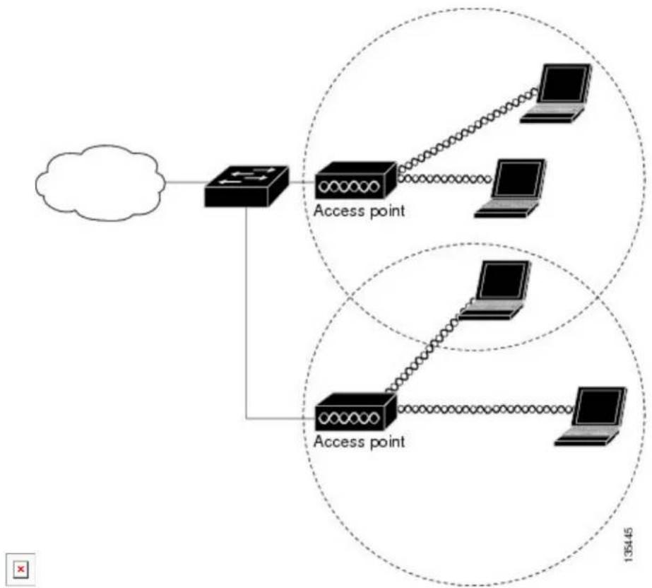
flowchart
graph TD
    A["Cloud"] --> B["Router"]
    B --> C["Access point"]
    C --> D["Laptop"]
    C --> E["Laptop"]
    C --> F["Access point"]
    F --> G["Laptop"]
    F --> H["135445"]
In an all-wireless network, an access point acts as a stand-alone root unit. The access point is not attached to a wired LAN; it functions as a hub linking all stations together. The access point serves as the focal point communications, increasing the communication range of wireless users. Figure below shows an access point in an all-wireless network.
Configuring and Deploying the Access Point
This section describes how to connect the access point to a wireless LAN controller. The configuration pi takes place on the controller. See the Cisco Wireless LAN Controller Configuration Guide for additional information.
The Controller Discovery Process
The access point uses standard Control and Provisioning of Wireless Access Points Protocol (CAPWAP) to communicate between the controller and other wireless access points on the network. CAPWAP is a standard inter-operable protocol which enables an access controller to manage a collection of wireless termination
points. The discovery process using CAPWAP is identical to the Lightweight Access Point Protocol (LWAPI) used with previous Cisco Aironet access points. LWAPP-enabled access points are compatible with CAPWAP and conversion to a CAPWAP controller is seamless. Deployments can combine CAPWAP and LWAPP software on the controllers.
The functionality provided by the controller does not change except for customers who have Layer 2 deployments, which CAPWAP does not support.
In a CAPWAP environment, a wireless access point discovers a controller by using CAPWAP discovery mechanisms and then sends it a CAPWAP join request. The controller sends the access point a CAPWAP join response allowing the access point to join the controller. When the access point joins the controller, the controller manages its configuration, firmware, control transactions, and data transactions.
Note For additional information about the discovery process and CAPWAP, see the Cisco Wireless LAN Controller Software Configuration Guide. This document is available on Cisco.com.
Note CAPWAP support is provided in controller software release 8.5 or later. However, your controller must be running the release that supports Cisco 1100 Series access points.
Note You cannot edit or query any access point using the controller CLI if the name of the access point contain a space.
Note Make sure that the controller is set to the current time. If the controller is set to a time that has already passed, the access point might not join the controller because its certificate may not be valid for that time.
Access points must be discovered by a controller before they can become an active part of the network. The access point supports these controller discovery processes:
- Layer 3 CAPWAP discovery—Can occur on different subnets than the access point and uses IP addresses and UDP packets.
- Locally stored controller IP address discovery—If the access point was previously joined to a controller, the IP addresses of the primary, secondary, and tertiary controllers are stored in the access point's non-volatile memory. This process of storing controller IP addresses on an access point for later deployment is called priming the access point. For more information about priming, see the "Performing a Pre-Installation Configuration" section.
- DHCP server discovery—This feature uses DHCP option 43 to provide controller IP addresses to the access points. Cisco switches support a DHCP server option that is typically used for this capability. For more information about DHCP option 43, see the “Configuring DHCP Option 43” section.
- DNS discovery—The access point can discover controllers through your domain name server (DNS). For the access point to do so, you must configure your DNS to return controller IP addresses in respect to CISCO-CAPWAP-CONTROLLER.localdomain, where localdomain is the access point domain name. Configuring the CISCO-CAPWAP-CONTROLLER provides backwards compatibility in an existing customer deployment. When an access point receives an IP address and DNS information from a DHCP server, it contacts the DNS to resolve CISCO-CAPWAP-CONTROLLER.localdomain. When the DNS sends a list of controller IP addresses, the access point sends discovery requests to the controllers.
Deploying the Access Point on the Wireless Network
Procedure
PurposeCommand or Action
Step 1 Connect and power up the router.
Step 2 Observe the wireless LAN LED (for LED descriptions, see "Checking the Access Point LED" section).
Step 3 that it is not the Master.
NoteReconf MasterthCicscovirelesLADAN co controller should be used only for configuring access points and not in a working network.
Checking the Wireless LAN LED
Note It is expected that there will be small variations in the LED color intensity and hue from unit to unit. is within the normal range of the LED manufacturer's specifications and is not a defect.
The wireless LAN status LED indicates various conditions which are described in Table.
Table 12: Wireless LAN LED
Message MeaningsLED StateMessage Type
DRAM memory test in progressBlinking
DRAM memory test OK
Board initialization in progress
Initializing FLASH file system
FLASH memory test OK
Initializing Ethernet
Ethernet OK
Starting the Cisco AP-OS operating system of the AP
Initialization successful
Message MeaningsLED StateMessage Type
| Chirping GreenAssociation status Normal operating condition, but no wireless client associated | |
| Green | Normal operating condition with at least one wireless client associationSoftware upgrade is in progress.Blinking A |
| Cycling through Green, Red, and Amber | Discovery/join process is in progress. |
| Rapidly cycling through Red, Green, Amber, and off. | Access point location command invoked from controller web interface.Ethernet link is not operational.Blinking Re |
| Blinking AmberBoot loader warning configuration recovery in progress (Mode button pushed for 2 to 3 seconds) | |
| Red | Ethernet failure or image recovery (Mode button pushed for 20 to 30 seconds) |
| Blinking Green | Image recovery in progress (Mode button released)DRAM memory test failureRedBoot loaderFLASH file system failureBlinking Red and off |
| Blinking Red and off | One of the following:Environment variable failureBad MAC addressEthernet failure during image recoveryBoot environment failureNo Cisco image fileBoot failure |
Miscellaneous Usage and Configuration Guidelines
Using the reset command you can reset the AP to the default factory-shipped configuration. hw-module subslot x/y error-recovery password_reset
Note Since this is an IOS command, you must run this command on the Cisco 1100 router console, instead of the AP console.
The AP configuration files are cleared. This resets all configuration settings to factory defaults, including passwords, encryption keys, the IP address, and the SSID. However, the regulatory domain provisioning is not reset.
Important Information for Controller-Based Deployments
Keep these guidelines in mind when you use the Cisco 1100 series access points:
- The access point can only communicate with Cisco wireless LAN controllers.
- The access point does not support Wireless Domain Services (WDS) and cannot communicate with WDS devices. However, the controller provides functionality equivalent to WDS when the access po joins it.
- CAPWAP does not support Layer 2. The access point must get an IP address and discover the con using Layer 3, DHCP, DNS, or IP subnet broadcast.
- The access point console port is enabled for monitoring and debug purposes. All configuration comma are disabled when the access point is connected to a controller.
Deploying Cisco Mobility Express
Pre-Requisites for Deploying Mobility Express Solution
1 It is recommended not to have any other Cisco Wireless LAN Controllers; neither appliance nor virtual in the same network during set up or during daily operation of a Cisco Mobility Express network.
2 Decide on the first Access Point to be configured as a Master Access Point. This Access Point should capable of supporting the Wireless LAN Controller function.
3 A DHCP server must be available on the network so that Access Points and clients can obtain an IP Address. Starting AireOS Release 8.4.100.0 or later, one can configure a DHCP server on the Master Access Point as well but this is typically used for Site Survey.
Connecting Mobility Express Capable Access Point to the Network
Depending on the deployment, Mobility Express capable Access Points can be connected to an access port or a trunk port on the switch.
If Access Points and WLANs are all on the same network, Mobility Express capable Access Points can conn to an access port on the switch as shown below.
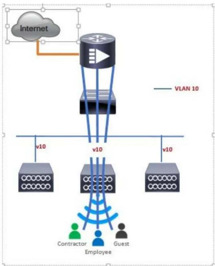
flowchart
graph TD
    A["Internet"] --> B["VLAN 10"]
    B --> C["Router"]
    C --> D["v10"]
    C --> E["v10"]
    C --> F["v10"]
    D --> G["Contractor"]
    E --> H["Employee"]
    F --> I["Guest"]
On Mobility Express, management traffic is untagged. If Access Points and WLANs are all on different VLANs, Mobility Express capable Access Points will connect to a trunk port on the switch and traffic for individual WLANs will be switched locally on individual VLANs. Shown below is a deployment with Access Points and WLANs on different VLANs.
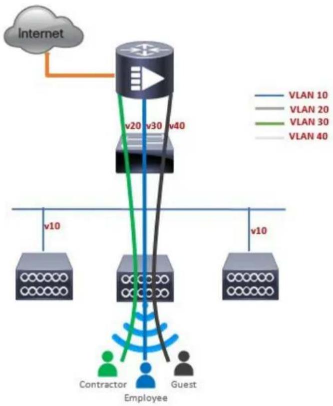
flowchart
graph TD
    A["Internet"] --> B["Router"]
    B --> C["VLAN 10"]
    B --> D["VLAN 20"]
    B --> E["VLAN 30"]
    B --> F["VLAN 40"]
    B --> G["Contractor"]
    B --> H["Guest"]
    B --> I["Employee"]
    style B fill:#f9f,stroke:#333
    style C fill:#bbf,stroke:#333
    style D fill:#bbf,stroke:#333
    style E fill:#bbf,stroke:#333
    style F fill:#bbf,stroke:#333
    style G fill:#dfd,stroke:#333
    style H fill:#dfd,stroke:#333
    style I fill:#dfd,stroke:#333
interface GigabitEthernet1/0/37 description » Connected to Master AP « switchport trunk native vlan 40 switchport trunk allowed vlan 10,20,30,40 switchport mode trunk
Determining image on the Access Point
The Cisco 1100 Series ISR access points can either have CAPWAP image or the Cisco Mobility Express image which is capable of running the virtual Wireless LAN controller function on the Access Point. To determine the image and capability of an Access Point, follow the procedure below:
Procedure
| PurposeCommand or Action | ||
| Step 1 | Login to the Access Point CLI using a console and type AP#show version and check the full output of show version. The default login credentials areUsername:Cisco and Password:Cisco. | |
| Step 2 | If show version output does display AP Image Type and Configuration parameters as highlighted below, it means that AP is running the CAPWAP image and a conversion to Cisco Mobility Express is required if you want to run the controller function on the Access Point. To convert from a CAPWAP AccessPoint to Mobility Express, go Conversion section. | notsc0 ISR-AP1100AC-B ARMv7 Processor rev 5 (v71) with AP016284/594068K bytes of memory.Processor board IDAP Running Image : 8.4.100.0Primary Boot Image : 8.4.100.0Backup Boot Image : 0.0.0.0AP Image type : MOBILITY EXPRESS IMAGEAP Configuration : MOBILITY EXPRESS CAPABLE1 Gigabit Ethernet interfaces2 802.11 Radiosradio FW version : e1c63a0bb171f78c5800c1478007abc1NSS FW version : not availableIf the show version displays AP Image Type: MOBILITY EXPRESS IMAGE and AP Configuration: NOT MOBILITY EXPRESS CAPABLE , it means that even though the Access Point has the Cisco Mobility Express image, it is configured to run as a CAPWA Access Point. In this case Access Point will not run the controller function and will not participate in the Master Election process upon failure of the active Master AP.cisco ISR-AP1100AC-B ARMv7 Processor rev 5 (v71) with 1016284/754820K bytes of memory.Processor board IDAP Running Image : 8.4.100.0Primary Boot Image : 8.4.100.0Backup Boot Image : 0.0.0.0AP Image type : MOBILITY EXPRESS IMAGEAP Configuration : NOT MOBILITY EXPRESS CAPABLE1 Gigabit Ethernet interfaces2 802.11 RadiosRadio FW version : elc63a0bb171f78c5800c1478007abc1NSS FW version : not availableFor this AP to run the controller function, AP Configuration has to be changed to MOBILITY EXPRESS CAPABLE . To change the AP Configuration, execute the following command from the AP CLI. AP#ap-type mobility-express tftp://Access Point will reboot and after it comes up, it will be capable running the controller function. You can check the output of show version again to confirm that AP Configuration has changed to MOBILITY EXPRESS CAPABLE .If the show version displays AP Image Type: MOBILITY EXPRESS IMAGE and AP Configuration: MOBILITY EXPRESS CAPABLE , it means that the Access Point has the Mobility Express image ar is capable of running the controller function. For this scenario, the output of the show version is shown below:cisco ISR-AP1100AC-B ARMv7 Processor rev 5 (v71) with 1016284/594068K bytes of memory.Processor board IDAP Running Image : 8.4.100.0Primary Boot Image : 8.4.100.0Backup Boot Image : 0.0.0.0AP Image type : MOBILITY EXPRESS IMAGEAP Configuration : MOBILITY EXPRESS CAPABLE1 Gigabit Ethernet interfaces2 802.11 RadiosRadio FW version : elc63a0bb171f78c5800c1478007abc1NSS FW version : not available |
Converting Access Point from CAPWAP to Cisco Mobility Express
One can convert an Access Point running CAPWAP to Cisco Mobility Express and vice versa.
Cisco Mobility Express support on 11ac Wave 2 Access Points is introduced in different AireOS releases ar it is important to note that before an Access Point can be converted to Mobility Express, it must have the minimum AireOS CAPWAP image which supported Cisco Mobility Express capability for that Access Point. Given below is the minimum OS release for an Access Point which will support conversion from CAPWAP to Cisco Mobility Express.
| Minimum AircOS Release with CAPWAP imageAccess Point | |
| Cisco IOS XE Everest 16.6.2 ReleaseCisco 1100 Series |

If the CAPWAP image on the Access Point is older than the minimum AireOS release capable of supporting Cisco Mobility Express, Access Point MUST first join a WLC running the minimum AireOS release or higher to upgrade its CAPWAP image. After the CAPWAP image of the AP has been upgraded, conversion of AP from CAPWAP to Mobility Express can be performed.
To perform a conversion on an Access Point running CAPWAP to Mobility Express, follow the procedure below:
Procedure
| Action | PurposeCommand or | |
| Step 1 | Download the conversion image for the Access Point from cisco.com to the TFTP server. It is a tar file. Do not untar the file. The following table lists the Cisco Mobility Express software for Cisco Wireless Release 8.4.100.0. | |
| Step 2 | Login to the Access Point | |
| Step 3 | ExecuteAP#show version on the Access Point CLI. From the show version output, you can determine the AP Image type and AP Configuration and can then proceed with the conversion | Case 1: If the AP Image type is MOBILITY EXPRESS IMAGE and AP configur is NOT MOBILITY EXPRESS CAPABLE, enter the command below to change t AP Configuration to MOBILITY EXPRESS CAPABLE .AP#ap-type mobility-expressExample:Pisco ISR-AP1100AC-E ARMv7 Processor rev 5 (v71) with 1016284/840700K bytes of memory.Processor board IDAP Running Image : 8.4.100.0Primary Boot Image : 8.4.100.0Backup Boot Image : 8.5.107.621 Gigabit Ethernet interfaces2 802.11 RadiosRadio FW version : elc63a0bb171f78c5800c1478007abc1NSS FW version : not availableRouter#ap-type mobility-expressChanging AP Type to Mobility ExpressWriting reload timestamp (Wed May 24 17:17:53 UTC 2017) to diskRouter#[05/24/2017 17:17:54.4699] UBIFS: un-mount UBI device 0, volume 3 [05/24/2017 17:17:54.5199] UBIFS: background thread "ubifs_bgt0_3" stops[05/24/2017 17:17:56.6099] reboot: RestartNote Since the Access Point has AP Image type: MOBILITY EXPRESS IMAG a new image will not be downloaded. After the command is executed, the Access Point will reboot and after it comes up, the AP Configuration will changed to MOBILITY EXPRESS CAPABLE.Case 2 : If the AP Image type and AP Configuration are not available, it means AP is running CAPWAP image. To do the conversion, execute the command belcRouter#ap-type mobility-express tftp:///TFTP Server IP>//Example:Router#ap-type mobility-express tftp://10.74.5.99/8.4CCO/aplg5Starting the ME image download...It may take a few minutes to finish download.If it is longer, please abort command, check network connection and try again#######100.0%Image transfer complete.Image downloaded, writing to flash...do CHECK_ME, part1 is active partImage signing verify success.upgrade.sh: btldr rel is 33 vs 33, does not need updateupgrade.sh: part to upgrade is part2upgrade.sh: activate part2, set BOOT to part2upgrade.sh: AP primary version: 8.4.100.0Archive done.[*10/11/2017 23:05:22.7599] AP Type changed: CAPWAP to ME. AP Mode changed to flexconnect. AP Rebooting...[*10/11/2017 23:05:22.7699] AP Rebooting: Reset Request from Controller(AP Type Changed from CAPWAP to ME)Writing reload timestamp (Wed Oct 11 23:05:22 UTC 2017) to diskM-P2B#[10/11/2017 23:05:23.9699] UBIFS: un-mount UBI device 0, volume 3[10/11/2017 23:05:24.0199] UBIFS: background thread "ubifs_bgt0_3" stopsThe system is going down NOW!Sent SIGKILL to all processes.1099]Requesting system reboot99][10/11/2017 23:05:26.1099] reboot: RestartingNote After the image download is complete, it will be written to the flash followe by a reboot. After the AP comes up, AP Image type will be MOBILITY EXPRESS IMAGE and AP Configuration will MOBILITY EXPRESS CAPABLE . |
| Step 4 | If this is the first Access Point in the network, it will start the controller function and will broadcast the CiscoAirProvision SSID. |
Converting Access Point from Cisco Mobility Express to CAPWAP
There are typically two reasons why one would want to convert an Access Point running Mobility Express image to CAPWAP. There are as follows:
1 You want to keep the Access Point in a Mobility Express deployment but do not want the Access point to participate in the Master election process upon a failover of the Master AP.
2 You want to migrate one or more Access Points with Mobility Express to an appliance or vWLC based deployment.
1 If your reason to convert to CAPWAP is 1 above, follow the procedure below:
a Login to the Access Point CLI either through console or ssh and go to exec mode. If you are try convert the Master AP to CAPWAP, connecting a console will lead you to the controller CLI. To the AP CLI, type apciscochell at the controller prompt and login to the Access Point shell.
b Execute ap#ap-type capwap CLI. This will change the AP Configuration to NOT MOBILITY EXPREF and the Access Point will no longer participate in the Master election process.
2 If your reason to convert to CAPWAP is 2 above, follow the procedure below:
a Login to the Access Point CLI either via console or ssh and go to exec mode.
b Execute the following CLI.
(Cisco Controller) >config ap unifiedmode <switch_name> <switch_ip_address>
<switch_name> and <switch_ip_address> is the name and IP address respectively of the WLC to which the APs need to be migrate.

The above command converts all connected Access Points with AP Configuration: MOBILITY EXPRESS CAPABLE to AP Configuration: NOT MOBILITY EXPRESS CAPABLE. When this command is issued, the APs are reloaded, and they come back up and look for the controller (switch_ip_address) to join.
Configuring Cisco Mobility Express controller
CLI Setup Wizard
To use the Setup Wizard from CLI, you must connect to the console port of the Access Point. The def parameters for the console ports are 9600 baud, eight data bits, one stop bit, and no parity. The console do not support hardware flow control.
After connecting to the console port on the Access Point, power up the Access Point. After a few minu Access Point will start the Controller.
To configure the Mobility Express controller, follow the steps as shown in the example below:
System Name [Cisco_2c:3a:40] (31 characters max): me-wlc
Enter Country Code list (enter 'help' for a list of countries) [US]:
Configure a NTP server now? [YES][no]: no
Configure the system time now? [YES][no]: no
Note! Default NTP servers will be used
Management Interface IP Address: 40.40.40.10
Management Interface Netmask: 255.255.255.0
Management Interface Default Router: 40.40.40.1
Cleaning up Provisioning SSID
Create Management DHCP Scope? [yes][NO]: yes
DHCP Network : 40.40.40.0
DHCP Netmask : 255.255.255.0
Router IP: 40.40.40.1
Start DHCP IP address: 40.40.40.11
Stop DHCP IP address: 40.40.40.254
DomainName :
DNS Server : [OPENDNS][user DNS]
Create Employee Network? [YES][no]: YES
Employee Network Name (SSID)?: WestAutoBody-Employee Employee VLAN Identifier? [MGMT][1-4095]: MGMT Employee Network Security? [PSK][enterprise]: PSK Employee PSK Passphrase (8-38 characters)?: Cisco123 Re-enter Employee PSK Passphrase: Cisco123 Create Guest Network? [yes][NO]: YES Guest Network Name (SSID)?: WestAutoBody-Guest Guest VLAN Identifier? [EMPLOYEE][1-4095]: EMPLOYEE Guest Network Security? [WEB-CONSENT][psk]: WEB-CONSENT Create Guest DHCP Scope? [yes][NO]: NO Enable RF Parameter Optimization? [YES][no]: YES Client Density [TYPICAL][Low][High]: TYPICAL Traffic with Voice [NO][Yes]: Yes
Configuration correct? If yes, system will save it and reset. [yes][NO]: yes Cleaning up Provisioning SSID
Note The Access Point will reboot and after it comes back up, login to the Mobility Express controller WebUI from the browser using https://
Over-the-Air Setup Wizard
Over-the-air is a simple and easy way to configure Mobility Express out of the box. Over-the-Air provision can be done using a WiFi enabled device or the Cisco Wireless app which can be downloaded from App S for iOS devices and Play Store for Android Devices. The Cisco Wireless app provides a minimum set of configurable options to deploy Mobility Express in just a few minutes.
Procedure
PurposeCommand or Action
Step 1 Note Which the Air Division the SAEcess Broadcastirps green, connect a WiFi enabled laptop to 2.4GHz.
green, connect a WiFi enabled laptop to the CiscoAirProvision SSID. The default password is password. The laptop will get an IP address from subnet 192.168.1.0/24.
Step 2 Open a web browser and browse to http://mobilityexpress.cisco. This will redirect to configuration wizard and the admin account page will appear.
Step 3 Create an admin account on the controller·Enter the admin username. Maximum up to 24 by specifying the following parameters ASCII characters.
- Enter the password. Maximum up to 24 ASCII characters. When specifying a password, ensure that:
- The password must contain characters from at least three of the following classes -
PurposeCommand or Action
lowercase letters, uppercase letters, digits, special characters.
* No character in the password can be repeated more than three times consecutively.
• The new password must not be the same as the associated username and the username reversed.
The password must not be cisco, ocsic, or any variants obtained by changing the capitalization of letters of the word Cisco. In addition, you cannot substitute 1, 1, or ! for i, 0 for o, or S for s.
Step 4 In the Set up Your Controller section, configure the following:
- Enter the System Name
- Select the Country from the drop-down list
- Date and Time should be auto-filled but one can manually configure it as well
- Select the Timezone from the drop-down list
- Enter the IP address of NTP Server if there is one available. If left blank, NTP Pools will be automatically configured
- Enter the Management IP Address of the controller
- Enter the Subnet Mask
- Enter the Default Gateway
Step 5 Disable Enable DHCP Server(Management Network) if an external DHCP server is being used. If internal DHCP server on the Mobility Express controller has to be used, specify the DHCP server related information.
Step 6 Click Next.
Step 7 In the Create Your Wireless Network, under Employee Network, configure the following:
- Enter the Network Name
- Select Security as WPA2 Personal or WPA2 Enterprise from the drop-down list
- If WPA2 Personal is selected, enter the Passphrase
Step 8 One can also enable RF Parameter Optimization and configure the following:
- Move the Client Density slider as needed
PurposeCommand or Action
- From the Traffic Type, select Data or Data and Voice
Step 9 Click Next.
Step 10
on the Apply button. The Access Point will reboot and after it comes up, it will run the controller.
NoteConfirm Accessetting with other page and click it comes
back up, login to the Mobility Express controller WebUI from the browser using https:
Network Plug and Play
Introduction
The Cisco Network Plug and Play solution provides a simple, secure, unified, and integrated offering for enterprise network customers to ease new site rollouts for provisioning Cisco Mobility Express. The solution allows use of Cloud Redirection service, on-prem, or combination which provide a unified approach to provision enterprise networks comprised of Cisco Mobility Express, Cisco routers, switches, with a near zero touch deployment experience.
You can use the Cisco Network Plug and Play application to pre-provision the site and add Cisco Mobility Express capable access points to the site. This includes entering access point information and uploading a controller configuration file for virtual controller which will run on Mobility Express capable access points.
When an installer installs and powers up the Cisco Mobility Express capable access points, it auto-discovers the Cisco APIC-EM controller by using the DHCP, DNS or cloud redirection service. After the auto-discove process is complete, the AP downloads the controller configuration file from local PnP server, or communicated with the cloud redirection service for direction to target PnP server.
Pre-Requisites
- APIC-EM Release 1.4 with Cisco Network Plug and Play, virtually hosted in a Cisco UCS or equivale server.
- Access Points–Cisco 802.11ac Wave 2 access points running Cisco Mobility Express software.
- Controller Configuration–Cisco Mobility Express controller configuration file to be uploaded on Network PnP.
APIC-EM Discovery Options
1 DHCP server configured with option 43 to allow Cisco Mobility Express capable access points to auto-discover the APIC-EM controller (option 43 is not required if only testing cloud redirection). DH option 43 consists of a string value that is a configured DHCP server: option 43 ascii "5A1N;B2;K4;I192.168.1.123;J80"
192.168.1.123 is the IP address of the APCI-EM ServerNote
2 On-prem PnP server can be added to DNS using 'pnpserver.yourlocal.domain' If DHCP discovery fails to get the IP address of the APIC-EM controller, for example, because option 43 is not configured, t Cisco Plug and Play Agent falls back on a DNS lookup method. Based on the network domain name returned by the DHCP server, it constructs a fully qualified domain name (FQDN) for the APIC-EM controller, using the preset hostname pnpserver. For example, if the DHCP server returns the domain "customer.com", the Cisco Plug and Play IOS Agent constructs the FQDN "pnpserver.customer.com It then uses the local name server to resolve the IP address for this FQDN
Cloud redirection service requires a connection to the internet, and valid DNS server that can resolve 'devicehelper.cisco.com'. The cloud redirection service redirect Cisco Mobility Express Access Point to APIC-EM.
Configuring APIC-EM / Network PnP Server
Site Pre-Provisioning Workflow
Cisco Network Plug and Play allows you to pre-provision and plan for new sites. When you create a no Cisco Network Plug and Play enables you to pre-provision Cisco Mobility Express access point(s) control configuration file, product ID, and product serial # for selected Access Points. This simplifies and acceler the time that it takes to get a site fully functional.
To pre-provision a site on your network, perform these steps:
Procedure
PurposeCommand or A
Step 1 Importing Cisco Mobility Express controller configuratio
Step 2 Creating a Project
Step 3 Adding Cisco Mobility Express capable Access Point to the Project and associating the controller config.
Importing Cisco Mobility Express Configuration File to Network PnP
Procedure
| Action | PurposeCommand or | |
| Step 1 | Login to APIC-EM controller and navigate to Network Plug and Play > Configurations | |
| Step 2 | Click on Upload to upload the controller configuration. | |
| Step 3 | Select a controller configuration file from your local machine. |
Network Plug and Play
| Action | PurposeCommand or |
Creating a Project
Procedure
| orAction | PurposeCommand | |
| Step 1 | Navigate to Network Plug and Play > Projects. | |
| Step 2 | Enter the name for the Project and click on the Add button. |
Network Plug and Play
| orAction | PurposeCommand | |
| Step 3 | Click on the Create button to create the Project. |
Network Plug and Play
| orAction | PurposeCommand |
PurposeCommand
or
Action
Step 4
Adding Cisco Mobility Express Capable Access Point to the Project and Associating the Controller Configuration
Procedure
PurposeCommand
or Action
Step 1 Navigate
to
Network
Plug and
Play >
Projects.
Step 2 Click on
Add
button
under
Project
Devices.
Step 3 In the
Add
Device
window,
enter the
following:
- Device Name—Enter the device name; unique for each site
- Product ID–Select the Access Point device ID from the drop-down list
- Serial Number–Enter the Serial Number of the Mobility Express Access Point
- Config–You can either upload a new configuration or select the configuration file which was
Network Plug and Play
| or Action | PurposeCommand | |
| Step 4 | Click the Add button. |
Network Plug and Play
| or Action | PurposeCommand |
APIC-EM Network Plug and Play Deployment Options with Cisco Mobility Express
There are two deployment options supported for deploying Cisco Mobility Express with Network Plug and Play.
APIC-EM controller in Private Cloud
In this deployment option, there will be an On-Prem APIC-EM controller which can be discovered by C Mobility Express Access Points using option 43 or DNS discovery.
Figure 2: APIC-EM controller in Private Cloud flow
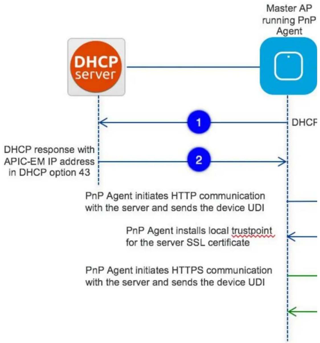
flowchart
graph TD
    A["DHCP server"] --> B["Master AP running PnP Agent"]
    B --> C["DHCF"]
    C --> D["1"]
    C --> E["2"]
    D --> F["DHCP response with APIC-EM IP address in DHCP option 43"]
    E --> F
    F --> G["PnP Agent initiates HTTP communication with the server and sends the device UDI"]
    G --> H["PnP Agent installs local trustpoint for the server SSL certificate"]
    H --> I["PnP Agent initiates HTTPS communication with the server and sends the device UDI"]
Option 43 points to APIC-EM controller IP address. To configure DHCP scope with Option 43, it is important to follow the format as shown below. In the example below, 192.168.1.123 is the IP address of APIC-EM controller.
ip dhcp pool pnp_device_pool
network 192.168.1.0 255.255.255.0
default-router 192.168.1.1
option 43 ascii "5A1N;B2;K4;I192.168.1.123;J80"
To discover APIC-EM controller using the DNS discovery options, configure the DNS server and domain name on the DHCP scope.
ip dhcp pool pnp_device_pool
network 192.168.1.0 255.255.255.0
default-router 192.168.1.1
domain-name cisco.com
dns-server 172.20.229.8
Cloud Plug and Play Connect Redirect to APIC-EM Controller
Cloud re-direction service uses Cisco public hosted cloud to re-direct Cisco Mobility Express capable access points to APIC-EM controller. The minimal requirement is that the Mobility Express Access Points network have DHCP and DNS, and connectivity reachable to Cisco public cloud. There is no need to configure Opt
43 on DHCP scope with this deployment option. A simple test would be to obtain DHCP address and p 'devicehelper.cisco.com' from where the Mobility Express AP will be deployed.
Figure 3: Cloud Plug and Play Device Redirect to APIC-EM controller flow
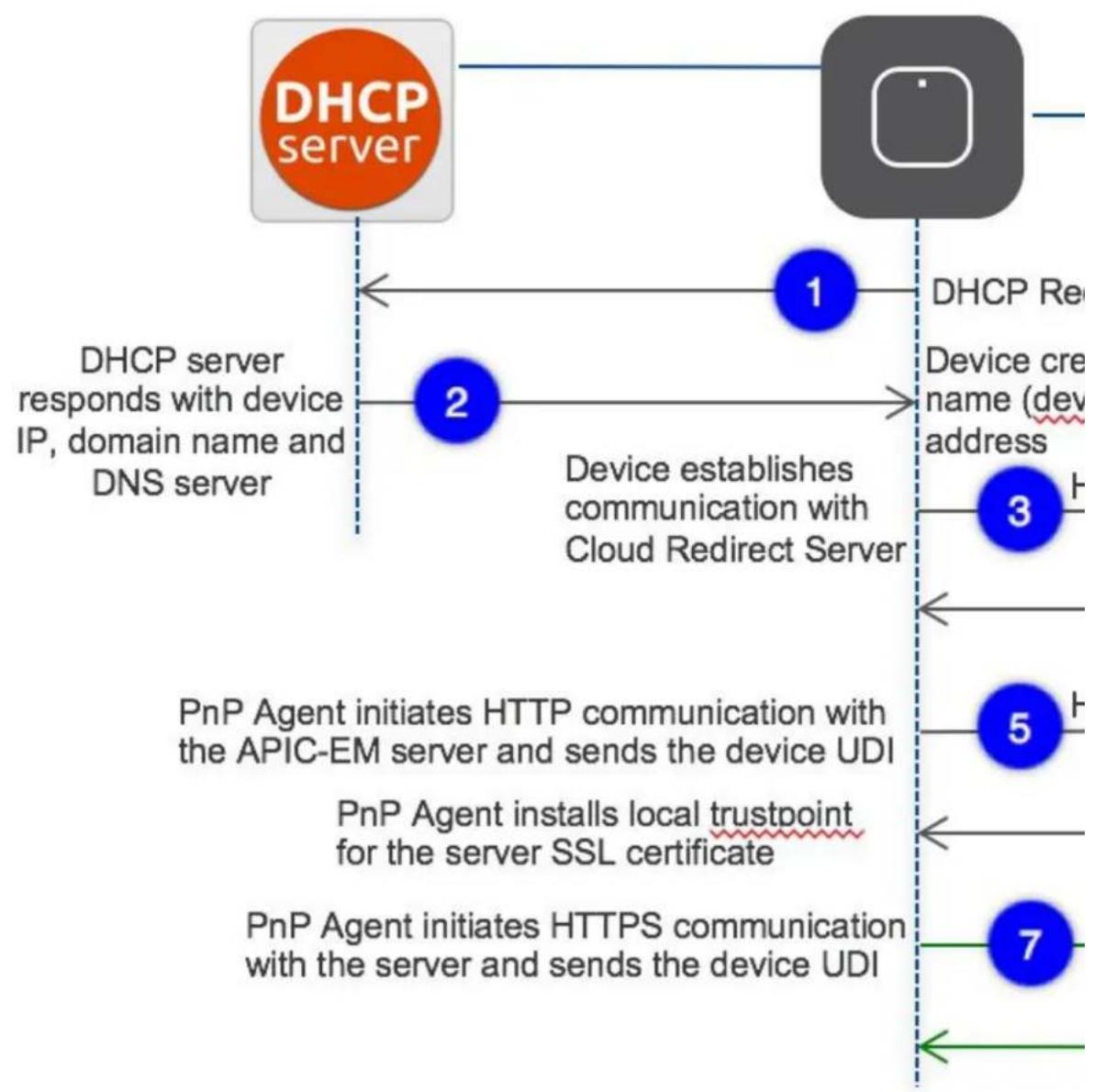
flowchart
graph TD
    A["DHCP server"] --> B["1"]
    B --> C["2"]
    C --> D["3"]
    D --> E["4"]
    E --> F["5"]
    F --> G["6"]
    G --> H["7"]
    I["DHCP server responds with device IP, domain name and DNS server"] --> C
    J["Device creates name (dev address)"] --> D
    K["PnP Agent initiates HTTP communication with the APIC-EM server and sends the device UDI"] --> E
    L["PnP Agent installs local trustpoint for the server SSL certificate"] --> G
    M["PnP Agent initiates HTTPS communication with the server and sends the device UDI"] --> H

Cloud Plug and Play Device Redirect Provisioning Workflow
This section describes the steps to redirect Cisco Mobility Express Access Points to APIC-EM controller using Cloud Plug and Play Connect service.
To configure cloud Plug and Play connect redirect service, perform the following steps:
1 Obtain a Smart Account
2 Create APIC-EM Controller Profile
3 Adding Mobility Express capable Access Point to the Devices list
4 Associate Mobility Express capable Access Point to APIC-EM Controller profile
Obtain a Smart Account
Procedure
| PurposeCommand or Action | ||
| Step 1 | Go to http://software.cisco.com | |
| Step 2 | Request a Smart Account or Log In (existing Smart Account holders). |   Download & Upgrade Software Download Download new software or updates to your current software eDelivery Get fast electronic fulfillment of software, licenses, and documentation Download & Upgrade Software Download Download new software or updates to your current software eDelivery Get fast electronic fulfillment of software, licenses, and documentation |
| Step 3 | Click on Controller Profiles. Select a Virtual Account. If you do have one, create a Virtual Account first. | |
| Step 4 | Click on the Add Profile to create a new controller profile. | |
| Cisco Software Central > Device Redirect Device Redirect Devices | Controller Profiles Virtual Account: TME Add Profile... Edit... Delete Make Default Sh Profile Name Controller Typ TME-APIC-EM PNP SERVEF |
PurposeCommand or Action
Step 5 Select Controller Type as PNP Server from the drop-down list and click on Next.
Step 6 Enter the following and click Next.
- Profile Name
- Description
- Select IPv4 or IPv6, HTTP or HTTPS and enter the IP address if the PN
Note If you select HTTPS, then you would have import a SSL certificate. Also, option
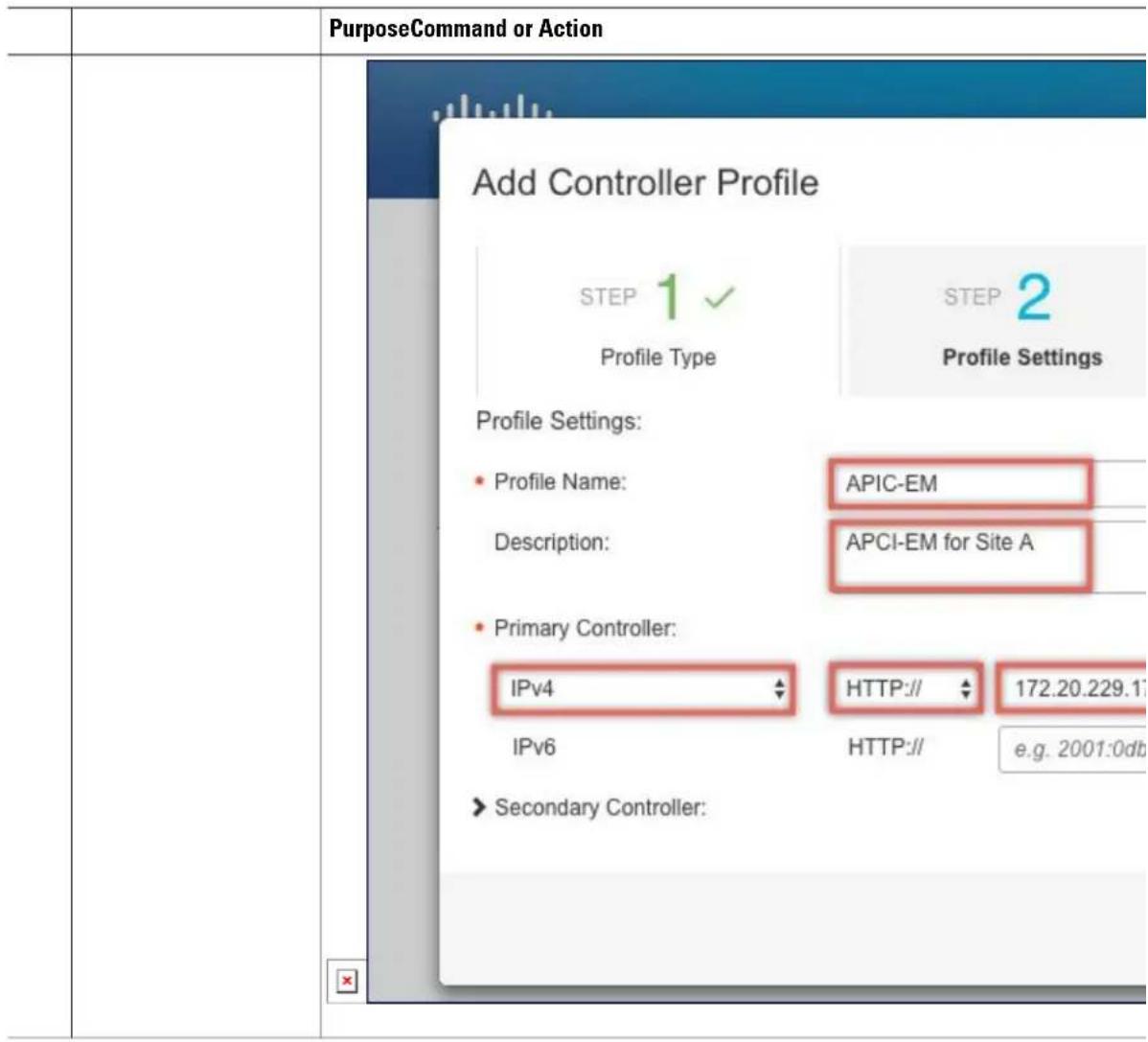
text_image
PurposeCommand or Action Add Controller Profile STEP 1 ✓ Profile Type STEP 2 Profile Settings Profile Settings: • Profile Name: APIC-EM Description: APCI-EM for Site A • Primary Controller: IPv4 HTTP:// 172.20.229.17 IPv6 HTTP:// e.g. 2001:0db ► Secondary Controller:| PurposeCommand or Action | |||
| Step 7 | Review the entries and click on Submit button to add the Controller Profile and finally click Done. | ||
| Add Controller Profile STEP 1 √ Profile Type | STEP 2 √ Profile Settings | ||
| Review the following options to make sure they are correct before y | |||
| Profile Type: Controller Type: | PNP SERVER | ||
| Profile Settings: Profile Name: | APIC-EM | ||
| Description: | APCI-EM for Site A | ||
| Primary IPv4 Address: | 172.20.229.17 | ||
| Primary Protocol: | http | ||
| Primary Port: | 80 | ||

text_image
PurposeCommand or Action Add Controller Profile STEP 1 ✓ Profile Type STEP 2 ✓ Profile Settings ✓ The controller profile "APIC-EM" was successfully created. Profile Name Controller Type TME-APIC-EM PNP SERVECreate APIC-EM Controller Profile
Procedure
| PurposeCommand or Action | ||
| Step 1 | Go to http://software.cisco.com and login | |
| Command or Action | Purpose | |
| Step 2 | Navigate to Provisioning >Plug and Play Connect |  Products & Services Su Cisco Software Central [KCT] Order Download & Upgr Products & Services Su Cisco Software Central [KCT] Order Download & Upgr  Download & Upgrade Software Download Download new software or updates to your current software eDelivery Get fast electronic fulfillment of software, licenses, and documentation Download & Upgrade Software Download Download new software or updates to your current software eDelivery Get fast electronic fulfillment of software, licenses, and documentation |
| Step 3 | Click on Controller Profiles. Select a Virtual Account. If you do have one, create a Virtual Account first. | |
| Step 4 | Click the Add Profile to create a new controller profile. | |
| Step 5 | Select Controller Type as PNP Server from the drop-down list and click on Next. | |
| Step 6 | Enter the following and click Next. | • Profile Name • Description • Select IPv4 or IPv6, HTTP or HTTPS and enter the IP address if the PNP ServerPurposeCommand or Action |
| Note If you select HTTPS, then you would have import a SSL certificate. Also, op | ||
| Step 7 | Review the entries and click on Submit button to add the Controller Profile and finally click Done. |
Adding Cisco Mobility Express capable Access Point to the Devices List
Procedure
| Action | PurposeCommand or | |
| Step 1 | Navigate to Provisioning > Plug and Play Connect. Click on Devices. | |
| Step 2 | Click on Devices. Select a Virtual Account. If you do have one, create a Virtual Account first. | |
| Step 3 | Click on Add Devices button to add a new device (Mobility Express Access Point). |
APIC-EM Network Plug and Play Deployment Options with Cisco Mobility Express
| Action | PurposeCommand or | ||
| Action | PurposeCommand or | ||
| Step 4 | Import a csv file with the Device info or select Enter Device info manually. Click Next. |  Products & Services Support Products & Services Support | |
| Cisco Software Central > Plug and Play ConnectPlug and Play Connect | |||
| Devices Controller Profiles Configurations BETA Configuration Ten | |||
| Virtual Account: TME | |||
| Add Device(s) | |||
| STEP 1 Identify Source | STEP 2 Identify Device(s) | ||
| Identify SourceSelect one of the following two options to add devices: | |||
| [1500] Import using a CSV file | |||
| [1534] Enter Device info manually | |||
| Also add Configuration to the Device BETA | |||
| Cancel | |||
| Contacts | Feedback | Help | Site Map | Terms & Conditions | Privacy Statement | |||
APIC-EM Network Plug and Play Deployment Options with Cisco Mobility Express
| Action | PurposeCommand or | |
| Step 5 | Click onIdentifyDevicebutton. TheIdentifyDevicewindow willpop up. EnterSerialNumber,select BasePID, andControllerProfile(createdearlier). Clickon the Savebuttonfollowed byNext button. | 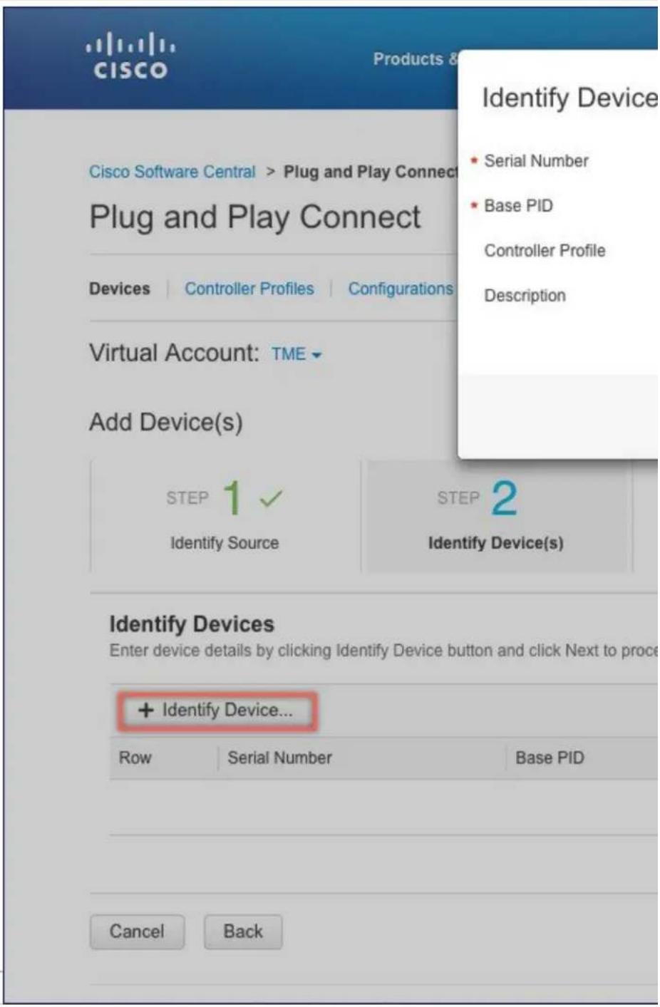 |
APIC-EM Network Plug and Play Deployment Options with Cisco Mobility Express
| Action | PurposeCommand or | |||
| Action | PurposeCommand or | |||
| Step 6 | Review the entries and click on Submit button to add the Device. Finally, click Donc. |  Products & Services Support Products & Services Support | ||
| Cisco Software Central > Plug and Play ConnectPlug and Play Connect | ||||
Devices | Controller Profiles | Configurations  | Configuration Ten | Configuration Ten | ||||
| Virtual Account: TME ▼Add Device(s) | ||||
| STEP 1 ✓Identify Source | STEP 2 ✓Identify Device(s) | |||
| Attempted to add 1 device(s)[zxeg] Successfully added 1 device(s) !It may take a few minutes for the new devices to show up in the D | ||||
| Contacts | Feedback | Help | Site Map | Terms & Conditions | Privacy Statement | ||||
APIC-EM Network Plug and Play Deployment Options with Cisco Mobility Express
| Action | PurposeCommand or | ||
| Action | PurposeCommand or | ||
| Step 7 | Verify that the Device has been added and the status is Pending (Redirection). |  Products & Services Support Products & Services Support | |
| Cisco Software Central > Plug and Play ConnectPlug and Play Connect | |||
Devices | Controller Profiles | Configurations  | Configuration Ten | Configuration Ten | |||
Virtual Account: TME ▼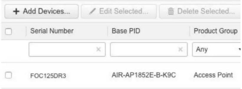 | |||
| Contacts | Feedback | Help | Site Map | Terms & Conditions | Privacy Statement | |||
| Action | PurposeCommand or | ||
Connecting Cisco Mobility Access Points
To bring up a new Mobility Express site, make sure that Plug and Play service has been configured with Mobility Express Access Points with related controller configuration. If APIC-EM controller in Private Cloud deployment option is used, Option 43 or DNS discovery on DHCP scope must be configured. If Cloud Plug and Play Connect redirect to APIC-EM controller deployment option is used, make sure all the related configuration on Cloud Plug and Play Connect has also been done for successful redirect to APIC-EM controller.
Now, it is time to connect the Mobility Express Access Points at the site. One may connect one or more than 20 points at a site. It is important to note that if multiple Mobility Express Access Points are connected at a Master Election will happen first and only after Master Access Point has been elected, it will initiate communication with the Network Plug and Play service and download the controller configuration file regardless of the deployment option. The other Access Points will not initiate communicate with the Network Plug and Play service. After the controller configuration file has been downloaded on the Access Point, it will reboot and after it comes up, it will run the controller. The rest of the Access Points at the site will join Master Access Point as Subordinate Access Points.
Using internal DHCP server on Cisco Mobility Express
Creating a DHCP Scope
Internal DHCP server can be enabled and DHCP scope created during Day 0 from Setup Wizard as well as in Day 1 using the controller WebUI. Typically, one would create DHCP scopes in Day 1 if they want to associate the scopes with WLANs.
To create a scope and associate it to a WLAN using the controller WebUI, follow the procedure below:
Procedure
| or Action | PurposeCommand | |
| Step 1 | Navigate to Wireless Settings > DHCP Server > Add new Pool . The Add |
PurposeCommand
or Action
DHCP
Pool
window
will pop
up.
Step 2 On the
Add
DHCP
Pool
window.
Enter the
following
fields:
- Enter the Pool Name for the WLAN
- Enable the Pool Status
- Enter the VLAN ID for the WLAN
- Enter the Lease Period for the DHCP clients. Default is 1 Day
- Enter the Network/Mask
- Enter the Start IP for the DHCP pool
- Enter the End IP for the DHCP pool
- Enter the Gateway IP for the DHCP pool
- Enter the Domain Name (Optional) for the DHCP pool
- For Name Servers, select User Defined if one needs to enter IP addresses of Name Servers or in which case OpenDNS Name Server IP addresses are automatically populated
Step 3 Click
Apply.
Step 4 After
creating
the
scope, it
is time to
assign
the
VLAN
mapped
to the
DHCP
scope to
the
WLAN.
To assign
a VLAN
to
WLAN,
navigate
to
Wireless
Settings
PurposeCommand
or Action
> WLANs .
Step 5 If the
WLAN
does not
exist,
create a
WLAN
or if one
does
exist, edit
the
existing
WLAN
and click
on the
VLAN
and
Firewall
tab.
Step 6 On the
VLAN
and
Firewall
tab,
configure
the
following:
- Select Yes for Use VLAN Tagging
- Enter the Native VLAN ID
- Select the DHCP Scope which was created previously for the WLAN. VLAN ID should be auton populated after the DHCP scope is selected
| or Action | PurposeCommand | |||||
| Add new WLAN | ||||||
| General | WLAN Security | VLAN & Firewall | Traffic Shaping | |||
| Use VLAN Tagging Yes | ||||||
| Native VLAN ID 122 | ||||||
| DHCP Scope WiFi-Guest | VLAN ID * 20 | |||||
| Enable Firewall No | ||||||
| VLAN and Firewall configuration apply to all WLANs | Apply | |||||
| Step 7 | Click Apply. | |||||
Configuring Cisco Mobility Express for Site Survey
Cisco 802.11ac Wave 2 access points are capable of running Cisco Mobility Express which a virtual wir controller function embedded on an Access Point.
Cisco Mobility Express access point running the wireless controller function will also provide wireless connectivity to the clients. It also supports internal DHCP server which enables Access Point to be used Site Survey.
Introduction
Cisco 802.11ac Wave 2 access points are capable of running Cisco Mobility Express which a virtual wir controller function embedded on an Access Point.
Cisco Mobility Express access point running the wireless controller function will also provide wireless connectivity to the clients. It also supports internal DHCP server which enables Access Point to be used for Site Survey.
Configuring Mobility Express for Site Survey Using CLI
Procedure
PurposeCommand or Action
Step 1 Connect to the console of the Access Point.
Step 2 Power up the Access Point using a power adapter or battery pack.
Step 3 Wait for the Access Point to boot up completely such that it is running the Wireless Controller and is waiting to be configured.
Step 4 Configure the Wireless Note Controller using the CLI Setup Wizard:
For Site Survey, a DHCP server is required and is supported on Cisco Mobility Express. DHCP Server configuration highlighted below is mandatory if you want to enable DHCP server on Cisco Mobility Express.
Would you like to terminate autoinstall? [yes]:yes
Enter Administrative User Name (24 characters max):admin
Enter Administrative Password (3 to 24 characters max):Cisco123
Re-enter Administrative Password: Cisco123
System Name:[Cisco_3a:d2:b4] (31 characters max):me-wlc
Enter Country Code list(enter 'help' for a list of countries) [US]:US
Configure a NTP server now?[YES][no]:no
Configure the system time now?[YES][no]:yes
Enter the date in MM/DD/YY format:02/28/17
Enter the time in HH:MM:SS format:11:30:00
Enter timezone location index(enter 'help' for a list of timezones):5
Management Interface IP Address: 10.10.10.2
Management Interface Netmask: 255.255.255.0
Management Interface Default Router: 10.10.10.1
Create Management DHCP Scope?[yes][NO]:yes
DHCP Network: 10.10.10.0
DHCP Netmask: 255.255.255.0
Router IP: 10.10.10.1
Start DHCP IP address: 10.10.10.10
Stop DHCP IP address: 10.10.10.250
DomainName: mewlc.local
DNS Server:[OPENDNS][user DNS]OPENDNS
Create Employee Network?[YES][no]:yes
Employee Network Name(SSID)?:site_survey
| PurposeCommand or Action | ||
| Employee VLAN Identifier?[MGMT][1-4095]:MGMTEmployee Network Security?[PSK][enterprise]:PSKEmployee PSK Passphrase (8-38 characters)?: Cisco123Re-enter Employee PSK Passphrase:Cisco123Re-enter Employee PSK Passphrase:Cisco123Create Guest Network? [yes][NO]:NOEnable RF Parameter Optimization?[YES][no]:noConfiguration correct? If yes, system will save it and reset.[yes][NO]:yes | ||
| Step 5 | Wait for the Access Point to boot up completely. After the Wireless controller has started, log back in to the controller using administrative username or password configured during the initial setup wizard. | |
| Step 6 | (Optional): During the CLI setup wizard, Employee Network Security was configured to PSK This can be disabled for easy association of clients and also disable SSID broadcast to avoid unwanted clients from joining the SSID. To disable PSK and SSID broadcast, enter the following commands in the Controller CLI. | Cisco Controller)>config wlan disable 1(Cisco Controller)>config wlan security wpa disable 1(Cisco Controller)>config wlan broadcast-ssid disablewlan 1(Cisco Controller)>config wlan enable 1(Cisco Controller)>save config |
| Step 7 | To configure channel, TX power, and channel bandwidth for the radios, disable the radio first, make the changes and then re-enable it. | To change the 2.4GHz radio to channel 6, follow the steps below:(Cisco Controller)>config 802.11b disable6(Cisco Controller)>config 802.11b enableTo change the 2.4GHz radio Transmit Power to power level 3, follow the steps below:(Cisco Controller)>config 802.11b disable3(Cisco Controller)>config 802.11b txPower44(Cisco Controller)>config 802.11a enableTo change the 5 GHz radio to channel 44, follow the steps below:(Cisco Controller)>config 802.11a disable44(Cisco Controller)>config 802.11a txPowername> 5(Cisco Controller)>config 802.11a enableTo change the 5 GHz radio channel width to 40MHz, follow the steps below:(Cisco Controller)>config 802.11a disable(Cisco Controller)>config 802.11a chan_width40(Cisco Controller)>config 802.11a enableIf access points are being used for Site Survey, please note the following with respect to the XOR radio.1 Default operation state of XOR radio is 2.4GHz.2 When the XOR (2.4 GHz) radio is configured to operate at 5GHz, 100MHz frequency separation is required from dedicated 5GHz radio.3 When the XOR radio is configured to operate in 5GHz mode on an internal (I) Access Points, the Transmit power (tx) power will be fixed and cannot be modified.4 One can configure the XOR radio on internal (I) Access Points from 2.4GHz to 5 and vice versa. On an external (E) Access Point, one must have an external antenna plugged into the DART connector prior to changing any configuration on the XOR radio.5 To configure the XOR (2.4GHz) radio to operate at 5GHz on Access Points, follow the steps below:(Cisco Controller)>config 802.11-abgn disable ap(Cisco Controller)>config 802.11-abgn role ap manual client-serving(Cisco Controller)>config 802.11-abgn band ap ap 5GHz(Cisco Controller)>config 802.11-abgn enable apTo configure the XOR radio operating at 5 GHz to channel 40, follow the steps below:(Cisco Controller)>config 802.11-abgn disable ap(Cisco Controller)>config 802.11-abgn channel ap ap 40(Cisco Controller)>config 802.11-abgn enable apTo configure the XOR radio operating at 5 GHz channel width to 40MHz, follow the steps below:(Cisco Controller)>config 802.11-abgn disable ap(Cisco Controller)>config 802.11-abgn chan_width ap 40(Cisco Controller)>config 802.11-abgn enable ap |
Creating Wireless Networks
Cisco Mobility Express solution supports a maximum of 16 WLANs. Each WLAN has a unique WLAN (1 through 16), a unique Profile Name, SSID, and can be assigned different security policies.
Access Points broadcast all active WLAN SSIDs and enforce the policies that you define for each WLAN. You can configure WLANs with different service set identifiers (SSIDs) or with the same SSID. An SSI identifies the specific wireless network that you want the controller to access. Creating WLANs with the SSID enables you to assign different Layer 2 security policies within the same wireless LAN. To distinguish among WLANs with the same SSID, you must create a unique profile name for each WLAN. WLANs have the same SSID must have unique Layer 2 security policies so that clients can make a WLAN selection on information advertised in beacon and probe responses.
A number of WLAN Security options are supported on Cisco Mobility Express solution and are outlined below:
1 Open
2 WPA2 Personal
3 WPA2 Enterprise (External RADIUS, AP)
For Guest WLAN, a number of capabilities are supported:
1 CMX Guest Connect
2 WPA2 Personal
3 Captive Portal (AP)
4 Captive Portal (External Web Server)
Creating Employee WLANs
.
Creating Employee WLAN with WPA2 Personal
Procedure
PurposeCommand of
Step 1 Navigate to Wireless Settings > WLANs and then click on Add new WLAN button. The Add new WLAN Window will pop up.
Step 2 In the Add new WLAN window, on the General page, configure the following:
Step 3 Click on the WLAN Security and configure the following:
Step 4 Click Apply.
Creating Employee WLAN using WPA2 Enterprise with External Radius Server
Procedure
PurposeCommand or A
| Step 1 | Navigate to Wireless Settings > WLANs and then click on Add new WLAN button. The Add new WLAN Window will pop up. |
| Step 2 | In the Add new WLAN window, on the General page configure the following: |
| Step 3 | Click on the WLAN Security and configure the following: |
| Step 4 | Add the Radius server and configure the following: |
| Step 5 | Click Apply. |
Creating Employee WLAN with WPA2 Enterprise and Authentication Server as AP
Procedure
PurposeCommand or Action
| Step 1 | Navigate to Wireless Settings > WLANs and then click on Add new WLAN button. The Add new WLAN Window will pop up. | |
| Step 2 | In the Add new WLAN window, on the General page configure the following: | • Enter the Profile Name.• Enter the SSID. |
| Step 3 | Click on the WLAN Security and configure the following: | • Select Security as WPA2 Enterprise.• Select Authentication Server as AP. |
| Note | AP is the Master AP running the controller function. In this use case, controller is the Authentication Server and therefore Local WLAN user account must exist to onboard the clients. | |
Step 4 Click the Apply.
Creating Employee WLAN with WPA2 Enterprise/External RADIUS and MAC Filtering
Procedure
PurposeCommand or Action
Step 1 Navigate to Wireless Settings > WLANs and then click on Add new WLAN. The Add new WLAN Window will pop up.
Step 2 In the Add new WLAN window, on the General tab, configure the following: - Enter the Profile Name - Enter the SSID
Step 3 Click on the WLAN Security tab and configure the following: - Enable MAC Filtering - Select Security Type as WPA2 Enterprise - Select Authentication Server as External RADIUS - Select RADIUS Compatibility from the drop-down list - Select MAC Delimiter from the drop-down list
Step 4 Add the Radius server and configure the following: - Enter the Radius IP - Enter the Radius Port - Enter the Shared Secret - Click on tick icon
Step 5 Click Apply.
Creating Guest WLANs
Mobility Express controller can provide guest user access on WLANs which are specifically designated for use by guest users. To set this WLAN exclusively for guest user access, enable the Guest Network under WLAN Security tab.
Creating Guest WLAN with Captive Portal on CMX Connect
Procedure
PurposeCommand or Action
Step 1 Navigate to Wireless Settings > WLANs and then click on Add new WLAN button. The Add new WLAN Window will pop up.
Step 2 In the Add new WLAN window, on the General tab, configure the following: - Enter the Profile Name - Enter the SSID
Step 3 Enable the Guest Network under the WLAN Security tab.
Step 4 Select Captive Portal as CMX Connect.
Step 5 NoteEntofCaptivePortal/RUR must have the following format: https://yya7lc.cmxcisco.com/visitor/login where yya7lc is your Account ID.
Step 6 NoteClick Ad Approval steps are required on CMX Cloud to create the Captive Portal, Site with Access Points and associating Captive Portal to the Site.
Creating Guest WLAN with Internal Splash Page
There is an internal splash page built into the Mobility Express controller which can be used to onboard the clients connecting to Guest WLANs. This internal splash page can also be customized by uploading a customized bundle. To upload a customized internal splash page, navigate to Wireless Settings > Guest WLANs. Select Page Type as Customized and click on the Upload button to upload a customized page bun For internal splash page, Cisco Mobility Express supports multiple options for Access Type. They are as follows:
1 Local User Account
2 Web Consent
3 Email Address
4 RADIUS
5 WPA2 Personal
Procedure
PurposeCommand or Action
Step 1 Navigate to Wireless Settings > WLANs and then click on Add new WLAN button. The Add new WLAN Window will pop up.
Step 2 In the Add new WLAN window, on• Enter the Profile Name the General tab, configure the following: • Enter the SSID
Step 3 Enable the Guest Network under the WLAN Security tab.
Step 4 Select Captive Portal as Internal Splash Page.
Step 5 Select one of the following Access Type as needed:
- Local User Account-Splash Page will present the user to enter username and password which must be authenticated by the controller before network access is granted. Local WLAN users must be created on the controller to onboard the Guest clients.
- Web Consent-Splash Page will present the user to acknowledge before network access is granted.
- Email Address–Splash Page will present the user to enter the email address before network access is granted.
- RADIUS-Splash Page will present the user to enter username and password which must be authenticated by the RADIUS server before network access is granted. Select Access Type as RADIUS and enter the RADIUS server configuration.
- WPA2 Personal–This is an example of L2 + L3 (Web Consent). Layer 2 PSK security authentication will happen first followed by Splash Page which will present the user to acknowledge before network access is granted. Select Access Type as WPA2 Personal and enter the Passphrase.
Step 6 Click Apply.
Creating Guest WLAN with External Splash Page
An external splash page is one which resides on an external Web Server. Similar to the internal splash page Cisco Mobility Express supports multiple options for Access Type with external splash page. They are as follows:
- Local User Account
- Web Consent
- Email Address
• RADIUS
• WPA2 Personal
Procedure
| PurposeCommand or Action | ||
| Step 1 | Navigate to Wireless Settings > WLANs and then click on Add WLAN button. The Add new WLAN Window will pop up. | new |
| Step 2 | In the Add new WLAN window, the General tab, configure the following: | on• Enter the Profile Name• Enter the SSID |
| Step 3 | Enable the Guest Network under WLAN Security tab. | the |
| Step 4 | Select Captive Portal as External Splash Page. | |
| Step 5 | Select one of the following Access Type as needed: | Local User Account-Splash Page will present the user to enter username and password which must be authenticated by the controller before network access is granted. Local WLAN users must be created on the controller to onboard the Guest clients.Web Consent-Splash Page will present the user to acknowledge before network access is granted.Email Address-Splash Page will present the user to enter the email address before network access is granted.RADIUS-Splash Page will present the user to enter username and password which must be authenticated by the RADIUS server before network access is granted. Select Access Type as RADIUS and enter the RADIUS server configuration.WPA2 Personal-This is an example of L2 + L3 (Web Consent). Layer 2 PSK security authentication willhappen first followed by Splash Page which will present the user to acknowledge before network access is granted. Select Access Type as WPA2 Personal and enter the Passphrase. |
| Step 6 | Click Apply |
Internal Splash Page for Web Authentication
Cisco Mobility Express supports a default internal guest portal that comes built-in and also a customized which can be imported by the user.
Using Default Internal Guest Portal
To use the default Guest Portal Page or import a customized Guest Portal page, follow the procedure be
Procedure
| PurposeCommand or Action | ||
| Step 1 | Navigate to Wireless Settings > Guest WLANs. | |
| Step 2 | Configure the following on the Guest WLAN page: | Page Type-Select as Internal (Default).Preview-You can Preview the page by clicking on the Preview button.Display Cisco Logo-To hide the Cisco logo that appears in the top right corner of the default page, you can choose No. This fiel is set to Yes by default.Redirect URL After Login-To have the guest users redirected to a particular URL (such as the URL for your company) after login enter the desired URL in this text box. You can enter up to 254 characters.Page Headline-To create your own headline on the login page, enter the desired text in this text box. You can enter up to 127 characters. The default headline is Welcome to the Cisco Wireless Network.Page Message-To create your own message on the login page, enter the desired text in this text box. You can enter up to 2047 characters. The default message is Cisco is pleased to provide the Wireless LAN infrastructure for your network. Please login and put your air space to work. |
PurposeCommand or Action
Step 3 Click Apply.
Using Customized Internal Guest Portal
If a customized guest portal has to be presented to guest users, a sample page can be downloaded from cisco.com which can then be edited and imported to the Cisco Mobility Express controller. After the page I been edited and ready to be uploaded to the Cisco Mobility Express controller, follow the steps below.
Procedure
PurposeCommand or Action
Step 1 Navigate to Wireless Settings > Guest WLANs.
Step 2 Configure the following on the Guest WLAN page:
• Page Type—Select as Customized.
- Customized page Bundle–Click on the Upload button to upload the he customized page bundle to the Mobility Express controller.
- Preview–You can Preview the Guest portal by clicking on the Preview button.
- Redirect URL After Login-To have the guest users redirected to a particular URL (such as the URL for your company) after login, enter the desired URL in this text box. You can enter up to 254 characters.
Step 3 Click Apply.
Managing WLAN Users
Cisco Mobility Express supports creation of local user accounts. These users can be authenticated for WLAN configured to use Security as WPA2 Enterprise with Authentication Server set to AP or Guest WLANs configured to use internal or external splash page with Access Type as Local User Account.
To create local user accounts, follow the procedure below:
Procedure
PurposeCommand or Action
Step 1 Navigate to Wireless Settings > WLAN
Users and then click on Add WLAN User button.
Step 2 Navigate to Wireless Settings > WLAN • User Name—Enter the username
Users and then click on Add WLAN User button.
- Lifetime–For Guest User, define the user account validity. Default is 86400 seconds (or, 24 hours) from the time of its creation.
- WLAN Profile—Select the WLAN to which the user will connect
- Password–Enter the password for the user account
- Description–Additional details or comments for the user account
- Click on tickicon.
Adding MAC for Local MAC Filtering on WLANs
Cisco Mobility Express supports MAC Filtering on WLANs on controller as well as with external RADIF MAC addresses can be added to the controller and be either Whitelisted or Blacklisted. To add MAC add to the controller, follow the procedure below:
Procedure
PurposeCommand or Action
Step 1 Navigate to Wireless Settings > WLAN
Users and click on Local MAC Addresses.
Step 2 Click Add MAC Address.
Step 3 In the Add MAC Address window, configure MAC Address—Enter the MAC Address the following:
• Description—Enter the description
- Type-Select whether this MAC has to be WhitleList of BlackList
- Profile Name–Select the WLAN to which the user will connect
| PurposeCommand or Action | ||
| Step 4 | Click Apply. |
Managing Services with Cisco Mobility Express
Application Visibility and Control
Network Based Application Recognition (NBAR) provides application-aware control on a wireless network and enhances manageability and productivity. It also extends Cisco's Application Visibility and Control (AVC) as an end-to-end solution, which gives a complete visibility of applications in the network and allows the administrator to take some action on the same.
NBAR is a deep-packet inspection technology, which supports stateful L4 - L7 classification. The key use cases for NBAR are capacity planning, network usage base lining and better understanding of what application are consuming bandwidth. Trending of application usage helps network admin improve quality of experience by protecting key applications from bandwidth-hungry applications when there is congestion on the network, capability to prioritize or de-prioritize, and drop certain application traffic. The AVC/NBAR2 engine interoperates with QoS settings on the specific WLAN.
Enabling Application Visibility on WLAN
To configure Application Visibility on a WLAN, follow the procedure below:
Procedure
To enable Application Visibility on WLAN, navigate to Wireless Settings > WLANs. On the Add new WLAN or Edit WLAN window, click on the Traffic Shaping tab. To enable Application Visibility on this WLAN, select Enabled for Application Visibility Control.
Enabling Application Control on WLAN
After Application Visibility has been enabled on the WLAN, one can add control for various applications. There are two ways to add control for applications. One can either add control directly from the Application widget on the Network Summary page or one can navigate to Monitoring > Applications and add control for applications as needed.
Adding Application Control from Network Summary Page
Procedure
| PurposeCommand or A | ||
| Step 1 | Add the Applications widget on the Network Summary Page. To add the Applications widget, click on the + icon on the right of the Network Summary banner. Select the | |
| PurposeCommand | ||
| Applications widget. The Applications widget will display the top 10 applications being browsed by the clients in the Mobility Express network. | ||
| Step 2 | Click on the application you wish to add control. The Add AVC Rule window will pop up. Select the Action. Action can be Mark, Drop or Rate Limit. For Mark, one can select DSCP as Platinum, Gold, Silver, Bronze or Custom. If custom is selected, one has to specific he DSCP value. For Rate Limit, one can specify the Average Rate and Burst Rate for the application. | |
| Step 3 | Select one or more AVC Profile/SSID combinations. | |
| Step 4 | Click Apply. | |
Adding Application Control from Applications Page
Procedure
| PurposeCommand | ||
| Step 1 | Navigate to Monitoring > Applications Page. | |
| Step 2 | Click on the application you wish to add control. The Add AVC Rule window will pop up. Select the Action. Action can be Mark, Drop or Rate Limit. For Mark, one can select DSCP as Platinum, Gold, Silver, Bronze or Custom. If custom is selected, one has to specific he DSCP value. For Rate Limit, one can specify the Average Rate and Burst Rate for the application. | window |
| Step 3 | Select one or more AVC Profile/SSID combinations. | |
| Step 4 | Click Apply. |
iOS Optimized WiFi Connectivity and Fast Lane
Configuring Optimized WiFi Connectivity
802.11r enabled WLAN provides faster roaming for wireless client devices. It is desired that iOS devices running iOS 10 will be able to join a WLAN with 11r enabled for better roaming experience. However, is enabled on a WLAN, the legacy devices that do not recognize the FT AKM's beacons and probe resp will not be able to join the WLAN. We need a way to identify the Client device capability and allow capable device to join on the WLAN as an FT enabled device and at the same time to allow legacy do join as an 11i/WPA2 device.
Cisco Mobility Express Release 8.4 will enable 802.11r on an 802.11i-enabled WLAN selectively for iOS devices. The capable iOS devices will identify this functionality and perform an FT Association on the W The Cisco Wireless infrastructure will allow FT association on the WLAN from devices that can negotiate
FT association on a non-FT WLAN. In addition, with Mobility Express running AireOS 8.4, 802.11k and 1.1 features are enabled by default on an SSID. These features help clients roam better by telling them when to roam and providing them with information about neighboring APs so that no time is wasted scanning when roaming is needed. Since iOS devices support dual band, the 802.11k neighbor list is updated on dual-band, adaptively for iOS devices.
To configure 11k, r, v on a WLAN, follow the procedure below:
Procedure
| or Action | PurposeCommand | |
| Step 1 | EnableExpertView onCiscoMobilityExpress.ExpertView isavailable onthe topbanner ofthe CiscoMobilityExpressWebUI asshownbelow andenabledvariousconfigurableparameterswhich arenotavailable inStandardview. |  |
| Step 2 | Navigate to Wireless Settings > WLANs. On the Add new WLAN or Edit WLAN window, click on the Advanced tab. Configure 802.11k, r, v as needed on this page. | Edit WLAN General WLAN Security VLAN & Firewall Traffic Shaping 802.11k Enabled(Default) 802.11r Adaptive(Default) 802.11v Enabled(Default) Client Band Select ✓ Client Load Balancing ✓ |
| Step 3 | Click Apply. |
Configuring Fast Lane
Apple iOS device mark QoS as per IETF recommendations. With Mobility Express running AireOS 8.4, can enable the Fastlane feature from CLI, which enables several beneficial functions:
Your WLC QoS configuration is optimized globally to better support real-time applications
iOS 10 devices can send upstream voice traffic without the requirement to perform WMM TSPEC/TCLA negotiation. The infrastructure will honor the voice marking for these devices.
You can apply a QoS profile to your iOS 10 devices, and decide which applications should receive QoS marking upstream, and which applications should be sent as best effort or background.
To configure Fast Lane on a WLAN from CLI, follow the procedure below:
Procedure
| PurposeCommand or Action | ||
| Step 1 | Login to the controller CLI. | |
| Step 2 | Enable Fast Lane using the below: | C:\chisco Controller) >config qos fastlane enable 1Warning: This command will temporarily disable all WLANs and Networks.Active WLANs and networks will be re-enabled automatically after the configuration completes.This command will also override the file named AUTOQOS-AVC-PROFILE, if it exists,and will apply it to the WLAN, if Application Visibility is enabled.Are you sure that you want to continue? (y/N)y |
Cisco Mobility Express with CMX Cloud
Cisco CMX Cloud
Cisco Connected Mobile Experiences Cloud (Cisco CMX Cloud) is an simple and scalable offering which enables delivery of wireless guest access and in-venue analytics, integrating seamlessly with Cisco wireless infrastructure.
This cloud-delivered Software-as-a-Service (SaaS) offering is quick to deploy and intuitive to use. It is based on CMX 10.x code and is compatible with Cisco Mobility Express Release 8.3. It offers the following service
- Connect for Guest Access-Providing an easy-to-use guest-access solution for visitors through a custom portal using various authentication methods including social, self-registration, and Short Message Service (SMS).
- Presence Analytics-Detecting all Wi-Fi devices (the "devices") in the venue and providing analytics on their presence, including dwell times, new vs. repeat visitors, and peak time.
Cisco CMX Cloud Solution Compatibility Matrix
- Cisco Mobility Express running AircOS Release 8.3 and later.
- All Cisco Mobility Express supported Access Points.
Minimum Requirements for Cisco CMX Cloud Deployment
Below are the minimum requirements for CMX Cloud deployment:
1 Verify Cisco CMX Cloud Solution Compatibility Matrix above.
2 Recommended browser is Chrome 45 or later.
3 Signup at https://cmxcisco.com for 60 day trial or go to Cisco Commerce Workspace (CCW) and pure license for your choice of CMX Cloud service.
Enabling CMX Cloud Service on Mobility Express for Presence Analytics
After CMX Cloud Account has been created, next step is to configure and enable the CMX Cloud Service Master Access Point so that it can send data to the CMX Cloud. To configure, follow the procedure below
Procedure
PurposeCommand or Action
Step 1 On Cisco Mobility Express WebUI, navigate to Advanced > CMX.
Step 2 Enter the CMX Server URL (Site URL).
Step 3 Enter the CMX Server Token (Account Token).
Step 4 NoteClickApplye Test Link button to verify connectivity from Master AP to CMX Cloud Site using the configured information.
Configuring Site on CMX Cloud for Presence Analytics
To create a site and add Access Points to the site in CMX Cloud for Presence Analytics, follow the pr below:
Procedure
PurposeCommand or Action
Step 1 Login to CMX Cloud account at https://cmscisco.com/
Step 2 Navigate to Manage > Cloud Enabled WLC and verify that the IP address of the WLC shows up on the list.
Step 3 Navigate to PRESENCE ANALYTICS > Manage. You should be in the Sites pane. Click on the Add Site button to create a site.
Step 4 In the NEW SITE window, configure the following detailsEnter the Name for the site
- Enter the Address for the site
- Select Timezone from the drop-down list
PurposeCommand or Action
- Select the Signal Strength Threshold for Ignore, Passerby, and Visitors
- Enter the Minimum Dwell Time for Visitor (minutes)
Step 5 Click Save to create the Site.
Step 6 After the Site is created, click on Access Points under PRESENCE ANALYTICS > Manage.
Step 7 Select the Access Points and add them to the Site by clicking on Add to Site button and selecting the Site from the drop-down list.
Step 8 Finally, navigate to Presence Analytics dashboard. Select the Site you created. Within a few minutes, you should begin to see Presence data get populated.
Managing the Cisco Mobility Express Deployment
Managing Access Points
Starting Release 8.4, Cisco Mobility Express supports up to 50 Access Points. To view the list or modify parameters on an Access Points, follow the procedure below:
Procedure
PurposeCommand or Action
Step 1 Note Navigate first Wireless Point with the P icon is the Master AP and the rest of them are Subordinate Access Points. Settings > Access Points.
| Step 2 To modify the parameters on an access point, click on Point window will come up displaying the General parameters about the Access Point. | · Operating Mode(Read only field)-For a master AP, this field displays AP & Controller. For other associated APs, this field displays AP only.the Edit button. The Access· AP Mac(Read only field)-Displays the MAC address of the Access Point.· AP Model(Read only field)-Displays the model details of the Access Point.· IP Configuration-Choose Obtain from DHCP to allow the IP address of the AP be assigned by a DHCP server on the network, |
PurposeCommand or Action
or choose Static IP address. If you choose Static IP address, then you can edit the IP Address, Subnet Mask, and Gateway fields.
- AP Name–Edit the name of access point. This is a free text field.
- Location–Edit the location for the access point. This is a free text field.
Step 3 Under the Controller tab (Available only for Master AP), one can modify the following parameters:
- System Name—Enter the System Name for Mobility Express
- IP Address–IP address decides the login URL to the controller's web interface. The URL is in https://
format. If you change this IP address, the login URL also changes. - Subnet Mask—Enter the Subnet Mask.
• Country Code—Enter the Country Code.
Step 4 Under Radio 1 (2.4 GHz) and Radio 2 (5 GHz), one can edit the following parameters:
- Admin Mode-Enabled/Disabled. This enables or disables the corresponding radio on the AP (2.4 GHz for 802.11 b/g/n or 5 G for 802.11 a/n/ac).
- Channel–Default is Automatic. Automatic enables Dynamic Channel Assignment. This means that channels are dynamically assigned to each AP, under the control of the Mobility Express controller. This prevents neighboring APs from broadcasting over the same channel and hence prevents interference and other communication problems. For the 2.4GHz radio, 11 channels are offered in the US, up to 14 in other parts of the world, but only 1-6-11 can be considered non-overlapping if they are used by neighboring APs. For the 5GHz radio, up to 23 non-overlapping channels are offered. Assigning a specific value statically assigns a channel to that AP.
• 802.11 b/g/n-1 to 11. - 802.11 a/n/ac -40, 44, 48, 52, 56, 60, 64, 100, 104, 108, 112, 116, 132, 136, 140, 149, 153, 157, 161, 165.
- Channel Width - 20 MHz for 2.4GHz and for 20, 40 and 80 for GHz.
- Transmit Power - 1 to 8. The default value is Automatic.
This is a logarithmic scale of the transmit power, that is the transmiss energy used by the AP, 1 being the highest,2 being half of it, 3 being 1/4th and so on. Selecting Automatic adjusts the radio transmitter output power based on the varying signal level at the receiver. This allows th transmitter to operate at less than maximum power for most of the tim when fading conditions occur, transmit power will be increased as needed until the maximum is reached.
Step 5 Click Apply.
Master AP Failover and Electing a New Master
Cisco Mobility Express is supported on Cisco 1100 series Access Points. If you have a mix of these Acces Points in a Cisco Mobility Express deployment, the Master AP election process determines which of the supported Access Point will be elected to run Mobility Express controller function in case of a Failover of the Active Master AP. VRRP is used to detect the failure of Master AP which initiates the election of a n Master.

Note
Mobility Express uses MAC 00-00-5E-00-01-VRID where VRID is 1 so if there are other instances of VRRP running in the environment, use VRID other than 1 for those instances.
Master AP Failover
To have redundancy in the Mobility Express network, it must have two or more Mobility Express capable Access Points. These Access Points should have AP Image type as MOBILITY EXPRESS IMAGE and AP Configuration as MOBILITY EXPRESS CAPABLE. In an event of a failure of Master AP, another Mobility Express capable AP is elected as a Master automatically. The newly elected Master AP has the same IP an configuration as the original Master AP.

Note
Given Access Point models support different scale limits in terms of the number of Access Points supported, it is highly recommended to have at least two or more Access Points which support the same scale limits.

Note
Access Points, which have the Mobility Express Image but AP Configuration, is NOT MOBILITY EXPRESS CAPABLE, will not participate in the Master AP election process.
Electing a new Master Access Point
As mentioned above, Master Access Point election is based on a set of priorities. The priorities are as follows:
Before You Begin
Master election process is based on a set of priorities. When an active Master Access Point fails, the elective process gets initiated and it elects the Access Point with the highest priority as the Master AP.

Note
During the Master Election process, even though the Master AP running the controller function is down, the remaining Access Points will fall into Standalone mode and will continue to service connected clients and switch data traffic locally. After the new Master is elected, the Standalone Access points will move to connected mode.
Procedure
| PurposeCommand | ||
| Step 1 | User Defined Master-User can select an Access Point to be the Master Access Point. If such a selection is made, no new Master will be elected in case of a failure of the active Master. After five minutes, if the current Master is still not active, it will be assumed dead and Master Election will begin to elect a new Master. To manually define a Master, follow the procedure below: | |
| Step 2 | Next Preferred Master - Admin can configure the Next Preferred Master from CLI. When this is configured and the active Master AP fails, the one configured as the Next Preferred Master will be elected as a Master. To configure the Next Preferred Master, follow the procedure below: | |
| Step 3 | Most Capable Access Point- If the first two priorities are not configured, Master AP election algorithm will select the new Master based on the capability of the Access Point. | |
| Step 4 | Least Client Load- If here are multiple Access Points with the same capability, the one with least client load is elected as the Master Access Point. | |
| Step 5 | Lowest MAC Address-If all of the Access Points are the same and have the same client load, then Access Point with the lowest MAC will be elected as a Master. |
Electing a new Master Access Point

text_image
CHAPTER 9Cisco Fourth-Generation LTE Advanced on Cisco 1100 Series Integrated Services Router (ISR)
This document provides an overview of the software features and configuration information for Cisco 4G LTE-Advanced on the Cisco 1100 Series Integrated Services Router (ISR). For further information Cisco 4G LTE Advanced SKUs, faceplates, and LED descriptions, see the Cisco 1100 Series Integrated Services Router Hardware Installation Guide.
• Finding Feature Information, page 203
• Overview of Cisco 4G LTE Advanced, page 204
- Prerequisites for Configuring Cisco 4G LTE Advanced, page 206
• Restrictions for Configuring Cisco 4G LTE Advanced, page 206
• Features not Supported in 4G LTE Advanced, page 207
• Cisco 4G LTE-Advanced Features, page 207
- Configuring Cisco 4G LTE Advanced, page 212
- Configuration Examples for 3G and 4G Serviceability Enhancement, page 239
- ( \beta_{1}=\beta_{2}=\beta_{3}=\beta_{4}=\beta_{5}=\beta_{6}=\beta_{7}=\beta_{8}=\beta_{9}=\beta_{10}=\beta_{11}=\beta_{12}=\beta_{13}=\beta_{14}=\beta_{15}=\beta_{16}=\beta_{17}=\beta_{18}=\beta_{19}=\beta_{20}=\beta_{21}=\beta_{22}=\beta_{23}=\beta_{24}=\beta_{25}=\beta_{26}=\beta_{27}=\beta_{28}=\beta_{29}=\beta_{30}=\beta_{31}=\beta_{32}=\beta_{33}=\beta_{34}=\beta_{35}=\beta_{36}=\beta_{37}=\beta_{38}=\beta_{39}=\beta_{40}=\beta_{41}=\beta_{42}=\beta_{43}=\beta_{44}=\beta_{45}=\beta_{46}=\beta_{47}=\beta_{48}=\beta_{49}=\beta_{50}=\beta_{51}=\beta_{52}=\beta_{53}=\beta_{54}=\beta_{55}=\beta_{56}=\beta_{57}=\beta_{58}=\beta_{59}=\beta_{60}=\beta_{61}=\beta_{62}=\beta_{63}=\beta_{64}=\beta_{65}=\beta_{66}=\beta_{67}=\beta_{68}=\beta_{69}=\beta_{70}\quad\text{and}\quad\text{otherwise}\quad\text{otherwise}]
Overview of Cisco 4G LTE Advanced
Cisco Fourth-Generation LTE Advanced on Cisco 1100 Series Integrated Services Router (ISR)
Use Cisco Feature Navigator to find information about platform support and Cisco software image support. To access Cisco Feature Navigator, go to http://www.cisco.com/go/cfn . An account on Cisco.com is not required.
Overview of Cisco 4G LTE Advanced
Cisco 4G LTE addresses the modular 4G LTE cellular connectivity on the Cisco C1100 Series ISRs. Cisco 4G LTE support the following 4G/3G modes:
- 4G LTE—4G LTE mobile specification provides multi-megabit bandwidth, more efficient radio network, latency reduction, and improved mobility. LTE solutions target new cellular networks. These networks initially support up to 300Mb / s peak rates in the downlink and up to 50Mb / s peak rates in the uplink. The throughput of these networks is higher than the existing 3G networks.
- 3G Evolution High-Speed Packet Access (HSPA/HSPA+)—HSPA is a UMTS-based 3G network. It supports High-Speed Downlink Packet Access (HSDPA) and High-Speed Uplink Packet Access (HSUPA) data for improved download and upload speeds. Evolution High-Speed Packet Access (HSPA+) supports Multiple Input/Multiple Output (MIMO) antenna capability.
The following table describes the Cisco 4G LTE SKUs:
Table 13: Cisco 4G LTE SKUs
| Region Theaters | Cisco LTE Advanced 3.0 LTEA SKU (European Union, North America) | Cisco LTE Advanced 3.0 LTELASKUs (Latin America, Asia-Pacific) |
| Bands | LTE bands 1-5, 7, 12, 13, 20, 25, 26, 29, 30, and 41FDD LTE 700 MHz (band 12), 700 MHz (band 29), 800 MHz (band 20), 850 MHz (band 5 CLR), 850 MHz (band 26 Low), 900 MHz (band 8), 1800 MHz (band 3), 1900 MHz (band 2), 1900 MHz (PCS band 25), 1900 MHz and 2100 | LTE bands 1, 3, 5, 7, 8, 18, 19, 21, 28, 38, 39, 40, and 41FDD LTE 700 MHz (band 28), 850 MHz (band 5 CLR), 850 MHz (bands 18 and 19 Low), 900 MHz (band 8), 1500 MHz (band 21), 1800 MHz (band 3), 2100 MHz (band 1), or 2600 MHz (band 7) |
The following figure explains the 4G LTE packet core network architecture.
Figure 4: 4G LTE Packet Core Network Architecture
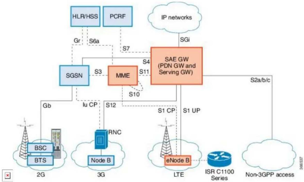
flowchart
graph TD
    A["HLR/HSS"] -->|Gr| B["SGSN"]
    C["PCRF"] -->|S6a| D["MME"]
    D -->|S7| E["SAE GW (PDN GW and Serving GW)"]
    E -->|S4| F["IP networks"]
    E -->|S11| G["SGi"]
    E -->|S10| H["S2a/b/c"]
    H --> I["ISR C1100 Series"]
    H --> J["Non-3GPP access"]
    K["BSC"] --> L["BTS"]
    M["RNC"] --> N["Node B"]
    O["Gb"] --> P["2G"]
    Q["Iu CP"] --> R["3G"]
    S["S12"] --> T["Node B"]
    U["S1 UP"] --> V["LTE"]
    W["S2a/b/c"] --> X["Internet"]
Gateways
The Serving Gateway (SGW) routes and forwards user data packets, while also acting as the mobility anchor for the user plane, and is the anchor for mobility between LTE and other 3GPP technologies. The Packet Data Network (PDN) Gateway (PGW) provides connectivity from the User Equipment (UE) to external packet data networks by being the point of exit and entry of traffic for the UE.
A UE may have simultaneous connectivity with more than one PGW for accessing multiple PDNs. The PGW performs policy enforcement, packet filtering for each user, charging support, lawful interception, and packet screening. Another key role of the PGW is to act as the anchor for mobility between 3GPP and non-3GPP technologies such as WiMAX and 3GPP2 (CDMA 1X and EvDO).
The System Architecture Evolution GW (SAE GW) is the entity that covers the PGW and SGW functionality in the Evolved Packet Core (EPC).
RNC
The Radio Network Controller (RNC) is responsible for controlling the Radio Access Network (RAN) that are connected to it. The RNC carries out radio resource management and some of the mobility management functions and is the point where encryption is done before user data is sent to and from the mobile. The RNC connects to the Circuit-Switched Core Network through the Media Gateway (MGW).
Base Transceiver Station.BTS
Base Station Controller.BSC
Service GPRS Support Node.SGSN
Prerequisites for Configuring Cisco 4G LTE Advanced
- If the signal is not good at the router, use the Cisco offered antenna accessories and extension cables place the antenna away from router in a better coverage area.
- You must have 4G LTE network coverage where your router is physically placed. For a complete list of supported carriers.
- You must subscribe to a service plan with a wireless service provider and obtain a Subscriber Identity Module (SIM) card. Only micro SIM is supported.
- You must install the SIM card before configuring the 4G LTE or Cisco C1100 series router.
- The standalone antenna that supports GPS capabilities must be installed for the GPS feature to work. See the Cisco 4G Indoor/Outdoor Active GPS Antenna (GPS-ACT-ANTM-SMA) document for installation information.
Restrictions for Configuring Cisco 4G LTE Advanced
- Currently, cellular networks support only user initiated bearer establishment.
- Due to the shared nature of wireless communications, the experienced throughput varies depending on the number of active users or congestion in a given network.
- Cellular networks have higher latency compared to wired networks. Latency rates depend on the technology and carrier. Latency also depends on the signal conditions and can be higher because of network congestion.
- CDMA-EVDO, CDMA-1xRTT, and GPRS technology modes are not supported.
- Any restrictions that are part of the terms of service from your carrier.
- SMS—Only one text message up to 160 characters to one recipient at a time is supported. Larger texts are automatically truncated to the proper size before being sent.
- It is strongly recommended that you configure SNMP V3 with authentication/privacy.
Features not Supported in 4G LTE Advanced
The following features are not supported on Cisco 4G LTE Advanced C1100 Series ISR, when compared to Classic IOS:
• TTY support or Line
- Chat script/dialer string
- External Dialer
• Dying Gasp configuration
- DM log output to USB flash is not supported.
Cisco 4G LTE-Advanced Features
Cisco 4G LTE-Advanced support the following major features:
• Global Positioning System (GPS) and National Marine Electronics Association (NMEA) streaming.
- Short Message Service (SMS)
• 3G/4G Simple Network Management Protocol (SNMP) MIB
• SIM lock and unlock capabilities
• Dual SIM
• Auto SIM
• NeMo
• Public Land Mobile Network (PLMN) selection
• IPv6
National Marine Electronics Association (NMEA) streams GPS data either from a 4G LTE through a virtual COM port and a TCP/IP Ethernet connection to any marine device (such as a Windows-based PC) that runs a commercially available GPS-based application.
The following GPS and NMEA features are supported on the Cisco 4G LTE-Advanced:
• GPS standalone mode (satellite-based GPS)
• Cisco IOS CLI display coordinates.
• External application displays router map location
- Objects in the CISCO-WAN-3G-MIB supports GPS and NMEA features
• The Cisco 4G LTE-Advanced only support NMEA over IP and uses show commands in the platform

Note
Assisted GPS mode is not supported.
For instructions on setting up the GPS antenna, see the Cisco-4G Indoor/Outdoor Active GPS Antenna (GPS-ACT-ANTM-SMA) document.
Example: Connecting to a Server Hosting a GPS Application
You can feed the NMEA data to a remote server that hosts the GPS application. The server can be connected to the router either directly using an Ethernet cable or through a LAN or WAN network. If the application supports serial port, run a serial port emulation program to create a virtual serial port over the LAN or WAN connection.

Note
Microsoft Streets & Trips is a licensed software that you can download from the Microsoft website.
To connect a Cisco 4G LTE-Advanced through IP to a PC running Microsoft Streets & Trips, perform the following steps:
1 Connect the PC to the router using an Ethernet cable.
2 Ensure that the PC and router can ping.
Dual SIM Card
SIM card primary slot is selected when router boots up or when NIM reloads. The default slot is 0. If card is not present in the primary slot, select the alternative slot if SIM card is present.
controller cellular 0/2/0
lte sim primary slot <slot#>
If the active SIM card loses connectivity to the network a failover to the alternative SIM card slot occu By default the failover timer is two minutes. The failover timer can be set from 1 to 7 minutes.
controller cellular 0/2/0
lte failovertimer <3-7>
You can also manually switch the SIM slot via the command line interface.
cellular 0/2/0 lte sim activate slot <0-1>
Auto SIM
Auto-SIM is supported in Sierra wireless firmware Ver 02.20.03.
A new CLI is added in the cellular controller to enable/disable Auto-SIM.
The modem in Auto-SIM mode selects the right carrier firmware after a SIM slot switch and an automa modem reset. Auto-SIM is supported on any LTE-LA (EM7430), and LTE-EA (EM7455) SKUs. During bootup, if the Auto-SIM configuration on the modem doesn't match to the IOS configuration, the corresponding Auto-SIM or manual mode is pushed to the modem.
After an Auto-SIM configuration change, the modem is automatically reset; the default is "auto-sim" enabled:
controller cellular 0/2/0
[no] lte firmware auto-sim
If Auto-SIM is disabled and the modem is in manual mode, select a carrier with a new exec CLI: cellular lte firmware-activate
Enable/Disable Auto-SIM:
(config)#controller cellular0/2/0
(config)# [no] lte sim firmware auto-sim
Manual mode:
controller cellular0/2/0
no lte sim firmware auto-sim
The following CLI shows the firmware-index of the carrier in the modem: show cellular 0/2/0 firmware
Short Message Service (SMS) Capabilities
Cisco 4G LTE-Advanced support receiving, transmitting, archiving, and deleting of SMS messages. This support includes the ability to view up to 25 received texts, and archive more messages in a custom file location. SMS is supported on multiple carriers. Cisco 4G LTE-Advanced also have the capability to reveal from LTE SMS to 3G and 2G SMS technology if necessary.
A sending device behind a Cisco 4G LTE-Advanced transmits an SMS text message over the 4G cellula through cellular towers until it the message reaches the recipient's router, which then notifies the recipient device, such as a cell phone. The receiving device uses the same process to return a reply to the sending. The following figure describes the flow from a mobile device to a sending device. For SMS transmission
work, end users must have a text-capable device, and optionally, a text plan. If end users do not have a text plan, standard SMS rates apply to their text transmissions.
Figure 5: SMS Network
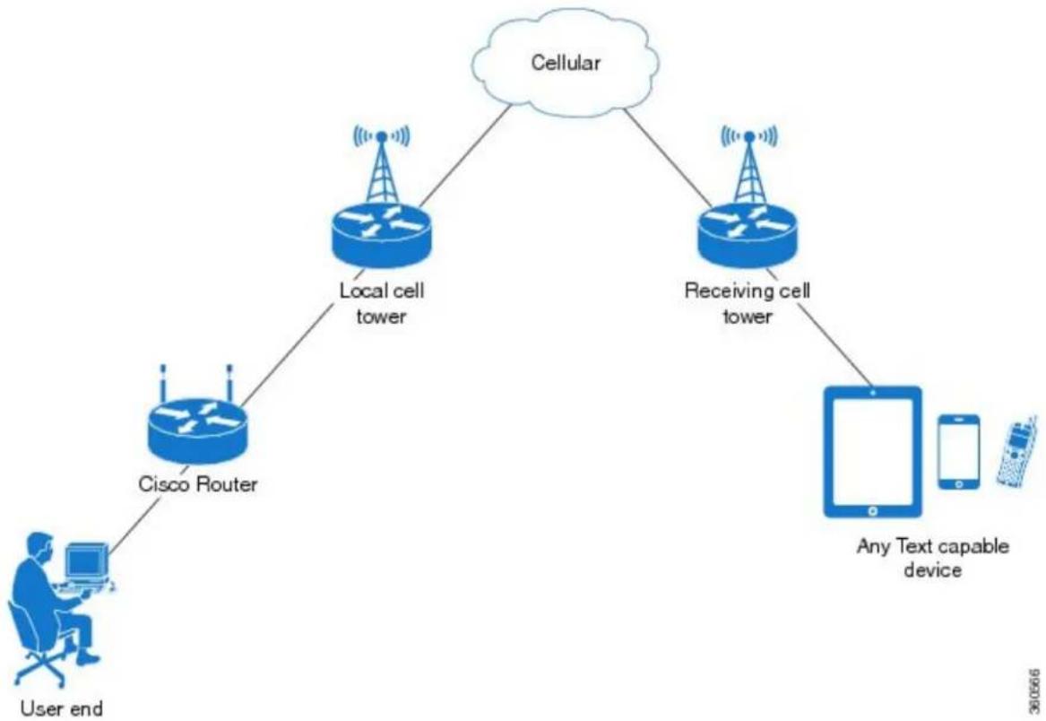
flowchart
graph TD
    A["User end"] --> B["Cisco Router"]
    B --> C["Local cell tower"]
    C --> D["Cellular"]
    D --> E["Receiving cell tower"]
    E --> F["Any Text capable device"]
    F --> G["Mobile Device"]
Using a SIM Card
Cisco 4G LTE-Advanced needs an active SIM card provided by a service provider. The SIM cards are usually provided in an unlocked state so that it can be used without a Personal Identification Number (PIN). If the SIM is unlocked, it can be inserted into a 4G LTE-Advanced and used without an authorization code.
The SIM can be initially locked with a PIN code (4 to 8 digits s long) defined by the service provider. C your service provider for the PIN code.
The SIM-Lock feature allows a SIM to be locked or unlocked with a PIN code so that it is used only in authorized device. Perform the SIM lock and unlock procedures using the Cisco IOS CLI through a console or Telnet/SSH to the ISR.
After the SIM is locked, it cannot initiate a call unless authentication is done using the same PIN. Authentica is done automatically by Cisco IOS through configuration of the PIN. This mandatory configuration for automatic SIM authentication is done using the Cisco IOS CLI as part of the router startup configuration.
After the Cisco IOS configuration is in place, the ISR can initiate an LTE connection. The ISR uses the configured PIN to authenticate prior to the LTE connection. If the Cisco IOS PIN configuration is missing if the PIN is incorrect, the SIM authentication will fail and the connection will not be initiated.
If the locked SIM is moved to a different ISR or to another device, or if the 4G LTE-Advanced in which locked SIM resides is moved to a different 4G LTE-Advanced slot in the same ISR, the ISR configuration should be changed. The configuration is associated with the cellular controller that is specific to an ISR LTE-Advanced slot number. This will ensure that the SIM card will not be used in any unauthorized device, if there are multiple 4G LTE-Advanced in a single ISR, that the appropriate PIN is applied to each LTE-Advanced SIM. An authentication command (with the same PIN used to lock the SIM) must be done on the new device or on the new cellular controller slot to successfully initiate the LTE connection.
The following procedures are used to configure a SIM:

It is very important to use the correct PIN after it is configured. The SIM card will be blocked if the PIN is entered three consecutive times on a locked SIM during authentication or when trying to unlock locked SIM. You can unblock a blocked SIM card using the PUK code. Contact your service provider of the PUK code. Use the cellular
Data Account Provisioning
One or more modem data profiles can be created to provision a modem on a 4G LTE SKU. An active account with a service provider with one or more (dual) SIM cards must be installed. The modem data is pre-configured on the modem.
The following tasks are used to verify the signal strength and service availability of the modem and to modify, and delete modem data profiles:
IP Multimedia Subsystem Profiles
IP Multimedia Subsystem (IMS) profiles establish a session, and are a part of the modem configuration that are stored in the modem's NVRAM. An IMS network is an access-independent and standard-based IP connectivity service that enables different types of multimedia services to end users using common Internet-based protocols.
4G LTE-Advanced LEDs
The following table describes the LED behavior in 4G LTE-Advanced.
Table 14: 4G LTE-Advanced LED Indicators
| Color/Bar and DescriptionLED | ||
| Green (Solid)LTE SIM(0) & SIM | Mbdem up, SIM installed and active | |
| LTE data activityGreen Blink | ||
| Off | Modem not up; or modem up and no SIM | |
| Amber (Solid) | Modem up, SIM installed but not active | |
| Indication | High RSSI >= -69dBmFour BarRSSI - Use | |
| Three Bar | Medium RSSI, -89dBm◇-70dBm | |
| Low RSSI, -99dBm◇ -90dBmTwo Bar | ||
| RSSI <= -100dBmOnc Bar | ||
| No Service0 or No Bar | ||
| Green(solid)SERVICE - Uses Color | LoFInsignal present (RSSI LEDs will be Green) | |
| Amber(solid) | 2G/3G signal present (RSSI LEDs will be Amber) | |
| No service detected.No Color | ||
| GPS coordinates are obtained.Green (Solid) | ||
| Off | GPS is disabled, GPS is enabled without GPS mode and NMEA configuration, or GPS is acquiring | |
Configuring Cisco 4G LTE Advanced
For 4G-LTE-Advanced, the numbering for slot 0, module 0, and port 0 is 0/2/0 for all commands.
Verifying Modem Signal Strength and Service Availability
For the 4G LTE Advanced, the unit argument identifies the router slot, module slot, and port separated by slashes (0/2/0).
Procedure
| PurposeCommand or Action | ||
| Step 1 | show cellular unit network | Displays information about the carrier network, cell site, and available service. |
| Example: | ||
| Router# show cellular 0/2/0 network | ||
| Step 2 | show cellular unit radio | Shows the radio signal strength. |
| Example: | Note The RSSI should be better than -90 dBm for steady and reliable connection. | |
| Router# show cellular 0/2/0 radio | ||
| Step 3 | show cellular unit profile | Shows information about the modem data profiles created. |
| Example: | ||
| Router# show cellular 0/2/0 profile | ||
| Step 4 | show cellular unit security | Shows the security information for the modem, such as SIM and modem lock status. |
| Example: | ||
| Router# show cellular 0/2/0 security | ||
| Step 5 | show cellular unit all | Shows consolidated information about the modem, profiles created, radio signal strength, network security, and so on. |
| Example: | ||
| Router# show cellular 0/2/0 all |
Creating, Modifying, or Deleting Modem Data Profiles
You can create multiple profiles on Cisco 4G LTE Advanced. The following are the default Internet pro: numbers for some of the modems:
• EM7430 - Profile 1
- EM7455 (with Verizon or Sprint SIM inserted) - Both Profile 1 and Profile 3
• EM7455 (with AT&T SIM or other SP SIM inserted) – Profile 1
Usage Guidelines for Creating, Modifying, or Deleting Data Profiles
Follow these guidelines while you configure a data profile:
- In most cases, you do not have to make any profile-related changes if your modem comes with a data profile, for instance, AT&T, Sprint and Verizon.
- If any profile parameter changes are required for a connection type, the changes will most likely be carried out in the default profiles.
• To configure different profile types and use them for a different connection, you can create separate profiles with different parameters (for instance, APN names). Note that only one profile is active at a given time. - Use the show cellular
profile command to view the data profile. An asterisk(*) is displayed against the data profile. - The data profile is used to set up a data call. If you want to use a different profile, that profile needs to be made the default one. Use the lte sim data-profile number command to change the default profile under controller cellular 0/2/0.

Note
For the 4G LTE Advanced, the unit argument identifies the router slot, module slot, and port separated by slashes (0/2/0).
Procedure
| Command or Action | Purpose | |
| Step 1 | cellular unit lte profile [create | delete]profile-number [apn [authentication [username password [bearer-type]]]]Example:Router# cellular 0/2/0 lte profile create 2 apn.com pap username pwd ipv4 | Creates, modifies, or deletes a modem data profile in the privileged EXEC mode.The profile-number argument specifies the profile number created for the modem. The maximum number of profiles that can be created for each modem is given as follows:EM7455 – Up to 16 profilesEM7430 – Up to 16 profiles(Optional) The apnargument specifies an Access Point Name (APN) in the profile. An APN is provided by your service provider. Only a single APN can be specified in a single profile.(Optional) The authentication parameter specifies the authentication type used. Acceptable parameters are chap, none (no authentication), pap, and pap_chap (PAP or CHAP authentication).(Optional) The username and password arguments are given by a service provider.(Optional) The bearer-type parameter specifies the type of data payload exchanged over the air link when the packet data session |
Cisco Fourth-Generation LTE Advanced on Cisco 1100 Series Integrated Services Router (ISR)
Creating, Modifying, or Deleting Modem Data Profiles
| Command or Action | Purpose | |
| is established with this profile. Acceptable data type parameters are: ipv4, ipv6, and ipv4v6 (IPv4 and IPv6).Note The default data profile numbers for the various modem SKUs are given as follows:• EM7430 – Profile 1• EM7455 (use AT&T service) – Profile 1• EM7455 (use Verizon or Sprint service) – Profile 3The data profile is displayed by using the show cellular unit profile command with an asterisk(*). |
Configuration Examples
The following example shows how to change a default profile on 4G LTE Advanced:
router(config-controller)# lte sim data-profile 2 attach-profile 1 slot
The following example shows the output of the show cellular command for Verizon network service:
router# show cellular 0/2/0 profile
Profile 1 = INACTIVE **
法定代表人:
PDP Type = IPv4v6
Access Point Name (APN) = vwins
Authentication - None
Access Point Name (APN) = ureadmin
Authentication = None
Authentication = None
Profile 6 = INACTIVE
PDP Type = IPv4v6
Access Point Name (APN) = CISCO.GW4.VZWENTP
Authentication = None
* - Default profile
** - LTE attach profile
Multiple PDN Contexts
This feature enables router to connect to multiple (currently two) packet data networks. This allows users to enable different features independently on each PDN. For instance, the first PDN can be used for public Internet access and the second one for VPN connectivity; each PDN has its own set of IP addresses and Q characteristics.
During the initialization of the router, two cellular interfaces corresponding to the two PDNs are created: cellular 0/2/0 and cellular 0/2/1
These interfaces can be viewed as two logical interfaces using the same radio resources.
Here onwards, the interface cellular 0/2/0 is referred as the first PDN, and cellular 0/2/1 as the second PDN. The first step, in bringing up the two PDNs, is applying the configuration on both the cellular interfaces and their corresponding lines, in order to make two simultaneous data calls.
The next step is associating the data-bearer profile with its corresponding cellular interface or PDN. It is sufficient to associate the profile for just the first PDN under the controller cellular configuration. Note that the second PDN assumes a profile that is just one above the profile used for the first PDN. For example, the first PDN uses profile 1, the second PDN uses profile 2 automatically when the call is initiated for the second one.
After the interesting traffic is routed through these cellular interfaces, data calls are initiated and each interface is assigned its own IP and DNS addresses provided by the cellular network.

Note
Both PDNs share radio resources. Therefore, any throughput measurement needs to take into account the aggregate throughput on both PDNs, instead of just one.

Note
For Verizon cellular network, the second PDN uses profile #6 automatically, when the call is initiated for the second data connection.
Configuration Examples
The following example shows how to configure multiple PDN on Cisco 4G LTE SKU:
interface Cellular0/2/0
ip address negotiated
dialer in-band
dialer idle-timeout 0
dialer-group 1
ipv6 enable
pulse-time 1
!
interface Cellular0/2/1
ip address negotiated
dialer in-band
dialer idle-timeout 0
dialer-group 1
ipv6 enable
pulse-time 1
!
dialer-list 1 protocol ip permit

ip route 192.192.187.0 255.255.255.0 Cellular0/2/0
ip route 192.171.187.254 255.255.255.255 Cellular0/2/1

The following show commands can be used to verify the status of the multiple PDN calls:

Router#sh cellular 0/2/0 profile
Profile 1 = ACTIVE* **
----
PDP Type = IPv4v6
PDP address = 29.29.29.9
PDP IPV6 address = 2001:2678:2680:5DF0:D058:1AD3:C07A:297D/64 Scope: Global
Access Point Name (APN) = broadband
Authentication = None
    Primary DNS address = 8.0.0.8
    Secondary DNS address = 8.8.4.4
    Primary DNS IPV6 address = 2001:4860:4860:0:0:0:8888
    Secondary DNS IPV6 address = 2001:4860:4860:0:0:0:8844

Profile 2 = ACTIVE
----
PDP Type = IPv4v6
PDP address = 21.21.21.222
PDP IPV6 address = 2001:567A:567A:1479:C41B:BE17:31C2:95AC/64 Scope: Global
Access Point Name (APN) = basic
Authentication = None
    Primary DNS address = 171.70.168.183
    Secondary DNS address = 8.8.8.8
    Primary DNS IPV6 address = 2001:4860:4860:0:0:0:8888
    Secondary DNS IPV6 address = 2001:4860:4860:0:0:0:8844

Profile 3 = INACTIVE
----
PDP Type = IPv4
Access Point Name (APN) = mpdn
Authentication = None
Profile 4 = INACTIVE
----
PDP Type = IPv4
Access Point Name (APN) = broadband
Authentication = None

Profile 5 = INACTIVE
----
PDP Type = IPv4
Access Point Name (APN) = cisco.gw4.vzwentp
Authentication = None

Profile 6 = INACTIVE
----
PDP Type = IPv4
Access Point Name (APN) = mobility-da1
Authentication = None

Profile 7 = INACTIVE
----
PDP Type = IPv4
Access Point Name (APN) = mobility-da2
Authentication = None

Profile 8 = INACTIVE
PDP Type = IPv4
Access Point Name (APN) = broadband
Authentication = None

Profile 9 = INACTIVE

PDP Type = IPv4
Access Point Name (APN) = mpdndt-qos
Authentication = None

Profile 10 = INACTIVE

PDP Type = IPv4
Access Point Name (APN) = mobility-de2
Authentication = None

Profile 11 = INACTIVE

PDP Type = IPv4
Access Point Name (APN) = broadband
Authentication = None

Profile 12 = INACTIVE

PDP Type = IPv4
Access Point Name (APN) = wfqos
Authentication = CHAP
Username: ipv4v6
Password: xxxxxxx

Profile 13 = INACTIVE

PDP Type = IPv4
Access Point Name (APN) = broadband
Authentication = CHAP
Username: ipv4v6
Password: xxxxxxx

Profile 14 = INACTIVE

PDP Type = IPv4
Access Point Name (APN) = mobility-de2
Authentication = CHAP
Username: ipv4v6
Password: xxxxxxx

Profile 15 = INACTIVE

PDP Type = IPv4
Access Point Name (APN) = aaaauth
Authentication = CHAP
Username: ipv4v6
Password: xxxxxxx

Profile 16 = INACTIVE

PDP Type = IPv4
Access Point Name (APN) = broadband
Authentication = CHAP
Username: ipv4v6
Password: xxxxxxx

* - Default profile
** - LTE attach profile

Configured default profile for active SIM 0 is profile 1.

Router# sh cellular 0/2/0 connection
Profile 1, Packet Session Status = ACTIVE
    Cellular0/2/0:
    Data Packets Transmitted = 9, Received = 9
    Data Transmitted = 900 bytes, Received = 900 bytes
IP address = 29.29.29.9
IPV6 address = 2001:2678:2680:5DF0:D058:1AD3:C07A:297D/64 Scope: Global
Primary DNS address = 8.0.0.8
Secondary DNS address = 8.8.4.4
Primary DNS IPV6 address = 2001:4860:4860:0:0:0:0:8888
Secondary DNS IPV6 address = 2001:4860:4860:0:0:0:0:8844
Profile 2, Packet Session Status = ACTIVE
Cellular0/2/1:
Data Packets Transmitted = 7, Received = 2
Data Transmitted = 700 bytes, Received = 176 bytes
IP address = 21.21.21.222
IPV6 address = 2001:567A:567A:1479:C41B:BE17:31C2:95AC/64 Scope: Global
Primary DNS address = 171.70.168.183
Secondary DNS address = 8.8.8.8
Primary DNS IPV6 address = 2001:4860:4860:0:0:0:0:8888
Secondary DNS IPV6 address = 2001:4860:4860:0:0:0:0:8844
Profile 3, Packet Session Status = INACTIVE
Profile 4, Packet Session Status = INACTIVE
Profile 5, Packet Session Status = INACTIVE
Profile 6, Packet Session Status = INACTIVE
Profile 7, Packet Session Status = INACTIVE
Profile 8, Packet Session Status = INACTIVE
Profile 9, Packet Session Status = INACTIVE
Profile 10, Packet Session Status = INACTIVE
Profile 11, Packet Session Status = INACTIVE
Profile 12, Packet Session Status = INACTIVE
Profile 13, Packet Session Status = INACTIVE
Profile 14, Packet Session Status = INACTIVE
Profile 15, Packet Session Status = INACTIVE
Profile 16, Packet Session Status = INACTIVE
Router#sh ip interface brief
Interface IP-Address OK? Method Status Protocol
GigabitEthernet0/0/0 1.3.88.55 YES manual up up
GigabitEthernet0/0/1 unassigned YES unset administratively down down
GigabitEthernet0/1/0 unassigned YES unset administratively down down
GigabitEthernet0/1/1 unassigned YES unset administratively down down
GigabitEthernet0/1/2 unassigned YES unset administratively down down
GigabitEthernet0/1/3 unassigned YES unset administratively down down
GigabitEthernet0/1/4 unassigned YES unset administratively down down
GigabitEthernet0/1/5 unassigned YES unset administratively down down
GigabitEthernet0/1/6 unassigned YES unset administratively down down
GigabitEthernet0/1/7 unassigned YES unset administratively down down
Wl0/1/8 unassigned YES unset administratively down down
Cellular0/2/0 29.29.29.9 YES IPCP up up
Cellular0/2/1 21.21.21.222 YES IPCP up up
Vlanl unassigned YES manual up down
Router#
Router# show ip dns view
DNS View default parameters:
DNS Resolver settings:
    Domain lookup is enabled
    Default domain name:
    Domain search list:
    Domain name-servers:
    8.0.0.8
    2001:4860:4860::8888
    8.8.4.4
    2001:4860:4860::8844
    171.70.168.183
    8.8.8.8

DNS Server settings:
    Forwarding of queries is enabled
    Forwarder addresses: DNS View default parameters: DNS Resolver settings:
Domain lookup is enabled Default domain name: Domain search list: Domain name-servers:
8.8.8.8
172.26.38.1
172.26.38.2

DNS Server settings:
Forwarding of queries is enabled
Forwarder addresses:
Router#
Configuring a SIM for Data Calls
Locking and Unlocking a SIM Card Using a PIN Code
Perform this task to lock or unlock a SIM card given by your service provider.
The SIM card gets blocked if the wrong PIN is entered three consecutive times. Make sure you enter the correct PIN the SIM is configured with. If your SIM card gets blocked, contact your service provider for a PUK code. Using the PUK code, you can unblock the SIM card.
For the 4G LTE Advanced, the unit argument identifies the router slot, module slot, and port separated by slashes (0/2/0).
Procedure
PurposeCommand or Action
Step 1 cellular unit lte sim {lock | unlock} pin
Locks or unlocks the SIM card using a PIN code.
Example:
- pin—A code (4 to 8 digits long) provided by your carrier to lock or unlock the SIM card.
Router# cellular 0/2/0 lte sim lock 1111
Changing the PIN Code
Perform this task to change the PIN code of a SIM.
For the 4G LTE Advanced, the unit argument identifies the router slot, module slot, and port separated by slashes (0/2/0).
Procedure
PurposeCommand or Action
Step 1 cellular unit lte sim change-pin pin
new-pChanges the assigned PIN code. SIM should be in locked state when the PIN is being changed.
Example:
Router# cellular 0/2/0 lte sim change-pin 1111 1234
Verifying the Security Information of a Modem
Perform this task to verify the security information of a modem.
Note For the 4G LTE Advanced, the unit argument identifies the router slot, module slot, and port separated by slashes (0/2/0).
Procedure
PurposeCommand or Action
Step 1 show cellular unit security
Shows the security information of the modem, including the SIM lock status.
Example:
Router# show cellular 0/2/0 security
Configuring Automatic Authentication for a Locked SIM
An unencrypted PIN can be configured to activate the Card Holder Verification (CHV1) code that authenti a modem.
The SIM card gets blocked if the wrong PIN is entered three consecutive times. Make sure you enter the correct PIN the SIM is configured with. If your SIM card gets blocked, contact your service provider for PUK code.
Follow these procedures when using an unencrypted Level 0 PIN to configure CHV1. For instructions on how to configure CHV1 using an encrypted Level 7 PIN, see the Configuring an Encrypted PIN for a SIM, on page 222.
A SIM should be locked for SIM authentication to work. To verify the SIM's status, use the show cellular unit security command.
For the 4G LTE Advanced, the unit argument identifies the router slot, module slot, and port separated by slashes (0/2/0).
Procedure
PurposeCommand or Action
Step 1 Enters global configuration mode.configure terminal
Example:
Router# configure terminal
Step 2 controller cellular unit Enters the cellular controller configuration mode.
Example:
Router(config)# controller cellular 0/2/0
Step 3 Ite sim authenticate 0 pin Authenticates the SIM CHV1 code by using an unencrypted (0) keyword and PIN. This PIN is sent to the modem for
PurposeCommand or Action
authentication with each subsequent LTE connection. If authentication passes based on the configured PIN, the data call is allowed. If authentication fails, the modem does not initiate the data call.
Note This command is valid only when an unencrypted PIN is used. To configure CHV1 code using an encrypted PIN, see the Configuring an Encrypted PIN for a SIM, on page 222.
Configuring an Encrypted PIN for a SIM
To configure an encrypted PIN, the scrambled value of the PIN must be obtained. To get the scrambled Le 7 PIN and to configure the SIM CHV1 code for verification using this encrypted PIN, enter the following commands in the EXEC mode.
Note When obtaining the encrypted PIN for a SIM, a username and password are created by configuring password encryption, defining the username and associated password, copying the resulting scrambled password, and using this scrambled password in the SIM authentication command. After the scrambled PIN has been obtained and used in SIM authentication, the username created can be deleted from the Cisco IOS configuration.
Note A SIM should be locked for SIM authentication to work. To verify the SIM's status, use the show cellular
Note For the 4G LTE SKU, the unit argument identifies the router slot, module slot, and port separated by slashes (0/2/0).
Procedure
PurposeCommand or Action
Step 1
Enters global configuration mode.configure terminal
Example:
Router# configure terminal
Step 2
Enables password encryption.service password-encryption
Example:
Router(config)# service password-encryption
PurposeCommand or Action
| Step 3 | username name privilege 0 password creates username and password.pin | •name—Specifies the username. |
| Example: | •pin—Specifies the four- to eight-digit PIN code. | |
| Router(config)# username SIMprivilege 0 password 1111 | ||
| Step 4 | do show run | i name | Shows the username configuration line with the encrypted level 7 PIN for the username created in Step 3 (user “SIM” in the example shown). |
| Example: | Copy the scrambled password for use in Step 6 (as the PIN). | |
| Router(config)# do show run | i SIM | ||
| Step 5 | controller cellular unit | Enters the cellular controller configuration mode. |
| Example: | ||
| Router(config)# controller cellular0/2/0 | ||
| Step 6 | lte sim authenticate {0 | 7} pin | Authenticates the SIM CHV1 code by using the encrypted keyword 7 and the scrambled PIN from Step 4. The PIN is sent to the modem for authentication with each subsequent LTE connection. If authentication passes based on the configured PIN, the data call is allowed. If authentication fails, the modem does not initiate the data call. |
| Step 7 | exit | (Optional) Exits the cellular controller configuration mode. |
| Example: | ||
| Router(config-controller)# exit | ||
| Step 8 | no username name | (Optional) Removes the username and password created in Step 3. |
| Example: | ||
| Router(config)# no username SIM | ||
| Step 9 | (Optional) Disables password encryption.no service pass | |
| Example: | ||
| Router(config)# no servicepassword-encryption |
Applying a Modem Profile in a SIM Configuration
Procedure
| PurposeCommand or Action | ||
| Step 1 | Example:Router# configure terminal | Enters the global configuration mode.configure terminal |
| Step 2 | controller cellular unitExample:Router(config)# controller cellular 0/2/0 | Enters the cellular controller configuration mode. |
| Step 3 | Ite sim data-profile number attach-profile number | Applies the configured profile number to the SIM and its slot number. The default (primary) slot is 0.The attach profile is the profile used by the modem to attach to the LTE network.The data profile is the profile used to send and receive data over the cellular network. |
Data Call Setup
To set up a data call, use the following procedures:
Configuring the Cellular Interface
To configure the cellular interface, enter the following commands starting in EXEC mode.
For the 4G LTE Advanced, the unit argument identifies the router slot, module slot, and port separated by slashes (0/2/0).
If a tunnel interface is configured with ip unnumbered cellular 0/2/0, it is necessary to configure the actual static IP address under the cellular interface, in place of ip address negotiated.
Procedure
| PurposeCommand or Action | ||
| Step 1 | Example:Router# configure terminal | Enters global configuration mode.configure terminal |
| Step 2 | Example:Router(config)#interface cellular0/2/0 | Specifies the cellular interface.interface cellular un |
| Step 3 | ip address negotiatedExample:Router(config-if)#ip addressnegotiated | Specifies that the IP address for a particular interface is dynamically obtained. |
| Step 4 | dialer in-bandExample:Router(config-if)#dialer in-band | Enables DDR and configures the specified serial interface to use in-band dialing. |
| Step 5 | dialer-group group-numberExample:Router(config-if)#dialer-group 1 | Specifies the number of the dialer access group to which the specific interface belongs. |
| Step 6 | Example:Router(config-if)#exit | Enters the global configuration mode.exit |
| Step 7 | ip route network-number network-mask{ip-address | interface} [administrative distance] [name name]Example:Router(config)#ip route209.165.200.225 255.255.255.224cellular 0/2/0 | Establishes a floating static route with the configured administrative distance through the specified interface.Note A higher administrative distance should be configured for the route through the backup interface so that it is used only when the primary interface is down. |
| Step 8 | dialer-list dialer-group protocolprotocol-name {permit | deny | listaccess-list-number | access-group}Example:Router(config)#dialer-list 1 protocolip list 1 | Creates a dialer list for traffic of interest and permits access to an entire protocol. |
Configuring DDR
To configure DDR for the cellular interface, enter the following commands starting in EXEC mode.
Note For the 4G LTE Advanced, the unit argument identifies the router slot, module slot, and port separated by slashes (0/2/0).
Procedure
| PurposeCommand or Action | ||
| Step 1 | Enters global configuration mode.configure terminal | |
| Example: | ||
| Router# configure terminal | ||
| Step 2 | interface cellular unit | Specifies the cellular interface. |
| Example: | ||
| Router(config)# interface cellular 0/2/0 | ||
| Step 3 | ip address negotiated | Specifies that the IP address for a particular interface is dynamically obtained. |
| Example: | ||
| Router(config-if)# ip address negotiated | ||
| Step 4 | dialer in-band | Enables DDR and configures the specified serial interface to use in-band dialing. |
| Example: | ||
| Router(config-if)# dialer in-band | ||
| Step 5 | ip address negotiated | Specifies that the IP address for a particular interface is dynamically obtained. |
| Example: | ||
| Router(config-if)# ip address negotiated | ||
| Step 6 | dialer idle-timeout seconds | Specifies the duration of idle time, in seconds, after which a line has no outbound traffic. “0” second means no idle timeout. The default idle timeout is 120 seconds if there is no idle timer specified. |
| Example: | ||
| Router(config-if)# dialer idle-timeout 30 | ||
| Step 7 | dialer-group group-number | Specifies the number of the dialer access group to which the specific interface belongs. |
| Example: | ||
| Router(config-if)# dialer-group 1 | ||
| Step 8 | Example:Router(config-if)# exit | Enters the global configuration mode.exit |
| Step 9 | dialer-list dialer-group protocol protocol-nam{permit | deny | listaccess-list-number|access-group}Example:Router(config)# dialer-list 1 protocolip list 1 | Creates a dialer list for traffic of interest and permits access to an entire protocol. |
| Step 10 | ip-source-addressExample:Router(config)# access-list 1 permitany | Defines traffic of interest.access-list access-list-num |
Enabling 4G GPS and NMEA Data Streaming
GPS NMEA data streaming to external NMEA 2.0-compliant GPS plotter applications can be enabled on Cisco 4G LTE Advanced.

Note
For a 4G LTE-Advanced, the unit argument identifies the router slot, module slot, and the port, and is separated by slashes (0/2/0).
Procedure
| PurposeCommand or Action | ||
| Step 1 | Example:Router# configure terminal | Enters the configuration mode.configure 1 |
| Step 2 | controller cellular unitExample:Router(config)# controller cellular 0/2/0 | Enters the controller cellular configuration mode. |
| PurposeCommand or Action | ||
| Step 3 | lte gps enable | (Optional) GPS is enabled by default. Use this command to enable the GPS feature if GPS has been disabled for any reason. |
| Example:Router(config-controller)# lte gps enable | ||
| Step 4 | Enables the standalone GPS mode.lte gps m | |
| Example:Router(config-controller)# lte gps mode standalone | ||
| Step 5 | lte gps nmea {ip | udp [source address][destination address][destination port]} | Enables NMEA. Cisco 4G LTE Advanced support only IP NMEA. Therefore, the IP interface and serial interface options are unavailable. |
| Example:Router(config-controller)# lte gps nmea ip orRouter(config-controller)# lte gps nmea | ||
| Step 6 | test cellular unit modem-power-cycle | GPS can take effect only after modem power cycle. |
| Example:Router# test cellular 0/2/0 modem-power-cycle | ||
| Step 7 | cnd | Exits the controller configuration mode and returns to the privileged EXEC mode. |
| Example:Router(config-controller)# end | ||
| Step 8 | show cellular unit gps | Displays a summary of the following GPS data: |
| Example:Router# show cellular 0/2/0 gps | • GPS state information (GPS disabled, GPS acquiring, GPS enabled) | |
| GPS Info---- | • GPS mode configured (standalone) | |
| GPS Feature: enabledGPS Mode Configured: standaloneGPS Port Selected: Dedicated GPS portGPS Status: GPS coordinates acquiredLast Location Fix Error: Offline [0x0]Latitude: 38 Deg 11 Min 22.1939 Sec NorthLongitude: 96 Deg 40 Min 48.7066 Sec WestTimestamp (GMT): Thu Jun 29 07:13:42 2017 | ||
| Fix type index: 0, Height: 318 mSatellite Info---- | • GPS satellite information• GPS feature (enabled or disabled)• GPS port selected (Dedicated GPS and GPS port with voltage-no-bias) | |
| Satellite #3, elevation 62, azimuth 282, SNR 53Satellite #4, elevation 28, azimuth 61, SNR 53Satellite #5, elevation 63, azimuth 281, SNR 54Satellite #6, elevation 10, azimuth 254, SNR 53Satellite #7, elevation 42, azimuth 268, SNR 53Satellite #8, elevation 57, azimuth 106, SNR 50Satellite #13, elevation 32, azimuth 177, SNR 54Satellite #22, elevation 38, azimuth 210, SNR 54Satellite #24, elevation 27, azimuth 299, SNR 54Satellite #29, elevation 60, azimuth 317, SNR 53Satellite #1, elevation 5, azimuth 63, SNR 0Satellite #9, elevation 64, azimuth 264, SNR 0 | ||
| PurposeCommand or Action | ||
| Satellite #12, elevation 2, azimuth 195, SNR 0Satellite #26, elevation 0, azimuth 331, SNR 0Satellite #27, elevation 52, azimuth 84, SNR 0Satellite #28, elevation 0, azimuth 0, SNR 0Router# | ||
| Step 9 | show cellular unit gps detailExample:Router# show cellular 0 gps detailGPS Info----GPS Feature: enabledGPS Mode Configured: standaloneGPS Port Selected: Dedicated GPS portGPS Status: GPS coordinates acquiredLast Location Fix Error: Offline [0x0]Latitude: 38 Deg 11 Min 22.1939 Sec NorthLongitude: 96 Deg 40 Min 48.7066 Sec WestTimestamp (GMT): Thu Jun 29 07:13:42 2017Fix type index: 0, Height: 0 mHDOP:, GPS Mode Used: not configuredSatellite Info----Satellite #3, elevation 0, azimuth 0, SNR 53Satellite #4, elevation 0, azimuth 0, SNR 52Satellite #5, elevation 29, azimuth 143, SNR 51Satellite #6, elevation 0, azimuth 46, SNR 53Satellite #7, elevation 0, azimuth 0, SNR 52Satellite #8, elevation 0, azimuth 0, SNR 53Satellite #12, elevation 60, azimuth 140, SNR 54Satellite #13, elevation 0, azimuth 0, SNR 54Satellite #22, elevation 0, azimuth 0, SNR 51Satellite #24, elevation 13, azimuth 203, SNR 53Satellite #26, elevation 0, azimuth 0, SNR 53Satellite #29, elevation 20, azimuth 278, SNR 52Satellite #2, elevation 61, azimuth 52, SNR 0Satellite #9, elevation 0, azimuth 0, SNR 0Router# | Displays detailed GPS data. |
Configuring 4G SMS Messaging

Note
For an 4G LTE Advanced, the unit argument identifies the router slot, module slot, and the port, and is separated by slashes (0/2/0).
Procedure
| PurposeCommand or Action | ||
| Step 1 | Example:Router# configure terminal | Enters the configuration mode.configure terminal |
PurposeCommand or Action
Step 2 controller cellular unit
Enters the controller cellular configuration mode.
Example:
Router(config)# controller cellular 0/2/0
Step 3 lte sms archive path FTP-URL
Specifies an FTP server folder path to send all the incoming and outgoing SMS messages. After the folder path is identified, it is appended automatically with outbox and inbox folders for the path to which SMS messages are sent and received, for example:
Example:
Router(config-controller)# lte sms archive path ftp://username:password@172.25.211.175/SMS-LTE
ftp://172.25.211.175/SMS-LTE/outbox ftp://172.25.211.175/SMS-LTE/inbox
Step 4 cellular unit ltc sms view { all | ID | summaryDisplays the message contents of incoming texts received by a modem.
Example:
Router# cellular 0/2/0 lte sms view summary ID FROM YY/MM/DD HR:MN:SC SIZE CONTENT 0 4442235525 12/05/29 10:50:13 137 Your entry last month has... 2 5553337777 13/08/01 10:24:56 5 First 3 5553337777 13/08/01 10:25:02 6 Second
- all—Displays the message contents of up to 255 incoming text messages received by the modem.
- ID—Displays the message contents for a specified ID (0-255) of an incoming text message.
- summary—Displays a summary of the incoming text messages received by the modem.
Step 5 end
Exits the configuration mode and returns to the privileged EXEC mode.
Example:
Router# end
Step 6 show cellular unit sms
Displays all the information in the text messages sent and received. Message information includes text messages sent successfully, received, archived, and messages pending to be sent. LTE-specific information on errors in case of a FAILED attempt may also be displayed.
Example:
Router# show cellular 0/2/0 sms Incoming Message Information
SMS stored in modem = 20 SMS archived since booting up = 0 Total SMS deleted since booting up = 0 Storage records allocated = 25 Storage records used = 20 Number of callbacks triggered by SMS = 0 Number of successful archive since booting up = 0 Number of failed archive since booting up = 0
Outgoing Message Information Total SMS sent successfully = 0 Total SMS send failure = 0 Number of outgoing SMS pending = 0 Number of successful archive since booting up
| PurposeCommand or Action | ||
| = 0Number of failed archive since booting up = 0Last Outgoing SMS Status = SUCCESSCopy-to-SIM Status = 0x0Send-to-Network Status = 0x0Report-Outgoing-Message-Number:Reference Number = 0Result Code = 0x0Diag Code = 0x0 0x0 0x0 0x0 0x0SMS Archive URL =ftp://lab:lab@1.3.150.1/outbox | ||
| Step 7 | cellular unit lte sms send numberExample:Router# cellular 0/2/0 lte sms send 15554443333 | Enables a user to send a 4G LTE band SMS message to other valid recipients, provided they have a text message plan. The number argument is the telephone number of the SMS message recipient.Note 10-digit or 11-digit (phone) numbers are the proper numerical format for sending a text. For example, ##### or 1#######. Seven digits are not supported. |
| Step 8 | cellular unit lte sms delete [ all | id ]Example:Router# cellular 0/2/0 lte sms delete [ all | id ] | (Optional) Deletes one message ID or all of the stored messages from memory. |
Configuring Modem DM Log Collection
Diagnostic Monitor (DM) is a Qualcomm proprietary protocol. Diagnostic software tools, such as Sierra Wireless SwiLog and Qualcomm QXDM, are based on DM protocol. These tools can be used to capture transactions between the modem and the network over the RF interface, which makes them useful tools troubleshooting 3G and 4G data connectivity or performance issues.
To configure DM log collection, enter the following commands, starting in privileged EXEC mode.
Procedure
| PurposeCommand or Action | ||
| Step 1 | Example:Router# configure terminal | Enters global configuration mode.configure terminal |
PurposeCommand or Action
Step 2 controller cellular slot
Enters cellular controller configuration mode.
Example:
Router(config)# controller cellular 0/2/0
Step 3 {lte} modem dm-log {enable | filesize size | filter location:filename | output path URL | rotation | size log-size}
Configures DM logging for LTE modem.
Example:
Router(config-controller)# lte modem dm-log enable
- enable—Enables DM logging.
- filesize size—Specifies the maximum log file size, in MB. Range is from 1 to 64. Default is 20.
- filter location:filename—Specifies the DM log filter file location and filename. Flash is the only valid value for the location parameter.
Note If the DM log filter file is not specified, the generic filter file, which comes with the
Note diagnostic software tool, will be used. The DM log filter file should be in SQF format.
- output path URL—Specifies the path where the DM logging output files will be stored. The default path is the router flash.
- rotation—Enables log rotation.
Note The rotation option is only supported if the log files are stored in the router flash or USB flash.
- size log-size—Specifies the maximum log size, in MB. Range is from 0 to 1024. Default is 64.
Step 4
Returns to privileged EXEC mode.end
Example:
Router(config-controller)# end
Step 5 show cellular unit logs dm-log
(Optional) Displays DM log configuration and statistics.
Example:
Router# show cellular 0/2/0 logs dm-log Router#sh cell 0/2/0 log dm-log Integrated DM logging is on output path = Utility Flash filter = MC74xx generic - v11026_Generic_GSM_WCDMA_LTE
Example
The following example shows how to specify the maximum log file size for LTE:
Router(config-controller)# controller cell 0/2/0
Router(config-controller)# lte modem dm-log filesize 64
The following example shows how to specify the filter file for LTE:
Router(config-controller)# controller cell 0/2/0
Router(config-controller)# lte modem dm-log filter flash:SwiLogPlus_generic_filter_6.3.sqf
The following example shows how to enable DM log rotation for LTE:
Router(config-controller)# controller cell 0/2/0
Router(config-controller)# lte modem dm-log rotation
The following example shows how to specify the maximum log size for LTE:
Router(config-controller)# controller cell 0/2/0
Router(config-controller)# lte modem dm-log size 1024
Enabling Modem Crashdump Collection
Modem crashdump collection is useful in debugging firmware crash. To collect crash data, the modem has to be pre-configured so that it will stay in memdump mode after a crash. Memdump mode is a special boot-and-hold mode for the memdump utility to collect crash data.
For earlier releases, the crashdump collection required the PC to be connected to the router using a USE or a special RJ45-USB cable on a non-HSPA+7 3G module.
As part of the 3G and 4G serviceability enhancement, the crashdump collection utility is integrated into IOS.
To enable modem crashdump collection, perform the following steps.
Note The integrated modem crashdump collection feature is supported only on 3G HSPA and 4G LTE Advanced based SKUs.
Before You Begin
Ensure that the following prerequisites are met before attempting to enable crashdump logging:
- The modem needs to be provisioned for modem crashdump collection. Contact Cisco TAC for detail
- The modem should be in crash state. Run tests that will result in modem firmware crash. A "MODEM_DOWN" message on the router console or syslog is indicative of modem firmware crash.
Note After the modem firmware crashes, the modem is available for crashdump log collection only. Data calls cannot be made.
Procedure
PurposeCommand or Action
Step 1 test { cell-cwan } unit Enables or disables modem crashdump collection.
modem-crashdump { on location | off }
Example:
Router# test cell-host 0/2/0 modem-crashdump on local uf
- cell-host
—Keyword for fixed platform.
- cell-cwan
— Keyword for LTE on a modular inside platform.
- unit
—For LTE module, this is the router slot, module slot, and port separated by slashes (for example, 0/2/0). For fixed platform, this is the number 0.
• on
Enables crashdump log collection.
- location
—Specifies the destination URL where the modem crashdump logs will be stored.
- off
—Disables crashdump log collection.
Displaying Modem Log Error and Dump Information
As part of the 3G serviceability enhancement in Cisco IOS Release 15.2(4)M2 and Cisco IOS Release 15.3(1)AT commands strings (at!err and at!gcdump) can be sent to the modem using Cisco IOS CLI rather than setting up a reverse telnet session to the cellular modem to obtain log error and dump information.
To obtain log error and dump information, perform the following steps.
The modem log error and dump collection feature is supported only on 3G SKUs. Note
Procedure
PurposeCommand or Action
Step 1 show cellular unit log error Shows modem log error and dump information.
Example:
Router# show cellular 0/2/0 log error
PurposeCommand or Action
Step 2 test cellular unit modem-error-clear(Optional) Clears out the error and dump registers. By default, error and dump registers are not cleared out after a read. This command changes the operation so that registers are cleared once they are read. As a result, the AT command strings are changed to "at!errclr=-1" for CDMA and "at!err=0" for GSM modems. Example: Router# test cellular 0/2/0 modem-error-clear
Configuration Examples for Cisco 4G LTE Advanced
The following example shows how to configure Cisco 4G LTE Advanced:
Router# show running-config
Building configuration...
Current configuration : 2991 bytes
!
! Last configuration change at 21:31:48 UTC Mon May 18 2015
!
version 15.5
service timestamps debug datetime msec
service timestamps log datetime msec
service internal
no platform punt-keepalive disable-kernel-core
platform shell
!
hostname C1111-LTEEA
!
boot-start-marker
!
!
logging buffered 10000000
no logging console
enable password lab
!
no aaa new-model
!
!
!
!
!
!
!
subscriber templating
!
multilink bundle-name authenticated
icense udipid ISR4321/K9 sn FDO181701PZ
!
spanning-tree extend system-id
!
!
redundancy
mode none
!
!
!
!
controller Cellular 0/2/0
lte sim data-profile 16 attach-profile 16
lte gps mode standalone
lte gps nmea
lte modem link-recovery disable

interface GigabitEthernet0/0/1
ip address 172.19.151.180 255.255.255.0
ip nat outside

negotiation auto
!
interface Cellular0/2/0
ip address negotiated
ip nat outside
dialer in-band
dialer idle-timeout 0
dialer watch-group 1
dialer-group 1
pulse-time 1
!
interface Cellular0/2/1
no ip address
shutdown
dialer in-band
pulse-time 1
!
!
interface Vlan1
no ip address
!
no ip nat service dns tcp
no ip nat service dns udp
ip nat inside source list 1 interface Cellular0/2/0 overload
ip forward-protocol nd
ip http server
no ip http secure-server
ip http max-connections 16
ip tftp source-interface GigabitEthernet0/0/1
ip dns server
ip route 0.0.0.0 0.0.0.0 Cellular0/2/0
ip route 223.255.254.0 255.255.255.0 1.3.0.1
!
!
access-list 1 permit 10.1.0.0 0.0.255.255
dialer watch-list 1 ip 8.8.8.8 255.255.255.255
dialer-list 1 protocol ip permit
!
snmp-server community public RO
snmp-server community private RW
snmp-server community lab RW
snmp-server host 1.3.66.144 public
snmp-server manager
control-plane
!
!
line con 0
exec-timeout 0 0
stopbits 1
line aux 0
exec-timeout 0 0
stopbits 1
line vty 0 4
login
transport input all
!
end
Verifying the 4G LTE Advanced Router Information
You can verify the configuration by using the following show commands:
show version
Router#sh ver
Cisco IOS XE Software, Version BLD_V166_THROTTLE_LATEST_20170622_080605_V16_6_0_237 Cisco IOS Software [Everest], ISR Software (ARMV8EB_LINUX_IOSD-UNIVERSALK9_IAS-M), Experimental Version 16.6.20170622:072729
[v166_throttle-/scratch/mcpre/BLD-BLD_V166_THROTTLE_LATEST_20170622_080605 108] Copyright (c) 1986-2017 by Cisco Systems, Inc. Compiled Thu 22-Jun-17 03:39 by mcpre
Cisco IOS-XE software, Copyright (c) 2005-2017 by cisco Systems, Inc. All rights reserved. Certain components of Cisco IOS-XE software are licensed under the GNU General Public License ("GPL") Version 2.0. The software code licensed under GPL Version 2.0 is free software that comes with ABSOLUTELY NO WARRANTY. You can redistribute and/or modify such GPL code under the terms of GPL Version 2.0. For more details, see the documentation or "License Notice" file accompanying the IOS-XE software, or the applicable URL provided on the flyer accompanying the IOS-XE software.
ROM: IOS-XE ROMMON
Router uptime is 2 hours, 16 minutes
Uptime for this control processor is 2 hours, 18 minutes
System returned to ROM by Reload Command
System image file is
"bootflash:cl100-universalk9_ias.BLV166_THROTTLE_LATEST_20170622_080605_V16_6_0_237.SSA.bin" Last reload reason: Reload Command
This product contains cryptographic features and is subject to United States and local country laws governing import, export, transfer and use. Delivery of Cisco cryptographic products does not imply third-party authority to import, export, distribute or use encryption. Importers, exporters, distributors and users are responsible for compliance with U.S. and local country laws. By using this product you agree to comply with applicable laws and regulations. If you are unable to comply with U.S. and local laws, return this product immediately.
A summary of U.S. laws governing Cisco cryptographic products may be found at: http://www.cisco.com/wwl/export/crypto/tool/stqrg.html
If you require further assistance please contact us by sending email to export@cisco.com.
Suite License Information for Module:'esg'
Suite Suite Current Type Suite Next reboot
Technology Package License Information:
Technology Technology-package Technology-package Current Type Next reboot
cisco C1111-8PLTEAW (1RU) processor with 1464691K/6147K bytes of memory.
Processor board ID FGL21071SK4
1 Virtual Ethernet interface
11 Gigabit Ethernet interfaces
2 Cellular interfaces
32768K bytes of non-volatile configuration memory.
4194304K bytes of physical memory.
6598655K bytes of flash memory at bootflash:.
978928K bytes of USB flash at usb0:. OK bytes of WebUI ODM Files at webui:
show platform
router# sh platform Chassis type: C1111-8PLTELAWN
Slot Type State Insert time (ago)
0 C1111-8PLTELAWN ok 00:04:56
0/0 C1111-2x1GE ok 00:02:41
0/1 C1111-ES-8 ok 00:02:40
0/2 C1111-LTE ok 00:02:41
0/3 ISR-AP1100AC-N ok 00:02:41
R0 C1111-8PLTELAWN ok, active 00:04:56
F0 C1111-8PLTELAWN ok, active 00:04:56
P0 PWR-12V ok 00:04:30
Slot CPLD Version Firmware Version
0 17100501 16.6(1r)RC3
R0 17100501 16.6(1r)RC3
F0 17100501 16.6(1r)RC3
show interfaces
router#sh interface cellular 0/2/0
Cellular0/2/0 is up, line protocol is up
Hardware is LTE Adv CAT6 - Europe/North America Multimode LTE/DC-HSPA+/HSPA+/HSPA/UMTS/
Internet address is 10.14.162.11/32
MTU 1500 bytes, BW 50000 Kbit/sec, DLY 20000 usec,
reliability 255/255, txload 1/255, rxload 1/255
Encapsulation HDLC, loopback not set
Keepalive not supported
DTR is pulsed for 1 seconds on reset
Last input never, output 00:00:42, output hang never
Last clearing of "show interface" counters never
Input queue: 0/375/0/0 (size/max/drops/flushes); Total output drops: 0
Queueing strategy: fifo
Output queue: 0/40 (size/max)
5 minute input rate 0 bits/sec, 0 packets/sec
5 minute output rate 0 bits/sec, 0 packets/sec
5 packets input, 460 bytes, 0 no buffer
Received 0 broadcasts (0 IP multicasts)
0 runts, 0 giants, 0 throttles
0 input errors, 0 CRC, 0 frame, 0 overrun, 0 ignored, 0 abort
21 packets output, 1692 bytes, 0 underruns
0 output errors, 0 collisions, 8 interface resets
0 unknown protocol drops
0 output buffer failures, 0 output buffers swapped out
0 carrier transitions
router#
Configuration Examples for 3G and 4G Serviceability Enhancement
Example: Sample Output for the show cellular logs dm-log Command
The following shows a sample output of the show cellular logs dm-log command:
Router# show cellular 0/2/0 logs dm-log
Integrated DM logging is on
filter = generic
maximum log size = 67108864
maximum file size = 20971520
log rotation = disabled
7 packets sent to the modem, 3232 bytes, 0 errors
75 packets received from the modem, 57123 bytes, 0 input drops
75 packets stored in file system, 57123 bytes, 0 errors, 0 aborts
2 max rcv queue size
current file size = 57123
current log size = 57123
total log size = 57123
DM log files: (1 files)
Example: Sample Output for the show cellular logs modem-crashdump Command
The following shows a sample output of the show cellular logs modem-crashdump command:
Router# show cellular 0/2/0 logs modem-crashdump
Modem crashdump logging: off
Progress = 100%
Last known State = Getting memory chunks
Total consecutive NAKs = 0
Number of retries = 0
Memory Region Info:
1: Full SDRAM [Base:0x0, Length:0x2000000]
2: MDSP RAM A region [Base:0x91000000, Length:0x8000]
3: MDSP RAM B region [Base:0x91200000, Length:0x8000]
4: MDSP RAM C region [Base:0x91400000, Length:0xC000]
5: MDSP Register region [Base:0x91C00000, Length:0x28]
6: ADSP RAM A region [Base:0x70000000, Length:0x10000]
7: ADSP RAM B region [Base:0x70200000, Length:0x10000]
8: ADSP RAM C region [Base:0x70400000, Length:0xC000]
9: ADSP RAM I region [Base:0x70800000, Length:0x18000]
10: CMM Script [Base:0x6A350, Length:0x310]
Router#
Configuration Examples for 4G LTE Advanced
Example: Basic Cellular Interface Configuration: Cisco 4G LTE Advanced
The following example shows how to configure the cellular interface to be used as a primary and is config as the default route:
Router# show running-config
interface Cellular 0/2/0
ip address negotiated
dialer in-band
dialer-group 1
ip route 172.22.1.10 255.255.255.255 cellular 0/2/0
dialer-list 1 protocol ip permit
Example: GRE Tunnel over Cellular Interface Configuration
The following example shows how to configure the static IP address when a GRE tunnel interface is configured with ip address unnumbered cellular interface:

Note
The GRE tunnel configuration is supported only if the service providers provide a public IP address on the LTE interface.

Note
For service providers using a private IP address, the point-to-point static GRE tunnel cannot be set up with a private IP address at one end and a public IP address on the other end.
interface Tunnel2
ip unnumbered <internal LAN interface GE0/0 etc.>
tunnel source Cellular0/2/0
tunnel destination a.b.c.d
interface Cellular0/2/0
ip address negotiated
no ip mroute-cache
dialer in-band
dialer-group 1
Example: 4G LTE Advanced as Backup with NAT and IPSec
The following example shows how to configure the 4G LTE Advanced on the router as backup with NAT and IPsec:
The receive and transmit speeds cannot be configured. The actual throughput depends on the cellular network service.
For service providers using a private IP address, use the crypto ipsec transform-set esp command (that is, esp-aes esp-sha256-hmac...).
ip dhcp excluded-address 10.4.0.254!
ip dhcp pool lan-pool
    network 10.4.0.0 255.255.0.0
    dns-server 10.4.0.254
    default-router 10.4.0.254

!
!
crypto isakmp policy 1
    encr 3des
    authentication pre-share
crypto isakmp key address a.b.c.d
!
!
crypto ipsec transform-set ah-sha-hmac esp-3des
!
crypto map gsm1 10 ipsec-isakmp
    set peer a.b.c.d
    set transform-set
    match address 103

!
interface ATM0/2/0
    no ip address
    ip virtual-reassembly
    load-interval 30
    no atm ilmi-keepalive
    dsl operating-mode auto

!
interface ATM0/2/0.1 point-to-point
    backup interface Cellular0/2/0
ip address negotiated
ip mtu 1492
ip nat outside
ip virtual-reassembly
encapsulation ppp
load-interval 30
dialer pool 2
dialer-group 2
ppp authentication chap callin
ppp chap hostname cisco@dsl.com
ppp chap password 0 cisco
ppp iccp dns request
crypto map gsm1

ip nat outside
ip virtual-reassembly
no snmp trap link-status
pvc 0/35
pppoe-client dial-pool-number 2

!

interface Cellular0/2/0
ip address negotiated
ip nat outside
ip virtual-reassembly
no ip mroute-cache
dialer in-band
dialer idle-timeout 0
dialer-group 1
crypto map gsm1

!

interface Vlan1
description used as default gateway address for DHCP clients
ip address 10.4.0.254 255.255.0.0
ip nat inside
ip virtual-reassembly

!
ip local policy route-map track-primary-if
ip route 0.0.0.0 0.0.0.0 Dialer2 track 234
ip route 0.0.0.0 0.0.0.0 Cellular0/3/0 254

!

ip nat inside source route-map nat2cell interface Cellular0/2/0 overload
ip nat inside source route-map nat2dsl overload
ip sla 1
icmp-echo 2.2.2.2 source
timeout 1000
frequency 2
ip sla schedule 1 life forever start-time now
access-list 1 permit any
access-list 101 deny ip 10.4.0.0 0.0.255.255 10.0.0.0 0.255.255.255
access-list 101 permit ip 10.4.0.0 0.0.255.255 any
access-list 102 permit icmp any host 2.2.2.2
access-list 103 permit ip 10.4.0.0 0.0.255.255 10.0.0.0 0.255.255.255
dialer-list 1 protocol ip list 1
dialer-list 2 protocol ip permit
!
!
route-map track-primary-if permit 10
match ip address 102
!
route-map nat2dsl permit 10
match ip address 101
!
route-map nat2cell permit 10
match ip address 101
match interface Cellular0/2/0
!
exec-timeout 0 0
login
modem InOut
Example: SIM Configuration
Locking the SIM Card
The following example shows how to lock the SIM. The italicized text in this configuration example is used to indicate comments and are not be seen when a normal console output is viewed.
Router# sh cellular 0/2/0 security
Card Holder Verification (CHV1) = Disabled
SIM Status = OK
SIM User Operation Required = None
Number of CHV1 Retries remaining = 3
Router# !! SIM is in unlocked state.!
Router# cellular 0/2/0 lte sim lock 1111
!!!WARNING: SIM will be locked with pin=1111(4).
Do not enter new PIN to lock SIM. Enter PIN that the SIM is configured with.
Call will be disconnected!!!
Are you sure you want to proceed?[confirm]
Router#
Apr 26 19:35:28.339: %CELLWAN-2-MODEM_DOWN: Modem in NIM slot 0/2 is DOWN
Apr 26 19:35:59.967: %CELLWAN-2-MODEM_UP: Modem in NIM slot 0/2 is now UP
Router#
Router# sh cellular 0/2/0 security
Card Holder Verification (CHV1) = Enabled
SIM Status = Locked
SIM User Operation Required = Enter CHV1
Number of CHV1 Retries remaining = 3
Router# !! SIM is in locked state.!
Unlocking the SIM Card
The following example shows how to unlock the SIM. The italicized text throughout this configuration exa is used to indicate comments and will not be seen when a normal console output is viewed.
Router# sh cellular 0/2/0 security
Card Holder Verification (CHV1) = Enabled
SIM Status = Locked
SIM User Operation Required = Enter CHV1
Number of CHV1 Retries remaining = 3
Router# !! SIM is in locked state.!
Router# cellular 0/2/0 lte sim unlock 1111
!!!WARNING: SIM will be unlocked with pin=1111(4).
Do not enter new PIN to unlock SIM. Enter PIN that the SIM is configured with.
Call will be disconnected!!!
Are you sure you want to proceed?[confirm]
Router#
Router# sh cellular 0/2/0 security
Card Holder Verification (CHV1) = Disabled
SIM Status = OK
SIM User Operation Required = None
Number of CHV1 Retries remaining = 3
Router# !! SIM is in unlocked state.!
Automatic SIM Authentication
The following example shows how to configure automatic SIM authentication. The italicized text through this configuration example is used to indicate comments and will not be seen when a normal console ou is viewed.
Router# show cellular 0/2/0 security
Card Holder Verification (CHV1) = Disabled
SIM Status = OK

SIM User Operation Required = None
Number of CHV1 Retries remaining = 3

Router# !! SIM is in unlocked state.!Router# cellular 0/2/0 lte sim lock 1111
!!!WARNING: SIM will be locked with pin=1111(4).
Do not enter new PIN to lock SIM. Enter PIN that the SIM is configured with.
Call will be disconnected!!!
Are you sure you want to proceed?[confirm]

Router#
Apr 26 21:22:34.555: %CELLWAN-2-MODEM_DOWN: Modem in NIM slot 0/2 is DOWN
Apr 26 21:23:06.495: %CELLWAN-2-MODEM_UP: Modem in NIM slot 0/2 is now UP
Router#
Router# sh cellular 0/2/0 security
Card Holder Verification (CHV1) = Enabled
SIM Status = Locked
SIM User Operation Required = Enter CHV1
Number of CHV1 Retries remaining = 3
Router# !! SIM is in locked state. SIM needs to be in locked state for SIM authentication to !
work.!Router#
Router# configure terminal
Enter configuration commands, one per line. End with CNTL/Z.
Router(config)# controller cellular 0/2/0
Router(config-controller)# lte sim authenticate 0 1111
CHV1 configured and sent to modem for verification
Router(config-controller)# end
Router#
Apr 26 21:23:50.571: %SYS-5-CONFIG_I: Configured from console by console
Router#
Router# sh cellular 0/2/0 security
Card Holder Verification (CHV1) = Enabled
SIM Status = OK
SIM User Operation Required = None
Number of CHV1 Retries remaining = 3
Router#!! SIM is now in locked state but it can be used for connectivity since authentication is !
good. Authentication can be saved in the router configuration so that when you boot up ! t with the same locked SIM, connection can be established with the correct ! Cisco IOS confi
Changing the PIN Code
The following example shows how to change the assigned PIN code. The italicized text throughout this configuration example is used to indicate comments and will not be seen when a normal console output is viewed.
Router# sh cellular 0/2/0 security
Card Holder Verification (CHV1) = Disabled
SIM Status = OK

SIM User Operation Required = None
Number of CHV1 Retries remaining = 3

Router#!! SIM is in unlocked state.!Router#
Router# cellular 0/2/0 lte sim lock 1111
!!!!WARNING: SIM will be locked with pin=1111(4).
Do not enter new PIN to lock SIM. Enter PIN that the SIM is configured with.
Call will be disconnected!!!
Are you sure you want to proceed?[confirm]
Router#
Apr 26 21:58:11.903: %CELLWAN-2-MODEM_DOWN: Modem in NIM slot 0/2 is DOWN
Apr 26 21:58:43.775: %CELLWAN-2-MODEM_UP: Modem in NIM slot 0/2 is now UP
Router#
Router# sh cellular 0/2/0 security
Card Holder Verification (CHV1) = Enabled
SIM Status = Locked
SIM User Operation Required = Enter CHV1
Number of CHV1 Retries remaining = 3

Router#!! SIM is in locked state. SIM needs to be in locked state to change its PIN.!Router#
Router# cellular 0/2/0 lte sim change-pin 1111 0000
!!!!WARNING: SIM PIN will be changed from:1111(4) to:0000(4)
Call will be disconnected. If old PIN is entered incorrectly in 3 attempt(s), SIM will be blocked!!!
Are you sure you want to proceed?[confirm]
Resetting modem, please wait...
CHV1 code change has been completed. Please enter the new PIN in controller configuration for verification
Router#
Apr 26 21:59:16.735: %CELLWAN-2-MODEM_DOWN: Modem in NIM slot 0/2 is DOWN
Apr 26 21:59:48.387: %CELLWAN-2-MODEM_UP: Modem in NIM slot 0/2 is now UP
Router#
Router#
Router# sh cellular 0/2/0 security
Card Holder Verification (CHV1) = Enabled
SIM Status = Locked
SIM User Operation Required = Enter CHV1
Number of CHV1 Retries remaining = 3

Router#!! SIM stays in locked state, as expected, but with new PIN.!Router# cellular 0/2/0 lte sim unlock 0000
!!!!WARNING: SIM will be unlocked with pin=0000(4).
Do not enter new PIN to unlock SIM. Enter PIN that the SIM is configured with.
Call will be disconnected!!!
Are you sure you want to proceed?[confirm]
Router#
Router# show cellular 0/2/0 security
Card Holder Verification (CHV1) = Disabled
SIM Status = OK
SIM User Operation Required = None
Number of CHV1 Retries remaining = 3

Router#!! Unlock with new PIN is successful. Hence, changing PIN was successful.!
Configuring an Encrypted PIN
The following example shows how to configure automatic SIM authentication using an encrypted PIN. The italicized text throughout this configuration example is used to indicate comments and will not be seen via a normal console output is viewed.
Router# configure terminal
Enter configuration commands, one per line. End with CNTL/Z.
Router(config)# service password-encryption
Router(config)# username SIM privilege 0 password 1111
Router(config)# do sh run | i SIM
username SIM privilege 0 password 7 055A575E70.!! Copy the encrypted level 7 PIN. Use this scrambled PIN in the SIM authentication ! command.!
Router(config)# controller cellular 0/2/0
Router(config-controller)# lte sim authenticate 7 055A575E70
CHV1 configured and sent to modem for verification
Router(config-controller)# exit
Router(config)# no username SIM
Router(config)# end
May 14 20:20:52.603: %SYS-5-CONFIG_I: Configured from console by console
Upgrading the Modem Firmware
The following table describes the Sierra Wireless modems that are supported on Cisco 4G LTE Advanced. The firmware for the modem is upgradable using Cisco IOS commands. The firmware is a Crossword E: (cwe) file and can be downloaded from the wireless software download page on Cisco.com.

Firmware upgrade is supported on utility flash. Note
Use only Cisco certified firmware. Using a firmware version not certified by Cisco may impact the wireless service provider network adversely.

Caution
Do not disconnect power or switch the router off during the firmware upgrade process. This may result in permanent modem failure.

Firmware downgrade is not supported. Note
Table 15: Modem SKUs
| ModemSKU | |
| EM7455LTE-EA | |
| EM7430LTE-LA |
Upgrading the Modem Firmware Manually With CLI
Procedure
PurposeCommand or Action
| Step 1 | Go to the Cisco Wireless WAN software download website at: http://software.cisco.com/download/navigator.html | Provides access to Cisco Wireless WAN software downloads page to select the firmware for Cisco 4G. |
| Note This website is only available to registered Cisco.com users. |
| Step 2 | Select your product for firmware upgrade.On the Cis to Products -> Cisco Interfaces and Modules-> Cisco High-Speed WAN interface Cardsand select your product from the list of available cards. |
| Step 3 | Select and download the appropriate firmwareDownload the modem firmware file to flash memory on the router. |
| Step 4 | terminal monitor | Enables the logging console in privileged EXEC mode. |
Example:
Router# terminal monitor
| Step 5 | microcode reload cellular pa-bay slot modem-provision | Initiates the firmware upgrade process. |
[flash:
Example:
Router# microcode reload cellular 0 2
modem-provision bootflash:/
• pa-bay—Use 0 for 4G LTE Advanced.
- slot—For 4G LTE Advanced, slot number, 0 to 3, where the 4G LTE Advanced is plugged in.
- For remote download, you can transfer this using the wireless link from Cisco.com onto flash.
| Step 6 | show cellular 0/2/0 hardware | Verifies the firmware upgrade process. |
Example:
Router# show cellular 0 hardware Modem Firmware built = 2016/06/30 10:54:05 Hardware Version = 1.0 Device Model ID: EM7455
EM74xx Manual Modem Firmware Upgrade: Example
Router# sh cellu 0/2/0 hardware
Modem Firmware Version = SWI9X30C_02.20.03.00
Modem Firmware built = 2016/06/30 10:54:05
Hardware Version = 1.0
Device Model ID: EM7455
International Mobile Subscriber Identity (IMSI) = <imsi>
International Mobile Equipment Identity (IMEI) = <imei>
Integrated Circuit Card ID (ICCID) = <iccid>
Mobile Subscriber Integrated Services
Digital Network-Number (MSISDN) =
Modem Status = Modem Online
Current Modem Temperature = 44 deg C
PRI SKU ID = 1102526, PRI version = 002.020_000, Carrier = AT&T
OEM PRI version = 006
Router#cd fw_22_vzw
Router#dir
Directory of bootflash:/fw_22_vzw/

227586 -rw- 64389490 Jun 30 2000 10:21:29 +00:00 74XX_02.20.03.22.cwe
227587 -rw- 16951 Jun 30 2000 10:22:10 +00:00
7455_02.20.03.22_Verizon_002.026_000.nvu

6816092160 bytes total (5965422592 bytes free)
Router#cd
Router#microcode reload cellular 0 2 modem-provision bootflash:/fw_22_vzw/
Reload microcode? [confirm]
Log status of firmware download in router flash?[confirm]
Firmware download status will be logged in bootflash:fwlogfile
Microcode Reload Process launched for cwan slot/bay =0/2; hw type=0x102download option = 0
Router#Success !! send FW Upgrade command to card
*************************
The interface will be Shut Down for Firmware Upgrade
This will terminate any active data connections.
*************************
****************************************************************************************
Modem will be upgraded!
Upgrade process will take up to 15 minutes. During
this time the modem will be unusable.
Please do not remove power or reload the router during
the upgrade process.
**********************************************************************
*Jul 6 10:19:34.701: %LINK-5-CHANGED: Interface Cellular0/2/0, changed state to
administratively down
*Jul 6 10:19:34.701: %LINK-5-CHANGED: Interface Cellular0/2/1, changed state to
administratively down
FIRMWARE INFO BEFORE UPGRADE:
Modem Device ID: EM7455 MODEM F/W Boot Version: SWI9X30C_02.20.03.00
Modem F/W App Version: SWI9X30C_02.20.03.00 Modem SKU ID: 1102526
Modem Package Identifier: Modem Carrier String: 4
Modem PRI Ver: 000.006 Modem Carrier Name: ATT
Modem Carrier Revision: 002.020 000
FW_UPGRADE: Modem needs CWE, PRI
*Jul 6 10:19:57.978: %CELLWAN-2-MODEM_DOWN: Modem in NIM slot 0/2 is DOWN
FW_UPGRADE: Upgrade begin at Thu Jul 6 10:20:01 2000
FW_UPGRADE: Upgrade end at Thu Jul 6 10:21:14 2000
FW_UPGRADE: Firmware upgrade success....
FW_UPGRADE: Waiting for modem to become online
FIRMWARE INFO AFTER UPGRADE:
Modem Device ID: EM7455 MODEM F/W Boot Version: SWI9X30C_02.20.03.22
Modem F/W App Version: SWI9X30C_02.20.03.22 Modem SKU ID: 1102526
Modem Package Identifier: Modem Carrier String: 5
Modem PRI Ver: 000.006 Modem Carrier Name: VERIZON
Modem Carrier Revision: 002.026 000
F/W Upgrade: Firmware Upgrade has Completed Successfully
*Jul 6 10:21:55.275: %CELLWAN-2-MODEM_RADIO: Cellular0/2/0 Modem radio has been turned on
*Jul 6 10:21:57.276: %LINK-3-UPDOWN: Interface Cellular0/2/0, changed state to down
*Jul 6 10:21:57.277: %LINK-3-UPDOWN: Interface Cellular0/2/1, changed state to down
Router#
Router# sh cellu 0/2/0 hardware
Modem Firmware Version = SWI9X30C_02.20.03.22
Modem Firmware built = 2016/10/11 16:03:14
Hardware Version = 1.0
Device Model ID: EM7455
International Mobile Subscriber Identity (IMSI) = <imsi>
International Mobile Equipment Identity (IMEI) = <imei>
Integrated Circuit Card ID (ICCID) = <iccid>
Mobile Subscriber Integrated Services
Digital Network-Number (MSISDN) = <msisdn>
Modem Status = Modem Online
Current Modem Temperature = 0 deg C
PRI SKU ID = 1102526, PRI version = 002.026_000, Carrier = Verizon
OEM PRI version = 006
Configuring dm-log to Utility Flash: Example
Router(config)#controller cellular 0/2/0
Router(config-controller)#lte modem dm-log enable
Router(config-controller)#
*May 8 17:57:09.905: %SYS-5-CONFIG_I: Configured from console by console
Router#
Router#sh cell 0/2/0 log dm-log
Integrated DM logging is on
output path = Utility Flash
filter = bootflash:v11026_Generic_GPS.sqf
maximum log size = 0
maximum file size = 0
log rotation = disabled

32 packets sent to the modem, 4021 bytes, 0 errors
23668 packets received from the modem, 11131720 bytes, 0 input drops
23668 packets stored in utility flash, 11131720 bytes

current file size = 11131720
current log size = 11131720
total log size = 11131720
Utility Flash DM log files: (1) files

Router#
SNMP MIBs
Note It is recommended that you configure SNMP V3 with authentication/privacy when implementing SNMP SET operation.
The following Simple Management Network Protocol (SNMP) MIBs are supported on Cisco 4G LTE Advanced
• IF-MIB
- ENTITY-MIB
• CISCO-WAN-3G-MIB
• CISCO-WAN-CELL-EXT-MIB
For the CISCO-WAN-3G-MIB, the following tables and sub-tables are supported for 3G and LTE technologies
• ciscoWan3gMIB(661)
• ciscoWan3gMIBNotifs(0)
• ciscoWan3gMIBObjects(1)
Cisco Fourth-Generation LTE Advanced on Cisco 1100 Series Integrated Services Router (ISR)
SNMP 4G LTE Advanced Configuration: Example
• c3gWanCommonTable(1)
• c3gWanGsm(3)
• c3gGsmIdentityTable(1)
• c3gGsmNetworkTable(2)
• c3gGsmPdpProfile(3)
• c3gGsmPdpProfileTable(1)
• c3gGsmPacketSessionTable(2)
• c3gGsmRadio(4)
• c3gGsmRadioTable(1)
• c3gGsmSecurity(5)
• c3gGsmSecurityTable(1)
For the CISCO-WAN-CELL-EXT-MIB, the following tables and sub-tables are supported for LTE technology only:
• ciscoWanCellExtM1B(817)
• ciscoWanCellExtMIBNotifs(0)
• ciscoWanCellExtMIBObjects(1)
• ciscoWanCellExtLte(1)
• ewceLteRadio(1)
• cweeLteProfile(2)
You can download the MIBs from the Cisco MIB Locator at http://www.cisco.com/go/mibs.
SNMP 4G LTE Advanced Configuration: Example
The following example describes how to confirm 2G AG MIR trans on the router:
The following example describes how to configure SNMP capability on the router:
snmp-server group neomobilityTeam v3 auth notify 3gView
snmp-server view 3gView ciscoWan3gMIB included
snmp-server community neomobility-test RW snmp-server community public RW
snmp-server enable traps c3g
snmp server enable traps LTE
snmp-server host 172.19.153.53 neomobility c3g snmp-server host 172.19.152.77 public c3g
snmp-server host 172.19.152.77 public udp-port 6059
The following example describes how to configure an external host device to communicate with the router through SNMP:
setenv SR_MGR_CONF_DIR /users/<userid>/mibtest
setenv SR_UTIL_COMMUNITY neomobility-test
setenv SR_UTIL_SNMP_VERSION -v2c
setenv SR_TRAP_TEST_PORT 6059
Troubleshooting
This section provides the necessary background information and resources available for troubleshooting the Cisco 4G LTE Advanced.
Verifying Data Call Setup
To verify the data call setup, follow these steps:
1 After you create a modem data profile using the cellular profile create command and configuring DDR on the cellular interface, send a ping from the router to a host across the wireless network.
2 If the ping fails, debug the failure by using the following debug and show commands:
3 debug chat
4 debug modem
5 debug dialer
6 show cellular all
7 show controller cell0/2/0
8 show interface cellular
9 show running-config
10 show ip route
11 show platform
12 Save the output from these commands and contact your system administrator.
Checking Signal Strength
If the Received Signal Strength Indication (RSSI) level is very low (for example, if it is less than -110 dBm), follow these steps:
Procedure
| PurposeCommand or | ||
| Step 1 | Check the antenna connection. Make sure the TNC connector is correctly threaded and tightened. | |
| Step 2 | If you are using a remote antenna, move the antenna cradle and check if the RSSI has improved. | |
| Step 3 | Contact your wireless service provider to verify if there is service availability in your area. |
Verifying Service Availability
The following is a sample output for the show cellular all command for a scenario where the antenna is disconnected and a modem data profile has not been created.
Router# show cellular 0/2/0 all
Hardware Information
====================
Modem Firmware Version = SWI9X30C_02.20.03.00
Modem Firmware built = 2016/06/30 10:54:05
Hardware Version = 1.0
Device Model ID: EM7455
International Mobile Subscriber Identity (IMSI) = 123456000031546
International Mobile Equipment Identity (IMEI) = 356129070052334
Integrated Circuit Card ID (ICCID) = 8949001508130031546
Mobile Subscriber Integrated Services
Digital Network-Number (MSISDN) =
Modem Status = Modem Online
Current Modem Temperature = 42 deg C
PRI SKU ID = 1102526, PRI version = 002.017_000, Carrier = Generic
OEM PRI version = 002

Profile Information
====================

Profile 1 = ACTIVE* **
====================
PDP Type = IPv4v6
PDP address = 29.29.29.196
PDP IPV6 address = 2001:2678:2680:5FD7:DDE7:70E1:DC07:CCB7/64 Scope: Global
Access Point Name (APN) = broadband
Authentication = None
    Primary DNS address = 8.0.0.8
    Secondary DNS address = 8.8.4.4
    Primary DNS IPV6 address = 2001:4860:4860:0:0:0:8888
    Secondary DNS IPV6 address = 2001:4860:4860:0:0:0:8844

Profile 2 = ACTIVE
====================
PDP Type = IPv4v6
PDP address = 21.21.21.206
PDP IPV6 address = 2001:567A:567A:1480:5DD6:18D1:BD63:49DA/64 Scope: Global
Access Point Name (APN) = basic
Authentication = None
    Primary DNS address = 171.70.168.183
    Secondary DNS address = 8.8.8.8
    Primary DNS IPV6 address = 2001:4860:4860:0:0:0:8888
    Secondary DNS IPV6 address = 2001:4860:4860:0:0:0:8844
Profile 3 = INACTIVE
PDP Type = IPv4
Access Point Name (APN) = mpdn
Authentication = None

Profile 4 = INACTIVE
PDP Type = IPv4
Access Point Name (APN) = broadband
Authentication = None

Profile 5 = INACTIVE
PDP Type = IPv4
Access Point Name (APN) = cisco.gw4.vzwentp
Authentication = None

Profile 6 = INACTIVE
PDP Type = IPv4
Access Point Name (APN) = mobility-de1
Authentication = None

Profile 7 = INACTIVE
PDP Type = IPv4
Access Point Name (APN) = mobility-de2
Authentication = None

Profile 8 = INACTIVE
PDP Type = IPv4
Access Point Name (APN) = broadband
Authentication = None

Profile 9 = INACTIVE
PDP Type = IPv4
Access Point Name (APN) = mpdndt-qos
Authentication = None

Profile 10 = INACTIVE
PDP Type = IPv4
Access Point Name (APN) = mobility-de2
Authentication = None

Profile 11 = INACTIVE
PDP Type = IPv4
Access Point Name (APN) = broadband
Authentication = None

Profile 12 = INACTIVE
PDP Type = IPv4
Access Point Name (APN) = wfqos
Authentication = CHAP
Username: ipv4v6
Password:

Profile 13 = INACTIVE
PDP Type = IPv4
Access Point Name (APN) = broadband
Authentication = CHAP
Username: ipv4v6
Password:

Profile 14 = INACTIVE
PDP Type = IPv4
Access Point Name (APN) = mobility-de2
Authentication = CHAP
Username: ipv4v6
Password:
Profile 15 = INACTIVE
PDP Type = IPv4
Access Point Name (APN) = aaaauth
Authentication = CHAP
Username: ipv4v6
Password:
Profile 16 = INACTIVE
PDP Type = IPv4
Access Point Name (APN) = broadband
Authentication = CHAP
Username: ipv4v6
Password:
* - Default profile
** - LTE attach profile
Configured default profile for active SIM 0 is profile 1.
Data Connection Information
Profile 1, Packet Session Status = ACTIVE
    Cellular0/2/0:
    Data Packets Transmitted = 198, Received = 209
    Data Transmitted = 14410 bytes, Received = 24882 bytes
    IP address = 29.29.29.196
    IPV6 address = 2001:2678:2680:5FD7:DDE7:70E1:DC07:CCB7/64 Scope: Global
    Primary DNS address = 8.0.0.8
    Secondary DNS address = 8.8.4.4
    Primary DNS IPV6 address = 2001:4860:4860:0:0:0:8888
    Secondary DNS IPV6 address = 2001:4860:4860:0:0:0:8844

Profile 2, Packet Session Status = ACTIVE
    Cellular0/2/1:
    Data Packets Transmitted = 12, Received = 13
    Data Transmitted = 1200 bytes, Received = 1144 bytes
    IP address = 21.21.21.206
    IPV6 address = 2001:567A:567A:1480:5DD6:18D1:BD63:49DA/64 Scope: Global
    Primary DNS address = 171.70.168.183
    Secondary DNS address = 8.8.8.8
    Primary DNS IPV6 address = 2001:4860:4860:0:0:0:8888
    Secondary DNS IPV6 address = 2001:4860:4860:0:0:0:8844

Profile 3, Packet Session Status = INACTIVE
Profile 4, Packet Session Status = INACTIVE
Profile 5, Packet Session Status = INACTIVE
Profile 6, Packet Session Status = INACTIVE
Profile 7, Packet Session Status = INACTIVE
Profile 8, Packet Session Status = INACTIVE
Profile 9, Packet Session Status = INACTIVE
Profile 10, Packet Session Status = INACTIVE
Profile 11, Packet Session Status = INACTIVE
Profile 12, Packet Session Status = INACTIVE
Profile 13, Packet Session Status = INACTIVE
Profile 14, Packet Session Status = INACTIVE
Profile 15, Packet Session Status = INACTIVE
Profile 16, Packet Session Status = INACTIVE

Network Information

Current System Time = Tue Jan 8 23:24:22 1980
--More--
*Jun 19 06:13:14.665: %IOSXE_OIR-6-INSSPA: SPA inserted in sCurrent Service Status = Normal
Current Service = Packet switched
Current Roaming Status = Roaming
Network Selection Mode = Automatic
Network = 123 456
Mobile Country Code (MCC) = 123
Mobile Network Code (MNC) = 456
Packet switch domain(PS) state = Attached
LTE Carrier Aggregation state = Deconfigured
Registration state(EMM) = Registered
EMM Sub State = Normal Service
Tracking Area Code (TAC) = 1801
Cell ID = 768001
Network MTU is not Available
Radio Information
Radio power mode = online
LTE Rx Channel Number = 2000
LTE Tx Channel Number = 20000
LTE Band = 4
LTE Bandwidth = 10 MHz
Current RSSI = -71 dBm
Current RSRP = -95 dBm
Current RSRQ = -7 dB
Current SNR = 26.4 dB
Physical Cell Id = 12
Number of nearby cells = 1
Idx PCI (Physical Cell Id)
1 12
Radio Access Technology(RAT) Preference = LTE
Radio Access Technology(RAT) Selected = LTE
Modem Security Information
--------
Active SIM = 0
SIM switchover attempts = 0
Card Holder Verification (CHVI) = Disabled
SIM Status = OK
SIM User Operation Required = None
Number of CHVI Retries remaining = 3
Cellular Firmware List
Idx Carrier FwVersion PriVersion Status
1 ATT 02.20.03.00 002.019_000 Inactive
2 GENERIC 02.20.03.00 002.017_000 Active
3 SPRINT 02.20.03.22 002.020_000 Inactive
4 TELSTRA 02.20.03.00 002.018_000 Inactive
5 VERIZON 02.20.03.22 002.026_000 Inactive
Firmware Activation mode : AUTO
GPS Information
[EMPTY]
GPS Info
GPS Feature: enabled
GPS Mode Configured: not configured
GPS Status: NMEA Disabled

SMS Information
====================

Incoming Message Information
====================

SMS stored in modem = 0
SMS archived since booting up = 0
Total SMS deleted since booting up = 0
Storage records allocated = 25
Storage records used = 0
Number of callbacks triggered by SMS = 0
Number of successful archive since booting up = 0
Number of failed archive since booting up = 0
Outgoing Message Information
Total SMS sent successfully = 0
Total SMS send failure = 0
Number of outgoing SMS pending = 0
Number of successful archive since booting up = 0
Number of failed archive since booting up = 0
Last Outgoing SMS Status = SUCCESS
Copy-to-SIM Status = 0x0
Send-to-Network Status = 0x0
Report-Outgoing-Message-Number:
    Reference Number = 0
    Result Code = 0x0
    Diag Code = 0x0 0x0 0x0 0x0 0x0
SMS Archive URL =
Error Information
This command is not supported on 4G modems.
Modem Crashdump Information
Modem crashdump logging: off
Successful Call Setup
The following is a sample output when a call is set up. It shows a received IP address from the netwo setup is successful and data path is open.
debug dialer
debug cellular 0/2/0 messages callcontrol
Modem Troubleshooting Using Integrated Modem DM Logging
As part of the 3G and 4G serviceability enhancement in Cisco IOS Release 15.2(4)M2 and Cisco IOS R 15.3(1)T, DM log collection has been integrated into Cisco IOS, eliminating the need for an external PC simplifying the DM log collection process. The lte modem dm-log command can be used in controller configuration mode to configure integrated DM logging to monitor traffic on the modem. See the Cisco 3G and 4G Serviceability Enhancement User Guide for more information on configuring Integrated DM Logging parameters.
Modem Settings for North America and Carriers Operating on 700 MHz Band
For LTE-EA deployments in North America and for carriers operating in the 700 MHz band, the following changes to the modem settings are required to prevent long network attach times.
The output of show cellular x/x/x all command shows the following:
• Current RSSI is -125 dBM
- LTE Technology Preference = No preference specified (AUTO)
The following sections explain useful commands for changing modem settings:
Changing Modem Settings
To change the modem settings to force the modem to scan different technologies, use the following Cisco IOS command:
Router# cellular 0/2/0 lte technology ?
auto Automatic LTE Technology Selection
lte LTE
umts UMTS
Electronic Serial Number (ESN)
The ESN number is located directly on the modem label in hexadecimal notation. It can also be retrieved using the Cisco IOS CLI using the show cellular slot/port/module hardware command.
The sample output below shows the ESN number:
Hardware Information
[Non-Text]
Electronic Serial Number (ESN) = 0x603c9854 [09603971156]
Electronic Serial Number (ESN) =
Additional References
Related Documents
Cisco IOS commands
Document TitleRelated Topic
- Cisco IOS Master Commands List, All Releases
http://www.cisco.com/cn/US/docs/ios/mcl/allreleasemcl/all_book.html
Hardware Overview and Installation
- Cisco 4G-LTE Wireless WAN EHWIC
http://www.cisco.com/en/US/docs/routers/access/interfaces/ic/hardware/installation/guide/EHWIC-4G-LTEHW.html
- Cisco Fourth-Generation LTE Network Interface Module Installation Guide
http://www.cisco.com/c/en/us/td/docs/routers/access/interfaces/NIM/hardware/installation/guide/4GLTENIM_HIG.html
| Document TitleRelated Topic | |
| Supported Cisco antennas and cables |
| Related Topic | Document Title |
| • Installing Cisco Interface Cards in CiscoAccess Routershttp://www.cisco.com/en/US/docs/routers/access/interfaces/ic/hardware/installation/guide/inst_ic.html• Cisco 4G/3G Omnidirectional Dipole Antenna (4G-LTE-ANTM-D)http://www.cisco.com/en/US/docs/routers/access/wireless/hardware/notes/4G3G_ant.html• Cisco 4G Indoor Ceiling-Mount Omnidirectional Antenna (4G-ANTM-OM-CM)http://www.cisco.com/en/US/docs/routers/access/wireless/hardware/notes/antcm4gin.html• Cisco Outdoor Omnidirectional Antenna for 2G/3G/4G Cellular (ANT-4G-OMNI-OUT-N)http://www.cisco.com/en/US/docs/routers/connectedgrid/antennas/installingOutdoor_Omni_for_2G_3G_4G_Cellular.html• Cisco Integrated 4G Low-Profile Outdoor Saucer Antenna (ANT-4G-SR-OUT-TNC)http://www.cisco.com/en/US/docs/routers/connectedgrid/antennas/installing4G_LowProfile_Outdoor_Saucer.html• Cisco Single-Port Antenna Stand for Multiband TNC Male-Terminated Portable Antenna (Cisco 4G-AF015_R_Cisco 4G-AF010-R) |
Document TitleRelated Topic
Cisco 4G Indoor/Outdoor Active GPS Antenna (GPS-ACT-ANTM-SMA)
Datasheet
- Modules data sheets for ISR4k
http://www.cisco.com/c/en/us/products/routers/4000-series-integrated-services-routers-isl/datasheet-listing.html
- LTE datasheet
http://www.cisco.com/en/US/docs/routers/access/wireless/hardware/notes/4Gantex15-10r.html http://www.cisco.com/c/cn/us/td/docs/routers/accss/4400/roadmap/isr4400roadmap.html
MIBs
• IF-MIB
• CISCO-ENTITY-VENDORTYPE-OID-MIB
• CISCO-WAN-3G-MIB
MIBs LinkMIB
To locate and download MIBs for selected platforms, Cisco software releases, and feature sets, use Cisco MIB Locator found at the following URL:
http://www.cisco.com/go/mibs
RFCs
TitleRFC
Mobile IP Vendor/Organization-Specific ExtensionsRFC
Technical Assistance
LinkDescription
The Cisco Support and Documentation website http://www.cisco.com/cisco/web/support/index.html provides online resources to download documentation, software, and tools. Use these resources to install and configure the software and to troubleshoot and resolve technical issues with Cisco products and technologies. Access to most tools on the Cisco Support and Documentation website requires a Cisco.com user ID and password.
Additional References

text_image
CHAPTER 10Configuring Ethernet Switch Ports
This chapter contains the following sections:
- Configuring VLANs, page 261
- Configuring VTP, page 262
- Configuring 802.1x Authentication, page 263
- Configuring Spanning Tree Protocol, page 264
- Configuring MAC Address Table Manipulation, page 265
- Configuring Switch Port Analyzer, page 266
- Configuring IGMP Snooping, page 267
- Configuring HSRP, page 267
- Configuring VRRP, page 268
Configuring VLANs
| Router(config-if)# ip address 1.1.1.1 255.255.255.0 |
| Router(config-if)# no shut |
| Router(config-if)# interface vlan 2 |
| Router(config-if)# ip address 2.2.2.2 255.255.255.0 |
| Router(config-if)# no shut |
| Router(config-if)# interface gigabitethernet 0/1/0 |
| Router(config-if)# switchport mode access |
| Router(config-if)# switchport access vlan 1 |
| Router(config-if)# interface gigabitethernet 0/1/1 |
| Router(config-if)# switchport access vlan 2 |
| Router(config-if)# exit |
Configuring VTP
VTP is a Layer 2 messaging protocol that maintains VLAN configuration consistency by managing the addition, deletion, and renaming of VLANs on a network-wide basis. VTP minimizes misconfigurations and configuration inconsistencies that can cause several problems, such as duplicate VLAN names, incorrect VLAN-type specifications, and security violations.
Before you create VLANs, you must decide whether to use VTP in your network. Using VTP, you can make configuration changes centrally on one or more switches and have those changes automatically communicated to all the other switches in the network. Without VTP, you cannot send information about VLANs to other switches.VTP is designed to work in an environment where updates are made on a single switch and are so through VTP to other switches in the domain. It does not work well in a situation where multiple updates the VLAN database occur simultaneously on switches in the same domain, which would result in an inconsistency in the VLAN database.
You should understand the following concepts for configuring VTP.
- VTP domain: A VTP domain (also called a VLAN management domain) consists of one switch or several interconnected switches or switch stacks under the same administrative responsibility sharing the same VTP domain name. A switch can be in only one VTP domain. You make global VLAN configuration changes for the domain.
- VTP server: In VTP server mode, you can create, modify, and delete VLANs, and specify other configuration parameters (such as the VTP version) for the entire VTP domain. VTP Version 3 should be configured on each switch manually including the VTP server and client. VTP servers advertise their VLAN configurations to other switches in the same VTP domain and synchronize their VLAN configurations with other switches based on advertisements received over trunk links. VTP server is the default mode.
- VTP client: A VTP client behaves like a VTP server and transmits and receives VTP updates on its trunks, but you cannot create, change, or delete VLANs on a VTP client. VLANs are configured on another switch in the domain that is in server mode.
- VTP transparent: VTP transparent switches do not participate in VTP. A VTP transparent switch does not advertise its VLAN configuration and does not synchronize its VLAN configuration based on received advertisements. However, in VTP version 2 or version 3, transparent switches do forward VTP advertisements that they receive from other switches through their trunk interfaces. You can create, modify, and delete VLANs on a switch in VTP transparent mode.
• VTP pruning is not supported.
For detailed information on VTP, see the following web link:
http://www.cisco.com/c/en/us/td/docs/routers/access/interfaces/software/feature/guide/geshwic_
cfg.html#wp1046901
Example: Configuring VTP
The following example shows how to configure the switch as a VTP server:
Router# configure terminal
Router(config)# vtp mode server
Router(config)# vtp domain Lab_Network
Router(config)# exit
The following example shows how to configure the switch as a VTP client:
Router# configure terminal
Router(config)# vtp domain Lab_Network
Router(config)# vtp mode client
Router(config)# exit
The following example shows how to configure the switch as VTP transparent:
Router# configure terminal
Router(config)# vtp mode transparent
Router(config)# exit
Configuring 802.1x Authentication
IEEE 802.1x port-based authentication defines a client-server-based access control and authentication protocol to prevent unauthorized clients from connecting to a LAN through publicly accessible ports. The authenticat server authenticates each client connected to a switch port before allowing access to any switch or LAN services. Until the client is authenticated, IEEE 802.1x access control allows only Extensible Authenticatic Protocol over LAN (EAPOL), Cisco Discovery Protocol (CDP), and Spanning Tree Protocol (STP) traffic through the port to which the client is connected. After authentication, normal traffic passes through the
With IEEE 802.1x authentication, the devices in the network have specific roles:
- Supplicant—Device (workstation) that requests access to the LAN and switch services and responds to requests from the router. The workstation must be running IEEE 802.1x-compliant client software such as that offered in the Microsoft Windows XP operating system. (The supplicant is sometimes called client.)
- Authentication server—Device that performs the actual authentication of the supplicant. The authentication server validates the identity of the supplicant and notifies the router whether or not the supplicant is authorized to access the LAN and switch services. The Network Access Device transparently passes authentication messages between the supplicant and the authentication server, and the authentication process is carried out between the supplicant and the authentication server. The particular EAP meth used will be decided between the supplicant and the authentication server (RADIUS server). The RAD security system with EAP extensions is available in Cisco Secure Access Control Server Version 3.0 later. RADIUS operates in a client and server model in which secure authentication information is exchanged between the RADIUS server and one or more RADIUS clients.
- Authenticator—Router that controls the physical access to the network based on the authentication status of the supplicant. The router acts as an intermediary between the supplicant and the authentication se requesting identity information from the supplicant, verifying that information with the authentication server, and relaying a response to the supplicant. The router includes the RADIUS client, which is responsible for encapsulating and decapsulating the EAP frames and interacting with the authentication server.
For detailed information on how to configure 802.1x port-based authentication, see the following link:
http://www.cisco.com/c/cn/us/td/docs/ios-xml/ios/sec_usr_8021x/configuration/15-mt/ sec-user-8021x-15-mt-book/config-iece-802x-pba.html
Example: Enabling IEEE 802.1x and AAA on a Switch Port
This example shows how to configure Cisco 1100 series router as 802.1x authenticator:
Router> enable
Router# configure terminal
Router(config)# dotlx system-auth-control
Router(config)# aaa new-model
Router(config)# aaa authentication dotlx default group radius
Router(config)# interface gigabitethernet 0/1/0
Router(config-if)# switchport mode access
Router(config-if)# access-session port-control auto
Router(config-if)# dotlx pae authenticator
Router(config-if)# access-session closed
Router(config-if)# access-session host-mode single-host
Router(config-if)# end
Configuring Spanning Tree Protocol
Spanning Tree Protocol (STP) is a Layer 2 link management protocol that provides path redundancy while preventing loops in the network. For a Layer 2 Ethernet network to function properly, only one active path can exist between any two stations. Multiple active paths among end stations cause loops in the network. If a loop exists in the network, end stations might receive duplicate messages. Switches might also learn end-station MAC addresses on multiple Layer 2 interfaces. These conditions result in an unstable network. Spanning-tree operation is transparent to end stations, which cannot detect whether they are connected to a single LAN segment or a switched LAN of multiple segments.
The STP uses a spanning-tree algorithm to select one switch of a redundantly connected network as the root of the spanning tree. The algorithm calculates the best loop-free path through a switched Layer 2 network by assigning a role to each port based on the role of the port in the active topology:
- Root—A forwarding port elected for the spanning-tree topology
- Designated—A forwarding port elected for every switched LAN segment
- Alternate—A blocked port providing an alternate path to the root bridge in the spanning tree
- Backup—A blocked port in a loopback configuration
The switch that has all of its ports as the designated role or as the backup role is the root switch. The sw that has at least one of its ports in the designated role is called the designated switch. Spanning tree forces redundant data paths into a standby (blocked) state. If a network segment in the spanning tree fails and a redundant path exists, the spanning-tree algorithm recalculates the spanning-tree topology and activates the standby path. Switches send and receive spanning-tree frames, called bridge protocol data units (BPDUs), at regular intervals. The switches do not forward these frames but use them to construct a loop-free path. BPI contain information about the sending switch and its ports, including switch and MAC addresses, switch priority, port priority, and path cost. Spanning tree uses this information to elect the root switch and root p for the switched network and the root port and designated port for each switched segment.
When two ports on a switch are part of a loop, the spanning-tree port priority and path cost settings control which port is put in the forwarding state and which is put in the blocking state. The spanning-tree port price value represents the location of a port in the network topology and how well it is located to pass traffic. The path cost value represents the media speed.
For detailed configuration information on STP see the following link:
http://www.cisco.com/c/en/us/td/docs/routers/access/interfaces/NIM/software/configuration/guide/4_8PortGENIM.html#pgfld-1079138
Example: Spanning Tree Protocol Configuration
The following example shows configuring spanning-tree port priority of a Gigabit Ethernet interface. If a occurs, spanning tree uses the port priority when selecting an interface to put in the forwarding state.
Router# configure terminal
Router(config)# interface gigabitethernet 0/1/0
Router(config-if)# spanning-tree vlan 1 port-priority 64
Router(config-if)# end
The following example shows how to change the spanning-tree port cost of a Gigabit Ethernet interface. loop occurs, spanning tree uses cost when selecting an interface to put in the forwarding state.
Router#configure terminal
Router(config)# interface gigabitethernet 0/1/0
Router(config-if)# spanning-tree cost 18
Router(config-if)# end
The following example shows configuring the bridge priority of VLAN 10 to 33792:
Router# configure terminal
Router(config)# spanning-tree vlan 10 priority 33792
Router(config)# end
The following example shows configuring the hello time for VLAN 10 being configured to 7 seconds. T hello time is the interval between the generation of configuration messages by the root switch.
Router# configure terminal
Router(config)# spanning-tree vlan 10 hello-time 7
Router(config)# end
The following example shows configuring forward delay time. The forward delay is the number of secon an interface waits before changing from its spanning-tree learning and listening states to the forwarding s
Router# configure terminal
Router(config)# spanning-tree vlan 10 forward-time 21
Router(config)# end
The following example shows configuring maximum age interval for the spanning tree. The maximum-agi time is the number of seconds a switch waits without receiving spanning-tree configuration messages before attempting a reconfiguration.
Router# configure terminal
Router(config)# spanning-tree vlan 20 max-age 36
Router(config)# end
The following example shows the switch being configured as the root bridge for VLAN 10, with a network diameter of 4.
Router# configure terminal
Router(config)# spanning-tree vlan 10 root primary diameter 4
Router(config)# exit
Configuring MAC Address Table Manipulation
The MAC address table contains address information that the switch uses to forward traffic between ports. All MAC addresses in the address table are associated with one or more ports. The address table includes these types of addresses:
- Dynamic address: a source MAC address that the switch learns and then drops when it is not in u: You can use the aging time setting to define how long the switch retains unseen addresses in the t
- Static address: a manually entered unicast address that does not age and that is not lost when the s resets.
The address table lists the destination MAC address, the associated VLAN ID, and port associated with 1 address and the type (static or dynamic).
See the "Example: MAC Address Table Manipulation" for sample configurations for enabling secure MAC
address, creating a static entry, set the maximum number of secure MAC addresses and set the aging tim
For detailed configuration information on MAC address table manipulation see the following link:
http://www.cisco.com/c/cn/us/td/docs/routers/access/interfaces/software/feature/guidc/geshwic_cfg.html#wp1048223
Example: MAC Address Table Manipulation
The following example shows creating a static entry in the MAC address table.
Router# configure terminal
Router(config)# mac address-table static 0002.0003.0004 interface GigabitEthernet 0/1/0 vlan 3
Router(config)# end
The following example shows setting the aging timer.
Router# configure terminal
Router(config)# mac address-table aging-time 300
Router(config)# end
Configuring Switch Port Analyzer
Cisco 1100 Series ISRs support local SPAN only, and upto one SPAN session. You can analyze network traffic passing through ports by using SPAN to send a copy of the traffic to another port on the switch or another switch that has been connected to a network analyzer or other monitoring or security device. SPAN copies (or mirrors) traffic received or sent (or both) on source ports to a destination port for analysis. SPAN does not affect the switching of network traffic on the source ports. You must dedicate the destination port for SPAN use. Except for traffic that is required for the SPAN or RSPAN session, destination ports do not receive or forward traffic.
Only traffic that enters or leaves source ports or traffic that enters or leaves source can be monitored by u:SPAN; traffic routed to a source cannot be monitored. For example, if incoming traffic is being monitored, traffic that gets routed from another source cannot be monitored; however, traffic that is received on the source and routed to another can be monitored.
For detailed information on how to configure a switched port analyzer (SPAN) session, see the following w link:
http://www.cisco.com/c/en/us/td/docs/switches/lan/catalyst3750/software/release/15-0_2_se/configuration/guide/scg3750/swspan.html
Example: SPAN Configuration
The following example shows how to configure a SPAN session to monitor bidirectional traffic from a Giga Ethernet source interface:
Router# configure terminal
Router(config)# monitor session 1 source gigabitethernet 0/1/0
Router(config)# end
The following example shows how to configure a gigabit ethernet interface as the destination for a SPAN session:
Router# configure terminal
Router(config)# monitor session 1 destination gigabitethernet 0/1/0
Router(config)# end
The following example shows how to remove gigabit ethernet as a SPAN source for SPAN session 1:
Router# configure terminal
Router(config)# no monitor session 1 source gigabitethernet 0/1/0
Router(config)# end
Configuring IGMP Snooping
IGMP snooping constrains the flooding of multicast traffic by dynamically configuring Layer 2 interfaces that multicast traffic is forwarded to only those interfaces associated with IP multicast devices. As the na implies, IGMP snooping requires the LAN switch to snoop on the IGMP transmissions between the host the router and to keep track of multicast groups and member ports. When the switch receives an IGMP from a host for a particular multicast group, the switch adds the host port number to the forwarding tab entry; when it receives an IGMP Leave Group message from a host, it removes the host port from the entry. It also periodically deletes entries if it does not receive IGMP membership reports from the multic clients.
The multicast router sends out periodic general queries to all VLANs. All hosts interested in this multica traffic send join requests and are added to the forwarding table entry.
Use the [no] ip igmp snooping enable command to configure IGMP Snooping on Cisco 1100 Series ISR By default, IGMP snooping is globally enabled in Cisco 1100 Series ISRs.
Configuring HSRP

HSRP is supported only on the SVI interface. Note
The Hot Standby Router Protocol (HSRP) is Cisco's standard method of providing high network availability by providing first-hop redundancy for IP hosts on an IEEE 802 LAN configured with a default gateway address. HSRP routes IP traffic without relying on the availability of any single router. It enables a set router interfaces to work together to present the appearance of a single virtual router or default gateway to the hosts on a LAN. When HSRP is configured on a network or segment, it provides a virtual Media A Control (MAC) address and an IP address that is shared among a group of configured routers. HSRP all two or more HSRP-configured routers to use the MAC address and IP network address of a virtual router. The virtual router does not exist; it represents the common target for routers that are configured to provide backup to each other. One of the routers is selected to be the active router and another to be the standl which assumes control of the group MAC address and IP address should the designated active router fail. HSRP uses a priority mechanism to determine which HSRP configured device is to be the default active device. To configure a device as the active device, you assign it a priority that is higher than the priority in all the other HSRP-configured devices. The default priority is 100, so if you configure just one device to a higher priority, that device will be the default active device. In case of ties, the primary IP addresses compared, and the higher IP address has priority. If you do not use the standby preempt interface config command in the configuration for a router, that router will not become the active router, even if its priority higher than all other routers.
For more information about configuring HSRP, see the following link:
http://www.cisco.com/c/en/us/td/docs/ios-xml/ios/ipapp_fhrp/configuration/15-mt/fhp-15-mt-book/fhp-hsrp.html
Example: Configuring HSRP
In this example, Router A is configured to be the active device for group 1 and standby device for group B. Device B is configured as the active device for group 2 and standby device for group 1.
RouterA# configure terminal
RouterA(config)# interface vlan 2
RouterA(config-if)# ip address 10.1.0.21 255.255.0.0
RouterA(config-if)# standby 1 priority 110
RouterA(config-if)# standby 1 preempt
RouterA(config-if)# standby 1 ip 10.1.0.3
RouterA(config-if)# standby 2 priority 95
RouterA(config-if)# standby 2 preempt
RouterA(config-if)# standby 2 ip 10.1.0.4
RouterA(config-if)# end
RouterB# configure terminal
RouterB(config)# interface vlan 2
RouterB(config-if)# ip address 10.1.0.22 255.255.0.0
RouterB(config-if)# standby 1 priority 105
RouterB(config-if)# standby 1 preempt
RouterB(config-if)# standby 1 ip 10.1.0.3
RouterB(config-if)# standby 2 priority 110
RouterB(config-if)# standby 2 preempt
RouterB(config-if)# standby 2 ip 10.1.0.4
Configuring VRRP
The Virtual Router Redundancy Protocol (VRRP) is an election protocol that dynamically assigns responsibility for one or more virtual routers to the VRRP routers on a LAN, allowing several routers on a multiaccess list to utilize the same virtual IP address. A VRRP router is configured to run the VRRP protocol in conjunction with one or more other routers attached to a LAN. In a VRRP configuration, one router is elected as the router master, with the other routers acting as backups in case the virtual router master fails.
An important aspect of the VRRP is VRRP router priority. Priority determines the role that each VRRP router plays and what happens if the virtual router master fails. If a VRRP router owns the IP address of the virtual router and the IP address of the physical interface, this router will function as a virtual router master. Prior also determines if a VRRP router functions as a virtual router backup and the order of ascendancy to become a virtual router master if the virtual router master fails. You can configure the priority of each virtual route backup using the vrrp priority command.
By default, a preemptive scheme is enabled whereby a higher priority virtual router backup that becomes available takes over for the virtual router backup that was elected to become virtual router master. You can disable this preemptive scheme using the no vrrp preempt command. If preemption is disabled, the virtual router backup that is elected to become virtual router master remains the master until the original virtual router master recovers and becomes master again.
The virtual router master sends VRRP advertisements to other VRRP routers in the same group. The advertisements communicate the priority and state of the virtual router master. The VRRP advertisements are encapsulated in IP packets and sent to the IP Version 4 multicast address assigned to the VRRP group. The advertisements are sent every second by default; the interval is configurable.
For more information on VRRP, see the following link:
http://www.cisco.com/c/en/us/td/docs/ios-xml/ios/ipapp_fhrp/configuration/15-mt/fhp-15-mt-book/fhp-vrrp.html
Example: Configuring VRRP
In the following example, Router A and Router B each belong to two VRRP groups, group1 and group 5. this configuration, each group has the following properties:
Group 1:
• Virtual IP address is 10.1.0.10.
- Router A will become the master for this group with priority 120.
- Advertising interval is 3 seconds.
- Preemption is enabled.
Group 5:
- Router B will become the master for this group with priority 200.
- Advertising interval is 30 seconds.
- Preemption is enabled.
RouterA(config)# interface vlan 2
RouterA(config-if)# ip address 10.1.0.2 255.0.0.0
RouterA(config-if)# vrrp 1 priority 120
RouterA(config-if)# vrrp 1 authentication cisco
RouterA(config-if)# vrrp 1 timers advertise 3
RouterA(config-if)# vrrp 1 timers learn
RouterA(config-if)# vrrp 1 ip 10.1.0.10
RouterA(config-if)# vrrp 5 priority 100
RouterA(config-if)# vrrp 5 timers advertise 30
RouterA(config-if)# vrrp 5 timers learn
RouterA(config-if)# vrrp 5 ip 10.1.0.50
RouterA(config-if)# no shutdown
RouterA(config-if)# end
RouterB(config)# interface vlan 2
RouterB(config-if)# ip address 10.1.0.1 255.0.0.0
RouterB(config-if)# vrrp 1 priority 100
RouterB(config-if)# vrrp 1 authentication cisco
RouterB(config-if)# vrrp 1 timers advertise 3
RouterB(config-if)# vrrp 1 timers learn
RouterB(config-if)# vrrp 1 ip 10.1.0.10
RouterB(config-if)# vrrp 5 priority 200
RouterB(config-if)# vrrp 5 timers advertise 30
RouterB(config-if)# vrrp 5 timers learn
RouterB(config-if)# vrrp 5 ip 10.1.0.50
RouterB(config-if)# no shutdown
RouterB(config-if)# end

text_image
CHAPTER 11Slot and Subslot Configuration
This chapter contains the following sections:
- Configuring the Interfaces, page 271
Configuring the Interfaces
The following sections describe how to configure interfaces and also provide examples of configuring the router interfaces:
Configuring the Interfaces: Example
The following example shows the interface gigabitEthernet command being used to add the interface and set the IP address. 00/0 is the slot/subslot/port. The ports are numbered 0 to 3.
Router# show running-config interface gigabitEthernet 0/0/0
Building configuration... Current configuration : 71 bytes
interface gigabitEthernet0/0/0 no in address
TXBS TXPS TRTL
* GigabitEthernet0/0/0 0 0 0 0 0 0
0 0 0
* GigabitEthernet0/0/1 0 0 0 0 0 0
0 0 0
* GigabitEthernet0/1/0 0 0 0 0 0 0
0 0 0
* GigabitEthernet0/1/1 0 0 0 0 0 0
0 0 0
* GigabitEthernet0/1/2 0 0 0 0 0 0
0 0 0
* GigabitEthernet0/1/3 0 0 0 0 0 0
0 0 0
Interface IHQ IQD OHQ OQD RXBS RXPS TXBS TXPS TRTL
* GigabitEthernet0/1/4 0 0 0 0 0 0
0 0 0
* GigabitEthernet0/1/5 0 0 0 0 0 0
0 0 0
* GigabitEthernet0/1/6 0 0 0 0 0 0
0 0 0
* GigabitEthernet0/1/7 0 0 0 0 0 0
0 0 0
* Wl0/1/8 0 0 0 0 0 0
0 0 0
* Cellular0/2/0 0 0 0 0 0 0
0 0 0
Cellular0/2/1 0 0 0 0 0 0
0 0 0
* Loopback3 0 0 0 0 0 0
0 0 0
* Loopback50 0 0 0 0 0 0
0 0 0
* Loopback100 0 0 0 0 0 0
0 0 0
* Loopback544534 0 0 0 0 0 0
0 0 0
Viewing Information About an Interface: Example
The following example shows how to display a brief summary of an interface's IP information and status, including the virtual interface bundle information, by using the show ip interface brief command:
Router# show ip interface brief
Interface IP-Address OK? Method Status Protocol
GigabitEthernet0/0/0 192.168.1.46 YES NVRAM up up
GigabitEthernet0/0/1 15.15.15.1 YES NVRAM up up
GigabitEthernet0/1/0 unassigned YES unset up up
GigabitEthernet0/1/1 unassigned YES unset up up
GigabitEthernet0/1/2 unassigned YES unset up up
GigabitEthernet0/1/3 unassigned YES unset up up
GigabitEthernet0/1/4 unassigned YES unset up up
GigabitEthernet0/1/5 unassigned YES unset up up
GigabitEthernet0/1/6 unassigned YES unset up up
GigabitEthernet0/1/7 unassigned YES unset up up
W10/1/8 unassigned YES unset up up
Cellular0/2/0 unassigned YES NVRAM up up
Cellular0/2/1 unassigned YES NVRAM administratively down down
Loopback3 unassigned YES unset up up
Loopback50 5.5.5.5 YES NVRAM up up
Loopback100 unassigned YES unset up up
Loopback544534 unassigned YES unset up up
Loopback32432532 unassigned YES unset up up
Port-channel2 unassigned YES unset down down
Vlan1 10.10.10.1 YES NVRAM up up

text_image
CHAPTER 12Online Insertion and Removal
Online insertion and removal (OIR) enables you to replace faulty modules without affecting system operation. There is only soft OIR, which is done via CLI.
• Soft OIR Procedures, page 273
Soft OIR Procedures
The following describes the soft OIR procedures:
Router# hw-module subslot 0/0 start
client#
*Oct 26 21:50:22.272: BIOSXE OIR-6-SOFT_STARTSPA: SPA(C1111-2x1GE) restarted in subslot D/0
CLIENTS 408-36-21+58+78-553-1891-018-6+097-178CABD-853-651111+2+057-0111-01
Route# burmodule subhalor 5/8 area
Proceed with stop of module? [confirm]
*Oct 26 21:50:15.498; MSPA_OIR-6-OFFLINECARD; SPA (C1111-2x1GE) offline in subslot 0/0
*Oct 26 21:50:15.499: VIOXXE_OIR-6-SOFT_STOPSPA: SPA(C1111-2x1GE) stopped in subslot 0/0,
Interfaces disabled
Router# hw-module subslot 0/0 reload
Proceed with reload of module? [confirm]
Router#
*Now 6.17c21+58.17K: AT/NTV AT/B=60/0FT WET/ANERIL: SBA/1111a2017F val loaded An annalor n/n
Soft OIR Procedures

text_image
CHAPTER 13Process Health Monitoring
This chapter describes how to manage and monitor the health of various components of your router. It contains the following sections:
• Monitoring Control Plane Resources, page 275
• Monitoring Hardware Using Alarms, page 279
Monitoring Control Plane Resources
The following sections explain the details of memory and CPU monitoring from the perspective of the Cisco IOS process and the overall control plane:
- Avoiding Problems Through Regular Monitoring, on page 275
• Cisco IOS Process Resources, on page 275
• Overall Control Plane Resources, on page 277
Avoiding Problems Through Regular Monitoring
not include information for resources on the entire platform. When the show memory command is used in a system with 4 GB RAM running a single Cisco IOS process, the following memory usage is displayed:
Router# show memory
Tracekey : 1#24c450a57e03d03a6788866ae1d462e4
Address Bytes Prev Next Ref PrevF NextF what Alloc
PC
Head Total(b) Used(b) Free(b) Lowest(b) Largest(b)
Processor 7F51210010 1499843648 303330248 1196513400 786722360 713031588
lsmpi_io 7F506281A8 6295128 6294304 824 824 412
Dynamic heap limit(MB) 680 Use(MB) 0
Processor memory
| Address | Bytes | Prev | Next | Ref | PrevF | NextF | what |
| Alloc PC | |||||||
| 7F51210010 | 0000000568 | 00000000 | 7F512102A0 | 001 | ---- | ---- | *Init* |
| :400000+896EB88 | |||||||
| 7F512102A0 | 0000032776 | 7F51210010 | 7F51218300 | 001 | ---- | ---- | Managed Chunk Q |
| :400000+295B3C8 | |||||||
| 7F51218300 | 0000000056 | 7F512102A0 | 7F51218390 | 001 | ---- | ---- | *Init* |
| :400000+896EB88 | |||||||
| 7F51218390 | 0000012808 | 7F51218300 | 7F5121B5F0 | 001 | ---- | ---- | *Init* |
| :400000+896EB88 | |||||||
| Address | Bytes | Prev | Next | Ref | PrevF | NextF | what |
| Alloc PC | |||||||
| 7F5121B5F0 | 0000032776 | 7F51218390 | 7F51223650 | 001 | ---- | ---- | List Elements |
| :400000+2948680 | |||||||
| 7F51223650 | 0000010008 | 7F5121B5F0 | 7F51225DC0 | 001 | ---- | ---- | List Headers |
| :400000+2948680 | |||||||
| 7F51225DC0 | 0000032776 | 7F51223650 | 7F5122DE20 | 001 | ---- | ---- | IOSXE Process S |
| :400000+295B3C8 | |||||||
| 7F5122DE20 | 0000032776 | 7F51225DC0 | 7F51235E80 | 001 | ---- | ---- | IOSXE Queue Pro |
| :400000+295B3C8 | |||||||
| 7F51235E80 | 0000065544 | 7F5122DE20 | 7F51245EE0 | 001 | ---- | ---- | IOSXE Queue Bal |
| :400000+295B3C8 | |||||||
| 7F51245EE0 | 0000000112 | 7F51235E80 | 7F51245FA8 | 001 | ---- | ---- | *Init* |
| :400000+2951DE0 | |||||||
| 7F51245FA8 | 0000036872 | 7F51245EE0 | 7F5124F008 | 001 | ---- | ---- | *Init* |
| :400000+2950FB4 | |||||||
| 7F5124F008 | 0000010008 | 7F51245FA8 | 7F51251778 | 001 | ---- | ---- | Platform VM Pag |
| :400000+295B3C8 | |||||||
| 7F51251778 | 0000000328 | 7F5124F008 | 7F51251918 | 001 | ---- | ---- | *Init* |
| :400000+896EB88 | |||||||
| 7F51251918 | 0000000328 | 7F51251778 | 7F51251AB8 | 001 | ---- | ---- | *Init* |
| :400000+896EB88 | |||||||
| 7F51251AB8 | 0000000896 | 7F51251918 | 7F51251E90 | 001 | ---- | ---- | Watched Message |
| :400000+295B3C8 | |||||||
...
The show process cpu command displays Cisco IOS CPU utilization average:
Router# show process cpu
| CPU utilization for five seconds: 1%/1%; one minute: 1%; five minutes: 1% | |||||||
| PID | Runtime (ms) | Invoked | uSecs | 5Sec | 1Min | 5Min | TTY Process |
| 1 | 0 | 21 | 0 | 0.00% | 0.00% | 0.00% | 0 Chunk Manager |
| 2 | 5692 | 12584 | 452 | 0.00% | 0.00% | 0.00% | 0 Load Meter |
| 3 | 0 | 1 | 0 | 0.00% | 0.00% | 0.00% | 0 PKI Trustpool |
| 4 | 0 | 1 | 0 | 0.00% | 0.00% | 0.00% | 0 Retransmission o |
| 5 | 0 | 1 | 0 | 0.00% | 0.00% | 0.00% | 0 IPC ISSU Dispatc |
| 6 | 16 | 12 | 1333 | 0.00% | 0.00% | 0.00% | 0 RF Slave Main Th |
| 7 | 4 | 1 4000 | 0.00% | 0.00% | 0.00% | 0 EDDRI MAIN | |
| 8 | 0 | 1 | 0 | 0.00% | 0.00% | 0.00% | 0 RO Notify Timers |
| 9 | 38188 | 8525 | 4479 | 0.00% | 0.04% | 0.05% | 0 Check heaps |
| 10 | 12 | 1069 | 11 | 0.00% | 0.00% | 0.00% | 0 Pool Manager |
| 11 | 0 | 1 | 0 | 0.00% | 0.00% | 0.00% | 0 DiscardQ Backgro |
| PID | Runtime (ms) | Invoked | uSecs | 5Sec | 1Min | 5Min | TTY Process |
12 0 2 0 0.00% 0.00% 0.00% 0 Timers
13 0 29 0 0.00% 0.00% 0.00% 0 WATCH_AFS
14 0 1 0 0.00% 0.00% 0.00% 0 MEMLEAK_PROCESS
15 3840 23732 161 0.00% 0.00% 0.00% 0 ARP Input
16 1156 65637 17 0.00% 0.00% 0.00% 0 ARP Background
17 0 2 0 0.00% 0.00% 0.00% 0 ATM Idle Timer
18 0 1 0 0.00% 0.00% 0.00% 0 ATM ASYNC PROC
19 0 1 0 0.00% 0.00% 0.00% 0 CEF MIB_API
20 0 1 0 0.00% 0.00% 0.00% 0 AAA_SERVER_DEADT
21 0 1 0 0.00% 0.00% 0.00% 0 Policy Manager
22 0 2 0 0.00% 0.00% 0.00% 0 DDR Timers
PID Runtime(ms) Invoked uSecs 5Sec 1Min 5Min TTY Process
23 76 19 4000 0.00% 0.00% 0.00% 0 Entity MIB API
24 124 38 3263 0.00% 0.00% 0.00% 0 PrstVbl
25 0 2 0 0.00% 0.00% 0.00% 0 Serial Backgroun
26    0    1    0   0.00%   0.00%   0.00%   O RMI RM Notify Wa
27 0 2 0 0.00% 0.00% 0.00% 0 ATM AutoVC Perio
28    0    2    0   0.00%   0.00%   0.00%   O ATM VC Auto Crea
29 768 31455 24 0.00% 0.00% 0.00% O IOSXE heartbeat
30 186   1866   96   186   96   186   96   DB Lock Manager
31 1   1   1   1   1   DB Notification
32 1   1   1   1   1   1   IPC Apps Task
33 1   1   1   1   1   ifIndex Receive
...
Overall Control Plane Resources
Control plane memory and CPU utilization on each control processor allows you to keep a tab on the o control plane resources. You can use the show platform software status control-processor brief command (summary view) or the show platform software status control-processor command (detailed view) to view control plane memory and CPU utilization information.
All control processors should show status, Healthy. Other possible status values are Warning and Critical. Warning indicates that the router is operational, but that the operating level should be reviewed. Critical implies that the router is nearing failure.
If you see a Warning or Critical status, take the following actions:
- Reduce the static and dynamic loads on the system by reducing the number of elements in the configuration or by limiting the capacity for dynamic services.
- Reduce the number of routes and adjacencies, limit the number of ACLs and other rules, reduce the number of VLANs, and so on.
The following sections describe the fields in the show platform software status control-processor command output.
Load Average
Load average represents the process queue or process contention for CPU resources. For example, on a single-core processor, an instantaneous load of 7 would mean that seven processes are ready to run, one which is currently running. On a dual-core processor, a load of 7 would mean that seven processes are to run, two of which are currently running.
Memory Utilization
Memory utilization is represented by the following fields:
• Total—Total system memory
Overall Control Plane Resources
Process Health Monitoring
• Used—Consumed memory
• Free—Available memory
• Committed—Virtual memory committed to processes
CPU Utilization
CPU utilization is an indication of the percentage of time the CPU is busy, and is represented by the following fields:
• CPU—Allocated processor
- User—Non-Linux kernel processes
• System—Linux kernel process
• Nice—Low-priority processes
- Idle—Percentage of time the CPU was inactive
- IRQ—Interrupts
• SIRQ—System Interrupts
• IOwait—Percentage of time CPU was waiting for I/O
Example: show platform software status control-processor Command
The following are some examples of using the show platform software status control-processor command:
Router# show platform software status control-processor
RPO: online, statistics updated 5 seconds ago
load Average: healthy
1-min: 0.90, status: healthy, under 5.00
5-Min: 0.87, status: healthy, under 5.00 15-Min: 3.95, status: healthy, under 5.01
Ueda: 1979268 (575) program healthy
(1) 2017年1月1日
Conducts: 2002-50 Energrine Statistics
CPU: CPU Utilization (percentage of time spent)
CPU Utilization
Slot CPU User System Nice Idle IRQ SIRQ IOwait
RP0 0 1.54 0.92 0.00 97.53 0.00 0.00 0.00
1 1.64 1.12 0.00 97.22 0.00 0.00 0.00
2 3.32 8.36 0.00 88.30 0.00 0.00 0.00
3 12.58 64.44 0.00 22.97 0.00 0.00 0.00
Monitoring Hardware Using Alarms
Router Design and Monitoring Hardware
The router sends alarm notifications when problems are detected, allowing you to monitor the network remote. You do not need to use show commands to poll devices on a routine basis; however, you can perform onsite monitoring if you choose.
BootFlash Disk Monitoring
The bootflash disk must have enough free space to store two core dumps. This condition is monitored, a the bootflash disk is too small to store two core dumps, a syslog alarm is generated, as shown in the f example:
Oct 6 14:10:56.292: %FLASH_CHECK-3-DISK_QUOTA: R0/0: flash_check: Flash disk quota exceeded
[free space is 1429020 kB] - Please clean up files on bootflash.
Approaches for Monitoring Hardware Alarms
Viewing the Console or Syslog for Alarm Messages
The network administrator can monitor alarm messages by reviewing alarm messages sent to the system console or to a system message log (syslog).
Enabling the logging alarm Command
The logging alarm command must be enabled for the system to send alarm messages to a logging device, such as the console or a syslog. This command is not enabled by default.
You can specify the severity level of the alarms to be logged. All the alarms at and above the specified generate alarm messages. For example, the following command sends only critical alarm messages to log devices:
Router(config)# logging alarm critical
If alarm severity is not specified, alarm messages for all severity levels are sent to logging devices.
Examples of Alarm Messages
The following are examples of alarm messages that are sent to the console.
Alarms
To view alarms, use the show facility-alarm status command. The following example shows a critical alarm for the power supply:
| Router# show facility-alarm statusSystem Totals Critical: 4 Major: 0 Minor: 0 | ||||
| Source Time Severity Description [Index] | ||||
| POE Bay 0 Missing [0] | Jul 12 2017 22:26:58 | INFO | Power Over Ethernet Module | |
| GigabitEthernet0/1/0 | Jul 12 2017 22:27:25 | CRITICAL | Physical Port Link Down [1] | |
| GigabitEthernet0/1/1 | Jul 12 2017 22:27:25 | CRITICAL | Physical Port Link Down [1] | |
| GigabitEthernet0/1/2 | Jul 12 2017 22:27:25 | CRITICAL | Physical Port Link Down [1] | |
| GigabitEthernet0/1/3 | Jul 12 2017 22:27:25 | CRITICAL | Physical Port Link Down [1] | |
| Cellular0/2/0 State Down [2] | Jul 12 2017 22:27:24 | INFO | Physical Port Administrative | |
| Cellular0/2/1 State Down [2] | Jul 12 2017 22:27:24 | INFO | Physical Port Administrative | |
| ATM0/3/0 State Down [2] | Jul 12 2017 22:28:27 | INFO | Physical Port Administrative | |
To view critical alarms, use the show facility-alarm status critical command, as shown in the following example:
| Router# show facility-alarm status critical | |||||||
| ystem Totals Critical: 4 Major: 0 Minor: 0 | |||||||
| Source | Time Severity Description | [Index] | |||||
| ---- | ---- | ---- | ---- | ||||
| GigabitEthernet0/1/0 | Jul | 12 | 2017 | 22:27:25 | CRITICAL | Physical Port | Link Down [1] |
| GigabitEthernet0/1/1 | Jul | 12 | 2017 | 22:27:25 | CRITICAL | Physical Port | Link Down [1] |
| GigabitEthernet0/1/2 | Jul | 12 | 2017 | 22:27:25 | CRITICAL | Physical Port | Link Down [1] |
| GigabitEthernet0/1/3 | Jul | 12 | 2017 | 22:27:25 | CRITICAL | Physical Port | Link Down [1] |
To view the operational state of the major hardware components on the router, use the show platform diag command. This example shows that power supply P0 has failed:
Router# show platform diag
Chassis type: C1117-4PLTEEA
Slot: 0, C1117-4PLTEEA
Running state : ok
Internal state : online
Internal operational state : ok
Physical insert detect time : 00:01:52 (09:02:14 ago)
Software declared up time : 00:03:12 (09:00:54 ago)
CPLD version : 17100501
Firmware version : 16.6(1r)RC3
Sub-slot: 0/0, C1117-1x1GE
Operational status : ok
Internal state : inserted
Physical insert detect time : 00:04:34 (08:59:32 ago)
Logical insert detect time : 00:04:34 (08:59:32 ago)
Sub-slot: 0/1, C1117-ES-4
Operational status : ok
Internal state : inserted
Physical insert detect time : 00:04:34 (08:59:32 ago)
Logical insert detect time : 00:04:34 (08:59:32 ago)
Sub-slot: 0/2, C1117-LTE
Operational status : ok
Internal state : inserted
Physical insert detect time : 00:04:34 (08:59:32 ago)
Logical insert detect time : 00:04:34 (08:59:32 ago)

Sub-slot: 0/3, C1117-VADSL-A
Operational status : ok
Internal state : inserted
Physical insert detect time : 00:04:34 (08:59:32 ago)
Logical insert detect time : 00:04:34 (08:59:32 ago)

Slot: R0, C1117-4PLTEEA
Running state : ok, active
Internal state : online
Internal operational state : ok
Physical insert detect time : 00:01:52 (09:02:14 ago)
Software declared up time : 00:01:52 (09:02:14 ago)
CPLD version : 17100501
Firmware version : 16.6(1r)RC3

Slot: F0, C1117-4PLTEEA
Running state : ok, active
Internal state : online
Internal operational state : ok
Physical insert detect time : 00:01:52 (09:02:14 ago)
Software declared up time : 00:04:06 (09:00:00 ago)
Hardware ready signal time : 00:02:44 (09:01:22 ago)
Packet ready signal time : 00:04:31 (08:59:35 ago)
CPLD version : 17100501
Firmware version : 16.6(1r)RC3

Slot: P0, PWR-12V
State : ok
Physical insert detect time : 00:02:24 (09:01:43 ago)

Slot: GE-POE, Unknown
State : NA
Physical insert detect time : 00:00:00 (never ago)
Reviewing and Analyzing Alarm Messages
To facilitate the review of alarm messages, you can write scripts to analyze alarm messages sent to the or syslog. Scripts can provide reports on events such as alarms, security alerts, and interface status.
Syslog messages can also be accessed through Simple Network Management Protocol (SNMP) using the history table defined in the CISCO-SYSLOG-MIB.
Network Management System Alerts a Network Administrator when an Alarm is Reported Through SNMP
The SNMP is an application-layer protocol that provides a standardized framework and a common language used for monitoring and managing devices in a network.
SNMP provides notification of faults, alarms, and conditions that might affect services. It allows a netwo administrator to access router information through a network management system (NMS) instead of review logs, polling devices, or reviewing log reports.
To use SNMP to get alarm notification, use the following MIBs:
- ENTITY-MIB, RFC4133(required for the CISCO-ENTITY-ALARM-MIB, ENTITY-STATE-MIB and CISCO-ENTITY-SENSOR-MIB to work)
Approaches for Monitoring Hardware Alarms
Process Health Monitoring
• CISCO-ENTITY -ALARM-MIB
• ENTITY-STATE-MIB
• CISCO-ENTITY-SENSOR-MIB(for transceiver environmental alarm information, which is not provided through the CISCO-ENTITY-ALARM-MIB)

text_image
CHAPTER 14System Messages
This chapter contains the following sections:
• Information About Process Management, page 283
• How to Find Error Message Details, page 283
Information About Process Management
You can access system messages by logging in to the console through Telnet protocol and monitoring your system components remotely from any workstation that supports the Telnet protocol.
Starting and monitoring software is referred to as process management. The process management infrastructure for a router is platform independent, and error messages are consistent across platforms running on Cisco IOS XE. You do not have to be directly involved in process management, but we recommend that you read the system messages that refer to process failures and other issues.
How to Find Error Message Details
The process lifecycle notification component failed Note the time of the message and investigate the preventing proper detection of a process start and kernel error message logs to learn more about the stop. This problem is likely the result of a software defect in the software subpackage. cannot be corrected or the logs are not helpful, copy the error message exactly as it appears on the console along with the output of the show tech-support command and provide the gathered information to a Cisco technical support representative.
Error Message: \$PMAN-0-PROCFAILCRIT A critical process [chars] has failed (rc [dec])
| Recommended ActionExplanation | |
| A process important to the functioning of the ro has failed. | Note the time of the message and investigate the error message logs to learn more about the problem. If the problem persists, copy the message exactly as it appears on the console or in the system log. Research and attempt to resolve the issue using the tools and utilities provided at: http://www.cisco.com/tac. With some messages, these tools and utilities will supply clarifying information. Search for resolved software issues using the Bug Search Tool at: http://www.cisco.com/cisco/psn/bssprt/bss. If you still require assistance, open a case with the Technical Assistance Center at: http://tools.cisco.com/ServiceRequestTool/create/, or contact your Cisco technical support representative and provide the representative with the information you have gathered. Attach the following information to your case in nonzipped, plain-text (.txt) format: the output of the show logging and show tech-support commands and your pertinent troubleshooting logs. |
Error Message: *PMAN-3-PROCFAILOPT An optional process [chars] has failed (rc [dec])
| Recommended ActionExplanation | |
| A process that does not affect the forwarding of has failed. | No effect the time of the message and investigate the kernel error message logs to learn more about the problem. Although traffic will still be forwarded after receiving this message, certain functions on the router may be disabled because of this message and the error should be investigated. If the logs are not helpful or indicate a problem you cannot correct, copy the message exactly as it appears on the console or in the system log. Research and attempt to resolve the issue using the tools and utilities provided at http://www.cisco.com/tac. With some messages, these tools and utilities will supply clarifying information. Search for resolved software issues using the Bug Search Tool at: http://www.cisco.com/cisco/psn/bssprt/bss. If you still require assistance, open a case with the Technical Assistance Center at: http://tools.cisco.com/ServiceRequestTool/create/, or contact your Cisco technical support representative and provide the representative with the information you have gathered. Attach the following information to your case in nonzipped, plain-text (.txt) format: the output of the show logging and show tech-support commands and your pertinent troubleshooting logs. |
Error Message: %PMAN-3-PROCFAIL The process [chars] has failed (rc [dec])
| Recommended ActionExplanation | |
| The process has failed as the result of an error. | This message will appear with other messages related to the process. Check the other messages to determine the reason for the failures and see if corrective action can be taken. If the problem persists, copy the message exactly as it appears on the console or in the system log. Research and attempt to resolve the issue using the tools and utilities provided at: http://www.cisco.com/tac. With some messages, these tools and utilities will supply clarifying information. Search for resolved software issues using the Bug Search Tool at: http://www.cisco.com/cisco/psn/bssprt/bss. If you still require assistance, open a case with the Technical Assistance Center at: http://tools.cisco.com/ServiceRequestTool/create/, or contact your Cisco technical support representative and provide the representative with the information you have gathered. Attach the following information to your case in nonzipped, plain-text (.txt) format: the output of the show logging and show tech-support commands and your pertinent troubleshooting logs. |
Error Message: \$PMAN-3-PROCFAIL_IGNORE [chars] process exits and failures are being ignored due to debug settings. Normal router functionality will be affected. Critical router functions like RP switchover, router reload, FRU resets, etc. may not function properly.
| Recommended ActionExplanation | |
| A process failure is being ignored due to the user-configured debug settings. | If this behavior is desired and the debug settings are set according to a user's preference, no action is needed. If the appearance of this message is viewed as a problem, change the debug settings. The router is not expected to behave normally with this debug setting. Functionalities such as SSO switchover, router reloads, FRU resets, and so on will be affected. This setting should only be used in a debug scenario. It is not normal to run the router with this setting. |
Error Message: \$PMAN-3-PROCHOLDDOWN The process [chars] has been helddown (rc [dec])
| Recommended ActionExplanation |
The process was restarted too many times with repeated failures and has been placed in the hold-down state.
This message will appear with other messages related to the process. Check the other messages to determine the reason for the failures and see if corrective action can be taken. If the problem persists, copy the message exactly as it appears on the console or in the system log. Research and attempt to resolve the issue using the tools and utilities provided at: http://www.cisco.com/tac. With some messages, these tools and utilities will supply clarifying information. Search for resolved software issues using the Bug Search Tool at: http://www.cisco.com/cisco/psn/bssprt/bss. If you still require assistance, open a case with the Technical Assistance Center at: http://tools.cisco.com/ServiceRequestTool/crate/, or contact your Cisco technical support representative and provide the representative with the information you have gathered. Attach the following information to your case in nonzipped, plain-text (.txt) format: the output of the show logging and show tech-support commands and your pertinent troubleshooting logs.
Error Message: \$PMAN-3-RELOAD_RP_SB_NOT_READY : Reloading: [chars]
| Recommended ActionExplanation | |
| The route processor is being reloaded because there is no ready standby instance. | Ensure that the reload is not due to an error condition. |
Error Message: \$PMAN-3-RELOAD_RP : Reloading: [chars]
| Recommended ActionExplanation | |
| The RP is being reloaded. | Ensure that the reload is not due to an error condition. If it is due to an error condition, collect information requested by the other log messages. |
Error Message: %PMAN-3-RELOAD_SYSTEM : Reloading: [chars]
| Recommended ActionExplanation | |
| The system is being reloaded. | Ensure that the reload is not due to an error condition. If it is due to an error condition, collect information requested by the other log messages. |
Error Message: %PMAN-3-PROC_BAD_EXECUTABLE : Bad executable or permission problem with process [chars]
| Recommended ActionExplanation | |
| The executable file used for the process is bad permission problem. | Enshares that the named executable is replaced with the correct executable. |
Error Message: \$PMAN-3-PROC_BAD_COMMAND: Non-existent executable or bad library used for process
| Recommended ActionExplanation | |
| The executable file used for the process is miss or a dependent library is bad. | Ensure that the named executable is present and the dependent libraries are good. |
Error Message: \$PMAN-3-PROC_EMPTY_EXEC_FILE : Empty executable used for process [chars]
| Recommended ActionExplanation | |
| Ensure that the named executable is non-zero in size. The c |
Error Message: \$PMAN-5-EXITACTION : Process manager is exiting: [chars]
| Recommended ActionExplanation | |
| The process manager is exiting. | Ensure that the process manager is not exiting due to an error condition. If it is due to an error condition, collect information requested by the other log messages. |
Error Message: &PMAN-6-PROCSHUT : The process [chars] has shutdown
| Recommended ActionExplanation | |
| The process has gracefully shut down. | No user action is necessary. This message is provided for informational purposes only. |
Error Message: \$PMAN-6-PROCSTART : The process [chars] has started
| Recommended ActionExplanation | |
| The process has launched and is operating propcNo. user action is necessary. This message is provided for informational purposes only. | |
Error Message: \$PMAN-6-PROCSTATELESS : The process [chars] is restarting stateless
| Recommended ActionExplanation | |
| The process has requested a stateless restart. | No user action is necessary. This message is provided for informational purposes only. |
How to Find Error Message Details

text_image
CHAPTER 15Environmental Monitoring and PoE Management
This chapter contains the following sections:
• Environmental Monitoring, page 291
• Environmental Monitoring and Reporting Functions, page 291
• Environmental Monitoring Functions, page 292
• Environmental Reporting Functions, page 293
• Managing PoE, page 298
• Additional References, page 299
Environmental Monitoring
The router provides a robust environment-monitoring system with several sensors that monitor the system temperatures. The following are some of the key functions of the environmental monitoring system:
• Monitoring temperature of CPUs, Motherboard, and WiFi
• Recording abnormal events and generating notifications
• Environmental Reporting Functions, on page 293
Environmental Monitoring Functions
Environmental monitoring functions use sensors to monitor the temperature of the cooling air as it moves through the chassis.
The router is expected to meet the following environmental operating conditions
• Non-operating Temperature: -40°F to 158°F (-40°C to 70°C)
• Non-operating Humidity: 5 to 95% relative humidity (non-condensing)
• Non-operating Altitude: 0 ft to 15,000 ft (0m to 4570m)
- Operating Temperature: 32°F to 104°F (0°C to 40°C) at sea level
- Operating Humidity: 10% to 85% relative humidity (non-condensing)
- Operating Humidity Short Term—10% to 85% relative humidity noncondensing
- Operating Altitude: 0 ft to 10,000 ft (0 to 3000 m)
The following table displays the levels of status conditions used by the environmental monitoring system.
Table 16: Levels of Status Conditions Used by the Environmental Monitoring System
| Status Level | Description |
| Normal | All monitored parameters are within normal tolerance. |
| Warning | The system has exceeded a specified threshold. The system continues to operate, but operator action is recommended to bring the system back to a normal state. |
| Critical | An out-of-tolerance temperature or voltage condition exists. Although the system continues to operate, it is approaching shutdown. Immediate operator action is required. |
the high warning threshold starts at that voltage +10%. (voltage + 10% is warning) the low warning threshold starts at the voltage -10%. (voltage - 10% is warning)
Environmental Reporting Functions
You can retrieve and display environmental status reports using the following commands:
• show diag all eeprom
• show diag slot R0 eeprom detail
• show environment
• show environment all
• show inventory
• show platform all
• show platform diag
• show platform software status control-processor
• show version
• show power
• show power inline
These commands show the current values of parameters such as temperature and voltage.
The environmental monitoring system updates the values of these parameters every 60 seconds. Brief exam of these commands are shown below:
show diag all eeprom: Example
Router# show diag all eeprom
Router# show diag all eeprom
MIDPLANE EEPROM data:
Product Identifier (PID) : C1111-8PLTELAWN
Version Identifier (VID) : V01
PCB Serial Number : FOC21193NZB
Hardware Revision : 1.0
Asset ID : 00000
CLEI Code :
External PoE Module POEO EEPROM data is not initialized
Internal PoE is not present
Slot R0 EEPROM data:
Product Identifier (PID) : C1111-8PLTELAWN
Version Identifier (VID) : V01
PCB Serial Number : FOC21193NZB
Hardware Revision : 1.0
CLEI Code :
Slot R0 EEPROM data:
Product Identifier (PID) : C1111-8PLTELAWN
Version Identifier (VID) : V01
PCB Serial Number : FOC21193NZB
Hardware Revision : 1.0
CLEI Code :
Slot R0 EEPROM data:
Product Identifier (PID) : C1111-8PLTELAWN
Version Identifier (VID) : V01
PCB Serial Number : FOC21193NZB
Hardware Revision : 1.0
CLEI Code :
SPA EEPROM data for subslot 0/0:

Product Identifier (PID) : C1111-2x1GE
Version Identifier (VID) : V01
PCB Serial Number :
Top Assy. Part Number : 68-2236-01
Top Assy. Revision : A0
Hardware Revision : 2.2
CLEI Code : CNUIAHSAAA
SPA EEPROM data for subslot 0/1:

Product Identifier (PID) : C1111-ES-8
Version Identifier (VID) : V01
PCB Serial Number :
Top Assy. Part Number : 68-2236-01
Top Assy. Revision : A0
Hardware Revision : 2.2
CLEI Code : CNUIAHSAAA
SPA EEPROM data for subslot 0/2:

Product Identifier (PID) : C1111-LTE
Version Identifier (VID) : V01
PCB Serial Number :
Top Assy. Part Number : 68-2236-01
Top Assy. Revision : A0
Hardware Revision : 2.2
CLEI Code : CNUIAHSAAA
SPA EEPROM data for subslot 0/3:

Product Identifier (PID) : ISR-AP1100AC-N
PCB Serial Number : FOC2112776W
SPA EEPROM data for subslot 0/4 is not available
SPA EEPROM data for subslot 0/5 is not available
Router#
show environment: Example
In this example, note the output for the slots POE0 and POE1. Cisco IOS XE 3.10 and higher supports an external PoE module.
Router# show environment
Number of Critical alarms: 0
Number of Major alarms: 0
Number of Minor alarms: 0
Slot Sensor Current State Reading Threshold(Minor, Major, Critical, Shutdown)
| R0 | Temp: Intl | Normal | 32 | Celsius | (na ,na ,83 ,na ) (Celsius) |
| R0 | Temp: Int2 | Normal | 27 | Celsius | (na ,na ,81 ,na ) (Celsius) |
| R0 | Temp: Int3 | Normal | 28 | Celsius | (na ,na ,81 ,na ) (Celsius) |
| R0 | Temp: Int4 | Normal | 30 | Celsius | (na ,na ,75 ,na ) (Celsius) |
| R0 | Temp: CPU | Normal | 39 | Celsius | (na ,na ,102,na ) (Celsius) |
| R0 | Temp: Wifi | Normal | 38 | Celsius | (na ,na ,88 ,na ) (Celsius) |
show environment all: Example
Router# show environment all
Sensor List: Environmental Monitoring
Sensor Location State Reading
Temp: Int1 R0 Normal 33 Celsius
Temp: Int2 R0 Normal 26 Celsius
Temp: Int3 R0 Normal 27 Celsius
Temp: Int4 R0 Normal 31 Celsius
Temp: CPU R0 Normal 39 Celsius
Temp: Wifi R0 Normal 38 Celsius
show inventory: Example
Router# show inventory
******************************************************************************************INFO: Please use "show license UDI" to get serial number for licensing.
NAME: "Chassis", DESCR: "Cisco C1111-8P Chassis"
PID: C1111-8P, VID: V01, SN: FGL203820D5
NAME: "Power Supply Module 0", DESCR: "External Power Supply Module"
PID: PWR-12V, VID: V01, SN: JAB0929092D
NAME: "module 0", DESCR: "Cisco C1111-8P Built-In controller"
PID: C1111-8P, VID: , SN:
NAME: "subslot 0/0", DESCR: "Front Panel 2 port Gigabitethernet Module"
PID: C1111-2x1GE, VID: V01, SN:
NAME: "subslot 0/1", DESCR: "C1111-ES-8"
PID: C1111-ES-8, VID: V01, SN:
NAME: "module R0", DESCR: "Cisco C1111-8P Route Processor"
PID: C1111-8P, VID: V01, SN: FOC20250ZCY
NAME: "module F0", DESCR: "Cisco C1111-8P Forwarding Processor"
PID: C1111-8P, VID:, SN:
show platform: Example
Router# show platform
Chassis type: C1111-8PLTELAWN
Slot Type State Insert time (ago)
0 C1111-8PLTELAWN ok 00:04:56
0/0 C1111-2x1GE ok 00:02:41
0/1 C1111-ES-8 ok 00:02:40
0/2 C1111-LTE ok 00:02:41
0/3 ISR-AP1100AC-N ok 00:02:41
R0 C1111-8PLTELAWN ok, active 00:04:56
F0 C1111-8PLTELAWN ok, active 00:04:56
P0 PWR-12V ok 00:04:30
Slot CPLD Version Firmware Version
0 17100501 16.6(1r)RC3
R0 17100501 16.6(1r)RC3
F0 17100501 16.6(1r)RC3
Router#
show platform diag: Example
Router# show platform diag
Router# show platform diag
Chassis type: C1111-8P
Slot: 0, C1111-8P
Running state : ok
Internal state : online
Internal operational state : ok
Physical insert detect time : 00:01:33 (00:16:24 ago)
Software declared up time : 00:02:32 (00:15:24 ago)
CPLD version : 17021603
Firmware version : 12.2[user5-tsn_volt_margin 107]

Sub-slot: 0/0, C1111-2x1GE
Operational status : booting
Internal state : inserted
Physical insert detect time : 00:16:29 (00:01:27 ago)
Logical insert detect time : 00:16:29 (00:01:27 ago)

Sub-slot: 0/1, C1111-ES-8
Operational status : ok
Internal state : inserted
Physical insert detect time : 00:03:31 (00:14:25 ago)
Logical insert detect time : 00:03:31 (00:14:25 ago)

Slot: R0, C1111-8P
Running state : ok, active
Internal state : online
Internal operational state : ok
Physical insert detect time : 00:01:33 (00:16:24 ago)
Software declared up time : 00:01:33 (00:16:24 ago)
CPLD version : 17021603
Firmware version : 12.2[user5-tsn_volt_margin 107]

Slot: F0, C1111-8P
Running state : ok, active
Internal state : online
Internal operational state : ok
Physical insert detect time : 00:01:33 (00:16:24 ago)
Software declared up time : 00:03:03 (00:14:53 ago)
Hardware ready signal time : 00:02:16 (00:15:41 ago)
Packet ready signal time : 00:03:28 (00:14:28 ago)
CPLD version : 17021603
Firmware version : 12.2[user5-tsn_volt_margin 107]

Slot: P0, PWR-12V
State : ok
Physical insert detect time : 00:01:55 (00:16:01 ago)

Slot: GE-POE, Unknown
State : NA
Physical insert detect time : 00:00:00 (never ago)

show platform software status control-processor: Exampl
Router# show platform software status control-processor
RP0: online, statistics updated 1 seconds ago
Load Average: healthy
1-Min: 4.63, status: healthy, under 5.00
5-Min: 4.13, status: healthy, under 5.00
15-Min: 2.95, status: healthy, under 5.00
Memory (kb): healthy
Total: 3448308
Used: 2134932 (62%), status: healthy
Free: 1313376 (38%)
Committed: 1973856 (57%), under 90%

Per-core Statistics

CPU0: CPU Utilization (percentage of time spent)
User: 0.70, System: 1.41, Nice: 0.00, Idle: 97.87
IRQ: 0.00, SIRQ: 0.00, IOWait: 0.00

CPU1: CPU Utilization (percentage of time spent)
User: 0.61, System: 1.22, Nice: 0.00, Idle: 98.16
IRQ: 0.00, SIRQ: 0.00, IOWait: 0.00

CPU2: CPU Utilization (percentage of time spent)
User: 1.16, System: 5.30, Nice: 0.00, Idle: 93.52
IRQ: 0.00, SIRQ: 0.00, IOWait: 0.00

CPU3: CPU Utilization (percentage of time spent)
User: 6.64, System: 21.58, Nice: 0.00, Idle: 71.77 IRQ: 0.00, SIRQ: 0.00, IOwait: 0.00
show diag slot RO eeprom detail: Example
Router# show diag slot R0 eeprom detail
Slot R0 EEPROM data:
EEPROM version : 4
Compatible Type : 0xFF
Chassis MAC Address : a023.9f33.elcc
PCB Serial Number : FOC21193NZB
Controller Type : 3368
Hardware Revision : 1.0
Processor type : DD
PCB Part Number : 74-111526-01
PCB Revision : 11
Deviation Number : 0
Fab Version : 01
RMA Number : 0-0-0-0
RMA History : 00
MAC Address block size : 128
Chassis Serial Number : FGL212392WT
Product Identifier (PID) : C1111-8PLTELAWN
Version Identifier (VID) : V01
Top Assy. Part Number : 800-46768-01
CLEI Code : TBD
Asset ID : 00000
Asset ID :
Router#
show version: Example
Router# show version
Cisco IOS XE Software, Version VERSION_20170712_064012_V16_7_0_100 Cisco IOS Software [Fuji], ISR Software (ARMV8EB_LINUX_IOSD-UNIVERSALK9_IAS_NPE-M), Experimental Version 16.7.20170712:060513 [VERSION_20170712_064012_V16_7_0_100 109] Copyright (c) 1986-2017 by Cisco Systems, Inc. Compiled Wed 12-Jul-17 02:31 by mcpre
Cisco IOS-XE software, Copyright (c) 2005-2017 by cisco Systems, Inc. All rights reserved. Certain components of Cisco IOS-XE software are licensed under the GNU General Public License ("GPL") Version 2.0. The software code licensed under GPL Version 2.0 is free software that comes with ABSOLUTELY NO WARRANTY. You can redistribute and/or modify such GPL code under the terms of GPL Version 2.0. For more details, see the documentation or "License Notice" file accompanying the IOS-XE software, or the applicable URL provided on the flyer accompanying the IOS-XE software.
ROM: IOS-XE ROMMON
Router uptime is 19 minutes Uptime for this control processor is 22 minutes System returned to ROM by Critical process cmcc fault on cc_0_0 (rc=139) System image file is "tftp://192.168.1.1/user/image.bin" Last reload reason: reload
This product contains cryptographic features and is subject to United States and local country laws governing import, export, transfer and use. Delivery of Cisco cryptographic products does not imply third-party authority to import, export, distribute or use encryption. Importers, exporters, distributors and users are responsible for
compliance with U.S. and local country laws. By using this product you agree to comply with applicable laws and regulations. If you are unable to comply with U.S. and local laws, return this product immediately.
A summary of U.S. laws governing Cisco cryptographic products may be found at: http://www.cisco.com/wwl/export/crypto/tool/stqrg.html
If you require further assistance please contact us by sending email to export@cisco.com.
Suite License Information for Module:'esg'
Suite Suite Current Type Suite Next reboot
FoundationSuiteK9_npe None None None securityk9_npe appxk9
Technology Package License Information:
Technology Technology-package Technology-package Current Type Next reboot
appxk9 None None None securityk9 None None None ipbase ipbasek9 None ipbasek9
cisco C1111-8P (1RU) processor with 1470552K/6147K bytes of memory. Processor board ID FGL203820D5
1 Virtual Ethernet interface 10 Gigabit Ethernet interfaces 32768K bytes of non-volatile configuration memory. 4194304K bytes of physical memory. 6762495K bytes of flash memory at bootflash:. OK bytes of WebUI ODM Files at webui:.
Configuration register is 0x0
Managing PoE
The Power over Ethernet (PoE) feature allows you to manage power on the switch ports on a PoE enabled router. By using PoE, you do not need to supply connected PoE-enabled devices with wall power. This eliminates the cost for additional electrical cabling that would otherwise be necessary for connected devices. The router supports PoE (802.3af) and PoE+ (802.3at). PoE provides up to 15.4 W of power, and PoE+ provides up to 30 W of power.
Monitoring Your Power Supply
You can monitor the total available power budget on your router using the show power inline [GigabitEthernet detail] command in privileged EXEC mode.
This command allows you to check the availability of sufficient power for the powered device type before it is connected to the router.
Example—Inline power where there is no PoE module
In this example, there is no module present that supports PoE. Power is being supplied to an IP phone and a switch.
Router# show power inline
Available:84.0(w) Used:37.1(x) Remaining:46.9(w)
Interface Admin Oper Power Device Class Max (Watts)
In this example, the command includes the following information:
Available:31.0(w)—Available PoE power
Used37. I(w)—PoE power used by all the router's ports
Oper—PoE power state of each connected powered device (on/off)
Power—PoE power used by each connected powered device
Class—PoE power classification
Enabling Cisco Discovery Protocol
Cisco Discovery Protocol (CDP) is enabled by default on the router.
For more information on using CDP, see Cisco Discovery Protocol Configuration Guide, Cisco IOS XE Release 3S.
Additional References
The following sections provide references related to the power efficiency management feature.
MIBs
| MIBs | MIBs Link |
Technical Assistance
| LinkDescription | |
| The Cisco Support website provides extensive on resources, including documentation and tools for troubleshooting and resolving technical issues with Cisco products and technologies.To receive security and technical information about your products, you can subscribe to various services, such as the Product Alert Tool (accessed from Field Notices), the Cisco Technical Services Newsletter, and Really Simple Syndication (RSS) Feeds.Access to most tools on the Cisco Support website requires a Cisco.com user ID and password. | http://www.cisco.com/cisco/web/support/index.html |

text_image
CHAPTER 16Configuring SFP Auto-Failover
This chapter contains the following sections:
• Enabling Auto-Detect, page 301
Enabling Auto-Detect
When the media-type is not configured, the Auto-Detect feature is enabled by default. The Auto-Detect feature automatically detects the media that is connected and links up. If both the media are connected, whichever media comes up first is linked. By default, the media-type on FPGE ports is set to auto-select. User can overwrite the media-type configuration to either RJ-45 or SFP using the media-type rj45sfp command under the FPGE interface. The media type configuration also falls back to "Auto-select" mode when the no media-type command is configured. You can use the no media-type command in interface configuration mode to enable the Auto-Detect feature.
Configuring Auto-Detect
The Auto-Detect feature is enabled by default on the Front Panel Gige Ports. Auto-Failure is enabled by default when auto-select is enabled. To confirm the Auto-Detect, perform these stores
| PurposeCommand or Action | ||
| Step 3 | media-type auto-selectExample:Router(config-if)# media-type auto-select | Auto-select mode uses whichever connector is attached. The options are:•rj45—Uses RJ45 connector.•sfp—Uses SFP connector.•auto-select |
| Step 4 | Example:Router(config-if)#end | Exits configuration mode.End |
Examples
The following example shows the default configuration and the show running configuration does not show any media type when the no media-type is selected.
Router(config)# show running interface gigabitethernet 0/0/0 Building configuration...
Current configuration : 71 bytes ! interface GigabitEthernet0/0/0 no ip address negotiation auto end
Configuring the Primary and Secondary Media
When the router receives an indication that the primary media is down, the secondary failover media is enable. After the switchover, the media does not switch back to primary media when the primary media is restored. You need to use either shut or no shut command or reload the module to switch the media-type back to primary(preferred) media.
To assign the primary or secondary failover media on the GE-SFP port, perform these steps:
Procedure
| PurposeCommand or Action | ||
| Step 1 | Example:Router# configure terminal | Enters global configuration mode.configure term |
| PurposeCommand or Action | ||
| Step 2 | interface gigabitethernet {slot | bay | port}Example:Router(config)# interface gigabitethernet slot/bay/port | Enters interface configuration mode. |
| Step 3 | media-type rj45 autofailoverExample:Router(config-if)# media-type rj45 autofailover | Configures the port with rj45 as the primary media for automatic failover. |
| Step 4 | Example:Router(config-if)#end | Exits configuration mode.End |
Examples
The following example shows the primary configuration.
Router(config)# show running interface gigabitethernet 0/0/0 Building configuration...
Current configuration : 102 bytes ! interface GigabitEthernet0/0/0 no ip address media-type rj45 auto-failover negotiation auto end
Configuring the Primary and Secondary Media

text_image
CHAPTER 17Configuring Cellular IPv6 Address
This chapter contains the following sections:
• Cellular IPv6 Address, page 305
Cellular IPv6 Address
IPv6 addresses are represented as a series of 16-bit hexadecimal fields separated by colons (:) in the format: x:xx:xx:xx:xx. Following are two examples of IPv6 addresses:
• 2001:CDBA:0000:0000:0000:0000:32579652
• 2001:CDBA:3257:9652 (zeros can be omitted)
IPv6 addresses commonly contain successive hexadecimal fields of zeros. Two colons (:) may be used to compress successive hexadecimal fields of zeros at the beginning, middle, or end of an IPv6 address (the colons represent successive hexadecimal fields of zeros). The table below lists compressed IPv6 address formats.
An IPv6 address prefix, in the format ipv6-prefix/prefix-length, can be used to represent bit-wise contiguous blocks of the entire address space. The ipv6-prefix must be in the form documented in RFC 2373 where the
Link-Lock Address
A link-local address is an IPv6 unicast address that can be automatically configured on any interface using the link-local prefix FE80::/10 (1111 1110 10) and the interface identifier in the modified EUI-64 format. A link-local address is automatically configured on the cellular interface when an IPv6 address is enabled.
After the data call is established, the link-local address on the cellular interface is updated with the host general link-local address that consists of the link-local prefix FF80::/10 (1111 1110 10) and the auto-generated interface identifier from the USB hardware address. The figure below shows the structure of a link-local address.
Global Address
A global IPv6 unicast address is defined by a global routing prefix, a subnet ID, and an interface ID. The routing prefix is obtained from the PGW. The Interface Identifier is automatically generated from the USB hardware address using the interface identifier in the modified EUI-64 format. The USB hardware address changes after the router reloads.
Configuring Cellular IPv6 Address
To configure the cellular IPv6 address, perform these steps:
Procedure
| PurposeCommand or Action | ||
| Step 1 | Example:Router# configure terminal | Enters global configuration mode.configure terminal |
| Step 2 | interface Cellular {type|number}Example:Router(config)# interface cellular 0/1/0 | Specifies the cellular interface. |
| Step 3 | ip address negotiatedExample:Router(config-if)# ipv6 address negotiated | Specifies that the IP address for a particular interface is dynamically obtained. |
| Step 4 | encapsulation slipExample:Router(config-if)# encapsulation slip | Specifies Serial Line Internet Protocol (SLIP) encapsulation for an interface configured for dial-on-demand routing (DDR). |
| Step 5 | load-intervalseondsExample:Router(config-if)# load-interval 30 | Specifies the length of time for which data is used to compute load statistics. |
| Step 6 | dialer in-bandExample:Router(config-if)# dialer in-band | Enables DDR and configures the specified serial interface to use in-band dialing. |
| Step 7 | dialer idle-timeout secondsExample:Router(config-if)# dialer idle-timeout 0 | Specifies the dialer idle timeout period. |
| Step 8 | Example:Router(config-if)# dialer string lte | Specifies the number or string to dial.dialer strin |
| Step 9 | dialer-groupgroup-numberExample:Router(config-if)# dialer-group 1 | Specifies the number of the dialer access group to which the specific interface belongs. |
| Step 10 | no peer default ip addressExample:Router(config-if)# no peer default ip address | Removes the default address from your configuration. |
| Step 11 | ipv6 address autoconfigExample:Router(config-if)# ipv6 address autoconfig | Enables automatic configuration of IPv6 addresses using stateless autoconfiguration on an interface and enables IPv6 processing on the interface. |
| Step 12 | Example:Router(config-if)# async mode interactive | Please provide the inputs?async mode interactive |
| Step 13 | routing dynamicExample:Router(config-if)#routing dynamic | Enables the router to pass routing updates to other routers through an interface. |
| Step 14 | dialer-listdialer-groupprotocolprotocol-name {permit |deny|list |access-list-number |access-group }Example:Router(config)# dialer-list 1 protocol ipv6 permit | Defines a dial-on-demand routing (DDR) dialer list for dialing by protocol or by a combination of a protocol and a previously defined access list. |
| Step 15 | ipv6 route ipv6-prefix/prefix-length 128Example:Router(config)#ipv6 route 2001:1234:1234::3/128 Cellular0/1/0 | |
| Step 16 | Example:Router(config-if)#end | Exits to global configuration mode.End |
Examples
The following example shows the Cellular IPv6 configuration.
Router(config)# interface Cellular0/0/0
ip address negotiated
encapsulation slip
load-interval 30
dialer in-band
dialer idle-timeout 0
dialer string lte
dialer-group 1
no peer default ip address
ipv6 address autoconfig
async mode interactive
routing dynamic
!
interface Cellular0/1/0
ip address negotiated
encapsulation slip
load-interval 30
dialer in-band
dialer idle-timeout 0
dialer string lte
dialer-group 1
no peer default ip address
ipv6 address autoconfig
async mode interactive
routing dynamic
dialer-list 1 protocol ipv6 permit
ipv6 route 2001:1234:1234::/64 Cellular0/1/0
ipv6 route 2001:4321:4321::5/128 Cellular0/1/1

text_image
CHAPTER 18Dying Gasp Through SNMP, Syslog, and Ethernet OAM
Dying Gasp—One of the following unrecoverable condition occurs:
- System reload
- Interface shutdown
• Power failure—supported on specific platforms
This type of condition is vendor specific. An Ethernet Operations, Administration, and Maintenance (OAM) notification about the condition may be sent immediately.
• Prerequisites for Dying Gasp Support, page 309
• Restrictions for Dying Gasp Support, page 309
• Information About Dying Gasp Through SNMP, Syslog and Ethernet OAM, page 310
• How to Configure Dying Gasp Through SNMP, Syslog and Ethernet OAM, page 310
- Configuration Examples for Dying Gasp Through SNMP, Syslog and Ethernet OAM, page 312
• Feature Information for Dvine Gasp Sunsort. page 312
- The dying gasp support feature cannot be configured using CLI. To configure hosts using SNMP, refer to the SNMP host configuration examples below.
- In the case of system reload or interface shutdown on the Cisco 4000 Series ISRs and Cisco 1100 Series ISRs running Cisco IOS-XE Everest Release 16.6.2, dying gasp packets are sent to peer routers. However, the system state is not captured in the system logs (syslogs) or SNMP traps.
Information About Dying Gasp Through SNMP, Syslog and Ethernet OAM
Dying Gasp
One of the OAM features as defined by IEEE 802.3ah is Remote Failure Indication, which helps in detectir faults in Ethernet connectivity that are caused by slowly deteriorating quality. Ethernet OAM provides a mechanism for an OAM entity to convey these failure conditions to its peer via specific flags in the OAM PDU. One of the failure condition method to communicate is Dying Gasp, which indicates that an unrecoverable condition has occurred; for example, when an interface is shut down. This type of condition is vendor speci A notification about the condition may be sent immediately and continuously.
How to Configure Dying Gasp Through SNMP, Syslog and Ethernet OAM
Dying Gasp Trap Support for Different SNMP Server Host/Port Configurations
You can configure up to five different SNMP server host/port configurations.Note
Environmental Settings on the Network Management Server
setenv SR_TRAP_TEST_PORT=UDP port
setenv SR_UTIL_COMMUNITY=public
setenv SR_UTIL_SNMP_VERSION=v2c
setenv SR_MGR_CONF_DIR=Path to the executable snmpinfo.DAT file
The following example shows SNMP trap configuration on the host:
Router# configure terminal
Enter configuration commands, one per line. End with CNTL/Z.
Router(config)#
Router(config)# snmp-server host 7.0.0.149 vrf Mgmt-intf version 2c public udp-port 6264
Router(config)#
Router(config)# ^Z
Router#
After performing a power cycle, the following output is displayed on the router console:
Router#
System Bootstrap, Version 16.6(2r), RELEASE SOFTWARE (fcl)
Technical Support: http://www.cisco.com/techsupport
Copyright (c) 1994-2017 by cisco Systems, Inc.
Current image running: Boot ROMO
Last reset cause: LocalSoft
C1111-8PLTELA platform with 4194304 Kbytes of main memory
rommon 1>
================
Dying Gasp Trap Received for the Power failure event:
Trap on the Host
+++++++++
snmp-server host = 7.0.0.149 (nms1-lnx) and SR_TRAP_TEST_PORT=6264
/auto/sw/packages/snmpr/15.4.1.9/bin> /auto/sw/packages/snmpr/15.4.1.9/bin/traprcv
Waiting for traps.
Received SNMPv2c Trap:
Community: public
From: 7.29.25.101
snmpTrapOID.0 = ciscoMgmt.305.1.3.5.0.2
ciscoMgmt.305.1.3.6 = Dying Gasp - Shutdown due to power loss
Message Displayed on the Peer Router on Receiving Dying Gasp Notification
001689: *May 30 14:16:47.746 IST: %ETHERNET_OAM-6-RFI: The client on interface Gi0/0/0 has received a remote failure indication from its remote peer(failure reason = remote client power failure action = )
Displaying SNMP Configuration for Receiving Dying Gasp Notification
Use the show running-config command to display the SNMP configuration for receiving dying gasp notificat
Router# show running-config | i snmp snmp-server community public RW snmp-server host 7.0.0.149 vrf Mgmt-intf version 2c public udp-port 6264 Router#
Configuration Examples for Dying Gasp Through SNMP, Syslog and Ethernet OAM
Example: Configuring SNMP Community Strings on a Router
Setting up the community access string to permit access to the SNMP:
Router> enable
Router# configure terminal
Router(config)# snmp-server community public RW
Router(config)# exit
For more information on command syntax and examples, refer to the Cisco IOS Network Management Command Reference.
Example: Configuring SNMP-Server Host Details on the Router Console
Specifying the recipient of a SNMP notification operation:
Router> enable
Router# configure terminal
Router(config)# snmp-server host X.X.X.XXX vrf mgmt-intf version 2c public udp-port 9800
Router(config)# exit
For more information on command syntax and examples, refer to the Cisco IOS Network Management Command Reference.
Feature Information for Dying Gasp Support
The following table provides release information about the feature or features described in this module. This table lists only the software release that introduced support for a given feature in a given software release train. Unless noted otherwise, subsequent releases of that software release train also support that feature.
Use Cisco Feature Navigator to find information about platform support and Cisco software image support. To access Cisco Feature Navigator, go to www.cisco.com/go/cfn. An account on Cisco.com is not required.
Table 17: Feature Information for Dying Gasp Support
| Feature InformationReleasesFeature Name | ||
| Cisco IOS XE Release 16.6.2DyingGasp OAM provides a mechanism for an OAM entity to convey failure conditions to its peer via specific flags in the OAM PDU. One of the failure condition method to communicate is Dying Gasp, which indicates that an unrecoverable condition has occurred; for example, when an interface is shut down. This type of condition is vendor specific. A notification about the condition may be sent immediately and continuously. |
Feature Information for Dying Gasp Support
Troubleshooting
This section describes the troubleshooting scenarios.
Before troubleshooting a software problem, you must connect a terminal or PC to the router by using the light-blue console port. With a connected terminal or PC, you can view status messages from the router enter commands to troubleshoot a problem.
You can also remotely access the interface (Ethernet, ADSL, or telephone) by using Telnet. The Telnet option assumes that the interface is up and running.
• Before Contacting Cisco or Your Reseller, page 315
• ADSL Troubleshooting, page 316
• SHDSL Troubleshooting, page 316
• VDSL2 Troubleshooting, page 316
• show interfaces Troubleshooting Command, page 317
• ATM Troubleshooting Commands, page 319
- Software Upgrade Methods, page 323
• Recovering a Lost Password, page 324
- References, page 328
Before Contacting Cisco or Your Reseller
If you cannot locate the source of a problem, contact your local reseller for advice. Before you call, you have the following information ready:
• Chassis type and serial number
- Maintenance agreement or warranty information
- Type of software and version number
- Date you received the hardware
- Brief description of the problem
- Brief description of the steps you have taken to isolate the problem
ADSL Troubleshooting
If you experience trouble with the ADSL connection, verify the following:
- The ADSL line is connected and is using pins 3 and 4. For more information on the ADSL connection, see the hardware guide for your router.
- The ADSL CD LED is on. If it is not on, the router may not be connected to the DSL access multiplexer (DSLAM). For more information on the ADSL LEDs, see the hardware installation guide specific for your router.
- The correct Asynchronous Transfer Mode (ATM) virtual path identifier/virtual circuit identifier (VPIVCI) is being used.
• The DSLAM supports discrete multi-tone (DMT) Issue 2. - The ADSL cable that you connect to the Cisco router must be 10BASE-T Category 5, unshielded twisted-pair (UTP) cable. Using regular telephone cable can introduce line errors.
SHDSL Troubleshooting
Symmetrical high-data-rate digital subscriber line (SHDSL) is available on the Cisco 888 routers. If you experience trouble with the SHDSL connection, verify the following:
- The SHDSL line is connected and using pins 3 and 4. For more information on the G.SHDSL connection, see the hardware guide for your router.
- The G.SHDSL LED is on. If it is not on, the router may not be connected to the DSL access multiplexer (DSLAM). For more information on the G.SHDSL LED, see the hardware installation guide specific for your router.
- The correct asynchronous transfer mode (ATM) virtual path identifier/virtual circuit identifier (VPI/VCI) is being used.
• The DSLAM supports the VDSL2 signaling protocol.
Use the show controllers vdsl 0 command in EXEC mode to view a VDSL2 configuration. The debug vdsl 0 daemon state command can be used to enable the debug messages that print the state transition of VDSL2 training.
If there is trouble with the VDSL firmware file, you can reload or upgrade it without upgrading your Cisco IOS image. Use the command:
controller vdsl 0 firmware flash:
to load the firmware file into the VDSL modem chipset. Then enter shutdown/no shutdown commands on the controller vds10 interface. After this, the new firmware will be downloaded and the VDSL2 line starts training up.

Note
Cisco 860VAE series ISRs require that the router be reloaded (IOS reload) before the new VDSL firmware will be loaded.
If the command is not present or the named firmware file is corrupt or not available, the default firmware file flash:vdsl.bin is checked to be present and not corrupt. The firmware in this file is then downloaded to the modem chipset.

Note
Cisco 860VAE series ISRs will state the reason of failure during bootup if the new VDSL firmware fails to load after IOS reload.
show interfaces Troubleshooting Command
Use the show interfaces command to display the status of all physical ports (Ethernet, Fast Ethernet, and ATM) and logical interfaces on the router. Table 18: show interfaces Command Output Description, on page 318 describes messages in the command output.
The following example shows how to view the status of Ethernet or Fast Ethernet Interfaces:
Board of the interface athermost 5 statistic curve for the interface faratharanet 2
VC idle disconnect time:300 seconds
Last input 01:16:31, output 01:16:31, output hang never
Last clearing of "show interface" counters never
Input queue:0/75/0 (size/max/drops); Total output drops:0
Queueing strategy:Per VC Queueing
5 minute input rate 0 bits/sec, 0 packets/sec
5 minute output rate 0 bits/sec, 0 packets/sec
512 packets input, 59780 bytes, 0 no buffer
Received 0 broadcasts, 0 runts, 0 giants, 0 throttles
0 input errors, 1024 CRC, 0 frame, 0 overrun, 0 ignored, 0 abort
426 packets output, 46282 bytes, 0 underruns
0 output errors, 0 collisions, 2 interface resets
0 output buffer failures, 0 output buffers swapped out
The following example shows how to view the status of Dialer Interfaces:
Router# show interfaces dialer 1
Dialer 1 is up, line protocol is up
Hardware is Dialer interface
Internet address is 1.1.1.1/24
MTU 1500 bytes, BW 100000 Kbit, DLY 100000 usec, reliability
255/255. txload 1/255, rxload 1/255
Encapsulation PPP, loopback not set
Keepalive set (10 sec)
DTR is pulsed for 5 seconds on reset
LCP Closed
The table below describes possible command output for the show interfaces command.
Table 18: show interfaces Command Output Description
| CauseOutput | |
| For ATM Interfaces | |
| The ATM line is up and operating correctly.ATM 0 is up, | |
| ATM 0 is down, line protocol is down | The ATM interface has been disabled with the shutdown command.orThe ATM line is down, possibly because the ADSL cable is disconnected or because the wrong type of cable is connected to the ATM port. |
| ATM 0.n is up, line protocol is up | The specified ATM subinterface is up and operating correctly. |
| ATM 0.n is administratively down, line protocol down | The specified ATM subinterface has been disabled with the shutdown command. |
| ATM 0.n is down, line protocol is down | The specified ATM subinterface is down, possibly because the ATM line has been disconnected (by the service provider). |
| For Ethernet/Fast Ethernet Interfaces | |
| Ethernet/Fast Ethernet n is up, line protocol is | The specified Ethernet/Fast Ethernet interface is connected to the network and operating correctly. |
| Ethernet/Fast Ethernet n is up, line protocol is | Downspecified Ethernet/Fast Ethernet interface has been correctly configured and enabled, but the Ethernet cable might be disconnected from the LAN. |
| Ethernet/Fast Ethernet n is administratively down line protocol is down | The specified Ethernet/Fast Ethernet interface has been disabled with the shutdown command, and the interface is disconnected. |
| For Dialer Interfaces | |
| Dialer n is up, line protocol is up | The specified dialer interface is up and operating correctly. |
| Dialer n is down, line protocol is down | This is a standard message and may not indicate anything is actually wrong with the configuration.orIf you are having problems with the specified dialer interface, this can mean it is not operating, possibly because the interface has been brought down with the shutdown command, or the ADSL cable is disconnected. |
ATM Troubleshooting Commands
Use the following commands to troubleshoot your ATM interface:
ping atm interface Command
Use the ping atm interface command to determine whether a particular PVC is in use. The PVC does not need to be configured on the router to use this command. The below example shows the use of this co to determine whether PVC 8/35 is in use.
The following example shows how to determine if a PVC is in use:
Router# ping atm interface atm 0 8 35 seg-loopback
Type escape sequence to abort.
Sending 5, 53-byte segment OAM echoes, timeout is 2 seconds:
! ! ! ! !
Success rate is 100 percent (5/5), round-trip min/avg/max = 148/148/148 ms
This command sends five OAM F5 loopback packets to the DSLAM (segment OAM packets). If the PVC is configured at the DSLAM, the ping is successful.
To test whether the PVC is being used at the aggregator, enter the following command:
Router# ping atm interface atm 0 8 35 end-loopback
Type escape sequence to abort.
Sending 5, 53-byte end-to-end OAM echoes, timeout is 2 seconds:
!!!!
Success rate is 100 percent (5/5), round-trip min/avg/max = 400/401/404 ms
This command sends end-to-end OAM F5 packets, which are echoed back by the aggregator.
show atm interface Command
To display ATM-specific information about an ATM interface, use the show atm interface atm 0 command from privileged EXEC mode.
The following example shows how to view information about an ATM interface:
Router# show atm interface atm 0
Interface ATMO:
AAL enabled: AAL5, Maximum VCs:11, Current VCCs:0
Maximum Transmit Channels:0
Max. Datagram Size:1528
PLIM Type: INVALID - 640Kbps, Framing is INVALID,
DS3 lbo:short, TX clocking:LINE
0 input, 0 output, 0 IN fast, 0 OUT fast
Avail bw = 640
Config. is ACTIVE
The table below describes some of the fields shown in the command output.
Table 19: show atm interface Command Output Description
| DescriptionField | |
| ATM interface | Interface number. Always 0 for the Cisco 860 and Cisco 880 series access routers. |
| AAL enabled | Type of AAL enabled. The Cisco 860 and Cisco 880 series access routers support AAL5. |
| Maximum VCs | Maximum number of virtual connections this interface supports. |
| Number of active virtual channel connections (VCCs).Current | |
| Maximum number of transmit channels.Maximum Transmit | |
| Max Datagram Size | Configured maximum number of bytes in the largest datagram. |
| Physical layer interface module (PLIM) type.PLIM Type |
debug atm Commands
Use the debug commands to troubleshoot configuration problems that you might be having on your network. The debug commands provide extensive, informative displays to help you interpret any possible problems.
Guidelines for Using Debug Commands
Read the following guidelines before using debug commands to ensure appropriate results.
- All debug commands are entered in privileged EXEC mode.
- To view debugging messages on a console, enter the logging console debug command.
- Most debug commands take no arguments.
- To disable debugging, enter the undebug all command.
- To use debug commands during a Telnet session on your router, enter the terminal monitor command.
Caution Debugging is assigned a high priority in your router CPU process, and it can render your router unusable. For this reason, use debug commands only to troubleshoot specific problems. The best time to use debug commands is during periods of low network traffic so that other activity on the network is not adversely affected.
You can find additional information and documentation about the debug commands in the Cisco IOS Debug Command Reference.
debug atm errors Command
Use the debug atm errors command to display ATM errors. The no form of this command disables debugging output.
The following example shows how to view the ATM errors:
Router# debug atm errors
ATM errors debugging is on
Router#
01:32:02:ATM(ATM0.2):VC(3) Bad SAP received 4500
01:32:04:ATM(ATM0.2):VC(3) Bad SAP received 4500
01:32:06:ATM(ATM0.2):VC(3) Bad SAP received 4500
01:32:08:ATM(ATM0.2):VC(3) Bad SAP received 4500
01:32:10:ATM(ATM0.2):VC(3) Bad SAP received 4500
debug atm events Command
Use the debug atm events command to display events that occur on the ATM interface processor and to diagnose problems in an ATM network. This command provides an overall picture of the stability of the network. The no form of this command disables debugging output.
If the interface is successfully communicating with the Digital Subscriber Line Access Multiplexer (DSLA at the telephone company, the modem state is 0x10. If the interface is not communicating with the DSL the modem state is 0x8. Note that the modem state does not transition to 0x10.
The following example shows how to view the ATM interface processor events-success:
Router# debug atm events
Router#
00:02:57: DSL: Send ADSL_OPEN command.
00:02:57: DSL: Using subfunction 0xA
00:02:57: DSL: Using subfunction 0xA
00:02:57: DSL: Sent command 0x5
00:02:57: DSL: Received response: 0x26
00:02:57: DSL: Unexpected response 0x26
00:02:57: DSL: Send ADSL_OPEN command.
00:02:57: DSL: Using subfunction 0xA
00:02:57: DSL: Using subfunction 0xA
00:02:57: DSL: Sent command 0x5
00:03:00: DSL: 1: Modem state = 0x8
00:03:02: DSL: 2: Modem state = 0x10
00:03:05: DSL: 3: Modem state = 0x10
00:03:07: DSL: 4: Modem state = 0x10
00:03:09: DSL: Received response: 0x24
00:03:09: DSL: Showtime!
00:03:09: DSL: Sent command 0x11
00:03:09: DSL: Received response: 0x61
00:03:09: DSL: Read firmware revision 0x1A04
00:03:09: DSL: Sent command 0x31
00:03:09: DSL: Received response: 0x12
00:03:09: DSL: operation mode 0x0001
00:03:09: DSL: SM: [DMTDSL_DO_OPEN -> DMTDSL_SHOWTIME]
The following example shows how to view the ATM interface processor events—failure:
Router# debug atm events
Router#
00:02:57: DSL: Send ADSL_OPEN command.
00:02:57: DSL: Using subfunction 0xA
00:02:57: DSL: Using subfunction 0xA
00:02:57: DSL: Sent command 0x5
00:02:57: DSL: Received response: 0x26
00:02:57: DSL: Unexpected response 0x26
00:02:57: DSL: Send ADSL_OPEN command.
00:02:57: DSL: Using subfunction 0xA
00:02:57: DSL: Using subfunction 0xA
00:02:57: DSL: Sent command 0x5
00:03:00: DSL: 1: Modem state = 0x8
00:03:00: DSL: 1: Modem state = 0x8
00:03:00: DSL: 1: Modem state = 0x8
00:03:00: DSL: 1: Modem state = 0x8
00:03:00: DSL: 1: Modem state = 0x8
debug atm packet Command
Use the debug atm packet command to display all process-level ATM packets for both outbound and inbound packets. The output reports information online when a packet is received or a transmission is attempted. The no form of this command disables debugging output.
Caution Because the debug atm packet command generates a significant amount of output for every packet processed, use it only when network traffic is low, so that other system activities are not adversely affected.
The command syntax is:
debug atm packet [interface atm number [vcd vcd-number ][vc vpi/vci number]]
no debug atm packet [interface atm number [vcd vcd-number ][vc vpi/vci number]]
where the keywords are defined as follows:
interface atm number (Optional) ATM interface or subinterface number.
vcd vcd-number (Optional) Number of the virtual circuit designator (VCD).
vc vpi/vci number VPI/VCI value of the ATM PVC.
The below example shows sample output for the debug atm packet command.
Router# debug atm packet
Router#
01:23:48:ATM0(O):
VCD:0x1 VPI:0x1 VCI:0x64 DM:0x0 SAP:AAAA CTL:03 OUI:000000 TYPE:0800 Length:0x70
01:23:48:4500 0064 0008 0000 FF01 9F80 0E00 0010 0E00 0001 0800 A103 0AF3 17F7 0000
VCD:0x1 VPI:0x1 VCI:0x64 Type:0x0 SAP:AAAA CTL:03 OUI:000000 TYPE:0800 Length:0x70
01:23:48:4500 0064 0008 0000 FE01 A080 0E00 0001 0E00 0010 0000 A903 0AF3 17F7 0000
The table below describes some of the fields shown in the debug atm packet command output.
Table 20: debug atm packet Command Output Description
| DescriptionField | |
| Interface that is generating the packet.ATM0 | |
| Output packet. (I) would mean receive packet.(O) | |
| VCD: 0xn | Virtual circuit associated with this packet, where n is some value. |
| VPI: 0xn | Virtual path identifier for this packet, where n is some value. |
| Descriptor mode bits, where n is some value.DM: 0xn | |
| Length: n | Total length of the packet (in bytes) including the ATM headers. |
Software Upgrade Methods
Several methods are available for upgrading software on the Cisco 860 and Cisco 880 series Integrated Se Routers, including:
- Copy the new software image to flash memory over the LAN or WAN while the existing Cisco IC software image is operating.
Recovering a Lost Password
Troubleshooting
- Copy the new software image to flash memory over the LAN while the boot image (ROM monitor) is operating.
- Copy the new software image over the console port while in ROM monitor mode.
- From ROM monitor mode, boot the router from a software image that is loaded on a TFTP server. To use this method, the TFTP server must be on the same LAN as the router.
Recovering a Lost Password
To recover a lost enable or lost enable-secret password:
1 Change the Configuration Register, on page 324
2 Reset the Router, on page 326
3 Reset the Password and Save Your Changes, on page 327 (for lost enable secret passwords only)
4 Reset the Configuration Register Value, on page 328

Note
Recovering a lost password is only possible when you are connected to the router through the console port. These procedures cannot be performed through a Telnet session.

Tip
See the "Hot Tips" section on Cisco.com for additional information on replacing enable secret passwords.
Change the Configuration Register
To change a configuration register, follow these steps:
Procedure
licensed under the GNU General Public License ("GPL") Version 2.0. The software code licensed under GPL Version 2.0 is free software that comes with ABSOLUTELY NO WARRANTY. You can redistribute and/or modify such GPL code under the terms of GPL Version 2.0. For more details, see the documentation or "License Notice" file accompanying the IOS-XE software, or the applicable URL provided on the flyer accompanying the IOS-XE software.
ROM: IOS-XE ROMMON
Router uptime is 6 minutes
Uptime for this control processor is 8 minutes
System returned to ROM by Reload Command
System image file is "usb0:c1100-universalk9_ias.16.06.02.SPA.bin"
Last reload reason: Reload Command
This product contains cryptographic features and is subject to United States and local country laws governing import, export, transfer and use. Delivery of Cisco cryptographic products does not imply third-party authority to import, export, distribute or use encryption. Importers, exporters, distributors and users are responsible for compliance with U.S. and local country laws. By using this product you agree to comply with applicable laws and regulations. If you are unable to comply with U.S. and local laws, return this product immediately.
A summary of U.S. laws governing Cisco cryptographic products may be found at: http://www.cisco.com/wwl/export/crypto/tool/stqrg.html
If you require further assistance please contact us by sending email to export@cisco.com.
Suite License Information for Module:'esg'
Suite Suite Current Type Suite Next reboot
FoundationSuiteK9 None None None
securityk9
appxk9
Technology Package License Information:
Technology Technology-package Technology-package Current Type Next reboot
appxk9 None None None
securityk9 None None None
ipbase ipbasek9 None ipbasek9
cisco C1111-8PLTELAWN (1RU) processor with 1464345K/6147K bytes of memory.
Processor board ID FGL212392WT
8 Virtual Ethernet interfaces
11 Gigabit Ethernet interfaces
2 Cellular interfaces
32768K bytes of non-volatile configuration memory.
4194304K bytes of physical memory.
6762495K bytes of flash memory at bootflash:.
7855044K bytes of USB flash at usb0:.
OK bytes of WebUI ODM Files at webui:
Configuration register is 0x2100
Change the Configuration Register
Troubleshooting
Bouta#
Step 4 Record the setting of the configuration register.
Step 5 To enable the break setting (indicated by the value of bit 8 in the configuration register), enter the config-register 0x01 command from privileged EXEC mode.
- Break enabled—Bit 8 is set to 0.
- Break disabled (default setting)—Bit 8 is set to 1.
Reset the Router
To reset the router, follow these steps:
Procedure
Step 1 If break is enabled, go to 2. If break is disabled, turn the router off (O), wait 5 seconds, and turn it on (i) again. Within 60 seconds, press the Break key. The terminal displays the ROM monitor prompt. Go to 3.
Note Some terminal keyboards have a key labeled Break. If your keyboard does not have a Break key,
Step 2 Press break. The terminal displays the following prompt:
Example:
EOMON 2>
Step 3 Enter config 0x142 to reset the configuration register:
Example:
common 2> confreg 0x142
Step 4 Initialize the router by entering the reset command:
Example:
Router>
Step 7 Enter the enable command to enter enable mode. Configuration changes can be made only in enable mode
Example:
Router> enable
The prompt changes to the privileged EXEC prompt:
Example:
Router#
Step 8 Enter the show startup-config command to display an enable password in the configuration file:
Example:
Router# show startup-config
What to Do Next
If you are recovering an enable password, do not perform the steps in the following Reset the Password and Save Your Changes, on page 327 section. Instead, complete the password recovery process by performing the steps in the Reset the Configuration Register Value, on page 328 section.
If you are recovering an enable secret password, it is not displayed in the show startup-config command output. Complete the password recovery process by performing the steps in the following Reset the Password and Save Your Changes, on page 327section.
Reset the Password and Save Your Changes
To reset your password and save the changes, follow these steps:
Procedure
Step 1 Enter the configure terminal command to enter global configuration mode:
Example:
Router# configure terminal
Step 2 Enter the enable secret command to reset the enable secret password in the router:
Example:
Router(config)# enable secret password
Step 3 Enter exit to exit global configuration mode:
Example:
Router(config)# exit
Step 4 Save your configuration changes:
Example:
Router# copy running-config startup-config
Reset the Configuration Register Value
To reset the configuration register value after you have recovered or reconfigured a password, follow these steps:
Procedure
Step 1 Enter the configure terminal command to enter global configuration mode:
Example:
Router# configure terminal
Step 2 Enter the configure register command and the original configuration register value that you recorded.
Example:
Router(config)# config-reg
value
Step 3 Enter exit to exit configuration mode:
Example:
Router(config)# exit
Note To return to the configuration being used before you recovered the lost enable password, do not save the configuration changes before rebooting the router.
Step 4 Reboot the router, and enter the recovered password.
References
Refer to the following troubleshooting scenarios from the Cisco ISR guides:
- Monitor CPU Usage - http://www.cisco.com/c/en/us/support/docs/routers/4000-series-integrated-services-routers/210760-Monitor-CPU-Usage-On-ISR4300-Series.html
- Memory Troubleshooting Guide for Cisco 4000 Series ISRs - http://www.cisco.com/c/en/us/td/docs/routers/access/4400/troubleshooting/memorytroubleshooting/isr4000_mem.html
- Stuck in ROMMON Trouble Shooting - http://www.cisco.com/c/en/us/support/docs/routers/4000-series-integrated-services-routers/200678-Troubleshoot-Cisco-4000-Series-ISR-Stuck.html
• Monitoring Control Plane Resource & Hardware Alarms Trouble Shooting - https://www.cisco.com/c/en/us/td/docs/routers/access/4400/software/configuration/guide/isr4400swcfg/bm_isr_4400_sw_config_guide_chapter_01000.html#concept_5A8508E657FA48E7B9563BE9073D4884 - SFP Modules Maintenance and Troubleshooting - http://www.cisco.com/c/en/us/support/docs/interfaces-modules/cwdm-gbic-sfp/72370-sfp-trevr-mods.html
- How to Find Error Message Details - https://www.cisco.com/c/en/us/td/docs/routers/access/4400/software/configuration/guide/isr4400swcfg/bm_isr_4400_sw_config_guide_chapter_01001.html#concept_AD47EC93DC3D4557B99BC155B8BB68FA
- IOS XE Syslog Messages - http://www.cisco.com/c/en/us/td/docs/ios/system/messages/guide/xemsg01.html
- Debugging AppNav/AppNav-XE and ISR-WAAS - http://www.cisco.com/c/en/us/td/docs/routers/access/4400/appnav/istr/istr_appnav/istr_trblshoot.html
- Troubleshooting for Cisco Smart Licensing Client - https://www.cisco.com/c/en/us/td/docs/routers/access/4400/software/configuration/guide/isr4400swcfg/isr4400swcfg_chapter_010011.html#reference_C0E7BB9ED86D4FA18202EE72E87EB3A9
- Retrieving the License and Configuration Files - http://www.cisco.com/c/en/us/td/docs/routers/access/4400/flashmemory/isr4000_flashmem.html#72593
• Power and Cooling System Trouble Shooting - http://www.cisco.com/c/en/us/td/docs/routers/access/4400/troubleshooting/guide/isr4400trbl.html
• T1/E1 Data Clocking Trouble Shooting and Configuration - http://www.cisco.com/c/en/us/id/docs/routers/access/4400/feature/guide/isr4400nextclock.html#54707 - Troubleshooting Layer 2/3 Switch SW - http://www.cisco.com/c/en/us/td/docs/routers/access/interfaces/cesm/software/configuration/guide/4451_config.html#pgfld-1000127
- Best Practices for Implementing WAN MACsec and MKA - http://www.cisco.com/c/en/us/td/docs/ios-xml/ios/macsec/configuration/xe-16/macsec-xe-16-book/wan-macsec-mka-support-enhance.html#reference_66BBEB1DDF3147DB8B89B6BB6CEBB7DC
References