
NXC5200 - Controller ZYXEL - Free user manual and instructions
Find the device manual for free NXC5200 ZYXEL in PDF.


| Product Type | Wireless LAN Controller |
| Model | NXC5200 |
| Brand | ZyXEL |
| Dimensions (W x D x H) | Approx. 440 x 300 x 44 mm (19-inch rackmount, 1U) |
| Weight | Approx. 7 kg |
| Power Supply | Dual power cords (redundant), 100-240V AC, 50/60 Hz |
| Default IP Address | https://192.168.1.1 |
| Default Login (Username/Password) | admin / 1234 |
| Ethernet Ports | 8 x 1000Base-T Gigabit Ethernet (auto-negotiating, auto-crossover) |
| Optional Fiber Ports | Up to 4 additional fiber ports via expansion module |
| Maximum Managed APs | 240 (with licenses; default 48) |
| Wireless Standards | IEEE 802.11a/b/g/n/ac (managed APs) |
| Security Features | Firewall, IDP, Anti-Virus, ADP, IP/MAC Binding, Captive Portal, Certificates |
| Management Interfaces | Web Configurator (HTTPS), CLI (SSH/Telnet/Console), SNMP |
| Virtual Networking | VLAN (802.1Q), Zones, Policy Routes, NAT, ALG |
| High Availability | Device HA (Active-Passive) with synchronization |
| Bandwidth Management | Application Patrol, Traffic prioritization (DSCP) |
| Rack Mounting | 19-inch rackmount kit included |
| Maintenance & Cleaning | Clean with dry cloth; do not expose to water or dust; ensure ventilation slots unobstructed |
| Safety Warnings | Do not use near water; disconnect power before servicing; only qualified personnel should open the device |
| Spare Parts / Repairability | LAN module, power cords, fan modules (contact vendor); firmware updates via File Manager |
| Certifications | FCC, CE, WEEE (see product label) |
Frequently Asked Questions - NXC5200 ZYXEL
User questions about NXC5200 ZYXEL
0 question about this device. Answer the ones you know or ask your own.
Ask a new question about this device
Download the instructions for your Controller in PDF format for free! Find your manual NXC5200 - ZYXEL and take your electronic device back in hand. On this page are published all the documents necessary for the use of your device. NXC5200 by ZYXEL.
USER MANUAL NXC5200 ZYXEL
Wireless LAN Controller
User's Guide
natural_image
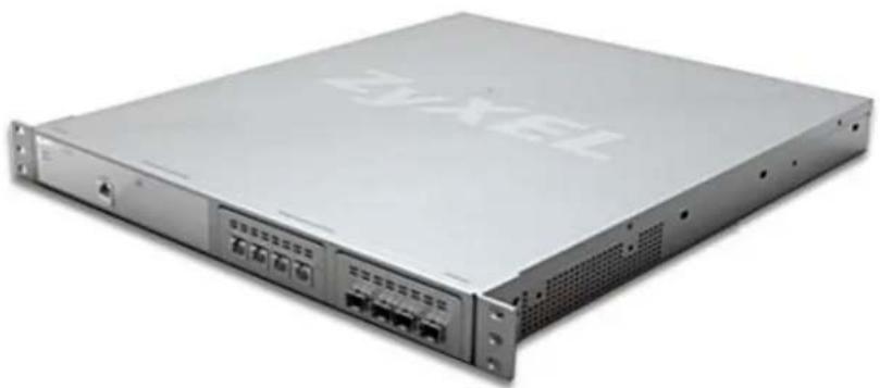
Exterior view of a server rack unit (no visible text or symbols)Default Login Details
IP Address https://192.168.1.1
User Name admin
Password 1234
Version 2.20
Edition 1, 05/2010
www.zyxel.com
ZyXEL
About This User's Guide
Intended Audience
This manual is intended for people who want to want to configure the NXC using the Web Configurator.
Related Documentation
- Quick Start Guide
The Quick Start Guide is designed to show you how to make the NXC hardware connections and access the Web Configurator wizards. (See the wizard real time help for information on configuring each screen.) It also contains a connection diagram and package contents list.
• CLI Reference Guide
The CLI Reference Guide explains how to use the Command-Line Interface (CLI) to configure the NXC.
Note: It is recommended you use the Web Configurator to configure the NXC.
• Web Configurator Online Help
Click the help icon in any screen for help in configuring that screen and supplementary information.
- ZyXEL Web Site
Please refer to www.zyxel.com for additional support documentation and product certifications.
User Guide Feedback
Help us help you. Send all User Guide-related comments, questions or suggestions for improvement to the following address, or use e-mail instead. Thank you!
The Technical Writing Team, ZyXEL Communications Corp., 6 Innovation Road II, Science-Based Industrial Park, Hsinchu, 300, Taiwan.
E-mail: techwriters@zyxel.com.tw
Need More Help?
More help is available at www.zyxel.com.
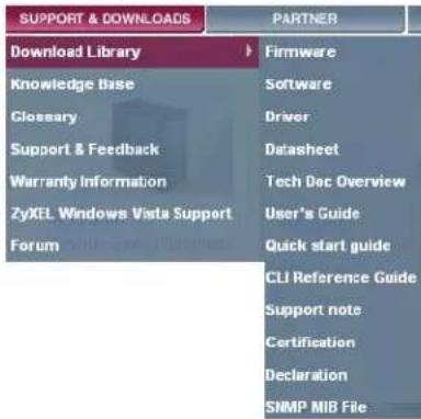
- Download Library
Search for the latest product updates and documentation from this link. Read the Tech Doc Overview to find out how to efficiently use the User Guide, Quick Start Guide and Command Line Interface Reference Guide in order to better understand how to use your product.
- Knowledge Base
If you have a specific question about your product, the answer may be here. This is a collection of answers to previously asked questions about ZyXEL products.
- Forum
This contains discussions on ZyXEL products. Learn from others who use ZyXEL products and share your experiences as well.
Customer Support
Should problems arise that cannot be solved by the methods listed above, you should contact your vendor. If you cannot contact your vendor, then contact a ZyXEL office for the region in which you bought the device.
See http://www.zyxel.com/web/contact_us.php for contact information. Please have the following information ready when you contact an office.
• Product model and serial number.
- Warranty Information.
- Date that you received your device.
- Brief description of the problem and the steps you took to solve it.
Disclaimer
Graphics in this book may differ slightly from the product due to differences in operating systems, operating system versions, or if you installed updated firmware/software for your device. Every effort has been made to ensure that the information in this manual is accurate.
Document Conventions
Warnings and Notes
These are how warnings and notes are shown in this User's Guide.
Warnings tell you about things that could harm you or your device.
Note: Notes tell you other important information (for example, other things you may need to configure or helpful tips) or recommendations.
Syntax Conventions
- The product may be referred to as the "NXC", the "device", the "system" or the "product" in this User's Guide.
- Product labels, screen names, field labels and field choices are all in bold font.
- A key stroke is denoted by square brackets and uppercase text, for example, [ENTER] means the "enter" or "return" key on your keyboard.
- “Enter” means for you to type one or more characters and then press the [ENTER] key. “Select” or “choose” means for you to use one of the predefined choices.
- A right angle bracket ( > ) within a screen name denotes a mouse click. For example, Maintenance > Log > Log Setting means you first click Maintenance in the navigation panel, then the Log sub menu and finally the Log Setting tab to get to that screen.
- Units of measurement may denote the “metric” value or the “scientific” value. For example, “k” for kilo may denote “1000” or “1024”, “M” for mega may denote “1000000” or “1048576” and so on.
- “e.g.,” is a shorthand for “for instance”, and “i.e.,” means “that is” or “in other words”.
Icons Used in Figures
Figures in this User's Guide may use the following generic icons. The NXC icon is not an exact representation of your device.
| NXC Computer Notebook computer | ||
 |  |  |
| Server Firewall Telephone | ||
 |  |  |
| Switch Router | ||
 |  | |
Safety Warnings
- Do NOT use this product near water, for example, in a wet basement or near a swimming pool.
- Do NOT expose your device to dampness, dust or corrosive liquids.
- Do NOT store things on the device.
- Do NOT install, use, or service this device during a thunderstorm. There is a remote risk of electric shock from lightning.
- Connect ONLY suitable accessories to the device.
- Do NOT open the device or unit. Opening or removing covers can expose you to dangerous high voltage points or other risks. ONLY qualified service personnel should service or disassemble this device. Please contact your vendor for further information.
- Make sure to connect the cables to the correct ports.
- Place connecting cables carefully so that no one will step on them or stumble over them.
- Always disconnect all cables from this device before servicing or disassembling.
- Caution: This unit has more than one power supply cord. Disconnect two power supply cords before servicing to avoid electric shock. (has multiple power cords, e.g., chassis-based Ethernet switch. Make sure you specify the correct number of power cords in both the English and the French that follows)
- Attention: Cet appareil comporte plus d'un cordon d'alimentation. Afin de prévenir les chocs électriques, debrancher les deux cordons d'alimentation avant de faire le dépannage.
- Use ONLY an appropriate power adaptor or cord for your device. Connect it to the right supply voltage (for example, 110V AC in North America or 230V AC in Europe).
- Do NOT remove the plug and connect it to a power outlet by itself; always attach the plug to the power adaptor first before connecting it to a power outlet.
- Do NOT allow anything to rest on the power adaptor or cord and do NOT place the product where anyone can walk on the power adaptor or cord.
- Do NOT use the device if the power adaptor or cord is damaged as it might cause electrocution.
- If the power adaptor or cord is damaged, remove it from the device and the power source.
- Do NOT attempt to repair the power adaptor or cord. Contact your local vendor to order a new one.
- Do not use the device outside, and make sure all the connections are indoors. There is a remote risk of electric shock from lightning.
- CAUTION: RISK OF EXPLOSION IF BATTERY (on the motherboard) IS REPLACED BY AN INCORRECT TYPE. DISPOSE OF USED BATTERIES ACCORDING TO THE INSTRUCTIONS. Dispose them at the applicable collection point for the recycling of electrical and electronic equipment. For detailed information about recycling of this product, please contact your local city office, your household waste disposal service or the store where you purchased the product.
- Do NOT obstruct the device ventilation slots, as insufficient airflow may harm your device.
Your product is marked with this symbol, which is known as the WEEE mark. WEEE stands for Waste Electronics and Electrical Equipment. It means that used electrical and electronic products should not be mixed with general waste. Used electrical and electronic equipment should be treated separately.

Table of Contents
About This User's Guide....3
Document Conventions....6
Safety Warnings....8
Table of Contents......9
Part I: User's Guide.... 23
Chapter 1 Introduction......25
1.1 Overview 25
1.2 Rack-mounted Installation 25
1.2.1 Rack-Mounted Installation Procedure 26
1.2.2 LAN Module Installation Procedure 27
1.3 Front and Back Panels 29
1.3.1 1000Base-T Ports 29
1.3.2 Optional Fiber Ports 30
1.3.3 Front Panel LEDs 31
1.4 Management Overview ...... 31
1.5 Starting and Stopping the NXC 32
Chapter 2 Features and Applications....35
2.1 Features 35
2.2 Applications ...... 37
2.2.1 AP Management 37
2.2.2 Wireless Security 37
2.2.3 Captive Portal 38
2.2.4 Load Balancing 38
2.2.5 Dynamic Channel Selection 38
2.2.6 User-Aware Access Control 39
2.2.7 Device HA 39
Chapter 3 The Web Configurator ....41
3.1 Overview 41
3.2 Access 41
3.3 The Main Screen 43
3.3.1 Title Bar 44
3.3.2 Navigation Panel 44
3.3.3 Warning Messages 49
3.3.4 Site Map 50
3.3.5 Object Reference 50
3.3.6 Tables and Lists 55
Chapter 4 Configuration Basics....59
4.1 Overview 59
4.2 Object-based Configuration 59
4.3 Zones, Interfaces, and Physical Ports 60
4.3.1 Interface Types 60
4.3.2 Example Interface and Zone Configuration 61
4.4 Feature Configuration Overview 62
4.4.1 Feature 62
4.4.2 Licensing Registration 62
4.4.3 Licensing Update 63
4.4.4 Wireless 63
4.4.5 Interface 63
4.4.6 Policy Routes 63
4.4.7 Static Routes 64
4.4.8 Zones 64
4.4.9 NAT 64
4.4.10 ALG 64
4.4.11 Captive Portal 65
4.4.12 Firewall 65
4.4.13 Application Patrol 65
4.4.14 Anti-Virus 65
4.4.15 IDP 66
4.4.16 ADP 66
4.4.17 Device HA 66
4.5 Objects 66
4.5.1 User/Group 67
4.5.2 AP Profile 67
4.5.3 MON Profile 68
4.6 System 68
4.6.1 DNS, WWW, SSH, TELNET, FTP, and SNMP 68
4.6.2 Logs and Reports 68
4.6.3 File Manager 69
4.6.4 Diagnostics 69
4.6.5 Shutdown 69
Chapter 5
Tutorials....71
5.1 Overview 71
5.2 Sample Network Setup 72
5.2.1 Tutorial Tasks 73
5.2.2 Set the Management VLAN (vlan99) 74
5.2.3 Set the Other VLANs (vlan101, vlan102) 75
5.2.4 Configure the AAA Object 77
5.2.5 Configure the Auth. Method Objects (staff, guest) 79
5.2.6 Create the AP Profiles (staff, guest) 80
5.2.7 Create the Guest User Account 83
5.2.8 Configure the Captive Portal Settings 84
5.2.9 Configure the Guest Firewall Rules 85
5.3 Blocking Network Protocols 87
5.3.1 Configuring the WLAN Zone 87
5.3.2 Configuring the Firewall 88
5.3.3 Blocking Sub-Protocols 90
5.4 Rogue AP Detection 92
5.4.1 Rogue AP Containment 96
5.5 Load Balancing 97
5.6 Dynamic Channel Selection 98
Part II: Technical Reference 101
Chapter 6
Dashboard 103
6.1 Overview 103
6.1.1 What You Can Do in this Chapter 103
6.2 Dashboard 104
6.2.1 CPU Usage 109
6.2.2 Memory Usage 110
6.2.3 Session Usage 111
6.2.4 DHCP Table 112
6.2.5 Number of Login Users 113
Chapter 7
Monitor....115
7.1 Overview 115
7.1.1 What You Can Do in this Chapter 115
7.2 What You Need to Know ....116
7.3 Port Statistics 117
7.3.1 Port Statistics Graph 118
7.4 Interface Status ....119
7.5 Traffic Statistics 121
7.6 Session Monitor 124
7.7 IP/MAC Binding Monitor 127
7.8 Login Users 128
7.9 AP List 129
7.9.1 Station Count of AP 130
7.10 Radio List 131
7.10.1 AP Mode Radio Information 132
7.11 Station List 133
7.12 Detected Device 134
7.13 Application Patrol 135
7.13.1 Application Patrol: General Settings 135
7.13.2 Application Patrol: Bandwidth Statistics 136
7.13.3 Application Patrol: Protocol Statistics 137
7.13.4 Application Patrol: Protocol Statistics by Rule 138
7.14 Anti-Virus 139
7.15 IDP 141
7.16 View Log 143
7.17 View AP Log 146
Chapter 8
Registration....151
8.1 Overview ...... 151
8.1.1 What You Can Do in this Chapter 151
8.1.2 What you Need to Know 151
8.2 Registration 153
8.3 Service 155
Chapter 9
Signature Update 157
9.1 Overview 157
9.1.1 What You Can Do in this Chapter 157
9.1.2 What you Need to Know 157
9.2 Anti-Virus 158
9.3 IDP/AppPatrol 159
9.4 System Protect 161
Chapter 10
Wireless 163
10.1 Overview 163
10.1.1 What You Can Do in this Chapter 163
10.1.2 What You Need to Know 163
10.2 Controller 164
10.3 AP Management 165
10.3.1 Edit AP List 166
10.4 MON Mode 167
10.4.1 Add/Edit Rogue/Friendly List 169
10.5 Load Balancing 170
10.5.1 Disassociating and Delaying Connections 171
10.6 DCS 173
10.7 Technical Reference 174
10.7.1 Dynamic Channel Selection 174
10.7.2 Load Balancing 176
Chapter 11 Interfaces....177
11.1 Interface Overview 177
11.1.1 What You Can Do in this Chapter 177
11.1.2 What You Need to Know 177
11.2 Ethernet Summary 178
11.2.1 Edit Ethernet 180
11.2.2 Object References 185
11.3 VLAN Interfaces 186
11.3.1 VLAN Summary 188
11.3.2 Add/Edit VLAN 189
11.4 Technical Reference 193
Chapter 12 Policy and Static Routes ...... 197
12.1 Overview 197
12.1.1 What You Can Do in this Chapter 197
12.1.2 What You Need to Know 197
12.2 Policy Route 199
12.2.1 Add/Edit Policy Route 202
12.3 Static Route 206
12.3.1 Static Route Setting 207
12.4 Technical Reference 208
Chapter 13 Zones ....213
13.1 Overview 213
13.1.1 What You Can Do in this Chapter 214
13.1.2 What You Need to Know 214
13.2 Zone 215
13.3 Add/Edit Zone 216
Chapter 14
NAT 217
14.1 Overview 217
14.1.1 What You Can Do in this Chapter 217
14.2 NAT Summary 218
14.2.1 Add/Edit NAT 219
14.3 Technical Reference 222
Chapter 15
ALG 225
15.1 Overview 225
15.1.1 What You Can Do in this Chapter 225
15.1.2 What You Need to Know 226
15.1.3 Before You Begin 227
15.2 ALG 228
15.3 Technical Reference 230
Chapter 16
IP/MAC Binding 233
16.1 Overview 233
16.1.1 What You Can Do in this Chapter 233
16.1.2 What You Need to Know 234
16.2 IP/MAC Binding Summary 234
16.2.1 Edit IP/MAC Binding 235
16.2.2 Add/Edit Static DHCP Rule 237
16.3 IP/MAC Binding Exempt List 238
Chapter 17
Captive Portal 239
17.1 Overview 239
17.1.1 What You Can Do in this Chapter 240
17.2 Captive Portal 240
17.2.1 Add Exceptional Services 242
17.2.2 Auth. Policy Add/Edit 243
17.3 Login Page 245
Chapter 18
Firewall....249
18.1 Overview 249
18.1.1 What You Can Do in this Chapter 249
18.1.2 What You Need to Know 250
18.1.3 Firewall Rule Example Applications 252
18.1.4 Firewall Rule Configuration Example 255
18.1.5 Asymmetrical Routes 256
18.2 Firewall 257
18.2.1 Add/Edit Firewall Screen 260
18.3 Session Limit 262
18.3.1 Add/Edit Session Limit 263
Chapter 19
Application Patrol 265
19.1 Overview 265
19.1.1 What You Can Do in this Chapter 265
19.1.2 What You Need to Know 266
19.1.3 Application Patrol Bandwidth Management Examples 271
19.2 Application Patrol Common Applications 275
19.2.1 Edit Application 276
19.2.2 Add/Edit Policy 279
19.3 Other Applications 281
19.3.1 Add/Edit Policy 284
Chapter 20
Anti-Virus 287
20.1 Overview 287
20.1.1 What You Can Do in this Chapter 287
20.1.2 What You Need to Know 288
20.1.3 Before You Begin 289
20.2 Anti-Virus Summary 290
20.2.1 Add/Edit Rule 293
20.3 Black List 295
20.4 Add/Edit Pattern 296
20.5 White List 298
20.6 Signature 299
20.7 Technical Reference 301
Chapter 21
IDP 303
21.1 Overview 303
21.1.1 What You Can Do in this Chapter 303
21.1.2 What You Need To Know 303
21.1.3 Before You Begin 304
21.2 IDP Summary 304
21.3 Profile Summary 307
21.3.1 Base Profiles 308
21.4 Creating New Profiles 309
21.5 Add/Edit Profile 311
21.5.1 Policy Types 314
21.5.2 IDP Service Groups 316
21.5.3 Query View Screen 317
21.5.4 Query Example 319
21.6 Custom IDP Signatures 320
21.6.1 IP Packet Header 320
21.7 Custom Signatures 321
21.7.1 Add/Edit Custom Signature 323
21.7.2 Custom Signature Example 329
21.7.3 Applying Custom Signatures 331
21.7.4 Verifying Custom Signatures 332
21.8 Technical Reference 333
Chapter 22
ADP 337
22.1 Overview 337
22.1.1 What You Can Do in this Chapter 337
22.1.2 What You Need To Know 337
22.1.3 Before You Begin 338
22.2 ADP Summary 339
22.3 Profile Summary 340
22.3.1 Base Profiles 341
22.3.2 Creating New ADP Profiles 342
22.3.3 Traffic Anomaly Profiles 342
22.3.4 Protocol Anomaly Profiles 345
22.3.5 Protocol Anomaly Configuration 345
22.4 Technical Reference 349
Chapter 23
Device HA 357
23.1 Overview 357
23.1.1 What You Can Do in this Chapter 357
23.1.2 What You Need to Know 358
23.1.3 Before You Begin 358
23.2 Device HA General 359
23.3 Active-Passive Mode 361
23.3.1 Edit Monitored Interface 364
23.4 Technical Reference 366
Chapter 24
User/Group 373
24.1 Overview 373
24.1.1 What You Can Do in this Chapter 373
24.1.2 What You Need To Know 373
24.2 User Summary 376
24.2.1 Add/Edit User 376
24.3 Group Summary 379
24.3.1 Add/Edit Group 380
24.4 Setting 381
24.4.1 Edit User Authentication Timeout Settings 384
24.4.2 User Aware Login Example 386
Chapter 25
AP Profile....387
25.1 Overview 387
25.1.1 What You Can Do in this Chapter 387
25.1.2 What You Need To Know 387
25.2 Radio 388
25.2.1 Add/Edit Radio Profile 389
25.3 SSID 392
25.3.1 SSID List 392
25.3.2 Security List 396
25.3.3 MAC Filter List 399
Chapter 26
MON Profile 401
26.1 Overview 401
26.1.1 What You Can Do in this Chapter 401
26.1.2 What You Need To Know 401
26.2 MON Profile 402
26.2.1 Add/Edit MON Profile 403
26.3 Technical Reference 404
Chapter 27
Addresses....407
27.1 Overview 407
27.1.1 What You Can Do in this Chapter 407
27.1.2 What You Need To Know 407
27.2 Address Summary 407
27.2.1 Add/Edit Address 409
27.3 Address Group Summary 410
27.3.1 Add/Edit Address Group Rule 411
Chapter 28
Services 413
28.1 Overview 413
28.1.1 What You Can Do in this Chapter 413
28.1.2 What You Need to Know 413
28.2 Service Summary 415
28.2.1 Add/Edit Service Rule 416
28.3 Service Group Summary 417
28.3.1 Add/Edit Service Group Rule 418
Chapter 29
Schedules 419
29.1 Overview 419
29.1.1 What You Can Do in this Chapter 419
29.1.2 What You Need to Know 419
29.2 Schedule Summary 420
29.2.1 Add/Edit Schedule One-Time Rule 421
29.2.2 Add/Edit Schedule Recurring Rule 422
Chapter 30
AAA Server 425
30.1 Overview 425
30.1.1 What You Can Do in this Chapter 425
30.1.2 What You Need To Know 425
30.2 Active Directory / LDAP 429
30.2.1 Add/Edit Active Directory / LDAP Server 430
30.3 RADIUS 433
30.3.1 Add/Edit RADIUS 434
Chapter 31
Authentication Method....437
31.1 Overview 437
31.1.1 What You Can Do in this Chapter 437
31.1.2 Before You Begin 437
31.2 Authentication Method 437
31.2.1 Add Authentication Method 438
Chapter 32
Certificates 441
32.1 Overview 441
32.1.1 What You Can Do in this Chapter 441
32.1.2 What You Need to Know 441
32.1.3 Verifying a Certificate 443
32.2 My Certificates 445
32.2.1 Add My Certificates 447
32.2.2 Edit My Certificates 451
32.2.3 Import Certificates 454
32.3 Trusted Certificates 455
32.3.1 Edit Trusted Certificates 457
32.3.2 Import Trusted Certificates 460
32.4 Technical Reference 461
Chapter 33
System 463
33.1 Overview 463
33.1.1 What You Can Do in this Chapter 463
33.2 Host Name 464
33.3 Date and Time 464
33.3.1 Pre-defined NTP Time Servers List 467
33.3.2 Time Server Synchronization 468
33.4 Console Speed 469
33.5 DNS Overview 469
33.5.1 DNS Server Address Assignment 469
33.5.2 Configuring the DNS Screen 470
33.5.3 Address Record 472
33.5.4 PTR Record 473
33.5.5 Adding an Address/PTR Record 473
33.5.6 Domain Zone Forwarder 474
33.5.7 Add Domain Zone Forwarder 474
33.5.8 MX Record 475
33.5.9 Add MX Record 476
33.5.10 Add Service Control 476
33.6 WWW Overview 477
33.6.1 Service Access Limitations 477
33.6.2 System Timeout 478
33.6.3 HTTPS 478
33.6.4 Configuring WWW Service Control 479
33.6.5 Service Control Rules 483
33.6.6 HTTPS Example 483
33.7 SSH 490
33.7.1 How SSH Works 491
33.7.2 SSH Implementation on the NXC 492
33.7.3 Requirements for Using SSH 492
33.7.4 Configuring SSH 493
33.7.5 Examples of Secure Telnet Using SSH 494
33.8 Telnet 496
33.9 FTP 497
33.10 SNMP 500
33.10.1 Supported MIBs 501
33.10.2 SNMP Traps 501
33.10.3 Configuring SNMP 502
33.11 Language 503
Chapter 34
Log and Report 505
34.1 Overview 505
34.1.1 What You Can Do In this Chapter 505
34.2 Email Daily Report 505
34.3 Log Setting 507
34.3.1 Log Setting Summary 508
34.3.2 Edit Log Settings 510
34.3.3 Edit Remote Server 514
34.3.4 Active Log Summary 516
Chapter 35
File Manager....519
35.1 Overview 519
35.1.1 What You Can Do in this Chapter 519
35.1.2 What you Need to Know 519
35.2 Configuration File 522
35.3 Firmware Package 525
35.4 Shell Script 527
Chapter 36
Diagnostics....531
36.1 Overview 531
36.1.1 What You Can Do in this Chapter 531
36.2 Diagnostics 531
36.3 Packet Capture 532
36.3.1 Packet Capture Files 534
36.3.2 Example of Viewing a Packet Capture File 535
36.4 Wireless Frame Capture 536
36.4.1 Wireless Frame Capture Files 538
Chapter 37
Reboot....539
37.1 Overview 539
37.1.1 What You Need To Know 539
37.2 Reboot 539
Chapter 38
Shutdown....541
38.1 Overview 541
38.1.1 What You Need To Know 541
38.2 Shutdown 541
Chapter 39
Troubleshooting....543
39.1 Overview 543
39.1.1 General 543
39.1.2 Wireless 555
39.2 Resetting the NXC 557
39.3 Getting More Troubleshooting Help 557
Chapter 40
Product Specifications 559
Appendix A Log Descriptions 565
Appendix B Common Services....613
Appendix C Displaying Anti-Virus Alert Messages in Windows....617
Appendix D Importing Certificates....619
Appendix E Wireless LANs 633
Appendix F Open Software Announcements 647
Appendix G Legal Information....699
Index....703
PART I
User's Guide
Introduction
1.1 Overview
The NXC is a comprehensive wireless LAN controller. Its flexible configuration helps network administrators set up wireless LAN networks and efficiently enforce security policies over them. In addition, the NXC provides excellent throughput, making it an ideal solution for reliable, secure service.
The NXC's security features include firewall, anti-virus, Intrusion Detection and Prevention (IDP), Anomaly Detection and Protection (ADP), and certificates. It also provides bandwidth management, captive portal configuration, NAT, port forwarding, policy routing, DHCP server, extensive wireless AP control options, and many other powerful features. Flexible configuration helps you set up the network and enforce security policies efficiently.
The front panel physical Gigabit Ethernet ports (labeled P1, P2, P3, and so on) are mapped to Gigabit Ethernet (ge) interfaces. By default P1 is mapped to ge1, P2 is mapped to ge2 and so on.
• The default LAN IP address is 192.168.1.1.
- The default administrator login user name and password are "admin" and "1234" respectively.
1.2 Rack-mounted Installation
Note: ZyXEL provides a sliding rail accessory for your use with your device. Please contact your local vendor for details.
The NXC can be mounted on an EIA standard size, 19-inch rack or in a wiring closet with other equipment. Follow the steps below to mount your NXC on a standard EIA rack using a rack-mounting kit. Make sure the rack will safely support the combined weight of all the equipment it contains and that the position of the NXC does not make the rack unstable or top-heavy. Take all necessary precautions to anchor the rack securely before installing the unit.
Note: Leave 10 cm of clearance at the sides and 20 cm in the rear.
Use a #2 Phillips screwdriver to install the screws.
Note: Failure to use the proper screws may damage the unit.
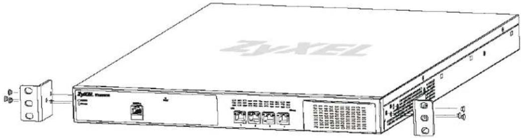
1.2.1 Rack-Mounted Installation Procedure
1 Align one bracket with the holes on one side of the NXC and secure it with the included bracket screws (smaller than the rack-mounting screws).
2 Attach the other bracket in a similar fashion.
natural_image
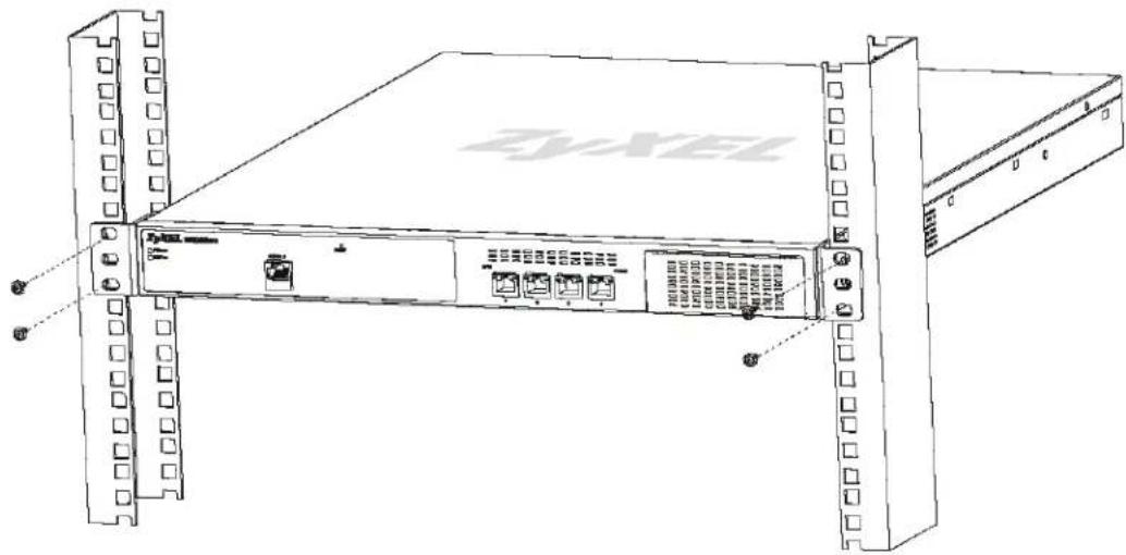
Line drawing of a Zyxel networking device with ports and connectors (no text or symbols on the device itself)3 After attaching both mounting brackets, position the NXC in the rack by lining up the holes in the brackets with the appropriate holes on the rack. Secure the NXC to the rack with the rack-mounting screws.
1.2.2 LAN Module Installation Procedure
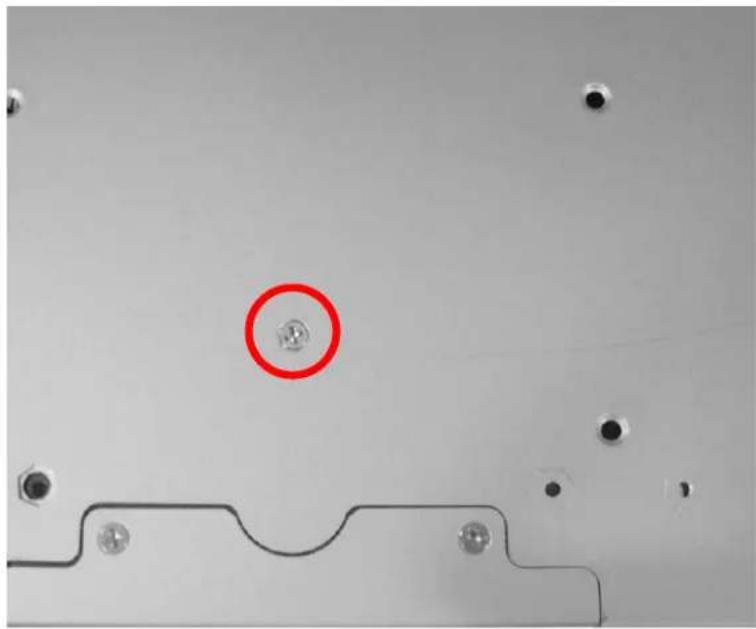
1 Turn the NXC over so that its bottom side faces up, then remove the LAN module screw.
natural_image
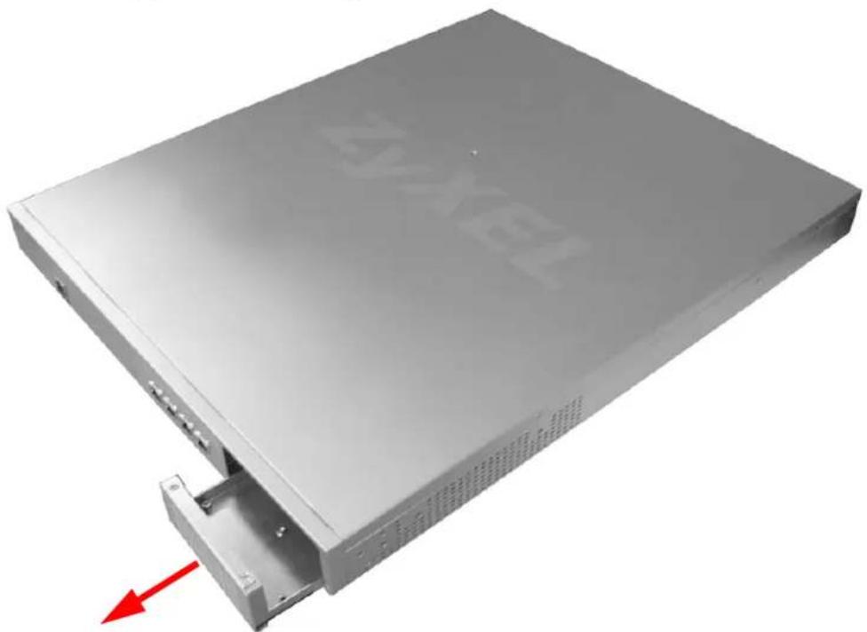
Close-up of a mechanical component with a red circle highlighting a small feature, no visible text or symbols.2 Slide the empty LAN Module tray out of the NXC chassis.
natural_image
Exterior view of a silver computer drive with a red arrow indicating compression (no text or symbols visible)3 Slide the LAN Module into the empty module bay, gently but firmly pressing it into the NXC's logic board until you feel it snap into place.
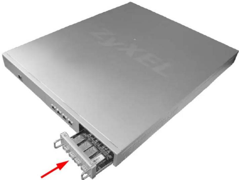
natural_image
Exterior view of a silver server rack with internal components and a red arrow indicating a specific port (no text or symbols visible)4 Secure the newly installed LAN Module with the screw you removed in step 1.
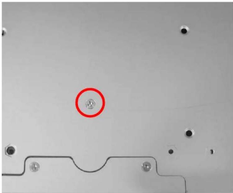
natural_image
Close-up of a mechanical component with a red circle highlighting a feature, no visible text or symbols1.3 Front and Back Panels
This section gives you an overview of the front and back panels. There are three possible front panel configurations, depending on how the expansion bay is used. The back panel remains static across all configurations.
In configuration 1, the expansion bay is empty.
Figure 1 NXC Front Panel - Configuration 1

In configuration 2, the expansion bay utilizes an Ethernet module which provides an additional 4 Ethernet ports.
Figure 2 NXC Front Panel - Configuration 2

In configuration 3, the expansion bay utilizes a Fiber port modules, which provides fiber optic connectivity. This allows you to expand management of your APs to distances greater than allowed by pure Ethernet connections.
Figure 3 NXC Front Panel - Configuration 3

Here is the back panel for all configurations.
Figure 4 NXC Back panel - All Configurations

natural_image
Front view of a server rack with indicator lights and ports (no readable text or symbols)1.3.1 1000Base-T Ports
The 1000Base-T auto-negotiating, auto-crossover Ethernet ports support 100/1000 Mbps Gigabit Ethernet so the speed can be 100 Mbps or 1000 Mbps. The duplex mode can be both half or full duplex at 100 Mbps and full duplex only at 1000 Mbps. An auto-negotiating port can detect and adjust to the optimum Ethernet speed (100/1000 Mbps) and duplex mode (full duplex or half duplex) of the connected device.
An auto-crossover (auto-MDI/MDI-X) port automatically works with a straight-through or crossover Ethernet cable.
Default Ethernet Settings
The factory default negotiation settings for the Ethernet ports on the NXC are:
- Speed: Auto
- Duplex: Auto
- Flow control: On (you cannot configure the flow control setting, but the NXC can negotiate with the peer and turn it off if needed)
1.3.2 Optional Fiber Ports
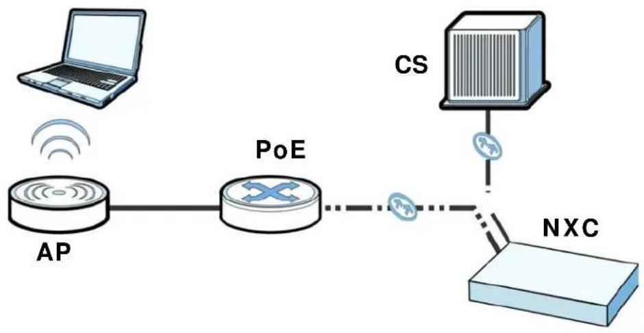
Fiber connectivity requires a few additional considerations when you deploy the NXC with that in mind.
Figure 5 Fiber Connection Example
flowchart
graph LR
    A["Laptop"] -->|Wireless Signal| B["AP"]
    B --> C["PoE"]
    C --> D["NXC"]
    D --> E["Server"]
    E --> F["CS"]
    F -->|Wireless Signal| C
First, you must have a fiber-based Core Switch (CS) upstream of the NXC. It connects to one of the available fiber ports in the Fiber port module loaded into the NXC's expansion bay. Next, an additional fiber connection is established between the NXC and a downstream fiber-based Power over Ethernet (PoE) capable of converting Fiber-to-Ethernet data packets (such as the ZyXEL MC1000-SFP-FP). Finally, you connect your AP to the edge switch using an Ethernet cable.
1.3.3 Front Panel LEDs
This section describes the front panel LEDs.
Figure 6 NXC Front Panel - Configuration 3
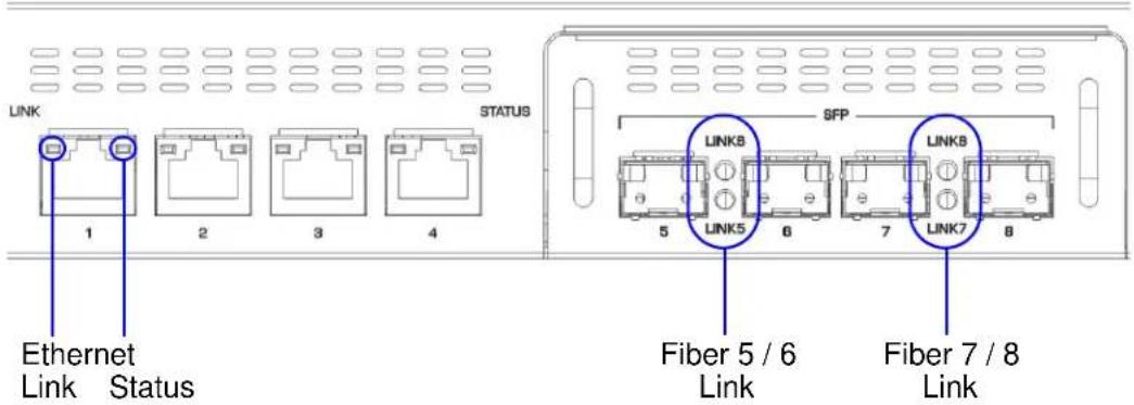
The following table describes the LEDs.
Table 1 Front Panel LEDs
| LED COLOR STATUS DESCRIPTION | |||
| POWER Off The power m | module is tur | ned off, not receiving power,or not functioning. | |
| Green On | The power module is operating. | ||
| STATUS Off The NXC is turned off. | |||
| Green On | The NXC is ready and operating normally. | ||
| Flashing The NXC is self-testing. | |||
| Ethernet Link Amber On | The port has a connected RJ-45 cable. | ||
| Flashing The port is sending and receiving data. | |||
| Ethernet Status | Green On | The port is functioning at 10/100M speed. | |
| Amber On | The port is functioning at 1000M speed. | ||
| Fiber Link Amber On The | port has a connected fiber cable. | ||
1.4 Management Overview
You can use the following ways to manage the NXC.
Web Configurator
The Web Configurator allows easy NXC setup and management using an Internet browser. This User's Guide provides information about the Web Configurator.
Command-Line Interface (CLI)
The CLI allows you to use text-based commands to configure the NXC. You can access it using remote management (for example, SSH or Telnet) or via the console port. See the Command Reference Guide for more information.
Console Port
You can use the console port to manage the NXC using CLI commands. See the Command Reference Guide for more information about the CLI.
The default settings for the console port are as follows.
Table 2 Console Port Default Settings
| SETTING VALUE | |
| Speed 115200 bps | |
| Data Bits 8 | |
| Parity None | |
| Stop Bit 1 | |
| Flow Control Off | |
1.5 Starting and Stopping the NXC
Here are some of the ways to start and stop the NXC.
Always use Maintenance > Shutdown or the shutdown command before you turn off the NXC or remove the power. Not doing so can cause the firmware to become corrupt.
Table 3 Starting and Stopping the NXC
| METHOD DESCRIPTION | |
| Turning on the power | A cold start occurs when you turn on the power to the NXC. The NXC powers up, checks the hardware, and starts the system processes. |
| Rebooting the NXC A | warm start (without powering down and powering up again) occurs when you use the Reboot button in the Reboot screen or when you use the reboot command. The NXC writes all cached data to the local storage, stops the system processes, and then does a warm start. |
| Using the RESET button | If you press the RESET button, the NXC sets the configuration to its default values and then reboots. |
Table 3 Starting and Stopping the NXC
| METHOD DESCRIPTION | |
| ClickingMaintenance > Shutdown > Shutdown or using the shutdown command | Clicking Maintenance > Shutdown > Shutdown or using the shutdown command writes all cached data to the local storage and stops the system processes. Wait for the device to shut down and then manually turn off or remove the power. It does not turn off the power. |
| Disconnecting the power | Power off occurs when you turn off the power to the NXC. The NXC simply turns off. It does not stop the system processes or write cached data to local storage. |
The NXC does not stop or start the system processes when you apply configuration files or run shell scripts although you may temporarily lose access to network resources.
Features and Applications
This chapter introduces the main features and applications of the NXC.
2.1 Features
The NXC is a wireless LAN controller. It has security features that include firewall, anti-virus, Intrusion Detection and Prevention (IDP), Anomaly Detection and Protection (ADP), and certificates. It also provides bandwidth management, NAT, port forwarding, captive portal configuration, policy routing, DHCP server, wireless AP control options, and many other powerful features.
Data Forwarding
The NXC allows you to seamlessly manage the Access Points (APs) on your network by having all configurable data tunneled to it or bridged to the local network based on SSID settings.
AP Monitoring
You can assign a number of APs to act as wireless monitors, which can detect rogue APs and help you in building a list of friendly ones. This gives you a security advantage when setting up your network to prevent intrusions.
Managed APs
The NXC is initially configured to support up to 48 managed APs (such as the NWA5160N). You can increase this by subscribing to additional licenses. As of this writing, each license upgrade allows an additional 48 managed APs while the maximum number of APs a single NXC can support is 240.
Flexible Security Zones
Many security settings are applied by zone, not by interface, port, or network. As a result, it is much simpler to set up and to change security settings in the NXC. You can create your own custom zones.
Firewall
The NXC's firewall is a stateful inspection firewall. The NXC restricts access by screening data packets against defined access rules. It can also inspect sessions. For example, traffic from one zone is not allowed unless it is initiated by a computer in another zone first.
Intrusion Detection and Prevention (IDP)
IDP (Intrusion Detection and Protection) can detect malicious or suspicious packets and respond instantaneously. It detects pattern-based attacks in order to protect against network-based intrusions. See Section 21.5.1 on page 314 for a list of attacks that the NXC can protect against. You can also create your own custom IDP rules.
Anomaly Detection and Prevention (ADP)
ADP (Anomaly Detection and Prevention) can detect malicious or suspicious packets and respond instantaneously. It can detect:
- Anomalies based on violations of protocol standards (RFCs – Requests for Comments)
- Abnormal flows such as port scans.
The NXC's ADP protects against network-based intrusions. See Section 22.3.3 on page 342 and Section 22.3.4 on page 345 for more on the kinds of attacks that the NXC can protect against. You can also create your own custom ADP rules.
Bandwidth Management
Bandwidth management allows you to allocate network resources according to defined policies. This policy-based bandwidth allocation helps your network to better handle applications such as Internet access, e-mail, Voice-over-IP (VoIP), video conferencing and other business-critical applications.
Anti-Virus Scanner
With the anti-virus packet scanner, your NXC scans files transmitting through the enabled interfaces into the network. The NXC helps stop threats at the network edge before they reach the local host computers.
Application Patrol
Application patrol manages instant messenger and peer-to-peer applications like MSN and BitTorrent. You can even control the use of a particular application's individual features (like text messaging, voice, video conferencing, and file transfers). Application patrol has powerful bandwidth management including
traffic prioritization to enhance the performance of delay-sensitive applications like voice and video. You can also use an option that gives SIP priority over all other traffic. This maximizes SIP traffic throughput for improved VoIP call sound quality.
2.2 Applications
These are some example applications for your NXC. See also Chapter 5 on page 71 for configuration tutorial examples.
2.2.1 AP Management
Manage up to 240 separate Access Points (APs) from a single, persistent location. APs can also be configured to monitor for rogue APs.
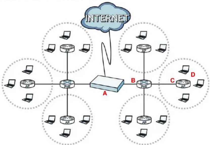
Figure 7 AP Management Example
flowchart
graph TD
    A["INTERNET"] --> B["AP"]
    A --> C["AP"]
    A --> D["AP"]
    B --> E["PCB"]
    C --> F["PCB"]
    D --> G["PCB"]
    E --> H["AP"]
    F --> I["AP"]
    G --> J["AP"]
    H --> K["AP"]
    I --> L["AP"]
    J --> M["AP"]
    K --> N["AP"]
    L --> O["AP"]
    M --> P["AP"]
    N --> Q["AP"]
    O --> R["AP"]
    P --> S["AP"]
    Q --> T["AP"]
    R --> U["AP"]
    S --> V["AP"]
    T --> W["AP"]
    U --> X["AP"]
    V --> Y["AP"]
    W --> Z["AP"]
    X --> AA["AP"]
    Y --> AB["AP"]
    Z --> AC["AP"]
    AA --> AD["AP"]
    AB --> AE["AP"]
    AC --> AF["AP"]
    AD --> AG["AP"]
    AE --> AH["AP"]
    AF --> AI["AP"]
Here, the NXC (A) connects to a number of Power over Ethernet (PoE) devices (B). They connect to the NWA5260 Access Points (C), which in turn provide access to the network for the wireless clients (D) within their broadcast radius.
2.2.2 Wireless Security
Keep the connections between wireless clients and your APs secure with the NXC's comprehensive wireless security tools. APs can be configured to require WEP and WPA encryption from all wireless clients attempting to associate with them. Furthermore, you can protect your network by monitoring for rogue APs. Rogue APs are wireless access points operating in a network's coverage area that are not
under the control of the network's administrators, and can potentially open up critical holes in a network's security policy.
2.2.3 Captive Portal
The NXC can be configured with a captive portal, which intercepts all network traffic, regardless of address or port, until a connecting wireless user authenticates his or her session, through a designated login Web page.
Figure 8 Applications: Captive Portal
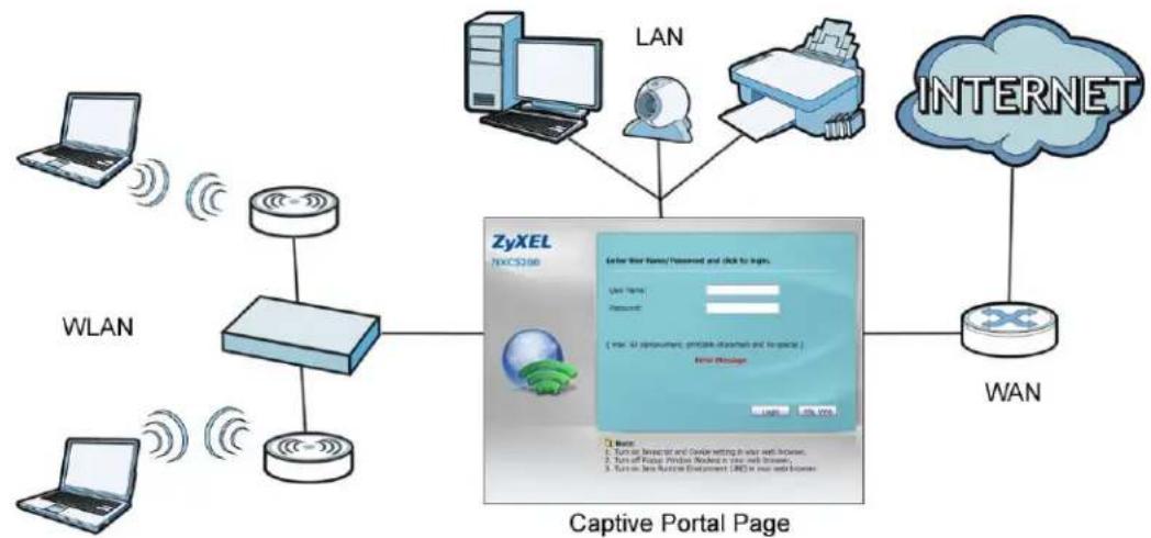
The captive portal page only appears once per authentication session. Unless a user idles out or closes the connection, he or she generally will not see it again during the same session.
2.2.4 Load Balancing
With load balancing you can easily distribute wireless traffic across multiple APs to relieve strain on your network. When a station becomes overloaded, it can automatically delay a connection until the client associates with another network, or it can alternatively disassociate idle clients or those clients with weak connections from the network.
2.2.5 Dynamic Channel Selection
The NXC can automatically select the radio channel upon which its APs broadcast by scanning the area around those APs and determining what channels are currently being used by other devices not connected to the network.
2.2.6 User-Aware Access Control
Set up security policies that restrict access to sensitive information and shared resources based on the user who is trying to access it.
2.2.7 Device HA
Set one NXC as the master device and an additional NXC as a backup device to ensure that one is always available for the network.
The Web Configurator
3.1 Overview
The NXC Web Configurator allows easy management using an Internet browser.
In order to use the Web Configurator, you must:
- Use Internet Explorer 7.0 and later or Firefox 1.5 and later
- Allow pop-up windows
- Enable JavaScript (enabled by default)
- Enable Java permissions (enabled by default)
- Enable cookies
The recommended screen resolution is 1024 x 768 pixels and higher.
3.2 Access
1 Make sure your NXC hardware is properly connected. See the Quick Start Guide.
2 Browse to https://192.168.1.1. The Login screen appears.
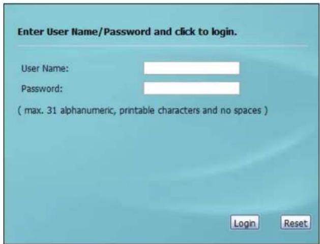
3 Enter the user name (default: "admin") and password (default: "1234").
4 Click Login. If you logged in using the default user name and password, the Update Admin Info screen appears. Otherwise, the dashboard appears.
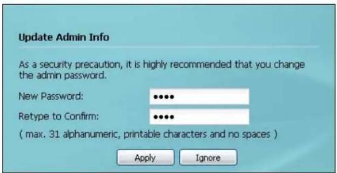
This screen appears every time you log in using the default user name and default password. If you change the password for the default user account, this screen does not appear anymore.
3.3 The Main Screen
The Web Configurator's main screen is divided into these parts:
Figure 9 The Web Configurator's Main Screen
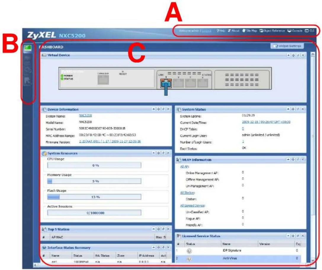
• A - Title Bar
• B - Navigation Panel
• C - Main Window
3.3.1 Title Bar
The title bar provides some useful links that always appear over the screens below, regardless of how deep into the Web Configurator you navigate.
Figure 10 Title Bar

The icons provide the following functions.
Table 4 Title Bar: Web Configurator Icons
| LABEL DESCRIPTION | |
| Logout Click this to log out of the Web Configurator. | |
| Help Click this to open the help page for the current screen. | |
| About Click this to display basic information about the NXC. | |
| Site Map Click this to see an overview of links to the Web Configurator screens. | |
| Object Reference | Click this to open a screen where you can check which configuration items reference an object. |
| Console Click this to open the console in which you can use the command line interface (CLI). See the NXC CLI Reference Guide for details. | |
| CLI Click this to open a popup window that displays the CLI commands sent by the Web Configurator. | |
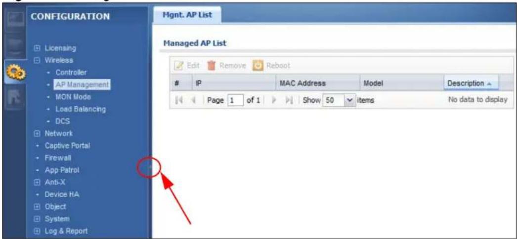
3.3.2 Navigation Panel
Use the menu items on the navigation panel to open screens to configure NXC features. Click the arrow in the middle of the right edge of the navigation panel to hide the navigation panel menus or drag it to resize them. The following sections introduce the NXC's navigation panel menus and their screens.
Figure 11 Navigation Panel
3.3.2.1 Dashboard
The dashboard displays general device information, system status, system resource usage, licensed service status, and interface status in widgets that you can re-arrange to suit your needs.
For details on the Dashboard's features, see Chapter 6 on page 103.
3.3.2.2 Monitor Menu
The monitor menu screens display status and statistics information.
Table 5 Monitor Menu Screens Summary
| FOLDER OR LINK TAB FUNCTION | ||
| System Status | ||
| Port Statistics Displays packet statistics for each physical port. | ||
| Interface Status Displays general interface information and packet statistics. | ||
| Traffic Statistics Collect and display traffic statistics. | ||
| Session Monitor Displays the status of all current sessions. | ||
| IP/MAC Binding Lists the devices that have received an IP address from NXC interfaces using IP/MAC binding. | ||
| Login Users Lists the users currently logged into the NXC. | ||
| Wireless | ||
| AP Info | AP List | Displays information about the connected APs. |
| Radio List Displays information about the radios of the connected APs. | ||
| Station Info Displays information about the connected stations. | ||
| Rogue AP | Displays information about suspected rogue APs. | |
| AppPatrol Statistics Displays bandwidth and protocol statistics. | ||
| Anti-X Statistics | ||
| Anti-Virus | Collects and display statistics on the viruses that the NXC has detected. | |
| IDP | Collects and display statistics on the intrusions that the NXC has detected. | |
| Log | View Log | Lists log entries for the NXC. |
| View AP Log | Allows you to query connected APs and view log entries for them. | |
3.3.2.3 Configuration Menu
Use the configuration menu screens to configure the NXC's features.
Table 6 Configuration Menu Screens Summary
| FOLDER OR LINK | TAB FUNCTION | |||
| Licensing | ||||
| Registration | Registration | Register the device and activate trial services. | ||
| Service View the licensed service status and upgrade licensed services. | ||||
| Signature Update | Anti-Virus Update | anti-virus signatures immediately or by a schedule. | ||
| IDP/AppPatrol Update | date IDP signatures immediately or by a schedule. | |||
| System Protect Update | date system-protect signatures immediately or by a schedule. | |||
| Wireless | ||||
| Controller Configure how the NXC handles APs that newly connect to the network. | ||||
| AP Management | Edit wireless AP information, remove APs, and reboot them. | |||
| MON Mode Configure how the NXC monitors for rogue APs. | ||||
| Load Balancing | Configure load balancing for traffic moving to and from wireless clients. | |||
| DCS Configure dynamic wireless channel selection. | ||||
| Network | ||||
| Interface | Ethernet | Manage Ethernet interfaces and virtual Ethernet interfaces. | ||
| VLAN | Create and manage VLAN interfaces and virtual VLAN interfaces. | |||
| Routing | Policy Route | Create and manage routing policies. | ||
| Static Route | Create and manage IP static routing information. | |||
| Zone | Configure zones used to define various policies. | |||
| NAT | Set up and manage port forwarding rules. | |||
| ALG | Configure SIP, H.323, and FTP pass-through settings. | |||
| IP/MAC Binding | Summary | Configure IP to MAC address bindings for devices connected to each supported interface. | ||
| Exempt List | Configure ranges of IP addresses to which the NXC does not apply IP/MAC binding. | |||
| Captive Portal | Captive Portal | Assign the captive portal web page to various network services. | ||
| Login Page | Assign and customize the login page user's see when they hit the captive portal. | |||
| FOLDER OR LINK | TAB | FUNCTION | ||
| Firewall Firewall Create and manage level-3 traffic rules. | ||||
| Session Limit Limit the number of concurrent client NAT/firewall sessions. | ||||
| AppPatrol General Enable or disable traffic management by application and see registration and signature information. | ||||
| Common Manage traffic of the most commonly used web, file transfer and e-mail protocols. | ||||
| IM Manage instant messenger traffic. | ||||
| Peer to Peer Manage peer-to-peer traffic. | ||||
| VoIP Manage VoIP traffic. | ||||
| Streaming Manage streaming traffic. | ||||
| Other Manage other kinds of traffic. | ||||
| Anti-X | ||||
| Anti-Virus | General | Turn anti-virus on or off, set up anti-virus policies and check the anti-virus engine type and the anti-virus license and signature status. | ||
| Black/White List Set up anti-virus black (blocked) and white (allowed) lists of virus file patterns. | ||||
| Signature | Search for signatures by signature name or attributes and configure how the NXC uses them. | |||
| IDP General Display and manage IDP bindings. | ||||
| Profile | Create and manage IDP profiles. | |||
| Custom Signatures | Create, import, or export custom signatures. | |||
| ADP | General | Display and manage ADP bindings. | ||
| Profile | Create and manage ADP profiles. | |||
| Device HA | General | Configure device HA global settings, and see the status of each interface monitored by device HA. | ||
| Active-Passive Mode | Configure active-passive mode device HA. | |||
| Object | ||||
| User/Group | User | Create and manage users. | ||
| Group | Create and manage groups of users. | |||
| Setting Manage default settings for all users, general settings for user sessions, and rules to force user authentication. | ||||
| AP Profile | Radio | Create and manage wireless radio settings files that can be associated with different APs. | ||
| SSID | Create and manage wireless SSID, security, and MAC filtering settings files that can be associated with different APs. | |||
| MON Profile Create and manage rogue AP monitoring files that can be associated with different APs. | ||||
| Address Address Create and manage host, range, and network (subnet) addresses. | ||||
| Service Service Create and manage TCP and UDP services. | ||||
| Service Group Create and manage groups of services. | ||||
| Schedule Create one-time and recurring schedules. | ||||
| AAA Server | Active Directory | Configure the default Active Directory settings. | ||
| LDAP Configure the default LDAP settings. | ||||
| RADIUS Configure the default RADIUS settings. | ||||
| Auth. Method Create and manage ways of authenticating users. | ||||
| Certificate | My Certificates | Create and manage the NXC's certificates. | ||
| Trusted Certificates | Import and manage certificates from trusted sources. | |||
| System | ||||
| Host Name Configure the system and domain name for the NXC. | ||||
| Date/Time | Configure the current date, time, and time zone in the NXC. | |||
| Console Speed | Set the console speed. | |||
| DNS | Configure the DNS server and address records for the NXC. | |||
| WWW | Configure HTTP, HTTPS, and general authentication. | |||
| SSH | Configure SSH server and SSH service settings. | |||
| TELNET | Configure telnet server settings for the NXC. | |||
| FTP | Configure FTP server settings. | |||
| SNMP | Configure SNMP communities and services. | |||
| Language | Select the Web Configurator language. | |||
| Log & Report | ||||
| Email Daily Report | Configure where and how to send daily reports and what reports to send. | |||
| Log Setting | Configure the system log, e-mail logs, and remote syslog servers. | |||
3.3.2.4 Maintenance Menu
Use the maintenance menu screens to manage configuration and firmware files, run diagnostics, and reboot or shut down the NXC.
Table 7 Maintenance Menu Screens Summary
| FOLDER OR LINK | TAB FUNCTION | |
| File Manager Configuration File | Manage and upload configuration files for the NXC. | |
| View the current firmware version and to upload firmware. | ||
| Shell Script Manage and run shell script files for the NXC. | ||
| Diagnostics Diagnostic Collect diagnostic information. | ||
| Packet Capture Capture packets for analysis. | ||
| Wireless Frame Capture | Capture wireless frames from APs for analysis. | |
| Reboot Restart the NXC. | ||
| Shutdown Turn off the NXC. | ||
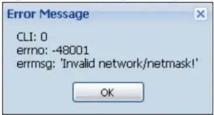
3.3.3 Warning Messages
Warning messages, such as those resulting from misconfiguration, display in a popup window.
Figure 12 Warning Message
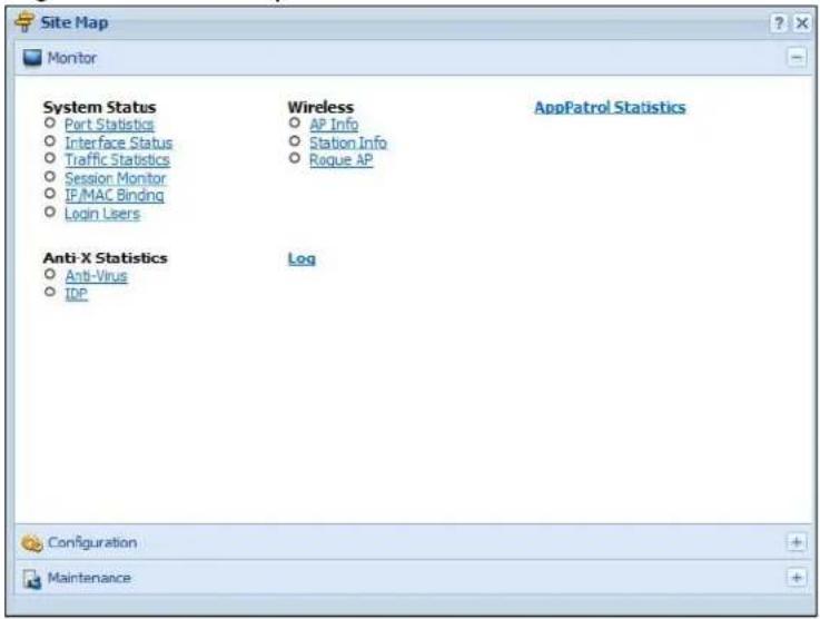
3.3.4 Site Map
Click Site MAP to see an overview of links to the Web Configurator screens. Click a screen's link to go to that screen.
Figure 13 Site Map
3.3.5 Object Reference
Click Object Reference to open the Object Reference screen. Select the type of object and the individual object and click Refresh to show which configuration settings reference the object. The following example shows which configuration settings reference the ldap-users user object (in this case the first firewall rule).
Figure 14 Object Reference
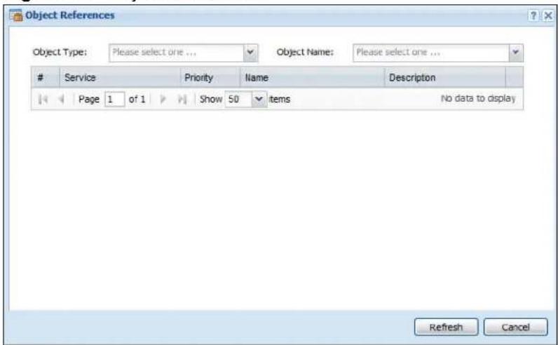
The fields vary with the type of object. The following table describes labels that can appear in this screen.
Table 8 Object References
| LABEL DESCRIPTION | |
| Object Name Th | s identifies the object for which the configuration settings that use it are displayed. Click the object's name to display the object's configuration screen in the main window. |
| # This field is a | sequential value, and it is not associated with any entry. |
| Service This is the type of setting that references the selected object. Click a service's name to display the service's configuration screen in the main window. | |
| Priority If it is applicable, this field lists the referencing configuration item's position in its list, otherwise N/ A displays. | |
| Name This field | identifies the configuration item that references the object. |
| Description If the referencing configuration item has a description configured, it displays here. | |
| Refresh Click this to update the information in this screen. | |
| Cancel Click Cancel to close the screen. | |
3.3.5.1 CLI Messages
Click CLI to look at the CLI commands sent by the Web Configurator. These commands appear in a popup window, such as the following.
Figure 15 CLI Messages
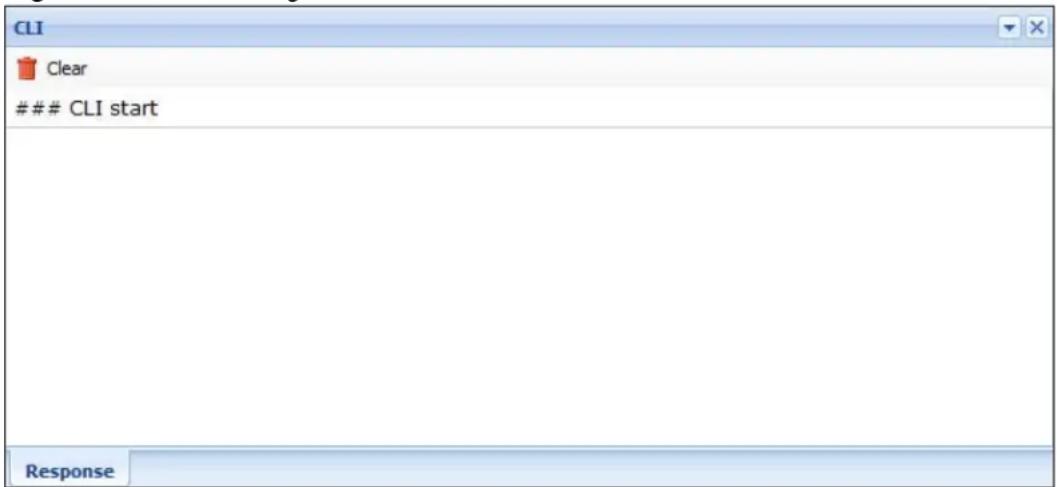
Click Clear to remove the currently displayed information.
Note: See the Command Reference Guide for information about the commands.
3.3.5.2 Console
The Console allows you to use CLI commands from directly within the Web Configurator rather than having to use a separate terminal program. In addition to logging in directly to the NXC's CLI, you can also log into other devices on the network through this Console. It uses SSH to establish a connection.
Note: To view the fuctions in the Web Configurator user interface that correspond directly to specific NXC CLI commands, use the CLI Messages window (see Section 3.3.5.1 on page 51) in tandem with this one.
Figure 16 Console
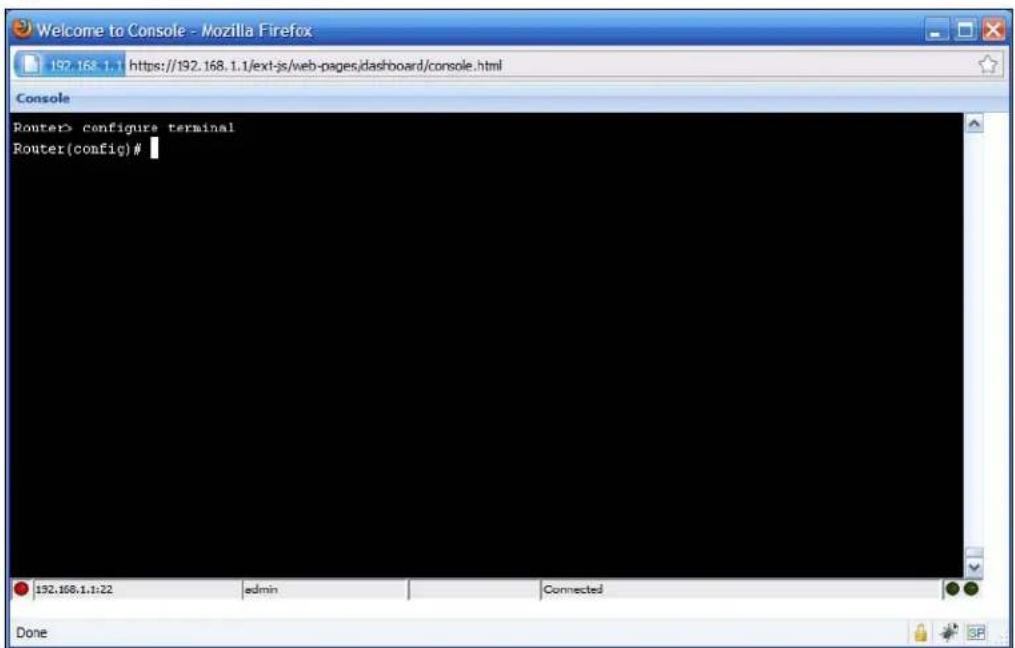
The following table describes the elements in this screen.
Table 9 Console
| LABEL DESCRIPTION | |
| Command Line | Router> configure terminalRouter(config)#Enter commands for the device that you are currently logged into here. If you are logged into the NXC, see the CLI Reference Guide for details on using the command line to configure it. |
| Device IP Address | 192.168.1.1:22This is the IP address of the device that you are currently logged into. |
| Logged-In User |  This displays the username of the account currently logged into the NXC through the Console Window.Note: You can log into the Web Configurator with a different account than used to log into the NXC through the Console. This displays the username of the account currently logged into the NXC through the Console Window.Note: You can log into the Web Configurator with a different account than used to log into the NXC through the Console. |
| Connection Status |  This displays the connection status of the account currently logged in.If you are logged in and connected, then this displays 'Connected'.If you lose the connection, get disconnected, or logout, then this displays 'Not Connected'. This displays the connection status of the account currently logged in.If you are logged in and connected, then this displays 'Connected'.If you lose the connection, get disconnected, or logout, then this displays 'Not Connected'. |
| Tx/RX Activity Monitor |  This displays the current upload / download activity. The faster and more frequently an LED flashes, the faster the data connection. This displays the current upload / download activity. The faster and more frequently an LED flashes, the faster the data connection. |
Before you use the Console, ensure that:
- Your web browser of choice allows pop-up windows from the IP address assigned to your NXC.
- Your web browser allows Java programs.
- You are using the latest version of the Java program (http://www.java.com).
To login in through the Console:
1 Click the Console button on the Web Configurator title bar.

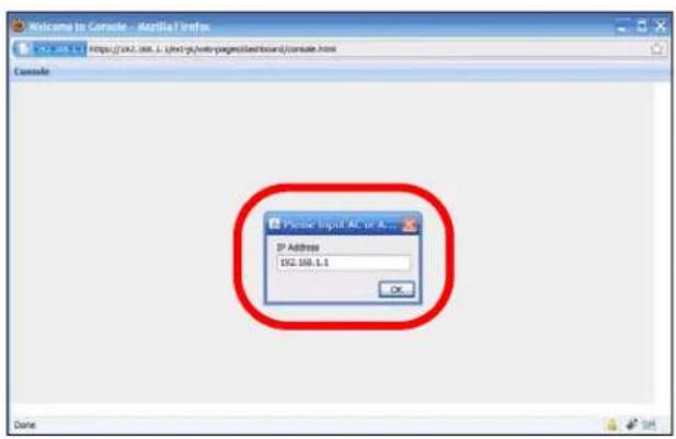
2 Enter the IP address of the NXC and click OK.
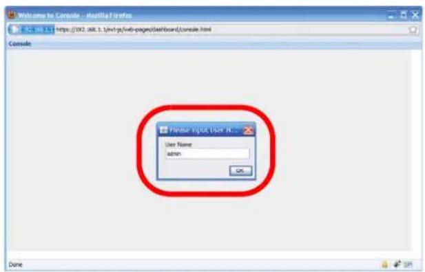
3 Next, enter the User Name of the account being used to log into your target device and then click OK.
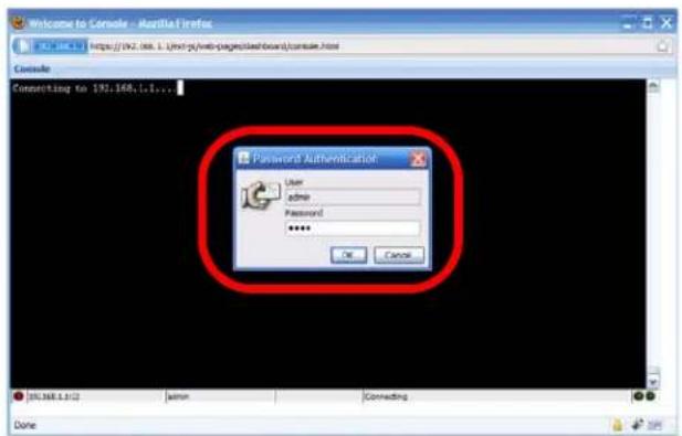
4 You may be prompted to authenticate your account password, depending on the type of device that you are logging into. Enter the password and click OK.
5 If your login is successful, the command line appears and the status bar at the bottom of the Console updates to reflect your connection state.
![Welcome to Console - Azziila Firefox 2.03.1.1 https://2021.Akt.1.1.html/web pages.html/Board/coma.html Console Route's configure terminal Route (config)# [05:166.1.1.2] admin Connected Done](/content/2026/05/762668/images/e3ac293eb8a64ff5c053076d497bbd9f9288eb12b9924a2258d75531be5e59de.jpg)
3.3.6 Tables and Lists
The Web Configurator tables and lists are quite flexible and provide several options for how to display their entries.
3.3.6.1 Manipulating Table Display
Here are some of the ways you can manipulate the Web Configurator tables.
1 Click a column heading to sort the table's entries according to that column's criteria.
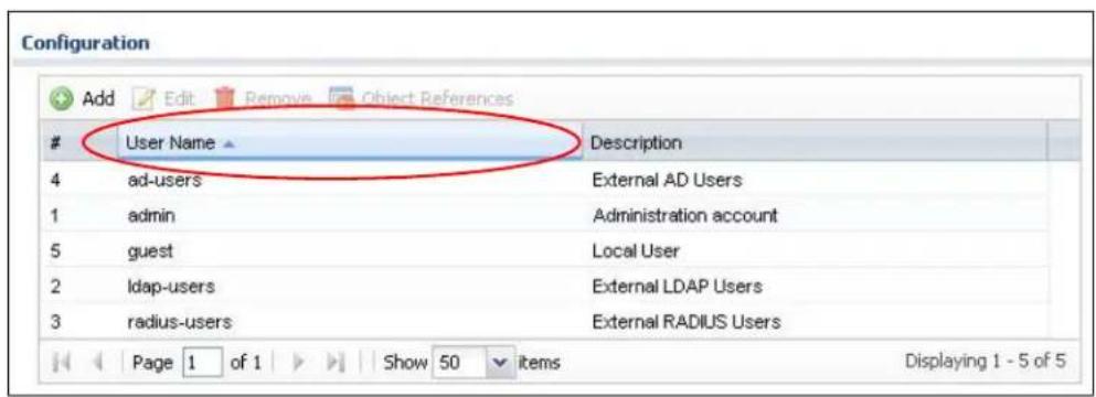
2 Click the down arrow next to a column heading for more options about how to display the entries. The options available vary depending on the type of fields in the column. Here are some examples of what you can do:
- Sort in ascending alphabetical order
- Sort in descending (reverse) alphabetical order
- Select which columns to display
- Group entries by field
• Show entries in groups
- Filter by mathematical operators (<, >, or =) or searching for text.

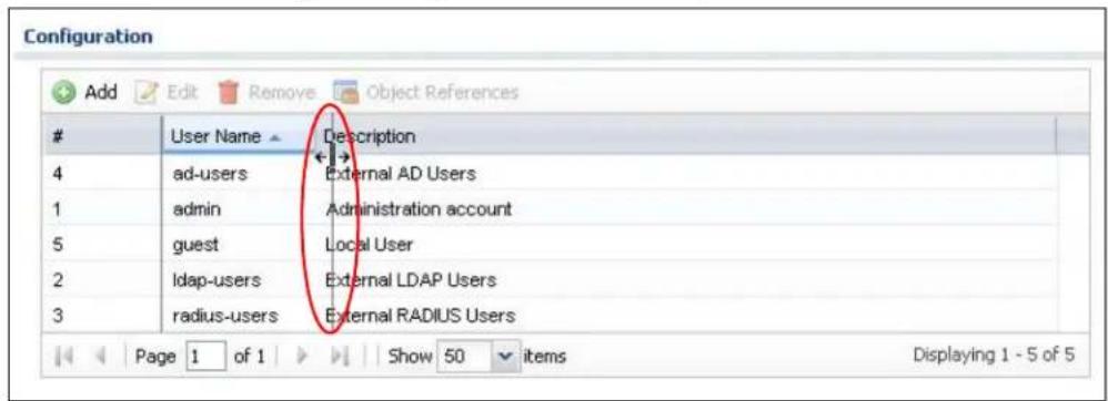
3 Select a column heading cell's right border and drag to re-size the column.
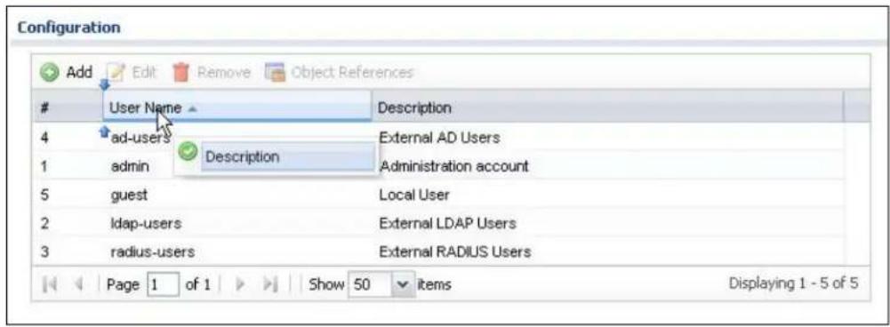
4 Select a column heading and drag and drop it to change the column order. A green check mark displays next to the column's title when you drag the column to a valid new location.
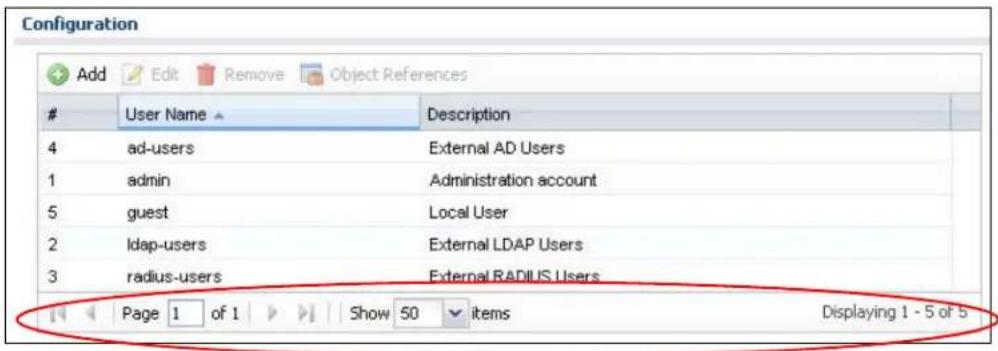
5 Use the icons and fields at the bottom of the table to navigate to different pages of entries and control how many entries display at a time.
3.3.6.2 Working with Table Entries
The tables have icons for working with table entries. A sample is shown next. You can often use the [Shift] or [Ctrl] key to select multiple entries to remove, activate, or deactivate.
Table 10 Common Table Icons
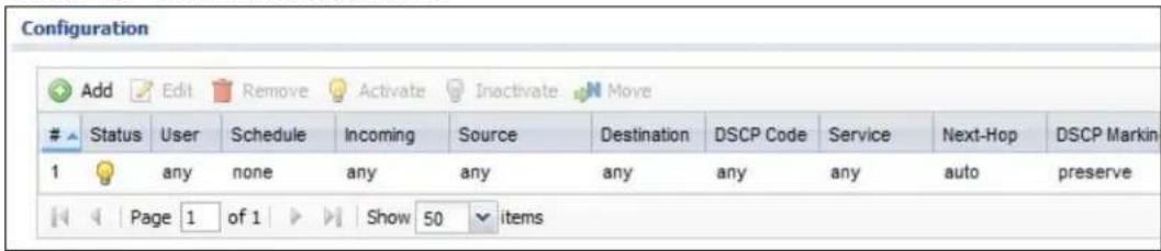
Here are descriptions for the most common table icons.
Table 11 Common Table Icons
| LABEL DESCRIPTION | |
| Add Click this to create a new entry. For features where the entry's position in the numbered list is important (features where the NXC applies the table's entries in order like the firewall for example), you can select an entry and click Add to create a new entry after the selected entry. | |
| Edit | Double-click an entry or select it and click Edit to open a screen where you can modify the entry's settings. In some tables you can just click a table entry and edit it directly in the table. For those types of tables small red triangles display for table entries with changes that you have not yet applied. |
| Remove | To remove an entry, select it and click Remove. The NXC confirms you want to remove it before doing so. |
| Activate | To turn on an entry, select it and click Activate. |
| Inactivate | To turn off an entry, select it and click Inactivate. |
| LABEL DESCRIPTION | |
| Object References | Select an entry and click Object References to open a screen that shows which settings use the entry. |
| Move To change an | entry's position in a numbered list, select it and clickMove to display a field to type a number for where you want to put that entry and press [ENTER] to move the entry to the number that you typed. For example, if you type 6, the entry you are moving becomes number 6 and the previous entry 6 (if there is one) gets pushed up (or down) one. |
3.3.6.3 Working with Lists
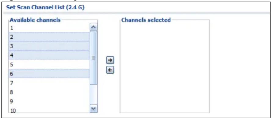
When a list of available entries displays next to a list of selected entries, you can often just double-click an entry to move it from one list to the other. In some lists you can also use the [Shift] or [Ctrl] key to select multiple entries, and then use the arrow button to move them to the other list.
Figure 17 Working with Lists
Configuration Basics
4.1 Overview
This section provides information to help you configure the NXC effectively. Some of it is helpful when you are just getting started. Some of it is provided for your reference when you configure various features in the NXC.
4.2 Object-based Configuration
The NXC stores information or settings as objects. You use these objects to configure many of the NXC's features and settings. Once you configure an object, you can reuse it in configuring other features.
When you change an object's settings, the NXC automatically updates all the settings or rules that use the object. For example, if you create a radio object, you can have firewall, application patrol, and other settings use it. If you modify the radio object, all the firewall, application patrol, and other settings that are linked to that object automatically apply the updated settings.
You can create address objects based on an interface's IP address, subnet, or gateway. The NXC automatically updates every rule or setting that uses these objects whenever the interface's IP address settings change. For example, if you change an Ethernet interface's IP address, the NXC automatically updates the rules or settings that use the interface-based, LAN subnet address object.
You can use the Configuration > Objects screens to create objects before you configure features that use them. If you are in a screen that uses objects, you can also usually select Create new Object to be able to configure a new object.
Use the Object Reference screen to see what objects are configured and which configuration settings reference specific objects.
4.3 Zones, Interfaces, and Physical Ports
Zones (groups of interfaces) simplify security settings. Here is an overview of zones, interfaces, and physical ports in the NXC.
Table 12 Zones, Interfaces, and Physical Ethernet Ports
| Zones (LAN, WLAN) | A zone is a group of interfaces. Use zones to apply security settings such as firewall, IDP, remote management, anti-virus, and application patrol. |
| Interfaces (Ethernet, VLAN) | Interfaces are logical entities that (layer-3) packets pass through. Use interfaces in configuring zones, device HA, policy routes, static routes, and NAT. Port combine physical ports into interfaces. |
| Physical Ethernet Ports (1, 2, 3, 4) | The physical port is where you connect a cable. In configuration, you use physical ports when configuring port groups. You use interfaces and zones in configuring other features. |
4.3.1 Interface Types
There are two types of interfaces in the NXC. In addition to being used in various features, interfaces also describe the network that is directly connected to it.
- Ethernet interfaces are the foundation for defining other interfaces and network policies. By
- VLAN interfaces recognize tagged frames. The NXC automatically adds or removes the tags as needed. Each VLAN can only be associated with one Ethernet interface.
Note: By default, all Ethernet interfaces are placed into vlan0, allowing the NXC to function as a bridge device.
4.3.2 Example Interface and Zone Configuration
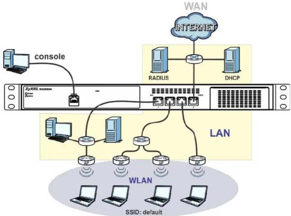
This section introduces the NXC's default zone member physical interfaces and the default configuration of those interfaces. The following figure uses letters to denote public IP addresses or part of a private IP address.
Figure 18 Default Network Topology
flowchart
graph TD
    A["Host Server"] -->|console| B["Router"]
    B --> C["RADIUS"]
    B --> D["DHCP"]
    C --> E["LAN"]
    D --> E
    F["WiN"] --> G["INTERNET"]
    H["WLAN"] --> I["AP"]
    J["SSID: default"] --> K["AP"]
    L["PC"] --> M["AP"]
    N["PC"] --> O["AP"]
    P["PC"] --> Q["AP"]
Table 13 NXC Sample Topology
| PORT INTERFACE ZONE | IP ADDRESS AND DHCP SETTINGS | SUGGESTED USE WITH DEFAULT SETTINGS | ||
| P1~P8 | ge1~ge8 | LAN(vlan0) | 192.168.1.1, DHCP server enabled | Dedicated LAN connections |
| WLAN DHCP clients Managed Wireless | APs | |||
| CONSOLE N/A None None | Local management | |||
- The LAN zone contains the ge1\~ ge8 interfaces (physical ports P1\~P8). By default, all LAN interfaces are put in vlan0.
- The WLAN zone contains Access Points (APs) that are available to the public. These APs uses private IP addresses that can be assigned by an upstream DHCP server (default) or the NXC itself in some configurations.
- The console port is not in a zone and can be directly accessed by a computer attached to it using a special console-to-Ethernet adapter.
4.4 Feature Configuration Overview
This section provides information about configuring the main features in the NXC. The features are listed in the same sequence as the menu item(s) in the Web Configurator. Each feature description is organized as shown below.
4.4.1 Feature
This provides a brief description. See the appropriate chapter(s) in this User's Guide for more information about any feature.
| MENU ITEM(S) | This shows you the sequence of menu items and tabs you should click to find the main screen(s) for this feature. See the web help or the related User's Guide chapter for information about each screen. |
| PREREQUISITES | These are other features you should configure before you configure the main screen(s) for this feature.If you did not configure one of the prerequisites first, you can often select an option to create a new object. After you create the object you return to the main screen to finish configuring the feature.You may not have to configure everything in the list of prerequisites. For example, you do not have to create a schedule for a policy route unless time is one of the criterion. |
| WHERE USED | There are two uses for this.These are other features you should usually configure or check right after you configure the main screen(s) for this feature.You have to delete the references to this feature before you can delete any settings. |
Note: PREQUISITES or WHERE USED does not appear if there are no prerequisites or references in other features to this one. For example, no other features reference AP management entries, so there is no WHERE USED entry.
4.4.2 Licensing Registration
Use these screens to register your NXC and subscribe to services like anti-virus, IDP and application patrol. You must have Internet access to myZyXEL.com.
| MENU ITEM(S) | Configuration > Licensing > Registration |
| PREREQUISITES | Internet access to myZyXEL.com |
4.4.3 Licensing Update
Use these screens to update the NXC's signature packages for the anti-virus, IDP and application patrol features. You must have a valid subscription to update the anti-virus and IDP/application patrol signatures. You must also have Internet access to myZyXEL.com.
| MENU ITEM(S) | Configuration > Licensing > Signature Update |
| PREREQUISITES | Registration (for anti-virus and IDP/application patrol), Internet access to myZyXEL.com |
4.4.4 Wireless
Use these screens to manage your wireless Access Points.
| MENU ITEM(S) | Configuration > Network > Wireless. |
| PREREQUISITES | Radio profiles, SSID profiles, and security profiles |
4.4.5 Interface
Most of the features that use interfaces support Ethernet and VLAN interfaces.
Note: When you create an interface, no security is applied to it until you assign it to a zone first.
| MENU ITEM(S) | Configuration > Network > Interface. |
| PREREQUISITES | None |
| WHERE USED | Zones, device HA, policy routes, static routes, NAT, application patrol |
4.4.6 Policy Routes
Use policy routes to override the NXC's default routing behavior in order to send packets through the appropriate interface. You can also use policy routes for bandwidth management (out of the NXC), port triggering, and general NAT on the source address. You have to set up the criteria, next-hops, and NAT settings first.
| MENU ITEM(S) | Configuration > Network > Routing > Policy Routes |
| PREREQUISITES | Criteria: users, user groups, interfaces (incoming), addresses (source, destination), address groups (source, destination), schedules, services, service groupsNext-hop: addresses (HOST gateway), interfacesNAT: addresses (translated address), services and service groups (port triggering) |
4.4.7 Static Routes
Use static routes to tell the NXC about networks not directly connected to the NXC.
| MENU ITEM(S) | Configuration > Network > Routing > Static Route |
| PREREQUISITES | Interfaces |
4.4.8 Zones
A zone is a group of interfaces. The NXC uses zones, not interfaces, in many security settings, such as firewall rules and remote management.
Zones cannot overlap. Each interface can be assigned to one zone. Virtual interfaces are automatically assigned to the same zone as the interface on which they run. When you create a zone, the NXC does not create any firewall rules, assign an IDP profile, or configure remote management for the new zone.
| MENU ITEM(S) | Configuration > Network > Zone |
| PREREQUISITES | Interfaces |
| WHERE USED | Firewall, anti-virus, ADP, application patrol |
4.4.9 NAT
Use Network Address Translation (NAT) to make computers on a private network behind the NXC available outside the private network.
The NXC only checks regular (through-NXC) firewall rules for packets that are redirected by NAT, it does not check the to-NXC firewall rules.
| MENU ITEM(S) | Configuration > Network > NAT |
| PREREQUISITES | Interfaces, addresses (HOST) |
4.4.10 ALG
The NXC's Application Layer Gateway (ALG) allows VoIP and FTP applications to go through NAT on the NXC. You can also specify additional signaling port numbers.
| MENU ITEM(S) | Configuration > Network > ALG |
4.4.11 Captive Portal
A captive portal intercepts all HTTP-packets, regardless of address or port, until the user authenticates his or her connection, usually through a specifically designated login Web page..
MENU ITEM(S) Configuration > Captive Portal
4.4.12 Firewall
The firewall controls the travel of traffic between or within zones. You can also configure the firewall to control traffic for NAT (DNAT) and policy routes (SNAT). You can configure firewall rules based on schedules, specific users (or user groups), source or destination addresses (or address groups) and services (or service groups). Each of these objects must be configured in a different screen.
To-NXC firewall rules control access to the NXC. Configure to-NXC firewall rules for remote management. By default, the firewall only allows management connections from the LAN, WAN zone.
| MENU ITEM(S) | Configuration > Firewall |
| PREREQUISITES | Zones, schedules, users, user groups, addresses, services, service groups |
4.4.13 Application Patrol
Use application patrol to control which individuals can use which services through the NXC (and when they can do so). You can also specify allowed amounts of bandwidth and priorities. You must subscribe to use application patrol. You can subscribe using the Configuration > Licensing > Registration screens or one of the wizards.
| MENU ITEM(S) | Configuration > AppPatrol |
| PREREQUISITES | Registration, zones, schedules, users, user groups, addresses. These are only used as criteria in exceptions and conditions. |
4.4.14 Anti-Virus
Use anti-virus to detect and take action on viruses. You must subscribe to use anti-virus. You can subscribe using the Licensing > Registration screens or one of the wizards.
| MENU ITEM(S) | Configuration > Anti-X > Anti-Virus |
| PREREQUISITES | Registration, zones |
4.4.15 IDP
Use IDP to detect and take action on malicious or suspicious packets. You must subscribe to use IDP. You can subscribe using the Licensing > Registration screens or one of the wizards.
| MENU ITEM(S) | Configuration > Anti-X > IDP |
| PREREQUISITES | Registration, zones |
4.4.16 ADP
Use ADP to detect and take action on traffic and protocol anomalies.
| MENU ITEM(S) | Configuration > Anti-X > ADP |
| PREREQUISITES | Zones |
4.4.17 Device HA
To increase network reliability, device HA lets a backup NXC automatically take over if a master NXC fails.
| MENU ITEM(S) | Configuration > Device HA |
| PREREQUISITES | Interfaces (with a static IP address), to-NXC firewall |
4.5 Objects
Objects store information and are referenced by other features. If you update this information in response to changes, the NXC automatically propagates the change through the features that use the object. Select an object (such as a user group, address, address group, service, service group, zone, or schedule) and then click Object Reference at the top of the list box where the object appears in order to display basic information about it.
The following table introduces the objects. You can also use this table when you want to delete an object because you have to delete references to the object first.
Table 14 Objects Overview
| OBJECT WHERE USED | |
| user/group | See the User/Group section on page 67 for details. |
| ap profile | See the AP Profile section on page 67 for details. |
| mon profile | See the MON Profile section on page 68 for details. |
Table 14 Objects Overview
| OBJECT WHERE USED | |
| address Policy routes (criteria, next-hop [HOST], NAT), authentication policies, firewall, application patrol (source, destination), NAT (HOST), user settings (force user authentication), address groups | |
| address group Policy routes (criteria), firewall, application patrol (source, destination), captive portal (force user authentication), address groups, remote management (System) | |
| service, service group | Policy routes (criteria, port triggering), firewall, service groups, log (criteria) |
| schedule Policy routes (criteria), authentication policies, firewall, application patrol, user settings (force user authentication) | |
| AAA server Authentication methods | |
| authentication methods | WWW (client authentication), captive portal |
| certificates WWW, | SSH, FTP, controller |
| SSID profile captive portal | |
4.5.1 User/Group
Use these screens to configure the NXC's administrator and user accounts. The NXC provides the following user types.
Table 15 User Types
| TYPE ABILITIES | |
| admin Change NXC | configuration (web, CLI) |
| ldap users LDAP authentication for downstream network clients | |
| radius users RADIUS | authentication for downstream network clients |
| ad users AD authentication for downstream network clients | |
4.5.2 AP Profile
Use these screens to configure preset profiles for the Access Points (APs) connected to your NXC's wireless network.
Table 16 AP Profile Types
| TYPE ABILITIES | |
| Radio Create radio | profiles for the APs on your network. |
| SSID | Create SSID profiles for the APs on your network. |
| Security | Create security profiles for the APs on your network. |
| MAC Filtering | Create MAC filtering profiles for the APs on your network. |
4.5.3 MON Profile
Use these screens to set up monitor mode configurations that allow your connected APs to scan for other wireless devices in the vicinity.
Table 17 MON Profile Types
| TYPE ABILITIES | |
| Monitor Create monitor mode configurations that can be used by the APs to periodically listen to a specified channel or number of channels for other wireless devices broadcasting on the 802.11 frequencies. | |
4.6 System
This section introduces some of the management features in the NXC. Use Host Name to configure the system and domain name for the NXC. Use Date/ Time to configure the current date, time, and time zone in the NXC. Use Console Speed to set the console speed. Use Language to select a language for the Web Configurator screens.
4.6.1 DNS, WWW, SSH, TELNET, FTP, and SNMP
Use these screens to set which services or protocols can be used to access the NXC through which zone and from which addresses (address objects) the access can come.
| MENU ITEM(S) | Configuration > System > DNS, WWW, SSH, TELNET, FTP, SNMP, Language |
| PREREQUISITES | To-NXC firewall, zones, addresses, address groups, certificates (WWW, SSH, FTP), authentication methods (WWW) |
4.6.2 Logs and Reports
The NXC provides a system log, offers two e-mail profiles to which to send log messages, and sends information to four syslog servers. It can also e-mail you statistical reports on a daily basis.
| MENU ITEM(S) | Configuration > Log & Report |
4.6.3 File Manager
Use these screens to upload, download, delete, or run scripts of CLI commands. You can manage:
- Configuration files. Use configuration files to back up and restore the complete configuration of the NXC. You can store multiple configuration files in the NXC and switch between them without restarting.
- Shell scripts. Use shell scripts to run a series of CLI commands. These are useful for large, repetitive configuration changes and for troubleshooting.
You can edit configuration files and shell scripts in any text editor.
| MENU ITEM(S) | Maintenance > File Manager |
4.6.4 Diagnostics
The NXC can generate a file containing the NXC's configuration and diagnostic information. It can also capture packets going through the NXC's interfaces so you can analyze them to identify network problems
| MENU ITEM(S) | Maintenance > Diagnostics |
4.6.5 Shutdown
Use this to shutdown the device in preparation for disconnecting the power.
Always use Maintenance > Shutdown > Shutdown or the shutdown command before you turn off the NXC or remove the power. Not doing so can cause the firmware to become corrupt.
| MENU ITEM(S) | Maintenance > Shutdown |
Tutorials
5.1 Overview
The tutorials featured here require a basic understanding of connecting to and using the Web Configurator, as well as an understanding of networking concepts and topology design.
The default login information for the NXC's Web Configurator is:
Table 18 NXC Default Login Information
| LOGIN VALUE SEE ALSO | ||
| IP Address 192.168.1.1 Chapter 3 on page 41. | ||
| User Name admin | ||
| Password 1234 | ||
5.2 Sample Network Setup
This tutorial shows you how to create a wireless network that allows two types of connections: staff and guest. Staff connections have full access to the network, while guests are limited to Internet access (DNS, HTTP and HTTPS services).
Figure 19 Tutorial Network Topology
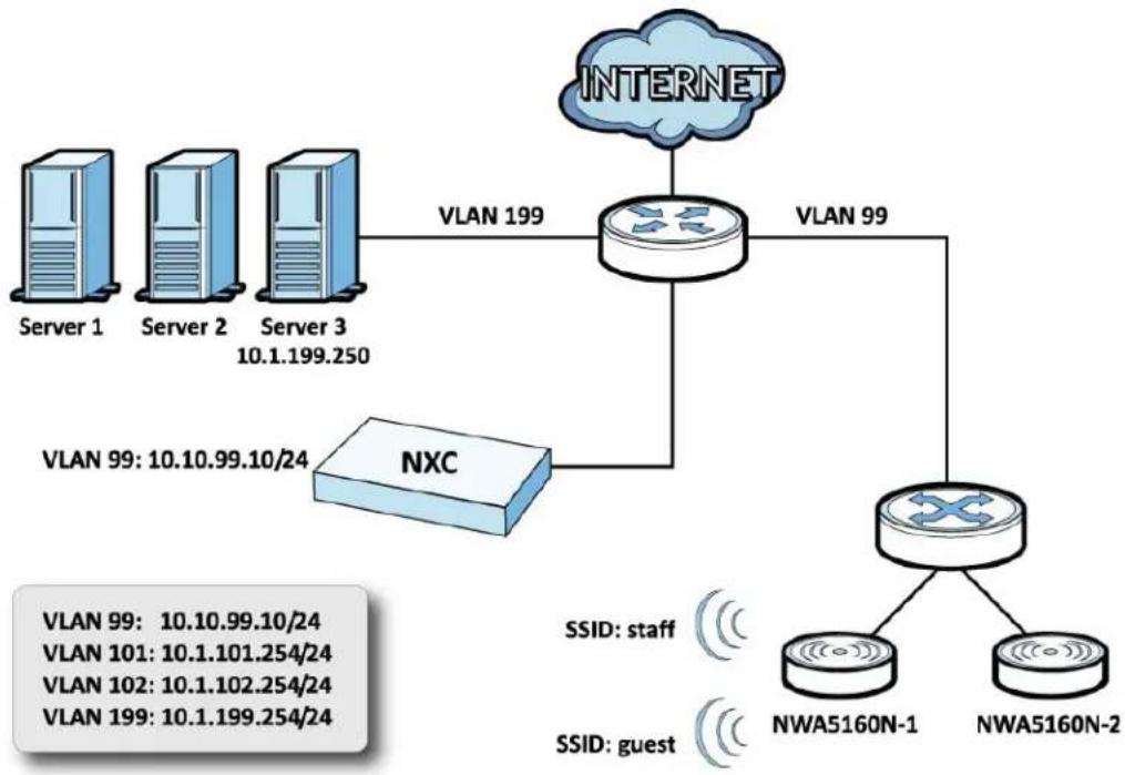
flowchart
graph TD
    Server1["Server 1"] -->|VLAN 199| Router["Router"]
    Server2["Server 2"] -->|VLAN 199| Router
    Server3["Server 3"] -->|VLAN 199| Router
    Router -->|VLAN 99| NWA5160N-1["NWA5160N-1"]
    Router -->|VLAN 99| NWA5160N-2["NWA5160N-2"]
    NXC["NXC"] -->|VLAN 99: 10.10.99.10/24| Router
    NWA5160N-1 -->|SSID: staff| Router
    NWA5160N-2 -->|SSID: guest| Router
Requirements: A DHCP server with Option 138, an AD server, a switch that supports 802.1q, a Layer-3 routing device and firewall.
Note: In this topology, vlan 199 is managed by the router responsible for the upstream portion of the network, such as a ZyWALL.
The following VLAN settings are used in this tutorial:
Table 19 Tutorial Topology Summary
| VLAN VLAN ID IP ADDRESS | ||
| Management 99 10.10.99.10/24 | ||
| Staff 101 10.1.101.254/24 | ||
| Guest 102 10.1.102.254/24 |
Figure 20 Tutorial Guest VLAN Example
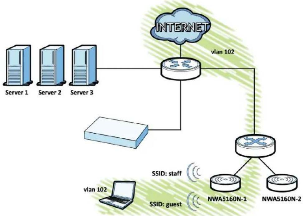
flowchart
graph TD
    A["Server 1"] --> B["Router"]
    C["Server 2"] --> B
    D["Server 3"] --> B
    E["vlan 102"] --> B
    F["Router"] --> G["NWA5160N-1"]
    F --> H["NWA5160N-2"]
    B --> I["vlan 102"]
    B --> J["VLAN 102"]
    style B fill:#f9f,stroke:#333
    style I fill:#ccf,stroke:#333
    style J fill:#ccf,stroke:#333
In this example, the guest VLAN (102) is highlighted with the connections that it may make over this particular network topology. The staff VLAN (101) is unhighlighted because it has access to all aspects of the network.
5.2.1 Tutorial Tasks
In this tutorial, you will:
Table 20 Tutorial Tasks Summary
| TASK SEE ALSO | |
| Set the Management VLAN (vlan99) Chapter 11 on page 177 | |
| Set the Other VLANs (vlan101, vlan102) Chapter 11 on page 177 | |
| Configure the AAA Object Chapter 30 on page 425 | |
| Configure the Auth. Method Objects (staff, guest) Chapter 31 on page 437 | |
| Create the AP Profiles (staff, guest) Chapter 25 on page 387 | |
| Create the Guest User Account Chapter 24 on page 373 | |
| Configure the Captive Portal Settings Chapter 17 on page 239 | |
| Configure the Guest Firewall Rules Chapter 18 on page 249 | |
5.2.2 Set the Management VLAN (vlan99)
This section shows you how to set up the VLAN for managing the NXC. This is only for network administrators to access the device.
1 Open the Configuration > Network > Interface > VLAN screen then click the Add button.
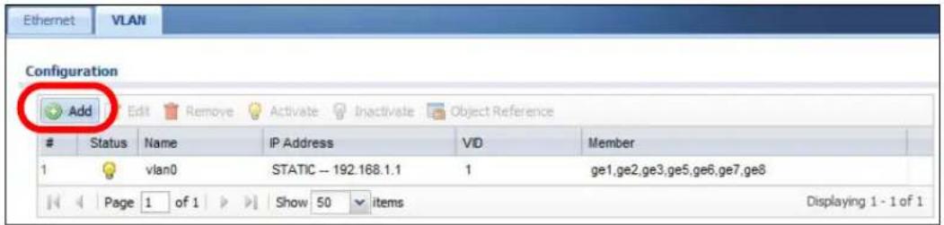
2 The Add VLAN window opens.
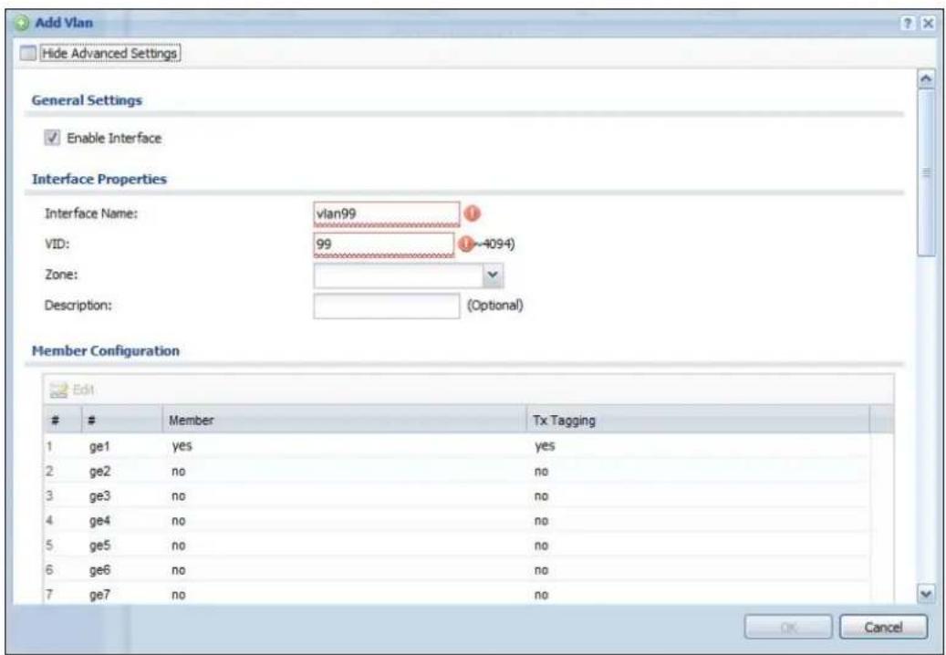
2a Enable Interface: Select this to enable this interface.
2b Interface Name: Enter 'vlan99'.
2c VID: Enter '99' as the VLAN ID tag.
2d Under Member Configuration, set the ge1 Member status to Yes and TX Tagging to Yes.
2e Scroll down to IP Address Assignment and select Use Fixed IP Address.
2fIP Address: Enter 10.10.99.10.
2g Subnet Mask: Enter 255.255.255.0.
3 Click OK to save these changes.
See Also: Chapter 11 on page 177.
5.2.3 Set the Other VLANs (vlan101, vlan102)
This section shows you how to set up the other VLANs on your network. They correspond to the topology map presented at the beginning of this tutorial.
Note: You will use this procedure twice: once for VLAN 101 and the other time for VLAN 102. VLAN 101 is presented first, while VLAN 102 is presented second.
1 For VLAN 101: Open the Configuration > Network > Interface > VLAN screen then click the Add button.
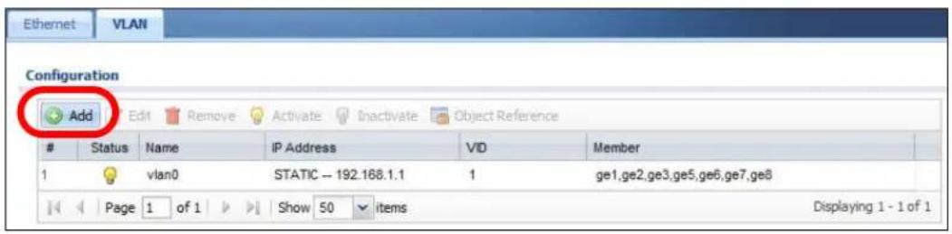
2 The Add VLAN window opens.
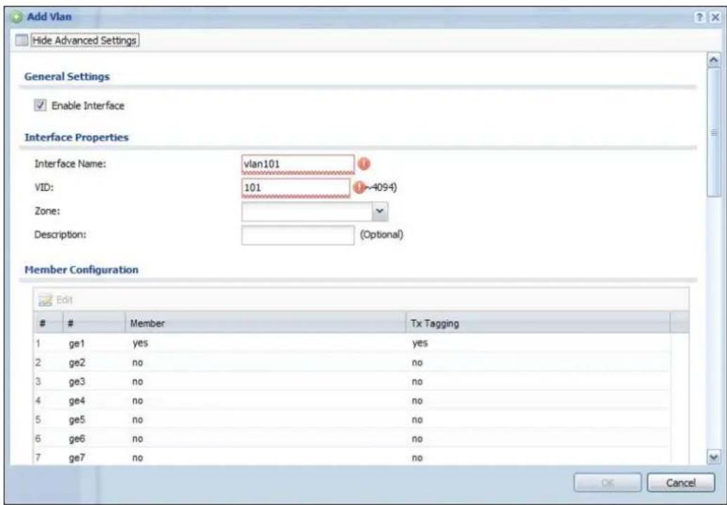
2a Enable Interface: Select this to enable this interface.
2b Interface Name: Enter 'vlan101'.
2c VID: Enter '101' as the VLAN ID tag.
2d Under Member Configuration, set the ge1 Member status to Yes and TX Tagging to Yes.
2e Scroll down to IP Address Assignment and select Use Fixed IP Address.
2fIP Address, enter 10.10.101.254.
2g Subnet Mask: Enter 255.255.255.0.
2h Gateway: Enter 10.10.101.254.
3 For VLAN 102: Open the Configuration > Network > Interface > VLAN screen then click the Add button.
4 The Add VLAN window opens.
4a Enable Interface: Select this to enable this interface.
4b Interface Name: Enter 'vlan102'.
4c VID: Enter '102' as the VLAN ID tag.
4d Under Member Configuration, set the ge1 Member status to Yes and TX Tagging to Yes.
4e Scroll down to IP Address Assignment and select Use Fixed IP Address.
4fIP Address, enter 10.10.102.254.
4g Subnet Mask: Enter 255.255.255.0.
4h Gateway: Enter 10.10.102.254.
5 Click OK to save these changes.
After configuring VLANs 99, 101, and 102, the Configuration > Network > Interfaces > VLAN screen should look similar to this:
Figure 21 Tutorial VLANs Summary
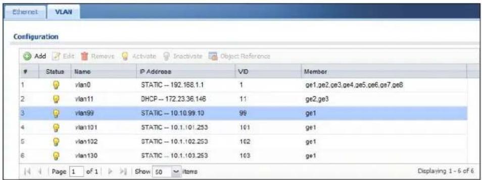
See Also: Chapter 11 on page 177.
5.2.4 Configure the AAA Object
This section shows you how to set up the AAA (Authentication, Authorization, Accounting) server settings to allow registered users to log into the network through the staff SSID.
1 Open the Configuration > Object > AAA Server > Active Directory screen and then click the Add button.
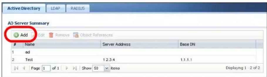
2 The Add Active Directory window opens.
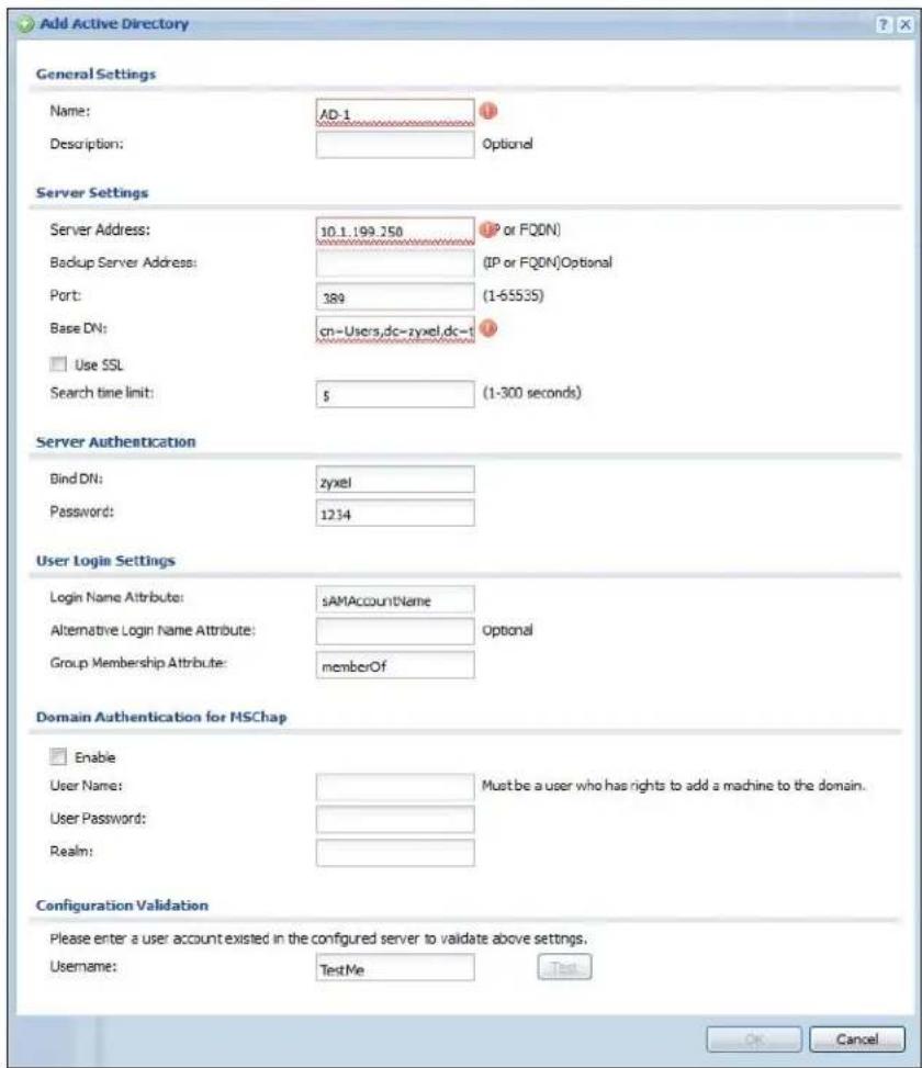
2a Name: Enter AD-1.
2b Under Server Settings, enter a Server Address of 10.1.199.250.
2c Base DN: Enter settings that match your AD server configuration. For this example, use 'cn=Users,dc=zyxel,dc=test'.
2d Under Server Authentication, enter a Bind DN that has privileges on your AD server. In this tutorial, use 'zyxel'.
2e Password: Enter the password for the Bind DN that has privileges on your AD server. In this tutorial, use '1234'.
2f Scroll down to Configuration Validation, enter a valid test account for your AD sever in the Username field, and click Test. This tests the settings you just entered in this window.
Note: Unless your AD server is configured to explicitly handle these tutorial settings, the Test button may not work. However, it is handy know for future reference.
3 Click OK to save these settings.
See Also: Chapter 30 on page 425.
5.2.5 Configure the Auth. Method Objects (staff, guest)
This section shows you how to set up the Authentication Method profile to allow registered users to log into the network through the staff SSID and guest users to login through the guest SSID.
1 Open the Configuration > Object > Auth. Method screen and then click the Add button.
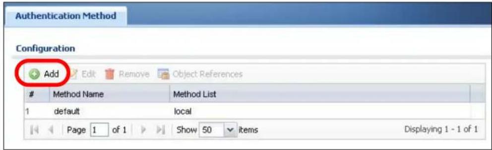
2 The Add Authentication Method window opens.
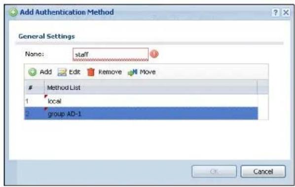
2a Name: Enter 'staff'.
2b Click the Add button to create a blank rule in the Method list.
2c Click the rule to expand the list of available AAA server profiles and then select group AD-1. This is the AAA server profile created in Section 5.2.4 on page 77.
3 Click OK to save these settings.
4 To create a guest authentication object, repeat steps 1-3 but with the following guest settings instead:
4a Name: Enter 'guest'.
4b Click the Add button to create a blank rule in the Method list.
4c Click the rule to expand the list of available AAA server profiles and then select local. The guest account created in Section 5.2.7 on page 83 is stored in this authentication database.
See Also: Chapter 31 on page 437.
5.2.6 Create the AP Profiles (staff, guest)
This section shows you how to configure the Access Point (AP) profiles that will be used by your APs once they are connected to the network. You will first create a security profile and an SSID profile for staff access, then you will create a second pair for guest access. Finally, you will associate them with a radio profile which is linked to your AP's radio transmitter.
1 Open the Configuration > Object > AP Profile > SSID > Security List screen and then click the Add button.
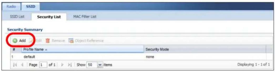
2 The Add Security Profile window opens.
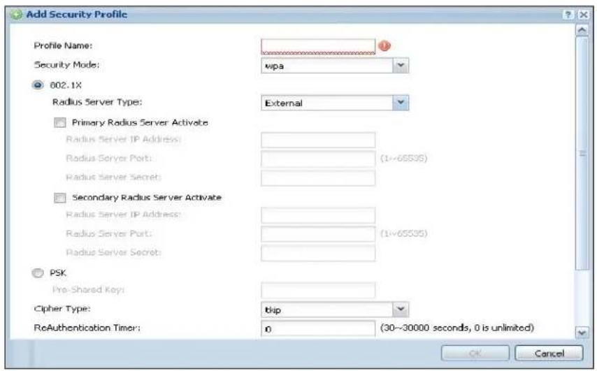
2a Profile Name: Enter 'wap2'.
2b Security Mode: Select wpa2 from the list of available wireless security encryption methods.
2c Under Security Settings, select 802.1X then set the Radius Type to Internal. For Authentication Method, select 'staff' from the list. This is the method that you created in Section 5.2.5 on page 79.
3 Next, open the Configuration > Object > AP Profile > SSID > SSID List screen and click the Add button.
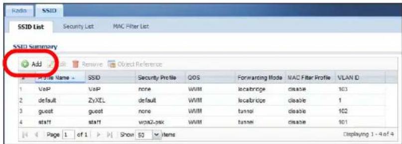
4 The Add SSID Profile window opens.
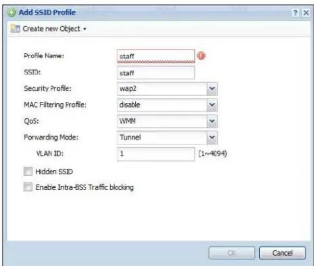
4a Profile Name: Enter 'staff'.
4b SSI D: Enter 'staff'. This is the wireless network name that appears when wireless clients are looking for networks to join.
4c Security Profile: Select wap2 from the list. This is the security profile created in Step 1a.
4d QoS: Select WMM.
4e Forwarding Mode: Select Tunnel from the list.
4f VLAN Interface: Select vlan101 from the list, which you created in Section 5.2.3 on page 75.
4g Click OK to save these settings.
5 Repeat steps 1 and 2. All settings are the same, except as follows:
5a Profile Name: Enter 'guest'.
5b SSID: Enter 'guest'.
5c VLAN Interface: Select vlan102 from the list.
6 Open the Configuration > Object> AP Profile > Radio screen and then click the Add button.
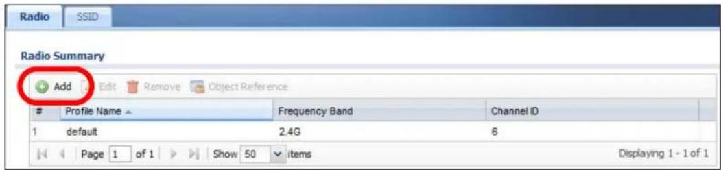
7 The Add Radio Profile window opens.
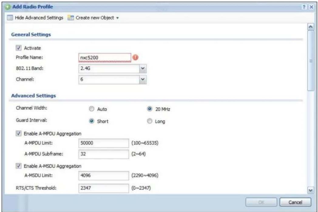
7a Activate: Select this to make the radio profile active.
7b Profile Name: Enter 'nxc5200'.
7c Scroll down to MBSSID Settings. For item #1, select the staff SSID Profile. For item #2, select the guest SSID profile. These are the two profiles you created in steps 1-3 of this procedure.
7d Click OK to save these settings.
See Also: Chapter 25 on page 387.
5.2.7 Create the Guest User Account
This section shows you how to create a guest user account. Guest users should log into the network with the following user name and password: guest1 / guest1.
1 Open the Configuration > Object > User/ Group > User screen and click the Add button.
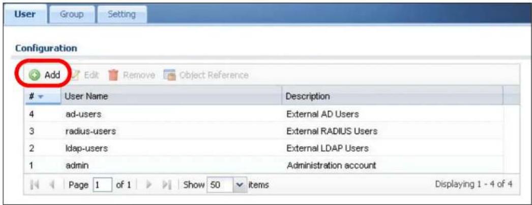
2 The Add A User window opens.
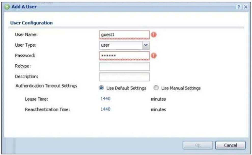
2a User Name: Enter 'guest1'.
2b Password: Enter 'guest1', then enter it again in the Retype field to confirm.
3 Click OK to save these settings.
See Also: Chapter 24 on page 373.
5.2.8 Configure the Captive Portal Settings
This section shows you how to configure the NXC captive portal settings. This is the web page that appears whenever anyone connects to the guest SSID, and it is here where they can login using the guest credentials that you configured in Section 5.2.7 on page 83.
1 Open the Configuration > Captive Portal screen.
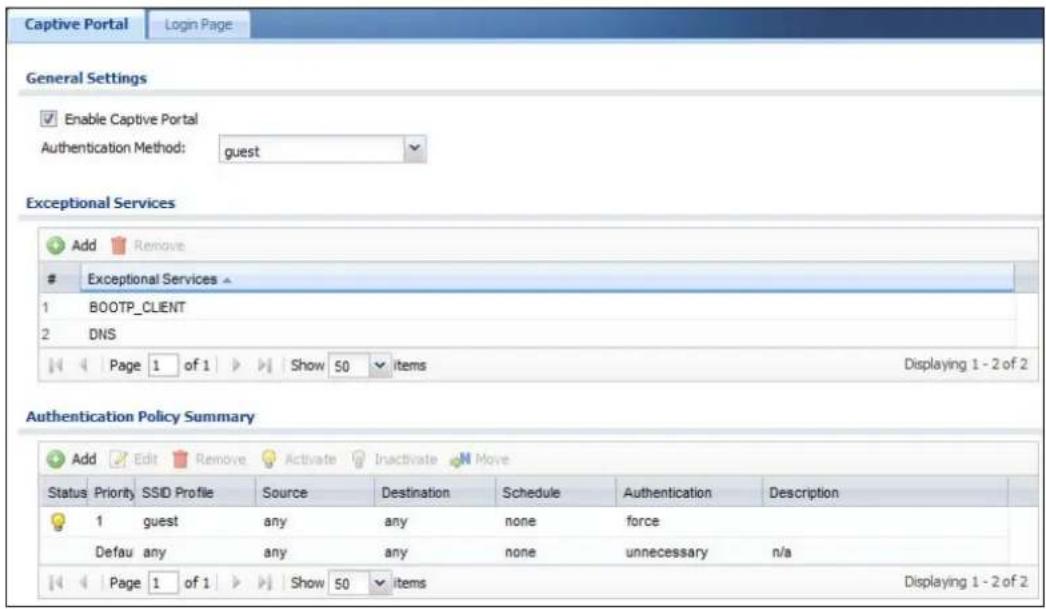
2 Enable Captive Portal: Select this to turn on the captive portal feature for all wireless networks managed by the NXC. Although enabled, it does not appear for all SSIDs; only those assigned to the feature.
3 Authentication Method: Select guest from the list. This is the Auth. Method profile that you created in Section 5.2.5 on page 79.
4 Under Authentication Policy Summary, click the Add button.
5 The Auth. Policy Edit window opens.
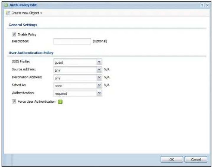
5a SSID Profile: Select guest from the list.
5b Authentication: Select required from the list.
See Also: Chapter 17 on page 239.
5.2.9 Configure the Guest Firewall Rules
Finally, configure the firewall rules required for regulating how guest users can use the network. There are 5 firewall rules that you will need to configure:
Table 21 Tutorial Firewall Rules
| RULE USER SERVICE ACCESS | ||
| # 1 guest1 deny | ||
| # 2 guest1 DNS_UDP allow | ||
| # 3 guest1 DNS_TCP allow | ||
| # 4 guest1 HTTP allow | ||
| # 5 guest1 HTTPS allow |
1 Open the Configuration > Firewall screen.
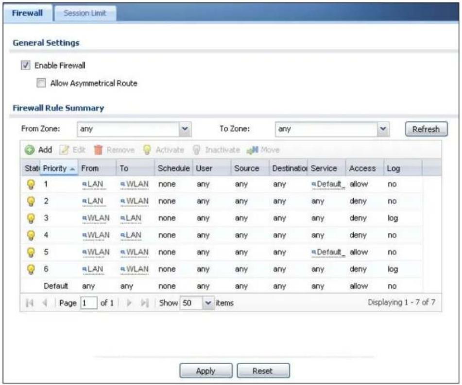
2 For each rule, click the Add button to open the Add Firewall Rule window.
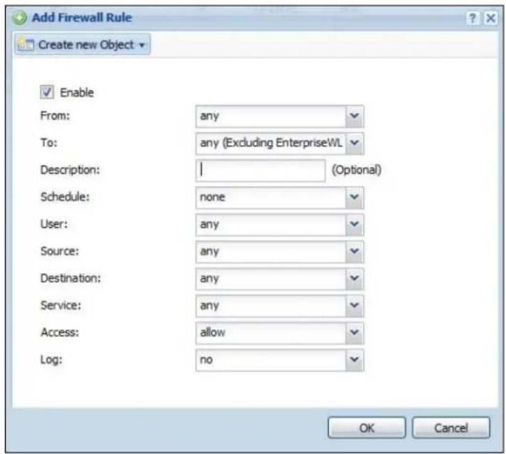
3 Enter the settings for the specific firewall rule described in Table 21 on page 85.
4 Click OK to save the firewall rule settings.
For example, to configure firewall rule #5:
1 Open the Configuration > Firewall screen and click the Add button.
2 The Add Firewall Rule window opens.
2a User: Select guest1 from the list.
2b Service: Select HTTPS from the list.
2c Access: Select allow from the list.
3 Click OK to save these settings. The new firewall rule now appears in the Firewall Rules Summary table.
Note: For the purposes of this tutorial, the firewall rules can be created in any order just so long as they use the settings presented here.
See Also: Chapter 18 on page 249.
5.3 Blocking Network Protocols
The NXC's firewall allows you to control which protocols are allowed on your wireless network. If the NXC is connected to an upstream Internet access device, then incoming traffic off the WAN should be filtered by that device's firewall feature. However traffic coming into the NXC from wireless clients is not filtered until you configure its own firewall first.
5.3.1 Configuring the WLAN Zone
This section shows you how to configure the WLAN zone, which is necessary for implementing the firewall rules and Application Patrol rules.
1 Open the Configuration > Network > Zone screen.
2 Select WLAN from the User Configuration table and click the Edit button.
3 The Add Zone window opens.
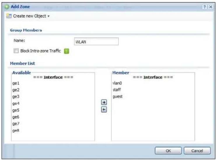
4 In Member List, select an interface from Available and add it to Member. For the purposes of this tutorial, add staff and guest. These are the VIDs configured in Section 5.2.3 on page 75.
5 Click OK to save these settings.
See Also: Chapter 13 on page 213.
5.3.2 Configuring the Firewall
This section shows you how to configure the firewall to block certain network protocols, such as AIM.
1 Click Configuration > Firewall.
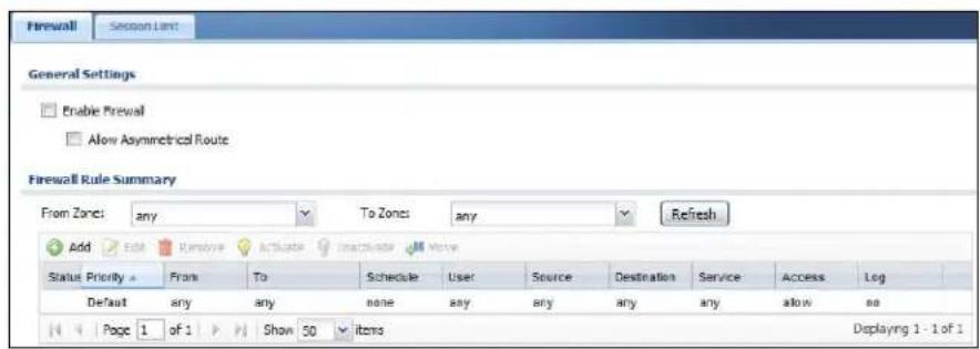
2 Click the Add button in the Firewall Rule Summary table.
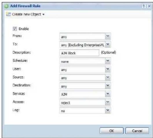
2a User: Leave this as any to apply the rule to all users, or select a specific subset of users, such as guest or staff.
2b Enable: Select this to make the firewall rule active.
2c Description: Enter a description for the rule that makes it easy to identify later. For the purposes of this tutorial, enter 'AIM Block'. (This field is entirely optional, so if you leave it blank there will be no adverse effects.)
2d Service: Select AIM from the list.
2e Access: Select reject from this list to block the service.
3 Click OK to save your changes.
See Also: Chapter 18 on page 249.
5.3.3 Blocking Sub-Protocols
Let's say that instead of blocking all AIM traffic, you want to only block the file transfer and video chat options for the various Instant Messenger programs used by employees, since those are fairly bandwidth intensive activities that maybe you don't want to burden your wireless network. This tutorial shows you how to do that with the NXC's Application Patrol feature.
1 Click Configuration > App Patrol > IM.
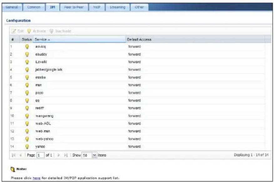
2 In the Configuration table, select aol-icq then click Edit.
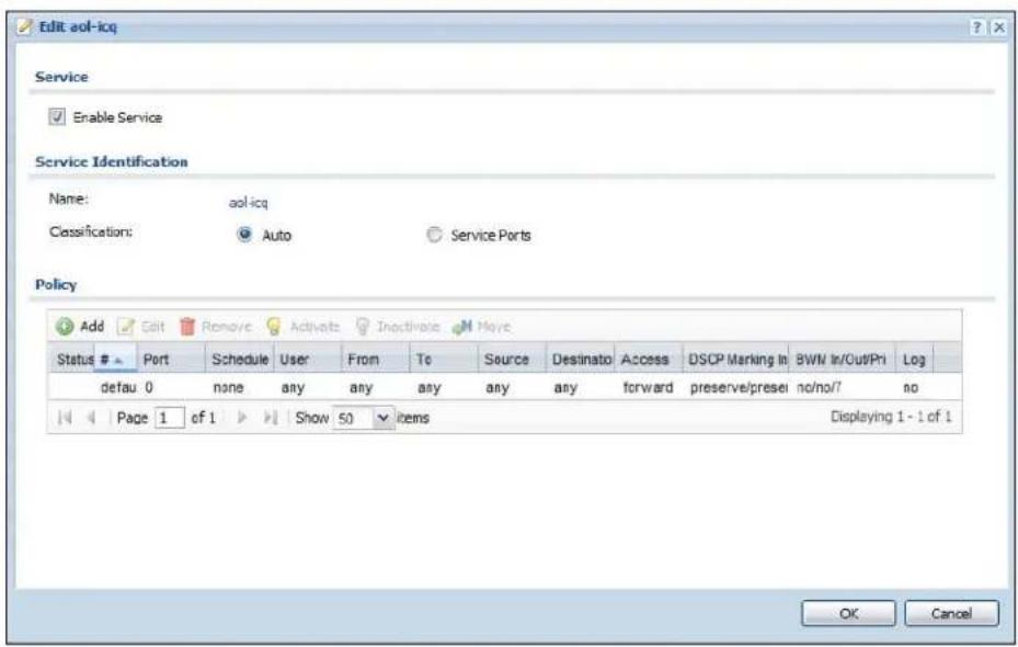
3 Select Enable Service.
4 In the Policy table, click Add.
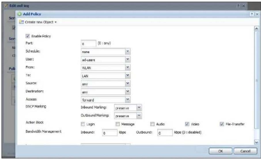
4a Enable Policy: Select this to make the policy active.
4b User: Select ad-users from the list, since for the purposes of this tutorial only employees are authenticated by an external AD server (as configured in Section 5.2.5 on page 79.)
4c From: Select WLAN from the list (Section 5.3.1 on page 87). This means only employees logging over the wireless network have this restriction applied to them.
4d Action Block: Select Video and File Transfer. This limits the restriction only to video chat and file transfer requests.
5 Click OK to save your changes.
See Also: Chapter 19 on page 265.
5.4 Rogue AP Detection
Rogue APs are wireless access points interacting with the network managed by the NXC but which are not under the control of the network administrator. In short, they are a security risk because they circumvent network security policy. AP detection only works when at least 1 AP is configured for Monitor mode.
The following are some suggestions on monitor AP placement:
- Neighboring companies that both support wireless network. If you can detect your neighbor's APs and you know they are 'friendly', you can add them to the friendly exception list.
- Reception areas. If a reception area has a high volume of visitor traffic, it might be useful to see if anyone is setting up their wireless device as an AP.
- High security areas. An AP set to Monitor mode will let you see if anyone sets up an unauthorized AP that could potentially compromise your security.
In this example, an employee illicitly connects his own AP (RG) to the network that the NXC manages. While not necessarily a malicious act, it can nonetheless have severe security consequences on the network.
Figure 22 Rogue AP Example A
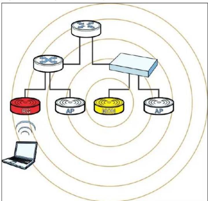
flowchart
graph TD
    A["Router"] --> B["Switch"]
    B --> C["Router"]
    C --> D["MON"]
    D --> E["AP"]
    E --> F["AP"]
    G["RG"] --> H["Router"]
    I["AP"] --> J["Router"]
    K["Laptop"] --> L["Wireless Signal"]
    style A fill:#f9f,stroke:#333
    style B fill:#ccf,stroke:#333
    style C fill:#cfc,stroke:#333
    style D fill:#fcc,stroke:#333
    style E fill:#cff,stroke:#333
    style F fill:#ffc,stroke:#333
    style G fill:#f9f,stroke:#333
    style H fill:#ccf,stroke:#333
    style I fill:#cfc,stroke:#333
    style J fill:#fcc,stroke:#333
    style K fill:#ffc,stroke:#333
Here, an attacker sets up a rogue AP (RG) outside the network, which he uses in an attempt to mimic an NXC-controlled SSID in order to capture passwords and other information when authorized wireless clients mistakenly connect to it.
Figure 23 Rogue AP Example B
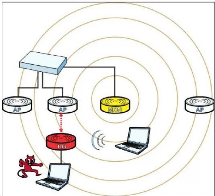
flowchart
graph TD
    A["Router"] --> B["AP"]
    A --> C["AP"]
    A --> D["AP"]
    A --> E["MON"]
    A --> F["AP"]
    A --> G["AP"]
    H["Roger"] --> I["Laptop"]
    J["Wireless Link"] --> K["Wireless Link"]
    style A fill:#f9f,stroke:#333
    style H fill:#ccf,stroke:#333
    style J fill:#ccf,stroke:#333
    style K fill:#ccf,stroke:#333
    style_L["Red Dog Icon"] --> H
    style_M["Red Dog Icon"] --> N["Red Dog Icon"]
This tutorial shows you how to detect rogue APs on your network:
1 Click Configuration > Object > MON Profile.
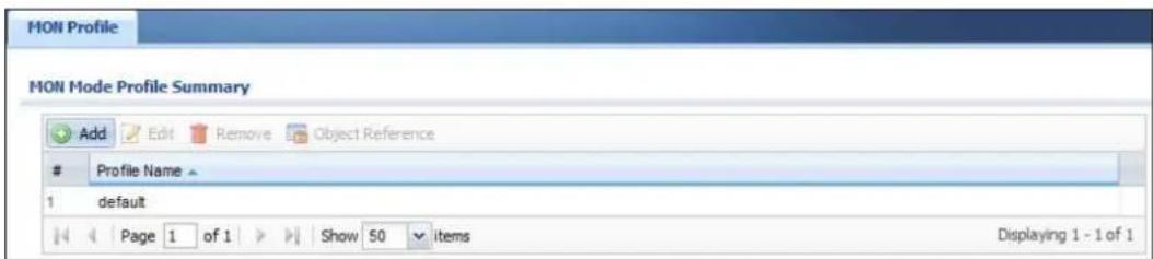
2 Click the Add button.
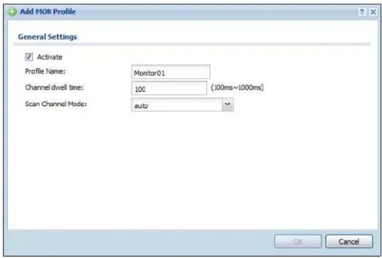
When the Add Mon Profile window opens, configure the following:
Activate: Select this to allow your monitor APs to use this profile.
Profile Name: For the purposes of this tutorial set this to 'Monitor01'.
Channel Dwell Time: Leave this as the default 100 milliseconds. This field is the number of milliseconds that the monitor AP scans each channel before moving on to the next.
Scan Channel Mode: Set this to auto to automatically scan channels in the area.
3 Click OK to save your changes.
4 Next, click Configuration > Wireless > AP Management.
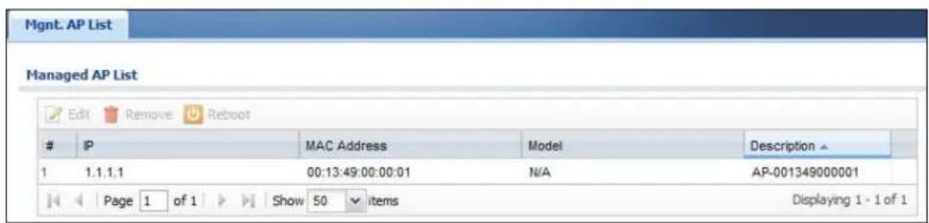
5 Select an AP and click Edit.
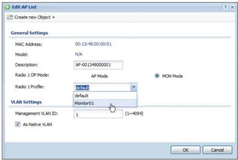
When the Edit AP List window opens, configure the following:
Radio 1 OP Mode: Set this to MON Mode to turn the AP into a rogue AP monitoring device.
Radio 1 Profile: Select your newly created 'Monitor01' profile from the list.
6 Click OK to save your changes.
See also: Chapter 7 on page 115 and Chapter 26 on page 401.
5.4.1 Rogue AP Containment
When the NXC discovers a rogue AP within its broadcast radius, it can react in one of two ways: If the rogue AP is connected directly to the network (such as plugged into a switch downstream of the NXC), then the network administrator must manually disconnect it. The NXC does not allow the isolation of a rogue AP connected directly to the network.
However, if a rogue AP independent of the NXC mimics a legitimate one, then the NXC can interfere with it by broadcasting dummy packets so that it cannot make connections with employee clients and capture data from them.
Figure 24 Containing a Rogue AP
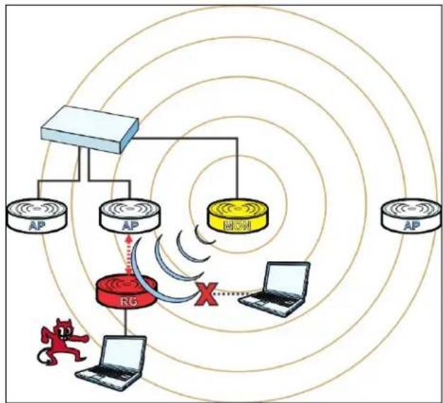
flowchart
graph TD
    A["Router"] --> B["AP"]
    A --> C["AP"]
    A --> D["AP"]
    A --> E["AP"]
    A --> F["AP"]
    A --> G["AP"]
    A --> H["Laptop"]
    A --> I["Router"]
    I --> J["AP"]
    I --> K["AP"]
    I --> L["AP"]
    I --> M["Laptop"]
    I --> N["Laptop"]
    style A fill:#f9f,stroke:#333
    style B fill:#ccf,stroke:#333
    style C fill:#ccf,stroke:#333
    style D fill:#ccf,stroke:#333
    style E fill:#ccf,stroke:#333
    style F fill:#ccf,stroke:#333
    style G fill:#ccf,stroke:#333
    style H fill:#ccf,stroke:#333
    style I fill:#ccf,stroke:#333
    style J fill:#ccf,stroke:#333
    style K fill:#ccf,stroke:#333
    style L fill:#ccf,stroke:#333
    style M fill:#ccf,stroke:#333
    style N fill:#ccf,stroke:#333
This tutorial shows you how to quarantine a rogue AP on your network:
1 Click Configuration > Wireless > MON Mode.
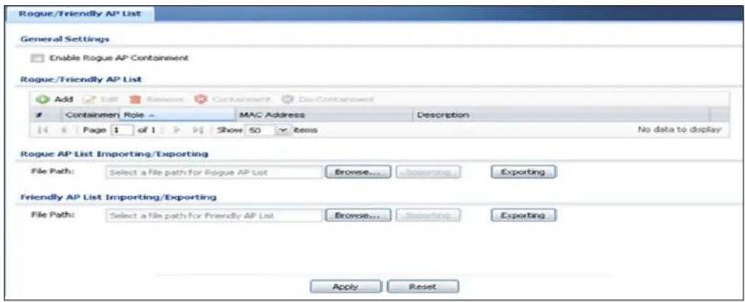
2 Click the Add button.
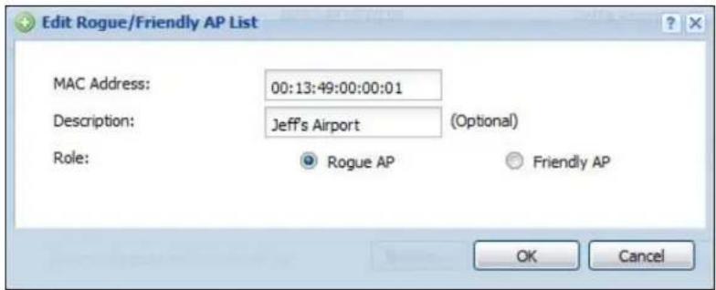
When the Edit Rogue/ Friendly AP List opens, paste the MAC address copied from the other screen in the corresponding field, set its Role as Rogue AP and then click OK to save your changes.
3 The new rogue AP appears in the Rogue/ Friendly AP List.
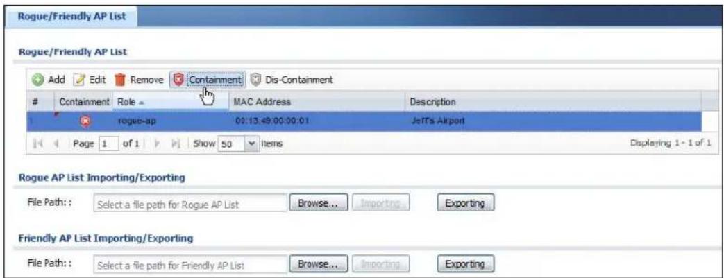
Select it, then click the Containment button to quarantine it away from the rest of the network.
5.5 Load Balancing
When your AP becomes overloaded, there are two basic responses it can take. The first one is to “delay” a client connection by withholding the connection until the data transfer throughput is lowered or the client connection is picked up by another AP. (If the client isn’t picked up after a set period of time, the AP allows it to connect regardless.) The second response is to kick the connections until the AP is no longer considered overloaded. Both of these tactics are known as ‘load balancing’.
This tutorial shows you how to configure the NXC's load balancing feature.
1 Click Configuration > Wireless > Load Balancing.
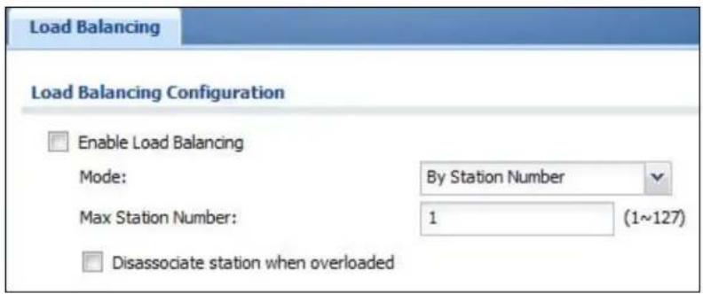
2 Select Enable Load Balancing to turn on this feature.
3 Set the Mode. If you choose By Station Number, then enter the Max Station Number in the available field. This balances network traffic based on the number of specified stations downstream of the NXC. If you choose By Traffic Level, then enter the traffic threshold at which the NXC starts balancing connected stations.
4 Select Disassociate station when overloaded to disconnect stations when the load balancing threshold is crossed. The stations are first disconnected based on how long they have been idle, then secondly based on the weakness of their connection signal strength.
5 Click Apply to save your changes.
See also: Chapter 10 on page 163.
5.6 Dynamic Channel Selection
Dynamic Channel Selection (DCS) is a feature that allows an AP to automatically select the radio channel upon which it broadcasts by scanning the area around it and determining what channels are currently being used by other devices.
When numerous APs broadcast within a given area, they introduce the possibility of heightened radio interference, especially if some or all of them are broadcasting on the same radio channel. This can make accessing the network potentially rather difficult for the stations connected to them. If the interference becomes too great, then the network administrator must open his AP configuration options and manually change the channel to one that no other AP is using (or at least a channel that has a lower level of interference) in order to give the connected stations a minimum degree of channel interference.
1 Click Configuration > Wireless > DCS.
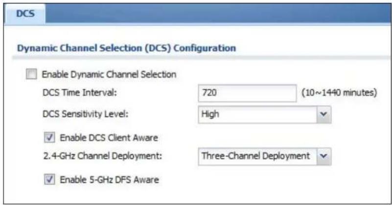
2 Select Enable Dynamic Channel Selection to turn on this feature.
3 Set the DCS Time Interval. This is how often the NXC surveys the other APs within its broadcast radius. If you place your APs in an area with a large number of competing APs, set this number lower to ensure that your device can adjust quickly changing conditions.
4 Select DCS Sensitivity Level. This is how sensitive the APs on your network are to other channels. Generally, as long as the area in which your AP is located has minimal interference from other devices you can set the DCS Sensitivity Level to Low. This means that the AP has a very broad tolerance.
5 Select Enable DCS Client Aware. Select this so that the APs on your network do not change channels as long as any wireless clients are connected to them. When they must change channels, they will wait until all stations disconnect first.
6 Select a 2.4 GHz Channel Deployment scheme. Choose Three-Channel Deployment to have the device rotate through 3 channels. Choose Four-Channel Deployment to have the device rotate through 4 channels, if allowed.
7 Click Apply to save your changes.
See also: Chapter 10 on page 163.
PART II
Technical Reference
Dashboard
6.1 Overview
Use the Dashboard screens to check status information about the NXC.
6.1.1 What You Can Do in this Chapter
- The main Dashboard screen (Section 6.2 on page 104) displays the NXC's general device information, system status, system resource usage, licensed service status, and interface status. You can also display other status screens for more information.
- The DHCP Table screen (Section 6.2.4 on page 112) displays the IP addresses currently assigned to DHCP clients and the IP addresses reserved for specific MAC addresses.
- The Current Users screen (Section 6.2.5 on page 113) displays the users currently logged into the NXC.
6.2 Dashboard
This screen is the first thing you see when you log into the NXC. It also appears every time you click the Dashboard icon in the navigation panel. The Dashboard displays general device information, system status, system resource usage, licensed service status, and interface status in widgets that you can re-arrange to suit your needs. You can also collapse, refresh, and close individual widgets.
Figure 25 Dashboard
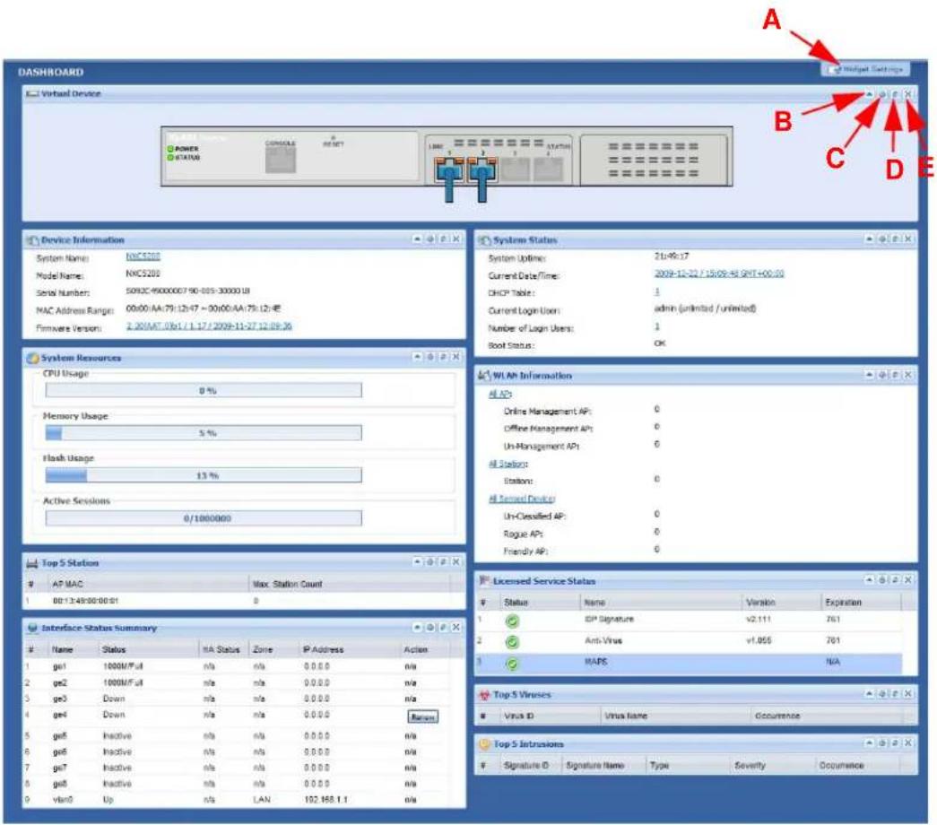
The following table describes the labels in this screen.
Table 22 Dashboard
| LABEL DESCRIPTION | |
| Widget Settings (A) | Use this link to re-open closed widgets. Widgets that are already open appear grayed out. |
| Up Arrow (B) Click | this to collapse a widget. |
| Refresh Time Setting (C) | Set the interval for refreshing the information displayed in the widget. |
| LABEL | DESCRIPTION |
| Refresh Now (D) Click this to update the widget's information immediately. | |
| Close Widget (E) | Click this to close the widget. UseWidget Settingto re-open it. |
| Virtual Device The following front and rear panel labels display when you hover your cursor over a connected interface or slot. | |
| Status This field displays the current status of each interface or device installed in a slot. The possible values depend on what type of interface it is.Inactive- The Ethernet interface is disabled.Down- The Ethernet interface is enabled but not connected.Speed / Duplex- The Ethernet interface is enabled and connected. This field displays the port speed and duplex setting (Full or Half). | |
| HA Status This field displays the status of the interface in the virtual router.Active- This interface is the master interface in the virtual router.Stand-By- This interface is a backup interface in the virtual router.Fault- This VRRP group is not functioning in the virtual router right now. For example, this might happen if the interface is down.n/ a- Device HA is not active on the interface. | |
| Zone This field displays the zone to which the interface is currently assigned. | |
| IP Address/ Mask | This field displays the current IP address and subnet mask assigned to the interface. If the interface is a member of an active virtual router, this field displays the IP address it is currently using. This is either the static IP address of the interface (if it is the master) or the management IP address (if it is a backup). |
| Device Information | |
| System Name This field displays the name used to identify the NXC on any network. Click the icon to open the screen where you can change it. | |
| Model Name This field displays the model name of this NXC. | |
| Serial Number This field displays the serial number of this NXC. | |
| MAC Address Range | This field displays the MAC addresses used by the NXC. Each physical port has one MAC address. The first MAC address is assigned to physical port 1, the second MAC address is assigned to physical port 2, and so on. |
| Firmware Version | This field displays the version number and date of the firmware the NXC is currently running. Click the icon to open the screen where you can upload firmware. |
| System Resources | |
| CPU Usage This field displays what percentage of the NXC's processing capability is currently being used. Hover your cursor over this field to display theShow CPU Usageicon that takes you to a chart of the NXC's recent CPU usage. | |
| LABEL DESCRIPTION | |
| Memory Usage | This field displays what percentage of the NXC's RAM is currently being used. Hover your cursor over this field to display the Show Memory Usage icon that takes you to a chart of the NXC's recent memory usage. |
| Flash Usage This | is field displays what percentage of the NXC's onboard flash memory is currently being used. |
| Active Sessions | This field displays how many traffic sessions are currently open on the NXC. These are the sessions that are traversing the NXC. Hover your cursor over this field to display icons. Click the Detail icon to go to the Session Monitor screen to see details about the active sessions. Click the Show Active Sessions icon to display a chart of NXC's recent session usage. |
| Top 5 Station Displays the top 5 Access Points (AP) with the highest number of station (aka wireless client) connections. | |
| # This field displays the rank of the station. | |
| AP MAC This field displays the MAC address of the AP to which the station belongs. | |
| Max. Station Count | This field displays the maximum number of wireless clients that have connected to this AP. |
| Interface Status Summary | If an Ethernet interface does not have any physical ports associated with it, its entry is displayed in light gray text. Click the Detail icon to go to a (more detailed) summary screen of interface statistics. |
| Name This field displays the name of each interface. | |
| Status This field displays the current status of each interface. The possible values depend on what type of interface it is.Inactive- The Ethernet interface is disabled.Down- The Ethernet interface is enabled but not connected.Speed / Duplex- The Ethernet interface is enabled and connected. This field displays the port speed and duplex setting (Full or Half). | |
| HA Status This field displays the status of the interface in the virtual router.Active- This interface is the master interface in the virtual router.Stand-By- This interface is a backup interface in the virtual router.Fault- This VRRP group is not functioning in the virtual router right now. For example, this might happen if the interface is down.n/ a- Device HA is not active on the interface. | |
| Zone This field displays the zone to which the interface is currently assigned. | |
| IP Address This field displays the current IP address assigned to the interface. If the IP address is 0.0.0.0, the interface is disabled or did not receive an IP address and subnet mask via DHCP.If this interface is a member of an active virtual router, this field displays the IP address it is currently using. This is either the static IP address of the interface (if it is the master) or the management IP address (if it is a backup). | |
| Action Use this field to get or to update the IP address for the interface.Click Renew to send a new DHCP request to a DHCP server. | |
| System Status | |
| System Uptime | This field displays how long the NXC has been running since it last restarted or was turned on. |
| Current Date/ Time | This field displays the current date and time in the NXC. The format is yyyy-mm-dd hh:mm:ss. |
| DHCP Table Click this to look at the IP addresses currently assigned to the NXC's DHCP clients and the IP addresses reserved for specific MAC addresses. | |
| Current Login User | This field displays the user name used to log in to the current session, the amount of reauthentication time remaining, and the amount of lease time remaining. |
| Number of Login Users | This field displays the number of users currently logged in to the NXC. Click the icon to pop-open a list of the users who are currently logged in to the NXC. |
| Boot Status This field displays details about the NXC's startup state.OK - The NXC started up successfully.Firmware update OK - A firmware update was successful.Problematic configuration after firmware update - The application of the configuration failed after a firmware upgrade.System default configuration - The NXC successfully applied the system default configuration. This occurs when the NXC starts for the first time or you intentionally reset the NXC to the system default settings.Fallback to lastgood configuration - The NXC was unable to apply the startup-config.conf configuration file and fell back to the lastgood.conf configuration file.Fallback to system default configuration - The NXC was unable to apply the lastgood.conf configuration file and fell back to the system default configuration file (system-default.conf).Booting in progress - The NXC is still applying the system configuration. | |
| WLAN Information | This shows a summary of connected wireless Access Points (APs). |
| All AP This section displays a summary for all connected wireless APs. | |
| Online Management AP | This displays the number of currently connected management APs. |
| Offline Management AP | This displays the number of currently offline managed APs. |
| Un-Management AP | This displays the number of non-managed APs. |
| LABEL | DESCRIPTION |
| All Station This section displays a summary of connected stations. | |
| Station This displays the number of stations currently connected to the network. | |
| All Sensed Device This sections displays a summary of all wireless devices detected by the network. | |
| Un-Classified AP | This displays the number of detected unclassified APs. |
| Rogue AP This displays the number of detected rogue APs. | |
| Friendly AP This displays the number of detected friendly APs. | |
| Licensed Service Status | |
| # This shows how many licensed services there are. | |
| Status This is the current status of the license. | |
| Name This identifies the licensed service. | |
| Version This is the version number of the anti-virus or IDP signatures (anti-virus and IDP). | |
| Expiration If the service license is valid, this shows when it will expire. N/A displays if the service license does not have a limited period of validity. | |
| Top 5 Viruses | |
| # This is the entry's rank in the list of the most commonly detected viruses. | |
| Virus ID This is the IDentification number of the anti-virus signature. | |
| Virus Name This is the name of a detected virus. | |
| Occurrence This is how many times the NXC has detected the event described in the entry. | |
| Top 5 Intrusions | |
| # This is the entry's rank in the list of the most commonly detected intrusions. | |
| Signature ID | This is the IDentification number of the IDP signature. |
| Signature Name | The signature name identifies a specific intrusion pattern. |
| Type | This column displays when you display the entries by Signature Name. It shows the categories of intrusions. |
| Severity | This is the level of threat that the intrusions may pose. |
| Occurrence This is how many times the NXC has detected the event described in the entry. | |
6.2.1 CPU Usage
Use this screen to look at a chart of the NXC's recent CPU usage. To access this screen, click CPU Usage in the dashboard.
Figure 26 Dashboard > CPU Usage
line
| Time | Value | | -------- | ----- | | 19:41 | 0 | | 23:41 | 0 | | 03:41 | 0 | | 07:41 | 0 | | 11:41 | 0 | | 15:41 | 0 |The following table describes the labels in this screen.
Table 23 Dashboard > CPU Usage
| LABEL DESCRIPTION | |
| The y-axis represents the percentage of CPU usage. | |
| The x-axis shows the time period over which the CPU usage occurred | |
| Refresh Interval | Enter how often you want this window to be automatically updated. |
| Refresh Now Click this to update the information in the window right away. | |
6.2.2 Memory Usage
Use this screen to look at a chart of the NXC's recent memory (RAM) usage. To access this screen, click Memory Usage in the dashboard.
Figure 27 Dashboard > Memory Usage
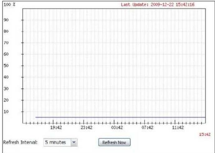
line
| Time | Value | | -------- | ----- | | 19:42 | 5 | | 23:42 | 5 | | 03:42 | 5 | | 07:42 | 5 | | 11:42 | 5 | | 15:42 | 5 |The following table describes the labels in this screen.
Table 24 Dashboard > Memory Usage
| LABEL DESCRIPTION | |
| The y-axis represents the percentage of RAM usage. | |
| The x-axis shows the time period over which the RAM usage occurred | |
| Refresh Interval | Enter how often you want this window to be automatically updated. |
| Refresh Now Click this to update the information in the window right away. | |
6.2.3 Session Usage
Use this screen to look at a chart of the NXC's recent traffic session usage. To access this screen, click Session Usage in the dashboard.
Figure 28 Dashboard > Session Usage
line
| Time | Value | | -------- | ----- | | 15:43 | 10 |The following table describes the labels in this screen.
Table 25 Dashboard > Session Usage
| LABEL DESCRIPTION | |
| Sessions The y-axis represents the number of session. | |
| The x-axis shows the time period over which the session usage occurred | |
| Refresh Interval | Enter how often you want this window to be automatically updated. |
| Refresh Now Click this to update the information in the window right away. | |
6.2.4 DHCP Table
Use this screen to look at the IP addresses currently assigned to DHCP clients and the IP addresses reserved for specific MAC addresses. To access this screen, click the icon beside DHCP Table in the dashboard.
Figure 29 Dashboard > DHCP Table
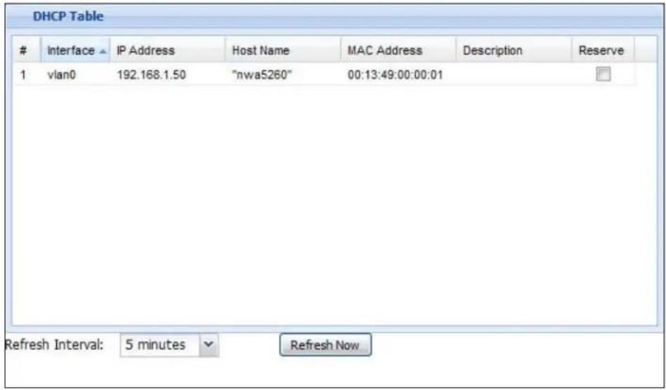
The following table describes the labels in this screen.
Table 26 Dashboard > DHCP Table
| LABEL DESCRIPTION | |
| # This field is a sequential value, and it is not associated with a specific entry. | |
| Interface This field identifies the interface that assigned an IP address to a DHCP client. | |
| IP Address This field displays the IP address currently assigned to a DHCP client or reserved for a specific MAC address. Click the column's heading cell to sort the table entries by IP address. Click the heading cell again to reverse the sort order. | |
| Host Name This field displays the name used to identify this device on the network (the computer name). The NXC learns these from the DHCP client requests. “None” shows here for a static DHCP entry. | |
| MAC Address This field displays the MAC address to which the IP address is currently assigned or for which the IP address is reserved. Click the column's heading cell to sort the table entries by MAC address. Click the heading cell again to reverse the sort order. | |
| Description For a static DHCP entry, the host name or the description you configured shows here. This field is blank for dynamic DHCP entries. | |
| Reserve If this field is selected, this entry is a static DHCP entry. The IP address is reserved for the MAC address.If this field is clear, this entry is a dynamic DHCP entry. The IP address is assigned to a DHCP client.To create a static DHCP entry using an existing dynamic DHCP entry, select this field, and then clickApply.To remove a static DHCP entry, clear this field, and then clickApply. |
6.2.5 Number of Login Users
Use this screen to look at a list of the users currently logged into the NXC. To access this screen, click the dashboard's Number of Login Users icon.
Figure 30 Dashboard > Number of Login Users

The following table describes the labels in this screen.
Table 27 Dashboard > Number of Login Users
| LABEL DESCRIPTION | |
| # This field is a sequential value and is not associated with any entry. | |
| User ID This field displays the user name of each user who is currently logged in to the NXC. | |
| Reauth Lease T. | This field displays the amount of reauthentication time remaining and the amount of lease time remaining for each user. |
| Type This field displays the way the user logged in to the NXC. | |
| IP address This field displays the IP address of the computer used to log in to the NXC. | |
| Force Logout Click this icon to end a user's session. | |
Monitor
7.1 Overview
Use the Monitor screens to check status and statistics information.
7.1.1 What You Can Do in this Chapter
- The Port Statistics screen (Section 7.3.1 on page 118) displays packet statistics for each physical port.
- The Port Statistics Graph screen (Section 7.3.1 on page 118) displays a line graph of packet statistics for each physical port.
- The Interface Status screen (Section 7.4 on page 119) displays all of the NXC's interfaces and their packet statistics.
- The Traffic Statistics screen (Section 7.5 on page 121) allows you to start or stop data collection and view statistics.
- The Session Monitor screen (Section 7.6 on page 124) displays sessions by user or service.
- The IP/ MAC Binding screen (Section 7.7 on page 127) displays lists of the devices that have received an IP address from NXC interfaces with IP/MAC binding enabled.
- The Login Users screen (Section 7.8 on page 128) displays a list of the users currently logged into the NXC.
- The AP List screen (Section 7.9 on page 129) displays which APs are currently connected to the NXC.
- The Radio List screen (Section 7.10 on page 131) displays statistics about the wireless radio transmitters in each of the APs connected to the NXC.
- The Station List screen (Section 7.11 on page 133) displays statistics pertaining to the connected stations (or "wireless clients").
- The Detected Device screen (Section 7.12 on page 134) displays the wireless devices passively detected by the NXC..
- The AppPatrol Statistics screen (Section 7.13 on page 135) displays a bandwidth usage graph and statistics for each protocol.
- The Anti-Virus screen (Section 7.14 on page 139) starts or stops data collection and displays virus statistics.
- The IDP screen (Section 7.15 on page 141) starts or stops data collection and displays IDP statistics.
- The View Log screen (Section 7.16 on page 143) displays the NXC's current log messages. You can change the way the log is displayed, you can e-mail the log, and you can also clear the log in this screen.
- The View AP Log screen (Section 7.17 on page 146) displays the NXC's current wireless AP log messages.
7.2 What You Need to Know
The following terms and concepts may help as you read through the chapter.
Rogue AP
Rogue APs are wireless access points operating in a network's coverage area that are not under the control of the network's administrators, and can open up holes in a network's security. See Chapter 26 on page 401 for details.
Friendly AP
Friendly APs are other wireless access points that are detected in your network, as well as any others that you know are not a threat (those from neighboring networks, for example). See Chapter 26 on page 401 for details.
7.3 Port Statistics
Use this screen to look at packet statistics for each Gigabit Ethernet port. To access this screen, click Monitor > System Status > Port Statistics.
Figure 31 Monitor > System Status > Port Statistics
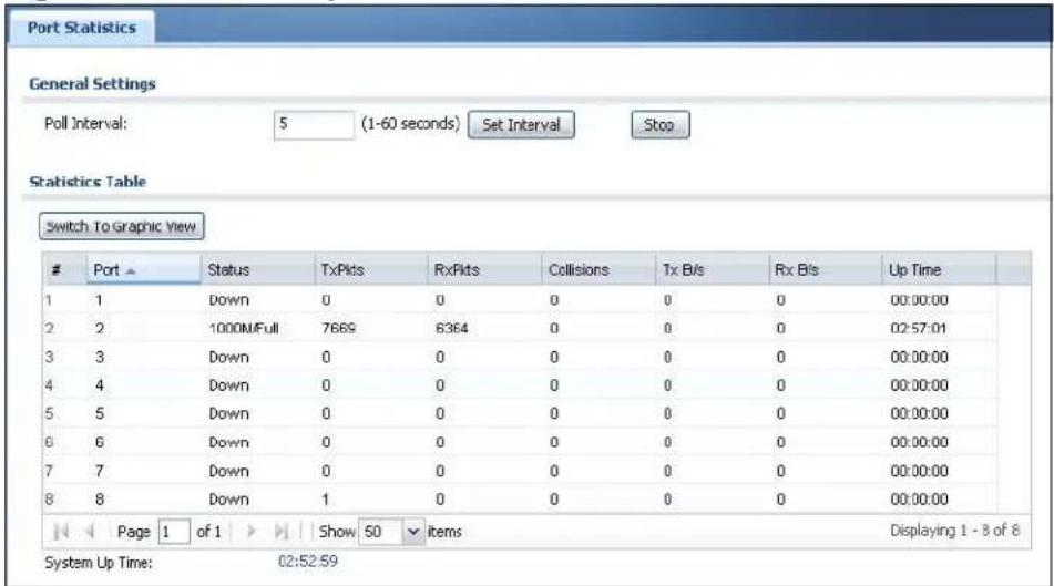
The following table describes the labels in this screen.
Table 28 Monitor > System Status > Port Statistics
| LABEL DESCRIPTION | |
| Poll Interval Enter how often you want this window to be updated automatically, and click Set Interval. | |
| Set Interval | Click this to set the Poll Interval the screen uses. |
| Stop Click this to stop the window from updating automatically. You can start it again by setting the Poll Interval and clicking Set Interval. | |
| Switch to Graphic View | Click this to display the port statistics as a line graph. |
| # This field displays the port's number in the list. | |
| Port This field displays the physical port number. | |
| Status This field displays the current status of the physical port. Down - The physical port is not connected. Speed / Duplex - The physical port is connected. This field displays the port speed and duplex setting (Full or Half). | |
| TxPkts This field displays the number of packets transmitted from the NXC on the physical port since it was last connected. | |
| RxPkts This field displays the number of packets received by the NXC on the physical port since it was last connected. | |
| Collisions This field displays the number of collisions on the physical port since it was last connected. | |
| Tx B/s This field | displays the transmission speed, in bytes per second, on the physical port in the one-second interval before the screen updated. |
| Rx B/s This field | displays the reception speed, in bytes per second, on the physical port in the one-second interval before the screen updated. |
| Up Time This field | ld displays how long the physical port has been connected. |
| System Up Time | This field displays how long the NXC has been running since it last restarted or was turned on. |
7.3.1 Port Statistics Graph
Use the port statistics graph to look at a line graph of packet statistics for each physical port. To view, click Port Statistics in the Status screen and then the Switch to Graphic View Button.
Figure 32 Monitor > System Status > Port Statistics > Switch to Graphic View
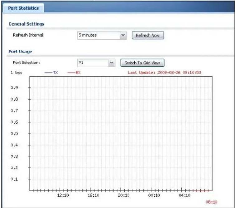
line
| Time | TX | RX | | -------- | ---- | ---- | | 08:10 | 0.1 | 0.1 | | 12:10 | 0.2 | 0.2 | | 16:10 | 0.3 | 0.3 | | 20:10 | 0.4 | 0.4 | | 00:10 | 0.5 | 0.5 | | 04:10 | 0.6 | 0.6 | | 08:10 | 0.7 | 0.7 | | 12:10 | 0.8 | 0.8 | | 16:10 | 0.9 | 0.9 |The following table describes the labels in this screen.
Table 29 Monitor > System Status > Port Statistics > Switch to Graphic View
| LABEL DESCRIPTION | |
| Refresh Interval | Enter how often you want this window to be automatically updated. |
| Refresh Now Click this to update the information in the window right away. | |
| Port Selection Select the number of the physical port for which you want to display graphics. | |
Table 29 Monitor > System Status > Port Statistics > Switch to Graphic View
| LABEL DESCRIPTION | |
| Switch to Grid View | Click this to display the port statistics as a table. |
| bps The y-axis represents the speed of transmission or reception. | |
| time The x-axis shows the time period over which the transmission or reception occurred | |
| TX This line represents traffic transmitted from the NXC on the physical port since it was last connected. | |
| RX This line represents the traffic received by the NXC on the physical port since it was last connected. | |
| Last Update This field displays the date and time the information in the window was last updated. | |
| System Up Time | This field displays how long the NXC has been running since it last restarted or was turned on. |
7.4 Interface Status
This screen lists all of the NXC's interfaces and gives packet statistics for them. Click Monitor > System Status > Interface Status to access this screen.
Figure 33 Monitor > System Status > Interface Status
| Interface Summary | ||||||||
| Interface Status | ||||||||
| Name | Port | Status | HA Sta | Zone | IP Addr/Netmask | IP Assignmet | Services | Action |
| ge1 | P1 | 1000M/Full | n/a | n/a | 0.0.0.0 / 0.0.0.0 | Static | n/a | n/a |
| ge2 | P2 | 1000M/Full | n/a | n/a | 0.0.0.0 / 0.0.0.0 | Static | n/a | n/a |
| ge3 | P3 | Down | n/a | n/a | 0.0.0.0 / 0.0.0.0 | Static | n/a | n/a |
| ge4 | P4 | Down | n/a | n/a | 0.0.0.0 / 0.0.0.0 | DHCP client | n/a | Renew |
| ge5 | P5 | Inactive | n/a | n/a | 0.0.0.0 / 0.0.0.0 | Static | n/a | n/a |
| ge6 | P6 | Inactive | n/a | n/a | 0.0.0.0 / 0.0.0.0 | Static | n/a | n/a |
| ge7 | P7 | Inactive | n/a | n/a | 0.0.0.0 / 0.0.0.0 | Static | n/a | n/a |
| ge8 | P8 | Inactive | n/a | n/a | 0.0.0.0 / 0.0.0.0 | Static | n/a | n/a |
| vlan0 | n/a | Up | n/a | LAN | 192.168.1.1 / 255.255.255. Static DHCP server n/a | |||
Each field is described in the following table.
Table 30 Monitor > System Status > Interface Status
| LABEL DESCRIPTION | |
| Interface Status | If an Ethernet interface does not have any physical ports associated with it, its entry is displayed in light gray text. |
| Name | This field displays the name of each interface. If there is aExpandicon (plus-sign) next to the name, click this to look at the status of virtual interfaces on top of this interface. |
| Port This field displays the physical port number. | |
| Status This field | displays the current status of each interface. The possible values depend on what type of interface it is.For Ethernet interfaces:Inactive- The Ethernet interface is disabled.Down- The Ethernet interface is enabled but not connected.Speed / Duplex- The Ethernet interface is enabled and connected. This field displays the port speed and duplex setting (Full or Half). |
| HA Status This field | displays the status of the interface in the virtual router.Active- This interface is the master interface in the virtual router.Stand-By- This interface is a backup interface in the virtual router.Fault- This VRRP group is not functioning in the virtual router right now. For example, this might happen if the interface is down.n/ a- Device HA is not active on the interface. |
| Zone This field displays the zone to which the interface is assigned. | |
| IP Addr/Netmask | This field displays the current IP address and subnet mask assigned to the interface. If the IP address and subnet mask are 0.0.0.0, the interface is disabled or did not receive an IP address and subnet mask via DHCP.If this interface is a member of an active virtual router, this field displays the IP address it is currently using. This is either the static IP address of the interface (if it is the master) or the management IP address (if it is a backup). |
| IP Assignment This field displays how the interface gets its IP address.Static- This interface has a static IP address.DHCP Client- This interface gets its IP address from a DHCP server.Dynamic- This is the auxiliary interface. | |
| Services This field lists which services the interface provides to the network. This field displaysn/ aif the interface does not provide any services to the network. | |
| Action Use this field to get or to update the IP address for the interface. ClickRenewto send a new DHCP request to a DHCP server. ClickConnectto try to connect the interface. If the interface cannot use one of these ways to get or to update its IP address, this field displaysn/ a. | |
| Interface Statistics | This table provides packet statistics for each interface. |
| Refresh Click this | s button to update the information in the screen. |
| Name | This field displays the name of each interface. If there is a Expand icon (plus-sign) next to the name, click this to look at the statistics for virtual interfaces on top of this interface. |
| Status This field | displays the current status of the interface. Down - The interface is not connected. Speed / Duplex - The interface is connected. This field displays the port speed and duplex setting (Full or Half). |
| TxPkts This field | displays the number of packets transmitted from the NXC on the interface since it was last connected. |
| RxPkts This field | displays the number of packets received by the NXC on the interface since it was last connected. |
| Tx B/s This field | displays the transmission speed, in bytes per second, on the interface in the one-second interval before the screen updated. |
| Rx B/s This field | displays the reception speed, in bytes per second, on the interface in the one-second interval before the screen updated. |
7.5 Traffic Statistics
Click Monitor > System Status > Traffic Statistics to display this screen. This screen provides basic information about the different kinds of data traffic moving through the NXC. For example:
- Most-visited Web sites and the number of times each one was visited. This count may not be accurate in some cases because the NXC counts HTTP GET packets.
- Most-used protocols or service ports and the amount of traffic on each one
• LAN IP with heaviest traffic and how much traffic has been sent to and from each one
You use the Traffic Statistics screen to tell the NXC when to start and when to stop collecting information for these reports. You cannot schedule data collection; you have to start and stop it manually in the Traffic Statistics screen.
Figure 34 Monitor > System Status > Traffic Statistics
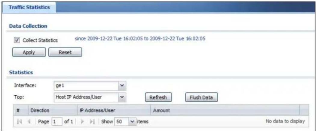
There is a limit on the number of records shown in the report. See Table 32 on page 124 for more information. The following table describes the labels in this screen.
Table 31 Monitor > System Status > Traffic Statistics
| LABEL DESCRIPTION | |
| Data Collection | |
| Collect Statistics | Select this to have the NXC collect data for the report. If the NXC has already been collecting data, the collection period displays to the right. The progress is not tracked here real-time, but you can click the Refresh button to update it. |
| Apply | Click Apply to save your changes back to the NXC. |
| Reset | Click Reset to return the screen to its last-saved settings. |
| Statistics | |
| Interface Select | the interface from which to collect information. You can collect information from Ethernet or VLAN interfaces. |
| Top Select the type of report to display. Choices are:Host IP Address/ User - displays the IP addresses or users with the most traffic and how much traffic has been sent to and from each one.Service/ Port - displays the most-used protocols or service ports and the amount of traffic for each one.Web Site Hits - displays the most-visited Web sites and how many times each one has been visited.Each type of report has different information in the report (below). | |
| Refresh Click this | button to update the report display. |
| Flush Data Click | this button to discard all of the screen's statistics and update the report display. |
| These fields are available when the Traffic Type is Host IP Address/User. | |
| # This field is the rank of each record. The IP addresses and users are sorted by the amount of traffic. | |
| IP Address/User | This field displays the IP address or user in this record. The maximum number of IP addresses or users in this report is indicated in Table 32 on page 124. |
| Direction This field indicates whether the IP address or user is sending or receiving traffic.Ingress- traffic is coming from the IP address or user to the NXC.Egress- traffic is going from the NXC to the IP address or user. | |
| Amount This field displays how much traffic was sent or received from the indicated IP address or user. If the Direction is Ingress, a red bar is displayed; if the Direction is Egress, a blue bar is displayed. The unit of measure is bytes, Kbytes, Mbytes or Gbytes, depending on the amount of traffic for the particular IP address or user. The count starts over at zero if the number of bytes passes the byte count limit. See Table 32 on page 124. | |
| These fields are available when the Traffic Type is Service/ Port. | |
| # This field is the rank of each record. The protocols and service ports are sorted by the amount of traffic. | |
| Service/Port This field displays the service and port in this record. The maximum number of services and service ports in this report is indicated in Table 32 on page 124. | |
| Protocol This field indicates what protocol the service was using. | |
| Direction This field indicates whether the indicated protocol or service port is sending or receiving traffic.Ingress- traffic is coming into the router through the interfaceEgress- traffic is going out from the router through the interface | |
| Amount This field displays how much traffic was sent or received from the indicated service / port. If the Direction is Ingress, a red bar is displayed; if the Direction is Egress, a blue bar is displayed. The unit of measure is bytes, Kbytes, Mbytes, Gbytes, or Tbytes, depending on the amount of traffic for the particular protocol or service port. The count starts over at zero if the number of bytes passes the byte count limit.See Table 32 on page 124. | |
| These fields are available when the Traffic Type is Web Site Hits. | |
| # This field is the rank of each record. The domain names are sorted by the number of hits. | |
| Web Site This field | ld displays the domain names most often visited. The NXC counts each page viewed on a Web site as another hit. The maximum number of domain names in this report is indicated in Table 32 on page 124. |
| Hits This field displays how many hits the Web site received. The NXC counts hits by counting HTTP GET packets. Many Web sites have HTTP GET references to other Web sites, and the NXC counts these as hits too. The count starts over at zero if the number of hits passes the hit count limit. See Table 32 on page 124. | |
The following table displays the maximum number of records shown in the report, the byte count limit, and the hit count limit.
Table 32 Maximum Values for Reports
| LABEL DESCRIPTION | |
| Maximum Number of Records | 20 |
| Byte Count Limit | 2^64 bytes; this is just less than 17 million terabytes. |
| Hit Count Limit | 2^64 hits; this is over 1.8 × 10^19 hits. |
7.6 Session Monitor
This screen displays information about active sessions for debugging or statistical analysis. It is not possible to manage sessions in this screen. The following information is displayed.
- User who started the session
- Protocol or service port used
- Source address
- Destination address
• Number of bytes received (so far)
• Number of bytes transmitted (so far) - Duration (so far)
You can look at all the active sessions by user, service, source IP address, or destination IP address. You can also filter the information by user, protocol / service or service group, source address, and/or destination address and view it by user.
Click Monitor > System Status > Session Monitor to display the following screen.
Figure 35 Monitor > System Status > Session Monitor
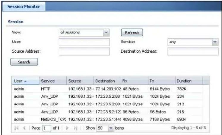
The following table describes the labels in this screen.
Table 33 Monitor > System Status > Session Monitor
| LABEL DESCRIPTION | |
| View Select how | you want the information to be displayed. Choices are:sessions by users - display all active sessions grouped by usersessions by services - display all active sessions grouped by service or protocolsessions by source IP - display all active sessions grouped by source IP addressessessions by destination IP - display all active sessions grouped by destination IP addressall sessions - filter the active sessions by the User, Service, Source Address, and Destination Address, and display each session individually (sorted by user). |
| Refresh Click this | is button to update the information on the screen. The screen also refreshes automatically when you open and close the screen. |
| The User, Service, Source Address, and Destination Address fields display if you view all sessions. Select your desired filter criteria and click the Search button to filter the list of sessions. | |
| User | This field displays when View is set to all sessions. Type the user whose sessions you want to view. It is not possible to type part of the user name or use wildcards in this field; you must enter the whole user name. |
| Service | This field displays when View is set to all sessions. Select the service or service group whose sessions you want to view. The NXC identifies the service by comparing the protocol and destination port of each packet to the protocol and port of each services that is defined. (See Chapter 28 on page 413 for more information about services.) |
| Source | This field displays whenViewis set to all sessions. Type the source IP address whose sessions you want to view. You cannot include the source port. |
| Destination | This field displays whenViewis set to all sessions. Type the destination IP address whose sessions you want to view. You cannot include the destination port. |
| Search | This button displays whenViewis set to all sessions. Click this button to update the information on the screen using the filter criteria in theUser, Service, Source Address, and Destination Addressfields. |
| Active Sessions | This is the total number of active sessions that matched the search criteria. |
| Show Select the | number of active sessions displayed on each page. You can use the arrow keys on the right to change pages. |
| User This field | displays the user in each active session.If you are looking at the sessions by users (or all sessions) report, click + or - to display or hide details about a user's sessions. |
| Service This field | displays the protocol used in each active session.If you are looking at the sessions by services report, click + or - to display or hide details about a protocol's sessions. |
| Source This field | displays the source IP address and port in each active session.If you are looking at the sessions by source IP report, click + or - to display or hide details about a source IP address's sessions. |
| Destination This | field displays the destination IP address and port in each active session.If you are looking at the sessions by destination IP report, click + or - to display or hide details about a destination IP address's sessions. |
| Rx This field | plays the amount of information received by the source in the active session. |
| Tx This field | plays the amount of information transmitted by the source in the active session. |
| Duration This field | ld displays the length of the active session in seconds. |
7.7 IP/MAC Binding Monitor
Click Monitor > System Status > IP/ MAC Binding to open the IP/ MAC Binding Monitor screen. This screen lists the devices that have received an IP address from NXC interfaces with IP/MAC binding enabled and have ever established a session with the NXC. Devices that have never established a session with the NXC do not display in the list.
Figure 36 Monitor > System Status > IP/MAC Binding
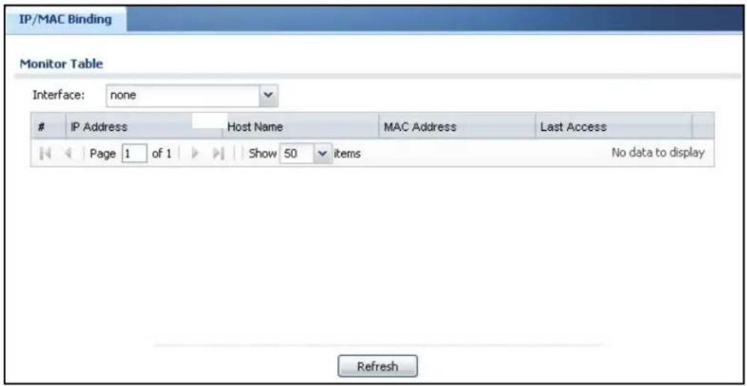
The following table describes the labels in this screen.
Table 34 Monitor > System Status > IP/MAC Binding
| LABEL DESCRIPTION | |
| Interface | Select a NXC interface that has IP/MAC binding enabled to show to which devices it has assigned an IP address. |
| # This is the index number of an IP/MAC binding entry. | |
| IP Address | This is the IP address that the NXC assigned to a device. |
| Host Name This field displays the name used to identify this device on the network (the computer name). The NXC learns these from the DHCP client requests. | |
| MAC Address This field displays the MAC address to which the IP address is currently assigned. | |
| Last Access This is when the device last established a session with the NXC through this interface. | |
| Refresh Click this button to update the information in the screen. | |
7.8 Login Users
Use this screen to look at a list of the users currently logged into the NXC. To access this screen, click Monitor > System Status > Login Users.
Figure 37 Monitor > System Status > Login Users
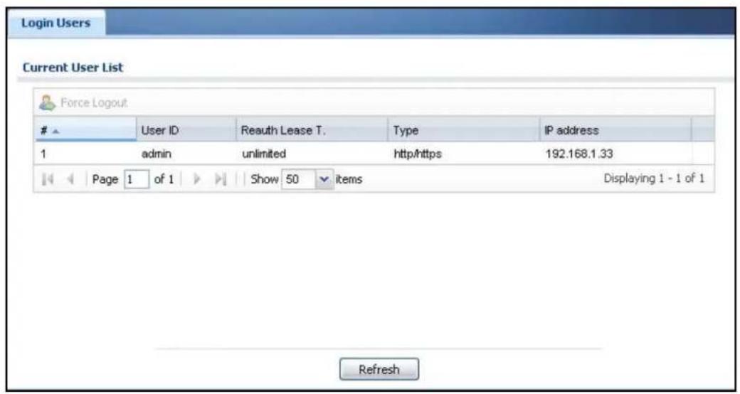
The following table describes the labels in this screen.
Table 35 Monitor > System Status > Login Users
| LABEL DESCRIPTION | |
| # This field is a sequential value and is not associated with any entry. | |
| User ID This field displays the user name of each user who is currently logged in to the NXC. | |
| Reauth Lease T. | This field displays the amount of reauthentication time remaining and the amount of lease time remaining for each user. See Chapter 24 on page 373. |
| Type This field displays the way the user logged in to the NXC. | |
| IP address This field displays the IP address of the computer used to log in to the NXC. | |
| Force Logout Click this icon to end a user's session. | |
| Refresh Click this button to update the information in the screen. | |
7.9 AP List
Use this screen to view which APs are currently connected to the NXC. To access this screen, click Monitor > Wireless > AP Info > AP List.
Figure 38 Monitor > Wireless > AP Info > AP List
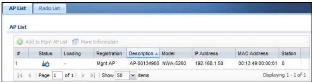
The following table describes the labels in this screen.
Table 36 Monitor > Wireless > AP Info > AP List
| LABEL DESCRIPTION | |
| Add to Mgmt AP List | Click this to add the selected AP to the Managed AP list. |
| More Information | Click this to view a daily station count about the selected AP. The count records station activity on the AP over a consecutive 24 hour period. |
| # This is the AP's index number in this list. | |
| Status This visually displays the AP's connection status with icons. For details on the different Status states, see the next table. | |
| Loading This indicates the AP's load balance status. | |
| Registration This indicates whether the AP is registered with the Managed AP list. | |
| Description This displays the AP's associated description. The default description is "AP-" + the AP's MAC Address. | |
| Model This displays the AP's model number. | |
| IP Address This displays the AP's IP address. | |
| MAC Address This displays the AP's MAC address. | |
| Station This displays the number of stations (aka wireless clients) associated with the AP. | |
| Refresh Click this to refresh the items displayed on this page. | |
The following table describes the icons in this screen.
Table 37 Monitor > Wireless > AP List Icons
| LABEL DESCRIPTION | |
| This is an AP that is not on the management list. | |
| This is an AP that is on the management list and which is online. | |
| LABEL DESCRIPTION | |
| This is an AP that is in the process of having its firmware updated. | |
| This is an AP that is both on the management list and which is offline. | |
| When an AP is being load balanced, this icon means it is operating over the maximum allocated bandwidth. | |
| When an AP is being load balanced, this icon means it is operating at the maximum allocated bandwidth. | |
| When an AP is being load balanced, this icon means it is operating under the maximum allocated bandwidth. | |
7.9.1 Station Count of AP
Use this screen to look at station statistics for the connected AP. To access this screen, click the More Information button in the AP List screen.
Figure 39 Monitor > System Status > AP List > Station Count of AP
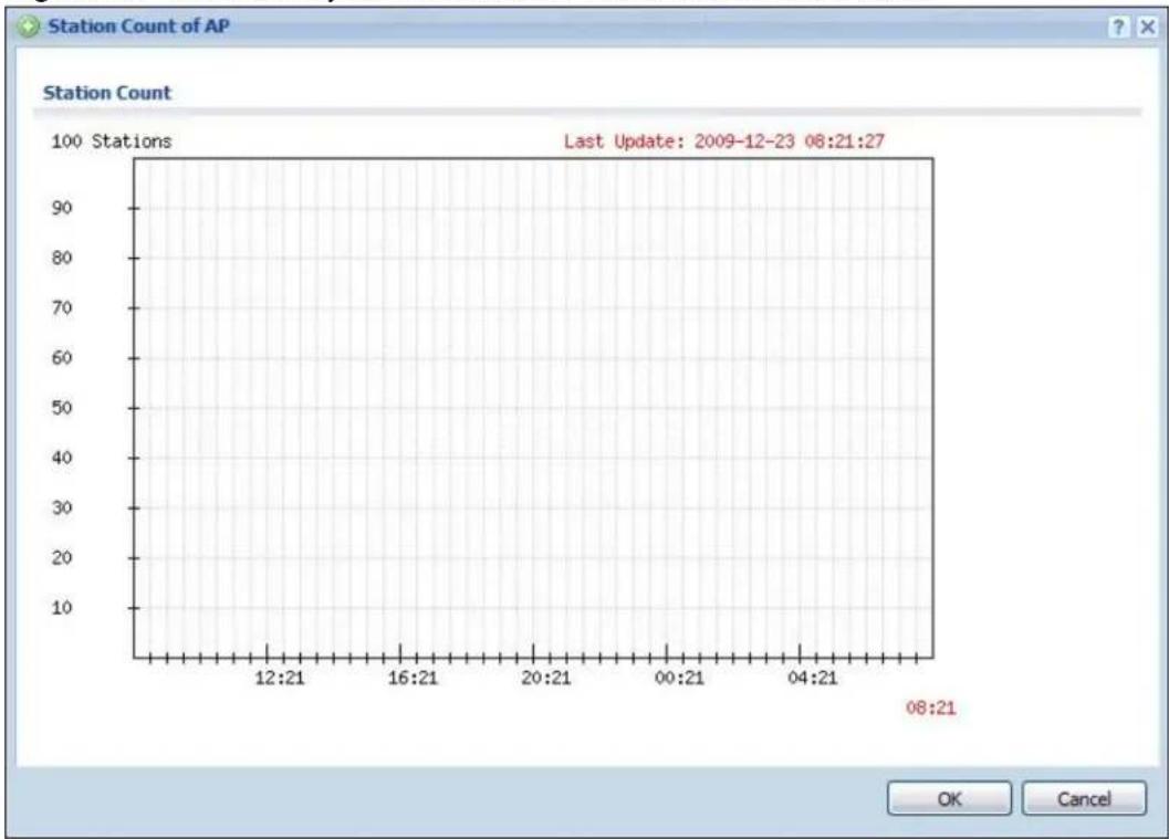
line
| Time | Station Count | | -------- | ------------- | | 08:21 | 10 |The following table describes the labels in this screen.
Table 38 Monitor > System Status > AP List > Station Count of AP
| LABEL DESCRIPTION | |
| Station Count The y-axis represents the number of connected stations. | |
| Time The x-axis shows the time over which a station was connected. | |
| Last Update This field displays the date and time the information in the window was last updated. |
7.10 Radio List
Use this screen to view statistics about the wireless radio transmitters in each of the APs connected to the NXC. To access this screen, click Monitor > Wireless > AP Info > Radio List.
Figure 40 Monitor > Wireless > AP Info > Radio List
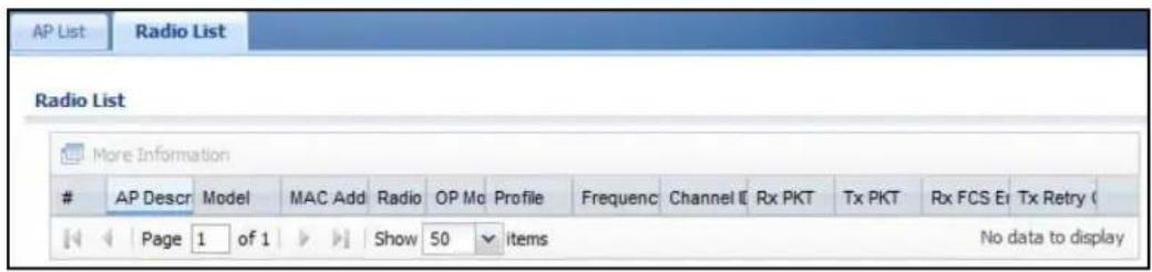
The following table describes the labels in this screen.
Table 39 Monitor > Wireless > AP Info > Radio List
| LABEL DESCRIPTION | |
| More Information | Click this to view additional information about the selected radio's wireless traffic. Information spans a 24 hour period. |
| # This is the radio's index number in this list. | |
| AP Description This displays the description of the AP to which the radio belongs. | |
| Model This displays the model of the AP to which the radio belongs. | |
| MAC Address This displays the MAC address of the radio. | |
| Radio This indicates the radio number on the AP to which it belongs. | |
| OP Mode This indicates the radio's operating mode. Operating modes are AP (access point) or MON (monitor). | |
| Profile This indicates the profile name to which the radio belongs. | |
| Frequency This indicates the wireless frequency currently being used by the radio. | |
| Channel ID | This indicates the radio's channel ID. |
| Rx PKT | This displays the total number of packets received by the radio. |
| Tx PKT | This displays the total number of packets transmitted by the radio. |
| Rx FCS Error Count | This indicates the number of received packet errors accrued by the radio. |
| Tx Retry Count | This indicates the number of times the radio has attempted to re-transmit packets. |
7.10.1 AP Mode Radio Information
This screen allows you to view detailed information about a selected radio's wireless traffic for the preceding 24 hours. To access this window, click the More Information button in the Radio List Statistics screen.
Figure 41 Monitor > Wireless > AP Info > Radio List > AP Mode Radio Information
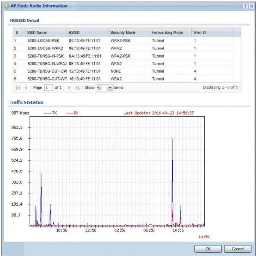
line
| Time | TX | RX | | -------- | ----- | ----- | | 18:56 | 95.7 | 191.4 | | 22:56 | 287.1 | 382.8 | | 02:56 | 574.2 | 478.5 | | 06:56 | 765.6 | 191.4 | | 10:56 | 191.4 | 287.1 | | 14:56 | 95.7 | 95.7 |The following table describes the labels in this screen.
Table 40 Monitor > Wireless > AP Info > Radio List > AP Mode Radio Information
| LABEL DESCRIPTION | |
| MBSSID Detail | This list shows information about all the wireless clients that have connected to the specified radio over the preceding 24 hours. |
| # This is the | items sequential number in the list. It has no bearing on the actual data in this list. |
| SSID Name | This displays an SSID associated with this radio. There can be up to eight maximum. |
| BSSID This d | plays a BSSID associated with this radio. The BSSID is tied to the SSID. |
| Security Mode | This displays the security mode in which the SSID is operating. |
| Forwarding Mode | This displays the forwardnig mode in use by the SSID. |
| VLAN ID This | displays the VLAN ID associated with the SSID. |
| Traffic Statistics | This graph displays the overall traffic information the radio over the preceding 24 hours. |
| y-axis This axis | is represents the amount of data moved across this radio in megabytes per second. |
| x-axis This axis | is represents the amount of time over which the data moved across this radio. |
| OK Click this to | close this window. |
| Cancel Click this | to close this window. |
7.11 Station List
Use this screen to view statistics pertaining to the associated stations (or "wireless clients"). Click Monitor > Wireless > Station Info to access this screen.
Figure 42 Monitor > Wireless > Station List

The following table describes the labels in this screen.
Table 41 Monitor > Wireless > Station List
| LABEL DESCRIPTION | |
| # This is the station's index number in this list. | |
| MAC Address This is the station's MAC address. | |
| Associated AP This indicates the AP through which the station is connected to the network. | |
| SSID Name This indicates the name of the wireless network to which the station is connected. A single AP can have multiple SSIDs or networks. | |
| Security Mode This indicates which secure encryption methods is being used by the station to connect to the network. | |
| Association Time | This indicates how long the station has been associated with the AP. |
| Refresh Click this to refresh the items displayed on this page. | |
7.12 Detected Device
Use this screen to view the wireless devices passively detected by the NXC. Click Monitor > Wireless > Rogue AP > Detected Device to access this screen.
Note: At least one of the APs connected to the NXC must be set to Monitor mode in order to detect other wireless devices in its vicinity.
Figure 43 Monitor > Wireless > Rogue AP > Detected Device
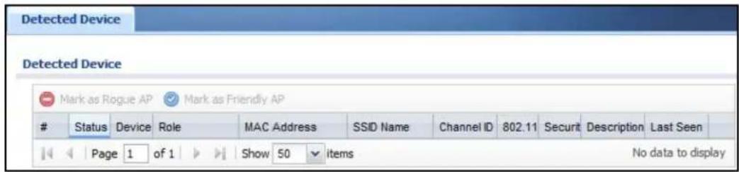
The following table describes the labels in this screen.
Table 42 Monitor > Wireless > Rogue AP > Detected Device
| LABEL DESCRIPTION | |
| Mark as Rogue AP | Click this button to mark the selected AP as a rogue AP. A rogue AP can be contained in theConfiguration > Wireless > MON Mode screen (Chapter 10 on page 163). |
| Mark as Friendly AP | Click this button to mark the selected AP as a friendly AP. For more on managing friendly APs, see theConfiguration > Wireless > MON Mode screen (Chapter 10 on page 163). |
| # This is the station's index number in this list. | |
| Status This indicates the detected device's status. | |
| Device This indicates the type of device detected. | |
| Role This indicates the detected device's role (such as friendly or rogue). | |
| MAC Address This indicates the detected device's MAC address. | |
| SSID Name This indicates the detected device's SSID. | |
| Channel ID This indicates the detected device's channel ID. | |
| 802.11 Mode This indicates the 802.11 mode (a/b/g/n) transmitted by the detected device. | |
| Security This indicates the encryption method (if any) used by the detected device. | |
| Description This displays the detected device's description. For more on managing friendly and rogue APs, see theConfiguration > Wireless > MON Mode screen (Chapter 10 on page 163). | |
| Last Seen This indicates the last time the device was detected by the NXC. | |
| Refresh Click this to refresh the items displayed on this page. | |
7.13 Application Patrol
The Application Patrol screens display bandwidth usage graphs and statistics for selected protocols.
Click Monitor > AppPatrol Statistics to open the following screens.
7.13.1 Application Patrol: General Settings
Use the top of the Monitor > AppPatrol Statistics screen to configure what to display.
Figure 44 Monitor > AppPatrol Statistics: General Settings
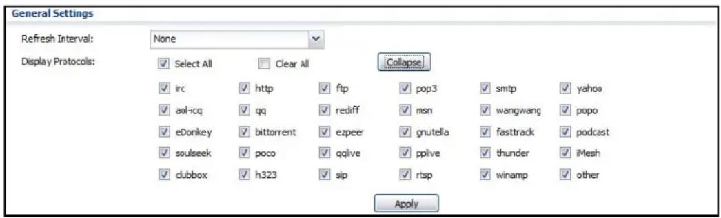
The following table describes the labels in this screen.
Table 43 Monitor > AppPatrol Statistics: General Settings
| LABEL DESCRIPTION | |
| Refresh Interval | Select how often you want the statistics display to update. |
| Display Protocols | Select the protocols for which to display statistics.Select All selects all of the protocols.Clear All clears all of the protocols.Click Expand to display individual protocols. Collapse hides them.Statistics for the selected protocols display after you click Apply. |
7.13.2 Application Patrol: Bandwidth Statistics
The middle of the Monitor > AppPatrol Statistics screen displays a bandwidth usage line graph for the selected protocols.
Figure 45 Monitor > AppPatrol Statistics: Bandwidth Statistics
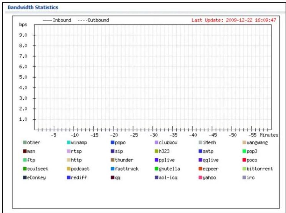
line
| Network | Inbound | Outbound | |-------------|---------|----------| | other | 1.0 | 1.0 | | winamp | 1.0 | 1.0 | | popo | 1.0 | 1.0 | | clubbox | 1.0 | 1.0 | | iMesh | 1.0 | 1.0 | | wangwang | 1.0 | 1.0 | | msn | 1.0 | 1.0 | | rtsp | 1.0 | 1.0 | | sip | 1.0 | 1.0 | | h323 | 1.0 | 1.0 | | smtp | 1.0 | 1.0 | | pop3 | 1.0 | 1.0 | | ftp | 1.0 | 1.0 | | http | 1.0 | 1.0 | | thunder | 1.0 | 1.0 | | pplive | 1.0 | 1.0 | | qglive | 1.0 | 1.0 | | poco | 1.0 | 1.0 | | soulseek | 1.0 | 1.0 | | podcast | 1.0 | 1.0 | | fasttrack | 1.0 | 1.0 | | gnutella | 1.0 | 1.0 | | ezpeer | 1.0 | 1.0 | | bittorrent | 1.0 | 1.0 | | eDonkey | 1.0 | 1.0 | | rediff | 1.0 | 1.0 | | qq | 1.0 | 1.0 | | aol-icq | 1.0 | 1.0 | | yahoo | 1.0 | 1.0 | | irc | 1.0 | 1.0 |- The y-axis represents the amount of bandwidth used.
- The x-axis shows the time period over which the bandwidth usage occurred.
-
A solid line represents a protocol's incoming bandwidth usage. This is the protocol's traffic that the NXC sends to the initiator of the connection.
-
A dotted line represents a protocol's outgoing bandwidth usage. This is the protocol's traffic that the NXC sends out from the initiator of the connection.
- Different colors represent different protocols.
7.13.3 Application Patrol: Protocol Statistics
The bottom of the Monitor > AppPatrol Statistics screen displays statistics for each of the selected protocols.
Figure 46 Monitor > AppPatrol Statistics: Protocol Statistics
| Protocol Statistics | ||||||
| x | Service | Forwarded Data(KB) | Dropped Data(KB) | Rejected Data(KB) | Matched Auto Connection | Matched Service Porto Con |
| 1 | vsk-men | 0 | 0 | 0 | 0 | 0 |
| 2 | rc | 0 | 0 | 0 | 0 | 0 |
| 3 | chone | 0 | 0 | 0 | 0 | 0 |
| 4 | sc-ing | 0 | 0 | 0 | 0 | 0 |
| 5 | ag | 0 | 0 | 0 | 0 | 0 |
| 6 | naber | 0 | 0 | 0 | 0 | 0 |
| 7 | reatf | 0 | 0 | 0 | 0 | 0 |
| 8 | aConley | 0 | 0 | 0 | 0 | 0 |
| 9 | bad | 0 | 0 | 0 | 0 | 0 |
| 10 | tattrentl | 0 | 0 | 0 | 0 | 0 |
| 11 | agreeer | 0 | 0 | 0 | 0 | 0 |
| 12 | euro | 0 | 0 | 0 | 0 | 0 |
| 13 | arutella | 0 | 0 | 0 | 0 | 0 |
| 14 | testrocki | 0 | 0 | 0 | 0 | 0 |
| 15 | scutsetk. | 0 | 0 | 0 | 0 | 0 |
| 16 | poco. | 0 | 0 | 0 | 0 | 0 |
| 17 | active. | 0 | 0 | 0 | 0 | 0 |
| 18 | adive. | 0 | 0 | 0 | 0 | 0 |
| 19. 19. 20. 21. 22. 23. 24. 25. 26. 27. 28. 29. Page 1 of 1 Show 50 Items Displaying 1 - 28 of 29 | ||||||
The following table describes the labels in this screen.
Table 44 Monitor > AppPatrol Statistics: Protocol Statistics
| LABEL DESCRIPTION | |
| Service This is the protocol. Click the service's name to display a screen with statistics for each of the service's application patrol rules. | |
| Forwarded Data (KB) | This is how much of the application's traffic the NXC has sent (in kilobytes). |
| Dropped Data (KB) | This is how much of the application's traffic the NXC has discarded without notifying the client (in kilobytes). This traffic was dropped because it matched an application policy set to “drop”. |
| Rejected Data (KB) | This is how much of the application's traffic the NXC has discarded and notified the client that the traffic was rejected (in kilobytes). This traffic was rejected because it matched an application policy set to “reject”. |
| Matched Auto Connection | This is how much of the application's traffic the NXC identified by examining the IP payload. |
| Matched Service Ports Connection | This is how much of the application's traffic the NXC identified by examining OSI level-3 information such as IP addresses and port numbers. |
7.13.4 Application Patrol: Protocol Statistics by Rule
The bottom of the Monitor > AppPatrol Statistics screen displays statistics for each of the selected protocols. Click a service's name to display this screen with statistics for each of the service's application patrol rules.
Figure 47 Monitor > AppPatrol Statistics > Service
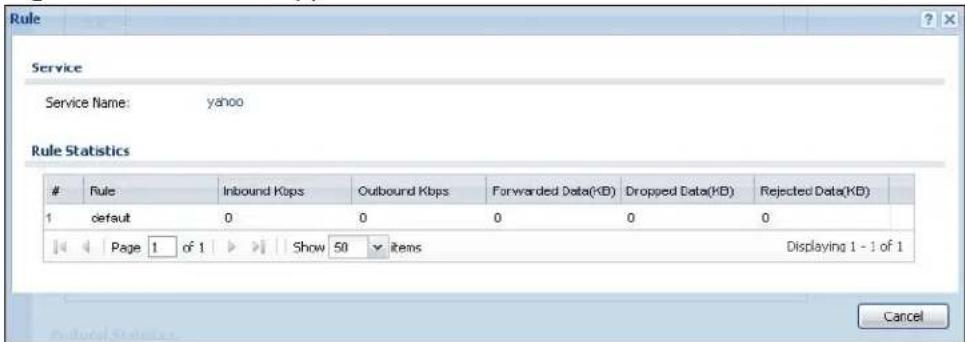
The following table describes the labels in this screen.
Table 45 Monitor > AppPatrol Statistics > Service
| LABEL DESCRIPTION | |
| Service Name This is the application. | |
| Rule Statistics This table displays the statistics for each of the service's application patrol rules. | |
| # This field is a sequential value, and it is not associated with a specific rule. | |
| Inbound Kbps This is the incoming bandwidth usage for traffic that matched this protocol rule, in kilobits per second. This is the protocol's traffic that the NXC sends to the initiator of the connection. So for a connection initiated from the LAN to the WAN, the traffic sent from the WAN to the LAN is the inbound traffic. | |
| Outbound Kbps This is the outgoing bandwidth usage for traffic that matched this protocol rule, in kilobits per second. This is the protocol's traffic that the NXC sends out from the initiator of the connection. So for a connection initiated from the LAN to the WAN, the traffic sent from the LAN to the WAN is the outbound traffic. | |
| Forwarded Data (KB) This is how much of the application's traffic the NXC has sent (in kilobytes). | |
| Dropped Data (KB) | This is how much of the application's traffic the NXC has discarded without notifying the client (in kilobytes). This traffic was dropped because it matched a policy set to “drop”. |
| Rejected Data (KB) | This is how much of the application's traffic the NXC has discarded and notified the client that the traffic was rejected (in kilobytes). This traffic was rejected because it matched a policy set to “reject”. |
| Cancel | Click Cancel to close this screen. |
7.14 Anti-Virus
Click Monitor > Anti-X Statistics > Anti-Virus to display the following screen. This screen displays anti-virus statistics.
Figure 48 Monitor > Anti-X Statistics > Anti-Virus
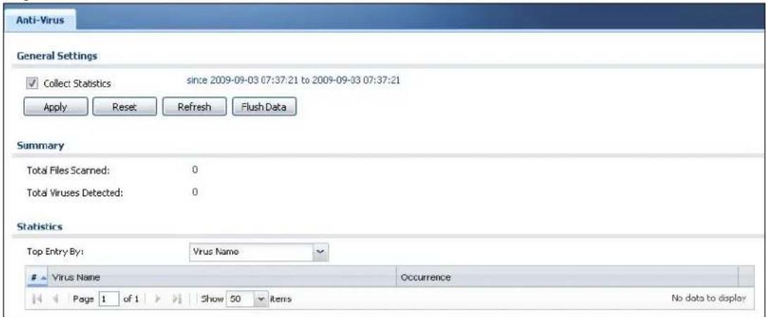
The following table describes the labels in this screen.
Table 46 Monitor > Anti-X Statistics > Anti-Virus
| LABEL DESCRIPTION | |
| Collect Statistics | Select this check box to have the NXC collect anti-virus statistics.The collection starting time displays after you clickApply. All of the statistics in this screen are for the time period starting at the time displayed here. The format is year, month, day and hour, minute, second. All of the statistics are erased if you restart the NXC or clickFlush Data. Collecting starts over and a new collection start time displays. |
| Apply | ClickApplyto save your changes back to the NXC. |
| Reset | ClickResetto return the screen to its last-saved settings. |
| Refresh Click this button to update the report display. | |
| Flush Data Click | this button to discard all of the screen's statistics and update the report display. |
| Total Files Scanned | This field displays the number of different files that the NXC scanned for viruses. |
| Total Viruses Detected | This field displays the number of different viruses that the NXC has detected. |
| Top Entry By Use | this field to have the following (read-only) table display the top anti-virus entries by Virus Name, Source IP or Destination IP.Select Virus Name to list the most common viruses that the NXC has detected.Select Source IP to list the source IP addresses from which the NXC has detected the most virus-infected files.Select Destination IP to list the most common destination IP addresses for virus-infected files that NXC has detected. |
| # This field displays the entry's rank in the list of the top entries. | |
| Virus name | This column displays when you display the entries by Virus Name. This displays the name of a detected virus. |
| Source IP | This column displays when you display the entries by Source. It shows the source IP address of virus-infected files that the NXC has detected. |
| Destination IP | This column displays when you display the entries by Destination. It shows the destination IP address of virus-infected files that the NXC has detected. |
| Occurrences This field displays how many times the NXC has detected the event described in the entry. | |
The statistics display as follows when you display the top entries by source.
Figure 49 Monitor > Anti-X Statistics > Anti-Virus: Source IP

The statistics display as follows when you display the top entries by destination.
Figure 50 Monitor > Anti-X Statistics > Anti-Virus: Destination IP

7.15 IDP
Click Monitor > Anti-X Statistics > IDP to display the following screen. This screen displays IDP (Intrusion Detection and Prevention) statistics.
Figure 51 Monitor > Anti-X Statistics > IDP
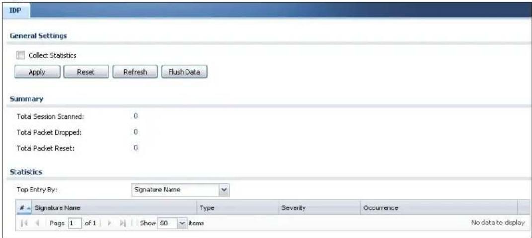
The following table describes the labels in this screen.
Table 47 Monitor > Anti-X Statistics > IDP
| LABEL DESCRIPTION | |
| Collect Statistics | Select this check box to have the NXC collect IDP statistics.The collection starting time displays after you clickApply. All of the statistics in this screen are for the time period starting at the time displayed here. The format is year, month, day and hour, minute, second. All of the statistics are erased if you restart the NXC or clickFlush Data. Collecting starts over and a new collection start time displays. |
| Apply | ClickApplyto save your changes back to the NXC. |
| Reset | ClickResetto return the screen to its last-saved settings. |
| Refresh Click this button to update the report display. | |
| Flush Data Click this button to discard all of the screen's statistics and update the report display. | |
| Total Session Scanned | This field displays the number of sessions that the NXC has checked for intrusion characteristics. |
| Total Packet Dropped | The NXC can detect and drop malicious packets from network traffic. This field displays the number of packets that the NXC has dropped. |
| Total Packet Reset | The NXC can detect and drop malicious packets from network traffic. This field displays the number of packets that the NXC has reset. |
| Top Entry By Use | this field to have the following (read-only) table display the top IDP entries by Signature Name, Source or Destination.Select Signature Nameto list the most common signatures that the NXC has detected.Select Source to list the source IP addresses from which the NXC has detected the most intrusion attempts.Select Destination to list the most common destination IP addresses for intrusion attempts that the NXC has detected. |
| # This field displays the entry's rank in the list of the top entries. | |
| Signature Name | This column displays when you show the entries by Signature Name.The signature name identifies a specific intrusion pattern. Click the hyperlink for more detailed information on the intrusion. |
| Signature ID | This column displays when you show the entries by Signature Name. It shows the ID associated with the signature. |
| Type | This column displays when you show the entries by Signature Name. It shows the categories of intrusions. See Table 116 on page 314 for more information. |
| Severity | This column displays when you show the entries by Signature Name. It shows the level of threat that the intrusions may pose. See Table 115 on page 312 for more information. |
| Source IP | This column displays when you show the entries by Source. It shows the source IP address of the intrusion attempts. |
| Destination IP | This column displays when you show the entries by Destination. It shows the destination IP address at which intrusion attempts were targeted. |
| Occurrences This field displays how many times the NXC has detected the event described in the entry. | |
The statistics display as follows when you display the top entries by source.
Figure 52 Monitor > Anti-X Statistics > IDP: Source

The statistics display as follows when you display the top entries by destination.
Figure 53 Monitor > Anti-X Statistics > IDP: Destination

7.16 View Log
Log messages are stored in two separate logs, one for regular log messages and one for debugging messages. In the regular log, you can look at all the log messages by selecting All Logs, or you can select a specific category of log messages (for example, firewall or user). You can also look at the debugging log by selecting Debug Log. All debugging messages have the same priority.
To access this screen, click Monitor > Log. The log is displayed in the following screen.
Note: When a log reaches the maximum number of log messages, new log messages automatically overwrite existing log messages, starting with the oldest existing log message first.
- For individual log descriptions, see Appendix A on page 565.
- For the maximum number of log messages in the NXC, see Chapter 40 on page 559.
Events that generate an alert (as well as a log message) display in red. Regular logs display in black. Click a column's heading cell to sort the table entries by that column's criteria. Click the heading cell again to reverse the sort order.
Figure 54 Monitor > View Log
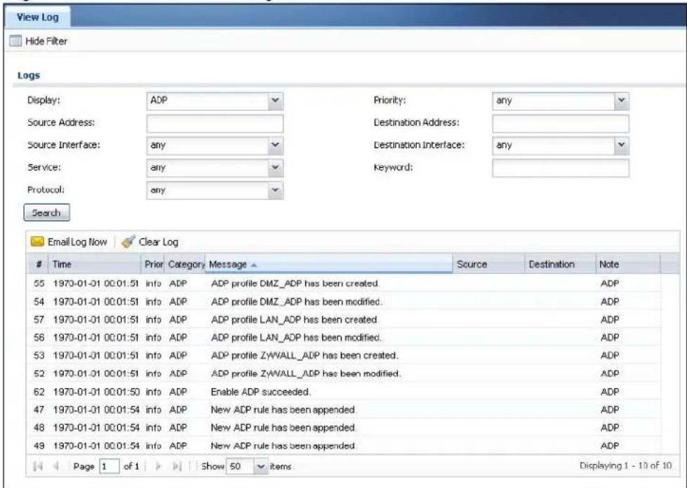
The following table describes the labels in this screen.
Table 48 Monitor > View Log
| LABEL DESCRIPTION | |
| Show Filter / Hide Filter | Click this button to show or hide the filter settings.If the filter settings are hidden, the Display, Email Log Now, Refresh, and Clear Log fields are available.If the filter settings are shown, the Display, Priority, Source Address, Destination Address, Service, Keyword, and Search fields are available. |
| Display Select the category of log message(s) you want to view. You can also view All Logs at one time, or you can view the Debug Log. | |
| Priority This displays when you show the filter. Select the priority of log messages to display. The log displays the log messages with this priority or higher. Choices are: any, emerg, alert, crit, error, warn, notice, and info, from highest priority to lowest priority. This field is read-only if the Category is Debug Log. | |
| Source Address | This displays when you show the filter. Type the source IP address of the incoming packet that generated the log message. Do not include the port in this filter. |
| Destination Address | This displays when you show the filter. Type the IP address of the destination of the incoming packet when the log message was generated. Do not include the port in this filter. |
| Source Interface | This displays when you show the filter. Select the source interface of the packet that generated the log message. |
| Destination Interface | This displays when you show the filter. Select the destination interface of the packet that generated the log message. |
| Service This displays when you show the filter. Select the service whose log messages you would like to see. The Web Configurator uses the protocol and destination port number(s) of the service to select which log messages you see. | |
| Keyword This displays when you show the filter. Type a keyword to look for in the Message, Source, Destination and Note fields. If a match is found in any field, the log message is displayed. You can use up to 63 alphanumeric characters and the underscore, as well as punctuation marks ( )', :;?! +-*/ = # $% @ ; the period, double quotes, and brackets are not allowed. | |
| Protocol This displays when you show the filter. Select a service protocol whose log messages you would like to see. | |
| Search This displays when you show the filter. Click this button to update the log using the current filter settings. | |
| Email Log Now | Click this button to send log messages to the Active e-mail addresses specified in the Send Log To field on the Log Settings page. |
| Clear Log Click this button to clear the whole log, regardless of what is currently displayed on the screen. | |
| # | This field is a sequential value, and it is not associated with a specific log message. |
| Time This field displays the time the log message was recorded. | |
| Priority This field | displays the priority of the log message. It has the same range of values as the Priority field above. |
| Category This field | displays the log that generated the log message. It is the same value used in the Display and (other) Category fields. |
| Message This field | displays the reason the log message was generated. The text “[count= x]”, where x is a number, appears at the end of the Message field if log consolidation is turned on and multiple entries were aggregated to generate into this one. |
| Source This field | displays the source IP address and the port number in the event that generated the log message. |
| Destination This field | displays the destination IP address and the port number of the event that generated the log message. |
| Note This field displays any additional information about the log message. | |
The Web Configurator saves the filter settings if you leave the View Log screen and return to it later.
7.17 View AP Log
Use this screen to view the NXC's current wireless AP log messages. Click Monitor > Log > View AP Log to access this screen.
Figure 55 Monitor > Log > View AP Log
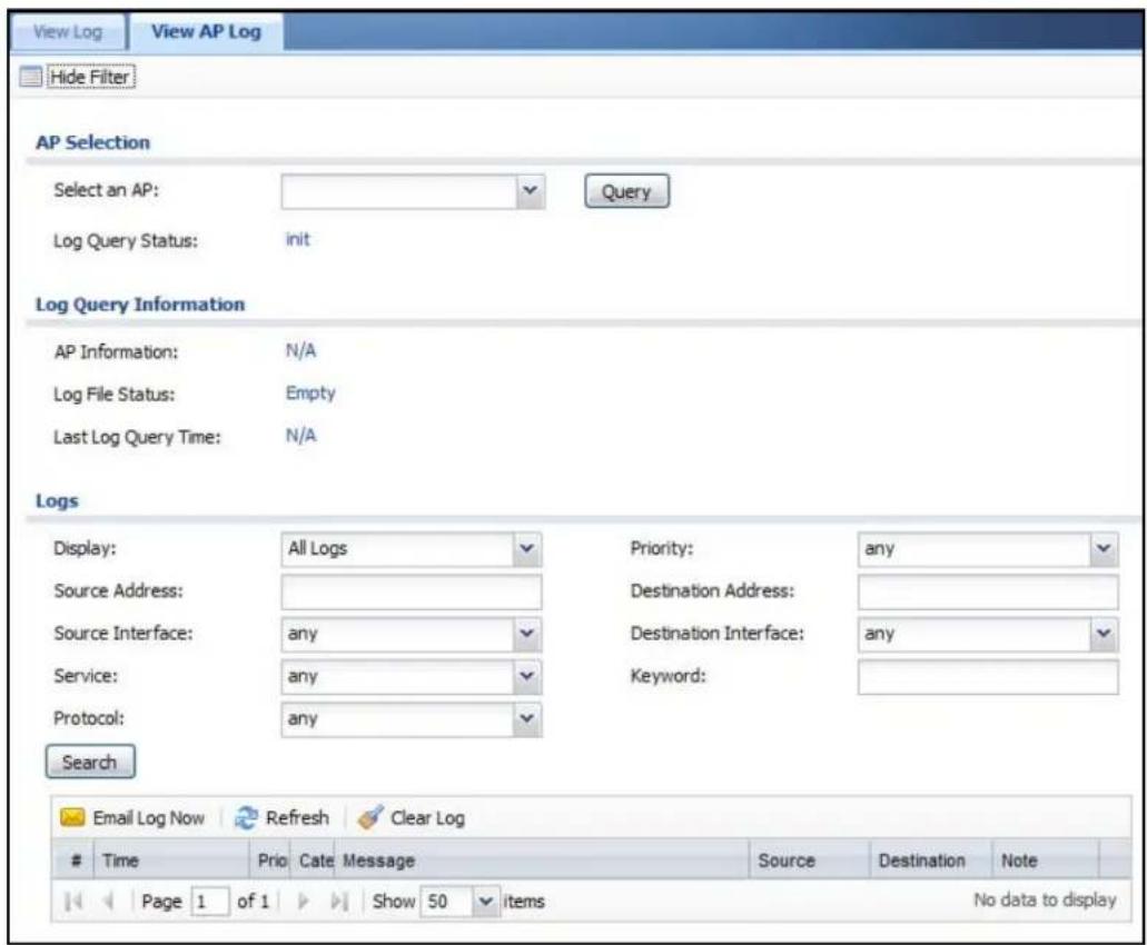
The following table describes the labels in this screen.
Table 49 Monitor > Log > View AP Log
| LABEL DESCRIPTION | |
| Show/ Hide Filter | Click this to show or hide the AP log filter. |
| Select an AP Select an AP from the list to view its log messages. | |
| Log Query Status | This indicates the current log query status.init - Indicates the query has not been initialized.querying - Indicates the query is in process.fail - Indicates the query failed.success - Indicates the query succeeded. |
| AP Information | This displays the MAC address for the selected AP. |
Table 49 Monitor > Log > View AP Log
| LABEL DESCRIPTION | |
| Log File Status | This indicates the status of the AP's log messages. |
| Last Log Query Time | This indicates the last time the AP was queried for its log messages. |
| Display Select the | log file from the specified AP that you want displayed. |
| Note: This criterion only appears when you Show Filter. | |
| Priority Select a | priority level to use for filtering displayed log messages. |
| Note: This criterion only appears when you Show Filter. | |
| Source Address | Enter a source IP address to display only the log messages that include it. |
| Note: This criterion only appears when you Show Filter. | |
| Destination Address | Enter a destination IP address to display only the log messages that include it. |
| Note: This criterion only appears when you Show Filter. | |
| Source Interface | Enter a source interface to display only the log messages that include it. |
| Note: This criterion only appears when you Show Filter. | |
| Destination Interface | Enter a destination interface to display only the log messages that include it. |
| Note: This criterion only appears when you Show Filter. | |
| Service Select a | service type to display only the log messages related to it. |
| Note: This criterion only appears when you Show Filter. | |
| Keyword Enter a | keyword to display only the log messages that include it. |
| Note: This criterion only appears when you Show Filter. | |
| Protocol Select a | protocol to display only the log messages that include it. |
| Note: This criterion only appears when you Show Filter. | |
| Search Click this | to start the log query based on the selected criteria. If no criteria have been selected, then this displays all log messages for the specified AP regardless. |
| Email Log Now Click this open a new e-mail in your default e-mail program with the selected log attached. | |
| Refresh Click this to refresh the log table. | |
| Clear Log Click this to clear the log on the specified AP. | |
| # | This field is a sequential value, and it is not associated with a specific log message. |
| Time This indicates the time that the log messages was created or recorded on the AP. | |
Table 49 Monitor > Log > View AP Log
| LABEL DESCRIPTION | |
| Priority This indicates the selected log message's priority. | |
| Category This indicates the selected log message's category. | |
| Message This displays content of the selected log message. | |
| Source This displays the source IP address of the selected log message. | |
| Destination This displays the source IP address of the selected log message. | |
| Note This displays any notes associated with the selected log message. |
Registration
8.1 Overview
Use the Configuration > Licensing > Registration screens to register your NXC and manage its service subscriptions.
8.1.1 What You Can Do in this Chapter
- The Registration screen (Section 8.2 on page 153) registers your NXC with myZyXEL.com and activates services.
- The Signature Update screen (Section 8.3 on page 155) displays the status of your service registrations and upgrade licenses.
8.1.2 What you Need to Know
This section introduces the topics covered in this chapter.
myZyXEL.com
myZyXEL.com is ZyXEL's online services center where you can register your NXC and manage subscription services available for the NXC. To update signature files or use a subscription service, you have to register the NXC and activate the corresponding service at myZyXEL.com (through the NXC).
Note: You need to create a myZyXEL.com account before you can register your device and activate the services at myZyXEL.com.
You can directly create a myZyXEL.com account, register your NXC and activate a service using the Registration screen. Alternatively, go to http://www.myZyXEL.com with the NXC's serial number and LAN MAC address to register it. Refer to the web site's on-line help for details.
Note: To activate a service on a NXC, you need to have access to myZyXEL.com via that NXC.
Subscription Services Available on the NXC
You can have the NXC use anti-virus, IDP (Intrusion Detection and Prevention and AppPatrol (application patrol)). See the respective User's Guide chapters for more information about these features.
Anti-Virus Engines
Subscribe to signature files for ZyXEL's anti-virus engine or one powered by Kaspersky.
- When using the trial, you can switch from one engine to the other in the Registration screen. There is no limit on the number of times you can change the anti-virus engine selection during the trial, but you only get a total of one anti-virus trial period (not a separate trial period for each anti-virus engine).
- After the trial expires, you need to purchase an iCard for the anti-virus engine you want to use and enter the PIN number (license key) in the Registration > Service screen. You must use the ZyXEL anti-virus iCard for the ZyXEL anti-virus engine and the Kaspersky anti-virus iCard for the Kaspersky anti-virus engine. If you were already using an iCard anti-virus subscription, any remaining time on your earlier subscription is automatically added to the new subscription. Even if the earlier iCard anti-virus subscription was for a different anti-virus engine. For example, suppose you purchase a one-year Kaspersky engine anti-virus service subscription and use it for six months. Then you purchase a one-year ZyXEL engine anti-virus service subscription and enter the iCard's PIN number (license key) in the Configuration > Registration > Service screen. The one-year ZyXEL engine anti-virus service subscription is automatically extended to 18 months.
Intrusion Detection and Prevention & Application Patrol
Intrusion Detection and Prevention (IDP) can detect malicious or suspicious packets and respond instantaneously. Packet inspection signatures examine OSI (Open System Interconnection) layer-4 to layer-7 packet contents for malicious data. Generally, packet inspection signatures are created for known attacks while anomaly detection looks for abnormal behavior.
Application patrol provides a convenient way to manage the use of various applications on the network. It manages general protocols (for example, HTTP and FTP) and instant messenger (IM), peer-to-peer (P2P), Voice over IP (VoIP), and streaming (RSTP) applications. You can even control the use of a particular application's individual features (like text messaging, voice, video conferencing, and file transfers).
You can subscribe to signature files for ZyXEL's IDP and Application Patrol engines.
Managed APs
The NXC is initially configured to support up to 48 managed APs (such as the NWA5160N). You can increase this by subscribing to additional licenses. As of this writing, each license upgrade allows an additional 48 managed APs while the maximum number of APs a single NXC can support is 240.
8.2 Registration
Use this screen to register your NXC with myZyXEL.com and activate a service. Click Configuration > Licensing > Registration in the navigation panel to open the screen as shown next.
Figure 56 Configuration > Licensing > Registration
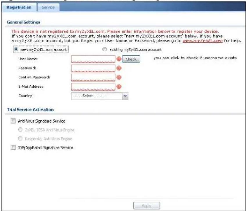
The following table describes the labels in this screen.
Table 50 Configuration > Licensing > Registration
| LABEL DESCRIPTION | |
| General Setup | If you select existing myZyXEL.com account, only the User Name and Password fields are available. |
| new myZyXEL.com account | If you haven't created an account at myZyXEL.com, select this option and configure the following fields to create an account and register your NXC. |
| existing myZyXEL.com account | If you already have an account at myZyXEL.com, select this option and enter your user name and password in the fields below to register your NXC. |
| UserName Enter a user | name for your myZyXEL.com account. The name should be from six to 20 alphanumeric characters (and the underscore). Spaces are not allowed. |
| Check Click this button to check with the myZyXEL.com database to verify the user name you entered has not been used. | |
| Password Enter a pass | word of between six and 20 alphanumeric characters (and the underscore). Spaces are not allowed. |
| Confirm Password Enter | the password again for confirmation. |
| E-Mail Address Enter | your e-mail address. You can use up to 80 alphanumeric characters (periods and the underscore are also allowed) without spaces. |
| Country Select your country from the drop-down box list. | |
| Trial Service Activation | Select the check box to activate a trial service subscription. The trial period starts the day you activate the trial. After the trial expires, you can buy an iCard and enter the license key in the Registration Service screen to extend the service. |
| Anti-Virus Signature Service | The NXC's anti-virus packet scanner uses the signature files on the NXC to detect virus files.Select ZyXEL's anti-virus engine or the Kaspersky anti-virus engine. During the trial you can use these fields to change from one anti-virus engine to the other.After the service is activated, the NXC can download the up-to-date signature files for the selected anti-virus engine from the update server (http://myupdate.zywall.zyxel.com). |
| IDP/AppPatrol Signature Service | The IDP and application patrol features use the IDP/AppPatrol signature files on the NXC. IDP detects malicious or suspicious packets and responds immediately. Application patrol conveniently manages the use of various applications on the network. After the service is activated, the NXC can download the up-to-date signature files from the update server (http://myupdate.zywall.zyxel.com).You will get automatic e-mail notification of new signature releases from mySecurityZone after you activate the IDP/AppPatrol service. You can also check for new signatures at http://mysecurity.zyxel.com. |
| Apply Click Apply to save your changes back to the NXC. | |
Note: If the NXC is registered already, this screen is read-only and indicates whether trial services are activated (if any). You can still select the unchecked trial service(s) to activate it after registration. Use the Service screen to update your service subscription status.
Figure 57 Configuration > Licensing > Registration: Registered Device
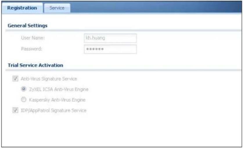
8.3 Service
Use this screen to display the status of your service registrations and upgrade licenses. To activate or extend a standard service subscription, purchase an iCard and enter the iCard's PIN number (license key) in this screen. Click
Configuration > Licensing > Registration > Service to open the screen as shown next.
Figure 58 Configuration > Licensing > Registration > Service
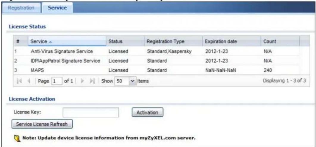
The following table describes the labels in this screen.
Table 51 Configuration > Licensing > Registration > Service
| LABEL DESCRIPTION | |
| License Status | |
| # This is the entry's position in the list. | |
| Service This lists the services that available on the NXC. | |
| Status | This field displays whether a service is activated (Licensed) or not (Not Licensed) or expired (Expired). |
| Registration Type | This field displays whether you applied for a trial application (Trial) or registered a service with your iCard's PIN number (Standard). This field is blank when a service is not activated. For an anti-virus service subscription this field also displays the type of anti-virus engine. |
| Expiration date This field displays the date your service expires.You can continue to use IDP/AppPatrol or Anti-Virus after the registration expires, you just won't receive updated signatures. | |
| License Upgrade | |
| License Key Enter your iCard's PIN number and click Activation to activate or extend a standard service subscription. If a standard service subscription runs out, you need to buy a new iCard (specific to your NXC) and enter the new PIN number to extend the service. | |
| Service License Refresh | Click this button to renew service license information (such as the registration status and expiration day). |
Signature Update
9.1 Overview
This chapter shows you how to update the NXC's signature packages.
9.1.1 What You Can Do in this Chapter
- The Anti-virus screen (Section 9.2 on page 158) updates the anti-virus signatures. See Chapter 20 on page 287 for details on anti-virus.
- The IDP/ AppPatrol screen (Section 9.3 on page 159) updates the signatures used for IDP and application patrol. See Chapter 21 on page 303 for details on IDP. See Chapter 19 on page 265 for details on application patrol.
- The System Protect screen (Section 9.4 on page 161) updates the system-protection signatures.
9.1.2 What you Need to Know
The following terms and concepts may help as you read this chapter.
- You need a valid service registration to update the anti-virus signatures and the IDP/AppPatrol signatures.
- You do not need a service registration to update the system-protection signatures.
- Schedule signature updates for a day and time when your network is least busy to minimize disruption to your network.
- Your custom signature configurations are not over-written when you download new signatures.
Note: The NXC does not have to reboot when you upload new signatures.
9.2 Anti-Virus
This screen allows you to update your anti-virus engine. Click Configuration > Licensing > Update > Anti-Virus to display the following screen.
Figure 59 Configuration > Licensing > Update > Anti-Virus
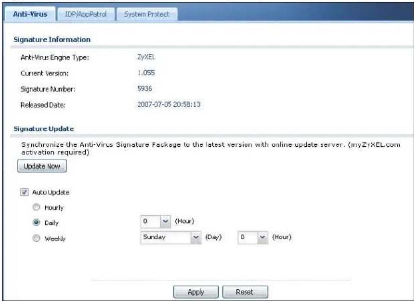
The following table describes the labels in this screen.
Table 52 Configuration > Licensing > Update > Anti-Virus
| LABEL DESCRIPTION | |
| Signature Information | The following fields display information on the current signature set that the NXC is using. |
| Anti-Virus Engine Type | This field displays whether the NXC is set to use ZyXEL's anti-virus engine or the one powered by Kaspersky.Upgrading the NXC to firmware version 2.11 and updating the anti-virus signatures automatically upgrades the ZyXEL anti-virus engine to v2.0. v2.0 has more virus signatures and offers improved non-executable file scan throughput. |
| Current Version | This field displays the anti-virus signatures version number currently used by the NXC. This number is defined by the ZyXEL Security Response Team (ZSRT) who maintain and update them.This number gets larger as new signatures are added, so you should refer to this number regularly. Go to https://mysecurity.zyxel.com/mysecurity/ to see what the latest version number is. You can also subscribe to signature update e-mail notifications. |
| Signature Number | This field displays the number of signatures in this set. |
| Released Date | This field displays the date and time the set was released. |
| Signature Update | Use these fields to have the NXC check for new signatures at myZyXEL.com. If new signatures are found, they are then downloaded to the NXC. |
| Update Now Click this button to have the NXC check for new signatures immediately. If there are new ones, the NXC will then download them. | |
| Auto Update | Select this check box to have the NXC automatically check for new signatures regularly at the time and day specified.You should select a time when your network is not busy for minimal interruption. |
| Hourly Select | this option to have the NXC check for new signatures every hour. |
| Daily Select this option to have the NXC check for new signatures every day at the specified time. The time format is the 24 hour clock, so ‘23’ means 11PM for example. | |
| Weekly Select this option to have the NXC check for new signatures once a week on the day and at the time specified. | |
| Apply Click this button to save your changes to the NXC. | |
| Reset Click this button to return the screen to its last-saved settings. | |
9.3 IDP/AppPatrol
Click Configuration > Licensing > Update > IDP/ AppPatrol to display the following screen.
The NXC comes with signatures for the IDP and application patrol features. These signatures are continually updated as new attack types evolve. New signatures can be downloaded to the NXC periodically if you have subscribed for the IDP/AppPatrol signatures service.
You need to create an account at myZyXEL.com, register your NXC and then subscribe for IDP service in order to be able to download new packet inspection
signatures from myZyXEL.com (see the Registration screens). Use the Update IDP / AppPatrol screen to schedule or immediately download IDP signatures.
Figure 60 Configuration > Licensing > Update > IDP/AppPatrol
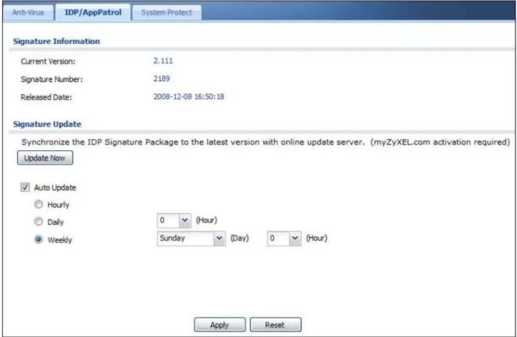
The following table describes the fields in this screen.
Table 53 Configuration > Licensing > Update > IDP/AppPatrol
| LABEL DESCRIPTION | |
| Signature Information | The following fields display information on the current signature set that the NXC is using. |
| Current Version | This field displays the IDP signature and anomaly rule set version number. This number gets larger as the set is enhanced. |
| Signature Number | This field displays the number of IDP signatures in this set. This number usually gets larger as the set is enhanced. Older signatures and rules may be removed if they are no longer applicable or have been supplanted by newer ones. |
| Released Date | This field displays the date and time the set was released. |
| Signature Update | Use these fields to have the NXC check for new IDP signatures at myZyXEL.com. If new signatures are found, they are then downloaded to the NXC. |
| Update Now Click this button to have the NXC check for new IDP signatures immediately. If there are new ones, the NXC will then download them. | |
| Auto Update | Select this check box to have the NXC automatically check for new IDP signatures regularly at the time and day specified.You should select a time when your network is not busy for minimal interruption. |
| Hourly Select | this option to have the NXC check for new IDP signatures every hour. |
| Daily Select this | this option to have the NXC check for new IDP signatures everyday at the specified time. The time format is the 24 hour clock, so '23' means 11PM for example. |
| Weekly Select | this option to have the NXC check for new IDP signatures once a week on the day and at the time specified. |
| Apply Click this button to save your changes to the NXC. | |
| Reset Click this button to return the screen to its last-saved settings. | |
9.4 System Protect
Click Configuration > Licensing > Update > System Protect to display the following screen.
Use this screen to schedule or immediately download system-protection signatures. The NXC comes with signatures that it uses to protect itself from intrusions. These signatures are continually updated as new attack types evolve. These system protection signature updates are free and can be downloaded to the NXC periodically. The system-protection function is part of the IDP feature. The system-protection feature is enabled by default and can only be disabled via the commands. You do not need an IDP subscription to use the system-protection feature or to download updated system-protection signatures.
Figure 61 Configuration > Licensing > Update > System Protect
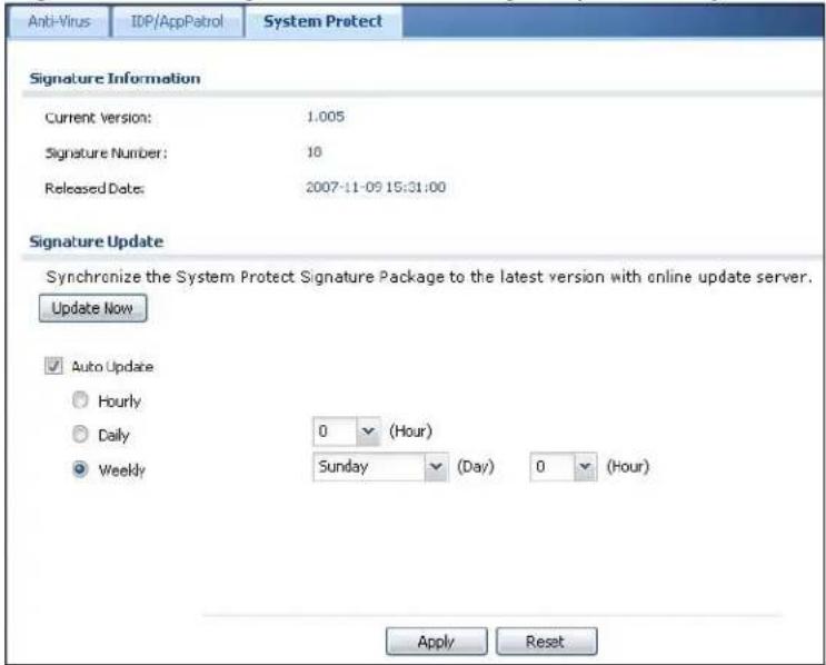
The following table describes the fields in this screen.
Table 54 Configuration > Licensing > Update > System Protect
| LABEL DESCRIPTION | |
| Signature Information | The following fields display information on the current signature set that the NXC is using. |
| Current Version | This field displays the system protect signature and anomaly rule set version number. This number gets larger as the set is enhanced. |
| Signature Number | This field displays the number of signatures in this set. This number usually gets larger as the set is enhanced. Older signatures and rules may be removed if they are no longer applicable or have been supplanted by newer ones. |
| Released Date | This field displays the date and time the set was released. |
| Signature Update | Use these fields to have the NXC check for new signatures at myZyXEL.com. If new signatures are found, they are then downloaded to the NXC. |
| Update Now Click | Click this button to have the NXC check for new signatures immediately. If there are new ones, the NXC will then download them. |
| Auto Update | Select this check box to have the NXC automatically check for new signatures regularly at the time and day specified.You should select a time when your network is not busy for minimal interruption. |
| Hourly Select | this option to have the NXC check for new signatures every hour. |
| Daily Select this option to have the NXC check for new signatures every day at the specified time. The time format is the 24 hour clock, so ‘23' means 11PM for example. | |
| Weekly Select this option to have the NXC check for new signatures once a week on the day and at the time specified. | |
| Apply Click this button to save your changes to the NXC. | |
| Reset Click this button to return the screen to its last-saved settings. | |
Wireless
10.1 Overview
Use the Wireless screens to configure how the NXC manages the Access Point that are connected to it.
10.1.1 What You Can Do in this Chapter
- The Controller screen (Section 10.2 on page 164) sets how the NXC allows new APs to connect to the network.
- The AP Management screen (Section 10.3 on page 165) manages all of the APs connected to the NXC.
- The MON Mode screen (Section 10.4 on page 167) allows you to assign APs either to the rogue AP list or the friendly AP list.
- The Load Balancing screen (Section 10.5 on page 170) configures network traffic load balancing between the APs and the NXC.
- The DCS screen (Section 10.6 on page 173) configures dynamic radio channel selection on managed APs.
10.1.2 What You Need to Know
The following terms and concepts may help as you read this chapter.
Station / Wireless Client
A station or wireless client is any wireless-capable device that can connect to an AP using a wireless signal.
Dynamic Channel Selection (DCS)
Dynamic Channel Selection (DCS) is a feature that allows an AP to automatically select the radio channel upon which it broadcasts by scanning the area around it and determining what channels are currently being used by other devices.
Load Balancing (Wireless)
Wireless load balancing is the process where you limit the number of connections allowed on an wireless access point (AP) or you limit the amount of wireless traffic transmitted and received on it so the AP does not become overloaded.
10.2 Controller
Use this screen to set how the NXC allows new APs to connect to the network. Click Configuration > Wireless > Controller to access this screen.
Figure 62 Configuration > Wireless > Controller
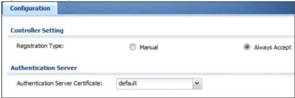
Each field is described in the following table.
Table 55 Configuration > Wireless > Controller
| LABEL DESCRIPTION | |
| Registration Type | SelectManualto add each AP to the NXC for management, orAlways Acceptto automatically add APs to the NXC for management.Note: Select the Manual option for managing a specific set of APs. This is recommended as the registration mechanism cannot automatically differentiate between friendly and rogue APs. For details on how to handle rogue APs, seeSection 7.12 on page 134.APs must be connected to the NXC by a wired connection or network. |
| Authentication Server Certificate | Select a server certificate from this list, otherwise use the default one. This certificate is required if the NXC is used as a RADIUS server for wireless 802.1x authentication (EAP-PEAP/ TTLS/ TLS). |
| Apply Click Apply | to save your changes back to the NXC. |
| Reset | ClickResetto return the screen to its last-saved settings. |
10.3 AP Management
Use this screen to manage all of the APs connected to the NXC. Click Configuration > Wireless > AP Management to access this screen.
Figure 63 Configuration > Wireless > AP Management
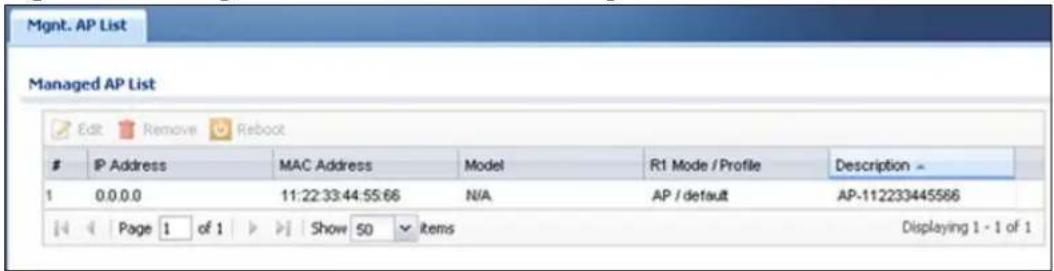
Each field is described in the following table.
Table 56 Configuration > Wireless > AP Management
| LABEL DESCRIPTION | |
| Edit Select an AP and click this button to edit its properties. | |
| Remove Select an AP and click this button to remove it from the list. | |
| Note: If in theConfiguration > Wireless > Controller screen you set theRegistration Type to Always Accept, then as soon as you remove an AP from this list it reconnects. | |
| Reboot Select an AP and click this button to force it to restart. | |
| # This field is a sequential value, and it is not associated with any interface. | |
| IP This field displays the IP address of the AP. | |
| MAC Address This field displays the MAC address of the AP. | |
| Model This field displays the AP's hardware model information. It displays “N/A” (not applicable) only when the AP disconnects from the NXC and the information is unavailable as a result. | |
| R1 Mode / Profile This field displays the AP or MON profile for Radio 1. | |
| Description This field displays the AP's description, which you can configure by selecting the AP and clicking theEditbutton. | |
10.3.1 Edit AP List
Select an AP and click the Edit button in the Configuration > Wireless > AP Management table to display this screen.
Figure 64 Configuration > Wireless > Edit AP List
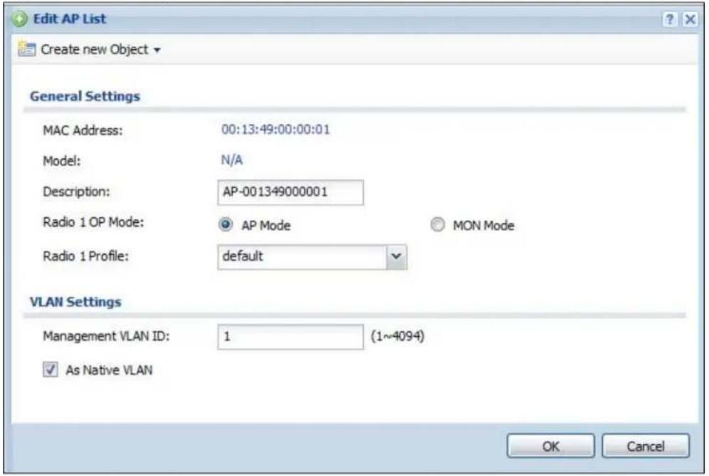
Each field is described in the following table.
Table 57 Configuration > Wireless > Edit AP List
| LABEL DESCRIPTION | |
| Create new Object | Use this menu to create a new Radio or SSID object to associate with this AP. |
| MAC Address This displays the MAC address of the selected AP. | |
| Model This field displays the AP's hardware model information. It displays “N/A” (not applicable) only when the AP disconnects from the NXC and the information is unavailable as a result. | |
| Description Enter a description for this AP. You can use up to 31 characters, spaces and underscores allowed. | |
| Radio 1 OP Mode Select the operating mode for radio 1.AP Mode means the AP can receive connections from wireless clients and pass their data traffic through to the NXC to be managed (or subsequently passed on to an upstream gateway for managing).MON Mode means the AP monitors the broadcast area for other APs, then passes their information on to the NXC where it can be determined if those APs are friendly or rogue. If an AP is set to this mode it cannot receive connections from wireless clients. | |
| Radio 1 Profile Select a profile from the list. If no profile exists, you can create a new one through theCreate new Objectmenu. | |
| Management VLAN ID | Enter a VLAN ID for this AP. |
| As Native VLAN Select this option to treat this VLAN ID as a VLAN created on the NXC and not one assigned to it from outside the network. | |
| OK Click OK to save your changes back to the NXC. | |
| Cancel Click Cancel to close the window with changes unsaved. | |
10.4 MON Mode
Use this screen to assign APs either to the rogue AP list or the friendly AP list. A rogue AP is a wireless access point operating in a network's coverage area that is not under the control of the network administrator, and which can potentially open up holes in a network's security.
Click Configuration > Wireless > MON Mode to access this screen.
Figure 65 Configuration > Wireless > MON Mode
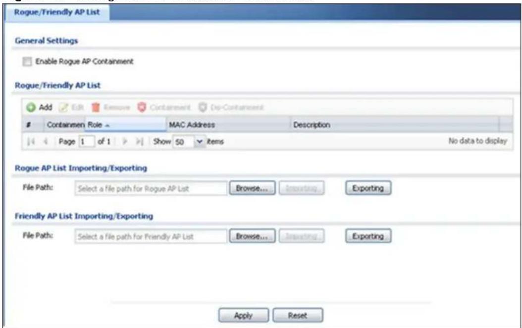
Each field is described in the following table.
Table 58 Configuration > Wireless > MON Mode
| LABEL DESCRIPTION | |
| General Settings | |
| Enable Rogue AP Containment | Select this to enable rogue AP containment. |
| Rogue/Friendly AP List | |
| Add Click this button | to add an AP to the list and assign it either friendly or rogue status. |
| Edit Select an AP in the list to edit and reassign its status. | |
| Remove Select an AP in the list to remove. | |
| Containment Click this button to quarantine the selected AP.A quarantined AP cannot grant access to any network services.Any stations that attempt to connect to a quarantined AP are disconnected automatically. | |
| Dis-Containment Click this button to unquarantine the selected AP.An unquarantined AP has normal access to the network. | |
| # This field is a sequential value, and it is not associated with any interface. | |
| Containment This field indicates the selected AP's containment status. | |
| Role | This field indicates whether the selected AP is a rogue-ap or a friendly-ap. To change the AP's role, click the Edit button. |
| MAC Address This field indicates the AP's radio MAC address. | |
| Description This field displays the AP's description. You can modify this by clicking the Edit button. | |
| Importing/Exporting These controls allow you to export the current list of rogue and friendly APs or import existing lists. | |
| File Path / Browse / Importing | Enter the file name and path of the list you want to import or click the Browse button to locate it. Once the File Path field has been populated, click Importing to bring the list into the NXC. |
| Exporting | Click this button to export the current list of either rogue APs or friendly APS. |
| Apply | Click Apply to save your changes back to the NXC. |
| Reset | Click Reset to return the screen to its last-saved settings. |
10.4.1 Add/Edit Rogue/Friendly List
Select an AP and click the Edit button in the Configuration > Wireless > MON Mode table to display this screen.
Figure 66 Configuration > Wireless > MON Mode > Add/Edit Rogue/Friendly
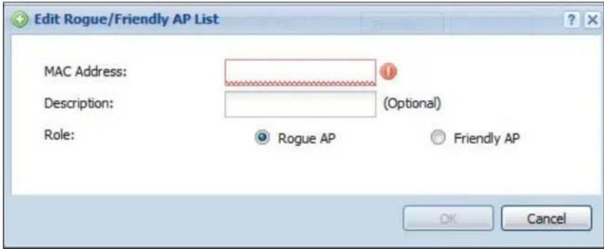
Each field is described in the following table.
Table 59 Configuration > Wireless > MON Mode > Add/Edit Rogue/Friendly
| LABEL DESCRIPTION | |
| MAC Address | Enter the MAC address of the AP you want to add to the list. A MAC address is a unique hardware identifier in the following hexadecimal format: xx:xx:xx:xx:xx:xx where xx is a hexadecimal number separated by colons. |
| Description Enter up to 60 characters for the AP's description. Spaces and underscores are allowed. | |
| Role | Select either Rogue AP or Friendly AP for the AP's role. |
| Apply Click Apply to save your changes back to the NXC. | |
| Reset | Click Reset to return the screen to its last-saved settings. |
10.5 Load Balancing
Use this screen to configure wireless network traffic load balancing between the APs on your network. Click Configuration > Wireless > Load Balancing to access this screen.
Figure 67 Configuration > Wireless > Load Balancing
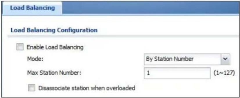
Each field is described in the following table.
Table 60 Configuration > Wireless > Load Balancing
| LABEL DESCRIPTION | |
| Enable Load Balancing | Select this to enable load balancing on the NXC. |
| Mode Select a mode by which load balancing is carried out.Select By Station Number to balance network traffic based on the number of specified stations connect to an AP.Select By Traffic Level to balance network traffic based on the volume generated by the stations connected to an AP.Once the threshold is crossed (either the maximum station numbers or with network traffic), then the AP delays association request and authentication request packets from any new station that attempts to make a connection. This allows the station to automatically attempt to connect to another, less burdened AP if one is available. | |
| Max Station Number | Enter the threshold number of stations at which an AP begins load balancing its connections. |
| Traffic Level Select the threshold traffic level at which the AP begins load balancing its connections (low, medium, high). | |
| Disassociate station when overloaded | Select this option to “kick” wireless clients connected to the AP when it becomes overloaded. If you do not enable this option, then the AP simply delays the connection until it can afford the bandwidth it requires, or it shunts the connection to another AP within its broadcast radius.The kick priority is determined automatically by the NXC and is as follows:Idle Timeout- Devices that have been idle the longest will be kicked first. If none of the connected devices are idle, then the priority shifts toSignal Strength.Signal Strength- Devices with the weakest signal strength will be kicked first.Note:If you enable this function, you should ensure that there are multiple APs within the broadcast radius that can accept any rejected or kicked wireless clients; otherwise, a wireless client attempting to connect to an overloaded AP will be kicked continuously and never be allowed to connect. |
| Apply Click Apply | to save your changes back to the NXC. |
| Reset | Click Resetto return the screen to its last-saved settings. |
10.5.1 Disassociating and Delaying Connections
When your AP becomes overloaded, there are two basic responses it can take. The first one is to “delay” a client connection. This means that the AP withholds the connection until the data transfer throughput is lowered or the client connection is picked up by another AP. If the client is picked up by another AP then the original AP cannot resume the connection.
For example, here the AP has a balanced bandwidth allotment of 6 Mbps. If laptop R connects and it pushes the AP over its allotment, say to 7 Mbps, then the AP
delays the red laptop's connection until it can afford the bandwidth or the laptop is picked up by a different AP with bandwidth to spare.
Figure 68 Delaying a Connection
![1 Mbps A 2 Mbps B 6 Mbps [7 Mbps] C 2 Mbps R 2 Mbps](/content/2026/05/762668/images/52afb7ecc97b000720f2bd7734017d79ec15f6bade540029067d7ccb4aca764f.jpg)
The second response your AP can take is to kick the connections that are pushing it over its balanced bandwidth allotment.
Figure 69 Kicking a Connection
![1 Mbps 2 Mbps B C 6 Mbps [7 Mbps] R 2 Mbps](/content/2026/05/762668/images/7069f0bee2add25ae0e73eb23c2d0d603b6863488ab090d75c19f0c7e9da7361.jpg)
Connections are kicked based on either idle timeout or signal strength. The NXC first looks to see which devices have been idle the longest, then starts kicking them in order of highest idle time. If no connections are idle, the next criteria the NXC analyzes is signal strength. Devices with the weakest signal strength are kicked first.
10.6 DCS
Use this screen to configure dynamic radio channel selection on managed APs. Click Configuration > Wireless > DCS to access this screen.
Figure 70 Configuration > Wireless > DCS
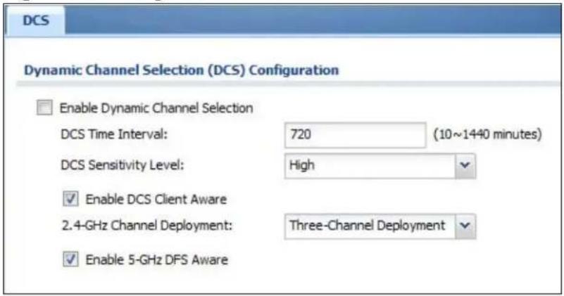
Each field is described in the following table.
Table 61 Configuration > Wireless > DCS
| LABEL DESCRIPTION | |
| Enable Dynamic Channel Selection | Select this to turn on dynamic channel selection for the APs that the NXC manages. |
| DCS Time Interval | Enter a number of minutes. This regulates how often the NXC surveys the other APs within its broadcast radius. If the channel on which it is currently broadcasting suddenly comes into use by another AP, the NXC will then dynamically select the next available clean channel or a channel with lower interference. |
| DCS Sensitivity Level | Select the AP's sensitivity level toward other channels. Options are High, Medium, and Low.Generally, as long as the area in which your AP is located has minimal interference from other devices you can set the DCS Sensitivity Level to Low. This means that the AP has a very broad tolerance.If you are not sure about the number and location of any other devices in the region, set the level to Medium. The AP's tolerance for interference is relatively narrow.On the other hand, if you know there are numerous other devices in the region, you should set the level to High to keep the interference to a minimum. In this case, the NXC's tolerance for interference is quite strict.Note: Generally speaking, the higher the sensitivity level, the more frequently the AP switches channels. As a consequence, anyone connected to the AP will experience more frequent disconnects and reconnects unless you select Enable DCS Client Aware. |
| Enable DCS Client Aware | Select this to have the AP wait until all connected clients have disconnected before switching channels.If you disable this then the AP switches channels immediately regardless of any client connections. In this instance, clients that are connected to the AP when it switches channels are dropped. |
| 2.4 GHz Channel Deployment | Select Three-Channel Deployment to limit channel switching to channels 1,6, and 11, the three channels that are sufficiently attenuated to have almost no impact on one another. In other words, this allows you to minimize channel interference by limiting channel-hopping to these three “safe” channels.Select Four-Channel Deployment to limit channel switching to four channels. Depending on the country domain, if the only allowable channels are 1-11 then the NXC uses channels 1, 4, 7, 11 in this configuration; otherwise, the NXC uses channels 1, 5, 9, 13 in this configuration. Four channel deployment expands your pool of possible channels while keeping the channel interference to a minimum. |
| Enable 5 GHz DFS Aware | Select this if your APs are operating in an area known to have RADAR devices. This allows the device to downgrade its frequency to below 5 GHz in the event a RADAR signal is detected, thus preventing it from interfering with that signal.Enabling this forces the AP to select a non-DFS channel. |
| Apply Click Apply to save your changes back to the NXC. | |
| Reset | Click Reset to return the screen to its last-saved settings. |
10.7 Technical Reference
The following section contains additional technical information about the features described in this chapter.
10.7.1 Dynamic Channel Selection
When numerous APs broadcast within a given area, they introduce the possibility of heightened radio interference, especially if some or all of them are broadcasting on the same radio channel. If the interference becomes too great, then the network administrator must open his AP configuration options and manually change the channel to one that no other AP is using (or at least a channel that has a lower level of interference) in order to give the connected stations a minimum degree of interference. Dynamic channel selection frees the network administrator from this task by letting the AP do it automatically. The AP can scan the area around it looking for the channel with the least amount of interference.
In the 2.4 GHz spectrum, each channel from 1 to 13 is broken up into discrete 22 MHz segments that are spaced 5 MHz apart. Channel 1 is centered on 2.412 GHz while channel 13 is centered on 2.472 GHz.
Figure 71 An Example Three-Channel Deployment
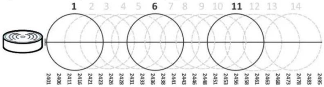
radar
| Segment | Value | | ------- | ----- | | 1 | 2401 | | 2 | 2406 | | 3 | 2411 | | 4 | 2416 | | 5 | 2421 | | 6 | 2423 | | 7 | 2426 | | 8 | 2428 | | 9 | 2431 | | 10 | 2433 | | 11 | 2436 | | 12 | 2438 | | 13 | 2441 | | 14 | 2443 | | 15 | 2446 | | 16 | 2448 | | 17 | 2451 | | 18 | 2453 | | 19 | 2456 | | 20 | 2458 | | 21 | 2461 | | 22 | 2463 | | 23 | 2468 | | 24 | 2473 | | 25 | 2478 | | 26 | 2483 | | 27 | 2495 |Three channels are situated in such a way as to create almost no interference with one another if used exclusively: 1, 6 and 11. When an AP broadcasts on any of these three channels, it should not interfere with neighboring APs as long as they are also limited to same trio.
Figure 72 An Example Four-Channel Deployment
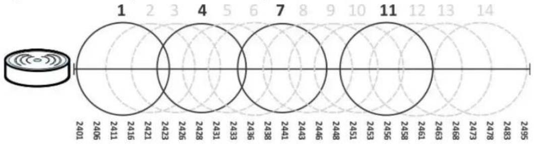
radar
| Label | Value | |-------|-------| | 1 | 2401 | | 2 | 2406 | | 3 | 2411 | | 4 | 2416 | | 5 | 2421 | | 6 | 2426 | | 7 | 2431 | | 8 | 2436 | | 9 | 2438 | | 10 | 2441 | | 11 | 2443 | | 12 | 2446 | | 13 | 2448 | | 14 | 2451 | | | 2453 | | | 2456 | | | 2458 | | | 2461 | | | 2463 | | | 2468 | | | 2473 | | | 2478 | | | 2483 | | | 2495 |However, some regions require the use of other channels and often use a safety scheme with the following four channels: 1, 4, 7 and 11. While they are situated sufficiently close to both each other and the three so-called “safe” channels (1,6 and 11) that interference becomes inevitable, the severity of it is dependent upon other factors: proximity to the affected AP, signal strength, activity, and so on.
Finally, there is an alternative four channel scheme for ETSI, consisting of channels 1, 5, 9, 13. This offers significantly less overlap that the other one.
Figure 73 An Alternative Four-Channel Deployment
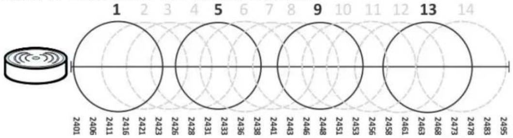
radar
| Segment | Value | |---------|-------| | 1 | 2401 | | 2 | 2406 | | 3 | 2411 | | 4 | 2416 | | 5 | 2421 | | 6 | 2423 | | 7 | 2426 | | 8 | 2431 | | 9 | 2436 | | 10 | 2438 | | 11 | 2441 | | 12 | 2443 | | 13 | 2446 | | 14 | 2448 | | 15 | 2451 | | 16 | 2453 | | 17 | 2456 | | 18 | 2458 | | 19 | 2461 | | 20 | 2463 | | 21 | 2468 | | 22 | 2473 | | 23 | 2478 | | 24 | 2483 | | 25 | 2495 |10.7.2 Load Balancing
Because there is a hard upper limit on an AP's wireless bandwidth, load balancing can be crucial in areas crowded with wireless users. Rather than let every user connect and subsequently dilute the available bandwidth to the point where each connecting device receives a meager trickle, the load balanced AP instead limits the incoming connections as a means to maintain bandwidth integrity.
There are two kinds of wireless load balancing available on the NXC:
Load balancing by station number limits the number of devices allowed to connect to your AP. If you know exactly how many stations you want to let connect, choose this option.
For example, if your company's graphic design team has their own AP and they have 10 computers, you can load balance for 10. Later, if someone from the sales department visits the graphic design team's offices for a meeting and he tries to access the network, his computer's connection is delayed, giving it the opportunity to connect to a different, neighboring AP. If he still connects to the AP regardless of the delay, then the AP may boot other people who are already connected in order to associate with the new connection.
Load balancing by traffic level limits the number of connections to the AP based on maximum bandwidth available. If you are uncertain as to the exact number of wireless connections you will have then choose this option. By setting a maximum bandwidth cap, you allow any number of devices to connect as long as their total bandwidth usage does not exceed the configured bandwidth cap associated with this setting. Once the cap is hit, any new connections are rejected or delayed provided that there are other APs in range.
Imagine a coffee shop in a crowded business district that offers free wireless connectivity to its customers. The coffee shop owner can't possibly know how many connections his AP will have at any given moment. As such, he decides to put a limit on the bandwidth that is available to his customers but not on the actual number of connections he allows. This means anyone can connect to his wireless network as long as the AP has the bandwidth to spare. If too many people connect and the AP hits its bandwidth cap then all new connections must basically wait for their turn or get shunted to the nearest identical AP.
Interfaces
11.1 Interface Overview
Use these screens to configure the NXC's interfaces.
- Ports are the physical ports to which you connect cables.
- Interfaces are used within the system operationally. You use them in configuring various features. An interface also describes a network that is directly connected to the NXC. For example, You connect the LAN network to the interface.
- Zones are groups of interfaces used to ease security policy configuration.
11.1.1 What You Can Do in this Chapter
- The Ethernet screens (Section 11.2 on page 178) configure the Ethernet interfaces. Ethernet interfaces are the foundation for defining other interfaces and network policies.
- The VLAN screens (Section 11.3 on page 186) divide the physical network into multiple logical networks. VLAN interfaces receive and send tagged frames. The NXC automatically adds or removes the tags as needed..
11.1.2 What You Need to Know
The following terms and concepts may help as you read this chapter.
Interface Characteristics
Interfaces generally have the following characteristics (although not all characteristics apply to each type of interface).
- An interface is a logical entity through which (layer-3) packets pass.
- An interface is bound to a physical port or another interface.
- Many interfaces can share the same physical port.
• An interface belongs to at most one zone. - Many interfaces can belong to the same zone.
Types of Interfaces
You can create several types of interfaces in the NXC.
- Ethernet interfaces are the foundation for defining other interfaces and network policies.
- VLAN interfaces receive and send tagged frames. The NXC automatically adds or removes the tags as needed.
11.2 Ethernet Summary
This screen lists every Ethernet interface. To access this screen, click Configuration > Network > Interface.
Unlike other types of interfaces, you cannot create new Ethernet interfaces nor can you delete any of them. If an Ethernet interface does not have any physical ports assigned to it, it is effectively removed from the NXC even though you can still configure it.
Ethernet interfaces are similar to other types of interfaces in many ways. They have an IP address, subnet mask, and gateway used to make routing decisions. They restrict the amount of bandwidth and packet size. They can provide DHCP services, and they can verify the gateway is available.
Use Ethernet interfaces to control which physical ports exchange routing information with other routers and how much information is exchanged through each one. The more routing information is exchanged, the more efficient the routers should be. However, the routers also generate more network traffic, and some routing protocols require a significant amount of configuration and management.
Figure 74 Configuration > Network > Interface > Ethernet
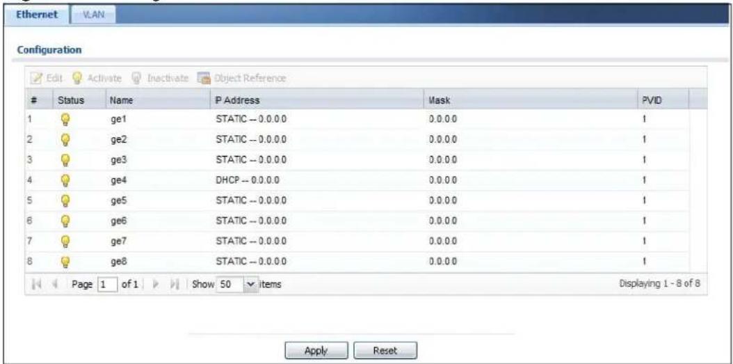
Each field is described in the following table.
Table 62 Configuration > Network > Interface > Ethernet
| LABEL DESCRIPTION | |
| Edit | Double-click an entry or select it and click Edit to open a screen where you can modify the entry's settings. |
| Activate | To turn on an interface, select it and click Activate. |
| Inactivate | To turn off an interface, select it and click Inactivate. |
| Object References | Select an entry and click Object References to open a screen that shows which settings use the entry. |
| # This field is a sequential value, and it is not associated with any interface. | |
| Status This icon is lit when the entry is active and dimmed when the entry is inactive. | |
| Name This field displays the name of the interface. | |
| IP Address This field displays the current IP address of the interface. If the IP address is 0.0.0.0, the interface does not have an IP address yet.This screen also shows whether the IP address is a static IP address (STATIC) or dynamically assigned (DHCP). IP addresses are always static in virtual interfaces. | |
| Mask This field displays the interface's subnet mask in dot decimal notation. | |
| PVID This field indicates the interface's PVID. | |
| Apply Click Apply to save your changes back to the NXC. | |
| Reset | Click Reset to return the screen to its last-saved settings. |
11.2.1 Edit Ethernet
This screen lets you configure IP address assignment and interface parameters. To access this screen, click an Edit icon in the Ethernet screen.
Note: If you create IP address objects based on an interface's IP address, subnet, or gateway, the NXC automatically updates every rule or setting that uses the object whenever the interface's IP address settings change. For example, if you change LAN's IP address, the NXC automatically updates the corresponding interface-based, LAN subnet address object.
Figure 75 Configuration > Network > Interface > Ethernet > Edit
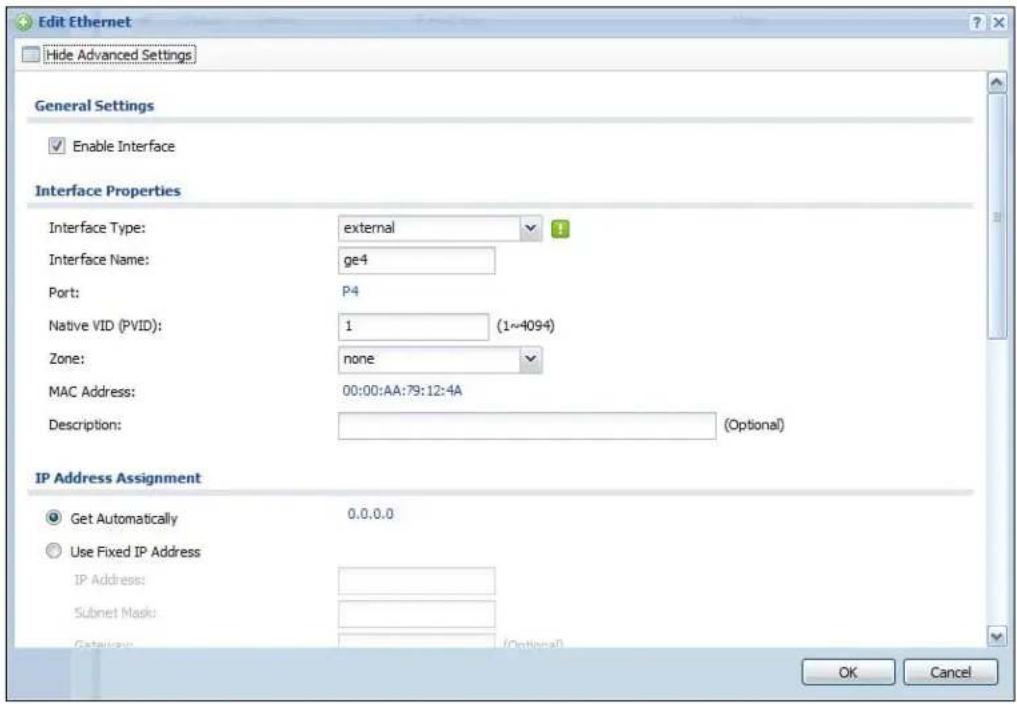
This screen's fields are described in the table below.
Table 63 Configuration > Network > Interface > Ethernet > Edit
| LABEL DESCRIPTION | |
| Show / Hide Advanced Settings | Click this button to display a greater or lesser number of configuration fields. |
| General Settings | |
| Enable Interface | Select this to enable this interface. Clear this to disable this interface. |
| Interface Properties | |
| Interface Type | Select to which type of network you will connect this interface. When you select Internal or External the rest of the screen's options automatically adjust to correspond. The NXC automatically adds default route and SNAT settings for traffic it routes from internal interfaces to external interfaces; for example LAN to WAN traffic.Select Internal to connect to a local network. Other corresponding configuration options: DHCP server and DHCP relay. The NXC automatically adds default SNAT settings for traffic flowing from this interface to an external interface.Select External to connect to an external network (like the Internet).If you select General, the rest of the screen's options do not automatically adjust and you must manually configure a policy route to add routing and SNAT settings for the interface. |
| Interface Name | Specify a name for the interface. It can use alphanumeric characters, hyphens, and underscores, and it can be up to 11 characters long. |
| Port This indicates the port that you are currently editing. | |
| Native VID (PVID) | Enter the PVID for this port (1~4094). |
| Zone Select a zone with which to associate this port. | |
| MAC Address This field is read-only. This is the MAC address that the Ethernet interface uses. | |
| Description Enter a description of this interface. It is not used elsewhere. You can use alphanumeric and () +/ :=?! *#@_%- characters, and it can be up to 60 characters long. | |
| IP Address Assignment | These IP address fields configure an IP address on the interface itself. If you change this IP address on the interface, you may also need to change a related address object for the network connected to the interface. For example, if you use this screen to change the IP address of your LAN interface, you should also change the corresponding LAN subnet address object. |
| Get Automatically | This option appears when you set the Interface Properties to External or General. Select this to make the interface a DHCP client and automatically get the IP address, subnet mask, and gateway address from a DHCP server. |
| Use Fixed IP Address | This option appears when you set the Interface Properties to External or General. Select this if you want to specify the IP address, subnet mask, and gateway manually. |
| IP Address | This field is enabled if you set the Interface Properties to Internal or you select Use Fixed IP Address.Enter the IP address for this interface. |
| Subnet Mask | This field is enabled if you select Use Fixed IP Address.Enter the subnet mask of this interface in dot decimal notation. The subnet mask indicates what part of the IP address is the same for all computers in the network. |
| Gateway | This field is enabled if you select Use Fixed IP Address.Enter the IP address of the gateway. The NXC sends packets to the gateway when it does not know how to route the packet to its destination. The gateway should be on the same network as the interface. |
| Metric Enter the | priority of the gateway (if any) on this interface. The NXC decides which gateway to use based on this priority. The lower the number, the higher the priority. If two or more gateways have the same priority, the NXC uses the one that was configured first. |
| Interface Parameters | |
| Egress Bandwidth | Enter the maximum amount of traffic, in kilobits per second, the NXC can send through the interface to the network. Allowed values are 0 - 1048576. |
| Ingress Bandwidth | This is reserved for future use.Enter the maximum amount of traffic, in kilobits per second, the NXC can receive from the network through the interface. Allowed values are 0 - 1048576. |
| MTU Maximum | Transmission Unit. Type the maximum size of each data packet, in bytes, that can move through this interface. If a larger packet arrives, the NXC divides it into smaller fragments. Allowed values are 576 - 1500. Usually, this value is 1500. |
| Connectivity Check | These fields appear when you set the Interface Properties to External or General.The interface can regularly check the connection to the gateway you specified to make sure it is still available. You specify how often the interface checks the connection, how long to wait for a response before the attempt is a failure, and how many consecutive failures are required before the NXC stops routing to the gateway. The NXC resumes routing to the gateway the first time the gateway passes the connectivity check. |
| Enable Connectivity Check | Select this to turn on the connection check. |
| Check Method | Select the method that the gateway allows.Select icmp to have the NXC regularly ping the gateway you specify to make sure it is still available.Select tcp to have the NXC regularly perform a TCP handshake with the gateway you specify to make sure it is still available. |
| Check Period | Enter the number of seconds between connection check attempts. |
| Check Timeout | Enter the number of seconds to wait for a response before the attempt is a failure. |
| Check Fail Tolerance | Enter the number of consecutive failures before the NXC stops routing through the gateway. |
| Check Default Gateway | Select this to use the default gateway for the connectivity check. |
| Check this address | Select this to specify a domain name or IP address for the connectivity check. Enter that domain name or IP address in the field next to it. |
| Check Port | This field only displays when you set the Check Method to tcp. Specify the port number to use for a TCP connectivity check. |
| DHCP Setting | These fields appear when you set the Interface Properties to Internal or General. |
| DHCP Select what type of DHCP service the NXC provides to the network.Choices are:None - the NXC does not provide any DHCP services. There is already a DHCP server on the network.DHCP Relay - the NXC routes DHCP requests to one or more DHCP servers you specify. The DHCP server(s) may be on another network.DHCP Server - the NXC assigns IP addresses and provides subnet mask, gateway, and DNS server information to the network. The NXC is the DHCP server for the network. | |
| These fields appear if the NXC is a DHCP Relay. | |
| Relay Server 1 | Enter the IP address of a DHCP server for the network. |
| Relay Server 2 | This field is optional. Enter the IP address of another DHCP server for the network. |
| These fields appear if the NXC is a DHCP Server. | |
| IP Pool Start Address | Enter the IP address from which the NXC begins allocating IP addresses. If you want to assign a static IP address to a specific computer, use the Static DHCP Table.If this field is blank, the Pool Size must also be blank. In this case, the NXC can assign every IP address allowed by the interface's IP address and subnet mask, except for the first address (network address), last address (broadcast address) and the interface's IP address. |
| Pool Size Enter the number of IP addresses to allocate. This number must be at least one and is limited by the interface's Subnet Mask. For example, if the Subnet Mask is 255.255.255.0 and IP Pool Start Address is 10.10.10.10, the NXC can allocate 10.10.10.10 to 10.10.10.254, or 245 IP addresses.If this field is blank, the IP Pool Start Address must also be blank. In this case, the NXC can assign every IP address allowed by the interface's IP address and subnet mask, except for the first address (network address), last address (broadcast address) and the interface's IP address. | |
| First DNS Server, Second DNS Server, Third DNS Server | Specify the IP addresses up to three DNS servers for the DHCP clients to use. Use one of the following ways to specify these IP addresses.Custom Defined - enter a static IP address.From ISP - select the DNS server that another interface received from its DHCP server.NXC - the DHCP clients use the IP address of this interface and the NXC works as a DNS relay. |
| First WINS Server, Second WINS Server | Type the IP address of the WINS (Windows Internet Naming Service) server that you want to send to the DHCP clients. The WINS server keeps a mapping table of the computer names on your network and the IP addresses that they are currently using. |
| Lease time Specify how long each computer can use the information (especially the IP address) before it has to request the information again.Choices are:infinite - select this if IP addresses never expire.days, hours, and minutes - select this to enter how long IP addresses are valid. | |
| Enable IP/MAC Binding | Select this option to have this interface enforce links between specific IP addresses and specific MAC addresses. This stops anyone else from manually using a bound IP address on another device connected to this interface. Use this to make use only the intended users get to use specific IP addresses. |
| Enable Logs for IP/MAC Binding Violation | Select this option to have the NXC generate a log if a device connected to this interface attempts to use an IP address that is bound to another device's MAC address. |
| Static DHCP Table | Configure a list of static IP addresses the NXC assigns to computers connected to the interface. Otherwise, the NXC assigns an IP address dynamically using the interface's IP Pool Start Address and Pool Size. |
| Add Click this to create a new entry. | |
| Edit Select an entry and click this to be able to modify it. | |
| Remove Select an entry and click this to delete it.# This field is a sequential value, and it is not associated with a specific entry. | |
| IP Address Enter the IP address to assign to a device with this entry's MAC address. | |
| MAC Address Enter the MAC address to which to assign this entry's IP address. | |
| Description | Enter a description to help identify this static DHCP entry. You can use alphanumeric and () +/ := ?! *#@_%- characters, and it can be up to 60 characters long. |
| MAC Address Setting | Have the interface use either the factory assigned default MAC address, a manually specified MAC address, or clone the MAC address of another device or computer. |
| Use Default MAC Address | Select this option to have the interface use the factory assigned default MAC address. By default, the NXC uses the factory assigned MAC address to identify itself. |
| Overwrite Default MAC Address | Select this option to have the interface use a different MAC address. Either enter the MAC address in the fields or click Clone by host and enter the IP address of the device or computer whose MAC you are cloning. Once it is successfully configured, the address will be copied to the configuration file. It will not change unless you change the setting or upload a different configuration file. |
| Related Setting | |
| Configure Policy Route | Click Policy Route to go to the policy route summary screen where you can manually associate traffic with this interface.You must manually configure a policy route to add routing and SNAT settings for an interface with the Interface Type set to General. You can also configure a policy route to override the default routing and SNAT behavior for an interface with the Interface Type set to Internal or External. |
| OK | Click OK to save your changes back to the NXC. |
| Cancel | Click Cancel to exit this screen without saving. |
11.2.2 Object References
When a configuration screen includes an Object References icon, select a configuration object and click Object References to open the Object
References screen. This screen displays which configuration settings reference the selected object. The fields shown vary with the type of object.
Figure 76 Object References
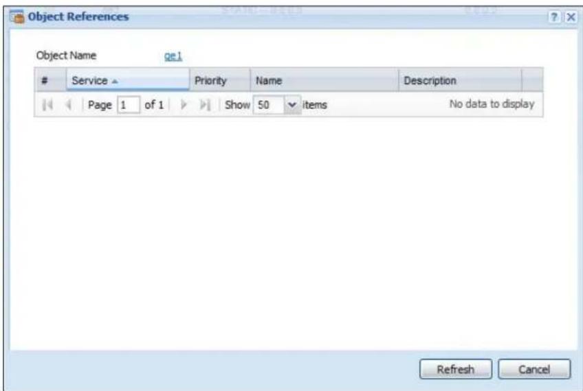
The following table describes labels that can appear in this screen.
Table 64 Object References
| LABEL DESCRIPTION | |
| Object Name Th | s identifies the object for which the configuration settings that use it are displayed. Click the object's name to display the object's configuration screen in the main window. |
| # This field is a | sequential value, and it is not associated with any entry. |
| Service This is th | the type of setting that references the selected object. Click a service's name to display the service's configuration screen in the main window. |
| Priority If it is applicable, this field lists the referencing configuration item's position in its list, otherwise N/ A displays. | |
| Name This field | identifies the configuration item that references the object. |
| Description If the | referencing configuration item has a description configured, it displays here. |
| Refresh Click this | to update the information in this screen. |
| Cancel Click Cancel to close the screen. | |
11.3 VLAN Interfaces
A Virtual Local Area Network (VLAN) divides a physical network into multiple logical networks. The standard is defined in IEEE 802.1q.
Note: By default, the NXC acts a bridge device. This means all interfaces (ge1\~g8) are grouped together into a single VID, vlan0. See Section 4.3.2 on page 61 for more information on this configuration. Also note that vlan0 cannot be removed and the VID cannot be changed.
Figure 77 Example: Before VLAN
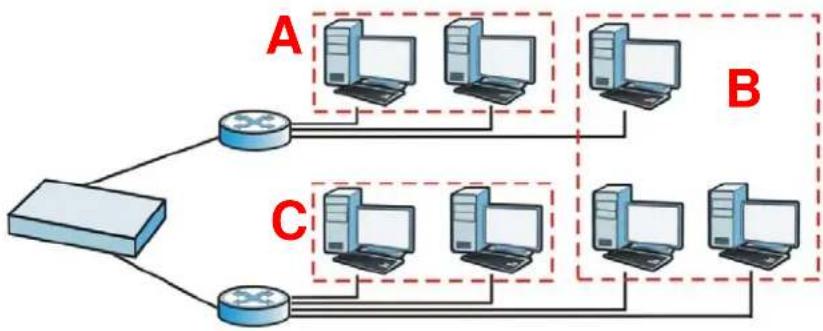
flowchart
graph TD
    A["Client 1"] --> B["Router"]
    B --> C["Client 2"]
    C --> D["Router"]
    D --> E["Client 3"]
    E --> F["Router"]
    style A fill:#f9f,stroke:#333
    style B fill:#ccf,stroke:#333
    style C fill:#cfc,stroke:#333
In this example, there are two physical networks and three departments A, B, and C. The physical networks are connected to hubs, and the hubs are connected to the router.
Alternatively, you can divide the physical networks into three VLANs.
Figure 78 Example: After VLAN
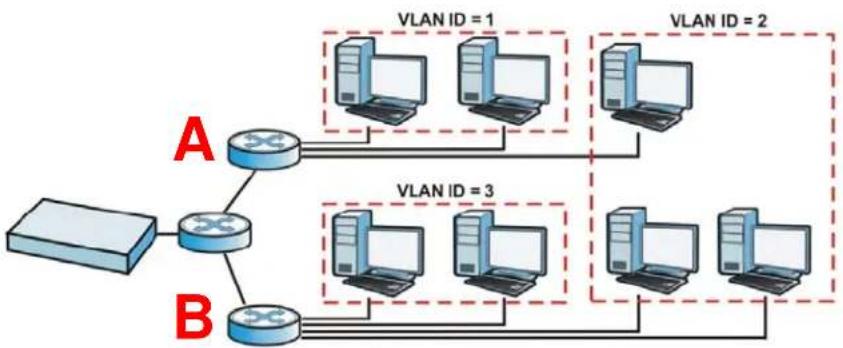
flowchart
graph TD
    A["Host"] --> B["Router"]
    B --> C["VLAN ID = 1"]
    B --> D["VLAN ID = 2"]
    B --> E["VLAN ID = 3"]
    B --> F["VLAN ID = 4"]
Each VLAN is a separate network with separate IP addresses, subnet masks, and gateways. Each VLAN also has a unique identification number (ID). The ID is a 12-bit value that is stored in the MAC header. The VLANs are connected to switches, and the switches are connected to the router. (If one switch has enough connections for the entire network, the network does not need switches A and B.)
- Traffic inside each VLAN is layer-2 communication (data link layer, MAC addresses). It is handled by the switches. As a result, the new switch is required to handle traffic inside VLAN 2. Traffic is only broadcast inside each VLAN, not each physical network.
- Traffic between VLANs (or between a VLAN and another type of network) is layer-3 communication (network layer, IP addresses). It is handled by the router.
This approach provides a few advantages.
- Increased performance - In VLAN 2, the extra switch should route traffic inside the sales department faster than the router does. In addition, broadcasts are limited to smaller, more logical groups of users.
- Higher security - If each computer has a separate physical connection to the switch, then broadcast traffic in each VLAN is never sent to computers in another VLAN.
- Better manageability - You can align network policies more appropriately for users. For example, you can create different policy route rules for each VLAN (each department in the example above), and you can set different bandwidth limits for each VLAN. These rules are also independent of the physical network, so you can change the physical network without changing policies.
In this example, the new switch handles the following types of traffic:
• Inside VLAN 2.
- Between the router and VLAN 1.
- Between the router and VLAN 2.
- Between the router and VLAN 3.
11.3.1 VLAN Summary
This screen lists every VLAN interface. To access this screen, click Configuration > Network > Interface > VLAN.
Figure 79 Configuration > Network > Interface > VLAN
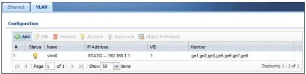
Each field is explained in the following table.
Table 65 Configuration > Network > Interface > VLAN
| LABEL DESCRIPTION | |
| Add Click this to create a new VLAN. | |
| Edit | Double-click an entry or select it and click Edit to open a screen where you can modify the entry's settings. |
| Remove | To remove an entry, select it and click Remove. The NXC confirms you want to remove it before doing so. |
| Activate | To turn on an entry, select it and click Activate. |
| Inactivate | To turn off an entry, select it and click Inactivate. |
| Object References | Select an entry and click Object References to open a screen that shows which settings use the entry. |
| # This field is a sequential value, and it is not associated with any interface. | |
| Status This icon is lit when the entry is active and dimmed when the entry is inactive. | |
| Name This field displays the name of the interface. | |
| IP Address | This field displays the current IP address of the interface. If the IP address is 0.0.0.0, the interface does not have an IP address yet.This screen also shows whether the IP address is a static IP address (STATIC) or dynamically assigned (DHCP). IP addresses are always static in virtual interfaces. |
| VID For VLAN interfaces, this field displays• the Ethernet interface on which the VLAN interface is created• the VLAN IDFor virtual interfaces, this field is blank. | |
| Member This field indicates which zones the VLAN belongs to as a member. | |
| Apply Click Apply to save your changes back to the NXC. | |
| Reset | Click Reset to return the screen to its last-saved settings. |
11.3.2 Add/Edit VLAN
This screen lets you configure IP address assignment, interface bandwidth parameters, DHCP settings, and connectivity check for each VLAN interface. To access this screen, click the Add icon at the top of the Add column or click an Edit icon next to a VLAN interface in the VLAN Summary screen. The following screen appears.
Figure 80 Configuration > Network > Interface > VLAN > Add/Edit
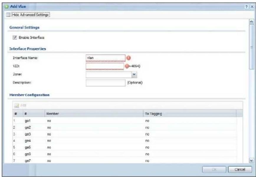
Each field is explained in the following table.
Table 66 Configuration > Network > Interface > VLAN > Add/Edit
| LABEL DESCRIPTION | |
| Show / Hide Advanced Settings | Click this button to display a greater or lesser number of configuration fields. |
| General Settings | |
| Enable Interface | Select this to turn this interface on. Clear this to disable this interface. |
| Interface Properties | |
| LABEL | DESCRIPTION |
| Interface Name | This field is read-only if you are editing an existing VLAN interface. Enter the number of the VLAN interface. You can use a number from 0~4094. For example, vlan0, vlan8, and so on. |
| VID Enter the VLAN ID. This 12-bit number uniquely identifies each VLAN. Allowed values are 1 - 4094. (0 and 4095 are reserved.) | |
| Zone Select the zone to which the VLAN interface belongs. | |
| Description Enter a description of this interface. It is not used elsewhere. You can use alphanumeric and () +/ :=?! *#@_%- characters, and it can be up to 60 characters long. | |
| Member Configuration | Use these settings to assign interfaces to this VLAN as members. |
| Edit Click this to edit the selected interface's membership values. | |
| # This is sequential indicator of the interface number. | |
| # This indicates the interface name. | |
| Member This indicates whether the selected interface is a member or not of the VLAN which is currently being edited.Click this field to edit the value. | |
| Tx Tagging This indicates whether the selected interface tags outbound traffic with this VLAN's ID.Click this field to edit the value. | |
| IP Address Assignment | |
| Get Automatically | Select this if this interface is a DHCP client. In this case, the DHCP server configures the IP address, subnet mask, and gateway automatically. |
| Use Fixed IP Address | Select this if you want to specify the IP address, subnet mask, and gateway manually. |
| IP Address | This field is enabled if you select Use Fixed IP Address.Enter the IP address for this interface. |
| Subnet Mask | This field is enabled if you select Use Fixed IP Address.Enter the subnet mask of this interface in dot decimal notation. The subnet mask indicates what part of the IP address is the same for all computers in the network. |
| Gateway | This field is enabled if you select Use Fixed IP Address.Enter the IP address of the gateway. The NXC sends packets to the gateway when it does not know how to route the packet to its destination. The gateway should be on the same network as the interface. |
| Metric Enter the priority of the gateway (if any) on this interface. The NXC decides which gateway to use based on this priority. The lower the number, the higher the priority. If two or more gateways have the same priority, the NXC uses the one that was configured first. | |
| Related Setting | |
| LABEL DESCRIPTION | |
| Configure Policy Route | Click Policy Route to go to the screen where you can manually configure a policy route to associate traffic with this VLAN. |
| Interface Parameters | |
| Egress Bandwidth | Enter the maximum amount of traffic, in kilobits per second, the NXC can send through the interface to the network. Allowed values are 0 - 1048576. |
| Ingress Bandwidth | This is reserved for future use.Enter the maximum amount of traffic, in kilobits per second, the NXC can receive from the network through the interface. Allowed values are 0 - 1048576. |
| MTU Maximum | Transmission Unit. Type the maximum size of each data packet, in bytes, that can move through this interface. If a larger packet arrives, the NXC divides it into smaller fragments. Allowed values are 576 - 1500. Usually, this value is 1500. |
| DHCP Setting The | DHCP settings are available for the OPT, LAN and DMZ interfaces. |
| DHCP Select what type of DHCP service the NXC provides to the network.Choices are:None - the NXC does not provide any DHCP services. There is already a DHCP server on the network.DHCP Relay - the NXC routes DHCP requests to one or more DHCP servers you specify. The DHCP server(s) may be on another network.DHCP Server - the NXC assigns IP addresses and provides subnet mask, gateway, and DNS server information to the network. The NXC is the DHCP server for the network. | |
| These fields appear if the NXC is a DHCP Relay. | |
| Relay Server 1 | Enter the IP address of a DHCP server for the network. |
| Relay Server 2 | This field is optional. Enter the IP address of another DHCP server for the network. |
| These fields appear if the NXC is a DHCP Server. | |
| IP Pool Start Address | Enter the IP address from which the NXC begins allocating IP addresses. If you want to assign a static IP address to a specific computer, click Add Static DHCP.If this field is blank, the Pool Size must also be blank. In this case, the NXC can assign every IP address allowed by the interface's IP address and subnet mask, except for the first address (network address), last address (broadcast address) and the interface's IP address. |
| Pool Size Enter th | the number of IP addresses to allocate. This number must be at least one and is limited by the interface's Subnet Mask. For example, if the Subnet Mask is 255.255.255.0 and IP Pool Start Address is 10.10.10.10, the NXC can allocate 10.10.10.10 to 10.10.10.254, or 245 IP addresses.If this field is blank, the IP Pool Start Address must also be blank.In this case, the NXC can assign every IP address allowed by the interface's IP address and subnet mask, except for the first address (network address), last address (broadcast address) and the interface's IP address. |
| First DNS Server Second DNS Server Third DNS Server | Specify the IP addresses up to three DNS servers for the DHCP clients to use. Use one of the following ways to specify these IP addresses.Custom Defined - enter a static IP address.From ISP - select the DNS server that another interface received from its DHCP server.NXC - the DHCP clients use the IP address of this interface and the NXC works as a DNS relay. |
| First WINS Server, Second WINS Server | Type the IP address of the WINS (Windows Internet Naming Service) server that you want to send to the DHCP clients. The WINS server keeps a mapping table of the computer names on your network and the IP addresses that they are currently using. |
| Lease time Specify how long each computer can use the information (especially the IP address) before it has to request the information again.Choices are:infinite - select this if IP addresses never expiredays, hours, and minutes - select this to enter how long IP addresses are valid. | |
| Enable IP/MAC Binding | Select this option to have the NXC enforce links between specific IP addresses and specific MAC addresses for this VLAN. This stops anyone else from manually using a bound IP address on another device connected to this interface. Use this to make use only the intended users get to use specific IP addresses. |
| Enable Logs for IP/MAC BindingViolation | Select this option to have the NXC generate a log if a device connected to this VLAN attempts to use an IP address that is bound to another device's MAC address. |
| Static DHCP Table | Configure a list of static IP addresses the NXC assigns to computers connected to the interface. Otherwise, the NXC assigns an IP address dynamically using the interface's IP Pool Start Address and Pool Size. |
| Add Click this to create a new entry. | |
| Edit Select an entry and click this to be able to modify it. | |
| Remove Select an entry and click this to delete it. | |
| # This field is a sequential value, and it is not associated with a specific entry. | |
| IP Address Enter | the IP address to assign to a device with this entry's MAC address. |
| MAC Address Enter | the MAC address to which to assign this entry's IP address. |
| Description | Enter a description to help identify this static DHCP entry. You can use alphanumeric and() + / := ?! * \# @ \_ % - characters, and it can be up to 60 characters long. |
| Connectivity Check | The NXC can regularly check the connection to the gateway you specified to make sure it is still available. You specify how often to check the connection, how long to wait for a response before the attempt is a failure, and how many consecutive failures are required before the NXC stops routing to the gateway. The NXC resumes routing to the gateway the first time the gateway passes the connectivity check. |
| Enable Connectivity Check | Select this to turn on the connection check. |
| Check Method Select | the method that the gateway allows.Select icmp to have the NXC regularly ping the gateway you specify to make sure it is still available.Select tcp to have the NXC regularly perform a TCP handshake with the gateway you specify to make sure it is still available. |
| Check Period Enter | the number of seconds between connection check attempts. |
| Check Timeout Enter | the number of seconds to wait for a response before the attempt is a failure. |
| Check Fail Tolerance | Enter the number of consecutive failures before the NXC stops routing through the gateway. |
| Check Default Gateway | Select this to use the default gateway for the connectivity check. |
| Check this address | Select this to specify a domain name or IP address for the connectivity check. Enter that domain name or IP address in the field next to it. |
| Check Port | This field only displays when you set the Check Method to tcp. Specify the port number to use for a TCP connectivity check. |
| OK | Click OK to save your changes back to the NXC. |
| Cancel | Click Cancel to exit this screen without saving. |
11.4 Technical Reference
The following section contains additional technical information about the features described in this chapter.
IP Address Assignment
Most interfaces have an IP address and a subnet mask. This information is used to create an entry in the routing table.
In most interfaces, you can enter the IP address and subnet mask manually. In PPPoE/PPTP interfaces, however, the subnet mask is always 255.255.255.255 because it is a point-to-point interface. For these interfaces, you can only enter the IP address.
In many interfaces, you can also let the IP address and subnet mask be assigned by an external DHCP server on the network. In this case, the interface is a DHCP client. Virtual interfaces, however, cannot be DHCP clients. You have to assign the IP address and subnet mask manually.
In general, the IP address and subnet mask of each interface should not overlap, though it is possible for this to happen with DHCP clients.
In the example above, if the NXC gets a packet with a destination address of 5.5.5.5, it might not find any entries in the routing table. In this case, the packet is dropped. However, if there is a default router to which the NXC should send this packet, you can specify it as a gateway in one of the interfaces. For example, if there is a default router at 200.200.200.100, you can create a gateway at 200.200.200.100 on ge2. In this case, the NXC creates the following entry in the routing table.
Table 67 Example: Routing Table Entry for a Gateway
| IP ADDRESS(ES) DESTINATION | |
| 0.0.0.0/0 200.200.200 | 10 |
| 0 | |
The gateway is an optional setting for each interface. If there is more than one gateway, the NXC uses the gateway with the lowest metric, or cost. If two or more gateways have the same metric, the NXC uses the one that was set up first (the first entry in the routing table). In PPPoE/PPTP interfaces, the other computer is the gateway for the interface by default. In this case, you should specify the metric.
If the interface gets its IP address and subnet mask from a DHCP server, the DHCP server also specifies the gateway, if any.
Interface Parameters
The NXC restricts the amount of traffic into and out of the NXC through each interface.
- Egress bandwidth sets the amount of traffic the NXC sends out through the interface to the network.
- Ingress bandwidth sets the amount of traffic the NXC allows in through the interface from the network. ^1
If you set the bandwidth restrictions very high, you effectively remove the restrictions.
The NXC also restricts the size of each data packet. The maximum number of bytes in each packet is called the maximum transmission unit (MTU). If a packet is larger than the MTU, the NXC divides it into smaller fragments. Each fragment is sent separately, and the original packet is re-assembled later. The smaller the MTU, the more fragments sent, and the more work required to re-assemble packets correctly. On the other hand, some communication channels, such as Ethernet over ATM, might not be able to handle large data packets.
DHCP Settings
Dynamic Host Configuration Protocol (DHCP, RFC 2131, RFC 2132) provides a way to automatically set up and maintain IP addresses, subnet masks, gateways, and some network information (such as the IP addresses of DNS servers) on computers in the network. This reduces the amount of manual configuration you have to do and usually uses available IP addresses more efficiently.
In DHCP, every network has at least one DHCP server. When a computer (a DHCP client) joins the network, it submits a DHCP request. The DHCP servers get the request; assign an IP address; and provide the IP address, subnet mask, gateway, and available network information to the DHCP client. When the DHCP client leaves the network, the DHCP servers can assign its IP address to another DHCP client.
In the NXC, some interfaces can provide DHCP services to the network. In this case, the interface can be a DHCP relay or a DHCP server.
As a DHCP relay, the interface routes DHCP requests to DHCP servers on different networks. You can specify more than one DHCP server. If you do, the interface routes DHCP requests to all of them. It is possible for an interface to be a DHCP relay and a DHCP client simultaneously.
As a DHCP server, the interface provides the following information to DHCP clients.
- IP address - If the DHCP client's MAC address is in the NXC's static DHCP table, the interface assigns the corresponding IP address. If not, the interface assigns IP addresses from a pool, defined by the starting address of the pool and the pool size.
Table 68 Example: Assigning IP Addresses from a Pool
| START IP ADDRESS POOL SIZE RANGE OF ASSIGNED IP ADDRESS | ||
| 50.50.50.33 5 50.50.50.33 - 50.50.50.37 | ||
| 75.75.75.1 200 75.75.75.1 - 75.75.75.200 | ||
| 99.99.1.1 1023 99.99.1.1 - 99.99.4.255 | ||
| 120.120.120.100 100 120.120.120.100 - 120.120.120.199 | ||
The NXC cannot assign the first address (network address) or the last address (broadcast address) in the subnet defined by the interface's IP address and subnet mask. For example, in the first entry, if the subnet mask is 255.255.255.0, the NXC cannot assign 50.50.50.0 or 50.50.50.255. If the subnet mask is 255.255.0.0, the NXC cannot assign 50.50.0.0 or 50.50.255.255. Otherwise, it can assign every IP address in the range, except the interface's IP address.
If you do not specify the starting address or the pool size, the interface the maximum range of IP addresses allowed by the interface's IP address and subnet mask. For example, if the interface's IP address is 9.9.9.1 and subnet mask is 255.255.255.0, the starting IP address in the pool is 9.9.9.2, and the pool size is 253.
- Subnet mask - The interface provides the same subnet mask you specify for the interface.
- Gateway - The interface provides the same gateway you specify for the interface.
- DNS servers - The interface provides IP addresses for up to three DNS servers that provide DNS services for DHCP clients. You can specify each IP address manually (for example, a company's own DNS server), or you can refer to DNS servers that other interfaces received from DHCP servers (for example, a DNS server at an ISP). These other interfaces have to be DHCP clients.
It is not possible for an interface to be the DHCP server and a DHCP client simultaneously.
WINS
WINS (Windows Internet Naming Service) is a Windows implementation of NetBIOS Name Server (NBNS) on Windows. It keeps track of NetBIOS computer names. It stores a mapping table of your network's computer names and IP addresses. The table is dynamically updated for IP addresses assigned by DHCP. This helps reduce broadcast traffic since computers can query the server instead of broadcasting a request for a computer name's IP address. In this way WINS is similar to DNS, although WINS does not use a hierarchy (unlike DNS). A network can have more than one WINS server. Samba can also serve as a WINS server.
Policy and Static Routes
12.1 Overview
Use policy routes and static routes to override the NXC's default routing behavior in order to send packets through the appropriate interface.
12.1.1 What You Can Do in this Chapter
- The Policy Route screens (Section 12.2 on page 199) list and configure policy routes.
- The Static Route screens (Section 12.3 on page 206) list and configure static routes.
12.1.2 What You Need to Know
The following terms and concepts may help as you read this chapter.
Policy Routing
Traditionally, routing is based on the destination address only and the NXC takes the shortest path to forward a packet. IP Policy Routing (IPPR) provides a mechanism to override the default routing behavior and alter the packet forwarding based on the policy defined by the network administrator. Policy-based routing is applied to incoming packets on a per interface basis, prior to the normal routing.
How You Can Use Policy Routing
- Source-Based Routing – Network administrators can use policy-based routing to direct traffic from different users through different connections.
- Bandwidth Shaping – You can allocate bandwidth to traffic that matches routing policies and prioritize traffic (however the application patrol's bandwidth management is more flexible and recommended for TCP and UDP traffic). You can also use policy routes to manage other types of traffic (like ICMP traffic).
Note: Bandwidth management in policy routes has priority over application patrol bandwidth management.
- Cost Savings – IPPR allows organizations to distribute interactive traffic on high-bandwidth, high-cost paths while using low-cost paths for batch traffic.
- Load Sharing – Network administrators can use IPPR to distribute traffic among multiple paths.
Static Routes
The NXC usually uses the default gateway to route outbound traffic from computers on the LAN to the Internet. To have the NXC send data to devices not reachable through the default gateway, use static routes.
Policy Routes Versus Static Routes
- Policy routes are more flexible than static routes. You can select more criteria for the traffic to match and can also use schedules, NAT, and bandwidth management.
- Policy routes are only used within the NXC itself. Static routes can be propagated to other routers.
- Policy routes take priority over static routes. If you need to use a routing policy on the NXC and propagate it to other routers, you could configure a policy route and an equivalent static route.
DiffServ
QoS is used to prioritize source-to-destination traffic flows. All packets in the same flow are given the same priority. CoS (class of service) is a way of managing traffic in a network by grouping similar types of traffic together and treating each type as a class. You can use CoS to give different priorities to different packet types.
DiffServ (Differentiated Services) is a class of service (CoS) model that marks packets so that they receive specific per-hop treatment at DiffServ-compliant network devices along the route based on the application types and traffic flow. Packets are marked with DiffServ Code Points (DSCPs) indicating the level of service desired. This allows the intermediary DiffServ-compliant network devices to handle the packets differently depending on the code points without the need to negotiate paths or remember state information for every flow. In addition, applications do not have to request a particular service or give advanced notice of where the traffic is going.
DSCP Marking and Per-Hop Behavior
DiffServ defines a new DS (Differentiated Services) field to replace the Type of Service (TOS) field in the IP header. The DS field contains a 2-bit unused field and a 6-bit DSCP field which can define up to 64 service levels. The following figure illustrates the DS field.
DSCP (6 bits) Unused (2 bits)
DSCP is backward compatible with the three precedence bits in the ToS octet so that non-DiffServ compliant, ToS-enabled network device will not conflict with the DSCP mapping.
The DSCP value determines the forwarding behavior, the PHB (Per-Hop Behavior), that each packet gets across the DiffServ network. Based on the marking rule, different kinds of traffic can be marked for different kinds of forwarding. Resources can then be allocated according to the DSCP values and the configured policies.
12.2 Policy Route
Click Configuration > Network > Routing to open this screen. Use this screen to see the configured policy routes and turn policy routing based bandwidth management on or off.
A policy route defines the matching criteria and the action to take when a packet meets the criteria. The action is taken only when all the criteria are met. The criteria can include the user name, source address and incoming interface, destination address, schedule, IP protocol (ICMP, UDP, TCP, etc.) and port.
The actions that can be taken include:
- Routing the packet to a different gateway or outgoing interface.
- Limiting the amount of bandwidth available and setting a priority for traffic.
IPPR follows the existing packet filtering facility of RAS in style and in implementation.
Figure 81 Configuration > Network > Routing > Policy Route
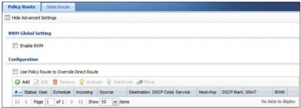
The following table describes the labels in this screen.
Table 69 Configuration > Network > Routing > Policy Route
| LABEL DESCRIPTION | |
| Show / Hide Advanced Settings | Click this button to display a greater or lesser number of configuration fields. |
| Enable BWM This is a global setting for enabling or disabling bandwidth management on the NXC. You must enable this setting to have individual policy routes or application patrol policies apply bandwidth management.This same setting also appears in the AppPatrol > General screen.Enabling or disabling it in one screen also enables or disables it in the other screen. | |
| Use Policy Route to Override Direct Route | Select this to have the NXC forward packets that match a policy route according to the policy route instead of sending the packets directly to a connected network. |
| Add | Click this to create a new entry. Select an entry and click Add to create a new entry after the selected entry. |
| Edit | Double-click an entry or select it and click Edit to open a screen where you can modify the entry's settings. |
| Remove | To remove an entry, select it and click Remove. The NXC confirms you want to remove it before doing so. |
| Activate | To turn on an entry, select it and click Activate. |
| Inactivate | To turn off an entry, select it and click Inactivate. |
| Move To change | a rule's position in the numbered list, select the rule and click Move to display a field to type a number for where you want to put that rule and press [ENTER] to move the rule to the number that you typed.The ordering of your rules is important as they are applied in order of their numbering. |
| # This is the number of an individual policy route. | |
| Status This icon | is lit when the entry is active and dimmed when the entry is inactive. |
| User This is the | name of the user (group) object from which the packets are sent.anymeans all users. |
| Schedule | This is the name of the schedule object. none means the route is active at all times if enabled. |
| Incoming This | is the interface on which the packets are received. |
| Source | This is the name of the source IP address (group) object. any means all IP addresses. |
| Destination | This is the name of the destination IP address (group) object. any means all IP addresses. |
| DSCP Code This | is the DSCP value of incoming packets to which this policy route applies.anymeans all DSCP values or no DSCP marker.defaultmeans traffic with a DSCP value of 0. This is usually best effort trafficThe “af” entries stand for Assured Forwarding. The number following the “af” identifies one of four classes and one of three drop preferences.The “wmm” entries are for QoS. For more information on QoS and WMM categories, see page 209. |
| Service | This is the name of the service object. any means all services. |
| Next-Hop This | is the next hop to which packets are directed. It helps forward packets to their destinations and can be a router or outgoing interface. |
| DSCP Marking | This is how the NXC handles the DSCP value of the outgoing packets that match this route. If this field displays a DSCP value, the NXC applies that DSCP value to the route’s outgoing packets.preservemeans the NXC does not modify the DSCP value of the route’s outgoing packets.defaultmeans the NXC sets the DSCP value of the route’s outgoing packets to 0.The “af” choices stand for Assured Forwarding. The number following the “af” identifies one of four classes and one of three drop preferences.The “wmm” entries are for QoS. For more information on QoS and WMM categories, see page 209. |
| SNAT This is the | source IP address that the route uses.It displays none if the NXC does not perform NAT for this route. |
| BWM | This is the maximum bandwidth allotted to the policy. 0 means there is no bandwidth limitation for this route. |
| Apply | Click Applyto save your changes back to the NXC. |
| Reset | Click Resetto return the screen to its last-saved settings. |
12.2.1 Add/Edit Policy Route
Click Configuration > Network > Routing to open the Policy Route screen. Then click the Add or Edit icon to open the Policy Route Edit screen. Use this screen to configure or edit a policy route.
Figure 82 Configuration > Network > Routing > Policy Route > Add/Edit
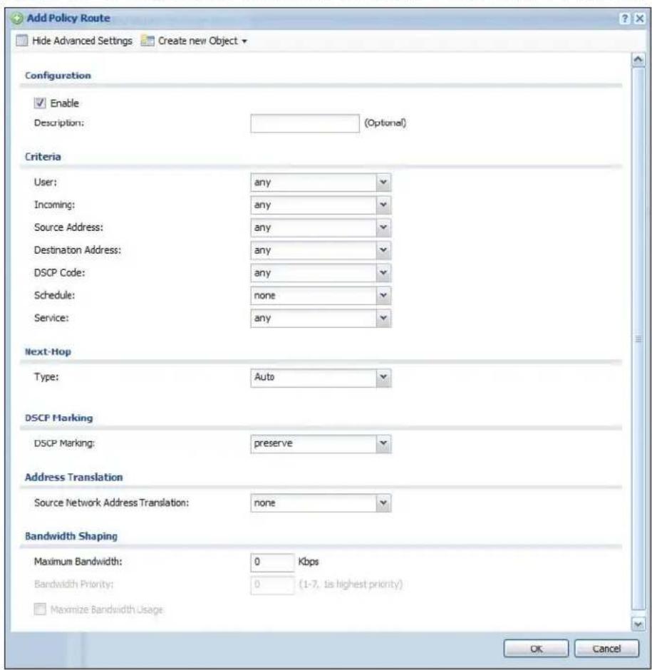
The following table describes the labels in this screen.
Table 70 Configuration > Network > Routing > Policy Route > Add/Edit
| LABEL DESCRIPTION | |
| Show / Hide Advanced Settings | Click this button to display a greater or lesser number of configuration fields. |
| Create new Object | Use this to configure any new settings objects that you need to use in this screen. |
| Configuration | |
| Enable Select this | to activate the policy. |
| Description Enter | a descriptive name of up to 31 printable ASCII characters for the policy. |
| Criteria | |
| User Select a user | name or user group from which the packets are sent. |
| Incoming Select | where the packets are coming from; any or an interface. For an interface you also need to select the individual interface. |
| Source Address | Select a source IP address object from which the packets are sent. |
| Destination Address | Select a destination IP address object to which the traffic is being sent. |
| DSCP Code | Select a DSCP code point value of incoming packets to which this policy route applies or selectUser Definedto specify another DSCP code point. The lower the number the higher the priority with the exception of 0 which is usually given only best-effort treatment.anymeans all DSCP value or no DSCP marker.defaultmeans traffic with a DSCP value of 0. This is usually best effort trafficThe “af” choices stand for Assured Forwarding. The number following the “af” identifies one of four classes and one of three drop preferences.The “wmm” entries are for QoS. For more information on QoS and WMM categories, seepage 209. |
| User-DefinedDSCP Code | Use this field to specify a custom DSCP code point. |
| Schedule | Select a schedule to control when the policy route is active.nonemeans the route is active at all times if enabled. |
| Service Select a | service or service group to identify the type of traffic to which this policy route applies. |
| Next-Hop | |
| Type | SelectAutoto have the NXC use the routing table to find a next-hop and forward the matched packets automatically.SelectGatewayto route the matched packets to the next-hop router or switch you specified in theGatewayfield. You have to set up the next-hop router or switch as a HOST address object first.SelectInterfaceto route the matched packets through the specified outgoing interface to a gateway (which is connected to the interface). |
| Gateway | This field displays when you selectGatewayin the Typefield. Select a HOST address object. The gateway is an immediate neighbor of your NXC that will forward the packet to the destination. The gateway must be a router or switch on the same segment as your NXC’s interface(s). |
| Interface | This field displays when you selectInterfacein the Typefield. Select an interface to have the NXC send traffic that matches the policy route through the specified interface. |
| Auto-Disable | This field displays when you selectInterfacein the Typefield. Select this to have the NXC automatically disable this policy route when the next-hop’s connection is down. |
| DSCP Marking | |
| DSCP Marking Set | Set how the NXC handles the DSCP value of the outgoing packets that match this route.Select one of the pre-defined DSCP values to apply or selectUser Definedto specify another DSCP value. The “af” choices stand for Assured Forwarding. The number following the “af” identifies one of four classes and one of three drop preferences.Selectpreserveto have the NXC keep the packets’ original DSCP value.Selectdefaultto have the NXC set the DSCP value of the packets to 0.The “wmm” entries are for QoS. For more information on QoS and WMM categories, seepage209. |
| User-DefinedDSCP Code | Use this field to specify a custom DSCP value. |
| AddressTranslation | Use this section to configure NAT for the policy route. |
| SourceNetworkAddressTranslation | Selectnoneto not use NAT for the route.Selectoutgoing-interfaceto use the IP address of the outgoing interface as the source IP address of the packets that matches this route. If you selectoutgoing-interfacely, you can also configure port trigger settings for this interface.Otherwise, select a pre-defined address (group) to use as the source IP address(es) of the packets that match this route.UseCreate new Objectif you need to configure a new address (group) to use as the source IP address(es) of the packets that match this route. |
| Port Triggering | Configure trigger port forwarding to allow computers on the LAN to dynamically take turns using a service that uses a dedicated range of ports on the client side and a dedicated range of ports on the server side.Note: You need to create a firewall rule to allow an incoming service before using a port triggering rule. |
| Add | Click this to create a new entry. Select an entry and clickAddto create a new entry after the selected entry. |
| Edit Select an | entry and click this to be able to modify it. You can also just double-click an entry to be able to modify it. |
| Remove Select | an entry and click this to delete it. |
| Move The ordering | of your rules is important as they are applied in order of their numbering.To move an entry to a different number in the list, click theMoveicon.In the field that appears, specify the number to which you want to move the entry. |
| # This is thereule index number. | |
| Incoming Service | Select the service that the client computer sends to a remote server.The incoming service should have the same service or protocol type as what you configured in theServicefield. |
| Trigger Service | Select a service that a remote server sends. It causes (triggers) the NXC to forward the traffic (received on theoutgoing interface) to the client computer that requested the service. |
| Bandwidth Shaping | This allows you to allocate bandwidth to a route and prioritize traffic that matches the routing policy.You must also enable bandwidth management in the main policy route screen (Network >Routing >Policy Route) in order to apply bandwidth shaping. |
| Maximum Bandwidth | Specify the maximum bandwidth (from 1 to 1048576) allowed for the route in kbps. If you enter0here, there is no bandwidth limitation for the route.If the sum of the bandwidths for routes using the same next hop is higher than the actual transmission speed, lower priority traffic may not be sent if higher priority traffic uses all of the actual bandwidth.To reserve bandwidth for traffic that does not match any of the policy routes, leave some of the interface's bandwidth unbudgeted and do not enableMaximize Bandwidth Usage. |
| Bandwidth Priority | Enter a number between 1 and 7 to set the priority for traffic. The smaller the number, the higher the priority. If you set the maximum bandwidth to0, the bandwidth priority will be changed to0after you clickOK.That means the route has the highest priority and will get all the bandwidth it needs up to the maximum available.A route with higher priority is given bandwidth before a route with lower priority.If you set routes to have the same priority, then bandwidth is divided equally amongst those routes. |
| Maximize Bandwidth Usage | Select this check box to have the NXC divide up all of the interface's unallocated and/or unused bandwidth among the policy routes that require bandwidth. Do not select this if you want to reserve bandwidth for traffic that does not match any of the policy routes. |
| OK | ClickOKto save your changes back to the NXC. |
| Cancel | ClickCancelto exit this screen without saving. |
12.3 Static Route
Click Configuration > Network > Routing > Static Route to open the Static Route screen. This screen displays the configured static routes.
Figure 83 Configuration > Network > Routing > Static Route
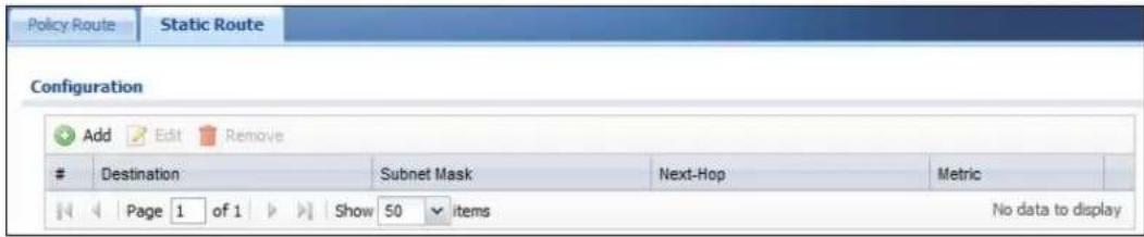
The following table describes the labels in this screen.
Table 71 Configuration > Network > Routing > Static Route
| LABEL DESCRIPTION | |
| Add Click this to create a new static route. | |
| Edit | Double-click an entry or select it and click Edit to open a screen where you can modify the entry's settings. |
| Remove | To remove an entry, select it and click Remove. The NXC confirms you want to remove it before doing so. |
| # This is the number of an individual static route. | |
| Destination This is the destination IP address. | |
| Subnet Mask This is the IP subnet mask. | |
| Next-Hop This is the IP address of the next-hop gateway or the interface through which the traffic is routed. The gateway is a router or switch on the same segment as your NXC's interface(s). The gateway helps forward packets to their destinations. | |
| Metric This is the route's priority among the NXC's routes. The smaller the number, the higher priority the route has. | |
12.3.1 Static Route Setting
Select a static route index number and click Add or Edit. The screen shown next appears. Use this screen to configure the required information for a static route.
Figure 84 Configuration > Network > Routing > Static Route > Add/Edit
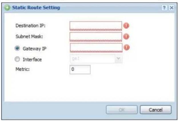
The following table describes the labels in this screen.
Table 72 Configuration > Network > Routing > Static Route > Add/Edit
| LABEL DESCRIPTION | |
| Destination IP | This parameter specifies the IP network address of the final destination. Routing is always based on network number. If you need to specify a route to a single host, use a subnet mask of 255.255.255.255 in the subnet mask field to force the network number to be identical to the host ID. |
| Subnet Mask Enter the IP subnet mask here. | |
| Gateway IP Select the radio button and enter the IP address of the next-hop gateway. The gateway is a router or switch on the same segment as your NXC's interface(s). The gateway helps forward packets to their destinations. | |
| Interface | Select the radio button and a predefined interface through which the traffic is sent. |
| Metric Metric represents the “cost” of transmission for routing purposes. IP routing uses hop count as the measurement of cost, with a minimum of 1 for directly connected networks. Enter a number that approximates the cost for this link. The number need not be precise, but it must be 0~127. In practice, 2 or 3 is usually a good number. | |
| OK | Click OK to save your changes back to the NXC. |
| Cancel | Click Cancel to exit this screen without saving. |
12.4 Technical Reference
The following section contains additional technical information about the features described in this chapter.
NAT and SNAT
NAT (Network Address Translation - NAT, RFC 1631) is the translation of the IP address in a packet in one network to a different IP address in another network. Use SNAT (Source NAT) to change the source IP address in one network to a different IP address in another network.
Assured Forwarding (AF) PHB for DiffServ
Assured Forwarding (AF) behavior is defined in RFC 2597. The AF behavior group defines four AF classes. Inside each class, packets are given a high, medium or low drop precedence. The drop precedence determines the probability that routers in the network will drop packets when congestion occurs. If congestion occurs between classes, the traffic in the higher class (smaller numbered class) is generally given priority. Combining the classes and drop precedence produces the following twelve DSCP encodings from AF11 through AF43. The decimal equivalent is listed in brackets.
Table 73 Assured Forwarding (AF) Behavior Group
| Class 1 Class 2 Class 3 Class 4 | ||||
| Low Drop Precedence AF11 | (10) AF21 (18) AF31 (26) | AF41 (34) | ||
| Medium Drop Precedence AF12 (12) AF22 (20) AF32 | (28) AF42 (36) | |||
| High Drop Precedence AF13 | (14) AF23 (22) AF33 (30) | AF43 (38) | ||
WMM
Wi-Fi Multimedia (WMM) provides basic Quality of Service (QoS) features to wireless networks. The four categories of QoS described by WMM are: voice (VO), video (VI), best effort (BE), and background (BK). These categories, known as a “access categories” (AC), are mapped to 802.1D priority values which can then be mapped to their corresponding DSCP hex values.
Table 74 WMM to DiffServ Conversion on the NXC
| Priority | WMM AC | 802.1D Priority | DSCP Hex Value |
| Lowest | BK 1 0x08 | ||
| BK 2 0x10 | |||
| BE 0 0x00 | |||
| BE 3 0x18 | |||
| VI 4 0x20 | |||
| VI 5 0x28 | |||
| VO 6 0x30 | |||
| Highest | VO 7 0x38 |
The WMM ACs as implemented on the NXC have the following functions:
VOICE: All wireless traffic to the SSID is tagged as voice data. This is recommended if an SSID is used for activities like placing and receiving VoIP phone calls.
VIDEO: All wireless traffic to the SSID is tagged as video data. This is recommended for activities like video conferencing.
BEST EFFORT: All wireless traffic to the SSID is tagged as “best effort,” meaning the data travels the best route it can without displacing higher priority traffic. This is good for activities that do not require the best bandwidth throughput, such as surfing the Internet.
BACKGROUND: All wireless traffic to the SSID is tagged as low priority or "background traffic", meaning all other access categories take precedence over this one. If traffic from an SSID does not have strict throughput requirements, then this access category is recommended. For example, an SSID that only has network printers connected to it.
Port Triggering
Some services use a dedicated range of ports on the client side and a dedicated range of ports on the server side. With regular port forwarding, you set the port(s) and IP address to forward a service (coming in from the remote server) to a client
computer. The problem is that port forwarding only forwards a service to a single IP address. In order to use the same service on a different computer, you have to manually replace the client computer's IP address with another client computer's IP address.
Port triggering allows the client computer to take turns using a service dynamically. Whenever a client computer's packets match the routing policy, it can use the pre-defined port triggering setting to connect to the remote server without manually configuring a port forwarding rule for each client computer.
Port triggering is used especially when the remote server responses using a different port from the port the client computer used to request a service. The NXC records the IP address of a client computer that sends traffic to a remote server to request a service (incoming service). When the NXC receives a new connection (trigger service) from the remote server, the NXC forwards the traffic to the IP address of the client computer that sent the request.
In the following example, you configure two services for port triggering:
Incoming service: Game (UDP: 1234)
Trigger service: Game-1 (UDP: 5670-5678)
1 Computer A wants to play a multiplayer online game and tries to connect to game server 1 using port 1234. The NXC records the IP address of computer A when the packets match a policy with SNAT configured.
2 Game server 1 responds using a port number ranging between 5670 - 5678. The NXC allows and forwards the traffic to computer A.
3 Computer A and game server 1 are connected to each other until the connection is closed or times out. Any other computers (such as B or C) cannot connect to remote server 1 using the same port triggering rule as computer A unless they are using a different next hop (gateway or outgoing interface) from computer A or until the connection is closed or times out.
Figure 85 Trigger Port Forwarding Example
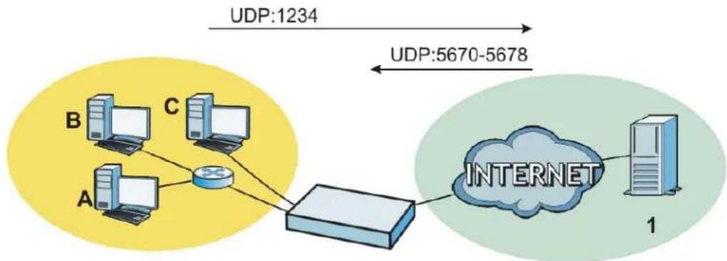
flowchart
graph TD
    A["Server A"] --> R["Router"]
    B["Server B"] --> R
    C["Server C"] --> R
    R --> Internet["Internet"]
    Internet --> Server1["Server 1"]
    style Internet fill:#cce5ff,stroke:#333
    note1["UDP:1234"] --> R
    note2["UDP:5670-5678"] --> R
Maximize Bandwidth Usage
The maximize bandwidth usage option allows the NXC to divide up any available bandwidth on the interface (including unallocated bandwidth and any allocated bandwidth that a policy route is not using) among the policy routes that require more bandwidth.
When you enable maximize bandwidth usage, the NXC first makes sure that each policy route gets up to its bandwidth allotment. Next, the NXC divides up an interface's available bandwidth (bandwidth that is unbudgeted or unused by the policy routes) depending on how many policy routes require more bandwidth and on their priority levels. When only one policy route requires more bandwidth, the NXC gives the extra bandwidth to that policy route.
When multiple policy routes require more bandwidth, the NXC gives the highest priority policy routes the available bandwidth first (as much as they require, if there is enough available bandwidth), and then to lower priority policy routes if there is still bandwidth available. The NXC distributes the available bandwidth equally among policy routes with the same priority level.
Zones
13.1 Overview
Set up zones to configure network security and network policies in the NXC. A zone is a group of interfaces. The NXC uses zones instead of interfaces in many security and policy settings, such as firewall rules and anti-virus. Zones cannot overlap. Each interface can be assigned to just one zone.
Figure 86 Example: Zones
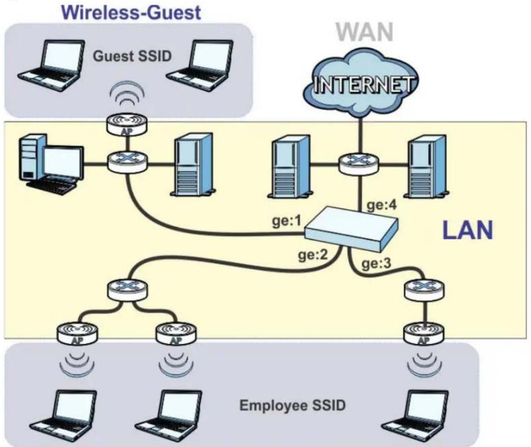
flowchart
graph TD
    subgraph_Wireless_Guest["Wireless-Guest"]
        A["Computer"] --> B["AP"]
        C["Client Server"] --> D["AP"]
        E["Desktop Computer"] --> F["AP"]
        G["Server"] --> H["AP"]
        I["Client Server"] --> J["AP"]
    end

    subgraph_Wi-Fi["Wi-Fi Network"]
        K["Internet"] --> L["LAN"]
        M["AP"] --> N["AP"]
        O["AP"] --> P["AP"]
        Q["AP"] --> R["AP"]
        S["AP"] --> T["AP"]
        U["AP"] --> V["AP"]
    end

    subgraph_Employee_SSID["Employee SSID"]
        W["Computer"] --> X["AP"]
        Y["Desktop Computer"] --> Z["AP"]
        AA["Server"] --> AB["AP"]
        AC["Client Server"] --> AD["AP"]
        AE["AP"] --> AF["AP"]
        AG["AP"] --> AH["AP"]
    end

    subgraph_LAN["LAN Network"]
        AI["Ge 1"] --> AJ["Ge 2"]
        AK["Ge 3"] --> AJ
        AJ --> AL["Ge 4"]
    end

    style Wireless_Guest fill:#f9f,stroke:#333
    style Wi-Fi fill:#bbf,stroke:#333
    style Employee_SSID fill:#dfd,stroke:#333
    style LAN fill:#dfd,stroke:#333
Wireless-Employee
13.1.1 What You Can Do in this Chapter
The Zone screens (see Section 13.2 on page 215) manage the NXC's zones.
13.1.2 What You Need to Know
The following terms and concepts may help as you read this chapter.
Effects of Zones on Different Types of Traffic
Zones effectively divide traffic into three types--intra-zone traffic, inter-zone traffic, and extra-zone traffic--which are affected differently by zone-based security and policy settings.
Intra-zone Traffic
- Intra-zone traffic is traffic between interfaces in the same zone.
- In each zone, you can either allow or prohibit all intra-zone traffic.
- You can also set up firewall rules to control intra-zone traffic, but many other types of zone-based security and policy settings do not affect intra-zone traffic.
Inter-zone Traffic
Inter-zone traffic is traffic between interfaces in different zones.
Extra-zone Traffic
- Extra-zone traffic is traffic to or from any interface that is not assigned to a zone.
- Some zone-based security and policy settings may apply to extra-zone traffic, especially if you can set the zone attribute in them to Any or All. See the specific feature for more information.
13.2 Zone
The Zone screen provides a summary of all zones. In addition, this screen allows you to add, edit, and remove zones. To access this screen, click Configuration > Network > Zone.
Figure 87 Configuration > Network > Zone
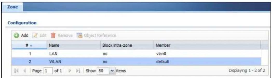
The following table describes the labels in this screen.
Table 75 Configuration > Network > Zone
| LABEL DESCRIPTION | |
| Add Click this to | create a new, user-configured zone. |
| Edit | Double-click an entry or select it and click Edit to open a screen where you can modify the entry's settings. |
| Remove | To remove a user-configured zone, select it and click Remove. The NXC confirms you want to remove it before doing so. |
| Object References | Select an entry and click Object References to open a screen that shows which settings use the entry. |
| # This field is a | sequential value, and it is not associated with any interface. |
| Name This field | displays the name of the zone. |
| Block Intra-zone | This field indicates whether or not the NXC blocks network traffic between members in the zone. |
| Member This fiel | d displays the names of the interfaces that belong to each zone. |
13.3 Add/Edit Zone
This screen allows you to add or edit a zone. To access this screen, go to the Zone screen, and click the Add icon or an Edit icon.
Figure 88 Network > Zone > Add/Edit
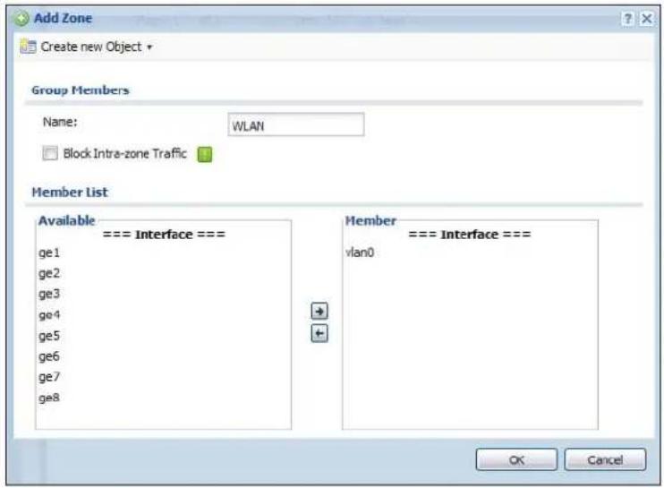
The following table describes the labels in this screen.
Table 76 Network > Zone > Add/Edit
| LABEL DESCRIPTION | |
| Name Type the | name used to refer to the zone. You may use 1-31 alphanumeric characters, underscores( ), or dashes (-), but the first character cannot be a number. This value is case-sensitive. |
| Block Intra-zone Traffic | Select this check box to block network traffic between members in the zone. |
| Member List | Available lists the interfaces that do not belong to any zone. Select the interfaces that you want to add to the zone you are editing, and click the right arrow button to add them.Member lists the interfaces that belong to the zone. Select any interfaces that you want to remove from the zone, and click the left arrow button to remove them. |
| OK | Click OK to save your customized settings and exit this screen. |
| Cancel | Click Cancel to exit this screen without saving. |
14.1 Overview
NAT (Network Address Translation - NAT, RFC 1631) is the translation of the IP address of a host in a packet. For example, the source address of an outgoing packet, used within one network is changed to a different IP address known within another network. Use Network Address Translation (NAT) to make computers on a private network behind the NXC available outside the private network. If the NXC has only one public IP address, you can make the computers in the private network available by using ports to forward packets to the appropriate private IP address.
Suppose you want to assign ports 21-25 to one FTP, Telnet and SMTP server (A in the example), port 80 to another (B in the example) and assign a default server IP address of 192.168.1.35 to a third (C in the example). You assign the LAN IP addresses and the ISP assigns the WAN IP address. The NAT network appears as a single host on the Internet.
Figure 89 Multiple Servers Behind NAT Example
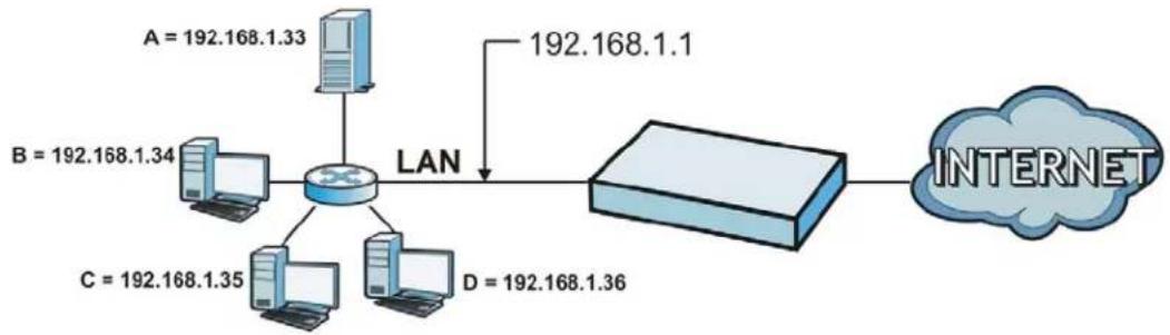
flowchart
graph LR
    A["Router"] -->|LAN| B["Router"]
    A -->|192.168.1.33| C["Client A"]
    A -->|192.168.1.1| D["Client D"]
    C --> E["Client B"]
    D --> F["Client C"]
    E --> G["Client C"]
    F --> H["Client D"]
    G --> I["Internet"]
    H --> I
14.1.1 What You Can Do in this Chapter
The NAT screens (see Section 14.2 on page 218) display and manage the list of NAT rules and see their configuration details. You can also create new NAT rules and edit or delete existing ones.
14.2 NAT Summary
The NAT summary screen provides a summary of all NAT rules and their configuration. In addition, this screen allows you to create new NAT rules and edit and delete existing NAT rules. To access this screen, login to the Web Configurator and click Configuration > Network > NAT. The following screen appears, providing a summary of the existing NAT rules.
Figure 90 Configuration > Network > NAT
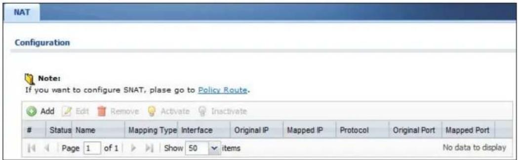
The following table describes the labels in this screen.
Table 77 Configuration > Network > NAT
| LABEL DESCRIPTION | |
| Add Click this to | create a new entry. |
| Edit | Double-click an entry or select it and click Edit to open a screen where you can modify the entry's settings. |
| Remove | To remove an entry, select it and click Remove. The NXC confirms you want to remove it before doing so. |
| Activate | To turn on an entry, select it and click Activate. |
| Inactivate | To turn off an entry, select it and click Inactivate. |
| # This field is a sequential value, and it is not associated with a specific entry. | |
| Status This icon | is lit when the entry is active and dimmed when the entry is inactive. |
| Name This field | displays the name of the entry. |
| Mapping Type | This field displays what kind of NAT this entry performs: Virtual Server, 1:1 NAT, or Many 1:1 NAT. |
| Interface This field | displays the interface on which packets for the NAT entry are received. |
| Original IP This field | displays the original destination IP address (or address object) of traffic that matches this NAT entry. It displays any if there is no restriction on the original destination IP address. |
| Mapped IP This field | displays the new destination IP address for the packet. |
| Protocol This field | displays the service used by the packets for this NAT entry. It displays any if there is no restriction on the services. |
| Original Port This field displays the original destination port(s) of packets for the NAT entry. This field is blank if there is no restriction on the original destination port. | |
| Mapped Port This field displays the new destination port(s) for the packet. This field is blank if there is no restriction on the original destination port. | |
| Apply Click this button to save your changes to the NXC. | |
| Reset Click this button to return the screen to its last-saved settings. | |
14.2.1 Add/Edit NAT
This screen lets you create new NAT rules and edit existing ones. To open this window, open the NAT summary screen. Then, click on an Add icon or Edit icon to open the following screen.
Figure 91 Configuration > Network > NAT > Add/Edit
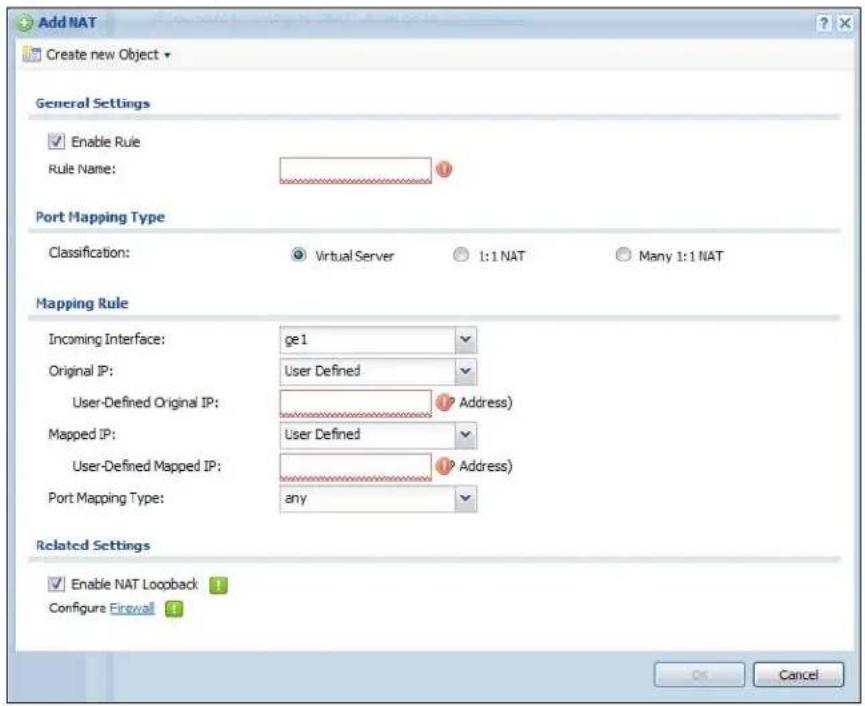
The following table describes the labels in this screen.
Table 78 Configuration > Network > NAT > Add/Edit
| LABEL DESCRIPTION | |
| Create new Object | Use to configure any new settings objects that you need to use in this screen. |
| Enable Rule Use | this option to turn the NAT rule on or off. |
| Rule Name Type | in the name of the NAT rule. The name is used to refer to the NAT rule. You may use 1-31 alphanumeric characters, underscores( ), or dashes (-), but the first character cannot be a number. This value is case-sensitive. |
| Classification Select what kind of NAT this rule is to perform. | |
| Virtual Server - This makes computers on a private network behind the NXC available to a public network outside the NXC (like the Internet).1:1 NAT - If the private network server will initiate sessions to the outside clients, select this to have the NXC translate the source IP address of the server's outgoing traffic to the same public IP address that the outside clients use to access the server.Many 1:1 NAT - If you have a range of private network servers that will initiate sessions to the outside clients and a range of public IP addresses, select this to have the NXC translate the source IP address of each server's outgoing traffic to the same one of the public IP addresses that the outside clients use to access the server. The private and public ranges must have the same number of IP addresses.One many 1:1 NAT rule works like multiple 1:1 NAT rules, but it eases configuration effort since you only create one rule. | |
| Incoming Interface | Select the interface on which packets for the NAT rule must be received. It can be an Ethernet or VLAN interface. |
| Original IP Specify the destination IP address of the packets received by this NAT rule's specified incoming interface.any - Select this to use all of the incoming interface's IP addresses including dynamic addresses or those of any virtual interfaces built upon the selected incoming interface.User Defined - Select this to manually enter an IP address in the User Defined field. For example, you could enter a static public IP assigned by the ISP without having to create a virtual interface for it.Host address - select a host address object to use the IP address it specifies. The list also includes address objects based on interface IPs. So for example you could select an address object based on a WAN interface even if it has a dynamic IP address. | |
| User Defined Original IP | This field is available if Original IP is User Defined. Type the destination IP address that this NAT rule supports. |
| Original IP Subnet/Range | This field displays for Many 1:1 NAT. Select the destination IP address subnet or IP address range that this NAT rule supports. The original and mapped IP address subnets or ranges must have the same number of IP addresses. |
| Mapped IP Select to which translated destination IP address this NAT rule forwards packets.User Defined - this NAT rule supports a specific IP address, specified in the User Defined field.HOST address - the drop-down box lists all the HOST address objects in the NXC. If you select one of them, this NAT rule supports the IP address specified by the address object. | |
| User Defined Original IP | This field is available ifMapped IPis User Defined. Type the translated destination IP address that this NAT rule supports. |
| Mapped IP Subnet/Range | This field displays for Many 1:1 NAT. Select to which translated destination IP address subnet or IP address range this NAT rule forwards packets. The original and mapped IP address subnets or ranges must have the same number of IP addresses. |
| Port Mapping Type | Use the drop-down list box to select how many original destination ports this NAT rule supports for the selected destination IP address (Original IP). Choices are:Any- this NAT rule supports all the destination ports.Port- this NAT rule supports one destination port.Ports- this NAT rule supports a range of destination ports. You might use a range of destination ports for unknown services or when one server supports more than one service. |
| Protocol Type | This field is available ifMapping Typeis PortorPorts. Select the protocol (TCP, UDP, or Any) used by the service requesting the connection. |
| Original Port | This field is available ifMapping Typeis Port. Enter the original destination port this NAT rule supports. |
| Mapped Port | This field is available ifMapping Typeis Port. Enter the translated destination port if this NAT rule forwards the packet. |
| Original Start Port | This field is available ifMapping Typeis Ports. Enter the beginning of the range of original destination ports this NAT rule supports. |
| Original End Port | This field is available ifMapping Typeis Ports. Enter the end of the range of original destination ports this NAT rule supports. |
| Mapped Start Port | This field is available ifMapping Typeis Ports. Enter the beginning of the range of translated destination ports if this NAT rule forwards the packet. |
| Mapped End Port | This field is available ifMapping Typeis Ports. Enter the end of the range of translated destination ports if this NAT rule forwards the packet. The original port range and the mapped port range must be the same size. |
| Enable NAT Loopback | Enable NAT loopback to allow users connected to any interface (instead of just the specifiedIncoming Interface) to use the NAT rule's specifiedOriginal IPaddress to access theMapped IPdevice. For users connected to the same interface as theMapped IPdevice, the NXC uses that interface's IP address as the source address for the traffic it sends from the users to theMapped IPdevice.For example, if you configure a NAT rule to forward traffic from the WAN to a LAN server, enabling NAT loopback allows users connected to other interfaces to also access the server. For LAN users, the NXC uses the LAN interface's IP address as the source address for the traffic it sends to the LAN server.If you do not enable NAT loopback, this NAT rule only applies to packets received on the rule's specified incoming interface. |
| Firewall By default | the firewall blocks incoming connections from external addresses. After you configure your NAT rule settings, click the Firewall link to configure a firewall rule to allow the NAT rule's traffic to come in.The NXC checks NAT rules before it applies To-NXC firewall rules, so To-NXC firewall rules do not apply to traffic that is forwarded by NAT rules. The NXC still checks other firewall rules according to the source IP address and mapped IP address. |
| OK Click OK to save your changes back to the NXC. | |
| Cancel | Click Cancel to return to the NAT summary screen without creating the NAT rule (if it is new) or saving any changes (if it already exists). |
14.3 Technical Reference
The following section contains additional technical information about the features described in this chapter.
NAT Loopback
Suppose a NAT 1:1 rule maps a public IP address to the private IP address of a LAN SMTP e-mail server to give WAN users access. NAT loopback allows other users to also use the rule's original IP to access the mail server.
For example, a LAN user's computer at IP address 192.168.1.89 queries a public DNS server to resolve the SMTP server's domain name (xxx.LAN-SMTP.com in this example) and gets the SMTP server's mapped public IP address of 1.1.1.1.
Figure 92 LAN Computer Queries a Public DNS Server
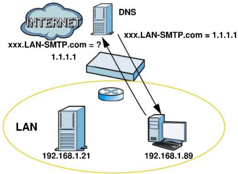
flowchart
graph TD
    A["Internet"] --> B["DNS"]
    B --> C["1.1.1.1"]
    C --> D["192.168.1.21"]
    C --> E["192.168.1.89"]
    F["LAN"] --> G["192.168.1.21"]
    F --> H["192.168.1.89"]
    I["xxx.LAN-SMTP.com = ?"] --> J["1.1.1.1"]
    K["xxxx.LAN-SMTP.com = 1.1.1.1"] --> L["192.168.1.89"]
The LAN user's computer then sends traffic to IP address 1.1.1.1. NAT loopback uses the IP address of the NXC's LAN interface (192.168.1.1) as the source address of the traffic going from the LAN users to the LAN SMTP server.
Figure 93 LAN to LAN Traffic
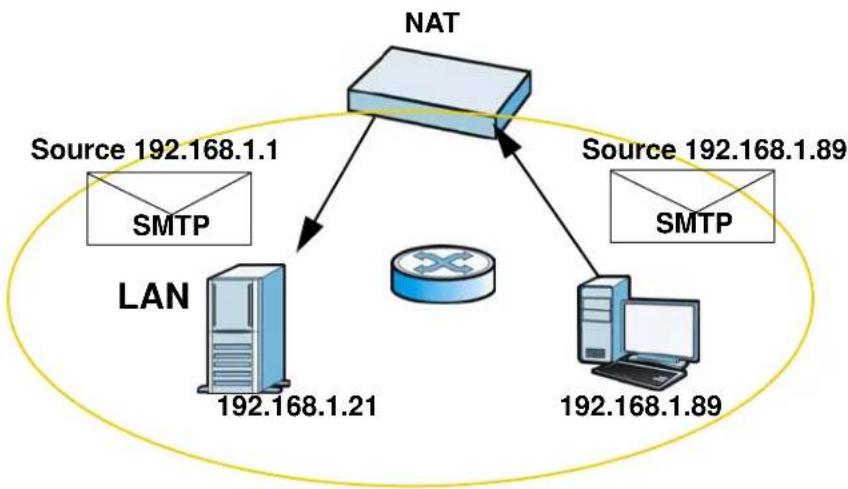
flowchart
graph TD
    A["NAT"] -->|Source 192.168.1.1\nSMTP| B["LAN"]
    A -->|Source 192.168.1.89\nSMTP| C["Router"]
    B -->|192.168.1.21| C
    C -->|192.168.1.89| D["Computer"]
The LAN SMTP server replies to the NXC's LAN IP address and the NXC changes the source address to 1.1.1.1 before sending it to the LAN user. The return traffic's source matches the original destination address (1.1.1.1). If the SMTP server
replied directly to the LAN user without the traffic going through NAT, the source would not match the original destination address which would cause the LAN user's computer to shut down the session.
Figure 94 LAN to LAN Return Traffic
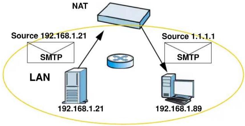
flowchart
graph TD
    A["NAT"] -->|Source 192.168.1.21 SMTP| B["LAN"]
    A -->|Source 1.1.1 SMTP| C["Computer"]
    B -->|192.168.1.21| D["Router Icon"]
    C -->|192.168.1.89| D
15.1 Overview
Application Layer Gateway (ALG) allows the following applications to operate properly through the NXC's NAT.
- SIP - Session Initiation Protocol (SIP) - An application-layer protocol that can be used to create voice and multimedia sessions over Internet.
• H.323 - A teleconferencing protocol suite that provides audio, data and video conferencing. - FTP - File Transfer Protocol - an Internet file transfer service.
The following example shows SIP signaling (1) and audio (2) sessions between SIP clients A and B and the SIP server.
Figure 95 SIP ALG Example
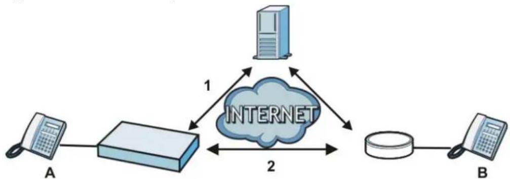
flowchart
graph TD
    A["Client A"] --> R["Router"]
    R -->|1| S["Internet Cloud"]
    S -->|2| R
    S --> B["Client B"]
The ALG feature is only needed for traffic that goes through the NXC's NAT.
15.1.1 What You Can Do in this Chapter
The ALG screen (Section 15.2 on page 228) configures the SIP, H.323, and FTP ALG settings.
15.1.2 What You Need to Know
The following terms and concepts may help as you read this chapter.
Application Layer Gateway (ALG), NAT and Firewall
The NXC can function as an Application Layer Gateway (ALG) to allow certain NAT un-friendly applications (such as SIP) to operate properly through the NXC's NAT and firewall. The NXC dynamically creates an implicit NAT session and firewall session for the application's traffic from the WAN to the LAN. The ALG on the NXC supports all of the NXC's NAT mapping types.
FTP ALG
The FTP ALG allows TCP packets with a specified port destination to pass through. If the FTP server is located on the LAN, you must also configure NAT (port forwarding) and firewall rules if you want to allow access to the server from the WAN.
H.323 ALG
• The H.323 ALG supports peer-to-peer H.323 calls.
- The H.323 ALG handles H.323 calls that go through NAT or that the NXC routes. You can also make other H.323 calls that do not go through NAT or routing. Examples would be calls between LAN IP addresses that are on the same subnet.
- The H.323 ALG allows calls to go out through NAT. For example, you could make a call from a private IP address on the LAN to a peer device on the WAN.
- The H.323 ALG operates on TCP packets with a specified port destination.
• The NXC allows H.323 audio connections.
- The NXC can also apply bandwidth management to traffic that goes through the H.323 ALG.
The following example shows H.323 signaling (1) and audio (2) sessions between H.323 devices A and B.
Figure 96 H.323 ALG Example
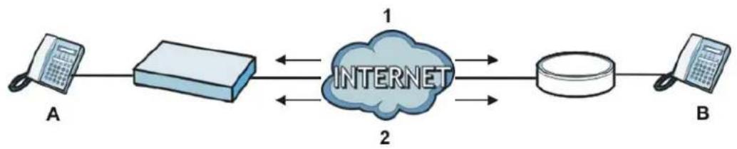
flowchart
graph LR
    A["A"] --> B["Internet"]
    B --> C["1"]
    B --> D["2"]
    C --> E["2"]
    D --> E
SIP ALG
- SIP clients can be connected to the LAN. A SIP server must be on the WAN. The SIP server and SIP clients must be in different networks.
- Using the SIP ALG allows you to use bandwidth management on SIP traffic.
- The SIP ALG handles SIP calls that go through NAT or that the NXC routes. You can also make other SIP calls that do not go through NAT or routing. Examples would be calls between LAN IP addresses that are on the same subnet.
- The SIP ALG supports peer-to-peer SIP calls. The firewall (by default) allows peer to peer calls from the LAN zone to go to the WAN zone and blocks peer to peer calls from the WAN zone to the LAN zone.
- The SIP ALG allows UDP packets with a specified port destination to pass through.
- The NXC allows SIP audio connections.
- You do not need to use STUN (Simple Traversal of User Datagram Protocol (UDP) through Network Address Translators) for VoIP devices behind the NXC when you enable the SIP ALG.
- Configuring the SIP ALG to use custom port numbers for SIP traffic also configures the application patrol to use the same port numbers for SIP traffic. Likewise, configuring the application patrol to use custom port numbers for SIP traffic also configures SIP ALG to use the same port numbers for SIP traffic.
Peer-to-Peer Calls and the NXC
The NXC ALG can allow peer-to-peer VoIP calls for both H.323 and SIP. You must configure the firewall and NAT (port forwarding) to allow incoming (peer-to-peer) calls from the WAN to a private IP address on the LAN (or DMZ).
VoIP Calls from the WAN with Multiple Outgoing Calls
When you configure the firewall and NAT (port forwarding) to allow calls from the WAN to a specific IP address on the LAN, you can also use policy routing to have H.323 (or SIP) calls from other LAN or DMZ IP addresses go out through a different WAN IP address. The policy routing lets the NXC correctly forward the return traffic for the calls initiated from the LAN IP addresses.
15.1.3 Before You Begin
You must also configure the firewall and enable NAT in the NXC to allow sessions initiated from the WAN.
15.2 ALG
Click Configuration > Network > ALG to open this screen. Use this screen to turn ALGs off or on, configure the port numbers to which they apply, and configure SIP ALG time outs.
Note: If the NXC provides an ALG for a service, you must enable the ALG in order to use the application patrol on that service's traffic.
Figure 97 Configuration > Network > ALG
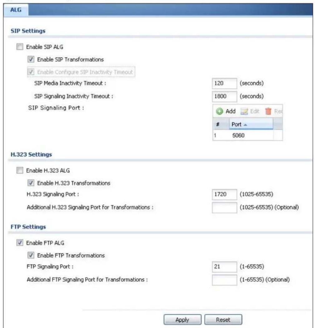
The following table describes the labels in this screen.
Table 79 Configuration > Network > ALG
| LABEL DESCRIPTION | |
| Enable SIP ALG Turn on the SIP ALG to detect SIP traffic and help build SIP sessions through the NXC's NAT. Enabling the SIP ALG also allows you to use the application patrol to detect SIP traffic and manage the SIP traffic's bandwidth. | |
| Enable SIP Transformations | Select this to have the NXC modify IP addresses and port numbers embedded in the SIP data payload.You do not need to use this if you have a SIP device or server that will modify IP addresses and port numbers embedded in the SIP data payload. |
| Enable Configure SIP Inactivity Timeout | Select this option to have the NXC apply SIP media and signaling inactivity time out limits. |
| SIP Media Inactivity Timeout | Use this field to set how many seconds (1~86400) the NXC will allow a SIP session to remain idle (without voice traffic) before dropping it.If no voice packets go through the SIP ALG before the timeout period expires, the NXC deletes the audio session. You cannot hear anything and you will need to make a new call to continue your conversation. |
| SIP Signaling Inactivity Timeout | Most SIP clients have an “expire” mechanism indicating the lifetime of signaling sessions. The SIP user agent sends registration packets to the SIP server periodically and keeps the session alive in the NXC.If the SIP client does not have this mechanism and makes no calls during the NXC SIP timeout, the NXC deletes the signaling session after the timeout period. Enter the SIP signaling session timeout value (1~86400). |
| SIP Signaling Port | If you are using a custom UDP port number (not 5060) for SIP traffic, enter it here. Use the Add icon to add fields if you are also using SIP on additional UDP port numbers. |
| Enable H.323 ALG | Turn on the H.323 ALG to detect H.323 traffic (used for audio communications) and help build H.323 sessions through the NXC's NAT. Enabling the H.323 ALG also allows you to use the application patrol to detect H.323 traffic and manage the H.323 traffic's bandwidth. |
| Enable H.323 Transformations | Select this to have the NXC modify IP addresses and port numbers embedded in the H.323 data payload.You do not need to use this if you have a H.323 device or server that will modify IP addresses and port numbers embedded in the H.323 data payload. |
| H.323 Signaling Port | If you are using a custom TCP port number (not 1720) for H.323 traffic, enter it here. |
| Additional H.323 Signaling Port for Transformations | If you are also using H.323 on an additional TCP port number, enter it here. |
| LABEL DESCRIPTION | |
| Enable FTP ALG Turn on the FTP ALG to detect FTP (File Transfer Program) traffic and help build FTP sessions through the NXC's NAT. Enabling the FTP ALG also allows you to use the application patrol to detect FTP traffic and manage the FTP traffic's bandwidth. | |
| Enable FTP Transformations | Select this option to have the NXC modify IP addresses and port numbers embedded in the FTP data payload to match the NXC's NAT environment.Clear this option if you have an FTP device or server that will modify IP addresses and port numbers embedded in the FTP data payload to match the NXC's NAT environment. |
| FTP Signaling Port | If you are using a custom TCP port number (not 21) for FTP traffic, enter it here. |
| Additional FTP Signaling Port for Transformations | If you are also using FTP on an additional TCP port number, enter it here. |
| Apply | Click Apply to save your changes back to the NXC. |
| Reset | Click Reset to return the screen to its last-saved settings. |
15.3 Technical Reference
The following section contains additional technical information about the features described in this chapter.
ALG
Some applications cannot operate through NAT (are NAT un-friendly) because they embed IP addresses and port numbers in their packets' data payload. The NXC examines and uses IP address and port number information embedded in the VoIP traffic's data stream. When a device behind the NXC uses an application for which the NXC has VoIP pass through enabled, the NXC translates the device's private IP address inside the data stream to a public IP address. It also records session port numbers and allows the related sessions to go through the firewall so the application's traffic can come in from the WAN to the LAN.
FTP
File Transfer Protocol (FTP) is an Internet file transfer service that operates on the Internet and over TCP/IP networks. A system running the FTP server accepts commands from a system running an FTP client. The service allows users to send commands to the server for uploading and downloading files.
H.323
H.323 is a standard teleconferencing protocol suite that provides audio, data and video conferencing. It allows for real-time point-to-point and multipoint communication between client computers over a packet-based network that does not provide a guaranteed quality of service. NetMeeting uses H.323.
SIP
The Session Initiation Protocol (SIP) is an application-layer control (signaling) protocol that handles the setting up, altering and tearing down of voice and multimedia sessions over the Internet. SIP is used in VoIP (Voice over IP), the sending of voice signals over the Internet Protocol.
SIP signaling is separate from the media for which it handles sessions. The media that is exchanged during the session can use a different path from that of the signaling. SIP handles telephone calls and can interface with traditional circuit-switched telephone networks.
RTP
When you make a VoIP call using H.323 or SIP, the RTP (Real time Transport Protocol) is used to handle voice data transfer. See RFC 1889 for details on RTP.
IP/MAC Binding
16.1 Overview
IP address to MAC address binding helps ensure that only the intended devices get to use privileged IP addresses. The NXC uses DHCP to assign IP addresses and records to MAC address it assigned each IP address. The NXC then checks incoming connection attempts against this list. A user cannot manually assign another IP to his computer and use it to connect to the NXC.
Suppose you configure access privileges for IP address 192.168.1.27 and use static DHCP to assign it to Tim's computer's MAC address of 12:34:56:78:90:AB. IP/MAC binding drops traffic from any computer trying to use IP address 192.168.1.27 with another MAC address.
Figure 98 IP/MAC Binding Example
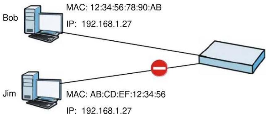
flowchart
graph TD
    Bob["Bob"] -->|MAC: 12:34:56:78:90:AB\nIP: 192.168.1.27| Router["Router"]
    Jim["Jim"] -->|MAC: AB:CD:EF:12:34:56\nIP: 192.168.1.27| Router
16.1.1 What You Can Do in this Chapter
- The Summary and Edit screens (Section 16.2 on page 234) bind IP addresses to MAC addresses
- The Exempt List screen (Section 16.3 on page 238) configures ranges of IP addresses to which the NXC does not apply IP/MAC binding.
16.1.2 What You Need to Know
The following terms and concepts may help as you read this chapter.
DHCP
IP/MAC address bindings are based on the NXC's dynamic and static DHCP entries.
Interfaces Used With IP/MAC Binding
IP/MAC address bindings are grouped by interface. You can use IP/MAC binding with Ethernet, bridge, VLAN interfaces. You can also enable or disable IP/MAC binding and logging in an interface's configuration screen.
16.2 IP/MAC Binding Summary
Click Configuration > Network > IP/ MAC Binding to open the IP/ MAC Binding Summary screen. This screen lists the total number of IP to MAC address bindings for devices connected to each supported interface.
Figure 99 Configuration > Network > IP/MAC Binding > Summary
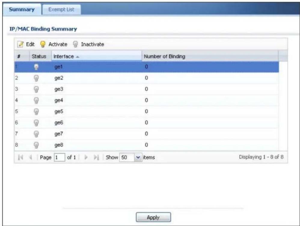
The following table describes the labels in this screen.
Table 80 Configuration > Network > IP/MAC Binding > Summary
| LABEL DESCRIPTION | |
| Edit | Double-click an entry or select it and click Edit to open a screen where you can modify the entry's settings. |
| Activate | To turn on an entry, select it and click Activate. |
| Inactivate | To turn off an entry, select it and click Inactivate. |
| # This field is a | sequential value, and it is not associated with a specific entry. |
| Status This icon | is lit when the entry is active and dimmed when the entry is inactive. |
| Interface | This is the name of an interface that supports IP/MAC binding. |
| Number of Binding | This field displays the interface's total number of IP/MAC bindings and IP addresses that the interface has assigned by DHCP. |
| Apply | Click Apply to save your changes back to the NXC. |
16.2.1 Edit IP/MAC Binding
Click Configuration > Network > IP/ MAC Binding > Edit to open this screen. Use this screen to configure an interface's IP to MAC address binding settings.
Figure 100 Configuration > Network > IP/MAC Binding > Edit
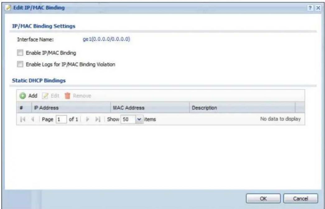
The following table describes the labels in this screen.
Table 81 Configuration > Network > IP/MAC Binding > Edit
| LABEL DESCRIPTION | |
| IP/MACBindingSettings | |
| Interface Name | This field displays the name of the interface within the NXC and the interface's IP address and subnet mask. |
| Enable IP/MACBinding | Select this option to have this interface enforce links between specific IP addresses and specific MAC addresses. This stops anyone else from manually using a bound IP address on another device connected to this interface. Use this to make use only the intended users get to use specific IP addresses. |
| Enable Logs for IP/MACBindingViolation | Select this option to have the NXC generate a log if a device connected to this interface attempts to use an IP address not assigned by the NXC. |
| Static DHCP Bindings | This table lists the bound IP and MAC addresses. The NXC checks this table when it assigns IP addresses. If the computer's MAC address is in the table, the NXC assigns the corresponding IP address. You can also access this table from the interface's edit screen. |
| Add Click this to | create a new entry. |
| Edit | Double-click an entry or select it and click Edit to open a screen where you can modify the entry's settings. |
| Remove | To remove an entry, select it and click Remove. The NXC confirms you want to remove it before doing so. |
| # This is the index number of the static DHCP entry. | |
| IP Address | This is the IP address that the NXC assigns to a device with the entry's MAC address. |
| MAC Address This is the MAC address of the device to which the NXC assigns the entry's IP address. | |
| Description This helps identify the entry. | |
| OK | Click OK to save your changes back to the NXC. |
| Cancel | Click Cancel to exit this screen without saving. |
16.2.2 Add/Edit Static DHCP Rule
Click Configuration > Network > IP/ MAC Binding > Edit to open this screen. Click the Add or Edit icon to open the following screen. Use this screen to configure an interface's IP to MAC address binding settings.
Figure 101 Configuration > Network > IP/MAC Binding > Edit > Add/Edit
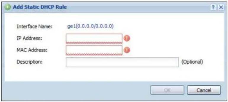
The following table describes the labels in this screen.
Table 82 Configuration > Network > IP/MAC Binding > Edit > Add/Edit
| LABEL DESCRIPTION | |
| Interface Name | This field displays the name of the interface within the NXC and the interface's IP address and subnet mask. |
| IP Address | Enter the IP address that the NXC is to assign to a device with the entry's MAC address. |
| MAC Address Enter the MAC address of the device to which the NXC assigns the entry's IP address. | |
| Description | Enter up to 64 printable ASCII characters to help identify the entry. For example, you may want to list the computer's owner. |
| OK | Click OK to save your changes back to the NXC. |
| Cancel | Click Cancel to exit this screen without saving. |
16.3 IP/MAC Binding Exempt List
Click Configuration > Network > IP/ MAC Binding > Exempt List to open the IP/ MAC Binding Exempt List screen. Use this screen to configure ranges of IP addresses to which the NXC does not apply IP/MAC binding.
Figure 102 Configuration > Network > IP/MAC Binding > Exempt List
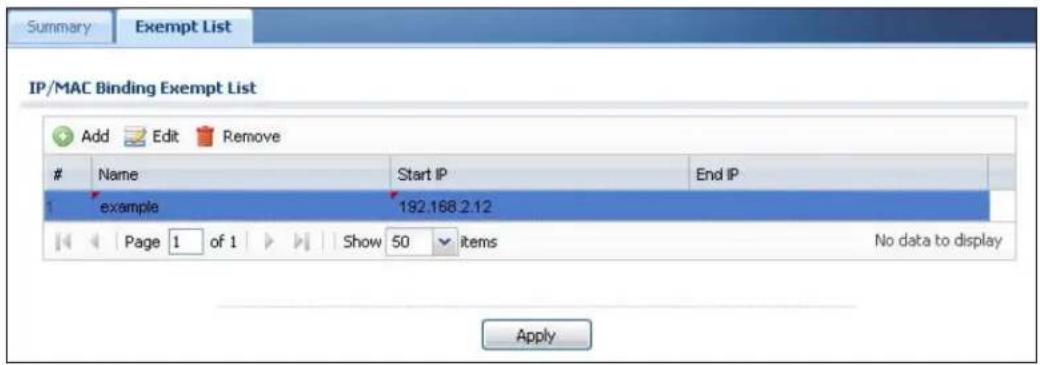
The following table describes the labels in this screen.
Table 83 Configuration > Network > IP/MAC Binding > Exempt List
| LABEL DESCRIPTION | |
| Add Click this to | create a new entry. |
| Edit | Click an entry or select it and click Edit to modify the entry's settings. |
| Remove | To remove an entry, select it and click Remove. The NXC confirms you want to remove it before doing so. |
| # | This is the index number of the IP/MAC binding list entry. |
| Name Enter a name to help identify this entry. | |
| Start IP Enter the first IP address in a range of IP addresses for which the NXC does not apply IP/MAC binding. | |
| End IP Enter the last IP address in a range of IP addresses for which the NXC does not apply IP/MAC binding. | |
| Add icon | Click the Add icon to add a new entry.Click the Remove icon to delete an entry. A window displays asking you to confirm that you want to delete it. |
| Apply | Click Apply to save your changes back to the NXC. |
Captive Portal
17.1 Overview
A captive portal intercepts all network traffic, regardless of address or port, until the user authenticates his or her connection, usually through a specifically designated login Web page.
As an added security measure, the NXC contains captive portal functionality. This means all web page requests can initially be redirected to a special web page that requires you to authenticate your session. Once authentication is successful, you can then connect to the rest of the network or Internet.
Typically, you often find captive portal pages in public hotspots such as bookstores, coffee shops, and hotel rooms, to name a few; as soon as you attempt to open a web page, the hotspot's AP reroutes your browser to a captive portal page that prompts you to log in.
Figure 103 Captive Portal Example
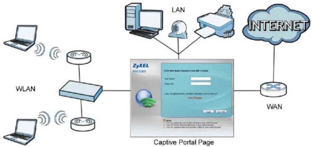
flowchart
graph TD
    A["Laptop"] -->|WLAN| B["Router"]
    C["Laptop"] -->|WLAN| D["Router"]
    B --> E["ZyXEL NXCS260"]
    D --> E
    E --> F["Internet"]
    F --> G["WAN"]
    H["LAN"] --> I["User Name: Password and Click to Links"]
    I --> J["User Name: Password"]
    J --> K["User Name: Password"]
    K --> L["User Name: Password"]
    L --> M["User Name: Password"]
    M --> N["User Name: Password"]
    N --> O["User Name: Password"]
    O --> P["User Name: Password"]
    P --> Q["User Name: Password"]
    Q --> R["User Name: Password"]
    R --> S["User Name: Password"]
    S --> T["User Name: Password"]
    T --> U["User Name: Password"]
    U --> V["User Name: Password"]
    V --> W["User Name: Password"]
    W --> X["User Name: Password"]
    X --> Y["User Name: Password"]
    Y --> Z["User Name: Password"]
    Z --> AA["User Name: Password"]
    AA --> AB["User Name: Password"]
    AB --> AC["User Name: Password"]
    AC --> AD["User Name: Password"]
    AD --> AE["User Name: Password"]
    AE --> AF["User Name: Password"]
    AF --> AG["User Name: Password"]
    AG --> AH["User Name: Password"]
    AH --> AI["User Name: Password"]
    AI --> AJ["User Name: Password"]
    AJ --> AK["User Name: Password"]
    AK --> AL["User Name: Password"]
    AL --> AM["User Name: Password"]
    AM --> AN["User Name: Password"]
    AN --> AO["User Name: Password"]
    AO --> AP["User Name: Password"]
    AP --> AQ["User Name: Password"]
    AQ --> AR["User Name: Password"]
    AR --> AS["User Name: Password"]
    AS --> AT["User Name: Password"]
    AT --> AU["User Name: Password"]
    AU --> AV["User Name: Password"]
    AV --> AW["User Name: Password"]
    AW --> AX["User Name: Password"]
    AX --> AY["User Name: Password"]
The captive portal page only appears once per authentication session. Unless a user idles out or closes the connection, he or she generally will not see it again during the same session.
17.1.1 What You Can Do in this Chapter
- The Captive Portal screen (Section 17.2 on page 240) configures which HTTP-based network services default to the captive portal page when a client makes an initial network connection.
- The Login Page screen (Section 17.3 on page 245) assigns a default login page or create a customized one.
17.2 Captive Portal
This screen allows you to configure which HTTP-based network services default to the captive portal page when client makes an initial network connection.
Click Configuration > Captive Portal to access this screen.
Note: You can configure the look and feel of the captive portal web page on the Login Page screen; see Section 17.3 on page 245 for details
Figure 104 Configuration > Captive Portal
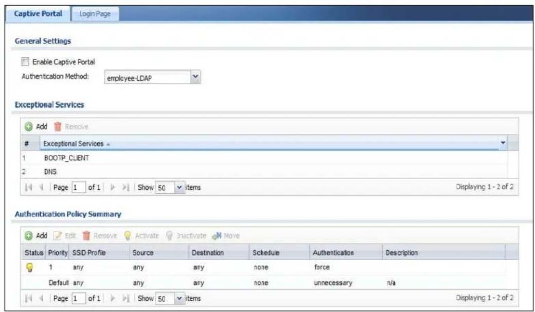
The following table describes the labels in this screen.
Table 84 Configuration > Captive Portal
| LABEL DESCRIPTION | |
| Enable Captive Portal | Select this turn on the captive portal feature.Once enabled, all network traffic is blocked until a client authenticates with the NXC through the specifically designated captive portal page. |
| Authentication Method | Select an authentication method for the captive portal page. You can configure the authentication method in theConfiguration > Object >Auth.Method screen (Chapter 31 on page 437).This sets the default for all wireless clients interacting with the network through the captive portal page. You can override this in theAuth.Policy Edit screen (Section 17.2.2 on page 243). |
| Exceptional Services | This table allows you to configure exceptions to the captive portal interception of network traffic. |
| Add Click to add | a service that is allowed to by-pass the captive portal. This allows certain networking features (such as being able to connect to a DNS server, one of the pre-configured default exceptions), to remain unhindered. |
| Remove Select | an exception from the table then click this button to remove it.Once removed, all traffic from the specified protocol goes back to being intercepted by the captive portal. |
| # | This is the index number of theExceptional Serviceslist entry. |
| Exceptional Services | This column lists the services that you have flagged as exceptions to captive portal interception. |
| Authentication Policy Summary | This table defines how captive portal interception is implemented using the SSIDs, source IPs, and destination IPs that you specify. |
| Add Click this to | create a new entry. |
| Edit | Double-click an entry or select it and clickEditto open a screen where you can modify the entry's settings. |
| Remove | To remove an entry, select it and clickRemove. The NXC confirms you want to remove it before doing so. |
| Activate | To turn on an entry, select it and clickActivate. |
| Inactivate | To turn off an entry, select it and click Inactivate. |
| Move | Click this to assign the selected policy a newPriority.When you click the button, an entry box opens beside it. Enter the priority value, then press [Enter]. |
| Status This indicates whether a policy is active or inactive. | |
| Priority This indicates the priority of a policy.Priority values are unique to each policy. If you want to adjust the priority, use theMovebutton. | |
| SSID Profile This indicates the SSID profile to which a policy belongs. | |
| Source This indicates the source IP address to be monitored by the policy.All traffic from the source IP has the policy applied to it. | |
| Destination This | indicates the destination IP address to be monitored by the policy.All traffic going to the destination IP has the policy applied to it. |
| Schedule This in | indicates which Schedule objects (if any) is applied to the policy. A schedule object allows you to configure which times the rule is in effect. |
| Authentication This indicates whether authentication is required for the policy. | |
| Description | This displays the description of the policy. It has no intrinsic value to the system. |
17.2.1 Add Exceptional Services
This screen allows you to manage exceptions to captive portal interception. Click the Add button in the Exceptional Services table on the Captive Portal screen to access this screen.
Note: If you want 802.1x to work properly, you must set BOOTP_Client and DNS as exceptional services.
Figure 105 Configuration > Captive Portal > Add Exceptional Services
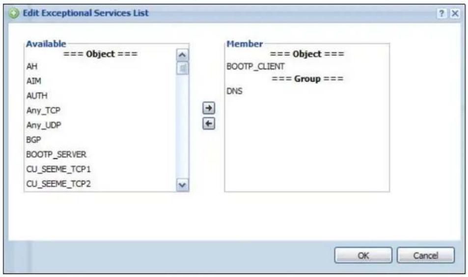
The following table describes the labels in this screen.
Table 85 Configuration > Captive Portal > Add Exceptional Services
| LABEL DESCRIPTION | |
| Available | This lists all available network services eligible for being excepted from captive portal interception. |
| Member | This lists all networks services currently assigned to the Exceptional Services table. |
| OK | Click OK to save your changes back to the NXC. |
| Cancel | Click Cancel to exit this screen without saving. |
17.2.2 Auth. Policy Add/Edit
This screen allows you to add authentication policies to captive portal interception. Click the Add or Edit button (for an existing policy) in the Authentication Policy Summary table on the Captive Portal screen to access this screen.
Figure 106 Configuration > Captive Portal > Auth. Policy Add/Edit
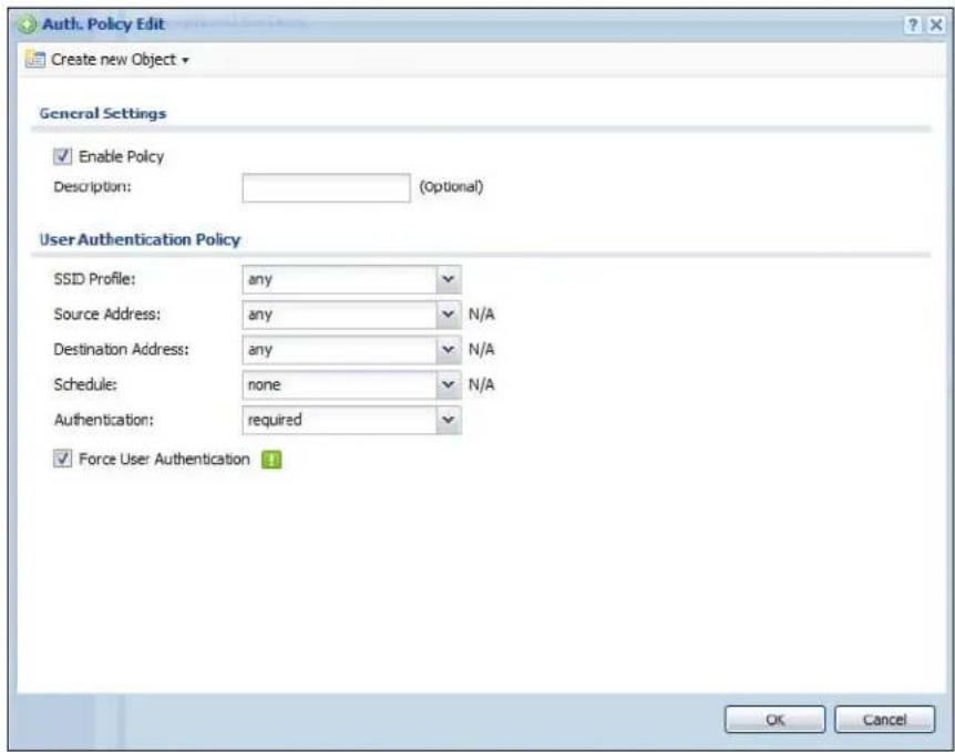
The following table describes the labels in this screen.
Table 86 Configuration > Captive Portal > Auth. Policy Add/Edit
| LABEL DESCRIPTION | |
| Create New Object | Select an object (SSID Profile, Address, or Service) from the list to create a new one. You can then use the object with the authentication policy rule. For example, if you create a new SSID Profile called ‘CoffeeBar’, then you can select it immediately from the SSID Profile item in the Add Authentication Services screen. |
| Enable Policy | Select this to enable the new authentication policy. You can later edit the authentication policy and deselect it if you want to disable it. |
| Description Enter | an optional description of the authentication policy. You can enter up to 60 characters. |
Table 86 Configuration > Captive Portal > Auth. Policy Add/Edit
| LABEL DESCRIPTION | |
| SSID Profile Select an SSID profile from the list. If none are available, you can create a new one using the Create New Object button. | |
| Source Address | Select an address object from the list. If none are available, you can create a new one using the Create New Object button.The source address is an IP address for which the captive portal intercepts all network traffic. |
| Destination Address | Select an address object from the list. If none are available, you can create a new one using the Create New Object button.The destination address is an IP address for which the captive portal intercepts all network traffic toward. |
| Schedule Select | a schedule from the list. If none are available, you can create one in Configuration > Object > Schedule. |
| Authentication | Select whether authentication is required or not necessary for this rule. |
| Force User Authentication | Select this option to redirect HTTP traffic to the login screen if the user has not logged in yet. |
| OK | Click OK to save your changes back to the NXC. |
| Cancel | Click Cancel to exit this screen without saving. |
17.3 Login Page
The login page appears whenever the captive portal intercepts network traffic, preventing unauthorized users from gaining access to the network. Use this page to select the default login page or customize it. Click Configuration > Captive Portal > Login Page to display it.
Figure 107 Configuration > Captive Portal > Login Page
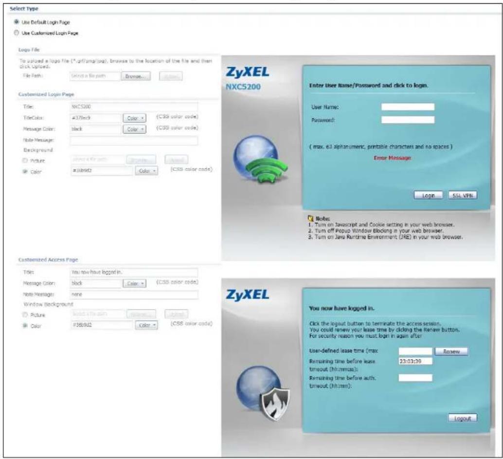
The following table describes the labels in this screen.
Table 87 Configuration > Captive Portal > Login Page
| LABEL DESCRIPTION | |
| Use Default Login Page | Select this to use the default login page built into the device. If you later create a custom login page, you can still return to the NXC's default page as it is saved indefinitely. |
| Use Customized Login Page | Select this to a custom login page instead of the default one built into the NXC. Once this option is selected, the custom login page controls below become active. |
Table 87 Configuration > Captive Portal > Login Page
| LABEL DESCRIPTION | |
| Logo File This section allows you to choose and upload a custom logo image for the customized login page.This corresponds to the “ZyXEL” logo image in the default page. | |
| File Path /Browse /Upload | Browse for the image file or enter the file path in the available input box, then click theUploadbutton to put it on the NXC. Once uploaded, this image file replaces the default “ZyXEL” logo on the login page.You can use the following image file formats: GIF, PNG, or JPG. |
| Customized Login Page | This section allows you to customize the other elements on the captive portal login page. |
| Title Enter 1-6 | 4 characters for the page title. Spaces are allowed.This corresponds to the “NXC5200” title in the default page. |
| Title Color Select | a font color for the page title. You can use the color palette chooser, or enter a color value of your own. |
| MessageColor | Specify the color of the screen’s text. |
| NoteMessage | Enter a note to display below the title. Use up to 1024 printable ASCII characters. Spaces are allowed. |
| Background Set how the window’s background looks.To use a graphic, selectPictureand upload a graphic. Specify the location and file name of the logo graphic or clickBrowseto locate it.You can use the following image file formats: GIF, PNG, or JPG.To use a color, selectColorand specify the color. | |
| CustomizedAccess Page | This section allows you to customize elements on the ‘access’ page that appears upon successful login. |
| Title Enter 1-6 | 4 characters for the page title. Spaces are allowed.This corresponds to the “NXC5200” title in the default page. |
| MessageColor | Specify the color of the screen’s text. |
| NoteMessage | Enter a note to display below the title. Use up to 1024 printable ASCII characters. Spaces are allowed. |
| WindowBackground | Set how the window’s background looks.To use a graphic, selectPictureand upload a graphic. Specify the location and file name of the logo graphic or clickBrowseto locate it.You can use the following image file formats: GIF, PNG, or JPG.To use a color, selectColorand specify the color. |
| Apply | ClickApplyto save your changes back to the NXC. |
| Reset | ClickResetto return the screen to its last-saved settings. |
The following identify the parts you can customize in the login and access pages.
Figure 108 Login Page Customization
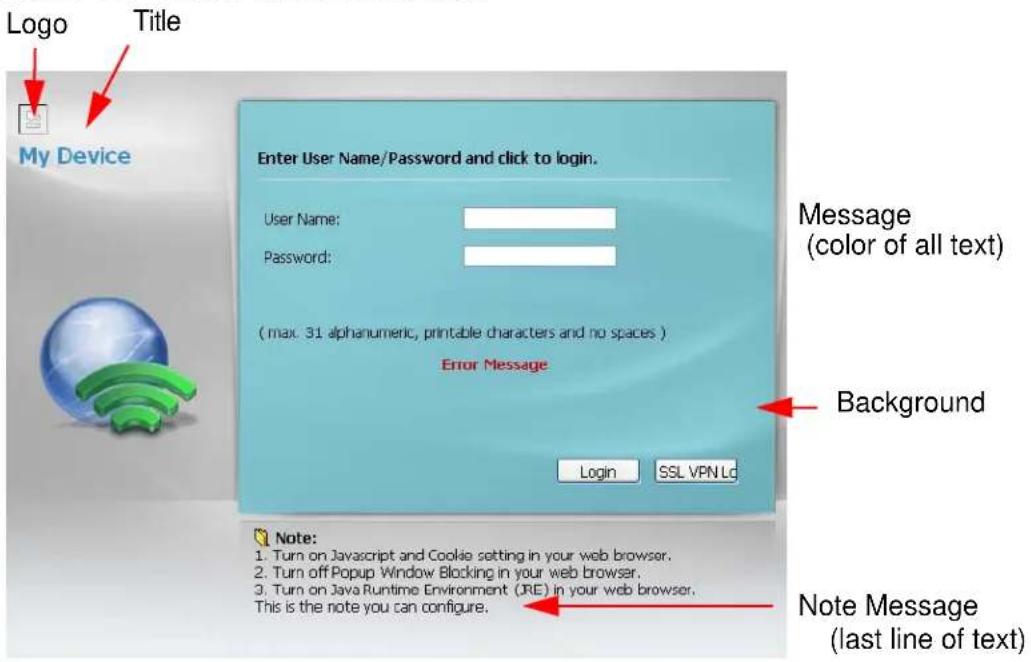
Figure 109 Access Page Customization
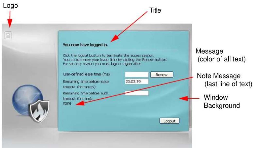
You can specify colors in one of the following ways:
- Click Color to display a screen of web-safe colors from which to choose.
- Enter the name of the desired color.
- Enter a pound sign (#) followed by the six-digit hexadecimal number that represents the desired color. For example, use “#000000” for black.
- Enter "rgb" followed by red, green, and blue values in parenthesis and separate by commas. For example, use "rgb(0,0,0)" for black.
Your desired color should display in the preview screen on the right after you click in another field, click Apply, or press [ENTER]. If your desired color does not display, your browser may not support it. Try selecting another color.
Firewall
18.1 Overview
Use the firewall to block or allow services that use static port numbers. Use application patrol to control services using flexible/dynamic port numbers. The firewall can also limit the number of user sessions.
This figure shows the NXC's default firewall rules in action and demonstrates how stateful inspection works. Administrator 1 can initiate a Telnet session from within the LAN zone and responses to this request are allowed. However, other Telnet traffic initiated from the WAN or WLAN zone and destined for the LAN zone is blocked. Communications from the WLAN through the LAN to the WAN is allowed.
Figure 110 Default Firewall Action
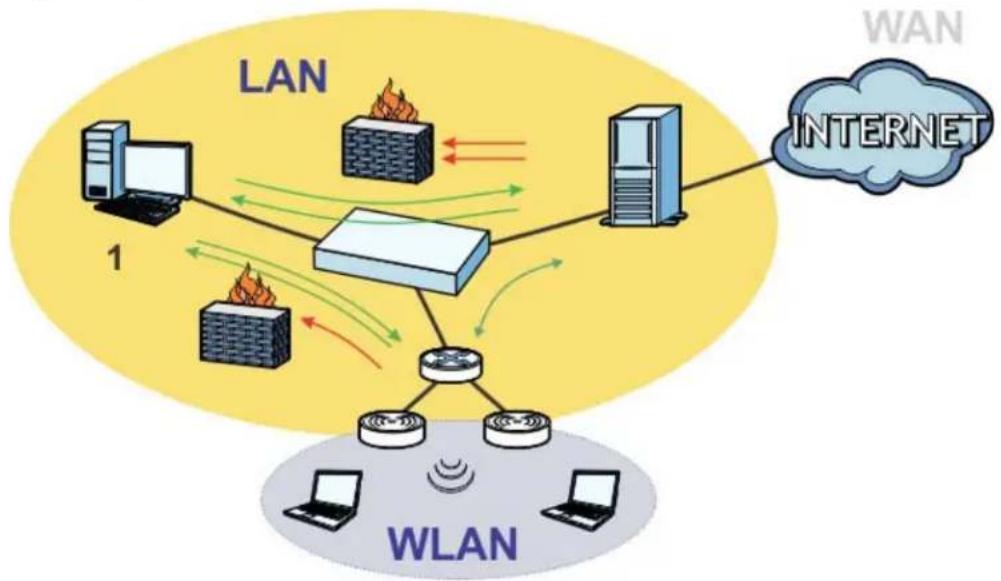
flowchart
graph TD
    subgraph LAN
        A["Server 1"] -->|LAN| B["Switch"]
        C["Server 2"] -->|LAN| B
        D["Server 3"] -->|LAN| B
        E["Server 4"] -->|LAN| B
        F["Server 5"] -->|LAN| B
    end
    subgraph WLAN
        G["Desktop 1"] --> H["Switch"]
        I["Desktop 2"] --> H
        J["Desktop 3"] --> H
        K["Desktop 4"] --> H
        L["Desktop 5"] --> H
    end
    B <-->|Internet| W["WAN"]
    style LAN fill:#f9f,stroke:#333
    style WLAN fill:#bbf,stroke:#333
18.1.1 What You Can Do in this Chapter
- The Firewall screens (Section 18.2 on page 257) enable or disable the firewall and asymmetrical routes, and manage and configure firewall rules.
- The Session Limit screens (Section 18.3 on page 262) limit the number of concurrent NAT/firewall sessions a client can use.
18.1.2 What You Need to Know
The following terms and concepts may help as you read this chapter.
Stateful Inspection
The NXC has a stateful inspection firewall. The NXC restricts access by screening data packets against defined access rules. It also inspects sessions. For example, traffic from one zone is not allowed unless it is initiated by a computer in another zone first.
Zones
A zone is a group of interfaces. Group the NXC's interfaces into different zones based on your needs. You can configure firewall rules for data passing between zones or even between interfaces in a zone.
Default Firewall Behavior
Firewall rules are grouped based on the direction of travel of packets to which they apply. Here is the default firewall behavior for traffic going through the NXC in various directions.
Table 88 Default Firewall Behavior
| FROM ZONE TO ZONE BEHAVIOR | |
| From WAN to NXC Traffic | from the WAN to the NXC itself is allowed for certain default services described inTo-NXC Rules on page 250. All other WAN to NXC traffic is dropped. |
| From WAN to any (other than the NXC) | Traffic from the WAN to any of the networks behind the NXC is dropped. |
| From DMZ to NXC Traffic | from the DMZ to the NXC itself is allowed for certain default services described inTo-NXC Rules on page 250. All other DMZ to NXC traffic is dropped. |
| From DMZ to any (other than the NXC) | Traffic from the DMZ to any of the networks behind the NXC is dropped. |
| From ANY to ANY Traffic that does not match any firewall rule is allowed. So for example, LAN to WAN, LAN to DMZ, and LAN to WLAN traffic is allowed. This also includes traffic to or from interfaces that are not assigned to a zone (extra-zone traffic). | |
To-NXC Rules
Rules with NXC as the To Zone apply to traffic going to the NXC itself. By default:
- The firewall allows only LAN, WAN computers to access or manage the NXC.
- The NXC drops most packets from the WAN zone to the NXC itself, except for VRRP traffic for Device HA, and generates a log.
- The NXC drops most packets from the DMZ zone to the NXC itself, except for DNS and NetBIOS traffic, and generates a log.
When you configure a firewall rule for packets destined for the NXC itself, make sure it does not conflict with your service control rule. The NXC checks the firewall rules before the service control rules for traffic destined for the NXC.
You can configure a To-NXC firewall rule (with From Any To NXC direction) for traffic from an interface which is not in a zone.
Global Firewall Rules
Firewall rules with from any and/or to any as the packet direction are called global firewall rules. The global firewall rules are the only firewall rules that apply to an interface that is not included in a zone. The from any rules apply to traffic coming from the interface and the to any rules apply to traffic going to the interface.
Firewall Rule Criteria
The NXC checks the schedule, user name (user's login name on the NXC), source IP address, destination IP address and IP protocol type of network traffic against the firewall rules (in the order you list them). When the traffic matches a rule, the NXC takes the action specified in the rule.
User Specific Firewall Rules
You can specify users or user groups in firewall rules. For example, to allow a specific user from any computer to access a zone by logging in to the NXC, you can set up a rule based on the user name only. If you also apply a schedule to the firewall rule, the user can only access the network at the scheduled time. A user-aware firewall rule is activated whenever the user logs in to the NXC and will be disabled after the user logs out of the NXC.
Firewall and Application Patrol
To use a service, make sure both the firewall and application patrol allow the service's packets to go through the NXC. The NXC checks the firewall rules before the application patrol rules for traffic going through the NXC.
Session Limits
Accessing the NXC or network resources through the NXC requires a NAT session and corresponding firewall session. Peer to peer applications, such as file sharing applications, may use a large number of NAT sessions. A single client could use all of the available NAT sessions and prevent others from connecting to or through the NXC. The NXC lets you limit the number of concurrent NAT/firewall sessions a client can use.
18.1.3 Firewall Rule Example Applications
Suppose that your company decides to block all of the LAN users from using IRC (Internet Relay Chat) through the Internet. To do this, you would configure a LAN to WAN firewall rule that blocks IRC traffic from any source IP address from going to any destination address. You do not need to specify a schedule since you need the firewall rule to always be in effect. The following figure shows the results of this rule.
Figure 111 Blocking All LAN to WAN IRC Traffic Example
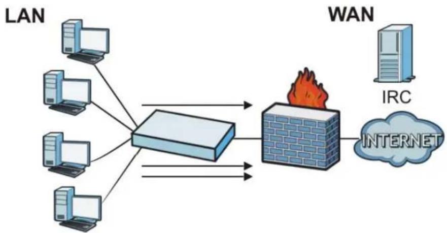
flowchart
graph LR
    A["LAN"] --> B["Switch"]
    C["LAN"] --> B
    D["LAN"] --> B
    E["LAN"] --> B
    F["LAN"] --> B
    G["LAN"] --> B
    H["WAN"] --> I["Internet"]
    J["IRC"] --> I
    B --> K["Fire"]
    I --> K
Your firewall would have the following rules.
Table 89 Blocking All LAN to WAN IRC Traffic Example
| # | USER | SOURCE | DESTINATION | SCHEDULE | SERVICE | ACTION |
| 1 Any Any Any | IRC Deny | |||||
| 2 Any Any Any | Any Allow |
- The first row blocks LAN access to the IRC service on the WAN.
- The second row is the firewall's default policy that allows all LAN to WAN traffic.
The NXC applies the firewall rules in order. So for this example, when the NXC receives traffic from the LAN, it checks it against the first rule. If the traffic matches (if it is IRC traffic) the firewall takes the action in the rule (drop) and stops checking the firewall rules. Any traffic that does not match the first firewall rule will match the second rule and the NXC forwards it.
Now suppose that your company wants to let the CEO use IRC. You can configure a LAN to WAN firewall rule that allows IRC traffic from the IP address of the CEO's computer. You can also configure a LAN to WAN rule that allows IRC traffic from any computer through which the CEO logs into the NXC with his/her user name. In order to make sure that the CEO's computer always uses the same IP address, make sure it either:
- Has a static IP address,
or
- You configure a static DHCP entry for it so the NXC always assigns it the same IP address.
Now you configure a LAN to WAN firewall rule that allows IRC traffic from the IP address of the CEO's computer (192.168.1.7 for example) to go to any destination address. You do not need to specify a schedule since you want the firewall rule to always be in effect. The following figure shows the results of your two custom rules.
Figure 112 Limited LAN to WAN IRC Traffic Example
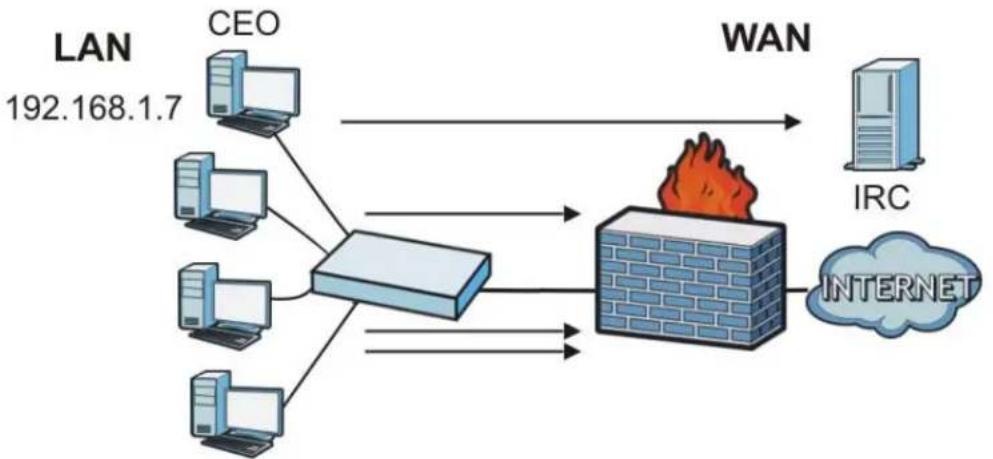
flowchart
graph TD
    A["LAN 192.168.1.7"] --> B["CEO"]
    A --> C["Client Server"]
    A --> D["Client Server"]
    A --> E["Client Server"]
    A --> F["Client Server"]
    B --> G["WAN"]
    C --> G
    D --> G
    E --> G
    F --> G
    G --> H["IRC"]
    G --> I["INTERNET"]
Your firewall would have the following configuration.
Table 90 Limited LAN to WAN IRC Traffic Example 1
| # | USER | SOURCE | DESTINATION | SCHEDULE | SERVICE | ACTION |
| 1 Any 19 | 2.168.1.7 | Any Any IRC | Allow | |||
| 2 | Any | Any | Any | Any | IRC | Deny |
| 3 | Any | Any | Any | Any | Any | Allow |
- The first row allows the LAN computer at IP address 192.168.1.7 to access the IRC service on the WAN.
- The second row blocks LAN access to the IRC service on the WAN.
- The third row is the firewall's default policy of allowing all traffic from the LAN to go to the WAN.
Alternatively, you configure a LAN to WAN rule with the CEO's user name (say CEO) to allow IRC traffic from any source IP address to go to any destination address.
Your firewall would have the following configuration.
Table 91 Limited LAN to WAN IRC Traffic Example 2
| # | USER | SOURCE | DESTINATION | SCHEDULE | SERVICE | ACTION |
| 1 CEO Any Any Any IRC Allow | ||||||
| 2 | Any | Any | Any | Any | IRC | Deny |
| 3 | Any | Any | Any | Any | Any | Allow |
- The first row allows any LAN computer to access the IRC service on the WAN by logging into the NXC with the CEO's user name.
- The second row blocks LAN access to the IRC service on the WAN.
- The third row is the firewall's default policy of allowing all traffic from the LAN to go to the WAN.
The rule for the CEO must come before the rule that blocks all LAN to WAN IRC traffic. If the rule that blocks all LAN to WAN IRC traffic came first, the CEO's IRC traffic would match that rule and the NXC would drop it and not check any other firewall rules.
18.1.4 Firewall Rule Configuration Example
The following Internet firewall rule example allows Doom players from the WAN to IP addresses 192.168.1.10 through 192.168.1.15 (Dest_1) on the LAN.
1 Click Configuration > Firewall. In the summary of firewall rules click Add in the heading row to configure a new first entry. Remember the sequence (priority) of the rules is important since they are applied in order
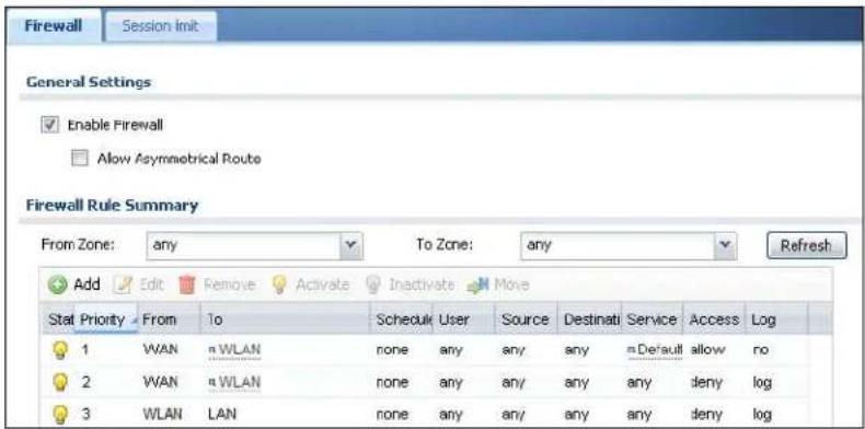
2 At the top of the screen, click Create new Object > Address.
3 The screen for configuring an address object opens. Configure it as follows and click OK.
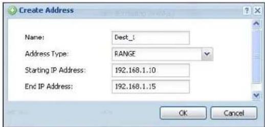
4 Click Create new Object > Service. Configure it as follows and click OK.
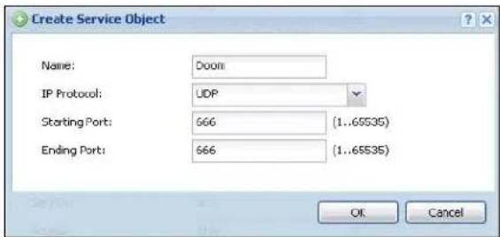
5 Select From WLAN and To LAN1.
6 Enter the name of the firewall rule.
7 Select Dest_1 is selected for the Destination and Doom is selected as the Service. Enter a description and configure the rest of the screen as follows. Click OK when you are done.
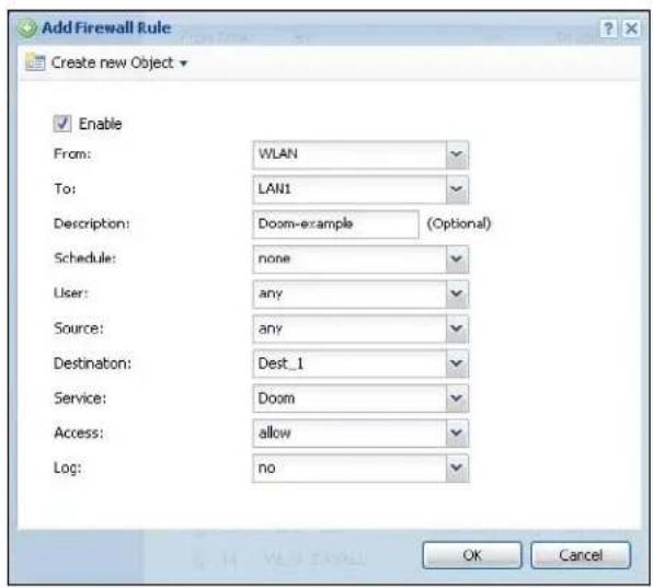
8 The firewall rule appears in the firewall rule summary.
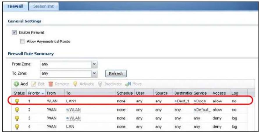
18.1.5 Asymmetrical Routes
If an alternate gateway on the LAN has an IP address in the same subnet as the NXC's LAN IP address, return traffic may not go through the NXC. This is called an asymmetrical or "triangle" route. This causes the NXC to reset the connection, as the connection has not been acknowledged.
You can have the NXC permit the use of asymmetrical route topology on the network (not reset the connection). However, allowing asymmetrical routes may let traffic from the WAN go directly to the LAN without passing through the NXC. A better solution is to use virtual interfaces to put the NXC and the backup gateway
on separate subnets. Virtual interfaces allow you to partition your network into logical sections over the same interface. See the chapter about interfaces for more information.
By putting LAN 1 and the alternate gateway (A in the figure) in different subnets, all returning network traffic must pass through the NXC to the LAN. The following steps and figure describe such a scenario.
1 A computer on the LAN initiates a connection by sending a SYN packet to a receiving server on the WAN.
2 The NXC reroutes the packet to gateway A, which is in Subnet 2.
3 The reply from the WAN goes to the NXC.
4 The NXC then sends it to the computer on the LAN in Subnet 1.
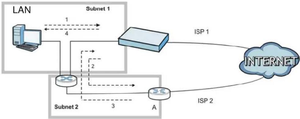
flowchart
graph TD
    LAN["LAN"] -->|1| Subnet1["Subnet 1"]
    LAN -->|4| Subnet2["Subnet 2"]
    Subnet1 -->|2| Subnet2
    Subnet2 -->|3| A["A"]
    Subnet2 -->|4| ISP1["ISP 1"]
    ISP1 --> INTERNET["INTERNET"]
    A --> ISP2["ISP 2"]
    ISP2 --> INTERNET
18.2 Firewall
The following describes the Firewall screen functions.
Click Configuration > Firewall to open the Firewall screen. Use this screen to enable or disable the firewall and asymmetrical routes, set a maximum number of sessions per host, and display the configured firewall rules. Specify from which zone packets come and to which zone packets travel to display only the rules specific to the selected direction. Note the following.
- If you enable intra-zone traffic blocking (see the chapter about zones), the firewall automatically creates (implicit) rules to deny packet passage between the interfaces in the specified zone.
- Besides configuring the firewall, you also need to configure NAT rules to allow computers on the WAN to access LAN devices.
- The NXC applies NAT (Destination NAT) settings before applying the firewall rules. So for example, if you configure a NAT entry that sends WAN traffic to a LAN IP address, when you configure a corresponding firewall rule to allow the traffic, you need to set the LAN IP address as the destination.
- The ordering of your rules is very important as rules are applied in sequence.
Figure 113 Configuration > Firewall
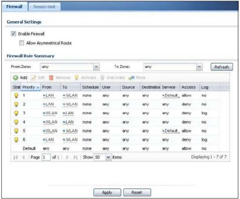
The following table describes the labels in this screen.
Table 92 Configuration > Firewall
| LABEL DESCRIPTION | |
| General Settings | |
| Enable Firewall | Select this check box to activate the firewall. The NXC performs access control when the firewall is activated. |
| Allow Asymmetrical Route | If an alternate gateway on the LAN has an IP address in the same subnet as the NXC's LAN IP address, return traffic may not go through the NXC. This is called an asymmetrical or “triangle” route. This causes the NXC to reset the connection, as the connection has not been acknowledged.Select this check box to have the NXC permit the use of asymmetrical route topology on the network (not reset the connection).Note: Allowing asymmetrical routes may let traffic from the WAN go directly to the LAN without passing through the NXC. A better solution is to use virtual interfaces to put the NXC and the backup gateway on separate subnets. |
| LABEL | DESCRIPTION |
| From Zone / To Zone | This is the direction of travel of packets. Select from which zone the packets come and to which zone they go.Firewall rules are grouped based on the direction of travel of packets to which they apply. For example, from LAN to LAN means packets traveling from a computer or subnet on the LAN to either another computer or subnet on the LAN.From any displays all the firewall rules for traffic going to the selected To Zone.To any displays all the firewall rules for traffic coming from the selected From Zone.From any to any displays all of the firewall rules.To NXC rules are for traffic that is destined for the NXC and control which computers can manage the NXC. |
| Add | Click this to create a new entry. Select an entry and click Add to create a new entry after the selected entry. |
| Edit | Double-click an entry or select it and click Edit to open a screen where you can modify the entry's settings. |
| Remove | To remove an entry, select it and click Remove. The NXC confirms you want to remove it before doing so. |
| Activate | To turn on an entry, select it and click Activate. |
| Inactivate | To turn off an entry, select it and click Inactivate. |
| Move To change | a rule's position in the numbered list, select the rule and click Move to display a field to type a number for where you want to put that rule and press [ENTER] to move the rule to the number that you typed.The ordering of your rules is important as they are applied in order of their numbering. |
| The following read-only fields summarize the rules you have created that apply to traffic traveling in the selected packet direction. | |
| Status This icon | is lit when the entry is active and dimmed when the entry is inactive. |
| Priority This is th | the position of your firewall rule in the global rule list (including all through-NXC and to-NXC rules). The ordering of your rules is important as rules are applied in sequence. Default displays for the default firewall behavior that the NXC performs on traffic that does not match any other firewall rule. |
| From To | This is the direction of travel of packets to which the firewall rule applies. |
| Schedule | This field tells you the schedule object that the rule uses. none means the rule is active at all times if enabled. |
| User This is the | user name or user group name to which this firewall rule applies. |
| Source This dis | plays the source address object to which this firewall rule applies. |
| Destination This | displays the destination address object to which this firewall rule applies. |
| LABEL DESCRIPTION | |
| Service This displays the service object to which this firewall rule applies. | |
| Access | This field displays whether the firewall silently discards packets (deny), discards packets and sends a TCP reset packet to the sender (reject) or permits the passage of packets (allow). |
| Log This field shows you whether a log (and alert) is created when packets match this rule or not. | |
| Apply Click Apply to save your changes back to the NXC. | |
| Reset | Click Reset to return the screen to its last-saved settings. |
18.2.1 Add/Edit Firewall Screen
In the Firewall screen, click the Edit or Add icon to display this screen.
Figure 114 Configuration > Firewall > Add/Edit
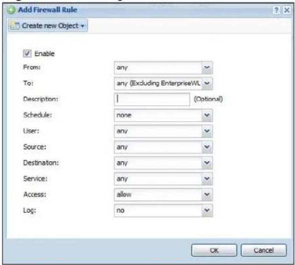
The following table describes the labels in this screen.
Table 93 Configuration > Firewall > Add/Edit
| LABEL DESCRIPTION | |
| Create new Object | Use to configure any new settings objects that you need to use in this screen. |
| Enable Select this check box to activate the firewall rule. | |
| From To | For through-NXC rules, select the direction of travel of packets to which the rule applies.any means all interfaces.NXC means packets destined for the NXC itself. |
| Description Enter | a descriptive name of up to 60 printable ASCII characters for the firewall rule. Spaces are allowed. |
| Schedule Select | a schedule that defines when the rule applies. Otherwise, select none and the rule is always effective. |
| User This field is | not available when you are configuring a to-NXC rule.Select a user name or user group to which to apply the rule. The firewall rule is activated only when the specified user logs into the system and the rule will be disabled when the user logs out.Otherwise, select any and there is no need for user logging.Note: If you specified a source IP address (group) instead of any in the field below, the user's IP address should be within the IP address range. |
| Source Select a | source address or address group for whom this rule applies.Select any if the policy is effective for every source. |
| Destination Select | a destination address or address group for whom this rule applies. Select any if the policy is effective for every destination. |
| Service Select a | service or service group from the drop-down list box. |
| Access Use the d | drop-down list box to select what the firewall is to do with packets that match this rule.Select deny to silently discard the packets without sending a TCP reset packet or an ICMP destination-unreachable message to the sender.Select reject to deny the packets and send a TCP reset packet to the sender. Any UDP packets are dropped without sending a response packet.Select allow to permit the passage of the packets. |
| Log | Select whether to have the NXC generate a log (log), log and alert (log alert) or not (no) when the rule is matched. |
| OK | Click OK to save your customized settings and exit this screen. |
| Cancel Click Cancel to exit this screen without saving. | |
18.3 Session Limit
Click Configuration > Firewall > Session Limit to display the Firewall Session Limit screen. Use this screen to limit the number of concurrent NAT/firewall sessions a client can use. You can apply a default limit for all users and individual limits for specific users, addresses, or both. The individual limit takes priority if you apply both.
Figure 115 Configuration > Firewall > Session Limit
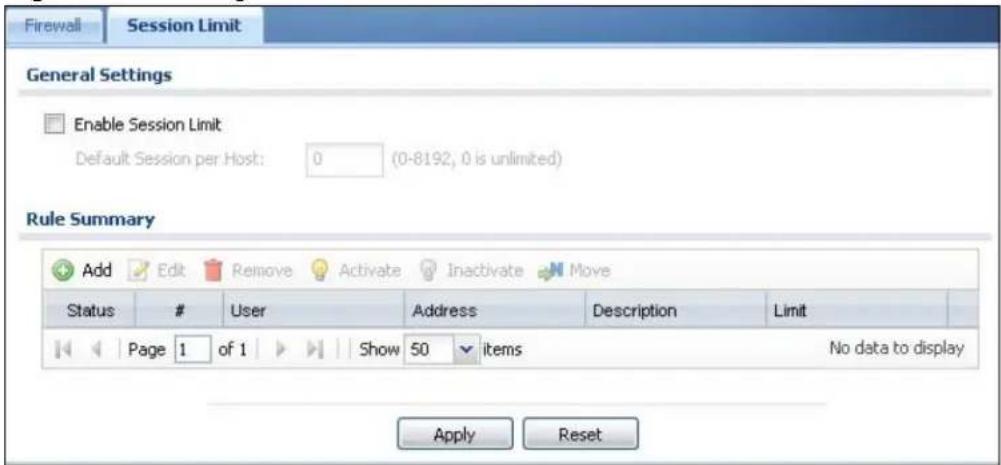
The following table describes the labels in this screen.
Table 94 Configuration > Firewall > Session Limit
| LABEL DESCRIPTION | |
| General Settings | |
| Enable Session limit | Select this check box to control the number of concurrent sessions hosts can have. |
| Default Session per Host | Use this field to set a common limit to the number of concurrent NAT/firewall sessions each client computer can have.If only a few clients use peer to peer applications, you can raise this number to improve their performance. With heavy peer to peer application use, lower this number to ensure no single client uses too many of the available NAT sessions.Create rules below to apply other limits for specific users or addresses. |
| Rule Summary | This table lists the rules for limiting the number of concurrent sessions hosts can have. |
| Add | Click this to create a new entry. Select an entry and click Add to create a new entry after the selected entry. |
| Edit | Double-click an entry or select it and click Edit to open a screen where you can modify the entry's settings. |
| Remove | To remove an entry, select it and click Remove. The NXC confirms you want to remove it before doing so. |
| Activate | To turn on an entry, select it and click Activate. |
| Inactivate | To turn off an entry, select it and click Inactivate. |
| Move To change | a rule's position in the numbered list, select the rule and clickMove to display a field to type a number for where you want to put that rule and press [ENTER] to move the rule to the number that you typed.The ordering of your rules is important as they are applied in order of their numbering. |
| Status This icon | is lit when the entry is active and dimmed when the entry is inactive. |
| # This is the index | number of a session limit rule. It is not associated with a specific rule. |
| User This is the user name or user group name to which this session limit rule applies. | |
| Address This is the address object to which this session limit rule applies. | |
| Limit This is how many concurrent sessions this user or address is allowed to have. | |
| Apply Click Apply to save your changes back to the NXC. | |
| Reset | Click Reset to return the screen to its last-saved settings. |
18.3.1 Add/Edit Session Limit
Click Configuration > Firewall > Session Limit and the Add or Edit icon to display the Firewall Session Limit Edit screen. Use this screen to configure rules that define a session limit for specific users or addresses.
Figure 116 Configuration > Firewall > Session Limit > Add/Edit
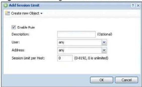
The following table describes the labels in this screen.
Table 95 Configuration > Firewall > Session Limit > Add/Edit
| LABEL DESCRIPTION | |
| Create new Object | Use to configure any new settings objects that you need to use in this screen. |
| Enable Rule Select | ct this check box to turn on this session limit rule. |
| Description Enter | information to help you identify this rule. Use up to 64 printable ASCII characters. Spaces are allowed. |
| User Select a user | name or user group to which to apply the rule. The rule is activated only when the specified user logs into the system and the rule will be disabled when the user logs out.Otherwise, select any and there is no need for user logging.Note: If you specified an IP address (or address group) instead of any in the field below, the user's IP address should be within the IP address range. |
| Address Select a | source address or address group for whom this rule applies.Select any if the policy is effective for every source address. |
| Session Limit per Host | Use this field to set a limit to the number of concurrent NAT/firewall sessions this rule's users or addresses can have.For this rule's users and addresses, this setting overrides the Default Session per Host setting in the general Firewall Session Limit screen. |
| OK | Click OK to save your customized settings and exit this screen. |
| Cancel | Click Cancel to exit this screen without saving. |
Application Patrol
19.1 Overview
Application patrol provides a convenient way to manage the use of various applications on the network. It manages general protocols (for example, HTTP and FTP) and instant messenger (IM), peer-to-peer (P2P), Voice over IP (VoIP), and streaming (RSTP) applications. You can even control the use of a particular application's individual features (like text messaging, voice, video conferencing, and file transfers). Application patrol also has powerful bandwidth management including traffic prioritization to enhance the performance of delay-sensitive applications like voice and video.
There is also an option that gives SIP traffic priority over all other traffic going through the NXC. This maximizes SIP traffic throughput for improved VoIP call sound quality.
19.1.1 What You Can Do in this Chapter
- The General summary screen (Section 19.2 on page 275) enables and disables application patrol.
- The Common, Instant Messenger, Peer to Peer, VoIP, and Streaming screens (Section 19.2 on page 275) display the applications the NXC can recognize, and review the settings for each one. You can also enable and disable the rules for each application and specify the default and custom policies for each application.
- The Application Patrol Edit screen (Section 19.2.1 on page 276) edits the settings for an application.
- The Application Policy Edit screen (Section 19.2.2 on page 279) edits a group of settings for an application.
- The Other screens (see Section 19.3 on page 281) control what the NXC does when it does not recognize the application, and it identifies the conditions that refine this. It also lets you open the Other Configuration Add/ Edit screen to create new conditions or edit existing ones.
19.1.2 What You Need to Know
The following terms and concepts may help as you read this chapter.
If you want to use a service, make sure both the firewall and application patrol allow the service's packets to go through the NXC.
Note: The NXC checks firewall rules before it checks application patrol rules for traffic going through the NXC.
Application patrol examines every TCP and UDP connection passing through the NXC and identifies what application is using the connection. Then, you can specify, by application, whether or not the NXC continues to route the connection.
Configurable Application Policies
The NXC has policies for individual applications. For each policy, you can specify the default action the NXC takes once it identifies one of the service's connections.
You can also specify custom policies that have the NXC forward, drop, or reject a service's connections based on criteria that you specify (like the source zone, destination zone, original destination port of the connection, schedule, user, source, and destination information). Your custom policies take priority over the policy's default settings.
Classification of Applications
There are two ways the NXC can identify the application. The first is called auto. The NXC looks at the IP payload (OSI level-7 inspection) and attempts to match it with known patterns for specific applications. Usually, this occurs at the beginning of a connection, when the payload is more consistent across connections, and the NXC examines several packets to make sure the match is correct.
Note: The NXC allows the first eight packets to go through the firewall, regardless of the application patrol policy for the application. The NXC examines these first eight packets to identify the application.
The second approach is called service ports. The NXC uses only OSI level-4 information, such as ports, to identify what application is using the connection. This approach is available in case the NXC identifies a lot of “false positives” for a particular application.
Custom Ports for SIP and the SIP ALG
Configuring application patrol to use custom port numbers for SIP traffic also configures the SIP ALG to use the same port numbers for SIP traffic. Likewise, configuring the SIP ALG to use custom port numbers for SIP traffic also configures application patrol to use the same port numbers for SIP traffic.
DiffServ and DSCP Marking
QoS is used to prioritize source-to-destination traffic flows. All packets in the same flow are given the same priority. CoS (class of service) is a way of managing traffic in a network by grouping similar types of traffic together and treating each type as a class. You can use CoS to give different priorities to different packet types.
DiffServ (Differentiated Services) is a class of service (CoS) model that marks packets so that they receive specific per-hop treatment at DiffServ-compliant network devices along the route based on the application types and traffic flow. Packets are marked with DiffServ Code Points (DSCPs) indicating the level of service desired. This allows the intermediary DiffServ-compliant network devices to handle the packets differently depending on the code points without the need to negotiate paths or remember state information for every flow. In addition, applications do not have to request a particular service or give advanced notice of where the traffic is going.
Use application patrol to set a DSCP value for an application's traffic that the NXC sends out.
Bandwidth Management
When you allow an application, you can restrict the bandwidth it uses or even the bandwidth that particular features in the application (like voice, video, or file sharing) use. This restriction may be ineffective in certain cases, however, such as using MSN to send files via P2P.
The application patrol bandwidth management is more flexible and powerful than the bandwidth management in policy routes. Application patrol controls TCP and UDP traffic. Use policy routes to manage other types of traffic (like ICMP).
Note: Bandwidth management in policy routes has priority over application patrol bandwidth management. It is recommended to use application patrol instead of policy routes to manage the bandwidth of TCP and UDP traffic.
Connection and Packet Directions
Application patrol looks at the connection direction, that is from which zone the connection was initiated and to which zone the connection is going.
A connection has outbound and inbound packet flows. The NXC controls the bandwidth of traffic of each flow as it is going out through an interface.
- The outbound traffic flows from the connection initiator to the connection responder.
- The inbound traffic flows from the connection responder to the connection initiator.
Outbound and Inbound Bandwidth Limits
You can limit an application's outbound or inbound bandwidth. This limit keeps the traffic from using up too much of the out-going interface's bandwidth. This way you can make sure there is bandwidth for other applications. When you apply a bandwidth limit to outbound or inbound traffic, each member of the out-going zone can send up to the limit. Take a LAN to WLAN policy for example.
- Outbound traffic is limited to 200 kbps. The connection initiator is on the LAN so outbound means the traffic traveling from the LAN to the WLAN. Each of the WLAN zone's two interfaces can send the limit of 200 kbps of traffic.
- Inbound traffic is limited to 500 kbs. The connection initiator is on the LAN so inbound means the traffic traveling from the WLAN to the LAN.
Figure 117 LAN to WLAN, Outbound 200 kbps, Inbound 500 kbps
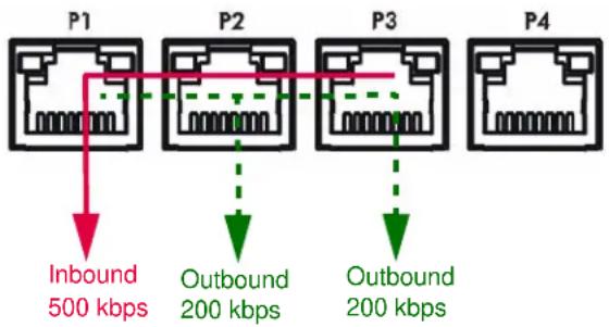
Bandwidth Management Priority
- The NXC gives bandwidth to higher-priority traffic first, until it reaches its configured bandwidth rate.
- Then lower-priority traffic gets bandwidth.
- The NXC uses a fairness-based (round-robin) scheduler to divide bandwidth among traffic flows with the same priority.
- The NXC automatically treats traffic with bandwidth management disabled as priority 7 (the lowest priority).
Maximize Bandwidth Usage
Maximize bandwidth usage allows applications with maximize bandwidth usage enabled to "borrow" any unused bandwidth on the out-going interface.
After each application gets its configured bandwidth rate, the NXC uses the fairness- based scheduler to divide any unused bandwidth on the out-going interface amongst applications that need more bandwidth and have maximize bandwidth usage enabled.
Unused bandwidth is divided equally. Higher priority traffic does not get a larger portion of the unused bandwidth.
Bandwidth Management Behavior
Note: This section uses examples that assume the device is operating in routing mode, not bridge mode.
The following sections show how bandwidth management behaves with various settings. For example, you configure DMZ to WAN policies for FTP servers A and B. Each server tries to send 1000 kbps, but the WAN is set to a maximum outgoing speed of 1000 kbps. You configure policy A for server A's traffic and policy B for server B's traffic.
Figure 118 Bandwidth Management Behavior
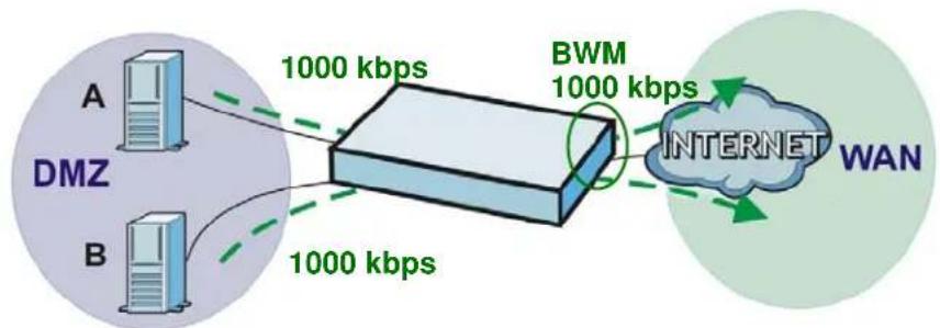
flowchart
graph LR
    A["DMZ"] -->|1000 kbps| B["BWM"]
    B -->|1000 kbps| C["INTERNET"]
    C -->|1000 kbps| D["WAN"]
    style A fill:#f9f,stroke:#333
    style B fill:#f9f,stroke:#333
    style C fill:#ccf,stroke:#333
    style D fill:#cfc,stroke:#333
Configured Rate Effect
In the following table the configured rates total less than the available bandwidth and maximize bandwidth usage is disabled, both servers get their configured rate.
Table 96 Configured Rate Effect
| POLICY | CONFIGURED RATE | MAX. B. U. | PRIORITY | ACTUAL RATE |
| A 300 | kbps No 1 300 kbps | |||
| B 200 | kbps No 1 200 kbps |
Priority Effect
Here the configured rates total more than the available bandwidth. Because server A has higher priority, it gets up to its configured rate (800 kbps), leaving only 200 kbps for server B.
Table 97 Priority Effect
| POLICY | CONFIGURED RATE | MAX. B. U. | PRIORITY | ACTUAL RATE |
| A 800 | kbps Yes 1 800 kbps | |||
| B 100 | 0 kbps Yes 2 200 kbps |
Maximize Bandwidth Usage Effect
With maximize bandwidth usage enabled, after each server gets its configured rate, the rest of the available bandwidth is divided equally between the two. So server A gets its configured rate of 300 kbps and server B gets its configured rate of 200 kbps. Then the NXC divides the remaining bandwidth (1000 - 500 = 500) equally between the two (500 / 2 = 250 kbps for each). The priority has no effect on how much of the unused bandwidth each server gets.
So server A gets its configured rate of 300 kbps plus 250 kbps for a total of 550 kbps. Server B gets its configured rate of 200 kbps plus 250 kbps for a total of 450 kbps.
Table 98 Maximize Bandwidth Usage Effect
| POLICY | CONFIGURED RATE | MAX. B. U. | PRIORITY | ACTUAL RATE |
| A | 300 kbps | Yes 1 550 kbps | ||
| B | 200 kbps | Yes | 2 450 kbps | |
Priority and Over Allotment of Bandwidth Effect
Server A has a configured rate that equals the total amount of available bandwidth and a higher priority. You should regard extreme over allotment of traffic with different priorities (as shown here) as a configuration error. Even though the NXC still attempts to let all traffic get through and not be lost, regardless of its priority, server B gets almost no bandwidth with this configuration.
Table 99 Priority and Over Allotment of Bandwidth Effect
| POLICY | CONFIGURED RATE | MAX. B. U. | PRIORITY | ACTUAL RATE |
| A | 1000 kbps | Yes | 1 | 999 kbps |
| B | 1000 kbps | Yes | 2 | 1 kbps |
19.1.3 Application Patrol Bandwidth Management Examples
Note: The following examples assume the NXC is operating in routing mode, not in bridge mode. In bridge mode there are only two zones: LAN and WLAN. In routing mode, you can configure any of the zones described here.
Bandwidth management is very useful when applications are competing for limited bandwidth. For example, say you have a WAN zone interface connected to an ADSL device with a 8 Mbps downstream and 1 Mbps upstream ADSL connection. The following sections give some simplified examples of using application patrol policies to manage applications competing for that 1 Mbps of upstream bandwidth.
Here is an overview of what the rules need to accomplish. See the following sections for more details.
- SIP traffic from VIP users must get through with the least possible delay regardless of if it is an outgoing call or an incoming call. The VIP users must be able to make and receive SIP calls no matter which interface they are connected to.
- HTTP traffic needs to be given priority over FTP traffic.
- FTP traffic from the WAN to the DMZ must be limited so it does not interfere with SIP and HTTP traffic.
- FTP traffic from the LAN1 to the DMZ can use more bandwidth since the interfaces support up to 1 Gbps connections, but it must be the lowest priority and limited so it does not interfere with SIP and HTTP traffic.
Figure 119 Application Patrol Bandwidth Management Example
SIP: Any to WAN Outbound: 200 Kbps Inbound: 200 Kbps Priority: 1 Max. B. U.
SIP: WAN to Any Outbound: 200 Kbps Inbound: 200 Kbps Priority: 1 Max. B. U.
HTTP: Any to WAN Outbound: 100 Kbps Inbound: 500 Kbps Priority: 2 Max. B. U.
FTP: WAN to DMZ Outbound: 100 Kbps Inbound: 300 Kbps Priority: 3 No Max. B. U.
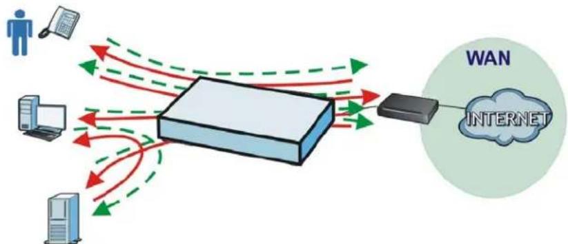
flowchart
graph TD
    A["User"] -->|Data Flow| B["Server"]
    C["Client"] -->|Data Flow| B
    D["Desktop"] -->|Data Flow| B
    E["WiN"] --> F["INTERNET"]
    style A fill:#f9f,stroke:#333
    style C fill:#f9f,stroke:#333
    style D fill:#f9f,stroke:#333
    style E fill:#f9f,stroke:#333
    style B fill:#ccf,stroke:#333
    style F fill:#ccf,stroke:#333
FTP: LAN to DMZ Outbound: 50 Mbps Inbound: 50 Mbps Priority: 4 No Max. B. U.
SIP: Any to WAN Outbound: 200 Kbps Inbound: 200 Kbps Priority: 1 Max. B. U.
HTTP: Any to WAN Outbound: 100 Kbps Inbound: 500 Kbps Priority: 2 Max. B. U.
FTP: WAN to DMZ Outbound: 100 Kbps Inbound: 300 Kbps Priority: 3 No Max. B. U.
SIP: WAN to Any Outbound: 200 Kbps Inbound: 200 Kbps Priority: 1 Max. B. U.
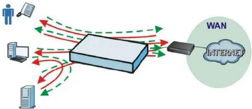
flowchart
graph TD
    A["User"] --> B["Router"]
    C["Server"] --> B
    D["Desktop"] --> B
    B --> E["Internet"]
    style E fill:#f9f,stroke:#333,stroke-width:2px
    note right of B WAN
    note left of B INTERNET
FTP: LAN1 to DMZ Outbound: 50 Mbps Inbound: 50 Mbps Priority: 4 No Max. B. U.
19.1.3.1 Setting the Interface's Bandwidth
Use the interface screens to set the WAN zone interface's upstream bandwidth to be equal to (or slightly less than) what the connected device can support. This example uses 1000 Kbps.
19.1.3.2 SIP Any to WAN Bandwidth Management Example
- Manage SIP traffic going to the WAN zone from a VIP user on the LAN or DMZ.
- Outbound traffic (to the WAN from the LAN and DMZ) is limited to 200 kbps. The NXC applies this limit before sending the traffic to the WAN.
- Inbound traffic (to the LAN and DMZ from the WAN) is also limited to 200 kbps. The NXC applies this limit before sending the traffic to LAN or DMZ.
- Highest priority (1). Set policies for other applications to lower priorities so the SIP traffic always gets the best treatment.
- Enable maximize bandwidth usage so the SIP traffic can borrow unused bandwidth.
Figure 120 SIP Any to WAN Bandwidth Management Example
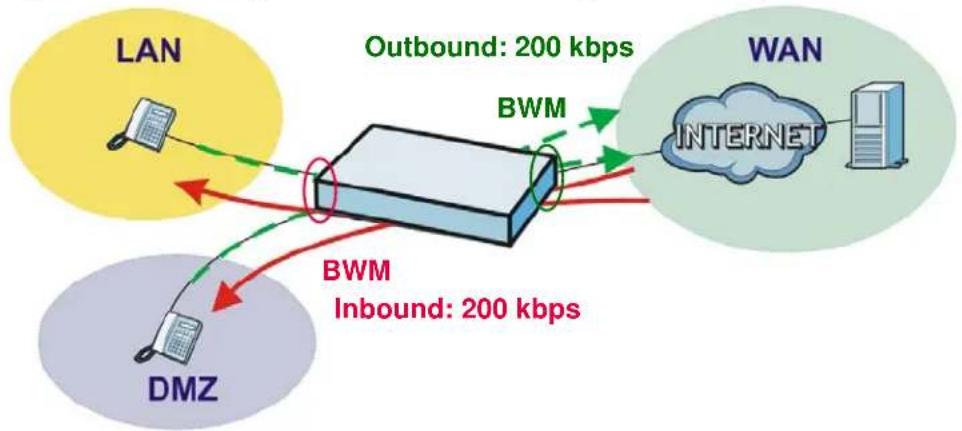
flowchart
graph TD
    A["LAN"] -->|Outbound: 200 kbps| B["BWM"]
    C["DMZ"] -->|Inbound: 200 kbps| B
    D["WAN"] -->|Outbound: 200 kbps| B
    B --> E["Internet"]
    style A fill:#FFD700,stroke:#333
    style C fill:#FFD700,stroke:#333
    style D fill:#FFD700,stroke:#333
19.1.3.3 SIP WAN to Any Bandwidth Management Example
You also create a policy for calls coming in from the SIP server on the WAN. It is the same as the SIP Any to WAN policy, but with the directions reversed (WAN to Any instead of Any to WAN).
19.1.3.4 HTTP Any to WAN Bandwidth Management Example
- Inbound traffic gets more bandwidth as the local users will probably download more than they upload (and the ADSL connection supports this).
- Second highest priority (2). Set policies for other applications (except SIP) to lower priorities so the local users' HTTP traffic gets sent before non-SIP traffic.
- Enable maximize bandwidth usage so the HTTP traffic can borrow unused bandwidth.
Figure 121 HTTP Any to WAN Bandwidth Management Example
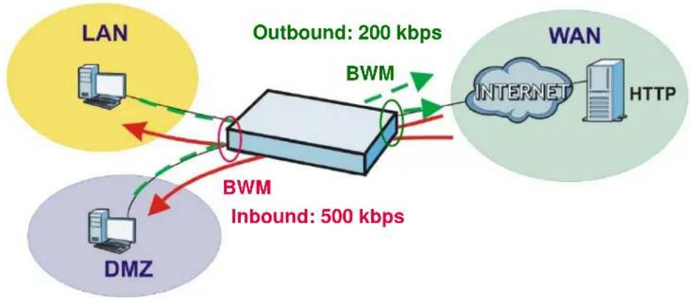
flowchart
graph TD
    A["LAN"] -->|Outbound: 200 kbps| B["BWM"]
    C["DMZ"] -->|Inbound: 500 kbps| B
    B --> D["WAN"]
    D --> E["INTERNET"]
    D --> F["HTTP"]
    style A fill:#FFD700,stroke:#333
    style C fill:#FFD700,stroke:#333
    style B fill:#E6F3FF,stroke:#333
    style D fill:#B2C4A2,stroke:#333
    style E fill:#B2C4A2,stroke:#333
    style F fill:#B2C4A2,stroke:#333
19.1.3.5 FTP WAN to DMZ Bandwidth Management Example
- ADSL supports more downstream than upstream so you allow remote users 300 kbps for uploads to the DMZ FTP server (outbound) but only 100 kbps for downloads (inbound).
• Third highest priority (3). - Disable maximize bandwidth usage since you do not want to give FTP more bandwidth.
Figure 122 FTP WAN to DMZ Bandwidth Management Example
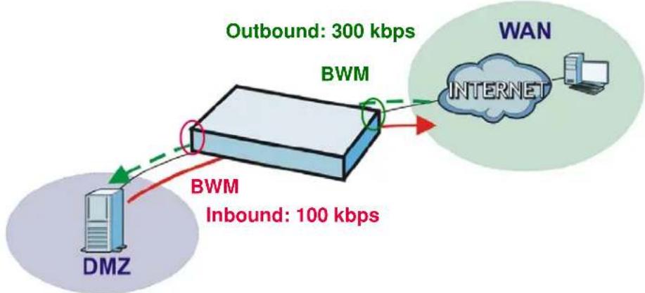
flowchart
graph TD
    A["DMZ"] -->|Outbound: 300 kbps| B["BWM"]
    B --> C["Internet"]
    C --> D["WAN"]
    style A fill:#f9f,stroke:#333
    style B fill:#ccf,stroke:#333
    style C fill:#cfc,stroke:#333
    style D fill:#fcc,stroke:#333
19.1.3.6 FTP LAN to DMZ Bandwidth Management Example
- The LAN and DMZ zone interfaces are connected to Ethernet networks (not an ADSL device) so you limit both outbound and inbound traffic to 50 Mbps.
• Fourth highest priority (4). - Disable maximize bandwidth usage since you do not want to give FTP more bandwidth.
Figure 123 FTP LAN to DMZ Bandwidth Management Example
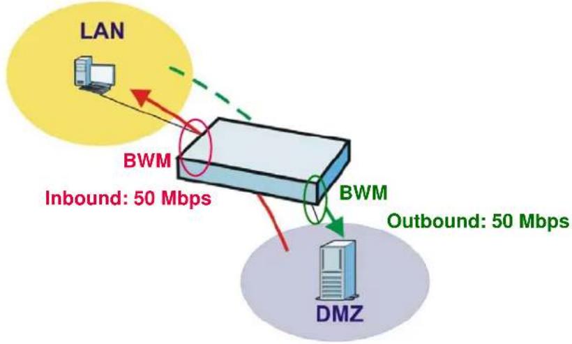
flowchart
graph TD
    A["LAN"] -->|Inbound: 50 Mbps| B["BWM"]
    B --> C["Outbound: 50 Mbps"]
    D["DMZ"] -->|Outbound: 50 Mbps| B
    style A fill:#f9f,stroke:#333
    style B fill:#ccf,stroke:#333
    style D fill:#cfc,stroke:#333
19.2 Application Patrol Common Applications
Use the application patrol Common, Instant Messenger, Peer to Peer, VoIP, or Streaming screen to manage traffic of individual applications.
Use the Common screen (shown here as an example) to manage traffic of the most commonly used web, file transfer and e-mail protocols.
Click Configuration > App Patrol > Common to open the following screen.
Figure 124 Configuration > App Patrol > Common Applications
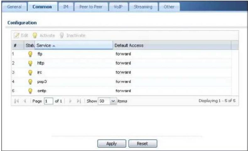
The following table describes the labels in this screen.
Table 100 Configuration > App Patrol > Common Applications
| LABEL DESCRIPTION | |
| Edit | Double-click an entry or select it and click Edit to open a screen where you can modify the entry's settings. |
| Activate | To turn on an entry, select it and click Activate. |
| Inactivate | To turn off an entry, select it and click Inactivate. |
| # This field is a sequential value, and it is not associated with a specific application. | |
| Status The activate (light bulb) icon is lit when the entry is active and dimmed when the entry is inactive. | |
| Service This field displays the name of the application. | |
| Default Access This field displays what the NXC does with packets for this application.Choices are: forward, drop, and reject. | |
| Apply Click Apply to save your changes back to the NXC. | |
| Reset | Click Reset to return the screen to its last-saved settings. |
19.2.1 Edit Application
Use this screen to edit the settings for an application. To access this screen, go to the application patrol Common, Instant Messenger, Peer to Peer, VoIP, or Streaming screen and click an application's Edit icon. The screen displayed here is for the MSN instant messenger service.
Figure 125 Edit Application
The following table describes the labels in this screen.
Table 101 Edit Application
LABEL DESCRIPTION
| Service | |
| Enable Service | Select this check box to turn on patrol for this application. |
| Service Identification | |
| Name This field displays the name of the application. | |
| Classification Specify how the NXC should identify this application. Choices are: | |
| Auto - the NXC identifies this application by matching the IP payload with the application's pattern(s). | |
| Service Ports - the NXC identifies this application by looking at the destination port in the IP header. | |
| Service Port | This is available if the Classification is Service Ports. You can view and edit the list of ports used to identify this application. |
| Add Click this to create a new entry. | |
| Edit Select an entry and click this to be able to modify it. | |
| LABEL | DESCRIPTION |
| Remove Select | an entry and click this to delete it. |
| # This field is | a sequential value, and it is not associated with a specific entry.Note: The NXC checks ports in the order they appear in the list. While this sequence does not affect the functionality, you might improve the performance of the NXC by putting more commonly used ports at the top of the list. |
| Service Port This column lists port numbers the NXC uses to identify this application. | |
| Policy | |
| Add | Click this to create a new entry. Select an entry and click Add to create a new entry after the selected entry. |
| Edit Select an | entry and click this to be able to modify it. |
| Remove Select | an entry and click this to delete it. |
| Activate | To turn on an entry, select it and click Activate. |
| Inactivate | To turn off an entry, select it and click Inactivate. |
| Move To change | an entry's position in the numbered list, select it and click Move to display a field to type a number for where you want to put that entry and press [ENTER] to move the entry to the number that you typed. |
| Status The activate (light bulb) icon is lit when the entry is active and dimmed when the entry is inactive. | |
| # This field is | a sequential value, and it is not associated with a specific condition.Note: The NXC checks conditions in the order they appear in the list. While this sequence does not affect the functionality, you might improve the performance of the NXC by putting more common conditions at the top of the list. |
| Port This field | displays the specific port number to which this policy applies. |
| Schedule | This is the schedule that defines when the policy applies. any means the policy is active at all times if enabled. |
| User | This is the user name or user group to which the policy applies. If any displays, the policy applies to all users. |
| From This is the source zone of the traffic to which this policy applies. | |
| To This is the destination zone of the traffic to which this policy applies. | |
| Source | This is the source address or address group for whom this policy applies. If any displays, the policy is effective for every source. |
| Destination | This is the destination address or address group for whom this policy applies. If any displays, the policy is effective for every destination. |
| LABEL DESCRIPTION | |
| Access This field displays what the NXC does with packets for this application that match this policy.forward - the NXC routes the packets for this application.Drop - the NXC does not route the packets for this application and does not notify the client of its decision.Reject - the NXC does not route the packets for this application and notifies the client of its decision. | |
| DSCP Marking | This is how the NXC handles the DSCP value of the outgoing packets that match this policy.In - Inbound, the traffic the NXC sends to a connection's initiator.Out - Outbound, the traffic the NXC sends out from a connection's initiator.If this field displays a DSCP value, the NXC applies that DSCP value to the route's outgoing packets.preserve means the NXC does not modify the DSCP value of the route's outgoing packets.default means the NXC sets the DSCP value of the route's outgoing packets to 0.The "af" choices stand for Assured Forwarding. The number following the "af" identifies one of four classes and one of three drop preferences.The "wmm" entries are for QoS. For more information on QoS and WMM categories, see page 209. |
| BWM These fields show the amount of bandwidth the application's traffic that matches the policy can use. These fields only apply when Access is set to forward.In - This is how much inbound bandwidth, in kilobits per second, this policy allows the application to use. Inbound refers to the traffic the NXC sends to a connection's initiator. If no displays here, this policy does not apply bandwidth management for the application's incoming traffic.Out - This is how much outbound bandwidth, in kilobits per second, this policy allows the application to use. Outbound refers to the traffic the NXC sends out from a connection's initiator. If no displays here, this policy does not apply bandwidth management for the application's outgoing traffic.Pri - This is the priority for this application's traffic that matches this policy. The smaller the number, the higher the priority. The traffic of an application with higher priority is given bandwidth before traffic of an application with lower priority. The NXC ignores this number if the incoming and outgoing limits are both set to 0. In this case the traffic is automatically treated as being set to the lowest priority (7) regardless of this field's configuration. | |
| Log | This field shows whether the NXC generates a log (log), a log and alert (log alert) or neither (no) when the application's traffic matches this policy. |
| OK Click OK to save your changes back to the NXC. | |
| Cancel | Click Cancel to exit this screen without saving your changes. |
19.2.2 Add/Edit Policy
This screen allows you to edit a group of settings for an application. To access this screen, go to the application patrol Common, Instant Messenger, Peer to Peer, Vol P, or Streaming screen and click an application's Edit icon. Then click the Add icon or an Edit icon in the Policy table. The screen displayed here is for the MSN instant messenger service.
Figure 126 Add/Edit Policy
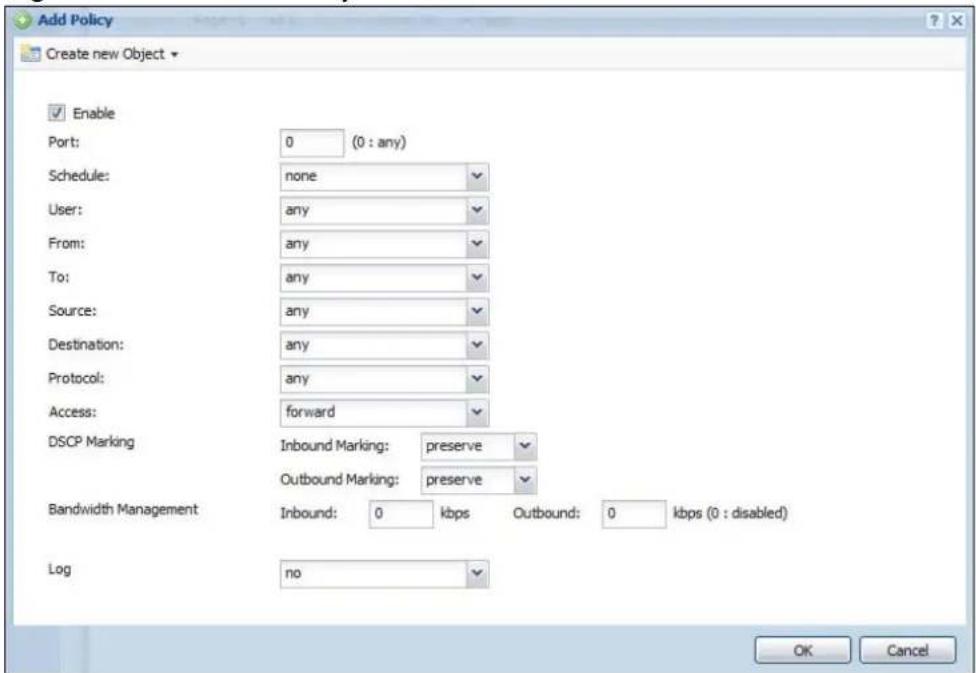
The following table describes the labels in this screen.
Table 102 Add/Edit Policy
| LABEL DESCRIPTION | |
| Create new Object | Use to configure any new settings objects that you need to use in this screen. |
| Enable Select this | is check box to turn on this policy for the application. |
| Port Use this field | d to specify a specific port number to which to apply this policy. Type zero, if this policy applies for every port number. |
| Schedule Select | a schedule that defines when the policy applies or selectCreate Objectto configure a new one. Otherwise, selectnone to make the policy always effective. |
| User Select a user | er name or user group to which to apply the policy. UseCreate new Objectif you need to configure a new user account. Selectanyto apply the policy for every user. |
| From Select the | source zone of the traffic to which this policy applies. |
| To Select the dest | destination zone of the traffic to which this policy applies. |
| Source Select a | source address or address group for whom this policy applies.UseCreate new Objectif you need to configure a new one. Selectanyif the policy is effective for every source. |
| Destination Select | ct a destination address or address group for whom this policy applies. UseCreate new Objectif you need to configure a new one.Selectanyif the policy is effective for every destination. |
| Access This field | controls what the NXC does with packets for this application that match this policy. Choices are:forward- the NXC routes the packets for this application.Drop- the NXC does not route the packets for this application and does not notify the client of its decision.Reject- the NXC does not route the packets for this application and notifies the client of its decision. |
| DSCP Marking Set | Set how the NXC handles the DSCP value of the outgoing packets that match this policy. Inbound refers to the traffic the NXC sends to a connection's initiator. Outbound refers to the traffic the NXC sends out from a connection's initiator.Select one of the pre-defined DSCP values to apply or selectUser Definedto specify another DSCP value. The “af” choices stand for Assured Forwarding. The number following the “af” identifies one of four classes and one of three drop preferences.Selectpreserveto have the NXC keep the packets' original DSCP value.Selectdefaultto have the NXC set the DSCP value of the packets to 0.The “wmm” entries are for QoS. For more information on QoS and WMM categories, seepage 209. |
| Bandwidth Management | Configure these fields to set the amount of bandwidth the application can use. These fields only apply whenAccessis set toforward.You must also enable bandwidth management in the main application patrol screen (AppPatrol > General) in order to apply bandwidth shaping. |
| Inbound kbps | Type how much inbound bandwidth, in kilobits per second, this policy allows the application to use. Inbound refers to the traffic the NXC sends to a connection's initiator.If you enter 0 here, this policy does not apply bandwidth management for the application's traffic that the NXC sends to the initiator. Traffic with bandwidth management disabled (inbound and outbound are both set to 0) is automatically treated as the lowest priority (7).If the sum of the bandwidths for routes using the same next hop is higher than the actual transmission speed, lower priority traffic may not be sent if higher priority traffic uses all of the actual bandwidth. |
| Outbound kbps | Type how much outbound bandwidth, in kilobits per second, this policy allows the application to use. Outbound refers to the traffic the NXC sends out from a connection's initiator.If you enter 0 here, this policy does not apply bandwidth management for the application's traffic that the NXC sends out from the initiator. Traffic with bandwidth management disabled (inbound and outbound are both set to 0) is automatically treated as the lowest priority (7).If the sum of the bandwidths for routes using the same next hop is higher than the actual transmission speed, lower priority traffic may not be sent if higher priority traffic uses all of the actual bandwidth. |
| Maximize Bandwidth Usage | This field displays when the inbound or outbound bandwidth management is not set to 0. Enable maximize bandwidth usage to let the traffic matching this policy “borrow” any unused bandwidth on the out-going interface.After each application gets its configured bandwidth rate, the NXC uses the fairness- based scheduler to divide any unused bandwidth on the out-going interface amongst applications that need more bandwidth and have maximize bandwidth usage enabled. |
| Log | Select whether to have the NXC generate a log (log), log and alert (log alert) or neither (no) when the application's traffic matches this policy. |
| OK Click OK to save your changes back to the NXC. | |
| Cancel | Click Cancel to exit this screen without saving your changes. |
19.3 Other Applications
Sometimes, the NXC cannot identify the application. For example, the application might be a new application, or the packets might arrive out of sequence. (The NXC does not reorder packets when identifying the application.)
The Other (applications) screen controls the default policy for TCP and UDP traffic that the NXC cannot identify. You can use source zone, destination zone, destination port, schedule, user, source, and destination information as criteria to create a sequence of specific conditions, similar to the sequence of rules used by firewalls, to specify what the NXC should do more precisely. You can also control
the bandwidth used by these other applications. This screen also allows you to add, edit, and remove conditions to this default policy.
Click AppPatrol > Other to open the Other screen.
Figure 127 AppPatrol > Other
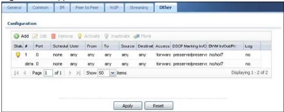
The following table describes the labels in this screen.
Table 103 AppPatrol > Other
| LABEL DESCRIPTION | |
| Add | Click this to create a new entry. Select an entry and click Add to create a new entry after the selected entry. |
| Edit Select an entry and click this to be able to modify it. | |
| Remove Select an entry and click this to delete it. | |
| Activate | To turn on an entry, select it and click Activate. |
| Inactivate | To turn off an entry, select it and click Inactivate. |
| Move To change | an entry's position in the numbered list, select it and clickMove to display a field to type a number for where you want to put that entry and press [ENTER] to move the entry to the number that you typed. |
| Status The activate (light bulb) icon is lit when the entry is active and dimmed when the entry is inactive. | |
| # This field is a sequential value, and it is not associated with a specific condition.Note: The NXC checks conditions in the order they appear in the list. While this sequence does not affect the functionality, you might improve the performance of the NXC by putting more common conditions at the top of the list. | |
| Port This field displays the specific port number to which this policy applies. | |
| Schedule | This is the schedule that defines when the policy applies. any means the policy always applies. |
| User | This is the user name or user group to which the policy applies. If any displays, the policy applies to all users. |
| From This is the source zone of the traffic to which this policy applies. | |
| To This is the destination zone of the traffic to which this policy applies. | |
| Source This is the source address or address group for whom this policy applies. If any displays, the policy is effective for every source. | |
| Destination This is the destination address or address group for whom this policy applies. If any displays, the policy is effective for every destination. | |
| Protocol This is the protocol of the traffic to which this policy applies. | |
| Access This field displays what the NXC does with packets that match this policy.forward - the NXC routes the packets.Drop - the NXC does not route the packets and does not notify the client of its decision.Reject - the NXC does not route the packets and notifies the client of its decision. | |
| DSCP Marking This is how the NXC handles the DSCP value of the outgoing packets that match this policy.In - Inbound, the traffic the NXC sends to a connection's initiator.Out - Outbound, the traffic the NXC sends out from a connection's initiator.If this field displays a DSCP value, the NXC applies that DSCP value to the route's outgoing packets.preserve means the NXC does not modify the DSCP value of the route's outgoing packets.default means the NXC sets the DSCP value of the route's outgoing packets to 0.The "af" choices stand for Assured Forwarding. The number following the "af" identifies one of four classes and one of three drop preferences. | |
| BWM These fields show the amount of bandwidth the traffic can use. These fields only apply when Access is set to forward.In - This is how much inbound bandwidth, in kilobits per second, this policy allows the matching traffic to use. Inbound refers to the traffic the NXC sends to a connection's initiator. If no displays here, this policy does not apply bandwidth management for the inbound traffic.Out - This is how much outgoing bandwidth, in kilobits per second, this policy allows the matching traffic to use. Outbound refers to the traffic the NXC sends out from a connection's initiator. If no displays here, this policy does not apply bandwidth management for the outbound traffic.Pri - This is the priority for the traffic that matches this policy. The smaller the number, the higher the priority. Traffic with a higher priority is given bandwidth before traffic with a lower priority. The NXC ignores this number if the incoming and outgoing limits are both set to 0. In this case the traffic is automatically treated as being set to the lowest priority (7) regardless of this field's configuration. | |
| Log Select whether to have the NXC generate a log (log), log and alert (log alert) or neither (no) when traffic matches this policy. | |
| Apply Click Apply to save your changes back to the NXC. | |
| Reset | Click Reset to return the screen to its last-saved settings. |
19.3.1 Add/Edit Policy
This screen allows you to create a new condition or edit an existing one. To access this screen, go to the Other Protocol screen, and click either the Add icon or an Edit icon.
Figure 128 AppPatrol > Other > Add/Edit
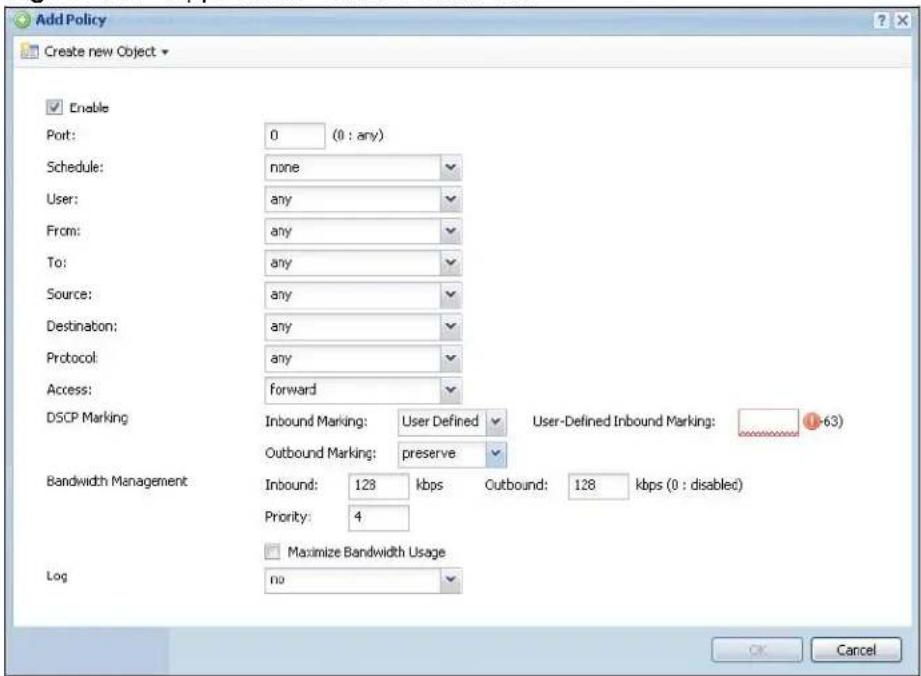
The following table describes the labels in this screen.
Table 104 AppPatrol > Other > Add/Edit
| LABEL DESCRIPTION | |
| Create new Object | Use to configure any new settings objects that you need to use in this screen. |
| Enable Select this | is check box to turn on this policy. |
| Port Use this field | d to specify a specific port number to which to apply this policy. Type zero, if this policy applies for every port number. |
| Schedule Select | a schedule that defines when the policy applies or select Create Object to configure a new one. Otherwise, select any to make the policy always effective. |
| User Select a user name or user group to which to apply the policy. UseCreate new Object if you need to configure a new user account. Select any to apply the policy for every user. | |
| From Select the source zone of the traffic to which this policy applies. | |
| To Select the destination zone of the traffic to which this policy applies. | |
| Source Select a source address or address group for whom this policy applies.Use Create new Object if you need to configure a new one. Select any if the policy is effective for every source. | |
| Destination Select a destination address or address group for whom this policy applies. Use Create new Object if you need to configure a new one.Select any if the policy is effective for every destination. | |
| Protocol | Select the protocol for which this condition applies. Choices are: TCP and UDP. Select any to apply the policy to both TCP and UDP traffic. |
| Access This field controls what the NXC does with packets that match this policy.Choices are:forward - the NXC routes the packets.Drop - the NXC does not route the packets and does not notify the client of its decision.Reject - the NXC does not route the packets and notifies the client of its decision. | |
| DSCP Marking Set how the NXC handles the DSCP value of the outgoing packets that match this policy. Inbound refers to the traffic the NXC sends to a connection's initiator. Outbound refers to the traffic the NXC sends out from a connection's initiator.Select one of the pre-defined DSCP values to apply or select User Defined to specify another DSCP value. The "af" choices stand for Assured Forwarding. The number following the "af" identifies one of four classes and one of three drop preferences.Select preserve to have the NXC keep the packets' original DSCP value.Select default to have the NXC set the DSCP value of the packets to 0. | |
| Bandwidth Management | Configure these fields to set the amount of bandwidth the application can use. These fields only apply when Access is set to forward. |
| Inbound kbps | Type how much inbound bandwidth, in kilobits per second, this policy allows the traffic to use. Inbound refers to the traffic the NXC sends to a connection's initiator.If you enter 0 here, this policy does not apply bandwidth management for the matching traffic that the NXC sends to the initiator. Traffic with bandwidth management disabled (inbound and outbound are both set to 0) is automatically treated as the lowest priority (7).If the sum of the bandwidths for routes using the same next hop is higher than the actual transmission speed, lower priority traffic may not be sent if higher priority traffic uses all of the actual bandwidth. |
| Outbound kbps | Type how much outbound bandwidth, in kilobits per second, this policy allows the traffic to use. Outbound refers to the traffic the NXC sends out from a connection's initiator.If you enter 0 here, this policy does not apply bandwidth management for the matching traffic that the NXC sends out from the initiator. Traffic with bandwidth management disabled (inbound and outbound are both set to 0) is automatically treated as the lowest priority (7).If the sum of the bandwidths for routes using the same next hop is higher than the actual transmission speed, lower priority traffic may not be sent if higher priority traffic uses all of the actual bandwidth. |
| Priority This field displays when the inbound or outbound bandwidth management is not set to 0. Enter a number between 1 and 7 to set the priority for traffic that matches this policy. The smaller the number, the higher the priority.Traffic with a higher priority is given bandwidth before traffic with a lower priority.The NXC uses a fairness-based (round-robin) scheduler to divide bandwidth between traffic flows with the same priority.The number in this field is ignored if the incoming and outgoing limits are both set to 0. In this case the traffic is automatically treated as being set to the lowest priority (7) regardless of this field's configuration. | |
| Maximize Bandwidth Usage | This field displays when the inbound or outbound bandwidth management is not set to 0. Enable maximize bandwidth usage to let the traffic matching this policy “borrow” any unused bandwidth on the out-going interface.After each application or type of traffic gets its configured bandwidth rate, the NXC uses the fairness- based scheduler to divide any unused bandwidth on the out-going interface amongst applications and traffic types that need more bandwidth and have maximize bandwidth usage enabled. |
| Log This field controls what kind of record the NXC creates when traffic matches this policy.no - the NXC does not record anythinglog - the NXC creates a record in the loglog alert - the NXC creates an alert | |
| OK Click OK to save your changes back to the NXC. | |
| Cancel | Click Cancel to exit this screen without saving your changes. |
Anti-Virus
20.1 Overview
Use the NXC's anti-virus feature to protect your connected network from virus/spyware infection. The NXC checks traffic going in the direction(s) you specify for signature matches. In the following figure the NXC is set to check traffic coming from the WAN zone (which includes two interfaces) to the LAN zone.
Figure 129 NXC Anti-Virus Example
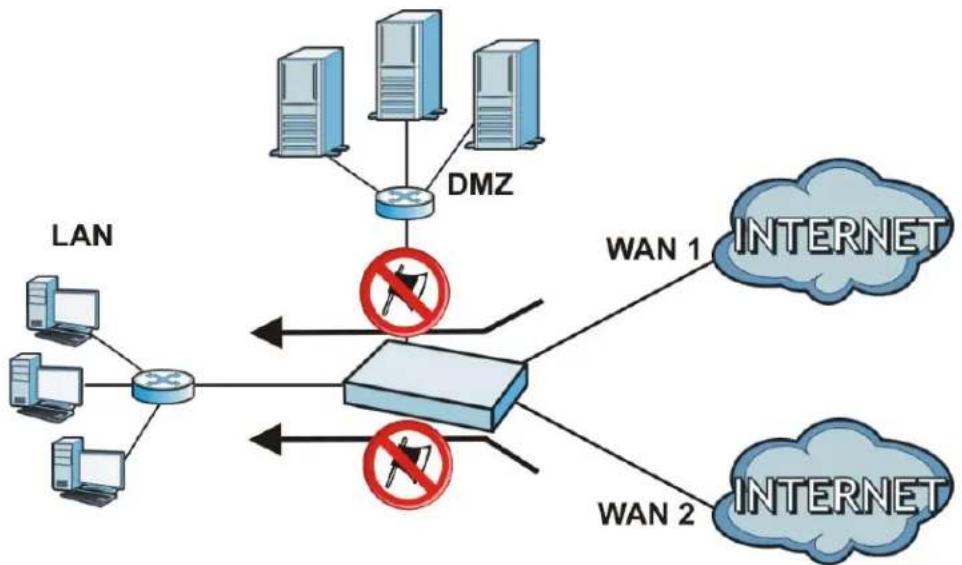
flowchart
graph TD
    LAN -->|LAN| Server1["Server"]
    LAN -->|LAN| Server2["Server"]
    Server1 --> DMZ["DMZ"]
    Server2 --> DMZ
    DMZ -->|WAN 1| WAN1["INTERNET"]
    LAN -->|LAN| Server3["Server"]
    LAN -->|LAN| Server4["Server"]
    Server3 -->|WAN 2| WAN2["INTERNET"]
    Server4 -->|WAN 2| WAN2
    style LAN fill:#f9f,stroke:#333
    style Server1 fill:#ccf,stroke:#333
    style Server2 fill:#ccf,stroke:#333
    style LAN fill:#dfd,stroke:#333
    style DMZ fill:#dfd,stroke:#333
    style WAN1 fill:#cfc,stroke:#333
    style WAN2 fill:#cfc,stroke:#333
20.1.1 What You Can Do in this Chapter
- The General screens (Section 20.2 on page 290) turn anti-virus on or off, set up anti-virus policies and check the anti-virus engine type and the anti-virus license and signature status.
- The Black/ White List screen (Section 20.3 on page 295) sets up anti-virus black (blocked) and white (allowed) lists of virus file patterns.
- The Signature screen (Section 20.6 on page 299) allows you to search the signatures to get more information about them.
20.1.2 What You Need to Know
The following terms and concepts may help as you read this chapter.
Anti-Virus Engines
Subscribe to signature files for ZyXEL's anti-virus engine or one powered by Kaspersky. When using the trial, you can switch from one engine to the other in the Registration screen. After the trial expires, you need to purchase an iCard for the anti-virus engine you want to use and register it in the Registration > Service screen. You must use the ZyXEL anti-virus iCard for the ZyXEL anti-virus engine and the Kaspersky anti-virus iCard for the Kaspersky anti-virus engine. See Chapter 8 on page 151 for details.
Virus and Worm
A computer virus is a small program designed to corrupt and/or alter the operation of other legitimate programs. A worm is a self-replicating virus that resides in active memory and duplicates itself. The effect of a virus attack varies from doing so little damage that you are unaware your computer is infected to wiping out the entire contents of a hard drive to rendering your computer inoperable.
NXC Anti-Virus Scanner
The NXC has a built-in signature database. Setting up the NXC between your local network and the Internet allows the NXC to scan files transmitting through the enabled interfaces into your network. As a network-based anti-virus scanner, the NXC helps stop threats at the network edge before they reach the local host computers.
You can set the NXC to examine files received through the following protocols:
- FTP (File Transfer Protocol)
- HTTP (Hyper Text Transfer Protocol)
- SMTP (Simple Mail Transfer Protocol)
- POP3 (Post Office Protocol version 3)
- IMAP4 (Internet Message Access Protocol version 4)
How the NXC Anti-Virus Scanner Works
The following describes the virus scanning process on the NXC.
1 The NXC first identifies SMTP, POP3, IMAP4, HTTP and FTP packets through standard ports.
2 If the packets are not session connection setup packets (such as SYN, ACK and FIN), the NXC records the sequence of the packets.
3 The scanning engine checks the contents of the packets for virus.
4 If a virus pattern is matched, the NXC removes the infected portion of the file along with the rest of the file. The un-infected portion of the file before a virus pattern was matched still goes through.
5 If the send alert message function is enabled, the NXC sends an alert to the file's intended destination computer(s).
Note: Since the NXC erases the infected portion of the file before sending it, you may not be able to open the file.
Notes About the NXC Anti-Virus
The following lists important notes about the anti-virus scanner:
1 The NXC anti-virus scanner can detect polymorphic viruses.
2 When a virus is detected, an alert message is displayed in Microsoft Windows computers. Refer to the Appendix C on page 617 if your Windows computer does not display the alert messages.
3 Changes to the NXC's anti-virus settings affect new sessions (not the sessions that already existed before you applied the changed settings).
4 The NXC does not scan the following file/traffic types:
- Simultaneous downloads of a file using multiple connections. For example, when you use FlashGet to download sections of a file simultaneously.
- Encrypted traffic. This could be password-protected files or VPN traffic where the NXC is not the endpoint (pass-through VPN traffic).
- Traffic through custom (non-standard) ports. The only exception is FTP traffic. The NXC scans whatever port number is specified for FTP in the ALG screen.
- ZIP file(s) within a ZIP file.
20.1.3 Before You Begin
- Before using anti-virus, see Chapter 8 on page 151 for how to register for the anti-virus service.
- You may need to customize the zones (in the Network > Zone) used for the anti-virus scanning direction.
20.2 Anti-Virus Summary
Use this screen to configure your NXC's anti-virus settings. Click Configuration > Anti-X > Anti-Virus to display the configuration screen as shown next.
Figure 130 Configuration > Anti-X > Anti-Virus > General
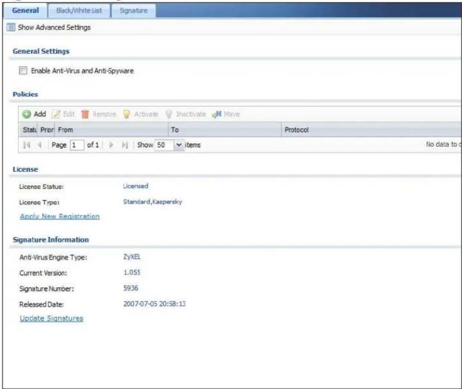
The following table describes the labels in this screen.
Table 105 Configuration > Anti-X > Anti-Virus > General
| LABEL DESCRIPTION | |
| Show / Hide Advanced Settings | Click this button to display a greater or lesser number of configuration fields. |
| Enable Anti-Virus and Anti-Spyware | Select this check box to check traffic for viruses and spyware. The following table lists policies that define which traffic the NXC scans and the action it takes upon finding a virus. |
| Scan EICAR | Select this option to have the NXC check for the EICAR test file and treat it in the same way as a real virus file. The EICAR test file is a standardized test file for signature based anti-virus scanners. When the virus scanner detects the EICAR file, it responds in the same way as if it found a real virus. Besides straightforward detection, the EICAR file can also be compressed to test whether the anti-virus software can detect it in a compressed file. The test string consists of the following human-readable ASCII characters.X5O!P%@AP[4\PZX54(P^)7CC)7] EICAR-STANDARD-ANTIVIRUSTEST-FILE!H+ H* |
| Policies | |
| Add | Click this to create a new entry. Select an entry and click Add to create a new entry after the selected entry. |
| Edit Select an | entry and click this to be able to modify it. |
| Remove Select | an entry and click this to delete it. |
| Activate | To turn on an entry, select it and click Activate. |
| Inactivate | To turn off an entry, select it and click Inactivate. |
| Move To change | an entry's position in the numbered list, select it and clickMove to display a field to type a number for where you want to put that entry and press [ENTER] to move the entry to the number that you typed. |
| Status The activ | ivate (light bulb) icon is lit when the entry is active and dimmed when the entry is inactive. |
| Priority | This is the position of an anti-virus policy in the list. The ordering of your anti-virus policies is important as the NXC applies them in sequence. Once traffic matches an anti-virus policy, the NXC applies that policy and does not check the traffic against any more policies. |
| From The anti-virus policy has the NXC scan traffic coming from this zone and going to the To zone. | |
| To The anti-virus policy has the NXC scan traffic going to this zone from the From zone. | |
| Protocol These | are the protocols of traffic to scan for viruses.FTP applies to traffic using the TCP port number specified for FTP in the ALG screen.HTTP applies to traffic using TCP ports 80, 8080 and 3128.SMTP applies to traffic using TCP port 25.POP3 applies to traffic using TCP port 110.IMAP4 applies to traffic using TCP port 143. |
| License The following fields display information about the current state of your subscription for virus signatures. | |
| License Status | This field displays whether a service is activated (Licensed) or not (Not Licensed) or expired (Expired). |
| License Type | This field displays whether you applied for a trial application (Trial) or registered a service with your iCard's PIN number (Standard). None displays when the service is not activated. |
| Apply new Registration | This link appears if you have not registered for the service or only have the trial registration. Click this link to go to the screen where you can register for the service. |
| Signature Information | The following fields display information on the current signature set that the NXC is using. |
| Anti-Virus Engine Type | This field displays whether the NXC is set to use ZyXEL's anti-virus engine or the one powered by Kaspersky.Upgrading the NXC to firmware version 2.11 and updating the anti-virus signatures automatically upgrades the ZyXEL anti-virus engine to v2.0. v2.0 has more virus signatures and offers improved non-executable file scan throughput. |
| Current Version | This field displays the anti-virus signature set version number. This number gets larger as the set is enhanced. |
| Signature Number | This field displays the number of anti-virus signatures in this set. |
| Released Date | This field displays the date and time the set was released. |
| Update Signatures | Click this link to go to the screen you can use to download signatures from the update server. |
| Apply | Click Apply to save your changes. |
| Reset | Click Reset to return the screen to its last-saved settings. |
20.2.1 Add/Edit Rule
Click the Add or Edit icon in the Configuration > Anti-X > Anti-Virus > General screen to display this configuration screen.
Figure 131 Configuration > Anti-X > Anti-Virus > General > Add/Edit
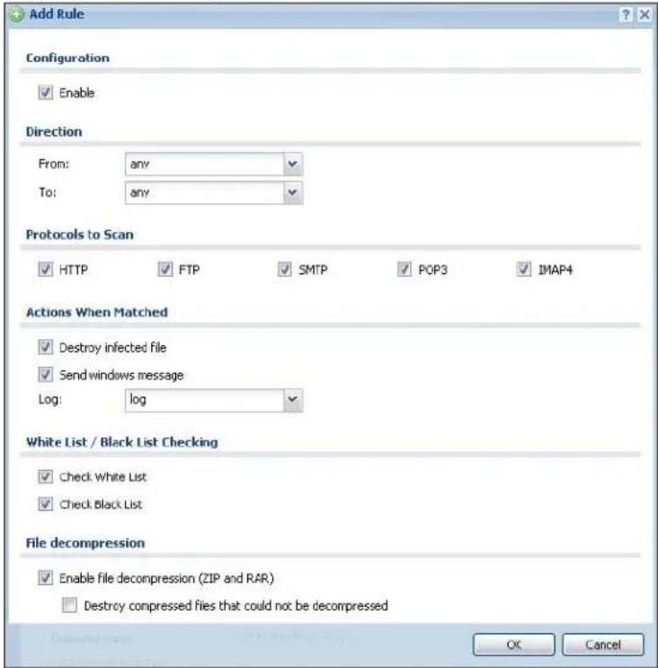
The following table describes the labels in this screen.
Table 106 Configuration > Anti-X > Anti-Virus > General > Add/Edit
| LABEL DESCRIPTION | |
| Enable Select this | check box to have the NXC apply this anti-virus policy to check traffic for viruses. |
| FromTo | Select source and destination zones for traffic to scan for viruses. The anti-virus policy has the NXC scan traffic coming from the From zone and going to the To zone. |
| Protocols to Scan | Select which protocols of traffic to scan for viruses. |
| HTTP applies to traffic using TCP ports 80, 8080 and 3128.FTP applies to traffic using the TCP port number specified for FTP in the ALG screen.SMTP applies to traffic using TCP port 25.POP3 applies to traffic using TCP port 110.IMAP4 applies to traffic using TCP port 143. | |
| Actions When Matched | |
| Destroy infected file | When you select this check box, if a virus pattern is matched, the NXC overwrites the infected portion of the file (and the rest of the file) with zeros. The un-infected portion of the file before a virus pattern was matched goes through unmodified. |
| Send Windows Message | Select this check box to set the NXC to send a message alert to files' intended user(s) using Microsoft Windows computers connected to the to interface.Refer toAppendix C on page 617if your Windows computer does not display the alert messages. |
| Log These are the | log options:no: Do not create a log when a packet matches a signature(s).log: Create a log on the NXC when a packet matches a signature(s).log alert: An alert is an e-mailed log for more serious events that may need more immediate attention. Select this option to have the NXC send an alert when a packet matches a signature(s). |
| White List / Black List Checking | |
| Check White List | Select this check box to check files against the white list. |
| Check Black List | Select this check box to check files against the black list. |
| File decompression | |
| Enable file decompression (ZIP and RAR) | Select this check box to have the NXC scan a ZIP file (the file does not have to have a "zip" or "rar" file extension). The NXC first decompresses the ZIP file and then scans the contents for viruses.Note: The NXC decompresses a ZIP file once. The NXC does NOT decompress any ZIP file(s) within a ZIP file. |
| Destroy compressed files that could not be decompressed | Note: When you select this option, the NXC deletes ZIP files that use password encryption.Select this check box to have the NXC delete any ZIP files that it is not able to unzip. The NXC cannot unzip password protected ZIP files or a ZIP file within another ZIP file. There are also limits to the number of ZIP files that the NXC can concurrently unzip.Note: The NXC's firmware package cannot go through the NXC with this option enabled. The NXC classifies the firmware package as not being able to be decompressed and deletes it.You can upload the firmware package to the NXC with the option enabled, so you only need to clear this option while you download the firmware package. |
| OK | Click OK to save your changes. |
| Cancel | Click Cancel to exit this screen without saving your changes. |
20.3 Black List
Click Configuration > Anti-X > Anti-Virus > Black/ White List to display this screen. Use the Black List screen to set up the Anti-Virus black (blocked) list of virus file patterns. Click a column's heading cell to sort the table entries by that column's criteria. Click the heading cell again to reverse the sort order.
Figure 132 Configuration > Anti-X > Anti-Virus > Black/White List > Black List
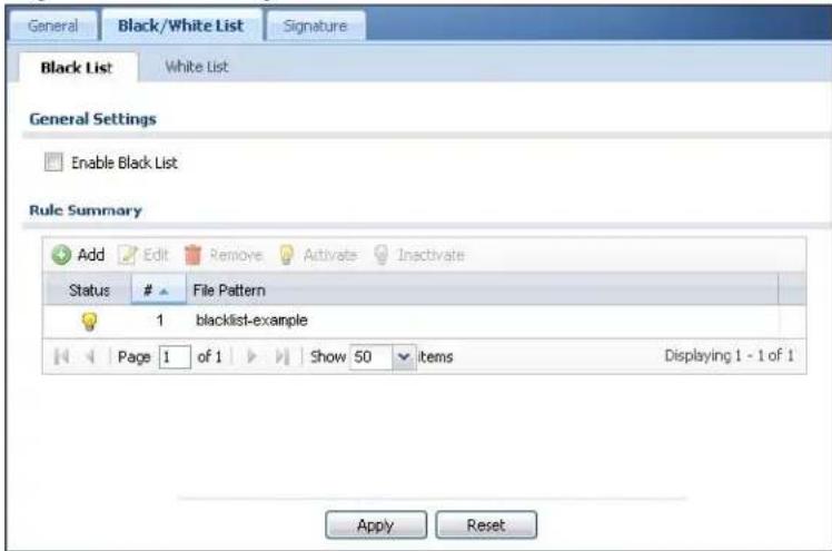
The following table describes the labels in this screen.
Table 107 Configuration > Anti-X > Anti-Virus > Black/White List > Black List
| LABEL DESCRIPTION | |
| Enable Black List | Select this check box to log and delete files with names that match the black list patterns. Use the black list to log and delete files with names that match the black list patterns. |
| Add Click this to create a new entry. | |
| Edit Select an entry and click this to be able to modify it. | |
| Remove Select an entry and click this to delete it. | |
| Activate | To turn on an entry, select it and click Activate. |
| Inactivate | To turn off an entry, select it and click Inactivate. |
| Status The activate (light bulb) icon is lit when the entry is active and dimmed when the entry is inactive. | |
| # This is the entry's index number in the list. | |
Table 107 Configuration > Anti-X > Anti-Virus > Black/White List > Black List
| LABEL DESCRIPTION | |
| File Pattern This is the file name pattern. If a file's name that matches this pattern, the NXC logs and deletes the file. | |
| Apply | Click Apply to save your changes. |
| Reset | Click Reset to return the screen to its last-saved settings. |
20.4 Add/Edit Pattern
Use this screen add a file pattern or edit an existing file pattern for your anti-virus black or white lists. From the Configuration > Anti-X > Anti-Virus > Black/White List > Black List (or White List) screen, click the Add icon or an Edit icon to display the following screen.
- For a black list entry, enter a file pattern that should cause the NXC to log and delete a file.
- For a white list entry, enter a file pattern that should cause the NXC to allow a file.
Figure 133 Black List (or White List) > Add/Edit Pattern
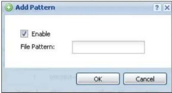
The following table describes the labels in this screen.
Table 108 Black List (or White List) > Add/Edit Pattern
| LABEL DESCRIPTION | |
| Enable If this is a | black list entry, select this option to have the NXC apply this entry when using the black list.If this is a white list entry, select this option to have the NXC apply this entry when using the white list. |
| File Pattern For a | black list entry, specify a pattern to identify the names of files that the NXC should log and delete.For a white list entry, specify a pattern to identify the names of files that the NXC should not scan for viruses.Use up to 80 characters. Alphanumeric characters, underscores ( _), dashes (-), question marks (?) and asterisks (*) are allowed.A question mark (?) lets a single character in the file name vary. For example, use “a?.zip” (without the quotation marks) to specify aa.zip, ab.zip and so on.Wildcards (*) let multiple files match the pattern. For example, use “* a.zip” (without the quotation marks) to specify any file that ends with “a.zip”. A file named “testa.zip would match. There could be any number (of any type) of characters in front of the “a.zip” at the end and the file name would still match. A file named “test.zipa” for example would not match.A * in the middle of a pattern has the NXC check the beginning and end of the file name and ignore the middle. For example, with “abc*.zip”, any file starting with “abc” and ending in “.zip” matches, no matter how many characters are in between.The whole file name has to match if you do not use a question mark or asterisk.If you do not use a wildcard, the NXC checks up to the first 80 characters of a file name. |
| OK Click OK to save your changes. | |
| Cancel | Click Cancel to exit this screen without saving your changes. |
20.5 White List
Click Configuration > Anti-X > Anti-Virus > Black/ White List > White List to display the screen shown next. Use the Black/ White List screen to set up Anti-Virus black (blocked) and white (allowed) lists of virus file patterns. Click a column's heading cell to sort the table entries by that column's criteria. Click the heading cell again to reverse the sort order.
Figure 134 Configuration > Anti-X > Anti-Virus > Black/White List > White List
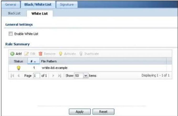
The following table describes the labels in this screen.
Table 109 Configuration > Anti-X > Anti-Virus > Black/White List > White List
| LABEL DESCRIPTION | |
| Enable White List | Select this check box to have the NXC not perform the anti-virus check on files with names that match the white list patterns.Use the white list to have the NXC not perform the anti-virus check on files with names that match the white list patterns. |
| Add Click this to create a new entry. | |
| Edit Select an entry and click this to be able to modify it. | |
| Remove Select an entry and click this to delete it. | |
| Activate | To turn on an entry, select it and click Activate. |
| Inactivate | To turn off an entry, select it and click Inactivate. |
| Status The activate (light bulb) icon is lit when the entry is active and dimmed when the entry is inactive. | |
| # This is the entry's index number in the list. | |
| File Pattern | This is the file name pattern. If a file's name matches this pattern, the NXC does not check the file for viruses. |
| Apply | Click Apply to save your changes. |
| Reset | Click Reset to return the screen to its last-saved settings. |
20.6 Signature
Click Configuration > Anti-X > Anti-Virus > Signature to display this screen. Use this screen to locate signatures and display details about them.
If Internet Explorer opens a warning screen about a script making Internet Explorer run slowly and the computer maybe becoming unresponsive, just click No to continue. Click a column's heading cell to sort the table entries by that column's criteria. Click the heading cell again to reverse the sort order.
Figure 135 Configuration > Anti-X > Anti-Virus > Signature
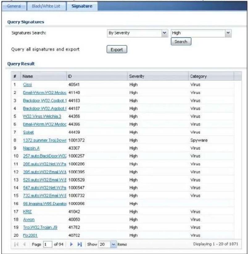
The following table describes the labels in this screen.
Table 110 Configuration > Anti-X > Anti-Virus > Signature
| LABEL DESCRIPTION | |
| Signatures Search | Select the criteria on which to perform the search.Select By Name from the drop down list box and type the name or part of the name of the signature(s) you want to find. This search is not case-sensitive.Select By ID from the drop down list box and type the ID or part of the ID of the signature you want to find.Select By Severity from the drop down list box and select the severity level of the signatures you want to find.Select By Category from the drop down list box and select whether you want to see virus signatures or spyware signatures.Click Search to have the NXC search the signatures based on your specified criteria. |
| Query all signatures and export | Click Export to have the NXC save all of the anti-virus signatures to your computer in a .txt file. |
| Query Result | |
| # This is the entry's index number in the list. | |
| Name | This is the name of the anti-virus signature. Click the Name column heading to sort your search results in ascending or descending order according to the signature name.Click a signature's name to see details about the virus. |
| ID This is the | Identification number of the anti-virus signature. Click the ID column header to sort your search results in ascending or descending order according to the ID. |
| Severity This | is the severity level of the anti-virus signature. Click the severity column header to sort your search results by ascending or descending severity. |
| Category This | column displays whether the signature is for identifying a virus or spyware. Click the column heading to sort your search results by category. |
20.7 Technical Reference
The following section contains additional technical information about the features described in this chapter.
Types of Computer Viruses
The following table describes some of the common computer viruses.
Table 111 Common Computer Virus Types
| TYPE DESCRIPTION | |
| File Infector | This is a small program that embeds itself in a legitimate program. A file infector is able to copy and attach itself to other programs that are executed on an infected computer. |
| Boot Sector Virus | This type of virus infects the area of a hard drive that a computer reads and executes during startup. The virus causes computer crashes and to some extend renders the infected computer inoperable. |
| Macro Virus Macro viruses or Macros are small programs that are created to perform repetitive actions. Macros run automatically when a file to which they are attached is opened. Macros spread more rapidly than other types of viruses as data files are often shared on a network. | |
| E-mail Virus E-mail viruses are malicious programs that spread through e-mail. | |
| Polymorphic Virus | A polymorphic virus (also known as a mutation virus) tries to evade detection by changing a portion of its code structure after each execution or self replication. This makes it harder for an anti-virus scanner to detect or intercept it.A polymorphic virus can also belong to any of the virus types discussed above. |
Computer Virus Infection and Prevention
The following describes a simple life cycle of a computer virus.
1 A computer gets a copy of a virus from a source such as the Internet, e-mail, file sharing or any removable storage media. The virus is harmless until the execution of an infected program.
2 The virus spreads to other files and programs on the computer.
3 The infected files are unintentionally sent to another computer thus starting the spread of the virus.
4 Once the virus is spread through the network, the number of infected networked computers can grow exponentially.
Types of Anti-Virus Scanner
The section describes two types of anti-virus scanner: host-based and network-based.
A host-based anti-virus (HAV) scanner is often software installed on computers and/or servers in the network. It inspects files for virus patterns as they are moved in and out of the hard drive. However, host-based anti-virus scanners cannot eliminate all viruses for a number of reasons:
- HAV scanners are slow in stopping virus threats through real-time traffic (such as from the Internet).
- HAV scanners may reduce computing performance as they also share the resources (such as CPU time) on the computer for file inspection.
- You have to update the virus signatures and/or perform virus scans on all computers in the network regularly.
A network-based anti-virus (NAV) scanner is often deployed as a dedicated security device (such as your NXC) on the network edge. NAV scanners inspect real-time data traffic (such as E-mail messages or web) that tends to bypass HAV scanners. The following lists some of the benefits of NAV scanners.
- NAV scanners stops virus threats at the network edge before they enter or exit a network.
- NAV scanners reduce computing loading on computers as the read-time data traffic inspection is done on a dedicated security device.
21.1 Overview
This chapter introduces packet inspection IDP (Intrusion Detection and Prevention), IDP profiles, binding an IDP profile to a traffic flow, custom signatures and updating signatures. An IDP system can detect malicious or suspicious packets and respond instantaneously. IDP on the NXC protects against network-based intrusions.
21.1.1 What You Can Do in this Chapter
- The General screen (Section 21.2 on page 304) turns IDP on or off, binds IDP profiles to traffic directions, and displays registration and signature information.
- The Profile screen (Section 21.3 on page 307) adds a new profile, edits an existing profile or deletes an existing profile.
- The Custom Signature screens (Section 21.7 on page 321) create a new signature, edit an existing signature, delete existing signatures or save signatures to your computer.
21.1.2 What You Need To Know
The following terms and concepts may help as you read this chapter.
Packet Inspection Signatures
A signature identifies a malicious or suspicious packet and specifies an action to be taken. You can change the action in the profile screens. Packet inspection signatures examine OSI (Open System Interconnection) layer-4 to layer-7 packet contents for malicious data. Generally, packet inspection signatures are created for known attacks while anomaly detection looks for abnormal behavior.
Zone
A zone is a combination of NXC interfaces used for configuring security. See the zone chapter for details on zones and the interfaces chapter for details on interfaces.
IDP Profiles
An IDP profile is a set of related IDP signatures that you can activate as a set and configure common log and action settings. You can apply IDP profiles to traffic flowing from one zone to another. For example, apply the default LAN_IDP profile to any traffic going to the LAN zone in order to protect your LAN computers.
Note: You can only apply one IDP profile to one traffic flow.
Base IDP Profiles
Base IDP profiles are templates that you use to create new IDP profiles. The NXC comes with several base profiles.
IDP Policies
An IDP policy refers to application of an IDP profile to a traffic flowing from one zone to another.
Applying Your IDP Configuration
Changes to the NXC's IDP settings affect new sessions (not the sessions that already existed before you applied the changed settings).
21.1.3 Before You Begin
- Register for a trial IDP subscription in the Registration screen. This gives you access to free signature updates. This is important as new signatures are created as new attacks evolve. When the trial subscription expires, purchase and enter a license key using the same screens to continue the subscription.
- Configure zones on the NXC - see Chapter 13 on page 213 for more information.
21.2 IDP Summary
Click Configuration > Anti-X > IDP > General to open this screen. Use this screen to turn IDP on or off, bind IDP profiles to traffic directions, and view registration and signature information.
Note: You must register in order to use packet inspection signatures. See the Registration screens.
If you try to enable IDP when the IDP service has not yet been registered, a warning screen displays and IDP is not enabled.
Figure 136 Configuration > Anti-X > IDP > General
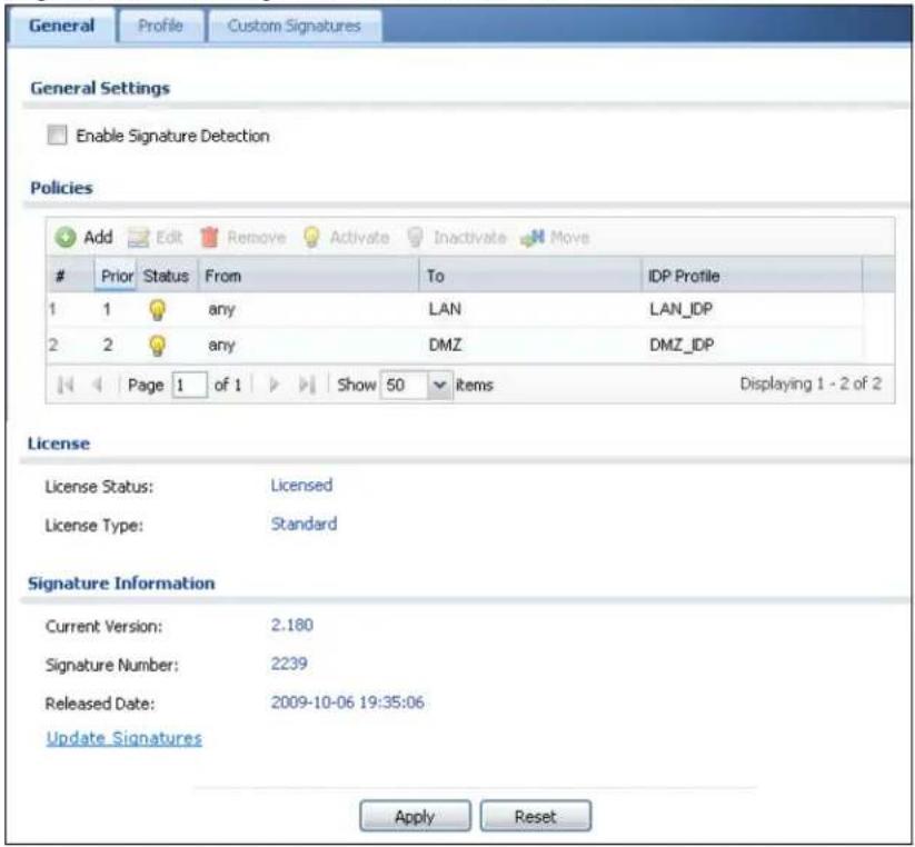
The following table describes the screens in this screen.
Table 112 Configuration > Anti-X > IDP > General
| LABEL DESCRIPTION | |
| General Settings | |
| Enable Signature Detection | You must register for IDP service in order to use packet inspection signatures. If you don't have a standard license, you can register for a once-off trial one. |
| Policies Use this list | to specify which IDP profile the NXC uses for traffic flowing in a specific direction. Edit the policies directly in the table. |
| Add | Click this to create a new entry. Select an entry and click Add to create a new entry after the selected entry. |
| Edit Select an entry and click this to be able to modify it. | |
| Remove Select an entry and click this to delete it. | |
| Activate | To turn on an entry, select it and click Activate. |
| Inactivate | To turn off an entry, select it and click Inactivate. |
| Move To change | an entry's position in the numbered list, select it and click Move to display a field to type a number for where you want to put that entry and press [ENTER] to move the entry to the number that you typed. |
| LABEL DESCRIPTION | |
| # This is the entry's index number in the list. | |
| Priority IDP policies are applied in order of priority. | |
| Status The activate (light bulb) icon is lit when the entry is active and dimmed when the entry is inactive. | |
| From, To This is the direction of travel of packets to which an IDP profile is bound. Traffic direction is defined by the zone the traffic is coming from and the zone the traffic is going to.Note: Depending on your network topology and traffic load, binding every packet direction to an IDP profile may affect the NXC's performance.Use the From field to specify the zone from which the traffic is coming. Use the To field to specify the zone to which the traffic is going.From LAN1 To LAN1 means packets traveling from a computer on one LAN1 subnet to a computer on another LAN subnet via the NXC's LAN1 zone interfaces. The NXC does not check packets traveling from a LAN1 computer to another LAN1 computer on the same subnet.From WAN To WAN means packets that come in from the WAN zone and the NXC routes back out through the WAN zone. | |
| IDP Profile This field shows which IDP profile is bound to which traffic direction. Select an IDP profile to apply to the entry's traffic direction. Configure the IDP profiles in the IDP profile screens. | |
| License You need to create an account at myZyXEL.com, register your NXC and then subscribe for IDP in order to be able to download new packet inspection signatures from myZyXEL.com. There's an initial free trial period for IDP after which you must pay to subscribe to the service. See the Registration chapter for details. | |
| License Status Licensed, Not Licensed or Expired indicates whether you have subscribed for IDP services or not or your registration has expired. | |
| License Type This field shows Trial, Standard or None depending on whether you subscribed to the IDP trial, bought an iCard for IDP service or neither. | |
| Apply new Registration This link appears if you have not registered for the service or only have the trial registration. Click this link to go to the screen where you can register for the service. | |
| Signature Information The following fields display information on the current signature set that the NXC is using. | |
| Current Version This field displays the IDP signature set version number. This number gets larger as the set is enhanced. | |
| Signature Number This field displays the number of IDP signatures in this set. This number usually gets larger as the set is enhanced. Older signatures and rules may be removed if they are no longer applicable or have been supplanted by newer ones. | |
| Released Date This field displays the date and time the set was released. | |
| LABEL DESCRIPTION | |
| Update Signatures | Click this link to go to the screen you can use to download signatures from the update server. |
| Apply | Click Apply to save your changes. |
| Reset | Click Reset to return the screen to its last-saved settings. |
21.3 Profile Summary
An IDP profile is a set of packet inspection signatures.
Packet inspection signatures examine packet content for malicious data. Packet inspection applies to OSI (Open System Interconnection) layer-4 to layer-7 contents. You need to subscribe for IDP service in order to be able to download new signatures.
In general, packet inspection signatures are created for known attacks while anomaly detection looks for abnormal behavior.
Select Anti-X > IDP > Profile. Use this screen to:
- Add a new profile
- Edit an existing profile
- Delete an existing profile.
Click a column's heading cell to sort the table entries by that column's criteria. Click the heading cell again to reverse the sort order.
Figure 137 Configuration > Anti-X > IDP > Profile
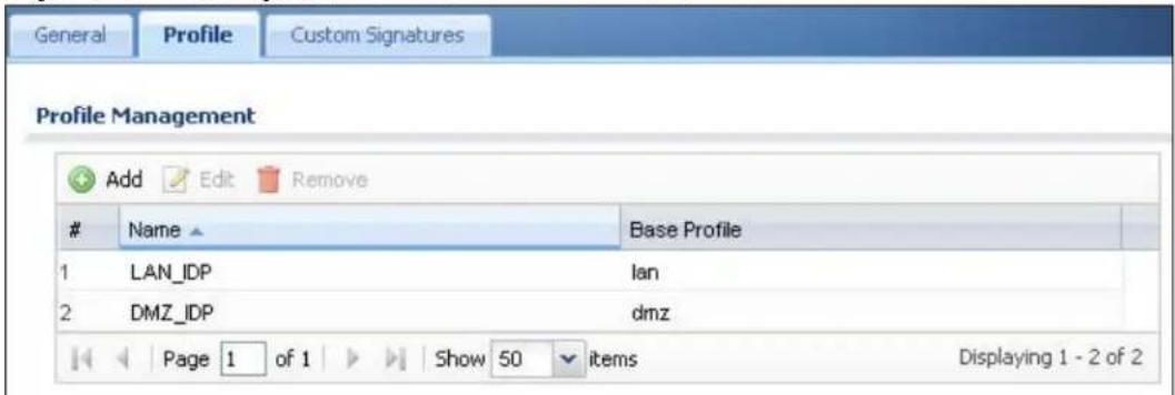
The following table describes the fields in this screen.
Table 113 Configuration > Anti-X > IDP > Profile
| LABEL DESCRIPTION |
| Add Click this to create a new entry. |
| Edit Select an entry and click this to be able to modify it. |
| Remove Select an entry and click this to delete it. |
| # This is the entry's index number in the list. |
| Name This is the name of the profile you created. |
| Base Profile This is the base profile from which the profile was created. |
21.3.1 Base Profiles
The NXC comes with several base profiles. You use base profiles to create new profiles. In the Configuration > Anti-X > IDP > Profile screen, click Add to display the following screen.
Figure 138 Base Profiles
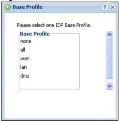
The following table describes this screen.
Table 114 Base Profiles
| BASE PROFILE | DESCRIPTION |
| none All signatures are disabled. No logs are generated nor actions are taken. | |
| all All signatures are enabled. Signatures with a high or severe severity level (greater than three) generate log alerts and cause packets that trigger them to be dropped. Signatures with a very low, low or medium severity level (less than or equal to three) generate logs (not log alerts) and no action is taken on packets that trigger them. | |
| wan Signatures for all services are enabled. Signatures with a medium, high or severe severity level (greater than two) generate logs (not log alerts) and no action is taken on packets that trigger them. Signatures with a very low or low severity level (less than or equal to two) are disabled. | |
| Ian This profile is | most suitable for common LAN network services.Signatures for common services such as DNS, FTP, HTTP, ICMP, IM, IMAP, MISC, NETBIOS, P2P, POP3, RPC, RSERVICE, SMTP, SNMP, SQL, TELNET, TFTP, MySQL are enabled. Signatures with a high or severe severity level (greater than three) generate logs (not log alerts) and cause packets that trigger them to be dropped. Signatures with a low or medium severity level (two or three) generate logs (not log alerts) and no action is taken on packets that trigger them. Signatures with a very low severity level (one) are disabled. |
| dmz This profile is | most suitable for networks containing your servers.Signatures for common services such as DNS, FTP, HTTP, ICMP, IMAP, MISC, NETBIOS, POP3, RPC, RSERVICE, SMTP, SNMP, SQL, TELNET, Oracle, MySQL are enabled. Signatures with a high or severe severity level (greater than three) generate log alerts and cause packets that trigger them to be dropped. Signatures with a low or medium severity level (two or three) generate logs (not log alerts) and no action is taken on packets that trigger them. Signatures with a very low severity level (one) are disabled. |
| OK | Click OK to save your changes. |
| Cancel | Click Cancel to exit this screen without saving your changes. |
21.4 Creating New Profiles
You may want to create a new profile if not all signatures in a base profile are applicable to your network. In this case you should disable non-applicable signatures so as to improve NXC IDP processing efficiency.
You may also find that certain signatures are triggering too many false positives or false negatives. A false positive is when valid traffic is flagged as an attack. A false negative is when invalid traffic is wrongly allowed to pass through the NXC. As each network is different, false positives and false negatives are common on initial IDP deployment.
You could create a new ‘monitor profile’ that creates logs but all actions are disabled. Observe the logs over time and try to eliminate the causes of the false alarms. When you’re satisfied that they have been reduced to an acceptable level, you could then create an ‘inline profile’ whereby you configure appropriate actions to be taken when a packet matches a signature.
To create a new profile:
1 Click the Add icon in the Configuration > Anti-X > IDP > Profile screen to display a pop-up screen allowing you to choose a base profile.
2 Select a base profile and then click OK to go to the profile details screen.
Note: If Internet Explorer opens a warning screen about a script making Internet Explorer run slowly and the computer maybe becoming unresponsive, just click No to continue.
3 Type a new profile name
4 Enable or disable individual signatures.
5 Edit the default log options and actions.
21.5 Add/Edit Profile
Select Configuration > Anti-X > IDP > Profile and then Add a new or Edit an existing profile select. Packet inspection signatures examine the contents of a packet for malicious data. It operates at layer-4 to layer-7.
Figure 139 Configuration > Anti-X > IDP > Profile > Add/Edit Profile

The following table describes the fields in this screen.
Table 115 Configuration > Anti-X > IDP > Profile > Add/Edit Profile
| LABEL DESCRIPTION | |
| Name This is the name of the profile. You may use 1-31 alphanumeric characters, underscores(_, or dashes (-), but the first character cannot be a number. This value is case-sensitive. These are valid, unique profile names:MyProfilemYProfileMymy12_3-4These are invalid profile names:1mYProfileMy ProfileMyProfile?Whatalongprofilename123456789012 | |
| Switch to query view | Click this button to go to a screen where you can search for signatures by criteria such as name, ID, severity, attack type, vulnerable attack platforms, service category, log options or actions. |
| Activate | To turn on an entry, select it and click Activate. |
| Inactivate | To turn off an entry, select it and click Inactivate. |
| Log | To edit an item's log option, select it and use the Log icon. These are the log options:no: Select this option on an individual signature or a complete service group to have the NXC create no log when a packet matches a signature(s).log: Select this option on an individual signature or a complete service group to have the NXC create a log when a packet matches a signature(s).log alert: An alert is an e-mailed log for more serious events that may need more immediate attention. Select this option to have the NXC send an alert when a packet matches a signature(s). |
| Action To edit | what action the NXC takes when a packet matches a signature, select the signature and use the Action icon. |
| none: Select this action on an individual signature or a complete service group to have the NXC take no action when a packet matches the signature(s). | |
| drop: Select this action on an individual signature or a complete service group to have the NXC silently drop a packet that matches the signature(s). Neither sender nor receiver are notified. | |
| reject-sender: Select this action on an individual signature or a complete service group to have the NXC send a reset to the sender when a packet matches the signature. If it is a TCP attack packet, the NXC will send a packet with a ‘RST’ flag. If it is an ICMP or UDP attack packet, the NXC will send an ICMP unreachable packet. | |
| reject-receiver: Select this action on an individual signature or a complete service group to have the NXC send a reset to the receiver when a packet matches the signature. If it is a TCP attack packet, the NXC will send a packet with an a ‘RST’ flag. If it is an ICMP or UDP attack packet, the NXC will do nothing. | |
| reject-both: Select this action on an individual signature or a complete service group to have the NXC send a reset to both the sender and receiver when a packet matches the signature. If it is a TCP attack packet, the NXC will send a packet with a ‘RST’ flag to the receiver and sender. If it is an ICMP or UDP attack packet, the NXC will send an ICMP unreachable packet. | |
| # This is the entry's index number in the list. | |
| Status The acti | ivate (light bulb) icon is lit when the entry is active and dimmed when the entry is inactive. |
| Service Click | the + sign next to a service group to expand it. A service group is a group of related IDP signatures. |
| Message This | is the name of the signature. |
| SID This is the | signature ID (identification) number that uniquely identifies a NXC signature. |
| Severity These | are the severities as defined in the NXC. The number in brackets is the number you use if using commands. |
| Severe (5): These denote attacks that try to run arbitrary code or gain system privileges. | |
| High (4): These denote known serious vulnerabilities or attacks that are probably not false alarms. | |
| Medium (3): These denote medium threats, access control attacks or attacks that could be false alarms. | |
| Low (2): These denote mild threats or attacks that could be false alarms. | |
| Very Low (1): These denote possible attacks caused by traffic such as Ping, trace route, ICMP queries etc. | |
| Policy Type This | is the attack type as defined on the NXC. |
| Log | These are the log options. To edit this, select an item and use the Log icon. |
| Action This is | the action the NXC should take when a packet matches a signature here. To edit this, select an item and use the Action icon. |
| OK A profile | consists of three separate screens. If you want to configure just one screen for an IDP profile, click OK to save your settings to the NXC, complete the profile and return to the profile summary page. |
| Cancel | Click Cancel to return to the profile summary page without saving any changes. |
| Save If you want to configure more than one screen for an IDP profile, click Save to save the configuration to the NXC, but remain in the same page. You may then go to another profile screen (tab) in order to complete the profile. Click OK in the final profile screen to complete the profile. | |
21.5.1 Policy Types
This section describes IDP policy types, also known as attack types, as categorized in the NXC. You may refer to these types when categorizing your own custom rules.
Table 116 Policy Types
| POLICY TYPE DESCRIPTION | |
| P2P Peer-to-peer (P2P) is where computing devices link directly to each other and can directly initiate communication with each other; they do not need an intermediary. A device can be both the client and the server. In the NXC, P2P refers to peer-to-peer applications such as e-Mule, e-Donkey, BitTorrent, iMesh, etc. | |
| IM IM (Instant Messenger) refers to chat applications. Chat is real-time,text-based communication between two or more users via networks-connected computers. After you enter a chat (or chat room), any room member can type a message that will appear on the monitors of all the other participants. | |
| SPAM Spam is unsolicited “junk” e-mail sent to large numbers of people to promote products or services. | |
| DoS/DDoS The goal of Denial of Service (DoS) attacks is not to steal information, but to disable a device or network on the Internet.A Distributed Denial of Service (DDoS) attack is one in which multiple compromised systems attack a single target, thereby causing denial of service for users of the targeted system. | |
| Scan A scan describes the action of searching a network for an exposed service. An attack may then occur once a vulnerability has been found. Scans occur on several network levels.A network scan occurs at layer-3. For example, an attacker looks for network devices such as a router or server running in an IP network.A scan on a protocol is commonly referred to as a layer-4 scan. For example, once an attacker has found a live end system, he looks for open ports.A scan on a service is commonly referred to a layer-7 scan. For example, once an attacker has found an open port, say port 80 on a server, he determines that it is a HTTP service run by some web server application. He then uses a web vulnerability scanner (for example, Nikto) to look for documented vulnerabilities. | |
| Buffer Overflow A buffer overflow occurs when a program or process tries to store more data in a buffer (temporary data storage area) than it was intended to hold. The excess information can overflow into adjacent buffers, corrupting or overwriting the valid data held in them.Intruders could run codes in the overflow buffer region to obtain control of the system, install a backdoor or use the victim to launch attacks on other devices. | |
| Virus/Worm A computer virus is a small program designed to corrupt and/or alter the operation of other legitimate programs. A worm is a program that is designed to copy itself from one computer to another on a network. A worm's uncontrolled replication consumes system resources, thus slowing or stopping other tasks. | |
| Backdoor/Trojan A backdoor (also called a trapdoor) is hidden software or a hardware mechanism that can be triggered to gain access to a program, online service or an entire computer system. A Trojan horse is a harmful program that is hidden inside apparently harmless programs or data.Although a virus, a worm and a Trojan are different types of attacks, they can be blended into one attack. For example, W32/Blaster and W32/Sasser are blended attacks that feature a combination of a worm and a Trojan. | |
| Access Control Access control refers to procedures and controls that limit or detect access. Access control attacks try to bypass validation checks in order to access network resources such as servers, directories, and files. | |
| Web Attack Web attacks refer to attacks on web servers such as IIS (Internet Information Services). |
21.5.2 IDP Service Groups
An IDP service group is a set of related packet inspection signatures.
Table 117 IDP Service Groups
| WEB_PHP | WEB_MISC | WEB_IIS | WEB_FRONTPAGE |
| WEB_CGI | WEB_ATTACKS | TFTP | TELNET |
| SQL | SNMP | SMTP | RSERVICES |
| RPC | POP3 | POP2 | P2P |
| ORACLE | NNTP | NETBIOS | MYSQL |
| MISC_EXPLOIT | MISC_DDOS | MISC_BACKDOOR | MISC |
| IMAP | IM | ICMP | FTP |
| FINGER | DNS |
The following figure shows the WEB_PHP service group that contains signatures related to attacks on web servers using PHP exploits. PHP (PHP: Hypertext Preprocessor) is a server-side HTML embedded scripting language that allows web developers to build dynamic websites.
Logs and actions applied to a service group apply to all signatures within that group. If you select original setting for service group logs and/or actions, all signatures within that group are returned to their last-saved settings.
Figure 140 Configuration > Anti-X > IDP > Edit Profile
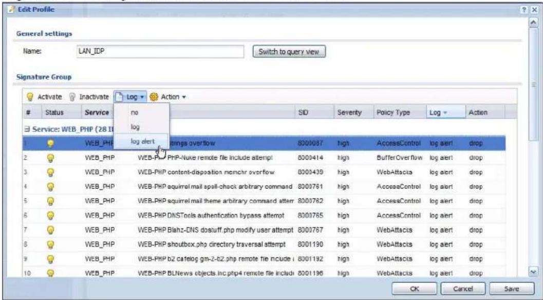
21.5.3 Query View Screen
Click Switch to query view in the Edit Profile screen to display the signature query screen. In the query view screen, you can search for signatures by criteria such as name, ID, severity, attack type, vulnerable attack platforms, service category, log options or actions.
Figure 141 Configuration > Anti-X > IDP > Edit Profile
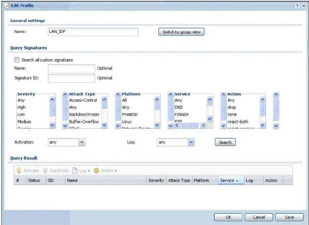
The following table describes the fields specific to this screen's query view.
Table 118 Configuration > Anti-X > IDP > Edit Profile
| LABEL DESCRIPTION | |
| Name This is the | name of the profile that you created in the IDP > Profiles > Group View screen. |
| Switch to group view | Click this button to go to the IDP profile group view screen where IDP signatures are grouped by service and you can configure activation, logs and/or actions. |
| Query Signatures | Select the criteria on which to perform the search. |
| Search all custom signatures | Select this check box to search for signatures you created or imported in the Custom Signatures screen. You can search by name or ID. If the name and ID fields are left blank, then all custom signatures are displayed. |
| Name Type the | name or part of the name of the signature(s) you want to find. |
| Signature ID | Type the ID or part of the ID of the signature(s) you want to find. |
| LABEL | DESCRIPTION |
| Severity Search | ch for signatures by severity level(s). Hold down the [Ctrl] key if you want to make multiple selections.These are the severities as defined in the NXC. The number in brackets is the number you use if using commands.Severe (5): These denote attacks that try to run arbitrary code or gain system privileges.High (4): These denote known serious vulnerabilities or attacks that are probably not false alarms.Medium (3): These denote medium threats, access control attacks or attacks that could be false alarms.Low (2): These denote mild threats or attacks that could be false alarms.Very-Low (1): These denote possible attacks caused by traffic such as Ping, trace route, ICMP queries etc. |
| Attack Type Search | for signatures by attack type(s). Attack types are known as policy types in the group view screen. Hold down the [Ctrl] key if you want to make multiple selections. |
| Platform Search | ch for signatures created to prevent intrusions targeting specific operating system(s). Hold down the [Ctrl] key if you want to make multiple selections. |
| Service Search | ch for signatures by IDP service group(s). Hold down the [Ctrl] key if you want to make multiple selections. |
| Action Search | for signatures by the response the NXC takes when a packet matches a signature. Hold down the [Ctrl] key if you want to make multiple selections. |
| Activation Search | ch for activated and/or inactivated signatures here. |
| Log Search for signatures by log option here. | |
| Search Click this | button to begin the search. The results display at the bottom of the screen. Results may be spread over several pages depending on how broad the search criteria selected were. The tighter the criteria selected, the fewer the signatures returned. |
| Query Result The | results are displayed in a table showing the SID, Name, Severity, Attack Type, Platform, Service, Activation, Log, and Action criteria as selected in the search. Click the SID column header to sort search results by signature ID. |
| OK | Click OK to save your settings to the NXC, complete the profile and return to the profile summary page. |
| Cancel | Click Cancel to return to the profile summary page without saving any changes. |
| Save | Click Save to save the configuration to the NXC, but remain in the same page. You may then go to the another profile screen (tab) in order to complete the profile. Click OK in the final profile screen to complete the profile. |
21.5.4 Query Example
This example shows a search with these criteria:
• Severity: severe and high
- Attack Type: DDoS
- Platform: Windows 2000 and Windows XP computers
• Service: Any
- Actions: Any
Figure 142 Query Example Search Results
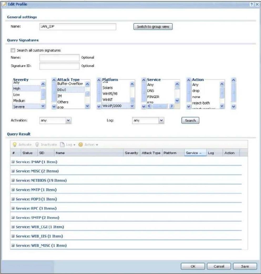
21.6 Custom IDP Signatures
Create custom signatures for new attacks or attacks peculiar to your network. Custom signatures can also be saved to/from your computer so as to share with others. You need some knowledge of packet headers and attack types to create your own custom signatures.
21.6.1 IP Packet Header
These are the fields in an Internet Protocol (IP) version 4 packet header.
Figure 143 IP v4 Packet Headers
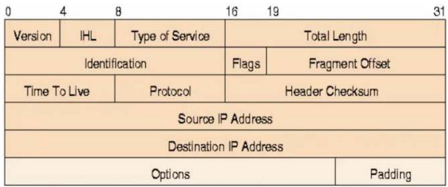
The header fields are discussed below:
Table 119 IP v4 Packet Headers
| HEADER DESCRIPTION | |
| Version The value 4 indicates IP version 4. | |
| IHL IP Header Length | is the number of 32 bit words forming the total length of the header (usually five). |
| Type of Service The Type of Service, (also known as Differentiated Services Code Point (DSCP)) is usually set to 0, but may indicate particular quality of service needs from the network. | |
| Total Length This is the size of the datagram in bytes. It is the combined length of the header and the data. | |
| Identification This is a 16-bit number, which together with the source address, uniquely identifies this packet. It is used during reassembly of fragmented datagrams. | |
| Flags Flags are used to control whether routers are allowed to fragment a packet and to indicate the parts of a packet to the receiver. | |
| Fragment Offset This is a byte count from the start of the original sent packet. | |
| Time To Live This is a counter that decrements every time it passes through a router. When it reaches zero, the datagram is discarded. It is used to prevent accidental routing loops. | |
| Protocol The protocol | indicates the type of transport packet being carried, for example, 1 = ICMP; 2= IGMP; 6 = TCP; 17= UDP. |
| Header Checksum This | is used to detect processing errors introduced into the packet inside a router or bridge where the packet is not protected by a link layer cyclic redundancy check. Packets with an invalid checksum are discarded by all nodes in an IP network. |
| Source IP Address This | is the IP address of the original sender of the packet. |
| Destination IP Address | This is the IP address of the final destination of the packet. |
| Options IP options is a variable-length list of IP options for a datagram that define IP Security Option, IP Stream Identifier, (security and handling restrictions for the military), Record Route (have each router record its IP address), Loose Source Routing (specifies a list of IP addresses that must be traversed by the datagram), Strict Source Routing (specifies a list of IP addresses that must ONLY be traversed by the datagram), Timestamp (have each router record its IP address and time), End of IP List and No IP Options. | |
| Padding Padding is used as a filler to ensure that the IP packet is a multiple of 32 bits. | |
21.7 Custom Signatures
Select Configuration > Anti-X > IDP > Custom Signatures. The first screen shows a summary of all custom signatures created. Click the SID or Name heading to sort. Click the Add icon to create a new signature or click the Edit icon to edit an existing signature. You can also delete custom signatures here or save them to your computer.
The NXC checks all signatures and continues searching even after a match is found. If two or more rules have conflicting actions for the same packet, then the NXC applies the more restrictive action (reject-both, reject-receiver or reject-sender, drop, none in this order). If a packet matches a rule for reject-receiver and it also matches a rule for reject-sender, then the NXC will reject-both.
Figure 144 Configuration > Anti-X > IDP > Custom Signatures
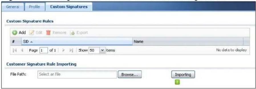
The following table describes the fields in this screen.
Table 120 Configuration > Anti-X > IDP > Custom Signatures
| LABEL DESCRIPTION | |
| Custom Signature Rules | Use this part of the screen to create, edit, delete or export (save to your computer) custom signatures. |
| Add Click this to create a new entry. | |
| Edit Select an entry and click this to be able to modify it. | |
| Remove Select an entry and click this to delete it. | |
| Activate | To turn on an entry, select it and click Activate. |
| Export To save an entry or entries as a file on your computer, select them and click Export. Click Save in the file download dialog box and then select a location and name for the file.Custom signatures must end with the 'rules' file name extension, for example, MySig.rules. | |
| # This is the entry's index number in the list. | |
| SID SID is the signature ID that uniquely identifies a signature. Click the SID header to sort signatures in ascending or descending order. It is automatically created when you click the Add icon to create a new signature. You can edit the ID, but it cannot already exist and it must be in the 9000000 to 9999999 range. | |
| Name This is the name of your custom signature. Duplicate names can exist, but it is advisable to use unique signature names that give some hint as to intent of the signature and the type of attack it is supposed to prevent. | |
| Customer Signature Rule Importing | Use this part of the screen to import custom signatures (previously saved to your computer) to the NXC.Note: The name of the complete custom signature file on the NXC is ‘custom.rules’. If you import a file named ‘custom.rules’, then all custom signatures on the NXC are overwritten with the new file. If this is not your intention, make sure that the files you import are not named ‘custom.rules’. |
| File Path Type | the file path and name of the custom signature file you want to import in the text box (or clickBrowse to find it on your computer) and then clickImportto transfer the file to the NXC.New signatures then display in the NXCIDP >Custom Signatures screen. |
21.7.1 Add/Edit Custom Signature
In the Custom Signatures screen, click the Add icon to create a new signature or click the Edit icon to edit an existing signature.
A packet must match all items you configure in this screen before it matches the signature. The more specific your signature (including packet contents), then the fewer false positives the signature will trigger.
Try to write signatures that target a vulnerability, for example a certain type of traffic on certain operating systems, instead of a specific exploit.
Figure 145 Configuration > Anti-X > IDP > Custom Signatures > Add/Edit
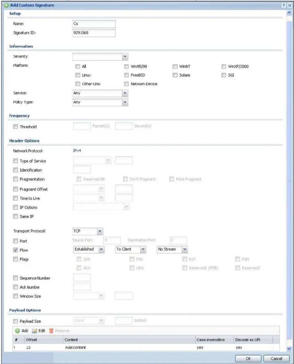
The following table describes the fields in this screen.
Table 121 Configuration > Anti-X > IDP > Custom Signatures > Add/Edit
| LABEL DESCRIPTION | |
| Name Type the name of your custom signature. You may use 1-31 alphanumeric characters, underscores( ), or dashes (-), but the first character cannot be a number. This value is case-sensitive.Duplicate names can exist but it is advisable to use unique signature names that give some hint as to intent of the signature and the type of attack it is supposed to prevent. Refer to (but do not copy) the packet inspection signature names for hints on creating a naming convention. | |
| Signature ID | A signature ID is automatically created when you click the Add icon to create a new signature. You can edit the ID to create a new one (in the 9000000 to 9999999 range), but you cannot use one that already exists. You may want to do that if you want to order custom signatures by SID. |
| Information Use the following fields to set general information about the signature as denoted below. | |
| Severity The severity level denotes how serious the intrusion is. Categorize the seriousness of the intrusion here. | |
| Platform Some intrusions target specific operating systems only. Select the operating systems that the intrusion targets, that is, the operating systems you want to protect from this intrusion. SGI refers to Silicon Graphics Incorporated, who manufactures multi-user Unix workstations that run the IRIX operating system (SGI's version of UNIX). A router is an example of a network device. | |
| Service Select the IDP service group that the intrusion exploits or targets.The custom signature then appears in that group in the IDP > Profile > Group View screen. | |
| Policy Type Categorize the type of intrusion here. | |
| Frequency Recurring packets of the same type may indicate an attack. Use the following field to indicate how many packets per how many seconds constitute an intrusion | |
| Threshold | Select Threshold and then type how many packets (that meet the criteria in this signature) per how many seconds constitute an intrusion. |
| Header Options | |
| Network Protocol Configure signatures for IP version 4. | |
| Type Of Service | Type of service in an IP header is used to specify levels of speed and/or reliability. Some intrusions use an invalid Type Of Service number. Select the check box, then select Equal or Not-Equal and then type in a number. |
| Identification | The identification field in a datagram uniquely identifies the datagram. If a datagram is fragmented, it contains a value that identifies the datagram to which the fragment belongs. Some intrusions use an invalid Identification number. Select the check box and then type in the invalid number that the intrusion uses. |
| Fragmentation A | fragmentation flag identifies whether the IP datagram should be fragmented, not fragmented or is a reserved bit. Some intrusions can be identified by this flag. Select the check box and then select the flag that the intrusion uses. |
| Fragmentation Offset | When an IP datagram is fragmented, it is reassembled at the final destination. The fragmentation offset identifies where the fragment belongs in a set of fragments. Some intrusions use an invalid Fragmentation Offset number. Select the check box, select Equal, Smaller or Greater and then type in a number |
| Time to Live Time | to Live is a counter that decrements every time it passes through a router. When it reaches zero, the datagram is discarded. Usually it's used to set an upper limit on the number of routers a datagram can pass through. Some intrusions can be identified by the number in this field. Select the check box, select Equal, Smaller or Greater and then type in a number. |
| IP Options IP options | is a variable-length list of IP options for a datagram that define IP Security Option, IP Stream Identifier, (security and handling restrictions for the military), Record Route (have each router record its IP address), Loose Source Routing (specifies a list of IP addresses that must be traversed by the datagram), Strict Source Routing (specifies a list of IP addresses that must ONLY be traversed by the datagram), Timestamp (have each router record its IP address and time), End of IP List and No IP Options. IP Options can help identify some intrusions. Select the check box, then select an item from the list box that the intrusion uses |
| Same IP Select the | check box for the signature to check for packets that have the same source and destination IP addresses. |
| Transport Protocol | The following fields vary depending on whether you choose TCP, UDP or ICMP. |
| Transport Protocol: TCP | |
| Port Select the | check box and then enter the source and destination TCP port numbers that will trigger this signature. |
| Flow If selected, | the signature only applies to certain directions of the traffic flow and only to clients or servers. Select Flow and then select the identifying options.Established: The signature only checks for established TCP connectionsStateless: The signature is triggered regardless of the state of the stream processor (this is useful for packets that are designed to cause devices to crash)To Client: The signature only checks for server responses from A to B.To Server: The signature only checks for client requests from B to A.From Client:.The signature only checks for client requests from B to A.From Servers: The signature only checks for server responses from A to B.No Stream: The signature does not check rebuilt stream packets.Only Stream: The signature only checks rebuilt stream packets. |
| Flags Select what | TCP flag bits the signature should check. |
| Sequence Number | Use this field to check for a specific TCP sequence number. |
| Ack Number Use | this field to check for a specific TCP acknowledgement number. |
| Window Size Use | this field to check for a specific TCP window size. |
| Transport Protocol: UDP | |
| Port Select the ch | check box and then enter the source and destination UDP port numbers that will trigger this signature. |
| Transport Protocol: ICMP | |
| Type Use this field to check for a specific ICMP type value. | |
| Code Use this field to check for a specific ICMP code value. | |
| ID Use this field to check for a specific ICMP ID value. This is useful for covert channel programs that use static ICMP fields when they communicate. | |
| Sequence Number | Use this field to check for a specific ICMP sequence number. This is useful for covert channel programs that use static ICMP fields when they communicate. |
| Payload Options The | longer a payload option is, the more exact the match, the faster the signature processing. Therefore, if possible, it is recommended to have at least one payload option in your signature. |
| Payload Size This field may be used to check for abnormally sized packets or for detecting buffer overflows.Select the check box, then select Equal, Smaller or Greater and then type the payload size.Stream rebuilt packets are not checked regardless of the size of the payload. | |
| Add Click this to create a new entry. | |
| Edit Select an entry and click this to be able to modify it. | |
| Remove Select an entry and click this to delete it. | |
| # This is the entry's index number in the list. | |
| Offset This field specifies where to start searching for a pattern within a packet. For example, an offset of 5 would start looking for the specified pattern after the first five bytes of the payload. | |
| Content Type the content that the signature should search for in the packet payload. Hexadecimal code entered between pipes is converted to ASCII. For example, you could represent the ampersand as either & or |26| (26 is the hexadecimal code for the ampersand). | |
| Case-insensitive Select Yes if content casing does NOT matter. | |
| Decode as URI A Uniform Resource Identifier (URI) is a string of characters for identifying an abstract or physical resource (RFC 2396). A resource can be anything that has identity, for example, an electronic document, an image, a service ("today's weather report for Taiwan"), a collection of other resources. An identifier is an object that can act as a reference to something that has identity. Example URIs are:ftp://ftp.is.co.za/rfc/rfc1808.txt; ftp scheme for File Transfer Protocol serviceshttp://www.math.uio.no/faq/compression-faq/part1.html; http scheme for Hypertext Transfer Protocol servicesmailto:mduerst@ifi.unizh.ch; mailto scheme for electronic mail addressestelnet://melvyl.ucop.edu/; telnet scheme for interactive services via the TELNET ProtocolSelect Yes for the signature to search for normalized URI fields. This means that if you are writing signatures that includes normalized content, such as %2 for directory traversals, these signatures will not be triggered because the content is normalized out of the URI buffer.For example, the URI:/scripts/..%c0%af../winnt/system32/cmd.exe?/c+verwill get normalized into:/winnt/system32/cmd.exe?/c+ver | |
| OK Click this button | to save your changes to the NXC and return to the summary screen. |
| Cancel Click this button | to return to the summary screen without saving any changes. |
21.7.2 Custom Signature Example
Before creating a custom signature, you must first clearly understand the vulnerability.
21.7.2.1 Understand the Vulnerability
Check the NXC logs when the attack occurs. Use web sites such as Google or Security Focus to get as much information about the attack as you can. The more specific your signature, the less chance it will cause false positives.
As an example, say you want to check if your router is being overloaded with DNS queries so you create a signature to detect DNS query traffic.
21.7.2.2 Analyze Packets
Use the packet capture screen and a packet analyzer (also known as a network or protocol analyzer) such as Wireshark or Ethereal to investigate some more.
Figure 146 DNS Query Packet Details
![46348 3921.079709 192.168.1.1 46349 3921.079720 192.168.1.33 46350 3921.079725 192.168.1.1 46351 3921.079736 192.168.1.33 46352 3923.770412 192.168.1.33 46353 3923.810622 192.168.1.1 46354 3923.810663 192.168.1.33 46355 3923.810711 192.168.1.1 46356 3923.810722 192.168.1.33 46357 3923.810729 192.168.1.1 46358 3923.810739 192.168.1.33 46359 3923.811730 192.168.1.1 46360 3923.811740 192.168.1.33 46361 3923.811745 192.168.1.1 46362 3923.811755 192.168.1.33 46363 3923.811761 192.168.1.1 Protocol: UDP (0x11) Header checksum: 0xce07 [correct] Source: 192.168.1.33 (192.168.1.33) Destination: 192.168.1.1 (192.168.1.1) User Datagram Protocol, Src Port: 25301 (25301), Dst Port: domain (53) Domain Name System (query) Transaction ID: 0x9d13 Flags: 0x0100 (standard query) 0... .... .... .... = Response: Message is a query .000 0... .... .... = Opcode: Standard query (0) .... ...0... .... = Truncated: Message is not truncated .... ...1 .... .... = Recursion desired: Do query recursively .... ... .0... .... = Z: reserved (0) .... ... ...0 ... = Non-authenticated data OK: Non-authenticated data is unacc Questions: 1 Answer RRs: 0 Authority RRs: 0 Additional RRs: 0 Queries www.gravatar.com: type A, class IN 0000 00 00 aa 78 57 43 00 of 3d ec 5e c3 08 00 45 00 0010 00 3e e9 34 00 00 80 11 ce 07 c0 a8 01 21 c0 a8 0020 01 01 62 d5 00 35 00 2a 58 19 9d 13 01 00 00 01 0030 00 00 00 00 00 03 77 77 77 08 67 72 61 76 61 0040 74 61 72 03 63 6f 6d 00 00 01 ...xwc.. =A...E. >.4... ....!.. .b..5.* X...... ......w ww.grava tar.com....](/content/2026/05/762668/images/ccac885b1e1d779a8a38a51c8c7d243d3564efb006db846e99ca6a2ba1629d12.jpg)
From the details about DNS query you see that the protocol is UDP and the port is 53. The type of DNS packet is standard query and the Flag is 0x0100 with an offset of 2. Therefore enter |010| as the first pattern.
The final custom signature should look like as shown in the following figure.
Figure 147 Example Custom Signature
![Add Custom Signature Setup Name: Cs Signature ID: 9790443 Information Severity: Platform: All Win95/98 WinNT WinXP/2000 Linux FreeBSD Solaris 5GI Other-Unix Network-Device Service: Any Policy Type: Any Frequency Threshold Packet(s) Second(s) Header Options Network Protocol: IPv4 Type of Service Identification Fragmentation Reserved Bit Don't Fragment More Fragment Fragment Offset Time to Live IP Options Same IP Transport Protocol: UDP Port Source Port: 0 Destination Port: 53 Payload Options Payload Size Byte(s) Add Edit Remove Offset Content Case-insensitive Decode as URI 1 2 [010] no no OK Cancel](/content/2026/05/762668/images/33df5d57fd8336fec96be86e8f1110be5ef8c0b45e8ddfa6187f57eee675254e.jpg)
21.7.3 Applying Custom Signatures
After you create your custom signature, it becomes available in the IDP service group category in the Configuration > Anti-X > IDP > Profile > Edit screen. Custom signatures have an SID from 9000000 to 9999999.
You can activate the signature, configure what action to take when a packet matches it and if it should generate a log or alert in a profile. Then bind the profile to a zone.
Figure 148 Example: Custom Signature in IDP Profile
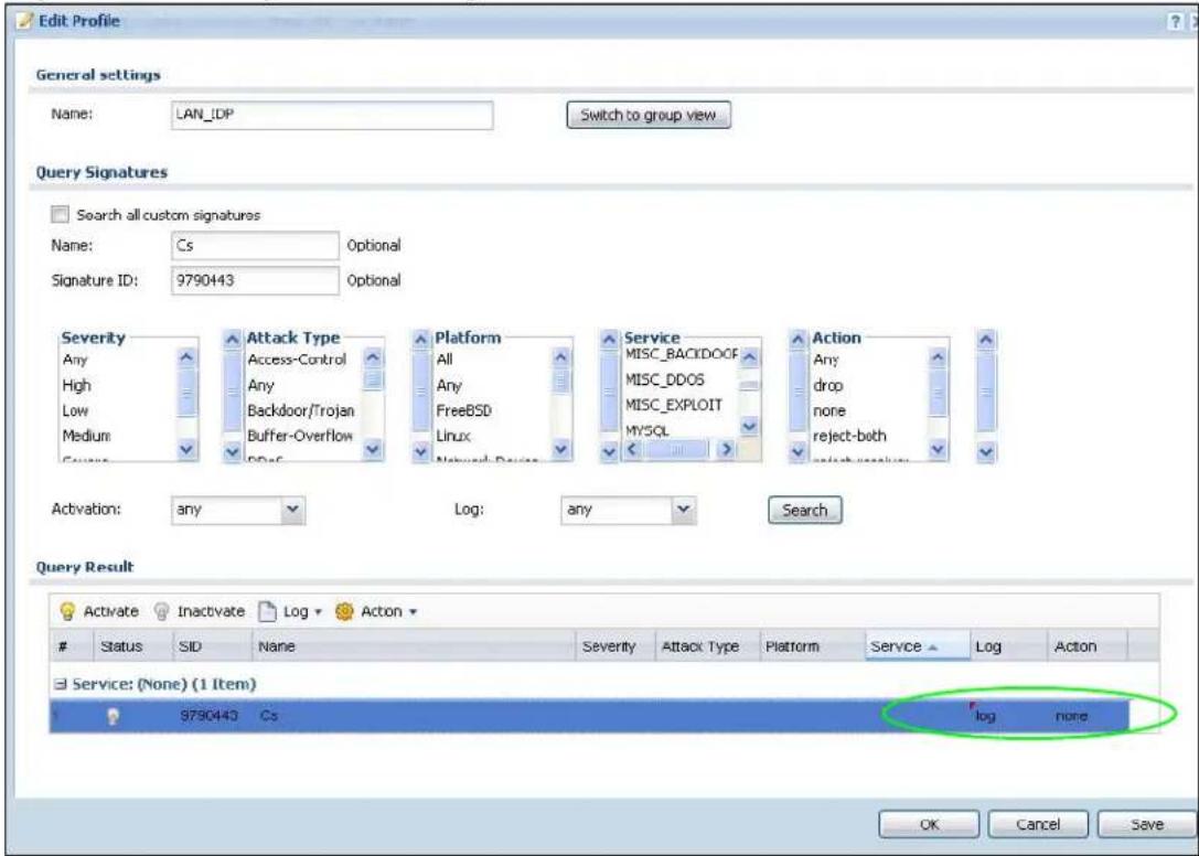
21.7.4 Verifying Custom Signatures
Configure the signature to create a log when traffic matches the signature. (You may also want to configure an alert if it is for a serious attack and needs immediate attention.) After you apply the signature to a zone, you can see if it works by checking the logs (Monitor > Log).
The Priority column shows warn for signatures that are configured to generate a log only. It shows critical for signatures that are configured to generate a log and alert. All IDP signatures come under the IDP category. The Note column displays ACCESS FORWARD when no action is configured for the signature. It displays ACCESS DENIED if you configure the signature action to drop the packet.
The destination port is the service port (53 for DNS in this case) that the attack tries to exploit.
Figure 149 Custom Signature Log
| x | Time | Priornt | Category | Message | Source | Destination | Mde | |||||
| 1 | 2008-12-09 09:51.16 | crtI | IDP | from Any to Any, [type=Sig(9790443)] Co Action: No Action Severity: medium | 192.168.1.30:11494 | 172.23 5.2 53 | ACCESS FORWARD | |||||
| 2 | 2009-12-09 09:51.10 | crtI | IDP | from Any to Any, [type=Sig(9790443)] Co Action: No Action Severity: medium | 192.168.1.33:57027 | 172.23 5.2 53 | ACCESS FORWARD | |||||
| 3 | 2009-12-09 09:51.17 | crtI | IDP | from Any to Any, [type=Sig(9790443)] Co Action: No Action Severity: medium | 192.168.1.33:32771 | 172.23 5.2 53 | ACCESS FORWARD | |||||
| 4 | 2009-12-09 09:51.17 | crtI | IDP | from Any to Any, [type=Sig(9790443)] Co Action: No Action Severity: medium | 192.168.1.33:56873 | 172.23 5.2 53 | ACCESS FORWARD | |||||
| 5 | 2009-12-09 09:51.17 | crtI | IDP | from Any to Any, [type=Sig(9790443)] Co Action: No Action Severity: medium | 192.168.1.33:46284 | 172.23 5.2 53 | ACCESS FORWARD | |||||
| 6 | 2009-12-09 09:51.16 | crtI | IDP | from Any to Any, [type=Sig(9790443)] Co Action: No Action Severity: medium | 192.168.1.33:5908 | 172.23 5.2 53 | ACCESS FORWARD | |||||
| 7 | 2009-12-09 09:51.16 | crtI | IDP | from Any to Any, [type=Sig(9790443)] Co Action: No Action Severity: medium | 192.168.1.33:11148 | 172.23 5.2 53 | ACCESS FORWARD | |||||
| 8 | 2009-12-09 09:51.16 | crtI | IDP | from Any to Any, [type=Sig(9790443)] Co Action: No Action Severity: medium | 192.168.1.33:16850 | 172.23 5.2 53 | ACCESS FORWARD | |||||
| 9 | 2009-12-09 09:51.15 | crtI | IDP | from Any to Any, [type=Sig(9790443)] Co Action: No Action Severity: medium | 192.168.1.33:64652 | 172.23 5.2 53 | ACCESS FORWARD | |||||
| 10 | 2009-12-09 09:51.15 | crtI | IDP | from Any to Any, [type=Sig(9790443)] Co Action: No Action Severity: medium | 192.168.1.33:57238 | 172.23 5.2 53 | ACCESS FORWARD | |||||
| 11 | 2009-12-09 09:51.15 | crtI | IDP | from Any to Any, [type=Sig(9790443)] Co Action: No Action Severity: medium | 192.168.1.33:24508 | 172.23 5.2 53 | ACCESS FORWARD | |||||
| 12 | 2009-12-09 09:51.13 | crtI | IDP | from Any to Any, [type=Sig(9790443)] Co Action: No Action Severity: medium | 192.168.1.33:49816 | 172.23 5.2 53 | ACCESS FORWARD | |||||
| 13 | 2009-12-09 09:51.12 | crtI | IDP | from Any to Any, [type=Sig(9790443)] Co Action: No Action Severity: medium | 192.168.1.33:57663 | 172.23 5.2 53 | ACCESS FORWARD | |||||
| 14 | 2009-12-09 09:50.38 | info | IDP | IDP rule 1 has been inserted | 192 · 168 · 8.33 · 87663 DP | |||||||
| 15 | 2009-12-09 09:50.35 | info | IDP | IDP rule 2 has been modified | DP | |||||||
| 16 | 2009-12-09 09:50.39 | info | IDP | IDP rule 1 has been modified | DP | |||||||
| 17 | 2009-12-09 09:50.26 | info | IDP | IDP profile SPF2772 has been modified | DP | |||||||
| 18 | 2009-12-09 09:50.15 | info | IDP | IDP profile SPF2772 has been modified | DP | |||||||
| 19 | 2009-12-09 09:50.15 | info | IDP | IDP profile SPF2772 has been created | DP | |||||||
| 20 | 2009-12-09 09:49.21 | info | IDP | Enable IDP succeeded | DP | |||||||
| 21 | 2009-12-09 09:48.58 | noticeUser | ||||||||||
21.8 Technical Reference
The following section contains additional technical information about the features described in this chapter.
Host Intrusions
The goal of host-based intrusions is to infiltrate files on an individual computer or server in with the goal of accessing confidential information or destroying information on a computer.
You must install a host IDP directly on the system being protected. It works closely with the operating system, monitoring and intercepting system calls to the kernel or APIs in order to prevent attacks as well as log them.
Disadvantages of host IDPs are that you have to install them on each device (that you want to protect) in your network and due to the necessarily tight integration with the host operating system, future operating system upgrades could cause problems.
Network Intrusions
Network-based intrusions have the goal of bringing down a network or networks by attacking computer(s), switch(es), router(s) or modem(s). If a LAN switch is compromised for example, then the whole LAN is compromised. Host-based intrusions may be used to cause network-based intrusions when the goal of the host virus is to propagate attacks on the network, or attack computer/server operating system vulnerabilities with the goal of bringing down the computer/server. Typical “network-based intrusions” are SQL slammer, Blaster, Nimda MyDoom etc.
Snort Signatures
You may want to refer to open source Snort signatures when creating custom NXC ones. Most Snort rules are written in a single line. Snort rules are divided into two logical sections, the rule header and the rule options as shown in the following example:
alert tcp any any -> 192.168.1.0/24 111 (content:"|00 01 a5|"; msg:"mountd access");)
The text up to the first parenthesis is the rule header and the section enclosed in parenthesis contains the rule options. The words before the colons in the rule options section are the option keywords.
The rule header contains the rule's:
- Action
- Protocol
- Source and destination IP addresses and netmasks
- Source and destination ports information.
The rule option section contains alert messages and information on which parts of the packet should be inspected to determine if the rule action should be taken.
These are some equivalent Snort terms in the NXC.
Note: Not all Snort functionality is supported in the NXC.
Table 122 NXC - Snort Equivalent Terms
| NXC TERM SNORT EQUIVALENT TERM | |
| Type Of Service tos | |
| Identification id | |
| Fragmentation fragbits | |
| Fragmentation Offset fragoffset | |
| Time to Live ttl | |
| IP Options ipopts | |
| NXC TERM | SNORT EQUIVALENT TERM |
| Same IP sameip | |
| Transport Protocol | |
| Transport Protocol: TCP | |
| Port (In Snort rule header) | |
| Flow flow | |
| Flags flags | |
| Sequence Number seq | |
| Ack Number ack | |
| Window Size window | |
| Transport Protocol: UDP (In Snort rule header) | |
| Port (In Snort rule header) | |
| Transport Protocol: ICMP | |
| Type itype | |
| Code icode | |
| ID icmp_id | |
| Sequence Number icmp_seq | |
| Payload Options (Snort rule options) | |
| Payload Size dsize | |
| Offset (relative to start of payload) | offset |
| Relative to end of last match | distance |
| Content | content |
| Case-insensitive | nocase |
| Decode as URI | uricontent |
22.1 Overview
This chapter introduces ADP (Anomaly Detection and Prevention), anomaly profiles and applying an ADP profile to a traffic direction. ADP protects against anomalies based on violations of protocol standards (RFCs – Requests for Comments) and abnormal flows such as port scans.
ADP and IDP Comparison:
1 ADP anomaly detection is in general effective against abnormal behavior while IDP packet inspection signatures are in general effective for known attacks (see Chapter 21 on page 303 for information on packet inspection).
2 ADP traffic and anomaly rules are updated when you upload new firmware. This is different from the IDP packet inspection signatures and the system protect signatures you download from myZyXEL.com.
22.1.1 What You Can Do in this Chapter
- The General screen (Section 22.2 on page 339) turns anomaly detection on or off and applies anomaly profiles to traffic directions.
- The Profile screen (Section 22.3 on page 340) adds new profiles, edits an existing profile or deletes an existing profile.
22.1.2 What You Need To Know
The following terms and concepts may help as you read this chapter.
Traffic Anomalies
Traffic anomaly rules look for abnormal behavior or events such as port scanning, sweeping or network flooding. It operates at OSI layer-2 and layer-3. Traffic anomaly rules may be updated when you upload new firmware.
Protocol Anomalies
Protocol anomalies are packets that do not comply with the relevant RFC (Request For Comments). Protocol anomaly detection includes HTTP Inspection, TCP Decoder, UDP Decoder and ICMP Decoder. Protocol anomaly rules may be updated when you upload new firmware.
ADP Profile
An ADP profile is a set of traffic anomaly rules and protocol anomaly rules that you can activate as a set and configure common log and action settings. You can apply ADP profiles to traffic flowing from one zone to another.
Base ADP Profiles
Base ADP profiles are templates that you use to create new ADP profiles. The NXC comes with several base profiles.
ADP Policy
An ADP policy refers to application of an ADP profile to a traffic flow.
22.1.3 Before You Begin
Configure the NXC's zones - see Chapter 13 on page 213 for more information.
22.2 ADP Summary
Click Configuration > Anti-X > ADP > General. Use this screen to turn anomaly detection on or off and apply anomaly profiles to traffic directions.
Figure 150 Configuration > Anti-X > ADP > General
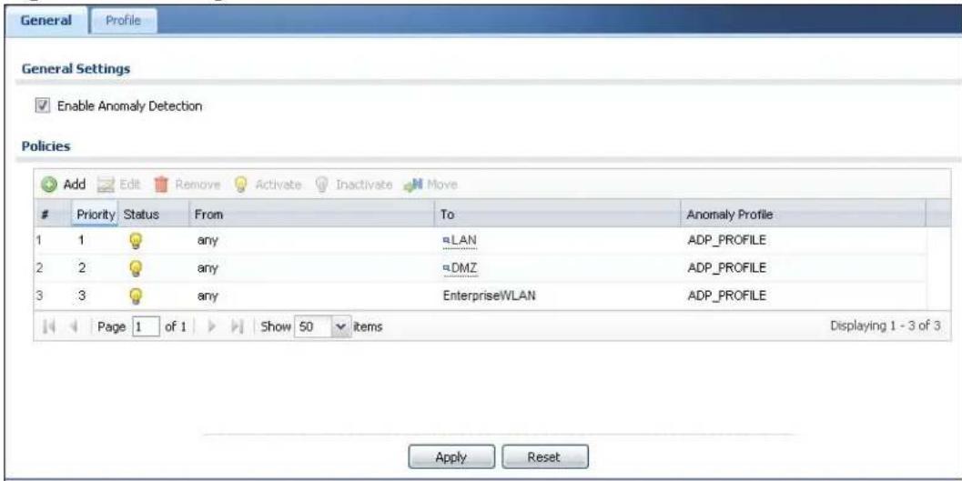
The following table describes the screens in this screen.
Table 123 Configuration > Anti-X > ADP > General
| LABEL DESCRIPTION | |
| General Settings | |
| Enable Anomaly Detection | Select this check box to enable traffic anomaly and protocol anomaly detection. |
| Policies Use this list | to specify which anomaly profile the NXC uses for traffic flowing in a specific direction. Edit the policies directly in the table. |
| Add | Click this to create a new entry. Select an entry and click Add to create a new entry after the selected entry. |
| Edit Select an entry and click this to be able to modify it. | |
| Remove Select an entry and click this to delete it. | |
| Activate | To turn on an entry, select it and click Activate. |
| Inactivate | To turn off an entry, select it and click Inactivate. |
| Move To change | an entry's position in the numbered list, select it and click Move to display a field to type a number for where you want to put that entry and press [ENTER] to move the entry to the number that you typed. |
| # This is the entry's index number in the list. | |
| Priority This is the rank in the list of anomaly profile policies. The list is applied in order of priority. | |
| Status The activate (light bulb) icon is lit when the entry is active and dimmed when the entry is inactive. | |
| From, To This is | the direction of travel of packets to which an anomaly profile is bound. Traffic direction is defined by the zone the traffic is coming from and the zone the traffic is going to.Use theFromfield to specify the zone from which the traffic is coming. SelectNXCto specify traffic coming from the NXC itself.Use theTofield to specify the zone to which the traffic is going.SelectNXCto specify traffic destined for the NXC itself.From LAN1 To LAN1 means packets traveling from a computer on one LAN1 subnet to a computer on another LAN1 subnet via the NXC's LAN1 zone interfaces. The NXC does not check packets traveling from a LAN1 computer to another LAN1 computer on the same subnet.From WAN To WAN means packets that come in from the WAN zone and the NXC routes back out through the WAN zone.Note: Depending on your network topology and traffic load, applying every packet direction to an anomaly profile may affect the NXC's performance. |
| Anomaly Profile | An anomaly profile is a set of anomaly rules with configured activation, log and action settings. This field shows which anomaly profile is bound to which traffic direction. Select an ADP profile to apply to the entry's traffic direction. Configure the ADP profiles in the ADP profile screens. |
| Apply | ClickApplyto save your changes. |
| Reset | ClickResetto return the screen to its last-saved settings. |
22.3 Profile Summary
Use this screen to:
- Create a new profile using an existing base profile
- Edit an existing profile
- Delete an existing profile
Select Configuration > Anti-X > ADP > Profile to display this screen.
Figure 151 Configuration > Anti-X > ADP > Profile
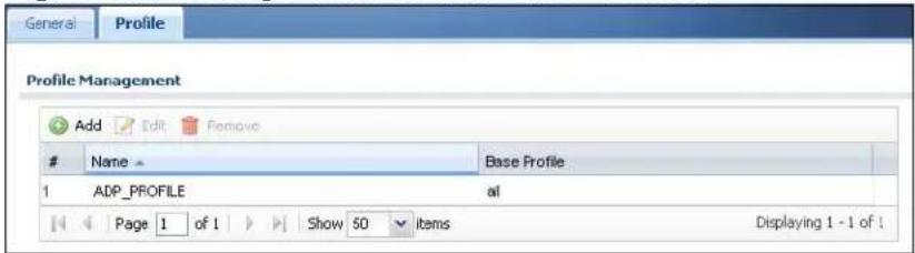
The following table describes the fields in this screen.
Table 124 Configuration > Anti-X > ADP > Profile
| LABEL DESCRIPTION | |
| Add Click this to create a new entry. | |
| Edit Select an entry and click this to be able to modify it. | |
| Remove Select an entry and click this to delete it. | |
| # This is the entry's index number in the list. | |
| Name This is the name of the profile you created. | |
| Base Profile This is the base profile from which the profile was created. |
22.3.1 Base Profiles
The NXC comes with base profiles. You use base profiles to create new profiles. In the Configuration > Anti-X > ADP > Profile screen, click Add to display the following screen.
Figure 152 Base Profiles
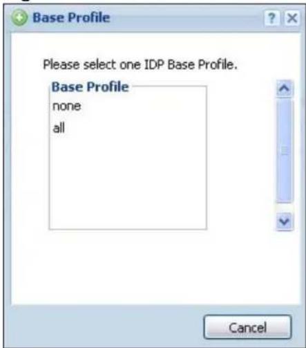
These are the default base profiles at the time of writing.
Table 125 Base Profiles
| BASE PROFILE | DESCRIPTION |
| none All traffic anomaly and protocol anomaly rules are disabled. No logs are generated nor actions are taken. | |
| all All traffic anomaly and protocol anomaly rules are enabled. Rules with a high or severe severity level (greater than three) generate log alerts and cause packets that trigger them to be dropped. Rules with a very low, low or medium severity level (less than or equal to three) generate logs (not log alerts) and no action is taken on packets that trigger them. | |
| OK | Click OK to save your changes. |
| Cancel | Click Cancel to exit this screen without saving your changes. |
22.3.2 Creating New ADP Profiles
You may want to create a new profile if not all rules in a base profile are applicable to your network. In this case you should disable non-applicable rules so as to improve NXC ADP processing efficiency.
You may also find that certain rules are triggering too many false positives or false negatives. A false positive is when valid traffic is flagged as an attack. A false negative is when invalid traffic is wrongly allowed to pass through the NXC. As each network is different, false positives and false negatives are common on initial ADP deployment.
You could create a new ‘monitor profile’ that creates logs but all actions are disabled. Observe the logs over time and try to eliminate the causes of the false alarms. When you’re satisfied that they have been reduced to an acceptable level, you could then create an ‘inline profile’ whereby you configure appropriate actions to be taken when a packet matches a rule.
ADP profiles consist of traffic anomaly profiles and protocol anomaly profiles. To create a new profile, select a base profile and then click OK to go to the profile details screen. Type a new profile name, enable or disable individual rules and then edit the default log options and actions.
22.3.3 Traffic Anomaly Profiles
The traffic anomaly screen is the second screen in an ADP profile. Traffic anomaly detection looks for abnormal behavior such as scan or flooding attempts. In the Configuration > Anti-X > ADP > Profile screen, click the Edit icon or click the Add icon and choose a base profile. If you made changes to other screens
belonging to this profile, make sure you have clicked OK or Save to save the changes before selecting the Traffic Anomaly tab.
Figure 153 Add/Edit Profile > Traffic Anomaly
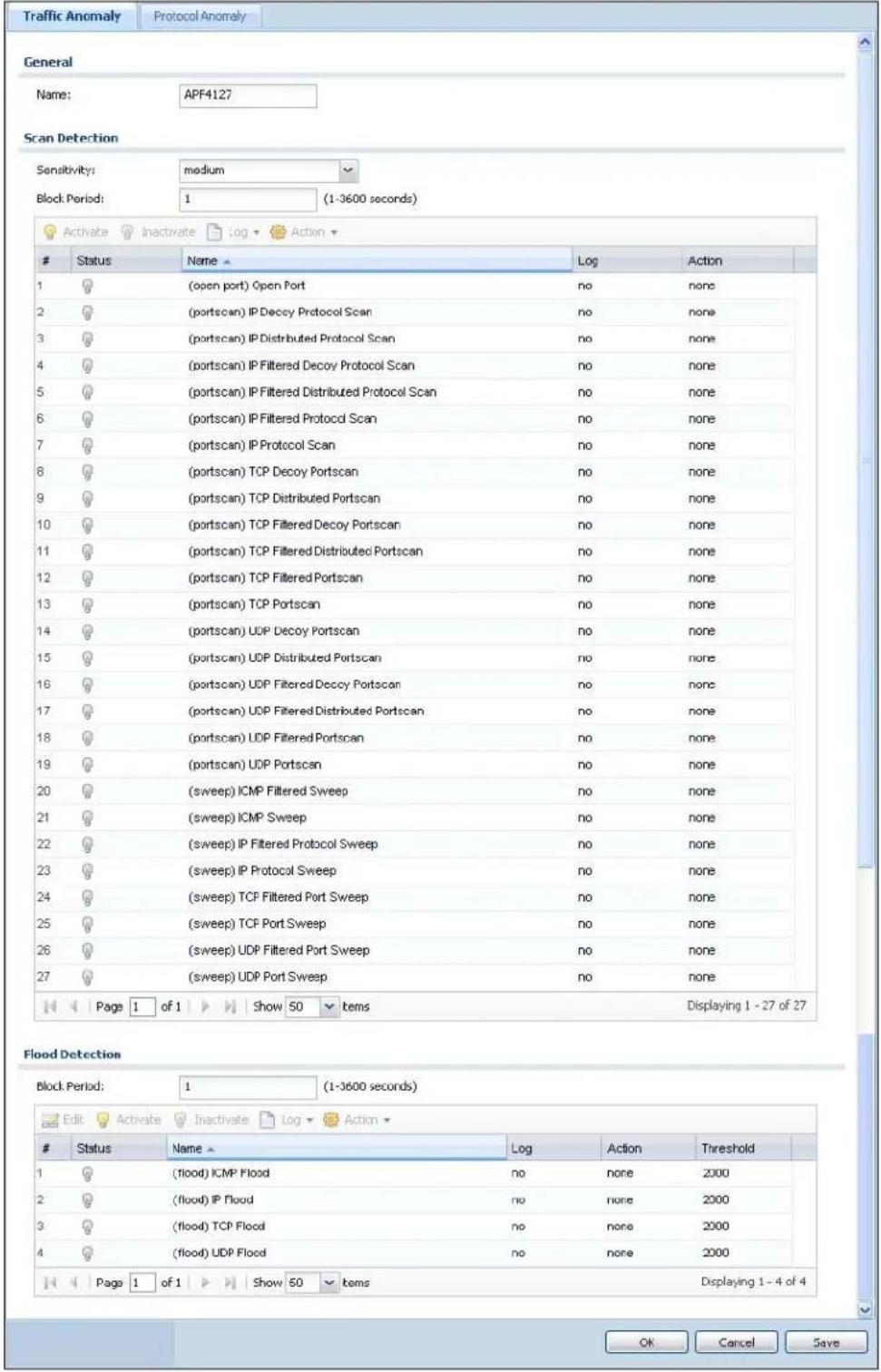
The following table describes the fields in this screen.
Table 126 Add/Edit Profile > Traffic Anomaly
| LABEL DESCRIPTION | |
| Name This is the | name of the ADP profile. You may use 1-31 alphanumeric characters, underscores(_) , or dashes (-), but the first character cannot be a number. This value is case-sensitive. These are valid, unique profile names:MyProfilemYProfileMymy12_3-4These are invalid profile names:1mYProfileMy ProfileMyProfile?Whatalongprofilename123456789012 |
| Scan/Flood Detection | |
| Sensitivity (Sc | can detection only.) Select a sensitivity level so as to reduce false positives in your network. If you choose low sensitivity, then scan thresholds and sample times are set low, so you will have fewer logs and false positives; however some traffic anomaly attacks may not be detected.If you choose high sensitivity, then scan thresholds and sample times are set high, so most traffic anomaly attacks will be detected; however you will have more logs and false positives. |
| Block Period | Specify for how many seconds the NXC blocks all packets from being sent to the victim (destination) of a detected anomaly attack. |
| Activate | To turn on an entry, select it and click Activate. |
| Inactivate | To turn off an entry, select it and click Inactivate. |
| Log | To edit an item's log option, select it and use the Log icon. Select whether to have the NXC generate a log (log), log and alert (log alert) or neither (no) when traffic matches this anomaly rule. |
| Action To edit w | what action the NXC takes when a packet matches a rule, select the signature and use the Action icon none: The NXC takes no action when a packet matches the signature(s).block: The NXC silently drops packets that matches the rule. Neither sender nor receiver are notified. |
| # This is the entry's index number in the list. | |
| Status The activvate (light bulb) icon is lit when the entry is active and dimmed when the entry is inactive. | |
| Name | This is the name of the traffic anomaly rule. Click the Name column heading to sort in ascending or descending order according to the rule name. |
| Log | These are the log options. To edit this, select an item and use the Log icon. |
| Action This is | the action the NXC should take when a packet matches a rule. To edit this, select an item and use the Action icon. |
| Threshold For | flood detection you can set the number of detected flood packets per second that causes the NXC to take the configured action. |
| OK | Click OK to save your settings to the NXC, complete the profile and return to the profile summary page. |
| Cancel | Click Cancel to return to the profile summary page without saving any changes. |
| Save | Click Save to save the configuration to the NXC but remain in the same page. You may then go to the another profile screen (tab) in order to complete the profile. Click OK in the final profile screen to complete the profile. |
22.3.4 Protocol Anomaly Profiles
Protocol anomaly is the third screen in an ADP profile. Protocol anomaly (PA) rules check for protocol compliance against the relevant RFC (Request for Comments).
Protocol anomaly detection includes HTTP Inspection, TCP Decoder, UDP Decoder, and ICMP Decoder where each category reflects the packet type inspected.
Protocol anomaly rules may be updated when you upload new firmware.
22.3.5 Protocol Anomaly Configuration
In the Configuration > Anti-X > ADP > Profile screen, click the Edit icon or click the Add icon and choose a base profile, then select the Protocol Anomaly tab. If you made changes to other screens belonging to this profile, make sure you have clicked OK or Save to save the changes before selecting the Protocol Anomaly tab.
Figure 154 Add/Edit Profile > Protocol Anomaly
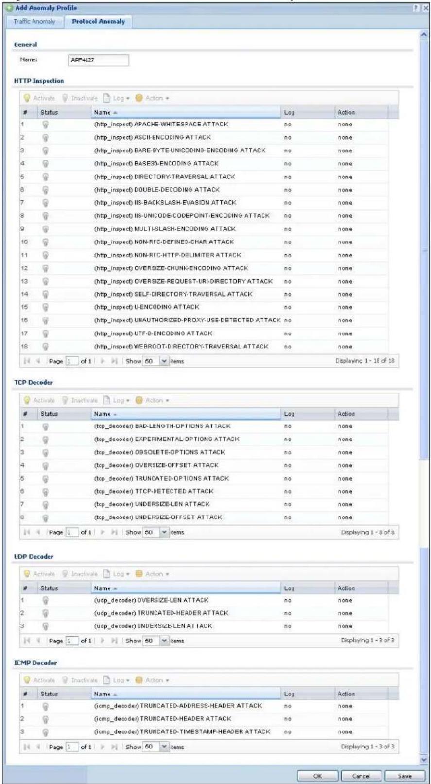
The following table describes the fields in this screen.
Table 127 Add/Edit Profile > Protocol Anomaly
| LABEL DESCRIPTION | |
| Name This is the name of the profile. You may use 1-31 alphanumeric characters, underscores( ), or dashes (-), but the first character cannot be a number. This value is case-sensitive. These are valid, unique profile names:MyProfilemYProfileMymy12_3-4These are invalid profile names:1mYProfileMy ProfileMy Profile?Whatalongprofilename123456789012 | |
| HTTP Inspection/TCP Decoder/UDP Decoder/ICMP Decoder | |
| Activate | To turn on an entry, select it and click Activate. |
| Inactivate | To turn off an entry, select it and click Inactivate. |
| Log | To edit an item's log option, select it and use the Log icon. Select whether to have the NXC generate a log (log), log and alert (log alert) or neither (no) when traffic matches this anomaly rule. |
| Action To edit w | what action the NXC takes when a packet matches a signature,select the signature and use the Action icon. |
| original setting: Select this action to return each signature in a service group to its previously saved configuration. | |
| none: Select this action on an individual signature or a complete service group to have the NXC take no action when a packet matches a rule. | |
| drop: Select this action on an individual signature or a complete service group to have the NXC silently drop a packet that matches a rule. Neither sender nor receiver are notified. | |
| reject-sender: Select this action on an individual signature or a complete service group to have the NXC send a reset to the sender when a packet matches the signature. If it is a TCP attack packet, the NXC will send a packet with a 'RST' flag. If it is an ICMP or UDP attack packet, the NXC will send an ICMP unreachable packet. | |
| reject-receiver: Select this action on an individual signature or a complete service group to have the NXC send a reset to the receiver when a packet matches the rule. If it is a TCP attack packet, the NXC will send a packet with an a 'RST' flag. If it is an ICMP or UDP attack packet, the NXC will do nothing. | |
| reject-both: Select this action on an individual signature or a complete service group to have the NXC send a reset to both the sender and receiver when a packet matches the rule. If it is a TCP attack packet, the NXC will send a packet with a 'RST' flag to the receiver and sender. If it is an ICMP or UDP attack packet, the NXC will send an ICMP unreachable packet. | |
| # This is the entry's index number in the list. | |
| Status The activ | ivate (light bulb) icon is lit when the entry is active and dimmed when the entry is inactive. |
| Name | This is the name of the protocol anomaly rule. Click the Name column heading to sort in ascending or descending order according to the protocol anomaly rule name. |
| Activation Click | the icon to enable or disable a rule or group of rules. |
| Log | These are the log options. To edit this, select an item and use the Log icon. |
| Action This is th | the action the NXC should take when a packet matches a rule. To edit this, select an item and use the Action icon. |
| Log | Select whether to have the NXC generate a log (log), log and alert (log alert) or neither (no) when traffic matches this anomaly rule. |
| Action Select w | what the NXC should do when a packet matches a rule. |
| none: The NXC takes no action when a packet matches the signature(s). | |
| block: The NXC silently drops packets that matches the rule. Neither sender nor receiver are notified. | |
| OK | Click OK to save your settings to the NXC, complete the profile and return to the profile summary page. |
| Cancel | Click Cancel to return to the profile summary page without saving any changes. |
| Save | Click Save to save the configuration to the NXC but remain in the same page. You may then go to the another profile screen (tab) in order to complete the profile. Click OK in the final profile screen to complete the profile. |
22.4 Technical Reference
This section is divided into traffic anomaly background information and protocol anomaly background information.
Port Scanning
An attacker scans device(s) to determine what types of network protocols or services a device supports. One of the most common port scanning tools in use today is Nmap.
Many connection attempts to different ports (services) may indicate a port scan. These are some port scan types:
• TCP Portscan
• UDP Portscan
- IP Portscan
An IP port scan searches not only for TCP, UDP and ICMP protocols in use by the remote computer, but also additional IP protocols such as EGP (Exterior Gateway Protocol) or IGP (Interior Gateway Protocol). Determining these additional protocols can help reveal if the destination device is a workstation, a printer, or a router.
Decoy Port Scans
Decoy port scans are scans where the attacker has spoofed the source address. These are some decoy scan types:
• TCP Decoy Portscan
- UDP Decoy Portscan
• IP Decoy Portscan
Distributed Port Scans
Distributed port scans are many-to-one port scans. Distributed port scans occur when multiple hosts query one host for open services. This may be used to evade intrusion detection. These are distributed port scan types:
• TCP Distributed Portscan
• UDP Distributed Portscan
• IP Distributed Portscan
Port Sweeps
Many different connection attempts to the same port (service) may indicate a port sweep, that is, they are one-to-many port scans. One host scans a single port on multiple hosts. This may occur when a new exploit comes out and the attacker is looking for a specific service. These are some port sweep types:
- TCP Portsweep
- UDP Portsweep
• I P P o r t s w e e p
• ICMP Portsweep
Filtered Port Scans
A filtered port scan may indicate that there were no network errors (ICMP unreachables or TCP RSTs) or responses on closed ports have been suppressed. Active network devices, such as NAT routers, may trigger these alerts if they send out many connection attempts within a very small amount of time. These are some filtered port scan examples.
- TCP Filtered Portscan
- UDP Filtered Portscan • IP Filtered Portscan
- TCP Filtered Decoy Portscan
- UDP Filtered D bP Filteyed Decoy Portscan
Portscan
• TCP Filtered Portsweep - UDP Filtered Portsweep • IP Filtered Portsweep
- I CMP Filtered TCP Filtered Distributed Portsweep Portscan
• UDP Filtered Distributed Portscan
• IP Filtered Distributed Portscan
Flood Detection
Flood attacks saturate a network with useless data, use up all available bandwidth, and therefore make communications in the network impossible.
ICMP Flood Attack
An ICMP flood is broadcasting many pings or UDP packets so that so much data is sent to the system, that it slows it down or locks it up.
Smurf
A smurf attacker (A) floods a router (B) with Internet Control Message Protocol (ICMP) echo request packets (pings) with the destination IP address of each packet as the broadcast address of the network. The router will broadcast the ICMP echo request packet to all hosts on the network. If there are numerous hosts, this will create a large amount of ICMP echo request and response traffic.
If an attacker (A) spoofs the source IP address of the ICMP echo request packet, the resulting ICMP traffic will not only saturate the receiving network (B), but the network of the spoofed source IP address (C).
Figure 155 Smurf Attack
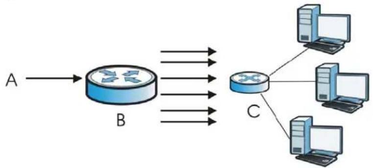
flowchart
graph LR
    A["A"] --> B["B"]
    B --> C["C"]
    C --> D["Computer 1"]
    C --> E["Computer 2"]
    C --> F["Computer 3"]
TCP SYN Flood Attack
Usually a client starts a session by sending a SYN (synchronize) packet to a server. The receiver returns an ACK (acknowledgment) packet and its own SYN, and then the initiator responds with an ACK (acknowledgment). After this handshake, a connection is established.
Figure 156 TCP Three-Way Handshake
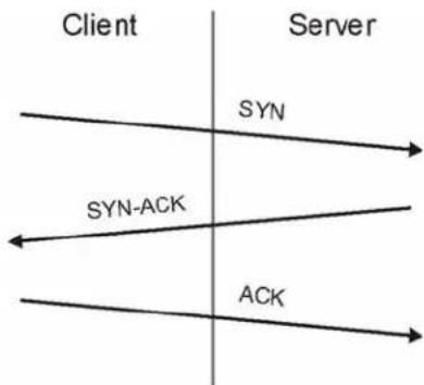
flowchart
graph LR
    A["Client"] -->|SYN| B["Server"]
    B -->|SYN-ACK| A
    A -->|ACK| B
A SYN flood attack is when an attacker sends a series of SYN packets. Each packet causes the receiver to reply with a SYN-ACK response. The receiver then waits for the ACK that follows the SYN-ACK, and stores all outstanding SYN-ACK responses on a backlog queue. SYN-ACKs are only moved off the queue when an ACK comes back or when an internal timer ends the three-way handshake. Once the queue is full, the system will ignore all incoming SYN requests, making the system unavailable for other users.
Figure 157 SYN Flood
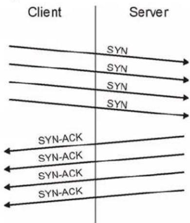
flowchart
graph TD
    A["Client"] --> B["Server"]
    A -->|SYN| C["SYN-ACK"]
    A -->|SYN| D["SYN-ACK"]
    A -->|SYN| E["SYN-ACK"]
    A -->|SYN| F["SYN-ACK"]
    B --> G["Server"]
    B --> H["Client"]
LAND Attack
In a LAND attack, hackers flood SYN packets into a network with a spoofed source IP address of the network itself. This makes it appear as if the computers in the network sent the packets to themselves, so the network is unavailable while they try to respond to themselves.
UDP Flood Attack
UDP is a connection-less protocol and it does not require any connection setup procedure to transfer data. A UDP flood attack is possible when an attacker sends a UDP packet to a random port on the victim system. When the victim system receives a UDP packet, it will determine what application is waiting on the destination port. When it realizes that there is no application that is waiting on the port, it will generate an ICMP packet of destination unreachable to the forged source address. If enough UDP packets are delivered to ports on victim, the system will go down.
HTTP Inspection and TCP/UDP/ICMP Decoders
The following table gives some information on the HTTP inspection, TCP decoder, UDP decoder and ICMP decoder NXC protocol anomaly rules.
Table 128 HTTP Inspection and TCP/UDP/ICMP Decoders
| LABEL DESCRIPTION | |
| HTTP Inspection | |
| APACHE-WHITESPACE ATTACK | This rule deals with non-RFC standard of tab for a space delimiter. Apache uses this, so if you have an Apache server, you need to enable this option. |
| ASCII-ENCODING ATTACK | This rule can detect attacks where malicious attackers use ASCII-encoding to encode attack strings. Attackers may use this method to bypass system parameter checks in order to get information or privileges from a web server. |
| BARE-BYTE-UNICODING-ENCODING ATTACK | Bare byte encoding uses non-ASCII characters as valid values in decoding UTF-8 values. This is NOT in the HTTP standard, as all non-ASCII values have to be encoded with a %. Bare byte encoding allows the user to emulate an IIS server and interpret non-standard encodings correctly. |
| BASE36-ENCODING ATTACK | This is a rule to decode base36-encoded characters. This rule can detect attacks where malicious attackers use base36-encoding to encode attack strings. Attackers may use this method to bypass system parameter checks in order to get information or privileges from a web server. |
| DIRECTORY-TRAVERSAL ATTACK | This rule normalizes directory traversals and self-referential directories. So, “/abc/this_is_not_a_real_dir/../xyz” get normalized to “/abc/xyz”. Also, “/abc/./xyz” gets normalized to “/abc/xyz”. If a user wants to configure an alert, then specify “yes”, otherwise “no”. This alert may give false positives since some web sites refer to files using directory traversals. |
| DOUBLE-ENCODING ATTACK | This rule is IIS specific. IIS does two passes through the request URI, doing decodes in each one. In the first pass, IIS encoding (UTF-8 unicode, ASCII, bare byte, and %u) is done. In the second pass ASCII, bare byte, and %u encodings are done. |
| IIS-BACKSLASH-EVASION ATTACK | This is an IIS emulation rule that normalizes backslashes to slashes. Therefore, a request-URI of "/abc\xyz" gets normalized to "/abc/xyz". |
| IIS-UNICODE-CODEPOINT-ENCODING ATTACK | This rule can detect attacks which send attack strings containing non-ASCII characters encoded by IIS Unicode. IIS Unicode encoding references the unicode.map file. Attackers may use this method to bypass system parameter checks in order to get information or privileges from a web server. |
| MULTI-SLASH-ENCODING ATTACK | This rule normalizes multiple slashes in a row, so something like: "abc/////xyz" get normalized to "abc/xyz". |
| NON-RFC-DEFINED-CHAR ATTACK | This rule lets you receive a log or alert if certain non-RFC characters are used in a request URI. For instance, you may want to know if there are NULL bytes in the request-URI. |
| NON-RFC-HTTP-DELIMITER ATTACK | This is when a newline "\n" character is detected as a delimiter. This is non-standard but is accepted by both Apache and IIS web servers. |
| OVERSIZE-CHUNK-ENCODING ATTACK | This rule is an anomaly detector for abnormally large chunk sizes. This picks up the apache chunk encoding exploits and may also be triggered on HTTP tunneling that uses chunk encoding. |
| OVERSIZE-REQUEST-URI-DIRECTORY ATTACK | This rule takes a non-zero positive integer as an argument. The argument specifies the max character directory length for URL directory. If a URL directory is larger than this argument size, an alert is generated. A good argument value is 300 characters. This should limit the alerts to IDS evasion type attacks, like whisker. |
| SELF-DIRECTORY-TRAVERSAL ATTACK | This rule normalizes self-referential directories. So, "/abc/.xyz" gets normalized to "/abc/xyz". |
| U-ENCODING ATTACK This rule emulates the IIS %u encoding scheme. The %u encoding scheme starts with a %u followed by 4 characters, like %uXXXX. The XXXX is a hex encoded value that correlates to an IIS unicode codepoint. This is an ASCII value. An ASCII character is encoded like, %u002f = /, %u002e = ., etc. | |
| UTF-8-ENCODING ATTACK | The UTF-8 decode rule decodes standard UTF-8 unicode sequences that are in the URI. This abides by the unicode standard and only uses % encoding. Apache uses this standard, so for any Apache servers, make sure you have this option turned on. When this rule is enabled, ASCII decoding is also enabled to enforce correct functioning. |
| WEBROOT-DIRECTORY-TRAVERSAL ATTACK | This is when a directory traversal traverses past the web server root directory. This generates much fewer false positives than the directory option, because it doesn't alert on directory traversals that stay within the web server directory structure. It only alerts when the directory traversals go past the web server root directory, which is associated with certain web attacks. |
| TCP Decoder | |
| BAD-LENGTH-OPTIONS ATTACK | This is when a TCP packet is sent where the TCP option length field is not the same as what it actually is or is 0. This may cause some applications to crash. |
| EXPERIMENTAL-OPTIONS ATTACK | This is when a TCP packet is sent which contains non-RFC-complaint options. This may cause some applications to crash. |
| OBSOLETE-OPTIONS ATTACK | This is when a TCP packet is sent which contains obsolete RFC options. |
| OVERSIZE-OFFSET ATTACK | This is when a TCP packet is sent where the TCP data offset is larger than the payload. |
| TRUNCATED-OPTIONS ATTACK | This is when a TCP packet is sent which doesn't have enough data to read. This could mean the packet was truncated. |
| TTCP-DETECTED ATTACK | T/TCP provides a way of bypassing the standard three-way handshake found in TCP, thus speeding up transactions. However, this could lead to unauthorized access to the system by spoofing connections. |
| UNDERSIZE-LEN ATTACK | This is when a TCP packet is sent which has a TCP datagram length of less than 20 bytes. This may cause some applications to crash. |
| UNDERSIZE-OFFSET ATTACK | This is when a TCP packet is sent which has a TCP header length of less than 20 bytes. This may cause some applications to crash. |
| UDP Decoder | |
| OVERSIZE-LEN ATTACK | This is when a UDP packet is sent which has a UDP length field of greater than the actual packet length. This may cause some applications to crash. |
| TRUNCATED-HEADER ATTACK | This is when a UDP packet is sent which has a UDP datagram length of less the UDP header length. This may cause some applications to crash. |
| UNDERSIZE-LEN ATTACK | This is when a UDP packet is sent which has a UDP length field of less than 8 bytes. This may cause some applications to crash. |
| ICMP Decoder | |
| TRUNCATED-ADDRESS-HEADER ATTACK | This is when an ICMP packet is sent which has an ICMP datagram length of less than the ICMP address header length. This may cause some applications to crash. |
| TRUNCATED-HEADER ATTACK | This is when an ICMP packet is sent which has an ICMP datagram length of less than the ICMP header length. This may cause some applications to crash. |
| TRUNCATED-TIMESTAMP-HEADER ATTACK | This is when an ICMP packet is sent which has an ICMP datagram length of less than the ICMP Time Stamp header length. This may cause some applications to crash. |
Device HA
23.1 Overview
Device HA lets a backup NXC automatically take over if the master NXC fails.
Figure 158 Device HA Backup Taking Over for the Master
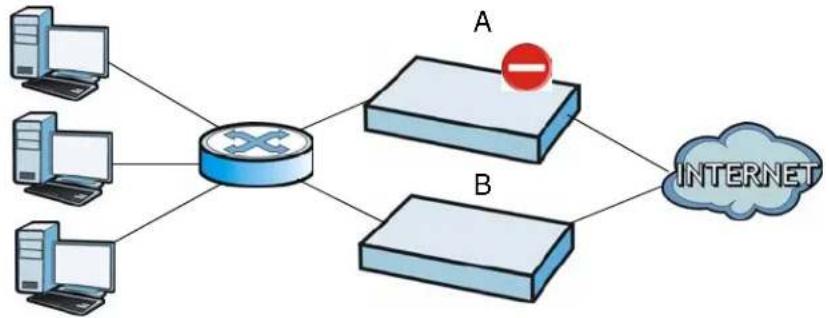
flowchart
graph TD
    A["Server 1"] --> R["Router"]
    B["Server 2"] --> R
    C["Server 3"] --> R
    D["Server 4"] --> R
    R --> E["Server 5"]
    F["Server 6"] --> E
    G["Server 7"] --> E
    H["Server 8"] --> E
    I["Server 9"] --> E
    J["Server 10"] --> E
    K["Server 11"] --> E
    L["Server 12"] --> E
    M["Server 13"] --> E
    N["Server 14"] --> E
    O["Server 15"] --> E
    P["Server 16"] --> E
    Q["Server 17"] --> E
    R --> R
    E --> R
    style R fill:#f9f,stroke:#333,stroke-width:2px
    style E fill:#ccf,stroke:#333,stroke-width:2px
    style Q fill:#cfc,stroke:#333,stroke-width:2px
In this example, device B is the backup for device A in the event something happens to it and prevents it from managing the wireless network.
23.1.1 What You Can Do in this Chapter
- The General screen (Section 23.2 on page 359) configures device HA global settings, and displays the status of each interface monitored by device HA.
- The Active-Passive Mode screens (Section 23.3 on page 361) use active-passive mode device HA. You can configure general active-passive mode device HA settings, view and manage the list of monitored interfaces, and synchronize backup NXCs.
23.1.2 What You Need to Know
The following terms and concepts may help as you read this chapter.
Management Access
You can configure a separate management IP address for each interface. You can use it to access the NXC for management whether the NXC is the master or a backup. The management IP address should be in the same subnet as the interface IP address.
Synchronization
Use synchronization to have a backup NXC copy the master NXC's configuration, signatures (anti-virus, IDP/application patrol, and system protect), and certificates.
Note: Only NXCs of the same model and firmware version can synchronize.
Otherwise you must manually configure the master NXC's settings on the backup (by editing copies of the configuration files in a text editor for example).
23.1.3 Before You Begin
- Configure a static IP address for each interface that you will have device HA monitor.
Note: Subscribe to services on the backup NXC before synchronizing it with the master NXC.
- Synchronization includes updates for services to which the master and backup NXCs are both subscribed. For example, a backup subscribed to IDP/AppPatrol, but not anti-virus, gets IDP/AppPatrol updates from the master, but not anti-virus updates. It is highly recommended to subscribe the master and backup NXCs to the same services.
23.2 Device HA General
This screen lets you enable or disable device HA, and displays which device HA mode the NXC is set to use along with a summary of the monitored interfaces. Click Configuration > Device HA General to display.
Figure 159 Configuration > Device HA > General
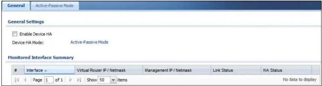
The following table describes the labels in this screen.
Table 129 Configuration > Device HA > General
| LABEL DESCRIPTION | |
| Enable Device HA | Turn the NXC's device HA feature on or off.Note: It is not recommended to use STP (Spanning Tree Protocol) with device HA. |
| Device HA Mode | This displays active-passive mode by default. Legacy mode device HA is not supported by the NXC.The master and its backups must all use the same device HA mode. |
| Monitored Interface Summary | This table shows the status of the interfaces that you selected for monitoring in the other device HA screens. |
| # This is the entry's index number in the list. | |
| Interface These | are the names of the interfaces that are monitored by device HA. |
| Virtual Router IP / Netmask | This is the interface's IP address and subnet mask. Whichever NXC is the master uses this virtual router IP address and subnet mask. |
| Management IP / Netmask | This field displays the interface's management IP address and subnet mask. You can use this IP address and subnet mask to access the NXC whether it is in master or backup mode. |
| Link Status This | tells whether the monitored interface's connection is down or up. |
| HA Status The text before the slash shows whether the device is configured as the master or the backup role.This text after the slash displays the monitored interface's status in the virtual router.Active - This interface is up and using the virtual IP address and subnet mask.Stand-By - This interface is a backup interface in the virtual router. It is not using the virtual IP address and subnet mask.Fault - This interface is not functioning in the virtual router right now. In active-passive mode (or in legacy mode with link monitoring enabled), if one of the master NXC's interfaces loses its connection, the master NXC forces all of its interfaces to the fault state so the backup NXC can take over all of the master NXC's functions. | |
| Apply | Click Apply to save your changes back to the NXC. |
| Reset | Click Reset to return the screen to its last-saved settings. |
23.3 Active-Passive Mode
The Device HA Active-Passive Mode screen lets you configure general active-passive mode device HA settings, view and manage the list of monitored interfaces, and synchronize backup NXCs. To access this screen, click Configuration > Device HA > Active-Passive Mode.
Figure 160 Configuration > Device HA > Active-Passive Mode
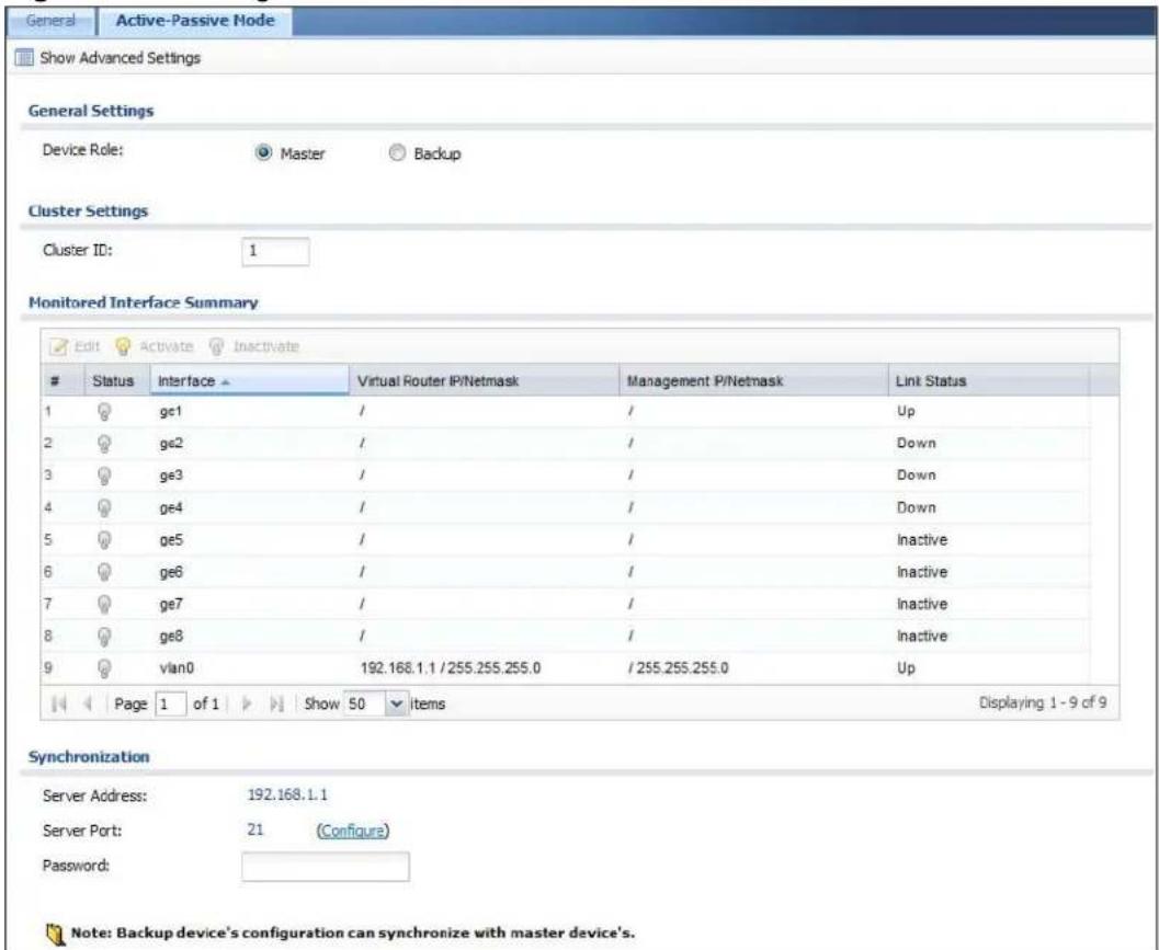
The following table describes the labels in this screen.
Table 130 Configuration > Device HA > Active-Passive Mode
| LABEL DESCRIPTION | |
| Show / Hide Advanced Settings | Click this button to display a greater or lesser number of configuration fields. |
| Device Role Select | the device HA role that the NXC plays in the virtual router.Choices are:Master- This NXC is the master NXC in the virtual router. This NXC uses the virtual IP address for each monitored interface.Note: Do not set this field to Master for two or more NXCs in the same virtual router (same cluster ID).Backup- This NXC is a backup NXC in the virtual router. This NXC does not use any of the virtual IP addresses. |
| Priority This field | is available for a backup NXC. Type the priority of the backup NXC. The backup NXC with the highest value takes over the role of the master NXC if the master NXC becomes unavailable. The priority must be between 1 and 254. (The master interface has priority 255.) |
| Enable Preemption | This field is available for a backup NXC. Select this if this NXC should become the master NXC if a lower-priority NXC is the master when this one is enabled. (If the role is master, the NXC preempts by default.) |
| Cluster Settings | |
| Cluster ID Type t | the cluster ID number. A virtual router consists of a master NXC and all of its backup NXCs. If you have multiple NXC virtual routers on your network, use a different cluster ID for each virtual router. |
| Authentication Select | the authentication method the virtual router uses. Every interface in a virtual router must use the same authentication method and password. Choices are:None- this virtual router does not use any authentication method.Text- this virtual router uses a plain text password for authentication. Type the password in the field next to the radio button. The password can consist of alphanumeric characters, the underscore, and some punctuation marks (+-/*= :; .! @&%#~‘\() ), and it can be up to eight characters long.IP AH (MD5)- this virtual router uses an encrypted MD5 password for authentication. Type the password in the field next to the radio button. The password can consist of alphanumeric characters, the underscore, and some punctuation marks (+-/*= :; .! @&%#~‘\() ), and it can be up to eight characters long. |
| Monitored Interface Summary | This table shows the status of the device HA settings and status of the NXC's interfaces. |
| Edit Select an entry | try and click this to be able to modify it. |
| Activate | To turn on an entry, select it and click Activate. |
| Inactivate | To turn off an entry, select it and click Inactivate. |
| # This is the entry's index number in the list. | |
| Status The activate | ( light bulb) icon is lit when the entry is active and dimmed when the entry is inactive. |
| Interface This field | Identifies the interface. At the time of writing, Ethernet and bridge interfaces can be included in the active-passive mode virtual router. The member interfaces of any bridge interfaces do not display separately. |
| Virtual Router IP / Netmask | This is the master NXC's (static) IP address and subnet mask for this interface. If a backup takes over for the master, it uses this IP address. These fields are blank if the interface is a DHCP client or has no IP settings. |
| Management IP / Netmask | This field displays the interface's management IP address and subnet mask. You can use this IP address and subnet mask to access the NXC whether it is in master or backup mode. |
| Link Status This tells whether the monitored interface's connection is down or up. | |
| Synchronization | Use synchronization to have a backup NXC copy the master NXC's configuration, certificates, AV signatures, IDP and application patrol signatures, and system protect signatures.Every interface's management IP address must be in the same subnet as the interface's IP address (the virtual router IP address). |
| Server Address If | this NXC is set to backup role, enter the IP address or Fully-Qualified Domain Name (FQDN) of the NXC from which to get updated configuration. Usually, you should enter the IP address or FQDN of a virtual router on a secure network.If this NXC is set to master role, this field displays the NXC's IP addresses and/or Fully-Qualified Domain Names (FQDN) through which NXCs in backup role can get updated configuration from this NXC. |
| Sync. Now Click this to copy the specified NXC's configuration. | |
| Server Port If this | NXC is set to backup role, enter the port number to use for Secure FTP when synchronizing with the specified master NXC.If this NXC is set to master role, this field displays the NXC's Secure FTP port number. Click the link if you need to change the FTP port number.Every NXC in the virtual router must use the same port number. If the master NXC changes, you have to manually change this port number in the backups. |
| Password Enter the password used for verification during synchronization. Every NXC in the virtual router must use the same password.If you leave this field blank in the master NXC, no backup NXCs can synchronize from it.If you leave this field blank in a backup NXC, it cannot synchronize from the master NXC. | |
| Auto Synchronize | Select this to get the updated configuration automatically from the specified NXC according to the specified Interval. The first synchronization begins after the specified Interval; the NXC does not synchronize immediately. |
| Interval | When you select Auto Synchronize, set how often the NXC synchronizes with the master. |
| Apply This appears when the NXC is currently using active-passive mode device HA. Click Apply to save your changes back to the NXC. | |
| Reset | Click Reset to return the screen to its last-saved settings. |
23.3.1 Edit Monitored Interface
This screen lets you enable or disable monitoring of an interface and set the interface's management IP address and subnet mask. To access this screen, click Configuration > Device HA > Active-Passive Mode > Edit.
If you configure device HA settings for an Ethernet interface and later add the Ethernet interface to a bridge, the NXC retains the interface's device HA settings and uses them again if you later remove the interface from the bridge. If the bridge is later deleted or the interface is removed from it, Device HA will recover the interface's setting.
A bridge interface's device HA settings are not retained if you delete the bridge interface.
Figure 161 Device HA > Active-Passive Mode > Edit Monitored Interface
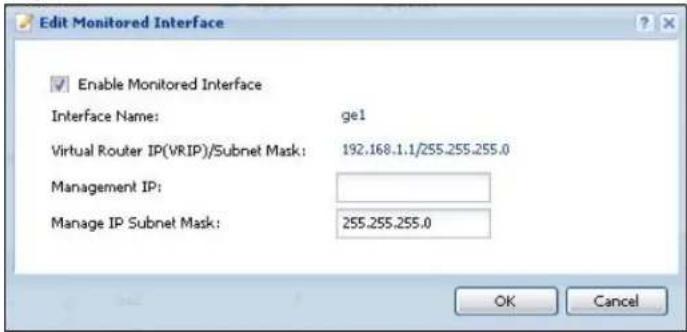
The following table describes the labels in this screen.
Table 131 Device HA > Active-Passive Mode > Edit Monitored Interface
| LABEL DESCRIPTION | |
| Enable Monitored Interface | Select this to have device HA monitor the status of this interface's connection. |
| Interface Name | This identifies the interface.Note: Do not connect the bridge interfaces on two NXCs without device HA activated on both. Doing so could cause a broadcast storm.Either activate device HA before connecting the bridge interfaces or disable the bridge interfaces, connect the bridge interfaces, activate device HA, and finally reactivate the bridge interfaces. |
| Virtual Router IP (VRIP) / Subnet Mask | This is the interface's (static) IP address and subnet mask in the virtual router. Whichever NXC is currently serving as the master uses this virtual router IP address and subnet mask. These fields are blank if the interface is a DHCP client or has no IP settings. |
| Management IP | Enter the interface's IP address for management access. You can use this IP address to access the NXC whether it is the master or a backup. This management IP address should be in the same subnet as the interface IP address. |
| Manage IP Subnet Mask | Enter the subnet mask of the interface's management IP address. |
| OK | Click OK to save your changes back to the NXC. |
| Cancel | Click Cancel to exit this screen without saving your changes. |
23.4 Technical Reference
The following section contains additional technical information about the features described in this chapter.
Virtual Router
The master and backup NXC form a single 'virtual router'. In the following example, master NXC A and backup NXC B form a virtual router.
Figure 162 Virtual Router
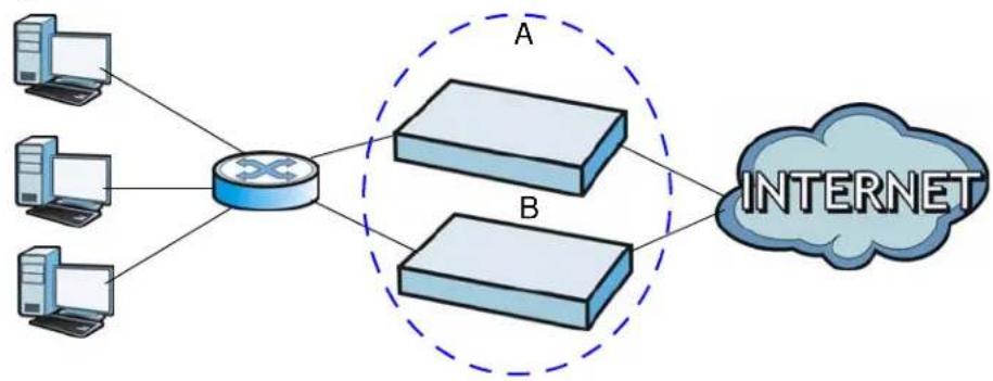
flowchart
graph TD
    A["Server 1"] --> R["Router"]
    B["Server 2"] --> R
    C["Server 3"] --> R
    R --> D["Internet Cloud"]
    style D fill:#f9f,stroke:#333
Cluster ID
You can have multiple NXC virtual routers on your network. Use a different cluster ID to identify each virtual router. In the following example, NXCs A and B form a virtual router that uses cluster ID 1. NXCs C and D form a virtual router that uses cluster ID 2.
Figure 163 Cluster IDs for Multiple Virtual Routers
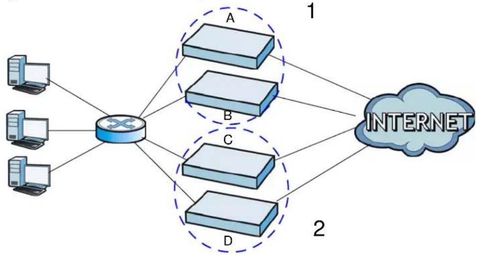
flowchart
graph TD
    A["Computer"] --> R["Router"]
    B["Computer"] --> R
    C["Computer"] --> R
    D["Computer"] --> R
    R --> E["1"]
    R --> F["2"]
    R --> G["INTERNET"]
Monitored Interfaces in Active-Passive Mode Device HA
You can select which interfaces device HA monitors. If a monitored interface on the NXC loses its connection, device HA has the backup NXC take over.
Enable monitoring for the same interfaces on the master and backup NXCs. Each monitored interface must have a static IP address and be connected to the same subnet as the corresponding interface on the backup or master NXC.
Virtual Router and Management IP Addresses
- If a backup takes over for the master, it uses the master's IP addresses. These IP addresses are known as the virtual router IP addresses.
• Each interface can also have a management IP address. You can connect to this IP address to manage the NXC regardless of whether it is the master or the backup.
For example, NXC B takes over A's 192.168.1.1 LAN interface IP address. This is a virtual router IP address. NXC A keeps it's LAN management IP address of 192.168.1.5 and NXC B has its own LAN management IP address of 192.168.1.6. These do not change when NXC B becomes the master.
Figure 164 Management IP Addresses
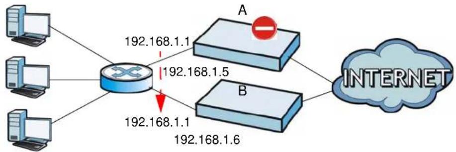
flowchart
graph TD
    A["Computer"] --> R["Router"]
    B["Computer"] --> R
    C["Computer"] --> R
    D["Computer"] --> R
    R --> E["192.168.1.1"]
    R --> F["192.168.1.5"]
    R --> G["192.168.1.1"]
    R --> H["192.168.1.6"]
    I["A"] --> J["Router"]
    K["B"] --> J
    J --> L["INTERNET"]
Active-Passive Mode Device HA with Bridge Interfaces
Here are two ways to avoid a broadcast storm when you connect the bridge interfaces on two NXCs.
First Option for Connecting the Bridge Interfaces on Two NXCs
The first way is to activate device HA before connecting the bridge interfaces as shown in the following example.
1 Make sure the bridge interfaces of the master NXC (A) and the backup NXC (B) are not connected.
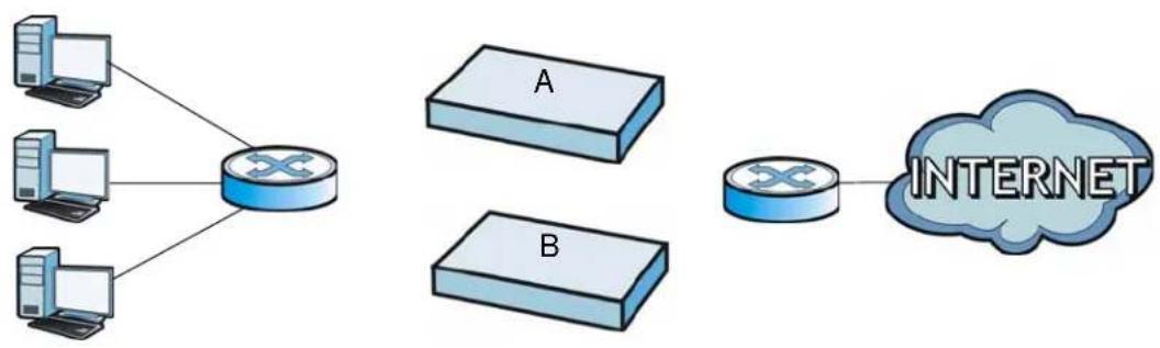
flowchart
graph TD
    A["Server"] --> C["Router"]
    B["Client 1"] --> C
    D["Client 2"] --> C
    E["Client 3"] --> C
    C --> F["A"]
    C --> G["B"]
    F --> H["Internet"]
2 Configure the bridge interface on the master NXC, set the bridge interface as a monitored interface, and activate device HA.
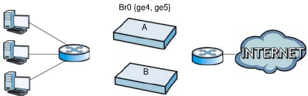
3 Configure the bridge interface on the backup NXC, set the bridge interface as a monitored interface, and activate device HA.
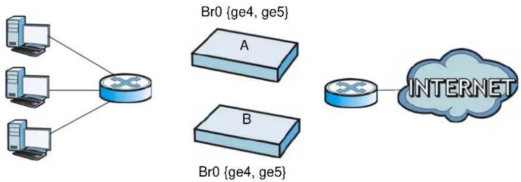
flowchart
graph TD
    A["Router"] --> B["PC1"]
    A --> C["PC2"]
    A --> D["PC3"]
    B --> E["Br0 {ge4, ge5}"]
    C --> F["Br0 {ge4, ge5}"]
    D --> G["Br0 {ge4, ge5}"]
    E --> H["Router"]
    F --> H
    G --> H
    H --> I["INTERNET"]
4 Connect the NXCs.
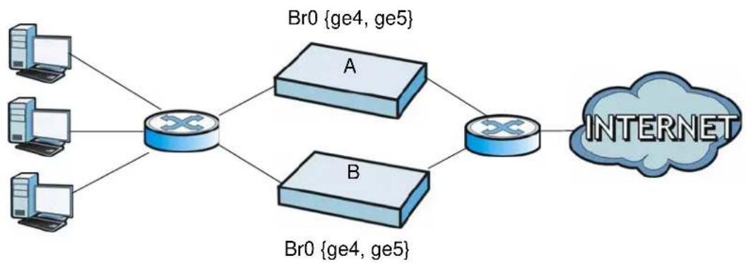
flowchart
graph TD
    A["Computer 1"] --> C["Router"]
    B["Computer 2"] --> C
    D["Computer 3"] --> C
    C --> E["A"]
    C --> F["B"]
    E --> G["Router"]
    F --> G
    G --> H["INTERNET"]
Second Option for Connecting the Bridge Interfaces on Two NXCs
Another option is to disable the bridge interfaces, connect the bridge interfaces, activate device HA, and finally reactivate the bridge interfaces as shown in the following example.
1 In this case the NXCs are already connected, but the bridge faces have not been configured yet. Configure a disabled bridge interface on the master NXC but disable it. Then set the bridge interface as a monitored interface, and activate device HA.
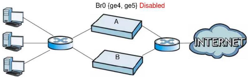
flowchart
graph TD
    A["Router"] --> B["Switch"]
    C["Router"] --> B
    D["Router"] --> B
    E["Router"] --> B
    B --> F["Switch"]
    G["Internet"] --> F
    style A fill:#cce5ff,stroke:#333
    style C fill:#cce5ff,stroke:#333
    style D fill:#cce5ff,stroke:#333
    style E fill:#cce5ff,stroke:#333
    style F fill:#ccf2ff,stroke:#333
2 Configure a corresponding disabled bridge interface on the backup NXC. Then set the bridge interface as a monitored interface, and activate device HA.
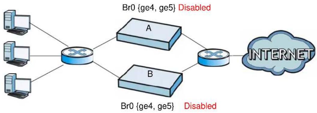
flowchart
graph TD
    A["Server 1"] --> C["Router"]
    B["Server 2"] --> C
    D["Server 3"] --> C
    C --> E["A"]
    C --> F["B"]
    E --> G["Router"]
    F --> G
    G --> H["INTERNET"]
    style H fill:#ccc,stroke:#333
3 Enable the bridge interface on the master NXC and then on the backup NXC.
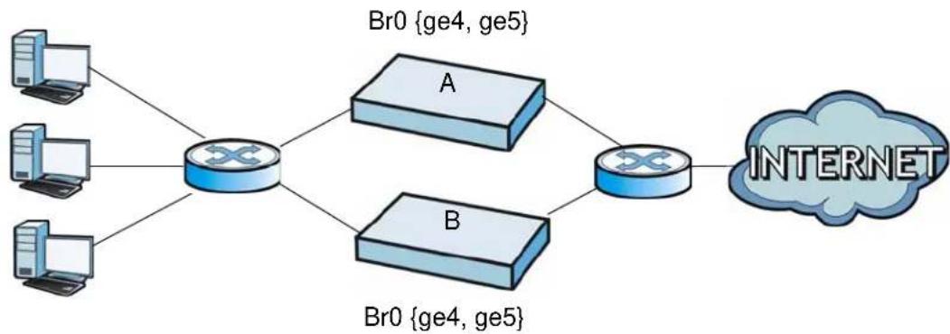
flowchart
graph TD
    A["Computer 1"] --> C["Router"]
    B["Computer 2"] --> C
    D["Computer 3"] --> C
    C --> E["A"]
    C --> F["B"]
    E --> G["Router"]
    F --> G
    G --> H["INTERNET"]
4 Connect the NXCs.
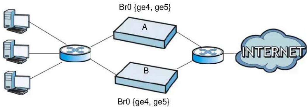
flowchart
graph TD
    A["Computer 1"] --> C["Router"]
    B["Computer 2"] --> C
    D["Computer 3"] --> C
    C --> E["A"]
    C --> F["B"]
    E --> G["Router"]
    F --> G
    G --> H["INTERNET"]
Synchronization
During synchronization, the master NXC sends the following information to the backup NXC.
- Startup configuration file (startup-config.conf)
• AV signatures
• IDP and application patrol signatures
• System protect signatures
• Certificates (My Certificates, and Trusted Certificates)
Synchronization does not change the device HA settings in the backup NXC.
Synchronization affects the entire device configuration. You can only configure one set of settings for synchronization, regardless of how many VRRP groups you might configure. The NXC uses Secure FTP (on a port number you can change) to
synchronize, but it is still recommended that the backup NXC synchronize with a master NXC on a secure network.
The backup NXC gets the configuration from the master NXC. The backup NXC cannot become the master or be managed while it applies the new configuration. This usually takes two or three minutes or longer depending on the configuration complexity.
The following restrictions apply with active-passive mode.
- The master NXC must have no inactive monitored interfaces.
- The backup NXC cannot be the master. This refers to the actual role at the time of synchronization, not the role setting in the configuration screen.
The backup applies the entire configuration if it is different from the backup's current configuration.
User/Group
24.1 Overview
This chapter describes how to set up user accounts, user groups, and user settings for the NXC. You can also set up rules that control when users have to log in to the NXC before the NXC routes traffic for them.
24.1.1 What You Can Do in this Chapter
- The User screen (see Section 24.2 on page 376) provides a summary of all user accounts.
- The Group screen (see Section 24.3 on page 379) provides a summary of all user groups. In addition, this screen allows you to add, edit, and remove user groups. User groups may consist of access users and other user groups. You cannot put admin users in user groups
- The Setting screen (see Section 24.4 on page 381) controls default settings, login settings, lockout settings, and other user settings for the NXC. You can also use this screen to specify when users must log in to the NXC before it routes traffic for them.
24.1.2 What You Need To Know
The following terms and concepts may help as you read this chapter.
User Account
A user account defines the privileges of a user logged into the NXC. User accounts are used in firewall rules and application patrol, in addition to controlling access to configuration and services in the NXC.
User Types
These are the types of user accounts the NXC uses.
Table 132 Types of User Accounts
| TYPE ABILITIES | LOGIN METHOD(S) | |
| Admin Users | ||
| admin Change N | XC configuration (web, CLI) WWW, TELNET | T, SSH, FTP, Console, Dial-in |
| limited-admin Look | Look at NXC configuration (web, CLI) Perform basic diagnostics (CLI) | WWW, TELNET, SSH, Console, Dial-in |
| Access Users | ||
| user Access network servicesBrowse user-mode commands (CLI) | Captive Portal, TELNET, SSH | |
| guest Access network services Captive Portal | ||
| ext-user External user account Captive Portal | ||
| ext-group-user External group user account | Captive Portal | |
Note: The default admin account is always authenticated locally, regardless of the authentication method setting.
Ext-User Accounts
Set up an ext-user account if the user is authenticated by an external server and you want to set up specific policies for this user in the NXC. If you do not want to set up policies for this user, you do not have to set up an ext-user account.
All ext-user users should be authenticated by an external server, such as AD, LDAP or RADIUS. If the NXC tries to use the local database to authenticate an ext-user, the authentication attempt always fails.
Note: If the NXC tries to authenticate an ext-user using the local database, the attempt always fails.
Once an ext-user user has been authenticated, the NXC tries to get the user type from the external server. If the external server does not have the information, the NXC sets the user type for this session to User.
Ext-Group-User Accounts
Ext-Group-User accounts work are similar to ext-user accounts but allow you to group users by the value of the group membership attribute configured for the AD or LDAP server.
Ext-Server Accounts
Ext-Server accounts are admin accounts that can log into the NXC from the WAN and which are authenticated by an associated RADIUS server.
User Groups
User groups may consist of user accounts or other user groups. Use user groups when you want to create the same rule for several user accounts, instead of creating separate rules for each one.
Note: You cannot put access users and admin users in the same user group.
Note: You cannot put the default admin account into any user group.
User Awareness
By default, users do not have to log into the NXC to use the network services it provides. The NXC automatically routes packets for everyone. If you want to restrict network services that certain users can use via the NXC, you can require them to log in to the NXC first. The NXC is then ‘aware’ of the user who is logged in and you can create ‘user-aware policies’ that define what services they can use.
User Role Priority
The NXC checks the following in order of priority.
1 User role setting in ext-user.
2 User role setting in ext-group-user.
3 User role setting in default user (ldap-users, ad-users, radius-users).
24.2 User Summary
The User screen provides a summary of all user accounts. To access this screen click Configuration > Object > User/ Group.
Figure 165 Configuration > Object > User
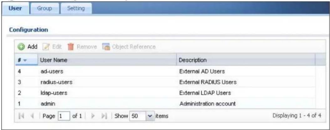
The following table describes the labels in this screen.
Table 133 Configuration > Object > User
| LABEL DESCRIPTION | |
| Add Click this to | create a new entry. |
| Edit | Double-click an entry or select it and click Edit to open a screen where you can modify the entry's settings. |
| Remove | To remove an entry, select it and click Remove. The NXC confirms you want to remove it before doing so. |
| Object References | Select an entry and click Object References to open a screen that shows which settings use the entry. |
| # This field is a sequential value, and it is not associated with a specific user. | |
| User Name This | field displays the user name of each user. |
| Description This | field displays the description for each user. |
24.2.1 Add/Edit User
The User Add/ Edit screen allows you to create a new user account or edit an existing one.
24.2.1.1 Rules for User Names
Enter a user name from 1 to 31 characters.
The user name can only contain the following characters:
- Alphanumeric A-z 0-9 (there is no unicode support)
- _ [underscores]
- [dashes]
The first character must be alphabetical (A-Z a-z), an underscore (_), or a dash (-). Other limitations on user names are:
- User names are case-sensitive. If you enter a user 'bob' but use 'BOB' when connecting via CIFS or FTP, it will use the account settings used for 'BOB' not 'bob'.
- User names have to be different than user group names.
• Here are the reserved user names:

To access this screen, go to the User screen, and click Add or Edit.
Figure 166 Configuration > User/Group > User > Add/Edit A User
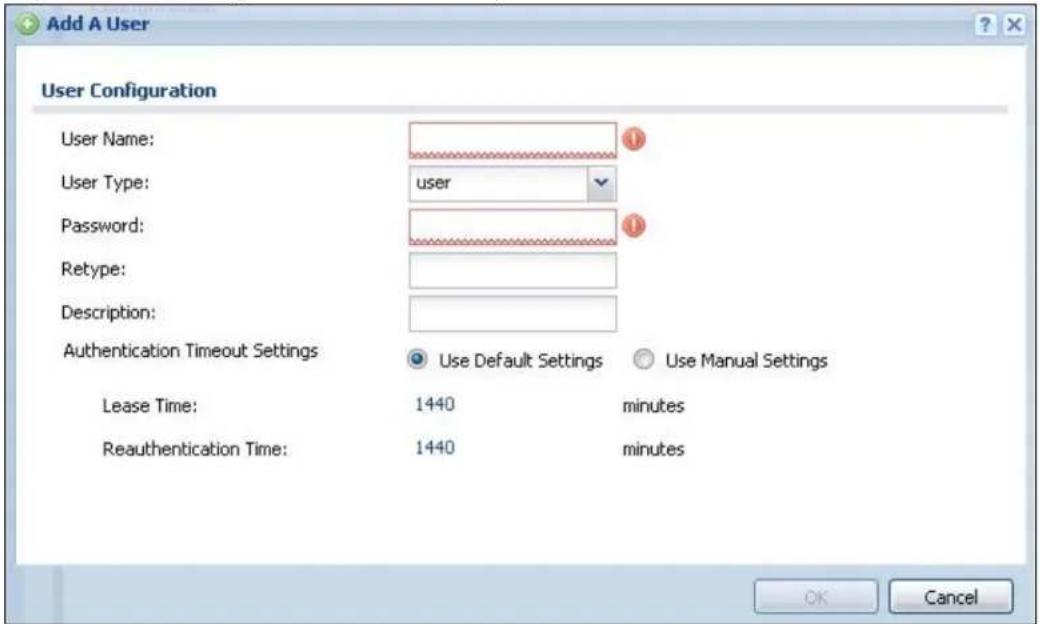
The following table describes the labels in this screen.
Table 134 Configuration > User/Group > User > Add/Edit A User
| LABEL DESCRIPTION | |
| User Name Type the user name for this user account. You may use 1-31 alphanumeric characters, underscores( ), or dashes (-), but the first character cannot be a number. This value is case-sensitive. User names have to be different than user group names, and some words are reserved.. | |
| User Type Select what type of user this is. Choices are:admin - this user can look at and change the configuration of the NXClimited-admin - this user can look at the configuration of the NXC but not to change ituser - this user has access to the NXC's services but cannot look at the configurationguest - this user has access to the NXC's services but cannot look at the configurationext-user - this user account is maintained in a remote server, such as RADIUS or LDAP.ext-group-user - this user account is maintained in a remote server, such as RADIUS or LDAP. | |
| Password | This field is not available if you select the ext-user or ext-group-user type.Enter the password of this user account. It can consist of 4 - 31 alphanumeric characters. |
| Retype | This field is not available if you select the ext-user or ext-group-user type. |
| Group Identifier | This field is available for a ext-group-user type user account.Specify the value of the AD or LDAP server's Group Membership Attribute that identifies the group to which this user belongs. |
| Associated AAA Server Object | This field is available for a ext-group-user type user account. Select the AAA server to use to authenticate this account's users. |
| Description Enter the description of each user, if any. You can use up to 60 printable ASCII characters. Default descriptions are provided. | |
| Authentication Timeout Settings | If you want to set authentication timeout to a value other than the default settings, select Use Manual Settings then fill your preferred values in the fields that follow. |
| Lease Time Enter the number of minutes this user has to renew the current session before the user is logged out. You can specify 1 to 1440 minutes. You can enter 0 to make the number of minutes unlimited. Admin users renew the session every time the main screen refreshes in the Web Configurator. Access users can renew the session by clicking the Renew button on their screen. If you allow access users to renew time automatically, the users can select this check box on their screen as well. In this case, the session is automatically renewed before the lease time expires. | |
| Reauthentication Time | Type the number of minutes this user can be logged into the NXC in one session before the user has to log in again. You can specify 1 to 1440 minutes. You can enter 0 to make the number of minutes unlimited. Unlike Lease Time, the user has no opportunity to renew the session without logging out. |
| Configuration Validation | Use a user account from the group specified above to test if the configuration is correct. Enter the account's user name in the User Name field and click Test. |
| OK | Click OK to save your changes back to the NXC. |
| Cancel | Click Cancel to exit this screen without saving your changes. |
24.3 Group Summary
User groups consist of access users and other user groups. You cannot put admin users in user groups. The Group screen provides a summary of all user groups. In addition, this screen allows you to add, edit, and remove user groups. To access this screen, login to the Web Configurator, and click Configuration > Object > User/Group > Group.
Figure 167 Configuration > Object > User/Group > Group
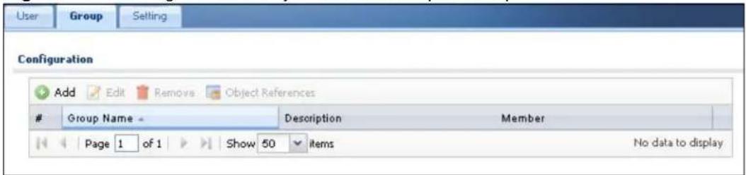
The following table describes the labels in this screen.
Table 135 Configuration > Object > User/Group > Group
| LABEL DESCRIPTION | |
| Add Click this to | create a new entry. |
| Edit | Double-click an entry or select it and click Edit to open a screen where you can modify the entry's settings. |
| Remove | To remove an entry, select it and click Remove. The NXC confirms you want to remove it before doing so. Removing a group does not remove the user accounts in the group. |
| Object References | Select an entry and click Object References to open a screen that shows which settings use the entry. |
| # This field is a sequential value, and it is not associated with a specific user group. | |
| Group Name This field displays the name of each user group. | |
| Description This | field displays the description for each user group. |
| Member This field | lists the members in the user group. Each member is separated by a comma. |
24.3.1 Add/Edit Group
This screen allows you to add a new user group or edit an existing one. To access this screen, go to the Group screen, and click either the Add icon or an Edit icon.
Figure 168 Configuration > User/Group > Group > Add/Edit Group
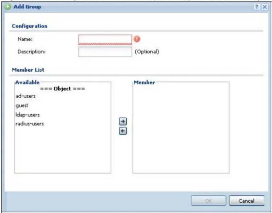
The following table describes the labels in this screen.
Table 136 Configuration > User/Group > Group > Add/Edit Group
| LABEL DESCRIPTION | |
| Name Type the | name for this user group. You may use 1-31 alphanumeric characters, underscores( ), or dashes (-), but the first character cannot be a number. This value is case-sensitive. User group names have to be different than user names. |
| Description Enter | the description of the user group, if any. You can use up to 60 characters, punctuation marks, and spaces. |
| Member List | The Member list displays the names of the users and user groups that have been added to the user group. The order of members is not important. Select users and groups from the Available list that you want to be members of this group and move them to the Member list. You can double-click a single entry to move it or use the [Shift] or [Ctrl] key to select multiple entries and use the arrow button to move them.Move any members you do not want included to the Available list. |
| OK | Click OK to save your changes back to the NXC. |
| Cancel | Click Cancel to exit this screen without saving your changes. |
24.4 Setting
This screen controls default settings, login settings, lockout settings, and other user settings for the NXC. You can also use this screen to specify when users must log in to the NXC before it routes traffic for them.
To access this screen, login to the Web Configurator, and click Configuration > Object > User/ Group > Setting.
Figure 169 Configuration > Object > User/Group > Setting
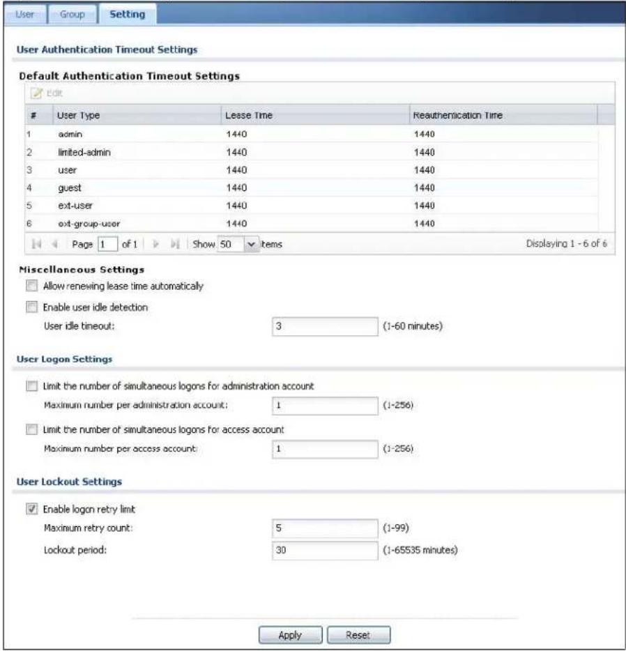
The following table describes the labels in this screen.
Table 137 Configuration > Object > User/Group > Setting
| LABEL DESCRIPTION | |
| User AuthenticationTimeout Settings | |
| Default AuthenticationTimeout Settings | These authentication timeout settings are used by default when you create a new user account. They also control the settings for any existing user accounts that are set to use the default settings. You can still manually configure any user account's authentication timeout settings. |
| Edit | Double-click an entry or select it and click Edit to open a screen where you can modify the entry's settings. |
| # This field is a sequential | value, and it is not associated with a specific entry. |
| User Type These are the kinds of user account the NXC supports.admin- this user can look at and change the configuration of the NXClimited-admin- this user can look at the configuration of the NXC but not to change ituser- this user has access to the NXC's services but cannot look at the configurationguest- this user has access to the NXC's services but cannot look at the configurationext-user- this user account is maintained in a remote server, such as RADIUS or LDAP.ext-group-user- this user account is maintained in a remote server, such as RADIUS or LDAP. | |
| Lease Time This is the default lease time in minutes for each type of user account. It defines the number of minutes the user has to renew the current session before the user is logged out.Admin users renew the session every time the main screen refreshes in the Web Configurator. Access users can renew the session by clicking theRenewbutton on their screen. If you allow access users to renew time automatically, the users can select this check box on their screen as well. In this case, the session is automatically renewed before the lease time expires. | |
| Reauthentication Time | This is the default reauthentication time in minutes for each type of user account. It defines the number of minutes the user can be logged into the NXC in one session before having to log in again. UnlikeLeasetime, the user has no opportunity to renew the session without logging out. |
| Miscellaneous Settings | |
| Allow renewing lease time automatically | Select this check box if access users can renew lease time automatically, as well as manually, simply by selecting theUpdating leasetime automaticallycheck box on their screen. |
| Enable user idle detection | This is applicable for access users.Select this check box if you want the NXC to monitor how long each access user is logged in and idle (in other words, there is no traffic for this access user). The NXC automatically logs out the access user once theUser idletimeouthas been reached. |
| User idle timeout This is applicable for access users.This field is effective whenEnable user idledetectionis checked. Type the number of minutes each access user can be logged in and idle before the NXC automatically logs out the access user. | |
| User Logon Settings | |
| Limit the number of simultaneous logons for administration account | Select this check box if you want to set a limit on the number of simultaneous logins by admin users. If you do not select this, admin users can login as many times as they want at the same time using the same or different IP addresses. |
| Maximum number per administration account | This field is effective when Limit ... for administration account is checked. Type the maximum number of simultaneous logins by each admin user. |
| Limit the number of simultaneous logons for access account | Select this check box if you want to set a limit on the number of simultaneous logins by non-admin users. If you do not select this, access users can login as many times as they want as long as they use different IP addresses. |
| Maximum number per access account | This field is effective when Limit ... for access account is checked. Type the maximum number of simultaneous logins by each access user. |
| User Lockout Settings | |
| Enable logon retry limit | Select this check box to set a limit on the number of times each user can login unsuccessfully (for example, wrong password) before the IP address is locked out for a specified amount of time. |
| Maximum retry count | This field is effective when Enable logon retry limit is checked. Type the maximum number of times each user can login unsuccessfully before the IP address is locked out for the specified lockout period. The number must be between 1 and 99. |
| Lockout period | This field is effective when Enable logon retry limit is checked. Type the number of minutes the user must wait to try to login again, if logon retry limit is enabled and the maximum retry count is reached. This number must be between 1 and 65,535 (about 45.5 days). |
| Apply Click Apply to save | the changes. |
| Reset | Click Reset to return the screen to its last-saved settings. |
24.4.1 Edit User Authentication Timeout Settings
This screen allows you to set the default authentication timeout settings for the selected type of user account. These default authentication timeout settings also control the settings for any existing user accounts that are set to use the default settings. You can still manually configure any user account's authentication timeout settings.
To access this screen, go to the Configuration > Object > User/ Group > Setting screen, and click one of the Default Authentication Timeout Settings section's Edit icons.
Figure 170 User/Group > Setting > Edit User Authentication Timeout Settings
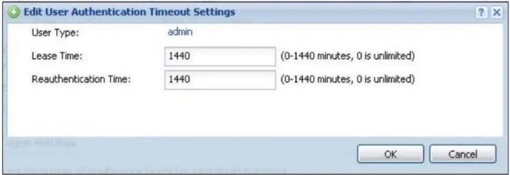
The following table describes the labels in this screen.
Table 138 User/Group > Setting > Edit User Authentication Timeout Settings
| LABEL DESCRIPTION | |
| User Type This read-only field identifies the type of user account for which you are configuring the default settings.admin- this user can look at and change the configuration of the NXClimited-admin- this user can look at the configuration of the NXC but not to change ituser- this user has access to the NXC's services but cannot look at the configurationext-user- this user account is maintained in a remote server, such as RADIUS or LDAP.ext-group-user- this user account is maintained in a remote server, such as RADIUS or LDAP. | |
| Lease Time Enter | the number of minutes this type of user account has to renew the current session before the user is logged out. You can specify 1 to 1440 minutes. You can enter 0 to make the number of minutes unlimited.Admin users renew the session every time the main screen refreshes in the Web Configurator. Access users can renew the session by clicking theRenewbutton on their screen. If you allow access users to renew time automatically, the users can select this check box on their screen as well. In this case, the session is automatically renewed before the lease time expires. |
| Reauthentication Time | Type the number of minutes this type of user account can be logged into the NXC in one session before the user has to log in again. You can specify 1 to 1440 minutes. You can enter 0 to make the number of minutes unlimited. UnlikeLeasetime, the user has no opportunity to renew the session without logging out. |
| OK | Click OKto save your changes back to the NXC. |
| Cancel | Click Cancelto exit this screen without saving your changes. |
24.4.2 User Aware Login Example
Access users cannot use the Web Configurator to browse the configuration of the NXC. Instead, after access users log into the NXC, the following screen appears.
Figure 171 User Aware Login
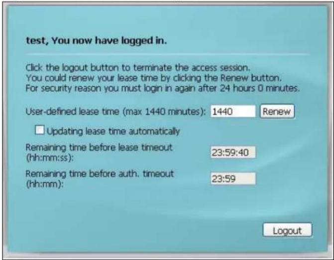
The following table describes the labels in this screen.
Table 139 User Aware Login
| LABEL DESCRIPTION | |
| User-defined lease time (max ... minutes) | Access users can specify a lease time shorter than or equal to the one that you specified. The default value is the lease time that you specified. |
| Renew Access users can click this button to reset the lease time, the amount of time remaining before the NXC automatically logs them out. The NXC sets this amount of time according to theUser-defined lease time field in this screenLease time field in the User Add/ Edit screenLease time field in the Setting screen | |
| Updating lease time automatically | This box appears if you checked the Allow renewing lease time automatically box in the Setting screen. Access users can select this check box to reset the lease time automatically 30 seconds before it expires. Otherwise, access users have to click the Renew button to reset the lease time. |
| Remaining time before lease timeout | This field displays the amount of lease time that remains, though the user might be able to reset it. |
| Remaining time before auth. timeout | This field displays the amount of time that remains before the NXC automatically logs the access user out, regardless of the lease time. |
25.1 Overview
This chapter shows you how to configure preset profiles for the Access Points (APs) connected to your NXC's wireless network.
25.1.1 What You Can Do in this Chapter
- The Radio screen (Section 25.2 on page 388) creates radio configurations that can be used by the APs.
- The SSI D screen (Section 25.3 on page 392) configures three different types of profiles for your networked APs.
25.1.2 What You Need To Know
The following terms and concepts may help as you read this chapter.
Wireless Profiles
At the heart of all wireless AP configurations on the NXC are profiles. A profile represents a group of saved settings that you can use across any number of connected APs. You can set up the following wireless profile types:
- Radio - This profile type defines the properties of an AP's radio transmitter. You can have a maximum of 64 radio profiles on the NXC.
- SSID - This profile type defines the properties of a single wireless network signal broadcast by an AP. Each radio on a single AP can broadcast up to 8 SSIDs. You can have a maximum of 64 SSID profiles on the NXC.
- Security - This profile type defines the security settings used by a single SSID. It controls the encryption method required for a wireless client to associate itself with the SSID. You can have a maximum of 64 security profiles on the NXC.
- MAC Filtering - This profile provides an additional layer of security for an SSID, allowing you to block access or allow access to that SSID based on wireless client MAC addresses. If a client's MAC address is on the list, then it is either allowed or denied, depending on how you set up the MAC Filter profile. You can have a maximum of 64 MAC filtering profiles on the NXC.
SSID
The SSID (Service Set Identifier) is the name that identifies the Service Set with which a wireless station is associated. Wireless stations associating to the access point (AP) must have the same SSID. In other words, it is the name of the wireless network that clients use to connect to it.
WEP
WEP (Wired Equivalent Privacy) encryption scrambles all data packets transmitted between the AP and the wireless stations associated with it in order to keep network communications private. Both the wireless stations and the access points must use the same WEP key for data encryption and decryption.
WPA and WPA2
Wi-Fi Protected Access (WPA) is a subset of the IEEE 802.11i standard. WPA2 (IEEE 802.11i) is a wireless security standard that defines stronger encryption, authentication and key management than WPA. Key differences between WPA(2) and WEP are improved data encryption and user authentication.
IEEE 802.1x
The IEEE 802.1x standard outlines enhanced security methods for both the authentication of wireless stations and encryption key management. Authentication is done using an external RADIUS server.
25.2 Radio
This screen allows you to create radio profiles for the APs on your network. A radio profile is a list of settings that an NWA5160N AP can use to configure either one of its two radio transmitters. To access this screen click Configuration > Object > AP Profile.
Note: You can have a maximum of 64 radio profiles on the NXC.
Figure 172 Configuration > Object > AP Profile > Radiot
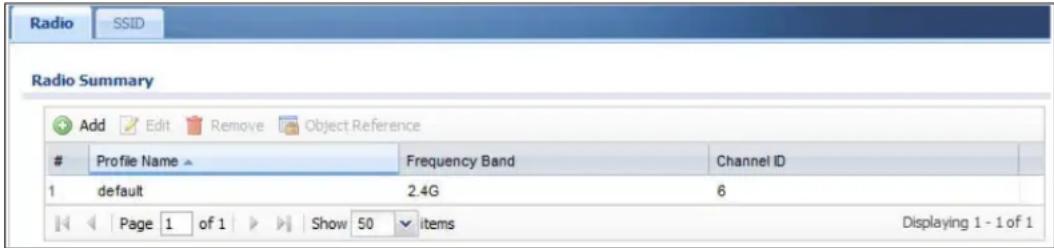
The following table describes the labels in this screen.
Table 140 Configuration > Object > AP Profile > Radio
| LABEL DESCRIPTION | |
| Add Click this to | add a new radio profile. |
| Edit Click this to | edit the selected radio profile. |
| Remove Click this to remove the selected radio profile. | |
| Object Reference | Click this to view which other objects are linked to the selected radio profile. |
| # This field is a sequential value, and it is not associated with a specific user. | |
| Profile Name This field indicates the name assigned to the radio profile. | |
| Frequency Band | This field indicates the frequency band which this radio profile is configured to use. |
| Channel ID This field indicates the broadcast channel which this radio profile is configured to use. | |
25.2.1 Add/Edit Radio Profile
This screen allows you to create a new radio profile or edit an existing one. To access this screen, click the Add button or select a radio profile from the list and click the Edit button.
Figure 173 Configuration > Object > AP Profile > Add/Edit Profile
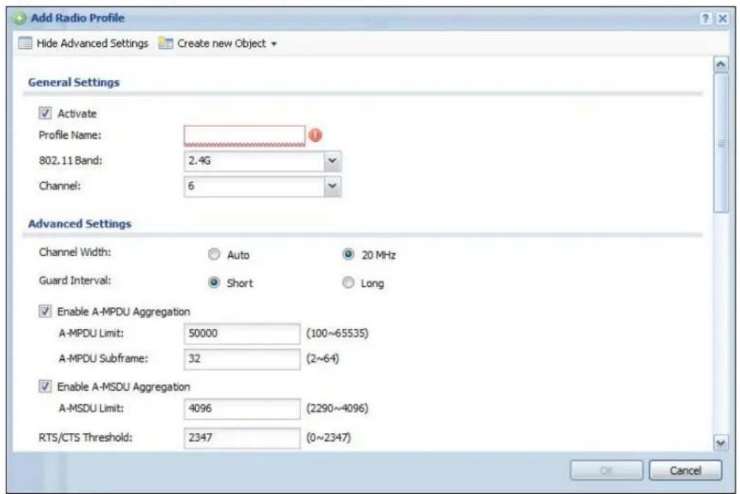
The following table describes the labels in this screen.
Table 141 Configuration > Object > AP Profile > Add/Edit Profile
| LABEL DESCRIPTION | |
| Hide / Show Advanced Settings | Click this to hide or show the Advanced Settings in this window. |
| Create New Object | Select an item from this menu to create a new object of that type.Any objects created in this way are automatically linked to this radio profile. |
| General Settings | |
| Activate Select this option to make this profile active. | |
| Profile Name Enter up to 31 alphanumeric characters to be used as this profile's name. Spaces and underscores are allowed. | |
| 802.11 Band Select the wireless band which this radio profile should use.2.4 GHz is the frequency used by IEEE 802.11b/g/n wireless clients.5 GHz is the frequency used by IEEE 802.11a/n wireless clients. | |
| Channel Select the wireless channel which this radio profile should use.It is recommended that you choose the channel least in use by other APs in the region where this profile will be implemented. This will reduce the amount of interference between wireless clients and the AP to which this profile is assigned. | |
| Advanced Settings | |
| Channel Width Select the channel bandwidth you want to use for your wireless network.Select Auto to allow the NXC to adjust the channel bandwidth depending on network conditions.Select 20 MHz if you want to lessen radio interference with other wireless devices in your neighborhood. | |
| Guard Interval | Set the guard interval for this radio profile to either short or long.The guard interval is the gap introduced between data transmission from users in order to reduce interference. Reducing the interval increases data transfer rates but also increases interference.Increasing the interval reduces data transfer rates but also reduces interference. |
| Enable A-MPDU Aggregation | Select this to enable A-MPDU aggregation.Message Protocol Data Unit (MPDU) aggregation collects Ethernet frames along with their 802.11n headers and wraps them in a 802.11n MAC header. This method is useful for increasing bandwidth throughput in environments that are prone to high error rates. |
| A-MPDU Limit Enter the maximum frame size to be aggregated. | |
| A-MPDU Subframe | Enter the maximum number of frames to be aggregated each time. |
| Enable A-MSDU Aggregation | Select this to enable A-MSDU aggregation.Mac Service Data Unit (MSDU) aggregation collects Ethernet frames without any of their 802.11n headers and wraps the header-less payload in a single 802.11n MAC header. This method is useful for increasing bandwidth throughput. It is also more efficient than A-MPDU except in environments that are prone to high error rates. |
| A-MSDU Limit Enter the maximum frame size to be aggregated. | |
| RTS/CTS Threshold | Use RTS/CTS to reduce data collisions on the wireless network if you have wireless clients that are associated with the same AP but out of range of one another. When enabled, a wireless client sends an RTS (Request To Send) and then waits for a CTS (Clear To Send) before it transmits. This stops wireless clients from transmitting packets at the same time (and causing data collisions).A wireless client sends an RTS for all packets larger than the number (of bytes) that you enter here. Set the RTS/CTS equal to or higher than the fragmentation threshold to turn RTS/CTS off. |
| Fragmentation Threshold | The threshold (number of bytes) for the fragmentation boundary for directed messages. It is the maximum data fragment size that can be sent. Enter an even number between 256 and 2346. |
| Beacon Interval | When a wirelessly networked device sends a beacon, it includes with it a beacon interval. This specifies the time period before the device sends the beacon again. The interval tells receiving devices on the network how long they can wait in low-power mode before waking up to handle the beacon. This value can be set from 80ms to 1000ms. A high value helps save current consumption of the access point. |
| DTIM Delivery Traffic Indication Message (DTIM) is the time period after which broadcast and multicast packets are transmitted to mobile clients in the Active Power Management mode. A high DTIM value can cause clients to lose connectivity with the network. This value can be set from 1 to 255. | |
| Output Power | Set the output power of the AP in this field. If there is a high density of APs in an area, decrease the output power of the NWA5160N to reduce interference with other APs. Select one of the following 100% (Full Power), 50%, 25%, or 12.5%. See the product specifications for more information on your NXC's output power.Note: Reducing the output power also reduces the NXC's effective broadcast radius. |
| Rate Configuration | This section controls the data rates permitted for clients.For each Rate, select a rate option from its list. The rates are:Fast Select - Select an 802.11 broadcast frequency to determine the baseline rate configuration.Basic Rate (Mbps) - Set the basic rate configuration in Mbps.Support Rate (Mbps) - Set the support rate configuration in Mbps.MCS Rate - Set the MCS rate configuration. |
| MBSSID Settings This section allows you to associate an SSID profile with the radio profile. | |
| Edit Select and $SID and click this button to reassign it. The selected SSID becomes editable immediately upon clicking. | |
| SSID Settings Indicates which SSID profile is associated with this radio profile. | |
| OK | Click OK to save your changes back to the NXC. |
| Cancel | Click Cancel to exit this screen without saving your changes. |
25.3 SSID
The SSID screens allow you to configure three different types of profiles for your networked APs: an SSID list, which can assign specific SSID configurations to your APs; a security list, which can assign specific encryption methods to the APs when allowing wireless clients to connect to them; and a MAC filter list, which can limit connections to an AP based on wireless clients MAC addresses.
25.3.1 SSID List
This screen allows you to create and manage SSID configurations that can be used by the APs. An SSID, or Service Set Identifier, is basically the name of the wireless network to which a wireless client can connect. The SSID appears as readable text to any device capable of scanning for wireless frequencies (such as the WiFi adapter in a laptop), and is displayed as the wireless network name when a person makes a connection to it.
To access this screen click Configuration > Object > AP Profile > SSID.
Note: You can have a maximum of 64 SSID profiles on the NXC.
Figure 174 Configuration > Object > AP Profile > SSID List
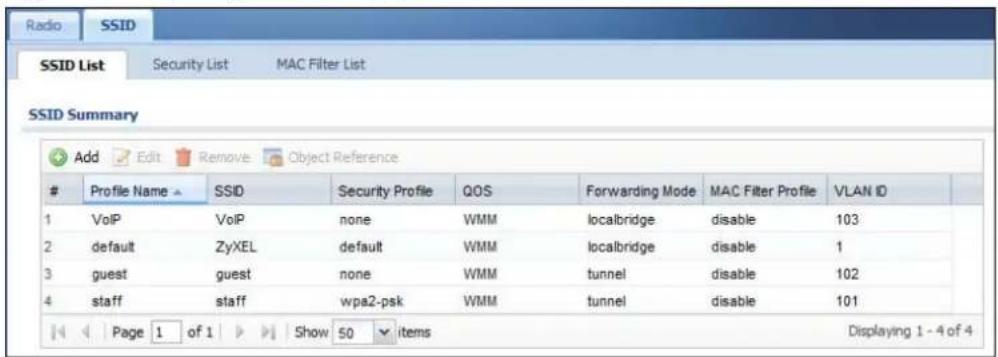
The following table describes the labels in this screen.
Table 142 Configuration > Object > AP Profile > SSID List
| LABEL DESCRIPTION | |
| Add Click this to | add a new SSID profile. |
| Edit Click this to | edit the selected SSID profile. |
| Remove Click this to remove the selected SSID profile. | |
| Object Reference | Click this to view which other objects are linked to the selected SSID profile (for example, radio profile). |
| # This field is a sequential value, and it is not associated with a specific user. | |
| Profile Name This field indicates the name assigned to the SSID profile. | |
| SSID This field indicates the SSID name as it appears to wireless clients. | |
| Security Profile This field indicates which (if any) security profile is associated with the SSID profile. | |
| QOS This field indicates the QoS type associated with the SSID profile. | |
| MAC Filter Profile This field indicates which (if any) MAC Filter Profile is associated with the SSID profile. | |
| VLAN ID This field indicates the VLAN ID associated with the SSID profile. | |
25.3.1.1 Add/Edit SSID Profile
This screen allows you to create a new SSID profile or edit an existing one. To access this screen, click the Add button or select an SSID profile from the list and click the Edit button.
Figure 175 Configuration > Object > AP Profile > Add/Edit SSID Profile
![Add SSID Profile Create new Object Profile Name: SSID: ZyXEL Security Profile: default MAC Filtering Profile: disable QoS: WMN Forwarding Mode: Local bridge VLAN ID: 1 [1~4094] Hidden SSID Enable Intra-BSS Traffic blocking OK Cancel](/content/2026/05/762668/images/4cc9dedc805e9f50d251d611ff45e086f780e468ffd6af3102f891915a993db6.jpg)
The following table describes the labels in this screen.
Table 143 Configuration > Object > AP Profile > Add/Edit SSID Profile
| LABEL DESCRIPTION | |
| Create new Object | Select an object type from the list to create a new one associated with this SSID profile. |
| Profile Name Enter | ter up to 31 alphanumeric characters for the profile name. This name is only visible in the Web Configurator and is only for management purposes. Spaces and underscores are allowed. |
| SSID Enter the $SID name for this profile. This is the name visible on the network to wireless clients. Enter up to 32 characters, spaces and underscores are allowed. | |
| Security Profile | Select a security profile from this list to associate with this SSID. If none exist, you can use the Create new Object menu to create one.Note: It is highly recommended that you create security profiles for all of your SSIDs to enhance your network security. |
| MAC Filtering Profile | Select a MAC filtering profile from the list to associate with this SSID. If none exist, you can sue the Create new Object menu to create one.MAC filtering allows you to limit the wireless clients connecting to your network through a particular SSID by wireless client MAC addresses. Any clients that have MAC addresses not in the MAC filtering profile of allowed addresses are denied connections.The disable setting means no MAC filtering is used. |
| QoS Select a Quality of Service (QoS) access category to associate with this SSID. Access categories minimize the delay of data packets across a wireless network. Certain categories, such as video or voice, are given a higher priority due to the time sensitive nature of their data packets.QoS access categories are as follows:disable:Turns off QoS for this SSID. All data packets are treated equally and not tagged with access categories.WMM:Enables automatic tagging of data packets. The NXC assigns access categories to the SSID by examining data as it passes through it and making a best guess effort. If something looks like video traffic, for instance, it is tagged as such.WMM_VOICE:All wireless traffic to the SSID is tagged as voice data. This is recommended if an SSID is used for activities like placing and receiving VoIP phone calls.WMM_VIDEO:All wireless traffic to the SSID is tagged as video data. This is recommended for activities like video conferencing.WMM_BEST_EFFORT:All wireless traffic to the SSID is tagged as “best effort,” meaning the data travels the best route it can without displacing higher priority traffic. This is good for activities that do not require the best bandwidth throughput, such as surfing the Internet.WMM_BACKGROUND:All wireless traffic to the SSID is tagged as low priority or “background traffic”, meaning all other access categories take precedence over this one. If traffic from an SSID does not have strict throughput requirements, then this access category is recommended. For example, an SSID that only has network printers connected to it. | |
| Forwarding Mode | Select a forwarding mode for traffic from this SSID. |
| VLAN ID | If you selected the Bridge forwarding mode, enter the VLAN ID that will be used to tag all traffic originating from this SSID if the VLAN is different from the native VLAN. |
| Hidden SSID Se | ect this if you want to “hide” your SSID from wireless clients. This tells any wireless clients in the vicinity of the AP using this SSID profile not to display its SSID name as a potential connection. Not all wireless clients respect this flag and display it anyway.When an SSID is “hidden” and a wireless client cannot see it, the only way you can connect to the SSID is by manually entering the SSID name in your wireless connection setup screen(s) (these vary by client, client connectivity software, and operating system). |
| Enable Intra-BSS Traffic Blocking | Select this option to prevent crossover traffic from within the same SSID. |
| OK | Click OK to save your changes back to the NXC. |
| Cancel | Click Cancel to exit this screen without saving your changes. |
25.3.2 Security List
This screen allows you to manage wireless security configurations that can be used by your SSIDs. Wireless security is implemented strictly between the AP broadcasting the SSID and the stations that are connected to it.
To access this screen click Configuration > Object > AP Profile > SSID > Security List.
Note: You can have a maximum of 64 security profiles on the NXC.
Figure 176 Configuration > Object > AP Profile > SSID > Security List
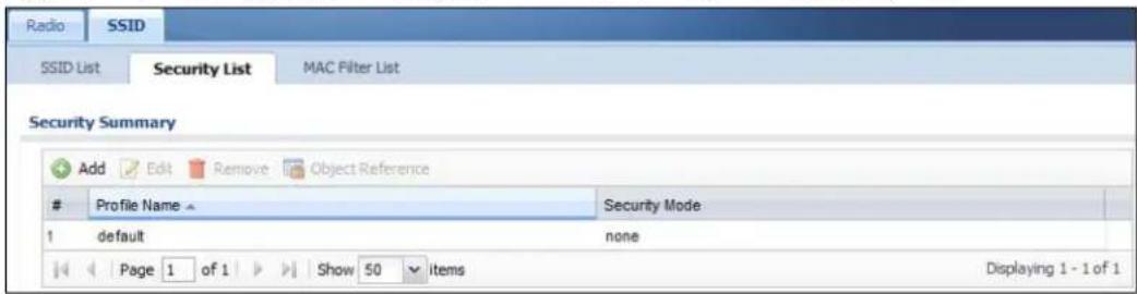
The following table describes the labels in this screen.
Table 144 Configuration > Object > AP Profile > SSID > Security List
| LABEL DESCRIPTION | |
| Add Click this to | add a new security profile. |
| Edit Click this to | edit the selected security profile. |
| Remove Click this to remove the selected security profile. | |
| Object Reference | Click this to view which other objects are linked to the selected security profile (for example, SSID profile). |
| # This field is a sequential value, and it is not associated with a specific user. | |
| Profile Name This field indicates the name assigned to the security profile. | |
| Security Mode This field indicates this profile's security mode (if any). | |
25.3.2.1 Add/Edit Security Profile
This screen allows you to create a new security profile or edit an existing one. To access this screen, click the Add button or select a security profile from the list and click the Edit button.
Note: This screen's options change based on the Security Mode selected. Only the default screen is displayed here.
Figure 177 SSID > Security ProfileAdd/Edit Security Profile
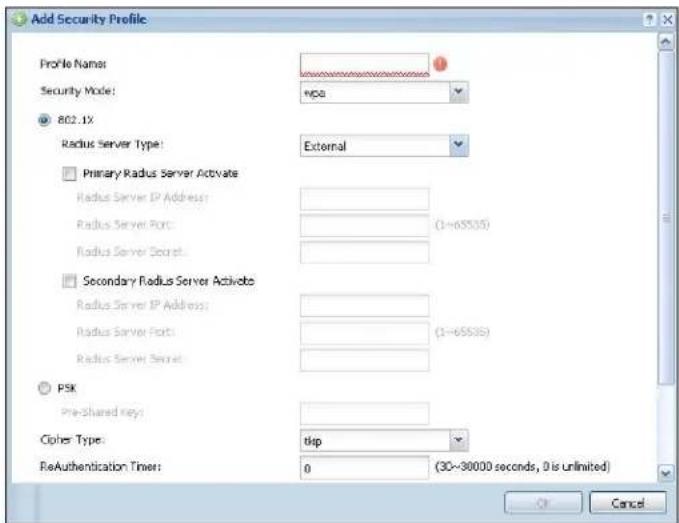
The following table describes the labels in this screen.
Table 145 SSID > Security Profile > Add/Edit Security Profile
| LABEL DESCRIPTION | |
| Profile Name Enter | up to 31 alphanumeric characters for the profile name. This name is only visible in the Web Configurator and is only for management purposes. Spaces and underscores are allowed. |
| Security Mode | Select a security mode from the list:wep, wpa, wpa2, or wpa2-mix. |
| 802.1X Select this | to enable 802.1x secure authentication. |
| Radius Server Type | Select internal to use the NXC's internal authentication database, or external to use an external RADIUS server for authentication. |
| Primary / Secondary Radius Server Activate | Select this to have the NXC use the specified RADIUS server. |
| Radius Server IP Address | Enter the IP address of the RADIUS server to be used for authentication. |
| Radius Server Port | Enter the port number of the RADIUS server to be used for authentication. |
| Radius Server Secret | Enter the shared secret password of the RADIUS server to be used for authentication. |
| Authentication Method | Select an authentication method if you have created any in theConfiguration > Object > Auth. Method screen. |
| Reauthentication Timer | Enter the interval (in seconds) between authentication requests. Enter a 0 for unlimited requests. |
| Idle Timeout Enter | the idle interval (in seconds) that a client can be idle before authentication is discontinued. |
| Authentication Type | Select a WEP authentication method. Choices areOpen or Share key. |
| Key Length Select | the bit-length of the encryption key to be used in WEP connections.If you select WEP-64:Enter 10 hexadecimal digits in the range of “A-F”, “a-f” and “0-9” (for example, 0x11AA22BB33) for eachKeyused.orEnter 5 ASCII characters (case sensitive) ranging from “a-z”, “A-Z” and “0-9” (for example, MyKey) for eachKeyused.If you select WEP-128:Enter 26 hexadecimal digits in the range of “A-F”, “a-f” and “0-9” (for example, 0x00112233445566778899AABBCC) for eachKeyused.orEnter 13 ASCII characters (case sensitive) ranging from “a-z”, “A-Z” and “0-9” (for example, MyKey12345678) for eachKeyused. |
| Key 1~4 | Based on yourKey Lengthselection, enter the appropriate length hexadecimal or ASCII key. |
| PSK Select this option to use a Pre-Shared Key with WPA encryption. | |
| Pre-Shared Key Enter a pre-shared key of between 8 and 63 case-sensitive ASCII characters (including spaces and symbols) or 64 hexadecimal characters. | |
| Cipher Type Select | an encryption cipher type from the list.auto- This automatically chooses the best available cipher based on the cipher in use by the wireless client that is attempting to make a connection.tkip- This is the Temporal Key Integrity Protocol encryption method added later to the WEP encryption protocol to further secure. Not all wireless clients may support this.aes- This is the Advanced Encryption Standard encryption method. It is a more recent development over TKIP and considerably more robust. Not all wireless clients may support this. |
| Group Key Update Timer | Enter the interval (in seconds) at which the AP updates the group WPA encryption key. |
| Pre-Authentication | Enable or Disable pre-authentication to allow the AP to send authentication information to other APs on the network, allowing connected wireless clients to switch APs without having to re-authenticate their network connection. |
| LABEL DESCRIPTION | |
| OK | Click OK to save your changes back to the NXC. |
| Cancel | Click Cancel to exit this screen without saving your changes. |
25.3.3 MAC Filter List
This screen allows you to create and manage security configurations that can be used by your SSIDs. To access this screen click Configuration > Object > AP Profile > SSI D > MAC Filter List.
Note: You can have a maximum of 64 MAC filtering profiles on the NXC.
Figure 178 Configuration > Object > AP Profile > SSID > MAC Filter List
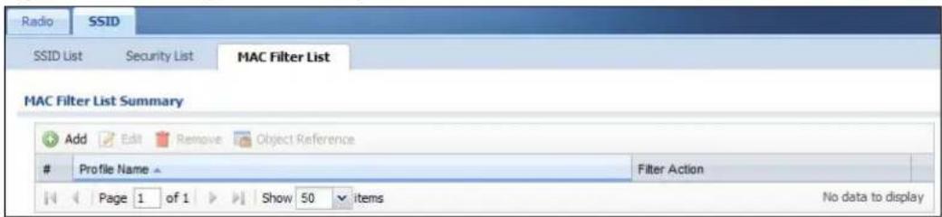
The following table describes the labels in this screen.
Table 146 Configuration > Object > AP Profile > SSID > MAC Filter List
| LABEL DESCRIPTION | |
| Add Click this to | add a new MAC filtering profile. |
| Edit Click this to | edit the selected MAC filtering profile. |
| Remove Click this to | remove the selected MAC filtering profile. |
| Object Reference | Click this to view which other objects are linked to the selected MAC filtering profile (for example, SSID profile). |
| # This field is a sequential value, and it is not associated with a specific user. | |
| Profile Name This field indicates the name assigned to the MAC filtering profile. | |
| Filter Action This field indicates this profile's filter action (if any). | |
25.3.3.1 Add/Edit MAC Filter Profile
This screen allows you to create a new MAC filtering profile or edit an existing one. To access this screen, click the Add button or select a MAC filter profile from the list and click the Edit button.
Figure 179 SSID > MAC Filter List > Add/Edit MAC Filter Profile
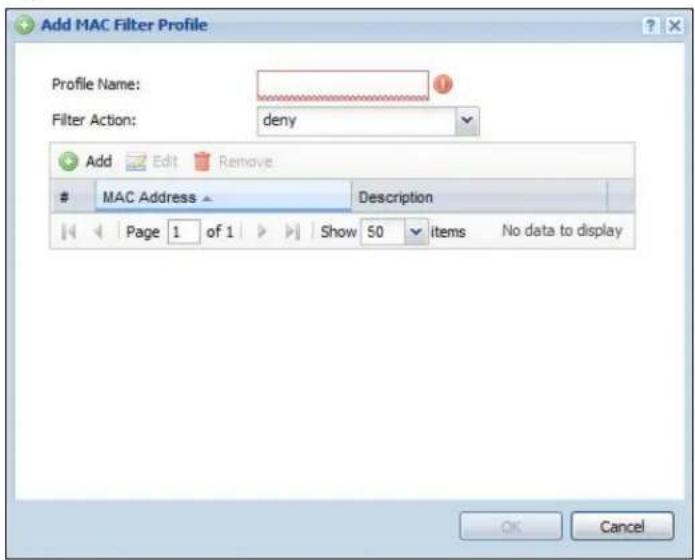
The following table describes the labels in this screen.
Table 147 SSID > MAC Filter List > Add/Edit MAC Filter Profile
| LABEL DESCRIPTION | |
| Profile Name Enter up to 31 alphanumeric characters for the profile name. This name is only visible in the Web Configurator and is only for management purposes. Spaces and underscores are allowed. | |
| Filter Action | Select allow to permit the wireless client with the MAC addresses in this profile to connect to the network through the associated SSID; select deny to block the wireless clients with the specified MAC addresses. |
| Add Click this to add a MAC address to the profile's list. | |
| Edit Click this to edit the selected MAC address in the profile's list. | |
| Remove Click this to remove the selected MAC address from the profile's list. | |
| # This field is a sequential value, and it is not associated with a specific user. | |
| MAC Address This field specifies a MAC address associated with this profile. | |
| Description This field displays a description for the MAC address associated with this profile. You can click the description to make it editable. Enter up to 60 characters, spaces and underscores allowed. | |
MON Profile
26.1 Overview
This screen allows you to set up monitor mode configurations that allow your connected APs to scan for other wireless devices in the vicinity. Once detected, you can use the MON Mode screen (Chapter 10 on page 163) to classify them as either rogues or friendlies and then manage them accordingly.
26.1.1 What You Can Do in this Chapter
The MON Profile screen (Section 26.2 on page 402) creates preset monitor mode configurations that can be used by the APs.
26.1.2 What You Need To Know
The following terms and concepts may help as you read this chapter.
Active Scan
An active scan is performed when an 802.11-compatible wireless monitoring device is explicitly triggered to scan a specified channel or number of channels for other wireless devices broadcasting on the 802.11 frequencies by sending probe request frames.
Passive Scan
A passive scan is performed when an 802.11-compatible monitoring device is set to periodically listen to a specified channel or number of channels for other wireless devices broadcasting on the 802.11 frequencies.
26.2 MON Profile
This screen allows you to create monitor mode configurations that can be used by the APs. To access this screen, login to the Web Configurator, and click Configuration > Object > MON Profile.
Figure 180 Configuration > Object > MON Profile
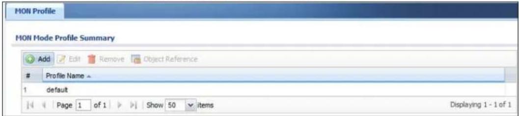
The following table describes the labels in this screen.
Table 148 Configuration > Object > MON Profile
| LABEL DESCRIPTION | |
| Add Click this to | add a new monitor mode profile. |
| Edit Click this to | edit the selected monitor mode profile. |
| Remove Click this to | remove the selected monitor mode profile. |
| Object Reference | Click this to view which other objects are linked to the selected monitor mode profile (for example, an AP management profile). |
| # This field is a sequential value, and it is not associated with a specific user. | |
| Profile Name This field indicates the name assigned to the monitor profile. | |
26.2.1 Add/Edit MON Profile
This screen allows you to create a new monitor mode profile or edit an existing one. To access this screen, click the Add button or select and existing monitor mode profile and click the Edit button.
Figure 181 Configuration > Object > MON Profile > Add/Edit MON Profile
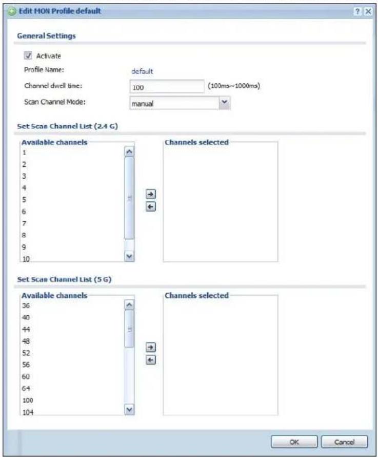
The following table describes the labels in this screen.
Table 149 Configuration > Object > MON Profile > Add/Edit MON Profile
| LABEL DESCRIPTION | |
| Activate Select this | to activate this monitor mode profile. |
| Profile Name This fi | eld indicates the name assigned to the monitor mode profile. |
| Channel dwell time | Enter the interval (in milliseconds) before the AP switches to another channel for monitoring. |
| Scan Channel Mode | Select auto to have the AP switch to the next sequential channel once the Channel dwell time expires.Select manual to set specific channels through which to cycle sequentially when the Channel dwell time expires. Selecting this options makes the Scan Channel List options available. |
| Set Scan Channel List (2.4 G) | Move a channel from the Available channels column to the Channels selected column to have the APs using this profile scan that channel when Scan Channel Mode is set to manual.These channels are limited to the 2 GHz range (802.11 b/g/n). |
| Set Scan Channel List (5 G) | Move a channel from the Available channels column to the Channels selected column to have the APs using this profile scan that channel when Scan Channel Mode is set to manual.These channels are limited to the 5 GHz range (802.11 a/n). |
| OK | Click OK to save your changes back to the NXC. |
| Cancel | Click Cancel to exit this screen without saving your changes. |
26.3 Technical Reference
The following section contains additional technical information about the features described in this chapter.
Rogue APs
Rogue APs are wireless access points operating in a network's coverage area that are not under the control of the network's administrators, and can open up holes in a network's security. Attackers can take advantage of a rogue AP's weaker (or non-existent) security to gain access to the network, or set up their own rogue APs in order to capture information from wireless clients. If a scan reveals a rogue AP, you can use commercially-available software to physically locate it.
Figure 182 Rogue AP Example
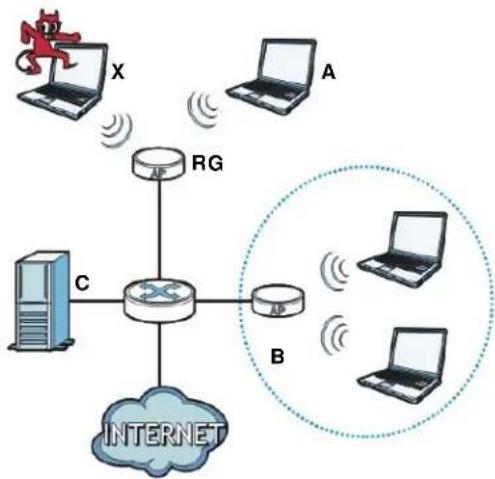
flowchart
graph TD
    X["User"] -->|X| Router["Router"]
    A["A"] -->|A| Router
    Router -->|RG| C["Computer"]
    C --> Internet["Internet"]
    Router -->|B| Laptop1["Laptop"]
    Router -->|B| Laptop2["Laptop"]
    Router -->|B| Laptop3["Laptop"]
    Router -->|B| Router1["Router"]
    Router1 -->|X| X
    Router1 -->|A| A
    Router1 -->|B| B
    Router1 -->|B| C
In the example above, a corporate network's security is compromised by a rogue AP (RG) set up by an employee at his workstation in order to allow him to connect his notebook computer wirelessly (A). The company's legitimate wireless network (the dashed ellipse B) is well-secured, but the rogue AP uses inferior security that is easily broken by an attacker (X) running readily available encryption-cracking software. In this example, the attacker now has access to the company network, including sensitive data stored on the file server (C).
Friendly APs
If you have more than one AP in your wireless network, you should also configure a list of “friendly” APs. Friendly APs are other wireless access points that are detected in your network, as well as any others that you know are not a threat (those from recognized networks, for example). It is recommended that you export (save) your list of friendly APs often, especially if you have a network with a large number of access points.
Addresses
27.1 Overview
Address objects can represent a single IP address or a range of IP addresses. Address groups are composed of address objects and other address groups.
27.1.1 What You Can Do in this Chapter
- The Address screen (Section 27.2 on page 407) provides a summary of all addresses in the NXC.
- The Address Group summary screen (Section 27.3 on page 410) and the Address Group Add/ Edit screen maintain address groups in the NXC.
27.1.2 What You Need To Know
The following terms and concepts may help as you read this chapter.
Addresses
Address objects and address groups are used in dynamic routes, firewall rules, application patrol, and VPN connection policies. Please see the respective sections for more information about how address objects and address groups are used in each one.
Address groups are composed of address objects and address groups. The sequence of members in the address group is not important.
27.2 Address Summary
The address screens are used to create, maintain, and remove addresses. There are the types of address objects.
- HOST - a host address is defined by an IP Address.
- RANGE - a range address is defined by a Starting IP Address and an Ending IP Address.
- SUBNET - a network address is defined by a Network IP address and Netmask subnet mask.
The Address screen provides a summary of all addresses in the NXC. To access this screen, click Configuration > Object > Address > Address. Click a column's heading cell to sort the table entries by that column's criteria. Click the heading cell again to reverse the sort order.
Figure 183 Configuration > Object > Address > Address Summary
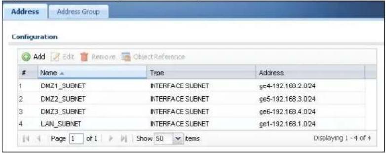
The following table describes the labels in this screen.
Table 150 Configuration > Object > Address > Address Summary
| LABEL DESCRIPTION | |
| Add Click this to | create a new entry. |
| Edit | Double-click an entry or select it and click Edit to be able to modify the entry's settings. |
| Remove | To remove an entry, select it and click Remove. The NXC confirms you want to remove it before doing so. |
| Object Reference | Select an entry and click Object References to open a screen that shows which settings use the entry. |
| # This field is a sequential value, and it is not associated with a specific address. | |
| Name This field displays the configured name of each address object. | |
| Type | This field displays the type of each address object. “INTERFACE” means the object uses the settings of one of the NXC's interfaces. |
| Address This field displays the IP addresses represented by each address object. If the object's settings are based on one of the NXC's interfaces, the name of the interface displays first followed by the object's current address settings. | |
27.2.1 Add/Edit Address
The Add/ Edit Address screen allows you to create a new address or edit an existing one. To access this screen, go to the Address screen, and click either the Add icon or an Edit icon.
Figure 184 Configuration > Object > Address > Address > Add/Edit
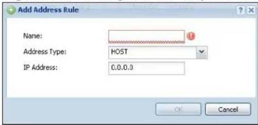
The following table describes the labels in this screen.
Table 151 Configuration > Object > Address > Address > Add/Edit
| LABEL DESCRIPTION | |
| Name Type the | name used to refer to the address. You may use 1-31 alphanumeric characters, underscores( ), or dashes (-), but the first character cannot be a number. This value is case-sensitive. |
| Address Type | Select the type of address you want to create. Choices are:HOST,RANGE, SUBNET, INTERFACE IP, INTERFACE SUBNET, andINTERFACE GATEWAY.Note:The NXC automatically updates address objects that are based on an interface's IP address, subnet, or gateway if the interface's IP address settings change. For example, if you change ge1's IP address, the NXC automatically updates the corresponding interface-based, LAN subnet address object. |
| IP Address | This field is only available if theAddress Typeis HOST. This field cannot be blank. Enter the IP address that this address object represents. |
| Starting IP Address | This field is only available if theAddress Typeis RANGE. This field cannot be blank. Enter the beginning of the range of IP addresses that this address object represents. |
| Ending IP Address | This field is only available if theAddress Typeis RANGE. This field cannot be blank. Enter the end of the range of IP address that this address object represents. |
| Network | This field is only available if theAddress Typeis SUBNET, in which case this field cannot be blank. Enter the IP address of the network that this address object represents. |
| Netmask | This field is only available if theAddress Typeis SUBNET, in which case this field cannot be blank. Enter the subnet mask of the network that this address object represents. Use dotted decimal format. |
| Interface | If you selectedINTERFACE IP, INTERFACE SUBNET, or INTERFACE GATEWAYas theAddress Type, use this field to select the interface of the network that this address object represents. |
| OK | Click OK to save your changes back to the NXC. |
| Cancel | Click Cancel to exit this screen without saving your changes. |
27.3 Address Group Summary
The Address Group screen provides a summary of all address groups. To access this screen, click Configuration > Object > Address > Address Group. Click a column's heading cell to sort the table entries by that column's criteria. Click the heading cell again to reverse the sort order.
Figure 185 Configuration > Object > Address > Address Group
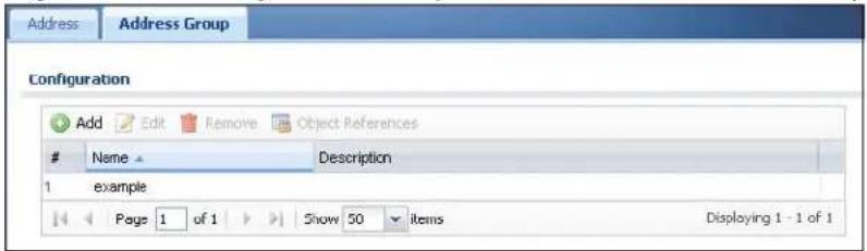
The following table describes the labels in this screen.
Table 152 Configuration > Object > Address > Address Group
| LABEL DESCRIPTION | |
| Add Click this to | create a new entry. |
| Edit | Double-click an entry or select it and click Edit to be able to modify the entry's settings. |
| Remove | To remove an entry, select it and click Remove. The NXC confirms you want to remove it before doing so. |
| Object References | Select an entry and click Object References to open a screen that shows which settings use the entry. |
| # This field is a sequential value, and it is not associated with a specific address group. | |
| Name This field displays the name of each address group. | |
| Description This field displays the description of each address group, if any. | |
27.3.1 Add/Edit Address Group Rule
The Add/ Edit Address Group Rule screen allows you to create a new address group or edit an existing one. To access this screen, go to the Address Group screen and click either the Add icon or an Edit icon.
Figure 186 Configuration > Object > Address > Address Group > Add/Edit
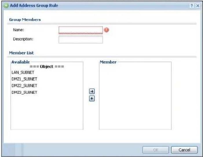
The following table describes the labels in this screen.
Table 153 Configuration > Object > Address > Address Group > Add/Edit
| LABEL DESCRIPTION | |
| Name Enter a name for the address group. You may use 1-31 alphanumeric characters, underscores( ), or dashes (-), but the first character cannot be a number. This value is case-sensitive. | |
| Description This field displays the description of each address group, if any. You can use up to 60 characters, punctuation marks, and spaces. | |
| Member List | The Member list displays the names of the address and address group objects that have been added to the address group. The order of members is not important.Select items from the Available list that you want to be members and move them to the Member list. You can double-click a single entry to move it or use the [Shift] or [Ctrl] key to select multiple entries and use the arrow button to move them.Move any members you do not want included to the Available list. |
| OK | Click OK to save your changes back to the NXC. |
| Cancel | Click Cancel to exit this screen without saving your changes. |
Services
28.1 Overview
Use service objects to define TCP applications, UDP applications, and ICMP messages. You can also create service groups to refer to multiple service objects in other features.
28.1.1 What You Can Do in this Chapter
- The Service screens (Section 28.2 on page 415) display and configure the NXC's list of services and their definitions.
- The Service Group screens (Section 28.2 on page 415) display and configure the NXC's list of service groups.
28.1.2 What You Need to Know
The following terms and concepts may help as you read this chapter.
IP Protocols
IP protocols are based on the eight-bit protocol field in the IP header. This field represents the next-level protocol that is sent in this packet. This section discusses three of the most common IP protocols.
Computers use Transmission Control Protocol (TCP, IP protocol 6) and User Datagram Protocol (UDP, IP protocol 17) to exchange data with each other. TCP guarantees reliable delivery but is slower and more complex. Some uses are FTP, HTTP, SMTP, and TELNET. UDP is simpler and faster but is less reliable. Some uses are DHCP, DNS, RIP, and SNMP.
TCP creates connections between computers to exchange data. Once the connection is established, the computers exchange data. If data arrives out of sequence or is missing, TCP puts it in sequence or waits for the data to be re-transmitted. Then, the connection is terminated.
In contrast, computers use UDP to send short messages to each other. There is no guarantee that the messages arrive in sequence or that the messages arrive at all.
Both TCP and UDP use ports to identify the source and destination. Each port is a 16-bit number. Some port numbers have been standardized and are used by low-level system processes; many others have no particular meaning.
Unlike TCP and UDP, Internet Control Message Protocol (ICMP, IP protocol 1) is mainly used to send error messages or to investigate problems. For example, ICMP is used to send the response if a computer cannot be reached. Another use is ping. ICMP does not guarantee delivery, but networks often treat ICMP messages differently, sometimes looking at the message itself to decide where to send it.
Service Objects and Service Groups
Use service objects to define IP protocols.
• TCP applications
- UDP applications
- ICMP messages
- user-defined services (for other types of IP protocols)
These objects are used in policy routes, firewall rules, and IDP profiles.
Use service groups when you want to create the same rule for several services, instead of creating separate rules for each service. Service groups may consist of services and other service groups. The sequence of members in the service group is not important.
28.2 Service Summary
The Service summary screen provides a summary of all services and their definitions. In addition, this screen allows you to add, edit, and remove services.
To access this screen, log in to the Web Configurator, and click Configuration > Object > Service > Service. Click a column's heading cell to sort the table entries by that column's criteria. Click the heading cell again to reverse the sort order.
Figure 187 Configuration > Object > Service > Service
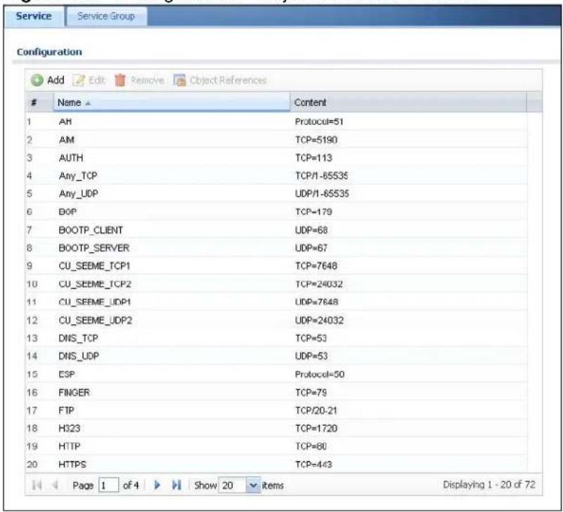
The following table describes the labels in this screen.
Table 154 Configuration > Object > Service > Service
| LABEL DESCRIPTION | |
| Add Click this to | create a new entry. |
| Edit | Double-click an entry or select it and click Edit to be able to modify the entry's settings. |
| Remove | To remove an entry, select it and click Remove. The NXC confirms you want to remove it before doing so. |
| Object References | Select an entry and click Object References to open a screen that shows which settings use the entry. |
| # This field is a sequential value, and it is not associated with a specific service. | |
| Name This field | displays the name of each service. |
| Content This field | displays a description of each service. |
28.2.1 Add/Edit Service Rule
The Add/ Edit Service Rule screen allows you to create a new service or edit an existing one. To access this screen, go to the Service screen and click either the Add icon or an Edit icon.
Figure 188 Configuration > Object > Service > Service > Add/Edit
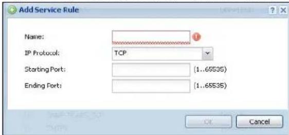
The following table describes the labels in this screen.
Table 155 Configuration > Object > Service > Service > Add/Edit
| LABEL DESCRIPTION | |
| Name Type the | name used to refer to the service. You may use 1-31 alphanumeric characters, underscores( ), or dashes (-), but the first character cannot be a number. This value is case-sensitive. |
| IP Protocol | Select the protocol the service uses. Choices are: TCP, UDP, ICMP, and User Defined. |
| Starting Port Ending Port | This field appears if the IP Protocol is TCP or UDP. Specify the port number(s) used by this service. If you fill in one of these fields, the service uses that port. If you fill in both fields, the service uses the range of ports. |
| ICMP Type | This field appears if the IP Protocol is ICMP Type.Select the ICMP message used by this service. This field displays the message text, not the message number. |
| IP Protocol Number | This field appears if the IP Protocol is User Defined.Enter the number of the next-level protocol (IP protocol). Allowed values are 0 - 255. |
| OK | Click OK to save your changes back to the NXC. |
| Cancel | Click Cancel to exit this screen without saving your changes. |
28.3 Service Group Summary
The Service Group summary screen provides a summary of all service groups. In addition, this screen allows you to add, edit, and remove service groups.
To access this screen, log in to the Web Configurator, and click Configuration > Object > Service > Service Group.
Figure 189 Configuration > Object > Service > Service Group
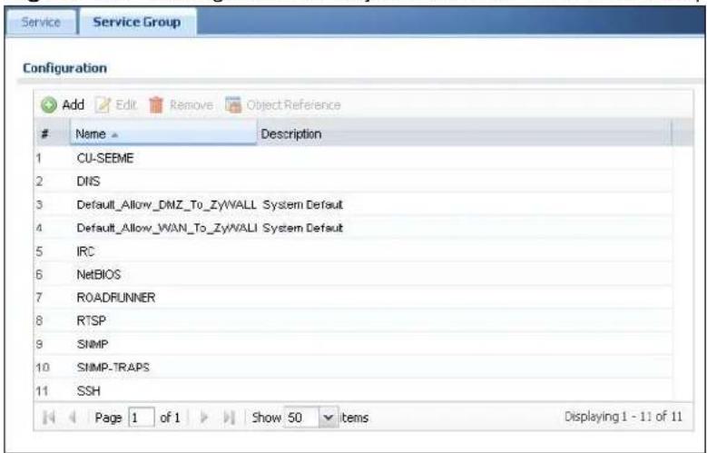
The following table describes the labels in this screen.
Table 156 Configuration > Object > Service > Service Group
| LABEL DESCRIPTION | |
| Add Click this to | create a new entry. |
| Edit | Double-click an entry or select it and click Edit to be able to modify the entry's settings. |
| Remove | To remove an entry, select it and click Remove. The NXC confirms you want to remove it before doing so. |
| Object References | Select an entry and click Object References to open a screen that shows which settings use the entry. |
| # This field is a sequential value, and it is not associated with a specific service group. | |
| Name This field displays the name of each service group.By default, the NXC uses services starting with “Default_Allow_” in the firewall rules to allow certain services to connect to the NXC. | |
| Description This field displays the description of each service group, if any. | |
28.3.1 Add/Edit Service Group Rule
The Add/ Edit Service Group Rule screen allows you to create a new service group or edit an existing one. To access this screen, go to the Service Group screen and click either the Add icon or an Edit icon.
Figure 190 Configuration > Object > Service > Service Group > Add/Edit
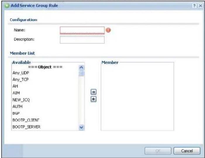
The following table describes the labels in this screen.
Table 157 Configuration > Object > Service > Service Group > Add/Edit
| LABEL DESCRIPTION | |
| Name Enter the | name of the service group. You may use 1-31 alphanumeric characters, underscores( ), or dashes (-), but the first character cannot be a number. This value is case-sensitive. |
| Description Enter | a description of the service group, if any. You can use up to 60 printable ASCII characters. |
| Member List | The Member list displays the names of the service and service group objects that have been added to the service group. The order of members is not important.Select items from the Available list that you want to be members and move them to the Member list. You can double-click a single entry to move it or use the [Shift] or [Ctrl] key to select multiple entries and use the arrow button to move them.Move any members you do not want included to the Available list. |
| OK | Click OK to save your changes back to the NXC. |
| Cancel | Click Cancel to exit this screen without saving your changes. |
Schedules
29.1 Overview
Use schedules to set up one-time and recurring schedules for policy routes, firewall rules, and application patrol. The NXC supports one-time and recurring schedules. One-time schedules are effective only once, while recurring schedules usually repeat. Both types of schedules are based on the current date and time in the NXC.
Note: Schedules are based on the NXC's current date and time.
29.1.1 What You Can Do in this Chapter
- The Schedule screen (Section 29.2 on page 420) displays a list of all schedules in the NXC.
- The One-Time Schedule Add/ Edit screen (Section 29.2.1 on page 421) creates or edits a one-time schedule.
- The Recurring Schedule Add/ Edit screen (Section 29.2.2 on page 422) creates or edits a recurring schedule.
29.1.2 What You Need to Know
The following terms and concepts may help as you read this chapter.
One-time Schedules
One-time schedules begin on a specific start date and time and end on a specific stop date and time. One-time schedules are useful for long holidays and vacation periods.
Recurring Schedules
Recurring schedules begin at a specific start time and end at a specific stop time on selected days of the week (Sunday, Monday, Tuesday, Wednesday, Thursday, Friday, and Saturday). Recurring schedules always begin and end in the same day. Recurring schedules are useful for defining the workday and off-work hours.
29.2 Schedule Summary
The Schedule summary screen provides a summary of all schedules in the NXC. To access this screen, click Configuration > Object > Schedule.
Figure 191 Configuration > Object > Schedule
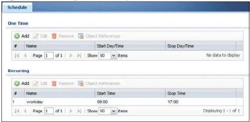
The following table describes the labels in this screen.
Table 158 Configuration > Object > Schedule
| LABEL DESCRIPTION | |
| One Time | |
| Add Click this to create a new entry. | |
| Edit | Double-click an entry or select it and click Edit to be able to modify the entry's settings. |
| Remove | To remove an entry, select it and click Remove. The NXC confirms you want to remove it before doing so. |
| Object References | Select an entry and click Object References to open a screen that shows which settings use the entry. |
| # This field is a sequential value, and it is not associated with a specific schedule. | |
| Name This field displays the name of the schedule, which is used to refer to the schedule. | |
| Start Day / Time | This field displays the date and time at which the schedule begins. |
| Stop Day / Time | This field displays the date and time at which the schedule ends. |
| Recurring | |
| Add Click this to create a new entry. | |
| Edit | Double-click an entry or select it and click Edit to be able to modify the entry's settings. |
| Remove | To remove an entry, select it and click Remove. The NXC confirms you want to remove it before doing so. |
| Object References | Select an entry and click Object References to open a screen that shows which settings use the entry. |
| # This field is a sequential value, and it is not associated with a specific schedule. | |
| Name This field displays the name of the schedule, which is used to refer to the schedule. | |
| Start Time This field displays the time at which the schedule begins. | |
| Stop Time This field displays the time at which the schedule ends. | |
29.2.1 Add/Edit Schedule One-Time Rule
The Add/ Edit Schedule One-Time Rule screen allows you to define a one-time schedule or edit an existing one. To access this screen, go to the Schedule screen and click either the Add icon or an Edit icon in the One Time section.
Figure 192 Configuration > Object > Schedule > Add/Edit (One-Time)
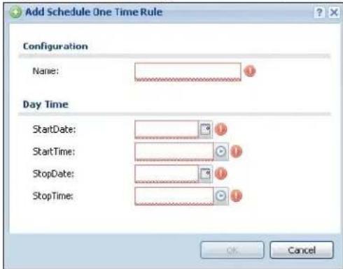
The following table describes the labels in this screen.
Table 159 Configuration > Object > Schedule > Add/Edit (One-Time)
| LABEL DESCRIPTION | |
| Configuration | |
| Name Type the name used to refer to the one-time schedule. You may use 1-31 alphanumeric characters, underscores( ), or dashes (-), but the first character cannot be a number. This value is case-sensitive. | |
| Date Time | |
| StartDate Specify the year, month, and day when the schedule begins.Year - 1900 - 2999Month - 1 - 12Day - 1 - 31 (it is not possible to specify illegal dates, such as February 31.)Hour - 0 - 23Minute - 0 - 59 | |
| StartTime Specify the hour and minute when the schedule begins. | |
| Hour - 0 - 23Minute - 0 - 59 | |
| StopDate Specify the year, month, and day when the schedule ends. | |
| Year - 1900 - 2999Month - 1 - 12Day - 1 - 31 (it is not possible to specify illegal dates, such as February 31.)Hour - 0 - 23Minute - 0 - 59 | |
| StopTime Specify the hour and minute when the schedule ends. | |
| Hour - 0 - 23Minute - 0 - 59 | |
| OK | Click OK to save your changes back to the NXC. |
| Cancel | Click Cancel to exit this screen without saving your changes. |
29.2.2 Add/Edit Schedule Recurring Rule
The Add/ Edit Schedule Recurring Rule screen allows you to define a recurring schedule or edit an existing one. To access this screen, go to the Schedule screen and click either the Add icon or an Edit icon in the Recurring section.
Figure 193 Configuration > Object > Schedule > Add/Edit (Recurring)
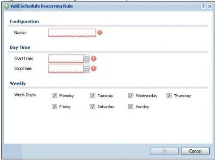
The Year, Month, and Day columns are not used in recurring schedules and are disabled in this screen. The following table describes the remaining labels in this screen.
Table 160 Configuration > Object > Schedule > Add/Edit (Recurring)
| LABEL DESCRIPTION | |
| Configuration | |
| Name Type the name used to refer to the recurring schedule. You may use 1-31 alphanumeric characters, underscores(_, or dashes (-), but the first character cannot be a number. This value is case-sensitive. | |
| Date Time | |
| StartTime Specify the hour and minute when the schedule begins each day. Hour - 0 - 23 Minute - 0 - 59 | |
| StopTime Specify the hour and minute when the schedule ends each day. Hour - 0 - 23 Minute - 0 - 59 | |
| Weekly | |
| Week Days Select each day of the week the recurring schedule is effective. | |
| OK | Click OK to save your changes back to the NXC. |
| Cancel | Click Cancel to exit this screen without saving your changes. |
AAA Server
30.1 Overview
You can use a AAA (Authentication, Authorization, Accounting) server to provide access control to your network. The AAA server can be a Active Directory, LDAP, or RADIUS server. Use the AAA Server screens to create and manage objects that contain settings for using AAA servers. You use AAA server objects in configuring ext-group-user user objects and authentication method objects.
30.1.1 What You Can Do in this Chapter
- The Active Directory / LDAP screens (Section 30.2 on page 429) configure Active Directory or LDAP server objects.
- The RADIUS screen (Section 30.3 on page 433) configures the default external RADIUS server to use for user authentication.
30.1.2 What You Need To Know
The following terms and concepts may help as you read this chapter.
Directory Service (AD/LDAP)
LDAP/AD allows a client (the NXC) to connect to a server to retrieve information from a directory. A network example is shown next.
Figure 194 Example: Directory Service Client and Server
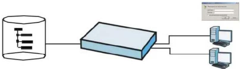
flowchart
graph LR
    A["Database"] --> B["Server"]
    B --> C["Client 1"]
    B --> D["Client 2"]
The following describes the user authentication procedure via an LDAP/AD server.
1 A user logs in with a user name and password pair.
2 The NXC tries to bind (or log in) to the LDAP/AD server.
3 When the binding process is successful, the NXC checks the user information in the directory against the user name and password pair.
4 If it matches, the user is allowed access. Otherwise, access is blocked.
RADIUS Server
RADIUS (Remote Authentication Dial-In User Service) authentication is a popular protocol used to authenticate users by means of an external server instead of (or in addition to) an internal device user database that is limited to the memory capacity of the device. In essence, RADIUS authentication allows you to validate a large number of users from a central location.
Figure 195 RADIUS Server Network Example
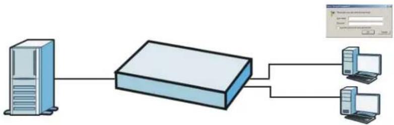
flowchart
graph LR
    A["Server"] --> B["Rout"]
    B --> C["Client 1"]
    B --> D["Client 2"]
ASAS
ASAS (Authenex Strong Authentication System) is a RADIUS server that works with the One-Time Password (OTP) feature. Purchase a NXC OTP package in order to use this feature. The package contains server software and physical OTP tokens (PIN generators). Do the following to use OTP. See the documentation included on the ASAS' CD for details.
1 Install the ASAS server software on a computer.
2 Create user accounts on the NXC and in the ASAS server.
3 Import each token's database file (located on the included CD) into the server.
4 Assign users to OTP tokens (on the ASAS server).
5 Configure the ASAS as a RADIUS server in the NXC's Configuration > Object > AAA Server screens.
6 Give the OTP tokens to (local or remote) users.
Authentication Capability List
This list displays the NXC's authentication capabilities:
Table 161 Authentication Capability List
| INTERNAL AUTHENTICATION METHOD | EXTERNAL RADIUS | |||
| AD LDAP | RADIUS | |||
| E A | P | - | T | L |
| EAP-TTLS (Mschapv2/Mschap) | O^A | O | O | O |
| EAP-TTLS (eap) | X | X | X | O |
| EAP-TTLS (pap) | O | O | O | O |
| EAP-PEAP (Mschapv2) | O^A | O | O | O |
| EAP-PEAP (TLS) | X | X | X | O |
| E A | P | - | M | D |
A. Must set domain authentication.
AAA Servers Supported by the NXC
The following lists the types of authentication server the NXC supports.
- Local user database
The NXC uses the built-in local user database to authenticate administrative users logging into the NXC's Web Configurator or network access users logging into the network through the NXC. - Directory Service (LDAP/AD)
LDAP (Lightweight Directory Access Protocol)/AD (Active Directory) is a directory service that is both a directory and a protocol for controlling access to a network. The directory consists of a database specialized for fast information retrieval and filtering activities. You create and store user profile and login information on the external server.
• RADIUS
RADIUS (Remote Authentication Dial-In User Service) authentication is a popular protocol used to authenticate users by means of an external or built-in RADIUS server. RADIUS authentication allows you to validate a large number of users from a central location.
Note: Because the NXC has an internal authentication database, you can create local login accounts on it without needing to rely on an external authentication server. The built-in authentication server supports PEAP/EAP-TLS/EAP-TTLS.
Directory Structure
The directory entries are arranged in a hierarchical order much like a tree structure. Normally, the directory structure reflects the geographical or organizational boundaries. The following figure shows a basic directory structure branching from countries to organizations to organizational units to individuals.
Figure 196 Basic Directory Structure
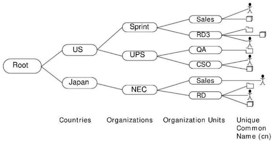
flowchart
graph TD
    A["Root"] --> B["US"]
    A --> C["Japan"]
    B --> D["Sprint"]
    B --> E["UPS"]
    B --> F["NEC"]
    D --> G["Sales"]
    D --> H["RD3"]
    E --> I["QA"]
    E --> J["CSO"]
    F --> K["Sales"]
    F --> L["RD"]
    G --> M["Unique Common Name (cn)"]
    H --> M
    I --> M
    J --> M
    K --> M
    L --> M
Distinguished Name (DN)
A DN uniquely identifies an entry in a directory. A DN consists of attribute-value pairs separated by commas. The leftmost attribute is the Relative Distinguished Name (RDN). This provides a unique name for entries that have the same "parent DN" ("cn=domain1.com, ou=Sales, o=MyCompany" in the following examples).
cn=domain1.com, ou = Sales, o=MyCompany, c=US
cn=domain1.com, ou = Sales, o=MyCompany, c=JP
Base DN
A base DN specifies a directory. A base DN usually contains information such as the name of an organization, a domain name and/or country. For example, o=MyCompany, c=UK where o means organization and c means country.
Bind DN
A bind DN is used to authenticate with an LDAP/AD server. For example a bind DN of cn=zyAdmin allows the NXC to log into the LDAP/AD server using the user name of zyAdmin. The bind DN is used in conjunction with a bind password. When a bind DN is not specified, the NXC will try to log in as an anonymous user. If the bind password is incorrect, the login will fail.
30.2 Active Directory / LDAP
Use the Active Directory or LDAP screen to manage the list of AD or LDAP servers the NXC can use in authenticating users.
Note: Both the Active Directory and LDAP screens, while on separate tabs, are identical in configuration. This section applies to both equally.
Click Configuration > Object > AAA Server > Active Directory/ LDAP to display the Active Directory / LDAP screen.
Figure 197 Configuration > Object > AAA Server > Active Directory/LDAP
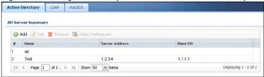
The following table describes the labels in this screen.
Table 162 Configuration > Object > AAA Server > Active Directory/LDAP
| LABEL DESCRIPTION | |
| Add Click this to | create a new entry. |
| Edit | Double-click an entry or select it and click Edit to open a screen where you can modify the entry's settings. |
| Remove | To remove an entry, select it and click Remove. The NXC confirms you want to remove it before doing so. |
| Object References | Select an entry and click Object References to open a screen that shows which settings use the entry. |
| # This field displays the index number. | |
| Server Address | This is the address of the AD or LDAP server. |
| Base DN | This specifies a directory. For example, o=ZyXEL, c=US. |
30.2.1 Add/Edit Active Directory / LDAP Server
Click Object > AAA Server > Active Directory/ LDAP to display the Active Directory (or LDAP) screen. Click the Add icon or an Edit icon to display the following screen. Use this screen to create a new entry or edit an existing one.
Note: The Active Directory and LDAP server setup screens are almost identical, so the features for both screens are described in this section.
Figure 198 AAA Server > Active Directory > Add/Edit
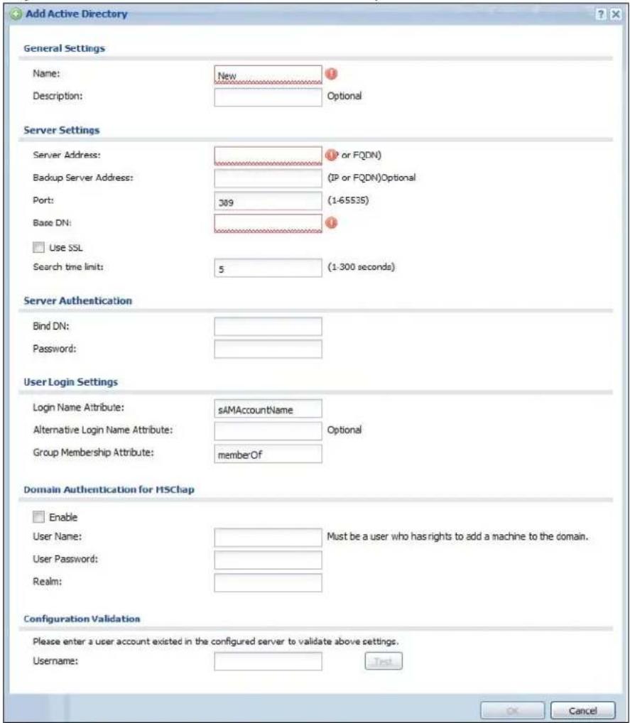
Figure 199 AAA Server > LDAP > Add/Edit
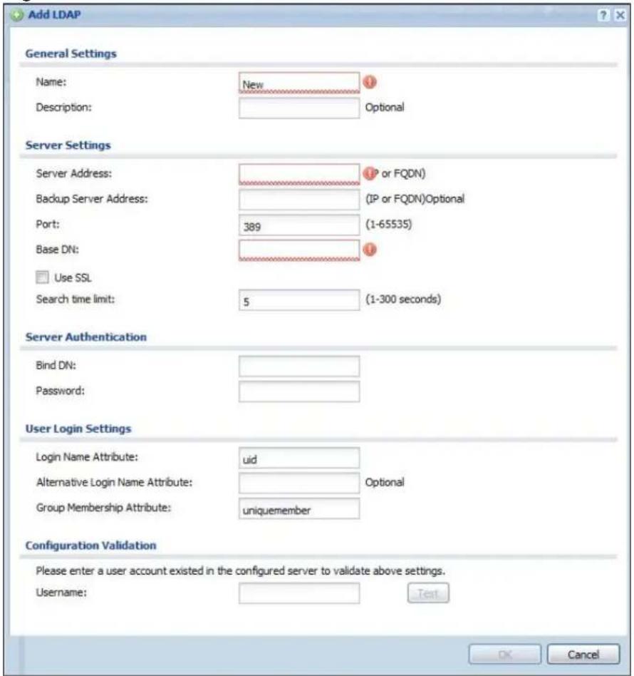
The following table describes the labels in these screens.
Table 163 Add/Edit
| LABEL DESCRIPTION | |
| Name Enter a descriptive name (up to 63 alphanumerical characters) for identification purposes. | |
| Description Enter the description of each server, if any. You can use up to 60 printable ASCII characters. | |
| Server Address Enter the address of the AD server. | |
| Backup Server Address | If the AD has a backup server, enter its address here. |
| Port Specify the port number on the AD to which the NXC sends authentication requests. Enter a number between 1 and 65535.This port number should be the same on all AD or LDAP server(s) in this group. | |
| Base DN Specify the directory (up to 127 alphanumerical characters). For example, o=ZyXEL, c=US. | |
| Use SSL | Select Use SSL to establish a secure connection to the AD or LDAP server(s). |
| Search time limit | Specify the timeout period (between 1 and 300 seconds) before the NXC disconnects from the AD server. In this case, user authentication fails.Search timeout occurs when either the user information is not in the AD or the AD is down. |
| Bind DN Specify | the bind DN for logging into the AD server. Enter up to 127 alphanumerical characters.For example, cn=zyAdmin specifies zyAdmin as the user name. |
| Password If required | red, enter the password (up to 15 alphanumerical characters) for the NXC to bind (or log in) to the AD server. |
| Base DN Specify | the directory (up to 127 alphanumerical characters). For example, o=ZyXEL, c=US. |
| Login Name Attribute | Enter the type of identifier the users are to use to log in. For example “name” or “e-mail address”. |
| Alternative Login Name Attribute | If there is a second type of identifier that the users can use to log in, enter it here. For example “name” or “e-mail address”. |
| Group Membership Attribute | Enter the name of the attribute that the NXC is to check to determine to which group a user belongs. The value for this attribute is called a group identifier; it determines to which group a user belongs. You can addext-group-useruser objects to identify groups based on these group identifier values.For example you could have an attribute named “memberOf” with values like “sales”, “RD”, and “management”. Then you could also create aext-group-useruser object for each group. One with “sales” as the group identifier, another for “RD” and a third for “management”. |
| Enable Select this | to enable domain authentication for MSChap.Note: This is only for LDAP. |
| User Name Enter | the user name for the user who has rights to add a machine to the domain.Note: This is only for LDAP. |
| User Password Enter | enter the password for the associated user name.Note: This is only for LDAP. |
| Realm Enter the realm IP address. | Note: This is only for LDAP. |
| Configuration Validation | Use a user account from the server specified above to test if the configuration is correct. Enter the account’s user name in theUsernamefield and click Test. |
| OK Click OK to save the changes. | |
| Cancel | Click Cancel to discard the changes. |
30.3 RADIUS
Use the RADIUS screen to manage the list of RADIUS servers the NXC can use in authenticating users. Click Configuration > Object > AAA Server > RADIUS to display the RADIUS screen.
Figure 200 Configuration > Object > AAA Server > RADIUS
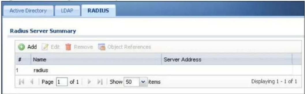
The following table describes the labels in this screen.
Table 164 Configuration > Object > AAA Server > RADIUS
| LABEL DESCRIPTION | |
| Add Click this to create a new entry. | |
| Edit | Double-click an entry or select it and click Edit to open a screen where you can modify the entry's settings. |
| Remove | To remove an entry, select it and click Remove. The NXC confirms you want to remove it before doing so. |
| Object References | Select an entry and click Object References to open a screen that shows which settings use the entry. |
| # This field displays the index number. | |
| Name This is the name of the RADIUS server entry. | |
| Server Address | This is the address of the AD or LDAP server. |
30.3.1 Add/Edit RADIUS
Click Configuration > Object > AAA Server > RADIUS to display the RADIUS screen. Click the Add icon or an Edit icon to display the following screen. Use this screen to create a new AD or LDAP entry or edit an existing one.
Figure 201 Configuration > Object > AAA Server > RADIUS > Add/Edit
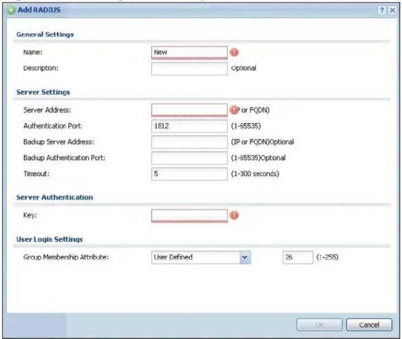
The following table describes the labels in this screen.
Table 165 Configuration > Object > AAA Server > RADIUS > Add/Edit
| LABEL DESCRIPTION | |
| Name Enter a descriptive name (up to 63 alphanumeric characters) for identification purposes. | |
| Description Enter the description of each server, if any. You can use up to 60 printable ASCII characters. | |
| Server Address | Enter the address of the RADIUS server. |
| Authentication Port | Specify the port number on the RADIUS server to which the NXC sends authentication requests. Enter a number between 1 and 65535. |
| Backup Server Address | If the RADIUS server has a backup server, enter its address here. |
| Backup Authentication Port | Specify the port number on the RADIUS server to which the NXC sends authentication requests. Enter a number between 1 and 65535. |
| Timeout Specify | the timeout period (between 1 and 300 seconds) before the NXC disconnects from the RADIUS server. In this case, user authentication fails.Search timeout occurs when either the user information is not in the RADIUS server or the RADIUS server is down. |
| Key Enter a pass | sword (up to 15 alphanumeric characters) as the key to be shared between the external authentication server and the NXC.The key is not sent over the network. This key must be the same on the external authentication server and the NXC. |
| Group Membership Attribute | Select the name and number of the attribute that the NXC is to check to determine to which group a user belongs. If it does not display, select user-defined and specify the attribute's number.This attribute's value is called a group identifier; it determines to which group a user belongs. You can addext-group-useruser objects to identify groups based on these group identifier values.For example you could have an attribute named "memberOf" with values like "sales", "RD", and "management". Then you could also create aext-group-useruser object for each group. One with "sales" as the group identifier, another for "RD" and a third for "management". |
| OK Click OK to save the changes. | |
| Cancel | Click Cancel to discard the changes. |
Authentication Method
31.1 Overview
Authentication method objects set how the NXC authenticates wireless, HTTP/HTTPS clients, and captive portal clients. Configure authentication method objects to have the NXC use the local user database, and/or the authentication servers and authentication server groups specified by AAA server objects. By default, user accounts created and stored on the NXC are authenticated locally.
31.1.1 What You Can Do in this Chapter
The Auth. Method screens (Section 31.2 on page 437) create and manage authentication method objects.
31.1.2 Before You Begin
Configure AAA server objects before you configure authentication method objects.
31.2 Authentication Method
Click Configuration > Object > Auth. Method to display this screen.
Note: You can create up to 16 authentication method objects.
Figure 202 Configuration > Object > Auth. Method
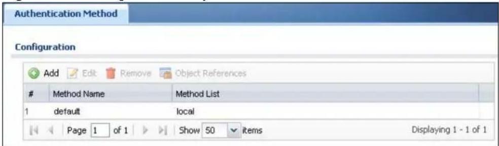
The following table describes the labels in this screen.
Table 166 Configuration > Object > Auth. Method
| LABEL DESCRIPTION | |
| Add Click this to create a new entry. | |
| Edit | Double-click an entry or select it and click Edit to open a screen where you can modify the entry's settings. |
| Remove | To remove an entry, select it and click Remove. The NXC confirms you want to remove it before doing so. |
| Object References | Select an entry and click Object References to open a screen that shows which settings use the entry. |
| # This field displays the index number. | |
| Method Name | This field displays a descriptive name for identification purposes. |
| Method List This field displays the authentication method(s) for this entry. | |
31.2.1 Add Authentication Method
Follow the steps below to create an authentication method object.
1 Click Configuration > Object > Auth. Method.
2 Click Add.
3 Specify a descriptive name for identification purposes in the Name field. You may use 1-31 alphanumeric characters, underscores(_, or dashes (-), but the first character cannot be a number. This value is case-sensitive. For example, "My_Device".
4 Click Add to insert an authentication method in the table.
5 Select a server object from the Method List drop-down list box.
6 You can add up to four server objects to the table. The ordering of the Method List column is important. The NXC authenticates the users using the databases (in the local user database or the external authentication server) in the order they appear in this screen.
If two accounts with the same username exist on two authentication servers you specify, the NXC does not continue the search on the second authentication server when you enter the username and password that doesn't match the one on the first authentication server.
7 Click OK to save the settings or click Cancel to discard all changes and return to the previous screen.
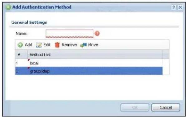
The following table describes the labels in this screen.
Table 167 Configuration > Object > Auth. Method > Add
| LABEL DESCRIPTION | |
| Name Specify a | descriptive name for identification purposes.You may use 1-31 alphanumeric characters, underscores( ), or dashes (-), but the first character cannot be a number. This value is case-sensitive. For example, "My_Device". |
| Add | Click this to create a new entry. Select an entry and click Add to create a new entry after the selected entry. |
| Edit | Double-click an entry or select it and click Edit to open a screen where you can modify the entry's settings. |
| Remove | To remove an entry, select it and click Remove. The NXC confirms you want to remove it before doing so. |
| Move To change | a method's position in the numbered list, select the method and click Move to display a field to type a number for where you want to put it and press [ENTER] to move the rule to the number that you typed.The ordering of your methods is important as NXC authenticates the users using the authentication methods in the order they appear in this screen. |
| # This field displays the index number. | |
| Method List Select | a server object from the drop-down list box. You can create a server object in the AAA Server screen.The NXC authenticates the users using the databases (in the local user database or the external authentication server) in the order they appear in this screen.If two accounts with the same username exist on two authentication servers you specify, the NXC does not continue the search on the second authentication server when you enter the username and password that doesn't match the one on the first authentication server. |
| OK Click OK to save the changes. | |
| Cancel | Click Cancel to discard the changes. |
Certificates
32.1 Overview
The NXC can use certificates (also called digital IDs) to authenticate users. Certificates are based on public-private key pairs. A certificate contains the certificate owner's identity and public key. Certificates provide a way to exchange public keys for use in authentication.
32.1.1 What You Can Do in this Chapter
- The My Certificate screens (Section 32.2 on page 445) generate and export self-signed certificates or certification requests and import the NXC's CA-signed certificates.
- The Trusted Certificates screens (Section 32.3 on page 455) save CA certificates and trusted remote host certificates to the NXC. The NXC trusts any valid certificate that you have imported as a trusted certificate. It also trusts any valid certificate signed by any of the certificates that you have imported as a trusted certificate.
32.1.2 What You Need to Know
The following terms and concepts may help as you read this chapter.
When using public-key cryptology for authentication, each host has two keys. One key is public and can be made openly available. The other key is private and must be kept secure.
These keys work like a handwritten signature (in fact, certificates are often referred to as “digital signatures”). Only you can write your signature exactly as it should look. When people know what your signature looks like, they can verify whether something was signed by you, or by someone else. In the same way, your private key “writes” your digital signature and your public key allows people to verify whether data was signed by you, or by someone else.
This process works as follows:
1 Tim wants to send a message to Jenny. He needs her to be sure that it comes from him, and that the message content has not been altered by anyone else along the way. Tim generates a public key pair (one public key and one private key).
2 Tim keeps the private key and makes the public key openly available. This means that anyone who receives a message seeming to come from Tim can read it and verify whether it is really from him or not.
3 Tim uses his private key to sign the message and sends it to Jenny.
4 Jenny receives the message and uses Tim's public key to verify it. Jenny knows that the message is from Tim, and that although other people may have been able to read the message, no-one can have altered it (because they cannot re-sign the message with Tim's private key).
5 Additionally, Jenny uses her own private key to sign a message and Tim uses Jenny's public key to verify the message.
The NXC uses certificates based on public-key cryptology to authenticate users attempting to establish a connection, not to encrypt the data that you send after establishing a connection. The method used to secure the data that you send through an established connection depends on the type of connection.
The certification authority uses its private key to sign certificates. Anyone can then use the certification authority's public key to verify the certificates.
A certification path is the hierarchy of certification authority certificates that validate a certificate. The NXC does not trust a certificate if any certificate on its path has expired or been revoked.
Certification authorities maintain directory servers with databases of valid and revoked certificates. A directory of certificates that have been revoked before the scheduled expiration is called a CRL (Certificate Revocation List). The NXC can check a peer's certificate against a directory server's list of revoked certificates. The framework of servers, software, procedures and policies that handles keys is called PKI (public-key infrastructure).
Advantages of Certificates
Certificates offer the following benefits.
- The NXC only has to store the certificates of the certification authorities that you decide to trust, no matter how many devices you need to authenticate.
- Key distribution is simple and very secure since you can freely distribute public keys and you never need to transmit private keys.
Self-signed Certificates
You can have the NXC act as a certification authority and sign its own certificates.
Factory Default Certificate
The NXC generates its own unique self-signed certificate when you first turn it on. This certificate is referred to in the GUI as the factory default certificate.
Certificate File Formats
Any certificate that you want to import has to be in one of these file formats:
- Binary X.509: This is an ITU-T recommendation that defines the formats for X.509 certificates.
- PEM (Base-64) encoded X.509: This Privacy Enhanced Mail format uses lowercase letters, uppercase letters and numerals to convert a binary X.509 certificate into a printable form.
- Binary PKCS# 7: This is a standard that defines the general syntax for data (including digital signatures) that may be encrypted. A PKCS #7 file is used to transfer a public key certificate. The private key is not included. The NXC currently allows the importation of a PKS# 7 file that contains a single certificate.
- PEM (Base-64) encoded PKCS#7: This Privacy Enhanced Mail (PEM) format uses lowercase letters, uppercase letters and numerals to convert a binary PKCS#7 certificate into a printable form.
- Binary PKCS# 12: This is a format for transferring public key and private key certificates. The private key in a PKCS # 12 file is within a password-encrypted envelope. The file's password is not connected to your certificate's public or private passwords. Exporting a PKCS # 12 file creates this and you must provide it to decrypt the contents when you import the file into the NXC.
Note: Be careful not to convert a binary file to text during the transfer process. It is easy for this to occur since many programs use text files by default.
32.1.3 Verifying a Certificate
Before you import a trusted certificate into the NXC, you should verify that you have the correct certificate. You can do this using the certificate's fingerprint. A certificate's fingerprint is a message digest calculated using the MD5 or SHA1 algorithm. The following procedure describes how to check a certificate's fingerprint to verify that you have the actual certificate.
1 Browse to where you have the certificate saved on your computer.
2 Make sure that the certificate has a “.cer” or “.crt” file name extension.
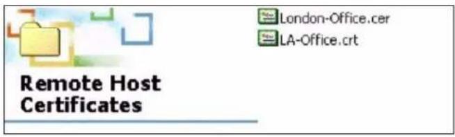
3 Double-click the certificate's icon to open the Certificate window. Click the Details tab and scroll down to the Thumbprint Algorithm and Thumbprint fields.
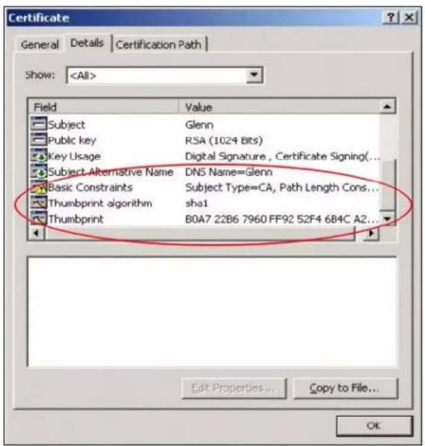
4 Use a secure method to verify that the certificate owner has the same information in the Thumbprint Algorithm and Thumbprint fields. The secure method may very based on your situation. Possible examples would be over the telephone or through an HTTPS connection.
32.2 My Certificates
Click Configuration > Object > Certificate > My Certificates to open this screen. This is the NXC's summary list of certificates and certification requests.
Figure 203 Configuration > Object > Certificate > My Certificates
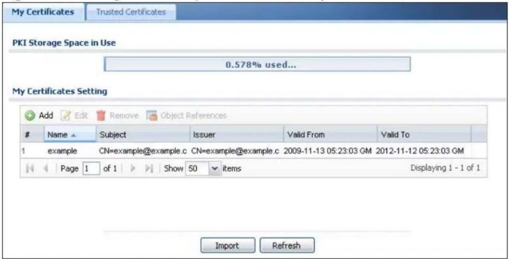
The following table describes the labels in this screen.
Table 168 Configuration > Object > Certificate > My Certificates
| LABEL DESCRIPTION | |
| PKI Storage Space in Use | This bar displays the percentage of the NXC's PKI storage space that is currently in use. When the storage space is almost full, you should consider deleting expired or unnecessary certificates before adding more certificates. |
| Add Click this to | go to the screen where you can have the NXC generate a certificate or a certification request. |
| Edit | Double-click an entry or select it and click Edit to open a screen with an in-depth list of information about the certificate. |
| Remove The NXC | keeps all of your certificates unless you specifically delete them. Uploading a new firmware or default configuration file does not delete your certificates. To remove an entry, select it and click Remove. The NXC confirms you want to remove it before doing so. Subsequent certificates move up by one when you take this action. |
| Object References | You cannot delete certificates that any of the NXC's features are configured to use. Select an entry and click Object References to open a screen that shows which settings use the entry. |
| # This field displays the certificate index number. The certificates are listed in alphabetical order. | |
| Name This field displays the name used to identify this certificate. It is recommended that you give each certificate a unique name. | |
| Type This field displays what kind of certificate this is. | |
| REQ represents a certification request and is not yet a valid certificate. Send a certification request to a certification authority, which then issues a certificate. Use the My Certificate Import screen to import the certificate and replace the request.SELF represents a self-signed certificate.CERT represents a certificate issued by a certification authority. | |
| Subject This field displays identifying information about the certificate's owner, such as CN (Common Name), OU (Organizational Unit or department), O (Organization or company) and C (Country). It is recommended that each certificate have unique subject information. | |
| Issuer This field displays identifying information about the certificate's issuing certification authority, such as a common name, organizational unit or department, organization or company and country. With self-signed certificates, this is the same information as in the Subject field. | |
| Valid From This field displays the date that the certificate becomes applicable. | |
| Valid To This field displays the date that the certificate expires. The text displays in red and includes an Expired! message if the certificate has expired. | |
| Import Click Import to open a screen where you can save a certificate to the NXC. | |
| Refresh Click Refresh to display the current validity status of the certificates. | |
32.2.1 Add My Certificates
Click Configuration > Object > Certificate > My Certificates and then the Add icon to open the My Certificates Add screen. Use this screen to have the NXC create a self-signed certificate, enroll a certificate with a certification authority or generate a certification request.
Figure 204 Configuration > Object > Certificate > My Certificates > Add
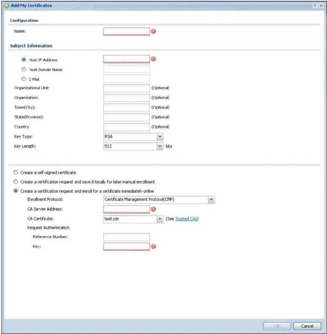
The following table describes the labels in this screen.
Table 169 Configuration > Object > Certificate > My Certificates > Add
| LABEL DESCRIPTION | |
| Name Type a name | to identify this certificate. You can use up to 31 alphanumeric and ;'~!@# %^ &()_+[]',= - characters. |
| Subject Information | Use these fields to record information that identifies the owner of the certificate. You do not have to fill in every field, although you must specify a Host IP Address, Host Domain Name, or E-Mail. The certification authority may add fields (such as a serial number) to the subject information when it issues a certificate. It is recommended that each certificate have unique subject information.Select a radio button to identify the certificate's owner by IP address, domain name or e-mail address. Type the IP address (in dotted decimal notation), domain name or e-mail address in the field provided. The domain name or e-mail address is for identification purposes only and can be any string.A domain name can be up to 255 characters. You can use alphanumeric characters, the hyphen and periods.An e-mail address can be up to 63 characters. You can use alphanumeric characters, the hyphen, the @ symbol, periods and the underscore. |
| Organizational Unit | identify the organizational unit or department to which the certificate owner belongs. You can use up to 31 characters. You can use alphanumeric characters, the hyphen and the underscore. |
| Organization Identify | the company or group to which the certificate owner belongs. You can use up to 31 characters. You can use alphanumeric characters, the hyphen and the underscore. |
| Town (City) Identify | the town or city where the certificate owner is located. You can use up to 31 characters. You can use alphanumeric characters, the hyphen and the underscore. |
| State, (Province) | Identify the state or province where the certificate owner is located. You can use up to 31 characters. You can use alphanumeric characters, the hyphen and the underscore. |
| Country Identify the | nation where the certificate owner is located. You can use up to 31 characters. You can use alphanumeric characters, the hyphen and the underscore. |
| Key Type | Select RSA to use the Rivest, Shamir and Adleman public-key algorithm.Select DSA to use the Digital Signature Algorithm public-key algorithm. |
| Key Length Select a | number from the drop-down list box to determine how many bits the key should use (512 to 2048). The longer the key, the more secure it is. A longer key also uses more PKI storage space. |
| Enrollment Options | These radio buttons deal with how and when the certificate is to be generated. |
| Create a self-signed certificate | Select this to have the NXC generate the certificate and act as the Certification Authority (CA) itself. This way you do not need to apply to a certification authority for certificates. |
| LABEL DESCRIPTION | |
| Create a certification request and save it locally for later manual enrollment | Select this to have the NXC generate and store a request for a certificate. Use the My Certificate Details screen to view the certification request and copy it to send to the certification authority.Copy the certification request from the My Certificate Details screen and then send it to the certification authority. |
| Create a certification request and enroll for a certificate immediately online | Select this to have the NXC generate a request for a certificate and apply to a certification authority for a certificate.You must have the certification authority's certificate already imported in the Trusted Certificates screen.When you select this option, you must select the certification authority's enrollment protocol and the certification authority's certificate from the drop-down list boxes and enter the certification authority's server address. You also need to fill in the Reference Number and Key if the certification authority requires them. |
| Enrollment Protocol | This field applies when you select Create a certification request and enroll for a certificate immediately online. Select the certification authority's enrollment protocol from the drop-down list box.Simple Certificate Enrollment Protocol (SCEP) is a TCP-based enrollment protocol that was developed by VeriSign and Cisco.Certificate Management Protocol (CMP) is a TCP-based enrollment protocol that was developed by the Public Key Infrastructure X.509 working group of the Internet Engineering Task Force (IETF) and is specified in RFC 2510. |
| CA Server Address | This field applies when you select Create a certification request and enroll for a certificate immediately online. Enter the IP address (or URL) of the certification authority server.For a URL, you can use up to 511 of the following characters. a-zA-Z0-9'()+,/:=?;!* #@-%- |
| CA Certificate This fi | field applies when you select Create a certification request and enroll for a certificate immediately online. Select the certification authority's certificate from the CA Certificate drop-down list box.You must have the certification authority's certificate already imported in the Trusted Certificates screen. Click Trusted CAs to go to the Trusted Certificates screen where you can view (and manage) the NXC's list of certificates of trusted certification authorities. |
| LABEL DESCRIPTION | |
| Request Authentication | When you select Create a certification request and enroll for a certificate immediately online, the certification authority may want you to include a reference number and key to identify you when you send a certification request.Fill in both the Reference Number and the Key fields if your certification authority uses the CMP enrollment protocol. Just the Key field displays if your certification authority uses the SCEP enrollment protocol.For the reference number, use 0 to 99999999.For the key, use up to 31 of the following characters. a-zA-Z0-9;|`~!@#$%^&*()_+\{}':,/<>=- |
| OK | Click OK to begin certificate or certification request generation. |
| Cancel | Click Cancel to quit and return to the My Certificates screen. |
If you configured the My Certificate Create screen to have the NXC enroll a certificate and the certificate enrollment is not successful, you see a screen with a Return button that takes you back to the My Certificate Create screen. Click Return and check your information in the My Certificate Create screen. Make sure that the certification authority information is correct and that your Internet connection is working properly if you want the NXC to enroll a certificate online.
32.2.2 Edit My Certificates
Click Configuration > Object > Certificate > My Certificates and then the Edit icon to open the My Certificate Edit screen. You can use this screen to view in-depth certificate information and change the certificate's name.
Figure 205 Configuration > Object > Certificate > My Certificates > Edit
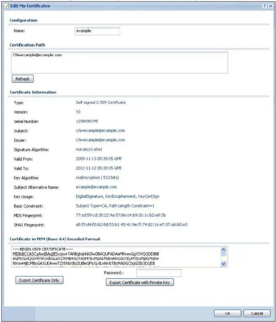
The following table describes the labels in this screen.
Table 170 Configuration > Object > Certificate > My Certificates > Edit
| LABEL DESCRIPTION | |
| Name This field displays the identifying name of this certificate. You can use up to 31 alphanumeric and ;'~!@#$%^&()_+[]{}',= - characters. | |
| Certification Path This field displays for a certificate, not a certification request.Click the Refresh button to have this read-only text box display the hierarchy of certification authorities that validate the certificate (and the certificate itself).If the issuing certification authority is one that you have imported as a trusted certification authority, it may be the only certification authority in the list (along with the certificate itself). If the certificate is a self-signed certificate, the certificate itself is the only one in the list. The NXC does not trust the certificate and displays "Not trusted" in this field if any certificate on the path has expired or been revoked. | |
| Refresh Click Refresh to display the certification path. | |
| Certificate Information | These read-only fields display detailed information about the certificate. |
| Type This field displays general information about the certificate. CA-signed means that a Certification Authority signed the certificate. Self-signed means that the certificate's owner signed the certificate (not a certification authority). "X.509" means that this certificate was created and signed according to the ITU-T X.509 recommendation that defines the formats for public-key certificates. | |
| Version This field displays the X.509 version number. " | |
| Serial Number This field displays the certificate's identification number given by the certification authority or generated by the NXC. | |
| Subject This field displays information that identifies the owner of the certificate, such as Common Name (CN), Organizational Unit (OU), Organization (O), State (ST), and Country (C). | |
| Issuer This field displays identifying information about the certificate's issuing certification authority, such as Common Name, Organizational Unit, Organization and Country.With self-signed certificates, this is the same as the Subject Name field."none" displays for a certification request. | |
| Signature Algorithm | This field displays the type of algorithm that was used to sign the certificate. The NXC uses rsa-pkcs1-sha1 (RSA public-private key encryption algorithm and the SHA1 hash algorithm). Some certification authorities may use rsa-pkcs1-md5 (RSA public-private key encryption algorithm and the MD5 hash algorithm). |
| Valid From This field displays the date that the certificate becomes applicable. "none" displays for a certification request. | |
| Valid To This field displays the date that the certificate expires. The text displays in red and includes an Expired! message if the certificate has expired. "none" displays for a certification request. | |
Table 170 Configuration > Object > Certificate > My Certificates > Edit
| LABEL DESCRIPTION | |
| Key Algorithm This | field displays the type of algorithm that was used to generate the certificate's key pair (the NXC uses RSA encryption) and the length of the key set in bits (1024 bits for example). |
| Subject Alternative Name | This field displays the certificate owner's IP address (IP), domain name (DNS) or e-mail address (EMAIL). |
| Key Usage This field | displays for what functions the certificate's key can be used. For example, “DigitalSignature” means that the key can be used to sign certificates and “KeyEncipherment” means that the key can be used to encrypt text. |
| Basic Constraint This | is field displays general information about the certificate. For example, Subject Type=CA means that this is a certification authority's certificate and “Path Length Constraint=1” means that there can only be one certification authority in the certificate's path. This field does not display for a certification request. |
| MD5 Fingerprint This | is the certificate's message digest that the NXC calculated using the MD5 algorithm. |
| SHA1 Fingerprint This | is the certificate's message digest that the NXC calculated using the SHA1 algorithm. |
| Certificate in PEM (Base-64)Encoded Format | This read-only text box displays the certificate or certification request in Privacy Enhanced Mail (PEM) format. PEM uses lowercase letters, uppercase letters and numerals to convert a binary certificate into a printable form.You can copy and paste a certification request into a certification authority's web page, an e-mail that you send to the certification authority or a text editor and save the file on a management computer for later manual enrollment.You can copy and paste a certificate into an e-mail to send to friends or colleagues or you can copy and paste a certificate into a text editor and save the file on a management computer for later distribution (via floppy disk for example). |
| Export This button | displays for a certification request. Use this button to save a copy of the request without its private key. Click this button and then Save in the File Download screen. The Save As screen opens, browse to the location that you want to use and click Save. |
| Export Certificate Only | Use this button to save a copy of the certificate without its private key. Click this button and then Save in the File Download screen. The Save As screen opens, browse to the location that you want to use and click Save. |
| Password If you want to export the certificate with its private key, create a password and type it here. Make sure you keep this password in a safe place. You will need to use it if you import the certificate to another device. | |
| Export Certificate with Private Key | Use this button to save a copy of the certificate with its private key. Type the certificate's password and click this button. Click Save in the File Download screen. The Save As screen opens, browse to the location that you want to use and click Save. |
Table 170 Configuration > Object > Certificate > My Certificates > Edit
| LABEL DESCRIPTION | |
| OK | Click OK to save your changes back to the NXC. You can only change the name. |
| Cancel | Click Cancel to quit and return to the My Certificates screen. |
32.2.3 Import Certificates
Click Configuration > Object > Certificate > My Certificates > Import to open the My Certificate Import screen. Follow the instructions in this screen to save an existing certificate to the NXC.
Note: You can import a certificate that matches a corresponding certification request that was generated by the NXC. You can also import a certificate in PKCS#12 format, including the certificate's public and private keys.
The certificate you import replaces the corresponding request in the My Certificates screen.
You must remove any spaces in the certificate's filename before you can import it.
Figure 206 Configuration > Object > Certificate > My Certificates > Import
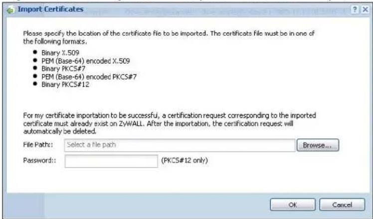
The following table describes the labels in this screen.
Table 171 Configuration > Object > Certificate > My Certificates > Import
| LABEL DESCRIPTION | |
| File Path | Type in the location of the file you want to upload in this field or clickBrowse to find it.You cannot import a certificate with the same name as a certificate that is already in the NXC. |
| Browse | ClickBrowse to find the certificate file you want to upload. |
| Password | This field only applies when you import a binary PKCS# 12 format file. Type the file's password that was created when the PKCS # 12 file was exported. |
| OK Click OK to save the certificate on the NXC. | |
| Cancel | Click Cancel to quit and return to the My Certificates screen. |
32.3 Trusted Certificates
Click Configuration > Object > Certificate > Trusted Certificates to open the Trusted Certificates screen. This screen displays a summary list of certificates that you have set the NXC to accept as trusted. The NXC also accepts any valid certificate signed by a certificate on this list as being trustworthy; thus you do not need to import any certificate that is signed by one of these certificates.
Figure 207 Configuration > Object > Certificate > Trusted Certificates
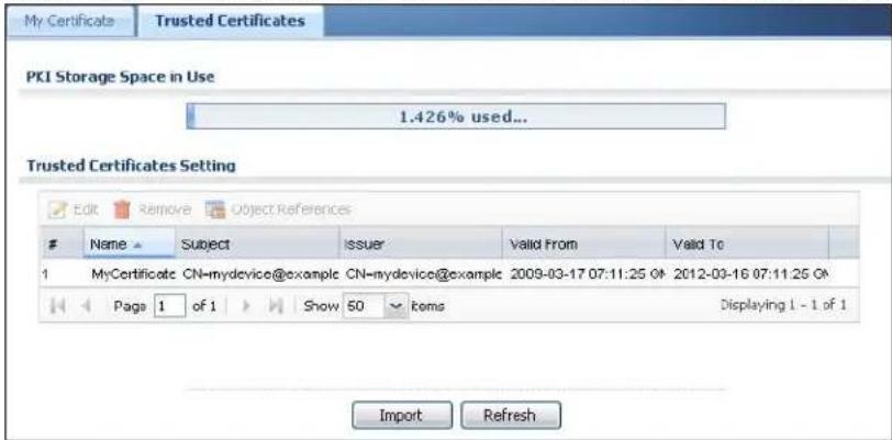
The following table describes the labels in this screen.
Table 172 Configuration > Object > Certificate > Trusted Certificates
| LABEL DESCRIPTION | |
| PKI Storage Space in Use | This bar displays the percentage of the NXC's PKI storage space that is currently in use. When the storage space is almost full, you should consider deleting expired or unnecessary certificates before adding more certificates. |
| Edit | Double-click an entry or select it and click Edit to open a screen with an in-depth list of information about the certificate. |
| Remove | The NXC keeps all of your certificates unless you specifically delete them. Uploading a new firmware or default configuration file does not delete your certificates. To remove an entry, select it and click Remove. The NXC confirms you want to remove it before doing so. Subsequent certificates move up by one when you take this action. |
| Object Reference | You cannot delete certificates that any of the NXC's features are configured to use. Select an entry and click Object References to open a screen that shows which settings use the entry. |
| # This field displays the certificate index number. The certificates are listed in alphabetical order. | |
| Name This field displays the name used to identify this certificate. | |
| Subject This field displays identifying information about the certificate's owner, such as CN (Common Name), OU (Organizational Unit or department), O (Organization or company) and C (Country). It is recommended that each certificate have unique subject information. | |
| Issuer This field displays identifying information about the certificate's issuing certification authority, such as a common name, organizational unit or department, organization or company and country. With self-signed certificates, this is the same information as in the Subject field. | |
| Valid From This field displays the date that the certificate becomes applicable. | |
| Valid To This field displays the date that the certificate expires. The text displays in red and includes an Expired! message if the certificate has expired. | |
| Import Click Import to open a screen where you can save the certificate of a certification authority that you trust, from your computer to the NXC. | |
| Refresh Click this button to display the current validity status of the certificates. | |
32.3.1 Edit Trusted Certificates
Click Configuration > Object > Certificate > Trusted Certificates and then a certificate's Edit icon to open the Trusted Certificates Edit screen. Use this screen to view in-depth information about the certificate, change the certificate's name and set whether or not you want the NXC to check a certification authority's list of revoked certificates before trusting a certificate issued by the certification authority.
Figure 208 Configuration > Object > Certificate > Trusted Certificates > Edit
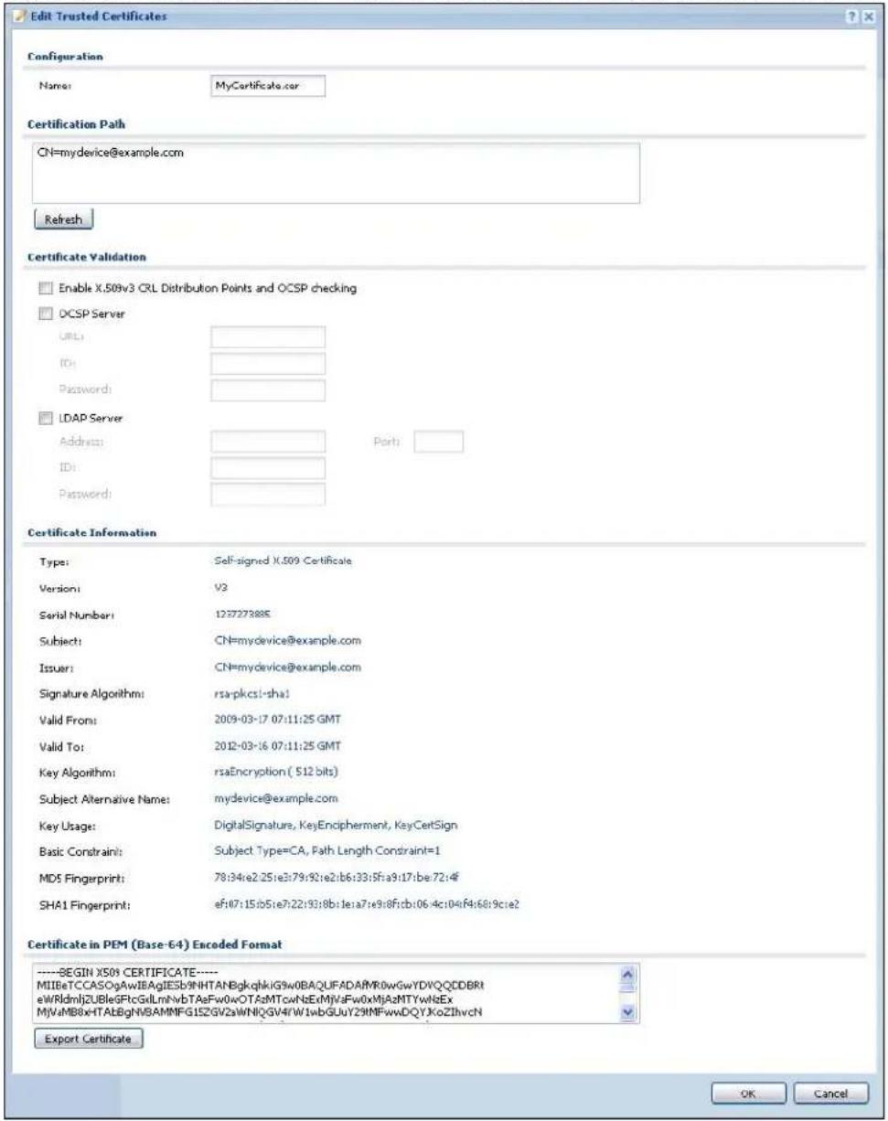
The following table describes the labels in this screen.
Table 173 Configuration > Object > Certificate > Trusted Certificates > Edit
| LABEL DESCRIPTION | |
| Name This field displays the identifying name of this certificate. You can change the name. You can use up to 31 alphanumeric and ;‘~ |@# $%^ &()_+[]{} ’,= - characters. | |
| Certification Path | Click the Refresh button to have this read-only text box display the end entity’s certificate and a list of certification authority certificates that shows the hierarchy of certification authorities that validate the end entity’s certificate. If the issuing certification authority is one that you have imported as a trusted certificate, it may be the only certification authority in the list (along with the end entity’s own certificate). The NXC does not trust the end entity’s certificate and displays “Not trusted” in this field if any certificate on the path has expired or been revoked. |
| Refresh Click Refresh to display the certification path. | |
| Enable X.509v3 CRL Distribution Points and OCSP checking | Select this check box to have the NXC check incoming certificates that are signed by this certificate against a Certificate Revocation List (CRL) or an OCSP server. You also need to configure the OSCP or LDAP server details. |
| OCSP Server Select | this check box if the directory server uses OCSP (Online Certificate Status Protocol). |
| URL Type the protocol, IP address and pathname of the OCSP server. | |
| ID The NXC may need to authenticate itself in order to assess the OCSP server. Type the login name (up to 31 ASCII characters) from the entity maintaining the server (usually a certification authority). | |
| Password Type the password (up to 31 ASCII characters) from the entity maintaining the OCSP server (usually a certification authority). | |
| LDAP Server Select | this check box if the directory server uses LDAP (Lightweight Directory Access Protocol). LDAP is a protocol over TCP that specifies how clients access directories of certificates and lists of revoked certificates. |
| Address Type the IP address (in dotted decimal notation) of the directory server. | |
| Port Use this field to specify the LDAP server port number. You must use the same server port number that the directory server uses. 389 is the default server port number for LDAP. | |
| ID The NXC may need to authenticate itself in order to assess the CRL directory server. Type the login name (up to 31 ASCII characters) from the entity maintaining the server (usually a certification authority). | |
| Password Type the password (up to 31 ASCII characters) from the entity maintaining the CRL directory server (usually a certification authority). | |
| Certificate Information | These read-only fields display detailed information about the certificate. |
Table 173 Configuration > Object > Certificate > Trusted Certificates > Edit
| LABEL DESCRIPTION | |
| Type This field displays general information about the certificate. CA-signed means that a Certification Authority signed the certificate. Self-signed means that the certificate's owner signed the certificate (not a certification authority). X.509 means that this certificate was created and signed according to the ITU-T X.509 recommendation that defines the formats for public-key certificates. | |
| Version This field displays the X.509 version number. | |
| Serial Number This field displays the certificate's identification number given by the certification authority. | |
| Subject This field displays information that identifies the owner of the certificate, such as Common Name (CN), Organizational Unit (OU), Organization (O) and Country (C). | |
| Issuer This field displays identifying information about the certificate's issuing certification authority, such as Common Name, Organizational Unit, Organization and Country.With self-signed certificates, this is the same information as in the Subject Name field. | |
| Signature Algorithm | This field displays the type of algorithm that was used to sign the certificate. Some certification authorities use rsa-pkcs1-sha1 (RSA public-private key encryption algorithm and the SHA1 hash algorithm). Other certification authorities may use rsa-pkcs1-md5 (RSA public-private key encryption algorithm and the MD5 hash algorithm). |
| Valid From This field displays the date that the certificate becomes applicable.The text displays in red and includes a Not Yet Valid! message if the certificate has not yet become applicable. | |
| Valid To This field displays the date that the certificate expires. The text displays in red and includes an Expiring! or Expired! message if the certificate is about to expire or has already expired. | |
| Key Algorithm This field displays the type of algorithm that was used to generate the certificate's key pair (the NXC uses RSA encryption) and the length of the key set in bits (1024 bits for example). | |
| Subject Alternative Name | This field displays the certificate's owner's IP address (IP), domain name (DNS) or e-mail address (EMAIL). |
| Key Usage This field displays for what functions the certificate's key can be used.For example, "DigitalSignature" means that the key can be used to sign certificates and "KeyEncipherment" means that the key can be used to encrypt text. | |
| Basic Constraint This field displays general information about the certificate. For example, Subject Type=CA means that this is a certification authority's certificate and "Path Length Constraint=1" means that there can only be one certification authority in the certificate's path. | |
| MD5 Fingerprint This is the certificate's message digest that the NXC calculated using the MD5 algorithm. You can use this value to verify with the certification authority (over the phone for example) that this is actually their certificate. | |
Table 173 Configuration > Object > Certificate > Trusted Certificates > Edit
| LABEL DESCRIPTION | |
| SHA1 Fingerprint | This is the certificate's message digest that the NXC calculated using the SHA1 algorithm. You can use this value to verify with the certification authority (over the phone for example) that this is actually their certificate. |
| Certificate in PEM(Base-64)Encoded Format | This read-only text box displays the certificate or certification request in Privacy Enhanced Mail (PEM) format. PEM uses lowercase letters, uppercase letters and numerals to convert a binary certificate into a printable form.You can copy and paste the certificate into an e-mail to send to friends or colleagues or you can copy and paste the certificate into a text editor and save the file on a management computer for later distribution (via floppy disk for example). |
| Export Certificate | Click this button and then Save in the File Download screen. The Save As screen opens, browse to the location that you want to use and click Save. |
| OK | Click OK to save your changes back to the NXC. You can only change the name. |
| Cancel | Click Cancel to quit and return to the Trusted Certificates screen. |
32.3.2 Import Trusted Certificates
Click Configuration > Object > Certificate > Trusted Certificates > Import to open the Trusted Certificates Import screen. Follow the instructions in this screen to save a trusted certificate to the NXC.
Note: You must remove any spaces from the certificate's filename before you can import the certificate.
Figure 209 Configuration > Object > Certificate > Trusted Certificates > Import
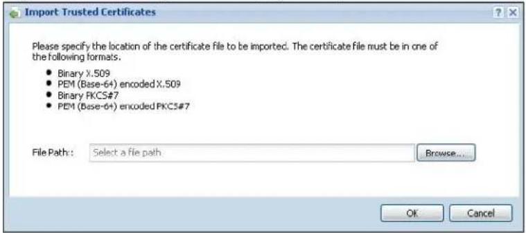
The following table describes the labels in this screen.
Table 174 Configuration > Object > Certificate > Trusted Certificates > Import
| LABEL DESCRIPTION | |
| File Path | Type in the location of the file you want to upload in this field or click Browse to find it.You cannot import a certificate with the same name as a certificate that is already in the NXC. |
| Browse | Click Browse to find the certificate file you want to upload. |
| OK Click OK | to save the certificate on the NXC. |
| Cancel Click | Cancel to quit and return to the previous screen. |
32.4 Technical Reference
The following section contains additional technical information about the features described in this chapter.
OCSP
OCSP (Online Certificate Status Protocol) allows an application or device to check whether a certificate is valid. With OCSP the NXC checks the status of individual certificates instead of downloading a Certificate Revocation List (CRL). OCSP has two main advantages over a CRL. The first is real-time status information. The second is a reduction in network traffic since the NXC only gets information on the certificates that it needs to verify, not a huge list. When the NXC requests certificate status information, the OCSP server returns a “expired”, “current” or “unknown” response.
33.1 Overview
Use the system screens to configure general NXC settings.
33.1.1 What You Can Do in this Chapter
- The Host Name screen (Section 33.2 on page 464) configures a unique name for the NXC in your network.
- The Date/ Time screen (Section 33.3 on page 464) configures the date and time for the NXC.
- The Console Speed screen (Section 33.4 on page 469) configures the console port speed when you connect to the NXC via the console port using a terminal emulation program.
- The DNS screen (Section 33.5 on page 469) configures the DNS (Domain Name System) server used for mapping a domain name to its corresponding IP address and vice versa.
- The WWW screens (Section 33.6 on page 477) configure settings for HTTP or HTTPS access to the NXC and how the login and access user screens look.
- The SSH screen (Section 33.7 on page 490) configures SSH (Secure SHEll) for securely accessing the NXC's command line interface. You can specify which zones allow SSH access and from which IP address the access can come.
- The Telnet screen (Section 33.8 on page 496) configures Telnet for accessing the NXC's command line interface. Specify which zones allow Telnet access and from which IP address the access can come.
- The FTP screen (Section 33.9 on page 497) specifies from which zones FTP can be used to access the NXC. You can also specify from which IP addresses the access can come. You can upload and download the NXC's firmware and configuration files using FTP. Please also see Chapter 35 on page 519 for more information about firmware and configuration files.
- The SNMP screen (Section 33.10 on page 500) configures the device's SNMP settings, including from which zones SNMP can be used to access the NXC. You can also specify from which IP addresses the access can come.
- The Language screen (Section 33.11 on page 503) sets the user interface language for the NXC's Web Configurator screens.
33.2 Host Name
A host name is the unique name by which a device is known on a network. Click Configuration > System > Host Name to open this screen.
Figure 210 Configuration > System > Host Name
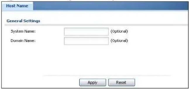
The following table describes the labels in this screen.
Table 175 Configuration > System > Host Name
| LABEL DESCRIPTION | |
| System Name | Choose a descriptive name to identify your NXC device. This name can be up to 64 alphanumeric characters long. Spaces are not allowed, but dashes (-) underscores (_ ) and periods (.) are accepted. |
| Domain Name | Enter the domain name (if you know it) here. This name is propagated to DHCP clients connected to interfaces with the DHCP server enabled. This name can be up to 254 alphanumeric characters long. Spaces are not allowed, but dashes “-” are accepted. |
| Apply | Click Apply to save your changes back to the NXC. |
| Reset | Click Reset to return the screen to its last-saved settings. |
33.3 Date and Time
For effective scheduling and logging, the NXC system time must be accurate. The NXC's Real Time Chip (RTC) keeps track of the time and date. There is also a software mechanism to set the time manually or get the current time and date from an external server.
To change your NXC's time based on your local time zone and date, click
Configuration > System > Date/ Time. The screen displays as shown. You can manually set the NXC's time and date or have the NXC get the date and time from a time server.
Figure 211 Configuration > System > Date/Time
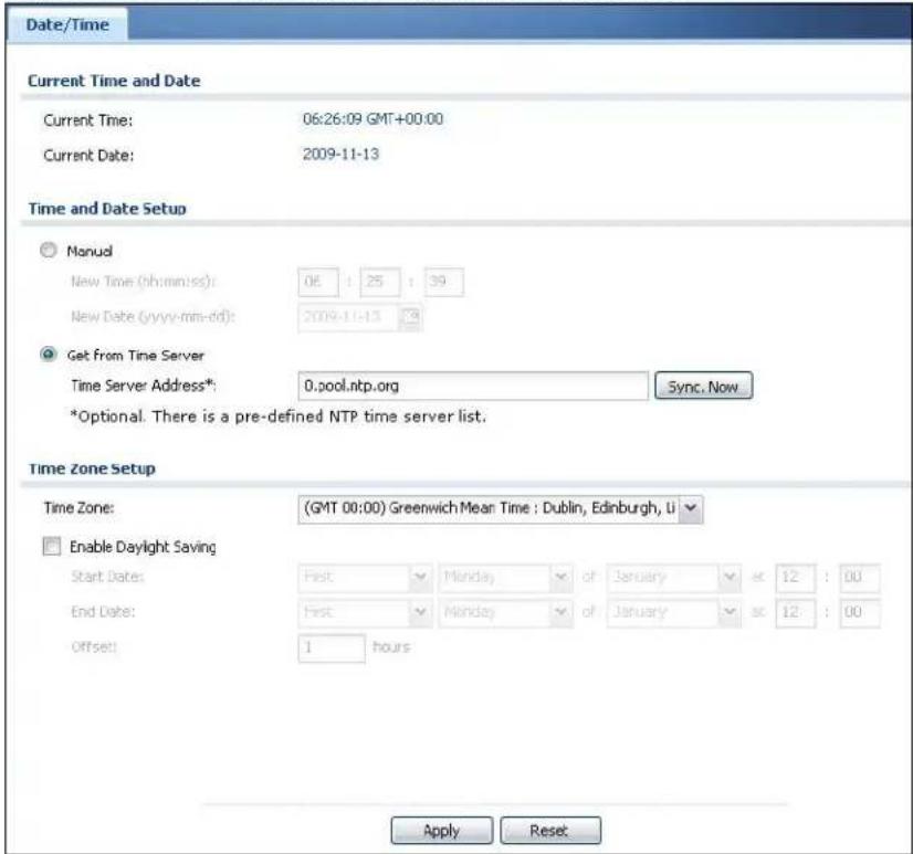
The following table describes the labels in this screen.
Table 176 Configuration > System > Date/Time
| LABEL DESCRIPTION | |
| Current Time and Date | |
| Current Time This field displays the present time of your NXC. | |
| Current Date This field displays the present date of your NXC. | |
| Time and Date Setup | |
| Manual Select this | radio button to enter the time and date manually. If you configure a new time and date, time zone and daylight saving at the same time, the time zone and daylight saving will affect the new time and date you entered. When you enter the time settings manually, the NXC uses the new setting once you click Apply. |
| New Time (hh-mm-ss) | This field displays the last updated time from the time server or the last time configured manually.When you set Time and Date Setup to Manual, enter the new time in this field and then click Apply. |
| LABEL DESCRIPTION | |
| New Date (yyyy-mm-dd) | This field displays the last updated date from the time server or the last date configured manually.When you set Time and Date Setup to Manual, enter the new date in this field and then click Apply. |
| Get from Time Server | Select this radio button to have the NXC get the time and date from the time server you specify below. The NXC requests time and date settings from the time server under the following circumstances.When the NXC starts up.When you click Apply or Synchronize Now in this screen.24-hour intervals after starting up. |
| Time Server Address | Enter the IP address or URL of your time server. Check with your ISP/ network administrator if you are unsure of this information. |
| Sync. Now Click this | is button to have the NXC get the time and date from a time server (see the Time Server Address field). This also saves your changes (except the daylight saving settings). |
| Time Zone Setup | |
| Time Zone | Choose the time zone of your location. This will set the time difference between your time zone and Greenwich Mean Time (GMT). |
| Enable Daylight Saving | Daylight saving is a period from late spring to early fall when many countries set their clocks ahead of normal local time by one hour to give more daytime light in the evening.Select this option if you use Daylight Saving Time. |
| Start Date | Configure the day and time when Daylight Saving Time starts if you selected Enable Daylight Saving. The at field uses the 24 hour format. Here are a couple of examples:Daylight Saving Time starts in most parts of the United States on the second Sunday of March. Each time zone in the United States starts using Daylight Saving Time at 2 A.M. local time. So in the United States you would select Second, Sunday, March and type 2 in the at field.Daylight Saving Time starts in the European Union on the last Sunday of March. All of the time zones in the European Union start using Daylight Saving Time at the same moment (1 A.M. GMT or UTC). So in the European Union you would select Last, Sunday, March. The time you type in the at field depends on your time zone. In Germany for instance, you would type 2 because Germany's time zone is one hour ahead of GMT or UTC (GMT+1). |
| LABEL DESCRIPTION | |
| End Date | Configure the day and time when Daylight Saving Time ends if you selected Enable Daylight Saving. The at field uses the 24 hour format. Here are a couple of examples:Daylight Saving Time ends in the United States on the first Sunday of November. Each time zone in the United States stops using Daylight Saving Time at 2 A.M. local time. So in the United States you would select First, Sunday, November and type 2 in the at field.Daylight Saving Time ends in the European Union on the last Sunday of October. All of the time zones in the European Union stop using Daylight Saving Time at the same moment (1 A.M. GMT or UTC). So in the European Union you would select Last, Sunday, October. The time you type in the at field depends on your time zone. In Germany for instance, you would type 2 because Germany's time zone is one hour ahead of GMT or UTC (GMT+1). |
| Offset Specify how | much the clock changes when daylight saving begins and ends.Enter a number from 1 to 5.5 (by 0.5 increments).For example, if you set this field to 3.5, a log occurred at 6 P.M. in local official time will appear as if it had occurred at 10:30 P.M. |
| Apply | Click Apply to save your changes back to the NXC. |
| Reset | Click Reset to return the screen to its last-saved settings. |
33.3.1 Pre-defined NTP Time Servers List
When you turn on the NXC for the first time, the date and time start at 2003-01-01 00:00:00. The NXC then attempts to synchronize with one of the following predefined list of Network Time Protocol (NTP) time servers.
The NXC continues to use the following pre-defined list of NTP time servers if you do not specify a time server or it cannot synchronize with the time server you specified.
Table 177 Default Time Servers
| 0.pool.ntp.org |
| 1.pool.ntp.org |
| 2.pool.ntp.org |
When the NXC uses the pre-defined list of NTP time servers, it randomly selects one server and tries to synchronize with it. If the synchronization fails, then the NXC goes through the rest of the list in order from the first one tried until either it is successful or all the pre-defined NTP time servers have been tried.
33.3.2 Time Server Synchronization
Click the Synchronize Now button to get the time and date from the time server you specified in the Time Server Address field.
When the Loading message appears, you may have to wait up to one minute.
Figure 212 Loading
The Current Time and Current Date fields will display the appropriate settings if the synchronization is successful.
If the synchronization was not successful, a log displays in the View Log screen. Try re-configuring the Date/Time screen.
To manually set the NXC date and time:
1 Click System > Date/ Time.
2 Select Manual under Time and Date Setup.
3 Enter the NXC's time in the New Time field.
4 Enter the NXC's date in the New Date field.
5 Under Time Zone Setup, select your Time Zone from the list.
6 As an option you can select the Enable Daylight Saving check box to adjust the NXC clock for daylight savings.
7 Click Apply.
To get the NXC date and time from a time server:
1 Click System > Date/ Time.
2 Select Get from Time Server under Time and Date Setup.
3 Under Time Zone Setup, select your Time Zone from the list.
4 Under Time and Date Setup, enter a Time Server Address.
5 Click Apply.
33.4 Console Speed
This section shows you how to set the console port speed when you connect to the NXC via the console port using a terminal emulation program. See Table 2 on page 32 for default console port settings.
Click Configuration > System > Console Speed to open this screen.
Figure 213 Configuration > System > Console Speed
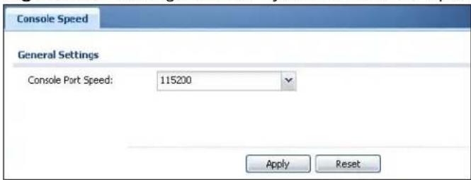
The following table describes the labels in this screen.
Table 178 Configuration > System > Console Speed
| LABEL DESCRIPTION | |
| Console Port Speed | Use the drop-down list box to change the speed of the console port. Your NXC supports 9600, 19200, 38400, 57600, and 115200 bps (default) for the console port.The Console Port Speed applies to a console port connection using terminal emulation software and NOT the Console in the NXC Web Configurator Status screen. |
| Apply | Click Apply to save your changes back to the NXC. |
| Reset | Click Reset to return the screen to its last-saved settings. |
33.5 DNS Overview
DNS (Domain Name System) is for mapping a domain name to its corresponding IP address and vice versa. The DNS server is extremely important because without it, you must know the IP address of a machine before you can access it.
33.5.1 DNS Server Address Assignment
The NXC can get the DNS server addresses in the following ways.
- The ISP tells you the DNS server addresses, usually in the form of an information sheet, when you sign up. If your ISP gives you DNS server addresses, manually enter them in the DNS server fields.
- If your ISP dynamically assigns the DNS server IP addresses (along with the NXC's WAN IP address), set the DNS server fields to get the DNS server address from the ISP.
- You can manually enter the IP addresses of other DNS servers.
33.5.2 Configuring the DNS Screen
Click Configuration > System > DNS to change your NXC's DNS settings. Use the DNS screen to configure the NXC to use a DNS server to resolve domain names for NXC system features like the time server. You can also configure the NXC to accept or discard DNS queries. Use the Network > Interface screens to configure the DNS server information that the NXC sends to the specified DHCP client devices.
Figure 214 Configuration > System > DNS
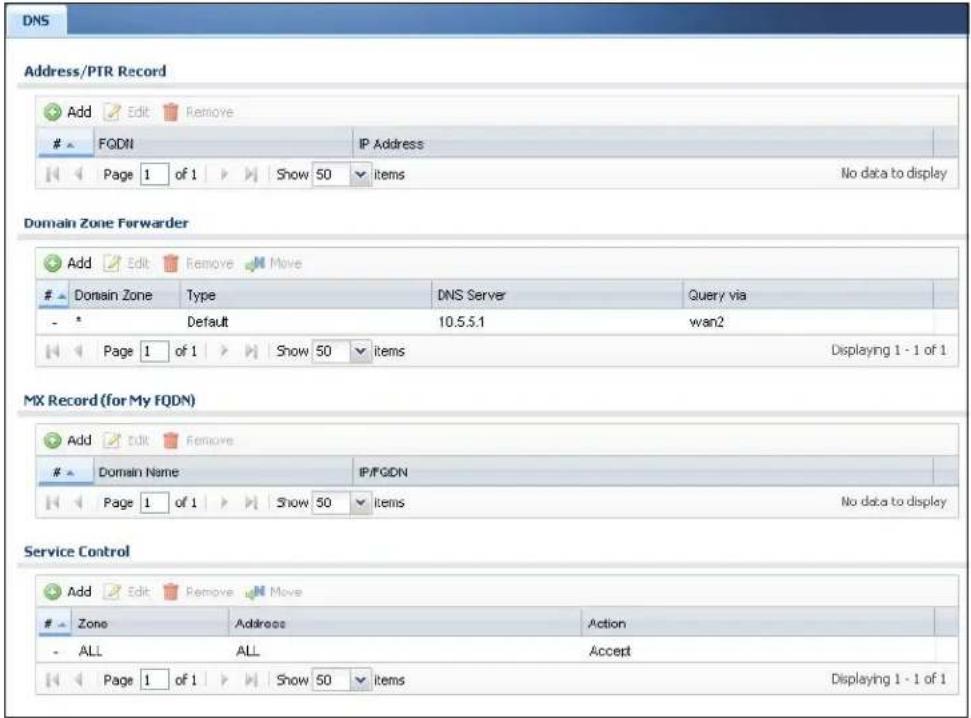
The following table describes the labels in this screen.
Table 179 Configuration > System > DNS
| LABEL DESCRIPTION | |
| Address/PTR Record | This record specifies the mapping of a Fully-Qualified Domain Name (FQDN) to an IP address. An FQDN consists of a host and domain name. For example, www.zyxel.com.tw is a fully qualified domain name, where “www” is the host, “zyxel” is the third-level domain, “com” is the second-level domain, and “tw” is the top level domain. |
| Add Click this to create a new entry. | |
| Edit | Double-click an entry or select it and click Edit to be able to modify the entry's settings. |
| Remove | To remove an entry, select it and click Remove. The NXC confirms you want to remove it before doing so. Note that subsequent entries move up by one when you take this action. |
| # This is the index number of the address/PTR record. | |
| FQDN This is a host's fully qualified domain name. | |
| IP Address This is the IP address of a host. | |
| Domain Zone Forwarder | This specifies a DNS server's IP address. The NXC can query the DNS server to resolve domain zones for features like the time server.When the NXC needs to resolve a domain zone, it checks it against the domain zone forwarder entries in the order that they appear in this list. |
| Add | Click this to create a new entry. Select an entry and click Add to create a new entry after the selected entry. |
| Edit | Double-click an entry or select it and click Edit to be able to modify the entry's settings. |
| Remove | To remove an entry, select it and click Remove. The NXC confirms you want to remove it before doing so. Note that subsequent entries move up by one when you take this action. |
| Move To change an entry's position in the numbered list, select the method and click Move to display a field to type a number for where you want to put it and press [ENTER] to move the rule to the number that you typed. | |
| # | This is the index number of the domain zone forwarder record. The ordering of your rules is important as rules are applied in sequence.A hyphen (-) displays for the default domain zone forwarder record. The default record is not configurable. The NXC uses this default record if the domain zone that needs to be resolved does not match any of the other domain zone forwarder records. |
| Domain Zone A domain zone is a fully qualified domain name without the host. For example, zyxel.com.tw is the domain zone for the www.zyxel.com.tw fully qualified domain name.A “*” means all domain zones. | |
| Type This displays whether the DNS server IP address is assigned by the ISP dynamically through a specified interface or configured manually (User-Defined). | |
| DNS Server | This is the IP address of a DNS server. This field displays N/A if you have the NXC get a DNS server IP address from the ISP dynamically but the specified interface is not active. |
| Query Via | This is the interface through which the NXC sends DNS queries to the entry's DNS server. |
| MX Record (for My FQDN) | A MX (Mail eXchange) record identifies a mail server that handles the mail for a particular domain. |
| Add Click this to create a new entry. | |
| # This is the index | number of the MX record. |
| Domain Name This | is the domain name where the mail is destined for. |
| IP/FQDN This is the | IP address or Fully-Qualified Domain Name (FQDN) of a mail server that handles the mail for the domain specified in the field above. |
| Service Control This | specifics from which computers and zones you can send DNS queries to the NXC. |
| Add | Click this to create a new entry. Select an entry and click Add to create a new entry after the selected entry. |
| Edit | Double-click an entry or select it and click Edit to be able to modify the entry's settings. |
| Remove | To remove an entry, select it and click Remove. The NXC confirms you want to remove it before doing so. Note that subsequent entries move up by one when you take this action. |
| Move To change | an entry's position in the numbered list, select the method and click Move to display a field to type a number for where you want to put it and press [ENTER] to move the rule to the number that you typed. |
| # This the index | number of the service control rule. The ordering of your rules is important as rules are applied in sequence.The entry with a hyphen (-) instead of a number is the NXC's (non-configurable) default policy. The NXC applies this to traffic that does not match any other configured rule. It is not an editable rule. To apply other behavior, configure a rule that traffic will match so the NXC will not have to use the default policy. |
| Zone This is the zone on the NXC the user is allowed or denied to access. | |
| Address This is the object name of the IP address(es) with which the computer is allowed or denied to send DNS queries. | |
| Action This displays whether the NXC accepts DNS queries from the computer with the IP address specified above through the specified zone (Accept) or discards them (Deny). | |
33.5.3 Address Record
An address record contains the mapping of a Fully-Qualified Domain Name (FQDN) to an IP address. An FQDN consists of a host and domain name. For example, www.zyxel.com is a fully qualified domain name, where "www" is the host, "zyxel" is the second-level domain, and "com" is the top level domain.
mail.myZyXEL.com.tw is also a FQDN, where "mail" is the host, "myZyXEL" is the third-level domain, "com" is the second-level domain, and "tw" is the top level domain.
The NXC allows you to configure address records about the NXC itself or another device. This way you can keep a record of DNS names and addresses that people on your network may use frequently. If the NXC receives a DNS query for an FQDN for which the NXC has an address record, the NXC can send the IP address in a DNS response without having to query a DNS name server.
33.5.4 PTR Record
A PTR (pointer) record is also called a reverse record or a reverse lookup record. It is a mapping of an IP address to a domain name.
33.5.5 Adding an Address/PTR Record
Click the Add icon in the Address/ PTR Record table to add an address/ PTR record.
Figure 215 Configuration > System > DNS > Add Address/PTR Recordt
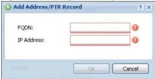
The following table describes the labels in this screen.
Table 180 Configuration > System > DNS > Add Address/PTR Record
| LABEL DESCRIPTION | |
| FQDN Type a Fully-Qualified Domain Name (FQDN) of a server. An FQDN starts with a host name and continues all the way up to the top-level domain name. For example, www.zyxel.com.tw is a fully qualified domain name, where “www” is the host, “zyxel” is the third-level domain, “com” is the second-level domain, and “tw” is the top level domain. Underscores are not allowed.Use “*.” as a prefix in the FQDN for a wildcard domain name (for example, *.example.com). | |
| IP Address Enter | the IP address of the host in dotted decimal notation. |
| OK | Click OK to save your customized settings and exit this screen. |
| Cancel Click Cancel to exit this screen without saving | |
33.5.6 Domain Zone Forwarder
A domain zone forwarder contains a DNS server's IP address. The NXC can query the DNS server to resolve domain zones for features like the time server. A domain zone is a fully qualified domain name without the host. For example, zyxel.com is the domain zone for the www.zyxel.com fully qualified domain name.
33.5.7 Add Domain Zone Forwarder
Click the Add icon in the Domain Zone Forwarder table to add a domain zone forwarder record.
Figure 216 Configuration > System > DNS > Add Domain Zone Forwarder
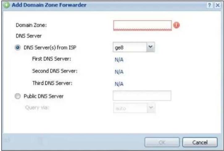
The following table describes the labels in this screen.
Table 181 Configuration > System > DNS > Add Domain Zone Forwarder
| LABEL DESCRIPTION | |
| Domain Zone A | domain zone is a fully qualified domain name without the host. For example, zyxel.com.tw is the domain zone for the www.zyxel.com.tw fully qualified domain name. For example, whenever the NXC receives needs to resolve a zyxel.com.tw domain name, it can send a query to the recorded name server IP address.Enter * if all domain zones are served by the specified DNS server(s). |
| DNS Server | Select DNS Server(s) from ISP if your ISP dynamically assigns DNS server information. You also need to select an interface through which the ISP provides the DNS server IP address(es). The interface should be activated and set to be a DHCP client. The fields below display the (read-only) DNS server IP address(es) that the ISP assigns. N/ A displays for any DNS server IP address fields for which the ISP does not assign an IP address.Note: If all interfaces are static, then this field is hidden.Select Public DNS Server if you have the IP address of a DNS server. Enter the DNS server's IP address in the field to the right. The NXC must be able to connect to the DNS server. The DNS server could be on the Internet or one of the NXC's local networks. You cannot use 0.0.0.0. Use the Query via field to select the interface through which the NXC sends DNS queries to a DNS server. |
| OK | Click OK to save your customized settings and exit this screen. |
| Cancel Click Cancel to exit this screen without saving | |
33.5.8 MX Record
A MX (Mail eXchange) record indicates which host is responsible for the mail for a particular domain, that is, controls where mail is sent for that domain. If you do not configure proper MX records for your domain or other domain, external e-mail from other mail servers will not be able to be delivered to your mail server and vice versa. Each host or domain can have only one MX record, that is, one domain is mapping to one host.
33.5.9 Add MX Record
Click the Add icon in the MX Record table to add a MX record.
Figure 217 Configuration > System > DNS > Add MX Record
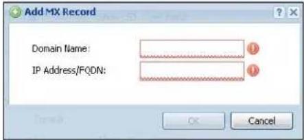
The following table describes the labels in this screen.
Table 182 Configuration > System > DNS > Add MX Record
| LABEL DESCRIPTION | |
| Domain Name Enter the domain name where the mail is destined for. | |
| IP Address/FQDN | Enter the IP address or Fully-Qualified Domain Name (FQDN) of a mail server that handles the mail for the domain specified in the field above. |
| OK | Click OK to save your customized settings and exit this screen. |
| Cancel Click Cancel to exit this screen without saving | |
33.5.10 Add Service Control
Click the Add icon in the Service Control table to add a service control rule.
Figure 218 Configuration > System > DNS > Add Service Control Rule
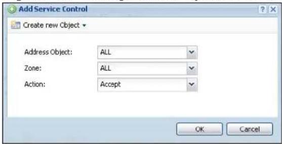
The following table describes the labels in this screen.
Table 183 Configuration > System > DNS > Add Service Control Rule
| LABEL DESCRIPTION | |
| Create new Object | Use this to configure any new settings objects that you need to use in this screen. |
| Address Object | Select ALL to allow or deny any computer to send DNS queries to the NXC.Select a predefined address object to just allow or deny the computer with the IP address that you specified to send DNS queries to the NXC. |
| Zone | Select ALL to allow or prevent DNS queries through any zones.Select a predefined zone on which a DNS query to the NXC is allowed or denied. |
| Action | Select Accept to have the NXC allow the DNS queries from the specified computer.Select Deny to have the NXC reject the DNS queries from the specified computer. |
| OK | Click OK to save your customized settings and exit this screen. |
| Cancel Click Cancel to exit this screen without saving | |
33.6 WWW Overview
The following figure shows secure and insecure management of the NXC coming in from the WAN. HTTPS and SSH access are secure. HTTP, Telnet, and dial-in management access are not secure.
Figure 219 Secure and Insecure Service Access From the WAN
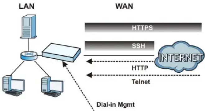
flowchart
graph TD
    A["LAN"] --> B["Router"]
    B --> C["Dial-in Mgmt"]
    D["WAN"] --> E["INTERNET"]
    E --> F["HTTPS"]
    E --> G["SSH"]
    E --> H["HTTP"]
    E --> I["Telnet"]
33.6.1 Service Access Limitations
A service cannot be used to access the NXC when:
1 You have disabled that service in the corresponding screen.
2 The allowed IP address (address object) in the Service Control table does not match the client IP address (the NXC disallows the session).
3 The IP address (address object) in the Service Control table is not in the allowed zone or the action is set to Deny.
4 There is a firewall rule that blocks it.
33.6.2 System Timeout
There is a lease timeout for administrators. The NXC automatically logs you out if the management session remains idle for longer than this timeout period. The management session does not time out when a statistics screen is polling.
Each user is also forced to log in the NXC for authentication again when the reauthentication time expires.
You can change the timeout settings in the User/ Group screens.
33.6.3 HTTPS
You can set the NXC to use HTTP or HTTPS (HTTPS adds security) for Web Configurator sessions. Specify which zones allow Web Configurator access and from which IP address the access can come.
HTTPS (HyperText Transfer Protocol over Secure Socket Layer, or HTTP over SSL) is a web protocol that encrypts and decrypts web pages. Secure Socket Layer (SSL) is an application-level protocol that enables secure transactions of data by ensuring confidentiality (an unauthorized party cannot read the transferred data), authentication (one party can identify the other party) and data integrity (you know if data has been changed).
It relies upon certificates, public keys, and private keys (see Chapter 32 on page 441 for more information).
HTTPS on the NXC is used so that you can securely access the NXC using the Web Configurator. The SSL protocol specifies that the HTTPS server (the NXC) must always authenticate itself to the HTTPS client (the computer which requests the HTTPS connection with the NXC), whereas the HTTPS client only should authenticate itself when the HTTPS server requires it to do so (select
Authenticate Client Certificates in the WWW screen). Authenticate Client Certificates is optional and if selected means the HTTPS client must send the NXC a certificate. You must apply for a certificate for the browser from a CA that is a trusted CA on the NXC.
Please refer to the following figure.
1 HTTPS connection requests from an SSL-aware web browser go to port 443 (by default) on the NXC's web server.
2 HTTP connection requests from a web browser go to port 80 (by default) on the NXC's web server.
Figure 220 HTTP/HTTPS Implementation
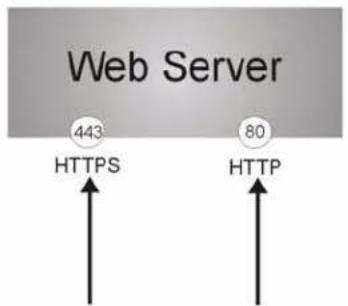
Note: If you disable HTTP in the WWW screen, then the NXC blocks all HTTP connection attempts.
33.6.4 Configuring WWW Service Control
Click Configuration > System > WWW to open the WWW screen. Use this screen to specify from which zones you can access the NXC using HTTP or HTTPS. You can also specify which IP addresses the access can come from.
Note: Admin Service Control deals with management access (to the Web Configurator). User Service Control deals with user access to the NXC.
Figure 221 Configuration > System > WWW > Service Control
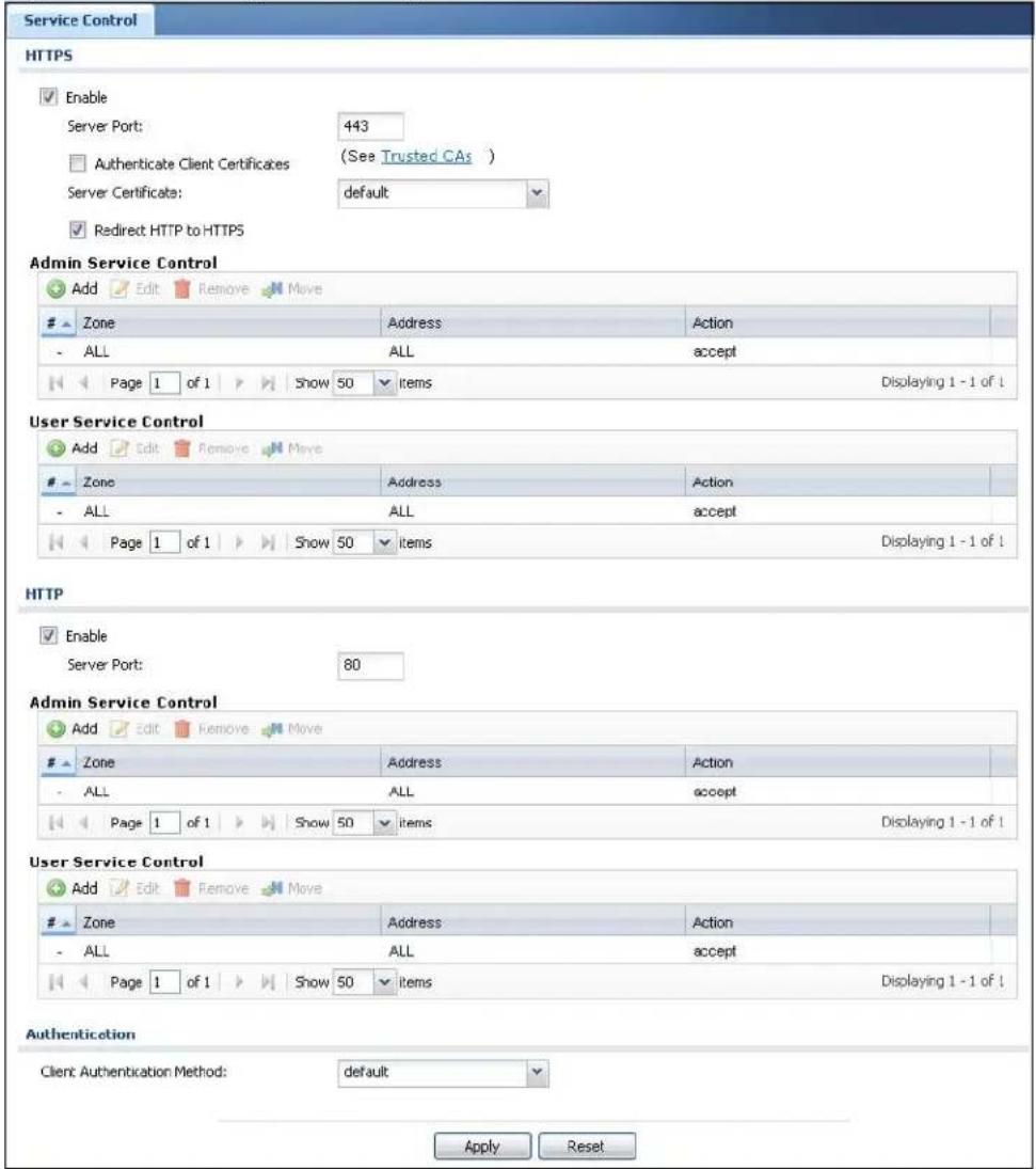
The following table describes the labels in this screen.
Table 184 Configuration > System > WWW > Service Control
| LABEL DESCRIPTION | |
| HTTPS | |
| Enable Select the check box to allow or disallow the computer with the IP address that matches the IP address(es) in the Service Control table to access the NXC Web Configurator using secure HTTPS connections. | |
| Server Port The HTTPS server listens on port 443 by default. If you change the HTTPS server port to a different number on the NXC, for example 8443, then you must notify people who need to access the NXC Web Configurator to use “https://NXC IP Address:8443” as the URL. | |
| Authenticate Client Certificates | Select Authenticate Client Certificates (optional) to require the SSL client to authenticate itself to the NXC by sending the NXC a certificate. To do that the SSL client must have a CA-signed certificate from a CA that has been imported as a trusted CA on the NXC. |
| Server Certificate Select a certificate the HTTPS server (the NXC) uses to authenticate itself to the HTTPS client. You must have certificates already configured in the My Certificates screen. | |
| Redirect HTTP to HTTPS | To allow only secure Web Configurator access, select this to redirect all HTTP connection requests to the HTTPS server. |
| Admin/User Service Control | Admin Service Control specifies from which zones an administrator can use HTTPS to manage the NXC (using the Web Configurator). You can also specify the IP addresses from which the administrators can manage the NXC.User Service Control specifies from which zones a user can use HTTPS to log into the NXC. You can also specify the IP addresses from which the users can access the NXC. |
| Add | Click this to create a new entry. Select an entry and click Add to create a new entry after the selected entry. |
| Edit | Double-click an entry or select it and click Edit to be able to modify the entry's settings. |
| Remove | To remove an entry, select it and click Remove. The NXC confirms you want to remove it before doing so. Note that subsequent entries move up by one when you take this action. |
| Move To change an entry's position in the numbered list, select the method and click Move to display a field to type a number for where you want to put it and press [ENTER] to move the rule to the number that you typed. | |
| # This is the index number of the service control rule.The entry with a hyphen (-) instead of a number is the NXC's (non-configurable) default policy. The NXC applies this to traffic that does not match any other configured rule. It is not an editable rule. To apply other behavior, configure a rule that traffic will match so the NXC will not have to use the default policy. | |
| Zone | This is the zone on the NXC the user is allowed or denied to access. |
| Address This is the object name of the IP address(es) with which the computer is allowed or denied to access. | |
| Action This displays whether the computer with the IP address specified above can access the NXC zone(s) configured in the Zone field (Accept) or not (Deny). | |
| HTTP | |
| Enable Select the check box to allow or disallow the computer with the IP address that matches the IP address(es) in the Service Control table to access the NXC Web Configurator using HTTP connections. | |
| Server Port You may change the server port number for a service if needed, however you must use the same port number in order to use that service to access the NXC. | |
| Admin/User Service Control | Admin Service Control specifies from which zones an administrator can use HTTP to manage the NXC (using the Web Configurator). You can also specify the IP addresses from which the administrators can manage the NXC.User Service Control specifies from which zones a user can use HTTP to log into the NXC. You can also specify the IP addresses from which the users can access the NXC. |
| Add | Click this to create a new entry. Select an entry and click Add to create a new entry after the selected entry. |
| Edit | Double-click an entry or select it and click Edit to be able to modify the entry's settings. |
| Remove | To remove an entry, select it and click Remove. The NXC confirms you want to remove it before doing so. Note that subsequent entries move up by one when you take this action. |
| Move To change an entry's position in the numbered list, select the method and click Move to display a field to type a number for where you want to put it and press [ENTER] to move the rule to the number that you typed. | |
| # This is the index number of the service control rule.The entry with a hyphen (-) instead of a number is the NXC's (non-configurable) default policy. The NXC applies this to traffic that does not match any other configured rule. It is not an editable rule. To apply other behavior, configure a rule that traffic will match so the NXC will not have to use the default policy. | |
| Zone | This is the zone on the NXC the user is allowed or denied to access. |
| Address This is the object name of the IP address(es) with which the computer is allowed or denied to access. | |
| Action This displays whether the computer with the IP address specified above can access the NXC zone(s) configured in the Zone field (Accept) or not (Deny). | |
| Authentication | |
| Client Authentication Method | Select a method the HTTPS or HTTP server uses to authenticate a client.You must have configured the authentication methods in the Auth. method screen. |
| Apply | Click Apply to save your changes back to the NXC. |
| Reset | Click Reset to return the screen to its last-saved settings. |
33.6.5 Service Control Rules
Click Add or Edit in the Service Control table in a WWW, SSH, Telnet, FTP or SNMP screen to add a service control rule.
Figure 222 Configuration > System > Service Control Rule > Add/Edit
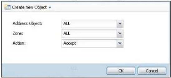
The following table describes the labels in this screen.
Table 185 Configuration > System > Service Control Rule > Add/Edit
| LABEL DESCRIPTION | |
| Create new Object | Use this to configure any new settings objects that you need to use in this screen. |
| Address Object | Select ALL to allow or deny any computer to communicate with the NXC using this service.Select a predefined address object to just allow or deny the computer with the IP address that you specified to access the NXC using this service. |
| Zone | Select ALL to allow or prevent any NXC zones from being accessed using this service.Select a predefined NXC zone on which a incoming service is allowed or denied. |
| Action | Select Accept to allow the user to access the NXC from the specified computers.Select Deny to block the user's access to the NXC from the specified computers. |
| OK | Click OK to save your customized settings and exit this screen. |
| Cancel Click Cancel to exit this screen without saving | |
33.6.6 HTTPS Example
If you haven't changed the default HTTPS port on the NXC, then in your browser enter "https://NXC IP Address/" as the web site address where "NXC IP Address" is the IP address or domain name of the NXC you wish to access.
33.6.6.1 Internet Explorer Warning Messages
When you attempt to access the NXC HTTPS server, a Windows dialog box pops up asking if you trust the server certificate. Click View Certificate if you want to verify that the certificate is from the NXC.
You see the following Security Alert screen in Internet Explorer. Select Yes to proceed to the Web Configurator login screen; if you select No, then Web Configurator access is blocked.
Figure 223 Security Alert Dialog Box (Internet Explorer)
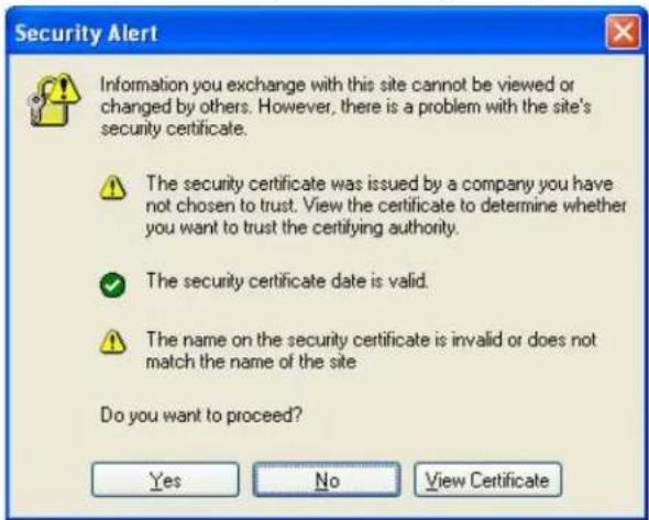
33.6.6.2 Avoiding Browser Warning Messages
Here are the main reasons your browser displays warnings about the NXC's HTTPS server certificate and what you can do to avoid seeing the warnings:
- The issuing certificate authority of the NXC's HTTPS server certificate is not one of the browser's trusted certificate authorities. The issuing certificate authority of the NXC's factory default certificate is the NXC itself since the certificate is a self-signed certificate.
- For the browser to trust a self-signed certificate, import the self-signed certificate into your operating system as a trusted certificate.
- To have the browser trust the certificates issued by a certificate authority, import the certificate authority's certificate into your operating system as a trusted certificate. Refer to Appendix D on page 619 for details.
33.6.6.3 Login Screen
After you accept the certificate, the NXC login screen appears. The lock displayed in the bottom of the browser status bar denotes a secure connection.
Figure 224 Login Screen (Internet Explorer)
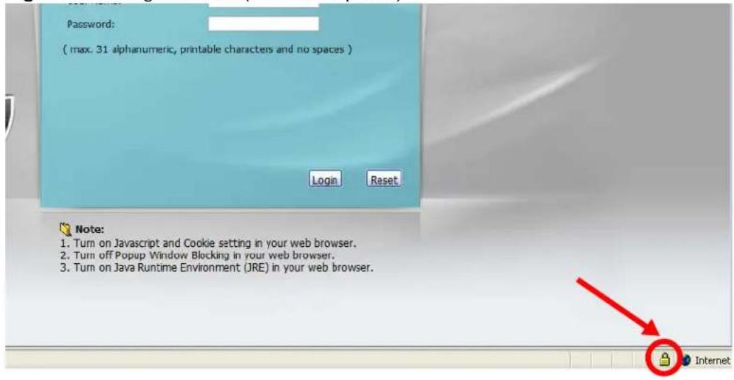
33.6.6.4 Enrolling and Importing SSL Client Certificates
The SSL client needs a certificate if Authenticate Client Certificates is selected on the NXC.
You must have imported at least one trusted CA to the NXC in order for the Authenticate Client Certificates to be active (see the Certificates chapter for details).
Apply for a certificate from a Certification Authority (CA) that is trusted by the NXC (see the NXC's Trusted CA Web Configurator screen).
Figure 225 Trusted Certificates
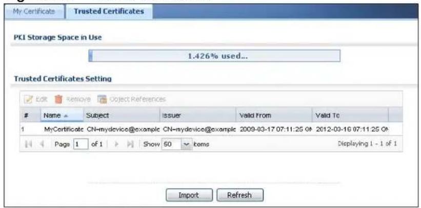
The CA sends you a package containing the CA's trusted certificate(s), your personal certificate(s) and a password to install the personal certificate(s).
33.6.6.5 Installing the CA's Certificate
1 Double click the CA's trusted certificate to produce a screen similar to the one shown next.
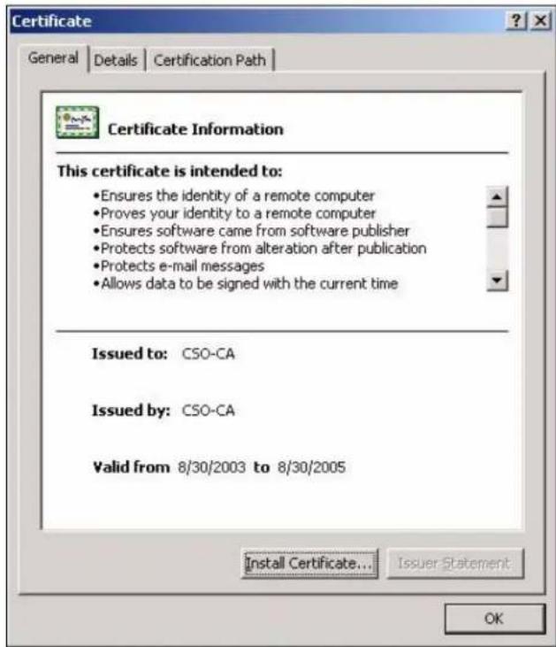
2 Click Install Certificate and follow the wizard as shown earlier in this appendix.
33.6.6.6 Installing a Personal Certificate
You need a password in advance. The CA may issue the password or you may have to specify it during the enrollment. Double-click the personal certificate given to you by the CA to produce a screen similar to the one shown next
1 Click Next to begin the wizard.
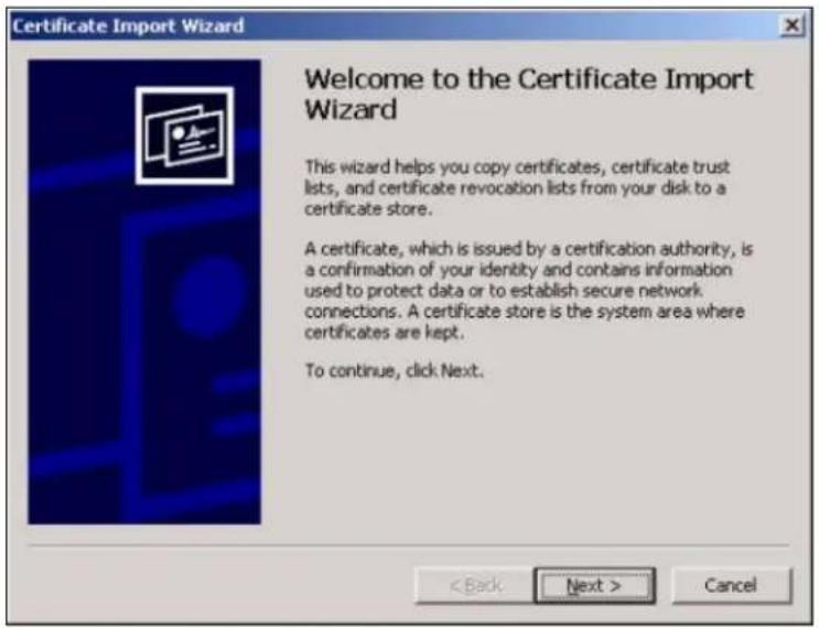
2 The file name and path of the certificate you double-clicked should automatically appear in the File name text box. Click Browse if you wish to import a different certificate.
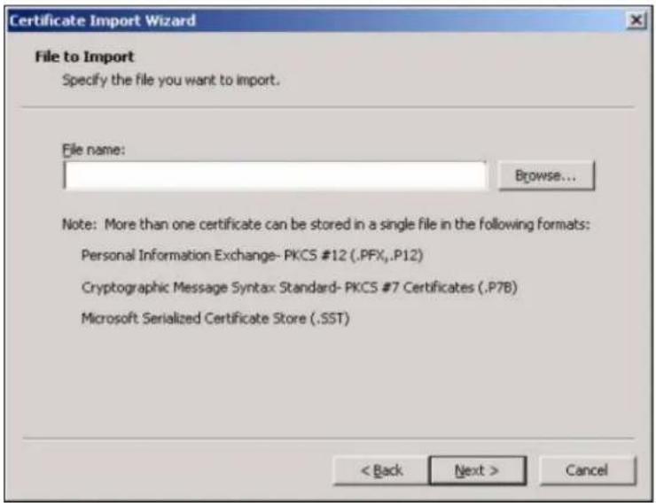
3 Enter the password given to you by the CA.
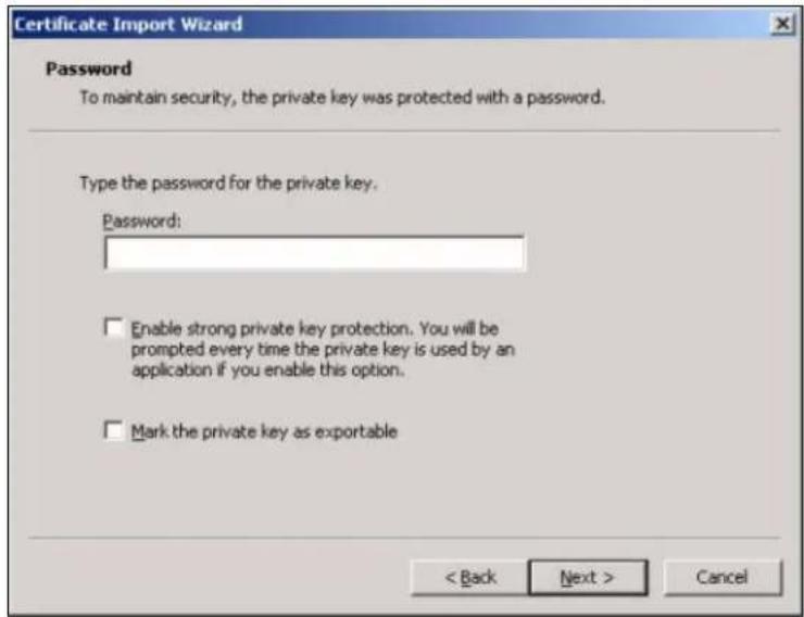
4 Have the wizard determine where the certificate should be saved on your computer or select Place all certificates in the following store and choose a different location.
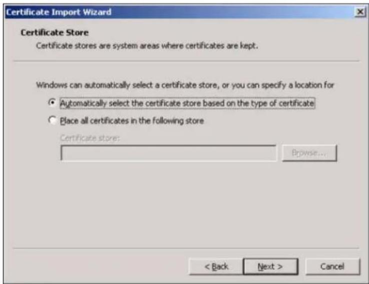
5 Click Finish to complete the wizard and begin the import process.
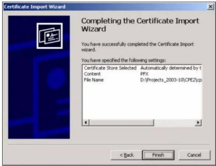
6 You should see the following screen when the certificate is correctly installed on your computer.
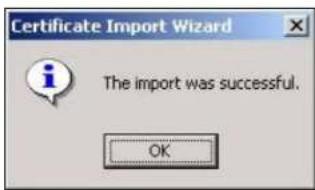
33.6.6.7 Using a Certificate When Accessing the NXC
To access the NXC via HTTPS:
1 Enter 'https://NXC IP Address/ in your browser's web address field.

2 When Authenticate Client Certificates is selected on the NXC, the following screen asks you to select a personal certificate to send to the NXC. This screen displays even if you only have a single certificate as in the example.
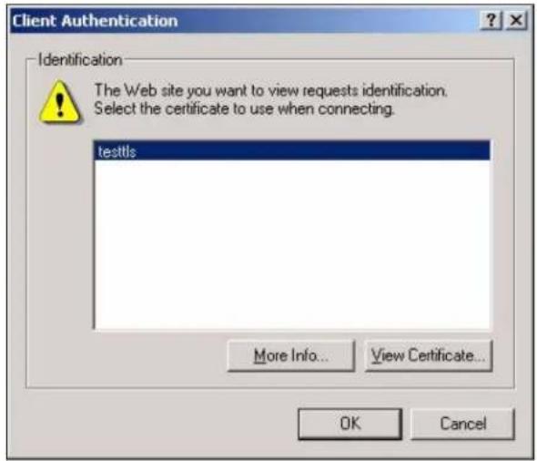
3 You next see the Web Configurator login screen.
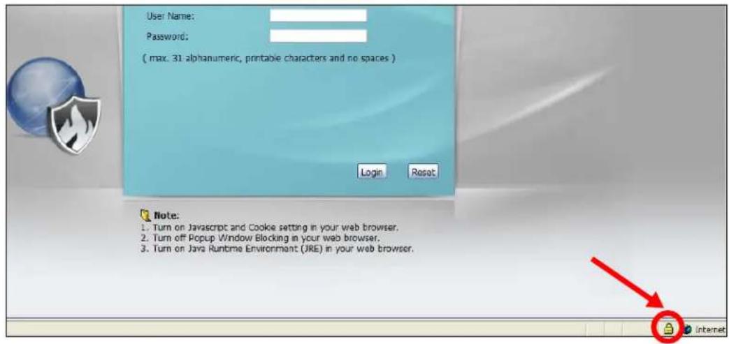
33.7 SSH
You can use SSH (Secure SHEll) to securely access the NXC's command line interface. Specify which zones allow SSH access and from which IP address the access can come.
SSH is a secure communication protocol that combines authentication and data encryption to provide secure encrypted communication between two hosts over an
unsecured network. In the following figure, computer A on the Internet uses SSH to securely connect to the WAN port of the NXC for a management session.
Figure 226 SSH Communication Over the WAN Example

flowchart
graph LR
    A["A"] --> B["Server"]
    B --> C["InternetNet Secure Connection"]
    C --> D["Server"]
    D --> E["B"]
33.7.1 How SSH Works
The following figure is an example of how a secure connection is established between two remote hosts using SSH v1.
Figure 227 How SSH v1 Works Example
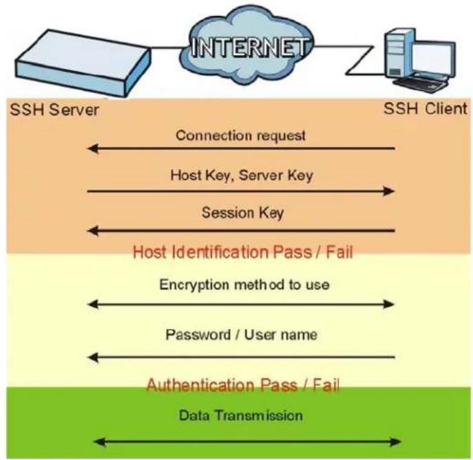
flowchart
graph TD
    A["SSH Server"] -->|Connection request| B["SSH Client"]
    B -->|Host Key, Server Key| C["Session Key"]
    C -->|Host Identification Pass / Fail| D["Encryption method to use"]
    D -->|Password / User name| E["Authentication Pass / Fail"]
    E -->|Data Transmission| F["Bottom Layer"]
1 Host Identification
The SSH client sends a connection request to the SSH server. The server identifies itself with a host key. The client encrypts a randomly generated session key with the host key and server key and sends the result back to the server.
The client automatically saves any new server public keys. In subsequent connections, the server public key is checked against the saved version on the client computer.
2 Encryption Method
Once the identification is verified, both the client and server must agree on the type of encryption method to use.
3 Authentication and Data Transmission
After the identification is verified and data encryption activated, a secure tunnel is established between the client and the server. The client then sends its authentication information (user name and password) to the server to log in to the server.
33.7.2 SSH Implementation on the NXC
Your NXC supports SSH versions 1 and 2 using RSA authentication and four encryption methods (AES, 3DES, Archfour, and Blowfish). The SSH server is implemented on the NXC for management using port 22 (by default).
33.7.3 Requirements for Using SSH
You must install an SSH client program on a client computer (Windows or Linux operating system) that is used to connect to the NXC over SSH.
33.7.4 Configuring SSH
Click Configuration > System > SSH to change your NXC's Secure Shell settings. Use this screen to specify from which zones SSH can be used to manage the NXC. You can also specify from which IP addresses the access can come.
Note: It is recommended that you disable Telnet and FTP when you configure SSH for secure connections.
Figure 228 Configuration > System > SSH
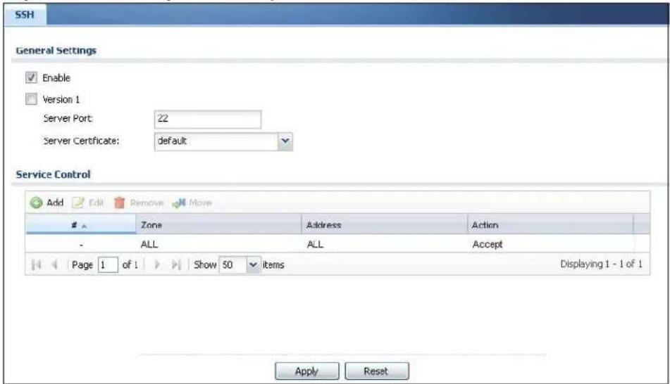
The following table describes the labels in this screen.
Table 186 Configuration > System > SSH
| LABEL DESCRIPTION | |
| Enable Select the | check box to allow or disallow the computer with the IP address that matches the IP address(es) in the Service Control table to access the NXC CLI using this service. |
| Version 1 Select | the check box to have the NXC use both SSH version 1 and version 2 protocols. If you clear the check box, the NXC uses only SSH version 2 protocol. |
| Server Port | You may change the server port number for a service if needed, however you must use the same port number in order to use that service for remote management. |
| Server Certificate | Select the certificate whose corresponding private key is to be used to identify the NXC for SSH connections. You must have certificates already configured in the My Certificates screen. |
| Service Control | This specifies from which computers you can access which NXC zones. |
| Add | Click this to create a new entry. Select an entry and click Add to create a new entry after the selected entry. |
| Edit | Double-click an entry or select it and click Edit to be able to modify the entry's settings. |
| Remove | To remove an entry, select it and click Remove. The NXC confirms you want to remove it before doing so. Note that subsequent entries move up by one when you take this action. |
| Move To change | an entry's position in the numbered list, select the method and click Move to display a field to type a number for where you want to put it and press [ENTER] to move the rule to the number that you typed. |
| # This the index | number of the service control rule. |
| Zone This is the | zone on the NXC the user is allowed or denied to access. |
| Address This is the | the object name of the IP address(es) with which the computer is allowed or denied to access. |
| Action This displays | wahs whether the computer with the IP address specified above can access the NXC zone(s) configured in the Zone field (Accept) or not (Deny). |
| Apply | Click Apply to save your changes back to the NXC. |
| Reset | Click Reset to return the screen to its last-saved settings. |
33.7.5 Examples of Secure Telnet Using SSH
This section shows two examples using a command interface and a graphical interface SSH client program to remotely access the NXC. The configuration and connection steps are similar for most SSH client programs. Refer to your SSH client program user's guide.
33.7.5.1 Example 1: Microsoft Windows
This section describes how to access the NXC using the Secure Shell Client program.
1 Launch the SSH client and specify the connection information (IP address, port number) for the NXC.
2 Configure the SSH client to accept connection using SSH version 1.
3 A window displays prompting you to store the host key in you computer. Click Yes to continue.
Figure 229 SSH Example 1: Store Host Key
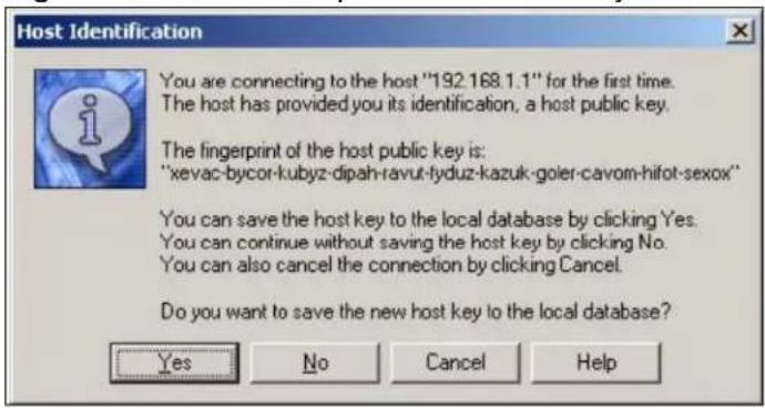
Enter the password to log in to the NXC. The CLI screen displays next.
33.7.5.2 Example 2: Linux
This section describes how to access the NXC using the OpenSSH client program that comes with most Linux distributions.
1 Test whether the SSH service is available on the NXC.
Enter "telnet 192.168.1.1 22" at a terminal prompt and press [ENTER]. The computer attempts to connect to port 22 on the NXC (using the default IP address of 192.168.1.1).
A message displays indicating the SSH protocol version supported by the NXC.
Figure 230 SSH Example 2: Test
$ telnet 192.168.1.1 22
Trying 192.168.1.1...
Connected to 192.168.1.1.
Escape character is '^]'.
SSH-1.5-1.0.0
2 Enter "ssh -1 192.168.1.1". This command forces your computer to connect to the NXC using SSH version 1. If this is the first time you are connecting to the NXC using SSH, a message displays prompting you to save the host information of the NXC. Type "yes" and press [ENTER].
Then enter the password to log in to the NXC.
Figure 231 SSH Example 2: Log in
$ ssh -1 192.168.1.1
The authenticity of host '192.168.1.1 (192.168.1.1)' can't be established.
RSA1 key fingerprint is 21:6c:07:25:7e:f4:75:80:ec:af:bd:d4:3d:80:53:d1.
Are you sure you want to continue connecting (yes/no)? yes
Warning: Permanently added '192.168.1.1' (RSA1) to the list of known hosts.
Administrator@192.168.1.1's password:
3 The CLI screen displays next.
33.8 Telnet
You can use Telnet to access the NXC's command line interface. Specify which zones allow Telnet access and from which IP address the access can come. Click Configuration > System > TELNET to configure your NXC for remote Telnet access. Use this screen to specify from which zones Telnet can be used to manage the NXC. You can also specify from which IP addresses the access can come.
Figure 232 Configuration > System > TELNET
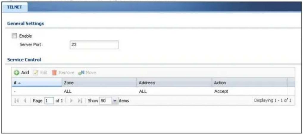
The following table describes the labels in this screen.
Table 187 Configuration > System > TELNET
| LABEL DESCRIPTION | |
| Enable Select the | check box to allow or disallow the computer with the IP address that matches the IP address(es) in theService Controltable to access the NXC CLI using this service. |
| Server Port You | may change the server port number for a service if needed, however you must use the same port number in order to use that service for remote management. |
| Service Control | This specifies from which computers you can access which NXC zones. |
| Add | Click this to create a new entry. Select an entry and clickAddto create a new entry after the selected entry. |
| Edit | Double-click an entry or select it and clickEditto be able to modify the entry's settings. |
| Remove | To remove an entry, select it and clickRemove. The NXC confirms you want to remove it before doing so. Note that subsequent entries move up by one when you take this action. |
| Move To change | an entry's position in the numbered list, select the method and clickMoveto display a field to type a number for where you want to put it and press [ENTER] to move the rule to the number that you typed. |
| # This the index | number of the service control rule.The entry with a hyphen (-) instead of a number is the NXC's (non-configurable) default policy. The NXC applies this to traffic that does not match any other configured rule. It is not an editable rule. To apply other behavior, configure a rule that traffic will match so the NXC will not have to use the default policy. |
| Zone This is the | zone on the NXC the user is allowed or denied to access. |
| Address This is | the object name of the IP address(es) with which the computer is allowed or denied to access. |
| Action This displays | ays whether the computer with the IP address specified above can access the NXC zone(s) configured in theZonefield (Accept) or not (Deny). |
| Apply | ClickApplyto save your changes back to the NXC. |
| Reset | ClickResetto return the screen to its last-saved settings. |
33.9 FTP
You can upload and download the NXC's firmware and configuration files using FTP. To use this feature, your computer must have an FTP client. See Chapter 35 on page 519 for more information about firmware and configuration files.
To change your NXC's FTP settings, click Configuration > System > FTP tab. The screen appears as shown. Use this screen to specify from which zones FTP can be used to access the NXC. You can also specify from which IP addresses the access can come.
Figure 233 Configuration > System > FTP
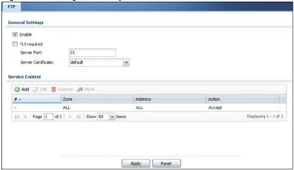
The following table describes the labels in this screen.
Table 188 Configuration > System > FTP
| LABEL DESCRIPTION | |
| Enable Select the | check box to allow or disallow the computer with the IP address that matches the IP address(es) in theService Controltable to access the NXC using this service. |
| TLS required Select the | check box to use FTP over TLS (Transport Layer Security) to encrypt communication.This implements TLS as a security mechanism to secure FTP clients and/or servers. |
| Server Port You | may change the server port number for a service if needed, however you must use the same port number in order to use that service for remote management. |
| Server Certificate | Select the certificate whose corresponding private key is to be used to identify the NXC for FTP connections. You must have certificates already configured in theMy Certificatesscreen. |
| Service Control | This specifies from which computers you can access which NXC zones. |
| Add | Click this to create a new entry. Select an entry and clickAddto create a new entry after the selected entry. |
| Edit | Double-click an entry or select it and clickEditto be able to modify the entry's settings. |
| Remove | To remove an entry, select it and click Remove. The NXC confirms you want to remove it before doing so. Note that subsequent entries move up by one when you take this action. |
| Move To change | an entry's position in the numbered list, select the method and click Move to display a field to type a number for where you want to put it and press [ENTER] to move the rule to the number that you typed. |
| # This the index | number of the service control rule.The entry with a hyphen (-) instead of a number is the NXC's (non-configurable) default policy. The NXC applies this to traffic that does not match any other configured rule. It is not an editable rule. To apply other behavior, configure a rule that traffic will match so the NXC will not have to use the default policy. |
| Zone This is the | zone on the NXC the user is allowed or denied to access. |
| Address This is | the object name of the IP address(es) with which the computer is allowed or denied to access. |
| Action | This displays whether the computer with the IP address specified above can access the NXC zone(s) configured in the Zone field (Accept) or not (Deny). |
| Apply | Click Apply to save your changes back to the NXC. |
| Reset | Click Reset to return the screen to its last-saved settings. |
33.10 SNMP
Simple Network Management Protocol is a protocol used for exchanging management information between network devices. Your NXC supports SNMP agent functionality, which allows a manager station to manage and monitor the NXC through the network. The NXC supports SNMP version one (SNMPv1) and version two (SNMPv2c). The next figure illustrates an SNMP management operation.
Figure 234 SNMP Management Model
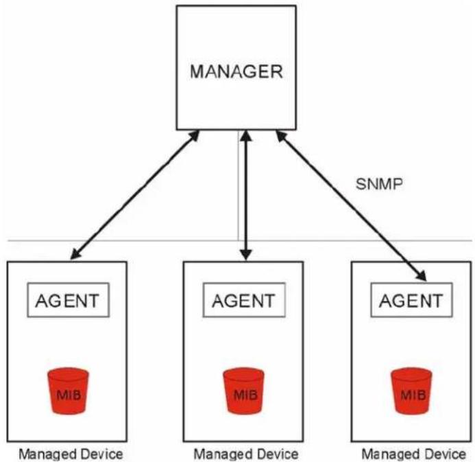
flowchart
graph TD
    A["MANAGER"] --> B["AGENT"]
    A --> C["AGENT"]
    A --> D["AGENT"]
    B --> E["Managed Device"]
    C --> F["Managed Device"]
    D --> G["Managed Device"]
    style A fill:#f9f,stroke:#333
    style B fill:#ccf,stroke:#333
    style C fill:#ccf,stroke:#333
    style D fill:#ccf,stroke:#333
An SNMP managed network consists of two main types of component: agents and a manager.
An agent is a management software module that resides in a managed device (the NXC). An agent translates the local management information from the managed device into a form compatible with SNMP. The manager is the console through which network administrators perform network management functions. It executes applications that control and monitor managed devices.
The managed devices contain object variables/managed objects that define each piece of information to be collected about a device. Examples of variables include such as number of packets received, node port status etc. A Management Information Base (MIB) is a collection of managed objects. SNMP allows a manager and agents to communicate for the purpose of accessing these objects.
SNMP itself is a simple request/response protocol based on the manager/agent model. The manager issues a request and the agent returns responses using the following protocol operations:
- Get - Allows the manager to retrieve an object variable from the agent.
- GetNext - Allows the manager to retrieve the next object variable from a table or list within an agent. In SNMPv1, when a manager wants to retrieve all elements of a table from an agent, it initiates a Get operation, followed by a series of GetNext operations.
- Set - Allows the manager to set values for object variables within an agent.
- Trap - Used by the agent to inform the manager of some events.
33.10.1 Supported MIBs
The NXC supports MIB II that is defined in RFC-1213 and RFC-1215. The NXC also supports private MIBs (zywall.mib and zyxel-zywall-ZLD-Common.mib) to collect information about CPU and memory usage and VPN total throughput. The focus of the MIBs is to let administrators collect statistical data and monitor status and performance. You can download the NXC's MIBs from www.zyxel.com.
33.10.2 SNMP Traps
The NXC will send traps to the SNMP manager when any one of the following events occurs.
Table 189 SNMP Traps
| OBJECT LABEL OBJECT ID DESCRIPTION | ||
| Cold Start 1.3.6.1.6.3. | 1.1.5.1 This trap is sent when the NXC is turned on or an agent restarts. | |
| linkDown 1.3.6.1.6.3. | 1.1.5.3 This trap is sent when the Ethernet link is down. | |
| linkUp 1.3.6.1.6.3.1.1 | .5.4 This trap is sent when the Ethernet link is up. | |
| authenticationFailure | 1.3.6.1.6.3.1.1.5.5 This trap is sent when an SNMP request comes from non-authenticated hosts. | |
33.10.3 Configuring SNMP
To change your NXC's SNMP settings, click Configuration > System > SNMP tab. The screen appears as shown. Use this screen to configure your SNMP settings, including from which zones SNMP can be used to access the NXC. You can also specify from which IP addresses the access can come.
Figure 235 Configuration > System > SNMP
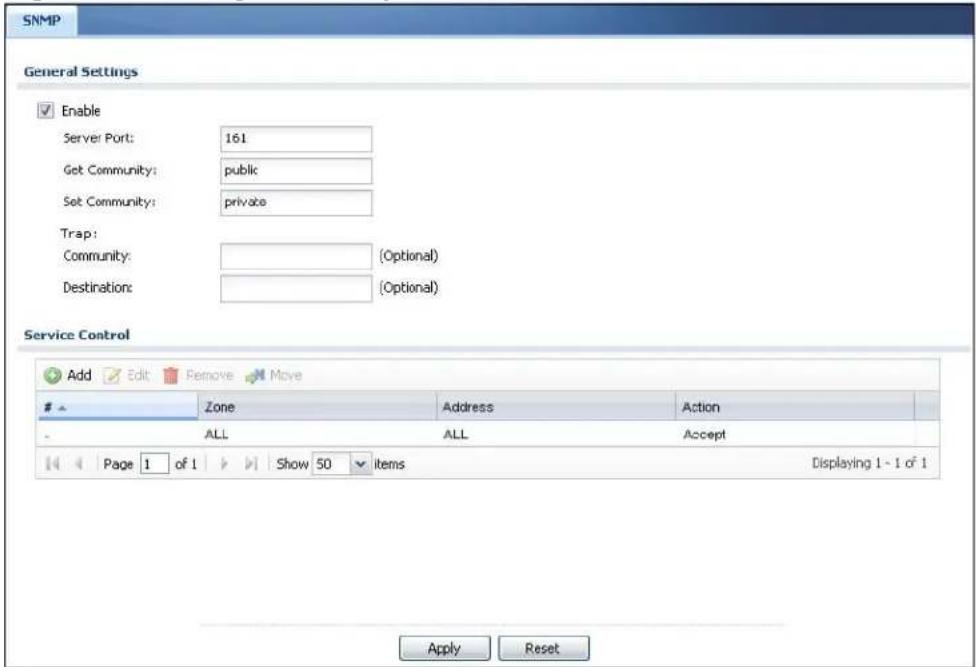
The following table describes the labels in this screen.
Table 190 Configuration > System > SNMP
| LABEL DESCRIPTION | |
| Enable Select the | check box to allow or disallow the computer with the IP address that matches the IP address(es) in the Service Control table to access the NXC using this service. |
| Server Port | You may change the server port number for a service if needed, however you must use the same port number in order to use that service for remote management. |
| Get Community | Enter the Get Community, which is the password for the incoming Get and GetNext requests from the management station. The default is public and allows all requests. |
| Set Community | Enter the Set community, which is the password for incoming Set requests from the management station. The default is private and allows all requests. |
| Trap | |
| Community Type | the trap community, which is the password sent with each trap to the SNMP manager. The default is public and allows all requests. |
| Destination | Type the IP address of the station to send your SNMP traps to. |
| Service Control | This specifies from which computers you can access which NXC zones. |
| Add Click this to | create a new entry. Select an entry and click Add to create a new entry after the selected entry. |
| Edit | Double-click an entry or select it and click Edit to be able to modify the entry's settings. |
| Remove | To remove an entry, select it and click Remove. The NXC confirms you want to remove it before doing so. Note that subsequent entries move up by one when you take this action. |
| Move To change | an entry's position in the numbered list, select the method and click Move to display a field to type a number for where you want to put it and press [ENTER] to move the rule to the number that you typed. |
| # This the index | number of the service control rule.The entry with a hyphen (-) instead of a number is the NXC's (non-configurable) default policy. The NXC applies this to traffic that does not match any other configured rule. It is not an editable rule. To apply other behavior, configure a rule that traffic will match so the NXC will not have to use the default policy. |
| Zone This is the | zone on the NXC the user is allowed or denied to access. |
| Address | This is the object name of the IP address(es) with which the computer is allowed or denied to access. |
| Action This displays | plays whether the computer with the IP address specified above can access the NXC zone(s) configured in the Zone field (Accept) or not (Deny). |
| Apply | Click Apply to save your changes back to the NXC. |
| Reset | Click Reset to return the screen to its last-saved settings. |
33.11 Language
Click Configuration > System > Language to open this screen. Use this screen to select a display language for the NXC's Web Configurator screens.
Figure 236 Configuration > System > Language
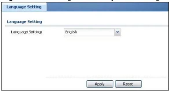
The following table describes the labels in this screen.
Table 191 Configuration > System > Language
| LABEL DESCRIPTION | |
| Language Setting Select a display language for the NXC's Web Configurator screens.You also need to open a new browser session to display the screens in the new language. | |
| Apply | Click Apply to save your changes back to the NXC. |
| Reset | Click Reset to return the screen to its last-saved settings. |
Log and Report
34.1 Overview
Use the system screens to configure daily reporting and log settings.
34.1.1 What You Can Do In this Chapter
- The Email Daily Report screen (Section 34.2 on page 505) configures how and where to send daily reports and what reports to send.
- The Log Setting screens (Section 34.3 on page 507) specify which logs are e-mailed, where they are e-mailed, and how often they are e-mailed.
34.2 Email Daily Report
Use this screen to start or stop data collection and view various statistics about traffic passing through your NXC.
Note: Data collection may decrease the NXC's traffic throughput rate.
Click Configuration > Log & Report > Email Daily Report to display the following screen. Configure this screen to have the NXC e-mail you system statistics every day.
Figure 237 Configuration > Log & Report > Email Daily Report
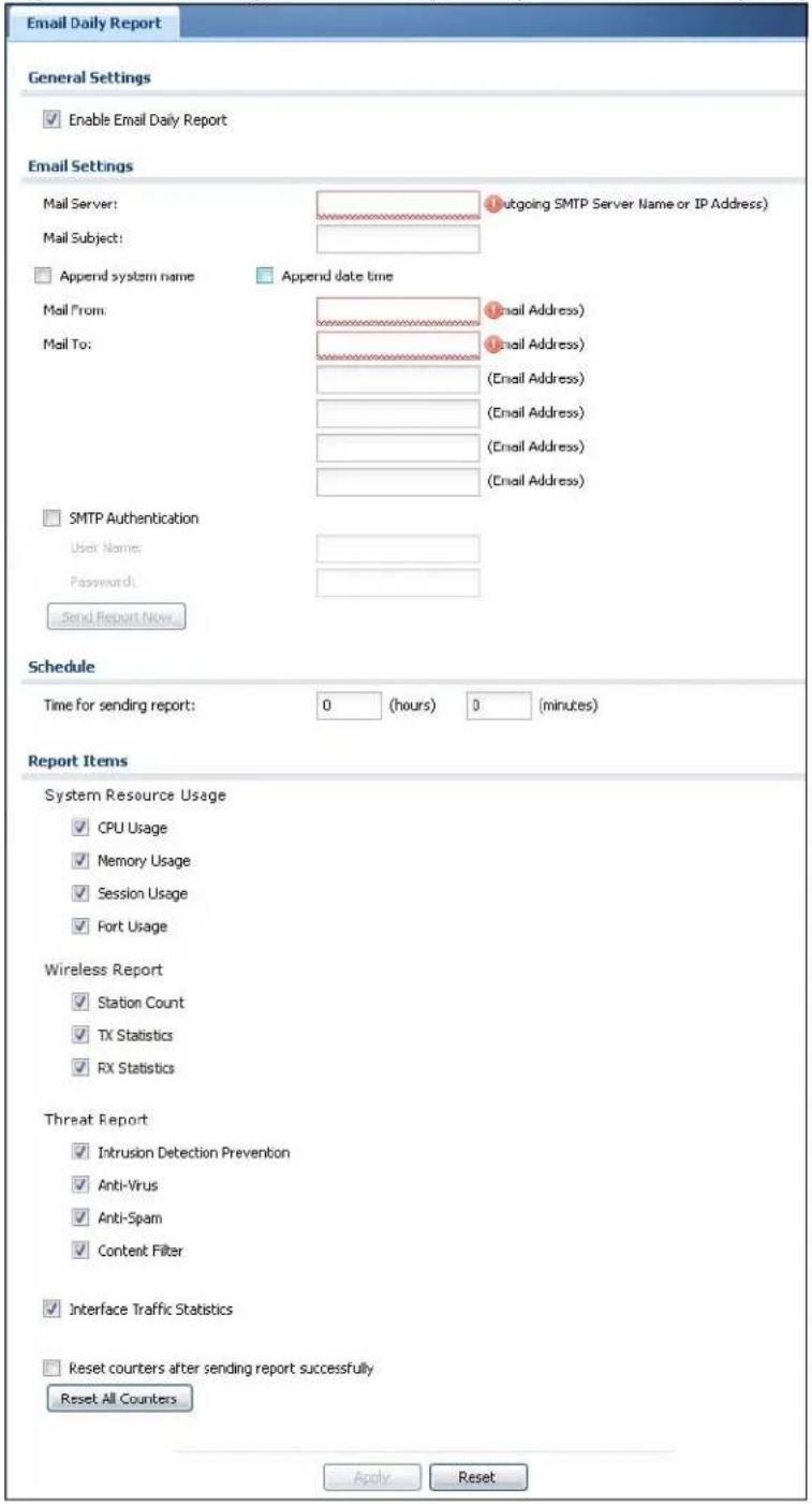
The following table describes the labels in this screen.
Table 192 Configuration > Log & Report > Email Daily Report
| LABEL DESCRIPTION | |
| Enable Email Daily Report | Select this to send reports by e-mail every day. |
| Mail Server Type | the name or IP address of the outgoing SMTP server. |
| Mail Subject Type | the subject line for the outgoing e-mail. Select Append system name to add the NXC's system name to the subject. Select Append date time to add the NXC's system date and time to the subject. |
| Mail From Type | the e-mail address from which the outgoing e-mail is delivered. This address is used in replies. |
| Mail To Type the | e-mail address (or addresses) to which the outgoing e-mail is delivered. |
| SMTP Authentication | Select this check box if it is necessary to provide a user name and password to the SMTP server. |
| User Name | This box is effective when you select the SMTP Authentication check box. Type the user name to provide to the SMTP server when the log is e-mailed. |
| Password | This box is effective when you select the SMTP Authentication check box. Type the password to provide to the SMTP server when the log is e-mailed. |
| Send Report Now | Click this button to have the NXC send the daily e-mail report immediately. |
| Time for sending report | Select the time of day (hours and minutes) when the log is e-mailed. Use 24-hour notation. |
| Report Items S | Select the information to include in the report. Select Reset counters after sending report successfully if you only want to see statistics for a 24 hour period. |
| Reset All Counters | Click this to discard all report data and start all of the counters over at zero. |
| Apply | Click Apply to save your changes back to the NXC. |
| Reset | Click Reset to return the screen to its last-saved settings. |
34.3 Log Setting
These screens control log messages and alerts. A log message stores the information for viewing (for example, in the View Log tab) or regular e-mailing later, and an alert is e-mailed immediately. Usually, alerts are used for events that require more serious attention, such as system errors and attacks.
The NXC provides a system log and supports e-mail profiles and remote syslog servers. The system log is available on the View Log tab, the e-mail profiles are used to mail log messages to the specified destinations, and the other four logs are stored on specified syslog servers.
The Log Setting tab also controls what information is saved in each log. For the system log, you can also specify which log messages are e-mailed, where they are e-mailed, and how often they are e-mailed.
For alerts, the Log Settings tab controls which events generate alerts and where alerts are e-mailed.
The Log Settings Summary screen provides a summary of all the settings. You can use the Log Settings Edit screen to maintain the detailed settings (such as log categories, e-mail addresses, server names, etc.) for any log. Alternatively, if you want to edit what events is included in each log, you can also use the Active Log Summary screen to edit this information for all logs at the same time.
34.3.1 Log Setting Summary
To access this screen, click Configuration > Log & Report > Log Setting.
Figure 238 Configuration > Log & Report > Log Setting
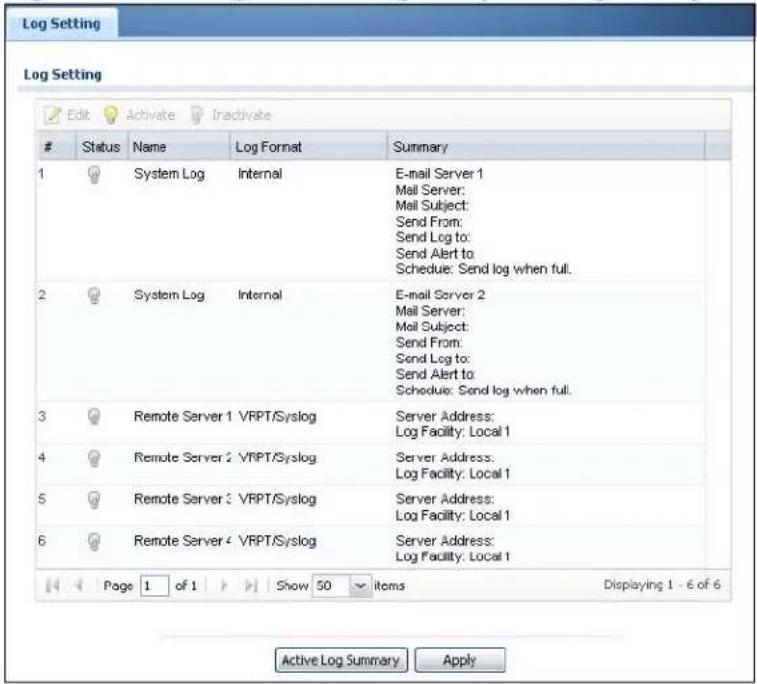
The following table describes the labels in this screen.
Table 193 Configuration > Log & Report > Log Setting
| LABEL DESCRIPTION | |
| Edit | Double-click an entry or select it and click Edit to open a screen where you can modify the entry's settings. |
| Activate | To turn on an entry, select it and click Activate. |
| Inactivate | To turn off an entry, select it and click Inactivate. |
| # This field is a sequential value, and it is not associated with a specific log. | |
| Name This field displays the name of the log (system log or one of the remote servers). | |
| Log Format This field displays the format of the log.Internal - system log; you can view the log on the View Log tab.VRPT/ Syslog - ZyXEL's Vantage Report, syslog-compatible format.CEF/ Syslog - Common Event Format, syslog-compatible format. | |
| Summary This field is a summary of the settings for each log. | |
| Active Log Summary | Click this button to open the Active Log Summary Edit screen. |
| Apply Click this button to save your changes (activate and deactivate logs) and make them take effect. | |
34.3.2 Edit Log Settings
This screen controls the detailed settings for each log in the system log (which includes the e-mail profiles). Go to the Log Settings Summary screen and click the system log Edit icon.
Figure 239 Configuration > Log & Report > Log Setting > Edit
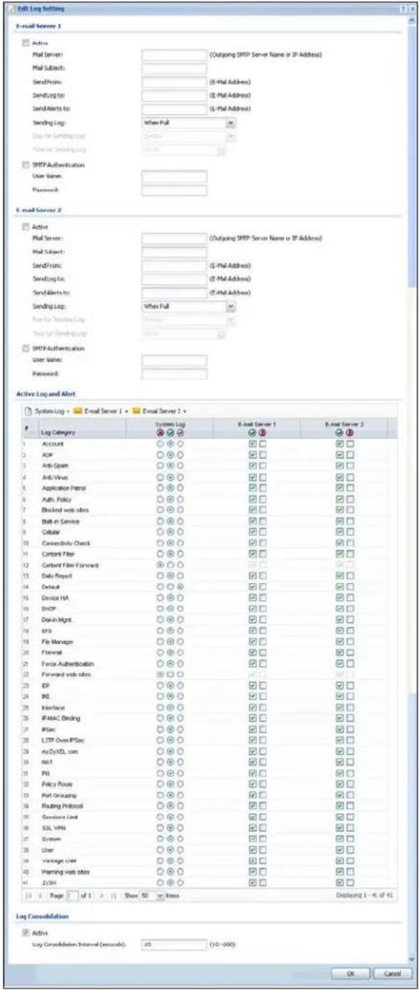
The following table describes the labels in this screen.
Table 194 Configuration > Log & Report > Log Setting > Edit
| LABEL DESCRIPTION | |
| E-Mail Server 1/2 | |
| Active Select this to send log messages and alerts according to the information in this section. You specify what kinds of log messages are included in log information and what kinds of log messages are included in alerts in the Active Log and Alert section. | |
| Mail Server Type the name or IP address of the outgoing SMTP server. | |
| Mail Subject Type the subject line for the outgoing e-mail. | |
| Send From Type the e-mail address from which the outgoing e-mail is delivered. This address is used in replies. | |
| Send Log To Type the e-mail address to which the outgoing e-mail is delivered. | |
| Send Alerts To Type the e-mail address to which alerts are delivered. | |
| Sending Log Select how often log information is e-mailed. Choices are: When Full, Hourly and When Full, Daily and When Full, and Weekly and When Full. | |
| Day for Sending Log | This field is available if the log is e-mailed weekly. Select the day of the week the log is e-mailed. |
| Time for Sending Log | This field is available if the log is e-mailed weekly or daily. Select the time of day (hours and minutes) when the log is e-mailed. Use 24-hour notation. |
| SMTP Authentication | Select this check box if it is necessary to provide a user name and password to the SMTP server. |
| User Name | This box is effective when you select the SMTP Authentication check box. Type the user name to provide to the SMTP server when the log is e-mailed. |
| Password | This box is effective when you select the SMTP Authentication check box. Type the password to provide to the SMTP server when the log is e-mailed. |
| Active Log and Alert | |
| System log | Use the System Log drop-down list to change the log settings for all of the log categories.disable all logs(red X) - do not log any information for any category for the system log or e-mail any logs to e-mail server 1 or 2.enable normal logs(green check mark) - create log messages and alerts for all categories for the system log. If e-mail server 1 or 2 also has normal logs enabled, the NXC will e-mail logs to them.enable normal logs and debug logs(yellow check mark) - create log messages, alerts, and debugging information for all categories. The NXC does not e-mail debugging information, even if this setting is selected. |
| LABEL DESCRIPTION | |
| E-mail Server 1 | Use the E-Mail Server 1 drop-down list to change the settings for e-mailing logs to e-mail server 1 for all log categories.Using the System Log drop-down list to disable all logs overrides your e-mail server 1 settings.enable normal logs (green check mark) - e-mail log messages for all categories to e-mail server 1.enable alert logs (red exclamation point) - e-mail alerts for all categories to e-mail server 1. |
| E-mail Server 2 | Use the E-Mail Server 2 drop-down list to change the settings for e-mailing logs to e-mail server 2 for all log categories.Using the System Log drop-down list to disable all logs overrides your e-mail server 2 settings.enable normal logs (green check mark) - e-mail log messages for all categories to e-mail server 2.enable alert logs (red exclamation point) - e-mail alerts for all categories to e-mail server 2. |
| # This field is a sequence | sequential value, and it is not associated with a specific address. |
| Log Category This | field displays each category of messages. It is the same value used in the Display and Category fields in the View Log tab. The Default category includes debugging messages generated by open source software. |
| System log | Select which events you want to log by Log Category. There are three choices:disable all logs (red X) - do not log any information from this categoryenable normal logs (green checkmark) - create log messages and alerts from this categoryenable normal logs and debug logs (yellow check mark) - create log messages, alerts, and debugging information from this category; the NXC does not e-mail debugging information, however, even if this setting is selected. |
| E-mail Server 1 Select whether each category of events should be included in the log messages when it is e-mailed (green check mark) and/or in alerts (red exclamation point) for the e-mail settings specified in E-Mail Server 1. The NXC does not e-mail debugging information, even if it is recorded in the System log. | |
| E-mail Server 2 Select whether each category of events should be included in log messages when it is e-mailed (green check mark) and/or in alerts (red exclamation point) for the e-mail settings specified in E-Mail Server 2. The NXC does not e-mail debugging information, even if it is recorded in the System log. | |
| Log Consolidation | |
| LABEL DESCRIPTION | |
| Active Select this to activate log consolidation. Log consolidation aggregates multiple log messages that arrive within the specified Log Consolidation Interval. In the View Log tab, the text “[count= x]”, where x is the number of original log messages, is appended at the end of the Message field, when multiple log messages were aggregated. | |
| Log Consolidation Interval | Type how often, in seconds, to consolidate log information. If the same log message appears multiple times, it is aggregated into one log message with the text “[count= x]”, where x is the number of original log messages, appended at the end of the Message field. |
| OK Click this to save your changes and return to the previous screen. | |
| Cancel Click this to return to the previous screen without saving your changes. | |
34.3.3 Edit Remote Server
This screen controls the settings for each log in the remote server (syslog). Go to the Log Settings Summary screen and click a remote server Edit icon.
Figure 240 Configuration > Log & Report > Log Setting > Edit Remote Server
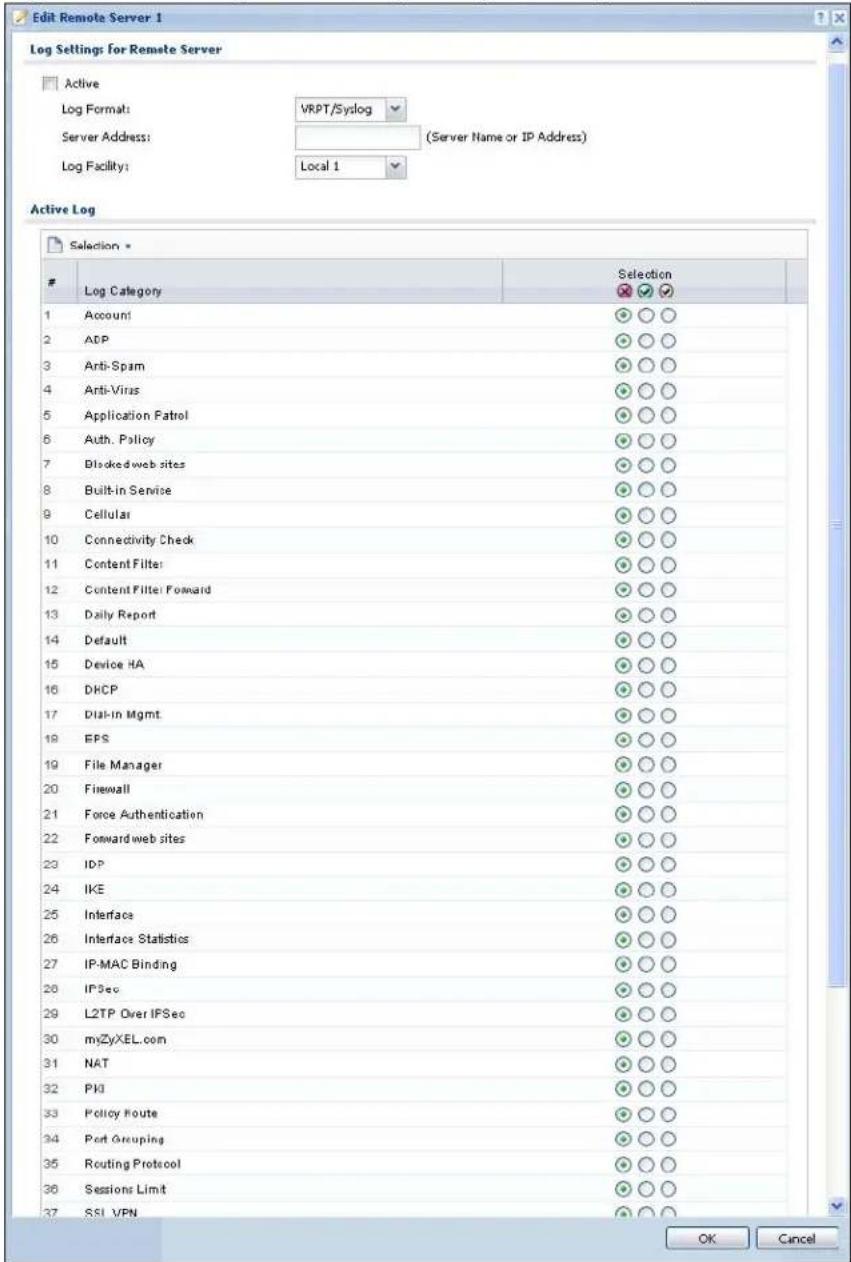
The following table describes the labels in this screen.
Table 195 Configuration > Log & Report > Log Setting > Edit Remote Server
| LABEL DESCRIPTION | |
| Log Settings for Remote Server | |
| Active Select | this check box to send log information according to the information in this section. You specify what kinds of messages are included in log information in the Active Log section. |
| Log Format | This field displays the format of the log information. It is read-only.VRPT/ Syslog - ZyXEL's Vantage Report, syslog-compatible format.CEF/ Syslog - Common Event Format, syslog-compatible format. |
| Server Address | Type the server name or the IP address of the syslog server to which to send log information. |
| Log Facility | Select a log facility. The log facility allows you to log the messages to different files in the syslog server. Please see the documentation for your syslog program for more information. |
| Active Log | |
| Selection | Use the Selection drop-down list to change the log settings for all of the log categories.disable all logs (red X) - do not send the remote server logs for any log category.enable normal logs (green check mark) - send the remote server log messages and alerts for all log categories.enable normal logs and debug logs (yellow check mark) - send the remote server log messages, alerts, and debugging information for all log categories. |
| # This field is | a sequential value, and it is not associated with a specific address. |
| Log Category | This field displays each category of messages. It is the same value used in the Display and Category fields in the View Log tab. The Default category includes debugging messages generated by open source software. |
| Selection | Select what information you want to log from each Log Category (except All Logs; see below). Choices are:disable all logs (red X) - do not log any information from this categoryenable normal logs (green checkmark) - log regular information and alerts from this categoryenable normal logs and debug logs (yellow check mark) - log regular information, alerts, and debugging information from this category |
| OK Click this to | save your changes and return to the previous screen. |
| Cancel Click this | to return to the previous screen without saving your changes. |
34.3.4 Active Log Summary
This screen allows you to view and to edit what information is included in the system log, e-mail profiles, and remote servers at the same time. It does not let you change other log settings (for example, where and how often log information is e-mailed or remote server names). To access this screen, go to the Log Settings Summary screen, and click the Active Log Summary button.
Figure 241 Active Log Summary
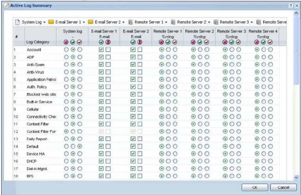
This screen provides a different view and a different way of indicating which messages are included in each log and each alert. (The Default category includes debugging messages generated by open source software.)
The following table describes the fields in this screen.
Table 196 Configuration > Log & Report > Log Setting > Active Log Summary
| LABEL DESCRIPTION | |
| System log | Use the System Log drop-down list to change the log settings for all of the log categories.disable all logs(red X) - do not log any information for any category for the system log or e-mail any logs to e-mail server 1 or 2.enable normal logs(green check mark) - create log messages and alerts for all categories for the system log. If e-mail server 1 or 2 also has normal logs enabled, the NXC will e-mail logs to them.enable normal logs and debug logs(yellow check mark) - create log messages, alerts, and debugging information for all categories. The NXC does not e-mail debugging information, even if this setting is selected. |
| E-mail Server 1 | Use the E-Mail Server 1 drop-down list to change the settings for e-mailing logs to e-mail server 1 for all log categories.Using the System Log drop-down list to disable all logs overrides your e-mail server 1 settings.enable normal logs(green check mark) - e-mail log messages for all categories to e-mail server 1.enable alert logs(red exclamation point) - e-mail alerts for all categories to e-mail server 1. |
| E-mail Server 2 | Use the E-Mail Server 2 drop-down list to change the settings for e-mailing logs to e-mail server 2 for all log categories.Using the System Log drop-down list to disable all logs overrides your e-mail server 2 settings.enable normal logs(green check mark) - e-mail log messages for all categories to e-mail server 2.enable alert logs(red exclamation point) - e-mail alerts for all categories to e-mail server 2. |
| Remote Server 1~4 | For each remote server, use the Selection drop-down list to change the log settings for all of the log categories.disable all logs(red X) - do not send the remote server logs for any log category.enable normal logs(green check mark) - send the remote server log messages and alerts for all log categories.enable normal logs and debug logs(yellow check mark) - send the remote server log messages, alerts, and debugging information for all log categories. |
| # This field is a sequential value, and it is not associated with a specific address. | |
| Log Category This field displays each category of messages. It is the same value used in the Display and Category fields in the View Log tab. The Default category includes debugging messages generated by open source software. | |
Table 196 Configuration > Log & Report > Log Setting > Active Log Summary
| LABEL DESCRIPTION | |
| System log | Select which events you want to log by Log Category. There are three choices:disable all logs(red X) - do not log any information from this categoryenable normal logs(green checkmark) - create log messages and alerts from this categoryenable normal logs and debug logs(yellow check mark) - create log messages, alerts, and debugging information from this category; the NXC does not e-mail debugging information, however, even if this setting is selected. |
| E-mail Server 1 E-mail | Select whether each category of events should be included in the log messages when it is e-mailed (green check mark) and/or in alerts (red exclamation point) for the e-mail settings specified in E-Mail Server 1. The NXC does not e-mail debugging information, even if it is recorded in the System log. |
| E-mail Server 2 E-mail | Select whether each category of events should be included in log messages when it is e-mailed (green check mark) and/or in alerts (red exclamation point) for the e-mail settings specified in E-Mail Server 2. The NXC does not e-mail debugging information, even if it is recorded in the System log. |
| Remote Server 1~4 | For each remote server, select what information you want to log from each Log Category(except All Logs; see below). Choices are:disable all logs(red X) - do not log any information from this categoryenable normal logs(green checkmark) - log regular information and alerts from this categoryenable normal logs and debug logs(yellow check mark) - log regular information, alerts, and debugging information from this category |
| OK Click this to | save your changes and return to the previous screen. |
| Cancel Click this | to return to the previous screen without saving your changes. |
File Manager
35.1 Overview
Configuration files define the NXC's settings. Shell scripts are files of commands that you can store on the NXC and run when you need them. You can apply a configuration file or run a shell script without the NXC restarting. You can store multiple configuration files and shell script files on the NXC. You can edit configuration files or shell scripts in a text editor and upload them to the NXC. Configuration files use a .conf extension and shell scripts use a .zysh extension.
35.1.1 What You Can Do in this Chapter
- The Configuration File screen (Section 35.2 on page 522) stores and names configuration files. You can also download and upload configuration files.
- The Firmware Package screen (Section 35.3 on page 525) checks your current firmware version and uploads firmware to the NXC.
- The Shell Script screen (Section 35.4 on page 527) stores, names, downloads, uploads and runs shell script files.
35.1.2 What you Need to Know
The following terms and concepts may help as you read this chapter.
Configuration Files and Shell Scripts
When you apply a configuration file, the NXC uses the factory default settings for any features that the configuration file does not include. When you run a shell script, the NXC only applies the commands that it contains. Other settings do not change.
These files have the same syntax, which is also identical to the way you run CLI commands manually. An example is shown below.
Figure 242 Configuration File / Shell Script: Example
<h1 id="enter-configuration-mode">enter configuration mode</h1>
configure terminal
<h1 id="change-administrator-password">change administrator password</h1>
username admin password 4321 user-type admin
<h1 id="configure-ge3">configure ge3</h1>
interface ge3
ip address 172.23.37.240 255.255.255.0
ip gateway 172.23.37.254 metric 1
exit
<h1 id="create-address-objects-for-remote-management-to-nxc-firewall-rules">create address objects for remote management / to-NXC firewall rules</h1>
<h1 id="use-the-address-group-in-case-we-want-to-open-up-remote-management-later">use the address group in case we want to open up remote management later</h1>
address-object TW_SUBNET 172.23.37.0/24
object-group address TW_TEAM
address-object TW_SUBNET
exit
<h1 id="enable-telnet-access-not-enabled-by-default-unlike-other-services">enable Telnet access (not enabled by default, unlike other services)</h1>
ip telnet server
<h1 id="open-wlan-to-nxc-firewall-for-tw_team-for-remote-management">open WLAN-to-NXC firewall for TW_TEAM for remote management</h1>
firewall WLAN NXC insert 4
sourceip TW_TEAM
service TELNET
action allow
exit
write
While configuration files and shell scripts have the same syntax, the NXC applies configuration files differently than it runs shell scripts. This is explained below.
Table 197 Configuration Files and Shell Scripts in the NXC
Configuration Files (.conf) Shell Scripts (.zysh)

• Resets to default configuration.
• Goes into CLI Configuration mode.
• Runs the commands in the configuration file.

• G o e s i n t o C L I Priv
• Runs the commands in the shell script.
You have to run the aforementioned example as a shell script because the first command is run in Privilege mode. If you remove the first command, you have to run the example as a configuration file because the rest of the commands are executed in Configuration mode.
Comments in Configuration Files or Shell Scripts
In a configuration file or shell script, use “#” or “!” as the first character of a command line to have the NXC treat the line as a comment.
Your configuration files or shell scripts can use "exit" or a command line consisting of a single (!" to have the NXC exit sub command mode.
Note: "exit" or "!" must follow sub commands if it is to make the NXC exit sub command mode.
Line 3 in the following example exits sub command mode.
interface gel
ip address dhcp
!
Lines 1 and 3 in the following example are comments and line 4 exits sub command mode.
!
interface gel
<h1 id="this-interface-is-a-dhcp-client">this interface is a DHCP client</h1>
!
Lines 1 and 2 are comments. Line 5 exits sub command mode.
! this is from Joe
<h1 id="on-20080405">on 2008/04/05</h1>
interface gel
ip address dhcp
!
Errors in Configuration Files or Shell Scripts
When you apply a configuration file or run a shell script, the NXC processes the file line-by-line. The NXC checks the first line and applies the line if no errors are detected. Then it continues with the next line. If the NXC finds an error, it stops applying the configuration file or shell script and generates a log.
You can change the way a configuration file or shell script is applied. Include setenv stop-on-error off in the configuration file or shell script. The NXC ignores any errors in the configuration file or shell script and applies all of the valid commands. The NXC still generates a log for any errors.
35.2 Configuration File
Click Maintenance > File Manager > Configuration File to open this screen. Use the Configuration File screen to store, run, and name configuration files. You can also download configuration files from the NXC to your computer and upload configuration files from your computer to the NXC.
Once your NXC is configured and functioning properly, it is highly recommended that you back up your configuration file before making further configuration changes. The backup configuration file will be useful in case you need to return to your previous settings.
Configuration File Flow at Restart
- If there is not a startup-config.conf when you restart the NXC (whether through a management interface or by physically turning the power off and back on), the NXC uses the system-default.conf configuration file with the NXC's default settings.
- If there is a startup-config.conf, the NXC checks it for errors and applies it. If there are no errors, the NXC uses it and copies it to the lastgood.conf configuration file as a back up file. If there is an error, the NXC generates a log and copies the startup-config.conf configuration file to the startup-config-bad.conf configuration file and tries the existing lastgood.conf configuration file. If there isn't a lastgood.conf configuration file or it also has an error, the NXC applies the system-default.conf configuration file.
- You can change the way the startup-config.conf file is applied. Include the setenv-startup stop-on-error off command. The NXC ignores any errors in the startup-config.conf file and applies all of the valid commands. The NXC still generates a log for any errors.
Figure 243 Maintenance > File Manager > Configuration File
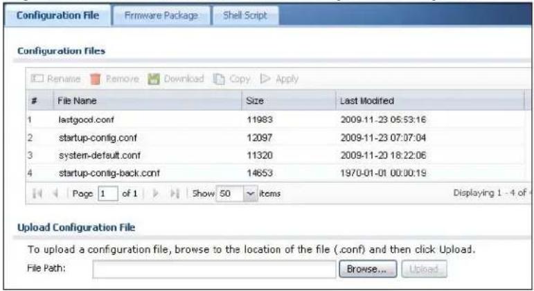
Do not turn off the NXC while configuration file upload is in progress.
The following table describes the labels in this screen.
Table 198 Maintenance > File Manager > Configuration File
| LABEL DESCRIPTION | |
| Rename | Use this button to change the label of a configuration file on the NXC.You can only rename manually saved configuration files. You cannot rename the lastgood.conf, system-default.conf and startup-config.conf files.You cannot rename a configuration file to the name of another configuration file in the NXC.Click a configuration file's row to select it and click Rename to open the Rename File screen.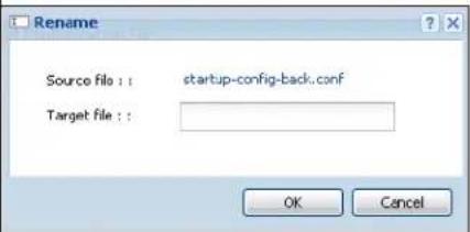 Specify the new name for the configuration file. Use up to 25 characters (including a-zA-Z0-9;~!@#%^&()_+[]',= -).Click OK to save the duplicate or click Cancel to close the screen without saving a duplicate of the configuration file. Specify the new name for the configuration file. Use up to 25 characters (including a-zA-Z0-9;~!@#%^&()_+[]',= -).Click OK to save the duplicate or click Cancel to close the screen without saving a duplicate of the configuration file. |
| Remove | Click a configuration file's row to select it and click Remove to delete it from the NXC. You can only delete manually saved configuration files.You cannot delete the system-default.conf, startup-config.conf and lastgood.conf files.A pop-up window asks you to confirm that you want to delete the configuration file. Click OK to delete the configuration file or click Cancel to close the screen without deleting the configuration file. |
| Download | Click a configuration file's row to select it and click Download to save the configuration to your computer. |
Copy Use this button to save a duplicate of a configuration file on the NXC.Click a configuration file's row to select it and click Copy to open the Copy File screen.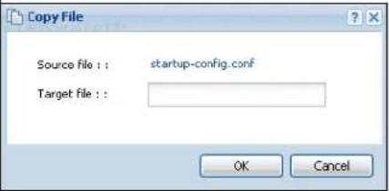 Specify a name for the duplicate configuration file. Use up to 25 characters (including a-zA-Z0-9;~!@#%^&()_+[]{}',= -).Click OK to save the duplicate or click Cancel to close the screen without saving a duplicate of the configuration file. Specify a name for the duplicate configuration file. Use up to 25 characters (including a-zA-Z0-9;~!@#%^&()_+[]{}',= -).Click OK to save the duplicate or click Cancel to close the screen without saving a duplicate of the configuration file. | |
| Apply Use this button to have the NXC use a specific configuration file.Click a configuration file's row to select it and clickApplyto have the NXC use that configuration file. The NXC does not have to restart in order to use a different configuration file, although you will need to wait for a few minutes while the system reconfigures.The following screen gives you options for what the NXC is to do if it encounters an error in the configuration file. | |
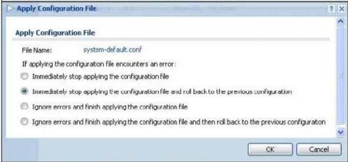 | |
| Immediately stop applying the configuration file- this is not recommended because it would leave the rest of the configuration blank.If the interfaces were not configured before the first error, the console port may be the only way to access the device.Immediately stop applying the configuration file and roll back to the previous configuration- this gets the NXC started with a fully valid configuration file as quickly as possible.Ignore errors and finish applying the configuration file- this applies the valid parts of the configuration file and generates error logs for all of the configuration file's errors. This lets the NXC apply most of your configuration and you can refer to the logs for what to fix.Ignore errors and finish applying the configuration file and then roll back to the previous configuration- this applies the valid parts of the configuration file, generates error logs for all of the configuration file's errors, and starts the NXC with a fully valid configuration file.Click OK to have the NXC start applying the configuration file or click Cancel to close the screen | |
| # | This column displays the number for each configuration file entry. This field is a sequential value, and it is not associated with a specific address. The total number of configuration files that you can save depends on the sizes of the configuration files and the available flash storage space. |
| File Name This column displays the label that identifies a configuration file. | |
| You cannot delete the following configuration files or change their file names.Thesystem-default.conffile contains the NXC's default settings.Select this file and clickApplyto reset all of the NXC settings to the factory defaults. This configuration file is included when you upload a firmware package.Thestartup-config.conffile is the configuration file that the NXC is currently using. If you make and save changes during your management session, the changes are applied to this configuration file. The NXC applies configuration changes made in the Web Configurator to the configuration file when you clickApplyorOK. It applies configuration changes made via commands when you use the write command.Thelastgood.confis the most recently used (valid) configuration file that was saved when the device last restarted. If you upload and apply a configuration file with an error, you can apply lastgood.conf to return to a valid configuration. | |
| Size This column displays the size (in KB) of a configuration file. | |
| Last Modified This column displays the date and time that the individual configuration files were last changed or saved. | |
| UploadConfigurationFile | The bottom part of the screen allows you to upload a new or previously saved configuration file from your computer to your NXCYou cannot upload a configuration file namedsystem-default.confor lastgood.conf.If you uploadstartup-config.conf, it will replace the current configuration and immediately apply the new settings. |
| File Path Type in the location of the file you want to upload in this field or clickBrowse... to find it. | |
| Browse... | ClickBrowse... to find the .conf file you want to upload. The configuration file must use a “.conf” filename extension. You will receive an error message if you try to upload a fie of a different format.Remember that you must decompress compressed (.zip) files before you can upload them. |
| Upload | ClickUploadto begin the upload process. This process may take up to two minutes. |
35.3 Firmware Package
Click Maintenance > File Manager > Firmware Package to open this screen. Use the Firmware Package screen to check your current firmware version and upload firmware to the NXC.
Note: The Web Configurator is the recommended method for uploading firmware. You only need to use the command line interface if you need to recover the firmware. See the CLI Reference Guide for how to determine if you need to recover the firmware and how to recover it.
Find the firmware package at www.zyxel.com in a file that (usually) uses the system model name with a .bin extension, for example, "nxc.bin".
The NXC's firmware package cannot go through the NXC when you enable the anti-virus Destroy compressed files that could not be decompressed option. The NXC classifies the firmware package as not being able to be decompressed and deletes it. You can upload the firmware package to the NXC with the option enabled, so you only need to clear the Destroy compressed files that could not be decompressed option while you download the firmware package.
The firmware update can take up to five minutes. Do not turn off or reset the NXC while the firmware update is in progress!
Figure 244 Maintenance > File Manager > Firmware Package
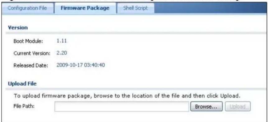
The following table describes the labels in this screen.
Table 199 Maintenance > File Manager > Firmware Package
| LABEL DESCRIPTION | |
| Boot Module | This is the version of the boot module that is currently on the NXC. |
| Current Version | This is the firmware version and the date created. |
| Released Date | This is the date that the version of the firmware was created. |
| File Path | Type in the location of the file you want to upload in this field or click Browse ... to find it. |
| Browse... | Click Browse... to find the .bin file you want to upload. Remember that you must decompress compressed (.zip) files before you can upload them. |
| Upload | Click Upload to begin the upload process. This process may take up to two minutes. |
After you see the Firmware Upload in Process screen, wait two minutes before logging into the NXC again.
Figure 245 Firmware Upload In Process

Note: The NXC automatically reboots after a successful upload.
The NXC automatically restarts causing a temporary network disconnect. In some operating systems, you may see the following icon on your desktop.
Figure 246 Network Temporarily Disconnected
After five minutes, log in again and check your new firmware version in the HOME screen.
If the upload was not successful, the following message appears in the status bar at the bottom of the screen.
Figure 247 Firmware Upload Error
![Message Error: [-42007], Firmware content error!](/content/2026/05/762668/images/42d7dae24a626ba04708b10d492d693c76e26e94ed76d137015f82ee08e5566b.jpg)
35.4 Shell Script
Use shell script files to have the NXC use commands that you specify. Use a text editor to create the shell script files. They must use a ".zysh" filename extension.
Click Maintenance > File Manager > Shell Script to open this screen. Use the Shell Script screen to store, name, download, upload and run shell script files. You can store multiple shell script files on the NXC at the same time.
Note: You should include write commands in your scripts. If you do not use the write command, the changes will be lost when the NXC restarts. You could use multiple write commands in a long script.
Figure 248 Maintenance > File Manager > Shell Script
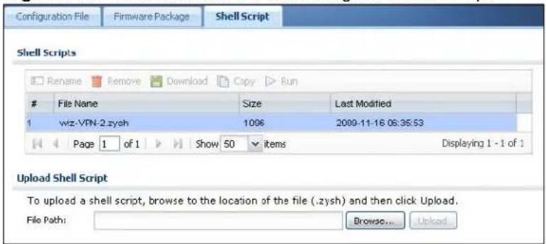
Each field is described in the following table.
Table 200 Maintenance > File Manager > Shell Script
| LABEL DESCRIPTION | |
| Rename | Use this button to change the label of a shell script file on the NXC.You cannot rename a shell script to the name of another shell script in the NXC.Click a shell script's row to select it and clickRename to open theRename File screen. |
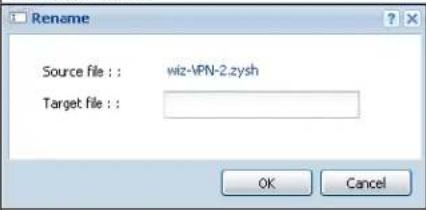 | |
| Specify the new name for the shell script file. Use up to 25 characters (including a-zA-Z0-9;~!@#%^&()_+[]',.=-).ClickOKto save the duplicate or clickCancelto close the screen without saving a duplicate of the configuration file. | |
| Remove | Click a shell script file's row to select it and clickDeleteto delete the shell script file from the NXC.A pop-up window asks you to confirm that you want to delete the shell script file. ClickOKto delete the shell script file or clickCancelto close the screen without deleting the shell script file. |
| Download | Click a shell script file's row to select it and clickDownloadto save the configuration to your computer. |
| Copy Use this button to save a duplicate of a shell script file on the NXC.Click a shell script file's row to select it and click Copy to open the Copy File screen. | |
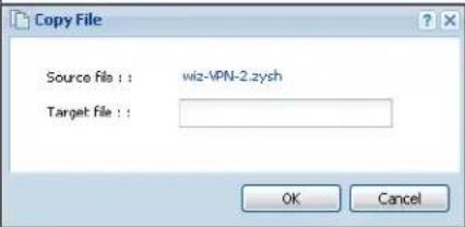 | |
| Specify a name for the duplicate file. Use up to 25 characters (including a-zA-Z0-9;~!@#%^&()_+[]{}',=-.Click OK to save the duplicate or click Cancel to close the screen without saving a duplicate of the configuration file. | |
| Run Use this button to have the NXC use a specific shell script file.Click a shell script file's row to select it and click Run to have the NXC use that shell script file. You may need to wait awhile for the NXC to finish applying the commands. | |
| # This column displays the number for each shell script file entry. | |
| File Name | This column displays the label that identifies a shell script file. |
| Size This column displays the size (in KB) of a shell script file. | |
| Last Modified | This column displays the date and time that the individual shell script files were last changed or saved. |
| Upload Shell Script | The bottom part of the screen allows you to upload a new or previously saved shell script file from your computer to your NXC. |
| File Path | Type in the location of the file you want to upload in this field or click Browse ... to find it. |
| Browse... | Click Browse... to find the .zysh file you want to upload. |
| Upload | Click Upload to begin the upload process. This process may take up to several minutes. |
Diagnostics
36.1 Overview
Use the diagnostics screens for troubleshooting.
36.1.1 What You Can Do in this Chapter
- The Diagnostics screen (Section 36.2 on page 531) generates a file containing the NXC's configuration and diagnostic information if you need to provide it to customer support during troubleshooting.
- The Packet Capture screen (Section 36.3 on page 532) captures data packets going through the NXC.
- The Wireless Frame Capture screens (Section 36.4 on page 536) capture network traffic going through the AP interfaces connected to your NXC.
36.2 Diagnostics
This screen provides an easy way for you to generate a file containing the NXC's configuration and diagnostic information. You may need to generate this file and send it to customer support during troubleshooting.
Click Maintenance > Diagnostics to open the Diagnostic screen.
Figure 249 Maintenance > Diagnostics
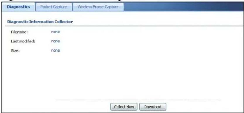
The following table describes the labels in this screen.
Table 201 Maintenance > Diagnostics
| LABEL DESCRIPTION | |
| Filename This is the name of the most recently created diagnostic file. | |
| Last modified This is the date and time that the last diagnostic file was created.The format is yyyy-mm-dd hh:mm:ss. | |
| Size This is the size of the most recently created diagnostic file. | |
| Collect Now Click this to have the NXC create a new diagnostic file. | |
| Download Click this to save the most recent diagnostic file to a computer. | |
36.3 Packet Capture
Use this screen to capture network traffic going through the NXC's interfaces. Studying these packet captures may help you identify network problems.
Click Maintenance > Diagnostics > Packet Capture to open the packet capture screen.
Note: New capture files overwrite existing files of the same name. Change the File Suffix field's setting to avoid this.
Figure 250 Maintenance > Diagnostics > Packet Capture > Capture
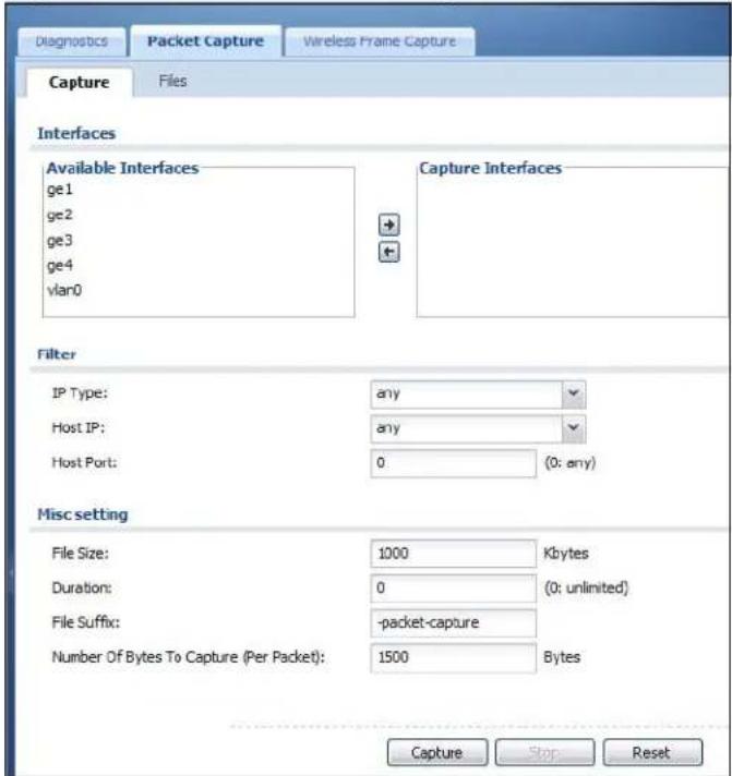
The following table describes the labels in this screen.
Table 202 Maintenance > Diagnostics > Packet Capture
| LABEL DESCRIPTION | |
| Interfaces Enabled int | erfaces (except for virtual interfaces) appear underAvailable Interfaces. Select interfaces for which to capture packets and click the right arrow button to move them to theCapture Interfaceslist. Use the [Shift] and/or [Ctrl] key to select multiple objects. |
| IP Type Select the prot | ocol of traffic for which to capture packets. Selectanyto capture packets for all types of traffic. |
| Host IP Select a host IP | address object for which to capture packets. Selectanyto capture packets for all hosts. SelectUser Definedto be able to enter an IP address. |
| Host Port | This field is configurable when you set theIP Typeto any, tcp, orudp. Specify the port number of traffic to capture. |
| File Size Specify a max | imum size limit in kilobytes for the total combined size of all the capture files on the NXC, including any existing capture files and any new capture files you generate.Note: If you have existing capture files you may need to set this size larger or delete existing capture files.The valid range is 1 to 10000. The NXC stops the capture and generates the capture file when either the file reaches this size or the time period specified in theDurationfield expires. |
| Duration Set a time lim | init in seconds for the capture. The NXC stops the capture and generates the capture file when either this period of time has passed or the file reaches the size specified in theFileSizefield. 0 means there is no time limit. |
| File Suffix Specify text | to add to the end of the file name (before the dot and filename extension) to help you identify the packet capture files.Modifying the file suffix also avoids making new capture files that overwrite existing files of the same name.The file name format is “interface name-file suffix.cap”, for example “vlan2-packet-capture.cap”. |
| Number Of Bytes To Capture (Per Packet) | Specify the maximum number of bytes to capture per packet. The NXC automatically truncates packets that exceed this size. As a result, when you view the packet capture files in a packet analyzer, the actual size of the packets may be larger than the size of captured packets. |
| LABEL DESCRIPTION | |
| Capture Click this button | on to have the NXC capture packets according to the settings configured in this screen.You can configure the NXC while a packet capture is in progress although you cannot modify the packet capture settings.The NXC's throughput or performance may be affected while a packet capture is in progress.After the NXC finishes the capture it saves a separate capture file for each selected interface. The total number of packet capture files that you can save depends on the file sizes and the available flash storage space. Once the flash storage space is full, adding more packet captures will fail. |
| Stop Click this button | to stop a currently running packet capture and generate a separate capture file for each selected interface. |
| Reset Click this button | to return the screen to its last-saved settings. |
36.3.1 Packet Capture Files
Click Maintenance > Diagnostics > Packet Capture > Files to open the packet capture files screen. This screen lists the files of packet captures the NXC has performed. You can download the files to your computer where you can study them using a packet analyzer (also known as a network or protocol analyzer) such as Wireshark.
Figure 251 Maintenance > Diagnostics > Packet Capture > Files
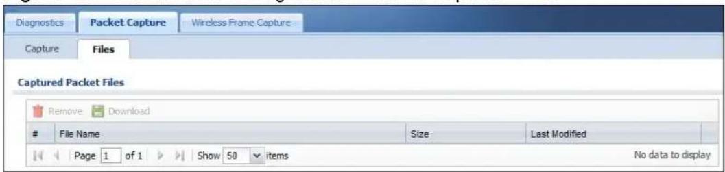
The following table describes the labels in this screen.
Table 203 Maintenance > Diagnostics > Packet Capture > Files
| LABEL DESCRIPTION | |
| Remove | Select files and click Remove to delete them from the NXC. Use the [Shift] and/or [Ctrl] key to select multiple files. A pop-up window asks you to confirm that you want to delete. |
| Download | Click a file to select it and click Download to save it to your computer. |
| # | This column displays the number for each packet capture file entry. The total number of packet capture files that you can save depends on the file sizes and the available flash storage space. |
| File Name | This column displays the label that identifies the file. The file name format is interface name-file suffix.cap. |
| Size This column displays the size (in bytes) of a configuration file. | |
| Last Modified | This column displays the date and time that the individual files were saved. |
36.3.2 Example of Viewing a Packet Capture File
Here is an example of a packet capture file viewed in the Wireshark packet analyzer. Notice that the size of frame 15 on the wire is 1514 bytes while the captured size is only 1500 bytes. The NXC truncated the frame because the capture screen's Number Of Bytes To Capture (Per Packet) field was set to 1500 bytes.
Figure 252 Packet Capture File Example
![lan1-packet-capture.cap - Wireshark File Edit View Go Capture Analyze Statistics Telephony Tools Help Filter: Expression... Clear Apply No. - Time Source Destination Protocol Info 1 0.000000 172.16.1.1 172.16.1.33 TLSv1 Application Da 2 0.00744 172.16.1.1 172.16.1.33 TLSv1 Encrypted Aler 3 0.001246 172.16.1.1 172.16.1.33 TCP https > rmsigp 4 0.002448 172.16.1.33 172.16.1.1 TCP rmsigport > ht 5 0.002680 172.16.1.33 172.16.1.1 TCP rmsigport > ht 6 0.002939 172.16.1.33 172.16.1.1 TLSv1 Encrypted Aler 7 0.003106 172.16.1.33 172.16.1.1 TCP rmsigport > ht 8 0.003494 172.16.1.1 172.16.1.33 TCP https > rmsigp 9 0.05938 172.16.1.33 172.16.1.1 TCP rmlnk > https 10 0.066503 172.16.1.1 172.16.1.33 TCP https > rmlnk 11 0.066840 172.16.1.33 172.16.1.1 TCP rmlnk > https 12 0.067182 172.16.1.33 172.16.1.1 SSL client Hello 13 0.067591 172.16.1.1 172.16.1.33 TCP https > rmlnk 14 0.070900 172.16.1.1 172.16.1.33 TLSv1 server Hello, 15 0.072055 172.16.1.33 172.16.1.1 TLSv1 charge Cipher 16 0.072077 172.16.1.33 172.16.1.1 TLSv1 Ignored Unknow 17 0.072944 172.16.1.1 172.16.1.33 TCP https > rmlnk Frame 15 (15:4 bytes on wire, 15:00 bytes captured) Ethernet II, Src: G-ProCom 1e:4a:e0 (00:0f:Fe:le:4a:e0), Dst: ZyxelCom_00:30:59 (00:13:49:00:30:59) Internet Protocol, Src: 172.16.1.33 (172.16.1.33), Dst: 172.16.1.1 (172.16.1.1) Transmission Control Protocol, Src Port: rmlnk (28i8), dst Port: https (443), Seq: 173, Ack: 139, Len Secure Socket Layer [Unreassembled Packet: SSL] 0000 00 13 49 00 30 59 00 of fe le 4a e0 c8 00 45 00 ..I.OY.. ..J..E. 0010 05 dc 49 71 40 00 80 o6 5a 68 ac 10 cI zI ac 1o ..q@.. zh..!.. 0020 0i 0i 0b 02 0i bb bO 37 a8 2a be 79 fc aI 50 iO .......7 ."ny..P. 0030 ff 75 89 dd 00 oq oq i4 o3 oI oQ oI oI i6 o3 oI oQ oI oQ oI oQ oI oQ oI oQ oI oQ oI oQ oI oQ oI oQ oI oQ oI oQ oI oQ oI oQ oI oQ oI oQ oI oQ oI oQ oI oQ oI oQ oI oQ oI oQ oI oQ oI oQ oI oQ oI oQ oI o 0040 30 b8 e2 b3 cI dI dF bZ a2 od bZ cI ce oc e2 el O..c..Gr ..... Frame (frame), 15:00 bytes Packets: 1794 Displayed: 1794 Marked: O Profile: Default](/content/2026/05/762668/images/70a06fb92007c9cd59800cf6d6c173813eb4f25d0def726e9d195b689911c805.jpg)
36.4 Wireless Frame Capture
Use this screen to capture wireless network traffic going through the AP interfaces connected to your NXC. Studying these frame captures may help you identify network problems.
Click Maintenance > Diagnostics > Wireless Frame Capture to display this screen.
Note: New capture files overwrite existing files of the same name. Change the File Suffix field's setting to avoid this.
Figure 253 Maintenance > Diagnostics > Wireless Frame Capture > Capture
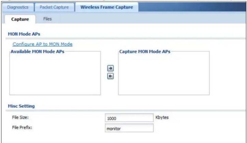
The following table describes the labels in this screen.
Table 204 Maintenance > Diagnostics > Wireless Frame Capture > Capture
| LABEL DESCRIPTION | |
| MON Mode APs | |
| Configure AP to MON Mode | Click this to go theConfiguration > Wireless > AP Management screen, where you can set one or more APs to monitor mode. |
| Available MON Mode APs | This column displays which APs on your wireless network are currently configured for monitor mode.Use the arrow buttons to move APs off this list and onto theCaptured MON Mode APs list. |
| Capture MON Mode APs | This column displays the monitor-mode configured APs selected to for wireless frame capture. |
| Misc Setting |
Table 204 Maintenance > Diagnostics > Wireless Frame Capture > Capture
| LABEL DESCRIPTION | |
| File Size Specify a | maximum size limit in kilobytes for the total combined size of all the capture files on the NXC, including any existing capture files and any new capture files you generate.Note: If you have existing capture files you may need to set this size larger or delete existing capture files.The valid range is 1 to 50000. The NXC stops the capture and generates the capture file when either the file reaches this size or the time period specified in the Duration field expires. |
| File Prefix Specify text to add to the front of the file name in order to help you identify frame capture files.You can modify the prefix to also create new frame capture files each time you perform a frame capture operation. Doing this does no overwrite existing frame capture files.The file format is: [file prefix].dump. For example, “monitor.dump”. | |
| Capture Click this button to have the NXC capture frames according to the settings configured in this screen.You can configure the NXC while a frame capture is in progress although you cannot modify the frame capture settings.The NXC’s throughput or performance may be affected while a frame capture is in progress.After the NXC finishes the capture it saves a combined capture file for all APs. The total number of frame capture files that you can save depends on the file sizes and the available flash storage space. Once the flash storage space is full, adding more frame captures will fail. | |
| Stop Click this button to stop a currently running frame capture and generate a combined capture file for all APs. | |
| Reset Click this button to return the screen to its last-saved settings. | |
36.4.1 Wireless Frame Capture Files
Click Maintenance > Diagnostics > Wireless Frame Capture > Files to open this screen. This screen lists the files of wireless frame captures the NXC has performed. You can download the files to your computer where you can study them using a packet analyzer (also known as a network or protocol analyzer) such as Wireshark.
Figure 254 Maintenance > Diagnostics > Wireless Frame Capture > Files
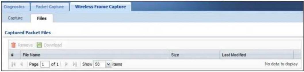
The following table describes the labels in this screen.
Table 205 Maintenance > Diagnostics > Wireless Frame Capture > Files
| LABEL DESCRIPTION | |
| Remove | Select files and click Remove to delete them from the NXC. Use the [Shift] and/or [Ctrl] key to select multiple files. A pop-up window asks you to confirm that you want to delete. |
| Download | Click a file to select it and click Download to save it to your computer. |
| # | This column displays the number for each packet capture file entry. The total number of packet capture files that you can save depends on the file sizes and the available flash storage space. |
| File Name | This column displays the label that identifies the file. The file name format is interface name-file suffix.cap. |
| Size This column displays the size (in bytes) of a configuration file. | |
| Last Modified | This column displays the date and time that the individual files were saved. |
Reboot
37.1 Overview
Use this to restart the device.
37.1.1 What You Need To Know
If you applied changes in the Web configurator, these were saved automatically and do not change when you reboot. If you made changes in the CLI, however, you have to use the write command to save the configuration before you reboot. Otherwise, the changes are lost when you reboot.
Reboot is different to reset; reset returns the device to its default configuration.
37.2 Reboot
This screen allows remote users can restart the device. To access this screen, click Maintenance > Reboot.
Figure 255 Maintenance > Reboot
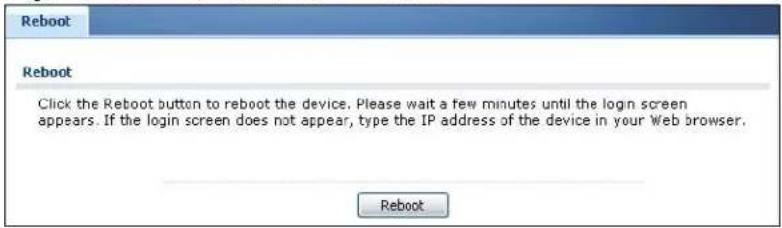
Click the Reboot button to restart the NXC. Wait a few minutes until the login screen appears. If the login screen does not appear, type the IP address of the device in your Web browser.
You can also use the CLI command reboot to restart the NXC.
Shutdown
38.1 Overview
Use this screen to shutdown the device.
Always use Maintenance > Shutdown > Shutdown or the shutdown command before you turn off the NXC or remove the power. Not doing so can cause the firmware to become corrupt.
38.1.1 What You Need To Know
Shutdown writes all cached data to the local storage and stops the system processes. Shutdown is different to reset; reset returns the device to its default configuration.
38.2 Shutdown
To access this screen, click Maintenance > Shutdown.
Figure 256 Maintenance > Shutdown
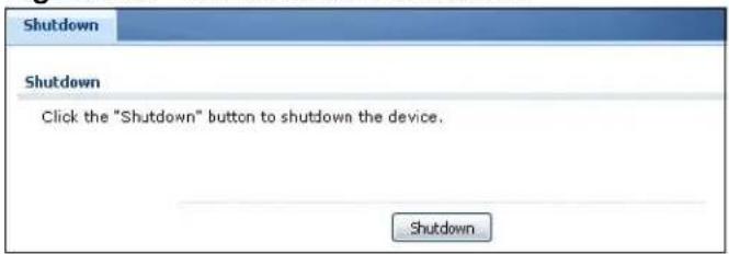
Click the Shutdown button to shut down the NXC. Wait for the device to shut down before you manually turn off or remove the power. It does not turn off the power.
You can also use the CLI command shutdown to shutdown the NXC.
Troubleshooting
39.1 Overview
This chapter offers some suggestions to solve problems you might encounter.
39.1.1 General
This section provides a broad range of troubleshooting tips for your device.
None of the LEDs turn on.
Make sure that you have the power cord connected to the NXC and plugged in to an appropriate power source. Make sure that you have both power cords connected to the NXC and plugged into appropriate power sources. Make sure you have both of the NXC's power switches turned on. Make sure you have the NXC turned on. Check all cable connections.
If the LEDs still do not turn on, you may have a hardware problem. In this case, you should contact your local vendor.
There is an audible alarm and one of the PWR lights is red.
- One of the power modules is not supplying power. Press the BUZZER RESET button on the NXC's front panel to stop the audible alarm.
- Check the power connections. Make sure that you have both power cords connected to the NXC and plugged into appropriate power sources. Also make sure you have the power sources and both of the NXC's power switches turned on.
- Replace the NXC power module that has a red PWR light.
Cannot access the NXC from the LAN.
- Check the cable connection between the NXC and your computer or switch.
- Ping the NXC from a LAN computer. Make sure your computer's Ethernet card is installed and functioning properly. Also make sure that its IP address is in the same subnet as the NXC's.
- In the computer, click Start > Programs > Accessories and then Command Prompt. In the Command Prompt window, type "ping" followed by the NXC's LAN IP address (192.168.1.1 is the default) and then press [ENTER]. The NXC should reply.
- If you've forgotten the NXC's password, use the RESET button. Press the button in for about 5 seconds (or until the PWR LED starts to blink), then release it. It returns the NXC to the factory defaults (password is 1234, LAN IP address 192.168.1.1 etc.; see your User's Guide for details).
- If you've forgotten the NXC's IP address, you can use the commands through the console port to check it. Connect your computer to the CONSOLE port using a console cable. Your computer should have a terminal emulation communications program (such as HyperTerminal) set to VT100 terminal emulation, no parity, 8 data bits, 1 stop bit, no flow control and 115200 bps port speed.
I cannot access the Internet.
- Check the NXC's connection to the Ethernet jack with Internet access. Make sure the Internet gateway device (such as a DSL modem) is working properly.
- If the NXC is operating in its default bridge mode, ensure that that the DHCP that is connected to it is properly configured to assign IP addresses.
- Check the NXC's security settings and/or interface and VLAN settings to ensure you have not inadvertently excluded your client device from accessing the network or the Internet.
I cannot update the anti-virus signatures.
- Make sure your NXC has the anti-virus service registered and that the license is not expired. Purchase a new license if the license is expired.
- Make sure your NXC is connected to the Internet.
I cannot update the IDP/application patrol signatures.
- Make sure your NXC has the IDP/application patrol service registered and that the license is not expired. Purchase a new license if the license is expired.
- Make sure your NXC is connected to the Internet.
I downloaded updated anti-virus or IDP/application patrol signatures. Why has the NXC not re-booted yet?
The NXC does not have to reboot when you upload new signatures.
I configured security settings but the NXC is not applying them for certain interfaces.
Many security settings are usually applied to zones. Make sure you assign the interfaces to the appropriate zones. When you create an interface, there is no security applied on it until you assign it to a zone.
The NXC is not applying the custom policy route I configured.
The NXC checks the policy routes in the order that they are listed. So make sure that your custom policy route comes before any other routes that the traffic would also match.
The NXC is not applying the custom firewall rule I configured.
The NXC checks the firewall rules in the order that they are listed. So make sure that your custom firewall rule comes before any other rules that the traffic would also match.
I can't enter the interface name I want.
The format of interface names other than the Ethernet interface names is very strict. Each name consists of 2-4 letters (interface type), followed by a number (x, limited by the maximum number of each type of interface). For example, VLAN interfaces are vlan0, vlan1, vlan2, ...; and so on.
My rules and settings that apply to a particular interface no longer work.
The interface's IP address may have changed. To avoid this create an IP address object based on the interface. This way the NXC automatically updates every rule or setting that uses the object whenever the interface's IP address settings change. For example, if you change LAN1's IP address, the NXC automatically updates the corresponding interface-based, LAN1 subnet address object.
Hackers have accessed my WEP-encrypted wireless LAN.
WEP is extremely insecure. Its encryption can be broken by an attacker, using widely-available software. It is strongly recommended that you use a more effective security mechanism. Use the strongest security mechanism that all the wireless devices in your network support. WPA2 or WPA2-PSK is recommended.
The wireless security is not following the re-authentication timer setting I specified.
If a RADIUS server authenticates wireless stations, the re-authentication timer on the RADIUS server has priority. Change the RADIUS server's configuration if you need to use a different re-authentication timer setting.
The NXC is not applying an interface's configured ingress bandwidth limit.
At the time of writing, the NXC does not support ingress bandwidth management.
The NXC is not applying my application patrol bandwidth management settings.
Bandwidth management in policy routes has priority over application patrol bandwidth management.
The NXC's performance slowed down after I configured many new application patrol entries.
The NXC checks the ports and conditions configured in application patrol entries in the order they appear in the list. While this sequence does not affect the functionality, you might improve the performance of the NXC by putting more commonly used ports at the top of the list.
The NXC's anti-virus scanner cleaned an infected file but now I cannot use the file.
The scanning engine checks the contents of the packets for virus. If a virus pattern is matched, the NXC removes the infected portion of the file along with the rest of the file. The un-infected portion of the file before a virus pattern was matched still goes through. Since the NXC erases the infected portion of the file before sending it, you may not be able to open the file.
The NXC is not scanning some zipped files.
The NXC cannot unzip password protected ZIP files or a ZIP file within another ZIP file. There are also limits to the number of ZIP files that the NXC can concurrently unzip.
The NXC is deleting some zipped files.
The anti-virus policy may be set to delete zipped files that the NXC cannot unzp. The NXC cannot unzip password protected ZIP files or a ZIP file within another ZIP file. There are also limits to the number of ZIP files that the NXC can concurrently unzip.
The NXC's performance seems slower after configuring IDP.
Depending on your network topology and traffic load, binding every packet direction to an IDP profile may affect the NXC's performance. You may want to focus IDP scanning on certain traffic directions such as incoming traffic.
IDP is dropping traffic that matches a rule that says no action should be taken.
The NXC checks all signatures and continues searching even after a match is found. If two or more rules have conflicting actions for the same packet, then the NXC applies the more restrictive action (reject-both, reject-receiver or reject-sender, drop, none in this order). If a packet matches a rule for reject-receiver and it also matches a rule for reject-sender, then the NXC will reject-both.
I uploaded a custom signature file and now all of my earlier custom signatures are gone.
The name of the complete custom signature file on the NXC is 'custom.rules'. If you import a file named 'custom.rules', then all custom signatures on the NXC are overwritten with the new file. If this is not your intention, make sure that the files you import are not named 'custom.rules'.
I cannot configure some items in IDP that I can configure in Snort.
Not all Snort functionality is supported in the NXC.
The NXC's performance seems slower after configuring ADP.
Depending on your network topology and traffic load, applying an anomaly profile to each and every packet direction may affect the NXC's performance.
The NXC routes and applies SNAT for traffic from some interfaces but not from others.
The NXC automatically uses SNAT for traffic it routes from internal interfaces to external interfaces. For example LAN to WAN traffic. You must manually configure a policy route to add routing and SNAT settings for an interface with the Interface Type set to General. You can also configure a policy route to override the default routing and SNAT behavior for an interface with the Interface Type set to Internal or External.
The NXC is not applying a policy route's port triggering settings.
You also need to create a firewall rule to allow an incoming service.
I cannot get the application patrol to manage SIP traffic.
Make sure you have the SIP ALG enabled.
I cannot get the application patrol to manage H.323 traffic.
Make sure you have the H.323 ALG enabled.
I cannot get the application patrol to manage FTP traffic.
Make sure you have the FTP ALG enabled.
The NXC keeps resetting the connection.
If an alternate gateway on the LAN has an IP address in the same subnet as the NXC's LAN IP address, return traffic may not go through the NXC. This is called an asymmetrical or "triangle" route. This causes the NXC to reset the connection, as the connection has not been acknowledged.
You can set the NXC's firewall to permit the use of asymmetrical route topology on the network (so it does not reset the connection) although this is not recommended since allowing asymmetrical routes may let traffic from the WAN go directly to the LAN without passing through the NXC. A better solution is to use virtual interfaces to put the NXC and the backup gateway on separate subnets.
I changed the LAN IP address and can no longer access the Internet.
The NXC automatically updates address objects based on an interface's IP address, subnet, or gateway if the interface's IP address settings change.
However, you need to manually edit any address objects for your LAN that are not based on the interface.
I configured application patrol to allow and manage access to a specific service but access is blocked.
- If you want to use a service, make sure both the firewall and application patrol allow the service's packets to go through the NXC.
- The NXC checks firewall rules before it checks application patrol rules for traffic going through the NXC.
I configured application patrol to block use of a specific service but a few packet's still get through.
The NXC allows the first eight packets to go through the firewall, regardless of the application patrol policy for the application. The NXC examines these first eight packets to identify the application.
I configured policy routes to manage the bandwidth of TCP and UDP traffic but the bandwidth management is not being applied properly.
It is recommended to use application patrol instead of policy routes to manage the bandwidth of TCP and UDP traffic.
Device HA is not working.
- You may need to disable STP (Spanning Tree Protocol).
- The master and its backups must all use the same device HA mode (active-passive).
- Configure a static IP address for each interface that you will have device HA monitor.
- Configure a separate management IP address for each interface. You can use it to access the NXC for management whether the NXC is the master or a backup. The management IP address should be in the same subnet as the interface IP address.
- Enable monitoring for the same interfaces on the master and backup NXCs.
• Each monitored interface must have a static IP address and be connected to the same subnet as the corresponding interface on the backup or master NXC. - If you have multiple NXC virtual routers on your network, use a different cluster ID to identify each virtual router. There can only be one master NXC in each virtual router (same cluster ID).
A broadcast storm results when I turn on Device HA.
Do not connect the bridge interfaces on two NXCs without device HA activated on both. Either activate device HA before connecting the bridge interfaces or disable the bridge interfaces, connect the bridge interfaces, activate device HA, and finally reactivate the bridge interfaces.
I cannot get the RADIUS server to authenticate the NXC's default admin account.
The default admin account is always authenticated locally, regardless of the authentication method setting.
The NXC fails to authentication the ext-user user accounts I configured.
An external server such as AD, LDAP or RADIUS must authenticate the ext-user accounts. If the NXC tries to use the local database to authenticate an ext-user, the authentication attempt will always fail.
I cannot add the admin users to a user group with access users.
You cannot put access users and admin users in the same user group.
I cannot add the default admin account to a user group.
You cannot put the default admin account into any user group.
I cannot get the Device HA synchronization to work.
Only NXCs of the same model and firmware version can synchronize.
Device HA synchronization is not working for subscription services.
Subscribe to services on the backup NXC before synchronizing it with the master NXC. Synchronization includes updates for services to which the master and backup NXCs are both subscribed. For example, a backup subscribed to IDP/AppPatrol, but not anti-virus, gets IDP/AppPatrol updates from the master, but not anti-virus updates. It is highly recommended to subscribe the master and backup NXCs to the same services.
The schedule I configured is not being applied at the configured times.
Make sure the NXC's current date and time are correct.
I cannot get a certificate to import into the NXC.
1 For My Certificates, you can import a certificate that matches a corresponding certification request that was generated by the NXC. You can also import a certificate in PKCS# 12 format, including the certificate's public and private keys.
2 You must remove any spaces from the certificate's filename before you can import the certificate.
3 Any certificate that you want to import has to be in one of these file formats:
- Binary X.509: This is an ITU-T recommendation that defines the formats for X.509 certificates.
- PEM (Base-64) encoded X.509: This Privacy Enhanced Mail format uses lowercase letters, uppercase letters and numerals to convert a binary X.509 certificate into a printable form.
- Binary PKCS#7: This is a standard that defines the general syntax for data (including digital signatures) that may be encrypted. A PKCS #7 file is used to transfer a public key certificate. The private key is not included. The NXC currently allows the importation of a PKS#7 file that contains a single certificate.
- PEM (Base-64) encoded PKCS#7: This Privacy Enhanced Mail (PEM) format uses lowercase letters, uppercase letters and numerals to convert a binary PKCS#7 certificate into a printable form.
- Binary PKCS# 12: This is a format for transferring public key and private key certificates. The private key in a PKCS # 12 file is within a password-encrypted envelope. The file's password is not connected to your certificate's public or private passwords. Exporting a PKCS # 12 file creates this and you must provide it to decrypt the contents when you import the file into the NXC.
Note: Be careful not to convert a binary file to text during the transfer process. It is easy for this to occur since many programs use text files by default.
My file sharing SSL application object does not work.
Make sure you configure the shared folder on the file server to allow remote access. Refer to the document that comes with your file server.
I cannot access the NXC from a computer connected to the Internet.
Check the service control rules and to-NXC firewall rules.
I uploaded a logo to display on the upper left corner of the Web Configurator login screen and access page but it does not display properly.
Make sure the logo file is a GIF, JPG, or PNG of 100 kilobytes or less.
I uploaded a logo to use as the screen or window background but it does not display properly.
Make sure the logo file is a GIF, JPG, or PNG of 100 kilobytes or less.
The NXC's traffic throughput rate decreased after I started collecting traffic statistics.
Data collection may decrease the NXC's traffic throughput rate.
I can only see newer logs. Older logs are missing.
When a log reaches the maximum number of log messages, new log messages automatically overwrite existing log messages, starting with the oldest existing log message first.
The commands in my configuration file or shell script are not working properly.
- In a configuration file or shell script, use “#” or “!” as the first character of a command line to have the NXC treat the line as a comment.
- Your configuration files or shell scripts can use "exit" or a command line consisting of a single "!" to have the NXC exit sub command mode.
- Include write commands in your scripts. Otherwise the changes will be lost when the NXC restarts. You could use multiple write commands in a long script.
Note: "exit" or "!" must follow sub commands if it is to make the NXC exit sub command mode.
I cannot get the firmware uploaded using the commands.
The Web Configurator is the recommended method for uploading firmware. You only need to use the command line interface if you need to recover the firmware. See the CLI Reference Guide for how to determine if you need to recover the firmware and how to recover it.
My packet capture captured less than I wanted or failed.
The packet capture screen's File Size sets a maximum size limit for the total combined size of all the capture files on the NXC, including any existing capture files and any new capture files you generate. If you have existing capture files you may need to set this size larger or delete existing capture files.
The NXC stops the capture and generates the capture file when either the capture files reach the File Size or the time period specified in the Duration field expires.
My earlier packet capture files are missing.
New capture files overwrite existing files of the same name. Change the File Suffix field's setting to avoid this.
39.1.2 Wireless
This section provides troubleshooting for wireless devices connected the NXC.
Wireless clients cannot connect to an AP.
- There may be a configuration mismatch between the AP and the NXC. This could be the result of a number of things, such as incorrect VLAN topology, incorrect AP profiles, incorrect security settings between the AP and the NXC, and so on. See Chapter 5 on page 71 for a simple primer on basic network topology and management.
- The wireless client's MAC address may be on the MAC filtering list. See Section 25.3.3 on page 399 for details on managing the NXC MAC Filter.
- The wireless client may not be able to get an IP:
If the NXC is operating in bridge mode, check the settings on the DHCP server associated with the network.
Check the wireless client's own network configuration settings to ensure that it is set up to receive its IP address automatically.
If the NXC or a connected Internet access device are managing the network with static IPs, make sure that the server settings for issuing those IPs are properly configured.
Check the wireless client's own network settings to ensure it is already set up with its static IP address.
- Authentication of the wireless client with the authentication server may have failed. Ensure the AP profile assigned to the AP uses a security profile that is properly configured and which is matches the security settings in use by the NXC. For example, if the security mode on the AP is set to WPA/WPA2 then make sure the authentication server is running and able to complete the 802.1x authentication sequence. See Chapter 25 on page 387 and Chapter 10 on page 163 for more.
- If you cannot solve the problem on your own, before contacting Customer Support use the built-in wireless frame capture tools (Chapter 36 on page 531) to capture data that can be used for more granular troubleshooting procedures. To use the built-in wireless frame capture tool, first set up a second NWA5160N nearby to act as a Monitor AP (Chapter 10 on page 163).
The AP status is registered as offline even though it is on.
- Check the network connections between the NXC and the AP to ensure they are still intact.
- The AP may be suffering from instability. Disconnect it to turn its power off, wait some time, then reconnect it and see if that resolves the issue.
- The CAPWAP daemon may be down. You can use the NXC's built-in diagnostic tools and CLI console to get CAPWAP debug messages which can later be sent to customer service for analysis. See Chapter 3 on page 41 for more information.
A wireless client cannot be authenticated through the Captive Portal.
If the Captive Portal redirects a wireless client to a failed login page or an internal server error page, then the authentication server may not be reachable. Make sure that the NXC can reach it if is external to the LAN by opening the Console Window and pinging the server's IP address.
Wireless clients are not being load balanced among my APs.
- Make sure that all the APs used by the wireless clients in question share the same SSID, security, and radio settings.
- Make sure that all the APs are in the same broadcast domain.
- Make sure that the wireless clients are in range of the other APs; if they are only in range of a single AP, then load balancing may not be as effective.
In the Monitor > Wireless > AP Info > AP List page, there is no load balancing indicator associated with any APs assigned to the load balancing task.
- Check to be sure that the AP profile which contains the load balancing settings is correctly assigned to the APs in question.
- The load balancing task may have been terminated because further load balancing on the APs in question is no longer required.
39.2 Resetting the NXC
If you cannot access the NXC by any method, try restarting it by turning the power off and then on again. If you still cannot access the NXC by any method or you forget the administrator password(s), you can reset the NXC to its factory-default settings. Any configuration files or shell scripts that you saved on the NXC should still be available afterwards.
Use the following procedure to reset the NXC to its factory-default settings. This overwrites the settings in the startup-config.conf file with the settings in the system-default.conf file.
Note: This procedure removes the current configuration.
1 Make sure the SYS LED is on and not blinking.
2 Press the RESET button and hold it until the SYS LED begins to blink. (This usually takes about five seconds.)
3 Release the RESET button, and wait for the NXC to restart.
You should be able to access the NXC using the default settings.
39.3 Getting More Troubleshooting Help
Search for support information for your model at www.zyxel.com for more troubleshooting suggestions.
Product Specifications
The following specifications are subject to change without notice.
This table provides basic device specifications.
Table 206 Default Login Information
| ATTRIBUTE SPECIFICATION | |
| Default IP Address (vlan0) | 192.168.1.1 |
| Default Subnet Mask (vlan0) | 255.255.255.0 (24 bits) |
| Default Username admin | |
| Default Password 1234 | |
The following table provides the product specifications.
Table 207 Product Specifications
| FEATURES ADDITIONAL INFORMATION | |
| WLAN Security and Control | 802.11i security (Wi-Fi WPA & WPA2 certified) |
| 802.1x authentication | |
| EAP-TLS, EAP-TTLS, -PEAP, -SIM, -FAST, -AKA support | |
| AES, TKIP & WEP encryption support | |
| Fast Roaming• 802.11i PMK caching• Roaming (IAPP) support based on IEEE 802.11f (Layer-2 update) | |
| Multiple SSID support up to 64 SSID profiles | |
| SSID-based RADIUS server selection | |
| Secure AP control & management over GRE | |
| CAPWAP standard based solution | |
| Simultaneous centralized & distributed WLAN support | |
| MAC address filtering through WLAN (support 2,048 MAC addresses) | |
| Blocking Intra-BSS Traffic | |
| Support Primary and Backup RADIUS server | |
| Identity-Based Security | Centralized wireless user authentication |
| Captive portal, 802.1x & MAC address authentication | |
| RADIUS, AD or LDAP servers | |
| Internal user database support | |
| Role-based authorization for access right protection | |
| Policy enforcement with stateful packet inspection | |
| Configurable policies for guest access | |
| Quality of Service 802.1 | 11e support - WMM, U-APSD and T-SPEC |
| Diffserv marking and 802.1p support | |
| Per-user and per-role rate limites (bandwidth control) | |
| Radio Management Support | port automatic channel & power settings for managed APs |
| Air-monitoring support while serving wireless users | |
| AP load balancing based on both users & bandwidth | |
| 802.11h support for radar detection & prevention | |
| Wireless Intrusion Prevention | Rogue AP detection, classification and containment |
| Firewall Zone-Based Access Control List | |
| Networking Built-in DHCP | CP serer & DHCP relay |
| Device HA for controller back-up redundancy | |
| 802.1d spanning tree protocol (STP) | |
| 802.1Q VLAN tagging | |
| Management Centralized AP provisioning & management | |
| Controller Administration | Web-based user interface access over HTTP & HTTPS |
| CLI access using SSH, Telnet & console port | |
| Authority conrtol for administration log-in | |
| Support administration authentication via RADIUS, LDAP or internal DB | |
| SNMP v2 support | |
| Standard MIBs & private MIBs support | |
| System logs & alerts | |
| Intrusion Detection and Prevention | In-line Mode (Routing/Bridge) |
| Zone-Based IDP Inspection | |
| Customizable Protection Profile | |
| Signature-based Deep Packet Inspection | |
| Automatic Signature Updates | |
| Custom Signatures | |
| Traffic Anomaly Detection and Protection | |
| Flooding Detection and Protection | |
| Protocol Anomaly Detection and Protection: HTTP/ICMP/TCP/UDP | |
| Anti-Virus ICSA-Certified | ZyXEL Anti-Virus or Kaspersky Anti-Virus |
| Stream-Based Anti-Virus engine | |
| Covers Top Active Viruses in the Wild List | |
| Scans HTTP/FTP/SMTP/POP3/IMAP4 | |
| Automatic Signature Updates | |
| No File Size Limitation | |
| Blacklist/Whitelist Support | |
| Performance and Capacity | Up to 60 centralized APs (tunnelled) |
| Up to 240 centralized APs (local bridge) | |
| 4 RJ-45 Gigabit Ethernet Ports | |
| Extension module available for 4 additional SFP/RJ-45 Gigabit Ethernet Ports | |
Table 208 System & Environmental Specifications
| AC Input Rating 100-240V~ | |
| AC Input Current 5.0A | |
| AC Input Frequency 60~50Hz | |
| Operating Temperature 0 ~ 50 degrees Celsius | |
| Storage Temperature -20 ~ 50 degrees Celsius | |
| Humidity, non-condensing 5~95% | |
| Dimension 426mm(L) * 396mm(W) * | 44.4mm(H) |
| Weight, unboxed 8.2 Kg | |
| Plug Regulatory and Safety Compliance | FCC part 15 Class ACE markEN 55022, EN 61000, EN 55024, EN 60950-1UL 60950-1 |
The following table lists many of the standards referenced by NXC features.
Table 209 Standards Referenced by Features
| FEATURE STANDARDS REFERENCED | |
| Interface-Bridge A subset of the ANSI/IEEE 802.1d standard | |
| Interface RFCs 2131, 2132, 1541 | |
| Interface-VLAN IEEE 802.1Q | |
| Telnet server RFCs 1408, 1572 | |
| SSH server RFCs 4250, 4251, 4252, 4253, 4254 | |
| Built-in service, DNS server RFCs | 1034, 1035, 1123, 1183, 1535, 1536, 1706, 1712, 1750, 1876, 1982, 1995, 1996, 2136, 2163, 2181, 2230, 2308, 2535, 2536, 2537, 2538, 2539, 2671, 2672, 2673, 2782, 3007, 3090 |
| Built-in service, DHCP server RFCs | 1542, 2131, 2132, 2485, 2489 |
| Built-in service, HTTP server RFCs | 1945, 2616, 2965, 2732, 2295 |
| Built-in service, SNMP agent RFCs | 1067, 1213, 2576, 2578, 2579, 2580, 2741, 2667, 2981, 3371 |
| Login, LDAP support. RFCs 2251, | 2252, 2253, 2254, 2255, 2256, 2589, 2829, 2830 |
| Used by Apache RFCs 2437, 2246, 2560, 2712, 3268, 3280, 3820, 4132 | |
| Built-in service, FTP server RFCs | 959, 2228, 2389, 2865, 2138, 2640 |
| Used by Centralized log | RFC 3164 |
| Login, new PAM module | OSF-RFC 86.0, 1321 |
| Built-in service, NTP client | RFCs 958, 1059, 1119, 1305 |
| Used by SSH service | RFCs 4250, 4251, 4252, 4253, 4254 |
| Used by Time service | RFCs 3339 |
| Used by Telnet service | RFCs 318, 854, 1413 |
| Used by SIP ALG | RFCs 3261, 3264 |
| DHCP relay | RFC 1541 |
| ZySH | W3C XML standard |
| ARP | RFC 826 |
| IP/IPv4 | RFC 791 |
| TCP | RFC 793 |
| CAPWAP | RFCs 5415, 5417, 4347(DTLS) |
| Built-in service, RADIUS server | RFCs 5281, 5247, 5176, 4679, 4675, 3748, 3716, 3580, 3579, 3576, 2868, 2865, 2607, 2548, 2289, 2284 |
| Built-in service, Domain authentication client | RFCs 2037 |
| Hostapd | RFCs 1042, 1186, 2104, 2246, 2433, 2548, 2618, 2619, 2620, 2716, 2759, 2865, 2869, 3079, 3394, 3579, 3580, 3610, 3748, 4137, 4186, 4187, 4284, 4746, 4763, 4764 |
| Wireless IEEE 802.11a, IEEE 802. | 11b, IEEE 802.11g, IEEE802.11n, IEEE 802.11i, IEEE 802.1x |
| Device-HA VRRP (Virtual Router Redundancy Protocol) | RFC2338 & RFC3768 |
Log Descriptions
This appendix provides descriptions of example log messages.
Table 210 Web Warning Logs
| LOG MESSAGE DESCRIPTION | |
| %s: %s The system detects | a proxy connection and is warning according to a profile1st %s: website host2nd %s: reason for warning. (Ex: Phishing, Service is unavailable...) |
Table 211 Forward Web Site Logs
| LOG MESSAGE DESCRIPTION | |
| %s: Trusted Web site The device allowed access to a web site in a trusted domain.%s: website host | |
| %s The device allowed access to a web site. The content filtering service is registered and activated or the service is not activated in a profile, this is a web site that is not blocked according to a profile and the default policy is not set to block.%s: website host | |
| %s: Service is not registered | The device allowed access to a web site. The content filtering service is unregistered and the default policy is not set to block.%s: website host |
Table 212 Blocked Web Site Logs
| LOG MESSAGE DESCRIPTION | |
| %s:%s | The rating server responded that the web site is in a specified category and access was blocked according to a content filter profile.1st %s: website host2nd %s: website category |
| %s: Unrated The rating server responded that the web site cannot be categorized and access was blocked according to a content filter profile.%s: website host | |
| %s: Service is unavailable | Content filter rating service is temporarily unavailable and access to the web site was blocked due to:1. Can't resolve rating server IP (No DNS)2. Invalid service license4. Rating service is restarting5. Can't connect to rating server6. Query failed7. Query timeout8. Too many queries9. Unknown reason%s: website host |
| %s: %s(cache hit) | The web site's category exists in the device's local cache and access was blocked according to a content filter profile.1st %s: website host2nd %s: website category |
| %s: Not in trusted web list | The web site is not a trusted host/domain, and the device blocks all traffic except for trusted web sites.%s: website host |
| %s: Contains ActiveX The web site contains ActiveX and access was blocked according to a profile.%s: website host | |
| %s: Contains Java applet | The web site contains Java applet and access was blocked according to a profile.%s: website host |
| %s: Contains cookie The web site contains a cookie and access was blocked according to a profile.%s: website host | |
| %s: Proxy mode is detected | The system detected a proxy connection and blocked access according to a profile.%s: website host |
| %s: Forbidden Web site | The web site is in forbidden web site list.%s: website host |
| %s: Keyword blocking | The web content matched a user defined keyword.%s: website host |
| %s: Blocking by default policy | No content filter policy is applied and access was blocked since the default action is block.%s: website host |
The ZySH logs deal with internal system errors.
Table 213 ZySH Logs
| LOG MESSAGE DESCRIPTION | |
| Invalid message queue. Maybe someone starts another zysh daemon. | |
| ZySH daemon is instructed to reset by %d | 1st:pid num |
| System integrity error! | |
| Group OPS | |
| cannot close property group | |
| cannot close group | |
| %s: cannot get size of group | 1st:zysh group name |
| %s: cannot specify properties for entry %s | 1st:zysh group name, 2st:zysh entry name |
| %s: cannot join group %s, loop detected | 1st:zysh group name, 2st:zysh group name |
| cannot create, too many groups (>%d) | 1st:max group num |
| %s: cannot find entry %s | 1st:zysh group name, 2st:zysh entry name |
| %s: cannot remove entry %s | 1st:zysh group name, 2st:zysh entry name |
| List OPS | |
| can't alloc entry: %s! | 1st:zysh entry name |
| can't retrieve entry: %s! | 1st:zysh entry name |
| can't get entry: %s! | 1st:zysh entry name |
| LOG MESSAGE DESCRIPTION | |
| can't print entry: %s! | 1st:zysh entry name |
| %s: cannot retrieve entries from list! | 1st:zysh list name |
| can't get name for entry %d! | 1st:zysh entry index |
| can't get reference count: %s! | 1st:zysh list name |
| can't print entry name: %s! | 1st:zysh entry name |
| Can't append entry: %s! | 1st:zysh entry name |
| Can't set entry: %s! 1st:zysh entry name | |
| Can't define entry: %s! | 1st:zysh entry name |
| %s: list is full! 1st:zysh list name | |
| Can't undefined %s 1st:zysh list name | |
| Can't remove %s 1st:zysh list name | |
| Table OPS | |
| %s: cannot retrieve entries from table! | 1st:zysh table name |
| %s: index is out of range! | 1st:zysh table name |
| %s: cannot set entry #%d | 1st:zysh table name,2st: zysh entry num |
| %s: table is full! 1st:zysh table name | |
| %s: invalid old/new index! | 1st:zysh table name |
| Unable to move entry #%d! | 1st:zysh entry num |
| %s: invalid index! 1st:zysh table name | |
| Unable to delete entry #%d! | 1st:zysh entry num |
| Unable to change entry #%d! | 1st:zysh entry num |
| %s: cannot retrieve entries from table! | 1st:zysh table name |
| %s: invalid old/new index! | 1st:zysh table name |
| Unable to move entry #%d! | 1st:zysh entry num |
| %s: apply failed at initial stage! | 1st:zysh table name |
| %s: apply failed at main stage! | 1st:zysh table name |
| %s: apply failed at closing stage! | 1st:zysh table name |
Table 214 ADP Logs
| LOG MESSAGE DESCRIPTION | |
| fromto[in=, Action:, Severity: | The NXC detected an anomaly in traffic traveling between the specified zones.The={scan-detection() | flood-detection() | http-inspection() | tcp-decoder)}.Thegives details about the attack, although the message is dropped if the log is more than 128 characters.Theis what the NXC did with the packet.Theis the threat level (very low, low, medium, high, or severe). |
| Enable ADP succeeded. ADP was turned on. | |
| Disable ADP succeeded. ADP was turned off. | |
| ADP rulehas been deleted. | The specified ADP rule has been deleted. |
| ADP rulehas been moved to. | The ADP rule with the specified index number (first num) was moved to the specified index number (second num). |
| New ADP rule has been appended. | An ADP rule has been added to the end of the list. |
| ADP rulehas been inserted. | An ADP rule has been inserted.is the number of the new rule. |
| ADP rulehas been modified. | The ADP rule of the specified number has been changed. |
| ADP profilehas been deleted. | The ADP rule with the specified name has been removed. |
| ADP profilehas been changed to. | An ADP rule's name has been changed from firstto the second. |
| ADP profilehas been created. | An ADP profile with the specified name has been added. |
| ADP profilehas been modified. | The ADP rule with the specified name has been changed. |
| Packet payload length is over the maximum system handle length | The NXC's ADP feature detected a packet with a length over 16000 bytes. |
| LAND attack packet.Source IP is the same as Destination IP. | The NXC's ADP feature detected traffic with the same IP address set as both the source and the destination. |
Table 215 Anti-Virus Logs
| LOG MESSAGE DESCRIPTION | |
| Initializing Anti-Virus signature reference table has failed. | The NXC failed to initialize the anti-virus signatures due to an internal error. |
| Reloading Anti-Virus signature database has failed. | The NXC failed to reload the anti-virus signatures due to an internal error. |
| Reloading Anti-Virus signature reference table has failed. | The NXC failed to reload the anti-virus signatures due to an internal error. |
| %s Virus infected - ID:%d,%s,%s. | The NXC's anti-virus feature detected a virus-infected file.1st %s: The protocol of the infected packet.2nd %d: virus ID3rd %s: name of the virus4th %s: name of the infected file |
| %s, due to over maximum compressed file, %s could not be decompressed. | The NXC could not decompress a compressed file because there were too many compressed files at the same time.1st %s: The protocol of the packet.2nd %s: The filename of the related file. |
| %s, due to more than one layer compressed file, %s could not be decompressed. | The NXC could not decompress a compressed file because it contained other compressed files.1st %s: The protocol of the packet.2nd %s: The filename of the related file. |
| %s, due to password protected compressed file, %s could not be decompressed. | The NXC could not decompress a compressed file because it had password protection.1st %s: The protocol of the packet.2nd %s: The filename of the related file. |
| %s, %s matched White-List %s | A file matched a file pattern in the anti-virus white list.1st %s: The protocol of the packet.2nd %s: The filename of the related file.3rd %s: The file pattern that the file matched. |
| %s, %s matched the Black-List %s | A file matched a file pattern in the anti-virus black list.1st %s: The protocol of the packet.2nd %s: The filename of the related file.3rd %s: The file pattern that the file matched. |
| AV signature update has failed. Can not update last update time. | The anti-virus signatures update did not succeed. |
| LOG MESSAGE DESCRIPTION | |
| AV signature update has failed. (Replacement failure) | Anti-virus signatures update failed because the NXC was not able to replace the old set of anti-virus signatures with the new one. |
| AV signature update has failed. (Unknown signature package). | Anti-virus signatures update failed because the NXC was not able to identify whether the downloaded signature package was an incremental or full update. |
| AV signature update from version %s to version %s has succeeded | The NXC updated the anti-virus signatures from the listed version to the second listed version. |
| AV signature update has failed. (File damaged) | An anti-virus signatures update failed because the signature file has been corrupted. |
| AV signature update has failed. (Memory not enough) | An anti-virus signatures update failed because the NXC did not have enough system resources free to finish the signature update. |
| AV signature size is over system limitation | An anti-virus signatures update failed because the anti-virus signature file was too large. |
| AV signature update has failed. | An anti-virus signatures update failed for unknown reasons. |
| Anti-Virus signatures missing, refer to your user documentation to recover the default database file. | When the NXC started it could not find the anti-virus signature file. See the CLI reference guide for how to restore the default system database. |
| Update signature version has failed. | An attempt to update the anti-virus signature version failed. cannot update signature version |
| AV signature update from %s version %s to %s version %s has succeeded. | The anti-virus signatures have been updated.1st %s: The anti-virus engine type before the update.2nd %s: The signature version before the update.3rd %s: The anti-virus engine type after the update.4th %s: The signature version after the update. |
| AV signature size is over system limitation | The anti-virus signature file size is too large. |
| AV has been activated Anti-virus has been turned on. | |
| AV has been deactivated Anti-virus has been turned off. | |
| Anti-Virus rule %d has been moved to %d | The anti-virus rule with the specified index number (1st %d) was moved to the specified index number (2nd %d). |
| Anti-Virus rules have been flushed. | All of the anti-virus rules have been deleted. |
| Anti-Virus rule %d has been deleted. | The anti-virus rule of the specified number has been deleted. |
| Anti-Virus rule %d has been modified. | The anti-virus rule of the specified number has been changed. |
| LOG MESSAGE DESCRIPTION | |
| Anti-Virus rule %d has been inserted. | An anti-virus rule has been inserted. %d is the number of the new rule. |
| Anti-Virus rule %d has been appended. | The anti-virus rule with the listed number (%d) has been added to the end of the list. |
| File pattern %s has been modified to %s in %s | A anti-virus file pattern was changed in the white list or the black list.1st%s: The original file pattern.2ed %s: The new file pattern.3rd %s The white list or black list. |
| File pattern %s has been deleted from %s | An anti-virus file pattern was deleted from the white or black list.1st %s: The file pattern.2nd %s: The white list or black list. |
| File pattern %s has been added in %s | An anti-virus file pattern was added to the white or black list.1st %s: The file pattern.2nd %s: The white list or black list. |
| %s has been %s An anti-virus file pattern white list or black list was turned on or off.1st %s: The white list or black list.2nd %s: Activated/deactivated. | |
| %s, due to decompress malfunction, %s could not be decompressed.Action on file: %s | File decompression failed due to an internal error.1st %s: The protocol of the packet.2nd %s: The filename of the related file.3rd %s: Whether the file was deleted (DESTROY) or forwarded (PASS). |
| Update signature info has failed. | Updating of the signature file information failed due to an internal error. |
Table 216 User Logs
| LOG MESSAGE DESCRIPTION | |
| %s %s from %s has logged in EnterpriseWLAN | A user logged into the NXC.1st %s: The type of user account.2nd %s: The user's user name.3rd %s: The name of the service the user is using (HTTP, HTTPS, FTP, Telnet, SSH, or console). |
| %s %s from %s has logged out EnterpriseWLAN | A user logged out of the NXC.1st %s: The type of user account.2nd %s: The user's user name.3rd %s: The name of the service the user is using (HTTP, HTTPS, FTP, Telnet, SSH, or console). |
| %s %s from %s has been logged out EnterpriseWLAN (re-auth timeout) | The NXC is signing the specified user out due to a re-authentication timeout.1st %s: The type of user account.2nd %s: The user's user name.3rd %s: The name of the service the user is using (HTTP, HTTPS, FTP, Telnet, SSH, or console). |
| %s %s from %s has been logged out EnterpriseWLAN (lease timeout) | The NXC is signing the specified user out due to a lease timeout.1st %s: The type of user account.2nd %s: The user's user name.3rd %s: The name of the service the user is using (HTTP, HTTPS, FTP, Telnet, SSH, or console). |
| %s %s from %s has been logged out EnterpriseWLAN (idle timeout) | The NXC is signing the specified user out due to an idle timeout.1st %s: The type of user account.2nd %s: The user's user name.3rd %s: The name of the service the user is using (HTTP, HTTPS, FTP, Telnet, SSH, or console). |
| Console has been put into lockout state | Too many failed login attempts were made on the console port so the NXC is blocking login attempts on the console port. |
| Address %u.%u.%u.%u has been put into lockout state | Too many failed login attempts were made from an IP address so the NXC is blocking login attempts from that IP address.%u.%u.%u.%u: the source address of the user's login attempt |
| Failed login attempt to EnterpriseWLAN from %s (login on a lockout address) | A login attempt came from an IP address that the NXC has locked out.%u.%u.%u.%u: the source address of the user's login attempt |
| Failed login attempt to EnterpriseWLAN from %s (reach the max. number of user) | The NXC blocked a login because the maximum login capacity for the particular service has already been reached.%s: service name |
| Failed login attempt to EnterpriseWLAN from %s (reach the max. number of simultaneous logon) | The NXC blocked a login because the maximum simultaneous login capacity for the administrator or access account has already been reached.%s: service name |
| User %s has been denied access from %s | The NXC blocked a login according to the access control configuration.%s: service name |
| User %s has been denied access from %s | The NXC blocked a login attempt by the specified user name because of an invalid user name or password.2nd %s: service name |
| LDAP/AD: Wrong IP or Port. IP:%s, Port: %d | LDAP/AD: Wrong IP or Port.Please check the AAA server setting. |
| Domain-auth fail Domain- | auth fail. Please check the domain-auth related setting. |
| Failed to join domain: Access denied | Failed to join domain: Access denied. Please check the AD server. |
Table 217 myZyXEL.com Logs
| LOG MESSAGE DESCRIPTION | |
| Send registration message to MyZyXEL.com server has failed. | The device was not able to send a registration message to MyZyXEL.com. |
| Get server response has failed. | The device sent packets to the MyZyXEL.com server, but did not receive a response. The root cause may be that the connection is abnormal. |
| Timeout for get server response. | zysh need to catch MyZyXEL.com agent's return code, this log will be shown when timeout. |
| User has existed. The user name already exists in MyZyXEL.com's database. So the user can't use it for device registration and needs to specify another one. | |
| User does not exist. The user name does not yet exist in MyZyXEL.com's database. So the user can use it for device registration. | |
| Internal server error. | MyZyXEL.com's database had an error when checking the user name. |
| Device registration has failed:%s. | Device registration failed, an error message returned by the MyZyXEL.com server will be appended to this log.%s: error message returned by the myZyXEL.com server |
| Device registration has succeeded. | The device registered successfully with the myZyXEL.com server. |
| Registration has failed. Because of lack must fields. | The device received an incomplete response from the myZyXEL.com server and it caused a parsing error for the device. |
| %s:Trial service activation has failed:%s. | Trail service activation failed for the specified service, an error message returned by the MyZyXEL.com server will be appended to this log.1st %s: service name2nd %s: error message returned by the myZyXEL.com server |
| %s:Trial service activation has succeeded. | Trail service was activated successfully for the specified service.%s: service name |
| Trial service activation has failed. Because of lack must fields. | The device received an incomplete response from the myZyXEL.com server and it caused a parsing error for the device. |
| Standard service activation has failed:%s. | Standard service activation failed, this log will append an error message returned by the MyZyXEL.com server.%s: error message returned by the myZyXEL.com server |
| Standard service activation has succeeded. | Standard service activation has succeeded. |
| Standard service activation has failed. Because of lack must fields. | The device received an incomplete response from the myZyXEL.com server and it caused a parsing error for the device. |
| Service expiration check has failed:%s. | The service expiration day check failed, this log will append an error message returned by the MyZyXEL.com server.%s: error message returned by myZyXEL.com server |
| Service expiration check has succeeded. | The service expiration day check was successful. |
| Service expiration check has failed. Because of lack must fields. | The device received an incomplete response from the myZyXEL.com server and it caused a parsing error for the device. |
| Server setting error. | The device could not retrieve the myZyXEL.com server's IP address or FQDN from local. |
| Resolve server IP has failed. | The device could not resolve the myZyXEL.com server's FQDN to an IP address through gethostbyname(). |
| Verify server's certificate has failed. | The device could not process an HTTPS connection because it could not verify the myZyXEL.com server's certificate. |
| Connect to MyZyXEL.com server has failed. | The device could not connect to the MyZyXEL.com server. |
| Do account check. The device started to check whether or not the user name in MyZyXEL.com's database. | |
| Do device register. The device started device registration. | |
| Do trial service activation. | The device started trail service activation. |
| Do standard service activation. | The device started standard service activation. |
| Do expiration check. The device started the service expiration day check. | |
| Build query message has failed. | Some information was missing in the packets that the device sent to the MyZyXEL.com server. |
| Parse receive message has failed. | The device cannot parse the response returned by the MyZyXEL.com server. Maybe some required fields are missing. |
| Change Anti-Virus engine. | The device started to change the type of anti-virus engine. |
| Change Anti-Virus engine has failed:%s. | The device failed to change the type of anti-virus engine. %s is the server response error message. |
| Change Anti-Virus engine has succeeded. | The device successfully changed the type of anti-virus engine. |
| Change Anti-Virus engine type has failed. Because of lack must fields. | The device failed to change the type of anti-virus engine because the response from the server is missing required fields. |
| Resolve server IP has failed. Update stop. | The update has stopped because the device couldn't resolve the myZyXEL.com server's FQDN to an IP address through gethostbyname(). |
| Verify server's certificate has failed. Update stop. | The device could not process an HTTPS connection because it could not verify the myZyXEL.com server's certificate. The update has stopped. |
| Send download request to update server has failed. | The device's attempt to send a download message to the update server failed. |
| Get server response has failed. | The device sent packets to the MyZyXEL.com server, but did not receive a response. The root cause may be that the connection is abnormal. |
| Timeout for get server response. | zysh need to catch MyZyXEL.com agent's return code, this log will be shown when timeout. |
| Send update request to update server has failed. | The device could not send an update message to the update server. |
| Update has failed. Because of lack must fields. | The device received an incomplete response from the update server and it caused a parsing error for the device. |
| Update server is busy now. File download after %d seconds. | The update server was busy so the device will wait for the specified number of seconds and send the download request to the update server again. |
| Device has latest file. No need to update. | The device already has the latest version of the file so no update is needed. |
| Device has latest signature file; no need to update | The device already has the latest version of the signature file so no update is needed. |
| Connect to update server has failed. | The device cannot connect to the update server. |
| Wrong format for packets received. | The device cannot parse the response returned by the server. Maybe some required fields are missing. |
| Server setting error. Update stop. | The device could not resolve the update server's FQDN to an IP address through gethostbyname(). The update process stopped. |
| Build query message failed. | Some information was missing in the packets that the device sent to the server. |
| Starting signature update. | The device started an IDP signature update. |
| IDP signature download has succeeded. | The device successfully downloaded an IDP signature file. |
| IDP signature update has succeeded. | The device successfully downloaded and applied an IDP signature file. |
| IDP signature download has failed. | The device still cannot download the IDP signature after 3 retries. |
| Anti-Virus signature download has succeeded. | The device successfully downloaded an anti-virus signature file. |
| Anti-Virus signature update has succeeded. | The device successfully downloaded and applied an anti-virus signature file. |
| Anti-Virus signature download has failed. | The device still cannot download the anti-virus signature after 3 retries. |
| System protect signature download has succeeded. | The device successfully downloaded the system protect signature file. |
| System protect signature update has succeeded. | The device successfully downloaded and applied a system protect signature file. |
| System protect signature download has failed. | The device still cannot download the system protect signature file after 3 retries. |
| Resolve server IP has failed. | The device could not resolve the myZyXEL.com server's FQDN to an IP address through gethostbyname(). |
| Connect to MyZyXEL.com server has failed. | The device could not connect to the MyZyXEL.com server. |
| Build query message has failed. | Some information was missing in the packets that the device sent to the server. |
| Verify server's certificate has failed. | The device could not process an HTTPS connection because it could not verify the server's certificate. |
| Get server response has failed. | The device sent packets to the server, but did not receive a response. The root cause may be that the connection is abnormal. |
| Expiration daily-check has failed:%s. | The daily check for service expiration failed, an error message returned by the MyZyXEL.com server will be appended to this log.%s: error message returned by myZyXEL.com server |
| Do expiration daily-check has failed.Because of lack must fields. | The device received an incomplete response to the daily service expiration check and the packets caused a parsing error for the device. |
| Server setting error. | The device could not retrieve the server's IP address or FQDN from local. |
| Do expiration daily-check has failed. | The daily check for service expiration failed. |
| Do expiration daily-check has succeeded. | The daily check for service expiration was successful. |
| Expiration daily-check will trigger PPP interface.Do self-check. | Before the device sends an expiration day check packet, it needs to check whether or not it will trigger a PPP connection. |
| System bootup.Do expiration daily-check. | The device processes a service expiration day check immediately after it starts up. |
| After register.Do expiration daily-check immediately. | The device processes a service expiration day check immediately after device registration. |
| Time is up.Do expiration daily-check. | The processes a service expiration day check every 24 hrs. |
| Read MyZyXEL.com storage has failed. | Read data from EEPROM has failed. |
| Open /proc/MRD has failed. | This error message is shown when getting MAC address. |
| IDP service has expired. | The IDP service period has expired. The device can find this through either a service expiration day check via MyZyXEL.com server or by the device's own count. |
| Content-Filter service has expired. | The content filtering service period has expired. The device can find this through either a service expiration day check via MyZyXEL.com server or by the device's own count. |
| Unknown TLS/SSL version: %d. | The device only supports SSLv3 protocol. %d: SSL version assigned by client. |
| Load trusted root certificates has failed. | The device needs to load the trusted root certificate before the device can verify a server's certificate. This log displays if the device failed to load it. |
| Certificate has expired. | Verification of a server's certificate failed because it has expired. |
| Self signed certificate. | Verification of a server's certificate failed because it is self-signed. |
| Self signed certificate in certificate chain. | Verification of a server's certificate failed because there is a self-signed certificate in the server's certificate chain. |
| Verify peer certificates has succeeded. | The device verified a server's certificate while processing an HTTPS connection. |
| Certification verification failed: Depth: %d, Error Number(%d):%s. | Verification of a server's certificate failed while processing an HTTPS connection. This log identifies the reason for the failure.1st %d: certificate chain level2nd %d: error number%s: error message |
| Certificate issuer name:%s. | Verification of the specified certificate failed because the device could not get the certificate's issuer name. %s is the certificate name. |
| The wrong format for HTTP header. | The header format of a packet returned by a server is wrong. |
| Timeout for get server response. | After the device sent packets to a server, the device did not receive any response from the server. The root cause may be a network delay issue. |
| Download file size is wrong. | The file size downloaded for AS is not identical with content-length |
| Parse HTTP header has failed. | Device can't parse the HTTP header in a response returned by a server. Maybe some HTTP headers are missing. |
Table 218 IDP Logs
| LOG MESSAGE DESCRIPTION | |
| System internal error.Detect IDP engine status failed. | There was an internal system error. The device failed in checking whether or not IDP is activated. |
| System internal error.Enable IDP failed. | There was an internal system error. The device failed in turning on IDP. |
| System internal error.Disable IDP failed. | There was an internal system error. The device failed in turning off IDP. |
| LOG MESSAGE DESCRIPTION | |
| Enable IDP succeeded. The device turned on the use of the IDP signature file. | |
| Disable IDP succeeded. | The device turned off the use of the IDP signature file. |
| Enable IDP engine failed. | The device failed to turn on the IDP engine. |
| Disable IDP engine failed. | The device failed to turn off the IDP engine. |
| Enable IDP engine succeeded. | The device turned on the IDP engine. |
| Disable IDP engine succeeded. | The device turned off the IDP engine. |
| IDP service is not registered. IDP will not be activated. | The IDP service could has not been turned on and the IDP signatures will not be updated because the IDP service is not registered. |
| IDP service standard license is expired. Update signature failed. | The IDP standard service license expired so the device cannot update the IDP signatures. |
| IDP service standard license is not registered. Update signature failed. | A IDP standard service license has not been registered. The device cannot update the IDP signatures. |
| IDP service trial license is expired. Update signature failed. | The IDP service trial license has expired. The device cannot update the IDP signatures. |
| IDP service trial license is not registered. Update signature failed. | The IDP service trial license has not been registered yet. The device cannot update the IDP signatures. |
| Custom signature add error: sid,. | An attempt to add a custom IDP signature failed. The error sid and message are displayed. |
| Custom signature import error: line,sid,. | An attempt to import a custom IDP signature failed. The errored line number in the file, the error sid and error message are displayed. |
| Custom signature replace error: line,sid,. | Custom IDP signature replacing failed. Error line number of file, sid and message will be shown |
| Custom signature edit error: sid,. | An attempt to edit a custom IDP signature failed. The error sid and message are displayed. |
| Custom signature more than . Replacement custom signature number is . | An attempt to replace a custom IDP signature failed. The maximum number of custom signatures (first num) and the number of the replacement signature (second num) display. |
| Custom signature more than. Remaining custom signature number is. | An attempt to add a custom IDP signature failed. The maximum number of custom signatures (first num), the number of remaining capacity for custom signatures (second num), and the number of the custom signature (third num) that was not added display. |
| Get custom signature number error. | The device failed to get the custom IDP signature number. |
| Add custom signature error: signatureis over length. | An attempt to add a custom IDP signature failed because the signature's contents were too long. |
| Edit custom signature error: signatureis over length. | An attempt to edit a custom IDP signature failed because the signature's contents were too long. |
| IDP off-line update failed. File damaged. | An update attempt for the IDP signatures failed. The signature file may be corrupt. |
| IDP signature update failed. File crashed. | An attempt to update the IDP signature file failed because the device could not decrypt the signature file. |
| IDP signature update failed. File damaged. | An attempt to update the IDP signature file failed because the device could not decompress the signature file. |
| IDP signature update failed. File update failed. | An attempt to update the IDP signatures failed. Updating the signature file failed. |
| IDP signature update failed. Can not update last update time. | An attempt to update the IDP signatures failed. Updating the time for the last signature file update failed. |
| IDP signature update failed. Can not update synchronized file. | An attempt to update the IDP signatures failed. Rebuilding of the IDP device HA synchronized file failed. |
| IDP signature update from versionto versionhas succeeded. | An IDP signature update succeeded. The previous and updated IDP signature versions are listed. |
| IDP system-protect signature update from versionto versionhas succeeded. | An update of the IDP system-protect signatures succeeded. The previous and updated signature versions are listed. |
| System-protect error. Create IDP debug directory failed | The IDP system-protect function had an error. Creation of the IDP debug directory failed. |
| System internal error. Create IDP statistics entry failed. | There was an internal system error. Creation of an IDP statistics entry failed. |
| System-protect error. Out of memory. IDP activation unchanged. | The IDP system-protect function had an error. The device did not have enough available memory. The setting for IDP activation has not changed. |
| LOG MESSAGE DESCRIPTION | |
| System-protect error. Create IDP proc failed. IDP activation failed. | Activation of the IDP system-protect function failed due to an internal system error. |
| fromto[type=] , Action:, Severity: | The NXC detected an intrusion in traffic traveling between the specified zones.The = { scan-detection() | flood-detection() | http-inspection() | tcp-decoder)}.The gives details about the attack, although the message is dropped if the log is more than 128 characters.Theis the threat level (very low, low, medium, high, or severe). |
| Program DFA failed. There | was an internal system error. The IDP search engine failed. |
| IDP signature update failed. Fail to extract temporary file. | An attempt to update the IDP signatures failed because the device could not extract the signature package's temporary file. |
| IDP signature update failed. | An attempt to update the IDP signatures failed due to an internal system error. |
| IDP signature update failed. Invalid signature content. | An attempt to update the IDP signatures failed due to an internal system error. |
| System internal error. Create IDP traffic anomaly entry failed. | There was an internal system error. |
| Query signature version failed. | The device could not get the signature version from the new signature package it downloaded from the update server. |
| Can not get signature version. | The device could not get the signature version from the new signature package it downloaded from the update server. |
| IDP system-protect signature update failed. Invalid IDP config file. | An IDP system-protect signature update failed. |
| IDP system-protect signature update failed. Invalid signature content. | An IDP system-protect signature update failed. |
| Enable IDP system-protect succeeded. | The IDP system-protect feature was successfully turned on. |
| Disable IDP system-protect succeeded. | The IDP system-protect feature was successfully turned off. |
| Check duplicate sid failed. Allocate memory error. | Checking for duplicated signature IDs failed. There was an error while allocating memory. |
| LOG MESSAGE DESCRIPTION | |
| Check duplicate sid failed. Open file error. | Checking for duplicated signature IDs failed. Opening a temporary file failed. |
| Duplicate sidin import file at line. | The listed signature ID is duplicated at the listed line number in the signature file. |
| IDP rulehas been deleted. | The listed IDP rule has been removed. |
| IDP rulehas been moved to. | The IDP rule with the specified index number (first num) was moved to the specified index number (second num). |
| New IDP rule has been appended. | An IDP rule has been added to the end of the list. |
| IDP rulehas been inserted. | An IDP rule has been inserted.is the number of the new rule. |
| IDP rulehas been modified. | The IDP rule of the specified number has been changed. |
| IDP profilehas been deleted. | The IDP profile with the specified name has been removed. |
| IDP profilehas been changed to. | An IDP profile's name has been changed from firstto the second. |
| IDP profilehas been created. | The IDP profile with the specified name has been added. |
| IDP profilehas been modified. | IDP profile has been modified.is profile name. |
| IDP signatures missing, please refer to your user documentation to recover the default database file | When the NXC started it could not find the IDP signature file. See the CLI reference guide for how to restore the default system database. |
| IDP signature size is over system limitation. | The IDP signature set is too large (exceeds the NXC's system limitation). |
Table 219 Application Patrol
| MESSAGE EXPLANATION | |
| Service=%s Mode=%sRule=%s Access=%s | Common packet logging. 1st %s: Protocol Name, 2nd %s:"port-less" or "port-base", 3rd %s: Rule Index, 4th %s:"forward", "drop" or "reject". |
| Service=%s Rule=%sAction=%s Access=drop | Special packet logging for IM action. 1st %s: Protocol Name, 2nd %s: "port-less" or "port-base", 3rd %s: "login","message", "audio", "video" or "file-transfer". |
| Initialize App. Patrolhas succeeded. | Application patrol was successfully initiated. |
| Rule %s:%s has beenmodified | An application patrol rule has been modified. 1st %s:Protocol Name, 2nd: Rule Index. |
| App. Patrol has been activated. | Application patrol was turned on. |
| App. Patrol has been deactivated. | Application patrol was turned off. |
| Protocol %s has been enabled. | The listed protocol has been turned on in the application patrol. |
| Protocol %s has been disabled. | The listed protocol has been turned off in the application patrol. |
| Classification mode of protocol %s has been modified to portless. | The device will now use the portless classification mode to identify the listed protocol's traffic. |
| Classification mode of protocol %s has been modified to portbase. | The device will now use the port-based classification mode to identify the listed protocol's traffic. |
| Bandwidth graph of protocol %s has been enabled. | The bandwidth graph has been turned on for the listed protocol's traffic. |
| Bandwidth graph of protocol %s has been disabled. | The bandwidth graph has been turned off for the listed protocol's traffic. |
| Default port %s of protocol %s has been added. | The listed default port (first %s) has been added for the listed protocol (second %s). |
| Default port %s of protocol %s has been removed. | The listed default port (first %s) has been deleted for the listed protocol (second %s). |
| Rule %s:%s has been moved to index %s. | An application patrol rule has been moved.1st %s: Protocol name2nd %s: From rule index number3rd %s: To rule index number |
| Rule %s:%s has been removed. | An application patrol rule has been deleted.1st %s: Protocol name2nd %s: From rule index number3rd %s: To rule index number |
| System fatal error: 60011001. | The device failed to initiate the application patrol daemon. |
| System fatal error: 60011002. | The device failed to get the application patrol protocol list. |
| System fatal error: 60011003. | The device failed to initiate XML. |
| System fatal error: 60011004. | The device failed to turn application patrol off while the system was initiating. |
Table 220 Firewall Logs
| LOG MESSAGE DESCRIPTION | |
| priority:%lu, from %sto %s, service %s, %s | 1st variable is the global index of rule, 2nd is the from zone,3rd is the to zone, 4th is the service name, 5th is ACCEPT/DROP/REJECT. |
| %s:%d: in %s(): Firewall | is dead, trace to %s is which file, %d is which line,%s is which function |
| Firewall has been %s. % | %s is enabled/disabled |
| Firewall rule %d hasbeen moved to %d. | 1st %d is the old global index of rule, 2nd %d is the newglobal index of rule |
| Firewall rule %d hasbeen deleted. | %d is the global index of rule |
| Firewall rules havebeen flushed. | Firewall rules were flushed |
| Firewall rule %d was%s. | %d is the global index of rule, %s is appended/inserted/modified |
| Firewall %s %s rule %dwas %s. | 1st %s is from zone, 2nd %s is to zone, %d is the index ofthe rule3rd %s is appended/inserted/modified |
| Firewall %s %s rule %dhas been moved to %d. | 1st %s is from zone, 2nd %s is to zone, 1st %d is the oldindex of the rule2nd %d is the new index of the rule |
| Firewall %s %s rule %dhas been deleted. | 1st %s is from zone, 2nd %s is to zone, %d is the index ofthe rule |
| Firewall %s %s ruleshave been flushed. | 1st %s is from zone, 2nd %s is to zone |
| abnormal TCP flagattack detected | Abnormal TCP flag attack detected |
| invalid state detected | Invalid state detected |
| The Asymmetrical Routehas been enabled. | Asymmetrical route has been turned on. |
| The Asymmetrical Routehas been disabled. | Asymmetrical Route has been turned off. |
Table 221 Sessions Limit Logs
| LOG MESSAGE DESCRIPTION | |
| Maximum sessions per host (%d) was exceeded. | %d is maximum sessions per host. |
Table 222 Policy Route Logs
| LOG MESSAGE DESCRIPTION | |
| Can't open bwm_entries | Policy routing can't activate BWM feature. |
| Can't open link_down Policy routing can't detect link up/down status. | |
| Cannot get handle from UAM, user-aware PR is disabled | User-aware policy routing is disabled due to some reason. |
| mblock: allocate memory failed! | Allocating policy routing rule fails: insufficient memory. |
| pt: allocate memory failed! | Allocating policy routing rule fails: insufficient memory. |
| To send message to policy route daemon failed! | Failed to send control message to policy routing manager. |
| The policy route %d allocates memory fail! | Allocating policy routing rule fails: insufficient memory.%d: the policy route rule number |
| The policy route %d uses empty user group! | Use an empty object group.%d: the policy route rule number |
| The policy route %d uses empty source address group! | Use an empty object group.%d: the policy route rule number |
| The policy route %d uses empty destination address group! | Use an empty object group.%d: the policy route rule number |
| The policy route %d uses empty service group | Use an empty object group.%d: the policy route rule number |
| Policy-route rule %d was inserted. | Rules is inserted into system.%d: the policy route rule number |
| Policy-route rule %d was appended. | Rules is appended into system.%d: the policy route rule number |
| Policy-route rule %d was modified. | Rule is modified.%d: the policy route rule number |
| Policy-route rule %d was moved to %d. | Rule is moved.1st %d: the original policy route rule number2nd %d: the new policy route rule number |
| Policy-route rule %d was deleted. | Rule is deleted.%d: the policy route rule number |
| Policy-route rules were flushed. | Policy routing rules are cleared. |
| BWM has been activated. | The global setting for bandwidth management on the NXC has been turned on. |
| BWM has been deactivated. | The global setting for bandwidth management on the NXC has been turned off. |
Table 223 Built-in Services Logs
| LOG MESSAGE DESCRIPTION | |
| User on %u.%u.%u.%u has been denied access from %s | HTTP/HTTPS/TELNET/SSH/FTP/SNMP access to the device was denied.%u.%u.%u.%u is IP address%s is HTTP/HTTPS/SSH/SNMP/FTP/TELNET |
| HTTPS certificate:%s does not exist. HTTPS service will not work. | An administrator assigned a nonexistent certificate to HTTPS.%s is certificate name assigned by user |
| HTTPS port has been changed to port %s. | An administrator changed the port number for HTTPS.%s is port number |
| HTTPS port has been changed to default port. | An administrator changed the port number for HTTPS back to the default (443). |
| HTTP port has changed to port %s. | An administrator changed the port number for HTTP.%s is port number assigned by user |
| HTTP port has changed to default port. | An administrator changed the port number for HTTP back to the default (80). |
| SSH port has been changed to port %s. | An administrator changed the port number for SSH.%s is port number assigned by user |
| SSH port has been changed to default port. | An administrator changed the port number for SSH back to the default (22). |
| SSH certificate:%s does not exist. SSH service will not work. | An administrator assigned a nonexistent certificate to SSH.%s is certificate name assigned by user |
| SSH certificate:%s format is wrong. SSH service will not work. | After an administrator assigns a certificate for SSH, the device needs to convert it to a key used for SSH.%s is certificate name assigned by user |
| TELNET port has been changed to port %s. | An administrator changed the port number for TELNET.%s is port number assigned by user |
| TELNET port has been changed to default port. | An administrator changed the port number for TELNET back to the default (23). |
| FTP certificate:%s does not exist. | An administrator assigned a nonexistent certificate to FTP.%s is certificate name assigned by user |
| FTP port has been changed to port %s. | An administrator changed the port number for FTP.%s is port number assigned by user |
| FTP port has been changed to default port. | An administrator changed the port number for FTP back to the default (21). |
| SNMP port has been changed to port %s. | An administrator changed the port number for SNMP.%s is port number assigned by user |
| SNMP port has been changed to default port. | An administrator changed the port number for SNMP back to the default (161). |
| Console baud has been changed to %s. | An administrator changed the console port baud rate.%s is baud rate assigned by user |
| Console baud has been reset to %d. | An administrator changed the console port baud rate back to the default (115200).%d is default baud rate |
| DHCP Server on Interface %s will not work due to Device HA status is Stand-By | If interface is stand-by mode for device HA, DHCP server can't be run. Otherwise it has conflict with the interface in master mode.%s is interface name |
| DHCP Server on Interface %s will be reapplied due to Device HA status is Active | When an interface has become the HA master, the DHCP server needs to start operating.%s is interface name |
| DHCP's DNS option:%s has changed. | DHCP pool's DNS option support from WAN interface. If this interface is unlink/disconnect or link/connect, this log will be shown.%s is interface name. The DNS option of DHCP pool has retrieved from it |
| Set timezone to %s. An | administrator changed the time zone.%s is time zone value |
| Set timezone to default. | An administrator changed the time zone back to the default (0). |
| Enable daylight saving. | An administrator turned on daylight saving. |
| Disable daylight saving. | An administrator turned off daylight saving. |
| DNS access control rules have been reached the maximum number. | An administrator tried to add more than the maximum number of DNS access control rules (64). |
| DNS access control rule %u of DNS has been appended. | An administrator added a new rule.%u is rule number |
| DNS access control rule %u has been inserted. | An administrator inserted a new rule.%u is rule number |
| DNS access control rule %u has been appended | An administrator appended a new rule.%u is rule number |
| DNS access control rule %u has been modified | An administrator modified the rule %u.%u is rule number |
| DNS access control rule %u has been deleted. | An administrator removed the rule %u.%u is rule number |
| DNS access control rule %u has been moved to %d. | An administrator moved the rule %u to index %d.%u is previous index%d variable is current index |
| The default record of Zone Forwarder have reached the maximum number of 128 DNS servers. | The default record DNS servers is more than 128. |
| Interface %s ping check is successful. Zone Forwarder adds DNS servers in records. | Ping check ok, add DNS servers in bind.%s is interface name |
| Interface %s ping check is failed. Zone Forwarder removes DNS servers in records. | Ping check failed, remove DNS servers from bind.%s is interface name |
| Interface %s ping check is disabled. Zone Forwarder adds DNS servers in records. | Ping check disabled, add DNS servers in bind.%s is interface name |
| Wizard apply DNS server failed. | Wizard apply DNS server failed. |
| Wizard adds DNS server %s failed because DNS zone setting has conflictd. | Wizard apply DNS server failed because DNS zone conflicted.%s is the IP address of the DNS server |
| Wizard adds DNS server %s failed because Zone Forwarder numbers have reached the maximum number of 32. | Wizard apply DNS server fail because the device already has the maximum number of DNS records configured.%s is IP address of the DNS server. |
| Access control rules of %s have reached the maximum number of %u | The maximum number of allowable rules has been reached.%s is HTTP/HTTPS/SSH/SNMP/FTP/TELNET.%u is the maximum number of access control rules. |
| Access control rule %u of %s was appended. | A new built-in service access control rule was appended.%u is the index of the access control rule.%s is HTTP/HTTPS/SSH/SNMP/FTP/TELNET. |
| Access control rule %u of %s was inserted. | An access control rule was inserted successfully.%u is the index of the access control rule.%s is HTTP/HTTPS/SSH/SNMP/FTP/TELNET. |
| Access control rule %u of %s was modified. | An access control rule was modified successfully.%u is the index of the access control rule.%s is HTTP/HTTPS/SSH/SNMP/FTP/TELNET. |
| Access control rule %u of %s was deleted. | An access control rule was removed successfully.%u is the index of the access control rule.%s is HTTP/HTTPS/SSH/SNMP/FTP/TELNET. |
| Access control rule %d of %s was moved to %d. | An access control rule was moved successfully.1st %d is the previous index .%s is HTTP/HTTPS/SSH/SNMP/FTP/TELNET.2nd %d is current previous index. |
| SNMP trap can not be sent successfully | Cannot send a SNMP trap to a remote host due to network error |
Table 224 System Logs
| LOG MESSAGE DESCRIPTION | |
| Port %d is up!! When LINK is up, %d is the port number. | |
| Port %d is down!! When LINK is down, %d is the port number. | |
| %s is dead at %s A daemon on (process) is gone (was killed by the operating system).1st %s: Daemon Name, 2nd %s: date and time | |
| %s process count is incorrect at %s | The count of the listed process is incorrect.1st %s: Daemon Name, 2nd %s: date and time |
| %s becomes Zombie at %s | A process is present but not functioning.1st %s: Daemon Name, 2nd %s: date and timeWhen memory usage exceed threshold-max, memory usage reaches %d%% :mem-threshold-max.When local storage usage exceeds threshold-max, %s: Partition name file system usage reaches %d%%: disk-threshold-max.When memory usage drops below threshold-min, System Memory usage drops below the threshold of %d%%: mem-threshold-min.When local storage usage drops below threshold-min, %s: partition_name file system drops below the threshold of %d%%: disk-threshold-min. |
| DHCP Server executed with cautious mode enabled | DHCP Server executed with cautious mode enabled. |
| DHCP Server executed with cautious mode disabled | DHCP Server executed with cautious mode disabled. |
| Received packet is not an ARP response packet | A packet was received but it is not an ARP response packet. |
| Receive an ARP response | The device received an ARP response. |
| Receive ARP response from %s (%s) | The device received an ARP response from the listed source. |
| The request IP is: %s, sent from %s | The device accepted a request. |
| Received ARP response NOT for the request IP address | The device received an ARP response that is NOT for the requested IP address. |
| Receive an ARP response from the client issuing the DHCP request | The device received an ARP response from the client issuing the DHCP request. |
| Receive an ARP response from an unknown client | The device received an ARP response from an unknown client. |
| In total, received %d arp response packets for the requested IP address | The device received the specified total number of ARP response packets for the requested IP address. |
| Clear arp cache successfully. | The ARP cache was cleared successfully. |
| Client MAC address is not an Ethernet address | A client MAC address is not an Ethernet address. |
| DHCP request received via interface %s (%s:%s), src_mac: %s with requested IP: %s | The device received a DHCP request through the specified interface. |
| IP conflict is detected. Send back DHCP-NAK. | IP conflict was detected. Send back DHCP-NAK. |
| Clear ARP cache done C | Clear ARP cache done. |
| Set manual time has succeeded. Current time is %s | The device date and time was changed manually. %s is the date and time. |
| NTP update successful, current time is %s | The device successfully synchronized with a NTP time server. %s is the date and time. |
| NTP update failed The d | device was not able to synchronize with the NTP time server successfully. |
| Device is rebooted by administrator! | An administrator restarted the device. |
| Insufficient memory. | Cannot allocate system memory. |
| Update the profile %s has failed because of strange server response. | Update profile failed because the response was strange, %s is the profile name. |
| Update the profile %s has succeeded because the IP address of FQDN %s was not changed. | Update profile succeeded, because the IP address of profile is unchanged, %s is the profile name. |
| Update the profile %s has succeeded. | Update profile succeeded, %s is the profile name. |
| Collect Diagnostic Information has failed - Server did not respond. | There was an error and the diagnostics were not completed. |
| Collect Diagnostic Infomation has succeeded. | The diagnostics scripts were executed successfully. |
| Port %d is up!! The spec | ified port has it's link up. |
| Port %d is down!! The s | specified port has it's link down. |
Table 225 Connectivity Check Logs
| LOG MESSAGE DESCRIPTION | |
| Can't open link_up2 | Cannot recover routing status which is link-down. |
| Can not open %s.pid | Cannot open connectivity check process ID file.%s: interface name |
| Can not open %s.arg Can | not open configuration file for connectivity check process.%s: interface name |
| The connectivity-check is activate for %s interface | The link status of interface is still activate after check of connectivity check process.%s: interface name |
| The connectivity-check is fail for %s interface | The link status of interface is fail after check of connectivity check process.%s: interface name |
| Can't get gateway IP of %s interface | The connectivity check process can't get the gateway IP address for the specified interface.%s: interface name |
| Can't alloc memory The | connectivity check process can't get memory from OS. |
| Can't load %s module | The connectivity check process can't load module for check link-status.%s: the connectivity module, currently only ICMP available. |
| Can't handle 'isalive' function of %s module | The connectivity check process can't execute 'isalive' function from module for check link-status.%s: the connectivity module, currently only ICMP available. |
| Create socket error The | connectivity check process can't get socket to send packet. |
| Can't get IP address of %s interface | The connectivity check process can't get IP address of interface.%s: interface name. |
| Can't get flags of %s interface | The connectivity check process can't get interface configuration.%s: interface name |
| Can't get remote address of %s interface | The connectivity check process can't get remote address of PPP interface%s: interface name |
| Can't get NETMASK address of %s interface | The connectivity check process can't get netmask address of interface.%s: interface name |
| Can't get BROADCAST address of %s interface | The connectivity check process can't get broadcast address of interface%s: interface name |
| Can't use MULTICAST IP for destination | The connectivity check process can't use multicast address to check link-status. |
| The destination is invalid, because destination IP is broadcast IP | The connectivity check process can't use broadcast address to check link-status. |
| Can't get MAC address of %s interface! | The connectivity check process can't get MAC address of interface.%s: interface name |
| To send ARP REQUEST error! | The connectivity check process can't send ARP request packet. |
| The %s routing status set to DEAD by connectivity-check | The interface routing can't forward packet.%s: interface name |
| The %s routing status set ACTIVATE by connectivity-check | The interface routing can forward packet.%s: interface name |
| The link status of %s interface is inactive | The specified interface failed a connectivity check. |
Table 226 Device HA Logs
| LOG MESSAGE DESCRIPTION | |
| Device HA VRRP Group %s has been added. | An VRRP group has been created, %s: the name of VRRP group. |
| Device HA VRRP group %s has been modified. | An VRRP group has been modified, %s: the name of VRRP group. |
| Device HA VRRP group %s has been deleted. | An VRRP group has been deleted, %s: the name of VRRP group. |
| Device HA VRRP interface %s for VRRP Group %s has changed. | Configuration of an interface that belonged to a VRRP group has been changed, 1st %s: VRRP interface name, 2ed %s: %s: the name of VRRP group. |
| Device HA syncing from %s starts. | Device HA Syncing from Master starts when user click "Sync Now" using Auto Sync, %s: The IP of FQDN of Master. |
| %s has no file to sync, Skip syncing it for %s. | There is no file to be synchronized from the Master when syncing a object (AV/AS/IDP/Certificate/System Configuration), But in fact, there should be something in the Master for the device to synchronize with, 1st %s: The syncing object, 2ed %s: The feature name for the syncing object. |
| Master configuration is the same with Backup. Skip updating it. | The System Startup configuration file synchronized from the Master is the same with the one in the Backup, so the configuration does not have to be updated. |
| %s file not existed, Skip syncing it for %s | There is no file to be synchronized from the Master when syncing a object (AV/AS/IDP/Certificate/System Configuration), But in fact, there should be something in the Master for the device to synchronize with, 1st %s: The syncing object, 2ed %s: The feature name for the syncing object. |
| Master firmware version can not be recognized. Stop syncing from Master. | Synchronizing stopped because the firmware version file was not found in the Master. A Backup device only synchronizes from the Master if the firmware versions are the same between the Master and the Backup. |
| Device HA Sync has failed when syncing %s for %s due to bad \"Sync Password\". | The synchronization password was incorrect when attempting to synchronize a certain object (AV/AS/IDP/Certificate/System Configuration).1st %s: The object to be synchronized, 2ed %s: The feature name for the object to be synchronized. |
| Device HA Sync has failed when syncing %s for %s due to bad \"Sync From\" or \"Sync Port\". | The Sync From IP address or Sync Port may be incorrect when synchronizing a certain object (AV/AS/IDP/Certificate/System Configuration). |
| Device HA Sync has failed when syncing %s for %s. | Synchronization failed when synchronizing a certain object (AV/AS/IDP/Certificate/System Configuration) due to an unknown reason, 1st %s: The object to be synchronized, 2ed %s: The feature name for the object to be synchronized. |
| Sync Failed: Cannot connect to Master when syncing %s for %s. | Synchronization failed because the Backup could not connect to the Master. The object to be synchronized, 2ed %s: The feature name for the object to be synchronized. |
| Backup firmware version can not be recognized. Stop syncing from Master. | The firmware version on the Backup cannot be resolved to check if it is the same as on the Master. A Backup device only synchronizes from the Master if the Master and the Backup have the same firmware versions. |
| Sync failed: Remote Firmware Version Unknown | The firmware version on the Master cannot be resolved to check if it is the same as on the Master. A Backup device only synchronizes from the Master if the Master and the Backup have the same firmware versions. |
| Master firmware version should be the same with Backup. | The Backup and Master have different firmware versions. A Backup device only synchronizes from the Master if the Master and the Backup have the same firmware versions. |
| Update %s for %s has failed. | Updating a certain object failed when updating (AS/AV/IDP/Certificate/System Configuration). 1st %s: The object to be synchronized, 2ed %s: The feature name for the object to be synchronized. |
| Update %s for %s has failed: %s. | Updating a certain object failed when updating (AS/AV/IDP/Certificate/System Configuration) due to some reason. 1st %s: The object to be synchronized, 2ed %s: The feature name for the object to be synchronized. |
| Device HA has skipped syncing %s since %s is %s. | A certain service has no license or the license is expired, so it was not synchronized from the Master. 1st %s: The object to be synchronized, 2ed %s: The feature name for the object to be synchronized, 3rd %s: unlicensed or license expired. |
| Device HA authentication type for VRRP group %s maybe wrong. | A VRRP group's Authentication Type (Md5 or IPSec AH) configuration may not match between the Backup and the Master. %s: The name of the VRRP group. |
| Device HA authentication string of text for VRRP group %s maybe wrong. | A VRRP group's Simple String (Md5) configuration may not match between the Backup and the Master. %s: The name of the VRRP group. |
| Device HA authentication string of AH for VRRP group %s maybe wrong. | A VRRP group's AH String (IPSec AH) configuration may not match between the Backup and the Master. %s: The name of the VRRP group. |
| Retrying to update %s for %s. Retry: %d. | An update failed. Retrying to update the failed object again. 1st %s: The object to be synchronized, 2ed %s: The feature name for the object to be synchronized, %d: the retry count. |
| Recovering to Backup original state for %s has failed. | An update failed. The device will try to recover the failed update feature to the original state before Device HA synchronizes the specified object. |
| Recovering to Backup original state for %s has succeeded. | Recovery succeeded when an update for the specified object failed. |
| One of VRRP groups has became avtive. Device HA Sync has aborted from Master %s. | %s: IP or FQDN of Master |
| Master configuration file does not exist. Skip updating ZySH Startup Configuration. | |
| System internal error: %s. Skip updating %s. | 1st %s: error string, 2ed %s: the syncing object |
| Master configuration file is empty. Skip updating ZySH Startup Configuration. | |
| Device HA Sync has failed when syncing %s for %s due to transmission timeout. | 1st %s: the syncing object, 2ed %s: the feature name for the syncing object |
| VRRP interface %s has been shutdown. | %s: The name of the VRRP interface. |
| VRRP interface %s has been brought up. | %s: The name of the VRRP interface. |
Table 227 NAT Logs
| LOG MESSAGE DESCRIPTION | |
| The NAT range is full | The NAT mapping table is full. |
| %s FTP ALG has succeeded. | The FTP Application Layer Gateway (ALG) has been turned on or off.%s: Enable or Disable |
| Extra signal port of FTP ALG has been modified. | Extra FTP ALG port has been changed. |
| Signal port of FTP ALG has been modified. | Default FTP ALG port has been changed. |
| %s H.323 ALG has succeeded. | The H.323 ALG has been turned on or off. %s: Enable or Disable |
| Extra signal port of H.323 ALG has been modified. | Extra H.323 ALG port has been changed. |
| Signal port of H.323 ALG has been modified. | Default H.323 ALG port has been changed. |
| %s SIP ALG has succeeded. | The SIP ALG has been turned on or off. %s: Enable or Disable |
| Extra signal port of SIP ALG has been modified. | Extra SIP ALG port has been changed. |
| Signal port of SIP ALG has been modified. | Default SIP ALG port has been changed. |
| Register SIP ALG extra port=%d failed. | SIP ALG apply additional signal port failed.%d: Port number |
| Register SIP ALG signal port=%d failed. | SIP ALG apply signal port failed.%d: Port number |
| Register H.323 ALG extra port=%d failed. | H323 ALG apply additional signal port failed.%d: Port number |
| Register H.323 ALG signal port=%d failed. | H323 ALG apply signal port failed.%d: Port number |
| Register FTP ALG extra port=%d failed. | FTP ALG apply additional signal port failed.%d: Port number |
| Register FTP ALG signal port=%d failed. | FTP ALG apply signal port failed.%d: Port number |
Table 228 Certificate Path Verification Failure Reason Codes
| CODE DESCRIPTION | |
| 1 Algorithm mismatch between the certificate and the search constraints. | |
| 2 Key usage mismatch between the certificate and the search constraints. | |
| 3 Certificate was not valid in the time interval. | |
| 4 (Not used) | |
| 5 Certificate is not valid. | |
| 6 Certificate signature was not verified correctly. | |
| 7 Certificate was revoked by a CRL. | |
| 8 Certificate was not added to the cache. | |
| 9 Certificate decoding failed. | |
| 10 Certificate was not found (anywhere). | |
| 11 Certificate chain looped (did not find trusted root). | |
| 12 Certificate contains critical extension that was not handled. | |
| 13 Certificate issuer was not valid (CA specific information missing). | |
| 14 (Not used) | |
| 15 CRL is too old. | |
| 16 CRL is not valid. | |
| 17 CRL signature was not verified correctly. | |
| 18 CRL was not found (anywhere). | |
| 19 CRL was not added to the cache. | |
| 20 CRL decoding failed. | |
| 21 CRL is not currently valid, but in the future. | |
| 22 CRL contains duplicate serial numbers. | |
| 23 Time interval is not continuous. | |
| 24 Time information not available. | |
| 25 Database method failed due to timeout. | |
| 26 Database method failed. | |
| 27 Path was not verified. | |
| 28 Maximum path length reached. |
Table 229 Interface Logs
| LOG MESSAGE DESCRIPTION | |
| Interface %s has been deleted. | An administrator deleted an interface. %s is the interface name. |
| AUX Interface dialing failed. This AUX interface is not enabled. | A user tried to dial the AUX interface, but the AUX interface is not enabled. |
| AUX Interface disconnecting failed. This AUX interface is not enabled. | The AUX interface is not enabled and a user tried to use the disconnect aux command. |
| Please type phone number of interface AUX first then dial again. | A user tried to dial the AUX interface, but the AUX interface does not have a phone number set. |
| Please type phone number of Interface AUX first then disconnect again. | The AUX interface does not have a phone number set and a user tried to use the disconnect aux command. |
| Interface %s will reapply because Device HA become active status. | Device-ha became active and is using a PPP base interface, the PPP interface must reapply, %s is the interface name. |
| Interface %s will reapply because Device HA is not running. | Device-ha was deleted and free PPP base interface, PPP interface must reapply, %s is the interface name. |
| Interface %s will stop connect because Device HA become standby status. | When device-ha is stand-by and use PPP base interface, PPP interface connection will stop, %s: interface name. |
| Create interface %s has been failed. | When PPP can't running fail, %s: interface name. |
| Base interface %s is disabled. Interface %s is disabled now. | When user disable ethernet, vlan or bridge interface and this interface is base interface of PPP or virtual interface. PPP and virtual will disable too. 1st %s is interface name, 2nd %s is interface. |
| Interface %s has been changed. | An administrator changed an interface's configuration. %s: interface name. |
| Interface %s has been added. | An administrator added a new interface. %s: interface name. |
| Interface %s is enabled. | An administrator enabled an interface. %s: interface name. |
| Interface %s is disabled. | An administrator disabled an interface. %s: interface name. |
| %s MTU > (%s MTU - 8), %s may not work correctly. | An administrator configured a PPP interface, PPP interface MTU > (base interface MTU - 8), PPP interface may not run correctly because PPP packets will be fragmented by base interface and the peer will not receive correct PPP packets. 1st %s: PPP interface name, 2nd %s: ethernet interface name. |
| (%s MTU - 8) < %s MTU, %s may not work correctly. | An administrator configured ethernet, vlan or bridge and this interface is base interface of PPP interface. PPP interface MTU > (base interface MTU - 8), PPP interface may not run correctly because PPP packets will be fragmented by base interface and peer will not receive correct PPP packets. 1st %s: Ethernet interface name, 2nd %s: PPP interface name. |
| Interface %s links down. Default route will not apply until interface %s links up. | An administrator set a static gateway in interface but this interface is link down. At this time the configuration will be saved but route will not take effect until the link becomes up.1st %s: interface name, 2nd %s: interface name. |
| name=%s,status=%s,TxPkts=%u,RxPkts=%u,Colli.=%u,TxB/s=%u,RxB/s=%u,UpTime=%s | Port statistics log. This log will be sent to the VRPT server.1st %s: physical port name, 2nd %s: physical port status, 1st %u: physical port Tx packets, 2nd %u: physical port Rx packets, 3rd %u: physical port packets collisions, 4th %u: physical port Tx Bytes/s, 5th %u: physical port Rx Bytes/s, 3rd %s: physical port up time. |
| name=%s,status=%s,TxPkts=%u,RxPkts=%u,Colli.=%u,TxB/s=%u,RxB/s=%u | Interface statistics log. This log will be sent to the VRPT server.1st %s: interface name, 2nd %s: interface status, 1st %u variable: interface Tx packets, 2nd %u variable: interface Rx packets, 3rd %u: interface packets collisions, 4th %u: interface Tx Bytes/s, 5th %u: interface Rx Bytes/s. |
| Interface %s start dailing. | A PPP or aux interface started dialing to a server. %s: interface name. |
| Interface %s connect failed: Connect to server failed. | A PPTP interface failed to connect to the PPTP server. %s: interface name. |
| Interface %s connection terminated. | A PPP or AUX connection will terminate. %s: interface name. |
| Interface %s connection terminated: idle timeout. | An idle PPP or AUX connection timed out.1%s: interface name. |
| Interface %s connect failed: MS-CHAPv2 mutual authentication failed. | MS-CHAPv2 authentication failed (the server must support mS-CHAPv2 and verify that the authentication failed, this does not include cases where the servers does not support MS-CHAPv2). %s: interface name. |
| Interface %s connect failed: MS-CHAP authentication failed. | MS-CHAP authentication failed (the server must support MS-CHAP and verify that the authentication failed, this does not include cases where the server does not support MS-CHAP). %s: interface name. |
| Interface %s connect failed: CHAP authentication failed. | CHAP authentication failed (the server must support CHAP and verify that the authentication failed, this does not include cases where the server does not support CHAP). CHAP: interface name. |
| Interface %s is connected. | A PPP or AUX interface connected successfully. %s: interface name. |
| Interface %s is disconnected. | A PPP or AUX interface disconnected successfully. %s: interface name. |
| Interface %s connect failed: Peer not responding. | The interface's connection will be terminated because the server did not send any LCP packets. %s: interface name. |
| Interface %s connect failed: PAP authentication failed. | PAP authentication failed (the server must support PAP and verify verify that the authentication failed, this does not include cases where the server does not support PAP). %s: PPP interface name. |
| Interface %s connect failed: Connect timeout. | A PPPOE connection timed out due to a lack of response from the PPPOE server. %s: PPP interface name. |
| Interface %s create failed because has no member. | A bridge interface has no member. %s: bridge interface name. |
| "Interface cellular Application Error Code %d\n. | The listed error code (%d) was generated due to an internal cellular interface error. |
| "An error [%d] occurred while negotiating with the device in %s. Please try to remove then insert the device. | The listed error code (%d) happened when the NXC attempted to negotiate with the cellular device installed in (or connected to) the listed slot (%s). Remove and reinstall the device. |
| "Unable to negotiate with the device in %s. Please try to remove then insert the device. | The NXC could not negotiate with the cellular device installed in (or connected to) the listed slot (%s). Remove and reinstall the device. |
| "Unable to configure the selected frequency band to the device in %s. Please try to remove then insert the device. | The NXC failed to set the cellular device installed in (or connected to) the listed slot (%s) to use the frequency band you configured. The cellular device may not support the band or you may need to try removing and reinstalling the device. |
| "PIN code is required for interface cellular%d. Please check the PIN code setting. | The PIN code configured for the listed cellular interface (%d) is incorrect or missing. |
| "SIM card has been successfully unlocked by PUK code on interface cellular%d. | You entered the correct PUK code and unlocked the SIM card for the cellular device associated with the listed cellular interface (%d). |
| "Incorrect PUK code of interface cellular%d. Please check the PUK code setting. | You entered an incorrect PUK code so you were not able to unlock the SIM card for the cellular device associated with the listed cellular interface (%d). |
| "SIM card of interface cellular%d in %s is damaged or not inserted. Please remove the device, then check the SIM card. | The SIM card for the cellular device associated with the listed cellular interface (%d) cannot be detected. The SIM card may be missing, not inserted properly, or damaged. Remove the device and check its SIM card. If it does not appear to be damaged, try re-inserting the SIM card. |
| "SIM card of interface cellular%d in %s is locked. Please enter PUK code to unlock. | The SIM card for the cellular device associated with the listed cellular interface (%d) is locked. This may be because the PIN code was entered incorrectly more than three times. You need to enter the PUK code to unlock the SIM card. . |
| "Incorrect PIN code of interface cellular%d. Please check the PIN code setting. | The listed cellular interface (%d) does has the wrong PIN code configured. |
| "Unable to query the signal quality from the device in %s. Please try to remove then insert the device. | The NXC could not check the signal strength for the listed cellular interface (%d). This could be due to an error or being out of range of the ISP's cellular station. |
| "Interface cellular%d cannot connect to the service provider. | The listed cellular interface (%d) cannot connect to the ISP. This could be due to an error or being out of range of the ISP's cellular station. |
| "Interface cellular%d is configured with incorrect APN. | The listed cellular interface (%d) does not have the correct APN (Access Point Name) configured. |
| "Interface cellular%d is configured with incorrect phone number. | The listed cellular interface (%d) does not have the correct phone number configured. |
| "Interface cellular%d is configured with incorrect username or password. | The listed cellular interface (%d) does not have the correct user name and password configured. |
| "Interface cellular%d is configured with device %s, but current inserted device is %s. | The listed cellular interface (%d) is configured for a particular cellular device (first %s), but a different cellular device (second %s) is inserted. |
| "Cellular device [%s %s] has been inserted into %s. | The cellular device (identified by its manufacturer and model) has been inserted in or connected to the specified slot. |
| "Cellular device [%s %s] has been removed from %s. | The cellular device (identified by its manufacturer and model) has been removed from the specified slot. |
| Interface cellular%d required authentication password.Please set password in cellular%d edit page. | You need to manually enter the password for the listed cellular interface (%d). |
Table 230 WLAN Logs
| LOG MESSAGE DESCRIPTION | |
| Wlan %s is enabled. The | WLAN (IEEE 802.11 b and or g) feature has been turned on. %s is the slot number where the WLAN card is or can be installed. |
| Wlan %s is disabled. The | WLAN (IEEE 802.11 b and or g) feature has been turned off. %s is the slot number where the WLAN card is or can be installed. |
| Wlan %s has been configured. | The WLAN (IEEE 802.11 b and or g) feature's configuration has been changed. %s is the slot number where the WLAN card is or can be installed. |
| Interface %s has been configured. | The configuration of the specified WLAN interface (%s) has been changed. |
| Interface %s has been deleted. | The specified WLAN interface (%s) has been removed. |
| Create interface %shas failed. Wlan device does not exist. | The wireless device failed to create the specified WLAN interface (%s). Remove the wireless device and reinstall it. |
| System internal error. No 802.1X or WPA enabled! | IEEE 802.1x or WPA is not enabled. |
| System internal error. Error configuring WPA state! | The NXC was not able to configure the wireless device to use WPA. Remove the wireless device and reinstall it. |
| System internal error. Error enabling WPA/802.1X! | The NXC was not able to enable WPA/IEEE 802.1X. |
| Station has associated. Interface: %s, MAC: %s. | A wireless client with the specified MAC address (second %s) associated with the specified WLAN interface (first %s). |
| WPA or WPA2 enterprise EAP timeout. Interface: %s, MAC: %s. | There was an EAP timeout for a wireless client connected to the specified WLAN interface (first %s). The MAC address of the wireless client is listed (second %s). |
| Station association has failed. Maximum associations have reached the maximum number. Interface: %s, MAC: %s. | A wireless client with the specified MAC address (second %s) failed to connect to the specified WLAN interface (first %s) because the WLAN interface already has its maximum number of wireless clients. |
| WPA authentication has failed. Interface: %s, MAC: %s. | A wireless client used an incorrect WPA key and thus failed to connect to the specified WLAN interface (first %s). The MAC address of the wireless client is listed (second %s). |
| Incorrect password for WPA or WPA2 enterprise internal authentication. Interface: %s, MAC: %s. | A wireless client used an incorrect WPA or WPA2 user password and failed authentication by the NXC's local user database while trying to connect to the specified WLAN interface (first %s). The MAC address of the wireless client is listed (second %s). |
| Incorrect username or password for WPA or WPA2 enterprise internal authentication. Interface: %s, MAC: %s. | A wireless client used an incorrect WPA or WPA2 user name or user password and failed authentication by the NXC's local user database while trying to connect to the specified WLAN interface (first %s). The MAC address of the wireless client is listed (second %s). |
| System internal error. %s: STA %s could not extract EAP-Message from RADIUS message | There was an error when attempting to extract the EAP-Message from a RADIUS message. The first %s is the WLAN interface. The second %s is the MAC address of the wireless client. |
Table 231 Account Logs
| LOG MESSAGE DESCRIPTION | |
| Account %s %s has been deleted. | A user deleted an ISP account profile.1st %s: profile type, 2nd %se: profile name. |
| Account %s %s has been changed. | A user changed an ISP account profile's options.1st %s: profile type, 2nd %s: profile name. |
| Account %s %s has been added. | A user added a new ISP account profile.1st %s: profile type, 2nd %s: profile name. |
Table 232 Force Authentication Logs
| LOG MESSAGE DESCRIPTION | |
| Force UserAuthentication will be enabled due to http server is enabled. | Force user authentication will be turned on because HTTP server was turned on. |
| Force UserAuthentication will be disabled due to http server is disabled. | Force user authentication will be turned off because HTTP server was turned off. |
| Force UserAuthentication may not work properly! | |
Table 233 File Manager Logs
| LOG MESSAGE DESCRIPTION | |
| ERROR:#s, %s Apply config | figuration failed, this log will be what CLI command is and what error message is.1st %s is CLI command.2nd %s is error message when apply CLI command. |
| WARNING:#s, %s Apply config | configuration failed, this log will be what CLI command is and what warning message is.1st %s is CLI command.2nd %s is warning message when apply CLI command. |
| ERROR:#s, %s Run script | failed, this log will be what wrong CLI command is and what error message is.1st %s is CLI command.2nd %s is error message when apply CLI command. |
| WARNING:#s, %s Run script | failed, this log will be what wrong CLI command is and what warning message is.1st %s is CLI command.2nd %s is warning message when apply CLI command. |
| Resetting system... Before apply configuration file. | |
| System resetted. Now apply %s.. | After the system reset, it started to apply the configuration file.%s is configuration file name. |
| Running %s... An administrator ran the listed shell script.%s is script file name. | |
Table 234 DHCP Logs
| LOG MESSAGE DESCRIPTION | |
| Can't find any lease for this client - %s, DHCP pool full! | All of the IP addresses in the DHCP pool are already assigned to DHCP clients, so there is no IP address to give to the listed DHCP client. |
| DHCP server offered %s to %s(%s) | The DHCP server feature gave the listed IP address to the computer with the listed hostname and MAC address. |
| Requested %s from %s(%s) | The NXC received a DHCP request for the specified IP address from the computer with the listed hostname and MAC address. |
| No applicable lease found for DHCP request - %s ! | There is no matching DHCP lease for a DHCP client's request for the specified IP address. |
| DHCP released %s with %s(%s) | A DHCP client released the specified IP address. The DHCP client's hostname and MAC address are listed. |
Table 234 DHCP Logs
| LOG MESSAGE DESCRIPTION | |
| Sending ACK to %s The DHCP server feature received a DHCP client's inform packet and is sending an ACK to the client. | |
| DHCP server assigned %sto %s(%s) | The DHCP server feature assigned a client the IP address that it requested. The DHCP client's hostname and MAC address are listed. |
Table 235 E-mail Daily Report Logs
| LOG MESSAGE DESCRIPTION | |
| Email Daily Report has been activated. | The daily e-mail report function has been turned on. The NXC will e-mail a daily report about the selected items at the scheduled time if the required settings are configured correctly. |
| Email Daily Report has been deactivated. | The daily e-mail report function has been turned off. The NXC will not e-mail daily reports. |
| Email daily report has been sent successfully. | The NXC sent a daily e-mail report mail successfully. |
| Cannot resolve mail server address %s. | The (listed) SMTP address configured for the daily e-mail report function is incorrect. |
| Mail server authentication failed. | The user name or password configured for authenticating with the e-mail server is incorrect. |
| Failed to send report.Mail From address %s1 is inconsistent with SMTP account %s2. | The user name and password configured for authenticating with the e-mail server are correct, but the (listed) sender e-mail address does not match the (listed) SMTP e-mail account. |
| Failed to connect to mail server %s. | The NXC could not connect to the SMTP e-mail server (%s). The address configured for the server may be incorrect or there may be a problem with the NXC's or the server's network connection. |
Table 236 IP-MAC Binding Logs
| LOG MESSAGE DESCRIPTION | |
| Drop packet %s-%u.%u.%u.%u-%02X:%02X:%02X:%02X:%02X: %02X: %02X | The IP-MAC binding feature dropped an Ethernet packet. The interface the packet came in through and the sender's IP address and MAC address are also shown. |
Table 236 IP-MAC Binding Logs
| LOG MESSAGE DESCRIPTION | |
| Cannot bind ip-mac from dhcpd:%s# %u.%u.%u.%u# %02X:%02X:%02X:%02X:%02X: | The IP-MAC binding feature could not create an IP-MAC binding hash table entry. The interface the packet came in through, the sender's IP address and MAC address, are also shown along with the binding type ("s" for static or "d" for dynamic). |
| Cannot remove ip-mac binding from dhcpd:%s# %u.%u.%u.%u# %02X:%02X:%02X:%02X:%02X:%02X: | The IP-MAC binding feature could not delete an IP-MAC binding hash table entry. The interface the packet came in through, the sender's IP address and MAC address, are also shown along with the binding type ("s" for static or "d" for dynamic). |
Table 237 CAPWAP Logs
| LOG MESSAGE DESCRIPTION | |
| WLAN Controller Start. Registration Type:%s | Indicates that AP management services has started. |
| WLAN Controller Reset. The | AP management service has reset. |
| WLAN Controller End. The | AP management service has ended. |
| Managed AP Connect.MACAddr:%02x%02x%02x%02x%02x%02x, Model:%s, Name:%s | The specified Managed AP connected to the CAPWAP server.1st %02x ~ 6th %02x: Managed AP MAC Address.7th %s: Managed AP Model Name.8th %s: Managed AP Description. |
| Managed AP Disconnect.MACAddr:%02x%02x%02x%02x%02x%02x, Model:%s, Name:%s, Reason:%s, State %s | The specified Managed AP disconnected from the CAPWAP server.1st %02x ~ 6th %02x: Managed AP MAC Address.7th %s: Managed AP Model Name.8th %s: Managed AP Description.9th %s: Managed AP Disconnect Reason.10th %s: Managed AP State. |
| Add a Managed AP.MACAddr:%02x%02x%02x%02x%02x%02x, Model:%s | The specified AP from un-managed list was added to managed list.1st %02x ~ 6th %02x: Managed AP MAC Address.7th %s: Managed AP Model Name. |
| Delete a Managed AP.MACAddr:%02x%02x%02x%02x%02x%02x, Model:%s | The specified AP from managed list was deleted.1st %02x ~ 6th %02x: Managed AP MAC Address.7th %s: Managed AP Model Name. |
Table 237 CAPWAP Logs
| LOG MESSAGE DESCRIPTION | |
| Update a Managed AP.MACAddr:%02x%02x%02x%02x%02x%02x,Model:%s | Configuration settings were issued to the specified AP on the managed list.1st %02x ~ 6th %02x: Managed AP MAC Address.7th %s: Managed AP Model Name. |
| Update a Managed AP Fail.MACAddr:%02x%02x%02x%02x%02x%02x,Model:%s | Configuration settings were issued to the specified AP on the managed list, but the AP sent back the ‘apply fail’ response.1st %02x ~ 6th %02x: Managed AP MAC Address.7th %s: Managed AP Model Name. |
| ReBoot Managed AP.MACAddr:%02x%02x%02x%02x%02x,Model:%s,Name:%s | Rebooted the specified AP on the managed list.1st %02x ~ 6th %02x: Managed AP MAC Address.7th %s: Managed AP Model Name.8th %s: Managed AP Description. |
| Switch Managed AP to Standalone AP.MACAddr:%02x%02x%02x%02x%02x%02x,Model:%s,Name:%s | Rollback the AP to Standalone Mode.1st %02x ~ 6th %02x: Managed AP MAC Address.7th %s: Managed AP Model Name.8th %s: Managed AP Description. |
| Upgrade Managed AP’s Firmware.MACAddr:%02x%02x%02x%02x%02x%02x,Model:%s,Name:%s | Indicates that the AP on the Managed List had its firmware upgraded.1st %02x ~ 6th %02x: Managed AP MAC Address.7th %s: Managed AP Model Name.8th %s: Managed AP Description. |
| Start Send Configuration to Managed AP.MACAddr:%02x%02x%02x%02x%02x%02x,Model:%s,Name:%s | Indicates that a Send Configuration request was sent to an AP on the Managed List.1st %02x ~ 6th %02x: Managed AP MAC Address.7th %s: Managed AP Model Name.8th %s: Managed AP Description. |
| Success Send Configuration to Managed AP.MACAddr:%02x%02x%02x%02x%02x%02x,Model:%s,Name:%s | Indicates that a Send Configuration Response was received from an AP on the Managed List.1st %02x ~ 6th %02x: Managed AP MAC Address.7th %s: Managed AP Model Name.8th %s: Managed AP Description. |
| Start Send Updating Configuration to Managed AP.MACAddr:%02x%02x%02x%02x%02x%02x,Model:%s,Name:%s | Indicates that a Send Updating Configuration request was sent to an AP on the Managed List.1st %02x ~ 6th %02x: Managed AP MAC Address.7th %s: Managed AP Model Name.8th %s: Managed AP Description. |
Table 237 CAPWAP Logs
| LOG MESSAGE DESCRIPTION | |
| Success Send Updating Configuration to Managed AP.MACAddr:%02x%02x%02x%02x%02x%02x,Model:%s, Name:%s | Indicates that a Send Updating Configuration Response was received from an AP on the Managed List.1st %02x ~ 6th %02x: Managed AP MAC Address.7th %s: Managed AP Model Name.8th %s: Managed AP Description. |
| STA Association.MACAddr:%02x%02x%02x%02x%02x%02x,AP=%s | A station connected to the specified AP.1st %02x ~ 6th %02x: Managed AP MAC Address.7th %s: Managed AP's description. |
| STA Disassociation.MACAddr:%02x%02x%02x%02x%02x%02x,AP=%s | A station disconnected from the specified AP.1st %02x ~ 6th %02x: Managed AP MAC Address.7th %s: Managed AP's description. |
| STA Roaming. MAC Addr:%02x:%02x:%02x:%02x:%02x:%02x,From=%s, To=%s | The specified station moved from the first specified AP to other specified AP.1st %02x~6th%02x: Station MAC Address.7th %s: Source AP's description.8th %s: Destination AP's description. |
| STA List Full. STA List of Managed AP [%s] is Full | Indicates that the number of stations connecting to the specified AP has reached its upper limit.1st %s: Managed AP's description. |
Table 238 CAPWAP Client Logs
| LOG MESSAGE DESCRIPTION | |
| Managed AP Receiving Updating ZySH Configuration from AC | The AP is receiving configuration settings from the NXC because the NXC changed configuration. (RUN State) |
| STA Association.MACAddr:%02x:%02x:%02x:%02x:%02x:%02x,AP=%s | Indicates the specified station associated with the specified AP.1st %02x~6th%02x: Station MAC Address.7th %s: AP's description. |
| STA Disassociation.MACAddr:%02x:%02x:%02x:%02x:%02x:%02x,AP=%s | Indicates the specified station de-associated from the specified AP.1st %02x~6th%02x: Station MAC Address.7th %s: AP's description. |
Table 238 CAPWAP Client Logs
| LOG MESSAGE DESCRIPTION | |
| STA Roaming.MACAddr:%02x:%02x:%02x:%02x:%02x:%02x,From=%s, To=%s | The specified station roamed from the first specified AP to the other.1st %02x~6th%02x: Station MAC Address.7th %s: Source AP's description.8th %s: Destination AP's description. |
| STA List Full. STA List of Managed AP [%s] is Full | The number of stations connecting to the specified AP has reached its upper limit.1st %s: WTP's description. |
Table 239 CAPWAP Data Forward Logs
| LOG MESSAGE DESCRIPTION | |
| after establish tunnel, receive ioctl from capwap (%s, %d, %d, %d, %d, %d) | The NXC received an ioctl message after establishing a data tunnel.1st %s: tunnel name1st %d: tunnel id2nd %d: radio id3rd %d: vap id4th %d: vid |
| before destroy tunnel %s , prepare to destroy vwp dev | Before the NXC destroys an old data tunnel it destroys the vwp dev first.1st %s: tunnel name |
| get tunnel dev failed Indicates that this particular action failed. | |
| remove netdev (%s, %s, %d, %d, %d, %d) from vwp list! | Indicates that this particular action failed.1st %s: tunnel name2nd %s: vwp net dev name1st %d: tunnel id2nd %d: radio id3rd %d: vap id4th %d: vid |
Table 239 CAPWAP Data Forward Logs
| LOG MESSAGE DESCRIPTION | |
| unregister netdev (%s, %s, %d, %d, %d, %d)! | This command unregisters net dev.1st %s: tunnel name2nd %s: vwp net dev name1st %d: tunnel id2nd %d: radio id3rd %d: vap id4th %d: vid |
| register netdev (%s, %s, %d, %d, %d, %d) failed! | Indicates that this particular action failed.1st %s: tunnel name2nd %s: vwp net dev name1st %d: tunnel id2nd %d: radio id3rd %d: vap id4th %d: vid |
| register netdev (%s, %s, %d, %d, %d, %d, %d, %d)(%02x:%02x:%02x:%02x:%02x:%02x:%02x) success! | Indicates that this particular action was a success.1st %s: tunnel name2nd %s: vwp net dev name1st %d: tunnel id2nd %d: radio id3rd %d: vap id4th %d: vid5th %d: ssid6th %d: IntraBSS Blocking1st %02x ~ 6th %02x: MAC address |
Table 240 AP Load Balancing Logs
| LOG MESSAGE DESCRIPTION | |
| kick station%02x:%02x:%02x:%02x:%02x:%02x: %02x: %02x | Indicates that the specified station was removed from an AP's wireless network because the AP became overloaded. |
Table 241 Rogue AP Logs
| LOG MESSAGE DESCRIPTION | |
| rogue ap detection is enabled. | Indicates that rogue AP detection is enabled. |
Table 242 Wireless Frame Capture Logs
| LOG MESSAGE DESCRIPTION | |
| Capture done!check_size:%d,max_file_size:%d\n | This message displays check_size %d and max_file_size %d when the wireless frame capture has been completed.1st %d: total files size of directory.2nd %d: max files size. |
| Can not initial monitor mode signal handler.\n | While an AP is in Monitor mode, the handler functions as a daemon; if it fails to initialize the handler, then this message is returned. |
Table 243 DCS Logs
| LOG MESSAGE DESCRIPTION | |
| dcs init failed!\n Indicates that the NXC failed to initialize the dcs daemon. | |
| init zylog fail\n Indicates that the NXC failed to initialize zylog. | |
| channel changed: %s %d-> %d\n | DCS has changed the wireless interface %s channel from %d to channel %d.1st %s: interface name1st %d: current channel2nd %d: new channel |
| dcs is terminated! DCS was terminated for an unknown reason. | |
Common Services
The following table lists some commonly-used services and their associated protocols and port numbers. For a comprehensive list of port numbers, ICMP type/code numbers and services, visit the IANA (Internet Assigned Number Authority) web site.
- Name: This is a short, descriptive name for the service. You can use this one or create a different one, if you like.
- Protocol: This is the type of IP protocol used by the service. If this is TCP/UDP, then the service uses the same port number with TCP and UDP. If this is USER-DEFINED, the Port(s) is the IP protocol number, not the port number.
- Port(s): This value depends on the Protocol. Please refer to RFC 1700 for further information about port numbers.
- If the Protocol is TCP, UDP, or TCP/UDP, this is the IP port number.
- If the Protocol is USER, this is the IP protocol number.
- Description: This is a brief explanation of the applications that use this service or the situations in which this service is used.
Table 244 Commonly Used Services
| NAME PROTOCOL | PORT(S) DESCRIPTION | ||
| AH (IPSEC_TUNNEL) | User-Defined 51 The IPSEC AH | (Authentication Header) tunneling protocol uses this service. | |
| AIM/New-ICQ | TCP | 5190 | AOL's Internet Messenger service. It is also used as a listening port by ICQ. |
| AUTH | TCP | 113 | Authentication protocol used by some servers. |
| BGP | TCP | 179 | Border Gateway Protocol. |
| BOOTP_CLIENT | UDP | 68 | DHCP Client. |
| BOOTP_SERVER | UDP | 67 | DHCP Server. |
| CU-SEEME TCP | UDP | 764824032 | A popular videoconferencing solution from White Pines Software. |
| DNS | TCP/UDP | 53 | Domain Name Server, a service that matches web names (for example www.zyxel.com) to IP numbers. |
| NAME | PROTOCOL | PORT(S) | DESCRIPTION |
| ESP (IPSEC_TUNNEL) | User-Defined 50 The IPSEC ESP | (Encapsulation Security Protocol) tunneling protocol uses this service. | |
| FINGER | TCP | 79 | Finger is a UNIX or Internet related command that can be used to find out if a user is logged on. |
| FTP TCP | TCP | 2021 | File Transfer Program, a program to enable fast transfer of files, including large files that may not be possible by e-mail. |
| H.323 | TCP | 1720 | NetMeeting uses this protocol. |
| HTTP | TCP | 80 | Hyper Text Transfer Protocol - a client/server protocol for the world wide web. |
| HTTPS | TCP | 443 | HTTPS is a secured http session often used in e-commerce. |
| ICMP | User-Defined | 1 | Internet Control Message Protocol is often used for diagnostic or routing purposes. |
| ICQ | UDP | 4000 | This is a popular Internet chat program. |
| IGMP (MULTICAST) | User-Defined 2 Internet Group | Management Protocol is used when sending packets to a specific group of hosts. | |
| IKE | UDP | 500 | The Internet Key Exchange algorithm is used for key distribution and management. |
| IRC | TCP/UDP | 6667 | This is another popular Internet chat program. |
| MSN Messenger | TCP | 1863 | Microsoft Networks' messenger service uses this protocol. |
| NEW-ICQ | TCP | 5190 | An Internet chat program. |
| NEWS | TCP | 144 | A protocol for news groups. |
| NFS | UDP | 2049 | Network File System - NFS is a client/server distributed file service that provides transparent file sharing for network environments. |
| NNTP | TCP | 119 | Network News Transport Protocol is the delivery mechanism for the USENET newsgroup service. |
| PING | User-Defined | 1 | Packet INternet Groper is a protocol that sends out ICMP echo requests to test whether or not a remote host is reachable. |
| POP3 | TCP | 110 | Post Office Protocol version 3 lets a client computer get e-mail from a POP3 server through a temporary connection (TCP/IP or other). |
| PPTP | TCP | 1723 | Point-to-Point Tunneling Protocol enables secure transfer of data over public networks. This is the control channel. |
| PPTP_TUNNEL (GRE) | User-Defined 47 PPTP (Point-to-Point Tunneling Protocol) enables secure transfer of data over public networks. This is the data channel. | ||
| RCMD TCP 512 Remote Command Service. | |||
| REAL_AUDIO | TCP | 7070 | A streaming audio service that enables real time sound over the web. |
| REXEC TCP 514 Remote Execution Daemon. | |||
| RLOGIN TCP 513 Remote Login. | |||
| RTELNET TCP 107 Remote Telnet. | |||
| RTSP | TCP/UDP | 554 | The Real Time Streaming (media control) Protocol (RTSP) is a remote control for multimedia on the Internet. |
| SFTP | TCP | 115 | Simple File Transfer Protocol. |
| SMTP | TCP | 25 | Simple Mail Transfer Protocol is the message-exchange standard for the Internet. SMTP enables you to move messages from one e-mail server to another. |
| SNMP | TCP/UDP | 161 | Simple Network Management Program. |
| SNMP-TRAPS | TCP/UDP | 162 | Traps for use with the SNMP (RFC:1215). |
| SQL-NET | TCP | 1521 | Structured Query Language is an interface to access data on many different types of database systems, including mainframes, midrange systems, UNIX systems and network servers. |
| SSH | TCP/UDP | 22 | Secure Shell Remote Login Program. |
| STRM WORKS | UDP | 1558 | Stream Works Protocol. |
| SYSLOG | UDP | 514 | Syslog allows you to send system logs to a UNIX server. |
| TACACS | UDP | 49 | Login Host Protocol used for (Terminal Access Controller Access Control System). |
| TELNET | TCP | 23 | Telnet is the login and terminal emulation protocol common on the Internet and in UNIX environments. It operates over TCP/IP networks. Its primary function is to allow users to log into remote host systems. |
| NAME PROTOCOL | PORT(S) DESCRIPTION | ||
| TFTP | UDP | 69 | Trivial File Transfer Protocol is an Internet file transfer protocol similar to FTP, but uses the UDP (User Datagram Protocol) rather than TCP (Transmission Control Protocol). |
| VDOLIVE | TCP | 7000 | Another videoconferencing solution. |
Displaying Anti-Virus Alert Messages in Windows
With the anti-virus packet scan, when a virus is detected, you can have the NXC display an alert message on Microsoft Windows-based computers. If the log shows that virus files are being detected but your Microsoft Windows-based computer is not displaying an alert message, use one of the following procedures to make sure your computer is set to display the messages.
Windows XP
1 Click Start > Control Panel > Administrative Tools > Services.
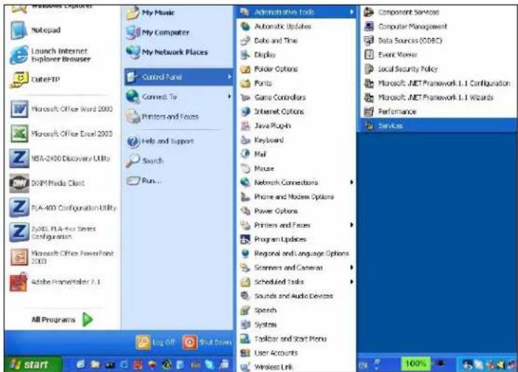
2 Select the Messenger service and click Start.
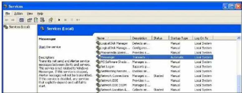
3 Close the window when you are done.
Windows 2000
1 Click Start > Settings > Control Panel > Administrative Tools > Services.
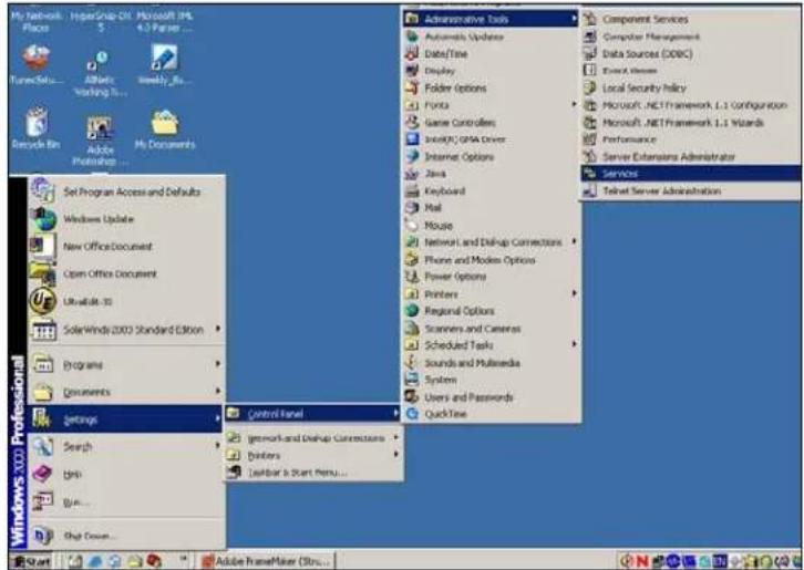
2 Select the Messenger service and click Start Service.
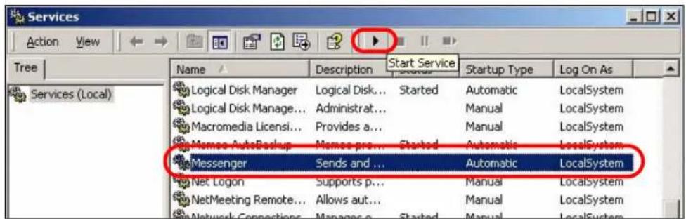
3 Close the window when you are done.
Importing Certificates
This appendix shows you how to import public key certificates into your web browser.
Public key certificates are used by web browsers to ensure that a secure web site is legitimate. When a certificate authority such as VeriSign, Comodo, or Network Solutions, to name a few, receives a certificate request from a website operator, they confirm that the web domain and contact information in the request match those on public record with a domain name registrar. If they match, then the certificate is issued to the website operator, who then places it on the site to be issued to all visiting web browsers to let them know that the site is legitimate.
Many ZyXEL products, such as the NSA-2401, issue their own public key certificates. These can be used by web browsers on a LAN or WAN to verify that they are in fact connecting to the legitimate device and not one masquerading as it. However, because the certificates were not issued by one of the several organizations officially recognized by the most common web browsers, you will need to import the ZyXEL-created certificate into your web browser and flag that certificate as a trusted authority.
Note: You can see if you are browsing on a secure website if the URL in your web browser's address bar begins with https:// or there is a sealed padlock icon () somewhere in the main browser window (not all browsers show the padlock in the same location.)
Internet Explorer
The following example uses Microsoft Internet Explorer 7 on Windows XP Professional; however, they can also apply to Internet Explorer on Windows Vista.
1 If your device's Web Configurator is set to use SSL certification, then the first time you browse to it you are presented with a certification error.
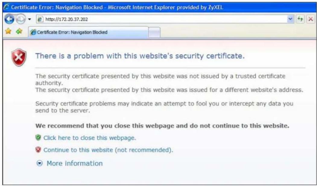
2 Click Continue to this website (not recommended).
3 In the Address Bar, click Certificate Error > View certificates.
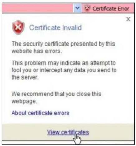
4 In the Certificate dialog box, click Install Certificate.
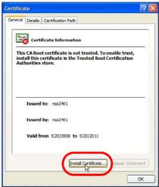
5 In the Certificate Import Wizard, click Next.
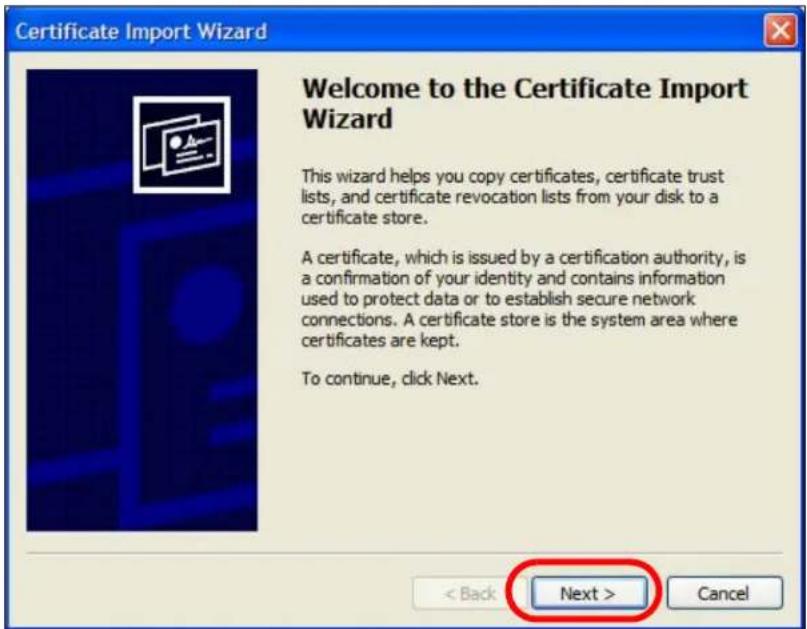
6 If you want Internet Explorer to Automatically select certificate store based on the type of certificate, click Next again and then go to step 9.
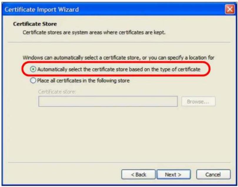
7 Otherwise, select Place all certificates in the following store and then click Browse.

8 In the Select Certificate Store dialog box, choose a location in which to save the certificate and then click OK.
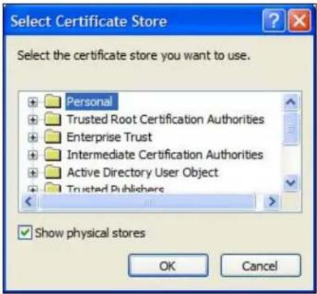
9 In the Completing the Certificate Import Wizard screen, click Finish.
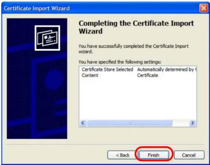
10 If you are presented with another Security Warning, click Yes.
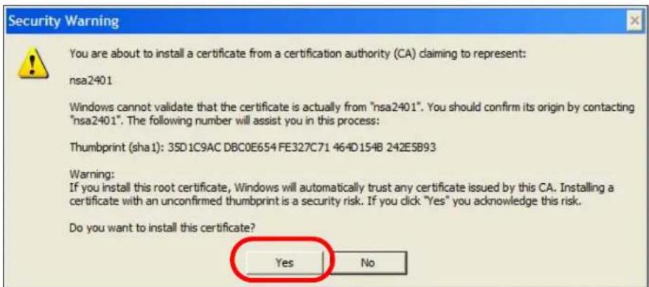
11 Finally, click OK when presented with the successful certificate installation message.
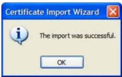
12 The next time you start Internet Explorer and go to a ZyXEL Web Configurator page, a sealed padlock icon appears in the address bar. Click it to view the page's Website Identification information.
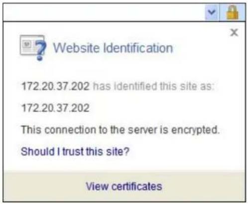
Installing a Stand-Alone Certificate File in Internet Explorer
Rather than browsing to a ZyXEL Web Configurator and installing a public key certificate when prompted, you can install a stand-alone certificate file if one has been issued to you.
1 Double-click the public key certificate file.

CALCER
2 In the security warning dialog box, click Open.
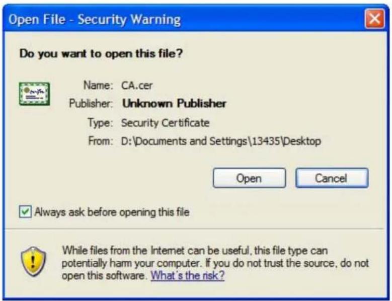
3 Refer to steps 4-12 in the Internet Explorer procedure beginning on page 620 to complete the installation process.
Removing a Certificate in Internet Explorer
This section shows you how to remove a public key certificate in Internet Explorer 7 on Windows XP.
1 Open Internet Explorer and click Tools > Internet Options.
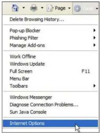
2 In the Internet Options dialog box, click Content > Certificates.
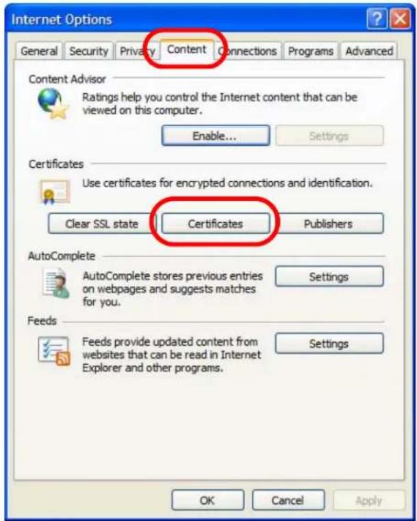
3 In the Certificates dialog box, click the Trusted Root Certificates Authorities tab, select the certificate that you want to delete, and then click Remove.
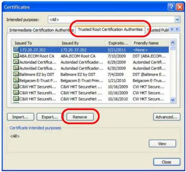
4 In the Certificates confirmation, click Yes.
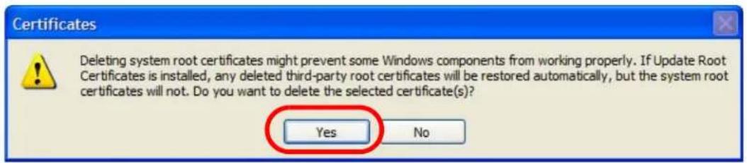
5 In the Root Certificate Store dialog box, click Yes.
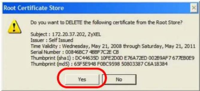
6 The next time you go to the web site that issued the public key certificate you just removed, a certification error appears.
Firefox
The following example uses Mozilla Firefox 2 on Windows XP Professional; however, the screens can also apply to Firefox 2 on all platforms.
1 If your device's Web Configurator is set to use SSL certification, then the first time you browse to it you are presented with a certification error.
2 Select Accept this certificate permanently and click OK.
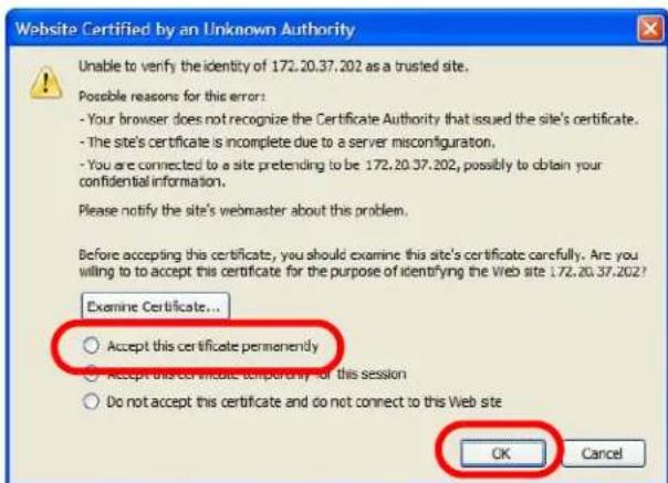
3 The certificate is stored and you can now connect securely to the Web Configurator. A sealed padlock appears in the address bar, which you can click to open the Page Info > Security window to view the web page's security information.

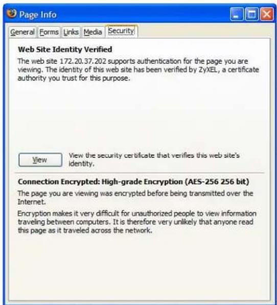
Installing a Stand-Alone Certificate File in Firefox
Rather than browsing to a ZyXEL Web Configurator and installing a public key certificate when prompted, you can install a stand-alone certificate file if one has been issued to you.
1 Open Firefox and click Tools > Options.
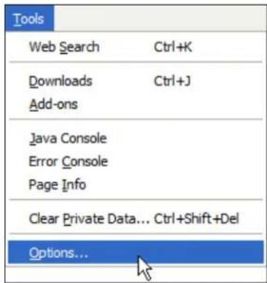
2 In the Options dialog box, click Advanced > Encryption > View Certificates.
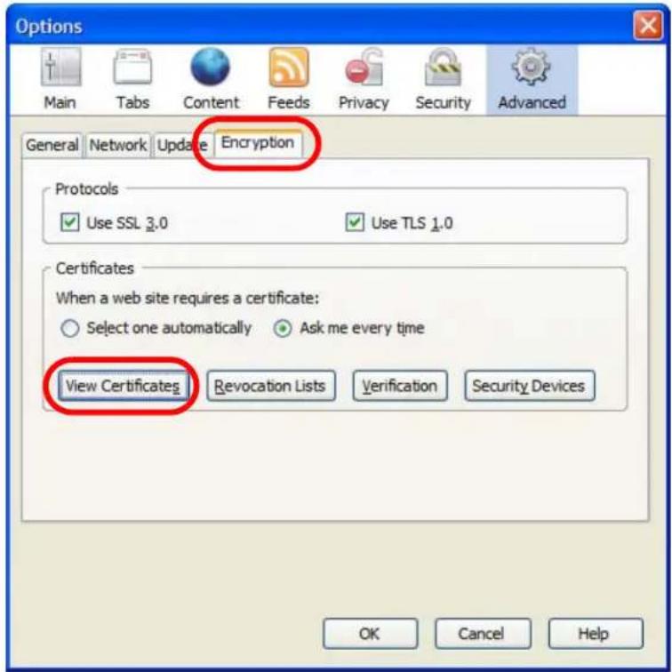
3 In the Certificate Manager dialog box, click Web Sites > Import.
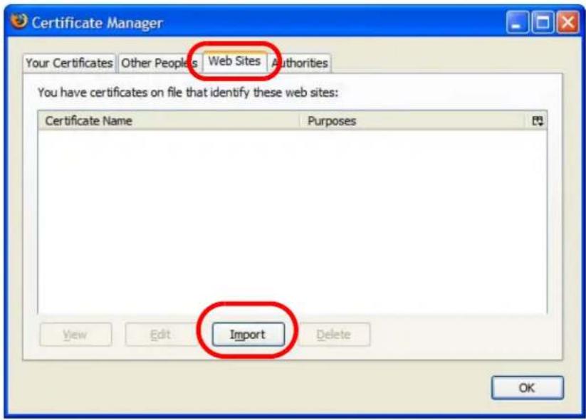
4 Use the Select File dialog box to locate the certificate and then click Open.
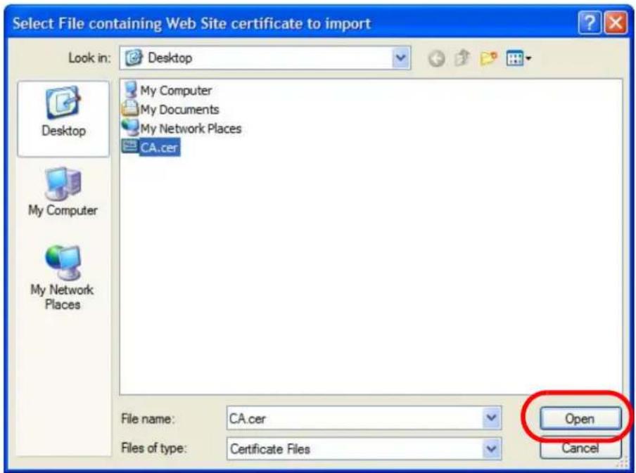
5 The next time you visit the web site, click the padlock in the address bar to open the Page Info > Security window to see the web page's security information.
Removing a Certificate in Firefox
This section shows you how to remove a public key certificate in Firefox 2.
1 Open Firefox and click Tools > Options.
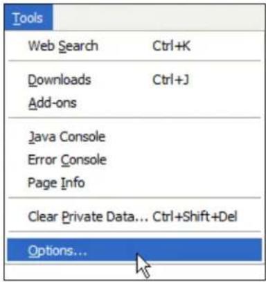
2 In the Options dialog box, click Advanced > Encryption > View Certificates.
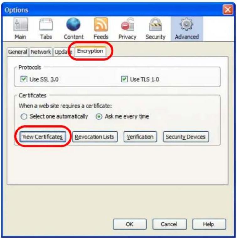
3 In the Certificate Manager dialog box, select the Web Sites tab, select the certificate that you want to remove, and then click Delete.
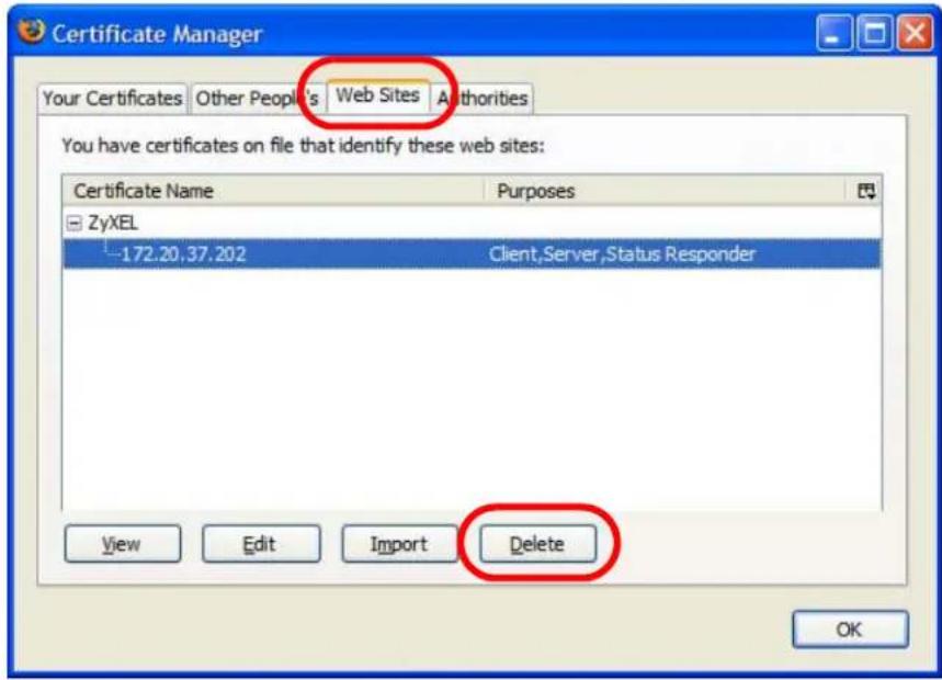
4 In the Delete Web Site Certificates dialog box, click OK.
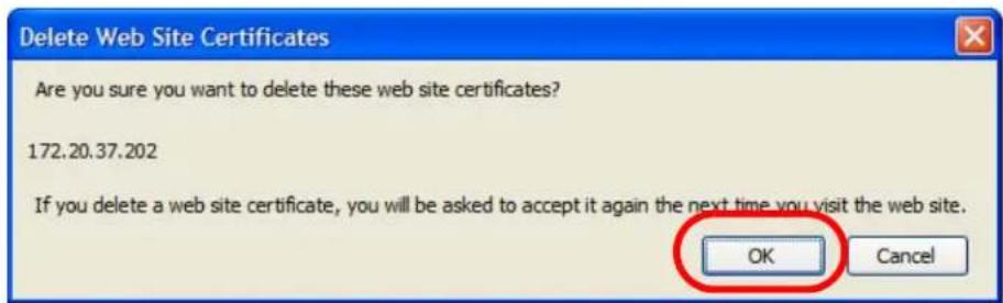
5 The next time you go to the web site that issued the public key certificate you just removed, a certification error appears.
Wireless LANs
Wireless LAN Topologies
This section discusses ad-hoc and infrastructure wireless LAN topologies.
Ad-hoc Wireless LAN Configuration
The simplest WLAN configuration is an independent (Ad-hoc) WLAN that connects a set of computers with wireless adapters (A, B, C). Any time two or more wireless adapters are within range of each other, they can set up an independent network, which is commonly referred to as an ad-hoc network or Independent Basic Service Set (IBSS). The following diagram shows an example of notebook computers using wireless adapters to form an ad-hoc wireless LAN.
Figure 257 Peer-to-Peer Communication in an Ad-hoc Network
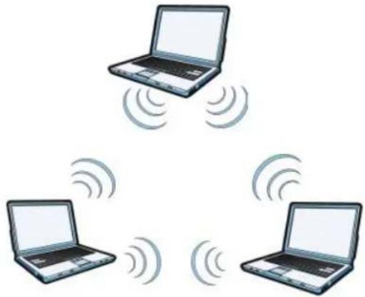
natural_image
Three laptops each connected to a central wireless signal icon (no text or symbols)BSS
A Basic Service Set (BSS) exists when all communications between wireless clients or between a wireless client and a wired network client go through one access point (AP).
Intra-BSS traffic is traffic between wireless clients in the BSS. When Intra-BSS is enabled, wireless client A and B can access the wired network and communicate
with each other. When Intra-BSS is disabled, wireless client A and B can still access the wired network but cannot communicate with each other.
Figure 258 Basic Service Set
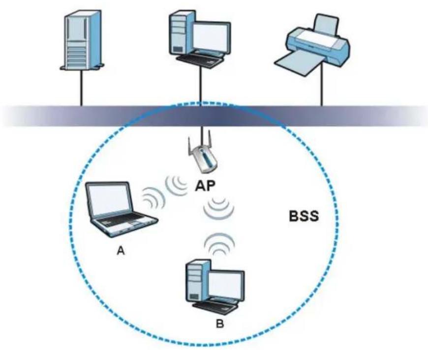
flowchart
graph TD
    A["Server A"] -->|Wireless Signal| AP["AP"]
    B["Server B"] -->|Wireless Signal| AP
    C["Server C"] -->|Wireless Signal| AP
    AP -->|Wireless Signal| BSS["BSS"]
    style AP fill:#f9f,stroke:#333
    style BSS fill:#ccf,stroke:#333
    style A fill:#cfc,stroke:#333
    style B fill:#cfc,stroke:#333
ESS
An Extended Service Set (ESS) consists of a series of overlapping BSSs, each containing an access point, with each access point connected together by a wired network. This wired connection between APs is called a Distribution System (DS).
This type of wireless LAN topology is called an Infrastructure WLAN. The Access Points not only provide communication with the wired network but also mediate wireless network traffic in the immediate neighborhood.
An ESSID (ESS IDentification) uniquely identifies each ESS. All access points and their associated wireless clients within the same ESS must have the same ESSID in order to communicate.
Figure 259 Infrastructure WLAN
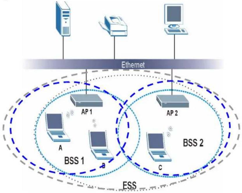
flowchart
graph TD
    A["Desktop"] --> B["Ethernet"]
    C["Printer"] --> B
    D["Computer"] --> B
    B --> E["AP 1"]
    B --> F["AP 2"]
    E --> G["A"]
    F --> H["BSS 1"]
    F --> I["BSS 2"]
    G --> J["A"]
    H --> K["BSS 1"]
    H --> L["BSS 2"]
    I --> M["C"]
    J --> N["ESS"]
    K --> N
    L --> N
    style A fill:#f9f,stroke:#333
    style C fill:#f9f,stroke:#333
    style D fill:#f9f,stroke:#333
    style B fill:#ccf,stroke:#333
    style E fill:#cff,stroke:#333
    style F fill:#cff,stroke:#333
    style G fill:#ffc,stroke:#333
    style H fill:#ffc,stroke:#333
    style I fill:#ffc,stroke:#333
    style J fill:#cfc,stroke:#333
    style K fill:#cfc,stroke:#333
    style L fill:#cfc,stroke:#333
Channel
A channel is the radio frequency(ies) used by wireless devices to transmit and receive data. Channels available depend on your geographical area. You may have a choice of channels (for your region) so you should use a channel different from an adjacent AP (access point) to reduce interference. Interference occurs when radio signals from different access points overlap causing interference and degrading performance.
Adjacent channels partially overlap however. To avoid interference due to overlap, your AP should be on a channel at least five channels away from a channel that an adjacent AP is using. For example, if your region has 11 channels and an adjacent AP is using channel 1, then you need to select a channel between 6 or 11.
RTS/CTS
A hidden node occurs when two stations are within range of the same access point, but are not within range of each other. The following figure illustrates a hidden node. Both stations (STA) are within range of the access point (AP) or wireless gateway, but out-of-range of each other, so they cannot "hear" each other, that is they do not know if the channel is currently being used. Therefore, they are considered hidden from each other.
Figure 260 RTS/CTS
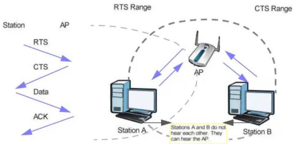
flowchart
graph TD
    A["Station A"] -->|RTS| B["AP"]
    A -->|CTS| B
    A -->|Data| B
    A -->|ACK| B
    B -->|CTS Range| C["AP"]
    C -->|CTS Range| D["Station B"]
    D -->|CTS Range| C
    C -->|CTS Range| E["Station A and B do not hear each other. They can hear the AP."]
When station A sends data to the AP, it might not know that the station B is already using the channel. If these two stations send data at the same time, collisions may occur when both sets of data arrive at the AP at the same time, resulting in a loss of messages for both stations.
RTS/ CTS is designed to prevent collisions due to hidden nodes. An RTS/ CTS defines the biggest size data frame you can send before an RTS (Request To Send)/CTS (Clear to Send) handshake is invoked.
When a data frame exceeds the RTS/CTS value you set (between 0 to 2432 bytes), the station that wants to transmit this frame must first send an RTS (Request To Send) message to the AP for permission to send it. The AP then responds with a CTS (Clear to Send) message to all other stations within its range to notify them to defer their transmission. It also reserves and confirms with the requesting station the time frame for the requested transmission.
Stations can send frames smaller than the specified RTS/CTS directly to the AP without the RTS (Request To Send)/CTS (Clear to Send) handshake.
You should only configure RTS/CTS if the possibility of hidden nodes exists on your network and the "cost" of resending large frames is more than the extra
network overhead involved in the RTS (Request To Send)/CTS (Clear to Send) handshake.
If the RTS/CTS value is greater than the Fragmentation Threshold value (see next), then the RTS (Request To Send)/CTS (Clear to Send) handshake will never occur as data frames will be fragmented before they reach RTS/CTS size.
Note: Enabling the RTS Threshold causes redundant network overhead that could negatively affect the throughput performance instead of providing a remedy.
Fragmentation Threshold
A Fragmentation Threshold is the maximum data fragment size (between 256 and 2432 bytes) that can be sent in the wireless network before the AP will fragment the packet into smaller data frames.
A large Fragmentation Threshold is recommended for networks not prone to interference while you should set a smaller threshold for busy networks or networks that are prone to interference.
If the Fragmentation Threshold value is smaller than the RTS/CTS value (see previously) you set then the RTS (Request To Send)/CTS (Clear to Send) handshake will never occur as data frames will be fragmented before they reach RTS/CTS size.
Preamble Type
Preamble is used to signal that data is coming to the receiver. Short and long refer to the length of the synchronization field in a packet.
Short preamble increases performance as less time sending preamble means more time for sending data. All IEEE 802.11 compliant wireless adapters support long preamble, but not all support short preamble.
Use long preamble if you are unsure what preamble mode other wireless devices on the network support, and to provide more reliable communications in busy wireless networks.
Use short preamble if you are sure all wireless devices on the network support it, and to provide more efficient communications.
Use the dynamic setting to automatically use short preamble when all wireless devices on the network support it, otherwise the NXC uses short preamble.
Note: The wireless devices MUST use the same preamble mode in order to communicate.
IEEE 802.11g Wireless LAN
IEEE 802.11g is fully compatible with the IEEE 802.11b standard. This means an IEEE 802.11b adapter can interface directly with an IEEE 802.11g access point (and vice versa) at 11 Mbps or lower depending on range. IEEE 802.11g has several intermediate rate steps between the maximum and minimum data rates. The IEEE 802.11g data rate and modulation are as follows:
Table 245 IEEE 802.11g
| DATA RATE (MBPS) MODULATION | |
| 1 DBPSK (Differential Binary Phase Shift Keyed) | |
| 2 DQPSK (Differential Quadrature Phase Shift Keying) | |
| 5.5 / 11 CCK (Complementary Code Keying) | |
| 6/9/12/18/24/36/48/54 OFDM (Orthogonal Frequency Division Multiplexing) |
Wireless Security Overview
Wireless security is vital to your network to protect wireless communication between wireless clients, access points and the wired network.
Wireless security methods available on the NXC are data encryption, wireless client authentication, restricting access by device MAC address and hiding the NXC identity.
The following figure shows the relative effectiveness of these wireless security methods available on your NXC.
Table 246 Wireless Security Levels
| SECURITY LEVEL | SECURITY TYPE |
| Least Secure | Unique SSID (Default) |
| Unique SSID with Hide SSID Enabled | |
| MAC Address Filtering | |
| WEP Encryption | |
| IEEE802.1x EAP with RADIUS Server Authentication | |
| Wi-Fi Protected Access (WPA) | |
| Most Secure | WPA2 |
Note: You must enable the same wireless security settings on the NXC and on all wireless clients that you want to associate with it.
IEEE 802.1x
In June 2001, the IEEE 802.1x standard was designed to extend the features of IEEE 802.11 to support extended authentication as well as providing additional accounting and control features. It is supported by Windows XP and a number of network devices. Some advantages of IEEE 802.1x are:
- User based identification that allows for roaming.
- Support for RADIUS (Remote Authentication Dial In User Service, RFC 2138, 2139) for centralized user profile and accounting management on a network RADIUS server.
- Support for EAP (Extensible Authentication Protocol, RFC 2486) that allows additional authentication methods to be deployed with no changes to the access point or the wireless clients.
RADIUS
RADIUS is based on a client-server model that supports authentication, authorization and accounting. The access point is the client and the server is the RADIUS server. The RADIUS server handles the following tasks:
- Authentication
Determines the identity of the users. - Authorization
Determines the network services available to authenticated users once they are connected to the network. - Accounting
Keeps track of the client's network activity.
RADIUS is a simple package exchange in which your AP acts as a message relay between the wireless client and the network RADIUS server.
Types of RADIUS Messages
The following types of RADIUS messages are exchanged between the access point and the RADIUS server for user authentication:
-
Access-Request
Sent by an access point requesting authentication. -
Access-Reject
Sent by a RADIUS server rejecting access. - Access-Accept
Sent by a RADIUS server allowing access. - Access-Challenge
Sent by a RADIUS server requesting more information in order to allow access. The access point sends a proper response from the user and then sends another Access-Request message.
The following types of RADIUS messages are exchanged between the access point and the RADIUS server for user accounting:
- Accounting - Request
Sent by the access point requesting accounting.
- Accounting-Response
Sent by the RADIUS server to indicate that it has started or stopped accounting.
In order to ensure network security, the access point and the RADIUS server use a shared secret key, which is a password, they both know. The key is not sent over the network. In addition to the shared key, password information exchanged is also encrypted to protect the network from unauthorized access.
Types of EAP Authentication
This section discusses some popular authentication types: EAP-MD5, EAP-TLS, EAP-TTLS, PEAP and LEAP. Your wireless LAN device may not support all authentication types.
EAP (Extensible Authentication Protocol) is an authentication protocol that runs on top of the IEEE 802.1x transport mechanism in order to support multiple types of user authentication. By using EAP to interact with an EAP-compatible RADIUS server, an access point helps a wireless station and a RADIUS server perform authentication.
The type of authentication you use depends on the RADIUS server and an intermediary AP(s) that supports IEEE 802.1x.
For EAP-TLS authentication type, you must first have a wired connection to the network and obtain the certificate(s) from a certificate authority (CA). A certificate (also called digital IDs) can be used to authenticate users and a CA issues certificates and guarantees the identity of each certificate owner.
EAP-MD5 (Message-Digest Algorithm 5)
MD5 authentication is the simplest one-way authentication method. The authentication server sends a challenge to the wireless client. The wireless client 'proves' that it knows the password by encrypting the password with the challenge and sends back the information. Password is not sent in plain text.
However, MD5 authentication has some weaknesses. Since the authentication server needs to get the plaintext passwords, the passwords must be stored. Thus someone other than the authentication server may access the password file. In addition, it is possible to impersonate an authentication server as MD5 authentication method does not perform mutual authentication. Finally, MD5 authentication method does not support data encryption with dynamic session key. You must configure WEP encryption keys for data encryption.
EAP-TLS (Transport Layer Security)
With EAP-TLS, digital certifications are needed by both the server and the wireless clients for mutual authentication. The server presents a certificate to the client. After validating the identity of the server, the client sends a different certificate to the server. The exchange of certificates is done in the open before a secured tunnel is created. This makes user identity vulnerable to passive attacks. A digital certificate is an electronic ID card that authenticates the sender's identity. However, to implement EAP-TLS, you need a Certificate Authority (CA) to handle certificates, which imposes a management overhead.
EAP-TTLS (Tunneled Transport Layer Service)
EAP-TTLS is an extension of the EAP-TLS authentication that uses certificates for only the server-side authentications to establish a secure connection. Client authentication is then done by sending username and password through the secure connection, thus client identity is protected. For client authentication, EAP-TTLS supports EAP methods and legacy authentication methods such as PAP, CHAP, MS-CHAP and MS-CHAP v2.
PEAP (Protected EAP)
Like EAP-TTLS, server-side certificate authentication is used to establish a secure connection, then use simple username and password methods through the secured connection to authenticate the clients, thus hiding client identity. However, PEAP only supports EAP methods, such as EAP-MD5, EAP-MSCHAPv2 and EAP-GTC (EAP-Generic Token Card), for client authentication. EAP-GTC is implemented only by Cisco.
LEAP
LEAP (Lightweight Extensible Authentication Protocol) is a Cisco implementation of IEEE 802.1x.
Dynamic WEP Key Exchange
The AP maps a unique key that is generated with the RADIUS server. This key expires when the wireless connection times out, disconnects or reauthentication times out. A new WEP key is generated each time reauthentication is performed.
If this feature is enabled, it is not necessary to configure a default encryption key in the wireless security configuration screen. You may still configure and store keys, but they will not be used while dynamic WEP is enabled.
Note: EAP-MD5 cannot be used with Dynamic WEP Key Exchange
For added security, certificate-based authentications (EAP-TLS, EAP-TTLS and PEAP) use dynamic keys for data encryption. They are often deployed in corporate environments, but for public deployment, a simple user name and password pair is more practical. The following table is a comparison of the features of authentication types.
Table 247 Comparison of EAP Authentication Types
| EAP-MD5 EAP-TLS EAP-TTLS PEAP LEAP | |||||
| Mutual Authentication No | Yes Yes Yes Yes | ||||
| Certificate – Client | No | Yes | Optional | Optional | No |
| Certificate – Server | No | Yes | Yes | Yes | No |
| Dynamic Key Exchange | No | Yes | Yes | Yes | Yes |
| Credential Integrity | None | Strong | Strong | Strong | Moderate |
| Deployment Difficulty | Easy | Hard | Moderate | Moderate | Moderate |
| Client Identity Protection | No No | Yes Yes No | |||
WPA and WPA2
Wi-Fi Protected Access (WPA) is a subset of the IEEE 802.11i standard. WPA2 (IEEE 802.11i) is a wireless security standard that defines stronger encryption, authentication and key management than WPA.
Key differences between WPA or WPA2 and WEP are improved data encryption and user authentication.
If both an AP and the wireless clients support WPA2 and you have an external RADIUS server, use WPA2 for stronger data encryption. If you don't have an external RADIUS server, you should use WPA2-PSK (WPA2-Pre-Shared Key) that only requires a single (identical) password entered into each access point, wireless gateway and wireless client. As long as the passwords match, a wireless client will be granted access to a WLAN.
If the AP or the wireless clients do not support WPA2, just use WPA or WPA-PSK depending on whether you have an external RADIUS server or not.
Select WEP only when the AP and/or wireless clients do not support WPA or WPA2. WEP is less secure than WPA or WPA2.
Encryption
Both WPA and WPA2 improve data encryption by using Temporal Key Integrity Protocol (TKIP), Message Integrity Check (MIC) and IEEE 802.1x. WPA and WPA2 use Advanced Encryption Standard (AES) in the Counter mode with Cipher block chaining Message authentication code Protocol (CCMP) to offer stronger encryption than TKIP.
TKIP uses 128-bit keys that are dynamically generated and distributed by the authentication server. AES (Advanced Encryption Standard) is a block cipher that uses a 256-bit mathematical algorithm called Rijndael. They both include a per-packet key mixing function, a Message Integrity Check (MIC) named Michael, an extended initialization vector (IV) with sequencing rules, and a re-keying mechanism.
WPA and WPA2 regularly change and rotate the encryption keys so that the same encryption key is never used twice.
The RADIUS server distributes a Pairwise Master Key (PMK) key to the AP that then sets up a key hierarchy and management system, using the PMK to dynamically generate unique data encryption keys to encrypt every data packet that is wirelessly communicated between the AP and the wireless clients. This all happens in the background automatically.
The Message Integrity Check (MIC) is designed to prevent an attacker from capturing data packets, altering them and resending them. The MIC provides a strong mathematical function in which the receiver and the transmitter each compute and then compare the MIC. If they do not match, it is assumed that the data has been tampered with and the packet is dropped.
By generating unique data encryption keys for every data packet and by creating an integrity checking mechanism (MIC), with TKIP and AES it is more difficult to decrypt data on a Wi-Fi network than WEP and difficult for an intruder to break into the network.
The encryption mechanisms used for WPA(2) and WPA(2)-PSK are the same. The only difference between the two is that WPA(2)-PSK uses a simple common password, instead of user-specific credentials. The common-password approach makes WPA(2)-PSK susceptible to brute-force password-guessing attacks but it's still an improvement over WEP as it employs a consistent, single, alphanumeric password to derive a PMK which is used to generate unique temporal encryption keys. This prevent all wireless devices sharing the same encryption keys. (a weakness of WEP)
User Authentication
WPA and WPA2 apply IEEE 802.1x and Extensible Authentication Protocol (EAP) to authenticate wireless clients using an external RADIUS database. WPA2 reduces the number of key exchange messages from six to four (CCMP 4-way handshake) and shortens the time required to connect to a network. Other WPA2 authentication features that are different from WPA include key caching and pre-authentication. These two features are optional and may not be supported in all wireless devices.
Key caching allows a wireless client to store the PMK it derived through a successful authentication with an AP. The wireless client uses the PMK when it tries to connect to the same AP and does not need to go with the authentication process again.
Pre-authentication enables fast roaming by allowing the wireless client (already connecting to an AP) to perform IEEE 802.1x authentication with another AP before connecting to it.
Wireless Client WPA Supplicants
A wireless client supplicant is the software that runs on an operating system instructing the wireless client how to use WPA. At the time of writing, the most widely available supplicant is the WPA patch for Windows XP, Funk Software's Odyssey client.
The Windows XP patch is a free download that adds WPA capability to Windows XP's built-in "Zero Configuration" wireless client. However, you must run Windows XP to use it.
WPA(2) with RADIUS Application Example
To set up WPA(2), you need the IP address of the RADIUS server, its port number (default is 1812), and the RADIUS shared secret. A WPA(2) application example with an external RADIUS server looks as follows. "A" is the RADIUS server. "DS" is the distribution system.
1 The AP passes the wireless client's authentication request to the RADIUS server.
2 The RADIUS server then checks the user's identification against its database and grants or denies network access accordingly.
3 A 256-bit Pairwise Master Key (PMK) is derived from the authentication process by the RADIUS server and the client.
4 The RADIUS server distributes the PMK to the AP. The AP then sets up a key hierarchy and management system, using the PMK to dynamically generate unique data encryption keys. The keys are used to encrypt every data packet that is wirelessly communicated between the AP and the wireless clients.
Figure 261 WPA(2) with RADIUS Application Example
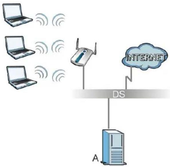
flowchart
graph TD
    A["Laptop"] -->|Wireless Signal| Router["Router"]
    B["Laptop"] -->|Wireless Signal| Router
    C["Laptop"] -->|Wireless Signal| Router
    D["Internet"] -->|Wireless Signal| Router
    Router -->|DS| A
    style A fill:#cce5ff,stroke:#333
    style B fill:#cce5ff,stroke:#333
    style C fill:#cce5ff,stroke:#333
    style D fill:#cce5ff,stroke:#333
WPA(2)-PSK Application Example
A WPA(2)-PSK application looks as follows.
1 First enter identical passwords into the AP and all wireless clients. The Pre-Shared Key (PSK) must consist of between 8 and 63 ASCII characters or 64 hexadecimal characters (including spaces and symbols).
2 The AP checks each wireless client's password and allows it to join the network only if the password matches.
3 The AP and wireless clients generate a common PMK (Pairwise Master Key). The key itself is not sent over the network, but is derived from the PSK and the SSID.
4 The AP and wireless clients use the TKIP or AES encryption process, the PMK and information exchanged in a handshake to create temporal encryption keys. They use these keys to encrypt data exchanged between them.
Figure 262 WPA(2)-PSK Authentication
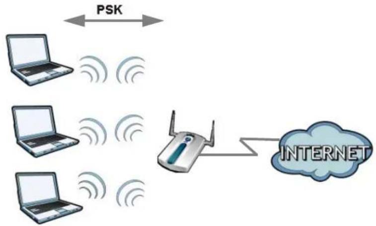
flowchart
graph TD
    A["Laptop"] <-->|PSK| B["Router"]
    C["Laptop"] <-->|PSK| B
    D["Laptop"] <-->|PSK| B
    E["Laptop"] <-->|PSK| B
    B --> F["INTERNET"]
Security Parameters Summary
Refer to this table to see what other security parameters you should configure for each authentication method or key management protocol type. MAC address filters are not dependent on how you configure these security features.
Table 248 Wireless Security Relational Matrix
| AUTHENTICATION METHOD/ KEY MANAGEMENT PROTOCOL | ENCRYPTIO N METHOD | ENTER MANUAL KEY | IEEE 802.1X |
| Open None No Disable | |||
| Enable without Dynamic WEP Key | |||
| Open | WEP | No | Enable with Dynamic WEP Key |
| Yes Enable without Dynamic WEP Key | |||
| Yes Disable | |||
| Shared | WEP | No | Enable with Dynamic WEP Key |
| Yes Enable without Dynamic WEP Key | |||
| Yes Disable | |||
| WPA TKIP/AES No Enable | |||
| WPA-PSK TKIP/AES Yes Disable | |||
| WPA2 TKIP/AES No Enable | |||
| WPA2-PSK TKIP/AES Yes Disable | |||
Open Software Announcements
End-User License Agreement for "NXC5200"
WARNING: ZyXEL Communications Corp. IS WILLING TO LICENSE THE SOFTWARE TO YOU ONLY UPON THE CONDITION THAT YOU ACCEPT ALL OF THE TERMS CONTAINED IN THIS LICENSE AGREEMENT. PLEASE READ THE TERMS CAREFULLY BEFORE COMPLETING THE INSTALLATION PROCESS AS INSTALLING THE SOFTWARE WILL INDICATE YOUR ASSENT TO THEM. IF YOU DO NOT AGREE TO THESE TERMS, THEN ZyXEL IS UNWILLING TO LICENSE THE SOFTWARE TO YOU, IN WHICH EVENT YOU SHOULD RETURN THE UNINSTALLED SOFTWARE AND PACKAGING TO THE PLACE FROM WHICH IT WAS ACQUIRED OR ZyXEL, AND YOUR MONEY WILL BE REFUNDED. HOWEVER CERTAIN COMPONENTS OF THE SOFTWARE, AND THIRD PARTY OPEN SOURCE PROGRAMS INCLUDED WITH THE SOFTWARE, HAVE BEEN OR MAY BE MADE AVAILABLE BY ZyXEL LISTED IN THE BELOW NOTICE (COLLECTIVELY THE "OPEN-SOURCED COMPONENTAS"). FOR THESE OPEN-SOURCED COMPONENTS YOU SHOULD COMPLY WITH THE TERMS OF THIS LICENSE AND ANY APPLIABLE LICNESING TERMS GOVERNING USE OF THE OPEN-SOURCED COMPONENTS, WHICH HAVE BEEN PROVIDED ON THE LICENSE NOTICE AS BELOW FOR THE SOFTWARE.
- Grant of License for Personal Use
ZyXEL Communications Corp. ("ZyXEL") grants you a non-exclusive, non sublicense, non-transferable license to use the program with which this license is distributed (the "Software"), including any documentation files accompanying the Software ("Documentation"), for internal business use only, for up to the number of users specified in sales order and invoice. You have the right to make one backup copy of the Software and Documentation solely for archival, back-up or disaster recovery purposes. You shall not exceed the scope of the license granted hereunder. Any rights not expressly granted by ZyXEL to you are reserved by ZyXEL, and all implied licenses are disclaimed.
- Ownership
You have no ownership rights in the Software. Rather, you have a license to use the Software as long as this License Agreement remains in full force and effect. Ownership of the Software, Documentation and all intellectual property rights therein shall remain at all times with ZyXEL. Any other use of the Software by any other entity is strictly forbidden and is a violation of this License Agreement.
- Copyright
The Software and Documentation contain material that is protected by International Copyright Law and trade secret law, and by international treaty provisions. All rights not granted to you herein are expressly reserved by ZyXEL. You may not remove any proprietary notice of ZyXEL or any of its licensors from any copy of the Software or Documentation.
- Restrictions
You may not publish, display, disclose, sell, rent, lease, modify, store, loan, distribute, or create derivative works of the Software, or any part thereof. You may not assign, sublicense, convey or otherwise transfer, pledge as security or otherwise encumber the rights and licenses granted hereunder with respect to the Software. Certain components of the Software, and third party open source programs included with the Software, have been or may be made available by ZyXEL listed in the below Notice (collectively the "Open-Sourced Components") You may modify or replace only these
Open-Sourced Components; provided that you comply with the terms of this License and any applicable licensing terms governing use of the Open-Sourced Components, which have been provided on the License Notice as below for the Software. ZyXEL is not obligated to provide any maintenance, technical or other support for the resultant modified Software. You may not copy, reverse engineer, decompile, reverse compile, translate, adapt, or disassemble the Software, or any part thereof, nor shall you attempt to create the source code from the object code for the Software. Except as and only to the extent expressly permitted in this License, by applicable licensing terms governing use of the Open-Sourced Components, or by applicable law, you may not market, co-brand, private label or otherwise permit third parties to link to the Software, or any part thereof. You may not use the Software, or any part thereof, in the operation of a service bureau or for the benefit of any other person or entity. You may not cause, assist or permit any third party to do any of the foregoing. Portions of the Software utilize or include third party software and other copyright material. Acknowledgements, licensing terms and disclaimers for such material are contained in the License Notice as below for the Software, and your use of such material is governed by their respective terms. ZyXEL has provided, as part of the Software package, access to certain third party software as a convenience. To the extent that the Software contains third party software, ZyXEL has no express or implied obligation to provide any technical or other support for such software. Please contact the appropriate software vendor or manufacturer directly for technical support and customer service related to its software and products.
5. Confidentiality
You acknowledge that the Software contains proprietary trade secrets of ZyXEL and you hereby agree to maintain the confidentiality of the Software using at least as great a degree of care as you use to maintain the confidentiality of your own most confidential information. You agree to reasonably communicate the terms and conditions of this License Agreement to those persons employed by you who come into contact with the Software, and to use reasonable best efforts to ensure their compliance with such terms and conditions, including, without limitation, not knowingly permitting such persons to use any portion of the Software for the purpose of deriving the source code of the Software.
6. No Warranty
THE SOFTWARE IS PROVIDED "AS IS." TO THE MAXIMUM EXTENT PERMITTED BY LAW, ZyXEL DISCLAIMS ALL WARRANTIES OF ANY KIND, EITHER EXPRESSED OR IMPLIED, INCLUDING, WITHOUT LIMITATION, IMPLIED WARRANTIES OF MERCHANTABILITY AND FITNESS FOR A PARTICULAR PURPOSE. ZyXEL DOES NOT WARRANT THAT THE FUNCTIONS CONTAINED IN THE SOFTWARE WILL MEET ANY REQUIREMENTS OR NEEDS YOU MAY HAVE, OR THAT THE SOFTWARE WILL OPERATE ERROR FREE, OR IN AN UNINTERUPTED FASHION, OR THAT ANY DEFECTS OR ERRORS IN THE SOFTWARE WILL BE CORRECTED, OR THAT THE SOFTWARE IS COMPATIBLE WITH ANY PARTICULAR PLATFORM. SOME JURISDICTIONS DO NOT ALLOW THE WAIVER OR EXCLUSION OF IMPLIED WARRANTIES SO THEY MAY NOT APPLY TO YOU. IF THIS EXCLUSION IS HELD TO BE UNENFORCEABLE BY A COURT OF COMPETENT JURISDICTION, THEN ALL EXPRESS AND IMPLIED WARRANTIES SHALL BE LIMITED IN DURATION TO A PERIOD OF THIRTY (30) DAYS FROM THE DATE OF PURCHASE OF THE SOFTWARE, AND NO WARRANTIES SHALL APPLY AFTER THAT PERIOD.
7. Limitation of Liability
IN NO EVENT WILL ZyXEL BE LIABLE TO YOU OR ANY THIRD PARTY FOR ANY INCIDENTAL OR CONSEQUENTIAL DAMAGES (INCLUDING, WITHOUT LIMITATION, INDIRECT, SPECIAL, PUNITIVE, OR EXEMPLARY DAMAGES FOR LOSS OF BUSINESS, LOSS OF PROFITS, BUSINESS INTERRUPTION, OR LOSS OF BUSINESS INFORMATION) ARISING OUT OF THE USE OF OR INABILITY TO USE THE PROGRAM, OR FOR ANY CLAIM BY ANY OTHER PARTY, EVEN IF ZyXEL HAS BEEN ADVISED OF THE POSSIBILITY OF SUCH DAMAGES. ZyXEL'S AGGREGATE LIABILITY WITH RESPECT TO ITS OBLIGATIONS UNDER THIS AGREEMENT OR OTHERWISE WITH RESPECT TO THE SOFTWARE AND DOCUMENTATION OR OTHERWISE SHALL BE EQUAL TO THE PURCHASE PRICE, BUT SHALL IN NO EVENT EXCEED THE PRODUCT'S PRICE. BECAUSE SOME STATES/COUNTRIES DO NOT ALLOW THE EXCLUSION OR LIMITATION OF LIABILITY FOR CONSEQUENTIAL OR INCIDENTAL DAMAGES, THE ABOVE LIMITATION MAY NOT APPLY TO YOU.
8. Export Restrictions
THIS LICENSE AGREEMENT IS EXPRESSLY MADE SUBJECT TO ANY APPLICABLE LAWS, REGULATIONS, ORDERS, OR OTHER RESTRICTIONS ON THE EXPORT OF THE SOFTWARE OR INFORMATION ABOUT SUCH SOFTWARE WHICH MAY BE IMPOSED FROM TIME TO TIME. YOU SHALL NOT EXPORT THE SOFTWARE, DOCUMENTATION OR INFORMATION ABOUT THE SOFTWARE AND DOCUMENTATION WITHOUT COMPLYING WITH SUCH LAWS, REGULATIONS, ORDERS, OR OTHER RESTRICTIONS. YOU AGREE TO INDEMNIFY ZyXEL AGAINST ALL CLAIMS, LOSSES, DAMAGES, LIABILITIES, COSTS AND EXPENSES, INCLUDING REASONABLE ATTORNEYS' FEES, TO THE EXTENT SUCH CLAIMS ARISE OUT OF ANY BREACH OF THIS SECTION 8.
9. Audit Rights
ZyXEL SHALL HAVE THE RIGHT, AT ITS OWN EXPENSE, UPON REASONABLE PRIOR NOTICE, TO PERIODICALLY INSPECT AND AUDIT YOUR RECORDS TO ENSURE YOUR COMPLIANCE WITH THE TERMS AND CONDITIONS OF THIS LICENSE AGREEMENT.
10. Termination
This License Agreement is effective until it is terminated. You may terminate this License Agreement at any time by destroying or returning to ZyXEL all copies of the Software and Documentation in your possession or under your control. ZyXEL may terminate this License Agreement for any reason, including, but not limited to, if ZyXEL finds that you have violated any of the terms of this License Agreement. Upon notification of termination, you agree to destroy or return to ZyXEL all copies of the Software and Documentation and to certify in writing that all known copies, including backup copies, have been destroyed. All provisions relating to confidentiality, proprietary rights, and non-disclosure shall survive the termination of this Software License Agreement.
11. General
This License Agreement shall be construed, interpreted and governed by the laws of Republic of China without regard to conflicts of laws provisions thereof. The exclusive forum for any disputes arising out of or relating to this License Agreement shall be an appropriate court or Commercial Arbitration Association sitting in ROC, Taiwan. This License Agreement shall constitute the entire Agreement between the parties hereto. This License Agreement, the rights granted hereunder, the Software and Documentation shall not be assigned by you without the prior written consent of ZyXEL. Any waiver or modification of this License Agreement shall only be effective if it is in writing and signed by both parties hereto. If any part of this License Agreement is found invalid or unenforceable by a court of competent jurisdiction, the remainder of this License Agreement shall be interpreted so as to reasonably effect the intention of the parties.
NOTE: Some components of this product incorporate source code covered under the open source code licenses. Further, for at least three (3) years from the date of distribution of the applicable product or software, we will give to anyone who contacts us at the ZyXEL Technical Support (support@zyxel.com.tw), for a charge of no more than our cost of physically performing source code distribution, a complete machine-readable copy of the complete corresponding source code for the version of the Programs that we distributed to you if we are in possession of such.
Notice
Information herein is subject to change without notice. Companies, names, and data used in examples herein are fictitious unless otherwise noted. No part may be reproduced or transmitted in any form or by any means, electronic or mechanical, for any purpose, except the express written permission of ZyXEL Communications Corporation.
This Product includes ntp software under the NTP License
NTP License
Copyright (c) David L. Mills 1992-2004
Permission to use, copy, modify, and distribute this software and its documentation for any purpose and without fee is hereby granted, provided that the above copyright notice appears in all copies and that both the copyright notice and this permission notice appear in supporting documentation, and that the name University of Delaware not be used in advertising or publicity pertaining to distribution of the software without specific, written prior permission. The University of Delaware makes no representations about the suitability this software for any purpose. It is provided "as is" without express or implied warranty.
This Product includes expat software under the Expat License
Expat License
Copyright (c) 1998, 1999, 2000 Thai Open Source Software Center Ltd
Permission is hereby granted, free of charge, to any person obtaining a copy of this software and associated documentation files (the "Software"), to deal in the Software without restriction, including
without limitation the rights to use, copy, modify, merge, publish, distribute, sublicense, and/or sell copies of the Software, and to permit persons to whom the Software is furnished to do so, subject to
the following conditions:
The above copyright notice and this permission notice shall be included in all copies or substantial portions of the Software.
THE SOFTWARE IS PROVIDED "AS IS", WITHOUT WARRANTY OF ANY KIND, EXPRESS OR IMPLIED, INCLUDING BUT NOT LIMITED TO THE WARRANTIES OF MERCHANTABILITY, FITNESS FOR A PARTICULAR PURPOSE AND NONINFRINGEMENT.
IN NO EVENT SHALL THE AUTHORS OR COPYRIGHT HOLDERS BE LIABLE FOR ANY CLAIM, DAMAGES OR OTHER LIABILITY, WHETHER IN AN ACTION OF CONTRACT, TORT OR OTHERWISE, ARISING FROM, OUT OF OR IN CONNECTION WITH THE SOFTWARE OR THE USE OR OTHER DEALINGS IN THE SOFTWARE.
This Product includes libtecla software under the an X11-style License
an X11-style license
This is a Free Software License
"This license is compatible with The GNU General Public License, Version 1"
"This license is compatible with The GNU General Public License, Version 2"
This is just like a Simple Permissive license, but it requires that a copyright notice be maintained.
Permission is hereby granted, free of charge, to any person obtaining a copy of this software and associated documentation files (the "Software"), to deal in the Software without restriction, including
without limitation the rights to use, copy, modify, merge, publish, distribute, sublicense, and/or sell copies of the Software, and to permit persons to whom the Software is furnished to do so, subject to
the following conditions:
The above copyright notice and this permission notice shall be included in all copies or substantial portions of the Software.
This Product includes openssl software under the OpenSSL License
OpenSSL
LICENSE ISSUES
The OpenSSL toolkit stays under a dual license, i.e. both the conditions of
the OpenSSL License and the original SSLeay license apply to the toolkit.
See below for the actual license texts. Actually both licenses are BSD-style
Open Source licenses. In case of any license issues related to OpenSSL
please contact openssl-core@openssl.org.
OpenSSL License
* Copyright (c) 1998-2008 The OpenSSL Project. All rights reserved.
* Redistribution and use in source and binary forms, with or without
* modification, are permitted provided that the following conditions
* are met:
* 1. Redistributions of source code must retain the above copyright
* notice, this list of conditions and the following disclaimer.
* 2. Redistributions in binary form must reproduce the above copyright
* notice, this list of conditions and the following disclaimer in
* the documentation and/or other materials provided with the
* distribution.
* 3. All advertising materials mentioning features or use of this
* software must display the following acknowledgment:
* "This product includes software developed by the OpenSSL Project
* for use in the OpenSSL Toolkit. (http://www.openssl.org/)
* 4. The names "OpenSSL Toolkit" and "OpenSSL Project" must not be used to
* endorse or promote products derived from this software without
* prior written permission. For written permission, please contact
* openssl-core@openssl.org.
* 5. Products derived from this software may not be called "OpenSSL"
* nor may "OpenSSL" appear in their names without prior written
* permission of the OpenSSL Project.
* 6. Redistributions of any form whatsoever must retain the following
* acknowledgment:
* "This product includes software developed by the OpenSSL Project
* for use in the OpenSSL Toolkit (http://www.openssl.org/)
* THIS SOFTWARE IS PROVIDED BY THE OpenSSL PROJECT ``AS IS'' AND ANY
* EXPRESSED OR IMPLIED WARRANTIES, INCLUDING, BUT NOT LIMITED TO, THE
* IMPLIED WARRANTIES OF MERCHANTABILITY AND FITNESS FOR A PARTICULAR
* PURPOSE ARE DISCLAIMED. IN NO EVENT SHALL THE OpenSSL PROJECT OR
* ITS CONTRIBUTORS BE LIABLE FOR ANY DIRECT, INDIRECT, INCIDENTAL,
* SPECIAL, EXEMPLARY, OR CONSEQUENTIAL DAMAGES (INCLUDING, BUT
* NOT LIMITED TO, PROCUREMENT OF SUBSTITUTE GOODS OR SERVICES;
* LOSS OF USE, DATA, OR PROFITS; OR BUSINESS INTERRUPTION)
* HOWEVER CAUSED AND ON ANY THEORY OF LIABILITY, WHETHER IN CONTRACT,
* STRICT LIABILITY, OR TORT (INCLUDING NEGLIGENCE OR OTHERWISE)
* ARISING IN ANY WAY OUT OF THE USE OF THIS SOFTWARE, EVEN IF ADVISED
* OF THE POSSIBILITY OF SUCH DAMAGE.
* This product includes cryptographic software written by Eric Young
* (eay@cryptsoft.com). This product includes software written by Tim
* Hudson (tjh@cryptsoft.com).
*
* /
Original SSLeay License
/* Copyright (C) 1995-1998 Eric Young (eay@cryptsoft.com)
* All rights reserved.
*
* This package is an SSL implementation written
* by Eric Young (eay@cryptsoft.com).
* The implementation was written so as to conform with Netscapes SSL.
*
* This library is free for commercial and non-commercial use as long as
* the following conditions are aheared to. The following conditions
* apply to all code found in this distribution, be it the RC4, RSA,
* Ihash, DES, etc., code; not just the SSL code. The SSL documentation
* included with this distribution is covered by the same copyright terms
* except that the holder is Tim Hudson (tjh@cryptsoft.com).
*
* Copyright remains Eric Young's, and as such any Copyright notices in
* the code are not to be removed.
* If this package is used in a product, Eric Young should be given attribution
* as the author of the parts of the library used.
* This can be in the form of a textual message at program startup or
* in documentation (online or textual) provided with the package.
*
* Redistribution and use in source and binary forms, with or without
* modification, are permitted provided that the following conditions
* are met:
* 1. Redistributions of source code must retain the copyright
* notice, this list of conditions and the following disclaimer.
* 2. Redistributions in binary form must reproduce the above copyright
* notice, this list of conditions and the following disclaimer in the
* documentation and/or other materials provided with the distribution.
* 3. All advertising materials mentioning features or use of this software
* must display the following acknowledgement:
* "This product includes cryptographic software written by
* Eric Young (eay@cryptsoft.com)"
* The word 'cryptographic' can be left out if the rouines from the library
* being used are not cryptographic related :-).
* 4. If you include any Windows specific code (or a derivative thereof) from
* the apps directory (application code) you must include an acknowledgement:
* "This product includes software written by Tim Hudson (tjh@cryptsoft.com)"
* THIS SOFTWARE IS PROVIDED BY ERIC YOUNG `` AS IS'' AND
* ANY EXPRESS OR IMPLIED WARRANTIES, INCLUDING, BUT NOT LIMITED TO, THE
* IMPLIED WARRANTIES OF MERCHANTABILITY AND FITNESS FOR A PARTICULAR PURPOSE
* ARE DISCLAIMED. IN NO EVENT SHALL THE AUTHOR OR CONTRIBUTORS BE LIABLE
* FOR ANY DIRECT, INDIRECT, INCIDENTAL, SPECIAL, EXEMPLARY, OR CONSEQUENTIAL
* DAMAGES (INCLUDING, BUT NOT LIMITED TO, PROCUREMENT OF SUBSTITUTE GOODS
* OR SERVICES; LOSS OF USE, DATA, OR PROFITS; OR BUSINESS INTERRUPTION)
* HOWEVER CAUSED AND ON ANY THEORY OF LIABILITY, WHETHER IN CONTRACT, STRICT
* LIABILITY, OR TORT (INCLUDING NEGLIGENCE OR OTHERWISE) ARISING IN ANY WAY
* OUT OF THE USE OF THIS SOFTWARE, EVEN IF ADVISED OF THE POSSIBILITY OF
* SUCH DAMAGE.
* The licence and distribution terms for any publicly available version or
* derivative of this code cannot be changed. i.e. this code cannot simply be
* copied and put under another distribution licence
This Product includes libevent and xinetd software under the a 3-clause BSD License
a 3-clause BSD-style license
This is a Free Software License
"This license is compatible with The GNU General Public License, Version 1"
"This license is compatible with The GNU General Public License, Version 2"
This is the BSD license without the obnoxious advertising clause. It's also known as the "modified BSD license." Note that the University of California now prefers this license to the BSD license with advertising clause, and now allows BSD itself to be used under the three-clause license.
Redistribution and use in source and binary forms, with or without
modification, are permitted provided that the following conditions are
met:
* Redistributions of source code must retain the above copyright notice, this list of conditions and the following disclaimer.
* Redistributions in binary form must reproduce the above copyright notice, this list of conditions and the following disclaimer in the documentation and/or other materials provided with the distribution.
* Neither the name of [original copyright holder] nor the names of its contributors may be used to endorse or promote products derived from this software without specific prior written permission.
THIS SOFTWARE IS PROVIDED BY THE COPYRIGHT HOLDERS AND CONTRIBUTORS "AS IS" AND ANY EXPRESS OR IMPLIED WARRANTIES, INCLUDING, BUT NOT LIMITED TO, THE IMPLIED WARRANTIES OF MERCHANTABILITY AND FITNESS FOR A PARTICULAR PURPOSE ARE DISCLAIMED. IN NO EVENT SHALL THE COPYRIGHT OWNER OR CONTRIBUTORS BE LIABLE FOR ANY DIRECT, INDIRECT, INCIDENTAL, SPECIAL, EXEMPLARY, OR CONSEQUENTIAL DAMAGES (INCLUDING, BUT NOT LIMITED TO, PROCUREMENT OF SUBSTITUTE GOODS OR SERVICES; LOSS OF USE, DATA, OR PROFITS; OR BUSINESS INTERRUPTION) HOWEVER CAUSED AND ON ANY THEORY OF LIABILITY, WHETHER IN CONTRACT, STRICT LIABILITY, OR TORT (INCLUDING NEGLIGENCE OR OTHERWISE) ARISING IN ANY WAY OUT OF THE USE OF THIS SOFTWARE, EVEN IF ADVISED OF THE POSSIBILITY OF SUCH DAMAGE.
This Product includes bind and dhcp software under the ISC License
ISC license
Copyright (c) 4-digit year, Company or Person's Name
Permission to use, copy, modify, and distribute this software for any purpose with or without fee is hereby granted, provided that the above copyright notice and this permission notice appear in all copies.
THE SOFTWARE IS PROVIDED "AS IS" AND ISC DISCLAIMS ALL WARRANTIES WITH REGARD TO THIS SOFTWARE INCLUDING ALL IMPLIED WARRANTIES OF MERCHANTABILITY AND FITNESS. IN NO
EVENT SHALL ISC BE LIABLE FOR ANY SPECIAL, DIRECT, INDIRECT, OR CONSEQUENTIAL DAMAGES OR ANY DAMAGES WHATSOEVER RESULTING FROM LOSS OF USE, DATA OR PROFITS, WHETHER IN AN ACTION OF CONTRACT, NEGLIGENCE OR OTHER TORTIOUS ACTION, ARISING OUT OF OR IN CONNECTION WITH THE USE OR PERFORMANCE OF THIS SOFTWARE.
This Product includes httpd software developed by the Apache Software Foundation under Apache License.
Apache License
Version 2.0, January 2004
http://www.apache.org/licenses/
TERMS AND CONDITIONS FOR USE, REPRODUCTION, AND DISTRIBUTION
- Definitions.
"License" shall mean the terms and conditions for use, reproduction, and distribution as defined by Sections 1 through 9 of this document.
"Licensor" shall mean the copyright owner or entity authorized by the copyright owner that is granting the License.
"Legal Entity" shall mean the union of the acting entity and all other entities that control, are controlled by, or are under common control with that entity. For the purposes of this definition, "control" means (i) the power, direct or indirect, to cause the direction or management of such entity, whether by contract or otherwise, or (ii) ownership of fifty percent (50%) or more of the outstanding shares, or (iii) beneficial ownership of such entity.
"You" (or "Your") shall mean an individual or Legal Entity exercising permissions granted by this License.
"Source" form shall mean the preferred form for making modifications, including but not limited to software source code, documentation source, and configuration files.
"Object" form shall mean any form resulting from mechanical transformation or translation of a Source form, including but not limited to compiled object code, generated documentation, and conversions to other media types.
"Work" shall mean the work of authorship, whether in Source or Object form, made available under the License, as indicated by a copyright notice that is included in or attached to the work (an example is provided in the Appendix below).
"Derivative Works" shall mean any work, whether in Source or Object form, that is based on (or derived from) the Work and for which the editorial revisions, annotations, elaborations, or other modifications represent, as a whole, an original work of authorship. For the purposes of this License, Derivative Works shall not include works that remain separable from, or merely link (or bind by name) to the interfaces of, the Work and Derivative Works thereof.
"Contribution" shall mean any work of authorship, including the original version of the Work and any modifications or additions to that Work or Derivative Works thereof, that is intentionally submitted to Licensor for inclusion in the Work by the copyright owner or by an individual or Legal Entity authorized to submit on behalf of the copyright owner. For the purposes of this definition, "submitted" means any form of electronic, verbal, or written communication sent to the Licensor or its representatives, including but not limited to communication on electronic mailing lists, source code control systems, and issue tracking systems that are managed by, or on behalf of, the Licensor for the purpose of discussing and improving the Work, but excluding communication that is conspicuously marked or otherwise designated in writing by the copyright owner as "Not a Contribution."
"Contributor" shall mean Licensor and any individual or Legal Entity on behalf of whom a Contribution has been received by Licensor and subsequently incorporated within the Work.
-
Grant of Copyright License. Subject to the terms and conditions of this License, each Contributor hereby grants to You a perpetual, worldwide, non-exclusive, no-charge, royalty-free, irrevocable copyright license to reproduce, prepare Derivative Works of, publicly display, publicly perform, sublicense, and distribute the Work and such Derivative Works in Source or Object form.
-
Grant of Patent License. Subject to the terms and conditions of this License, each Contributor hereby grants to You a perpetual, worldwide, non-exclusive, no-charge, royalty-free, irrevocable (except as stated in this section) patent license to make, have made, use, offer to sell, sell, import, and otherwise transfer the Work, where such license applies only to those patent claims licensable by such Contributor that are necessarily infringed by their Contribution(s) alone or by combination of their Contribution(s) with the Work to which such Contribution(s) was submitted. If You institute patent litigation against any entity (including a cross-claim or counterclaim in a lawsuit) alleging that the Work or a Contribution incorporated within the Work constitutes direct or contributory patent infringement, then any patent licenses granted to You under this License for that Work shall terminate as of the date such litigation is filed.
-
Redistribution. You may reproduce and distribute copies of the Work or Derivative Works hereof in any medium, with or without modifications, and in Source or Object form, provided that You meet the following conditions:
(a) You must give any other recipients of the Work or Derivative Works a copy of this License; and
(b) You must cause any modified files to carry prominent notices stating that You changed the files; and
(c) You must retain, in the Source form of any Derivative Works that You distribute, all copyright, patent, trademark, and attribution notices from the Source form of the Work, excluding those notices that do not pertain to any part of the Derivative Works; and
(d) If the Work includes a "NOTICE" text file as part of its distribution, then any Derivative Works that You distribute must include a readable copy of the attribution notices contained within such NOTICE file, excluding those notices that do not pertain to any part of the Derivative Works, in at least one of the following places: within a NOTICE text file distributed as part of the Derivative Works; within the Source form or documentation, if provided along with the Derivative Works; or, within a display generated by the Derivative Works, if and wherever such third-party notices normally appear. The contents of the NOTICE file are for informational purposes only and do not modify the License. You may add Your own attribution notices within Derivative Works that You distribute, alongside or as an addendum to the NOTICE text from the Work, provided that such additional attribution notices cannot be construed as modifying the License. You may add Your own copyright statement to Your modifications and may provide additional or different license terms and conditions for use, reproduction, or distribution of Your modifications, or for any such Derivative Works as a whole, provided Your use, reproduction, and distribution of the Work otherwise complies with the conditions stated in this License.
-
Submission of Contributions. Unless You explicitly state otherwise, any Contribution intentionally submitted for inclusion in the Work by You to the Licensor shall be under the terms and conditions of this License, without any additional terms or conditions. Notwithstanding the above, nothing herein shall supersede or modify the terms of any separate license agreement you may have executed with Licensor regarding such Contributions.
-
Trademarks. This License does not grant permission to use the trade names, trademarks, service marks, or product names of the Licensor, except as required for reasonable and customary use in describing the origin of the Work and reproducing the content of the NOTICE file.
-
Disclaimer of Warranty. Unless required by applicable law or agreed to in writing, Licensor provides the Work (and each Contributor provides its Contributions) on an "AS IS" BASIS, WITHOUT WARRANTIES OR CONDITIONS OF ANY KIND, either express or implied, including, without limitation,
any warranties or conditions of TITLE, NON-INFRINGEMENT, MERCHANTABILITY, or FITNESS FOR A PARTICULAR PURPOSE. You are solely responsible for determining the appropriateness of using or redistributing the Work and assume any risks associated with Your exercise of permissions under this License.
- Limitation of Liability. In no event and under no legal theory, whether in tort (including negligence), contract, or otherwise, unless required by applicable law (such as deliberate and grossly negligent acts) or agreed to in writing, shall any Contributor be liable to You for damages, including any direct, indirect, special, incidental, or consequential damages of any character arising as a result of this License or out of the use or inability to use the Work (including but not limited to damages for loss of goodwill, work stoppage, computer failure or malfunction, or any and all other commercial damages or losses), even if such Contributor has been advised of the possibility of such damages.
- Accepting Warranty or Additional Liability. While redistributing the Work or Derivative Works thereof, You may choose to offer, and charge a fee for, acceptance of support, warranty, indemnity, or other liability obligations and/or rights consistent with this License. However, in accepting such obligations, You may act only on Your own behalf and on Your sole responsibility, not on behalf of any other Contributor, and only if You agree to indemnify, defend, and hold each Contributor harmless for any liability incurred by, or claims asserted against, such Contributor by reason of your accepting any such warranty or additional liability.
END OF TERMS AND CONDITIONS
Version 1.1
Copyright (c) 1999-2003 The Apache Software Foundation. All rights reserved.
Redistribution and use in source and binary forms, with or without modification, are permitted provided that the following conditions are met:
Redistributions of source code must retain the above copyright notice, this list of conditions and the following disclaimer.
Redistributions in binary form must reproduce the above copyright notice, this list of conditions and the following disclaimer in the documentation and/or other materials provided with the distribution.
The end-user documentation included with the redistribution, if any, must include the following acknowledgment: "This product includes software developed by the Apache Software Foundation (http://www.apache.org/)." Alternately, this acknowledgment may appear in the software itself, if and wherever such third-party acknowledgments normally appear.
The names "Apache" and "Apache Software Foundation" must not be used to endorse or promote products derived from this software without prior written permission. For written permission, please contact apache@apache.org.
Products derived from this software may not be called "Apache", nor may "Apache" appear in their name, without prior written permission of the Apache Software Foundation.
THIS SOFTWARE IS PROVIDED ``AS IS'' AND ANY EXPRESSED OR IMPLIED WARRANTIES, INCLUDING, BUT NOT LIMITED TO, THE IMPLIED WARRANTIES OF MERCHANTABILITY AND FITNESS FOR A PARTICULAR PURPOSE ARE DISCLAIMED. IN NO EVENT SHALL THE APACHE SOFTWARE FOUNDATION OR ITS CONTRIBUTORS BE LIABLE FOR ANY DIRECT, INDIRECT, INCIDENTAL, SPECIAL, EXEMPLARY, OR CONSEQUENTIAL DAMAGES (INCLUDING, BUT NOT LIMITED TO, PROCUREMENT OF SUBSTITUTE GOODS OR SERVICES; LOSS OF USE, DATA, OR PROFITS; OR BUSINESS INTERRUPTION) HOWEVER CAUSED AND ON ANY THEORY OF LIABILITY, WHETHER IN CONTRACT, STRICT LIABILITY, OR TORT (INCLUDING NEGLIGENCE OR OTHERWISE) ARISING IN ANY WAY OUT OF THE USE OF THIS SOFTWARE, EVEN IF ADVISED OF THE POSSIBILITY OF SUCH DAMAGE.
This software consists of voluntary contributions made by many individuals on behalf of the Apache Software Foundation. For more information on the Apache Software Foundation, please see http://www.apache.org/.
Portions of this software are based upon public domain software originally written at the National Center for Supercomputing Applications, University of Illinois, Urbana-Champaign.
This Product includes gmp, p7zip and libgcgi under LGPL license.
GNU LESSER GENERAL PUBLIC LICENSE
Version 2.1, February 1999
Copyright (C) 1991, 1999 Free Software Foundation, Inc.
59 Temple Place, Suite 330, Boston, MA 02111-1307 USA
Everyone is permitted to copy and distribute verbatim copies of this license document, but changing it is not allowed. [This is the first released version of the Lesser GPL. It also counts
as the successor of the GNU Library Public License, version 2, hence the version number 2.1.
Preamble
The licenses for most software are designed to take away your freedom to share and change it. By contrast, the GNU General Public Licenses are intended to guarantee your freedom to share and change free software--to make sure the software is free for all its users.
This license, the Lesser General Public License, applies to some specially designated software packages--typically libraries--of the Free Software Foundation and other authors who decide to use it. You can use it too, but we suggest you first think carefully about whether this license or the ordinary General Public License is the better strategy to use in any particular case, based on the explanations below.
When we speak of free software, we are referring to freedom of use, not price. Our General Public Licenses are designed to make sure that you have the freedom to distribute copies of free software (and charge for this service if you wish); that you receive source code or can get
it if you want it; that you can change the software and use pieces of it in new free programs; and that you are informed that you can do these things.
To protect your rights, we need to make restrictions that forbid distributors to deny you these rights or to ask you to surrender these rights. These restrictions translate to certain responsibilities for you if you distribute copies of the library or if you modify it.
For example, if you distribute copies of the library, whether gratis or for a fee, you must give the recipients all the rights that we gave you. You must make sure that they, too, receive or can get the source code. If you link other code with the library, you must provide complete object files to the recipients, so that they can relink them with the library after making changes to the library and recompiling it. And you must show them these terms so they know their rights.
We protect your rights with a two-step method: (1) we copyright the library, and (2) we offer you this license, which gives you legal permission to copy, distribute and/or modify the library.
To protect each distributor, we want to make it very clear that there is no warranty for the free library. Also, if the library is modified by someone else and passed on, the recipients should know that what they have is not the original version, so that the original author's reputation will not be affected by problems that might be introduced by others.
Finally, software patents pose a constant threat to the existence of any free program. We wish to make sure that a company cannot effectively restrict the users of a free program by obtaining a restrictive license from a patent holder. Therefore, we insist that any patent license obtained for a version of the library must be consistent with the full freedom of use specified in this license.
Most GNU software, including some libraries, is covered by the ordinary GNU General Public License. This license, the GNU Lesser General Public License, applies to certain designated libraries, and is quite different from the ordinary General Public License. We use this license for certain libraries in order to permit linking those libraries into non-free programs.
When a program is linked with a library, whether statically or using a shared library, the combination of the two is legally speaking a combined work, a derivative of the original library. The ordinary General Public License therefore permits such linking only if the entire combination fits its criteria of freedom. The Lesser General Public License permits more lax criteria for linking other code with the library.
We call this license the "Lesser" General Public License because it does Less to protect the user's freedom than the ordinary General Public License. It also provides other free software developers Less of an advantage over competing non-free programs. These disadvantages are the reason we use the ordinary General Public License for many libraries. However, the Lesser license provides advantages in certain special circumstances.
For example, on rare occasions, there may be a special need to encourage the widest possible use of a certain library, so that it becomes a de-facto standard. To achieve this, non-free programs must be allowed to use the library. A more frequent case is that a free library does the same job as widely used non-free libraries. In this case, there is little to gain by limiting the free library to free software only, so we use the Lesser General Public License. In other cases, permission to use a particular library in non-free programs enables a greater number of people to use a large body of free software. For example, permission to use the GNU C Library in non-free programs enables many more people to use the whole GNU operating system, as well as its variant, the GNU/Linux operating system.
Although the Lesser General Public License is Less protective of the users' freedom, it does ensure that the user of a program that is linked with the Library has the freedom and the wherewithal to run that program using a modified version of the Library.
The precise terms and conditions for copying, distribution and modification follow. Pay close attention to the difference between a "work based on the library" and a "work that uses the library". The former contains code derived from the library, whereas the latter must be combined with the library in order to run.
GNU LESSER GENERAL PUBLIC LICENSE TERMS AND CONDITIONS FOR COPYING, DISTRIBUTION AND MODIFICATION
- This License Agreement applies to any software library or other program which contains a notice placed by the copyright holder or other authorized party saying it may be distributed under the terms of this Lesser General Public License (also called "this License").
Each licensee is addressed as "you".
A "library" means a collection of software functions and/or data prepared so as to be conveniently linked with application programs (which use some of those functions and data) to form executables. The "Library", below, refers to any such software library or work which has been distributed under these terms. A "work based on the Library" means either the Library or any derivative work under copyright law: that is to say, a work containing the Library or a portion of it, either verbatim or with modifications and/or translated straightforwardly into another language. (Hereinafter, translation is included without limitation in the term "modification".)
"Source code" for a work means the preferred form of the work for making modifications to it. For a library, complete source code means all the source code for all modules it contains, plus any associated interface definition files, plus the scripts used to control compilation and installation of the library. Activities other than copying, distribution and modification are not covered by this License; they are
outside its scope. The act of running a program using the Library is not restricted, and output from such a program is covered only if its contents constitute a work based on the Library (independent of the use of the Library in a tool for writing it). Whether that is true depends on what the Library does and what the program that uses the Library does.
- You may copy and distribute verbatim copies of the Library's complete source code as you receive it, in any medium, provided that you conspicuously and appropriately publish on each copy an appropriate copyright notice and disclaimer of warranty; keep intact all the notices that refer to this License and to the absence of any warranty; and distribute a copy of this License along with the Library. You may charge a fee for the physical act of transferring a copy, and you may at your option offer warranty protection in exchange for a fee.
- You may modify your copy or copies of the Library or any portion of it, thus forming a work based on the Library, and copy and distribute such modifications or work under the terms of Section 1 above, provided that you also meet all of these conditions: a) The modified work must itself be a software library. b) You must cause the files modified to carry prominent notices stating that you changed the files and the date of any change. c) You must cause the whole of the work to be licensed at no charge to all third parties under the terms of this License. d) If a facility in the modified Library refers to a function or a table of data to be supplied by an application program that uses the facility, other than as an argument passed when the facility is invoked, then you must make a good faith effort to ensure that, in the event an application does not supply such function or table, the facility still operates, and performs whatever part of its purpose remains meaningful. (For example, a function in a library to compute square roots has a purpose that is entirely well-defined independent of the application. Therefore, Subsection 2d requires that any application-supplied function or table used by this function must be optional: if the application does not supply it, the square root function must still compute square roots.) These requirements apply to the modified work as a whole. If identifiable sections of that work are not derived from the Library, and can be reasonably considered independent and separate works in themselves, then this License, and its terms, do not apply to those sections when you distribute them as separate works. But when you distribute the same sections as part of a whole which is a work based on the Library, the distribution of the whole must be on the terms of this License, whose permissions for other licensees extend to the entire whole, and thus to each and every part regardless of who wrote
it. Thus, it is not the intent of this section to claim rights or contest your rights to work written entirely by you; rather, the intent is to exercise the right to control the distribution of derivative or collective works based on the Library. In addition, mere aggregation of another work not based on the Library with the Library (or with a work based on the Library) on a volume of a storage or distribution medium does not bring the other work under the scope of this License. - You may opt to apply the terms of the ordinary GNU General Public License instead of this License to a given copy of the Library. To do this, you must alter all the notices that refer to this License, so that they refer to the ordinary GNU General Public License, version 2, instead of to this License. (If a newer version than version 2 of the ordinary GNU General Public License has appeared, then you can specify that version instead if you wish.) Do not make any other change in these notices. Once this change is made in a given copy, it is irreversible for that copy, so the ordinary GNU General Public License applies to all subsequent copies and derivative works made from that copy. This option is useful when you wish to copy part of the code of the Library into a program that is not a library.
- You may copy and distribute the Library (or a portion or derivative of it, under Section 2) in object code or executable form under the terms of Sections 1 and 2 above provided that you accompany it with the complete corresponding machine-readable source code, which must be distributed under the terms of Sections 1 and 2 above on a medium customarily used for software interchange. If distribution of object code is made by offering access to copy from a designated place, then offering equivalent access to copy the source code from the same place satisfies the requirement to distribute the source code, even though third parties are not
compelled to copy the source along with the object code.
- A program that contains no derivative of any portion of the Library, but is designed to work with the Library by being compiled or linked with it, is called a "work that uses the Library". Such a work, in isolation, is not a derivative work of the Library, and therefore falls outside the scope of this License.
However, linking a "work that uses the Library" with the Library creates an executable that is a derivative of the Library (because it contains portions of the Library), rather than a "work that uses the library". The executable is therefore covered by this License. Section 6 states terms for distribution of such executables. When a "work that uses the Library" uses material from a header file that is part of the Library, the object code for the work may be a derivative work of the Library even though the source code is not. Whether this is true is especially significant if the work can be linked without the Library, or if the work is itself a library. The threshold for this to be true is not precisely defined by law. If such an object file uses only numerical parameters, data structure layouts and accessors, and small macros and small inline functions (ten lines or less in length), then the use of the object file is unrestricted, regardless of whether it is legally a derivative work. (Executables containing this object code plus portions of the Library will still fall under Section 6.) Otherwise, if the work is a derivative of the Library, you may distribute the object code for the work under the terms of Section 6. Any executables containing that work also fall under Section 6, whether or not they are linked directly with the Library itself.
- As an exception to the Sections above, you may also combine or link a "work that uses the Library" with the Library to produce a work containing portions of the Library, and distribute that work under terms of your choice, provided that the terms permit modification of the work for the customer's own use and reverse engineering for debugging such modifications. You must give prominent notice with each copy of the work that the Library is used in it and that the Library and its use are covered by this License. You must supply a copy of this License. If the work during execution displays copyright notices, you must include the copyright notice for the Library among them, as well as a reference directing the user to the copy of this License. Also, you must do one of these things: a) Accompany the work with the complete corresponding
machine-readable source code for the Library including whatever changes were used in the work (which must be distributed under Sections 1 and 2 above); and, if the work is an executable linked with the Library, with the complete machine-readable "work that uses the Library", as object code and/or source code, so that the user can modify the Library and then relink to produce a modified executable containing the modified Library. (It is understood that the user who changes the contents of definitions files in the Library will not necessarily be able to recompile the application to use the modified definitions.) b) Use a suitable shared library mechanism for linking with the Library. A suitable mechanism is one that (1) uses at run time a
copy of the library already present on the user's computer system, rather than copying library functions into the executable, and (2) will operate properly with a modified version of the library, if the user installs one, as long as the modified version is interface-compatible with the version that the work was made with. c) Accompany the work with a written offer, valid for at least three years, to give the same user the materials specified in Subsection 6a, above, for a charge no more than the cost of performing this distribution. d) If distribution of the work is made by offering access to copy from a designated place, offer equivalent access to copy the above specified materials from the same place. e) Verify that the user has already received a copy of these materials or that you have already sent this user a copy. For an executable, the required form of the "work that uses the Library" must include any data and utility programs needed for reproducing the executable from it. However, as a special exception, the materials to be distributed need not include anything that is normally distributed (in either source or binary form) with the major components (compiler, kernel, and so on) of the operating system on which the executable runs, unless that component itself accompanies the executable.
It may happen that this requirement contradicts the license restrictions of other proprietary libraries that do not normally accompany the operating system. Such a contradiction means you cannot use both them and the Library together in an executable that you distribute.
- You may place library facilities that are a work based on the Library side-by-side in a single library together with other library facilities not covered by this License, and distribute such a combined library, provided that the separate distribution of the work based on the Library and of the other library
facilities is otherwise permitted, and provided that you do these two things: a) Accompany the combined library with a copy of the same work based on the Library, uncombined with any other library facilities. This must be distributed under the terms of the Sections above. b) Give prominent notice with the combined library of the fact that part of it is a work based on the Library, and explaining where to find the accompanying uncombined form of the same work.
- You may not copy, modify, sublicense, link with, or distribute the Library except as expressly provided under this License. Any attempt otherwise to copy, modify, sublicense, link with, or distribute the Library is void, and will automatically terminate your rights under this License. However, parties who have received copies, or rights, from you under this License will not have their licenses terminated so long as such parties remain in full compliance.
- You are not required to accept this License, since you have not signed it. However, nothing else grants you permission to modify or distribute the Library or its derivative works. These actions are prohibited by law if you do not accept this License. Therefore, by modifying or distributing the Library (or any work based on the Library), you indicate your acceptance of this License to do so, and all its terms and conditions for copying, distributing or modifying the Library or works based on it.
- Each time you redistribute the Library (or any work based on the Library), the recipient automatically receives a license from the original licensor to copy, distribute, link with or modify the Library subject to these terms and conditions. You may not impose any further restrictions on the recipients' exercise of the rights granted herein. You are not responsible for enforcing compliance by third parties with this License.
- If, as a consequence of a court judgment or allegation of patent infringement or for any other reason (not limited to patent issues), conditions are imposed on you (whether by court order, agreement or otherwise) that contradict the conditions of this License, they do not excuse you from the conditions of this License. If you cannot distribute so as to satisfy simultaneously your obligations under this License and any other pertinent obligations, then as a consequence you may not distribute the Library at all. For example, if a patent license would not permit royalty-free redistribution of the Library by all those who receive copies directly or indirectly through you, then the only way you could satisfy both it and this License would be to
refrain entirely from distribution of the Library. If any portion of this section is held invalid or unenforceable under any particular circumstance, the balance of the section is intended to apply, and the section as a whole is intended to apply in other circumstances. It is not the purpose of this section to induce you to infringe any patents or other property right claims or to contest validity of any such claims; this section has the sole purpose of protecting the integrity of the free software distribution system which is implemented by public license practices. Many people have made generous contributions to the wide range of software distributed through that system in reliance on consistent application of that system; it is up to the author/donor to decide if he or she is willing to distribute software through any other system and a licensee cannot impose that choice. This section is intended to make thoroughly clear what is believed to be a consequence of the rest of this License.
- If the distribution and/or use of the Library is restricted in certain countries either by patents or by copyrighted interfaces, the original copyright holder who places the Library under this License may add an explicit geographical distribution limitation excluding those countries, so that distribution is permitted only in or among countries not thus excluded. In such case, this License incorporates the limitation as if written in the body of this License.
-
The Free Software Foundation may publish revised and/or new versions of the Lesser General Public License from time to time. Such new versions will be similar in spirit to the present version, but may differ in detail to address new problems or concerns. Each version is given a distinguishing version number. If the Library specifies a version number of this License which applies to it and "any later version", you have the option of following the terms and conditions either of that version or of any later version published by the Free Software Foundation. If the Library does not specify a license version number, you may choose any version ever published by the Free Software Foundation.
-
If you wish to incorporate parts of the Library into other free programs whose distribution conditions are incompatible with these, write to the author to ask for permission. For software which is copyrighted by the Free Software Foundation, write to the Free Software Foundation; we sometimes make exceptions for this. Our decision will be guided by the two goals of preserving the free status of all derivatives of our free software and of promoting the sharing
and reuse of software generally.
NO WARRANTY
- BECAUSE THE LIBRARY IS LICENSED FREE OF CHARGE, THERE IS NO WARRANTY FOR THE LIBRARY, TO THE EXTENT PERMITTED BY APPLICABLE LAW. EXCEPT WHEN OTHERWISE STATED IN WRITING THE COPYRIGHT HOLDERS AND/OR OTHER PARTIES PROVIDE THE LIBRARY "AS IS" WITHOUT WARRANTY OF ANY KIND, EITHER EXPRESSED OR IMPLIED, INCLUDING, BUT NOT LIMITED TO, THE IMPLIED WARRANTIES OF MERCHANTABILITY AND FITNESS FOR A PARTICULAR PURPOSE. THE ENTIRE RISK AS TO THE QUALITY AND PERFORMANCE OF THE LIBRARY IS WITH YOU. SHOULD THE LIBRARY PROVE DEFECTIVE, YOU ASSUME THE COST OF ALL NECESSARY SERVICING, REPAIR OR CORRECTION.
- IN NO EVENT UNLESS REQUIRED BY APPLICABLE LAW OR AGREED TO IN WRITING WILL ANY COPYRIGHT HOLDER, OR ANY OTHER PARTY WHO MAY MODIFY AND/OR REDISTRIBUTE THE LIBRARY AS PERMITTED ABOVE, BE LIABLE TO YOU FOR DAMAGES, INCLUDING ANY GENERAL, SPECIAL, INCIDENTAL OR CONSEQUENTIAL DAMAGES ARISING OUT OF THE USE OR INABILITY TO USE THE LIBRARY (INCLUDING BUT NOT LIMITED TO LOSS OF DATA OR DATA BEING RENDERED INACCURATE OR LOSSES SUSTAINED BY YOU OR THIRD PARTIES OR A FAILURE OF THE LIBRARY TO OPERATE WITH ANY OTHER SOFTWARE), EVEN IF SUCH HOLDER OR OTHER PARTY HAS BEEN ADVISED OF THE POSSIBILITY OF SUCH DAMAGES.
END OF TERMS AND CONDITIONS.
This Product includes arp-sk, bridge-utils, busybox, dhcpd, rp-pppoe, dhcp-helper, gd, samba, ipset, keepalived, kismet, libeeprog, msmtp, netkit-telnet, pam, mkntpwd, ppp, proftpd, attr, vlan, syslog-ng, tccode, quagga, iproute2, iptables, Linux kernel, freeradius_server, and libol software under GPL license.
GNU GENERAL PUBLIC LICENSE
Version 2, June 1991
Copyright (C) 1989, 1991 Free Software Foundation, Inc.
59 Temple Place - Suite 330, Boston, MA 02111-1307, USA
Everyone is permitted to copy and distribute verbatim copies of this license document, but changing it is not allowed.
Preamble
The licenses for most software are designed to take away your freedom to share and change it. By contrast, the GNU General Public License is intended to guarantee your freedom to share and change free software--to make sure the software is free for all its users. This General Public License applies to most of the Free Software Foundation's software and to any other program whose authors commit to using it. (Some other Free Software Foundation software is covered by the GNU Library General Public License instead.) You can apply it to your programs, too.
When we speak of free software, we are referring to freedom, not price. Our General Public Licenses are designed to make sure that you have the freedom to distribute copies of free software (and charge for this service if you wish), that you receive source code or can get it if you want it, that you can change the software or use pieces of it in new free programs; and that you know you can do these things.
To protect your rights, we need to make restrictions that forbid anyone to deny you these rights or to ask you to surrender the rights. These restrictions translate to certain responsibilities for you if you distribute copies of the software, or if you modify it. For example, if you distribute copies of such a program, whether gratis or for a fee, you must give the recipients all the rights that you have. You must make sure that they, too, receive or can get the source code. And you must show them these terms so they know their rights.
We protect your rights with two steps: (1) copyright the software, and (2) offer you this license which gives you legal permission to copy, distribute and/or modify the software. Also, for each author's protection and ours, we want to make certain that everyone understands that there is no warranty for this free software. If the software is modified by someone else and passed on, we want its recipients to know that what they have is not the original, so that any problems introduced by others will not reflect on the original authors' reputations.
Finally, any free program is threatened constantly by software patents. We wish to avoid the danger that redistributors of a free program will individually obtain patent licenses, in effect making the program proprietary. To prevent this, we have made it clear that any patent must be licensed for everyone's free use or not licensed at all.
The precise terms and conditions for copying, distribution and modification follow.
TERMS AND CONDITIONS FOR COPYING, DISTRIBUTION AND MODIFICATION
-
This License applies to any program or other work which contains a notice placed by the copyright holder saying it may be distributed under the terms of this General Public License. The "Program", below, refers to any such program or work, and a "work based on the Program" means either the Program or any derivative work under copyright law: that is to say, a work containing the Program or a portion of it, either verbatim or with modifications and/or translated into another language. (Hereinafter, translation is included without limitation in the term "modification".) Each licensee is addressed as "you". Activities other than copying, distribution and modification are not covered by this License; they are outside its scope. The act of running the Program is not restricted, and the output from the Program is covered only if its contents constitute a work based on the Program (independent of having been made by running the Program). Whether that is true depends on what the Program does.
-
You may copy and distribute verbatim copies of the Program's source code as you receive it, in any medium, provided that you conspicuously and appropriately publish on each copy an appropriate copyright notice and disclaimer of warranty; keep intact all the notices that refer to this License and to the absence of any warranty; and give any other recipients of the Program a copy of this License along with the Program. You may charge a fee for the physical act of transferring a copy, and you may at your option offer warranty protection in exchange for a fee.
- You may modify your copy or copies of the Program or any portion of it, thus forming a work based on the Program, and copy and distribute such modifications or work under the terms of Section 1 above, provided that you also meet all of these conditions:
a) You must cause the modified files to carry prominent notices stating that you changed the files and the date of any change.
b) You must cause any work that you distribute or publish, that in whole or in part contains or is derived from the Program or any part thereof, to be licensed as a whole at no charge to all third parties under the terms of this License.
c) If the modified program normally reads commands interactively when run, you must cause it, when started running for such interactive use in the most ordinary way, to print or display an announcement including an appropriate copyright notice and a notice that there is no warranty (or else, saying that you provide a warranty) and that users may redistribute the program under these conditions, and telling the user how to view a copy of this License. (Exception: if the Program itself is interactive but does not normally print such an announcement, your work based on the Program is not required to print an announcement.)
These requirements apply to the modified work as a whole. If identifiable sections of that work are not derived from the Program, and can be reasonably considered independent and separate works in themselves, then this License, and its terms, do not apply to those sections when you distribute them as separate works. But when you distribute the same sections as part of a whole which is a work based on the Program, the distribution of the whole must be on the terms of this License, whose permissions for other licensees extend to the entire whole, and thus to each and every part regardless of who wrote it. Thus, it is not the intent of this section to claim rights or contest your rights to work written entirely by you; rather, the intent is to exercise the right to control the distribution of derivative or collective works based on the Program. In addition, mere aggregation of another work not based on the Program with the Program (or with a work based on the Program) on a volume of a storage or distribution medium does not bring the other work under the scope of this License.
- You may copy and distribute the Program (or a work based on it, under Section 2) in object code or executable form under the terms of Sections 1 and 2 above provided that you also do one of the following:
a) Accompany it with the complete corresponding machine-readable source code, which must be distributed under the terms of Sections 1 and 2 above on a medium customarily used for software interchange; or.
b) Accompany it with a written offer, valid for at least three years, to give any third party, for a charge no more than your cost of physically performing source distribution, a complete machine-readable copy of the corresponding source code, to be distributed under the terms of Sections 1 and 2 above on a medium customarily used for software interchange; or, c) Accompany it with the information you received as to the offer to distribute corresponding source code. (This alternative is allowed only for noncommercial distribution and only if you received the program in object code or executable form with such an offer, in accord with Subsection b above.) The source code for a work means the preferred form of the work for making modifications to it. For an executable work, complete source code means all the source code for all modules it contains, plus any associated interface definition files, plus the scripts used to control compilation and installation of the executable. However, as a special exception, the source code distributed need not include anything that is normally distributed (in either source or binary form) with the major components (compiler, kernel, and so on) of the operating system on which the executable runs, unless that component itself accompanies the executable. If distribution of executable or object code is made by offering access to copy from a designated place, then offering equivalent access to copy the source code from the same place counts as distribution of the source code, even though third parties are not compelled to copy the source along with the object code. - You may not copy, modify, sublicense, or distribute the Program except as expressly provided under this License. Any attempt otherwise to copy, modify, sublicense or distribute the Program is void, and will automatically terminate your rights under this License. However, parties who have received copies, or rights, from you under this License will not have their licenses terminated so long as such parties remain in full compliance.
- You are not required to accept this License, since you have not signed it. However, nothing else grants you permission to modify or distribute the Program or its derivative works. These actions are prohibited by law if you do not accept this License. Therefore, by modifying or distributing the Program (or any work based on the Program), you indicate your acceptance of this License to do so, and all its terms and conditions for copying, distributing or modifying the Program or works based on it.
- Each time you redistribute the Program (or any work based on the Program), the recipient automatically receives a license from the original licensor to copy, distribute or modify the Program subject to these terms and conditions. You may not impose any further restrictions on the recipients' exercise of the rights granted herein. You are not responsible for enforcing compliance by third parties to this License.
- If, as a consequence of a court judgment or allegation of patent infringement or for any other reason (not limited to patent issues), conditions are imposed on you (whether by court order, agreement or otherwise) that contradict the conditions of this License, they do not excuse you from the conditions of this License. If you cannot distribute so as to satisfy simultaneously your obligations under this License
and any other pertinent obligations, then as a consequence you may not distribute the Program at all. For example, if a patent license would not permit royalty-free redistribution of the Program by all those who receive copies directly or indirectly through you, then the only way you could satisfy both it and this License would be to refrain entirely from distribution of the Program. If any portion of this section is held invalid or unenforceable under any particular circumstance, the balance of the section is intended to apply and the section as a whole is intended to apply in other circumstances. It is not the purpose of this section to induce you to infringe any patents or other property right claims or to contest validity of any such claims; this section has the sole purpose of protecting the integrity of the free software distribution system, which is implemented by public license practices. Many people have made generous contributions to the wide range of software distributed through that system in reliance on consistent application of that system; it is up to the author/donor to decide if he or she is willing to distribute software through any other system and a licensee cannot impose that choice. This section is intended to make thoroughly clear what is believed to be a consequence of the rest of this License.
- If the distribution and/or use of the Program is restricted in certain countries either by patents or by copyrighted interfaces, the original copyright holder who places the Program under this License may add an explicit geographical distribution limitation excluding those countries, so that distribution is permitted only in or among countries not thus excluded. In such case, this License incorporates the limitation as if written in the body of this License.
- The Free Software Foundation may publish revised and/or new versions of the General Public License from time to time. Such new versions will be similar in spirit to the present version, but may differ in detail to address new problems or concerns. Each version is given a distinguishing version number. If the Program specifies a version number of this License which applies to it and "any later version", you have the option of following the terms and conditions either of that version or of any later version published by the Free Software Foundation. If the Program does not specify a version number of this License, you may choose any version ever published by the Free Software Foundation.
- If you wish to incorporate parts of the Program into other free programs whose distribution conditions are different, write to the author to ask for permission. For software which is copyrighted by the Free Software Foundation, write to the Free Software Foundation; we sometimes make exceptions for this. Our decision will be guided by the two goals of preserving the free status of all derivatives of our free software and of promoting the sharing and reuse of software generally.
NO WARRANTY
- BECAUSE THE PROGRAM IS LICENSED FREE OF CHARGE, THERE IS NO WARRANTY FOR THE PROGRAM, TO THE EXTENT PERMITTED BY APPLICABLE LAW. EXCEPT WHEN OTHERWISE STATED IN WRITING THE COPYRIGHT HOLDERS AND/OR OTHER PARTIES PROVIDE THE PROGRAM "AS IS" WITHOUT WARRANTY OF ANY KIND, EITHER EXPRESSED OR IMPLIED, INCLUDING, BUT NOT LIMITED TO, THE IMPLIED WARRANTIES OF MERCHANTABILITY AND FITNESS FOR A PARTICULAR PURPOSE. THE ENTIRE RISK AS TO THE QUALITY AND PERFORMANCE OF THE PROGRAM IS WITH YOU. SHOULD THE PROGRAM PROVE DEFECTIVE, YOU ASSUME THE COST OF ALL NECESSARY SERVICING, REPAIR OR CORRECTION.
- IN NO EVENT UNLESS REQUIRED BY APPLICABLE LAW OR AGREED TO IN WRITING WILL ANY COPYRIGHT HOLDER, OR ANY OTHER PARTY WHO MAY MODIFY AND/OR REDISTRIBUTE THE PROGRAM AS PERMITTED ABOVE, BE LIABLE TO YOU FOR DAMAGES, INCLUDING ANY GENERAL, SPECIAL, INCIDENTAL OR CONSEQUENTIAL DAMAGES ARISING OUT OF THE USE OR INABILITY TO USE THE PROGRAM (INCLUDING BUT NOT LIMITED TO LOSS OF DATA OR DATA BEING RENDERED INACCURATE OR LOSSES SUSTAINED BY YOU OR THIRD PARTIES OR A FAILURE OF THE PROGRAM TO OPERATE WITH ANY OTHER PROGRAMS), EVEN IF SUCH HOLDER OR OTHER PARTY HAS BEEN ADVISED OF THE POSSIBILITY OF SUCH DAMAGES.
END OF TERMS AND CONDITIONS
All other trademarks or trade names mentioned herein, if any, are the property of their respective owners.
This Product includes ppp, tcpdump, unzip, zip, libnet, net-snmp, openssh, libpcap and ftp-tls software under BSD license
BSD
Copyright (c) [dates as appropriate to package]
The Regents of the University of California. All rights reserved. Redistribution and use in source and binary forms, with or without modification, are permitted provided that the following conditions are met:
Redistributions of source code must retain the above copyright notice, this list of conditions and the following disclaimer.
Redistributions in binary form must reproduce the above copyright notice, this list of conditions and the following disclaimer in the documentation and/or other materials provided with the distribution.
Neither the name of the University nor of the Laboratory may be used to endorse or promote products derived from this software without specific prior written permission.
THIS SOFTWARE IS PROVIDED BY THE REGENTS AND CONTRIBUTORS ``AS IS'' AND ANY EXPRESS OR IMPLIED WARRANTIES, INCLUDING, BUT NOT LIMITED TO, THE IMPLIED WARRANTIES OF MERCHANTABILITY AND FITNESS FOR A PARTICULAR PURPOSE ARE DISCLAIMED. IN NO EVENT SHALL THE REGENTS OR CONTRIBUTORS BE LIABLE FOR ANY DIRECT, INDIRECT, INCIDENTAL, SPECIAL, EXEMPLARY, OR CONSEQUENTIAL DAMAGES (INCLUDING, BUT NOT LIMITED TO, PROCUREMENT OF SUBSTITUTE GOODS OR SERVICES; LOSS OF USE, DATA, OR PROFITS; OR BUSINESS INTERRUPTION) HOWEVER CAUSED AND ON ANY THEORY OF LIABILITY, WHETHER IN CONTRACT, STRICT LIABILITY, OR TORT (INCLUDING NEGLIGENCE OR OTHERWISE) ARISING IN ANY WAY OUT OF THE USE OF THIS SOFTWARE, EVEN IF ADVISED OF THE POSSIBILITY OF SUCH DAMAGE.
This Product includes libxml2 and krb5 software under the MIT License
The MIT License
Copyright (c)
Permission is hereby granted, free of charge, to any person obtaining a copy of this software and associated documentation files (the "Software"), to deal in the Software without restriction, including without limitation the rights to use, copy, modify, merge, publish, distribute, sublicense, and/or sell copies of the Software, and to permit persons to whom the Software is furnished to do so, subject to the following conditions:
The above copyright notice and this permission notice shall be included in all copies or substantial portions of the Software.
THE SOFTWARE IS PROVIDED "AS IS", WITHOUT WARRANTY OF ANY KIND, EXPRESS OR IMPLIED, INCLUDING BUT NOT LIMITED TO THE WARRANTIES OF MERCHANTABILITY, FITNESS FOR A PARTICULAR PURPOSE AND NONINFRINGEMENT. IN NO EVENT SHALL THE AUTHORS OR COPYRIGHT HOLDERS BE LIABLE FOR ANY CLAIM, DAMAGES OR OTHER LIABILITY, WHETHER IN AN ACTION OF CONTRACT, TORT OR OTHERWISE, ARISING FROM, OUT OF OR IN CONNECTION WITH THE SOFTWARE OR THE USE OR OTHER DEALINGS IN THE SOFTWARE.
This Product includes openldap software under the OpenLdap License
The Public License
Version 2.8, 17 August 2003
Redistribution and use of this software and associated documentation("Software"), with or without modification, are permitted provided that the following conditions are met:
- Redistributions in source form must retain copyright statements and notices,
- Redistributions in binary form must reproduce applicable copyright statements and notices, this list of conditions, and the following disclaimer in the documentation and/or other materials provided with the distribution, and
- Redistributions must contain a verbatim copy of this document.
The OpenLDAP Foundation may revise this license from time to time. Each revision is distinguished by a version number. You may use this Software under terms of this license revision or under the terms of any subsequent revision of the license.
THIS SOFTWARE IS PROVIDED BY THE OPENLDAP FOUNDATION AND ITS CONTRIBUTORS `` AS IS'' AND ANY EXPRESSED OR IMPLIED WARRANTIES, INCLUDING, BUT NOT LIMITED TO, THE IMPLIED WARRANTIES OF MERCHANTABILITY AND FITNESS FOR A PARTICULAR PURPOSE ARE DISCLAIMED. IN NO EVENT SHALL THE OPENLDAP FOUNDATION, ITS CONTRIBUTORS, OR THE AUTHOR(S) OR OWNER(S) OF THE SOFTWARE BE LIABLE FOR ANY DIRECT, INDIRECT, INCIDENTAL, SPECIAL, EXEMPLARY, OR CONSEQUENTIAL DAMAGES (INCLUDING, BUT NOT LIMITED TO, PROCUREMENT OF SUBSTITUTE GOODS OR SERVICES; LOSS OF USE, DATA, OR PROFITS; OR BUSINESS INTERRUPTION) HOWEVER CAUSED AND ON ANY THEORY OF LIABILITY, WHETHER IN CONTRACT, STRICT LIABILITY, OR TORT (INCLUDING NEGLIGENCE OR OTHERWISE) ARISING IN ANY WAY OUT OF THE USE OF THIS SOFTWARE, EVEN IF ADVISED OF THE POSSIBILITY OF SUCH DAMAGE.
The names of the authors and copyright holders must not be used in advertising or otherwise to promote the sale, use or other dealing in this Software without specific, written prior permission. Title to copyright in this Software shall at all times remain with copyright holders.
OpenLDAP is a registered trademark of the OpenLDAP Foundation.
Copyright 1999-2003 The OpenLDAP Foundation, Redwood City, California, USA. All Rights Reserved. Permission to copy and distribute verbatim copies of this document is granted.
This Product includes libpng software under the Libpng License
This copy of the libpng notices is provided for your convenience. In case of
any discrepancy between this copy and the notices in the file png.h that is
included in the libpng distribution, the latter shall prevail.
COPYRIGHT NOTICE, DISCLAIMER, and LICENSE:
If you modify libpng you may insert additional notices immediately following
this sentence.
This code is released under the libpng license.
libpng versions 1.2.6, August 15, 2004, through 1.4.1, February 25, 2010, are
Copyright (c) 2004, 2006-2007 Glenn Randers-Pehrson, and are
distributed according to the same disclaimer and license as libpng-1.2.5
with the following individual added to the list of Contributing Authors
Cosmin Truta
libpng versions 1.0.7, July 1, 2000, through 1.2.5 - October 3, 2002, are
Copyright (c) 2000-2002 Glenn Randers-Pehrson, and are
distributed according to the same disclaimer and license as libpng-1.0.6
with the following individuals added to the list of Contributing Authors
Simon-Pierre Cadieux
Eric S. Raymond
Gilles Vollant
and with the following additions to the disclaimer:
There is no warranty against interference with your enjoyment of the
library or against infringement. There is no warranty that our
efforts or the library will fulfill any of your particular purposes
or needs. This library is provided with all faults, and the entire
risk of satisfactory quality, performance, accuracy, and effort is with
the user.
libpng versions 0.97, January 1998, through 1.0.6, March 20, 2000, are
Copyright (c) 1998, 1999 Glenn Randers-Pehrson, and are
distributed according to the same disclaimer and license as libpng-0.96,
with the following individuals added to the list of Contributing Authors:
Tom Lane
Glenn Randers-Pehrson
Willem van Schaik
libpng versions 0.89, June 1996, through 0.96, May 1997, are
Copyright (c) 1996, 1997 Andreas Dilger
Distributed according to the same disclaimer and license as libpng-0.88,
with the following individuals added to the list of Contributing Authors:
John Bowler
Kevin Bracey
Sam Bushell
Magnus Holmgren
Greg Roelofs
Tom Tanner
libpng versions 0.5, May 1995, through 0.88, January 1996, are
Copyright (c) 1995, 1996 Guy Eric Schalnat, Group 42, Inc.
For the purposes of this copyright and license, "Contributing Authors"
is defined as the following set of individuals:
Andreas Dilger
Dave Martindale
Guy Eric Schalnat
Paul Schmidt
Tim Wegner
The PNG Reference Library is supplied "AS IS". The Contributing Authors and Group 42, Inc. disclaim all warranties, expressed or implied,
including, without limitation, the warranties of merchantability and of fitness for any purpose. The Contributing Authors and Group 42, Inc. assume no liability for direct, indirect, incidental, special, exemplary, or consequential damages, which may result from the use of the PNG Reference Library, even if advised of the possibility of such damage.
Permission is hereby granted to use, copy, modify, and distribute this source code, or portions hereof, for any purpose, without fee, subject to the following restrictions:
-
The origin of this source code must not be misrepresented.
-
Altered versions must be plainly marked as such and must not
be misrepresented as being the original source.
- This Copyright notice may not be removed or altered from any
source or altered source distribution.
The Contributing Authors and Group 42, Inc. specifically permit, without fee, and encourage the use of this source code as a component to supporting the PNG file format in commercial products. If you use this source code in a product, acknowledgment is not required but would be appreciated.
A "png_get_copyright" function is available, for convenient use in "about"
boxes and the like:
printf("%s", png_get_copyright(NULL));
Also, the PNG logo (in PNG format, of course) is supplied in the
files "pngbar.png" and "pngbar.jpg (88x31) and "pngnow.png" (98x31).
Libpng is OSI Certified Open Source Software. OSI Certified Open Source is a
certification mark of the Open Source Initiative.
Glenn Randers-Pehrson
glennrp at users.sourceforge.net
February 25, 2010
This Product includes libmd5-rfc software under the Zlib/libpng License
Copyright (c)
This software is provided 'as-is', without any express or implied
warranty. In no event will the authors be held liable for any damages
arising from the use of this software.
Permission is granted to anyone to use this software for any purpose,
including commercial applications, and to alter it and redistribute it
freely, subject to the following restrictions:
- The origin of this software must not be misrepresented; you must not
claim that you wrote the original software. If you use this software
in a product, an acknowledgment in the product documentation would be
appreciated but is not required.
- Altered source versions must be plainly marked as such, and must not be
misrepresented as being the original software.
- This notice may not be removed or altered from any source
distribution.
End-User License Agreement for "NWA5160N"
WARNING: ZyXEL Communications Corp. IS WILLING TO LICENSE THE SOFTWARE TO YOU ONLY UPON THE CONDITION THAT YOU ACCEPT ALL OF THE TERMS CONTAINED IN THIS LICENSE AGREEMENT. PLEASE READ THE TERMS CAREFULLY BEFORE COMPLETING THE INSTALLATION PROCESS AS INSTALLING THE SOFTWARE WILL INDICATE YOUR ASSENT TO THEM. IF YOU DO NOT AGREE TO THESE TERMS, THEN ZyXEL IS UNWILLING TO LICENSE THE SOFTWARE TO YOU, IN WHICH EVENT YOU SHOULD RETURN THE UNINSTALLED SOFTWARE AND PACKAGING TO THE PLACE FROM WHICH IT WAS ACQUIRED OR ZyXEL, AND YOUR MONEY WILL BE REFUNDED. HOWEVER CERTAIN COMPONENTS OF THE SOFTWARE, AND THIRD PARTY OPEN SOURCE PROGRAMS INCLUDED WITH THE SOFTWARE, HAVE BEEN OR MAY BE MADE AVAILABLE BY ZyXEL LISTED IN THE BELOW NOTICE (COLLECTIVELY THE "OPEN-SOURCED COMPONENTAS"). FOR THESE OPEN-SOURCED COMPONENTS YOU SHOULD COMPLY WITH THE TERMS OF THIS LICENSE AND ANY APPLIABLE LICNESING TERMS GOVERNING USE OF THE OPEN-SOURCED COMPONENTS, WHICH HAVE BEEN PROVIDED ON THE LICENSE NOTICE AS BELOW FOR THE SOFTWARE.
1. Grant of License for Personal Use
ZyXEL Communications Corp. ("ZyXEL") grants you a non-exclusive, non sublicense, non-transferable license to use the program with which this license is distributed (the "Software"), including any documentation files accompanying the Software ("Documentation"), for internal business use only, for up to the number of users specified in sales order and invoice. You have the right to make one backup copy of the Software and Documentation solely for archival, back-up or disaster recovery purposes. You shall not exceed the scope of the license granted hereunder. Any rights not expressly granted by ZyXEL to you are reserved by ZyXEL, and all implied licenses are disclaimed.
2. Ownership
You have no ownership rights in the Software. Rather, you have a license to use the Software as long as this License Agreement remains in full force and effect. Ownership of the Software, Documentation and all intellectual property rights therein shall remain at all times with ZyXEL. Any other use of the Software by any other entity is strictly forbidden and is a violation of this License Agreement.
3. Copyright
The Software and Documentation contain material that is protected by International Copyright Law and trade secret law, and by international treaty provisions. All rights not granted to you herein are expressly reserved by ZyXEL. You may not remove any proprietary notice of ZyXEL or any of its licensors from any copy of the Software or Documentation.
4. Restrictions
You may not publish, display, disclose, sell, rent, lease, modify, store, loan, distribute, or create derivative works of the Software, or any part thereof. You may not assign, sublicense, convey or otherwise transfer, pledge as security or otherwise encumber the rights and licenses granted hereunder with respect to the Software. Certain components of the Software, and third party open source programs included with the Software, have been or may be made available by ZyXEL listed in the below Notice (collectively the "Open-Sourced Components") You may modify or replace only these Open-Sourced Components; provided that you comply with the terms of this License and any applicable licensing terms governing use of the Open-Sourced Components, which have been provided on the License Notice as below for the Software. ZyXEL is not obligated to provide any maintenance, technical or other support for the resultant modified Software. You may not copy, reverse engineer, decompile, reverse compile, translate, adapt, or disassemble the Software, or any part thereof, nor shall you attempt to create the source code from the object code for the Software. Except as and only to the extent expressly permitted in this License, by applicable licensing terms governing use of the Open-Sourced Components, or by applicable law, you may not market, co-brand, private label or otherwise permit third parties to link to the Software, or any part thereof. You may not use the Software, or any part thereof, in the operation of a service bureau or for the benefit of any other person or entity. You may not cause, assist or permit any third party to do any of the foregoing. Portions of the Software utilize or include third party software and other copyright material.
Acknowledgements, licensing terms and disclaimers for such material are contained in the License Notice as below for the Software, and your use of such material is governed by their respective terms. ZyXEL has provided, as part of the Software package, access to certain third party software as a convenience. To the extent that the Software contains third party software, ZyXEL has no express or implied obligation to provide any technical or other support for such software. Please contact the appropriate software vendor or manufacturer directly for technical support and customer service related to its software and products.
5. Confidentiality
You acknowledge that the Software contains proprietary trade secrets of ZyXEL and you hereby agree to maintain the confidentiality of the Software using at least as great a degree of care as you use to maintain the confidentiality of your own most confidential information. You agree to reasonably communicate the terms and conditions of this License Agreement to those persons employed by you who come into contact with the Software, and to use reasonable best efforts to ensure their compliance with such terms and conditions, including, without limitation, not knowingly permitting such persons to use any portion of the Software for the purpose of deriving the source code of the Software.
6. No Warranty
THE SOFTWARE IS PROVIDED "AS IS." TO THE MAXIMUM EXTENT PERMITTED BY LAW, ZyXEL DISCLAIMS ALL WARRANTIES OF ANY KIND, EITHER EXPRESSED OR IMPLIED, INCLUDING, WITHOUT LIMITATION, IMPLIED WARRANTIES OF MERCHANTABILITY AND FITNESS FOR A PARTICULAR PURPOSE. ZyXEL DOES NOT WARRANT THAT THE FUNCTIONS CONTAINED IN THE SOFTWARE WILL MEET ANY REQUIREMENTS OR NEEDS YOU MAY HAVE, OR THAT THE SOFTWARE WILL OPERATE ERROR FREE, OR IN AN UNINTERUPTED FASHION, OR THAT ANY DEFECTS OR ERRORS IN THE SOFTWARE WILL BE CORRECTED, OR THAT THE SOFTWARE IS COMPATIBLE WITH ANY PARTICULAR PLATFORM. SOME JURISDICTIONS DO NOT ALLOW THE WAIVER OR EXCLUSION OF IMPLIED WARRANTIES SO THEY MAY NOT APPLY TO YOU. IF THIS EXCLUSION IS HELD TO BE UNENFORCEABLE BY A COURT OF COMPETENT JURISDICTION, THEN ALL EXPRESS AND IMPLIED WARRANTIES SHALL BE LIMITED IN DURATION TO A PERIOD OF THIRTY (30) DAYS FROM THE DATE OF PURCHASE OF THE SOFTWARE, AND NO WARRANTIES SHALL APPLY AFTER THAT PERIOD.
7. Limitation of Liability
IN NO EVENT WILL ZyXEL BE LIABLE TO YOU OR ANY THIRD PARTY FOR ANY INCIDENTAL OR CONSEQUENTIAL DAMAGES (INCLUDING, WITHOUT LIMITATION, INDIRECT, SPECIAL, PUNITIVE, OR EXEMPLARY DAMAGES FOR LOSS OF BUSINESS, LOSS OF PROFITS, BUSINESS INTERRUPTION, OR LOSS OF BUSINESS INFORMATION) ARISING OUT OF THE USE OF OR INABILITY TO USE THE PROGRAM, OR FOR ANY CLAIM BY ANY OTHER PARTY, EVEN IF ZyXEL HAS BEEN ADVISED OF THE POSSIBILITY OF SUCH DAMAGES. ZyXEL'S AGGREGATE LIABILITY WITH RESPECT TO ITS OBLIGATIONS UNDER THIS AGREEMENT OR OTHERWISE WITH RESPECT TO THE SOFTWARE AND DOCUMENTATION OR OTHERWISE SHALL BE EQUAL TO THE PURCHASE PRICE, BUT SHALL IN NO EVENT EXCEED THE PRODUCT'S PRICE. BECAUSE SOME STATES/COUNTRIES DO NOT ALLOW THE EXCLUSION OR LIMITATION OF LIABILITY FOR CONSEQUENTIAL OR INCIDENTAL DAMAGES, THE ABOVE LIMITATION MAY NOT APPLY TO YOU.
8. Export Restrictions
THIS LICENSE AGREEMENT IS EXPRESSLY MADE SUBJECT TO ANY APPLICABLE LAWS, REGULATIONS, ORDERS, OR OTHER RESTRICTIONS ON THE EXPORT OF THE SOFTWARE OR INFORMATION ABOUT SUCH SOFTWARE WHICH MAY BE IMPOSED FROM TIME TO TIME. YOU SHALL NOT EXPORT THE SOFTWARE, DOCUMENTATION OR INFORMATION ABOUT THE SOFTWARE AND DOCUMENTATION WITHOUT COMPLYING WITH SUCH LAWS, REGULATIONS, ORDERS, OR OTHER RESTRICTIONS. YOU AGREE TO INDEMNIFY ZyXEL AGAINST ALL CLAIMS, LOSSES, DAMAGES, LIABILITIES, COSTS AND EXPENSES, INCLUDING REASONABLE ATTORNEYS' FEES, TO THE EXTENT SUCH CLAIMS ARISE OUT OF ANY BREACH OF THIS SECTION 8.
9. Audit Rights
ZyXEL SHALL HAVE THE RIGHT, AT ITS OWN EXPENSE, UPON REASONABLE PRIOR NOTICE, TO PERIODICALLY INSPECT AND AUDIT YOUR RECORDS TO ENSURE YOUR COMPLIANCE WITH THE TERMS AND CONDITIONS OF THIS LICENSE AGREEMENT.
10.Termination
This License Agreement is effective until it is terminated. You may terminate this License Agreement at any time by destroying or returning to ZyXEL all copies of the Software and Documentation in your possession or under your control. ZyXEL may terminate this License Agreement for any reason, including, but not limited to, if ZyXEL finds that you have violated any of the terms of this License Agreement. Upon notification of termination, you agree to destroy or return to ZyXEL all copies of the Software and Documentation and to certify in writing that all known copies, including backup copies, have been destroyed. All provisions relating to confidentiality, proprietary rights, and non-disclosure shall survive the termination of this Software License Agreement.
11. General
This License Agreement shall be construed, interpreted and governed by the laws of Republic of China without regard to conflicts of laws provisions thereof. The exclusive forum for any disputes arising out of or relating to this License Agreement shall be an appropriate court or Commercial Arbitration Association sitting in ROC, Taiwan. This License Agreement shall constitute the entire Agreement between the parties hereto. This License Agreement, the rights granted hereunder, the Software and Documentation shall not be assigned by you without the prior written consent of ZyXEL. Any waiver or modification of this License Agreement shall only be effective if it is in writing and signed by both parties hereto. If any part of this License Agreement is found invalid or unenforceable by a court of competent jurisdiction, the remainder of this License Agreement shall be interpreted so as to reasonably effect the intention of the parties.
NOTE: Some components of this product incorporate source code covered under the open source code licenses. Further, for at least three (3) years from the date of distribution of the applicable product or software, we will give to anyone who contacts us at the ZyXEL Technical Support (support@zyxel.com.tw), for a charge of no more than our cost of physically performing source code distribution, a complete machine-readable copy of the complete corresponding source code for the version of the Programs that we distributed to you if we are in possession of such.
Notice
Information herein is subject to change without notice. Companies, names, and data used in examples herein are fictitious unless otherwise noted. No part may be reproduced or transmitted in any form or by any means, electronic or mechanical, for any purpose, except the express written permission of ZyXEL Communications Corporation.
This Product includes ntp software under the NTP License
NTP License
Copyright (c) David L. Mills 1992-2004
Permission to use, copy, modify, and distribute this software and its documentation for any purpose and without fee is hereby granted, provided that the above copyright notice appears in all copies and that both the copyright notice and this permission notice appear in supporting documentation, and that the name University of Delaware not be used in advertising or publicity pertaining to distribution of the software without specific, written prior permission. The University of Delaware makes no representations about the suitability this software for any purpose. It is provided "as is" without express or implied warranty.
This Product includes expat software under the Expat License
Expat License
Copyright (c) 1998, 1999, 2000 Thai Open Source Software Center Ltd
Permission is hereby granted, free of charge, to any person obtaining a copy of this software and associated documentation files (the "Software"), to deal in the Software without restriction, including
without limitation the rights to use, copy, modify, merge, publish, distribute, sublicense, and/or sell copies of the Software, and to permit persons to whom the Software is furnished to do so, subject to
the following conditions:
The above copyright notice and this permission notice shall be included in all copies or substantial portions of the Software.
THE SOFTWARE IS PROVIDED "AS IS", WITHOUT WARRANTY OF ANY KIND, EXPRESS OR IMPLIED, INCLUDING BUT NOT LIMITED TO THE WARRANTIES OF MERCHANTABILITY, FITNESS FOR A PARTICULAR PURPOSE AND NONINFRINGEMENT.
IN NO EVENT SHALL THE AUTHORS OR COPYRIGHT HOLDERS BE LIABLE FOR ANY CLAIM, DAMAGES OR OTHER LIABILITY, WHETHER IN AN ACTION OF CONTRACT, TORT OR OTHERWISE, ARISING FROM, OUT OF OR IN CONNECTION WITH THE SOFTWARE OR THE USE OR OTHER DEALINGS IN THE SOFTWARE.
This Product includes libtecla software under the an X11-style License
an X11-style license
This is a Free Software License
"This license is compatible with The GNU General Public License, Version 1"
"This license is compatible with The GNU General Public License, Version 2"
This is just like a Simple Permissive license, but it requires that a copyright notice be maintained.
Permission is hereby granted, free of charge, to any person obtaining a copy of this software and associated documentation files (the "Software"), to deal in the Software without restriction, including
without limitation the rights to use, copy, modify, merge, publish, distribute, sublicense, and/or sell copies of the Software, and to permit persons to whom the Software is furnished to do so, subject to
the following conditions:
The above copyright notice and this permission notice shall be included in all copies or substantial portions of the Software.
This Product includes openssl software under the OpenSSL License
OpenSSL
LICENSE ISSUES
The OpenSSL toolkit stays under a dual license, i.e. both the conditions of
the OpenSSL License and the original SSLeay license apply to the toolkit.
See below for the actual license texts. Actually both licenses are BSD-style
Open Source licenses. In case of any license issues related to OpenSSL
please contact openssl-core@openssl.org.
OpenSSL License
/ *
* Copyright (c) 1998-2008 The OpenSSL Project. All rights reserved.
*
* Redistribution and use in source and binary forms, with or without
* modification, are permitted provided that the following conditions
* are met:
*
* 1. Redistributions of source code must retain the above copyright
* notice, this list of conditions and the following disclaimer.
*
* 2. Redistributions in binary form must reproduce the above copyright
* notice, this list of conditions and the following disclaimer in
* the documentation and/or other materials provided with the
* distribution.
*
* 3. All advertising materials mentioning features or use of this
* software must display the following acknowledgment:
* "This product includes software developed by the OpenSSL Project
* for use in the OpenSSL Toolkit. (http://www.openssl.org/)
*
* 4. The names "OpenSSL Toolkit" and "OpenSSL Project" must not be used to
* endorse or promote products derived from this software without
* prior written permission. For written permission, please contact
* openssl-core@openssl.org.
*
* 5. Products derived from this software may not be called "OpenSSL"
* nor may "OpenSSL" appear in their names without prior written
* permission of the OpenSSL Project.
*
* 6. Redistributions of any form whatsoever must retain the following
* acknowledgment:
* "This product includes software developed by the OpenSSL Project
* for use in the OpenSSL Toolkit (http://www.openssl.org/)
*
* THIS SOFTWARE IS PROVIDED BY THE OpenSSL PROJECT ``AS IS'' AND ANY
* EXPRESSED OR IMPLIED WARRANTIES, INCLUDING, BUT NOT LIMITED TO, THE
* IMPLIED WARRANTIES OF MERCHANTABILITY AND FITNESS FOR A PARTICULAR
* PURPOSE ARE DISCLAIMED. IN NO EVENT SHALL THE OpenSSL PROJECT OR
* ITS CONTRIBUTORS BE LIABLE FOR ANY DIRECT, INDIRECT, INCIDENTAL,
* SPECIAL, EXEMPLARY, OR CONSEQUENTIAL DAMAGES (INCLUDING, BUT
* NOT LIMITED TO, PROCUREMENT OF SUBSTITUTE GOODS OR SERVICES;
* LOSS OF USE, DATA, OR PROFITS; OR BUSINESS INTERRUPTION)
* HOWEVER CAUSED AND ON ANY THEORY OF LIABILITY, WHETHER IN CONTRACT,
* STRICT LIABILITY, OR TORT (INCLUDING NEGLIGENCE OR OTHERWISE)
* ARISING IN ANY WAY OUT OF THE USE OF THIS SOFTWARE, EVEN IF ADVISED
* OF THE POSSIBILITY OF SUCH DAMAGE.
*
*
* This product includes cryptographic software written by Eric Young
* (eay@cryptsoft.com). This product includes software written by Tim
* Hudson (tjh@cryptsoft.com).
*
* /
Original SSLeay License
/* Copyright (C) 1995-1998 Eric Young (eay@cryptsoft.com)
* All rights reserved.
* This package is an SSL implementation written
* by Eric Young (eay@cryptsoft.com).
* The implementation was written so as to conform with Netscapes SSL.
* This library is free for commercial and non-commercial use as long as
* the following conditions are aheared to. The following conditions
* apply to all code found in this distribution, be it the RC4, RSA,
* Ihash, DES, etc., code; not just the SSL code. The SSL documentation
* included with this distribution is covered by the same copyright terms
* except that the holder is Tim Hudson (tjh@cryptsoft.com).
* Copyright remains Eric Young's, and as such any Copyright notices in
* the code are not to be removed.
* If this package is used in a product, Eric Young should be given attribution
* as the author of the parts of the library used.
* This can be in the form of a textual message at program startup or
* in documentation (online or textual) provided with the package.
* Redistribution and use in source and binary forms, with or without
* modification, are permitted provided that the following conditions
* are met:
* 1. Redistributions of source code must retain the copyright
* notice, this list of conditions and the following disclaimer.
* 2. Redistributions in binary form must reproduce the above copyright
* notice, this list of conditions and the following disclaimer in the
* documentation and/or other materials provided with the distribution.
* 3. All advertising materials mentioning features or use of this software
* must display the following acknowledgement:
* "This product includes cryptographic software written by
* Eric Young (eay@cryptsoft.com)"
* The word 'cryptographic' can be left out if the rouines from the library
* being used are not cryptographic related :-).
* 4. If you include any Windows specific code (or a derivative thereof) from
* the apps directory (application code) you must include an acknowledgement:
* "This product includes software written by Tim Hudson (tjh@cryptsoft.com)"
* THIS SOFTWARE IS PROVIDED BY ERIC YOUNG ``AS IS'' AND
* ANY EXPRESS OR IMPLIED WARRANTIES, INCLUDING, BUT NOT LIMITED TO, THE
* IMPLIED WARRANTIES OF MERCHANTABILITY AND FITNESS FOR A PARTICULAR PURPOSE
* ARE DISCLAIMED. IN NO EVENT SHALL THE AUTHOR OR CONTRIBUTORS BE LIABLE
* FOR ANY DIRECT, INDIRECT, INCIDENTAL, SPECIAL, EXEMPLARY, OR CONSEQUENTIAL
* DAMAGES (INCLUDING, BUT NOT LIMITED TO, PROCUREMENT OF SUBSTITUTE GOODS
* OR SERVICES; LOSS OF USE, DATA, OR PROFITS; OR BUSINESS INTERRUPTION)
* HOWEVER CAUSED AND ON ANY THEORY OF LIABILITY, WHETHER IN CONTRACT, STRICT
* LIABILITY, OR TORT (INCLUDING NEGLIGENCE OR OTHERWISE) ARISING IN ANY WAY
* OUT OF THE USE OF THIS SOFTWARE, EVEN IF ADVISED OF THE POSSIBILITY OF
* SUCH DAMAGE.
* The licence and distribution terms for any publicly available version or
* derivative of this code cannot be changed. i.e. this code cannot simply be
* copied and put under another distribution licence
This Product includes libevent and xinetd software under the a 3-clause BSD License
a 3-clause BSD-style license
This is a Free Software License
"This license is compatible with The GNU General Public License, Version 1"
"This license is compatible with The GNU General Public License, Version 2"
This is the BSD license without the obnoxious advertising clause. It's also known as the "modified BSD license." Note that the University of California now prefers this license to the BSD license with advertising clause, and now allows BSD itself to be used under the three-clause license.
Redistribution and use in source and binary forms, with or without
modification, are permitted provided that the following conditions are
met:
* Redistributions of source code must retain the above copyright notice, this list of conditions and the following disclaimer.
* Redistributions in binary form must reproduce the above copyright notice, this list of conditions and the following disclaimer in the documentation and/or other materials provided with the distribution.
* Neither the name of [original copyright holder] nor the names of its contributors may be used to endorse or promote products derived from this software without specific prior written permission.
THIS SOFTWARE IS PROVIDED BY THE COPYRIGHT HOLDERS AND CONTRIBUTORS "AS IS" AND ANY EXPRESS OR IMPLIED WARRANTIES, INCLUDING, BUT NOT LIMITED TO, THE IMPLIED WARRANTIES OF MERCHANTABILITY AND FITNESS FOR A PARTICULAR PURPOSE ARE DISCLAIMED. IN NO EVENT SHALL THE COPYRIGHT OWNER OR CONTRIBUTORS BE LIABLE FOR ANY DIRECT, INDIRECT, INCIDENTAL, SPECIAL, EXEMPLARY, OR CONSEQUENTIAL DAMAGES (INCLUDING, BUT NOT LIMITED TO, PROCUREMENT OF SUBSTITUTE GOODS OR SERVICES; LOSS OF USE, DATA, OR PROFITS; OR BUSINESS INTERRUPTION) HOWEVER CAUSED AND ON ANY THEORY OF LIABILITY, WHETHER IN CONTRACT, STRICT LIABILITY, OR TORT (INCLUDING NEGLIGENCE OR OTHERWISE) ARISING IN ANY WAY OUT OF THE USE OF THIS SOFTWARE, EVEN IF ADVISED OF THE POSSIBILITY OF SUCH DAMAGE.
This Product includes bind and dhcp software under the ISC License
ISC license
Copyright (c) 4-digit year, Company or Person's Name
Permission to use, copy, modify, and distribute this software for any purpose with or without fee is hereby granted, provided that the above copyright notice and this permission notice appear in all copies.
THE SOFTWARE IS PROVIDED "AS IS" AND ISC DISCLAIMS ALL WARRANTIES WITH REGARD TO THIS SOFTWARE INCLUDING ALL IMPLIED WARRANTIES OF MERCHANTABILITY AND FITNESS. IN NO EVENT SHALL ISC BE LIABLE FOR ANY SPECIAL, DIRECT, INDIRECT, OR CONSEQUENTIAL DAMAGES OR ANY DAMAGES WHATSOEVER RESULTING FROM LOSS OF USE, DATA OR PROFITS, WHETHER IN AN ACTION OF CONTRACT, NEGLIGENCE OR OTHER TORTIOUS ACTION, ARISING OUT OF OR IN CONNECTION WITH THE USE OR PERFORMANCE OF THIS SOFTWARE.
This Product includes httpd software developed by the Apache Software Foundation under Apache License.
Apache License
Version 2.0, January 2004
http://www.apache.org/licenses/
TERMS AND CONDITIONS FOR USE, REPRODUCTION, AND DISTRIBUTION
1. Definitions.
"License" shall mean the terms and conditions for use, reproduction, and distribution as defined by Sections 1 through 9 of this document.
"Licensor" shall mean the copyright owner or entity authorized by the copyright owner that is granting the License.
"Legal Entity" shall mean the union of the acting entity and all other entities that control, are controlled by, or are under common control with that entity. For the purposes of this definition, "control" means (i) the power, direct or indirect, to cause the direction or management of such entity, whether by contract or otherwise, or (ii) ownership of fifty percent (50%) or more of the outstanding shares, or (iii) beneficial ownership of such entity.
"You" (or "Your") shall mean an individual or Legal Entity exercising permissions granted by this License.
"Source" form shall mean the preferred form for making modifications, including but not limited to software source code, documentation source, and configuration files.
"Object" form shall mean any form resulting from mechanical transformation or translation of a Source form, including but not limited to compiled object code, generated documentation, and conversions to other media types.
"Work" shall mean the work of authorship, whether in Source or Object form, made available under the License, as indicated by a copyright notice that is included in or attached to the work (an example is provided in the Appendix below).
"Derivative Works" shall mean any work, whether in Source or Object form, that is based on (or derived from) the Work and for which the editorial revisions, annotations, elaborations, or other modifications represent, as a whole, an original work of authorship. For the purposes of this License, Derivative Works shall not include works that remain separable from, or merely link (or bind by name) to the interfaces of, the Work and Derivative Works thereof.
"Contribution" shall mean any work of authorship, including the original version of the Work and any modifications or additions to that Work or Derivative Works thereof, that is intentionally submitted to Licensor for inclusion in the Work by the copyright owner or by an individual or Legal Entity authorized to submit on behalf of the copyright owner. For the purposes of this definition, "submitted" means any form of electronic, verbal, or written communication sent to the Licensor or its representatives, including but not limited to communication on electronic mailing lists, source code control systems, and issue tracking systems that are managed by, or on behalf of, the Licensor for the purpose of discussing and improving the Work, but excluding communication that is conspicuously marked or otherwise designated in writing by the copyright owner as "Not a Contribution."
"Contributor" shall mean Licensor and any individual or Legal Entity on behalf of whom a Contribution has been received by Licensor and subsequently incorporated within the Work.
- Grant of Copyright License. Subject to the terms and conditions of this License, each Contributor hereby grants to You a perpetual, worldwide, non-exclusive, no-charge, royalty-free, irrevocable
copyright license to reproduce, prepare Derivative Works of, publicly display, publicly perform, sublicense, and distribute the Work and such Derivative Works in Source or Object form.
- Grant of Patent License. Subject to the terms and conditions of this License, each Contributor hereby grants to You a perpetual, worldwide, non-exclusive, no-charge, royalty-free, irrevocable (except as stated in this section) patent license to make, have made, use, offer to sell, sell, import, and otherwise transfer the Work, where such license applies only to those patent claims licensable by such Contributor that are necessarily infringed by their Contribution(s) alone or by combination of their Contribution(s) with the Work to which such Contribution(s) was submitted. If You institute patent litigation against any entity (including a cross-claim or counterclaim in a lawsuit) alleging that the Work or a Contribution incorporated within the Work constitutes direct or contributory patent infringement, then any patent licenses granted to You under this License for that Work shall terminate as of the date such litigation is filed.
- Redistribution. You may reproduce and distribute copies of the Work or Derivative Works hereof in any medium, with or without modifications, and in Source or Object form, provided that You meet the following conditions:
(a) You must give any other recipients of the Work or Derivative Works a copy of this License; and
(b) You must cause any modified files to carry prominent notices stating that You changed the files; and
(c) You must retain, in the Source form of any Derivative Works that You distribute, all copyright, patent, trademark, and attribution notices from the Source form of the Work, excluding those notices that do not pertain to any part of the Derivative Works; and
(d) If the Work includes a "NOTICE" text file as part of its distribution, then any Derivative Works that You distribute must include a readable copy of the attribution notices contained within such NOTICE file, excluding those notices that do not pertain to any part of the Derivative Works, in at least one of the following places: within a NOTICE text file distributed as part of the Derivative Works; within the Source form or documentation, if provided along with the Derivative Works; or, within a display generated by the Derivative Works, if and wherever such third-party notices normally appear. The contents of the NOTICE file are for informational purposes only and do not modify the License. You may add Your own attribution notices within Derivative Works that You distribute, alongside or as an addendum to the NOTICE text from the Work, provided that such additional attribution notices cannot be construed as modifying the License. You may add Your own copyright statement to Your modifications and may provide additional or different license terms and conditions for use, reproduction, or distribution of Your modifications, or for any such Derivative Works as a whole, provided Your use, reproduction, and distribution of the Work otherwise complies with the conditions stated in this License.
5. Submission of Contributions. Unless You explicitly state otherwise, any Contribution intentionally submitted for inclusion in the Work by You to the Licensor shall be under the terms and conditions of this License, without any additional terms or conditions. Notwithstanding the above, nothing herein shall supersede or modify the terms of any separate license agreement you may have executed with Licensor regarding such Contributions.
6. Trademarks. This License does not grant permission to use the trade names, trademarks, service marks, or product names of the Licensor, except as required for reasonable and customary use in describing the origin of the Work and reproducing the content of the NOTICE file.
7. Disclaimer of Warranty. Unless required by applicable law or agreed to in writing, Licensor provides the Work (and each Contributor provides its Contributions) on an "AS IS" BASIS, WITHOUT WARRANTIES OR CONDITIONS OF ANY KIND, either express or implied, including, without limitation, any warranties or conditions of TITLE, NON-INFRINGEMENT, MERCHANTABILITY, or FITNESS FOR A PARTICULAR PURPOSE. You are solely responsible for determining the appropriateness of using or redistributing the Work and assume any risks associated with Your exercise of permissions under this License.
- Limitation of Liability. In no event and under no legal theory, whether in tort (including negligence), contract, or otherwise, unless required by applicable law (such as deliberate and grossly negligent acts) or agreed to in writing, shall any Contributor be liable to You for damages, including any direct, indirect, special, incidental, or consequential damages of any character arising as a result of this License or out of the use or inability to use the Work (including but not limited to damages for loss of goodwill, work stoppage, computer failure or malfunction, or any and all other commercial damages or losses), even if such Contributor has been advised of the possibility of such damages.
- Accepting Warranty or Additional Liability. While redistributing the Work or Derivative Works thereof, You may choose to offer, and charge a fee for, acceptance of support, warranty, indemnity, or other liability obligations and/or rights consistent with this License. However, in accepting such obligations, You may act only on Your own behalf and on Your sole responsibility, not on behalf of any other Contributor, and only if You agree to indemnify, defend, and hold each Contributor harmless for any liability incurred by, or claims asserted against, such Contributor by reason of your accepting any such warranty or additional liability.
END OF TERMS AND CONDITIONS
Version 1.1
Copyright (c) 1999-2003 The Apache Software Foundation. All rights reserved.
Redistribution and use in source and binary forms, with or without modification, are permitted provided that the following conditions are met:
Redistributions of source code must retain the above copyright notice, this list of conditions and the following disclaimer.
Redistributions in binary form must reproduce the above copyright notice, this list of conditions and the following disclaimer in the documentation and/or other materials provided with the distribution.
The end-user documentation included with the redistribution, if any, must include the following acknowledgment: "This product includes software developed by the Apache Software Foundation (http://www.apache.org/)." Alternately, this acknowledgment may appear in the software itself, if and wherever such third-party acknowledgments normally appear.
The names "Apache" and "Apache Software Foundation" must not be used to endorse or promote products derived from this software without prior written permission. For written permission, please contact apache@apache.org.
Products derived from this software may not be called "Apache", nor may "Apache" appear in their name, without prior written permission of the Apache Software Foundation.
THIS SOFTWARE IS PROVIDED ``AS IS'' AND ANY EXPRESSED OR IMPLIED WARRANTIES, INCLUDING, BUT NOT LIMITED TO, THE IMPLIED WARRANTIES OF MERCHANTABILITY AND FITNESS FOR A PARTICULAR PURPOSE ARE DISCLAIMED. IN NO EVENT SHALL THE APACHE SOFTWARE FOUNDATION OR ITS CONTRIBUTORS BE LIABLE FOR ANY DIRECT, INDIRECT, INCIDENTAL, SPECIAL, EXEMPLARY, OR CONSEQUENTIAL DAMAGES (INCLUDING, BUT NOT LIMITED TO, PROCUREMENT OF SUBSTITUTE GOODS OR SERVICES; LOSS OF USE, DATA, OR PROFITS; OR BUSINESS INTERRUPTION) HOWEVER CAUSED AND ON ANY THEORY OF LIABILITY, WHETHER IN CONTRACT, STRICT LIABILITY, OR TORT (INCLUDING NEGLIGENCE OR OTHERWISE) ARISING IN ANY WAY OUT OF THE USE OF THIS SOFTWARE, EVEN IF ADVISED OF THE POSSIBILITY OF SUCH DAMAGE.
This software consists of voluntary contributions made by many individuals on behalf of the Apache Software Foundation. For more information on the Apache Software Foundation, please see http://www.apache.org/.
Portions of this software are based upon public domain software originally written at the National Center for Supercomputing Applications, University of Illinois, Urbana-Champaign.
This Product includes gmp under LGPL license.
GNU LESSER GENERAL PUBLIC LICENSE
Version 2.1, February 1999
Copyright (C) 1991, 1999 Free Software Foundation, Inc.
59 Temple Place, Suite 330, Boston, MA 02111-1307 USA
Everyone is permitted to copy and distribute verbatim copies of this license document, but changing it is not allowed. [This is the first released version of the Lesser GPL. It also counts
as the successor of the GNU Library Public License, version 2, hence the version number 2.1.
Preamble
The licenses for most software are designed to take away your freedom to share and change it. By contrast, the GNU General Public Licenses are intended to guarantee your freedom to share and change free software--to make sure the software is free for all its users.
This license, the Lesser General Public License, applies to some specially designated software packages--typically libraries--of the Free Software Foundation and other authors who decide to use it. You can use it too, but we suggest you first think carefully about whether this license or the ordinary General Public License is the better strategy to use in any particular case, based on the explanations below.
When we speak of free software, we are referring to freedom of use, not price. Our General Public Licenses are designed to make sure that you have the freedom to distribute copies of free software (and charge for this service if you wish); that you receive source code or can get
it if you want it; that you can change the software and use pieces of it in new free programs; and that you are informed that you can do these things.
To protect your rights, we need to make restrictions that forbid distributors to deny you these rights or to ask you to surrender these rights. These restrictions translate to certain responsibilities for you if you distribute copies of the library or if you modify it.
For example, if you distribute copies of the library, whether gratis or for a fee, you must give the recipients all the rights that we gave you. You must make sure that they, too, receive or can get the source code. If you link other code with the library, you must provide complete object files to the recipients, so that they can relink them with the library after making changes to the library and recompiling it. And you must show them these terms so they know their rights.
We protect your rights with a two-step method: (1) we copyright the library, and (2) we offer you this license, which gives you legal permission to copy, distribute and/or modify the library.
To protect each distributor, we want to make it very clear that there is no warranty for the free library. Also, if the library is modified by someone else and passed on, the recipients should know that what they have is not the original version, so that the original author's reputation will not be affected by problems that might be introduced by others.
Finally, software patents pose a constant threat to the existence of any free program. We wish to make sure that a company cannot effectively restrict the users of a free program by obtaining a restrictive license from a patent holder. Therefore, we insist that any patent license obtained for a version of the library must be consistent with the full freedom of use specified in this license.
Most GNU software, including some libraries, is covered by the ordinary GNU General Public License. This license, the GNU Lesser General Public License, applies to certain designated libraries, and is quite
different from the ordinary General Public License. We use this license for certain libraries in order to permit linking those libraries into non-free programs.
When a program is linked with a library, whether statically or using a shared library, the combination of the two is legally speaking a combined work, a derivative of the original library. The ordinary General Public License therefore permits such linking only if the entire combination fits its criteria of freedom. The Lesser General Public License permits more lax criteria for linking other code with the library.
We call this license the "Lesser" General Public License because it does Less to protect the user's freedom than the ordinary General Public License. It also provides other free software developers Less of an advantage over competing non-free programs. These disadvantages are the reason we use the ordinary General Public License for many libraries. However, the Lesser license provides advantages in certain special circumstances.
For example, on rare occasions, there may be a special need to encourage the widest possible use of a certain library, so that it becomes a de-facto standard. To achieve this, non-free programs must be allowed to use the library. A more frequent case is that a free library does the same job as widely used non-free libraries. In this case, there is little to gain by limiting the free library to free software only, so we use the Lesser General Public License. In other cases, permission to use a particular library in non-free programs enables a greater number of people to use a large body of free software. For example, permission to use the GNU C Library in non-free programs enables many more people to use the whole GNU operating system, as well as its variant, the GNU/Linux operating system.
Although the Lesser General Public License is Less protective of the users' freedom, it does ensure that the user of a program that is linked with the Library has the freedom and the wherewithal to run that program using a modified version of the Library.
The precise terms and conditions for copying, distribution and modification follow. Pay close attention to the difference between a "work based on the library" and a "work that uses the library". The former contains code derived from the library, whereas the latter must be combined with the library in order to run.
GNU LESSER GENERAL PUBLIC LICENSE TERMS AND CONDITIONS FOR COPYING, DISTRIBUTION AND MODIFICATION
- This License Agreement applies to any software library or other program which contains a notice placed by the copyright holder or other authorized party saying it may be distributed under the terms of this Lesser General Public License (also called "this License").
Each licensee is addressed as "you".
A "library" means a collection of software functions and/or data prepared so as to be conveniently linked with application programs (which use some of those functions and data) to form executables. The "Library", below, refers to any such software library or work which has been distributed under these terms. A "work based on the Library" means either the Library or any derivative work under copyright law: that is to say, a work containing the Library or a portion of it, either verbatim or with modifications and/or translated straightforwardly into another language. (Hereinafter, translation is included without limitation in the term "modification".)
"Source code" for a work means the preferred form of the work for making modifications to it. For a library, complete source code means all the source code for all modules it contains, plus any associated interface definition files, plus the scripts used to control compilation and installation of the library. Activities other than copying, distribution and modification are not covered by this License; they are outside its scope. The act of running a program using the Library is not restricted, and output from such a program is covered only if its contents constitute a work based on the Library (independent of the use of the Library in a tool for writing it). Whether that is true depends on what the Library does and what the program that uses the Library does.
- You may copy and distribute verbatim copies of the Library's complete source code as you receive it, in any medium, provided that you conspicuously and appropriately publish on each copy an
appropriate copyright notice and disclaimer of warranty; keep intact all the notices that refer to this License and to the absence of any warranty; and distribute a copy of this License along with the Library. You may charge a fee for the physical act of transferring a copy, and you may at your option offer warranty protection in exchange for a fee.
- You may modify your copy or copies of the Library or any portion of it, thus forming a work based on the Library, and copy and distribute such modifications or work under the terms of Section 1 above, provided that you also meet all of these conditions: a) The modified work must itself be a software library. b) You must cause the files modified to carry prominent notices stating that you changed the files and the date of any change. c) You must cause the whole of the work to be licensed at no charge to all third parties under the terms of this License. d) If a facility in the modified Library refers to a function or a table of data to be supplied by an application program that uses the facility, other than as an argument passed when the facility is invoked, then you must make a good faith effort to ensure that, in the event an application does not supply such function or table, the facility still operates, and performs whatever part of its purpose remains meaningful. (For example, a function in a library to compute square roots has a purpose that is entirely well-defined independent of the application. Therefore, Subsection 2d requires that any application-supplied function or table used by this function must be optional: if the application does not supply it, the square root function must still compute square roots.) These requirements apply to the modified work as a whole. If identifiable sections of that work are not derived from the Library, and can be reasonably considered independent and separate works in themselves, then this License, and its terms, do not apply to those sections when you distribute them as separate works. But when you distribute the same sections as part of a whole which is a work based on the Library, the distribution of the whole must be on the terms of this License, whose permissions for other licensees extend to the entire whole, and thus to each and every part regardless of who wrote
it. Thus, it is not the intent of this section to claim rights or contest your rights to work written entirely by you; rather, the intent is to exercise the right to control the distribution of derivative or collective works based on the Library. In addition, mere aggregation of another work not based on the Library with the Library (or with a work based on the Library) on a volume of a storage or distribution medium does not bring the other work under the scope of this License.
-
You may opt to apply the terms of the ordinary GNU General Public License instead of this License to a given copy of the Library. To do this, you must alter all the notices that refer to this License, so that they refer to the ordinary GNU General Public License, version 2, instead of to this License. (If a newer version than version 2 of the ordinary GNU General Public License has appeared, then you can specify that version instead if you wish.) Do not make any other change in these notices. Once this change is made in a given copy, it is irreversible for that copy, so the ordinary GNU General Public License applies to all subsequent copies and derivative works made from that copy. This option is useful when you wish to copy part of the code of the Library into a program that is not a library.
-
You may copy and distribute the Library (or a portion or derivative of it, under Section 2) in object code or executable form under the terms of Sections 1 and 2 above provided that you accompany it with the complete corresponding machine-readable source code, which must be distributed under the terms of Sections 1 and 2 above on a medium customarily used for software interchange. If distribution of object code is made by offering access to copy from a designated place, then offering equivalent access to copy the source code from the same place satisfies the requirement to distribute the source code, even though third parties are not
compelled to copy the source along with the object code.
- A program that contains no derivative of any portion of the Library, but is designed to work with the Library by being compiled or linked with it, is called a "work that uses the Library". Such a work, in isolation, is not a derivative work of the Library, and therefore falls outside the scope of this License.
However, linking a "work that uses the Library" with the Library creates an executable that is a derivative of the Library (because it contains portions of the Library), rather than a "work that uses the library". The executable is therefore covered by this License. Section 6 states terms for distribution of such executables. When a "work that uses the Library" uses material from a header file that is part of
the Library, the object code for the work may be a derivative work of the Library even though the source code is not. Whether this is true is especially significant if the work can be linked without the Library, or if the work is itself a library. The threshold for this to be true is not precisely defined by law. If such an object file uses only numerical parameters, data structure layouts and accessors, and small macros and small inline functions (ten lines or less in length), then the use of the object file is unrestricted, regardless of whether it is legally a derivative work. (Executables containing this object code plus portions of the Library will still fall under Section 6.) Otherwise, if the work is a derivative of the Library, you may distribute the object code for the work under the terms of Section 6. Any executables containing that work also fall under Section 6, whether or not they are linked directly with the Library itself.
- As an exception to the Sections above, you may also combine or link a "work that uses the Library" with the Library to produce a work containing portions of the Library, and distribute that work under terms of your choice, provided that the terms permit modification of the work for the customer's own use and reverse engineering for debugging such modifications. You must give prominent notice with each copy of the work that the Library is used in it and that the Library and its use are covered by this License. You must supply a copy of this License. If the work during execution displays copyright notices, you must include the copyright notice for the Library among them, as well as a reference directing the user to the copy of this License. Also, you must do one of these things: a) Accompany the work with the complete corresponding
machine-readable source code for the Library including whatever changes were used in the work (which must be distributed under Sections 1 and 2 above); and, if the work is an executable linked with the Library, with the complete machine-readable "work that uses the Library", as object code and/or source code, so that the user can modify the Library and then relink to produce a modified executable containing the modified Library. (It is understood that the user who changes the contents of definitions files in the Library will not necessarily be able to recompile the application to use the modified definitions.) b) Use a suitable shared library mechanism for linking with the Library. A suitable mechanism is one that (1) uses at run time a
copy of the library already present on the user's computer system, rather than copying library functions into the executable, and (2) will operate properly with a modified version of the library, if the user installs one, as long as the modified version is interface-compatible with the version that the work was made with. c) Accompany the work with a written offer, valid for at least three years, to give the same user the materials specified in Subsection 6a, above, for a charge no more than the cost of performing this distribution. d) If distribution of the work is made by offering access to copy from a designated place, offer equivalent access to copy the above specified materials from the same place. e) Verify that the user has already received a copy of these materials or that you have already sent this user a copy. For an executable, the required form of the "work that uses the Library" must include any data and utility programs needed for reproducing the executable from it. However, as a special exception, the materials to be distributed need not include anything that is normally distributed (in either source or binary form) with the major components (compiler, kernel, and so on) of the operating system on which the executable runs, unless that component itself accompanies the executable.
It may happen that this requirement contradicts the license restrictions of other proprietary libraries that do not normally accompany the operating system. Such a contradiction means you cannot use both them and the Library together in an executable that you distribute.
-
You may place library facilities that are a work based on the Library side-by-side in a single library together with other library facilities not covered by this License, and distribute such a combined library, provided that the separate distribution of the work based on the Library and of the other library facilities is otherwise permitted, and provided that you do these two things: a) Accompany the combined library with a copy of the same work based on the Library, uncombined with any other library facilities. This must be distributed under the terms of the Sections above. b) Give prominent notice with the combined library of the fact that part of it is a work based on the Library, and explaining where to find the accompanying uncombined form of the same work.
-
You may not copy, modify, sublicense, link with, or distribute the Library except as expressly provided under this License. Any attempt otherwise to copy, modify, sublicense, link with, or distribute
the Library is void, and will automatically terminate your rights under this License. However, parties who have received copies, or rights, from you under this License will not have their licenses terminated so long as such parties remain in full compliance.
-
You are not required to accept this License, since you have not signed it. However, nothing else grants you permission to modify or distribute the Library or its derivative works. These actions are prohibited by law if you do not accept this License. Therefore, by modifying or distributing the Library (or any work based on the Library), you indicate your acceptance of this License to do so, and all its terms and conditions for copying, distributing or modifying the Library or works based on it.
-
Each time you redistribute the Library (or any work based on the Library), the recipient automatically receives a license from the original licensor to copy, distribute, link with or modify the Library subject to these terms and conditions. You may not impose any further restrictions on the recipients' exercise of the rights granted herein. You are not responsible for enforcing compliance by third parties with this License.
-
If, as a consequence of a court judgment or allegation of patent infringement or for any other reason (not limited to patent issues), conditions are imposed on you (whether by court order, agreement or otherwise) that contradict the conditions of this License, they do not excuse you from the conditions of this License. If you cannot distribute so as to satisfy simultaneously your obligations under this License and any other pertinent obligations, then as a consequence you may not distribute the Library at all. For example, if a patent license would not permit royalty-free redistribution of the Library by all those who receive copies directly or indirectly through you, then the only way you could satisfy both it and this License would be to
refrain entirely from distribution of the Library. If any portion of this section is held invalid or unenforceable under any particular circumstance, the balance of the section is intended to apply, and the section as a whole is intended to apply in other circumstances. It is not the purpose of this section to induce you to infringe any patents or other property right claims or to contest validity of any such claims; this section has the sole purpose of protecting the integrity of the free software distribution system which is implemented by public license practices. Many people have made generous contributions to the wide range of software distributed through that system in reliance on consistent application of that system; it is up to the author/donor to decide if he or she is willing to distribute software through any other system and a licensee cannot impose that choice. This section is intended to make thoroughly clear what is believed to be a consequence of the rest of this License.
-
If the distribution and/or use of the Library is restricted in certain countries either by patents or by copyrighted interfaces, the original copyright holder who places the Library under this License may add an explicit geographical distribution limitation excluding those countries, so that distribution is permitted only in or among countries not thus excluded. In such case, this License incorporates the limitation as if written in the body of this License.
-
The Free Software Foundation may publish revised and/or new versions of the Lesser General Public License from time to time. Such new versions will be similar in spirit to the present version, but may differ in detail to address new problems or concerns. Each version is given a distinguishing version number. If the Library specifies a version number of this License which applies to it and "any later version", you have the option of following the terms and conditions either of that version or of any later version published by the Free Software Foundation. If the Library does not specify a license version number, you may choose any version ever published by the Free Software Foundation.
-
If you wish to incorporate parts of the Library into other free programs whose distribution conditions are incompatible with these, write to the author to ask for permission. For software which is copyrighted by the Free Software Foundation, write to the Free Software Foundation; we sometimes make exceptions for this. Our decision will be guided by the two goals of preserving the free status of all derivatives of our free software and of promoting the sharing
and reuse of software generally.
NO WARRANTY
- BECAUSE THE LIBRARY IS LICENSED FREE OF CHARGE, THERE IS NO WARRANTY FOR THE LIBRARY, TO THE EXTENT PERMITTED BY APPLICABLE LAW. EXCEPT WHEN OTHERWISE STATED IN WRITING THE COPYRIGHT HOLDERS AND/OR OTHER PARTIES PROVIDE THE LIBRARY "AS IS" WITHOUT WARRANTY OF ANY KIND, EITHER EXPRESSED OR IMPLIED, INCLUDING, BUT NOT LIMITED TO, THE IMPLIED WARRANTIES OF MERCHANTABILITY AND FITNESS FOR A PARTICULAR PURPOSE. THE ENTIRE RISK AS TO THE QUALITY AND PERFORMANCE OF THE LIBRARY IS WITH YOU. SHOULD THE LIBRARY PROVE DEFECTIVE, YOU ASSUME THE COST OF ALL NECESSARY SERVICING, REPAIR OR CORRECTION.
- IN NO EVENT UNLESS REQUIRED BY APPLICABLE LAW OR AGREED TO IN WRITING WILL ANY COPYRIGHT HOLDER, OR ANY OTHER PARTY WHO MAY MODIFY AND/OR REDISTRIBUTE THE LIBRARY AS PERMITTED ABOVE, BE LIABLE TO YOU FOR DAMAGES, INCLUDING ANY GENERAL, SPECIAL, INCIDENTAL OR CONSEQUENTIAL DAMAGES ARISING OUT OF THE USE OR INABILITY TO USE THE LIBRARY (INCLUDING BUT NOT LIMITED TO LOSS OF DATA OR DATA BEING RENDERED INACCURATE OR LOSSES SUSTAINED BY YOU OR THIRD PARTIES OR A FAILURE OF THE LIBRARY TO OPERATE WITH ANY OTHER SOFTWARE), EVEN IF SUCH HOLDER OR OTHER PARTY HAS BEEN ADVISED OF THE POSSIBILITY OF SUCH DAMAGES.
END OF TERMS AND CONDITIONS.
This Product includes arp-sk, bridge-utils, busybox, dhcpd, dhcp-helper, gd, hostapd, ipset, keepalived, kismet, libeeprog, msmtp, netkit-telnet, pam, pptp, ppp, proftpd, rp-pppoe, vlan, syslog-ng, tccode, quagga, iproute2, iptables, Linux kernel, wireless_tools, and libol software under GPL license.
GNU GENERAL PUBLIC LICENSE
Version 2, June 1991
Copyright (C) 1989, 1991 Free Software Foundation, Inc.
59 Temple Place - Suite 330, Boston, MA 02111-1307, USA
Everyone is permitted to copy and distribute verbatim copies of this license document, but changing it is not allowed.
Preamble
The licenses for most software are designed to take away your freedom to share and change it. By contrast, the GNU General Public License is intended to guarantee your freedom to share and change free software--to make sure the software is free for all its users. This General Public License applies to most of the Free Software Foundation's software and to any other program whose authors commit to using it. (Some other Free Software Foundation software is covered by the GNU Library General Public License instead.) You can apply it to your programs, too.
When we speak of free software, we are referring to freedom, not price. Our General Public Licenses are designed to make sure that you have the freedom to distribute copies of free software (and charge for this service if you wish), that you receive source code or can get it if you want it, that you can change the software or use pieces of it in new free programs; and that you know you can do these things.
To protect your rights, we need to make restrictions that forbid anyone to deny you these rights or to ask you to surrender the rights. These restrictions translate to certain responsibilities for you if you distribute copies of the software, or if you modify it. For example, if you distribute copies of such a program, whether gratis or for a fee, you must give the recipients all the rights that you have. You must make sure that they, too, receive or can get the source code. And you must show them these terms so they know their rights.
We protect your rights with two steps: (1) copyright the software, and (2) offer you this license which gives you legal permission to copy, distribute and/or modify the software. Also, for each author's
protection and ours, we want to make certain that everyone understands that there is no warranty for this free software. If the software is modified by someone else and passed on, we want its recipients to know that what they have is not the original, so that any problems introduced by others will not reflect on the original authors' reputations.
Finally, any free program is threatened constantly by software patents. We wish to avoid the danger that redistributors of a free program will individually obtain patent licenses, in effect making the program proprietary. To prevent this, we have made it clear that any patent must be licensed for everyone's free use or not licensed at all.
The precise terms and conditions for copying, distribution and modification follow.
TERMS AND CONDITIONS FOR COPYING, DISTRIBUTION AND MODIFICATION
-
This License applies to any program or other work which contains a notice placed by the copyright holder saying it may be distributed under the terms of this General Public License. The "Program", below, refers to any such program or work, and a "work based on the Program" means either the Program or any derivative work under copyright law: that is to say, a work containing the Program or a portion of it, either verbatim or with modifications and/or translated into another language. (Hereinafter, translation is included without limitation in the term "modification".) Each licensee is addressed as "you". Activities other than copying, distribution and modification are not covered by this License; they are outside its scope. The act of running the Program is not restricted, and the output from the Program is covered only if its contents constitute a work based on the Program (independent of having been made by running the Program). Whether that is true depends on what the Program does.
-
You may copy and distribute verbatim copies of the Program's source code as you receive it, in any medium, provided that you conspicuously and appropriately publish on each copy an appropriate copyright notice and disclaimer of warranty; keep intact all the notices that refer to this License and to the absence of any warranty; and give any other recipients of the Program a copy of this License along with the Program. You may charge a fee for the physical act of transferring a copy, and you may at your option offer warranty protection in exchange for a fee.
- You may modify your copy or copies of the Program or any portion of it, thus forming a work based on the Program, and copy and distribute such modifications or work under the terms of Section 1 above, provided that you also meet all of these conditions:
a) You must cause the modified files to carry prominent notices stating that you changed the files and the date of any change.
b) You must cause any work that you distribute or publish, that in whole or in part contains or is derived from the Program or any part thereof, to be licensed as a whole at no charge to all third parties under the terms of this License.
c) If the modified program normally reads commands interactively when run, you must cause it, when started running for such interactive use in the most ordinary way, to print or display an announcement including an appropriate copyright notice and a notice that there is no warranty (or else, saying that you provide a warranty) and that users may redistribute the program under these conditions, and telling the user how to view a copy of this License. (Exception: if the Program itself is interactive but does not normally print such an announcement, your work based on the Program is not required to print an announcement.)
These requirements apply to the modified work as a whole. If identifiable sections of that work are not derived from the Program, and can be reasonably considered independent and separate works in themselves, then this License, and its terms, do not apply to those sections when you distribute them as separate works. But when you distribute the same sections as part of a whole which is a work based on the Program, the distribution of the whole must be on the terms of this License, whose permissions for other licensees extend to the entire whole, and thus to each and every part regardless of who wrote it. Thus, it is not the intent of this section to claim rights or contest your rights to work written entirely by you; rather, the intent is to exercise the right to control the distribution of derivative or collective
works based on the Program. In addition, mere aggregation of another work not based on the Program with the Program (or with a work based on the Program) on a volume of a storage or distribution medium does not bring the other work under the scope of this License.
- You may copy and distribute the Program (or a work based on it, under Section 2) in object code or executable form under the terms of Sections 1 and 2 above provided that you also do one of the following:
a) Accompany it with the complete corresponding machine-readable source code, which must be distributed under the terms of Sections 1 and 2 above on a medium customarily used for software interchange; or,
b) Accompany it with a written offer, valid for at least three years, to give any third party, for a charge no more than your cost of physically performing source distribution, a complete machine-readable copy of the corresponding source code, to be distributed under the terms of Sections 1 and 2 above on a medium customarily used for software interchange; or, c) Accompany it with the information you received as to the offer to distribute corresponding source code. (This alternative is allowed only for noncommercial distribution and only if you received the program in object code or executable form with such an offer, in accord with Subsection b above.) The source code for a work means the preferred form of the work for making modifications to it. For an executable work, complete source code means all the source code for all modules it contains, plus any associated interface definition files, plus the
scripts used to control compilation and installation of the executable. However, as a special exception, the source code distributed need not include anything that is normally distributed (in either source or binary form) with the major components (compiler, kernel, and so on) of the operating system on which the executable runs, unless that component itself accompanies the executable. If distribution of executable or object code is made by offering access to copy from a designated place, then offering equivalent access to copy the source code from the same place counts as distribution of the source code, even though third parties are not compelled to copy the source along with the object code.
-
You may not copy, modify, sublicense, or distribute the Program except as expressly provided under this License. Any attempt otherwise to copy, modify, sublicense or distribute the Program is void, and will automatically terminate your rights under this License. However, parties who have received copies, or rights, from you under this License will not have their licenses terminated so long as such parties remain in full compliance.
-
You are not required to accept this License, since you have not signed it. However, nothing else grants you permission to modify or distribute the Program or its derivative works. These actions are prohibited by law if you do not accept this License. Therefore, by modifying or distributing the Program (or any work based on the Program), you indicate your acceptance of this License to do so, and all its terms and conditions for copying, distributing or modifying the Program or works based on it.
-
Each time you redistribute the Program (or any work based on the Program), the recipient automatically receives a license from the original licensor to copy, distribute or modify the Program subject to these terms and conditions. You may not impose any further restrictions on the recipients' exercise of the rights granted herein. You are not responsible for enforcing compliance by third parties to this License.
-
If, as a consequence of a court judgment or allegation of patent infringement or for any other reason (not limited to patent issues), conditions are imposed on you (whether by court order, agreement or otherwise) that contradict the conditions of this License, they do not excuse you from the conditions of this License. If you cannot distribute so as to satisfy simultaneously your obligations under this License and any other pertinent obligations, then as a consequence you may not distribute the Program at all. For example, if a patent license would not permit royalty-free redistribution of the Program by all those who receive copies directly or indirectly through you, then the only way you could satisfy both it and this License would be to refrain entirely from distribution of the Program. If any portion of this section is held invalid or unenforceable under any particular circumstance, the balance of the section is intended to apply and the section as a whole is intended to apply in other circumstances. It is not the purpose of this section to induce you to infringe any patents or other property right claims or to contest
validity of any such claims; this section has the sole purpose of protecting the integrity of the free software distribution system, which is implemented by public license practices. Many people have made generous contributions to the wide range of software distributed through that system in reliance on consistent application of that system; it is up to the author/donor to decide if he or she is willing to distribute software through any other system and a licensee cannot impose that choice. This section is intended to make thoroughly clear what is believed to be a consequence of the rest of this License.
- If the distribution and/or use of the Program is restricted in certain countries either by patents or by copyrighted interfaces, the original copyright holder who places the Program under this License may add an explicit geographical distribution limitation excluding those countries, so that distribution is permitted only in or among countries not thus excluded. In such case, this License incorporates the limitation as if written in the body of this License.
- The Free Software Foundation may publish revised and/or new versions of the General Public License from time to time. Such new versions will be similar in spirit to the present version, but may differ in detail to address new problems or concerns. Each version is given a distinguishing version number. If the Program specifies a version number of this License which applies to it and "any later version", you have the option of following the terms and conditions either of that version or of any later version published by the Free Software Foundation. If the Program does not specify a version number of this License, you may choose any version ever published by the Free Software Foundation.
- If you wish to incorporate parts of the Program into other free programs whose distribution conditions are different, write to the author to ask for permission. For software which is copyrighted by the Free Software Foundation, write to the Free Software Foundation; we sometimes make exceptions for this. Our decision will be guided by the two goals of preserving the free status of all derivatives of our free software and of promoting the sharing and reuse of software generally.
NO WARRANTY
- BECAUSE THE PROGRAM IS LICENSED FREE OF CHARGE, THERE IS NO WARRANTY FOR THE PROGRAM, TO THE EXTENT PERMITTED BY APPLICABLE LAW. EXCEPT WHEN OTHERWISE STATED IN WRITING THE COPYRIGHT HOLDERS AND/OR OTHER PARTIES PROVIDE THE PROGRAM "AS IS" WITHOUT WARRANTY OF ANY KIND, EITHER EXPRESSED OR IMPLIED, INCLUDING, BUT NOT LIMITED TO, THE IMPLIED WARRANTIES OF MERCHANTABILITY AND FITNESS FOR A PARTICULAR PURPOSE. THE ENTIRE RISK AS TO THE QUALITY AND PERFORMANCE OF THE PROGRAM IS WITH YOU. SHOULD THE PROGRAM PROVE DEFECTIVE, YOU ASSUME THE COST OF ALL NECESSARY SERVICING, REPAIR OR CORRECTION.
- IN NO EVENT UNLESS REQUIRED BY APPLICABLE LAW OR AGREED TO IN WRITING WILL ANY COPYRIGHT HOLDER, OR ANY OTHER PARTY WHO MAY MODIFY AND/OR REDISTRIBUTE THE PROGRAM AS PERMITTED ABOVE, BE LIABLE TO YOU FOR DAMAGES, INCLUDING ANY GENERAL, SPECIAL, INCIDENTAL OR CONSEQUENTIAL DAMAGES ARISING OUT OF THE USE OR INABILITY TO USE THE PROGRAM (INCLUDING BUT NOT LIMITED TO LOSS OF DATA OR DATA BEING RENDERED INACCURATE OR LOSSES SUSTAINED BY YOU OR THIRD PARTIES OR A FAILURE OF THE PROGRAM TO OPERATE WITH ANY OTHER PROGRAMS), EVEN IF SUCH HOLDER OR OTHER PARTY HAS BEEN ADVISED OF THE POSSIBILITY OF SUCH DAMAGES.
END OF TERMS AND CONDITIONS
All other trademarks or trade names mentioned herein, if any, are the property of their respective owners.
This Product includes ppp, tcpdump, unzip, zip, libnet, net-snmp, openssh, hostapd and ftp-tls software under BSD license
BSD
Copyright (c) [dates as appropriate to package]
The Regents of the University of California. All rights reserved. Redistribution and use in source and binary forms, with or without modification, are permitted provided that the following conditions are met:
Redistributions of source code must retain the above copyright notice, this list of conditions and the following disclaimer.
Redistributions in binary form must reproduce the above copyright notice, this list of conditions and the following disclaimer in the documentation and/or other materials provided with the distribution.
Neither the name of the University nor of the Laboratory may be used to endorse or promote products derived from this software without specific prior written permission.
THIS SOFTWARE IS PROVIDED BY THE REGENTS AND CONTRIBUTORS ``AS IS'' AND ANY EXPRESS OR IMPLIED WARRANTIES, INCLUDING, BUT NOT LIMITED TO, THE IMPLIED WARRANTIES OF MERCHANTABILITY AND FITNESS FOR A PARTICULAR PURPOSE ARE DISCLAIMED. IN NO EVENT SHALL THE REGENTS OR CONTRIBUTORS BE LIABLE FOR ANY DIRECT, INDIRECT, INCIDENTAL, SPECIAL, EXEMPLARY, OR CONSEQUENTIAL DAMAGES (INCLUDING, BUT NOT LIMITED TO, PROCUREMENT OF SUBSTITUTE GOODS OR SERVICES; LOSS OF USE, DATA, OR PROFITS; OR BUSINESS INTERRUPTION) HOWEVER CAUSED AND ON ANY THEORY OF LIABILITY, WHETHER IN CONTRACT, STRICT LIABILITY, OR TORT (INCLUDING NEGLIGENCE OR OTHERWISE) ARISING IN ANY WAY OUT OF THE USE OF THIS SOFTWARE, EVEN IF ADVISED OF THE POSSIBILITY OF SUCH DAMAGE.
This Product includes libxml2 software under the MIT License
The MIT License
Copyright (c)
Permission is hereby granted, free of charge, to any person obtaining a copy of this software and associated documentation files (the "Software"), to deal in the Software without restriction, including without limitation the rights to use, copy, modify, merge, publish, distribute, sublicense, and/or sell copies of the Software, and to permit persons to whom the Software is furnished to do so, subject to the following conditions:
The above copyright notice and this permission notice shall be included in all copies or substantial portions of the Software.
THE SOFTWARE IS PROVIDED "AS IS", WITHOUT WARRANTY OF ANY KIND, EXPRESS OR IMPLIED, INCLUDING BUT NOT LIMITED TO THE WARRANTIES OF MERCHANTABILITY, FITNESS FOR A PARTICULAR PURPOSE AND NONINFRINGEMENT. IN NO EVENT SHALL THE AUTHORS OR COPYRIGHT HOLDERS BE LIABLE FOR ANY CLAIM, DAMAGES OR OTHER LIABILITY, WHETHER IN AN ACTION OF CONTRACT, TORT OR OTHERWISE, ARISING FROM, OUT OF OR IN CONNECTION WITH THE SOFTWARE OR THE USE OR OTHER DEALINGS IN THE SOFTWARE.
This Product includes openldap software under the OpenLdap License
The Public License
Version 2.8, 17 August 2003
Redistribution and use of this software and associated documentation("Software"), with or without modification, are permitted provided that the following conditions are met:
- Redistributions in source form must retain copyright statements and notices,
-
Redistributions in binary form must reproduce applicable copyright statements and notices, this list of conditions, and the following disclaimer in the documentation and/or other materials provided with the distribution, and
-
Redistributions must contain a verbatim copy of this document.
The OpenLDAP Foundation may revise this license from time to time. Each revision is distinguished by a version number. You may use this Software under terms of this license revision or under the terms of any subsequent revision of the license.
THIS SOFTWARE IS PROVIDED BY THE OPENLDAP FOUNDATION AND ITS CONTRIBUTORS ``AS IS'' AND ANY EXPRESSED OR IMPLIED WARRANTIES, INCLUDING, BUT NOT LIMITED TO, THE IMPLIED WARRANTIES OF MERCHANTABILITY AND FITNESS FOR A PARTICULAR PURPOSE ARE DISCLAIMED. IN NO EVENT SHALL THE OPENLDAP FOUNDATION, ITS CONTRIBUTORS, OR THE AUTHOR(S) OR OWNER(S) OF THE SOFTWARE BE LIABLE FOR ANY DIRECT, INDIRECT, INCIDENTAL, SPECIAL, EXEMPLARY, OR CONSEQUENTIAL DAMAGES (INCLUDING, BUT NOT LIMITED TO, PROCUREMENT OF SUBSTITUTE GOODS OR SERVICES; LOSS OF USE, DATA, OR PROFITS; OR BUSINESS INTERRUPTION) HOWEVER CAUSED AND ON ANY THEORY OF LIABILITY, WHETHER IN CONTRACT, STRICT LIABILITY, OR TORT (INCLUDING NEGLIGENCE OR OTHERWISE) ARISING IN ANY WAY OUT OF THE USE OF THIS SOFTWARE, EVEN IF ADVISED OF THE POSSIBILITY OF SUCH DAMAGE.
The names of the authors and copyright holders must not be used in advertising or otherwise to promote the sale, use or other dealing in this Software without specific, written prior permission. Title to copyright in this Software shall at all times remain with copyright holders.
OpenLDAP is a registered trademark of the OpenLDAP Foundation.
Copyright 1999-2003 The OpenLDAP Foundation, Redwood City, California, USA. All Rights Reserved. Permission to copy and distribute verbatim copies of this document is granted.
This Product includes libpng software under the Libpng License
This copy of the libpng notices is provided for your convenience. In case of
any discrepancy between this copy and the notices in the file png.h that is
included in the libpng distribution, the latter shall prevail.
COPYRIGHT NOTICE, DISCLAIMER, and LICENSE:
If you modify libpng you may insert additional notices immediately following
this sentence.
This code is released under the libpng license.
libpng versions 1.2.6, August 15, 2004, through 1.4.1, February 25, 2010, are
Copyright (c) 2004, 2006-2007 Glenn Randers-Pehrson, and are
distributed according to the same disclaimer and license as libpng-1.2.5
with the following individual added to the list of Contributing Authors
Cosmin Truta
libpng versions 1.0.7, July 1, 2000, through 1.2.5 - October 3, 2002, are
Copyright (c) 2000-2002 Glenn Randers-Pehrson, and are
distributed according to the same disclaimer and license as libpng-1.0.6
with the following individuals added to the list of Contributing Authors
Simon-Pierre Cadieux
Eric S. Raymond
Gilles Vollant
and with the following additions to the disclaimer:
There is no warranty against interference with your enjoyment of the
library or against infringement. There is no warranty that our
efforts or the library will fulfill any of your particular purposes
or needs. This library is provided with all faults, and the entire
risk of satisfactory quality, performance, accuracy, and effort is with
the user.
libpng versions 0.97, January 1998, through 1.0.6, March 20, 2000, are
Copyright (c) 1998, 1999 Glenn Randers-Pehrson, and are
distributed according to the same disclaimer and license as libpng-0.96,
with the following individuals added to the list of Contributing Authors:
Tom Lane
Glenn Randers-Pehrson
Willem van Schaik
libpng versions 0.89, June 1996, through 0.96, May 1997, are
Copyright (c) 1996, 1997 Andreas Dilger
Distributed according to the same disclaimer and license as libpng-0.88,
with the following individuals added to the list of Contributing Authors:
John Bowler
Kevin Bracey
Sam Bushell
Magnus Holmgren
Greg Roelofs
Tom Tanner
libpng versions 0.5, May 1995, through 0.88, January 1996, are
Copyright (c) 1995, 1996 Guy Eric Schalnat, Group 42, Inc.
For the purposes of this copyright and license, "Contributing Authors"
is defined as the following set of individuals:
Andreas Dilger
Dave Martindale
Guy Eric Schalnat
Paul Schmidt
Tim Wegner
The PNG Reference Library is supplied "AS IS". The Contributing Authors and Group 42, Inc. disclaim all warranties, expressed or implied, including, without limitation, the warranties of merchantability and of fitness for any purpose. The Contributing Authors and Group 42, Inc. assume no liability for direct, indirect, incidental, special, exemplary, or consequential damages, which may result from the use of the PNG Reference Library, even if advised of the possibility of such damage. Permission is hereby granted to use, copy, modify, and distribute this source code, or portions hereof, for any purpose, without fee, subject to the following restrictions:
- The origin of this source code must not be misrepresented.
- Altered versions must be plainly marked as such and must not be misrepresented as being the original source.
- This Copyright notice may not be removed or altered from any source or altered source distribution.
The Contributing Authors and Group 42, Inc. specifically permit, without fee, and encourage the use of this source code as a component to supporting the PNG file format in commercial products. If you use this source code in a product, acknowledgment is not required but would be appreciated.
A "png_get_copyright" function is available, for convenient use in "about" boxes and the like:
printf("%s", png_get_copyright(NULL));
Also, the PNG logo (in PNG format, of course) is supplied in the files "pngbar.png" and "pngbar.jpg (88x31) and "pngnow.png" (98x31).
Libpng is OSI Certified Open Source Software. OSI Certified Open Source is a certification mark of the Open Source Initiative.
Glenn Randers-Pehrson
glennrp at users.sourceforge.net
February 25, 2010
This Product includes libmd5-rfc software under the Zlib/libpng License
Copyright (c)
This software is provided 'as-is', without any express or implied
warranty. In no event will the authors be held liable for any damages
arising from the use of this software.
Permission is granted to anyone to use this software for any purpose,
including commercial applications, and to alter it and redistribute it
freely, subject to the following restrictions:
-
The origin of this software must not be misrepresented; you must not
claim that you wrote the original software. If you use this software
in a product, an acknowledgment in the product documentation would be
appreciated but is not required. -
Altered source versions must be plainly marked as such, and must not be misrepresented as being the original software.
-
This notice may not be removed or altered from any source
distribution.
Legal Information
Copyright
Copyright © 2010 by ZyXEL Communications Corporation.
The contents of this publication may not be reproduced in any part or as a whole, transcribed, stored in a retrieval system, translated into any language, or transmitted in any form or by any means, electronic, mechanical, magnetic, optical, chemical, photocopying, manual, or otherwise, without the prior written permission of ZyXEL Communications Corporation.
Published by ZyXEL Communications Corporation. All rights reserved.
Disclaimer
ZyXEL does not assume any liability arising out of the application or use of any products, or software described herein. Neither does it convey any license under its patent rights nor the patent rights of others. ZyXEL further reserves the right to make changes in any products described herein without notice. This publication is subject to change without notice.
Certifications
Federal Communications Commission (FCC) Interference Statement
This device complies with Part 15 of FCC rules. Operation is subject to the following two conditions:
• This device may not cause harmful interference.
- This device must accept any interference received, including interference that may cause undesired operations.
FCC Warning
This device has been tested and found to comply with the limits for a Class A digital switch, pursuant to Part 15 of the FCC Rules. These limits are designed to provide reasonable protection against harmful interference in a commercial
environment. This device generates, uses, and can radiate radio frequency energy and, if not installed and used in accordance with the instruction manual, may cause harmful interference to radio communications. Operation of this device in a residential area is likely to cause harmful interference in which case the user will be required to correct the interference at his own expense.
CE Mark Warning:
This is a class A product. In a domestic environment this product may cause radio interference in which case the user may be required to take adequate measures.
Taiwanese BSMI (Bureau of Standards, Metrology and Inspection) A Warning:
警告使用者
Changes or modifications not expressly approved by the party responsible for compliance could void the user's authority to operate the equipment.
This Class A digital apparatus complies with Canadian ICES-003.
PRODUCT COMPLIES WITH 21 CFR 1040.10 AND 1040.11
PRODUIT CONFORME SELON 21CFR 1040.10 ET 1040.11
CLASS 1 LASER PRODUCT
APPAREIL À LASER DE CLASSE 1
Viewing Certifications
1 Go to http://www.zyxel.com.
2 Select your product on the ZyXEL home page to go to that product's page.
3 Select the certification you wish to view from this page.
ZyXEL Limited Warranty
ZyXEL warrants to the original end user (purchaser) that this product is free from any defects in materials or workmanship for a period of up to two years from the date of purchase. During the warranty period, and upon proof of purchase, should the product have indications of failure due to faulty workmanship and/or materials, ZyXEL will, at its discretion, repair or replace the defective products or components without charge for either parts or labor, and to whatever extent it shall deem necessary to restore the product or components to proper operating condition. Any replacement will consist of a new or re-manufactured functionally equivalent product of equal or higher value, and will be solely at the discretion of ZyXEL. This warranty shall not apply if the product has been modified, misused, tampered with, damaged by an act of God, or subjected to abnormal working conditions.
Note
Repair or replacement, as provided under this warranty, is the exclusive remedy of the purchaser. This warranty is in lieu of all other warranties, express or implied, including any implied warranty of merchantability or fitness for a particular use or purpose. ZyXEL shall in no event be held liable for indirect or consequential damages of any kind to the purchaser.
To obtain the services of this warranty, contact your vendor. You may also refer to the warranty policy for the region in which you bought the device at http://www.zyxel.com/web/support_warranty_info.php.
Registration
Register your product online to receive e-mail notices of firmware upgrades and information at www.zyxel.com.
Index
Symbols
A
AAA
Base DN 428
Bind DN 429, 432
directory structure 428
Distinguished Name, see DN
DN 428, 429, 431, 432
password 432
port 431, 434
search time limit 432
SSL 432
AAA server 425
AD 427
and users 374
directory service 425
LDAP 425, 427
local user database 427
object, where used 67
RADIUS 426, 427
RADIUS default 433
RADIUS group 434
see also RADIUS
access 41
access control attacks 315
access users 374, 375
idle timeout 383
multiple logins 384
see also users 374
Web Configurator 386
account
myZyXEL.com 153
user 373
accounting server 425
Active Directory, see AD
active sessions 106, 111, 124
AD 425, 428, 429, 431, 432
directory structure 428
Distinguished Name, see DN
password 432
port 431, 434
search time limit 432
SSL 432
address groups 407
and firewall 261
and FTP 499
and SNMP 503
and SSH 494
and Telnet 497
and WWW 483
where used 67
address objects 407
and firewall 261
and FTP 499
and NAT 204, 220
and policy routes 203
and SNMP 503
and SSH 494
and Telnet 497
and WWW 483
HOST 407
RANGE 408
SUBNET 408
types of 407
where used 67
address record 472
admin users 374
multiple logins 384
see also users 374
ADP 337
base profiles 338, 341
configuration overview 66
false negatives 342
false positives 342
inline profile 342
monitor profile 342
port scanning 349
prerequisites 66
protocol anomaly 338
signatures 161
traffic anomaly 338, 342
updating signatures 161
Advanced Encryption Standard, see AES
AES 643
alerts 508, 511, 512, 515, 516, 517
anti-virus 294
IDP 312
ALG 225, 230
and firewall 225
and NAT 226
and policy routes 227
configuration overview 64, 65
FTP 226
H.323 226, 231
peer-to-peer calls 227
RTP 231
see also VoIP pass through 226
SIP 226, 227
Anomaly Detection and Prevention, see ADP
anti-virus 287, 288
alert message 617
alerts 294
black list 294, 295, 296
boot sector virus 301
configuration overview 65
EICAR 291
e-mail virus 301
engines 288
file decompression 294
file infector virus 301
firmware package blocking 294
log options 294
macro virus 301
packet scan 288, 617
packet types 288
polymorphic virus 301
prerequisites 65
priority 291
registration status 291
scanner types 302
signatures 299
statistics 139
trial service activation 154
updating signatures 158
virus 288
virus types 301
white list 294, 298
worm 288
AP (Access Point) 635
Apache server 353, 354
Apache-whitespace attack 353
Application Layer Gateway, see ALG
application patrol 152, 265
actions 266
and firewall 266
bandwidth management 267
bandwidth management behavior 269
bandwidth management examples 271
bandwidth statistics 136
classification 266
configuration overview 65
configured rate effect 269
exceptions 266
interface's bandwidth 272
maximize bandwidth usage 269, 270, 281, 286
over allotment of bandwidth 270
port-less 266
ports 266
prerequisites 65
priority 270
priority effect 270
protocol statistics 137, 138
service ports 266
statistics 135
trial service activation 154
unidentified applications 281
updating signatures 159
vs firewall 249, 251
applications 37
AppPatrol, see application patrol 159
ASAS (Authenex Strong Authentication
System) 426
ASCII-encoding 353
ASCII-encoding attacks 353
asymmetrical routes 256
allowing through the firewall 258
vs virtual interfaces 256
attack
type 313
attacks
access control 315
Apache-whitespace 353
ASCII-encoding 353
backdoor 315
bare byte encoding 353
base36-encoding 353
buffer overflow 315
directory traversal 353
DoS/DDoS 314
double-encoding 354
false negatives 309
false positives 309
IIS-backslash-evasion 354
IIS-unicode-codepoint-encoding 354
IM 314
known 307
multi-slash-encoding 354
network-based 36
non-RFC-defined-char 354
non-RFC-HTTP-delimiter 354
obsolete-options 355
oversize-chunk-encoding 354
oversize-len 355
oversize-offset 355
oversize-request-uri-directory 354
P2P 314
pattern-based 36
scan 315
self-directory-traversal attack 354
severity of 313
spam 314
trapdoor 315
trojan 315
truncated-address-header 355
truncated-header 355, 356
truncated-options 355
truncated-timestamp-header 356
TTCP-detected 355
types of 314
u-encoding 354
undersize-len 355
undersize-offset 355
UTF-8-encoding 354
virus 288, 315
worm 315
Authenex Strong Authentication System (ASAS) 426
authentication
LDAP/AD 427
server 425
authentication method objects 437
and users 374
and WWW 482
create 438
where used 67
Authentication, Authorization, Accounting servers, see AAA server
authorization server 425
B
backdoor attacks 315
backing up configuration files 522
backslashes 354
bad-length-options attack 355
bandwidth
usage statistics 136
bandwidth management 152, 265
and policy routes 205
behavior 269
configured rate effect 269
examples 271
in application patrol 267
interface's bandwidth 272
maximize bandwidth usage 205, 211, 269, 270, 281, 286
over allotment of bandwidth 270
priority 270
priority effect 270
see also application patrol 152, 265
bare byte encoding 353
bare byte encoding attack 353
Base DN 428
base profiles
in ADP 338, 341
in IDP 304, 308
base36-encoding 353
base36-encoding attack 353
Basic Service Set, See BSS 633
Bind DN 429, 432
BitTorrent 314
Blaster 334
boot module 526
boot sector virus 301
BSS 633
buffer overflow 315
buffer overflow attacks 315
C
CA 641
and certificates 442
CA (Certificate Authority), see certificates
CEF (Common Event Format) 509, 515
Certificate Authority (CA) 641 see certificates
Certificate Management Protocol (CMP) 449
Certificate Revocation List (CRL) 442 vs OCSP 461
certificates 441
advantages of 442
and CA 442
and FTP 498
and HTTPS 478
and SSH 493
and synchronization (device HA) 371
and WWW 481
certification path 442, 452, 458
expired 442
factory-default 443
file formats 443
fingerprints 453, 459
importing 446
not used for encryption 442
revoked 442
self-signed 443, 448
serial number 452, 459
storage space 445, 455
thumbprint algorithms 444
thumbprints 444
used for authentication 442
verifying fingerprints 443
where used 67
certification requests 449
certifications
notices 700
viewing 700
channel 635
interference 635
CLI 32, 51
button 51
messages 51
popup window 51
Reference Guide 3
cluster ID 366, 551
cold start 32
commands 32
sent by Web Configurator 51
Common Event Format (CEF) 509, 515
common services 613
computer names 184, 192, 196
computer virus 288
infection and prevention 301
see also virus
configuration
information 531
object-based 59
overview 62
configuration files 519
at restart 522
backing up 522
downloading 523, 534, 538
downloading with FTP 497
editing 519
how applied 520
lastgood.conf 522, 525
managing 522
startup-config.conf 525
startup-config-bad.conf 522
syntax 520
system-default.conf 525
uploading 525
uploading with FTP 497
use without restart 519
connectivity check 182, 193
console port 32
speed 469
content (pattern) 328
content filtering
registration status 156
cookies 41
copyright 699
CPU usage 105, 109
CTS (Clear to Send) 636
current date/time 107, 464
and schedules 419
daylight savings 466
setting manually 468
time server 468
custom signatures 320, 323, 548
applying 331
example 329
verifying 332
custom.rules file 323, 548
D
date 464
daylight savings 466
DDoS attacks 314
decompression of files (in anti-virus) 294
default
interfaces and zones 61
login settings 559
port mapping 25
Denial of Service (DoS) attacks 314
device HA 357
active-passive mode 361
cluster ID 366, 551
configuration overview 66
copying configuration 358
device role 362
HA status 360
management access 358
management IP address 358
monitored interfaces 364, 367
password 363
prerequisites 66
synchronization 358, 371
synchronization password 363
synchronization port number 363
virtual router 366
virtual router and management IP addresses 367
device High Availability see device HA 357
device introduction 25
DHCP 195, 464
and DNS servers 196
and domain name 464
and interfaces 195
client list 112
pool 196
static DHCP 196
diagnostics 531
Differentiated Services Code Point (DSCP) 320
Digital Signature Algorithm public-key algorithm, see DSA
directory 425
directory service 425
file structure 428
directory traversal attack 353
directory traversals 353
disclaimer 5,699
Distinguished Name (DN) 428, 429, 431, 432
Distributed Denial of Service (DDoS) attacks 314
distributed port scans 350
DN 428, 429, 431, 432
DNS 469
address records 472
domain name forwarders 474
domain name to IP address 472
IP address to domain name 473
Mail eXchange (MX) records 475
pointer (PTR) records 473
DNS servers 469, 474
and interfaces 196
documentation
related 3
domain name 464
Domain Name System, see DNS
DoS (Denial of Service) attacks 314
double-encoding attack 354
DSA 448
Dynamic Host Configuration Protocol, see DHCP.
dynamic WEP key exchange 642
E
EAP Authentication 640
e-Donkey 314
EGP (Exterior Gateway Protocol) 349
EICAR 291
daily statistics report 506
virus 301
e-Mule 314
encryption 643
and anti-virus 294
RSA 452
end of IP list 321
ESS 634
Ethernet interfaces 178
and routing protocols 178
Ethernet Link LED 31
Ethernet ports 25
default settings 30
Ethernet Status LED 31
experimental-options attack 355
Extended Service Set IDentification 388
Extended Service Set, See ESS 634
F
false negatives 309, 342
false positives 309, 342, 344
FCC interference statement 699
features overview 35
Fiber Link LED 31
file decompression (in anti-virus) 294
file extensions
configuration files 519
shell scripts 519
file infector 301
file manager 519
configuration overview 69
filtered port scan 350
Firefox 41
firewall 249, 250
actions 261
and address groups 261
and address objects 261
and ALG 225
and application patrol 266
and H.323 (ALG) 226
and NAT 257
and port triggering 204, 549
and schedules 261, 280, 282, 284
and service groups 261
and services 261, 414
and SIP (ALG) 227
and user groups 261, 264
and users 261, 264
and zones 250, 259
asymmetrical routes 256, 258
configuration overview 65
global rules 251
prerequisites 65
priority 259
rule criteria 251
session limits 252, 262
triangle routes 256, 258
vs application patrol 249, 251
firmware
and restart 526
boot module, see boot module
current version 105, 526
getting updated 526
uploading 525, 526
uploading with FTP 497
flags 320
flash usage 106
flood detection 351
FQDN 472
fragmentation flag 326
fragmentation offset 326
fragmentation threshold 637
front panel ports 25
FTP 497
additional signaling port 230
ALG 225
and address groups 499
and address objects 499
and certificates 498
and zones 499
signaling port 230
with Transport Layer Security (TLS) 498
Fully-Qualified Domain Name, see FQDN
G
ge 25
Gigabit Ethernet 25
ports 25
Guide
CLI Reference 3
Quick Start 3
H
H.323 231
additional signaling port 229
ALG 225, 231
and firewall 226
and RTP 231
signaling port 229
HA status see device HA 360
header checksum 321
hidden node 636
host-based intrusions 333
HTTP
inspection 345, 353
over SSL, see HTTPS
redirect to HTTPS 481
vs HTTPS 478
HTTPS 478
and certificates 478
authenticating clients 478
avoiding warning messages 484
example 483
vs HTTP 478
with Internet Explorer 484
HyperText Transfer Protocol over Secure Socket
Layer, see HTTPS
|
IBSS 633
ICMP 414
code 327
datagram length 356
decoder 345, 353
echo 351
flood attack 351
portsweep 350
sequence number 327
Time Stamp header length 356
type 327
unreachables 350
identification (IP) 325
IDP 303
action 313, 348
alerts 312
and services 414
applying custom signatures 331
base profiles 304, 308
configuration overview 66
custom signature example 329
custom signatures 320
false negatives 309
false positives 309
inline profile 309
log options 312, 314, 345, 348
monitor profile 309
packet inspection profiles 311
packet inspection signatures 311
policy types 314
prerequisites 66
profiles 303, 305, 306
query view 312, 317
registration status 156, 306
reject sender 313, 348
reject-both 313, 348
reject-receiver 313, 348
service group 316
severity 313
signature categories 314
signature ID 313
signatures 303
signatures and synchronization (device HA) 371
Snort signatures 334
statistics 141
traffic directions 303
trial service activation 154
updating signatures 159
verifying custom signatures 332
IEEE 802.11g 638
IEEE 802.1q VLAN
IEEE 802.1x 388
IGP (Interior Gateway Protocol) 349
IHL (IP Header Length) 320
IIS
backslash-evasion attack 354
emulation 354
encoding 354
server 353
unicode 354
unicode-codepoint-encoding attack 354
IM (Instant Messenger) 314
iMesh 314
Independent Basic Service Set
See IBSS 633
initialization vector (IV) 643
inline profile 309, 342
inspection signatures 307
Instant Messenger (IM) 152, 265, 314
managing 152, 265
interface
bandwidth 272
mapping 25
status 106, 120
types 60
interfaces 25, 60, 177
and DNS servers 196
and NAT 220
and physical ports 60, 177
and policy routes 203
and static routes 207
and zones 60, 177
as DHCP relays 195
as DHCP servers 195, 464
bandwidth management 194
configuration overview 63
default configuration 61
DHCP clients 194
Ethernet, see also Ethernet interfaces.
gateway 194
general characteristics 177
IP address 194
metric 194
MTU 195
overlapping IP address and subnet mask 194
prerequisites 63
static DHCP 196
subnet mask 194
types 178
VLAN, see also VLAN interfaces.
where used 63
Internet Control Message Protocol, see ICMP
Internet Explorer 41
Internet Protocol (IP) 320
Intrusion, Detection and Prevention see IDP 303
intrusions
host 333
network 334
IP (Internet Protocol) 320
IP decoy portscan 349
IP distributed portscan 350
IP options 321, 326
IP policy routing, see policy routes
IP portscan 349
IP portsweep 350
IP protocols 413
ICMP, see ICMP
TCP, see TCP
UDP, see UDP
IP security option 321
IP static routes, see static routes
IP stream identifier 321
IP v4 packet headers 320
IP/MAC binding 233
exempt list 238
monitor 127
static DHCP 237
J
Java
permissions 41
JavaScript 41
K
key pairs 441
L
LAND attack 353
lastgood.conf 522, 525
LDAP 425
and users 374
Base DN 428
Bind DN 429, 432
directory 425
directory structure 428
Distinguished Name, see DN
DN 428, 429, 431, 432
password 432
port 431, 434
search time limit 432
SSL 432
level-4 inspection 266
level-7 inspection 266
license
key 156
upgrading 156
licensing 151
Lightweight Directory Access Protocol, see LDAP
local user database 427
log messages
categories 512, 515, 516, 517
debugging 143
regular 143
types of 143
log options 294
(IDP) 312, 314, 345, 348
logged in users 113
login
default settings 559
logout
Web Configurator 44
logs
configuration overview 68
descriptions 565
e-mail profiles 507
e-mailing log messages 144, 511
formats 509
log consolidation 512
settings 507
syslog servers 507
system 507
types of 507
loose source routing 321
M
MAC address
and VLAN 187
Ethernet interface 181
range 105
macro virus 301
management access and device HA 358
Management Information Base (MIB) 500, 501
managing bandwidth 267
mapping ports 25
memory usage 106, 110
message bar 49
Message Integrity Check (MIC) 643
messages
CLI 51
warning 49
metrics, see reports
model name 105
monitor profile
ADP 342
IDP 309
monitored interfaces 367
device HA 364
multiple slash encoding 354
multi-slash-encoding attack 354
mutation virus 301
My Certificates, see also certificates 445
MyDoom 334
myZyXEL.com 151, 159
accounts, creating 151
and IDP 306
N
NAT 208, 217
ALG, see ALG
and address objects 204
and address objects (HOST) 220
and ALG 226
and firewall 257
and interfaces 220
and policy routes 204
configuration overview 64
limitations 209
port triggering 210
prerequisites 64
NBNS 184, 192, 196
NetBIOS
Name Server, see NBNS.
NetMeeting 231
see also H.323
Netscape Navigator 41
Network Address Translation, see NAT
Network Time Protocol (NTP) 467
network-based intrusions 334
Nimda 334
Nmap 349
no IP options 321
non-RFC
characters 354
defined-char attack 354
HTTP-delimiter attack 354
0
object-based configuration 59
objects 59, 66
AAA server 425
addresses and address groups 407
authentication method 437
certificates 441
for configuration 59
introduction to 59
schedules 419
services and service groups 413
users, user groups 373
obsolete-options attack 355
offset (patterns) 328
One-Time Password (OTP) 426
Online Certificate Status Protocol (OCSP) 461 vs CRL 461
OSI (Open System Interconnection) 152, 303, 307
OSI level-4 266
OSI level-7 266
other documentation 3
OTP (One-Time Password) 426
oversize
chunk-encoding attack 354
len attack 355
offset attack 355
request-uri-directory attack 354
P
P1 25
P2P (Peer-to-peer) 314
attacks 314
see also Peer-to-peer
packet
inspection signatures 307, 311
scan 288
statistics 117, 118, 130
padding 321
Pairwise Master Key (PMK) 643, 645
payload
option 327
size 328
Peer-to-peer (P2P) 314
calls 227
managing 152, 265
physical ports 25
and interfaces 60
packet statistics 117, 118, 130
PIN generator 426
pointer record 473
policy routes 197
actions 199
and address objects 203
and ALG 227
and interfaces 203
and schedules 203, 277, 280, 282, 284
and services 414
and user groups 203, 277, 280, 282, 285
and users 203, 277, 280, 282, 285
and VoIP pass through 227
bandwidth management 205
benefits 197
configuration overview 63
criteria 199
prerequisites 63
polymorphic virus 301
pop-up windows 41
port mapping 25
port scan, filtered 350
port scanning 349
port sweep 350
port triggering 210
and firewall 204, 549
and policy routes 204
and service groups 205
and services 205
ports 25
Power LED 31
power off 33
power on 32
PPP interfaces
subnet mask 194
preamble mode 637
product
overview 25
registration 701
profiles
packet inspection 311
protocol anomaly 338, 353
detection 345
protocol usage statistics 137, 138
PSK 644
PTR record 473
Public-Key Infrastructure (PKI) 442
public-private key pairs 441
Q
QoS 198, 267
query view (IDP) 312, 317
Quick Start Guide 3
R
RADIUS 426, 427, 639
advantages 426
and users 374
message types 639
messages 639
shared secret key 640
Real-time Transport Protocol, see RTP
reboot 32, 69, 539, 541
vs reset 539, 541
record route 321
Reference Guide, CLI 3
registration 151
configuration overview 62
prerequisites 62
product 701
subscription services, see subscription services
registration status
anti-virus 291
IDP 306
reject (IDP)
both 313, 348
receiver 313, 348
sender 313, 348
related documentation 3
Relative Distinguished Name (RDN) 428, 429, 431, 432
Remote Authentication Dial-In User Service, see RADIUS
remote management
configuration overview 68
FTP, see FTP
prerequisites 68
Telnet 496
WWW, see WWW
reports
anti-virus 139
collecting data 122
configuration overview 68
daily 506
daily e-mail 506
IDP 141
specifications 124
traffic statistics 121
reset 557
vs reboot 539, 541
RESET button 32, 557
RFC
1631 (NAT) 208
1889 (RTP) 231
2131 (DHCP) 195
2132 (DHCP) 195
2510 (Certificate Management Protocol or CMP) 449
3261 (SIP) 231
Rivest, Shamir and Adleman public-key algorithm (RSA) 448
routing protocols
and Ethernet interfaces 178
RSA 448, 452, 459
RTP 231
see also ALG 231
RTS (Request To Send) 636
threshold 636, 637
s
safety warnings 8
same IP 326
scan attacks 315
scanner types 302
SCEP (Simple Certificate Enrollment Protocol) 449
schedules 419
and current date/time 419
and firewall 261, 280, 282, 284
and policy routes 203, 277, 280, 282, 284
one-time 419
recurring 419
types of 419
where used 67
screen resolution 41
Secure Socket Layer, see SSL
self-directory-traversal attack 354
self-referential directories 354
sensitivity level 344
serial number 105
service control
and users 478
limitations 477
timeouts 478
service groups 414
and firewall 261
and port triggering 205
in IDP 316
where used 67
service objects 413
Service Set 388
service subscription status 156
service trials 154
services 413, 414, 613
and device HA 358
and firewall 261, 414
and IDP 414
and policy routes 414
and port triggering 205
subscription 152
where used 67
Session Initiation Protocol, see SIP
session limits 252, 262
sessions 124
sessions usage 106, 111
severity (IDP) 309, 313
shell scripts 519
downloading 528
editing 527
how applied 520
managing 527
syntax 520
uploading 529
shutdown 33
signature categories
access control 315
backdoor/Trojan 315
buffer overflow 315
DoS/DDoS 314
IM 314
P2P 314
scan 315
spam 314
virus/worm 315
Web attack 315
signature ID 313, 322, 325
signatures 307
anti-virus 299
IDP 303
packet inspection 311
updating 157
Simple Certificate Enrollment Protocol (SCEP) 449
Simple Network Management Protocol, see SNMP
Simple Traversal of UDP through NAT, see STUN
SIP 231
ALG 225
and firewall 227
and RTP 231
media inactivity timeout 229
signaling inactivity timeout 229
signaling port 229
smurf attack 351
SNAT 208
SNMP 500, 501
agents 500
and address groups 503
and address objects 503
and zones 503
Get 501
GetNext 501
Manager 500
managers 500
MIB 500, 501
network components 500
Set 501
Trap 501
traps 501
versions 500
Snort
equivalent terms 334
rule header 334
rule options 334
signatures 334
Source Network Address Translation, see SNAT
spam 314
specifications 559
device 559
hardware 559
SQL slammer 334
SSH 490
and address groups 494
and address objects 494
and certificates 493
and zones 494
client requirements 492
encryption methods 492
for secure Telnet 494
how connection is established 491
versions 492
with Linux 495
with Microsoft Windows 494
SSL 478
and AAA 432
and AD 432
and LDAP 432
starting the device 32
startup-config.conf 525
and synchronization (device HA) 371
if errors 522
missing at restart 522
present at restart 522
startup-config-bad.conf 522
static DHCP 237
static routes 198
and interfaces 207
configuration overview 64
metric 207
prerequisites 64
statistics
anti-virus 139
application patrol 135
bandwidth 136
daily e-mail report 506
IDP 141
protocol 137, 138
traffic 121
status 104
status bar 49
warning message popup 49
Status LED 31
stopping the device 32
streaming protocols management 152, 265
strict source routing 321
STUN 227
and ALG 227
subscription services 152
and synchronization (device HA) 358
AppPatrol 154
IDP 154
new IDP/AppPatrol signatures 154
see also IDP
status 156, 291
trial service activation 154
upgrading 156
supported browsers 41
SYN flood 352
synchronization 358
and subscription services 358
information synchronized 371
password 363
port number 363
restrictions 372
syntax conventions 6
syslog 509, 515
syslog servers, see also logs
system log, see logs
system name 105,464
system protect
updating signatures 161
system reports, see reports
system uptime 107
system-default.conf 525
T
T/TCP 355
target market 25
TCP 413
ACK (acknowledgment) 352
ACK number 327
attack packet 313, 348
connections 413
decoder 345, 353
decoy portscan 349
distributed portscan 350
flag bits 327
port numbers 414
portscan 349
portsweep 350
RST 350
SYN (synchronize) 352
SYN flood 352
window size 327
Telnet 496
and address groups 497
and address objects 497
and zones 497
with SSH 494
Temporal Key Integrity Protocol (TKIP) 643
three-way handshake 352
time 464
time servers (default) 467
time to live 320
timestamp 321
token 426
traffic anomaly 338, 342
traffic statistics 121
Transmission Control Protocol, see TCP
Transport Layer Security (TLS) 498
trapdoor attacks 315
trial subscription services 154
triangle routes 256
allowing through the firewall 258
vs virtual interfaces 256
trojan attacks 315
troubleshooting 531, 543
truncated-address-header attack 355
truncated-header attack 355, 356
truncated-options attack 355
truncated-timestamp-header attack 356
Trusted Certificates, see also certificates 455
TTCP-detected attack 355
U
UDP 413
attack packet 313, 348
decoder 345, 353
decoy portscan 349
distributed portscan 350
flood attack 353
messages 413
port numbers 414
portscan 349
portsweep 350
u-encoding attack 354
undersize-len attack 355
undersize-offset attack 355
unreachables (ICMP) 350
update
configuration overview 63
prerequisites 63
updating
anti-virus signatures 158
IDP and application patrol signatures 159
signatures 157
system protect signatures 161
upgrading
firmware 525
licenses 156
uploading
configuration files 525
firmware 525
shell scripts 527
URI (Uniform Resource Identifier) 328
usage
CPU 105.109
flash 106
memory 106, 110
onboard flash 106
sessions 106, 111
user authentication 373
external 374
local user database 427
user awareness 375
User Datagram Protocol, see UDP
user group objects 373
user groups 373, 375
and firewall 261, 264
and policy routes 203, 277, 280, 282, 285
configuration overview 67
user name
rules 376
user objects 373
user sessions, see sessions
users 373
access, see also access users
admin (type) 374
admin, see also admin users
and AAA servers 374
and authentication method objects 374
and firewall 261, 264
and LDAP 374
and policy routes 203, 277, 280, 282, 285
and RADIUS 374
and service control 478
attributes for Ext-User 374, 375
configuration overview 67
currently logged in 107, 113
default lease time 383, 385
default reauthentication time 383, 385
default type for Ext-User 374
ext-group-user (type) 374
Ext-User (type) 374
ext-user (type) 374
groups, see user groups
Guest (type) 374
lease time 378
limited-admin (type) 374
lockout 384
reauthentication time 379
types of 374
user (type) 374
user names 376
UTF-8 decode 354
UTF-8-encoding attack 354
V
Vantage Report (VRPT) 509, 515
virtual interfaces
not DHCP clients 194
vs asymmetrical routes 256
vs triangle routes 256
Virtual Local Area Network, see VLAN.
virtual router 366
virus 315
attack 288, 315
boot sector 301
e-mail 301
file infector 301
life cycle 301
macro 301
mutation 301
polymorphic 301
scan 288
VLAN 186
advantages 187
and MAC address 187
ID 187
VLAN interfaces 178
VoIP pass through 231
and policy routes 227
see also ALG 226
VRPT (Vantage Report) 509, 515
W
warm start 32
warning message popup 49
warranty 701
note 701
Web attack 315
Web Configurator 31, 41
access 41
access users 386
requirements 41
supported browsers 41
web site
ZyXEL 3
webroot-directory-traversal attack 355
WEP (Wired Equivalent Privacy) 388
Wi-Fi Protected Access 388, 642
Windows Internet Naming Service, see WINS
Windows Internet Naming Service, see WINS.
WINS 184, 192, 196
WINS server 184
wireless client WPA supplicants 644
wireless security 638
Wireshark 330
WLAN
interference 635
security parameters 646
worm 288, 315
attacks 315
WPA 388, 642
key caching 644
pre-authentication 644
user authentication 644
vs WPA-PSK 644
wireless client supplicant 644
with RADIUS application example 644
WPA2 388, 642
user authentication 644
vs WPA2-PSK 644
wireless client supplicant 644
with RADIUS application example 644
WPA2-Pre-Shared Key (WPA2-PSK) 643
WPA2-PSK 643, 644
application example 645
WPA-PSK 643, 644
application example 645
WWW 479
and address groups 483
and address objects 483
and authentication method objects 482
and certificates 481
and zones 483
see also HTTP, HTTPS 479
www.zyxel.com 3
block intra-zone traffic 216, 257
configuration overview 64
default 61
extra-zone traffic 214
inter-zone traffic 214
intra-zone traffic 214
prerequisites 64
types of traffic 214
where used 64
ZyXEL
web site 3
Z
zones 60, 213
and firewall 250, 259
and FTP 499
and interfaces 60, 213
and SNMP 503
and SSH 494
and Telnet 497
and VPN 60, 213
and WWW 483
- User's Guide
- Default Login Details
- About This User's Guide
- Intended Audience
- Related Documentation
- User Guide Feedback
- Need More Help?
- Customer Support
- Disclaimer
- Document Conventions
- Warnings and Notes
- Warnings tell you about things that could harm you or your device.
- Syntax Conventions
- Icons Used in Figures
- Safety Warnings
- Table of Contents
- Chapter 4 Configuration Basics....59
- Chapter 5
- Tutorials....71
- Part II: Technical Reference 101
- Chapter 6
- Dashboard 103
- Chapter 7
- Monitor....115
- Chapter 8
- Registration....151
- Chapter 9
- Signature Update 157
- Chapter 10
- Wireless 163
- Chapter 11 Interfaces....177
- Chapter 12 Policy and Static Routes ...... 197
- Chapter 13 Zones ....213
- Chapter 14
- NAT 217
- Chapter 15
- ALG 225
- Chapter 16
- IP/MAC Binding 233
- Chapter 17
- Captive Portal 239
- Chapter 18
- Firewall....249
- Chapter 19
- Application Patrol 265
- Chapter 20
- Anti-Virus 287
- Chapter 21
- IDP 303
- Chapter 22
- ADP 337
- Chapter 23
- Device HA 357
- Chapter 24
- User/Group 373
- Chapter 25
- AP Profile....387
- Chapter 26
- MON Profile 401
- Chapter 27
- Addresses....407
- Chapter 28
- Services 413
- Chapter 29
- Schedules 419
- Chapter 30
- AAA Server 425
- Chapter 31
- Authentication Method....437
- Chapter 32
- Certificates 441
- Chapter 33
- System 463
- Chapter 34
- Log and Report 505
- Chapter 35
- File Manager....519
- Chapter 36
- Diagnostics....531
- Chapter 37
- Reboot....539
- Chapter 38
- Shutdown....541
- Chapter 39
- Troubleshooting....543
- Chapter 40
- Product Specifications 559
- PART I
- Introduction
- Overview
- Rack-mounted Installation
- Rack-Mounted Installation Procedure
- LAN Module Installation Procedure
- Front and Back Panels
- 1000Base-T Ports
- Default Ethernet Settings
- Optional Fiber Ports
- Front Panel LEDs
- Management Overview
- Web Configurator
- Command-Line Interface (CLI)
- Console Port
- Starting and Stopping the NXC
- Features and Applications
- Features
- Data Forwarding
- AP Monitoring
- Managed APs
- Flexible Security Zones
- Firewall
- Intrusion Detection and Prevention (IDP)
- Anomaly Detection and Prevention (ADP)
- Bandwidth Management
- Anti-Virus Scanner
- Application Patrol
- Applications
- AP Management
- Wireless Security
- Captive Portal
- Load Balancing
- Dynamic Channel Selection
- User-Aware Access Control
- Device HA
- The Web Configurator
- Overview
- Access
- The Main Screen
- Status Name Version Exp.
- Title Bar
- Navigation Panel
- IP MAC Address Model Description
- Dashboard
- Monitor Menu
- Configuration Menu
- Maintenance Menu
- Warning Messages
- Site Map
- Object Reference
- Service Priority Name Description
- CLI Messages
- Console
- Tables and Lists
- Manipulating Table Display
- User Name Description
- User Name ▼ Description
- User Name
- Working with Table Entries
- Status User Schedule Incoming Source Destination DSCP Code Service Next-Hop DSCP Markin
- Working with Lists
- Configuration Basics
- Overview
- Object-based Configuration
- Zones, Interfaces, and Physical Ports
- Interface Types
- Example Interface and Zone Configuration
- Feature Configuration Overview
- Feature
- Licensing Registration
- Licensing Update
- Wireless
- Interface
- Policy Routes
- Static Routes
- Zones
- NAT
- ALG
- Captive Portal
- Firewall
- Application Patrol
- Anti-Virus
- IDP
- ADP
- Device HA
- Objects
- User/Group
- AP Profile
- MON Profile
- System
- DNS, WWW, SSH, TELNET, FTP, and SNMP
- Logs and Reports
- File Manager
- Diagnostics
- Shutdown
- Tutorials
- Overview
- Sample Network Setup
- Tutorial Tasks
- Set the Management VLAN (vlan99)
- Status Name IP Address VID Member
- # Member Tx Tagging
- Set the Other VLANs (vlan101, vlan102)
- Configure the AAA Object
- Name Server Address Base DN
- The Add Active Directory window opens.
- Configure the Auth. Method Objects (staff, guest)
- Method Name Method List
- Method List
- Create the AP Profiles (staff, guest)
- Profile Name Security Mode
- Profile Name Frequency Band Channel ID
- Create the Guest User Account
- Configure the Captive Portal Settings
- Exceptional Services ▲
- The Auth. Policy Edit window opens.
- Configure the Guest Firewall Rules
- Blocking Network Protocols
- Configuring the WLAN Zone
- Configuring the Firewall
- Blocking Sub-Protocols
- Click Configuration > App Patrol > IM.
- Status Service = Default Access
- In the Configuration table, select aol-icq then click Edit.
- Select Enable Service.
- In the Policy table, click Add.
- Click OK to save your changes.
- Rogue AP Detection
- Profile Name ▲
- Rogue AP Containment
- Container Role MAC Address Description
- Containment Role MAC Address Description
- Load Balancing
- Dynamic Channel Selection
- PART II
- Technical Reference
- Dashboard
- Overview
- What You Can Do in this Chapter
- Dashboard
- AP MAC Max Station Count
- Name Status NA Status Zone IP Address Action
- Virus ID Virus Name Docurrence
- CPU Usage
- Memory Usage
- Session Usage
- DHCP Table
- Interface ▲ IP Address Host Name MAC Address Description Reserve
- Number of Login Users
- User ID ▲ Reauth Lease T. Type IP Address Force Logout
- Monitor
- Overview
- What You Can Do in this Chapter
- What You Need to Know
- Rogue AP
- Friendly AP
- Port Statistics
- Port Status TxPlks RxPlks Collisions Tx B/s Rx B/s Up Time
- Port Statistics Graph
- Interface Status
- Traffic Statistics
- Direction IP Address/User Amount
- Session Monitor
- IP/MAC Binding Monitor
- IP Address Host Name MAC Address Last Access
- Login Users
- User ID Reauth Lease T. Type IP address
- AP List
- Status Loading Registration Description Model IP Address MAC Address Station
- Station Count of AP
- Radio List
- AP Descr Model MAC Add Radio OP Mo Profile Frequenc Channel E Rx PKT Tx PKT Rx FCS Ei Tx Retry (
- AP Mode Radio Information
- Station List
- MAC Address ▲ Associated AP SSID Name Security Mode Association time
- Detected Device
- Status Device Role MAC Address SSID Name Channel ID 802.11 Securit Description Last Seen
- Application Patrol
- Application Patrol: General Settings
- Application Patrol: Bandwidth Statistics
- Application Patrol: Protocol Statistics
- Application Patrol: Protocol Statistics by Rule
- Rule Inbound Kbps Outbound Kbps Forwarded Data(KB) Dropped Data(KB) Rejected Data(KB)
- Anti-Virus
- Virus Name Occurrence
- Source IP Occurrence
- Destination IP Occurrence
- IDP
- Signature Name Type Severity Occurrence
- View Log
- Time Prior Category Message Source Destination Note
- View AP Log
- Time Prio Cate Message Source Destination Note
- Registration
- Overview
- What You Can Do in this Chapter
- What you Need to Know
- myZyXEL.com
- Subscription Services Available on the NXC
- Anti-Virus Engines
- Intrusion Detection and Prevention & Application Patrol
- Registration
- Service
- Service ▲ Status Registration Type Expiration date Count
- Signature Update
- Overview
- What You Can Do in this Chapter
- What you Need to Know
- Anti-Virus
- IDP/AppPatrol
- System Protect
- Wireless
- Overview
- What You Can Do in this Chapter
- What You Need to Know
- Station / Wireless Client
- Dynamic Channel Selection (DCS)
- Load Balancing (Wireless)
- Controller
- AP Management
- IP Address MAC Address Model R1 Mode / Profile Description
- Edit AP List
- MON Mode
- Add/Edit Rogue/Friendly List
- Load Balancing
- Disassociating and Delaying Connections
- DCS
- Technical Reference
- Dynamic Channel Selection
- Load Balancing
- Interfaces
- Interface Overview
- What You Can Do in this Chapter
- What You Need to Know
- Interface Characteristics
- Types of Interfaces
- Ethernet Summary
- Status Name P Address Mask PVID
- Edit Ethernet
- Object References
- Service ▲ Priority Name Description
- VLAN Interfaces
- VLAN Summary
- Add/Edit VLAN
- Technical Reference
- IP Address Assignment
- Interface Parameters
- DHCP Settings
- WINS
- Policy and Static Routes
- Overview
- What You Can Do in this Chapter
- What You Need to Know
- Policy Routing
- How You Can Use Policy Routing
- Static Routes
- Policy Routes Versus Static Routes
- DiffServ
- DSCP Marking and Per-Hop Behavior
- Policy Route
- Status User Schedule Incoming Source Destination DSCP Code Service Next-Hop DSCP Mark SNAT BWM
- Add/Edit Policy Route
- Static Route
- Destination Subnet Mask Next-Hop Metric
- Static Route Setting
- Technical Reference
- NAT and SNAT
- Assured Forwarding (AF) PHB for DiffServ
- WMM
- Port Triggering
- Maximize Bandwidth Usage
- Zones
- Overview
- What You Can Do in this Chapter
- What You Need to Know
- Effects of Zones on Different Types of Traffic
- Intra-zone Traffic
- Inter-zone Traffic
- Extra-zone Traffic
- Zone
- Name Block Intra-zone Member
- Add/Edit Zone
- Overview
- What You Can Do in this Chapter
- NAT Summary
- Status Name Mapping Type Interface Original IP Mapped IP Protocol Original Port Mapped Port
- Add/Edit NAT
- Technical Reference
- NAT Loopback
- Overview
- What You Can Do in this Chapter
- What You Need to Know
- Application Layer Gateway (ALG), NAT and Firewall
- FTP ALG
- H.323 ALG
- SIP ALG
- Peer-to-Peer Calls and the NXC
- VoIP Calls from the WAN with Multiple Outgoing Calls
- Before You Begin
- ALG
- Port ▲
- Technical Reference
- ALG
- FTP
- H.323
- SIP
- RTP
- IP/MAC Binding
- Overview
- What You Can Do in this Chapter
- What You Need to Know
- DHCP
- Interfaces Used With IP/MAC Binding
- IP/MAC Binding Summary
- Status Interface Number of Binding
- Edit IP/MAC Binding
- IP Address MAC Address Description
- Add/Edit Static DHCP Rule
- IP/MAC Binding Exempt List
- Name Start IP End IP
- Captive Portal
- Overview
- What You Can Do in this Chapter
- Captive Portal
- Exceptional Services
- Add Exceptional Services
- Auth. Policy Add/Edit
- Login Page
- Overview
- What You Can Do in this Chapter
- What You Need to Know
- Stateful Inspection
- Default Firewall Behavior
- To-NXC Rules
- Global Firewall Rules
- Firewall Rule Criteria
- User Specific Firewall Rules
- Firewall and Application Patrol
- Session Limits
- Firewall Rule Example Applications
- Firewall Rule Configuration Example
- Asymmetrical Routes
- Firewall
- Add/Edit Firewall Screen
- Session Limit
- Add/Edit Session Limit
- Overview
- What You Can Do in this Chapter
- What You Need to Know
- Configurable Application Policies
- Classification of Applications
- Custom Ports for SIP and the SIP ALG
- DiffServ and DSCP Marking
- Connection and Packet Directions
- Outbound and Inbound Bandwidth Limits
- Bandwidth Management Priority
- Bandwidth Management Behavior
- Configured Rate Effect
- Priority Effect
- Maximize Bandwidth Usage Effect
- Priority and Over Allotment of Bandwidth Effect
- Application Patrol Bandwidth Management Examples
- Setting the Interface's Bandwidth
- SIP Any to WAN Bandwidth Management Example
- SIP WAN to Any Bandwidth Management Example
- HTTP Any to WAN Bandwidth Management Example
- FTP WAN to DMZ Bandwidth Management Example
- FTP LAN to DMZ Bandwidth Management Example
- Application Patrol Common Applications
- Status Service ▲ Default Access
- Edit Application
- Add/Edit Policy
- Other Applications
- Add/Edit Policy
- Anti-Virus
- Overview
- What You Can Do in this Chapter
- What You Need to Know
- Virus and Worm
- NXC Anti-Virus Scanner
- How the NXC Anti-Virus Scanner Works
- Notes About the NXC Anti-Virus
- Before You Begin
- Anti-Virus Summary
- Add/Edit Rule
- Black List
- Add/Edit Pattern
- White List
- Signature
- Name ID Severity Category
- Technical Reference
- Types of Computer Viruses
- Computer Virus Infection and Prevention
- Types of Anti-Virus Scanner
- Overview
- What You Can Do in this Chapter
- What You Need To Know
- Packet Inspection Signatures
- Zone
- IDP Profiles
- Base IDP Profiles
- IDP Policies
- Applying Your IDP Configuration
- Before You Begin
- IDP Summary
- Prior Status From To IDP Profile
- Profile Summary
- Name Base Profile
- Base Profiles
- Creating New Profiles
- Add/Edit Profile
- Status Service Message SID Severity Policy Type Log Action
- Policy Types
- IDP Service Groups
- Status Service no SID Severity Policy Type Log Action
- Query View Screen
- Status SID Name Severity Attack Type Platform Service Log Action
- Query Example
- Custom IDP Signatures
- IP Packet Header
- Custom Signatures
- Add/Edit Custom Signature
- Offset Content Case-insensitive Decode as URI
- Custom Signature Example
- Understand the Vulnerability
- Analyze Packets
- Applying Custom Signatures
- Verifying Custom Signatures
- Technical Reference
- Host Intrusions
- Network Intrusions
- Snort Signatures
- Overview
- What You Can Do in this Chapter
- What You Need To Know
- Traffic Anomalies
- Protocol Anomalies
- ADP Profile
- Base ADP Profiles
- ADP Policy
- Before You Begin
- ADP Summary
- Priority Status From To Anomaly Profile
- Profile Summary
- Base Profiles
- Creating New ADP Profiles
- Traffic Anomaly Profiles
- Status Name Log Action
- Status Name Log Action Threshold
- Protocol Anomaly Profiles
- Protocol Anomaly Configuration
- Status Name Log Action
- Status{Name Log Action
- Status{Name Log Action
- Technical Reference
- Port Scanning
- Decoy Port Scans
- Distributed Port Scans
- Port Sweeps
- Filtered Port Scans
- Flood Detection
- ICMP Flood Attack
- Smurf
- TCP SYN Flood Attack
- LAND Attack
- UDP Flood Attack
- HTTP Inspection and TCP/UDP/ICMP Decoders
- Device HA
- Overview
- What You Can Do in this Chapter
- What You Need to Know
- Management Access
- Synchronization
- Before You Begin
- Device HA General
- Interface ▲ Virtual Router IP / Netmask Management IP / Netmask Link Status HA Status
- Active-Passive Mode
- Edit Activate Inactivate
- Status Interface Virtual Router IP/Netmask Management P/Netmask Link Status
- Edit Monitored Interface
- Technical Reference
- Virtual Router
- Cluster ID
- Monitored Interfaces in Active-Passive Mode Device HA
- Virtual Router and Management IP Addresses
- Active-Passive Mode Device HA with Bridge Interfaces
- First Option for Connecting the Bridge Interfaces on Two NXCs
- Second Option for Connecting the Bridge Interfaces on Two NXCs
- User/Group
- Overview
- What You Can Do in this Chapter
- What You Need To Know
- User Account
- User Types
- Ext-User Accounts
- Ext-Group-User Accounts
- Ext-Server Accounts
- User Groups
- User Awareness
- User Role Priority
- User Summary
- Add/Edit User
- Rules for User Names
- Group Summary
- Group Name Description Member
- Add/Edit Group
- Setting
- User Type Lesse Time Reauthentication Time
- Edit User Authentication Timeout Settings
- User Aware Login Example
- Overview
- What You Can Do in this Chapter
- What You Need To Know
- Wireless Profiles
- SSID
- WEP
- WPA and WPA2
- IEEE 802.1x
- Radio
- Add/Edit Radio Profile
- SSID
- SSID List
- Profile Name ▶ SSID Security Profile QOS Forwarding Mode MAC Filter Profile VLAN ID
- Add/Edit SSID Profile
- Security List
- Profile Name ▲ Security Mode
- Add/Edit Security Profile
- MAC Filter List
- Profile Name Filter Action
- Add/Edit MAC Filter Profile
- MAC Address Description
- MON Profile
- Overview
- What You Can Do in this Chapter
- What You Need To Know
- Active Scan
- Passive Scan
- MON Profile
- Add/Edit MON Profile
- Technical Reference
- Rogue APs
- Friendly APs
- Addresses
- Overview
- What You Can Do in this Chapter
- What You Need To Know
- Address Summary
- Name Type Address
- Add/Edit Address
- Address Group Summary
- Name Description
- Add/Edit Address Group Rule
- Services
- Overview
- What You Can Do in this Chapter
- What You Need to Know
- IP Protocols
- Service Objects and Service Groups
- Service Summary
- Name Content
- Add/Edit Service Rule
- Service Group Summary
- Add/Edit Service Group Rule
- Schedules
- Overview
- What You Can Do in this Chapter
- What You Need to Know
- One-time Schedules
- Recurring Schedules
- Schedule Summary
- Name Start Day/Time Stop Day/Time
- Name Start Time Stop Time
- Add/Edit Schedule One-Time Rule
- Add/Edit Schedule Recurring Rule
- AAA Server
- Overview
- What You Can Do in this Chapter
- What You Need To Know
- Directory Service (AD/LDAP)
- RADIUS Server
- ASAS
- Authentication Capability List
- AAA Servers Supported by the NXC
- Directory Structure
- Distinguished Name (DN)
- Base DN
- Bind DN
- Active Directory / LDAP
- Name Server Address Base Dtl
- Add/Edit Active Directory / LDAP Server
- RADIUS
- Name Server Address
- Add/Edit RADIUS
- Authentication Method
- Overview
- What You Can Do in this Chapter
- Before You Begin
- Authentication Method
- Add Authentication Method
- Certificates
- Overview
- What You Can Do in this Chapter
- What You Need to Know
- Advantages of Certificates
- Self-signed Certificates
- Factory Default Certificate
- Certificate File Formats
- Verifying a Certificate
- My Certificates
- Name Subject Issuer Valid From Valid To
- Add My Certificates
- Edit My Certificates
- Import Certificates
- Trusted Certificates
- Edit Trusted Certificates
- Import Trusted Certificates
- Technical Reference
- OCSP
- Overview
- What You Can Do in this Chapter
- Host Name
- Date and Time
- Pre-defined NTP Time Servers List
- Time Server Synchronization
- Console Speed
- DNS Overview
- DNS Server Address Assignment
- Configuring the DNS Screen
- FQDN IP Address
- Domain Zone Type DNS Server Query via
- Domain Name IP/FQDN
- Zone Address Action
- Address Record
- PTR Record
- Adding an Address/PTR Record
- Domain Zone Forwarder
- Add Domain Zone Forwarder
- MX Record
- Add MX Record
- Add Service Control
- WWW Overview
- Service Access Limitations
- System Timeout
- HTTPS
- Configuring WWW Service Control
- Service Control Rules
- HTTPS Example
- Internet Explorer Warning Messages
- Avoiding Browser Warning Messages
- Login Screen
- Enrolling and Importing SSL Client Certificates
- Installing the CA's Certificate
- Installing a Personal Certificate
- Using a Certificate When Accessing the NXC
- SSH
- How SSH Works
- Host Identification
- Encryption Method
- Authentication and Data Transmission
- SSH Implementation on the NXC
- Requirements for Using SSH
- Configuring SSH
- Examples of Secure Telnet Using SSH
- Example 1: Microsoft Windows
- Example 2: Linux
- Telnet
- FTP
- SNMP
- Supported MIBs
- SNMP Traps
- Configuring SNMP
- Language
- Log and Report
- Overview
- What You Can Do In this Chapter
- Email Daily Report
- Log Setting
- Log Setting Summary
- Status Name Log Format Summary
- Edit Log Settings
- Edit Remote Server
- Log Category Selection
- Active Log Summary
- Log Category System log -E-mail Server 1 E-mail Server 2 E-mail Server 2 Remote Server 1 Remote Server 2 Remote Server 3 Remote Server 4
- File Manager
- Overview
- What You Can Do in this Chapter
- What you Need to Know
- Configuration Files and Shell Scripts
- Comments in Configuration Files or Shell Scripts
- Errors in Configuration Files or Shell Scripts
- Configuration File
- Configuration File Flow at Restart
- File Name Size Last Modified
- Firmware Package
- The firmware update can take up to five minutes. Do not turn off or reset the NXC while the firmware update is in progress!
- Shell Script
- File Name Size Last Modified
- Diagnostics
- Overview
- What You Can Do in this Chapter
- Diagnostics
- Packet Capture
- Packet Capture Files
- Example of Viewing a Packet Capture File
- Wireless Frame Capture
- Wireless Frame Capture Files
- Reboot
- Overview
- What You Need To Know
- Reboot
- Shutdown
- Overview
- What You Need To Know
- Shutdown
- Troubleshooting
- Overview
- General
- None of the LEDs turn on.
- There is an audible alarm and one of the PWR lights is red.
- Cannot access the NXC from the LAN.
- I cannot access the Internet.
- I cannot update the anti-virus signatures.
- I cannot update the IDP/application patrol signatures.
- I downloaded updated anti-virus or IDP/application patrol signatures. Why has the NXC not re-booted yet?
- I configured security settings but the NXC is not applying them for certain interfaces.
- The NXC is not applying the custom policy route I configured.
- The NXC is not applying the custom firewall rule I configured.
- I changed the LAN IP address and can no longer access the Internet.
- I configured application patrol to allow and manage access to a specific service but access is blocked.
- I configured application patrol to block use of a specific service but a few packet's still get through.
- I configured policy routes to manage the bandwidth of TCP and UDP traffic but the bandwidth management is not being applied properly.
- Device HA is not working.
- A broadcast storm results when I turn on Device HA.
- I cannot get the RADIUS server to authenticate the NXC's default admin account.
- The NXC fails to authentication the ext-user user accounts I configured.
- My packet capture captured less than I wanted or failed.
- My earlier packet capture files are missing.
- Wireless
- Wireless clients cannot connect to an AP.
- The AP status is registered as offline even though it is on.
- A wireless client cannot be authenticated through the Captive Portal.
- Wireless clients are not being load balanced among my APs.
- Resetting the NXC
- Getting More Troubleshooting Help
- Product Specifications
- Log Descriptions
- Common Services
- Displaying Anti-Virus Alert Messages in Windows
- Windows XP
- Select the Messenger service and click Start.
- Windows 2000
- Click Start > Settings > Control Panel > Administrative Tools > Services.
- Select the Messenger service and click Start Service.
- Importing Certificates
- Internet Explorer
- Installing a Stand-Alone Certificate File in Internet Explorer
- Removing a Certificate in Internet Explorer
- Firefox
- Installing a Stand-Alone Certificate File in Firefox
- Open Firefox and click Tools > Options.
- In the Options dialog box, click Advanced > Encryption > View Certificates.
- Removing a Certificate in Firefox
- Wireless LANs
- Wireless LAN Topologies
- Ad-hoc Wireless LAN Configuration
- BSS
- ESS
- Channel
- RTS/CTS
- Fragmentation Threshold
- Preamble Type
- IEEE 802.11g Wireless LAN
- Wireless Security Overview
- RADIUS
- Types of RADIUS Messages
- Types of EAP Authentication
- EAP-MD5 (Message-Digest Algorithm 5)
- EAP-TLS (Transport Layer Security)
- EAP-TTLS (Tunneled Transport Layer Service)
- PEAP (Protected EAP)
- LEAP
- Dynamic WEP Key Exchange
- Encryption
- User Authentication
- Wireless Client WPA Supplicants
- WPA(2) with RADIUS Application Example
- WPA(2)-PSK Application Example
- Security Parameters Summary
- Open Software Announcements
- Confidentiality
- No Warranty
- Limitation of Liability
- Export Restrictions
- Audit Rights
- Termination
- General
- Notice
- LICENSE ISSUES
- Preamble
- GNU LESSER GENERAL PUBLIC LICENSE TERMS AND CONDITIONS FOR COPYING, DISTRIBUTION AND MODIFICATION
- NO WARRANTY
- GNU GENERAL PUBLIC LICENSE
- TERMS AND CONDITIONS FOR COPYING, DISTRIBUTION AND MODIFICATION
- END OF TERMS AND CONDITIONS
- BSD
- Grant of License for Personal Use
- Ownership
- Copyright
- Restrictions
- 10.Termination
- Definitions.
- Legal Information
- Copyright
- Certifications
- Federal Communications Commission (FCC) Interference Statement
- FCC Warning
- CE Mark Warning:
- Taiwanese BSMI (Bureau of Standards, Metrology and Inspection) A Warning:
- Viewing Certifications
- ZyXEL Limited Warranty
- Note
- Index
- Symbols
- A
- B
- C
- D
- E
- F
- G
- H
- |
- J
- K
- L
- M
- N
- 0
- P
- Q
- R
- s
- T
- U
- V
- W
- Z
Brand : ZYXEL
Model : NXC5200
Category : Controller