ENR-110 - Security Camera ACTi - Free user manual and instructions
Find the device manual for free ENR-110 ACTi in PDF.


User questions about ENR-110 ACTi
0 question about this device. Answer the ones you know or ask your own.
Ask a new question about this device
Download the instructions for your Security Camera in PDF format for free! Find your manual ENR-110 - ACTi and take your electronic device back in hand. On this page are published all the documents necessary for the use of your device. ENR-110 by ACTi.
USER MANUAL ENR-110 ACTi
- The information contained in this document is intended for general information purposes. ACTi Corporation shall not be liable for errors contained herein or for incidental or consequential damages arising from the furnishing, performance, or use of this manual.
● The information contained herein is subject to change without notice. - The English version of this document is the official one for all purpose. All the translated versions are provided as a convenience. Any discrepancies or differences created in the translations of any other languages are not legally binding.
Copyright
Copyright © 2013-2014 ACTi Corporation All Rights Reserved.
Trademarks
● ACTi Connecting Vision and its logo Corporation.


are registered trademarks of ACTi
- Microsoft® and Windows® are registered trademarks of Microsoft Corporation. All other product or company names mentioned in this document may be trademarks or registered trademarks of their respective owners.
Regulatory Compliance Information
Federal Communications Commission Statement

text_image
FCThis equipment has been tested and found to comply with the limits for a Class B digital device, pursuant to Part 15 of the FCC Rules. These limits are designed to provide reasonable protection against harmful interference in a residential installation. This equipment generates, uses and can radiate radio frequency energy and, if not installed and used in accordance with the instructions, may cause harmful interference to radio communications. However, there is no guarantee that interference will not occur in a particular installation. If this equipment does cause harmful interference to radio or television reception, which can be determined by turning the equipment off and on, the user is encouraged to try to correct the interference by one or more of the following measures:
- Reorient or relocate the receiving antenna.
- Increase the separation between the equipment and receiver.
- Connect the equipment into an outlet on a circuit different from that to which the receiver is connected.
- Consult the dealer or an experienced radio/TV technician for help.
WARNING: Changes or modifications to the equipment that are not expressly approved by the responsible party for compliance could void the user's authority to operate the equipment.
European Community Compliance Statement

text_image
CEThis product has been tested and found to comply with the limits for Class B Information Technology Equipment according to European Standard EN 55022 and EN 55024. In a domestic environment, this product may cause radio interference in which cause the user be
require to take adequate measures.
About This Manual
Target Audience
This manual is intended for System Administrators who are responsible for installing and setting up video surveillance system. The reader is expected to know the fundamentals of IP surveillance system integration and to own the administrative privileges to install and configure all the devices.
You may also visit ACTi Download Center for updates and documents: http://www.acti.com/downloadcenter
Technical Support
If you have any questions during system installation, please feel free to contact our engineers via our Customer Help Desk platform http://www.acti.com/CHD.
Table of Contents
1 Legal Notice 2
Disclaimer....2
Copyright....2
Trademarks....2
Regulatory Compliance Information .... 3
2 About This Manual 4
Target Audience 4
Technical Support....4
3 Table of Contents 5
4 Introduction 11
Product Overview.... 11
ENR Server / Client Architecture 11
Remote Client PC Requirements 12
Supported Video Format.... 13
5 Get Started 14
What's in the Box 14
At A Glance 15
ENR-110/120/130 15
ENR-140....16
Power Button & Reset Button....17
Turn On the Device....17
Turn Off the Device....17
Reset to Factory Default....19
LED Indicators.... 19
6 Installation 20
Prepare the Devices....20
Cameras 20
Monitor....21
USB Devices....21
USB Storage Device....21
Hard Disks 21
Install the Hard Disks 22
ENR-110/120/130 22
ENR-140....24
Network Connection Architecture 26
LAN 1 Port 26
Connection Setting Example 1 26
LAN 2 Port 27
Connection Setting Example 2....27
Connect the Devices....29
ENR-110/120/130 29
ENR-140 30
Quick Setup 31
Step 1: Log in to ENR....31
Step 2: Format the Hard Disks ...... 32
Step 3: Add Cameras 32
Auto Add 33
Search Cameras 33
7 Local Client Operation 35
Log in to / out of ENR.... 35
Log In....35
Change UI language 35
Remember Login Information 35
Set Auto Login 35
Log Out....35
Live Page UI Overview.... 36
Input Devices 37
Onscreen Keyboard 37
Mouse Settings....38
Onscreen Keyboard Settings....38
Set Cameras.... 39
Add Cameras....40
Copy Camera Settings....43
Delete Cameras....44
Change Camera Settings 45
(A) Video Format and Transmission Properties 45
(B) Fine-tune the Image: Brightness/Contrast/Saturation/Hue 46
(C) Motion Settings 47
Configure PTZ Presets 48
Open PTZ Panel 48
Manipulate PTZ Movements 48
Go to Preset Points 49
Edit PTZ Preset Tour 50
Device Information 51
Network Settings....52
IP Settings 53
Change Port Setting 54
Enable DHCP Server 55
Enable DDNS Service 56
Date & Time....57
Setup Manually....57
Synchronize with Time Zone 57
E-mail Settings....58
Disk Management....60
Storage Device Types 60
Format Hard Disks....61
Storage Settings - Set Recording Deletion Rule 61
Check Disk Status 62
Manage Abnormal Disks 63
Schedule Recordings 64
Event-Recording File Length 65
Set the Recording Schedule....65
Set the Event Schedule 66
Copy Schedule 66
Event Management....67
Event-Handling Schedule 67
Set Event Rules....68
Clear Event Rules....70
Copy Event Rules 71
Joystick....72
System Log 73
Export System Log 74
User Group Management 75
Add a Group 75
Edit / Delete a Group 76
Add a User....76
Edit / Delete a User 77
Upgrade Firmware 78
Backup / Restore Settings....79
Backup....79
Restore 80
Customize Live Screen Layout....81
Change Channel Position 81
Change Layout 81
Execute Sequence Patrol 83
Save a Customized View 83
Set a Default View 83
Customize System Language....84
Modify the Wording 84
8 Remote Client Operation 86
Access ENR Server....86
Find ENR in Your Network 86
Via UPnP Connection....87
Via ACTi IP Utility 88
Log In / Out of ENR 89
Log In....89
Enter Account & Password 89
Change UI language 89
Remember Login Information 89
Log Out....89
Accept ActiveX Controls Installation....90
Setup Wizard....91
Setup the System....92
Set System Name....92
Set Date & Time 93
Change Time Zone 93
Change Date and Time 93
Set Daylight Saving 93
Set NTP Server 93
Synchronize with Client Computer's Time 94
Configure Network Settings....95
Current IP Configurations 95
IP Settings 95
Enable DHCP Server 96
Set HTTP Port 97
Enable DDNS Service 97
Set E-mail Notification Service 99
Live Screen Event List Setting 100
Live Page UI Overview.... 101
Set Cameras....103
Add Cameras....103
Copy Camera Settings.... 107
Delete Cameras....108
Change Camera Settings 108
(A) Video Format and Transmission Properties 108
(B) Motion Settings 109
(C) Fine-tune the Image: Brightness/Contrast/Saturation/Hue 110
Configure PTZ Preset Points 112
Configure PTZ Preset Tour 113
Configure Fisheye Cameras 114
Set Recording Schedule.... 117
Event-Recording File Length 117
Set the Recording Schedule....118
Set the Event Handling Schedule.... 118
Copy Schedule 119
Event Management.... 120
Set Event Rules....120
Set System Event rule 120
Set Camera Event rule 121
Response Types 123
Copy Event Rules 125
Clear Event Rules.... 126
Disk Management 127
Format Hard Disks.... 127
Set Maximum Recording Days 128
Check Disk Status 128
Upgrade Firmware 129
Backup / Restore Settings.... 130
Backup....130
Restore 131
User Group Management 132
Add a Group 132
Edit / Delete a Group.... 133
Add a User.... 134
Account /Password Rules 134
Edit / Delete a User 134
Joystick....135
System Log 136
Export System Log 137
Customize Live Screen Layout.... 138
Add Camera Views to Channels.... 138
Remove Camera Views 138
Execute Sequence Patrol 139
Save a Customized View 139
Set a Default View ...... 139
Introduction
Product Overview
ACTi ENR-100 Series (hereafter referred to as ENR) is a compact and reliable multi-channel standalone NVR. It features a stable embedded Linux operating system and capabilities of supporting mega-pixel resolution H.264 streaming, an HDMI output for local display, PTZ control, scheduled / event-triggered / event speed-up recording, event management, synchronized playback, time / event-based playback search and video bookmarks. Its smart Setup Wizard and intuitive user interface allow the system installer to enjoy effortless installation experience, while making it easy for new users to get acquainted with the operation by first-time use. Other than the local client, the remote PC client may access the ENR system simultaneously, and experience user-friendly web interface customized for browser-based operations.
ENR Server / Client Architecture
In a video surveillance system architecture, ENR serves as service provider, aimed to run 24/7 non-stop a video management service for clients. An ENR Client makes requests for monitoring video streams or playing back recordings of ENR.
There are two types of ENR clients: Local Client and Remote Client. A client, connecting from whether a remote computer or from local, will be offered the same functionalities of ENR.
- Local Client: In the local site, the client user directly operates ENR by connecting an HDMI monitor and a USB mouse to the physical ENR.
- Remote Client: Over the TCP/IP network, the Remote Client communicates with ENR through HTTP Protocol. This client user will have to use a computer with Internet Explorer to access the ENR web interface, without the need of installing any client program beforehand. Logging in to ENR is as simple as visiting a website.
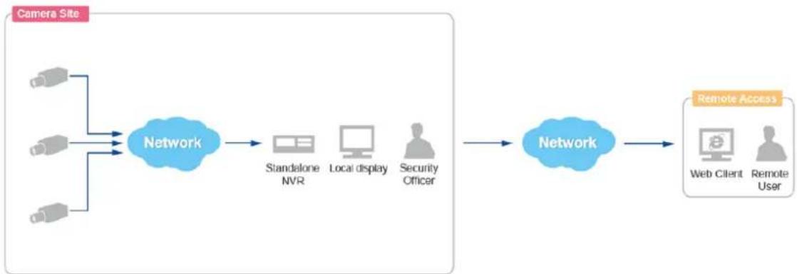
flowchart
graph LR
    A["Camera Site"] --> B["Network"]
    B --> C["Standalone NVR"]
    B --> D["Local display"]
    B --> E["Security Officer"]
    C --> F["Network"]
    D --> F
    E --> F
    F --> G["Remote Access"]
    G --> H["Web Client"]
    G --> I["Remote User"]
Remote User: Administrator / Supervisor / Manager / Security Officer
Remote Client PC Requirements
As ENR itself is a self-contained unit, the table below provides basic guidelines only for selecting proper hardware for the remote PC client. If your live view display quality is not satisfactory, please consider computers with more advanced spec as the decoding of multiple channels requires good hardware for smooth performance (*1).
| PC Spec (*2) | Minimum Requirements |
| CPU Processor | Intel Core 2 Quad 2.66 GHz |
| RAM | 4GB (*3) |
| Network | Ethernet (1000 Base-T recommended) |
| Operating System | Windows 7 and Windows 8(All versions) (*4) |
| Display Resolution | 1080p |
| Browser | Internet Explorer 9.0 or 10.0 |
*1 The quality of video display performance lies not only in the hardware but a few variables. Please refer to Error! Reference source not found. on page Error! Bookmark not defined. for instructions on how to achieve ideal video performance.
*2 PC spec requirements are the same for 32-bit and 64-bit systems.
*3 Microsoft Windows operating system has limits on memory and address space, regardless of the real or virtual memory available on a particular computer. Please use 64-bit system if your computer has more than 4GB RAM.
*4 Please make sure your operating system is fully patched with the latest service packs.
Supported Video Format
As 1080p HDMI monitors have become the most extensive display standard used in various applications, ENR is designed to conform to this standard with its capability of outputting 1080p video stream. Therefore, to reserve as much computing power for ENR unit as possible, up to four-megapixel H.264 video stream can be displayed on local live screen and local playback screen.
With a client computer, you may still acquire full support for displaying these types of video codec – MPEG4, MJPEG and H.264, and up to ten- megapixel video resolution from web client interface; also, the video stream is recorded at your desired format regardless of the displayed quality.
| Camera Management Export / Recording | Local Live View / Playback | Remote Live View / Playback | |
| Codec | MPEG4 MJPEG H.264 (*1) | H.264 (*2) | MPEG4 MJPEG H.264 |
| Resolution | Up to 10M pixels | Up to 4M pixels (*3) | Up to 10M pixels |
*1 ENR's "Auto Add" function will only add H.264 video streams.
*2 H.264 is the only displayable codec for local live view and playback. The channels using other codec will appear blank, although the recording is proceeding normally.
*3 ENR local live and playback can display up to four-megapixel resolution video. The channels using higher resolution video stream will appear blank, although the recording is proceeding normally.
Get Started
What's in the Box
This product package includes the following items:
| Item | Description |
| 1 | ENR Server x 1 |
| 2 | Printed quick installation guide x 1 |
| 3 | AC power adapter x 1 |
| 4 | Hard disk screws |
| 5 | Adapter converter set x 1 (For ENR110-120-130)This unit contains three types of adapter plugs – UK type, US type and Europe type.These adapter plugs do not change the voltage, but will only change the shape of adapter to fit your electrical outlet.Please detach the plugs, take the plug type you need and connect it to the AC power adapter. |
| 6 | USB Mouse x 1 |
At A Glance
ENR-110/120/130
Front Panel
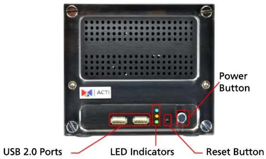
text_image
Power Button USB 2.0 Ports LED Indicators Reset ButtonRear Panel
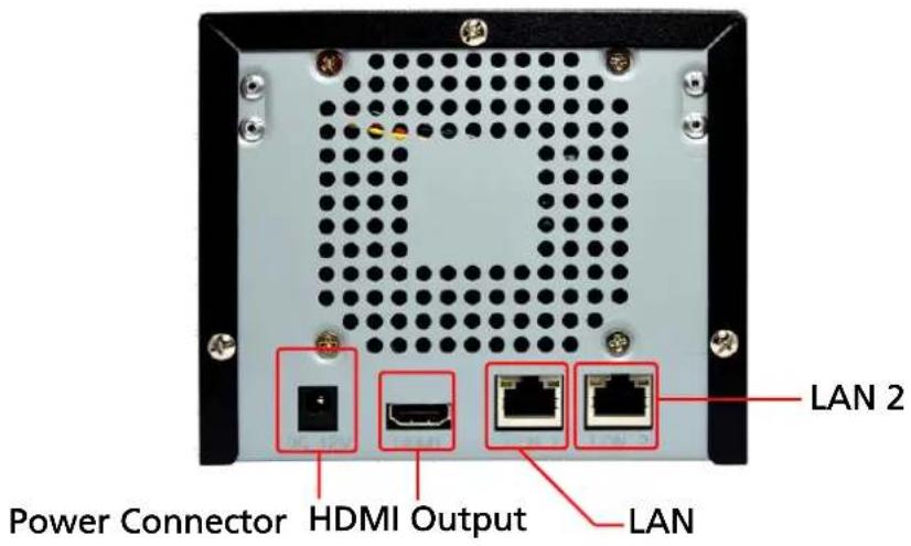
text_image
LAN 2 Power Connector HDMI Output LANENR-140
Front Panel
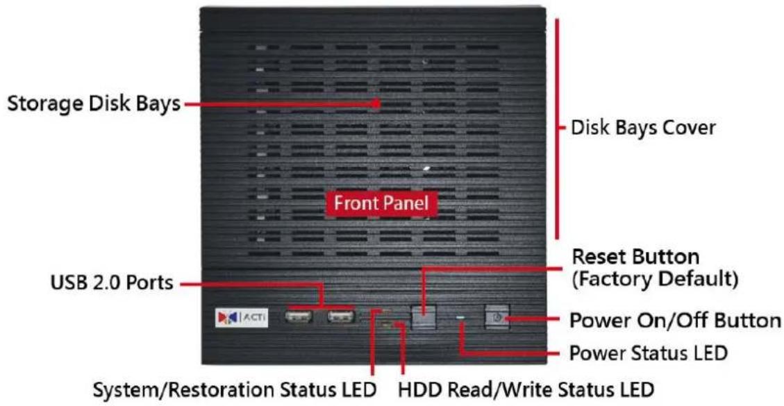
text_image
Storage Disk Bays Disk Bays Cover Front Panel USB 2.0 Ports Reset Button (Factory Default) Power On/Off Button Power Status LED System/Restoration Status LED HDD Read/Write Status LED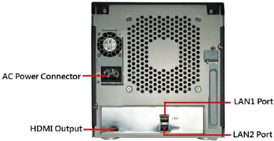
text_image
AC Power Connector HDMI Output LAN1 Port LAN2 PortPower Button & Reset Button
You can turn on / off the device with Power Button.
Turn On the Device
Press down the Power Button and release, the Power LED will light up and turn solid blue.
Turn Off the Device
As this unit is powered on, the Power LED and System LED are both lit, and the Power Button is in pressed state. To turn ENR off, please do the following:
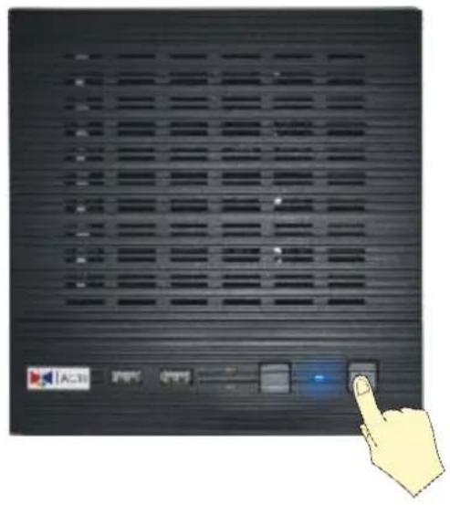
text_image
AC31 Power Control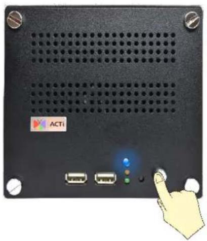
natural_image
Front view of a black electronic device with ports and a highlighted indicator light (no readable text or symbols)- On Live screen, click Setup → Power tab, and click "Shutdown".
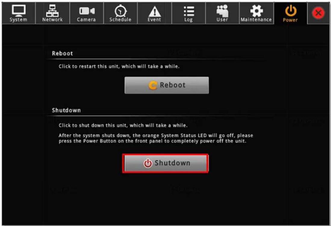
text_image
System Network Camera Schedule Event Log User Maintenance Power Reboot Click to restart this unit, which will take a while. Reboot Shutdown Click to shut down this unit, which will take a while. After the system shuts down, the orange System Status LED will go off, please press the Power Button on the front panel to completely power off the unit. Shutdown- The local display screen will turn black, with an information dialogue box showing up. Please observe the System LED on the front panel, when its orange light is off, you may press the Power Button to completely shut down the unit.
Reset to Factory Default
By resetting this device, all your system settings and system log will return to factory default. It is strongly recommended that you back up previous settings with Backup function and export the system logs before resetting to factory default.
- To begin, please turn off the device first.
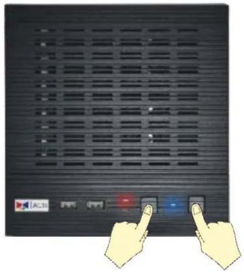
- Press down the Power Button to boot up the device, and immediately press and hold the Reset Button with a pin or clip, the System LED will light up for about 2\~3 seconds, and you may release the Reset Button as the red light is off.
The device will enter the resetting process immediately and automatically restart.
text_image
Diagram showing two hands pointing at a control panel with AC input and power, labeled in Chinese.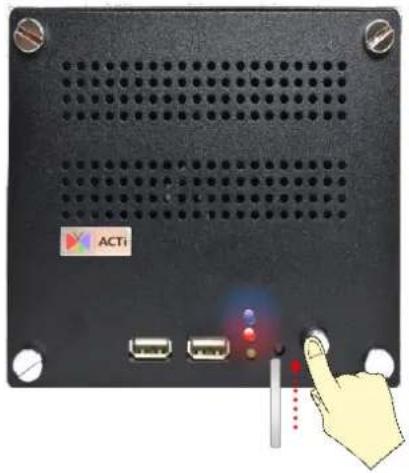
natural_image
Front view of a black electronic device rear panel with ports and indicator lights, no visible text or symbolsLED Indicators
The LED indicators on front panel show the current device status:
| Item | Indicator Status | Light Color | Description |
| Power LED | Solid | Blue | The device power is on. |
| System Status LED | Lights up for three seconds after Reset Button is pressed | Orange | The system resetting process is initializing. |
| Solid | The system service is running. | ||
| HDD LED | Flashing | Green | The hard disk is in activity. |
Installation
The installation procedures may vary depending on your site conditions. The procedures provided in this manual are based on an example consisting of (1) local network, (2) an ENR unit, (3) ACTi network cameras, (4) a POE network switch and (5) necessary peripherals.
Prepare the Devices
Before starting connecting all the devices together, please read the instructions below to make sure your devices are ready for ENR system.
Cameras
ENR is able to automatically add the connected cameras then immediately displays their live streams without your further configurations. Please fulfill the conditions below to make sure your cameras are ready for ENR Auto Add function:
- For a camera whose settings have been changed from factory default, make sure its output stream is H.264 encoder type.
- The camera's connection type is Dynamic mode (DHCP Client). You can configure the this connection settings via Web Configurator.
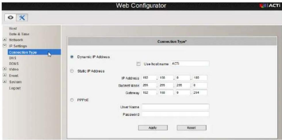
text_image
Web Configurator Host Date & Time Network IP Settings Connection Type DNS DDNS Video Event System Logout Connection Type* Dynamic IP Address Use host name ACTI Static IP Address IP Address 192 108 0 100 Subset Mask 255 255 255 0 Gateway 192 168 0 254 PPPoE User Name Password Apply Reset(ACTi camera web configurator interface)
If your camera is an other brand's product or you would like to add more streams from a device, use Search Cameras provided by Camera Setup Wizard.
Note
Since ENR displays only H.264 stream on local display, any device outputting non-H.264 stream will still be added to ENR system and viewed via the web client interface, while this channel will appear blank on local monitor.
Monitor
The monitor should supports HDMI port and 1080p full HD resolution display.
USB Devices
Please use a USB mouse, keyboard or joystick with a cable.
USB Storage Device
●The USB storage device is required for system backup and system log / snapshot / video export.
●ENR supports all FAT/FAT32/EXT2/EXT3/EXT4/NTFS file systems.
Hard Disks
For video recordings, you should install at least ONE certified 3.5-inch SATA hard disk.
Please always use the hard disks ACTi tested to be compatible with ENR. You may find the certified models with ACTi Hard Disk Selector http://www.acti.com/hddselector.
Install the Hard Disks
This system requires at least one hard disk to store video recordings and firmware image when upgrading system. Please follow the instructions below to install your hard disks in correct order to make sure the physical disk locations accord with the Disk ID shown in ENR server's Storage Device List.
ENR-110/120/130
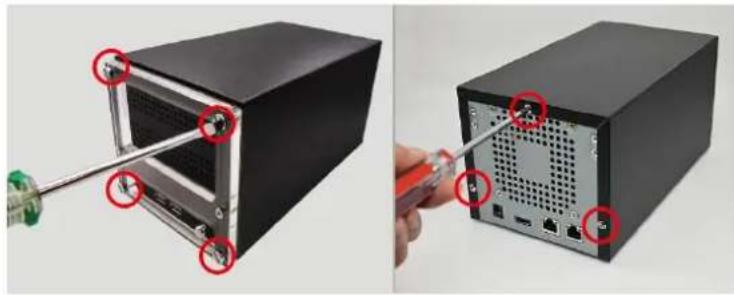
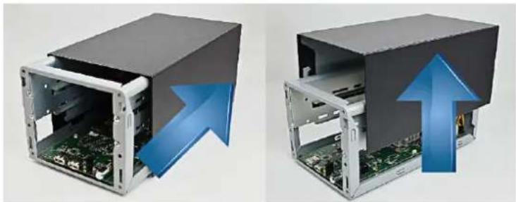
Step 1 Remove the Case Cover
natural_image
Two views of a server rack with a screwdriver inserted, showing internal components and ports (no text or symbols visible)Remove the four front panel screws, and then remove the three back panel screws.
natural_image
Two views of an open computer case with visible internal components and blue arrows indicating upward motion (no text or symbols)Slide the case backward until it stops, and then lift it up to remove.
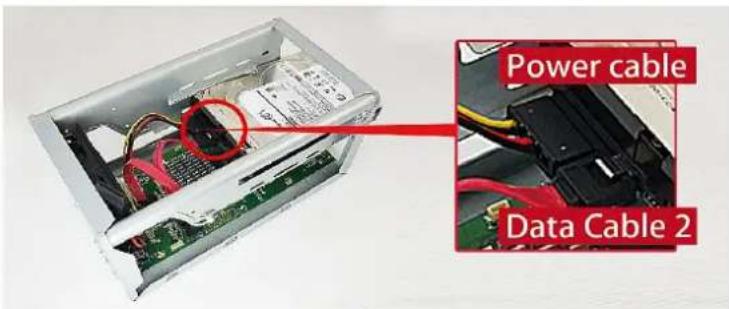
Step 2 Install Disk SATA-2
text_image
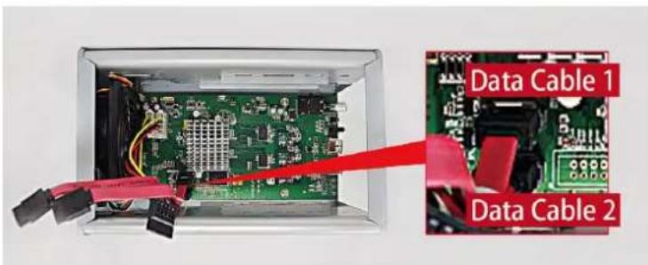
Power cable Data Cable 2Insert Disk SATA-2 in the lower bay, connect SATA power cable and SATA data cable 2 to the hard disk.
text_image
Data Cable 1 Data Cable 2Make sure you connect the correct data cable to the corresponding disk.
natural_image
Interior view of an electronic device showing internal components and wiring (no readable text or symbols)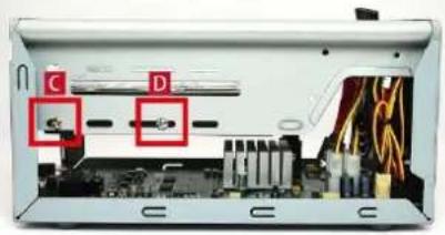
natural_image
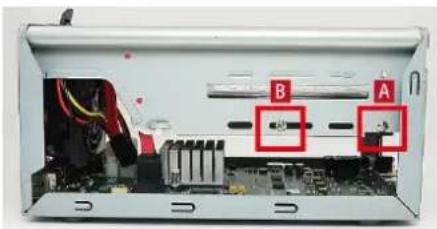
Interior view of an electronic device showing internal components and circuitry (no visible text or symbols)Lock Disk
SATA-2 using
disk screws in
this sequence:
A→B→C→D
Step 3 Install Disk SATA-1
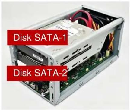
text_image
Disk SATA-1 Disk SATA-2Repeat Step1\~Step3 to install Disk SATA-1 to the upper bay. Remember to connect Disk SATA-1 with SATA data cable 1 shown in the illustration in Step 2.
Step 4 Install the Case Cover Back
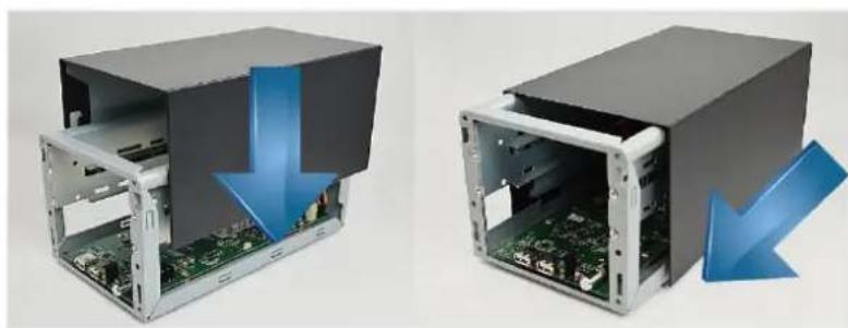
natural_image
Two views of an open computer case showing internal components and a blue downward arrow indicating compression or disassembly (no text or symbols present)Install the case in reverse order of removal step (see Step 2), slide the case cover back until it clicks. Lock the back panel and then front panel with its screws.
ENR-140
Please follow the instructions below to install your hard disks in correct order to make sure the physical disk locations accord with the Disk ID shown in ENR server's Storage Device List.
To start, TURN OFF THE DEVICE, open the front cover, repeat the following steps to install the hard disks into the disk bays.
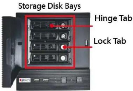
text_image
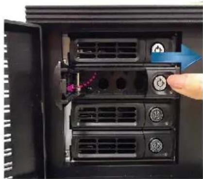
Storage Disk Bays Hinge Tab Lock TabStep 1 Remove the Tray
natural_image
Close-up of a computer tower drive showing ventilation slots and buttons, with a hand adjusting the button (no visible text or symbols)Slide the Lock Tab to the right, the Hinge Tab will pop out by itself. Remove the four front panel screws, and then remove the three back panel screws.
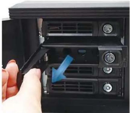
natural_image
Close-up of a hand inserting a device into a rack-mounted server unit, showing ventilation slots and a blue arrow indicating the direction (no text or symbols visible)Pull the Hinge Tab to 90 degrees from the front, and pull out the tray.
Step 2 Mount the Disk
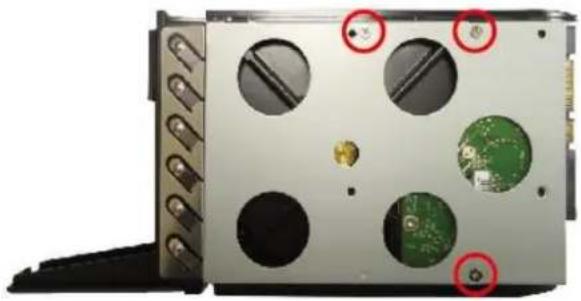
natural_image
Close-up of a computer case with green circuit boards and circular components, no visible text or symbolsMount the disk by locking it with supplied disk screws to the bottom of the tray.
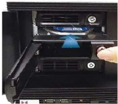
Step 3 Install the Tray
natural_image
Close-up of a computer drive bay with a hand inserting a component into the top panel (no visible text or symbols)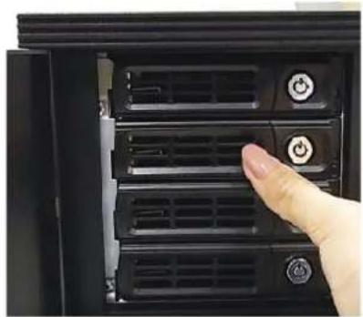
natural_image
Close-up of a hand pressing down on a black server rack with multiple ventilation slots and control buttons (no visible text or symbols)Press on Lock Tab, push the tray into the bay until it stops.
Finally, close the Hinge Tab.
Network Connection Architecture
When connecting ENR with your network, please make sure you plug the network cable into the right port.
ENR-110/120/130
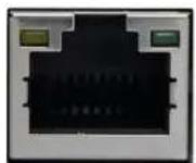
LAN 1 Port (Camera Port)
Default: 192.168.0.10
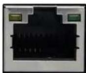
LAN 2 Port (WAN Port)
Default: Dynamic /192.168.1.10
ENR-140
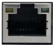
LAN 1 Port (Camera Port)
Default: 192.168.0.10
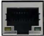
LAN 2 Port (WAN Port)
Default: Dynamic /192.168.1.10
LAN 1 Port
LAN 1 port is the default camera port for a typical local network. Via this port, the DHCP server built in ENR automatically assigns IP addresses to network cameras once they are connected. With this feature, you do not have to bother arranging the camera IP addresses on your own. By default, this DHCP server is enabled, so please avoid connecting ENR to a network where exits another DHCP server via this port.
Connection Setting Example 1
Below diagram displays an example connection setting using only LAN1 to connect networks cameras.
In this setting, ENR altogether with cameras are within the same network segment; in the mean time, there is no need of referencing another DHCP server in this system.
ENR-110/120/130
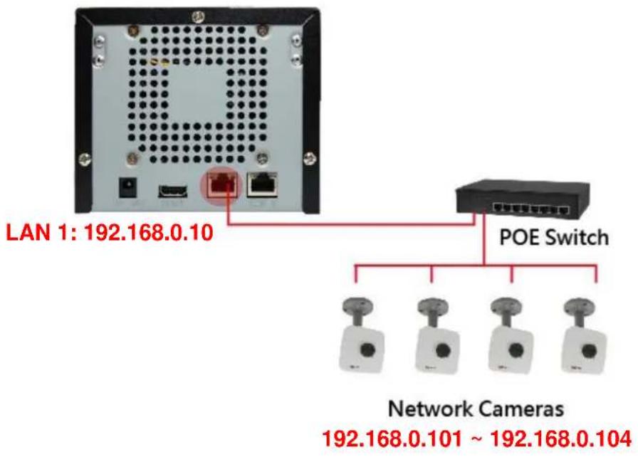
text_image
LAN 1: 192.168.0.10 POE Switch Network Cameras 192.168.0.101 ~ 192.168.0.104ENR-140
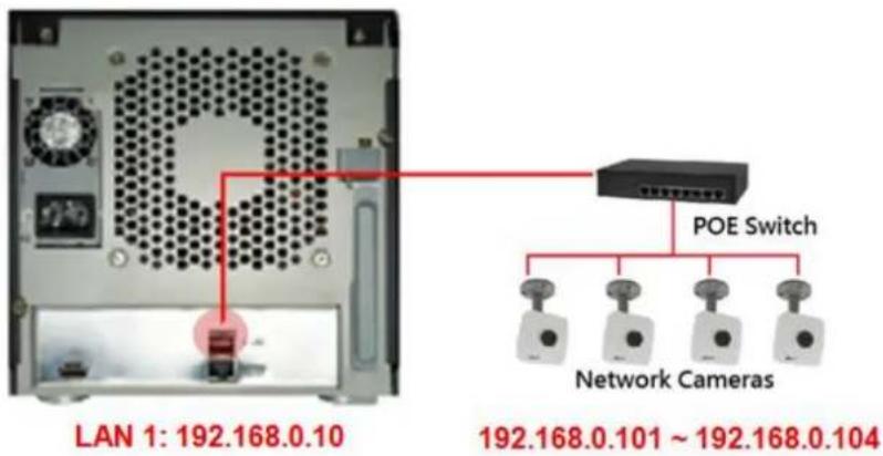
text_image
LAN 1: 192.168.0.10 POE Switch Network Cameras 192.168.0.101 ~ 192.168.0.104LAN 2 Port
LAN2 port is a typical Ethernet port. You will have to use this port to connect with a different network segment when your system requires (1) the connection with a remote PC client or network cameras, (2) the use of event-triggered e-mail service via an external SMTP server (3) the use of date/time synchronization with external NTP server.
By default, once connecting to a network, it will first try to get an IP address assigned by your network router from DHCP server. If your network does not assign IP address automatically, then LAN2 port will assume IP address 192.168.1.10.
Connection Setting Example 2
The diagram below displays an example connection setting using LAN1 + LAN2 to connect networks cameras within different network segments.
In this setting, ENR with three cameras are within the same network segment, while there is another camera locating in another network. In addition, this system requires the connection with an external SMTP server and a remote client.
ENR-110/120/130
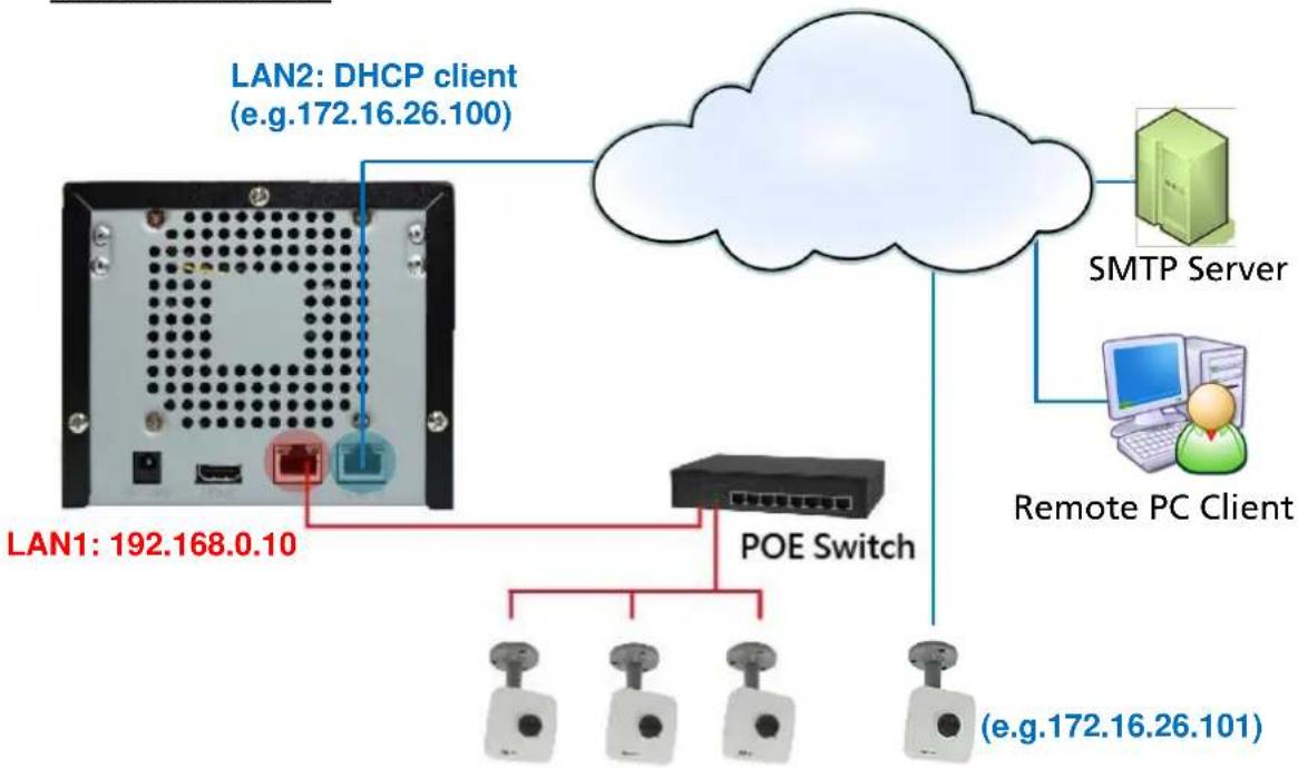
flowchart
graph TD
    A["LAN1: 192.168.0.10"] --> B["POE Switch"]
    C["LAN2: DHCP client (e.g.172.16.26.100)"] --> B
    D["Remote PC Client"] --> E["SMTP Server"]
    B --> F["(e.g.172.16.26.101)"]
Network Cameras
(EX:192.168.0.101 \~ 192.168.0.103)
ENR-140

flowchart
graph TD
    A["DHCP client LAN 2"] --> B["Network Cameras"]
    B --> C["POE Switch"]
    C --> D["SMTP Server"]
    D --> E["Remote PC Client"]
    style A fill:#f9f,stroke:#333
    style B fill:#ccf,stroke:#333
    style C fill:#cfc,stroke:#333
    style D fill:#fcc,stroke:#333
    style E fill:#cff,stroke:#333
You
may check and modify the network configurations by going to Live screen → select "Setup" → click Network tab. (For detailed configuration instructions, please refer to Network Settings on page 52).
Connect the Devices
Follow the procedures to connect the devices. These devices are supposed to be connected in the sequence shown below.
ENR-110/120/130
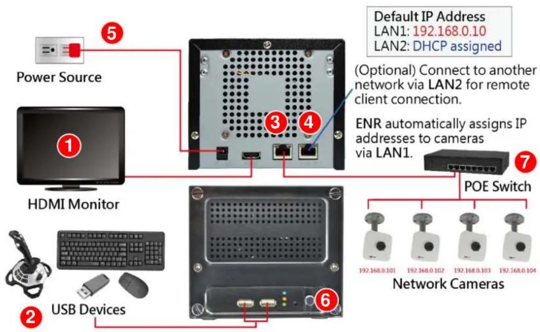
text_image
Default IP Address LAN1: 192.168.0.10 LAN2: DHCP assigned (Optional) Connect to another network via LAN2 for remote client connection. ENR automatically assigns IP addresses to cameras via LAN1. POE Switch Network Cameras Power Source HDMI Monitor USB Devices- Connect the HDMI monitor.
- Connect the USB devices.
- Attach the network cable to LAN1 port.
- Attach the network cable to LAN2 port. (Optional, required for remote client connection)
- Plug the power adapter into ENR and electricity outlet.
- Press down Power Button to start the device, the power status LED will turn solid blue.
- Connect the network cameras to the switch and power them on.
ENR-140

flowchart
graph TD
    A["Power Source"] --> B["DC Unit"]
    B --> C["POE Switch"]
    C --> D["Network Cameras"]
    D --> E["Remote Client"]
    D --> F["SMTP Server"]
    B --> G["HDMI Monitor"]
    G --> H["USB Devices"]
    H --> I["Network"]
    style A fill:#f9f,stroke:#333
    style B fill:#ccf,stroke:#333
    style C fill:#cfc,stroke:#333
    style D fill:#fcc,stroke:#333
    style E fill:#cff,stroke:#333
    style F fill:#ffc,stroke:#333
    style G fill:#cfc,stroke:#333
    style H fill:#fcc,stroke:#333
    style I fill:#cff,stroke:#333
- Plug the power adapter into ENR and electricity outlet.
- Connect the HDMI monitor.
- Connect the USB devices.
- Press down Power Button. The power status LED will turn solid blue.
- Attach the network cables to LAN1 Port.
- Connect the network cameras to the switch and power them on.
- Attach the network cables to LAN2 Port. (Optional, required for the access to another network)
Quick Setup
By the first time you log in to ENR, the Setup Wizard with bring you through the initial setup process. By finishing the quick setup, you will enter live screen immediately.
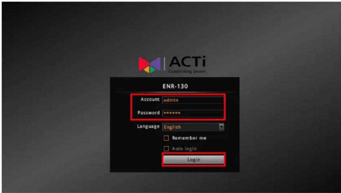
Step 1: Log in to ENR
After the device starts, you will first see ACTi splash screen then system interface.

text_image
ACTi Connecting VisionOn Login window. Click into the Account and Password fields to enter the default account information - admin / 123456, then click "Login".
text_image
ACTi Connecting Vision ENR-130 Account admin Password ******** Language English Remember me Auto login LoginStep 2: Format the Hard Disks
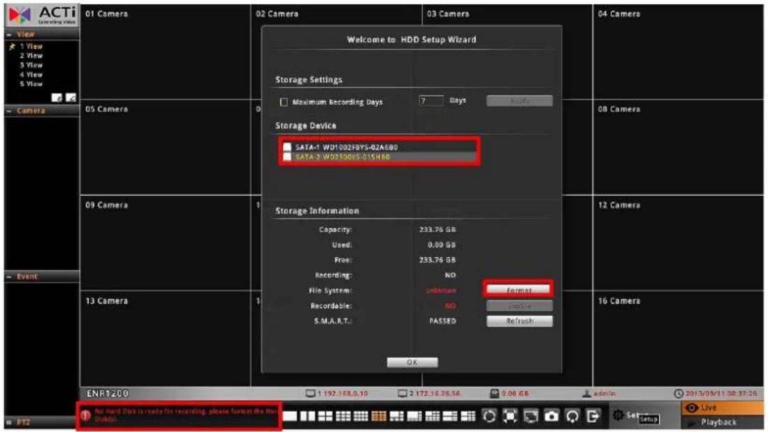
At present, the hard disks you installed in ENR are not ready for recording, they need formatting before use.
text_image
ACTi Drawing video 01 Camera 02 Camera 03 Camera Welcome to HDD Setup Wizard Storage Settings Maximum Recording Days 7 Days Supply Storage Device SATA-1 WD1002FBYS-02A6B0 SATA-2 WD2500V5-01SH80 Storage Information Capacity: 233.76 GB Used: 0.00 GB Free: 233.76 GB Recording: NO File System: Unknown Format Recordable: NO S.M.A.R.T.: PASSED Refresh 12 Camera 13 Camera 1 OK ENR1200 1 192.168.0.10 2 172.16.26.56 3:00 GB admin 2013/09/11 00:37:26 PT2 Live PlaybackOn HDD Setup Wizard window, select the unformatted disk and click "Format". Repeat this step to format the other disk, and then click "OK". As ENR has successfully formatted a hard disk, a message will pop out to notify you. After a successful formatting, the file system of the disk will show "ENR-FS", and this disk will immediately become ready for recording,

text_image
(Not Formatted) (Formatted) File System: unknown File System: ENR-FS Recordable: NO Recordable: YESStep 3: Add Cameras
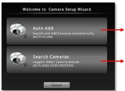
Please select Auto Add to automatically add cameras or Search Cameras to select cameras by yourself.
text_image
Welcome to Camera Setup Wizard Auto Add Search and Add Cameras Automatically (ACTI+H.264) Search Cameras Support Other Camera Brands (ACTI.AXIS.SONY.VIVOTEK) CancelThis will add detected H.264 video streams and display all video streams on Live screen right away
Search all the cameras including supported other brand cameras within your current network segment.
Auto Add
By using Auto Add function, ENR will add the first detected H.264 streams. Please input the Account and Password (this user account must be the camera's root account) to access the cameras.
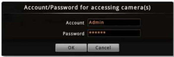
text_image
Account/Password for accessing camera(s) Account Admin Password ***** OK Cancel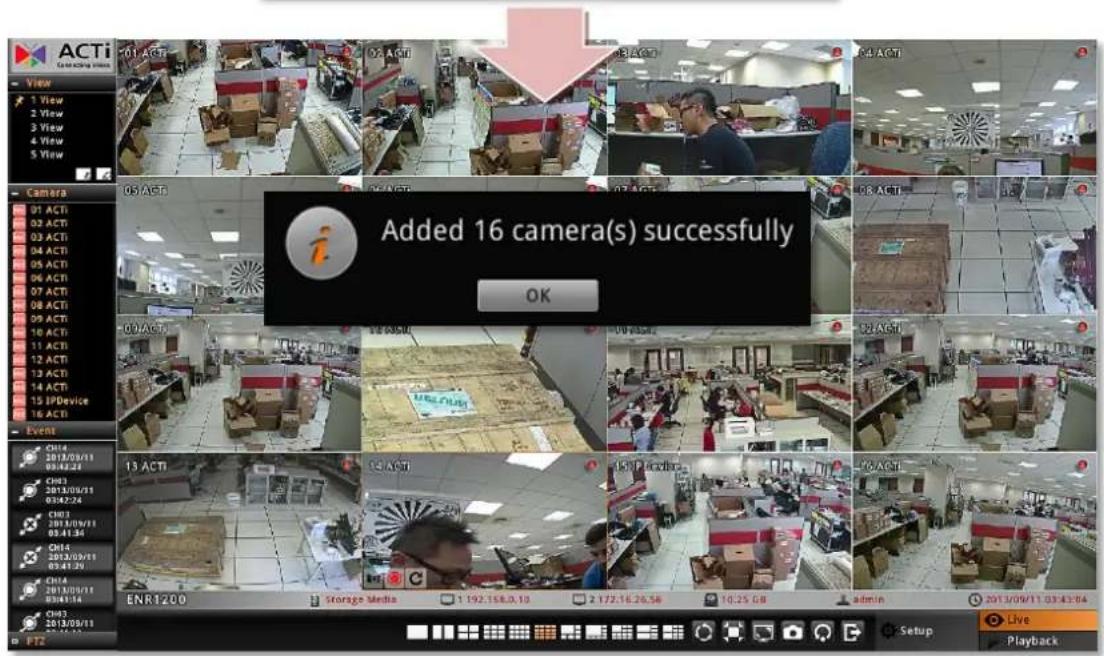
text_image
Added 16 camera(s) successfully OKSearch Cameras
Search Cameras allows you to select desired cameras and streams from multi-streaming devices, including other brand cameras.
- Select the camera manufacturer.
- Input the Account and Password to access the cameras (this user account must be the camera's root account).
- Click "Search".
- Select your desired cameras and click "Add". Please note that your clicking order will decide Live View channels arrangement. For example, you select cameras on the search list in this order: TCM-4511 → TCM-5111 → D11 → E52, which will exactly become the channel order: 01 Camera → 02 Camera → 03 Camera → 04 Camera
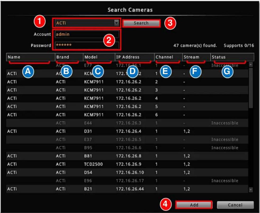
text_image
Search Cameras 1 ACTi Search 3 Account admin Password ***** 2 47 camera(s) found. Supports 0/16 Name Brand Model IP Address Channel Stream Status ACTI ACTi E77 172.16.26.1 1 - Inaccessible ACTI ACTi KCM C 172.16.26.2 1 - F G ACTI ACTi KCM7911 172.16.26.2 2 - ACTI ACTi KCM7911 172.16.26.2 3 - ACTI ACTi KCM7911 172.16.26.2 4 - ACTI ACTi KCM7911 172.16.26.2 5 - ACTI ACTi KCM7911 172.16.26.2 6 - ACTI ACTi E44 172.16.26.3 1 - Inaccessible ACTI ACTi D31 172.16.26.4 1 1,2 ACTI ACTi E37 172.16.26.5 1 - Inaccessible ACTI ACTi B95 172.16.26.6 1 - Inaccessible ACTI ACTi B81 172.16.26.8 1 1,2 ACTI ACTi TCD2500 172.16.26.9 1 1,2 ACTI ACTi DS4 172.16.26.10 1 1,2 ACTI ACTi E96 172.16.26.17 1 - Inaccessible ACTI ACTi B21 172.16.26.44 1 1,2 Add Cancel| No | Column | Description |
| A | Name | The camera models will be listed in alphabet order based on their model names. |
| B | Brand | Camera manufacturer |
| C | Model | Camera model name |
| D | IP Address | Camera IP Address |
| E | Channel | Represents video stream ID. For example, if a camera is in 4VGA mode, all four streams will be recognized as from four different devices, and so forth to a multi-channel video encoder. |
| F | Stream | Displays the camera's dual-streaming status. If this camera is in dual streaming mode, this status will shows “1,2”. ENR will take stream 1 for live view display, and stream 2 for recording. |
| G | Status | Blank: this camera is accessible and not added yet.In Use: this camera/stream has been added to the system.Inaccessible: this camera is inaccessible. You will have to try accessing it using another Username or Password, (make sure this account is that camera's root account), and click Search. |
Local Client Operation
Log in to / out of ENR
By default, an administrator account has already been existing in your system. To log in to ENR for the first time, you will have to key in the password in Login window.
Log In
If you are not logged in yet, click on screen to bring up the Login window.
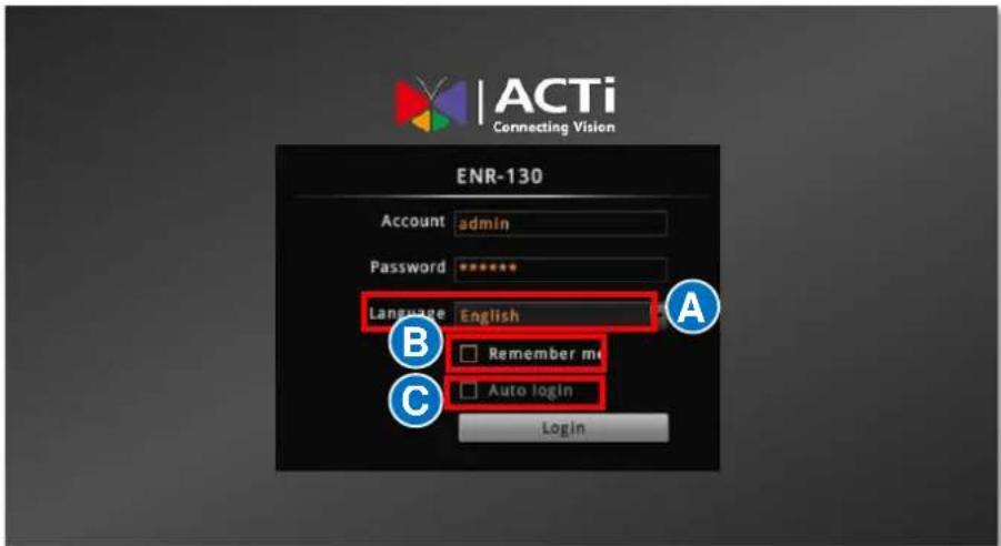
text_image
ACTi Connecting Vision ENR-130 Account admin Password ****** Language English Remember me Auto login LoginChange UI language A
To change UI language, select the desired language from "Language" dropdown list.
Remember Login Information B
To have the server remember your Account, Password and language setting for future, check "Remember me".
Set Auto Login ©
Check "Remember me" then "Auto Login", you will skip the Login page and directly enter Live screen when accessing ENR in the future. This feature makes using ENR more convenient, however it may pose a security risk because any other user can enter ENR using the account you established. The Remember me and Auto-login function will be cancelled when you logout from ENR.
Log Out
On Live screen, click "Logout NVR"
Live Page UI Overview
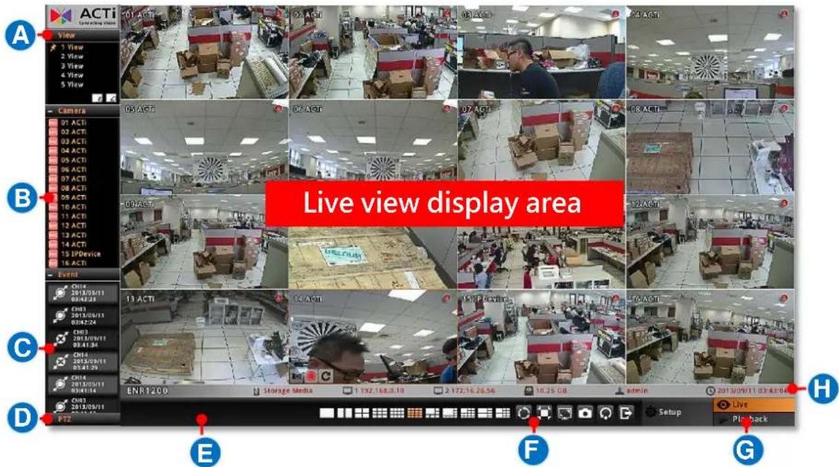
After logging in, you will enter Live screen. Live screen is the interface where you see the live views from your cameras. It is where most of the security professionals access the surveillance system
text_image
Live view display area A View 1 View 2 View 3 View 4 View 5 View B Event CH14 2013/05/11 08:42:28 CH03 2013/06/11 09:42:24 CH03 2013/09/11 05:41:34 CH03 2013/09/11 05:41:29 CH14 2013/09/11 09:41:24 CH03 2013/09/11 PTZ E F G H Storage Media 1 192.168.0.10 2 172.16.26.56 10.25 GB admin 2013/09/11 03:43:04 Live Play back| No | Description |
| A | View List:Lists five views available for customization. |
| B | Camera List:Lists all the connected cameras and their recording status. |
| C | Event List:Displays alerts of detected motion, recording and connection status. |
| D | PTZ Control PanelProvides live onscreen PTZ controls. This panel is only enabled when a PTZ camera channel is selected on live view display area. |
| E | System MessageDisplays import messages to inform you of certain system conditions that require your prompt action. |
| F | Live MenuLists available layout selection and live view operation controls |
| G | Page SwitchYou may switch to the Setup or Playback page by clicking the tags. The Setup page is only accessible from Live page. |
| H | System Status:Displays the following system status from left to right – (1) connected USB storage device, (2) LAN1 IP address, (3) LAN2 IP address, (4) total free disk space, (5) your user account and (6) current system time. |
Input Devices
The physical input devices (e.g. USB mouse and USB keyboard) are ready to use when you connect them to ENR via USB ports.
Onscreen Keyboard
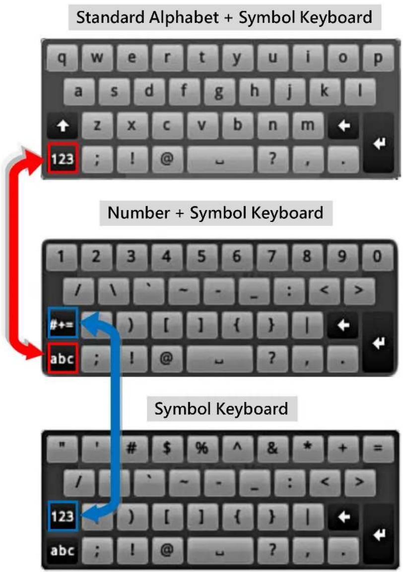
The onscreen keyboards allow you to input characters without using a physical one. By clicking in a character field (e.g. Account or Server name) or number field (e.g. IP address or Port), the specific onscreen keyboard will be brought up.
text_image
Standard Alphabet + Symbol Keyboard q w e r t y u i o p a s d f g h j k l ↑ z x c v b n m ← 123 ; ! @ ~ ? , . Number + Symbol Keyboard 1 2 3 4 5 6 7 8 9 0 / \ ` ~ - _ : < > #+= ) [ ] { } | ← abc ; ! @ ~ ? , . Symbol Keyboard " ' # $ % ^ & * + = / ` ~ - _ : < > 123 ) [ ] { } | ← abc ; ! @ ~ ? , .Mouse Settings
You may adjust the mouse's cursor speed via the path below:
On Live screen, click Setup → select System tab → click "Mouse".

text_image
System Network Camera Schedule Event Log User Maintenance Power Information Date and Time Email Mouse Keyboard Joystick Cursor Speed Click buttons to adjust mouse cursor speed. Slow Fast - +Onscreen Keyboard Settings
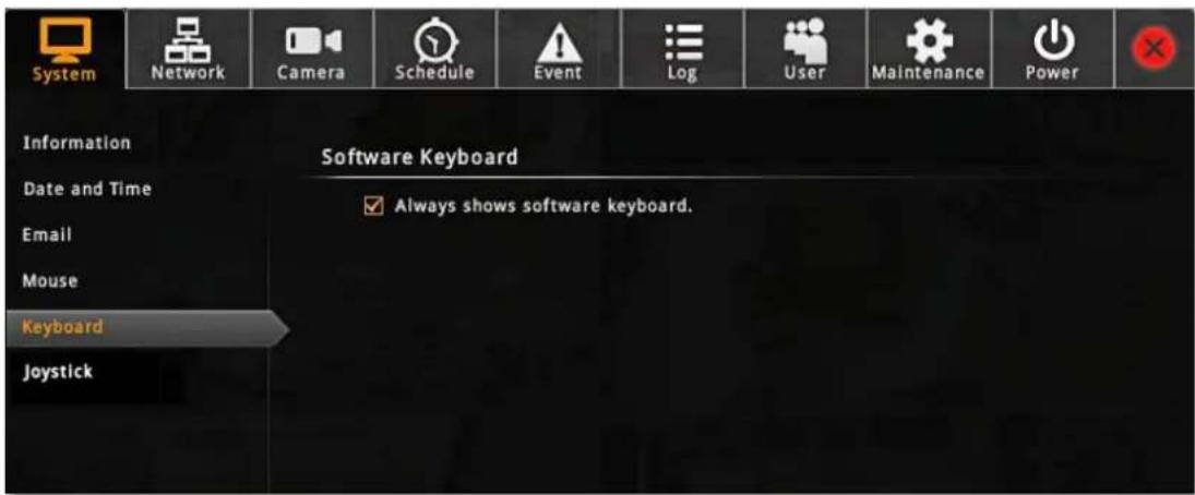
To disable the virtual keyboard if a physical one is already in use, on Live screen, click Setup → System tab → click "Keyboard". Uncheck the box "Always shows software keyboard".
text_image
System Network Camera Schedule Event Log User Maintenance Power Information Date and Time Email Mouse Keyboard Joystick Software Keyboard ✓ Always shows software keyboard.Set Cameras
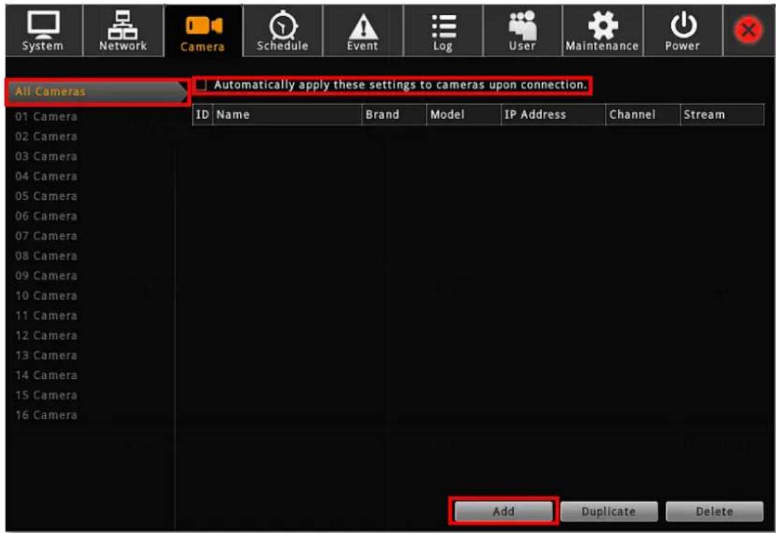
ENR user interface also allows you to easily configure, add or delete cameras without the use of another web browser. On Live page, click Setup → Camera tab. "All Cameras" display all the added cameras, click "Add" to start adding cameras.
text_image
System Network Camera Schedule Event Log User Maintenance Power All Cameras Automatically apply these settings to cameras upon connection. 01 Camera ID Name Brand Model IP Address Channel Stream 02 Camera 03 Camera 04 Camera 05 Camera 06 Camera 07 Camera 08 Camera 09 Camera 10 Camera 11 Camera 12 Camera 13 Camera 14 Camera 15 Camera 16 Camera Add Duplicate DeleteNote
ENR will synchronize with devices upon connecting to them. To make sure the settings on ENR side are prior to those on camera sides, please check "Auto save ENR settings into device upon connection". When this function is enabled, every modification you make via camera web configurator will be overwritten by ENR.
text_image
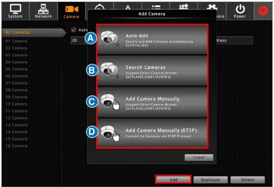
All Cameras 01 Camera 02 Camera 03 Camera 04 Camera 05 Camera 06 Camera 07 Camera 08 Camera 09 Camera 10 Camera 11 Camera 12 Camera 13 Camera 14 Camera 15 Camera 16 Camera Add Camera Auto Add Search and Add Cameras Automatically (ACTI+H.264) Search Cameras Support Other Camera Brands (ACTI,AXIS,SONY,YIVOTEK) Add Camera Manually Support Other Camera Brands (ACTI,AXIS,SONY,YIVOTEK) Add Camera Manually (RTSP) Connect to Cameras via RTSP Protocol Cancel Add Duplicate DeleteAdd Cameras
Click "Add". There are four methods you can use to add cameras:
(A) Click Auto Add to let ENR add the channels automatically. This is the same quick method provided by Camera Setup Wizard; please refer to Auto Add on page 33 for instructions.
(B) Click Search to scan through the available video sources, and select desired cameras to add by yourself. This is the same quick method provided by Camera Setup Wizard, please refer to Search Cameras on page 33 for instructions.
(C) You can add a camera by manually filling the connections properties. For cameras which are not located within the same network segment with ENR server, you may add it manually.
- Select a Camera ID from the Camera List on the left, and click "Add Camera Manually".
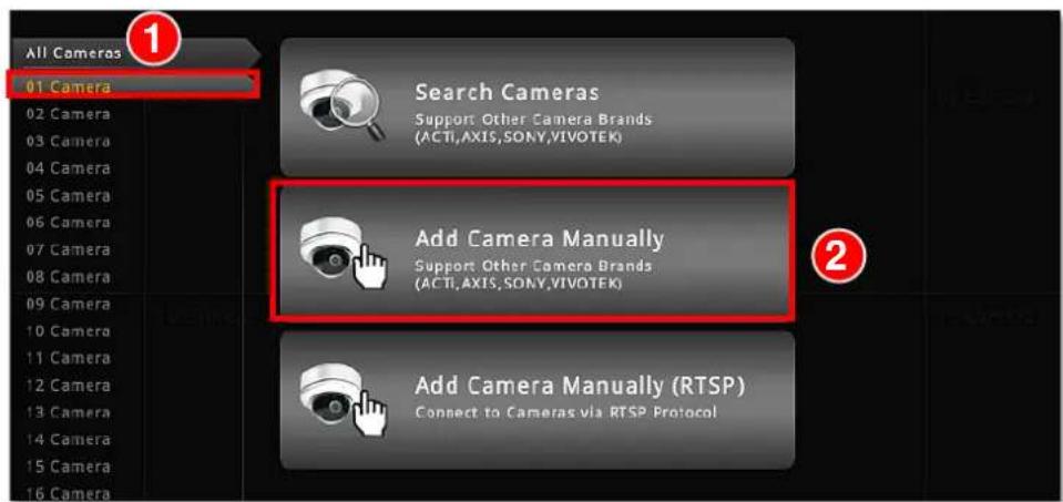
text_image
All Cameras 01 Camera Search Cameras Support Other Camera Brands (ACTI,AXIS,SONY,VIVOTEK) Add Camera Manually Support Other Camera Brands (ACTI,AXIS,SONY,VIVOTEK) Add Camera Manually (RTSP) Connect to Cameras via RTSP Protocol- Fill in the connection properties such as properties IP Address, Port, Username and Password, and click "Get Camera Settings".
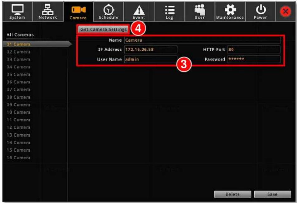
text_image
System Network Camera Schedule Event Log User Maintenance Power All Cameras Get Camera Settings 4 Name Camera IP Address 172.16.26.58 HTTP Port 80 User Name admin Password ***** 3- The camera settings will appear. Click "Save" to save it to this camera channel.
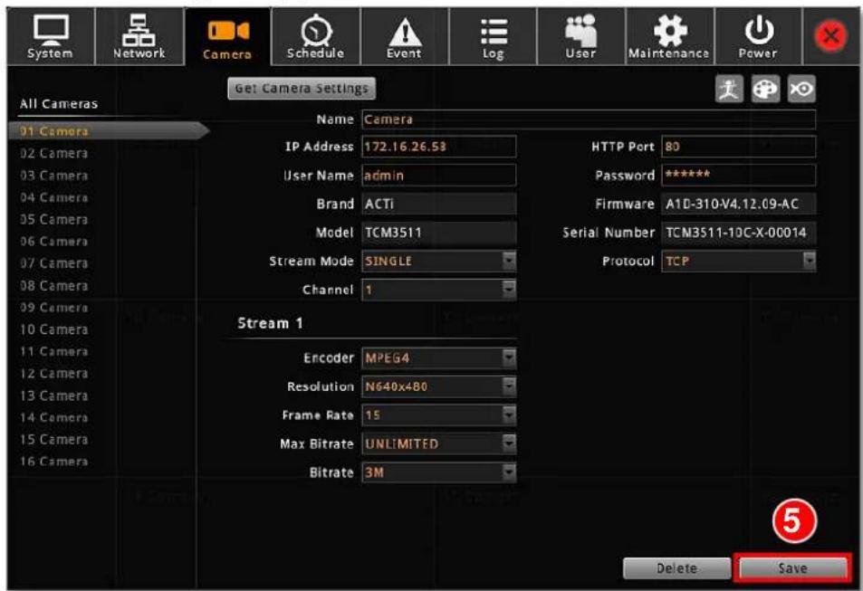
text_image
System Network Camera Schedule Event Log User Maintenance Power All Cameras Get Camera Settings 01 Camera Name Camera IP Address 172.16.26.58 User Name admin Brand ACTi Model TCM3511 Stream Mode SINGLE Channel 1 HTTP Port 80 Password ***** Firmware A1D-310-V4.12.09-AC Serial Number TCM3511-10C-X-00014 Protocol TCP Stream 1 Encoder MPEG4 Resolution N640x480 Frame Rate 15 Max Bitrate UNLIMITED Bitrate 3M Delete Save(D) You can manually add a camera through RTSP protocol without to the camera brand.
- Select a Camera ID from the Camera List on the left, and click "Add Camera Manually (RTSP)".
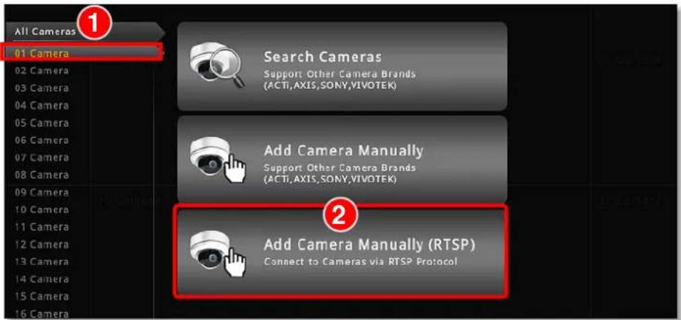
text_image
All Cameras 01 Camera Search Cameras Support Other Camera Brands (ACTI,AXIS,SONY,VIVOTEK) Add Camera Manually Support Other Camera Brands (ACTI,AXIS,SONY,VIVOTEK) Add Camera Manually (RTSP) Connect to Cameras via RTSP Protocol- Fill in the properties, make sure you select the correct URI type and Protocol type, and then click "Save".
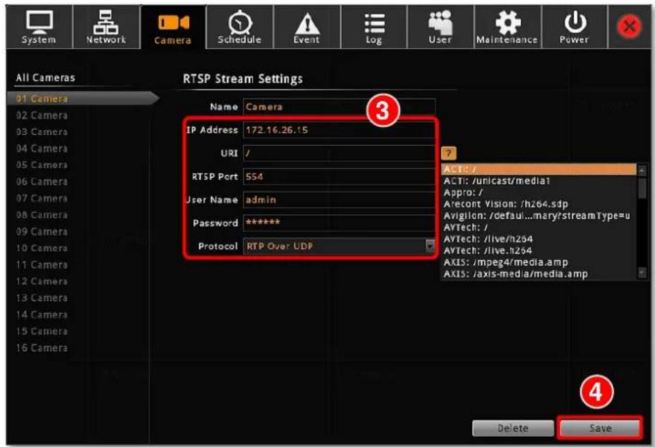
text_image
All Cameras RTSP Stream Settings 01 Camera Name Camera IP Address 172.16.26.15 URI / RTSP Port 554 User Name admin Password ***** Protocol RTP Over UDP 3 ? ACT: / ACTI: /unicast/media1 Appro: / Arecont Vision: /h264.sdp Avigilon: /default...mary/streamType=u AVTech: / AVTech: /live/h254 AVTech: /live.h254 AXIS: /mpeg4/media.amp AXIS: /axis-media/media.amp Delete SaveCopy Camera Settings
You may copy an added camera's settings to another empty channel. In this way, it is easier to manually add more than one camera of the same models.
On Camera tab, enter All Camera list, select the cameras you want to dupliacate, and click "Duplicate" The new cameras will be added to the list.
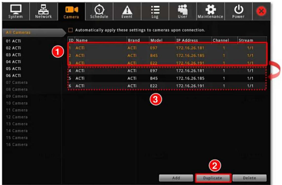
text_image
System Network Camera Schedule Event Log User Maintenance Power All Cameras Automatically apply these settings to cameras upon connection. ID Name Brand Model IP Address Channel Stream 1 ACTI ACTI E97 172.16.26.181 1 1/1 2 ACTI ACTI B45 172.16.26.185 1 1/1 3 ACTI ACTI E22 172.16.26.191 1 1/1 4 ACTI ACTI E97 172.16.26.181 1 1/1 5 ACTI ACTI B45 172.16.26.185 1 1/1 6 ACTI ACTI E22 172.16.26.191 1 1/1 Add Duplicate DeleteDelete Cameras
You may delete one channel at a time or delete more all at once.
On Camera tab, enter All Camera list, select the cameras you want to delete, and click "Delete". To deletae multiple cameras at once, you can use the mouse to drage out a selection range and then select "Delete".
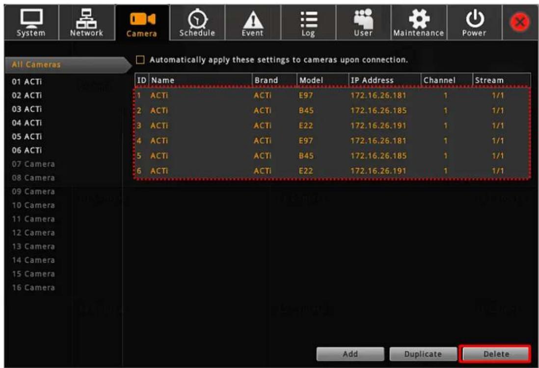
text_image
System Network Camera Schedule Event Log User Maintenance Power All Cameras Automatically apply these settings to cameras upon connection. 01 ACTi 02 ACTi 03 ACTi 04 ACTi 05 ACTi 06 ACTi 07 Camera 08 Camera ID Name Brand Model IP Address Channel Stream 1 ACTi ACTi E97 172.16.26.181 1 1/1 2 ACTi ACTi B45 172.16.26.185 1 1/1 3 ACTi ACTi E22 172.16.26.191 1 1/1 4 ACTi ACTi E97 172.16.26.181 1 1/1 5 ACTi ACTi B45 172.16.26.185 1 1/1 6 ACTi ACTi E22 172.16.26.191 1 1/1 Add Duplicate DeleteChange Camera Settings
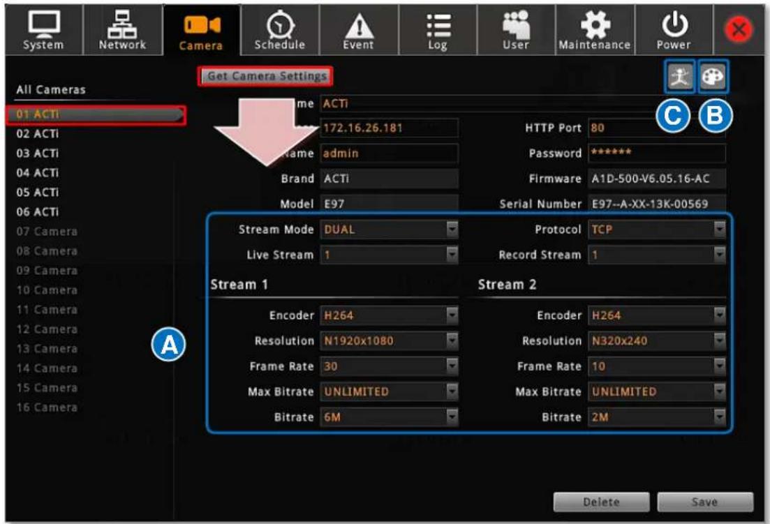
After the cameras are added, you may change their properties on Camera tab.
(A) Video format and transmission properties
(B) Video adjustment
(C) Motion Detection settings
text_image
System Network Camera Schedule Event Log User Maintenance Power All Cameras 01 ACTI Get Camera Settings Name ACTi 172.16.26.181 HTTP Port 80 C B 02 ACTI Name admin Password ***** 03 ACTI Brand ACTi Firmware A1D-500-V6.05.16-AC 04 ACTI Model E97 Serial Number E97-A-XX-13K-00569 05 ACTI Stream Mode DUAL Protocol TCP 06 ACTI Live Stream 1 Record Stream 1 Stream 1 Stream 2 Encoder H264 Encoder H264 Resolution N1920x1080 Resolution N320x240 Frame Rate 30 Frame Rate 10 Max Bitrate UNLIMITED Max Bitrate UNLIMITED Bitrate 6M Bitrate 2M Delete Save(A) Video Format and Transmission Properties
To modify the video format and transmission properties including Channel ID, Resolution,
Frame Rate, Protocol, and Bitrate, you will have to click
Get Camera Settings
first to sync with the camera first. After configuration, click "Save" to save this setting to camera
Note
- Changing the video resolution will reset your current motion region settings. Please re-configure the settings later.
- For local display viewing, please DO NOT (1) change the video resolution to higher than 4M pixels or (2) change the video codec to MJPEG or MPEG4, for these types of video streams are only displayable through ENR web interface.
(B) Fine-tune the Image: Brightness/Contrast/Saturation/Hue
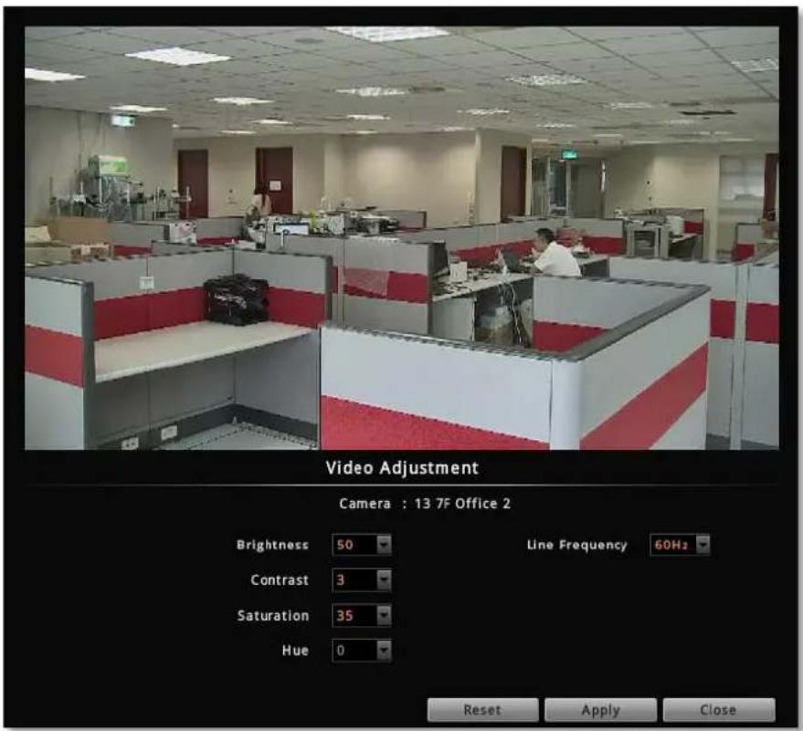
Not only clarity but also brightness, contrast, saturation and hue are essential factors to make images closer to real scene. For cameras that support these configurations, you may directly modify them and save via ENR interface.
After selecting a camera, click "Video Adjustment" window, the fields available for modification (depends on models) will be enabled. Select the desired value for the field, and click "Apply".
text_image
Video Adjustment Camera : 13 7F Office 2 Brightness 50 Contrast 3 Saturation 35 Hue 0 Line Frequency 60Hz Reset Apply Close| Field Name | Description |
| Brightness(1-100) | Defines how much portion of light and of dark appear in the image. As the value increases, the image appears brighter, and vice versa. |
| Contrast(1-100) | Defines the range level between light values and dark values. As the value increases, the separation between light and dark becomes more obvious. |
| Saturation(1-100) | Defines the level of the actual color intensity. As it increases, colors appear more pure; as it decreases, colors appear more gray-out. |
| Hue(1-100) | It is the term used to refer to the pure spectrum colors. Adjust this value to find the color closest to the real scene. |
| LineFrequency(50Hz / 60 Hz) | The function that adjusts the shutter speed options to match the frequencies of artificial light source of given country. For example, in Europe, the light frequency is 50Hz (due to power supply frequency of lights), that is 50 flashes per second. By setting line frequency to 50Hz in such case, the shutter speed options will be proportional with light source frequency, such as 1/25s, 1/50s, 1/100s, etc. It is necessary to have the camera's line frequency adjusted according to the power frequency of the light source to avoid flickering effect. |
(C) Motion Settings
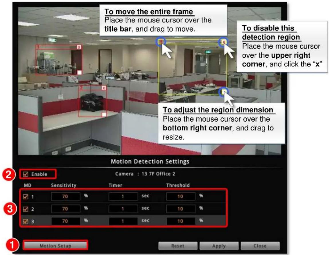
After selecting the camera, click "Motion Detection Settings". If this camera is in dual stream mode, only Channel ID 1 (Stream 1) supports motion detection feature. On Motion Detection Settings window, check "Enable" then click "Motion Setup". To enable one motion region, check it, a color frame will appear in the view. You may start setting the detection area by adjusting this yellow frame on the view. Simply use your mouse to move and resize the frame. Click "Apply" to save the settings.
text_image
To move the entire frame Place the mouse cursor over the title bar, and drag to move. To disable this detection region Place the mouse cursor over the upper right corner, and click the "x" To adjust the region dimension Place the mouse cursor over the bottom right corner, and drag to resize. Motion Detection Settings Enable Camera : 13 7F Office 2 MD Sensitivity Timer Threshold 1 70 % 1 sec 10 % 2 70 % 1 sec 10 % 3 70 % 1 sec 10 % Motion Setup Reset Apply Close| Field Name | Description |
| Sensitivity(0-100%) | Determines how sensitive the camera reacts to the movement. The higher the sensitivity level is, the smaller motion will trigger the alarm, but may give false alarms. Default is 70%. |
| Timer(0-300 secs) | The interval before the next motion detection can be triggered again.Default is 1 second. |
| Threshold(0-100%) | The threshold level of this motion detection region. The lower threshold level is, smaller portion of the region would be considered as motions, which is more easily to be triggered, but may give more false alarms.Default is 10%. |
Configure PTZ Presets
With PTZ cameras, you may define a view by where to look (through panning and tilting) and how close (through zooming) to zoom. Once these views have been saved in ENR as preset points, the device can always point to this view upon the event triggering or user's command. For local operation, the PTZ-related configurations are done on Live screen. Please note that, the PTZ-related settings you configure here will overwrite those on camera's firmware.
Open PTZ Panel
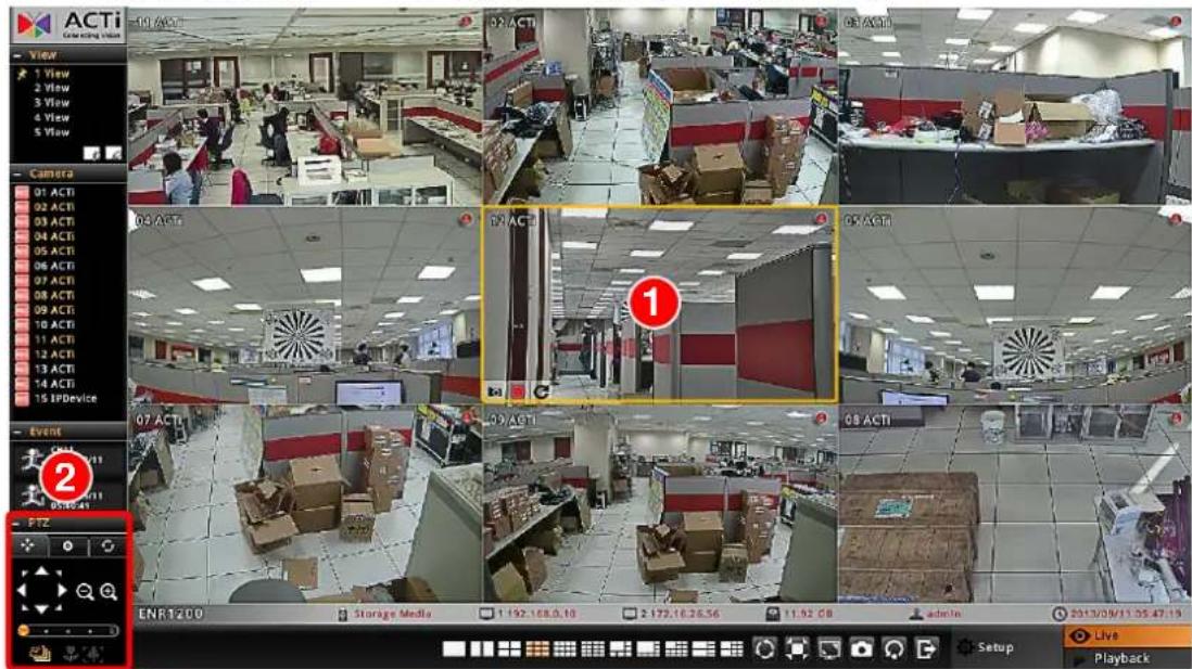
On Live screen, select a PTZ channel, the PTZ panel will become enabled.
text_image
ACTi View 1 View 2 View 3 View 4 View 5 View Camera 01 ACTI 02 ACTI 03 ACTI 04 ACTI 05 ACTI 06 ACTI 07 ACTI 08 ACTI 09 ACTI 10 ACTI 11 ACTI 12 ACTI 13 ACTI 14 ACTI 15 IPDevice Event 07 ACTI 08 ACTI ENR 1200 Storage Media 1 192.168.0.10 2 172.16.26.56 11.92 GB admin In 2013/09/11:55:47:19 Live Playback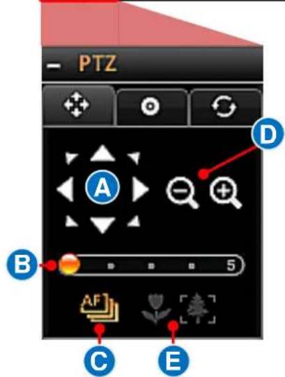
text_image
PTZ A B C E D 5Manipulate PTZ Movements
Click the tab ✦ to enter PTZ operation mode, and make make use of the device's PTZ capabilities to define a view.
| No | Function |
| A | Eight-direction arrow keysClick to pan or tilt the camera (only available for camera with Pan/Tilt/ capability). |
| B | Pan/Tilt/Zoom speedClick to change the speed. Provided speed scale is from 1 to 5 (available for cameras with Pan/Tilt/Zoom capability). |
| C | Auto focus (available for cameras with auto focus capability) |
| D | Zoom (Available for cameras with a controllable zoom) Zoom in Zoom out |
| E | Manual focus(Available for cameras with a controllable focus)Near focus Far focusThese buttons are enabled when the “Auto Focus” is disabled. |
Go to Preset Points
You may create/delete/go-to preset points in this mode.
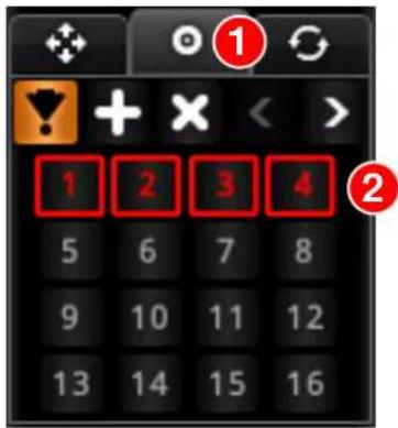
Go to a Preset Point
Click the tab 🔓 to enter Preset Points Operation mode, and click a red ID button.
text_image
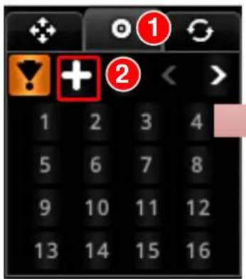
1 2 3 4 5 6 7 8 9 10 11 12 13 14 15 16Create a Presset Point
- Go to PTZ Operation mode ✗, use onscreen buttons to define a view.
- Click the tab to enter Preset Points Operation mode.
- Click +
- Click the desired preset point ID and input the point name in Preset Point Setting box. This preset point will be saved, and its ID will turn red.
text_image
Mobile phone app interface showing a keypad with function buttons and numeric keypad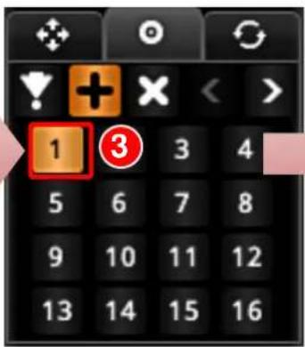
text_image
1 3 3 4 5 6 7 8 9 10 11 12 13 14 15 16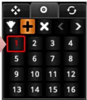
text_image
1 2 3 4 5 6 7 8 9 10 11 12 13 14 15 16Delete a Presset Point
On Preset Points Operation mode, click ✗ and then the preset point you want to delete.
Edit PTZ Preset Tour
Preset Tour is a preconfigured PTZ sequence that directs the camera to cycle through multiple preset points, including where to look and how long to look at each location. With this preset tour, your PTZ device can perform an automatic patrol to scan through your cared areas.
Before setting up Preset Tours, please make sure you have set PTZ Preset Points. To start:
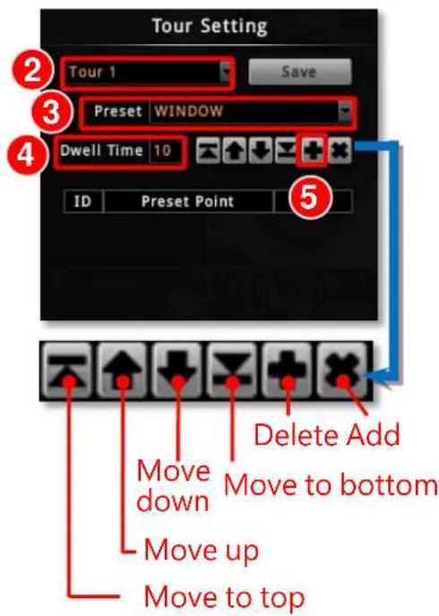
- On PTZ Panel, click 📋 and then 📋 to enter Tour edit window.
- On Tour Setting window, select a Tour from drop-down list.
- Select a Preset Point from drop-down list.
- Set the Dwell Time, default is 10 seconds.
- Click + to save this point into the list.
- Repeat step 1 \~ step 5 to add other points in your desired movement sequence. You may use the edit buttons to change the point order or delete a point. Click "Save" when this Tour list is well set. Click "Close" to exit this window.
- The ID of a saved tour will appear red. Click on it to start the tour, and click □ to stop it.
text_image
Tour Setting 2 Tour 1 Save 3 Preset WINDOW 4 Dwell Time 10 ID Preset Point 5 Move down Delete Add Move up Move to bottom Move to top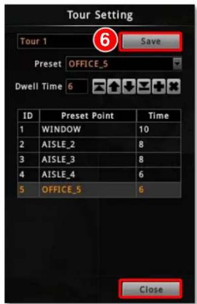
text_image
Tour Setting Tour 1 6 Save Preset OFFICE_5 Dwell Time 6 ID Preset Point Time 1 WINDOW 10 2 AISLE_2 8 3 AISLE_3 8 4 AISLE_4 6 5 OFFICE_5 6 Close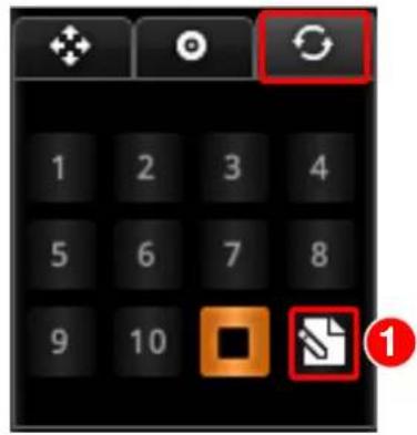
text_image
1 2 3 4 5 6 7 8 9 10 © ①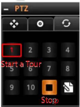
text_image
PTZ 1 2 3 4 Start a Tour 5 6 7 8 9 10 StopDevice Information
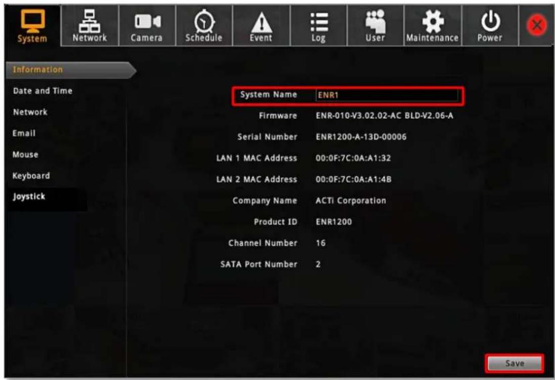
To change the device name, check firmware version information or Mac address, please go to Setup page → System tab → Network
After modifying the System Name, click "Save" to save the settings.
text_image
System Network Camera Schedule Event Log User Maintenance Power Information Date and Time Network Email Mouse Keyboard Joystick System Name ENR1 Firmware ENR-010-V3.02.02-AC BLD-V2.06-A Serial Number ENR1200-A-13D-00006 LAN 1 MAC Address 00:0F:7C:0A:A1:32 LAN 2 MAC Address 00:0F:7C:0A:A1:4B Company Name ACTi Corporation Product ID ENR1200 Channel Number 16 SATA Port Number 2 SaveNetwork Settings
There are two network interface cards in ENR. Either of these cards can be supported by the built-in DHCP server feature, which enables ENR to assign IP addresses to cameras via LAN1 or LAN2 port without another DHCP on router.
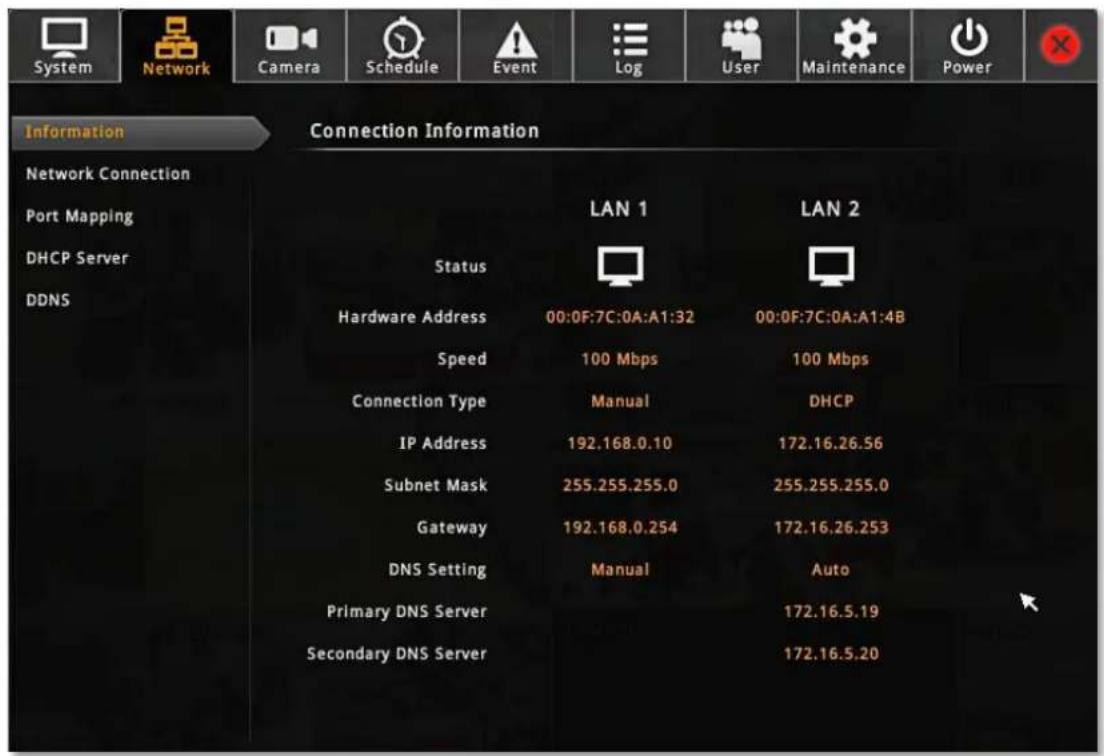
Go to Setup page → Network tab
The current settings of both LANs will be displayed here.
By default, LAN1 card is set to Manual mode with a fixed IP address 192.168.0.10, while LAN2 is in DHCP client mode. It is suggested that you connect LAN1 to LAN and connect LAN2 to WAN.
text_image
System Network Camera Schedule Event Log User Maintenance Power Information Connection Information Network Connection Port Mapping DHCP Server DDNS Status LAN 1 LAN 2 Hardware Address 00:0F:7C:0A:A1:32 00:0F:7C:0A:A1:4B Speed 100 Mbps 100 Mbps Connection Type Manual DHCP IP Address 192.168.0.10 172.16.26.56 Subnet Mask 255.255.255.0 255.255.255.0 Gateway 192.168.0.254 172.16.26.253 DNS Setting Manual Auto Primary DNS Server 172.16.5.19 Secondary DNS Server 172.16.5.20IP Settings
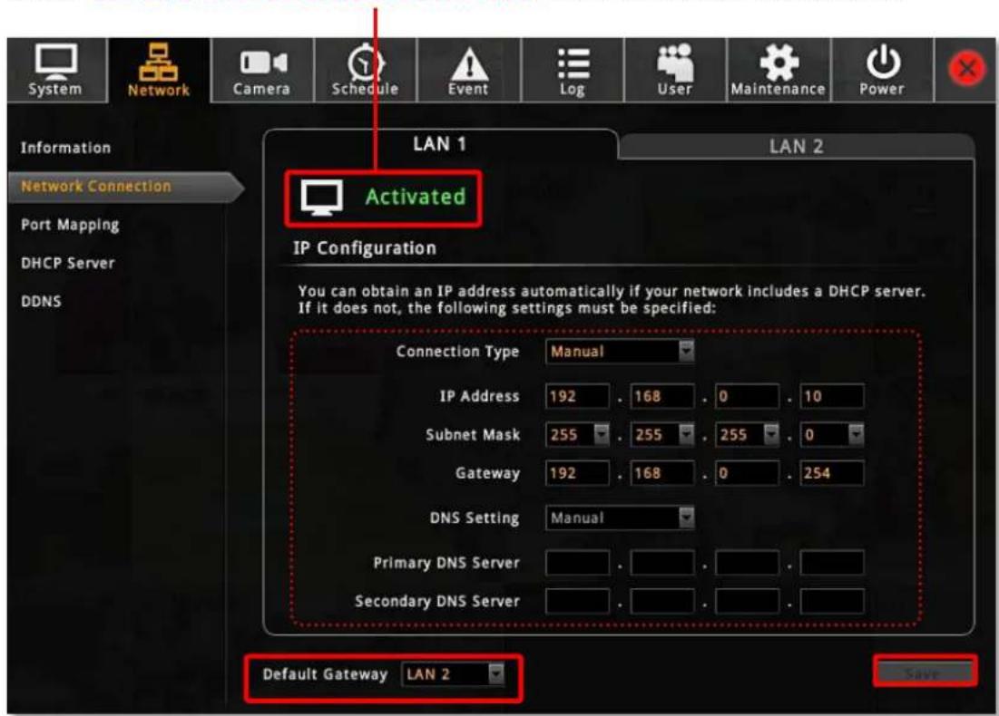
Go to Setup page → Network tab → click "Network Connection" and select the LAN interface card that you wish to set up. After setting up, please click "Save" on the bottom right to save the settings.
LAN Connection Status
Shows "Activated" when connected to a network.
Shows "Detected Network Cable Disconnection" when not connected to a network
text_image
System Network Camera Schedule Event Log User Maintenance Power Information Network Connection Port Mapping DHCP Server DDNS LAN 1 LAN 2 Activated IP Configuration You can obtain an IP address automatically if your network includes a DHCP server. If it does not, the following settings must be specified: Connection Type Manual IP Address 192 . 168 . 0 . 10 Subnet Mask 255 . 255 . 255 . 0 Gateway 192 . 168 . 0 . 254 DNS Setting Manual Primary DNS Server . Secondary DNS Server . Default Gateway LAN 2 Save| Field Name | Description |
| Connection Type | Choose one connection type for this LAN port. DHCP and PPPoE service will assign an IP Address to ENR, and there is no need for you to define other network information.Manual: Please obtain a static IP address and other network information including Subnet Mask, Gateway and DNS server from your network administrator.DHCP: Use this connection type if you have a DHCP server on your network router.PPPoE: Chose this when your ISP is using PPPoE type DSL line. Please contact you ISP to get theUsernameandPasswordfor this connection.LAN1 default isManual;LAN2 default isDHCP. |
| IP Address | Fixed IP Address. LAN1 default is 192.168.0.10; LAN2 default is Auto. |
ENR-100 Series System Administrator's Manual

ACTi
Clemmiting Water
| Subnet Mask | Used to define if the destination is in the same subnet. LAN1 default is 255.255.255.0; LAN2 default is Auto. |
| Gateway | A valid gateway setting is essential for data transmission between different subnets, such as accessing the DNS service or SMTP server on the Internet. LAN1 default is 192.168.0.254; LAN2 default is Auto. |
| DNS Setting Primary DNS Server Secondary DNS Server | The DNS server that translates domain names to actual IP addresses. If this LAN is Manual mode, and you will set an SMTP server for event notification, be sure to set the Primary DNS and Secondary DNS. LAN1 default is Manual; LAN2 default is Auto. |
| Default Gateway | Choose the gateway of the LAN card whose network is to connect with Internet. Default uses LAN2's setting. |
Change Port Setting
The default connection port used for remote web client to communicate with ENR is 80. To change it, click "Port Mapping" to modify and save the setting.
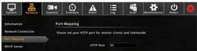
text_image
System Network Camera Schedule Event Log User Maintenance Power Information Port Mapping Network Connection Port Mapping DHCP Server Please set your HTTP port for remote clients and commands. HTTP Port 80Enable DHCP Server
You may enable the built-in DHCP server for either LAN1 or LAN2 port.
Go to Setup page → Network tab → click "DHCP Server":
- Check "Enable" and select a LAN, this LAN has to be in Manual mode.
- Set the Beginning IP Address and Ending Address, and click "Save". ENR will assign
IP addresses within this range to the cameras connected to the selected LAN port. Please (1) make sure the cameras are in DHCP client mode, (2) connect and power the cameras up after you enable this service.
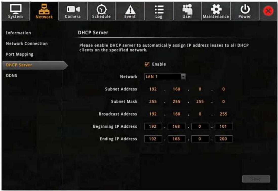
text_image
System Network Camera Schedule Event Log User Maintenance Power Information Network Connection Port Mapping DHCP Server DDNS DHCP Server Please enable DHCP server to automatically assign IP address leases to all DHCP clients on the specified network. Enable Network LAN 1 Subnet Address 192 . 168 . 0 . 0 Subnet Mask 255 . 255 . 255 . 0 Broadcast Address 192 . 168 . 0 . 255 Beginning IP Address 192 . 168 . 0 . 101 Ending IP Address 192 . 168 . 0 . 200 SaveEnable DDNS Service
ENR has built-in the DDNS update client feature, which saves ENR domain name address information and actively update its ip address to the DDNS provider's server.
- Visit the dynamic DNS service provider's website and register the domain name for your ENR.
ENR supports the following service providers:
● DynDNS: http://www.dyndns.com
● NO-IP: http://www.noip.com/
- Go to Setup page → Network tab → click "DDNS".
- Check "Enable", select the service provider, and input the Host Name, User Name and Password.
- Click "Save" to save the settings.
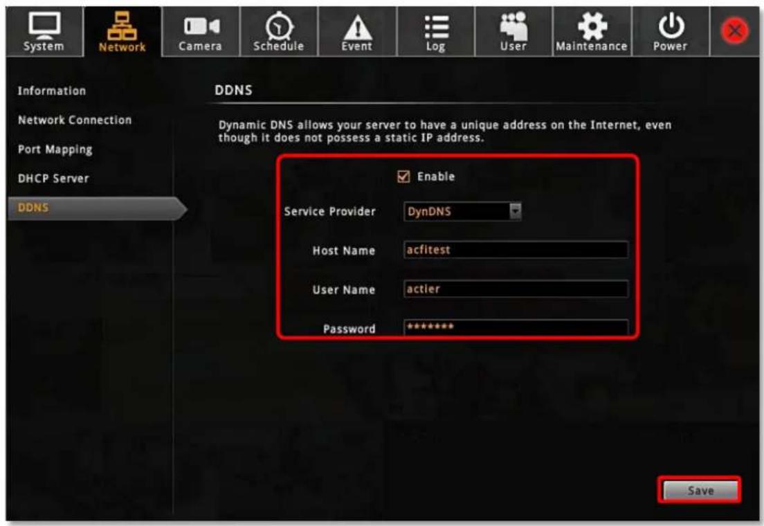
text_image
System Network Camera Schedule Event Log User Maintenance Power Information DDNS Network Connection Port Mapping DHCP Server DDNS Dynamic DNS allows your server to have a unique address on the Internet, even though it does not possess a static IP address. Enable Service Provider DynDNS Host Name acfitest User Name actier Password ******** SaveDate & Time
ENR provides three methods to synchronize the time setting; you can (1) manually set the date and time, (2) sync with Time Zone or (3) synchronize with NTP server.
On Live screen, click Setup → click System tab → click "Date and Time"
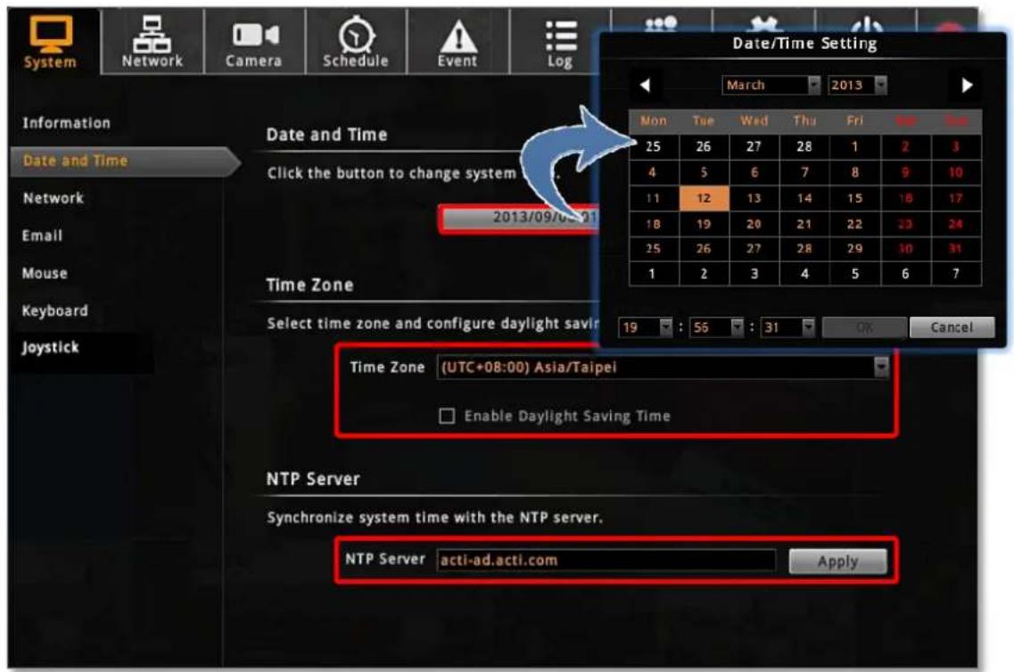
text_image
System Network Camera Schedule Event Log Information Date and Time Click the button to change system 2013/09/06-01 Time Zone Select time zone and configure daylight saved 19 : 56 : 31 OK Cancel Date/Time Setting March 2013 Mon Tue Wed Thu Fri Mon Fri 25 26 27 28 1 2 3 4 5 6 7 8 9 10 11 12 13 14 15 16 17 18 19 20 21 22 23 24 25 26 27 28 29 30 31 1 2 3 4 5 6 7 Time Zone (UTC+08:00) Asia/Taipei Enable Daylight Saving Time NTP Server Synchronize system time with the NTP server. NTP Server acti-ad.acti.com ApplySetup Manually
In Date & Time section, click the button that shows date and time information on it. On the popped-out calendar, select the correct date and time, then click "OK".
Synchronize with Time Zone
In Time Zone section, select your zone from the Time Zone drop-down list. If your time zone falls in Daylight Saving Time area, you may check the box "Enable Daylight Saving Time", and then system time will automatically adapt itself to daylight saving time clock.
Synchronize with NTP server
In NTP Server section, fill in the NTP server IP or domain name in the NTP Server field, and click "Apply" to start synchronizing.
E-mail Settings
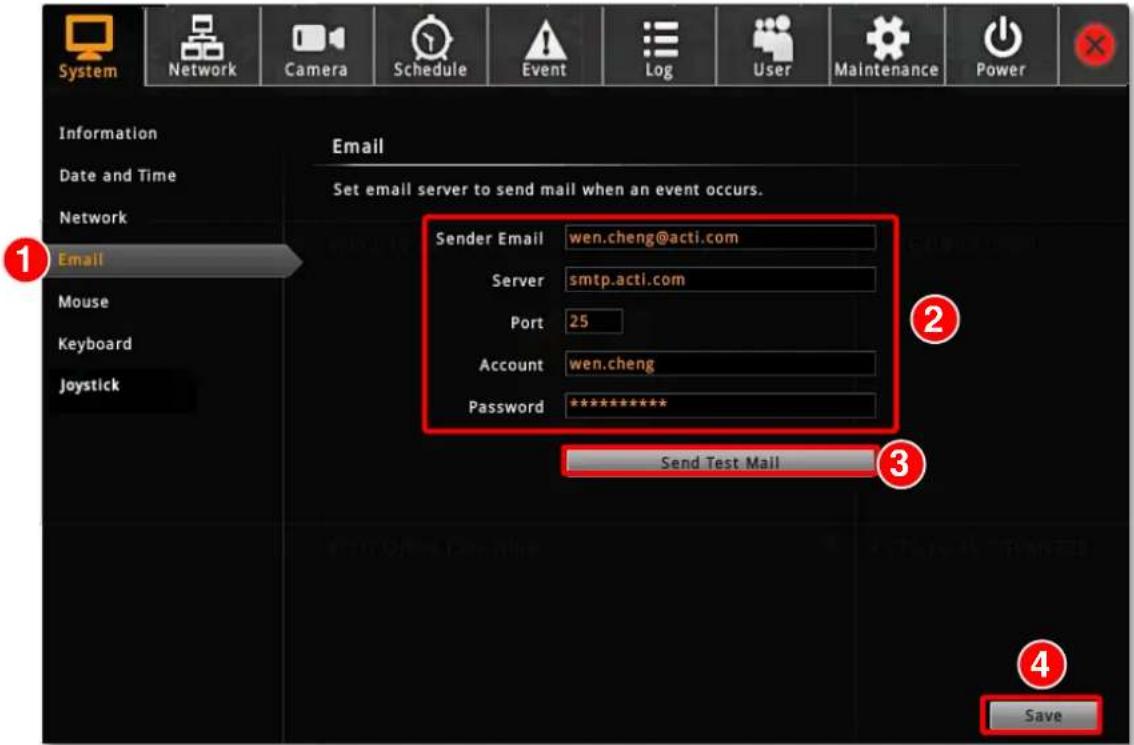
ENR supports e-mail notification for Event Handling sent through an SMTP server. To enable this service, you will have to configure the SMTP mail settings in advance. For SMTP service, please go to Setup page → System tab → Network and make sure the Default Gateway adopts the setting of the LAN connection has access to the SMTP server.
- On Live screen, click Setup → Select System tab → click "Email".
text_image
System Network Camera Schedule Event Log User Maintenance Power Information Date and Time Network Email Set email server to send mail when an event occurs. Sender Email wen.cheng@acti.com Server smtp.acti.com Port 25 Account wen.cheng Password ********** Send Test Mail 1 2 3 4 Save- Fill in every field according to the detailed instructions in the table below.
- Click "Send Test Mail" to send a test mail to this e-mail account. If the test mail is sent successfully, the dialog box below will pop up, which means your ENR server is ready to send out e-mail notifications when being triggered by an event.

text_image
Test mail has been sent to wen.cheng@acti.com, please check your inbox OK- Click "Save" to save these properties.
| Field Name | Description |
| Sender Email | Input the sender's e-mail address, should the same account you set for SMTP server. |
| Server | Input the sender's SMTP server address. Only alphabets, numbers, and the |
ENR-100 Series System Administrator's Manual
| symbols (.), (_), (-) are valid. ENR server supports the SMTP services with SSL protocol. If you wish to use a free webmail SMTP service, you may choose certain webmail providers such as Yahoo (SMTP: smtp.mail.yahoo.com Port:25) or Gmail (SMTP: smtp.gmail.com Port:25 or 465 for SSL protocol / 587 for TLS protocol) | |
| Port | Set the SMTP port, allowed value is from 1~65535, default is 25. |
| Account | Input the name of the SMTP server account. The form of account name depends on mail server, e.g. a Hotmail account name is a complete e-mail address, while other mail servers' are not. Only alphabets, numbers, and the symbols (@), (.), (_), (-) are valid. |
| Password | Input the password of the SMTP server account. Only alphabets and numbers are valid. |
Disk Management
ENR keeps the recordings on SATA hard disks installed in it. Whenever recording is taking place, ENR writes data to one of the disks, and switch to the other as the original one is full. Once the available space of the whole system is less than the reserved size, ENR will start deleting the oldest file to make the amount of space allowing each active channel to record for another 10 minutes.
You may observe the disk memory and recording status on Storage page.
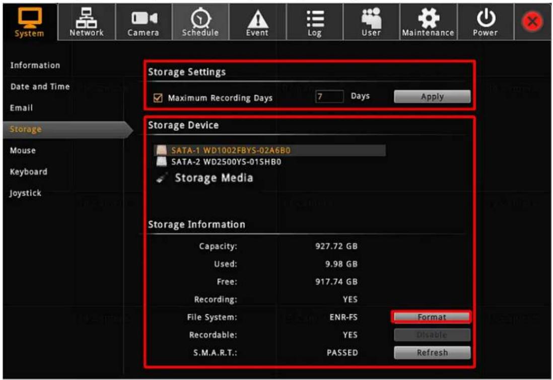
On Live screen, click Setup → click System tab → click "Storage". The connected storage devices will be shown in the Storage Device list. Select a storage device to check its Storage Information appearing as below.
Storage Device Types
● SATA1 represents the disk installed in upper bay for saving recordings.
● SATA2 represents the disk installed in lower bay for saving recordings.
● Storage Media represents the connected USB disk that you inserted for carrying firmware image file, backup file, exported system log file, snapshots or video.
text_image
System Network Camera Schedule Event Log User Maintenance Power Information Date and Time Email Storage Mouse Keyboard Joystick Storage Settings Maximum Recording Days 7 Days Apply Storage Device SATA-1 WD1002FBYS-02A6B0 SATA-2 WD2500YS-01SHB0 Storage Media Storage Information Capacity: 927.72 GB Used: 9.98 GB Free: 917.74 GB Recording: YES File System: ENR-FS Format Recordable: YES Disable S.M.A.R.T.: PASSED RefreshFormat Hard Disks
Any newly-installed hard disk has to be formatted into ENR file system format. Click "Format" to start formatting a new disk. After formatting, this disk will become ready for recording.
During normal operation, DO NOT REMOVE ANY DISK FROM THIS UNIT, or it might cause damage to the disks. You can only remove or install a disk when the device is shut down.
Please note that the system will stop recording during the disk formation.
Storage Settings - Set Recording Deletion Rule
In ENR system, there are two file-deletion mechanisms:
1. User defined - Maximum Recording Days
ENR can keep recording files for a certain number of days defined by you. Set this rule if you have more concern about how long the recordings are kept, especially when you do not want the old recordings to stay longer in the system than a certain period. By default, this rule is not activated, to modify it, check the box to input a number between 1\~999 and click "Apply".
2. Default - Automatic Disk Deletion
This is the default file deletion rule. When the total recordable disk space is full, an amount of disk space for approximate ten-minute long recording will be cleared to save new recordings.
If you activate the “Maximum Recording Days” rule, either of the thresholds reached earlier will execute the deletion first. Given that you set the Maximum Recording Days as 5 days, the recording files that stay on the disks longer than this period will be deleted, despite that there is still plenty of available disk space; on the other hand, if your disk space is not enough to keep all the recordings for 5 days, ENR will still delete the oldest files whenever the space is full.
Before setting up the rules, you can make use of a handy storage calculator provided by ACTi to find out the estimated storage your system requires: http://www.acti.com/project_planner
Also, be careful when you apply the Maximum Recording Days setting, for ENR will execute the deletion rule immediately whenever you click "Apply", meaning that the all the recording files kept longer than the last applied number of maximum days are just deleted in no time.
Check Disk Status
Hard disk failure often comes after detectable signs and thus can be predicable, thus it is important to detect these signs long before they really cause disk failures.
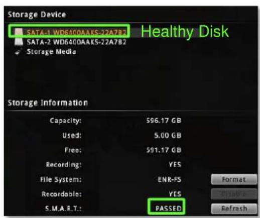
ENR performs S.M.A.R.T. Disk check on 24-hour basis since last check. This technology enables a system to monitor the disk status and anticipate disk failures, helping the system administrator to prevent from unexpected outage and data loss.
You may manually perform an instant S.M.A.R.T check by clicking "Refresh".
Once the disk a appears in "WARNING", "FAILED", or "UNKNOWN" status, it is not reliable for recording, and may fail when the number of bad sectors on the disk has grown high enough.
text_image
Storage Device SATA-1 WD6400AAKS-22A7B2 Healthy Disk SATA-2 WD6400AAKS-22A7B2 Storage Media Storage Information Capacity: 596.17 GB Used: 5.00 GB Free: 551.17 GB Recording: YES File System: ENR-FS Recordable: YES S.M.A.R.T.: PASSED Format Disable Refresh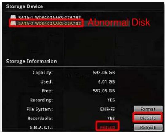
text_image
Storage Device SATA-1 WDG400AAKS-22A7B2 Abnormal Disk SATA-2 WDG400AAKS-22A7B2 Storage Information Capacity: 593.06 GB Used: 6.01 GB Free: 587.05 GB Recording: YES File System: ENR-FS Format Recordable: YES Disable S.M.A.R.T.: FAILED Refresh| S.M.A.R.T Status | Description | Solution |
| PASSED | This disk is in normal condition. | -- |
| WARNING | Certain error has been found on this disk. | 1.On “Storage” page, select the disk and click “Disable” next to Recordable status to stop the system from saving recording into it.2.Watch playback and export important video / system log. |
| FAILED | A number of errors have been found on this disk. | |
| UNKNOWN | Unable to get the disk information. |
Manage Abnormal Disks
A disk that is not recognized as "PASSED" by S.M.A.R.T. check may have unexpected failures anytime. However, it will still continue recording until it finally fails.
After you disabled the recording on this disk and review important recordings,
- Turn off the device.
-
Replace the abnormal disk with a new one, and turn on the device.
-
Go to Live screen, click Setup → click Maintenance tab → click "Storage", and click "Format" to format the new disk.
Schedule Recordings
Unlike the traditional analog surveillance system, the IP surveillance system provides a target-oriented recording schedule for devices; the view of each device can be recorded based on your required time segments and event types. For example, you may have a camera installed on the office ceiling do continuous recording during work hours, and record only upon the triggers (incidents that detected by system) at night. In this way, the system does not waste disk space storing meaningless parts, and you save lots of effort browsing playback for specific events.
For the recording schedule, ENR supports Schedule recording, Event recording and Event Speed-up Recording modes, which are set up on a week-based timetable; the event-handling schedule is configured here.
On ENR, you can configure camera's recording schedule on 7 days / 24 hours basis. The schedule is split into segments of one-hour-length. By default, once a device is added to the system, its schedule is automatically set to full-time schedule recording and event handling. You should configure it according to your system plan.
On Live screen → Select Setup → click "Schedule" tab and select one channel.
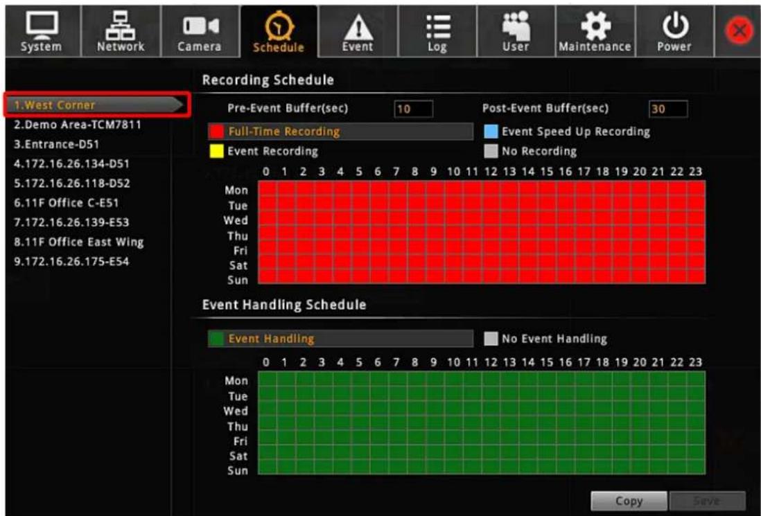
text_image
System Network Camera Schedule Event Log User Maintenance Power Recording Schedule 1.West Corner Pre-Event Buffer(sec) 10 Post-Event Buffer(sec) 30 Full-Time Recording Event Speed Up Recording Event Recording No Recording Mon Tue Wed Thu Fri Sat Sun 0 1 2 3 4 5 6 7 8 9 10 11 12 13 14 15 16 17 18 19 20 21 22 23 Event Handling Schedule Event Handling No Event Handling Mon Tue Wed Thu Fri Sat Sun 0 1 2 3 4 5 6 7 8 9 10 11 12 13 14 15 16 17 18 19 20 21 22 23 Copy SaveEvent-Recording File Length
Before setting the recording schedule, you may define the length of an event recording. To do this, configure the following properties shown as below, which will make an event recording as long as 10+30 second:

text_image
Recording Schedule Pre-Event Buffer(Sec) 10 Post-Event Buffer(Sec) 30| Field | Description |
| Pre-event Recording Buffer (sec): | ENR keeps a short cache of video received from devices. If an event is triggered, ENR will automatically store the pre-event buffer along with the recording of the event itself. |
| Post-event Recording Buffer (sec): | This will determine how long after the event is triggered should be included in the event recording file. |
Set the Recording Schedule
On the time table
- Click on the recording mode from

text_image
Full-Time Recording Event Recording Event Speed Up Recording No Recording| Field | Description |
| Full-Time Recording | Continuously record at the video frame rate you define in Camera Settings. |
| Event Speed Up Recording | Continuously record everything at 1FPS, when an event occurs, the frame rate will switch to the value you define in Camera Settings, and automatically switch back to 1FPS after the event ends. |
| Event Recording | Only events are recorded, at the video frame rate you define in Camera Settings. |
- Click and drag over the "Time Track" to set time period.
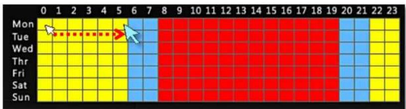
- Click "Save".
Set the Event Schedule
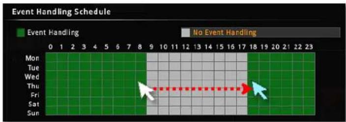
The Event Schedule defines when the event handling is activated. To set the event rules, please refer to Set Event Rules on page 68.
on page 68 for Event Rules settings. By default, the event handling is full-time activated; you may disable it during certain time period.
- Click on the recording mode "No Event Handling".
- Click and drag over the "Time Track" to set time period.
- Click "Save".
text_image
Event Handling Schedule Event Handling No Event Handling Mon Tue Wed Thu Fri Sat SunCopy Schedule
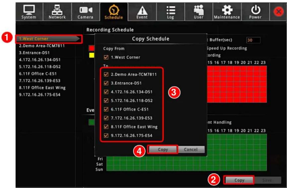
You may copy a camera's schedule setting to other multiple cameras. This saves much your time on configuring the schedules camera by camera.
- On Schedule tab, select a source camera from camera list, its schedule will be copied to others.
- Click "Copy"
- On Copy Schedule window, select the target cameras.
- Click "Copy" on Copy Schedule window.
text_image
System Network Camera Schedule Event Log User Maintenance Power Recording Schedule 1.West Corner 2.Demo Area-TCM7811 3.Entrance-D51 4.172.16.26.134-D51 5.172.16.26.118-D52 6.11F Office C-E51 7.172.16.26.139-E53 8.11F Office East Wing 9.172.16.26.175-E54 Copy Schedule Copy From ✓ 1.West Corner To ✓ 2.Demo Area-TCM7811 ✓ 3.Entrance-D51 ✓ 4.172.16.26.134-D51 ✓ 5.172.16.26.118-D52 ✓ 6.11F Office C-E51 ✓ 7.172.16.26.139-E53 ✓ 8.11F Office East Wing ✓ 9.172.16.26.175-E54 ③ Speed Up Recording Ordering 15 16 17 18 19 20 21 22 23 Eve ④ Copy Cancel Front Handling 15 16 17 18 19 20 21 22 23 Fri Sat Sun Copy SaveEvent Management
When something happens on camera site, such as someone walks by, the door opens or a fire breaks out – these are all Events. The event which occurs in the environment and was pre-programmed in the camera serves as Triggers. Triggers cause the device to react with
Responses. The link between trigger and response is governed by Event Rules. Each event rule detects one specific trigger and may initiate multiple responses. An example rule would be for ENR to send an e-mail to alert the manager (Response 1) and trigger the alarm (Response 2) when motion on camera site is detected (Trigger) during the event handing active period (Schedule).
Each device can be involved in several event rules. As different camera models possess various capabilities, the supported response types would vary. For example, a PTZ camera can execute a go-to preset point response, while this option is not available for other models without this feature.
Event-Handling Schedule
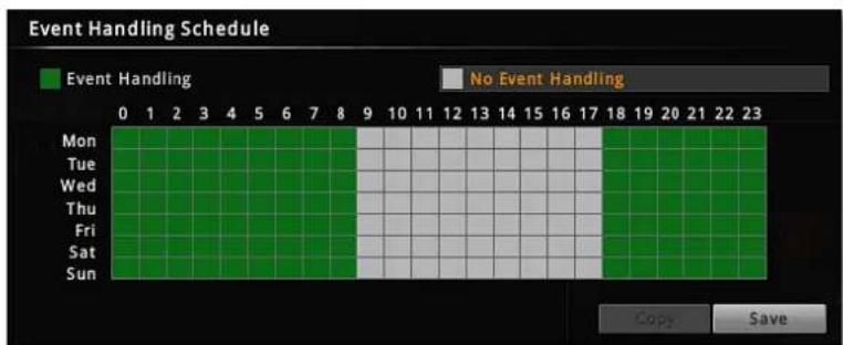
Event rules become active or inactive based upon a weekly schedule, to enable event-handling service, you will have to make sure the event-handling schedule of certain device is well configured. By default, the event-handling schedule of each camera is enabled for 24 hours once it is added to ENR system.
To configure the Event Handling Schedule, on Live screen, click Setup → click "Schedule", select the camera, and drag on the 24-hour time table.
bar
Event Handling Schedule | Day | Event Handling (Green) | No Event Handling (Gray) | |---|---|---| | Mon | 0 | 0 | | Tue | 0 | 0 | | Wed | 0 | 0 | | Thu | 0 | 0 | | Fri | 0 | 0 | | Sat | 0 | 0 | | Sun | 0 | 0 | Copy SaveSet Event Rules
On Live screen, click Setup → click Event tab → select a camera.
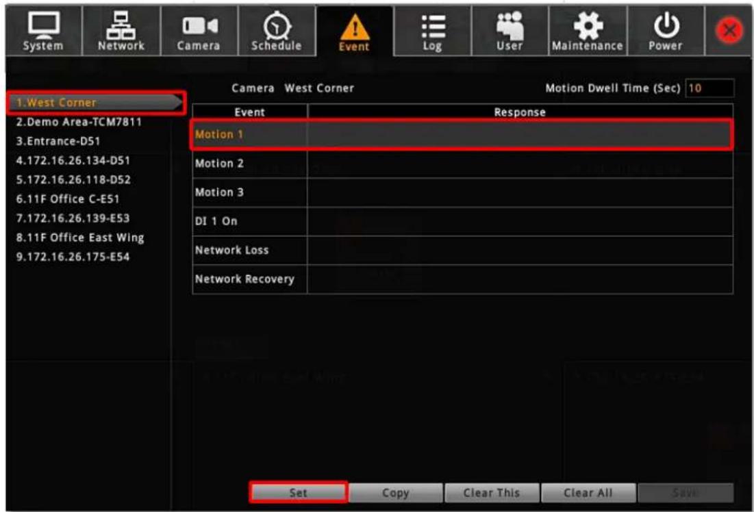
text_image
System Network Camera Schedule Event Log User Maintenance Power 1.West Corner 2.Demo Area-TCM7811 3.Entrance-D51 4.172.16.26.134-D51 5.172.16.26.118-D52 6.11F Office C-E51 7.172.16.26.139-E53 8.11F Office East Wing 9.172.16.26.175-E54 Camera West Corner Motion Dwell Time (Sec) 10 Event Response Motion 1 Motion 2 Motion 3 DI 1 On Network Loss Network Recovery Set Copy Clear This Clear All Save- Once a device is added to ENR server, the server would provide empty rules with compatible trigger types for you to configure such as Motion 1, Motion 2, Motion 3, DI 1, DI 2, Network Loss and Network Recovery. Select the Event Type, then click "Set".
- Select the trigger type:
●Trigger DO
Set the DO to become ON or OFF upon trigger, only the devices supporting DO functions are available. Check the "Enable" to enable this function, and the device whose connected DO(s) will be triggered. You may select one DO to be activated after the other and the duration time between them. Clik "OK" to confirm.
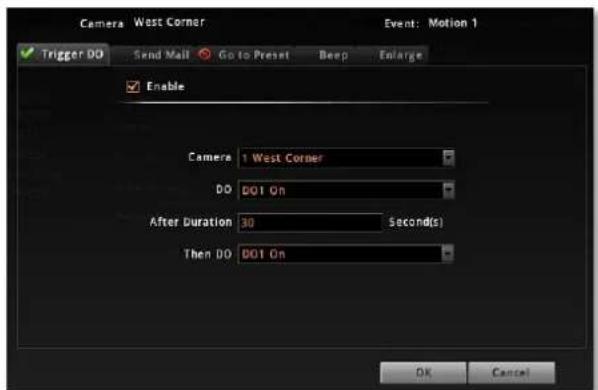
text_image
Camera West Corner Event: Motion 1 Trigger DO Send Mail Go to Preset Beep Enlarge Enable Camera 1 West Corner DO 001 On After Duration 30 Second(s) Then DO 001 On OK Cancel- Send Mail
Enable ENR to send e-mail notifications via SMTP service. Check the "Enable" to enable this function, and fill in the mail recipient's e-mail address in "To" field, notification title in "Subject" field and mail body in "Body" field, then choose a camera whose snapshot will be attached from Attach a Snapshot dropdown list. Clik "OK" to confirm. Please note that if you want to attach a snapshot to the notification e-mail, make sure your local display stays on Live screen during the event handing period, in this way, ENR can take the snapshots for motion events.
To enable this service, you have to configure the e-mail setting (please refer to E-mail Settings on page 58) before this trigger is enabled.
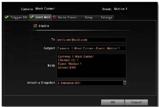
text_image
Camera West Corner Trigger DO Send Mail Go to Preset Beep Enlarge Enable To: wells.wel@actl.com Subject: Camera: 1 West Corner - Event: Motion 1 Body: Camera: 1 West Corner Channel ID: 1 Event: Motion 1 Server: ENR Attach a Snapshot: 3 Entrance-051 OK Cancel- Go to Preset
For the use of PTZ cameras to make movements toward certain triggers, please configure the preset points (refer to 49Go to Preset Points on page 49) on Live screen before you set the event rule.
On Go to Preset tab, check the "Enable" to enable this function (if there is no PTZ camera exsiting in ENR server to execute a PTZ response, a red sign would appear on the tab Go to Preset, please add a PTZ camera). Select which PTZ camera in ENR server to make the movement, then the preset points and duration time between them. Click "OK" to confirm.
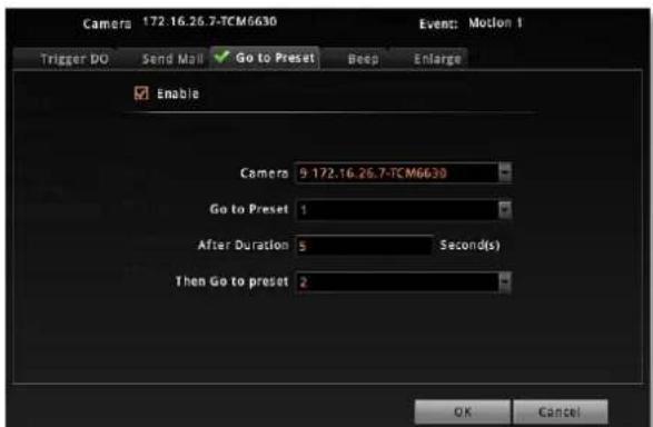
text_image
Camers 172.16.26.7-TCM6630 Event: Motion 1 Trigger DO Send Mail Go to Preset Beep Enlarge Enable Camers 9 172.16.26.7-TCM6630 Go to Preset 1 After Duration 5 Second(s) Then Go to preset 2 OK Cancel- Beep
ENR device can play beep sound upon being triggered by events. On Beep tab, check the "Enable" to enable this function. Input the duration time and prepeat times of the beep. Click "OK" to confirm.
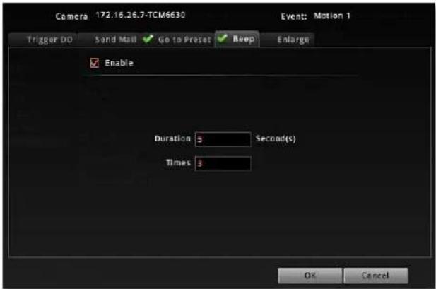
text_image
Camera 172.16.26.7-TCM6630 Event: Motion 1 Trigger DO Send Mail Go to Preset Keep Enlarge Enable Duration 5 Second(s) Times 3 OK Cancel●Enlarge
Live screen will display certain channel view in full screen for a while when the system is triggered. On Enlarge tab, check the "Enable" to enable this function. Select the camera whose live view will be enlarged on Live screen and the duration time. Click "OK" to confirm.
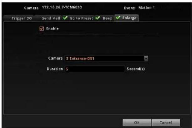
text_image
Camera 172.16.26.7-TCM6630 Trigger DO Send Mail Go to Preset Beep Enlarge Enable Camera 3 Entrance-051 Duration 5 Second(s) OK Cancel- After configuring the event handling rules, on Event tab, input the dwell time in
Motion Dwell Time (sec) : 10
for all the rules you set. Dwell Time defines, after an event occurs, the period of time during which the same event will not be triggered again.
- On Event tab, click "Save" to save the settings.
Clear Event Rules
On Event tab, you may select an event rule under certain camera, and click "Clear This" to delete it, or "Clear All" to delete all the rules belong to this camera.
Copy Event Rules
You may copy a camera's event rules to other multiple cameras. This saves much your time on setting up rules one by one.
- On Event tab, select a source camera from camera list, its rules will be copied to others.
- Click "Copy"
- On Copy Event window, select the target cameras.
- Click "Copy" on Copy Event window.
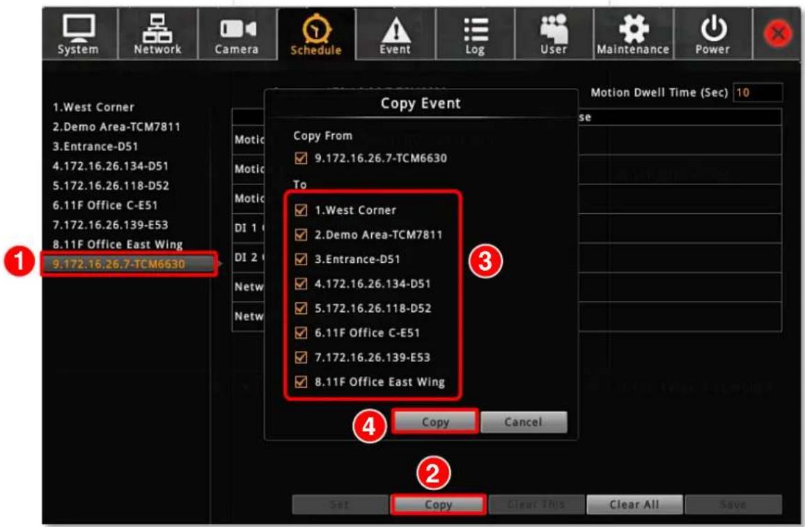
text_image
System Network Camera Schedule Event Log User Maintenance Power Copy Event 1.West Corner 2.Demo Area-TCM7811 3.Entrance-D51 4.172.16.26.134-D51 5.172.16.26.118-D52 6.11F Office C-E51 7.172.16.26.139-E53 8.11F Office East Wing 9.172.16.26.7-TCM6630 Copy From 9.172.16.26.7-TCM6630 To 1.West Corner 2.Demo Area-TCM7811 3.Entrance-D51 4.172.16.26.134-D51 5.172.16.26.118-D52 6.11F Office C-E51 7.172.16.26.139-E53 8.11FOffice East Wing Copy Cancel Copy Clear All SaveJoystick
ENR supports two types of controller for local operations:
● IP Desktop, manufactured by CH Products
- Extreme™ 3D Pro, manufactured by Logitech
- Connect the joystick to this unit.
- Go to Setup page → System tab → Joystick.
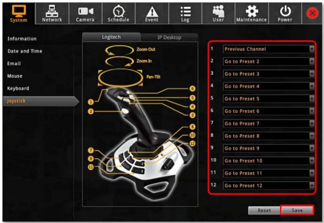
text_image
System Network Camera Schedule Event Log User Maintenance Power Information Date and Time Email Mouse Keyboard Joystick Logitech IP Desktop Zoom Out Zoom In Pan-Tilt 1 2 3 4 5 6 7 8 9 10 11 12 Previous Channel Go to Preset 2 Go to Preset 3 Go to Preset 4 Go to Preset 5 Go to Preset 6 Go to Preset 7 Go to Preset 8 Go to Preset 9 Go to Preset 10 Go to Preset 11 Go to Preset 12 Reset Save- There are 12 buttons available on each controller; you may assign a function selected from dropdown list to any button. Every time you change the settings on this page, please click "Save" to save the settings of this joystick model.
System Log
ENR records the important system activities and user's behaviors in System Log. Once the number of logs exceed 3000, ENR will erase the earliest 100 logs.
On Live screen, click Setup → click Log tab
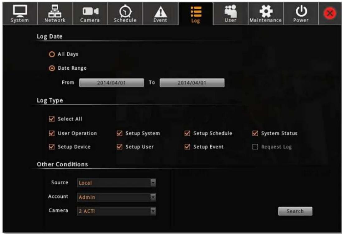
text_image
System Network Camera Schedule Event Log User Maintenance Power Log Date All Days Date Range From 2014/04/01 To 2014/04/01 Log Type Select All User Operation Setup System Setup Schedule System Status Setup Device Setup User Setup Event Request Log Other Conditions Source Local Account Admin Camera 2 ACTi Search- Define the time range:
You may choose "All Days" to show all the logs or choose "Day Range" to specify a range.
- Select Log Types
- Define other conditions. For example, you can view the logs of all remote clients by selecting "Remote" for Source.
- Click "Search" to start searching.will automatically refresh accordingly.
| ID | Date | Type | Account | Source | Camera | Description |
| 1 | 2014/04/01 16:44:08 | Setup Device | admin | Local | 8 | Add Camera |
| 2 | 2014/04/01 16:43:35 | Setup Device | admin | Local | 7 | Add Camera |
| 3 | 2014/04/01 16:17:00 | Setup Device | admin | Local | 6 | Add Camera |
| 4 | 2014/04/01 16:17:00 | Setup Device | admin | Local | 5 | Add Camera |
| 5 | 2014/04/01 16:17:00 | Setup Device | admin | Local | 4 | Add Camera |
| 6 | 2014/04/01 16:16:04 | Setup Device | admin | Local | 3 | Add Camera |
| 7 | 2014/04/01 16:16:04 | Setup Device | admin | Local | 2 | Add Camera |
| 8 | 2014/04/01 16:16:04 | Setup Device | admin | Local | 1 | Add Camera |
| 9 | 2014/04/01 15:28:09 | Setup Device | admin | Local | 16 | Delete Camera |
| 10 | 2014/04/01 15:28:09 | Setup Device | admin | Local | 15 | Delete Camera |
Export System Log
To export the logs, insert a USB disk into ENR, click "Export" and save the xml file to your local computer. You may view this file on a computer with Notepad or XML Editor.
<?xml version="1.0"?>
- <Logs>
    <Log Source="Local" Account="admin" Date="2013/09/07 04:51:08" ID="1">Camera 9 is added</Log>
    <Log Source="Local" Account="admin" Date="2013/09/07 04:50:05" ID="2">Camera 9 is deleted</Log>
    <Log Source="Local" Account="admin" Date="2013/09/07 04:49:50" ID="3">Camera 9 is added</Log>
    <Log Source="Local" Account="admin" Date="2013/09/07 04:49:50" ID="4">Camera 3 is added</Log>
    <Log Source="Local" Account="admin" Date="2013/09/07 04:48:01" ID="5">Camera 9 is deleted</Log>
    <Log Source="Local" Account="admin" Date="2013/09/07 04:47:54" ID="6">Camera 3 is deleted</Log>
    <Log Source="Local" Account="admin" Date="2013/09/07 04:43:40" ID="7">Backup system configuration</Log>
    <Log Source="Local" Account="admin" Date="2013/09/07 00:48:40" ID="8">User login</Log>
    <Log Source="System" Account="*" Date="2013/09/07 00:44:13" ID="9">System start up</Log>
</Logs>
User Group Management
In ENR, the access permissions are managed by User Groups. User Groups defines what functions are allowed for a group of users. Different User Groups will have different access rights in terms of permitted operations like monitoring Live screen or execute Playback. For example, an Administrator user is allowed for all the operations in ENR, while a standard normal user may only be permitted to do Live monitoring.
On Live screen, click Setup → click User tab to enter Group and User management page.
Add a Group
By default, the Administrator User Group with full permissions in ENR already exists. Except for the password and e-mail settings, you may not delete this account or change its permissions.
- Select "Group", click "Add" to bring up Add New Group window, enter the Name and Description of the group, and click "OK" to add it to the Group List.
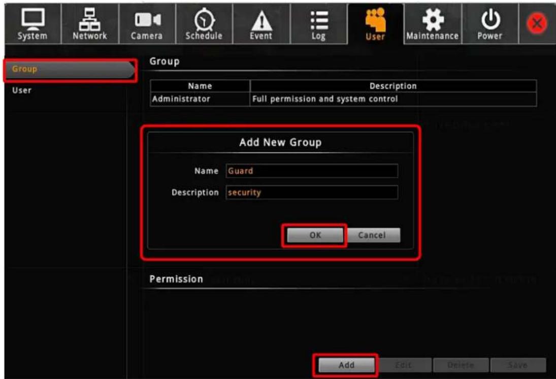
text_image
System Network Camera Schedule Event Log User Maintenance Power Group User Name Description Administrator Full permission and system control Add New Group Name Guard Description security OK Cancel Permission Add Edit Delete Save- On Group List, select this group. In Group Permission section, enable the permissions possessed by this group.
3. Click "Save" to save the group settings.
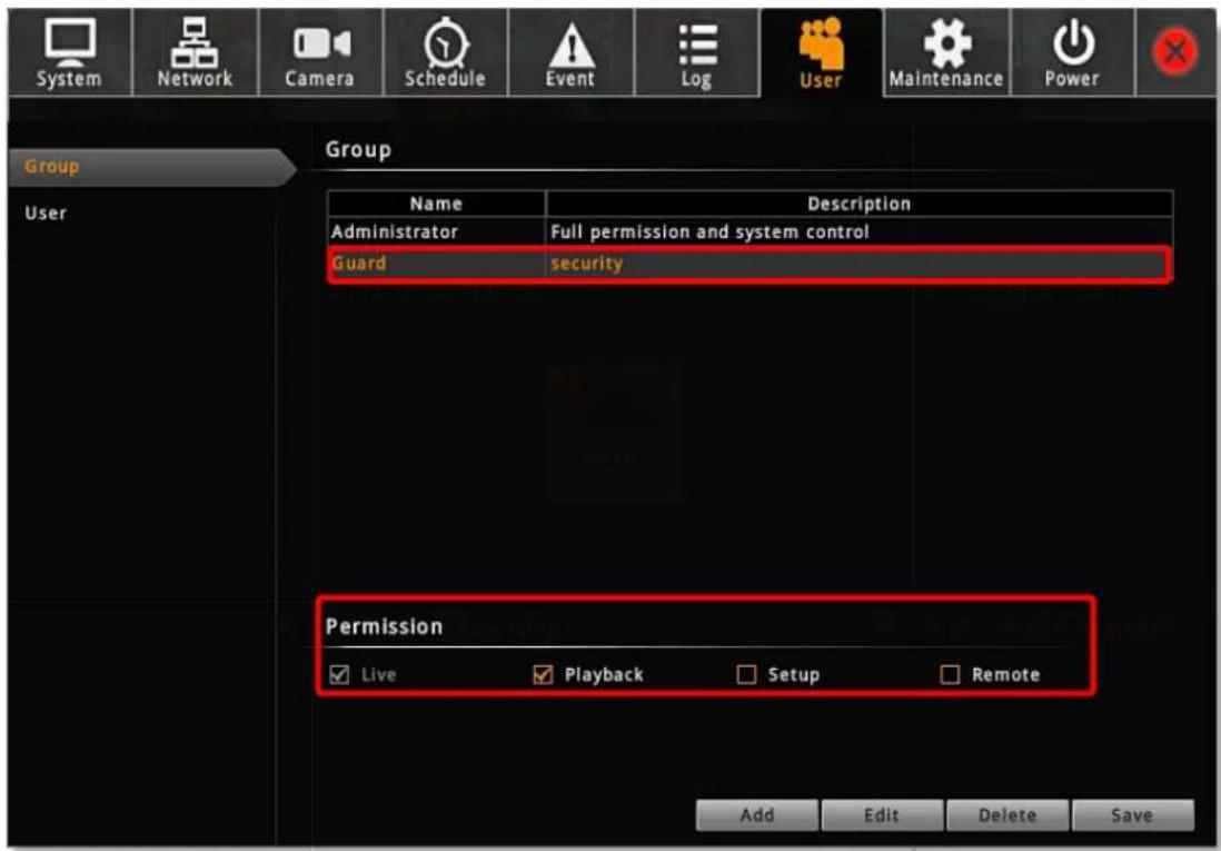
text_image
System Network Camera Schedule Event Log User Maintenance Power Group User Name Description Administrator Full permission and system control Guard security Permission ✓Live ✓Playback Setup ✓Remote Add Edit Delete SaveEdit / Delete a Group
You may edit an existing group by changing its Name, Description or Permissions or delete it. Once you delete a group, the Users belonging to it will be removed altogether. Select the group on Group List, click "Edit" or Delete".
Add a User
By default, the Administrator User already exists, which you may not delete.
- Select User, click "Add" to bring up Add New User window, enter the Name, Password, Email and select its User Group from dropdown list. Click "OK" to add it to the User List.
- Click "Save" to save the user settings.
Account /Password Rules
- Account field allows alphabets, numbers, and symbols except the following: * <> ? | “ \ : The maximum length of characters is 15.
- Password field allows alphabets, numbers and symbols. The maximum length of characters is 40.
- Both the Account and Password field are non-case-sensitive.
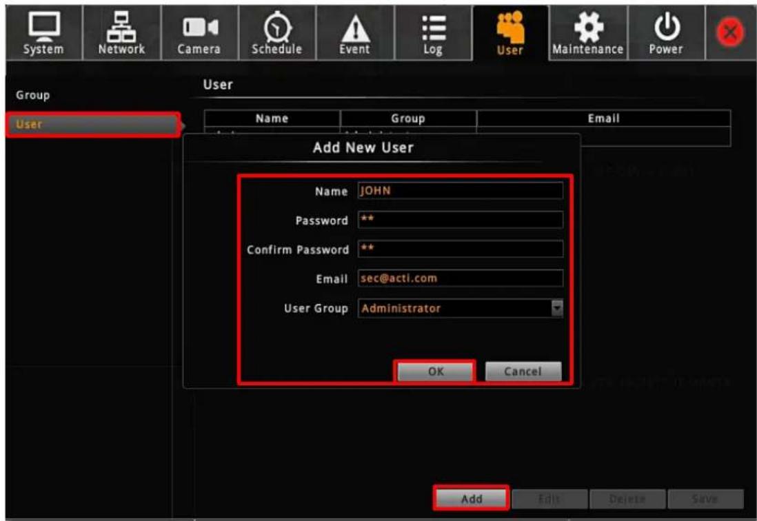
text_image
System Network Camera Schedule Event Log User Maintenance Power Group User Name Group Email Add New User Name JOHN Password ** Confirm Password ** Email sec@acti.com User Group Administrator OK Cancel Add Edit Delete SaveEdit / Delete a User
You may edit an existing user or delete it. Select the user on User List, click "Edit" or Delete". Please always click "Save" before leaving this page.
Upgrade Firmware
You may check ACTi corporate website for latest ENR firmware package and download it. Unzip the package and save the *.upg file to the root directory of a USB disk and insert it into ENR USB port.
- On Live screen, click Setup → click Maintenance tab → select "Firmware Upgrade".
- Click "Browse", find the target *.upg file and click "Open".
- Click "Upgrade".
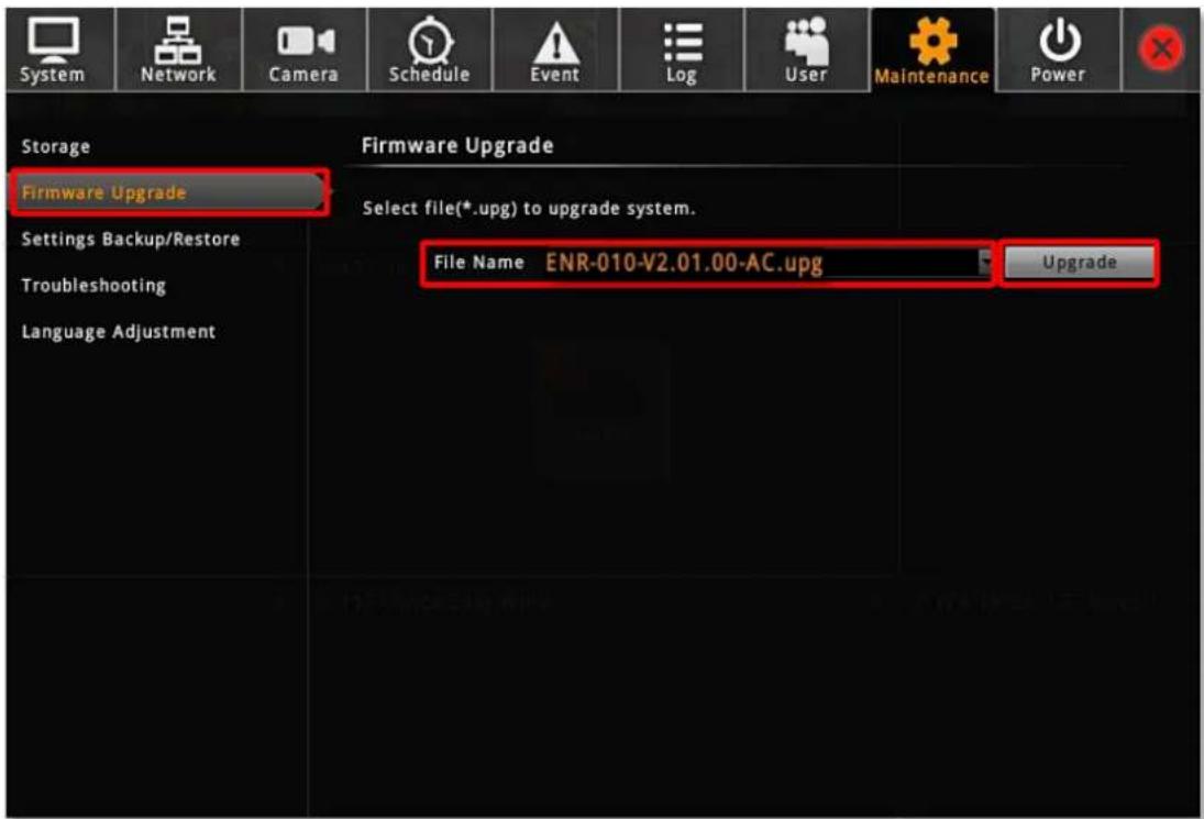
text_image
System Network Camera Schedule Event Log User Maintenance Power Storage Firmware Upgrade Select file(*.upg) to upgrade system. Settings Backup/Restore Troubleshooting Language Adjustment File Name ENR-010-V2.01.00-AC.upg Upgrade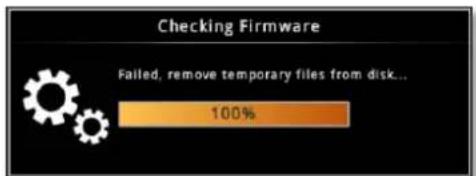
text_image
Checking Firmware Failed, remove temporary files from disk... 100%During upgrading, the system will stop every other activity including recording and event handling. The system will auto-restart after the upgrading completes.
After upgrading has started, DO NOT cut off the system power or eject the USB disk until ENR restarts.
Please note that
The USB disk carrying the firmware image should at least have 200 MB free space.
Making regular system backups is always recommended in case of unexpected disasters or accidents that may damage ENR server.
ENR server can create a backup file of the whole system settings as
Backup_[yyyymmdd].nvr file and save it to a connected USB disk within one click. The backed up settings include the following properties: (1) System Settings including System Name, Date & Time, Network, Email, Mouse and Keyboard, (2) Camera Settings, (3) Schedule Settings, and (4) Event Management.
The recordings will be kept on hard disks, please refer to ENR User's Manual to export a system log file and to export video files for a complete backup.
Backup
To start backing up system setting, please insert a USB disk into ENR first.
- On Live screen, click Setup"→ click Maintenance tab → click "Settings Backup / Restore".
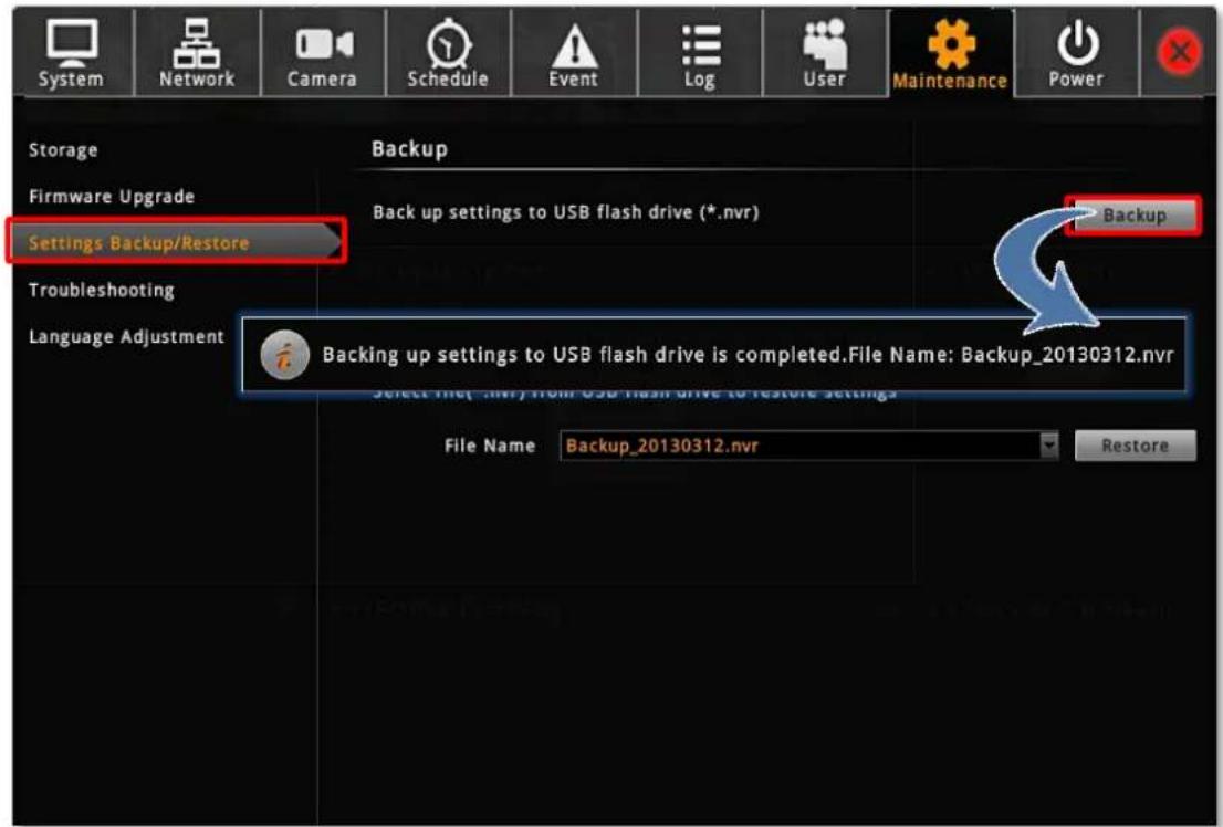
text_image
System Network Camera Schedule Event Log User Maintenance Power Storage Firmware Upgrade Settings Backup/Restore Troubleshooting Language Adjustment Backup Back up settings to USB flash drive (*.nvr) Backup Backing up settings to USB flash drive is completed.File Name: Backup_20130312.nvr File Name Backup_20130312.nvr Restore- Click "Backup", the backup file will be saved to your USB disk as .nvr file.
Restore
Before starting restoring the system, make sure you have connected the USB disk with the desired .nvr backup file in it, and the backup file is saved in the root directory.
- On Live screen, click Setup → click Maintenance tab → click "Setting Backup / Restore".
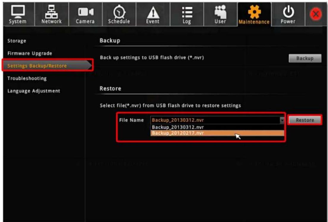
text_image
System Network Camera Schedule Event Log User Maintenance Power Storage Firmware Upgrade Settings Backup/Restore Troubleshooting Language Adjustment Backup Back up settings to USB flash drive (*.nvr) Backup Restore Select file(*.nvr) from USB flash drive to restore settings File Name Backup_20130312.nvr Backup_20130312.nvr Backup_20120217.nvr Restore- All the .nvr file detected from your USB disk root directory will be shown on the File Name dropdown list, select your desired one.
- Click "Restore" to start restoring the settings. The server will restore the settings from the backup file and reboot.
Customize Live Screen Layout
You may customize the layout style, channel position and patrol behavior. Your arrangement of Live screen layout will be the default view after any local user logs in to ENR.
Change Channel Position
You may place any channel in your desired window, and ENR will remember this arrangement until you change it.
You may move a camera view to any position by dragging it to the target channel.
In the example below, the green numbers represent the order of channels. Dragged by the mouse, Camera 1 will be swapped from Channel 1 to Channel 5.
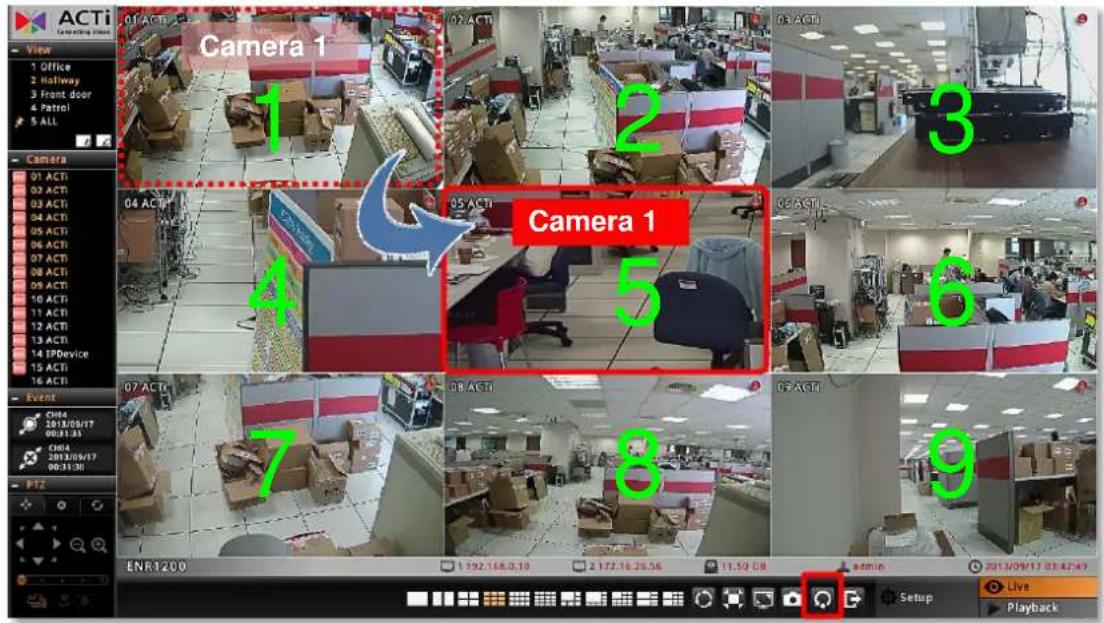
text_image
ACTi View 1 Office 2 Hallway 3 Front door 4 Patrol 5 ALL Camera 1 1 2 3 04 ACTI 05 ACTI 06 ACTI 07 ACTI 08 ACTI 09 ACTI 10 ACTI 11 ACTI 12 ACTI 13 ACTI 14 IPDevice 15 ACTI 16 ACTI Event CHINA 2018/09/17 00:31:35 CHINA 2018/09/17 00:31:30 PTZ ENR1200 1.192.168.0.10 2.172.16.25.56 11.59 GB admin 2013/09/17 03:42:49 Setup Live PlaybackYou can Reset the camera positions by clicking

on Live Menu.
Change Layout
To select a desired layout, click one on Live Menu. Each layout will display specific windows shown below. Therefore, you have to make sure the cameras you desired to watch are placed in the designated channels before applying the layout.

text_image
1 1 2 1 2 1 2 3 1 2 3 4 1 2 3 4 3 4 4 5 6 5 6 7 8 7 8 9 9 10 11 12 13 14 15 16
text_image
1 2 3 4 5 6 1 2 3 4 5 5 6 7 8 1 2 3 4 5 6 7 8 9 10 1 2 3 4 5 5 6 6 7 8 9 10 11 12 13For example, to watch Camera 2,4,6,8 in a quad layout, you should:
- Select a square grid layout (2x2, 3x3 or 4x4) where you can see all channels.
- Place Camera 2 into Channel 1, Camera 4 into Channel 2, Camera 6 into Channel 3, and Camera 8 into Channel 4.
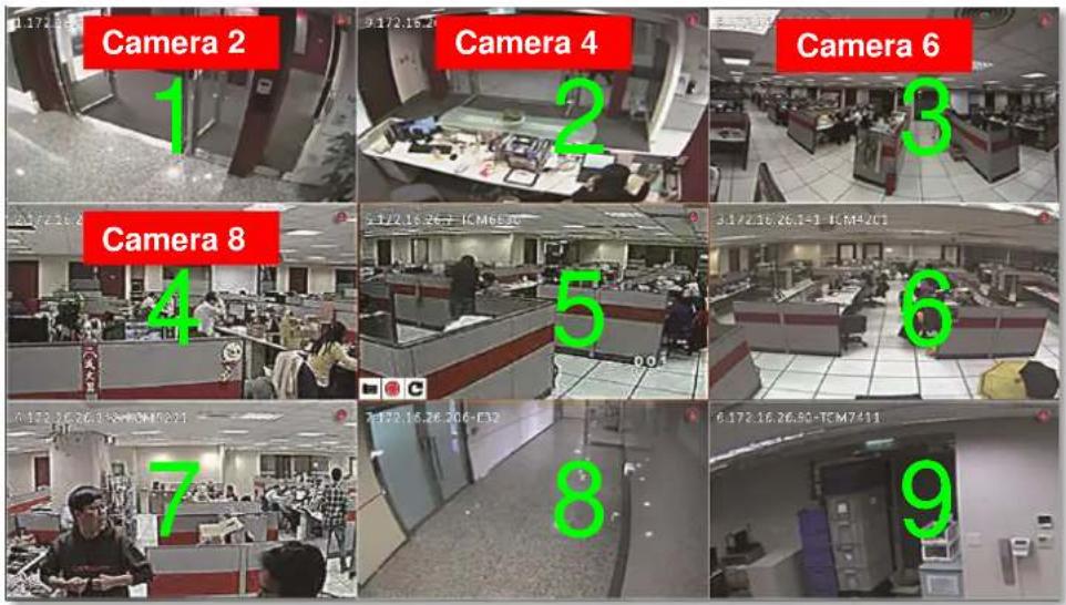
text_image
Camera 2 1 9:17:26.24 Camera 4 2 Camera 6 3 5:17:26.26.7-TCM6E30 6:17:26.26.1-1-TCM4201 7 8 9 Camera 8 4 A:172.16.26.152-TCM1221 7:17:26.26.206-F32 8:17:26.26.90-TCM7411- Select the 2x2 layout on Live Menu.


text_image
2.172.16.26.140-TCM5611 Camera 2 6 172.16.26.90-TCM7411 Camera 6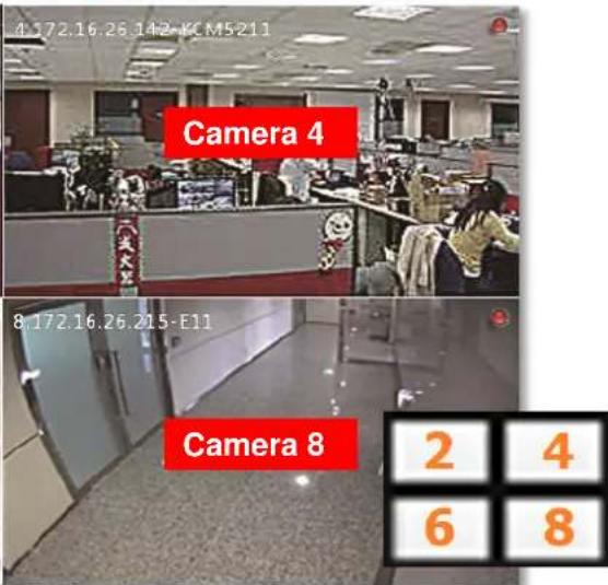
text_image
4.172.16.26.142-KCM5211 Camera 4 8.172.16.26.215-E11 Camera 8 2 4 6 8Note
The five customized views for local live view and those for remote live view are maintained separately; therefore, any modification you make to the views on View here list will not affect the View settings on remote Live screen.
Execute Sequence Patrol
The patrol function will slide-show multiple channels at your defined length of interval. At one time the layout will show as many channels as its maximum display channels. For instance, as Patrol is enable, a 3x3 layout will show channel 1\~9, then 10\~16 by turns.
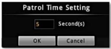
text_image
Patrol Time Setting 5 Second(s) OK Cancel- On Live Menu, click 📋 to bring up the Patrol Time Setting window.
- Input the patrol time
- Click "OK", the patrol will start until you click again.
Save a Customized View
You may save up to five customized view on local View List. A saved view will remember (1) the layout style, (2) camera arrangement, (3) view size (stretched / un-stretched / full-screen) and (4) Patrol setting.
- Select a View from the View List.
- Customize your layout with the tools provided on Live Menu.
- Click in bottom right corner of View List, enter
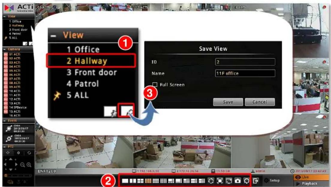
text_image
View 1 Office 2 Hallway 3 Front door 4 Patrol 5 ALL Save View ID 2 Name 11F office Full Screen Save Cancel Event CH04 2013/09/17 00:31:33 CH04 2013/09/17 00:31:30 ENR1200 1 192.168.0.10 2 172.16.26.56 11.50 08 admin 2013/09/17 03:42:49 Setup Live PlaybackSet a Default View
If you have enabled "Auto-login" function (please refer to Set Auto Login on page 35), you may also set one View as default, in this way, you may immediately start live monitoring after the system starts up. To set a default view, simply select a desired view on View list, and click

Customize System Language
ENR user interface supports multiple languages and offers you the flexibility to change the wording. There are over 10 supported UI languages you may choose on Login page. Each language (except for English) is open for customization based on your own needs. This section will describe how to choose or customize language wording for your ENR.
To start, you need to connect a USB disk to ENR to export the language file for editing.
Modify the Wording
After the USB disk is connected,
- On Live screen, click Setup → click Maintenance tab → click "Language Adjustment".
- On Language Adjustment page, below Export Language section, select your desired language form original language file list, and click "Export". ENR will pop up a window as the file is successfully saved to USB disk.
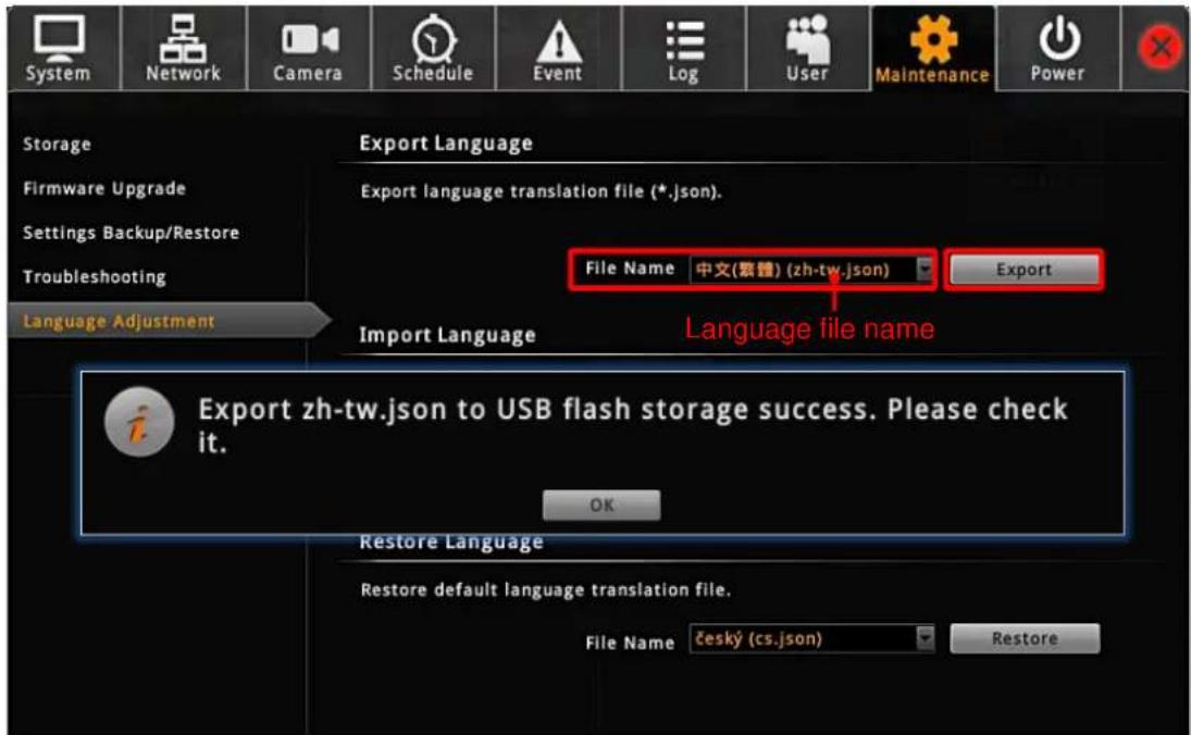
text_image
System Network Camera Schedule Event Log User Maintenance Power Storage Firmware Upgrade Settings Backup/Restore Troubleshooting Language Adjustment Export Language Export language translation file (*.json). File Name 中文(索體) (zh-tw.json) Export Import Language Language file name Export zh-tw.json to USB flash storage success. Please check it. OK Restore Language Restore default language translation file. File Name Český (cs.json) Restore- On a computer, open the file (*.json) with a text editor program. Each entry represents the current wording of an object. Please edit the wording of your language embedded in quotation marks (“”) on the right of the colon; The English term appearing on the left is the original system code, which should be left unchanged.
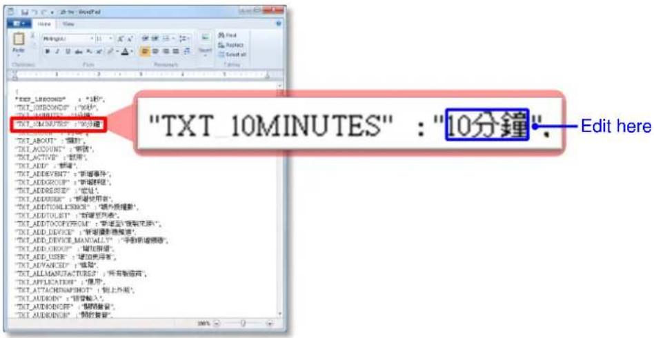
text_image
"TXT 10MINUTES" : "10分鐘" Edit here- After the modification is done, save this file with its original file name and file type onto the USB disk, make sure the text encoding format is UTF-8.
- Connect the USB disk with ENR, on Language Adjustment page, select the language file from drop-down list below Import Language section, and click "Import". ENR will pop up a window as the file is successfully imported into ENR server.
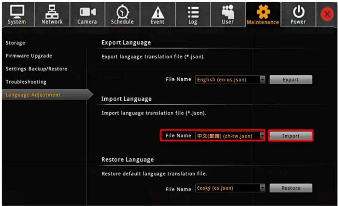
text_image
System Network Camera Schedule Event Log User Maintenance Power Storage Firmware Upgrade Settings Backup/Restore Troubleshooting Language Adjustment Export Language Export language translation file (*.json). File Name English (en-us.json) Import Language Import language translation file (*.json). File Name 中文(繁體) (zh-tw.json) Import Restore Language Restore default language translation file. File Name Český (cs.json) Restore- Log in to ENR again. On Login window, select the UI language before you click "Login".
- Check the UI to see if the modified term is correctly shown.
Restore the Wording
ENR always keeps the original language file in its memory, so you can restore the language wording to default. On Language Adjustment page, select the language file from drop-down list below Restore Language section, and click "Restore". The entire original language wording will restore after you log into the system again.
Remote Client Operation
Access ENR Server
A remote client refers to any client using a computer over WAN or LAN other than server computer. If you know the IP address and port number of the ENR, you may type in the IP address and port number directly into Internet Explorer. Sample IP will look like this:
http://220.228.146.21:1000 or domain name http://enr.acti.com. If the port number is 80, you do not need to append it when typing the address.
http://ip address:port number
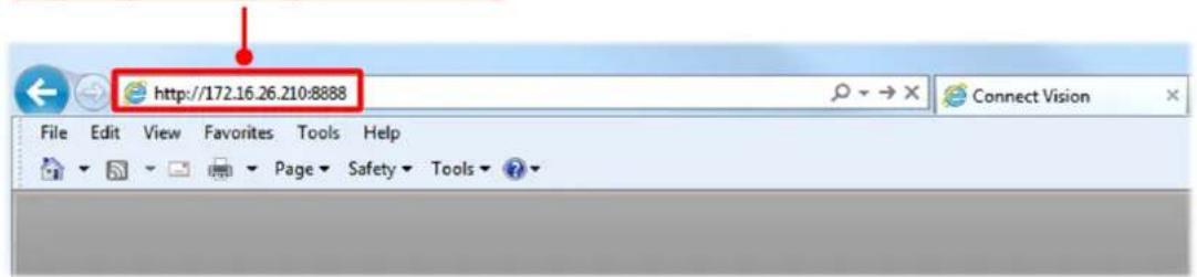
text_image
http://172.16.26.210:8888 File Edit View Favorites Tools Help Page Safety ToolsFind ENR in Your Network
The ip address of both ENR's LAN ports are shown on local live screen.
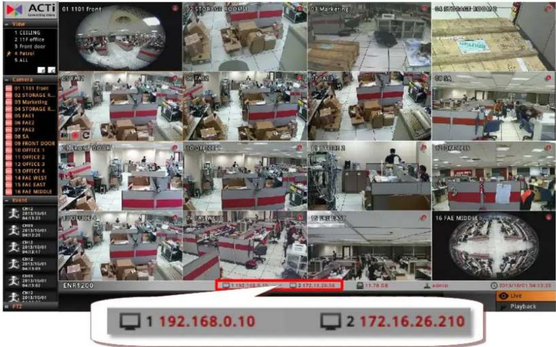
text_image
ACTi Control panel View 1 CEILING 2 1TF office 3 Front door 4 Patrol 5 ALL Camera 01 1101 front 02 STORAGE ROOM? 03 Marketing 04 STORAGE ROOM? 05 FAT 06 FAT2 07 FAT3 08 SA 09 FRONT DOOR 10 OFFICE 1 11 OFFICE 2 12 OFFICE 3 13 OFFICE 4 14 FAE WEST 15 FAE EAST 16 FAE MIDDLE Event CH12 2013/10/01 04/13:23 CH13 2013/10/01 04/13:26 CH14 2013/10/01 04/13:17 CH15 2013/10/01 04/13:02 CH16 2013/10/01 04/13:03 ENR1200 1 192.168.0.10 2 172.16.26.210If your client computer and ENR are both within the same network, find ENR's IP address via the following two quick methods - UPnP connection or ACti IP Utility.
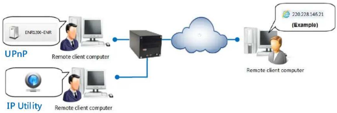
flowchart
graph LR
    A["UPnP"] --> B["Remote client computer"]
    C["IP Utility"] --> D["Remote client computer"]
    B --> E["Cloud Service"]
    D --> E
    E --> F["Remote client computer"]
    G["220.228.146.21 (Example)"] --> F
Via UPnP Connection
ENR supports UPnP connection. This means that once the device has an IP address, you will be able to find it in the local network in Windows Explorer → Network. Please note that your PC must be in the same subnet with ENR.
Once you locate ENR, double-click on it to open the client browser.
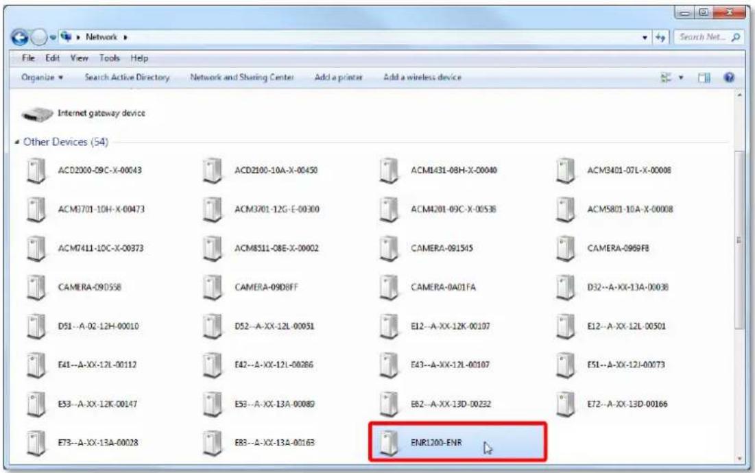
text_image
Network File Edit View Tools Help Organize Search Active Directory Network and Sharing Center Add a printer Add a wireless device Internet gateway device Other Devices (54) ACD2000-09C-X-00043 ACD2100-10A-X-00450 ACM1431-08H-X-00040 ACM3401-07L-X-00008 ACM3701-10H-X-00473 ACM3701-12G-E-00300 ACM4201-09C-X-00538 ACM5801-10A-X-00008 ACM7411-10C-X-00373 ACM8511-08E-X-00002 CAMERA-091545 CAMERA-0969FB CAMERA-09D558 CAMERA-09D8FF CAMERA-0A01FA D32--A-XX-13A-00038 D51--A-02-12H-00010 D52--A-XX-12L-00051 E12--A-XX-12K-00107 E12--A-XX-12L-00501 E41--A-XX-12L-00112 E42--A-XX-12L-00286 E43--A-XX-12L-00107 E51--A-XX-12J-00073 E53--A-XX-12K-00147 E53--A-XX-13A-00089 E62--A-XX-13D-00232 E72--A-XX-13D-00166 E73--A-XX-13A-00028 E83--A-XX-13A-00163 ENR100-ENRVia ACTi IP Utility
ACTi IP Utility is a software tool used to find all ACTi products including cameras and ENR servers. Download the latest IP Utility from the link below and install it on your computer.
http://www.acti.com/product/detail/Video_Management_System/ACTi_Utility_Suite
Execute this program, and find ENR from the search list, double-click on the IP address to open the client browser.
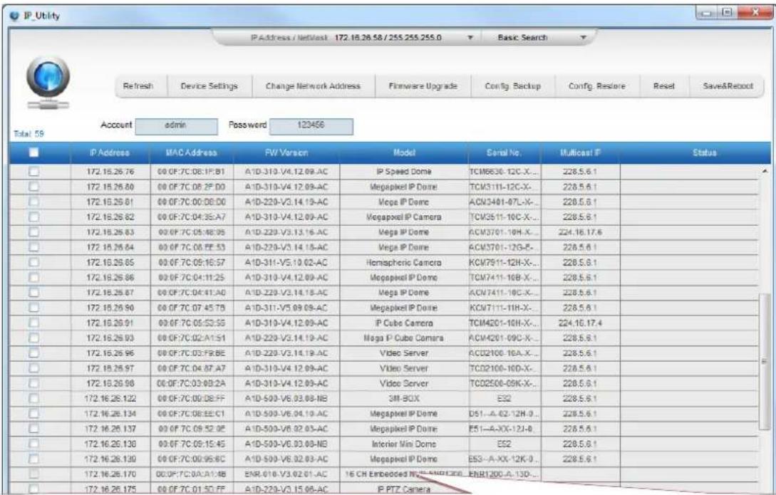
text_image
IP Utility IP Address / Network 172.16.28.58 / 255.255.255.0 Basic Search Refresh Device Settings Change Network Address Firmware Upgrade Config Backup Config Restore Reset Save&Reboot Account admin Fosswerd 120456 Total: 59 IP Address MAC Address FW Version Model Serial No. Multicast IP Status 172.16.26.76 00 OF:7C:08:1P:B1 A1D-310-V4.12.09-AC IP Speed Dome TCM6530-12C-X... 228.5.6.1 172.16.26.80 00 OF:7C:08:2F:D0 A1D-310-V4.12.09-AC Megapixel IP Dome TCM3111-12C-X- 228.5.6.1 172.16.26.81 00 OF:7C:00:08:D0 A1D-220-V3.14.19-AC Mega IP Dome ACM3401-07L-X- 228.5.6.1 172.16.26.82 00 OF:7C:04:3S:A7 A1D-310-V4.12.09-AC Megapixel IP Camera TCM3511-10C-X- 228.5.6.1 172.16.26.83 00 OF:7C:05:48:05 A1D-220-V3.13.16-AC Mega IP Dome ACM3701-10H-X- 224.16.17.6 172.16.26.84 00 OF:7C:08:FE:53 A1D-220-V3.14.18-AC Mega IP Dome ACM3701-12G-R- 228.5.6.1 172.16.26.85 00 OF:7C:09:16:57 A1D-311-V5.10.02-AC Homspheric Camera KCM7911-12H-X- 228.5.6.1 172.16.26.86 00 OF:7C:04:11:25 A1D-310-V4.12.09-AC Megapixel IP Dome TCM7411-10B-X- 228.5.6.1 172.16.26.87 00 OF:7C:04:41:A0 A1D-220-V3.14.18-AC Mega IP Dome ACM7411-10C-X- 228.5.6.1 172.16.26.90 00 OF:7C:07:45:7B A1D-311-V5.09.09-AC Megapixel IP Dome KCM7111-11H-X- 228.5.6.1 172.16.26.91 00 OF:7C:05:53:55 A1D-310-V4.12.09-AC IP Cube Camera TCM4201-10H-X- 224.16.17.4 172.16.26.93 00 OF:7C:02:A1:S1 A1D-220-V3.14.19-AC Mega IP Cube Camera ACM4201-09C-X- 228.5.6.1 172.16.26.96 00 OF:7C:03:F8:E6 A1D-220-V3.14.19-AC Video Server ACO2100-10A-X- 228.5.6.1 172.16.26.97 00 OF:7C:04:87:A7 A1D-310-V4 12.09-AC Video Server TCO2100-10D-X- 228.5.6.1 172.16.26.98 00 OF:7C:03:09:2A A1D-310-V4 12.09-AC Video Server TCO2500-09K-X- 228.5.6.1 172.16.26.122 00 OF:7C:09:38:FF A1D-599-V6,03,08-NB SIM BOX EQ2 228.5.6.1 172.16.26.134 00 OF:7C:08:EE:C1 A1D-599-V6,04,19-AC Megapixel IP Dome D5I-A-CC-12H-D- 228.5.6.1 172.16.26.137 00 OF:7C:09:52:E E A1D-599-V6,02,03-AC Megapixel IP Dome E5I-A-XX-12J-D- 228.5.6.1 172.16.26.138 00 OF:7C:09:15:45 A1D-599-V6,03,08-NB Interior Mini Dome EQ2 228.5.6.1 172.16.26.139 00 OF:7C:09:95:BC A1D-599-V6,02,03-AC Megapixel IP Dome ES3-A-XX-12K-D- 228.5.6.1 172.16.26.17O 00 OF:7C:CA:AIA:B ENR-0Ib-V3,02,0i-AC 16 CH Embedded NLS-MNORON ENR-ILO-A-ILO- TEN TEN TEN TEN TEN TEN172.16.26.56
00:0F:7C:0A:A1:4B
ENR-010-V4.99.20-AC
16 CH Embedded NVR-ENR1200
Log In / Out of ENR
After you By default, an administrator account has already been existing in your system. To log in to ENR for the first time, you will have to key in the password in Login window.
Log In
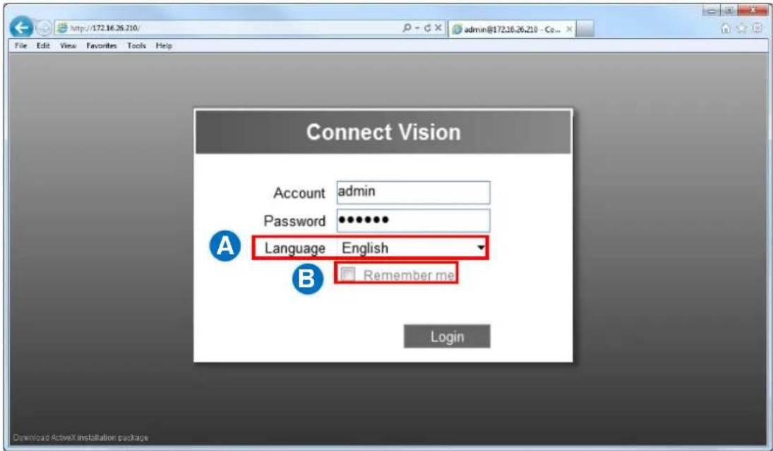
text_image
Connect Vision Account admin Password ••••••• Language English Remember me Login Download ActiveX installation packageEnter Account & Password
- Account (non case-sensitive): Admin (default)
- Password (case-sensitive): 123456 (default)
Change UI language A
To change UI language, select the desired language from "Language" dropdown list.
Remember Login Information B
To have the server remember your Account, Password and language setting for future, check "Remember me".
Log Out
On Live screen, click "Application" → "Logout".
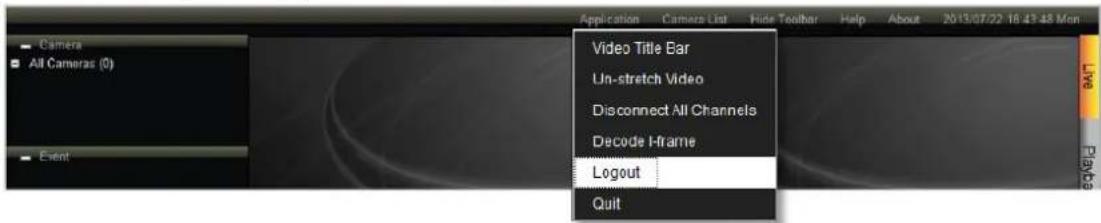
text_image
Camera All Cameras (0) Event Application Camera List Hide Toolbar Help About 2013/07/22 16:43:48 Mon Video Title Bar Un-stretch Video Disconnect All Channels Decode H-frame Logout QuitAccept ActiveX Controls Installation
ENR interface requires the add-on ActiveX Control components, please allow ActiveX controls to be downloaded and installed.
It is strongly recommended that (1) you add this ENR server into Internet Explorer's Trusted Sites and (2) turn off Windows Firewall on this client computer.

text_image
ActiveX Control 'nvViewer' Is Downloading, Please Wait. Required Activex Control 'nvViewer' Install Internet Explorer - Security Warning Do you want to install this software? Name: nvViewer.dll Publisher: ACTi Corporation More goions Install Don't Install While files from the Internet can be useful, this file type can potentially harm your computer. Only install software from publishers you trust. What's the risk? This website wants to install software from: 'ACTi Corporation'. What's the risk? Internet Explorer - Security Warning to install this software? Name: nvService.ocx Publisher: ACTi Corporation Install Don't Install Fles from the Internet can be useful, this file type can potentially harm your computer. Only install software from publishers you trust. What's the risk? installSetup Wizard
After logging in, if no camera has been added to ENR system, ENR Setup Wizard will lead you through three essential installation steps in order that you could quickly get camera live view.
For video recording, please remember to install hard disks and format them in physical ENR device.
You may click the Done bubble to skip to the quick setup procedures last step.
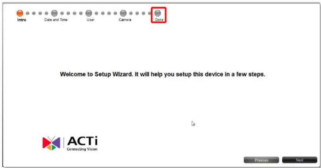
text_image
Intro Date and Time User Camera Done Welcome to Setup Wizard. It will help you setup this device in a few steps. ACTi Connecting Vision Previous NextAnd click "Done" to exit Setup Wizard.
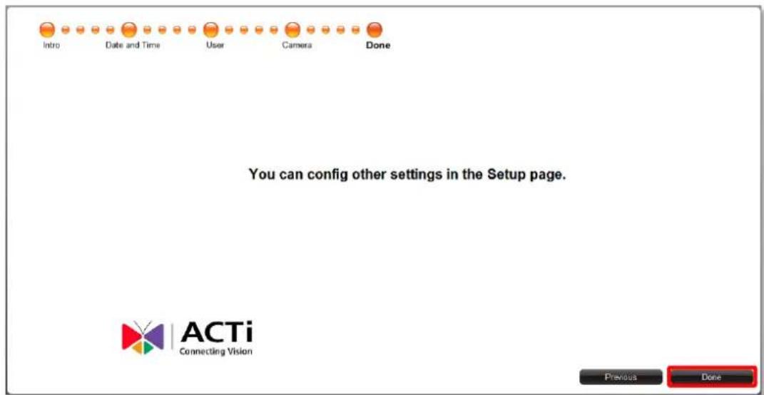
text_image
Intro Date and Time User Camera Done You can config other settings in the Setup page. ACTi Connecting Vision Previous DoneSetup the System
Before adding cameras to the system or starting up the recording and event handling, it is essential to configure certain system-wise settings on Setup page.
Set System Name
Go to Setup page → System tab → Information
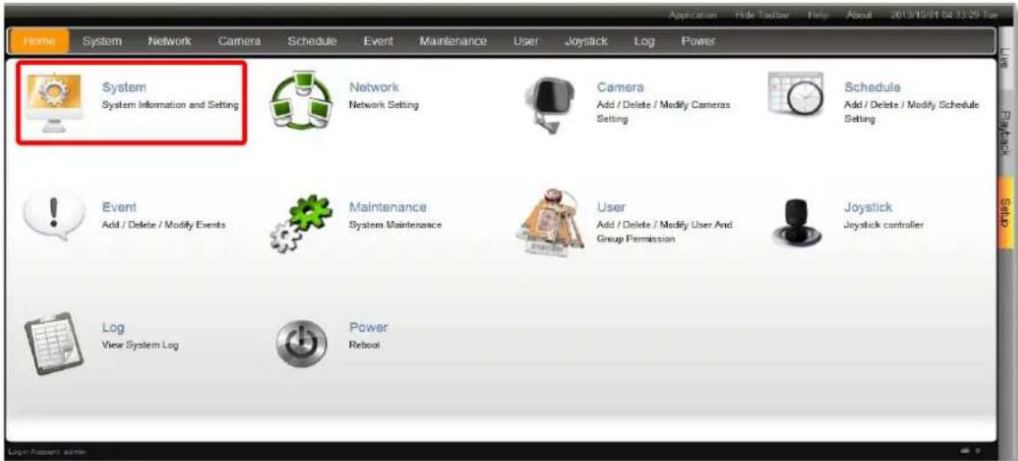
text_image
Home System Network Camera Schedule Event Maintenance User Joystick Log Power Application Hide Toolbar Help About 2013/10/01 04:33:29 Tue System System Information and Setting Network Network Setting Camera Add / Delete / Modify Cameras Setting Schedule Add / Delete / Modify Schedule Setting Event Add / Delete / Modify Events Maintenance System Maintenance User Add / Delete / Modify User And Group Permission Joystick Joystick controller Log View System Log Power RebootModify the name of this ENR server and click "Save". The maximum length is 10 digits of English alphabets.
Your ENR's current firmware version, serial number and MAC address are also shown here.
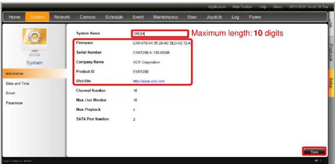
text_image
Home System Network Camera Schedule Event Maintenance User Joystick Log Power System Name [PE01] Maximum length: 10 digits Firmware ENR-010-V4.99.20-AC BLD-V2.12-A Serial Number ENR1200-A-13D-00006 Company Name ACTi Corporation Product ID ENR1200 WebSite http://www.acti.com Channel Number 16 Max Live Monitor 16 Max Playback 4 SATA Port Number 2 SaveSet Date & Time
Go to Setup page → System tab → Date and Time
You may configure other time-related settings here.

text_image
Home System Network Camera Schedule Event Maintenance User Joystick Log Power Time Zone (JTC+08 00) Asia/Tarpei Date and Time 2014/02/06 15:04:29 Enable Daylight Saving Time NTP Server watch.stdtime.gov.tw Apply Synchronize with the NTP server automatically Local Sync Date and TimeChange Time Zone
Select the time zone where ENR server belongs to. After selecting the time zone, it will change to the corresponding date and time.
Change Date and Time
It shows the current date and time on the device. Click Date and Time to bring up the calendar. Input the exact date and time, then click "OK".
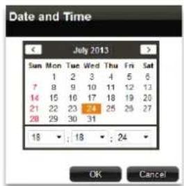
text_image
Date and Time July 2013 Sun Mon Tue Wed Thu Fri Sat 1 2 3 4 5 6 7 8 9 10 11 12 13 14 15 16 17 18 19 20 21 22 23 24 25 26 27 28 29 30 31 18 : 18 : 24 OK CancelSet Daylight Saving
If the device is located in an area where daylight saving time is used, click the check box to enable daylight saving. The time will be automatically adjusted. When the daylight saving time has finished, uncheck the box to return to original setting.
Set NTP Server
Please enter a NTP server address and click "Apply" to synchronize time with the NTP server. Make sure ENR has connection with the NTP Server.
To delete this NTP server, simply clear its address in this field and click "Apply".
Note
If your NTP server is a domain name address, make sure you have configured the DNS Setting and chosen appropriate Default Gateway on Setup page → System tab → Network
Synchronize with Client Computer's Time
Click Local Sync to synchronize the device time with the time on the computer you are using now, please click this button.
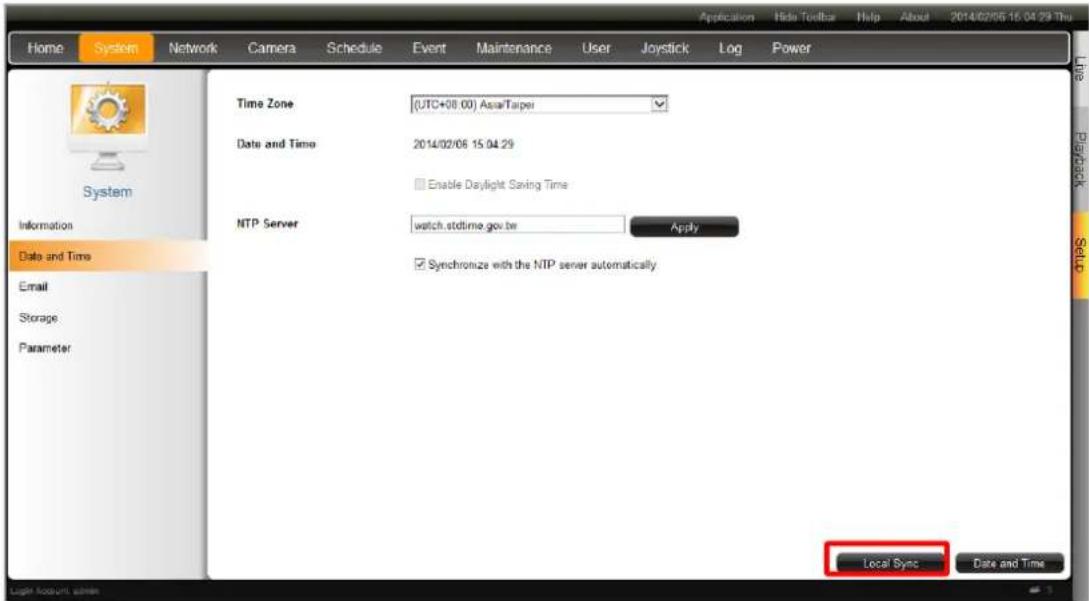
text_image
Home System Network Camera Schedule Event Maintenance User Joystick Log Power Time Zone (UTC+08:00) Asia/Tarpei Date and Time 2014/02/06 15:04:29 Enable Daylight Saving Time NTP Server watch.stdtime.gov.tw Apply Synchronize with the NTP server automatically Local Sync Date and Time Information Date and Time Email Storage ParameterConfigure Network Settings
There are two network interface cards in ENR.
Either of these cards can be supported by the built-in DHCP server feature, which enables ENR to assign IP addresses to cameras via LAN1 or LAN2 port without another DHCP on router.
By default, LAN1 card uses a fixed IP address 192.168.0.10, while LAN2 is in DHCP client mode. It is suggested that you connect LAN1 to LAN and connect LAN2 to WAN.
Current IP Configurations
Go to Setup page → Network tab.
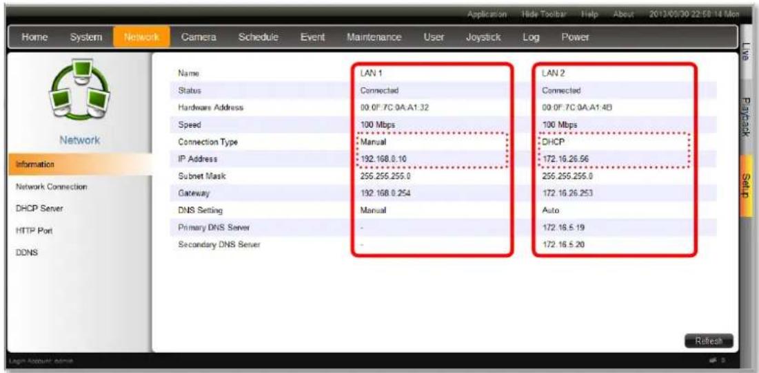
text_image
Home System Network Camera Schedule Event Maintenance User Joystick Log Power LAN 1 LAN 2 Connected 00:0F:7C:0A:A1:32 100 Mbps Connection Type Manual DHCP IP Address 192.168.0.10 172.16.26.56 Subnet Mask 255.255.255.0 255.255.255.0 Gateway 192.168.0.254 172.16.26.253 DNS Setting Manual Auto Primary DNS Server - 172.16.5.19 Secondary DNS Server - 172.16.5.20 RefreshIP Settings
On Network tab, click "Network Connection" then select the interface card that you wish to set up. After setting up, please click "Save" on the bottom right side to save the settings.
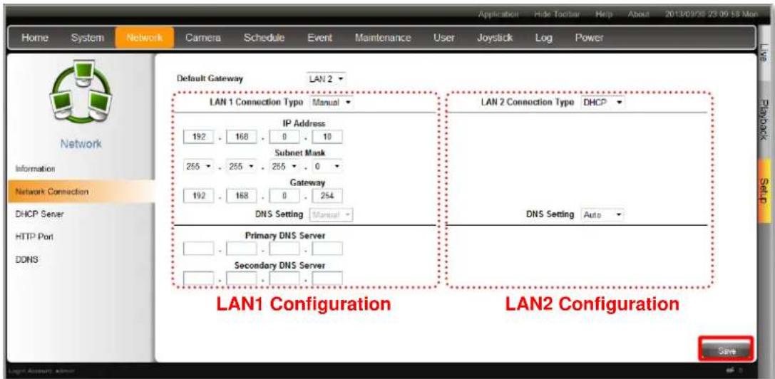
text_image
Home System Network Camera Schedule Event Maintenance User Joystick Log Power Default Gateway LAN 2 LAN 1 Connection Type Manual IP Address 192 168 0 10 Subnet Mask 255 255 255 0 Gateway 192 168 0 254 DNS Setting Manual LAN 2 Connection Type DHCP DNS Setting Auto Primary DNS Server Secondary DNS Server LAN1 Configuration LAN2 Configuration SaveENR-100 Series System Administrator's Manual
Please note that any change you make on this page requires the system to restart its service, please wait for a while and reconnect ENR using the new properties.
| HTTP Port | The connection port is used for remote web client to communicate with ENR. Default is 80. |
| Default Gateway | Default uses LAN2's setting.Choose one connection type for this LAN port. DHCP and PPPoE service will assign an IP Address to ENR, and there is no need for you to define other network information.Manual: Please obtain a static IP address and other network information including Subnet Mask, Gateway and DNS server from your network administrator. |
| Connection Type | |
| DHCP: Use this connection type if you have a DHCP server on your network router.PPPoE: Chose this when your ISP is using PPPoE type DSL line. Please contact you ISP to get the Username and Password for this connection.LAN1 default is Manual; LAN2 default is DHCP. | |
| IP Address | Fixed IP Address. LAN1 default is 192.168.0.10; LAN2 default is Auto. |
| Subnet Mask | Used to define if the destination is in the same subnet. LAN1 default is 255.255.255.0; LAN2 default is Auto. |
| Gateway | A valid gateway setting is essential for data transmission between different subnets, such as accessing the DNS service or SMTP server on the Internet. LAN1 default is 192.168.0.254; LAN2 default is Auto. |
| DNS Setting | The DNS server that translates domain names to actual IP addresses. If this LAN is Manual mode, and you will set an SMTP server for event notification, be sure to set the Primary DNS and Secondary DNS. LAN1 default is Manual; LAN2 default is Auto. |
Enable DHCP Server
You may enable the built-in DHCP server for either LAN1 (default) or LAN2 port.
Go to Setup page → Network tab → click "DHCP Server".
- Check "Enable" and select a LAN, this LAN has to be in Manual mode.
- Set the Beginning IP Address and Ending Address, and click "Save". ENR will assign IP addresses within this range to the cameras connected to the selected LAN port.
Please (1) make sure the cameras are in DHCP client mode, (2) connect and power the cameras up after you enable this service.
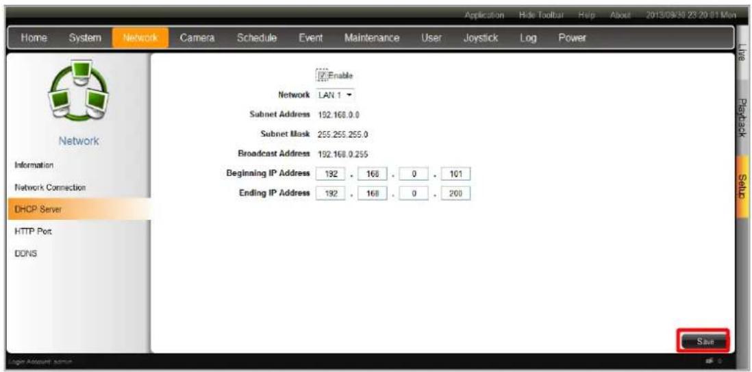
text_image
Home System Network Camera Schedule Event Maintenance User Joystick Log Power Network Enable Network LAN 1 Subnet Address 192.168.0.0 Subnet Mask 255.255.255.0 Broadcast Address 192.168.0.255 Beginning IP Address 192 . 168 . 0 . 101 Ending IP Address 192 . 168 . 0 . 200 DHCP Server HTTP Port DDNS SaveSet HTTP Port
To change the HTTP port of ENR server, go to Setup page → Network tab → click "HTTP Port". Configure the port number and click "Save".

text_image
Home System Network Camera Schedule Event Maintenance User Joystick Log Power Network Information Network Connection DHCP Server HTTP Port DONS HTTP Port 80 SaveEnable DDNS Service
ENR has built-in the DDNS update client feature, which saves ENR domain name address information and actively update its ip address to the DDNS provider's server.
- Visit the dynamic DNS service provider's website and register the domain name for your ENR.
ENR supports the following service providers:
● DynDNS: http://www.dyndns.com
● NO-IP: http://www.noip.com/
-
Go to Setup page → Network tab → click "DDNS".
-
Check "Enable", select the service provider, and input the Host Name, User Name and Password.
- Click "Save" to save the settings.
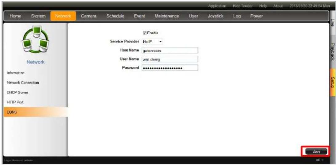
text_image
Home System Network Camera Schedule Event Maintenance User Joystick Log Power Network Information Network Connection DHCP Server HTTP Port DDNS Enable Service Provider No-IP Host Name gunsnoses User Name wen.cheng Password ************ SaveSet E-mail Notification Service
ENR supports e-mail notification for Event Handling. The e-mails are sent through an SMTP server, the settings of which are configured in this section.
Go to Setup page → System tab → Email.
Please fill up all the fields including Account and Password to access the e-mail address you input in "Sender Email". ENR will send notification e-mail via this SMTP server when an event occurs. For detailed instruction on how to set up an event rule related to SMTP service, please refer to Set Event Rules on page 120.
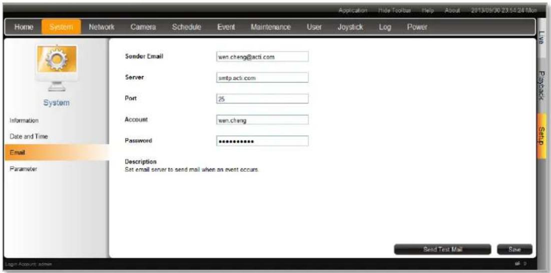
text_image
Home System Network Camera Schedule Event Maintenance User Joystick Log Power Sender Email wen.cheng@acti.com Server smtp.acti.com Port 25 Account wen.cheng Password ************ Description Set email server to send mail when an event occurs. Send Test Mail Save Login Account admin| Field Name | Description |
| Sender Email | Input the sender's e-mail address, should the same account you set for SMTP server. |
| Server | Input the sender's SMTP server address. Only alphabets, numbers, and the symbols (.), ( ), (-) are valid. ENR server supports the SMTP services with SSL protocol. If you wish to use a free webmail SMTP service, you may choose certain webmail providers such as Yahoo (SMTP: smtp.mail.yahoo.com Port:25) or Gmail (SMTP: smtp.gmail.com Port:25 or 465 for SSL protocol / 587 for TLS protocol) |
| Port | Set the SMTP port, allowed value is from 1~65535, default is 25. |
| Account | Input the name of the SMTP server account. The form of account name depends on mail server, e.g. a Hotmail account name is a complete e-mail address, while other e-mail servers' may be not. Only alphabets, numbers, and the symbols (@), ( ), ( ), (-) are valid. |
| Password | Input the password of the SMTP server account. Only alphabets and numbers are valid. |
After configuring, please click "Save" to save settings, and click "Send Test Mail" to validate this configuration, if this configuration is correct, a test e-mail will be sent to Sender Email, please login your SMTP server to check incoming e-mails.
Live Screen Event List Setting
The max number of latest events that can be displayed in event panel. Default is 100.
You can configure this setting on Setup page → System tab → Parameter.
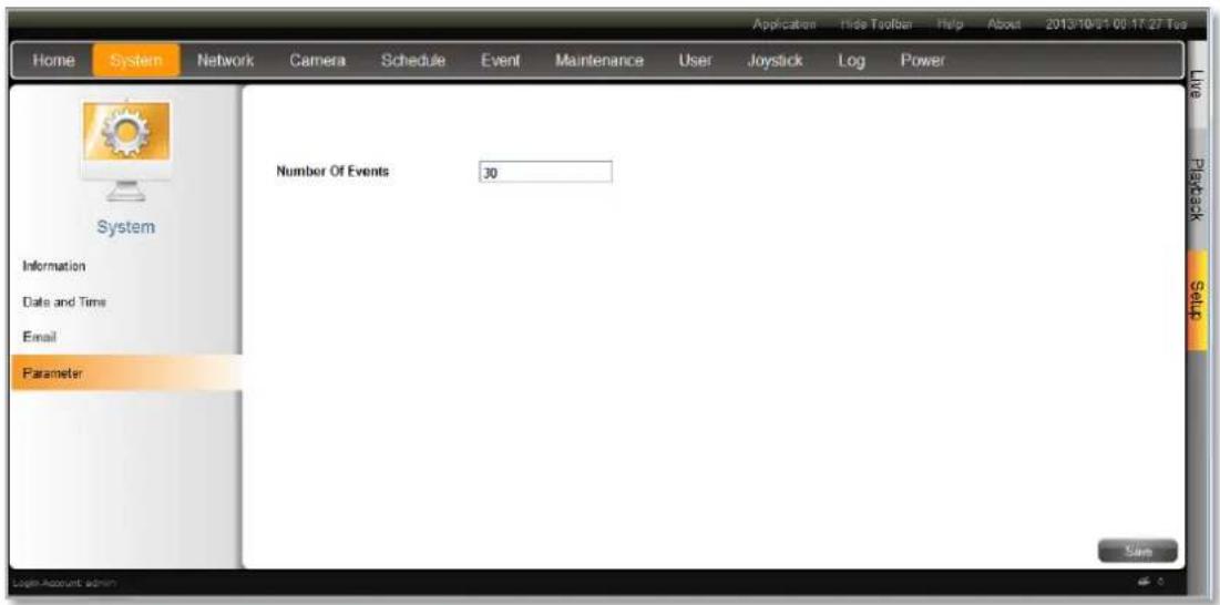
text_image
Home System Network Camera Schedule Event Maintenance User Joystick Log Power Number Of Events 30 System Information Date and Time Email Parameter Applicator Hide Toolbar Help About 2013/10/21 00:17:27 Tue Live Playback Setup Login Account adminLive Page UI Overview
After logging in, you will enter Live screen. Live screen is the interface where you see the live views from your cameras. It is where most of the security professionals access the surveillance system
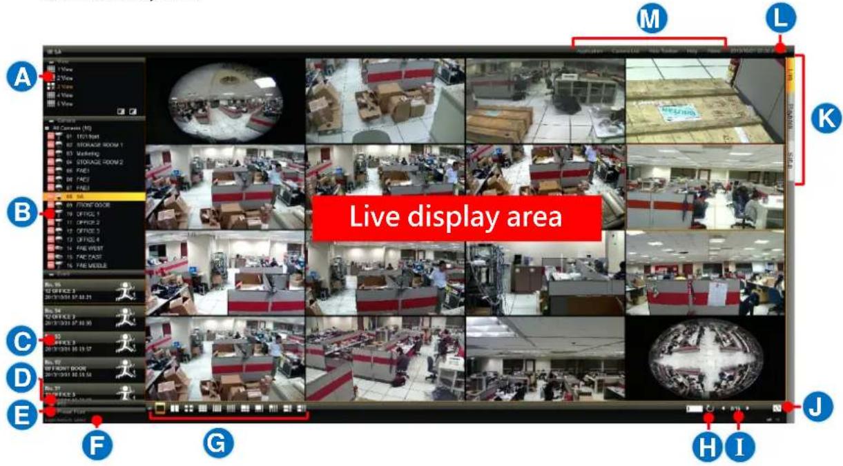
text_image
Live display area A B C D E F G H I M L K M N O P Q R S T U V W X Y Z A B C D E F G H I| No | Description |
| A | View List:Lists five View profiles for customization |
| B | Camera List:Lists all the added cameras and their recording status. |
| C | Event ListDisplays alerts of detected motion, digital inputs and connection status. |
| D | PTZ Control PanelProvides onscreen PTZ controls. This panel is only enabled when a PTZ camera channel is selected on live view display area. |
| E | Preset Point PanelProvides onscreen tour and preset points controls. This panel is only enabled when a PTZ camera channel is selected on live view display area. |
| F | Your current logged on Account name |
| G | Layout Selection ButtonsClick to change the current layout |
| H | PatrolClick to start/stop sequence patrol |
| I | Page Selection2/15Click on the numbers to view a row of available pages: 1 2 3 4 5 6 7 8 9 ▶ |
| J | Share Current View to LocalClick to start sharing your current view to local screen |
| K | Screen SwitchSwitch to the Setup or Playback page by clicking the tags. |
| L | Current System Time |
| M | ToolbarLists available tools for your current page |
Set Cameras
ENR remote user interface also allows you to easily configure, add or delete cameras without individually opening the cameras' web configurator.
Add Cameras
Go to Setup page → Camera tab.
- As there is currently no camera existing in ENR system, click "Add" to starting adding the first one.
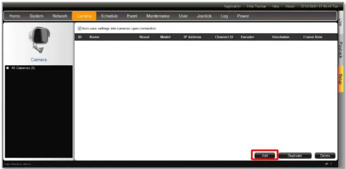
text_image
Home System Network Camera Schedule Event Maintenance User Joystick Log Power Application Hide Toolbar Help About 2013/10/01 07:48:45 Tus Auto-save settings into cameras upon connection ID Name Brand Model IP Address Channel ID Encoder Resolution Frame Rate AI Cameras (0) Add Duplicate Delete- Click "Search Cameras"
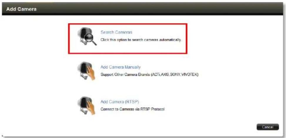
text_image
Add Camera Search Cameras Click this option to search cameras automatically. Add Camera Manually Support Other Camera Brands (ACTi.Axis.SONY.VIVO.TEK) Add Camera (RTSP) Connect to Cameras via RTSP Protocol Cancel
Search Cameras
Click this option to search cameras automatically.
Search Cameras method will list all the cameras connected to your network.
- On Search Cameras windows, input the Account and Password to access the cameras, select the manufacturer and click "Search". After all the connected cameras are found, click the cameras and then "Submit" to add them.

text_image
Search Cameras Account admin Password 81 camera(s) found. Supports 2/16 ACTi Search Name Brand Model IP Address Channel ID Encoder Resolution Frame Rate Status Camera-1 ACTi KCM5211 172.16.26.2 1 MPEG4 1280x720 20 Camera-1 ACTi KCM5211 172.16.26.2 2 MIPEG 640x480 30 Camera-1 ACTi KCM3911 172.16.26.3 1 MPEG4 2032x1936 5 Camera-1 ACTi D62 172.16.26.4 1 H264 1920x1080 15 Camera-1 ACTi D62 172.16.26.4 2 H264 1280x720 5 ACTi D62 172.16.26.5 1 Camera-1 ACTi E53 172.16.26.6 1 MIPEG 640x480 3 Previous Submit Cancel- Back on the All Cameras list, the selected cameras are already added into ENR system and started their full-time recording service.
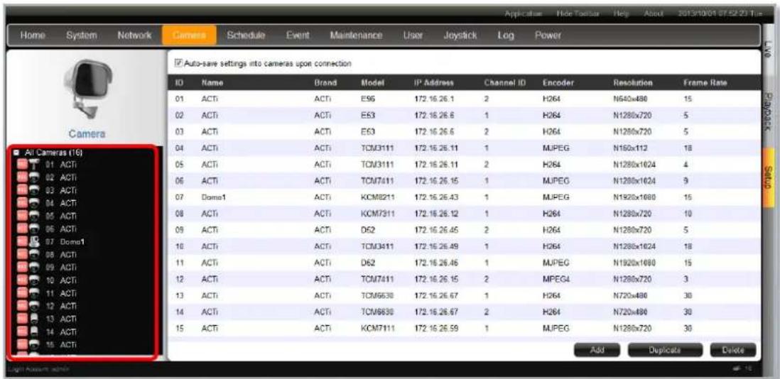
text_image
Home System Network Camera Schedule Event Maintenance User Joystick Log Power Camera Auto-save settings into cameras upon connection ID Name Brand Model IP Address Channel ID Encoder Resolution Frame Rate 01 ACTI ACTI ES6 172.16.26.1 2 H264 N640x480 15 02 ACTI ACTI ES3 172.16.26.6 1 H264 N1280x720 5 03 ACTI ACTI ES3 172.16.26.6 2 H264 N1280x720 5 04 ACTI ACTI TCM3111 172.16.26.11 1 MUPEG N150x112 18 05 ACTI ACTI TCM3111 172.16.26.11 2 H264 N1280x1024 4 06 ACTI ACTI TCM7411 172.16.26.15 1 MUPEG N1280x1024 9 07 Dome1 ACTI KCM8211 172.16.26.43 1 MUPEG N1920x1080 15 08 ACTI ACTI KCM7311 172.16.26.12 1 H264 N1280x720 10 09 ACTI ACTI D52 172.16.26.45 2 H264 N1280x720 5 10 ACTI ACTI TCM3411 172.16.26.49 1 H264 N1280x1024 18 11 ACTI ACTI D62 172.16.26.46 1 MUPEG N1920x1080 15 12 ACTI ACTI TCM7411 172.16.26.15 2 MPEG4 N1280x720 3 13 ACTI ACTI TCM6630 172.16.26.67 1
Add Camera Manually
Click this option to add camera manually.
If the camera is not located within your network segment, you may add it manually.
- Fill in the connection properties such as properties IP Address, Username and Password, HTTP Port, and click "Get Camera Settings".

text_image
01 New Channel Home System Network Camera Schedule Event Maintenance User Joystick Log Power Add Camera List Name: New Channel IP Address 172.16.26.5 HTTP Port 1005 User Name admin Password ****** Car Camera Settings Web Configurator S M A R T: checking of this HDD failed .- The camera properties including Firmware version and Serial Number will appear below, you may modify other video configurations and then click "Save".
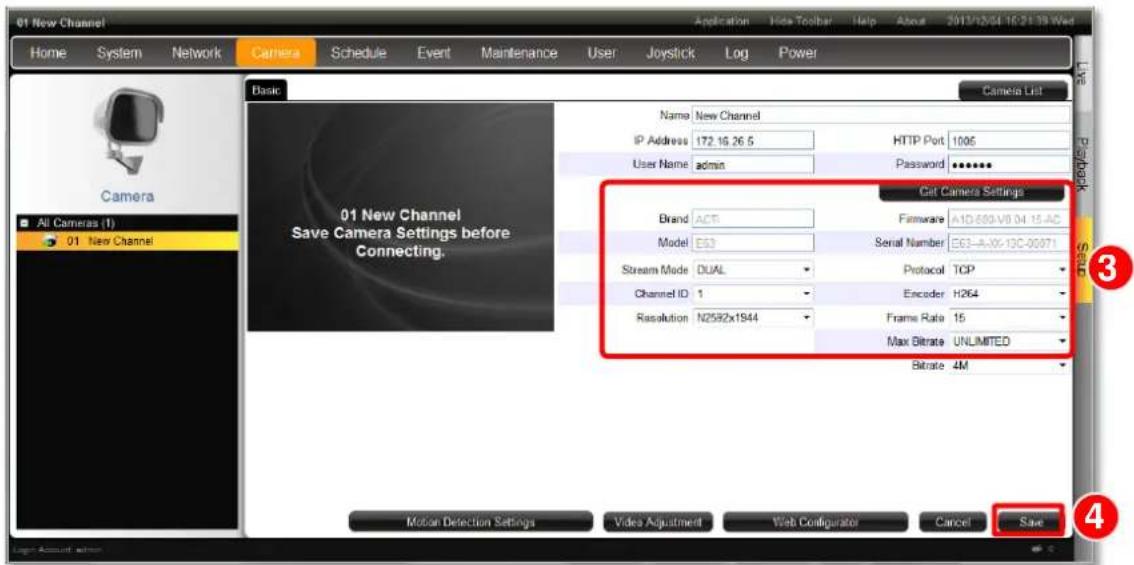
text_image
01 New Channel Home System Network Camera Schedule Event Maintenance User Joystick Log Power Camera List Basic Name New Channel IP Address 172.16.26.5 HTTP Port 1005 User Name admin Password ****** Cat Camera Settings Brand ACT Firmware A1D-689-V8 04-15-AC Model E53 Serial Number E63-A-XX-13C-00071 Stream Mode DUAL Protocol TCP Channel ID 1 Encoder H264 Resolution N2592x1944 Frame Rate 15 Max Bitrate UNLIMITED Bitrate 4M Motion Detection Settings Video Adjustment Web Configurator Cancel Save All Cameras (1) 01 New Channel 01 New Channel Save Camera Settings before Connecting. Motion Detection Settings Video Adjustment Web Configurator Cancel Save- Click "Save", the camera's live view will appear.
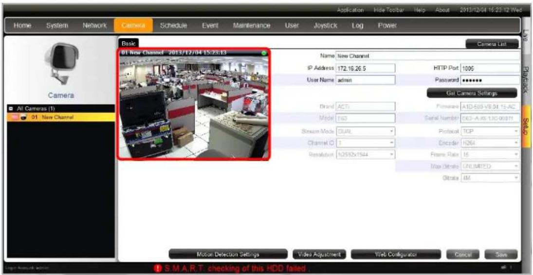
text_image
Home System Network Camera Schedule Event Maintenance User Joystick Log Power Application Hide Toolbar Help About 2013/12/04 15:23:12 Wed Camera List Basic 01 New Channel - 2013/12/04 15:23:13 IP Address 172.16.26.5 HTTP Port 1095 User Name admin Password ****** Get Camera Settings Brand ACTI Pimstone A1D-503-V6.04-15-AC Model E63 Serial Number 663-A/XX-13C-00971 Stream Mode DUAL Protocol TCP Channel ID 1 Encoder H264 Resolution 10592x1544 Frame Rate 15 Max Rate U/LIMITED Obitrate 4M Motion Detection Settings Video Adjustment Web Configurator Cancel Save S.M.A.R.T. checking of this HDD failedNote
ENR will synchronize with devices upon connecting to them. To make sure the settings on ENR side are prior to those on camera sides, please check "Auto save ENR settings into device upon connection". When this function is enabled, every modification you make via Camera's web configurator will be overwritten by ENR.

Add Camera (RTSP)
Connect to Cameras via RTSP Protocol
You may connect a camera via RTSP protocol. Via this mouthed, you can add a video stream from any brand camera.
Fill in the properties such as properties IP Address, URI type, RTSP Port, Protocol type, User name, Password, and click "Save".
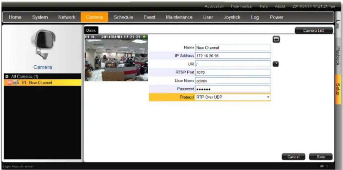
text_image
Home System Network Camera Schedule Event Maintenance User Joystick Log Power Camera List Basic 01 N... 2014/04/01 17:21:21 Camera All Cameras (1) RIP 01 New Channel Name: New Channel IP Address: 172.16.26.98 URI / ? RTSP Port: 7070 User Name: admin Password: ****** Protocol: RTP Over UDP Cancel Save Loger Applicuri adminCopy Camera Settings
You may copy an added camera's settings another channel. In this way, it is easier to manually add more than one camera of the same models.
- On All Cameras list, select an existing channel.
- Click "Duplicate", the selected cameras will be duplicated to new channels. In the example shown below, 01 Camera will be copied to a empty channel - 07 camera.
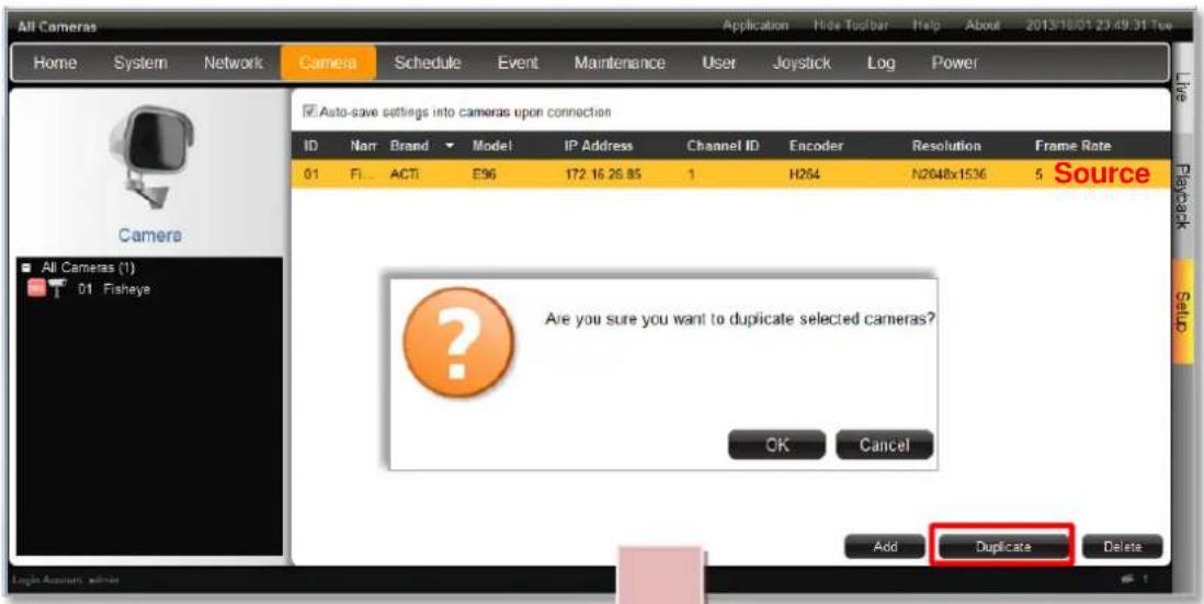
text_image
All Cameras Home System Network Camera Schedule Event Maintenance User Joystick\Log Power Auto-save settings into cameras upon connection ID Narr Brand Model IP Address Channel ID Encoder Resolution Frame Rate 01 FI ACTI E96 172.16.26.85 1 H264 N2048x1536 5 Source All Cameras (1) 01.Fisheye ? Are you sure you want to duplicate selected cameras? OK Cancel Add Duplicate Delete Login Accounts admin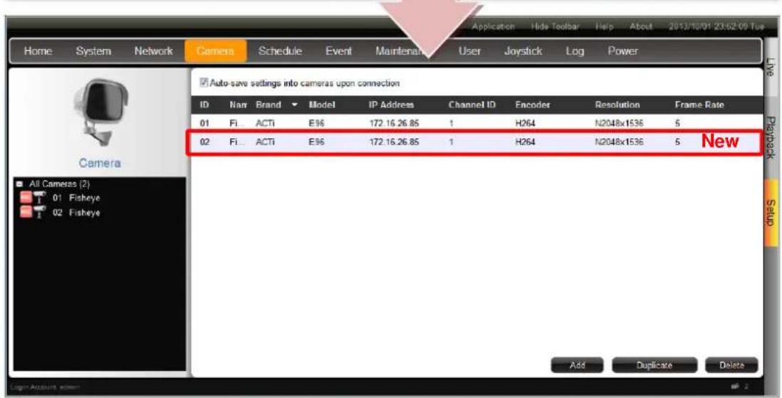
text_image
Home System Network Camera Schedule Event Maintenance User Joystick Log Power Auto-save settings into cameras upon connection ID Nan Brand Model IP Address Channel ID Encoder Resolution Frame Rate 01 Fi ACTi E96 172.16.26.85 1 H264 N2048x1536 5 02 Fi ACTi E96 172.16.26.85 1 H264 N2048x1536 5 New All Cameras (2) Fisheye Fisheye Add Duplicate DeleteDelete Cameras
On All Cameras list, select the cameras you wish to delete and click "Delete".
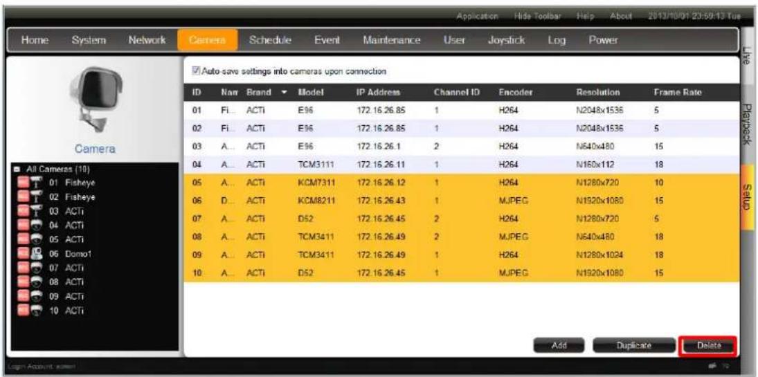
text_image
Home System Network Camera Schedule Event Maintenance User Joystick Log Power Camera Auto-save settings into cameras upon connection ID Nam Brand Model IP Address Channel ID Encoder Resolution Frame Rate 01 Fi... ACTi E96 172.16.26.85 1 H264 N2048x1536 5 02 Fi... ACTi E96 172.16.26.85 1 H264 N2048x1536 5 03 A... ACTi E96 172.16.26.1 2 H264 N640x480 15 04 A... ACTi TCM3111 172.16.26.11 1 H264 N160x112 18 05 A... ACTi KCM7311 172.16.26.12 1 H264 N1280x720 10 06 D... ACTi KCM8211 172.16.26.43 1 MJPEG N1920x1080 15 07 A... ACTi D52 172.16.26.45 2 H264 N1280x720 5 08 A... ACTi TCM3411 172.16.26.49 2 MJPEG N640x480 18 09 A... ACTi TCM3411 172.16.26.49 1 H264 N1280x1024 18 10 A... ACTi D52 172.16.26.45 1 MJPEG N1920x1080 15 Add Duplicate DeleteChange Camera Settings
After the cameras are added, select a camera on All Cameras list to configure its individual properties.
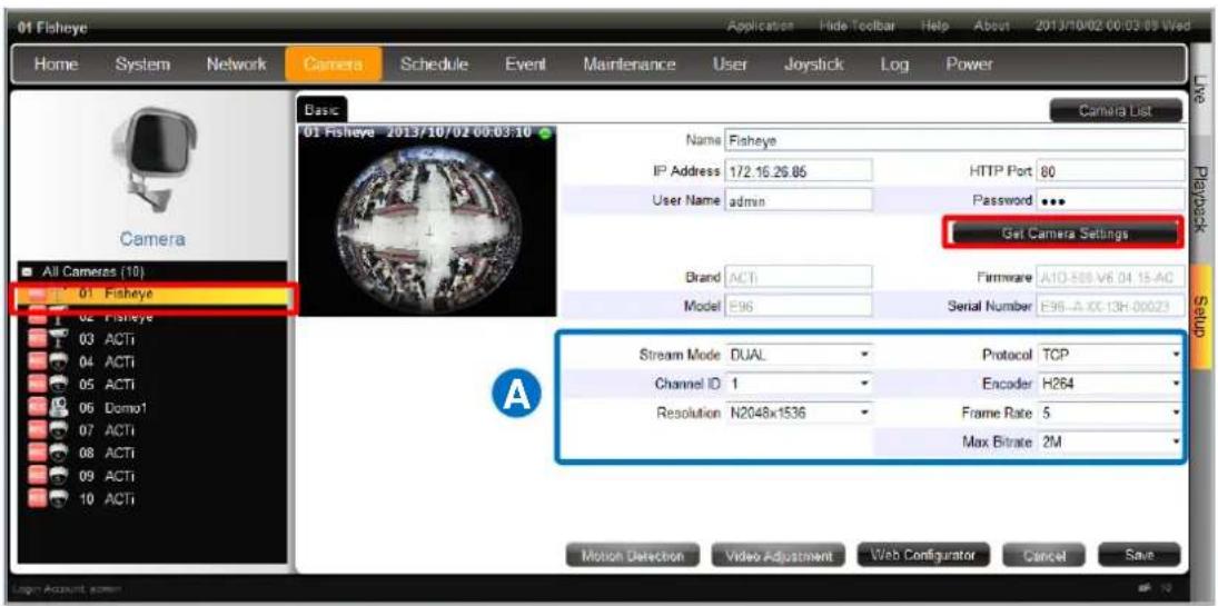
text_image
01 Fisheye Home System Network Camera Schedule Event Maintenance User Joystick Log Power Camera List Basic 01 Fisheye 2013/10/02 00:03:10 IP Address 172.16.26.85 HTTP Port 80 User Name admin Password ... Gat Camera Settings Brand ACTI Firmware A10-505-V6 04 15-AC Model E96 Serial Number E96-A-CC-13H-00023 Stream Mode DUAL Protocol TCP Channel ID 1 Encoder H264 Resolution N2048x1536 Frame Rate 5 Max Bitrate 2M Motion Detection Video Adjustment Web Configurator Cancel Save All Cameras (10) 01 Fisheye 02 Fisheye 03 ACTi 04 ACTi 05 ACTi 06 Domo1 07 ACTi 08 ACTi 09 ACTi 10 ACTi(A) Video Format and Transmission Properties
To modify the video format and transmission properties including Stream Mode, Channel ID, Resolution, Protocol, Encoder, Frame Rate, and Bitrate, you will have to click "Get Camera Settings" first to sync with the camera first. After configuration, click "Save" to save this setting to camera
(B) Motion Settings
After selecting the camera from All Cameras list, click "Motion Detection". If this camera is in dual stream mode, only Channel ID 1 (Stream 1) supports motion detection feature.
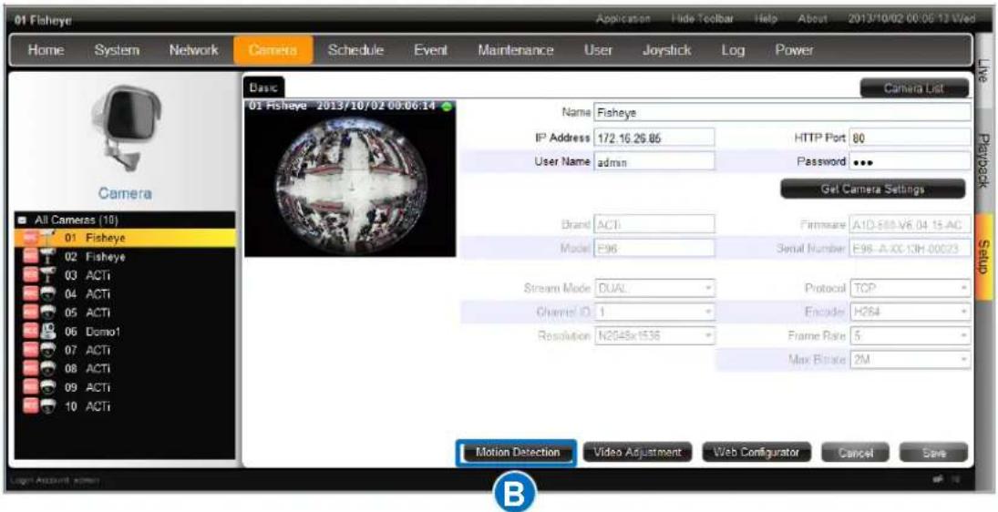
text_image
01 Fisheye Home System Network Camera Schedule Event Maintenance User Joystick Log Power Basic Camera List 01 Fisheye 2013/10/02 00:06:14 Name Fisheye IP Address 172.16.26.85 HTTP Port 80 User Name admin Password ... Get Camera Settings Brand ACTI Firmware A1D-589-V6.04.15 AC Model E96 Serial Number E98-A-XC-13H-00073 Stream Mode DUAL Protocol TCP Channel ID 1 Encoder H264 Resolution N2048x1536 Frame Rate 5 Max Bracket 2M Motion Detection Video Adjustment Web Configurator Cancel Save All Cameras (10) 01 Fisheye 02 Fisheye 03 ACTi 04 ACTi 05 ACTi 06 Domo1 07 ACTi 08 ACTi 09 ACTi 10 ACTi Live Playback Setup BOn Motion Detection Settings window, check "Enable" then click "Motion Setup". To enable one motion region, check it, a color frame will appear in the view. You may start setting the detection area by adjusting this yellow frame on the view. Simply use your mouse to move and resize the frame. Click "Apply" to save the settings.
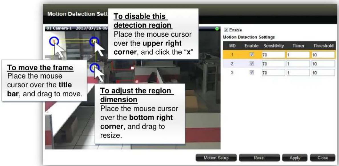
text_image
To disable this detection region Place the mouse cursor over the upper right corner, and click the "x" To move the frame Place the mouse cursor over the title bar, and drag to move. To adjust the region dimension Place the mouse cursor over the bottom right corner, and drag to resize.Adjustment Attributes
| Field Name | Description |
| Sensitivity(1-100) | Determines how sensitive the camera reacts to the movement. The higher the sensitivity level is, the smaller motion will trigger the alarm, but may give false alarms. Default is 70. |
ENR-100 Series System Administrator's Manual
| Timer(0-300 secs) | The interval before the next motion detection can be triggered again. Default is 1 second. |
| Threshold (%) | The threshold level of this motion detection region. The lower threshold level is, smaller portion of the region would be considered as motions, which is more easily to be triggered, but may give more false alarms. |
(C) Fine-tune the Image: Brightness/Contrast/Saturation/Hue
Not only details but also brightness, contrast, saturation and hue are essential factors to make images closer to real scene. For devices that support these property configurations, you may directly modify them and save to the device ENR interface.
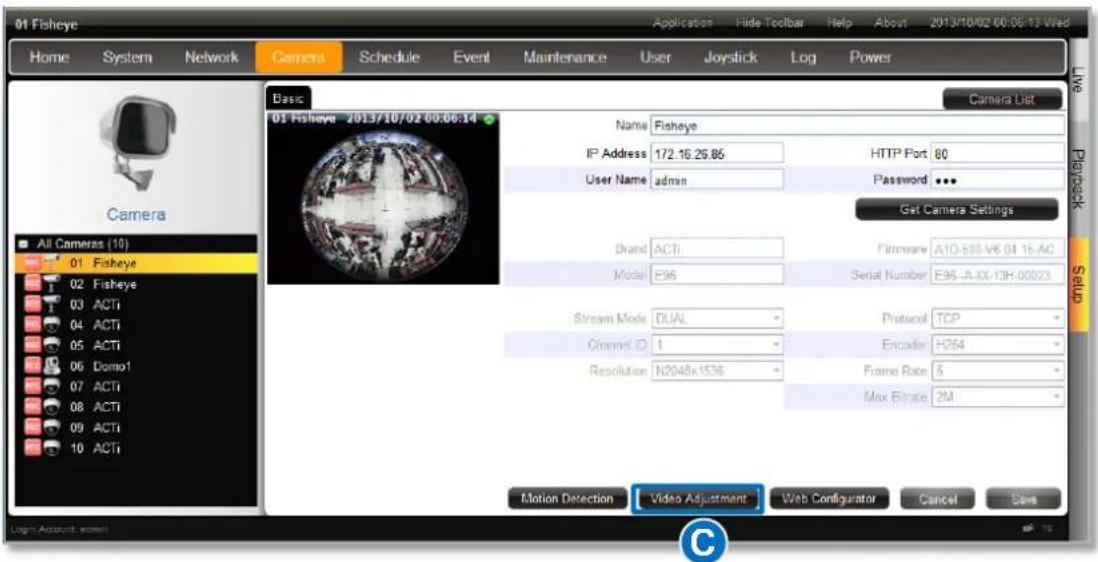
text_image
01 Fisheye Home System Network Camera Schedule Event Maintenance User Joystick Log Power Camera List Basic 01 Fisheye 2013/10/02 00:06:14 Name Fisheye IP Address 172.16.26.85 HTTP Port 80 User Name admin Password ... Get Camera Settings Brand ACTi Firmware A1D-593-V6.04.15-AC Model E96 Serial Number E96-A-XX-13H-00023 Stream Mode DUAL Protocol TCP Channel ID 1 Encoder H254 Resolution N2048x1536 Frame Rate 5 Max Ripple 2M Motion Detection Video Adjustment Web Configurator Cancel Save All Cameras (10) 01 Fisheye 02 Fisheye 03 ACTi 04 ACTi 05 ACTi 06 Domo1 07 ACTi 08 ACTi 09 ACTi 10 ACTi Live Playbox Setup Login Account screenOn Video Adjustment window, the fields available for modification (depends on models) will be enabled. Select the desired value for the field, and click "Apply".
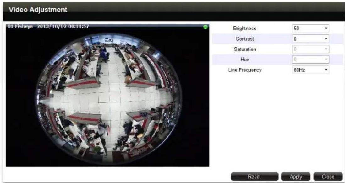
text_image
Video Adjustment 01 Fisheye 2013/10/02 00:11:57 Brightness 50 Contrast 0 Saturation 0 Hue 0 Line Frequency 60Hz Reset Apply CloseVideo Adjustment Attributes
| Field Name | Description |
| Brightness(1-100) | Defines how much portion of light and of dark appear in the image. As the value increases, the image appears brighter, and vice versa. |
| Contrast(1-100) | Defines the range level between light values and dark values. As the value increases, the separation between light and dark becomes more obvious. |
| Saturation(1-100) | Defines the level of the actual color intensity. As it increases, colors appear more pure; as it decreases, colors appear more gray-out. |
| Hue(1-100) | It is the term used to refer to the pure spectrum colors. Adjust this value to find the color closest to the real scene. |
| Line Frequency (50Hz / 60 Hz) | The unction that adjusts the shutter speed options to match the frequency of artificial light source of given country. For example, in Europe the light frequency (due to power supply frequency of lights) is 50Hz, that is 50 flashes per second. By setting line frequency to 50Hz in such case, the shutter speed options will be proportional with light source frequency, such as 1/25s, 1/50s, 1/100s, etc. It is necessary to have the camera's Line Frequency adjusted according to the power frequency of the light source to avoid flickering effect. |
Configure PTZ Preset Points
With PTZ devices, you may define a view by where to look (through panning and tilting) and how close (through zooming) to zoom. Once these views have been saved in ENR as preset points, the device can always point to this view upon the event triggering or user's command.
Go to Setup page → Camera tab, select a PTZ camera from All Cameras list, and click Preset Point.
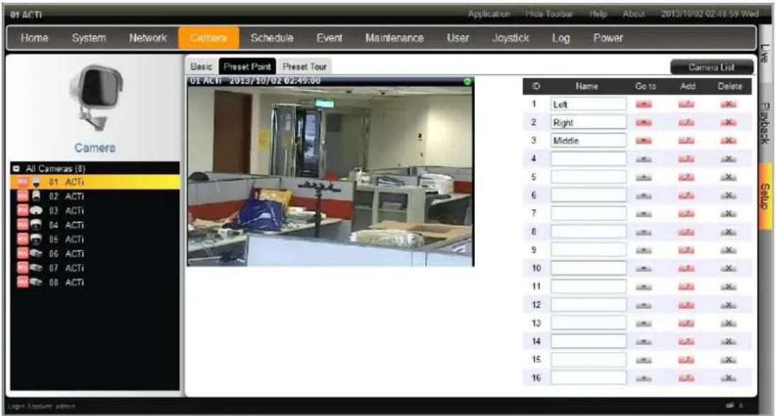
text_image
01 ACTI Home System Network Camera Schedule Event Maintenance User Joystick Log Power Basic Preset Point Preset Tour 01 ACTI 2013/10/02 02:49:00 Camera List ID Name Go to Add Delete 1 Left Right Middle Right Right 2 Right Middle Right Right 3 Middle 4 5 6 7 8 9 10 11 12 13 14 15 16 All Cameras (0) 01 ACTI 02 ACTI 03 ACTI 04 ACTI 05 ACTI 06 ACTI 07 ACTI 08 ACTI Log Account admin1. Define a view:
On mini live window, use the mouse to do the following PTZ operations:
■ To execute optical Panning and Tilting, click anywhere on the live window to allow the camera to move in that direction. The length of the direction indicator is proportional to the Pan and Tilt speed. The farther you place the cursor from the center, the faster the Pan/Tilt movement.
■ To execute optical Zoom in or Zoom out, scroll the mouse wheel forward to zoom in; scroll the mouse wheel backward to zoom out.
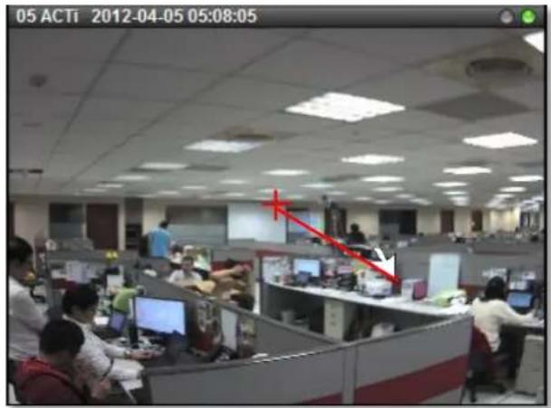
text_image
05 ACTi 2012-04-05 05:08:05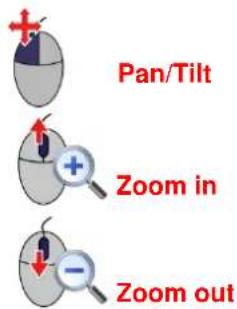
text_image
Pan/Tilt Zoom in Zoom out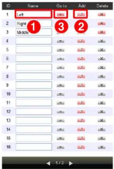
text_image
ID Name Go to Add Delete 1 Left Right Middle 1 2 3 4 5 6 7 8 9 10 11 12 13 14 15 162. Save to a Preset Point
On Preset Point list, select an ID, input the point name
and click

After a point is saved, click → next to its name to go to this point.
To delete this point, click

Configure PTZ Preset Tour
Preset Tour is a preconfigured PTZ sequence that directs the camera to cycle through multiple preset points, including where to look and how long to look at each location. With this preset tour, your PTZ device can perform an automatic patrol to scan through your cared areas.
Before setting up Preset Tours, please make sure you have configured PTZ settings and set PTZ Preset Points. To start:
- Go to Setup page → Camera tab, select a PTZ camera from All Cameras list, and click Preset Tour.
- Select a tour from Tour1\~Tour32, input its Name, pick a preset point, define its Dwell time and click "Add", this preset point will be added to the tour. Continue to add other preset points in your desired movement sequence and click "Save". After a tour is saved, it is available on Live page→Preset Point control panel.
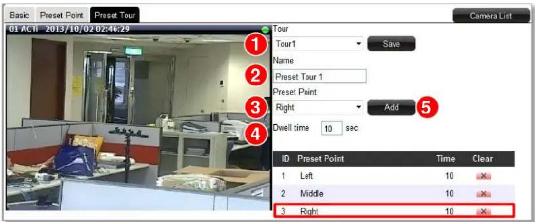
text_image
Basic Preset Point Preset Tour 01 ACTi 2013/10/02 02:46:29 Camera List Tour Tour1 Save Name Preset Tour 1 Preset Point Right Add 5 Dwell time 10 sec ID Preset Point Time Clear 1 Left 10 X 2 Middle 10 X 3 Right 10 XConfigure Fisheye Cameras
With hemispherical lenses, fisheye cameras generate images at up to 360-degree width, which can cover all four corners of a room or both sides of a long aisle. As the original image captured by wide-angle lens is much distorted, to suit most monitoring purposes, the Dewarping process is required to alter the uneven lines and shapes before the images are displayed. Nowadays, the fisheye cameras come in two types in terms of the image-correction capability:
- Fisheye Cameras with in-camera dewarping function The dewarping takes places in camera before the video is output to NVR server. Since the image correction counts on the camera itself, NVR server will not bear much extra loading, which benefits the system requiring many of these fisheye cameras (e.g. ACTi KCM-3911, KCM-7911)
- Fisheye Cameras without dewarping function These fisheye cameras output only original global images, relying on software algorithm processing provided by NVR sever to correct the images. They are suitable for a system with limited bandwidth, for NVR server processes and responds to User's ePTZ manipulation or demands for changing view modes immediately, without waiting for camera side to deliver a new frame (e.g. ACTi E96).
ENR's software algorithm can perfectly corrects the original fisheye images, generating 6 specific fisheye view modes from User's usual perspective. As a remote client, you may
- Select a desired fisheye view mode on Live screen and manipulate virtualized ePTZ operation with onscreen controls.
● Export the video clip of your desired fisheye view mode.
To make use of ENR's dewarping features for your fisheye cameras, please
1. Adjust Video Quality Settings
After the fisheye camera is successfully added, go to Setup page →Cameras tab, select the device and then click "Get Camera Settings", make sure you set the Stream Mode as "FISHEYE" for a hemispheric camera (KCM-3911, KCM-7911). This is to make sure this hemispheric camera is outputting fisheye original video stream as a mini fisheye dome camera does.
2. Adjust Fisheye Display Settings
Select your Mounting Type, and then Default Fisheye Mode. For a fisheye mode containing panorama view, you may want to configure the Default Rotate X (width of view) and Default Rotate Y (height of view) configurations.
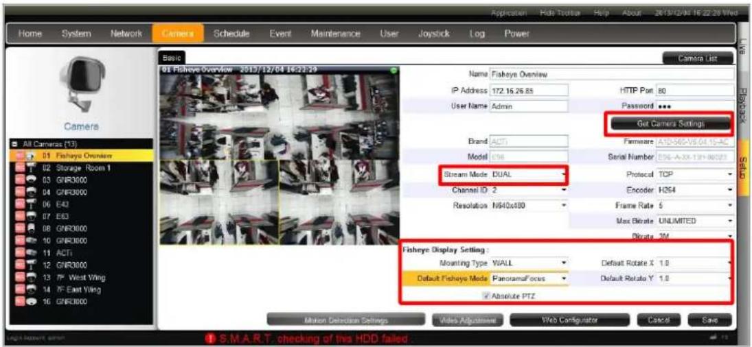
text_image
Home System Network Camera Schedule Event Maintenance User Joystick Log Power Home System Network Camera Schedule Event Maintenance User Joystick Log Power Camera List Basic 01 Fisheye Overview - 2013/12/04 16:22:29 Camera Name Fisheye Overview IP Address 172.16.26.85 HTTP Port 80 User Name Admin Password Get Camera Settings Brand ACTI Firmware A1D-56C-V9.04.15-AC Model E36 Serial Number E36-A-XX-13H-00023 Stream Mode: DUAL Protocol TCP Channel ID: 2 Encoder HDS4 Resolution: M940x100 Frame Rate: 5 Max Bitrate UNLIMITED Bitrate: 3M Fisheye Display Setting : Mounting Type: WALL Default Rotate X 1.8 Default Fisheye Mode: PanoramaFocus Default Rotate Y 1.8 Absolute PTZ Motion Detection Settings Video Adjustment Web Configurator Cancel Save| Fisheye Mode | Description | PTZ Navigation | |
| Original View | The very raw fisheye view |  | Digital PTZ |
| Dewarping | One large user-defined cropped area | ePTZ | |
 |  | ||
| Panorama | 360-degree panorama view for ceiling mount180-degree panorama view for wall mount | Digital PTZ | |
 | 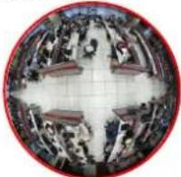 | ||
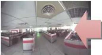 | 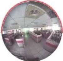 | ||
| Double Panorama | Two 180-degree panorama views | Digital PTZ | |
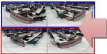 | 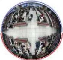 | ||
| Panorama /Focus | One panorama viewTwo small user-defined cropped regions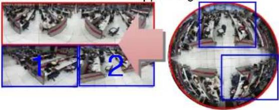 | ePTZ |
| Quad | Four small user-defined cropped regions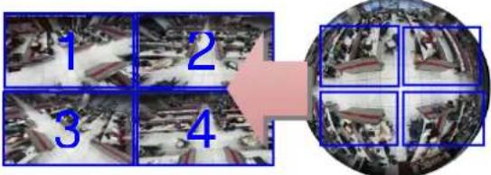 | ePTZ |
After the configuration is done, remember to click "Save" to save the settings.
Note
- Local Live and Playback can only display the original video stream output from a fisheye camera.
- Whichever fisheye view mode you are watching on remote interface, ENR will record the original video stream output from a fisheye camera; however, you may export the video in any desired view mode.
Set Recording Schedule
For the recording schedule, ENR supports Schedule recording, Event recording and Event Speed-up Recording modes, which are set up on a week-based timetable; the event-handling schedule is configured here.
On ENR, you can configure camera's recording schedule on 7 days / 24 hours basis. The schedule is split into segments of one-hour-length. By default, once a device is added to the system, its schedule is automatically set to full-time schedule recording and event handling. You should configure it according to your system plan.
Go to Setup page → Schedule tab, and select a camera to configure its recording schedule.
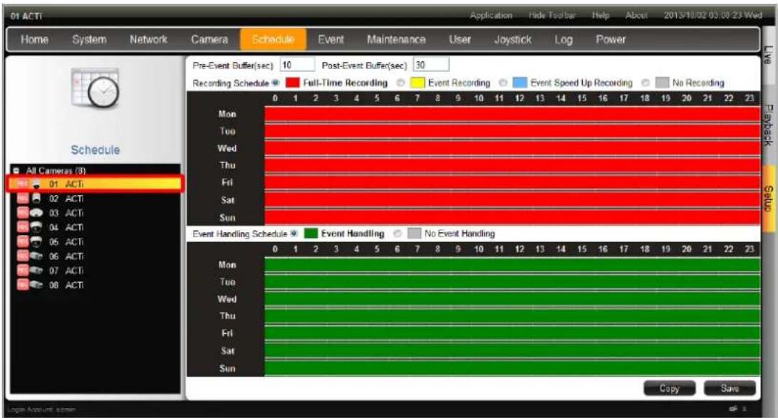
text_image
01 ACTI Home System Network Camera Schedule Event Maintenance User Joystick\Log Power Pre-Event Buffer(sec) 10 Post-Event Buffer(sec) 30 Recording Schedule Full-Time Recording Event Recording Event Speed Up Recording No Recording Mon Tue Wed Thu Fri Sat Sun All Cameras (0) 01 ACTI 02 ACTI 03 ACTI 04 ACTI 05 ACTI 06 ACTI 07 ACTI 08 ACTI Event Handling Schedule Event Handling No Event Handling Mon Tue Wed Thu Fri Sat Sun Copy SaveEvent-Recording File Length
Before setting the recording schedule, you may define the length of an event recording. To do this, configure the following properties shown as below, which will make an event recording as long as 10+30 second:
Pre-Event Buffer(sec) 10 Post-Event Buffer(sec) 30
| Field | Description |
| Pre-event Recording Buffer (sec): | ENR keeps a short cache of video received from devices. If an event is triggered, ENR will automatically store the pre-event buffer along with the recording of the event itself. |
| Post-event Recording Buffer (sec): | This will determine how long after the event is triggered should be included in the event recording file. |
Set the Recording Schedule
- Select a recording type.
Recording Schedule ○ Full-Time Recording ○ Event Recording ● Event Speed Up Recording
| Field | Description |
| Full-Time Recording | Continuously record at the video frame rate you define in Camera Settings. |
| Event Recording | Only events are recorded, at the video frame rate you define in Camera Settings. |
| Event Speed Up Recording | Continuously record everything at 1FPS, when an event occurs, the frame rate will switch to the value you define in Camera Settings, and automatically switch back to 1FPS after the event ends. |
- On the recording schedule time table, click and drag to set time period.
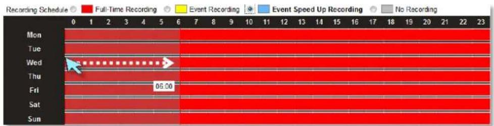
line
| Day | Full-Time Recording | Event Recording | Event Speed Up Recording | No Recording | |---|---|---|---|---| | Mon | 0 | 0 | 0 | 0 | | Tue | 0 | 0 | 0 | 0 | | Wed | 0 | 0 | 0 | 0 | | Thu | 0 | 0 | 0 | 0 | | Fri | 0 | 0 | 0 | 0 | | Sat | 0 | 0 | 0 | 0 | | Sun | 0 | 0 | 0 | 0 |-
Click "Save"
-
To delete the recording configuration, select section on time table. No Recording and drag on the desired
Set the Event Handling Schedule
The Event Schedule defines when the event handling is activated. To set the event rules, please refer to Set Event Rules on page 120. By default, the event handling is full-time activated; you may disable it for a certain period.
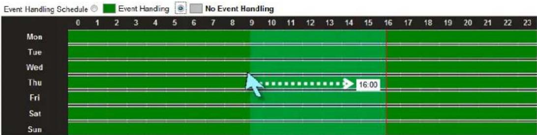
line
| Day | Event Handling Schedule | |---|---| | Mon | 0 | | Tue | 1 | | Wed | 2 | | Thu | 3 | | Fri | 4 | | Sat | 5 | | Sun | 6 |- Click ☐ No Event Handling
- Drag over the Event Handling Schedule time track to disable the event handling service.
- Click "Save".
Copy Schedule
You may copy a camera's schedule setting to other multiple cameras. This saves much your time on configuring the schedules camera by camera. On the bottom of this page, click "Copy" to bring up Copy Schedule window.
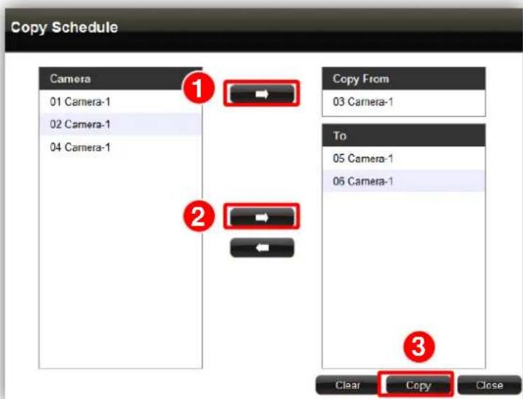
text_image
Copy Schedule Camera 01 Camera-1 02 Camera-1 04 Camera-1 Copy From 03 Camera-1 To 05 Camera-1 06 Camera-1 Clear Copy CloseSelect one camera as the source of schedule, and add other cameras to the "To" field. Click "Copy" to commit changes.
Event Management
ENR can react to events occurring on the storage disk and camera site based on the rules you set here.
Set Event Rules
Go to Setup page → Event tab, and select a camera or System to set Event rules.
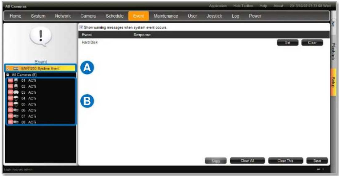
text_image
All Cameras Home System Network Camera Schedule Event Maintenance User Joystick\Log Power Event ENR1200 System Event All Cameras (6) 01 ACTI 02 ACTI 03 ACTI 04 ACTI 05 ACTI 06 ACTI 07 ACTI 08 ACTI Show warning messages when system event occurs. Event Response Hard Disk Set Clear A B Copy Clear All Clear This Save Login Account admin
Set System Event rule
Whenever any hard disk goes into abnormal status, ENR will trigger a response based on the rule you set.
- Click "Set" to enter the rule content.

text_image
Event Response Hard Disk Set Clear- Select your desired response type, configure the properties and then click "OK" to save this rules. There are two types of response for a system event: Beep and Send Mail.
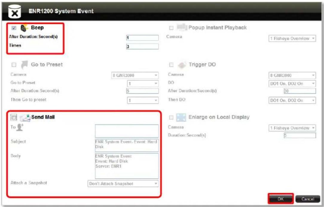
text_image
ENR1200 System Event Beep After Duration: Second(s) Times 1 3 Popup Instant Playback Camera 1 Fisheye Overview Go to Preset Camera 8 GNR3000 Go to Preset 1 After Duration: Second(s) 5 Then Go to preset 1 Trigger DO Camera 8 GNR3000 DO DO1 On, DO2 On After Duration: Second(s) 50 Then DO DO1 On, DO2 On Send Mail To Subject ENR System Event, Event: Hard Disk Body ENR System Event Event: Hard Disk Server: ENR1 Attach a Snapshot Don't Attach Snapshot Enlarge on Local Display Camera Duration: Second(s) 1 Fisheye Overview OK CancelB Set Camera Event rule
Whenever any encounter certain events (including detected motions, detected DI triggers, network loss and network recovery) ENR will trigger a response based on the rule you set.
- Select a camera and then click "Set" of your desired event type.
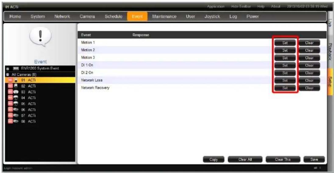
text_image
01 ACTI Home System Network Camera Schedule Event Maintenance User Joystick\Log Power Event Response Motion 1 Motion 2 Motion 3 DI 1 On DI 2 On Network Loss Network Recovery Set Clear Set Clear Set Clear Set Clear Set Clear Set Clear Set Clear Copy Clear All Clear This Save ENR1200 System Event All Cameras (8) 01 ACTI 02 ACTI 03 ACTI 04 ACTI 05 ACTI 06 ACTI 07 ACTI 08 ACTI Live Networks Software Login Account: admin- Select your desired response type, set the details and click "OK" to save the rules.
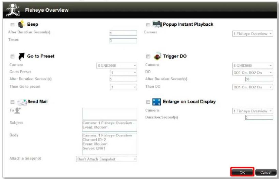
text_image
Fisheye Overview Beep After Duration: Second(s) Times 4 3 Popup Instant Playback Camera 1 Fisheye Overview Go to Preset Camera 8 GNR3000 Go to Preset 1 After Duration: Second(s) 5 Then Go to preset 1 Trigger DO Camera 8 GNR3000 DO DO1 On, DO2 On After Duration: Second(s) 30 Then DO DO1 On, DO2 On Send Mail To Subject Camera: 1 Fisheye Overview - Event: Motion1 Body Camera: 1 Fisheye Overview Channel ID: 2 Event: Motion1 Server: ENR1 Attach a Snapshot Don't Attach Snapshot Enlarge on Local Display Camera Duration: Second(s) 1 Fisheye Overview 6 OK CancelTo delete a certain response, simply de-select it from the response window, and then click "OK".
- After all the rules are set, click "Save" on Event tab to save all settings.
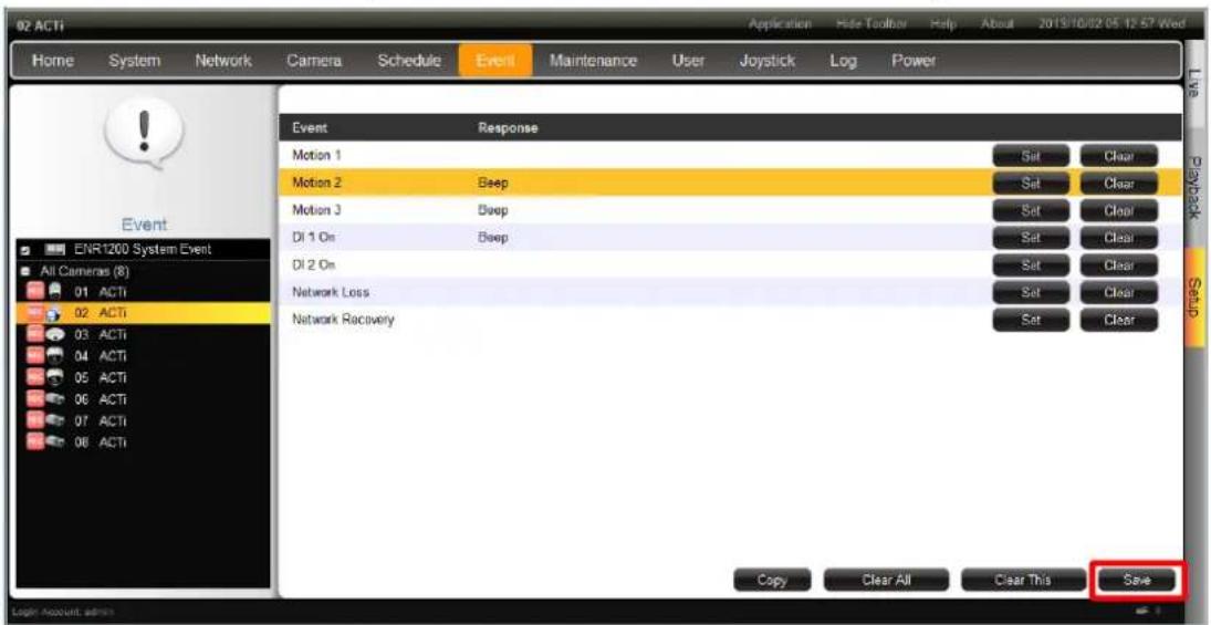
text_image
02 ACTI Home System Network Camera Schedule Event Maintenance User Joystick\Log Power Event Response Motion 1 Sat Clear Motion 2 Beep Sat Clear Motion 3 Beep Sat Clear DI 1 On Beep Sat Clear DI 2 On Sat Clear Network Loss Sat Clear Network Recovery Sat Clear Copy Clear All Clear This Save ENR1200 System Event All Cameras (8) 01 ACTI 02 ACTI 03 ACTI 04 ACTI 05 ACTI 06 ACTI 07 ACTI 08 ACTI Save Account adminResponse Types
ENR supports the following reaction types:
- Popup Instant Playback
ENR will pop up a small window on Live screen to play the 10-second period ahead of event. You will choose a specific camera whose recording is to be played.

text_image
Popup Instant Playback Camera 1 Fisheye Overview- Go to Preset
For the use of PTZ cameras to make movements toward certain triggers, please configure the preset points (refer to Configure PTZ Preset Points on page 112) before you set the event rule. You have to select which PTZ camera to make the movement, then the preset points and duration time between them.
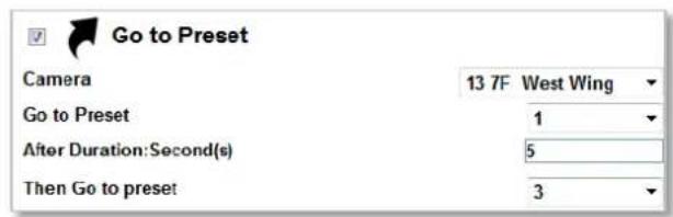
text_image
Go to Preset Camera 13 7F West Wing Go to Preset 1 After Duration:Second(s) 5 Then Go to preset 3- Beep
ENR device can play beep sound upon being triggered by events. Input the duration time and prepeat times of the beep.
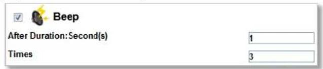
text_image
Beep After Duration:Second(s) 1 Times 3●Trigger DO
Set the DO to become ON or OFF upon trigger, only the devices supporting DO functions are available. Select the device whose connected DO(s) will be triggered. You may select one DO to be activated after the other and the duration time between them.
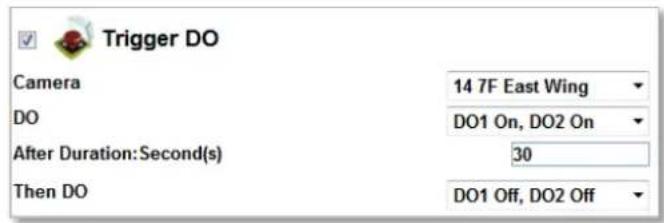
text_image
Trigger DO Camera 14 7F East Wing DO DO1 On, DO2 On After Duration:Second(s) 30 Then DO DO1 Off, DO2 Off- Send Mail
The response enables ENR to send e-mail notifications via SMTP service. Fill in the mail recipient's e-mail address in "To" field, notification title in "Subject" field and mail body in "Body" field, then choose a camera whose snapshot will be attached from Attach a Snapshot dropdown list.
To enable this service, you have to configure the SMTP settings (please refer to Set E-mail Notification Service on page 99) beforehand.
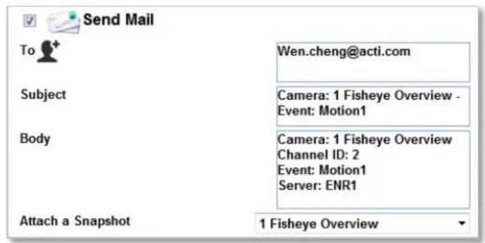
text_image
Send Mail To Wen.cheng@acti.com Subject Camera: 1 Fisheye Overview - Event: Motion1 Body Camera: 1 Fisheye Overview Channel ID: 2 Event: Motion1 Server: ENR1 Attach a Snapshot 1 Fisheye Overview●Enlarge
Local Live screen will display certain channel view in full screen for a while when the system is triggered. Select the camera whose live view will be enlarged on Live screen and the duration time.
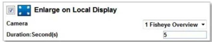
text_image
Enlarge on Local Display Camera Duration: Second(s) 1 Fisheye Overview 5Copy Event Rules
You may copy a camera's event rules to other multiple cameras. This saves much your time on setting up rules one by one. On Event tab, click "Copy"
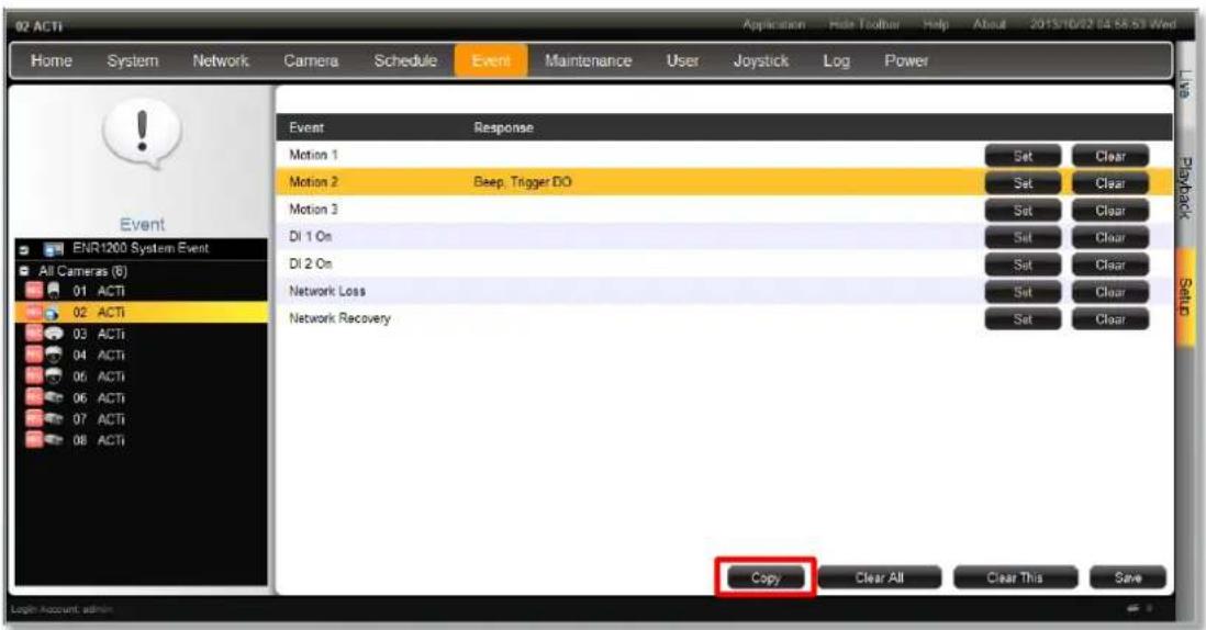
text_image
02 ACTI Home System Network Camera Schedule Event Maintenance User Joystick\Log Power Event Response Motion 1 Set Clear Motion 2 Beep, Trigger DO Set Clear Motion 3 Set Clear DI 1 On Set Clear DI 2 On Set Clear Network Loss Set Clear Network Recovery Set Clear Copy Clear All Clear This Save Login Account adminSelect one camera as the source of schedule, and add other cameras to the "To" field. Click "Copy" to commit changes.
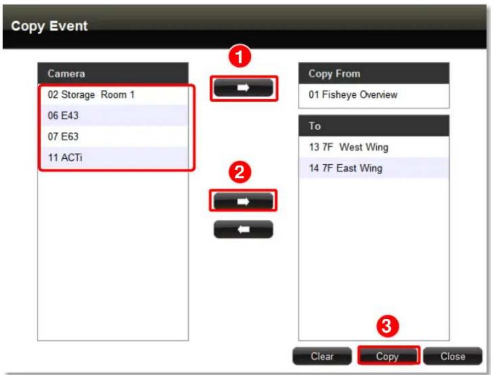
text_image
Copy Event Camera 02 Storage Room 1 06 E43 07 E63 11 ACTi Copy From 01 Fisheye Overview To 13 7F West Wing 14 7F East Wing Clear Copy CloseClear Event Rules
On Event tab, you may select an event rule under certain camera, and click "Clear" to delete it.
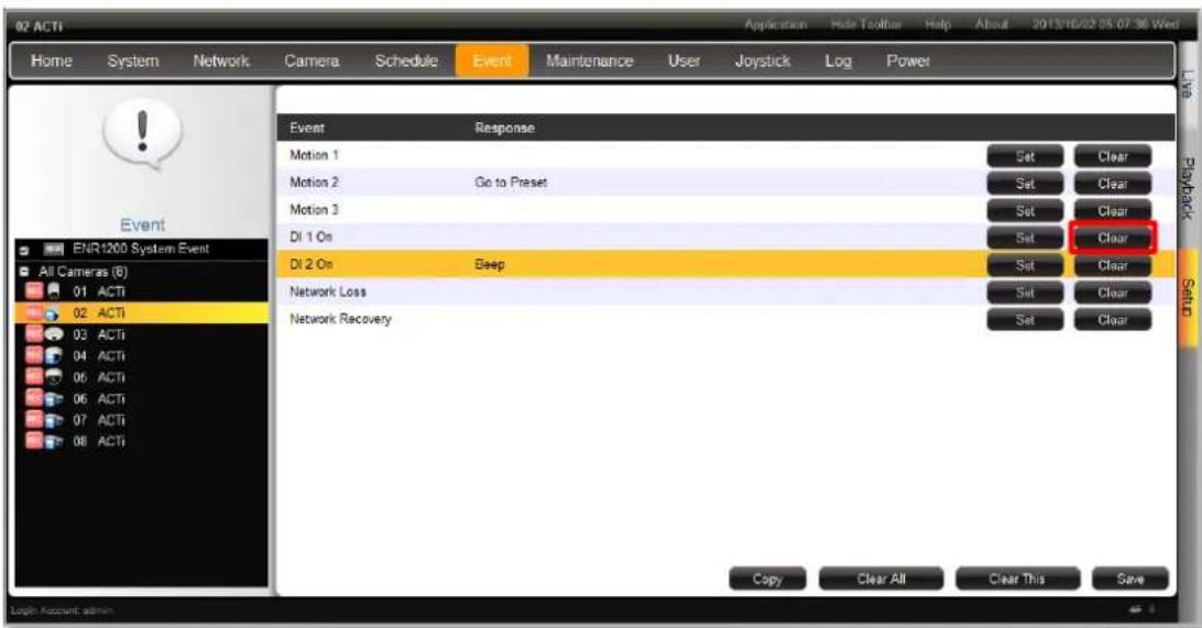
text_image
02 ACTI Home System Network Camera Schedule Event Maintenance User Joystick\Log Power Event Response Motion 1 Motion 2 Go to Preset Motion 3 DI 1 On DI 2 On Deep Network Loss Network Recovery Set Clear Set Clear Set Clear Set Clear Set Clear Copy Clear All Clear This Save ENR1200 System Event All Cameras (6) 01 ACTI 02 ACTI 03 ACTI 04 ACTI 05 ACTI 06 ACTI 07 ACTI 08 ACTI Application Hide Toolbar Help About 2013/10/02 05/07/36 Wed Log In Account adminTo directly clear all event rules set under a certain camera, click "Clear This".
You may also clear all the rules in ENR system by clicking "Clear All".
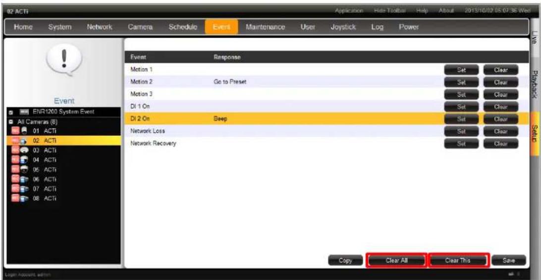
text_image
02 ACTI Home System Network Camera Schedule Event Maintenance User Joystick\Log Power Event Response Motion 1 Motion 2 Go to Preset Motion 3 DI 1 On DI 2 On Deep Network Loss Network Recovery Copy Clear All Clear This Save ENR1200 System Event All Cameras (6) 01 ACTI 02 ACTI 03 ACTI 04 ACTI 05 ACTI 06 ACTI 07 ACTI 08 ACTIPlease remember to click "Save" after deleting any rule.
Disk Management
ENR keeps the recordings on SATA hard disks installed in it. Whenever recording is taking place, ENR writes data to one of the disks, and switch to the other as the original one is full. Once the available space of the whole system is less than the reserved size, ENR will start deleting the oldest file to make the amount of space allowing each active channel to record for another 10 minutes.
You may observe the disk memory and recording status on Storage page.
Go to Setup page → System tab → Storage. The connected storage devices will be shown in the Storage Device list.
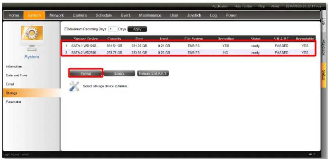
text_image
Application Help Toolbar Help About 2014/01/28 20:37:11 Tus Home System Network Camera Schedule Event Maintenance User Joystick Log Power Maximum Recording Days Days Apply Storage Device Canopy Free Used File System Recruitment Status S M A R T Recomitable 1 SATA-1 WD1002... 931.51 GB 931.30 GB 0.21 GB ENR-FS YES ready PASSED YES 2 SATA-2 WD2500... 233.76 GB 233.56 GB 0.20 GB ENR-FS NO ready PASSED YES Format Enable Refresh S.M.A.R.T. Select storage device to format. System Information Date and Time Email Storage ParameterFormat Hard Disks
Select a disk and click "Format".
You may execute disk formatting toward a newly-installed disk. You should follow the installation procedures (refer to Install the Hard Disks on page 22) to format the disks before ENR system start carrying out the surveillance task, for a disk that is not in ENR file system format is not ready for recording. Please note that the system will stop recording during the disk formation.
If you have to format a disk having been recording for a while, it is suggested that you export important video and system log in advance.
Set Maximum Recording Days
ENR can keep recording files for a certain number of days defined by you. Set this rule if you have more concern about how long the recordings are kept, especially when you do not want the old recordings to stay longer in the system than a certain period. By default, this rule is not activated, to modify it, check the box to input a number between 1\~999 and click "Apply".
For more deletion rules explanation, please refer to Storage Settings - Set Recording Deletion Rule on page 61.
Check Disk Status
Hard disk failure often comes after detectable signs and thus can be predicable, thus it is important to detect these signs long before they really cause disk failures.
ENR performs S.M.A.R.T. Disk check on 24-hour basis since last check. This technology enables a system to monitor the disk status and anticipate disk failures, helping the system administrator to prevent from unexpected outage and data loss.
You may manually perform an instant S.M.A.R.T check by clicking "Refresh".
Once the S.M.A.R.T status of disk appears "WARNING", "FAILED", or "UNKNOWN" instead of "PASSED", it is not reliable for recording, and may fail when the number of bad sectors on the disk has grown high enough. Please
- Click "Disable" next to Recordable status to stop the system from saving recording into it.
- Immediately export important video and system log, and then replace the disk following the instructions Manage Abnormal Disks on page 63.
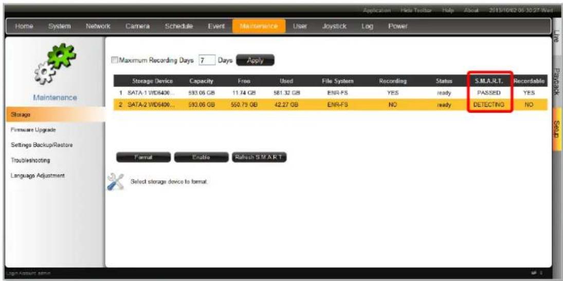
text_image
Home System Network Camera Schedule Event Maintenance User Joystick Log Power Home System Network Camera Schedule Event Application Help Toolbar Help About 2013/10/02 06:30:27 Wed Maximum Recording Days 7 Days Apply Storage Device Capacity Free Used File System Recording Status S.M.A.R.T. Recordable 1 SATA-1 WD5400... 593.06 GB 11.74 GB 581.32 GB ENR-FS YES ready PASSED YES 2 SATA-2 WD5400... 593.06 GB 550.75 GB 42.27 GB ENR-FS NO ready DETECTING NO Format Enable Refresh SMART Select storage device to formatUpgrade Firmware
You may check ACTi corporate website for latest ENR firmware package and download it. Unzip the package and save the *.upg file to your client computer.
- Make sure there is a recordable hard disk installed in ENR or a USB disk with at least 200MB space connected to ENR.
-
Go to Setup page → Maintenance tab → Firmware Upgrade. Click "Browse", find the target *.upg file and click "Open".
-
Click "Upgrade".
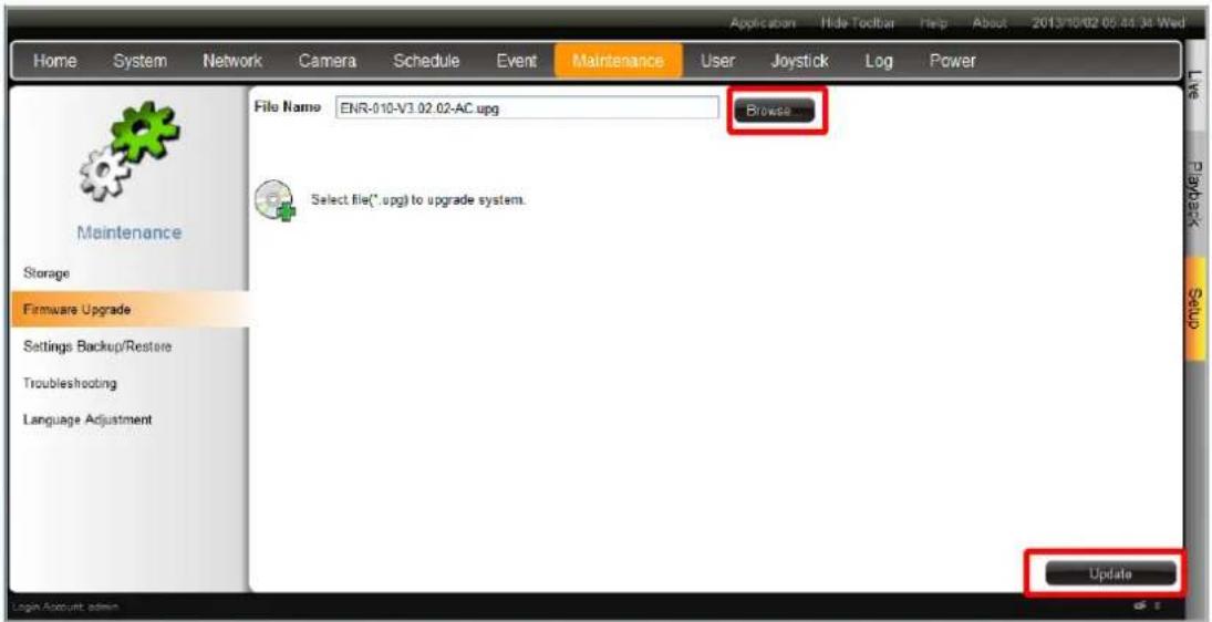
text_image
Home System Network Camera Schedule Event Maintenance User Joystick Log Power File Name ENR-010-V3.02.02-AC.upg Browse... Select file(*.upg) to upgrade system. UpdateDuring upgrading, the system will stop every other activity including recording and event handling. The system will auto-restart after the upgrading completes.
As upgrading has started, DO NOT cut off the system power or eject the USB disk until ENR restarts.
Making regular system backups is always recommended in case of unexpected disasters or accidents that may damage ENR server.
ENR server can create a backup file of the whole system settings as
Backup_[yyyymmdd].nvr file and save it to your client computer within one click. The backed up settings include the following properties: (1) System Settings including System Name, Date & Time, Network, Email, Mouse and Keyboard, (2) Camera Settings, (3) Schedule Settings, and (4) Event Management.
Backup
To start backing up system setting, please insert a USB disk into ENR first.
- Go to Setup page → Maintenance tab → Settings Backup / Restore.
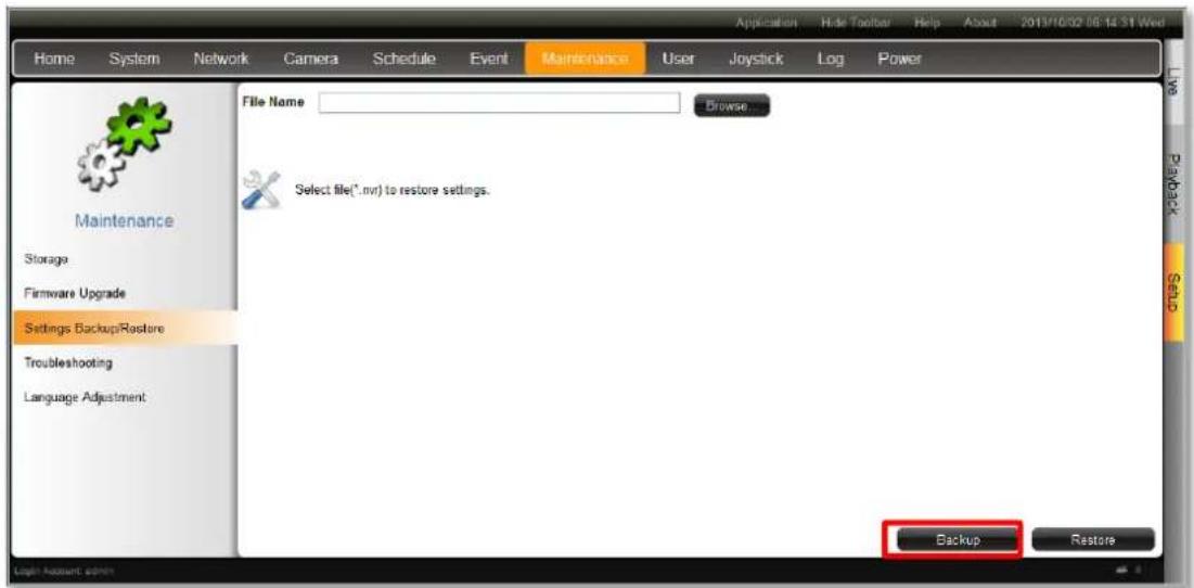
text_image
Home System Network Camera Schedule Event Maintenance User Joystick Log Power Application Hide Toolbar Help About 2013/10/02 06:14:31 Wed File Name Browse... Select file(*.nvr) to restore settings. Backup Restore Maintenance Storage Firmware Upgrade Settings BackupRestore Troubleshooting Language Adjustment Log1 Account admin- Click "Backup", the backup file will be saved to your client computer as .nvr file.

text_image
Do you want to save Backup_20130727.nvr (4.95 KB) from 172.16.26.184?Restore
Before starting restoring the system, make sure you have connected the USB disk with the desired .nvr backup file in it, and the backup file is saved in the root directory.
- Go to Setup page → Maintenance tab → Settings Backup / Restore.
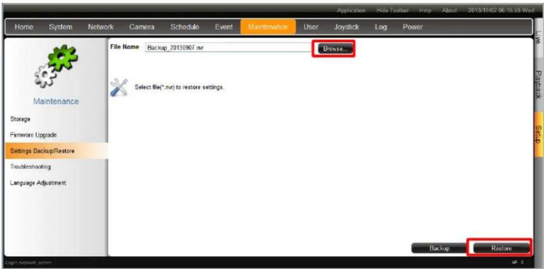
text_image
Home System Network Camera Schedule Event Maintenance User Joystick Log Power File Name: Backup_20130907.nvr Browse... Select file(*.nvr) to restore settings. Backup Restore- Click "Browse", find the target *.nvr file and click "Open".
- Click "Restore" to start restoring the settings.
User Group Management
In ENR, the access permissions are managed by User Groups. User Groups defines what functions are allowed for a group of users. Different User Groups will have different access rights in terms of permitted operations like monitoring Live screen or execute Playback. For example, an Administrator user is allowed for all the operations in ENR, while a standard normal user may only be permitted to do Live monitoring.
Go to Setup page → User tab.
Add a Group
By default, the Administrator User Group with full permissions in ENR already exists. Except for the password and e-mail settings, you may not delete this account or change its permissions.
- Enter Group, click "Add Group" to bring up Add New Group window, enter the Name and Description of the group, and click "OK" to add it to the Group List.
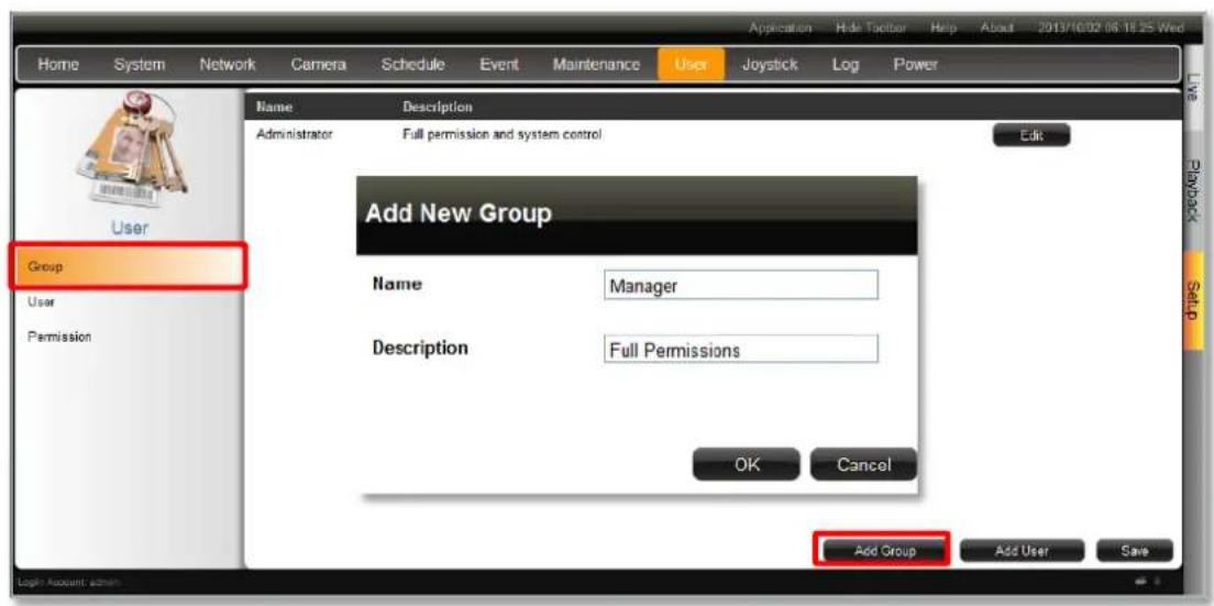
text_image
Home System Network Camera Schedule Event Maintenance User Joystick Log Power Name Description Administrator Full permission and system control Edit Add New Group Name Manager Description Full Permissions OK Cancel Add Group Add User Save Login Account admin- Enter Permission, and select the group from Group list, enable the permissions possessed by this group.
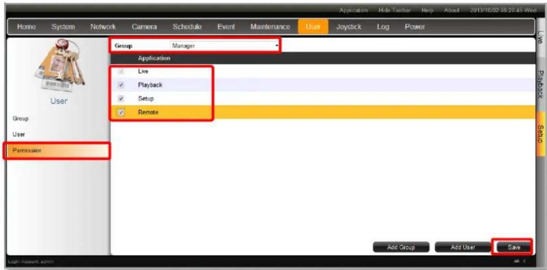
text_image
Home System Network Camera Schedule Event Maintenance User Joystick Log Power Group Manager Application Live Playback Setup Remote Group User Permission Add Group Add User Save- Click "Save" to save the group settings.
Edit / Delete a Group
You may edit an existing Group or delete it. Select the user on Group List, click "Edit" or Delete". Please always click "Save" before leaving this page.

text_image
Name Description Administrator Full permission and system control Edit Manager Full Control Edit DeleteAdd a User
By default, the Administrator User already exists, which you may not delete.
Go to Setup page → User tab.
- Enter User, click "Add User" to bring up Add New User window, enter the Name and Password, and select its User Group, click "OK" to add it to the User List.
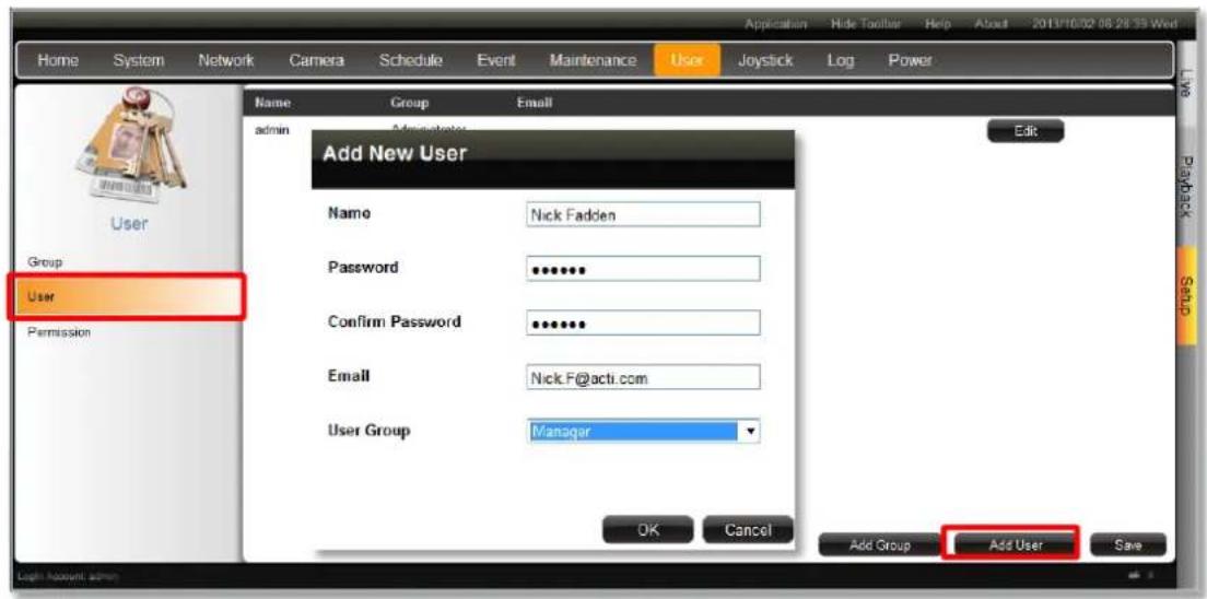
text_image
Home System Network Camera Schedule Event Maintenance User Joystick Log Power Home System Network Camera Schedule Event Maintenance User Joystick Log Power Name Group Email Admin Add New User Edit User Group Password Password Confirm Password Email User Group Manager OK Cancel Add Group Add User Save PlayBack Send Light account adminAccount /Password Rules
- Account field allows alphabets, numbers, and symbols except the following: * <> ? | “ \ : The maximum length of characters is 15.
- Password field allows alphabets, numbers and symbols. The maximum length of characters is 40.
- Both the Account and Password field are non-case-sensitive.
Edit / Delete a User
You may edit an existing user or delete it. Select the user on User List, click "Edit" or Delete". Please always click "Save" before leaving this page.

text_image
Name Group Email admin Administrator Edit Nick Fadden Manager Nick.F@acti.com Edit DeleteJoystick
ENR supports two types of controller for remote client operations:
● IP Desktop, manufactured by CH Products
- Extreme™ 3D Pro, manufactured by Logitech
- Connect the joystick to your client computer, and install its driver.
- Log in to ENR, and go to Setup page → Joystick tab.
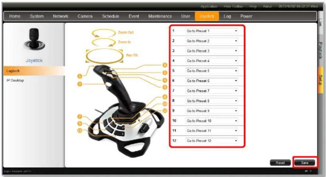
text_image
Home System Network Camera Schedule Event Maintenance User Joystick Logitech IP Desktop Zoom Out Zoom In Pen-Tilt 1 Go to Preset 1 2 Go to Preset 2 3 Go to Preset 3 4 Go to Preset 4 5 Go to Preset 5 6 Go to Preset 6 7 Go to Preset 7 8 Go to Preset 8 9 Go to Preset 9 10 Go to Preset 10 11 Go to Preset 11 12 Go to Preset 12 Application Hide Toolbar Help About 2013/18/02 06:02:31 Wed Playback Reset Save Login Account admin- There are 12 buttons available on each controller; you may assign a function selected from dropdown list to any button. Every time you change the settings on this page, please click "Save" to save the settings of this joystick model.
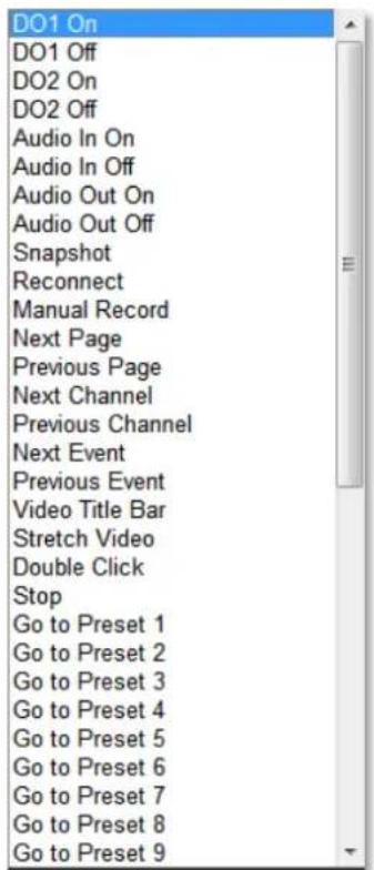
text_image
DO1 On DO1 Off DO2 On DO2 Off Audio In On Audio In Off Audio Out On Audio Out Off Snapshot Reconnect Manual Record Next Page Previous Page Next Channel Previous Channel Next Event Previous Event Video Title Bar Stretch Video Double Click Stop Go to Preset 1 Go to Preset 2 Go to Preset 3 Go to Preset 4 Go to Preset 5 Go to Preset 6 Go to Preset 7 Go to Preset 8 Go to Preset 9System Log
ENR records the important system activities and user's behaviors in System Log. Once the number of logs exceed 3000, ENR will erase the earliest 100 logs.
Go to Setup page → Log tab.

text_image
Home System Network Camera Schedule Event Maintenance User Joystick Log Power Show All Days Select Single Day 2013/10/01 1 System Remote Local ID Date Account Source Description 1 2013/10/01 22:54:52 admin Remote User login 2 2013/10/01 08:10:07 admin Remote Camera 1 is deleted 3 2013/10/01 08:04:21 admin Remote Camera 1 is added 4 2013/10/01 08:03:24 admin Remote Camera 15 is deleted 5 2013/10/01 08:03:24 admin Remote Camera 14 is deleted 6 2013/10/01 08:03:24 admin Remote Camera 13 is deleted 7 2013/10/01 08:03:24 admin Remote Camera 12 is deleted 8 2013/10/01 08:03:24 admin Remote Camera 11 is deleted 9 2013/10/01 08:03:24 admin Remote Camera 10 is deleted 10 2013/10/01 08:03:24 admin Remote Camera 9 is deleted 11 2013/10/01 08:03:24 admin Remote Camera 8 is deleted 12 2013/10/01 08:03:24 admin Remote Camera 7 is deleted Export Refresh- Define the time range:
You may choose "Show All Days" to show all the logs or choose "Select Single Day"
then click Date button 2013/09/07 to define a specific date.
- Select Log types:
| Log Types | Event |
| System | System start up, format storage |
| Local User Behaviors | Login & logout, add camera, reboot / shutdown system, modify event settings, upgrade firmware, format storage, backup / restore system configuration, modify schedule settings, modify time, modify e-mail server settings, modify system information, modify network settings, modify user & permissions, import language file |
| Remote User Behaviors | Login & logout, reboot / shutdown system, modify camera settings, modify event handling schedule/settings, upgrade firmware, format storage, backup / restore system configuration, modify recording schedule, modify time, modify e-mail server settings, modify system information, modify network settings, modify user &permissions, import language file, modify workspace parameter |
By changing the criteria, the result will automatically refresh accordingly.
Export System Log
To export the logs, click "Export" and save the xml file to your local computer. You may view this file with Notepad or XML Editor.
<?xml version="1.0"?>
- <Logs>
    <Log Source="Local" Account="admin" Date="2013/09/07 04:51:08" ID="1">Camera 9 is added</Log>
    <Log Source="Local" Account="admin" Date="2013/09/07 04:50:05" ID="2">Camera 9 is deleted</Log>
    <Log Source="Local" Account="admin" Date="2013/09/07 04:49:50" ID="3">Camera 9 is added</Log>
    <Log Source="Local" Account="admin" Date="2013/09/07 04:49:50" ID="4">Camera 3 is added</Log>
    <Log Source="Local" Account="admin" Date="2013/09/07 04:48:01" ID="5">Camera 9 is deleted</Log>
    <Log Source="Local" Account="admin" Date="2013/09/07 04:47:54" ID="6">Camera 3 is deleted</Log>
    <Log Source="Local" Account="admin" Date="2013/09/07 04:43:40" ID="7">Backup system configuration</Log>
    <Log Source="Local" Account="admin" Date="2013/09/07 00:48:40" ID="8">User login</Log>
    <Log Source="System" Account "*" Date="2013/09/07 00:44:13" ID="9">System start up</Log>
</Logs>
Customize Live Screen Layout
You may customize the layout style, channel position and patrol behavior. Your arrangement of Live screen layout will be the default view after any local user logs in to ENR.
Change Layout
(A) To change current view layout, select your desired layout by clicking on a Layout Selection Button.
Add Camera Views to Channels
(B) To immediately see all the camera views, double-click on "All Channels". The live view will change to the layout with the maximum channels.
(C) You may drag any camera from Camera list into your desire channel to display its view.
Remove Camera Views
(D) To remove a camera view from a channel, right-click on the channel to bring up Channel Menu and click "Disconnect".
(E) To remove all camera views at a time, click "Application" on title bar and then "Disconnect All Channels".
(F) Push the current view to local live view. By doing this, a new local customized view will be created to display this view. Please make sure there is no blank channel in your current remote live view.
text_image
Set Local View Name CELING ID 1 Full Screen Set Default View OK CancelWatch all camera views
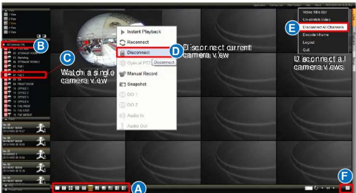
text_image
Video Title Bar Un-stretch Video Disconnect All Channels Decode Hframe Logout Quit E D Disconnect current camera view C Watch a single camera view A FLayout Selection Buttons
Patrol Switch
Execute Sequence Patrol
The patrol function will slide-show multiple channels at your defined length of interval. At one time the layout will show as many channels as its maximum display channels. For instance, during the patrol, a 3x3 layout will show channel 1\~9, and then 10\~16.

text_image
Screenshot of a software toolbar with icons and a red button labeled '3' and a circular icon.- On Live screen, input the duration of each view next to 📁.
- Click start the patrol.
- The patrol will go on until you click it again.
Save a Customized View
You may save up to five customized view on local View List. A saved view will remember (1) the layout style, (2) camera arrangement, (3) view size (stretched / un-stretched / full-screen)
- Select a View from the View List.
- Customize your layout with the tools provided on Layout Selection Buttons.
- Click in bottom right corner of View List to enter Save View window, input the view name and click "Save".
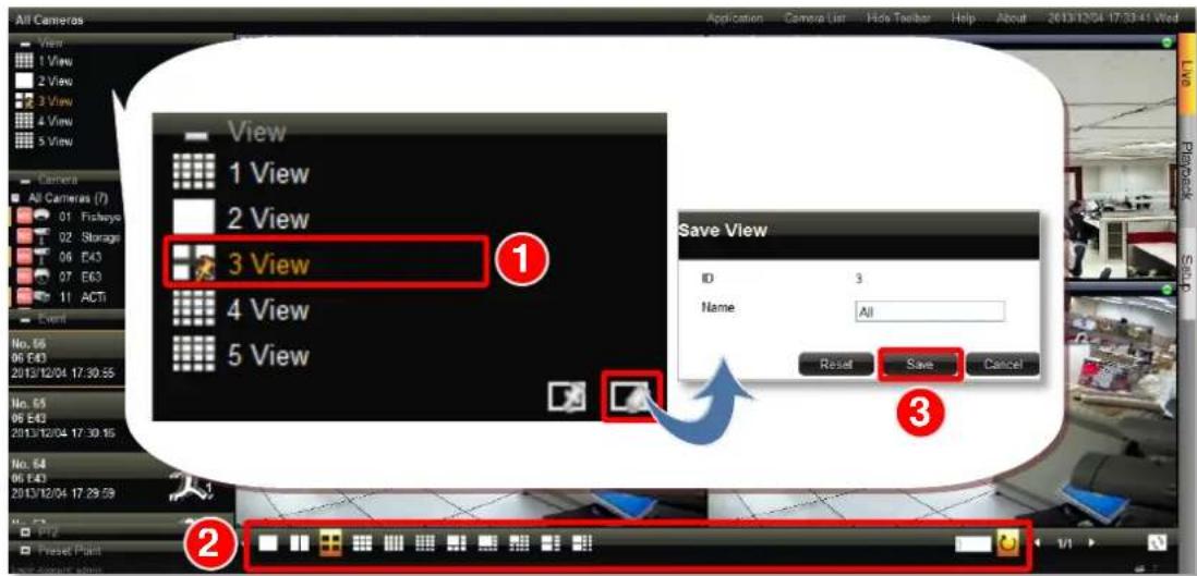
text_image
All Cameras View 1 View 2 View 3 View 4 View 5 View Camera All Cameras (7) 01 Friday 02 Storage 06 E43 07 E63 11 ACTI Event No. 55 06 E43 2013/12/04 17:30:55 No. 55 06 E43 2013/12/04 17:30:55 No. 54 06 E43 2013/12/04 17:29:59 P12 Preset Point Save View ID 3 Name All Reset Save Cancel 1 2 3Set a Default View
You may also set one View as default, in this way, you may immediately start live monitoring after logging in to the system. To set a default view, simply select a desired view on View list, and click
