
SUA750RMI1U - Server APC - Free user manual and instructions
Find the device manual for free SUA750RMI1U APC in PDF.


User questions about SUA750RMI1U APC
0 question about this device. Answer the ones you know or ask your own.
Ask a new question about this device
Download the instructions for your Server in PDF format for free! Find your manual SUA750RMI1U - APC and take your electronic device back in hand. On this page are published all the documents necessary for the use of your device. SUA750RMI1U by APC.
USER MANUAL SUA750RMI1U APC
1U Rack Mount1U Rack Mount
Uninterruptible Power Supply Uninterruptible Power Supply
Introduction
American Power Conversion Corporation (APC) is the leading national and international manufacturer of state-of-the-art uninterruptible power supplies, redundant switches, power management software, and related equipment. APC products protect hardware, software, and data from power disturbances in business and government offices throughout the world.
The APC Uninterruptible Power Supply (UPS) is designed to prevent blackouts, brownouts, sags, and surges from reaching your computer and other valuable electronic equipment. The UPS filters small utility line fluctuations and isolates your equipment from large disturbances by internally disconnecting from the utility line. The UPS provides continuous power from its internal battery until the utility line returns to safe levels or the battery is discharged.
1: INSTALLATION

Read the Safety Instruction sheet before installing the UPS.
Unpacking
Inspect the UPS upon receipt. APC designed robust packaging for your product. However, accidents and damage may occur during shipment. Notify the carrier and dealer if there is damage.
The packaging is recyclable; save it for reuse or dispose of it properly.
Check the package contents. The package contains the UPS, the front bezel, a literature kit containing one CD, one serial cable, one USB cable, product documentation and Safety Information. The package also includes rails, brackets, and a hardware packet, (necessary for rack mounting the UPS).
230V models: Two IEC jumper cables are included and a utility connector plug is included for use on servers with permanently attached power cords.

The UPS is shipped with the battery disconnected.
Positioning the UPS
Place the UPS where it will be used. The UPS is heavy. Select a location sturdy enough to handle the weight.
Do not operate the UPS where there is excessive dust or the temperature and humidity are outside the specified limits.
PLACEMENT
0^ - 40^ (32^ - 104^)
0-95% Relative Humidity
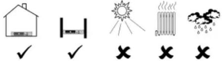
text_image
Weather and weather icons including house, thermometer, sun, thermometer, cloud, and checkmark symbolsInstalling the Rails in the Rack
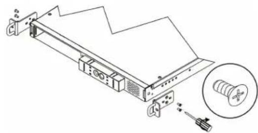
The UPS fits in a standard 46.5-cm (19-inch) rack. Mounting brackets and rails are packaged separately within the main box. Cleats for rack mounting are preinstalled on the UPS.
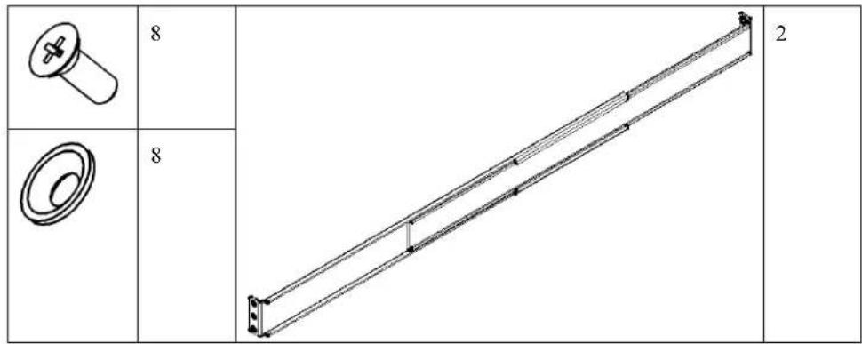
text_image
8 8 2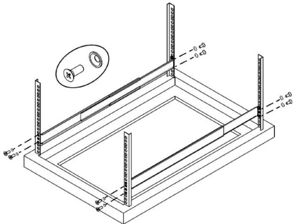
natural_image
Technical line drawing of a mechanical assembly with mounting brackets and a close-up inset showing a bolt (no text or symbols)Mounting the UPS in a Rack
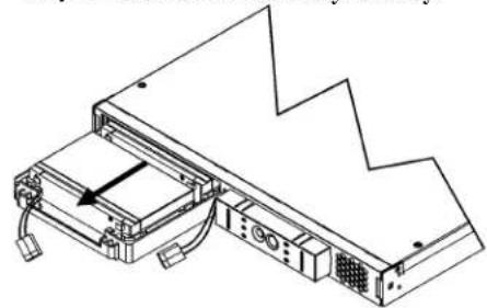
The UPS is heavy. To lighten it, you may remove the battery before mounting the unit in the rack (Steps 1 and 2).
Step 1
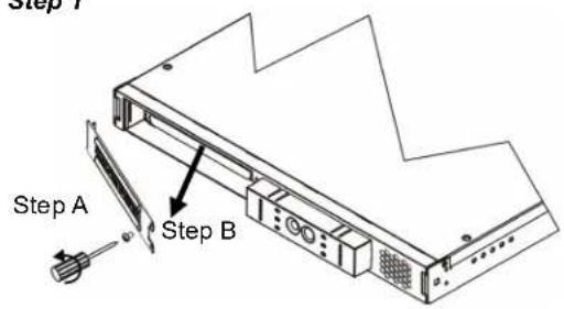
text_image
Step 1 Step A Step BStep 2 Be careful-the battery is heavy.
natural_image
Technical line drawing of a mechanical device with no visible text or symbolsInstall the UPS at or near the bottom of the rack.
Step 3
natural_image
Technical line drawing of a mechanical assembly with a magnified inset showing a screw and nut (no text or symbols)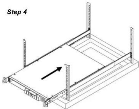
natural_image
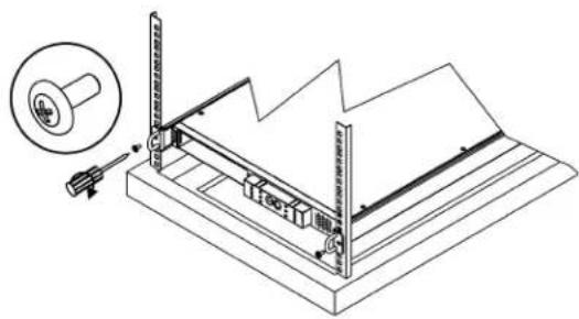
Isometric technical diagram of a structural frame with vertical supports and an arrow indicating direction (no text or symbols)Step 5
natural_image
Technical line drawing of a mechanical setup with a tool and magnified inset showing a cylindrical component (no text or symbols)
Check to make sure the rack will not tip after installing the UPS into the rack.
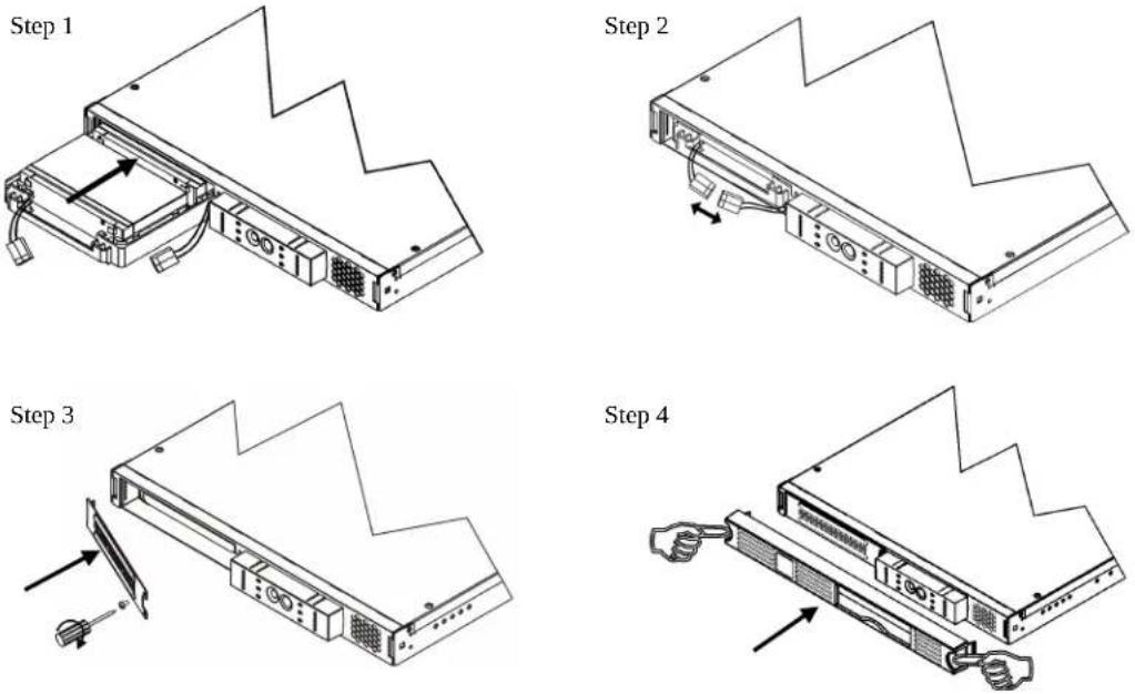
Installing and Connecting the Battery and Attaching the Front Bezel
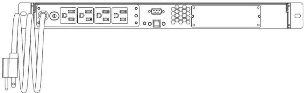
Connecting Equipment and Power to the UPS
SMART-UPS REAR PANEL
230V Models

natural_image
Back view of a server rack with multiple ports and connectors (no visible text or labels)120/100V Models
natural_image
Line drawing of a server rack with ports, connectors, and a coiled cable (no text or symbols)-
Connect equipment to the UPS. Note: Do not connect a laser printer to the UPS. A laser printer draws significantly more power than other types of equipment and may overload the UPS.
-
Add any optional accessories to the Smart-Slot.
-
Using a power cord, plug the UPS into a two-pole, three-wire, grounded receptacle only.
Avoid using extension cords.
• 120/100V models: The power cord is permanently attached to the rear panel of the UPS.
-
Turn on all connected equipment. To use the UPS as a master ON/OFF switch, be sure all connected equipment is switched ON. The equipment will not be powered until the UPS is turned on.
-
To power up the UPS press the ☐ button on the front panel.
- The UPS charges its battery when it is connected to utility power. The battery charges to 90% capacity during the first three hours of normal operation. Do not expect full battery run capability during this initial charge period.
- 120V Models: Check the site wiring fault LED located on the rear panel. It lights up if the UPS is plugged into an improperly wired utility power outlet. Refer to Troubleshooting in this manual.
- For additional computer system security, install PowerChutePlus ^® Smart-UPS monitoring software.
BASIC CONNECTORS
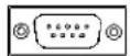
Serial Port
USB Port

Power management software and interface kits can be used with the UPS. Use only interface kits supplied or approved by APC.

Use an APC supplied cable to connect to the Serial Port. DO NOT use a standard serial interface cable since it is incompatible with the UPS connector. Both Serial and USB Ports are provided. They cannot be used simultaneously.
2: OPERATION
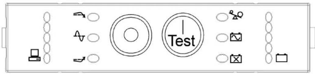
SMART-UPS FRONT PANEL
230/100V Models
text_image
Diagram of a test setup with labeled components including devices, indicators, and a central 'Test' icon.120V Models
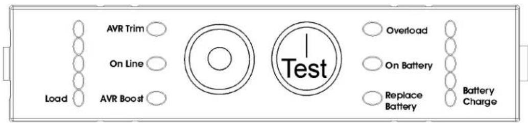
text_image
AVR Trim On Line Load AVR Boost Overload On Battery Replace Battery Battery Charge Test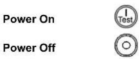
| 120V | 100/230V | 120V | 100/230V |
| 085% | 085% | 096% | 096% |
| 067% | 067% | 072% | 072% |
| 050% | 050% | 048% | 048% |
| 033% | 033% | 024% | 024% |
| 017% | 017% | 00% | 00% |
| Load | BatteryCharge |
Online
The online LED illuminates when the UPS is supplying utility power to the connected equipment. If the LED is not lit, the UPS is either not turned ON, or is supplying battery power.

AVR Trim

This LED illuminates to indicate the UPS is compensating for a high utility voltage.
AVR Boost

This LED illuminates to indicate the UPS is compensating for a low utility voltage.
On Battery

When the on battery power LED is lit the UPS is supplying battery power to the connected equipment. When on battery, the UPS sounds an alarm—four beeps every 30 seconds.
Overload

The LED illuminates and the UPS emits a sustained alarm tone when an overload condition occurs.
Replace Battery

Failure of a battery self-test causes the UPS to emit short beeps for one minute and the replace battery LED illuminates. Refer to Troubleshooting in this manual.
Battery
Disconnected

The replace battery LED flashes and short beep is emitted every two seconds to indicate the battery is disconnected.
Automatic Self-Test
The UPS performs a self-test automatically when turned on, and every two weeks thereafter (by default).
During the self-test, the UPS briefly operates the connected equipment on battery.
If the UPS fails the self-test, the replace battery LED lights and immediately returns to online operation. The connected equipment is not affected by a failed test. Recharge the battery for 24 hours and perform another self-test. If it fails, the battery must be replaced.
Manual Self-Test

Press and hold the button for a few seconds to initiate the self-test.
On Battery Operation
The Smart-UPS switches to battery operation automatically if the utility power fails. While running on battery, an alarm beeps four times every 30 seconds.
Press the 1 Test button (front panel) to silence the UPS alarm (for the current alarm only). If the utility power does not return, the UPS continues to supply power to the connected equipment until the battery is exhausted.
If PowerChute is not being used you must manually save your files and power down before the UPS turns off.
DETERMINING ON BATTERY RUN TIME
UPS battery life differs based on usage and environment. It is recommended that the battery/batteries be changed once every three years. See the APC web site, www.apc.com, for on battery run times.
3: USER CONFIGURABLE ITEMS
| NOTE: SETTINGS ARE MADE THROUGH SUPPLIED POWERCHUTE SOFTWARE OR OPTIONAL SMART SLOT ACCESSORY CARDS. | |||
| FUNCTION | FACTORYDEFAULT | USER SELECTABLECHOICES | DESCRIPTION |
| Automatic Self-Test Every 14 days (336 hours) | Every 7 days (168 hours), On Startup Only, No Self-Test | This function sets the interval at which the UPS will execute a self-test. Refer to your software manual for details. | |
| UPS ID UPS_IDEN Up to eight characters to | define the UPS | Use this field to uniquely identify the UPS, (ie. server name or location) for network management purposes. | |
| Date of Last Battery Replacement | Manufacture Date | Date of Battery Replacement mm/dd/yy | Reset this date when you replace the battery module. |
| Minimum Capacity Before Return from Shutdown | 0 percent 15, 30, 45, 50, 60, 75, 90 percent | The UPS will charge its batteries to the specified percentage before return from a shutdown. | |
| Voltage SensitivityThe UPS detects and reacts to line voltage distortions by transferring to battery operation to protect the connected equipment. Where power quality is poor, the UPS may frequently transfer to battery operation. If the connected equipment can operate normally under such conditions, reduce the sensitivity setting to conserve battery capacity and service life. | Brightly lit: UPS is set to high sensitivity.Dimly lit: UPS is set to medium sensitivity.Off: UPS is set to low sensitivity.highmediumlow | To change the UPS sensitivity, press the voltage sensitivity button (near panel). Use a pointed object (such as a pen) to do so.You can change the sensitivity level through PowerChute software. | |
| Alarm Control Enable Mute, Disable User can mute a present ongoing alarm or disable all existing alarms permanently. | |||
| Shutdown Delay 90 seconds | 0, 180, 270, 360, 450, 540, 630 seconds | Sets the interval between the time when the UPS receives a shutdown command and actual shutdown. | |
| Low Battery Warning.PowerChute interface software provides automatic, unattended shutdown when approximately two minutes (by default) of battery operated run time remains. | [CSKK] 2 min. | Brightly lit: Low battery warning interval is about two minutes.Dimly lit: Low battery warning interval is about five minutes.Off: Low battery warning interval is about eight minutes.[8x7W] 2 min.5 min.8 min.Possible interval settings: 2, 5, 8, 11, 14, 17, 20, 23 minutes. | The low battery warning beeps are continuous when two minutes of run time remain.To change the warning interval default setting, press the voltage sensitivity button (use a pointed object such as a pen to do so), while pressing and holding the [XO7X] button (front panel). |
| Synchronized Turn-on Delay | 0 seconds 60, 120 | 180, 240, 300, 360, 420 seconds | The UPS will wait the specified time after the return of utility power before turn-on (to avoid branch circuit overload). |
| High Transfer Point 230V models:253VAC120V models:127VAC100V models:108VAC | 230V models:257, 261, 265VAC120V models:130, 133, 136VAC100V models:110, 112, 114VAC | To avoid unnecessary battery usage, set the high transfer point higher if the utility voltage is chronically high and the connected equipment is known to work under this condition. | |
| Low Transfer Point 230V models:208VAC120V models:106VAC100V models:92VAC | 230V models:196, 200, 204VAC120V models:97, 100, 103VAC100V models:86, 88, 90VAC | Set the low transfer point lower if the utility voltage is chronically low and the connected equipment can tolerate this condition. | |
| Output Voltage 230V models:230VAC | 230V models:220, 225, 240VAC | 230V models ONLY: allows the user to select the on battery output voltage. | |
4: STORAGE, MAINTENANCE, AND TRANSPORTING
Storage
Store the UPS covered and positioned as for proper functioning, in a cool, dry location, with the batteries fully charged.
At -15 to +30 °C (+5 to +86 °F), charge the UPS battery every six months.
At +30 to +45 °C (+86 to +113 °F), charge the UPS battery every three months.
Replacing the Battery Module
This UPS has an easy to replace, hot-swappable battery module. Replacement is a safe procedure, isolated from electrical hazards. You may leave the UPS and connected equipment on for the following procedure. See your dealer or contact APC at the web site, www.apc.com for information on replacement battery modules.

Once the battery is disconnected, the connected equipment is not protected from power outages.
Be careful during the following steps-the battery module is heavy.
Refer to Installing and Connecting the Battery and Attaching the Front Bezel, in this manual.
Reverse the instructions for battery removal.


Be sure to deliver the spent battery to a recycling facility or ship it to APC in the replacement battery packing material.
Disconnecting the Battery for Transport

Always DISCONNECT THE BATTERY before shipping in compliance with U.S. Department of Transportation (DOT) regulations.
The battery may remain in the UPS; it does not have to be removed.
- Shut down and disconnect any equipment attached to the UPS.
- Shut down and disconnect the UPS from the power supply.
- Unplug the battery connector. Refer to Mounting the UPS in a Rack, Steps 1 and 2 in this manual.
For shipping instructions and to obtain appropriate packing materials contact APC at the web site, www.apc.com/support/contact.
5: TROUBLESHOOTING
Use the chart below to solve minor Smart-UPS installation and operation problems. Refer to the APC web site, www.apc.com, for assistance with complex UPS problems.
| PROBLEM AND POSSIBLE CAUSE | SOLUTION |
| UPS WILL NOT TURN ON | |
| Battery not connected properly. | Check that the battery connector is fully engaged. |
 button not pushed.UPS not connected to utility power supply.Very low or no utility voltage. button not pushed.UPS not connected to utility power supply.Very low or no utility voltage. | Press the  button once to power the UPS and the connected equipment.Check that the power cable from the UPS to the utility power supply is securely connected at both ends.Check the utility power supply to the UPS by plugging in a table lamp. If the light is very dim, have the utility voltage checked. button once to power the UPS and the connected equipment.Check that the power cable from the UPS to the utility power supply is securely connected at both ends.Check the utility power supply to the UPS by plugging in a table lamp. If the light is very dim, have the utility voltage checked. |
| UPS WILL NOT TURN OFF | |
 button not pushed. Press the button button not pushed. Press the button  to turn the UPS off.Internal UPS fault. Do not attempt to use the UPS. Unplug the UPS and have it serviced immediately. to turn the UPS off.Internal UPS fault. Do not attempt to use the UPS. Unplug the UPS and have it serviced immediately. | |
| UPS BEEPS OCCASIONALLY | |
| Normal UPS operation when running on battery. | None. The UPS is protecting the connected equipment. |
| UPS DOES NOT PROVIDE EXPECTED BACKUP TIME | |
| The UPS battery is weak due to a recent outage or is near the end of its service life. | Charge the battery. Batteries require recharging after extended outages.They wear faster when put into service often or when operated at elevated temperatures. If the battery is near the end of its service life, consider replacing the battery even if the replace battery LED is not yet lit. |
| ALL LEDs ARE LIT AND THE UPS EMITS A CONSTANT BEEPING | |
| Internal UPS fault. Do not attempt to use the UPS. Turn the UPS off and have it serviced immediately. | |
| FRONT PANEL LEDs FLASH SEQUENTIALLY | |
| The UPS has been shut down remotely through software or an optional accessory card. | None. The UPS will restart automatically when utility power returns. |
| ALL LEDs ARE OFF AND THE UPS IS PLUGGED INTO A WALL OUTLET | |
| The UPS is shut down and the battery is discharged from an extended outage. | None. The UPS will return to normal operation when the power is restored and the battery has a sufficient charge. |
UPS BEEPS OCCASIONALLY
| Normal UPS operation when running on battery. | None. The UPS is protecting the connected equipment. | |
| UPS DOES NOT PROVIDE EXPECTED BACKUP TIME | ||
| The UPS battery is weak due to a recent outage or is near the end of its service life. | Charge the battery. Batteries require recharging after extended outages. They wear faster when put into service often or when operated at elevated temperatures. If the battery is near the end of its service life, consider replacing the battery even if the replace battery LED is not yet lit. | |
| ALL LEDs ARE LIT AND THE UPS EMITS A CONSTANT BEEPING | ||
| Internal UPS fault. Do not attempt to use the UPS. Turn the UPS off and have it serviced immediately. | ||
| FRONT PANEL LEDs FLASH SEQUENTIALLY | ||
| The UPS has been shut down remotely through software or an optional accessory card. | None. The UPS will restart automatically when utility power returns. | |
| ALL LEDs ARE OFF AND THE UPS IS PLUGGED INTO A WALL OUTLET | ||
| The UPS is shut down and the battery is discharged from an extended outage. | None. The UPS will return to normal operation when the power is restored and the battery has a sufficient charge. | |
| PROBLEM AND POSSIBLE CAUSE | SOLUTION | |
| THE OVERLOAD LED IS LIT AND THE UPS EMITS A SUSTAINED ALARM TONE | ||
| The UPS is overloaded. The connected equipment exceeds the specified “maximum load” as defined in Specifications at the APC web site, www.apc.com.The alarm remains on until the overload is removed. Disconnect nonessential equipment from the UPS to eliminate the overload.The UPS continues to supply power as long as it is online and the circuit breaker does not trip; the UPS will not provide power from batteries in the event of a utility voltage interruption.If a continuous overload occurs while the UPS is on battery, the unit turns off output in order to protect the UPS from possible damage. | ||
| THE REPLACE BATTERY LED IS LIT | ||
| Replace Battery LED flashes and short beep is emitted every two seconds to indicate the battery is disconnected.Weak battery. Allow the battery to recharge for 24 hours. Then, perform a self-test. If the problem persists after recharging, replace the battery.Failure of a battery self-test. | Check that the battery connectors are fully engaged.to recharge for 24 hours. Then, perform a self-test. If the problem persists after recharging, replace the battery.The UPS emits short beeps for one minute and the replace battery LED illuminates. The UPS repeats the alarm every five hours. Perform the self-test procedure after the battery has charged for 24 hours to confirm the replace battery condition. The alarm stops and the LED clears if the battery passes the self-test. | |
| THE SITE WIRING FAULT LED IS LIT | ||
| 120V models only. Site wiringLED on rear panelThe UPS is plugged into an improperly wired utility power outlet. | Wiring faults detected include missing ground, hot-neutral polarity reversal, and overloaded neutral circuit.Contact a qualified electrician to correct the building wiring. | |
| THE INPUT CIRCUIT BREAKER TRIPS | ||
| The plunger on the circuit breaker (located to the right of the input cable connection) pops out. | Reduce the load on the UPS by unplugging equipment and press the plunger in. | |
| AVR BOOST OR AVR TRIM LEDs LIGHT | ||
| Your system is experiencing excessive periods of low or high voltage. | Have qualified service personnel check your facility for electrical problems. If the problem continues, contact the utility company for further assistance. | |
| PROBLEM AND POSSIBLE CAUSE | SOLUTION | |
| UPS OPERATES ON BATTERY ALTHOUGH NORMAL LINE VOLTAGE EXISTS | ||
| UPS input circuit breaker tripped. Very high, low, or distorted line voltage. Inexpensive fuel powered generators can distort the voltage. | Reduce the load on the UPS by unplugging equipment and resetting the circuit breaker (on the back of UPS) by pressing the plunger in.Move the UPS to a different outlet on a different circuit. Test the input voltage with the utility voltage display (see below). If acceptable to the connected equipment, reduce the UPS sensitivity. | |
| BATTERY CHARGE AND BATTERY LOAD LEDs FLASH SIMULTANEOUSLY | ||
| The internal temperature of the UPS has exceeded the allowable threshold for safe operation. | Check that the room temperature is within the specified limits for operation.Check that the UPS is properly installed allowing for adequate ventilation.Allow the UPS to cool down. Restart the UPS. If the problem continues contact APC at,www.apc.com/support | |
| DIAGNOSTIC UTILITY VOLTAGE FEATURE | ||
| Utility Voltage100V 230V 120V0119 0266 01330110 0248 01240100 0229 0114091 0213 0105082 0196 096BatteryCharge | The UPS has a diagnostic feature that displays the utility voltage. Plug the UPS into the normal utility power.Press and hold the button to view the utility voltage bar graph display. After a few seconds the five-LED, Battery Charge, display on the right of the front panel shows the utility input voltage.Refer to the figure at left for the voltage reading (values are not listed on the UPS).The display indicates the voltage is between the displayed value on the list and the next higher value.Three LEDs light, indicating utility voltage within the normal range.If no LEDs are lit and the UPS is plugged into a working utility power outlet, the line voltage is extremely low.If all five LEDs are lit, the line voltage is extremely high and should be checked by an electrician. | |
 | The UPS starts a self-test as part of this procedure. The self-test does not affect the voltage display. | |
Service
If the UPS requires service do not return it to the dealer. Instead, follow these steps:
- Review the problems discussed in the Troubleshooting section of this manual to eliminate common problems.
- If the problem persists, contact APC Customer Service through the APC web site, www.apc.com/support.
Note the model number of the UPS, the serial number, and the date purchased. If you call APC Customer Service, a technician will ask you to describe the problem and try to solve it over the phone, if possible. If this is not possible, the technician will issue a Returned Material Authorization Number (RMA#).
■ If the UPS is under warranty, repairs are free. If not, there is a repair charge.
- Pack the UPS in its original packaging. If the original packing is not available, refer to the APC web site, www.apc.com/support, for information about obtaining a new set.
- Pack the UPS properly to avoid damage in transit. Never use Styrofoam beads for packaging. Damage sustained in transit is not covered under warranty.

Always DISCONNECT THE BATTERY before shipping in compliance with U.S. Department of Transportation (DOT) regulations.
The battery may remain in the UPS; it does not have to be removed.
- Mark the RMA# on the outside of the package.
- Return the UPS by insured, prepaid carrier to the address given to you by Customer Service.
Contacting APC
Refer to the information provided at the APC Internet site,
http://www.apc.com/support.
6: REGULATORY AND WARRANTY INFORMATION
Regulatory Agency Approvals and Radio Frequency Warnings
230V MODELS


This is a Class A product. In a domestic environment this product may cause radio interference, in which case the user may be required to take corrective actions.
120V MODELS

LISTED 42C2 E95463

LR 63938

This equipment has been tested and found to comply with the limits for a Class A digital device, pursuant to part 15 of the FCC Rules. These limits are designed to provide reasonable protection against harmful interference when the equipment is operated in a commercial environment. This equipment generates, uses, and can radiate radio frequency energy and, if not installed and used in accordance with the instruction manual, may cause harmful interference to radio communications. Operation of this equipment in a residential area is likely to cause harmful interference in which case the user will be required to correct the interference at his own expense.
Shielded signal cables must be used with this product to ensure compliance with the Class A FCC limits.
警告使用者:
Declaration of Conformity
2002
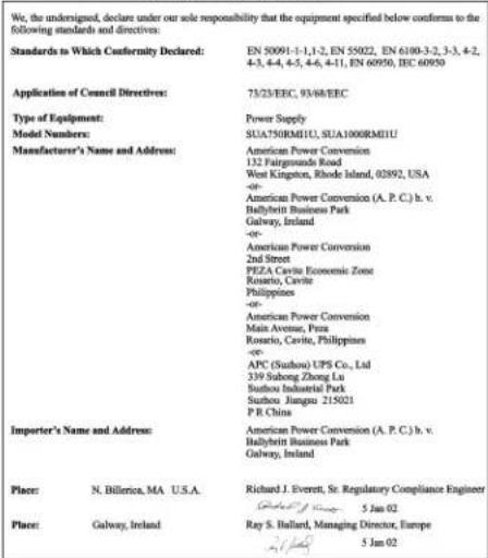
CE Declaration of Conformity
text_image
We, the undersigned, declare under our sole responsibility that the equipment specified below confirms to the following standards and directives: Standards to Which Conformity Declared: EN 50091-1-1,1-2, EN 55022, EN 6100-3-2, 3-3, 4-2, 4-3, 4-4, 4-5, 4-6, 4-11, EN 60950, IEC 60950 Application of Council Directives: 73/23/EEC, 93/48/EEC Type of Equipment: Power Supply Model Numbers: SUA750RM1U, SUA100RME1U Manufacturer's Name and Address: American Power Conversion 132 Fairgrounds Road West Kingston, Rhode Island, 02892, USA - American Power Conversion (A. P. C.) b. v. Ballybritt Business Park Galway, Ireland - - American Power Conversion 2nd Street PEZA Cavita Economic Zone Rosario, Cavita Philippines - - American Power Conversion Main Avenue, Pinia Rosario, Cavita, Philippines - - APC (Suzhou) UPS Co., Ltd 339 Subong Zhong Lu Suzhou Industrial Park Suzhou Jiangsu 215021 P R China Importer's Name and Address: American Power Conversion (A. P. C.) b. v. Ballybritt Business Park Galway, Ireland Place: N. Billerica, MA U.S.A. Richard J. Everett, Sr. Regulatory Compliance Engineer Guangxi@Jiangsu 5 Jan 02 Place: Galway, Ireland Ray S. Hallard, Managing Director, Europe Guangxi 5 Jan 02Limited Warranty
American Power Conversion (APC) warrants its products to be free from defects in materials and workmanship for a period of two years from the date of purchase. Its obligation under this warranty is limited to repairing or replacing, at its own sole option, any such defective products. To obtain service under warranty you must obtain a Returned Material Authorization (RMA) number from customer support. Products must be returned with transportation charges prepaid and must be accompanied by a brief description of the problem encountered and proof of date and place of purchase. This warranty does not apply to equipment that has been damaged by accident, negligence, or misapplication or has been altered or modified in any way. This warranty applies only to the original purchaser who must have properly registered the product within 10 days of purchase.
EXCEPT AS PROVIDED HEREIN, AMERICAN POWER CONVERSION MAKES NO WARRANTIES, EXPRESSED OR IMPLIED, INCLUDING WARRANTIES OF MERCHANTABILITY AND FITNESS FOR A PARTICULAR PURPOSE. Some states do not permit limitation or exclusion of implied warranties; therefore, the aforesaid limitation(s) or exclusion(s) may not apply to the purchaser.
EXCEPT AS PROVIDED ABOVE, IN NO EVENT WILL APC BE LIABLE FOR DIRECT, INDIRECT, SPECIAL, INCIDENTAL, OR CONSEQUENTIAL DAMAGES ARISING OUT OF THE USE OF THIS PRODUCT, EVEN IF ADVISED OF THE POSSIBILITY OF SUCH DAMAGE. Specifically, APC is not liable for any costs, such as lost profits or revenue, loss of equipment, loss of use of equipment, loss of software, loss of data, costs of substitutes, claims by third parties, or otherwise.
Entire contents copyright © 2002 by American Power Conversion Corporation. All rights reserved. Reproduction in whole or in part without permission is prohibited.
APC, Smart-UPS, and PowerChute are registered trademarks of American Power Conversion Corporation. All other trademarks are the property of their respective owners.