
GLS (2019) - Automotive Mercedes-Benz - Free user manual and instructions
Find the device manual for free GLS (2019) Mercedes-Benz in PDF.


User questions about GLS (2019) Mercedes-Benz
0 question about this device. Answer the ones you know or ask your own.
Ask a new question about this device
Download the instructions for your Automotive in PDF format for free! Find your manual GLS (2019) - Mercedes-Benz and take your electronic device back in hand. On this page are published all the documents necessary for the use of your device. GLS (2019) by Mercedes-Benz.
USER MANUAL GLS (2019) Mercedes-Benz
The following online version of the Owner's Manual describes all models as well as all the standard and optional equipment of your vehicle. Country-specific differences in the language variants are possible. Note that your vehicle may not be fitted with all features described. This is also the case for safety-relevant systems and functions. Please contact your authorised Mercedes-Benz dealer if you would like to have a printed Owner's Manual for other vehicle models and vehicle model years. The online version is the current valid Owner's Manual version. Possible variations to your vehicle may not be taken into account as Mercedes-Benz constantly updates their vehicles and equipment to the state of the art and introduces changes in design and equipment.
Please also read the printed Owner's Manual, any supplementary documents and the digital Owner's Manual in the vehicle.
Copyright
All Rights Reserved. All texts, images, graphics, are subject to Copyright and other laws for the protection of intellectual property. They may not be copied for commercial purposes or for transmission, nor changed and used on other websites.
natural_image
Green Mercedes-Benz SUV driving on a mountain road with river and forest background (no visible text or symbols)GLS
Owner's Manual
Mercedes-Benz

Front passenger airbag warning

AIRBAG




WARNING Risk of injury or fatal injuries if the front passenger airbag is enabled
If the front passenger front airbag is enabled, a child on the front passenger seat may be struck by the front passenger airbag during an accident.
NEVER use a rearward-facing child restraint system on a seat with an ENABLED FRONT AIRBAG, DEATH or SERIOUS INJURY to the CHILD can occur.
Observe the chapter "Children in the vehicle".
Thank you for purchasing a Mercedes-Benz
Before you first drive off, read this Owner's Manual carefully and familiarise yourself with your vehicle. For your own safety and a longer operating lifespan of the vehicle, follow the instructions and warning notices in this Owner's Manual. Disregarding them may lead to damage to the vehicle or injury to people.
The standard equipment and product description of your vehicle may vary and depends on the following factors:
- model
- order
- national version
- availability
The illustrations in this Owner's Manual show left-hand drive vehicle. On right-hand-drive vehicles, the layout of car parts and control elements differs accordingly.
Mercedes-Benz is constantly developing its vehicles further.
Mercedes-Benz therefore reserves the right to introduce changes in the following areas:
- design
- equipment
- technical features
The equipment in your vehicle may therefore differ from that shown in the descriptions and illustrations.
The following documents are integral parts of the vehicle:
• Digital Owner's Manual
• printed Owner's Manual
- service booklet
• equipment-dependent Supplements
a Keep these documents in the vehicle at all times. If you sell the vehicle, always pass all of the documents on to the new owner.
Symbols 5
At a glance 6
Cockpit 6
Indicator and warning lamps 10
Overhead control panel 12
Door control panel and seat adjustment .....
Control settings in the rear passenger
compartment 16
Emergencies and breakdowns 18
Digital Owner's Manual 20
Calling up the Digital Owner's Manual 20
General notes 22
Protection of the environment 22
Take-back of end-of-life vehicles 22
Mercedes-Benz GenuineParts 23
Owner's Manual 24
Operating safety 24
Declaration of Conformity 26
Diagnostics connection 31
Qualified specialist workshop 32
Vehicle registration 32
Correct use of the vehicle 32
Information on the REACH regulation 33
Notes for persons with electronic medi-
cal aids 33
Implied warranty 33
QR code for rescue card 34
Data storage 34
Copyright 36
Occupant safety 37
Restraint system 37
Seat belts 39
Airbags 43
PRE-SAFE ^® system 51
Safely transporting children in the vehi-
cle 5
Notes on pets in the vehicle 83
Opening and closing 84
Key 84
Doors 88
Running boards 94
Load compartment 95
Side windows 101
Sliding sunroof 105
Roller sunblinds 111
Anti-theft protection 114
Seats and stowing 117
Notes on the correct driver's seat posi-
tion 117
Seats 117
Steering wheel 137
Easy entry and exit feature 138
Operating the memory function 140
Memory function in the rear compart-
ment 141
Stowage areas 144
Cup holders 160
2Ashtray and cigarette lighter 164
Sockets 165
Coolbox 168
Wireless charging of the mobile phone
and connection with the exterior aerial ..... 169
Fitting/removing the floor mats 172
Light and sight 174
Exterior lighting 174
Interior lighting 181
Changing bulbs (only for vehicles with halogen headlamps) 183
Windscreen wipers and windscreen washer system 185
Mirrors 189
Operating the sun visors 192
Area permeable to radio waves on the windscreen 19
Infrared-reflective windscreen function ..... 193
Climate control 194
Overview of climate control systems ..... 194
Operating the climate control system ..... 196
Driving and parking 209
Driving 209
DYNAMIC SELECT switch 225
Automatic transmission 228
Transfer case 233
Function of the 4MATIC 235
Refuelling 235
Parking 242
Driving and driving safety systems 251
Trailer hitch 337
Bicycle rack function 342
Vehicle towing instructions 344
Instrument Display and on-board
computer 345
Instrument display overview 345
Overview of the buttons on the steering wheel 346
Operating the on-board computer 346
Adjusting the design of the instrument display 348
Showing display content on the instrument cluster 349
Overview of displays on the multifunction display 350
Adjusting the instrument lighting 351
Menus and submenus 351
Head-up Display 358
LINGUATRONIC 360
Notes on operating safety 360
Operation 361
Using LINGUATRONIC effectively 363
Essential voice commands 364
MBUX multimedia system 380
Overview and operation 380
System settings 415
Fit & Healthy 426
Navigation 432
Telephone 477
Online and Internet functions 517
Media 527
Radio 536
TV 539
Sound 547
MBUX rear tablet 551
Rear Seat Entertainment System 553
Maintenance and care 565
ASSYST PLUS service interval display ..... 565
Engine compartment 566
Cleaning and care 572
Breakdown assistance 583
Emergency 583
Flat tyre 585
Battery (vehicle) 591
Tow-starting or towing away 597
Electrical fuses 602
Wheels and tyres 605
Notes on noise or unusual handling characteristics 60
Notes on regularly inspecting wheels and tyres 60
Notes on snow chains 606
Tyre pressure 606
Wheel change 615
Emergency spare wheel 625
Collapsible spare wheel 627
Technical data 631
Notes on technical data 631
On-board electronics 631
Vehicle identification plate, VIN and engine number overview 633
Operating fluids 635
Vehicle data 644
Trailer hitch 649
Display messages and warning/indi-
cator lamps 651
Display messages 6 51
Warning and indicator lamps 711
Index 727
5
5
[Non-Text]
[Non-Text]
[Non-Text]
[Non-Text]
[Non-Text]
In this Owner's Manual, you will find the following symbols:

DANGER Danger due to not observing the warning notices
Warning notices draw your attention to hazards that may endanger your health or life, or the health or life of others.
▶ Observe the warning notices.

ENVIRONMENTAL NOTE Environmental damage due to failure to observe environmental notes
Environmental notes include information on environmentally responsible behaviour or environmentally responsible disposal.
▶ Observe environmental notes.

NOTE Damage to property due to failure to observe notes on material damage
Notes on material damage inform you of risks which may lead to your vehicle being damaged.
▶ Observe notes on material damage.
i Useful instructions or further information that could be helpful to you.
▶ Instruction
(→ page) Further information on a topic
Display Information on the multifunction display/media display
Highest menu level, which is to be selected in the multimedia system
Corresponding submenus, which are to be selected in the multimedia system
* M marks a cause
text_image
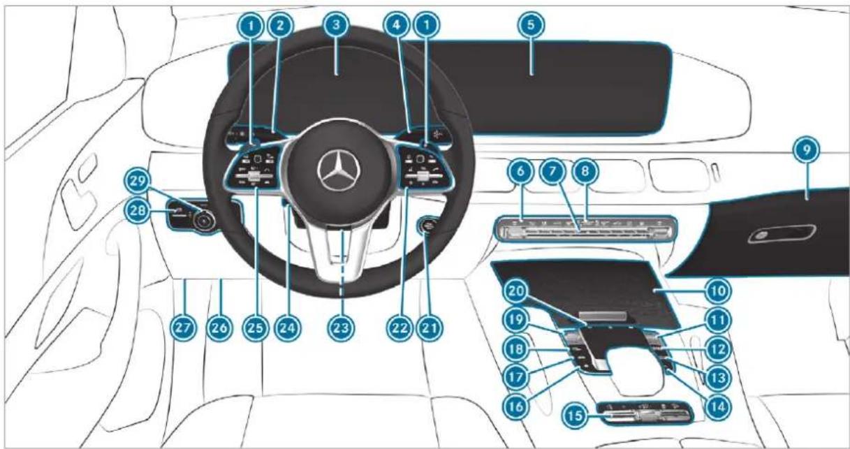
Diagram of a car interior with numbered parts for identification and assembly, highlighting the steering wheel and internal components.Left-hand drive vehicles
① Steering wheel gearshift paddles → 231
② Combination switch → 176
Instrument display → 345
4 DIRECT SELECT lever → 225
5 Media display → 383
Climate control systems → 196
7 Hazard warning light system → 177
8 PASSENGER AIR BAG indicator lamps → 48
Glove compartment → 146
⑩ Stowage compartment → 146
Control knob for volume and switching sound on/off → 380
⑫ Calls up navigation → 432
13 Calls up the radio → 537
Calls up media → 530
⑭ Calls up the telephone → 479
15 Control panel for:
Individual wheel control (vehicles without off- → 300 road package) or
Transfer case (vehicles with off-road package) → 233
Manual gearshifting → 231
AIRMATIC or → 286
E-ACTIVE BODY CONTROL → 294
Activating/deactivating ESP ^® → 253
Downhill Speed Regulation → 269
16 Calls up favourites → 402
⑰ Calls up vehicle functions → 393
18 Active Parking Assist → 321
19 DYNAMIC SELECT switch → 227
20 Touchpad → 383
21 Start/stop button → 210
ECO start/stop function → 223
22 MBUX multimedia system control panel → 383
23 Adjusts the steering wheel mechanically → 137
| 24 | Adjusts the steering wheel electrically | → | 138 |
| Switches the steering wheel heater on/off | → | 138 | |
| 25 | Control panel for: | ||
| On-board computer | → | 346 | |
| Cruise control or variable limiter | → | 267 |
Active Distance Assist DISTRONIC → 273
26 Diagnostics connection → 31
27 Opens the bonnet → 566
28 Electric parking brake → 248
29 Light switch → 174
text_image
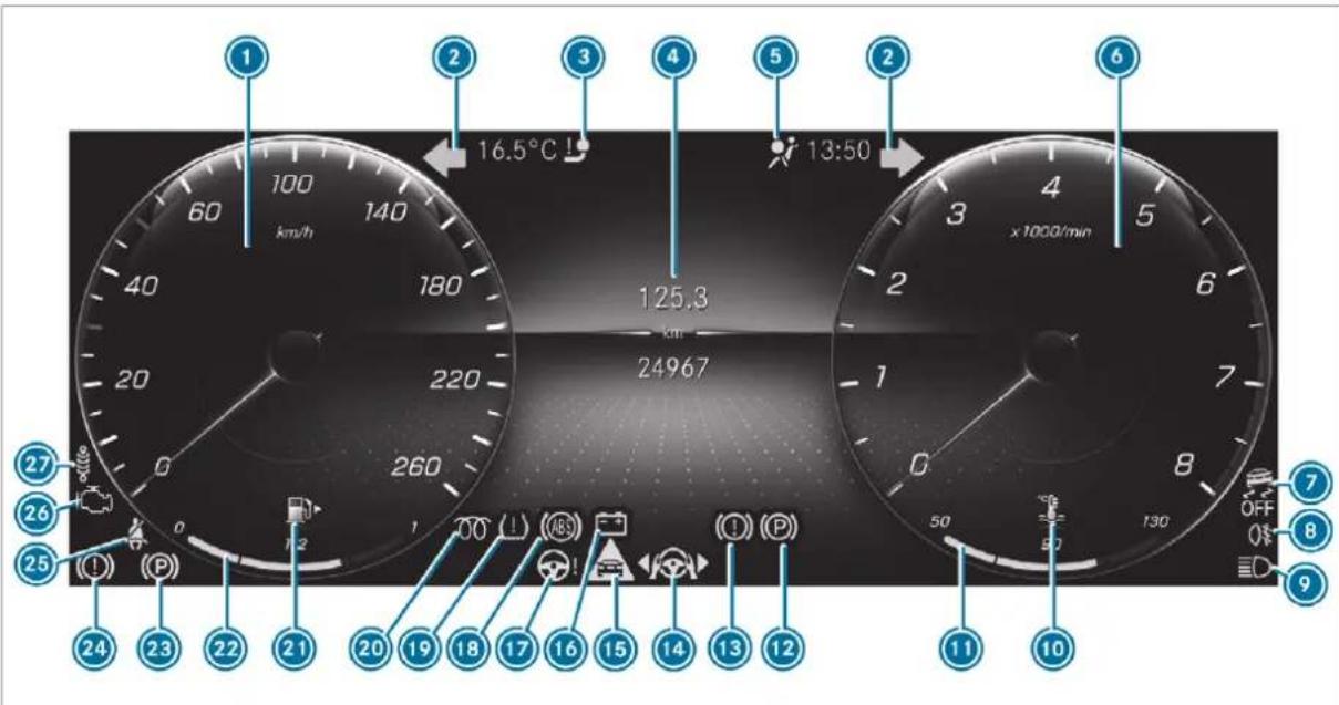
1 2 3 4 5 6 16.5°C 13:50 125.3 km 24967 x 1000/min 27 26 25 24 23 22 21 20 19 18 17 16 15 14 13 12 11 10Instrument display
Speedometer → 345
2 Turn signal lights → 176
Trailer hitch is not operational or is swiv- 714
elling
4 Multifunction display → 350
5 Restraint system → 713
6 Rev counter → 345
7 ESP OFF → 722
ESP ^® → 722
8 0‡ Rear fog light → 175
9 High beam → 176
Low beam → 174
200 Standing lights → 174
10 Coolant too hot/cold → 716
⑪ Coolant temperature display → 345
12 (P) Electric parking brake malfunction (yel- → 719 low)
13 (1) Brakes (yellow) → 719
14 Active Lane Change Assist → 280
15 Distance warning → 721
16 Electrical fault → 716
Electric power steering malfunction → 714
18 ABS malfunction → 722
19 Tyre pressure monitor → 725
20 00 Diesel engine: preglow
21 Fuel reserve with fuel filler cap location → 716 indicator
22 Fuel level indicator
23 Electric parking brake applied (red) → 719
24 (1) Brakes (red) → 719
25 Seat belt not fastened → 713
26 Engine diagnostics → 716
27 Suspension malfunction (red) → 721
Suspension malfunction (yellow) → 721
text_image
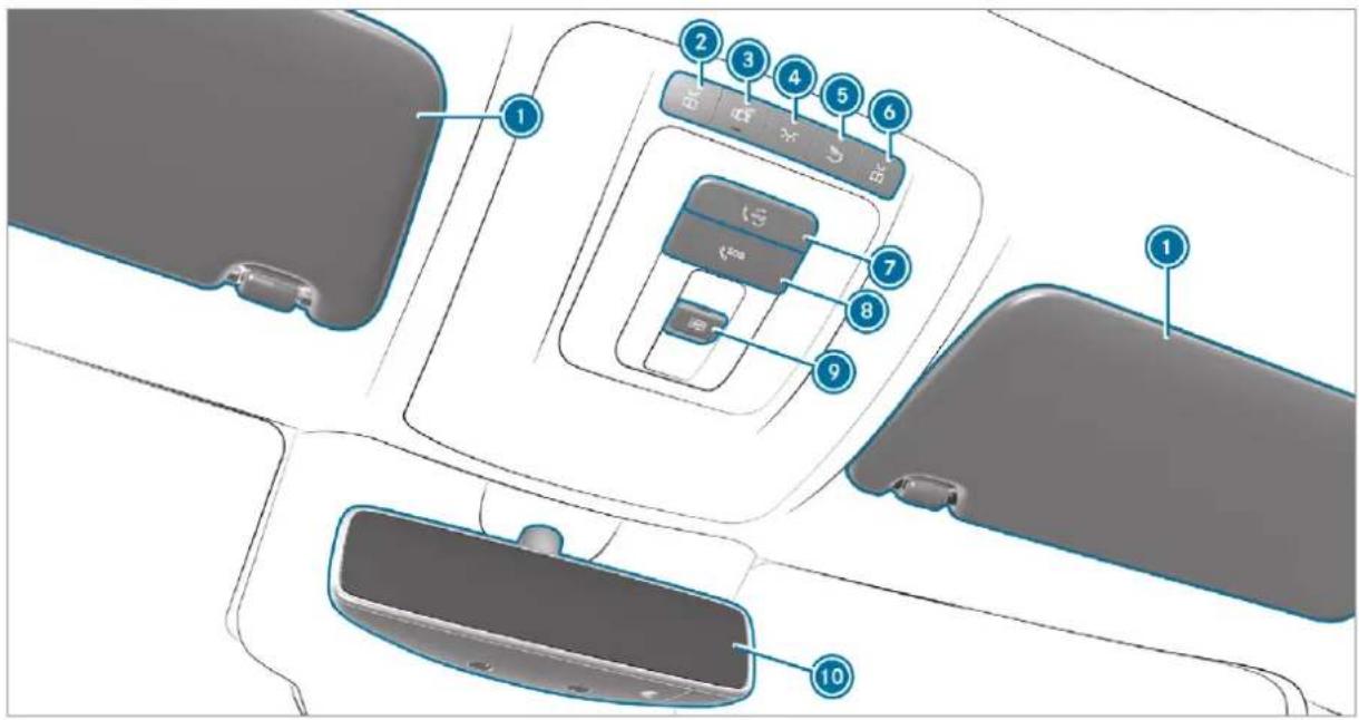
Diagram of car interior compartments with numbered labels pointing to specific areas such as the front panel, back panel, and rear panel.| 1 Sun visors | → | 192 |
| 2 Switches the left-hand reading lamp on/off | → | 181 |
| 3 Switches automatic interior lighting control on/off | → | 181 |
| 4 Switches the front interior lighting on/off | → | 181 |
| 5 Switches the rear interior lighting on/off | → | 181 |
| 6 | Switches the right-hand reading lamp on/off | → | 181 |
| 7 | me button | → | 505 |
| 8 | SOS button | → | 505 |
| 9 | Opens/closes the panorama sliding sunroof | → | 105 |
| Opens/closes the roller sunblind | → | 105 | |
| 10 | Inside rearview mirror | → | 191 |
text_image
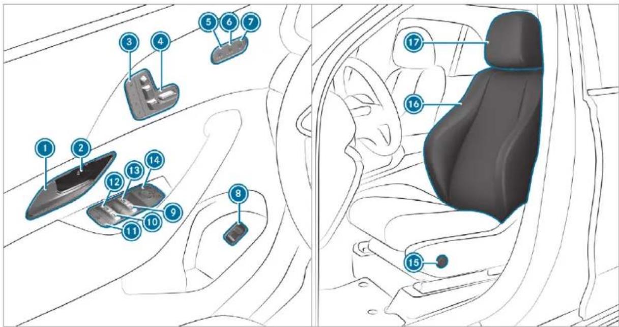
Diagram of car interior with numbered compartments and seat labels, likely for vehicle safety or diagnostic reference.① Opens the door → 89
Locks/unlocks the vehicle → 89
Sets the memory function → 140
4 Adjusts the seats electrically → 117
5 Switches the seat heating on/off → 134
6 Switches the seat ventilation on/off → 136
⑦ Adjusts the front passenger seat from the → 119 driver's seat
8 Opens/closes the tailgate → 95
⑨ Opens/closes the right side window → 101
10 Opens/closes the rear right side window → 101
Child safety lock for the rear side windows → 83
12 Opens/closes the rear left side window → 101
13 Opens/closes the left side window → 101
14 Operates the outside mirrors → 189
15 Adjusts the 4-way lumbar support → 121
16 Seat adjustment using the multimedia system → 131
17 Adjusts the head restraints → 127
text_image
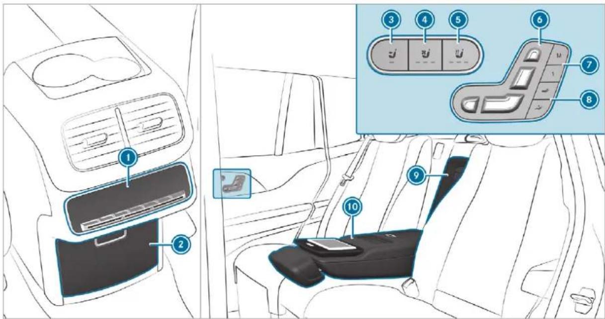
Diagram of car interior showing dashboard, seatbelt, and control panel with numbered labels① Rear climate control control panel → 195
② Stowage compartment in the centre console → 148
230 V socket → 165
3 Adjusts the front passenger seat electrically → 120
4 Switches the rear seat ventilation on/off → 136
5 Switches the rear seat heating on/off → 134
6 Adjusts the rear seats electrically → 121
Mercedes-Maybach vehicles: adjusts a reclin-
ing rear seat electrically → 121
⑦ Mercedes-Maybach vehicles: operates the → 141 memory function
B Mercedes-Maybach vehicles: sets the fully reclined position → 122
Mercedes-Maybach vehicles: access to the refrigerator box → 168
10 Stowage compartment in the rear armrest → 147
MBUX rear tablet bracket → 552
text_image
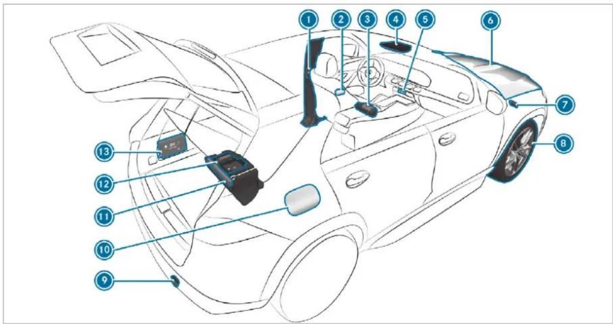
Labeled diagram of a car interior showing numbered components for identificationQR code for accessing the rescue card → 34
2 Safety vests → 583
3 Fire extinguisher → 585
④ me button and SOS button → 505
5 Hazard warning light system → 177
To check and top up operating fluids → 635
Starting assistance → 595
To tow-start and tow away → 598
8 Flat tyre → 585
To tow-start and tow away → 598
10 Fuel filler flap with instruction labels for tyre pressure, fuel type and QR code for accessing the rescue card → 235
Warning triangle → 583
12 TREFIT kit → 587
13 First-aid kit (soft sided) → 584
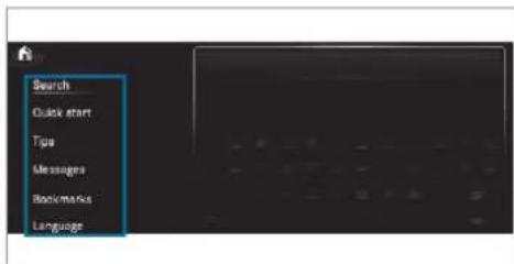
Calling up the Digital Owner's Manual
Multimedia system:

text_image
Search Quick start Tips Messages Bookmarks LanguageThe Digital Owner's Manual describes the function and operation of:
- the vehicle
• the multimedia system
Select one of the following menu items in a Digital Owner's Manual: -
Search: search for keywords in order to find quick answers to questions about the operation of the vehicle.
-
Quick start: find the first steps towards setting up your vehicle.
- Tips: find information that prepares you for certain everyday situations with your vehicle.
- Messages: receive additional information about the messages in the instrument display.
- Bookmarks: gain access to your personally saved bookmarks.
• Language: select the language for the Digital Owner's Manual.
text_image
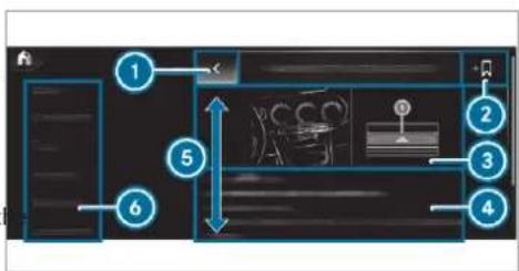
Diagram of a vehicle interior with numbered components and directional arrows indicating movement or flow.1 Back
② Adds bookmarks
3 Picture
④ Contents section
Directions of movement of contents section
6 Menu
Some sections in the Digital Owner's Manual, e.g. warning notes, can be opened and closed. Additional methods of calling up the Digital Owner's Manual:
Direct access: open the required content in the Digital Owner's Manual by pressing and holding an entry on the tab bar in the multimedia system:
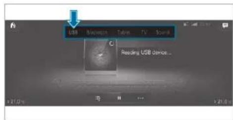
text_image
USB Bluegrass Tabris TV Sound C Reading USB devices...Instrument display: call up brief information as display messages in the instrument cluster.
LINGUATRONIC: call up via the voice control system
Global search: call up search results for contents of the Digital Owner's Manual in the home screen
For safety reasons, the Digital Owner's Manual is deactivated while driving.
The Owner's Manual can also be found in the Mercedes-Benz Guides App in all common app stores.
Protection of the environment

ENVIRONMENTAL NOTE Environmental damage due to operating conditions and personal driving style
The pollutant emission of the vehicle is directly related to the way you operate the vehicle.
Operate your vehicle in an environmentally responsible manner to help protect the environment. Please observe the following recommendations on operating conditions and personal driving style.
Operating conditions:
Make sure that the tyre pressure is correct.
Do not carry any unnecessary weight (e.g. roof luggage racks once you no longer need them).
Adhere to the service intervals.
A regularly serviced vehicle will contribute to environmental protection.
Always have maintenance work carried out at a qualified specialist workshop.
Personal driving style:
Do not depress the accelerator pedal when starting the engine.
Do not warm up the engine while the vehicle is stationary.
▶ Drive carefully and maintain a suitable distance from the vehicle in front.
Avoid frequent, sudden acceleration and braking.
Change gear in good time and use each gear only up to 23 of its maximum engine speed.
▶ Switch off the engine in stationary traffic, e.g. by using the ECO start/stop function.
▶ Drive fuel-efficiently. Observe the ECO display for a fuel-efficient driving style.

ENVIRONMENTAL NOTE Environmental pollution caused by irresponsible disposal of the high-voltage battery
A high-voltage battery contains materials which are harmful to the environment.
▶ Dispose of faulty high-voltage batteries at a qualified specialist workshop.
Take-back of end-of-life vehicles
EU countries only:
Mercedes-Benz will take back your end-of-life vehicle for environment-friendly disposal in accordance with the European Union (EU) End-of-Life Vehicles Directive.
A network of vehicle take-back points and dismantlers has been established for you to return your vehicle. You can leave it at any of these points free of charge. This makes an important contribution to closing the recycling circle and conserving resources.
For further information about the recycling and disposal of end-of-life vehicles, and the take-
back conditions, please visit the national Mercedes-Benz website for your country.
Mercedes-Benz GenuineParts

ENVIRONMENTAL NOTE Environmental damage caused by not using recycled reconditioned components
Daimler AG offers recycled reconditioned components and parts with the same quality as new parts. The same entitlement from the implied warranty is valid as for new parts.
Use recycled reconditioned components and parts from Daimler AG.
NOTE Impairment of the operating efficiency of the restraint systems from installing accessory parts or from repairs or welding
Airbags and seat belt tensioners, as well as control units and sensors for the restraint systems, may be installed in the following areas of your vehicle:
- doors
- door pillars
- door sills
- seats
- cockpit
- instrument cluster
- centre console
- lateral roof frame
Do not install accessory parts such as audio systems in these areas.
Do not carry out repairs or welding.
Have accessories retrofitted at a qualified specialist workshop.
You could jeopardise the operating safety of your vehicle if you use parts, tyres and wheels as well as accessories relevant to safety which have not been approved by Mercedes-Benz. Safety-relevant systems, e.g. the brake system, may malfunction. Only use Mercedes-Benz GenuineParts or parts of equal quality. Only use tyres, wheels and accessories that have been specifically approved for your vehicle model.
Mercedes-Benz tests original parts and conversion parts and accessories that have been specifically approved for your vehicle model for their reliability, safety and suitability. Despite ongoing market research, Mercedes-Benz is unable to assess other parts. Mercedes-Benz therefore accepts no responsibility for the use of such parts in Mercedes-Benz vehicles, even if they have been officially approved or independently approved by a testing centre.
Certain parts are only officially approved for installation or modification if they comply with legal requirements. All Mercedes-Benz Genuine-Parts meet the approval requirements. The use of non-approved parts may invalidate the vehicle's general operating permit.
This is the case in the following situations:
- the vehicle type is different from that for which the vehicle's general operating permit was granted.
- other road users could be endangered.
• the exhaust gas or noise level gets worse.
Always specify the vehicle identification number (VIN) ( page 633) when ordering Mercedes-Benz Genuine Parts.
Owner's Manual
This Owner's Manual describes all models and all standard and optional equipment available for your vehicle at the time of this Owner's Manual going to press. Country-specific differences are possible. Note that your vehicle may not be fitted with all features described. This is also the case for systems and functions relevant to safety. Therefore, the equipment on your vehicle may differ from that in the descriptions and illustrations.
The original purchase agreement for your vehicle contains a list of all of the systems in your vehicle.
Should you have any questions concerning equipment and operation, please consult a Mercedes-Benz Service Centre.
The Owner's Manual and Service Booklet are important documents and should be kept in the vehicle.
Operating safety
⚠ WARNING Risk of accident due to malfunctions or system failures
If you do not have the prescribed service/maintenance work or any required repairs carried out, this could result in malfunctions or system failures.
Always have the prescribed service/maintenance work as well any required repairs carried out at a qualified specialist workshop.
A WARNING Risk of accident and injury as a result of incorrect modifications to electronic component parts
Modification to electronic components, their software or wiring could impair their function and/or the function of other networked component parts. In particular, systems relevant to safety could also be affected.
As a result, they may no longer function as intended and/or endanger the operating safety of the vehicle.
▶ Never tamper with the wiring and electronic component parts or their software.
You should have all work on electrical and electronic components carried out at a qualified specialist workshop.
If you modify the on-board electronics, the general operating permit is rendered invalid.
Observe the "On-board electronics" section in "Technical data".
WARNING Risk of fire due to flammable materials on hot parts of the exhaust system
Flammable material such as leaves, grass or twigs may ignite if they come into contact with hot parts of the exhaust system.
When driving on unpaved roads or off-road, regularly check the vehicle underside.
Remove trapped plants or other flammable material, in particular.
If there is damage, consult a qualified specialist workshop immediately.
NOTE Damage to the vehicle
In the following situations, in particular, there is a risk of damage to the vehicle:
- the vehicle becomes grounded, e.g. on a high kerb or an unpaved road
- the vehicle is driven too fast over an obstacle, e.g. a kerb, speed bump or pot-hole
- a heavy object strikes the underbody or chassis components
In situations such as this, the body, the underbody, chassis components, wheels or tyres could be damaged without the damage being visible. Components damaged in this way can unexpectedly fail or, in the case of an accident, may not absorb the loads that arise as intended.
If the underbody panelling is damaged, flammable materials such as leaves, grass or twigs can collect between the underbody and the underbody panelling. These materials may ignite if they come into contact with hot parts on the exhaust system.
Have the vehicle checked and repaired immediately at a qualified specialist workshop.
or
If driving safety is impaired while continuing your journey, pull over and stop the vehicle immediately in accordance with the traffic conditions, and contact a qualified specialist workshop.
Vehicles with a 48 V on-board electrical system (EQ Boost technology)
DANGER Risk of fatal injury by touching damaged high-voltage components
Vehicles with a 48 V on-board electrical system contain individual high-voltage components. These high-voltage components are under high voltage.
If you modify component parts of these high-voltage components or touch damaged component parts, you may be electrocuted.
High voltage components may be damaged in an accident, although the damage may not be visible.
▶ Never perform modifications to component parts of high-voltage components.
▶ Never touch damaged component parts of high-voltage components.
▶ Never touch component parts of high-voltage components after an accident.
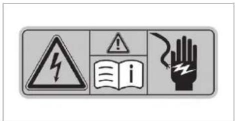
Vehicles with a 48 V on-board electrical system contain high voltage components. These components are marked with a high voltage label:
text_image
Warning sign with hazard symbol, warning sign, open book, and hand indicating electrical hazardAll work on high voltage components must be carried out at a qualified specialist workshop.
Declaration of Conformity
Electromagnetic compatibility
The electromagnetic compatibility of the vehicle components has been checked and certified according to the currently valid version of Regulation UN R10.
Wireless vehicle components
EU and EFTA countries only:
The following information applies to all wireless components of the vehicle and of the information systems and communication devices integrated into the vehicle:
The wireless components of this vehicle comply with the basic requirements and all other relevant conditions of Directive 2014/53/EU. You can obtain further information from a Mercedes Benz Service Centre.
Below are the addresses of the manufacturers wireless components. The addresses cannot be displayed on the equipment due to its size or type.
Brazil only:
Note on the two-way radio systems in the vehicle:
These systems are not protected from harmful interference and must not cause interference in duly approved systems.
Nigeria only:
The connection and use of two-way radios in this vehicle is not permitted by the Nigerian Communications Commission.
Thailand only:
The radio-based wireless components in this vehicle meet the requirements of the National Broadcasting and Telecommunications Commission (NBTC).
Tyre pressure monitoring sensors
Schrader Electronics Ltd, 11 Technology Park, Belfast Road, Antrim BT41 1QS, Northern Ireland
Remote locking system
Marquardt GmbH, Schloßstraße 16, 78604 Rietheim, Germany
Huf Hülsbeck & Fürst GmbH & Co. KG, Steeger Straße 17, 42551 Velbert, Germany
Hella KGaA Hueck & Co., Rixbecker Straße 75, 59552 Lippstadt, Germany
Remote locking system control unit
Marquardt GmbH, Schloßstraße 16, 78604 Rietheim, Germany
Leopold Kostal GmbH & Co. KG, Hauert 11, 44227 Dortmund, Germany
Continental Automotive GmbH, Siemensstraße 12, 93055 Regensburg, Germany
Antenna modules
Hirschmann Car Communication GmbH, Stuttgarter Straße 45-51, 72654 Neckartenzlingen, Germany
Kathrein Automotive GmbH & Co. KG, Römerring 1, 31137 Hildesheim, Germany
Door handles with near-field communication function
Huf Hülsbeck & Fürst GmbH & Co. KG, Steeger Straße 17, 42551 Velbert, Germany
Garage door openers
GenteX Corporation, 600 North Centennial Street, Zeeland MI 49464, USA
Sensor for interior monitoring
META Systems, Via Galimberti 9, 42124 Reggio Emilia, Italy
Radar sensors
Autoliv Electronics ASP Inc., 26545 American Drive, Southfield, MI 48034, USA
ADC Automotive Distance Control Systems GmbH, Peter-Dornier-Strasse 10, 88131 Lindau, Germany
Robert Bosch GmbH, Daimlerstrasse 6, 71229 Leonberg, Germany
Mobile communication and telematics
Harman Becker Automotive Systems GmbH, Postfach 2260, 76303 Karlsbad, Germany
Panasonic Automotive & Industrial Systems Europe GmbH, Robert-Bosch-Strasse 27-29, 63225 Langen, Germany
Mitsubishi Electric Corporation, 2-3-33 Miwa, Sanda-City, 669-1513 Hyogo, Japan
Wireless headphones
Harman Becker Automotive Systems GmbH, Postfach 2260, 76303 Karlsbad, Germany
Remote control
Ruwido Austria GmbH, Köstendorfer Strasse 8, 5202 Neumarkt, Austria
Valeo, 43 rue Bayen, 75017 Paris, France
Heater booster function remote control
Wireless applications in the vehicle
Besides the typical frequencies for mobile communications, Mercedes-Benz vehicles use the following wireless applications.
Wireless applications in the vehicle
| Technology | Frequency range | Transmission output/magnetic field strength |
| Remote locking system | 20 kHz (9-90 kHz) | ≤ 72 dBμA/m at 10 m |
| Remote locking system | 125 kHz (119-135 kHz) | ≤ 42 dBμA/m at 10 m |
| Near-field communication | 13.553-13.567 MHz | ≤ 42 dBμA/m at 10 m |
| Remote locking system, garage door opener, tyre pressure monitor | 433 MHz (433.05-434.79 MHz) | ≤ 10 mW e.r.p. |
| Heater booster function remote control, garage door opener | 868 MHz (868.0-868.6 MHz) | ≤ 25 mW e.r.p. |
| Heater booster function remote control, garage door opener | 869 MHz (868.7-869.2 MHz) | ≤ 25 mW e.r.p. |
| Bluetooth®, Kleer, RLAN, remote controls, wireless headphones | 2.4 GHz ISM band (2400-2483.5 MHz) | ≤ 100 mW e.i.r.p. |
| Sensor for interior monitoring, RLAN | 5.8 GHz UNII-3 (5725-5875 MHz) | ≤ 25 mW e.i.r.p. |
| 24 GHz ISM radar | 24.05-24.25 GHz* | ≤ 100 mW e.i.r.p. |
| 24 GHz UWB radar | 24.25–26.65 GHz* | ≤ -41.3 dBm/MHz e.i.r.p mean ≤ 0 dBm/50 MHz e.i.r.p. peak |
| 76 GHz radar | 76–77 GHz | ≤ 55 dBm peak e.i.r.p. |
| * Model series launched on the market before April 2016. | ||
| Carsharing module NFC: | 13.553–13.567 MHzBluetooth:2402–2480 MHz | NFC:≤ 42 dBμA/m at 10 mBluetooth:≤ +4 dBm (power category 2) |
Radio operating permit for antenna amplifier
| Radio equipment approval number RKE213E1 | |
| Country | Radio equipment approval number |
| Argentina | CNC® CEROSA NATIONAL® COGAL/ARADHERNRegistrierungsnummer: H-15475Produktname: VerstärkerModell:RKE2 13E1Hersteller: "KATHREIN Automotive GmbH"Adresse: Römerring 1, 31137 Hildesheim, GermanyFirma: "KATHREIN Automotive Portugal, Sociedade Unipessoal, Lda"Adresse: Parque Industrial Constantim, 5000-082 Vila Real, Portugal |
Jack
Copy and translation of the original declaration of conformity:
EC declaration of conformity
1.
The signatory, as a representative
Manufacturer:
BRANO a.s.
74741 Hradec nad Moravicí, Opavská 1000,
Czech Republic
ID No.: 64-387-5933
VAT Reg. No.: CZ64-387-5933
declares, as our sole responsibility, that the product:
- a)
Designation:
Jack
Type, number:
A) A 164 580 02 18, A 166 580 01 18
B) A 240 580 00 18
C) A 639 580 02 18
Year of manufacture: 2015
Fulfils all relevant conditions
Directive No. 2006/42/EC
b)
Description and purpose of use:
The jack is only intended for raising the specified vehicle in accordance with the operating instructions affixed to the jack.
3.
Reference data of the harmonised standards or specifications
A) ISO 4063, EN ISO 14341-A, DBL 7382.20, MBN 10435, AS 2693
B) ISO 4063, ISO 14341-A, DBL 7392.10, MBN 10435
C) DBL 7392.10, DBL 8230.10
The technical documentation of the product is stored at the manufacturer's plant. Representative for the compilation of the technical documentation: Director of the Technical Department Brano a.s.
4.
Hradec nad Moravicí
City
5.
05.05.2015
Date
Signed by
Director of Quality
TREFIT kit
Copy and translation of the original declaration of conformity:
EC declaration of conformity
In accordance with EC Directive 2006/42/EC
We hereby declare that the product
Product designation: Daimler electric air pump
Model designation: 0851ve, DT/UW 200046
MB part no.: A 000 583 8200
complies with the following relevant regulations: 2004/108/EC
Applied harmonised standards, in particular:
DIN EN 55014-1
DIN EN 55014-2:2009-06
Manufacturer: Dunlop Tech GmbH
Address: Birkenhainerstrasse 77, 63450 Hanau, Germany
Authorised representative: IMS dept.
Date: June 2015
Signature: IMS-AM, IMS-AE-L
Diagnostics connection
The diagnostics connection is only intended for the connection of diagnostic devices at a qualified specialist workshop.

WARNING Risk of accident due to connecting devices to the diagnostics connection
If you connect equipment to a diagnostics connection in the vehicle, it may affect the operation of vehicle systems.
As a result, the operating safety of the vehicle could be affected.
Only connect the vehicle diagnostics connection to devices which have been tested with regard to their use and are considered safe.

WARNING Risk of accident due to objects in the driver's footwell
Objects in the driver's footwell may impede pedal travel or block a depressed pedal. This jeopardises the operating and road safety of the vehicle.
Stow all objects in the vehicle securely so that they cannot get into the driver's footwell.
Always fit the floor mats securely and as prescribed in order to ensure that there is always sufficient room for the pedals.
Do not use loose floor mats and do not place floor mats on top of one another.
! NOTE Battery discharging from using devices connected to the diagnostics connection
Using devices at the diagnostics connection drains the battery.
▶ Check the charge level of the battery.
If the charge level is low, charge the battery, e.g. by driving a considerable distance.
Connecting equipment to the diagnostics connection can lead to emissions monitoring information being reset, for example. This may lead to the vehicle failing to meet the requirements of the next emissions inspection during the main inspection.
Qualified specialist workshop
A qualified specialist workshop has the necessary special skills, tools and qualifications to correctly carry out any necessary work on your vehicle. This particularly applies to safety-relevant works.
Always have the following work carried out on your vehicle at a qualified specialist workshop:
- safety-relevant works
• service and maintenance work - repair work
- modifications as well as installations and conversions
• work on electronic components - vehicles with 48 V on-board electrical system (EQ boost technology): work on high voltage components of the 48 V on-board electrical system
Mercedes-Benz recommends a Mercedes-Benz service centre.
Vehicle registration
Mercedes-Benz may ask its service centres to carry out technical inspections on certain vehicles. The quality or safety of the vehicle is improved as a result of the inspection.
Mercedes-Benz can only inform you about vehicle checks if Mercedes-Benz has your registration data.
It is possible that your vehicle has not yet been registered in your name in the following cases:
- if your vehicle was not purchased at an authorised specialist dealer.
- if your vehicle has not yet been examined at a Mercedes-Benz service centre.
It is advisable to register your vehicle with a Mercedes-Benz service centre.
Inform Mercedes-Benz as soon as possible about any change in address or vehicle ownership. You can do this at a Mercedes-Benz service centre, for example.
Correct use of the vehicle
If you remove any warning stickers, you or others could fail to recognise certain dangers. Leave warning stickers in position.
Observe the following information in particular when driving your vehicle:
• the safety notes in this manual
• technical data for the vehicle
- traffic rules and regulations
- laws and safety standards pertaining to motor vehicles
Information on the REACH regulation
EU and EFTA countries only:
The REACH regulation (Regulation (EC) No. 1907/2006, Article 33) stipulates a duty to supply information about substances of very high concern (SVHCs).
Daimler AG acts to the best of its knowledge to prevent these SVHCs from being used and to enable customers to safely handle these substances. There are SVHCs known to Daimler AG, according to supplier information and internal product information, found in individual components of this vehicle in quantities of over 0.1 percent by weight. Further information can be obtained at the following addresses:
- https://reach.daimler.com/de/home/
- https://reach.daimler.com/en/home/
Notes for persons with electronic medical aids
Daimler AG cannot, despite carefully developing vehicle systems, completely rule out the interaction of vehicle systems with electronic medical aids such as cardiac pacemakers.
For this reason, the following can occur in isolated cases, depending on the aids used:
- Aids malfunctioning
- Adverse health effects
Observe the notes and warnings of the manufacturer of the aids; if in doubt, contact the device manufacturer and your doctor. Daimler AG recommends using only few electrical vehicle systems if there is continuing uncertainty concerning the possibility of aids malfunctioning.
Have repairs and maintenance work in the area of vehicle components carrying live voltage and transmission aerials carried out by a qualified specialist workshop.
Implied warranty
NOTE Damage to the vehicle arising from violation of these operating instructions.
Damage to the vehicle can arise from violation of these operating instructions.
This damage is not covered either by the Mercedes-Benz implied warranty or by the New- or Used-Vehicle Warranty.
▶ Follow the instructions in these operating instructions on proper operation of your vehicle as well as on possible vehicle damage.
QR code for rescue card
The QR code is secured in the fuel filler flap and on the opposite side on the B-pillar. In the event of an accident, rescue services can use the QR code to quickly find the appropriate rescue card for your vehicle. The current rescue card contains the most important information about your vehicle in a compact form, e.g. the routing of the electric lines.
Further information can be obtained at https://www.mercedes-benz.de/qr-code.
Data storage
Electronic control units
Electronic control units are fitted in your vehicle. Some of these are necessary for the safe operation of your vehicle, while some assist you when driving (driver assistance systems). In addition, your vehicle provides comfort and entertainment functions, which are also made possible by electronic control units.
Electronic control units contain data memories which can temporarily or permanently store
technical information about the vehicle's operating state, component loads, maintenance requirements and technical events or faults.
In general, this information documents the state of a component part, a module, a system or surroundings such as:
- operating status of system components (e.g. fill levels, battery status, tyre pressure)
- status messages concerning the vehicle or its individual components (e.g. number of wheel revolutions/speed, longitudinal acceleration, lateral acceleration, display of fastened seat belts)
- malfunctions or faults in important system components (e.g. lights, brakes)
• information on events leading to vehicle damage - system reactions in special driving situations (e.g. airbag deployment, intervention of stability control systems)
- ambient conditions (e.g. temperature, rain sensor)
In addition to providing the actual control unit function, this data assists the manufacturer in detecting and rectifying faults and optimising vehicle functions. The majority of this data is temporary and is only processed in the vehicle itself. Only a small portion of the data is stored in the event or fault memory.
When your vehicle is serviced, technical data from the vehicle can be read out by service network employees (e.g. workshops, manufacturers) or third parties (e.g. breakdown services). Services include repair services, maintenance processes, warranty claims and quality assurance measures, for example. The read out is performed via the legally prescribed port for the diagnostics connection in the vehicle. The respective service network locations or third parties collect, process and use the data. They document technical statuses of the vehicle, assist in finding faults and improving quality and are transmitted to the manufacturer, if necessary. Furthermore, the manufacturer is subject to product liability. For this, the manufacturer requires technical data from vehicles.
Fault memories in the vehicle can be reset by a service outlet as part of repair or maintenance work.
Depending on the selected equipment, you can import data into vehicle convenience and info-tainment functions yourself.
This includes, for example:
- multimedia data such as music, films or photos for playback in an integrated multimedia system
- address book data for use in connection with an integrated hands-free system or an integrated navigation system
- entered navigation destinations
• data about the use of internet services
This data can be saved locally in the vehicle or it is located on a device which you have connected to the vehicle (e.g. a smartphone, USB flash drive or MP3 player). If this data is stored in the vehicle, you can delete it at any time. This data is sent to third parties only at your request, particularly when you use online services in accordance with the settings that you have selected.
You can store or change convenience settings/individualisations in the vehicle at any time.
Depending on the equipment, this includes, for example:
- settings for the seat and steering wheel positions
- suspension and climate control settings
• customisations such as interior lighting
If your vehicle is accordingly equipped, you can connect your smartphone or another mobile end device to the vehicle. You can control this by means of the control elements integrated in the vehicle. Images and audio from the smartphone can be output via the multimedia system. Certain information is simultaneously transferred to your smartphone.
Depending on the type of integration, this can include:
- general vehicle data
- position data
This allows you to use selected apps on your smartphone, such as navigation or music playback. There is no further interaction between the smartphone and the vehicle; in particular, vehicle data is not directly accessible. Which type further data processing occurs is determined by the provider of the specific app used. Which settings you can make, if any, depends on the specific app and the operating system of your smartphone.
Online services
Wireless network connection
If your vehicle has a wireless network connection, it enables data to be exchanged between your vehicle and additional systems. The wireless network connection is enabled via the vehicle's transmission and reception unit or via connected mobile end devices (e.g. smartphones). Online functions can be used via the wireless network connection. This includes online services and applications/apps provided by the manufacturer or other providers.
Manufacturer's services
Regarding online services of the manufacturer, the individual functions are described by the
manufacturer in a suitable place (e.g. Owner's pose of the collection and use of personal data Manual, website of the manufacturer) along with when services are provided by third parties.
the relevant data protection information. Personal data may be used for the provision of online services. Data is exchanged via a secure connection, e.g. the manufacturer's designated IT systems. Personal data is collected, processed and used via the provision of services exclusively on the basis of legal permissions or with prior consent.
The services and functions (sometimes subject to a fee) can usually be activated or deactivated. In some cases, this also applies to the entire vehicle's data connection. This excludes, in particular, legally prescribed functions and services.
Third party services
If it is possible to use online services from other providers, these services are the responsibility of the provider in question and subject to that provider's data protection conditions and terms of use. The manufacturer has no influence on the content exchanged.
For this reason, please ask the service provider for information about the type, extent and pur-
Copyright
Information on licences for free and open-source software used in your vehicle can be found on the data carrier in your vehicle document wallet and with updates on the following website: https://www.mercedes-benz.com/opensource
Restraint system
Protection provided by the restraint system
The restraint system includes the following components:
- Seat belt system
- Airbags
• Child restraint system
• Child seat securing systems
The restraint system can help prevent the vehicle occupants from coming into contact with parts of the vehicle interior in the event of an accident. In the event of an accident, the restraint system can also reduce the forces to which the vehicle occupants are subjected.
A seat belt can only provide the best level of protection if it is worn correctly. Depending on the detected accident situation, seat belt tensioners and/or airbags supplement the protection offered by a correctly worn seat belt. Seat belt tensioners and/or airbags are not deployed in every accident.
In order for the restraint system to provide the intended level of protection, each vehicle occupant must observe the following information:
- Fasten seat belts correctly.
- Sit in an almost upright seat position with their back against the seat backrest.
- Sit with their feet resting on the floor, if possible.
- Always secure persons under 1.50 m tall in an additional restraint system suitable for Mercedes-Benz vehicles.
However, no system available today can completely eliminate injuries and fatalities in every accident situation. In particular, the seat belt and airbag generally do not protect against objects penetrating the vehicle from the outside. It is also not possible to completely rule out the risk of injury caused by the airbag deploying.
Reduced restraint system protection

WARNING Risk of injury or death from modifications to the restraint system
The restraint system can no longer function correctly after alterations have been made.
The restraint system may then not protect the vehicle occupants as intended by failing in an accident or triggering unexpectedly, for example
▶ Never alter the parts of the restraint system.
▶ Never tamper with the wiring or any electronic component parts or their software.
If it is necessary to modify the vehicle to accommodate a person with disabilities, contact a qualified specialist workshop.
Mercedes-Benz recommends that you use driving aids which have been approved for your vehicle by Mercedes-Benz.
Restraint system functionality
When the ignition is switched on, a self-test is performed, during which the 🎨 restraint system warning lamp lights up. It goes out no later than a few seconds after the vehicle is started. The components of the restraint system are then functional.
Malfunctioning restraint system
A malfunction has occurred in the restraint system if:
- the restraint system warning lamp does not light up when the ignition is switched
- the restraint system warning lamp lights up continuously or repeatedly during journey

WARNING Risk of injury due to malfunctions in the restraint system
If the restraint system is malfunctioning, restraint system components may be triggered unintentionally or may not deploy as
intended during an accident. This may affect the seat belt tensioner or airbag, for example.
Have the restraint system checked and repaired immediately at a qualified specialist workshop.
Function of the restraint system in an accident
How the restraint system works is determined by the severity of the impact detected and the type of accident anticipated:
on. Frontal impact
- Rear impact
- Side impact
- Rollover
The activation thresholds for the components of the restraint system are determined based on the evaluation of the sensor values measured at various points in the vehicle. This process is preemptive in nature. The triggering/deployment of the components of the restraint system must
take place in good time at the start of the collision.
Factors which can only be seen and measured after a collision has occurred do not play a decisive role in the deployment of an airbag. Nor do they provide an indication of airbag deployment.
The vehicle may be deformed significantly without an airbag being deployed. This is the case if only parts which are relatively easily deformed are affected and the rate of vehicle deceleration is not high. Conversely, an airbag may be deployed even though the vehicle suffers only minor deformation. If very rigid vehicle parts such as longitudinal members are hit, for example, this may result in sufficiently high levels of vehicle deceleration.
The components of the restraint system can be activated or deployed independently of each other:
| Component Detected deployment situation | |
| Seat belt tensioners | Frontal impact, rear impact, side impact, rollover |
| Driver's airbag, front passenger airbag | Frontal impact |
| Knee airbag Frontal impact | |
| Side airbag Side impact | |
| Window airbag | Side impact, rollover, frontal impact |
| Cushionbag Frontal impact | |
| PRE-SAFE® Impulse Side | Side impact |
The front passenger airbag can only be deployed in an accident if the PASSENGER AIR BAG OFF
indicator lamp is off. If the front passenger seat is occupied, make sure, both before and during the journey, that the status of the front passenger airbag is correct ( page 48).
⚠ WARNING Rick of burns from hot airbag components
The airbag parts are hot after an airbag has been deployed.
▶ Do not touch the airbag parts.
Have a deployed airbag replaced at a qualified specialist workshop as soon as possible.
Mercedes-Benz recommends that you have the vehicle towed to a qualified specialist workshop after an accident. Take this into account, particularly if a seat belt tensioner is triggered or an airbag deployed.
If the seat belt tensioners are triggered or an air-bag is deployed, you will hear a bang, and a small amount of powder may also be released:
The bang will not generally affect your hearing.
In general, the powder released is not hazardous to health but may cause short-term breathing difficulties to persons suffering from asthma or other pulmonary conditions.
Provided it is safe to do so, leave the vehicle immediately or open the window in order to prevent breathing difficulties.
Seat belts
Protection provided by the seat belt
Always fasten your seat belt correctly before starting a journey. A seat belt can only provide the best level of protection if it is worn correctly.
⚠ WARNING Risk of injury or death due to incorrectly fastened seat belt
If the seat belt is not worn correctly, it cannot perform its intended protective function. In addition, an incorrectly fastened seat belt can also cause injuries, for example, in the event of an accident or when braking or changing direction suddenly.
▶ Always ensure that all vehicle occupants have their seat belts fastened correctly and are sitting properly.
Always observe the instructions about the correct driver's seat position and adjusting the seat ( page 117).
In order for the correctly worn seat belt to provide the intended level of protection, each vehicle occupant must observe the following information:
- The seat belt must not be twisted and must fit tightly and snugly across the body.
- The seat belt must be routed across the centre of the shoulder and as low down across the hips as possible.
- The shoulder section of the seat belt should not touch your neck nor be routed under your arm or behind your back.
- Avoid wearing bulky clothing, e.g. a winter coat.
- Push the lap belt down as far as possible across your hips and pull tight with the shoul-
der section of the belt. Never route the lap belt across your abdomen.
Pregnant women must also take particular care with this.
- Never route the seat belt across sharp, pointed, abrasive or fragile objects.
- Only one person should use each seat belt any one time. Never allow babies and children to travel sitting on the lap of another vehicle occupant.
- Never secure objects with a seat belt if the seat belt is also being used by one of the vehicle's occupants. Always observe the instructions for loading the vehicle when securing objects, luggage or loads (→ page 144).
Also ensure that no objects, e.g. a cushion, are ever placed between a person and the seat.
If children are travelling in the vehicle, be sure to observe the instructions and safety notes on
"Children in the vehicle" ( page 53).
Limitations of the protection provided by the seat belt

WARNING Risk of injury or death due to incorrect seat position
The seat belt does not offer the intended level of protection if you have not moved the seat backrest to an almost vertical position.
When braking or in the event of an accident, you could slide underneath the seat belt and sustain abdominal or neck injuries, for example.
Adjust the seat properly before beginning your journey.
Always ensure that the seat backrest is in an almost vertical position and that the shoulder section of your seat belt is routed across the centre of your shoulder.
A WARNING Risk of injury or death when additional restraint systems are not used for persons with a smaller build
Persons under 1.50 m tall cannot wear the seat belt correctly without a suitable additional restraint system.
If the seat belt is not worn correctly, it cannot perform its intended protective function. In addition, an incorrectly fastened seat belt can also cause injuries, for example, in the event of an accident or when braking or changing direction suddenly.
Always secure persons under 1.50 m tall in a suitable restraint system.
WARNING Risk of injury or death due to damaged or modified seat belts
Seat belts cannot provide protection in the following situations:
- the seat belt is damaged, has been modified, is extremely dirty, bleached or dyed
- the seat belt buckle is damaged or extremely dirty
- modifications have been made to the seat belt tensioner, seat belt anchorage or seat belt retractor
Seat belts may sustain non-visible damage an accident, e.g. due to glass splinters.
Modified or damaged seat belts could tear fail in the event of an accident, for example.
Modified belt tensioners may be deployed unintentionally or not function as intended.
▶ Never modify the seat belts, seat belt tensioners, seat belt anchorages or seat belt retractors.
▶ Make sure that the seat belts are not damaged, are not worn and are clean.
▶ Always have the seat belts checked immediately after an accident at a qualified specialist workshop.
Mercedes-Benz recommends that you only use seat belts that are approved specifically for your vehicle by Mercedes-Benz.
in
A WARNING Risk of injury or death from deployed pyrotechnic seat belt tensioners
Pyrotechnic seat belt tensioners that have been deployed are no longer operational and are unable to perform their intended protective function.
Therefore, have deployed pyrotechnic seat belt tensioners immediately replaced at a qualified specialist workshop.
Mercedes-Benz recommends that you have the vehicle towed to a qualified specialist workshop after an accident.
NOTE Damage caused by trapping the seat belt
If an unused seat belt is not fully retracted may become trapped in the door or in the seat mechanism.
Always ensure that an unused seat belt is fully retracted.
Fastening and adjusting seat belts
If the seat belt is pulled quickly or sharply, the seat belt retractor locks. The seat belt strap cannot be pulled out any further.
text_image
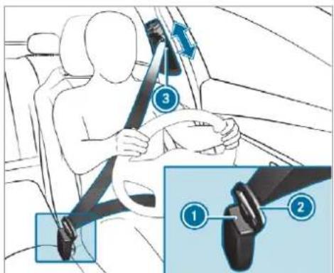
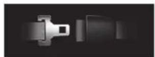
Diagram showing car seatbelt buckle assembly with numbered parts and directional arrows indicating motionAlways engage seat belt tongue ② of the seat belt into seat belt buckle ① of the corresponding seat.
Press and hold the seat belt outlet release and slide seat belt outlet ③ into the desired position.
Let go of the seat belt outlet release and ensure that seat belt outlet ③ locks into position.
NOTE Deployment of the seat belt tensioner and side impact airbag when the front passenger seat is unoccupied
If the seat belt tongue is engaged in the seat belt buckle of the unoccupied front passenger seat, the seat belt tensioner and the side impact airbag may also deploy in event of an accident along with other systems.
▶ Only one person should use each seat belt at any one time.
Seat belt adjustment function
Vehicles with PRE-SAFE®: if the front seat belt is not pulled tightly across your body, the seat belt adjustment may automatically apply a cer-
tain tightening force. Do not hold the seat belt tightly while it is adjusting. You can activate and deactivate the seat belt adjustment function using the multimedia system ( page 42).
Releasing a seat belt
Press the release button in the seat belt buckle and guide the seat belt back with the seat belt tongue.
Activating/deactivating seat belt adjustment via the multimedia system
Multimedia system:
Settings Vehicle
▶ Activate or deactivate Belt adjustment.
Seat belt warning function for the driver and front passenger
The 45 seat belt warning lamp in the instrument display is a reminder that all vehicle occupants must wear their seat belts correctly.
In addition, a warning tone may sound. As soon as the driver and front passenger their seat belts, the seat belt warning goes out.
Function of the rear seat belt status display
The rear seat belt status display is only available for certain countries.
When the ignition is switched on, the rear seat belt status display informs you for a certain amount of time which rear seat belt is not fastened.
You can immediately dismiss the rear seat belt status display using the back button on the left-hand side of the steering wheel (→ page 346
If a vehicle occupant unfastens a seat belt in the rear while the vehicle is motion, the rear seat belt status display appears again.
In addition, a warning tone may sound. In this case, the rear seat belt status display cannot be hidden using the back button on the left-hand side of the steering wheel.
Airbags
Overview of airbags

text_image
Diagram of car interior with numbered parts and labeled connectors, likely for vehicle or diagnostic reference.① Driver's knee airbag
② Driver's airbag
3 Front passenger airbag
4 Window airbag
5 Side airbag
The installation location of an airbag is identified by the AIRBAG symbol.
When enabled, an airbag can provide additional protection for the respective vehicle occupant.
Potential protection from each airbag:
| AIRBAG | Potential protection for: |
| Knee airbag Thigh, knee and lower leg | |
| Driver's airbag, front passenger airbag | Head and ribcage |
| Window airbag | H e a d |
| Side airbag Ribcage and pelvis | |

WARNING Risk of injury or fatal injuries if the front passenger airbag is enabled
If the front passenger front airbag is enabled, a child on the front passenger seat may be struck by the front passenger airbag during an accident.
NEVER use a rearward-facing child restraint system on a seat with an ENABLED FRONT AIRBAG, DEATH or SERIOUS INJURY to the CHILD can occur.
When fitting a child restraint system to the front passenger seat, observe the vehicle-specific information ( page 80). Also, always observe the notes on rearward-facing or forward-facing child restraint systems on the front passenger seat.
Information on automatic front passenger airbag shutoff
The front passenger airbag can only be deployed in an accident if the PASSENGER AIR BAG OFF indicator lamp is off. If the front passenger seat is occupied, make sure, both before and during the journey, that the status of the front passenger airbag is correct ( page 48).

NOTE Important points to remember if the front passenger seat is unoccupied
In an accident, the components of the restraint system may deploy unnecessarily on the front passenger side if:
- There are heavy objects on the front passenger seat.
- The seat belt tongue is engaged in the seat belt buckle of the front passenger seat and the front passenger seat is unoccupied.
Stow objects in a suitable place.
Only one person should use each seat belt at any one time.
Depending on the detected accident situation, the window airbag on the front passenger side at may deploy. The airbag is deployed regardless of whether the front passenger seat is occupied.
Information on the cushionbag in the reclining rear seat
The cushionbag offers additional occupant protection in the event of frontal impacts. When activated, the cushionbag deploys under the seat cushion. This helps prevent the vehicle occupant from slipping off the seat cushion.
If you install a child restraint system on the reclining rear seat, always observe the additional notes ( page 53).
Protection by the airbags
Depending on the accident situation, an airbag may supplement the protection offered by a correctly fastened seat belt.

WARNING Risk of injury or death due to incorrect seat position
If you deviate from the correct seat position, the airbag cannot perform its intended protective function and deployment may even cause further injuries.
In order to avoid risks, each vehicle occupant must always make sure of the following:
- Fasten seat belts correctly. Pregnant women must take particular care to ensure that the lap belt never lies across the abdomen.
- Adopt the correct seat position and keep as far away as possible from the airbags.
- Observe the following information.
Always make sure that there are no objects between the airbag and vehicle occupant.
To avoid the risks resulting from the deployment of an airbag, each vehicle occupant must observe the following information in particular:
- Before starting your journey, adjust your seat correctly; the driver's seat and front passenger seat should be moved as far back as possible.
When doing so, always observe the information on the correct driver's seat position ( page 117). - Only hold the steering wheel by the steering wheel rim. This allows the airbag to be fully deployed.
- Always lean against the seat backrest when the vehicle is in motion. Do not lean forwards or against the door or side window. You may otherwise be in the deployment area of the airbags.
- Always keep your feet on the floor. Do not put your feet on the cockpit, for example.
Your feet may otherwise be in the deployment area of the airbag.
- If children are travelling in the vehicle, observe the additional notes (→ page 53).
• Always stow and secure objects correctly.
Objects in the vehicle interior may prevent an airbag from functioning correctly. Each vehicle occupant must always make sure of the following in particular:
- There are no people, animals or objects between the vehicle occupants and an air-bag.
- There are no objects between the seat, doo and door pillar (B-pillar).
- There are no hard objects, e.g. coat hanger, hanging on the grab handles or coat hooks.
- There are no accessory parts, such as mobi navigation devices, mobile phones or cup holders, attached to the vehicle within the deployment area of an airbag, e.g. on the cockpit, on the door, on the side window o on the side wall trim.
In addition, no connecting cables, tensioning straps or retaining straps must be routed or attached to the vehicle within the deployment area of an airbag. Always comply with the accessory manufacturer's installation instructions and, in particular, the notes on suitable places for installation.
- There are no heavy, sharp-edged or fragile objects in the pockets of your clothing. Store such objects in a suitable place.
Limited protection provided by airbags
WARNING Risk of injury due to modifications to the airbag cover
If you modify the cover of an airbag or affix objects such as stickers to it, the airbag may no longer function correctly.
▶ Never modify the cover of an airbag and do not affix objects to it.
The installation location of an airbag is identified by the AIRBAG symbol ( page 43).
WARNING Risk of injury or death due to the use of unsuitable seat covers
Unsuitable seat covers can obstruct or prevent the deployment of the airbags integrated into the seats.
Consequently, the airbags cannot protect vehicle occupants as they are designed to do. In addition, the operation of the automatic front passenger airbag shutoff could be restricted.
You should only use seat covers that have been approved for the corresponding seats by Mercedes-Benz.
WARNING Risk of injury due to malfunctions of the sensors in the door panelling
Sensors to control the airbags are located in the doors. Modifications or work not performed correctly to the doors or door paneling, as well as damaged doors, can lead to the function of the sensors being impaired. The airbags might therefore not function properly any more.
Consequently, the airbags cannot protect vehicle occupants as they are designed to do.
▶ Never modify the doors or parts of the doors.
Always have work on the doors or door panelling carried out at a qualified specialist workshop.
WARNING Risk of injury due to deployed airbag
A deployed airbag no longer offers any protection and cannot provide the intended protective function in the event of an accident.
Have the vehicle towed to a qualified specialist workshop in order to have the deployed airbag replaced.
Have deployed airbags replaced immediately.
Status of the front passenger front airbag
Function of the automatic front passenger airbag shutoff
The automatic front passenger airbag shutoff is able to detect whether the front passenger seat is occupied by a person or a child restraint system. The front passenger airbag is enabled or disabled accordingly.
When fitting a child restraint system to the front passenger seat, always make sure of the following:
- Ensure that the child restraint system is positioned correctly ( page 59).
• Always observe the child restraint system manufacturer's installation instructions. - Never place objects, e.g. cushions, under or behind the child restraint system.
- Fully retract the seat cushion length adjustment.
-
The entire base of the child restraint system must always rest on the sitting surface of the front passenger seat.
-
The backrest of the forward-facing child restraint system must, as far as possible, be resting on the seat backrest of the front passenger seat.
- The child restraint system must not touch the roof or be put under strain by the head restraints. Adjust the seat backrest inclination and the head restraint setting accordingly.
WARNING Risk of injury or death due to objects between the seat surface and the child restraint system
Objects between the seat surface and the child restraint system could affect the function of the automatic front passenger front airbag shutoff.
This could result in the front passenger front airbag not functioning as intended during an accident.
Do not place any objects between the sitting surface and the child restraint system.
The entire base of the child restraint system must always rest on the sitting surface of the front passenger seat.
The backrest of the forward-facing child restraint system must, as far as possible, be resting on the seat backrest of the front passenger seat.
Always comply with the child restraint system manufacturer's installation instructions.
A person on the front passenger seat must observe the following information:
- Fasten seat belts correctly (→ page 39).
- Sit in an almost upright seat position with their back against the seat backrest.
- Sit with their feet resting on the floor, if possible.
The front passenger airbag may otherwise be disabled by mistake, for example in the following situations:
- The front passenger transfers their weight by supporting themselves on a vehicle armrest.
- The front passenger sits in such a way that their weight is raised from the sitting surface.
WARNING Risk of injury or death due to deactivated front passenger airbag
If the PASSENGER AIRBAG OFF indicator lamp is lit, the front passenger airbag is disabled. It will not be deployed in the event of an accident and cannot perform its intended protective function.
A person in the front passenger seat could then, for example, come into contact with the vehicle interior, especially if the person is sitting too close to the cockpit.
If the front passenger seat is occupied, always ensure that:
- The classification of the person in the front passenger seat is correct and the front passenger airbag is enabled or disabled in accordance with the person in the front passenger seat.
- The front passenger seat has been moved as far back as possible.
• The person is seated correctly.
Ensure, both before and during the journey, that the status of the front passenger airbag is correct.
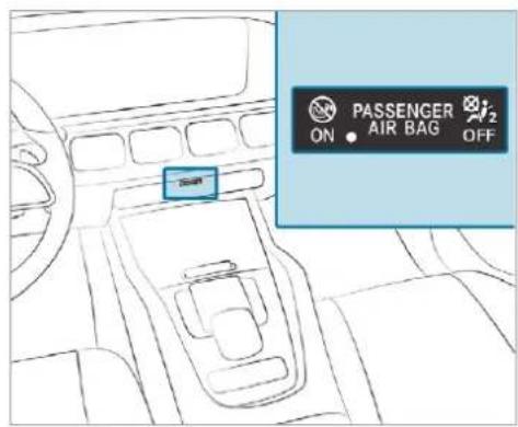
If the front passenger seat is occupied, the classification of the person or child restraint system on the front passenger seat takes place after the front passenger airbag shutoff self-test. The PASSENGER AIR BAG indicator lamps display the status of the front passenger airbag.
Always observe the notes on the function of the PASSENGER AIR BAG indicator lamps ( page 48).
Function of the PASSENGER AIR BAG indicator lamps
text_image
PASSENGER ON • AIR BAG OFFVehicles without automatic front passenger airbag shutoff have a special sticker affixed to the side of the cockpit on the front passenger side ( page 79).
Self-test of automatic front passenger airbag shutoff
When the ignition is switched on, a self-test is performed during which the two PASSENGER AIR BAG ON and OFF indicator lamps light up simultaneously.
The status of the front passenger airbag is displayed after the self-test:
- PASSENGER AIR BAG ON lights up for 60 seconds, subsequently both indicator lamps are off (PASSENGER AIR BAG ON an OFF): the front passenger airbag is able to deploy in the event of an accident.
- PASSENGER AIR BAG OFF lights up continuously: the front passenger airbag is disable. It will then not be deployed in the event of an accident.
If the PASSENGER AIR BAG ON indicator lamp is off, only the PASSENGER AIR BAG OFF indicator lamp shows the status of the front passenger airbag. The PASSENGER AIR BAG OFF indicator lamp may be lit continuously or be off.
If the PASSENGER AIR BAG OFF indicator lamp and the restraint system warning lamp
light up simultaneously, the front passenger seat may not be used. Also in this case, do not fit a child restraint system to the front passenger seat. Have automatic front passenger airbag shutoff checked and repaired immediately at a qualified specialist workshop.
Status display
If the front passenger seat is occupied, ensure, both before and during the journey, that the status of the front passenger airbag is correct for the current situation.
After fitting a rearward-facing child restraint system to the front passenger seat:
-PASSENGER AIR BAG OFF must be lit continuously.
⚠ WARNING Risk of injury or death from using a rearward-facing child restraint system when the front passenger front airbag is enabled
If you secure a child in a rearward-facing child restraint system on the front passenger seat and the PASSENGER AIR BAG OFF indi-
cator lamp is off, the front passenger airbag can deploy in the event of an accident. The child could be struck by the airbag.
Always ensure that the front passenger air-bag is disabled. The PASSENGER AIR BAG OFF indicator lamp must be lit.
NEVER use a rearward-facing child restraint system on a seat protected by an ENABLED FRONT AIRBAG in front of it, DEATH or SERIOUS INJURY to the CHILD can occur.
When fitting a child restraint system to the front passenger seat, observe the vehicle-specific information ( page 80).
Depending on the child restraint system and the stature of the child, the PASSENGER AIR BAG OFF indicator lamp may be off. In this case, do not fit the rearward-facing child restraint system to the front passenger seat.
Instead, fit the rearward-facing child restraint system to a suitable rear seat.
After fitting a forward-facing child restraint system to the front passenger seat: depending on the child restraint system and the stature
of the child, PASSENGER AIR BAG OFF may be lit continuously or be off. Always observe the following information.
A WARNING Risk of injury or death due to incorrect positioning of the forward-facing child restraint system
If you secure a child in a forward-facing child restraint system on the front passenger seat and you position the front passenger seat too close to the cockpit, in the event of an accident, the child could:
- Come into contact with the vehicle interior if the PASSENGER AIR BAG OFF indicator lamp is lit, for example.
- Be struck by the airbag if the PASSENGER AIR BAG OFF indicator lamp is off.
Always move the front passenger seat as far back as possible and fully retract the seat cushion length adjustment. Always make sure that the shoulder belt strap is correctly routed from the seat belt outlet on the vehicle to the shoulder belt guide on the child restraint sys-
tem. The shoulder belt strap must be routed forwards and downwards from the seat belt outlet. If necessary, adjust the seat belt outlet and the front passenger seat accordingly.
Always observe the child restraint system manufacturer's installation instructions.
When fitting a child restraint system to the front passenger seat, observe the vehicle-specific information ( page 80).
If a person is sitting on the front passenger seat: PASSENGER AIR BAG OFF may be lit continuously or be off, depending on the person's stature.
A person on the front passenger seat must always observe the following information:
- If the front passenger seat is occupied by an adult or a person with a stature corresponding to that of an adult, the PASSENGER AIR BAG OFF indicator lamp must be off. This indicates that the front passenger airbag is enabled.
If the PASSENGER AIR BAG OFF indicator lamp is lit continuously, an adult or person with a build corresponding to that of an adult should not use the front passenger seat. Instead, they should use a rear seat.
- If the front passenger seat is occupied by a person of smaller stature (e.g. a teenager or small adult), the PASSENGER AIR BAG OFF indicator lamp either lights up continuously or remains off, depending on the result of the classification.
- If the PASSENGER AIR BAG OFF indicator lamp is off: move the front passenger seat as far back as possible, or the person of smaller stature should use a rear seat.
- If the PASSENGER AIR BAG OFF indicator lamp is lit continuously: the person of smaller stature should not use the front passenger seat.
WARNING Risk of injury or death when the PASSENGER AIR BAG OFF indicator lamp is lit
If the PASSENGER AIR BAG OFF indicator lamp remains lit after the system self-test, the front passenger airbag is disabled. It will not be deployed in the event of an accident. In this case, the front passenger airbag cannot perform its intended protective function, e.g. when a person is seated in the front passenger seat.
That person could, for example, come into contact with the vehicle interior, especially if the person is sitting too close to the cockpit.
If the front passenger seat is occupied, always ensure that:
- The classification of the person in the front passenger seat is correct and the front passenger airbag is enabled or disabled in accordance with the person in the front passenger seat.
- The person is seated properly with a correctly fastened seat belt.
- The front passenger seat has been moved as far back as possible.
Be sure to also observe the following further related subjects:
- Child restraint system on the front passenger seat ( page 80).
- Suitable positioning of the child restraint system ( page 59).
PRE-SAFE® system
PRE-SAFE® (anticipatory occupant protection)
PRE-SAFE ^® is able to detect certain critical driving situations and implement pre-emptive measures to protect the vehicle occupants.
PRE-SAFE ^® can implement the following measures independently of each other:
- Tightening the seat belts on the driver's seat and front passenger seat.
- Closing the side windows.
- Vehicles with sliding sunroof: close the sliding sunroof.
- Vehicles with memory function: move the front passenger seat to a more favourable seat position.
- Vehicles with memory function in the rear compartment: move the outer rear seats to a more favourable seat position.
- Vehicles with multicontour seat: increase the air pressure in the seat side bolsters of the seat backrest.
- PRE-SAFE® Sound: provided that the multi-media system is switched on, generates a brief noise signal to stimulate the innate protective mechanism of a person's hearing.
NOTE Damage caused by objects in the footwell or behind the seat
The automatic adjustment of the seat position may result in damage to the seat and/or the object.
▶ Stow objects in a suitable place.
Reversing the PRE-SAFE® system measures
If an accident did not occur, the pre-emptive measures that were taken are reversed.
You will need to perform certain settings yourself.
If the seat belt pre-tensioning is not reduced, move the seat backrest back slightly. The locking mechanism releases.
Function of PRE-SAFE® PLUS (anticipatory occupant protection plus)
PRE-SAFE® PLUS can detect certain impacts, particularly an imminent rear impact, and take pre-emptive measures to protect the vehicle occupants. These measures cannot necessarily prevent an imminent impact.
PRE-SAFE® PLUS can implement the following measures independently of each other:
- Tightening the seat belts on the driver's seat and front passenger seat.
- Activating the rear hazard warning lights at a higher flashing frequency.
- Increasing brake pressure when the vehicle is stationary. This brake application is cancelled automatically when the vehicle pulls away.
If an accident did not occur, the pre-emptive measures that were taken are reversed.
System limits
The system will not initiate any action in the following situations:
- when reversing or
- when the vehicle is towing a trailer and there is a risk of a rear impact
The system will not initiate any braking application in the following situations:
• whilst driving or
- when entering or exiting a parking space while using Active Parking Assist
Function of PRE-SAFE® Impulse Side
If an imminent side impact is detected, PRE-SAFE® Impulse Side can pre-emptively move the front seat vehicle occupant's upper body towards the centre of the vehicle. It does this by rapidly inflating an air cushion in the outer seat side bolster of the seat backrest on the side on which the impact is anticipated. This increases the distance between the door and the vehicle occupant.
If PRE-SAFE® Impulse Side has been deployed or is faulty, the PRE-SAFE impulse side inoperative See Owner's Manual (→ page 652) display message appears.
Safely transporting children in the vehicle
Always observe when children are travelling in the vehicle
Also strictly observe the safety notes for the specific situation. In this way you can recognise potential risks and avoid dangers if children are travelling in the vehicle ( page 53).
Be diligent
Bear in mind that neglecting to secure a child in the child restraint system may have serious consequences. Always be diligent in securing a carefully before every journey.
To improve protection for children younger than 12 years old or under 1.50 m in height, Mercedes-Benz recommends you observe the following information:
- Always secure the child in a child restraint system suitable for this Mercedes-Benz vehicle.
- The child restraint system must be appropriate to the age, weight and size of the child.
- The vehicle seat must be suitable for fitting a child restraint system ( page 59).
Accident statistics show that children secured on the rear seats are generally safer than children secured on the front seats. For this reason, Mercedes-Benz strongly advises that you fit a child restraint system to a rear seat.
Generic term "child restraint system"
The generic term child restraint system is used in this Owner's Manual. A child restraint system is, for example:
- a baby car seat
• a rearward-facing child seat
• a forward-facing child seat - a child booster seat with a backrest and seat belt guide
Mercedes-Benz recommends using a child booster seat with a backrest.
The child restraint system must be appropriate to the age, weight and size of the child.
Observing laws and legal requirements
Always observe the legal requirements when using a child restraint system in the vehicle. Make sure that the child restraint system is approved in accordance with the valid test specifications and guidelines. Further information can be obtained at a qualified specialist workshop. Mercedes-Benz recommends that you use a Mercedes-Benz Service Centre for this purpose.
Only use approved child restraint systems
Only child restraint systems that meet the following UNECE standards are permitted for use in the vehicle:
- UN-R44
• UN-R129 (i-Size child restraint systems)
Information on child restraint system approval categories and details on the approval label on the child restraint system ( page 60).
Detecting risks, avoiding danger
Securing systems for child restraint systems in the vehicle
Only use the following securing systems for child restraint systems:
• the ISOFIX or i-Size mounting brackets
• the vehicle's seat belt system
• the Top Tether anchorages
Fitting an ISOFIX or an i-Size child restraint system is preferred.
Simply attaching to the securing rings on the vehicle can reduce the risk of fitting the child restraint system incorrectly.
When securing a child with the integrated seat belt of the ISOFIX or i-Size child restraint system, always comply with the permissible gross weight for the child and child restraint system ( page 69).
Advantage of a rearward-facing child restraint system
It is preferable to transport a baby or a small child in a suitable rearward-facing child restraint system. In this case, the child sits in the opposite direction to the direction of travel and faces backwards.
Babies and small children have comparatively weak neck muscles in relation to the size and weight of their head. The risk of injury to the cervical spine during an accident can be reduced a rearward-facing child restraint system.
Always secure a child restraint system correctly
A WARNING Risk of injury or death caused by incorrect installation of the child restraint system
If the child restraint system is incorrectly installed on a suitable seating position, it cannot perform its intended protective function.
In particular, the child cannot be restrained in the event of an accident, heavy braking or a sudden change of direction.
Always comply with the manufacturer's installation instructions for the child restraint system and its correct use.
▶ Make sure that the entire base of the child restraint system always rests on the sitting surface of the seat.
▶ Never place objects, e.g. cushions, under or behind the child restraint system.
Always use child restraint systems with the original cover designed for them.
Always replace damaged covers with genuine covers.
A WARNING Risk of injury or death due to unsecured child restraint systems in the vehicle
If the child restraint system is not correctly installed or secured, it could release, in particular, in the event of an accident, sudden braking or a sudden change in direction.
The child restraint system could be flung around and hit vehicle occupants.
Always install child restraint systems correctly, even when not in use.
Always comply with the child restraint system manufacturer's installation instructions.
• Always observe the child restraint system manufacturer's installation and operating
instructions as well as the vehicle-specific information:
- Fit the ISOFIX or i-Size child restraint system to the rear seat ( page 69).
- Secure the child restraint system with the seat belt on the rear seat ( page 78).
- Secure the child restraint system with the seat belt on the front passenger seat ( page 80). Observe the specific instructions for the rearward-facing and forward-facing child restraint systems ( page 80).
If the front passenger seat is occupied, ensure, both before and during the journey, that the status of the front passenger airbag is correct for the current situation ( page 48).
- Observe the warning labels in the vehicle interior and on the child restraint system.
- Also secure Top Tether if present.
Notes for Mercedes-Maybach vehicles with a reclining rear seat
When fitting a child restraint system, move the reclining rear seat backrest to an almost upright position. The reclining rear seat backrest must be in contact with the child restraint system. Observe the notes on the cushionbag ( page 43).
If you fit a child restraint system to the reclining rear seat, be sure to observe the child restraint system manufacturer's installation instructions.
Do not alter the child restraint system
⚠ WARNING Risk of injury due to alterations to the child restraint system
The child restraint system may no longer function as it is supposed to if you make alterations or attach objects to it, e.g. toys or unsuitable accessories. This poses an increased risk of injury!
Never alter the child restraint system. Only attach accessories which the manufacturer of the child restraint system has authorised especially for this child restraint system.
Mercedes-Benz recommends Mercedes-Benz care products for cleaning child restraint systems recommended by Mercedes-Benz.
Only use child restraint systems which are in proper working condition
⚠ WARNING Risk of injury or death caused by the use of damaged child restraint systems
Child restraint systems or their retaining systems that have been subjected to a load in an accident may then not be able to perform their intended protective function.
In particular, the child cannot be restrained in the event of an accident heavy braking or a sudden change of direction.
Always replace child restraint systems immediately that have been damaged or involved in an accident.
Have the securing systems for the child restraint systems checked at a qualified specialist workshop before installing a child restraint system again.
Avoid direct sunlight
WARNING Risk of burns when the child seat is exposed to direct sunlight
If the child restraint system is exposed to direct sunlight or heat, parts could heat up. Children could suffer burns on these parts, particularly on metallic parts of the child restraint system.
Always make sure that the child restraint system is not exposed to direct sunlight.
▶ Protect it with a blanket, for example.
If the child restraint system has been exposed to direct sunlight, allow it to cool before securing a child into it.
▶ Never leave children unattended in the vehicle.
Observe when stopping or parking
WARNING Risk of accident and injury due to children left unattended in the vehicle
If children are left unattended in the vehicle, they could:
- Open doors, thereby endangering other persons or road users.
- Get out and be struck by oncoming traffic.
- Operate vehicle equipment and become trapped, for example.
In addition, the children could also set the vehicle in motion, for example by:
- Releasing the parking brake.
- Changing the transmission position.
• Starting the vehicle.
▶ Never leave children unattended in the vehicle.
When leaving the vehicle, always take the key with you and lock the vehicle.
Keep the vehicle key out of reach of children.
This also applies to the Digital Vehicle Key if the "Digital Vehicle Key" function is activated via Mercedes me connect.
⚠ WARNING Risk of fatal injury due to exposure to extreme heat or cold in the vehicle
If people -particularly children - are exposed to extreme temperatures over an extended period of time, there is a risk of serious or even fatal injury!
▶ Never leave anyone – particularly children – unattended in the vehicle.
▶ Never leave animals in the vehicle unattended.
Overview of recommended child restraint systems
Further information on the correct child restraint system can be obtained at a qualified specialist workshop. Mercedes-Benz recommends that you use a Mercedes-Benz Service Centre for this purpose.
Securing with ISOFIX
| Weight categorySize category | Type ^1 Type approval number | Order number ^2 |
| 1 Manufacturer: Britax Römer | 2 With colour code 9H95 | |
| Category 0+:up to 13 kg and up to approx. 15 monthsSize category E | BABY SAFE plusE1 04 301 146 | B6 6 86 8224 |
| Category I:9 to 18 kgSize category B1 | DUO plusE1 04 301 133 | A 000 970 17 02 |
Securing with the vehicle seat belt
| Weight category | Type1Type approval number | Order number2 |
| 1 Manufacturer: Britax Römer | 2 With colour code 9H95 | |
| Category 0:up to 10 kg and up to approx. 6 months | BABY SAFE plus IIE1 04 301 146 | A 000 970 13 02 |
| Category 0+:up to 13 kg and up to approx. 15 months | BABY SAFE plus IIE1 04 301 146 | A 000 970 13 02 |
| Category I:9 to 18 kg and from approximately 9 months to 4 years | DUO plusE1 04 301 133 | A 000 970 17 02 |
| Category II/III:15 to 36 kg and from approximately 4 to 12 years | KIDFIX XPE1 04 301 304 | A 000 970 23 02 |
Overview of suitable seats in the vehicle for fitting a child restraint system
Securing systems for child restraint systems
| Vehicle seat | ||
| Left/right rear seat (second seat row) | Preferred securing system:ISOFIX child seat securing system(→ page 63)ori-Size child seat securing system(→ page 67)Also secure Top Tether if present(→ page 72) | Alternative securing system:Vehicle seat belt (→ page 74). |
| Left/right rear seat (third seat row) | Preferred securing system:ISOFIX child seat securing system(→ page 63)Also secure Top Tether if present(→ page 72) | Alternative securing system:Vehicle seat belt (→ page 74) |
| Front passenger seat | Securing system:• Vehicle seat belt (→ page 74) | Be sure to observe:• If the front passenger seat is occupied, ensure, both before and during the journey, that the status of the front passenger airbag is correct for the current situation (→ page 48).• Notes on automatic front passenger airbag shut off (→ page 47). |
| Centre rear seat (second seat row) | Securing system:• Vehicle seat belt (→ page 74) | |
Approval categories for child restraint systems
Only use approved child restraint systems
Only child restraint systems that meet the following UNECE standards are permitted for use in the vehicle:
- UN-R44
• UN-R129 (i-Size child restraint systems)
Identification on the child restraint system
Information about the approval category, weight category and approval number, for example, is on the approval label on the child restraint system.
There may be further information such as the ISOFIX size categories, depending on the approval category of the child restraint system.
Approval categories in accordance with UN-R44
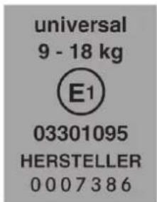
text_image
universal 9 - 18 kg E1 03301095 HERSTELLER 0007386Example of an approval label
- Universal: child restraint systems in the "Universal" category are approved for installation in vehicles. They can be used, in accordance with overviews of the suitability
of seats for securing child restraint systems, on seats labelled U, UF or IUF.
The identification IUF refers to ISOFIX child restraint systems in the "Universal" category. These child restraint systems must also be secured using Top Tether or support points.
- Semi-Universal: child restraint systems in the "Semi-Universal" category may only be used if the vehicle and vehicle seat are listed in the child restraint system manufacturer's vehicle model list.
- Vehicle-specific: child restraint systems in the "vehicle-specific" category may only be used if the vehicle and vehicle seat are listed in the child restraint system manufacturer's vehicle model list.
Approval categories in accordance with UN-R129
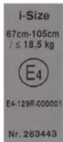
Example of an approval label
- i-Size: child restraint systems in the "i-Size" category are approved for installation in vehicles with i-Size mounting brackets. They can be used, in accordance with overviews of the
suitability of seats for securing child restraint systems, on seats labelled i-U.
The identification i-U refers to i-Size child restraint systems in the "Universal" category.
Observe the suitability of vehicle seats
Depending on the approval category, there are forward-facing and rearward-facing child restraint systems. Their use can be restricted for certain vehicle seats:
- Suitability of seats for securing ISOFIX child restraint systems ( page 63).
- Suitability of seats for securing i-Size child restraint systems ( page 67).
- Suitability of seats for securing belt-secured child restraint systems ( page 74)
Fitting the ISOFIX or i-Size child restraint system on the rear seat
Overview of suitability of the seats for attaching ISOFIX child restraint systems
| ISOFIX identification | |
| ISOFIX is a standardised securing system for specially designed restraint systems.The symbol indicates seats suitable for attaching an ISOFIX child restraint system in accordance with UN R44 (→ page 60).Attach only child restraint systems that are approved in accordance with UN R44 as per the following ISOFIX tables. | |
Carry cot
| Size class: | Equipment: | Left/right rear seat (second and third row of seats) |
| F | I | SO/L1 X |
| G | I | SO/L2 X |
| X Not suitable for an ISOFIX child restraint system in this weight group and/or size class. |
Weight group 0 (up to 10 kg and up to approx. 6 months)
| Size class: | Equipment: | Left/right rear seat (second and third row of seats) |
| E | I | SO/R1 I L |
| IL Suitable for ISOFIX child restraint systems according to the table in "Overview of the recommended child restraint systems", or if the vehicle and the seat are listed on the child restraint system manufacturer's vehicle model list. |
Weight group 0+ (up to 13 kg and up to approx. 15 months) for second row of seats
| Size class: | Equipment: | Left/right rear seat | |
| E | I | SO/R1 | I L |
| D | I | SO/R2, ISO/R2X IL | |
| C | I | SO/R3 | I L (1) |
| IL Suitable for ISOFIX child restraint systems according to the table in "Overview of the recommended child restraint systems", or if the vehicle and the seat are listed on the child restraint system manufacturer's vehicle model list.(1) When using a child restraint system of size class (ISO/R3), move the front seat into the highest position. Make sure that the seat backrest of the front seat does not rest against the child restraint system. | |||
Weight group 0+ (up to 13 kg and up to approx. 15 months) for third row of seats
| Size class: | Equipment: | Left/right rear seat | |
| E | I | SO/R1 | I L |
| D | I | SO/R2, ISO/R2X X | |
| C | I | SO/R3 | X |
| IL Suitable for ISOFIX child restraint systems according to the table in "Overview of the recommended child restraint systems", or if the vehicle and the seat are listed on the child restraint system manufacturer's vehicle model list.X Not suitable for an ISOFIX child restraint system in this weight group and/or size class. | |||
Weight group 1 (9–18 kg and approx. 9 months to 4 years)
| Size class: | Equipment: | Left/right rear seat (second row of seats) |
| D | I | SO/R2, ISO/R2X IL |
| C | I | SO/R3 I L (1) |
| B | I | SO/F2 IUF |
| B1 | ISO/F2X | IUF |
| A | I | SO/F3 IUF |
| IL Suitable for ISOFIX child restraint systems according to the table in "Overview of the recommended child restraint systems", or if the vehicle and the seat are listed on the child restraint system manufacturer's vehicle model list.IUF Suitable for forward-facing ISOFIX child restraint systems of the "Universal" category in this weight group.(1) When using a child restraint system of size class (ISO/R3), move the front seat into the highest position. Make sure that the seat backrest of the front seat does not rest against the child restraint system. |
Weight group 1 (9–18 kg and approx. 9 months to 4 years)
| Size class: | Equipment: | Left/right rear seat (third row of seats) |
| D | I | SO/R2, ISO/R2X X |
| C | I | SO/R3 X |
| B | I | SO/F2 IUF |
| B1 ISO/F2X IUFA | I | SO/F3 IUF |
| X Not suitable for an ISOFIX child restraint system in this weight group and/or size class.IUF Suitable for forward-facing ISOFIX child restraint systems of the "Universal" category in this weight group. |
Overview of suitability of the seats for attaching i-Size child restraint systems
| i-Size identification | |
| i-Size is a standardised securing system for specially designed restraint systems.The symbol indicates seats suitable for attaching an i-Size child restraint system in accordance with UN R129 (→ page 60).Child restraint systems may be attached that are approved in accordance with- UN R44 as per the ISOFIX tables (→ page 63), or- UN R129 as per the following i-Size tables | |
| Front passenger seat | Centre rear seat | |
| i-Size child restraint system (ISO/R2, ISO/F2X, ISO/B2, ISO/B3) | X | X |
| X Not suitable for an i-Size child restraint system in the "Universal" category. | ||
| Left/right rear seat (second seat row) | Left/right rear seat (third seat row) | |
| i-Size child restraint system (ISO/R2, ISO/F2X, ISO/B2, ISO/B3) | i-U X | |
| i-U Suitable for forward-facing and rearward-facing i-Size child restraint systems in the "Universal" category. | X Not suitable for an i-Size child restraint system in the "Universal" category. |
Fitting the ISOFIX or i-Size child restraint system on the rear seat
WARNING Risk of injury if the rear bench seat/rear seat and seat backrest are not engaged
If the rear bench seat/rear seat and seat backrest are not engaged they could fold forwards, e.g. when braking suddenly or in the event of an accident.
- If this is the case, the vehicle occupant would be forced into the seat belt by the rear bench seat/rear seat or by the seat backrest. The seat belt cannot protect as intended and could result in additional injury.
- Objects or loads in the boot/load compartment cannot be restrained by the seat backrest.
Make sure that the seat backrest and the rear bench seat/rear seat are engaged before every trip.
If the seat backrest is not engaged and locked in place, this will be shown on the multifunction display on the instrument cluster (fold rear seat back electrically) or the red lock verification indicator will be visible (fold rear seat back mechanically).
WARNING -Risk of injury or death if the permissible gross mass of the child and child restraint system is exceeded
For ISOFIX or i-Size child restraint systems in which the child is secured using the seat integrated in the child restraint system, the permissible gross mass of the child and child restraint system is 33 kg.
If the child and the child restraint system together weigh more than 33 kg, the ISOFIX or i-Size child restraint system with integrated seat belt does not offer sufficient protection. Too much load may be placed on the ISOFIX or i-Size child restraint systems and the child may not be restrained correctly in the event of an accident, for example.
If the child and the child restraint system together weigh more than 33 kg,
use only an ISOFIX or i-Size child restraint system with which the child is secured with the vehicle seat belt.
Also secure the child restraint system with the Top Tether belt, if available.
Always comply with the information about the mass of the child restraint system:
- in the manufacturer's installation and operating instructions for the child restraint system used
- on a label on the child restraint system, if present
Regularly check that the permissible gross mass of the child and child restraint system is still complied with.
When fitting a child restraint system, observe the following:
√ Always observe the correct use of the seats and consider their suitability for attaching a child restraint system.
ISOFIX child seat securing system ( page 63)
or
i-Size child seat securing system (→ page 67)
√ Always comply with the manufacturer's installation and operating instructions for the child restraint system used.
√ Make sure that the child's feet do not come into contact with the front seat. If necessary, move the front seat forward slightly.
When fitting an ISOFIX child restraint system, also observe the following:
√ When using a Group 0/0+ baby car seat and a Group 1 rearward-facing child restraint system on a rear seat: adjust the front seat so that the seat does not touch the child restraint system.
When using a Group 1 forward-facing child restraint system: remove the head restraint from the respective seat, if possible. In addition, the backrest of the child restraint system must, as far as possible, lie flat against the backrest of the vehicle seat.
Once the child restraint system has been removed, replace the head restraints immediately and adjust them correctly.
√ When using a child restraint system on a seat on the third row of seats: adjust the front seat so that it does not touch the child restraint system, and move the seat backrest of the front seat into an upright position if necessary.
For certain child restraint systems in weight group 2 or 3, there may be restrictions on the maximum size setting, e.g. due to possible contact with the roof.
√ The child restraint system must not be tensioned between the roof and the seat cushion and/or be fitted facing the wrong direction. Where possible, adjust the seat cushion inclination accordingly.
√ The child restraint system must not be put under strain by the head restraints. Adjust the head restraints accordingly.
When fitting an i-Size child restraint system, also observe the following:
√ When using a rearward-facing child restraint system: adjust the front seat so that it does not touch the child restraint system.
When using a forward-facing child restraint system: remove the head restraint from the respective seat, if possible. In addition, the backrest of the child restraint system must, as far as possible, lie flat against the backrest of the vehicle seat. Once the child restraint system has been removed, replace the head restraints immediately and adjust them correctly.
Before every journey, make sure that the ISOFIX child restraint system or the i-Size child restraint system is engaged correctly in both mounting brackets in the vehicle.
NOTE Be careful not to damage the seat belt for the centre seat when fitting the child restraint system
Make sure that the seat belt is not trapped.
Vehicles with single rear seats:
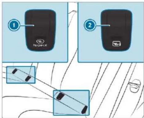
text_image
① ISOFIX ②① ISOFIX mounting bracket
② i-Size mounting bracket
Remove and stow away covers ① or ② of the mounting brackets in the vehicle.
Attach the ISOFIX or i-Size child restraint system to both mounting brackets in the vehicle.
After removing the child restraint system, reattach covers ① or ②.
Vehicles with a rear bench seat:
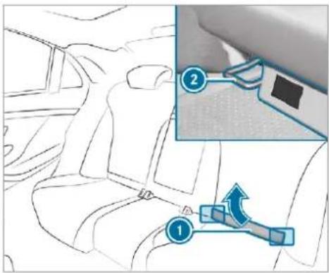
text_image
Diagram showing car seatbelt insertion with labeled parts and directional arrows indicating movementMercedes-Maybach vehicles with reclining rear seats: before an ISOFIX or i-Size child restraint system is installed, tilt the reclining rear seat backrest back slightly.
Remove the upholstered lining ①.
▶ Vehicles without reclining rear seats: fold the upholstered lining ① upwards.
Turn the support on the rear side of the upholstered lining ① by 90°. The upholstered lining ① will remain folded upwards.
Attach the ISOFIX or i-Size child restraint system to both mounting brackets ② in the vehicle.
Mercedes-Maybach vehicles with reclining rear seats: return the reclining rear seat backrest to an upright position. The reclining rear seat backrest must be in contact with the child restraint system.
Vehicles with a third row of seats:
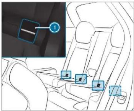
text_image
Diagram of a car interior with highlighted components and a numbered annotation boxAttach the ISOFIX child restraint system to both ISOFIX mounting brackets ① in the vehicle.
Securing a Top Tether
WARNING Risk of injury or death if the rear seat backrests are not locked after fitting Top Tether belts
If the rear seat backrests are not locked, they could fold forwards in the event of an accident, heavy braking or sudden changes of direction.
As a result, child restraint systems cannot perform their intended protective function. Rear seat backrests that are not locked can also cause additional injuries, e.g. in the event of an accident.
Always lock rear seat backrests after fitting Top Tether belts.
Observe the lock verification indicator.
If the seat backrest is not engaged and locked in place, this will be shown on the multifunction display on the instrument cluster (fold rear seat back electrically) or the red lock verification indicator will be visible (fold rear seat back mechanically).

If the child restraint system is equipped with a Top Tether belt:
The risk of injury can be reduced by a Top Tether. The Top Tether belt facilitates an additional connection between the child restraint system attached with ISOFIX or i-Size and the vehicle.
The Top Tether anchorages for the second row of seats are located on the rear side of the two outer rear seats on the second row of seats. For the third row of seats, use the Top Tether anchorage on the rear side of the seat backrest on the third row of seats.
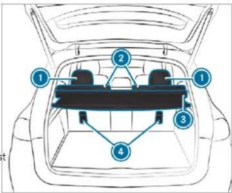
text_image
Diagram of a car backrest with numbered compartments and structural connectionsSecond row of seats
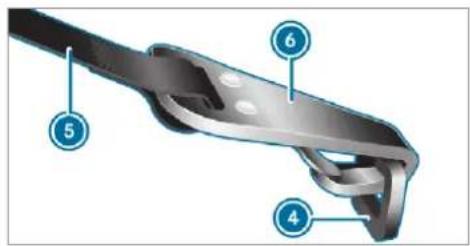
text_image
Technical diagram of a mechanical component with numbered parts labeled 4, 5, and 6If necessary, slide the head restraint upwards (→ page 128).
Fit the ISOFIX or i-Size child restraint system with Top Tether. Comply with the child restraint system manufacturer's installation instructions when doing so.
Guide the Top Tether belt ⑤ under the head restraint ① between the two head restraint bars.
If the load compartment cover ③ is installed, guide the Top Tether belt ⑤ downwards between the load compartment cover ③ and the seat backrest ②.
Hook Top Tether hook ⑥ of Top Tether belt ⑤ into Top Tether anchorage ④ without twisting.
Tension the Top Tether belt ⑤. Comply with the child restraint system manufacturer's installation instructions when doing so.
If necessary, slide the head restraint ① downwards (→ page 128). Make sure that you do not interfere with the correct routing of the Top Tether belt ⑤.
Securing the child restraint system with the seat belt
Notes on the suitability of seats for attaching belt-secured child restraint systems Rear seats (second seat row)
| Weight category | Left/right rear seat | Centre rear seat ^1 |
| 1 Child restraint systems with a supporting bracket are not suitable for this seat. | ||
| Category 0: up to 10 kg | U, L | U, L |
| Category 0+: up to 13 kg | U, L | U, L |
| Category I: 9 to 18 kg | U, L | U, L |
| Weight category | Left/right rear seat | Centre rear seat1 |
| Category II: 15 to 25 kg | U, L | U, L |
| Category III: 22 to 36 kg | U, L | U, L |
| U Suitable for child restraint systems of the "Universal" category in this weight category.L Suitable for semi-universal child restraint systems according to the table in "Recommended child restraint systems", or if the vehicle and the seat are listed in the child restraint system manufacturer's vehicle model list. | ||
Rear seats (third seat row)
| Weight category | Left/right rear seat |
| Category 0: up to 10 kg | U, L |
| Category 0+: up to 13 kg | U, L |
| Category I: 9 to 18 kg | U, L |
| Category II: 15 to 25 kg | U, L |
| Category III: 22 to 36 kg | U, L |
| U Suitable for child restraint systems of the "Universal" category in this weight category.L Suitable for semi-universal child restraint systems according to the table in "Recommended child restraint systems", or if the vehicle and the seat are listed in the child restraint system manufacturer's vehicle model list. |
Mercedes-Maybach vehicles with a reclining rear seat: the bottom and back of a forward-facing child restraint system must make full con-
tact with the reclining rear seat sitting surface and seat backrest. The child restraint system must not touch the roof. Adjust the seat back-
rest inclination accordingly. Also observe the child restraint system manufacturer's installation instructions.
Front passenger seat - Notes
Notes on child restraint systems on the front passenger seat
- If it is absolutely necessary for you to fit a child restraint system to the front passenger seat, be sure to observe the information on child restraint systems on the front passenger seat ( page 80).
Observe the specific instructions for the rearward-facing and forward-facing child restraint systems. If the front passenger seat is occupied, ensure, both before and during the journey, that the status of the front passenger airbag is correct for the current situation ( page 48).
Front passenger seat
| Weight category | Front passenger airbag enabled ^1 | Front passenger airbag disabled ^1,2 |
| 1 Adjust the seat cushion inclination so that the front edge of the seat cushion is in the highest position and the rear edge of the seat cushion is in the lowest position. | 2 The vehicle is equipped with automatic front passenger airbag shutoff. The PASSENGER AIR BAG OFF indicator lamp must be lit. | |
| Category 0: up to 10 kg | X | U, L |
| Category 0+: up to 13 kg | X | U, L |
| Category I: 9 to 18 kg | UF | U, L |
| Category II: 15 to 25 kg | UF | U, L |
| Category III: 22 to 36 kg | UF | U, L |
| X Not suitable for children in this weight category.UF Suitable for forward-facing child restraint systems of the "Universal" category in this weight category. | U Suitable for child restraint systems of the "Universal" category in this weight category.L Suitable for semi-universal child restraint systems according to the table in "Recommended child restraint systems", or if the vehicle and the seat are listed in the child restraint system manufacturer's vehicle model list. |
Securing the child restraint system with the seat belt on the rear seat

WARNING Risk of injury if the rear bench seat/rear seat and seat backrest are not engaged
If the rear bench seat/rear seat and seat backrest are not engaged they could fold forwards, e.g. when braking suddenly or in the event of an accident.
- If this is the case, the vehicle occupant would be forced into the seat belt by the rear bench seat/rear seat or by the seat backrest. The seat belt cannot protect as intended and could result in additional injury.
- Objects or loads in the boot/load compartment cannot be restrained by the seat backrest.
Make sure that the seat backrest and the rear bench seat/rear seat are engaged before every trip.
If the seat backrest is not engaged and locked in place, this will be shown on the multifunction display on the instrument cluster (fold rear seat back electrically) or the red lock verification indicator will be visible (fold rear seat back mechanically).
When fitting a belt-secured child restraint system, observe the following:
√ Always comply with the manufacturer's installation and operating instructions for the child restraint system used.
For a child restraint system in the "Universal" or "Semi-Universal" category, make sure that the system has been approved for the vehicle seat.
Observe the notes under "Suitability of seats for attaching belt-secured child restraint systems" ( page 74).
√ When using a category 0/0+ baby car seat and a category I rearward-facing child restraint system on a rear seat: adjust the front seat so that the seat does not touch the child restraint system.
When using a category I forward-facing child restraint system: remove the head restraint from the respective seat, if possible.
anti- After the child restraint system has been removed, replace the head restraints immediately and adjust them correctly.
☑ The backrest of the forward-facing child restraint system must, as far as possible, be resting on the seat backrest of the rear seat.
For certain child restraint systems in weight category II or III, there may be restrictions on the maximum size setting, e.g. due to possible contact with the roof.
√ The child restraint system must not be put under strain between the roof and the seat cushion and/or be fitted facing the wrong direction. Where possible, adjust the seat cushion inclination accordingly.
√ The child restraint system must not be put under strain by the head restraint. Adjust the head restraints accordingly.
√ Make sure that the child's feet do not touch the front seat. If necessary, move the front seat slightly forwards.
Fit the child restraint system.
The entire base of the child restraint system must always rest on the sitting surface of the rear seat.
Always make sure that the shoulder belt strap is correctly routed from the seat belt outlet of the vehicle to the shoulder belt guide on the child restraint system. The shoulder belt strap must be routed forwards and downwards from the seat belt outlet.
Notes on vehicles without automatic front passenger airbag shutoff
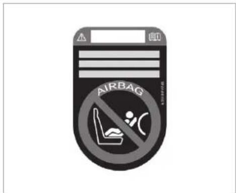
text_image
AIRBAG 4.5018776Sticker visible when the front passenger door is open
Vehicles without automatic front passenger airbag shutoff have a special sticker affixed to the side of the cockpit on the front passenger side.
Make sure you observe the following information:
- Never fit a rearward-facing child restraint system to the front passenger seat
• Always fit a rearward-facing child restraint system to a suitable rear seat
Suitability of seats for attaching belt-secured child restraint systems ( page 74) - Secure the child restraint system with the seat belt on the rear seat ( page 78).
- Notes on rearward-facing and forward-facing child restraint systems on the front passenger seat ( page 80)
Notes on rearward-facing and forward-facing child restraint systems on the front passenger seat

WARNING Risk of injury or death from using a rearward-facing child restraint system when the front passenger front airbag is enabled
If you secure a child in a rearward-facing child restraint system on the front passenger seat and the PASSENGER AIR BAG OFF indicator lamp is off, the front passenger airbag can deploy in the event of an accident.
The child could be struck by the airbag.
Always ensure that the front passenger air-bag is disabled. The PASSENGER AIR BAG OFF indicator lamp must be lit.
NEVER use a rearward-facing child restraint system on a seat protected by an ENABLED FRONT AIRBAG in front of it, DEATH or SERIOUS INJURY to the CHILD can occur.
Observe the specific instructions for the rearward-facing and forward-facing child restraint systems ( page 80).
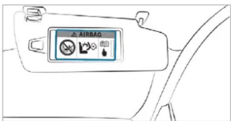
text_image
AIRBAGWarning notice on the front passenger sun visor
Always observe the status of the front passenger airbag on the PASSENGER AIR BAG OFF indicator lamp:
- If it is absolutely necessary to fit a child restraint system to the front passenger seat, always observe the information on automatic front passenger airbag shutoff ( page 47).
- When using a rearward-facing child restraint system on the front passenger seat, the front
passenger airbag must always be disabled. This is only the case if the PASSENGER AIR BAG OFF indicator lamp is lit continuously ( page 48).
- If the PASSENGER AIR BAG OFF indicator lamp is off, the front passenger airbag is enabled. The front passenger airbag may deploy during an accident.
Securing the child restraint system with the seat belt on the front passenger seat
When fitting a belt-secured child restraint system on the front passenger seat, always observe the following:
√ Observe the child restraint system manufacturer's installation and operating instructions.
For a child restraint system in the "Universal" or "Semi-Universal" category, make sure that the system has been approved for the vehicle seat.
Observe the notes under "Suitability of seats for attaching belt-secured child restraint systems" ( page 74).
When using a forward-facing child restraint system in category I: remove the head restraint from the respective seat, if possible.
After the child restraint system has been removed, replace the head restraints immediately and adjust them correctly.
☑ The backrest of the forward-facing child restraint system must, as far as possible, be resting on the seat backrest of the front passenger seat.
For certain child restraint systems in weight category II or III, there may be restrictions on the maximum size setting, e.g. due to possible contact with the roof.
√ The child restraint system must not be tensioned between the roof and the seat cushion and/or be fitted facing the wrong direction.
√ The child restraint system must not be put under strain by the head restraints. Adjust the head restraints accordingly.
√ Never place objects under or behind the child restraint system, e.g. cushions.
Set the front passenger seat as far back as Child safety locks possible and move the seat into the highest position if possible. Activating/deactivating for the rear doors
Fully retract the seat cushion length adjustment.
Adjust the seat cushion inclination so that the front edge of the seat cushion is in the highest position and the rear edge of the seat cushion is in the lowest position.
Set the seat backrest to the most vertical position possible.
Fit the child restraint system.
The entire base of the child restraint system must always rest on the sitting surface of the front passenger seat.
Always make sure that the shoulder belt strap is correctly routed from the seat belt outlet of the vehicle to the shoulder belt guide on the child restraint system. The shoulder belt strap must be routed forwards and downwards from the seat belt outlet.
If necessary, adjust the seat belt outlet and the front passenger seat accordingly.
Child safety locks
Activating/deactivating the child safety lock for the rear doors
WARNING Risk of accident and injury due to children left unattended in the vehicle
If children are left unattended in the vehicle, they could:
- Open doors, thereby endangering other persons or road users.
- Get out and be struck by oncoming traffic.
- Operate vehicle equipment and become trapped, for example.
In addition, the children could also set the vehicle in motion, for example by:
- Releasing the parking brake.
- Changing the transmission position.
- Starting the vehicle.
▶ Never leave children unattended in the vehicle.
When leaving the vehicle, always take the key with you and lock the vehicle.
Keep the vehicle key out of reach of children.
This also applies to the Digital Vehicle Key if the "Digital Vehicle Key" function is activated via Mercedes me connect.

WARNING Risk of fatal injury due to exposure to extreme heat or cold in the vehicle
If people -particularly children - are exposed to extreme temperatures over an extended period of time, there is a risk of serious or even fatal injury!
▶ Never leave anyone – particularly children – unattended in the vehicle.
▶ Never leave animals in the vehicle unattended.

WARNING Risk of accident and injury due to children left unattended in the vehicle
If children are travelling in the vehicle, they could, in particular:
- open doors, thereby endangering other persons or road users
• get out and be struck by oncoming traffic
• operate vehicle equipment and become trapped, for example
Always activate the child safety locks installed if children are travelling in the vehicle.
▶ Never leave children unattended in the vehicle.
When leaving the vehicle, always take the key with you and lock the vehicle. This also applies to the Digital Vehicle Key if the "Digital Vehicle Key" function is activated via Mercedes me connect.
Vehicles for the United Kingdom: observe the important safety notes in the "Notes on the additional door lock" section.
There are child safety locks for the rear doors and the rear side windows.
The child safety lock on the rear doors secures each door separately. The doors can no longer be opened from the inside.
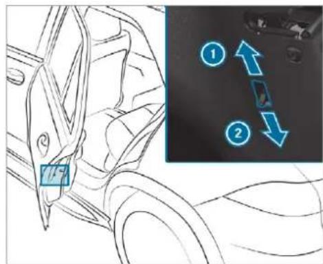
text_image
Diagram showing car interior with labeled parts and directional arrows indicating movement or movement, including numbered annotations ① and ②.Press the lever in direction ① (activate) or ② (deactivate).
Make sure that the child safety locks are working properly.
Activating/deactivating the child safety lock for the rear side windows
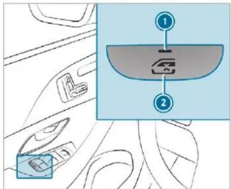
text_image
Diagram showing car interior compartments with labeled parts and a zoomed-in view of the dashboard areaTo activate/deactivate: press button ②.
The rear side window can be opened or closed in the following cases:
- With indicator lamp ① lit: via the switch on the driver's door.
- With indicator lamp ① off: via the switch on the corresponding rear door or driver's door.
Notes on pets in the vehicle
WARNING Risk of accident and injury due to animals left unsecured or unattended in the vehicle
If you leave animals in the vehicle unattended or unsecured, they could possibly press down buttons or switches.
Thereby an animal may:
- activate vehicle equipment and become trapped, for example
- switch systems on or off and endanger other road users
Unsecured animals may be thrown around in the vehicle in the event of an accident or sudden steering and braking manoeuvres and injure vehicle occupants in the process.
▶ Never leave animals in the vehicle unattended.
Always correctly secure animals while driving, e.g. using a suitable animal carrier.
Key
Overview of key functions

WARNING Risk of accident and injury due to children left unattended in the vehicle
If children are left unattended in the vehicle, they could:
- Open doors, thereby endangering other persons or road users.
- Get out and be struck by oncoming traffic.
- Operate vehicle equipment and become trapped, for example.
In addition, the children could also set the vehicle in motion, for example by:
• Releasing the parking brake.
- Changing the transmission position.
- Starting the vehicle.
▶ Never leave children unattended in the vehicle.
When leaving the vehicle, always take the key with you and lock the vehicle.
Keep the vehicle key out of reach of children.
This also applies to the Digital Vehicle Key if the "Digital Vehicle Key" function is activated via Mercedes me connect.

NOTE Damage to the key caused by magnetic fields

Keep the key away from strong magnetic fields.
The key may vary from the one shown in the diagram, depending on the vehicle equipment.
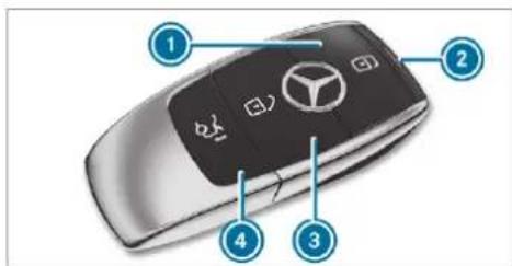
text_image
Diagram of a car keychain with labeled components including the BMW logo and four key points.Locks
② Indicator lamp
3 Unlocks
4 Opens/closes the tailgate
If indicator lamp ② does not light up after pressing the 📁 or 🏠 button, the battery is discharged.
Replacing the key battery ( page 86).
The key locks and unlocks the following components:
- the doors
- the fuel filler flap
- the tailgate
If the vehicle is not opened within approximately 40 seconds after unlocking, it locks again. Anti-theft protection is primed again.
Do not keep the key together with electronic devices or metal objects. This can affect the key's functionality.
Do not keep the key in the temperature-controlled cup holder. Otherwise, the key will not be reliably detected.
Activating/deactivating the acoustic locking verification signal
Multimedia system:



▶ Activate or deactivate Acoustic lock.
i Please note:
The selected setting for the acoustic locking verification signal must comply with the relevant national road and traffic regulations. In some countries, including Germany, using the acoustic locking verification signal is for-
bidden by traffic laws (in accordance with §16 Para. 1 and §30 Para. 1 of the German national road traffic regulations). The driver of the vehicle must comply with these regulations. In countries where the use of this function is forbidden, this function is not activated in the vehicle and must not be activated.
Changing the unlocking settings
Possible unlocking functions of the key:
- central unlocking
- unlocking the driver's door and fuel filler flap
To switch between settings: press the 📄 and ⏻ buttons simultaneous approximately six seconds until the indicator lamp flashes twice.
Options if the unlocking function for the driver's door and fuel filler flap has been selected:
- To unlock the vehicle centrally: press the button twice.
- Vehicles with KEYLESS-GO: if you touch the inner surface of the door handle on the driver's door, only the driver's door and fue filler flap are unlocked.
Deactivating the key functions
If you do not use the vehicle or a key for an extended period of time, you can reduce the energy consumption of the respective key. To do so, deactivate the key functions.
To deactivate: press the ☑ button on the key twice in quick succession.
The key indicator lamp flashes twice briefly and lights up once.
To activate: press any button on the key.
By for
When the vehicle is started with the key in
the stowage compartment of the centre con-
sole, the key functions are automatically
activated (→ page 212).
Removing/inserting the emergency key
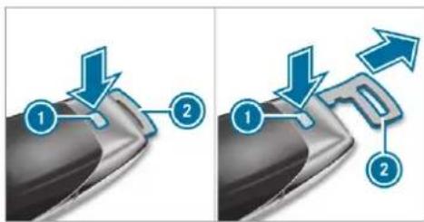
text_image
Diagram illustrating two-step mechanical or electrical process with labeled components and directional arrowsTo remove: press release knob ①. Emergency key ② is pushed out slightly.
Pull out emergency key ② until it engages in the intermediate position.
Press release knob ① again and fully remove emergency key ②.
To insert: press release knob ①.
Insert emergency key ② to the intermediate position or fully until it engages.
① You can use the intermediate position of emergency key ② to attach the key to a key ring.
Replacing the key battery

DANGER Serious damage to health caused by swallowing batteries
Batteries contain toxic and corrosive substances. Swallowing batteries may cause serious damage to health.
There is a risk of fatal injury.
Keep batteries out of the reach of children.
If batteries are swallowed, seek medical attention immediately.

ENVIRONMENTAL NOTE Environmental damage due to improper disposal of batteries

Batteries contain pollutants. It is illegal to dispose of them with the household rubbish.


Dispose of batteries in an environmentally responsible manner. Take discharged batteries to a qualified specialist workshop or to a collection point for used batteries.
Requirements:
- You require a CR 2032 3 V cell battery.
Mercedes-Benz recommends that you have the battery replaced at a qualified specialist workshop.
Remove the emergency key ( page 86).
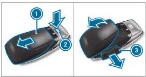
text_image
Diagram showing three steps of car door turning process with numbered arrows indicating directionPress release knob ② down fully and slide cover ① in the direction of the arrow.
Fold out cover ① in the direction of the arrow and remove.
Remove battery compartment ③ and take out the discharged battery.
Insert the new battery into battery compartment ③. Observe the positive pole marking in the battery compartment and on the battery when doing this.
▶ Push in battery compartment ③.
Re-attach cover ① and push it until it engages.
Problems with the key
| Problem | Possible causes/consequences and ▶ Solutions |
| You can no longer lock or unlock the vehicle. | Possible causes:The key battery is weak or discharged.There is interference from a powerful radio signal source.The key is faulty.Check the battery using the indicator lamp and replace if necessary (→ page 86).Use the emergency key to lock or unlock (→ page 86).Have the key checked at a qualified specialist workshop. |
| You have lost a key. | Have the key deactivated at a qualified specialist workshop.If necessary, have the mechanical lock replaced as well. |
Doors
Notes on the additional door lock
The additional door lock is only available for vehicles for the United Kingdom.

WARNING Risk of injury to persons inside the vehicle when the additional door lock is activated
If the additional door lock is activated, the doors can no longer be opened from the inside.
If there are persons in the vehicle, they can no longer leave the vehicle, e.g. in hazardous situations.
▶ Never leave persons unattended in the vehicle, particularly children, elderly persons or persons in need of help.
If there are persons in the vehicle, do not activate the additional door lock.
The additional door lock is automatically activated in the following situations:
• The vehicle is locked using the key.
• The vehicle is locked using KEYLESS-GO.
If the vehicle has been locked via Mercedes me connect, the additional door lock is not activated.
If the additional door lock is activated, the doors cannot be opened from the inside.
① After locking you can issue a signal with the horn.
You can prevent the additional door lock from being activated by deactivating interior protection before locking the vehicle ( page 116).
Unlocking/opening the doors from the inside
United Kingdom only: observe the notes on the additional door lock ( page 88).
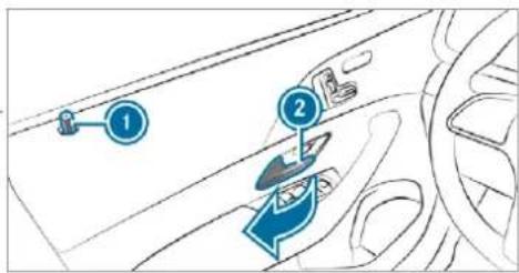
text_image
Diagram showing car interior airflow direction with numbered arrows and a labeled componentPull door handle ②. Locking pin ① pops up when the door is unlocked.
Centrally locking and unlocking the vehicle from the inside
Mercedes-Maybach vehicles: the buttons are also located in the rear doors.
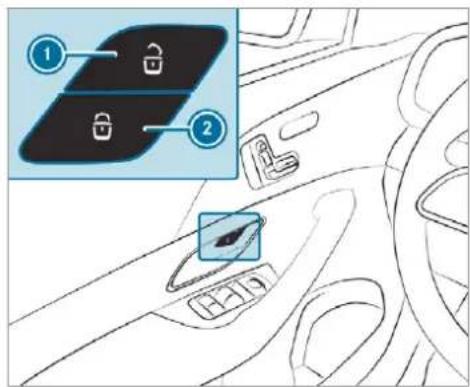
text_image
Diagram showing car interior with lock icons and a highlighted panel, labeled with numbers 1 and 2To unlock: press button 1.
To lock: press button 2.
This does not lock or unlock the fuel filler flap. The vehicle is not unlocked:
• If you have locked the vehicle using the key.
- If you have locked the vehicle using KEY-LESS-GO.
Locking/unlocking the vehicle with a Digital Vehicle Key
Requirements:
• one of the following versions of the Digital Vehicle Key is available:
- suitable mobile phone
- Digital Vehicle Key sticker
- the vehicle is equipped with the "Digital Vehicle Key" function.
- the "Digital Vehicle Key" function is activated via Mercedes me connect: https://www.mercedes.me.
• the mobile phone is sufficiently charged.
You can check the suitability of your mobile phone by entering the phone number at https://www.mercedes.me. Information about suitable mobile phones can be obtained from your Mercedes-Benz Service Centre or at https:// www.mercedes-benz-mobile.com.
① Mercedes-Benz recommends that you carry the emergency key in case of function restrictions.
The function is only available in connection with Mercedes me connect and only in certain countries.
i Protective cases around the mobile phone can impair the range of functions.
If the vehicle has been parked for longer than two weeks, the NFC aerial in the door handle is deactivated.
Pull the door handle. The NFC aerial is activated.
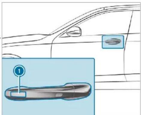
text_image
Diagram showing a car's side profile with a highlighted door and numbered label '1'Touch the door handle on the driver's door in the area where NFC aerial is located with the part of the Digital Vehicle Key where the NFC aerial is located. The vehicle is locked or unlocked alternately.
If you lose the Digital Vehicle Key, deactivate the "Digital Vehicle Key" service in Mercedes me connect via https://www.mercedes.me.
Locking/unlocking the vehicle with KEY-LESS-GO
Requirements:
• The key is outside the vehicle.
- The distance between the key and the vehicle does not exceed 1 m.
- The driver's door and the door at which the door handle is used are closed.
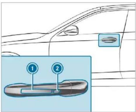
text_image
Diagram showing car door and interior components with numbered labels 1 and 2 pointing to a device handleTo unlock the vehicle: touch the inner surface of the door handle.
To lock the vehicle: touch sensor surface ① or ②.
▶ Convenience closing: touch recessed sensor surface ② until the closing process has been completed.
i Further information on convenience closing ( page 103).
If you open the tailgate from outside it is automatically unlocked.
Problems with KEYLESS-GO
| Problem | Possible causes/consequences and ▶ Solutions |
| You can no longer lock or unlock the vehicle using KEYLESS-GO. | Possible causes:The key functions have been deactivated (→ page 85).The key battery is weak or discharged.There is interference from a powerful radio signal source.The key is faulty.Activate the key functions (→ page 85).Check the battery using the indicator lamp and replace if necessary (→ page 86).Use the emergency key to unlock or lock the vehicle (→ page 86).Have the vehicle and key checked at a qualified specialist workshop. |
Activating/deactivating the automatic locking feature
The vehicle is locked automatically when the ignition is switched on and the wheels are turning faster than walking pace.
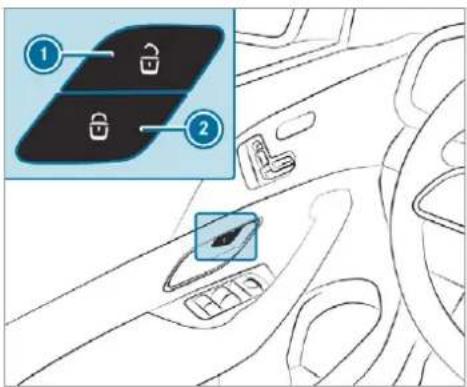
text_image
Diagram of car interior showing dashboard and steering wheel with lock icons labeled 1 and 2To activate: press and hold button ② for approximately five seconds until an acoustic signal sounds.
To deactivate: press and hold button ① for approximately five seconds until an acoustic signal sounds.
In the following situations, there is a danger of being locked out when the function is activated:
- While the vehicle is being tow started/pushed.
- If the vehicle is being tested on a roller dynamometer.
Power closing function
If you push the door into the lock to the first detent position, the power closing function will automatically pull the door into the lock.
Locking/unlocking the driver's door with the emergency key
If you wish to lock the vehicle entirely using the emergency key, first press the button for locking from the inside while the driver's door is open. Then proceed to lock the driver's door using the emergency key.
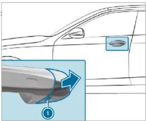
text_image
Diagram showing car door and handle with a magnified view highlighting the handle area, labeled with number 1.Insert the emergency key as far as it will go into opening ① in the cover.
▶ Pull and hold the door handle.
Pull the cover on the emergency key as straight as possible away from the vehicle until it releases.
Release the door handle.
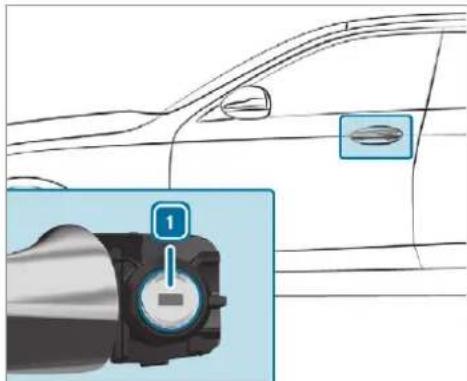
natural_image
Diagram of a car interior showing a battery plug and a lock, with no visible text or symbols.To unlock: turn the emergency key anticlockwise to position 1.
To lock: turn the emergency key clockwise to position 1.
Carefully press the cover onto the lock cylinder until it engages and is seated firmly.
Running boards
Operation of the running boards
Mercedes-Maybach vehicles: the vehicle is equipped with electrically extendable running boards. If you have selected the automatic mode in the multimedia system, (→ page 95) the running board will extend automatically on the respective side when a door is opened. You can use manual mode to clean the running boards (→ page 579).
The running boards will extend and retract only if the vehicle is stationary.
In the following cases, the running boards will retract automatically:
- If you select an off-road drive program (→ page 225).
• If you activate car wash mode (→ page 574). - If the outside mirrors fold in automatically (→ page 192).
- If you are driving at a speed greater than 4 km/h.
If you have selected the automatic mode in the multimedia system and you manually extend the running boards when the doors are closed, the running boards will remain extended, even if you open a door and then close it again. Automatic mode will be reactivated only when you are driving at a speed greater than 4km / h .

NOTE Damage to the running boards during extension or retraction
The running boards extend at the side during extension. During retraction, the running boards are integrated in the side skirt.
Make sure that there is sufficient space during extension and retraction.
Observe any display messages that may be displayed on the instrument cluster ( page 651).
Extending and retracting the running boards via the multimedia system
Multimedia system:
Settings Vehicle
SIDE RUNNING BOARD
▶ Select Extend or Retract.
Automatically extending and retracting the running boards
Activate or deactivate AUTOMATIC EXTENSION.
① This equipment is available only for Mercedes-Maybach vehicles.
Load compartment
Opening the tailgate
A DANGER Risk of exhaust gas poisoning Combustion engines emit poisonous exhaust gases such as carbon monoxide. Exhaust gases can enter the vehicle interior if the tail-
gate is open when the engine is running, especially if the vehicle is in motion.
Always switch off the engine before opening the tailgate.
▶ Never drive with the tailgate open.
NOTE Damage to the tailgate caused by obstacles above the vehicle
The tailgate swings rearwards and upwards when it is opened.
Make sure that there is sufficient space behind and above the tailgate.
You have the following options for opening the tailgate:
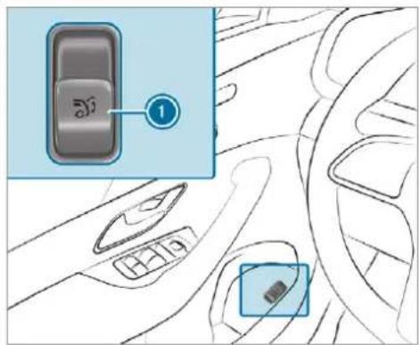
text_image
Diagram showing car interior with a highlighted control panel and a zoomed-in view of the door panelPull the remote opening switch ① for the tailgate.
Press and hold the 📂 button on the key.
▶ Vehicles with HANDS-FREE ACCESS: make a kicking movement with your foot below the bumper ( page 98).
If the tailgate is unlocked, pull the tailgate handle and release it.
For a tailgate stopped in an intermediate position, pull it upwards and release it as soon as it starts to open.
The tailgate is equipped with an automatic obstruction detection function. If a solid object blocks or restricts the tailgate during automatic opening, this process is stopped. The automatic obstruction detection function is only an aid. It not a substitute for your attentiveness when you are opening the tailgate.
Closing the tailgate
⚠ WARNING Risk of injury from unsecured items in the vehicle
If objects, luggage or loads are not secured or not secured sufficiently, they could slip, tip over or be thrown around and thereby hit vehicle occupants.
There is a risk of injury, particularly in the event of sudden braking or a sudden change in direction.
Always stow objects in such a way that they cannot be thrown around.
Before the journey, secure objects, luggage or loads against slipping or tipping over.
Observe the notes on loading the vehicle. To close the tailgate, the following options are available:
Pull the tailgate downwards slightly. Release it as soon as it begins to close.
WARNING Risk of becoming trapped during automatic closing of the tailgate
Parts of the body could become trapped during automatic closing of the tailgate. Moreover, people, e.g. children, may be standing in the closing area or may enter the closing area during the closing process.
Make sure that nobody is in the vicinity of the closing area during the closing process.
Use one of the following options to stop the closing process:
- press the 📃 button on the key.
- press or pull the remote operating switch on the driver's door.
- press the closing or locking button on the tailgate.
- Pull the tailgate handle.
▶ Vehicles with HANDS-FREE ACCESS: it is also possible to stop the closing process by making a kicking movement below the rear bumper.
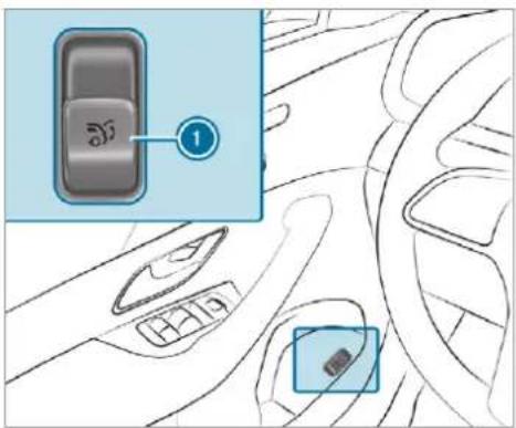
text_image
Diagram showing car interior with a highlighted control panel and a zoomed-in view of the door panelSwitch on the power supply or the ignition.
Press the remote operating switch ① for the tailgate.
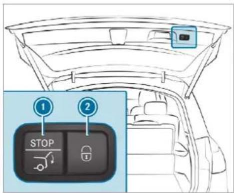
text_image
1 STOP 2Press the closing button ① on the tailgate.
Vehicles with KEYLESS-GO
Press the locking button ② on the tailgate. If a key is detected outside the vehicle, the tailgate will close and the vehicle will be locked.
Press and hold the ⚪ button on the key (with the key in the vicinity of the vehicle).
Vehicles with HANDS-FREE ACCESS
Make a kicking movement with your foot below the bumper ( page 98).
Automatic reversing function for the tailgate
The tailgate is equipped with automatic obstruction detection with reversing function. If a solid object blocks or restricts the tailgate during automatic closing, the tailgate will automatically open again slightly. Automatic obstruction detection with reversing function is only an aid. It is not a substitute for your attentiveness when you are closing the tailgate.
During the closing process, make sure that no body parts are in the closing area.
WARNING Risk of becoming trapped despite reversing function
The reversing function does not react:
• to soft, light and thin objects, e.g. fingers.
• over the last 8 mm of the closing path.
In these situations in particular, the reversing function cannot prevent someone being trapped.
When closing, make sure that no body parts are in the closing area.
If someone is trapped:
- press the button on the key, or
- press or pull the remote operating switch on the driver's door, or
- press the closing or locking button on tailgate, or
- Pull the tailgate handle.
HANDS-FREE ACCESS function
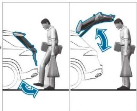
natural_image
Illustration showing a person performing a car lift exercise with directional arrows indicating motion (no text or symbols)With HANDS-FREE ACCESS you can open, close or stop the closing process of the tailgate by performing a kicking movement under the rear bumper.
The kicking movement triggers the opening or closing process alternately.
Observe the notes when opening ( page 95) and closing ( page 96) the tailgate.
Two warning tones sound when the tailgate is opening or closing.
⚠ WARNING Risk of burns caused by a hot exhaust system
The vehicle exhaust system can become very hot. If you use HANDS-FREE ACCESS, you could burn yourself by touching the exhaust system.
Always ensure that you only make a kicking movement within the detection range of the sensors.
NOTE Vehicle damage due to unintentional opening of the tailgate
- when using an automatic car wash
- when using a high pressure cleaner
▶ Deactivate KEYLESS-GO or make sure that the key located is at least 3 m
away from the vehicle in such situations.
When making the kicking movement, make sure that your feet are firmly on the ground, otherwise you could lose your balance, e.g. on ice. Observe the following notes:
• The key is behind the vehicle.
- Stand at least 30 cm away from the vehicle while performing the kicking movement.
- Do not come into contact with the bumper while making the kicking movement.
- Do not carry out the kicking movement too slowly.
- The kicking movement must be towards the vehicle and back again.

natural_image
Front view of a car with a blue circular marker labeled '1' pointing to the rear bumper area (no text or symbols on the car itself)① Detection range of the sensors
If several consecutive kicking movements are not successful, wait ten seconds.
System limits
The system may be impaired or may not function in the following cases: De
- The area around the sensor is dirty, e.g. to road salt or snow.
- The kicking movement is made using a prosthetic leg.
The tailgate can open or close unintentionally in the following situations:
- If a person's arms or legs are moving in the sensor detection range, e.g. when polishing the vehicle or picking up objects.
- If objects are moved or placed behind the vehicle, e.g. tensioning straps or luggage.
- If clamping straps, tarpaulins or other coverings are pulled over the bumper.
- If a protective mat with a length reaching over the boot sill down into the detection range of the sensors is used.
- If the protective mat is not secured correctly.
- When working on the trailer hitch, trailers or rear bicycle racks.
Deactivate the key functions ( page 85) or do not carry the key about your person in such situations.
Limiting the opening angle of the tailgate
Activating the opening angle limiter
You can limit the opening angle of the tailgate in the top half of its opening range to approximately 20 cm before the end position.
Stop the opening procedure of the tailgate at the desired position.
Press and hold the closing button on the gate until you hear a short acoustic signal. The opening angle limiter will be activated. The tailgate will then stop in the stored position when opened.
To open the tailgate fully, pull the handle on the outside of the tailgate again after it has stopped automatically.
Deactivating the opening angle limiter
Press and hold the closing button on the tailgate until two short acoustic signals sound.
Releasing the tailgate in an emergency
This equipment is available only for Mercedes-Maybach vehicles.
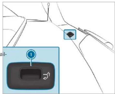
text_image
Diagram showing a car interior with a labeled control panel and directional arrows, including a numbered indicator '1' pointing to the control panel.Remove cover 1.
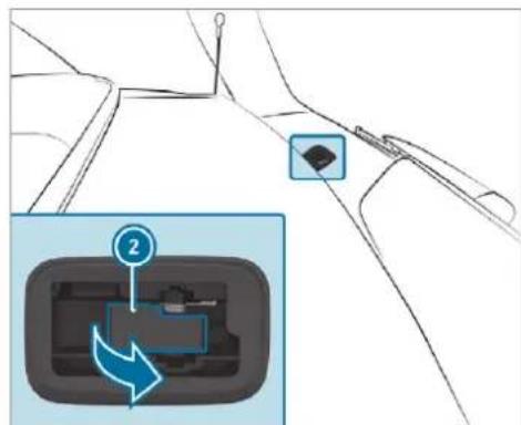
text_image
Diagram showing a device component with a numbered label '2' and an arrow indicating rotation or adjustment.Pull lever ② in the direction of the arrow until the tailgate unlocks.
Unlocking the tailgate with the emergency key
Requirements:
• Not for Mercedes-Maybach vehicles.
Emergency release of the tailgate for Mercedes-Maybach vehicles ( page 100).
- The rear seat backrest has been folded forward.
- The load compartment cover has been removed (→ page 154).

text_image
Diagram showing a car interior with labeled parts and a magnified inset highlighting a key component.Insert the emergency key ② into the opening ① in the trim and push it in. The tailgate will be unlocked.
Side windows
Opens and closes the side windows
⚠ WARNING Risk of becoming trapped when opening a side window
When you open a side window, parts of the body could be drawn in or become trapped between the side window and window frame.
When opening, make sure that nobody is touching the side window.
If someone is trapped, release the button immediately or pull it in order to close the side window again.
WARNING Risk of becoming trapped when closing a side window
When closing a side window, body parts could be trapped in the closing area in the process.
When closing, make sure that no body parts are in the closing area.
If someone is trapped, release the button immediately or press the button in order to reopen the side window.
WARNING Risk of becoming trapped when children operate the side windows
Children could become trapped if they operate the side windows, particularly when unattended.
▶ Activate the override feature for the rear side windows.
When leaving the vehicle, always take the key with you and lock the vehicle.
▶ Never leave children unattended in the vehicle.
Requirements:
- The power supply or the ignition is switched on.
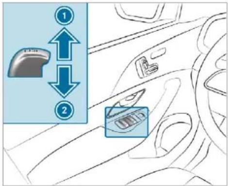
text_image
Diagram showing car interior with two directional arrows labeled 1 and 2 pointing to a computer mouse icon, indicating movement or adjustment.Closing
2 Opening
The buttons on the driver's door take precedence.
To start automatic operation: press the button beyond the point of resistance or pull and release it.
To interrupt automatic operation: press or pull the ☐ button again.
When the vehicle is switched off, the side windows can continue being operated.
This function is available for around four minutes or until a front door is opened.
① Vehicles with electric roller sunblinds on rear doors on the left and right: the buttons for the rear side windows also open and close the roller sunblinds (→ page 111).
Automatic reversing function of the side windows
If an object blocks a side window during the closing process, the side window will open automatically. The automatic reversing function is only an aid and is not a substitute for your attentiveness.
During the closing process, make sure that no body parts are in the closing area.
WARNING Risk of becoming trapped despite there being reversing protection on the side window
The reverse function does not react:
• to soft, light and thin objects, e.g. fingers
- during resetting
This means that the reverse function cannot prevent someone from becoming trapped in these situations.
When closing, make sure that no body parts are in the closing area.
If someone becomes trapped, press the button to open the side window again.
Automatic function of the side windows
In the following cases, the side windows will be closed automatically when the vehicle is switched off:
- if it starts to rain (detection by the rain sensor on the windscreen)
• in extreme temperatures
• after six hours
- if there is a malfunction in the power supply
The side windows will be closed as far as the ventilation position.
Vehicles with a sliding sunroof: the side windows will be closed completely if the sliding sunroof is open.
If the side windows are obstructed during automatic closing, the side window concerned will open again slightly. The automatic function for the sliding sunroof and the side windows will then be deactivated.
Convenience opening (ventilating the vehicle before starting a journey)

WARNING Risk of entrapment when opening a side window
When opening a side window, parts of the body could be drawn in or become trapped between the side window and window frame.
When opening, make sure that nobody is touching the side window.
Release the button immediately if somebody becomes trapped.
Press and hold the button on the The following functions are performed:
• The vehicle is unlocked
• The side windows are opened.
• The sliding sunroof is opened.
• The panoramic sliding sunroof is opened.
- The seat ventilation of the driver's seat is switched on.
If the roller sunblinds of the panoramic sliding sunroof are closed, the roller sunblinds are opened first.
If the roller sunblinds of the rear doors are closed, the roller sunblinds are opened first.
To interrupt convenience opening: release the ☑ button.
To continue convenience opening: press and hold the 📁 button again.
Convenience closing (closing the vehicle from outside)

WARNING Risk of entrapment caused by inadvertent convenience closing
When the convenience closing feature is operating, parts of the body could become trapped in the closing area of the side window and the sliding sunroof.
▶ Observe the complete closing procedure when using convenience closing.
When closing, make sure that no body parts are in the closing area.
Press and hold the ☑ button on the The following functions are performed:
• The vehicle is locked.
• The side windows are closed.
• The sliding sunroof is closed.
- The panoramic sliding sunroof is closed.
To interrupt convenience closing: release the button.
To close the roller sunblinds: press and hold the ☐ button again.
① Convenience closing can also be operated with KEYLESS-GO ( page 91).
Problems with the side windows
A WARNING Risk of becoming trapped or fatally injured if reversing protection is not activated
If you close a side window again immediately after it has been blocked, the side window
will close with increased or maximum force. The reversing feature will then not be active. Parts of the body could become trapped in the closing area in the process.
Make sure that no parts of the body are in the closing area.
To stop the closing process, release the button or press the button again to re-open the side window.
Problem
A side window cannot be closed and you cannot see the cause.
Possible causes/consequences and ▶ Solutions
▶ Check to see whether any objects are in the window guide.
Adjust the side windows.
Adjusting the side windows
If a side window is obstructed during closing and reopens again immediately:
| Problem | Possible causes/consequences and ▶ Solutions |
| ▶ Immediately after this, pull the corresponding button again until the side window has closed, and hold the button for at least one more second (re-adjustment).The side window is closed without the automatic reversing function.If the side window is obstructed again and reopens again immediately:▶ Immediately after this, pull the corresponding button again until the side window has closed, and hold the button for at least one more second (follow-up adjustment).The side window is closed without the automatic reversing function. | |
| The side windows cannot be opened closed using the convenience opening feature. | The key battery is weak or discharged.or▶ Check the battery using the indicator lamp and replace it if necessary (→ page 86). |
Sliding sunroof
Opening and closing the sliding sunroof
The term "sliding sunroof" also refers to the panorama sliding sunroof.
⚠ WARNING Risk of becoming trapped while opening and closing the sliding sunroof
During opening and closing, parts of the body could get caught in the sweep of the sliding sunroof.
When opening or closing, make sure that no body parts are in the sweep.
Release the button immediately if somebody becomes trapped.
or
▶ Press the button in any direction during the automatic opening/closing process. The opening/closing process is stopped.
WARNING Risk of entrapment if the sliding sunroof is operated by children
Children operating the sliding sunroof could get caught in the moving parts, particularly if unattended.
▶ Never leave children unattended in the vehicle.
When leaving the vehicle, always take the key with you and lock the vehicle.
WARNING Risk of entrapment while opening and closing the roller sunblinds
When opening or closing, make sure that no body parts become trapped between the roller sunblind and frame or sliding sunroof.
When opening or closing, make sure that no body parts are in the sweep of the roller sunblind.
Release the switch immediately if somebody becomes trapped.
or
▶ Press the switch in any direction during the automatic opening/closing process. The opening/closing process is stopped.
! NOTE Malfunction caused by snow and ice
Snow and ice may lead to a malfunction of the sliding sunroof.
Only open the sliding sunroof if it is free of snow and ice.
NOTE Damage caused by protruding objects
Objects that protrude from the sliding sun-roof may damage the sealing strips.
Do not allow anything to protrude from the sliding sunroof.
! NOTE Important points to remember when a roof rack is fitted
When a roof rack is fitted, raising or opening the sliding sunroof may be limited.
▶ Check whether the sliding sunroof can be raised or opened when a roof rack is fitted.
If in doubt, do not raise or open the sliding sunroof.
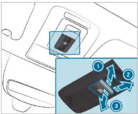
text_image
Diagram showing a device's internal structure with three labeled arrows indicating directional flow or interaction, alongside an inset image of the device's internal components.① Raising
2 Opening
3 Closing/lowering
Use the [icon] button to operate the panoramic sliding sunroof and the roller sunblind.
The panorama sliding sunroof can be operated only when the roller sunblind is open.
Check whether the sliding sunroof can be raised or opened when a roof rack is fitted.
To start automatic operation: press the button beyond the point of resistance or pull and release it.
To interrupt automatic operation: briefly press the button in any direction. The opening/closing process will be stopped.
Automatic reversing function of the sliding sunroof
If an object is obstructing the sliding sunroof during the closing process, the sliding sunroof will open again automatically. The automatic reversing function is only an aid and is not a substitute for your attentiveness.
During the closing process, make sure that no body parts are in the closing area.
WARNING Risk of entrapment even with the reversing feature active
The reverse function does not react in particular:
• to soft, light and thin objects, e.g. fingers
• over the last 4 mm of the closing path
- during resetting
This means that the reverse function cannot prevent someone from becoming trapped in these situations.
When closing, make sure that no body parts are in the closing area.
Release the button immediately if somebody becomes trapped.
or
▶ Briefly press the button in any direction during automatic operation. The closing process is stopped.
Automatic reversing function of the roller sunblind
If an object is obstructing the roller sunblind during the closing process, the roller sunblind will open again automatically. The automatic reversing function is only an aid and is not a substitute for your attentiveness.
When closing the roller sunblind, make sure that no body parts are in the range of movement.
⚠ WARNING Risk of becoming trapped despite reversing function
In particular, the reversing function does not react to soft, light and thin objects, e.g. fingers.
This means that the reversing function cannot prevent entrapment in these situations.
When closing the roller sunblind, make sure that no body parts are in the range of movement.
Release the button immediately if somebody becomes trapped.
or
▶ Press the button in any direction during the automatic closing process. The closing process is stopped.
Automatic functions of the sliding sunroof
The term "sliding sunroof" also refers to the panorama sliding sunroof.
By pushing or pulling the button, you can interrupt the automatic functions: "Rain closing function when driving" and "Automatic lowering".
The sliding sunroof will be closed automatically when the vehicle has been switched off in the following situations:
- if it starts to rain (detection by the rain sensor on the windscreen)
• in the event of extreme outside temperatures
• after six hours
• if there is a malfunction in the power supply
The sliding sunroof then rises at the rear in order to continue ventilating the vehicle interior.
If the sliding sunroof is obstructed during an automatic closing procedure, the roof is opened slightly again. The automatic function for the sliding sunroof and the side windows will then be deactivated.
Rain closing function when driving
Vehicles with a panorama sliding sunroof: if it starts to rain, the raised sliding sunroof will automatically be lowered while the vehicle is in motion.
Automatic lowering function
Vehicles with a panorama sliding sunroof: if the sliding sunroof is raised at the rear, it will automatically be lowered slightly at higher speeds. At low speeds, it will be raised again automatically.

WARNING Risk of entrapment by automatic lowering of the sliding sunroof
At high speeds the raised sliding sunroof automatically lowers slightly at the rear.
This could trap you or other persons.
Make sure that nobody reaches into the sweep of the sliding sunroof whilst the vehicle is in motion.
If somebody becomes trapped, briefly push the sliding sunroof button forwards or backwards. The sliding sunroof lifts during opening.
Problems with the sliding sunroof
The term "sliding sunroof" also refers to the panorama sliding sunroof.
Problem
Possible causes/consequences and ▶ Solutions
The sliding sunroof cannot be closed and you cannot see the cause.
WARNING Risk of becoming trapped or fatal injury by closing the sliding sunroof again
If you close the sliding sunroof again immediately after it has been blocked or reset, the sliding sunroof closes with increased force.
Parts of the body could become trapped in the closing area in the process.
▶ Make sure that no parts of the body are in the closing area. ▶ Release the button immediately if somebody becomes trapped.
or
Press the button in any direction during the automatic closing process. The closing process is stopped.
If the sliding sunroof is obstructed during closing and reopens again slightly:
Immediately after automatic reversing, pull and hold the button down again to the point of resistance until the sliding sunroof is closed. The sliding sunroof will be closed with increased force.
| Problem | Possible causes/consequences and ▶ Solutions |
| If the sliding sunroof is obstructed again and reopens again slightly:▶ Repeat the previous step.The sliding sunroof will be closed again with increased force. | |
| Vehicles without a panoramic sliding sunroof: the sliding sunroof does not operate smoothly. | ▶ Push the [icon] button up to the point of resistance a number of times until the sliding sunroof is fully open.▶ Press the [icon] button for another second.▶ Close the sliding sunroof. |
| Vehicles with a panoramic sliding sunroof: the sliding sunroof or the roller sunblind does not operate smoothly. | ▶ Pull and hold the [icon] button little by little until the sliding sunroof is fully closed.▶ Pull and hold the [icon] button little by little until the roller sunblind is fully closed.▶ Use automatic operation to fully open and then close the sliding sunroof. |
Roller sunblinds
Extending or retracting the roller sunblinds on the rear side windows

WARNING Risk of becoming trapped when extending or retracting the roller sunblind
Body parts could become trapped in the sweep of the roller sunblind when it is being extended or retracted.
Make sure that no body parts are in the sweep of the roller sunblind when it is being extended or retracted.
If someone becomes trapped, briefly press the button in the opposite direction.
The opening or closing process will briefly be stopped. The roller sunblind will then return to its starting position.

NOTE Damage caused by objects
Objects could cause malfunctions of the roller sunblind.
Make sure that the roller sunblind can move freely.
The roller sunblinds for the rear side windows can be operated with the buttons for the side windows in the driver's door and in the rear doors.
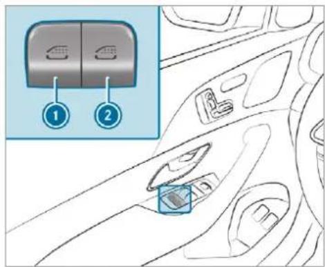
text_image
Diagram of car interior showing two labeled buttons (① and ②) with a blue box indicating a switch or device.① Rear left side window / roller sunblind
② Rear right side window / roller sunblind
To close fully: briefly pull the corresponding button when the side window is closed.
To open fully: briefly press the corresponding button.
Operating the roller sunblind for the panoramic roof

WARNING Risk of becoming trapped when opening and closing the roller sun-blinds
Body parts can become trapped between the roller sunblind and frame when opening or closing.
When opening or closing, make sure that no body parts are in the range of movement of the roller sunblind.
Release the button immediately if somebody becomes trapped.
or
Briefly press the button in any direction during automatic operation. The opening/closing process is stopped.
Requirements:
- The power supply is switched on (→ page 209).
Opening and closing the roller sunblind
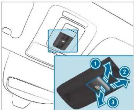
text_image
Diagram showing a device with three labeled arrows indicating directional flow, including numbered annotations ①, ②, and ③.To open: push the [☐] button in direction ① or pull in direction ②.
To close: pull the [☐] button in direction ③.
If you push or pull the button beyond the point of resistance, you will start automatic operation in the direction in question. You can
stop automatic operation by pushing or pulling the button again.
Operating the roller sunblind for the panoramic roof from the rear passenger compartment
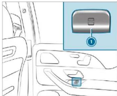
natural_image
Interior view of a car showing the dashboard and seat area with an inset image of a smart lock (no text or symbols)To open: press button ①.
To close: pull button ①.
When the panoramic roof is open, it will close first. To close the roller sunblind, press button ① again.
If you push or pull the ① button beyond the point of resistance, you will start automatic operation in the direction in question. You can stop automatic operation by pushing or pulling the button again.
Automatic reversing function of the roller sunblind
If an object is obstructing the roller sunblind during the closing process, the roller sunblind will open again automatically. The automatic reversing function is only an aid and is not a sub for your attentiveness.
When closing the roller sunblind, make sure that no body parts are in the range of movement.
⚠ WARNING Risk of becoming trapped despite reversing function
In particular, the reversing function does not react to soft, light and thin objects, e.g. fingers.
This means that the reversing function cannot prevent entrapment in these situations.
- When closing the roller sunblind, make sure that no body parts are in the range of movement. - Release the button immediately if somebody becomes trapped.
or ▶ Press the button in any direction during the automatic closing process. The closing process is stopped.
Adjusting the roller sunblind for the panoramic roof
Requirements:
• The power supply is switched on (→ page 209).
If the roller sunblind cannot be moved smoothly, re-adjust the roller sunblind.
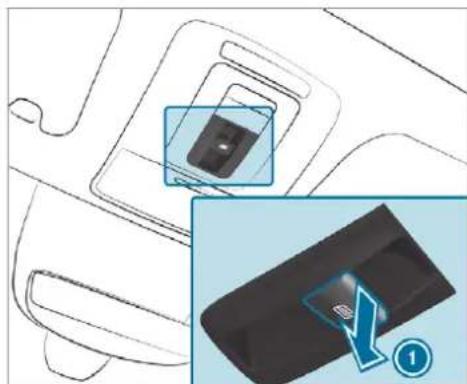
natural_image
Diagram showing a device with a highlighted internal component and a close-up of its internal structure (no text or symbols present)Pull the button down repeatedly to the point of resistance in the direction of arrow until the roller sunblind is fully closed.
Pull and hold the button for another second.
▶ Check whether the roller sunblind can be completely opened again.
If this is not the case, repeat the steps above.
If the roller sunblind still cannot be moved smoothly, contact a qualified specialist workshop.
Anti-theft protection
Function of the immobiliser
The immobiliser prevents your vehicle from being started without the correct key.
The immobiliser is automatically activated when the ignition is switched off and deactivated when the ignition is switched on.
ATA (Anti-Theft Alarm system)
Function of the ATA system
If the ATA system is primed, a visual and audible alarm is triggered in the following situations:
- when a door is opened
- when the tailgate is opened
-
when the bonnet is opened
-
when interior protection is triggered (→ page 115)
- when tow-away protection is triggered (→ page 115)
The ATA system is primed automatically after approximately ten seconds in the following situations:
• after locking the vehicle with the key
• after locking the vehicle using KEYLESS-GO
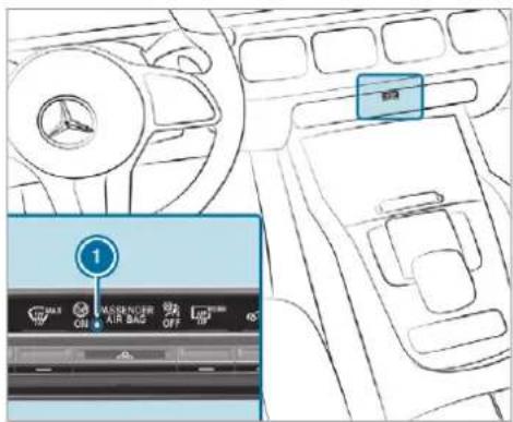
text_image
Diagram of car interior with labeled controls and a highlighted '1' button, showing brand logos and airflow indicators.Indicator lamp ① flashes when the ATA system is primed.
The ATA system is deactivated automatically in the following situations:
• after unlocking the vehicle with the key
• after unlocking the vehicle using KEYLESS-GO
- after pressing the start/stop button with the key in the stowage compartment (→ page 212)
When the Mercedes-Benz emergency call system is active and the alarm stays on for more than 30 seconds, a message is automatically sent to the Customer Assistance Centre ( page 512).
Deactivating the ATA
Press the ☑, ☐ or ☑ button on the key.
or
Press the start/stop button with the key in the stowage compartment ( page 212)
Deactivating the alarm using KEYLESS-GO
Grasp the outside door handle with the key outside the vehicle.
Function of tow-away protection
An audible and visual alarm is triggered if an alteration to your vehicle's angle of inclination is detected while tow-away protection is primed.
Tow-away protection is automatically primed after approximately 60 seconds:
• after locking the vehicle with the key
• after locking the vehicle using KEYLESS-GO
Tow-away protection is only primed when the following components are closed:
- the doors
- the tailgate
Tow-away protection is automatically deactivated:
- after pressing the ☑ or ⚢ button on the key
- after pressing the start/stop button with the key in the stowage compartment (→ page 212)
• after unlocking the vehicle using KEYLESS-GO
Information on detecting damage on a parked vehicle ( page 250).
Priming/deactivating tow-away protection
Multimedia system:
Settings Quick access
▶ Prime or deactivate Tow-away protection.
Tow-away protection is primed again in the following cases:
• The vehicle is unlocked again.
- A door is opened.
• The vehicle is locked again.
If quick access is unavailable, select the Vehicle submenu in the Settings main menu to prime or deactivate tow-away protection.
Function of interior protection
When interior protection is primed, a visual and audible alarm is triggered if movement is detected in the vehicle interior.
Interior protection is primed automatically after approximately ten seconds:
• after locking the vehicle with the key
• after locking the vehicle using KEYLESS-GO
Interior protection is only primed when the following components are closed:
- the doors
- the tailgate
Interior protection is automatically deactivated:
- after pressing the ☑ or ☑ button on the key
- after pressing the start/stop button with the key in the stowage compartment ( page 212)
• after unlocking the vehicle using KEYLESS-GO
The following situations can lead to a false alarm:
- moving objects such as mascots in the vehicle interior
- when the side window is open
- when the sliding sunroof is open
- when the panoramic sliding sunroof is open
- when the panoramic sliding sunroof is open
Priming/deactivating interior protection
Multimedia system:
→ Settings ▶ Quick access
▶ Prime or deactivate Interior motion sensor.
Interior protection is primed again in the following cases:
• The vehicle is unlocked again.
- A door is opened.
- The vehicle is locked again.
If quick access is unavailable, select the Vehicle menu under Settings to prime or deactivate interior protection.
Notes on the correct driver's seat position

WARNING Risk of injury through adjusting vehicle settings while the vehicle is in motion
You could lose control of the vehicle in the following situations in particular:
- if you adjust the driver's seat, the head restraints, the steering wheel or the mirror while the vehicle is in motion.
- if you fasten your seat belt while the vehicle is in motion.

Before starting the engine: adjust the driver's seat, the head restraints, the steering wheel or the mirror and fasten your seat belt.
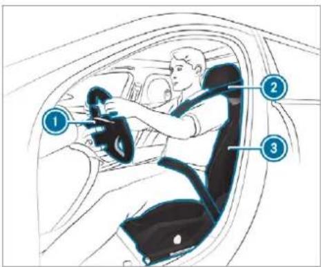
text_image
Diagram of a car interior showing driver's seat, steering wheel, and numbered parts for identification.Ensure the following when you are adjusting the steering wheel ①, seat belt ② and driver's seat ③:
- you are sitting as far away from the driver's airbag as possible, taking the following points into consideration.
- you are sitting in an upright position
-
your thighs are slightly supported by the seat cushion
-
your legs are not fully extended and you can depress the pedals properly
- the back of your head is supported at eye level by the centre of the head restraint
- you can hold the steering wheel with your arms slightly bent
- you can move your legs freely
- you can see all the displays on the instrument cluster clearly
- you have a good overview of the traffic conditions
- your seat belt sits snugly against your body and passes across the centre of your shoulder and across your hips in the pelvic area
Seats
Adjusting the front seat

WARNING Risk of becoming trapped if the seats are adjusted by children
Children could become trapped if they adjust the seats, particularly when unattended.
When leaving the vehicle, always take the key with you and lock the vehicle. This also applies to the digital vehicle key if the "Digital Vehicle Key" function is activated via Mercedes me connect.
▶ Never leave children unattended in the vehicle.
The seats can be adjusted when the ignition is switched off.

WARNING Risk of becoming trapped when adjusting the seats
When you adjust a seat, you or other vehicle occupants could become trapped, e.g. on the seat guide rail.
When adjusting a seat, make sure that no one has any body parts in the sweep of the seat.
Observe the safety notes on "Airbags" and "Children in the vehicle".

WARNING Risk of injury through adjusting vehicle settings while the vehicle is in motion
You could lose control of the vehicle in the following situations in particular:
- if you adjust the driver's seat, the head restraints, the steering wheel or the mirror while the vehicle is in motion.
- if you fasten your seat belt while the vehicle is in motion.
Before starting the engine: adjust the driver's seat, the head restraints, the steering wheel or the mirror and fasten your seat belt.

WARNING Risk of becoming trapped if the seat height is adjusted carelessly
If you adjust the seat height carelessly, you or other vehicle occupants could be trapped and thereby injured.
Children in particular could accidentally press the electrical seat adjustment buttons and become trapped.
While moving the seats, make sure that hands or other body parts do not get under the lever assembly of the seat adjustment system.

WARNING Risk of injury due to head restraints which are not fitted or are adjusted incorrectly
If head restraints are not fitted or are adjusted incorrectly, they cannot provide protection as intended.
There is an increased risk of injury in the head and neck area, e.g. in the event of an accident or when braking.
Always drive with the head restraints fitted.
Before driving off, make sure for every vehicle occupant that the centre of the head restraint supports the back of the head at about eye level.
Do not interchange the head restraints of the front and rear seats. Otherwise, you will not be able to adjust the height and angle of the head restraints correctly.
Adjust the head restraint fore-and-aft position so that it is as close as possible to the back of your head.

WARNING Risk of injury or death due to incorrect seat position
The seat belt does not offer the intended level of protection if you have not moved the backrest to an almost vertical position.
In particular, when you are braking or in the event of an accident, you could slide underneath the seat belt and sustain abdomen or neck injuries, for example.
Adjust the seat properly before beginning your journey.
Always ensure that the backrest is in an almost vertical position and that the shoulder section of your seat belt is routed across the centre of your shoulder.
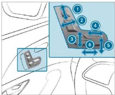
text_image
Diagram showing car interior components with numbered parts and directional arrows indicating movement or flow① Head restraint height
② Seat backrest inclination
3 Seat height
④ Seat cushion length
5 Seat cushion inclination
6 Seat fore-and-aft position
Save the settings with the memory function ( page 140).
Adjusting the front passenger seat electrically from the driver's seat
Requirements:
• The power supply is switched on.
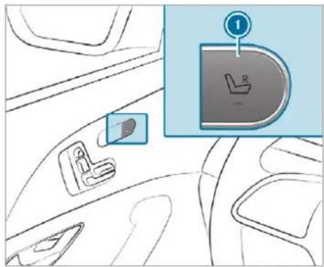
text_image
Diagram showing car interior with seatbelt, seatbelt switch, and seatbelt icon labeled 'R' with number 1 pointing to the seatbelt.You can call up the following functions for the front passenger seat:
- seat adjustment
- seat heating
- Seat ventilation
- memory function
To select the front passenger seat: press button ①. When the indicator lamp lights up, the front passenger seat is selected.
Adjust the front passenger seat using the buttons on the driver's side door control panel.
Select the driver's seat: press the ① button again.
When the indicator lamp goes out, the driver's seat has been selected.
Adjusting the front passenger seat electrically from the rear
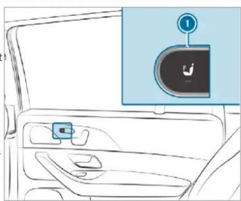
natural_image
Interior view of a car showing the side panel and seatbelt with a highlighted door (no text or symbols)To select the front passenger seat: press button ①.
When the indicator lamp lights up, the front passenger seat is selected.
Adjust the front passenger seat using the buttons on the door control panel in the rear passenger compartment ( page 121).
Mercedes-Maybach vehicles: if the front passenger seat is in the foremost position, you can set the seat backrest at a very steep angle. This achieves a better front view from the rear compartment. Despite the steep seat backrest, a person may occupy the front passenger seat.
Adjusting the 4-way lumbar support
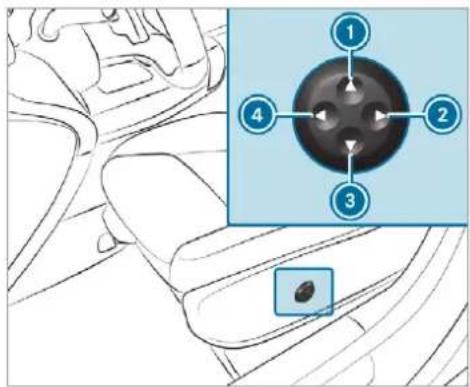
text_image
Diagram showing car interior and dashboard with numbered components, including a highlighted circular component with four labeled parts.① Higher
2 Softer
3 Lower
4 Firmer
Using buttons ① to ④, adjust the contour of the backrest individually to suit your back.
Adjusting the rear seats electrically
The middle seat backrest is adjusted together with the left seat.
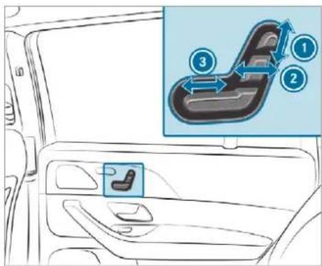
text_image
Diagram showing car interior with a highlighted slide and numbered instructions for loading or adjustment.① Head restraint height
② Seat backrest inclination
3 Seat fore-and-aft position
Save the settings with the memory function ( page 141).
Adjusting a reclining rear seat electrically
This equipment is available only for Mercedes-Maybach vehicles.
The reclining rear seats are on the driver's and front passenger sides.
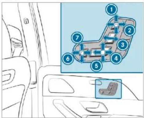
text_image
Diagram showing car interior and vehicle layout with numbered components, including a highlighted section of the car's side panel.① Head restraint height
② Head restraint fore-and-aft position
3 Seat backrest inclination
4 Combined seat cushion inclination and length
5 Combined seat cushion inclination and length
6 Fore-and-aft position of the leg rest
⑦ Angle of the leg rest
Save the settings with the memory function (→ page 141).
The leg rest will fold down if overloaded. If this is the case, fold up the leg rest and engage it.
Setting the fully reclined position
Requirements:
• the power supply is switched on.
This equipment is available only for Mercedes-Maybach vehicles.
text_image
Diagram showing a car interior with a highlighted vehicle component and a numbered label pointing to it.To set the fully reclined position: press button ①.
- the rear seat will move into the reclined position.
• the rear seat head restraint will move.
• the leg rest will rise. - the front passenger seat will move as far forwards as possible.
- the front passenger seat head restraint is completely retracted. - the front passenger seat backrest will move as far forwards and as far down as it will go.
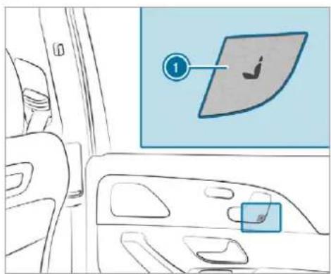
text_image
Diagram showing a car interior with a highlighted vehicle door panel and a numbered label pointing to the door.To restore the standard seat settings: press button ①.
▶ Call up the settings with the memory function ( page 141).
① You can use the rear-compartment child safety lock to disable this function ( page 83).
The leg rest will fold down if overloaded. If this is the case, fold up the leg rest and engage it.
Attaching and removing the additional cushion of the leg rest
This equipment is available only for Mercedes-Maybach vehicles.
Use the additional cushion only when the vehicle is stationary. The additional cushion is in the vehicle.
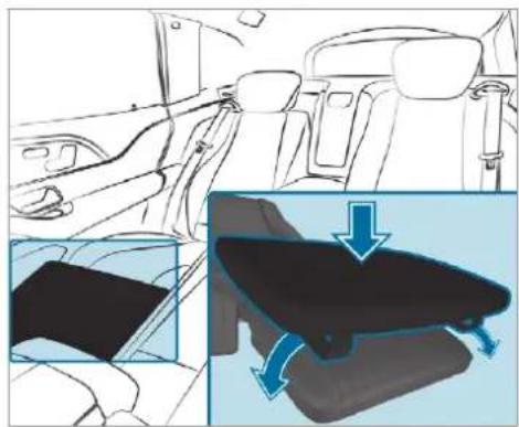
natural_image
Interior view of a car showing dashboard, seatbelt, and rearview side view with a close-up of the backrest (no text or symbols)To attach: place the additional cushion on the leg rest.
Pull the rubber straps laterally over the leg rest.
To remove: remove the rubber straps from the leg rest and stow the additional cushion safely in the vehicle.
Folding the rear seats on the second row of seats forwards and back electrically

WARNING Risk of injury due to seat backrest folded forwards
If the rear seat backrest is folded forwards, persons in the third row of seats could collide with parts of the seat adjustment mechanism, in particular in the event of an accident, sudden braking or an abrupt change of direction.
If there is a person in the third row of seats, the rear seat in front of that person must be folded back into the driving position before starting the journey.
▶ People in the third row of seats must not place their legs on a rear seat back-rest that has been folded forwards.
Always ensure that all vehicle occupants have their seat belts fastened correctly and are sitting properly. Particular attention must be paid to children.
If you no longer require the seat backrest to be folded down for loading or for getting in and out, fold it back into place.

WARNING Risk of becoming trapped if the seat is not engaged
The seat does not engage when folded forwards. The seat can fold backwards unexpectedly, e.g. when accelerating, braking or in the event of an abrupt change of direction or an accident.
People in the seat's sweep can become trapped.
If a seat is folded forwards, always fold it back before driving off.
▶ Make sure that the seat is engaged.
If a seat in the second row of seats is not engaged, this will be shown on the multifunction display on the instrument cluster.
Requirements:
- The area into which the rear seat is folded is clear.
• The rear seat has been folded up.
• Vehicles with comfort seating: the centre armrest is folded up.
• Vehicles with an extended centre console: the stowage compartment in the centre console is closed.
- Vehicles with a folding rear armrest: the rear armrest has been folded up.
- Vehicles with centre rear seat backrests: the centre rear seat backrest has been folded up.
Folding the rear seat in the front position This equipment is not available for Mercedes- Maybach vehicles.
You can fold the seats in the second row of seats forwards for the following situations:
• For easier access to the load compartment
- Vehicles with a third row of seats: for getting in or out
Vehicles with a centre seat backrest: the centre rear seat folds forwards and backwards, together with the left rear seat.
Depending on the vehicle equipment, the rear seats can be folded forwards as follows:
- Six-seater: on the right-hand side of the vehicle only
- Seven-seater with centre seat backrest: both sides
To increase the size of the luggage compartment, you can move the rear seat backrests into the luggage compartment floor position ( page 149).
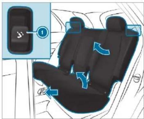
text_image
Diagram of car seatbelt with blue directional arrows indicating movement or rotation, showing a switch labeled '1' and directional arrows.Button in the backrest shoulder of the second row of seats
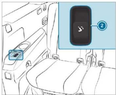
text_image
Diagram of car interior with labeled seatbelt and device icon, showing a blue box with a switch symbol and numbered annotation.Button in the armrest of the third row of seats (seven-seater)
When the rear door is open: briefly pull release button ① in the backrest shoulder of the rear seat.
or
briefly press release button ② in the arm-rest of the third row of seats.
When the rear door is closed: pull and hold release button ① in the backrest shoulder of the rear seat.
or
press and hold release button ② in the arm-rest of the third row of seats.
The head restraint moves downwards. The rear seat backrest moves into the front position. The rear seat moves forwards until it unlocks. The rear seat then tips forwards.
If a seat in the second row of seats is not engaged, this will be shown on the multifunction display on the instrument cluster.
① You can prevent the rear seats from folding forwards when the rear door is closed by activating the child safety lock for the rear side windows ( page 83).
Folding the rear seat back into the driving position
Press and hold release button ① in the backrest shoulder of the rear seat or ② in
the armrest of the third row of seats and hold it down until the rear seat audibly engages. The rear seat will tip downwards and move back. The rear seat backrest and head restraint will automatically move into the driving position.
If a seat in the second row of seats is not engaged, this will be shown on the multifunction display on the instrument cluster.
To interrupt the folding procedure before engagement, let go of the release button. continue the folding procedure, press and hold the release button again.
Folding the rear seats forwards mechanically (emergency release)
You can also fold the rear seats forwards mechanically using release loops. The release loops are located on the outer sides and rear sides of the seats on the second row of seats.
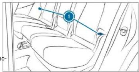
text_image
1 C-To Release loops on the second row of seats
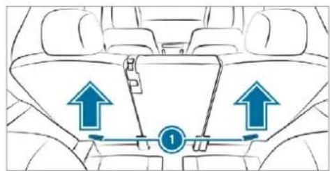
text_image
Diagram of car interior showing seatbelt and directional arrows indicating movement or force on the dashboardRelease loops on the rear sides of the second row of seats
▶ Pull one of the release loops ①.
▶ Fold the rear seat backrest forwards.
Before starting the journey, make sure that the rear seat backrest and the rear bench seat are engaged.
Head restraints
Adjusting the front seat head restraints mechanically
WARNING Risk of injury through adjusting vehicle settings while the vehicle is in motion
You could lose control of the vehicle in the following situations in particular:
- if you adjust the driver's seat, the head restraints, the steering wheel or the mirror while the vehicle is in motion.
- if you fasten your seat belt while the vehicle is in motion.
Before starting the engine: adjust the driver's seat, the head restraints, the
steering wheel or the mirror and fasten your seat belt.
WARNING Risk of injury due to head restraints which are not fitted or are adjusted incorrectly
If head restraints are not fitted or are adjusted incorrectly, they cannot provide protection as intended.
There is an increased risk of injury in the head and neck area, e.g. in the event of an accident or when braking.
▶ Always drive with the head restraints fitted.
Before driving off, make sure for every vehicle occupant that the centre of the head restraint supports the back of the head at about eye level.
Do not interchange the head restraints of the front and rear seats. Otherwise, you will not be able to adjust the height and angle of the head restraints correctly.
Adjust the head restraint fore-and-aft position so that it is as close as possible to the back of your head.
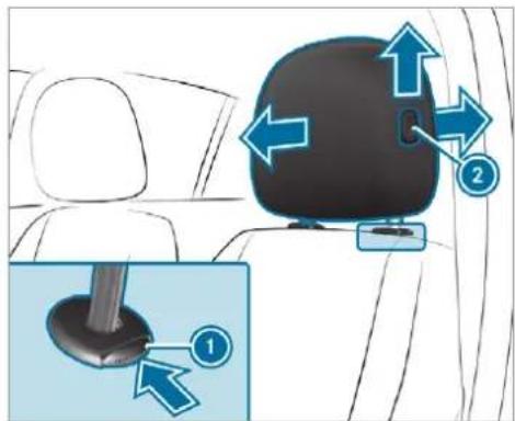
text_image
Diagram showing car backrest seat with directional arrows and labeled parts, including a magnified inset of the seat.To raise: pull the head restraint up.
To lower: press release knob ① in the direction of the arrow and push the head restraint down.
To move forward: press release knob and pull the head restraint forward.
To move backwards: press release knob and push the head restraint backwards.
Adjusting the front seat luxury head restraints mechanically
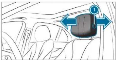
natural_image
Interior view of a car showing the seatbelt and dashboard (no text or symbols visible)To move forward: press release knob and pull the head restraint forward.
To move backwards: press release knob and push the head restraint backwards.
Adjusting the EASY ADJUST luxury head restraints on the front seats mechanically This equipment is available only for Mercedes-Maybach vehicles.
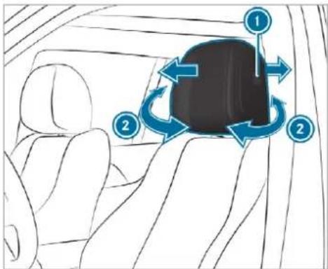
text_image
Diagram showing car interior with numbered directional arrows indicating movement or rotation around a vehicle seatTo move forward: press release knob and pull the head restraint forward.
To move backwards: press release knob and push the head restraint backwards.
To adjust the side bolsters of the head restraint: pull or push right or left-hand side bolster ②.
The fore-and-aft position of the head restraint will be adjusted automatically when you adjust the backrest using the buttons on the door control panel.
Adjusting the head restraints of the rear seats mechanically
Depending on the vehicle equipment, the head restraints on the third row of seats as well as the centre head restraint on the second row of seats can be adjusted mechanically.
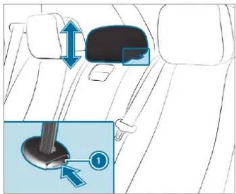
text_image
Diagram showing car seatbelt insertion with directional arrows and a close-up of the seatbelt component labeled '①'Head restraint of the standard vehicle (example)
To raise: pull the head restraint up.
To lower (standard vehicles): press the release knob ① in the direction of the arrow and push the head restraint down.
To lower (Mercedes-Maybach vehicles): push the head restraint down.
Vehicles with a third row of seats
The head restraints on the third row of seats have a usage and non-usage position. The usage position is the extended, top position in which the head restraint engages; the non-usage position is the bottom, retracted position of the head restraint. If the seats on the third row of seats are being used, the head restraint must be in the top, engaged usage position.
If the third row of seats is occupied: move the head restraints to the very top and have them engage there.
If the third row of seats is not occupied: move the head restraints to the very bottom.
Fitting/removing the head restraint of the middle rear seat on the second row
Removing
This function is available only for seven-seater vehicles.
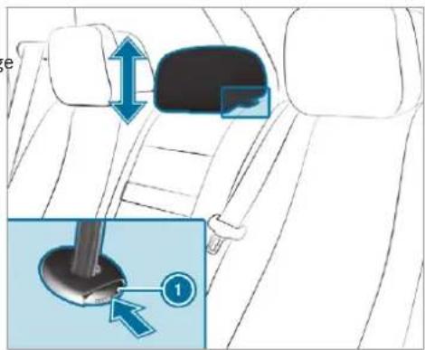
text_image
Diagram showing car seatbelt adjustment with magnified detail highlighting the seatbelt component labeled '①'Release the middle rear seat backrest and fold it forward slightly ( page 149).
Pull the head restraint upwards as far as it will go.
Push release knob ① in the direction of the arrow and pull out the head restraint.
Installing
Insert the head restraint such that the notches on the bar are on the left when viewed in the direction of travel.
▶ Push the head restraint down until it engages.
Fold the middle rear seat backrest back until it engages.
Adjusting the luxury head restraints of the rear seats mechanically
Mercedes-Maybach vehicles: you can set only the side bolsters mechanically. You can adjust the angle of the head restraint electrically.
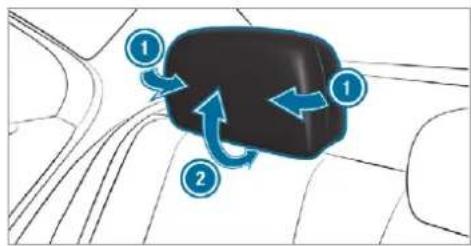
flowchart
graph TD
    A["①"] --> B["②"]
    B --> C["①"]
    style A fill:#000,stroke:#000,color:#fff
    style B fill:#000,stroke:#000,color:#fff
    style C fill:#000,stroke:#000,color:#fff
Head restraint of the standard vehicle (example)
To adjust the side bolsters of the head restraint: pull or push right or left-hand side bolster ①.
To adjust the angle of the head restraint: pull or push the head restraint in the direction of the arrow ②.
Attaching and removing the additional cushion of the luxury head restraint in the rear compartment
This equipment is available only for Mercedes-Maybach vehicles.
Use the additional cushion only when the vehicle is stationary. The additional cushion is in the vehicle.
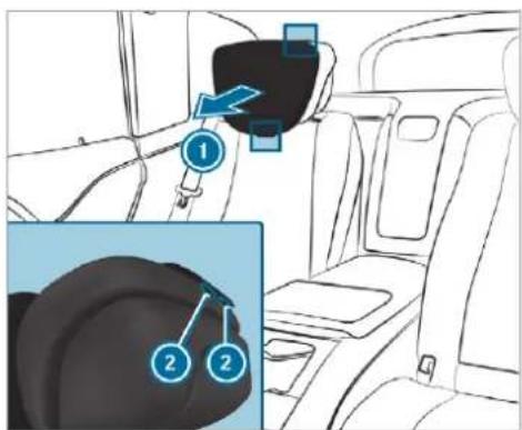
text_image
Diagram showing car seatbelt insertion with numbered labels and directional arrows indicating movement or positioning.▶ Position the head restraint as far forwards as possible.
To attach the additional cushion: hold additional cushion ① against the head
restraint and push press studs ② into the counterpieces.
To remove the additional cushion: release press studs ② and remove additional cushion ①.
Configuring the seat settings
Multimedia system:
→ Comfort ▶ Seat comfort
Adjusting the backrest contour in the lumbar region of the seat backrest (lumbar)
Select Lumbar.
Select the settings ⚙ for the desired seat.
Adjust the air cushions.
Adjusting the backrest side bolsters
▶ Select Side bolsters.
Adjust the air cushion for the desired seat.
Setting the seat heating balance
▶ Select Seat heating balance.
Adjust the heat distribution for the desired seat.
Setting automatic seat adjustment
WARNING Risk of becoming trapped during adjustment of the driver's seat after calling up a driver profile
Selecting a profile may trigger an adjustment of the driver's seat to the position saved under the profile. You or other vehicle occupants could be injured in the process.
Make sure that when the position of driver's seat is being adjusted using the multimedia system, no people or body parts are in the seat's range of movement.
If there is a risk of someone becoming trapped, stop the adjustment process immediately:
a) Tap the warning message on the media display.
or
b) Press a memory position button or a seat adjustment switch on the driver's door. The adjustment process is stopped.
Requirements:
- Adapting the driver's seat and steering wheel position to the body size: automatic seat adjustment has been switched on.
Multimedia system:
→ Settings → Vehicle
Auto. seat adjustment
Switching automatic seat adjustment on/off When the active user profile is changed while the vehicle is stationary, the driver's seat, steering wheel, outside mirrors and seat contour will automatically be adapted to the driver.
▶ Select On or Off.
This setting is available only for individual user profiles. For the guest profile, automatic seat adjustment cannot be switched on or off. Further information about user profiles ( page 394).
Adjusting driver's seat and steering wheel position to body size
The vehicle calculates a suitable driver's seat and steering wheel position on the basis of the driver's body size and sets this directly.
To set the unit of measurement: select cm or ft/in.
Set the size using the scale.
Select Start positioning.
The driver's seat and steering wheel position is adjusted to the body size that has been set.
If the driver's seat and steering wheel position calculated by the vehicle is not practical or comfortable, it can be manually changed at any time via the control buttons. The outside mirrors are not set via this function. Instead, they have to be set manually via the switches.
You can also make these settings via the Mercedes me portal for your user profile. By synchronising the profiles in the vehicle and the Mercedes me connect profiles, you can carry over these settings for your vehicle. Further information about synchronising user profiles ( page 397).
Setting the easy entry and exit feature
Select Steer. wheel and seat, Steering wheel only or Off.
If you use an individual user profile and have set your body size, this information is carried over for the easy entry and exit feature. This causes the driver's seat and steering wheel to automatically move into the correct position (→ page 396).
Overview of massage programs
Overview
| Programs Function | |
| Hot Relaxing back | Combination of heat and massage. Starts by massaging the back. In addition, warm pressure points become noticeable, starting in the pelvic area. |
| Hot Relaxing shoulder | Combination of heat and massage. Starts by massaging the shoulders. In addition, warm pressure points become noticeable, starting in the pelvic area. |
| Activating Massage | Activating massage with upward-moving massage waves. |
| Classic Massage | Relaxing back massage. |
| Wave Massage | Regenerating massage via massage waves across the back and in the seat cushion. |
| Mobilizing Massage | Mobilizing massage with upward-moving massage waves. Can promote deeper respiration and hence improve circulation and blood pressure. |
| Active Workout backrest and Active Workout cushion | These programs require your cooperation. Alternating between tensing and releasing helps to improve blood flow to your muscles. Press against a pressure point as soon as you feel it. |
Selecting the massage programme for the front seats
Multimedia system:
Comfort Massage
Select a massage programme (→ page 133)
▶ Start the program for the desired seat ▶.
To set the massage intensity: switch High intensity on or off.
For the rear seats, the massage programmes can be selected on the following devices (if available):
- on the rear displays (→ page 559) The selection can be made for the rear seats on the second and third rows of seats.
- on the MBUX rear tablet The selection is made in the same way as on the rear displays for the rear seats on the second row of seats.
Resetting seat settings
Multimedia system:
→ Comfort ▶ Seat comfort
Select Reset.
Select ☑ for the desired seat. The settings for the selected seat are reset.
Switching the seat heating on/off
WARNING Risk of burns due to repeatedly switching on the seat heater
Repeatedly switching on the seat heater can cause the seat cushion and seat backrest padding to become very hot.
The health of persons with limited temperature sensitivity or a limited ability to react to high temperatures may be affected or they may even suffer burn-like injuries.
Do not repeatedly switch on the seat heater.
To protect against overheating, the seat heating may be temporarily deactivated after it is switched on repeatedly.
! NOTE Damage to the seats caused by objects or documents when the seat heater is switched on
When the seat heater is switched on, overheating may occur due to objects or documents placed on the seats e.g. seat cushions or child seats. This could cause damage to the seat surface.
Make sure that no objects or documents are on the seats when the seat heater is switched on.
Requirements:
• The power supply is switched on.
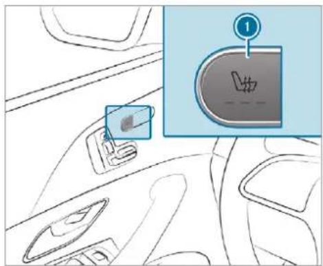
text_image
Diagram showing car interior with a doorbell and a small inset image of the doorbell with a hand symbol, labeled with number 1.Seat heating in the cockpit
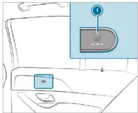
text_image
Diagram showing car interior with a highlighted seatbelt and numbered indicator '1'Seat heating in the rear
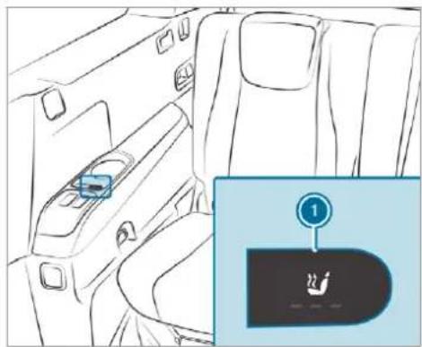
natural_image
Interior view of a car showing the side panel and seatbelt (no text or symbols visible)Seat heating in the third row of seats
To switch on / increase the level: press button ① repeatedly until the desired heating level is set. Depending on the heating level, up to three indicator lamps will light up.
To switch off / reduce the level: press button ① repeatedly until the desired heating level is set. If all indicator lamps are off, the seat heating is switched off.
The seat heating will automatically switch down from the three heating levels after 8, 10 and 20 minutes until the seat heating is switched off.
Setting the panel heating
Multimedia system:


Settings
Vehicle

Panel heating
When the seat heater is switched on, the armrests, the centre panels of the doors and the centre console can be heated.
Switch the function for the desired seats on or off.
• The power supply is switched on.
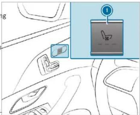
text_image
Diagram showing car interior with seatbelt and seatbelt switch, labeled with number 1 pointing to a deviceSeat ventilation in the cockpit
Switching the seat ventilation on/off
Requirements:
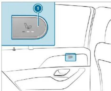
natural_image
Interior view of a car showing the dashboard and seat area with a highlighted screen (no text or symbols)Seat ventilation in the rear
To switch on / increase the level: press button ① repeatedly until the desired ventilation level is set. Depending on the ventilation level, up to three indicator lamps will light up.
To switch off / reduce the level: press button ① repeatedly until the desired ventilation level is set. If all indicator lamps are off, the seat ventilation is switched off.
Steering wheel
Adjusting the steering wheel mechanically
A WARNING Risk of injury through adjusting vehicle settings while the vehicle is in motion
You could lose control of the vehicle in the following situations in particular:
- if you adjust the driver's seat, the head restraints, the steering wheel or the mirror while the vehicle is in motion.
- if you fasten your seat belt while the vehicle is in motion.
Before starting the engine: adjust the driver's seat, the head restraints, the
steering wheel or the mirror and fasten your seat belt.
WARNING Risk of entrapment for children when adjusting the steering wheel
Children could injure themselves if they adjust the steering wheel.
▶ Never leave children unattended in the vehicle.
When leaving the vehicle, always take the key with you and lock the vehicle. This also applies to the digital vehicle key if the "Digital Vehicle Key" function is activated via Mercedes me connect.
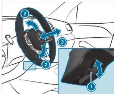
text_image
Diagram illustrating car steering wheel and steering wheel assembly with numbered steps and directional arrows indicating motion.Push release lever ① down as far as it will go.
The steering column is unlocked.
Adjust height ② and distance ③ to the steering wheel.
Push release lever ① up as far as it will go. The steering column is locked.
Check and make sure that the steering column is locked by moving the steering wheel.
Adjusting the steering wheel electrically
The steering wheel can be adjusted when the ignition is switched off.
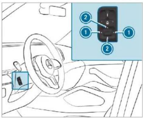
text_image
Diagram of a car interior with labeled parts and an inset showing a control panel with numbered indicators.To adjust the distance to the steering wheel
② To adjust the height
Save the settings with the memory function ( page 140).
Switches the steering wheel heater on or off
Requirements:
• The ignition is switched on.
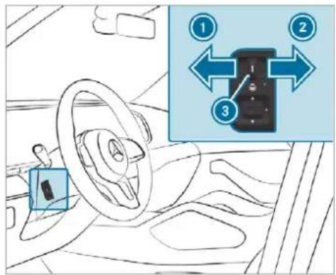
text_image
Diagram of car interior showing steering wheel, dashboard, and control panel with numbered arrows indicating directional movementTo switch on: push the switch to position

The indicator lamp ③ lights up.
To switch off: push the switch to position

Indicator lamp ③ goes out.
When you switch the ignition off, the steering wheel heater switches off.
Easy entry and exit feature
Using the easy entry and exit feature
⚠ WARNING Risk of accident when pulling away during the adjustment process of the easy exit feature
- If you pull away while the easy entry and exit feature is making adjustments, you could lose control of the vehicle.
Always wait until the adjustment process is complete before pulling away.
A WARNING Risk of becoming trapped while adjusting the easy entry and exit feature
When the easy entry and exit feature adjusts the steering wheel and the driver's seat, you and other vehicle occupants - particularly children - could become trapped.
During the adjustment process for the easy entry and exit feature, make sure that no one has any body parts in the sweep of the steering wheel or the driver's seat.
If there is a risk of becoming trapped by the steering wheel:
▶ Move the adjustment lever of the steering wheel. The adjustment process is stopped.
If there is a risk of becoming trapped by the driver's seat:
▶ Press the seat adjustment switch. The adjustment process is stopped.
▶ Never leave children unattended in the vehicle.
When leaving the vehicle, always take the key with you and lock the vehicle. This also applies to the digital vehicle key if the "Digital Vehicle Key" function is activated via Mercedes me connect.
You can stop the adjustment process by pressing one of the memory function position switches.
A WARNING Risk of becoming trapped during activation of the easy entry and exit feature by children
If children activate the easy entry and exit feature, they can become trapped, particularly when unattended.
▶ Never leave children unattended in the vehicle.
When leaving the vehicle, always take the key with you and lock the vehicle.
This also applies to the Digital Vehicle Key if the "Digital Vehicle Key" function is activated via Mercedes me connect.
If the easy entry and exit feature is active, the steering wheel will move upwards and the driver's seat will move back in the following situations:
- You switch the ignition off with the driver's door open
- You open the driver's door with the ignition switched off
The steering wheel will move upwards only if it is not already as high as it will go. The driver's seat will move backwards only if it is already in the rearmost position. The driver's seat backrest will move forwards only if it is not already in the front-most position.
The steering wheel and the driver's seat will move back to the last drive position in the following cases:
- You switch the power supply or the ignition on when the driver's door is closed
- You close the driver's door with the ignition switched on.
The last drive position will be stored when:
- You switch the ignition off.
- You save the seat setting via the memory function
If you press one of the memory function position switches, the adjustment process will be stopped.
Operating the memory function
WARNING Risk of an accident if the memory function is used while driving
If you use the memory function on the driver's side while driving, you could lose control of the vehicle as a result of the adjustments being made.
Only use the memory function on the driver's side when the vehicle is stationary.
WARNING Risk of entrapment when setting the seat with the memory function
When the memory function adjusts the seat, you and other vehicle occupants - particularly children - could become trapped.
During the adjustment process of the memory function, make sure that no one has any body parts in the sweep of the seat.
If someone becomes trapped, press a preset position button or seat adjustment switch immediately.
WARNING Risk of entrapment if the memory function is activated by children
Children could become trapped if they activate the memory function, particularly when unattended.
▶ Never leave children unattended in the vehicle.
When leaving the vehicle, always take the key with you and lock the vehicle.
This also applies to the Digital Vehicle Key if the "Digital Vehicle Key" function is activated via Mercedes me connect.
The memory function can be used when the ignition is switched off.
Storing
Seat adjustments for up to three people can be stored and called up using the memory function.
The following systems can be selected:
- Front seat
- Outside mirrors
- Head-up display
- Steering column
- Seat contour
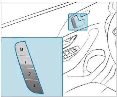
text_image
M 1 2 3Set the front seat, the outside mirrors, the head-up display, the steering column and seat contour to the desired position.
Press memory button M and then press pre-set position button 1, 2 or 3 within three seconds.
An acoustic signal sounds. The settings are stored.
To call up: press and briefly hold preset position button 1, 2 or 3. After releasing the button, the front seat, outside mirrors, head-up display, steering column, and seat contour are moved into the stored position automatically.
Memory function in the rear compartment
Operating the rear seat via the memory function in the rear passenger compartment
Storing
This function is available only for Mercedes-Maybach vehicles.
Seat adjustments for the rear seat can be stored and called up using the rear seat memory func-
- Driver's side: two persons
• Front passenger side: one person
The following settings can be stored for the rear seats:
- Position of the seat, backrest and head restraint
- Seat heating: distribution of the heated sections of the seat cushion and seat backrest
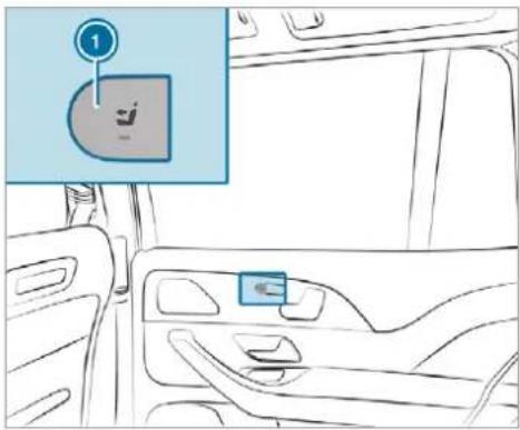
text_image
Diagram of car interior with labeled buttons and a numbered annotation pointing to the right panelPress button 1.
The rear seat is selected if the indicator lamp in the button does not light up.
Adjust the rear seat using the buttons in the door control panel ( page 121).
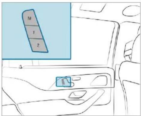
text_image
M 1 2Briefly press memory button M and then press preset position button 1 or 2 within three seconds.
The settings for the rear seat are stored in the corresponding preset position.
① You cannot store any settings on the button for straightening the fully reclined position.
Calling up
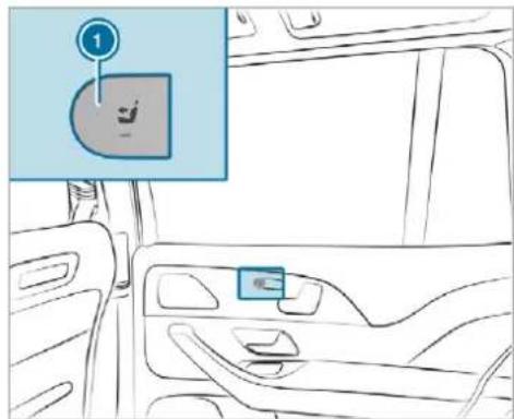
text_image
Diagram showing a car interior with a labeled component '1' pointing to the door panel, likely indicating a safety or safety feature.Press button ①. The rear seat is selected if the indicator lamp in the button does not light up.
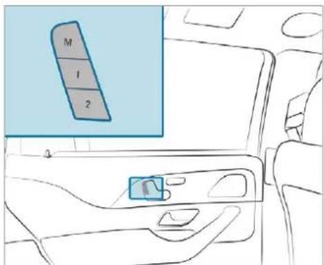
text_image
M 1 2Press corresponding preset position button 1 or 2. The rear seat will move to the stored position.
Operating the front passenger seat and rear seats via the memory function in the rear passenger compartment
Requirements:
- For selecting the front passenger seat: the power supply is switched on
Storing
This function is available only for Mercedes-Maybach vehicles.
Seat adjustments for the front passenger seat and the rear seat can be stored and called up using the rear seat memory function.
The following settings can be stored for the front passenger seat:
- Position of the seat, backrest and head restraint
The following settings can be stored for the rear seats:
- Position of the seat, backrest and head restraint
- Seat heating: distribution of the heated sections of the seat cushion and seat backrest
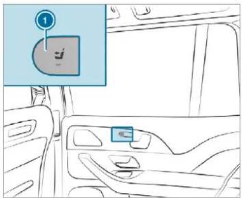
text_image
Diagram showing car interior with a highlighted location pin labeled '1' and a small icon pointing to the door.Press button ①. The rear seat is selected if the indicator lamp in the button does not light up.
Adjust the rear seat using the buttons in the door control panel ( page 121).
Press button ①.
When the indicator lamp lights up, the front passenger seat is selected.
Adjust the front passenger seat using the buttons on the door control panel in the rear passenger compartment ( page 117).
Ensure that the indicator lamp in button lights up.
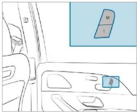
natural_image
Interior view of a car showing the dashboard and seat area with a highlighted door panel (no text or symbols)Press memory button M and, within three seconds, press preset position button 1. The settings for the front passenger seat and the rear seat are stored in the preset position.
You cannot store any settings on the buttons for setting and straightening the fully reclined position.
Calling up
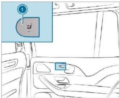
text_image
Diagram showing a car interior with a highlighted control panel labeled '1' pointing to a button, and a small icon on the door.Press button ①. When the indicator lamp lights up, the front passenger seat is selected.
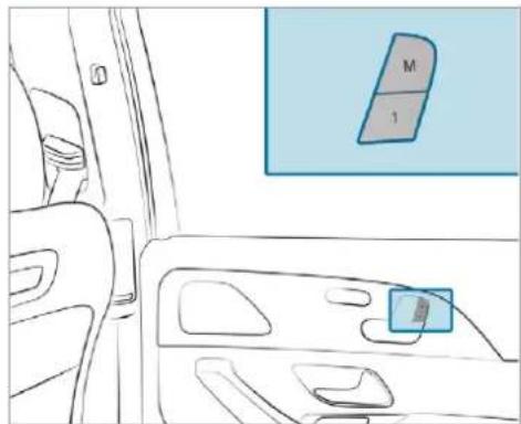
natural_image
Interior view of a car dashboard with a highlighted door panel (no text or symbols)Press preset position button 1. Both seats move into the stored position.
① You can use the rear-compartment child safety lock to disable this function ( page 83).
Stowage areas
Notes on loading the vehicle
DANGER Risk of exhaust gas poisoning
Combustion engines emit poisonous exhaust gases such as carbon monoxide. Exhaust gases can enter the vehicle interior if the tailgate is open when the engine is running, especially if the vehicle is in motion.
Always switch off the engine before opening the tailgate.
▶ Never drive with the tailgate open.
⚠ WARNING Risk of injury from unsecured items in the vehicle
If objects, luggage or loads are not secured or not secured sufficiently, they could slip, tip over or be thrown around and thereby hit vehicle occupants.
There is a risk of injury, particularly in the event of sudden braking or a sudden change in direction.
Always stow objects in such a way that they cannot be thrown around.
Before the journey, secure objects, luggage or loads against slipping or tipping over.
WARNING Risk of injury from inadequate stowage of objects
If you do not adequately stow objects in the vehicle interior, they could slip or be tossed around and thereby strike vehicle occupants. In addition, cup holders, open stowage spaces and mobile phone brackets cannot always restrain the objects they contain in the event of an accident.
There is a risk of injury, particularly in the event of sudden braking or a sudden change in direction.
Always stow objects in such a way that they cannot be tossed around in these or similar situations.
Always make sure that objects do not project from stowage spaces, luggage nets or stowage nets.
▶ Close all sealable stowage spaces before you start your journey.
Stow and secure objects that are heavy, hard, pointed, sharp-edged, fragile or too large in the load compartment.
WARNING Risk of burns from the tailpipe and tailpipe trims
The exhaust tailpipe and tailpipe trims can become very hot. If you come into contact with these parts of the vehicle, you could burn yourself.
▶ Always be particularly careful around the tailpipe and the tailpipe trims and supervise children especially closely in this area.
▶ Allow vehicle parts to cool down before touching them.
The driving characteristics of your vehicle are dependent on the distribution of the load within the vehicle. You should bear the following in mind when loading the vehicle:
- never exceed the permissible gross mass or the permissible axle loads for the vehicle (including occupants).
Information can be found on the vehicle identification plate ( page 633).
- the load must not protrude above the upper edge of the seat backrests.
- All vehicles except Mercedes-Maybach vehicles: always use the partition net when transporting objects in the load compartment.
- always place the load behind unoccupied seats if possible.
- secure the load using the tie-down eyes and distribute the load evenly.
Stowage spaces in the vehicle interior
Overview of the front stowage compartments
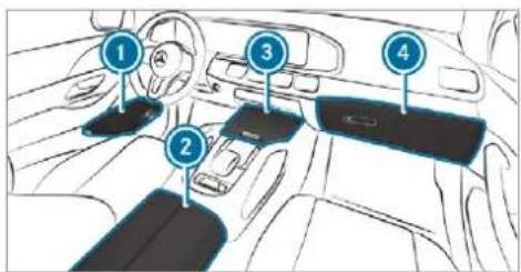
text_image
Diagram of car interior with numbered components for identification① Stowage space in the doors
② Stowage compartment in the armrest with USB ports (depending on vehicle equipment)
3 Stowage/telephone compartment with cup holder in the centre console at front
Mercedes-Maybach vehicles: stowage/telephone compartment with temperature-controlled cup holder, USB ports (depending on the vehicle equipment) and charging module for wireless charging of mobile phones (depending on the vehicle equipment) in the front centre console
Glove compartment
Locking/unlocking the glove compartment
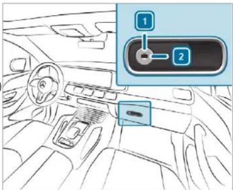
text_image
Diagram of a car interior with labeled parts and a highlighted control panel showing two numbered components.Turn the emergency key a quarter turn clockwise 2 (to lock) or anti-clockwise 1 (to unlock).
Folding the folding table out or in
⚠ WARNING Risk of injury from the open folding table
If you are driving with the folding table open, vehicle occupants could strike against it, in particular in the event of an accident, sudden braking or an abrupt change of direction.
Close the folding table before each journey.
! NOTE Damage to the folding tables when moving the seats back
Open folding tables may be damaged when the seats are moved back.
Make sure that the folding tables are folded in when moving the front seats back.
Folding out
This equipment is available only for Mercedes-Maybach vehicles.
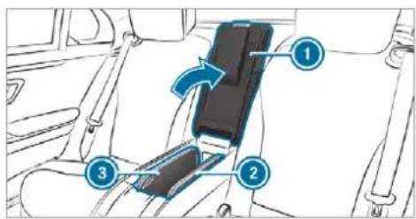
text_image
Diagram of car seatbelt mechanism with numbered components and directional arrow indicating rotation▶ Open rear arm rest Ⓤ (→ page 147).
Pull the folding table forwards and upwards by recess ② or ③ and swing outwards.
▶ Fold the table panels apart.
To fold in: fold the table panels together and swing in the folding table.
Using the stowage compartment and MBUX rear tablet in the rear armrest
NOTE Damage to the rear armrest due to body weight
When folded out, the rear armrest can be damaged by body weight.
Do not sit or support yourself on the rear seat armrest.
In vehicles with a folding rear seat armrest, this can be folded down to allow the stowage compartments to be used. The available rear seat armrests and stowage compartments vary depending on the vehicle equipment.
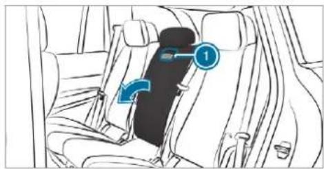
natural_image
Interior view of a car showing seat, rear seats, and a highlighted seat with blue arrows indicating direction (no text or symbols)Depending on the vehicle equipment, pull or the handle or loop ① and fold down the rear seat armrest.
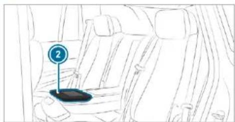
natural_image
Line drawing of a car backseat with a highlighted seatbelt (no text or symbols)Depending on the vehicle equipment, use the MBUX rear tablet ② (→ page 551).
Opening the stowage compartment in the rear-compartment centre console Depending on the vehicle equipment, the design of the centre console may differ.
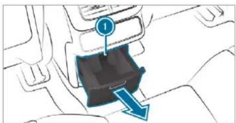
natural_image
Diagram of a car interior showing a blue arrow pointing to a black vehicle component (no text or symbols present)Stowage compartment in the rear centre console (all vehicles except Mercedes-Maybach 4-seater)
Press stowage compartment ①. Stowage compartment ① opens in the direction of the arrow.
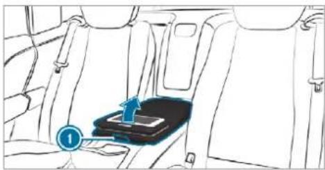
natural_image
Interior view of a car showing seatbelt and dashboard with a blue directional arrow (no text or symbols)Stowage compartment in the rear centre console (Mercedes-Maybach 4-seater vehicles)
Press button ① and swing the cover of the armrest upwards.
Opening the stowage box in the backrest in the rear compartment

NOTE Damage to the rear armrest due to body weight
When folded out, the rear armrest can be damaged by body weight.
Do not sit or support yourself on the rear seat armrest.
This equipment is available only for Mercedes-Maybach vehicles.
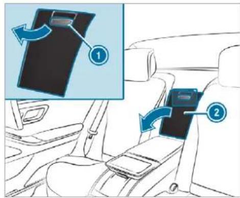
text_image
Diagram showing car seatbelt buckle assembly with labeled parts and directional arrows indicating movementVehicles with individual seats (example)
▶ Vehicles with 5-seater variant: fold down the rear armrest.
Pull handle ① and fold down cover ②.
Removing the handset from the stowage compartment in the rear compartment
Opens the drawer
This equipment is available only for Mercedes-Maybach vehicles with individual rear seats.
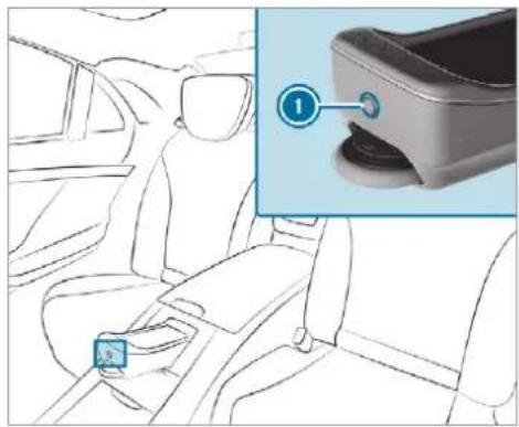
natural_image
Interior view of a car showing seatbelt and dashboard, with a close-up inset highlighting a component (no text or symbols)Vehicles with individual rear seats
Press button 1.
Remove the handset.
Closing the drawer
Place the handset in the drawer.
Press the handset drawer back until it engages.
Through-loading facility to luggage compartment
Folding the rear seat backrest forwards
⚠ WARNING Risk of becoming trapped when adjusting the seats
When you adjust a seat, you may trap yourself or a vehicle occupant.
When adjusting a seat, make sure that no one has any body parts in the sweep of the seat.
WARNING Risk of accident if seat and seat backrest are not engaged
If the seat and seat backrest are not engaged they could fold forwards, e.g. when braking or in the event of an accident.
This poses the following risks in particular:
- A seat or seat backrest that is not engaged can push the vehicle occupant against the seat belt. The seat belt would then not be able to provide the intended protection and could cause additional injury.
- A child restraint system would no longer be supported correctly or positioned correctly and would no longer perform its intended function.
- The seat backrest cannot restrain objects or goods in the luggage compartment.
Always ensure that the seat and seat back-rest are engaged, especially:
- before passengers travel on a seat with the easy entry and exit feature.
• after adjusting the seat.
• after the easy entry and exit feature is used. - after the load compartment enlargement has been folded down.
Always ensure that all vehicle occupants have their seat belts fastened correctly and are sitting properly. Particular attention must be paid to children.
If you no longer require the folded-down rear seat backrest as a loading area, fold the rear seat backrest back into place.
Make sure that the red marking of the lock verification indicator is no longer visible. Otherwise, the seat backrest will not be locked.
Requirements:
- Vehicles with centre rear seat backrest: the centre rear seat backrest is not in the luggage compartment floor position.
- Vehicles with a folding rear armrest: the rear armrest has been folded up.
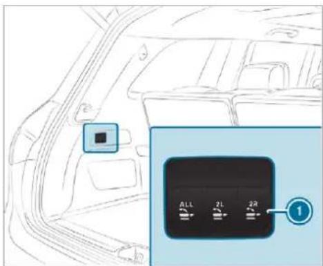
text_image
ALL 2L 2R 1Seven-seater (example)
To fold the rear seat backrest forwards: briefly press one of buttons ① to fold the left or right rear seat backrest forwards. The rear seat backrest head restraint will move into a suitable position. The rear seat will fold forwards.
Vehicles with centre rear seat backrest: the centre rear seat backrest will fold forwards together with the left rear seat backrest.
If a seat in the second row of seats is not engaged and locked, this will be shown on the multifunction display on the instrument cluster.
Seven-seater: With the ALL button, all rear seat backrests can be folded forwards together.
Fold the centre rear seat backrest forwards separately (seven-seater)
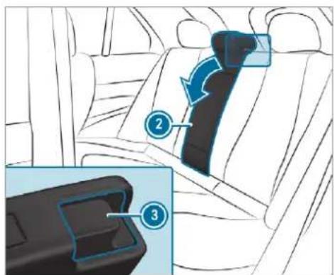
text_image
Diagram showing car seatbelt insertion process with numbered steps and directional arrows indicating movementPress release catch 3.
Fold rear seat backrest ② forwards.
Folding back the rear seat backrest
! NOTE Damage caused by trapping the seat belt when folding back the seat backrest
The seat belt could become trapped and thus be damaged when the seat backrest is folded back.
Make sure that the seat belt is not trapped when folding back the seat back-rest.
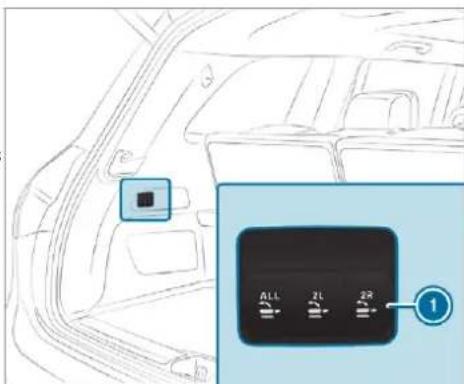
text_image
Diagram of a car interior with a highlighted sensor panel showing three buttons labeled ALL, ZL, and ZR.Seven-seater (example)
To fold back the rear seat backrest: briefly press one of buttons ① to fold back the left or right rear seat backrest.
The rear seat will fold back.
Vehicles with centre rear seat backrest: the centre rear seat backrest will fold back together with the left rear seat backrest.
If a rear seat backrest is not engaged and locked, this will be shown on the multifunction display on the instrument cluster.
Seven-seater: With the ALL button, all rear seat backrests can be folded back together.
Folding back the centre seat backrest separately (seven-seater)
Swivel rear seat backrest back until it audibly engages.
Folding the seat backrest on the third row of seats forwards
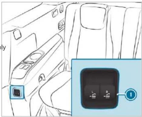
natural_image
Interior view of a car showing the backrest and side profile with a close-up of the right side panel (no text or symbols visible)Left-hand drive vehicle (example)
In the rear (seven-seater): pull the buttons ① briefly to fold the left or right seat back-rest forwards.
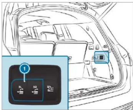
text_image
Diagram of car interior showing front panel with two buttons labeled '1' and '2', including a zoomed-in inset for detail.In the load compartment: press the buttons ① briefly to fold the left or right seat back-rest forwards.
Folding back the seat backrest on the third row of seats
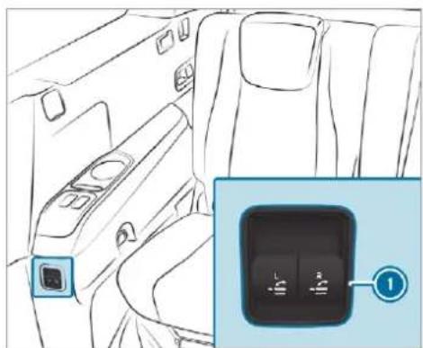
natural_image
Interior view of a car showing the backrest and side panel with a small inset image of a control switch (no text or symbols)Left-hand drive vehicle (example)
In the rear: press the buttons ① briefly to fold back the left- or right-hand seat back-rest. If a seat backrest is not engaged and locked, this will be shown on the multifunction display on the instrument cluster.
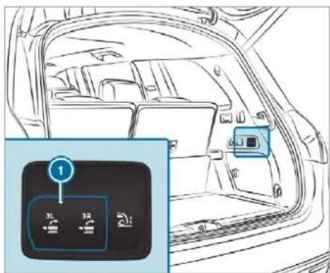
text_image
Diagram of car interior with labeled buttons and a highlighted control panel showing '1' and '2'In the load compartment: briefly pull the buttons ① to fold back the left- or right-hand seat backrest. d, If a seat backrest is not engaged and locke this will be shown on the multifunction display on the instrument cluster.
EASY-PACK load compartment cover and partition net cassette
Notes on the load compartment cover
WARNING Risk of injury or death due to poorly secured objects
The load compartment cover alone cannot secure or restrain heavy objects, items of luggage or heavy loads.
You could be hit by an unsecured load, particularly in the event of abrupt changes in direction, sudden braking or an accident.
Always stow objects in such a way that they cannot be thrown around.
▶ Secure objects, luggage or loads against slipping or tipping over, e.g. by
using lashing material, even if you are using the load compartment cover.

NOTE Damage to the load compartment cover when loading the vehicle
The load compartment cover may be damaged when loading the vehicle.
Do not place any objects above the lower edge of the side windows or on the load compartment cover.
This equipment is available for all vehicles except Mercedes-Maybach vehicles.
Extending/retracting the load compartment cover
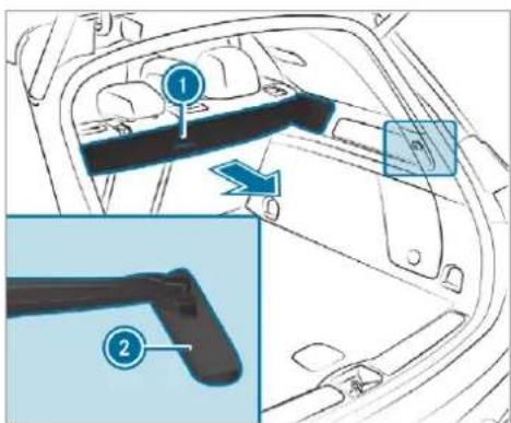
text_image
Diagram of car interior showing seatbelt and door panel with numbered labels and directional arrowTo extend: pull the load compartment cover back by grab handle ① and clip it into the brackets ② on the left and right.
Retracting
Remove the load compartment cover from the brackets on the left and right.
Guide the load compartment cover forwards using the grab handle until it is fully retracted.
The rolled-up load compartment cover can be used in two positions:
- Folded 45° upwards for loading (fold down before commencing your journey)
• Horizontal position
Fitting or removing the load compartment cover
Requirement:
• The load compartment cover is rolled up.
Removing the load compartment cover
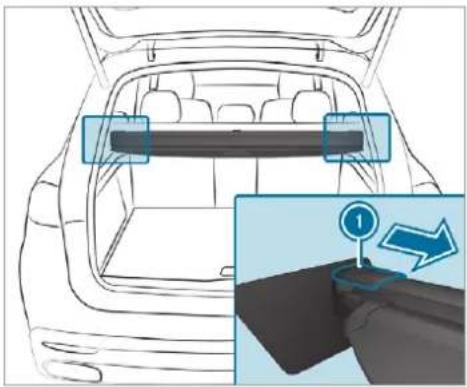
natural_image
Top-down line drawing of a car backrest with a highlighted horizontal panel and a zoomed-in view showing a hand holding a steering wheel (no text or symbols)Press end cap ① on the left or right inwards.
Pull out the load compartment cover backwards.
Stowing the load compartment cover
The load compartment cover can be stowed beneath the load compartment floor.
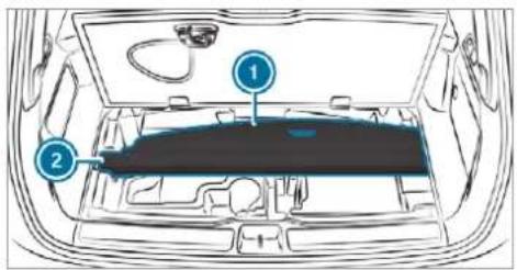
text_image
Diagram of a car's front engine compartment with numbered parts labeled 1 and 2Open the load compartment floor ( page 158).
To insert: Place the load compartment cover ① into the brackets ②. Ensure it is seated correctly.
To remove: Take the load compartment cover out of the brackets ②.
Fitting the load compartment cover
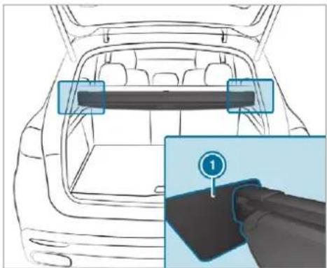
natural_image
Line drawing of a car backrest with a highlighted internal panel and a close-up of the interior showing a cable or connector (no text or symbols present)Place the load compartment cover in the brackets ① on the left and right. The end caps of the load compartment cover engage audibly.
Attaching/removing the partitioning net

WARNING Risk of injury or death due to poorly secured objects
The partitioning net alone cannot secure or restrain heavy objects, items of luggage or heavy loads.
You could be hit by an unsecured load, particularly in the event of abrupt changes in direction, sudden braking or an accident.
Always stow objects in such a way that they cannot be thrown around.
▶ Secure objects, luggage or loads against slipping or tipping over, e.g. by using lashing material, even if you are using the partitioning net.
For safety reasons, always use a partitioning net when transporting a load. The partitioning net can be used with or without load compartment enlargement
Damaged partitioning nets can no longer fulfil their functions and must be replaced. Visit a qualified specialist workshop.
This equipment is available for all vehicles except Mercedes-Maybach vehicles.
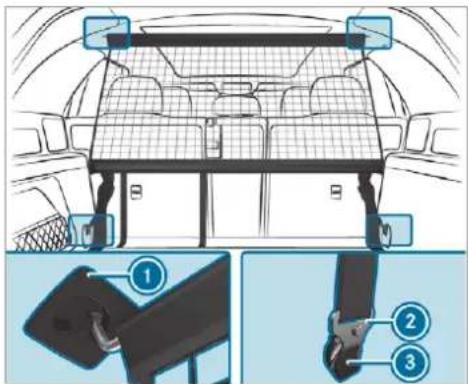
text_image
Diagram of a car interior with labeled parts, showing structural components and safety instructions.Partitioning net without load compartment enlargement
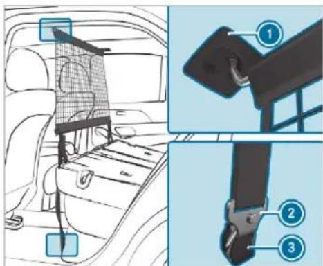
text_image
Diagram of car seatbelt assembly with numbered parts and component labelsPartitioning net with load compartment enlargement
To attach: Extend the partition net.
Attach the top guide rod to the holders ① on the roof lining.
Engage the hooks ② in the eyelets ③ on the left and right.
Pull on the loose ends of the lashing straps until the partitioning net is tight.
After driving a short distance, check the tension of the partitioning net and re-tension it if necessary.
To remove: Pull the belt clamps until the lashing straps are loose.
Remove the hooks ② from the eyelets ③ on the left and right.
Remove the top guide rod from the holders ①.
Overview of the tie-down eyes in the load compartment
Observe the notes on loading the vehicle ( page 144).
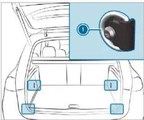
text_image
Diagram of car interior with labeled parts and a magnified inset showing a circular object with numbered label '1'① Tie-down eyes
The front tie-down eyes are accessible when third row of seats is in the luggage compartment floor position ( page 149).
Mercedes-Maybach vehicles: both tie-down eyes on Mercedes-Maybach vehicles are located in the rear load compartment, left and right.
Overview of bag hooks
⚠ WARNING Risk of injury when using bag hooks with heavy objects
The bag hooks cannot restrain heavy objects or items of luggage.
Objects or items of luggage could be thrown around and hit vehicle occupants as a result, particularly in the event of sudden braking or abrupt changes in direction.
▶ Only hang light objects on the bag hooks.
▶ Never hang hard, sharp-edged or fragile objects on the bag hooks.
Observe the notes on loading the vehicle ( page 144).
Subject the bag hooks to a maximum load of 3 kg and do not attach any goods to them.
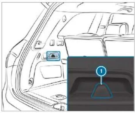
natural_image
Interior view of a car showing the rearview and side profile with a highlighted control panel (no text or symbols)
Bag hook
Coat hook
This equipment is available for all vehicles except Mercedes-Maybach vehicles.
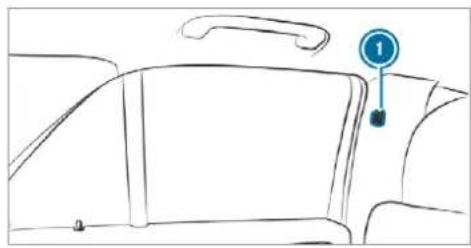
natural_image
Line drawing of a car interior with a numbered marker (1) pointing to the side panel, no text or symbols present.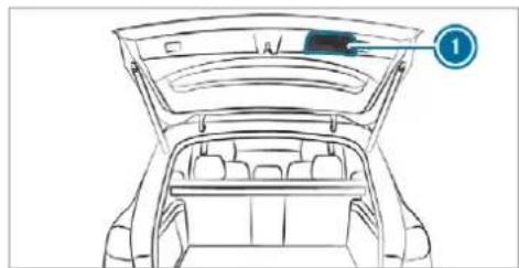
natural_image
Line drawing of a car back opening with the hood open, showing structural details (no text or symbols)Coat hooks ① can be found in the interior on the B-pillar and on the tailgate.
Coat hooks are not suitable for heavy objects. Use the coat hooks only for light objects such as jackets.
Opening or closing the stowage space under the load compartment floor

WARNING Risk of injury due to an open load compartment floor
If you drive when the load compartment floor is open, objects could be thrown around and thereby strike vehicle occupants. There is a risk of injury, particularly in the event of sudden braking or a sudden change in direction.

Always close the load compartment floor before a journey.
Opening
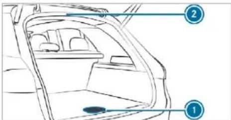
text_image
Diagram of a car interior with labeled parts, showing front and rear views with numbered annotations.▶ Pull handle ① upwards.
Lift the load compartment floor upwards using handle ①.
Fold out hook on the underside of the load compartment floor.
Clip hook onto drip rail ②.
Closing
Unhook the hook from drip rail ② and fasten it to the bracket on the underside of the load compartment floor.
Fold the load compartment floor downwards and then press handle ① down until it engages.
Locking and unlocking the load compartment floor
This equipment is available for all vehicles except Mercedes-Maybach vehicles.
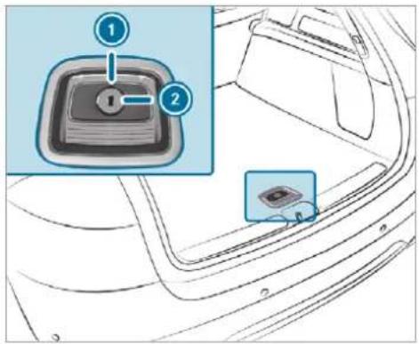
text_image
Diagram showing a car interior with a switch labeled 1 and 2, and a close-up of the switch inside the dashboard.Turn the emergency key a quarter turn clockwise 2 (to lock) or anti-clockwise 1 (to unlock).
Attaching a roof rack
⚠ WARNING Risk of injury if the maximum roof load is exceeded
When you load the roof, the centre of gravity of the vehicle rises and the usual driving characteristics as well as the steering and braking characteristics change. During cornering, the vehicle tilts more strongly and may react more sluggishly to steering movements.
If you exceed the maximum roof load, the driving characteristics, as well as the steering and braking characteristics, will be greatly impaired.
Always comply with the maximum roof load and adjust your driving style.
You will find information on the maximum roof load in the "Technical data" section.
NOTE Vehicle damage from non-approved roof racks
The vehicle could be damaged by roof racks which have not been tested and approved by Mercedes-Benz.
Use only roof racks tested and approved for Mercedes-Benz.
▶ Depending on the vehicle equipment, ensure that when the roof rack is fitted, the sliding sunroof can be fully raised.
▶ Depending on the vehicle equipment, ensure that when the roof rack is fitted, the tailgate can be fully opened.
▶ Position the load on the roof rack in such a way that the vehicle will not sustain damage even when it is in motion.
NOTE Damage to the panorama sliding sunroof caused by a non-approved roof rack
The panorama sliding sunroof may be damaged by the roof rack if you attempt to open
it when using a roof rack not tested and approved for Mercedes-Benz.
When a roof rack is fitted, open the panorama sliding sunroof only if this has been tested and approved for Mercedes-Benz.
The panorama sliding sunroof may be raised to allow ventilation of the vehicle interior.
▶ Secure the roof rack to the roof railing.
Observe the manufacturer's installation instructions.
Cup holders
Using cup holders
A WARNING - Risk of accident or injury when using the cup holder while the vehicle is in motion
The cup holder cannot hold a container secure while the vehicle is in motion.
If you use a cup holder while the vehicle is in motion, the container may be flung around and liquids could be spilled. The vehicle occupants may come into contact with the liquid and if it is hot, they could be scalded. You could be distracted from traffic conditions and you may lose control of the vehicle.
Only use the cup holder when the vehicle is stationary.
Only use the cup holder for containers of the right size.
Always close the container, particularly if the liquid is hot.
Depending on the vehicle's equipment, the following cup holders will be available:
- In the front stowage compartment of the centre console
• In the rear centre console - All vehicles except Mercedes-Maybach vehicles: in the rear armrest on the second row of seats
- All vehicles except Mercedes-Maybach vehicles: on the left and right, next to the rear seats on the third row of seats
Observe the following for Mercedes-Maybach vehicles equipped with champagne flutes:
- Do not use the champagne flutes while the vehicle is in motion.
- Do not use champagne flutes made of breakable glass, and store them in the load compartment if possible.

text_image
Diagram showing car interior with labeled parts, including a highlighted section and numbered annotations.Vehicles without a temperature-controlled cup holder (all vehicles except Mercedes-Maybach vehicles): the bracket arms of the front cup holder can be folded in or out.
To fold the bracket arm in: push bracket arm ① outwards to the side until it engages. When the bracket arm is folded in, the cup holder cannot fulfil its holding function.
To fold the bracket arm out: press release button ②.
Opening or closing the cup holders in the rear armrest
NOTE Damage to the rear armrest due to body weight
When folded out, the rear armrest can be damaged by body weight.
Do not sit or support yourself on the rear seat armrest.
NOTE Damage to the cup holder
When the rear armrest is folded back the cup holder could become damaged.
Only fold the rear armrest back when the cup holder is closed.
The cup holders in the rear armrest are available for all vehicles except Mercedes-Maybach vehicles.
① Depending on its equipment, your vehicle will have a rear armrest with a cup holder.
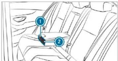
text_image
Diagram of car seatbelt with numbered labels pointing to specific seatsTo open: press cup holder ① or ②. Cup holder ① or ② will extend automatically.
To close: push cup holder ① or ② back until it engages.
Switching the cooling or heating function for the temperature-controlled cup holder on or off

WARNING Risk of injury by touching the heating elements
The cup holder's heating elements may be very hot.
You can burn yourself on them.
Do not touch the cup holder's hot heating elements.
Ensure that no children can access the cup holder's hot heating elements.
▶ Never leave children unattended in the vehicle.

NOTE Damage to objects in the temperature-controlled cupholder
If you place objects into the temperature-controlled cup holder, they may become damaged.

Do not place objects into the temperature-controlled cup holder.
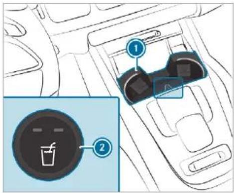
text_image
Diagram showing car interior with two labeled buttons and a circular device icon, likely illustrating a device control or safety interface.Cup holder in the front centre console
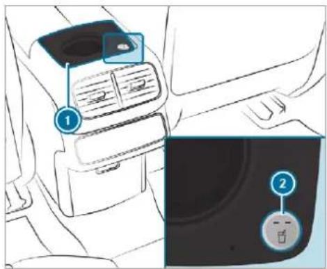
text_image
Diagram showing car interior with labeled parts and a close-up of the dashboard with a circular button labeled '2'Cup holder in the rear centre console
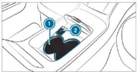
text_image
Diagram of car gear shift mechanism with labeled parts 1 and 2Cup holder in the rear centre console (Mercedes-Maybach four-seater vehicles)
To switch on: on cup holder ①, press button ② repeatedly until the blue (keep cool) or red (keep warm) indicator lamp on the button lights up. If you use the heating function, the metal insert of the cup holder is heated. Once a certain temperature has been reached, the warning lamp lights up. Do not reach into the cup holder's metal insert when the warning lamp is lit.
To switch off: press button ② repeatedly until the indicator lamp on the button goes out.
i Clean the removable rubber mat only with clean, lukewarm water and the cup holder only with a soft cloth.
Ashtray and cigarette lighter
Using the ashtray
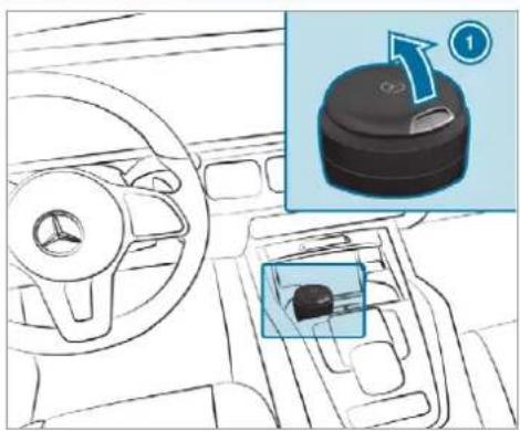
text_image
Diagram showing car dashboard and steering wheel with a highlighted rotary knob labeled ①To use the ashtray: place the ashtray in one of the cup holders in the centre console or the rear compartment.
① Mercedes-Maybach vehicles: depending on the equipment, there is an additional ashtray
in the door stowage compartment in the right rear door.
▶ Check that it is seated firmly.
Comply with the notes on loading the vehicle ( page 144).
To open the ashtray: fold cover 1 upwards.
The top part of the ashtray can be removed for cleaning or emptying by twisting it. Clean the ashtray, e.g. with clean, lukewarm water.
Using the cigarette lighter

WARNING - Risk of fire and injury from the hot cigarette lighter
You can burn yourself if you touch the hot heating element or the socket of the cigarette lighter.
in addition, flammable materials may ignite if:
• you drop the hot cigarette lighter
- a child holds the hot cigarette lighter to objects, for example
Always hold the cigarette lighter by the knob.
Always make sure that the cigarette lighter is out of reach of children.
▶ Never leave children unattended in the vehicle.
Requirements:
• The ignition is switched on.
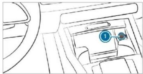
natural_image
Interior view of a car dashboard with steering wheel and seatbelt (no text or symbols visible)Press in cigarette lighter ①. The cigarette lighter will pop out automatically when the heating element is red-hot.
Sockets
Using the 12 V socket in the front centre console
Requirements:
- Only connect devices up to a maximum of 240 W (20 A).
① This equipment is not available in all countries.
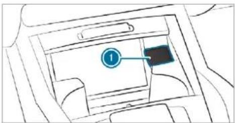
text_image
Diagram of a car interior with labeled component '1' and a highlighted areaLift up cap ① of the socket and insert the plug of the device.
If you have connected a device to the 12 V socket, leave the cover of the stowage compartment open.
Using the 230 V socket in the rear passenger compartment
A DANGER Risk of fatal injury due to damaged connecting cables or sockets
When a suitable device is connected, the 230 V power socket will be carrying a high voltage. You could receive an electric shock if the connecting cable or the 230 V power socket is pulled out of the trim or is damaged or wet.
▶ Use only connecting cables that are dry and free of damage.
When the ignition is switched off, make sure that the 230 V power socket is dry.
Immediately have the 230 V power socket checked or replaced at a quali-
fied specialised workshop if it is damaged or has been pulled out of the trim.
▶ Never plug the connecting cable into a 230 V power socket that is damaged or has been pulled out of the trim.
DANGER Risk of fatal injury due to incorrect handling of the socket
You could receive an electric shock in particular:
• if you reach into the socket.
- if you insert unsuitable devices or objects into the socket.
Do not reach into the socket.
▶ Only connect suitable devices to the socket.
Requirements:
- Only connect devices with a suitable plug which conforms to the standards specific to the country you are in.
- Only connect devices up to a maximum of 150 W (0.65 A).
- Do not use multiple socket outlets.
Depending on the vehicle equipment, the design of the centre console and stowage compartment may differ.
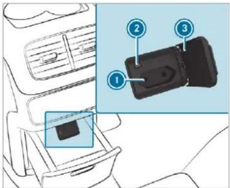
text_image
Diagram showing car seatbelt components with numbered labels pointing to specific parts in a vehicle interior.Using the 230 V socket in the centre console of the rear compartment
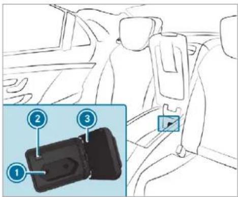
text_image
Diagram showing car seatbelt insertion with numbered labels pointing to specific parts in the inset view.230 V socket in the centre console of the rear compartment (Mercedes-Maybach 4-seat vehicles)
Mercedes-Maybach vehicles with individual rear seats: open the stowage compartment of the centre console of the rear compartment ( page 148).
Open flap ③.
Insert the plug of the device into 230 V socket ①.
When the on-board electrical system voltage is sufficient, indicator lamp ② lights up.
Using the 12 V socket in the load compartment
Requirements:
- Only devices up to a maximum of 240 W (20 A) are permissible.
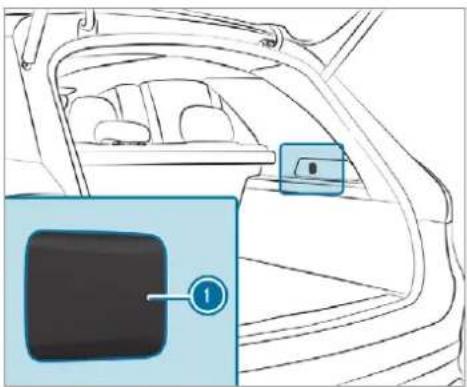
natural_image
Interior view of a car showing the backrest and seat area with a highlighted panel (no text or symbols)Lift up cap ① of the socket and insert the plug of the device.
- in the front centre console next to the mobile phone stowage compartment
• in the rear centre console - vehicles with Rear Comfort Package: in the centre armrest of the second row of seats in the rear compartment
- Mercedes-Maybach vehicles with 5 seats in the rear compartment: in the centre armrest in the rear compartment
- Mercedes-Maybach vehicles with individual rear seats: in the centre console of the rear compartment
- vehicles with three rows of seats: to the right and left next to the seat
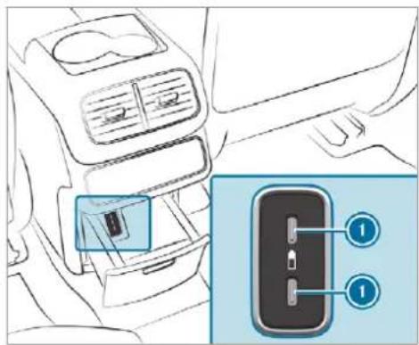
text_image
Diagram showing car interior and internal device placement with numbered labels for ports or connectorsExample: USB ports in the centre console in the rear compartment
Overview of USB ports
Depending on the vehicle equipment, the vehicle has the following USB ports:
- in the stowage compartment of the cockpit armrest ( page 146)
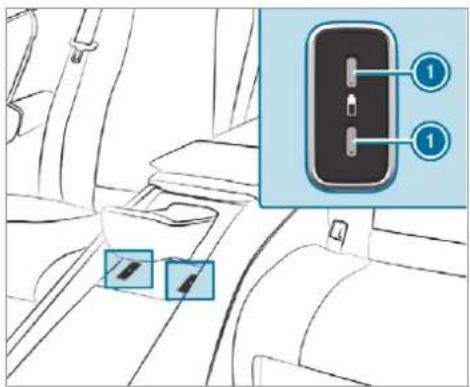
text_image
Diagram showing car interior with labeled parts and a highlighted device panel with numbered annotationsExample: USB ports in the centre console in the rear compartment (Mercedes-Maybach vehicles)
If the ignition is switched on you can charge USB devices, e.g. mobile phones, at USB ports ①. The charging voltage is approximately 5 V (up to 3 A).
Coolbox
Using the refrigerator box

WARNING Risk of fire due to a covered ventilation grille on the coolbox
If you cover the ventilation grille for the cool-box, it may overheat.

Always make sure that the ventilation grille is not covered.
The ventilation grille for the refrigerator box is in the boot.
This equipment is available only for Mercedes-Maybach vehicles.
Subject the refrigerator box to a maximum load of 3.5 kg.
Store only plastic bottles in the upper compartment of the refrigerator box. The contents of the bottle must be no more than 0.5 litres.
If you do not need to use the refrigerator box for an extended period, switch it off, defrost it and clean it. After doing so, leave the lid open for a time.
The refrigerator box will reduce its cooling capacity or switch off in the following cases:
- too many electrical consumers are turned on.
• the starter battery is not sufficiently charged.
If this is the case, the indicator lamps will flash on the button for switching the refrigerator box on and off. The cooling function will automatically switch back on as soon as there is sufficient voltage.
To install the refrigerator box in the load compartment or remove it, please contact a qualified specialist workshop.
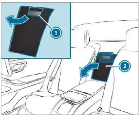
text_image
Diagram showing car seatbelt insertion process with labeled parts and directional arrows indicating movementExample: vehicles with individual rear seats
▶ Vehicles with 5-seater variant: fold down the rear armrest.
Pull the handle of stowage box ① and fold down the cover of stowage box ②.
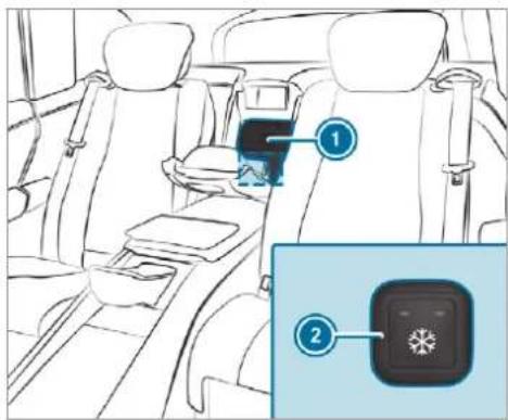
text_image
Diagram of car interior with labeled parts, showing seatbelt and app interface iconsExample: vehicles with individual rear seats
To open: pull the handle of refrigerator box ① and fold down the cover of the refrigerator box.
To switch on: press button ② repeatedly until an indicator lamp (low cooling) lights up or two indicator lamps (high cooling) light up.
To switch off: press button ② repeatedly until both indicator lamps go out.
Wireless charging of the mobile phone and connection with the exterior aerial
Notes on wirelessly charging the mobile phone
WARNING Risk of injury due to objects being stowed incorrectly
If objects in the vehicle interior are stowed incorrectly, they can slide or be thrown around and hit vehicle occupants. In addition, cup holders, open stowage spaces and mobile phone receptacles cannot always retain all objects they contain.
There is a risk of injury, particularly in the event of sudden braking or a sudden change in direction.
Always stow objects so that they cannot be thrown around in such situations.
Always make sure that objects do not protrude from stowage spaces, luggage nets or stowage nets.
▶ Close the lockable stowage spaces before starting a journey.
Always stow and secure heavy, hard, pointed, sharp-edged, fragile or bulky objects in the boot/load compartment.
Observe the notes on loading the vehicle.

WARNING Risk of fire from placing objects in the mobile phone stowage compartment
There is a risk of fire, in particular, if you place more than one mobile phone in the mobile phone stowage compartment.
Apart from a mobile phone, do not place any other objects in the mobile phone stowage compartment, especially those made of metal.

NOTE Damage to objects caused by placing them in the mobile phone stowage compartment
If objects are placed in the mobile phone stowage compartment, they may be damaged by electromagnetic fields.
Do not place credit cards, storage media or other objects sensitive to electromagnetic fields in the mobile phone stowage compartment.

NOTE Damage to the mobile phone stowage compartment caused by liquids
If liquids enter the mobile phone stowage compartment, the compartment may be damaged.
▶ Ensure that no liquids enter the mobile phone stowage compartment.
Always observe the notes for persons with electronic medical aids ( page 33).
- Depending on the vehicle equipment, the mobile phone is connected to the vehicle's exterior aerial via the charging module.
- The charging function and wireless connection of the mobile phone to the vehicle's exterior aerial are only available if the ignition is switched on.
- Small mobile phones may not be able to be charged in every position of the mobile phone stowage compartment.
- Large mobile phones which do not rest flat in the mobile phone stowage compartment may not be able to be charged or connected with the vehicle's exterior aerial.
- The mobile phone may heat up during the charging process. This may also depend on the applications (apps) currently open in the background.
- To ensure more efficient charging and connection with the vehicle's exterior aerial, remove the protective cover from the mobile phone. Protective covers which are necessary for wireless charging are excluded.
Wireless charging of a mobile phone in the cockpit
Requirements:
- The mobile phone is suitable for wireless charging.
A list of compatible mobile phones can be found at: https://www.mercedes-benzmobile.com/
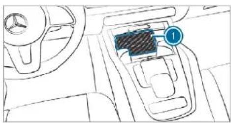
text_image
Diagram of a car interior showing the seatbelt switch with labeled component '1'Place the mobile phone as close to the centre of mat ① as possible with the display facing upwards.
When a message is shown in the multimedia system, the mobile phone is being charged.
Malfunctions detected during the charging process are shown in the multimedia system display.
① The mat can be removed for cleaning, e.g. using clean, lukewarm water.
Wireless charging of a mobile phone in the rear passenger compartment
! NOTE Damage to the drawer in the centre console of the rear compartment due to body weight
When open, the drawer in the centre console of the rear compartment can be damaged by body weight.
Do not support yourself on the open drawer.
Requirements:
- The mobile phone must be suitable for wireless charging.
A list of compatible mobile phones can be found at: https://www.mercedes-benzmobile.com/
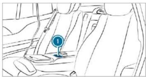
natural_image
Line drawing of a car interior showing the seat and dashboard (no text or symbols)Mat in front of the stowage compartment in the rear armrest
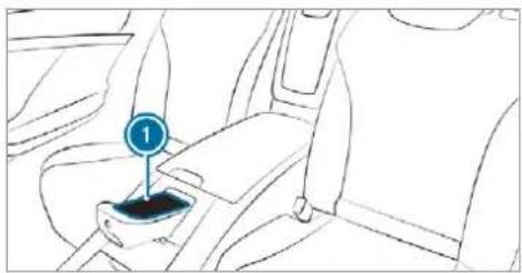
natural_image
Line drawing of a car seatbelt with a numbered indicator (1) pointing to the seat area, no text or symbols present.Mat in the centre console of the rear compartment (only Mercedes-Maybach vehicles with individual rear seats)
Place the mobile phone as close to the centre of mat Ⓞ as possible with the display facing upwards. When the indicator lamp lights up, the mobile phone is being charged.
Fitting/removing the floor mats

WARNING Risk of accident due to objects in the driver's footwell
Objects in the driver's footwell may impede pedal travel or block a depressed pedal. This jeopardises the operating and road safety of the vehicle.
Stow all objects in the vehicle securely so that they cannot get into the driver's footwell.
Always fit the floor mats securely and as prescribed in order to ensure that there is always sufficient room for the pedals.
Do not use loose floor mats and do not place floor mats on top of one another.
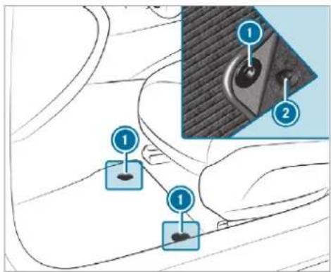
text_image
Diagram showing car seatbelt components with numbered labels and a close-up inset of the seatbelt detailTo fit: move the corresponding seat backwards and lay the floor mat in the footwell.
Press the studs ① onto the holders ②.
Adjust the corresponding seat.
To remove: pull the floor mat off the holders ②.
Remove the floor mat.
① Vehicles with a third row of seats (all vehicles except Mercedes-Maybach vehicles): To fit and remove the floor mats on the third row of seats, slide the corresponding seat on the second row of seats forwards.
Exterior lighting
Notes on adjusting the lights when driving abroad
Vehicles with static LED headlamps: It is not necessary to convert the headlamps. The legal requirements are also met in countries in which traffic drives on the other side of the road.
Vehicles with Intelligent Light System: The headlamps are automatically adjusted when the vehicle enters countries in which traffic drives on the other side of the road.
In the following cases, check the headlamp setting and change it manually if necessary:
- If the Dipped-beam setting (left/right-side traffic) Manual adjustment only display message is displayed.
- If the Check dipped-beam setting (left/right-side traffic) display message is displayed.
Once the headlamps have been converted:
- Oncoming traffic will not be dazzled.
- The edge of the road will not be illuminated as far or as high.
- The "motorway mode" and "enhanced fog light" functions will not be available.
Information about lighting systems and your responsibility
The various lighting systems of the vehicle are only aids. The driver of the vehicle is responsible for correct vehicle illumination in accordance with the prevailing light and visibility conditions, legal requirements and traffic situation.
Light switch
Operating the light switch
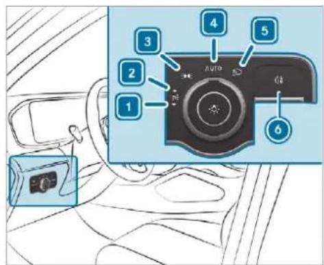
text_image
1 2 3 4 5 6 AUTO1 ←P ≡ Left-hand parking lights
2 P←→ Right-hand parking lights
3 3005 Standing lights and licence plate lighting
4 AUTO Automatic driving lights (preferred light switch position)
5 Low beam / high beam
6 0‡ Switches the rear fog light on/off
When low beam is activated, the indicator for the standing lights ≥0.05 is deactivated and replaced by the low beam indicator lamp ≥0 .
Always park your vehicle safely using sufficient lighting, in accordance with the relevant legal stipulations.
! NOTE Battery discharging by operating the standing lights
Operating the standing lights over a period of hours puts a strain on the battery.
Where possible, switch on the right or left + parking light.
In the event of severe battery discharging, the standing lights or parking lights are automatically switched off to facilitate the next engine start.
The exterior lighting (except standing and parking lights) will switch off automatically when the driver's door is opened.
- Observe the notes on surround lighting (→ page 181).
Automatic driving lights function
The standing lights, low beam and daytime running lights will be switched on automatically depending on the ignition status and the light conditions.
WARNING Risk of accident when the dipped beam is switched off in poor visibility
When the light switch is set to AUTO, the dipped beam may not be switched on automatically if there is fog, snow or other causes of poor visibility such as spray.
In such cases, turn the light switch to 📋.
The automatic driving lights are only an aid. You are responsible for vehicle lighting.
Switching the rear fog lights on or off Requirements:
- The light switch is in the 📋 or AUTO position.
Press the 0 button.
Please observe the country-specific laws on the use of rear fog lamps.
Operating the combination switch for the lights
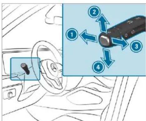
text_image
Diagram showing car interior and a device with numbered instructions for adjusting the seatbelt.① High beam
② Turn signal light, right
3 Headlamp flashing
④ Turn signal light, left
Use the combination switch to activate the desired function.
High beam
To switch on: turn the light switch to the 📋 or 🐊 AUTO position.
Push the combination switch in the direction of arrow ①. When the high beam is activated, the indicator lamp for low beam 📋 will be deactivated and replaced by the indicator lamp for high beam 📋.
To switch off: push the combination switch in the direction of arrow ① or pull it in the direction of arrow ③.
Headlamp flashing
Pull the combination switch in the direction of arrow 3.
Turn signal light
To indicate briefly: push the combination switch briefly to the point of resistance in the direction of arrow ② or ④. The corresponding turn signal light will flash three times.
To indicate permanently: push the combination switch beyond the point of resistance in the direction of arrow ② or ④.
Vehicles with Active Lane Change Assist:
- Indicator operation activated by the driver can extend for the duration of the lane change.
- If the driver indicated directly beforehand but a lane change was not immediately possible, the turn signal indicator may activate automatically.
Activating/deactivating the hazard warning lamps
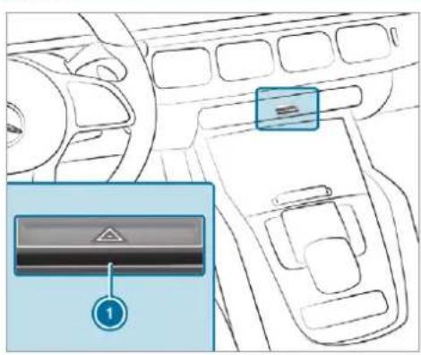
text_image
Diagram of car interior showing dashboard, steering wheel, and control panel with labeled buttonsPress button ①.
The hazard warning lamps will switch on automatically if:
• the airbag has been deployed.
- the vehicle is heavily braked from a speed of more than 70 km/h to a standstill.
When you pull away again, the hazard warning lamps will switch off automatically at approximately 10 km/h. You can also switch off the hazard warning lamps using button ①.
When the turn indicator is activated, the hazard warning lamps are interrupted.
Intelligent Light System
Intelligent Light System function
The MULTIBEAM LED headlamps adapt to the driving and weather situation and provide extended functions for improved illumination of the road.
The system comprises the following functions:
• Active headlamps ( page 177)
• Cornering light (→ page 178)
• Motorway mode (→ page 178)
• Enhanced fog light function ( page 178)
• Off-road light (→ page 179)
The system is active only when it is dark.
Active headlamps function
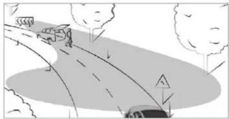
natural_image
Illustration of a car driving on a curved road with trees and an arrow indicating direction (no text or symbols)Functions of the active headlamps:
- The headlamps follow the steering movements.
- Relevant areas are better illuminated during travel.
The functions are active when the low beam is switched on.
Depending on the vehicle's equipment, the course of the lane in which you are driving will also be evaluated and the active headlamps function will adjust the light in advance.
Cornering light function
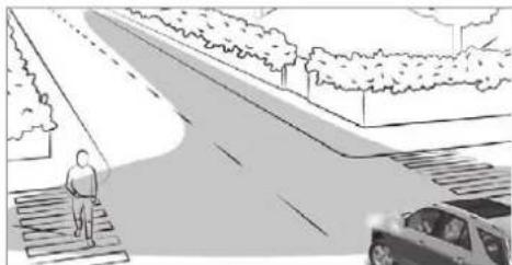
natural_image
Illustration of a person standing on a pedestrian crossing a road with a car parked nearby (no text or symbols)The cornering light function improves the illumination of the carriageway over a wide angle in the turning direction, enabling better visibility on tight bends, for example. It can be activated only when the low beam is switched on.
The function is active under the following conditions:
- at speeds below 40 km/h when the turn signal light is switched on or the steering wheel is turned
- at speeds between 40 km/h and 70 km/h when the steering wheel is turned
Roundabout and intersection function: the cornering light will be activated on both sides based on an evaluation of the current GPS position of the vehicle. It will remain active until after the vehicle has left the roundabout or the intersection.
Motorway mode function
Motorway mode increases the range and brightness of the cone of light, enabling better visibility.
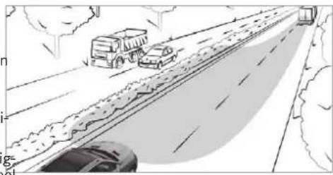
natural_image
Illustration of a multi-lane highway with vehicles and trees, no visible text or symbolsThe function will be active if a motorway journey is detected by means of:
- the vehicle's speed
• the multifunction camera
- the GPS
The function will not be active at speeds below 80 km/h.
Enhanced fog light function
The enhanced fog light function reduces glare for the driver and improves the illumination of the edge of the carriageway.
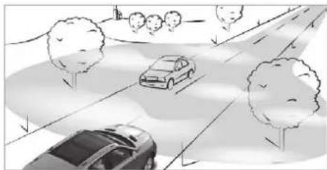
natural_image
Illustration of a road scene with cars and trees, no text or symbols presentThe function is automatically activated under the following conditions:
- At speeds below 70 km/h and when the rear fog light is switched on.
The function is automatically deactivated under the following conditions:
- At speeds above 100 km/h after activation.
- When the rear fog light is switched off.
You can activate the enhanced fog light function up to a speed of 100 km/h by switching on the rear fog light.
Function of the off-road light
The off-road light improves illumination during off-road driving. The low beam is distributed symmetrically and across a wide angle, and brightness is increased slightly. This makes it easier to find your way when driving off-road and to detect obstacles at an early stage. The active headlamps function is deactivated during this time so that steering movements do not change the illumination.
The function is active when the low beam is switched on if you are not driving at a speed greater than 50 km/h and the (Offroad) or

selected.
(Offroad Plus) drive program has been
Switching the Intelligent Light System on/off
Requirements:
• the ignition is switched on.
Multimedia system:
Settings Lights
▶ Intelligent Light System
▶ Activate or deactivate the function.
Adaptive Highbeam Assist Plus
Adaptive Highbeam Assist Plus function
⚠ WARNING Risk of accident despite Adaptive Highbeam Assist Plus
Adaptive Highbeam Assist Plus does not recognise the following road users:
- Road users without lights, e.g. pedestrians
- Road users with poor lighting, e.g. cyclists
- Road users whose lighting is obstructed, e.g. by a barrier
On very rare occasions, Adaptive Highbeam Assist Plus may fail to recognise other road users that have lights, or may recognise them too late.
In this, or in similar situations, the automatic main beam will not be deactivated or will be activated despite the presence of other road users.
Always observe the traffic carefully and switch off the main beam in good time.
Adaptive Highbeam Assist Plus cannot take into account road, weather or traffic conditions.
Detection may be restricted in the following cases:
• In poor visibility, e.g. fog, heavy rain or snow
- If there is dirt on the sensors or the senso are obscured
Adaptive Highbeam Assist Plus is only an aid. You are responsible for adjusting the vehicle's
lighting to the prevailing light, visibility and traffic conditions.
i Adaptive Highbeam Assist Plus is available only in vehicles with Intelligent Light System.
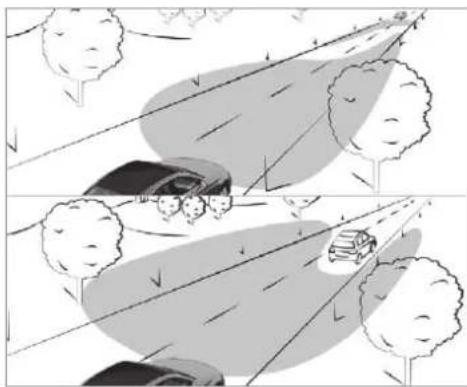
natural_image
Two-panel illustration showing a car driving on a road with trees, no text or symbols present.The Adaptive Highbeam Assist Plus automatically switches between the following types of light:
- Low beam
- Partial high beam
- High beam
Partial high beam uses the high beam to shine past other road users rather than dazzling them. The vehicle in front will be illuminated by the low beam.
At speeds greater than 30 km/h:
- If no other road users are detected, the high beam will be switched on automatically.
- If other road users are detected, the partial high beam will be switched on automatically.
At speeds below 25 km/h or when there is sufficient street lighting:
- The partial high beam will switch off automatically.
• The high beam will switch off automatically
At speeds greater than approximately 50 km/h:
- The headlamp range of the low beam is regulated automatically based on the distance to other road users.
The system's optical sensor is located behind the windscreen near the overhead control panel.
Switching Adaptive Highbeam Assist Plus on/off
To switch on: turn the light switch to the AUTO position.
Switch on the main beam using the combination switch.
When the main beam is switched on automatically in the dark, the 三 indicator lamp on the multifunction display will light up.
To switch off: switch off the main beam using the combination switch.
Setting the dipped beam (only vehicles with MULTIBEAM LED headlamps)
Multimedia system:
Settings Lights
Dipped-beams
Select Right-side traffic, Left-side traffic or Automatic.
Setting the exterior lighting switch-off delay time
Requirements:
• The light switch is in the AUTO position.
Multimedia system:
→ Settings Lights
Ext. light. del. sw. off
Set the switch-off delay time. The exterior lighting is activated for the set time when the vehicle is parked.
Switching the surround lighting on/off
Multimedia system:
→ Settings Lights
Surround lighting
When Surround lighting is active, the exterior lighting lights up for 40 seconds after the vehicle is unlocked. When you start the vehicle, the surround lighting is deactivated and the automatic driving lights are activated.
Illuminated side running boards: when the surround lighting is switched on, the illumination of the running boards is activated when a door is opened. If the door is not closed, the running board courtesy lighting is automatically deactivated after 40 seconds.
▶ Activate or deactivate the function.
Interior lighting
Adjusting the interior lighting
Front overhead control panel
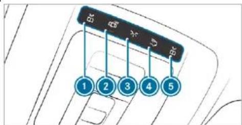
text_image
BK BK X D BK 1 2 3 4 51 Front left reading lamp
2 Automatic interior lighting control
3 Front interior lighting
Rear interior lighting
5 Front right reading lamp
To switch on or off: press button ① - ⑤ accordingly.
Control panel in the grab handle
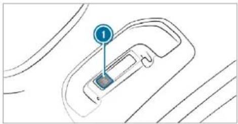
natural_image
Diagram of a car interior showing a hand cursor and a numbered label (1) pointing to the left side of the door (no text or symbols beyond the label)

Rear reading lamp

To switch on or off: press button ①.
Adjusting the ambient lighting
Multimedia system:

→ Settings Lights

Ambient lighting
Setting the colour
Select Colour.

Set the desired colour.
There are 64 colours available.
Adjusting the brightness

Select Brightness.
Adjust the brightness.
Activating the brightness for zones

Select Brightness.

Select Brightness zones.
The EMPHÄSIS, AMBIENT and ROOF zones can be set separately.
Activating multi-coloured lighting

Select Colour.

Select Multi-colour.
There are ten preset colour combinations available.

Select a colour combination.
Activating multi-coloured animation

Select Colour.

Select Multi-colour animat..
The chosen colour combination will change at predefined intervals.
Activating welcome lighting

Select Colour.

Select Welcome.
When the vehicle is unlocked, a special ambient lighting sequence will run.
Activating dependency on air conditioning settings

Select Colour.

Select Climate.
If changes are made to the temperature setting in the vehicle, the colour of the ambient lighting will change briefly.
Switching the interior lighting switch-off delay time on/off
Multimedia system:
→ Settings Lights
▶▶ Int. light. del. sw. off
Switch the lighting switch-off delay time on or off. When this function is active, the interior lighting is lit up for short time after the vehicle has been locked.
Changing bulbs (only for vehicles with halogen headlamps)
Notes on changing bulbs
WARNING Risk of burns from hot component parts whilst replacing a bulb Bulbs, lamps and plugs can become very hot during operation. When replacing a bulb, you could burn yourself on these component parts.
Allow the component parts to cool down before replacing the bulb.
- Do not use a bulb if it has been dropped its glass has been scratched. The bulb may otherwise explode.
- Do not touch the glass bulb with your bare hands.
- Protect bulbs from moisture and do not allow bulbs to come into contact with liquids.
Overview of the bulbs to be changed
Halogen headlamps
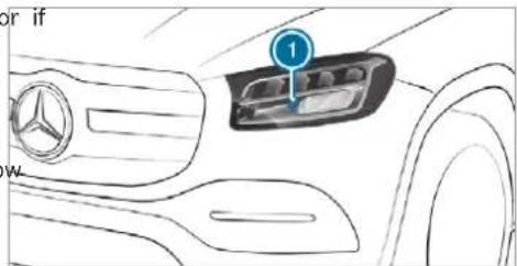
text_image
or if 1 W① High beam: H7 55 W bulb
Changing the front bulbs (vehicles with halogen headlamps)
Fitting/removing the cover in the front wheel arch Requirements
• The lighting system is switched off.
- The appropriate front wheel is turned inwards.
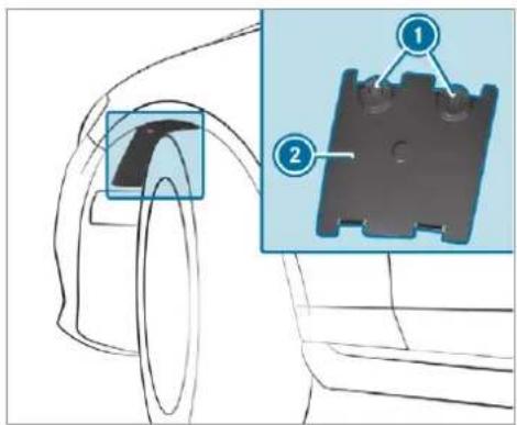
text_image
Technical diagram showing a mechanical component with labeled parts, including a highlighted section and an inset view of the component.Removal (left-hand side of the vehicle): using a screwdriver, turn rotating catches ① clockwise as far as they will go. Cover ② will be released.
Removal (right-hand side of the vehicle): using a screwdriver, turn rotating catches ① anti-clockwise as far as they will go. Cover ② will be released.
Remove cover 2.
To fit: insert cover ② into the wheel arch liner.
- Left-hand side of the vehicle: using a screwdriver, turn rotating catches anti-clockwise as far as they will go.
- Right-hand side of the vehicle: using a screwdriver, turn rotating catches ① clockwise as far as they will go.
Cover ② will be locked.
Replacing light sources in the halogen head-lamp
Requirements:
• Main beam: bulb type H7 55 W
• The lighting system is switched off.
- The cover in the front wheel arch has been removed.
- The bonnet is open.
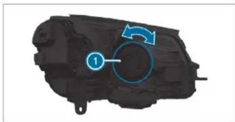
natural_image
Mechanical component with blue circular arrow and numbered label (1), no readable text or symbols beyond the labelTurn housing cover ① anti-clockwise and remove it.
▶ Turn the socket anti-clockwise and remove it.
▶ Pull the light source out of the socket.
Insert the new light source into the socket such that the entire base of the light source is resting on the bottom of the socket.
Insert the socket and turn it clockwise.
Press on the housing cover and turn it clockwise.
Replace the cover on the front wheel arch.
Windscreen wipers and windscreen washer system
Switching the windscreen wipers on/off

text_image
Diagram showing car interior with labeled parts and a magnified view of the engine component1 0 Windscreen wipers off
2 … Automatic wiping, normal
3 .... Automatic wiping, frequent
4 — Continuous wiping, slow 5 — Continuous wiping, fast
Turn the combination switch to the correct position 1 - 5.
Single wipe/washing: push the button on the combination switch in the direction of arrow ①.
- Single wipe
• Wipes with washer fluid
Vehicles with MAGIC VISION CONTROL: in position 2 or 3, the windscreen washing process is automatically triggered if dirt is detected on the windscreen unless the Top up washer fluid message is being displayed.
Switching the rear window wiper on/off
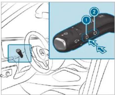
text_image
Diagram showing car interior with labeled parts and a close-up of the steering wheel, highlighting two numbered components.Single wipe/washing
Intermittent wiping
Single wipe: press button ① to the point of resistance.
Wiping with washer fluid: press button ① beyond the point of resistance.

Switching intermittent wiping on/off: press button 2.
Vehicles with rain sensor: the wipe interval automatically adapts to the driving conditions.
The symbol will appear on the instrument cluster when the rear window wiper is switched on.
Replacing the windscreen wiper blades

WARNING Risk of becoming trapped if the windscreen wipers are switched on while wiper blades are being replaced
If the windscreen wipers begin to move while you are changing the wiper blades, you can be trapped by the wiper arm.
▶ Always switch off the windscreen wipers and ignition before changing the wiper blades.
Moving the wiper arms into the replacement position
Switch the ignition on and switch off again immediately.
Within around 15 seconds, press the button on the combination switch for approximately three seconds(→ page 185). The wiper arms will move into the replacement position.
Removing the wiper blades
Fold the wiper arms away from the wind-screen.
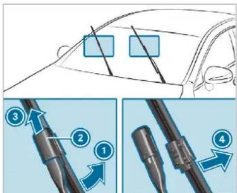
text_image
Diagram illustrating car safety instructions with numbered steps and directional arrows for engine componentsHold the wiper arm with one hand. With the other hand, turn the wiper blade in the direction of arrow ① away from the wiper arm as far as it will go.
Slide catch ② in the direction of arrow ③ until it engages in the removal position.
Remove the wiper blade from the wiper arm in the direction of arrow 4.
Fitting the wiper blades
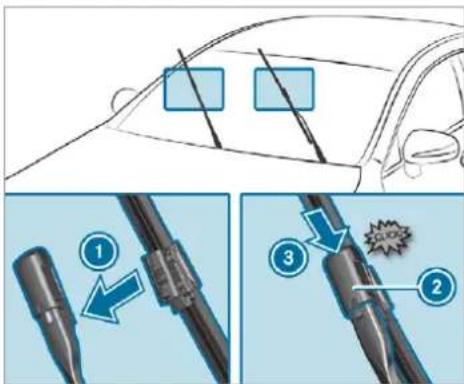
text_image
Diagram illustrating car safety instructions with numbered steps and component diagramsInsert the new wiper blade into the wiper arm in the direction of arrow ①.
Slide catch ② in the direction of arrow ③ until it engages in the locking position.
Make sure that the wiper blade is seated correctly.
Fold the wiper arms back onto the wind-screen.
Switch on the ignition.
Press the button on the combination switch.
The wiper arms will move into the original position.
Maintenance display
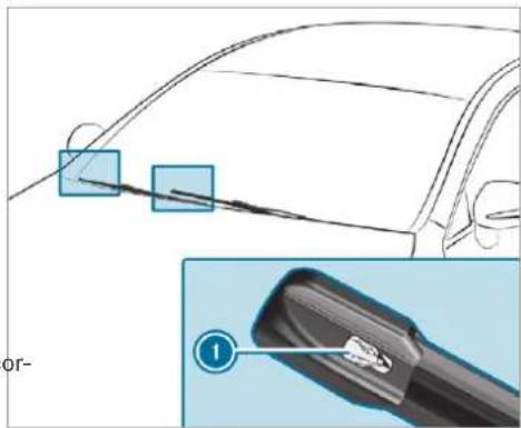
text_image
Diagram showing car exterior and cable connector with labeled parts, including a numbered inset view.Remove the protective film ① from the maintenance display on the tip of the newly fitted wiper blades.
If the colour of the maintenance display changes from black to yellow, the wiper blades should be replaced.
① The duration until the colour changes varies depending on the usage conditions.
Replacing the windscreen wiper blades (MAGIC VISION CONTROL)
Moving the wiper arms into the replacement position
▶ Switch the ignition off.
Within around 15 seconds, press the button on the combination switch (→ page 185).
The wiper arms will move into the replacement position.
Removing the wiper blades
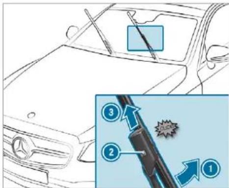
text_image
Diagram showing car dashboard cleaning steps with numbered instructions and a magnified detail view highlighting safety features.To bring the wiper blade into position to be removed: hold the wiper arm firmly in one hand. With the other hand, turn the wiper blade in the direction of arrow beyond the point of resistance. The wiper blade will engage in the removal position with a click.
To remove the wiper blade: press release knob ②, pull the wiper blade in the direction of arrow ③ and remove.
Fitting the wiper blades
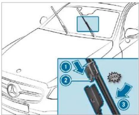
text_image
Diagram showing car interior with tool, safety warning symbol, and numbered instructions for cleaning or repair.Push the new wiper blade onto the wiper in the direction of arrow ① until release knob ② engages.
- Press the wiper blade onto the wiper arm in the direction of arrow ③ beyond the point of resistance. The wiper blade will engage with a noticeable click and move freely again. - Fold the wiper arm back onto the wind-screen.
Replacing the rear window wiper blade
WARNING Risk of becoming trapped if the windscreen wipers are switched on while wiper blades are being replaced
If the windscreen wipers begin to move while you are changing the wiper blades, you can be trapped by the wiper arm.
▶ Always switch off the windscreen wipers and ignition before changing the wiper blades.
^a im ^a Removing the wiper blade
▶ Switch off the ignition.
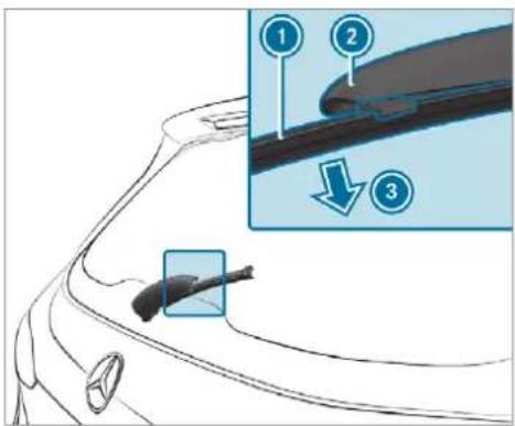
text_image
Diagram of a car's side profile with labeled parts and an inset showing a cable or connector detail.Fold wiper arm ② away from the rear window until it engages in the replacement position.
▶ Unclip wiper blade ① from wiper arm and remove it in the direction of arrow ③.
Fitting the wiper blade
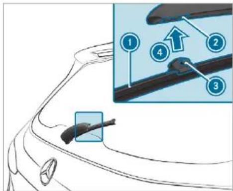
text_image
Diagram showing car body parts with numbered annotations highlighting specific features or parts in a technical diagram.Position wiper blade ① with both lugs ③ on holder ② on the wiper arm.
Push wiper blade ① in the direction of arrow ④ until it engages in holder ②.
Make sure that wiper blade ① is seated correctly.
Fold the wiper arm from the replacement position back onto the rear window.
Mirrors
Operating the outside mirrors
WARNING Risk of injury through adjusting vehicle settings while the vehicle is in motion
You could lose control of the vehicle in the following situations:
- if you adjust the driver's seat, the head restraints, the steering wheel or the mirror while the vehicle is in motion
- if you fasten your seat belt while the vehicle is in motion
Before starting the engine: adjust the driver's seat, the head restraints, the steering wheel or the mirror and fasten your seat belt.

WARNING Risk of accident due to mis-judgement of distances when using the outside mirror
The outside mirrors reflect objects on a smaller scale. The objects in view are in fact closer than they appear.
As a result, you may misjudge the distance between you and the road user driving behind you, e.g. when changing lanes.
Therefore, always look over your shoulder in order to ensure that you are aware of the actual distance between you and the road users driving behind you.
Folding the outside mirrors in/out
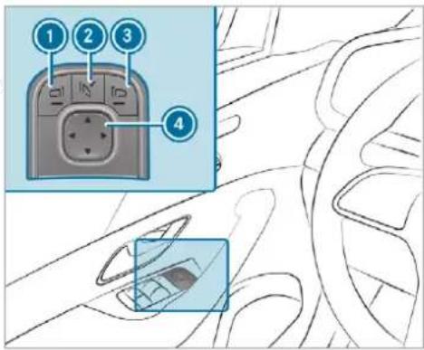
text_image
Diagram showing car interior with labeled buttons and a close-up of the door panel, likely illustrating steering or navigation instructions.
Briefly press button ②
If the battery has been disconnected or has discharged, the outside mirrors must be moved briefly using button. Only then will the automatic mirror folding function work properly.

Mercedes-Maybach vehicles: when the outside mirrors fold in, the extendable running boards will retract if these were previously extended.
Adjusts the outside mirrors
Press button ① or ③ to select the outside mirror to be adjusted.
Use button ④ to adjust the position of the mirror glass.
Engaging the outside mirrors
If an outside mirror has been forcibly disengaged, proceed as follows.
▶ Vehicles without electrically folding outside mirrors: manually push the outside mirror into the correct position.
Vehicles with electrically folding outside mirrors: press and hold button ②. You will hear a click and the mirror will audibly engage in position. The outside mirror will now be set to the correct position.
Automatic anti-dazzle mirrors function

WARNING Risk of acid burns and poisoning due to the anti-dazzle mirror electrolyte
Electrolyte may escape if the glass in an automatic anti-dazzle mirror breaks.
The electrolyte is hazardous to health and causes irritation. It must not come into contact with your skin, eyes, respiratory organs or clothing or be swallowed.
If you come into contact with electrolyte, observe the following:
- Immediately rinse the electrolyte from your skin with water and seek medical attention.
- If electrolyte comes into contact with your eyes, immediately rinse them thoroughly with clean water and seek medical attention.
-
If the electrolyte is swallowed, immediately rinse your mouth out thoroughly. Do not induce vomiting. Seek medical attention immediately.
-
Immediately change out of clothing which has been contaminated with electrolyte.
- If an allergic reaction occurs, seek medical attention immediately.
The inside rearview mirror and the outside mirror on the driver's side will automatically go into anti-dazzle mode if light from a headlamp hits the sensor on the inside rearview mirror.
System limits
The system will not go into anti-dazzle mode if:
• The engine is switched off.
- Reverse gear is engaged.
• The interior lighting is switched on.
Front-passenger outside mirror parking position function
① The parking position is available only in vehicles with a memory function.
The parking position makes parking easier.
In the following situations, the front-passenger outside mirror will swivel downwards in the direction of the rear wheel on the front passenger's side:
• the parking position is stored (→ page 192)
• The front-passenger mirror is selected
- Reverse gear is engaged.
The front-passenger outside mirror will move back to its original position in the following situations:
- You shift the transmission to another transmission position
- You shift the transmission to another transmission position
- You are travelling at speeds greater than 15 km/h
- You press the button for the outside mirror on the driver's side
Storing and calling up the parking position of the front-passenger outside mirror
Storing
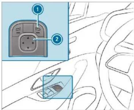
text_image
Diagram showing car interior with labeled buttons and a close-up of the dashboard panelSelect the front-passenger outside mirror using button ①.
Engage reverse gear.
Move the front-passenger outside mirror into the desired parking position using button ②.
Calling up
Select the front-passenger outside mirror using button ①.
Engage reverse gear.
The front-passenger outside mirror will move to the stored parking position.
Activating/deactivating the automatic mirror folding function
Multimedia system:
→ Settings Vehicle
▶ Switch Automatic fold-in on or off.
Operating the sun visors
Using the single sun visor
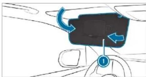
natural_image
Diagram of a car interior showing a steering wheel, dashboard, and directional arrows indicating motion (no text or symbols)Glare from the front: fold sun visor down.
Glare from the side: release the catch and swing the sun visor ① to the side.
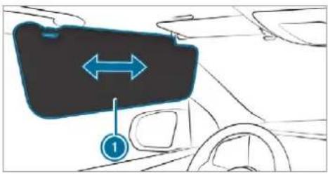
text_image
Diagram showing a car's license plate with bidirectional arrow and numbered label (1) pointing to the side.▶ Vehicles with an extendable sun visor: slide sun visor ① horizontally as required.
Using the additional sun visor
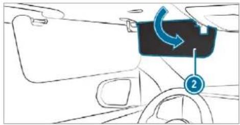
natural_image
Diagram of a car interior showing a blue curved arrow and numbered label (2), no readable text or symbols present.▶ Vehicles with an additional sun visor: fold additional sun visor ② down.
Area permeable to radio waves on the windscreen
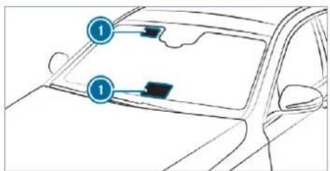
text_image
Diagram of a car interior with numbered annotations pointing to the dashboard and side panelsRadio-controlled equipment, such as toll systems, can be mounted only on areas ① of the windscreen that are permeable to radio waves.
Areas permeable to radio waves ① are best visible from outside the vehicle when the windscreen is illuminated with an external light source.
Note this position for vehicles with:
- Windscreen heating
• Infrared reflective windscreen
Infrared-reflective windscreen function
The infrared-reflective windscreen is coated and reduces the build-up of heat in the vehicle interior.
The coating shields the vehicle interior from radio waves.
Overview of climate control systems
Notes on climate control
An interior air filter in combination with the prefilter in the engine compartment must always be used so that the air conditioning system, pollution level monitoring and the air filtration work correctly. Make sure that the filter is installed correctly and the filter housing in the engine compartment is closed correctly using the cap and always tightly sealed when in operation. U filters recommended and approved by Mercedes-Benz. Always have service work carried out at a qualified specialist workshop.
THERMATIC control panel overview
The indicator lamps on the buttons indicate that the corresponding function is activated.
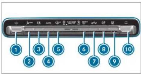
text_image
1 2 3 4 5 6 7 8 9 10

Sets the temperature


Calls up / exits the air conditioning
Pressing and holding the button (approx. four seconds): resets climate control to the basic settings


Sets the airflow or switches off climate vol


Sets climate control to automatic page 196)


Defrosts the windscreen


Switches the rear window heater on or
7 Switches air-recirculation mode on/off(→ page 198)
B A/C Switches the A/C function on/off(→ page 196)
Switches residual heat on/off (→ page 198)
9 Vehicles without a stationary heater: SYNC activates/deactivates synchronisation (→ page 198)
Vehicles with a stationary heater: switches the stationary heater on/off (→ page 201)

Sets the front passenger side temperature
THERMOTRONIC control panel overview
The indicator lamps on the buttons indicate that the corresponding function is activated.
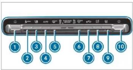
text_image
1 2 3 4 5 6 7 8 9 10Sets the driver's side temperature
2 menu Calls up / exits the air conditioning
Pressing and holding (approx. four seconds): resets climate control to the basic settings
3 Sets the airflow or switches off climate control
4 AUTO Sets climate control to automatic (→ page 196)
5 Defrosts the windscreen
6 REAR Switches the rear window heater on/off
7 Switches air-recirculation mode on/off(→ page 198)
B A/C Switches the A/C function on/off(→ page 196)
Switches residual heat on/off (→ page 198)
9 Vehicles without a stationary heater: SYNC activates/deactivates synchronisation (→ page 198)
Vehicles with a stationary heater: switches the stationary heater on/off ( page 201)
10 Sets the front passenger side temperature
Overview of the rear operating unit
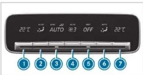
text_image
22℃ AUTO AUTO OFF 22℃ 1 2 3 4 5 6 7Sets the temperature, left
② Sets the air distribution, left
3 Sets climate control to automatic mode ( page 197)
Setting the airflow
5 Switches climate control on/off (→ page 196)
Switches the residual heat on/off (→ page 199)
6 Sets the air distribution, right
7 Sets the temperature, right
The settings for the second and third row of seats (equipment-dependent) can be made via the rear operating unit, the multimedia system ( page 197) or the MBUX rear tablet ( page 551) depending on the vehicle's equipment.
Operating the climate control system
Switching climate control on/off
To switch on: set the airflow to level 1 or higher using the button.
To switch off: set the airflow to level 0 using the button.
If climate control is switched off, the windows may mist up more quickly. Switch off climate control only briefly.
Switching the climate control in the rear on/off
Press button 5.
When climate control in the second seat row is switched off, the indicator lamp is activated and OFF is shown on the rear display.
Switching the A/C function on or off via the control panel
The A/C function heats, cools and dehumidifies the vehicle's interior air.
Press the A/C button.
Switch off the A/C function only briefly; otherwise, the windows may mist up more quickly.
Condensation may drip from the underside of the vehicle when cooling mode is active. This is not a sign that there is a fault.
Calling up the air conditioning menu
Calling up the air conditioning menu using the multimedia system
Select one of the temperature displays at the lower edge of the media display.
Calling up the air conditioning menu using the button on the control panel
Press the 📊 button on the control panel.
Activating/deactivating the A/C function via the multimedia system
^5 The A/C function heats, cools and dehumidifies the vehicle's interior air.
▶ Call up the air conditioning menu ( page 196).
▶ Select First row of seats.
Select A/C.
Depending on the previous status, the function is activated or deactivated.
Setting climate control to automatic mode
In automatic mode, the set temperature is controlled and maintained at a constant level by the air supply.
Press the AUTO button.
To switch to manual mode: press the button.
In automatic mode, you can choose between five different air quantities using the button. Automatic mode is retained.
Automatically controlling the climate control in the rear
In automatic mode, the set temperature is regulated by the temperature of the dispensed air and the airflow.
Press the AUTO button ( page 195).
Overview of air distribution settings
The symbols on the display indicate which vents the airflow is being directed through:
| defroster and side air vents | |
| centre and side air vents | |
| footwell and side air vents | |
| centre, side and footwell vents | |
| defroster, footwell and side air vents | |
| all vents | |
| defroster, middle and side air vents |
AUTO automatic air distribution
Setting the air distribution
Call up the air conditioning menu ( page 196).
▶ Select First row of seats or Second row of seats.
To set the air distribution: select 📋, or 🌐.
Set the airflow.
Several air distribution options can be selected at the same time, for example to set the temperature/air conditioning for the windscreen and the footwells simultaneously. The climate control for the windscreen can only be selected for the first seat row.
Setting climate control for the rear passenger compartment (multimedia system)
Setting the temperature
▶ Call up the air conditioning menu ( page 196).
▶ Select Second row of seats or Third row of seats.
For Maybach vehicles: select Second row of seats.
i Maybach vehicles are fitted with one and two rows of seats.
Set the temperature.
Setting the airflow
▶ Call up the air conditioning menu ( page 196).
▶ Select Second row of seats or Third row of seats.
For Maybach vehicles: select Second row of seats.
(i) Maybach vehicles are fitted with one and two rows of seats.
Set the airflow.
Controlling the rear climate control automatically
Select REAR AUTO. Rear climate control is controlled automatically.
Deactivating rear climate control
Select REAR OFF. Rear climate control is deactivated.
Activating/deactivating the climate control synchronisation function via the control panel
Climate control can be set centrally using the synchronisation function. The temperature and air distribution setting for the driver side is added automatically for all climate control zones.
Press the SYNC button.
The synchronisation function is deactivated if the settings for one of the other climate zones are changed.
Activating/deactivating the climate control synchronisation function using the multimedia system
Climate control can be set centrally using the synchronisation function. The driver's settings for temperature, air quantity and air distribution are adopted automatically for all climate zones.
Call up the air conditioning menu ( page 196).
▶ Select First row of seats.
Select SYNC.
Depending on the previous status, the function is activated or deactivated.
Demisting the windows
Windows misted up on the inside
Press the AUTO button.
If the windows continue to mist up: press the button.
Windows misted up on the outside
▶ Switch on the windscreen wipers.
Press the AUTO button.
Switching air-recirculation mode on/off
Press the 📄 button. The interior air will be recirculated.
Air-recirculation mode automatically switches to fresh air mode after some time.
If air-recirculation mode is switched on, the windows may mist up more quickly. Switch on air-recirculation mode only briefly.
Switches the residual heat on/off
Requirements:
• the vehicle is parked.
It is possible to make use of the residual heat from the engine to continue heating or ventilating the front compartment of the vehicle for
approximately 30 minutes, depending on the temperature set.
To activate: press button A/C
Residual heat will be switched off automatically.
Switching the residual heat in the rear on/off
Requirements:
• the vehicle is parked.
When the residual heat of the engine is activated in the rear compartment, you can heat or ventilate the rear compartment for approximately 30 minutes.
Press the ⑤ button (→ page 195).
Activating/deactivating ionisation
The ionisation improves the quality of the vehicle's interior air. The ionisation of the interior is odourless.
▶ Call up the air conditioning menu ( page 196).
▶ Select Air quality.
Select IONISATION.
Depending on the previous status, the function is activated or deactivated.
Fragrance system
Setting the fragrance system Requirements:
• Automatic climate control is activated.
• The glove box is closed.
The fragrance system distributes a pleasant fragrance throughout the vehicle interior from a flacon located in the glove box.
▶ Call up the climate control menu ( page 196).
▶ Select Air quality.
▶ Select AIR FRESHENER.
The fragrance system begins at the highest intensity.
Keep pressing until the desired intensity is reached.
The intensity levels can be selected in the following order: Strong - Medium - Weak - Off
Inserting or removing the flacon of the fragrance system
⚠ WARNING Risk of injury from liquid perfume
If children open the flacon, they could drink the liquid perfume or it could come into contact with their eyes.
Do not leave children unattended in the vehicle.
Consult a doctor immediately if liquid perfume has been drunk.
If liquid perfume comes into contact with your eyes or skin, rinse your eyes with clean water.
If symptoms continue, consult a doctor.

ENVIRONMENTAL NOTE Environmental damage due to improper disposal of full flacons

Full flacons must not be disposed household waste.


Full flacons must be taken to I substance collection point.
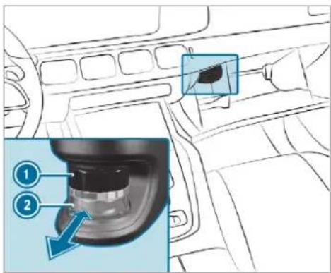
text_image
Diagram of car interior showing a gear shift with numbered parts and directional arrow indicating motion
Cap

Flacon

To insert: slide the flacon into the holder as far as it will go.

To remove: after opening the glove box, wait for approximately seven seconds and pull out the flacon.
If you do not use genuine Mercedes-Benz interior perfumes, observe the manufacturers' safety notices on the perfume packaging.
Dispose of the genuine Mercedes-Benz interior perfume flacon when it is empty and do not refill it.
Refillable flacon
Unscrew the cap of the empty flacon.
Fill the flacon with a maximum of 15 ml.
Screw the cap back on to the flacon.
Always refill the empty refillable flacon with the same perfume. Observe the separate information sheet with the flacon.
Information on the windscreen heater
The windscreen heater is switched on automatically if the MAX button is activated.
In addition, it is automatically switched on when necessary.
Stationary heater/ventilation
Stationary heater/stationary ventilation function
- The air inside the vehicle is heated or ventilated to the set temperature.
- The air inside the vehicle cannot be cooled down to temperatures below the outside temperature.
- If the outside temperature changes, ventilation mode automatically switches to heating mode or heating mode automatically switches to ventilation mode.
The stationary heater and the exhaust gas outlet are situated behind the right-hand front wheel.
Switching the stationary heater/ventilation on/off via the control panel

DANGER Risk of fatal injury due to poisonous exhaust gases
If the tailpipe is blocked or sufficient ventilation is not possible, poisonous exhaust gases such as carbon monoxide may enter the vehi-
cle. This is the case in enclosed spaces or the vehicle gets stuck in snow, for example.
▶ Always switch the stationary heater off in enclosed spaces without an air extraction systems, e.g. in garages.
Keep the tailpipe and the area around the vehicle free from snow when the engine or the stationary heater are running.
Open a window on the windward side of the vehicle to ensure an adequate supply of fresh air.

WARNING Risk of fire due to hot stationary heater components
When the stationary heater is switched on, parts of the vehicle can become very hot, e.g. the stationary heater exhaust system.
Flammable materials such as leaves, grass or twigs may ignite if they come into contact with:
- hot parts of the stationary heater exhaust system
- the exhaust gas itself
There is a risk of fire.
When the stationary heater is switched on, make sure that:
- hot vehicle parts do not come into contact with flammable materials.
- the exhaust gas can flow out of the stationary heater exhaust pipe unhindered.
- the exhaust gas does not come into contact with flammable materials.

NOTE Battery discharge caused by stationary heater or stationary ventilation operation
Operating the stationary heater or stationary ventilation drains the battery.
After heating or ventilating the vehicle twice, drive for a longer period of time.
Requirements:
• the fuel tank is sufficiently full.
Please note that if the tank fill level is too low, it can result in function restrictions during stationary heating operation.
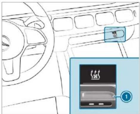
natural_image
Interior view of a car dashboard with steering wheel and air conditioner unit (no text or symbols visible)- Set the desired temperature using the ▼▲ button. - Press button ①. The red or blue indicator lamp on button ① will light up or go out.
Indicator lamp colours:
- blue: stationary ventilation is switched on.
• red: the stationary heater is switched on.
• yellow: the departure time is preselected.
The stationary heater/ventilation will switch off automatically after 50 minutes.
Operation using the app: the stationary heater/ventilation can also be operated via the Mercedes me connect app. Further information can be found in the separate Owner's Manual at http://manuals.daimler.com/baix/cars/connectme/en_GB/index.html.
Setting the stationary heater / stationary ventilation via the multimedia system
Call up the air conditioning menu ( page 196).
▶ Select Auxiliary heating.
Selecting the departure time
Select the time TIME A: XX, TIME B: XX or TIME C: XX.
Setting the departure time
Select the time TIME A: XX, TIME B: XX or TIME C: XX.
▶ Select the pen beside the time.
Set a time.
Setting the stationary heater/stationary ventilation via remote control Requirements:
• the fuel tank is sufficiently filled.
Switching on immediately
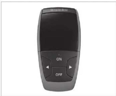
text_image
Mercedes-Benz ON OFFPress and hold the ON button.
Setting the departure time
Briefly press the ON button.
Press the ◀ or ▶ button repeatedly until the time to be changed appears on the display.
Press the ON and OFF buttons simultaneously.
The 🔒 symbol on the remote control display flashes.
Press the ◀ and ▶ buttons to set the desired departure time.
Press the ON and OFF buttons simultaneously.
The new departure time will be stored.
Up to three departure times can be stored.
To activate the departure time: select the desired departure time and press and hold the ON button.
The symbol, the departure time and, depending on the selected departure time, the letter A, B or C will appear on the display.
To deactivate the departure time: select the desired departure time and press and hold the OFF button.
OFF will appear on the display.
To check the status of the active stationary heater: briefly press the ON button.
Switching off immediately
Press and hold the OFF button.
Overview of the remote control displays (stationary heater/stationary ventilation)
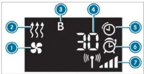
text_image
2 1 3 B 4 5 6 7① Stationary ventilation switched on
② Stationary heater switched on
3 Selected departure time
4 Remaining time for the stationary heater/stationary ventilation (in minutes)
⑤ Stationary heater/stationary ventilation active
6 Departure time activated
7 Signal strength
Further possible displays:
• Time: activated departure time.
- Zero minutes: the running time for the stationary heater is increased, as the engine has not yet reached operating temperature when it is started.
- OFF: the stationary heater/stationary ventilation is switched off.
Replacing the remote control battery (stationary heater)

DANGER Serious damage to health caused by swallowing batteries
Batteries contain toxic and corrosive substances. Swallowing batteries may cause serious damage to health.
There is a risk of fatal injury.
Keep batteries out of the reach of children.
If batteries are swallowed, seek medical attention immediately.

ENVIRONMENTAL NOTE Environmental damage due to improper disposal of batteries

Batteries contain toxic and corro-tances.


Take discharged batteries to a specialist workshop or to a point for used batteries.
Requirements:
• a CR2450 lithium battery
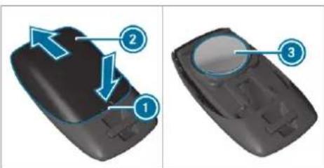
text_image
Diagram showing two views of a mobile phone with numbered annotations indicating directional changes.▶ Push a pointed object into recess ①.
Slide battery cover ② backwards in the direction of the arrow.
Insert new battery ③ with the lettering facing upwards.
Slide battery cover ② in the opposite direction to the arrow onto the remote control until the battery cover engages.
Problems with the remote control for the stationary heater/stationary ventilation
| Problem | Possible causes/consequences and ▶ Solutions |
| FAIL [IMAGE] | The signal transmission between the transmitter and the vehicle is malfunctioning.▶ Change your position in relation to the vehicle, moving closer if necessary. |
| FAIL | The starter battery is not sufficiently charged.▶ Charge the starter battery. |
| The fuel tank is not sufficiently filled.▶ Refuel at the nearest filling station. | |
| FAIL [IMAGE] | The stationary heater is malfunctioning.▶ Have the stationary heater checked at a qualified specialist workshop. |
Air vents
Adjusting the front air vents

WARNING - Risk of burns/frostbite due to not maintaining a sufficient distance to the air vents
Very hot or very cold air can flow from the air vents.
This could result in burns or frostbite in the immediate vicinity of the air vents.
▶ Always ensure that all vehicle occupants maintain a sufficient distance to the air vents.
If necessary, redirect the airflow to another area of the vehicle interior.
To guarantee the flow of fresh air through the air vents into the vehicle interior, comply with the following:
• Always keep the vents and the ventilation grille in the vehicle interior free.
- Keep the air inlet free of deposits (→ page 572).
- Optimum climate comfort is achieved with the air vents in the centre position.
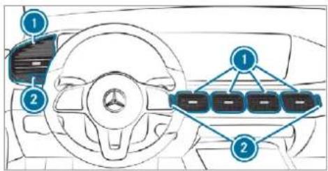
text_image
Diagram of a car interior with labeled components and a multi-lane display panel showing vehicle status indicators.To open or close center air vents: turn controller ② up or down as far as it will go.
To open or close side air vents: turn controller ② to the left or right as far as it will go.
To adjust the air direction: hold air vent in the centre and move it up or down or to the left or right.
Adjusting the rear air vents
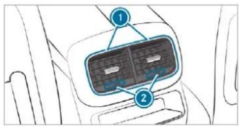
text_image
Diagram of a car air conditioner panel with labeled parts 1 and 2Air vents in the centre console
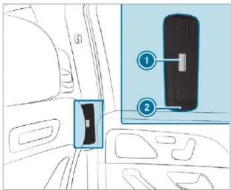
text_image
Diagram showing car interior with labeled compartments and a device panel, highlighting two numbered zones.Air vents in the B-pillar
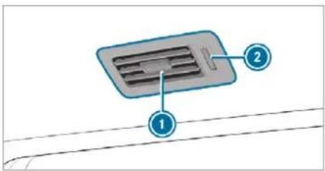
text_image
Diagram of a ventilation system component with labeled parts 1 and 2Air vents above the second and third row of seats (all vehicles except Mercedes-Maybach vehicles)
To set the airflow direction: hold air vent ① in the centre and move it accordingly.
To open or close: turn the controller ② as far as it will go.
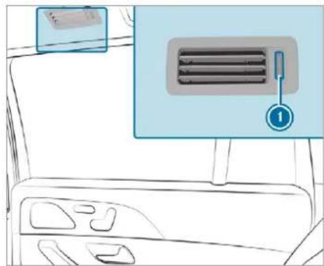
natural_image
Line drawing of a car interior showing dashboard and air vent (no text or symbols)Air vents above the second row of seats, towards the load compartment (Mercedes-Maybach vehicles)
To open or close: turn the controller ① as far as it will go.
Opening or closing the air vent in the glove box
NOTE Damage to temperature-sensitive objects in the glove box
Temperature-sensitive objects stored in the glove box may be damaged by the air vent located inside the glove compartment.
▶ Close the air vent when you heat the vehicle.
At high outside temperatures, open the air vent and switch on the A/C function.
The automatic climate control must be switched on to cool the glove box.
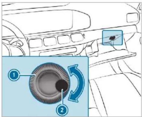
text_image
Diagram showing car wheel assembly with numbered parts and directional arrows indicating rotation or adjustment
To open or close: turn controller ① of air vent ② to the left or right.
Driving
Notes on Mercedes-AMG vehicles
Observe the notes on the following topics in the Supplement, as you may otherwise fail to recognise dangers:
• AMG Performance exhaust system
• AMG RIDE CONTROL
• (DYNAMIC SELECT switch) drive programs
- Functions of ESP
Switching on the power supply or the ignition (without engine start)

WARNING Risk of accident and injury due to children left unattended in the vehicle
If children are left unattended in the vehicle, they could:
- Open doors, thereby endangering other persons or road users.
- Get out and be struck by oncoming traffic.
- Operate vehicle equipment and become trapped, for example.
In addition, the children could also set the vehicle in motion, for example by:
- Releasing the parking brake.
- Changing the transmission position.
- Starting the vehicle.
▶ Never leave children unattended in the vehicle.
When leaving the vehicle, always take the key with you and lock the vehicle.
Keep the vehicle key out of reach of children.
Also observe the "Notes on pets in the vehicle". This also applies to the Digital Vehicle Key if the "Digital Vehicle Key" function is activated via Mercedes me connect.
Requirements:
- the key is located in the vehicle and the key battery is not discharged.
- or: a Digital Vehicle Key is located in the marked space (→ page 211).
• the brake pedal is not depressed.
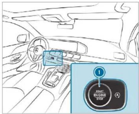
text_image
1 START ENGINE STOPTo switch on the power supply: press button ① once. You can activate the windscreen wiper, for example.
The power supply is switched off again if the following conditions are met:
- you open the driver's door.
- you press button ① twice more.
To switch on the ignition: press button twice.
The indicator lamps in the instrument cluster light up.
The ignition is switched off again if one of the following conditions is met:
- you do not start the vehicle within 15 minutes and the transmission is in position P or the electric parking brake is applied.
- you press button ① once.
Starting the vehicle
Starting the vehicle with the start/stop button

DANGER Risk of death caused by exhaust gases
Combustion engines emit poisonous exhaust gases such as carbon monoxide. Inhaling these exhaust gases is hazardous to health and leads to poisoning.
▶ Never leave the engine or, if present, the auxiliary heating running in an enclosed space without sufficient ventilation.

WARNING Risk of fire due to flammable material in the engine compartment or the exhaust system
Flammable materials brought in by either animals or environmental influences may ignite if they come into contact with hot parts of the engine or exhaust system.
Therefore, check regularly that there are no flammable materials in the engine compartment or on the exhaust system.
Requirements:
- the key is located in the vehicle and the key battery is not discharged.
- or: a Digital Vehicle Key is located in the marked space (→ page 211).
Shift the transmission to position P or N.
Depress the brake pedal and press button once.
If the vehicle does not start: switch off non-essential consumers and press button once.
If the vehicle still does not start, one of the following display messages appears in the multifunction display:
Place the key in the marked space See Owner's Manual: start the vehicle in emergency operation mode ( page 212).
or
Key not detected Place smartphone in charging bracket: place the mobile phone in the marked space ( page 171).
You can switch off the engine while driving by pressing button ① for about three seconds or by pressing button ② three times within three seconds. Be sure to observe the safety notes under "Driving tips" (→ page 215).
Starting the vehicle with a Digital Vehicle Key Requirements:
• one of the following versions of the Digital Vehicle Key is available:
- suitable mobile phone
- Digital Vehicle Key sticker
- the vehicle is equipped with the "Digital Vehicle Key" function.
- the "Digital Vehicle Key" function is activated via Mercedes me connect: https://www.mercedes.me.
• the mobile phone is sufficiently charged.
You can check the suitability of your mobile phone by entering the phone number at https://www.mercedes.me. Information about suitable mobile phones can be obtained from your Mercedes-Ben Service Centre or at https:// www.mercedes-benz-mobile.com.
① Mercedes-Benz recommends that you carry the emergency key in case of function restrictions.
The function is only available in connection with Mercedes me connect and only in certain countries.
① Protective cases around the mobile phone can impair the range of functions.
Using the Digital Vehicle Key for the first time
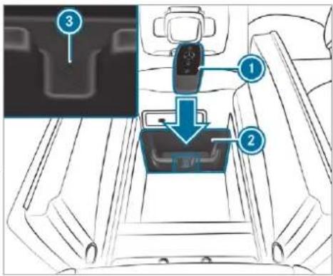
text_image
Diagram of car seatbelt mechanism with labeled parts and zoomed-in detail view▶ Deactivate the key ① (→ page 85).
Place the key ① in the marked space ② next to the symbol ③.
Place the mobile phone or Digital Vehicle Key sticker in the marked space for wireless charging ( page 171).
Depress the brake pedal and start the vehicle using the start/stop button.
Any further starts with the Digital Vehicle Key
The key is not needed for any further starts.
Place the mobile phone or Digital Vehicle Key sticker in the marked space for wireless charging ( page 171).
▶ Start the vehicle using the start/stop button.
The "Digital Vehicle Key" service can be deactivated in Mercedes me connect at https://www.mercedes.me. The function is then deactivated in the mobile phone via an online connection. If connection to the Internet is not possible, e.g. after the mobile phone or the Digital Vehicle Key sticker has been stolen, the key function can be deactivated at a Mercedes-Benz service centre.
Starting the vehicle with key in the marked space (emergency operation mode)
If the vehicle does not start and the Place the key in the marked space See Owner's Manual message appears in the multifunction display, you can start the vehicle in emergency operation mode.
text_image
3 1 2 le,Make sure that the marked space ② is empty.
Remove the key ① from the key ring.
Place the key ① in the marked space ② next to the symbol ③.
The vehicle will start after a short time.
If you remove the key ① from the marked space ② the engine continues running. For further vehicle starts however, the key ① must be located in the marked space ② next to the symbol ③ during the entire journey.
Have the key ① checked at a qualified specialist workshop.
If the vehicle does not start:
place the key ① in the marked space ② and leave it there.
Depress the brake pedal and start the vehicle using the start/stop button.
① You can also switch on the power supply or the ignition with the start/stop button.
Starting the vehicle via Remote Online services
Cooling or heating the vehicle interior before commencing your journey
① This function is not available in all countries.
If you start the vehicle via your smartphone, the previously selected air conditioning adjustment is active.
Ensure the following before starting the engine:
- the legal stipulations in the area where your vehicle is parked allow engine starting via smartphone.
- it is safe to start and run the engine where your vehicle is parked.
• the fuel tank is sufficiently filled.
• the starter battery is sufficiently charged.
You can also set the temperature with your smartphone. Information on Mercedes me connect and other services: https://www.mercedes.me This function is not available for all models.
Charging the battery before commencing your journey
If the vehicle battery is discharged, you receive a message on your smartphone. You can then start the vehicle with the smartphone to charge the battery. The vehicle is automatically switched off after ten minutes.
Ensure the following before starting the engine:
- the legal stipulations in the area where your vehicle is parked allow engine starting via smartphone.
- it is safe to start and run the engine where your vehicle is parked.
• the fuel tank is sufficiently filled.
Starting the vehicle (Remote Online)
WARNING Risk of crushing or entrapment due to unintentional starting of the engine
Limbs could be crushed or trapped if the engine is started unintentionally during service or maintenance work.
▶ Always secure the engine against unintentional starting before carrying out maintenance or repair work.
Requirements:
- park position is selected.
- the anti-theft alarm system is not activated.
• the panic alarm is not activated.
- the hazard warning light system is switched off.
• The bonnet is closed.
• the doors are closed and locked.
• the windows and sliding sunroof are closed.
Start the vehicle using the smartphone. After every vehicle start, the engine runs for ten minutes.
You can carry out a maximum of two consecutive starting attempts. The vehicle must be started once with the key before trying to start the vehicle again with the smartphone. you can stop the vehicle again at any time.
i Further information can be found in the smartphone app.
Securing the engine against starting before carrying out maintenance or repair work:
switch on the hazard warning light system. or
unlock the doors.
or
▶ open a side window or the sliding sunroof.
Running-in notes
To preserve the engine during the first 1,500 km:
- drive at varying road speeds and engine speeds.
- drive the vehicle in drive program C or E.
- shift to the next highest gear at the very latest when the needle reaches the last third before the red area in the rev counter.
- do not shift down a gear manually in order to brake.
- avoid overstraining the vehicle, e.g. driving at full throttle.
- do not depress the accelerator pedal past the pressure point (kickdown).
- only increase the engine speed gradually and accelerate the vehicle to full speed after 1,500 km.
This also applies when the engine or parts of drivetrain have been replaced.
Please also observe the following running-in notes:
- in certain driving and driving safety systems, the sensors adjust automatically while a tain distance is being driven after the vehicle has been delivered or after repairs. Full system effectiveness is not reached until the end of this teach-in process.
- brakepads, brake discs and tyres that are either new or have been replaced only achieve optimum braking effect and grip after several hundred kilometres of driving. Compensate for the reduced braking effect by applying greater force to the brake pedal.
Notes on optimised acceleration
If all necessary requirements and activation conditions are fulfilled, the best possible acceleration can be achieved from a standstill.
Do not use the optimised acceleration on public roads. Individual wheels could spin and you
should lose control of the vehicle. There is an increased risk of skidding and/or accident. Be sure to observe the safety notes and information on ESP ( page 253).
Pulling away with optimised acceleration
WARNING Risk of skidding and having an accident from wheels spinning
When you use optimised acceleration, individual wheels could spin and you could lose control of the vehicle.
If ESP ^® is deactivated, there is a risk of skidding and accident!
Make sure that no persons or obstacles are in the close vicinity of your vehicle.
Requirements:
• the vehicle has been run in (→ page 214).
• the vehicle and tyres are in good condition.
- the engine and transmission are at normal operating temperature.
NOTE Increased wear due to optimised acceleration
When pulling away with optimised acceleration, all components of the drivetrain are subjected to a very high load.
This can lead to increased component wear.
Do not always pull away with optimised acceleration.
Engage the D drive position ( page 230).
Move the steering wheel to the straight-ahead position.
Select the sportiest available drive program
S ^+ or S (→ page 227).
Deactivating ESP® (→ page 258).
Depress and hold the brake pedal firmly with your left foot.
With your right foot, fully depress the accelerator pedal.
After no more than five seconds, take your left foot quickly off the brake, but keep the accelerator pedal depressed. The vehicle pulls away at maximum acceleration.
Switch on ESP once the acceleration procedure is complete.
Ending optimised acceleration
Remove your foot from the accelerator pedal.
Reactivate the ESP.
i After you pull away with optimised acceleration, components of the drivetrain can become very hot, which means that optimised acceleration values may be reached again only after a few minutes.
Notes on driving
WARNING Risk of accident due to objects in the driver's footwell
Objects in the driver's footwell may impede pedal travel or block a depressed pedal.
This jeopardises the operating and road safety of the vehicle.
Stow all objects in the vehicle securely so that they cannot get into the driver's footwell.
Always fit the floor mats securely and as prescribed in order to ensure that there is always sufficient room for the pedals.
Do not use loose floor mats and do not place floor mats on top of one another.
WARNING Risk of accident due to unsuitable footwear
Operating the pedals may be impaired by wearing unsuitable footwear, e.g.:
- platform shoes
- high-heeled shoes
- slippers
Always wear suitable footwear when driving so that you can operate the pedals safely.
WARNING Risk of accident when switching off the ignition when driving
If you switch off the ignition while driving, safety functions are restricted or no longer available. This may affect the power steering system and the brake force boosting, for example.
You will then need to use considerably more force to steer and brake.
Do not switch off the ignition while driving.
DANGER Risk of death caused by exhaust gases
Combustion engines emit poisonous exhaust gases such as carbon monoxide. Inhaling these exhaust gases is hazardous to health and leads to poisoning.
▶ Never leave the engine or, if present, the auxiliary heating running in an enclosed space without sufficient ventilation.
A WARNING Risk of skidding and of an accident due to shifting down on slippery road surfaces
If you shift down on slippery road surfaces to increase the engine braking effect, the drive wheels may lose traction.
Do not shift down on slippery road surfaces to increase the engine braking effect.
DANGER Risk of fatal injury due to poisonous exhaust gases
If the tailpipe is blocked or sufficient ventilation is not possible, poisonous exhaust gases such as carbon monoxide may enter the vehicle. This is the case when the vehicle becomes stuck in snow, for example.
Keep the tailpipe and the area around the vehicle free from snow when the engine or the stationary heater are running.
Open a window on the side of the vehicle facing away from the wind to ensure an adequate supply of fresh air.
⚠ WARNING Risk of accident due to the brake system overheating
If you leave your foot on the brake pedal when driving, the brake system may overheat.
This increases the braking distance and the brake system may even fail.
▶ Never use the brake pedal as a footrest.
Do not depress the brake pedal and the accelerator pedal at the same time while driving.
! NOTE Causing wear to the brake linings by permanently depressing the brake pedal
Do not permanently depress the brake pedal while driving.
To use braking effect of the engine, shift to a lower gear in good time.
! NOTE Damage to the drivetrain and engine when pulling away
Do not warm up the engine while the vehicle is stationary. Pull away immediately.
Avoid high engine speeds and driving at full throttle until the engine has reached its operating temperature.
! NOTE Damage to the catalytic converter due to non-combusted fuel
The engine is not running smoothly and is misfiring.
Non-combusted fuel may get into the catalytic converter.
▶ Only depress the accelerator pedal slightly.
Have the cause rectified immediately at a qualified specialist workshop.
Notes on driving on salt-treated roads
The braking effect is limited on salt-treated roads.
Therefore, observe the following notes:
- due to salt build-up on the brake disks and brakepads, the braking distance can increase considerably or result in braking only on one side
- maintain a much greater safe distance to the vehicle in front
To remove salt build-up:
- brake occasionally while paying attention to the traffic conditions
- carefully depress the brake pedal at the end of the journey and when starting the next journey
Notes on aquaplaning
Aquaplaning can take place once a certain amount of water has accumulated on the road surface.
Observe the following notes during heavy precipitation or in conditions in which aquaplaning may occur:
- reduce speed
- avoid tyre ruts
- avoid sudden steering movements
- brake carefully
① Also observe the notes on regularly checking wheels and tyres (→ page 605).
Notes on driving through water on the road surface
Water which has entered into the vehicle can damage the engine, electrics and transmission.
Water can also enter the air intake of the engine and cause engine damage.
Observe the following if you must drive through water:
- observe the maximum permissible fording depth ( page 646)
- drive at walking pace at most, otherwise water can enter the vehicle interior or engine compartment
- vehicles travelling in front, or oncoming vehicles, can create waves which may exceed maximum permissible height of the water
The braking effect of the brakes is reduced after fording. Brake carefully while paying attention to the traffic conditions until braking power has been fully restored.
Notes on off-road driving

WARNING Risk of accident if you do not keep to line of fall on inclines
If you drive at an angle or turn on an incline, the vehicle could slip sideways, tip and roll-over.
Always drive on inclines in the line of fall (straight up or down) and do not turn.

WARNING Risk of fire due to flammable materials on hot parts of the exhaust system
Flammable material such as leaves, grass or twigs may ignite if they come into contact with hot parts of the exhaust system.
When driving on unpaved roads or off-road, regularly check the vehicle underside.
Remove trapped plants or other flammable material, in particular.
If there is damage, consult a qualified specialist workshop immediately.
When driving off-road, substances such as sand, mud and water or water mixed with oil may get into the brakes. This may lead to a reduction in braking effect or total brake failure as a result of increased wear. The braking characteristics will vary depending on the material that has entered the system. Clean the brakes after driving off-road. If you then notice reduced braking effect or hear scraping noises, have the brake system checked at a qualified specialist workshop.
Adjust your driving style to the changed braking characteristics.

NOTE Damage caused by driving over obstacles
The vehicle can be damaged by:
- driving up on high kerbs or unpaved roads.
- quickly driving over obstacles such as kerbs, speed bumps or potholes.
- heavy objects hitting the underbody or chassis components.
Do not drive over obstacles that could damage the vehicle.
▶ Check the vehicle regularly for damage during off-road driving.
Adjust the vehicle speed to suit the road surface conditions.
If there is damage, consult a qualified specialist workshop immediately.

ENVIRONMENTAL NOTE Environmental damage due to non-observance of prohibition signs
Environmental protection has priority. Treat nature with respect.
Be sure to observe prohibition signs.
Checklist before driving off-road
Check the following points before driving off-road:
- Fuel level
- Vehicles with a diesel engine: AdBlue® level
- Engine oil level: fill engine oil up to the maximum level to ensure full gradeability ( page 568).
- Tyre-change tool kit and spare wheel
- Tyres and wheels
Further information about special all-terrain tyres for retrofitting can be obtained from a qualified specialist workshop.
Off-road driving
Read this section before driving your vehicle off-road. Practise by driving over more gentle off-road terrain first.
- Observe the notes on the cross-country ABS ( page 253).
- If necessary, select the 📄 or 🌐 drive program (vehicles with an Off-road package) before driving off-road (→ page 227).
- Before driving off-road, shift the transfer case to the LOW RANGE off-road gear (vehicles with an Offroad package) (→ page 234).
- Select a vehicle level suitable for off-road terrain ( page 289). To avoid damaging the vehicle, make sure there is always sufficient ground clearance.
- Always keep the engine running and in gear when driving on downhill gradients and slopes. Observe the notes on driving in mountainous terrain.
- Do not drive on unknown terrain that is not easily visible and stay on marked routes.
• Always keep the doors and windows closed while the vehicle is in motion.
- Deactivate Active Distance Assist DISTRONIC, cruise control and the variable limiter.
- Adapt your driving style to the terrain.
- Do not use the HOLD function on steep downhill or uphill gradients with slippery or loose surfaces.
Driving on sand
When driving on sand, also observe the following instructions:
- Select the drive program.
- Select a higher vehicle level.
- Shift to a lower gear.
- Drive quickly to overcome the rolling resistance, otherwise the vehicle may dig itself in.
-
Drive in the tracks of other vehicles if possible. Make sure that the following prerequisites are met:
-
the tyre ruts are not too deep
- the sand is firm enough
- the ground clearance is sufficient
Mercedes-AMG vehicles: observe the notes in the Supplement. You could otherwise fail to recognise dangers.
Fording
Also observe the following information when fording:
- Drive at no more than 10 km/h.
- Observe the maximum permissible fording depth ( page 646).
- Switch off automatic climate control (→ page 196).
- Vehicles with stationary heater/ventilation: switch the stationary heater/ventilation off (→ page 201).
- Ensure that a bow wave does not form as you drive.
- Do not stop in the water and do not switch off the engine. Ensure the ECO start/stop function is switched off ( page 223).
Driving in mountainous terrain
Also observe the following information when driving in mountainous terrain:
- Observe the values of the approach/departure angle and of the maximum gradient ( page 646).
- Avoid high engine speeds.
- Use the braking power of the engine when driving downhill.
- Shift to a lower gear on uphill gradients and on long, steep downhill gradients.
- Activate DSR before driving downhill, if necessary (→ page 269).
Checklist after driving off-road
Driving off-road places greater demands on your vehicle than driving on normal roads. Check the entire vehicle for damage and foreign bodies every time after driving off-road. Foreign bodies in the wheels or drivetrain can lead to imbalances and therefore vibrations.
- If the 📄 or 🌐 drive program is selecaxle joints ted: select another drive program.
-
Shift the transfer case to the on-road position HIGH RANGE.
-
Switch DSR off.
- Lower the vehicle level again to a level suitable to the road conditions, e.g. to the normal level.
- Apply the brakes to dry them after fording.
- Check that the service brake is working normally after a long downhill stretch.
- Clean the following components every time after driving off-road:
- licence plate number
- headlamps and tail lamps
- tyres, wheels and wheel arches
- underbody
- After driving through sand, mud, water or gravel, have the following components checked and cleaned:
- brake discs and brakepads
- Tyres and wheels
ECO start/stop function
Operation of the ECO start/stop function Mercedes-AMG vehicles: observe the notes in the Supplement. You could otherwise fail to recognise dangers.
Vehicles without a 48 V on-board electrical system (EQ Boost technology)
The ECO start/stop function is available only in the [S], [C], [E], [CV] and [I*] drive programs (depending on the setting).
The engine is switched off automatically in the following situations if all vehicle conditions for an automatic engine stop are met:
- you brake the vehicle to a standstill in transmission position D or N.
if you switch on the HOLD function in transmission position D or N, the engine will automatically stop in the following situations:
- you stop behind a vehicle that is pulling away.
- you stop at a stop sign when there is no vehicle in front of you.
- you turn the steering wheel hard at a low speed.
① In transmission position R, the engine is not switched off automatically even when the HOLD function is switched on.
The engine is restarted automatically if:
- you release the brake pedal in transmission position D when the HOLD function is not active.
- you engage transmission position [D] or [R].
- you depress the accelerator pedal.
- an automatic engine start is required by the vehicle.
ECO start/stop function symbols in the multifunction display:
- the symbol (green) appears when the vehicle is at a standstill: the engine was switched off by the ECO start/stop function.
- the symbol 📄 (yellow) appears when the vehicle is at a standstill: not all vehicle conditions for an engine stop have been met.
- neither the symbol [A] nor [R] appears when the vehicle is at a standstill: an intelligent stop inhibitor was detected, e.g. a stop sign.
- the symbol (A) OFF appears: the ECO start/stop function is deactivated or there is a malfunction.
If, in spite of an intelligent stop inhibitor, the engine should be switched off by the ECO start/stop function, you have the following options:
- switch on the HOLD function in transmission position D or N.
- you engage transmission position P.
If the engine was switched off by the ECO start/stop function and you leave the vehicle, a warning tone sounds and the engine is not restarted. The display message Vehicle is operational
Switch off ignition before exiting also appears in the multifunction display. If you do not switch off the ignition, the ignition is automatically switched off after three minutes.
Vehicles with a 48 V on-board electrical system (EQ Boost technology)
The ECO start/stop function is available only in the S, C, E, CV and I drive programs (depending on the setting).
The engine is switched off automatically in the following situations if all vehicle conditions for an automatic engine stop are met:
- you brake the vehicle to a standstill in transmission position [D] or [N].
- you depress the brake pedal when travelling at a low speed.
If you switch on the HOLD function or select a different transmission position than , the engine will automatically stop in the following situations:
- you stop behind a vehicle that is pulling away.
- you stop at a stop sign when there is no vehicle in front of you.
- you turn the steering wheel hard at a low speed.
The engine is restarted automatically if:
- you release the brake pedal in transmission position [D] when the HOLD function is not active and one of the following conditions are met:
- drive program C or E is not selected.
- drive program C or E is sele but the vehicle does not start to move.
- drive program C or E is selected, the vehicle is moving at a speed of more that 20 km/h and Glide mode is not activated.
- you engage transmission position [D] or [R].
- you release the brake pedal, the vehicle is not in Glide mode and it starts to move on a gentle downhill gradient at a speed below 3 km/h.
- you depress the accelerator pedal.
- an automatic engine start is required by the vehicle.
ECO start/stop function symbols in the multifunction display:
- the symbol (green) appears when the vehicle is at a standstill: the engine was switched off by the ECO start/stop function.
- the symbol (yellow) appears when the vehicle is at a standstill: not all vehicle conditions for an engine stop have been met.
- neither the symbol (A) nor (B) appears when the vehicle is at a standstill: an intelligent stop inhibitor was detected, e.g. a stop sign.
- the symbol (A) OFF appears: the ECO start/stop function is deactivated or there is a malfunction.
If, in spite of an intelligent stop inhibitor, the engine should be switched off by the ECO start/stop function, activate the HOLD function or engage transmission position P. If the engine was switched off by the ECO start/stop function and you leave the vehicle, a warning tone sounds and the engine is not restarted. The display message Vehicle is operational
Switch off ignition before exiting also appears the multifunction display. If you do not switch off the ignition, the ignition is automatically switched off after three minutes.
Deactivating or activating the ECO start/stop function
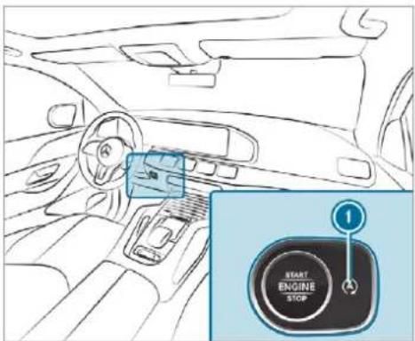
text_image
START ENGINE STOP
Press button ①. A display appears in the instrument cluster when switching the ECO start/stop function off/on.
A continuous display appears in the instrument cluster while the ECO start/stop function is deactivated.
ECO display function
The ECO display summarises your driving characteristics from the start of the journey to its completion and assists you in achieving the most economical driving style.
You can influence consumption if you:
• drive with particular care
• drive the vehicle in drive program E
• observe the gearshift recommendations
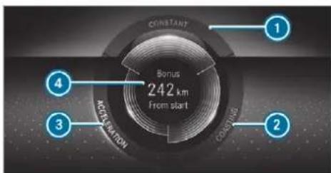
text_image
CONSTANT Bonus 242 km from start 1 4 3 ACCOILIZATION COMPENS 2The lettering in the segment will light up brightly, the outer edge will light up and the segment v fill up when the following driving style is adopted:
• ① Steady speed
• ② Gentle deceleration and rolling
• 3 Moderate acceleration
The lettering in the segment will be grey, the outer edge will be dark and the segment will empty when the following driving style is adopted:
• ① Fluctuations in speed
• ② Heavy braking
• Sporty acceleration
The ECO display will show you when you have driven economically:
- The three segments will fill up completely at the same time
• The edge around all three segments will light up
The additional range achieved as a result of your driving style in comparison with a driver with a very sporty driving style will be shown in the centre of the display. The range displayed does not indicate a fixed reduction in consumption.
it will appear on the multifunction display. The following symbols can be displayed:
text_image
mph %Examples of an event ahead
ECO Assist function
Vehicles with a 48 V on-board electrical system (EQ Boost technology):
ECO Assist analyses data for the vehicle's expected route. This allows the system to optimally adjust the driving style for the route ahead, save fuel and recuperate. If the system detects an event ahead (e.g. a speed limit or a roundabout),
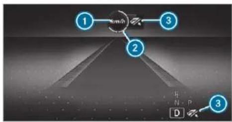
text_image
km/h 1 2 3 D 3① Event ahead
② Distance to the event ahead
3 "Foot off the accelerator" prompt
The number of segments shown ② changes depending on the distance to the event ahead:
- A few segments: the event ahead is near.
- Many segments: the event ahead is further away.
When the vehicle nears the event, ECO Assist will calculate the optimal speed for maximum fuel economy and recuperative energy based on the distance, speed and downhill gradient. The Foot off the accelerator ③ message appears in
the multifunction display. The first segments in front of the vehicle will turn green. The remaining segments will initially stay white. If the driver lifts off the accelerator pedal in good time, remaining segments on the display will successively turn green until the event shown is reached. The drivetrain will be set for maximum fuel economy. Recuperation will charge the battery. Recuperation will be adapted to the selected drive program.
The event will be shown for a short time after it has been passed. If there is no response to the Foot off the accelerator prompt, the segments will remain white.
If the event involves a vehicle in front, all segments will immediately turn green once there a response to the Foot off the accelerator prompt.
For active ECO Assist in drive program E, symbol ③ will appear on the multifunction display and on the head-up display beside transmission position D. Symbol ③ will also appear when the assistant display is not selected.
If the system does not intervene during the event ahead, nothing will be displayed. The system is passive.
the ECO Assist is active only in drive programs E and C.
System limits
ECO Assist can function even more precisely if the route is adhered to when route guidance is active. The basic function is also available without active route guidance. Not all information and traffic situations can be foreseen. The quality depends on the map data.
ECO Assist is only an aid. The driver is responsible for keeping a safe distance from the vehicle in front, for vehicle speed and for braking in good time. The driver must be ready to brake at all times irrespective of whether the system intervenes.
The system may be impaired or may not function in the following situations:
- if visibility is poor (e.g. due to insufficient illumination of the road, highly variable shade conditions, rain, snow, fog or heavy spray).
- if there is glare (e.g. from oncoming traffic, direct sunlight or reflections).
- if there is dirt on the windscreen in the vicinity of the multifunction camera or the came is misted up, damaged or obscured.
- if traffic signs are hard to discern (e.g. due to dirt, snow or insufficient lighting, or because they are obscured).
- If the information on the navigation system's digital map is incorrect or out of date.
- If the signs are ambiguous, e.g. traffic signs in roadworks or in adjacent lanes.
DYNAMIC SELECT switch
Function of the DYNAMIC SELECT switch
Mercedes-AMG vehicles: observe the notes in the Supplement. You could otherwise fail to recognise dangers.
Depending on the engine and equipment, the vehicle has different drive programs.
Use the DYNAMIC SELECT switch to change between the following drive programs:

(Individual): individual settings

(Sport +): particularly sporty driving style

(Sport): sporty driving style

(Comfort): comfortable and economical driving style

(Maybach): highest level of driving comfort for comfortable and luxurious travel (Mercedes-Maybach vehicles only)

(Eco): particularly economical driving style

(CURVE): comfortable driving with curve inclination function (vehicles with E-ACTIVE BODY CONTROL)

Offroad: driving on less demanding off-road terrain

(Offroad +): driving on difficult off-road terrain
Mercedes-Maybach vehicles: In the drive programs and, the extendible running boards remain retracted or retract if they have already been extended.
The drive program selected appears in the multifunction display of the on-board computer.
Depending on the drive program, the following systems change their characteristics:
- drive
- engine and transmission management
- Active Distance Assist DISTRONIC
- ESP®
- vehicles with AIRMATIC or E-ACTIVE BODY CONTROL:
- Suspension tuning
- Vehicle level
• electric power steering
Notes on the roof load display
Certain drive programs and ESPsettings are unsuitable for transporting a roof load.
If one of these drive programs is set or selected,

the symbol is shown as a warning. When this symbol is shown, the selected drive program is not suitable for transporting a load on the roof.
The following drive programs are affected:
- Sport drive program
- Sport + drive program
- Individual drive program with the ESP® setting Sport or Sport+
The symbol is also shown in the following situations:
- Within the themes if a corresponding drive program is saved For more information on themes see ( page 398).
- Within the reset display if the previously active drive program is unsuitable for the transport of a roof load For further information on the reset display, see (→ page 227).
Selecting the drive program
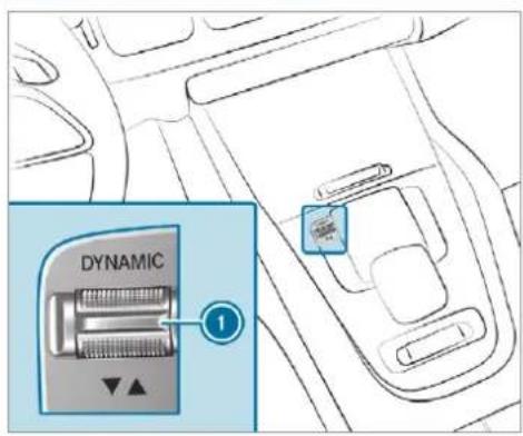
text_image
DYNAMIC 1Press DYNAMIC SELECT switch ① forwards or backwards. The drive program selected appears in the multifunction display.
Configuring DYNAMIC SELECT (multimedia system)
Multimedia system:

Setting drive program I
- Select Individual config.. - Select and set a category.
Switching the reset display on/off
▶ Switch Ask when starting on or off.
Function on: the next time the vehicle is started a prompt appears asking whether the last active drive program should be restored. If the ECO start/stop function was deactivated, an additional prompt appears asking if the function should remain deactivated.
The prompt appears only if the previously active settings deviate from the standard settings.
Function off: the next time the vehicle is started the C drive program is set automatically. The ECO start/stop function is activated automatically.
This function must be activated for each us profile separately. Only when this function is activated will the drive program and Eco start/stop setting for the previous journey be saved for the respective user profile.
Displaying vehicle data
Multimedia system:

▶ Select Vehicle.
The vehicle data is displayed.
Displaying engine data
Multimedia system:
Info
▶ Select Engine.
The engine data is displayed.
The actual (maximum) values that can be achieved for engine output and engine torque may deviate from the certified values within the country-specific guidelines for permissible tolerances (basis: UN-ECE No. 85 or country-specific guidelines).
Factors that can influence this are, for example:
- Sea level
- Fuel grade
- Outside temperature
The values displayed serve only as orientation. The values for engine output and engine torque shown in the media display may deviate from the actual values.
Calling up fuel consumption indicator
Multimedia system:
Info
▶ Select Consumption.
The current and average fuel consumption is displayed.
Automatic transmission
DIRECT SELECT lever
Function of the DIRECT SELECT lever
⚠ WARNING Risk of accident due to incorrect gearshifting
If the engine speed is higher than the idle speed and you engage the transmission position D or R, the vehicle may accelerate sharply.
If you engage the transmission position D or R when the vehicle is at a standstill, always depress the brake pedal firmly and do not accelerate at the same time.
⚠ WARNING Risk of accident and injury due to children left unattended in the vehicle
If children are left unattended in the vehicle, they could:
- Open doors, thereby endangering other persons or road users.
- Get out and be struck by oncoming traffic.
- Operate vehicle equipment and become trapped, for example.
In addition, the children could also set the vehicle in motion, for example by:
- Releasing the parking brake.
- Changing the transmission position.
- Starting the vehicle.
▶ Never leave children unattended in the vehicle.
When leaving the vehicle, always take the key with you and lock the vehicle.
Keep the vehicle key out of reach of children.
This also applies to the Digital Vehicle Key if the "Digital Vehicle Key" function is activated via Mercedes me connect.
Use the DIRECT SELECT lever to shift the transmission position. The current transmission position is displayed in the multifunction display.
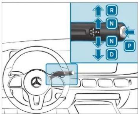
text_image
Diagram of a car dashboard with directional arrows and labeled buttons (R, N, P, D) indicating traffic or movement directions.P Park position
R Reverse gear
N Neutral
D Drive position
Engaging reverse gear R
Depress the brake pedal and push the DIRECT SELECT lever upwards past the first point of resistance. The transmission position display R is shown in the multifunction display.
Engaging neutral N
Depress the brake pedal and push the DIRECT SELECT lever up or down to the first point of resistance. The transmission position display N is shown in the multifunction display.
Subsequently releasing the brake pedal will allow you to move the vehicle freely, e.g. to push it or tow it away.
Proceed as follows if you want the automatic transmission to remain in neutral N even if the ignition is switched off or the driver's door is opened:
Start the vehicle.
Depress the brake pedal and engage neutral N when the car is stationary.
The message N permanently active Risk of vehicle rolling appears in the instrument cluster.
Release the brake pedal.
▶ Switch the ignition off.
If you then exit the vehicle leaving the key in the vehicle, the automatic transmission remains in neutral [N].
The park position P is automatically re-engaged if one of the following conditions is met:
- you switch to transmission position D or R.
- you press the button P.
Engaging park position P
Observe the notes on parking the vehicle ( page 242).
Depress the brake pedal until the vehicle is stationary.
When the vehicle is stationary, press button P.
Park position is only engaged when the transmission position display P is shown in the multifunction display. If no transmission position display P appears, secure the vehicle to prevent it from rolling away.
(i) Depending on the situation, it may take some time until P is engaged. Therefore, always pay attention to the transmission position display.
Park position P is engaged automatically if one of the following conditions is met:
- you switch off the ignition when the vehicle is stationary and the transmission is in position D or R.
- you open the driver's door when the vehicle is stationary or when driving at a very low speed and the transmission is in position or R.
-
you switch off the motor and bring the vehicle to a standstill when the vehicle is rolling and the transmission is in position D or R.
-
you switch off the motor, bring the vehicle to a standstill and open the driver's door when the vehicle is stationary or when the vehicle is rolling and the transmission is in position [N].
- Engaging park position P automatically is required by the vehicle.
To manoeuvre with an open driver's door, open the driver's door while stationary and engage transmission position [D] or [R] again.
Engaging drive position D
▶ Depress the brake pedal and push the DIRECT SELECT lever down past the first point of resistance.
The transmission position display D is shown in the multifunction display.
When the automatic transmission is in transmission position [D], it shifts the gears automatically. This depends, among other things, on the following factors:
• the selected drive program
• the position of the accelerator pedal
- the driving speed
Manual gearshifting

WARNING Risk of skidding and of an accident due to shifting down on slippery road surfaces
If you shift down on slippery road surfaces to increase the engine braking effect, the drive wheels may lose traction.
Do not shift down on slippery road surfaces to increase the engine braking effect.
Permanent setting (vehicles with Offroad package or E-Active Body Control)
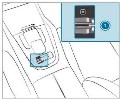
text_image
Diagram showing a car seatbelt switch with labeled component M and numbered connection point 1To activate/deactivate: pull rocker switch ①. If indicator lamp is lit, manual gearshifting is activated. The current gear is displayed in the multifunction display.
Temporary setting
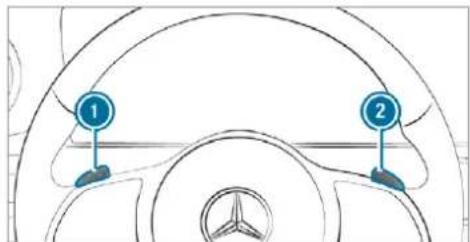
text_image
Diagram of a car steering wheel with numbered components and brand logo at the headTo activate: pull steering wheel gearshift paddle ① or ②. Manual gearshifting is activated for a short time. Transmission position [M] and the current gear appear in the multifunction display.
To deactivate: pull steering wheel gearshift paddle ② and hold it in place. The transmission position D appears in the multifunction display.
To permanently shift the gears manually in drive program using the steering wheel gearshift paddles, select the M (Manual) setting for the transmission.
Gearshifting
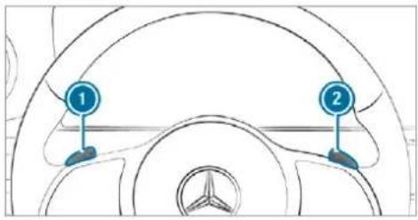
text_image
Diagram of a car dashboard with labeled parts 1 and 2, showing steering wheel and dashboard controls.To shift up: pull steering wheel gearshift paddle ②.
To shift down: pull steering wheel gearshift paddle ①.
Mercedes-AMG vehicles: observe the notes in the Supplement. Otherwise, you may fail to recognise dangers.
Gearshift recommendation
Mercedes-AMG vehicles: observe the notes in the Supplement. Otherwise, you may fail to recognise dangers.
The gearshift recommendation assists you in adopting an economical driving style.
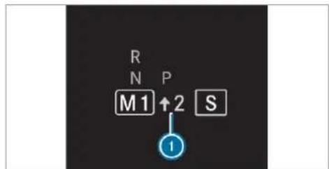
text_image
R N P M1 ↑2 S ①If gearshift recommendation message ① is shown on the multifunction display, shift to the recommended gear.
Using kickdown
Mercedes-AMG vehicles: observe the notes in the Supplement. Otherwise, you may fail to recognise dangers.
▶ Maximum acceleration: depress the accelerator pedal beyond the pressure point.
The automatic transmission shifts up to the next gear when the maximum engine speed is reached to protect the engine from overrevving.
Glide mode function
Mercedes-AMG vehicles: observe the notes in the Supplement. You could otherwise fail to recognise dangers.
With an anticipatory driving style, Glide mode helps you to reduce fuel consumption.
Glide mode is characterised by the following:
- the combustion engine is disconnected from the drivetrain and continues to run in neutral.
- the transmission position [D] is displayed in green in the multifunction display.
- Vehicles with 48 V on-board electrical system (EQ-Boost technology): the combustion engine can be switched off. All of the vehicle functions remain active.
Glide mode is activated if the following conditions are met:
• Mercedes-Maybach vehicles: drive pro-

gram is selected.
- All other models: drive program E is selected.
• the speed is within a suitable range. - the road's course is suitable, e.g. no steep uphill or downhill inclines or tight bends.
- There is no trailer coupled to the trailer hitch, and no bicycle rack fitted.
- you do not depress the accelerator or brake pedal (except for light brake applications).
Glide mode can also be activated if you have selected the "Eco" setting for the drive in the drive program.
Glide mode is deactivated again if one of the conditions is no longer met.
Glide mode can also be prevented by the following parameters:
- incline
- downhill gradient
- Temperature
- height
- speed
• operating status of the engine - traffic situation
Transfer case
Function of the transfer case

WARNING Risk of skidding and having an accident when in LOW RANGE on slippery road surfaces
If you select the LOW RANGE off-road gear on a slippery road surface, the wheels could lose traction in the following situations:
- if you release the accelerator pedal when the vehicle is in motion.
- if off-road ABS intervenes when braking.
If the wheels lose traction, it will no longer be possible to steer the vehicle.
▶ Never select the LOW RANGE off-road gear when driving on slippery road surfaces.

WARNING Risk of accident when the transfer case is in neutral position
The transfer case can be in neutral position you do not wait until shift operation is complete. The power transmission to the driven wheels is then interrupted. The vehicle may thereby inadvertently roll away.
▶ Wait until the transfer case shift operation is complete.
This function is only available in vehicles with Off-road package.
Shift the transfer case to the on-road position HIGH RANGE or into the LOW RANGE off-road gear.
Do not switch off the engine during shift operation and do not shift the automatic transmission. Do not use LOW RANGE in the following situations to another position.
Shift ranges
HIGH RANGE LOW RANGE
if Road position for all normal on-road driving situations.
Off-road gear for driving off-road, when fording and on steep uphill or downhill inclines.
Properties of the LOW RANGE off-road gear:
- reduced maximum permissible speed: 50 km/h
• increased tractive power - Changing the transmission ratio by a factor of about three
- increased drive torque
- when driving on public roads.
Shifting the transfer case
Shifting to the LOW RANGE off-road gear
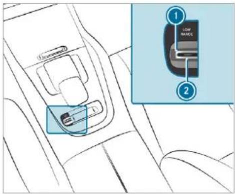
text_image
Diagram showing a car interior with labeled parts and an inset highlighting a low frame component.Requirements:
- you are not driving on a paved or public road.
• the vehicle is stationary.
Pull the LOW RANGE ① rocker switch. Indicator lamp ② will flash. The shift request stays active for a maximum of 30 seconds. If all requirements for shift operation are not fulfilled within this time, the indicator lamp ② switches off again and the shift operation must be started again.
Shift the transmission to position N. If shift operation is successful, the message LOW RANGE on appears in the instrument cluster, an audible signal sounds and indicator lamp ② and an indicator lamp in the instrument cluster light up continuously.
Shift the transmission to position D.
The vehicle stays in LOW RANGE if you park the vehicle in LOW RANGE, even after the engine has been restarted.
You will not be able to switch on LOW RANGE if drive program S or S' is switched on. The vehicle switches to drive program C.
In the on-road position, shift to HIGH RANGE
Requirements:
- the engine is running and you are not driving faster than 50 km/h.
Pull the LOW RANGE 1 rocker switch. The shift request stays active for a maximum of 30 seconds. If all requirements for shift operation have not been fulfilled within this time, shift operation must be started again.
Shift the transmission to position N. If shift operation is successful, the message LOW RANGE off appears in the instrument cluster, an audible signal sounds and the indicator lamps go out. Shift the transmission to position D.
Function of the 4MATIC
4MATIC ensures that all four wheels are driven when needed. Together with ESPand 4ETS, 4MATIC improves the traction of your vehicle whenever a driven wheel spins due to insufficient traction.
If you fail to adapt your driving style, 4MATIC can neither reduce the risk of an accident nor override the laws of physics. 4MATIC cannot take account of road, weather and traffic conditions. 4MATIC is only an aid. You are responsible especially for maintaining a safe distance from the vehicle in front, for vehicle speed, for braking in good time and for staying in lane.
In wintry road conditions, the maximum effect of 4MATIC can be achieved only if you use winter tyres (M+S tyres), with snow chains if necessary.
Refuelling
Refuelling the vehicle
WARNING Risk of fire or explosion from fuel
Fuels are highly flammable.
▶ Fire, naked flames, smoking and creation of sparks must be avoided.
Switch off the ignition and, if available, the stationary heater, before and while refuelling the vehicle.

WARNING Risk of injury from fuels
Fuels are poisonous and hazardous to your health.
Do not swallow fuel or let it come into contact with skin, eyes or clothing.
Do not inhale fuel vapour.
Keep children away from fuel.
Keep doors and windows closed during the refuelling process.
If you or other people come into contact with fuel, observe the following:
Immediately rinse fuel off your skin with soap and water.
If fuel comes into contact with your eyes, immediately rinse them thoroughly with clean water. Seek medical attention immediately.
If you swallow fuel, seek medical attention immediately. Do not induce vomiting.
Change immediately out of clothing that has come into contact with fuel.

WARNING Risk of fire and explosion due to electrostatic charge
Electrostatic charge can create sparks and thereby ignite fuel vapours.
Before you open the fuel filler cap or take hold of the pump nozzle, touch the metallic vehicle body. This discharges any electrostatic charge that may have built up.
Do not get into the vehicle again during the refuelling process. Otherwise, electrostatic charge can build up again.

WARNING Risk of fire from fuel mixture
Vehicles with a diesel engine:
If you mix diesel fuel with petrol, the flash point of the fuel mixture is lower than that of pure diesel fuel.
While the engine is running, component parts in the exhaust system may overheat without warning.
▶ Never refuel using petrol.
▶ Never mix petrol with diesel fuel.

NOTE Damage caused by the wrong fuel
Vehicles with a petrol engine:
Even small amounts of the wrong fuel could result in damage to the fuel system, the engine and the emission control system.
Only refuel using unleaded, sulphur-free fuel that conforms to European EN 228, or an equivalent specification.
Fuel of this specification may contain up to 10% ethanol. Your vehicle is suitable for use with E10 fuel.
Never refuel with one of the following fuels:
- diesel
- regular petrol with an octane number lower than 91 RON
- petrol with more than 10% ethanol by volume, e.g. E15, E20, E85, E100
- petrol with more than 3% methanol by volume, e.g. M15, M30
• petrol with additives containing metal
If you have accidentally refuelled with the wrong fuel:
▶ do not switch the ignition on.
Consult a qualified specialist workshop.
NOTE Damage caused by the wrong fuel
Vehicles with a diesel engine:
Even small amounts of the wrong fuel could result in damage to the fuel system, the engine and the emission control system.
Only refuel using sulphur-free diesel fuel that conforms to European stand-
ard EN 590, or an equivalent specification.
In countries without sulphur-free diesel fuel, refuel using only low-sulphur diesel fuel with a sulphur content less than 50 ppm.
Never refuel using any of the following fuels:
- petrol
- marine diesel
- heating oil
• pure bio-diesel fuel or vegetable oil - paraffin or kerosene
If you accidentally refuel with the wrong fuel:
▶ Do not switch the ignition on.
Consult a qualified specialist workshop.
NOTE Do not use diesel to refuel vehicles with a petrol engine
If you have accidentally refuelled with the wrong fuel:
- do not switch the ignition on. Otherwise fuel can enter the engine.
Even small amounts of the wrong fuel could result in damage to the fuel system and the engine. The repair costs are high.
Consult a qualified specialist workshop.
Have the fuel tank and fuel lines drained completely.
NOTE Do not use petrol to refuel vehicles with a diesel engine
If you have accidentally refuelled with the wrong fuel:
- do not switch the ignition on. Otherwise, fuel can enter the fuel system.
Even small amounts of the wrong fuel could result in damage to the fuel system and the engine. The repair costs are high.
Consult a qualified specialist workshop.
Have the fuel tank and fuel lines drained completely.
! NOTE Damage to the fuel system caused by overfilled fuel tanks
Only fill the fuel tank until the pump nozzle switches off.
If you have added too much fuel because of a defective filling pump, for instance:
▶ Do not switch the ignition on.
Consult a qualified specialist workshop.
! NOTE Fuel may spray out when you remove the fuel pump nozzle
Only fill the fuel tank until the pump nozzle switches off.
Requirements:
• The vehicle is unlocked ( page 85).
Do not get into the vehicle again during the refuelling process. Otherwise, electrostatic charge could build up again.
Observe the notes on operating fluids and fuel ( page 635).
The recommended octane number for your vehicle can be found on the information label in the fuel filler flap ( page 235).
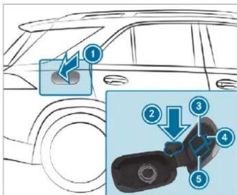
text_image
Diagram illustrating car seatbelt cleaning steps with numbered instructions for cleaning and disassemblyFuel filler flap
2 Bracket for fuel filler cap
3 Tyre pressure table
QR code for rescue card
Fuel type
Press on the back area of fuel filler flap ①.
Turn the fuel filler cap anti-clockwise and remove it.
Insert the fuel filler cap from above into bracket ②.
Completely insert the pump nozzle into the tank filler neck, hook in place and refuel.
Only fill the fuel tank until the pump nozzle switches off.
① Vehicles with a diesel engine: the tank filler neck is designed for refuelling at diesel filling pumps.
① Vehicles with a diesel engine: when the fuel tank is completely empty, top up with at least 5 litres of diesel.
① Vehicles with a diesel engine: use a filler neck with a large diameter for vehicles with a diesel engine when topping up fuel from fuel can. Otherwise, the filler neck cannot slide into the tank.
Replace the cap on the filler neck and turn clockwise until it engages audibly.
Close fuel filler flap 1
i Close the fuel filler flap before locking the vehicle.
AdBlue® (vehicles with a diesel engine only)
Notes on refilling AdBlue®
NOTE Small amounts of ammonia vapour may be released when opening the AdBlue® tank
Only fill the AdBlue ^® tank in well-ventilated areas.
Do not let AdBluecome into contact with skin, eyes or clothes.
Keep AdBlue ^® away from children.
NOTE Do not ingest AdBlue®
^1 If AdBlue ^® is swallowed:
Immediately rinse out your mouth thoroughly.
▶ Drink plenty of water.
▶ Seek medical attention immediately.
Observe the notes on operating fluids ( page 635).
AdBlue ^ is a water-soluble fluid for the NOx exhaust gas aftertreatment of diesel engines. In order for the exhaust gas aftertreatment to function properly, only use AdBlue ^ in accordance with ISO 22241.
AdBlue ^® is characterised by the following:
- non-toxic
• colourless and odourless - non-flammable
AdBlue ^® is available here:
- AdBlue® can be topped up by fast service at a qualified specialist workshop, e.g. a Mercedes-Benz Service Centre.
- AdBlue ^ is available at many filling stations from AdBlue ^ filling pumps.
- Alternatively, AdBlue® is available at qualified specialist workshops, e.g. Mercedes-Benz Service Centres, and at many filling stations in AdBlue® refill canisters or AdBlue® refill bottles.
i Ensure the connection between the refill container and vehicle filler neck does not drip.
Topping up AdBlue®
NOTE Engine damage due to AdBlue® being in the fuel
AdBlue ^® must not be used to fill the fuel tank.
Only use AdBlue ^® to fill the AdBlue ^® tank.
Do not overfill the AdBlue® tank.
NOTE Contamination of the vehicle interior due to AdBlue® leakage
After topping up, carefully close the AdBlue® refill container.
Avoid carrying AdBlue ^® refill containers permanently in the vehicle.
Requirements:
• The vehicle is unlocked.
The following messages appear in order in the multifunction display when the AdBlue ^® tank requires topping up:
- Refill AdBlue See Owner's ManualThe AdBlue® level has fallen below the reserve range. Top up AdBlue® immediately.
- Top up AdBlue Emergency op. in XXX miles See Owner's Manual The low AdBlue level will lead to limited performance after the remaining distance displayed has been driven. Top up AdBlue® immediately.
- XX,X I Top up AdBlue Emer. op.: max. XXX km/h Start not poss. in XXX kmThe low AdBlue® level will lead to limited performance from the speed displayed. After the remaining distance displayed has been covered, it will no longer be possible to start the engine. Top up with at least the amount of AdBlue® displayed.
- XX,X I Top up AdBlue Switch on ignition, wait 60 sec. or eng. start not poss.. The AdBlue® tank is empty. You can no longer start the engine. Top up with at least the amount of
AdBlue ^® displayed. Switch on the ignition and wait for approximately 60 seconds. Start the engine.
You can see the AdBlue ^® range and level in the multifunction display ( page 351).
The AdBlue ^® range shown depends strongly on the driving style and operating conditions. The actual range can therefore deviate from the calculated range.
Opening the AdBlue® filler cap

text_image
Diagram showing car interior components with numbered labels and directional arrows indicating movement or flowPress on the back area of fuel filler flap ①.
Turn AdBlue® filler cap ② anti-clockwise and remove it.
You can also store the AdBlue® filler cap in the fuel filler cap holder in the fuel filler flap hinge arm.
Preparing the AdBlue ^® refill canister
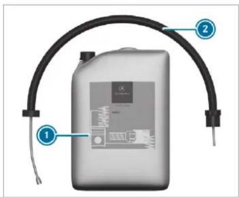
text_image
Diagram of a battery with labeled parts and components, showing connections to a curved black cable or connector.Screw on the fastener of AdBlue ^® refill canister 2.
Screw disposable hose ① onto the opening of AdBlue® refill canister ② until hand-tight.
Topping up AdBlue®
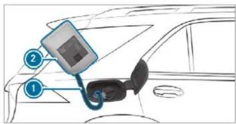
text_image
Diagram showing car charging station with labeled components including battery and plug connectionsScrew disposable hose ① onto the filler neck of the vehicle until hand-tight.
Lift up and tip AdBlue® refill canister ②. The filling process stops when the AdBlue® tank is completely full.
AdBlue ^® refill canister ② can be removed when it has been only partially emptied
Unscrew and close disposable hose ① and AdBlue® refill canister ② in reverse order.
Replace the AdBlue ^® filler cap and turn it clockwise.
Close the fuel filler flap.
Switch on the ignition for at least 60 seconds.
If the vehicle could not be started as the AdBlue ^® tank was empty, it can take up to 60 seconds for the refill to be detected.
Start the vehicle.
① Avoid storing AdBlue® refill containers permanently in the vehicle.
Parking
Parking the vehicle

WARNING Risk of accident and injury caused by an insufficiently secured vehicle rolling away.
If the vehicle is not securely parked sufficiently, it can roll away in an uncontrolled way even at a slight downhill gradient.
▶ Ensure that the parked vehicle is always properly secured against rolling away as follows:
- on uphill or downhill gradients, turn the front wheels so that the vehicle rolls towards the kerb if it starts moving.
- apply the parking brake.
- switch the transmission to position [P].

WARNING Risk of fire caused by hot exhaust system parts
Flammable material such as leaves, grass or twigs may ignite if they come into contact with hot parts of the exhaust system or exhaust gas flow.
Park the vehicle so that no flammable material can come into contact with hot vehicle components.
In particular, do not park on dry grassland or harvested grain fields.

WARNING Risk of accident and injury due to children left unattended in the vehicle
If children are left unattended in the vehicle, they could:
- Open doors, thereby endangering other persons or road users.
- Get out and be struck by oncoming traffic.
- Operate vehicle equipment and become trapped, for example.
In addition, the children could also set the vehicle in motion, for example by:
- Releasing the parking brake.
- Changing the transmission position.
- Starting the vehicle.
▶ Never leave children unattended in the vehicle.
When leaving the vehicle, always take the key with you and lock the vehicle.
Keep the vehicle key out of reach of children.
This also applies to the Digital Vehicle Key if the "Digital Vehicle Key" function is activated via Mercedes me connect.
! NOTE Damage to the vehicle due to it rolling away
Always secure the vehicle against rolling away.
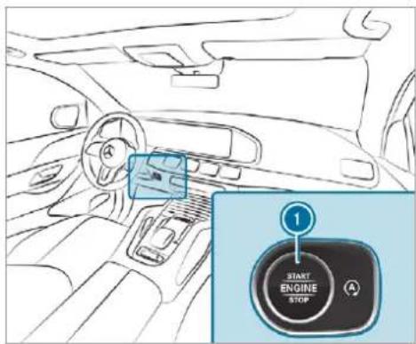
text_image
1 START ENGINE STOPBring the vehicle to a standstill by applying the brake pedal.
On uphill or downhill gradients, turn the front wheels so that the vehicle rolls towards the kerb if it starts moving.
▶ Apply the electric parking brake.
Engage transmission position P in a stationary vehicle with the brake pedal applied (→ page 230).
Switch off the engine and the ignition by pressing the ① button.
Release the service brake slowly.
▶ Get out of the vehicle and lock it.
When you park the vehicle, you can still operate the side windows and the panoramic sliding sunroof for approximately five minutes if the driver's door is closed.
When you park the vehicle, you can still operate the side windows and the sliding sunroof for approximately five minutes if the driver's door is closed.
Garage door opener
Programming buttons for the garage door opener

DANGER Risk of death caused by exhaust gases
Combustion engines emit poisonous exhaust gases such as carbon monoxide. Inhaling these exhaust gases is hazardous to health and leads to poisoning.
▶ Never leave the engine or, if present, the auxiliary heating running in an enclosed space without sufficient ventilation.

WARNING Risk of injury when opening or closing a door with the garage door opener
When you operate or program the door with the integrated garage door opener, people in the range of movement of the door may become trapped or struck by the door.
When using the integrated garage door opener, always make sure that nobody is within the range of movement of the door.
Requirements:
- The vehicle has been parked outside the garage or outside the range of movement of the door.
• The engine is switched off.
• The ignition is switched on.
The garage door opener function is always available when the ignition is switched on.
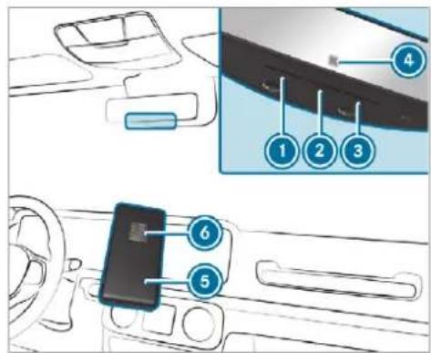
text_image
Diagram showing car interior components with numbered labels pointing to a device panelPress and hold button ①, ② or ③ that you wish to program.
Indicator lamp ④ flashes yellow.
① It can take up to 20 seconds before the indicator lamp flashes yellow.
Release the previously pressed button. Indicator lamp 4 continues to flash yellow.
Point remote control ⑤ from a distance of 1 cm to 8 cm towards button ①, ② or ③.
Press and hold button ⑥ of remote control ⑤ until one of the following signals appears:
- Indicator lamp ④ lights up green continuously. Programming is complete.
- Indicator lamp ④ flashes green. Programming was successful. Additionally, synchronisation of the rolling code with the door system must also be carried out
If indicator lamp ④ does not light up or f green: repeat the procedure.
Release all of the buttons.
The remote control for the door drive is not included in the scope of delivery of the garage door opener.
Synchronising the rolling code Requirements:
• The door system uses a rolling code.
- The vehicle must be within range of the garage door or door drive.
- The vehicle as well as persons and objects, are located outside the range of movement of the door.
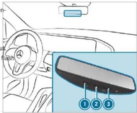
text_image
n- ut flash 1 2 3▶ Press the programming button on the door drive unit. Initiate the next step within approximately 30 seconds.
Press previously programmed button ①, ② or ③ repeatedly until the door closes. When the door closes, programming is completed.
i Please also read the operating instructions for the door drive.
Troubleshooting when programming the remote control
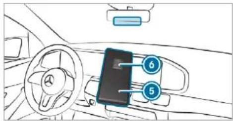
text_image
Diagram of car interior showing steering wheel, dashboard, and smartphone with numbered labels pointing to key components.Check if the transmitter frequency of remote control ⑤ is supported.
Replace the batteries in remote control ⑤.
Hold remote control ⑤ at various angles from a distance of 1 cm to 8 cm in front of
the inside rearview mirror. You should test every position for at least 25 seconds before trying another position.
Hold remote control ⑤ at the same angles at various distances in front of the inside rear view mirror. You should test every position for at least 25 seconds before trying another position.
Note that some remote controls transmit only for a limited period, press button ⑥ on remote control ⑤ again before transmission ends.
Align the aerial line of the door opener unit with the remote control.
i Support and additional information on programming:
- On the HomeLink® Hotline on (0) 08000 466 354 65 or +49 (0) 6838 907-277.
• On the Internet at https://www.homelink.com.
Opening or closing the door Requirements:
- The corresponding button is programmed to Clearing the garage door opener memory operate the door.
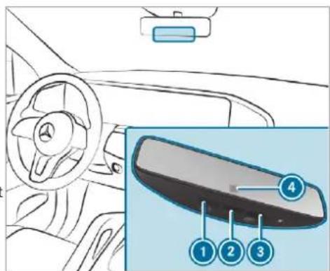
text_image
Diagram of a car interior showing steering wheel, dashboard, and rearview mirror with numbered labels pointing to key components.Press and hold buttons ①, ② or ③ until the door opens or closes.
If indicator lamp ④ flashes yellow after approximately 20 seconds: press and hold the previously pressed button again until the door opens or closes.
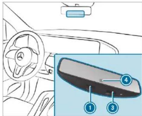
text_image
Diagram of a car interior showing steering wheel, dashboard, and rearview mirror with numbered labelsPress and hold buttons ① and ③. Indicator lamp ④ lights up yellow.
If indicator lamp ④ flashes green: release buttons ① and ③.
The entire memory has been deleted.
Radio equipment approval numbers for the garage door opener
Radio equipment approval numbers

text_image
ANATEL 1850-16-6324Brazil
Radio equipment approval numbers
| Country | Radio equipment approval number |
| Egypt | TAC.2511151293.WIR |
| Andorra CE | |
| Australia | R-NZ |
| Barbados MED 1578 | |
| Chile | 2488/DFRS20576/F-74 |
| European Union | CE |
| Gibraltar | C E |
| Iceland CE | |
| Jordan TRC/LPD/2015/299 | |
| Canada | IC: 4112A-MUAHL5 |
| Kuwait CE | |
| Liechtenstein | CE |
Further information on the declaration of conformity for wireless vehicle components ( page 26).
| Country | Radio equipment approval number |
| Mexico RCP | GEMU15-0448 |
| Monaco CE | |
| New Zealand | R-NZ |
| Norway | C E |
| Russian Federation | Not required |
| Saudi Arabia | TA 10525 |
| Switzerland | CE |
| South Africa | ICASA TA-2015/1386 |
| Turkey | Not required |
| United Arab Emirates | ER41849/15Dealer No: DA35176/14 |
| United States | FCC ID: NZLMUAHL5 |
Electric parking brake
Electric parking brake function (applying automatically)

WARNING Risk of accident and injury due to children left unattended in the vehicle
If children are left unattended in the vehicle, they could:
- Open doors, thereby endangering other persons or road users.
- Get out and be struck by oncoming traffic.
- Operate vehicle equipment and become trapped, for example.
In addition, the children could also set the vehicle in motion, for example by:
- Releasing the parking brake.
- Changing the transmission position.
- Starting the vehicle.
▶ Never leave children unattended in the vehicle.
When leaving the vehicle, always take the key with you and lock the vehicle.
Keep the vehicle key out of reach of children.
This also applies to the Digital Vehicle Key if the "Digital Vehicle Key" function is activated via Mercedes me connect.
The electric parking brake is applied if the transmission is in position P and one of the following conditions is fulfilled:
• The engine is switched off.
- The seat belt tongue is not inserted in the seat belt buckle of the driver's seat and the driver's door is opened.
- The transfer case is in the LOW RANGE position.
To prevent application: pull the handle of the electric parking brake.
In the following situations, the electric parking brake is also applied:
• Active Distance Assist DISTRONIC is bringing the vehicle to a standstill.
- The HOLD function is keeping the vehicle stationary.
• Active Parking Assist is keeping the vehicle stationary.
This is the case if one of the following conditions is also fulfilled:
• The engine is switched off.
- The seat belt tongue is not inserted in the seat belt buckle of the driver's seat and the driver's door is opened.
• There is a system malfunction.
• The power supply is insufficient.
• The vehicle is stationary for a lengthy period.
When the electric parking brake is applied, the red () indicator lamp appears in the instrument cluster.
The electric parking brake is not automatically applied if the engine is switched off by the ECO start/stop function.
Electric parking brake function (releasing automatically)
The electric parking brake is released when the following conditions are fulfilled:
• The driver's door is closed.
• The engine is running.
- The transmission is in position D or R and you depress the accelerator pedal or you shift from transmission position P to D or R when on level ground with the driver's door closed.
- If the transmission is in position , the tailgate must be closed.
- The seat belt tongue is inserted into the seat belt buckle of the driver's seat.
If the seat belt tongue is not inserted into the seat belt buckle of the driver's seat, the following conditions must be fulfilled:
- You shift from transmission position P.
• You have previously driven at speeds greater than 3 km/h
When the electric parking brake is released, the red indicator lamp in the instrument cluster goes out.
Applying/releasing the electric parking brake manually
Applying
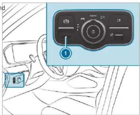
text_image
Diagram showing car interior with a car seatbelt and a digital camera control panel labeled 'AUTO' pointing to the left side.Push handle ①. The red (P) indicator lamp appears in the instrument cluster.
The electric parking brake is only securely applied if the indicator lamp is lit continuously.
Releasing
Switch on the ignition.
Pull handle ①. The red (P) indicator lamp in the instrument cluster goes out.
Emergency braking
Press and hold handle ①. As long as the vehicle is driving, the Release parking brake message is displayed. When the vehicle has been braked to a standstill, the electric parking brake is applied. The red (P) indicator lamp appears in the instrument cluster.
Information on detecting damage on a parked vehicle
If a collision is detected when the tow-away protection is primed on a locked vehicle, you will receive a notification in the multimedia system when you switch on the ignition.
You will receive information about the following points:
- The area of the vehicle that may have been damaged.
• The force of the impact.
The following situations can lead to inadvertent activation:
- The parked vehicle is moved, e.g. in a two-storey garage.
i Deactivate tow-away protection in order to prevent inadvertent activation. If you deactivate tow-away protection, damage detection will also be deactivated.
System limits
Detection may be restricted in the following situations:
- the vehicle is damaged without impact, e.g. if an outside mirror is torn off or the paint is damaged by a key
- an impact occurs at low speed
• the electric parking brake is not applied
Notes on parking up the vehicle
If you leave the vehicle parked up for longer than six weeks, it may suffer damage through disuse.
The 12 V battery may also be impaired or damaged by heavy discharging.
i Further information can be obtained at a qualified specialist workshop.
Standby mode (extension of the starter battery's period out of use)
Standby mode function
This function is not available for all models.
If standby mode is activated, energy loss will be minimised during extended periods of non-operation.
Standby mode is characterised by the following:
• the starter battery is preserved.
- the maximum non-operational time appears in the media display.
- the connection to online services is interrupted.
- the ATA (anti-theft alarm system) is not available.
- the interior protection and tow-away protection functions are not available.
- the function for detecting damage on a parked vehicle is not available.
If the following conditions are fulfilled, standby mode can be activated or deactivated using multimedia system:
• the engine is switched off.
• the ignition is switched on.
Exceeding the vehicle's displayed non-operational time may cause inconvenience, i.e. it can-
not be guaranteed that the starter battery will reliably start the engine.
The starter battery must be charged first in the following situations:
- The vehicle's non-operational time must be extended.
- The Battery charge insufficient for standby mode message appears in the media display.
i Standby mode is automatically deactivated when the ignition is switched on.
Activating/deactivating standby mode (parking up the vehicle)
Requirements:
• The engine is switched off.
Multimedia system:
Settings Vehicle
Switch Standby mode on or off.
When you activate the function, a prompt appears.
Select Yes.
Standby mode is activated.
Driving and driving safety systems
Driving systems and your responsibility
Your vehicle is equipped with driving systems which assist you in driving, parking and manoeuvring the vehicle. The driving systems are aids and do not relieve you of your responsibility pertaining to road traffic law. Pay attention to the traffic conditions at all times and intervene when necessary. Be aware of the limitations regarding the safe use of these systems.
Information on radar and ultrasonic sensors
Some driving and driving safety systems use radar or ultrasonic sensors to monitor the area in front of, behind or next to the vehicle (depending on the vehicle's equipment).
Depending on the vehicle's equipment, the radar sensors are integrated behind the bumpers and/or behind the radiator grille. The ultrasonic sensors are located in the front and rear bumpers. Keep these parts free of dirt, ice and slus ( page 579). The sensors must not be covered, for example by bicycle racks, overhanging
loads, stickers, foil or foils to protect against stone chipping. Additional licence plate brackets can likewise impair the function of the ultrasonic sensors. In the event of damage to the bumpers or radiator grille, or following a collision impacting the bumpers or radiator grille, have the function of the sensors checked at a qualified specialist workshop. If the sensors are damaged, some driving systems and driving safety systems may no longer function properly.
Overview of driving systems and driving safety systems
In this section, you will find information about the following driving systems and driving safety systems:
• 360° Camera (→ page 316)
• ABS (Anti-lock Braking System)
(→ page 252)
• Active Distance Assist DISTRONIC ( page 271)
• Adaptive Brake Lights (→ page 265)
• AIRMATIC ( page 286)
• Active Brake Assist ( page 259)
• Active Lane Keeping Assist ( page 334)
- Start-off assist
• ATTENTION ASSIST (→ page 325)
• BAS (Brake Assist System) (→ page 253)
- Hill Start Assist (→ page 284)
- DSR (Downhill Speed Regulation) (→ page 269)
• E-ACTIVE BODY CONTROL ( page 294)
• EBD (Electronic Brakeforce Distribution)
(→ page 259)
- ESP® (Electronic Stability Program) (→ page 253)
- Off-road ESP ^ (→ page 257)
- ESP ^ Crosswind Assist (→ page 258)
- ESP® trailer stabilisation (→ page 258)
• Speed Limit Assist ( page 327)
• Active Speed Limit Assist ( page 275)
• HOLD function ( page 285)
• STEER CONTROL (→ page 259)
• Active Steering Assist with emergency corridor function ( page 278)
- Limiter (→ page 266)
• Active Emergency Stop Assist (→ page 281)
• Active Parking Assist ( page 319)
- Parking Assist PARKTRONIC (→ page 305)
• Reversing camera ( page 312)
• Active Lane Change Assist ( page 280)
• Active Traffic Jam Assist (→ page 282)
• Cruise control ( page 265)
- Blind Spot Assist and Active Blind Spot Assist with exit warning (→ page 331)
• Traffic Sign Assist ( page 329)
Function of ABS
The Anti-lock Brake System (ABS) regulates the brake pressure in critical driving situations:
- During braking, e.g. at full brake application or insufficient tyre traction, the wheels are prevented from locking.
• Vehicle steerability while braking is ensured.
If ABS intervenes when braking, you will feel a pulsing in the brake pedal. The pulsating brake pedal can be an indication of hazardous road conditions and can serve as a reminder to take extra care while driving.
System limits
- ABS is active from speeds of approx. 8 km/h.
- ABS may be impaired or may not function if malfunction has occurred and the yellow ☑ ABS warning lamp lights up continuously in the instrument cluster after the engine is started.
Functions of Off-road ABS
i Off-road ABS is activated automatically when you select the 📄 or 🌐 drive program.
Off-road ABS is specially adapted for driving off-road:
- The front wheels lock cyclically during braking.
- The braking distance is shortened due to the digging-in effect.
System limits
- Off-road ABS functions at speeds below 40 km/h.
- If Off-road ABS intervenes, the ability to steer may be restricted.
Function of BAS (Brake Assist System)
WARNING Risk of an accident caused by a malfunction in BAS (Brake Assist System)
If BAS is malfunctioning, the braking distance in an emergency braking situation is increased.
▶ Depress the brake pedal with full force in emergency braking situations. ABS prevents the wheels from locking.
BAS supports your emergency braking situation with additional brake force.
If you depress the brake pedal quickly, BAS is activated:
- BAS automatically boosts the brake pressure.
• BAS can shorten the braking distance.
• ABS prevents the wheels from locking.
The brakes will function as usual once you release the brake pedal. BAS is deactivated.
Functions of ESP ^® (Electronic Stability Program)
⚠ WARNING Risk of skidding if ESRs malfunctioning
If ESP ^ is malfunctioning, ESP ^ cannot carry out vehicle stabilisation. In addition, other driving safety systems are switched off.
▶ Drive on carefully.
Have ESP ^ checked at a qualified specialist workshop.

WARNING Risk of skidding if ESRs deactivated
If you deactivate ESP, ESP cannot carry out vehicle stabilisation.
ESP® should only be deactivated in the following situations.
ESP ^® can monitor and improve driving stability and traction in the following situations, within physical limits:
- When pulling away on wet or slippery carriageways.
- When braking.
- Vehicles with trailer hitch: in trailer operation from speeds of 65 km/h, if the vehicle/trailer combination begins to sway from side to side.
- In strong side winds when you are driving faster than 75 km/h.
If the vehicle deviates from the direction desired by the driver, ESP can stabilise the vehicle by intervening in the following ways:
• One or more wheels are braked.
- The engine output is adapted according to the situation.
ESP ^ is deactivated if the ☐ OFF ESPOFF warning lamp lights up continuously in the instrument cluster:
- Driving stability will no longer be improved.
- Vehicles with trailer hitch: stabilisation of the vehicle/trailer combination is no longer active.
• Crosswind Assist is no longer active.
• The drive wheels could spin.
• ETS/4ETS traction control is still active.
When ESP ^ is deactivated, you are still assisted by ESP ^ when braking.
If the ESP warning lamp flashes in the instrument cluster, one or several vehicle wheels has reached its grip limit:
- Adapt your driving style to suit the current road and weather conditions.
- Do not deactivate ESP.
- Only depress the accelerator pedal as far as nt is necessary when pulling away.
It can be advantageous to deactivate ESP the following situations to improve traction:
- When using snow chains.
- In deep snow.
- On sand or gravel.
i Spinning the wheels results in a cutting action, which enhances traction.
If the ESP warning lamp lights up continuously, ESP ^ is not available due to a malfunction. Observe the following information:
• Warning and indicator lamps (→ page 711)
• Display messages (→ page 651)
ETS/4ETS (Electronic Traction System)
ETS/4ETS traction control is part of ESP® and makes it possible to pull away and accelerate on a slippery carriageway.
If you select the 📄 or 🌐 drive program, a special ETS system specifically suited to off-road terrain is automatically activated.
ETS/4ETS can improve the vehicle's traction by intervening in the following ways:
- The drive wheels are braked individually if they spin.
- More drive torque is transferred to the wheel or wheels with traction.
Influence of drive programs on ESP®
The drive programs enable ESPo adapt to different weather and road conditions as well as the driver's preferred driving style. You can select the drive programs using the DYNAMIC SELECT switch ( page 227).
ESP® characteristics per drive program
| Drive program | ESP® mode | Characteristics |
| C (Comfort)E (Economy)Vehicles with E-ACTIVE BODY CONTROL:CV (CURVE) | ESP® Comfort | These drive programs provide the ideal balance between traction and stability.Drive program C is the drive program recommended for all road conditions.Select drive program C, CV or E both in dry and particularly in difficult road conditions, such as snow or ice, or when the road is wet from rain. |
| S (Sport) | ESP® Sport | This drive program continues to offer stability but with a sporty setup which allows the enthusiastic driver a more active driving style.Select drive program S in good road conditions, for example on dry roads and clear stretches of road. |
| (Sport +) | ESP® Sport + | The vehicle's own understeering and oversteering characteristics are accentuated. This allows a more active driving style to be adopted.Select drive program in good road conditions, for example on dry roads and clear stretches of road. |
| Vehicles with Off-road package:(Off-road)(Off-road +)Vehicles without Off-road package:(Off-road) | Off-road ESP®Off-road + ESP | These drive programs assist you when driving off-road.Select the drive program for easily negotiable off-road terrain, e.g. dirt tracks, gravel or sandy surfaces.Select the drive program for rough terrain, e.g. for steep and/or uneven terrain or for driving on rocky terrain. |
Function of Off-road ESP®
Off-road ESP® is activated automatically when you select the 📄 or 🏠 drive program. It intervenes later if there is oversteering or understeering, thus improving traction.
Activating/deactivating ESP® (Electronic Stability Program) (vehicles without Off-road package)
Multimedia system:


ck access
i ESP® can only be activated/deactivated using quick access when at least one other function is available in quick access. ESP® can otherwise be found in the Assistance menu.
Mercedes-AMG vehicles: observe the notes in the Supplement. Otherwise, you may fail to recognise dangers.

Select ESP.
A prompt appears.

Select On or

Off.
ESP® is deactivated if the OFF ESOFF warning lamp lights up continuously in the instrument cluster.
Observe the information on warning lamps and display messages which may be shown in the instrument cluster.
Activating/deactivating ESP® (Electronic Stability Program) (vehicles with Off-road package or E-Active Body Control)
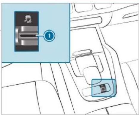
text_image
Diagram showing a car interior with a switch labeled '1' and a highlighted component, likely illustrating a vehicle safety or safety concept.Pull rocker switch ①.
ESP ^ is deactivated if the ESOFF warning lamp lights up continuously in the instrument cluster.
Observe the information on warning lamps and display messages which may be shown in the instrument cluster.
Function of ESP® Crosswind Assist
ESP® Crosswind Assist detects sudden gusts of side wind and helps the driver to keep the vehicle in the lane:
- ESP® Crosswind Assist is active at vehicle speeds between approx. 75 km/h and 200 km/h when driving straight ahead or cornering slightly.
- The vehicle is stabilised by means of a targeted and individual brake application on one side.
Function of ESP® trailer stabilisation

WARNING Risk of accident in poor road and weather conditions
In poor road and weather conditions, the trailer stabilisation cannot prevent lurching of
the vehicle/trailer combination. Trailers with a high centre of gravity may tip over before ESP® detects this.
Always adapt your driving style to suit the current road and weather conditions.
When driving with a trailer, ESPan stabilise your vehicle if the trailer begins to swerve from side to side:
- ESP® trailer stabilisation is active above speeds of 65 km/h.
- Slight swerving is reduced by means of a targeted, individual brake application on one side.
- In the event of severe swerving, the engine output is also reduced and all wheels are braked.
ESP ^® trailer stabilisation may be impaired or may not function if:
- The trailer is not connected correctly or is not detected properly by the vehicle.
Function of EBD (Electronic Brake force Distribution)
EBD is characterised by the following:
• Monitoring and regulating the brake pressure on the rear wheels.
- Improved driving stability when braking, especially on bends.
Function of STEER CONTROL
STEER CONTROL helps you by transmitting a noticeable steering force to the steering wheel in the direction required for vehicle stabilisation.
This steering recommendation is given particularly in the following situations:
- both right wheels or both left wheels are on a wet or slippery road surface when you brake
• the vehicle starts to skid
System limits
STEER CONTROL may be impaired or may not function in the following situations:
- ESP ^ is deactivated.
- ESP® is malfunctioning.
• The steering is malfunctioning.
If ESP ^ is malfunctioning, you will be assisted further by the electric power steering.
Function of Active Brake Assist
Active Brake Assist consists of the following functions:
• Distance warning function
• Autonomous braking function
• Situation-dependent braking assistance
• Vehicles with Driving Assistance Package: Evasive Steering Assist and cornering function
Active Brake Assist can help you to minimise the risk of a collision with vehicles, cyclists or pedestrians, or reduce the effects of such a collision.
If Active Brake Assist has detected a risk of collision, a warning tone sounds and the dis-
tance warning lamp lights up in the instrument cluster.
Vehicles with PRE-SAFE®: depending on the country, an additional haptic warning occurs in the form of slight, repeated tensioning of the seat belt.
If you do not react to the warning, autonomous braking can be initiated in critical situations. In especially critical situations, Active Brake Assist can initiate autonomous braking directly. In this case, the warning lamp and warning tone occur simultaneously with the braking application.
If you apply the brake yourself in a critical situation or apply the brake during autonomous braking, situation-dependent braking assistance occurs. The brake pressure increases up to maximum full-stop braking if necessary.
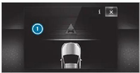
natural_image
Top-down view of a car under lane markings with a traffic light symbol (no readable text or labels)If autonomous braking or situation-dependent braking assistance has occurred, display ① appears in the multifunction display and then automatically goes out after a short time. If the autonomous braking function or the situation-dependent braking assistance is triggered, additional preventive measures for occupant protection (PRE-SAFE®) may also be initiated.

WARNING Risk of an accident caused by limited detection performance of Active Brake Assist
Active Brake Assist cannot always clearly identify objects and complex traffic situations.
In such cases, Active Brake Assist might:
- Give a warning or brake without reason
• Not give a warning or not brake
Always pay careful attention to the traffic situation; do not rely on Active Brake Assist alone. Active Brake Assist is only an aid. The driver is responsible for maintaining a suitable distance to the vehicle in front, vehicle speed and for braking in good time.
Be prepared to brake or swerve if necessary.
i If the system is unavailable, the OFF display appears in the multifunction display.
Also observe the system limits of Active Brake Assist.
The individual subfunctions are available in the following speed ranges:
The distance warning function issues a warning in the following situations:
- From approximately 30 km/h, if over several seconds the distance maintained to the vehicle travelling in front is too small for the
driven speed, the △ distance warning lamp lights up in the instrument cluster.
- From approximately 7 km/h, if your vehicle is critically close to a vehicle or pedestrian, you will hear an intermittent warning tone and the △ distance warning lamp lights up in the instrument cluster.
Vehicles with PRE-SAFE®: depending on the country, an additional haptic warning occurs in the form of slight, repeated tensioning of the seat belt.
Brake immediately or take evasive action, provided it is safe to do so and the traffic situation allows this.
The distance warning function can aid you in the following situations with an intermittent warning tone and a warning lamp:
| Vehicles travelling in front | Stationary vehicles | Crossing vehicles | Moving pedestrians | Stationary pedestrians | Crossing cyclists | Cyclists traveling in front | Stationary cyclists | |
| Vehicles without Driving Assistance Package | Up to approx. 250 km/h | Up to approx. 80 km/h | No reaction | Up to approx. 80 km/h | No reaction | Up to approx. 60 km/h | Up to approx. 80 km/h | No reaction |
| Vehicles with Driving Assistance Package | Up to approx. 250 km/h | Up to approx. 100 km/h | Up to approx. 70 km/h | Up to approx. 80 km/h | Up to approx. 70 km/h | Up to approx. 70 km/h | Up to approx. 80 km/h | Up to approx. 70 km/h |
The autonomous braking function may intervene at speeds starting from approximately 7 km/h in the following situations:
| Vehicles travelling in front | Stationary vehicles | Crossing vehicles | Moving pedestrians | Stationary pedestrians | Crossing cyclists | Cyclists traveling in front | Stationary cyclists | |
| Vehicles without Driving Assistance Package | Up to approx. 200 km/h | Up to approx. 50 km/h | No reaction | Up to approx. 60 km/h | No reaction | Up to approx. 60 km/h | Up to approx. 80 km/h | No reaction |
| Vehicles with Driving Assistance Package | Up to approx. 250 km/h | Up to approx. 100 km/h | Up to approx. 70 km/h | Up to approx. 70 km/h | Up to approx. 70 km/h | Up to approx. 70 km/h | Up to approx. 80 km/h | Up to approx. 70 km/h |
Situation-dependent braking assistance may intervene at speeds starting from approximately 7 km/h in the following situations:
| Vehicles travelling in front | Stationary vehicles | Crossing vehicles | Moving pedestrians | Stationary pedestrians | Crossing cyclists | Cyclists traveling in front | Stationary cyclists | |
| Vehicles without Driving Assistance Package | Up to approx. 250 km/h | Up to approx. 80 km/h | No reaction | Up to approx. 60 km/h | No reaction | Up to approx. 60 km/h | Up to approx. 80 km/h | No reaction |
| Vehicles with Driving Assistance Package | Up to approx. 250 km/h | Up to approx. 100 km/h | Up to approx. 70 km/h | Up to approx. 70 km/h | Up to approx. 70 km/h | Up to approx. 70 km/h | Up to approx. 80 km/h | Up to approx. 70 km/h |
Cancelling a brake application of Active Brake Assist
You can cancel a brake application of Active Brake Assist at any time by:
- Fully depressing the accelerator pedal or with kickdown.
• Releasing the brake pedal.
Active Brake Assist may cancel the brake application when one of the following conditions is fulfilled:
• You manoeuvre to avoid the obstacle.
• There is no longer a risk of collision.
- An obstacle is no longer detected in front of your vehicle.
Evasive Steering Assist (only vehicles with Driving Assistance Package)
Evasive Steering Assist has the following characteristics:
- The ability to detect stationary or moving pedestrians.
-
Assistance through power-assisted steering if it detects a swerving manoeuvre.
-
Activation by an abrupt steering movement during a swerving manoeuvre.
- Assistance during swerving and straightening of the vehicle.
- Reaction from a speed of approximately 20 km/h up to a speed of approximately 70 km/h.
You can prevent the assistance at any time by actively steering.
Cornering function (only vehicles with Driving Assistance Package)
If a danger of collision from an oncoming vehicle is detected when turning across an oncoming lane, autonomous braking can be initiated at speeds below 15 km/h before you have left the lane in which you are driving.

WARNING Risk of an accident despite Evasive Steering Assist
Evasive Steering Assist cannot always clearly identify objects and complex traffic situations.
In addition, the steering support of Evasive Steering Assist is generally not sufficient to avoid a collision.
In such cases Evasive Steering Assist can:
- give an unnecessary warning or provide assistance
- not give a warning or not provide assistance
Always pay careful attention to the traffic situation; do not rely on Evasive Steering Assist alone.
Be ready to brake and take evasive action, if necessary.
▶ Prevent the assistance by actively steering in non-critical driving situations.
▶ Drive at an appropriate speed if pedestrians are close to the path of your vehicle.
System limits
Full system performance is not available for a few seconds after switching on the ignition or after driving off.
The system may be impaired or may not function in the following situations:
- In snow, rain, fog, heavy spray, if there is glare, in direct sunlight or in greatly varying light conditions.
- If the sensors are dirty, misted up, damaged or covered.
- If the sensors are impaired due to interference from other radar sources, e.g. strong radar reflections in multi-storey car parks.
- If a loss of tyre pressure or a defective tyre has been detected and displayed.
- If DSR is activated.
- In complex traffic situations where objects cannot always be clearly identified.
-
If pedestrians or vehicles move quickly into the sensor detection range.
• If pedestrians are hidden by other objects. -
If the typical outline of a pedestrian cannot be distinguished from the background.
- If a pedestrian is not detected as such, e.g. due to special clothing or other objects.
- On bends with a tight radius.
The Active Brake Assist sensors adjust automatically while a certain distance is being driven after the vehicle has been delivered. Active Brake Assist is unavailable or only partially available during this teach-in period.
Setting Active Brake Assist
Requirements:
• The ignition is switched on.
Multimedia system:

The following settings are available:
- Early
Medium - Late
Select a setting. The setting is retained when the engine is next started.
Deactivating Active Brake Assist
i It is recommended that you always leave Active Brake Assist activated.
Select Off.
The distance warning function, the autonomous braking function and the Evasive Assist are deactivated. When the vehicle is next started, the middle setting is automatically selected.
If Active Brake Assist is deactivated, the symbol appears in the status bar of the multifunction display.
Function of Adaptive Brake Lights
Adaptive Brake Lights warn following traffic in an emergency braking situation with the following actions:
- By flashing the brake lamps
- By activating the hazard warning lights
If the vehicle is braked sharply from speeds above 50 km/h, the brake lamps flash rapidly. This provides traffic travelling behind you with an even more noticeable warning.
If the vehicle is travelling at speeds of more than 70km / h at the beginning of the brake application, the hazard warning lights switch on once the vehicle is stationary. When you pull away again, the hazard warning lights will switch off automatically at approximately 10km / h . You can also switch off the hazard warning lights using the hazard warning button.
Cruise control and limiter
Function of cruise control
Cruise control regulates the speed to the value selected by the driver.
If you accelerate to overtake, for example, the stored speed is not deleted. If you remove your foot from the accelerator pedal after overtaking, cruise control will resume speed regulation back to the stored speed.
Cruise control is operated using the corresponding steering wheel buttons. You can store any
speed above 20 km/h up to the maximum speed or up to the set winter tyre limit. The maximum speed is reduced when driving in LOW RANGE off-road gear ( page 233).
If you fail to adapt your driving style, cruise control can neither reduce the risk of an accident nor override the laws of physics. It cannot take into account road, weather or traffic conditions. Cruise control is only an aid. The driver is responsible for the distance to the vehicle in front, for vehicle speed, for braking in good time and for staying in lane.
Mercedes-AMG vehicles: cruise control is available up to a maximum speed of 250 km/h.
Displays in the multifunction display
The status of cruise control and the stored speed are shown in the multifunction display.
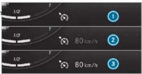
text_image
1/2 1 1/2 1 80 km/h 1/2 1 80 km/h ① ② ③① Cruise control is selected
② Speed is saved, cruise control is deactivated
3 Speed is saved, cruise control is activated
The segments extending from the current stored speed to the end of the scale, or to the set winter tyre limit, light up in the speedometer.
System limits
Cruise control may be unable to maintain the stored speed on uphill gradients. The stored speed is resumed when the gradient evens out.
Change into a lower gear in good time on long and steep downhill gradients. Take particular
note of this when driving a laden vehicle. By doing so, you will make use of the engine's braking effect. This relieves the load on the brake system and prevents the brakes from overheating and wearing too quickly.
Do not use cruise control in the following situations:
- In traffic situations which require frequent changes of speed, e.g. in heavy traffic, on winding roads.
- On slippery roads. Accelerating can cause the drive wheels to lose traction and the vehicle could then skid.
• If you are driving when visibility is poor.
Function of the limiter
The limiter restricts the speed of the vehicle. To reduce the speed to the set speed, the limiter applies the brakes automatically.
You can limit the speed as follows:
- Variable: for speed restrictions, e.g. in built-up areas.
• Permanent: for long-term speed restrictions, e.g. when driving in winter tyre mode.
The variable limiter is operated using the corresponding steering wheel buttons. You can store any speed above 20 km/h up to the maximum speed or up to the set winter tyre limit. You can also perform settings while the vehicle is stationary if the vehicle has been started.
If you fail to adapt your driving style, the limiter can neither reduce the risk of an accident nor override the laws of physics. It cannot take into account road, weather or traffic conditions. The limiter is only an aid. The driver is responsible for the distance to the vehicle in front, for vehicle speed, for braking in good time and for staying in lane.
Mercedes-AMG vehicles: the limiter is available up to a maximum speed of 250 km/h.
Displays on the multifunction display
The status of the variable limiter and the stored speed are shown in the multifunction display.
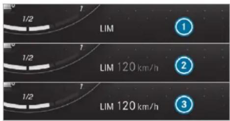
text_image
LIM 1/2 1 LIM 120 km/h 1/2 1 LIM 120 km/h① Variable limiter is selected
② Speed is stored, variable limiter is deactivated
3 Speed is stored, variable limiter is activated
The segments in the speedometer light up, up to the currently stored speed. When the driving speed is greater than the stored speed, display ③ flashes.
Kickdown
If you depress the accelerator pedal beyond the pressure point (kickdown), the variable limiter switches to passive mode. The Limiter passive message appears in the multifunction display.
After completion of kickdown, the variable limiter is activated again in the following situations:
- If the driven speed drops below the stored speed.
- If the stored speed is called up.
• If you store a new speed.
Operating cruise control or the variable limiter
⚠ WARNING Risk of accident due to stored speed
If you call up the stored speed and this is lower than your current speed, the vehicle decelerates.
Take into account the traffic situation before calling up the stored speed.
Requirements:
Cruise control
• Cruise control is selected.
- ESP ^ must be activated, but not intervening.
• The driven speed is at least 20 km/h.
• The transmission is in position D.
Variable limiter
• The vehicle has been started.
• The variable limiter is selected.
Switching between cruise control and the variable limiter
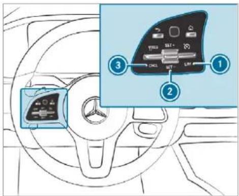
text_image
Diagram of car dashboard control panel with labeled buttons and ports, showing three numbered parts for function selection.To select cruise control: press rocker switch ① up.
To select the variable limiter: press rocker switch ① down.
① Vehicles with Active Distance Assist DISTRONIC: the variable limiter is selected by a different button ( page 273).
Activating cruise control or the variable limiter
Press rocker switch ② up (SET+) or down (SET-).
The current driven speed is stored and the vehicle maintains this speed (cruise control) or does not exceed it (limiter).
or
Press rocker switch ③ up (RES). The last stored speed is called up and the vehicle maintains this speed (cruise control) or does not exceed it (variable limiter). If the last stored speed has previously been deleted, the currently driven speed is stored.
When you switch off the vehicle, the last speed stored is cleared.
When you activate cruise control or Active Distance Assist DISTRONIC, the last speed stored for the variable limiter is cleared.
Increasing/decreasing the stored speed
Press rocker switch ② up (SET+) or down (SET-) to the pressure point.
The stored speed is increased or reduced by 1 km/h.
or
Press rocker switch ② up (SET+) or down (SET-) to the pressure point and hold. The stored speed is increased or reduced in increments of 1 km/h.
or
Press rocker switch ② up (SET+) or down (SET-) beyond the pressure point.
The stored speed is increased or reduced by 10 km/h.
or
Press rocker switch ② up (SET+) or down (SET-) and hold beyond the pressure point. The stored speed is increased or reduced in increments of 10 km/h.
or
▶ Accelerate the vehicle to the desired speed.
▶ Press rocker switch ② up (SET+).
Adopting the detected speed
If cruise control/the variable limiter is activated and Speed Limit Assist or Traffic Sign Assist has detected a speed restriction sign with a maximum permissible speed and this is displayed in the instrument cluster, you can choose between the following options:
Press rocker switch ③ up (RES). The maximum permissible speed shown by the traffic sign is stored and the vehicle maintains or does not exceed this speed.
To deactivate cruise control: press rocker switch ③ down (CNCL).
To deactivate cruise control: press rocker switch ① down.
Deactivating cruise control or the variable limiter
Press rocker switch ③ down (CNCL).
If you brake, deactivate ESP or if ESP intervenes, cruise control is deactivated. The variable limiter is not deactivated.
Permanent limiter
If the vehicle should never exceed a specific speed (e.g. for driving in winter tyre mode), you can set this speed with the permanent limiter.
You do this by limiting the speed to a value between 160 km/h and 240 km/h in the multi-media system ( page 269).
Shortly before the set speed is reached, it appears in the multifunction display. When you confirm the message with ←, display messages no longer appear until you switch off the vehicle. The speed will only be displayed again once the vehicle has been restarted or if the set speed is changed.
The permanent limiter does not switch to passive mode even during kickdown and the driven speed remains below the set speed.
Setting the speed limitation for winter tyres Multimedia system:
→ Settings → Vehicle → Winter tyres limit
▶ Select a speed or deactivate the function.
DSR (Downhill Speed Regulation)
Function of DSR (Downhill Speed Regulation)
DSR is an aid to assist you when driving downhill. It keeps the speed of travel at the selected target speed. The steeper the downhill gradient, the greater the DSR braking effect on the vehicle. On flat stretches of road and uphill gradients, the DSR brakes the vehicle minimally or not at all.
When DSR is activated and the transmission is position [D], [R] or [N], DSR controls the drivin speed. The target speed can be set to a value between 2 km/h and 18 km/h. By braking or accelerating, you can drive at a higher or lower speed than the target speed at any time.
DSR is deactivated automatically if you drive at speeds greater than 45 km/h or select drive
program S or S'. The off message then appears in the multifunction display. The status indicator in the multifunction display disappears. You also hear a warning tone.
Mercedes-Maybach vehicles: in drive program

the DSR function is likewise not avail-
Information on DSR

WARNING Risk of skidding and having an accident when DSR is activated on slippery road surfaces
If the speed driven and the target speed differ, and you activate DSR on a slippery road surface, the wheels may lose traction.
Take into account the road surface and the difference between the driving speed and target speed before activating DSR.
If you fail to adapt your driving style, DSR can neither reduce the risk of an accident nor override the laws of physics. It cannot take into account road, weather or traffic conditions. DSR is only an aid. You are responsible for maintaining a safe distance to the vehicle in front, for vehicle speed, for braking in good time and for staying in lane.
You are always responsible for keeping control of the vehicle and for assessing whether the downhill gradient can be managed. Depending on road surface and tyres, DSR may not always be able to keep to the target speed. Select a target speed suitable for the environmental conditions and also apply the brakes yourself if required.
Activating/deactivating DSR (vehicles with Off-road package or E-Active Body Control) Requirements:
- You are driving at 40 km/h or slower. If the current vehicle speed is too high, the Max. speed 40 km/h message appears in the multifunction display.
- You have not selected drive program S or S+.
• Active Distance Assist DISTRONIC is deactivated.
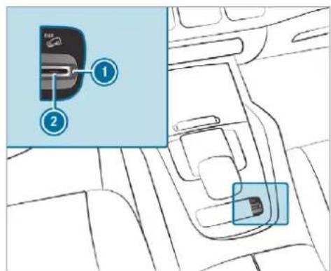
text_image
Diagram showing a car interior with labeled parts, including a highlighted component and numbered callouts.
To activate: pull rocker switch ①.
Indicator lamp ② lights up.
The symbol appears in the multifunction display.
To deactivate: pull rocker switch ①. Indicator lamp ② and the symbol out.
Activating/deactivating DSR (Downhill Speed Regulation) (vehicles without Off-road package)
Requirements:
- You are driving at 40 km/h or slower. If the current vehicle speed is too high, the Max. speed 40 km/h message appears in the multifunction display. - Active Distance Assist DISTRONIC is deactivated.
Multimedia system:
Settings
▶ Schnellzugriff (Quick access)
Select DSR.
The DSR symbol appears in the multifunction display when the function is activated.
Changing the target speed
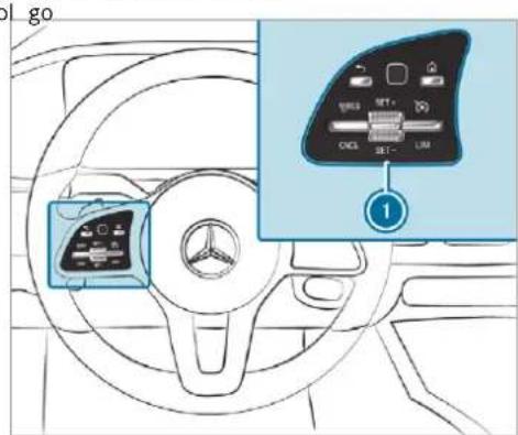
text_image
go ①To increase or decrease the target speed:
press rocker switch ① up to the point of resistance for a higher target speed and down for a lower target speed. The selected target speed increases or decreases by 1 km/h and appears with the DSR symbol in the multifunction display.
The target speed always adjusts in 1 km/h increments. This is regardless of whether you press the rocker switch to or beyond the point of resistance.
Active Distance Assist DISTRONIC
Function of Active Distance Assist DISTRONIC
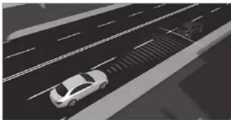
natural_image
Aerial view of a car driving on a multi-lane road with lane markings (no visible text or symbols)Active Distance Assist DISTRONIC maintains the set speed on free-flowing roads. If vehicles in front are detected, the set distance is maintained, if necessary, until the vehicle comes to a halt. The vehicle accelerates or brakes depending on the distance to the vehicle in front and
the set speed. The speed and distance to the vehicle in front are set and saved on the steering wheel on vehicles without the Driving Assistance Package, in the range between 20 km/h and 200 km/h and, on vehicles with the Driving Assistance Package, in the range between 20 km/h and 210 km/h. The maximum speed reduced when driving in LOW RANGE off-road gear ( page 233).
Other features of Active Distance Assist DISTRONIC:
- Adjusts the driving style depending on the selected drive program (fuel efficient, comfortable or dynamic) ( page 225)
- Vehicles with Driving Assistance Package: reacts to stationary vehicles detected in urban speed ranges (except bicycles and motorcycles)
- Initiates acceleration to the stored speed if the turn signal indicator is switched on to change to the overtaking lane
- Vehicles with Driving Assistance Package: takes one-sided overtaking restrictions into account on motorways or on multi-lane
roads with separate carriageways (country-dependent)
Vehicles with Active Parking Assist and Driving Assistance Package: if the vehicle has been braked to a standstill on multi-lane, separate carriageways by Active Distance Assist DISTRONIC, it can automatically follow the vehicle in front driving off again within 30 seconds a critical situation is detected when driving off, visual and acoustic warning is given indicating that the driver must now take control of the vehicle. The vehicle is not accelerated any further. Active Distance Assist DISTRONIC is only an aid. The driver is responsible for keeping a safe distance to the vehicle in front, for vehicle speed and for braking in good time.
System limits
The system may be impaired or may not function in the following situations:
- In snow, rain, fog, heavy spray, if there is glare, in direct sunlight or in greatly varying light conditions.
- If there is swirling dust, e.g. when driving off-road or on sandy surfaces.
- The windscreen in the area of the camera is dirty, misted up, damaged or covered.
• If the radar sensors are dirty or covered. - In multi-storey car parks or on roads with steep uphill or downhill gradients.
• If there are narrow vehicles in front, such as bicycles or motorcycles.
In addition, on slippery roads, braking or accelerating can cause one or several wheels to lose traction and the vehicle could then skid.
Do not use Active Distance Assist DISTRONIC in these situations.
WARNING Risk of accident from acceleration or braking by Active Distance Assist DISTRONIC
Active Distance Assist DISTRONIC may accelerate or brake in the following cases, for example:
- If the vehicle pulls away using Active Distance Assist DISTRONIC.
- If the stored speed is called up and is considerably faster or slower than the currently driven speed.
- If Active Distance Assist DISTRONIC no longer detects a vehicle in front or does not react to relevant objects.
Always carefully observe the traffic conditions and be ready to brake at all times.
Take into account the traffic situation before calling up the stored speed.
WARNING Risk of accident due to insufficient deceleration by Active Distance Assist DISTRONIC
Active Distance Assist DISTRONIC brakes your vehicle with up to 50 % of the maximum possible deceleration. If this deceleration is not sufficient, Active Distance Assist DISTRONIC alerts you with a visual and acoustic warning.
In these cases, adjust your speed and keep a sufficient distance.
Brake the vehicle yourself and/or take evasive action.
WARNING Risk of accident if detection function of Active Distance Assist DISTRONIC is impaired
Active Distance Assist DISTRONIC does not react or has a limited reaction:
- when driving on a different lane or when changing lanes
• to pedestrians, animals, bicycles or stationary vehicles, or unexpected obstacles
• to complex traffic conditions
• to oncoming vehicles and crossing traffic
As a result, Active Distance Assist DISTRONIC may neither give warnings nor intervene in such situations.
Always observe the traffic conditions carefully and react accordingly.
Operating Active Distance Assist DISTRONIC Requirements:
• The vehicle has been started.
• The electric parking brake is released.
- ESP ^ is activated and is not intervening.
• The transmission is in position D.
• The driver's door is closed.
- Check of the radar sensor system has been successfully completed.
- Parking Assist PARKTRONIC is not being used to park the vehicle or to exit from a parking space.
- DSR is deactivated.
• Vehicles with Off-road package: the drive program is deactivated. - The vehicle does not skid.
Switching between the variable limiter and Active Distance Assist DISTRONIC
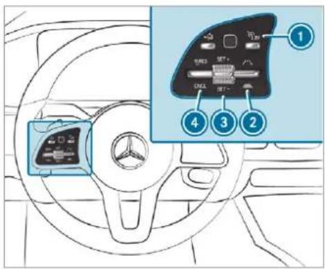
text_image
Diagram of car dashboard with labeled control panel and driver shift, showing numbered parts for function keys.
Press button

Activating the variable limiter or Active Distance Assist DISTRONIC
To activate without a stored speed: press rocker switch ③ up (SET+) or down (SET-) or press rocker switch ④ up (RES). Remove your foot from the accelerator pedal (Active Distance Assist DISTRONIC). The current driven speed is stored and maintained (Active Distance Assist DISTRONIC) or limited (variable limiter) by the vehicle.
or
To activate with a stored speed: press rocker switch ④ up (RES). Remove your foot from the accelerator pedal (Active Distance Assist DISTRONIC).
① By pressing rocker switch ④ up again, the speed limitation shown in the instrument cluster will be adopted by Active Distance Assist DISTRONIC or variable limiter.
Accepting the displayed speed restriction when Distance Assist DISTRONIC or the limiter is activated
Press rocker switch ④ up (RES). The speed limit displayed in the instrument cluster is adopted as the stored speed. The vehicle adapts its speed to that of the vehicle in front, but only up to the stored speed.
Pulling away with Active Distance Assist DISTRONIC
Remove your foot from the brake pedal and activate Active Distance Assist DISTRONIC. Press rocker switch ④ up (RES).
or
Depress the accelerator pedal briefly and firmly.
The functions of Active Distance Assist DISTRONIC continue to be carried out.
Deactivating Active Distance Assist DISTRONIC

WARNING Risk of accident due to Active Distance Assist DISTRONIC still being activated when you leave the driver's seat
If you leave the driver's seat while the vehicle is being braked by Active Distance Assist DISTRONIC only, the vehicle can roll away.
Always deactivate Active Distance Assist DISTRONIC and secure the vehicle to prevent it from rolling away before you leave the driver's seat.
▶ Press rocker switch ④ down (CNCL).
If you brake, deactivate ESP or if ESP intervenes, Active Distance Assist DISTRONIC is deactivated.
Increasing or reducing the speed
Press rocker switch ③ up (SET+) or down (SET-) to the pressure point. The stored speed is increased or reduced by 1 km/h.
or
Press rocker switch ③ up (SET+) or down (SET-) to the pressure point and hold. The stored speed is increased or reduced in increments of 1 km/h.
or
Press rocker switch ③ up (SET+) or down (SET-) beyond the pressure point. The stored speed is increased or reduced by 10 km/h.
or
Press rocker switch ③ up (SET+) or down (SET-) and hold beyond the pressure point. The stored speed is increased or reduced in increments of 10 km/h.
Reducing or increasing the specified distance from the vehicle in front
Press rocker switch ② up or down.
Function of Active Speed Limit Assist
The following function is country-dependent and only available in conjunction with the Driving Assistance Package.
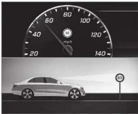
text_image
60 80 100 40 myh 120 20 140 80If a change in the speed limit is detected and automatic adoption of speed limits is activated, the new speed is automatically adopted as the stored speed ( page 330).
The driven speed is adjusted when the vehicle is level with the traffic sign at the latest. In the case of signs indicating entry into an urban the speed is adapted according to the speed permitted within the urban area. The speed display in the Instrument Display is always used when the vehicle is level with the traffic sign.
If there is no speed restriction on an unlimited stretch of road (e.g. on a motorway), the recommended speed is automatically adopted as the stored speed. The system uses the speed stored on an unlimited stretch of road as the recommended speed. If you do not alter the stored speed on an unlimited stretch of road, the recommended speed is 130 km/h.
If Active Distance Assist DISTRONIC has been put into passive mode by pressing the accelerator pedal, only speed limits which are higher than the set speed are adopted.
Active Speed Limit Assist is only an aid. The driver is responsible for keeping a safe distance from the vehicle in front, for vehicle speed and for braking in good time. The maximum permissible speed also depends on factors such as the road surface and traffic conditions.
System limits
Temporary speed restrictions (e.g. for a certain are time or due to weather conditions) cannot be properly detected by the system. The maximum limpermissible speed applying to a vehicle with a updailer is not detected by the system. In these situations you must adjust your speed yourself.
WARNING Risk of accident due to Active Speed Limit Assist adapting the vehicle's speed
The speed adopted by Active Speed Limit Assist may be too high or incorrect in some individual cases, such as:
• In the wet or in fog
- When towing a trailer
▶ Ensure that the driven speed complies with traffic regulations.
Adjust the driving speed to suit current traffic and weather conditions.
Function of route-based speed adaptation
The following function is country-dependent and only available in conjunction with the Driving Assistance Package.
When Active Distance Assist DISTRONIC is activated, the vehicle speed will be adjusted accordingly to the route events ahead. Depending on the drive program selected, the vehicle negotiates a route event ahead in a fuel-saving, comfortable or dynamic manner. When the route event has been passed, the vehicle accelerates again to the stored speed. The set distance to the vehicle in front, vehicles detected ahead and speed restrictions ahead are taken into account.
Route-based speed adaptation can be configured in the multimedia system ( page 277).
The following route events are taken into account:
- Bends
• T-junctions, roundabouts and toll stations - Turns and exits
- Traffic jams ahead (only with Live Traffic (→ page 458))
When the toll station is reached, Active Distance Assist DISTRONIC adopts the speed as the stored speed.
Also, the speed is reduced if the turn signal indicator to change lanes is switched on and one of the following situations is detected:
- Turning off at junctions
- Driving on slowing-down lanes
- Driving on lanes adjacent to slowing-down lanes
The driver is responsible for choosing the right speed and observing other road users. This applies in particular to junctions, roundabouts and traffic lights, as route-based speed adaptation does not brake the vehicle to a standstill.
When route guidance is active, the first speed adjustment is carried out automatically. If the turn signal indicator is switched on, the selected route is confirmed and further speed adjustment is activated.
Speed adjustment is cancelled in the following cases:
- If the turn signal indicator is switched off before the route event.
- If the driver depresses the accelerator or brake pedal during the process.
System limits
Route-based speed adaptation does not take right of way regulations into account. The driver is responsible for complying with road traffic regulations and driving at a suitable speed. In difficult conditions, for example unclear roads, lane narrowing, wet road surfaces, snow or ice, or when driving with a trailer, the speed adjustment made by the system may not always be suitable. In these situations the driver must intervene accordingly.
⚠ WARNING Risk of accident in spite of route-based speed adjustment
Route-based speed adjustment might malfunction or be temporarily unavailable in the following situations:
- If the driver does not follow the calculated route
• If map data is not up to date or available
• In road construction areas
• In bad weather or road conditions
• If the accelerator pedal is depressed - In the event of electronically displayed speed limitations
Adjust the speed to the traffic situation.
Setting route-based speed adaptation
Requirements:
- Active Distance Assist DISTRONIC is activated.
Multimedia system:
→ Settings ▶ Assistance
▶ Route-based speed adapt.
▶ Activate or deactivate the function. When the function is active, the vehicle speed is adjusted depending on the route events ahead.
i Further information on the route-based speed adaptation ( page 276).
Active Steering Assist
Function of Active Steering Assist
The following function is country-dependent and only available in conjunction with the Driving Assistance Package.
Active Steering Assist is only available up to a speed of 210 km/h. The system helps you to stay in the centre of the lane by means of moderate steering interventions. Depending on the speed driven, Active Steering Assist uses the vehicles ahead and lane markings as a reference.
Depending on the country, in the lower speed range Active Steering Assist can use the surrounding traffic as a reference. If necessary, Active Steering Assist can then also provide assistance when driving outside the centre of the lane to form a rescue lane, for example.
When the system is actively steering, the symbol is shown in green in the multifunction display.
If the detection of lane markings and vehicles ahead is impaired, Active Steering Assist switches to passive mode. The system provides no support in this case. During the transition from active to passive status, the [+] symbol is shown as enlarged and flashing. Once the system is passive, the [+] symbol is shown as grey in the multifunction display.
Steering and touch detection
The driver is required to keep their hands on the steering wheel at all times and be able to intervene at any time to correct the course of the vehicle and keep it in lane. The driver must expect a change from active to passive mode or vice versa at any time.
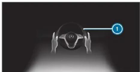
natural_image
Illustration of hands holding a car steering wheel with a numbered circle pointing to it (no text or symbols on the diagram itself)If the system detects that the driver has not steered the vehicle for a considerable period of time or has removed their hands from the steering wheel, an optical warning is given first. Display ① appears in the multifunction display. If the driver still does not steer the vehicle, or gives no confirmation to the system, a warning tone sounds in addition to the visual warning message.
The warning is not issued, or is stopped, when the driver gives confirmation to the system:
• The driver steers the vehicle.
- The driver presses a steering wheel button operates Touch Control.
If Active Steering Assist detects that a system limit has been reached, a visual warning is issued and a warning tone sounds.
Active Steering Assist is only an aid. The driver is responsible for the distance to the vehicle in front, for vehicle speed, for braking in good time and for staying in lane. Before changing lanes, the driver must make sure that the neighbouring lane is free (glance over the shoulder).
System limits
Active Steering Assist has a limited steering torque for lateral guidance. In some cases, the steering intervention is not sufficient to keep the vehicle in the lane or to drive through exits.
The system may be impaired or may not function in the following instances:
- There is poor visibility, e.g. due to snow, rain, fog, heavy spray, greatly varying light conditions or strong shadows on the carriageway.
- There is glare, e.g. from oncoming traffic, direct sunlight or reflections.
or Insufficient road illumination.
- The windscreen is dirty, misted up, damaged or covered in the vicinity of the camera, e.g. by a sticker.
- No, or several, unclear lane markings are present for one lane, or the markings change quickly, e.g. in a construction area or junctions.
- The lane markings are worn away, dark or covered up, e.g. by dirt or snow.
- The distance to the vehicle in front is too small and the lane markings thus cannot be detected.
• The road is narrow and winding. - There are obstacles on the lane or projecting out into the lane, such as object markers.
On The system does not provide assistance in the following conditions:
- On tight bends and when turning.
- When crossing junctions.
- At roundabouts or toll stations.
-
When towing a trailer.
-
When actively changing lane without switching on the turn signal indicator.
- When the tyre pressure is too low.
Depending on the selected vehicle settings, Active Steering Assist may be unavailable. Observe the status display of Active Steering Assist in the multifunction display
(→ page 283).

WARNING Risk of accident if Active Steering Assist unexpectedly stops functioning
If the system limits of Active Steering Assist are reached there is no guarantee that the system will remain active or will keep the vehicle in lane.
Always keep your hands on the steering wheel and observe the traffic carefully.
Always steer the vehicle paying attention to traffic conditions.

WARNING Risk of accident if Active Steering Assist unexpectedly intervenes
A malfunction in the detection of lane markings and objects can occur.
This could cause unexpected steering intervention.
▶ Steer according to traffic conditions.
Activating/deactivating Active Steering Assist
Requirements:
- ESP ^ is activated, but is not intervening.
• Active Distance Assist DISTRONIC is activated.
Multimedia system:






Function of Active Lane Change Assist
The following function is country-dependent and only available in conjunction with the Driving Assistance Package.
Active Lane Change Assist supports the driver when changing lanes by applying steering torque if the driver operates a turn signal indicator.
Assistance when changing lanes is provided if all the following conditions are met:
- You are driving on a motorway or road with multiple lanes in the direction of travel.
- The neighbouring lane is separated by a broken lane marking.
• No vehicle is detected in the adjacent lane. - The driven speed is between 80 km/h and 180 km/h.
• Active Lane Change Assist is switched on in the multimedia system.
• Active Steering Assist is switched on and active.
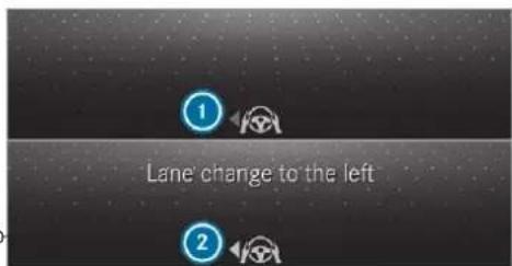
text_image
Lane change to the leftIf no vehicle is detected in the adjacent lane and a lane change is permitted, the lane change begins after the driver has activated the turn signal indicator. This is shown to the driver with a green arrow ② next to the steering wheel symbol. The Lane change to the left message also appears, for example. If Active Lane Change Assist has been activated with the turn signal indicator but a lane change is not immediately possible, a grey arrow ① appears next to the steering wheel symbol, which remains green. When the lane change assistance starts, the turn signal indicator is automatically activated along with the display in the multifunction display.
If the assistance graphic is shown when changing lanes, the lane change display appears with an additional arrow pointing towards the adjacent lane ( page 283).
If a lane change is not possible, the arrow fades out after a few seconds and a new lane change must be initiated. An immediate lane change is only possible on motorway sections without speed limits.
If the system is impaired, Active Lane Change Assist may be cancelled. If it is cancelled, the Lane change cancelled message appears in the multifunction display and a warning tone sounds.

WARNING Risk of accident from changing lane to an occupied adjacent lane
Lane Change Assist cannot always detect clearly if the adjacent lane is free. The lane change might be initiated although the adjacent lane is not free.
Before changing lanes, make sure that the neighbouring lane is free and there is no danger to other road users.
▶ Monitor the lane change.
A WARNING Risk of accident if Lane Change Assist unexpectedly stops functioning
If the system limitations for Lane Change Assist have been reached, there is no guarantee that the system will remain active. Lane Change Assist cannot then assist you by applying steering torques.
▶ Always monitor the lane change and keep your hands on the steering wheel. Observe the traffic conditions and steer and/or brake if necessary.
System limits
The system limitations of Active Steering Assist apply to Active Lane Change Assist ( page 278).
The system may also be impaired or may not function in the following situations:
- The sensors in the rear bumper are dirty, damaged or covered by a sticker or ice and snow, for example.
• The exterior lighting is malfunctioning.
The Active Lane Change Assist sensors adjust automatically while a certain distance is being driven after the vehicle has been delivered. Active Lane Change Assist is unavailable or only partially available during this teach-in process, no arrow appears next to the Active Steering Assist symbol when the turn signal indicator is activated.
Activating/deactivating Active Lane Change Assist
Multimedia system:
→ Settings → Assistance
▶ Active Lane Change Assist
▶ Activate or deactivate the function.
Function of Active Emergency Stop Assist
If the driver continually ignores the visual or acoustic warning to put their hands on the steer-
ing wheel, the Beginning emergency stop message appears in the multifunction display. If the driver still does not respond, Active Distance Assist DISTRONIC reduces the speed. The vehicle is decelerated in stages to a standstill.
Depending on the country, at speeds below 60 km/h the hazard warning lights switch on automatically.
When the vehicle is stationary, the following actions are carried out:
- the vehicle is secured with the electric parking brake
• Active Distance Assist DISTRONIC is ended
• the vehicle is unlocked - if possible, an emergency call is placed to the Mercedes-Benz emergency call centre
The driver can cancel the deceleration at any time by performing one of the following actions:
- steering
- braking or accelerating
- pressing a steering-wheel button
• operating Touch Control
- activating or deactivating Active Distance Assist DISTRONIC
Function of Active Traffic Jam Assist
Active Traffic Jam Assist is country-dependent and only available for vehicles with the Driving Assistance Plus Package.
Active Traffic Jam Assist helps you when in traffic jams on multi-lane roads with separate carriageways by automatically pulling away within up to 60 seconds and with moderate steering manoeuvres. It orients itself using the vehicle in front and lane markings. Active Traffic Jam Assist automatically maintains a safe distance from the vehicle in front and vehicles cutting in. Active Traffic Jam Assist requires you, as the driver, to keep your hands on the steering wheel at all times so that you are able to intervene at any time to correct the course of the vehicle and keep it in lane.
Active Traffic Jam Assist is only an aid. The driver is responsible for keeping a safe distance to the vehicle in front, for vehicle speed and for braking in good time.
Active Traffic Jam Assist activates automatically when all of the following conditions are met:
- You are in a traffic jam on a motorway or high-speed major road.
• Active Distance Assist DISTRONIC is switched on and active ( page 273).
• Active Brake Assist is available ( page 259). - Active Steering Assist is switched on and active (→ page 280).
• Active Traffic Jam Assist is activated ( page 283).
• You are travelling no faster than 60 km/h.
The following symbol is displayed in the instrument cluster when the system is active:

System limits
The system limitations of Active Distance Assist DISTRONIC and Active Steering Assist apply to Active Traffic Jam Assist ( page 278).
Activating/deactivating Active Traffic Jam Assist
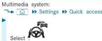
flowchart
graph TD
    A["Start"] --> B["Settings"]
    B --> C["Quick access"]
    C --> D["Select"]
Overview of Active Distance Assist DISTRONIC displays in the instrument cluster
The assistance graphic and the status display show the status of the following functions in the instrument cluster:
• Active Distance Assist DISTRONIC
- Route-based speed adaptation
• Active Steering Assist
Assistant display
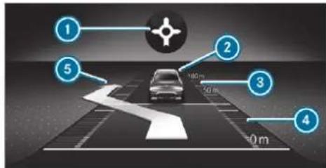
text_image
1 2 3 4 5 100 m 50 m 0 mRoute-based speed adaptation: type of route event
2 Vehicle in front
3 Distance indicator
Set specified distance
⑤ Active Lane Change Assist lane change display
Active Distance Assist DISTRONIC status display and route-based speed adaptation
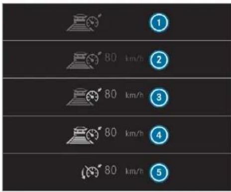
text_image
1 2 3 4 5 80 km/h 80 km/h 80 km/hActive Distance Assist DISTRONIC selected, set specified distance (number of segments below the vehicle)
2 Active Distance Assist DISTRONIC deactivated, speed stored
3 Active Distance Assist DISTRONIC active, speed stored, no vehicle detected (bright vehicle symbol)
4 Active Distance Assist DISTRONIC active, speed stored, vehicle detected (green vehicle symbol)
⑤ Active Distance Assist DISTRONIC and route-based speed adaptation active, speed stored
On motorways or high-speed major roads, the green vehicle symbol is displayed cyclically when the vehicle is ready to pull away.
If you depress the accelerator pedal beyond the setting of the Active Distance Assist DISTRONIC, the system is switched to passive mode. The suspended message appears in the multifunction display.
Speedometer
The stored speed is highlighted on the speedometer. If the speed of the vehicle in front or the speed adjustment is less than the stored speed due to the route event ahead, the segments in the speedometer light up. Deactivation of Active Distance Assist DISTRONIC, as well as altera-
tions to the speed due to manual or automatic adoption of the speed limit, are displayed in the control feedback of the multifunction display on a single line.
Active Steering Assist status display
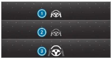
flowchart
graph TD
    A["1"] --> B["2"]
    B --> C["3"]
① Grey steering wheel: Active Steering Assist switched on and passive
② Green steering wheel: Active Steering Assist switched on and active
3 Flashing steering wheel: prompt to the driver to actively confirm or transition from active to passive status, system limits detected
During the transition from active to passive status, symbol ③ is shown as enlarged and flashing. Once the system is passive, symbol ① is shown as grey in the multifunction display.
Function of Hill Start Assist
Hill Start Assist holds the vehicle for a short time when pulling away on a hill under the following conditions:
- The transmission is in position D or R.
• The electric parking brake is released.
This gives you enough time to move your foot from the brake pedal to the accelerator pedal and depress it before the vehicle begins to roll away.

WARNING Risk of accident and injury due to the vehicle rolling away
After a short time, Hill Start Assist no longer holds the vehicle and it can roll away.
Therefore, swiftly move your foot from the brake pedal to the accelerator
pedal. Never attempt to leave the vehicle if it is being held by Hill Start Assist.
HOLD function
HOLD function
The HOLD function holds the vehicle at a standstill without requiring you to depress the brake pedal, e.g. while waiting in traffic.
The HOLD function is only an aid. The responsibility for the vehicle safely standing still remains with the driver.
System limits
The HOLD function is only intended to provide assistance when driving and is not a sufficient means of safeguarding the vehicle against rolling away when stationary.
• The incline must not be greater than 30%.
Activating/deactivating the HOLD function
WARNING Risk of an accident due to the HOLD function being activated when you leave the vehicle
If you leave the vehicle while only the HOLD function is braking the vehicle, the vehicle can roll away in the following situations:
- If there is a malfunction in the system or in the power supply.
- If the HOLD function is deactivated by depressing the accelerator pedal or brake pedal, e.g. by a vehicle occupant.
▶ Always deactivate the HOLD function and secure the vehicle against rolling away before leaving the vehicle.
NOTE Damage from automatic braking
If one of the following functions is switched on, the vehicle brakes automatically in certain situations:
• Active Brake Assist
• Active Distance Assist DISTRONIC
- HOLD function
• Active Parking Assist
To avoid damage to the vehicle, deactivate these systems in the following or similar situations:
During towing
In a car wash
Requirements:
• The vehicle is stationary.
- The driver's door is closed or the seat belt the driver's side is fastened.
- The engine is running or has been automatically switched off by the ECO start/stop function.
• The electric parking brake is released.
• Active Distance Assist DISTRONIC is deactivated.
• The transmission is in position D, R or
Activating the HOLD function
Depress the brake pedal and after a short time quickly depress further until the HOLD display appears in the multifunction display.
Release the brake pedal.
Deactivating the HOLD function
Depress the accelerator pedal to pull away.
or
Depress the brake pedal until the HOLD display disappears from the multifunction display.
The HOLD function is deactivated in the following situations:
• Active Distance Assist DISTRONIC is activated.
- The transmission is switched to position
- The vehicle is secured with the electric parking brake.
N in the following situations, the vehicle is held by transmission position P and/or by the electric parking brake: - The seat belt is unfastened and the driver's door is opened.
• The vehicle is switched off. - There is a malfunction in the system or the power supply is insufficient.
AIRMATIC
Function of AIRMATIC
AIRMATIC is an air suspension system with an all-round level control system, which also ensures the best possible suspension and constant ground clearance, even with a laden vehicle. When driving at speed, the vehicle is low-
P. ered automatically to improve driving safety and to reduce fuel consumption. You also have the option of manually adjusting the vehicle level. AIRMATIC is comprised of the following functions and components:
- All-round air suspension
• Speed-dependent lowering - Manually selectable high level setting for greater ground clearance which can be adjusted using a level button
- Vehicles with ADS PLUS: also Adaptive Damping System with constant adjustment of damping characteristics for improved driving comfort
Suspension settings and vehicle level per drive program
| Drive program | Suspension settings and vehicle level | |
 | (Comfort)(Economy) | The suspension setting is comfortable.The vehicle is set to the normal level.When driving at speeds above approximately 140 km/h, the vehicle is lowered.When driving at speeds below approximately 40 km/h, the vehicle is raised again.Operation with a trailer or bicycle rack: if the electrical connection has been correctly established, the vehicle remains at normal level irrespective of speed. |
| (Maybach) | ||
| S | (Sport) | The suspension setting is firmer.The vehicle is set to Sport level.Operation with a trailer or bicycle rack: if the electrical connection has been correctly established, the vehicle remains at normal level. |
| S' | (Sport +) | The suspension setting is even firmer.The vehicle is set to Sport + level.Operation with a trailer or bicycle rack: if the electrical connection has been correctly established, the vehicle remains at normal level. |
| Drive program | Suspension settings and vehicle level |
| (Off-road in vehicles without Off-road package) | The suspension setting is suitable for easily negotiable off-road terrain.The vehicle is set to off-road level + 1.When driving at speeds above approximately 80 km/h, the vehicle is lowered.When driving at speeds below approximately 45 km/h, the vehicle is raised. |
| (Off-road in vehicles with Off-road package) | The suspension setting is suitable for easily negotiable off-road terrain.The vehicle is set to off-road level + 1.When driving at speeds above approximately 115 km/h, the vehicle is lowered.When driving at speeds below approximately 75 km/h, the vehicle is raised. |
| (Off-road + in vehicles with Off-road package) | The suspension setting is suitable for difficult off-road terrain.The vehicle is set to off-road level + 1.When driving at speeds above approximately 80 km/h, the vehicle is lowered.When driving at speeds below approximately 45 km/h, the vehicle is raised. |
| (Individual) | You can call up individual suspension settings here. |
| Lower when entering On(Entering/exiting level) | The active entry/exit level sets the vehicle to the Sport + level to facilitate entering/exiting the vehicle.When driving at speeds above approx. 30 km/h, the entry/exit level is deactivated and the vehicle is raised. |
Differences between different vehicle levels compared to the normal level
| Vehicle level | Vehicles without Off-road package | Vehicles with Off-road package |
| Car wash | Approx. +90 mm | Approx. +90 mm |
| Off-road level | Unavailable Approx. +3 | +90 mm |
| Off-road level | Unavailable Approx. +2 | +60 mm |
| Off-road level | Approx. +60 mm | Approx. +30 mm |
| Sport | A pprox. -15 mm | Approx. -15 mm |
| Sport + | A pprox. -25 mm | Approx. -25 mm |
System limits
AIRMATIC may not be available or have only limited availability in the following cases:
- The overheating protection has been activated due to frequent level changes within a short time. The warning lamp appears in the multifunction display.
After the cooling phase, the system is again available without restriction.
Setting the vehicle level (vehicles with AIR-MATIC)
⚠ WARNING Risk of accident because vehicle level is too high
If you drive at a higher vehicle level, the driving characteristics may be impaired due to the higher vehicle centre of gravity.
The vehicle can drift outwards, for example, when steering or cornering.
Always choose a vehicle level which is suited to the driving style and the road surface conditions.
⚠ WARNING Risk of entrapment from vehicle lowering
When lowering the vehicle, other people could become trapped if their limbs are between the vehicle body and the tyres or underneath the vehicle.
Make sure no one is underneath the vehicle or in the immediate vicinity of the wheel arches when the vehicle is being lowered.
⚠ WARNING Risk of becoming trapped due to the vehicle lowering
Vehicles with AIRMATIC or level control: when you unload luggage or leave the vehicle, the vehicle first rises slightly and then returns to the set level shortly afterwards.
You or anyone else in the vicinity of the wheel arches or the underbody could thus become trapped.
The vehicle can also be lowered after being locked.
When leaving the vehicle, make sure that nobody is in the vicinity of the wheel arches or the underbody.
NOTE Damage due to vehicle lowering
Parts of the body could be damaged when the vehicle is lowered.
Make sure that there are no obstacles such as kerbs underneath or in the immediate vicinity of the body when the vehicle is being lowered.
Requirements:
• The vehicle has been started.
- Vehicles without Off-road package: the vehicle is not moving faster than 65 km/h or when being operated with a trailer or bicycle rack with a correctly established electrical connection 30 km/h.
• Vehicles with Off-road package:
- Off-road level +1: the vehicle is not moving faster than 100 km/h or when being operated with a trailer or bicycle rack
with a correctly established electrical connection 30 km/h.
- Off-road level +2: the vehicle is not moving faster than 65 km/h or when being operated with a trailer or bicycle rack with a correctly established electrical connection 30 km/h.
- Off-road level +3: the vehicle is not moving faster than 20 km/h and the rear fog lamp is not switched on.
Raising the vehicle (vehicles without Off-road package)
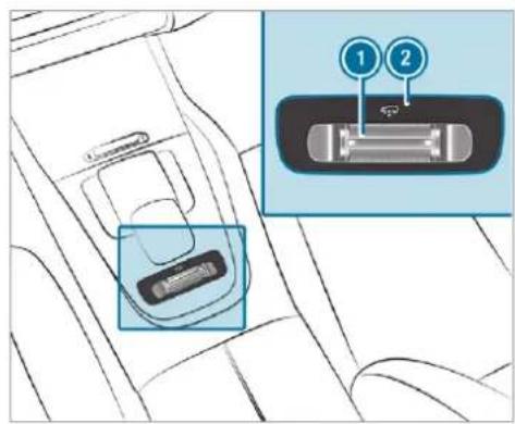
text_image
Diagram showing car seatbelt insertion with labeled buttons 1 and 2, highlighting a specific slot.Push rocker switch ① forwards. Indicator lamp ② flashes while the vehicle is being raised and lights up continuously when it has finished rising.
Your selection is saved. The off-road level set remains stored even after the ignition has been switched off.
Operation with a trailer or bicycle rack: if you are driving at speeds greater than 30 km/h, the vehicle rises to the normal level in the drive programs Sport or Sport + if the electrical condition has been correctly established.
The vehicle is lowered again in the following situations:
- When driving faster than 80 km/h.
- When driving briefly between 65 km/h and 80 km/h.
• After selecting a different drive program using the DYNAMIC SELECT switch.
The vehicle is adjusted to the height of the active drive program.
Operation with a trailer or bicycle rack: if you are driving at speeds greater than 30 km/h, the vehicle lowers to the normal level if the electrical connection has been correctly established.
Lowering the vehicle (vehicles without Off-road package)
Pull rocker switch ①. The vehicle is adjusted to the height of the active drive program.
Operation with a trailer or bicycle rack: the vehicle lowers to the normal level if the electrical connection has been correctly established.
Raising the vehicle (vehicles with Off-road package)
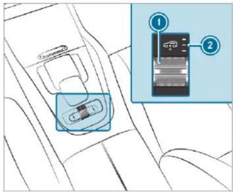
text_image
Diagram showing car seatbelt insertion with labeled components and a magnified inset highlighting the device's internal structure.▶ Push rocker switch ① forwards.
- Off-road level +1: one indicator lamp lights up continuously when the vehicle has finished rising.
- Off-road level +2: two indicator lamps light up continuously when the vehicle has finished rising.
- Off-road level +3: three indicator lamps ● light up continuously when the vehicle has finished rising.
Your selection is saved. The off-road level set remains stored even after the ignition has been switched off.
The vehicle is lowered again in the following situations:
- Off-road level +3: when driving faster than 20 km/h or when the rear fog lamp is switched on.
The vehicle is lowered to off-road level +2. - Off-road level +2:
- When driving faster than 80 km/h.
- When driving briefly between 65 km/h and 80 km/h.
The vehicle is lowered to off-road level +1. Operation with a trailer or bicycle rack: if
you are driving at speeds greater than 30 km/h, the vehicle lowers to the normal level if the electrical connection has been correctly established.
- Off-road level +1:
- When driving faster than 115 km/h.
- When driving briefly between 100 km/h and 115 km/h.
Operation with a trailer or bicycle rack: you are driving at speeds greater than 30 km/h.
The vehicle is lowered to the normal level.
• After selecting a different drive program using the DYNAMIC SELECT switch.
The vehicle is adjusted to the height of the active drive program.
Operation with a trailer or bicycle rack: the vehicle lowers to the normal level if the electrical connection has been correctly established.
Lowering the vehicle (vehicles with Off-road package)
Pull rocker switch 1.
- Off-road level +3: the vehicle is lowered to off-road level +2. Two indicator lamps
② light up continuously when the vehicle has finished lowering.
- Off-road level +2: the vehicle is lowered to off-road level +1. One indicator lamp
② lights up continuously when the vehicle has finished lowering. - Off-road level +1: the vehicle is lowered to the normal level. No indicator lamp lights up when the vehicle has finished lowering.
Your selection is saved. The off-road level set remains stored even after the ignition has been switched off.
Setting the entering/exiting level (AIRMATIC) Requirements:
• The engine is running.
- The vehicle is moving at speeds less than 30 km/h.
Multimedia system:
Settings
▶ Schnellzugriff (Quick access)
Select Lower when entering On. The vehicle is lowered to low level -2 to facilitate entering and exiting.
i Further information on AIRMATIC ( page 286).
Lowering and raising the rear of the vehicle
WARNING Risk of entrapment from vehicle lowering
When lowering the vehicle, other people could become trapped if their limbs are between the vehicle body and the tyres or underneath the vehicle.
Make sure no one is underneath the vehicle or in the immediate vicinity of the wheel arches when the vehicle is being lowered.
Requirements:
• all vehicle doors are closed
• there is no trailer coupled
• there is no bicycle rack fitted
- the battery is sufficiently charged; if necessary, start the engine
Lowering the rear of the vehicle
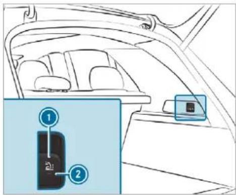
text_image
Diagram of car interior showing seat arrangement and a highlighted device with labeled parts 1 and 2Apply the electric parking brake.
Shift the transmission to position P (→ page 230).
Pull switch ① in the right-hand load compartment trim briefly.
Indicator lamp ② flashes until the vehicle has been lowered.
The vehicle is lowered at the rear axle by approx. 40 mm. When the vehicle has been lowered, indicator lamp ② remains lit.
When the rear of the vehicle has been completely lowered, indicator lamp 2 remains lit.
Lowering is interrupted in the following situations:
• a vehicle door is opened
- switch ① is pulled again
- the vehicle is being driven faster than 2 km/h
The vehicle is automatically set to the level of the most recently selected drive program if you drive at speeds greater than 2 km/h.
If indicator lamp ② flashes twice and the rear of the vehicle does not lower:
Make sure that the requirements are met.
Lowering the rear of the vehicle allows the vehicle to be loaded more easily. Observe the notes on loading the vehicle when doing this ( page 144).
Raising the rear of the vehicle
Check if the battery is sufficiently charged. If necessary, start the engine.
Pull switch ① briefly. Indicator lamp ② goes out. The vehicle will be raised to the currently selected level.
The vehicle is automatically set to the level of the most recently selected drive program if you drive at speeds greater than 2 km/h.
If the vehicle cannot be raised:
Ensure that the battery is sufficiently charged; if necessary, start the engine. The raising process continues.
E-ACTIVE BODY CONTROL
Function of E-ACTIVE BODY CONTROL
E-ACTIVE BODY CONTROL is an electrohydraulic suspension system with variable damping for improved driving comfort. The all-round level control system ensures the best possible suspension and constant ground clearance, even with a laden vehicle. When driving at speed, the vehicle is lowered automatically to improve driving safety and to reduce fuel consumption. The suspension setting is adjusted depending on t road surface, vehicle load and the drive program selected.
The ROAD SURFACE SCAN function detects areas of unevenness in the road before you drive over them by means of a multifunction camera. This reduces chassis movements.
The damping is adjusted individually to each wheel and depends on the following factors:
- Driving style, e.g. sporty
• Road condition, e.g. bumps
- Drive program
E-ACTIVE BODY CONTROL is comprised of the following functions and components:
• ROAD SURFACE SCAN
• Curve inclination function CURVE
- Recovery mode
• Individual wheel control
e• Air suspension with automatic level control
- speed-dependent lowering to reduce fuel consumption
- Manual level adjustment
- ADS PLUS (Adaptive Damping System with constant adjustment of damping characteristics)
• DYNAMIC SELECT switch and level button
Suspension settings and vehicle level per drive program
| Drive program | Suspension settings and vehicle level |
| S (Sport) | The suspension setting is firmer.The vehicle is set to Sport level.ROAD SURFACE SCAN is deactivated.The curve inclination function is deactivated.Operation with a trailer or bicycle rack: if the electrical connection has been correctly established, the vehicle remains at normal level. |
| St (Sport +) | The suspension setting is even firmer.The vehicle is set to Sport + level.ROAD SURFACE SCAN is deactivated.The curve inclination function is active.Operation with a trailer or bicycle rack: if the electrical connection has been correctly established, the vehicle remains at normal level. |
| [Comfort] | The suspension setting is comfortable.The vehicle is set to the normal level.When driving at speeds above approximately 140 km/h, the vehicle is lowered.When driving at speeds below approximately 40 km/h, the vehicle is raised.ROAD SURFACE SCAN is active.C: The curve inclination function is deactivated. : The curve inclination function is active.Operation with a trailer or bicycle rack: if the electrical connection has been correctly established, the vehicle remains at normal level. : The curve inclination function is active.Operation with a trailer or bicycle rack: if the electrical connection has been correctly established, the vehicle remains at normal level. |
| (H33Y) | |
| (Maybach) | |
| (CURVE) | The suspension setting is comfortable.The vehicle is set to the normal level.When driving at speeds above approximately 140 km/h, the vehicle is lowered.When driving at speeds below approximately 40 km/h, the vehicle is raised again.ROAD SURFACE SCAN is active.The curve inclination function is active. |
| (Economy) | The suspension setting is comfortable.The vehicle is set to the normal level.When driving at speeds above approximately 140 km/h, the vehicle is lowered.When driving at speeds below approximately 40 km/h, the vehicle is raised again.ROAD SURFACE SCAN is deactivated.The curve inclination function is deactivated.Operation with a trailer or bicycle rack: if the electrical connection has been correctly established, the vehicle remains at normal level. |
| (Off-road in vehicles without Off-road package) | The suspension setting is suitable for easily negotiable off-road terrain.The vehicle is set to off-road level +1.When driving at speeds above approximately 80 km/h the vehicle is lowered.When driving at speeds below approximately 45 km/h, the vehicle is raised.ROAD SURFACE SCAN is deactivated.The curve inclination function is deactivated.Recovery mode and the individual wheel control function can be activated provided the necessary conditions are met. |
| (Off-road in vehicles Off-road package) | withThe suspension setting is suitable for easily negotiable off-road terrain.The vehicle is set to off-road level +1.When driving at speeds above approximately 115 km/h, the vehicle is lowered.When driving at speeds below approximately 75 km/h, the vehicle is raised.ROAD SURFACE SCAN is deactivated.The curve inclination function is deactivated.Recovery mode and the individual wheel control function can be activated provided the necessary conditions are met. |
| (Off-road + in vehicles with Off-road package) | The suspension setting is suitable for difficult off-road terrain.The vehicle is set to off-road level +1.When driving at speeds above approximately 80 km/h, the vehicle is lowered.When driving at speeds below approximately 45 km/h, the vehicle is raised.ROAD SURFACE SCAN is deactivated.The curve inclination function is deactivated.Recovery mode and the individual wheel control function can be activated provided the necessary conditions are met. |
| Individual | You can call up individual suspension settings here. |
Differences between different vehicle levels compared to the normal level
| Vehicle level | Vehicles without Off-road package | Vehicles with Off-road package |
| Car wash | Approx. +90 mm | Approx. +90 mm |
| Off-road level +3 | Unavailable Approx. +90 mm | |
| Off-road level +2 | Unavailable Approx. +60 mm | |
| Off-road level +1 | Approx. +60 mm | Approx. +30 mm |
| Sport | A pprox. -15 mm | Approx. -15 mm |
| Sport + | A pprox. -25 mm | Approx. -25 mm |
Function of ROAD SURFACE SCAN
① This function is not available in all countries.
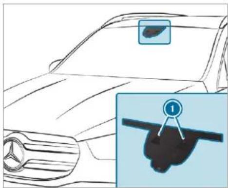
natural_image
Line drawing of a car front view with a close-up inset showing a black object labeled '1' (no text or symbols on the main diagram)The ROAD SURFACE SCAN function monitors the road in front of your vehicle using a multifunction camera ①. ROAD SURFACE SCAN detects unevenness in the road surface, e.g. bumps, before the vehicle drives over them. Chassis movements are reduced and driving comfort is increased.
ROAD SURFACE SCAN is automatically activated if the following conditions are met:
- Drive program [C] (Comfort) or [CV] (CURVE) is selected.
• The vehicle is set to the normal level. - You are driving at a speed between 7 km/h and 180 km/h.
System limits
ROAD SURFACE SCAN can be impaired in the following situations or can stop functioning:
- If the carriageway is insufficiently lit, e.g. at night.
- In snow, rain, fog, heavy spray, if there is glare, in direct sunlight or in greatly varying light conditions.
- If the windscreen in the area of multifunction camera ① is dirty, misted up, damaged or covered.
- If the road surface has no optic structure or reflects light.
-
If you are driving too close to the vehicle in front.
-
If sections of the route have a very small radius of curvature.
- During abrupt driving manoeuvres, e.g. heavy braking or sudden acceleration.
Observe the notes on cleaning the multifunction camera ( page 579).
Function of recovery mode

WARNING Risk of injury due to the vehicle moving up and down
When free driving mode is activated, the vehicle bounces up and down. Body parts could become trapped if they are between the vehicle body and the tyres or underneath the vehicle.
Make sure that nobody is under or in the immediate vicinity of the vehicle when free driving mode is activated.

NOTE Risk of damage due to the vehicle moving up and down
When free driving mode is activated, the vehicle moves up and down. Vehicle parts may be damaged if the underbody bottoms out.

Make sure that there is sufficient ground clearance when rocking free mode is activated.
Rocking free mode is a function of the suspension which can assist the driver on loose surfaces (e.g. sand, snow) when freeing a vehicle which has become stuck.
The vehicle body rocks in slow, vertical motions when recovery mode has been activated. This temporarily puts the wheels under greater load, which means they have increased traction and the vehicle is freed.
You can activate free driving mode via Off-road Assist ( page 304).
Function of individual wheel control

WARNING Risk of becoming trapped due to the vehicle lowering
The vehicle can be lowered when the individual wheel control function has been activated. Body parts could become trapped if they are between the vehicle body and the tyres or underneath the vehicle.

Make sure that nobody is under the vehicle or in the immediate vicinity of the wheel arches when individual wheel control is activated.

NOTE Risk of damage due to the vehicle moving up and down
The vehicle can be lowered or raised on one or more wheels when the individual wheel control function has been activated. Vehicle parts could be damaged due to contact with objects.

Make sure that the vehicle has sufficient room to move when the individual
wheel control function has been activated.
Individual wheel control is a function of the sus pension, which can be used to set the vehicle level for each wheel individually. This can help to improve alignment of the body when driving off-road.
You can activate individual wheel control via Off-road Assist ( page 304).
Adjusting the vehicle level (vehicles with E-ACTIVE BODY CONTROL)
⚠ WARNING Risk of accident because vehicle level is too high
If you drive at a higher vehicle level, the driving characteristics may be impaired due to the higher vehicle centre of gravity.
The vehicle can drift outwards, for example, when steering or cornering.
Always choose a vehicle level which is suited to the driving style and the road surface conditions.
WARNING Risk of entrapment from vehicle lowering
When lowering the vehicle, other people could become trapped if their limbs are between the vehicle body and the tyres or underneath the vehicle.
Make sure no one is underneath the vehicle or in the immediate vicinity of the wheel arches when the vehicle is being lowered.
⚠ WARNING Risk of becoming trapped due to the vehicle lowering
Vehicles with AIRMATIC or level control: when you unload luggage or leave the vehicle, the vehicle first rises slightly and then returns to the set level shortly afterwards. You or anyone else in the vicinity of the wheel arches or the underbody could thus become trapped.
The vehicle can also be lowered after being locked.
When leaving the vehicle, make sure that nobody is in the vicinity of the wheel arches or the underbody.
Requirements:
• The vehicle has been started.
- Vehicles without Off-road package: the vehicle is being driven no faster than 65 km/h or when being operated with a trailer or bicycle rack with a correctly established electrical connection 30 km/h.
• Vehicles with Off-road package:
- Off-road level +1: the vehicle is not moving faster than 100 km/h or when being operated with a trailer or bicycle rack with a correctly established electrical connection 30 km/h.
- Off-road level +2: the vehicle is not moving faster than 65 km/h or when being operated with a trailer or bicycle rack with a correctly established electrical connection 30 km/h.
- Off-road level +3: the vehicle is not moving faster than 20 km/h.
Raising the vehicle (vehicles without Off-road package)
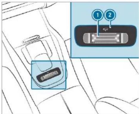
text_image
Diagram showing car seatbelt insertion with labeled buttons 1 and 2, highlighting a device component.
Push rocker switch ① forwards.
Indicator lamp ② flashes while the vehicle is being raised and lights up continuously with it has finished rising.
Your selection is saved. The off-road level set remains stored even after the ignition has been switched off.
Operation with a trailer or bicycle rack: if you are driving at speeds greater than 30 km/h, the vehicle rises to the normal level in the drive programs Sport S or Sport + S' cal connection has been correctly established.
The vehicle is lowered again in the following situations:
- When driving faster than 80 km/h.
- When driving briefly between 65 km/h and 80 km/h.
• After selecting a different drive program using the DYNAMIC SELECT switch.
The vehicle is adjusted to the height of the active drive program.
Operation with a trailer or bicycle rack: if you are driving at speeds greater than 30 km/h, the vehicle lowers to the normal level if the electrical connection has been correctly established.
Lowering the vehicle (vehicles without Off-road package)

Pull rocker switch ①.
The vehicle is adjusted to the height of the active drive program.
Operation with a trailer or bicycle rack: the he-electri-vehicle lowers to the normal level if the electrical connection has been correctly established.
Raising the vehicle (vehicles with Off-road package)
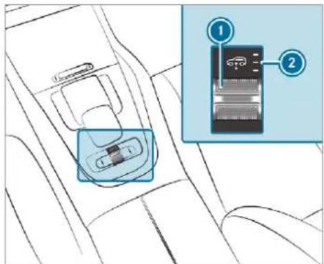
text_image
Diagram showing car seatbelt insertion mechanism with labeled parts 1 and 2▶ Push rocker switch ① forwards.
- Off-road level +1: one indicator lamp lights up continuously when the vehicle has finished rising.
- Off-road level +2: two indicator lamps light up continuously when the vehicle has finished rising.
- Off-road level +3: three indicator lamps ② light up continuously when the vehicle has finished rising.
Your selection is saved. The off-road level set remains stored even after the ignition has been switched off.
The vehicle is lowered again in the following situations:
- Off-road level +3: when driving faster than 20 km/h.
The vehicle is lowered to off-road level +2. - Off-road level +2:
- When driving faster than 80 km/h.
- When driving briefly between 65 km/h and 80 km/h.
The vehicle is lowered to off-road level +1.
Operation with a trailer or bicycle rack: if you are driving at speeds greater than 30 km/h, the vehicle lowers to the normal level if the electrical connection has been correctly established.
- Off-road level +1:
- When driving faster than 115 km/h.
- When driving briefly between 100 km/h and 115 km/h.
- Operation with a trailer or bicycle rack: you are driving at speeds greater than 30 km/h.
The vehicle is lowered to the normal level.
- After selecting a different drive program using the DYNAMIC SELECT switch. The vehicle is adjusted to the height of the active drive program.
Operation with a trailer or bicycle rack: the vehicle lowers to the normal level if the electrical connection has been correctly established.
Lowering the vehicle (vehicles with Off-road package)
Pull rocker switch ①.
- Off-road level +3: the vehicle is lowered to off-road level +2. Two indicator lamps ② light up continuously when the vehicle has finished lowering.
- Off-road level +2: the vehicle is lowered to off-road level +1. One indicator lamp lights up continuously when the vehicle has finished lowering.
- Off-road level +1: the vehicle is lowered to the normal level. No indicator lamp lights up when the vehicle has finished lowering.
Your selection is saved. The off-road level set remains stored even after the ignition has been switched off.
Setting Off-road Assist
Requirements:
• the vehicle is stationary
• the vehicle is set to off-road level 1 or 2
- the Off-road or Off-road Plus (only vehicles with Off-road package) drive program has been selected
• the ignition is switched on
- all doors and the bonnet are closed
- the transmission is not engaged in position
P
• there is no trailer coupled
• the vehicle is outdoors
- the detected lateral inclination of the vehicle must not exceed approx. 15°
- the system is within its operating temperature
• the on-board voltage is sufficiently high
Multimedia system:
→ Settings ▶ Assistance
▶ Offroad Assist
Recovery mode
Recovery mode assists the driver when pulling away on rough terrain, such as sand or snow.
▶ Select Free driving mode.
▶ Select Start.
Recovery mode is activated.
▶ Select Stop to stop recovery mode.
Recovery mode is automatically deactivated in the following situations:
- you are actually travelling faster than 15 km/h
• after a running time of 30 seconds
- it is detected that an object has hit the underbody of the vehicle hard
• not all conditions are met
i Further information on recovery mode ( page 300).
Individual wheel control
Individual wheel control enables the vehicle level to be set separately for each wheel.
▶ Select Individual wheel control.
Set the vehicle level for the desired wheel.
You can also use the touch display to set the level for two or more wheels at the same time.
Select Reset to set all wheels to the default setting.
Individual wheel control is automatically deactivated in the following situations:
• you are travelling faster than 15 km/h
- it is detected that an object has hit the underbody of the vehicle hard
• not all conditions are met
(i) Further information on individual wheel control ( page 300).
Parking Assist PARKTRONIC
Function of Parking Assist PARKTRONIC
Parking Assist PARKTRONIC is an electronic parking assistance system with ultrasound. It monitors the area around your vehicle using six sensors on the front bumper and six sensors the rear bumper. Parking Assist PARKTRONIC shows you the distance between your vehicle and a detected obstacle visually and audibly.
Parking Assist PARKTRONIC is only an aid. It is not a substitute for your attention to the surroundings. The responsibility for safe manoeuvring and parking remains with you. Make sure that there are no persons, animals or objects in the manoeuvring area while manoeuvring and parking in/exiting parking spaces.
In the standard setting, an intermittent warning tone sounds from a distance of approximately 0.3 m to an obstacle in front and approximately
1.0 m to an obstacle behind. A continuous warning tone sounds from a distance of approximately 0.2 m. Using the Warn early all-round setting in the multimedia system, the warning tones for front and side impact protection can be set to sound at a greater distance of approximately 1.0 m in front and 0.6 m on the sides ( page 310).
① The Warn early all-round setting is always active in the rear of the vehicle.
If Parking Assist PARKTRONIC is deactivated, Active Parking Assist is unavailable.
Parking Assist PARKTRONIC display in the multimedia system
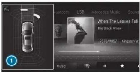
text_image
Pis Bluetooth USB Mercedes Music Sound When The Leaves Fall The Black Arrow 0573/9857 Kingston W MusicVehicles with Active Parking Assist without a 360° Camera
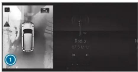
text_image
Radio 87.5 MHzVehicles with Active Parking Assist and a 360° Camera
If Active Parking Assist is deactivated and an obstacle is detected in the path of the vehicle, a pop-up window for Parking Assist PARKTRONIC ^1 appears in the multimedia system at speeds below 10 km/h.
The colour of the individual segments of the warning display is based on the distance to the detected obstacle:
- Yellow segments: obstacles at a distance between approx. 0.6 m and 1.0 m
- Orange segments: obstacles at a distance between approx. 0.3 m and 0.6 m
- Red segments: obstacles at a very short distance of approx. 0.3 m or less
Display of Parking Assist PARKTRONIC in the head-up display
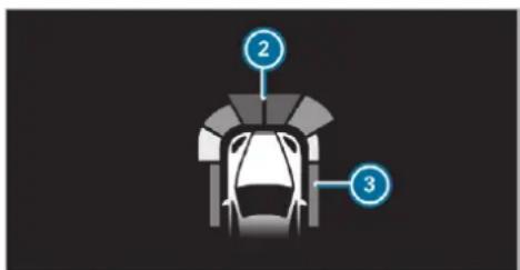
text_image
Diagram of a car parking garage with labeled parts 2 and 3Optionally, obstacles detected by Parking Assist PARKTRONIC from a distance of approximately 1.0 m in front ② and 0.6 m on the sides ③ can also be displayed in the head-up display.
System limits
Parking Assist PARKTRONIC does not necessarily take into account the following obstacles:
- Obstacles below the detection range, e.g. persons, animals or objects.
- Obstacles above the detection range, e.g. overhanging loads, overhangs or loading ramps of lorries.
The sensors must be free of dirt, ice and slush. Otherwise, they may not function correctly.
Clean the sensors regularly, especially after driving off-road, taking care not to scratch or damage them.
Vehicles with trailer hitch: Parking Assist PARKTRONIC is deactivated for the rear zone when you establish an electrical connection between your vehicle and a trailer.
Problems with Parking Assist PARKTRONIC
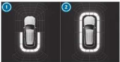
natural_image
Top-down diagram of a car inside a vehicle hull, showing two views (① and ②) with no text or symbols.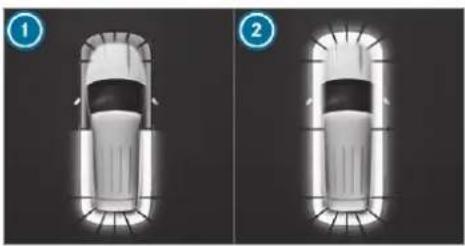
natural_image
Two identical 3D-rendered car illustrations shown from top and side views, no text or symbols present.Vehicles with 360° Camera
Vehicles without 360° Camera
| Problem | Possible causes/consequences and ▶ Solutions |
| Parking Assist PARKTRONIC is malfunctioning and has been deactivated due to signal interference. ▶ Start the vehicle again. | |
| Rear 1 or all-round 2 segments up red. The P_jj^CHF symbol appears in the multifunction display. | LightCheck if Parking Assist PARKTRONIC is working at a different location. |
| Rear 1 or all-round 2 segments up red. At the same time, a warning tone sounds for approximately two seconds every time the vehicle is started. The P_jj^CHF symbol appears in the multifunction display. | The sensors are dirty.▶ Clean the sensors and observe the notes on care of vehicle parts (→ page 579). |
| Parking Assist PARKTRONIC has been deactivated due to a malfunction.▶ Start the vehicle again.▶ If the problem persists, consult a qualified specialist workshop. |
Function of the passive side impact protection
Passive side impact protection is an additional Parking Assist PARKTRONIC function which warns the driver about obstacles at the side of the vehicle. A warning is issued when obstacles are detected between the front and rear detection range. In order for an object on the side to be detected, the sensors in the front and rear bumper must first detect the object while you are driving past it.
During the parking procedure or manoeuvring, objects are detected as the vehicle drives past. If you steer in the direction of a detected obstacle and there is a risk of a lateral collision, a warning is issued. The segments on the sides light up yellow or red, depending on the distance to the obstacle.
Segment colour depending on distance
| Colour Lateral distance | |
| Yellow | Approx. 30 - 60 cm |
| Red | Approx. < 30 cm |
In order for lateral front or rear segments to be displayed, the vehicle must first travel a distance of at least half of the vehicle length. Once the vehicle has travelled the length of the vehicle, all
of the lateral front and rear segments can be displayed.
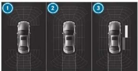
natural_image
Three-down diagram of a car with radar or sensor grid overlay, showing top, front, and side views (no text or symbols)Parking Assist PARKTRONIC display: vehicles without a 360° Camera
① Operational front and rear
② Operational front, rear and sides
③ Obstacle detected at the front right (yellow) and rear (red)
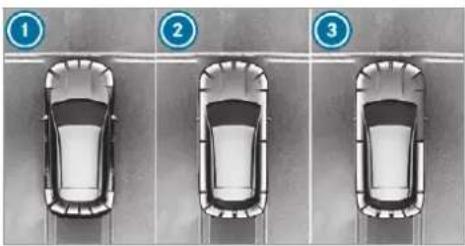
text_image
Diagram showing three cars on a road with numbered traffic signs (1, 2, 3) indicating lane numbers.Parking Assist PARKTRONIC display: vehicles with a 360° Camera
① Operational front and rear
② Operational front, rear and sides
3 Obstacles detected at the front right (red)
Saved obstacles on the sides are deleted in the following situations, for example:
- You park the vehicle and switch off the ignition.
- You open the doors.
After the engine is restarted, obstacles on the sides must be detected again before a new warning can be issued.
System limits
The system limits for Parking Assist
PARKTRONIC apply to passive side impact protection.
The following objects are not detected, for example:
- Pedestrians who approach the vehicle from the side
- Objects placed next to the vehicle
Activating/deactivating Parking Assist PARKTRONIC
! NOTE Risk of an accident from objects at close range
Parking Assist PARKTRONIC may not detect certain objects at close range.
When parking or manoeuvring the vehicle, pay particular attention to any objects which are above or below the sensors, e.g. flowerpots or drawbars. The vehicle or other objects could otherwise be damaged.
If the _i^CFF symbol is shown in the multifunction display, Parking Assist PARKTRONIC is not active.
Multimedia system:
→ Settings ▶ Quick access ▶ PARKTRONIC
▶ Activate or deactivate the function. ⓘ Parking Assist PARKTRONIC is automatically activated when the vehicle is started.
Adjusting the warning tones of Parking Assist PARKTRONIC
Multimedia system:
→ Settings → Assistance ▶ Camera & parking
Adjusting the volume of the warning tones
- Select Warning tone volume. - Set a value.
Adjusting the pitch of the warning tones
- Select Warning tone pitch. - Set a value.
Specifying the starting point for the warning tones
You can specify whether the Parking Assist PARKTRONIC warning tones should commence when the vehicle is further away from an obstacle.
- Select Warn early all-round. - Activate or deactivate the function.
Activating/deactivating audio fadeout
You can specify whether the volume of a media source in the multimedia system is to be reduced when Parking Assist PARKTRONIC sounds a warning tone.
- Select Audio fadeout during warning tones. - Activate or deactivate the function.
Function of Trailer Manoeuvring Assist
! NOTE Damage to trailers with a stabilisation device against swerving
In the case of trailers with a stabilisation device against swerving, the trailer or trailer tow hitch could be damaged.
If a trailer coupling with Trailer Manoeuvring Assist is used, only use trailers without a stabilisation device against swerving.
NOTE Damage due to overhanging loads in front or drawbar installations
The vehicle and the trailer may be damaged during manoeuvring due to overhanging loads at the front of the trailer or drawbar installations.
Pay attention to overhanging loads or drawbar installations while manoeuvring.
Trailer Manoeuvring Assist assists you when reversing with a trailer. By means of a turning angle sensor in the trailer coupling, Trailer Manoeuvring Assist monitors the articulation angle between the vehicle and trailer and adjusts it to a specified value.
You can either enter the articulation angle value directly via the multimedia system or use a straightening manoeuvre. When carrying out a
straightening manoeuvre, the system calculates the articulation angle automatically and straightens the vehicle/trailer combination to the trailer's current direction.
Trailer Manoeuvring Assist must be taught-in before it can adjust the articulation angle ( page 311).
Observe the notes on towing a trailer ( page 337).
System limits
The system may be impaired or may not function in the following situations:
- The gradient is more than approximately 15%.
Using Trailer Manoeuvring Assist Requirements:
• The vehicle has been started.
• A trailer has been detected.
Teaching-in Trailer Manoeuvring Assist
Drive forwards a short distance with the car/trailer combination. The completed teach-in process is shown in the media display.
Using Trailer Manoeuvring Assist
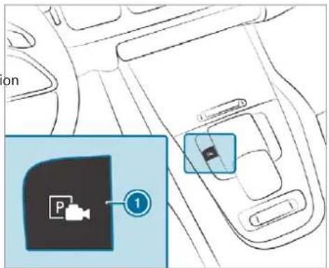
text_image
on P ①Press button 1.
Engage reverse gear R.
The camera image is shown in the media d play.
Adjust the articulation angle ( page 311).
▶ Activate the straightening manoeuvre ( page 311).
▶ Accelerate and brake as required.
(i) Pay attention to your surroundings and be ready to brake at all times.
Adjusting Trailer Manoeuvring Assist (multimedia system)
Requirements:
- The ignition and engine are on, or the vehicle is operational.
- The zero point of the car/trailer combination has been taught-in by briefly driving forwards ( page 310).
- Trailer Manoeuvring Assist has been started (→ page 311).
• the vehicle is stationary
• The gradient is less than approximately 15%.
Adjusting the articulation angle of the trailer
Select
The articulation angle can be changed on the media display or on the touchpad.
Swipe left or right to change the articulation angle.
The maximum articulation angle depends on the length of the trailer. This is calculated by the system by driving the vehicle forwards, including cornering. Before the length of the trailer has been calculated, the maximum articulation angle is approximately 23^ . The longer the trailer is, the higher the maximum articulation angle (max. approximately 60^ ).
▶ Set the desired articulation angle.
When the articulation angle entered has been reached, the drawbar is locked by the system so that the angle is maintained.
Activating the straightening manoeuvre
Select
The system calculates the articulation angle in such a way that the direction of the trailer
at the time of activation is maintained. There Reversing camera
is a short countersteering movement of the trailer while the vehicle is reversed, which then guides it back to the desired line. In this way, the vehicle is aligned straight with the trailer and, at the same time, the direction the trailer is maintained.
Function of the reversing camera
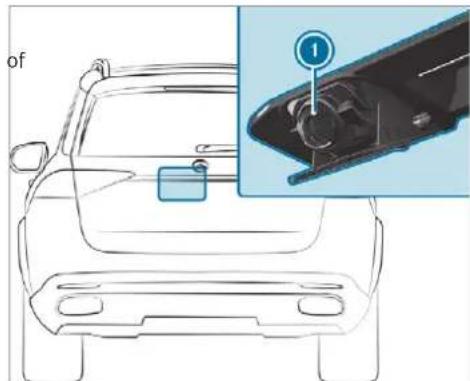
natural_image
Top-down line drawing of a car front view with an inset showing a close-up of the engine compartment (no text or symbols)If you have activated the function in the multimedia system ( page 319), the image from reversing camera ① is shown in the media display when the reverse gear is engaged. Dynamic guide lines show the path the vehicle will take with the steering wheel in its current position.
This helps you to orient yourself and to avoid obstacles when reversing.
The reversing camera is only an aid. It is not substitute for your attention to the surroundings.
The responsibility for safe manoeuvring and parking remains with you. Make sure that there are no persons, animals or objects etc., in the manoeuvring area while manoeuvring and parking.
The guide lines in the media display show the distances to your vehicle. The distances displayed only apply to road level.
Depending on the vehicle equipment, you can select from the following views:
- Normal view
- Wide-angle view
- Trailer view
The area behind the vehicle is displayed as a mirror image, as in the inside rearview mirror.
Vehicles without Active Parking Assist
The following camera views are available in the multimedia system:
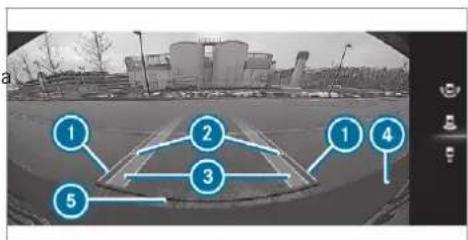
flowchart
graph TD
    A["1"] --> B["2"]
    B --> C["3"]
    C --> D["4"]
    D --> E["5"]
Normal view
① Yellow guide line, vehicle width (driven surface) depending on the current steering wheel angle (dynamic)
② Yellow guide line at a distance of approximately 1.0 m from the rear area
3 Yellow lane marking the course the tyres will take at the current steering wheel angle (dynamic)
4 Bumper
5 Red guide line at a distance of approximately 0.3 m from the rear area
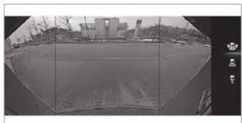
natural_image
Black-and-white fisheye view of an industrial facility with buildings and a clear sky (no visible text or symbols)Wide-angle view
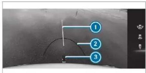
text_image
Diagram showing three labeled points (1, 2, 3) on a curved surface with directional arrows and control buttonsTrailer view (vehicles with a trailer hitch) Yellow guide line, locating aid
② Red guide line at a distance of approximately 0.3 m from the ball head of the trailer hitch
Ball head of the trailer hitch
Vehicles with Active Parking Assist
The following camera views are available in the multimedia system:
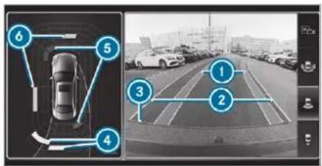
text_image
Diagram showing a car detection system with numbered components and a surveillance camera view of a highway ahead.Normal view
Yellow lane marking the course the tyres will take at the current steering wheel angle (dynamic)
2 Yellow guide line, vehicle width (driven surface) depending on the current steering wheel angle (dynamic)
3 Red guide line at a distance of approximately 0.3 m from the rear area
4 Yellow warning indicator of Parking Assist PARKTRONIC: obstacles at a distance between approximately 0.6 m and 1.0 m
5 Red warning display of Parking Assist PARKTRONIC: obstacles are very close (approximately 0.3 m or less)
Orange warning display of Parking Assist PARKTRONIC: obstacles are a medium distance away (between approximately 0.3 m and 0.6 m)
If the entire system fails, the segments of the warning display are shown in red. The indicator lamp on the PARKTRONIC button lights up and the P_^* symbol appears in the multifunction display.
If the system fails at the rear, the display of the segments changes as follows:
- The rear segments are shown in red when reversing.
- The rear segments are hidden when driving forwards.
If Parking Assist PARKTRONIC is deactivated, the warning display fades out ( page 307).
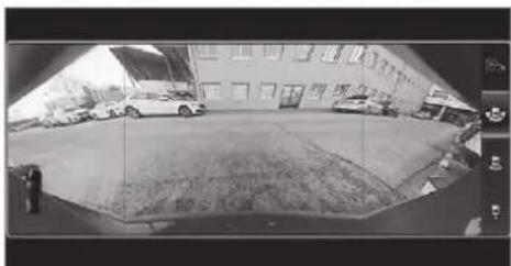
natural_image
Black-and-white fisheye view of a courtyard with parked cars and a building, no visible text or symbolsWide-angle view
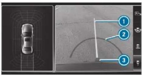
text_image
Diagram showing car navigation with three labeled steps: top view, left side, and right side.Trailer view (vehicles with a trailer hitch)
① Yellow guide line, locating aid
2 Red guide line at a distance of approximately 0.3 m from the ball head of the trailer
Ball head of the trailer hitch
System failure

natural_image
Black square with white video camera symbol and diagonal line (no text or numbers)If the reversing camera is not operational, a message appears in the multimedia system.
System limits
The reversing camera will not function or will only partially function in the following situations:
• The tailgate is open.
• There is heavy rain, snow or fog.
• The light conditions are poor, e.g. at night.
- The camera lens is obstructed, dirty or mis-ted up. Observe the notes on cleaning the reversing camera (→ page 579).
- The camera or rear of your vehicle is damaged. In this case, have the camera and its position and setting checked at a qualified specialist workshop.
Do not use the reversing camera in these types of situation. You could otherwise injure others or collide with objects when parking the vehicle.
If the vehicle is carrying a heavy load, leaving the standard height can result in inaccuracies in the guide lines and in the display of the generated images, depending on technical conditions.
The field of vision and other functions of the reversing camera may be restricted due to additional accessories on the rear of the vehicle (e.g. licence plate bracket or bicycle rack).
The contrast of the display may be impaired by direct sunlight or by other light sources, e.g. when driving out of a garage. In this case, pay particular attention.
i Have the display repaired or replaced if, for example, pixel errors considerably restrict its use.
360° Camera
Function of the 360° Camera
The 360° Camera is a system that consists of four cameras. The cameras cover the immediate vehicle surroundings. The system assists you, e.g. when parking or at exits with reduced visibility.
The views of the 360° Camera are always available when driving forwards up to a speed of approximately 16 km/h and when reversing.
The 360° Camera is only an aid and may show distorted view of obstacles, show them incorrectly or not show them at all. It is not a substitute for your attention to the surroundings. The responsibility for safe manoeuvring and parking remains with you. Make sure that there are no persons, animals or objects etc., in the manoeuvring area while manoeuvring and parking. The system evaluates images from the following cameras:
- Reversing camera
- Front camera
- Two side cameras in the outside mirrors
Views of the 360° Camera
You can select from different views:
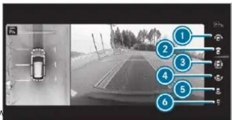
text_image
Camera navigation interface showing a car on a road with numbered annotations pointing to key lanes.① Wide-angle view, front
② Top view with image from the front camera
3 Top view with images from the side cameras in the outside mirrors
4 Wide-angle view, rear
5 Top view with image from the reversing camera
6 Top view with trailer view (vehicles with a trailer hitch)
Top view
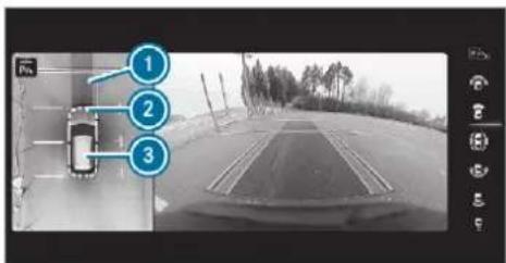
text_image
Street photo with numbered annotation boxes pointing to a vehicle detection device on a road aheadLane indicating the route the vehicle will take at the current steering wheel angle
2 Warning display of Parking Assist PARKTRONIC
3 Your vehicle from above
The colour of the individual segments of warning display ② is based on the distance to the detected obstacle:
- Yellow segments: obstacles at a distance between approx. 0.6 m and 1.0 m
- Orange segments: obstacles at a distance between approx. 0.3 m and 0.6 m
- Red segments: obstacles at a very short distance of approx. 0.3 m or less
When Parking Assist PARKTRONIC is operational and no object is detected, the segments of the warning display are shown in grey.
If the entire system fails, the segments of the warning display are shown in red. The indicator lamp on the PARKTRONIC button lights up and the P_^ symbol appears in the multifunction display.
If the system fails at the rear, the display of the segments changes as follows:
- The rear segments are shown in red when reversing.
- The rear segments are hidden when driving forwards.
If Parking Assist PARKTRONIC is deactivated, the warning display fades out ( page 307).
Guide lines
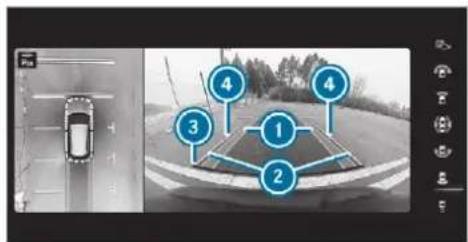
text_image
Diagram showing a car on a road with numbered locations and a traffic sensor overlay① Yellow lane marking the course the tyres will take at the current steering wheel angle (dynamic)
2 Yellow guide line, vehicle width (driven surface) depending on the current steering wheel angle (dynamic)
3 Red guide line at a distance of approximately 0.3 m from the rear area
④ Mark at a distance of approx. 1.0 m
When Active Parking Assist is active, lane markings are displayed in green.
The guide lines in the media display show the distances to your vehicle. The distances apply to road level.
In trailer mode, the guide lines are shown at the level of the trailer hitch.
Trailer view (vehicles with a trailer hitch)
If you select trailer view and no trailer is coup to the vehicle, the following display appears:
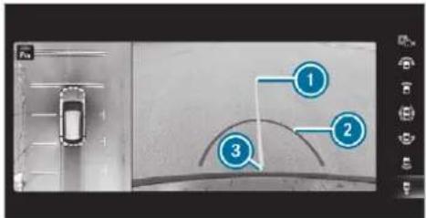
text_image
Diagram showing a car with three labeled points (1, 2, 3) pointing to a curved road or path on a vehicle ahead.① Yellow guide line, locating aid
2 Red guide line at a distance of approximately 0.3 m to the ball head of the trailer hitch
③ Ball head of the trailer hitch
natural_image
Top-down view of a car parked in a lot with lane markings (no visible text or symbols)When the electrical connection is established between the vehicle and the trailer, the display changes to the side camera view.
This view supports manoeuvring procedures with a trailer.
Side view of the mirror cameras
The sides of the vehicle can be seen in this view.
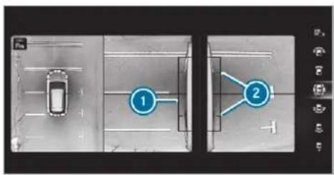
text_image
Diagram showing two labeled lanes with a car icon, likely illustrating parking or road safety instructions.① Guide line of external vehicle dimensions with outside mirrors folded out
② Marker of the wheel contact points
System failure
If the 360° Camera is not ready for operation, the following message appears in the multimedia system:

natural_image
Camera icon with no text or symbols, featuring a diagonal line crossing the camera (no text or symbols present)System limits
The 360° Camera will not function or will only partially function in the following situations:
• The doors are open.
• The side mirrors are folded in.
• The tailgate is open.
• There is heavy rain, snow or fog.
• The light conditions are poor, e.g. at night.
- The camera lens is obstructed, dirty or misted up.
- If cameras or vehicle components in which the cameras are fitted are damaged. In this event, have the cameras, their positions and
their setting checked at a qualified specialist workshop.
Do not use the 360° Camera under such circumstances. You could otherwise injure others or collide with objects when parking vehicle.
If the vehicle is carrying a heavy load, leaving the standard height can result in inaccuracies in the guide lines and in the display of the generated images, depending on technical conditions.
The field of vision and other functions of the camera system may be restricted due to additional attachments on the vehicle (e.g. licence plate bracket, bicycle rack).
The contrast of the display may be impaired by abrupt direct sunlight or by other light sources, e.g. when driving out of a garage. In this case, pay particular attention.
i Have the display repaired or replaced if, for example, pixel errors considerably restrict its use.
See the notes on cleaning the 360^ Camera ( page 579).
Selecting a view for the 360° Camera Requirements:
The Auto reversing camera function is activated in the multimedia system ( page 319).
e Engage reverse gear.
Select the desired view in the multimedia system ( page 316).
Switching reversing camera automatic mode on/off
The reversing camera is only an aid. It is not a substitute for your attention to the surroundings. The responsibility for safe manoeuvring and parking remains with you. Make sure that no persons, animals or objects etc. are in the manoeuvring range. Pay attention to your surroundings and be ready to brake at all times.
Multimedia system:
→ Settings → Assistance ▶ Camera & parking
▶ Switch Auto reversing camera on or off.
Opening the camera cover of the reversing camera
Multimedia system:
→ Settings ▶ Assistance
▶▶ Camera & parking
▶ Select Open camera cover.
The camera cover closes automatically after some time or after an ignition cycle.
Active Parking Assist
Function of Active Parking Assist
Active Parking Assist is an electronic parking assistance system which uses ultrasound and is automatically activated during forward travel. The system is operational at speeds below approximately 35 km/h.
If all requirements are met, the □ display appears in the multifunction display. The system then independently locates and measures parallel and perpendicular parking spaces on both sides of the vehicle.
When Active Parking Assist has detected parking spaces, the P display appears in the mu
function display. The arrows show on which side of the road detected parking spaces are located. They are then shown in the media display. The parking space and, if necessary, the parking direction can be selected as desired. Active Parking Assist calculates a suitable vehicle path, switches on the turn signal indicator and assist you in parking and exiting the parking space.
Active Parking Assist provides assistance when changing gear, accelerating, braking and steering the vehicle.
Active Parking Assist is only an aid. It is not a substitute for your attention to the surroundings. The responsibility for safe manoeuvring and parking remains with you. Make sure that no persons, animals or objects etc. are in the manoeuvring range.
Active Parking Assist is cancelled if, among other things, one of the following actions is carried out:
- Parking Assist PARKTRONIC is deactivated.
• Active Parking Assist is deactivated. - You begin steering.
-
You apply the parking brake.
-
You engage transmission position [P].
- ESP® intervenes.
- You open the doors or the tailgate while driving.
System limits
Objects located above or below the detection range of Parking Assist PARKTRONIC or Active Parking Assist are not detected when the parking space is being measured. These are also not taken into account when the parking manoeuvre is calculated, e.g. overhanging loads, overhangs or loading ramps of lorries, or the boundaries of parking spaces. In some circumstances, Active Parking Assist may therefore guide you into the parking space prematurely.

WARNING Risk of accident due to objects located above or below the detection range of Active Parking Assist
If there are objects above or below the detection range, the following situations may arise:
• Active Parking Assist may steer too early.
- Vehicles with automatic transmission: The vehicle may not stop in front of these objects.
This could cause a collision.
In these situations, do not use Active Parking Assist.
Snowfall or heavy rain may lead to a parking space being measured inaccurately. Parking spaces that are partially occupied by trailer drawbars might not be identified as such or be measured incorrectly. Only use Active Parking Assist on level, high-grip ground.
Do not use Active Parking Assist in the following situations:
- In extreme weather conditions such as ice, packed snow or in heavy rain.
- When transporting a load that protrudes beyond the vehicle.
- If the parking space is on a steep downhill or uphill gradient.
- When snow chains are fitted.
Active Parking Assist may also display parking spaces that are not suitable for parking, e.g. the following:
- Parking spaces where parking is prohibited.
- Parking spaces on unsuitable surfaces.
Active Parking Assist will not assist you with parking spaces at right angles to the direction of travel in the following situations:
- If two parking spaces are located immediately next to each other.
- If the parking space is immediately next to a low obstacle such as a kerb.
Active Parking Assist will not assist you with parking spaces parallel or at right angles to the direction of travel in the following situations:
• If the parking space is on a kerb.
- If the parking space is bordered by an obstacle, e.g. a tree, a post or a trailer.
Parking with Active Parking Assist
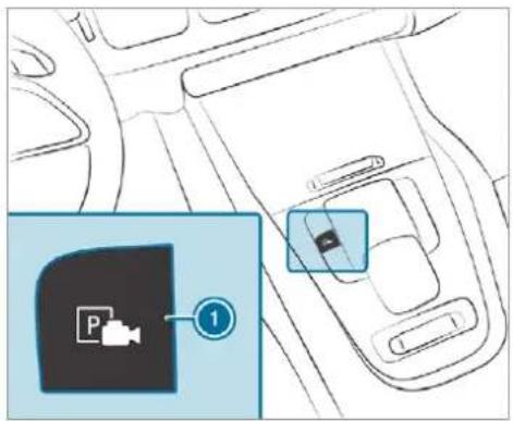
text_image
Diagram showing a car interior with a parking pad icon and a numbered annotation pointing to the pad.Press button 1.
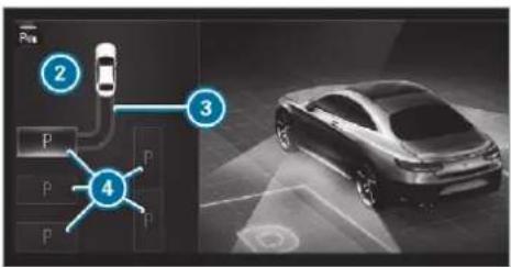
flowchart
graph TD
    A["2 Parking"] --> B["3 Parking"]
    B --> C["4 Parking"]
    style A fill:#f9f,stroke:#333
    style B fill:#ccf,stroke:#333
    style C fill:#cfc,stroke:#333
The media display shows the view of Active Parking Assist. Area ② displays detected parking spaces ④ and vehicle path ③.
i Vehicle path ③ shown on the media display may differ from the actual vehicle path.
If you have driven past a parking space: bring the vehicle to a standstill.
Select desired parking space 4.
Where necessary, select the parking direction: forwards or reverse.
Vehicle path ③ is shown, depending on selected parking space ④ and the parking direction.
Confirm selected parking space 4.
The turn signal indicator is switched on automatically when the parking procedure begins. The turn signal indicator is switched off automatically when you switch to [D].
You are responsible for selecting the turn signal indicator in accordance with the traffic conditions. If necessary, select the turn signal indicator accordingly.

WARNING Risk of accident due to vehicle swinging out while parking or pulling out of a parking space
While parking or exiting a parking space, the vehicle swings out and can drive onto areas of the oncoming lane.
This could cause you to collide with objects or other road users.
Pay attention to objects and other road users.
Where necessary, stop the vehicle or cancel the parking procedure with Active Parking Assist.
If, for example, the Please engage reverse gear message appears in the media display select the corresponding transmission position. The vehicle drives into the selected parking space.
On completion of the parking procedure, the Parking Assist finished, take control of vehicle display message appears. Further manoeuvring may still be necessary.
After completion of the parking procedure, safeguard the vehicle against rolling away. When required by legal requirements or local conditions: turn the wheels towards the kerb.
You can stop the vehicle and change the transmission position during the parking procedure. The system then calculates a new vehicle path. The parking procedure can
then be continued. If no new vehicle path is available, the transmission position will be changed again. If the vehicle has not yet reached the parking space, the parking procedure will be cancelled, should a gear be changed.
Exiting a parking space with Active Parking Assist Requirements:
- The vehicle has been parked with Active Parking Assist.
Please note that you are responsible for the vehicle and surroundings during the entire parking procedure.
Start the vehicle.
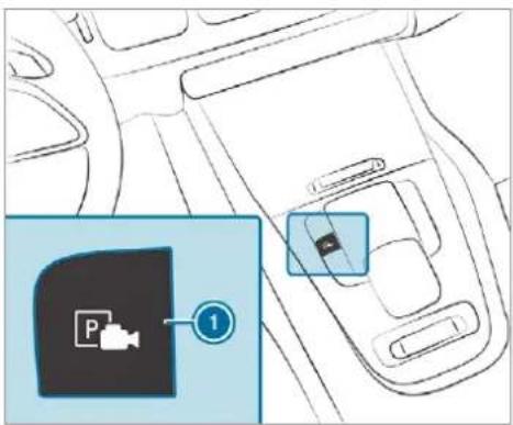
text_image
Diagram showing a car interior with a parking pad icon and a numbered annotation pointing to the pad.Press button ①. The media display shows the view of Active Parking Assist.
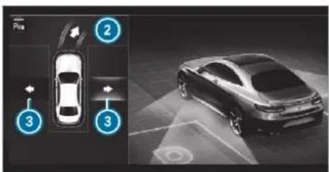
text_image
Diagram showing car parking and parking lane with numbered annotations indicating locations of parking and parking lanes.If the vehicle has been parked at right angles to the direction of travel: in area ②, select direction of travel ③, left or right.
The vehicle path shown on the media display may differ from the actual vehicle path.
Confirm direction of exit ③ to drive out of the parking space.
① The turn signal indicator is switched on automatically when the exiting procedure begins.
You are responsible for selecting the turn signal indicator in accordance with the traffic conditions. If necessary, select the turn signal indicator accordingly.
A WARNING Risk of accident due to vehicle swinging out while parking or pulling out of a parking space
While parking or exiting a parking space, the vehicle swings out and can drive onto areas of the oncoming lane.
This could cause you to collide with objects or other road users.
Pay attention to objects and other road users.
Where necessary, stop the vehicle or cancel the parking procedure with Active Parking Assist.
If, for example, the Please engage forward gear message appears in the media display: select the corresponding transmission position.
The vehicle moves out of the parking space. The turn signal indicator is switched off automatically.
After the exiting procedure has been completed, the Parking Assist finished, take control of vehi
cle message appears in the media display. A warning tone and the following display in the media display prompt you to take over control of the vehicle:

You have to accelerate, brake, steer and change gear yourself again.
Function of Drive Away Assist
Drive Away Assist can reduce the severity of an impact when pulling away. If an obstacle is detected in the direction of travel, the vehicle's speed is briefly reduced to approx. 2 km/h. If a critical situation is detected, the symbol appears in the media display.

WARNING Risk of accident caused by limited detection performance of Drive Away Assist
Drive Away Assist cannot always clearly identify objects and traffic situations.
In such cases, Drive Away Assist might:
- Warn you without reason and limit the vehicle speed.
- Not warn you or not limit the vehicle speed.
Always pay careful attention to the traffic situation; do not rely on Drive Away Assist alone.
Be prepared to brake or swerve as necessary, provided the traffic situation permits and that it is safe to take evasive action.
Drive Away Assist is only an aid. It is not a substitute for your attention to the surroundings. The responsibility for safe manoeuvring and parking remains with you. Make sure that no persons, animals or objects etc. are in the manoeuvring range.
A risk of a collision may arise in the following situations, for example:
- If the driver mixes up the accelerator and brake pedals.
• If the wrong gear is selected.
Drive Away Assist is active under the following conditions:
• If Parking Assist PARKTRONIC is activated.
- Every time the gear is changed to [R] or D when the vehicle is at a standstill.
- If the detected obstacle is less than approx. 1.0 m away.
- If the manoeuvring assistant function is activated in the multimedia system.
System limits
The performance of Drive Away Assist is limited on inclines.
When driving with a trailer, Drive Away Assist is not available.
Also observe the system limits of Parking Assist PARKTRONIC ( page 305).
Function of Cross Traffic Alert
Also read the instructions on Blind Spot Assist ( page 331).
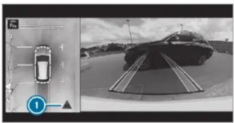
natural_image
Two-panel black-and-white image showing a car on a road and a car on a paved area with a parking sign (no readable text or symbols)Vehicles with Blind Spot Assist: Cross Traffic Alert can warn drivers of any crossing traffic when reversing out of a parking space. The radar sensors in the bumper also monitor the area adjacent to the vehicle. If a critical situation is detected, symbol ① appears in the media display. If the driver does not respond to the warning, the vehicle's brakes can be applied automatically.
If the radar sensors are obstructed by vehicles or other objects, detection is not possible.
Cross Traffic Alert is active under the following conditions:
• if Blind Spot Assist is activated.
- if the vehicle is reversing at walking pace.
- If the manoeuvring assistant function is activated in the multimedia system.
System limits
Cross Traffic Alert is not available on inclines.
Cross Traffic Alert is not available when driving with a trailer.
Also observe the system limits of Active Blind Spot Assist ( page 331).
Activating/deactivating manoeuvring assistance
Multimedia system:
→ Settings → Assistance ▶ Camera & parking
Activate or deactivate Manoeuvring assistance.
(i) Manoeuvring assistance must be active for the function of Drive Away Assist ( page 324).
ATTENTION ASSIST
Function of ATTENTION ASSIST
ATTENTION ASSIST assists you on long, monotonous journeys, e.g. on motorways and trunk roads. If ATTENTION ASSIST detects indicators of fatigue or increasing lapses in concentration on the part of the driver, it suggests taking a break.
ATTENTION ASSIST is only an aid. It cannot always detect fatigue or lapses in concentration in time. The system is not a substitute for a well-rested and attentive driver. On long journeys, take regular breaks in good time that allow for adequate recuperation.
You can choose between two settings:
• Standard: normal system sensitivity.
- Sensitive: higher system sensitivity. The driver is warned earlier and the attention level detected by ATTENTION ASSIST is adapted accordingly.
If drowsiness or increasing lapses in concentration are detected, the ATTENTION ASSIST: Take a break! warning appears in the Instrument Dis-
play. You can acknowledge the message and take a break where necessary. If you do not take a break and ATTENTION ASSIST continues to detect increasing lapses in concentration, you will be warned again after a minimum of 15 minutes.
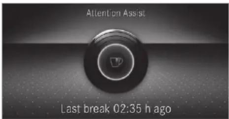
text_image
Attention Assist Last break 02:35 h agoYou can have the following status information for ATTENTION ASSIST displayed in the assistance menu of the on-board computer:
- The length of the journey since the last break.
-
The attention level determined by ATTENTION ASSIST:
-
the fuller the circle, the higher the attentional level determined
- as your attention wanes, the circle in the centre of the display becomes smaller
If ATTENTION ASSIST is unable to calculate the attention level and cannot issue a warning, the System suspended message appears.
If a warning is given in the Instrument Display, the multimedia system offers to search for a rest area. You can select a rest area and start navigation to this rest area. This function can be activated and deactivated in the multimedia system.
If ATTENTION ASSIST is deactivated, the symbol appears in the assistance graphic in the Instrument Display when the engine is running. ATTENTION ASSIST is activated automatically when the engine is re-started. The last selected sensitivity level remains stored.
System limits
ATTENTION ASSIST is active in the 60 km/h to 200 km/h speed range.
The functionality of ATTENTION ASSIST is restricted, and warnings may be delayed or not occur at all in the following situations:
- If you have been driving for less than approximately 30 minutes.
- If the road condition is poor (uneven road surface or potholes).
• If there is a strong side wind. - If you adopt a sporty driving style (high cornering speeds or high rates of acceleration).
- If the Steering Assist function of Active Distance Assist DISTRONIC is active.
• If the time has been set incorrectly. - In active driving situations, if you change lanes and vary your speed frequently.
The ATTENTION ASSIST tiredness or alertness assessment is deleted and restarted when continuing the journey in the following situations:
• If you switch off the engine.
- If you unfasten your seat belt and open the driver's door (e.g. changing drivers or taking a break).
Setting ATTENTION ASSIST
Multimedia system:

Setting options
▶ Select Standard, Sensitive or Off.
Suggesting a rest area
▶ Select Suggest rest area.
▶ Activate or deactivate the function. If ATTENTION ASSIST detects fatigue or increasing lack of attention, it suggests a rest area in the vicinity. ▶ Select the suggested rest area. You are guided to the selected rest area.
Speed Limit Assist
Function of Speed Limit Assist
i The availability of the following function is country-dependent.
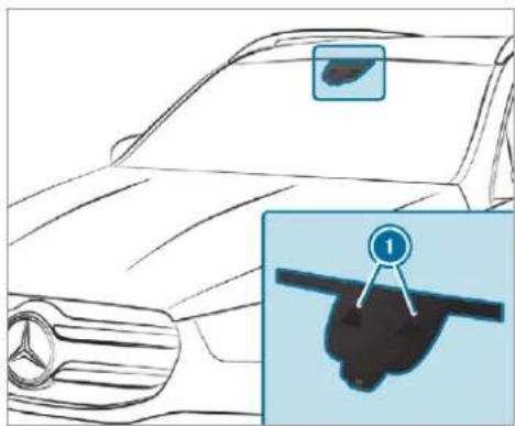
natural_image
Line drawing of a car front view with a close-up inset showing a hand holding a black object (no text or symbols)Speed Limit Assist detects speed limits with multifunction camera ① and displays them in the instrument cluster and optionally in the head-up display. The camera also detects speed limits with a restriction indicated by an additional sign (e.g. when wet). The system detects stop signs, thereby preventing the engine from being switched off by the ECO start/stop function.
Speed Limit Assist is only an aid. The driver is responsible for keeping a safe distance to the vehicle in front, for vehicle speed and for braking in good time.
Warning when the maximum permissible speed is exceeded
The system can warn you if you unintentionally exceed the maximum permissible speed. To do this, you can specify in the multimedia system by how much the maximum permissible speed can be exceeded before a warning is issued. You can specify whether the warning is to be just a visual warning or an acoustic one as well.
Display in the Instrument Display
① The illustrations show the Instrument Display in the widescreen cockpit.
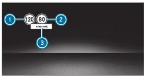
flowchart
graph TD
    A["1"] --> B["120"]
    B --> C["80"]
    C --> D["3"]
    style C fill:#f9f,stroke:#333
① Permissible speed
② Permissible speed when there is a restriction
③ Additional sign with restriction
Speed Limit Assist is not available in all countries. If it is unavailable, the following display is shown in the speedometer:

System limits
The system may be impaired or may not funct in the following situations:
- If there is poor visibility, e.g. due to insufficient illumination of the road, if there are highly variable shade conditions or in rain, snow, fog or heavy spray.
- If there is glare, e.g. from oncoming traffic, direct sunlight or reflections.
- If the windscreen in the area of the multifunction camera is dirty, or if the camera misted up, damaged or covered.
- If the traffic signs are hard to detect, e.g. due to dirt or snow, or because they are covered or due to insufficient lighting.
- If you turn sharply, when passing traffic signs outside the camera's field of vision.
Setting Speed Limit Assist
;Multimedia system:

Adjusting the type of warning
▶ Select Visual & audible, Visual or None.
Adjusting the warning threshold
This value determines the speed at which a warning is issued when exceeded.
is▶ Select Warning threshold.
▶ Set the desired speed.
If one of the following systems is activated, the speed detected can be manually adopted as the speed limit:
• Active Distance Assist DISTRONIC
- Cruise control
- Variable limiter
Further information ( page 273).
Traffic Sign Assist
Function of Traffic Sign Assist
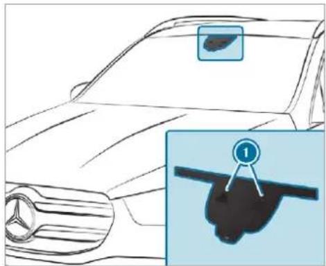
natural_image
Line drawing of a car front view with a close-up inset showing a hand holding a black object (no text or symbols)Traffic Sign Assist detects traffic signs with multifunction camera ①. It assists you by displaying detected speed limits and overtaking restrictions in the instrument cluster and optionally in the head-up display or central display.
Since Traffic Sign Assist also uses the data stored in the navigation system, it can update the display in the following situations without detecting traffic signs:
- When the vehicle changes roads, e.g. slip road or motorway exit.
- When a village or town boundary which is stored in the digital map is passed.
If the system detects that you are driving onto a section of road in the wrong direction of travel, it triggers a warning.
The camera also detects traffic signs with a restriction indicated by an additional sign (e.g. when wet).
Traffic Sign Assist is only an aid. The driver is responsible for keeping a safe distance from the vehicle in front, for vehicle speed and for braking in good time.
Warning when the maximum permissible speed is exceeded
The system can warn you if you unintentionally exceed the maximum permissible speed. To do this, you can specify in the multimedia system
by how much the maximum permissible speed can be exceeded before a warning is issued. You can specify whether the warning is to be just a visual warning or an acoustic one as well.
Display in the Instrument Display
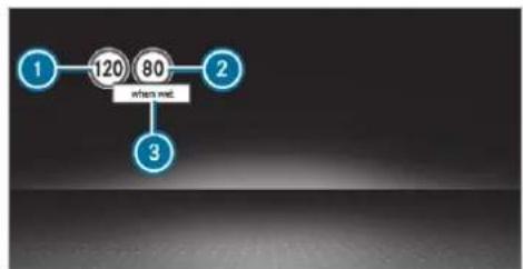
flowchart
graph TD
    A["1"] --> B["120"]
    B --> C["80"]
    C --> D["3"]
    style C fill:#f9f,stroke:#333
Instrument Display in the widescreen cockpit
1 Permissible speed
② Permissible speed when there is a restriction
③ Additional sign with restriction
Vehicles with a standard Instrument Display: a + symbol next to a traffic sign in the Instrument Display indicates that additional traffic signs have been detected. These can also be displayed in the media display and optionally in the head-up display.
If Traffic Sign Assist cannot determine the current maximum permissible speed (e.g. due to missing signs), the following display appears in the Instrument Display:

This is displayed continuously if the vehicle is in a country where Traffic Sign Assist is not supported. Traffic Sign Assist is not available in all countries.
Also observe the information on display messages in Traffic Sign Assist ( page 651).
Warning when approaching pedestrian crossings (vehicles with Driving Assistance Package)
The system can warn you if you approach a pedestrian crossing with your vehicle. A message appears in the instrument cluster.
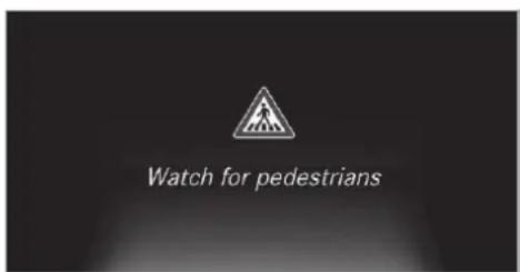
text_image
Watch for pedestriansThe warning occurs if appropriate traffic signs or road markings are recognised and pedestrians are present in the danger zone.
System limits
The system may be impaired or may not function in the following situations:
- If there is poor visibility, e.g. due to insufficient illumination of the road, if there are highly variable shade conditions or in rain, snow, fog or heavy spray.
- If there is glare, e.g. from oncoming traffic, direct sunlight or reflections.
- If the windscreen in the area of the multifunction camera is dirty, or if the camera is misted up, damaged or covered.
- If the traffic signs are hard to detect, e.g. due to dirt or snow, or because they are covered or due to insufficient lighting.
- If the information in the navigation system's digital map is incorrect or out-of-date.
- If the signs are ambiguous, e.g. traffic signs on construction sites or in adjacent lanes.
- If you turn sharply, when passing traffic signs outside the camera's field of vision.
Setting Traffic Sign Assist Requirements:
- Only vehicles with Driving Assistance Package:
Active Distance Assist DISTRONIC must be activated for the automatic adoption of speed limits.
Multimedia system:


Settings

Assistance

affic Sign

ist
Activating/deactivating automatic adoption of speed limits (only vehicles with Driving Assistance Package)
▶ Select Adopt limit.
▶ Activate or deactivate the function. The speed limits detected by Traffic Sign Assist are automatically adopted by Active Distance Assist DISTRONIC.
If one of the following systems is activated, the speed detected can be manually adopted as the speed limit:
• Active Distance Assist DISTRONIC
- Cruise control
- Variable limiter
Further information ( page 273).
Displaying detected traffic signs in the media display
▶ Select Display in head unit.
▶ Activate or deactivate the function.
Adjusting the type of warning
▶ Select Visual & audible, Visual or Off.
Adjusting the warning threshold
This value determines the speed at which a warning is issued when exceeded.
▶ Select Warning threshold.
▶ Set the desired speed.
Blind Spot Assist and Active Blind Spot Assist with exit warning
Function of Blind Spot Assist and Active Blind Spot Assist with exit warning
Blind Spot Assist and Active Blind Spot Assist use two lateral, rear-facing radar sensors to monitor the area up to 40 m behind and 3 m next to your vehicle.
If a vehicle is detected at speeds above approximately 12 km/h and this vehicle subsequently enters the monitoring range directly next to your vehicle, the warning lamp in the outside mirror lights up red.
If a vehicle is detected close to the side of your vehicle, the red warning lamp in the outside mirror flashes. If you switch on the turn signal indicator in the corresponding direction, a warning tone sounds once. If the turn signal indicator remains switched on, all other detected vehicles are indicated only by the flashing of the red warning lamp.
If you overtake a vehicle quickly, no warning is given.
WARNING Risk of accident despite Blind Spot Assist
Blind Spot Assist does not react to vehicles approaching and overtaking you at a greatly different speed.
As a result, Blind Spot Assist cannot warn drivers in this situation.
▶ Always pay careful attention to the traffic situation and maintain a safe distance at the side of the vehicle.
Blind Spot Assist and Active Blind Spot Assist are only aids. They may fail to detect some vehicles and are no substitute for attentive driving. Always ensure that there is sufficient distance to the side for other road users and obstacles.
Exit warning
The exit warning is an additional function of Blind Spot Assist and can warn vehicle occupants about approaching vehicles when leaving the vehicle when stationary.

WARNING Risk of accident despite exit warning
The exit warning reacts neither to stationary objects nor to vehicles approaching you at a greatly different speed.
As a result, the exit warning cannot warn drivers in these situations.
Always pay particular attention to the traffic situation when opening the doors
and make sure there is sufficient clearance.
If there is a vehicle in the monitoring range, this is indicated in the outside mirror. If a vehicle occupant opens the door on the side with the warning, a warning tone sounds and the warning lamp in the outside mirror starts to flash.
This additional function is only available when Blind Spot Assist is activated and up to a number of three minutes after the ignition has been switched off. The exit warning is no longer available once the warning lamp in the outside mirror flashes three times.
The exit warning is only an aid and not a substitute for the attention of vehicle occupants. The responsibility for opening and closing the doors and for leaving the vehicle remains with the vehicle occupants.
System limits
Blind Spot Assist and Active Blind Spot Assist may be limited in the following situations:
- if there is dirt on the sensors or the sensors are obscured
- in poor visibility, e.g. due to fog, heavy rain or snow
- if there are narrow vehicles, e.g. bicycles or motorbikes
• if the road has very wide or narrow lanes - if vehicles are not driving in the middle of their lane
Warnings may be issued in error when driving close to crash barriers or similar solid lane borders. Always make sure that there is sufficient distance to the side for other traffic or obstacles.
Warnings may be interrupted when driving alongside long vehicles, for example lorries, for a prolonged time.
Blind Spot Assist is not operational when reverse gear is engaged.
Blind Spot Assist is not operational when a trailer is coupled to the vehicle and the electrical connection has been correctly established.
The exit warning may be limited in the following situations:
- when the sensors are covered by adjacent vehicles in narrow parking spaces
- when people approach the vehicle
- in the event of stationary or slowly moving objects
Function of brake application (Active Blind Spot Assist)
The brake application function is only available for vehicles with a Driving Assistance Package.
If Active Blind Spot Assist detects a risk of a side impact in the monitoring range, a course-correcting brake application is carried out. This is designed to help you avoid a collision.
The course-correcting brake application is available in the speed range between approximately 30 km/h and 200 km/h.
A WARNING Risk of accident despite brake application of Active Blind Spot Assist
A course-correcting brake application cannot always prevent a collision.
Always steer, brake or accelerate yourself, especially if Active Blind Spot Assist warns you or makes a course-correcting brake application.
Always maintain a safe distance at the sides.
WARNING Risk of accident despite Active Blind Spot Assist
Active Blind Spot Assist does not react to the following:
- if vehicles overtake too closely on the side, placing them in the blind spot area
- vehicles approaching and overtaking you at a greatly different speed
As a result, Active Blind Spot Assist may neither give warnings nor intervene in such situations.
Always pay careful attention to the traffic situation and maintain a safe distance at the side of the vehicle.
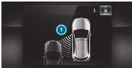
natural_image
Top-down view of two cars with a circular icon labeled '1' and an 'i' button, no visible text or symbols on the cars or background.If a course-correcting brake application occurs, the red warning lamp flashes in the outside mirror and a warning tone sounds. In addition, a display ① indicating the danger of a side collision appears in the multifunction display.
In rare cases, the system may make an inappropriate brake application. This brake application
may be interrupted at any time if you steer slightly in the opposite direction or accelerate.
System limits
Either a course-correcting brake application appropriate to the driving situation, or none at all, may occur in the following situations:
• Vehicles or obstacles, e.g. crash barriers, are located on both sides of your vehicle.
• A vehicle approaches too closely on the side.
- You have adopted a sporty driving style with high cornering speeds.
- You brake or accelerate significantly.
- A driving safety system intervenes, e.g. ESP® or Active Brake Assist.
- ESP ^ is deactivated.
- A loss of tyre pressure or a defective tyre is detected.
- You are driving with a trailer and the electrical connection to the trailer hitch has been correctly established.
Activating/deactivating Blind Spot Assist or Active Blind Spot Assist
Multimedia system:


Settings

Assistance

Activate or deactivate Blind Spot Assist.
or

Activate or deactivate Act. Blind Spot Assist.

Depending on the vehicle's equipment, Blind Spot Assist or Active Blind Spot Assist is available.
Active Lane Keeping Assist
Function of Active Lane Keeping Assist
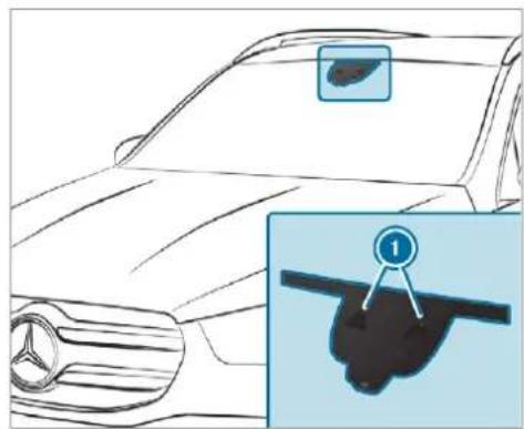
natural_image
Line drawing of a car front view with a magnified inset showing a hand holding a black object (no text or symbols)Active Lane Keeping Assist monitors the area in front of your vehicle by means of multifunction camera ①. It serves to protect you against unintentionally leaving your lane. You will be warned by vibration pulses in the steering wheel and guided by a course-correcting brake application back into your lane.
You are warned by vibration pulses in the steering wheel in the following circumstances:
• Active Lane Keeping Assist detects a lane marking.
- A front wheel drives over this lane marking.
You will also be guided back into your lane by means of a course-correcting brake application if the following conditions are met:
• Active Lane Keeping Assist detects lane markings on both edges of the lane.
- A front wheel drives over a solid lane marking.
You can activate or deactivate the Active Lane Keeping Assist warning.
The status of Active Lane Keeping Assist is displayed in the on-board computer:
- 7:\ (green): Active Lane Keeping Assist activated and operating.
- ☐: (grey): Active Lane Keeping Assist is activated, but not operating.
- ☐: Active Lane Keeping Assist is deactivated or there is a malfunction.
Active Lane Keeping Assist can neither reduce the risk of an accident if you fail to adapt your driving style nor override the laws of physics. It cannot take into account road, weather or traffic conditions. Active Lane Keeping Assist is only an aid. You are responsible for maintaining a safe distance to the vehicle in front, for vehicle speed, for braking in good time and for staying in lane.
Active Lane Keeping Assist can bring the vehicle back into the lane with a lane-correcting brake application. In the case of a broken lane marking being detected, a brake application will only be made if a vehicle has been detected in the adjacent lane. Oncoming traffic can be detected.
Vehicles with Driving Assistance Package or Driving Assistance Plus Package: overtaking vehicles and vehicles in adjacent lanes can also be detected.
Vehicles without Driving Assistance Package or Driving Assistance Plus Package: a lane-correcting brake application also takes place when, in addition to a broken lane marking, the edge of a firm road surface is detected (e.g. central reservation).
Active Lane Keeping Assist is available in the speed range between 60 km/h and 200 km/h.
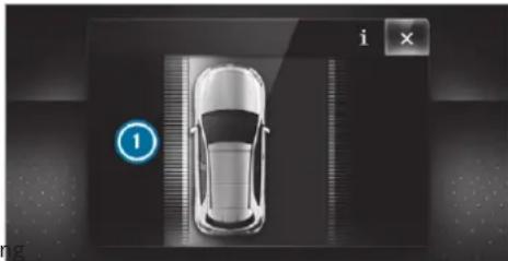
natural_image
Top-down view of a car with a numbered indicator (1) and control buttons (i, ×) in the corner, no readable text or symbols on the car or background.If a lane-correcting brake application occurs, display ① appears in the multifunction display.
Sensitivity of Active Lane Keeping Assist
The availability of the following function is country-dependent.
A lane-correcting brake application also occurs in the Sensitive setting in the following situations:
• Active Lane Keeping Assist detects a solid lane marking.
- A front wheel drives over this lane marking.
System limits
No lane-correcting brake application occurs in the following situations:
- You clearly and actively steer, brake or accelerate.
- You have switched on the turn signal indicator (situation-dependent).
- A driving safety system intervenes, such as ESP®, Active Brake Assist or Active Blind Spot Assist.
- You have adopted a sporty driving style with high cornering speeds or high rates of acceleration.
- When ESP ^ is deactivated.
- When driving with a trailer, the electrical connection to the trailer has been correctly established.
- If a loss of tyre pressure or a defective tyre has been detected and displayed.
The system may be impaired or may not function. If the carriageway is very narrow and winding in the following situations:
- If there is poor visibility, e.g. due to insufficient illumination of the road, if there are highly variable shade conditions or in rain, snow, fog or heavy spray.
- If there is glare, e.g. from oncoming traffic, the sun or reflections.
- If the windscreen in the area of the multifunction camera is dirty, or if the camera misted up, damaged or covered.
- If there are no lane markings, or several unclear lane markings are present for one lane, e.g. around roadworks.
- If the lane markings are worn, dark or covered.
- If the distance to the vehicle in front is too short and thus the lane markings cannot be detected.
- If the lane markings change quickly, e.g. lanes branch off, cross one another or merge.
Vehicles without Driving Assistance Package or Driving Assistance Plus Package: Active Lane Keeping Assist uses radar sensors to monitor several areas around the vehicle. If the radar sensors in the rear bumper are dirty or covered with snow, the system may be impaired or may not function. If an obstacle in the lane in which you are driving has been detected, no lane-correcting brake application occurs.
Activating/deactivating Active Lane Keeping Assist
Multimedia system:
→ ▶ Settings ▶ Quick access ▶ Active Lane Keeping Assist
▶ Activate or deactivate the function.
Setting Active Lane Keeping Assist
Multimedia system:

Setting the sensitivity
i The availability of this function is dependent on the country.
▶ Select Standard, Sensitive or Off.
Activating/deactivating the haptic warning
Select Warning. Activate or deactivate the function.
Trailer hitch
Notes on trailer operation
Mercedes-AMG vehicles: be sure to observe the notes in the Supplement. Otherwise, you may fail to recognise dangers.
Observe the following notes on the tongue weight:
- Do not use a tongue weight that exceeds or falls below the permissible tongue weight
- Use a tongue weight as close as possible to the maximum tongue weight
Do not exceed the following values:
• Permissible trailer load - Permissible rear axle load of the towing vehicle
• Permissible gross mass of the towing vehicle
• Permissible gross mass of the trailer
• Maximum permissible speed of the trailer Ensure the following before starting a journey: - The tyre pressure on the rear axle of the towing vehicle is set for a maximum load
• The lighting of the connected trailer is operational
In the event of increased rear axle load, the car/trailer combination may not exceed a maximum speed of 100 km/h for reasons concerning the operating permit. This also applies in countries in which the permissible maximum speed for car/trailer combinations is above 100 km/h.
Vehicles with AIRMATIC or E-ACTIVE BODY CONTROL: if the socket of the trailer hitch is occupied, e.g. by a trailer or rear bicycle rack, the vehicle is set to the normal level regardless of the drive program at speeds greater than 30 km/h.
When you are reversing with a trailer, remember to use the Trailer Manoeuvring Assist function ( page 310).
Extending/retracting the ball neck fully electrically
WARNING Risk of accident due to the ball neck not being engaged
If the ball neck is not engaged, the trailer may come loose.
Make sure that the ball neck securely engages and locks into place.
! NOTE Damage to the all-electric trailer hitch due to additional pressure
The all-electric trailer hitch could be mechanically damaged by applying additional pressure when the ball neck is being extended or retracted.
Do not make the ball neck extend/retract faster by applying additional pressure.
Requirements:
• The vehicle is secured against rolling away.
• The range of movement is clear.
- The trailer cables or adapter plugs have been removed.
Extending the ball neck fully electrically
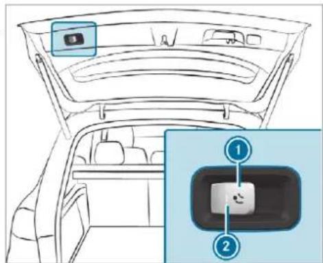
text_image
Diagram of a car rearview showing the camera module and its internal panel with labeled parts 1 and 2.To extend: pull button ①. Indicator lamp ② will flash and the display message Trailer coupling extending...will appear on the multifunction display. The ball neck will extend fully electrically.
Wait until the ball neck has locked in place. The ball neck is securely locked in place when indicator lamp ② is continuously lit. If the ball neck is not securely locked in place, indicator lamp ② will flash and the display message Check trailer hitch lockwill appear on the multifunction display.
Retracting the ball neck fully electrically
▶ Pull button ①. Indicator lamp ② will flash and the message Trailer coupling extending... will appear on the multifunction display. The ball neck will retract fully electrically. ▶ Wait until the ball neck has locked in place. The ball neck will be securely locked in place once indicator lamp ② goes out. If the ball neck is not securely locked in place, indicator lamp ② will flash and the message Check trailer hitch lock will appear on the multifunction display.
Observe the information on the displays on the instrument cluster:
• Indicator and warning lamps (→ page 711)
• Display messages ( page 651)
Folding the ball neck in/out fully electrically (multimedia system)

WARNING Risk of accident due to the ball neck not being engaged
If the ball neck is not engaged, the trailer may come loose.
▶ Always engage the ball neck as described.

NOTE Damage to the all-electric trailer hitch due to additional pressure
The all-electric trailer hitch could be mechanically damaged by applying additional pressure when the ball neck is being extended or retracted.
Do not make the ball neck extend/retract faster by applying additional pressure.
Requirements:
• The vehicle is secured against rolling away.
• The swivel range is clear.
- The trailer cables or adapter plugs have been removed.
Multimedia system:
→ Settings ▶ Quick access
Extending the ball neck fully electrically
Select .
The Trailer coupling extending... display message will appear on the multifunction display. The ball neck will extend fully electrically.
▶ Wait until the ball neck has locked in place.
If the ball neck is not securely locked in place, the Check trailer hitch lock display message will appear on the multifunction display.
Retracting the ball neck fully electrically
Select 📄. The Trailer coupling extending... display message will appear on the multifunction display. The ball neck will retract fully electrically.
▶ Wait until the ball neck has locked in place. If the ball neck is not securely locked in place, the Check trailer hitch lock display message wi appear on the multifunction display.
Coupling up / uncoupling a trailer
⚠ WARNING Risk of injury from the vehicle level being changed
Vehicles with level control system: the vehicle level may be changed unintentionally, e.g. by other persons. You may become trapped if you couple up or uncouple a trailer while the vehicle level is changing. In addition, other people could become trapped if their limbs are between the vehicle body and the tyres or underneath the vehicle.
When coupling up or uncoupling a trailer, make sure that:
The doors or tailgate are not opened or closed.
You do not initiate the level control system and do not operate the DYNAMIC SELECT switch.
Do not lock or unlock the vehicle.
Requirements:
- The ball neck is extended and engaged in a securely locked position
Trailers with a 7-pin plug can be connected to the vehicle with the following adapters:
- Adapter plug
- Adapter cable
The trailer will be correctly detected by the vehicle only if the following conditions are met:
• The trailer is connected correctly
• The trailer lighting system is in working order
The functions of the following systems are affected by a correctly connected trailer:
• Active Lane Keeping Assist
- ESP® trailer stabilisation
• Parking Assist PARKTRONIC
• Active Parking Assist
• Blind Spot Assist or Active Blind Spot Assist
- Drive Away Assist
- Cross Traffic Alert
- Trailer Manoeuvring Assist
- Reversing camera
- 360^ camera
Coupling up a trailer
NOTE Damage to the battery due to full discharge
Charging the trailer battery using the power supply of the trailer can damage the vehicle battery.
Do not use the vehicle's power supply to charge the trailer battery.
Remove the cover from the ball head and store it in a safe place ( page 144).
▶ Position the trailer on a level surface behind the vehicle and couple it up to the vehicle.
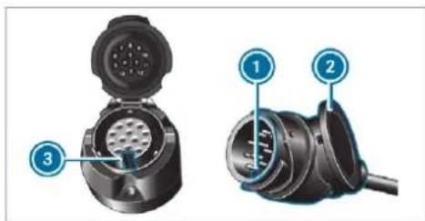
text_image
Technical diagram of a device with labeled parts, showing exploded and assembled viewsOpen the socket cap.
Insert the plug with lug ① in groove ③ on the socket.
Turn the bayonet coupling ② to the right as far as it will go.
Let the cap engage.
Secure the cable to the trailer with cable ties (only if you are using an adapter cable).
Make sure that the cable is always slack for ease of movement during cornering.
Under the following conditions, a message may appear on the multifunction display even if the trailer has been connected correctly:
• LEDs have been installed in the trailer lighting system
- The current has fallen below the trailer lighting system's minimum current (50 mA)
i Accessories can be connected to the permanent power supply up to 180 W and to the power supply that is switched on via the ignition lock.
Uncoupling a trailer

WARNING Risk of being crushed and becoming trapped when uncoupling a trailer
When uncoupling a trailer with an engaged inertia-activated brake, your hand may become trapped between the vehicle and the trailer drawbar.
Do not uncouple trailers with an engaged overrun brake.

NOTE Damage when uncoupling in a state of overrun
Uncoupling in a state of overrun can damage the vehicle.
Do not uncouple trailers with an engaged overrun brake.

WARNING Risk of becoming trapped when disconnecting the trailer cable
Vehicles with level control system: The vehicle may lower when the trailer cable is disconnected.
This could result in you or other people becoming trapped if your or their limbs are between the vehicle body and the tyres or underneath the vehicle.
Make sure that nobody is underneath the vehicle or in the immediate vicinity of the wheel arches when you disconnect the trailer cable.

NOTE Damage to the rear bumper from installing adapter cables or adapter plugs
The following parts could be damaged when swiveling the ball neck fully electrically:
- Bumper
- Adapter cable
- Adapter plug
Always remove the adapter cable or adapter plug before swiveling the ball neck fully electrically.
▶ Secure the trailer against rolling away.
▶ Disconnect the electrical connection between the vehicle and the trailer.
▶ Uncouple the trailer.
Place the cover on the ball head.
Bicycle rack function

WARNING Risk of an accident when using the bicycle rack incorrectly
The bicycle rack may become detached from the vehicle in the following cases:
- the permissible load capacity of the trailer hitch is exceeded.
• the bicycle rack is used incorrectly. - the bicycle rack is secured to the ball neck beneath the ball head.
Observe the following for your own safety and that of other road users:
- always adhere to the permissible load capacity of the trailer hitch.
- only use the bicycle rack to transport bicycles.
-
always mount the bicycle rack properly by attaching to the ball head and the ball neck guide pin, if possible.
-
when transporting four bicycles, always use bicycle racks which have additional support on the ball neck guide pin.
- only use bicycle racks approved by Mercedes-Benz.
- always observe the bicycle rack operating instructions.

NOTE Damage to, or cracks on, the trailer hitch due to unsuitable bicycle racks or bicycle racks being used incorrectly

use only bicycle racks approved by Mercedes-Benz.
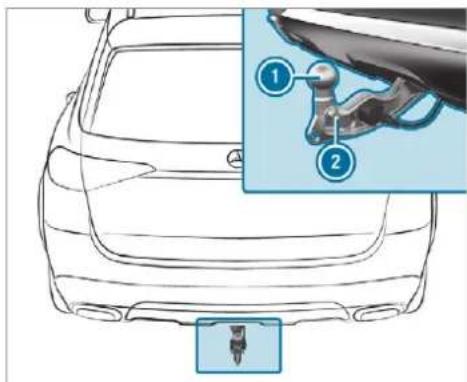
text_image
Technical diagram of a car rear bumper with labeled parts and an inset showing a mechanical component detail.Trailer hitch (example with additional guide pin)
Depending on the bicycle rack's design, different numbers of bicycles can be transported.
The following bicycle rack designs are possible:
- When mounted by attaching to the ball head Ⓞ, the maximum load capacity is 75 kg. Up to three bicycles can be transported.
- When mounted on the ball head ① and guide pin ②, the maximum load capacity 100 kg. Up to four bicycles can be transported.
The load capacity is calculated from the weight of the bicycle rack and the bicycle rack load.
The vehicle's driving characteristics will change when a bicycle rack is fitted. Adapt your driving style accordingly. Drive carefully and maintain safe distance.
When using a bicycle rack, set the tyre pressure for increased load on the rear axle of the vehicle. Further information on the tyre pressure can be found in the tyre pressure table ( page 607).
Notes on loading
The larger the distance between the load's centre of gravity and the ball head, the greater the load on the trailer hitch.
Observe the following notes:
- Mount heavy bicycles as close to the vehicle as possible.
the Always distribute the load on the bicycle rack is as evenly as possible across the vehicle's longitudinal axis.
Mercedes-Benz recommends removing all detachable parts from bicycles (e.g. baskets, child seats, rechargeable batteries) before loading them onto the bicycle rack. This will improve the aerodynamic resistance and centre of gravity of the bicycle rack.
Always secure the bicycles to prevent them from moving around and check them at regular intervals to ensure that they are secure.
Do not use tarpaulins or other covers. The driving characteristics and rear view may be impaired. In addition, aerodynamic resistance and the load on the trailer hitch will increase.
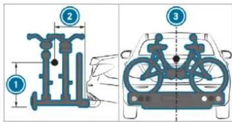
text_image
Diagram illustrating bicycle usage modes and front view of a car, with labeled components and structural differences.Load distribution on the bicycle rack
① Vertical distance between centre of gravity and ball head
2 Horizontal distance between centre of gravity and ball head
③ The centre of gravity is on the vehicle's centre axis
Observe the following information when loading the bicycle rack:
| 3 bicycles 4 bicycles | ||
| Total weight of bicycle rack and load | Up to 75 kg | Up to 100 kg |
| Max. distance1 | 420 mm | 420 mm |
| Max. distance2 | 300 mm | 400 mm |
When transporting four bicycles or with a total weight between 75 kg and 100 kg, always use bicycle racks with additional support on the trailer hitch guide pin.
tems, safe driving characteristics cannot be guaranteed for the towing vehicle or the towed vehicle. The vehicle-trailer combination may swerve from side to side. Comply with the permitted towing methods ( page 597) and the instructions for towing with both axles on the ground ( page 598).
Vehicle towing instructions
The vehicle is not suitable for the use of tow bar systems that are used for flat towing or dinghy towing, for example. Attaching and using tow bar systems can lead to damage on the vehicle. When you are towing a vehicle with tow bar sys-
Instrument display overview
Mercedes-AMG vehicles: be sure to observe the notes in the Supplement. You could otherwise fail to recognise dangers.

WARNING Risk of accident due to an instrument display malfunction
If the Instrument Display has failed or malfunctioned, you may not recognise function restrictions applying to safety relevant systems.
The operating safety of your vehicle may be impaired.
▶ Drive on carefully.
Have the vehicle checked immediately at a qualified specialist workshop.
If the operating safety of your vehicle is impaired, park the vehicle immediately and safely. Contact a qualified specialist workshop.
Instrument display in the widescreen cockpit
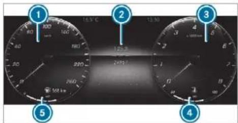
text_image
1 2 3 4 5 6 7 8 9 10 11 12 13 14 15 16 17 18 19 20 21 22 23 24 25 26 27 28 29 30 31 32 33 34 35 36 37 38 39 40 41 42 43 44 45 46 47 48 49 50 51 52 53 54 55 56① Speedometer (example)
2 Multifunction display
3 Rev counter (example)
4 Coolant temperature display (example)
5 Fuel level, fuel filler flap location indicator, range
In addition to multifunction display ②, further content can be shown on displays ① and ③ (→ page 349).
The segments on speedometer ① indicate the system status for the following:
• Cruise control(→ page 265)
- Limiter (→ page 266)
• Active Distance Assist DISTRONIC ( page 271)
NOTE Engine damage due to excessively high engine speeds
The engine will be damaged if you drive with the engine in the overrevving range.
Do not drive with the engine in the over-revving range.
The fuel supply will be interrupted to protect the engine when the red mark on the rev counter (overrevving range) is reached.
During normal operating conditions, coolant temperature display ④ may rise to 120 °C.

WARNING Danger of burns when opening the bonnet
If you open the engine bonnet when the engine has overheated or during a fire in the engine compartment, you could come into contact with hot gases or other escaping operating fluids.
Before opening the bonnet, allow the engine to cool down.
In the event of a fire in the engine compartment, keep the engine bonnet closed and call the fire service.
Vehicles with a 48 V on-board electrical system (EQ Boost technology)
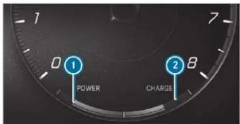
text_image
0 1 POWER CHARGE 8POWER shows the electric drive support
② CHARGE shows the recuperation power of the electric motor
READY shows the drive system's operational readiness.
Overview of the buttons on the steering wheel
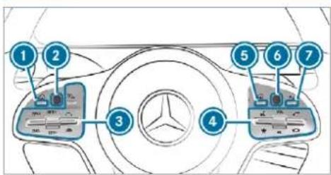
text_image
Diagram of a car interior with numbered components and control panel labels①puter Back/Home button, on-board com-
Press and hold: shows standard display
② Touch Control, on-board computer
3 Control panel for cruise control/limiter or Active Distance Assist DISTRONIC
4 Control panel for MBUX multimedia system:
LINGUATRONIC
★ Displays favourites
VOL: control knob, adjusts the volume or switches the sound off (press)

Makes/accepts a call Rejects/ends a call
5 Calls up the home screen
6 Touch Control multimedia system
7 Back button
Operating the on-board computer
Mercedes-AMG vehicles: observe the notes in the Supplement. You could otherwise fail to recognise dangers.

WARNING Risk of distraction from information systems and communications equipment
If you operate information and communication equipment integrated in the vehicle when driving, you will be distracted from the traffic situation. This could also cause you to lose control of the vehicle.
▶ Only operate this equipment when the traffic situation permits.
If you cannot be sure of this, stop the vehicle whilst paying attention to road and traffic conditions and operate the equipment with the vehicle stationary.
Observe the legal requirements for the country in which you are currently driving when operating the on-board computer.
The on-board computer displays will appear on the multifunction display ( page 350).
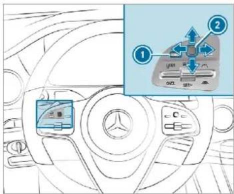
text_image
Diagram showing car interior with labeled components and directional arrows, including a zoomed-in view of the main component.The on-board computer is operated using the left-hand Touch Control ② and the left-hand back/home button ①.
When the on-board computer is being operated, different acoustic signals will sound as operating feedback, e.g. when the end of a list is reached or when you are scrolling through a list.
The following menus are available:
- Assistance
- Telephone
- Navigation
- Trip
- Radio
• Media - Styles & display
• Service
The menus can be called up from the menu ba on the multifunction display.
To call up the menu bar: briefly press the back button on the left ① until the menu bar is displayed.
① Vehicles without Active Distance Assist DISTRONIC: press the button to call up the menu bar of the on-board computer.
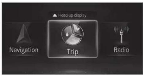
text_image
Head up display Navigation Trip Radio① The illustration shows the instrument display in the widescreen cockpit.
To scroll in the menu bar: swipe left or right on the left-hand Touch Control 2.
To call up a menu or confirm a selection: press the left-hand Touch Control 2.
To scroll through displays or lists on the menu: swipe upwards or downwards on the left-hand Touch Control ②.
To call up a submenu or confirm a selection: press the left-hand Touch Control ②.
To exit a submenu: press the back button on the left ①.
Selecting the head-up display
To switch on the head-up display: switch on the head-up display via the multimedia system or activate it in the menu bar by swiping upwards on the left-hand Touch Control ②.
The head-up display menu has been selected on the head-up display.
To switch to the head-up display: press the left-hand Touch Control ② or swipe upwards on the left-hand Touch Control ②.
To select what the head-up display shows: swipe upwards or downwards on the left-hand Touch Control ②.
Full-surface menu
You can display the following menus in full on the instrument display:
- Assistance
- Trip
- Navigation
On the corresponding menu, use the left-hand Touch Control ② to scroll to the end of the list. Press the left-hand Touch Control ②. The selected menu will be displayed in full.
Adjusting the design of the instrument display
On-board computer:

Styles & display
Setting the design
- Swipe upwards or downwards on the left-hand Touch Control. - Press the left-hand Touch Control. The instrument display will be shown in the selected design.
The following designs can be selected, depending on the vehicle equipment:
• Mercedes-Maybach vehicles: Maybach
- Classic
- Sport
R Progressive
R Understated
R Standard displays
R Angle of incline and approach/departure angle
Additional display content can also be shown on the instrument cluster.
The display content on the instrument cluster adapts to the topic selected on the multimedia system.
To select display content: swipe to the right or left on the left-hand Touch Control.
▶ Swipe upwards or downwards on the left-hand Touch Control to select the required display content.
When the display content is selected, it will briefly be highlighted.
① The index points show the selected display content.
② Display content, left (example: speedometer)
When the display content is selected ②, it will briefly be highlighted.
Display content selection, left:
R Speedometer
R Time/date
R Trip computer From start and From reset
R Range
R Audio
③ Display content, centre (example: media menu)
The index points show the selected menu content
The display content in the centre shows the menu content of the respective menus from the menu bar on the multifunction display.
Display content menu selection, centre:
R Assistance
R Telephone
- Navigation
- Trip
- Radio
Media - Styles and display
- Service

text_image
100 200 300 400 500 600 700 800 900 1000 1100 1200 1300 1400 1500 1600 1700 1800 1900 2000 2100 2200 2300 2400 2500 2600 2700 2800 2900 3000 3100 3200 3300 3400 3500 3600 3700 3800 3900 4000 4100 4200 4300 4400 4500 4600 4700 4800 4900 5000 5100 5200 5300 5400 5500 5600 5700 5800 5900 6000 6100 6200 6300 6400 6500 6600 6700 6800 6900 7000 7100 7200 7300 7400 7500 7600 7700 7800 7900 8000 8100 8200 8300 8400 8500 8600 8700 8800 8900 9000 9100 9200 9300 9400 9500 9600 9700 9800 9900 1.1mV 1.2mV 1.3mV 1.4mV 1.5mV 1.6mV 1.7mV 1.8mV 1.9mV 2.1mV 2.2mV 2.3mV 2.4mV 2.5mV 2.6mV 2.7mV 2.8mV 2.9mV 3.1mV 3.2mV 3.3mV 3.4mV 3.5mV 3.6mV 3.7mV 3.8mV 3.9mV 4.1mV 4.2mV 4.3mV 4.4mV 4.5mV 4.6mV 4.7mV 4.8mV 4.9mV 5.1mV 5.2mV 5.3mV 5.4mV 5.5mV 5.6mV 5.7mV 5.8mV 5.9mV 6.1mV 6.2mV 6.3mV 6.4mV 6.5mV 6.6mV 6.7mV 6.8mV 6.9mV 7.1mV 7.2mV 7.3mV 7.4mV 7.5mV 7.6mV 7.7mV 7.8mV 7.9mV 8.1mV 8.2mV 8.3mV 8.4mV 8.5mV 8.6mV 8.7mV 8.8mV 8.9mV4 Display content, right (example: rev counter)
Display content selection, right:
- Rev counter
• Average fuel consumption -
ECO display
-
Navigation
G-meter - Assistant display
4MATIC - Suspension (equipment-dependent)
Overview of displays on the multifunction display
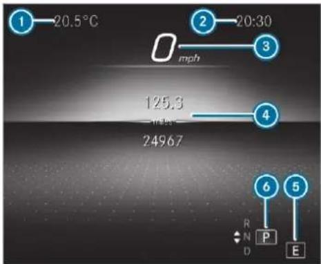
text_image
1—20.5°C 2—20:30 mph 125.3 msec 24967 4 6 5 R N D P EOutside temperature
2 Time
3 Digital speedometer
④ Display section
5 Drive program
6 Transmission position
Further displays on the multifunction display:
Gearshift recommendation ( page 232)
Active Parking Assist (→ page 321)
Parking Assist PARKTRONIC deactivated (→ page 309)
DSR ( page 269)
Cruise control (→ page 265)
LIM Limiter ( page 266)
Active Distance Assist DISTRONIC (→ page 271)
Active Brake Assist (→ page 265)
Active Steering Assist ( page 278)
Active Lane Keeping Assist (→ page 334)
Active Lane Change Assist (→ page 280)
(A) ECO start/stop function (→ page 221)
HOLD HOLD function (→ page 285)
Adaptive Highbeam Assist Plus (→ page 179)
120mm Maximum permissible speed exceeded (for certain countries only)
Vehicles with Speed Limit Assist: detected instructions and traffic signs ( page 327).
Vehicles with Traffic Sign Assist: detected instructions and traffic signs ( page 329). For an overview of the indicator and warning lamps, see ( page 711).
Adjusting the instrument lighting
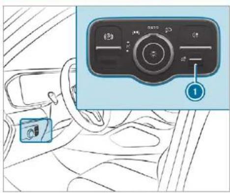
text_image
Diagram showing car interior with dashboard, steering wheel, and control panel labeled '1' pointing to a button▶ Turn brightness control ① up or down. The lighting of the instrument display and in the control elements of the vehicle interior is adjusted.
Menus and submenus
Calling up functions on the Service menu of the on-board computer
On-board computer:
Service
To select a function: swipe upwards or downwards on the left-hand Touch Control.
▶ Press the left-hand Touch Control.
Functions on the Service menu:
- Message memory (→ page 651)
- AdBlue: Adblue ^ range and fill level
-
Tyres:
-
Restart the tyre pressure loss warning system ( page 614)
- Check the tyre pressure with the tyre pressure monitor ( page 608)
- Restart the tyre pressure monitor ( page 609)
• ASSYST PLUS: call up the service due date ( page 565)
• Coolant: coolant temperature display
• Engine oil level: engine oil level
- Consumption info: fuel life cycle consumption
Calling up displays on the Assistance menu
On-board computer:

Assistance
The following displays are available on the Assistance menu:
- Assistance
• Attention level ( page 325) - Full screen

To switch between the displays: swipe upwards or downwards on the left-hand Touch Control.
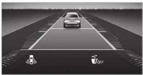
natural_image
Top-down view of a car driving on a multi-lane road with sensor icons and 'OFF' signs (no text or symbols on the diagram itself)Status displays on the assistant display:
• ATTENTION ASSIST: deactivated
- Grey lane markings: Active Lane Keeping Assist activated
- Green lane markings: Active Lane Keeping Assist active
- Grey radar waves next to vehicle: Blind Spot Assist or Active Blind Spot Assist enabled
- Green radar waves next to vehicle: Blind Spot Assist or Active Blind Spot Assist active
• Active Distance Assist DISTRONIC displays ( page 271)
• ECO Assist displays
Calling up displays on the Trip menu
On-board computer:

Trip
To select a display: swipe upwards or downwards on the left-hand Touch Control.
Trip menu in the widescreen cockpit:
- Standard display
- Range
• Current fuel consumption
• ECO display (→ page 223) - Trip computer From start and From reset
- Full screen
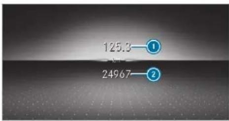
bar
| Label | Value | |---|---| | ① | 125.3 | | ② | 24967 |Standard display (example)
1 Trip distance
② Total distance
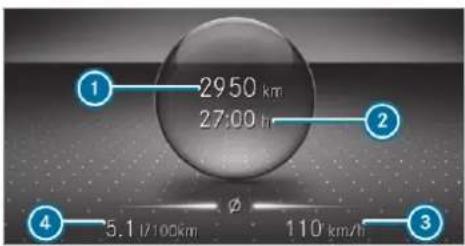
text_image
1 2950 km 27:00 hr 2 4 5.1 L/100km φ 110 km/h 3Trip computer (example)
1 Total distance
2 Driving time
③ Average speed
4 Average fuel consumption
Resetting values on the Trip menu of the onboard computer
On-board computer:

The spelling on the main menu displayed may differ. Therefore, observe the menu
overview for the instrument display ( page 346).
You can reset the values of the following functions:
- Trip distance
- Trip computer From start and From reset
• ECO display (→ page 223)
To select the function to be reset: swipe upwards or downwards on the left-hand Touch Control.
▶ Press the left-hand Touch Control.
Select Yes.
▶ Press the left-hand Touch Control.
If you press and hold the left-hand Touch Control, the values of the function will be reset immediately.
Calling up navigation instructions on the onboard computer
On-board computer:
Navigation
The following displays are available in the navigation menu:
- Navigation view
- Map view
• Full-surface map view
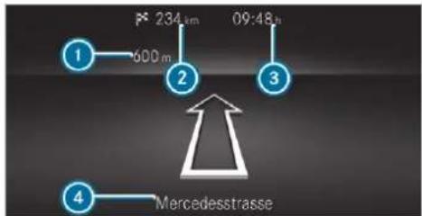
text_image
1 4 234 km 09:48 h 600 m MercedesstrasseExample: no change of direction announced
① Distance to the next change of direction
② Distance to the next destination
3 Estimated arrival time at next destination
4 Current road
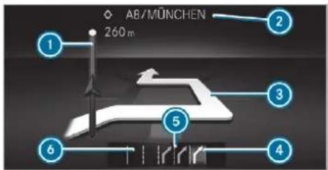
text_image
AB/MÜNCHEN 260 m 1 2 3 4 5 6Example: change of direction announced
① Distance to the change of direction
Road to which the change of direction leads
3 Change-of-direction symbol
4 Recommended lane (white)
5 Possible lane
6 Lane not recommended (dark grey)
Further possible displays on the Navigation menu:
- Direction of travel: display of direction of travel and road currently being travelled on.
- New route... or Calculating route...: a new route is being calculated.
- Road not mapped: the road is unknown, e.g. it has only recently been built.
- No route: no route could be calculated to the selected destination.
- Off map: the map for the current location is not available.
- Area of dest. reached: when an intermediate destination is reached, the intermediate destination flag will be displayed with the number of the intermediate destination □. After this, route guidance will continue. Once the destination is reached, the chequered flag □ will be displayed. Route guidance will now be complete
To exit the menu: press the back button on the left.
Vehicles with the MBUX multimedia system:
You can also start navigation to one of the recent destinations on the Navigation menu:
▶ Press the left-hand Touch Control.
To select a destination: swipe upwards or downwards on the left-hand Touch Control.
Press the left-hand Touch Control. Route guidance will start.
If route guidance has already been activated a query will appear asking whether you wish to end the current route guidance.
Select Yes.
Press the left-hand Touch Control. Route guidance will start.
Selecting radio stations using the on-board computer
On-board computer: Radio
text_image
1 4™ FM SWR 1 2 3 The Best of Nothing① Frequency range
2 Station
③ Name of track
The illustration shows the Instrument Display in the Widescreen Cockpit
When you select a station from the memory presets, the preset will appear next to the station name. When you select a saved station in the
frequency range, an asterisk will appear next to the station name.
To select a radio station: swipe upwards or downwards on the left-hand Touch Control.
Selecting the frequency range or memory preset
▶ Press the left-hand Touch Control.
Swipe upwards or downwards on the left-hand Touch Control.
Press the left-hand Touch Control.
Operating media playback using the on-board computer
On-board computer:
Media
text_image
1 Paul's iPhone 7: The Cold Bug The Alan Persons Project 2 31 Media source
② Track number and current track
3 Name of artist (example)
The illustration shows the Instrument Display in the Widescreen Cockpit
To change tracks on an active media source: swipe upwards or downwards on the left-hand Touch Control.
① This is how to change the channel on the TV media source.
Changing a media source
▶ Press the left-hand Touch Control.
To select a media source: swipe upwards or downwards on the left-hand Touch Control.
Press the left-hand Touch Control.
Dialling telephone numbers using the on-board computer
WARNING Risk of distraction from information systems and communications equipment
If you operate information and communication equipment integrated in the vehicle when driving, you will be distracted from the traffic situation. This could also cause you to lose control of the vehicle.
▶ Only operate this equipment when the traffic situation permits.
If you cannot be sure of this, stop the vehicle whilst paying attention to road and traffic conditions and operate the equipment with the vehicle stationary.
When using the phone, observe the legal requirements for the country in which you are currently driving.
Requirements:
- The mobile phone is connected to the multi-media system.
On-board computer:
Telephone
The most recent telephone calls (dialled, received and missed calls) are displayed on the Telephone menu.
To select an entry: swipe upwards or downwards on the left-hand Touch Control.
Press the left-hand Touch Control. If there is only one telephone number saved to an entry: the telephone number will be selected.
If there are multiple telephone numbers saved to an entry: swipe upwards or downwards on the left-hand Touch Control to select the desired telephone number.
Press the left-hand Touch Control.
The telephone number will be dialled.
The following displays may appear instead of the telephone numbers dialled:
- Please wait: the application is starting. If a Bluetooth® connection to the mobile phone is not established, the menu for authorising and connecting a mobile phone will be displayed on the multimedia system (→ page 480).
- Updating data: the call list is being updated.
- Importing contacts: contacts are being imported from the mobile phone or a storage medium.
Accepting or rejecting an incoming call Vehicles with head-up display: when you receive a call, the Incoming call message will appear on the head-up display.
- Swipe upwards or downwards on the left-hand Touch Control and select 📞 or 📞 (Reject). - Press the left-hand Touch Control.
You may accept or reject the call using the 📞 or 🏠 button on the steering wheel.
Setting the head-up display using the on-board computer
On-board computer: → HEAD-UP DISPLAY
The following head-up display settings can be selected:
- Position
- Brightness
- Displays
- Messages
- Assistance status
- Telephone
- Audio
- Linguatronic
To choose a setting: swipe to the right on (Accept the left-hand Touch Control. The Settings menu will be selected.
To call up the Settings menu: press the left-hand Touch Control.
To adjust the position: swipe upwards or downwards on the left-hand Touch Control.
To adjust the brightness: swipe to the left or right on the left-hand Touch Control.
To set messages, assistance status, telephone, audio and LINGUATRONIC: press the left-hand Touch Control. The list of setting options will be displayed.
Swipe upwards or downwards on the left-hand Touch Control and select a setting by pressing the left-hand Touch Control.
Selecting what the head-up display shows
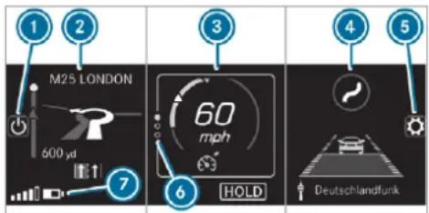
text_image
1 2 M25 LONDON 600 yd 7 3 60 mph HOLD 4 5 Deutschlandfunk(Example)
To switch the head-up display on/off
② Left display area
Navigation system
Inclination, gradient and compass
Average consumption
G-meter
3 Central display area
Set speed in the driver assistance system, e.g. cruise control
Warnings from driver assistance systems, e.g. distance warning
④ Right display area
Traffic Sign Assist
Vehicle level
Differential
Assistant display
5 To adjust the position, brightness and lower display area
6 Index points
⑦ Lower display area
Display areas ② to ④ that are not required can be hidden.
In audio mode, the station name or track will be shown temporarily when the audio source is being actively operated. In addition, the latest calls will be displayed when the telephone list on the instrument display is actively operated.
To select a display: swipe upwards on the left-hand Touch Control.
Press the left-hand Touch Control.
Head-up Display
Function of the head-up display
The head-up display projects information above the cockpit into the driver's field of vision, e.g. the speed of the vehicle, information from the navigation system or driver assistance systems and some warning messages.
Depending on the vehicle's equipment, different content can be shown in the three display areas of the head-up display ( page 357).
Display elements
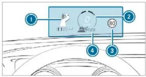
text_image
1 2 3 4 80 9120① Navigation instructions
2 Current speed
3 Detected instructions and traffic signs
4 Set speed in the driver assistance system (e.g. cruise control)
System limits
The visibility of the displays will be affected by the following conditions:
- seat position
• image position setting -
light conditions
-
wet carriageways
- objects on the display cover
• polarisation in sunglasses
In extreme sunlight, sections of the display may appear washed out. You can correct this by switching the head-up display off and on again.
Switching the head-up display on/off via the multimedia system
Multimedia system:
Settings Quick access
Select HUD.
The head-up-display is activated.
Notes on operating safety
⚠ WARNING Risk of distraction from information systems and communications equipment
If you operate information and communication equipment integrated in the vehicle when driving, you will be distracted from the traffic situation. This could also cause you to lose control of the vehicle.
▶ Only operate this equipment when the traffic situation permits.
If you cannot be sure of this, stop the vehicle whilst paying attention to road and traffic conditions and operate the equipment with the vehicle stationary.
WARNING Risk of an accident from operating mobile communication equipment while the vehicle is in motion
Mobile communications devices distract the driver from the traffic situation. This could
also cause the driver to lose control of the vehicle.
As the driver, only operate mobile communications devices when the vehicle is stationary.
As a vehicle occupant, only use mobile communications devices in the areas intended for this purpose, e.g. in the rear passenger compartment.
⚠ WARNING Risk of injury due to objects being stowed incorrectly
If objects in the vehicle interior are stowed incorrectly, they can slide or be thrown around and hit vehicle occupants. In addition, cup holders, open stowage spaces and mobile phone receptacles cannot always retain all objects they contain.
There is a risk of injury, particularly in the event of sudden braking or a sudden change in direction.
Always stow objects so that they cannot be thrown around in such situations.
Always make sure that objects do not protrude from stowage spaces, luggage nets or stowage nets.
Close the lockable stowage spaces before starting a journey.
▶ Always stow and secure heavy, hard, pointed, sharp-edged, fragile or bulky objects in the boot/load compartment.
For your own safety, always observe the following points when operating mobile communications equipment and especially your voice control system:
- Observe the legal requirements for the country in which you are driving.
-
While driving, only operate mobile communications equipment and your voice control system when the traffic conditions permit it. You may otherwise be distracted from the traffic conditions and cause an accident, injuring yourself and others.
-
If you use the voice control system in an emergency your voice can change and your telephone call, e.g. an emergency call, can thereby be unnecessarily delayed.
- Familiarise yourself with the voice control system functions before starting the journey.
- Comply with the loading guidelines ( page 144).
Operation
Overview of operating the multifunction steering wheel
LINGUATRONIC is operational approximately thirty seconds after the ignition is switched on.
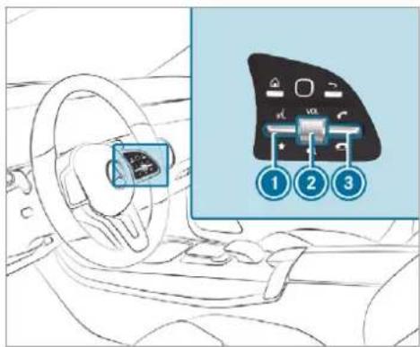
text_image
Diagram showing car interior with steering wheel and dashboard, alongside a labeled control panel with numbered buttons 1, 2, and 3.① Press the rocker switch up: □ starts the dialogue
2 Press the control knob: switches sound off or on (ends the dialogue)
Turn the control knob up/down: increases/decreases the volume
3 Press the rocker switch down: 📞 rejects/ends a call (ends the dialogue)
Conducting a dialogue
For the dialogue with LINGUATRONIC, you can use complete sentences of colloquial language as voice commands, such as, for example, "Please show me the list of the last calls" or "How warm is it outside?". It is not necessary to first change to the relevant application such as "Telephone" or "Vehicle function".
To activate or continue dialogue by using a keyword: say "Hello Mercedes" to activate LINGUATRONIC. Voice activation must be switched on in the multimedia system (→ page 363). For this, it is not necessary to press up the rocker switch on the multifunction steering wheel. Voice activation can also be directly combined with a voice command, e.g. "Hi Mercedes, how fast can I drive?".
Press the □ rocker switch up on the multifunction steering wheel. You can say a voice command after an acoustic signal.
To correct an entry: say the Correction voice command.
To select an entry from the selection list: say the line number or the contents.
To browse the selection list: say the Next or Back voice command.
To interrupt the dialogue: say the Pause voice command.
The dialogue can be continued with the "Hello Mercedes" voice command or by pressing up the rocker switch on the multifunction steering wheel.
To jump to the preceding dialogue: say the Back voice command.
To jump back to the top dialogue level: say the Home voice command.
To cancel the dialogue: say the Close voice command or press the 📄 or 🏠 button on the multifunction steering wheel.
To interrupt a voice output: speak in the middle of a voice dialogue when the system is still answering. The voice output is shortened and the conclusion is reached more quickly.
The Voice barge-in option must be switched on in the multimedia system for this (→ page 363).
Overview of operable functions in LINGUA-TRONIC
You can use the LINGUATRONIC voice control system to operate the following functions depending on the vehicle equipment:
- Telephone
• Text message and e-mail - Navigation
- Address book
- Radio
• Media
• TV - Vehicle functions
- Weather
Full functionality is only available for you with activation of online voice control ( page 363).
Notes on the language setting
You can change the language of LINGUATRONIC via the system language settings. If the set system language is not supported by LINGUATRONIC, English will be selected.
LINGUATRONIC is available in the following languages:
• German
- English
- French
- Italian
- Dutch
- Polish
- Portuguese
- Russian
- Swedish
- Spanish
- Czech
- Turkish
Setting LINGUATRONIC (multimedia system)
Requirements:
- For online voice control: your vehicle is connected with your Mercedes me user account (→ page 509).
- There is an Internet connection (→ page 517).
- For online use of contacts: online voice control is activated.
Multimedia system:

Switching voice activation of LINGUATRONIC on/off
▶ Select Voice activation "Hi Mercedes". Depending on the previous status, the function is activated or deactivated.
When the function is active, the "Hi Mercedes" voice command can activate the dialogue.
Activating/deactivating online voice control
Activate Online recognition.
i Online voice control is activated at the factory.
- Select Online recognition subscript..
You will be connected with the Mercedes portal.
- Activate online voice control in the Mercedes me portal.
Activating contacts for online use
▶ Select Contact upload for online recognition. When the function is active, contacts will be found more easily and accurately using voice input. The quality of the enunciation of contact names by the system will also be improved.
Switching on voice interruption
▶ Select Voice barge-in. If the function is active, a command can be interjected during voice output of the system.
Using LINGUATRONIC effectively
LINGUATRONIC audible help functions
mUsing the corresponding voice commands you receive the following information and assistance in the following cases:
- For optimal operation: say the Voice control tutorial voice command or call up the Digital Owner's Manual with Could you go to the LINGUATRONIC tutorial please?, for example. The full extent of the Digital Owner's Manual is available when the vehicle is stationary. Here you can also find explanatory videos which introduce you to the functions of LINGUATRONIC.
- Current application: on the multifunction steering wheel, press the rocker switch up and say the Help voice command. You will
receive suggestions and information about operation of LINGUATRONIC for the current application.
- Continued dialogue: say the Help voice command during a voice dialogue. For every step of the dialogue you receive matching information.
- Specific function: say the voice command for the desired function, e.g. with "Hello Mercedes, I need help with the radio" or after pressing the rocker switch on the multifunction steering wheel up, say the Help for the telephone voice command, for example.
Notes on optimal use of LINGUATRONIC
Notes on how to improve recognition:
- Activate online voice control (→ page 363).
- Only operate LINGUATRONIC from the driver's seat.
- Say the voice commands coherently and clearly, but do not exaggerate the words.
- Avoid loud noises that cause interference while making a voice command entry, e.g.
the entertainment in the rear-passenger compartment.
• For telephone or address book entries:
- Only create sensible address book entries in the system/mobile phone, e.g. enter surname and first name in the correct field.
- Do not use any abbreviations, unnecessary spaces or special characters.
- For radio or TV programme names: say the Read out station list voice command and say the desired station name in the way the voice output reads aloud to you.
To improve recognition, depending on the outside temperature, either the blowers for ventilation or heating are reduced when LIN GUATRONIC is started.
Notes on online voice control
Online voice control improves recognition and makes additional results available as a result of external information, e.g. information about POIs
and about the weather. We therefore recommend that you activate online voice control.
You will need a Mercedes me user account for this. If you do not yet have a user account you have to create one and connect it with your vehicle ( page 509).
Then call up your Mercedes me user account. The Mercedes me services are shown and can be activated ( page 509).
In addition, online voice control must be activated ( page 363).
Essential voice commands
Notes on the voice commands
Aside from the exact voice commands (see the "Voice command" column in the following tables) to call up specific functions, in most cases LIN-GUATRONIC also understands a great many paraphrases from daily usage. Examples of these are listed in the "Colloquial examples" column. For some languages however these examples are only available to a limited extent.
Content in angled brackets, e.g.
destination could, for example, be completed with: Set Mercedes-Benz Arena as intermediate destination.
Overview of switch voice commands
Switch voice commands can be used to open certain applications.
Switch voice commands
| Voice command | Colloquial example | Function |
| Switch to navigation I would like to go to navigation | Switches to navigation | |
| Switch to address book I would like to switch to the address book | Switches to the address book | |
| Switch to telephone | I would like to switch to the telephone | |
| Switch to messages Can you switch to messages please? | Switches to the text message application. | |
| Switch to e-mail I would like to go to the e-mail application | Switches to the e-mail application | |
| Switch to radio I would like to switch to the radio | Switches to radio | |
| Switch to TV I would like to switch to the TV | Switches to TV | |
| Switch to media I would like to switch to the media application | Switches to media | |
| Switch to comfort I would like to | go to the comfort application | Switches to the comfort settings |
| Switch to vehicle info I would like | to go to the vehicle application | Switches to vehicle information |
| Switch to settings I would like to | go to the settings menu | Switches to the menu with the setting options |
It is not necessary to first call up a menu in order to operate a function it contains with LINGUATRONIC. You can operate the function directly using voice input, e.g. call a contact or enter a destination for navigation.
You can find further information in the overview tables for voice commands.
Overview of navigation voice commands
Using the navigation voice commands you can enter POIs and conventional addresses or navi-
gate to your own contacts. You can also carry out important navigation settings directly. The following list offers just a small selection of the possible navigation commands. You will receive additional suggestions if you say Help for navigation.
Navigation voice commands
| Voice command | Colloquial example | Function |
| Navigate to <address> Navigate to | Cambridge in the King Street | Starts route guidance to the desired address. |
| Navigate to <contact> | D rive/bring me to address of John Smith | Starts route guidance to a contact from the address book. |
| Navigate to <3 word address> | The example is for the German language:Drive to Tapfer.Gebäude.Verliehen | Starts route guidance to a 3 word address from what3words.The example mentioned navigates you to the Brandenburg Gate.Observe the following information:3 word addresses are language dependent.Searching for a destination using 3 word addresses is not possible in all countries and in all languages. Additional information on 3 word addresses from what3words can be found in the Navigation section under "Entering the destination as a 3 word address".The Brandenburg Gate, for example, has the following 3 word addresses:German:tapfer.gebäude.verliehenEnglish:that.lands.winningFrench:posteaux.bobineur.ombrant |
| Home I would like to go home/I | want to drive to my home address | Starts route guidance to the home address. |
| Work I would like to navigate to work | Starts route guidance to work. | |
| Enter POI Take me to a POI | Enters a POI, e.g. Brandenburg Gate. | |
| Navigate to <POI> Navigate to "McDonald's" | Starts route guidance to a POI. | |
| Navigate to the online POI <POI> | Navigate to online POI "McDonald's | Searches online for a POI and starts route guidance. |
| Start route guidance Begin route guidance/Can you start route guidance? | Starts route guidance to a destination. | |
| Cancel route guidance Can you quit route guidance? | Cancels route guidance. | |
| Restart route guidance I would like to resume route guidance | Continues route guidance after a break. | |
| Setas intermediate des-Set "Stratton Road in Swindon" as destination an intermediate destination | Selects an intermediate destination for the route. | |
| Setas intermediate des-Set "John Smith" as intermediate destination destination | Selects an intermediate destination from the contacts for the route. | |
| Setas intermediate destina-tion | Set "Buckingham Palace" as an intermediate destination | Selects a POI as an intermediate destination for the route. |
| Enter address inI would like to enter a new address in "France" | Selects a destination in another country. | |
| Enter postcode Start route guidance to a new post-code | Enters a postcode. | |
| Last destinations Show the previous destinations | Selects a destination from the previous destinations. | |
| Show alternative routes Search for alternative routes | Shows one of the alternative routes calculated. | |
| Driving recommendations on Switch on driving recommendations | Switches on voice output for route guidance. | |
| Driving recommendations off Mute the driving instructions | Switches off voice output for route guidance. | |
| Show traffic map Switch on traffic jam info | Displays traffic information on the map. | |
| Hide traffic map Switch off the traffic jam messages | Hides the traffic information. | |
| POI icons on Show me point of interest icons on the map please | Displays the POI symbols on the map. | |
| Hide POI icons I would like to hide all POI symbols | Hides the POI symbols. | |
Overview of telephone voice commands
You can use the telephone voice commands to make phone calls or search through the address
book. The following list offers just a small selection of the possible telephone commands. You
will receive additional suggestions if you say Help for phone.
Telephone voice commands
| Voice command | Colloquial example | Function |
| CallI would like you to dial 0171xxxxxxx | like you to dial 0171xxxxxxx | Makes a telephone call by entering the telephone number directly. |
| CallCall Jane Smith on her mobile | her mobile | Makes a telephone call directly by entering a name from the address book. |
| Call Mercedes-Benz emergency call centre | Could you call the Mercedes-Benz emergency centre? | Triggers an emergency call to the Mercedes-Benz emergency call centre. |
| Call Mercedes me I’d like you to call the MB break-down assistance please | call the MB break-down assistance please | Places a call with Mercedes-Benz breakdown assistance. |
| Latest calls Show me the list of missed calls | missed calls | Shows the list of missed calls. |
| Previous calls Show me the last calls | The list shows all outgoing, incoming and missed calls. | |
| Incoming calls Show me the calls received | received | Shows the list of incoming calls. |
| Outgoing calls Show me the list of outgoing calls | Shows the list of outgoing calls. | |
| Search for | C ould you open the Smith"? | Open contact contact data of a contact in the address book. |
| Redial Redial/Call last phone number | Makes a call to the last telephone number dialled. | |
| Change phone | C ould you please ond phone? | Chang with the primary telephone |
Overview of radio and TV voice commands
Radio and TV voice commands can also be used when the radio or TV application runs in the
background and another application is visible in the foreground. The following list offers just a small selection of the possible radio or TV voice
commands. You will receive additional suggestions if you say Help for radio or Help for TV.
Radio and TV voice commands
| Voice command | Colloquial example | Function |
| StationI would like to select station "Cool FM" | To select the radio station mentioned | |
| FrequencyGo to station/radio frequency"eighty seven point five mega-hertz". | To enter a radio frequency, e.g. for the FM range | |
| Next TV channel Change to the next TV channel | To call up the next TV channel in a list | |
| Previous station Switch to the last radio station | To switch to the previous radio station | |
| Storing TV channels Save the TV channel name | To save the current TV channel in the favourites list | |
| Save radio station | S ave the radio station, a station name for a radio station | |
| Show station list Please show me | the list of all radio stations | To show the list of radio stations that can be received |
| Read out TV channel list Read the TV program list to me | To listen to the names of all receivable TV channels | |
| Read out radio station list Please read out the radio programme | To have the list of available stations for the currently selected radio application read aloud | |
| Traffic information on Switch on the traffic info | To switch on traffic announcements | |
| Traffic information off I'd like to switch off traffic info | To switch off traffic announcements | |
| Radio info on I want you to turn on additional radio station text | To switch on information about the current station | |
| Radio info off | I want you to turn off additional radio station text | To switch off information about the current station |
Overview of media player voice commands
Media player voice commands can also be used when the media player application runs in the
background and another application is visible in the foreground. The following list offers just a small selection of the possible media player
voice commands. You will receive additional suggestions if you say Help for media or Help for player.
Media player voice commands
| Voice command | Colloquial example | Function |
| Play <track/albums/artists/composers/music genres> | Play "Yellow Submarine" | The names of all available tracks, albums, artists, composers or genres are accepted during the search. In the case of a clear search result the track found is played back immediately. |
| Play track <track> Play song "So What" | The available tracks are played back. | |
| Play album <album> Play album "A Night at the Opera" | The available albums are played back. | |
| Play artist <artist> | I want to listen "Madonna" | The available artists are played back. |
| Play composer <composer> | I'd like to hear the composer "Lud-wig van Beethoven" | The available composers are played back. |
| Play music genre <music genre> | I'd like to hear the music genre "Bebop" | The available music genres are played back. |
| Search for trackI would like to search for the song "Sailing" | The names of all available tracks are accepted during the search. A selection list appears from which you can select the desired music. If you wish to play all the tracks in a selection list, say "Play all tracks". | |
| Search for albumSearch for albumOpera"search for album "A Nigh name of all available albums are accepted during the search. A selection list appears from which you can select the desired music. If you wish to play all the tracks in a selection list, say "Play all tracks". | ||
| Search for artistI would like to search "Elton John"The female and all available artists are accepted during the search. A selection list appears from which you can select the desired music. If you wish to play all the tracks in a selection list, say "Play all tracks". | ||
| Search for composerSearch for composer "Beethoven"The names of all available composers are accepted during the search. A selection list appears from which you can select the desired music. If you wish to play all the tracks in a selection list, say "Play all tracks". | ||
| Search for music genreSearch for music genre "Pop"The names of all available music genres are accepted during the search. A selection list appears from which you can select the desired music. If you wish to play all the tracks in a selection list, say "Play all tracks". | ||
| Next track Start the next song/video clip/filmPrevious track Play the last song/track/clip againRepeat this track I'd like to listen to this track againThe current track is played back from the beginning. | Plays back the next track. | |
| Plays back the previous track. | ||
| The current track is played back from the beginning. | ||
| Play similar music I'd like to hear | similar music | Plays back similar tracks. |
| Play random music Play me a random track | Plays back random tracks. | |
| Random playback on Turn random | playback on | Switches to random mode. |
| Random track list off Switch off shuffle mode | Switches off random mode. | |
| What am I listening to? Which music is currently playing? | The information about the track currently playing is read aloud. | |
Overview of message voice commands
Messages can be created, edited and listened to using the message voice commands. The follow-
ing list offers just a small selection of the possible message commands. You will receive additional suggestions if you say Help for messaging.
Message voice commands
| Voice command | Colloquial example | Function |
| Text message toI would | like to write a new text to "John Smith's mobile number" | Creates a text message. All address book names are available. |
| Text message toI would like you to write a new text to "Jane Smith" with the following text: "I am running late" | I would like you to write a new text to "Jane Smith" with the following text: "I am running late" | Writes a text message to the person mentioned. The content of the text can be spoken immediately if online voice control has been activated. |
| Read out new text messages I would like you to read out the new text messages | Reads out new text messages. | |
| Read out the last text message from | I would like you to read out the text message from "John Smith" | Reads out the last text message from the person mentioned. |
| E-mail toI would like to | write a new e-mail to "John Smith, office" | Creates an e-mail. |
| E-mail toI would like to write an e-mail to "John Smith, private" with the following text: "Running late". | Writes an email message to the person mentioned. The content of the text can be spoken immediately if online voice control has been activated. | |
| Forward e-mail to I would like you to forward this e-mail to "John Smith" | Forwards the selected or open e-mail. | |
| Read out new e-mails I would like you to read out the new email | Reads out the new e-mails. | |
| Read out the last e-mail from | I would like you to read out the email from my wife | Reads out the last e-mail from the person mentioned. |
| E-mail in English toWrite | a mail in English to John Smith | Writes an email in English to the person mentioned. |
Overview of vehicle voice commands
You can use the vehicle voice commands to directly call up the corresponding menus for the vehicle settings and operate vehicle functions.
The following list offers just a small selection of the possible vehicle voice commands. You will receive additional suggestions if you say Help for vehicle settings or Help for vehicle functions.
If no seat or side is mentioned for commands that relate to a seat or side of vehicle
then all actions are carried out automatically for the driver's seat.
Vehicle voice commands
| Voice command | Colloquial example | Function |
| Temperature colder I would like to | reduce the temperature | Lowers the temperature of the air conditioning system. |
| Air recirculation on I would like to | activate the air circulation | Switches on air recirculation mode for the air conditioning system. |
| Automatic climate control driver on | I would like to switch on the automatic climate control for the driver's seat | Switches on automatic climate control for the driver's or front passenger side. |
| Ambient light blue I would like to | set the interior lighting to blue | Switches the ambiance light, e.g. to blue. |
| Wave massage driver on I would like to switch on the wave massage for the driver's seat | Switches on the wave massage for the driver's or front passenger seat. | |
| Massage driver's seat off Switch | the driver's side massage off | Switches off the massage function for the driver's or front passenger seat. |
| Seat heating driver on I would like | to switch on the seat heating for the driver's seat | Switches on the seat heating for the driver's or front passenger seat. |
| Seat heating front passenger level 2 | Seat heating front-passenger on level 2 | Sets the seat heating for the driver's or front passenger seat to level 2. |
| Current speed limit I would like to | hear the speed limit | Calls up the current speed limit. |
| Outside temperature I would like to | find out what the temperature outside is like | Calls up the outside temperature. |
| Average consumption What is the | current average con-sumption? | Calls up average consumption. |
| Vehicle data Can you please display the vehicle data menu? | Calls up the vehicle data. | |
| Range Tell me the current range | Calls up the current range data. | |
| Assistance menu Show me the driver assistance set-tings | Displays the assistance settings. | |
| Climate control menu I would like | to see the climate con-trol menu | Displays the climate control settings. |
| Light menu I would like to change | the light set-tings | Displays the light settings. |
| Seats menu I would like to switch | to seat menu | Displays the seat adjustment settings. |
| Massage menu I would like to switch | to the mas-sage seat menu | Displays the massage settings. |
| Next service | T ell me my ment | Carlextupethiceneoposervice due date. |
Overview and operation
Overview of the MBUX multimedia system

WARNING Risk of distraction from information systems and communications equipment
If you operate information and communication equipment integrated in the vehicle when driving, you will be distracted from the traffic situation. This could also cause you to lose control of the vehicle.
Only operate this equipment when the traffic situation permits.
If you cannot be sure of this, stop the vehicle whilst paying attention to road and traffic conditions and operate the equipment with the vehicle stationary.
You must observe the legal requirements for the country in which you are currently driving when operating the multimedia system.
MBUX stands for Mercedes-Benz User Experience.
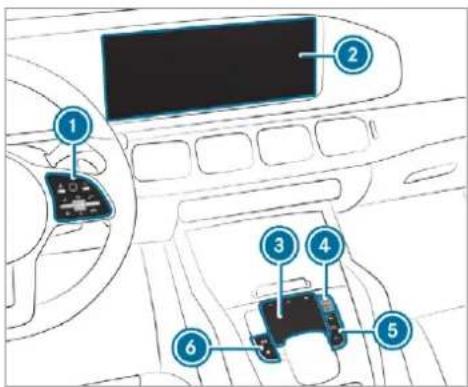
text_image
Diagram of car interior with numbered components, likely a diagnostic or electronics setup① Touch Control and control panel for the MBUX multimedia system
Operating Touch Control(→ page 383)
2 Media display with touch functionality
Home screen overview(→ page 382)
Operating the touchscreen (→ page 384)
3 Touchpad
Operating the touchpad(→ page 385)
4 Control knob
Press and hold: switches the multimedia system or display on or off
Press briefly: switches the mute function on/off
Turn: adjusts the volume
⑤ Buttons for navigation, radio/media and telephone
Calling up applications(→ page 393)
6 Buttons for vehicle functions/system settings and favourites/themes Calling up applications(→ page 393)
You can operate the multimedia system with the following central control elements:
- Touch Control ① and touchpad ③
The operation for both control elements is achieved by cursor control.
• Media display 2
Alternatively, you can conduct a dialogue with LINGUATRONIC ( page 361).
If the vehicle is fitted with the MBUX in-car assistant, selected functions of the multimedia system can be operated contact-free as well as turning the reading light on or off ( page 388).
Numerous application, online services, services and apps are available for you. You can call these up using the home screen or using butt ⑤ and ⑥ next to the touchpad.
You can conveniently call up and add favourites using the ★ rocker switch on the steering wheel or using the ★ button next to the touchpad. Quick-access in the home screen and in the applications serve to select functions more quickly.
If you use the learn function of the multimedia system, you will receive suggestions during operation of the most probable navigation destinations, media sources, radio stations and contacts. The configuration of the suggestions takes place in your profile. You can compile your profile from various vehicle settings and settings of the multimedia system. You can create themes for various driving situations in the home screen
as well as using the ★ rocker switch or the button.
The Notifications Centre collects incoming notifications, e.g. about an available software update. Depending on the type of notification it offers various actions. You can call up the Notifications Centre on the home screen and in the application menus.
With the global search in the vehicle you can search on-board across many categories as well as online in the Internet. You can use the global search in the home screen and in the notifications.
Anti-theft protection
This device is equipped with technical provisions to protect it against theft. More detailed information about anti-theft protection can be obtained at a qualified specialist workshop.
Notes on the media display
Observe the notes on caring for the interior ( page 581).
Automatic temperature-controlled switch-off feature: if the temperature is too high, the brightness is initially reduced automatically. The media display may then switch off completely for a while.
If you are wearing polarised sunglasses, it may be difficult to read the multimedia system display.
Home screen overview
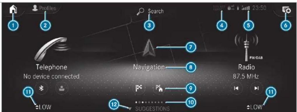
text_image
Profiles Search 23:50 Telephone No device connected Navigation 8 Radio 87.5 MHz LOW SUGGESTIONS 11 12 10 11 4 5 6 FM/DAB① On the home screen: displays the first three applications
In other displays: calls up the home screen
② Calls up the profile
③ Calls up the global search
4 SOS NOT READY display only when the Mercedes-Benz emergency call system is not available
⑤ Displays, for example network display, battery status of the mobile phone connected, signal strength of the mobile phone network, time
6 Calls up the Notifications Centre The star indicates new notifications.
7 Calls up an application using the symbol
Name of the application, beneath the current selection or information
9 Quick-access (in the example: calls up destination entry, enters the destination address for home)
10 Number of applications and currently selected display area
⑪ Calls up the air conditioning menu (→ page 196)
⑫ Calls up SUGGESTIONS, THEMES and FAVOURITES
Central control elements overview
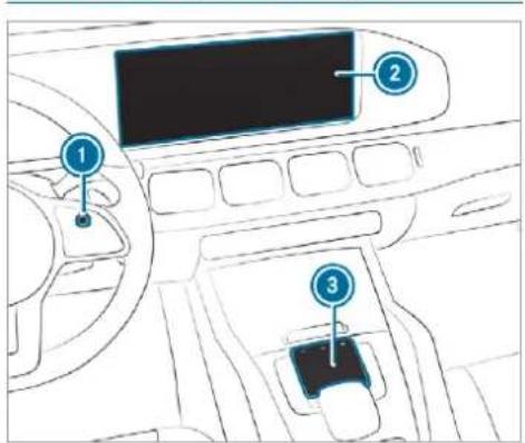
text_image
Diagram of a car dashboard with labeled parts including steering wheel, screen, and seatbelt① Touch Control
② Media display with touch functionality
3 Touchpad
Touch Control
Operating Touch Control (MBUX multimedia system)
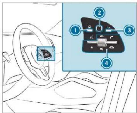
text_image
Diagram showing car interior with labeled parts and a close-up of the dashboard key for dial indicator① button
Shows the home screen and calls up applications

Shows suggestions, themes and favourites: when the home screen is shown, swipe down on Touch Control ②.


button
Pressing briefly: returns to the previous display

Control panel for MBUX multimedia system: ★ rocker switch
Press down briefly: shows favourites
Press down and hold: adds favourites and themes
Control knob
Turn: adjusts the volume VOL
Press: switches off the sound


rocker switch
Press up: makes or accepts a call

rocker switch
Press down: rejects or ends a call
You can navigate in menus and lists via the touch-sensitive surface of Touch Control ② by using a single-finger swipe.
To select the menu item or entry: swipe up, down, left or right.
Press Touch Control ②.
To enter a character: enter a character using the keyboard.
To move the digital map: swipe in any direction.
Setting the sensitivity for the Touch Control Multimedia system:
→ ▶ Settings ▶ System
▶ Controls ▶ Touch Control sensitivity
▶ Select Fast, Medium or Slow.
Setting acoustic operating feedback for the Touch Control
Multimedia system:
→ Settings ▶ System
Controls
The function is supported by the selection in a list.
▶ Select Acoustic operating feedback.
Set Normal, Loud or Off. If the function is activated you will hear a clicking sound when scrolling in a list. When the beginning or end of the list is reached you will hear another clicking sound.
Touchscreen
Operating the touchscreen
Tapping
To select a menu item or entry: tap on a symbol or an entry.
To increase the map scale: tap twice quickly with one finger.
To reduce the map scale: tap with two fingers.
To enter characters with the keypad: tap on a button.
Single-finger swipe
To navigate in menus: swipe up, down, left or right.
To move the digital map: swipe in any direction.
To use handwriting to enter characters: write the character with one finger on the touchscreen.
Two-finger swipe
To zoom in and out of the map: move two fingers together or apart.
To enlarge or reduce the size of a section of a website: move two fingers together or apart.
To turn the map: turn anti-clockwise or clockwise using two fingers.
Touching, holding and moving
To move the map: touch the touchscreen and move your finger in any direction.
To set the volume on a scale: touch the touchscreen and move the finger to the left or right.
Touching and holding
To save the destination in the map: touch the touchscreen and hold until a message is shown.
To call up a global menu in the applications: touch the touchscreen and hold until the OPTIONS menu appears.
Setting acoustic operation feedback for the touchscreen
Multimedia system:
Settings System
Controls
The function is supported by the selection in a list.
▶ Select Acoustic operating feedback.
Set Normal, Loud or Off.
If the function is activated you will hear a clicking sound when scrolling in a list. When the beginning or end of the list is reached you will hear another clicking sound.
Touchpad
Operating the touchpad
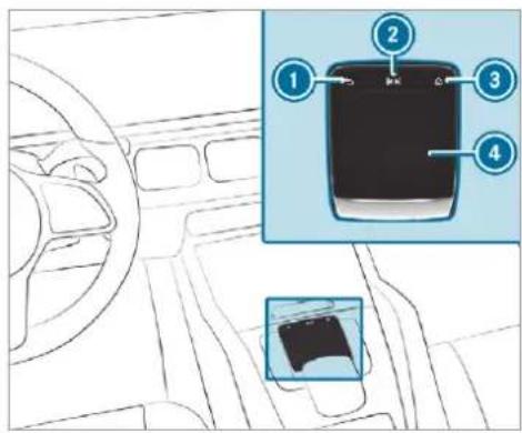
text_image
Diagram of a car interior with numbered parts and a close-up inset showing a device component.button
Pressing briefly: returns to the previous display
button
Pressing: calls up the control menu of the last active audio source
3
Swiping to the left of right across ◀◀▶: selects the previous or next radio station/ music track
button
Pressing: shows the home screen and calls up applications
4
Touchpad
i
Calls up suggestions, themes and favourites: when the home screen is shown, swipe down on touchpad 4.
You can navigate in menus and lists via the touch-sensitive surface of touchpad by using a single-finger swipe.
To select the menu item or entry: move the selection by swiping up, down, left or right.
Confirm the selection by pressing on touch-pad 4.
or
If Touchpad tap is activated, tapping is sufficient ( page 386).
To enter a character: select a character on the keyboard ( page 409).
or
Write a character on the touchpad with handwriting input.
To move the digital map: when the digital map is shown with the navigation menu, swipe up with one finger.
Press the touchpad. The digital map can be moved.
Swipe in all directions.
Use the following functions with a two-finger swipe:
To call up the Notifications Centre: swipe down with two fingers.
To close the Notifications Centre: swipe up with two fingers.
To call up the control menu of the last active audio source: swipe up with two fingers.
To zoom in and out of the map: move two fingers together or apart.
To enlarge or reduce the size of a section of a website: move two fingers together or apart.
Setting the sensitivity for the touchpad Multimedia system:


▶


▶


Touchpad tap on or off. If the function is switched on, a tap on the touchpad is enough to select a menu item.
Switching the read-aloud function for handwriting recognition on/off Requirements:
- The multimedia system is equipped with a voice control system.
- The read-aloud function is available for the selected system language.
Multimedia system:
Settings ▶ System ▶ Audio
Switch Read out handwriting recognition on or off. If the function is activated, characters are read aloud as they are written on the touch-pad.
Activating/deactivating haptic operating feedback for the touchpad
Multimedia system:
Settings System
Controls
The function supports you when making entries on the touchpad and when selecting menus.
Switch Haptic operating feedback on or off. When the function is activated, a tactile feedback in the form of a vibration is effected when the touchpad is operated.
Setting acoustic operating feedback for the touchpad
Multimedia system:
Settings System
▶ Controls
The function is supported by the selection in a list.
▶ Select Acoustic operating feedback.
▶ Set Normal, Loud or Off.
If the function is activated you will hear a clicking sound when scrolling in a list. When the beginning or end of the list is reached you will hear another clicking sound.
Selecting a station and track using the touchpad
Swipe to the left or right over the [◀▶] button.
Radio: the previous or next station is set.
Media source: the previous or next track is selected.
or
To show the control menu: press the button on the touchpad.
or
Swipe upwards using two fingers on the touchpad. The control menu appears for the audio source that was last selected.
Swipe left or right using one finger. Radio: the previous or next station is set. Media source: the previous or next track is selected.
To hide the control menu: swipe down on the touchpad using two fingers.
MBUX Interior Assistant
Notes on lasers and laser classification
⚠ WARNING Risk of injury from laser radiation from the camera
This product uses a laser system. If the housing is opened or damaged, invisible laser
beams can escape in an uncontrolled manner.
Laser radiation can damage your retina.
▶ Do not open the housing.
Always have maintenance work and repairs carried out by a qualified specialist workshop.
This device is a class 1 laser product in accordance with DIN EN 60825-1:2014

WARNING Risk of distraction from information systems and communications equipment
If you operate information and communication equipment integrated in the vehicle
when driving, you will be distracted from the traffic situation. This could also cause you to lose control of the vehicle.
Only operate this equipment when the traffic situation permits.
If you cannot be sure of this, stop the vehicle whilst paying attention to road and traffic conditions and operate the equipment with the vehicle stationary.
You must observe the legal requirements for the country in which you are currently driving when operating the multimedia system.
Overview of the MBUX Interior Assistant
If the vehicle is fitted with the MBUX Interior Assistant, selected functions of the multimedia
system can be operated contact-free. In addition, the reading light or search light can be switched on or off contact-free.
The MBUX Interior Assistant can differentiate between driver and front passenger interactions. The MBUX Interior Assistant recognises certain hand positions (poses).
The MBUX Interior Assistant supports the following interactions:
| Interaction area Interaction Description | ||
| In front of the media display/above the touch-pad | Proximity to the control element | The MBUX Interior Assistant recognises the approach of the hand towards a control element.Depending on the active application, the display will be adjusted in the media display. Some functions differentiate between driver and front passenger.No specific hand position is required. |
| Above the centre console | Defined poses | With defined poses a function is triggered depending on the application active. |
| Below the inside rearview mirror | Brief up and down movements | With brief vertical up and down movements below the inside rearview mirror the reading light for the driver or the front passenger is switched on and off. |
| Front passenger seat | Stretching out the hand above the front passenger seat | By stretching out the hand above the front passenger seat the search light is switched on. If the hand is withdrawn from this area, the search light is switched off again. |
Operating functions by proximity of the hand to the touchscreen and touchpad Requirements:
- One of the following applications appears in the media display:
- Seat settings with displays for the driver and front passenger seat, e.g. Seat comfort
-
Home screen
-
Radio menu or media menu
- Map in the navigation
Active Parking Assist - Recognition occurs as the hand approaches to approximately 10 cm from the touchpad or the touchscreen.
Seat adjustments by the driver or front passenger
In the seat settings menu, the MBUX Interior Assistant detects proximity to various control elements of the multimedia system. In addition, the MBUX Interior Assistant detects from which seat the action emanates.
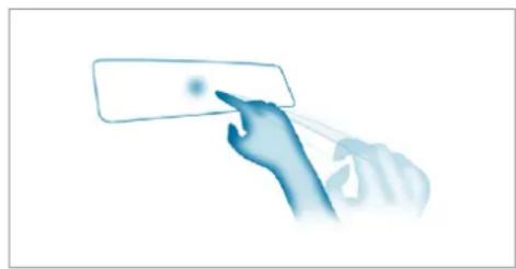
natural_image
Hand holding a rectangular button with a dot, pointing at it (no text or symbols visible)Hand approaching the touchscreen
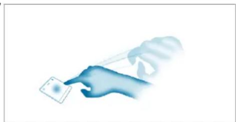
natural_image
Illustration of a hand holding a small object, no text or symbols presentHand approaching the touchpad
When the seat settings are shown, move your hand towards the touchscreen or touchpad. The seat of the person operating, driver's seat or front passenger seat, is enlarged in the media display.
The appropriate control elements are pre-selected automatically.
Depending on the function, the person operating can either switch the function on or off directly or make other settings.
Highlighting an application on the home screen
The MBUX Interior Assistant detects in which area the hand is in front of the touchscreen. The display of objects shown is adjusted to improve orientation.
Move your hand towards the touchscreen. The symbol for the application is enlarged. The quick-access applications will be highlighted.
Continue operation, e.g. select a quick-access application.
i Further information about the home screen ( page 382).
Activating cover change in the radio menu and media menu
The MBUX Interior Assistant reduces the number of operating steps.
Move your hand towards the touchscreen or touchpad.
The current information, e.g. about the radio station, track and artist are hidden. Cover change is activated.
Continue operation and select a cover.
As your hand is moved away from the touchscreen or touchpad, the current information is shown again.
Further information on the radio menu (→ page 537) and the media menu (→ page 530).
Showing the navigation menu on the map
The MBUX Interior Assistant shows the navigation menu.
Move your hand towards the touchscreen or touchpad.
The navigation menu is shown.
Continue operation and select a symbol.
As your hand is moved away from the touchscreen or touchpad, the media display hides the navigation menu.
(i) Further information on the navigation menu ( page 432).
Showing operating symbols in the Active Parking Assist camera image (only from driver's seat)
The MBUX Interior Assistant facilitates quick-access for the driver to various camera views.
When Active Parking Assist is shown, move your hand towards the touchscreen.
The camera operation symbols are displayed.
Continue operation and display the desired front, rear, left and right camera views.
i Further information on Active Parking Assist functions ( page 319).
Operating a function with the favourites pose
Requirements:
• There is at least one favourite.
• The favourite has been connected with the MBUX Interior Assistant.
- The area for recognition of the favourite's pose (V pose) is above the centre console at the height of the climate control vents and the media display. The hand should have a distance of at least 10 cm from the media display.
• The V pose is held for a brief time.
Calling up favourites
The driver and front passenger can connect two different favourites with the V pose.
If a favourite has not yet been saved and connected with the MBUX Interior Assistant, the multimedia system will assist you.

natural_image
Blue-tinted illustration of a hand making a peace sign gesture (no text or symbols)Carrying out the V pose
Position the hand above the centre console and in the direction of the media display. The back of the hand is facing upwards. In doing so the index and middle finger are extended with the other fingers bent inwards. The favourite is called up.
Switching the reading light for the driver and front passenger on/off with the MBUX Interior Assistant Requirements:
• The function is available when it is dark.
- The hand movement is carried out in the interaction area (under the inside rearview mirror).
Briefly moving the hand up and down under the inside rearview mirror switches the reading light specifically for the driver or front passenger on or off.
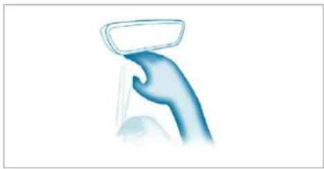
natural_image
Hand holding a small object, possibly a cleaning or cleaning tool, with no visible text or symbols.Carrying out operation of the reading light
Move the hand up and down vertically under the reading light. The reading light is switched on or off.
Switching the search light for the driver on/off with the MBUX Interior Assistant Requirements:
• The front passenger seat is not occupied.
• The function is available when it is dark.
- The hand movement is completed in the interaction area (front-passenger seat).
- The seat belt on the front passenger seat must not be inserted in the seat belt buckle.
Stretching out with the hand over the front passenger seat when unoccupied switches a search light on for the driver when it is dark. Pulling the hand back switches the search light off again.
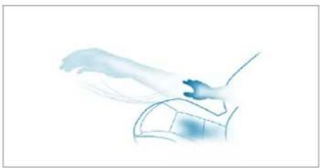
natural_image
Illustration of a hand holding a small object near a vehicle (no text or symbols)Interaction area for operating the search light
To switch on: reach across the front passenger seat with your hand. The search light is switched on for the driver.
To switch off: take your hand back away from the front passenger seat. The search light is switched off again.
Settings for the MBUX Interior Assistant
Multimedia system:

To switch on full functionality of the MBUX Interior Assistant: select On.
The option is activated ●.
To activate additional functions for reading and search lights: select Including reading light.
When the option is switched on, the display button is activated.
The functions for the reading and search lights are activated in addition to the proximity functions.
To switch off the MBUX Interior Assistant: select Off.
The option is activated •.
Main functions
Calling up applications
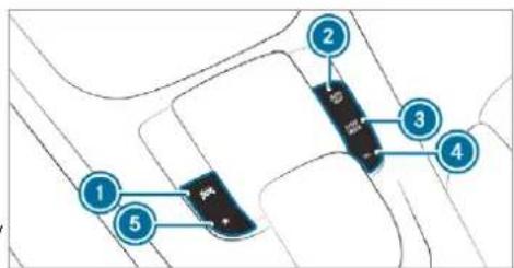
text_image
Diagram showing labeled points (1, 2, 3, 4, 5) on a road or road intersection with a central black object and directional arrows.① button
Calls up vehicle functions
2 NAVI MAP button
Calls up navigation
3 RADIO MEDIA button
Calls up radio or media
④ TEL button
Calls up the telephone
⑤ ★ button
Press briefly: calls up favourites
(→ page 402)
Press and hold: adds a favourite
(→ page 402) or creates a new theme
(→ page 398)
Alternatively in the home screen: when you start the vehicle the home screen is shown in the media display.
Select the application by swiping and tapping.
or
In any display: press the 📋 button on the Touch Control or on the touchpad.
or
Tap on the symbol on the touchscreen. The applications are displayed.
Select the application by swiping and tapping.
Changing the arrangement of applications on the home screen
▶ Call up the home screen.
Touch and hold an application on the touchscreen until symbols appear.
Tap on ◀ or ▶ and move the application in the menu.
Tap on
Profile
Notes on profiles
WARNING Risk of becoming trapped during adjustment of the driver's seat after calling up a driver profile
Selecting a profile may trigger an adjustment of the driver's seat to the position saved under the profile. You or other vehicle occupants could be injured in the process.
Make sure that when the position of driver's seat is being adjusted using the multimedia system, no people or body parts are in the seat's range of movement.
If there is a risk of someone becoming trapped, stop the adjustment process immediately:
a) Tap the warning message on the media display.
or
b) Press a memory position button or a seat adjustment switch on the driver's door.
The adjustment process is stopped.
The driver's seat is equipped with an anti-entrapment feature.
If the driver's door is open, the driver's seat will not be set after calling up the driver's profile.
Overview of profiles
Using the multimedia system up to seven profiles can be created in the vehicle.
Profiles store your personal vehicle settings and settings for the multimedia system.
If the vehicle is used by several drivers, the driver can select their profile before the journey, without changing the settings of other drivers.
You can select the profile:
- When entering (→ page 397)
• Using the home screen ( page 382)
The profile settings are activated as soon as a profile is selected.
When you call up your profile, the driver's seat, steering wheel and outside mirrors can be set. If you call up your profile when driving then the driver's seat position will not be adjusted.
You can cancel the setting process with the following actions:
- Tap on the Positioning seat and steering wheel. Please tap to cancel. warning on the media display.
- Press one of the seat operating buttons in the driver's door.
Profile content
Depending on the vehicle equipment, the following settings can be stored in your profile, for example:
- Driver's seat, steering wheel and mirror settings
- Driver's seat memory
• Radio (including station list) - Last destinations
• Climate control - Ambient lighting
• DYNAMIC SELECT I (individual) - Instrument Display, Head-up Display and style (display style of the multimedia system)
- Themes, suggestions and favourites
Settings for driver assistance systems cannot be saved in the profile.
Mercedes me connect profile
If you use a profile from Mercedes me connect the following online functions are available, for example:
- You can configure the settings in the vehicle using the Mercedes me app and the Mercedes me portal.
- You can synchronise your profile on Mercedes me connect with the profile in the vehicle ( page 397).
- You can add a personal profile photo that is shown in the vehicle.
- You can take your profile and some of your settings with you in new vehicles.
Requirements for using Mercedes me connect profiles:
For the vehicle owner:
- You have a Mercedes me user account.
- The vehicle has been connected with the user account.
• The personalisation service is activated.
For additional users of the vehicle:
• You have a Mercedes me user account.
- The vehicle owner has invited you to connect your user account on Mercedes me with that of his vehicle.
• You have accepted the invitation.
Creating a new profile
Multimedia system:


Profiles
▶ Select + Create profile.
Select an avatar.
Enter the name and confirm with OK.
Select Continue>
To save the current settings in a profile: select Current settings.
Select Save.
or
To adopt the factory settings: select Factory settings.
Select Save.
i Further information on setting a user profile (→ page 396).
▶ Activate Bluetooth® and select Connect phone, to connect a mobile phone with the user profile (→ page 480).
You can also set up a user profile without registering a mobile phone.
Select Finished. The user profile is saved.
Selecting profile options
Multimedia system:


Profiles
Select ⋯ for a profile.
To edit a profile: select Edit profile.
Select an avatar.
Change the name, if necessary.
Select Save.
To configure suggestions: select Suggestions settings ( page 401).
To reset favourites or themes: select Reset favourites to factory settings or Reset themes to factory settings.
Select Yes.
To reset a profile: select Reset profile to factory settings.
Select Yes.
To delete a profile: select Delete profile.
Select Yes.
The guest profile cannot be deleted.
Protecting profile content
To protect your profile content and settings you can create a PIN in the Mercedes me portal for your profile. When PIN protection is active, you have to enter the PIN to select your profile.
▶ Select Protect content.
Select Mercedes me portal.
The browser opens and you are transferred to the Mercedes me portal.
Selecting a profile
Multimedia system:


Profiles
When you call up your profile, the driver's seat, steering wheel and outside mirrors can be set.
You can cancel the setting process with the following actions:
- Tap on the Positioning seat and steering wheel. Please tap to cancel. warning on the media display.
- Press one of the seat operating buttons in the driver's door.
▶ Select a profile.
Press the OK button to confirm the message.
The profile is loaded and activated.
Alternatively, the profile can already be selected when the vehicle is entered ( page 397).
Synchronising a profile
Requirements:
• You have a Mercedes me user account.
- The vehicle is connected with your Mercedes me user account.
• The personalisation service is activated on Mercedes me connect.
Multimedia system:


Profiles
▶ General settings
Synchronisation enables the following:
- You can configure the vehicle settings using the Mercedes me app.
- The profile on Mercedes me connect and profile in the vehicle are aligned (profile management).
Activate Synchronise profiles automatically. The profiles in the vehicle are automatically synchronised with the profiles on Mercedes me connect when the ignition is switched and off.
or
▶ Select Synchronise profiles now.
After selecting this option, the profiles in the vehicle are synchronised with the profiles on Mercedes me connect.
i During synchronisation the profile list and the profile functions are blocked.
Note on data protection: if you do not wish to share your data with Mercedes me, make sure that the automatic synchronisation is switched off and do not select Synchronise profiles now.
Showing the profile selection when entering Requirements:
- At least one profile has been created.
Multimedia system:


Profiles
If the option is activated, you can see a profile soon as you get in.

Select General settings.
▶ Activate Show profile selection when entering. When the vehicle is started, the media display shows the active profile.
Themes
Overview of themes
You can configure the vehicle settings according to your preferences and save as a theme. A theme can be called up any time via the home screen. There is then no need to make the desired settings again.
There are pre-defined themes available, e.g. Journey, Efficiency and Lounge.
Example for the use of themes
For recurring driving situations, such as long drives on the motorway, you can save your preferred settings in a theme in the vehicle.
You can save the following settings in a theme, for example:
• Displays (e.g. navigation map or tachometer)
• Preferred radio station
• Favoured drive program
These settings are saved under the name you wish when setting up a theme ( page 398). On the next motorway journey you can select this theme and thereby restore your settings.
Content of a theme
Depending on vehicle equipment the following settings can be saved in a theme:
- Setting of the Instrument Display (→ page 345)
- Setting of the Head-up Display (→ page
- Setting of the ambient lighting (→ page 182)
• Active audio source, e.g. radio or USB - Starting screen for the media display
• Visual style ( page 415)
• DYNAMIC SELECT drive program (→ page 227) - Eco start/stop setting (→ page 223)
- Navigation system settings
A theme contains the currently active settings in the vehicle.
Calling up themes
Multimedia system:

When the home screen is shown, swipe up until THEMES appears.
Select a theme.
Creating new themes
Requirements:
- The settings which are to be saved in the theme are active.
357) The overview shows the settings which can be saved in a theme ( page 398).
Multimedia system:

Select + Set theme.
The settings which are saved in the theme are shown.
Select Continue ▷.
Select additional settings which are to be saved in the theme.
- Select Audio, to save the active audio settings in the theme.
- Select Navigation (Navigation), to save the active navigation settings in the theme.
Select Continue >.
▶ Select an entry screen.
Select Continue ▷.
Select an image.
Enter the names into the entry field and confirm with OK.
To save a theme: select Save.
When the maximum number that can be saved is reached:
Select OK from the prompt.
Select a theme that should be overwritten. The settings which are saved in the theme are shown.
Select Continue ▷.
Select additional settings which are to be saved in the theme.
- Select Audio, to save the active audio settings in the theme.
- Select Navigation (Navigation), to save the active navigation settings in the theme.
Select Continue >.
▶ Select an entry screen.
Select Continue ▷.
Select an image.
Enter the names into the entry field and confirm with OK.
To save a theme: select Save.
Creating using the ★ rocker switch or button
Press and hold the bottom section of the rocker switch on the steering wheel.
or
Press and hold the ★ button next to the touchpad.
Select + Set theme. The settings which are saved in the theme are shown.
Select Continue ▷.
Select additional settings which are to be saved in the theme.
- Select Audio, to save the active audio settings in the theme.
- Select Navigation (Navigation), to save the active navigation settings in the theme.
Select Continue ▷.
Select an image.
Enter the names into the entry field and confirm with OK.
To save a theme: select Save.
Modifying themes
Multimedia system:

When the home screen is shown, swipe up until THEMES appears.
Press on a theme until the OPTIONS menu shown.
Select Rename.
Enter the name.
Select Save √.
Moving themes
Multimedia system:


When the home screen is shown, swipe up until THEMES appears.
Press on a theme until the OPTIONS menu shown.
Select Move.
Tap on or.
Tap on
Moving the themes menu in the home screen
Select
Swipe upwards and select Set new order.
Select Themes.
Tap on ▲ or ▼.
Tap on
Deleting themes
Multimedia system:


When the home screen is shown, swipe up until THEMES appears.
Press on a theme until the OPTIONS menu shown.
Select Delete.
Select Yes.
Suggestions
Suggestions overview
The vehicle can learn the habits of the driver. Based on previously used functions, the most likely navigation destinations, media sources, radio stations or contacts are offered under SUGGESTIONS.
Suggestions are shown when the following requirements are fulfilled:
• A profile has been created ( page 396).
• A profile has been selected.
• You have accepted data recording.
- From the beginning of usage, the multimedia system must analyse the user habits. When sufficient data is collected then the suggestions are available.
If the requirements mentioned are not fulfilled, a preview with a description of the function appears in the SUGGESTIONS menu.
You can configure data recording ( page 401) or delete the suggestions recorded ( page 401).
Calling up suggestions Requirements:
- A profile has been created and is selected (→ page 397).
Tap on in the media display. The home screen is shown.
Swipe up until the SUGGESTIONS menu is shown.
Select a navigation destination, a media source, a radio station or a contact. If route guidance is already active, you cannot start a new route guidance or set an
intermediate destination for the existing route.
Configuring suggestions
Requirements:
- To protect settings using a PIN: your profile is connected with Mercedes me and your Mercedes me account is PIN protected.
Multimedia system:


Profiles
Select for a profile.
Select Suggestions settings.
To switch suggestions display on/off: switch Allow destination suggestions, Allow music suggestions and Allow contact suggestions on or off.
If an option is switched on, suggestions for navigation destinations, media sources, radio stations or contacts are shown.
If the option is switched off, no suggestions are shown.
To deactivate the learn function for one day: activate Deactivate intelligent learning for 24h.
For 24 hours no new actions will be trained and no data recorded for the active profile.
Suggestions will continue to be shown. The remaining time is shown next to Deact. learn. for 24h.
Before the time runs out, a message is shown that the multimedia system will continue the learn function shortly.
Example: if the option is switched on and a route to a new destination has been calculated, this destination would not be taken into account for the learn function.
To reset the suggestion history: select Reset suggestion history.
① This process cannot be reversed.
Select Yes.
To protect settings with a PIN: switch on PIN protection.
If PIN protection is switched on, you must enter the Mercedes me PIN to set the sug-
gestions. This PIN will be set in the Mercedes me portal for the personalisation service to protect your personal settings.
Renaming suggestions
Only navigation destinations can be renamed.
Tap on the symbol in the media display. The home screen is shown.
Swipe up until the SUGGESTIONS menu is shown.
▶ Highlight a navigation destination and press until the OPTIONS menu is shown.
▶ Select Rename.
Enter the name.
To confirm the entry: select Yes.
Deleting a suggestion
Tap on in the media display. The home screen is shown.
Swipe up until the SUGGESTIONS menu is shown.
▶ Highlight a suggestion and press until the OPTIONS menu is shown.
Select Delete.
The query as to whether the suggestion is deleted temporarily or permanently appears.
If the suggestion should be shown again at a later time: select Not now.
If the suggestion should not be shown again: select Never.
Favourites
Overview of favourites
Favourites offer you quick access to frequently used applications. It is possible to create 20 favourites in total.
You can select favourites from categories or you add favourites directly from an application.
Calling up favourites
In the media display
Tap on . The home screen is shown.
Swipe up until FAVOURITES is shown.
On the steering wheel or the touchpad
Press the ★ rocker switch on the steering wheel down.
or
Press the ★ button next to the touchpad.
Adding favourites
Selecting favourites from categories
Tap on in the media display. The home screen is shown.
Swipe up until FAVOURITES is shown.
Select + Create favourite. The categories are displayed.
Select the category. The favourites are displayed.
Select a favourite.
The favourite is stored at the next available position.
All positions in the favourites are taken: confirm the message shown with OK. A list shows all the favourites.
Select a favourite which should be overwritten.
Adding a favourite from an application
Examples of adding from an application are:
- Saving a contact.
- Storing a radio station.
- Adding a media source.
- Saving a navigation destination.
- Adding an ENERGIZING comfort program (if available).
To save a contact as a global favourite: select a contact ( page 490). The details are displayed.
Press on a telephone number until the OPTIONS menu is shown.
▶ Select Save as favourite. The contact is added as a favourite.
To store a radio station as a global favourite: set a radio station ( page 537).
Press on the radio station until the OPTIONS menu is shown.
Select Save as favourite. The radio station is added as a favourite.
Renaming favourites
Tap on in the media display. The home screen is shown.
Swipe up until FAVOURITES is shown.
Press on a favourite until the OPTIONS menu is shown.
Select Rename.
Enter the name.
Select OK.
Moving favourites
Moving favourites in the favourites menu
Tap on in the media display. The home screen is shown.
Swipe up until FAVOURITES is shown.
Press on a favourite until the OPTIONS menu is shown.
Select Move.
Move the favourite to the new position.
Tap on
Moving the favourites menu in the personalisation
Tap on [icon] in the media display. The home screen is shown.
Swipe up until Set new order is shown.
▶ Select Set new order.
Move Favourites to the new position.
Tap on
Deleting favourites
Tap on in the media display. The home screen is shown.
Swipe up until FAVOURITES is shown.
Press on a favourite until the OPTIONS menu is shown.
Select Delete.
Select Yes.
Notifications Centre
Overview of the Notifications Centre
The following communications are collected in the Notifications Centre:
- Communications which are generated by the vehicle or from multimedia system.
- Communications which are received through the use of services.
The following notification types are available for you:
- Navigable destinations and routes
- Messages (text messages)
- Calendar entries and reminders, e.g. from In Car Office
This function is not available in all countries - System information, e.g. Important software update available.
- Other notifications, e.g. from additional online services that can be subscribed to
The □ Notifications Centre can be found on the home screen, in menus and at the top right of the navigation map (→ page 382).
Newly received messages will be indicated with a star in the symbol.
Notifications are normally briefly shown as they are received. This occurs for nearly every application that you are currently using. If you take no action, these are stored for future access in the Notifications Centre.
The notifications are sorted chronologically. The most recent notifications are at the top.
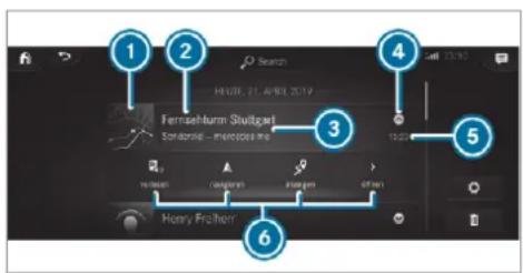
text_image
1 2 Search HEUB 21. AVEL 2019 Fernsehburn Stuttgart Sondering - meripose mo 3 4 5 6 Henry FreiherrA notification shows the following information:
• Symbol or image ① for the application
- Title ②, which contains the name, a telephone number or a navigation destination, for example
• The service and additional information ③
- A time stamp ⑤
- If several actions are available, symbol ④ to open or close the notification.
Depending on the type of notification, up to four different actions ⑥ are available.
Examples of actions include:
- Read aloud
- Placing a call
- Reply
- Calling up a web page
- Navigation
Some notifications, e.g. a navigation destination, are stored longer. Therefore, it is not necessary to carry out available actions directly on the
receipt of the notifications. A route guidance can be started at a later time.
① You can start a global search in the Notifications Centre ( page 406).
Calling up notifications
Opening the Notifications Centre
On the touchpad: swipe down with two fingers.
or
On the touchscreen: tap on the symbol for the Notifications Centre.
or
On the Touch Control and on the touch-pad: mark the symbol for the Notifications Centre by swiping.
▶ Press on the control element.
Selecting a notification
Swipe up or down. Tap or press on the control element.
Calling up old notifications
If notifications have not been called up after four hours, these are stored in the archive.
▶ Swipe upwards and select Archive.
▶ Select the notification.
Closing the Notifications Centre
On the touchpad: swipe up with two fingers.
Selecting actions for a notification
The following options are available:
- Select the action directly in an application after a notification is received and shown.
- Select the action later after calling up in the Notifications Centre.
An action is available: select the action.
Several actions are available: if the notification is not open, select the ☑
Select the action.
The notification is still available.
If Additional information is available, select the action. Additional information is shown in a window or as text, image or text and image.
To close the window: select OK.
Editing notifications
▶ Call up the Notifications Centre ( page 404).
To make settings: select
① If no settings can be made, a message appears.
▶ Select the service.
Switch the options on or off.
The following options are available:
- Allow notifications
• Display in notification centre
• Show notifications
• Acoustic feedback
When Allow notifications is switched on, the other options cannot be selected.
To delete: touch a message on the touchscreen and slide to the left or right.
Select
▶ Select Delete or Delete all.
Delete deletes a single notification.
Delete all deletes all notifications currently shown.
With ☑ you will exit delete mode.
Global search
Global search overview
You can use the global search in the home screen and in the notifications.
The global search provides search results for the following categories:
- Navigation
- Entertainment
- Telephone, social media, In-Car Office
In-Car Office is not available in all countries.
• User interface and Digital Owner's Manual
- Internet
The global search enables you to search for towns, roads and tourist attractions with the navigation system, for example.
The global search makes it possible to enter a 3 word address ( page 439). When you enter a 3 word address, separate each word with an empty space or a full stop.
During the entry process the most likely suggestions are shown beneath the search field. When you enter "S", "Stuttgart", "Steak" and "Sandra" are shown, for example. If you select "Stuttgart", you receive the suggestions "Starbucks", "Steak" and "City railway", for example.
The search results in the list are shown, sorted according to category. Next to the category is the number of results. You will be shown the best results from each category. Additional results can be found after selecting the respective category.
If you confirm an entry with OK, all categories and the number of results will be shown in a summary. After selecting a category you can
select the search results within the category. When you select a search result the detailed view opens. In the detailed view you can choose whether and which actions you want to carry out with the respective search result. For example, you can start route guidance or place a call to somebody. The actions are named correspondingly.
The search can be carried out with the following input methods:
- Entering characters using the on-screen keypad
- Entering characters with handwriting recognition
- Dictation function
Using the global search
Multimedia system:

Select Search.
or
▶ Call up the notifications ( page 404).
Select Search.
Enter the search term into the search field. During the entry process the three most likely suggestions are offered beneath the search field. In the list on the right, the top two search results are shown for each category.
Use the character input function
Alternatively, you can use the □ dictation function for the search.
To accept a suggestion: select the suggestion.
The three most likely suggestions are offered.
Continue the search or accept a suggestion.
To accept the second search result: select the search result.
An action starts or a list is shown.
Select a search result or an action in the list.
To show all categories: select OK.
To show search results for a category: select a category.
To show details: select a search result.
To start an action: select an action. After selection of an action, a track is played back or the route to a destination is calculated, for example.
Switching the sound on/off
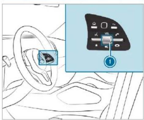
text_image
Diagram showing car interior with steering wheel and dashboard, alongside a close-up of the control panel with Chinese labels.On the multifunction steering wheel

text_image
ed VOLUME 阀 /心On the multimedia system
To mute: press volume control ①. The current audio source is switched off. The symbol appears in the status line of the media display. If you are listening to a radio station, for example, and switch off the sound then all media sources will be muted.
Traffic and navigation announcements can still be heard in this case. Likewise, voice control and telephony are not affected. To switch on: turn volume control or change the media source.
Adjusting the volume
Adjusting with the control knob
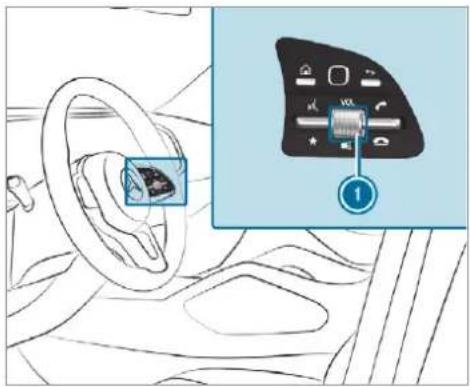
text_image
Diagram showing car interior and dashboard control panel with labeled component 1On the multifunction steering wheel
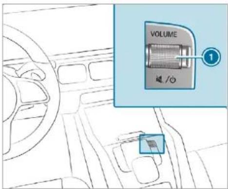
text_image
VOLUME ① 磁 /oOn the multimedia system

Turn volume control ①.
The volume of the current volume group (e.g. entertainment) is set. The volume of other groups can be adjusted separately.
Adjust the volume in the following situations:
• During a traffic announcement
• During a navigation announcement

• During a telephone call
Setting in the menu
Press the button.
Select Settings.
Select System.
Select Audio.
▶ Select a volume setting.
Set the volume.
Entering characters
Using the character input function

WARNING Risk of distraction from information systems and communications equipment
If you operate information and communication equipment integrated in the vehicle when driving, you will be distracted from the traffic situation. This could also cause you to lose control of the vehicle.
Only operate this equipment when the traffic situation permits.
If you cannot be sure of this, stop the vehicle whilst paying attention to road and traffic conditions and operate the equipment with the vehicle stationary.
You must observe the legal requirements for the country in which you are currently driving when operating the multimedia system. Requirements:
- For the handwriting recognition read-aloud function: the multimedia system is equipped with a voice control system.
- The read-aloud function is available for the selected system language.
- The handwriting recognition read-aloud function is activated.
Character entry can be carried out with these control elements:
- Touch Control
- Touchscreen (media display)
- Touchpad
Character input can be started with a control element and resumed with another.
When the keypad is shown, enter the characters on the control element by swiping and pressing or by tapping (touchscreen).
or
Write the characters on the touchpad or the touchscreen.
The touchpad supports character input with the following functions:
- Handwriting recognition offers character suggestions.
- If the read aloud function is activated for handwriting recognition then the entered characters are read aloud.
Examples of character entry:
- Renaming a favourite
- Looking for search results in the global search.
- Entering a destination address in the navigation system
- Entering a web address
Entering characters on the touchpad Requirements:
- If you wish to have the character input read aloud: the read aloud function of the handwriting recognition is switched on (→ page 386).
- An online connection is required for some functions.
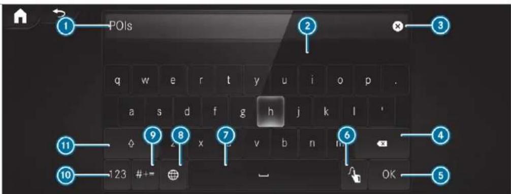
text_image
POIs q w e r t y u i o p . a s d f g h j k l ' ◇ 2 x v b n m 123 #+= - OKUsing the keyboard
① Input line
② Shows suggestions during input (if available)
3 Deletes an entry
4 Deletes
Pressing or pressing briefly deletes the last character entered
Pressing and holding deletes the entry
5 Accepts an entry
6 Switches to handwriting input
⑦ Enters a space
Changes the keyboard language
9 Switches to special characters
10 Switches to digits and additional special characters (if available for the current character set)
ABC Switches to letters (level 2)
10 Pressing or pressing briefly switches between upper-case and lower-case letters (if available for the current character set) Pressing and holding switches to upper-case letters permanently
If available, the ☐ symbol allows you to change to voice input.
When Touchpad tap is switched on ☐, tapping is sufficient to select a character or an option (→ page 386).
Call up the character entry to rename a favourite, for example ( page 403).
Select the character by swiping and pressing. The character is entered in input line ①. Suggestions are shown in ②.
To select a suggestion: select one of the entries.
Resume character input.
To enter an alternative character: press and hold a character.
▶ Select the character.
To end character input: press the ↩ button.
The available editing functions depend on the editing task, the language set and the character level.
Entry using the keyboard can also be completed using the Touch Control.
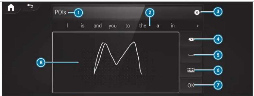
text_image
POIs 1 I is and you to the a in > 2 3 4 5 6 7 8 OKUsing handwriting input
① Input line
② Shows suggestions during input
③ Deletes an entry
4 Deletes
Pressing or pressing briefly deletes the last character entered
Pressing and holding deletes the entry
5 Enters a space
6 Switches to input using the keyboard
⑦ Accepts an entry
B Writes characters on the drawing surface If available, the symbol allows you to change to voice input.
When Touchpad tap is switched on ☐, tapping is sufficient to select an option (→ page 386).
Call up the character entry to rename a favourite, for example ( page 403).
When the keyboard is displayed, select 🔊.
Write the character on the touchpad with a finger.
The character is entered in input line ①. Suggestions are shown in ②.
To select a suggestion: select one of the entries.
Resume character input. The letters can be written next to each other or above each other.
To end character input: press the ↩ button.
Entering characters on the touchscreen Requirements:
- If you wish to have the character input read aloud: the read aloud function of the handwriting recognition is switched on (→ page 386).
- An online connection is required for some functions.
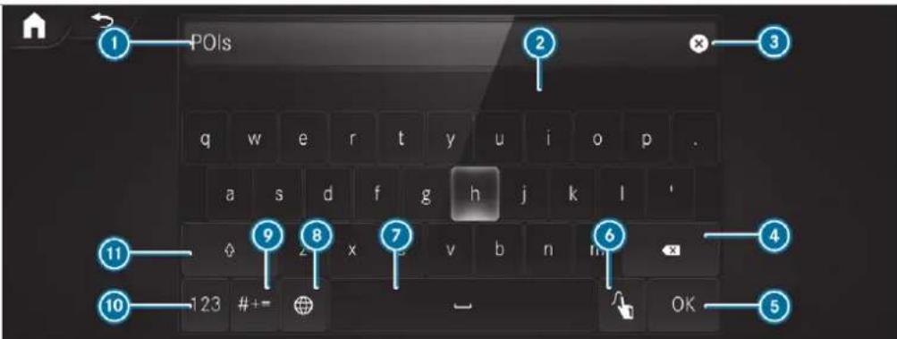
text_image
POIs q w e r t y u i o p . a s d f g h j k l ' Ø 2 x v b n m 123 #+= OKUsing the keyboard
① Input line
② Shows suggestions during input (if available)
③ Deletes an entry
4 Deletes
Pressing briefly deletes the last character entered
Pressing and holding deletes the entry
5 Accepts an entry
6 Switches to handwriting input
⑦ Enters a space
Changes the keyboard language
9 Switches to special characters
10 Switches to digits and additional special characters (if available for the current character set)
ABC Switches to letters (level 2)
Pressing or pressing briefly switches between upper-case and lower-case letters (if available for the current character set) Pressing and holding switches to upper-case letters permanently
If available, the ☐ symbol allows you to change to voice input.
▶ Call up the character entry to rename a favourite, for example ( page 403). The keyboard is shown.
Briefly press on a character.
The character is entered in input line ①.
Suggestions are shown in ②.
To select a suggestion: select one of the entries.
If available, display additional suggestions with < or >.
Resume character input.
To enter an alternative character: press and hold a character.
▶ Select the character.
To end character entry: press briefly on
The available editing functions depend on the editing task, the language set and the character level.
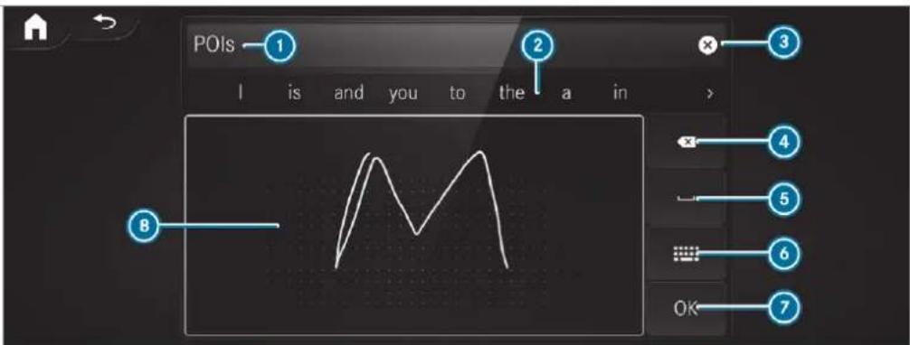
text_image
POIs 1 I is and you to the a in 2 3 4 5 6 7 8Using handwriting input
① Input line
② Shows suggestions during input
3 Deletes an entry
4 Deletes
Pressing briefly deletes the last character entered
Pressing and holding deletes the entry
6 Enters a space
6 Switches to input using the keyboard
⑦ Accepts an entry
B Writes characters on the drawing surface If available, the symbol allows you to change to voice input.
▶ Call up the character entry to rename a favourite, for example (→ page 403).
When the keyboard is displayed, select ↗.
Write the character with one finger on the touchscreen.
The character is entered in input line ①.
Suggestions are shown in ②.
To select a suggestion: select one of the entries.
If available, display additional suggestions with < or >.
Resume character input. The letters can be written next to each other or above each other.
To end character entry: press briefly on
Setting the keyboard for character entry
Multimedia system:
Settings ▶ System ▶ Controls
▶ Keyboards and handwriting
Confirm Select keyboards.
Select the keyboard language in the list.
System settings
Display
Configuring display settings
Multimedia system:
→ Settings ▶ System ▶ Styles & display
Setting the design
Select Styles.
Select Classic, Sport or Progressive.
The multimedia system display changes depending on the style selected. If you revert to the factory settings, the Classic style is set.
To adjust the ambient lighting to a style: select Ambient lighting adjustment. This function adjusts the ambient lighting for the selected display style.
Setting the display brightness
▶ Select Display brightness.
▶ Select a brightness value.
Switching the display surround lighting on/off
▶ Select Illuminate display indirectly. The indirect lighting is switched on or off.
Switching the display off/on
Off: select Display off.
On: press a button, TEL, for example.
Selecting the display design
▶ Select Day/night design.
Select Automatic, Day design or Night design.
Switching the temperature display on/off
▶ Select Temperature display.
Select Outside temp. or Coolant temp.. The selected temperature is displayed in the instrument cluster.
Time and date
Setting the time and date automatically Multimedia system:

▶ Deactivate Manual time adjustment. The time and date are set automatically for the selected time zone and summer time option.
(i) The correct time is required for the following functions:
- Route guidance with time-dependent traffic guidance.
• Calculation of expected time of arrival.
Setting the time zone Requirements:
- For the manual time zone: Automatic time zone is switched off.
Multimedia system:

Setting the time zone manually
Select Time zone:. The list of countries is displayed.
If there are several time zones available in a country, these will be shown after the country is selected.
Select a country and, if required, a time zone. The time zone set is displayed after Time zone:.
Setting the time zone automatically
▶ Activate Automatic time zone.
Setting the time and date format Multimedia system:

Set the date and time format ●.
Setting the time and date manually Requirements:
- The Manual time adjustment function is switched on.
- For setting the date manually: no GPS is installed in the vehicle.
Multimedia system:

Setting the time (without time zone)
▶ Select Set time.
Set a time.
Setting the time (with time zone)
▶ Select Set time.
If a time zone is set the time is set automatically. At least one seat belt is fastened on the rear using the time zone. The time can be adjusted by bench seat.
a maximum of plus or minus 60 minutes.
Adjust the time using the slide control.
Setting the date
▶ Select Set date.
Set a date.
In vehicles with GPS, a date cannot be set even with active manual time adjustments. The date is then set automatically through the selected time zone.
Switching voice amplification to the rear on/off (vehicles with long wheelbase)
Requirements:
- Your vehicle is equipped with the Burmester ^® surround sound system or the Burmester ^® high-end 3D surround sound system.
• The ignition is switched on. - Doors, side windows and the panorama sliding sunroof are closed.
Multimedia system:
→ Settings ▶ System ▶ Audio
Voice amplification
The function supports communication between the driver and front passenger with passengers in the rear compartment. When voice amplification to rear is activated, the signals picked up by the microphone are amplified and played back over the speakers in the rear compartment, depending upon vehicle noise levels. An automatic adjustment occurs based on speaker volume and ambient noise in order to improve speech intelligibility and maintain the naturalness of speech.
▶ Activate or deactivate the function.
Setting the intensity of the voice amplification
▶ Select Voice amplification - intensity.
Set the intensity on the control. Depending on the intensity set, the voice amplification to the rear is increased or reduced.
Connectivity
Switching transmission of the vehicle position on/off
Requirements:
• A Mercedes me account is available.
- At least one service is activated in the Mercedes me portal which has access to th transmitted position data.
The function is country-dependent. For more information, consult a Mercedes-Benz service centre.
Multimedia system:
→ Settings → System Wi-Fi & Bluetooth
▶ Select Transmit vehicle position.
▶ Activate or deactivate the function.
Bluetooth®
Information about Bluetooth®
Bluetooth ^® technology is a standard for short-range wireless data transfer up to approximately 10 m.
You can use Bluetooth to connect your mobile phone to the multimedia system and use the following functions, for example:
- Hands-free system with access to the following options:
- contacts ( page 489)
- call lists (→ page 493)
- text message (→ page 494)
• Internet connection (→ page 517) - Listening to music via Bluetooth® audio (→ page 531)
- Transferring business cards (vCards) into the vehicle
Bluetooth ^® is a registered trademark of Bluetooth Special Interest Group (SIG) Inc.
i Internet connection via Bluetooth is not available in all countries.
Activating/deactivating Bluetooth®
Multimedia system:
→ ▶ Settings ▶ System
Wi-Fi & Bluetooth
Switch Bluetooth on or off.
Wi-Fi
Wi-Fi connection overview
You can use Wi-Fi to establish a connection with a Wi-Fi network and to access the Internet or other network devices.
The following connection options are available:
- Wi-Fi connection
The Wi-Fi connection to a Wi-Fi-capable device, e.g. a mobile phone or a tablet PC established. - Multimedia system as a Wi-Fi hotspot Using this function, a tablet PC or notebook can be connected, for example. The connected device can use the data tariff of the vehi-
cle. A maximum of three devices can be connected with the hotspot at the same time.
The use of the vehicle data tariff by external devices is not available in all countries.
To establish a connection, you can use the following methods:
- WPS PIN
The connection to a secure Wi-Fi network is made via a PIN. - WPS PBC
The connection to a secure Wi-Fi network is made by pressing a button (push button). - Security key
The connection to a secure Wi-Fi network is made via a security key.
Setting up Wi-Fi
Requirements:
- To set up the Wi-Fi connection of the multimedia system with new devices: there is no communication module installed.
- The device to be connected supports one of the three means of connection described.
Multimedia system:
→ Settings ▶ System
Wi-Fi & Bluetooth
Activating/deactivating Wi-Fi
Select Wi-Fi.
If Wi-Fi is switched on, you can connect the multimedia system with external hotspots. If Wi-Fi is deactivated, communication via Wi-Fi to all devices is interrupted. This also means that a connection to the communication module cannot be established. Then some functions such as dynamic route guidance with Live Traffic Information are not available.
Connecting the multimedia system with a new device via Wi-Fi
This function is available if a communication module is not installed.
The type of connection established must be selected on the multimedia system and on the device to be connected.
① The connection procedure may differ depending on the device. Follow the instruc-
tions that are shown in the display. Further information (see the manufacturer's operating instructions).
▶ Select Internet settings.
▶ Select Connect via Wi-Fi.
▶ Select Add hotspot.
Connecting using a security key
Select the options ▶ of the desired Wi-Fi network.
▶ Select Connect using security key.
Have the security key displayed on the device to be connected (see the manufacturer's operating instructions).
Enter this security key on the multimedia system.
Confirm the entry with ok.
i All devices support a security key as a means of connection.
Connecting using a WPS PIN
Select the options ▶ of the desired Wi-Fi network.
Select Connect using WPS PIN input. The multimedia system generates an eight-digit PIN.
Enter this PIN on the device to be connected.
Confirm the entry.
Connecting using a button
Select the options ▶ of the desired Wi-Fi network.
▶ Select Connect via WPS PBC.
Select "Connect via WPS PBC" in the option on the device to be connected (see the manufacturer's operating instructions).
Press the WPS button on the device to be connected.
▶ Select Continue in the multimedia system.
Activating automatic connection
▶ Select Connect via Wi-Fi.
Select the options ▶ of the desired Wi-Fi network.
▶ Activate Permanent Internet connection.
Connecting with a known Wi-Fi
▶ Select Connect via Wi-Fi.
Select a Wi-Fi network.
The connection is established again.
Setting up a Wi-Fi hotspot
Multimedia system:
Settings ▶ System
Wi-Fi & Bluetooth
Configuring the multimedia system as a Wi-Fi hotspot
The type of connection established depends on the device to be connected. The function must be supported by the multimedia system and by the device to be connected. The type of connection established must be selected on the multimedia system and on the device to be connected.
▶ Select Vehicle hotspot.
▶ Select Connect device to vehicle hotspot.
Connecting using WPS PIN generation
▶ Select Connect using WPS PIN generation.
Enter the PIN shown in the media display on the device to be connected and confirm.
Connecting using WPS PIN entry
▶ Select Connect using WPS PIN input.
Enter the PIN that is shown on the external device's display on the multimedia system.
Connecting using a button
▶ Select Connect via WPS PBC.
Press the push button on the device to be connected (see the manufacturer's operating instructions).
▶ Select Continue.
Connecting using a security key
Select Connect device to vehicle hotspot. A security key is displayed.
Select the vehicle from the device to be connected. The vehicle is displayed with the MB Hotspot XXXXX network name.
Enter the security key which is shown in the media display on the device to be connected.
Confirm the entry.
Connecting using NFC
▶ Select Connect via NFC.
Activate NFC on the mobile device (see the manufacturer's operating instructions).
Bring the mobile device into the NFC area of the vehicle ( page 482).
Select Finished.
The mobile device is now connected to the multimedia system hotspot via NFC.
Generating a new security key
▶ Select Vehicle hotspot.
▶ Select Generate security key.
A connection will be established with the newly created security key.
To save a security key: select Save. When a new security key is saved, all existing Wi-Fi connections are then disconnected. If the Wi-Fi connections are being re-established, the new security key must be entered.
Managing MBUX Touch devices
Requirements:
- The MBUX Touch app is installed on the external device (e.g. tablet or smartphone).
- Wi-Fi is activated ( page 418) and the multimedia system is configured as a Wi-Fi hotspot ( page 420).
Multimedia system:

Connecting and authorising a new device
▶ Select Authorise a new device.
▶ Select Add new device to the list.
Enter the security key in the external device. The Please start MBUX Touch on your device and follow the instructions. message appears.
Select Continue.
The connection request from the device Accept.
Enter the PIN shown on the external device. The device is authorised.
Authorising a connected device
▶ Select Authorise a new device.
Continue using connected devices The Please start MBUX Touch on your and follow the instructions. message appears.
Select Continue.
The connection request from the device Accept.
Enter the PIN shown on the external device. The device is authorised.
De-authorising the device
Select DEAUTHORISE DEVICE.
Select an authorised device from the list. A prompt will appear asking whether you would like to de-authorise the selected device.
Select Continue.
▶ Select Yes.
The device is de-authorised.
The function is only available for Mercedes-Maybach vehicles.
Switching rear displays and the child safety lock for the Rear Seat Entertainment System on/off
Multimedia system:

Switching rear displays on/off
▶ Select Rear left or Rear right.
▶ Select Display on.
The rear display is switched on or off.
Locking rear displays (child safety lock)
▶ Select Rear left or Rear right.
Select Lock.
The rear display remains switched on and is locked. It cannot be operated.
Locking the MBUX rear tablet
▶ Select MBUX rear tablet.
Select Lock.
The MBUX rear tablet is locked or unlocked.
Locking an external device
This function is only available for Mercedes-Maybach vehicles.
▶ Select an external device.
Select Lock.
The device connected via the MBUX Remote Control app is locked or unlocked.
System language
Notes on the system language
This function allows you to determine the language for the menu displays and the navigation announcements. The selected language affects the characters available for entry. The navigation announcements are not available in all languages. If a language is not available, the nation announcements will be in English.
Setting the system language
Multimedia system:
Settings ▶ System
Language
Set the language.
If you are using Arabic map data, the text information can also be shown in Arabic on the navigation map. To do so, select العربية as the language from the language list. Navigation announcements are then also made in Arabic.
Setting the distance unit
Multimedia system:
→ Settings ▶ System ▶ Units
▶ Select km or mi.
In the multifunction display of the Instrument Display, switch the Additional speedometer display on.
Data import and export
Data import/export function
The following functions are possible:
- Transferring data from one system or vehicle to another system or vehicle.
-
Creating a backup copy of your personal data and loading it again.
-
Protecting your personal data against unwanted export with PIN protection.
Please note that the NTFS file system is not supported. The FAT32 file system is recommended.
Importing/exporting data
NOTE Loss of data due to premature removal
Do not remove the data storage medium when data is being exported.
Mercedes-Benz is not liable for any loss of data.
Requirements:
• The vehicle is stationary.
• The ignition is switched on.
• A USB device is connected.
Multimedia system:
Settings System
System backup
▶ Select Import data or Export data.
Importing
- Select a data storage medium. A prompt appears asking whether you really wish to overwrite the current data. If data originates from another vehicle, this is recognised during data reading. - Confirm the prompt.
The files are imported. The multimedia system is restarted once the data has been imported.
(i) Current vehicle settings can be edited after the import.
Exporting
If PIN protection is activated, your PIN is requested.
Enter the four-digit PIN.
Select a data storage medium.
A prompt appears asking whether you really wish to carry out the export.
Confirm the prompt.
The data is exported. The data export may take several minutes.
After successful export, the data is saved in the "MyMercedesBackup" directory which can be found on the storage medium.
Activating/deactivating PIN protection
Requirements:
- To unlock the PIN: there is an Internet connection.
• A Mercedes me account exists at https://me.secure.mercedes-benz.com. - An individual user profile is active (→ page 397).
Multimedia system:
Settings System
PIN protection
Setting the PIN
Select Set PIN.
Enter a four-digit PIN.
Enter the four-digit PIN again. If both PINs match, PIN protection is active.
Changing the PIN
▶ Select Change settings.
Enter the current PIN.
▶ Select Change PIN.
Set a new PIN.
Activating PIN protection for data export
Select Protect data export. Activate or deactivate the function.
Unblocking the PIN via the Mercedes me portal
If the PIN has been entered incorrectly three times, the PIN will be blocked. You can have a
single-use password sent to you via the Mercedes me connect online portal to reset the PIN protection.
▶ Select Unblock PIN.
Enter the single-use password.
PIN protection is reset, and you can set a new PIN.
Software update
Information on software updates
A software update consists of three steps:
- Downloading or copying of the data required for installation
• Installation of the update - Activation of the update by restarting the system
The multimedia system provides a message when an update is available.
Depending on the source, you can perform various updates:
Software updates
| Source of the update | Update type |
| Internet | N avigat tem updates, Digital Owner's Manual |
| External storage medium, e.g. USB flash drive | Navigation maps |
i Installation can take several minutes and cancellation is not possible. If you do not install the software updates then the status of your vehicle will not be up-to-date. During the installation, individual functions or control elements are not available or only available to a limited degree.
Advantages of updating software
Software updates ensure your vehicle's technology is up-to-date.
In order to improve the quality of our services you will receive future updates for your multimedia system, the Mercedes me connect services
and your vehicle's communication module. These will conveniently be sent to you via the mobile phone connection in your vehicle and, in many cases, installed automatically. You can monitor the status of your updates at any time on the Mercedes me portal and find information about potential innovations.
Your advantages at a glance:
- conveniently receive software updates via the mobile phone network
- improves the quality and availability of Mercedes me connect services
- keeps your multimedia system and communication module up-to-date
Further information about software updates can be found at https://me.mercedes-benz.com
Performing a software update Requirements:
- For online updates: an Internet connection is established ( page 517).
- For automatic online updates: your vehicle has a permanently installed communication module.
Multimedia system:
→ ▶ Settings ▶ System
Software update
Automatically
Activate Automatic online updates. The updates will be downloaded and installed automatically. The current status of the updates is displayed.
Manually
▶ Deactivate Automatic online updates.
Select an update from the list and start the update.
Activating the software update
▶ Restart the system. The modifications from the software update will be active.
Function of important system updates
Important system updates may be necessary for the security of your multimedia system's data.
Install these updates, or else the security of your multimedia system cannot be ensured.
If automatic software updates are activated, If the download of a deep system update is cc the system updates will be downloaded autopleted and the update is ready for installation, matically (→ page 424). you will be informed of this after the next igni-
As soon as an update is available for download, and corresponding message appears on the media display.
You have the following selection options:
- Accept and install
The update will be downloaded in the back-ground.
• Information
Information about the pending system update is displayed. - Later
The update can be downloaded manually at later time ( page 424).
Deep system updates
Deep system updates access vehicle or system settings and can therefore only be carried out
when the vehicle is stationary and the ignition is switched off.
If the download of a deep system update is completed and the update is ready for installation, you will be informed of this after the next ignition cycle, for example.
Park the vehicle safely in a suitable location before starting the installation.
Requirements for the installation:
• The ignition is switched off.
- Notes and warnings have been read and accepted.
• The electric parking brake is applied.
If all requirements are met, the update will be installed. The multimedia system cannot be operated while the update is being installed and vehicle functions are restricted.
If errors should occur during the installation, the multimedia system automatically attempts to restore the previous version. If restoration of the previous version is not possible, a symbol appears on the media display. Please consult a
qualified specialist workshop to resolve the problem.
Resetting the multimedia system (reset function)
Multimedia system:
Personal data is deleted, for example:
- Station presets
• Connected mobile phones
• individual user profiles
The guest profile is reset when the settings are restored to the factory settings.
A prompt appears again asking whether you really wish to reset.
Select Yes.
The multimedia system is reset to the factory settings. If you have set a PIN for your system, this will also be reset.
Fit & Healthy
Setting ENERGIZING seat kinetics
Requirements:
• These functions are available only for fully electric seats with a memory function.
Multimedia system:
→ Comfort ▶ Seat comfort
▶ Select Seat kinetics.
ENERGIZING seat kinetics can support back health by changing the seat position during a journey. The muscles and joints are repeatedly stressed and relieved by means of minor movements of the cushion and backrest.
Starting seat kinetics
Select ▶.
The program will run for the set duration.
Configuring seat kinetics
Select
Depending on the setting, the seat backrest, the seat cushion or both seat components may be involved in the function.
▶ Select the desired setting.
Vehicles with a multicontour seat:
In addition to the seat backrest and seat cushion, the lumbar region can be activated for the function.
▶ Switch Including lumbar on or off.
Setting the duration
Select
The following running times are available:
• Short journey (16 minutes)
• Medium-dist. journey (32 minutes)
• Long-distance journey (96 minutes)
▶ Select a running time.
The selected programme will start.
ENERGIZING COMFORT
Overview of the ENERGIZING COMFORT programme
Programme overview:
| Programme Function | |
| Refresh | Can make targeted changes to the interior climate to refresh vehicle occupants. Cooling airflow and ionisation purify the air. The vehicle interior is illuminated with cool colours and the seats are ventilated. |
| Warmth | Can increase the comfort level of the vehicle occupants. The vehicle's panel, seat and steering wheel heating produce a cosy warmth. The air is purified using ionisation and a pleasant fragrance is released. The vehicle interior is illuminated with warm lighting. |
| Vitality | Can counteract diminishing attentiveness in monotonous driving situations. Fast-paced music and a vitalising massage provide invigorating stimulation for the vehicle occupants. The air is purified using ionisation and a pleasant fragrance is released. The vehicle interior is illuminated in a stimulating hue and the seat is ventilated. |
| Pleasure | Can promote a positive mood in the vehicle occupants as well as mental and physical regeneration. Moderately fast music is played and a massage programme is activated. The air is purified using ionisation and a pleasant fragrance is released. The vehicle interior is illuminated with amicable lighting. |
| Well being | Can aid the physical and mental relaxation of vehicle occupants. A back massage combined with local warmth provide relaxation. The air is purified using ionisation and a pleasant fragrance is released. The audio player plays selections of calming music and the vehicle interior is illuminated with pleasant lighting. |
| Training | Can counteract the onset of muscle tension, limbs falling asleep or stress with targeted relaxation or stimulation exercises. The exercises are demonstrated in short videos. The air is purified using ionisation and a pleasant fragrance is released. The vehicle interior is illuminated with lighting appropriate to the exercise. The training consists of audio content and a brief animation. The audio content is conceived so that it can also be played back when you are driving. The animation is only shown when the vehicle is driving slower than 5 km/h. The animation is hidden at higher speeds. Always observe the traffic conditions if you are training when driving. |
| Tips | The system gives tips for possible exercises or measures for improving the comfort level of the vehicle occupants. Playback is purely aural. By selecting the desired area of the body you can receive targeted tips for the comfort level of this area. |
Programmes for the Rear Seat Entertainment System
| Power Nap | The programme consists of three phases:Sleep onset phaseRelaxing music is played in this phase, and the warmed seats provide a subtle massage.Sleep phaseThe active functions are deactivated or restricted as much as possible.Waking phaseIn this phase, slightly stimulating music is played, and the air is purified with ionisation and scented. The seat is ventilated. The vehicle interior is illuminated with stimulating light. |
i Please note that the available programmes and the associated functions depend on your vehicle equipment. Depending on your equipment, fewer functions may be available.
Starting the ENERGIZING COMFORT programme
WARNING Increased risk of an accident when using the ENERGIZING COMFORT programme Tips and Training
If you use the ENERGIZING COMFORT programme Tips and Training when you are driving, you could be distracted from the traffic situation.
Only carry out exercises when the traffic circumstances permit.
Make sure that you are always aware of the traffic situation around you when listening to the tips.
Requirements:
• The ignition is switched on.
Multimedia system:
Comfort ➤ ENERGIZING COMFORT
Starting the ENERGIZING programme
Select a programme.
Select Start.
The selected programme will run for ten minutes.
The Power Nap programme is only available for the rear seats.
If, during an active programme, a function requirement is no longer met, a corresponding message appears. The active programme is cancelled.
Selecting the seat for the ENERGIZING programmes
▶ Select a programme.
Select Seats.
Select the desired seat.
When the ENERGIZING programme starts, it starts for the selected seat.
Configuring ENERGIZING programmes
Select a programme.
Select
▶ Switch the functions included in the programme on or off.
Setting the time for the Power Nap (rear seats only)
▶ Calling up Power Nap.
Select
▶ Select the desired duration.
Starting the training programme
Select Training.
The following training programmes are available:
- Muscle stimul.
- Muscle relax.
Balance
Select a programme.
The programme starts.
To activate fragrancing for training: select Air freshener.
The animation for demonstration of the exercises is only shown when the vehicle is stationary or when you are driving slower than 5 km/h. At higher speeds the picture is hidden and you will only be able to hear the instructions.
Starting tips
Select Tips.
The following categories are available:
- Upper body
- Lower back
- Head
- Shoulders
- Pelvis
Select the desired area of the body ▶. Playback of the tip for this area of the body starts.
Select ■ to stop playback of the tip.
① You receive a tip for each option. To listen to the next tip, again select a desired category.
ENERGIZING COACH
Function of the ENERGIZING COACH
Requirements:
- The ENERGIZING COACH (ENERGIZING COACH) service is activated in the Mercedes me portal or the Mercedes me app.
With ENERGIZING COACH you can evaluate the driving and driver situation. Depending on the situation, it offers recommendations for the start of an appropriate ENERGIZING COMFORT programme.
The following programs could be suggested:
- Vitality
As an activating program in monotonous driving situations or for long journey times, for example.
Information on the vitality program see ( page 427).
- Joy
As a balancing program in demanding driving situations.
Information on the pleasure program see ( page 427).
By connecting a GARMIN fitness tracker, for example the GARMIN vivosmæt3, additional information can be entered into the evaluation for the recommendation of an ENERGIZING comfort program. The additional information includes the stress level, that is calculated by the fitness tracker. The stress level is based primarily on the pulse.
Requirements for the integration of additional information via a GARMIN fitness tracker:
- Your fitness tracker is connected with your GARMIN account.
iv• Your GARMIN account is connected with your Mercedes me account.
If you wear your GARMIN fitness tracker at night also, the sleep data is included in the evaluation of the ENERGIZING COACH.
Requirement for the integration of the sleep data:
- The GARMIN fitness tracker is synchronised with the GARMIN account before the beginning of the journey.
If ATTENTION ASSIST determines an excessive lack of attention, ENERGIZING COACH makes no further suggestions. Further information about ATTENTION ASSIST ( page 327).
Calling up the ENERGIZING COACH display Multimedia system:
→ ▶ Comfort
Select ENERGIZING COACH. Your current pulse as well as an evaluation of your pulse for the last 30 minutes driving time are shown. A corresponding error message is shown if there is no mobile phone connected or no pulse can be sent to the system for an extended period.
① Only pulse values in the range of 30-140 bpm are shown on the media display. The navigation menu is hidden if route guidance is active.
The pulse values have no medical validity but are only informative in nature and are there fore also not required to be accurate.
In the event of an error message make sure that the following requirements are fulfilled:
- The fitness tracker is connected with your GARMIN account.
- Your GARMIN account is connected with your Mercedes me account on your mobile phone.
- The mobile phone is connected as the main phone to the multimedia system ( page 480).
The navigation menu is hidden if route guidance is active.
If route guidance is not active the map appears.
The navigation menu is shown.
The navigation menu is hidden if route guidance is active.
To show: tap on the touchscreen.
or
- Press the Touch Control or the touchpad.
- To hide: the navigation menu is hidden automatically.
Showing/hiding the navigation menu
Navigation
Navigation
Switching navigation on
Multimedia system:
Navigation (Navigation)
Alternatively: press the NAVI MAF button. The map appears. The current vehicle position is shown. The navigation menu is shown.
Navigation overview
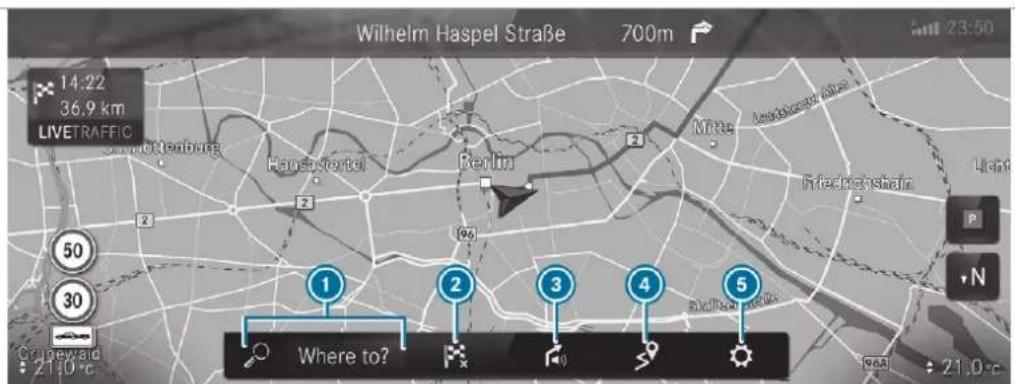
text_image
Wilhelm Haspel Straße 700m 14:22 36.9 km LIVETRAFFIC Hansfortel Berlin Möhe Anschweck Alser Friedrichshain Licht P N 50 30 Cinewaid Where to? 2110°C RGA 21,0°CExample: digital map with navigation menu
To enter a POI or address and additional destination entry options
To interrupt route guidance (if route guidance is active)
3 To repeat a navigation announcement and switch navigation announcements on or off
To call up the ON ROUTE menu
• To show Route overview
• To select Alternative routes
• Report traffic incident (Car-to-X)
• To call up the TRAFFIC menu
◇ To show Traffic announcements
◇ To show Area announcements
◇ To show Live Traffic Subscription Info
-
To show Route list
• To call up the POSITION menu
◇ Store position
◇ To show Compass
◇ To show Qibla (available in selected countries)
⑤ Quick-access and settings -
To show Traffic
- To show Parking
• To show Motorway information - Via Advanced options to use View, Announcements and Route
i The options are not available in all countries.
You can enter 3 word addresses in the online search ( page 439). This option is not available in all countries.
Destination entry
Notes on destination entry
A WARNING Risk of distraction from operating integrated communication equipment while the vehicle is in motion
If you operate communication equipment integrated in the vehicle when driving, you will be distracted from the traffic situation. This could also cause you to lose control of the vehicle.
Only operate this equipment when the traffic situation permits.
If you cannot be sure of this, stop the vehicle whilst paying attention to road and traffic conditions and operate the equipment with the vehicle stationary.
You must observe the legal requirements for the country in which you are currently driving when operating the multimedia system.
Entering a POI or address
A WARNING Risk of distraction from information systems and communications equipment
If you operate information and communication equipment integrated in the vehicle when driving, you will be distracted from the traffic situation. This could also cause you to lose control of the vehicle.
Only operate this equipment when the traffic situation permits.
If you cannot be sure of this, stop the vehicle whilst paying attention to road and traffic conditions and operate the equipment with the vehicle stationary.
You must observe the legal requirements for the country in which you are currently driving when operating the multimedia system.
Requirements:
- For the online search: Mercedes me connect is available.
- You have set up a user account in the Mercedes me portal.
- The vehicle has been activated for use of Mercedes me connect and you have accepted the terms and conditions for the service.
Further information can be found at: https://www.mercedes.me
• The service has been activated.
Multimedia system:
→ ▶ Navigation ▶ Where to?
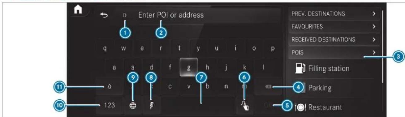
text_image
Enter POI or address PREV. DESTINATIONS > FAVOURITES > RECEIVED DESTINATIONS > POIS > Filling station Parking RestaurantOn-board search with the keypad Destination entry uses the on-board search of the database stored in the multimedia system. The country in which the vehicle is located is set

Enter the POI or the address using the keyboard (in the image) or using handwriting
recognition ⑥ in input line ②. The entries can be made in any order. During destination entry, suggestions are offered in ③ by the multimedia system. Destination selection takes place in list ③ or with ⑤ OK.
The following entries can be made, for example:
• City, street, house number
- Street, town
- Postcode
- POI name
• POI categories, e.g. Filling station
- Town, POI name
- Telephone number, if this is available for the POI
- Contact name
Example of quick address entry:
- If you are searching for Königsstraße in Stuttgart, for example, you can enter STUT and KÖN.
- If you are searching for a POI in the United Kingdom, for example, you can enter THE SHARD.
If you would like to try out both examples, you may also need to change the country.
Alternatively, use voice input Ⓗ.
To switch to handwriting recognition: select 6.
Write the character on the touchpad. The letters can be written next to each other or above each other ( page 409).
To return to entry using the keyboard: select ☐.
or
Press the touchpad.
To delete an entry: select ④. The characters are deleted individually.
or
If characters have been entered in ②, select ☒ next to the input line. The complete entry is deleted.
To switch to upper-case or lower-case letters: select 11.
To switch to digits, special characters and symbols: select 10. 123 changes to ABC.
Display ⑪ changes to #+=.
Select 11 and switch to additional special characters.
To enter a space: select ⑦.
To set the language: select ⑨.
▶ Select the language.
① This function is useful for countries in which several character sets are supported. An
example is Russia, which uses Cyrillic and Latin characters.
To change the country: select country indicator ①.
Enter the country indicator, e.g. F for France. The list is filtered.
Select the country on list ③. The destination can be entered.
To accept a destination: select the destination in list 3.
If the destination is ambiguous, select the destination in the list.
The destination address is shown. The route can be calculated.
Using online search
(i) Requirements: the media display shows an Internet connection with a double-arrow symbol in the status line.
Online search is not available in all countries.
Destination entry uses online map services. If the on-board search finds no suitable destinations or if you change countries, the online search is available.
For the destination you can enter an address, a POI or a 3 word address.
i Enter a 3 word address ( page 439).
Select country indicator ①
Select the provider for the online service from the countries list.
or
If the on-board search delivers no results, enter the destination in the input line. The entry order is not relevant, e.g. street and town. Use the functions described for the on-board search.
The search results are displayed.
▶ Select the destination in the list. The detailed view for the route is displayed.
Selecting previous destinations Requirements:
• Previous destinations are stored.
- For destination suggestions: you have created a profile (→ page 396).
- The Allow destination suggestions option is switched on (→ page 401).
- The multimedia system has already gathered sufficient data in order to show destination suggestions.
Multimedia system:
→ ↗ Navigation ↗ 📋 Where to? ▶ PREV. DESTINATIONS
The following entries can be selected in the previous destinations:
- Destination suggestions (→ page 457)
- Destinations
- Routes
Select the destination or route The destination address is shown. The route can be calculated.
① You can save a previous destination or a destination suggestion as a favourite (→ page 457).
You have fast access to the destinations via the favourites ( page 441).
Selecting a POI Requirements:
- For use of personal POIs: a USB device is connected with the multimedia system.
- Personal POIs with the GPS Exchange format (.gpx) have been saved in the "PersonalPOI" folder on the USB device.
Multimedia system:
→ ➕ Navigation ➕ Where to? POIS
Searching using categories (no route guidance)
Select the category.
or
▶ Select All categories.
Select the category and the sub-category (if available).
The search takes place in the vicinity of the vehicle's current position. The search result are sorted by distance in ascending order.
The POIs show the following information:
• direction of the linear distance to the POI (arrow)
- name of POI
- linear distance to the POI
To filter according to categories or in search results: enter a search entry in the Search text field.
Select a POI from the list. The destination address is shown. The route can be calculated.
Searching using categories (route guidance active)
▶ Select the category.
or
▶ Select All categories.
Select the category and the sub-category (if or available).
To filter according to categories or in search results: enter a search entry in the Search text field.
Select the search positions In the vicinity, Near destination or Along the route.
If there are intermediate destinations for the route and Near destination has been selected, select the search position in the route overview.
Select a POI from the list. The destination address is shown. The route can be calculated.
Searching for personal POIs
▶ Select Personal POIs.
Select a category.
If route guidance is active, select a search position In the vicinity, Near destination or Along the route.
Select a personal POI.
The destination address is shown. The route can be calculated.
Enter a search entry into the search field and filter the list.
▶ Select a personal POI.
Editing personal POI categories
Select a personal POI category from the list A menu opens.
To change a name: select Change name.
Enter the name.
Select OK.
To change a symbol: select Change icon.
Select a symbol.
To delete a personal POI category: select Delete.
Select Yes.
You can configure the categories for quick-access.
If you calculate the route, for example, the first three of these categories can be selected as symbols.
Select All categories.
Select the category and the sub-category (if available).
Select ☆ or ★.
☆ adds the category.
★ removes the category.
If all available quick-access positions are full, select the category to be replaced.
Configuring categories for quick-access
Selecting a contact for destination entry Requirements:
- A mobile phone is connected to the multimedia system (→ page 480).
Multimedia system:

Using the contact list
▶ Select a contact. The contact details are displayed. ▶ Select the address.
Using search entry
Enter a name or telephone number, for example, into the search field. Select OK. Select the contact. Select the address. The destination address is shown. The row can be calculated.
(i) Route guidance to a contact address is reliable in the following cases:
- the contact address is complete. - the contact data matches the map data in the digital map.
Entering geo-coordinates Multimedia system:

- Select Latitude or Longitude. - Select geo-coordinates as latitude and longitude coordinates in degrees, minutes and seconds. To do this swipe up or down respectively. The map shows the position. - Confirm the entry with OK. - To set the destination: select ▲ or 🔒. - Calculate the route (→ page 442).
Entering the destination as a 3 word address Requirements:
- Searching for a destination using 3 word addresses is possible in the online search (→ page 434). - The media display shows an Internet connection with a double-arrow symbol in the status line.
Multimedia system:

i Searching for a destination using 3 word addresses is not possible in all countries are in all languages. ▶ Select the country indicator. ▶ Select the provider for the online service from the countries list.
or
If the on-board search delivers no search results, enter the destination address as a 3 word address. Separate each of the words with a full stop. The search results are displayed. Select the destination in the list. The destination address is shown. The route can be calculated.

WHAT3 WORDS
3 word addresses from what3words are an alternative addressing system for multilingual georeferencing of global locations with a resolution of three metres. Using this grid, locations on the Earth's surface are included which do not have a building address such as street and house number, for example.
The Brandenburg Gate has this language dependent 3 word address:
3 word addresses are unique, easy to remember and suffice for most routine applications.
You can convert addresses to 3 word addresses and back again:
• At the website http://what3words.com
• In the what3words apps
Selecting a destination on the map
Multimedia system:


Navigation
▶ Move the map ( page 465).
Using the touchscreen: press and hold on the touchscreen.
The destination address is shown. If several destinations are located at the selected position, a list shows the available roads and POIs.
Select the destination in the list. The destination address is shown. The route can be calculated.
Using the touchpad: when the crosshair marks the destination, press and hold on the control element.
The destination address is shown.
If several destinations are located around the crosshair, a list shows the available roads and POIs.
▶ Select the destination in the list.
The destination address is shown. The route can be calculated.
Showing POIs in the vicinity of the map
If several destinations are located around the crosshair, the function is available.
Select ....
▶ Select POIs in the vicinity. The map appears.
Swipe left or right on the control element. The previous or next POI is highlighted on the map. The name or the address is shown.
Select the POI symbol.
or
To filter the display according to the POI category: scroll on the control element.
Select the POI category.
Selecting a destination from favourites Requirements:
- Destinations are saved as favourites. Save a previous destination or a destination suggestion as a favourite ( page 457).
Multimedia system:
→ ➤ Navigation ➤ Where to?
▶ FAVOURITES
Select a favourite.
The destination address is shown. The route can be calculated.
The following options are available in the favourites menu:
• Saving addresses for home and work
- Creating favourites
- Deleting favourites
If no address has been saved for home and work: select Home or Work.
- Confirm the prompt with Yes. - Enter the favourite as a POI or address (→ page 434). - To save a favourite: select Add favourites. - Enter the favourite as a POI or address (→ page 434).
or
If all the positions in the favourites are full, first select a favourite which is to be overwritten ( page 402).
▶ Follow the instructions provided.
To delete a favourite: select ▼ for a destination.
Select Delete.
or
Press on a favourite until the OPTIONS menu is shown.
Select Delete.
Selecting received destinations Requirements:
• There is an Internet connection.
• A destination has been sent to the vehicle.
Multimedia system:
→ ➤ Navigation ➤ ➤ Where to? ▶ RECEIVED DESTINAT.
The vehicle can receive destinations from services or apps.
▶ Select a destination.
The destination address is shown. The route can be calculated.
(i) You can save a received destination in the favourites (→ page 457).
You have fast access to the destinations via the favourites ( page 441).
Deleting a received destination
To delete a destination: select ▼ for a destination.
Select Delete.
Select Yes.
To delete all destinations: select ⋯.
Select Delete all.
Select Yes.
Route
Calculating a route Requirements:
• The destination has been entered.
• The destination address is shown.
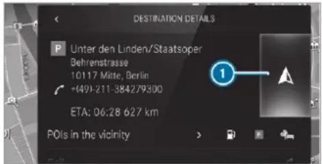
text_image
DESTINATION DETAILS P Unter den Linden/Staatsoper Behrenstrasse 10117 Mitte, Berlin +(49)-211-384279300 ETA: 06:28 627 km POIs in the vicinity

No route yet A route has been mapped

Select ▲. The route to the destination is calculated. The map shows the route. Route guidance then begins.
or
Select ☐.
If a route is already mapped, a prompt is shown.
▶ Select Set as intermediate dest..
The selected destination address is set as the next intermediate destination. Route guidance begins.
If there are already four intermediate destinations, the multimedia system asks whether intermediate destination 4 should be deleted. Confirm the prompt with Yes.
or
▶ Select Start new route guidance. The selected destination address is set as new destination. The previous destination and the intermediate destinations are deleted. Route guidance to the new destination begins.
Searching for POIs in the vicinity of the destination shown
The POI symbols to the right of POIs in the vicinity show the first three categories for quick-access. You can configure these categories ( page 437).
Select a POI symbol.
The search results are displayed.
Select a POI.
The destination address is shown. The route can be calculated.
or
▶ Select POIs in the vicinity ▶.
Search using categories, enter a search entry or search for a personal POI ( page 437).
Select a POI.
The destination address is shown. The route can be calculated.
aOther menu functions
To save the destination: select ☆.
▶ Select an option. The following options are available:
- Save in "Previous destinations"
- Save as favourite
- Save as "Home"
- Save as "Work"
To call the destination: if a telephone number is available, select Call.
To share the destination using NFC or QR code: select Share via NFC or QR code.
Hold the NFC area of the mobile phone (see manufacturer's operating instructions) on the mat or place the mobile phone on it (→ page 482).
or
Hold the mobile phone near to the multimedia system and scan the QR code.
To call up an Internet address: if a web address is available, select www.
To show on the map: select Display on the map.
Selecting a route type
Multimedia system:
→ → Navigation →
▶ Advanced ▶ Route
Select the route type. If no route has been created, the next route is calculated on the basis of the new route type.
If a route has already been created, the route is calculated on the basis of the new route type. The following route types are available:
e Fast
A route with a quick journey time is calculated.
- Short
A route with a short driving distance is calculated.
- Eco
An economical route is calculated. The journey time may be somewhat longer than for quicker routes.
- Trailer
The option is available if a trailer has been coupled with the vehicle.
A prompt is shown in the multimedia system. Confirm the prompt.
The route is optimised for trailer operation with a maximum speed of 80 km/h.
Traffic information can be taken into account for the route types:
Select Dynamic route guidance ▶.
▶ Select Automatic, After asking or Off.
Explanation of the options:
- Automatic
The route is calculated with the currently set route type.
Traffic messages via Live Traffic Information or FM RDS-TMC are taken into account ( page 458).
Live Traffic Information and FM RDS-TMC are not available in all countries.
• After asking
A prompt appears when a new route is detected with a shorter journey time based on traffic reports. You can continue to use the current route or use the dynamic route instead ( page 444).
• Off
No traffic reports are taken into account for the route.
Calculating alternative routes
▶ Activate Suggest alternative route.
The display button is activated. Alternative routes are calculated for every route.
▶ Select an alternative route ( page 447).
Accepting a detour recommendation after a prompt Requirements:
• After asking is switched on (→ page 443) in the DYNAMIC ROUTE GUIDANCE menu.
- Route guidance is active.
- There are traffic reports for the current route.
If a new route with a shorter driving time is determined, the current and new routes will be shown.
The notification is shown in another application. Confirm the notification.
To accept the new route: select Accept recommended detour.
To maintain the current route: select Keep to current route.
Selecting route options
Multimedia system:

Avoiding areas
▶ Select Avoid options.
Select Avoid areas ( page 468).
Avoiding or using motorways, ferries, tunnels, motorail trains, unpaved roads
▶ Select Avoid options.
Activate or deactivate the avoid option.
To avoid: the display button is activated. The route avoids motorways, for example.
To use: the display button is off. The route takes motorways into consideration, for example.
These route options are not available in every country.
The selected route options cannot always be taken into account. Therefore, a route may include a ferry, for instance, even though the Avoid ferries avoid option is enabled. A mes-
sage then appears and you will hear a corresponding message.
Avoiding or using toll roads
▶ Select Avoid options.
Select Toll roads.
Switch Avoid all on or off.
To avoid: the display button is activated. The route avoids all toll roads.
To use: the display button is off. The route takes into account all roads that require the payment of a usage fee (toll).
or
To avoid a type of payment: select Avoid. The route avoids all toll roads with the selected method of payment.
To use a type of payment: select Use. The route takes into account all toll roads with the selected method of payment.
These route options are not available in every country.
Avoiding or using roads requiring a special toll sticker
▶ Select Avoid options.
▶ Select Vignette roads.
▶ Switch All on or off.
or
▶ Activate or deactivate the countries.
To avoid: the display button is activated. The route avoids roads requiring a special toll sticker in the selected countries.
To use: the display button is off. The route takes into account roads in the selected country which require you to pay a time-based fee (vignette). A vignette allows for the use of a route network for a limited time period.
These route options are not available in every country.
Selecting notifications for the route Requirements:
- For an audible indication when approaching a personal POI: the USB device contains personal POIs.
- The USB device is connected with the multi-media system.
- The category in which the personal POI belongs is activated.
Multimedia system:
Navigation
▶ Advanced ▶ Announcements
Switch No driving recomm. on or off. No navigation announcements are issued when the display button is switched on.
To select a navigation announcement: select an option • under the DRIVING RECOMMEND. category.
The following options are available:
• Acoustic signal only
In place of the spoken navigation announcement you hear a gong. The gong signals an upcoming driving manoeuvre and also sounds during the driving manoeuvre.
- Reduced driving recomm.
If a navigation announcement is available, you hear a brief announcement, e.g. "turn right".
• Detailed driving recomm.
If a navigation announcement is available and the Announce street names option is switched on, you hear a complete
announcement, e.g. "In 200 m at the end of the street turn right into Station Road".
To have street names announced during a driving manoeuvre: switch on Announce street names.
▶ Select Reduced driving recomm. or Detailed driving recomm..
The name of the street into which you should turn is announced.
The options in the DRIVING RECOMMEND. category are not available in every country and in all languages.
Selecting messages for TRAFFIC
Activate a message. The display button is activated.
The following options are available:
- Traffic incidents
Traffic incidents are announced, e.g. roadworks and road blocks.
This function is not available in all countries and languages.
- Announce warnings
Warning messages are announced, e.g. before tailbacks that pose a risk (if available).
This function is not available in all countries and languages.
Audible indication when approaching a personal POI
Select the Personal POIs option in the ALERTS category.
▶ Activate a category.
The display button is activated. When approaching a personal POI in this category an audible indication will be issued.
Showing destination information for the route
Requirements:
• A destination is entered.
Multimedia system:

▶ Select Route overview.
When route guidance is active, the destination and intermediate destinations are shown, if these have been entered and not yet been passed.
The route can include up to four intermediate destinations.
Select a destination or an intermediate destination.
The following information is displayed:
• Remaining driving distance
- Time of arrival
• Remaining journey time
• Name, destination address
• Phone number (if available)
• Web address (if available)
Planning routes
Multimedia system:
Navigation
Route overview
▶ Select Set intermediate destination.
Enter the intermediate destination as a POI or address, for example ( page 434).
Select the intermediate destination. After selection of an intermediate destination, the route overview is shown again.
Calculate the route with intermediate destinations(→ page 447)
If there are already four intermediate destinations, delete an intermediate destination ( page 446).
Editing a route with intermediate destinations
Requirements:
- The destination and at least one intermediate destination have been entered.
Multimedia system:
Navigation
Route overview
To change the sequence of destinations:
select ▼ for a destination.
A menu opens.
Select Move.
is highlighted.
Move the intermediate destination or the destination with ▲ or ▼ to the desired position.
Tap on
To delete a destination: select ▼ for an intermediate destination or destination.
Select Delete.
The destination is deleted.
Calculating a route with intermediate destinations Requirements:
- The destination and at least one intermediate destination have been entered.
Multimedia system:
Navigation
Route overview
▶ Select Start route guidance.
or
If the route has been edited, select To Navigation ↩.
Confirm the prompt with Yes.
The route is calculated. Route guidance begins.
Displaying the route list
Multimedia system:
Navigation
Select Route list.
The route sections are displayed. The current vehicle position is marked on the map.
The current vehicle position is shown with the following information:
- The ▲ symbol for the current vehicle position is displayed.
- The name of the road on which you are currently driving is shown.
- The road number of the road on which you are currently driving is shown.
The route list is updated during the journey.
To show route sections: swipe up or down on the control element. The route section is shown on the map.
Selecting an alternative route Requirements:
- The Suggest alternative route option is switched on (→ page 443).
Multimedia system:
→ → Navigation →
Select Alternative routes.
The routes are displayed in accordance with the setting made in the route settings.
The routes are numbered.
▶ Select the alternative route.
To show the route on the map: select Display on the map.
Move the map ( page 465).
Set the map scale ( page 465).
To avoid or use route options: select ⋯.
Switch the route option, e.g. Motorways, on or off.
To avoid: the display button is activated. The alternative route avoids motorways.
To use: the display button is off. The alternative route uses motorways.
Activating a commuter route Requirements:
• You have created a profile ( page 396).
- The Allow destination suggestions option is switched on (→ page 401).
- The Activate commuter route option is switched on.
- The multimedia system has gathered sufficient data in order to show destination suggestions.
- Routes have been learned for these destination suggestions.
This commuter route is not available in all countries.
Multimedia system:
→ ↗ Navigation ↗
▶ Advanced ▶ Route
▶ Activate Activate commuter route. The display button is activated. The navigation system automatically detects that the vehicle is on a commuter route. It automatically starts a route guidance without voice output. For the daily commuter route, traffic incidents on the route are also reported when driving without active route guidance.
Switching the automatic filling station search on/off
Multimedia system:
→ Settings → Vehicle
Switch Filling station search on or off. When the fuel reserve level is reached, and the display button is switched on, a message appears to start searching for filling stations.
Starting an automatic filling station search Requirements:
- The automatic filling station search is activated ( page 448).
Driving situation
The fuel level in the fuel tank reaches the reserve fuel level.
The following notification is shown in the media display Reserve fuel Tap here to search for filling stations.
Confirm the notification. The automatic filling station search begins. The available filling stations along the route or in the vicinity of the vehicle's current posi- tion are displayed.
Select a filling station. The address of the filling station is displayed.
Calculate the route ( page 442). The filling station is set as the destination or the next intermediate destination.
If there are already four intermediate destinations: select Yes in the prompt. The filling station is entered in the route overview. Intermediate destination 4 is deleted. Route guidance begins.
Starting the automatic service station search
Requirements:
- ATTENTION ASSIST and the Suggest rest area function are activated ( page 327).
- There are service stations along the route section ahead.
Driving situation
The following notification is shown in the media display ATTENTION ASSIST Tap here to search for rest areas.
Confirm the notification.
The service station search starts. The available service stations along the route or in the vicinity of the vehicle's current position are displayed.
Select a service station.
The service station address is displayed.
Calculate the route ( page 442).
The service station is set as the destination or the next intermediate destination.
If there are already four intermediate destinations: select Yes in the prompt. The service station is entered in the route overview. Intermediate destination 4 is deleted. Route guidance begins.
Showing a stored route on the map Requirements:
- A USB device with stored routes is connected with the multimedia system ( page 531).
- The route is stored in the "Routes" folder with the GPS Exchange format (.gpx).
Multimedia system:
→ ▶ Navigation ▶ Where to? ▶ STORED ROUTES
Select a route.
▶ Select Display on the map.
Move the map ( page 465).
Starting a saved route Requirements:
- A USB device with stored routes is connected with the multimedia system (→ page 531).
- The route is stored in the "Routes" folder with the GPS Exchange format (.gpx).
Multimedia system:
→ ▶ Navigation ▶ Where to? ▶ STORED ROUTES
Select a route.
Select Start route guidance from the beginning or Start route guidance from current location. Route guidance starts.
i The route can be saved with ☆ in the menu (→ page 442).
Recording a route Requirements:
- A USB device is connected with the multimedia system ( page 531).
Multimedia system:
→ ▶ Navigation ▶ Where to?
STORED ROUTES
To start recording: select Start to record new route.
A red recording symbol is shown.
The route is stored on the USB device.
To stop recording: select End recording.
Saving a recorded route Requirements:
- A USB device is connected with the multimedia system (→ page 531).
Multimedia system:
→ Navigation → Where to?
STORED ROUTES
Select a route.
Select ☆.
▶ Select Save in "Previous destinations". The route is stored in the "Previous destinations" memory and can be called up from there for route guidance.
Editing a stored route
Requirements:
- A USB device with stored routes is connected with the multimedia system ( page 531).
Multimedia system:
→ → Navigation → Where to?
STORED ROUTES
Select a route with ▼.
To enter a name: select Change name.
Enter the name.
Select OK.
or
When the name has been changed, press the button.
Select Yes.
To delete a route: select Delete.
Select Yes.
Route guidance
Notes on route guidance
⚠ WARNING Risk of distraction from operating integrated communication equipment while the vehicle is in motion
If you operate communication equipment integrated in the vehicle when driving, you will be distracted from the traffic situation. This could also cause you to lose control of the vehicle.
Only operate this equipment when the traffic situation permits.
If you cannot be sure of this, stop the vehicle whilst paying attention to road and traffic conditions and operate the equipment with the vehicle stationary.
You must observe the legal requirements for the country in which you are currently driving when operating the multimedia system. Route guidance begins once a route has been calculated.
The road and traffic rules and regulations always have priority over multimedia system driving instructions.
Driving instructions are:
• Navigation announcements
- Route guidance displays
• Lane recommendations
If you do not follow the driving instructions or if you leave the calculated route, a new route is calculated automatically.
Driving instructions may differ from the actual road and traffic conditions if:
• The route is diverted
- The direction of a one-way street has been changed
For this reason, you must always observe road and traffic rules and regulations during your journey as well as the prevailing traffic conditions.
The route may differ from the ideal route due to the following:
- Roadworks
• Incomplete digital map data
Notes on GPS reception
The correct function of the navigation system depends amongst other things on GPS reception. In certain situations GPS reception can be impaired, defective or even not possible, e.g. in tunnels or in multi-storey car parks.
Changing direction overview
Changes of direction are shown in the following displays:
- Detailed image of the junction
The display appears when you drive into a junction.
• 3D image The display appears when driving on junction-free, multi-lane roads, for example on motorway exits and motorway interchanges.
Detailed image of the junction
text_image
White map 300 m 1 2 4 3 Washington StreetCurrent distance to the change of direction
2 Driving manoeuvre
3 Current vehicle position
④ Manoeuvre point
3D image
text_image
Singen München 2 3 4 1 Korntal-MünchlingenCurrent distance to the change of direction
2 Driving manoeuvre
3 Current vehicle position
④ Manoeuvre point
There are three phases when changing direction:
- Preparation phase
If there is enough time between the changes of direction, the multimedia system prepares you for the upcoming change of direction. A navigation announcement is issued depending on the settings for driving recommendations, e.g. "Prepare to turn right".
Select navigation announcements for driving recommendations ( page 445).
The map appears in full-screen mode. The status line shows: the direction information or the name of the road which is to be turned into and the distance to the change of direction.
- Announcement phase
The multimedia system announces the upcoming change of direction depending on the settings for driving recommendations, e.g. by announcing "In 200 m at the end of the street turn right into Station Road".
The display is split into two parts. The map is displayed on the left; on the right, there is a detailed image of the junction or a 3D image of the upcoming change of direction.
• Change-of-direction phase
The multimedia system announces the imminent change of direction depending on the settings for driving recommendations, e.g. by announcing "Now turn right".
The display is split into two parts.
The change of direction takes place when the distance to manoeuvre point ④ is shown with 0 m and the symbol for vehicle position ③ has reached manoeuvre point ④.
When the change of direction is complete, the map appears in full-screen mode.
(i) Changes of direction are also shown in the Instrument Display.
Lane recommendations overview
This display appears for multi-lane roads.
The multimedia system can show lane recommendations if the digital map contains the relevant data.
text_image
Wilhelm Haspel Straße 700m 14:22 36.9 km LIVETRAFIC ① ② ③Recommended lane (white arrow, blue background)
② Possible lanes (white arrow)
③ Lanes not recommended (grey arrow)
Explanation of the displayed lanes:
- Recommended lane ① In this lane, you will be able to complete both the next change of direction and the one after that.
- Possible lane ② In this lane, you will only be able to complete the next change of direction.
- Lane not recommended ③
In this lane, you will not be able to complete the next change of direction without changing lane.
During the change of direction, new lanes may be added.
Bus lanes are also shown.
Lane recommendations can also be displayed in the Instrument Display and in the Head-up Display.
Using motorway information Requirements:
- The Motorway information option is switched on (→ page 468).
text_image
Wilhelm Haspel Straße 700m 35km Ludwigsburg 30km Stuttgart 15kmWhen driving on the motorway, upcoming motorway facilities ① and available service facilities
② are shown in the overview. These include car parks, service stations and motorway exits, for example.
To open the display: select ▷. The entries are sorted according to increasing distance from the current vehicle position.
To close the display: tap on the map. or
To use motorway information: select an entry.
If several service facilities are available, select a service facility from the list. The destination address and the map position are shown.
Calculate the route ( page 442).
or
▶ Search for a POI in the vicinity.
or
Use other functions, e.g. save the destination address of the service facility.
Using quick-access for a destination information, alternative route and POIs Requirements:
- The POI categories for quick-access are configured (→ page 437).
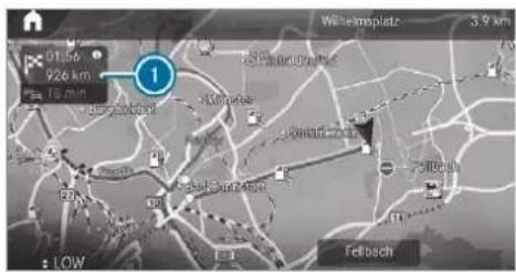
text_image
01:56 926 km 18 min 1 Willemsplatz 3.9 km FellbachIf route guidance is active, select ①. The address of the destination or the next intermediate destination is shown.
Using alternative routes
▶ Select Alternative route. The routes are displayed in accordance with the setting made in the route settings. The routes are numbered.
▶ Select the alternative route.
Setting a POI as an intermediate destination
Select a category symbol, e.g. P for a park.
Select a POI from the list.
The selection takes place on the route. The destination address is shown. The route be calculated.
To use POI categories for quick-access: select a search position In the vicinity, Near destination or Along the route.
Select a POI from the list.
or
Enter a search entry into the search field and filter the list.
Select a POI from the list. The destination address is shown. The route can be calculated.
Saving the current vehicle position
Select Store position. The current vehicle position is saved to the "Previous destinations" memory.
Destination reached
Once the destination is reached, you will see the chequered flag. Route guidance is finished. The Navigation menu is shown.
When an intermediate destination has been reached, you will see the intermediate destination flag with the number of your intercanmediate destination. Route guidance is continued.
Switching navigation announcements on/off
To switch off: turn the volume control on the steering wheel or next to the touchpad during a navigation announcement (→ page 407). The Spoken driving recommendations have been deactivated. message appears.
or
Show the navigation menu ( page 432).
Select 📁.
The symbol changes to 📁.
To activate: select ☐.
The current navigation announcement is played.
The symbol changes to !.
% This function can be added and called up from the favourites within the navigation category.
Switching navigation announcements on or off during a phone call
Press the © button on the steering wheel or on the touchpad.
or
Tap on © in the media display.
Select Settings.
Select System.
Select Audio.
Select Navigation and traffic announcements.
Switch Driving recommendations during call on or off. When the option is switched on, the display button is activated.
To leave the menu: select q.
Adjusting the volume of navigation announcements
Multimedia system:
4 © 5 Settings 5 System 5 Audio
5 Navigation and traffic announcements
Select Driving recommendation vol..
Set the volume.
To leave the menu: select q.
Route guidance is active
Turn the volume control on the steering wheel or next to the touchpad during a navigation announcement.
Switching audio fadeout on or off during navigation announcements
Press the © button on the steering wheel or on the touchpad.
or
Tap on © in the media display.
Select Settings.
Select System.
Select Audio.
Switch Audio fadeout on or off. When the option is switched on, the display button is activated.
To leave the menu: select q.
Repeating navigation announcements Requirements:
R a route has already been created.
R route guidance is active.
Multimedia system:
4 Navigation (Navigation)
Select !.
Select #.
The current navigation announcement is repeated.
% This function can be added and called up from the favourites within the navigation category.
Cancelling route guidance
Requirements:
R a route has already been created.
R route guidance is active.

Show the navigation menu.

Select in the navigation menu (→ page 433).
Overview of route guidance to an off-road destination
An off-road destination is within the digital map. The map contains no roads that lead to the destination.
You can enter geo-coordinates or a 3 word address for off-road destinations on the map. Route guidance guides you for as long as possible with navigation announcements and disp on roads that are known to the multimedia system.
Shortly before you reach the last known position on the map, you will hear the "Please follow the direction arrow" announcement, for example. The display shows a direction arrow and the linear distance to the destination.
Overview of route guidance from an off-road location to a destination
In an off-road position, the current vehicle position is located within the digital map on roads that are not available.
The following displays appear when route guidance begins:
- A message appears that the road is not on the map.
- A direction arrow showing the linear direction to the POI.
When the vehicle is back on a road known to the multimedia system, route guidance continues as normal.
Overview of off-road status during route guidance
Due to roadworks, for example, there may be differences between the data on the digital map and the actual course of the road. In such case the multimedia system will temporarily be unable to locate the vehicle's current position on the digital map. The vehicle is off-road.
If the vehicle is displayed as being offroad, the following information appears:
- A message appears that the road is not on the map.
- A direction arrow showing the linear direction to the POI.
When the vehicle is back on a road known to the multimedia system, route guidance continues as normal.
Destination
Saving the current vehicle position
Multimedia system:


Select Store position.
The current vehicle position is saved to the "Last destinations" memory.
Using quick-access
text_image
0156 926 km 18 mm 1 Willemsplatz 3.9 km FellbachIf route guidance is active, select ①. The address of the destination or the next intermediate destination is shown.
Select Store position.
Editing the previous destinations Requirements:
- To edit destination suggestions: the Allow destination suggestions option is activated ( page 401).
- The multimedia system has gathered sufficient data in order to show destination suggestions.
Multimedia system:
→ Navigation → Where to?
▶ PREV. DESTINATIONS
The following entries can be edited:
- Destination suggestions
- Destinations
- Routes
To no longer display a destination suggestion: select ▼ for a destination suggestion.
Select Do not suggest.
Saving the last destination as a favourite
i After saving, the destination can be called up via the favourites (→ page 402).
Select ▼ for a destination.
▶ Select □ Save as favourite.
To save as a favourite: select Save as favourite.
To save as "Home" address: select Save as "Home".
To save as "Work" address: select Save as "Work".
Deleting a previous destination
To delete a destination: select ▼ for a destination.
Select Delete.
Select Yes.
To delete all destinations: select ....
▶ Select Delete all.
Select Yes.
Using external destinations and routes
External destinations and routes can be received from the following sources, for example:
- Mercedes-Benz Apps
• door-to-door navigation
A prompt appears on the media display. Received destinations and routes are saved in the previous destinations.
A destination has been received: select Yes.
Calculate the route.
If route guidance is already active, select Se as intermediate dest. or Start new route guidance.
or
If a destination was received with photo information, select Start route guidance.
Calculate the route.
or
If a destination has been received from an app, select Details.
Calculate the route.
A route has been received: select Yes.
Select Start route guidance from the beginning or Start route guidance from current location.
Route guidance starts from the selected position.
Route guidance with current traffic reports
Traffic information overview
i The services are not available in every country.
Traffic reports can be received with the following services:
• Live Traffic Information
- FM RDS-TMC
It is not possible to use both services simultaneously.
Live Traffic Information or FM RDS-TMC is displayed with a symbol.
(i) Hazard warnings can be received using the Car-to-X service.
There may be differences between the traffic reports received and the actual road and traffic conditions.
Important information on Live Traffic Information:
- Current traffic reports are received via the Internet connection (for selected countries).
- The traffic situation is updated at short, regular intervals.
- In selected countries, the subscription service is available free of charge for a period of three years from the manufacturing date. Information from the service provider can shown ( page 459).
Registering Live Traffic Information:
- The service must be registered with Mercedes me (→ page 459).
This secures the free-of-charge period of three years.
Information on the vehicle's position is regularly sent to Daimler AG. The data is immediately rendered anonymous by Daimler AG and forwarded to the traffic data provider. Using this data, traffic reports relevant to the vehicle's position are sent to the vehicle. The vehicle acts as a sensor for the flow of traffic and helps to improve the quality of the traffic reports.
If you do not want to transmit the vehicle position, you have the following options:
- You deactivate the service in the Mercedes me portal.
- You have the service deactivated at a Mercedes-Benz service centre.
eUseful information on FM RDS-TMC:
- A FM RDS-TMC radio station broadcasts traffic reports alongside the radio programme.
• FM RDS-TMC is not available in all countries.
Showing information from the service provider for Live Traffic Information Requirements:
- The vehicle is equipped with Live Traffic Information.
Multimedia system:

▶ Select Provider information.
The logo of the service provider for Live Traffic Information is shown.
When the subscription for Live Traffic Information has expired then in selected countries FM RDS-TMC is available.
Further information on Live Traffic Information can be called up on the home screen using Mercedes me & Apps ( page 509).
Registering Live Traffic Information Requirements:
- The vehicle is equipped with Live Traffic Information.
- You have a user account on the Mercedes me website.
The Live Traffic Information service must be registered. This secures the full period of three years.
Create a user account at Mercedes me at: https://www.mercedes.me. A valid email address is required for this.
Register the vehicle using the vehicle identification number (VIN).
To carry out the registration yourself: connect the vehicle with your Mercedes me user account in the Mercedes me portal. A code is sent to the multimedia system.
Enter the code into the multimedia system.
Accept the general and specific terms of use.
Registration in the Mercedes-Benz service centre: have the connection carried out at a Mercedes-Benz service centre.
Extending a Live Traffic Information subscription Requirements:
- The vehicle is equipped with Live Traffic Information.
- You have a user account on the Mercedes me website.
▶ Call up the Mercedes me website.
▶ Call up the Mercedes me user account.
Switch to the Mercedes me connect online store via the linked vehicle.
Select the Live Traffic Information service.
▶ Select the renewal period.
Add the product to the shopping basket.
Accept the general and specific terms of use. Live Traffic Information remains activated for the selected extension period. Activation begins on the date of extension.
Showing traffic information Requirements:
- The Traffic display is switched on (→ page 461).
- The following traffic displays are switched on (→ page 461):
Traffic incidents
Free-flowing traffic
Delay
Multimedia system:

▶ Select Navigation.
The map shows the following traffic information:
- traffic incidents, for example:
- roadworks
- road blocks
- warning messages
When route guidance is active, the symbols for traffic incidents will be shown in colour on the route. Off the route they are grey.
- warning message symbols:
- symbol
- road safety notes, e.g. when approaching the end of a traffic jam If the vehicle approaches a danger area on the route, a warning message is displayed on the map. In addition, an audible notification can follow a hazard warning.
-
traffic flow information:
-
traffic jam (red line)
- slow-moving traffic (orange line)
- heavy traffic (yellow line)
free-flowing traffic (green line)
- display for traffic delays on the route lasting at least one minute
Displaying traffic incidents
Requirements:
- The Traffic incidents display is switched on (→ page 461).
Multimedia system:

▶ Select Traffic announcements. If there are traffic reports, you will see a list. Traffic reports include accidents and other traffic events, for example. The list is sorted according to distance and shows the traffic reports received both on and off the route.
A traffic report shows the following information:
- Street number
- Traffic incident symbol
On the route: coloured Off the route: grey - Cause
- Street symbol for a traffic incident on the route
• Distance from current vehicle position
Select a traffic report ▷.
The detailed information is shown, for example the route section.
Showing traffic incidents in the vicinity of the map
Select a traffic incident symbol on the map. The details about the traffic incident are displayed.
Select
▶ Select Traffic incidents in vicinity.
The map shows the traffic incident symbols in the vicinity.
Traffic incident information is displayed in the status line:
- Traffic incident symbol
- Cause of the traffic incident, e.g. construction work
• Warning message (highlighted red)
To select a traffic incident symbol: select < or >.
To select a map section: tap on the touchscreen.
or
Press the Touch Control or the touchpad.
Move the map.
To return to the navigation map: tap on ↗.
or
Press the ↩ button on the Touch Control or on the touchpad.
Activate Traffic. The display button is activated.
Switching the traffic information display on Multimedia system:

Activating Incidents, Free Flow and Delay
▶ Select Advanced.
Select View.
Select Map elements.
In the TRAFFIC category, activate the Traffic incidents, Free-flowing traffic and Delay entries.
The display buttons are activated.
If traffic information has been received, then traffic incidents such as roadworks, road blocks, local area reports (e.g. fog) and warning messages are displayed.
The traffic delay is displayed for the current route. Traffic delays lasting one minute or longer are taken into consideration.
Showing local area messages
Multimedia system:

▶ Select Area announcements.
Local area messages are shown, for example fog or heavy rain.
▶ Select a local area message. The details are displayed.
Car-to-X-Communication
Car-to-X-Communication overview
The following requirements apply for using Car-to-X-Communication:
- The vehicle is equipped with a multimedia system featuring navigation and a communication module with an activated, integrated SIM card.
• Car-to-X-Communication is activated.
Car-to-X-Communication is available in selected countries.
The communication module automatically establishes an Internet connection once the ignition switched on. If there are any hazard warnings, they will be provided shortly thereafter. Depending on the mobile phone connection, the provision takes place from within a second up to about a minute.
Benefits of Car-to-X-Communication:
- Hazards are recognised automatically in the background by the vehicle or may be reported by the driver. These are then sent to vehicles with Car-to-X-Communication in the immediate vicinity.
- If available, current details relating to hazard spots near the vehicle's current position are received.
This gives you sufficient time to adapt your driving style to the traffic conditions.
The use of Car-to-X-Communication requires the regular transmission of vehicle data to Daimler AG. The data is then immediately pseudonymised by Daimler AG. The vehicle data is deleted after an appropriate amount of time has elapsed (several weeks) and is not stored permanently.
Data which serves as identification is replaced during the pseudonymisation process. In this way, your identity is protected against access by unauthorised third parties.
Displaying hazard warnings
Multimedia system:
Navigation (Navigation)
If hazard warnings are available these can be shown as symbols on the map. The display depends on the settings for the Traffic and Traffic incidents options.
▶ Set the options ( page 461).
The following displays are available:
• Show all symbols.
The Traffic and Traffic incidents options are switched on.
- Only show symbols on the expected route.
The Traffic option is switched off, the Traffic incidents option is switched on.
- Show no symbols.
The Traffic incidents option is switched off.
The following hazard warnings are shown on the map:
- Broken-down vehicles
- Accidents
- Hazardous weather
- General hazards
• Hazard warning lights, when switched on - Crosswind warning
- Mobile roadworks
The display is not available in all countries and regions.
In the Federal Republic of Germany the display is currently available in the Federal State of Hesse.
If the vehicle is approaching a hazard spot with a vehicle speed of at least the voice output "Traffic incident ahead" is issued 60 km/h the voice output "Traffic incident ahead" is issued.
The voice output is not issued for hazardous weather.
Sending hazard warnings
Automatically detected hazard warnings are sent by the vehicle.
To send a hazard warning yourself: tap on the media display when the map is shown. The navigation menu is shown.
Select
▶ Select Report traffic incident. A prompt is shown.
▶ Select Yes.
The Thank you for supporting accident prevention. message appears.
Route guidance with augmented reality
Overview of route guidance with augmented reality

WARNING Risk of accident and injury caused by distraction, incorrect image or interpretation of the display
The distance to other road users or information, such as traffic lights, can be incorrectly assessed from the camera image. The camera image of the augmented reality display is not suitable to be used for driving.
Always keep your eyes on the actual traffic situation. Only glance briefly at the camera image.
Be aware that depending on the driving situation there may be hazards that are not captured in the camera image, e.g. when turning. Avoid observing the camera image for extended periods.
During route guidance with augmented reality a camera image with the real traffic scene is shown in the media display before a turning manoeuvre.

text_image
Zum Gartenborn 1 2 3 Koblenzer Strasse 200 m 11.24 11.21 22.0 e① Street name
② House number
③ Change of direction arrow
Route guidance with augmented reality is not available in all countries.
Route guidance with augmented reality is currently not available on motorways.
The camera image can contain the following additional information:
• Change of direction arrow
- Street names
- House numbers
Activating route guidance with augmented reality

WARNING Risk of accident and injury caused by inaccurate positioning of additional information
The additional information indicated with the augmented reality display can be incorrectly positioned in the camera image. For this reason, the camera image cannot replace the need to observe the actual driving situation.
Maintain the actual driving situation in view for all driving manoeuvres, e.g. when turning and when changing lanes.
Requirements:
- Route guidance is active.
Multimedia system:
Navigation
If the detailed junction view appears during route guidance, tap on the camera symbol. The display button is activated. The camera image is shown in the media display depending on the situation.
The camera image will be shown instead of the navigation map before a turning manoeuvre and will show the additional information.
To return to the navigation map: tap on the camera symbol again. The display button is off.
Showing street names for route guidance with augmented reality Requirements:
- Augmented reality is activated (→ page 464).
Multimedia system:
Navigation
▶ Advanced ▶ Augmented Reality
Activate Street names and House numbers. The display buttons are activated. During route guidance, street names and house numbers are shown as additional information in the video image.
Switching on display of traffic lights with augmented reality for route guidance Requirements:
- Augmented reality is activated (→ page 464).
• The Traffic light zoom option is switched on.
When the vehicle is standing in first position at a junction, the camera image will show an enlarged traffic lights display.
① When the vehicle pulls away the navigation map is shown again.
Multimedia system:
→ → Navigation
▶ Advanced ▶ Augmented Reality
Activate Traffic light zoom. The display button is activated.
▶ Under TRAFFIC LIGHT VIEW select one of the Off, After asking or Automatic options. If After asking is set, the Traffic light indicator available message is shown. The camera image is shown after confirmation of the message.
If Automatic is set, the traffic lights display is shown automatically in the camera image when available.
To return to the navigation map: press the button.
Map and compass
Setting the map scale
Multimedia system:
Navigation
Zooming in
When the map is shown, tap twice quickly with one finger on the media display or the touchpad.
or
Move two fingers apart on the media display or on the touchpad.
Zooming out
Tap with two fingers on the media display or the touchpad.
or
Move two fingers together on the media display or on the touchpad.
① You can set the unit of measurement of the map scale ( page 422).
Moving the map
Multimedia system:
Navigation
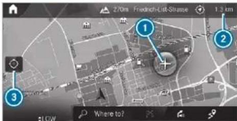
text_image
270m Friedrich-List-Straße 1.3 km 2 3 Where to?On the touchscreen: move the finger in any direction when the map is shown.
On the touchpad: call up the navigation menu by pressing.
Swipe your finger up. Press the touchpad.
Crosshair ① appears. The map can be moved.
Touch the touchpad and move your finger in any direction.
The map moves in the opposite direction under crosshair ①.
When the map has been moved the following information appears in the status line, for example:
- Distance ② from the vehicle's current position is shown.
• Information about the current map position is shown, e.g. the name of the road.
The following functions are available:
- Select a destination on the map (→ page 440).
- Select a POI (→ page 437).
• Show traffic incidents on the map ( page 460).
To reset the map to the current vehicle position: select 3.
Rotating the map
With two fingers, rotate anti-clockwise or clockwise on the media display or the touch-pad.
Selecting the map orientation
Multimedia system:

▶ Advanced
Select View.
Select Map orientation.
▶ Select an option.
The • dot indicates the current setting.
The following options are available:
- 2D heading up option: the 2D map view aligned to the direction of travel.
- 2D north up option: the 2D map view is displayed so that north is always at the top.
• 3D option: the 3D map view is aligned to the direction of travel.
Using quick-access: repeatedly tap or press on the compass symbol on the map. The view changes in the sequence 3D, 2D heading up to 2D north up. If the map is moved, it can switch between 3D and 2D north up.
Selecting POI symbols for the map display
Multimedia system:

POIs include restaurants and hotels, for example. These can be displayed as symbols on the map. Not all POIs are available everywhere.
Personal POIs are destinations which you have saved on a USB device, for example.
The display of POI symbols on the map can be activated or deactivated as a favourite.
To switch on/off using quick-access: if available, switch POI symbols on or off. The POI symbols for the selected categories are shown on the map.
or
To switch on/off in the menu: select Advanced.
Select View.
▶ Select Map elements.
Select POI symbols ▶.
The POI SYMBOLS menu is shown.
▶ Switch Display POIs on or off.
Selecting categories
Select ▶ in the POI SYMBOLS All categories menu.
Switch Show all on or off.
When the option is switched on, the POI symbols for all categories are shown on the map.
or
Select the categories and sub-categories (if available) ▶.
Activate or deactivate the categories.
The POI symbols for the selected categories are shown on the map.
Selecting personal POI categories
Select ▶ in the POI SYMBOLS Personal POIs menu.
Select a category ▷.
Switch Display on the map on or off. When the display is switched on and the vehicle approaches a personal POI in this category, a visual and audible notification can be issued.
To set a notification when approaching: select a category or a personal POI ▼.
Switch Visual warning and Acoustic notification on or off.
Switching display of categories for quick-access on/off
Switch a category on or off in the POI SYMBOLS menu.
Resetting the POI symbol display
▶ Select POI SYMBOLS Reset POIs in the menu. The settings are reset to the standard settings.
Selecting the display of text information in the map
Multimedia system:

▶ Advanced
Select View.
▶ Select Text information.
Select an option in the FOOTER category. The • dot indicates the current setting.
The following options are available:
- Current street option
The street you are currently on is shown in the bottom bar.
When the map is moved, the street name, the POI name or the area name appears under the crosshair.
- The Geo-coordinates option shows the following information in the bottom bar:
The elevation shown may deviate from the actual elevation.
- None option The media display shows no text information in the bottom bar.
Switching motorway information on/off Multimedia system:

Using quick-access: switch Motorway information on or off.
The display button is activated or off.
Using the menu: select Advanced.
Select View.
▶ Select Text information.
Switch Motorway information on or off. When the display button is switched on, tional information about the motorway facilities ahead appears during the motorway journey. These include car parks, service stations and motorway exits, for example.
Displaying the next intersecting street Requirements:
- Route guidance is not active.
Multimedia system:

▶ Advanced
Select View.
Select Text information.
Activate Next intersecting street.
The display button is activated. If the option is switched on and the journey continues without route guidance, the name of the intersecting street will be displayed at the upper edge of the display.
Displaying the map version Multimedia system:

▶ Advanced
Select View.
Select Map version.
The detail information is displayed.
The online map update service from Mercedes me connect can be used to update the map data ( page 469).
A message is shown in the media display when a new map version is available.
Information about new versions of the digital map can be obtained from a Mercedes-Benz service centre.
Overview of avoiding an area for the route
You can define areas along a route that you would like to avoid.
new Motorways or multi-lane expressways, which are routed through an area to be avoided are taken into account for the route.
Avoiding a new area for the route Multimedia system:

▶ Advanced ▶ Route ▶ Avoid options
▶ Avoid areas
Select Avoid new area.
To start in the map: select Using map.
Move the map ( page 465).
To start via destination search: select Via address entry.
Enter the address ( page 434).
Select the destination in the list or accept with OK. The map appears.
To show an area: tap or press on the control element.
A red rectangle appears. This designates the area that should be avoided.
To change the map scale: move two fingers apart or together on the media display or on the touchpad.
The map is zoomed in or out.
To set an area: select OK. The Avoid area has been set. message appears. The area is entered into the list.
Multimedia system:
Navigation
▶ Advanced ▶ Route ▶ Avoid options
▶ Avoid areas
▶ Select an area in the list.
Select Edit.
Changing an area to be avoided
To move an area on the map: swipe in any direction on the control element.
To change the size of the area: tap or press on the control element.
Swipe up or down on the control element.
Select OK.
The Avoid area has been set. message appears. The area is entered into the list.
To take account of an area for the route: select an area from the list.
▶ Activate Avoid area.
The display button is activated.
If route guidance is active, a new route is calculated.
If there is no route yet, the setting is carried over to the next route guidance.
The route can include an area that is to be avoided in the following cases:
- the destination is located in an area is to be avoided.
- the route includes motorways or multi-lane expressways which pass through an area to be avoided.
- there is no sensible alternative route.
Deleting an area
Multimedia system:
Navigation
▶ Advanced ▶ Route ▶ Avoid options
▶ Avoid areas
To delete an area: select an area in the list.
Select Delete.
▶ Confirm the prompt with Yes.
To delete all areas: if at least two areas to avoid are set, select Delete all.
▶ Confirm the prompt with Yes.
Map data update overview
Updating at the Mercedes-Benz service centre
The digital maps generated by the map software become outdated in the same way as conventional road maps. Optimal route guidance can only be provided by the navigation system in conjunction with the most up-to-date map data. Information about new versions of the digital
map can be obtained from a Mercedes-Benz service centre.
You can have updates to the digital map implemented there.
i Additional costs can be incurred in this connection.
Online map update
The online map update service from Mercedes me connect can be used to update the map data.
Requirements:
- Mercedes me connect is available.
- You have a user account for the Mercedes me portal.
• The service is available.
• The service has been activated.
i The online map update service is not available in all countries.
The following options are available for the update:
• For one region (automatic map update)
If the Automatic online updates system setting is switched off ( page 424), you receive a message that a map update is available. You can confirm the message and download the map update.
- For several or all regions (manual map update)
The map data will first be downloaded onto a storage medium and then updated on the multimedia system.
Further information on online map updates is available here:
- At any Mercedes-Benz service centre
• Under: https://www.mercedes.me
Further information on updates can be found at: https://manuals.daimler.com/baix/cars/connectme/en_GB/index.html.
Overview of map data
Your vehicle is supplied with map data at the factory. Depending on the country, map data for your region is either pre-installed or the map data is supplied on a data storage medium.
If the map data on your vehicle has been installed at the factory and you wish to reinstall it, you do not need to enter the activation code.
For map data that you have purchased in the form of a data storage medium, you must enter the accompanying activation code.
If you save the map data on a data storage medium with the online map update service, no entry is required. The activation code is stored on the data storage medium during the downloading process.
Observe the following when entering the activation code:
- The activation code can be used for one vehicle
• The activation code is not transferable
• The activation code has six digits
In the event of the following problems, please contact a Mercedes-Benz service centre:
- The multimedia system does not accept the activation code
• You have lost the activation code
Displaying the compass
Multimedia system:
→ ↗ Navigation ↗ ↗ Position
Select Compass.
The compass display shows the following information:
- the current direction of travel with bearing (360° format) and compass direction
• longitude and latitude coordinates in degrees, minutes and seconds - height (rounded)
• number of satellites from which a signal can be received
The information is not available in every country.
Displaying Qibla
Multimedia system:
→ ↗ Navigation ↗ ↗ Position
Select Qibla.
The arrow on the compass shows the direction to Mecca in relation to the current direction of travel.
The number of satellites received is shown.
① This function is not available in all countries.
Setting the map scale automatically
Multimedia system:
Navigation
▶ Advanced
Select View.
▶ Select Map orientation.
Activate Auto zoom.
The display button is activated. The map scale is set automatically depending on your driving speed and the type of road.
The automatically selected map scale can changed manually. After a few seconds, this is automatically reset.
Displaying the satellite map
Multimedia system:
Navigation
▶ Advanced
Select View.
Select Map elements.
Switch Satellite map on or off. If the display button is activated, satellite maps are displayed in map scales from 2 k If the display button is deactivated, satellite maps are not displayed in map scales from 2 km to 20 km.
① The satellite maps for these map scales are not available in all countries.
Displaying the range
Requirements:
- The multimedia system supports the function.
_bd Multimedia system:
Navigation
▶ Advanced
▶ Select View.
▶ Select Map elements.
▶ Activate Range.
The display button is activated.
The range is shown on the map with the following displays:
• For petrol and diesel vehicles: green display
When the lower reserve capacity is reached then the range display on the map is switched off.
The range display on the map is not available in all countries.
Displaying weather information and other map contents
Requirements:
- Mercedes me connect is available.
- You have a user account for the Mercedes me portal.
• The service is available.
• The service has been activated.
Multimedia system:


Select View.
Select Map elements.
▶ Scroll up and show the ONLINE MAP CONTENTS category.
The available services are displayed. The services are provided by Mercedes me connect.
Switch on a service, e.g. Weather.
Current weather information is displayed on the navigation map, e.g. temperature or cloud cover. The service information is not shown in all map scales, e.g. weather symbols.
Further information about available services and about displaying information in the map scales can be found in the Mercedes me Portal: https://me.secure.mercedes-benz.com
(i) Weather information is not available in all countries.
Showing map view in the multifunction display of the instrument cluster
Multimedia system:

▶ Advanced
Select View.
▶ Select Map orientation.
▶ Scroll up and show the INSTRUMENT CLUSTER VIEW category.
To set the map scale automatically: switch on Auto zoom.
The display button is activated. The map scale is set automatically depending on your driving speed and the type of road.
To select map orientation: select an option.
The ● dot indicates the current selection.
The following options are available:
- 2D heading up option: the 2D map view is aligned to the direction of travel.
- 2D north up option: the 2D map view is displayed so that north is always at the top.
- 3D option: the 3D map view is aligned to the direction of travel.
Parking service
Notes on the parking service

WARNING Risk of accident and injury due to not observing the maximum permitted access height
If the vehicle height exceeds the maximum permitted access height for multi-storey car parks and underground car parks, the vehicle roof as well as other vehicle parts could be damaged.
There could be a risk of injury to the vehicle occupants.
Before driving into a multi-storey car park or underground car park observe the locally signposted access height.
If the vehicle height, including any additional equipment, exceeds the maximum permitted access height, do not drive into the multi-storey car park or underground car park.
This service is not available in all countries.
Selecting parking options

NOTE Before selecting the parking option
The data is based on information provided by the respective service provider.
Mercedes Benz accepts no liability for the accuracy of the information provided relating to the multi-storey car park/parking area.
Always observe the local Information and conditions.
Requirements:
- The navigation services option is available, subscribed to and activated in the Mercedes me portal.
- The parking service is within the scope of the navigation service.
• Parking is activated ( page 474).
Multimedia system:


Navigation


in the map.

Select a parking option.
The map shows the parking options in the vicinity.
The following information is displayed (if available):
- Destination address, distance from current vehicle position and arrival time
• Information on the multi-storey car park/car park
For example, opening times, parking charges, current occupancy, maximum parking time, maximum access height.
The maximum access height shown by the parking service does not replace the need for observation of the actual circumstances.
• Available payment options (Mercedes pay, coins, bank notes, cards)
• Details on parking tariffs
• Number of available parking spaces -
Payment method (e.g. at the parking machine)
• Services/facilities at the parking option -
Telephone number ▶ Calculate the route (→ page 442).
The following functions can also be selected (if available):
• Search for POIs in the vicinity. - Save the destination.
- Place a call at the destination.
• Share the destination using NFC or QR code - Call up the web address.
• Show the destination on the map.
Displaying parking options on the map Requirements:
- The navigation services option is available, subscribed to and activated in the Mercedes me portal.
- The parking service is within the scope of navigation service.
Multimedia system:

Activate Parking.
The display button is activated. The parking options within the vicinity of the current vehicle position are shown.
Paying parking charges Requirements:
• The navigation services option is available and activated in the Mercedes me portal.
The parking service is within the scope of navigation service.
- You have registered with your payment details for the payment of parking in the Mercedes me portal with Mercedes Pay and the respective contract partner.
Parking is activated ( page 474).
Multimedia system:

This option is not available in all countries.
Select a parking option on the map.
If a car park that can be paid for has been selected, scroll down in the parking details.
Select Pay.
Once the vehicle has reached a parking position with payment function and the ignition is switched off, a message appears. Using this message you can pay from the vehicle and start the payment process.
To start the payment process: confirm the message.
Please note the maximum parking period displayed and any existing additional limitations. If required, a message will inform you about the necessity of displaying information confirming the online payment for the parking space.
▶ Select Start the payment process.
If required, enter the personalised PIN.
Press OK to confirm.
The successful start of your parking transaction is shown.
Complete the booking with OK.
To cancel the booking: select Cancel when you receive the confirmation message. Minimum charges may be incurred.
To end the booking: stop the active transaction via the Mercedes Me app. You receive a summary of the procedure and the costs.
If an active parking procedure for your vehicle is detected when you continue driving, a message appears asking if you wish to end this parking procedure.
▶ Confirm the message. When the parking procedure is stopped successfully, another message appears with the details about your completed parking procedure.
Dashcam
Notes on the dashcam
NOTE Before using the dashcam
Before using any or all functions of the Dashcam, please read this Disclaimer carefully. If you do not accept, agree to or understand this Disclaimer, please do not use the Dashcam. By using the Dashcam, you are deemed to have accepted and agreed to the contents of this Disclaimer.
As manufacturer of the vehicle, we provide you with the device and associated software system of the Dashcam to provide you with the functionalities that we consider you may wish to have while using the Dashcam. We are unable to predict or verify whether any image(s) or geographic information captured or recorded during your use of the Dashcam is legitimate. As such, we are unable to take responsibility for any adverse consequences that may arise from the actual image(s) or geographic information captured or recorded during use of the Dashcam.
Warning: please comply with all applicable laws and regulations when you use the Dashcam. For example, please do not capture or record image(s) or geographic information which may be considered as state secret sensitive information (e.g. military areas). In case of any violations of the relevant laws and regulations, the actual user will be liable for the corresponding responsibilities and we will not take responsibility for any misuse of the Dashcam.
Observe the country-specific regulations.
The dashcam is available in the navigation system in combination with the augmented reality function.
Selecting a USB device for a video recording with the dashcam Requirements:
- At least one USB device is connected with the multimedia system (→ page 531).
Multimedia system:
Mercedes me & Apps
Dashcam
▶ Select the USB device.
Starting/stopping video recording with the dashcam
Requirements:
- A USB device is connected with the multimedia system (→ page 531).
• The ignition is switched on.
Multimedia system:
→ Mercedes me & Apps
Dashcam
If several USB devices are connected with the multimedia system, select the USB device ( page 475).
Select the Individual recording or Loop recording recording mode. If Individual recording is selected and the memory is full the recording stops. An individual recording is automatically protected against being overwritten.
If Loop recording has been selected, several short video files are recorded. When the memory limit is reached, the oldest video file is deleted and recording is continued automatically.
To start: select Start recording.
The length of the recording is shown. The
Please do not remove the storage medium.
message appears. The video file is stored on
the USB device.
To end: select End recording.
A report may appear in the following cases:
- For the Individual recording recording mode: the memory is full or there are only a few minutes recording time available. The video recording stops or will be stopped imminently.
Change the USB device or delete a video file.
- If a video recording has started and a national border is detected, the National border crossed. Please observe the countryside specific regulations regarding video recording. message appears.
This function is not available in all countries.
- The camera is not functional, the Camera unavailable message appears. Have the camera checked in a Mercedes-Benz service centre.
Deleting a dashcam video recording Requirements:
- A USB device with video recordings is connected with the multimedia system ( page 531).
Multimedia system:
Mercedes me & Apps
Dashcam
Select the symbol.
The RECORDINGS menu appears.
Select ▼ for a video file.
Select Delete.
Select Yes.
To delete all video files: select ⋯.
Select Delete all entries.
Configuring dashcam settings Requirements:
- A USB device is connected with the multimedia system (→ page 531).
Multimedia system:
→ Mercedes me & Apps → Dashcam
Select
To show messages after passing a national border: switch on National border alert.
The display button is activated.
A message appears in the following situations:
• A video is being recorded.
• The vehicle has passed a national border.
① This function is not available in all countries.
To start automatic video recording: select Automatic video recording.
▶ Activate Automatic video recording. The display button is activated. When the vehicle is started, video recording starts automatically.
① This function is not available in all countries.
Telephone
Telephony
Notes on telephony
WARNING Risk of distraction from operating integrated communication equipment while the vehicle is in motion
If you operate communication equipment integrated in the vehicle when driving, you will be distracted from the traffic situation. This could also cause you to lose control of the vehicle.
Only operate this equipment when the traffic situation permits.
If you cannot be sure of this, stop the vehicle whilst paying attention to road
and traffic conditions and operate the equipment with the vehicle stationary.
WARNING Risk of an accident from operating mobile communication equipment while the vehicle is in motion
Mobile communications devices distract the driver from the traffic situation. This could also cause the driver to lose control of the vehicle.
As the driver, only operate mobile communications devices when the vehicle is stationary.
As a vehicle occupant, only use mobile communications devices in the areas intended for this purpose, e.g. in the rear passenger compartment.
You must observe the legal requirements for the country in which you are currently driving when operating mobile communication equipment in the vehicle.

WARNING Risk of injury due to objects being stowed incorrectly
If objects in the vehicle interior are stowed incorrectly, they can slide or be thrown around and hit vehicle occupants. In addition, cup holders, open stowage spaces and mobile phone receptacles cannot always retain all objects they contain.
There is a risk of injury, particularly in the event of sudden braking or a sudden change in direction.
▶ Always stow objects so that they cannot be thrown around in such situations.
Always make sure that objects do not protrude from stowage spaces, luggage nets or stowage nets.
▶ Close the lockable stowage spaces before starting a journey.
▶ Always stow and secure heavy, hard, pointed, sharp-edged, fragile or bulky objects in the boot/load compartment.
Observe the additional information on stowing mobile communications devices correctly:
- Loading the vehicle (→ page 144) Further information can be obtained from a Mercedes-Benz service centre or at: https://www.mercedes-benz-mobile.com/
Telephone menu overview
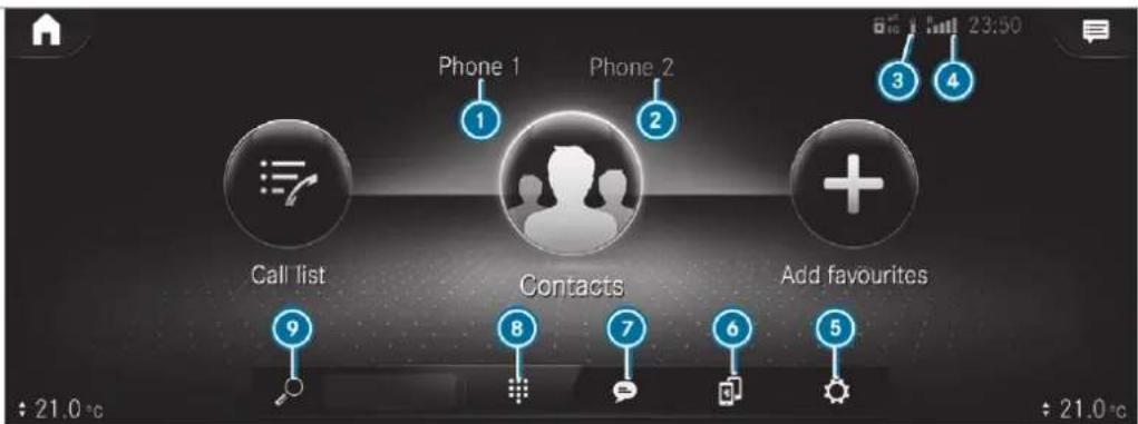
text_image
Phone 1 Phone 2 Call list Contacts Add favourites 9 8 7 6 5 : 21.0 °C 23:50Bluetooth® device name of the currently connected mobile phone/of the mobile phone
2 Bluetooth ^10 device name of the currently connected mobile phone/of the mobile phone (two phone mode)
3 Battery status of the connected mobile phone
Signal strength of the mobile phone network Bluetooth® profile overview
5 Options
6 Device manager
7 Messages
8 Numerical pad
9 Contact search
| Bluetooth® profile of the mobile phone | Function |
| PBAP (Phone Book Access Profile) | Contacts are automatically displayed in the multimedia system |
Bluetooth ^® profile of the mobile phone
| MAP (Message Access Profile) |
| Message functions can be used |
Telephony operating modes overview
Depending on your equipment, the following telephony operating modes are available:
- A mobile phone is connected to the multimedia system via Bluetooth(→ page 480).
- Two mobile phones are connected with the multimedia system via Bluetooth®(two phone mode) (→ page 481).
- You can use all the functions of the multi-media system with the mobile phone in the foreground.
- You can receive incoming calls and messages with the mobile phone in the background.
You can interchange the mobile phone in the foreground and background any time ( page 481).
- A mobile phone is connected to the multimedia system as an SAP (Sim Access Profile) telephone ( page 485).
- Only a SIM card is connected to the multimedia system (→ page 486).
- A SIM card is connected in combination a specific mobile phone (→ page 486).
Irrespective of this, Bluetooth ^® audio functionality can be used with any mobile phone (→ page 531).
a mobile phone with "Twincard" is logged into the network with the second SIM card at the same time
The multimedia system supports calls in HD Voice ^® for improved speech quality. A requirement for this is that the mobile phone and the mobile phone network provider of the person you are calling support HD Voice ^® .
eDepending on the quality of the connection, the voice quality may fluctuate.
Information on telephony
The following situations can lead to the call being disconnected while the vehicle is in motion:
- there is insufficient network coverage in the area
- you move from one transmission/reception station to another and no communication channels are free
- the SIM card used is not compatible with network available
Connecting a mobile phone Requirements:
- Bluetooth ^ is activated on the mobile phone (see the manufacturer's operating instructions).
- Bluetooth ^ is activated on the multimedia system (→ page 418).
Multimedia system:


Searching for a mobile phone

Select

。
▶ Select Connect new device.
Connecting a mobile phone (authorisation using Secure Simple Pairing)
▶ Select a mobile phone.
A code is displayed in the multimedia system and on the mobile phone.
If the codes match: confirm the code on the mobile phone.
For older mobile phone models, enter a one to sixteen-digit number code on the mobile phone and on the multimedia system for authorisation.
i Up to 15 mobile phones can be authorised on the multimedia system.
Authorised mobile phones are reconnected automatically.
The connected mobile phone can also be used as Bluetooth audio equipment (→ page 531).
Connecting a second mobile phone (two phone mode)
Requirements:
- At least one mobile phone is already connected to the multimedia system via Bluetooth®.
Multimedia system:
Phone
Select
▶ Select Connect new device.
▶ Select the mobile phone.
Select Device name 1 + Device name 2. The selected mobile phone is connected to the multimedia system.
Interchanging mobile phones (two phone mode)
Multimedia system:
Phone
Both mobile phones are shown individually in separate tabs.
Select the tab with the desired mobile phone. The mobile phone in the selected tab is the mobile phone in the foreground.
With the exception of telephone settings, the submenus in the telephone menu relate to
the mobile phone in the foreground. In the telephone settings, settings can be made for both mobile phones.
Changing the function of a mobile phone Requirements:
- At least one mobile phone is connected to the multimedia system via Bluetooth (→ page 480).
Multimedia system:
Phone
Activating a function
Select the device manager.
Select a grey symbol in the line of a mobile phone.
The corresponding function is activated.
Deactivating a function
Select the device manager.
One function is active: select the coloured symbol in the line of a mobile phone. The mobile phone is disconnected from the multimedia system.
Several functions are active: select a coloured symbol in the line of a mobile phone. The corresponding function is deactivated.
Replacing mobile phones
Multimedia system:


No authorised mobile phone available: select Connect new device.
Select a mobile phone.
Newly authorised mobile phone: confirm the number code on the mobile phone.
Using in single telephone mode
▶ Select Device name.
A newly authorised mobile phone is connected in single telephone mode.
If the mobile phone has already been authorised and connected in single telephone mode, it is connected again in single telephone mode.
If a mobile phone has already been authorised and connected in two phone mode with
another mobile phone, it will be connected future in single telephone mode.
Using in two phone mode
Select Device name 1 + Device name 2. A newly authorised mobile phone is connected with the selected mobile phone in two phone mode. If the mobile phone has already been authorised and connected in single telephone mode, it will be connected in future with the selected mobile phone in two phone mode. If the mobile phone was previously connected with another mobile phone, this connection is cancelled.
Disconnecting/de-authorising a mobile phone
Multimedia system:
r-→ [house] ➤ Phone
Select
Select ⋯ in the line of the mobile phone
To disconnect: select Disconnect. If applicable, the mobile phone will be automatically reconnected when the vehicle is next started.
To de-authorise: select Deauthorise.
Information on Near Field Communication (NFC)
NFC enables short-range wireless data transfer or connection of a mobile phone with the multi-media system.
The following functions are available without having authorised a mobile phone:
- Transferring a URL or a contact to be viewed in the multimedia system (see the manufacturer's operating instructions).
- Setting up the vehicle's Wi-Fi access data via the system settings (→ page 420).
Further information can be obtained at: https://www.mercedes-benz-mobile.com/
Using the mobile phone with Near Field Communication (NFC) Requirements:
- NFC is activated on the mobile phone (see the manufacturer's operating instructions)
- The mobile phone's screen is switched on and unlocked (see the manufacturer's operating instructions)
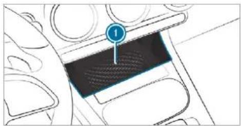
natural_image
Diagram of a car interior showing a hand holding a blue circular object labeled '1' (no text or symbols beyond the label)To connect a mobile phone: hold the NFC area of the mobile phone (see manufacturer's operating instructions) on mat ① or place the mobile phone on it.
▶ Follow the additional prompts on the media display to connect the mobile phone. Connect the mobile phone in single telephone mode ( page 480). Connect the mobile phone in two phone mode ( page 481).
To replace a mobile phone: hold the NFC area of the mobile phone (see manufacturer's operating instructions) on mat ① or place the mobile phone on it.
▶ Follow the additional prompts on the media display to replace the mobile phone in one or two phone mode ( page 481).
If required, confirm the prompts on your mobile phone (see the manufacturer's operating instructions).
If your mobile phone supports wireless charging, it will be automatically charged via NFC when it is connected or replaced. A requirement for this is that the mobile phone is on the mat ( page 171).
If you want to charge a mobile phone without connecting it to the multimedia system, lay it on the mat without beforehand unblocking the screen.
Further information can be found at: https://www.mercedes-benz-mobile.com/
Setting the reception and transmission volume
Requirements:
• A mobile phone is connected ( page 480).
Multimedia system:

This function ensures optimal language quality.
i Please note that the respective mobile phone must be selected for adjustment of the reception and transmission volume.
▶ Select Volume.
Set the reception and transmission volume using Reception and Transmission.
Further information on the recommended reception and transmission volume: https://www.mercedes-benz-mobile.com/
Setting the ringtone
Multimedia system:

Select Ringtones.
Set the ringtone.
If the mobile phone supports the transfer of the ringtone, you will hear the ringtone of the mobile phone instead of that of the vehicle audio system.
Starting/stopping mobile phone voice recognition
Requirements:
- The mobile phone in the foreground is connected with the multimedia system (→ page 480).
Starting mobile phone voice recognition
Press and hold the ☐ button on the multifunction steering wheel for more than one second. You can use mobile phone voice recognition.
Stopping mobile phone voice recognition
Press the 🔒 or 🔒 button on the multifunction steering wheel.
If a mobile phone is connected via Smartphone Integration, the voice recognition of this mobile phone is started or stopped.
Car telephony
Overview of car telephony operating modes
Car telephony offers you the following operating modes:
- Using a mobile phone with Bluetooth profile SAP (SIM Access Profile) (→ page 485)
• Using SIM card (→ page 486) - Using SIM card in combination with a specific mobile phone
This operating mode is mainly intended for those using multiple SIM cards. As soon as the mobile phone associated with the SIM card is connected with the multimedia system in the vehicle, the SIM card is automatically activated for car telephony. The associa-
tion of the SIM card with the set mobile phone prevents automatic activation of car telephony via the SIM card if the vehicle is borrowed by other persons, for example (→ page 486).
Symbols of car telephony
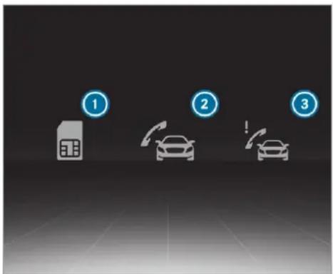
text_image
Diagram showing three car icons labeled 1, 2, and 3, likely representing charging stations or charging modes.① Mobile phone is only used in combination with SIM Card
② Car phone connected
3 Fault with car telephony (check the status of the SIM card PIN ( page 486))
Setting up car telephony with a mobile phone via Bluetooth® SAP Requirements:
- Bluetooth® is activated on the mobile phone (see the manufacturer's operating instructions).
- Bluetooth ^ is activated on the multimedia system (→ page 418).
- The mobile phone supports the Bluetooth® profile SAP (SIM Access Profile).
Multimedia system:

Select the device manager.
▶ Select Connect new device.
Select a mobile phone with Bluetooth profile SAP.
Connect the mobile phone with the multimedia system via Secure Simple Pairing or the passkey ( page 480).
Enter the SIM card PIN and confirm.
If the mobile phone is connected as a car phone, calls cannot be made on the mobile phone, since its SIM card is being used by the vehicle.
i Connect the mobile phone to the vehicle hotspot for data reception.
Changing between Bluetooth ^® telephony and car telephony via Bluetooth ^® profile SAP
To change to Bluetooth® telephony: select the ⋯ symbol in the line of the mobile phone in the device manager.
Select Use as Bluetooth phone.
The mobile phone is no longer connected via Bluetooth® profile SAP but via the Bluetooth® HFP profile (Hands Free Profile).
To change to car telephony via Bluetooth® profile SAP: select the ⋯ symbol in the line of the mobile phone in the device manager.
Select Use as car phone.
The mobile phone is connected using the SAP Bluetooth® profile.
① This option is only shown if the mobile phone supports the Bluetooth SAP profile.
Setting up car telephony via SIM card
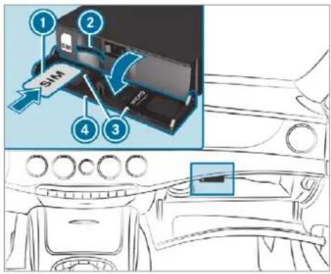
text_image
① ② SM ④ ③ MEC3Lightly press cover ④ of the compartment for the SIM card reader in the glove box. The compartment opens.
Insert SIM card ① in card slot ②. Micro or nano cards can be used with adapters ③.
If required confirm that mobile phones already connected should be disconnected.
If required enter and confirm the SIM card PIN.
To use a SIM card individually: answer the SIM card connected. Do you want to use this SIM card with only one particular device? query with No. Incoming and outgoing calls are available in the vehicle's multimedia system using the SIM card.
Every time the vehicle is started, the SIM card is automatically connected and logged into the radio cell.
In addition to the SIM card another mobile phone can be connected in two phone mode (→ page 481).
To use the SIM card only in combination with a specific mobile phone: answer the SIM card connected. Do you want to use this SIM card with only one particular device? query with Yes.
Select a mobile phone that has been authorised or connect a new mobile phone. Incoming and outgoing calls are available in the vehicle's multimedia system using the SIM card.
The SIM card only logs into the radio cell when the associated mobile phone is connected. The associated mobile phone can be fixed in the settings for the SIM card ( page 487).
Checking the status of the SIM card PIN
Multimedia system:
Phone
The symbol for car telephony appears with an exclamation mark if re-entering the PIN is required.
Select the device manager.
Select the name of the mobile phone or the SIM card.
Enter the SIM card PIN and confirm.
Calling up the car telephony settings
Multimedia system:

▶ Select the desired settings.
The following settings are available:
• SIM card (→ page 487)
- Withhold phone number (→ page 487)
• Call waiting ( page 487)
- Select network provider (→ page 488)
• Call forwarding (→ page 488)
• Data usage, voice (→ page 488)
Setting the SIM card
Multimedia system:

SIM card
The following options are available:
To save a PIN: press the button.
The LED symbol lights up. The SIM card PIN is saved.
To re-enter a PIN: the PIN is entered automatically.
To combine a SIM card with a specific mobile phone: press the Activation only with device button.
The LED symbol lights up. Use of the SIM card with a specific mobile phone is activated. The name of the associated mobile phone is shown.
To use the SIM card alone: press the Activation only with device button again.
The LED symbol goes out. Use of the SIM card with a specific mobile phone is deactivated.
To change the associated mobile phone:
when the LED symbol opposite Activation only with device is lit, press the button twice. The LED symbol first goes out and then lights up again.
Answer the SIM card connected. Do you want to use this SIM card with only one particular device? query with Yes.
Select a mobile phone that has been authorised or connect a new mobile phone.
Setting telephone number transmission
Multimedia system:

▶Withhold phone number
The following options are available:
▶ Withhold own number
Show own number
Network standard
Setting the call waiting function
Multimedia system:

▶ Call waiting
To activate call waiting: press the button. The LED symbol lights up. The function is active.
To deactivate call waiting: press the button. The LED symbol goes out. The function is deactivated.
Select a network provider
Multimedia system:

To select automatically: press the Automatically select network provider button. The LED symbol lights up. The function is active.
To select manually: press the Automatically select network provider button. The LED symbol goes out. The function is deactivated.
Select Call up network status.
Available network providers are shown.
▶ Select a network provider.
Setting call forwarding
Multimedia system:

▶ Select New call forwarding rule.
The following arrangements for forwarding a call appear:
- Forward all calls
- Forward call if engaged
• Forward call if call missed
• Forward call if unreachable
Select an arrangement.
Entering a telephone number
Setting the data use language
Multimedia system:

You have the following options when selecting the transmission standard:
▶ Automatic
▶ Automatic (without LTE)
To select manually: select the desired standard 3G or 2G.
Calls
Telephone operation
Multimedia system:

Making a call by entering the numbers
Select
Enter a number.
Select □.
The call is made.
Accepting a call
Select Accept.
Rejecting a call
Select Reject.
Ending a call
Select
Activating functions during a call
The following functions are available during a call:

End call

Microphone off

Numerical keypad (show to send DTMF tones)

Add call

Transfer to phone (an active call in hands-free mode is transferred over to the telephone)
Select a function.
Conducting calls with several participants Requirements:
• There is an active call (→ page 488).
• Another call is being made.
Switching between calls
Select the contact. The selected call is active. The other call is on hold.
Activating a call on hold
▶ Select the contact of the call on hold.
Conducting a conference call
Select 📁️ Create conferen. call. The new participant is included in the conference call.
Ending an active call
▶ Select 📊 End call.
① On some mobile phones, the call on hold is① activated as soon as the active call is ended.
Accepting/rejecting a waiting call Requirements:
• There is an active call ( page 488).
If you receive a call while already in a call, a message is displayed.
Depending on the mobile phone and mobile work operator you will hear a call-waiting sound. In addition, in two phone mode you will hear acoustic signal when the call goes through to the other (not yet active) mobile phone.
Select Accept.
The incoming call is ac
If only one mobile phone is connected with the multimedia system, the previous call will be put on hold.
If during a call you accept a call with the other mobile phone when in two phone mode then the existing call is ended.
Select Reject.
This function and behaviour depends on your mobile phone network provider and the mobile phone (see the manufacturer's operating instructions).
Contacts
Information about the contacts menu
The contacts menu contains all contacts from existing data sources, e.g. mobile phone or dat storage medium.
Depending on the data source, it is possible to save/load the following number of contacts:
• Permanently saved contacts: 3,000 entries
- Contacts loaded from the mobile phone: 5,000 entries per mobile phone From the contacts menu, you can perform the following actions:
• Make a call, for example call a contact ( page 491)
• Navigation ( page 439)
• Compose messages (→ page 494)
• Additional options (→ page 491)
If a mobile phone is connected to the multimedia system ( page 480) and automatic calling ( page 490) is activated, the mobile phone contacts are displayed in the address book.
The multimedia system can show suggestions based on frequently used contacts as well as incoming and outgoing calls ( page 401). These are shown at the top of the contact list.
Downloading mobile phone contacts
Multimedia system:

▶ Select Contacts & call list.
Automatically
If the Synchronise contacts automatically function is not active: activate the function by pressing once.
Manually
If the Synchronise contacts automatically function is active: deactivate the function by pressing once. Select Synchronise contacts.
You can see from the status of controller to the right of the Synchronise contacts automatically display text whether the function is active.
Calling up contacts
Multimedia system:

The following options can be used to search for contacts:
- searching by initials
- searching by name
• searching by phone number
Enter characters into the search field.
Select the contact.
A contact can contain the following details:
- phone numbers
- navigation addresses
- geo-coordinates
- Internet address
- e-mail addresses
- voice tag (if set)
- relation (if set)
Editing the format of a contact's name Multimedia system:

Select General.
▶ Select Name format.
The following options are available:
- Surname, First name
- Surname First name
- First name Surname
Select an option.
Overview of importing contacts
Contacts from various sources
Source Requirements:
| USB device The USB device is connected with the USB port. | |
| Bluetoothconnection | If the sending of vCards via Bluetooth is supported, vCards can be received on mobile phones or net-books, for example. Bluetooth® is activated in the multimedia system and on the respective device (see the manufacturer's operating instructions). |
Importing contacts into the contacts menu
Multimedia system:

Select a mobile phone
Select an option.
Saving a mobile phone contact
Multimedia system:

Select in the line of the mobile phone contact.
Select ⋯.
▶ Select Save in vehicle.
Select Yes.
The contact saved in the multimedia system is identified by the ↓ symbol.
Calling a contact
Multimedia system:

Select Search contacts.
Enter characters into the search field.
Select the contact.
Select the telephone number. The number is dialled.
Selecting further options in the contacts menu
Multimedia system:

Select ▶ in the line of the contact.
Select
^2 Depending on the stored data, the following options are available:
- Add voice tag/Delete voice tag
- Set relation/Remove relation
- Send DTMF tones (for a number with DTMF tones)
The function is available when a call is active
▶ Select an option.
Selecting options for suggestions in the contacts menu
Requirements:
• A profile has been created ( page 396).
- The Allow contact suggestions setting is switched on (→ page 401).
Multimedia system:

Select Call list.
Select ▼ in the line of a suggested tact.
The following options are available:
- Save as favourite The suggestions are saved as global favourites and do not appear on the home screen. - Do not suggest
Select an option.
Deleting contacts Requirements:
• The contacts are saved in the vehicle.
- To delete an individual contact, this has been imported manually into the vehicle.
Multimedia system:

Deleting all contacts
Select General. Select Delete contacts. Select an option.
Deleting a contact
- Select .
- Select > in the line of the contact.
- Select ...
- Select Delete contact.
- Select Yes.
Saving a contact as a favourite
Multimedia system:

▶ Select a contact.
- Select ▶ in the line of the contact. - Select the telephone number. The contact is stored as a favourite in the telephone menu overview.
Deleting favourites in the telephone menu overview
Multimedia system:

- Select a favourite in the telephone menu overview (→ page 492). - Press and hold the favourite. - Select Delete. - Select Yes.
Deleting all favourites
Tap on in the media display. Select Phone. Select Select the connected telephone. Select Contacts & call list.
Select Delete all favourites.
A pop-up window appears: Do you want to delete all favourites?
Select Yes.
Call list
Overview of the call list
Depending on whether your mobile phone supports the PBAP Bluetooth® profile or not, this can have different effects on the presentation and functions of the call list.
If the PBAP Bluetoothprofile is supported, the effects are as follows:
- The call lists from the mobile phone are played in the multimedia system.
- When connecting the mobile phone, you have to confirm the connection for the PBAP Bluetooth® profile.
If the PBAP Bluetooth® profile is not supported, the effects are as follows:
- The multimedia system generates a call list independently as soon as calls are made in the vehicle.
- The call list is not synchronised with the lists in the mobile phone.
The multimedia system can show suggestions based on frequently used contacts as well as incoming and outgoing calls ( page 401). These are shown at the top of the call list.
Making a call from the call list Multimedia system:
s-→ Phone
Select Call list. Select an entry. The call is made.
Calling up additional options in the call list Multimedia system:
Phone
Select Call list.
For previously stored contacts: select ▷ in the line of an entry.
The search results are displayed.
For contacts who have not been stored: select
call Selecting options for suggestions in the call list
Requirements:
• A profile has been created ( page 396).
- The Allow contact suggestions setting is switched on (→ page 401).
Multimedia system:
Phone
Select Call list.
Select ☑ in the line of a suggested entry. The following options are available:
- Save as favourite
- Do not suggest
Select an option.
Deleting the call list
Multimedia system:

▶ Select Contacts & call list.
▶ Select Delete call list.
Select Yes.
This function is only available if your mobile does not support the PBAP Bluetooth profile.
Text messages
Overview of message functions
In the messages menu you can receive and send text messages.
If the connected mobile phone supports the Bluetooth® MAP profile, the message function can be used on the multimedia system.
You can obtain further information about settings and supported functions of Bluetooth® capable mobile phones from a Mercedes-Benz
service centre or at: https://www.mercedes-benz-mobile.com/
Some mobile phones require further settings after being connected to the multimedia system (see manufacturer's operating instructions).
Setting message displays
Multimedia system:

▶ Select Message display.
The following options are available:
- All messages
- New and unread messages
- Messages while the vehicle is in motion
- Off (the message function is no longer available.)
Select a setting.
Reading messages
Multimedia system:

Using the read-aloud function
Select a contact.
Select [icon] to read aloud.
The message is read aloud.
Dictating and sending a new message Requirements:
• There is an Internet connection.
Multimedia system:

Select a new message using 🔒.
Adding a recipient
Select +.
Select a contact.
Dictating text
Select
The dictating function is started.
Say the message.
After the voice message has been processed, it is shown as text.
Sending a message
Select Send.
When the vehicle is stationary you can use the keyboard to write a message. No Internet connection is required to use the keyboard.
Replying to a message in the messaging history
Multimedia system:


A message list is shown.
Select ▶ next to a contact. The messaging history with this contact is shown.
Select . The dictating function is started.
Say the message.
After the voice message has been processed,
it is shown as text.
Select Send.
Using message templates
Multimedia system:

Using a template as a new message
▶ Select 📋 to write a new message.
▶ Add a recipient using ⊕.
Select a = template.
Answering a message with a template
▶ Select a message sequence with a contact.
Select a template.
Select a email template.
Forwarding a message
Multimedia system:

A message list is shown.
Select ▶ next to a contact.
The messaging history with this contact is shown.
▶ Press and hold on a message.
To forward a message: select Forward.
Calling a message sender
Multimedia system:

A message list is shown.
Select ▶ next to a contact.
The messaging history with this contact is shown.
Select
Select Call.
Using telephone numbers or URLs from a text message Requirements:
- An Internet connection is available to call up a URL.
Multimedia system:

A message list is shown.
Select > next to a contact.
The messaging history with this contact is shown.
Select a telephone number or a URL in the message.
If a URL is selected the web browser opens.
If a telephone number is selected the following options are available:
- Call
- New message
▶ Select an option.
Deleting a message
Multimedia system:

▶ Select a contact.
Press and hold on a message.
To delete the message: select Delete.
In-Car Office
In-Car Office functions
Using In-Car Office, you can connect your online services with the multimedia system.
The following functions are available:
- Display of the upcoming appointments in the calendar.
- Start navigation to an appointment. It is a requirement that the appointment contains a navigable destination for the location.
• Display the appointment. - Display and selection of tasks and calls to complete.
i Please note that certain functions are only available when the vehicle is stationary.
Calling up In-Car Office Requirements:
- A mobile phone is connected as the main phone to the multimedia system.
- You have a user account in the Mercedes me portal: https://me.secure.mercedes-benz.com
- The In-Car Office service is activated in the Mercedes me portal.
- You have a user account with an online service, e.g. with Office 365, and have connected this with In-Car Office via the Mercedes me portal.
Multimedia system:

Select In-Car Office. You will see an appointments overview for the current day.
You can find the following displays in the appointments overview:
• All-day appointments: All day
- Appointments with a limited duration, e.g. four-hour appointment with starting and completion time details.
Selecting a calendar entry function in In-Car Office
Multimedia system:
Mercedes me & Apps In-Car Office Calendar
Select an appointment. The following functions are available:
Select a function.
i Some functions are only available when additional information about the appointment is entered. Functions which are not available are not shown.
The Call function is only available if a number for the appointment has been saved. The Navigate function is only available, if a navigable location for the appointment has been saved in the associated online account
Selecting the functions of Tasks & Calls
Multimedia system:
Mercedes me & Apps In-Car Office Tasks & calls
Select an entry. The following functions are available: - Read aloud - Call This option is only available for tasks if a telephone number has been saved. - Delete Select an option.
Marking an entry as completed in Tasks & Calls
Multimedia system:
Mercedes me & Apps In-Car Office Tasks & calls
Select the Tasks & calls symbol. An overview of the tasks and calls appears. Individual task or call: mark the selected entry as completed √.
Noting an incoming call
When you receive an incoming call a prompt appears asking whether the call should be accepted, rejected or noted.
Select Reminder. The call is declined and added to the In-Call Office Tasks & calls automatically.
Managing e-mails
Multimedia system:

Showing/reading e-mail
▶ Select an e-mail. The e-mail is opened.
Additional functions are available:
- Creating e-mail.(→ page 498)
• Answering e-mail (→ page 498)
• Forwarding e-mail(→ page 499)
Writing new e-mail
Requirements:
- A mobile phone with e-mail contacts is already connected to the multimedia system via Bluetooth ^® .
Multimedia system:

Using the keyboard
Select +.
▶ Add recipients using ⊕.
Enter the subject and text of the e-mail in the corresponding fields with the keypad.
Select Send.
Using the dictation function
The dictation function is not available everywhere nor without limitation. For initial activation of the function it may be necessary to select the terms of use in the Mercedes me portal.
Select . The dictating function is started.
▶ Dictate the subject and text of the e-mail. After the voice entry has been processed, it is shown as text.
Select Send.
Using voice control
Use the LINGUATRONIC Write an e-mail voice command.
You are guided by the dialogue.
i Additional information on operation of LINGUATRONIC ( page 361).
Answering e-mail Requirements:
- A mobile phone with e-mail contacts is connected to the multimedia system via Bluetooth®.
Using the keyboard
Select an e-mail.
Select Reply.
Enter the e-mail text in the corresponding field.
Select Send.
Using the dictation function
The dictation function is not available everywhere nor without limitation. For initial activation of the function it may be necessary select the terms of use in the Mercedes me portal.
Select an e-mail.
Select Reply.
Select . The dictating function is started.
▶ Dictate the text of the e-mail.
After the voice entry has been processed, it is shown as text.
Select Send.
Using voice control
Use the LINGUATRONIC Answer e-mail voice command. You are guided by the dialogue.
i Additional information on operation of LIN-GUATRONIC ( page 361).
Forwarding e-mail
Requirements:
• A mobile phone with e-mail contacts is con-Mercedes-Benz link
nected to the multimedia system via Bluetooth ^® .
Multimedia system:
Mercedes me & Apps
In-Car Office E-mail
Using the keyboard
Select an e-mail.
Select Forward.
To forward with attachment: select Forward with attachment.
To forward without attachment: select Forward without attachment.
Enter the e-mail text in the corresponding field using the keypad.
Select Send.
Overview of Mercedes-Benz Link
WARNING Risk of distraction from information systems and communications equipment
If you operate information and communication equipment integrated in the vehicle when driving, you will be distracted from the traffic situation. This could also cause you to lose control of the vehicle.
Only operate this equipment when the traffic situation permits.
If you cannot be sure of this, stop the vehicle whilst paying attention to road and traffic conditions and operate the equipment with the vehicle stationary.
You must observe the legal requirements for the country in which you are currently driving when operating the multimedia system.
With Mercedes-Benz Link you can use mobile phone functions via the multimedia system. It is operated using the touchscreen or the voice-
operated control system. You can activate the voice-operated control system by pressing and holding the button on the multifunction steering wheel.
When using Mercedes-Benz Link via the voice-operated control system, the multimedia system can still be operated via LINGUATRONIC ( page 361).
The Mercedes-Benz Link control box supplementary equipment is required for this. This is available at a Mercedes-Benz service centre.
Only one mobile phone at a time can be connected via Mercedes-Benz Link to the multimedia system.
When a mobile phone is connected with Mercedes-Benz Link, only one additional mobile phone can be connected using Bluetooth® with the multimedia system when in two phone mode.
The Mercedes-Benz Link control box uses the Android operating system.
The service provider is responsible for these apps and the services and content connected to it.
Notes on Mercedes-Benz Link
If a mobile phone is used with Mercedes-Benz Link, USB access using the media menu is possible for this mobile phone.
Only one route guidance can be active at a time. If route guidance is active on the media system, it is closed when route guidance is started on the mobile phone.
Connecting Mercedes-Benz Link with the multimedia system Requirements:
^25 The vehicle is fitted with the Mercedes-Benz Link control box.
- The Mercedes-Benz Link app is installed on the mobile phone.
• The mobile phone is switched on.
- Mercedes-Benz Link is connected to the multimedia system via the USB port using a suitable cable ( page 531).
The first activation of Mercedes-Benz Link on the multimedia system must be carried out when the vehicle is stationary for safety reasons.
Multimedia system:
Mercedes me & Apps
Smartphone ▶ Mercedes-Benz Link
▶ Start Mercedes-Benz Link
Accepting/rejecting the data protection regulations
For the initial start of the application: a message with the data protection provisions appears.
▶ Select Accept & start.
Quitting Mercedes-Benz Link
Press the button.
Mercedes-Benz Link starts automatically when it is connected with the system using a cable. If Mercedes-Benz Link was not displayed in the foreground before disconnecting, the application starts in the background when reconnected. You can call up Mercedes-Benz Link using the main menu.
You can find more information in the Mercedes-Benz Link control box operating instructions.
Calling up Mercedes-Benz Link sound settings
Multimedia system:


Mercedes me & Apps

martphone ▶ Mercedes-Benz Link


Select sound settings.
Ending Mercedes-Benz Link
Disconnect the connecting cable between Mercedes-Benz Link and the multimedia system.
Mercedes-Benz recommends disconnecting the connecting cable only when the vehicle is stationary.
Apple CarPlay®
Overview of Apple CarPlay®
A WARNING Risk of distraction from information systems and communications equipment
If you operate information and communication equipment integrated in the vehicle when driving, you will be distracted from the traffic situation. This could also cause you to lose control of the vehicle.
▶ Only operate this equipment when the traffic situation permits.
If you cannot be sure of this, stop the vehicle whilst paying attention to road and traffic conditions and operate the equipment with the vehicle stationary.
You must observe the legal requirements for the country in which you are currently driving when operating the multimedia system.
iPhone® functions can be used via the multimedia system using Apple CarPlay They are operated using the touchscreen, touchpad, Touch
Control or the S ^® voice-operated control system. You can activate the voice-operated control system by pressing and holding the _012 button on the multifunction steering wheel.
When using Apple CarPlay via the voice-operated control system, the multimedia system can still be operated via LINGUATRONIC (→ page 361).
Only one iPhone® at a time can be connected vi Apple CarPlay® with the multimedia system.
Also for use of Apple CarPlay with two phone mode, only one additional mobile phone can be connected using Bluetooth with the multimedia system.
The availability of Apple CarPlay may vary according to the country.
The service provider is responsible for this application and the services and content connected to it.
Apple CarPlay® is a registered trademark of Apple Inc.
Information on Apple CarPlay®
When Apple CarPlay ^® is being used, the iPod media source is not available for the respective iPhone ^® .
Only one route guidance can be active at a If route guidance is active on the multimedia tem, it is closed when route guidance is started on the mobile phone.
Connecting an iPhone ^® via Apple CarPlay ^® (cable)
Requirements:
- The current version of your device's operating system is being used (see the manufacturer's operating instructions).
- There is an Internet connection for the full range of functions for Apple CarPlay
- The iPhone ^ is connected to the multimedia system via the USB port using a suitable cable (→ page 531).
Multimedia system:
→ Mercedes me & Apps
▶▶ Smartphone ▶▶ Apple CarPlay
▶ Start Apple CarPlay
Alternative: If an Apple CarPlay application is active (e.g. when music is being played route guidance is active), you can call up active application using the RADIO, NAVI or MEDI, MAP or TEL application buttons (→ page 393).
Control using the application buttons can switched on or off ( page 502).
Accepting/rejecting the data protection regulations
For the initial start of the application: a message with the data protection provisions appears.
▶ Select Accept & start.
Exiting Apple CarPlay®
Press the button.
i Apple CarPlay ^ starts automatically when the iPhone ^ is connected with the system using a cable. If Apple CarPlay was not displayed in the foreground before disconnect-
ing, the application starts in the background when reconnected. You can call up Apple CarPlay ^® in the main menu.
Calling up Apple CarPlay ^® tone settings Multimedia system:
▶ Select sound settings.
Setting control of the application buttons (Apple CarPlay®)
Multimedia system:
Mercedes me & Apps Smartphone Apple CarPlay General
To switch on Control via application buttons: activate the display button.
To switch off Control via application buttons: deactivate the display button.
Ending Apple CarPlay®
To end the connection of Apple Car-Play®(with cable): disconnect the connec-
tion via the connecting cable between the mobile phone and multimedia system.
Mercedes-Benz recommends disconnecting the connecting cable only when the vehicle is stationary.
Android Auto
Android Auto overview
WARNING Risk of distraction from information systems and communications equipment
If you operate information and communication equipment integrated in the vehicle when driving, you will be distracted from the traffic situation. This could also cause you to lose control of the vehicle.
Only operate this equipment when the traffic situation permits.
If you cannot be sure of this, stop the vehicle whilst paying attention to road and traffic conditions and operate the equipment with the vehicle stationary.
You must observe the legal requirements for the country in which you are currently driving when operating the multimedia system.
Mobile phone functions can be used with Android Auto using the Android operating system on the multimedia system. It is operated using the touchscreen or the voice-operated control system. You can activate the voice-operated control system by pressing and holding the button on the multifunction steering wheel.
When using Android Auto via the voice-operated control system, the multimedia system can still be operated via LINGUATRONIC ( page 361).
Only one mobile phone at a time can be connected via Android Auto with the multimedia system.
Also for use of Android Auto with two phone mode, only one additional mobile phone can be connected using Bluetooth® with the multimedia system.
The availability of Android Auto and Android Auto apps may vary according to the country.
The service provider is responsible for this application and the services and content connected to it.
Information on Android Auto
If a mobile phone is used with Android Auto, USB access using the media menu is not possible for this mobile phone.
Only one route guidance can be active at a tir If route guidance is active on the multimedia system, it is closed when route guidance is started on the mobile phone.
Connecting a mobile phone via Android Auto (awired)
Requirements:
- The mobile phone supports Android Auto from Android 5.0.
- The Android Auto app is installed on the mobile phone.
- In order to use the telephone functions, the mobile phone must be connected to the multimedia system via Bluetooth (→ page 480).
If there was no prior Internet connection, this is established with the use of the mobile phone with Android Auto.
- The mobile phone is connected to the multi-media system via the USB port using suitable cable ( page 531).
- There is an Internet connection for the full range of functions for Android Auto.
Multimedia system:
→ Mercedes me & Apps
▶ Smartphone ▶ Android Auto
▶ Start Android Auto
Alternative: If an Android Auto application is active (e.g. when music is being played or route guidance is active), you can call up the active application using the RADIO ME-DIA, NAV MAF or TEL application buttons (→ page 393).
Control using the application buttons can switched on or off ( page 504).
The first activation of Android Auto on the multimedia system must be carried out when the vehicle is stationary for safety reasons.
Accepting/rejecting the data protection regulations
For the initial start of the application: a message with the data protection provisions appears.
Select Accept & start.
Exiting Android Auto
Press the button.
Android Auto starts automatically when the mobile phone is connected with the system using a cable. If Android Auto was not displayed in the foreground before disconnecting, the application starts in the background when reconnected. You can call up Android Auto in the main menu.
Calling up the Android Auto sound settings
Multimedia system:
→ ▶ Mercedes me & Apps
e ▶ Smartphone ▶ Android Auto ▶
▶ Select sound settings.
Setting control of the application buttons (Android Auto)
Multimedia system:
→ ▶ Mercedes me & Apps ▶ Smartphone ▶ Android Auto ▶ ▶ General
To switch on Control via application buttons: activate the display button.
To switch off Control via application buttons: deactivate the display button.
Ending Android Auto
To end the connection of Android Auto (with cable): disconnect the connection via the connecting cable between the mobile phone and multimedia system.
Mercedes-Benz recommends disconnecting the connecting cable only when the vehicle is stationary.
Transferred vehicle data with Android Auto and Apple CarPlay®
Overview of transferred vehicle data
When using Android Auto or Apple CarPlayer, a certain vehicle data is transferred to the mobile phone. This enables you to get the best out of selected mobile phone services. Vehicle data not directly accessible.
The following system information is transmitted:
• Software release of the multimedia system
• System ID (anonymised)
The transfer of this data is used to optimise communication between the vehicle and the mobile phone.
To do this, and to assign several vehicles to the mobile phone, a vehicle identifier is randomly generated.
This has no connection to the vehicle identification number (VIN) and is deleted when the multimedia system is reset ( page 426).
The following driving status data is transmitted:
• Transmission position engaged
- Distinction between parked, standstill, rolling and driving
• Day/night mode of the instrument cluster
The transfer of this data is used to alter how content is displayed to correspond to the driving situation.
^15 The following position data is transmitted:
- Coordinates
- Speed
- Compass direction
• Acceleration direction
This data is only transferred while the navigation system is active, in order to improve it (e.g. so it can continue functioning when in a tunnel).
Mercedes me calls
Making a call via the overhead control panel
Mercedes me calls are not possible in every country. Find out at a Mercedes-Benz service centre if these functions are available in your country.
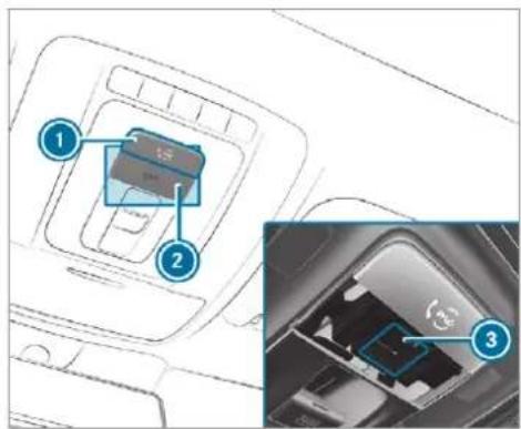
text_image
Diagram showing a device inside a car with labeled parts and an inset close-up of the interior component.① me button for service, concierge or information calls
② SOS button cover
③ SOS button (emergency call system)
To make a Mercedes me call: press me button ①.
To make an emergency call: press SOS button cover ② briefly to open.
Press and hold SOS button ③ for at least • Other products and services from Mercedes-one second.
If a Mercedes me call is active, an emergency Data is transferred during the connection to the call can still be triggered. This has priority over Mercedes-Benz Customer Centre ( page 507). all other active calls.
Information about the Mercedes me call using the me button
A call to the Mercedes-Benz Customer Centre has been initiated via the me button in the overhead control panel or the multimedia system ( page 505).
Using the voice dialogue system you access the desired service:
• Concierge Service (if the service is activated)
- Accident and breakdown management (→ page 508)
• Mercedes-Benz Customer Centre for general information about the vehicle
You can find information on the following topics:
• Activation of Mercedes me connect
- Operating the vehicle
• Nearest Mercedes-Benz service centre
Calling the Mercedes-Benz Customer Centre using the multimedia system Requirements:
- Access to a GSM network is available.
- The contract partner's GSM network coverage is available in the respective region.
- The ignition must be switched on so that vehicle data can be transferred automatically.
Multimedia system:

▶ Call Mercedes me connect.
After confirmation, the multimedia system sends the required vehicle data. The data transfer is shown in the media display.
Then, you can select a service and be connected to a specialist at the Mercedes-Benz Customer Centre.
-Further information on Mercedes me connect, the provided service scope and operation are available at: http://manuals.daimler.com/baix/cars/connectme/en_GB/index.html
Arranging a service appointment via a Mercedes me call
If you have activated the maintenance management service, relevant vehicle data is transferred automatically to the Mercedes-Benz Customer Centre. You will then receive individual recommendations regarding the maintenance of your vehicle.
Regardless of whether you have consented to the maintenance management service, the multi-media system reminds you after a certain amount of time that a service is due. A prompt appears asking if you would like to make an appointment.
To arrange a service appointment: select Call.
After your agreement the vehicle data is sent and a Mercedes-Benz Customer Centre employee deals with your appointment. The
information is then sent to your desired service outlet.
This will contact you to confirm the appointment and if necessary consult about the details.
If you select Later after the service message appears, the message is hidden and reappears after a certain period of time.
Giving consent to data transfer during a Mercedes me call Requirements:
- There is an active Mercedes me call via theted and the data protection prompt has been multimedia system or the me button in the confirmed the following data is transmitted:
Select Yes. Relevant identification data is transmitted automatically.
More information on Mercedes me: https://www.mercedes.me
Transferred data during a Mercedes me call
The data transferred during a Mercedes me call depends on which service is selected in the voice control system and whether Mercedes connect services are activated.
If no Mercedes me connect services are activa
The prompt to confirm data transfer does not appear in all countries.
If the accident and breakdown service and Mercedes me connect Concierge Service are not activated on Mercedes me, the Do you want to transmit vehicle data and the vehicle's position to the Mercedes-Benz Customer Centre in order to improve the processing of your request? message appears.
If a call is made for a service appointment via the service reminder, the following data may be transmitted:
- Current mileage and maintenance data Transfer is possible assuming the required data transfer technology is supported by the mobile service operator and the quality of the mobile connection is sufficient.
Self Accident and Breakdown Management is called via the voice control system and no service has been activated, but the data protection query has been confirmed, the following data can also be called up from the vehicle by the Mercedes-Benz Customer Centre:
• Current vehicle location
At the time of going to press, this function is technically not yet available but can be supported in the future.
If the data protection prompt has been rejected the following data is transmitted:
- Reason for the initiation of the call
- Rejection of the data protection prompt
Mercedes me connect
Notes on Mercedes me connect
Mercedes me connect is not available in every country. Find out at a Mercedes-Benz service centre if these functions are available in your country.
Mercedes me connect consists of multiple services.
Depending on whether the services are activated and on the vehicle equipment, you can use the following services via the multimedia system and the overhead control panel, for example:
- Accident and breakdown management (me button)
- If the service is activated: Concierge Service (me button)
- Mercedes-Benz emergency call system (automatic emergency call or SOS button)
Mercedes me connect accident and breakdown management, the Mercedes me connect Concierge Service (if service is activated) and the Mercedes-Benz emergency call centre are available for you around the clock.
The me button and the SOS button can be found on the vehicle's overhead control panel ( page 505).
You can also call the Mercedes-Benz Customer Centre using the multimedia system ( page 506).
Please note that Mercedes me connect is a Mercedes-Benz service. In emergencies, always call the national emergency services first using the standard national emergency service phone numbers. In emergencies, you can also use the Mercedes-Benz emergency call system ( page 512).
Observe the conditions of use for Mercedes me connect and other services. These can be obtained in the Mercedes me portal: https://me.secure.mercedes-benz.com
Further information on Mercedes me connect, the provided service scope and operation: http://manuals.daimler.com/baix/cars/connectme/en_GB/index.html
Information on Mercedes me connect accident and breakdown management
The accident and breakdown management can include the following functions:
- Supplement to the Mercedes-Benz emergency call system (→ page 512)
If necessary, the contact person at the Mercedes-Benz emergency call centre forwards the call to Mercedes me connect breakdown and accident management. Forwarding the call is however not possible in all countries. - Breakdown assistance by a mechanic on location and/or the towing away of the vehicle to the nearest Mercedes-Benz service centre
You may be charged for these services.
More information about Mercedes me connect services can be obtained in the Mercedes me portal: https://me.secure.mercedes-benz.com
Data transferred during Mercedes me connect call services
The data transferred during a Mercedes me nect call depends on the reason the call was initiated, which service is selected in the voice control system and which Mercedes me con services are activated.
Which data is transferred for the services can be taken from the currently valid terms of use. These can be obtained in the Mercedes metal: https://me.secure.mercedes-benz.com
Mercedes me and apps
Information about Mercedes me
When you log in with a user account to the Mercedes me portal, then services and offers from Mercedes-Benz will be available to you.
Availability is country-dependent.
For more information consult a Mercedes-Benz service centre or visit the Mercedes me portal: https://me.secure.mercedes-benz.com
i Make sure you always keep the Mercedes me apps updated.
Calling up the Mercedes me user account
Multimedia system:
con-→ Mercedes me & Apps
Your vehicle is connected with a user account
Select Mercedes me. Information about the connected user account appears.
por- Your vehicle is not yet connected with a user account
Select Mercedes me.
The instructions for creating a user account and connecting the vehicle with this follow on the media display.
If the Mercedes me app is available on a mobile phone, the vehicle connection can be accomplished using the QR code shown.
Calling up the Mercedes me services Requirements:
- The vehicle is connected with the user account.
Multimedia system:
→ Mercedes me & Apps
Select Services.
Within the various categories you can see the Mercedes me services you have already purchased and also those still available to purchase.
To activate or deactivate the services, log in to your user account in the Mercedes me portal.
Deleting a connection between a user account and the vehicle
Requirements:
- The (vehicle) profile of the user account that was first connected with the vehicle is selected.
• The profile is synchronised ( page 397). - A PIN has been set.
Multimedia system:
Mercedes me & Apps
Mercedes me
▶ Select Delete vehicle assignment.
Enter the PIN of the connected user account,
Only the user, whose user account was fi connected with the vehicle can delete the connection between all user accounts and the vehicle.
Mercedes-Benz emergency call system
Information on available emergency call systems
Two types of emergency call system are available to you in the vehicle:
• Mercedes-Benz emergency call system
112 emergency call system (EU eCall)
The following applies for both emergency call systems:
- The transfer of specific data is required for the intended function of both emergency call systems. This will be explained in the "Data transfer" section ( page 513).
- Both emergency call systems are included as standard equipment in your vehicle and are activated at the factory.
- The use of both emergency call systems is exempt from charges.
- Both emergency call systems only function in areas in which the wireless service providers offer mobile phone coverage.
For both systems, insufficient network coverage from the wireless service providers can result in an emergency call not being transmitted.
Differences between the Mercedes-Benz emergency call system and 112 emergency call system (EU eCall)
| Mercedes-Benz emergency call system | 112 emergency call system (EU eCall) |
| The Mercedes-Benz emergency call system is permanently logged in to the mobile phone network.Automatic and manual Mercedes-Benz emergency calls are transmitted to a Mercedes-Benz emergency call centre.In the event that the emergency call centre of the Mercedes-Benz emergency call system cannot be reached (e.g. due to a lack of network coverage), the 112 emergency call is carried out automatically. | If you decide on the 112 emergency call system (EU eCall), then the system only logs in to the mobile phone network after the triggering of a manual or automatic emergency call.The 112 emergency call system (EU eCall) transmits automatic and manual emergency calls directly to public coordination centres. |
The 112 emergency call system (EU eCall) in your vehicle meets the delegated regulation EU 2017/79. Proper and full functionality of the 112 emergency call system (EU eCall) depends on circumstances beyond the influence of Daimler AG. This includes mobile network coverage and the technical infrastructure of the public reception centres in the respective countries.
Please observe that in the event of a repair genuine Mercedes-Benz batteries must be used which have been certified pursuant to the delegated regulation EU 2017/79
(Appendix I). Other manufacturers are also permitted provided their batteries are certified according to the delegated regulation EU 2017/79.
You can find more information on the regional availability of the Mercedes-Benz emergency call system at: https://www.mercedes-benz-mobile.com/extra/ecall/
There is the option of deactivating the Mercedes-Benz emergency call system and using only the 112 emergency call system (EU eCall). Contact address for carrying out deacti-
vation of the Mercedes-Benz emergency call sys- tem are the local dealers.
Mercedes-Benz recommends the activation of the Mercedes-Benz emergency call system for the following reasons:
- In emergency situations when abroad, you can also get support in a language you speak.
- Several transmission technologies are used to accelerate the transfer of the accident data and improve reliability of the transmission.
- The Mercedes-Benz emergency call system is permanently logged in to the mobile phone network, which ensures faster placement of the emergency call and faster transfer of the accident data.
Measures for rescue, recovery or towing away can then be initiated in quickly.
- With a Mercedes-Benz emergency call, the accident data is only transferred to the public coordination centre with the approval of the customer.
In the event of an automatically triggered emergency call in which there is no voice contact, the accident data is transmitted immediately to the public emergency call centre.
- Should the Mercedes-Benz emergency call centre not be available, the 112 emergency call is carried out automatically.
Overview of emergency call systems
Both the Mercedes-Benz emergency call system as well as the 112 emergency call system (EU eCall) can help to reduce the time between an accident and the arrival of emergency services
at the site of the accident. They help locate an accident site in places that are difficult to access.
Both emergency call systems can initiate an emergency call automatically ( page 512) or manually.
Only make emergency calls if you or others are in need of rescue. Do not make an emergency call in the event of a breakdown or a similar situation.
Messages on the display
The following messages appear in the media display of both emergency call systems:
- SOS NOT READY: the ignition is not on or there is a malfunction with the emergency call system. This does not necessarily indicate complete failure of the emergency call system. Emergency calls call still be transmitted.
The display only refers to the vehicle and does not take account of the availability of mobile phone networks and the Mercedes-Benz emergency call centre.
The functional readiness of the emergency call system on the vehicle can be seen when the SOS NOT READY display disappears once the ignition is switched on.
- SOS: The icon appears in the display during an active emergency call.
If there is a malfunction in the emergency call system (e.g. a fault with the speaker, microphone, airbag, SOS button), a corresponding message appears in the multifunction display of the instrument cluster.
Triggering an automatic emergency call Requirements:
• The ignition is switched on.
• The starter battery is sufficiently charged.
Both the Mercedes-Benz emergency call system as well as the 112 emergency call system (EU eCall) automatically initiate an emergency call in the following situations:
- After activation of the restraint systems such as airbags or seat belt tensioners after an accident.
• After an automatically initiated emergency stop by Active Emergency Stop Assist.
The emergency call has been made:
- A voice connection is established with the emergency call centre.
- A message with accident data is transmitted to the emergency call centre.
The SOS button in the overhead control panel flashes until the emergency call is finished.
If no connection can be made to the public emergency services, a corresponding message appears in the display.
Dial the 112 emergency number or an appropriate local emergency call number on your mobile phone.
If an emergency call has been initiated:
- Remain in the vehicle if the road and traffic conditions permit you to do so until a voice connection is established with the emergency call centre.
- On the basis of the call, the emergency call centre decides whether it is necessary to call rescue teams and/or the police to the accident site.
- If no vehicle occupant answers, an ambulance is sent to the vehicle immediately.
Triggering a manual emergency call
To use the SOS button in the overhead control panel: press the SOS button at least one second long ( page 505).
To use voice control: use the LINGUA-TRONIC voice commands ( page 370).
The emergency call has been made:
- A voice connection is established with an emergency call centre.
-
Remain in the vehicle if the road and traffic conditions permit you to do so until a voice connection is established with the emergency call centre.
-
On the basis of the call, the emergency call centre decides whether it is necessary to call rescue teams and the police to the accident site.
- A message with accident data is transmitted to the emergency call centre.
If no connection can be made to the public emergency services, a corresponding message appears in the media display.
Dial the 112 emergency number or an appropriate local emergency call number on your mobile phone.
Emergency call system data transmission
For both the Mercedes-Benz emergency call system as well as the 112 emergency call system (EU eCall) data is transferred to the Mercedes-Benz emergency call centre or the public emergency call centre.
Depending on the emergency call system activated ( page 510) different data is transmitted to the appropriate emergency call centre.
Transferred data according to activated emergency call system:
| Mercedes-Benz emergency call | 112 emergency call |
| GPS position data of the vehicleGPS position data on the route (a few hundred metres before the accident)Direction of travelVehicle identification numberDrive type of the vehicle (e.g. petrol, diesel, CNG, LPG, electric or hydrogen)Number of people determined to be in the vehicleWhether the emergency call was initiated manually or automaticallyTime of the accidentLanguage setting on the multimedia systemWhether Mercedes me connect is available or notThis is a requirement for the option of forwarding the call to the Mercedes-Benz Customer Centre if necessary. | Vehicle's GPS position dataGPS position data on the route (a few hundred metres before the accident)Direction of travelVehicle identification numberDrive type of the vehicle (e.g. petrol, diesel, CNG, LPG, electric or hydrogen)Number of people determined to be in the vehicleWhether the emergency call was initiated manually or automaticallyTime of the accident |
If only the 112 emergency call system (EU eCall) is activated in the vehicle, the accident data is transmitted directly to the public emergency call centre.
For accident clarification purposes, the following measures can be taken up to an hour after the emergency call has been initiated:
- The current vehicle position can be called up.
- A voice connection to the vehicle occupants can be established.
- Emergency call data as described above can be called up.
For Russia: various functions, e.g. receiving traffic information, cannot be performed for up to two hours after sending an emergency call.
Function of the emergency call system self-diagnosis (Russia)
Your car verifies the operability of the emergency call system each time the ignition is ON. In case of system failure, you will be informed with text message on the instrument cluster and with red indicator SOS NOT READY on the media display.
Please, make sure, that during 30 seconds after switching ignition ON the red indicator SOS NOT READY in the upper right corner of the
media display is switched OFF, this means the emergency call system passed diagnostics successfully. If necessary, switch ON the media play, if it was switched OFF before.
Starting/ending ERA-GLONASS test mode (Russia) Requirements:
• The starter battery is sufficiently charged.
• The ignition is switched on.
- The vehicle has been stationary for at least one minute.
To start the test mode: press and hold the button on the multifunction steering wheel for at least five seconds. The test mode is started and automatically ends after the language test has been performed.
To end the test mode manually: switch off the ignition. The test mode is ended.
Information on data processing
dis Processing of personal data via the Mercedes-Benz emergency call system
All processing of personal data via the Mercedes-Benz emergency call system corresponds with the specifications in the EU Regulation 2016/679 "on the protection of individuals with regard to the processing of personal data (GDPR)".
The data is solely used by the Mercedes-Benz emergency call system for rescue and recovery in the event of an accident.
The owner of a vehicle, that is equipped with a Mercedes-Benz emergency call system in addition to the 112 emergency call system (EU eCall), has the right to use the 112 emergency call system instead of the Mercedes-Benz emergency call system.
Contact address for carrying out deactivation of the Mercedes-Benz emergency call system are the local dealers.
Processing of personal data via the 112 emergency call system (EU eCall)
All processing of personal data via the 112 emergency call system (EU eCall) corresponds with the specifications in the EU Regulation 2016/679 "on the protection of individuals with regard to the processing of personal data (GDPR)" and is based particularly on the necessity of upholding the vital interests of the affected person in accordance with Article 6, Clause 1, Letter d of the GDPR.
The processing of this type of data is strictly limited to the purpose of operating the emergency calls to the standard European emergency call number 112.
Data recipient
The recipients of data that is processed using the 112 emergency call system (EU eCall) are the relevant emergency call inquiry terminals that are specified to first receive and handle emergency calls to the standard European emergency call number 112 by the respective country authorities in whose territory you are located.
Arrangements for data processing
Both emergency call systems are designed so that the following requirements are fulfilled:
- The data contained in the system memory not accessible outside the system prior to the initiation of an emergency call.
- Both emergency call systems cannot be traced and there is no continuous tracking normal operation.
- The data in the system's internal memory automatically and continuously deleted.
- The location data of the vehicle is continuously overwritten in the system's internal memory, so that no more than the last three current locations required for the normal function of the system are available.
- The record of the activity data of both emergency call systems is only kept for as long as is required to fulfil the purpose of handling the emergency call, and under no circumstances for more than 13 hours after the time that an emergency call is initiated.
Rights of persons affected by the data processing
The person affected by the data processing (the vehicle owner) has the right to access the data is and if applicable can demand the correction, deletion or barring of data that affects him or her and that the processing of which does not correspond with the GDPR regulations. Each correction, deletion or barring carried out according to this regulation must be shared with the third party to which the data has been transmitted, provided this does not prove to be infeasible and does not incur disproportionate expenditure.
The person affected by the data processing has the right to complain to the appropriate data protection authority should they be of the opinion that their rights have been infringed by the processing of their personal data.
Responsible contact point for the processing of access rights: Authorised company representative for data protection, Daimler AG, HPC G353, D-70546 Stuttgart, Germany
Online and Internet functions
Internet connection
Information on connecting to the Internet
WARNING Risk of distraction from information systems and communications equipment
If you operate information and communication equipment integrated in the vehicle when driving, you will be distracted from the traffic situation. This could also cause you to lose control of the vehicle.
Only operate this equipment when the traffic situation permits.
If you cannot be sure of this, stop the vehicle whilst paying attention to road and traffic conditions and operate the equipment with the vehicle stationary.
You must observe the legal requirements for the country in which you are currently driving when operating the multimedia system.
A WARNING Risk of an accident from operating mobile communication equipment while the vehicle is in motion
Mobile communications devices distract the driver from the traffic situation. This could also cause the driver to lose control of the vehicle.
As the driver, only operate mobile communications devices when the vehicle is stationary.
As a vehicle occupant, only use mobile communications devices in the areas intended for this purpose, e.g. in the rear passenger compartment.
You must observe the legal requirements for the country in which you are currently driving when operating mobile communication equipment in the vehicle.
Depending on the vehicle's equipment, you can establish an Internet connection in the following ways:
- Vehicles with a communication module: Internet use including Mercedes me connect services and data roaming (→ page 517).
-
Vehicles without a communication module:
-
via Wi-Fi with a data-enabled mobile phone ( page 518)
- via Bluetooth® with a data-enabled mobile phone (→ page 518)
• via car telephony ( page 519)
The Internet functions can only be used to a listed degree whilst driving.
Function of the communication module
On vehicles with a built-in communication module, the Internet connection is established via an integrated SIM card.
To use Internet access via the communication module the following conditions must be met:
- Mercedes me connect is active and ready operation.
- Mercedes me connect is activated for Internet access.
- In some countries: data volume via Mercedes me connect is available.
In some countries: if the data volume limit is reached, the availability of Mercedes me connect services is limited. The data volume must be purchased via Mercedes me connect.
Contact a Mercedes-Benz service centre to find out whether it is possible to purchase data volume in your country.
Setting up an Internet connection via Wi-Fi Requirements:
- the Wi-Fi function is activated on the multi-media system ( page 418).
-
the Wi-Fi function is activated on the mobile phone (see the manufacturer's operating instructions).
-
Internet access via Wi-Fi is activated (see the manufacturer's operating instructions).
The Internet connection via Wi-Fi is restricted or does not function if:
• the mobile phone is switched off - mobile data use is deactivated on the mobile phone
- the Wi-Fi function is deactivated on the multi-media system
- the Wi-Fi function is deactivated on the mobile phone
- Internet access via Wi-Fi is deactivated on the mobile phone
Multimedia system:
→ ▶ Settings ▶ System
Wi-Fi & Bluetooth Internet settings
Connect via Wi-Fi
Select the network.
Log in to the Wi-Fi network ( page 418).
Setting up an Internet connection via Bluetooth®
Requirements:
- The mobile phone supports the Bluetooth® profile PAN (Personal Area Network).
The mobile phone is connected to the multi-media system via Bluetooth(→ page 480). If a mobile phone is connected to the multi-media system for the first time via Bluetooth®, you will be assisted through the process of setting up an Internet connection.
The Internet connection can also be configured manually.
Multimedia system:
→ Settings ▶ System
Wi-Fi & Bluetooth Internet settings
Connect via Bluetooth
Select the mobile phone.
The Internet connection is established.
The Internet connection via Bluetooth is restricted or does not function in the following cases:
• the mobile phone is switched off
- the mobile phone is connected a an additional mobile phone
- the mobile phone network coverage is insufficient
- mobile data use is deactivated on the mobile phone
- the Bluetooth® function on the multimedia system is switched off and the mobile phone is to be connected via Bluetooth®
- the Bluetooth® function is switched off on the mobile phone and the mobile phone is to be connected via Bluetooth
- neither the mobile phone network nor the mobile phone allow simultaneous use of a telephone and an Internet connection
- the mobile phone has not been enabled for Internet access via Bluetooth
Setting up an Internet connection using car telephony Requirements:
- This equipment and function is available only for Mercedes-Maybach vehicles.
For use with a mobile phone:
- The mobile phone supports the Bluetooth® SAP profile (SIM Access Profile) (see manufacturer's operating instructions).
- The mobile phone is switched on.
- The mobile phone is only connected as an SAP telephone and not in the Hands-Free Profile.
Using a SIM card:
- A SIM card is inserted in the card slot in the telephone module.
- The SIM card PIN is entered in the multi-media system.
After connecting the mobile phone or the SIM card with the multimedia system, there follows an automatic query about configuration of the hotspot.
Confirm the query for setting up the mobile hotspot via car telephony with Yes. A submenu for the hotspot manual configuration settings appears.
To set the access data for the wireless service provider manually: check the access data in the overview.
▶ Select Confirm settings.
If the provider is recognised correctly, the correct settings are already entered. If the access data is not correct, you can adjust this using the predefined settings.
To select the predefined access data of the mobile phone network provider: select the Select predefined settings submenu. A list of countries appears.
Select the country of your mobile phone network provider.
The list of available providers appears.
▶ Select your mobile phone network provider. When an overview of the provider settings appears, make the necessary settings.
▶ Select Confirm settings.
A confirmation for successful configuration appears.
To avoid possible additional costs, set the access data in the manual configuration settings, e.g. the Roaming option, according to your data tariff. You can contact your mobile phone network provider to obtain the precise access data.
▶ Confirm the connection with the vehicle hotspot using the security key ( page 420).
Only for connections using the Bluetooth® SAP profile: if you use a mobile phone to provide the mobile hotspot for the vehicle, this telephone will no longer have any telephony and Internet functions and it cannot receive any more mobile phone data. To continue to use Internet functions on the mobile phone, you can connect it with the vehicle hotspot. In this way, the mobile phone accesses its own mobile phone data again, albeit using Wi-Fi. For this reason, to avoid additional costs, switch off the automatic download of software updates via Wi-Fi on your mobile phone.
Setting up the mobile hotspot at a later time is also possible using the System menu. If required, you can call up and adjust the
access data at a later time in the same menu.
Establishing an automatic Internet connection
Multimedia system:
→ ▶ Settings ▶ System ▶ Wi-Fi & Bluetooth▶ Internet settings
▶ Highlight the mobile phone. ▶ Select ▶. ▶ Activate Permanent Internet connection □.
Cancelling Internet access permission for a mobile phone
Multimedia system:
→ ▶ Settings ▶ System ▶ Wi-Fi & Bluetooth▶ Internet settings
- Select > in the line of the mobile phone. - Select Delete configuration. - Select Yes.
Displaying mobile phone details
Multimedia system:
→ ▶ Settings ▶ System ▶ Wi-Fi & Bluetooth▶ Internet settings
▶ Select ▶ in the line of the mobile phone. ▶ Select Details.
Establishing an Internet connection
Multimedia system:
Mercedes me & Apps For example, select Browser.
The multimedia system usually establishes the Internet connection automatically. If the multimedia system is not connected to the Internet, the Internet connection is established when an Internet application is used.
i The availability of the function is dependent on the country.
Setting automatic disconnection of the Internet connection
Multimedia system:


Settings
System

Wi-Fi

etooth

net se
Select ▶ in the line of the mobile phone
▶ Select Disconnect when inactive.
The following options are available:
- 5 minutes
• 10 minutes - 20 minutes
- Unlimited
Select an option.
Connection status
Connection status overview
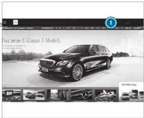
① Display of existing connection (double arrow) and reception field strength of the communication module or of the connected Bluetooth® device
① The function is country-dependent.
Displaying the connection status
Multimedia system:


Settings

System

Wi-

Bluetooth
▶ Select Internet status.
- When connected via Wi-Fi or a Bluetooth ^® device, the approximate data volume transmitted is displayed. The exact values can be requested from your mobile phone network provider.
-
In the case of a connection via the communication module the following status information is shown:
-
Type of network
- Status online/offline
Web browser
Calling up a web page

WARNING Risk of distraction from information systems and communications equipment
If you operate information and communication equipment integrated in the vehicle when driving, you will be distracted from the traffic situation. This could also cause you to lose control of the vehicle.
Only operate this equipment when the traffic situation permits.
If you cannot be sure of this, stop the vehicle whilst paying attention to road and traffic conditions and operate the equipment with the vehicle stationary.
You must observe the legal requirements for the country in which you are currently driving when operating the multimedia system.
Multimedia system:
Mercedes me & Apps
Browser
Calling up a new web page
Select URL.
Entering a web address
Select ok.
i The function is country-dependent.
① Websites cannot be shown while the vehicle is in motion.
Calling up a website from the browser history
To call up the previous or next page from the history: select ← or →.
Web browser overview
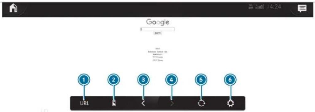
text_image
Google Search 1 2 3 4 5 6 URL① URL entry
2 Bookmarks
③ Web page, back
④ Web page, forwards
5 To refresh/stop
6 Options
Calling up web browser options
Multimedia system:

The following functions are available:
- Bookmarks
- Options with the settings:
Browser settings
- Delete browser data
▶ Select an option.
Change the settings.
Calling up the web browser settings
Multimedia system:

The following functions are available:
- Block popups
- Enable Javascript
- Enable cookies
To switch a function on: activate the display button.
To switch a function off: deactivate the display button.
Deleting Internet history
Multimedia system:
The following options are available:
• All
- Cache
- Cookies
- History
- Entered URLs
- Form data
Select an option.
Select Yes.
Managing bookmarks
Multimedia system:

Select
Selecting a bookmark
Select an entry.
Creating a bookmark
Select Add current site to bookmarks. The bookmark is created.
Editing a bookmark
Select ▶ after a bookmark.
Select Edit.
Enter the name.
Select OK.
Deleting a bookmark
Select ▷ after a bookmark.
Select Delete.
Select Yes.
Closing the browser
Multimedia system:
Tuneln radio
Calling up Tuneln radio
Requirements:
• A Mercedes me account is available.
- The vehicle is connected with the Mercedes me account.
- The Tuneln radio service is activated in the Mercedes me portal.
• The data volume is available.
Depending on the country, data volume may need to be purchased.
- A fast Internet connection for data transmission free of interference.
i New data volumes can be purchased in the Mercedes me portal
The functions and services are country-dependent. For more information, consult a Mercedes-Benz service centre.
Multimedia system:
→ ▶ Radio
Select Tuneln radio. The Tuneln menu appears. The last station set starts playing.
The connection quality depends on the local mobile phone reception.
Overview of Tuneln radio
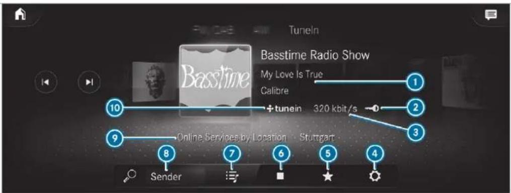
text_image
Tuneln Basstime Radio Show My Love Is True Calibre + tunein 320 kbit/s 1 2 3 9 Online Services by Location Stuttgart 8 7 6 5 4 Sender① Additional information on the current station
② Display (if connected to private user account)
3 Data transfer rate
4 Options
5 Favourites
6 To start/end
7 To browse
Search
9 Selected category
10 Internet Radio provider
Selecting and connecting to a Tuneln radio station
Multimedia system:
Radio ▶ Tuneln radio
Select
Select a category.
Select a station. The connection is established automatically.
or
▶ Select the search field.
Enter a station name.
i A relatively large volume of data can be transmitted when using TuneIn radio.
Saving/deleting a TuneIn radio station as a favourite
Multimedia system:
→ Radio → Tuneln radio
Select a station.
Select ★. The list of saved favourite stations appears.
▶ Select Add to favourites.
or
Create an account for the online provider (Tuneln radio) and then log in on the multimedia system. Your favourites are imported to the multimedia system.
Deleting favourites
▶ Select a station.
Select ★.
▶ Select Delete favourite.
Setting the TuneIn radio options
Multimedia system:
→ Radio ▶ Tuneln radio ▶
Tuneln radio
The following options are available:
- Select stream: select the stream quality.
- Login to TuneIn account: log in to your TuneIn user account.
- Log out of account: log out of your TuneIn user account.
Select an option.
Showing the station list for the last category selected
Multimedia system:
→ Radio ▶ Tuneln radio
Press the cover of the current station. Depending on how the station was selected, a station list is shown.
Media
Information about media mode
Information about supported formats and data storage media
⚠ WARNING Risk of distraction when handling data storage media
If you handle a data storage medium while driving, your attention is diverted from the traffic conditions. This could also cause you to lose control of the vehicle.
Only handle a data storage medium when the vehicle is stationary.
The multimedia system supports the following formats and data media:
| Permissible file systems | FAT32, exFAT, NTFS |
| Permissible data carriers | USB devices, iPod®/iPhone®, MTP devices, Bluetooth® audio equipment |
| Supported audio formats | MP3, WMA, AAC, WAV, FLAC, ALAC |
| Supported video formats | MPEG, AVI, DivX, MKV, MP4, M4V, WMV |
i Observe the following notes:
- The multimedia system supports a total of up to 50,000 files.
- Data storage media up to 2 TB are supported (32-bit address space).
-
Due to the large variety of available music and video files regarding encoders, sampling rates and data transfer rates, playback cannot be guaranteed.
-
Due to the wide range of USB devices available on the market, playback cannot be guaranteed for all USB devices.
- Videos up to FullHD (1920x1080) are supported.
- Copy-protected music and video files or DRM (Digital Rights Management) encrypted files cannot be played back.
- MP3 players must support Media Transfer Protocol (MTP).
Information on copyright protection and trademarks
Audio files which you create yourself (e.g. copies of data storage media you make yourself) are generally subject to copyright protection. In many countries, reproductions are not permitted without the prior consent of the copyright holder, even for private use. Make sure that you know about the applicable copyright regulations and that you comply with these.

text_image
DO DOLBY AUDIOManufactured under licence from Dolby Laboratories. Dolby, Dolby Audio and the double-D symbol are trademarks of Dolby Laboratories.

gracenote.
Gracenote, the Gracenote logo and logotype, "Powered by Gracenote", MusicID and Playlist Plus are either registered trademarks or trademarks of Gracenote, Inc. in the United States and/or other countries.
TIDAL
TIDAL and TIDAL logo are registered trademark of Aspiro AB in the European Union and other countries.
Overview of the media menu
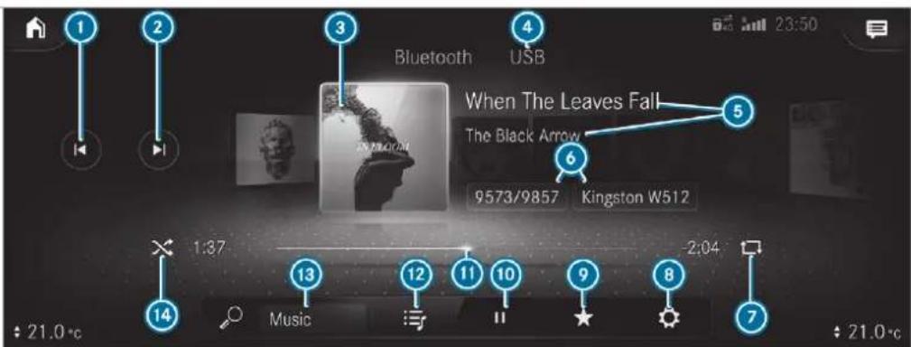
text_image
1 2 3 Bluetooth USB When The Leaves Fall The Black Arrow 9573/9857 Kingston W512 1:37 Music 2:04 21.0°C 21.0°C① Previous track or fast rewind
② Next track or fast forward
3 Album cover
4 Active media source
5 Track and artist
6 Current track number/track in playback list and active data storage medium
7 Repeat
Settings
Additional options
10 Controls playback
11 Timeline
12 Categories
13 Music search
14 Random playback
Connecting the data storage medium to the multimedia system
Connecting USB devices
! NOTE Damage caused by high temperatures
High temperatures can damage USB devices.
Remove the USB device after use and take it out of the vehicle.
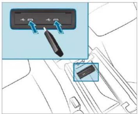
text_image
Diagram showing a device panel with three buttons and an inset close-up of the component, likely illustrating a mechanical or electrical assembly.The multimedia connection unit is found in the stowage compartment under the armrest and has two type C USB ports. Depending on the vehicle's equipment, additional USB ports can be found in the stowage compartment of the centre console or rear folding compartment.
Connect the USB device to the USB port.
USB hubs cannot be connected with the multimedia system.
When connecting several Apple devices simultaneously, pay attention to the order in which the devices are connected. The multimedia system only connects with the device that is connected first. Additional Apple ^® devices that are connected at the same time are only supplied with power.
Searching for and authorising a Bluetooth® audio device
Requirements:
- Bluetooth® is activated on the multimedia system and audio equipment.
- The audio equipment supports the Bluetooth® audio profiles A2DP and AVRCP.
- The audio equipment is "visible" for other devices.
Multimedia system:

Authorising a new Bluetooth ^® audio device
Select Connect new device.
Detected equipment is displayed in the device list.
Select an audio device.
Authorisation starts. A code is displayed on the multimedia system and on the mobile phone.
If the codes are identical, confirm on the audio equipment.
Select Only as Bluetooth audio device. The Bluetooth® audio equipment is connected with the multimedia system.
Connecting previously authorised Bluetooth® audio equipment
Select a Bluetooth® audio device from the list. The connection is established.
Starting media playback
Requirements:
- A data storage medium is connected to the multimedia system.
Multimedia system:

Select USB or Bluetooth as the media source.
Controlling media playback
Multimedia system:

To pause playback: select
To continue playback: select ▶.
To repeat a track: select ↩.
For the repeat function there are the following settings:
- Select once: the active playlist is repeated.
- Select twice: the current track is repeated.
- Select three times: the repeat function is deactivated.
To play back tracks in random order: select ↗.
To wind a track forwards or backwards: tap on the desired point on the timeline.
To select the next track: select ▷.
To select the previous track: select ▶.
To scroll through tracks quickly: press and hold ▶ or ▷.
To show the current track list: select the track image shown.
Additional options for setting media play-back
Multimedia system:
Media
Calling up additional options
Select ★. The additional options are shown.
The following options are available:
- Play similar tracks Select during playback of a track in order to create a playlist with similar tracks.
- Surprise mix A playlist with randomly selected tracks is created.
- Add to favourite songs The current track is added to the favourite songs.
- Delete from favourite songs The current track is removed from the favourite songs.
Select an option.
Music online
Calling up music online Requirements:
• A Mercedes me account is available.
- The vehicle is connected with the Mercedes me account.
- The online music service is activated in the Mercedes me portal.
There is an account for the music streaming service.
- A subscription for the music streaming service has been obtained.
- The data volume is available. Depending on the country, data volume may need to be purchased.
- A fast Internet connection for data transmission free of interference.
New data volumes can be purchased via the Mercedes me portal.
The functions and services are country-dependent. For more information, consult a Mercedes-Benz service centre.
Multimedia system:
Media
Select Online music. With Online music you can listen to music via a streaming service.
The online music menu is only shown if the online music service is activated in the Mercedes me portal and an account for the music streaming service is connected. The services in the Mercedes me portal have to be activated separately for each vehicle.
Music playback can be controlled with the Touch Control, the touchscreen, the touchpad or using the media application.
Searching for music in online music
Multimedia system:
→ Media → Online music
Searching for categories in online music
The media content of the streaming provider can be scanned through in the category search. The
available categories depend on the streaming provider.
Select 📊. The list of available categories appears.
Select a category.
Keyword search in online music
You can look for content using the keyword search with free text input.
Select . A keyboard for character entry appears.
Enter the term searched for.
The search begins from the first three characters entered. The more characters entered the more concrete the search results become.
Select the desired entry from the result list. If the selected result is an album, song or playback list then playback is started. If the selected result is a new category then this is opened in the search.
Configuring online music options
Multimedia system:
→ Media ▶ Online music
During media playback, press ★ in the Media menu. Three options appear:
- Add the song to your own favourites
- Add the song to a playback list
• The Title Radio option
Select one of the three options.
If Title Radio is selected, a playback list with similar music tracks is created. The available options depend on what is offered by the provider of the streaming service.
Media search
Notes about the search function in categories
Under 📊 you can search through all available media files. There are several categories availa-
ble for selection. The categories shown depend on the connected device and data format.
Available categories with Bluetoothaudio:
- Current tracklist
The folders and categories of the connected device are shown.
Available categories with audio files:
- Current tracklist
- Playlists
- Folder
• Albums - Artists
- Tracks
- Favourite songs
- Frequently played
• Most recently added - Mood (→ page 535)
- Music genres
• Year -
Composers
-
Select by cover
- Podcasts (Apple® devices)
• Audiobooks (Apple® devices)
Available categories with video files:
- Folder
- Videos
The categories are available as soon as the entire media content has been read in and analysed.
Starting a search in categories
Multimedia system:

Select a category.
Select 🔒 and enter a search term.
Sorting results shown or playing back all media found
Select
To play back all results found in the category: select Play all.
If, for example, the Albums category is active, all albums found by the desired artist will be played back.
To sort results alphabetically: select Sort from A-Z.
To sort results in reverse alphabetical order: select Sort from Z-A.
i The available options depend on the selected category and the connected device.
Using the keyword search
Multimedia system:

You can look for content using the keyword search with free text input.
Select 🔒.
A keyboard for character entry appears.
Enter the term searched for.
The search begins with the first character entered. The more characters entered the more concrete the search results become.
Select the desired entry from the result list. If the selected result is an album, song or playback list then playback is started. If the selected result is a new category then this is opened in the search.
Searching for a track according to mood Multimedia system:

By searching in categories, you can find music tracks suitable for a mood.
Select Mood.
A grid with the following moods appears:
- Positive
- Calm
- Dark
- Energetic
▶ Pull the controller to the desired position. The system searches for tracks that are suitable for the mood entered.
Making video settings
Multimedia system:

▶ Select Video settings.
▶ Select an aspect ratio.
Setting full screen
Select
Radio
Switching on the radio
Multimedia system:

Alternatively: press the RADIO MEDIA button. The radio display appears. You will hear the last station played on the last frequency band selected.
Radio overview
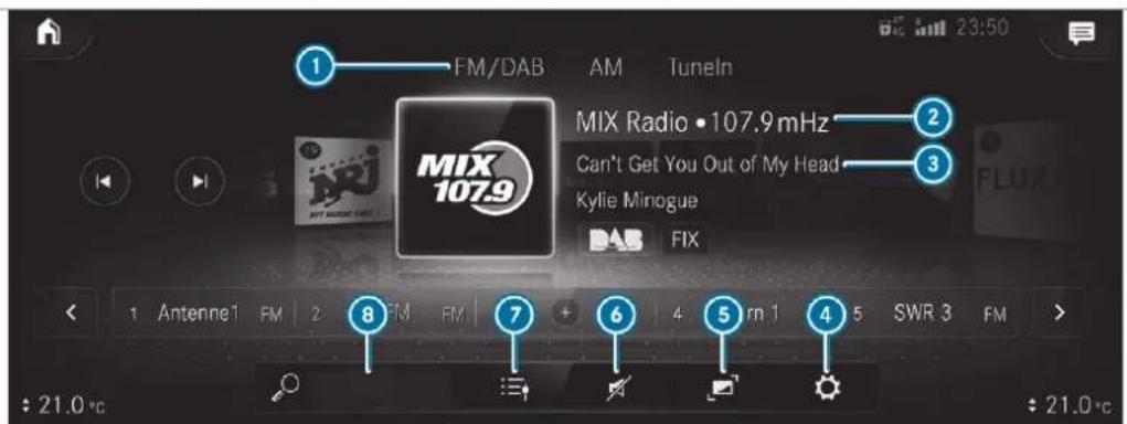
text_image
FM/DAB AM TuneIn MIX Radio •107.9 mHz Can't Get You Out of My Head Kylie Minogue FIX 1 Antenne 1 FM 2 FM FM 7 + 6 4 rm 5 SWR 3 FM : 21.0 °C : 21.0 °CActive frequency band
② Station name or set frequency
③ Artist, title, album and radio text
4 Options
5 Full screen/DAB slideshow
6 Mute function
7 Station list
Search
Setting the frequency band
Multimedia system:

▶ Select a frequency band.
Selecting a radio station
Multimedia system:

Swipe to the left or right on the control element.
Calling up the radio station list
Multimedia system:
→ ▶ Radio
Select :≡. The station list appears.
Select a station.
Searching for radio stations using station names or frequency entry
Multimedia system:
→ ▶ Radio
Select .
Enter a station name or frequency.
▶ Select a station.
Storing radio stations
Multimedia system:
→ ▶ Radio
▶ Select a radio station.
Memory slots are available in station presets
Select +.
or
▶ Press and hold on the radio station.
Replacing an entry in the station presets
Press and hold on an entry in the station pre-sets.
Select Yes.
Editing station presets
Multimedia system:
→ ▶ Radio
Moving stations
▶ Press and hold a stored station.
Select Move.
Move the station to the new position.
Deleting stations
▶ Press and hold a station.
Select Delete.
Replacing a station
Press and hold a station.
▶ Select Replace radio station.
Calling up a slide show (FM/DAB radio mode)
Multimedia system:
Radio
The slide show displays additional information provided by the station as an image. This can include logos, album covers, music tracks, programmes, news or service information, for example.
Select ▼.
Activating/deactivating the frequency fix function
Multimedia system:
→ Radio → General
▶ Switch Frequency fix on or off. If the function is activated, the set frequency is kept even if the reception is poor.
Activating/deactivating traffic announcements
Multimedia system:
→ Radio → General
▶ Switch Traffic announcements (TA) on or
Setting the traffic information service volume increase
Multimedia system:
Settings Audio
Select Navigation and traffic announcements.
▶ Select Traffic announc. vol. increase.
Set a level between 0 and 10.
Accept the value with <.
Displaying radio text
Multimedia system:
→ Radio → General
▶ Switch Radio text information on or off.
TV
Information on TV mode
Information on copyright protection and trademarks
fUbiquitous DTCP-IP
Copyright® 2015 Ubiquitous Corp.
DVB and DVB logos are trademarks of the DVB Project.
The TV tuner enables reception of digital channels according to the following standards:
• DVB-T
• DVB-T2
In some countries, the standards may not be available, or may not be available in all areas.
A Cl+ module (Common Interface Module), which is not included in the scope of delivery, is used to decrypt HD programmes according to the Cl+ standard. In some countries, an additional smart card is required, which is inserted into the Cl+ module (see the manufacturer's operating manual).
The Cl+ module is connected in the Cl+ box in the glove compartment.
The Cl+ box is designed for operation at temperatures between 0 °C and 65 °C. At operating temperatures that are higher or too low a message appears in the multimedia system and the Cl+ module is switched off automatically. If the Cl+ module is switched off, no encrypted channels can be received.
NOTE Damage to the Cl+ module and Smart Card
The Cl+ module is designed for use in the home. The Cl+ module can overheat and be damaged by continuous exposure to high outside temperatures.
Make sure that the Cl+ module is not subject to high temperatures for extended periods of time. If the Cl+ module is damaged, no encrypted channels can be received.
The TV tuner can receive programmes in Dolby Digital Plus.

text_image
DO DOLBY AUDIOManufactured under licence from Dolby Laboratories. Dolby, Dolby Audio and the double-D symbol are trademarks of Dolby Laboratories.
The TV tuner automatically sets the TV standard.
TV reception is dependent on the following factors:
- Speed
• Characteristics of the selected TV channel
TV reception may be influenced by the following factors:
• Electronic devices which are taken into the vehicle may impair TV reception.
- The conditions for reception may change whilst the vehicle is in motion.
Poor reception conditions can have the following effect:
- The TV tuner switches to an alternative channel with better reception which is digitally broadcasting the same programme content.
- The TV tuner mutes the sound, freezes the screen or hides it. The symbol appears in the display.
Switching to TV mode
Multimedia system:

Select TV.
The TV picture appears. If available, the channel and programme information is displayed.
If the vehicle is travelling faster than 5 km/h the television picture is hidden from the driver. If available, the channel and programme information is continuously displayed.
To show a TV programme in full screen: tap on the preview picture.
TV mode overview
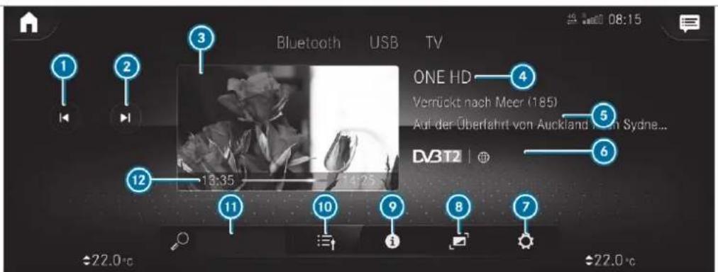
① Selects the previous TV channel from the channel list
② Selects the next TV channel from the channel list
3 Preview picture, calls up full screen
4 Channel name
5 Programme information
6 Features of the TV channel and the current programme
⑦ Calls up options
Calls up full screen
9 Shows the electronic programme preview (EPG)
10 Calls up the station list
⑪ Searches for a TV channel
12 Start and finish times of the current programme, graphic showing the remaining broadcast time
Overview of symbols
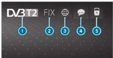
flowchart
graph TD
    A["DV3T2"] --> B["1"]
    B --> C["2"]
    C --> D["3"]
    D --> E["4"]
    E --> F["5"]
    style A fill:#f9f,stroke:#333
    style B fill:#ccf,stroke:#333
    style C fill:#cfc,stroke:#333
    style D fill:#fcc,stroke:#333
    style E fill:#cff,stroke:#333
    style F fill:#ffc,stroke:#333
TV standard
② Channel fix active
3 Audio languages available
4 Subtitles available
5 TV channel is encrypted
Open lock: TV channel can be decrypted with the currently connected Cl+ module
Showing or hiding full screen
To show: select in menu ⑧ or preview picture ③.
To hide: press the ↩ button. The TV menu appears.
Selecting TV channels
Selecting TV channels from the menu
Multimedia system:

Select < or >. The TV tuner sets the previous/next channel from the channel list.
The control menu is shown for about twelve seconds. Then the full screen image appears.
In the full screen: swipe to the left or right over the ◀ button on the touchpad.
Selecting TV channels from the channel list Multimedia system:

Select in the menu.
Select a TV channel.
The TV tuner selects the channel from the channel list.
Tap on the preview picture and show the full screen.
To search for a TV channel: select the search bar in the menu next to 🔒.
Enter the first characters.
Select the TV channel from the channel list.
i Further information on the search bar ( page 544).
Selecting a TV channel from the channel pre- sets and from the favourites Requirements:
s. The TV channel has been saved in the channel presets and in the favourites.
Multimedia system:

Select in the menu.
▶ Select Presets.
▶ Select the TV channel.
Setting in the favourites
Briefly press the ★ rocker switch on the steering wheel down.
▶ Select the TV channel.
Selecting TV channels in the background Requirements:
• The navigation system is active, for example
- TV mode is switched on in the background and the sound from the selected TV channel can be heard
Swipe to the left or right over the ◀ button on the touchpad.
The previous or next TV channel is set.
or
In the control menu: press the ◀ button on the touchpad.
Select < or >.
The previous or next TV channel is set.
Displaying current programme information for the selected station (EPG)
Multimedia system:

EPG displays the following information (if available):
- Broadcast times
- Names of the current and upcoming programmes
Select a programme name with ▶. The programme information is displayed.
To scroll: swipe up or down.
To leave the programme information display: select <.
or
Select To TV.
Function of the channel fix setting
Channel fix is switched on
The channel is not changed. This is useful if, for example, you drive the vehicle through reception regions that overlap. It prevents frequent switching back and forth between channels.
The FIX indicator is shown in the TV playback main menu.
Channel fix is switched off
Depending on reception quality, the TV tuner automatically switches to an alternative channel with the same programme content but better reception. Using this function, the best possible
television picture can be found, regardless of the reception quality.
Activating/deactivating channel fix Multimedia system:

▶ General
▶ Select General settings.
Switch Station fix on or off.
When the option is switched on, the display button is activated.
Switching the country-specific character set for the TV channel on/off
Multimedia system:

▶ General
▶ Select General settings.
Switch Country-specific character set on or off.
When the option is switched on, a country-specific character set is used for the display.
When the option is switched off, the character set transmitted by the currently set TV channel is used for the display.
The respective TV channel is responsible for the transmission of the channel-dependent character set.
Channel list overview
The TV tuner shows the current programme on the digital TV channels or radio stations with adequate reception in its own channel list.
The order of the channel lists is alphabetical country-specific.
The TV tuner requires a short amount of time to update the information.
The channel lists show the following information:
• receivable channel names
- programme title
The information is shown under the following conditions:
- it is broadcast by the digital channel
• the reception conditions are adequate
Favourites
Overview of TV programmes (favourites)
You can create a total of 40 digital TV channels in the channel favourites.
For quick-access you can save TV channels as favourites.
Storing TV channels
Multimedia system:

Select in the menu.
Select Presets.
▶ Select Store current station in the presets.
or
Press on the preview picture in the TV play-back main menu until the OPTIONS menu appears.
▶ Select Add to presets.
The current TV channel is stored in the channel presets in the next available position. If all the memory presets are occupied, select a memory preset to be overwritten.
When the TV channel is stored, the preset number is shown in the preview picture and in the control menu.
To move a TV channel in the channel presets: if at least two TV channels are saved, select ▼ for a TV channel.
Select Move.
Move the TV channel with ▲ or ▼ to the new position.
Tap on
To save a TV channel in the favourites: select ▼ for a TV channel.
Select Save as favourite.
or
Press on preview picture ③ in the menu until the OPTIONS menu appears.
▶ Select Save as favourite.
A message appears.
To delete a TV channel: select Delete the current channel from the presets.
or
Select ▼ for a TV channel.
Select Delete.
Select Yes.
TV programme
Setting the TV audio language
Multimedia system:
→ Media ▶ TV ▶
▶▶ General
Select Audio/subtitles.
Select one of the available audio languages ▶ under the AUDIO LANGUAGE category.
Select one of the available options for the selected audio language.
The selected audio language, e.g. French, will be kept until the multimedia system is switched off.
When you switch on the multimedia system again, the system language is loaded as the audio language. If this is not available, the audio language that appears at the beginning of the list is loaded.
Setting the TV subtitles
Multimedia system:
Select Audio/subtitles.
Select the available languages ▶ under the SUBTITLES category.
Select one of the available options for the selected language.
The selected language, e.g. French, will be kept until the multimedia system is switched off.
When you switch on the multimedia system again, the system language is loaded as language. If this is not available, the language that appears at the beginning of the list is loaded.
To show no subtitles: switch Activate off.
Teletext
Teletext overview
Teletext pages are located between page 100 and page 899.
A dynamic teletext page consists of several subpages.
The display of subpages changes automatically or can be called up with the arrow buttons.
Information on MHEG-5 digital teletext:
- digital teletext is only available in some countries, e.g. the UK and New Zealand
- interactive multimedia applications such as weather forecasts, news reports and sport results are available
- it may take some time before all the pages load
Showing teletext
the Multimedia system:
→ Media ▶ TV ▶ ▶ General ▶ Teletext
To switch to page selection: switch between number entry and selection using the arrow button with □ and 123.
To call up a side: enter the numbers in quick succession.
or
▶ Select the arrow buttons.
To return to the TV programme: select TV.
MHEG-5 digital teletext
Apart from the functions described above, additional options can be used.
To call up data content using colours: select a colour.
To move back a level: select a list symbol.
Picture settings
Selecting picture settings for the TV
Multimedia system:

To set the picture format: activate one of the Automatic, 4:3, 8:3, 16:9, 21:9 or Zoom display buttons.
The brightness is automatically set.
HD programmes
Receiving encrypted HD programmes

NOTE Damage to the CI+ module and Smart Card
The Cl+ module is designed for use in the home. The Cl+ module can overheat and be damaged by continuous exposure to high outside temperatures.
Make sure that the Cl+ module is not subject to high temperatures for extended periods of time. If the Cl+ module is damaged, no encrypted channels can be received.
A CI+ module (Common Interface Module), which is not included in the scope of delivery, is used to decrypt HD programmes according to the CI+ standard.
In some countries, an additional smart card is required, which is inserted into the Cl+ module (see the manufacturer's operating manual). The Cl+ module is connected in the Cl+ box in the glove compartment.
To insert the Smart Card in the CI+ module: if required (country-dependent), insert the Smart Card into the CI+ module slot. Encrypted HD programmes can be received according to the CI+ standard.
The Cl+ box is designed for operation at temperatures between 0 °C and 65 °C. At operating temperatures that are higher or too low a message appears in the multimedia system and the Cl+ module is switched off automatically. If the Cl+ module is switched off, no encrypted channels can be received.
If a Cl+ module is connected, Card status reminder is switched on (→ page 547) and the ignition is switched off, the Alert: Cl+ card is still in the vehicle. message appears in the media display.
Calling up the Cl+ module menu
Multimedia system:



To call up the Cl+ menu: select Open menu. The subscription number can be shown in the menu, for example. The content of the menu depends on the manufacturer of the + module.
(i) You need the subscription menu to extend the subscription, for example. Further information can be found in the manufacturer's operating instructions.
To show the version number: select Display version.
To restart the Cl+ module: if playback is experiencing interference you can try and resolve the problem using Restart Cl+.
To switch the reminder of a connected CI + module on or off: select ☐.
Select General settings.
Switch the Card status reminder option on or off.
To reset the TV tuner: select Reset TV.
Sound
Tone settings
Information about the sound system
The sound system has a total output of 125 W and is equipped with seven speakers. It is available for all functions in the radio and media modes.
Calling up the sound menu
Multimedia system:


The following functions are available:
• Equaliser
• Balance and Fader
• Volume
Select a function.
Adjusting treble, mid-range and bass settings
Multimedia system:


Set TREBLE, MID or BASS.
Activating/deactivating automatic volume adjustment
Multimedia system:


Automatic volume adjustment compensates for differing volumes when changing between audio sources and within an audio source.

Switch Automatic adjustment on or off.
Adjusting the balance/fader
Multimedia system:

Balance and Fader
Adjusting the balance
Move the volume distribution between the right and left sides of the vehicle in the grid. The volume is distributed between the speakers on the left and right sides in the vehicle.
Adjusting the fader
Move the volume distribution between the front and rear of the vehicle in the grid shown. The volume is distributed between the speakers in the front and rear of the vehicle.
Burmester ^® surround sound system
Information about the Burmester ^® surround sound system
The Burmester ^® surround sound system has a total output of 590 W and is equipped with 13
speakers. It is available for all functions in the radio and media modes.
Calling up the sound menu in the Burmester ^® surround sound system
Multimedia system:

The following functions are available:
Equaliser
• Balance and Fader
- Sound focus
- Sound profiles
Volume
Select a function.
Adjusting the treble, mid and bass settings on the Burmester® surround sound system Multimedia system:

Equaliser
Set TREBLE, MID or BASS.
Activating/deactivating volume adjustment in the Burmester ^® surround sound system
Multimedia system:

Automatic volume adjustment compensates for differing volumes when changing between audio sources and within an audio source.
▶ Switch Automatic adjustment on or off.
Adjusting the balance/fader in the Burmester ^® surround sound system
Multimedia system:

Balance and Fader
Adjusting the balance
Move the volume distribution between the right and left sides of the vehicle in the grid shown. The volume is distributed between the speakers on the left and right sides in the vehicle.
Adjusting the fader
Move the volume distribution between the front and rear of the vehicle in the grid shown. The volume is distributed between the speakers in the front and rear of the vehicle.
Selecting a sound profile in the Burmester® surround sound system
Multimedia system:
→ Media → Burmester Sound profiles
The following profiles are available:
- Pure
- Surround
▶ Select a sound profile.
Adjusting the sound focus in the Burmester® surround sound system
Multimedia system:
→ Media → Burmester Sound focus Select a position for the sound focus or All seats.
Burmester ^® high-end 3D surround sound system
Information on the Burmester® high-end 3D surround sound system
The Burmester ^® high-end 3D surround sound system has a total output of 1610 watts and is equipped with 26 speakers. It is available for all functions in the radio and media modes.
Calling up the sound menu in the Burmester® high-end 3D surround sound system
Multimedia system:
→ Media → Burmester
The following functions are available:
• Equaliser
• Balance and Fader
- VIP seat
- Sound profiles
Volume
Select a function.
Adjusting the treble, mid-range and bass settings on the Burmester® high-end 3D surround sound system
Multimedia system:
→ Media → Burmester
Equaliser
Set TREBLE, MID or BASS.
Activating/deactivating volume adjustment in the Burmester ^® high-end 3D surround sound system
Multimedia system:

Automatic volume adjustment compensates for differing volumes when changing between audio sources and within an audio source.
▶ Activate or deactivate the function.
Adjusting the balance/fader in the Burmester® high-end 3D surround sound system
Multimedia system:

Adjusting the balance
Move the volume distribution between the right and left sides of the vehicle in the grid shown. The volume is distributed between the speakers on the left and right sides in the vehicle.
Adjusting the fader
Move the volume distribution between the front and rear of the vehicle in the grid shown. The volume is distributed between the speakers in the front and rear of the vehicle.
Adjusting the seat-based sound optimisation in the Burmester® high-end 3D surround sound system
Multimedia system:
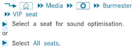
text_image
→ Media → Burmester → VIP seat ▶ Select a seat for sound optimisation. or ▶ Select All seats.Selecting the sound profile in the Burmester ^® high-end 3D surround sound system
Multimedia system:

The following profiles are available:
- Pure
3D
Live - Surround
- Easy Listening
▶ Select a sound profile.
MBUX rear tablet
Overview of the MBUX rear tablet
A WARNING Risk of an accident from operating mobile communication equipment while the vehicle is in motion
Mobile communications devices distract the driver from the traffic situation. This could also cause the driver to lose control of the vehicle.
As the driver, only operate mobile communications devices when the vehicle is stationary.
As a vehicle occupant, only use mobile communications devices in the areas intended for this purpose, e.g. in the rear passenger compartment.
A WARNING Risk of distraction from operating the multimedia system with the MBUX rear tablet
Other vehicle occupant can make changes to the multimedia system with the MBUX rear tablet, e.g. adjust the volume of the multimedia system, change radio station or adjust die ambient lighting.
The driver could be distracted from the traffic situation by undesired changes and thereby cause an accident.
If required lock access of the MBUX rear tablet to the multimedia system.
▶ Activate the child safety lock in the multimedia system to limit operation of the MBUX rear tablets.
A WARNING Risk of becoming trapped through operation of the MBUX rear tablet outside the vehicle
If the MBUX rear tablet is operated outside the vehicle, seats can be moved using the
seat control. Vehicle occupants and animals could become trapped by the seat adjustment.
▶ Only operate the seat control when inside the vehicle.
A WARNING Risk of injury as a result of the MBUX rear tablet not being secured in the vehicle
If the MBUX rear tablet is loose in the vehicle interior, it could be thrown around and thereby hit vehicle occupants.
▶ Always securely lock the MBUX rear tablet in the bracket intended for that purpose.
The MBUX rear tablet consists of a tablet ( page 552) and a bracket integrated in the backrest ( page 552).
If the tablet has been paired with the multimedia system, the MBUX rear tablet can make settings on the multimedia system from the rear passenger compartment.
The function of operating the multimedia system with the paired tablet, can be blocked in the multimedia system.
The MBUX rear tablet can also be used outside the vehicle.
Overview of the MBUX rear tablet
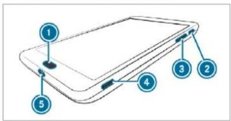
text_image
1 2 3 4 5Home button
② On/off button
③ Louder/quieter button
4 SD card slot
5 USB port
The MBUX rear tablet is an Android Samsung tablet. The vehicle's multimedia system can be operated with the MBUX rear tablet. Operation of the tablet is carried out using the touch display (see the manufacturer's operating instructions).
The MBUX rear tablet can also be used without the vehicle.
Do not make any changes to the seat settings or multimedia system with the MBUX rear tablet when outside the vehicle.
You can update the tablet operating system in the device settings (see the manufacturer's operating instructions). An Internet connection is required for the update, for example using the private network at home. Updates can also be installed at a Mercedes-Benz service centre. Software from the manufacturer can also be used to download and install updates (see the manufacturer's Internet page).
Overview of the MBUX rear tablet bracket
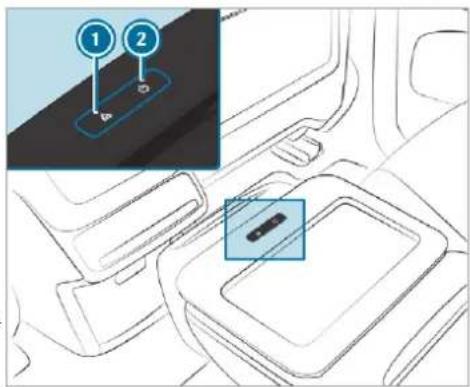
text_image
Diagram showing a car interior with two labeled buttons (1 and 2) pointing to a device, highlighting a button on the lower panel.① Releases the MBUX rear tablet from the bracket
2 Pressing and holding the button: switches the MBUX rear tablet on or off
Pressing the button briefly: activates of deactivates the screen of the MBUX rear tablet
The MBUX rear tablet is charged when it is locked into the bracket.
If it is not being used during the journey, lock the MBUX rear tablet in the holder designed for this purpose.
Rear Seat Entertainment System
Operating safety

WARNING Risk of injury from unsecured items in the vehicle
If objects such as headphones/headsets or external audio/video sources are not secured in the vehicle interior, they can be flung around and hit vehicle occupants.
Always stow these items or similar objects carefully so that they cannot be flung around, for example in a lockable vehicle stowage compartment.
Observe the notes on loading the vehicle.
i Ventilation must not be impeded by covering the ventilation openings with items (such as
newspaper, table-cloths, clothes, curtains, etc).
① No naked flame sources (such as lighted candles), shall be placed on apparatus.
Rear Seat Entertainment System overview
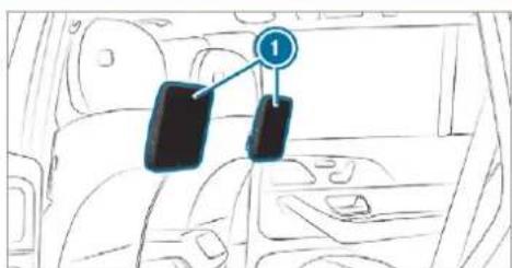
text_image
Diagram showing a car interior with two labeled parts, one marked with number 1 and arrow pointing to the second part.Model name: Daimler RSE
For the Daimler RSE the label applies for direct
current .
The Rear Seat Entertainment System includes:
- Two rear displays ① behind the head restraints of the front seats
- Connections for USB (type C) and HDMI mir on the rear displays (→ page 554)
- Up to two wireless headphones as accessories
No content can be saved nor can any applications be installed in the Rear Seat Entertainment System.
Rear displays
Overview of the rear displays
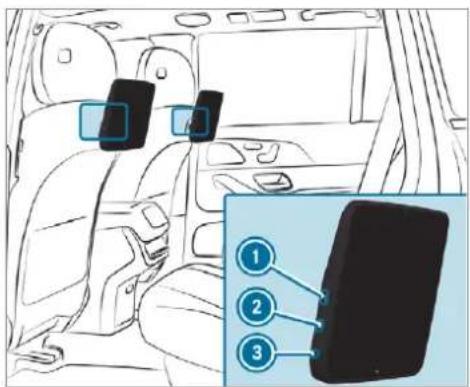
text_image
Diagram of car interior with three labeled buttons and a close-up of a device panel showing three numbered buttons.① HDMI mini port
② USB port (type C)
3 Socket for corded headphones with a 3.5 mm stereo jack
The rear compartment displays are located behind the head restraints of the front seats.
The rear displays are equipped as touchscreens. Further information on operating touchscreens ( page 384).
When the rear door is opened, the welcome screen appears.
The rear displays connect automatically with the multimedia system.
i Headphones with wired remote control and stereo jack (3.5 mm) cannot be used.
Switching a rear display on/off
On the rear display: press the Ⓞ button. The rear display is switched on or off.
Switching the child-proof lock for the rear displays on/off on the MBUX multimedia system ( page 421).
Home screen overview (rear display)
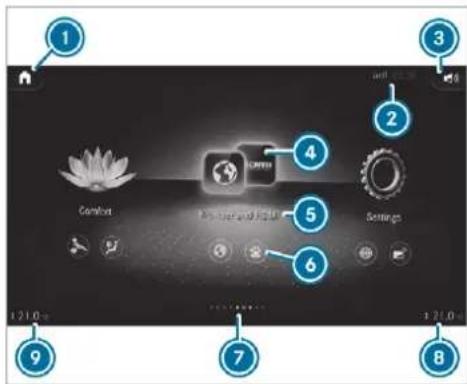
text_image
Comfort 200000 Apt. 100000 Settings 1 2 3 4 5 6 7 8 9 121.0m 121.0mExample
① Calls up the home screen
On the home screen: displays the first three applications
② Displays, e.g. network display, time
3 Sets volumes
④ Opens an application via symbols
⑤ Name of the application
6 Quick-access
7 Number of applications and currently selected display area
8 Calls up the air conditioning menu, right
⑨ Calls up the air conditioning menu, left
Headphones
Headphones overview (Rear Seat Entertainment System)

WARNING Risk of injury due to high volume of the headphones
Your hearing can be damaged when exposed to high volumes.

Make sure that the volumes at the rear displays are set to a comfortable volume before putting on the headphones.
The following external headphones can be connected to each rear display:
- Bluetooth® headphones
- Corded headphones via a 3-pin stereo jack, 3.5 mm
The headphones are not in the scope of delivery for the Rear Seat Entertainment System.
You can obtain headphones from Mercedes-Benz Accessories or in a specialist shop (see the manufacturer's operating instructions).
The function of wireless headphones can be impaired by other radio-based electronic devices, such as mobile phones, for example.
text_image
Diagram of a USB cable connector with labeled parts 1, 2, and 3Connection of corded headphones with a 3-pin stereo jack, 3.5 mm
① Audio L (audio signal for left channel)
② Audio R (audio signal for right channel)
3 Earth
Handset
Overview of the handset
This equipment is available only for Mercedes-Maybach vehicles with individual rear seats.
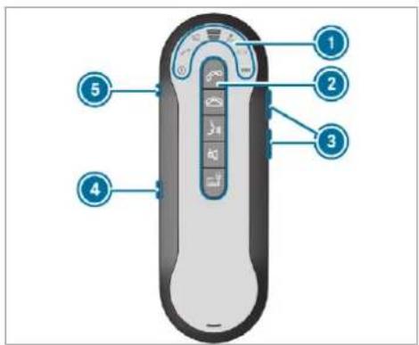
text_image
Diagram of a remote control device with numbered labels pointing to key ports and function buttons① LED displays
② Keypad
3 Volume settings
④ Micro USB port
5 Headphone jack
Function of the LED displays (handset)
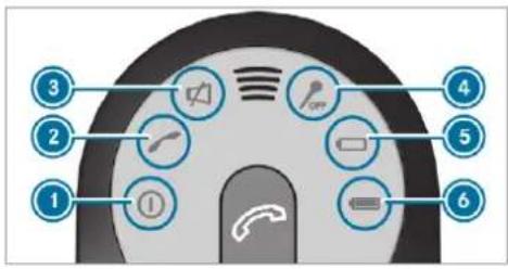
text_image
Diagram of a car's front panel with numbered UI icons for function keys or functionsThe LED displays on the handset have the following meanings:
| Display | M e a n i n g |
| 1 | The handset is operational. |
| 2 | The display flashes:Connecting callIncoming callActive call on the multimedia systemThe call can also be transferred to the handset.The display lights up continuously:Active call on the handset. |
| 3 | is lit The handset is muted. |
| up | No acoustic signal sounds for incoming calls. |
| 4 | is lit The handset microphone is switched off. |
| 5 | "Battery discharged" display |
| 6 | "Battery charge status" display |
Handset functions
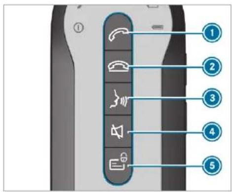
text_image
Diagram of a mobile phone control panel with labeled buttons and function iconsThe buttons on the handset have the following functions:
| Button | F unction |
| 1 | Answers an incoming callTransfers an existing call to the handsetPress briefly twice: redials numberPress briefly: switches the handset between a call on ho and an active callPress and hold: switches to a conference call with the call c hold and an active call |
| 2 | Rejects an incoming callEnds an existing call |
Button Function
| 3 | Activates voice recognition of the connected mobile phone (with Hands-Free Profile)With an active call on the hand-set: activates hands-free mode (front) |
| 4 | Mutes the handset when there is no active callSwitches off the microphone when a call is active |
| 5 | No private information is displayed in the multimedia system:Incoming calls and messages are made anonymousContacts and messages in the connected mobile phone/SIM card are not shown |
Switching the handset on/off
To switch on: press and hold the button until the LED displays light up (→ page 556).
To switch off: press and hold the button until the LED displays go out (→ page 556).
① The handset is switched on and off automatically when it is in the bracket.
Charging the handset
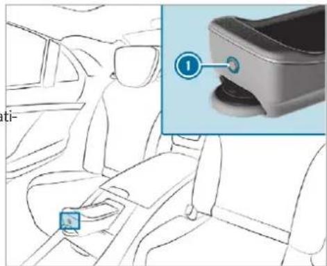
text_image
ti- ①Open the drawer with button ① and place the handset in the drawer. (→ page 149).
Press drawer back until it engages. The handset is charged.
① The handset can also be charged using the micro USB port.
You cannot replace the rechargeable battery yourself. Please consult a Mercedes-Benz Service Centre to do this.
Rear seats
Adjusting the rear seats on the Rear Seat Entertainment System
Rear Seat Entertainment System:
→ Comfort ▶ Seat comfort
Setting seat climate control
The functions are available depending on the vehicle equipment.
Select Seat Climate.
To set seat heating: tap on the bar until the desired heating level is set or the seat heating is switched off. Depending on the heating level, up to three indicator lamps will light up.
The indicator lamps are also lit in the seat button in the side door.
To switch the panel heating on/off: switch Panel heating on or off. When panel heating is switched on, the a ests, the centre panels on the doors and centre console are heated.
To adjust distribution of seat heating/seat ventilation: slide the control knob.
Settings can be made for different areas of the seat, for example:
- Sitting surface
- Sitting surface and backrest
- Backrest
To set seat ventilation: tap on the bar until the desired ventilation level is set or the seat ventilation is switched off. Depending on the ventilation level, up to three indicator lamps will light up.
① The indicator lamps are also lit in the seat button in the side door.
Adjusting the backrest contour in the lumbar region of the seat backrest (lumbar)
The function is available depending on the vehicle equipment.
Select Lumbar.
▶ Select the seat.
Select the seat again and set the air cushion.
Adjusting the backrest side bolsters
① The function is available depending on the vehicle equipment.
▶ Select Side bolsters.
▶ Select the seat.
Adjust the air cushions.
Selecting the massage programme for the rear seats
Rear Seat Entertainment System:
▶ Select the seat.
▶ Select a massage programme.
① For an overview of the massage and workout programmes ( page 133).
To start a massage programme: select
▶
To set the massage intensity: switch the HIGH display button on or off. Massage intensity is increased when the display button is switched on.
Setting climate control for the rear passenger compartment (Rear Seat Entertainment System)
Setting the temperature
① The function is available depending on the vehicle equipment.
Select the temperature display at the lower edge of the rear display.
▶ Select Second row of seats or Third row of seats.
For Maybach vehicles: select Second row of seats.
(i) Maybach vehicles are fitted with one and two rows of seats.
Set the temperature.
Setting the airflow
The function is available depending on the vehicle equipment.
Select the temperature display at the lower edge of the rear display.
▶ Select Second row of seats or Third row of seats.
For Maybach vehicles: select Second row of seats.
① Maybach vehicles are fitted with one and two rows of seats.
Set the airflow.
Setting the air distribution
The function is available depending on the vehicle equipment.
The air distribution can be set for the seats in the second row.
Select the temperature display at the lower edge of the rear display.
▶ Select Second row of seats.
Select 📂 or 🌐 for the left or right seat. The air is routed through the centre and side air vents. The air is routed through the footwell and side air vents.
Controlling the rear climate control automatically
The function is available depending on the vehicle equipment.
Select REAR AUTO.
Rear climate control is controlled automatically.
Deactivating rear climate control
① The function is available depending on the vehicle equipment.
Select REAR OFF.
Rear climate control is deactivated.
Setting the ambience light in the rear passenger compartment
Rear Seat Entertainment System:
Comfort Ambient lighting
Setting the colour
Select the colour of the light from the chromatic circle.
Activating multi-coloured lighting
▶ Select Multi-colour.
Select a colour programme.
Activating multi-coloured animation
Activate Multi-colour animat.. The chosen colour programme will change at predefined intervals.
Adjusting the brightness
Select Brightness.
To activate brightness for zones: switch Brightness zones on or off. If Brightness zones is switched on, the zones can be set individually.
Set the zones.
Setting the colour effects
Select Effects.
▶ Switch Welcome or Climate on or off.
(i) Further information on the topic of setting ambiance light ( page 182).
Setting the language in the rear passenger compartment
Rear Seat Entertainment System:
Settings System
Language
Set the language.
Selecting system settings in the rear compartment
Rear Seat Entertainment System:
Settings System
Adjusting the brightness
Select Display.
Adjust the brightness.
Connecting a device in the device manager
▶ Select Device Manager.
Select a device that is to be connected. Headphones and headsets are connected with the rear display.
Mobile phones and other devices are connected with the multimedia system.
Navigation
Switching on navigation in the rear compartment
Rear Seat Entertainment System:
Navigation (Navigation)
The map appears and shows the current vehicle position.
▶ Select an option in the navigation menu.
The following options are available, for example on the rear display:
- Entering the destination and transferring the destination to the multimedia system using Send to Car Navigation
- Setting the map scale (→ page 465)
- Moving the map and rotating the map.
• Showing route information.
• Installing the online map update for regions.
This option is not available in all countries.
Web browser
Web browser overview (Rear Seat Entertainment System)
Depending on the country and the vehicle equipment, a web browser can be called up on the rear display. The rear display uses a web browser from the manufacturer.
You cannot download any content.
Calling up the web browser (Rear Seat Entertainment System)
Requirements:
- The vehicle is equipped with a permanently installed communication module (→ page 517).
Rear Seat Entertainment System:
→ ↗ Browser & Connectivity
Browser
▶ Select an application.
Media
Information about media mode in the rear compartment
There is one USB port and one HDMI connection in the Rear Seat Entertainment System
(→ page 554).
Data storage media supported by the Rear Seat Entertainment System:
- USB storage device
The data storage medium is connected with the rear display via the USB port (type C) ( page 554).
The data storage medium is connected with the multimedia system using the multimedia connection unit in the stowage compartment under the armrest ( page 531).
- iPod®
- iPhone®
- MTP devices
- Bluetooth® audio equipment
Bluetooth® audio equipment can only be authorised using the multimedia system (→ page 531).
The Rear Seat Entertainment System supports a total of up to 50,000 files. The Rear Seat Entertainment System can also access files on the multimedia system.
Further information about media mode ( page 527).

HIGH-DEFINITION MULTIMEDIA INTERFACE
The terms HDMI and HDMI High-Definition Multimedia Interface, and the HDMI Logo are trademarks or registered trademarks of HDMI Licensing LLC in the United States and other countries.
Switching on media mode in the rear passenger compartment Requirements:
- A data storage medium is connected with the rear display or the multimedia system.
- A Bluetooth® audio device is connected with the multimedia system.
Rear Seat Entertainment System:
Media
▶ Select USB, Bluetooth or My USB.
If a USB storage device is connected with a rear display ( page 554), the My USB option is available.
The following functions are available:
• Controlling media playback (→ page 563)
• Using the keyword search
(→ page 535)
- Searching for media files using categories (→ page 534)
i Selecting sound settings in the rear compartment ( page 564).
Controlling media playback in the Rear Seat Entertainment System
Rear Seat Entertainment System:

▶ Select USB, Bluetooth or My USB.
If a USB storage device is connected with rear display ( page 554), the My USB option is available.
To pause or continue playback: select
or .
To select the next or previous track: select ▶ or ◀.
To scroll through tracks quickly: press and hold ▶ or ▷.
To wind a track forwards or backwards: tap on the desired point on the timeline.
To play back tracks in random order: select ✗.
To repeat a track: select □.
For the repeat function there are the following options:
- Tap once: the active playlist is repeated.
- Tap twice: the current track is repeated.
- Tap three times: the repeat function is deactivated.
To show the current track list: select the cover.
Radio
Switching to radio in the rear passenger compartment
Rear Seat Entertainment System:
Radio
Select a station with < or >. The station is selected on the multimedia system.
To set a frequency band: select a frequency band.
The following functions are available:
- Searching for radio stations(→ page 538)
- Selecting from the station list (→ page 538)
• Switching options on or off.
Traffic announcements
When the option is switched on, the TA symbol is shown in the menu bar.
Frequency fix
Display radio text information
Sound
Overview of sound settings in the rear compartment
The sound settings depend on which sound system is available.
Depending on the equipment installed, one of the following systems is supported:
• Sound system ( page 547)
- Burmester ^® surround sound system (→ page 548)
- Burmester ^ high-end 3D surround sound system (→ page 549)
Selecting sound settings in the rear compartment
Rear Seat Entertainment System:

Select Sound.
Select Equaliser.
Adjust the tone settings.
Switching Cabin Audio on/off and setting volumes
Select
Select Media.
▶ Select USB or My USB.
Switch the display button with the loud-speaker symbol on or off.
To set the volumes: move the control knob to the left or right on one of the scales. The volume for the vehicle interior or for the headphones is set.
ASSYST PLUS service interval display
Function of the ASSYST PLUS service interval display
The ASSYST PLUS service interval display on the instrument display provides information on the remaining time or distance before the next service due date.
You can hide this service display using the back button on the left-hand side of the steering wheel.
Depending on how the vehicle is used, the ASSYST PLUS service interval display may shorten the service interval, e.g. in the following cases:
• mainly short-distance driving
- when the engine is often left idling for long periods
• in the event of frequent cold start phases
- vehicles with a diesel particulate filter: in the event of frequently interrupted regeneration of the diesel particulate filter
Mercedes-Benz recommends avoiding such operating conditions.
You can obtain information concerning the servicing of your vehicle from a qualified specialist workshop, e.g. a Mercedes-Benz Service Centre.
Displaying the service due date
On-board computer:
Service ▶ ASSYST PLUS
The next service due date is displayed.
To exit the display: press the back button on the left-hand side of the steering wheel.
Be sure to also pay attention to the following related topic:
- Operating the on-board computer (→ page 346).
Information on regular maintenance work
NOTE Premature wear through failure to observe service due dates
Service work which is not carried out at the right time or incompletely can lead to increased wear and damage to the vehicle.
▶ Always observe the prescribed service intervals.
▶ Always have the prescribed service work carried out at a qualified specialist workshop.
Special service requirements
The prescribed service interval is based on normal operation of the vehicle. Maintenance work will need to be performed more often if the vehicle is operated under arduous conditions or increased loads.
The ASSYST PLUS service interval display is only an aid. The driver of the vehicle bears responsibility as regards to whether maintenance work needs to be performed more often than speci-
fied based on the actual operating conditions and/or loads.
Examples of arduous operating conditions:
- regular city driving with frequent intermediate stops
• mainly short-distance driving - frequent operation in mountainous terrain or on poor road surfaces
- when the engine is often left idling for long periods
• operation in particularly dusty conditions and/or if air-recirculation mode is frequently used
In these or similar operating conditions, have the interior air filter, engine air cleaner, engine oil and oil filter etc. changed more frequently. The tyres must be checked more frequently if the vehicle is operated under increased loads. Further information can be obtained at a qualified specialist workshop.
Battery disconnection periods
The ASSYST PLUS service interval display can only calculate the service due date when the battery is connected.
Note down the service due date displayed on the instrument display before disconnecting the battery ( page 565).
Engine compartment
Opening/closing the bonnet
⚠ WARNING Risk of accident due to driving with the engine bonnet unlocked
An unlocked engine bonnet may open up when the vehicle is in motion and block your view.
▶ Never unlock the engine bonnet when driving.
Before every trip, ensure that the engine bonnet is locked.
WARNING Risk of accident and injury when opening and closing the engine bonnet
When opening or closing the engine bonnet, it may suddenly drop into the end position. There is a risk of injury for anyone in the engine bonnet's range of movement.
Only open or close the engine bonnet when there are no persons in the engine bonnet's range of movement.
⚠ WARNING Danger of burns when opening the bonnet
If you open the engine bonnet when the engine has overheated or during a fire in the engine compartment, you could come into contact with hot gases or other escaping operating fluids.
Before opening the bonnet, allow the engine to cool down.
In the event of a fire in the engine compartment, keep the engine bonnet closed and call the fire service.
WARNING Risk of injury due to moving parts
Certain components in the engine compartment may continue to move or suddenly move again even after the ignition has been switched off, e.g. the cooler fan.
Make sure of the following before performing tasks in the engine compartment:
▶ Switch the ignition off.
▶ Never touch the danger zone surrounding moving component parts, e.g. the rotation area of the fan.
Remove jewellery and watches.
Keep items of clothing and hair away from moving parts.
WARNING Risk of injury from touching component parts under voltage
The ignition system and the fuel injection system work under high voltage. If you touch component parts which are under voltage, you could receive an electric shock.
▶ Never touch components of the ignition system or the fuel injection system when the ignition is switched on.
WARNING Risk of burns from hot component parts in the engine compartment
Certain components in the engine compartment can be very hot, e.g. the engine, the radiator and parts of the exhaust system.
▶ Allow the engine to cool down and only touch component parts described in the following.
A WARNING Risk of injury from using the windscreen wipers while the engine bonnet is open
When the engine bonnet is open, and the windscreen wipers are set in motion, you can be trapped by the wiper linkage.
▶ Always switch off the windscreen wipers and ignition before opening the engine bonnet.
Opening the bonnet
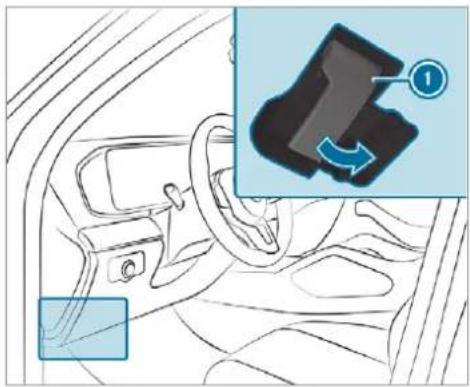
natural_image
Interior view of a car dashboard with steering wheel and gear, showing a close-up of the dashboard's key (no text or symbols visible)To release the bonnet, pull on handle ①.
Closing the bonnet

NOTE Damage to the bonnet
If the bonnet is closed manually, there is a risk of dents.

Do not close the bonnet manually.
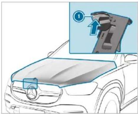
natural_image
Diagram of a car hood with an inset showing a mechanical component (no text or symbols present)Push handle ① of the bonnet catch upwards and lift the bonnet by approximately 40 cm.
▶ Lower the bonnet to a height of around 20 cm and then allow it to fall, applying a little force as you let it go.
If the bonnet can still be lifted slightly, open the bonnet again and close it with a little more force until it engages correctly.
Engine oil
Checking the engine oil level using the on-board computer
Requirements:
• The engine has warmed up.
• The vehicle is parked on a level surface.
• The engine is running at idle speed.
The engine oil level is determined during driving. Determining the engine oil level can take up to 30 minutes with a normal driving style and even longer with an active driving style.
On-board computer:
Service ➤ Engine oil level
You will see one of the following messages on the multifunction display:
- Engine oil level Measuring now: measurement of the oil level is not yet possible.
Repeat the request after a maximum of 30 minutes driving.
- Engine oil level OK and the bar display for indicating the oil level on the multifunction display is green and is between "min" and "max": the oil level is correct.
- Engine oil level Add 1,0 l and the bar display for indicating the oil level on the multifunction display is orange and is below "min":
▶ Add 1 l of engine oil.
- Reduce engine oil level and the bar display for indicating the oil level on the multifunction display is orange and is above "max":
Drain off any excess engine oil that has been added. To do so, consult a qualified specialist workshop.
- For engine oil level turn on ignition:
Switch on the ignition to check the engine oil level.
- Engine oil level System inoperative: sensor faulty or not inserted.
Consult a qualified specialist workshop.
• Engine oil level System currently unavail.:
Close the bonnet.
Topping up engine oil
⚠ WARNING Risk of burns from hot component parts in the engine compartment
Certain components in the engine compartment can be very hot, e.g. the engine, the radiator and parts of the exhaust system.
▶ Allow the engine to cool down and only touch component parts described in the following.
WARNING Risk of fire and injury from engine oil
If engine oil comes into contact with hot component parts in the engine compartment, it may ignite.
Make sure that no engine oil is spilled next to the filler opening.
Allow the engine to cool off and thoroughly clean the engine oil from component parts before starting the vehicle.
! NOTE Engine damage caused by an incorrect oil filter, incorrect oil or additives
Do not use engine oils or oil filters which do not correspond to the specifications explicitly prescribed for the service intervals.
Do not alter the engine oil or oil filter in order to achieve longer change intervals than prescribed.
Do not use additives.
▶ Follow the instructions in the service interval display regarding the oil change.
! NOTE Damage caused by topping up too much engine oil
Too much engine oil can damage the engine or the catalytic converter.
Have excess engine oil removed at a qualified specialist workshop.
Depending on the engine, the cap may be installed in the engine compartment in different locations.
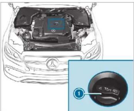
text_image
Diagram of a car engine bay with Chinese label '人' and a dial indicator showing '①'▶ Turn cap ① anti-clockwise and remove it.
Top up the engine oil.
Replace cap ① and turn it clockwise as far as it will go.
▶ Check the oil level again ( page 568).
Checking the coolant level
⚠ WARNING Risk of burns from hot component parts in the engine compartment
Certain components in the engine compartment can be very hot, e.g. the engine, the radiator and parts of the exhaust system.
Allow the engine to cool down and only touch component parts described in the following.
⚠ WARNING Risk of scalding from hot coolant
The engine cooling system is pressurised, particularly when the engine is warm. If you open the cap, you could be scalded by hot coolant spraying out.
Let the engine cool down before opening the cap.
When opening the cap, wear protective gloves and safety glasses.
Open the cap slowly to release pressure.
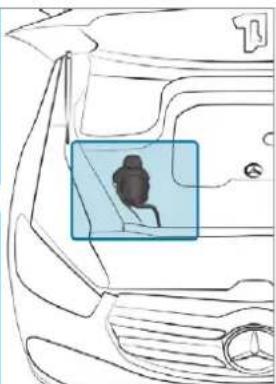
natural_image
Line drawing of a car's front and side view showing a highlighted interior area with a person silhouette (no text or symbols)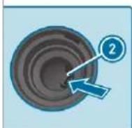
Park the vehicle on a level surface.
▶ Check the coolant temperature display in the instrument cluster.
The coolant temperature must be below 70 °C.
Slowly turn cap ① anti-clockwise to release overpressure.
Continue turning cap ① anti-clockwise and remove it.
The coolant level is correct in the following cases:
• if the engine is cold, up to marker bar ②
- if the engine is warm, up to 1.5 cm over marker bar ②
If necessary, top up with coolant that has been approved for Mercedes-Benz.
• Further information on coolant (→ page 643)
Topping up the windscreen washer system
⚠ WARNING Risk of burns from hot component parts in the engine compartment
Certain components in the engine compartment can be very hot, e.g. the engine, the radiator and parts of the exhaust system.
▶ Allow the engine to cool down and only touch component parts described in the following.
WARNING Danger of burns when opening the bonnet
If you open the engine bonnet when the engine has overheated or during a fire in the engine compartment, you could come into contact with hot gases or other escaping operating fluids.
Before opening the bonnet, allow the engine to cool down.
In the event of a fire in the engine compartment, keep the engine bonnet closed and call the fire service.
WARNING - Risk of fire and injury due to windscreen washer concentrate
Windscreen washer concentrate is highly flammable. It could ignite if it comes into contact with hot engine component parts or the exhaust system.
Make sure that no windscreen washer concentrate spills out next to the filler opening.
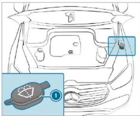
text_image
Diagram of a car interior with labeled components and an inset showing a gear-like device with a numbered label.Remove cap ① by the tab.
Top up the washer fluid.
- Further information about the washer fluid ( page 644)
Keeping the air-water duct free
Keep the area between the bonnet and the windscreen free of deposits, e.g. ice, snow and leaves.
Cleaning and care
Information on washing the vehicle in a car wash

WARNING Risk of an accident due to reduced braking power after washing the vehicle
Braking efficiency is reduced after washing the vehicle.
After the vehicle has been washed, brake carefully while paying attention to the traffic conditions until braking power has been fully restored.

NOTE Damage due to unsuitable car wash
Before driving into a car wash make sure that the car wash is suitable for the vehicle dimensions.
▶ Ensure there is sufficient ground clearance between the underbody and the guide rails of the car wash.
▶ Ensure that the clearance width of the car wash, in particular the width of the guide rails, is sufficient.
To avoid damage to your vehicle when using a car wash, ensure the following beforehand:
• Active Distance Assist DISTRONIC and the HOLD function are deactivated.
- the 360° Camera or the reversing camera is switched off.
- the side windows and sliding sunroof are completely closed.
• the outside mirrors are folded in.
- the blower for the ventilation/heating is switched off.
- the windscreen wiper switch is in position 0.
- the key is at a minimum distance of 3 m away from the vehicle, otherwise the tailgate could open unintentionally.
- in car washes with a conveyor system: neutral N is engaged.
i Drive straight and in to the centre of the guide rails of the car wash to prevent damage to the tyres and rims.
In car washes with a conveyor system: if you would like to leave the vehicle while it is being washed, make sure the key is located in the vehicle. The park position P is otherwise automatically engaged.
If, after the car wash, you remove the wax from the windscreen and wiper rubbers, this will prevent smearing and reduce wiper noise.
Automatic car wash mode
In car wash mode, the vehicle is prepared for driving into the automatic car wash. Car wash
mode can be activated at a speed of up to 20 km/h ( page 574).
The following settings are made when car wash mode is activated:
• the outside mirrors are folded down.
- the rain sensor is deactivated to prevent the windscreen washer system from starting up automatically.
• the rear window wiper is deactivated.
- the windows and the sliding sunroof are closed.
- Mercedes-Maybach vehicles: the running boards are retracted.
- the air conditioning system is set to air-recirculation mode.
- Parking Assist PARKTRONIC is deactivated.
- Vehicles with 360° Camera: the front image is activated after approx. eight seconds.
- Vehicles with AIRMATIC: the vehicle is raised to the maximum possible chassis level(→ page 289).
If rising takes longer than 25 seconds, the following message appears on the multifunction display:
Preparation for car wash incomplete See media display. After some time, the vehicle automatically continues rising.
- Vehicles with E-ACTIVE BODY CONTROL: the vehicle is raised to the maximum possible chassis level(→ page 301).
If rising takes longer than 25 seconds, the following message appears on the multifunction display:
Preparation for car wash incomplete See media display. After some time, the vehicle automatically continues rising.
If one of the settings cannot be selected, this is displayed by a X behind the respective setting.
Above a speed of 20 km/h car wash mode is automatically deactivated.
The following settings are reset when car wash mode is deactivated:
• the outside mirrors are folded out.
• the rain sensor is activated.
• the rear window wiper is activated.
- the air conditioning system is set to fresh air mode.
- Parking Assist PARKTRONIC is reset to the previously selected setting.
- the windows and the sliding sunroof remain closed.
- Mercedes-Maybach vehicles: the running boards remain retracted.
- Vehicles with 360° Camera: the front image is deactivated at speeds above 18 km/h.
• Vehicles with AIRMATIC: the vehicle is lowered to the previously set chassis level.
• Vehicles with E-ACTIVE BODY CONTROL: the vehicle is lowered to the previously set chassis level.
Activating/deactivating automatic car wash mode
Requirements:
• The vehicle is stationary.
• The engine is running.
Multimedia system:

Activating automatic car wash mode
▶ Select Car wash mode.
Select Start.
If one of the settings cannot be selected, this is displayed by a X behind the respective setting.
For an overview of the settings made when activating automatic car wash mode ( page 572).
Deactivating automatic car wash mode
Select Stop.
The automatic car wash settings are reset.
The automatic car wash mode is automatically deactivated as soon as a speed of 20 km/h is exceeded.
Information on using a high-pressure cleaner
WARNING Risk of an accident when using high-pressure cleaners with circular jet nozzles
The water jet of a circular jet nozzle (dirt grinder) can cause externally invisible damage to the tyres or chassis parts.
Components damaged in this way may unexpectedly fail.
Do not use high-pressure cleaners with circular jet nozzles to clean the vehicle.
Have damaged tyres or chassis parts replaced immediately.
To avoid damage to your vehicle, observe the following when using a high-pressure cleaner:
- keep the key at least 3 m away from the vehicle. Otherwise the tailgate could open unintentionally.
-
maintain a distance of at least 30 cm to the vehicle.
-
vehicles with decorative foil: parts of your vehicle are covered with a decorative foil. Maintain a distance of at least 70 cm between the foil-covered parts of the vehicle and the nozzle of the high-pressure cleaner. Move the high-pressure cleaner nozzle around whilst cleaning. The water temperature of the high-pressure cleaner must not exceed 60 °C.
- observe the information on the correct distance in the equipment manufacturer's operating instructions.
- do not point the nozzle of the high-pressure cleaner directly at sensitive parts such as tyres, slits, electrical components, batteries, light bulbs and ventilation slots.
Wash the vehicle with lukewarm water using a soft car sponge. When doing so, do not expose the vehicle to direct sunlight.
Carefully hose the vehicle off with water and dry using a chamois. Take care not to point the water jet directly towards the air inlet grille below the bonnet.
Washing the vehicle by hand
Observe the legal requirements, e.g. in a number of countries, washing by hand is only permitted in specially designated wash bays.
▶ Use a mild cleaning agent, e.g. car shampoo.
Notes on paintwork/matt finish paintwork care
Observe the following information:
| Cleaning and care | Avoiding paintwork damage and interference to the driver assistance systems | |
| Paintwork | Insect remains: soak with insect remover and rinse off the treated areas afterwards.Bird droppings: soak with water and rinse off afterwards.Tree resin, oils, fuels and greases: remove by rubbing gently with a cloth soaked in petroleum ether or lighter fluid.Coolant and brake fluid: remove with a damp cloth and clean water.Tar stains: use tar remover.Wax: use silicone remover. | Do not attach stickers, films or similar materials. Only have film attached to the bumper at a qualified specialist workshop.Remove dirt immediately, where possible. |
| Matt finish | Only use care products approved for Mercedes-Benz. | Do not attach stickers, films or similar materials. Only have film attached to the bumper at a qualified specialist workshop.Do not polish the vehicle and light-alloy wheels.Only use car washes that correspond to the latest engineering standards.Do not use car wash programmes with a final hot wax treatment.Do not use paint cleaners, buffing or polishing products, gloss preservers, e.g. wax. |
In the event of paintwork damage:
• Always have paintwork repairs carried out at a qualified specialist workshop.
• Make sure the radar sensors function ( page 251).
Notes on cleaning decorative foils
Observe the notes on matt finish care in the chapter "Notes on paintwork/matt finish paint-work care" (→ page 576). They also apply to matt decorative foils.
Observe the following information:
| Cleaning | Avoiding damage to the decorative foil |
| For cleaning, use plenty of water and a mild cleaning agent without additives or abrasive substances, e.g. a car shampoo approved for Mercedes-Benz.Remove dirt immediately, where possible, whilst avoiding rubbing too hard. There is otherwise a risk of damaging the decorative foil irreparably.If there is dirt on the finish or if the decorative foil is dull: use the Paint Cleaner recommended and approved for Mercedes-Benz.Insect remains: soak with insect remover and rinse off the treated areas afterwards.Bird droppings: soak with water and rinse off afterwards.To prevent water stains, dry a foil-wrapped vehicle with a soft, absorbent cloth after every car wash. | The service life and colouring of decorative foils are impaired by:- sunlight- temperature, e.g. hot air blower- weather conditions- stone chippings and dirt- chemical cleaning agents- oily productsDo not use polish on matt decorative foil. Polishing will have the effect of shining the foil-wrapped surface.Do not treat matt or structured decorative foils with wax. Permanent stains may occur. |
Scratches, corrosive deposits, areas affected by corrosion and damage caused by incorrect care cannot always be completely repaired. In such cases, visit a qualified specialist workshop.
You can obtain more information on care and cleaning products from the manufacturer.
In the case of foil-wrapped surfaces, optical differences may occur between the surfaces that were not protected by a decorative foil after removing a decorative foil.
i Have work or repairs to decorative foils carried out at a qualified specialist workshop, e.g. in a Mercedes-Benz Service Centre.
Notes on care of car parts

WARNING Risk of entrapment if the windscreen wipers are switched on while the windscreen is being cleaned
If the windscreen wipers are set in motion while you are cleaning the windscreen or wiper blades, you can be trapped by the wiper arm.
Always switch off the windscreen wipers and the ignition before cleaning the windscreen or wiper blades.
WARNING Risk of burns from the tailpipe and tailpipe trims
The exhaust tailpipe and tailpipe trims can become very hot. If you come into contact
with these parts of the vehicle, you could burn yourself.
Always be particularly careful around the tailpipe and the tailpipe trims and supervise children especially closely in this area.
▶ Allow vehicle parts to cool down before touching them.
Observe the following information:
| Notes on cleaning and care | Avoiding vehicle damage | |
| Wheels/rims | Use water and acid-free wheel cleaners. | Do not use acidic wheel cleaners to remove brake dust.This could damage wheel bolts and brake components.To avoid corrosion of the brake discs and brakepads, drive the vehicle for a few minutes after cleaning before parking it. The brake discs and brakepads warm up and dry out. |
| Windows | Clean windows inside and outside with a damp cloth and with a cleaning agent recommended for Mercedes-Benz. | Do not use dry cloths or abrasive or solvent-based cleaning agents to clean the inside of windows. |
| Wiper blades | Fold out the wiper blades and clean them using a damp cloth. | Do not clean the wiper blades too often. |
| Exterior lighting | Clean the lenses with a wet sponge and mild cleaning agent, e.g. car shampoo. | Only use cleaning agents or cleaning cloths that are suitable for plastic lenses. |
| Sensors | Clean the sensors in the front and rear bumper and in the radiator grille with a soft cloth and car shampoo. | When using a high-pressure cleaner, maintain a minimum distance of 30 cm. |
| Running boards | Use water and acid-free cleaning agents. | Do not clean the aluminium trim insert of the running board with alkaline or acidic cleaning agents such as wheel cleaners. Do not use acidic wheel cleaners to remove brake dust. The aluminium trim inserts could otherwise be damaged. |
| Reversing camera and 360° Camera | Open the camera cover with the multimedia system (→ page 319). Use clean water and a soft cloth to clean the camera lens. | Do not use a high-pressure cleaner. |
| Tailpipes | Clean with a cleaning agent recommended for Mercedes-Benz, especially in the winter and after washing the vehicle. | Do not use acidic cleaning agents. |
| Trailer hitch | Remove traces of rust on the ball, e.g. with a wire brush.Remove dirt with a lint-free cloth.After cleaning, oil or grease the ball head lightly.Observe the notes on care in the trailer hitch manufacturer's operating instructions. | Do not clean the ball neck with a high-pressure cleaner or solvent. |
Notes on care of the interior

WARNING Risk of injury from plastic parts breaking off after the use of solvent-based care products
Care and cleaning products containing solvents can cause surfaces in the cockpit to become porous.
When the airbags are deployed, plastic parts may break away.
Do not use any care or cleaning products containing solvents to clean the cockpit.

WARNING Risk of injury or death from bleached seat belts
Bleaching or dyeing seat belts can severely weaken them.
This can, for example, cause seat belts to tear or fail in an accident.
▶ Never bleach or dye seat belts.
Observe the following information:
| Cleaning and care | Avoiding vehicle damage | |
| Seat belts | Clean with lukewarm and soapy water. | Do not use chemical cleaning agents.Do not dry seat belts by heating them to over 80 °C or exposing them to direct sunlight. |
| Display | Clean the surface carefully with a microfibre cloth and a suitable display care product (TFT/LCD). | Switch off the display and let it cool down.Do not use any other agents. |
| Plastic trim | Clean with a damp microfibre cloth.For heavy soiling: use a care product recommended for Mercedes-Benz. | Do not attach stickers, films or similar materials.Do not allow cosmetics, insect repellent or sun cream to come in contact with the plastic trim. |
| Real wood/trim elements | Clean with a microfibre cloth.Black piano-lacquer look: clean with a damp cloth and soapy water.For heavy soiling: use a care product recommended for Mercedes-Benz. | Do not use solvent-based cleaning agents, polishes or waxes. |
| Roof lining | Clean with a brush or dry shampoo. | |
| Carpet | Use a carpet and textile cleaning agent recommended for Mercedes-Benz. | |
| Genuine leather seat covers | Clean with a damp cloth and then wipe with a dry cloth.Leather care: use a leather care agent that has been recommended for Mercedes-Benz. | Do not allow the leather to become too damp.Do not use a microfibre cloth. |
| DINAMICA seat covers | Clean with a damp cloth. | Do not use a microfibre cloth. |
| Imitation leather seat covers | Clean with a damp cloth and 1% soapy water. | Do not use a microfibre cloth. |
| Cloth seat covers | Clean with a damp microfibre cloth and 1% soapy water and allow to dry. |
Emergency
Removing the safety vest
The safety vests are located in the safety vest compartments in the driver's and front passenger door stowage compartments.
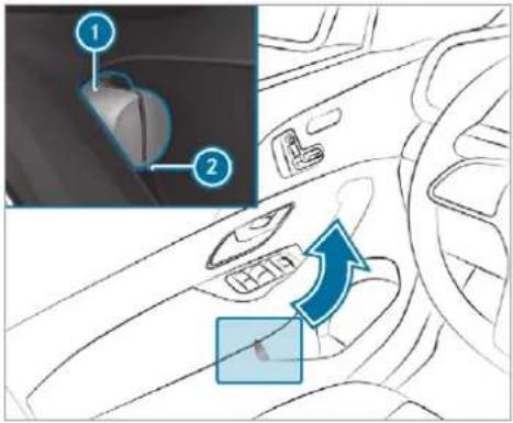
text_image
Diagram of car interior showing dashboard and steering wheel with labeled parts and directional arrowTo remove: pull out safety vest bag ① by loop ②.
Open safety vest bag ① and remove the safety vest.
Additional safety vests can be stored in the stowage space of the rear passenger compartment and in the load compartment.
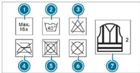
text_image
1 Max. 15x 2 40° 3 6 7 2① Maximum number of washes
② Maximum wash temperature
Do not bleach
4 Do not iron
Do not tumble dry
6 Do not dry clean
⑦ This is a class 2 vest
The requirements defined by the legal standard are only fulfilled if the safety vest is the correct size and is fully closed.
Replace the safety vest in the following cases:
- it is damaged or dirt on the reflective strips can no longer be removed.
- the maximum number of washes is exceeded.
- the fluorescence of the safety jacket has faded.
Warning triangle
Removing the warning triangle
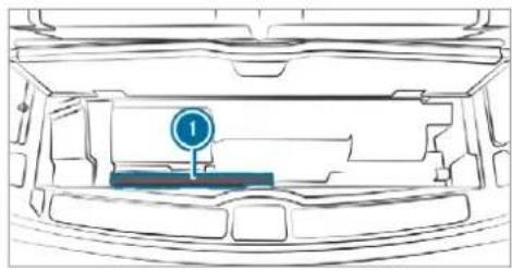
natural_image
Diagram of a car interior showing the hood and dashboard with a blue circular marker labeled '1' (no text or symbols beyond the marker)Remove warning triangle 1.
Setting up the warning triangle
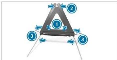
flowchart
graph TD
    A["Zone 1"] --> B["Zone 2"]
    A --> C["Zone 3"]
    A --> D["Zone 3"]
    style A fill:#99ccff,stroke:#333
    style B fill:#99ccff,stroke:#333
    style C fill:#99ccff,stroke:#333
    style D fill:#99ccff,stroke:#333
Fold side reflectors ① upwards to form a triangle and attach at the top using upper press-stud ②.
Fold legs ③ down and out to the side.
First-aid kit (soft-sided) overview
Mercedes-Maybach vehicles
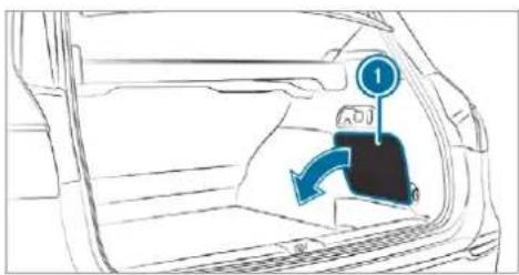
text_image
Diagram showing car interior with directional arrow and numbered label '1' pointing to a vehicle door panelIn the as-delivered state, the first-aid kit (soft sided) is in the load compartment on the right-hand side behind service flap ①.
All other vehicles
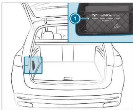
text_image
Diagram of a car backrest with labeled component '1' and highlighted interior areaExample: first-aid kit (soft sided)
In the as-delivered state, first-aid kit (soft sided) is in the load compartment in the left-hand or right-hand stowage compartment, depending on the model.
Removing the fire extinguisher

WARNING Risk of accident due to an incorrectly secured fire extinguisher in the driver's footwell
A fire extinguisher in the driver's footwell may impede pedal travel or block a depressed pedal.
This jeopardises the operating and road safety of the vehicle.
Moreover, the fire extinguisher can be thrown about in the driver's footwell and injure the driver or other vehicle occupants.
Always store and secure the fire extinguisher in the bracket.
Do not remove the fire extinguisher while driving.
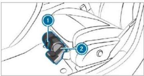
text_image
Diagram of car seatbelt mechanism with numbered components and directional arrows indicating movement or force
Left-hand drive vehicle: pull tab upwards.

Remove fire extinguisher ②.
Flat tyre
Notes on flat tyres

WARNING Risk of accident due to a flat tyre
A flat tyre severely affects the driving characteristics as well as the steering and braking of the vehicle.
Tyres without run-flat characteristics:
Do not drive on with a flat tyre.
Change the flat tyre immediately with an emergency spare wheel or spare wheel. Alternatively, consult a qualified specialist workshop.
Tyres with run-flat characteristics:
▶ Observe the information and warning notes on MOExtended tyres (run-flat tyres).
In the event of a flat tyre, the following options are available depending on your vehicle's equipment:
- Vehicles with MOExtended tyres: it is possible to continue the journey for a short period of time. Make sure you observe the notes on MOExtended tyres (run-flat tyres) (→ page 586).
-
Vehicles with a TREFIT kit: you can repair the tyre so that it is possible to continue the journey for a short period of time. To do this, use the TREFIT kit (→ page 587).
-
Vehicles with Mercedes me connect: you can make a call for breakdown assistance via the overhead control panel in the case of a breakdown (→ page 505).
- All vehicles: change the wheel (→ page 619).
The emergency spare wheel is only available in certain countries.
Notes on MOExtended tyres (run-flat tyres)
⚠ WARNING Risk of accident when driving in emergency mode
When driving in emergency mode, the handling characteristics are impaired. e.g. when cornering, when accelerating strongly and when braking.
Do not exceed the permissible maximum speed.
Avoid any abrupt steering and driving maneuvers as well as driving over obstacles (curbs, pot holes, off-road).
This applies, in particular, to a loaded vehicle.
▶ Stop driving in the emergency mode if you notice:
- banging noise
- vehicle vibration
• smoke which smells like rubber
• continuous ESP® intervention
• cracks in tire side walls
After driving in emergency mode have the rims checked by a qualified specialist workshop with regard to their further use.
The defective tire must be replaced in every case.
You can recognise MOExtended tyres by the MOExtended marking which appears on the side wall of the tyre.
Vehicles with tyre pressure loss warning system: MOExtended tyres may only be used in conjunction with an activated tyre pressure loss warning system.
Vehicles with tyre pressure monitoring system: MOExtended tyres may only be used in conjunction with an activated tyre pressure monitoring system.
If a pressure loss warning message appears in the multifunction display, proceed as follows:
- Check the tyre for damage.
• If driving on, observe the following notes.
With MOExtended tyres (run-flat tyres), you can continue to drive your vehicle even if there is a total loss of pressure in one or more tyres. However, the tyre affected must not show any clearly visible damage.
Driving distance possible in emergency mode after the pressure loss warning:
| Load condition Driving distance possible in emergency mode | |
| Partially laden 80 km | |
| Fully laden 30 km | |
The driving distance possible in emergency mode may vary depending on the driving style. Observe the maximum permissible speed of 80 km/h.
If a tyre has gone flat and cannot be replaced with an MOExtended tyre, you can use a standard tyre as a temporary measure.
TREFIT kit storage location
The TREFIT kit is located under the load compartment floor.
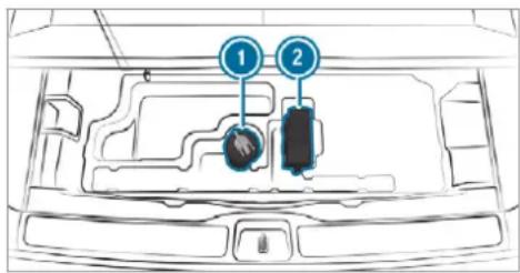
text_image
Diagram of a car interior with labeled parts, showing numbered indicators for component identification.Example: TREFIT kit
① Tyre sealant bottle
② Tyre inflation compressor
You can find information on the power category (LK) and/or electrical data on the bac of the tyre inflation compressor:
• LK3 - 12 V/20A, 240 W, 1 kg
At a distance of approximately 1 m to the tyre inflation compressor and approximately 1.6 m above the ground, the following sound pressure levels apply:
- Emission sound pressure level _pA L 84 dB (A)
• Sound power level L_WA 92 dB (A)
The tyre inflation compressor is maintenance-free. If there is a malfunction, please contact a qualified specialist workshop.
Using the TREFIT kit
Requirements:
- Tyre sealant bottle and tyre inflation compressor ( page 587).
- TREFIT sticker
- Gloves (depending on the vehicle equipment)
You can use TREFIT tyre sealant to seal perforation damage of up to 4 mm, particularly those in the tyre contact surface. You can use TREFIT in outside temperatures down to -20 °C.
⚠ WARNING Risk of accident when using tyre sealant
In the following situations in particular, the tyre sealant is unable to provide sufficient
breakdown assistance, as it is unable to seal the tyre properly:
- there are cuts or punctures in the tyre larger than those previously mentioned.
• the wheel rim is damaged. - you have driven at very low tyre pressures or on a flat tyre.
Do not drive on.
Consult a qualified specialist workshop.
WARNING Risk of injury and poisoning from tyre sealant
Tyre sealant is hazardous to health and causes irritation. Do not allow it to come into contact with your skin, eyes or clothing, and do not swallow it. Do not inhale any vapours. Keep the tyre sealant away from children.
Observe the following if you come into contact with the tyre sealant:
Rinse off the tyre sealant from your skin using water immediately.
If tyre sealant gets into your eyes, thoroughly rinse them using clean water immediately.
If tyre sealant has been swallowed, thoroughly rinse out your mouth immediately and drink plenty of water. Do not induce vomiting and seek medical attention immediately.
Change out of clothing which has come into contact with tyre sealant immediately.
If an allergic reaction occurs, seek medical attention immediately.
! NOTE Overheating due to the tyre inflation compressor running too long
Do not run the tyre inflation compressor for longer than ten minutes without interruption.
Comply with the manufacturer's safety notes on the sticker on the tyre inflation compressor.
Have the tyre sealant bottle replaced in a qualified specialist workshop every five years.
Do not remove any foreign objects which have entered the tyre.

text_image
MAX 80 50 Km/h Mph TiREFi ① ②Affix part ① of the TIREFIT sticker to the instrument cluster within the driver's field of vision.
Affix part ② of the TIREFIT sticker near the valve on the wheel with the defective tyre.
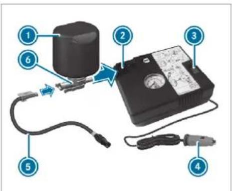
text_image
Diagram of a device with numbered components and labeled parts, including a cylindrical component and connected cables.Pull plug ④ with the cable and hose ⑤ out of the tyre inflation compressor housing.
Push the plug of hose ⑤ into flange ⑥ of tyre sealant bottle ① until the plug engages.
Place tyre sealant bottle ① head downwards into recess ② of the tyre inflation compressor.
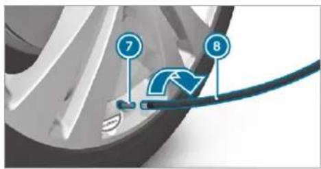
text_image
7 8Remove the valve cap from valve ⑦ on the faulty tyre.
Screw filling hose ⑧ onto valve ⑦.
Insert plug ④ into a 12 V socket in your vehicle.
▶ Switch on the ignition.
Press on and off switch ③ on the tyre inflation compressor.
The tyre inflation compressor is switched on. The tyre is inflated. First, tyre sealant is pumped into the tyre. The pressure may briefly rise to approximately 500 kPa (5 bar/73 psi).
Do not switch off the tyre inflation compressor during this phase!
Let the tyre inflation compressor run for a maximum of ten minutes. The tyre should then have attained a tyre pressure of at least 200 kPa (2.0 bar/29 psi).
If tyre sealant leaks out, make sure you clean affected area as quickly as possible. It is preferable to use clean water.
If you get tyre sealant on your clothing, have it cleaned as soon as possible with perchloroethylene.
If, after ten minutes, a tyre pressure of 200 kPa (2.0 bar/29 psi) has not been attained:
▶ Switch off the tyre inflation compressor. ▶ Unscrew the filling hose from the valve of the defective tyre.
Please note that tyre sealant may leak out when unscrewing the filling hose.
Drive forwards or reverse very slowly for approximately 10 m.
Pump up the tyre again.
After a maximum of ten minutes the tyre pressure must be at least 200 kPa (2.0 bar/29 psi).
A WARNING Risk of accident due to the specified tyre pressure not being achieved
If the specified tyre pressure is not achieved after the specified time, the tyre is too badly damaged. The tyre sealant cannot repair the tyre in this instance.
Damaged tyres and a tyre pressure that is too low can significantly impair braking and handling characteristics.
Do not drive on.
Consult a qualified specialist workshop.
If, after ten minutes, a tyre pressure of 200 kPa (2.0 bar/29 psi) has been attained:
▶ Switch off the tyre inflation compressor.
Unscrew the filling hose from the valve of the defective tyre.
WARNING Risk of accident from driving with sealed tyres
A tyre temporarily sealed with tyre sealant impairs driving characteristics and is not suitable for higher speeds.
Adapt your driving style accordingly and drive carefully.
Do not exceed the maximum speed limit with a tyre that has been repaired using tyre sealant.
Observe the maximum permissible speed for a tyre sealed with tyre sealant 80 km/h.
Affix the upper section of the TREFIT sticker to the instrument cluster in a location where it will be easily seen by the driver.
NOTE Staining from leaking tyre sealant
After use, excess tyre sealant may leak out from the filling hose.
Therefore, place the filling hose in the plastic bag that contained the TREFIT kit.
ENVIRONMENTAL NOTE Environmental pollution caused by environmentally irresponsible disposal
Tyre sealant contains pollutants.
Have the tyre sealant bottle disposed of professionally, e.g. at a Mercedes-Benz Service Centre.
Stow the tyre sealant bottle, the tyre inflation compressor and the warning triangle.
▶ Pull away immediately.
▶ Stop driving after approximately ten minutes and check the tyre pressure using the tyre inflation compressor.
The tyre pressure must now be at least 130 kPa (1.3 bar/19 psi).
A WARNING Risk of accident due to the specified tyre pressure not being achieved
If the specified tyre pressure is not achieved after a brief drive, the tyre is too badly damaged. The tyre sealant cannot repair the tyre in this instance.
Damaged tyres and a tyre pressure that is too low can significantly impair braking and handling characteristics.
Do not drive on.
Consult a qualified specialist workshop.
Countries that have Mercedes-Benz
Service24h: you will find a sticker with the telephone number, e.g. on the B-pillar on the driver's side.
To increase the tyre pressure: switch on the tyre inflation compressor.
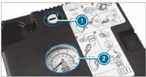
text_image
Diagram showing a device with labeled parts including gauges and tool icons, likely for technical or industrial documentation.To reduce the tyre pressure: press pressure release button ① next to manometer

When the tyre pressure is correct, unscrew the filling hose from the valve of the sealed tyre.
Screw the valve cap onto the valve of the sealed tyre.
Pull the tyre sealant bottle out of the tyre inflation compressor.
The filling hose stays on the tyre sealant bottle.
Drive to the nearest qualified specialist workshop and have the tyre, tyre sealant bottle and filling hose replaced there.
Battery (vehicle)
Notes on the 12 V battery
A WARNING Risk of an accident due to work carried out incorrectly on the battery
Work carried out incorrectly on the battery can, for example, lead to a short circuit. This can lead to function restrictions in safety-relevant systems, e.g. the lighting system, ABS (anti-lock braking system) or ESRElectronic Stability Program). The operating safety of your vehicle may be restricted.
You could lose control of the vehicle in the following situations:
- when braking
- in the event of abrupt steering manoeuvres and/or when the vehicle's speed is not adapted to the road conditions
In the event of a short circuit or a similar incident, contact a qualified specialist workshop immediately.
Do not continue driving.
Always have work on the battery carried out at a qualified specialist workshop.
• Further information on ABS (→ page 252)
• Further information on ESP(→ page 253)
For safety reasons, Mercedes-Benz recommends that you only use batteries which have been tested and approved for your vehicle by Mercedes-Benz. These batteries provide increased impact protection to prevent vehicle occupants from suffering acid burns should the battery be damaged in the event of an accident.
All vehicles except vehicles with a lithium-ion battery

WARNING Risk of explosion due to electrostatic charge
Electrostatic charge can cause sparks which may ignite the highly flammable gas mixture in the battery.
To discharge any electrostatic charge that may have built up, touch the metal vehicle body before handling the battery.
The highly flammable gas mixture is created while the battery is charging and during starting assistance.

WARNING Danger of chemical burns from the battery acid
Battery acid is caustic.
Avoid contact with the skin, eyes or clothing.
Do not lean over the battery.
Do not inhale battery gases.
Keep children away from the battery.
Immediately rinse battery acid off thoroughly with plenty of clean water and seek medical attention immediately.
All vehicles

ENVIRONMENTAL NOTE Environmental damage due to improper disposal of batteries

Batteries contain pollutants. It is illegal to dispose of them with the household rubbish.


Dispose of batteries in an environmentally responsible manner. Take discharged batteries to a qualified
specialist workshop or to a collection point for used batteries.
If you have to disconnect the 12 V battery, contact a qualified specialist workshop.
Comply with safety notes and take protective measures when handling batteries.

Risk of explosion.

Fire, naked flames and smoking are prohibited when handling the battery. Avoid creating sparks.

Electrolyte or battery acid is corrosive. Avoid contact with the skin, eyes or clothing. Wear suitable protective clothing, in particular gloves, an apron and a face mask. Immediately rinse electrolyte or acid splashes off with clean water. Consult a doctor if necessary.

Wear safety glasses.

Keep children away.

Observe this Owner's Manual.
Observe the following if you do not intend to use the vehicle over an extended period of time:
- Activate standby mode.
- Alternatively: connect the battery to a battery charger approved by Mercedes-Benz or consult a qualified specialist workshop to disconnect the battery.
Notes on starting assistance and on charging the 12 V battery
Vehicles with a lithium-ion battery
When charging the battery and during starting assistance, always use the jump-start connection point in the engine compartment.
NOTE Damaging the battery through overvoltage
When using a battery charger without a maximum charging voltage, the battery or the vehicle electronics may be damaged.
Only use battery chargers with a maximum charging voltage of 14.8 V.
All other vehicles
When charging the battery and during starting assistance, always use the jump-start connection point in the engine compartment.

NOTE Damaging the battery through overvoltage
When using a battery charger without a maximum charging voltage, the battery or the vehicle electronics may be damaged.
Only use battery chargers with a maximum charging voltage of 14.8 V.

WARNING Risk of explosion from hydrogen gas igniting
A battery generates hydrogen gas during the charging process. If there is a short circuit or sparks start to form, there is a danger of the hydrogen gas igniting.
▶ Make sure that the positive terminal of the connected battery does not come into contact with vehicle parts.
▶ Never place metal objects or tools on a battery.
When connecting and disconnecting the battery, you must observe the described order for the battery clamps.
When giving starting assistance, always make sure that you only connect battery terminals with identical polarity.
During starting assistance, you must observe the described order for connecting and disconnecting the jump lead.
Do not connect or disconnect the battery clamps while the engine is running.

WARNING Risk of explosion during charging process and starting assistance
During the charging process and starting assistance, the battery may release an explosive gas mixture.
Avoid fire, naked flames, creating sparks and smoking.
Make sure that there is sufficient ventilation during the charging process and during starting assistance.
▶ Do not lean over a battery.

WARNING Risk of explosion from a frozen battery
A discharged battery may freeze at temperatures slightly above or below freezing point.
During starting assistance or battery charging, battery gas may be released.
▶ Always thaw a frozen battery out first before charging it or performing starting assistance.
If the indicator/warning lamps in the instrument cluster do not light up at low temperatures, it is very likely that the discharged battery has frozen. In this case you may neither jump-start the vehicle nor charge the battery.
The service life of a battery that has been thawed may be dramatically shortened. The starting characteristics may be impaired, especially at low temperatures.
It is recommended that you have a thawed battery checked at a qualified specialist workshop.
All vehicles

NOTE Damage caused by numerous or extended attempts to start the engine
Numerous or extended attempts to start the engine may damage the catalytic converter due to non-combusted fuel.

Avoid numerous and extended attempts to start the engine.
Observe the following points during starting assistance and when charging the battery:
- Only use undamaged jump lead/charging cables with a sufficient cross-section and insulated terminal clamps.
- Non-insulated parts of the terminal clamps must not come into contact with other metal parts while the jump lead/charging cable is connected to the battery/jump-start connection point.
- The jump lead/charging cable must not come into contact with any parts which may move when the engine is running.
• Always make sure that neither you nor the battery is electrostatically charged.
- Keep away from fire and naked flames.
- Do not lean over the battery.
Observe the additional following points when charging the battery:
- Only use battery chargers tested and approved for Mercedes-Benz.
- Read the battery charger's operating instructions before charging the battery.
Observe the additional following points during starting assistance:
- Starting assistance may be performed using only batteries with a nominal voltage of 12 V.
• The vehicles must not touch. - Vehicles with a petrol engine: jump-start the vehicle only when the engine and exhaust system are cold.
Starting assistance and charging the 12 V battery
Requirements:
- The vehicle is secured with the electric parking brake.
- Vehicles with automatic transmission: the transmission is in position P.
- The ignition and all electrical consumers are switched off.
• The bonnet is open.
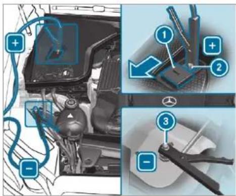
text_image
Diagram illustrating car engine components with numbered annotations and tool tips, showing engine parts and repair instructions.Example: engine compartment
Slide cover ① of positive clamp ② on the jump-starting connection point in the direction of the arrow.
Connect positive clamp ② on your vehicle to the positive pole of the donor battery using When the starting assistance/charging process the jump lead/charging cable. Always begin is complete, perform the following steps:
with positive clamp ② on your own vehicle first.
During starting assistance: start the engine of the donor vehicle and run at idle speed.
Connect the negative pole of the donor battery and earth point ③ of your own vehicle by using the jump lead/charging cable. Begin with the donor battery first.
During starting assistance: start the engine of your own vehicle.
During the charging process: start the charging process.
During starting assistance: let the engines run for several minutes.
During starting assistance: before disconnecting the jump lead, switch on an electric consumer in your own vehicle, e.g. the rear window heater or lighting.
First, remove the jump lead/charging cable from earth point ③ and the negative pole of the donor battery, then from positive clamp ② and the positive pole of the donor battery. Begin each time with the contacts on your own vehicle first.
After removing the jump lead/charging cable, close cover ① of positive clamp ②.
Further information can be obtained at a qualified specialist workshop.
Replacing the 12 V battery
Observe the notes on the 12 V battery ( page 591).
Mercedes-Benz recommends that you have the 12 V battery replaced at a qualified specialist car workshop, e.g. at a Mercedes-Benz Service Centre.
Observe the following notes if you want to replace the battery yourself:
- Always replace a faulty battery with a battery which meets the specific vehicle requirements.
The vehicle is equipped with an AGM technology battery (Absorbent Glass Mat) or a lithium-ion battery. Full vehicle functionality is only guaranteed with an AGM battery or lithium-ion battery. For safety reasons, Mercedes-Benz recommends that you only use batteries which have been tested and approved for your vehicle by Mercedes-Benz. -
Carry over detachable parts, such as vent hoses, elbow fittings or terminal covers from the battery being replaced.
-
Make sure that the vent hose is always connected to the original opening on the side of the battery.
Fit any existing or supplied cell caps. Otherwise, gases or battery acid could escape. - Make sure that detachable parts are reconnected in the same way.
Tow-starting or towing away
Permitted towing methods
Mercedes-Benz recommends transporting your vehicle in the case of a breakdown, rather than towing it away.
For towing, use a tow rope or tow bar with both axles on the ground. Do not use tow bar systems.

NOTE Damage to the vehicle due to towing away incorrectly

Observe the instructions and notes on towing away.
Permitted towing methods
| Vehicle equipment/towing method | 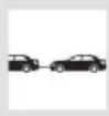 | 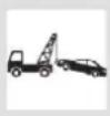 | 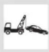 |
| Both axles on the ground | Front axle raised | Rear axle raised | |
| 4MATIC vehicles | Yes, maximum 50 km at 50 km/h | No | No |
Towing away the vehicle with both axles on the ground
Observe the notes on the permitted towing methods ( page 597).
Make sure that the battery is connected and charged.
A discharged battery has the following effects:
• the engine cannot be started
- the electric parking brake cannot be released or applied
- the automatic transmission cannot be shifted to position N or P
If the automatic transmission cannot be shifted to position N, or the multifunction display in the instrument cluster does not show anything, the vehicle must be transported away ( page 599). A towing vehicle with lifting equipment is required for vehicle transportation.
! NOTE Damage due to towing away at excessively high speeds or over long distances
The drivetrain could be damaged when towing at excessively high speeds or over long distances.
A towing speed of 50 km/h must not be exceeded.
A towing distance of 50 km must not be exceeded.
WARNING Risk of accident when towing a vehicle which is too heavy
If the vehicle being tow-started or towed away is heavier than the permissible gross mass, the following situations can occur:
• the towing eye may become detached.
- the car/trailer combination may swerve or even overturn.
If another vehicle is tow-started or towed away, its weight must not exceed the permissible gross mass of your own vehicle.
Information on the permissible gross mass the vehicle can be found on the vehicle identification plate ( page 633).
Do not open the driver's door or front passenger door as the automatic transmission may otherwise shift to position P automatically.
Fit the towing eye ( page 601).
Fasten the tow bar.
! NOTE Damage due to incorrect connection of the tow bar
Only connect the tow rope or tow bar to the towing eyes.
① You can also attach the tow bar to the trailer hitch.
Deactivate the automatic locking mechanism ( page 92).
Do not activate the HOLD function.
Deactivate tow-away protection ( page 115).
Deactivate Active Brake Assist (→ page 265).
Shift the automatic transmission to position ( page 229).
Release the electric parking brake.
A WARNING Risk of accident due to limited safety-related functions during the towing process
Safety-related functions are limited or no longer available in the following situations:
• the ignition is switched off.
- the brake system or power steering system is malfunctioning.
- the energy supply or the on-board electrical system is malfunctioning.
When your vehicle is then towed away, significantly more effort may be required to steer and brake than is normally required.
▶ Use a tow bar.
Make sure that the steering wheel can move freely, before towing the vehicle away.
! NOTE Damage due to excessive tractive power
If you pull away sharply, the tractive power may be too high and the vehicles could be damaged.
▶ Pull away slowly and smoothly.
Loading the vehicle for transport
Observe the notes on towing away ( page 598).
Connect the tow bar to the towing eye in order to load the vehicle.
① You can also attach the tow bar to the trailer hitch.
Shift the automatic transmission to position N.
The automatic transmission may be locked in position in the event of damage to the electrics. To shift to , provide the on-board electrical system with power (→ page 595).
Load the vehicle onto the transporter.
Shift the automatic transmission to position P.
Use the electric parking brake to secure the vehicle against rolling away.
Only secure the vehicle by the wheels.
Vehicles with ADS PLUS (Adaptive Damping System PLUS)

WARNING Risk of an accident when transporting vehicles with Adaptive Damping System PLUS
The reduced damping forces on the vehicle being transported can cause the vehicle/trailer combination to start to swing.
As a result, when transporting vehicles with the Adaptive Damping System PLUS, the vehicle/trailer combination may start to skid. Consequently, you could lose control of your vehicle.
When transporting, ensure that:
- the vehicle has been loaded onto the transporter correctly
- the vehicle is secured at all four wheels with suitable tensioning straps
- the maximum permissible speed of 60 km/h is not exceeded when transporting

NOTE Damage to the vehicle from securing it incorrectly
After loading, the vehicle must be secured on all four wheels. Otherwise, the vehicle could be damaged.
A minimum distance of 20 cm upwards and 10 cm downwards must be kept to the transport platform.
Secure the vehicle on all four wheels after loading.
4MATIC vehicles/vehicles with automatic transmission
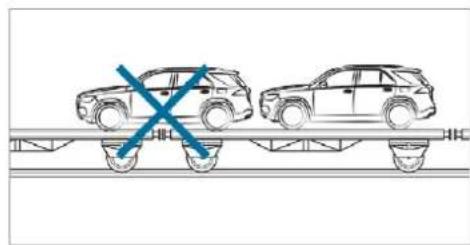
natural_image
Diagram of two cars on a track with a blue X mark indicating collision or crossing (no text or symbols)Make sure that the front and rear axles come to rest on the same transportation vehicle.
NOTE Damage to the drivetrain due to incorrect positioning
Do not position the vehicle above the connection point of the transport vehicle.
Towing eye storage location
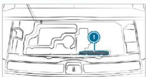
natural_image
Top-down line drawing of a car interior showing the dashboard and steering wheel (no text or symbols)Example: towing eye
Towing eye ① is located under the load compartment floor.
Installing the towing eye
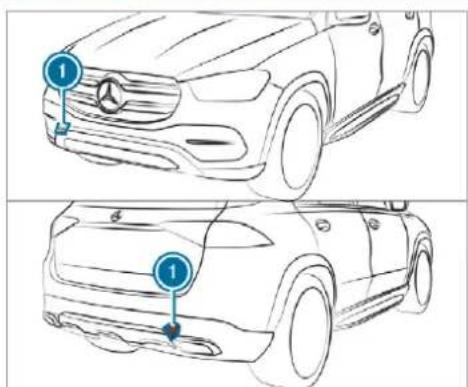
text_image
Technical line drawing of a car showing front and side views with numbered annotationsPress the mark on cover ① inwards and remove.
Screw in the towing eye clockwise as far as it will go and tighten.
Vehicles with a trailer hitch: vehicles with a trailer hitch do not have a rear bracket for the
towing eye. Fasten the tow bar to the trailer hitch.
① Make sure that cover ① engages in the bumper when you remove the towing eye.
! NOTE Damage to the vehicle due to incorrect use of the towing eye
When a towing eye is used to recover a vehicle, the vehicle may be damaged in the process.
Only use the towing eye to tow away or tow start the vehicle.
Tow starting the vehicle (emergency engine start)
Vehicles with automatic transmission
! NOTE Damage to the automatic transmission due to tow-starting
The automatic transmission may be damaged in the process of tow-starting vehicles with automatic transmission.
▶ Vehicles with automatic transmission must not be tow-started.
▶ Vehicles with automatic transmission must not be tow-started.
Electrical fuses
Notes on electrical fuses
⚠ WARNING Risk of accident and injury due to overloaded lines
If you manipulate or bridge a faulty fuse or if you replace it with a fuse with a higher amperage, the electric line could be overloaded.
This could result in a fire.
Always replace faulty fuses with speci- fied new fuses containing the correct amperage.
NOTE Damage due to incorrect fuses
Electrical components or systems may be damaged by incorrect fuses, or their functionality may be significantly impaired.
Only use fuses that have been approved by Mercedes-Benz and which have the correct fuse rating.
Blown fuses must be replaced with fuses of the same rating, which you can recognise by the colour and fuse rating. The fuse ratings and further information to be observed can be found in the fuse assignment diagram.
Fuse assignment diagram: on the fuse box in the load compartment ( page 604).
! NOTE Damage or malfunctions caused by moisture
Moisture may cause damage to the electrical system or cause it to malfunction.
When the fuse box is open, make sure that no moisture can enter the fuse box.
When closing the fuse box, make sure that the seal of the lid is positioned correctly on the fuse box.
If the newly inserted fuse also blows, have the cause traced and rectified at a qualified specialist workshop.
Ensure the following before replacing a fuse:
• The vehicle is secured against rolling away.
- All electrical consumers are switched off.
• The ignition is switched off.
The electrical fuses are located in various fuse boxes:
- Fuse box in the engine compartment on the left-hand side of the vehicle, when viewed in the direction of travel ( page 603)
-
Fuse box on the driver's side of the cockpit (→ page 603)
-
Fuse box in the front passenger footwell (→ page 603)
- Fuse box in the load compartment on the right-hand side of the vehicle, when viewed in the direction of travel (→ page 604)
Opening and closing the fuse box in the engine compartment
Requirement:
• You need a dry cloth and a screwdriver.
Observe the notes on electrical fuses ( page 602).
Opening
WARNING Risk of injury from using the windscreen wipers while the engine bonnet is open
When the engine bonnet is open, and the windscreen wipers are set in motion, you can be trapped by the wiper linkage.
Always switch off the windscreen wipers and ignition before opening the engine bonnet.
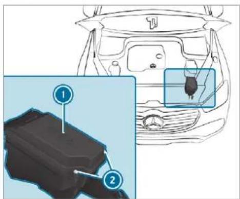
text_image
Diagram showing a car interior with labeled parts and an inset close-up of the engine compartment, highlighting two components.Remove any existing moisture from the fuse box using a dry cloth.
Loosen screws ② and remove fuse box lid ① from the top.
Closing
▶ Check whether the seal is positioned correctly in the lid.
Insert the lid into the bracket at the rear of the fuse box.
Fold down the lid of the fuse box and tighten screws ②.
Close the bonnet.
Opening and closing the fuse box in the cockpit
The fuse box is on the side of the dashboard under a cover.
Contact a Mercedes-Benz Service Centre for further information.
Opening and closing the fuse box in the front passenger footwell
Contact a Mercedes-Benz Service Centre for further information.
Opening and closing the fuse box in the load compartment
Observe the notes on electrical fuses ( page 602).
▶ Open the side cover.
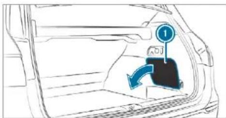
text_image
Diagram showing car interior with directional arrow and numbered label '1' pointing to a vehicleRemove cover 1.
The fuse allocation chart is on the side of the fuse box.
Notes on noise or unusual handling characteristics
While driving, pay attention to vibrations, noises and unusual handling characteristics, e.g. pulling to one side. This may indicate that the wheels or tyres are damaged. If you suspect that a tyre is defective, reduce your speed immediately. Stop the vehicle as soon as possible to check the wheels and tyres for damage. Hidden tyre damage could also be causing the unusual handling characteristics. If you find no signs of damage, have the tyres and wheels checked at a qualified specialist workshop.
Notes on regularly inspecting wheels and tyres

WARNING Risk of accident from damaged tyres
Damaged tyres can cause tyre pressure loss. As a result, you could lose control of your vehicle.
▶ Check the tyres regularly for signs of damage and replace any damaged tyres immediately.
WARNING Risk of aquaplaning due to insufficient tyre tread
Insufficient tyre tread will result in reduced tyre grip. The tyre tread is no longer able dissipate water.
This means that in heavy rain or slush the risk of aquaplaning is increased, in particular where speed is not adapted to suit the conditions.
If the tyre pressure is too high or too low, tyres may exhibit different levels of wear at different locations on the tyre tread.
Thus, you should regularly check the tread depth and the condition of the tread across the entire width of all tyres.
Minimum tread depth for:
• Summer tyres: 3 mm
- M+S tyres: 4 mm
For safety reasons, replace the tyres before the legally prescribed limit for the minimum tread depth is reached.
to Carry out the following checks on all wheels regularly, at least once a month or as required, e.g. prior to a long journey or driving off-road:
- Check the tyre pressure (→ page 606).
- Visually inspect wheels and tyres for damage.
- Check the valve caps.
The valves must be protected against moisture and dirt by the valve caps approved especially for your vehicle by Mercedes-Benz.
- Visual check of the tyre tread depth and the tyre contact surface across the entire width. The minimum tread depth for summer tyres is 3 mm and for winter tyres 4 mm.
Notes on snow chains

NOTE Damage to components of the vehicle body or chassis due to fitted snow chains
If you fit snow chains to the front wheels of 4MATIC vehicles, you may damage components of the vehicle body or chassis.
Only fit snow chains to the rear wheels of 4MATIC vehicles.
- Snow chains are only permissible for certain wheel/tyre combinations. You can obtain information about this from a Mercedes-Benz Service Centre.
- For safety reasons, only use snow chains that have been specifically approved for your vehicle by Mercedes-Benz, or snow chains with the same quality standard.
- If snow chains are fitted, the maximum permissible speed is 50 km/h.
-
Vehicles with Active Parking Assist: do not use Active Parking Assist when snow chains are fitted.
-
Vehicles with AIRMATIC or E-ACTIVE BODY CONTROL: if snow chains are fitted, only drive at raised vehicle level.
① You can permanently limit the maximum vehicle speed for driving with winter tyres (→ page 269).
You can deactivate ESP to pull away (→ page 258). This allows the wheels to spin, achieving an increased driving force.
Tyre pressure
Notes on tyre pressure

WARNING Risk of accident due to insufficient or excessive tyre pressure
Underinflated or overinflated tyres pose the following risks:
- The tyres may burst, especially as the load and vehicle speed increase.
- The tyres may wear excessively and/or unevenly, which may greatly impair tyre traction.
- The driving characteristics, as well as steering and braking, may be greatly impaired.
Comply with the recommended tyre pressure and check the tyre pressure of all tyres including the spare wheel regularly:
• at least once a month - when the load changes
• before embarking on a longer journey - if operating conditions change, e.g. off-road driving
Adjust the tyre pressure as necessary.
Tyre pressure which is too high or too low can:
- Shorten the service life of the tyres.
- Cause increased tyre damage.
- Adversely affect driving characteristics and thus driving safety, e.g. due to aquaplaning.

WARNING Risk of accident from repeated tyre pressure drop
If the tyre pressure drops repeatedly, the wheel, valve or tyre may be damaged.
Insufficient tyre pressure can cause the tyres to burst.
Inspect the tyre for signs of foreign objects.
▶ Check whether the wheel or valve has a leak.
If you are unable to rectify the damage, contact a qualified specialist workshop.
Information on the recommended tyre pressure for the vehicle's factory-fitted tyres can be found on the tyre pressure table on the inside of the fuel filler flap ( page 607).
Use a suitable pressure gauge to check the tyre pressure. The outer appearance of a tyre does not permit any reliable conclusion about the tyre pressure.
Vehicles with a tyre pressure monitoring system: you can also check the tyre pressure using the on-board computer.
Only correct tyre pressures when the tyres are cold. Conditions for cold tyres:
- The vehicle has been parked with the tyres out of direct sunlight for at least three hours.
• The vehicle has travelled less than 1.6 km.
A rise in the tyre temperature of 10 °C increases the tyre pressure by approx. 10 kPa (0.1 bar/1.5 psi). Take this into account when checking the tyre pressure of warm tyres.
Notes on trailer operation
Always inflate the rear axle tyres to the recommended tyre pressures on the tyre pressure table for increased load.
Tyre pressure table
The tyre pressure table is on the inside of the fuel filler flap.
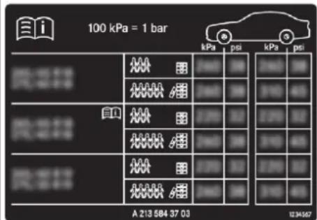
text_image
100 kPa = 1 bar kPa psi kPa psi A 213 584 37 03 12:34:57The tyre pressure table shows the recommended tyre pressure for all tyres approved for this vehicle. The recommended tyre pressures apply for cold tyres under various operating conditions, i.e. loading and/or speed of the vehicle.
If one or more tyre sizes precede a tyre pressure, the tyre pressure information following is only valid for those tyre sizes.
If the preceding tyre sizes are complemented by The tyre pressure and the tyre temperature the symbol, the tyre pressure information appear in the multifunction display
following shows alternative tyre pressures.
These tyre pressures may improve your vehicle's ride comfort. Fuel consumption may then increase slightly.
The load conditions "partially laden" and "fully laden" are defined in the table for different numbers of passengers and amounts of luggage. Actual number of seats may differ from this.
Be sure to also observe the following further related subjects:
• Notes on tyre pressure ( page 606)
Tyre pressure monitoring system
Function of the tyre pressure monitoring system
The system checks the tyre pressure and the tyre temperature of the tyres fitted to the vehicle by means of a tyre pressure sensor.
New tyre pressure sensors, e.g. in winter tyres, are automatically taught-in during the first journey they are used.
(→ page 608).
If there is a substantial pressure loss or if the tyre temperature is excessive, you will be warned in the following ways:
• via display messages (→ page 701)
e^ via the (1) warning lamp in the instrument cluster (→ page 725)
The tyre pressure monitoring system is only an aid. It is the driver's responsibility to set the tyre pressure to the recommended cold tyre pressure suitable for the operating situation. Set the tyre pressure for cold tyres using a tyre pressure gauge. Note that the correct tyre pressure for the current operating situation must first be taught-in to the tyre pressure monitoring system.
In most cases, the tyre pressure monitoring tem will automatically update the new reference values after you have changed the tyre pressure. 'You can, however, also update the reference values by restarting the tyre pressure monitoring system manually ( page 609).
System limits
The system may be impaired or may not function in the following situations:
• the tyre pressure has been set incorrectly
- there is a sudden pressure loss caused, for example, by a foreign object penetrating the tyre
- there is a malfunction caused by another radio signal source
Be sure to also pay attention to the following related topic:
• notes on tyre pressure (→ page 606)
Checking the tyre pressure with the tyre pressure monitoring system Requirements:
• The ignition is switched on.
sysOn-board computer:
→ Service ▶ Tyres
One of the following displays appears:
- Current tyre pressure and tyre temperature of the individual wheels:

text_image
270 58℃ 270 58℃ 280 58℃ 280 kPa 58℃- Tyre pressures will be displayed after a few minutes of driving
- Tyre pressure monitor active: the teach-in process of the system is not yet complete. The tyre pressures are already being monitored.
▶ Compare the tyre pressure with the recommended tyre pressure for the current operating condition ( page 607). Observe the notes on tyre temperature ( page 606).
The values displayed in the multifunction display may deviate from those of the tyre pressure gauge as they refer to sea level. At high altitudes, the tyre pressure values indicated
by a pressure gauge are higher than those shown by the on-board computer. In this case, do not reduce the tyre pressure.
Make sure to observe the following further related subject:
• Notes on tyre pressure (→ page 606)
Restarting the tyre pressure monitoring system
Requirements:
- The recommended tyre pressure is correctly set for the respective operating status on each of the four wheels ( page 606).
Restart the tyre pressure monitoring system in the following situations:
• The tyre pressure has changed.
- The wheels or tyres have been changed or newly fitted.
On-board computer:
Service ▶ Tyres
Swipe downwards on Touch Control on the left-hand side of the steering wheel. The Use current pressures as new reference values? message is shown in the multifunction display.
To begin restart, press Touch Control on the left-hand side of the steering wheel. The Tyre press. monitor restarted message is shown in the multifunction display.
Current warning messages are deleted and the yellow ⏻ warning lamp goes out.
After you have been driving for a few minutes, the system checks whether the current tyre pressures are within the specified range. The current tyre pressures are then accepted as reference values and monitored.
Make sure to observe the following further related subject:
• Notes on tyre pressure ( page 606)
Radio-equipment approval of the tyre pressure monitoring system
Radio equipment approval numbers
| Country | Radio equipment approval number |
| Argentina |  CNC ID: H-20027 CNC ID: H-20027 |
| Australia |  |
| Country | Radio equipment approval number |
| European Union | CEHereby, Huf Hülsbeck & Fürst GmbH & Co. KG declares that the radio equipment type TSSRE4A & TSSSG4G6 is in compliance with Directive 2014/53/EU.The full text of the EU declaration of conformity is available at the following internet address: http://www.huf-group.com/eudocFrequency band: 433,92 MHzMaximum Transmission Power: <10 mWManufacturer:Huf Electronics Bretten GmbH Gewerbestr. 4075015 BrettenGermany |
| Indonesia | 52 166/SDPPI/20173533 |
| Israel | A. The use of this product does not need a wireless operation license.B. The product does not include an RF disturbance protection, and should not disturb other licensed products.C. It is forbidden to replace the antenna or to make any change in this product. |
| Country | Radio equipment approval number |
| Jordan | Kingdom of Jordan Type approval for Tyre Pressure Sensor and ECU Manufacturer: Huf Electronics Bretten GmbHModel: TSSRE4AType Approval Number: TRC/LPD/2017/421Model: TSSSG4G6Type Approval Number: TRC/LPD/2017/422 |
| Malaysia |
| Country | Radio equipment approval number |
| Morocco | AGREE PAR L'ANRT MAROCModele: TSSRE4ANumero d'agreement: MR 14320 ANRT 2017Date d'agreement: 07/07/2017Modele: TSSSG4G6Numero d'agreement: MR 14319 ANRT 2017Date d'agreement: 07/07/2017 |
| Mexico Model: TSSRE4AIFETEL: RLVHUTS17-0806 | |
| Moldova |  1024 1024 |
| Oman TRAR/4516/17D100428 | |
| Philippinen |  NTCType ApprovedNo: ESD-1715393C NTCType ApprovedNo: ESD-1715393C |
| Russia |  |
| Serbia |  |
| Singapore | Complies with IDA Standards DA103787 |

| Country | Radio equipment approval number |
| Taiwan |  |
| CCAO17LP0380T4CCAO17LP0390T7經型式認證合格之低功率射頻電機,非經許可,公司、商號或使用者均不得擅自變更頻率、加大功率或變更原設計之特性及功能。低功率射頻電機之使用不得影響飛航安全及下擾合法通信;經發現有下擾現象時,應立即停用,並改善至無下擾時方得繼續使用。前項合法通信,指依電信法規定作業之無線電通信。低功率射頻電機須忍受合法通信或工業、科學及醫療用電波輻射性電機設備之干擾。According to “Administrative Regulations on Low Power Radio Waves Radiated Devices”.Without permission granted by the DGT, any company, enterprise, or user is not allowed to change frequency, enhance transmitting power or alter original characteristic as well as performance to a approved low power radio-frequency devices.The low power radio-frequency devices shall not influence aircraft security and interfere legal communications; If found, the user shall cease operating imme- |
| Country | Radio equipment approval number |
| diately until no interference is achieved.The said legal communications means radio communications is operated in compliance with the Telecommunications Act.The low power radio-frequency devices must be susceptible with the interference from legal communications or ISM radio wave radiated devices. | |
| Thailand | This telecommunication equipment conforms to NTC technical requirement. |
| Ukraine | |
| Model: TSSRE4A & TSSSG4G6 UA.TR.109.0109-17 |
| Country | Radio equipment approval number |
| United Arab Emi-rates (UAE) | TRARegistered No: ER57806/17Dealer No: DA36976/14 |
| Vietnam |
Tyre pressure loss warning system
Function of the tyre pressure loss warning system
The tyre pressure loss warning system warns the driver by means of display messages when there is a severe tyre pressure loss.
After a change in tyre pressure, a wheel rotation or a tyre change, or if you have refitted wheels
or tyres, the tyre pressure loss warning system has to be restarted ( page 614).
The tyre pressure loss warning system does not replace the need to regularly check the tyre pressures.
System limitations
The system may be impaired or may not funct particularly in the following situations:
• incorrectly set tyre pressure
- sudden pressure loss caused, for example, by a foreign object penetrating the tyre
• steady pressure loss in several tyres
The system has a restricted or delayed function particularly in the following situations:
• poor ground conditions, e.g. snow or gravel
- driving with snow chains
- when adopting a very sporty driving style with high cornering speeds or sudden acceleration
• driving with a very heavy or large trailer
- driving with a high load
Be sure to also observe the following further related subjects:
• Notes on tyre pressure (→ page 606)
- Display messages about the tyres (→ page 701)
Restarting the tyre pressure loss warning system
Requirements:
- The recommended tyre pressure is correctly set for the respective operating status on each of the four wheels ( page 606).
Restart the tyre pressure loss warning system in the following situations:
• The tyre pressure has changed.
- The wheels or tyres have been changed or newly fitted.
On-board computer:
Service ▶ Tyres
Swipe downwards on Touch Control on the left-hand side of the steering wheel. The Run Flat Indicator activeRestart message is shown in the multifunction display.
To begin restart, press Touch Control on the left-hand side of the steering wheel. The Tyre pressure now OK? message is shown in the multifunction display.
Select Yes.
To confirm restart, press Touch Control on the left-hand side of the steering wheel. The Run Flat Indicator restarted message is shown in the multifunction display.
After you have driven for a few minutes, the tyre pressure loss warning system monitors the set tyre pressures of all the tyres.
Be sure to also observe the following further related subjects:
• Notes on tyre pressure (→ page 606)
Wheel change
Notes on selecting, fitting and replacing tyres
Mercedes-AMG vehicles: observe the notes in the Supplement. You could otherwise fail to recognise dangers.
You can ask for information regarding permitted wheel/tyre combinations at a Mercedes-Benz Service Centre.
⚠ WARNING Risk of accident due to incorrect dimensions of wheels and tyres
If wheels and tyres of the wrong size are used, the wheel brakes or wheel suspension components may become damaged.
Always replace wheels and tyres with those that fulfil the specifications of the original part.
When replacing wheels, make sure to fit the correct:
- Designation
- Type
When replacing tyres, make sure to fit the correct:
- Designation
- Manufacturer
- Type
WARNING Risk of injury through exceeding the specified tyre load-bearing capacity or the permissible speed rating
Exceeding the specified tyre load-bearing capacity or the permissible speed rating may lead to tyre damage and to the tyres bursting.
Therefore, only use tyre types and sizes approved for your vehicle model.
Observe the tyre load-bearing capacity rating and speed rating required for your vehicle.
NOTE Vehicle and tyre damage through tyre types and sizes that have not been approved
For safety reasons, only use tyres, wheels and accessories which have been specially approved by Mercedes-Benz for your vehicle.
These tyres are specially adapted to the control systems, such as ABS, ES and 4MATIC, and marked as follows:
• MO = Mercedes-Benz Original
• MOE = Mercedes-Benz Original Extended (run-flat tyres only for certain wheels)
- MO1 = Mercedes-Benz Original (only certain AMG tyres)
Certain characteristics, such as handling, vehicle noise emissions, fuel consumption, etc. may otherwise be adversely affected. Furthermore, other tyre sizes could result in the tyres rubbing against the body and axle components when loaded. This could result in damage to the tyre or the vehicle.
Only use tyres, wheels and accessories that have been checked and recommended by Mercedes-Benz.

NOTE Risk to driving safety from retrea- ded tyres
Retreaded tyres are neither tested nor recommended by Mercedes-Benz, since previous damage cannot always be detected on retreaded tyres.
For this reason driving safety cannot be guaranteed.
Do not use used tyres if you have no information about their previous usage.

NOTE Possible damage to wheels or tyres when driving over obstacles
Large wheels have a lower tyre section width. The lower the tyre section width, the greater is the risk of damage to wheels or tyres when driving over obstacles.

Avoid obstacles or drive particularly carefully.

NOTE Possible wheel and tyre damage when parking on kerbs or in potholes
Parking on kerbs or in potholes may damage the wheels and tyres.

f possible, park only on flat surfaces.

Avoid kerbs and potholes when parking.

NOTE Damage to electronic component parts from the use of tyre-fitting tools
Vehicles with a tyre pressure monitoring system: electronic component parts are located in the wheel. Tyre-fitting tools should not be applied in the area of the valve.
The tools could damage the electronic component parts.

Have the tyres changed at a qualified specialist workshop only.

NOTE Damage to summer tyres at low ambient temperatures
At low ambient temperatures, tears could form when driving with summer tyres, causing permanent damage to the tyre.

At temperatures below 7 °C, use M+S tyres.
Accessory parts that are not approved for your vehicle by Mercedes-Benz or are not being used correctly can impair the operating safety.
Before purchasing and using non-approved accessories, visit a qualified specialist workshop and enquire about:
- Suitability
- Legal stipulations
• Factory recommendations

WARNING Risk of accident with high performance tyres
The special tyre tread in combination with the optimised tyre compound, means that
the risk of skidding or hydroplaning on wet roads is increased.
In addition, the tyre grip is greatly reduced at a low outside temperature and tyre running temperature.
Switch on the ESPand adapt your driving style accordingly.
▶ Use M+S tyres at outside temperatures of less than 50 °F.
Observe the following when selecting, fitting and replacing tyres:
- Country-specific requirements for tyre approval that define a specific tyre type for your vehicle.
Furthermore, the use of certain tyre types in certain regions and areas of operation can be highly beneficial.
- Only use tyres and wheels of the same type (summer tyres, winter tyres, MOExtended tyres) and the same make.
- Only fit wheels of the same size on one axle (left and right).
It is only permissible to fit a different wheel size in the event of a flat tyre in order to drive to the specialist workshop.
- Only fit tyres of the correct size onto the wheels.
- Do not make any modifications to the brake system, the wheels or the tyres.
- Only fit tyres of the correct size onto the wheels. - Do not make any modifications to the brake system, the wheels or the tyres.
The use of shims or brake dust shields is not permitted and may invalidate the vehicle's general operating permit.
- Vehicles with a tyre pressure monitoring system: all fitted wheels must be equipped with functioning sensors for the tyre pressure monitoring system.
- At temperatures below 7 °C, use winter tyres or all-season tyres marked M+S for all wheels.
- Vehicles with a tyre pressure monitoring system: all fitted wheels must be equipped with functioning sensors for the tyre pressure monitoring system. - At temperatures below 7 °C, use winter tyres or all-season tyres marked M+S for all wheels.
Winter tyres bearing the snowflake symbol in addition to the M+S marking provide the best possible grip in wintry road conditions.
For M+S tyres, only use tyres with the same tread.
- Observe the maximum permissible speed for the M+S tyres fitted.
If this is below the vehicle's maximum speed, this must be indicated by an appropriate label in the driver's field of vision.
Run in new tyres at moderate speeds for the first 100 km.
- Replace the tyres after six years at the latest, regardless of wear.
- When replacing with tyres that do not feature run-flat characteristics: vehicles with MOExtended tyres are not equipped with a TREFIT kit at the factory. Equip the vehicle with a TREFIT kit after replacing with tyres that do not feature run-flat characteristics, e.g. winter tyres.
- Replace the tyres after six years at the latest, regardless of wear. - When replacing with tyres that do not feature run-flat characteristics: vehicles with MOExtended tyres are not equipped with a TREFIT kit at the factory. Equip the vehicle with a TREFIT kit after replacing with tyres that do not feature run-flat characteristics, e.g. winter tyres.
① You can permanently limit the maximum vehicle speed for driving with winter tyres ( page 269).
For more information on wheels and tyres, contact a qualified specialist workshop.
Be sure to also observe the following further related subjects:
• Notes on tyre pressure (→ page 606)
• Tyre pressure table ( page 607)
- Notes on the emergency spare wheel ( page 625)
Notes on interchanging wheels

WARNING Risk of injury through different wheel sizes
Interchanging the front and rear wheels if the wheels or tyres have different dimensions may severely impair the driving characteristics.
The disk brakes or wheel suspension components may also be damaged.
Rotate front and rear wheels only if the wheels and tyres are of the same dimensions.
Interchanging the front and rear wheels if the wheels or tyres have different dimensions can render the general operating permit invalid.
The wear patterns on the front and rear wheels differ:
- Front wheels wear more on the shoulder of the tyre
- Rear wheels wear more in the centre of the tyre
Do not drive with tyres that have too little tread depth. This significantly reduces traction on wet roads (aquaplaning).
On vehicles with the same front and rear wheel size, you can interchange the wheels every 5,000 to 10,000 km, depending on the wear. Ensure the direction of rotation is maintained for the wheels.
Observe the instructions and safety notes on "Changing a wheel" when doing so ( page 619).
Notes on storing wheels
When storing wheels, observe the following notes:
- After removing wheels, store them in a cool, dry and preferably dark place.
- Protect the tyres from contact with oil, grease or fuel.
Overview of the tyre-change tool kit
Apart from some country-specific variants, vehicles are not equipped with a tyre-change tool kit. For more information on which tools are required and approved to perform a wheel change on your vehicle, consult a qualified specialist workshop.
Required tyre-change tools may include, for example:
- Jack
- Chock
- Wheel wrench
The jack weighs approximately 3.4 kg.
The maximum load capacity of the jack can • Folding chock be found on the sticker affixed to the jack. • Ratchet ring s
The jack is maintenance-free. If there is a malfunction, please contact a qualified specialist workshop.
Tyre-change tool kit ⓘ is located under the load compartment floor.
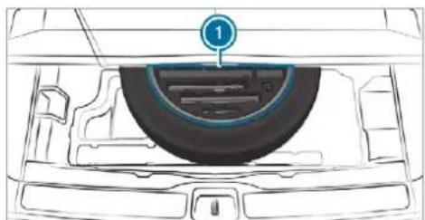
natural_image
Diagram of a car interior showing a tire and dashboard with a numbered component (no text or symbols)The tyre-change tool kit includes the following:
- Jack
- Wheel wrench
- Wheel studs
- Extension attachment for wheel studs, if necessary (depending on vehicle version)
• Folding chock
- Ratchet ring spanner
Setting up the folding chock
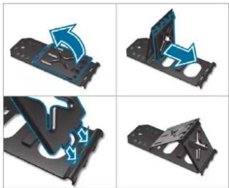
natural_image
Four-panel diagram showing mechanical assembly steps with blue arrows indicating motion (no text or symbols)Preparing the vehicle for a wheel change
Requirements:
- The required tyre-change tool kit is available. If your vehicle is not equipped with the tyre-change tool kit, consult a qualified specialist workshop to find out about suitable tools.
• The vehicle is not on a slope. - The vehicle is on solid, non-slippery and lev-ground.
Apply the electric parking brake manually.
Move the front wheels to the straight-ahead position.
Shift the transmission to position P.
▶ Vehicles with level control system: set the normal vehicle level ( page 289).
▶ Switch off the engine.
Make sure that the engine cannot be started.
Place chocks or other suitable items under the front and rear of the wheel that is diagonally opposite the wheel you wish to change.
▶ Raise the vehicle ( page 621).
Additionally, for Mercedes-Maybach vehicles:
▶ Retract the running boards ( page 95)
To remove stone chipping protective covers ②:
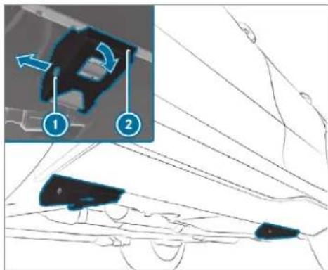
text_image
Technical diagram showing a mechanical component with labeled parts and directional arrows, including numbered annotations 1 and 2.▶ Loosen expansion rivet ① and pull it out. ▶ Fold down and remove stone chipping protective covers ②.
Removing and fitting hub caps
Requirements:
- The vehicle is prepared for a wheel change (→ page 619).
Plastic hub cap
To remove: turn the centre cover of the hub cap anti-clockwise and remove the hub cap.
To fit: make sure that the centre cover of the hub cap is turned anti-clockwise.
▶ Position the hub cap and turn the centre cover clockwise until the hub cap engages physically and audibly.
Aluminium hub cap
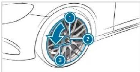
text_image
Diagram of a car wheel with numbered components and directional arrows indicating motion or flowTo remove: position socket ② on hub cap ①.
i The socket can be found in the tyre-change tool kit.
▶ Position wheel spanner ③ on socket ②.
Using wheel spanner ③, turn hub cap ① anti-clockwise and remove it.
To fit: position hub cap ① and turn until it is completely flush with the wheel.
Position socket ② on hub cap ①.
Attach wheel spanner ③ to socket ② and tighten the hub cap clockwise. Specified tightening torque: 25 Nm.
Raising the vehicle when changing a wheel
Requirements:
• There are no persons in the vehicle.
- The vehicle has been prepared for a wheel change (→ page 619).
Important notes on using the jack:
- Use only a vehicle-specific jack that has been approved by Mercedes-Benz to raise the vehicle.
- The jack is only designed for raising and holding the vehicle for a short time while a wheel is being changed and not for maintenance work under the vehicle.
- The jack must be placed on a firm, flat and non-slip surface. If necessary, use a large, flat, load-bearing, non-slip underlay.
- The foot of the jack must be positioned vertically under the jack support point.
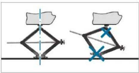
natural_image
Diagram showing two mechanical linkage configurations with blue X marks indicating joint points (no text or symbols present)Rules of conduct when the vehicle is raised:
- Never place your hands or feet under the vehicle.
• Never lie under the vehicle. - Do not start the engine and do not release the electric parking brake.
- Do not open or close any doors or the tail-gate.
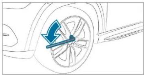
natural_image
Diagram of a car wheel with a blue arrow indicating clockwise motion (no text or symbols)Using the wheel wrench, loosen the wheel bolts on the wheel you wish to change by about one full turn. Do not unscrew the bolts completely.
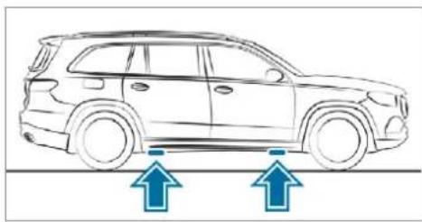
natural_image
Line drawing of a car with two blue arrows pointing upward, indicating motion or movement (no text or symbols present)Position of jack support points
⚠ WARNING Risk of injury from incorrect positioning of the jack
If you do not position the jack correctly at the appropriate jacking point of the vehicle, the jack could tip with the vehicle raised.
Only position the jack at the appropriate jacking point of the vehicle. The base of the jack must be positioned vertically under the jacking point of the vehicle.
NOTE Vehicle damage from the jack
If you do not position the jack correctly at the appropriate jack support point of the vehicle, the jack could tip over with the vehicle raised.
The jack is designed exclusively for jacking up the vehicle at the jack support points.
Take the ratchet ring spanner out of the tyre-change tool kit and place it on the hexagon nut of the jack so that the letters "AUF" are visible.
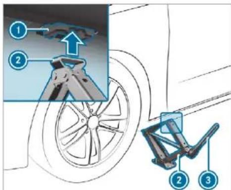
text_image
Diagram illustrating bicycle wheel assembly with numbered components and a magnified detail showing the joint structure.Position jack ② at jack support point ①.
Turn ratchet ring spanner ③ clockwise until jack ② sits completely on jack support point ① and the base of the jack lies evenly on the ground.
Continue to turn ratchet ring spanner ③ until the tyre is raised a maximum of 3 cm off the ground.
Loosen and remove the wheel ( page 623).
Mercedes-Maybach vehicles:
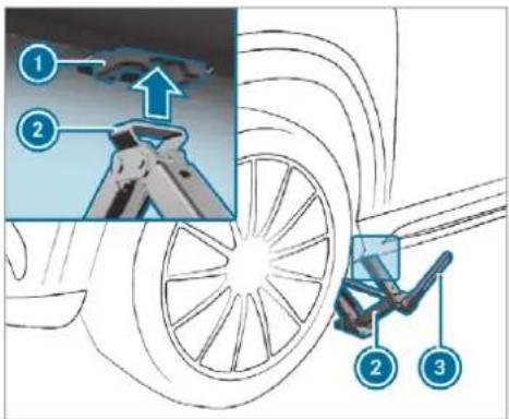
text_image
Diagram illustrating car wheel assembly with numbered components and motion indicatorsRequirements:
- The running boards are retracted (→ page 95)
- The stone chipping protective covers are removed ( page 619)
▶ Position jack ② at jack support point ①.
Turn ratchet ring spanner ③ clockwise until jack ② sits completely on jack support point ① and the base of the jack lies evenly on the ground.
Continue to turn ratchet ring spanner ③ until the tyre is raised a maximum of 3 cm off the ground.
Loosen and remove the wheel ( page 623).
Removing a wheel
Requirements:
• The vehicle is raised ( page 621).
Mercedes-AMG vehicles: observe the notes in the Supplement. Otherwise, you may fail to recognise dangers.
When changing a wheel, avoid applying any force to the brake discs, since this could impair the level of comfort when braking.
NOTE Damage to threading from dirt on wheel bolts
Do not place wheel bolts in sand or on a dirty surface.
▶ Completely unscrew the wheel bolts.
Remove the wheel.
Fit the new wheel ( page 623).
Fitting a new wheel
Requirements:
• The wheel is removed ( page 623).
Mercedes-AMG vehicles: observe the notes in the Supplement. Otherwise, you may fail to recognise dangers.
⚠ WARNING Risk of accident from losing a wheel
Oiled, greased or damaged wheel bolt/wheel nut threads or wheel hub/wheel mounting bolt threads can cause the wheel bolts/wheel nuts to come loose.
As a result, you could lose a wheel while driving.
▶ Never oil or grease the threads.
In the event of damage to the threads, contact a qualified specialist workshop immediately.
Have the damaged wheel bolts or damaged hub threads replaced.
Do not continue driving.
Observe the information on the choice of tyres ( page 615).
For tyres with a specified direction of rotation, an arrow on the side wall of the tyre indicates the correct direction of rotation. Observe the direction of rotation when fitting.

WARNING Risk of injury from tightening wheel bolts and nuts
If you tighten the wheel bolts or wheel nuts when the vehicle is raised, the jack could tip.
Only tighten wheel bolts or wheel nuts when the vehicle is on the ground.
Be sure to observe the instructions and safety notes on "Changing a wheel" (→ page 615).
For safety reasons, only use wheel bolts which have been approved by Mercedes-Benz and for the wheel in question.
Tighten the wheel bolts evenly in a diagonal pattern in the order indicated until they are finger-tight.
If the collapsible emergency spare wheel has been fitted, inflate the collapsible emergency spare wheel ( page 629).
▶ Lower the vehicle ( page 624).
Lowering the vehicle after a wheel change
Requirements:
- The new wheel has been fitted (→ page 623).
Observe the information on tyre pressure ( page 606).
Place the ratchet ring spanner onto the hexagon nut of the jack so that the lettering "AB" is visible.
To lower the vehicle: turn the ratchet ring spanner of the jack anti-clockwise.
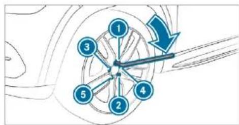
text_image
Diagram showing a circular structure with numbered points and an arrow indicating direction, likely illustrating a mechanical or electrical concept.Tighten the wheel bolts evenly in a diagonal pattern in the order indicated ① to ⑤ with a maximum of 80 Nm.
Then tighten the wheel bolts evenly in a diagonal pattern in the order indicated ① to ⑤ to the specified tightening torque of 150 Nm.

WARNING Risk of injury through incorrect tightening torque
The wheels could come loose if the wheel bolts or wheel nuts are not tightened to the prescribed tightening torque.
Make sure the wheel bolts or wheel nuts are tightened to the prescribed tightening torque.
If you are not sure, do not move the vehicle. Consult a qualified specialist workshop and have the tightening torque checked immediately.
Check the tyre pressure of the newly mounted wheel and adjust accordingly.
▶ Vehicles with tyre pressure loss warning system: restart the tyre pressure loss warning system ( page 614).
▶ Vehicles with a tyre pressure monitoring system: restart the tyre pressure monitoring system ( page 609).
Exception: the new wheel is an emergency spare wheel.
Emergency spare wheel
Notes on the emergency spare wheel
A WARNING Risk of accident caused by incorrect wheel and tyre dimensions
The wheel or tyre size and the tyre type of the emergency spare wheel or spare wheel and the wheel to be replaced may differ. Mounting an emergency spare wheel/spare wheel may severely impair the driving characteristics.
To prevent hazardous situations:
Adapt your driving style accordingly and drive carefully.
▶ Never fit more than one emergency spare wheel or spare wheel that differs in size.
Only use an emergency spare wheel or spare wheel of a different size briefly.
Do not switch off ESP
Have the emergency spare wheel or spare wheel of a different size replaced at the nearest qualified specialist work-
shop. The new wheel must have the correct dimensions.
Check the tyre pressure of the emergency spare wheel fitted. Correct the pressure as necessary.
The maximum permissible speed with an emergency spare wheel fitted is 80 km/h.
Do not fit the emergency spare wheel with snow chains.
Replace the emergency spare wheel after six years at the latest, regardless of wear.
Vehicles with a tyre pressure monitoring system: if an emergency spare wheel is fitted the tyre pressure monitoring system cannot function reliably. For a few minutes after an emergency spare wheel is fitted, the system may still display the tyre pressure of the removed wheel. Only restart the system again when the emergency spare wheel has been replaced with a new wheel.
Be sure to also observe the following further related subjects:
• Notes on tyre pressure (→ page 606)
- Tyre pressure table (→ page 607)
Removing the emergency spare wheel
The emergency spare wheel is located under load compartment floor.
① Not for Mercedes-Maybach vehicles.
Observe the information on mounting tyres ( page 615).
Open the tailgate.
Open the load compartment floor ( page 158).
Remove the emergency spare wheel bag with the emergency spare wheel.
Open the emergency spare wheel bag and remove the emergency spare wheel.
Inflating the emergency spare wheel

NOTE Overheating due to the tyre inflation compressor running too long
Do not run the tyre inflation compressor for longer than ten minutes without interruption.
Requirements:
- Comply with the manufacturer's safety notes on the sticker of the emergency spare wheel and on the tyre inflation compressor.
- Remove the tyre inflation compressor from the stowage space under the luggage compartment floor ( page 587).
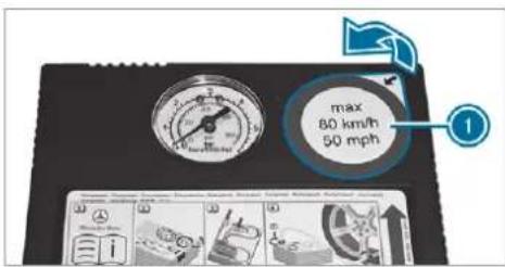
text_image
max 80 km/h 50 mph 1Remove sticker ① from the tyre inflation compressor housing and affix it to the instrument cluster within the driver's field of vision.
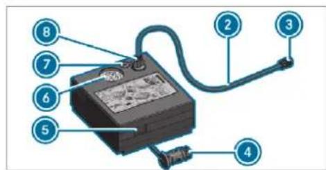
text_image
Diagram of an electrical testing device with numbered components for identificationPull filler hose ② and plug ④ out of the tyre inflation compressor housing.
Insert plug ⑧ of filler hose ② in the socket on the tyre inflation compressor and then turn it until plug ⑧ engages.
Unscrew the cap from the valve on the emergency spare wheel.
Screw union nut ③ of filler hose ② onto the valve.
Make sure on and off switch ⑤ of the tyre inflation compressor is set to 0.
Insert plug ④ in a socket in your vehicle.
• Cigarette lighter socket: (→ page 164)
• 12 V socket: (→ page 165)
- Observe the notes on the cigarette lighter: (→ page 164)
- Observe the notes on sockets: (→ page 165)
Turn the key to position 1 in the ignition lock.
Press on and off switch ⑤ on the tyre inflation compressor to I.
The tyre inflation compressor is switched on. The tyre is inflated. The tyre pressure is shown on manometer 6.
Pump the tyre to the specified tyre pressure. The specified tyre pressure is stated on the label of the emergency spare wheel.
When the specified tyre pressure has been reached, press on and off switch ⑤ on the tyre inflation compressor to 0.
The tyre inflation compressor is switched off.
Turn the key to position [0] in the ignition lock.
If the tyre pressure is higher than the specified pressure, press pressure release valve button ⑦ until the correct tyre pressure has been reached.
Unscrew union nut ③ of filler hose ② from the valve.
Screw the valve cap of the emergency spare wheel onto the valve again.
Stow filler hose ② and plug ④ in the lower section of the compressor housing.
Stow the tyre inflation compressor in the vehicle.
Collapsible spare wheel
Notes on the collapsible spare wheel
WARNING Risk of accident caused by incorrect wheel and tyre dimensions
The wheel or tyre size and the tyre type of the emergency spare wheel or spare wheel and the wheel to be replaced may differ. Mounting an emergency spare wheel/spare wheel may severely impair the driving characteristics.
To prevent hazardous situations:
Adapt your driving style accordingly and drive carefully.
▶ Never fit more than one emergency spare wheel or spare wheel that differs in size.
Only use an emergency spare wheel or spare wheel of a different size briefly.
Do not switch off ESP
Have the emergency spare wheel or spare wheel of a different size replaced at the nearest qualified specialist workshop. The new wheel must have the correct dimensions.
The collapsible spare wheel is an emergency spare wheel which is only suitable for use for a limited period of time and in a restricted manner in the event of a flat tyre (e.g. until the nearest workshop).
The tyre sidewalls are folded when in transport mode. Before use, the collapsible spare wheel has to be inflated with the accompanying compressor.
Check the tyre pressure of the collapsible spare wheel once fitted. Correct the pressure as necessary.
The maximum permissible speed with a collapsible spare wheel fitted is 80 km/h.
Do not fit snow chains with the collapsible spare wheel.
Replace the collapsible spare wheel after six years at the latest, regardless of wear.
Vehicles with a tyre pressure monitoring system: if a collapsible spare wheel is fitted the tyre pressure monitoring system cannot function reliably. For a few minutes after an emergency spare wheel is fitted, the system may still display the tyre pressure of the removed wheel. Only restart the system again when the collapsible spare wheel has been replaced with a new wheel.
Be sure to also observe the following further related subjects:
• Notes on tyre pressure (→ page 606)
• Tyre pressure table ( page 607)
Notes on vehicles with a Burmester sound system

WARNING Risk of injury or death due to an unsecured collapsible spare wheel
If the collapsible spare wheel is not secured correctly, it can slip, tip over or be thrown around.
Vehicle occupants could be hit by an unsecured collapsible spare wheel and be seriously injured as a result, particularly when accelerating, braking, abruptly changing direction or in the event of an accident.
Always store the collapsible spare wheel in the emergency spare wheel bag and attach it to the bracket in the load compartment.
▶ Always ensure that the lashing straps on the emergency spare wheel bag are safely secured on the rear tie-down eyes on the load compartment floor.
Depending on the vehicle's equipment, the collapsible spare wheel is located in an emergency
spare wheel bag on a bracket in the load compartment. The collapsible spare wheel in the emergency spare wheel bag and the bracket are lashed with straps and secured using the rear tie-down eyes on the load compartment floor.
Removing the collapsible spare wheel
Vehicles without a Burmester sound system
The collapsible spare wheel is located under t load compartment floor.
Observe the information on mounting tyres ( page 615).
Open the tailgate.
Open the load compartment floor ( page 158).
Remove the collapsible spare wheel.
Vehicles with a Burmester sound system
The collapsible spare wheel is secured in the lapsible spare wheel bag in the load compartment.
Observe the information on mounting tyres ( page 615).
▶ Open the load compartment.
▶ Detach the securing straps.
Unhook the retaining spring hooks of the securing straps from the brackets.
Remove the collapsible spare wheel bag together with the collapsible spare wheel.
Open the collapsible spare wheel bag and remove the collapsible spare wheel.
Mercedes-Maybach vehicles
Without refrigerator box: the collapsible spare wheel is located in the collapsible spare wheel bag on the load compartment floor.
Observe the information on mounting tyres ( page 615).
▶ Open the load compartment.
▶ Detach the securing straps.
▶ Unhook the retaining spring hooks of the col-securing straps from the brackets.
Remove the collapsible spare wheel bag together with the collapsible spare wheel.
Open the collapsible spare wheel bag and remove the collapsible spare wheel.
With refrigerator box: the collapsible spare wheel is located in the collapsible spare wheel bag inside the open load compartment floor.
Observe the information on mounting tyres ( page 615).
▶ Open the load compartment.
Detach the securing straps.
Unhook the retaining spring hooks of the securing straps from the brackets.
Remove the collapsible spare wheel bag together with the collapsible spare wheel.
Open the collapsible spare wheel bag and remove the collapsible spare wheel.
Inflating the collapsible spare wheel
Requirements:
- Mount the collapsible spare wheel as described (→ page 623).
- Remove the tyre inflation compressor from the stowage space under the boot floor ( page 587).
! NOTE Damage to the collapsible spare wheel when lowering the vehicle
Lowering the vehicle without previously inflating the collapsible spare wheel can damage its rim.
▶ Inflate the collapsible spare wheel using the tyre inflation compressor before lowering the vehicle.
! NOTE Overheating due to the tyre inflation compressor running too long
Do not run the tyre inflation compressor for longer than ten minutes without interruption.
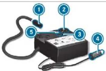
text_image
Diagram of a handheld electronic device with numbered components labeled 1 to 5Pull connector ④ and the hose out of the housing.
Unscrew the cap from the valve on the collapsible spare wheel.
Screw union nut ① of the hose onto the valve.
Make sure on and off switch ③ of the tyre inflation compressor is set to 0.
Insert plug ④ into the cigarette lighter socket (→ page 164) or into a 12 V socket (→ page 165) in your vehicle.
Switch on the power supply ( page 209).
Press on and off switch ③ on the tyre inflation compressor to 1.
The tyre inflation compressor is switched on. The tyre is inflated. The tyre pressure is shown on manometer ②.
Pump the tyre to the specified tyre pressure. The specified tyre pressure is printed on the yellow label of the collapsible spare wheel.
When the specified tyre pressure has been reached, press on and off switch ③ on the tyre inflation compressor to 0.
If the tyre pressure is higher than the specified pressure, press pressure release valve button ⑤ until the correct tyre pressure has been reached.
Notes on technical data
Mercedes-AMG vehicles: be sure to observe the notes in the Supplement. Otherwise, you may fail to recognise dangers.
The technical data was determined in accordance with EU Directives. The data stated only applies to vehicles with standard equipment. You can obtain further information from a Mercedes-Benz Service Centre.
Only for certain countries: you can find vehicle-specific vehicle data in the EC-Certificate of Conformity (CERTIFICATE OF CONFORMITY). These documents are delivered with your vehicle.
On-board electronics
Notes on tampering with the engine electronics
NOTE Premature wear through improper maintenance
Improper maintenance may cause vehicle components to wear more quickly and the vehicle's operating permit may be invalidated.
Always have work on the engine electronics and related components carried out at a qualified specialist workshop.
Two-way radios
Notes on fitting two-way radios
⚠ WARNING Risk of accident due to improper work on two-way radios
The electromagnetic radiation from two-way radios can interfere with the on-board elec-
tronics if RF transmitters are manipulated or retrofitted incorrectly.
This could jeopardise the operating safety of the vehicle.
You should have all work on electrical and electronic components carried out at a qualified specialist workshop.
WARNING Risk of accident from incorrect operation of two-way radios
If you operate two-way radios incorrectly in the vehicle, the electromagnetic radiation could interfere with the on-board electronics, e.g.:
- if the two-way radio is not connected to an exterior aerial
- if the exterior aerial is not correctly mounted or is not of low reflection
This could jeopardise the operating safety of the vehicle.
Have the low-reflection exterior aerial fitted at a qualified specialist workshop.
When operating two-way radios in the vehicle, always connect them to the low-reflection exterior aerial.
NOTE Invalidation of the operating permit due to failure to comply with the instructions for installation and use
The operating permit may be invalidated if the instructions for installation and use of two-way radios are not observed.
▶ Only use approved frequency bands.
▶ Observe the maximum permissible output power in these frequency bands.
▶ Only use approved aerial positions.
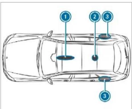
text_image
1 2 3 3① Front roof area
② Rear roof area
3 Rear wings
On vehicles with a panoramic sliding sunroof, fitting an aerial to the front or rear roof area is not permitted.
On the rear wings, it is recommended that you fit the aerial on the side of the vehicle closest to the centre of the road.
Use Technical Specification ISO/TS 21609 (Road Vehicles - "EMCs for installation of aftermarket radio frequency transmitting equipment") when retrofitting two-way radios. Comply with the legal requirements for detachable parts.
If your vehicle has fittings for two-way radio equipment, use the power supply and aerial connectors provided in the pre-installation. Be sure to observe the manufacturer's supplements when fitting.
Two-way radio transmission output
The maximum transmission output (PEAK) at the base of the aerial must not exceed the values in the following table.
Frequency band and maximum transmission output
| Frequency band Maximum transmission output | |
| Short wave3 - 54 MHz | 100 W |
| 4 m frequency band74 - 88 MHz | 30 W |
| 2 m frequency band144 - 174 MHz | 50 W |
| Trunked radio system/Tetra380 - 460 MHz | 10 W |
| 70 cm frequency band420 - 450 MHz | 35 W |
| Two-way radio(2G/3G/4G) | 10 W |
The following can be used in the vehicle without restrictions:
- two-way radios with a maximum transmission output of up to 100 mW
- RF transmitters with transmitter frequencies in the 380 - 410 MHz frequency band and a maximum transmission output of up to 2 W (trunked radio system/Tetra)
• mobile phones (2G/3G/4G)
There are no restrictions when positioning the aerial on the outside of the vehicle for some wavebands.
This applies to the following wavebands:
- trunked radio system/Tetra
- 70 cm frequency band
- 2G/3G/4G
Vehicle identification plate, VIN and engine number overview
Vehicle identification plate
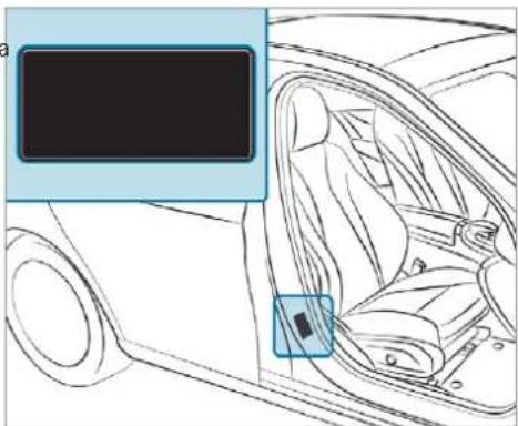
natural_image
Interior view of a car showing the seat, dashboard, and steering wheel (no text or symbols visible)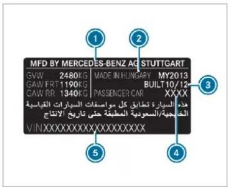
text_image
MFD BY MERCEDES-BENZ AG STUTTGART GVW 2480KG | MADE IN HUNGARY MY2013 GAW FRT 1190KG BUILT 10/12 GAW RR 1340KG PASSENGER CAR XXXX هندّد ال Siberا ظطابق كل مواستاقات pesticides قدياسة الغربية/السعودية المعلiffe誌誌 تاریخ الانتاج VINXXXXXXXXXXXXXXXXXX 1 2 3 4 5Vehicle identification plate (example: Kuwait)
① Vehicle manufacturer
② Place of manufacture
③ Manufacturing date
④ Paint code
5 VIN
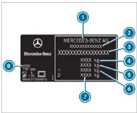
text_image
Mercedes-Benz AG XXXXXXXXXXXXXX XXXXXXXXXXXXXX XXXX kg XXXX kg XXXX kg XXXX kg 1- 2- Made in Germany 8 1 2 3 4 5 6 7Vehicle identification plate (example: all other countries)
① Vehicle manufacturer
2 EU general operating permit number (only for certain countries)
VIN (vehicle identification number)
4 Maximum permissible gross vehicle weight (kg)
Maximum permissible gross weight of vehicle combination (kg) (for certain countries only, optional)
6 Maximum permissible front axle load (kg)
⑦ Maximum permissible rear axle load (kg)
Paint code
The data shown in the illustration is example data.
VIN in front of the front seat
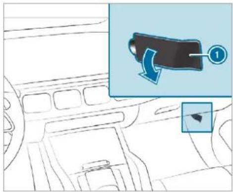
text_image
Diagram showing car interior with a highlighted vehicle component and directional arrow, labeled with number 1① VIN (vehicle identification number)
VIN at the lower edge of the windscreen
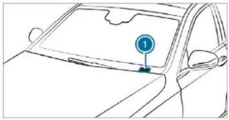
natural_image
Line drawing of a car's front window with a circular traffic sign labeled '1' (no text or symbols on the car itself)① VIN (vehicle identification number)
The VIN as a label at the lower edge of the wind-screen is only available in some countries.
Engine number
The engine number is stamped into the crank-case.
i Further information can be obtained at a qualified specialist workshop.
Operating fluids
Notes on operating fluids
Mercedes-AMG vehicles: be sure to observe the notes in the Supplement. Otherwise, you may fail to recognise dangers.
WARNING Risk of injury from operating fluids harmful to your health
Operating fluids may be poisonous and harmful to your health.
Observe the text on the original containers when using, storing or disposing of operating fluids.
Always store operating fluids sealed in their original containers.
Always keep children away from operating fluids.

ENVIRONMENTAL NOTE Environmental pollution caused by environmentally irresponsible disposal
▶ Dispose of operating fluids in an environmentally responsible manner.
Operating fluids include the following:
- fuels
- DeNOx agent AdBlue® for exhaust gas after-treatment
- lubricants
- coolant
- brake fluid
- windscreen washer fluid
• climate control system refrigerant
Only use products approved by Mercedes-Benz. Damage caused by the use of products that have not been approved is not covered by the Mercedes-Benz warranty or goodwill gestures.
You can identify operating fluids approved by Mercedes-Benz by the following inscriptions on the container:
• MB-Freigabe (e.g. MB-Freigabe 229.51)
• MB-Approval (e.g. MB-Approval 229.51)
Further information on approved operating fluids is available at the following locations:
- in the Mercedes-Benz Specifications for Operating Fluids by entering the designation - at https://bevo.mercedes-benz.com
- in the Mercedes-Benz BeVo app
• at a qualified specialist workshop

WARNING Risk of fire or explosion from fuel
Fuels are highly flammable.
▶ Fire, naked flames, smoking and creation of sparks must be avoided.
Switch off the ignition and, if available, the stationary heater, before and while refuelling the vehicle.

WARNING Risk of injury from fuels
Fuels are poisonous and hazardous to your health.
Do not swallow fuel or let it come into contact with skin, eyes or clothing.
Do not inhale fuel vapour.
Keep children away from fuel.
Keep doors and windows closed during the refuelling process.
If you or other people come into contact with fuel, observe the following:
Immediately rinse fuel off your skin with soap and water.
If fuel comes into contact with your eyes, immediately rinse them thoroughly with clean water. Seek medical attention immediately.
If you swallow fuel, seek medical attention immediately. Do not induce vomiting.
Change immediately out of clothing that has come into contact with fuel.
Fuel
Information on fuel grades for vehicles with petrol engines
Observe the notes on operating fluids ( page 635).
NOTE Damage caused by the wrong fuel
Even small amounts of the wrong fuel could result in damage to the fuel system, the engine and the emission control system.
Only refuel using unleaded, sulphur-free fuel that conforms to European EN 228, or an equivalent specification.
Fuel of this specification may contain up to 10% ethanol by volume. Your vehicle is suitable for use with E10 fuel.
Never refuel with one of the following fuels:
• diesel
- regular petrol with an octane number lower than 91 RON
- petrol with more than 10% ethanol by volume, e.g. E15, E20, E85, E100
- petrol with more than 3% methanol by volume, e.g. M15, M30
• petrol with additives containing metal
If you have accidentally refuelled with the wrong fuel:
▶ do not switch on the ignition.
consult a qualified specialist workshop.
The following compatibility indications for fuel apply to your vehicle:
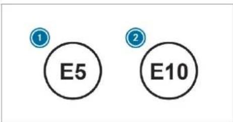
text_image
E5 E10① For petrol with maximum 5% ethanol by volume
For petrol with maximum 10% ethanol by volume
According to European standard EN 16942 you can find the compatibility indications at the following locations:
• on the instruction label on the fuel filler flap
- on the fuel pump or pump nozzle suitable for your vehicle throughout Europe
If the available fuel is not sufficiently low in sulphur, this can produce unpleasant odours.
The recommended octane number for your vehicle can also be found on the instruction label in the fuel filler flap ( page 235).
As a temporary measure, if the recommended fuel is not available, you may also use regular unleaded petrol with at least 91 RON. This may reduce engine output and increase fuel consumption.
Never refuel using petrol with an even lower RON.
Further information on fuel can be obtained at filling station or a qualified specialist workshop.
Information on additives in petrol
Observe the notes on operating fluids ( page 635).

NOTE Damage from use of unsuitable additives
Even small amounts of the wrong additive may lead to malfunctions occurring.
Only add cleaning additives recommended by Mercedes-Benz to the fuel.
Mercedes-Benz recommends that you use fuel brands that have additives.
In some countries, the fuel available may not have sufficient additives. Residue could build up in the fuel injection system as a result. In this case, in consultation with a Mercedes-Benz service centre, the fuel may be mixed with the cleaning additive recommended by Mercedes-Benz. Be sure to observe the notes and mixing ratios specified on the container.
Information on fuel grades for vehicles with a diesel engine
General notes
Observe the notes on operating fluids ( page 635).

WARNING Risk of fire from fuel mixture
If you mix diesel fuel with petrol, the flash point of the fuel mixture is lower than that of pure diesel fuel.
While the engine is running, component parts in the exhaust system may overheat without warning.
▶ Never refuel using petrol in diesel engines.
▶ Never mix petrol with diesel fuel.
NOTE Damage caused by the wrong fuel
Even small amounts of the wrong fuel could result in damage to the fuel system, the engine and the emission control system.
Only refuel using sulphur-free diesel fuel that conforms to European standard EN 590, or an equivalent specification.
In countries without sulphur-free diesel fuel, refuel using only low-sulphur diesel fuel with a sulphur content less than 50 ppm.
Never refuel with one of the following fuels:
- petrol
- marine diesel
- heating oil
• pure bio-diesel fuel or vegetable oil
- paraffin or kerosene
If you have accidentally refuelled with the wrong fuel:
Do not switch the ignition on.
Consult a qualified specialist workshop.
The following compatibility indication for fuel applies to your vehicle:


① For diesel fuel with a maximum of 7% by volume bio-diesel (fatty acid methyl ester)
According to European standard EN 16942 you can find the compatibility indications at the following locations:
- on the information label on the fuel filler flap (→ page 235)
- on the fuel pump or pump nozzle suitable for your vehicle throughout Europe
Information on low outside temperatures
Refuel your vehicle with as much winter diesel fuel as possible at the beginning of winter. Before changing over to winter diesel fuel, the fuel tank should be empty, if possible. When first refuelling with winter diesel fuel, only refuel using a small amount, e.g. to reserve level. The fuel tank can be filled as usual when next refuelling.
Further information on fuel can be obtained at filling station or a qualified specialist workshop.
Tank content and fuel reserve
Missing values were not available at the time of going to press.
The total capacity of the fuel tank may vary, depending on the vehicle equipment.
Capacity
| Model Total capacity | |
| All models 90.0 litres | |
| Model | of which reserve fuel |
| All models | 9 |
| Mercedes-Maybach | Total capacity |
| All models | |
| Mercedes-Maybach | of which reserve fuel |
| All models | 9 |
AdBlue®
Notes on AdBlue®
Observe the notes on operating fluids ( page 635).
AdBlue ^® is a water-soluble fluid for the NOx exhaust gas aftertreatment of diesel engines.
It may be improper or punishable in some countries to operate a vehicle that uses no AdBlue ^® or one that does not comply with the specifications of these operating instructions.
NOTE Malfunctions due to the dilution of AdBlue® or the use of additive-enhanced AdBlue®
The function of the NOx exhaust gas after-treatment can be impaired by the use of unsuitable denoxification agents.
Only use AdBlue® in accordance with ISO 22241.
Do not dilute AdBlue with water.
Do not use additive-enhanced AdBlue®
NOTE Damage and malfunctions due to impurities in AdBlue®
Consequences of impurities in AdBlue®
• increased emission values
• damage to the catalytic converter
- NOx exhaust gas aftertreatment malfunctions
Avoid impurities in AdBlue®
AdBlue ^® residues crystallise after a period of time, and contaminate the surfaces with which they come into contact. Clean the dirty surfaces with water as soon as possible.
When you open the AdBlue ^® tank, small amounts of ammonia vapour may escape. Do not inhale any ammonia vapours that may be released. Only fill the AdBlue ^® tank in well-ventilated areas.
AdBlue ^® capacity
Total capacity of AdBlue ^® tank
| Model | T |
| All models 31.6 litres |
AdBlue® consumption
The average AdBlue® consumption is between 1% and 5% of fuel consumption. Like fuel con-
sumption, AdBlue ^® consumption is highly dependent upon driving style and operating conditions. For this reason, your vehicle's actual consumption figures under day-to-day operating conditions may differ from the consumption figures calculated. The frequency at which you will have to top up AdBlue ^® will also vary. Have the AdBlue ^® supply checked at a qualified specialist workshop before making journeys outside of Europe. Before a longer stay outside of Europe, consult a qualified specialist workshop.
AdBlue ^® range and fill level
The AdBlue ^® fill level and range can be displayed via the on-board computer. The AdBlue range shown depends strongly on the driving style and operating conditions. The actual range can therefore deviate from the range currently dis-ralled in the on-board computer. The information supplied in the Owner's Manual regarding the reserve quantity at the first display warning and on the minimum top-up quantity when the tank is empty is also to be understood as guide values.
Display the AdBlue range and level ( page 351).
Engine oil
Notes on engine oil
Observe the notes on operating fluids ( page 635).

text_image
Mercedes-Benz Oil recommendedNOTE Engine damage caused by an incorrect oil filter, incorrect oil or additives
Do not use engine oils or oil filters which do not correspond to the specifi-
cations explicitly prescribed for the service intervals.
Do not alter the engine oil or oil filter in order to achieve longer change intervals than prescribed.
Do not use additives.
▶ Have the engine oil renewed at regular intervals.
Mercedes-Benz recommends that you have the oil change carried out at a qualified specialist workshop.
Only Mercedes-Benz approved engine oils may be used in Mercedes-Benz engines.
Further information on engine oil and oil filters is available at the following locations:
• in the Mercedes-Benz Specifications for Operating Fluids by entering the designation
- at https://bevo.mercedes-benz.com
- in the Mercedes-Benz BeVo app
• at a qualified specialist workshop
Petrol engines: for certain countries, different engine oils can be used in conjunction with reduced maintenance intervals.
i Further information on different engine oils can be obtained at a qualified specialist workshop.
Quality and capacity of engine oil
MB-Freigabe or MB-Approval
| Petrol engines | Engine oil specifications |
| GLS 450 4MATIC 229.51, 229.52, 229.61 229.71* | |
| GLS 580 4MATIC 229.52 229.61* |
MB-Freigabe or MB-Approval
| Mercedes-Maybach | Engine oil specifications |
| EU countries: | 229.5* |
| Mercedes-Maybach | 229.51 |
| GLS 600 4MATIC | |
| Non-EU countries: | 229.5 |
| Mercedes-Maybach | |
| GLS 600 4MATIC |
MB-Freigabe or MB-Approval
| Diesel engines | Engine oil specifications |
| All models 229.52 | 229.61* |
* recommended for lowest possible fuel consumption (lowest SAE viscosity class in each case; observe possible restrictions of the approved SAE viscosity classes)
To achieve the lowest possible fuel consumption, it is recommended to use the engine oil specifi-
cations marked in the table for the lowest SAE viscosity class. Possible restrictions of the approved SAE viscosity classes must be observed.
Mercedes-Maybach GLS 600 4MATIC: Only use SAE 0W-40 or SAE 5W-40 engine oils.
If the engine oils listed in the table are not available, you may add a maximum of 1.0 litre of the following engine oils once only.
Engine oils for one-time filling only in exceptional cases:
- petrol engines:
- GLS 450 4MATIC: MB-Freigabe or MB-Approval 229.31 or ACEA C3
- GLS 580 4MATIC: MB-Freigabe or MB-Approval 229.51 or ACEA C3
Mercedes-Maybach GLS 600 4MATIC: MB-Freigabe or MB-Approval 229.3 or ACEA A3/B4
• diesel engines: MB-Freigabe or MB-Approval 229.51 or ACEA C3
The following values refer to an oil change, including the oil filter.
Replacement amount
| Model | R amount |
| GLS 450 4MATIC 8.5 | litres |
| GLS 580 4MATIC 9.5 | litres |
| All other models 9.0 | litres |
| Mercedes-Maybach | R e p amount |
| Mercedes-Maybach GLS 600 4MATIC | 9.5 litres |
Notes on brake fluid
Observe the notes on operating fluids ( page 635).

WARNING Risk of an accident due to vapour pockets forming in the brake system
The brake fluid constantly absorbs moisture from the air. This lowers the boiling point of the brake fluid. If the boiling point is too low, vapour pockets may form in the brake system when the brakes are applied hard.
This impairs the braking effect.
Have the brake fluid renewed at the specified intervals.
Have the brake fluid regularly replaced at a qualified specialist workshop. Only use brake fluid approved by Mercedes-Benz according to MB-Freigabe or MB-Approval 331.0.
You can obtain further information on brake fluid in the following places:
• in the Mercedes-Benz Specifications for Operating Fluids
- at https://bevo.mercedes-benz.com
- in the Mercedes-Benz BeVo app
• at a qualified specialist workshop
Coolant
Notes on coolant
Observe the notes on operating fluids ( page 635).

WARNING Risk of fire- and injury from antifreeze
If antifreeze comes into contact with hot component parts in the engine compartment, it may ignite.
▶ Allow the engine to cool down before you top up the antifreeze.
Make sure that no antifreeze spills out next to the filler opening.
Thoroughly clean the antifreeze from component parts before starting the vehicle.

NOTE Damage caused by incorrect coolant
Only add coolant that has been pre-mixed with the required antifreeze protection.
Information on coolant is available at the following locations:
• in the Mercedes-Benz Specifications for Operating Fluids 310.1
- at https://bevo.mercedes-benz.com
- in the Mercedes-Benz BeVo App
• at a qualified specialist workshop

NOTE Overheating at high outside temperatures
If an inappropriate coolant is used, the engine cooling system is not sufficiently protected against overheating and corrosion at high outside temperatures.
Always use coolant approved by Mercedes-Benz.
Observe the instructions in the Mercedes-Benz Specifications for Operating Fluids310.1.
Have the coolant regularly replaced at a qualified specialist workshop.
The proportion of corrosion inhibitor/antifreeze concentrate in the engine cooling system should be:
- a minimum of 50% (antifreeze protection down to approximately -37 °C)
- a maximum of 55% (antifreeze protection down to -45 °C)
Notes on windscreen washer fluid
Observe the notes on operating fluids ( page 635).
WARNING - Risk of fire and injury due to windscreen washer concentrate
Windscreen washer concentrate is highly flammable. It could ignite if it comes into
contact with hot engine component parts or the exhaust system.
Make sure that no windscreen washer concentrate spills out next to the filler opening.
! NOTE Damage to the exterior lighting due to unsuitable windscreen washer fluid
Unsuitable windscreen washer fluids may damage the plastic surface of the exterior lighting.
Only use windscreen washer fluids which are also suitable for use on plastic surfaces, e.g. MB SummerFit or MB WinterFit.
! NOTE Blocked spray nozzles caused by mixing windscreen washer fluids
Do not mix MB SummerFit and MB WinterFit with other windscreen washer fluids.
Do not use distilled or de-ionised water as the fill level sensor may be triggered erroneously.
Recommended windscreen washer fluid:
- Above freezing point: e.g. MB SummerFit
• Below freezing point: e.g. MB WinterFit
For the correct mixing ratio, refer to the information on the antifreeze container.
Mix the washer fluid with the windscreen washer fluid all year round.
Vehicle data
Vehicle dimensions
The heights specified may vary as a result of the following factors:
- tyres
- load
• condition of the suspension - optional equipment
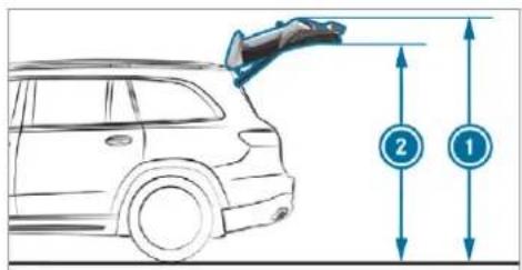
text_image
Diagram showing a car with an attached object and two labeled measurement points (1 and 2) indicating vertical alignment.Height when opened
| Model | 1Height when opened* | 2He room* |
| Vehicles with AIR-MATIC | 2144 mm-2234 mm | 1929 mm-2019 mm |
| Vehicles with Off-road package | 2144 mm-2274 mm | 1929 mm-2059 mm |
| Mercedes-Maybach | 1Height when opened* | 2He room* |
| All models 2159 mm | -2234 mm | 1944 mm-2019 mm |
*When the rear-end lowering is activated, the values are correspondingly lower.
Vehicle dimensions
| - All models | |
| Vehicle length | 5 |
| Vehicle length, AMG Styling | 5213 mm |
| Vehicle width including outside mirrors | 2157 mm |
| Vehicle width excluding outside mirrors, min. to max. | 1956 mm - 2030 mm |
| Maximum vehicle height (AIRMATIC) | 1888 mm |
| Maximum vehicle height (Off-road package) | 1928 mm |
| Minimum vehicle height (high-way driving level) | 1823 mm - 1838 mm |
| Wheelbase 3135 mm | |
| Maximum ground clearance (AIRMATIC) | 259 mm |
All models
| Maximum ground clearance(Off-road package) | 289 mm |
| Minimum ground clearance(AIRMATIC/Off-road package) | 174 mm |
Mercedes-Maybach
| Vehicle length | 5 |
| Vehicle width including outside mirrors | 2157 mm |
| Vehicle width excluding outside mirrors, min. to max. | 2030 mm |
| Maximum vehicle height | 1888 mm |
| Minimum vehicle height (high-way driving level) | 1838 mm |
| Wheelbase 3135 mm | |
| Maximum ground clearance 210 mm | |
Weights and loads
Please note that for the specified vehicle data:
- Items of optional equipment increase the unladen weight and reduce the payload.
- vehicle-specific weight information can be found on the vehicle identification plate ( page 633).
Roof load
| All models | |
| Maximum roof load | 100 kg |
Running board
All models
| Maximum load 200 kg |
Off-road driving
Fording depth

NOTE Damage caused by water when fording
Water can enter the engine compartment and vehicle interior if:
- you exceed the maximum permissible fording depth when driving through standing water
• a bow wave forms during fording - water accumulates during fording of flowing water
Do not exceed the maximum permissible fording depth and drive slowly through the water.
The specified value indicates the maximum permissible fording depth for:
- vehicles that are ready to drive – fuel tank full, all fluids topped up, with driver
• slow driving through standing water
Driving through flowing water reduces the permissible fording depth due to the accumulation of water.
Observe the notes on off-road driving and ford-ing ( page 218).
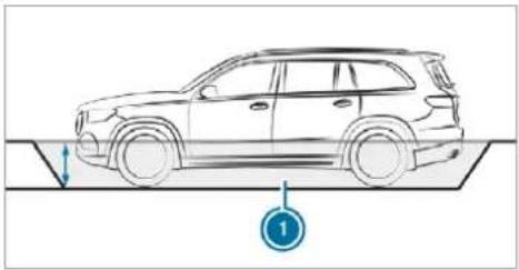
natural_image
Line drawing of a car on a slope with a numbered annotation (1) indicating a specific point or step, no text or symbols present.| Model | Fording depth |
| Vehicles with AIRMATIC | |
| Raised level | 5 |
| Vehicles with Off-road package |
| Model | Fording depth |
| Off-road level 1 | 50 cm |
| Off-road level 2 | 50 cm |
| Off-road level 3 | 60 cm |
| Mercedes-Maybach | Fording depth |
| Raised level | 5 |
Angle of approach/departure
The specified values are maximum values for vehicles that are ready to drive - fuel tank full, all fluids topped up, with driver. The values depend on the vehicle tyres and vehicle weight. Observe the notes on driving in mountainous terrain .
0 cm
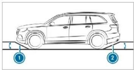
natural_image
Line drawing of a car on a road with two circular annotations indicating positions 1 and 2 (no text or symbols present)Angle of approach/departure 0 cm
| All models (vehicles without AMG Styling) | 1 Front | 2 Rear |
| Vehicles with AIRMATIC* | ||
| Normal level | 2 | 3° 20° |
| Raised level | 27° | 24° |
| Vehicles with Off-road package | ||
| Normal level | 2 | 3° 20° |
| Off-road level 1 | 25° | 22° |
| Off-road level 2 | 27° | 24° |
| Off-road level 3 | 29° | 26° |
| All models (vehicles with AMG Styling) | 1 Front | 2 Rear |
| Vehicles with AIRMATIC | ||
| Normal level | 21° - 22° | 20° - 21° |
| Raised level | 25° | 24° |
| Vehicles with Off-road package | ||
| Normal level | 21° - 22° | 20° - 21° |
| Off-road level 1 | 23° - 24° | 22° - 23° |
| All models (vehicles with AMG Styling) | 1 Front | 2 Rear |
| Off-road level 2 | 25° | 24° |
| Off-road level 3 | 27° - 28° | 25° - 26° |
| Mercedes-Maybach | 1 Front | 2 Rear |
| Normal level | 24° | 21° |
| Raised level | 27° | 25° |
*Depending on the tyre size
Maximum gradient climbing ability
The vehicle's gradient climbing ability depends on the weight distribution in the vehicle, the terrain conditions and the road surface conditions.
The specified value applies when:
- the vehicle is ready to drive – fuel tank full, all fluids topped up, with driver
- the LOW RANGE off-road gear of the transfer case is engaged
- the road surfaces conditions and thus the traction are good
A gradient climbing ability of 100% corresponds to an incline of 45°.
Observe the notes on driving in mountainous terrain.
| Model | Maximum gradient climbing ability |
| Vehicles without Off-road package | 80% |
| Vehicles with Off-road packageWhen LOW RANGE off-road gear is engaged | 100% |
| Mercedes-Maybach | Maximum gradient climbing ability |
| All models | 80% |
Trailer hitch
General notes on the trailer hitch
Modifications to the engine cooling system may be necessary, depending on the vehicle model. The retrofitting of a trailer hitch is only permissible if a towing capacity is specified in your vehicle documents.
Further information can be obtained at a qualified specialist workshop.
Mounting dimensions
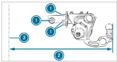
text_image
Technical diagram of a mechanical assembly with numbered components and dimension lines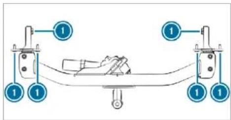
text_image
Diagram showing a mechanical assembly with labeled components and numbered parts, likely illustrating a gear or tool mechanism.① Fastening points
② Overhang dimension
③ Rear axle centre line
The overhang dimension and fastening points are valid for a trailer hitch installed at the factory.
Missing values were not available at the time of going to press.
| Model | Overhang dimension |
| All models 1257 mm | |
| Mercedes-Maybach | Overhang dimension |
| All models |
Towing capacity
You will find vehicle-specific weight information in the vehicle documents.
The tongue weight is not included in the towing capacity.
| Model Towing capacity, | |
| braked (at a mini-mum start-off gra-deability of 12%) | |
| All models 3300 kg - 3500 kg | |
| Mercedes-Maybach | Towing capacity, braked (at a mini-mum start-off gra-deability of 12%) |
| All models 3300 kg - 3500 kg | |
| Towing capacity, unbraked | |
| Model Towing capacity, unbraked | |
| All models | 7 |
Maximum tongue weight

NOTE Damage caused by the trailer coming loose
If the tongue weight used is too low, the trailer may come loose.
The tongue weight must not be below 50 kg.
▶ Use a tongue weight that is as close as possible to the maximum permissible tongue weight.
You will find vehicle-specific weight information in the vehicle documents.
Tongue weight
| Model Maximum tongue50 kg weight | |
| All models | 132 kg - 140 kg |
| Mercedes-Maybach | Maximum tongue weight |
| All models | 132 kg - 140 kg |
Permissible rear axle load (trailer operation)
Axle load
| Model Axle load | ||
| Towing capacity3300 kg | Towing capacity3500 kg | |
| GLS 350 d4MATIC | 1970 kg | 1930 kg |
| GLS 400 d4MATIC | 1970 kg | 1930 kg |
| GLS 5804MATIC | 1950 kg | 1900 kg |
| Mercedes-Maybach | Axle load | |
| Towing capacity3300 kg | Towing capacity3500 kg | |
| All models | 1900 kg | 1900 kg |
Display messages
Introduction
Notes on display messages
Display messages appear on the multifunction display.
Display messages with graphic symbols are simplified in the Owner's Manual and may differ from the symbols on the multifunction display. The multifunction display shows high-priority display messages in red. Certain display messages are accompanied by a warning tone.
Please act in accordance with the display messages and follow the additional notes in the Owner's Manual.
For some display messages, a symbol will also be shown:
- Further information
- × Hide display message
You can select the desired symbol by swiping left or right on the left-hand Touch Control. Press the ⓘ symbol to show further information
on the multifunction display. Press the symbol to hide the display message.
You can hide low-priority display messages by pressing the 📊 button or the left-hand Touch Control. The display messages will then be stored in the message memory.
Rectify the cause of a display message as quickly as possible.
High-priority display messages cannot be hidden. The multifunction display shows these display messages continuously until the cause of the display message has been rectified.
Calling up stored display messages
On-board computer:
Service 1 message
If there are no display messages, No messages will appear on the multifunction display.
▶ Scroll through the display messages by swiping upwards or downwards on the left-hand Touch Control.
To exit the message memory: press the button.
Occupant safety
| Display messages | Possible causes/consequences and ▶ Solutions |
 Restraint sys. malfunction Consult workshop Restraint sys. malfunction Consult workshop | * The restraint system is malfunctioning (→ page 38).⚠ WARNING Risk of injury due to malfunctions in the restraint systemIf the restraint system is malfunctioning, restraint system components may be triggered unintentionally or may not deploy as intended during an accident. This may affect the seat belt tensioner or airbag, for example.▶ Have the restraint system checked and repaired immediately at a qualified specialist workshop. |
| Recognition of a restraint system fault:• The restraint system warning lamp 🔍 does not light up when the ignition is switched on.• The restraint system warning lamp 🔍 lights up continuously or repeatedly during a journey.▶ Consult a qualified specialist workshop immediately. | |
 Front left malfunction Consult workshop (example) Front left malfunction Consult workshop (example) | * The corresponding restraint system is malfunctioning (→ page 38).⚠ WARNING Risk of injury due to malfunctions in the restraint systemIf the restraint system is malfunctioning, restraint system components may be triggered unintentionally or may not deploy as intended during an accident. This may affect the seat belt tensioner or airbag, for example.▶ Have the restraint system checked and repaired immediately at a qualified specialist workshop.Recognition of a restraint system fault:The restraint system warning lampdoes not light up when the ignition is switched on.The restraint system warning lamplights up continuously or repeatedly during a journey.Consult a qualified specialist workshop immediately. |
 Left windowbag malfunction Consult workshop (example) Left windowbag malfunction Consult workshop (example) | * The corresponding window airbag is malfunctioning (→ page 38).WARNINGRisk of injury or fatal injury due to a malfunction in the window airbagThe window airbag might be triggered unintentionally or might not be triggered at all in the event of an accident with high deceleration.Have the window airbag checked and repaired immediately at a qualified specialist workshop.Consult a qualified specialist workshop immediately. |
| Front-passenger airbag disabled See Owner's Manual | * The front passenger airbag has been disabled even though an adult or a person with an adult stature is on the front passenger seat. If additional forces are applied to the seat, the weight the system detects may be too low.WARNING - Risk of injury or even fatal injury when the front passenger airbag is disabledIf the front passenger airbag is disabled, It will not be deployed in the event of an accident and cannot perform its intended protective function.A person in the front passenger seat could then, for example, come into contact with the vehicle interior, especially if the person is sitting too close to the dashboard.▶ Be aware of the status of the front passenger airbag both before and during the journey. |
| ▶ Stop the vehicle immediately in accordance with the traffic conditions.▶ Check the status of the automatic front passenger airbag actuation (→ page 48).▶ If necessary, consult a qualified specialist workshop immediately. | |
| Front-passenger airbag enabled See Owner's Manual | * The front passenger airbag is enabled while the vehicle is in motion:• even when a child, a small adult or an object weighing less than the system weight threshold is located on the front passenger seat• even when the front passenger seat is not occupiedThe system may detect objects or forces that are adding to the weight applied to the seat. |
| ⚠ WARNING Risk of injury or fatal injury if a child restraint system is used while the front passenger front airbag is enabledIf you secure a child in a child restraint system on the front passenger seat and the front passenger airbag is enabled, the front passenger airbag can deploy in the event of an accident.The child could be struck by the airbag.▶ Ensure, both before and during the journey, that the status of the front passenger airbag is correct.NEVER use a rearward facing child restraint on a seat protected by an ACTIVE AIRBAG in front of it, DEATH or SERIOUS INJURY to the CHILD can occur. | |
| ▶ Stop the vehicle immediately in accordance with the traffic conditions.▶ Check the status of the automatic front passenger airbag actuation (→ page 48).▶ If necessary, consult a qualified specialist workshop immediately. | |
| PRE-SAFE inoperative See Owner's Manual | * The PRE-SAFE® functions are malfunctioning.▶ Consult a qualified specialist workshop. |
| PRE-SAFE impulse side inoperative See Owner's Manual | * The PRE-SAFE® Impulse Side system is malfunctioning or inoperative after having already been triggered.▶ Consult a qualified specialist workshop. |
Key
| Display messages | Possible causes/consequences and ▶ Solutions | |
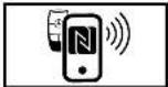 Replace key See Owner's Manual Replace key See Owner's Manual | * Vehicles with a digital vehicle key: only a few or no authorisations remain for starting the engine.▶ Make sure that the internet connection is not restricted by certain mobile phone settings.▶ Open Mercedes me connect https://www.mercedes.me and call up the Digital Vehicle Key service.▶ Deactivate the service first and then activate it again.▶ If the display message still appears, contact the Mercedes-Benz Customer Assistance Center (CAC).* Vehicles with a digital vehicle key sticker: only a few or no authorisations remain for starting the engine.▶ Order a new digital vehicle key sticker from a Mercedes-Benz Service Centre or at the https://www.mercedes-benz-mobile.com/. | |
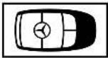 Replace key Replace key | * The key needs to be replaced.▶ Consult a qualified specialist workshop. | |
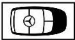 Change key batteries Change key batteries | * The key battery is discharged.▶ Replace the battery (→ page 86). | |
| Display messages | Possible causes/consequences and ▶ Solutions | |
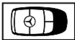 Key not detected (white display message) Key not detected (white display message) | * The key is currently undetected.▶ Change the location of the key in the vehicle.▶ If the key is still not recognised, place it in the slot for starting with the key (→ page 212). | |
 Key not detected (red display message) Key not detected (red display message) | * The key cannot be detected and may no longer be in the vehicle.The key is no longer in the vehicle and you switch off the engine:You can no longer start the engine.You cannot centrally lock the vehicle.Ensure that the key is in the vehicle.If the key detection function has a malfunction due to a strong radio signal source:Stop the vehicle immediately in accordance with the traffic conditions.Place the key in the slot for starting the engine with the key (→ page 212). | |
| Place the key in the marked space See Owner's Manual | * Key detection is malfunctioning.▶ Change the location of the key in the vehicle.Place the key in the slot for starting the engine with the key (→ page 212). | |
Lights
| Display messages | Possible causes/consequences and ▶ Solutions |
 Left dipped beam (example) Left dipped beam (example) | * The corresponding light source is defective.► Drive on carefully.► Consult a qualified specialist workshop immediately.or► Check whether you are permitted to replace the light source yourself (→ page 183).i LED light bulbs: the display message for the corresponding lamp appears only when all the light-emitting diodes in the lamp are faulty. |
 Malfunction See Owner's Manual Malfunction See Owner's Manual | * The exterior lighting is malfunctioning.► Consult a qualified specialist workshop.* Vehicles with a trailer hitch: a fuse may have blown.► Stop the vehicle in accordance with the traffic conditions.► Check the fuses and replace them if necessary (→ page 602). |
 Automatic driving lights inoperative Automatic driving lights inoperative | * T he light sensor is malfunctioning.► Consult a qualified specialist workshop. |
 Active Light System inoperative Active Light System inoperative | * T he active headlamps are malfunctioning.► Consult a qualified specialist workshop. |
 Switch on headlamps Switch on headlamps | * Y ou are driving without low-beam headlamps.► Turn the light switch to theSDorAUTOposition. |
 Switch off lights Switch off lights | * You are leaving the vehicle and the lights are still switched on.► Turn the light switch to theAUTOposition. |
 Intelligent Light System inoperative Intelligent Light System inoperative | * The Intelligent Light System is faulty. The lighting system continues to function properly without the functions of the Intelligent Light System.► Consult a qualified specialist workshop. |
| Adaptive Highbeam Assist Plus currently unavailableSee Owner's Manual | * Adaptive Highbeam Assist Plus is temporarily unavailable.The system limits have been reached (→ page 179).▶ Drive on.Once the cause of the problem is no longer present, the system will be available again. The Adaptive Highbam Assist Plus available again display message will appear. |
| Adaptive Highbam Assist Plus inoperative | * A daptive Highbam Assist Plus is malfunctioning.▶ Consult a qualified specialist workshop. |
| Hazard warning lamps malfunctioning | * The hazard warning lamp switch is malfunctioning.▶ Consult a qualified specialist workshop. |
Climate control
| Display messages | Possible causes/consequences and ▶ Solutions |
 inoperative See Owner's Man. inoperative See Owner's Man. | * The stationary heater is temporarily malfunctioning.When the vehicle is stationary on a level surface and the engine has cooled down, make up to four attempts to switch on the stationary heater, waiting several minutes between each attempt.If the stationary heater does not switch on, consult a qualified specialist workshop. |
 inoperative Battery low inoperative Battery low | * The on-board electrical system voltage is too low.The stationary heater has switched itself off.▶ Drive an extended distance until the battery has reached a sufficient charge level again. |
 inoperative Refuel vehicle inoperative Refuel vehicle | * There is too little fuel in the fuel tank. The stationary heater cannot be switched on.▶ Refuel the vehicle. |
Vehicle
| Display messages | Possible causes/consequences and ▶ Solutions |
| Update successfully completed | * Installation of the software update has been successfully completed (→ page 424). |
| Update failed Software remains unchanged | * An error occurred during the installation of the software update (→ page 424).The previous software version remains in place. |
| Update failed | * An error occurred during the installation of the software update (→ page 424).Make a Mercedes me call via the overhead control panel (→ page 505). |
 Vehicle is operationalSwitch off ignition before exiting Vehicle is operationalSwitch off ignition before exiting | * You are leaving the vehicle when it is in a ready-to-drive state.▶ When you leave the vehicle, switch off the ignition, secure the vehicle against rolling away and take the key with you.▶ If you do not leave the vehicle, switch off the electrical consumers, e.g. the seat heating. Otherwise, the 12 V battery may discharge and it will then be possible to start the vehicle only with the aid of a second battery (starting assistance). |
 Operation only possible in transmission position P Operation only possible in transmission position P | * The ball neck will not swivel because transmission position D, R or neutral N is selected.▶ Depress the brake pedal.▶ Engage park position P. |
 Trailer coupling extending... Trailer coupling extending... | * The ball neck will retract/extend.Do not attempt to speed up, slow down or initiate the swivel movement using your hand, foot or other aids. During the swivel movement, do not couple a trailer.When the ball neck has reached an operational position, the display message will disappear. |
Display messages

Check trailer hitch lock (white display message)
Possible causes/consequences and ▶ Solutions
* The trailer hitch is not operational during a journey with a trailer.
▶ Stop the vehicle immediately in accordance with the traffic conditions and switch off the engine.
▶ Uncouple the trailer and secure it against rolling away.
When the display message disappears, couple up the trailer and drive on.
A WARNING Risk of an accident if the ball neck is not locked
If the ball neck is not in the locked position, the trailer may come loose.
▶ Pull over and stop the vehicle safely as soon as possible, paying attention to road and traffic conditions. Do not continue driving under any circumstances.
▶ Uncouple the trailer and secure it against rolling away.
▶ Initiate a new swivelling procedure and do not re-couple the trailer until the display message disappears.
If the display message does not disappear, the trailer hitch is malfunctioning and the ball neck is not locked.
Do not couple up the trailer. Drive on without the trailer. Note the reduced ground clearance due to the unlocked ball neck.
Consult a qualified specialist workshop.
* The trailer hitch will not be operational when the vehicle is stationary.
Uncouple the coupled trailer and secure it against rolling away.
If the display message does not disappear, the trailer hitch is malfunctioning and the ball neck is not locked.
| Display messages | Possible causes/consequences and ▶ Solutions |
| ▸ Do not couple up the trailer. Drive on without the trailer. Note the reduced ground clearance due to the unlocked ball neck.▸ Consult a qualified specialist workshop. | |
| Side running board not retracted Observe the excess width of the vehicle | * Mercedes-Maybach vehicles: the running boards are not retracted.The running boards can be retracted via the multimedia system only when the vehicle is stationary (→ page 95).The running boards and the side skirt must be free of dirt, ice and snow. Otherwise, they are unable to retract.Clean the running boards (→ page 579).Repeat the retraction of the running boards (→ page 94).If the running boards cannot be retracted again, consult a qualified specialist workshop.If the running boards are not retracted, check the excess width of the vehicle. |
| Side running board not extended | * Mercedes-Maybach vehicles: the running boards are not extended.The running boards extend only when the vehicle is stationary.The running boards and the side skirt must be free of dirt, ice and snow. Otherwise, they are unable to extend.Clean the running boards (→ page 579).Repeat the extension of the running boards (→ page 94).If the running boards fail to extend again, consult a qualified specialist workshop.If the running boards are not extended, be particularly careful when getting in or out. |
 Steering malfunctionIncreased physical effortSee Owner's Manual Steering malfunctionIncreased physical effortSee Owner's Manual | * The power steering assistance is malfunctioning.⚠ WARNING Risk of an accident due to altered steering characteristicsIf the power assistance of the steering fails partially or completely, you will need to use more force to steer.▶ If safe steering is possible, drive on carefully.▶ Visit or consult a qualified specialist workshop immediately. |
| ▶ If safe steering is possible, drive on carefully.▶ Visit or consult a qualified specialist workshop immediately. | |
 Steering malfunction Stopimmediately See Owner's Manual Steering malfunction Stopimmediately See Owner's Manual | * The steering is malfunctioning. Steering capability is significantly impaired.⚠ WARNING Risk of accident if steering capability is impairedIf the steering does not function as intended, the vehicle's operating safety is jeopardised.▶ Pull over and stop the vehicle safely as soon as possible, paying attention to road and traffic conditions.Do not continue driving under any circumstances.▶ Consult a qualified specialist workshop. |
| ▶ Stop the vehicle immediately in accordance with the traffic conditions. Do not continue driving.▶ Consult a qualified specialist workshop.* A t least one door is open. ▶ Close all doors. | |
 | |
 | * T he bonnet is open. ▲ WARNING Risk of accident due to driving with the engine bonnet unlocked An unlocked engine bonnet may open up when the vehicle is in motion and block your view. ▶ Never unlock the engine bonnet when driving. ▶ Before every trip, ensure that the engine bonnet is locked. ▶ Stop the vehicle immediately, paying attention to road and traffic conditions. ▶ Close the bonnet. |
 | * T he tailgate is open. ▲ DANGER Risk of exhaust gas poisoning Combustion engines emit poisonous exhaust gases such as carbon monoxide. Exhaust gases can enter the vehicle interior if the tailgate is open when the engine is running, especially if the vehicle is in motion. ▶ Always switch off the engine before opening the tailgate. ▶ Never drive with the tailgate open. |
| ▶ Close the tailgate. | |
| LOW RANGE only when vehicle stationary | * One or more shifting conditions were not met.▶ Stop the vehicle.▶ Engage neutral N.▶ Repeat the gear change. |
| LOW RANGE Shift to position N briefly | * One or more shifting conditions were not met.▶ Engage neutral N.▶ Repeat the gear change. |
| LOW RANGE Not in drive program "Sport" | * You will not be able to select the LOW RANGE off-road gear if the drive program S or S' is switched on.The drive program therefore automatically switches to C.▶ Select the LOW RANGE off-road gear (→ page 234). |
| LOW RANGE Malfunction To park, apply parking brake | * T he transfer case is malfunctioning.▶ Do not shift the transfer case!▶ Use the electric parking brake to secure the vehicle against rolling away.▶ Consult a qualified specialist workshop. |
| LOW RANGE Shifting cancelled Please reactivate | * The transfer case did not perform the gear change.▶ Repeat the gear change.▶ Ensure all shifting conditions are met (→ page 234). |
| LOW RANGE Malfunction | * T he transfer case is malfunctioning.▶ Do not shift the transfer case!▶ Use the electric parking brake to secure the vehicle against rolling away.▶ Consult a qualified specialist workshop. |
| LOW RANGE Stop Apply parking brake | * T he transfer case is malfunctioning.▶ Stop the vehicle in accordance with the traffic conditions.▶ Apply the electric parking brake.▶ Where necessary, also secure the vehicle against rolling away.▶ Engage park position P. |
| LOW RANGE Max. speed 10 km/h | * The maximum speed of 10 km/h for the gear change has been exceeded.▶ Drive more slowly.▶ Repeat the gear change. |
| LOW RANGE Max. speed 40 km/h | * The maximum speed of 40 km/h for the gear change has been exceeded.▶ Drive more slowly.▶ Repeat the gear change. |
| Gearbox protection Limit 20 km/h Switch off LOW RANGE | * The oil temperature in the transfer case is too high. ▶ In the on-road position, shift to HIGH RANGE. |
| Anti-theft alarm system Malfunction | * The anti-theft alarm system is malfunctioning. ▶ Consult a qualified specialist workshop. |
 Top up washer fluid Top up washer fluid | * The washer fluid level in the washer fluid reservoir has dropped below the minimum. ▶ Top up the washer fluid (→ page 571). |
Engine
| Display messages | Possible causes/consequences and ▶ Solutions |
 Top up coolant See Owner's Manual Top up coolant See Owner's Manual | * The coolant level is too low. |
| NOTE Engine damage due to insufficient coolant | |
| Avoid long journeys with insufficient coolant. | |
| Add coolant (→ page 570). | |
| ▶ Have the engine cooling system checked at a qualified specialist workshop. | |
 Coolant Stop vehicleSwitch engine off Coolant Stop vehicleSwitch engine off | * The coolant is too hot.▶ Stop the vehicle immediately in accordance with the traffic conditions and switch off the engine.⚠ WARNING Danger of burns when opening the bonnetIf you open the engine bonnet when the engine has overheated or during a fire in the engine compartment, you could come into contact with hot gases or other escaping operating fluids.▶ Before opening the bonnet, allow the engine to cool down.▶ In the event of a fire in the engine compartment, keep the engine bonnet closed and call the fire service. |
| ▶ Wait until the engine has cooled down.▶ Make sure that the air supply to the radiator is not impaired.▶ Avoiding high loads on the engine, drive to the nearest qualified specialist workshop. In doing so, ensure that the coolant temperature display remains below 120 °C. | |
 | * The fan motor is defective.▶ Avoiding high loads on the engine, drive to the nearest qualified specialist workshop. In doing so, ensure that the coolant temperature display remains below 120 °C. |
| To switch off the engine, press the Start/Stop button for at least 3 seconds or 3 times. | * You have pressed the start/stop button while driving. ▶ Information about switching off the engine while driving (→ page 210). |
 Reserve fuel level Reserve fuel level | * The fuel supply has dropped into the reserve range. ▶ Refuel. |
 Clean the fuel filter Clean the fuel filter | * Vehicles with diesel engines: the fuel filter is dirty or the water in the fuel filter needs to be drained. ▶ Consult a qualified specialist workshop. |
 Replace air cleaner Replace air cleaner | * Vehicles with diesel engines: the engine air filter is dirty and must be replaced. ▶ Consult a qualified specialist workshop. |
| Drive system Malfunction Visit workshop | * T he drive system is malfunctioning. ▶ Consult a qualified specialist workshop. |
| Drive system Malfunction Stop Switch engine off | * T he drive system is malfunctioning. ▶ Stop the vehicle immediately in accordance with the traffic conditions and switch off the engine. ▶ Consult a qualified specialist workshop. |
Transmission
| Display messages | Possible causes/consequences and ▶ Solutions |
| Apply brake to deselect Park (P) position | * You have attempted to shift the transmission out of park position P and into another transmission position. ▶ Depress the brake pedal. ▶ Select transmission position D, R or neutral N. |
| To shift out of P or N, depress brake and start engine | * You have attempted to shift the transmission out of park position P or neutral N and into another transmission position. ▶ Depress the brake pedal. ▶ Change the transmission position. ▶ Start the engine. |
| Only select Park (P) when vehicle is stationary | * Park position P can be engaged only when the vehicle is stationary. ▶ To stop, depress the brake pedal. ▶ Shift the transmission to park position P while the vehicle is stationary. |
| Apply brake to select R | * You have attempted to select transmission position R. ▶ Depress the brake pedal. ▶ Select transmission position R. |
| Risk of vehicle rollingDriver door open and transmission not in P | * The driver's door is not fully closed and transmission position D, R or neutral N is selected. ▶ Select park position P when switching off the vehicle. |
| N permanently active Risk of vehicle rolling | * While the vehicle is rolling or while you are driving, neutral N has been engaged. ▶ To stop, depress the brake pedal. ▶ Shift the transmission to park position P while the vehicle is stationary. ▶ To continue driving, select transmission position D or R. |
| Without changing gear, consult workshop | * The transmission is malfunctioning. The transmission position can no longer be changed. ▶ When transmission position D is selected, consult a qualified specialist workshop and do not change the transmission position. ▶ For all other transmission positions, park the vehicle safely. ▶ Consult a qualified specialist workshop. |
| Reversing not poss. Consult workshop | * The transmission is malfunctioning. The transmission position R cannot be selected. ▶ Consult a qualified specialist workshop. |
| Transmission Malfunction Stop | * The transmission is malfunctioning. The transmission shifts to neutral N automatically. ▶ Stop the vehicle immediately in accordance with the traffic conditions. ▶ Depress the brake pedal. ▶ Engage park position P. ▶ Consult a qualified specialist workshop. |
| Stop vehicle Leave engine running Wait Transmission cooling | * The transmission is overheating. Pulling away may be temporarily impaired or not possible. ▶ Stop the vehicle immediately in accordance with the traffic conditions. Do not continue driving. ▶ Leave the engine running. ▶ Wait until the display message disappears before pulling away. |
| Auxiliary battery malfunction | * The auxiliary battery for the transmission is no longer being charged. ▶ Consult a qualified specialist workshop. ▶ Until then, always select park position P manually before you switch off the engine. ▶ Before leaving the vehicle, apply the electric parking brake. |
Brakes
Display messages

Parking brake See Owner's Manual
Possible causes/consequences and ▶ Solutions
* The yellow Ⓓ indicator lamp is lit. The electric parking brake is malfunctioning.
To apply:
▶ Switch the ignition off and switch it back on.
Apply the electric parking brake manually ( page 249).
If it is not possible to apply the electric parking brake:
Consult a qualified specialist workshop.
Where necessary, also secure the parked vehicle against rolling away.
* The yellow (P) indicator lamp and the red (P) indicator lamp are lit. The electric parking brake is malfunctioning.
To release:
▶ Switch the ignition off and switch it back on.
Release the electric parking brake manually ( page 249).
or
Release the electric parking brake automatically ( page 249).
If it is still not possible to release the electric parking brake:
Do not continue driving. Consult a qualified specialist workshop.
| Display messages | Possible causes/consequences and ▶ Solutions |
| * The yellow (P) indicator lamp is lit and the red (P) indicator lamp is flashing. The electric parking brake is malfunctioning.The electric parking brake could not be applied or released.▶ Switch the ignition off and switch it back on.To apply:▶ Release and then apply the electric parking brake manually (→ page 249).To release:▶ Apply and then release the electric parking brake manually.If it is not possible to apply the electric parking brake or the red (P) indicator lamp continues to flash:▶ Do not continue driving. Consult a qualified specialist workshop.▶ Where necessary, also secure the parked vehicle against rolling away.* The yellow (P) indicator lamp is lit and the red (P) indicator lamp flashes for approximately ten seconds after the electric parking brake has been applied or released. It then remains lit or goes out. The electric parking brake is malfunctioning.If the battery charge level is too low:▶ Charge the battery.To apply:▸ Switch the ignition off.The electric parking brake will be applied automatically.If the electric parking brake is not to be applied, e.g. at an automatic car wash or when the vehicle is being towed, leave the ignition switched on. This does not include having the vehicle towed with the rear axle raised.If the electric parking brake is not applied automatically:▸ Switch the ignition off and switch it back on.▸ Release and then apply the electric parking brake manually (→ page 249).If it is still not possible to apply the electric parking brake:▸ Consult a qualified specialist workshop.▸ Where necessary, also secure the parked vehicle against rolling away.To release:▸ If the conditions for automatic release are fulfilled and the electric parking brake is not released automatically, release the electric parking brake manually (→ page 249).If it is still not possible to release the electric parking brake:▸ Do not continue driving. Consult a qualified specialist workshop. | |
 Release parking brake Release parking brake | * The red (P) indicator lamp is flashing.The electric parking brake is applied while you are driving:A condition for automatic release of the electric parking brake has not been fulfilled (→ page 249).You are performing emergency braking using the electric parking brake (→ page 250).▶ Check the conditions for automatic release of the electric parking brake.▶ Release the electric parking brake manually. |
 Turn on the ignition to release the parking brake Turn on the ignition to release the parking brake | * The red (P) indicator lamp is lit.You have attempted to release the electric parking brake with the ignition switched off.▶ Switch on the ignition. |
 Check brake fluid level Check brake fluid level | * There is insufficient brake fluid in the brake fluid reservoir.⚠ WARNING Risk of an accident due to low brake fluid levelIf the brake fluid level is too low, the braking effect and the braking characteristics may be impaired.▶ Stop the vehicle as soon as possible, paying attention to road and traffic conditions. Do not continue driving.▶ Consult a qualified specialist workshop.▸ Do not top up the brake fluid. |
| ▸ Stop the vehicle immediately in accordance with the traffic conditions. Do not continue driving. | |
| ▸ Do not top up the brake fluid. | |
| ▸ Consult a qualified specialist workshop. | |
 Check brake pads See Owner's Manual Check brake pads See Owner's Manual | * The brakepads have reached the wear limit. |
| ⚠ WARNING Risk of accident due to restricted braking power | |
| When the brake pads have reached their wear limit, the braking power may be restricted. | |
| ▸ Drive on carefully. | |
| ▸ Have the brake system checked immediately at a qualified specialist workshop. | |
| ▸ Consult a qualified specialist workshop. |
Driving systems
| Display messages | Possible causes/consequences and ▶ Solutions | |
 ATTENTION ASSIST inoper-ative ATTENTION ASSIST inoper-ative | * A TTENTION ASSIST is malfunctioning.▶ Consult a qualified specialist workshop. | |
 ATTENTION ASSIST: Take a break! ATTENTION ASSIST: Take a break! | * ATTENTION ASSIST has detected fatigue or an increasing lack of concentration on the part of the driver (→ page 325).▶ If necessary, take a break. | |
 Fault Drive at max. 80 km/hDisplay messages Fault Drive at max. 80 km/hDisplay messages | * AIRMATIC is functioning only to a limited extent. The vehicle's handling characteristics may be affected.▶ Drive in a manner appropriate for the current level, but do not exceed 80 km/h.▶ Consult a qualified specialist workshop.Possible causes/consequences and ▶ Solutions | |
 Lowering Lowering | * The vehicle level may be lowered for the following reasons:You have selected a different drive program.You have exceeded the speed limit.You have changed the vehicle level by pressing the button.Operation with a trailer or bicycle rack: if an electrical connection has been correctly made, you have exceeded the speed limit.You have switched on the rear fog lamp in the off-road level +3. | |
 Vehicle rising Vehicle rising | * Your vehicle is adjusting to the level you have selected. | |
 Fault Drive at max. 80 km/h Fault Drive at max. 80 km/h | * At least one main function of the E-ACTIVE BODY CONTROL system is malfunctioning.The system is deactivated. | |
| NOTE The vehicle's suspension and damping behaviour has changed significantly, the vehicle body may tilt heavily to the side during cornering. | ||
| Reduce vehicle speed. Drive on carefully.Reduce the vehicle speed considerably before taking a curve. | ||
| Display messages | Possible causes/consequences and ▶ Solutions | |
| ▸ Avoid sudden steering movements. | ||
| ▸ Continue driving carefully at maximum 80 km/h. | ||
| ▸ If possible, stop the vehicle when safe to do so in the traffic conditions and switch the ignition off and on again. | ||
| ▸ If the display message continues to be displayed, consult a qualified specialist workshop. | ||
 Fault Stop Fault Stop | * There is a serious malfunction affecting the hydraulics of the E-ACTIVE BODY CONTROL system.The system is deactivated. | |
| ! NOTE The vehicle's driving characteristics have changed significantly. | ||
| ▸ Stop the vehicle immediately in accordance with the traffic conditions. Do not continue driving. | ||
| ▸ Stop the vehicle immediately in accordance with the traffic conditions. Do not continue driving. | ||
| ▸ Consult a qualified specialist workshop. | ||
| Please reduce speed | * You are driving too fast for the selected vehicle level. | |
| ▸ Drive more slowly and then select the desired vehicle level again. | ||
| You are driving too quickly with a trailer or the trailer hitch socket is being used, e.g. for a rear cycle rack. | ||
| ▸ Read the information on trailer operation. | ||
| Display messages | Possible causes/consequences and ▶ Solutions | |
 Vehicle rising Please wait Vehicle rising Please wait | * The vehicle level is too low. The vehicle will be raised to the selected vehicle level.▶ Wait until the display message disappears before pulling away. | |
 Compressor is cooling Compressor is cooling | * Due to frequent level changes within a short space of time, the compressor first needs to cool down in order to set the selected vehicle level.▶ Drive on in a manner appropriate for the current level. Make sure that there is sufficient ground clearance.When the compressor has cooled down, the vehicle will continue rising to the selected vehicle level. | |
| Active Steering Assist currently unavailable See Owner's Manual | * Active Steering Assist is temporarily unavailable.The ambient conditions are outside the system limits (→ page 278).▶ Drive on.As soon as the ambient conditions are within the system limits, the system will become available again.▶ If necessary, clean the windscreen in the camera's field of vision.▶ Check the tyre pressure if necessary. | |
Active Steering Assist inoperative | * Active Steering Assist is malfunctioning. Active Distance Assist DISTRONIC remains available.▶ Consult a qualified specialist workshop.* Active Steering Assist has reached the system limits(→ page 278).You have not steered independently for a considerable period of time.▶ Take over the steering and drive on in accordance with the traffic conditions. | |
| Beginning emergency stop | * Your hands are not on the steering wheel. An emergency stop is initiated (→ page 281).▶ Put your hands back on the steering wheel.You can cancel the deceleration at any time by performing one of the following actions:• steering• braking or accelerating• pressing a steering-wheel button• operating Touch Control• deactivating Active Distance Assist DISTRONIC | |
| Active Steering Assist currently unavailable due to multiple emergency stops | * Active Steering Assist is temporarily unavailable due to multiple emergency stops.▶ Take over the steering and stop in accordance with the traffic conditions.▶ Switch the ignition off and switch it back on.Active Steering Assist is available once more. | |
| Active Lane Keeping Assist currently unavailable See Owner's Manual | * Active Lane Keeping Assist is temporarily unavailable.The ambient conditions are outside the system limits (→ page 334).▸ Drive on.As soon as the ambient conditions are within the system limits, the system will become available again. | |
| Active Lane Keeping Assist inoperative | * Active Lane Keeping Assist is malfunctioning.▸ Consult a qualified specialist workshop. | |
| Active Stop-and-Go Assist currently unavailable see Owner's Manual | * Active Traffic Jam Assist is temporarily not available. Active Distance Assist DISTRONIC and Active Steering Assist are still available.The ambient conditions are outside the system limits (→ page 282).▸ Drive on.As soon as the ambient conditions are within the system limits, the system will become available again. | |
| Active Stop-and-Go Assist inoperative See Owner's Manual | * Active Traffic Jam Assist is malfunctioning.Active Traffic Jam Assist is deactivated. Active Distance Assist DISTRONIC and Active Steering Assist are still available.▸ Consult a qualified specialist workshop. | |
| Blind Spot Assist currently unavailable See Owner's Manual | * Blind Spot Assist is temporarily unavailable.The system limits have been reached (→ page 331).▸ Drive on.Once the cause of the problem is no longer present, the system will be available again.or▶ If the display message does not disappear, stop the vehicle in accordance with the traffic conditions and restart the engine. | |
| Blind Spot Assist inoperative | * B lind Spot Assist is malfunctioning.▶ Consult a qualified specialist workshop. | |
| Blind Spot Assist not available when towing a trailer See Owner's Manual | * When you establish the electrical connection to the trailer, Blind Spot Assist is unavailable.▶ Press the left-hand Touch Control and acknowledge the display message. | |
| Active Blind Spot Assist currently unavailable See Owner's Manual | * Active Blind Spot Assist is temporarily unavailable.The system limits have been reached (→ page 331).▶ Drive on.Once the cause of the problem is no longer present, the system will be available again.or▶ If the display message does not disappear, stop the vehicle in accordance with the traffic conditions and restart the engine. | |
| Active Blind Spot Assist inoperative | * A ctive Blind Spot Assist is malfunctioning.▶ Consult a qualified specialist workshop. | |
| Active Blind Spot Assist not available when towing a trailer See Owner's Manual | * When you establish the electrical connection to the trailer, Active Blind Spot Assist is unavailable. ▶ Press the left-hand Touch Control and acknowledge the display message. | |
| Active Parking Assist and PARKTRONIC inoperative See Owner's Manual | * Active Parking Assist and Parking Assist PARKTRONIC are malfunctioning. ▶ Stop the vehicle in accordance with the traffic conditions and restart the engine. ▶ If the display message continues to be displayed, consult a qualified specialist workshop. | |
| Traffic Sign Assist currently unavailable See Owner's Manual | * Traffic Sign Assist is temporarily unavailable. ▶ Drive on. Once the cause of the problem is no longer present, the system will be available again. | |
| Traffic Sign Assist inoperative | * T raffic Sign Assist is malfunctioning. ▶ Stop the vehicle in accordance with the traffic conditions and restart the engine. ▶ If the display message continues to be displayed, consult a qualified specialist workshop. | |
| Speed Limit Assist currently unavailable See Owner's Manual | * Speed Limit Assist is temporarily unavailable. ▶ Drive on. Once the cause of the problem is no longer present, the system will be available again. | |
| Speed Limit Assist inoperative | * S peed Limit Assist is malfunctioning. ▶ Consult a qualified specialist workshop. | |
Display messages
text_image
Four-step traffic safety icons with Chinese labels: car, speedometer, road ahead, warning sign, and car with signal waves.Currently unavailable Radar sensors dirty
Possible causes/consequences and ▶ Solutions
* The radar sensor system is malfunctioning. Possible causes:
- dirt on the sensors
- heavy rain or snow
- extended country driving without other traffic, e.g. in the desert
Driving systems and driving safety systems may be malfunctioning or temporarily unavailable.
Once the cause of the problem is no longer present, the driving systems and driving safety systems will be available again.
If the display message does not disappear:
▶ Stop the vehicle in accordance with the traffic conditions.
Clean all sensors ( page 579).
▶ Restart the engine.
Display messages
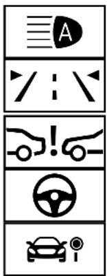
text_image
A ! - - - - - - -Currently unavailable Camera view restricted

Off
Possible causes/consequences and ▶ Solutions
* The camera view is restricted. Possible causes:
- dirt on the windscreen in the camera's field of vision
- heavy rain, snow or fog
- mist on the windscreen in front of the camera
Mist detected on the windscreen will be automatically removed with the aid of a built-in heater within approximately 12 minutes.
Driving systems and driving safety systems may be malfunctioning or temporarily unavailable.
Once the cause of the problem is no longer present, the driving systems and driving safety systems will be available again.
If the display message does not disappear:
▶ Stop the vehicle in accordance with the traffic conditions.
Clean the windscreen if necessary.
* The HOLD function is deactivated because the vehicle is slipping or a condition for activation is not fulfilled.
Reactivate the HOLD function later or check the activation conditions for the HOLD function ( page 285).
| Display messages | Possible causes/consequences and ▶ Solutions |
 inoperative inoperative | * The Downhill Speed Regulation is malfunctioning.▶ Consult a qualified specialist workshop. |
 Not in curr. drive prog. Not in curr. drive prog. | * The Downhill Speed Regulation is not available in the currently selected drive program.▶ Change the drive program (→ page 225). |
 Max. speed 40 km/h Max. speed 40 km/h | * The maximum speed of 40 km/h for the Downhill Speed Regulation has been exceeded.▶ Drive more slowly. |
 --- km/h --- km/h | * Active Distance Assist DISTRONIC cannot be activated as not all activation conditions are fulfilled.▶ Comply with the activation conditions of Active Distance Assist DISTRONIC (→ page 273). |
 suspended suspended | * If you depress the accelerator pedal beyond the Active Distance Assist DISTRONIC setting, the system will be put into passive mode (→ page 283). |
 Off Off | * Active Distance Assist DISTRONIC was deactivated. If a warning tone also sounds, Active Distance Assist DISTRONIC has deactivated automatically (→ page 273). |
| Active Distance Assist currently unavailable See Owner's Manual | * Active Distance Assist DISTRONIC is temporarily unavailable.The ambient conditions are outside the system limits (→ page 271).▶ Drive on.As soon as the ambient conditions are within the system limits, the system will become available again. |
| Active Distance Assist inoperative | * Active Distance Assist DISTRONIC is malfunctioning.Other driving systems and driving safety systems may also be malfunctioning.▶ Consult a qualified specialist workshop. |
| Active Distance Assist available again | * Active Distance Assist DISTRONIC is operational again and can be activated (→ page 273). |
 - - - km/h - - - km/h | * Cruise control cannot be activated as not all activation conditions are fulfilled.▶ Observe the activation conditions for cruise control (→ page 267). |
| Cruise control inoperative | * C ruise control is malfunctioning.▶ Consult a qualified specialist workshop. |
| Cruise control and Limiter inoperative | * Cruise control and the limiter are malfunctioning.▶ Consult a qualified specialist workshop. |
| Cruise control off | * C ruise control has been deactivated.If there is an additional warning tone, cruise control has been deactivated automatically (→ page 265). |
| Limiter passive | * If you depress the accelerator pedal beyond the pressure point (kickdown), the limiter is switched to passive mode (→ page 267). |
 - - - km/h - - - km/h | * The limiter cannot be activated as not all activation conditions have been fulfilled.▶ Observe the activation conditions of the limiter (→ page 267). |
| Limiter inoperative | * T he limiter is malfunctioning.▶ Consult a qualified specialist workshop. |
| Speed limit (winter tyres)XXX km/h | * You have reached the stored maximum permissible speed for winter tyres. It is not possible to exceed this speed. |
| 120km/h!Maximum speed exceeded | * You have exceeded the maximum permissible speed (for certain countries only).▶ Drive more slowly. |
Driving safety systems
| Display messages | Possible causes/consequences and ▶ Solutions |
 currently unavailable See Owner's Manual currently unavailable See Owner's Manual | * ABS and ESP are temporarily unavailable.Other driving systems and driving safety systems may also be temporarily unavailable.The brake system will continue to operate normally. Braking distance may increase in an emergency braking situation. |
| WARNING Risk of skidding if ABS and ESP are malfunctioningIf ABS and ESP are malfunctioning, the wheels could lock when braking and ESP cannot carry out vehicle stabilisation. |
Possible causes/consequences and ▶ Solutions
| Display messages | Possible causes/consequences and ▶ Solutions |
| The steering capability and braking characteristics are thus severely impaired. The braking distance may increase in an emergency braking situation. In addition, other driving safety systems are switched off. ▶ Drive on carefully. ▶ Have ABS and ESP checked immediately at a qualified specialist workshop. | |
| Drive carefully on a suitable stretch of road, making slight steering movements at a speed above 30 km/h. ▶ If the display message does not disappear, consult a qualified specialist workshop immediately. Drive carefully. | |
 inoperative See Owner's Manual inoperative See Owner's Manual | * ABS and ESP are malfunctioning.Other driving systems and driving safety systems may also be malfunctioning.The brake system will continue to operate normally. Braking distance may increase in an emergency braking situation. |
| ⚠ WARNING Risk of skidding if ABS and ESPe malfunctioningIf ABS and ESPare malfunctioning, the wheels could lock when braking and ESPnot carry out vehicle stabilisation.The steering capability and braking characteristics are thus severely impaired. The braking distance may increase in an emergency braking situation. In addition, other driving safety systems are switched off. ▶ Drive on carefully. ▶ Have ABS and ESP checked immediately at a qualified specialist workshop.▸ Drive on carefully.▸ Consult a qualified specialist workshop immediately. | |
 currently unavailable See Owner's Manual currently unavailable See Owner's Manual | * ESP® is temporarily unavailable.Other driving systems and driving safety systems may also be malfunctioning.⚠ WARNING Risk of skidding if ESPs malfunctioningIf ESP® is malfunctioning, ESP cannot carry out vehicle stabilisation. In addition, other driving safety systems are switched off.▸ Drive on carefully.▸ Have ESP® checked at a qualified specialist workshop. |
| ▸ Drive carefully on a suitable stretch of road, making slight steering movements at a speed above 30 km/h.▸ If the display message does not disappear, consult a qualified specialist workshop immediately. Drive carefully. | |
 inoperative See Owner's Manual inoperative See Owner's Manual | * ESP® is malfunctioning.Other driving systems and driving safety systems may also be malfunctioning.The brake system will continue to operate normally. Braking distance may increase in an emergency braking situation. |
| ⚠ WARNING Risk of skidding if ESPs malfunctioningIf ESP® is malfunctioning, ESP® cannot carry out vehicle stabilisation. In addition, other driving safety systems are switched off.▶ Drive on carefully.▶ Have ESP® checked at a qualified specialist workshop.▶ Drive on carefully.▶ Consult a qualified specialist workshop immediately. | |
 inoperative See Owner's Manual inoperative See Owner's Manual | * EBD, ABS and ESPare malfunctioning.Other driving systems and driving safety systems may also be malfunctioning. |
| ⚠ WARNING Risk of skidding if EBD, ABS and ESP® malfunctioningIf EBD, ABS and ESP® are malfunctioning, the wheels can lock when braking and ESP® not carry out vehicle stabilisation.The steering capability and braking characteristics are thus severely impaired. The braking distance may increase in an emergency braking situation. In addition, other driving safety systems are switched off.▶ Drive on carefully.▶ Have the brake system checked immediately at a qualified specialist workshop.▸ Drive on carefully.▸ Consult a qualified specialist workshop immediately. | |
| Active Brake Assist Functions currently limited See Owner's Manual | * Vehicles with the Driving Assistance Package: Active Brake Assist with cross-traffic function, Evasive Steering Assist or PRE-SAFFE PLUS are temporarily unavailable or only partially available.Vehicles without the Driving Assistance Package: Active Brake Assist is temporarily unavailable or only partially available.The ambient conditions are outside the system limits (→ page 259).▸ Drive on.As soon as the ambient conditions are within the system limits, the system will become available again.▸ If the display message does not disappear, stop the vehicle in accordance with the traffic conditions and restart the engine. |
| Active Brake Assist Functions limited See Owner's Manual | * Vehicles with Driving Assistance Package: Active Brake Assist with cross-traffic function, Evasive Steering Assist or PRE-SAFFE PLUS is malfunctioning.Vehicles without Driving Assistance Package: Active Brake Assist is malfunctioning.▸ Consult a qualified specialist workshop. |
Mercedes me connect
| Display messages | Possible causes/consequences and ▶ Solutions |
| Mercedes me connect Services limited See Owner's Manual | * Service limited.At least one of the main functions of the Mercedes me connect system is malfunctioning.▶ Observe the notes on the diagnostics connection (→ page 31).▶ Consult a qualified specialist workshop. |
 Inoperative Inoperative | * At least one of the main functions of the Mercedes me connect system or of the SOS emergency call system is malfunctioning.▶ Consult a qualified specialist workshop. |
Battery
| Display messages | Possible causes/consequences and ▶ Solutions |
 12 V battery See Owner's Manual 12 V battery See Owner's Manual | * The engine is off and the charge level is too low.▶ Switch off electrical consumers that are not required.To charge the battery:▶ Leave the engine running for a few minutes, or drive an extended distance.* If the message appears while the engine is running, this indicates an on-board electrical system malfunction. |
| ▶ Consult a qualified specialist workshop. | |
 See Owner's Manual See Owner's Manual | * The battery is not being charged. |
| ! NOTE Possible engine damage if you continue driving | |
| ▶ Do not continue driving under any circumstances.▶ Consult a qualified specialist workshop. | |
| ▶ Stop the vehicle immediately, paying attention to road and traffic conditions, and switch off the engine.▶ Consult a qualified specialist workshop. | |
 Stop vehicle See Owner's Manual Stop vehicle See Owner's Manual | * The battery is no longer being charged and the charge level is too low. |
| ! NOTE Possible engine damage if you continue driving | |
| ▶ Do not continue driving under any circumstances.▶ Consult a qualified specialist workshop. | |
| ▶ Stop the vehicle immediately in accordance with the traffic conditions. Do not continue driving.▶ Switch off the engine.▶ Consult a qualified specialist workshop. | |
 Stop vehicle Leave engine running Stop vehicle Leave engine running | * The battery charge level is too low.▶ Stop the vehicle immediately in accordance with the traffic conditions. Do not continue driving.▶ Leave the engine running.▶ Wait until the display message disappears before pulling away.▶ If the display message does not disappear: consult a qualified specialist workshop. |
 48 V battery See Owner's Manual 48 V battery See Owner's Manual | * The 48 V on-board electrical system has function restrictions. Convenience functions may be restricted.▶ Consult a qualified specialist workshop immediately. |
| Cannot start engine See Owner's Manual | * The charge level of the 48 V battery is too low. You can no longer start the engine.▶ Switch off electrical consumers that are not required.▶ Connect a suitable charger approved for Mercedes-Benz with sufficient charge output to the jump-start connection point of the 12 V battery (→ page 595).The 48 V battery is charged via the voltage converter in the vehicle. |
| Motor can be started again | * The 48 V battery has been charged automatically via the voltage converter.▶ Start the engine and drive the vehicle for a while to charge the 12 V battery and the 48 V battery. |
Display messages

Please wait 48 V battery charging
Possible causes/consequences and ▶ Solutions
* The 48 V battery is discharged. You have switched on the ignition while the 12 V battery was being charged with a suitable charger or while another vehicle was providing starting assistance. The discharged 48 V battery is charged automatically via the voltage converter. After a few minutes, the Motor can be started again display message will be shown on the multifunction display.
Start the engine.
Drive the vehicle for a while to charge the 12 V battery and the 48 V battery after disconnecting the charger from the vehicle.
If the Motor can be started again display message does not appear after a few minutes:
Try to start the engine again.
If the engine does not start, consult a qualified specialist workshop.
Tyre pressure monitor
Display messages
Tyre press. monitor currently unavailable
Possible causes/consequences and ▶ Solutions
* There is interference from a powerful radio signal source. As a result, no signals from the tyre pressure sensors are being received. The tyre pressure monitor is temporarily unavailable.
Drive on.
The tyre pressure monitor will restart automatically as soon as the cause has been rectified.
| Display messages | Possible causes/consequences and ▶ Solutions |
| Tyre press. monitor inoperative | * The tyre pressure monitor is malfunctioning. |
| ⚠ WARNING There is a risk of an accident if the tyre pressure monitoring system is malfunctioningIf the tyre pressure monitoring system is malfunctioning, it is not able to issue a warning if there is pressure loss in one or more of the tyres.Tyres with insufficient tyre pressure may, for example, affect the vehicle's handling characteristics, steering and braking. -▶ Have the tyre pressure monitoring system checked at a qualified specialist workshop. | |
| ▶ Consult a qualified specialist workshop. | |
| Tyre press. monitor inoperative No wheel sensors | * The wheels fitted do not have suitable tyre pressure sensors. The tyre pressure monitor is deactivated.▶ Fit wheels with suitable tyre pressure sensors. |
 Wheel sensor(s) missing Wheel sensor(s) missing | * There is no signal from the tyre pressure sensor of one or more wheels. No pressure value is displayed for the affected tyre.▶ Have the faulty tyre pressure sensor replaced at a qualified specialist workshop. |
 Check tyre(s) Check tyre(s) | * The tyre pressure in one or more tyres has dropped significantly. The wheel position is displayed.⚠ WARNING Risk of an accident due to insufficient tyre pressureTyres with insufficient tyre pressure pose the following risks:The tyres may burst, especially as the load and vehicle speed increase.The tyres may wear excessively and/or unevenly, which may greatly impair tyre traction.- The driving characteristics, steering and braking may be greatly impaired.You could then lose control of the vehicle.▶ Observe the recommended tyre pressures.▶ Adjust the tyre pressure if necessary. |
| ▶ Stop the vehicle in accordance with the traffic conditions.▶ Check the tyre pressure (→ page 606) and the tyres. | |
 Rectify tyre pressure Rectify tyre pressure | * The tyre pressure is too low in at least one of the tyres, or the difference in tyre pressure between the individual wheels is too great.▶ Check the tyre pressure and add air, if necessary.▶ When the tyre pressure is correct, restart the tyre pressure monitor (→ page 609). |
 Warning tyre defect Warning tyre defect | * The tyre pressure in one or more tyres has dropped suddenly. The wheel position is displayed.⚠ WARNING Risk of an accident from driving with a flat tyreFlat tyres are dangerous in the following ways:• The tyres can overheat and cause a fire.• - The driving characteristics, steering and braking may be greatly impaired.You could then lose control of the vehicle.▶ Do not drive with a flat tyre.▶ Observe the notes on flat tyres. |
| Notes on flat tyres (→ page 585).▶ Stop the vehicle in accordance with the traffic conditions.▶ Check the tyres. | |
| Tyre(s) overheated | * At least one tyre is overheating. The affected tyres are displayed in red. At temperatures close to the limit value, the tyres are displayed in yellow.▶ Drive more slowly. |
| Reduce speed | * At least one tyre is overheating. The affected tyres are displayed in red. At temperatures close to the limit value, the tyres are displayed in yellow.⚠ WARNING Risk of an accident from driving with overheated tyresOverheated tyres may burst, particularly at high speeds.▶ Reduce speed so that the tyres cool down. |
| ▶ Reduce speed so that the tyres cool down. |
Tyre pressure loss warning system
| Display messages | Possible causes/consequences and ▶ Solutions |
| Tyre pressure Check tyres | * The tyre pressure loss warning system has detected a significant loss of pressure. |
| ⚠ WARNING Risk of an accident due to insufficient tyre pressure | |
| Tyres with insufficient tyre pressure pose the following risks:• The tyres may burst, especially as the load and vehicle speed increase.• The tyres may wear excessively and/or unevenly, which may greatly impair tyre traction.• - The driving characteristics, steering and braking may be greatly impaired.You could then lose control of the vehicle.▶ Observe the recommended tyre pressures.▶ Adjust the tyre pressure if necessary. | |
| ▶ Stop the vehicle in accordance with the traffic conditions. | |
| ▶ Check the tyre pressure (→ page 606) and the tyres. | |
| ▶ When the tyre pressure is correct, restart the tyre pressure loss warning system (→ page 613). | |
| Check tyre pressures then restart Run Flat Indicator | * The tyre pressure loss warning system generated a display message and has not been restarted since. |
| ▶ When the tyre pressure is correct, restart the tyre pressure loss warning system (→ page 613). | |
| Run Flat Indicator inoperative | * The tyre pressure loss warning system is malfunctioning. |
| ▶ Consult a qualified specialist workshop. |
Exhaust gas aftertreatment
| Display messages | Possible causes/consequences and ▶ Solutions |
 Refill AdBlue See Owner's Manual Refill AdBlue See Owner's Manual | * The AdBlue® level has fallen below the reserve range.▶ Top up AdBlue® immediately (→ page 240). |
 Top up AdBlue Emergency op. in XXX miles See Owner's Manual Top up AdBlue Emergency op. in XXX miles See Owner's Manual | * The low AdBlue® level will lead to limited performance after the remaining distance displayed has been driven. ▶ Top up AdBlue® immediately (→ page 240). |
 XX,X I Top up AdBlue Emer. op.: max. XXX km/h Start not poss. in XXX km XX,X I Top up AdBlue Emer. op.: max. XXX km/h Start not poss. in XXX km | * The low AdBlue® level will lead to limited performance from the speed displayed. After the remaining distance displayed has been covered, it will no longer be possible to start the engine. ▶ Add at least the amount of AdBlue® displayed (→ page 240). |
 XX,X I Top up AdBlue Switch on ignition, wait 60 sec. or eng. start not poss. XX,X I Top up AdBlue Switch on ignition, wait 60 sec. or eng. start not poss. | * The AdBlue® tank is empty. You can no longer start the engine. ▶ Add at least the amount of AdBlue® displayed (→ page 240). ▶ Switch on the ignition and wait for around 60 seconds. ▶ Start the engine. |
 AdBlue system fault See Owner's Manual AdBlue system fault See Owner's Manual | * The AdBlue® system is malfunctioning.► Consult a qualified specialist workshop immediately. |
 AdBlue system fault Emergency op. in XXX miles See Owner's Manual AdBlue system fault Emergency op. in XXX miles See Owner's Manual | * The AdBlue® system is malfunctioning. Performance will be reduced once the remaining distance displayed has been covered.► Consult a qualified specialist workshop immediately. |
 AdBlue system fault Emer. op.: max. XXX km/h Start not poss. in XXX km AdBlue system fault Emer. op.: max. XXX km/h Start not poss. in XXX km | * Power restriction due to the AdBlue® system fault. After the distance displayed has been covered, it will no longer be possible to start the engine.► Consult a qualified specialist workshop immediately. |
Display messages

AdBlue system fault Engine start not possible
Possible causes/consequences and ▶ Solutions
* The AdBlue® system is malfunctioning. You can no longer start the engine.
Consult a qualified specialist workshop immediately.
Engine oil
Display messages
Add 1 litre engine oil when next refuelling
Possible causes/consequences and ▶ Solutions
* Display message only for certain engines:
The engine oil level has dropped to the minimum level.
NOTE Engine damage caused by driving with insufficient engine oil
Avoid long journeys with insufficient engine oil.
When next refuelling, add 1 litre of engine oil ( page 569).
Notes on engine oil ( page 641).
| Display messages | Possible causes/consequences and ▶ Solutions |
 Engine oil level Reduce oil level Engine oil level Reduce oil level | * D isplay message only for certain engines:The engine oil level is too high. |
| NOTE Engine damage caused by driving with excess engine oil | |
| ▶ Avoid long journeys with excess engine oil. | |
| ▶ Consult a qualified specialist workshop immediately and have the engine oil level reduced. | |
 Engine oil level Stop vehicle Switch engine off Engine oil level Stop vehicle Switch engine off | * Display message only for certain engines:The engine oil level is too low. |
| NOTE Engine damage caused by driving with insufficient engine oil | |
| ▶ Avoid long journeys with insufficient engine oil. | |
| ▶ Stop the vehicle immediately in accordance with the traffic conditions. Do not continue driving.▶ Switch off the engine.▶ Add 1 l of engine oil (→ page 569).▶ Check the engine oil level.Notes on engine oil (→ page 641). | |
 Engine oil pressure Stop Switch off engine Engine oil pressure Stop Switch off engine | * Display message only for certain engines:The oil pressure is too low. |
| ! NOTE Engine damage caused by driving with insufficient oil pressure | |
| ▶ Avoid driving with insufficient oil pressure. | |
| ▶ Stop the vehicle immediately in accordance with the traffic conditions. Do not continue driving. | |
| ▶ Consult a qualified specialist workshop. | |
 Engine oil level cannot be measured Engine oil level cannot be measured | * The electrical connection to the oil level sensor has been interrupted or the oil level sensor is faulty. |
| ▶ Consult a qualified specialist workshop. |
Warning and indicator lamps
Overview of indicator and warning lamps
Some systems will perform a self-test when the ignition is switched on. Some indicator and warning lamps may briefly light up or flash. This behaviour is non-critical. These indicator and
warning lamps indicate a malfunction only if they light up or flash after the engine has been started or during a journey.
Instrument display
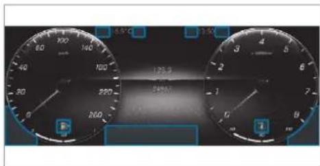
text_image
6.5°C 128.2 540.0VDepending on the display setting, the positions of the indicator lamps on the instrument display may differ from the example shown.
Indicator and warning lamps:
| Low beam (→ page 174) | |
| Standing lights (→ page 174) | |
| High beam (→ page 176) | |
| Turn signal light (→ page 176) | |
| Rear fog light (→ page 174) | |
| Restraint system (→ page 713) | |
| Seat belt not fastened (→ page 713) |


Brakes (yellow) ( page 719)
Brakes (red) ( page 719)
Electric parking brake (yellow) (→ page 719)
Electric parking brake (red) (→ page 719)
ABS malfunction ( page 722)
ESP® (→ page 722)
ESP ^® OFF ( page 722)
Distance warning (→ page 721)
Electric power steering malfunction ( page 714)
AIRMATIC / E-ACTIVE BODY CONTROL malfunction ( page 721)
Off-road gear (→ page 233)
On-road position ( page 233)
Engine diagnosis ( page 716) Preglow
Electrical fault ( page 716)
Fuel reserve with fuel filler cap location indicator ( page 716)

Coolant too hot or cold ( page 716)

Tyre pressure monitor ( page 725)

Trailer hitch is not operational or is swivelling ( page 714)
Occupant safety
| Warning/indicator lamp | Possible causes/consequences and ▶ Solutions |
 Restraint system warning lamp Restraint system warning lamp | The red restraint system warning lamp is lit while the engine is running.*The restraint system is malfunctioning (→ page 38).⚠ WARNING Risk of injury due to malfunctions in the restraint systemIf the restraint system is malfunctioning, restraint system components may be triggered unintentionally or may not deploy as intended during an accident. This may affect the seat belt tensioner or airbag, for example.▶ Have the restraint system checked and repaired immediately at a qualified specialist workshop. |
| ▶ Drive on carefully.▶ Note the messages on the multifunction display.▶ Consult a qualified specialist workshop immediately. | |
 Seat belt warning lamp flashes Seat belt warning lamp flashes | The red seat belt warning lamp flashes and an intermittent warning tone sounds.* The driver or front passenger has not fastened their seat belt while the vehicle is in motion.▶ Fasten your seat belt(→ page 42).* There are objects on the front passenger seat.▶ Remove the objects from the front passenger seat. |
Warning/indicator lamp
Seat belt warning lamp lights up
Possible causes/consequences and ▶ Solutions
The red seat belt warning lamp will light up once the engine has started.
In addition, a warning tone may sound.
* The seat belt warning lamp reminds the driver and front passenger to fasten their seat belts.
Fasten your seat belt ( page 42).
If you have placed objects on the front passenger seat, the seat belt warning lamp may remain lit.
Vehicle
Warning/indicator lamp

Trailer tow hitch warning lamp
Possible causes/consequences and ▶ Solutions
The red trailer tow hitch warning lamp is on.
*The trailer tow hitch is not operational or is swivelling.
WARNING Risk of an accident if the ball neck is not locked
If the ball neck is not in the locked position, the trailer may come loose.
▶ Pull over and stop the vehicle safely as soon as possible, paying attention to road and traffic conditions. Do not continue driving under any circumstances.
▶ Uncouple the trailer and secure it against rolling away.
Initiate a new swivelling procedure and do not re-couple the trailer until the display message disappears.
| Warning/indicator lamp | Possible causes/consequences and ▶ Solutions |
| ▶ Note the messages on the multifunction display.If the trailer hitch is swivelling:▶ Wait until the ball coupling has reached the operational position. | |
 Warning lamp for electric power steering Warning lamp for electric power steering | The red electric power steering warning lamp is lit while the engine is running.*The power assistance or the steering itself is malfunctioning. |
| ⚠ WARNING Risk of accident if steering capability is impairedIf the steering does not function as intended, the vehicle's operating safety is jeopardised.Pull over and stop the vehicle safely as soon as possible, paying attention to road and traffic conditions. Do not continue driving under any circumstances.Consult a qualified specialist workshop. | |
| ▶ Note the messages on the multifunction display. |
Engine
Warning/indicator lamp

Coolant warning lamp
Possible causes/consequences and ▶ Solutions
The red coolant warning lamp is lit while the engine is running.
*Possible causes:
• The temperature sensor is malfunctioning
- Coolant level too low
• The air supply to the radiator is obstructed
• The radiator fan is faulty
If there is an additional warning tone, the coolant temperature has exceeded 120 °C.
WARNING Danger of burns when opening the bonnet
If you open the engine bonnet when the engine has overheated or during a fire in the engine compartment, you could come into contact with hot gases or other escaping operating fluids.
Before opening the bonnet, allow the engine to cool down.
In the event of a fire in the engine compartment, keep the engine bonnet closed and call the fire service.
Stop the vehicle immediately in accordance with the traffic conditions and switch off the engine. Do not continue driving.
Note the messages on the multifunction display.
If the coolant temperature display is at the lower end of the temperature scale:
| Warning/indicator lamp | Possible causes/consequences and ▶ Solutions |
| ▶ Consult a qualified specialist workshop.or▶ Exit the vehicle and keep a safe distance from it until the engine has cooled down.▶ Check the coolant level (→ page 570).▶ Make sure that the air supply to the radiator is not impaired.▶ Avoiding high loads on the engine, drive to the nearest qualified specialist workshop. In doing so, ensure that the coolant temperature display remains below 120 °C. | |
 Engine diagnosis warning lamp Engine diagnosis warning lamp | The yellow engine diagnostics warning lamp is lit while the engine is running.*A malfunction has occurred in the engine, the exhaust system or the fuel system.The emissions limit value may have been exceeded and the engine may be running in emergency operation mode.▶ Have the vehicle checked as soon as possible at a qualified specialist workshop.*Vehicles with a diesel engine: the fuel tank may have been run dry.▶ Start the engine three to four times after refuelling.If the yellow engine diagnosis warning lamp goes out, emergency operation mode is cancelled. The vehicle need not be checked. |
| Electrical fault warning lamp | The red electrical fault warning lamp is lit.* There is a fault in the electrics.▶ Observe the messages on the multifunction display. |
 Fuel reserve warning lamp Fuel reserve warning lamp | The yellow fuel reserve warning lamp is lit while the engine is running.* The fuel supply has dropped into the reserve range.▶ Refuel. |
Brakes
Warning/indicator lamp

Red indicator lamp, electric parking brake applied

Yellow electric parking brake indicator lamp is malfunctioning

Brake system warning lamp (yellow)
Possible causes/consequences and ▶ Solutions
The red electric parking brake indicator lamp flashes or is lit. The yellow indicator lamp is also lit if the electric parking brake malfunctions.
* Observe the messages on the multifunction display.
The yellow brake system warning lamp is lit while the engine is running.
WARNING Risk of an accident due to a brake system malfunction
If the brake system is malfunctioning, braking characteristics may be impaired.
▶ Drive on carefully.
▶ Have the brake system checked immediately at a qualified specialist workshop.
Adjust your speed and continue to drive carefully, leaving a suitable distance to the vehicle in front.
| Warning/indicator lamp | Possible causes/consequences and ▶ Solutions |
| ▶ If the multifunction display shows a display message, please observe it.▶ Consult a qualified specialist workshop. | |
 Brake system warning lamp(red) Brake system warning lamp(red) | The red brake system warning lamp is lit while the engine is running.*Possible causes:• The brake force boosting is malfunctioning and the braking characteristics may be affected.• There is insufficient brake fluid in the brake fluid reservoir. |
| ⚠ WARNING Risk of accident and injury if brake force boosting is malfunctioningIf brake force boosting is malfunctioning, increased brake pedal force may be necessary for braking. The braking characteristics may be impaired. The braking distance can increase in emergency braking situations.▶ Stop in a safe location immediately. Do not continue driving!▶ Consult a qualified specialist workshop. | |
| ⚠ WARNING Risk of an accident due to low brake fluid levelIf the brake fluid level is too low, the braking effect and the braking characteristics may be impaired.▶ Stop the vehicle as soon as possible, paying attention to road and traffic conditions. Do not continue driving.▶ Consult a qualified specialist workshop.▶ Do not top up the brake fluid. |

WARNING Risk of accident and injury if brake force boosting is malfunctioning
WARNING Risk of an accident due to low brake fluid level
| Warning/indicator lamp | Possible causes/consequences and ▶ Solutions |
| ▶ Stop the vehicle immediately in accordance with the traffic conditions. Do not continue driving. ▶ Note the messages on the multifunction display. ▶ Consult a qualified specialist workshop. |
Driving systems
| Warning/indicator lamp | Possible causes/consequences and ▶ Solutions |
 Warning lamp for distance warning function Warning lamp for distance warning function | The red distance warning lamp lights up while the vehicle is in motion.* The distance to the vehicle in front is too small for the speed selected.If there is an additional warning tone, you are approaching an obstacle at too high a speed.▶ Be prepared to brake immediately.▶ Increase the distance.Function of Active Brake Assist (→ page 259). |
 Suspension warning lamp Suspension warning lamp | The yellow AIRMATIC/E-ACTIVE BODY CONTROL warning lamp is lit.* A fault has occurred in the AIRMATIC/E-ACTIVE BODY CONTROL.▶ Note the messages on the multifunction display. |
Warning/indicator lamp

Suspension warning lamp
Possible causes/consequences and ▶ Solutions
The red E-ACTIVE BODY CONTROL warning lamp is on.
*There is a fault in the E-ACTIVE BODY CONTROL.
NOTE The vehicle's driving characteristics have changed significantly.
▶ Stop the vehicle immediately in accordance with the traffic conditions. Do not continue driving.
Note the messages on the multifunction display.
▶ Stop the vehicle immediately in accordance with the traffic conditions. Do not continue driving.
Consult a qualified specialist workshop.
Driving safety systems
Warning/indicator lamp

ABS warning lamp
Possible causes/consequences and ▶ Solutions
The yellow ABS warning lamp is lit while the engine is running.
*ABS is malfunctioning.
If there is an additional warning tone, EBD is malfunctioning.
Other driving systems and driving safety systems may also be malfunctioning.
| Warning/indicator lamp | Possible causes/consequences and ▶ Solutions |
| ⚠ WARNING There is a risk of skidding if EBD or ABS is malfunctioningIf EBD or ABS is malfunctioning, the wheels may lock when braking.The steering capability and braking characteristics are thus severely impaired. Braking distance may increase in an emergency braking situation. In addition, other driving safety systems are switched off.▶ Drive on carefully.▶ Have the brake system checked immediately at a qualified specialist workshop. | |
| ▶ Drive on carefully.▶ Note the messages on the multifunction display.▶ Consult a qualified specialist workshop. | |
 ESP® warning lamp flashes ESP® warning lamp flashes | The yellow ESP® warning lamp flashes while the vehicle is in motion.* One or more wheels has reached its grip limit (→ page 253).▶ Adapt your driving style to suit the road and weather conditions. |
 ESP® warning lamp lights up ESP® warning lamp lights up | The yellow ESP® warning lamp is lit while the engine is running.* ESP® is malfunctioning.Other driving systems and driving safety systems may also be malfunctioning.⚠ WARNING Risk of skidding if ESPs malfunctioningIf ESP® is malfunctioning, ESP cannot carry out vehicle stabilisation. In addition, other driving safety systems are switched off.Drive on carefully.Have ESP® checked at a qualified specialist workshop.Drive on carefully.Note the messages on the multifunction display.Consult a qualified specialist workshop. |
 ESP® OFF warning lamp ESP® OFF warning lamp | The yellow ESP® OFF warning lamp is lit while the engine is running.*ESP® is deactivated.⚠ WARNING Risk of skidding when driving with ESP® deactivatedIf ESP® is deactivated, ESP cannot carry out vehicle stabilisation. The availability of further driving safety systems is also limited.Drive on carefully.Only deactivate ESP® for as long as the situation requires. |
Warning/indicator lamp
Possible causes/consequences and ▶ Solutions
If ESP ^® cannot be activated, ESPis malfunctioning.
Have ESP ^ checked immediately at a qualified specialist workshop.
Observe the notes on deactivating ESP® (→ page 253).
Tyre pressure monitor
Warning/indicator lamp

Tyre pressure monitoring system warning lamp flashes
Possible causes/consequences and ▶ Solutions
The yellow tyre pressure monitoring system warning lamp (pressure loss/malfunction) flashes for approximately one minute and then remains lit.
*The tyre pressure monitoring system is faulty.
WARNING There is a risk of an accident if the tyre pressure monitoring system is malfunctioning
If the tyre pressure monitoring system is malfunctioning, it is not able to issue a warning if there is pressure loss in one or more of the tyres.
Tyres with insufficient tyre pressure may, for example, affect the vehicle's handling characteristics, steering and braking. -
Have the tyre pressure monitoring system checked at a qualified specialist workshop.
Consult a qualified specialist workshop.
Warning/indicator lamp

Tyre pressure monitoring system warning lamp lights up
Possible causes/consequences and ▶ Solutions
The yellow tyre pressure monitoring system warning lamp (pressure loss/malfunction) is lit.
*The tyre pressure monitoring system has detected tyre pressure loss in at least one of the tyres.
WARNING Risk of an accident due to insufficient tyre pressure
Tyres with insufficient tyre pressure pose the following risks:
- The tyres may burst, especially as the load and vehicle speed increase.
- The tyres may wear excessively and/or unevenly, which may greatly impair tyre traction.
- The driving characteristics, steering and braking may be greatly impaired.
You could then lose control of the vehicle.
Observe the recommended tyre pressures.
Adjust the tyre pressure if necessary.
▶ Stop the vehicle, paying attention to road and traffic conditions.
▶ Check the tyre pressure and the tyres.
1, 2, 3 ...
4MATIC 235 Function 235
12V battery see Battery (vehicle)
12V socket see Socket (12 V)
48 V on-board electrical system Operating safety 24
230 V socket see Socket (230 V)
360° Camera 316 Care 579 Function 316 Opening the camera cover (reversing camera) 3 19 Selecting a view 319 Switching automatic operation on/off (reversing camera) 319
A
A/C function Activating/deactivating (multimedia system) .... 196 Switching on/off (control panel) .... 196
ABS (Anti-lock Braking System) 252
Acceleration see Kickdown
Access data Setting (Bluetooth ^® ) 5 18 Setting (car telephony) 519
Accident and breakdown management Mercedes me connect .... 508
Acoustic locking verification signal Activating/deactivating 85
Activating/deactivating automatic volume adjustment Burmester ^® surround sound system ... 548
Active Blind Spot Assist .... 331 Activating/deactivating .... 334 Brake application .... 333 Function .... 331
System limitations 331 Trailer operation 333
Active Brake Assist Function/notes .... 259 Setting .... 265
Active Distance Assist DISTRONIC .... 271 Active Emergency Stop Assist .... 281 Active Lane Change Assist .... 280 Calling up a speed .... 27 Displays in the instrument display .... 283 Function .... 271 Increasing/decreasing speed .... 273 Requirements: .... 273 Route-based speed adaptation .... 276 Selecting .... 273 Steering wheel buttons .... 273 Storing a speed .... 273 Switching off/deactivating .... 273 Switching on/activating .... 273 System limitations .... 271
Active Emergency Stop Assist .... 281 Active headlamps .... 177 Active Lane Change Assist .... 280 Activating/deactivating .... 281
Function 280
Active Lane Keeping Assist 334
Activating/deactivating 3 3
Activating/deactivating the warning ... 337
Function 334
Setting the sensitivity 337
System limits 334
Trailer operation 334
Active Parking Assist 319
Cross Traffic Alert 324
Drive Away Assist 324
Exiting a parking space 322
Function 319
Manoeuvring assistance 325
Parking 321
System limitations 319
Active Service System PLUS
see ASSYST PLUS
Active Speed Limit Assist 275
Display 275
Function 275
Active Steering Assist 278
Activating/deactivating 2 8
Active Emergency Stop Assist 281
Active Lane Change Assist 280
Displays in the instrument display ..... 283
6 Function 278
System limitations 278
Active Traffic Jam Assist
Activating/deactivating 2 8
Function 282
Adaptive brake lights 265
Adaptive cruise control
see Active Distance Assist DISTRONIC
Adaptive functions, MULTIBEAM LED
see Intelligent Light System
Adaptive Highbeam Assist Plus
Function 179
Switching on/off 180
AdBlue ^® 639
Additives 6 3
Capacity 640
Consumption 640
Fill level 351
Notes 239
Purity 639
Range 351
Topping up 2 4 0
Additional cushion
Leg rest 123
Rear head restraint 130
Additional door lock 88
Additives 641
AdBlue ^® 639
Engine oil 641
Fuel 638
Additives (AdBlue®)
see AdBlue®
Additives (engine oil)
see Additives
Additives (fuel)
see Fuel
Address book
see Contacts
Adjusting the balance/fader
Burmester ^® high-end 3D surround sound system 550
Burmester ^® surround sound system ... 548
Adjusting the bass, mid-range and treble
Burmester ^® high-end 3D surround sound system 549
Burmester ^® surround sound system ... 548
Adjusting the mid-range, treble and bass
Burmester ^® high-end 3D surround sound system 549
Burmester ^® surround sound system ... 548
Adjusting the sound focus
Burmester ^® surround sound system ... 549
Adjusting the sound optimisation
Burmester ^® high-end 3D surround sound system 550
Adjusting treble, mid-range and bass settings
Burmester ^® high-end 3D surround sound system 549
Burmester ^® surround sound system ... 548
ADS PLUS damping system see AIRMATIC
After-sales service centre see ASSYST PLUS
Air conditioning menu Calling up .... 196
Air conditioning system see Climate control
Air distribution Setting .... 1 94 Setting (multimedia system) .... 197
Air freshener system see Fragrance system
Air inlet see Air-water duct
Air pressure see Tyre pressure
Air suspension see AIRMATIC
Air vents 205 Adjusting (front) 205 Adjusting (rear) 206 Glove box 207
Air vents see Air vents
Air-recirculation mode 198
Air-water duct 572 Keeping free 572
Airbag 43 Activation 38
Cushionbag 43
Front airbag (driver, front passenger) .... 4
Installation locations 43
Knee airbag 43
Overview 43
PASSENGER AIR BAG indicator lamp ..... 48
Protection 45
Reduced protection 46
Side airbag 43
Window airbag 43
Airflow Setting 1 94
AIRMATIC 286
Setting 289
Suspension 286
Alarm system see ATA (anti-theft alarm system)
All-wheel drive see 4MATIC
Alternative route
see Route
Ambiance light
Setting (Rear Seat Entertainment System) 560
Ambient lighting
Setting (multimedia system) 18
Android Auto 503
Connecting a mobile phone 503
Control using the application buttons
50
Ending 504
Information 503
Overview 503
Sound settings 5
Transferred vehicle data 505
Animals
Pets in the vehicle 83
Anti-lock braking system
see ABS (Anti-lock Braking System)
Anti-skid chains
see Snow chains
Anti-theft alarm system
see ATA (anti-theft alarm system)
Anti-theft protection
Additional door lock 88
Immobiliser 114
Anti-theft protection
2 see ATÄ (anti-theft alarm system)
Anticipatory occupant protection
see PRE-SAFE® (anticipatory occu-
pant protection)
4 see PRE-SAFE® PLUS (anticipatory occupant protection plus)
Apple CarPlay ^® 501
4 Connecting an iPhone 502
+ Control using the application buttons 50
Ending 502
Notes 502
Overview 501
Sound settings 502
Transferred vehicle data 505
Ashtray
Front centre console 164
Assistance
Menu (on-board computer) 352
Assistance systems
see Driving safety system
ASSYST PLUS 565
Battery disconnection periods 566
Displaying the service due date 565
Function/notes 565
Regular maintenance work 565
Special service requirements 565
ATA (anti-theft alarm system) 114
Deactivating the alarm 115
Function 114
Function of interior protection 115
Priming/deactivating interior protection 116
Priming/deactivating tow-away pro-
tection 115
Tow-away protection function 115
ATTENTION ASSIST 325, 327
Function 325
Setting 327
System limitations 325
Attention assistant
see ATTENTION ASSIST
Augmented reality
see Route guidance with augmented reality
Authorised workshop
see Qualified specialist workshop
Automatic car wash mode
Activating 574
Automatic distance control
see Active Distance Assist DISTRONIC
Automatic driving lights
Automatic engine start (ECO start/
stop function) 221
Automatic engine stop (ECO start/
stop function) 221
Automatic front passenger front air-
bag deactivation system
see Automatic front passenger front airbag shutoff
Automatic front passenger front air-
bag shutoff 47,48
Function of the automatic front passenger front airbag deactivation system .... 47 PASSENGER AIR BAG indicator lamp .... 48
Automatic mirror folding function
Activating/deactivating 192
Automatic seat adjustment
Setting 1 31
Automatic transmission
DIRECT SELECT lever 228
Drive program display 227
Drive programs 2 25
DYNAMIC SELECT switch 225
Engaging drive position 230
Engaging neutral 229
Engaging park position 230
Engaging reverse gear 229
Kickdown 232
Manual gear changing 231
Steering wheel gearshift paddles ..... 231
Transmission position display 228
Transmission positions 228
Axle load
Permissible 633
Trailer operation 650
B
Bag hook 157
Ball neck
Extending/retracting 337
Folding in/out (multimedia system) .... 339
BAS (Brake Assist System) 253
Battery
Charging (Remote Online) 213
Key 86
Remote control (stationary heater) ..... 204
Battery
see Battery (vehicle)
Battery (vehicle) 596
Charging 595
Charging (Remote Online) 213
Notes 591
Notes (starting assistance and
charging) 593
Replacing 596
Starting assistance 595
Belt
see Seat belt
Bicycle rack
Trailer operation 342
Blind Spot Assist 331
Activating/deactivating 3 3
Function 331
System limitations 331
Blower
see Climate control
BlueTEC
see AdBlue ^®
Bluetooth ^® 418
Information 418
Setting up an Internet connection ..... 518
Switching on/off 418
Boot lid
see Tailgate
Bracket
MBUX rear tablet 552
Brake Assist System
see BAS (Brake Assist System)
Brake fluid
Notes 642
Brake force distribution
EBD (Electronic Brake force Distribu-
tion) 259
4Brakes
ABS (Anti-lock Braking System) 252
Active Brake Assist 259
Adaptive brake lights 265
BAS (Brake Assist System) 253
Driving tips 215
EBD (Electronic Brake force Distribu-
tion) 259
HOLD function 28 5
Limited braking effect (salt-treated
roads) 215
New/replaced brakepads/brake
discs 214
Running-in notes 214
Braking assistance
see BAS (Brake Assist System)
Breakdown
Overview of the help functions 18
Tow-starting 601
Towing away 598
Transporting the vehicle 599
Wheel change 619
Breakdown
see Flat tyre
Burmester ^® high-end 3D surround
sound system
Adjusting the balance/fader 550
Adjusting the sound optimisation ..... 550
Adjusting treble, mid-range and bass
settings 549
Automatic volume adjustment 550
Calling up the sound menu 549
Information 549
Selecting the sound profile 550
Burmester ^® surround sound system ..... 548
Adjusting the balance/fader 548
Adjusting the sound focus 549
Adjusting treble, mid-range and bass
settings 548
Automatic volume adjustment 548
Calling up the sound menu 548
Information 5 4 8
Selecting the sound profile 549
Buttons
Steering wheel 346
C
Call list
Deleting 494
Making a call 493
Overview 493
Selecting options 493
Selecting options for suggestions ..... 493
Calling up the sound menu
Burmester® high-end 3D surround
sound system 549
Burmester ^® surround sound system ... 548
Calls
Accepting 488
Activating functions during a call ..... 489
Calls with several participants 489
Declining 488
Ending a call 488
Incoming call during an existing call .... 489
Making 488
Mercedes me 505
Camera
see 360° Camera
see Reversing camera
Car key
see Key
Car telephony
see Telephone
Car wash
see Care
Car wash (care) 572
Car-to-X-Communication
Displaying hazard warnings 462
Overview 461
Sending hazard warnings 462
Care 581
Air-water duct 572
Car wash 572
Carpet 581
Decorative foil 577
Display 581
Exterior lighting 579
High-pressure cleaner 574
Paintwork 576
Plastic trim 581
Real wood/trim elements 581
Reversing camera/360° Camera ..... 579
Roof lining 581
Running boards 579
Seat belt 581
Seat cover 581
Sensors 579
Tailpipes 579
Trailer hitch 579
Washing by hand 575
Wheels/rims 579
Windows 579
Wiper blades 579
Carpet (Care) 581
Changing bulbs 183
Dipped beam 184
Fitting/removing cover (front wheel
arch) 183
Main beam 184
Notes 183
Overview 183
Turn signal light (front) 184
Changing gears 231
Manually 231
Changing hub caps 620
Changing the lights
Driving abroad (symmetrical low beam) 174
Charging
Battery (vehicle) 595
Mobile phone (wireless) 1
USB port 167
Child safety lock
Rear door 81
Rear side windows 83
Switching on/off (Rear Seat Entertainment System) 421
Child seat
Approval categories 60
Attaching (notes) 59
Basic instructions 5
Front passenger seat (notes) 80
Front passenger seat (without auto-
matic airbag shutoff) 79
ISOFIX/i-Size (fitting) 6
Notes on risks and dangers 53
Recommended child restraint sys-
tems 57
Seats suitable for belt-secured child restraint systems 74
Seats suitable for i-Size child restraint systems 67
Seats suitable for ISOFIX child restraint systems 63
Securing on the front passenger seat ....
Securing on the rear seat 78
Top Tether 72
Children
Avoiding dangers in the vehicle .... 53 Basic instructions .... 52
Chock 618
Storage location 618
Chock
see Chock
2 Cl+ module 547
Calling up a menu 547
Cl+ module (TV)
Inserting a Smart Card 546
Cigarette lighter
Front centre console 164
Cleaning
see Care
Climate control 194
Activating/deactivating the A/C function (control panel) 196
Activating/deactivating the A/C function (multimedia system) 196
Activating/deactivating the synchronisation function (control panel) ...... 198
Activating/deactivating the synchronisation function (multimedia system) 198
Air distribution settings 197
Air-recirculation mode 198
Automatic control 196
Automatic control (rear) 197
Calling up the air conditioning menu ... 196
Defrosting the windscreen 194
Demisting windows 198
Front air vents 205
Glove box air vent 207
Inserting/removing the flacon (fragrance system) 199
Ionisation 199
Note 194
Rear air vents 206
Rear compartment residual heat ..... 199
Rear operating unit 195
Residual heat 198
Sets the airflow 194
Setting (multimedia system) 196
Setting the air distribution 194
Setting the fragrance system 199
Setting the temperature 194
Stationary heater/ventilation 201
Switching on/off 196
Switching on/off (rear) 196
Switching the rear window heater on/off 194
THERMATIC control panel 194
THERMOTRONIC control panel 194
Ventilating the vehicle (convenience opening) 103
Windscreen heating 200
Coat hook 158
Cockpit 6
Overview 6
Coffee cup symbol
see ATTENTION ASSIST
Collapsible spare wheel 627
Inflating 629
Notes 627
Removing 629
Combination switch 176
Compass 471
Computer
see On-board computer
Connection status
Displaying 521
Overview 521
Connectivity
Switching transmission of the vehicle position on/off 417
Contacts 48
Calling up 490
Deleting 492
Deleting favourites 492
Downloading (from mobile phone) ..... 490
Importing 491
Saving as a favourite 492
Selecting options for suggestions ..... 492
Storing 491
Convenience closing 103
Convenience opening 103
Coolant (engine)
Check level 570
Notes 643
Cooling
see Climate control
Copyright 36
Cornering light 178
Cover
see Side windows
Cross Traffic Alert 324
Crosswind Assist
Function/notes 258
Cruise control 265
Activating 267
Buttons 267
Calling up a speed 267
Deactivating 267
Function 265
Requirements 267
Selecting 2 6
Setting a speed 267
Storing a speed 267
System limitations 265
Cup holder 160
Rear 147, 161
Switching the cooling/heating func-
tion on/off 162
Use (cockpit) 160
Cushionbag 43
D
Damage detection (parked vehicle) ..... 250
Dashboard
see Cockpit
Dashboard lighting
see Instrument lighting
Dashcam
Configuring the settings 477
Deleting a video recording 476
Notes 475
Selecting a USB device 475
Starting/stopping video recording ..... 476
Data acquisition
7 Vehicle 34
Data import/export 422
Function/notes 422
Importing/exporting 422
Data storage
Electronic control units 34
Online services 35
Vehicle 34
Date
Setting the time and date automati-
cally 416
Deactivating the alarm (ATA) 115
Dealership
see Qualified specialist workshop
Declaration of conformity
Electromagnetic compatibility 26
Jack 30
TREFIT kit 31
Wireless vehicle components 26,30
Decorative foil (cleaning instructions) .. 577
DeNOx agent
see AdBlue®
Designs
Menu (on-board computer) 348
Destination 456
Editing intermediate destinations ..... 446
Editing the previous destinations ..... 457
External 457
Quick-access to destination informa-
tion 454
Saving (current vehicle position) 456
Saving as global favourite 457
Destination entry 434
Entering a 3 word address 439
Entering a POI or address 434
Entering an intermediate destination .. 446
Entering geo-coordinates 439
Notes 434
Selecting a contact 439
Selecting a POI 437
Selecting a received destination 441
Selecting from favourites 441
Selecting from the map 440
Selecting previous destinations 437
Detecting inattentiveness
see ATTENTION ASSIST
Diagnostics connection 31
Diesel
Low outside temperatures 638
Notes 638
Digital Owner's Manual 20
Digital speedometer 352
Digital TV
see TV
Digital Vehicle Key sticker
Locking the vehicle 90
Starting the vehicle 211
Unlocking the vehicle 90
Dinghy towing
see Tow-bar system
Dipped beam
Changing bulbs 184
Setting 180
DIRECT SELECT lever 228
Engaging drive position 230
Engaging neutral 229
Engaging park position 230
Engaging park position automatically
2 3 0
Engaging reverse gear 229
Function 228
Display (Care) 581
Display (multimedia system) 384
Home screen 382
Operating 384
Setting acoustic operating feedback ... 385
Settings 415
Display (on-board computer)
Displays on the multifunction display .. 350
Display content
Displaying 349
Display message 651
Calling up (on-board computer) 651
Notes 651
Display messages
- - - km/h 692
- - - km/h 690
LIM - - - km/h 692
12 V battery See Owner's Manual 698
48 V battery See Owner's Manual 700
Active Light System inoperative 659
AdBlue system fault Emer. op.: max. XXX km/h Start not poss. in XXX km 708
AdBlue system fault Emergency op. in XXX miles See Owner's Manual 708
AdBlue system fault Engine start not possible 709
AdBlue system fault See Owner's Manual 708
Add 1 litre engine oil when next refuelling 709
ATTENTION ASSIST inoperative 68
ATTENTION ASSIST: Take a break! 680
Automatic driving lights inoper-
ative 658
Change key batteries 656
(①) Check brake fluid level 678
Check brake pads See Owner's Manual 679
Check trailer hitch lock (white display message) 663
Check tyre(s) 703
Clean the fuel filter 671
Compressor is cooling 683
Coolant Stop vehicle Switch
engine off 670
Currently unavailable Camera view restricted 689
Currently unavailable Radar sensors dirty 688
currently unavailable See Owner's Manual 693
currently unavailable See Owner's Manual 695
Engine oil level cannot be measured 711
Engine oil level Reduce oil level .. 710
Engine oil level Stop vehicle
Switch engine off 710
Engine oil pressure Stop
Switch off engine 711
Fault Drive at max. 80 km/h
680, 681
Front left malfunction Consult workshop (example) 652
inoperative Battery low 661
inoperative Refuel vehicle 661
inoperative See Owner's Man. ... 660
inoperative See Owner's Manual 694
inoperative See Owner's Manual 695
EBD inoperative See Owner's Manual 696
SOS Inoperative 698
inoperative 690
Intelligent Light System inoper-
ative 659
Key not detected (red display message) 657
Key not detected (white display message) 657
☐ Left dipped beam (example) ..... 658
Left windowbag malfunction Consult workshop (example) 653
Lowering 681
Malfunction See Owner's Manual 658
Max. speed 40 km/h 690
12Dkm/h! Maximum speed exceeded 693
Not in curr. drive prog. 690
707
Off 691
HOLD Off 689
Operation only possible in transmission position P 662
(P) Parking brake See Owner's Manual 6 7 5
Please wait 48 V battery charging 701
Rectify tyre pressure 703
Refill AdBlue See Owner's
Manual 706
(P) Release parking brake 678
Replace air cleaner 671
Replace key See Owner's Manual 6
Replace key 656
Reserve fuel level 671
Restraint sys. malfunction Consult workshop 652
See Owner's Manual 699
Steering malfunction Increased physical effort See Owner's Manual .... 665
Steering malfunction Stop immediately See Owner's Manual ..... 6 6
Stop vehicle Leave engine running 700
Stop vehicle See Owner's Manual 6 9 9
suspended 691
Switch off lights 659
Switch on headlamps 659
Top up AdBlue Emergency op. in XXX miles See Owner's Manual ..... 707
Top up coolant See Owner's Manual 669
Top up washer fluid 669
Trailer coupling extending... 662
(P) Turn on the ignition to release the parking brake 678
Vehicle is operational Switch off ignition before exiting 662
Vehicle rising Please wait 683
Vehicle rising 681
Warning tyre defect 704
Wheel sensor(s) missing 702
XX,X I Top up AdBlue Switch on ignition, wait 60 sec. or eng. start not poss. 707
Active Blind Spot Assist currently unavailable See Owner's Manual 686
Active Blind Spot Assist inoperative .... 686
Active Blind Spot Assist not available when towing a trailer See Owner's Manual 687
Active Brake Assist Functions currently limited See Owner's Manual ..... 697
Active Brake Assist Functions limited
See Owner's Manual 697
Active Distance Assist available again 691
Active Distance Assist currently unavailable See Owner's Manual 691
Active Distance Assist inoperative ..... 691
Active Lane Keeping Assist currently unavailable See Owner's Manual 684
Active Lane Keeping Assist inoperative 685
Active Parking Assist and
PARKTRONIC inoperative See Owner's Manual 687
Active Steering Assist currently unavailable due to multiple emergency stops 684
Active Steering Assist currently unavailable See Owner's Manual 683
Active Steering Assist inoperative ..... 683
Active Stop-and-Go Assist currently unavailable see Owner's Manual 685
Active Stop-and-Go Assist inoperative See Owner's Manual 685
Adaptive Highbeam Assist Plus currently unavailable See Owner's Manual 660
Adaptive Highbeam Assist Plus inoperative 660
Anti-theft alarm system Malfunction ... 669
Apply brake to deselect Park (P)
position 672
Apply brake to select R 673
Auxiliary battery malfunction 674
Beginning emergency stop 684
Blind Spot Assist currently unavailable See Owner's Manual 685
Blind Spot Assist inoperative 686
Blind Spot Assist not available when towing a trailer See Owner's Manual ... 686
Cannot start engine See Owner's Manual 700
Check tyre pressures then restart Run Flat Indicator 706
Cruise control and Limiter inoperative 692
Cruise control inoperative 692
Cruise control off 692
Drive system Malfunction Stop
Switch engine off 672
Drive system Malfunction Visit work-
shop 671
Front-passenger airbag disabled See Owner's Manual 653
Front-passenger airbag enabled See Owner's Manual 654
Gearbox protection Limit 20 km/h
Switch off LOW RANGE 669
Hazard warning lamps malfunctioning 660
Limiter inoperative 692
Limiter passive 692
LOW RANGE Malfunction 668
LOW RANGE Malfunction To park, apply parking brake 6 6 7
LOW RANGE Max. speed 10 km/h ..... 668
LOW RANGE Max. speed 40 km/h ..... 668
LOW RANGE Not in drive program "Sport" 667
LOW RANGE only when vehicle stationary 6 6 7
LOW RANGE Shift to position N briefly 667
LOW RANGE Shifting cancelled Please reactivate 667
LOW RANGE Stop Apply parking brake 668
Mercedes me connect Services limited See Owner's Manual 698
Motor can be started again 700
N permanently active Risk of vehicle rolling 673
Only select Park (P) when vehicle is stationary 672
Place the key in the marked space See Owner's Manual 657
Please reduce speed 682
PRE-SAFE impulse side inoperative See Owner's Manual 655
PRE-SAFE inoperative See Owner's Manual 655
Reduce speed 704
Reversing not poss. Consult work- shop 673
Risk of vehicle rolling Driver door open and transmission not in P 673
Run Flat Indicator inoperative 706
Side running board not extended ..... 664
Side running board not retracted
Observe the excess width of the vehicle 664
Speed limit (winter tyres) XXX km/h ... 693
Speed Limit Assist currently unavailable See Owner's Manual 687
Speed Limit Assist inoperative 687
Stop vehicle Leave engine running Wait Transmission cooling 674
To shift out of P or N, depress brake and start engine 672
To switch off the engine, press the Start/Stop button for at least 3 seconds or 3 times. 671
Traffic Sign Assist currently unavailable See Owner's Manual 687
Traffic Sign Assist inoperative 687
Transmission Malfunction Stop 674
Tyre press. monitor currently unavailable 701
Tyre press. monitor inoperative 702
Tyre press. monitor inoperative No wheel sensors 7
Tyre pressure Check tyres 705
Tyre(s) overheated 704
Update failed 661
Update failed Software remains unchanged 661
Update successfully completed 661
Without changing gear, consult workshop 673
Display on the windscreen
see Head-up display
Distance control
see Active Distance Assist DISTRONIC
Distance recorder
see Trip distance
DISTRONIC
see Active Distance Assist DISTRONIC
Door
Additional door lock 88
Child safety lock (rear door) 81
Locking (emergency key) 93
2 Opening (from the inside) 89
2 Power closing function 93
Unlocking (emergency key) 93
Unlocking (from the inside) 89
Door control panel 14
Door control panel (rear) 16
Downhill driving assistance
see DSR
Drawbar
see Tow-bar system
Drinks holder
see Cup holder
Drive Away Assist 324
Drive position
Engaging 23 0
Drive program display 227
Drive programs
see DYNAMIC SELECT
Driver's seat
see Seat
Driving abroad
Symmetrical low beam 174
Driving lights
see Automatic driving lights
Driving safety system 251
ABS (Anti-lock Braking System) 252
Active Brake Assist 259
Adaptive brake lights 265
BAS (Brake Assist System) 253
EBD (Electronic Brake force Distribu-
tion) 259
ESP® Crosswind Assist 258
ESP ^® trailer stabilisation 258
Off-road ABS 253
Off-road ESP ^® 257
Overview 252
Radar and ultrasonic sensors 251
Responsibility 251
STEER CONTROL 259
Driving system
see 360° Camera
see Active Blind Spot Assist
see Active Distance Assist DISTRONIC
see Active Emergency Stop Assist
see Active Lane Change Assist
see Active Lane Keeping Assist
see Active Parking Assist
see Active Speed Limit Assist
see Active Steering Assist
see AIRMATIC
see ATTENTION ASSIST
see Blind Spot Assist
see Cruise control
see Driving safety system
see DSR
see E-ACTIVE BODY CONTROL
see HOLD function
see Limiter
see Parking Assist PARKTRONIC
see Reversing camera
see Speed Limit Assist
see Traffic Sign Assist
Driving tips
Driving abroad (symmetrical low beam) 174
General driving tips 215
Running-in notes 214
Drowsiness detection
see ATTENTION ASSIST
DSR 269
Activating/deactivating 270, 271
Changing the target speed 271
Function 269
Notes 270
Dynamic handling control system
see ESP® (Electronic Stability Program)
DYNAMIC SELECT 225
Configuring drive program I 227
Displaying engine data 228
Displaying vehicle data 227
Drive program display 2
Drive programs 225
Function 225
Operating (DYNAMIC SELECT switch) 227
Selecting the drive program 227
E
E-ACTIVE BODY CONTROL 294
Individual wheel control 300
Recovery mode 300
Setting the level 301
Suspension 294
E-mails
see In-Car Office
E10 637
Easy entry feature
Function/notes 138
Easy exit feature
Function/notes 138
EBD (Electronic Brake force Distribution)
Function/notes 259
ECO Assist
Function/notes 224
ECO display
Function 223
Resetting 353
ECO start/stop function 221
Automatic engine start 221
Automatic engine stop 221
Operation 221
Switching off/on 223
Electric parking brake 248
Applying automatically 248
Applying or releasing manually 249
Emergency braking 250
Releasing automatically 249
Electrical fuses see Fuses
Electrohydraulic suspension see E-ACTIVE BODY CONTROL
Electromagnetic compatibility Declaration of conformity 26
Electronic Stability Program see ESP® (Electronic Stability Program)
Emergency Fire extinguisher .... 585 First-aid kit (soft sided) .... 584 Overview of the help functions .... 18 Removing the warning triangle .... 583 Safety vest .... 583 Setting up the warning triangle .... 584
Emergency braking 250
Emergency braking see BAS (Brake Assist System)
Emergency call system see Mercedes-Benz emergency call system
Emergency engine start 601
Emergency key
Inserting/removing 86
Locking a door 9
Unlocking a door 93
Unlocking the tailgate 100
Emergency operation mode Starting the vehicle ....
Emergency release
Tailgate 100
Emergency spare wheel 625 Inflating 626 Notes 625 Removing 626
ENERGIZING Coach
Calling up 431
Function 431
ENERGIZING COMFORT .... 426 Overview of programmes .... 427 Starting the programme .... 429
ENERGIZING seat kinetics Setting ....
ENERGIZING seat kinetics see ENERGIZING COMFORT
Engine
ECO start/stop function 221
Engine number 633 Starting (Digital Vehicle Key sticker) .... 211 Starting (emergency operation mode) .... 212 Starting (mobile phone) .... 211 Starting (Remote Online) .... 213 Starting (start/stop button) .... 210 Starting assistance .... 595 Switching off (start/stop button) .... 242
Engine bonnet
Opening/closing 5 6 6
Engine data
Displaying 228
Engine electronics
Notes 631
Engine number 633
Engine oil 569 Additives 641 Checking the oil level using the on-board computer 568 Filling capacity 641 MB-Freigabe or MB-Approval 641
Quality 641
Topping up 5 6
Entering characters 408
Function/notes 408
On the touchpad 409
On the touchscreen (media display) ..... 412
Setting the keyboard 415
Entering/exiting level
Setting 292
EQ Boost
Operating safety 24
ERA-GLONASS test mode
Starting/ending 515
ESC (Electronic Stability Control)
see ESP® (Electronic Stability Program)
ESP®
Crosswind Assist 258
Off-road 257
Trailer stabilisation 258
ESP® (Electronic Stability Program)
Activating/deactivating 2 5
Function/notes 253
EU general operating permit number .... 633
Extendable running boards 94
Extendable step
see Running boards
Exterior lighting
see Lights
Exterior lighting (Care) 579
External device
Locking (child safety lock) 421
F
Fatigue detection
see ATTENTION ASSIST
Fault message
see Display message
Favourites
Adding 402
Adding a destination 441
Calling up 402
Deleting 4
Home address 441
8 Moving 403
Overview 402
Renaming 403
Work address 441
Fill level
AdBlue ^® 351
Filling station search
Starting automatic search 448
Switching automatic search on/off ..... 448
Fire extinguisher 585
First-aid kit (soft sided) 584
Flacon
Inserting/removing 199
Flat towing
see Tow-bar system
Flat tyre 585
MOExtended tyres 586
Notes 585
TREFIT kit 5 87
Wheel change 619
Floor mats 172
Fog light (extended range) 178
Foil covering
Radar and ultrasonic sensors 251
Folding table 146
Fragrance
see Fragrance system
Fragrance system 199
Inserting/removing the flacon 199
Setting 199
Free driving mode
Starting 30
Free software 36
Frequencies
Mobile phone 632
Two-way radio 632
Frequency band
Dialling (on-board computer) 3
Front airbag (driver, front passenger) ..... 43
Front passenger seat 119
Adjusting from the driver's seat 119
Adjusting from the rear 120
Front passenger seat
see Seat
Front wheel arch 183
Fitting/removing the cover 183
Front wheel arch cover
Fitting/removing 183
Fuel 638
Additives 638
Diesel 63
E10 637
4 Fuel reserve 639
Low outside temperatures 638
Petrol 637
Quality (diesel) 638
Quality (petrol) 637
Refuelling 235
Sulphur content 637
5 Tank content 639
Fuel consumption
On-board computer 3 5
Fuel consumption indicator
Calling up 228
Function seat
see Door control panel
Function seat (rear)
see Seat (rear)
Fuses 602
Before replacing a fuse 602
Fuse assignment diagram 602
Fuse box in the engine compartment .. 603
Fuse box in the front passenger foot-
well 603
Fuse box in the load compartment ..... 604
Fuse box on the dashboard 603
Notes 602
G
Garage door opener
Clearing the memory 246
Opening or closing the door 246
Programming buttons 244
Radio equipment approval numbers .... 246
Resolving problems 245
Synchronising the rolling code 245
Gearshift recommendation 232
General operating permit number
(EU) 6 3 3
Genuine parts 23
Glide mode 232
Global search
Function 406
Overview 405
Glove box
Air vent 207
Glove compartment
Locking/unlocking 146
H
Handbrake
see Electric parking brake
Handling characteristics (unusual) ..... 605
HANDS-FREE ACCESS 98
Handset
Activating 558
Charging 558
Deactivating 558
Features 557
LED displays 556
Overview 555
Stowage compartment 149
Hazard warning lights 177
HD programmes
see Cl+ module
Head restraint
Attaching/removing the supplementary cushion 130
EASY ADJUST luxury head restraint (front) 128
Front (adjusting mechanically) 127
Front (luxury head restraint) 128
Rear (adjusting) 128
Rear (fitting/removing) 129
Rear (luxury head restraint) 130
Head-up display 357
Adjusting display elements (on-board computer) 357
Adjusting the brightness (on-board computer) 357
Function 358
Menu (on-board computer) 357
Operating the memory function ..... 140
Setting the position (on-board computer) 357
Switching on/off 359
Headlamp flasher 176
Headphones (Rear Seat Entertainment System)
Overview 555
Heating
see Climate control
High beam
Adaptive Highbeam Assist Plus 179
Switching on/off 176
HIGH RANGE
Shifting 234
High-pressure cleaner (care) 574
Hill Start Assist 284
HOLD function 285
Function/notes 285
Switching on/off 285
Home screen (media display)
Overview 382
Hotspot
Setting up (Wi-Fi) 420
|
i-Size child seat securing system
Fitting 69
Seats suitable for attaching 67
Identification plate
Engine 633
Vehicle 633
Ignition
Switching on (Start/Stop button) ..... 209
Ignition key
see Key
Immobiliser 114
Implied warranty
Vehicle 33
In-Car Office 496, 498
Answering e-mail 4 98
Calling up 496
Features 496
Forwarding e-mail 499
Managing e-mails 498
Marking a task as completed 497
Noting an incoming call 497
Selecting functions (calendar entry) .... 497
Selecting functions (Tasks & Calls) ..... 497
Writing e-mail 498
Increase in traffic information volume
Setting 5 39
Indicator lamps
see Warning/indicator lamps
Individual drive program
Configuring 227
Selecting 227
Inspection
see ASSYST PLUS
Instrument cluster
see Instrument display
Instrument display
Adjusting the lighting 351
Function/notes 345
Instrument cluster 10
Warning/indicator lamps 711
Instrument lighting 351
Intelligent Light System
Active headlamps 177
Adaptive Highbeam Assist Plus 179
Cornering light 178
Fog light (extended range) 178
Motorway mode 178
Overview 177
Switching on/off 179
Interior lighting
Ambiance light (Rear Seat Entertain-
ment System) 560
Ambient lighting 1 82
Reading light 181
Setting 181
Switch-off delay time 183
Interior protection
Function 115
Priming/deactivating 116
Intermediate destination
Calculating a route with intermediate
destinations 4 47
Entering 446
Modifying 446
Starting an automatic filling station
search 448
Starting the automatic service sta-
tion search 449
Internet
Calling up a web page 522
Closing the browser 524
Deleting a bookmark 524
Deleting history 524
Managing bookmarks 524
Internet connection
Cancelling permission (mobile phone) 5 2
Communication module function ..... 517
Connection status 521
Displaying the connection status ..... 521
Establishing 520
Establishing (car telephony) 519
Establishing automatically 520
Information 517
Mobile phone details 520
Restrictions 517
Setting access data (Bluetooth) 5 18
Setting automatic disconnection ..... 521
Setting up (Bluetooth) 518
Setting up (Wi-Fi) 518
Ionisation
Activating/deactivating (multimedia system) 199
iPhone®
see Apple CarPlay®
see Mercedes-Benz Link
ISOFIX child seat securing system
Fitting 69
Seats suitable for attaching 63
0J
Jack
Declaration of conformity 30
Storage location 618
Jump-start connection 595
General notes 593
K
Key 84
Acoustic locking verification signal ..... 85
Battery 86
Emergency key 86
Energy consumption 85
Features 84
Key ring attachment 86
Overview 84
Problem 8 8
Unlocking setting 85
Key functions
Deactivating 85
KEYLESS-GO
Locking the vehicle 91
Problem 92
Unlocking setting 85
Unlocking the vehicle 91
Kickdown 232
Using 232
Knee airbag 43
L
Lamp
see Interior lighting
Lamps (instrument display)
see Warning/indicator lamps
Lane detection (automatic)
see Active Lane Keeping Assist
Lane Keeping Assist
see Active Lane Keeping Assist
Language 422
Notes 422
Setting 422
LED light
see Intelligent Light System
Leg rest
Attaching/removing the additional cushion 123
Level control system
see AIRMATIC see E-ACTIVE BODY CONTROL
Light switch
Overview 174
Lighting
see Interior lighting see Lights
Lights 174
Active headlamps 177
Adaptive Highbeam Assist Plus 179
Adjusting the instrument lighting ..... 351
Automatic driving lights 175
Changing bulbs 183
Combination switch 176
Cornering light 178
Driving abroad (symmetrical low beam) 174
Fog light (extended range) 178
Hazard warning lights 177
Headlamp flasher 176
High beam 176
Intelligent Light System 177
Light switch 174
Low beam 174
Motorway mode 178
Off-road light 179
Parking lights 174
Rear fog light 174
Responsibility for lighting systems ..... 174
Setting the dipped beam 180
Setting the exterior lighting switch-off delay time 181
Standing lights 174
Switching the surround lighting
on/off 181
Turn signal lights 176
Limiter 266
Activating 267
Buttons 267
Calling up a speed 267
Deactivating 267
Function 266
Passive mode 266
Permanent setting 269
Requirements 267
Selecting 267
Setting a speed 267
Storing a speed 267
System limitations 266
Limiting speed
see Limiter
Limiting the opening angle (tailgate) .... 100
LINGUATRONIC 361
Audible help functions 363
Improving speech quality 364
Language setting 362
Media player voice commands 373
Message voice commands 375
Multifunction steering wheel (operat-
ing) 361
Navigation voice commands 366
Notes on the voice commands 364
Online voice control 364
Operable functions 362
Operating safety 360
Radio voice commands 371
Setting (multimedia system) 363
Switch voice commands 365
Telephone voice controls 370
Text message voice commands 375
TV voice commands 371
Vehicle voice commands 377
Voice prompting 361
Live Traffic Information
Displaying the traffic map 459
Displaying traffic incidents 460
Extending a subscription 45
Provider information 459
Registering on Mercedes me 459
Showing local area messages 461
Switching the traffic information display on 461
Load compartment cover
Extending/retracting 154
Notes 153
Removing/fitting 154
Load compartment floor
Locking/unlocking 159
Opening/closing 158
Load protection net
Attaching 156
Loading 157
Bag hook 157
Coat hook 158
Notes 144
Roof rack 159
Stowage space underneath the load compartment floor 158
Tie-down eyes 157
Loading guidelines 144
Loads
Securing 144
Locking/unlocking
Activating/deactivating the automatic locking feature 92
Additional door lock 88
Digital Vehicle Key sticker 90
Emergency key 93
KEYLESS-GO 91
Mobile phone 9
Opening the tailgate 95
Smartphone 90
Unlocking/opening the doors from the inside 89
Low beam
Switching on/off 174
Symmetrical low beam 174
LOW RANGE
Shifting 234
Lowering the vehicle
Rear of the vehicle 293
Lubricant additives
see Additives
Luggage
Securing 144
Lumbar support
see Lumbar support (4-way)
Lumbar support (4-way) 121
M
see Trailer Manoeuvring Assist
Map 459, 465
Avoiding an area 4
Avoiding an area (overview) 468
Changing an area 469
Deleting an area 469
Displaying Qibla 471
Displaying the compass 471
Displaying the map version 468
Displaying the next intersecting street 468
Displaying the range 471
Displaying the satellite map 471
Displaying the traffic map 459
Displaying weather information 472
Map data 470
Moving 465
Selecting POI symbols 4 6
Selecting text information 467
Selecting the map orientation 466
Setting the map scale 465
Setting the map scale automatically .... 471
Showing in the multifunction display of the instrument cluster 472
Switching motorway information
on/off 4 6
Updating 4 6
Massage programmes
Overview 13
Resetting the settings 134
Massage programs
Selecting the front seats 134
Massage settings
Resetting 134
Maximum gross vehicle weight 633
Maximum speed
see Limiter
MBUX Interior Assistant (multimedia
system) 388
Calling up favourites with the V pose ... 391
- Notes 387
Operating a function with the favourites pose 391
Operating functions through proxim-
ity of the hand 389
Overview 388
Selecting settings 393
Switching the reading light for the
driver and front passenger on/off ..... 3 9 2
Switching the search light for the driver on/off 3 9 2
MBUX rear tablet
Bracket 552
Locking (child safety lock) 421
Notes 551
Overview 551
Scope 551
Tablet 552
MBUX Touch 420
Managing devices 420
Mecca 471
Media
Menu (on-board computer) 356
Media display
Notes 381
Media mode
Adding a favourite song 533
Connecting Bluetooth® audio equip-
ment 531
Connecting USB devices 531
Controlling media playback 5 3 2
Copyright and trademarks 528
Making video settings 536
Notes about the search function in categories 5 3
Overview of the media menu 530
Playing back similar music tracks ..... 533
Removing a favourite song 533
Searching for a music track according to mood 535
Starting a search in categories 535
Starting media playback 532
Supported format and data storage media 527
Surprise mix 5 3
Using the keyword search 535
Media playback
Operating (on-board computer) 356
Media source
Selecting (on-board computer) 356
Medical aids 33
Memory function
Head-up display — Calling up stored settings 140
Head-up display – Storing settings ..... 140
Operating 140
Outside mirrors – Calling up stored settings 140
Outside mirrors – Storing settings ..... 140
Seat - Calling up stored settings ..... 140
Seat - Storing settings 140
Memory function in the rear passenger compartment
Operating rear seats 141
Operating the front passenger seat and rear seat 143
Menu (on-board computer)
Assistance 352
Designs 348
Head-up display 357
Media 356
Navigation 354
Overview 346
Radio 355
Service 351
Telephone 356
Trip 352
Mercedes me app
Calling up services 509
Calling up your user account 509
Deleting the connection to the user
account 509
Information 509
Mercedes me calls
Arranging a service appointment ..... 506
Calling the Mercedes-Benz Customer
Centre 506
Consenting to data transfer 507
Information 506
Making a call via the overhead con-
trol panel 505
Transferred data 507
Mercedes me connect
Accident and breakdown manage-
ment 508
Information 508
Transferred data 509
Mercedes-AMG vehicles
Notes 209
Mercedes-Benz emergency call sys-
tem 510
Automatic emergency call 512
Information 510
Information on data transfer ..... 513, 515
Manual emergency call 513
Overview 5
Self-diagnosis (Russia) 515
Starting/ending ERA-GLONASS test mode 5
Mercedes-Benz Link 499
Connecting 500
Ending 5 01
Note 500
Overview 499
Sound settings 501
Mercedes-Benz service centre
see Qualified specialist workshop
Message (multifunction display)
see Display message
Message memory 651
Messages 494
Calling a message sender 495
Composing 494
Configuring the displayed text mes-
sages 494
Deleting 496
Forwarding 495
Overview 494
Reading 494
2 Replying 495
Sending 4 94
Using a number/URL 496
5 Using templates 495
Voice commands (LINGUATRONIC) ..... 375
Mirrors
see Outside mirrors
Mobile phone
Cancelling permission for Internet
connection 520
Frequencies 632
Locking the vehicle 90
Starting the vehicle 211
Transmission output (maximum) ...... 6
Unlocking the vehicle 90
Wireless charging 171
Wireless charging (rear) 171
see Apple CarPlay®
Mobile phone
see Android Auto
see Mercedes-Benz Link
see Telephone
Mobile phone voice recognition
Starting 484
Stopping 484
Model series
see Vehicle identification plate
MOExtended tyres 586
Motorway mode 178
MULTIBEAM LED
see Intelligent Light System
Multifunction camera
ROAD SURFACE SCAN 299
Multifunction display
Overview of the displays 350
Multifunction steering wheel
Overview of buttons 346
Multifunction steering wheel
see Steering wheel
Multimedia system
Activating/deactivating DSR 271
Activating/deactivating standby
mode 2 5 1
Activating/deactivating voice ampli-
fication to rear 417
Adjusting the volume 408
Central control elements 383
Configuring display settings 415
Configuring drive program I 227
Damage detection (parked vehicle) ..... 250
ENERGIZING COMFORT programme
(overview) 427
ENERGIZING seat kinetics 426
Extending/retracting the running
boards 9 5
Favourites 402
Main functions 393
MBUX Interior Assistant (notes) 387
Overview 380
Restoring the factory settings 426
Setting route-based speed adapta-
tion 277
Setting the rear climate control ..... 197
Standby mode function 2
Starting the ENERGIZING COMFORT
programme 429
Switching the sound on/off 407
Multimedia system
see Display (multimedia system)
see Entering characters
see MBUX Interior Assistant (multi-
media system)
see Notifications Centre
see Profile
see Suggestions
see Themes
see Touch Control
see Touchpad
Music online
Calling up 533
Configuring options 534
Search function 533
N
Navigation
Menu (on-board computer) 354
Overview 433
Showing/hiding the menu 432
Switching on 432
Updating the map data 469
Voice commands (LINGUATRONIC) ..... 366
Navigation
see Destination
see Destination entry
see Map
see Parking service
see Route
see Route guidance
see Traffic information
Navigation announcements
Activating/deactivating 454
Adjusting the volume 455
Repeating 455
Switching audio fadeout on/off 455
Navigation messages
On-board computer 354
Near Field Communication (NFC) 482
Connecting the mobile phone to the multimedia system 482
General information 4 8
Locking the vehicle (digital vehicle
key sticker) 90
Locking the vehicle (mobile phone) ..... 90
Starting the vehicle (Digital Vehicle
Key sticker) 211
Starting the vehicle (mobile phone) ..... 211
Switching mobile phones 482
Unlocking the vehicle (digital vehicle
key sticker) 90
Unlocking the vehicle (mobile phone) .... 90
Using a mobile phone 482
Neutral
Engaging 229
NFC
see Near Field Communication (NFC)
Non-operational time
Activating/deactivating standby mode 2 5 Standby mode function 2 5
Notes
Optimised acceleration 214
Notifications Centre
Calling up a notification 4
Editing a notification 405
Global search (overview) 405
Notification types 403
Overview 403
Selecting actions for a notification ..... 405
Using the global search 406
0
Occupant safety
Pets in the vehicle 83
Occupant safety
see Airbag
see Automatic front passenger front airbag shutoff
see PRE-SAFE® (anticipatory occupant protection)
see PRE-SAFE® Impulse Side
see PRE-SAFE® PLUS (anticipatory
occupant protection plus)
see Restraint system
see Seat belt
Odometer
see Total distance
0 Off-road Assist
Setting 304
Off-road driving
Off-road driving
see Off-road driving
Off-road ESP®
Function/notes 257
Off-road ESP® (Electronic Stability
Program)
Switching on/off 258
Off-road light 179
Oil
see Engine oil
On-board computer 346
Assistance menu 352
Displaying the service due date 565
Head-up display menu 3 57
Media menu 3 5 6
Menu designs 348
Menu overview 346
Multifunction display 3 5 0
Navigation menu 354
Operate 346
Radio menu 355
Service menu 351
Telephone menu 356
Trip menu 352
On-board diagnostics interface
see Diagnostics connection
On-board electronics
Engine electronics 631
Notes 631
Two-way radios 631
Online services
Data storage 35
Online services
see In-Car Office
Open-source software 36
Opening the tailgate using your foot
HANDS-FREE ACCESS 98
Operating fluids
AdBlue ^® 639
Additives (fuel) 638
Brake fluid 642
Coolant (engine) 643
Engine oil 641
Fuel (diesel) 638
Fuel (petrol) 637
Notes 635
Windscreen washer fluid 644
Operating safety
48 V on-board electrical system 24
Declaration of conformity (electromagnetic compatibility) 2 6
Declaration of conformity (jack) 30
Declaration of conformity (TREFIT kit) .. 31
Declaration of conformity (wireless vehicle components) 26, 30
EQ Boost 24
Information 24
Operating system
see On-board computer
Optimised acceleration 214
Activating 214
Outside mirrors 189, 191
Anti-dazzle mode (automatic) 191
Automatic mirror folding function ..... 192
Folding in/out 189
Operating the memory function ..... 140
Parking position 191
Setting 189
Overhead control panel
Overview 12
Owner's Manual
Vehicle equipment 24
Owner's Manual (digital) 20
P
Paint code 633
Paintwork (cleaning instructions) ..... 576
Panel heating
Setting 1 36
Panoramic roof
Adjusting the roller sunblind 113
Operating the roller sunblind 112
Panoramic sliding sunroof
see Sliding sunroof
Park position
Inserting 230
Selecting automatically 230
Parking
see Electric parking brake
Parking aid
see Parking Assist PARKTRONIC
Parking Assist PARKTRONIC 305
Activating 309
Adjusting warning tones 310
Deactivating 309
Function 305
Problems 307
Side impact protection 308
System limitations 3 05
Parking assistance systems see Active Parking Assist
Parking brake see Electric parking brake
Parking lights 174
Parking options see Parking service
Parking position Outside mirrors .... 191 Storing the position of the passenger outside mirror using reverse gear .... 192
Parking service 473
Notes 473
Paying parking charges 474
Selecting parking options 473
Showing a parking option on the map 474
Parking up 250
PARKTRONIC Malfunction 307
PASSENGER AIR BAG status display see Automatic front passenger front airbag shutoff
Perfume see Fragrance system
Perfume vial see Fragrance system
Permissible axle load 633
Permitted towing methods 597
Petrol 637
Pets in the vehicle 83
Phone book see Contacts
PIN protection Switching on/off 423
Plastic trim (Care) 581
POI Quick access .... 454 Selecting .... 437
POI symbols Selecting 466
Power closing function Door 93
Power supply Switching on (Start/Stop button) ..... 209
Power windows see Side windows
PRE-SAFE® (anticipatory occupant protection) 51 Function 51 PRE-SAFE® Sound 5 1 Reversing measures 52
PRE-SAFE® Impulse Side 5 2 Activation 38 Function 52
PRE-SAFE® PLUS (anticipatory occupant protection plus) 52 Function 52 Reversing measures 52
Preventative occupant protection system see PRE-SAFE® (anticipatory occupant protection)
Previous destinations Selecting 4 37 Profile 394 Creating a new profile 396 Maximum number of profiles 3 94
Notes 394
Overview 394
Selecting a profile 3
Selecting profile options 396
Showing the profile selection when
entering 397
Synchronising 397
Programme information
TV channel 543
Programs
see DYNAMIC SELECT
Protection against collision
see Drive Away Assist
Protection of the environment
Notes 22
Take-back of end-of-life vehicles 22
Pulling away
see Notes
Q
Qibla 471
QR code
Rescue card 34
Qualified specialist workshop 32
R7
Radar and ultrasonic sensors
Damage 251
Radio
Activating 536
Activating/deactivating radio text ..... 539
Activating/deactivating traffic
announcements 539
Calling up a slide show 538
Calling up the station list 538
Deleting channels 538
Direct frequency entry 538
Displaying information 539
Displaying radio text 539
Editing station presets 538
Frequency fix 538
Menu (on-board computer) 355
Moving stations 538
Overview 537
Searching for stations 538
Setting a channel 537
Setting station tracking 538
Setting the frequency band 537
Setting the traffic information
service volume increase 539
Storing radio stations 538
Voice commands (LINGUATRONIC) ..... 371
Radio stations
Dialling (on-board computer) 355
Rain closing function
Sliding sunroof 108
Rain-closing feature
Side windows 102
Raising the vehicle
Rear of the vehicle 293
Range
AdBlue ^® 351
Displaying 352
REACH regulation 33
Reading light
Switching on/off with hand movements 392
Reading light
see Interior lighting
Real wood (Care) 581
Rear climate control
Setting (MBUX) 1 9 7
Rear display
Activating/deactivating 4 2 1
Home screen overview 554
Locking (child safety lock) 421
Overview 554
Rear door (child safety lock) 81
Rear fog light
Switching on/off 1 75
Rear of the vehicle
Lowering 293
Raising 293
Rear seat
see Seat
see Third row of seats
Rear seat belt
Status display 43
Rear seat belt status display 43
Rear Seat Entertainment System
Adjusting the brightness 561
Adjusting the rear seats 558
Calling up services, apps and web
browser 561
Calling up the device manager 561
Charging the handset 558
Climate control 559
Controlling playback 563
Handset functions 557
Handset LED displays 556
Handset overview 555
Headphones overview 555
Information about media mode 562
Operating safety 553
Overview 553
Overview of services, apps and web
browser 561
Overview of sound settings 563
Overview of the rear displays 554
Selecting a massage program 559
Selecting sound settings 564
Setting the language 561
Switching navigation on 561
Switching off the display 554
Switching off the handset 558
Switching on media mode 562
Switching on the handset 558
Switching on the radio 563
Rear window
Changing the wiper blade 188
Rear window heater 194
Rear window wipers
Activating/deactivating 185
Rear-view mirror
see Outside mirrors
Recycling
see Take-back of end-of-life vehicles
Reducing agent
see AdBlue®
Refrigerator box
Using 1 68
Refuelling
Refuelling the vehicle 235
Topping up AdBlu ^® 240
Registration
Vehicle 32
Remote control (stationary heater/
ventilation)
Displays 203
Problems 205
Replacing the battery 204
Setting 202
Remote Online
Charging the battery 213
Cooling or heating the vehicle inte-
rior 2 1
Starting the vehicle 213
Replacing a bulb
see Changing bulbs
Rescue card 34
Reserve
Fuel 639
Reset function (multimedia system) ..... 426
Residual heat 198
Rear compartment 199
Restoring (factory settings)
see Reset function (multimedia system)
Restraint system 37
Basic instructions for children 52
Function in an accident 38
Functionality 38
Malfunction 38
Protection 37
Reduced protection 37
Self-test 38
Warning lamp 38
Reverse gear
Inserting 229
Reversing camera 312
Care 579
Function 312
Opening the camera cover (360°
Camera) 319
Switching automatic operation
on/off (360° Camera) 319
Rims (Care) 579
ROAD SURFACE SCAN
Multifunction camera 299
Roll away protection
see HOLD function
Roller sunblind
Panoramic roof 112
Side windows (electric) 111
Roof lining (care) 581
Roof load 646
Roof load display
Information 226
Roof rack
Attaching 159
Loading 159
Route 442, 447
Accepting a detour recommendation
after a prompt 444
Activating a commuter route 448
Alternative route (quick-access) 454
Calculating 442
Displaying destination information ..... 446
Displaying the route list 447
Editing a stored route 450
External 457
Planning 4 46
Recording a route 449
Saving a recorded route 450
Selecting a type 443
Selecting an alternative route 447
Selecting notifications 445
Selecting options 444
Showing a stored route on the map .... 449
Starting a saved route 449
Starting the automatic service sta-
tion search 449
Switching the automatic filling station search on/off 448
With intermediate destinations ..... 447
Route guidance 450
Cancelling 4 5
Changing direction 451
Destination reached 454
From an off-road location 45
Lane recommendations 452
Motorway information 453
Notes 450
Off-road 456
To an off-road destination 456
Route guidance with augmented real-
ity 463
Activating 464
Displaying street names and house
numbers 464
Overview 463
Switching on display of traffic lights .... 464
Route-based speed adaptation
Displays in the instrument display ..... 283
Function 276
Setting 277
Run-flat characteristics
MOExtended tyres 586
Running boards 94
Care 579
5 Extending/retracting 95
Operation 9 4
Running-in notes 214
S
Safety systems
see Driving safety system
Safety vest 583
Satellite map 471
Search light
Switching on/off using hand movements 392
Seat 117, 149
4-way lumbar support 121
Adjusting (electrically) 117
Adjusting a reclining rear seat 121
Adjusting the front passenger seat
from the rear 120
Automatic seat adjustment 131
Configuring the settings 131
Correct driver's seat position 117
ENERGIZING seat kinetics 426
Folding back the backrest on the third row of seats 153
Folding the backrest (rear) back ... 124, 151
Folding the backrest (rear) forwards .... 149
Folding the backrest (rear) forwards to get in (third row of seats) 124
Folding the backrest on the third row
of seats forwards 152
Massage programme overview 133
Mechanically unlocking the backrest (rear) 1 24
Operating the memory function 140
Panel heating 136
Rear (adjusting electrically) 121
Rear (seat comfort) 121
Resetting the settings 134
Setting options 14
Setting the fully reclined position ..... 122
Workout programme overview 133
Seat
see Front passenger seat
Seat (rear) 16 Setting options 16
Seat belt 39, 42 Activating/deactivating seat belt adjustment 42 Adjusting the height 42 Care 581 Fastening 42 Protection 39 Rear seat belt status display 4 Reduced protection 40 Releasing 42 Seat belt adjustment (function) 42 Warning lamp 42
Seat belt adjustment Activating/deactivating .... 42 Function .... 42
Seat belt tensioners Activation ...... 38 Seat belt warning see Seat belt Seat cover (Care) ...... 581 Seat heater Activating/deactivating ...... 134
Seat kinetics Setting .... 426 Seat kinetics see ENERGIZING COMFORT Seat ventilation Switching on/off .... 136 Second telephone Connecting .... 481 Selecting a gear see Changing gears Selecting the sound profile Burmester® high-end 3D surround sound system .... 550 Burmester® surround sound system ... 549 Selector lever see DIRECT SELECT lever Self-test Automatic front passenger front air-bag shutoff .... 48 Sensors (Care) .... 579 Service Menu (on-board computer) .... 351
Service see ASSYST PLUS Service centre see Qualified specialist workshop Service interval display see ASSYST PLUS Service station search Starting automatic search .... 449 Services, apps and web browser (rear) Overview .... 561 Setting a speed see Cruise control Setting the date format .... 416 Setting the distance unit .... 422 Setting the map scale see Map Shift paddles see Steering wheel gearshift paddles Shifting gears Gearshift recommendation .... 232
Short messages
see Messages
Side airbag 43
Side impact protection 308
Side windows 101, 111
Automatic function 102
Child safety lock in the rear 83
Closing 101
Closing using the key 103
Convenience closing 103
Convenience opening 103
Opening 101
Opening with the key 103
Problem 104
Rain-closing feature 102
Roller sunblind (electric) 111
Sliding sunroof 105
Automatic functions 108
Closing 105
Closing using the key 103
Opening 105
Opening with the key 103
Problem 109
Rain closing function 1
Smart card
Inserting 546
Smartphone
Locking the vehicle 90
Unlocking the vehicle 90
Smartphone
see Android Auto
see Apple CarPlay®
see Mercedes-Benz Link
see Telephone
Snow chains 606
Socket (12 V) 165
Front centre console 165
Load compartment 166
Socket (230 V) 165
Rear 165
Software update 424
Information 424
Performing 424
System updates 425
Sound
PRE-SAFE® Sound 5 1
8 Wheels and tyres 605
Sound
see Burmester ^® surround sound system
see Tone settings
Sound settings
Adjusting the balance/fader 548
Adjusting treble, mid-range and bass
settings 547
Automatic volume adjustment 547
Spare wheel
see Collapsible spare wheel
see Emergency spare wheel
Speech dialogue system
see LINGUATRONIC
Speed Limit Assist 327
Function/notes 327
Setting 328
System limitations 327
Speed limitation for winter tyres
Setting 269
Speedometer
Digital 3 5 2
Standby mode
Activating/deactivating 251
Function 250
Standing lights 174
Start-off assist
see Optimised acceleration
Start/stop button
Parking the vehicle 242
Starting the vehicle 210
Switching on the power supply or ignition 209
Start/stop function
see ECO start/stop function
Starting assistance
see Jump-start connection
Starting the engine
see Vehicle
Starting-off aid
see Hill Start Assist
Station
Deleting 538
Direct frequency entry 538
Frequency fix 538
Moving 538
Searching 538
Setting 5 37
Storing 538
Station list
Calling up 538
Station presets
Modifying 538
Station tracking
Setting 538
Stationary heater/ventilation
Displays (remote control) 203
Problems (remote control) 205
Replacing the battery (remote control) 204
Setting (multimedia system) 202
Setting (remote control) 202
Switching on/off (control panel) 201
STEER CONTROL
Function/notes 259
Steering wheel 346
Adjusting (electrically) 138
Adjusting (manually) 137
Buttons 346
Steering wheel heater 138
Steering wheel gearshift paddles 231
Steering wheel heater
Switching on/off 138
Step
see Running boards
Stowage areas
see Loading
see Stowage compartment
Stowage compartment 146
Armrest 146
Centre armrest, rear 148
Centre console 146
Door 146
Folding table 146
Glove box 146
Handset (rear) 149
Rear seat backrest 147, 148
Stowage compartments
see Loading
see Stowage compartment
Stowage space underneath the load
compartment floor 158
Suggestions 400
Calling up 400
Configuring 401
Deleting 401
Overview 400
Renaming 401
Sulphur content 637
Sun visor
Operating 192
Surround lighting
Switching on/off 181
Surround View
see 360° Camera
Suspension
Individual wheel control (E-ACTIVE
BODY CONTROL) 300
Rocking free mode (E-ACTIVE BODY
CONTROL) 300
Setting the suspension level (AIR-
MATIC) 289
Setting the suspension level (E-
ACTIVE BODY CONTROL) 301
Suspension
see AIRMATIC
see E-ACTIVE BODY CONTROL
Suspension level (AIRMATIC)
Setting 2 89
Suspension level (E-ACTIVE BODY
CONTROL)
Setting 3 01
SVHC (substances of very high con-
cern) 33
Switch-off delay time
Exterior 181
Interior 183
Synchronisation function
Activating/deactivating (multimedia
system) 198
Switching on/off (control panel) ..... 198
System settings
Activating/deactivating PIN protec-
tion 423
Activating/deactivating voice ampli-
fication to rear 417
Reset function (multimedia system) .... 426
Setting the distance unit 422
Setting the time and date automati-
cally 416
Setting the time zone 416
Setting the time/date format 416
Switching transmission of the vehicle
position on/off 417
System settings
see Bluetooth®
see Data import/export
see Language
see MBUX Touch
see Software update
see Wi-Fi
T
Table
see Folding table
Tailgate 95
Closing 96
Emergency release 100
HANDS-FREE ACCESS 98
Limiting the opening angle 100
Opening 95
Opening dimensions 6 44
Unlocking (emergency key) 100
Tailpipes (Care) 579
Take-back of end-of-life vehicles 22 Protection of the environment 22
Tank content
AdBlue ^® 640
Fuel 639
Reserve (fuel) 639
Technical data
Axle load (trailer operation) 650
Fastening points (trailer hitch) 649
Information 631
Mounting dimensions (trailer hitch) ..... 649
Notes (trailer hitch) 649
Overhang dimension (trailer hitch) ..... 649
Tongue weight 650
Towing capacity (trailer operation) ..... 649
Vehicle identification plate 633
Telephone 356,479,484
Activating functions during a call ..... 489
Call waiting (car telephony) 487
Calls with several participants 489
Car telephony (establishing an Inter-
net connection) 519
Car telephony settings 487
Changing a function 4 81
Connecting a mobile phone (car telephony) 4 85
Connecting a mobile phone (Near Field Communication (NFC)) 4 82
Connecting a mobile phone (Pass-key) 480
Connecting a mobile phone (Secure Simple Pairing) 480
Connecting the SIM card (car telephony) 4 86
Conveying the telephone number (car telephony) 487
Data use language (car telephony) ..... 488
Disconnecting a mobile phone 482
Forwarding a call (car telephony) ..... 488
Importing contacts 491
Importing contacts (overview) 491
Incoming call during an existing call .... 489
Information 480
Interchanging mobile phones 48
Locking the vehicle (mobile phone) ..... 90
Menu (on-board computer) 356
Mobile phone voice recognition 484
Network provider (car telephony) ..... 488
Notes 477
Operating modes 480
Overview of car telephony 484
Reception and transmission volume .... 483
Replacing mobile phones 482
Setting the ringtone 484
Setting the SIM card (car telephony) ... 487
Starting the vehicle (mobile phone) ..... 211
Status of the SIM PIN 486
Switching mobile phones (Near Field
Communication (NFC) 482
Symbols of car telephony 485
Telephone menu overview 479
Telephone operation 488
Unlocking the vehicle (mobile phone) .... 90
Using Near Field Communication
(NFC) 482
Voice commands (LINGUATRONIC) ..... 370
Wireless charging (mobile phone in
the rear) 171
Wireless charging (mobile phone) ..... 171
Telephone number
Dialling (on-board computer) 356
Telephone operation
see Calls
Telephony operating modes
Bluetooth ^® Telephony 480
Making calls in the vehicle 480
Teletext
Displaying 545
Overview 545
Television
see TV
Temperature 194
Text messages
Voice commands (LINGUATRONIC) ..... 375
Text messages
see Messages
Themes 398
Calling up 398
Deleting 400
Fastening 398
Modifying 399
Moving 400
Overview 398
Third row of seats 152
Folding back the backrest on the third row of seats 153
Folding the backrest on the third row of seats forwards 152
Getting in/out 124
Through-loading feature
see Seat
see Third row of seats
Tie-down eyes 157
Time
Manual time setting 416
Setting the time and date automati-
cally 416
Setting the time zone 416
Setting the time/date format 416
TIREFIT kit 587
Declaration of conformity 31
Storage location 587
Using 587
Toll system
Windscreen 193
Tone settings 547
Calling up the sound menu 547
Information 547
Tongue weight 650
Tool
see Vehicle tool kit
Top Tether 72
Total distance 352
Displaying 352
Touch Control 383
On-board computer 346
Operating 383
Setting acoustic operating feedback ... 384
Setting the sensitivity 384
Touchpad 385
Activating/deactivating haptic operating feedback 387
Operating 385
Reading the handwriting recognition
aloud 386
Selecting a station and track 387
Setting acoustic operating feedback ... 387
Setting the sensitivity 386
Touchscreen (media display)
Entering characters 412
Operating 384
Setting acoustic operating feedback ... 385
Tow-away protection
Function 115
Priming/deactivating 115
Tow-bar system 344
Tow-starting 601
Towing away 598
Towing eye Installing 601 Storage location 601
Towing methods 597
Traffic announcements Activating/deactivating 539
Traffic information 458 Car-to-X-Communication 4 61 Displaying the traffic map 459 Displaying traffic incidents 460 Extending a Live Traffic Information subscription 459 Live Traffic Information 459 Overview 458 Registering Live Traffic Information 459 Switching on the display 461
Traffic map see Map Traffic Sign Assist .... 329 Function/notes .... 329
Setting 3 30 System limitations 329
Trailer hitch Axle load 650 Bicycle rack 342 Care 579 Coupling up/uncoupling a trailer 339 Extending/retracting the ball neck 337 Fastening points 649 Folding the ball neck in/out (multi-media system) 339 General notes 649 Mounting dimensions 649 Notes 337 Overhang dimension 649 Socket 339 Tongue weight 650 Towing capacity 649 Trailer Manoeuvring Assist 310
iler Manoeuvring Assist .... 310 Adjusting the articulation angle .... 311 Function .... 310 Straightening manoeuvre .... 311 Using .... 311
Trailer operation Active Blind Spot Assist .... 333 Active Lane Keeping Assist .... 334 Bicycle rack .... 342 Coupling up/uncoupling a trailer .... 339 Extending/retracting the ball neck .... 337 Folding the ball neck in/out (multi-media system) .... 339 Notes .... 337 Socket .... 339
Trailer stabilisation Function/notes 258
Transfer case HIGH RANGE .... 233 LOW RANGE .... 233 Shifting .... 234
Transferred vehicle data Android Auto .... 505 Apple CarPlay ^® .... 505
Transmission position display 228 Transporting Vehicle 599 Trim element (Care) 581
Trip
Menu (on-board computer) 352
Trip computer
Displaying 352
Resetting 353
Trip distance 352
Displaying 352
Resetting 353
Trip meter
see Trip distance
Tuneln
Calling up 524
Calling up the station list (category
last selected) 527
Deleting stations 527
Logging out 5 27
Overview 526
Registering 527
Saving stations 527
Selecting and connecting to a station 5 26
Selecting stream 527
Setting options 527
Terms of use 527
Turn signal indicator
see Turn signal lights
Turn signal lights 176
Changing bulbs (front) 1 84
Switching on/off 176
TV 371
Activating 540
Adjusting the brightness 546
Calling up the menu (CI+ module) ..... 547
Information 539
Overview 541
Picture settings 546
Setting subtitles 545
Setting the audio language 545
Showing teletext 545
Showing/hiding full screen 542
Teletext overview 545
Voice commands (LINGUATRONIC) ..... 371
TV channel
Activating/deactivating channel fix ..... 543
Channel fix 543
Channel list overview 544
Country-specific character set 543
EPG (electronic programme guide) ..... 543
Overview of favourites 544
Selecting from the channel list 542
Selecting from the control menu ..... 542
Selecting from the favourites 542
Selecting in the background 543
Storing 544
Two-way radios
Frequencies 632
Notes on installation 631
Transmission output (maximum) 6 32
Tyre inflation compressor
see TREFIT kit
Tyre pressure 607
Checking (tyre pressure monitoring system) 608
Notes 606
Restarting the tyre pressure loss warning system 614
Restarting the tyre pressure monitor-
ing system 6 09
TREFIT kit 5 87
Tyre pressure loss warning system (function) 613
Tyre pressure monitoring system
(function) 608
Tyre pressure table 607
Tyre pressure loss warning system
Function 613
Restarting 614
Tyre pressure monitor 610
Function 608
Tyre pressure monitoring system
Checking the tyre pressure 608
Checking the tyre temperature 608
Restarting 609
Tyre pressure table 607
Tyre temperature
Checking (tyre pressure monitoring system) 608
Tyre pressure monitoring system (function) 608
Tyre tread 605
Tyre-change tool kit
Overview 618
Tyres
Changing hub caps 620
Checking 6 05
Checking the tyre pressure (tyre pressure monitoring system) 608
Fitting 623
Flat tyre 585
Interchanging 618
MOExtended tyres 5 86
Noise 605
Notes on fitting 615
Removing 623
Replacing 615, 619
Restarting the tyre pressure loss warning system 614
Restarting the tyre pressure monitoring system 609
Selection 615
Snow chains 606
Storing 618
TREFIT kit 587
Tyre pressure (Notes) 606
Tyre pressure loss warning system (function) 613
Tyre pressure monitoring system (function) 608
Tyre pressure table 607
Unusual handling characteristics ..... 605
U
Units of measurement
Setting 4 22
Unlocking setting 85
USB port 167
User profile
see Profile
V
Vehicle 212
Activating/deactivating standby
mode 251
Additional door lock 88
Correct use 32
Damage detection (parking) 250
Data acquisition 34
Data storage 34
Diagnostics connection 3
Equipment 24
Implied warranty 33
Locking (automatically) 92
Locking (digital vehicle key sticker) ..... 90
Locking (from the inside) 89
Locking (KEYLESS-GO) 91
Locking (mobile phone) 90
Locking/unlocking (emergency key) ..... 93
Lowering 624
Medical aids 33
Parking up 250
QR code rescue card 34
Qualified specialist workshop 32
Raising 621
REACH regulation 33
Registration 32
Standby mode function 250
Starting (Digital Vehicle Key sticker) .... 211
Starting (emergency operation mode) 212
Starting (mobile phone) 211
Starting (Remote Online) 213
Starting (start/stop button) 210
Switching off (start/stop button) ..... 242
Towing 344
Unlocking (digital vehicle key sticker) .... 90
Unlocking (from the inside) 89
Unlocking (KEYLESS-GO) 9
Unlocking (mobile phone) 90
Ventilating (convenience opening) ..... 103
Voice commands (LINGUATRONIC) ..... 377
Vehicle data
Angle of approach/departure 646
Displaying (DYNAMIC SELECT) 227
Fording depth 646
Maximum gradient climbing ability ..... 646
Roof load 646
Transferring to Android Auto 505
Transferring to Apple CarPlay ^® ..... 505
Vehicle height 644
Vehicle length 644
Vehicle width 644
Wheelbase 644
Vehicle dimensions
Vehicle identification number
see VIN
Vehicle identification plate
EU general operating permit number .. 633
Paint code 633
Permissible axle load 633
Permissible gross mass 633
VIN 633
Vehicle interior
Cooling or heating (Remote Online) ..... 212
Vehicle key
see Key
Vehicle level
Setting individual wheel control 304
Vehicle maintenance
see ASSYST PLUS
Vehicle position
Switching transmission on/off 417
Vehicle tool kit 587
TIREFIT kit 587
Towing eye 601
Ventilating
Convenience opening 103
Ventilation
see Climate control
Vents
see Air vents
VIN 633
Identification plate 633
Seat 633
Windscreen 633
Vision
Demisting windows 198
Windscreen heating 200
Voice amplification to the rear
Activating/deactivating 4 1 7
Voice control system
see LINGUATRONIC
W
Warning lamps
see Warning/indicator lamps
Warning system
see ATA (anti-theft alarm system)
Warning triangle
Removing 583
Setting up 584
Warning/indicator lamp
ABS warning lamp 722
(1) Brake system warning lamp
(red) 7 20
(①) Brake system warning lamp
(yellow) 719
Coolant warning lamp 716
Electrical fault warning lamp ..... 718
Engine diagnosis warning lamp ... 717
ESP® OFF warning lamp 724
ESP® warning lamp flashes ..... 723
ESP® warning lamp lights up ..... 723
Fuel reserve warning lamp 718
(P) Red indicator lamp, electric parking brake applied 719
Restraint system warning lamp ... 713
Seat belt warning lamp flashes ... 713
Seat belt warning lamp lights up 714
Suspension warning lamp ... 721, 722
Trailer tow hitch warning lamp .... 714
Tyre pressure monitoring sys- tem warning lamp flashes 725
Tyre pressure monitoring sys- tem warning lamp lights up 726
Warning lamp for distance warning function 721
Warning lamp for electric
power steering 715
(P) Yellow electric parking brake
indicator lamp is malfunctioning 719
Warning/indicator lamps 711
Overview 711
PASSENGER AIR BAG 48
Warranty 33
Washer fluid
see Windscreen washer fluid
Washing by hand (care) 575
Water tank
see Air-water duct
Weather information 472
Web browser
Calling up a web page 522
Calling up options 523
Calling up the settings 524
Deleting a bookmark 524
Deleting Internet history 524
Ending 524
Managing bookmarks 524
Overview 523
Website
Calling up 522
What3words
Destination entry with a 3 word address 4 3 9
Wheel change
Fitting a new wheel 62
Lowering the vehicle 624
Preparation 619
Raising the vehicle 621
Removing a wheel 62
Removing/fitting hub caps 620
Wheel change
see Emergency spare wheel
Wheel rotation 618
Wheels
Care 579
Changing hub caps 620
Checking 60
Checking the tyre pressure (tyre
pressure monitoring system) 608
Fitting 623
Flat tyre 585
Interchanging 618
MOExtended tyres 5 8
Noise 605
Notes on fitting 615
Removing 623
Replacing 615,619
Restarting the tyre pressure loss warning system 614
3 Restarting the tyre pressure monitoring system 609
Selection 615
Snow chains 606
3 Storing 618
TREFIT kit 5
Tyre pressure (Notes) 606
Tyre pressure loss warning system (function) 613
Tyre pressure monitoring system (function) 608
Tyre pressure table 607
Unusual handling characteristics ..... 605
^5 Wi-Fi 418
Overview 418
Setting 418
Setting up a hotspot 420
Setting up an Internet connection ..... 518
Window airbag 43
Windows
see Side windows
Windows (Care) 579
Windscreen 187, 194
Defrosting 194
Infrared reflective 193
Radio waves 193
Replacing wiper blades (MAGIC VISION CONTROL) 187
Windscreen
see Windscreen
see Windshield
Windscreen heating 200
Windscreen heating
see Windscreen heating
Windscreen washer fluid 644
Notes 644
Windscreen washer system
Topping up 571
Windscreen wipers
Changing the wiper blades 186
Replacing wiper blades (MAGIC
VISION CONTROL) 187
Switching on/off 185
Windshield 186
Changing the wiper blades 186
Wing
see Front wheel arch
Winter operation
Snow chains 606
Winter tyres
Setting the permanent speed limitation 269
Wiper blades
Care 579
Replacing 186
Replacing (MAGIC VISION CONTROL) 1 87
Wireless charging
Function/notes 169
Mobile phone 171
Mobile phone (rear) 171
Wireless vehicle components
Declaration of conformity 26, 30
Workout program
Overview 133
Workshop
see Qualified specialist workshop
Publication details
Internet
Further information about Mercedes-Benz vehicles and about Daimler AG can be found on the following websites:
https://www.mercedes-benz.com
https://www.daimler.com
Documentation team
You are welcome to forward any queries or suggestions you may have regarding this Owner's Manual to the technical documentation team at the following address:
Daimler AG, HPC: CAC, Customer Service, 70546 Stuttgart, Germany
©Daimler AG: not to be reprinted, translated or otherwise reproduced, in whole or in part, without written permission from Daimler AG.
Vehicle manufacturer
Daimler AG
Mercedesstrasse 137
70327 Stuttgart
Germany
As at 04.02.19

Digital – in the vehicle
Familiarise yourself with the contents of the Owner's Manual directly via the vehicle's multimedia system (menu item "Vehicle information"). Start with the quick guide or broaden your knowledge with practical tips.

Vehicle document wallet
Here you can find comprehensive information about operating your vehicle and about services and guarantees in printed form.

Digital – on the Internet
You can find the Owner's Manual on the Mercedes-Benz homepage.

Digital – as an App
The Mercedes-Benz Guides App is available free-of-charge in familiar App stores.

1675845607Z102
Order no. P167 0165 02 Part no. 167 584 56 07 Z102
Edition AJ2019-2a

Apple® iOS Android
