
G-Pilot 3100 - Uncategorized NAVMAN - Free user manual and instructions
Find the device manual for free G-Pilot 3100 NAVMAN in PDF.


| Type | Marine Autopilot System |
| Brand | Navman |
| Model | G-Pilot 3100 |
| Compass Type | Fluxgate |
| Display | 2-line LCD with backlight |
| Dimensions (Control Unit) | 4.5 x 3.2 x 1.8 in (114 x 81 x 46 mm) |
| Weight (Control Unit) | 0.4 lb (180 g) |
| Power Supply | 12 V DC, 1 A max |
| Power Consumption | 1.5 W typical |
| Operating Temperature | -10°C to 50°C (14°F to 122°F) |
| Water Ingress Protection | IPX6 (splash proof) |
| Drive Type | Compatible with linear or rotary drives |
| Autopilot Modes | Standby, Auto, Track, Wind (with optional wind sensor) |
| NMEA Inputs | 0183 (GPS, depth, wind) |
| Heading Accuracy | ±1° under normal conditions |
| Installation | Through-hull or bracket mount for compass; panel or bracket for control |
| Maintenance | Periodically clean compass and check electrical connections |
| Safety Features | Automatic disengage, alarm on loss of heading or GPS signal |
| Spare Parts | Available from Navman dealers: control unit, compass, drive unit, cables |
| Regulatory Compliance | CE, FCC Part 15 |
Frequently Asked Questions - G-Pilot 3100 NAVMAN
User questions about G-Pilot 3100 NAVMAN
0 question about this device. Answer the ones you know or ask your own.
Ask a new question about this device
Download the instructions for your Uncategorized in PDF format for free! Find your manual G-Pilot 3100 - NAVMAN and take your electronic device back in hand. On this page are published all the documents necessary for the use of your device. G-Pilot 3100 by NAVMAN.
USER MANUAL G-Pilot 3100 NAVMAN
Note: This equipment has been tested and found to comply with the limits for a Class B digital device, pursuant to Part 15 of the FCC Rules. These limits are designed to provide reasonable protection against harmful interference in a normal installation. This equipment generates, uses and can radiate radio frequency energy and, if not installed and used in accordance with the instructions, may cause harmful interference to radio communications. However, there is no guarantee that interference will not occur in a particular installation. If this equipment does cause harmful interference to radio or television reception, which can be determined by turning the equipment off and on, the user is encouraged to try to correct the interference by one or more of the following measures:
• Reorient or relocate the receiving antenna.
• Increase the separation between the equipment and receiver.
- Connect the equipment into an output on a circuit different from that to which the receiver is connected.
• Consult the dealer or an experienced technician for help.
• A shielded cable must be used when connecting a peripheral to the serial ports.
Contents
Important....5
1 Introduction......6
1-1 A typical installation....6
2 Basic operation ....7
2-1 Turning on and off 7
2-2 The keys....7
2-3 Using the G-PILOT 3100....7
2-3-1 Starting the G-PILOT 3100 ....7
2-3-2 Using the G-PILOT 3100....7
2-3-3 Action in an emergency....8
2-3-4 Turning the G-PILOT 3100 off....8
2-4 Setting the steering mode 8
2-5 STBY (standby), AUTO and HAND STEER....9
2-6 Jog steer 10
3 Operation....11
3-1 Set backlight for screen and keys 11
3-2 Heading display.... 11
3-3 Bar data display 11
3-4 Info data display.... 11
3-5 Alarms 12
3-6 Simulate mode ....12
3-7 Using the menus 12
3-8 Key reference....15
4 Compass steering mode....16
4-1 Compass steering data 16
4-2 Engaging and disengaging the G- PILOT 3100 in compass mode......16
4-3 Changing course in compass mode....17
4-4 Dodging in compass mode....18
4-5 Auto tacking in compass mode 18
5 GPS steering mode 19
5-1 GPS navigation data 19
5-2 Engaging and disengaging the G-PILOT 3100 in GPS mode....20
5-3 Dodging in GPS mode 21
6 Wind steering mode....22
6-1 Wind steering data 22
6-2 Engaging the G-PILOT 3100 in wind mode ....24
6-3 Changing SWA (set wind angle) in wind mode 25
6-4 Dodging in wind mode....26
6-5 Auto tacking or gybing in wind mode....26
7 Optimizing steering performance....28
7-1 The steering parameters....28
7-2 Profiles 28
7-3 Adjusting the steering parameters....29
Appendix A - Specifications ....31
Appendix B - Alarm and warning messages....31
Appendix C - Troubleshooting....33
Appendix D - How to contact us ....94
Important
It is the owner's sole responsibility to install and use the instrument and transducer/s in a manner that will not cause accidents, personal injury or property damage. The user of this product is solely responsible for observing safe boating practices.
The choice, location, and installation of all components in any autopilot system is critical. If installation is not correct, the unit can not perform at its designed potential. If in doubt, consult your Navman dealer. Ensure that any holes that cut are in a safe position and will not weaken the boat's structure. If in doubt, consult a qualified boat builder.
Using the G-PILOT 3100:
- The G-PILOT 3100 is intended as an aid to save a helmsman from having to steer for long periods of time, not as the main means of steering the boat.
- The G-PILOT 3100 is not intended for use in extreme weather, in adverse conditions or in water near other boats, dangerous waters or land.
- The G-PILOT 3100 can not control the boat better than a helmsman. In adverse conditions steer the boat manually.
- Never leave the helm unattended. Keep a watch at all times. The helmsman should always monitor the course of the boat and the G-PILOT 3100 and be ready to resume steering the boat manually.
- The performance of the G-PILOT 3100 can be affected by the failure of a part, environmental conditions, improper installation and use.
NAVMAN NZ LIMITED DISCLAIMS ALL LIABILITY FOR ANY USE OF THIS PRODUCT IN A WAY THAT MAY CAUSE ACCIDENTS, DAMAGE OR THAT MAY VIOLATE THE LAW.
As Navman is continuously improving this product we retain the right to make changes to the product at any time which may not be reflected in this version of manual. Please contact your nearest Navman offi ce if you require any further assistance.
Governing Language: This statement, any instruction manuals, user guides and other information relating to the product (Documentation) may be translated to, or has been translated from, another language (Translation). In the event of any conflict between any Translation of the Documentation, the English language version of the Documentation will be the official version of the Documentation.
Copyright © 2003 Navman NZ Limited, New Zealand. All rights reserved. Navman is a registered trademark of Navman NZ Limited.
1 Introduction
The G-PILOT 3100 autopilot has three steering modes:
Compass: The boat sails at a set compass heading.
Wind: The boat sails and tacks at a set angle to the wind (requires a wind instrument, such as Navman's WIND 3100 series, to be connected).
GPS: The boat sails to a destination along a preset route (requires a GPS instrument, such as a Navman TRACKER chartplotter to be connected).
The G-PILOT 3100 has three states:
STBY (standby): The G-PILOT 3100 does not steer the boat. Steer the boat with the manual helm.
AUTO: The G-PILOT 3100 steers the boat automatically.
HAND STEER: The G-PILOT 3100 displays steering information for the helmsman to use to steer a course manually.
The unit is powered from the boat's power supply.
The G-PILOT 3100 is part of the Navman family of instruments for boats, which includes instruments for speed, depth, wind and repeaters. These instruments can be connected together to form an integrated data system for a boat. The G-PILOT 3100's performance is enhanced if it is connected to a boat speed instrument such as Navman's SPEED 3100 or a GPS.
Using this manual
For maximum benefit, please read this manual carefully before using the G-PILOT 3100.
This manual describes how to operate the G-PILOT 3100. Refer to the separate G-PILOT 3100 Installation Manual for information on how to install and setup the G-PILOT 3100 before use.
Cleaning and maintenance
Clean the parts of the G-PILOT 3100 with a damp cloth or mild detergent. Avoid abrasive cleaners, petrol or other solvents.
Do not paint any part of the G-PILOT 3100 except for the cables.
1-1 A typical installation
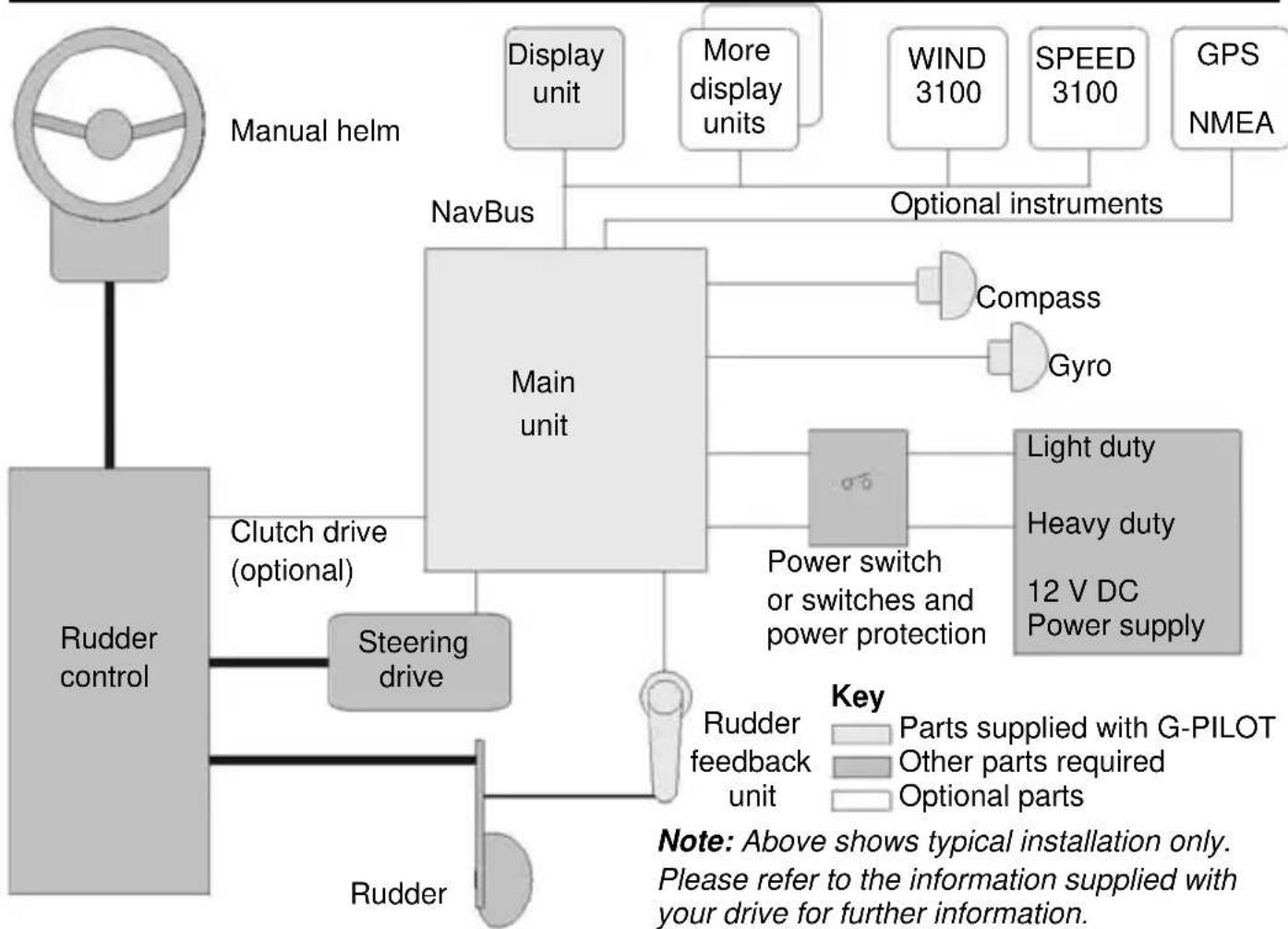
flowchart
graph TD
    A["Manual helm"] --> B["Rudder control"]
    B --> C["Steering drive"]
    C --> D["Main unit"]
    D --> E["Display unit"]
    D --> F["More display units"]
    D --> G["Compass"]
    D --> H["Gyro"]
    D --> I["Power switch or switches and power protection"]
    I --> J["Light duty"]
    I --> K["Heavy duty"]
    I --> L["12 V DC Power supply"]
    D --> M["Power feedback unit"]
    M --> N["Rudder"]
    D --> O["Optional instruments"]
    O --> P["Main unit"]
    P --> Q["Display unit"]
    P --> R["More display units"]
    P --> S["WIND 3100"]
    P --> T["SPEED 3100"]
    P --> U["GPS NMEA"]
    style A fill:#ccc,stroke:#333
    style B fill:#ccc,stroke:#333
    style C fill:#ccc,stroke:#333
    style D fill:#ccc,stroke:#333
    style E fill:#ccc,stroke:#333
    style F fill:#ccc,stroke:#333
    style G fill:#ccc,stroke:#333
    style H fill:#ccc,stroke:#333
    style I fill:#ccc,stroke:#333
    style J fill:#ccc,stroke:#333
    style K fill:#ccc,stroke:#333
    style L fill:#ccc,stroke:#333
    style M fill:#ccc,stroke:#333
    style N fill:#ccc,stroke:#333
    style O fill:#ccc,stroke:#333
    style P fill:#ccc,stroke:#333
    style Q fill:#ccc,stroke:#333
    style R fill:#ccc,stroke:#333
    style S fill:#ccc,stroke:#333
    style T fill:#ccc,stroke:#333
    style U fill:#ccc,stroke:#333
2 Basic operation
The display unit
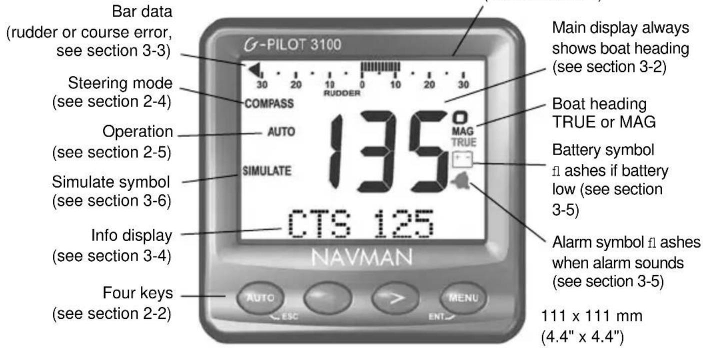
text_image
Bar data (rudder or course error, see section 3-3) Steering mode (see section 2-4) Operation (see section 2-5) Simulate symbol (see section 3-6) Info display (see section 3-4) Four keys (see section 2-2) Main display always shows boat heading (see section 3-2) Boat heading TRUE or MAG Battery symbol fl ashes if battery low (see section 3-5) Alarm symbol fl ashes when alarm sounds (see section 3-5) 111 x 111 mm (4.4" x 4.4") NAVMAN2-1 Turning on and off
Turn the unit on and off with the auxiliary power switch on the boat. The unit does not have its own power switch. When you turn it off, any settings you have made are retained.
If the word SIMULATE flashes on the display, then the unit is in simulate mode (see section 3-6).
2-2 The keys
The unit has four keys, labelled AUTO (ESC) < > and MENU (ENT).
In this manual:
- Press means to push the key for less than one second.
- Hold means to hold the key down until the display changes.
- Press one key + another key means to push both keys together.
The display unit gives a high pitch beep after a valid key press and a low pitch beep after an invalid key press. For information on using the keys, see sections 3-7 and 3-8.
Keylock
When keylock is turned on, the G-PILOT will ignore key presses. To turn keylock on or off:
• Press AUTO + MENU.
- Press ENT.
2-3 Using the G-PILOT 3100
2-3-1 Starting the G-PILOT 3100
1 Turn the G-PILOT 3100 on (see section 2-1). If the G-PILOT 3100 is connected to speed, wind or GPS instruments, turn these on too.
2 If necessary, adjust the backlight so that the display can be read easily (see section 3-1).
3 If necessary, change the user data (see section 3-7).
2-3-2 Using the G-PILOT 3100
1 Manually steer the boat to open waters before using the G-PILOT to steer the boat.
2 If necessary, change the steering mode (see section 2-4).
3 Engage, use and disengage the G-PILOT: For Compass mode: see section 4. For GPS mode: see section 5. For Wind mode: see section 6.
4 It is possible to change the steering mode during a voyage, for example:
- Change from GPS to compass at the end of a route.
- On a sailing boat, change from wind to compass or GPS when changing from sail to motor (see section 3-4).
5 The G-PILOT can be adjusted to optimize its steering performance:
• If necessary, adjust the turn rate so that the boat turns at a reasonable rate; go to TURN RATE in the OPTIONS menu (see section 3-7).
- Select a profi le suitable for the conditions (see section 7-2).
• If necessary, adjust the data in the profile to improve the steering performance (see section 7-3).
• If the G-PILOT steering performance is poor and the above adjustments do not correct the performance, consider performing a complete dockside setup and sea trial as described in the G-PILOT 3100 Installation manual.
Important:
• The G-PILOT cannot control the boat better than a helmsman. The G-PILOT is
not intended for use in extreme weather, in adverse conditions or near other boats, dangerous waters or land. In these conditions, disengage the G-PILOT and steer manually.
- Never leave the helm unattended, keep a watch at all times and be ready to resume steering the boat manually.
- Do not try to turn the rudder by hand when the G-PILOT is engaged.
- Local variations in magnetic field can affect the accuracy of the compass heading. Such variations are the responsibility of the user.
2-3-3 Action in an emergency
To regain control of the boat in an emergency situation:
• Either press AUTO to put the G-PILOT 3100 in STBY (standby)
• or turn the power switch(es) off.
Then manually steer the boat.
2-3-4 Turning the G-PILOT 3100 off
It is normal to turn the G-PILOT off upon reaching your destination.
2-4 Setting the steering mode
The G-PILOT 3100 has three ways to steer the boat: compass, GPS or wind. These are called the steering modes.
For a power boat
- For a boat without GPS, or for a boat with GPS when you do not want to navigate to a waypoint, choose compass mode. The G-PILOT 3100 steers the boat at a set compass heading.
• To use the G-PILOT 3100 with a GPS to navigate to a waypoint or along a route, choose GPS mode. The G-PILOT 3100 steers the boat using navigation data from the GPS.
For a sailing boat
• To sail, tack and gybe at a set angle to the wind, choose wind mode. Wind
mode requires a wind instrument, such as Navman's WIND 3100 to be connected via NavBus or NMEA.
• To steer to a set compass heading, choose compass mode.
• To use the G-PILOT 3100 with a GPS to navigate to a waypoint or along a route, choose GPS mode.
Note for sailing boats
• The G-PILOT is not recommended for use in light, changeable or gusty winds.
• Take care when running to avoid an accidental gybe.
• Wind mode requires the wind instrument to be accurately calibrated.
Setting the steering mode from the menu
Go to STER MODE in the MAIN menu (see section 3-7) and select COM (compass), GPS or WIND.
Setting the steering mode by shortcut key
Hold MENU to go directly to the steering mode menu.
Note
• To select GPS mode, the G-PILOT must be receiving data from a compatible GPS instrument, otherwise the G-PILOT will display NO DATA
• To engage the G-PILOT in GPS mode, the GPS must be navigating to a waypoint or along a route, otherwise the G-PILOT will display NAV ERROR. If the boat is too
far from the plotted course, the G-PILOT will display TRK ERROR (see section 5-2)
• To select Wind mode, the G-PILOT must be receiving data from a compatible wind instrument, otherwise the G-PILOT will display NO DATA.
Steering mode is shown on the display
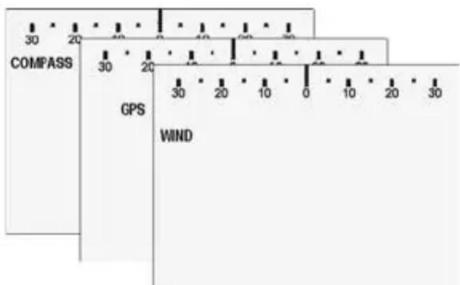
text_image
COMPASS 30 20 10 0 40 20 0 30 20 GPS WIND 30 20 10 0 10 20 302-5 STBY (standby), AUTO and HAND STEER
The G-PILOT 3100 can operate in STBY (standby), AUTO or HAND STEER:
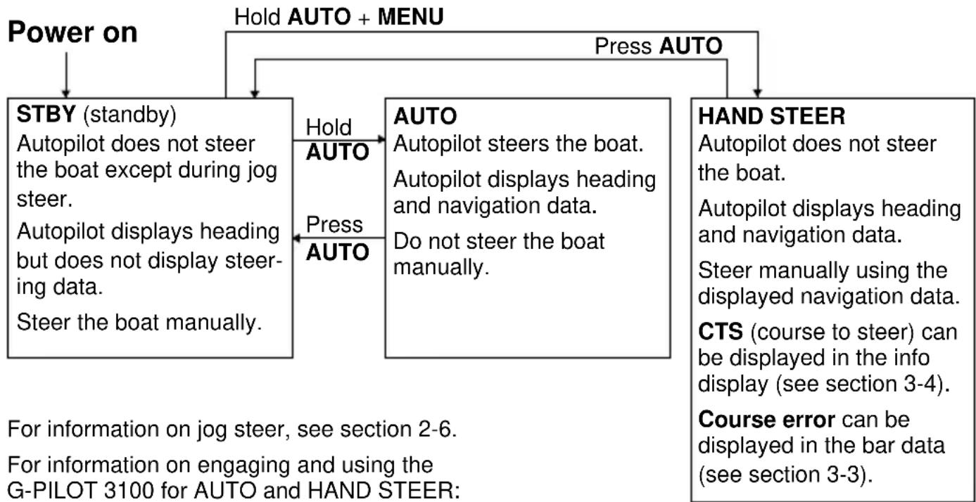
flowchart
graph TD
    A["Power on"] --> B["STBY (standby)<br>Autopilot does not steer the boat except during jog steer.<br>Autopilot displays heading but does not display steering data.<br>Steer the boat manually."]
    B --> C["Hold AUTO"]
    B --> D["Press AUTO"]
    C --> E["AUTO<br>Autopilot steers the boat.<br>Autopilot displays heading and navigation data.<br>Do not steer the boat manually."]
    D --> F["HAND STEER<br>Autopilot does not steer the boat.<br>Autopilot displays heading and navigation data.<br>Steer manually using the displayed navigation data.<br>CTS (course to steer) can be displayed in the info display (see section 3-4).<br>Course error can be displayed in the bar data (see section 3-3)."]
    F --> G["For information on jog steer, see section 2-6.<br>For information on engaging and using the G-PILOT 3100 for AUTO and HAND STEER:"]
For Compass mode: see section 4.
For GPS mode: see section 5.
For Wind mode: see section 6.
2-6 Jog steer
When the G-PILOT 3100 is in STBY (standby, see section 2-5) the helmsman must steer the boat manually. However the G-Pilot 3100 can turn the rudder; this is called jog steering:
• hold down < to turn the rudder to port
• hold down > to turn the rudder to starboard
- press and release < and > together to turn the rudder to amidships (this function is disabled until the rudder feedback unit and the compass have been calibrated (see the G- PILOT 3100 Installation Manual)).
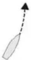
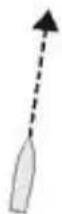
For example:
Rudder is amidships Boat keeps turning to port.

text_image
30 20 10 0 RUDDER 10 20 30to port, the rudder turns to port and the boat turns to port
Release <, the rudder stays to port

text_image
30 20 10 0 RUDDER 10 20 30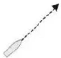
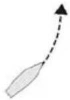
Rudder is to port

Hold >, the rudder turns to starboard
Release >, the rudder stops, but is still to port
Boat keeps turning to port

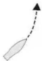
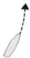
Rudder is to port Boat goes straightPress and release

< + > together the rudder turns to amidships.
To stop the rudder turning to amidships press
ESC, < or >

Warning Until the rudder feedback unit is calibrated, there is no rudder limit and the user must ensure that the rudder is not driven onto an endstop when using jog steering.
Note Normally during a jog the info data (see section 3-4) displays JOG. However, if CUR (drive current) is selected then this current is displayed during a jog as an aid for testing the steering drive.
3 Operation
3-1 Set backlight for screen and keys
To adjust the backlight, go to LAMP in the MAIN menu (see section 3-7). The options are OFF or 1 (least bright) to 4 (most bright).
3-2 Heading display
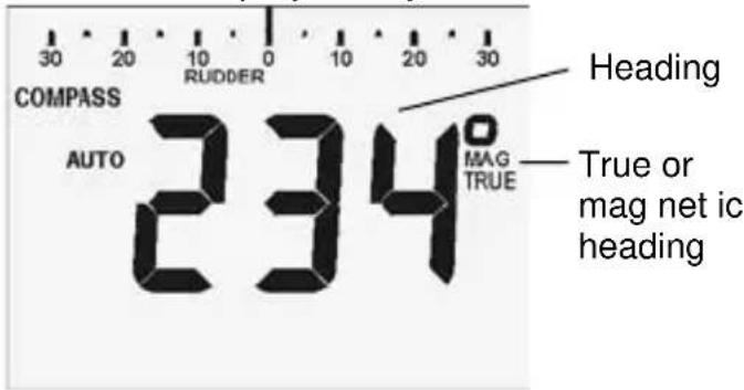
The main display always shows the boat heading:
text_image
COMPASS AUTO RUDDER 0 10 20 30 Heading 234 MAG TRUE True or mag net ic headingTo display MAG (magnetic) or TRUE headings, go to HDG TYPE in the OPTIONS menu (see section 3-7).
3-3 Bar data display
The bar data at the top of the display can display rudder angle or course error.
To select what is displayed, go to BAR DATA in the MAIN menu (see section 3-7). The options are RUD (rudder angle) or CE (course error). If the G-PILOT 3100 system has more than one display unit, then the bar data display can be selected differently in each display unit.
Rudder angle
Rudder angle is the angle that the rudder is turned from amidships. When the G-PILOT 3100 is driving the rudder, an arrowhead at the end of the bar data turns on, pointing in the
G-PILOT is not driving rudder, rudder is amidships

text_image
30 20 10 0 RUDDER 10 20 30G-PILOT driving rudder to port, rudder is at 12° to port

text_image
30 20 10 0 RUDDER 10 20 30G-PILOT is not driving rudder, rudder is at 18° to port,

text_image
30 20 10 0 10 20 30 RUDDERIf the rudder is turned 30^ or more, the display shows 30^ and the arrowhead is on:

text_image
30 20 10 0 RUDDER 10 20 30direction the rudder is moving. For example:
Rudder angle can be displayed even if the boat is being steered manually.
Course error
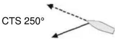
The course error is the angle between the actual boat heading and the intended autopilot course, for example:

text_image
Actual heading 90° CTS (course to steer) 110°Course error is 20^ to starboard

text_image
30 20 10 0 10 20 30 COURSE ERRORActual heading 290°
text_image
CTS 250°Course error is 40^ to port, but 30^ is the largest error that can be displayed, so the display shows 30^ to port

text_image
30 20 10 0 10 20 30 COURSE ERRORIn STBY (standby), course error displays as zero.
3-4 Info data display
The info data is at the bottom of the screen, and can display one item of steering or navigation data. To select what data is displayed, go to INFO DATA in the MAIN menu (see section 3-7). If the G-PILOT 3100 system has more than one display unit, then the info data display can be selected differently in each display unit.
The options are:
• CTS: The course the G-PILOT 3100 intends the boat to steer; in STBY (standby) there is no CTS and the display shows CTS — — —.
• XTE, BRG, COG, DTG, TTG, SOG: GPS navigation data (see section 5-1); requires connection to a GPS instrument.
- WND: Wind angle (see section 6-1). To display APP (apparent) or TRUE wind angle, go to WIND TYPE in the VESSEL menu (see section 3-7). Requires connection to a wind instrument.
• BAT: G-PILOT 3100 power supply voltage.
• CUR: Steering drive current; the drive can be tested by checking the current during a jog (see section 2-6).
• OFF: nothing is displayed.
3-5 Alarms
When the G-PILOT 3100 detects an alarm condition, it displays a warning message, the alarm symbol on the display fl ashes, the internal beeper sounds and any external beepers or lights operate.
Press any key to mute the alarm, then press ESC to cancel the alarm message.
The G-PILOT 3100 has two kinds of alarm, internal alarms and user defined alarms:
• To turn user defi ned alarms on or off and set the alarm condition (see the ALARMS menu, section 3-7).
• For a list of the alarms and what they mean, see appendix B.
Low battery alarm
If the G-PILOT 3100 power supply voltage drops below the battery alarm value, the G-PILOT 3100 gives a BAT ERROR alarm and the low battery symbol on the G-PILOT 3100 display fl ashes. If the G-PILOT 3100 is in AUTO then the steering drive might not operate if the power supply voltage is too low. We recommend switching to HAND STEER (see section 2-5).
3-6 Simulate mode
Simulate mode allows you to become familiar with the unit off the water. The word SIMULATE fl ashes on the display.
To turn Simulate mode on or off:
1 Turn the unit off (see section 2-1).
2 Hold down AUTO while you turn the unit on (see section 2-1).
3-7 Using the menus
The menus contain data and functions to control the performance and operation of the G-PILOT 3100.
Viewing or changing menu data
1 From normal operation, press MENU.
2 To select data in the MAIN menu:
- press < or > until the required data is displayed; press ENT
To select data in other menus:
i press < or > until CONFIG > is displayed; press ENT
ii press < or > until the required menu is displayed; press ENT
Note An > after an name indicates that the item is a menu.
3 To change the data:
• press < or > one or more times
• hold < or > to change the data in steps of ten
• to restore the data to its default value (see next page), press < + >.
4 Press ENT to store the changed data, or press ESC to ignore the change.
5 Press ESC one or more times to exit the menu or repeat steps 2 to 4 to view or change other data.
Shortcut After viewing or changing data, hold ESC to exit the menus.
The G-PILOT gives a long beep when you exit the menu. If you do not press a key for 30 seconds than the G-PILOT will automatically exit the menu.
MAIN menu
RESPONSE How far the course deviates before the G-PILOT 3100 corrects the course (1 to 10, A1 to A5; default depends on vessel type) (see section 7-1).
RATIO How much the G-PILOT 3100 turns the rudder to correct the course (1 to 10; default depends on vessel type) (see section 7-2).
LAMP The backlight brightness (1 to 4 or OFF; default = 1) (see section 3-1).
BAR DATA The data to display on the bar display (CE (course error) or RUD (rudder angle); default = RUD) (see section 3-3).
INFO DATA The data to display on the info data display (CTS, XTE, BRG, COG, DTG, TTG, SOG, WND, BAT, CUR, OFF; default = CTS) (see section 3-4).
List of menus and data
MAIN menu
Response
Ratio
Lamp
Bar data
Info data
Steer mode
Profi le
CONFIG > menu
ALARMS > menu
Course error alarm
XTE alarm
Waypoint acknowledge
Wind alarm
Battery alarm
Current alarm
OPTIONS > menu
Counter rudder gain
Trim gain
GPS gain
Wind gain
Dodge angle
Tack angle
Gybe angle
Tack delay
Turn rate
VESSEL > menu (STBY only)
Vessel type
Drive type
Wind type
Heading type
Magnetic variation
DEVICES > menu (STBY only)
Calibrate rudder feedback unit
Centre rudder feedback unit
Calibrate compass
Align heading
Align GPS
FACTORY > menu (STBY only)
Backlight group
Key beeps
NMEA 2 data
Main control unit version number
Display unit version number
Reset NVM
STER MODE The steering mode (COM (compass), GPS, WND; default = COM) (see section 2-4).
PROFILE The current set of steering parameters to use (1 to 5; default = 1) (see section 7-3).
CONFIG > Access data in menus other than the main menu.
ALARMS > menu
CE ALARM The maximum course error allowed before alarm sounds (1° to 90° or OFF; default = OFF).
XTE ALARM The maximum XTE error (in nm) allowed before alarm sounds (0.01 to 2 nm or OFF; default = OFF).
WPT AKN If the user is to acknowledge when the boat reaches waypoint (OFF or ON, default = OFF) (see section 5-2).
WND ALARM (If vessel type = SAIL) The maximum deviation between apparent wind angle and SWA (set wind angle) before alarm sounds (1° to 90° or OFF; default = OFF).
BAT ALARM The lowest battery voltage allowed before alarm sounds (7 to 14 V or OFF; default = OFF).
CUR ALARM The maximum drive current before alarm sounds (5 to 20 A; default = 10 A).
OPTIONS > menu
C-RD GAIN Counter rudder gain, used to optimize steering performance (1 to 10 or OFF; default depends on vessel type) (see section 7).
TRIM GAIN Trim gain, used to optimize steering performance (1 to 10 or OFF; default depends on vessel type) (see section 7).
GPS GAIN GPS gain, used to optimize steering performance (1 to 10; default = 3) (see section 7).
WIND GAIN Wind gain, used to optimize steering performance (1 to 10; default = 1) (see section 7).
DODGE ANG The angle the course will change by in a dodge (5° to 30°; default = 20°) (see sections 4-4, 5-3 or 6-4).
TACK ANG The angle of course change in a tack (50° to 160° or AUTO, default = AUTO) (see sections 4-5, 6-5).
GYBE ANG The angle of course change in a gybe (40° to 140° or AUTO or OFF, default = AUTO) (see sections 4-5, 6.5).
TACK DELY The delay between pressing tack and the boat starting to tack (1 to 120 sec or OFF; default = 30 sec) (see sections 4-5, 6-5).
TURN RATE Set the maximum boat turn rate allowed, in degrees per sec (3 to 20, default = 10 degrees per sec).
VESSEL > menu
This menu can only be accessed in STBY.
VESL TYPE Vessel type (SAIL, PLNE (planing), DISP (displacement); default = SAIL).
DRVE TYPE Steering drive type (MOTR, SPL- or SPL+; default = MOTR) (see G-PILOT 3100 Installation Manual).
WIND TYPE The wind type to use (APP or TRUE; default = APP).
HDG TYPE The compass heading type (MAG or TRUE; default = MAG).
MAG VAR The magnetic variation where the boat is (90°W to +90°E; default = 19°E).
DEVICES > menu
The items in the DEVICES menu are functions used to calibrate the G-PILOT 3100. This menu can only be accessed in STBY.
RFU CAL Start the procedure to calibrate the rudder feedback unit (see G-PILOT 3100 Installation Manual).
RFU CENTR Set rudder to position where boat sails in a straight line (see G-PILOT 3100 Installation Manual).
CSU CAL Start the procedure calibrate the compass (see G-PILOT 3100 Installation Manual).
ALIGN HDG Align the compass with the boat (see G-PILOT 3100 Installation Manual)
ALIGN GPS Align the current boat heading with a GPS heading (COG) if available (see G-PILOT 3100 Installation Manual).
FACTORY > menu
This menu can only be accessed in STBY.
BKL GROUP NavBus group number (0, 1, 2, 3 or 4, default = 1) (see G-PILOT 3100 Installation Manual).
KEY BEEPS A beep when a key is pressed (ON or OFF, default = ON).
NMEA2 DAT NMEA 2 port function (IN, SLOW or FAST; default = IN):
IN: NMEA 2 is an input
SLOW: NMEA 2 outputs heading & rudder angle once per second
FAST: NMEA 2 outputs heading ten times per second.
MCU VX.X Displays the G-PILOT 3100 main unit's software version number (e.g. MCU V1.3 is version 1.3).
HCU VX.X Displays the display unit's software version number (e.g. HCU V2.5 is version 2.5).
NVM RESET This function resets all G-PILOT 3100 user data to the factory default values. Once NVM RESET is displayed:
1 Press > to turn the function on
2 Press ENT to reset the data
3 Hold ESC to exit the menus
4 Perform the dockside setup and sea trials to recalibrate the G-PILOT 3100 (see G-PILOT 3100 Installation Manual).
3-8 Key reference
Power on
Hold AUTO + MENU
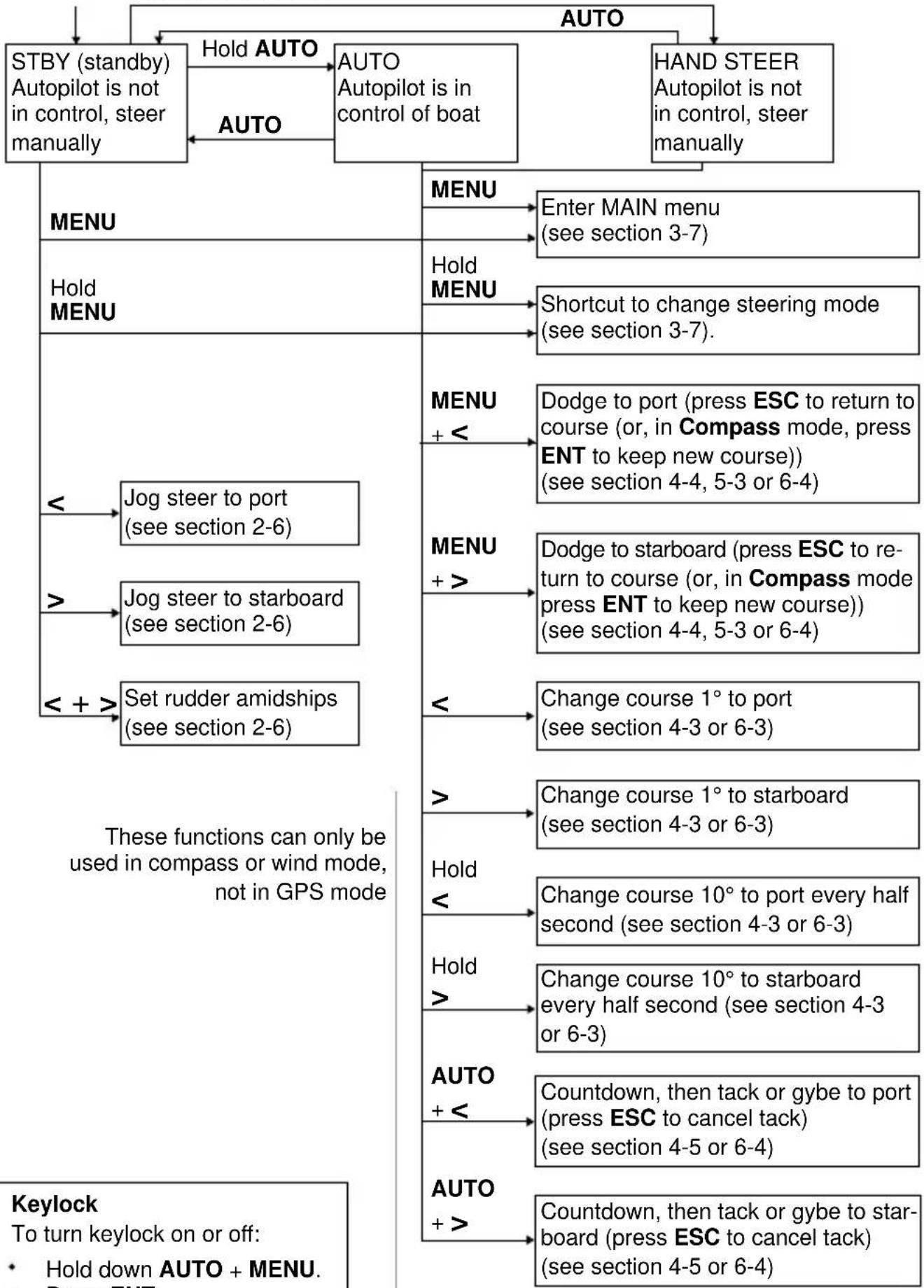
flowchart
graph TD
    A["STBY (standby) Autopilot is not in control, steer manually"] --> B["Hold AUTO"]
    B --> C["AUTO Autopilot is in control of boat"]
    C --> D["AUTO"]
    D --> E["HAND STEER Autopilot is not in control, steer manually"]

    F["MENU"] --> G["Enter MAIN menu (see section 3-7)"]
    H["Hold MENU"] --> I["Shortcut to change steering mode (see section 3-7)."]

    J["<<Jog steer to port (see section 2-6)"] --> K["<<Set rudder amidships (see section 2-6)"]
    L[">>Jog steer to starboard (see section 2-6)"] --> M["<<Set rudder amidships (see section 2-6)"]

    N["<<Dodge to port (press ESC to return to course (or, in Compass mode, press ENT to keep new course)) (see section 4-4, 5-3 or 6-4)"] --> O["<<Dodge to starboard (press ESC to return to course (or, in Compass mode press ENT to keep new course)) (see section 4-4, 5-3 or 6-4)"]
    P["<<Change course 1° to port (see section 4-3 or 6-3)"] --> Q["<<Change course 1° to starboard (see section 4-3 or 6-3)"]
    R["<<Hold <"] --> S["<<Change course 10° to port every half second (see section 4-3 or 6-3)"]
    T["<<Hold >"] --> U["<<Change course 10° to starboard every half second (see section 4-3 or 6-3)"]
    V["<<AUTO + <"] --> W["<<Countdown, then tack or gybe to port (press ESC to cancel tack) (see section 4-5 or 6-4)"]
    X["<<AUTO + >"] --> Y["<<Countdown, then tack or gybe to starboard (press ESC to cancel tack) (see section 4-5 or 6-4)"]

    style F fill:#f9f,stroke:#333
    style H fill:#f9f,stroke:#333
    style J fill:#f9f,stroke:#333
    style K fill:#f9f,stroke:#333
    style L fill:#f9f,stroke:#333
    style M fill:#f9f,stroke:#333
    style N fill:#f9f,stroke:#333
    style O fill:#f9f,stroke:#333
    style P fill:#f9f,stroke:#333
    style Q fill:#f9f,stroke:#333
    style R fill:#f9f,stroke:#333
    style S fill:#f9f,stroke:#333
    style T fill:#f9f,stroke:#333
    style U fill:#f9f,stroke:#333
    style V fill:#f9f,stroke:#333
    style W fill:#f9f,stroke:#333
4 Compass steering mode
The G-PILOT 3100 has three ways of steering the boat, compass, GPS and wind. To select an appropriate mode, see section 2-4. In Compass mode, the G-PILOT steers the boat to a set course, called CTS (Course to steer).
4-1 Compass steering data
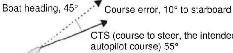
text_image
Boat heading, 45° Course error, 10° to starboard CTS (course to steer, the intended autopilot course) 55°4-2 Engaging and disengaging the G-PILOT 3100 in compass mode
Manually steer the boat to open waters. Sail straight on the intended course.
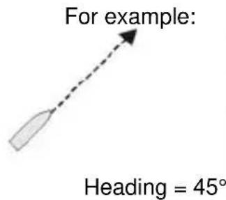
text_image
For example: Heading = 45°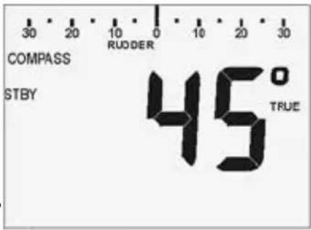
text_image
COMPASS STBY RUODER 0 10 20 30 45° TRUETo engage AUTO, hold AUTO
To engage HAND STEER, hold AUTO + MENU
AUTO:

text_image
COMPASS AUTO COURSE ERROR 0 10 20 30 45° TRUE CTS 45The G-PILOT steers the boat automatically.
HANDSTEER:
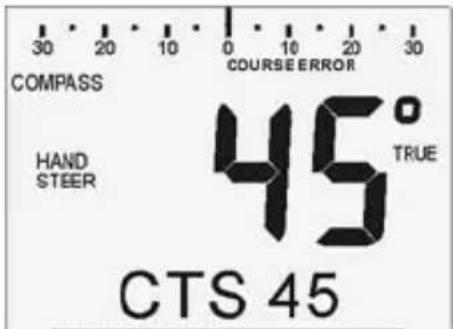
text_image
COMPASS COURSE ERROR HAND STEER 45° TRUE CTS 45Steer the boat manually. Display CTS in the info data or course error in the bar data and use these to steer by.
The G-PILOT 3100 sets CTS (course to steer) to the current heading, in this example 45°, and starts steering on this course.
Heading = 45°
CTS = 45°

To disengage the G-PILOT, press AUTO
The G-PILOT returns to STBY (standby). Steer the boat manually.
When the G-PILOT 3100 is engaged
Hold AUTO to attempt to switch to GPS mode (if vessel type is PLNE [planing] or DISP [displacement]) or to wind mode (if vessel type is SAIL).
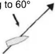
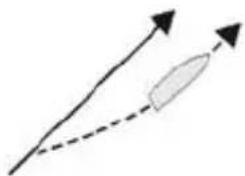
Waves or wind can push the boat's heading off course, The G-PILOT 3100 will steer the boat back on course, for example:
$$ \mathrm{CTS} = 4 5 ^ {\circ} $$
Wave pushes boat heading to 60°
natural_image
Simple diagram showing two arrows with a dashed line and an elongated oval shape, no text or symbols present.G-PILOT 3100 steers boat back to a heading of 45^
Wind or currents can push the boat to one side of the course, for example:
$$ \mathrm{CTS} = 4 5 ^ {\circ} $$
Current

natural_image
Simple line drawing of a rocket with solid and dashed trajectory lines (no text or symbols)Heading is maintained at 45°
4-3 Changing course in compass mode
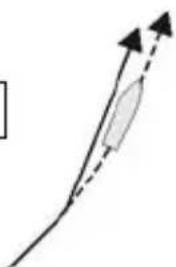
To change course in 1° steps:
• press < to change course by 1° to port
• press > to change course by 1° to starboard.
For example:
Heading = 45°
CTS = 45°
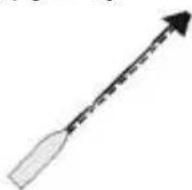
Press <
natural_image
Simple line drawing of a curved path with an arrow and a shaded oval (no text or symbols)CTS changes to 44°
Boat comes to 44° heading
Heading = 45°
CTS = 45°

Press >
CTS changes to 46°
Boat comes to 46° heading
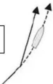
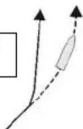
To change course in 10° steps:
• hold down < to change course by 10° to port every half second
• hold down > to change course by 10^ to starboard every half second.
For example:
Heading = 45°
CTS = 45°
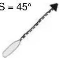
Hold < for half a second
natural_image
Simple line diagram showing two upward-pointing arrows with a shaded oval shape inside, no text or symbols present.CTS changes to 35°
Boat comes to 35° heading
Hold < until CTS is 15°
natural_image
Simple line diagram showing two upward arrows and a dashed arrow pointing to a shaded rectangular shape (no text or symbols)Boat comes to 15° heading
4-4 Dodging in compass mode
A dodge is a sharp change of course, usually to avoid an obstacle.
• press MENU + < to dodge to port by the dodge angle
• press MENU + > to dodge to starboard by the dodge angle.
For example:
Heading = 45°
CTS = 45°
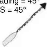
Press
MENU + <
CTS changes by the dodge angle. Boat comes to new heading. The G-PILOT beeps.
Press ENT to continue on the new heading
or
Press ESC to resume the earlier heading
Note
• To dodge further, press MENU + < or MENU + > more times.
• To view or change the dodge angle, go to DODGE ANG in the OPTIONS menu (see section 3-7).
4-5 Auto tacking in compass mode
Auto tacking is intended to tack a sailing boat. The course to steer changes by the tack angle.
• press AUTO + < to tack to port by the tack angle
• press AUTO + > to tack to starboard by the tack angle.
For example:
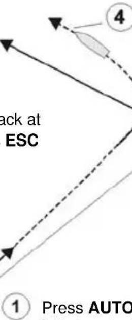
To cancel the tack at any time, press ESC
Heading = 45^ CTS = 45^
text_image
ack at ESC ① Press AUTOThe tack is fi nished when the boat reaches the new head-

At the end of the tack delay, CTS changes by the tack angle (if the tack angle is set to AUTO, the G-PILOT will use the default tack angle of 100^ ). The boat turns.
The boat sails straight while the G-PILOT 3100 counts down the tack delay.
The unit gives a long beep at 60 and 30 seconds to go, a short beep every second from 10 seconds to 1 second to go and a long beep that fi nishes when the countdown ends.
① Press AUTO + < to initiate a tack to port
TACK <3
3 seconds to go until the tack starts
WARNING: In Compass mode auto tack, the course to steer changes by the tack angle. The G-PILOT does not use data from any wind instrument. It is possible for the boat to gybe or to end in irons.
Note
• To tack to a fixed wind angle, use the G-PILOT 3100 in Wind mode (see section 6).
• To view or change the tack angle or the tack delay, go to TACK ANG or TACK DELY in the OPTIONS menu (see section 3-7). Gybe angle is not used in Compass mode.
• The gybe angle is not used in Compass mode.
5 GPS steering mode
The G-PILOT 3100 has three ways of steering the boat, compass, GPS and wind. To select an appropriate mode, see section 2-4. In GPS mode, the G-PILOT uses data from a GPS to steer the boat along a route or to a waypoint.
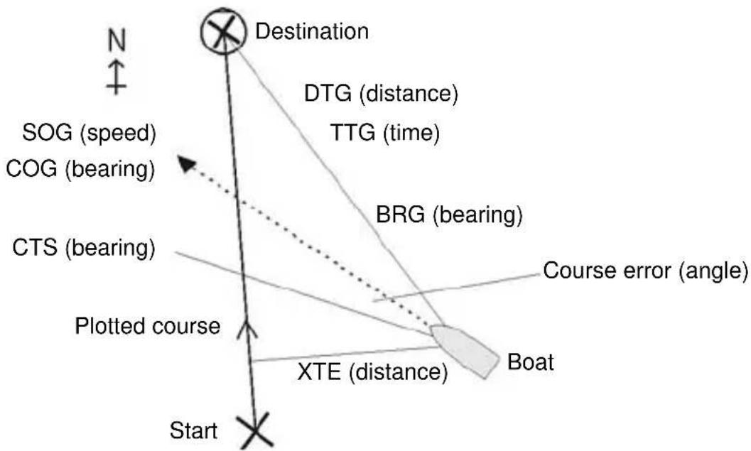
5-1 GPS navigation data Example of navigating to a waypoint:
flowchart
graph TD
    Start["Start"] -->|XTE (distance)| Boat["Boat"]
    Start --> PlottedCourse["Plotted course"]
    PlottedCourse --> CTS["Bearing"]
    CTS --> COG["Bearing"]
    COG --> SOG["speed"]
    SOG --> Destination["Destination"]
    Destination --> DTG["DTG distance"]
    Destination --> TTG["TTG time"]
    Destination --> BRG["BRG bearing"]
    BTG --> CourseError["Course error angle"]
    BTG --> XTE["Boat"]
    style Destination fill:#f9f,stroke:#333
    style Start fill:#ccf,stroke:#333
    style_Plant1["Start"] fill:#cfc,stroke:#333
    style_Plant2["Start"] fill:#cfc,stroke:#333
    style_Plant3["Start"] fill:#cfc,stroke:#333
    style_Plant4["Start"] fill:#cfc,stroke:#333
    style_Plant5["Start"] fill:#cfc,stroke:#333
    style_Plant6["Start"] fill:#cfc,stroke:#333
    style_Plant7["Start"] fill:#cfc,stroke:#333
    style_Plant8["Start"] fill:#cfc,stroke:#333
    style_Plant9["Start"] fill:#cfc,stroke:#333
    style_Plant10["Start"] fill:#cfc,stroke:#333
    style_Plant11["Start"] fill:#cfc,stroke:#333
    style_Plant12["Start"] fill:#cfc,stroke:#333
    style_Plant13["Start"] fill:#cfc,stroke:#333
    style_Plant14["Start"] fill:#cfc,stroke:#333
    style_Plant15["Start"] fill:#cfc,stroke:#333
    style_Plant16["Start"] fill:#cfc,stroke:#333
    style_Plant17["Start"] fill:#cfc,stroke:#333
    style_Plant18["Start"] fill:#cfc,stroke:#333
    style_Plant19["Start"] fill:#cfc,stroke:#333
    style_Plant20["Start"] fill:#cfc,stroke:#333
    style_Plant21["Start"] fill:#cfc,stroke:#333
    style_Plant22["Start"] fill:#cfc,stroke:#333
    style_Plant23["Start"] fill:#cfc,stroke:#333
    style_Plant24["Start"] fill:#cfc,stroke:#333
    style_Plant25["Start"] fill:#cfc,stroke:#333
    style_Plant26["Start"] fill:#cfc,stroke:#333
    style_Plant27["Start"] fill:#cfc,stroke:#333
    style_Plant28["Start"] fill:#cfc,stroke:#333
    style_Plant29["Start"] fill:#cfc,stroke:#333
    style_Plant30["Start"] fill:#cfc,stroke:#333
    style_Plant31["Start"] fill:#cfc,stroke:#333
    style_Plant32["Start"] fill:#cfc,stroke:#333
    style_Plant33["Start"] fill:#cfc,stroke:#333
    style_Plant34["Start"] fill:#cfc,stroke:#333
    style_Plant35["Start"] fill:#cfc,stroke:#333
    style_Plant36["Start"] fill:#cfc,stroke:#333
    style_Plant37["Start"] fill:#cfc,stroke:#333
    style_Plant38["Start"] fill:#cfc,stroke:#333
    style_Plant39["Start"] fill:#cfc,stroke:#333
    style_Plant40["Start"] fill:#cfc,stroke:#333
    style_Plant41["Start"] fill:#cfc,stroke:#333
    style_Plant42["Start"] fill:#cfc,stroke:#333
    style_Plant43["Start"] fill:#cfc,stroke:#333
    style_Plant44["Start"] fill:#cfc,stroke:#333
    style_Plant45["Start"] fill:#cfc,stroke:#333
    style_Plant46["Start"] fill:#cfc,stroke:#333
    style_Plant47["Start"] fill:#cfc,stroke:#333
    style_Plant48["Start"] fill:#cfc,stroke:#333
    style_Plant49["Start"] fill:#cfc,stroke:#333
    style_Plant50["Start"] fill:#cfc,stroke:#333
The boat is sailing from the start to the destination and has moved off the GPS plotted course from the start to the destination:
BRG Bearing to destination The bearing to the destination from the boat.
| Course error | The difference between CTS and the boat heading. | |
| CTS | Course to steer | Optimum course to steer to return to the plotted course. |
| DTG | Distance to go | Distance from the boat to the destination. |
| SOG | Speed over ground | The current boat speed over the ground. This is not necessarily the same as the boat speed through the water nor the speed at which the boat is approaching the destination. |
| TTG | Time to go | The estimated time to reach the destination. |
| XTE | Cross track error | The distance from the boat to the nearest point of the plotted course. XTE may have a letter: R means steer to the right to return to the plotted course, L means steer to the left. |
5-2 Engaging and disengaging the G-PILOT 3100 in GPS mode
Manually steer the boat to open waters. Start the GPS navigating to a waypoint, either a waypoint on a route or a single waypoint.
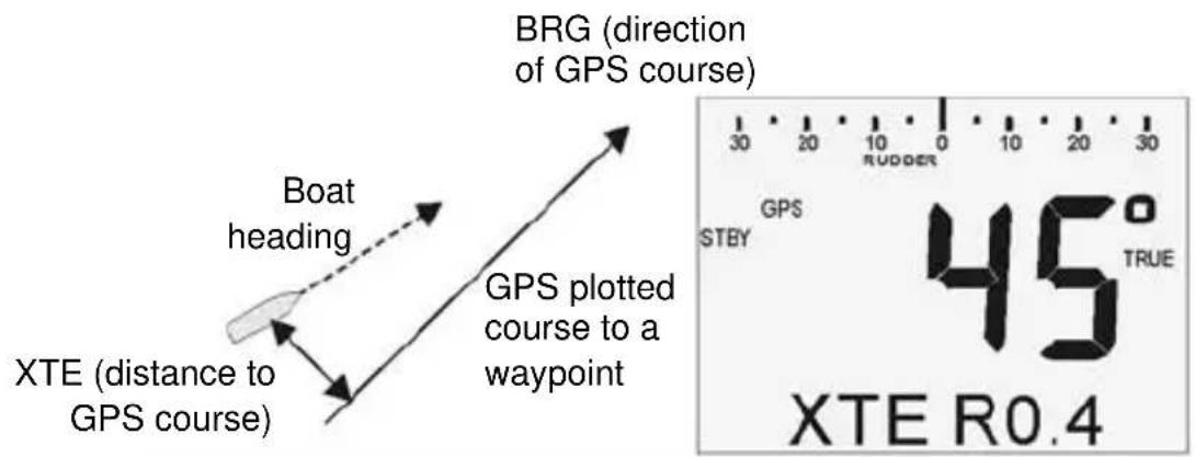
text_image
BRG (direction of GPS course) Boat heading GPS plotted course to a waypoint XTE (distance to GPS course) 30 20 10 0 10 20 30 RUDDER STBY GPS 45° TRUE XTE R0.4To engage AUTO, hold AUTO
To engage HAND STEER, hold AUTO + MENU
AUTO:
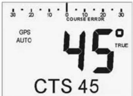
text_image
30 20 10 0 10 20 30 COURSE ERROR GPS AUTO 45° TRUE CTS 45The G-PILOT steers the boat automatically.
HANDSTEER:

text_image
30 20 10 0 10 20 30 COURSE ERROR GPS HAND STEER 45° TRUE XTE R0.4 GPS plotted courseSteer the boat manually. Display CTS in the info data or course error in the bar data and use these to steer by.
When the G-PILOT is engaged, if the XTE is more than 0.05 nm or the boat heading is not within 30° of BRG then the G-PILOT displays TRK ERROR. Press ESC to return to Compass mode or press ENT to have the G-PILOT steer the boat to the course.
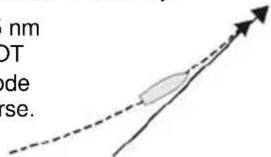
When the G-PILOT is engaged, it uses data from the GPS to steer the boat along the plotted course to the waypoint.
text_image
nm DT ode rse.To disengage the G-PILOT, press AUTO
The G-PILOT returns to STBY (standby). Steer the boat manually.
When the G-PILOT 3100 is engaged
Hold AUTO to change to Compass mode.
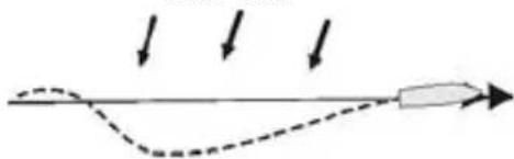
Wind or currents can push the boat off the GPS course. The G-PILOT 3100 will steer the boat back on course:
Current:
natural_image
Simple diagram showing a curved path with arrows indicating direction, no text or symbols presentIf the GPS is following a route and the boat reaches an intermediate waypoint:
• If WPT AKN is off, the G-PILOT automatically starts steering to the next waypoint in the route.
- Otherwise, the G-PILOT displays NEXT WPT?, sounds an alarm and continues on the current heading. Press any key to mute the alarm. Then press ENT to start steering to the next waypoint or press ESC to return to STBY.
NEXT WPT?
To view or change WPT AKN, go to WPT AKN in the ALARMS menu (see section 3-7).
When the boat reaches the final waypoint, the G-PILOT displays ROUTE END and stays on the current course:
- Press ESC to change to STBY; steer manually
- Press ENT to change to Compass mode and continue sailing at the current heading.
Note To return to the last waypoint if the boat has passed the waypoint, restart the GPS navigating to the waypoint.
5-3 Dodging in GPS mode
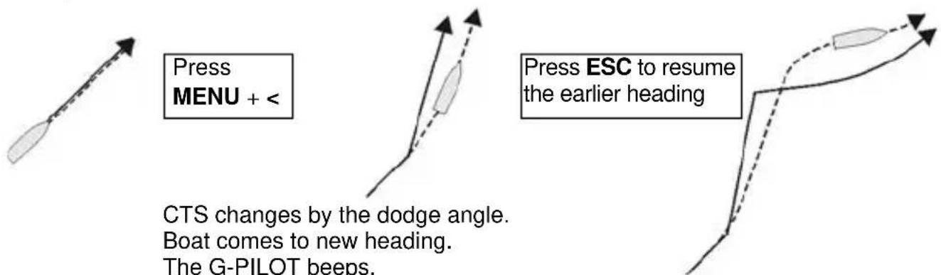
A dodge is a sharp change of course, usually to avoid an obstacle.
• press MENU + < to dodge to port by the dodge angle
• press MENU + > to dodge to starboard by the dodge angle.
For example:
text_image
Press MENU + < Press ESC to resume the earlier heading CTS changes by the dodge angle. Boat comes to new heading. The G-PILOT beeps.WARNING: The G-PILOT will steer back to the GPS plotted course. Make sure there are no obstacles or dangerous waters in the way.
Note
• To dodge further, press MENU + < or MENU + > more times.
• To view or change the dodge angle, go to DODGE ANG in the OPTIONS menu (see section 3-7).
6 Wind steering mode
The G-PILOT 3100 has three ways of steering the boat, compass, GPS and wind. To select an appropriate mode, see section 2-4. In wind mode, the G-PILOT steers the boat to a set angle to the wind, called SWA (set wind angle).
6-1 Wind steering data
text_image
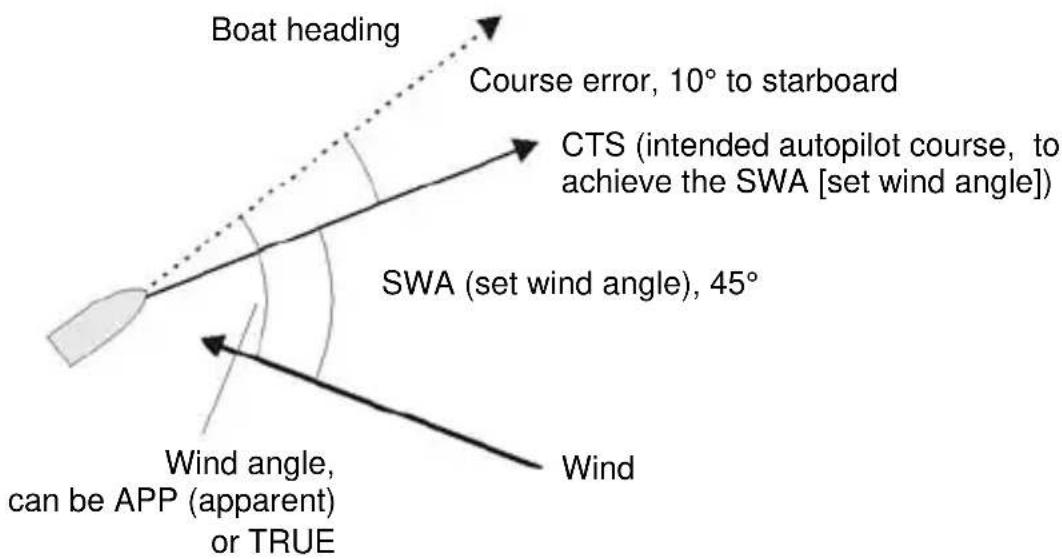
Boat heading Course error, 10° to starboard CTS (intended autopilot course, to achieve the SWA [set wind angle]) SWA (set wind angle), 45° Wind angle, can be APP (apparent) or TRUE Wind| APP | Apparent wind angle | The apparent wind angle at the boat. P in front of the angle means the wind is from port, S means that the wind is from starboard. |
| CTS | Course to steer | The course to steer to maintain the SWA (set wind angle). |
| Course error | The difference between APP (wind angle) and SWA (set wind angle). | |
| SWA | Set wind angle | The desired wind angle. |
| TRUE | True wind angle | The true wind angle at the boat. P in front of the angle means the wind is from port, S means that the wind is from starboard. |
True and apparent wind speed and direction
Apparent wind speed and direction are the values measured on the boat. True wind speed and direction are the values after allowing for boat speed through the air.
If the boat is moving, then the apparent wind speed is different to the true wind speed and the apparent wind direction is different to the true wind direction, as shown below.
Boat at rest
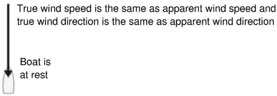
text_image
True wind speed is the same as apparent wind speed and true wind direction is the same as apparent wind direction Boat is at restBoat moving upwind Apparent wind speed is greater than true wind speed and apparent wind direction is closer to dead ahead than true wind direction
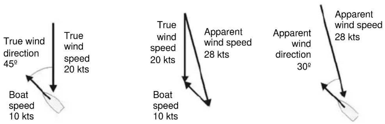
other
| Direction Type | Direction | Value Label | | -------------- | --------- | ----------- | | True | 45° | True wind speed | | True | 45° | 20 kts | | True | 45° | 10 kts | | Apparent | 20 kts | True wind speed | | Apparent | 20 kts | 20 kts | | Apparent | 20 kts | 10 kts | | Apparent | 28 kts | True wind speed | | Apparent | 28 kts | 28 kts | | Apparent | 30° | Apparent wind direction | | Apparent | 30° | 28 kts |Boat moving downwind Apparent wind speed is less than true wind speed and apparent wind direction is closer to dead ahead than true wind direction
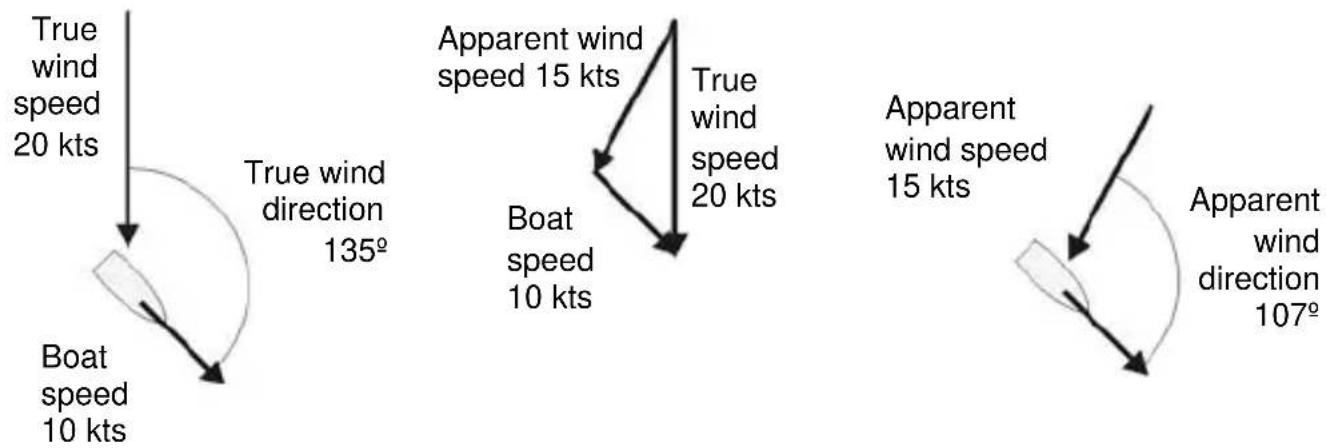
text_image
True wind speed 20 kts True wind direction 135° Boat speed 10 kts Apparent wind speed 15 kts Boat speed 10 kts True wind speed 20 kts Apparent wind speed 15 kts Apparent wind direction 107°6-2 Engaging the G-PILOT 3100 in wind mode
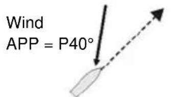
Manually steer the boat to open waters. Sail straight at the intended wind angle.
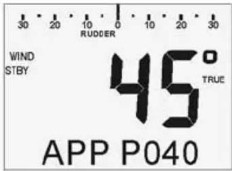
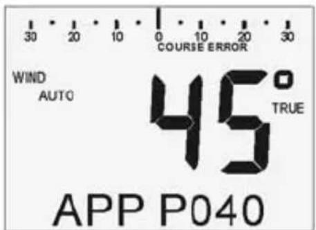
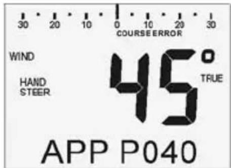
The G-PILOT info data can display TRUE (true wind angle) or APP (apparent wind angle) (see section 3-4).
For example:
text_image
Wind APP = P40°Heading = 45°
text_image
30 20 10 0 10 20 30 RUDDER WIND STBY 45° TRUE APP P040To engage AUTO, hold AUTO
To engage HAND STEER, hold AUTO + MENU
AUTO:
text_image
30 20 10 0 10 20 30 COURSE ERROR WIND AUTO 45° TRUE APP P040The G-PILOT steers the boat automatically.
HANDSTEER:
text_image
30 20 10 0 10 20 30 COURSE ERROR WIND HAND STEER 45° TRUE APP P040Steer the boat manually. Display CTS in the info data or course error in the bar data and use these to steer by.
Wind
$$ \mathrm{APP} = \mathrm{P} 4 0 ^ {\circ} $$
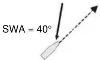
text_image
SWA = 40°The G-PILOT 3100 sets CTS (course to steer) to the current heading, in this example 45°, sets SWA (set wind angle) to the current wind angle and starts steering at this wind angle.
To disengage the G-PILOT, press AUTO
The G-PILOT returns to STBY (standby). Steer the boat manually.
The G-PILOT 3100 can also be engaged on the
starboard tack, for example:
or when running, for example:
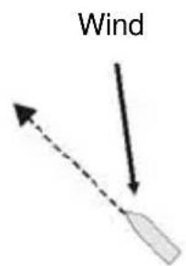
text_image
Wind$$ A P P = S 4 0 ^ {\circ} $$
$$ \mathrm{SWA} = 4 0 ^ {\circ} $$
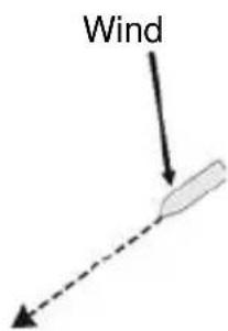
text_image
Wind$$ \mathrm{APP} = \mathrm{S} 1 2 0 ^ {\circ} $$
$$ \mathrm{SWA} = 1 2 0 ^ {\circ} $$
When the G-PILOT 3100 is engaged
Hold AUTO to change to Compass mode.
Wind or waves can push the boat so that the wind angle is different to SWA:
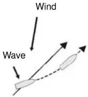
text_image
Wind WaveThe G-PILOT will steer the boat back to the SWA
Wind or currents can push the boat to one side of a straight course:
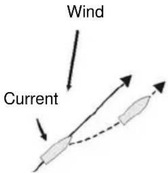
text_image
Wind CurrentThe G-PILOT will steer the boat at the set SWA
If the wind direction changes, the boat's heading will change to keep the set wind angle the same.
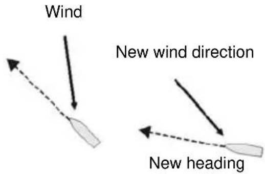
text_image
Wind New wind direction New headingThe wind alarm can be set to sound if the wind direction changes too far, go to WND ALARM in the ALARMS menu (see section 3-7).
6-3 Changing SWA (set wind angle) in wind mode
To change SWA in 1° steps:
• press < to change SWA by 1° to port
• press > to change SWA by 1° to starboard.
For example, on a port tack:

text_image
Wind Press <SWA = 40° SWA changes to 39°. Boat comes to new wind angle of 39°
or, on a starboard tack:
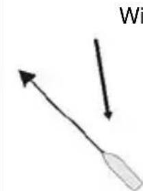
natural_image
Simple diagram showing two arrows pointing to a shaded elongated shape, labeled 'Wi' in the top right corner (no other text or symbols)SWA = 40°
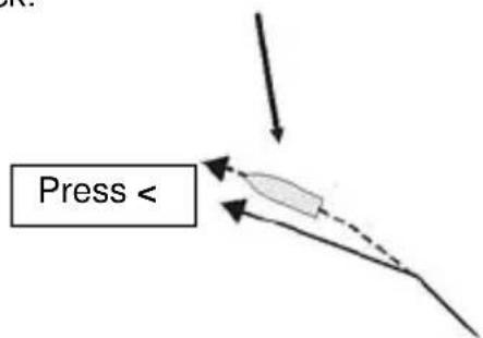
text_image
Press <SWA changes to 41°. Boat comes to new wind angle of 41°
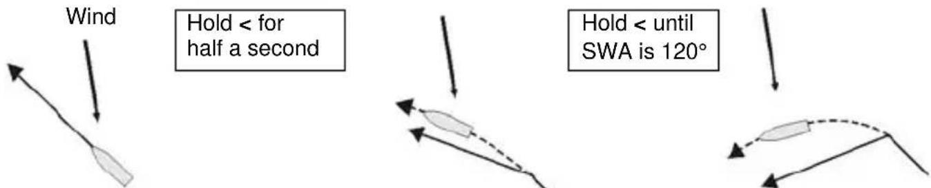
To change SWA in 10° steps:
• hold down < to change SWA by 10^ to port every half second
- hold down > to change SWA by 10^ to starboard every half second for example:
text_image
Wind Hold < for half a second Hold < until SWA is 120°SWA = 40° SWA changes to 50°. Boat comes to new wind angle of 50°
Boat comes to new wind angle of 120^
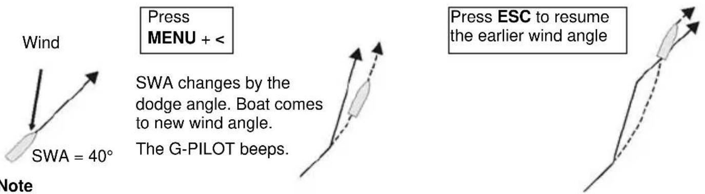
6-4 Dodging in wind mode
A dodge is a sharp change of course, usually to avoid an obstacle.
• press MENU + < to dodge to port by the dodge angle
• press MENU + > to dodge to starboard by the dodge angle.
For example:
text_image
Wind Press MENU + < SWA = 40° Note SWA changes by the dodge angle. Boat comes to new wind angle. The G-PILOT beeps. Press ESC to resume the earlier wind angleNote
• To dodge further, press MENU + < or MENU + > more times.
• To view or change the dodge angle, go to DODGE ANG in the OPTIONS menu (see section 3-7).
6-5 Auto tacking or gybing in wind mode
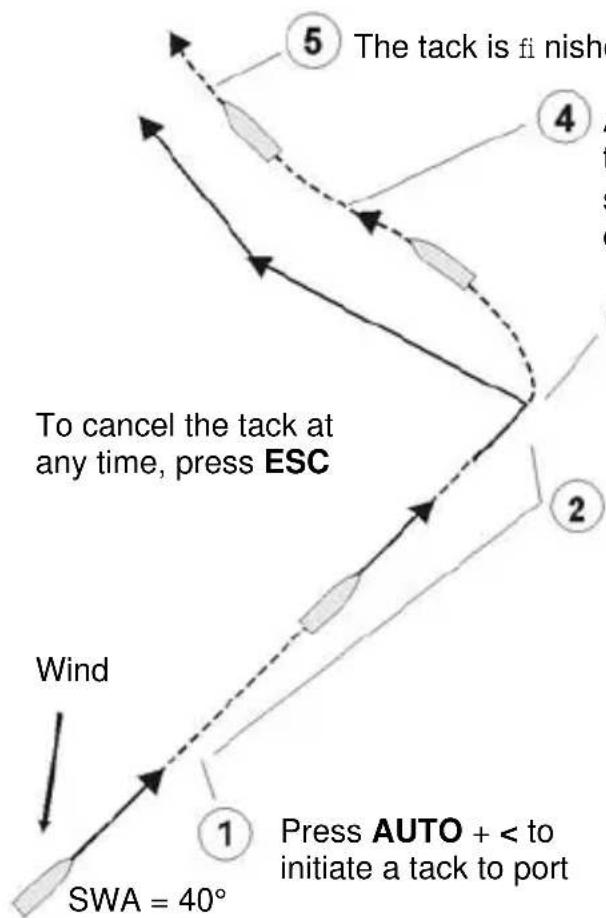
If SWA (set wind angle) is 90^ or less, the boat tacks, if SWA is more than 90^ the boat gybes. After the tack or gybe, SWA is the same as the SWA before the tack or gybe, but from the other side.
• press AUTO + < to tack or gybe to port
• press AUTO + > to tack or gybe to starboard
Example: SWA is 40^ , so the boat will tack, not gybe. If the tack angle is not set to AUTO, the boat changes direction twice, first by the tack angle and then so that SWA is the same as before the tack or gybe, but from the other side:
flowchart
graph TD
    A["1: Wind"] --> B["2: Takeoff"]
    B --> C["3: Takeoff"]
    C --> D["4: Launch to turn"]
    D --> E["5: Takeoff is finished"]
    style A fill:#f9f,stroke:#333
    style B fill:#ccf,stroke:#333
    style C fill:#cfc,stroke:#333
    style D fill:#fcc,stroke:#333
    note right of A: "To cancel the tack at any time, press ESC"
    note right of B: "Press AUTO + < to initiate a tack to port"
    note right of C: "SWA = 40°"
The tack is fi nished when the boat reaches the new wind angle
After the boat has reached the tack angle, the boat turns again so that the SWA (set wind angle) is the same as the SWA before the tack, but from the other side.
③ At the end of the tack delay, the course changes by the tack angle (in this example, the tack angle is not set to AUTO). The boat turns.
The boat sails straight while the G-PILOT 3100 counts down the tack delay.
The unit gives a long beep at 60 and 30 seconds to go, a short beep every second from 10 seconds to 1 second to go and a long beep that finishes when the countdown ends.
TACK <3
3 seconds to go until the tack starts
Example: SWA is 120^ , so the boat will gybe. The tack angle is not set to AUTO:
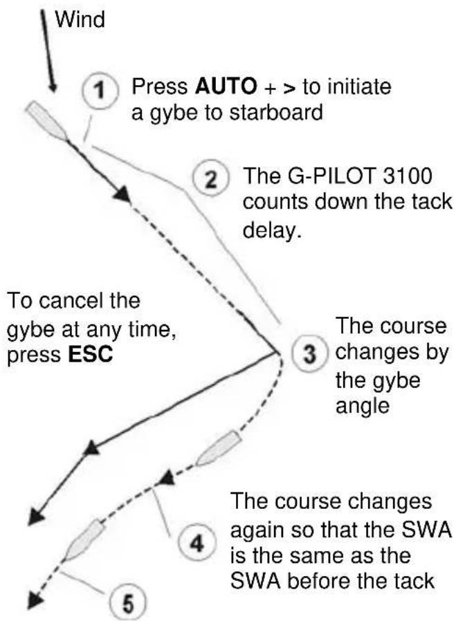
flowchart
graph TD
    A["Wind"] --> B["1 Press AUTO + > to initiate a gybe to starboard"]
    B --> C["2 The G-PILOT 3100 counts down the tack delay."]
    C --> D["3 The course changes by the gybe angle"]
    D --> E["4 The course changes again so that the SWA is the same as the SWA before the tack"]
    E --> F["5 To cancel the gybe at any time, press ESC"]
End of tack, boat is at new SWA
Example: SWA is 40^ . The tack angle is set to AUTO so the boat changes direction once:
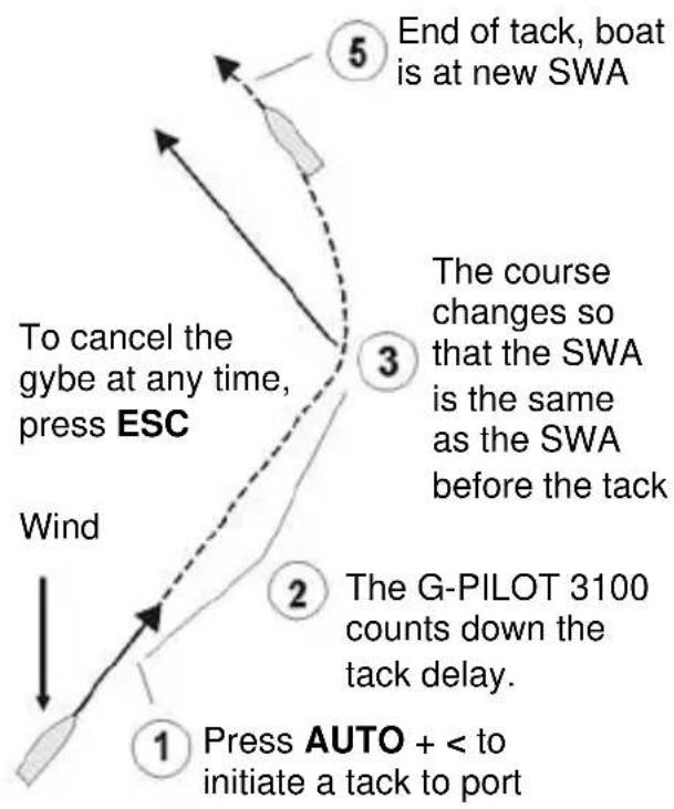
flowchart
graph TD
    A["Press AUTO + < to initiate a tack to port"] --> B["1"]
    B --> C["2"]
    C --> D["3"]
    D --> E["5"]
    E --> F["End of tack, boat is at new SWA"]
    style A fill:#f9f,stroke:#333
    style B fill:#f9f,stroke:#333
    style C fill:#f9f,stroke:#333
    style D fill:#f9f,stroke:#333
    style E fill:#f9f,stroke:#333
    style F fill:#f9f,stroke:#333
If SWA is more than 90^ and the gybe angle is set to AUTO then the boat will change direction once during a gybe, so that the SWA is the same as the SWA before the gybe.
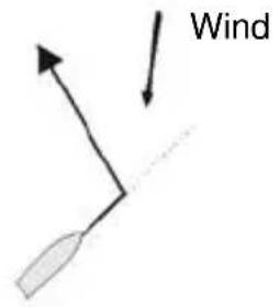
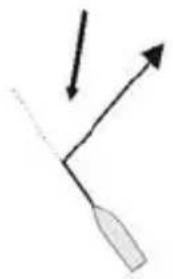
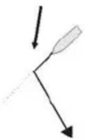
There are four possibilities for auto tacking or gybing:
Tack (SWA is 90° or less)
Gybe (SWA is more than 90°)
text_image
WindPress AUTO + < to tack to port
natural_image
Simple line drawing of a bent tool or tool with an arrow indicating direction (no text or symbols)Press AUTO + > to tack to starboard
natural_image
Simple diagram with two arrows pointing downward and an elongated shape inside, no text or symbols present.Press AUTO + < to gybe to port
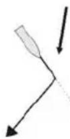
natural_image
Simple line drawing of a bent tool or tool with two arrows pointing downward (no text or symbols)Press AUTO + > to gybe to star-
TAK ERROR is displayed if you attempt other tacks or if the tack will end with the boat in irons.
Note
• To view or change the tack angle, gybe angle or tack delay, go to TACK ANG, GYBE ANG or TACK DELY in the OPTIONS menu (see section 3-7).
7 Optimizing steering performance
7-1 The steering parameters
The G-PILOT 3100 has six steering parameters which can be adjusted to optimize steering performance:
Response
How far the boat can move off course before the G-PILOT 3100 turns the rudder to correct the course. A lower response setting means the boat can move further off course before the G-PILOT 3100 corrects. To change, go to RESPONSE in the MAIN menu (see section 3-7). The range is 1 to 10, A1 to A5. A1 to A5 is an adaptive setting where the autopilot attempts to minimise the number of rudder corections while maintaining a desired course heading. The adaptive setting eliminates the need to set the response according to varying whether conditions. The range is A1 (slower adaption) to A5 (faster adaption).
Ratio
The rudder movement required to make a given course change. To change, go to RATIO in the MAIN menu (see section 3-7). The range is 1 (smaller corrections) to 10 (larger corrections).
Counter rudder gain
Determines how the rudder moves after making a large course change. To change, go to C-RD GAIN in the OPTIONS menu (see section 3-7). The range is 1 (low) to 10 (high) and OFF (no counter rudder gain).
Trim gain
If the boat encounters a sideways current or wind, then the boat will move off course sideways. The G-PILOT 3100 will automatically bring the boat back to the correct heading by applying a few degrees of rudder, called trim. Trim gain sets how quickly the trim is applied. To change, go to TRIM GAIN in the OPTIONS menu (see section 3-7).
GPS gain
The range is 1 (low) to 10 (high) and OFF (no counter trim gain). In GPS mode, this determines how much correction is applied to remove cross track error. To change, go to GPS GAIN in the OPTIONS menu (see section 3-7). The range is 1 to 10.
In wind mode, this determines how much correction is applied to reduce any difference between the set wind angle and the actual wind angle. To change, go to WIND GAIN in the OPTIONS menu (see section 3-7). The range is 1 to 10.
Optimum steering
Ideally, in AUTO or HANDSTEER the G-PILOT 3100 should steer the boat to the course without the rudder moving too often.

Optimum performance
The steering parameters are adjusted correctly
Tip When checking the steering performance of the boat, display course error on the bar data display (see section 3-3) and check how this changes with time.
7-2 Profi les
The values of the steering parameters required for optimum steering may vary with boat speed, sea conditions or wind conditions. Generally:
• for higher boat speeds, decrease ratio; for lower speeds increase ratio.
• for calm seas, increase response; for rough seas decrease response.
• for higher and/or more stable winds, increase wind gain; for lower and/or unstable winds, decrease wind gain.
To simplify changing the parameters when conditions change, the G-PILOT stores five sets of the steering parameters. Each set is called a profile and the profiles are numbered 1 to 5. To select a profile to use, go to PROFILE in the MAIN menu (see section 3-7).
1 When the G-PILOT is installed, the steering parameters in all the profiles are set to their default values.
2 Select profile 1 and adjust the steering parameters for optimum steering in typical conditions (see section 7-3).
3 If the conditions change and the steering is no longer optimum, select another profile and adjust the steering parameters again. Repeat this step as required to adjust the parameters in each profile.
4 When using the G-PILOT to steer, select a profile suitable for the current conditions. For example different profiles can be configured for rough conditions and calm conditions.
7-3 Adjusting the steering parameters
Problem: rudder turns too frequently

This causes wear on the steering linkage and uses power.
Decrease response.
Reduce ratio.
Reduce counter rudder gain.
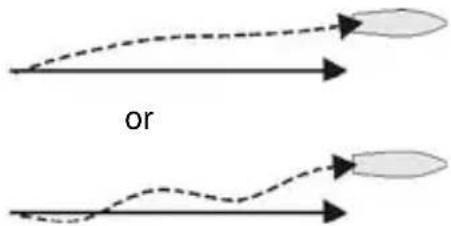
Problem: drifts off course to one side
flowchart
graph TD
    A["Start"] --> B{dashed arrow}
    B --> C["Arrow to top"]
    D["Start"] --> E{dashed arrow}
    E --> F["Arrow to bottom"]
    G["Start"] --> H{dashed arrow}
    H --> I["Arrow to right"]
Increase ratio.
Increase trim gain.
Increase response.
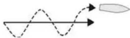
Problem: boat moves too far off course closely before the rudder turns to correct the course
natural_image
Simple diagram showing a sine wave with an arrow indicating direction and a separate elongated shape (no text or symbols)Decrease ratio.
Decrease counter rudder gain.
Decrease trim gain.
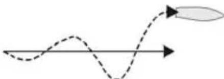
Problem: oscillations from side to side build up
natural_image
Simple diagram showing a dashed wavy line with an arrow pointing right, no text or symbols presentDecrease ratio.
Problem: after a large course change, boat overshoots and oscillates before settling to new course
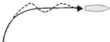
natural_image
Simple line drawing of a rocket launching with a curved trajectory and dashed motion path (no text or symbols)Increase counter rudder gain
Problem: after a large course change, boat takes too long to settle to new course

natural_image
Simple curved arrow diagram pointing right, no text or symbols presentDecrease counter rudder gain
Problem: after a sideways current or wind, the correction is applied too quickly or too slowly
If the boat encounters a sideways force, then it will move off course sideways. The G-PILOT will automatically bring the boat back to the correct heading by applying a few degrees of rudder, called trim. Trim gain sets how quickly the trim is applied. Trim gain should be adjusted to trim the boat in about one minute. Getting the Trim gain setting right can be difficult for your specific boat and it is easy to alter the Trim gain too much. Change the settings slowly and conservatively at first, until the right settings are known.
a Boat takes much more than one minute to trim
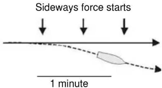
text_image
Sideways force starts 1 minuteIncrease trim gain
b Boat takes much less than one minute to trim
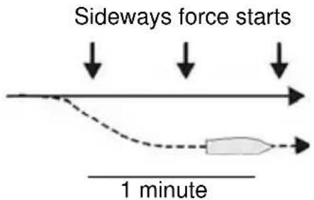
text_image
Sideways force starts 1 minuteDecrease trim gain
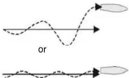
Problem: drifts off GPS course
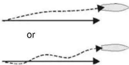
text_image
orIncrease GPS gain.
Problem: boat oscillated around GPS course
text_image
orDecrease GPS gain.
Appendix A - Specifications
Electrical
• Heavy duty power supply 10.5 to 16.5 V DC, 20 A maximum
• Light duty power supply 10.5 to 16.5 V DC:
• Main unit: 80 mA.
- Each display unit, 30 mA without backlighting, 110 mA with full backlighting.
- Other optional instruments: refer to the instrument's operation manual.
Interfaces
• NavBus connection to other Navman instruments.
• NMEA 0183 outputs: HDG, HDT, RSA; inputs APA, APB, BOD, BWC, MWD, MWV, RMA, RMB, RMC, VHW, VTG, XTE
• NMEA 0183 ports:
NMEA 1: Input
NMEA 2: Can be programmed to be an input or output
Standards compliance
• EMC compliance
USA (FCC): Part 15 Class B.
Europe (CE): EN50081-1, EN50082-1
New Zealand and Australia (C Tick): AS-NZS 3548.
- Environment:
Compass, gyro, rudder feedback unit: completely waterproof.
Display unit: IP66 from front when correctly mounted.
Main unit: requires a cool, dry, clean environment.
Main unit terminal block connections:
| Terminal Signal | |
| 1 | Heavy duty power positive, 10.5 to 16.5 V DC, 20 A maximum |
| 2 | Heavy duty power negative |
| 3 | Steering drive negative output |
| 4 | Steering drive positive output |
Main unit connector connections:
| Terminal | Signal |
| 1 | Light duty power positive, 10.5 to 16.5 V DC, 80 mA maximum |
| 2 | Light duty power supply common |
| 3 | NavBus + |
| 4 | NavBus - |
| 5 | NMEA common |
| 6 | NMEA in 1 |
| 7 | NMEA in 2 |
| 8 | Steering clutch relay drive output, switched ground to turn relay on, 30 V DC, 300 mA maximum |
Display unit power/data cable wires:
| Wire | Signal |
| Red | Power positive, 10.5 to 16.5 V DC, 30 mA without backlighting, 110 mA with full backlighting |
| Black | Power negative |
| Orange | NavBus + |
| Blue | NavBus - |
| Yellow | Factory use (isolate, do not cut) |
| White | Factory use (isolate, do not cut) |
| Green | External alarm, switched to ground, 30 V DC and 250 mA max. |
Appendix B - Alarm and warning messages
| Alarm display | Reason for message | Recommended action by user | Notes |
| BAT ALARM | Battery voltage is less than the minimum value set by the user | Check batteriesDisengage G-PILOT if voltage too low | a |
| CAL ERROR | The G-PILOT rudder feedback unit or compass unit is not calibrated | Calibrate both the units(see sections 5-2 and 6-1) | a |
| CCH ERROR | The clutch current is to high | Check clutch connection | a s |
| CE ALARM | Course error has exceeded the maximum value set by the user | Manually steer boat towards course | a |
| CSU ERROR | Compass not sending data to main unit | Check compass is connected to main unit; Service compass | a s |
| CUR ALARM | The motor current exceeded the maximum value set by the user | Check steering drive is not jammedIncrease the alarm value | a s |
| DRV ERROR | Rudder angle does not change when steering drive operates | Check drive power is turned on a s Check RFU is connected to rudder Check fuses inside end of main control unit Check steering drive operation | |
| GPS ERROR | GPS has stopped sending data to main unit | Check GPS operation a c s Check GPS connection | |
| GSU ERROR | Gyro not sending data to main unit | Check gyro is connected to a s main unit; Service gyro | |
| MCU ERROR | Main unit not sending data to display unit | Check display unit is connected to a s main unit Service main unit or display unit | |
| NAV ERROR | GPS is not navigating to a waypoint when trying to engage G-PILOT | Start GPS navigating to a waypointm or along a route | |
| NEXT WPT? | Boat has reached a waypoint (in GPS mode and WPT AKN is on) | Press any key to proceed to cancel alarm Then press ENT to start steering to the next waypoint or press ESC to return to | |
| STBY NO DATA | G-PILOT not receiving GPS data when setting mode to GPS | Check GPS operation m Check GPS connection | |
| or | G-PILOT not receiving wind instrument data when setting mode to wind | Check wind instrument operation m Check wind instrument connection | |
| NVM ERROR | Main unit memory has been corrupted | Service main unit a s | |
| PHA ERROR | Rudder turns wrong way to rudder feedback unit | Check the rudder feedback unit a s Perform a rudder calibration | |
| RFU ERROR | Rudder feedback unit has stopped sending data to main unit | Check rudder feedback unit is a s connected to main unit Service rudder feedback unit | |
| ROUTE END | Boat has reached the end of a GPS route | Press ESC to change to STBY or press ENT to change to compass mode, sailing at current heading | |
| TRK ERROR | G-PILOT has changed to GPS mode but boat is too far off course | Press ESC to return to STBY or press ENT to have the G-PILOT steer the boat to the correct course. | |
| TAK ERROR | In Wind mode, attempt to tack in the wrong way or boat will be in irons | Change angle to wind m | |
| WND ALARM | The wind angle has changed by more than the alarm value | Change SWA a Change to Compass mode | |
| WND ERROR | Wind instrument has stopped sending data to main unit | Check wind instrument operation a c s Check wind instrument connection | |
| XTE ALARM | XTE has exceeded the maximum value set by the user | Manually steer boat towards course a | |
| Notes a | Alarm sounds the internal and external (optional) beepers; press any key to mute alarm, then press ESC to cacel the alarm message | ||
| c | The G-PILOT 3100 changes to Compass mode | ||
| m | The G-PILOT 3100 mode does ot change | ||
| s | The G-PILOT 3100 changes to STBY | ||
Appendix C - Troubleshooting
This troubleshooting guide assumes that you have read and understood this manual.
It is possible in many cases to solve difficulties without having to send the unit back to the manufacturer for repair. Please follow this troubleshooting section before contacting the nearest Navman dealer.
There are no user serviceable parts. Specialized methods and testing equipment are required to ensure that the unit is reassembled correctly. Repairs to the unit must only be carried out by a service centre approved by Navman NZ Limited. Users who service the unit themselves will void the warranty. More information can be found on our Website: www.navman.com.
1 Unit will not turn on:
a Fuse blown or circuit breaker tripped.
b Battery voltage is outside the range 10.5 to 16.5 V DC.
c Power/data cable damaged.
2 G-PILOT 3100 makes too frequent course corrections:
• The value of response is too low (see G-PILOT 3100 Operation Manual).
3 When sailing a straight course, the boat drifts from side to side of the course:
a The boat should drift from side to side of the course when the G-PILOT 3100 steering is optimized.
b Change to a profi le suitable for boat speed and sea conditions (see G-PILOT 3100 Operation Manual).
c If the boat drifts too far from the course, adjust response, ratio, counter rudder gain, GPS gain (if G-PILOT is in GPS mode) or wind gain (if G-PILOT is in wind mode) (see G-PILOT 3100 Operation Manual).
4 When sailing a straight course, the boat drifts off course:
a Change to a profi le suitable for boat speed and sea conditions (see G-PILOT 3100 Operation Manual).
b Adjust response, ratio, counter rudder gain, GPS gain (if G-PILOT is in GPS mode) or wind gain (if G-PILOT is in wind mode) (see G-PILOT 3100 Operation Manual).
5 When making a large course change, boat does not follow the expected course:
a Change to a profi le suitable for boat speed and sea conditions (see G-PILOT 3100 Operation Manual).
b Check turn rate is not too low (go to TURN RATE in the OPTIONS menu, see G-PILOT 3100 Operation Manual).
c Adjust counter rudder gain (see G-PILOT 3100 Operation Manual).
6 Boat turns too sharply:
- Reduce turn rate (go to TURN RATE in the OPTIONS menu, see G-PILOT 3100 Operation Manual).
7 The word SIMULATE flashes on the display, values displayed are unexpected:
• Unit is in simulate mode (See G-PILOT 3100 Operation Manual).
8 The display fogs:
a Moist air has entered the breathing tube at the rear of the unit. Air the boat or run unit with backlight fully on.
b Water has entered the breathing tube. Return unit for service.
Appendix D - How to contact us
www.navman.com
NORTH AMERICA
Navman USA Inc.
30 Sudbury Rd, Acton, MA 01720.
Toll Free: +1 866 628 6261
Fax: +1 978 897 8264
e-mail: sales@navmanusa.com
web:www.navman.com
AUSTRALIA
Navman Australia Pty. Limited
Unit 2 / 5-13 Parsons St.
Rozelle, NSW 2039, Australia.
Ph: +61 2 9818 8382
Fax: +61 2 9818 8386
e-mail: sales@navman.com.au
web: www.navman.com
OCEANIA
New Zealand
Absolute Marine Ltd.
Unit B, 138 Harris Road,
East Tamaki, Auckland.
Ph: +64 9 273 9273
Fax: +64 9 273 9099
e-mail: navman@absolutemarine.co.nz
Papua New Guinea
Lohberger Engineering,
Lawes Road, Konedobu.
PO Box 810, Port Moresby.
Ph: +675 321 2122
Fax: +675 321 2704
e-mail: loheng@online.net.pg
web: www.lohberger.com.pg
SOUTH AMERICA
Argentina
Costanera Uno S.A.
purchase@costanerauno.com.ar
web: www.costanerauno.ar
Brazil
Peaceful Marine Electronics Co. Ltd.
Guangzhou, Hong Kong, Dalian,
Qingdao, Shanghai
1701 Yanjiang Building
195 Yan Jiang Zhong Rd. 510115
Guangzhou, China.
Ph: +86 20 3869 8839
Fax: +86 20 3869 8780
e-mail: sales@peaceful-marine.com
web: www.peaceful-marine.com
India
Access India Overseas Pvt. Ltd.
A-98, Sector 21,
Noida - 201 301, India.
Ph: +91 120 244 2697
TeleFax: +91 120 253 7881
Mobile: +91 98115 04557
e-mail: vkapil@del3.vsnl.net.in
Esmario Export Enterprises
Block No. F-1, 3rd Floor, Surya Towers
Sardar Patel Rd, Secunderbad 500 003.
Ph: +91 40 2784 5163
Fax: +91 40 2784 0595
e-mail: gjfeee@hdl.vsnl.net.in
web: www.esmario.com
Indonesia
Polytech Nusantara,
Graha Paramita 2nd Floor,
Kumhomarine Technology Co. Ltd.
604-842, 2F, 1118-15, Janglim1-Dong,
Saha-Gu, Busan, Korea.
Ph: +82 51 293 8589
Fax: +82 51 265 8984
e-mail: info@kumhomarine.com
web: www.kumhomarine.com
Maldives
Maizan Electronics Pte. Ltd.
Henveyru, 08 Sosunmagu.
Male', Maldives.
Mobile: +960 78 24 44
Ph: +960 32 32 11
Fax: +960 32 57 07
e-mail: ahmed@maizan.com.mv
Singapore, Malaysia, Brunei,
Indonesia and Philippines
RIQ PTE Ltd.
Blk 3007, 81 Ubi Road 1, #02-440,
Singapore 408701.
Ph: +65 6741 3723
Fax: +65 6741 3746
e-mail: riq@postone.com
Taiwan
Seafirst International Corporation
No. 281, Hou-An Road, Chien-Chen
Dist. Kaohsiung, Taiwan R.O.C.
Ph: +886 7 831 2688
Fax: +886 7 831 5001
e-mail: seafirst@seed.net.tw
web: www.seafirst.com.tw
Thailand
Thong Electronics (Thailand) Co. Ltd.
923/588 Ta Prong Road, Mahachai,
Muang, Samutsakhon 74000, Thailand.
Ph: +66 34 411 919
Fax: +66 34 422 919
e-mail: sales@thongelectronics.com
admins@thongelectronics.com
web: www.thongelectronics.com
Vietnam
Haidang Co. Ltd.
1763 Le Hong Phong St. Ward 12
District 10, Ho Chi Minh City.
Ph: +84 8 863 2159
Fax: +84 8 863 2124
e-mail: sales@haidangvn.com
web: www.haidangvn.com
MIDDLE EAST
Lebanon and Syria
Balco Stores
Balco Building, Moutran Street,
Tripoli (via Beirut). - Lebanon
P.O. Box: 622.
Ph: +961 6 624 512
Fax: +961 6 628 211
e-mail: balco@cyberia.net.lb
United Arab Emirates
Kuwait, Oman, Iran, Saudi
Arabia, Bahrain & Qatar
Abdullah Moh'd Ibrahim Trading, opp
Creak Rd. Baniyas Road, Dubai.
Ph: +971 4 229 1195
Fax: +971 4 229 1198
e-mail: sales@amitdubai.com
AFRICA
South Africa
Pertec (Pty) Ltd (Coastal Division)
16 Paarden Eiland Road.
Paarden Eiland, 7405
PO Box 527,
Paarden Eiland, 7420
Cape Town, South Africa.
Ph: +27 21 508 4707
Fax: +27 21 508 4888
e-mail: info@kfa.co.za
web: www.pertec.co.za
EUROPE
France, Belgium and Switzerland
Plastimo SA
Hamilton Business Park
Bailey Road, Hedge End
Southhampton, Hants S030 2HE.
Ph: +44 01489 778 850
Fax: +44 0870 751 1950
e-mail: sales@plastimo.co.uk
web: www.plastimo.co.uk
Sweden, Denmark, Finland and
Norway
Navimo Nordic
Lundenvägen 2,
473 21 Henân.
Ph: +46 304 360 60
Fax: +46 304 307 43
e-mail: info@plastimo.se
web: www.plastimo.se
Spain
Navimo España
Avenida Narcís Monturiol, 17
08339 Vilassar de Dalt,
Barcelona.
Ph: +34 93 750 75 04
Fax: +34 93 750 75 34
e-mail: plastimo@plastimo.es
web: www.plastimo.es
Portugal
Navimo Portugal
Other countries in Europe
Plastimo International
56325 Lorient Cedex, France.
Ph: +33 2 97 87 36 59
Fax: +33 2 97 87 36 29
e-mail:
plastimo.international@plastimo.fr
web: www.plastimo.com
REST OF WORLD/
MANUFACTURERS
Navman NZ Limited
13-17 Kawana St.
Northcote.
P.O. Box 68 155,
Newton,
Auckland,
New Zealand.
Ph: +64 9 481 0500
Fax: +64 9 481 0590
e-mail: marine.sales@navman.com
web: www.navman.com
Made in New Zealand MN0000213E
geo
| Longitude | Latitude | | --------- | -------- | | 250 | 250 | | 240 | 240 | | 230 | 230 | | 220 | 220 | | 210 | 210 | | 200 | 200 | | 190 | 190 | | 180 | 180 | | 170 | 170 | | 160 | 160 | | 150 | 150 | | 140 | 140 | | 130 | 130 | | 120 | 120 | | 110 | 110 | | 100 | 100 | | 90 | 90 | | 80 | 80 | | 70 | 70 | | 60 | 60 | | 50 | 50 | | 40 | 40 | | 30 | 30 | | 20 | 20 | | 10 | 10 | | 0 | 0 |NAVMAN