
GLS (2021) - Automotive Mercedes-Benz - Free user manual and instructions
Find the device manual for free GLS (2021) Mercedes-Benz in PDF.


User questions about GLS (2021) Mercedes-Benz
0 question about this device. Answer the ones you know or ask your own.
Ask a new question about this device
Download the instructions for your Automotive in PDF format for free! Find your manual GLS (2021) - Mercedes-Benz and take your electronic device back in hand. On this page are published all the documents necessary for the use of your device. GLS (2021) by Mercedes-Benz.
USER MANUAL GLS (2021) Mercedes-Benz
The following version of the Owner's Manual describes all models, series and special equipment of your vehicle. Country-specific language variations are possible. Please note that your vehicle might not be equipped with all the described functions. This also affects safety-relevant systems and functions. Please contact your authorised Mercedes-Benz dealership if you would like to receive a printed Owner's Manual for other vehicle models and vehicle model years.
The online Owner's Manual is the current and valid version. It is possible that deviations affecting your specific vehicle could not be taken into account as Mercedes-Benz constantly adapts its vehicles according to the latest technology and makes changes to the form and the equipment.
Please also read the printed Owner's Manual, supplementary documents and the digital Owner's Manual in the vehicle.
Copyright
All rights reserved. All texts, images and graphics are subject to copyright and other laws for the protection of intellectual property. They may not be copied or changed for any commercial use or for the purpose of being passed on nor used on other webistes.
natural_image
Green Mercedes-Benz SUV driving on a winding road beside a river, surrounded by forested hills (no visible text or symbols)GLS
Owner's Manual
Mercedes-Benz

Front passenger airbag warning

AIRBAG

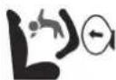


WARNING Risk of injury or death if the co-driver airbag is enabled
If the co-driver airbag is enabled, a child on the co-driver seat may be struck by the co-driver airbag during an accident.
NEVER use a rearward-facing child restraint system on a seat with an ENABLED FRONT AIRBAG; DEATH or SERIOUS INJURY to the CHILD can occur.
Observe the chapter "Children in the vehicle".
Thank you for buying Mercedes-Benz
Before you first drive off, read this Owner's Manual carefully and familiarise yourself with your vehicle. For your own safety and a longer operating lifespan of the vehicle, follow the instructions and warning notices in this Owner's Manual. Disregarding them may lead to damage to the vehicle or injury to people.
The standard equipment and product description of your vehicle may vary and depends on the following factors:
- Model
- Order
- National version
- Availability
The illustrations in this Owner's Manual show left-hand drive vehicle. On right-hand-drive vehicles, the layout of car parts and control elements differs accordingly.
Mercedes-Benz is constantly developing its vehicles further.
Mercedes-Benz therefore reserves the right to introduce changes in the following areas:
- Design
- Equipment
• Technical features
The equipment in your vehicle may therefore differ from that shown in the descriptions and illustrations.
The following documents are integral parts of the vehicle:
• Digital Owner's Manual
• Printed Owner's Manual
• Service booklet
• Equipment-dependent Supplements
a Keep these documents in the vehicle at all times. If you sell the vehicle, always pass all of the documents on to the new owner.
Symbols 5
At a glance 6
Cockpit 6
Indicator and warning lamps 10
Overhead control panel 12
Door operating unit and seat adjustment .....
Control settings in the rear passenger
compartment 16
Emergencies and breakdowns 18
Digital Owner's Manual 20
Calling up the Digital Owner's Manual 20
General notes 22
Protection of the environment 22
Take-back of end-of-life vehicles 22
Mercedes-Benz GenuineParts 23
Owner's Manual 24
Operating safety 24
Declaration of conformity 26
Diagnostics connection 31
Qualified specialist workshop 33
Vehicle registration 33
Correct use of the vehicle 33
Information on the REACH regulation ...... 33
Notes for persons with electronic medi-
cal aids 34
Implied warranty 34
QR code for rescue card 35
Data storage 35
*Copyright 38
Occupant safety 39
Restraint system 39
Seat belts 4
Airbags 45
PRE-SAFE ^® system 53
Automatic measures after an accident ..... 54
Safely transporting children in the vehi-
cle 5
Notes on pets in the vehicle 78
Opening and closing 79
Key 79
Doors 82
Running boards 87
Load compartment 8 8
Side windows 94
Sliding sunroof 98
Roller sunblinds 103
Anti-theft protection 104
Seats and stowing 107
Notes on the correct driver's seat posi-
tion 107
Seats 107
Steering wheel 126
Easy entry and exit feature 128
Memory function 129
Memory function in the rear compartment 1 30
Stowage areas 134
Cup holders 149
Sockets 150
Coolbox 153
Wireless charging of the mobile phone
and connection with the exterior aerial ..... 154
Fitting/removing the floor mats 157
Light and sight 159
Exterior lighting 159
Interior lighting 1
Windscreen wipers and windscreen
washer system 168
Mirrors 173
Area permeable to radio waves on the
windscreen 1 7
Infrared-reflective windscreen function ..... 176
Climate control 177
Overview of climate control systems ..... 177
Operating the climate control system ..... 178
Driving and parking 190
Driving 190
DYNAMIC SELECT switch 205
Automatic transmission 209
Transfer case 213
Function of the 4MATIC 215
Refuelling 215
Parking 222
Driving and driving safety systems 229
Trailer hitch 301
Bicycle rack function 306
Vehicle towing instructions 308
Instrument display and on-board
computer 310
Notes on the instrument display and on-board computer 310
Instrument display overview 311
Overview of the buttons on the steering wheel 3
Operating the on-board computer 312
Overview of what is shown on the multi-function display 3
Head-up display 314
MBUX multimedia system 317
Overview and operation 317
System settings 326
Navigation 330
Telephone 339
Mercedes me and apps 342
Mercedes-Benz emergency call system ..... 351
Radio, media & TV 359
Sound settings 365
Maintenance and care 367
ASSYST PLUS service interval display ..... 367
Engine compartment 368
Cleaning and care 374
Breakdown assistance 383
Emergency 383
Flat tyre 385
Battery (vehicle) 391
Tow-starting or towing away 397
Electrical fuses 401
Wheels and tyres 405
Notes on noise or unusual handling characteristics 40 5
Notes on regularly inspecting wheels and tyres 40
Notes on snow chains 405
Tyre pressure 406
Wheel change 409
Emergency spare wheel 420
Collapsible spare wheel 422
Technical data 425
Notes on technical data 425
On-board electronics 425
Regulatory radio identification of small components 4 2 7
Vehicle identification plate, VIN and engine number overview 427
Operating fluids 429
Vehicle data 438
Trailer hitch 441
Display messages and warning/indicator lamps 445 Display messages 445 Warning and indicator lamps 507
Index 522
In this Owner's Manual, you will find the following symbols:

DANGER Danger due to not observing the warning notices
Warning notices draw your attention to hazards that may endanger your health or life, or the health or life of others.
▶ Observe the warning notices.

ENVIRONMENTAL NOTE Environmental damage due to failure to observe environmental notes
Environmental notes include information on environmentally responsible behaviour or environmentally responsible disposal.
▶ Observe environmental notes.

NOTE Damage to property due to failure to observe notes on material damage
Notes on material damage inform you of risks which may lead to your vehicle being damaged.
▶ Observe notes on material damage.
These symbols indicate useful instructions or further information that could be helpful to you.
Instruction
(→ page) Further information on a topic
Display Information on the multifunction display/media display
Highest menu level, which is to be selected in the multimedia system
Relevant submenus, which are to be selected in the multimedia system
* I indicates a cause
text_image
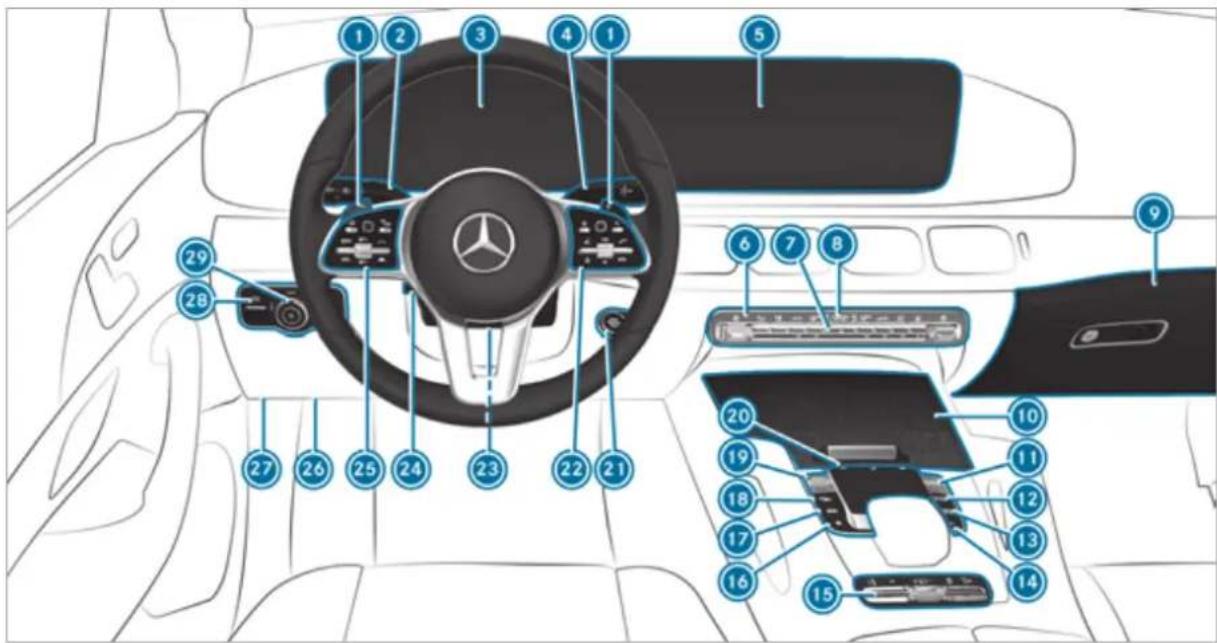
Diagram of a car interior with numbered parts for identification and assembly, highlighting the steering wheel and internal components.Left-hand-drive vehicles
① Steering wheel gearshift paddles → 211
② Combination switch → 161
Instrument display → 311
4 DIRECT SELECT lever → 209
5 Media display → 317
Climate control systems → 178
7 Hazard warning light system → 161
8 PASSENGER AIR BAG indicator lamps → 50
Glove compartment → 137
10 Stowage compartment → 137
Controller for volume and switching sound on/off → 317
Switches the MBUX multimedia system → 317 on/off
12 NAVI
MAP Calls up navigation → 319
13 RADIO MEDIA Calls up radio or media → 319
14 TEL Calls up the telephone → 319
15 Switch panel for:
Individual wheel control (vehicles with→ 277 out off-road package) or
LOW RANGE Transfer case (vehicles with off-road package) → 213
M Manual gearshifting → 211
AIRMATIC or → 267
E-ACTIVE BODY CONTROL → 274
Activating/deactivating ESP → 232
Downhill Speed Regulation → 248
16 ★ Calls up favourites → 319
17 Calls up vehicle functions → 319
18 Active Parking Assist → 295
19 DYNAMIC SELECT switch → 207
20 Touchpad → 319
21 Start/stop button → 191
(A) ECO start/stop function → 202
22 Control panel for the MBUX multimedia system → 312
23 Adjusts the steering wheel manually → 126
24 Adjusts the steering wheel electrically → 127

on/off
Switches the steering wheel heater → 128
Control panel:
On-board computer → 312
Cruise control or variable limiter → 239
Active Distance Assist DISTRONIC → 244
26 Diagnostics connection → 31
27 Opens the bonnet → 368
28 (P) Electric parking brake → 225
29 Light switch → 159
text_image
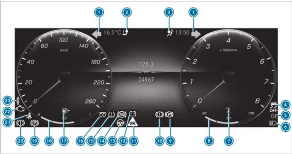
16.5°C 13:50 125.3 24967 x 1000/min 23 22 21 20 19 18 17 16 15 14 13 12 11 10 9 8 7 OFF 0$ 6Instrument display
Turn signal lights → 161
2 Trailer hitch → 509
③ Restraint system → 508
4 ESP OFF → 518
ESP ^® → 518
5 0‡ Rear fog light → 160
6 High beam → 161
Low beam → 159
00≤ Standing lights → 159
7 Coolant temperature → 511
8 Coolant temperature display → 311
9 Electric parking brake (yellow) → 514
10 (1) Brakes (yellow) → 514
11 Distance warning → 516
12 Electrical fault → 511
13 Power steering → 509
14 ABS → 518
15 Tyre pressure monitoring system → 520
16 700 Diesel engine: preglow
17 Reserve fuel with fuel filler flap location → 511 indicator
18 Fuel level → 311
19 (P) Electric parking brake (red) → 514
20 (1) Brakes (red) → 514
21 Seat belt → 508
Engine diagnostics → 511
23 Suspension (red) → 516
Suspension (yellow) → 516
text_image
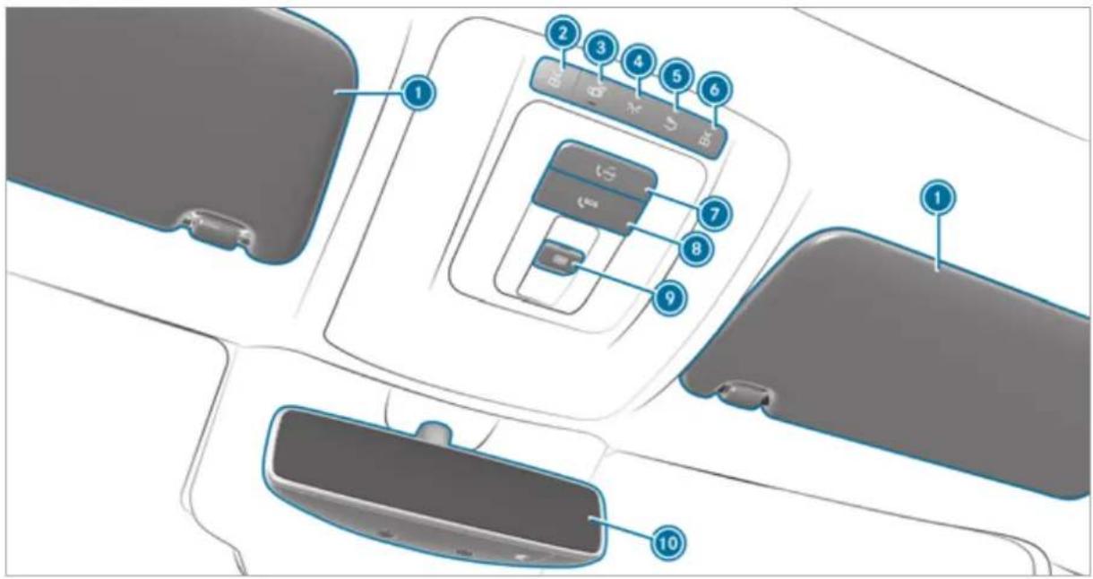
Diagram of car interior compartments with numbered labels pointing to specific areas such as keyboard, phone, and rear seats.Sun visors
2 Switches the left-hand reading lamp on/off → 166
3 Switches automatic interior lighting control on/off → 166
4 Switches the front interior lighting → 166 on/off
5 Switches the rear interior lighting → 166 on/off
6 Switches the right-hand reading lamp → 166
on/off
me button → 344
8 SOS SOS button → 344
9 Opens/closes the panorama sliding → 98 sunroof
Opens/closes the roller sunblind → 98
10 Inside rearview mirror → 174
At a glance - Door operating unit and seat adjustment
text_image
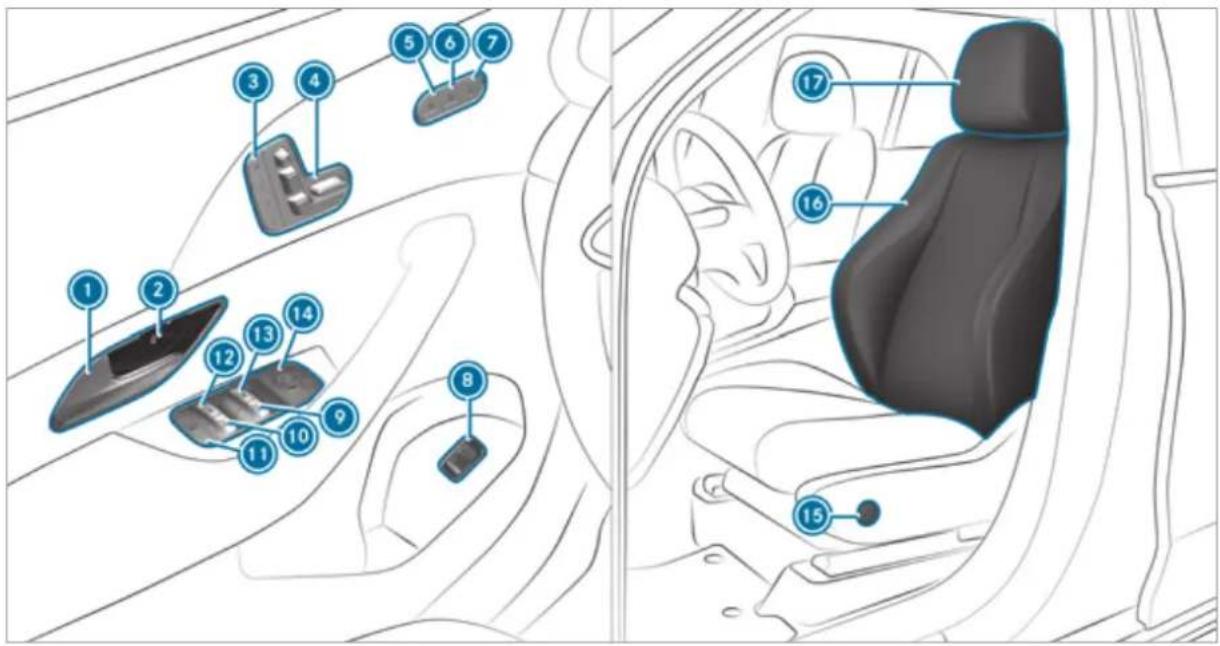
Diagram of car interior with numbered car compartments and seat labels① Opens the door → 83
Locks/unlocks the vehicle → 83
3 M Sets the memory function → 130
4 Adjusts the seats electrically → 107
5 Switches the seat heating on/off → 124
6 Switches the seat ventilation on/off → 125
Adjusts the front passenger seat from the driver's seat → 110
8 Opens/closes the tailgate → 88
9 Opens/closes the right side window → 94
10 Opens/closes the rear right side win- → 94
dow
11 Child safety lock for the rear side windows → 77
12 Opens/closes the rear left side window → 94
13 Opens/closes the left side window → 94
14 Operates the outside mirrors → 173
15 Adjusts the 4-way lumbar support → 111
16 Seat adjustment using the multimedia system → 121
Adjusts the head restraints → 117
text_image
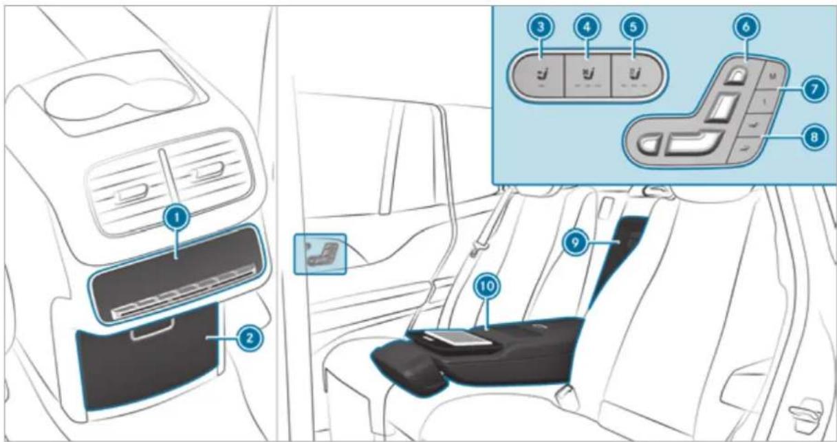
Diagram of car interior showing dashboard, seatbelt, and control panel with numbered labels① Rear climate control operating unit → 178
2 Stowage compartment in the centre console
230 V socket → 151
3 Adjusts the front passenger seat electrically → 111
4 Switches the rear seat ventilation → 125
on/off
5 Switches the rear seat heating on/off → 124
6 Adjusts the rear seats electrically → 112
Mercedes-Maybach vehicles: adjusts a reclining rear seat electrically → 112
⑦ Mercedes-Maybach vehicles: operates the → 131 memory function
8 Mercedes-Maybach vehicles: sets the fully reclined position → 113
Mercedes-Maybach vehicles: access to the refrigerator box → 153
10 Stowage compartment in the rear armrest
MBUX rear tablet bracket
text_image
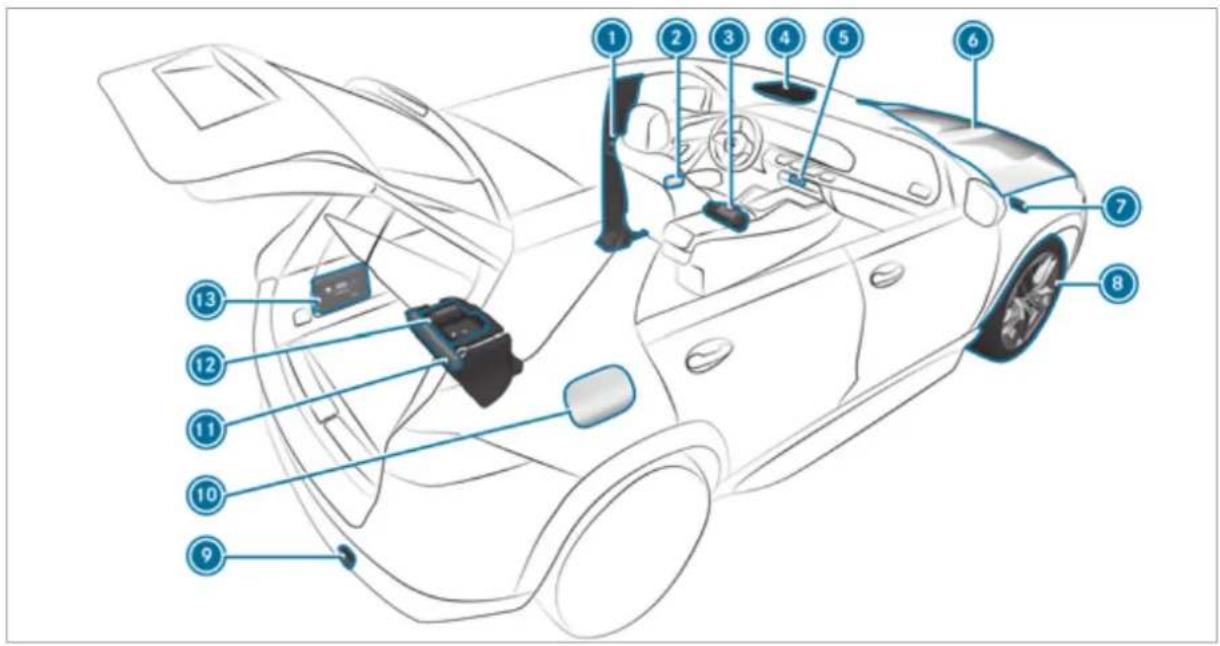
Labeled diagram of a car interior showing numbered parts for identification1 B-pillar with:
QR code for accessing the rescue card → 35
Safety vests → 383
3 Fire extinguisher → 385
4 me button → 344
SOS SOS button → 344
5 Hazard warning light system → 161
To check and top up operating fluids → 429
Starting assistance → 395
⑦ Tow-starting or towing away → 398
8 Flat tyre → 385
9 Tow-starting or towing away → 398
10 Fuel filler flap with:
information label on fuel type → 215
information label on tyre pressure → 407
QR code for accessing the rescue card → 35
⑪ Warning triangle → 383
⑫ TREFIT kit → 387
13 First-aid kit (soft sided) → 384
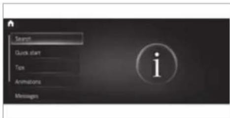
Calling up the Digital Owner's Manual
Multimedia system:

text_image
Search Quick start Tan Animations MessagesThe Digital Owner's Manual describes the functions and operation of the vehicle and the mult media system.
Select one of the following menu items in the Digital Owner's Manual:
- Search: search for keywords in order to find quick answers to questions about the operation of the vehicle.
- Quick start: here is where you find the first steps towards setting up your vehicle.
- Tips: find information that prepares you for certain everyday situations with your vehicle.
• Animations: watch animations of the vehicle functions. - Messages: receive additional information about the messages in the Instrument Display.
- Bookmarks: gain access to your personally saved bookmarks.
• Language: select the language for the Digital Owner's Manual.
text_image
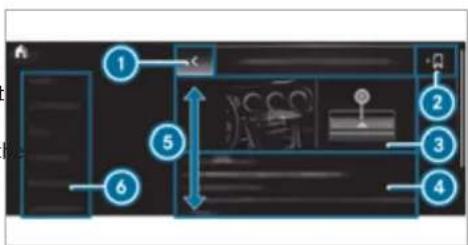
Diagram of a room layout with numbered zones and directional arrows indicating spatial relationships1 Back
② Adds bookmarks
3 Picture
④ Contents section
Directions of movement of contents section
6 Menu
Some sections in the Digital Owner's Manual, e.g. warning notes, can be expanded and collapsed.
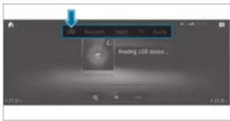
Additional methods of calling up the Digital Owner's Manual:
Direct access: open the required content in the Digital Owner's Manual by pressing and holding an entry on the tab bar in the multimedia system:
text_image
USB Bluetooth Japan TV Sound Reading USB device...Instrument Display: call up brief information as display messages in the instrument cluster
LINGUATRONIC: call up via the voice control system
For safety reasons, the Digital Owner's Manual is deactivated while driving.
Protection of the environment

ENVIRONMENTAL NOTE Environmental damage due to operating conditions and personal driving style
The pollutant emission of the vehicle is directly related to the way you operate the vehicle.
Operate your vehicle in an environmentally responsible manner to help protect the environment. Please observe the following recommendations on operating conditions and personal driving style.
Operating conditions:
Make sure that the tyre pressure is correct.
Do not carry any unnecessary weight (e.g. roof luggage racks once you no longer need them).
Adhere to the service intervals.
A regularly serviced vehicle will contribute to environmental protection.
Always have maintenance work carried out at a qualified specialist workshop.
Personal driving style:
Do not depress the accelerator pedal when starting the engine.
Do not warm up the engine while the vehicle is stationary.
▶ Drive carefully and maintain a suitable distance from the vehicle in front.
Avoid frequent, sudden acceleration and braking.
Change gear in good time and use each gear only up to 23 of its maximum engine speed.
Switch off the engine in stationary traffic, e.g. by using the ECO start/stop function.
▶ Drive in a fuel-efficient manner. Observe the ECO display for an economical driving style.
Take-back of end-of-life vehicles
EU countries only:
Mercedes-Benz will take back your end-of-life vehicle for environment-friendly disposal in accordance with the European Union (EU) End-of-Life Vehicles Directive.
A network of vehicle take-back points and dismantlers has been established for you to return your vehicle. You can leave it at any of these points free of charge. This makes an important contribution to closing the recycling circle and conserving resources.
For further information about the recycling and disposal of end-of-life vehicles, and the take-back conditions, please visit the national Mercedes-Benz website for your country.
Mercedes-Benz GenuineParts

ENVIRONMENTAL NOTE Environmental damage caused by not using recycled reconditioned components
Mercedes-Benz AG offers recycled reconditioned components and parts with the same quality as new parts. The same entitlement from the implied warranty is valid as for new parts.

Recycled reconditioned components and parts from Mercedes-Benz AG.

NOTE Impairment of the operating efficiency of the restraint systems from installing accessory parts or from repairs or welding
Airbags and seat belt tensioners, as well as control units and sensors for the restraint systems, may be installed in the following areas of your vehicle:
- Doors
- Door pillars
- Door sills
- Seats
- Cockpit
- Instrument cluster
- Centre console
- Lateral roof frame
Do not install accessory parts such as audio systems in these areas.
Do not carry out repairs or welding.
Have accessory parts retrofitted at a qualified specialist workshop.
You could jeopardise the operating safety of your vehicle if you use parts, tyres and wheels as well as accessories relevant to safety which have not been approved by Mercedes-Benz. Safety-relevant systems, e.g. the brake system, may malfunction. Only use Mercedes-Benz GenuineParts or parts of equal quality. Only use tyres, wheels and accessory parts that have been specifically approved for your vehicle model.
Mercedes-Benz tests original parts and conversion parts and accessory parts that have been specifically approved for your vehicle model for their reliability, safety and suitability. Despite ongoing market research, Mercedes-Benz is unable to assess other parts. Mercedes-Benz therefore accepts no responsibility for the use of such parts in Mercedes-Benz vehicles, even if they have been officially approved or independently approved by a testing centre.
Certain parts are only officially approved for installation or modification if they comply with legal requirements. All Mercedes-Benz Genuine-Parts meet the approval requirements. The use of non-approved parts may invalidate the vehicle's general operating permit.
This is the case in the following situations:
- The vehicle type is different from that for which the vehicle's general operating permit was granted.
- Other road users could be endangered.
• The exhaust gas or noise level gets worse.
Always specify the vehicle identification number (VIN) ( page 427) when ordering Mercedes-Benz GenuineParts.
Owner's Manual
This Owner's Manual describes all models and all standard and optional equipment available for your vehicle at the time of this Owner's Manual going to press. Country-specific differences are possible. Note that your vehicle may not be fitted with all features described. This is also the case for systems and functions relevant to safety. Therefore, the equipment on your vehicle may differ from that in the descriptions and illustrations.
The original purchase agreement for your vehicle contains a list of all of the systems in your vehicle.
Should you have any questions concerning equipment and operation, please consult a Mercedes-Benz Service Centre.
The Owner's Manual and Service Booklet are important documents and should be kept in the vehicle.
Operating safety
⚠ WARNING Risk of injury due to malfunctions or system failure
In order to avoid malfunctions or system failures:
Always have the specified service/maintenance work as well as any necessary repairs carried out at a qualified specialist workshop.
WARNING Risk of accident or injury due to improper modifications to electronic components
Modifications to electronic components, their software or wiring can impair their functionality and/or the functionality of other networked components or safety-relevant systems.
This can endanger the vehicle's operating safety.
You must not tamper with wiring, electronic components, or their software.
▶ Always have work on electrical and electronic devices carried out at a qualified specialist workshop.
If you modify the on-board electronics, the general operating permit is rendered invalid.
Observe the "On-board electronics" section in "Technical data".
A WARNING Risk of fire due to flammable materials on hot parts of the exhaust system
Flammable material such as leaves, grass or twigs may ignite if they come into contact with hot parts of the exhaust system.
When driving on unpaved roads or off-road, regularly check the vehicle underside.
Remove trapped plants or other flammable material, in particular.
If there is damage, consult a qualified specialist workshop immediately.
NOTE Damage to the vehicle due to driving too fast and due to impacts to the vehicle underbody or suspension components
In the following situations, in particular, there is a risk of damage to the vehicle:
- the vehicle becomes grounded, e.g. on a high kerb or an unpaved road
- the vehicle is driven too fast over an obstacle, e.g. a kerb, speed bump or pot-hole
- a heavy object strikes the underbody or suspension components
In situations such as these, damage to the body, underbody, suspension components, wheels or tyres may not be visible. Components damaged in this way can unexpectedly fail or, in the case of an accident, may no longer absorb the resulting force as intended.
If the underbody panelling is damaged, flammable materials such as leaves, grass or twigs can collect between the underbody the underbody panelling. These materials may ignite if they come into contact with hot parts of the exhaust system.
Have the vehicle checked and repaired immediately at a qualified specialist workshop.
or
If driving safety is impaired while continuing your journey, pull over and stop the vehicle immediately, while paying attention to road and traffic conditions, and contact a qualified specialist workshop.
Vehicles with a 48 V on-board electrical system (EQ Boost technology)
and
DANGER Risk of fatal injury by touching damaged high-voltage components
Vehicles with a 48 V on-board electrical system contain individual high-voltage components. These high-voltage components are under high voltage.
If you modify component parts of these high-voltage components or touch damaged component parts, you may be electrocuted.
High voltage components may be damaged in an accident, although the damage may not be visible.
▶ Never perform modifications to component parts of high-voltage components.
▶ Never touch damaged component parts of high-voltage components.
▶ Never touch component parts of high-voltage components after an accident.
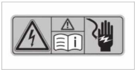
Vehicles with a 48 V on-board electrical system contain high voltage components. These components are marked with a high voltage label:
text_image
Warning sign with hazard symbol, warning sign, open book, and hand indicating electrical hazardAll work on high voltage components must be carried out at a qualified specialist workshop.
Declaration of conformity
Electromagnetic compatibility
The electromagnetic compatibility of the vehicle components has been checked and certified according to the currently valid version of Regulation UN R10.
Wireless vehicle components
For EU and EFTA countries only:
The following information applies to all wireless components of the vehicle and of the information systems and communication devices integrated in the vehicle:
The manufacturers of the wireless components ensure that all wireless components installed in the vehicle comply with Directive 2014/53/EU. The full texts of the EU declarations of conformity are available at the following website: https://moba.i.daimler.com/markets/ece-row/baix/cars/certificates-of-conformity/en_GB/index.html

You can obtain further information from a Mercedes-Benz service centre.
For Brazil only:
Note on two-way radio systems in the vehicle:
These systems are not protected against harmful interference and must not cause interference in properly approved systems.
Rear Seat Entertainment System:
This system is not protected against harmful interference and must not cause interference in properly approved systems.
This product is approved by ANATEL in accordance with the procedures set out in Resolution 242/2000 and complies with the relevant technical requirements. Further information can be found on the https://www.anatel.gov.br
Nigeria only:
Connection and use of the wireless communication equipment in this vehicle are permitted by the Nigerian Communications Commission.
Ukraine only:
The manufacturer hereby declares that the wireless vehicle components meet the technical regulations for two-way radios. You can obtain further information from a Mercedes-Benz Service Centre.
Wireless applications in the vehicle
Besides the typical frequencies for mobile communications, cars from Mercedes-Benz make
use of the following automotive radio applications:
Wireless applications in the vehicle
| Technology | Frequency range | Transmission output/magnetic field strength |
| Convenience central locking system | 20 kHz (9–90 kHz) | ≤ 72 dBμA/m at 10 m |
| Wireless power transmission | 105 kHz (90–119 kHz) | ≤ 42 dBμA/m at 10 m |
| Convenience central locking system | 120 kHz (119–135 kHz) | ≤ 42 dBμA/m at 10 m |
| Wireless power transmission | 127 kHz (119–135 kHz) | ≤ 66 dBμA/m at 10 m with the magnetic field strength level decreasing 3dB/octave above 119 kHz |
| Near-field communication | 13.553–13.567 MHz | ≤ 42 dBμA/m at 10 m |
| Convenience central locking system, garage door opener, tyre pressure monitoring system | 433 MHz (433.05–434.79 MHz) | ≤ 10 mW ERP |
| Heater booster function remote control, garage door opener | 868 MHz (868.0–868.6 MHz) | ≤ 25 mW ERP |
| Heater booster function remote control, garage door opener | 869 MHz (868.7–869.2 MHz) | ≤ 25 mW ERP |
| RLAN 5.1 GHz UNII-1 (5150–5250 MHz) ≤ 25 | mW EIRP | |
| Bluetooth®, Kleer, RLAN, remote control, wireless headphones | 2.4 GHz ISM band (2400–2483.5 MHz) | ≤ 100 mW EIRP |
| Sensor for interior protection, RLAN | 5.8 GHz UNII-3 (5725–5875 MHz) | ≤ 25 mW EIRP |
| Convenience central locking system | 7.25 GHz UWB (6.0–8.5 GHz) | ≤ -41.3 dBm/MHz EIRP mean ≤ 0 dBm/MHz EIRP peak |
| 76 GHz radar | 76–77 GHz | ≤ 55 dBm peak EIRP |
| Carsharing module | NFC:13.553–13.567 MHzBluetooth®:2402–2480 MHz | NFC:≤ 42 dBμA/m at 10 mBluetooth®:≤ + 4 dBm (power category 2) |
| Rear Seat Entertainment System | Bluetooth®:2400–2483.5 MHzWLAN 2.4 GHZ:2400–2483.5 MHzWLAN 5 GHz:5150–5250 MHz5725–5875 MHz | Bluetooth®:-0.8 dBmWLAN 2.4 GHZ:14.5 dBmWLAN 5 GHz:20.5 dBm13.3 dBm |
Information about the specific absorption rate
For France only:
The values were determined and tested in accordance with the Décret n° 2019-1186 guideline regarding the indication of the specific
absorption rate (SAR) of wireless vehicle components.
Information about the specific absorption rate
| Vehicle component (designation in accordance with EU DoC) | SAR value in W/kg | Applicable limit value |
| Radio data transmission telephone sys-tem | < 0.24 W/kg | 2 W/kg |
| Hermes 2.1 | < 0.4 W/kg | 2 W/kg |
| Compensator ECE DE003 & ECE DE004 | < 0.4 W/kg | 2 W/kg |
| Tablet PC SM-T230NZ < 0.7 W/kg | 4 | W/kg |
| DAI RSE | < 1.8 W/kg | 4 W/kg |
| NRCS2P < 0.003 W/kg | 2 | W/kg |
| NTG7RSU < 0.07 W/kg | 2 | W/kg |
| NTG7 < 0.08 W/kg | 2 W/kg |
Jack
Copy and translation of the original declaration of conformity:
EC declaration of conformity
1.
The undersigned, representing
Manufacturer:
BRANO a.s.
herewith declares under our sole responsibility that the product:
- a)
Name:
Jack
Type, Number:
A) A 164 580 02 18, A 166 580 01 18
B) A 240 580 00 18
C) A 639 580 02 18
D) A 639 580 03 18
E) A 910 580 00 00
F) A 247 580 00 00, A 293 580 00 00
Year of manufacture: 2020
Complies with all relevant provisions
Directive No. 2006/42/EC
b)
Description and purpose of use:
Car jack is intended solely for lifting of the concrete car, in accordance with the instruction label on the car jack.
3.
References of harmonized and other standards or specifications
ISO 4063, EN ISO 14341-A, AS 2693, DBL 8230.10, DBL 7382.20, DBL 7392.10, DBL 8451.15, MBN 10435,
Technical documentation of the product is stored at the premise of the manufacturer. The person responsible for assembling the technical documentation of the product: Head of the Technical Department Brano a.s.
4.
Hradec nad Moravicí
Place
5.
05.10.2020
Date
Engineer Petr Petr
[Signature]
Director of division ZZ
TREFIT kit
Copy and translation of the original declaration of conformity:
EC declaration of conformity
In accordance with EC Directive 2006/42/EC
We hereby declare that the product
Product designation: Daimler electric air pump
Model designation: 0867, DT/UW 200056
MB part no.: A 000 583 5101
complies with the following relevant regulations:
2004/108/EC
Applied harmonised standards, in particular:
DIN EN 55014-1: 2012
Manufacturer: Dunlop Tech GmbH
Address: Offenbacher Landstr. 8, 63456 Hanau
Authorised representative: IMS dept.
Date: October 2019
Signature: IMS-AE, IMS-AE-L
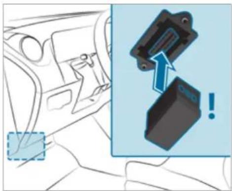
Diagnostics connection
The diagnostics connection is a technical interface in the vehicle. It is used, for example, within
the scope of repair and maintenance work or for reading out vehicle data by a specialist workshop. Diagnostic devices should therefore only be connected by a qualified specialist workshop.

WARNING Risk of accident due to connecting devices to the diagnostics connection
If you connect devices to the diagnostics connection of the vehicle, the function of vehicle systems and operating safety may be impaired.
For safety reasons, we recommend that you only use and connect products approved by your Mercedes-Benz service centre.

WARNING Risk of accident due to objects in the driver's footwell
Objects in the driver's footwell may impede pedal travel or block a depressed pedal. This jeopardises the operating and road safety of the vehicle.
Stow all objects in the vehicle securely so that they cannot get into the driver's footwell.
Always fit the floor mats securely and as prescribed in order to ensure that there is always sufficient room for the pedals.
Do not use loose floor mats and do not place floor mats on top of one another.

NOTE Battery discharging from using devices connected to the diagnostics connection
Using devices at the diagnostics connection drains the battery.
▶ Check the charge level of the battery.
If the charge level is low, charge the battery, e.g. by driving a considerable distance.
Please also note the information about the 12 V battery and short-distance trips in the "Driving and Parking" chapter ( page 195).
natural_image
Diagram showing a car interior with a highlighted door and an inset image of a mechanical component (no text or symbols)Connecting and using another device with the diagnostics connection can have the following effects:
• Malfunctions in the vehicle system
• Permanent damage to vehicle components
Please refer to the warranty terms and conditions for this matter.
Moreover, connecting equipment to the diagnostics connection can lead to emissions monitoring information being reset, for example. This may lead to the vehicle failing to meet the requirements of the next emissions inspection during the main inspection.
Qualified specialist workshop
A qualified specialist workshop has the necessary special skills, tools and qualifications to correctly carry out any necessary work on your vehicle. This particularly applies to safety-relevant works.
Always have the following work carried out on your vehicle at a qualified specialist workshop:
- Safety-relevant works
• Service and maintenance work - Repair work
- Modifications as well as installations and conversions
• Work on electronic components
- Vehicles with 48 V on-board electrical system (EQ boost technology): work on high voltage components of the 48 V on-board electrical system
Mercedes-Benz recommends a Mercedes-Benz service centre.
Vehicle registration
Mercedes-Benz may ask its service centres to carry out technical inspections on certain vehicles. The quality or safety of the vehicle is improved as a result of the inspection.
Mercedes-Benz can only inform you about vehicle checks if Mercedes-Benz has your registration data.
It is possible that your vehicle has not yet been registered in your name in the following cases:
- if your vehicle was not purchased at an authorised specialist dealer.
- if your vehicle has not yet been examined at a Mercedes-Benz service centre.
It is advisable to register your vehicle with a Mercedes-Benz service centre.
Inform Mercedes-Benz as soon as possible about any change in address or vehicle ownership. You can do this at a Mercedes-Benz service centre, for example.
Correct use of the vehicle
If you remove any warning stickers, you or others could fail to recognise certain dangers. Leave warning stickers in position.
Observe the following information in particular when driving your vehicle:
- the safety notes in this manual and respective Supplements
• technical data for the vehicle
• traffic rules and regulations - laws and safety standards pertaining to motor vehicles
Information on the REACH regulation
EU and EFTA countries only:
the REACH regulation (Regulation (EC) No. 1907/2006, Article 33) stipulates a duty to supply information about substances of very high concern (SVHCs).
Mercedes-Benz AG acts to the best of its knowledge to prevent these SVHCs from being used and to enable customers to safely handle these substances. There are SVHCs known to
Mercedes-Benz AG, according to supplier information and internal product information, found in individual components of this vehicle in quantities of over 0.1 percent by weight.
Further information can be obtained at the following addresses:
- https://reach.daimler.com/de/home/
- https://reach.daimler.com/en/home/
Notes for persons with electronic medical aids
Mercedes-Benz AG cannot, despite carefully developing vehicle systems, completely rule out the interaction of vehicle systems with electronic medical aids such as cardiac pacemakers.
In addition, there are components installed in the vehicle that, regardless of the operating status of the vehicle, can generate magnetic fields on a par with permanent magnets. These fiem can be found, for example, in the area around the multimedia and sound system or also in area of the seats, depending on the vehicle equipment.
For this reason, the following can occur in isolated cases, depending on the aids used:
• Medical aids malfunctioning
- Adverse health effects
Observe the notes and warnings of the manufacturer of the medical aids; if in doubt, contact device manufacturer and/or your doctor. If there is continuing uncertainty concerning the possibility of medical aids malfunctioning, Mercedes-Benz AG recommends using only few electrical vehicle systems and/or maintaining a distance from the components.
Only have repairs and maintenance work in the area of the following components carried out by a qualified specialist workshop:
• vehicle components carrying live voltage
- transmission aerials
• multimedia system and sound system
fieldsIf you have any queries or suggestions, consult a qualified specialist workshop.
Implied warranty

NOTE Damage to the vehicle arising from violation of these operating instructions.
Damage to the vehicle can arise from violation of these operating instructions.
thThis damage is not covered either by the Mercedes-Benz implied warranty or by the New- or Used-Vehicle Warranty.
▶ Follow the instructions in these operating instructions on proper operation of your vehicle as well as on possible vehicle damage.
QR code for rescue card
QR codes are attached in the fuel filler flap and on the opposite side on the B-pillar. In the event of an accident, rescue services can use the QR code to quickly find the appropriate rescue card for your vehicle. The current rescue card contains the most important information about your vehicle in a compact form, e.g. the routing of the electric lines.
Further information can be obtained at https://www.mercedes-benz.de/qr-code.
Data storage
Data processing in the vehicle
Electronic control units
Electronic control units are fitted in your vehicle. Control units process data which, for example, they receive from vehicle sensors, generate themselves or exchange between themselves. Some control units are required for the safe operation of your vehicle, some assist you when driving, such as driver assistance systems, while others enable convenience or infotainment functions.
The following provides you with general information regarding data processing in the vehicle. Additional information regarding exactly which data in your vehicle are collected, saved and transmitted to third parties, and for what purpose, can be found in the information directly related to the functional characteristics in question in their respective operating instructions. This information is also available online and, depending on the vehicle equipment, digitally.
Personal data
Every vehicle is identified by a unique vehicle identification number. Depending on the country, this vehicle identification number can be used by, for example, governmental authorities to determine the identity of the owner. There are other possibilities to use data collected from the vehicle to identify the owner or driver, such as the licence plate number.
Therefore, data generated or processed by control units may be attributable to a person or, under certain conditions, become attributable to a person. Depending on which vehicle data are available, it may be possible to make inferences about, for example, your driving behaviour, your location, your route or your use patterns.
Legal requirements regarding the disclosure of data
If legally required to do so, manufacturers are, in individual cases, legally obliged to provide governmental entities, upon request and to the extent required, data stored by the manufacturer. For example, this may be the case during the investigation of a criminal offence.
Governmental entities are themselves, in individual cases and within the applicable legal framework, authorised to read out data from the vehicle. In the case of an accident, information that can help with an investigation can, therefore, be taken from the airbag control unit, for example.
Operational data in the vehicle
This is data regarding the operation of the vehicle, which have been processed by control units. This includes the following data, for example:
- vehicle status information such as the speed, longitudinal acceleration, lateral accelera-
tion, number of wheel revolutions or the fastened seat belts display
- ambient conditions, such as temperature, rain sensor or distance sensor
Generally, the use of these data is temporary; they will not be stored beyond the period of operation and will only be processed within vehicle itself. Control units often contain data memories for vehicle keys, for example. Their use permits the temporary or permanent documentation of technical information about the vehicle's operating state, component loads, maintenance requirements and technical events or faults.
Depending on the vehicle equipment, the following data are stored:
- operating status of system components, such as fill levels, tyre pressure or battery status
- malfunctions or faults in important system components, such as lights or brakes
- system reactions in special driving situations, such as airbag deployment or the intervention of stability control systems
• information on events leading to vehicle damage
In certain cases, it may be required to store data that would have otherwise been used only temporarily. This may be the case if the vehicle has detected a malfunction, for example.
the If you use services, such as repair services and maintenance work, stored operational data as well as the vehicle identification number can be read out and used. They can be read out by service network employees, such as workshops and manufacturers or third parties, such as breakdown services. The same is true in the case of warranty claims and quality assurance measures.
In general, the readout is performed via the legally prescribed port for the diagnostics connection in the vehicle. The operational data that are read out document technical states of the vehicle or of individual components and assist the diagnosis of malfunctions, compliance with warranty obligations and quality improvement. To that end, these data, in particular information about component loads, technical events, malfunctions and other faults may be transmitted along with the vehicle identification number to the manufacturer. Furthermore, the manufacturer is subject to product liability. For this reason the manufacturer also uses operational data from the vehicle, for example, for recalls. These data can also be used to examine the customer's warranty and guarantee claims.
Fault memories in the vehicle can be reset by a service outlet or at your request as part of repair or maintenance work.
Convenience and infotainment functions
You can store convenience settings and individual settings in the vehicle and change or reset them at any time.
Depending on the vehicle equipment, this includes the following settings, for example:
- seat and steering wheel positions
in suspension and climate control settings
• individual settings, such as interior lighting
Depending on the selected equipment, you can import data into vehicle infotainment functions yourself.
Depending on the vehicle equipment, this includes the following data, for example:
- multimedia data, such as music, films or tos for playback in an integrated multimedia system
- address book data for use in connection w an integrated hands-free system or an inte-grated navigation system
- entered navigation destinations
• data about the use of Internet services
These data for convenience and infotainment functions may be saved locally in the vehicle or they may be located on a device which you have connected to the vehicle, such as a smartphone, USB flash drive or MP3 player. If you have entered these data yourself, you can delete them at any time.
This data is transmitted from the vehicle to third parties only at your request. This applies, in particular, when you use online services in accordance with the settings that you have selected.
Smartphone integration (e.g. Android Auto or Apple CarPlay®)
If your vehicle is accordingly equipped, you can connect your smartphone or another mobile end device to the vehicle. You can then control them by means of the control elements integrated in the vehicle. Images and audio from the smartphone can be output via the multimedia system. Certain information is simultaneously transferred to your smartphone. Depending on the type and integration, this includes position data, day/night mode and other general vehicle statuses. For more information please consult the Owner's Manual of the vehicle/infotainment system.
This integration allows the use of selected smartphone apps, such as navigation or music player apps. There is no further interaction between the smartphone and the vehicle; in particular, vehicle data is not directly accessible. The type of additional data processing is determined by the provider of the app being used. Which settings you can make, if any, depends on the specific app and the operating system of your smartphone.
Online services
Wireless network connection
If your vehicle has a wireless network connection, it enables data to be exchanged between your vehicle and additional systems. The wireless network connection is made possible by the vehicle's own transmitter and receiver or by a mobile end device that you have brought into the vehicle, for example, a smartphone. Online functions can be used via the wireless network connection. This includes online services and applications/apps provided to you by the manufacturer or by other providers.
Manufacturer's services
Regarding the manufacturer's online services, the individual functions are described by the manufacturer in a suitable place, for example, in the Owner's Manual or on the manufacturer's website, where the relevant data protection information is also given. Personal data may be used for the provision of online services. Data are exchanged via a secure connection, such as: the manufacturer's designated IT systems. Any personal data which are collected, processed
and used, other than for the provision of services, is done so exclusively on the basis of legal permission. This is the case, for example, for a legally prescribed emergency call system, a contractual agreement or when consent has been given.
You can have services and functions, some of which are subject to a fee, activated or deactivated. This excludes legally prescribed functions and services, such as an emergency call system.
Third party services
If you use online services from other providers (third parties), these services are the responsibility of the provider in question and subject to that provider's data protection conditions and terms of use. As a general rule, the manufacturer has no influence on the content exchanged.
For this reason, when services are provided by third parties, please ask the service provider in question for information about the type, extent and purpose of the collection and use of personal data.
Data protection rights
Depending on your country or the equipment and range of functions of your vehicle as well as the services you use and the services on offer, you are entitled to different data protection rights. Further information on data protection and your data protection rights can either be found on the manufacturer's website or you will receive this information as part of the various services and service offers. There you will also find the contact information for the manufacturer and its data protection officers.
At a workshop, for example, with the support of a specialist and possibly for a fee, you can have data read out which is stored only locally in the vehicle.
Copyright
Information on licences for free and open-source software used in your vehicle can be found on the data carrier in your vehicle document wallet and with updates on the following website:
https://www.mercedes-benz.com/opensource
Restraint system
Protection provided by the restraint system
The restraint system includes the following components:
- Seat belt system
- Airbags
• Child restraint system
• Child seat securing systems
The restraint system can help prevent the vehicle occupants from coming into contact with parts of the vehicle interior in the event of an accident. In the event of an accident, the restraint system can also reduce the forces to which the vehicle occupants are subjected.
A seat belt can only provide the best level of protection if it is worn correctly. Depending on the detected accident situation, seat belt tensioners and/or airbags supplement the protection offered by a correctly worn seat belt. Seat belt tensioners and/or airbags are not deployed in every accident.
In order for the restraint system to provide the intended level of protection, each vehicle occupant must observe the following information:
- Fasten seat belts correctly.
- Sit in an almost upright seat position with their back against the seat backrest.
- Sit with their feet resting on the floor, if possible.
- Always secure persons under 1.50 m tall in an additional restraint system suitable for Mercedes-Benz vehicles.
However, no system available today can completely eliminate injuries and fatalities in every accident situation. In particular, the seat belt and airbag generally do not protect against objects penetrating the vehicle from the outside. It is also not possible to completely rule out the risk of injury caused by the airbag deploying.
Reduced restraint system protection

WARNING Risk of injury or death due to modifications to the restraint system
Vehicle occupants may no longer be protected as intended if alterations are made to the restraint system.
▶ Never alter the parts of the restraint system.
▶ Never tamper with the wiring or any electronic component parts or their software.
If it is necessary to modify the vehicle to accommodate a person with disabilities, contact a qualified specialist workshop.
Mercedes-Benz recommends that you use driving aids which have been approved for your vehicle by Mercedes-Benz.
Restraint system functionality
When the ignition is switched on, a self-test is performed, during which the restraint sys-
tem warning lamp lights up. It goes out no later than a few seconds after the vehicle is started. The components of the restraint system are then functional.
Malfunctioning restraint system
A malfunction has occurred in the restraint system if:
- the restraint system warning lamp does not light up when the ignition is switched
- the restraint system warning lamp lights up continuously or repeatedly during journey

WARNING Risk of injury due to malfunctions in the restraint system
Components in the restraint system may be activated unintentionally or not deploy as intended in an accident.
Have the restraint system checked and repaired immediately at a qualified specialist workshop.
Function of the restraint system in an accident
How the restraint system works depends on the severity of the impact detected and the apparent type of accident:
- Frontal impact
- Rear impact
- Side impact
- Rollover
The activation thresholds for the components of the restraint system are determined based on the evaluation of the sensor values measured at various points in the vehicle. This process is preemptive in nature. The triggering/deployment the components of the restraint system must take place in good time at the start of the collision.
Factors which can only be seen and measured after a collision has occurred cannot play a decisive role in airbag deployment. Nor do they provide an indication of airbag deployment.
The vehicle may be deformed significantly without an airbag being deployed. This is the case if only parts which are relatively easily deformed are affected and the rate of vehicle deceleration is not high. Conversely, an airbag may be deployed even though the vehicle suffers only minor deformation. If very rigid vehicle parts such as longitudinal members are hit, this may result in sufficiently high levels of vehicle deceleration.
Depending on the detected deployment situation, the components of the restraint system can be activated or deployed independently of each other:
- Seat belt tensioner: frontal impact, rear impact, side impact, rollover
- Driver's airbag, front passenger airbag: frontal impact
- Knee airbag: frontal impact
- Side airbag: side impact
- Window airbag: side impact, rollover, frontal impact
- Cushionbag: frontal impact
- PRE-SAFE® Impulse Side: side impact
The front passenger airbag can only be deployed. The seat belt tensioners are triggered or an air-in an accident if the PASSENGER AIR BAG OFF bag is deployed, you will hear a bang, and a indicator lamp is off. If the front passenger seat small amount of powder may also be released: is occupied, make sure, both before and during. The bang will not generally affect your hearing. the journey, that the status of the front passenger airbag is correct ( page 50). In general, the powder released is not haz

WARNING Risk of burns from hot airbag components
The airbag parts are hot after an airbag has been deployed.
Do not touch the airbag parts.
Have a deployed airbag replaced at a qualified specialist workshop as soon as possible.
Mercedes-Benz recommends that you have the vehicle towed to a qualified specialist workshop after an accident. Take this into account, particularly if a seat belt tensioner is triggered or an airbag deployed.
Seat belts
Protection provided by the seat belt
Always fasten your seat belt correctly before starting a journey. A seat belt can only provide the best level of protection if it is worn correctly.

WARNING Risk of injury or death due to incorrectly fastened seat belt
If the seat belt is not worn correctly, it cannot perform its intended protective function. In addition, an incorrectly fastened seat belt can also cause injuries, for example, in the event of an accident or when braking or changing direction suddenly.
Always ensure that all vehicle occupants have their seat belts fastened correctly and are sitting properly.
Always observe the instructions about the correct driver's seat position and adjusting the seat ( page 107).
In order for the correctly worn seat belt to provide the intended level of protection, each vehicle occupant must observe the following information:
- The seat belt must not be twisted and mus fit tightly and snugly across the body.
- The seat belt must be routed across the centre of the shoulder and as low down across the hips as possible.
- The shoulder section of the seat belt should not touch your neck nor be routed under your arm or behind your back.
- Avoid wearing bulky clothing, e.g. a winter coat.
- Push the lap belt down as far as possible across your hips and pull tight with the shoulder section of the belt. Never route the lap belt across your abdomen.
Pregnant women must also take particular care with this. - Never route the seat belt across sharp, pointed, abrasive or fragile objects.
- Only one person should use each seat belt any one time. Never allow babies and children to travel sitting on the lap of another vehicle occupant.
- Never secure objects with a seat belt if the seat belt is also being used by one of the vehicle's occupants. Always observe the instructions for loading the vehicle when
securing objects, luggage or loads ( page 134).
Also ensure that no objects, e.g. a cushion, are ever placed between a person and the seat.
If children are travelling in the vehicle, be sure to observe the instructions and safety notes on "Children in the vehicle" ( page 56).
Limitations of the protection provided by the seat belt

WARNING Risk of injury or death due to incorrect seat position
The seat belt will not offer the intended level of protection if you have not moved the seat backrest to an almost vertical position.
In particular, you may slip under the seatbelt and injure yourself.
Adjust the seat properly before beginning your journey.
Always ensure that the seat backrest is in an almost vertical position and that
the shoulder section of your seat belt is routed across the centre of your shoulder.

WARNING Risk of injury or death when additional restraint systems are not used for persons with a smaller stature
Persons under 1.50 m tall cannot wear the seat belt correctly without a suitable additional restraint system.
Always secure persons under 1.50 m tall in a suitable restraint system.

WARNING Risk of injury or death due to damaged or modified seat belts
Seat belts cannot provide protection in the following situations:
- the seat belt is damaged, has been modified, is extremely dirty, bleached or dyed
- the seat belt buckle is damaged or extremely dirty
- modifications have been made to the seat belt tensioner, seat belt anchorage or seat belt retractor
Seat belts may sustain non-visible damage in an accident, e.g. due to glass splinters.
Modified or damaged seat belts could tear o fail in the event of an accident, for example.
Modified seat belt tensioners could accidentally trigger or fail to function as intended.
▶ Never modify the seat belt system, for example the seat belt, seat belt buckle, seat belt tensioner, seat belt anchorage and seat belt retractor.
Make sure that the seat belts are undamaged, not worn and clean.
Always have the seat belts checked immediately after an accident at a qualified specialist workshop.
Mercedes-Benz recommends that you use seat belts which have been approved for your vehicle by Mercedes-Benz.
WARNING Risk of injury or death from deployed pyrotechnic seat belt tensioners
Pyrotechnic seat belt tensioners that have been deployed are no longer operational and are unable to perform their intended protective function.
Therefore, have deployed pyrotechnic seat belt tensioners immediately replaced at a qualified specialist workshop.
Mercedes-Benz recommends that you have the vehicle towed to a qualified specialist workshop after an accident.
NOTE Damage caused by trapping the seat belt
If an unused seat belt is not fully retracted, may become trapped in the door or in the seat mechanism.
▶ Always ensure that an unused seat belt is fully retracted.
Fastening and adjusting seat belts
If the seat belt is pulled quickly or sharply, the seat belt retractor locks. The seat belt strap cannot be pulled out any further.
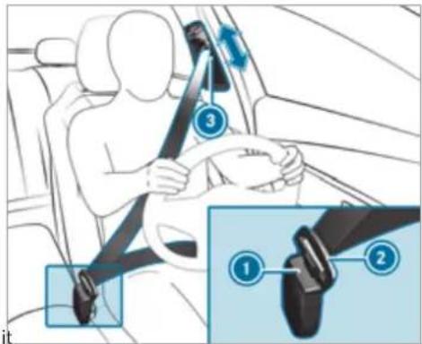
text_image
Diagram showing car seatbelt usage with numbered instructions and magnified detail viewAlways engage seat belt tongue ② of the seat belt into seat belt buckle ① of the corresponding seat.
Press and hold the seat belt outlet release and slide seat belt outlet ③ into the desired position.
Let go of the seat belt outlet release and ensure that seat belt outlet ③ locks into position.
A seat belt can only provide the best level protection if it is worn correctly. Observe the notes on fastening the seat belt ( page 41).
NOTE Deployment of the seat belt tensioner and side impact airbag when the front passenger seat is unoccupied
If the seat belt tongue is engaged in the seat belt buckle of the unoccupied front passenger seat, the seat belt tensioner and the side impact airbag may also deploy in the event of an accident along with other systems.
Only one person should use each seat belt at any one time.
Seat belt adjustment function
Vehicles with PRE-SAFE®: after a front seat belt has been fastened, the automatic seat belt adjustment may apply a certain tightening force. Do not hold the seat belt tightly while it is adjusting.
You can activate and deactivate the seat belt adjustment function using the multimedia system ( page 44).
Activating/deactivating seat belt adjustment via the multimedia system
Multimedia system:
Settings Vehicle
▶ Activate or deactivate Belt adjustment.
Releasing seat belts
Press the release button in the seat belt buckle and guide the seat belt back with the seat belt tongue.
Seat belt warning function for the driver and front passenger
The □ seat belt warning lamp in the instrument display is a reminder that all vehicle occupants must wear their seat belts correctly. In addition, a warning tone may sound.
As soon as the driver and front passenger fasten their seat belts, the seat belt warning goes out.
Function of the rear seat belt status display
The rear seat belt status display is only available for certain countries.
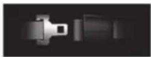
When the ignition is switched on, the rear seat belt status display informs you for a certain amount of time which rear seat belt is not fastened.
You can immediately dismiss the rear seat belt status display using the back button on the left-hand side of the steering wheel ( page 312).
If a vehicle occupant unfastens a seat belt in the rear while the vehicle is motion, the rear seat belt status display appears again.
In addition, a warning tone may sound. In this case, the rear seat belt status display cannot be hidden using the back button on the left-hand side of the steering wheel.
Airbags
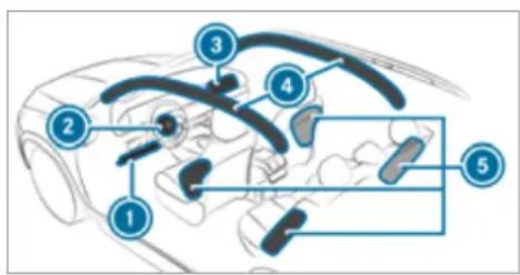
Overview of airbags
text_image
Diagram of car interior with numbered anatomical or mechanical components labeled 1 through 5① Driver's knee airbag
② Driver's airbag
3 Front passenger airbag
④ Window airbag
5 Side airbag
The installation location of an airbag is identified by the AIRBAG symbol.
When enabled, an airbag can provide additional protection for the respective vehicle occupant.
Potential protection provided by each airbag:
- Knee airbag: thigh, knee and lower leg
- Driver's airbag, front passenger airbag: head and ribcage
- Window airbag: head
- Side airbag: ribcage and pelvis
⚠ WARNING Risk of injury or death if the co-driver airbag is enabled
If the co-driver airbag is enabled, a child on the co-driver seat may be struck by the co-driver airbag during an accident.
NEVER use a rearward-facing child restraint system on a seat with an ENABLED FRONT AIRBAG; DEATH or SERIOUS INJURY to the CHILD can occur.
When fitting a child restraint system to the front passenger seat, observe the vehicle-specific information ( page 75). Also, always observe the notes on rearward-facing or forward-facing child restraint systems on the front passenger seat ( page 74).
Information on automatic front passenger airbag shutoff
The front passenger airbag can only be deployed in an accident if the PASSENGER AIR BAG OFF indicator lamp is off. If the front passenger seat is occupied, make sure, both before and during the journey, that the status of the front passenger airbag is correct ( page 50).
! NOTE Deployment of components of the restraint system when the front passenger seat is unoccupied
In an accident, the components of the restraint system may deploy unnecessarily on the front passenger side if:
- There are heavy objects on the front passenger seat.
- The seat belt tongue is engaged in the seat belt buckle of the front passenger seat and the front passenger seat is unoccupied.
Stow objects in a suitable place.
Only one person should use each seat belt at any one time.
Depending on the detected accident situation, the window airbag on the front passenger side may deploy. The airbag is deployed regardless of whether the front passenger seat is occupied.
Information on the cushionbag in the reclining rear seat
The cushionbag offers additional occupant protection in the event of frontal impacts. When enabled, the cushionbag deploys under the seat cushion. This helps prevent the vehicle occupant from slipping off the seat cushion. If you install a child restraint system on the reclining rear seat, always observe the additional notes ( page 56).
Protective capacity of the airbags
Depending on the accident situation, an airbag may supplement the protection offered by a correctly fastened seat belt.
⚠ WARNING Risk of injury or death due to an incorrect seat position
If you deviate from the correct seat position, the airbag cannot perform its intended protective function.
Each vehicle occupant must make sure of the following:
- Fasten seat belts correctly. Pregnant women must take particular care to ensure that the lap belt never lies across the abdomen.
- Adopt the correct seat position and keep as far away as possible from the airbags.
- Observe the following information.
▶ Always make sure that there are no objects between the airbag and vehicle occupant.
To avoid the risks resulting from the deployment of an airbag, each vehicle occupant must observe the following information in particular:
- Before starting your journey, adjust your seat correctly; the driver's seat and front
passenger seat should be moved as far as possible.
When doing so, always observe the information on the correct driver's seat position ( page 107).
- Only hold the steering wheel by the steering wheel rim. This allows the airbag to be fully deployed.
- Always lean against the seat backrest when the vehicle is in motion. Do not lean forwards or against the door or side window. You may otherwise be in the deployment area of the airbags.
- The occupants must always keep their feet on the floor. Do not put your feet on the cockpit, for example. Your feet may otherwise be in the deployment area of the
- If children are travelling in the vehicle, observe the additional notes ( page 56).
• Always stow and secure objects correctly.
bac Objects in the vehicle interior may prevent an airbag from functioning correctly. Each vehicle occupant must always make sure of the following in particular:
- There are no people, animals or objects between the vehicle occupants and an air-bag.
- There are no objects between the seat, door and door pillar (B-pillar).
- There are no hard objects, e.g. coat hangers, hanging on the grab handles or coat hooks.
- There are no accessory parts, such as mobile navigation devices, mobile phones or cup holders, within the deployment area of an air-bag, e.g. on the cockpit, on the door, on the side window or on the side trim.
airbag. In addition, no connecting cables, tensioning straps or retaining straps must be routed or attached to the vehicle within the deployment area of an airbag. Always comply with the accessory manufacturer's installation instructions and, in particular, the notes on suitable places for installation.
- There are no heavy, sharp-edged or fragile objects in the pockets of your clothing. Store such objects in a suitable place.
Limited protection provided by airbags
WARNING Risk of injury due to modifications to the cover of an airbag
If you modify the cover of an airbag or affix objects such as stickers to it, the airbag may no longer function correctly.
e▶ Never modify the cover of an airbag and do not affix objects to it.
The installation location of an airbag is identified by the AIRBAG symbol ( page 45).
⚠ WARNING Risk of injury or death due to the use of unsuitable seat covers
Due to unsuitable seat covers, the airbags cannot protect vehicle occupants as intended.
In addition, the operation of the automatic front passenger airbag shutoff could be restricted.
You should only use seat covers that have been approved for the corresponding seats by Mercedes-Benz.
⚠ WARNING Risk of injury due to malfunctioning sensors in the door
The function of the airbags can be impaired due to modifications or incorrect work performed on the doors or door trim, or if the doors are damaged.
▶ Never modify the doors or parts of the doors.
▶ Always have work on the doors or door trim carried out at a qualified specialist workshop.
⚠ WARNING Risk of injury due to deployed airbag
A deployed airbag no longer offers any protection.
Have the vehicle towed to a qualified specialist workshop in order to have the deployed airbag replaced.
Have deployed airbags replaced immediately.
Status of the front passenger front airbag
Function of the automatic front passenger airbag shutoff
The automatic front passenger airbag shutoff is able to detect whether the front passenger seat is occupied by a person or a child restraint system. The front passenger airbag is enabled or disabled accordingly.
WARNING Risk of injury or death due to objects under the co-driver seat
Objects trapped under the co-driver seat can interfere with the function of the automatic co-driver airbag shutoff or damage the system.
Do not store any objects under the co-driver seat.
When the co-driver seat is occupied, make sure that no objects are trapped under the co-driver seat.
When fitting a child restraint system to the front passenger seat, always make sure of the following:
- Ensure that the child restraint system is positioned correctly ( page 59).
- Always comply with the child restraint system manufacturer's installation instructions.
- Never place objects (e.g. cushions) under or behind the child restraint system.
- Fully retract the seat cushion length adjustment.
- The entire base of the child restraint system must always rest on the sitting surface of the front passenger seat.
- The backrest of the forward-facing child restraint system must, as far as possible, be resting on the seat backrest of the front passenger seat.
- The child restraint system must not touch the roof or be put under strain by the head restraints. Adjust the seat backrest inclination and the head restraint setting accordingly.
A WARNING Risk of injury or death due to objects between the seat surface and the child restraint system
Objects between the sitting surface and the child restraint system could affect the function of the automatic co-driver airbag shut-off.
Do not place any objects between the sitting surface and the child restraint system.
The entire base of the child restraint system must always rest on the sitting surface of the co-driver seat.
The backrest of the forward-facing child restraint system must, as far as possible, be resting on the seat backrest of the co-driver seat.
▶ Always comply with the child restraint system manufacturer's installation instructions.
A person on the front passenger seat must observe the following information:
- Fasten seat belts correctly (→ page 41).
- Sit in an almost upright seat position with their back against the seat backrest.
- Sit with their feet resting on the floor, if possible.
The front passenger airbag may otherwise be disabled by mistake, for example, in the following situations:
- The front passenger transfers their weight by supporting themselves on a vehicle armrest.
- The front passenger sits in such a way that their weight is raised from the sitting surface.
WARNING Risk of injury or death due to a disabled front passenger airbag
The front passenger airbag is disabled when the PASSENGER AIR BAG OFF indicator lamp is lit.
A person in the front passenger seat could then, for example, come into contact with the vehicle interior, especially if the person is sitting too close to the cockpit.
If the front passenger seat is occupied, always ensure that:
- the classification of the person in the front passenger seat is correct and the front passenger airbag is enabled or disabled in accordance with the person in the front passenger seat.
- the front passenger seat has been moved as far back as possible.
• the person is seated correctly.
Both before and during the journey, ensure that the status of the front passenger airbag is correct.
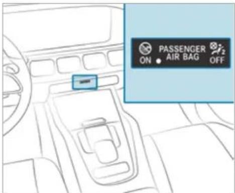
If the front passenger seat is occupied, the classification of the person or child restraint system on the front passenger seat takes place after the front passenger airbag shutoff self-test. The PASSENGER AIR BAG indicator lamps display the status of the front passenger airbag.
Always observe the notes on the function of the PASSENGER AIR BAG indicator lamps ( page 50).
Function of the PASSENGER AIR BAG indicator lamps
text_image
PASSENGER ON AIR BAG OFFSelf-test of automatic front passenger airbag shutoff
When the ignition is switched on, a self-test is performed during which the two PASSENGER AIR BAG ON and OFF indicator lamps light up simultaneously.
The status of the front passenger airbag is displayed via the PASSENGER AIR BAG indicator lamps after the self-test:
- ON is lit: the front passenger airbag may deploy during an accident.
The indicator lamp goes out after approximately 60 seconds. - ON and OFF are not lit: the front passenger airbag may deploy during an accident.
- OFF is lit: the front passenger airbag is disabled. It will then not be deployed in the event of an accident.
If the PASSENGER AIR BAG ON indicator lamp is off, only the PASSENGER AIR BAG OFF indicator lamp shows the status of the front passenger airbag. The PASSENGER AIR BAG OFF indicator lamp may be lit continuously or be off. If the PASSENGER AIR BAG OFF indicator lamp and the restraint system warning lamp light up simultaneously, the front passenger seat may not be used. Also in this case, do not fit a child restraint system to the front passenger seat. Have the automatic front passenger airbag
shutoff checked and repaired immediately at a qualified specialist workshop.
Status display
If the front passenger seat is occupied, ensure, both before and during the journey, that the status of the front passenger airbag is correct for the current situation.
After fitting a rearward-facing child restraint system to the front passenger seat:
PASSENGER AIR BAG OFF must be lit continuously.

WARNING Risk of injury or death when using a rearward-facing child restraint system while the front passenger airbag is enabled
If you secure a child in a rearward-facing child restraint system on the front passenger seat and the PASSENGER AIR BAG OFF indicator lamp is off, the front passenger airbag can deploy in the event of an accident. The child could be struck by the airbag.
Always ensure that the front passenger air-bag is disabled. The PASSENGER AIR BAG OFF indicator lamp must be lit.
NEVER use a rearward-facing child restraint system on a seat with an ENABLED FRONT AIRBAG. This can result in the DEATH of or SERIOUS INJURY to the CHILD.
When fitting a child restraint system to the front passenger seat, observe the vehicle-specific information ( page 74).
Depending on the child restraint system and the stature of the child, the PASSENGER AIR BAG OFF indicator lamp may be off. In this case, not fit the rearward-facing child restraint system to the front passenger seat.
Instead, fit the rearward-facing child restraint system to a suitable rear seat.
After fitting a forward-facing child restraint system to the front passenger seat: depending on the child restraint system and the stature of the child, PASSENGER AIR BAG OFF may be lit continuously or be off. Always observe the following information.

WARNING Risk of injury or death due to incorrect positioning of the forward-facing child restraint system
If you secure a child in a forward-facing child restraint system on the front passenger seat that is positioned too close to the cockpit, in the event of an accident, the child could:
- come into contact with the vehicle interior if the PASSENGER AIR BAG OFF indicator lamp is lit, for example
- be struck by the airbag if the PASSENGER AIR BAG OFF indicator lamp is off.
Always move the front passenger seat as far back as possible and fully retract the seat cushion length adjustment. While doing so, always make sure that the shoulder belt strap is correctly routed from the seat belt outlet of the vehicle to the shoulder belt guide on the child restraint system. The shoulder belt strap must be routed forwards and downwards from the seat belt outlet. If necessary, adjust the seat belt outlet
and the front passenger seat accordingly.
Always comply with the child restraint system manufacturer's installation instructions.
When fitting a child restraint system to the front passenger seat, observe the vehicle-specific information ( page 74).
If a person is sitting on the front passenger seat: PASSENGER AIR BAG OFF may be lit continuously or be off, depending on the person's stature.
A person on the front passenger seat must always observe the following information:
- If the front passenger seat is occupied by an adult or a person with a stature corresponding to that of an adult, the PASSENGER AIR BAG OFF indicator lamp must be off. This indicates that the front passenger airbag is enabled.
If the PASSENGER AIR BAG OFF indicator lamp is lit continuously, an adult or person
with a build corresponding to that of an adult must not use the front passenger seat. Instead, they should use a rear seat.
- If the front passenger seat is occupied by a person of smaller stature (e.g. a teenager or small adult), the PASSENGER AIR BAG OFF indicator lamp is either lit continuously or remains off, depending on the classification.
If the PASSENGER AIR BAG OFF indicator lamp is off: move the front passenger seat as far back as possible, or the person of smaller stature should use a rear seat.
- If the PASSENGER AIR BAG OFF indicator lamp is lit continuously: the person of smaller stature should not use the front passenger seat.
WARNING Risk of injury or death when the PASSENGER AIR BAG OFF indicator lamp is lit
If the PASSENGER AIR BAG OFF indicator lamp remains lit after the self-test, the front passenger airbag is disabled.
If the front passenger seat is occupied, always ensure that:
- The classification of the person in the front passenger seat is correct and the front passenger airbag is enabled or disabled in accordance with the person in the front passenger seat.
- The person is seated properly with a correctly fastened seat belt.
- The front passenger seat has been moved as far back as possible.
Be sure to also observe the following further related subjects:
- Child restraint system on the front passenger seat ( page 74)
- Suitable positioning of the child restraint system ( page 59)
PRE-SAFE® system
PRE-SAFE® (anticipatory occupant protection)
PRE-SAFE ^® is able to detect certain critical driving situations and implement pre-emptive measures to protect the vehicle occupants.
PRE-SAFE® can implement the following measures independently of each other:
- Tightening the seat belts on the driver's seat and front passenger seat.
- Closing the side windows.
• Vehicles with sliding sunroof: close the sliding sunroof. - Vehicles with memory function: move the front passenger seat to a more favourable seat position.
- Vehicles with memory function in the rear compartment: move the outer rear seats to a more favourable seat position.
- Vehicles with multicontour seat: increase the air pressure in the seat side bolsters of the seat backrest.
- PRE-SAFE® Sound: provided that the multi-media system is switched on, generates a brief noise signal to stimulate the innate protective mechanism of a person's hearing.
NOTE Damage caused by objects in the footwell or behind the seat
The automatic adjustment of the seat position may result in damage to the seat and/or the object.
▶ Stow objects in a suitable place.
Reversing the PRE-SAFE ^® system measures
If an accident did not occur, the pre-emptive measures that were taken are reversed.
You will need to perform certain settings yourself.
If the seat belt pre-tensioning is not reduced, move the seat backrest back slightly. The locking mechanism releases.
Function of PRE-SAFE® PLUS (anticipatory occupant protection plus)
PRE-SAFE® PLUS can detect certain impacts, particularly an imminent rear impact, and take pre-emptive measures to protect the vehicle occupants. These measures cannot necessarily prevent an imminent impact.
PRE-SAFE® PLUS can implement the following measures independently of each other:
- Tightening the seat belts on the driver's seat and front passenger seat.
- Activating the rear hazard warning lights at a higher flashing frequency.
- Increasing brake pressure when the vehicle is stationary. This brake application is cancelled automatically when the vehicle pulls away.
If an accident did not occur, the pre-emptive measures that were taken are reversed.
System limits
The system will not initiate any action in the following situations:
- when reversing
or - when the vehicle is towing a trailer and there is a risk of a rear impact
The system will not initiate any braking application in the following situations:
- whilst driving
or - when entering or exiting a parking space while using Active Parking Assist
Function of PRE-SAFE ^® Impulse Side
If an imminent side impact is detected, PRE-SAFE® Impulse Side can pre-emptively move the front seat vehicle occupant's upper body towards the centre of the vehicle. It does this by rapidly inflating an air cushion in the outer seat side bolster of the seat backrest on the side on which the impact is anticipated. This increases
the distance between the door and the vehicle occupant.
If PRE-SAFE Impulse Side has been deployed or is faulty, the PRE-SAFE impulse side inoperative See Owner's Manual(→ page 446) display message appears.
Automatic measures after an accident
Depending on the type and severity of the accident, and depending on the vehicle's equipment, the following measures can be implemented, for example:
• automatic braking (post-collision brake)
• activating the hazard warning lights
- triggering an automatic emergency call (→ page 353)
- switching off the engine To restart the vehicle, switch the ignition off and switch it back on (→ page 191). Depending on the type and severity of the accident, it is possible that the vehicle can no longer be started.
• switching off the fuel supply
- unlocking the vehicle doors
• lowering the side windows
- displaying the emergency guide in the multi-media system display
- switching on the interior lighting
Function of the post-collision brake
Depending on the accident situation, the post-collision brake can minimise the severity of a further collision or even avoid it.
If an accident is detected, the post-collision brake can implement automatic braking. When the vehicle has come to a standstill, the electric parking brake is automatically applied.
The driver can cancel automatic braking by taking the following actions:
- braking more strongly than automatic braking
- fully depressing the accelerator pedal with force
Safely transporting children in the vehicle
Always observe when children are travelling in the vehicle
Also strictly observe the safety notes for the specific situation. In this way you can recognise potential risks and avoid dangers if children are travelling in the vehicle ( page 56).
Be diligent
Bear in mind that negligence when securing a child in the child restraint system may have serious consequences. Always be diligent in securing a child carefully before every journey.
To improve protection for children younger than 12 years old or under 1.50m in height, Mercedes-Benz recommends you observe the following information:
- Always secure the child in a child restraint system suitable for this Mercedes-Benz vehicle.
- The child restraint system must be appropriate to the age, weight and size of the child.
- The vehicle seat must be suitable for fitting a child restraint system ( page 59).
Accident statistics show that children secured on the rear seats are generally safer than children secured on the front seats. For this reason, Mercedes-Benz strongly advises that you fit a child restraint system to a rear seat.
The generic term child restraint system
The generic term child restraint system is used in this Owner's Manual. A child restraint system is, for example:
- a baby car seat
• a rearward-facing child seat
• a forward-facing child seat - a child booster seat with a backrest and seat belt guide
Mercedes-Benz recommends using a child booster seat with a backrest.
The child restraint system must be appropriate to the age, weight and size of the child.
Observe laws and legal requirements
Always observe the legal requirements when using a child restraint system in the vehicle. Make sure that the child restraint system is approved in accordance with the valid test specifications and guidelines. Further information can be obtained at a qualified specialist workshop. Mercedes-Benz recommends that you use a Mercedes-Benz Service Centre for this purpose.
Only use approved child restraint systems
Only child restraint systems that meet the following UNECE standards are permitted for use in the vehicle:
- UN-R44
• UN-R129 (i-Size child restraint systems)
Information on child restraint system approval categories and details on the approval label on the child restraint system ( page 60).
Detecting risks, avoiding danger
Securing systems for child restraint systems in the vehicle
Only use the following securing systems for child restraint systems:
• the ISOFIX or i-Size securing rings
• the vehicle's seat belt system
• the Top Tether anchorages
Fitting an ISOFIX or an i-Size child restraint system is preferred.
Simply attaching to the securing rings on the vehicle can reduce the risk of fitting the child restraint system incorrectly.
When securing a child with the integrated seat belt of the ISOFIX or i-Size child restraint system, always comply with the permissible gross weight for the child and child restraint system ( page 64).
Advantage of a rearward-facing child restraint system
It is preferable to transport a baby or a small child in a suitable rearward-facing child restraint system. In this case, the child sits in the opposite direction to the direction of travel and faces backwards.
Babies and small children have comparatively weak neck muscles in relation to the size and weight of their head. The risk of injury to the cervical spine during an accident can be reduced a rearward-facing child restraint system.
Always secure a child restraint system correctly
WARNING Risk of injury or death due to incorrect installation of the child restraint system
The child can then not be protected or restrained as intended.
Be sure to comply with the manufacturer's installation instructions for the child restraint system and its correct use.
Make sure that the entire base of the child restraint system always rests on the sitting surface of the seat.
▶ Never place objects (e.g. cushions) under or behind the child restraint system.
▶ Use child restraint systems only with the original cover designed for them.
Always replace damaged covers with genuine covers.
A WARNING Risk of injury or death due to unsecured child restraint systems in the vehicle
If the child restraint system is incorrectly fitted or not secured, it can come loose.
The child restraint system could be flung around and hit vehicle occupants.
Always install child restraint systems correctly, even when not in use.
Always comply with the child restraint system manufacturer's installation instructions.
• Always observe the child restraint system manufacturer's installation and operating
instructions as well as the vehicle-specific information:
- Fitting the ISOFIX or i-Size child restraint system to the rear seat ( page 64).
Securing the child restraint system with the seat belt on the rear seat ( page 72).
Securing the child restraint system with the seat belt on the front passenger seat ( page 75). Observe the specific instructions for the rearward-facing and forward-facing child restraint systems ( page 74).
If the front passenger seat is occupied, ensure, both before and during the journey, that the status of the front passenger airbag is correct for the current situation ( page 50).
- Observe the warning labels in the vehicle interior and on the child restraint system.
- Also secure Top Tether if present.
Do not modify the child restraint system
WARNING Risk of injury due to modifications to the child restraint system
The child restraint system can no longer function properly. This poses an increased risk of injury.
▶ Never modify a child restraint system.
Only affix accessories which have been specially approved for this child restraint system by the child restraint system's manufacturer.
Mercedes-Benz recommends Mercedes-Benz care products for cleaning child restraint systems recommended by Mercedes-Benz.
Only use child restraint systems which are in proper working condition
A WARNING Risk of injury or death caused by the use of damaged child restraint systems
Child restraint systems or their retaining systems that have been subjected to stress in an accident may not be able to perform their intended protective function.
It may be the case that the child cannot be properly restrained.
▶ Always immediately replace child restraint systems that have been damaged or involved in an accident.
Have the securing systems for the child restraint systems checked at a qualified specialist workshop before installing a child restraint system again.
Avoid direct sunlight
WARNING Risk of burns when the child seat is exposed to direct sunlight
If the child restraint system is exposed to direct sunlight or heat, parts could heat up. Children could suffer burns from these parts, particularly on metallic parts of the child restraint system.
▶ Always make sure that the child restraint system is not exposed to direct sunlight.
Protect the child restraint system with a blanket, for example.
If the child restraint system has been exposed to direct sunlight, allow it to cool before securing a child into it.
▶ Never leave children unattended in the vehicle.
Observe when stopping or parking
A WARNING Risk of accident and injury due to leaving children unattended in the vehicle
If children are left unattended in the vehicle, they could, in particular:
- open doors, thereby endangering other persons or road users.
- get out and be struck by oncoming traffic.
• operate vehicle equipment and become trapped, for example.
In addition, the children could also set the vehicle in motion by, for example:
• releasing the parking brake.
- changing the transmission position.
- starting the vehicle.
▶ Never leave children unattended in the vehicle.
When leaving the vehicle, always take the key with you and lock the vehicle.
Keep the vehicle key out of the reach of children.
A WARNING Danger to life due to exposure to extreme heat or cold in the vehicle
If people, particularly children, are exposed to extreme temperatures over an extended period of time, there is a risk of serious injury or danger to life.
▶ Never leave persons, children in particular, unattended in the vehicle.
Overview of recommended child restraint systems
Further information on the correct child restraint system can be obtained at a qualified specialist workshop. Mercedes-Benz recommends that you use a Mercedes-Benz Service Centre for this purpose.
Securing with ISOFIX
Weight category 0+ (up to 13 kg and up to approx. 15 months)
| Type1 | BABY SAFE plus |
| Size category | E |
| Approval | E1 04 301 146 |
| Order number2 | B6 6 86 8224 |
| 1 Manufacturer: Britax Römer. | 2 With colour code 9H95. |
Weight category I (9 to 18 kg and from approximately 9 months to 4 years)
| Type1 | DUO plus |
| Size category B1 | |
| Approval E1 04 301 | 133 |
| Order number2 | A 000 970 43 02 |
| 1 Manufacturer: Britax Römer. | 2 With colour code 9H95. |
Securing with the vehicle seat belt
Weight category 0 (up to 10 kg and approximately 6 months) and weight category 0+ (up to 13 kg and approximately 15 months)
| Type1 | BABY SAFE plus II |
| Approval | E1 04 301 146 |
| Order number2 | A 000 970 38 02 |
| 1 Manufacturer: Britax Römer. | 2 With colour code 9H95. |
Weight category I (9 to 18 kg and from approximately 9 months to 4 years)
| Type1 | DUO plus |
| Approval E1 04 301 | 133 |
| Order number2 | A 000 970 43 02 |
| 1 Manufacturer: Britax Römer. | 2 With colour code 9H95. |
Weight category II/III (15 to 36 kg and from approximately 3 to 12 years)
| Type1 | KIDFIX XP |
| Approval E1 04 301 | 304 |
| Order number2 | A 000 970 49 02 |
| Type1 | AMG KIDFIX XP |
| Approval E1 04 301 | 304 |
| Order number2 | A 000 970 33 02 |
| 1 Manufacturer: Britax Römer. | 2 With colour code 9H95. |
Overview of suitable seats in the vehicle for fitting a child restraint system
Left/right rear seat
Second row of seats, preferred securing system:
ISOFIX child seat anchor ( page 62)
or
i-Size child seat anchor ( page 64)

Also secure Top Tether if present ( page 68)
Third row of seats, preferred securing system:

ISOFIX child seat anchor ( page 62)

Also secure Top Tether if present ( page 68).
Left/right rear seat (second and third seat row) - alternative securing system:

Vehicle seat belt ( page 70)
Front passenger seat
Securing system:

Vehicle seat belt ( page 70)
Be sure to observe:
- If the front passenger seat is occupied, ensure, both before and during the journey, that the status of the front passenger airbag is correct for the current situation ( page 50).
- Observe the notes on automatic front passenger airbag shutoff (→ page 48)
Centre rear seat
Centre rear seat (second seat row) – securing system:

Vehicle seat belt ( page 70)
Approval categories for child restraint systems
Only use approved child restraint systems
Only child restraint systems that meet the following UNECE standards are permitted for use in the vehicle:
- UN-R44
• UN-R129 (i-Size child restraint systems)
Identification on the child restraint system
Information about the approval category, weight category and approval number, for example, is on the approval label on the child restraint system.
There may be further information such as the ISOFIX size categories, depending on the approval category of the child restraint system.
Approval categories in accordance with UN-R44

text_image
universal 9 - 18 kg E1 03301095 HERSTELLER 0007386Example of an approval label
- Universal: child restraint systems in the "Universal" category are approved for installation in vehicles. They can be used, in accordance with overviews of the suitability
of seats for securing child restraint systems, on seats labelled U, UF or IUF.
The identification IUF refers to ISOFIX child restraint systems in the "Universal" category. These child restraint systems must also be secured using Top Tether or support points.
- Semi-Universal: child restraint systems in the "Semi-Universal" category may only be used if the vehicle and vehicle seat are listed in the child restraint system manufacturer's vehicle model list.
- Vehicle-specific: child restraint systems in the "vehicle-specific" category may only be used if the vehicle and vehicle seat are listed in the child restraint system manufacturer's vehicle model list.
Approval categories in accordance with UN-R129
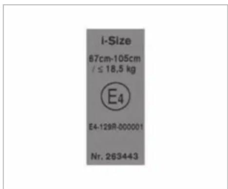
text_image
I-Size 87cm-105cm / ≤ 18,5 kg E4 E4-129R-000001 Nr. 263443Example of an approval label
- i-Size: child restraint systems in the "i-Size" category are approved for installation in vehicles with i-Size mounting brackets. They can be used, in accordance with overviews of the
suitability of seats for securing child restraint systems, on seats labelled i-U.
The identification i-U refers to i-Size child restraint systems in the "Universal" category. These child restraint systems must also be secured using Top Tether or support points.
Observe the suitability of vehicle seats
Depending on the approval category, there are forward-facing and rearward-facing child restraint systems. Their use can be restricted for certain vehicle seats:
- Suitability of seats for attaching ISOFIX child restraint systems ( page 62)
- Suitability of seats for securing i-Size child restraint systems ( page 64).
- Suitability of seats for attaching belt-secured child restraint systems ( page 70)
Fitting an ISOFIX or i-Size child restraint system on the rear seat
Overview of suitability of the seats for attaching ISOFIX child restraint systems
ISOFIX is a standardised securing system for specially designed child restraint systems.

The symbol indicates seats suitable for attaching an ISOFIX child restraint system in accordance with UN R44 ( page 60) Attach only child restraint systems that are approved in accordance with UN R44 as per the following ISOFIX tables.
Carry cot for second and third rows of seats
| Size class - Equipment | Left/right rear seat |
| F - ISO/L1 X | |
| G - ISO/L2 X | |
| X Not suitable for an ISOFIX child restraint system in this weight group and/or size class. | |
Weight group 0 (up to 10 kg and up to approx. 6 months) for second and third rows of seats
| Size class - Equipment | Left/right rear seat |
| E - ISO/R1 IL | |
| IL Suitable for ISOFIX child restraint systems according to the table in "Overview of the recommended child restraint systems", or if the vehicle and the seat are listed on the child restraint system manufacturer's vehicle model list. | |
Weight group 0+ (up to 13 kg and up to approx. 15 months) for second row of seats
| Size class - Equipment | Left/right rear seat |
| E - ISO/R1 IL | |
| D - ISO/R2, ISO/R2X | IL |
Size class - Equipment Left/right rear seat
C - ISO/R3 IL (1)
IL Suitable for ISOFIX child restraint systems according to the table in "Overview of the recommended child restraint systems", or if the vehicle and the seat are listed on the child restraint system manufacturer's vehicle model list.
(1) When using a child restraint system of size class (ISO/R3), move the front seat into the highest position. Make sure that the seat backrest of the front seat does not rest against the child restraint system.
Weight group 0+ (up to 13 kg and up to approx. 15 months) for third row of seats
| Size class - Equipment | Left/right rear seat |
| E - ISO/R1 IL | |
| D - ISO/R2, ISO/R2X | X |
| C - ISO/R3 X | |
| IL Suitable for ISOFIX child restraint systems according to the table in "Overview of the recommended child restraint systems", or if the vehicle and the seat are listed on the child restraint system manufacturer's vehicle model list. | |
| X Not suitable for an ISOFIX child restraint system in this weight group and/or size class. | |
Weight group 1 (9–18 kg and approx. 9 months up to 4 years) for second row of seats
| Size class - Equipment | Left/right rear seat |
| D - ISO/R2, ISO/R2X | IL |
| C - ISO/R3 IL (1) | |
| B - ISO/F2 IUF |
| Size class - Equipment | Left/right rear seat |
| B1 - ISO/F2X IUF | |
| A - ISO/F3 IUF | |
| II. Suitable for ISOFIX child restraint systems according to the table in "Overview of the recommended child restraint systems", or if the vehicle and the seat are listed on the child restraint system manufacturer's vehicle model list.IUF Suitable for forward-facing ISOFIX child restraint systems of the "Universal" category in this weight group.(1) When using a child restraint system of size class (ISO/R3), move the front seat into the highest position. Make sure that the seat backrest of the front seat does not rest against the child restraint system. | |
Weight group 1 (9–18 kg and approx. 9 months up to 4 years) for third row of seats
| Size class - Equipment | Left/right rear seat |
| D - ISO/R2, ISO/R2X | X |
| C - ISO/R3 X | |
| B - ISO/F2 IUF | |
| B1 - ISO/F2X IUF | |
| A - ISO/F3 IUF | |
| X Not suitable for an ISOFIX child restraint system in this weight group and/or size class.IUF Suitable for forward-facing ISOFIX child restraint systems of the "Universal" category in this weight group. | |
Overview of suitability of the seats for attaching i-Size child restraint systems
i-Size is a standardised securing system for specially designed child restraint systems.

The symbol indicates seats suitable for attaching an i-Size child restraint system in accordance with UN R129 ( page 60).
Child restraint systems that are permitted in accordance with UN R44 as per the ISOFIX tables ( page 62) or UN R129 per the following i-Size tables may be attached.
i-Size child restraint systems (ISO/R2, ISO/F2X, ISO/B2, ISO/B3)
| Front passenger seat | Left/right rear seat (second row of seats only) |
| X | i |
| X Not suitable for an i-Size child restraint system in the "Universal" category. as | i-U Suitable for forward-facing and rearward-facing i-Size child restraint systems in the "Universal" category. |
Fitting an ISOFIX or i-Size child restraint system on the rear seat

WARNING Risk of accident if the rear bench seat, rear seat and seat backrest are not engaged
The rear bench seat, rear seat and seat back-rest may fold forwards, even while the vehicle is in motion.
- As a result, the vehicle occupant will be pressed into the seat belt with increased force. The seat belt will not be able to protect as intended and could cause additional injury.
- Objects or loads in the boot or load compartment cannot be restrained by the seat backrest.
Make sure that the rear bench seat, the rear seat and the seat backrest are engaged before every trip.
If the seat backrest is not engaged and locked in place, this will be shown on the multifunction display on the instrument cluster (folding the rear seat back electrically) or the red lock verification indicator will be visible (folding the rear seat back mechanically).
WARNING Risk of injury or death if the permissible gross mass of the child and child restraint system together is exceeded.
Too much load may be placed on the ISOFIX or i-Size child restraint systems and the child may not be restrained correctly in the event of an accident, for example.
If the child and the child restraint system together weigh more than 33 kg, only use an ISOFIX or i-Size child restraint system with which the child is secured with the vehicle seat belt.
Also secure the child restraint system with the Top Tether belt, if available.
Always comply with the information about the mass of the child restraint system:
- in the manufacturer's installation and operating instructions for the child restraint system used
- on a label on the child restraint system, if present
Regularly check that the permissible gross mass of the child and child restraint system is still complied with.
When fitting a child restraint system, observe the following:
√ Always observe the correct use of the seats and consider their suitability for attaching a child restraint system.
ISOFIX child seat securing system ( page 62)
or
i-Size child seat securing system ( page 64)
√ Always comply with the manufacturer's installation and operating instructions for the child restraint system used.
√ Make sure that the child's feet do not touch the front seat. If necessary, move the front seat slightly forwards.
When fitting an ISOFIX child restraint system, also observe the following:
When using a baby car seat in weight group 0/0+ and a rearward-facing child
restraint system in weight group 1 on a rear seat: adjust the front seat so that the seat does not touch the child restraint system.
When using a forward-facing child restraint system in weight group 1:
remove the head restraint from the respective seat, if possible. In addition, the back-rest of the child restraint system must lie as flat as possible against the backrest of the vehicle seat.
After the child restraint system has been removed, replace the head restraints again immediately and adjust them correctly.
When using a child restraint system on a seat on the third row of seats: adjust the front seat so that it does not touch the child restraint system and move the seat backrest of the front seat into an upright position if necessary.
If the head restraint of the child seat cannot be fully extended when it is installed in the vehicle, this will result in restrictions on the
maximum size setting for child restraint systems in weight category II or III.
Contact with the roof when the head restraint is fully extended and locked in place will not result in any restrictions on use.
√ The child restraint system must not be put under strain between the roof and the seat cushion and/or be fitted facing the wrong direction. Where possible, adjust the seat cushion inclination accordingly.
√ The child restraint system must not be put under strain by the head restraint. Adjust the head restraints as appropriate.
When fitting an i-Size child restraint system, also observe the following:
√ When using a rearward-facing child restraint system: adjust the front seat so that it does not touch the child restraint system.
√ When using a forward-facing child restraint system: remove the head restraint from the respective seat, if possi-
ble. In addition, the backrest of the child restraint system must lie as flat as possible against the backrest of the vehicle seat.
After the child restraint system has been removed, replace the head restraints again immediately and adjust them correctly.
Before every journey, make sure that the ISOFIX child restraint system or the i-Size child restraint system is engaged correctly in both mounting brackets in the vehicle.
NOTE Damage to the seat belt for the centre seat during installation of the child restraint system
Make sure that the seat belt is not trapped.
Vehicles with single rear seats:
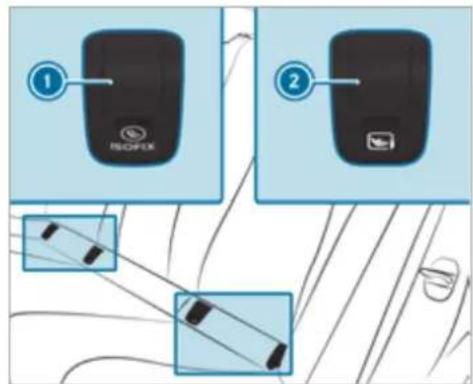
text_image
① NSOFLIX ②1 ISOFIX mounting bracket
② i-Size mounting bracket
Remove and stow away covers ① or ② of the mounting brackets in the vehicle.
Attach the ISOFIX or i-Size child restraint system to both mounting brackets in the vehicle.
After removing the child restraint system, reattach covers ① or ②.
Vehicles with a rear bench seat:
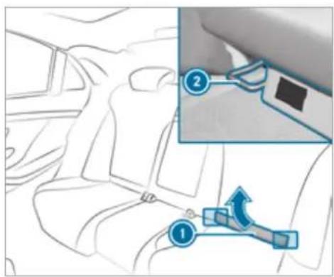
text_image
Diagram showing car seatbelt adjustment with numbered instructions for lifting a seatbeltMercedes-Maybach vehicles with reclining rear seats: before an ISOFIX or i-Size child restraint system is installed, tilt the backrest of the reclining rear seat back slightly.
Remove upholstered lining ①.
▶ Vehicles without reclining rear seats: fold upholstered lining ① upwards.
Turn the support on the rear side of upholstered lining ① by 90°.
Upholstered lining ① will remain folded upwards.
Attach the ISOFIX or i-Size child restraint system to both mounting brackets ② in the vehicle.
Mercedes-Maybach vehicles with reclining rear seats: return the reclining rear seat backrest to an upright position. The reclining rear seat backrest must be in contact with the child restraint system.
Vehicles with a third row of seats:
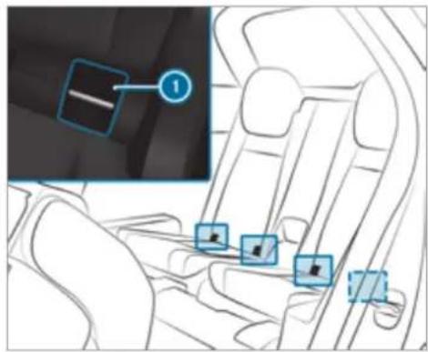
text_image
Diagram showing car interior with highlighted vehicle lane and location markers, including a numbered annotation box.Attach the ISOFIX child restraint system to both ISOFIX mounting brackets ①.
Securing Top Tether

WARNING Risk of injury or death if the rear seat backrests are not locked after Top Tether belts are fitted
The rear seat backrests may fold forwards when you are driving.
As a result, child restraint systems will no longer be able to perform their intended protective function. This may also cause additional injuries.
Always lock rear seat backrests after fitting Top Tether belts.
▶ Observe the lock verification indicator.
If the seat backrest is not engaged and locked in place, this will be shown on the multifunction display on the instrument cluster (folding the rear seat back electrically) or the red lock verification indicator will be visible (folding the rear seat back mechanically).

If the child restraint system is equipped with a Top Tether belt:
The risk of injury may be reduced by Top Tether. The Top Tether belt enables an additional connection between the child restraint system attached with ISOFIX or i-Size and the vehicle.
The Top Tether anchorages for the second row of seats are located on the rear side of the two outer rear seats on the second row of seats. For the third row of seats, use the Top Tether anchorage on the rear side of the seat backrest on the third row of seats.
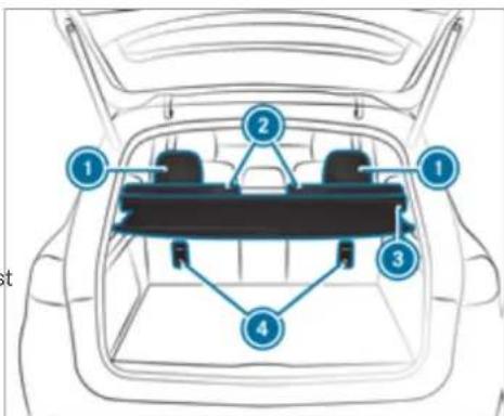
text_image
Diagram of a car backrest with numbered compartments and structural connectionsSecond row of seats
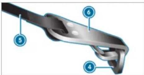
text_image
Technical diagram of a mechanical component with numbered parts labeled 4, 5, and 6If necessary, slide head restraint ① upwards (→ page 119).
Fit the ISOFIX or i-Size child restraint system with Top Tether. In doing so, comply with the child restraint system manufacturer's installation instructions.
Guide Top Tether belt ⑤ under head restraint ① between the two head restraint bars.
If load compartment cover ③ is installed, guide Top Tether belt ⑤ downwards between load compartment cover ③ and seat backrest ②.
Hook Top Tether hook ⑥ of Top Tether belt ⑤ into Top Tether anchorage ④ without twisting.
Tension Top Tether belt ⑤. In doing so, comply with the child restraint system manufacturer's installation instructions.
If necessary, slide head restraint ① downwards (→ page 119). Make sure that you do not interfere with the correct routing of Top Tether belt ⑤.
Mercedes-Maybach vehicles
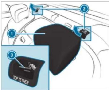
text_image
1 2 3 TOP TETHERIf necessary, slide head restraint ① upwards (→ page 119).
Remove cover ② of Top Tether anchorage ③.
Fit the ISOFIX or i-Size child restraint system with Top Tether. In doing so, comply with the
child restraint system manufacturer's installation instructions.
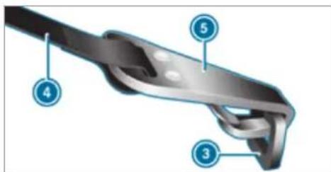
text_image
Technical diagram of a mechanical component with numbered parts labeled 3, 4, and 5Guide Top Tether belt ④ under head restraint ① between the two head restraint bars.
Hook Top Tether hook ⑤ of Top Tether belt ④ into Top Tether anchorage ③ without twisting.
Tension Top Tether belt ④. In doing so, comply with the child restraint system manufacturer's installation instructions.
If necessary, slide head restraint ① downwards (→ page 119). Make sure that you do
not interfere with the correct routing of Top Tether belt ④.
Securing the child restraint system with the seat belt
Notes on the suitability of seats for attaching belt-secured child restraint systems
Rear seats (second seat row)
| Weight category 0: up to 10 kg | |
| Left/right rear seat U, L | |
| Centre rear seat | U, L |
| Weight category 0+: up to 13 kg | |
| Left/right rear seat U, L | |
| Centre rear seat | U, L |
| Weight category l: 9 to 18 kg | |
| Left/right rear seat U, L | |
| Centre rear seat | U, L |
| Weight category II: 15 to 25 kg | |
| Left/right rear seat U, L | |
| Centre rear seat | U, L |
| Weight category III: 22 to 36 kg | |
| Left/right rear seat U, L | |
| Centre rear seat | U, L |
| 1 Child restraint systems with a supporting bracket are not suitable for this seat. | |
| U Suitable for child restraint systems of the "Universal" category in this weight category. | |
| L Suitable for semi-universal child restraint systems according to the table in "Recommended child restraint systems", or if the vehicle and the seat are listed in the child restraint system manufacturer's vehicle model list. |
Rear seats (third seat row)
| Weight category 0: up to 10 kg | |
| Left/right rear seat U, L | |
| Weight category 0+: up to 13 kg | |
| Left/right rear seat U, L | |
| Weight category I: 9 to 18 kg | |
| Left/right rear seat U, L | |
| Weight category II: 15 to 25 kg | |
| Left/right rear seat U, L | |
| Weight category III: 22 to 36 kg | |
| Left/right rear seat U, L |
U Suitable for child restraint systems of the "Universal" category in this weight category.
L Suitable for semi-universal child restraint systems according to the table in "Recommended child restraint systems", or if the vehicle and the seat are listed in the child restraint system manufacturer's vehicle model list.
Mercedes-Maybach vehicles with a reclining rear seat: the bottom and back of a forward-facing child restraint system must make full contact with the reclining rear seat sitting surface and seat backrest. The child restraint system must not touch the roof. Adjust the seat backrest inclination accordingly. Also observe the child restraint system manufacturer's installation instructions.
Notes on child restraint systems on the front passenger seat
- If it is absolutely necessary for you to fit a child restraint system to the front passenger seat, be sure to observe the information on
child restraint systems on the front passenger seat ( page 75).
- Observe the specific instructions for the rearward-facing and forward-facing child restraint systems. If the front passenger seat is occupied, ensure, both before and during the journey, that the status of the front passenger airbag is correct for the current situation ( page 50).
Front passenger seat
| Weight category 0: up to 10 kg | |
| Front passenger airbag enabled | X |
| Front passenger airbag disabled^2 | U, L |
| Weight category 0+: up to 13 kg | |
| Front passenger airbag enabled | X |
| Front passenger airbag disabled^2 | U, L |
| Weight category l: 9 to 18 kg | |
| Front passenger airbag enabled | UF |
| Front passenger airbag disabled | U, L |
| Weight category II: 15 to 25 kg | |
| Front passenger airbag enabled | UF |
| Front passenger airbag disabled | U, L |
| Weight category III: 22 to 36 kg | |
| Front passenger airbag enabled | UF |
| Front passenger airbag disabled | U, L |
| 1 Adjust the seat cushion inclination so that the front edge of the seat cushion is in the highest position and the rear edge of the seat cushion is in the lowest position. | |
| 2 The vehicle is equipped with automatic front passenger airbag shutoff. The PASSENGER AIR BAG OFF indicator lamp must be lit. | |
| X Not suitable for children in this weight category. | |
| U Suitable for child restraint systems of the "Universal" category in this weight category. |
| L Suitable for semi-universal child restraint systems according to the table in "Recommended child restraint systems", or if the vehicle and the seat are listed in the child restraint system manufacturer's vehicle model list. | |
| UF Suitable for forward-facing child restraint systems of the "Universal" category in this weight category. |
Securing the child restraint system with the seat belt on the rear seat

WARNING Risk of accident if the rear bench seat, rear seat and seat backrest are not engaged
The rear bench seat, rear seat and seat back-rest may fold forwards, even while the vehicle is in motion.
- As a result, the vehicle occupant will be pressed into the seat belt with increased force. The seat belt will not be able to protect as intended and could cause additional injury.
- Objects or loads in the boot or load compartment cannot be restrained by the seat backrest.
Make sure that the rear bench seat, the rear seat and the seat backrest are engaged before every trip.
If the seat backrest is not engaged and locked in place, this will be shown on the multifunction display on the instrument cluster (folding the rear seat back electrically) or the red lock verification indicator will be visible (folding the rear seat back mechanically).
When fitting a belt-secured child restraint system, observe the following:
√ Always comply with the manufacturer's installation and operating instructions for the child restraint system used.
For a child restraint system in the "Universal" or "Semi-Universal" category, make sure that the system has been approved for the vehicle seat.
Observe the notes under "Suitability of seats for attaching belt-secured child restraint systems" ( page 70).
√ When using a weight category 0/0+ baby car seat and a weight category I rearward-facing child restraint system on a rear seat: adjust the front seat so that the seat does not touch the child restraint system.
√ When using a weight category I forward-facing child restraint system: remove the head restraint from the respective seat, if possible.
After the child restraint system has been removed, replace the head restraints again immediately and adjust them correctly.
√ The backrest of the forward-facing child restraint system must, as far as possible, be resting on the seat backrest of the rear seat.
☑ If the head restraint of the child seat cannot be fully extended when it is installed in the vehicle, this will result in restrictions on the
maximum size setting for child restraint systems in weight category II or III.
Contact with the roof when the head restraint is fully extended and locked in place will not result in any restrictions on use.
√ The child restraint system must not be put under strain between the roof and the seat cushion and/or be fitted facing the wrong direction. Where possible, adjust the seat cushion inclination accordingly.
√ The child restraint system must not be put under strain by the head restraint. Adjust the head restraints as appropriate.
√ Make sure that the child's feet do not touch the front seat. If necessary, move the front seat slightly forwards.
Install the child restraint system.
The entire base of the child restraint system must always rest on the sitting surface of the rear seat.
Always make sure that the shoulder belt strap is correctly routed from the seat belt
outlet of the vehicle to the shoulder belt guide on the child restraint system. The shoulder belt strap must be routed forward from the seat belt outlet.
Notes on vehicles without automatic front passenger airbag shutoff
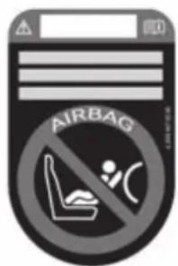
text_image
AIRBAGSticker visible when the front passenger door is open
Vehicles without automatic front passenger airbag shutoff have a special sticker affixed to the side of the cockpit on the front passenger side.
Make sure you observe the following information:
- Never fit a rearward-facing child restraint system to the front passenger seat
-
Always fit a rearward-facing child restraint system to a suitable rear seat
-
Suitability of seats for attaching belt-secured child restraint systems ( page 70)
- Secure the child restraint system with the seat belt on the rear seat ( page 72).
- Notes on rearward-facing and forward-facing child restraint systems on the front passenger seat ( page 74)
Notes on rearward-facing and forward-facing child restraint systems on the front passenger seat

WARNING Risk of injury or death when using a rearward-facing child restraint system while the front passenger airbag is enabled
If you secure a child in a rearward-facing child restraint system on the front passenger seat and the PASSENGER AIR BAG OFF indicator lamp is off, the front passenger airbag can deploy in the event of an accident.
The child could be struck by the airbag.
Always ensure that the front passenger airbag is disabled. The PASSENGER AIR BAG OFF indicator lamp must be lit.
▶ NEVER use a rearward-facing child restraint system on a seat with an ENABLED FRONT AIRBAG. This can result in the DEATH of or SERIOUS INJURY to the CHILD.
Observe the specific instructions for the rear-ward-facing and forward-facing child restraint systems ( page 75).
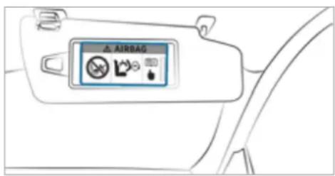
text_image
AIRBAGWarning notice on the front passenger sun visor
Always observe the status of the front passenger airbag on the PASSENGER AIR BAG OFF indicator lamp:
- If it is absolutely necessary to fit a child restraint system to the front passenger seat, always observe the information on automatic front passenger airbag shutoff ( page 48).
- When using a rearward-facing child restraint system on the front passenger seat, the front
passenger airbag must always be disabled. This is only the case if the PASSENGER AIR BAG OFF indicator lamp is lit continuously ( page 50).
- If the PASSENGER AIR BAG OFF indicator lamp is off, the front passenger airbag is enabled. The front passenger airbag may deploy during an accident.
Securing the child restraint system with the seat belt on the front passenger seat
When fitting a belt-secured child restraint system on the front passenger seat, always observe the following:
√ Observe the notes on rearward-facing and forward-facing child restraint systems on the front passenger seat ( page 74).
√ Observe the child restraint system manufacturer's installation and operating instructions.
For a child restraint system in the "Universal" or "Semi-Universal" category, make sure that the system has been approved for the vehicle seat.
Observe the notes under "Suitability of seats for attaching belt-secured child restraint systems" ( page 70).
When using a forward-facing child restraint system in weight category I: remove the head restraint from the respective seat, if possible.
After the child restraint system has been removed, replace the head restraints again immediately and adjust them correctly.
√ The backrest of the forward-facing child restraint system must, as far as possible, be resting on the seat backrest of the front passenger seat.
If the head restraint of the child seat cannot be fully extended when it is installed in the vehicle, this will result in restrictions on the maximum size setting for child restraint systems in weight category II or III.
Contact with the roof when the head restraint is fully extended and locked in place will not result in any restrictions on use.
√ The child restraint system must not be put under strain between the roof and the seat cushion and/or be fitted facing the wrong direction.
√ The child restraint system must not be put under strain by the head restraint. Adjust the head restraints as appropriate.
√ Never place objects (e.g. cushions) under o behind the child restraint system.
Set the front passenger seat as far back as possible and move the seat into the highest position if possible.
Fully retract the seat cushion length adjustment.
Adjust the seat cushion inclination so that the front edge of the seat cushion is in the highest position and the rear edge of the seat cushion is in the lowest position.
Set the seat backrest to the most vertical position possible.
Install the child restraint system. The entire base of the child restraint system must always rest on the sitting surface of the front passenger seat.
Always make sure that the shoulder belt strap is correctly routed from the seat belt outlet of the vehicle to the shoulder belt guide on the child restraint system. The shoulder belt strap must be routed forwards and downwards from the seat belt outlet.
If necessary, adjust the seat belt outlet and the front passenger seat accordingly.
Child safety locks
Activating or deactivating the child safety lock for the rear doors
WARNING Risk of accident and injury due to leaving children unattended in the vehicle
If children are left unattended in the vehicle, they could, in particular:
- open doors, thereby endangering other persons or road users.
• get out and be struck by oncoming traffic.
• operate vehicle equipment and become trapped, for example.
In addition, the children could also set the vehicle in motion by, for example:
• releasing the parking brake.
- changing the transmission position.
- starting the vehicle.
▶ Never leave children unattended in the vehicle.
When leaving the vehicle, always take the key with you and lock the vehicle.
Keep the vehicle key out of the reach of children.
A WARNING Danger to life due to exposure to extreme heat or cold in the vehicle
If people, particularly children, are exposed to extreme temperatures over an extended period of time, there is a risk of serious injury or danger to life.
▶ Never leave persons, children in particular, unattended in the vehicle.
A WARNING Risk of accident and injury due to children left unattended in the vehicle
If children are travelling in the vehicle, they could, in particular:
- open doors, thereby endangering other persons or road users.
• get out and be struck by oncoming traffic.
• operate vehicle equipment and become trapped, for example.
▶ Always activate the installed child safety locks if children are travelling in the vehicle.
▶ Never leave children unattended in the vehicle.
When leaving the vehicle, always take the key with you and lock the vehicle.
Vehicles for the United Kingdom: observe the important safety notes in the "Notes on the additional door lock" section.
There are child safety locks for the rear doors and the rear side windows.
The child safety lock on the rear doors secures each door separately. The doors can no longer be opened from the inside.
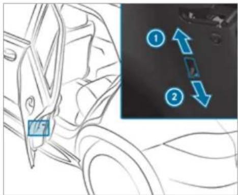
text_image
Diagram showing car door and side view with numbered arrows indicating movement or change, alongside a magnified inset of the door.Press the lever in direction ① (activate) or ② (deactivate).
Make sure that the child safety locks are working properly.
Activating and deactivating the child safety lock for the rear side windows
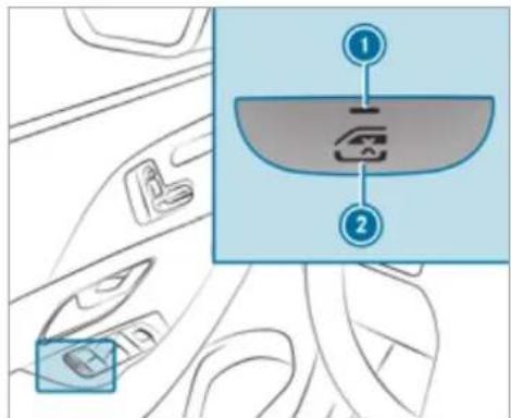
text_image
Diagram showing car interior with labeled parts and a zoomed-in view highlighting a component with 'X' and directional arrows.To activate/deactivate: press button ②.
The rear side window can be opened or closed in the following cases:
- indicator lamp ① is lit: via the switch on the driver's door
- indicator lamp ⓘ is off: via the switch on the corresponding rear door or driver's door
Notes on pets in the vehicle

WARNING Risk of accident and injury due to animals left unsecured or unattended in the vehicle
If you leave animals in the vehicle unattended or unsecured, they could press buttons or switches, for instance.
An animal may:
- activate vehicle equipment and become trapped, for example
- switch systems on or off and endanger other road users
Unsecured animals may be thrown about the vehicle in the event of an accident, or sudden steering and braking manoeuvres, and injure vehicle occupants.
▶ Never leave animals unattended in the vehicle.
Always correctly secure animals while driving, e.g. using a suitable animal carrier.
Key
Overview of key functions
A WARNING Risk of accident and injury due to leaving children unattended in the vehicle
If children are left unattended in the vehicle, they could, in particular:
- open doors, thereby endangering other persons or road users.
- get out and be struck by oncoming traffic.
- operate vehicle equipment and become trapped, for example.
In addition, the children could also set the vehicle in motion by, for example:
- releasing the parking brake.
• changing the transmission position. - starting the vehicle.
▶ Never leave children unattended in the vehicle.
When leaving the vehicle, always take the key with you and lock the vehicle.
Keep the vehicle key out of the reach of children.
NOTE Damage to the key caused by magnetic fields
Keep the key away from strong magnetic fields.
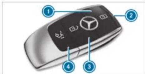
text_image
Diagram of a car key with labeled parts including the BMW logo and numbered annotationsVehicle key
1 Locks
2 Indicator lamp
3 Unlocks
④ Opens/closes the tailgate
If indicator lamp does not light up after pressing the ☑ or ☐ button, the battery is weak or possibly discharged. Replace the battery as soon as possible.
Replace the key battery ( page 81).
The key locks and unlocks the following components:
- doors
- fuel filler flap
- tailgate
If the vehicle is not opened within approximately 40 seconds after unlocking, it locks again. Anti-theft protection is primed again.
Do not keep the key together with electronic devices or metal objects. This can affect the key's functionality.
Do not keep the key in the temperature-controlled cup holder. Otherwise, the key will not be reliably detected.
Activating/deactivating the acoustic locking verification signal
Multimedia system:
→ Settings Vehicle
▶ Activate or deactivate Acoustic lock.
i Please note:
The selected setting for the acoustic locking verification signal must comply with the relevant national road and traffic regulations. In some countries, including Germany, using the acoustic locking verification signal is forbidden by traffic laws (in accordance with §16 Para. 1 and §30 Para. 1 of the German national road traffic regulations). The driver of the vehicle must comply with these regulations. In countries where the use of this function is forbidden, this function is not activated in the vehicle and must not be activated.
Changing the unlocking settings
Possible unlocking functions of the key:
- Central unlocking
- Unlocking the driver's door and fuel filler flap
To switch between settings: press the ☑ and ☑ buttons simultane approximately six seconds until the indicator lamp flashes twice.
Options if the unlocking function for the driver's door and fuel filler flap has been selected:
- To unlock the vehicle centrally: press the button twice.
- Vehicles with KEYLESS-GO: if you touch the inner surface of the door handle on the driver's door, only the driver's door and fuel filler flap are unlocked.
Deactivating the function of the key
Vehicles with KEYLESS-GO: if you deactivate the function of the key, the KEYLESS-GO functions are also deactivated. Access or drive authorization by KEYLESS-GO is then no longer possible with that particular key. Activate the function of the key so that all its functions will again be available.
You can also deactivate the function of the key to reduce the energy consumption of the key if you do not use the vehicle or a key for an extended period of time.
To deactivate: press the button on the key twice in quick succession. The key indicator lamp flashes twice briefly and lights up once.
To activate: press any button on the key.
When the vehicle is started with the key in the stowage compartment of the centre console, the function of the key is automatically activated ( page 192).
Removing/inserting the emergency key
Removing the emergency key

text_image
Diagram illustrating a mechanical or electrical process with labeled components and directional arrows indicating movement or force.Press release button ①.
Emergency key ② is pushed out slightly.
Pull out emergency key ② until it engages in the intermediate position.
Press release button ① again and fully remove emergency key ②.
Inserting the emergency key
Press release button 1.
Insert emergency key ② to the intermediate position or fully until it engages.
① You can use the intermediate position of emergency key ② to attach the key to a key ring.
Replacing the key battery
DANGER Risk of fatal injuries due to swallowing batteries
Batteries contain toxic and corrosive substances. Swallowing batteries may cause severe internal burns to occur within two hours.
There is a risk of fatal injury.
Keep batteries out of the reach of children.
If the cap and/or the battery compartment does not close securely, do not use the key any longer and keep it out of the reach of children.
If batteries are swallowed, seek medical attention immediately.
ENVIRONMENTAL NOTE Environmental damage due to improper disposal of batteries

Batteries contain pollutants. It is illegal to dispose of them with the household rubbish.

Dispose of batteries in an environmentally responsible manner. Take discharged batteries to a qualified specialist workshop or to a collection point for used batteries.
Requirements:
• You require a CR 2032 3 V cell battery.
Mercedes-Benz recommends that you have the battery replaced at a qualified specialist workshop.
Remove the emergency key ( page 81).
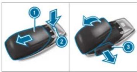
text_image
Diagram showing three steps of car wheel turning process with arrows indicating direction and rotationPress release knob ② down fully and slide cover ① in the direction of the arrow.
Fold out cover ① in the direction of the arrow and remove.
Remove battery compartment ③ and take out the discharged battery.
Insert the new battery into battery compartment ③. Observe the positive pole marking in the battery compartment and on the battery when doing this.
▶ Push in battery compartment ③.
Re-attach cover ① and push it until it engages.
Problems with the key, troubleshooting
You can no longer lock or unlock the vehicle
Possible causes:
• The key battery is weak or discharged.
▶ Check the battery using the indicator lamp ( page 79).
Replace the key battery, if necessary ( page 81).
Use the replacement key.
Use the emergency key to lock or unlock ( page 86).
Have the key checked at a qualified specialist workshop.
There is interference from a powerful radio signal source
Possible causes if the function of the key is impaired:
• high voltage power lines
- mobile phones
• electronic devices (notebooks, tablets) - shielding due to metal objects or induction loops for electrical gate systems or automatic barriers
Make sure that there is sufficient distance between the key and the potential source of interference.
You have lost a key
Have the key deactivated at a qualified specialist workshop.
If necessary, have the mechanical lock replaced as well.
Doors
Notes on the additional door lock
The additional door lock is only available for vehicles for the United Kingdom.

WARNING Risk of injury to persons inside the vehicle when the additional door lock is activated
If the additional door lock is activated, the doors can no longer be opened from the inside.
▶ Never leave persons, in particular children, unattended in the vehicle.
If there are persons in the vehicle, do not activate the additional door lock.
The additional door lock is automatically activated in the following situations:
• The vehicle is locked using the key.
• The vehicle is locked using KEYLESS-GO.
If the vehicle has been locked via Mercedes me connect, the additional door lock is not activated.
If the additional door lock is activated, the doors cannot be opened from the inside.
① After locking you can issue a signal with the horn.
You can prevent the additional door lock from being activated by deactivating interior protection before locking the vehicle ( page 106).
Unlocking/opening the doors from the inside
United Kingdom only: observe the notes on the additional door lock ( page 82).
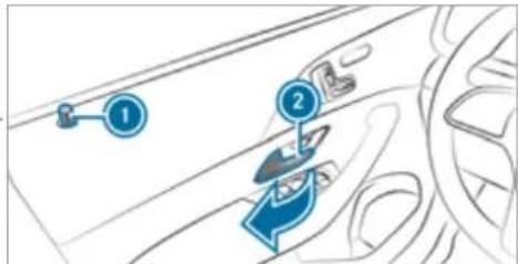
text_image
Diagram showing car interior components with numbered labels and directional arrows indicating movement or flowPull door handle Locking pin unlocked.
- pops up when the door is
Centrally locking and unlocking the vehicle from the inside

text_image
Diagram showing car interior with labeled lock icons and a zoomed-in panel view highlighting key components.To unlock: press button ①.
To lock: press button 2.
Mercedes-Maybach vehicles: the buttons are also located on the rear doors. This does not lock or unlock the fuel filler flap.
The vehicle is not unlocked:
• If you have locked the vehicle using the key.
- If you have locked the vehicle using KEY-LESS-GO.
Locking/unlocking the vehicle with KEY-LESS-GO
Requirements:
• The key is outside the vehicle.
- The distance between the key and the vehicle does not exceed 1 m.
- The driver's door and the door on which the door handle is used are closed.

NOTE Vehicle damage due to unintentional opening of the tailgate
- when using an automatic car wash
- when using a high pressure cleaner
▶ Deactivate the function of the key in these situations.
or
Make sure that the key is at a minimum distance of 3 m away from the vehicle.
Observe the following information:
• Information on washing the vehicle in a car wash ( page 374)
• Information on using a high-pressure cleaner ( page 377)
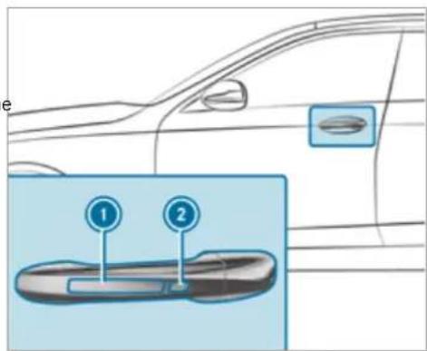
text_image
Diagram showing a car's side profile with two labeled sensors (1 and 2) and an inset highlighting the sensor placement.To unlock the vehicle: touch the inner surface of the door handle.
To lock the vehicle: touch sensor surface ① or ②.
▶ Convenience closing: touch recessed sensor surface ② until the closing process has been completed.
i Further information on convenience closing ( page 96).
If you open the tailgate from outside, it is automatically unlocked.
Problems with KEYLESS-GO, troubleshooting
You can no longer lock or unlock the vehicle using KEYLESS-GO
Possible causes:
• The function of the key has been deactivated.
• The key battery is weak or discharged.
Activate the function of the key ( page 80).
Check the battery using the indicator lamp ( page 79).
Replace the key battery, if necessary ( page 81).
▶ Use the replacement key.
Use the emergency key to lock or unlock ( page 86).
Have the vehicle and key checked at a qualified specialist workshop.
There is interference from a powerful radio signal source
Possible causes if the function of KEYLESS-GO is impaired:
• high voltage power lines
- mobile phones
• electronic devices (notebooks, tablets)
- shielding due to metal objects or induction loops for electrical gate systems or automatic barriers
Make sure that there is sufficient distance between the key and the potential source of interference.
Activating/deactivating the automatic locking feature
The vehicle is locked automatically when the ignition is switched on and the wheels are ing faster than walking pace.
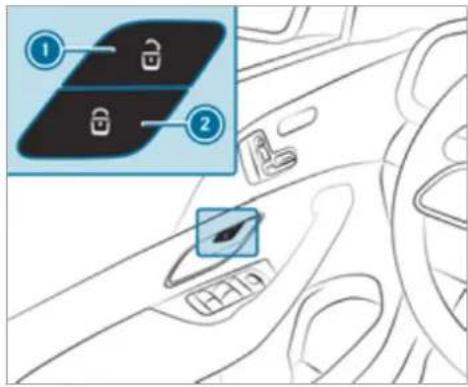
text_image
Diagram showing car interior with labeled parts and a close-up of a lock panel interfaceTo activate: press and hold button ② for approximately five seconds until an acoustic signal sounds.
To deactivate: press and hold button ① for approximately five seconds until an acoustic signal sounds.
turnIn the following situations, there is a danger of being locked out when the function is activated
- while the vehicle is being tow-started or pushed
- if the vehicle is being tested on a roller dynamometer
Power closing function
⚠ WARNING Risk of becoming trapped when the doors close automatically Body parts or objects can become trapped, causing injuries.
▶ Ensure that no body parts or objects are in the closing area.
▶ Automatic closing of the doors can be cancelled by pulling the outer or inner door handle.
If you push the door into the lock to the first detent position, the power closing function will automatically pull the door into the lock.
Locking/unlocking the driver's door with the emergency key
If you wish to lock the vehicle entirely using the emergency key, first press the button for locking from the inside while the driver's door is open. Then proceed to lock the driver's door using the emergency key.
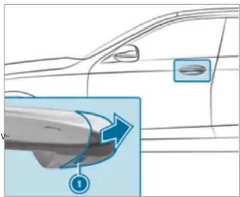
natural_image
Diagram showing a car's side profile with a magnified view of the handle and arrow, no text or symbols present.Remove the emergency key ( page 81).
Insert the emergency key as far as it will go into opening ① in the cover.
▶ Pull and hold the door handle.
▶ Pull the cover on the emergency key as straight as possible away from the vehicle until it releases.
Release the door handle.
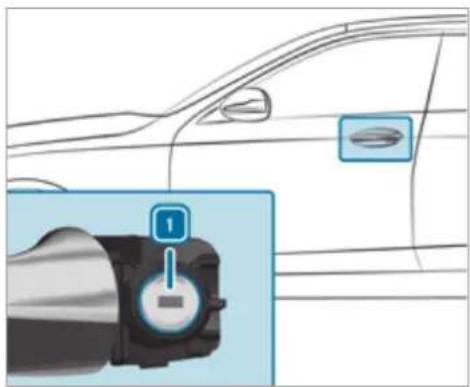
natural_image
Diagram of a car's side profile with a highlighted engine component (no text or symbols)To unlock: turn the emergency key anticlockwise to position 1.
To lock: turn the emergency key clockwise to position 1.
Carefully press the cover onto the lock cylinder until it engages and is seated firmly.
Running boards
Operation of the running boards
Mercedes-Maybach vehicles: the vehicle is equipped with electrically extendable running boards. If you have selected the automatic mode in the multimedia system, (→ page 88) the running board will extend automatically on the respective side when a door is opened. When the running boards are extended, check the excess width of the vehicle.
You can extend or retract the running boards manually for cleaning ( page 88).
The running boards will extend and retract only if the vehicle is stationary.
In the following cases, the running boards will retract automatically:
- If you select an off-road drive program (→ page 205).
• If you activate car wash mode ( page 376). - If the outside mirrors fold in automatically ( page 175).
- If you are driving at a speed greater than 4 km/h.
If you have selected the automatic mode in the multimedia system and you manually extend the running boards when the doors are closed, the running boards will remain extended. Even if you open a door and then close it again, the running boards will remain extended. Automatic mode will be reactivated only when you are driving at a speed greater than 4 km/h.
WARNING Risk of injury when extending or retracting the running boards
The running boards extend at the side during extension. During retraction, the running boards are integrated in the side skirt. Parts of the body could become trapped. There may be people in the range of movement. There is a risk of injury.
▶ Always ensure that there are no people within the range of movement of the running boards.
NOTE Damage to the running boards during extension or retraction
The running boards extend at the side during extension. During retraction, the running boards are integrated in the side skirt.
Make sure that there is sufficient space during extension and retraction.
! NOTE Damage to the vehicle body or underbody due to low ground clearance
The running boards are attached to the vehicle body via the underbody. This limits the ground clearance.
▶ Drive over obstacles, such as kerbs, particularly carefully and slowly.
Observe the corresponding display messages in the instrument cluster ( page 445).
Extending and retracting the running boards via the multimedia system
Multimedia system:
Settings Vehicle
SIDE RUNNING BOARD
▶ Select Extend or Retract.
Automatically extending and retracting the running boards
▶ Activate or deactivate AUTOMATIC EXTENSION.
① This equipment is available only for Mercedes-Maybach vehicles.
Load compartment
Opening the tailgate
DANGER Risk of exhaust gas poisoning Combustion engines emit poisonous exhaust gases such as carbon monoxide. Exhaust gases can enter the vehicle interior if the tail-
gate is open when the engine is running, especially if the vehicle is in motion.
Always switch off the engine before opening the tailgate.
▶ Never drive with the tailgate open.
NOTE Damage to the tailgate caused by obstacles above the vehicle
The tailgate swings rearwards and upwards when it is opened.
Make sure that there is sufficient space behind and above the tailgate.
If the tailgate is unlocked, pull the tailgate handle and release it again immediately.
▶ Vehicles with HANDS-FREE ACCESS: make a kicking movement with your foot below the bumper (→ page 91).
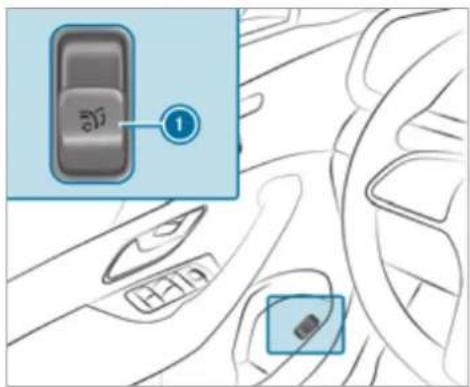
text_image
Diagram showing car interior control panel with labeled buttons and a numbered annotation pointing to the main panel.Pull remote operating switch ① for the tailgate.
Press and hold the 📞 button on the key.
If the tailgate is stopped in an intermediate position, pull it upwards. Release it as soon as it begins to open.
If an obstacle obstructs the tailgate during the automatic opening process, blockage detection
will stop the tailgate. The automatic blockage detection function is only an aid. It is not a stitute for your attentiveness.
Closing the tailgate
⚠ WARNING Risk of injury from unsecured items in the vehicle
If objects, luggage or loads are not secured or not secured sufficiently, they could slip, tip over or be thrown around and thereby hit vehicle occupants.
There is a risk of injury, particularly in the event of sudden braking or a sudden change in direction.
Always stow objects in such a way that they cannot be thrown around.
Before the journey, secure objects, luggage or loads against slipping or tipping over.
Observe the notes on loading the vehicle.
Notes on closing the tailgate: your vehicle is equipped with automatic key recognition. If a key
belonging to the vehicle is detected in the vehicle, the tailgate will not be locked.
Note that the tailgate will not be locked in the following situation:
- You have locked the vehicle and close the tailgate while a key belonging to the vehicle is inside the vehicle. and
- A second key belonging to the vehicle is not detected outside the vehicle.
Automatic key recognition is only an aid and is not a substitute for your attentiveness.
Before locking, ensure that at least one key belonging to the vehicle is outside the vehicle.
To close the tailgate: pull the tailgate downwards slightly. Release it as soon as it begins to close.
⚠ WARNING Risk of becoming trapped during automatic closing of the tailgate
Body parts may become trapped. There may be people in the closing area.
▶ Make sure that nobody is in the vicinity of the closing area during the closing process.
Use one of the following options to stop the closing process:
- Press the button on the key.
- Press or pull the remote operating switch on the driver's door.
- Press the closing or locking button on the tailgate.
- Pull the tailgate handle.
Vehicles with HANDS-FREE ACCESS: it is also possible to stop the closing process by making a kicking movement below the rear bumper.
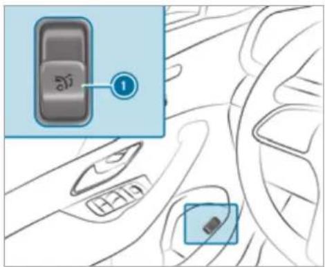
text_image
Diagram showing car control panel with Chinese label '1' pointing to a key, alongside a close-up of the control panel.▶ Switch on the power supply or the ignition.
Press remote operating switch ① for the tailgate.
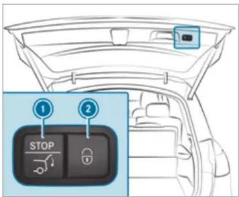
text_image
1 STOP 2Press closing button ① on the tailgate.
Vehicles with KEYLESS-GO
Press locking button ② on the tailgate. If a key is detected outside the vehicle, the tailgate will close and the vehicle will be locked.
Press and hold the 📞 button on the key (with the key in the vicinity of the vehicle).
Vehicles with HANDS-FREE ACCESS
Make a kicking movement with your foot below the bumper ( page 91).
Automatic reversing function for the tailgate
The tailgate is equipped with automatic blockage detection with a reversing function. If a solid object hinders or restricts the tailgate when it is closing automatically, the tailgate will automatically open again slightly. Automatic blockage detection with reversing function is only an aid. It is not a substitute for your attentiveness when you are closing the tailgate.
During the closing process, make sure that no body parts are in the closing area.
WARNING Risk of becoming trapped despite reversing function
The reversing function will not react:
• to soft, light and thin objects, e.g. fingers
• towards the end of the closing procedure
In these situations in particular, the reversing function cannot prevent someone being trapped.
▶ Ensure that no body parts are in the closing area.
If someone is trapped, either:
- Press the button on the key.
- Press or pull the remote operating switch on the driver's door.
- Press the closing or locking button on tailgate.
- Pull the tailgate handle.
HANDS-FREE ACCESS function
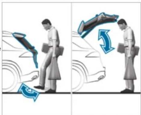
natural_image
Illustration showing a person performing a car lift exercise with directional arrows indicating motion (no text or symbols)With HANDS-FREE ACCESS you can open, close or stop the closing process of the tailgate by performing a kicking movement under the rear bumper.
The kicking movement triggers the opening or closing process alternately.
Observe the notes when opening ( page 88) and closing ( page 89) the tailgate.
① Two warning tones sound when the tailgate is opening or closing.
WARNING Risk of burns caused by a hot exhaust system
The vehicle exhaust system can become very hot. If you use HANDS-FREE ACCESS, you could burn yourself by touching the exhaust system.
▶ Always ensure that you only make a kicking movement within the detection range of the sensors.
NOTE Vehicle damage due to unintentional opening of the tailgate
- when using an automatic car wash
- when using a high pressure cleaner
▶ Deactivate the function of the key in these situations.
or
Make sure that the key is at a minimum distance of 3 m away from the vehicle.
When making the kicking movement, make sure that you are standing firmly on the ground. You could otherwise lose your balance, e.g. on ice. Observe the following notes:
• The key is behind the vehicle.
- Stand at least 30 cm away from the vehicle while performing the kicking movement.
- Do not come into contact with the bumper while making the kicking movement.
- Do not carry out the kicking movement too slowly.
- The kicking movement must be towards the vehicle and back again.
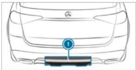
natural_image
Top-down line drawing of a car's rear bumper with a blue circular marker labeled '1' pointing to the front grille (no text or symbols beyond the label)① Detection range of the sensors
If several consecutive kicking movements are not successful, wait ten seconds.
System limits
The system may be impaired or may not function in the following cases:
- The sensors are dirty, e.g. due to road salt or snow.
- The kicking movement is made using a prosthetic leg.
The tailgate can open or close unintentionally in the following situations:
- A person's arms or legs are moving in the sensor detection range, e.g. when polishing the vehicle or picking up objects.
- Objects are moved or placed behind the vehicle, e.g. tensioning straps or luggage.
- Clamping straps, tarpaulins or other coverings are pulled over the bumper.
- A protective mat with a length reaching over the boot sill down into the detection range of the sensors is used.
• The protective mat is not secured correctly.
• Work is being done on the trailer hitch, trail-on ers or rear bicycle racks.
Deactivate the function of the key ( page 80) or do not carry the key about your person in such situations.
Limiting the opening angle of the tailgate
Activating the opening angle limiter
You can limit the opening angle of the tailgate in the top half of its opening range up to a point shortly before the end position.
Stop the opening procedure of the tailgate at the desired position.
Press and hold the closing button on the gate until you hear a short acoustic signal. The opening angle limiter will be activated. The tailgate will then stop in the stored position when opened.
To open the tailgate fully, pull the handle on the outside of the tailgate again after it has stopped automatically.
Deactivating the opening angle limiter
Press and hold the closing button on the tailgate until two short acoustic signals sound.
Releasing the tailgate in an emergency
Requirements:
• Only for Mercedes-Maybach vehicles.
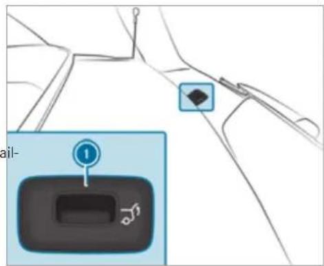
text_image
Diagram showing a car interior control panel with a numbered indicator and a location pin, likely from an automotive or navigation system.Remove cover ①.
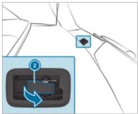
text_image
Diagram showing a device control panel with a numbered indicator and directional arrow, likely illustrating a system or navigation interface.Pull lever ② in the direction of the arrow until the tailgate unlocks.
Unlocking the tailgate with the emergency key
Requirements:
• Not for Mercedes-Maybach vehicles.
- The rear seat backrest has been folded forward.
- The load compartment cover has been removed.

text_image
Diagram showing a car interior with labeled components, including a highlighted section and a zoomed-in view of the device.Remove the emergency key ( page 81).
Insert emergency key ② into opening ① in the trim and push it in.
The tailgate will be unlocked.
Side windows
Opening and closing the side windows
WARNING Risk of becoming trapped when opening a side window
When you open a side window, parts of the body could be drawn in or become trapped between the side window and window frame.
When opening, make sure that nobody is touching the side window.
If someone is trapped, release the button immediately or pull it in order to close the side window again.
WARNING Risk of becoming trapped when closing a side window
When closing a side window, body parts could be trapped in the closing area in the process.
When closing, make sure that no body parts are in the closing area.
If someone is trapped, release the button immediately or press the button in order to reopen the side window.
WARNING Risk of becoming trapped when children operate the side windows
Children could become trapped if they operate the side windows, particularly when unattended.
Activate the child safety lock for the rear side windows.
When leaving the vehicle, always take the key with you and lock the vehicle.
▶ Never leave children unattended in the vehicle.
Requirements:
- The power supply or the ignition is switched on.
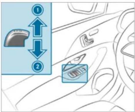
text_image
Diagram showing car interior with directional arrows and labeled parts, likely indicating movement or positioning in a vehicle.Closing
2 Opening
The buttons on the driver's door take precedence.
To start automatic operation: press the button beyond the point of resistance or pull and release it.
To interrupt automatic operation: press or pull the ☐ button again.
When the vehicle is switched off, you can continue to operate the side windows. This function is available for around four minutes or until a front door is opened.
① Vehicles with electric roller sunblinds on rear doors on the left and right: the buttons for the rear side windows also open and close the roller sunblinds (→ page 103).
Automatic reversing function of the side windows
If an obstacle impedes a side window during the closing process, the side window will open again automatically. The automatic reversing function is only an aid and is not a substitute for your attentiveness.
During the closing process, make sure that no body parts are in the closing area.
A WARNING Risk of becoming trapped despite there being reversing protection on the side window
The reversing function does not react:
• to soft, light and thin objects, e.g. fingers.
- during resetting.
The reversing function cannot prevent someone from becoming trapped in these situations.
During the closing process, make sure that no body parts are in the closing area.
If someone becomes trapped, press the button to open the side window again.
Automatic function of the side windows
In the following cases, the side windows will be closed automatically when the vehicle is switched off:
- if it starts to rain
Rain is detected by a rain sensor on the windscreen.
• in extreme temperatures
- after a certain time (depending on the onboard electrical system voltage)
• if there is a malfunction in the power supply
The side windows will be closed as far as the ventilation position.
Vehicles with a sliding sunroof: the side windows will be closed completely if the sliding sunroof is open.
If the side windows are obstructed during automatic closing, the side window concerned will open again slightly. The automatic function for the sliding sunroof and the side windows will then be deactivated.
Convenience opening (ventilating the vehicle before starting a journey)

WARNING Risk of entrapment when opening a side window
When opening a side window, parts of the body could be drawn in or become trapped between the side window and window frame.
When opening, make sure that nobody is touching the side window.
Release the button immediately if somebody becomes trapped.
Press and hold the ☑ button on the The following functions are performed:
• The vehicle is unlocked.
• The side windows are opened.
• The sliding sunroof is opened.
• The panoramic sliding roof is opened.
- The seat ventilation of the driver's seat is switched on.
If the roller sunblind of the panoramic sliding sunroof is closed, the roller sunblind is opened first.
If the roller sunblinds of the rear doors are closed, the roller sunblinds are opened first.
To interrupt convenience opening: release the 🔒 button.
To continue convenience opening: press and hold the 🔒 button again.
Convenience closing (closing the vehicle from outside)

WARNING Risk of entrapment due to not paying attention during convenience closing
When the convenience closing feature is operating, parts of the body could become trapped in the closing area of the side window and the sliding sunroof.
When the convenience closing feature is operating, monitor the entire closing
process and make sure that no body parts are in the closing area.
Press and hold the ⏻ button on the The following functions are performed:
• The vehicle is locked.
• The side windows are closed.
• The sliding sunroof is closed.
• The panoramic sliding roof is closed.
To interrupt convenience closing: release the button.
To continue convenience closing: press and hold the ☑ button again.
i Convenience closing also functions with KEYLESS-GO ( page 84).
Resolving problems with the side windows
WARNING Risk of becoming trapped or fatally injured if reversing protection is not activated
If you close a side window again immediately after it has been blocked, the side window will close with increased or maximum force. The reversing function is then not active and body parts may become trapped.
Make sure that no parts of the body are in the closing area.
To stop the closing process, release the button or press the button again to reopen the side window.
A side window cannot be closed and you can- not see the cause.
Check to see whether any objects are in the window guide.
Adjust the side windows.
Adjusting the side windows
If a side window is obstructed during closing a reopens again immediately:
Immediately after this, pull and hold the corresponding button again until the side window has closed and hold the button for at least one more second (re-adjustment).
The side window will be closed without the automatic reversing function.
If the side window is obstructed again and reopens again immediately:
Immediately after this, pull and hold the corresponding button again until the side window has closed and hold the button for at least one more second (follow-up adjustment). The side window will be closed without the automatic reversing function.
The side windows cannot be opened or closed using the convenience opening feature.
Possible causes:
• The key battery is weak or discharged.
Check the battery using the indicator lamp ( page 79).
Replace the key battery, if necessary ( page 81).
Sliding sunroof
Opening and closing the sliding sunroof
The term "sliding sunroof" also refers to the panorama sliding sunroof.

WARNING Risk of becoming trapped when the sliding sunroof is being opened and closed
Body parts may become trapped in the range of movement.
During opening and closing, make sure that no body parts are in the range of movement.
Release the button immediately if somebody becomes trapped.
or
Briefly press the button in any direction during automatic operation. The opening or closing process will be stopped.

WARNING Risk of entrapment if the sliding sunroof is operated by children
Children operating the sliding sunroof could get caught in the moving parts, particularly if unattended.
▶ Never leave children unattended in the vehicle.
When leaving the vehicle, always take the key with you and lock the vehicle.

WARNING Risk of becoming trapped when the roller sunblind is being opened and closed
Body parts may become trapped between the roller sunblind and frame or sliding roof.
When opening or closing, make sure that no body parts are in the roller sun-blind's range of movement.
Release the button immediately if somebody becomes trapped.
or
Briefly press the button in any direction during automatic operation.
The opening or closing process will be stopped.

NOTE Malfunction due to snow and ice
Snow and ice may cause the sliding sunroof to malfunction.
Open the sliding sunroof only if it is free of snow and ice.

NOTE Damage caused by protruding objects
Objects that protrude from the sliding sun-roof may damage the sealing strips.
Do not allow anything to protrude from the sliding sunroof.
NOTE Important points to remember when a roof luggage rack is fitted
When a roof luggage rack is fitted, raising or opening the sliding sunroof may be limited.
▶ Check whether the sliding sunroof can be raised or opened when a roof luggage rack is fitted.
If in doubt, do not raise or open the sliding sunroof.
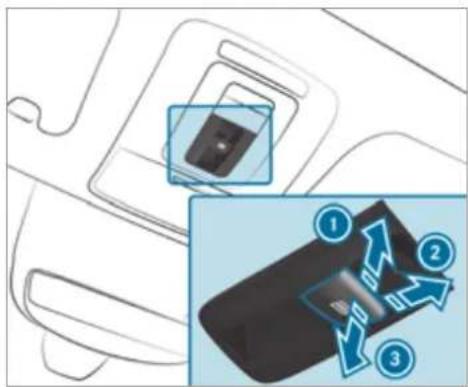
text_image
Diagram showing a car interior with a close-up of a device and three numbered arrows indicating flow or interaction.To raise
② To open
3 To close/lower
Use the button to operate the panorama sliding sunroof and the roller sunblind.
The panorama sliding sunroof can be operated only when the roller sunblind is open.
The roller sunblind can be opened only when the panorama sliding sunroof is closed or in the raised position.
Check whether the sliding sunroof can be raised or opened when a roof luggage rack is fitted.
To start automatic operation: press the button beyond the point of resistance or pull and release it.
To interrupt automatic operation: briefly press the button in any direction. The opening/closing process will be stopped.
To ventilate the vehicle interior: raise the sliding sunroof.
The roller sunblind will open slightly.
Operating the roller sunblind for the sliding sunroof from the rear passenger compartment
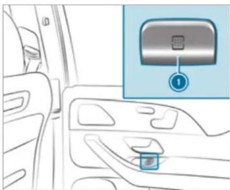
natural_image
Interior view of a car showing the dashboard and seat area with an inset close-up of a device (no text or symbols visible)To open: press button 1.
To close: pull button ①.
When the sliding sunroof is open, it will close first. To close the roller sunblind, you must pull button ① again.
If you press or pull button ① beyond the point of resistance, you will start automatic operation in the direction in question. You can stop automatic operation by pushing or pulling the button again.
Automatic reversing function of the sliding sunroof
If an obstacle obstructs the sliding sunroof during the closing process, the sliding sunroof will open again automatically. The automatic reversing function is only an aid and is not a substitute for your attentiveness.
During the closing process, make sure that no body parts are in the closing area.
A WARNING Risk of becoming trapped despite the reversing function being active
In particular, the reversing function does not react:
- to soft, light and thin objects, e.g. fingers. - towards the end of the closing procedure.
- during resetting.
During the closing process, make sure that no body parts are in the closing area.
Release the button immediately if somebody becomes trapped.
or
▶ Briefly press the button in any direction during automatic operation. te The closing process will be stopped.
Automatic reversing function of the roller sunblind
If an obstacle obstructs the roller sunblind during the closing process, the roller sunblind will open again automatically. The automatic reversing function is only an aid and is not a substitute for your attentiveness.
When closing the roller sunblind, make sure that no body parts are in the range of movement.
WARNING Risk of becoming trapped despite reversing function
In particular, the reversing function does not react to soft, light and thin objects, e.g. fingers.
When closing the roller sunblind, make sure that no body parts are in the range of movement.
Release the button immediately if somebody becomes trapped.
or
▶ Briefly press the button in any direction during the automatic closing process. The closing process will be stopped.
Automatic functions of the sliding sunroof
The term "sliding sunroof" also refers to the panorama sliding sunroof.
The sliding sunroof will be closed automatically when the vehicle has been switched off in the following situations:
- if it starts to rain
Rain is detected by a rain sensor on the windscreen.
• in extreme temperatures
- after a certain time (depending on the onboard electrical system voltage)
• if there is a malfunction in the power supply
The sliding sunroof will rise at the rear in order to continue ventilating the vehicle interior. If the sliding sunroof is obstructed during an automatic closing procedure, the roof will be opened again slightly. The automatic function for the sliding sunroof and the side windows will then be deactivated.
Rain-closing feature when driving
Vehicles with a panorama sliding sunroof: if it starts to rain, the raised sliding sunroof will automatically be lowered while the vehicle is in motion.
Automatic lowering function
Vehicles with a panorama sliding sunroof: if the sliding sunroof is raised at the rear, it will automatically be lowered slightly at higher
speeds. At low speeds, it will be raised again automatically.
WARNING Risk of becoming trapped by automatic lowering of the sliding sunroof
At higher speeds, the raised sliding sunroof will automatically be lowered slightly at the rear.
Make sure that nobody reaches into the sliding sunroof's range of movement while the vehicle is in motion.
If somebody becomes trapped, briefly push the sliding sunroof button forwards or backwards.
By pushing or pulling the button, you can interrupt the automatic functions "Rain closing function when driving" and "Automatic lowering".
Rectifying problems with the sliding sunroof

WARNING Risk of becoming trapped or fatal injuries when the sliding sunroof is closed again
If the sliding sunroof is closed again immediately after it has been blocked or reset, it will close with increased force.
Make sure that no parts of the body are in the closing area.
Release the button immediately if somebody becomes trapped.
or
Briefly press the button in any direction during the automatic closing process. The closing process will be stopped.
The sliding sunroof cannot be closed and you cannot see the cause.
The term "sliding sunroof" also refers to the panorama sliding sunroof.
If the sliding sunroof is obstructed during closing and reopens again slightly:
Immediately after automatic reversing, pull and hold the button down again to the point of resistance until the sliding sunroof is closed.
The sliding sunroof will be closed with increased force.
If the sliding sunroof is obstructed again and opens again slightly:
Repeat the previous step. The sliding sunroof will be closed again with increased force.
Vehicles without a panorama sliding sun-roof: the sliding sunroof is not operating smoothly.
▶ Reset the sliding sunroof.
Resetting the sliding sunroof
Push the button up to the point of resistance repeatedly until the sliding sun-roof is fully open.
Press the button for another second. Close the sliding sunroof.
Vehicles with a panorama sliding sunroof: the sliding sunroof or the roller sunblind is not operating smoothly.
Reset the sliding sunroof and the roller sun-blind.
Resetting the sliding sunroof and the roller sunblind
Pull and hold the button little by little until the sliding sunroof is fully closed.
Pull and hold the button little by little until the roller sunblind is fully closed.
Use automatic operation to fully open and then close the sliding sunroof.
Roller sunblinds
Extending or retracting the roller sunblinds on the rear side windows
A WARNING Risk of becoming trapped when extending or retracting the roller sunblind
Body parts could become trapped in the sweep of the roller sunblind when it is being extended or retracted.
Make sure that no body parts are in the sweep of the roller sunblind when it is being extended or retracted.
If someone becomes trapped, briefly press the button in the opposite direction.
The opening or closing process will briefly be stopped. The roller sunblind will then return to its starting position.
NOTE Damage caused by objects
Objects can cause the roller sunblind to malfunction.
Make sure that the roller sunblind can move freely.
The roller sunblinds for the rear side windows can be operated with the buttons for the side windows in the driver's door and in the rear doors.
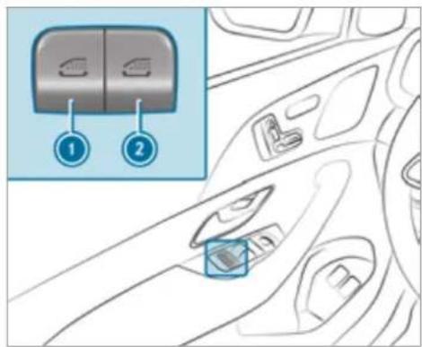
text_image
Diagram of car interior with labeled buttons and a zoomed-in view showing two switches in the first panel.① Rear left side window / roller sunblind
② Rear right side window / roller sunblind
To close fully: briefly pull the corresponding button when the side window is closed.
To open fully: briefly press the corresponding button.
Anti-theft protection
Function of the immobiliser
The immobiliser prevents your vehicle from being started without the correct key.
The immobiliser is automatically activated when the ignition is switched off and deactivated when the ignition is switched on.
ATA (Anti-Theft Alarm system)
Function of the ATA system
If the ATA system is primed, a visual and audible alarm is triggered in the following situations:
- when a door is opened
- when the tailgate is opened
- when the bonnet is opened
- when interior protection is triggered (→ page 105)
- when tow-away protection is triggered (→ page 105)
The ATA system is primed automatically after approximately ten seconds in the following situations:
• after locking the vehicle with the key
• after locking the vehicle using KEYLESS-GO
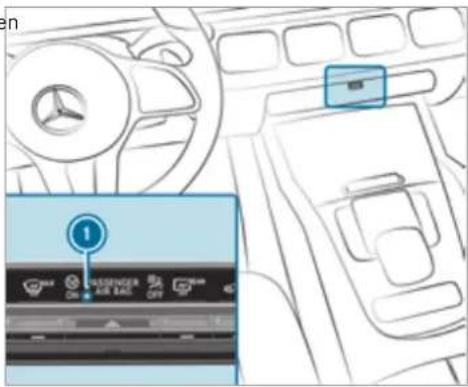
text_image
Diagram showing car interior with a Mercedes-Benz logo and a digital display showing '1' and function buttons like 'ON', 'PASSenger AIR BAG', 'OFF'.Indicator lamp ① flashes when the ATA system is primed.
The ATA system is deactivated automatically in the following situations:
• after unlocking the vehicle with the key
• after unlocking the vehicle using KEYLESS-GO
- after pressing the start/stop button with the key in the stowage compartment
(→ page 192)
When the Mercedes-Benz emergency call system is active and the alarm stays on for more than 30 seconds, a message is automatically sent to the Customer Assistance Centre ( page 354).
Deactivating the ATA
Press the ☑, ☑ or ☑ button on the key.
or
Press the start/stop button with the key in the stowage compartment ( page 192)
Deactivating the alarm using KEYLESS-GO
Grasp the outside door handle with the key outside the vehicle.
Function of tow-away protection
An audible and visual alarm is triggered if an alteration to your vehicle's angle of inclination is detected while tow-away protection is primed.
Tow-away protection is automatically primed after approximately 60 seconds:
• after locking the vehicle with the key
• after locking the vehicle using KEYLESS-GO
Tow-away protection is only primed when the following components are closed:
- doors
- tailgate
Tow-away protection is automatically deactivated:
- after pressing the ☐ or ☑ button on the key
- after pressing the start/stop button with the key in the stowage compartment
(→ page 192)
• after unlocking the vehicle using KEYLESS-GO
- when using HANDS-FREE ACCESS Information on collision detection on a parked vehicle (→ page 227).
Priming/deactivating tow-away protection
Multimedia system:
→ Settings ▶ Quick access
▶ Prime or deactivate Tow-away protection.
Tow-away protection is primed again in the following cases:
• The vehicle is unlocked again.
• A door is opened.
• The vehicle is locked again.
If quick access is unavailable, select the Vehicle submenu in the Settings main menu to prime or deactivate tow-away protection.
Function of interior protection
When interior protection is primed, a visual and audible alarm is triggered if movement is detected in the vehicle interior.
Interior protection is primed automatically after approximately ten seconds:
• after locking the vehicle with the key
• after locking the vehicle using KEYLESS-GO
Interior protection is only primed when the following components are closed:
- doors
- tailgate
Interior protection is automatically deactivated:
- after pressing the ☑ or ☑ button on the key
- after pressing the start/stop button with the key in the stowage compartment (→ page 192)
- after unlocking the vehicle using KEYLESS-GO
- when using HANDS-FREE ACCESS
The following situations can lead to a false alarm:
- moving objects such as mascots in the vehicle interior
- when a side window is open
- when a sliding sunroof is open
- when a panoramic sliding sunroof is open
Priming/deactivating interior protection
Multimedia system:
→ Settings ▶ Quick access
▶ Prime or deactivate Interior motion sensor.
Interior protection is primed again in the following cases:
• The vehicle is unlocked again.
- A door is opened.
• The vehicle is locked again.
If quick access is unavailable, select the Vehicle menu under Settings to prime or deactivate interior protection.
Notes on the correct driver's seat position
A WARNING Risk of accident due to adjusting vehicle settings while the vehicle is in motion
You could lose control of the vehicle in the following situations in particular:
- If you adjust the driver's seat, the head restraints, the steering wheel or the mirror while the vehicle is in motion.
- If you fasten your seat belt while the vehicle is in motion.
Before starting the engine: adjust the driver's seat, the head restraints, the steering wheel and the mirror and fasten your seat belt.
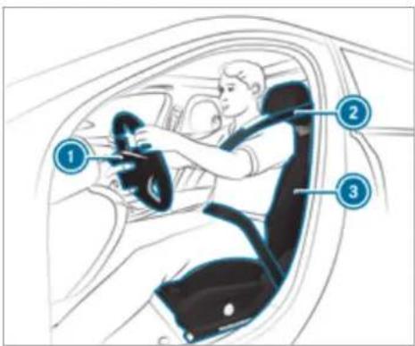
text_image
Diagram of a car interior showing driver's seatbelt, steering wheel, and dashboard with numbered labels pointing to key parts.Ensure the following when adjusting steering wheel ①, seat belt ② and driver's seat ③:
- You are sitting as far away from the driver's airbag as possible, taking the following points into consideration.
• You are sitting in an upright position -
Your thighs are slightly supported by the seat cushion
-
Your legs are not fully extended and you can depress the pedals properly
- The back of your head is supported at eye level by the centre of the head restraint
- You can hold the steering wheel with your arms slightly bent
• You can move your legs freely - You can see all the displays on the instrument cluster clearly
- You have a good overview of the traffic conditions
- Your seat belt sits snugly against your body and passes across the centre of your shoulder and across your hips in the pelvic area
Seats
Adjusting the front seat
WARNING Risk of becoming trapped if the seats are adjusted by children
Children could become trapped if they adjust the seats, particularly when unattended.
When leaving the vehicle, always take the key with you and lock the vehicle.
▶ Never leave children unattended in the vehicle.
You can adjust the seats when the ignition is switched off.

WARNING Risk of becoming trapped during seat adjustment
When you adjust a seat, you or other vehicle occupants could become trapped, e.g. on the seat guide rail.
Make sure when adjusting a seat that no one has any body parts in the sweep of the seat.
Observe the safety notes on "Airbags" and "Children in the vehicle".

WARNING Risk of injury if vehicle settings are adjusted while the vehicle is in motion
You could lose control of the vehicle in particular in the following situations:
- If you adjust the driver's seat, the head restraints, the steering wheel or the mirror while the vehicle is in motion.
- If you fasten your seat belt while the vehicle is in motion.
Before starting the engine: adjust the driver's seat, head restraints, steering wheel and mirror in particular and fasten your seat belt.

WARNING Risk of becoming trapped if the seat height is adjusted carelessly
If you adjust the seat height carelessly, you or other vehicle occupants could be trapped and thereby injured.
Children in particular could accidentally press the electrical seat adjustment buttons and become trapped.
While moving the seats, make sure that hands or other body parts do not get under the lever assembly of the seat adjustment system.

WARNING Risk of injury due to head restraints not being fitted or being adjusted incorrectly
If head restraints have not been installed or have not been adjusted correctly, there is an increased risk of injury in the head and neck area, e.g. in the event of an accident or when braking.
▶ Always drive with the head restraints fitted.
Before driving off, make sure for every vehicle occupant that the centre of the head restraint supports the back of the head at about eye level.
Do not interchange the head restraints of the front and rear seats. Otherwise, you will not be able to adjust the height and angle of the head restraints correctly.
Adjust the head restraint fore-and-aft position so that it is as close as possible to the back of your head.

WARNING Risk of injury or death due to incorrect seat position
The seat belt will not offer the intended level of protection if you have not moved the seat backrest to an almost vertical position.
In particular, you may slip under the seatbelt and injure yourself.
Adjust the seat properly before beginning your journey.
Always ensure that the seat backrest is in an almost vertical position and that the shoulder section of your seat belt is routed across the centre of your shoulder.
WARNING Risk of injury due to excessive strain on the grab handle
If you apply your full body weight to the grab handle or pull it abruptly, the grab handle may be damaged or become loose from its anchorage.
▶ Use the grab handles only to stabilise the seating position or to assist in getting in and out of the seat.
WARNING Risk of injury or death due to objects under the co-driver seat
Objects trapped under the co-driver seat can interfere with the function of the automatic co-driver airbag shutoff or damage the system.
Do not store any objects under the co-driver seat.
When the co-driver seat is occupied, make sure that no objects are trapped under the co-driver seat.
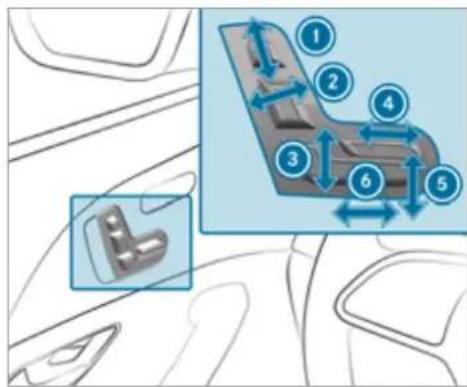
text_image
Diagram showing car interior components with numbered parts and directional arrows indicating movement or flow① Head restraint height
② Seat backrest inclination
3 Seat height
④ Seat cushion length
5 Seat cushion inclination
6 Seat fore-and-aft position
Save the settings with the memory function ( page 130).
Adjusting the front passenger seat electrically from the driver's seat

WARNING Risk of injury or death due to the front seat being positioned too close to the cockpit
The front airbags can also injure the occupants in the front of the vehicle.
Always adjust the front seats so they are as far away as possible from the front airbags.
In addition, observe the notes on correct seat adjustment.
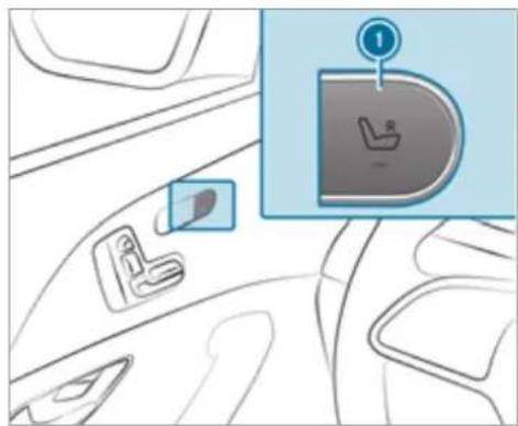
natural_image
Interior view of a car showing seatbelt, seatbelt clip, and seatbelt switch (no text or symbols)Requirements:
• The power supply is switched on.
You can call up the following functions for the front passenger seat:
- Seat adjustment
- Seat heating
- Seat ventilation
- Memory function
To select the front passenger seat: press button ①. When the indicator lamp lights up, the front passenger seat is selected.
Adjust the front passenger seat using the buttons on the driver's side door operating unit.
To select the driver's seat: press button ① again.
When the indicator lamp goes out, the driver's seat has been selected.
Adjusting the front passenger seat electrically from the rear
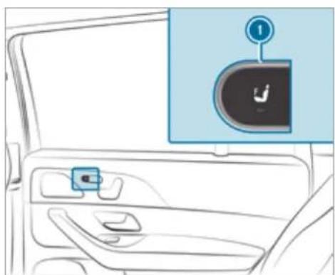
natural_image
Interior view of a car showing the door, seatbelt, and dashboard (no text or symbols visible)To select the front passenger seat: press button ①.
When the indicator lamp lights up, the front passenger seat is selected.
Adjust the front passenger seat using the buttons on the door operating unit in the rear passenger compartment ( page 112).
Mercedes-Maybach vehicles: if the front passenger seat is in the foremost position, you can set the seat backrest at a very steep angle. This will provide a better forward view from the rear compartment.
Despite the steep angle of the seat backrest, a person may occupy the front passenger seat.
Adjusting the 4-way lumbar support
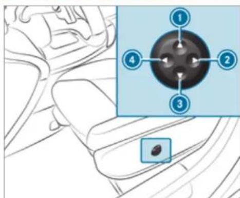
text_image
Diagram showing a car interior with labeled parts and an inset highlighting a central circular component with four numbered points.① Higher
2 Softer
3 Lower
4 Firmer
Use buttons ① to ④ to adjust the contour of the backrest.
Adjusting the rear seats electrically

NOTE Damage to the rear seat armrest when folding the centre seat backrest forward
If the rear seat armrest is folded down, it can be damaged when the centre seat backrest is folded forward.
Fold the rear seat armrest upwards before folding the centre seat backrest forward.
The middle seat backrest is adjusted together with the left seat.
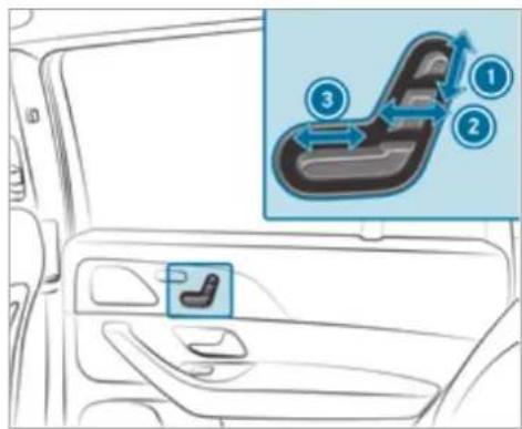
text_image
Diagram showing car interior with seatbelt and seatbelt switch, labeled with numbered steps 1, 2, and 3.① Head restraint height
2 Seat backrest inclination
3 Seat fore-and-aft position
Save the settings with the memory function ( page 131).
Adjusting the reclining rear seats electrically
The reclining rear seats are on the driver's and front passenger sides.
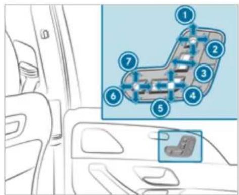
text_image
Diagram showing car interior with numbered components and a highlighted seatbelt component① Head restraint height
② Head restraint fore-and-aft position
3 Seat backrest inclination
4 Combined seat cushion inclination and length
6 Combined seat cushion inclination and length
6 Fore-and-aft position of the leg rest
⑦ Angle of the leg rest
Save the settings with the memory function ( page 131).
The leg rest will fold down if overloaded. If this is the case, fold up the leg rest and engage it.
Setting the fully reclined position
Requirements:
• The power supply is switched on.
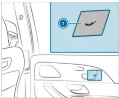
text_image
Diagram showing a car interior with a highlighted vehicle door panel and a numbered label pointing to the door panel.To set the fully reclined position: press button ①.
- The rear seat will move into the fully reclined position.
• The rear seat head restraint will move.
• The leg rest will rise. -
The front passenger seat will move as far forwards as possible.
-
The front passenger seat head restraint will be completely retracted.
- The front passenger seat backrest will move as far forwards and as far down as it will go.
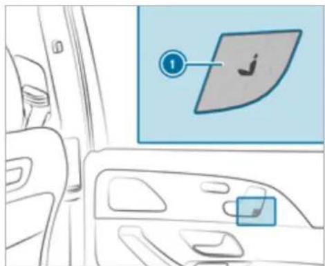
text_image
Diagram showing car interior with a highlighted vehicle door panel and a numbered label pointing to the right side.To restore the standard seat settings: press button ①.
or
▶ Call up the settings with the memory function ( page 131).
① You can use the rear-compartment child safety lock to disable this function (→ page 77).
① The leg rest will fold down if overloaded. If this is the case, fold up the leg rest and engage it.
Attaching and removing the additional cushion of the leg rest
Use the additional cushion only when the vehicle is stationary. The additional cushion is in the vehicle.
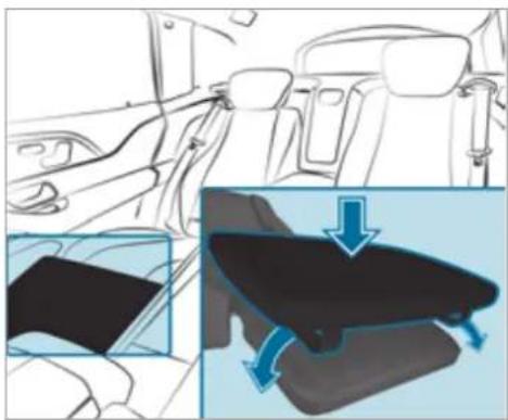
natural_image
Interior view of a car showing the seat, dashboard, and side panel with a blue arrow indicating motion (no text or symbols)To attach: place the additional cushion on the leg rest.
Pull the rubber straps laterally over the leg rest.
To remove: remove the rubber straps from the leg rest and stow the additional cushion safely in the vehicle.
Folding the rear seats on the second row of seats forwards and back electrically

WARNING Risk of injury due to seat backrest folded forwards
If the rear seat backrest is folded forwards, persons in the third row of seats could collide with parts of the seat adjustment mechanism, in particular in the event of an accident, sudden braking or an abrupt change of direction.
If there is a person in the third row of seats, the rear seat in front of that person must be folded back into the driving position before starting the journey.
▶ People in the third row of seats must not place their legs on a rear seat back-rest that has been folded forwards.
Always ensure that all vehicle occupants have their seat belts fastened correctly and are sitting properly. Particular attention must be paid to children.
If you no longer require the seat backrest to be folded down for loading or for getting in and out, fold it back into place.
⚠ WARNING Risk of becoming trapped if the seat is not engaged
The seat does not engage when folded forwards. The seat can fold backwards unexpectedly, e.g. when accelerating, braking or in the event of an abrupt change of direction or an accident.
People in the seat's sweep can become trapped.
If a seat is folded forwards, always fold it back before driving off.
▶ Make sure that the seat is engaged.
If a seat on the second row of seats is not engaged, this will be shown on the multifunction display on the instrument cluster.
Requirements:
- The area into which the rear seat is folded is clear.
• The rear seat has been folded up.
- Vehicles with comfort seating: the centre armrest is folded up.
- Vehicles with an extended centre console: the stowage compartment in the centre console is closed.
- Vehicles with a folding rear armrest: the rear armrest has been folded up.
- Vehicles with centre seat backrests: the centre seat backrest has been folded up.
Folding the rear seat into the front position
You can fold the seats on the second row of seats forwards for the following situations:
- For easier access to the luggage compartment
• Vehicles with a third row of seats: for getting in or out
Vehicles with a centre seat backrest: the centre rear seat folds forwards and backwards together with the left rear seat.
Depending on the vehicle equipment, you can fold the rear seats forwards as follows:
- Six-seater: on the right-hand side of the vehicle only
- Seven-seater with centre seat backrest: both sides
To increase the size of the luggage compartment, you can move the seat backrests into the luggage compartment floor position ( page 139).
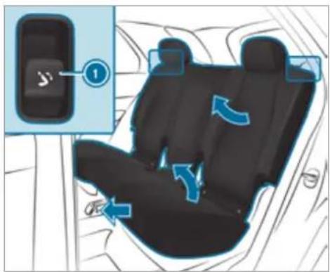
text_image
Diagram showing car seat placement with blue arrows indicating clockwise motion, labeled with number 1 and directional arrows.Button on the backrest shoulder of the second of seats
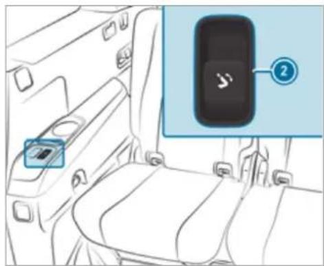
text_image
Diagram showing car seat and rear camera with labeled sensor device and numbered componentroButton on the armrest of the third row of seats (seven-seater)
When the rear door is open: briefly pull button ① on the backrest shoulder of the rear seat.
or
Briefly press button ② on the armrest of the third row of seats.
When the rear door is closed: pull and hold button ① on the backrest shoulder of the rear seat.
or
Press and hold button ② on the armrest of the third row of seats.
The head restraint will move downwards. The seat backrest will move into the front position. The rear seat will move forwards until it unlocks. The rear seat will then tip forwards.
If a seat on the second row of seats is not engaged, this will be shown on the multifunction display on the instrument cluster.
You can prevent the rear seats from folding forwards when the rear door is closed by activating the child safety lock for the side windows ( page 77).
Folding back the rear seat
Press button ① on the backrest shoulder of the rear seat or ② on the armrest of the
third row of seats and hold it down until the rear seat audibly engages.
The rear seat will tip downwards and move back. The seat backrests and head restraint will then move into a suitable seat position automatically.
If a seat on the second row of seats is not engaged, this will be shown on the multifunction display on the instrument cluster.
To interrupt the folding procedure before engagement, let go of button ①. To continue the folding procedure, press and hold button ① again.
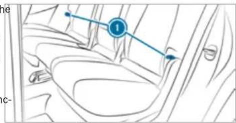
text_image
Diagram of a car interior with labeled parts and directional arrows indicating movement or flowRelease loops on the second row of seats
Folding the rear seats forwards mechanically (emergency release)
You can also fold the rear seats forwards mechanically using release loops. The release loops are located on the outer sides and rear sides of the seats on the second row of seats.
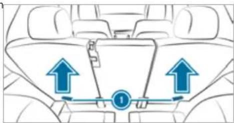
text_image
Diagram of car interior showing seatbelt and directional arrows with numbered labelsRelease loops on the rear sides of the second row of seats
Pull one of release loops ①.
▶ Fold the seat backrest forwards.
Before commencing your journey, make sure that the seat backrest and the rear bench seat are engaged.
Head restraints
Adjusting the front seat head restraints manually
A WARNING Risk of accident due to adjusting vehicle settings while the vehicle is in motion
You could lose control of the vehicle in the following situations in particular:
- If you adjust the driver's seat, the head restraints, the steering wheel or the mirror while the vehicle is in motion.
- If you fasten your seat belt while the vehicle is in motion.
Before starting the engine: adjust the driver's seat, the head restraints, the
steering wheel and the mirror and fasten your seat belt.

WARNING Risk of injury due to head restraints not being fitted or being adjusted incorrectly
If head restraints have not been installed or have not been adjusted correctly, there is an increased risk of injury in the head and neck area, e.g. in the event of an accident or braking.
Always drive with the head restraints fitted.
Before driving off, make sure for every vehicle occupant that the centre of the head restraint supports the back of the head at about eye level.
Do not interchange the head restraints of the front and rear seats. Otherwise, you will not be able to adjust the height and angle of the head restraints correctly.
Adjust the head restraint fore-and-aft position so that it is as close as possible to the back of your head.
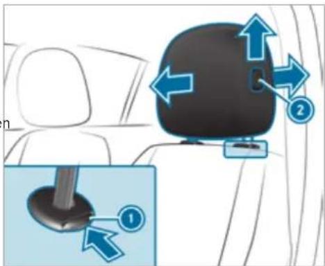
text_image
Diagram showing car seatbelt insertion with numbered arrows indicating movement or positioning, and a magnified inset highlighting the base component.To raise: pull the head restraint up.
To lower: press release knob ⓘ in the direction of the arrow and push the head restraint down.
To move forward: press release knob and pull the head restraint forward.
To move backwards: press release knob and push the head restraint backwards.
Adjusting the front seat luxury head restraints mechanically
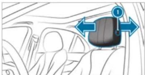
natural_image
Interior view of a car showing the backrest seat and dashboard, with directional arrows indicating movement (no text or symbols)To move forward: press release knob and pull the head restraint forward.
To move backwards: press release knob and push the head restraint backwards.
Adjusting the EASY ADJUST luxury head restraints on the front seats mechanically
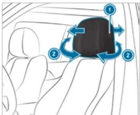
text_image
Diagram showing car interior with directional arrows and numbered labels indicating motion or movement pathsTo move forward: press release knob and pull the head restraint forward.
To move backwards: press release knob and push the head restraint backwards.
To adjust the side bolsters of the head restraint: pull or push right or left side bolster ②.
The fore-and-aft position of the head restraint will be adjusted automatically when you adjust the seat backrest inclination using the button on the door operating unit.
Adjusting the head restraints of the rear seats mechanically
Depending on the vehicle equipment, you can mechanically adjust the head restraints on the third row of seats as well as the centre head restraint on the second row of seats.
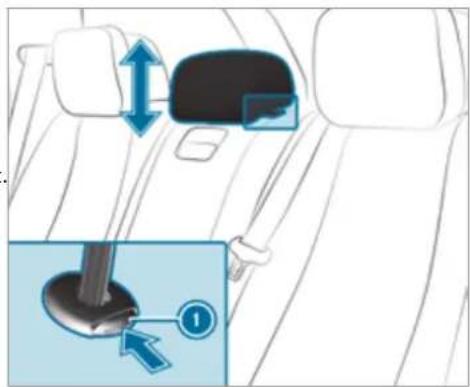
text_image
Diagram showing car seatbelt insertion mechanism with blue arrows indicating movement and a numbered step in the lower section.Head restraint of the standard vehicle (example)
To raise: pull the head restraint up.
To lower (standard vehicle): press release knob ① in the direction of the arrow and push the head restraint down.
To lower (Mercedes-Maybach vehicles): push the head restraint down.
Vehicles with a third row of seats
The head restraints on the third row of seats have a usage position and a non-usage position. The usage position is the extended, top position in which the head restraint engages; the non-usage position is the bottom, retracted position of the head restraint. If the seats on the third row of seats are being used, the head restraint must be in the top, engaged usage position.
If the third row of seats is occupied: move the head restraints to the very top and have them engage there.
If the third row of seats is not occupied: move the head restraints to the very bottom.
Fitting/removing the head restraint of the middle rear seat on the second row
Removing
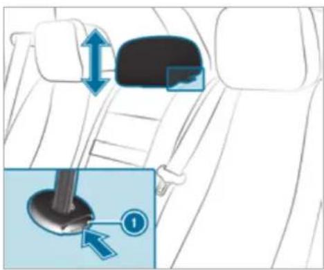
text_image
Diagram showing car seatbelt adjustment with blue arrows and a numbered inset highlighting the component '①'Release the middle rear seat backrest and fold it forward slightly ( page 139).
Pull the head restraint upwards as far as it will go.
Push release knob ① in the direction of the arrow and pull out the head restraint.
Installing
Insert the head restraint such that the notches on the bar are on the left when viewed in the direction of travel.
▶ Push the head restraint down until it engages.
Fold the middle rear seat backrest back until it engages.
Adjusting the luxury head restraints of the rear seats mechanically
Mercedes-Maybach vehicles: you can set only the side bolsters mechanically. You can adjust the angle of the head restraint electrically.
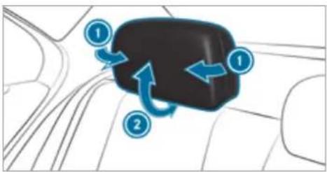
flowchart
graph TD
    A["Car"] --> B{Flow Direction}
    B -->|①| C["Car Left"]
    B -->|②| D["Car Right"]
    C --> E["Car Bottom"]
    D --> F["Car Top"]
Head restraint of the standard vehicle (example)
To adjust the side bolsters of the head restraint: pull or push right or left-hand side bolster ①.
To adjust the angle of the head restraint: pull or push the head restraint in the direction of arrow ②.
Attaching and removing the additional cushion of the luxury head restraint in the rear compartment
Use the additional cushion only when the vehicle is stationary. The additional cushion is in the vehicle.
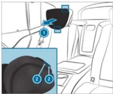
text_image
Diagram showing car seatbelt insertion with numbered instructions and a magnified view of the seatbelt component.▶ Position the head restraint as far forwards as possible.
To attach the additional cushion: hold additional cushion ① against the head restraint and push press studs ② into the counterpieces.
To remove the additional cushion: release press studs ② and remove additional cushion ①.
Configuring the seat settings
Multimedia system:
→ Comfort ▶ Seat comfort
Adjusting the backrest contour in the lumbar region of the seat backrest (lumbar)
Select Lumbar.
Select the settings | for the desired seat.
Adjust the air cushions.
Adjusting the backrest side bolsters
▶ Select Side bolsters.
Adjust the air cushion for the desired seat.
Setting the seat heating balance
▶ Select Seat heating balance.
Adjust the heat distribution for the desired seat.
Setting automatic seat adjustment

WARNING Risk of becoming trapped during adjustment of the driver's seat after calling up a driver profile
Selecting a user profile may trigger an adjustment of the driver's seat to the position saved under the user profile. You or other vehicle occupants could be injured in the process.
Make sure that when the position of driver's seat is being adjusted using the multimedia system, no people or body parts are in the seat's range of movement.
If there is a risk of someone becoming trapped, stop the adjustment process immediately:
a) Tap the warning message on the media display.
or
b) Press a memory position button or a seat adjustment switch on the driver's door. The adjustment process will be stopped.
Requirements:
- Adapting the driver's seat and steering wheel position to body size: automatic seat adjustment has been switched on.
Multimedia system:








Switching automatic seat adjustment on/off
When the active user profile is changed while the vehicle is stationary, the driver's seat, steering wheel, outside mirrors and seat contour will automatically be adapted to the driver.

Select On or Off.
This setting is available only for individual user profiles. For the guest profile, automatic seat adjustment cannot be switched
on or off. Further information about user profiles.
Adjusting driver's seat and steering wheel position to body size
The vehicle calculates a suitable driver's seat and steering wheel position on the basis of the driver's body size and sets this directly.

To set the unit of measurement: select cm or ft/in.

Set the size using the scale.

Select Start positioning.
The driver's seat and steering wheel position is adjusted to the body size that has been set.

If the driver's seat and steering wheel position calculated by the vehicle is not practical or comfortable, it can be manually changed at any time via the buttons.
The exterior mirrors are not set via this function. Instead, they have to be set manually via the switches.
You can also configure these settings via the Mercedes me portal for your user profile. By synchronising the profiles in the vehicle and the Mercedes me connect profiles, you can carry over these settings for your vehicle. Further information about synchronising user profiles.
Setting the easy entry and exit feature
▶ Select Steer. wheel and seat, Steering wheel only or Off.
If you use an individual user profile and have set your body size, this information is carried over for the easy entry and exit feature. This will cause the driver's seat and steering wheel to move into the correct position automatically.
Overview of massage programmes
- Hot Relaxing back Combination of heat and massage. It starts by massaging the back. In addition, warm pressure points become noticeable, starting in the pelvic area.
Hot Relaxing shoulder Combination of heat and massage. It starts by massaging the shoulders. In addition, warm pressure points become noticeable, starting in the pelvic area.
- Activating Massage Activating massage with upward-moving massage waves.
• Classic Massage Relaxing back massage.
Wave Massage Regenerating massage via massage waves across the back and in the seat cushion.
- Mobilizing Massage Mobilising massage with upward-moving massage waves. Can promote deeper respiration and hence improve circulation and blood pressure.
- Active Workout backrest and Active Workout cushion These programs require your cooperation. Alternating between tensing and releasing helps to improve blood flow to your muscles. Press against a pressure point as soon as you feel it.
Selecting the massage programme for the front seats
Multimedia system:
Start the program for the desired seat ▶.
To set the massage intensity: switch High intensity on or off.
For the rear seats, the massage programmes can be selected on the following devices (if available):
- On the rear displays
The selection can be made for the rear seats on the second and third rows of seats.
• On the MBUX rear tablet
The selection is made in the same way as on the rear displays for the rear seats on the second row of seats.
Resetting seat settings
Multimedia system:
→ Comfort ▶ Seat comfort
Select 🔒 for the desired seat.
▶ Confirm the prompt.
Switching the seat heating on/off
WARNING Risk of burns due to repeatedly switching on the seat heating
Repeatedly switching on the seat heating can cause the seat cushion and seat backrest padding to become very hot.
In particular, the health of persons with limited temperature sensitivity or a limited ability to react to high temperatures may be affected or they may even suffer burn-like injuries.
Do not repeatedly switch on the seat heating.
To protect against overheating, the seat heating may be temporarily deactivated after it is switched on repeatedly.
NOTE Damage to the seats caused by objects or documents when the seat heater is switched on
When the seat heater is switched on, overheating may occur due to objects or documents placed on the seats e.g. seat cushions or child seats. This could cause damage to the seat surface.
Make sure that no objects or documents are on the seats when the seat heater is switched on.
Requirements:
• The power supply is switched on.
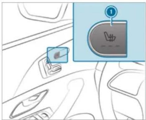
text_image
Diagram showing car interior with a highlighted switch labeled '1' and a logo, likely illustrating a diagnostic or safety concept.Seat heating in the cockpit
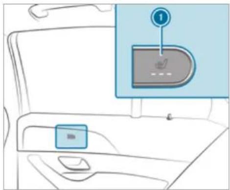
text_image
Diagram of a car interior with a highlighted control panel and numbered annotation '1'Seat heating in the rear
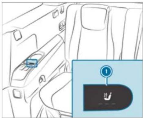
text_image
Diagram showing car interior with a blue box labeled '一' and a numbered button labeled '1' pointing to a device icon.Seat heating in the third row of seats
Press button ① repeatedly until the desired heating level is set. Depending on the heating level, up to three indicator lamps will light up. If all indicator lamps are off, the seat heating is switched off.
① The seat heating will automatically switch down from the three heating levels after 8,
10 and 20 minutes until the seat heating is switched off.
Setting the panel heating
Multimedia system:
→ Settings Vehicle
▶ Panel heating
When the seat heater is switched on, the armrests, the door centre panel and the centre console can be heated.
Switch the function for the desired seats on or off.
Switching the seat ventilation on/off
Requirements:
• the power supply is switched on.
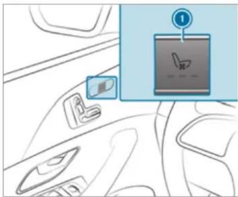
text_image
Diagram showing car interior with seatbelt, battery pack, and smartphone screen icon labeled '1'Seat ventilation in the cockpit
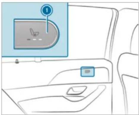
natural_image
Interior view of a car showing the dashboard and seat area with a highlighted screen (no text or symbols)Seat ventilation in the rear
Press button ① repeatedly until the desired ventilation level is set. Depending on the ventilation level, up to three indicator lamps will light up. If all indicator lamps are off, the seat ventilation is switched off.
Steering wheel
Adjusting the steering wheel manually

WARNING Risk of injury if vehicle settings are adjusted while the vehicle is in motion
You could lose control of the vehicle in particular in the following situations:
- If you adjust the driver's seat, the head restraints, the steering wheel or the mirror while the vehicle is in motion.
- If you fasten your seat belt while the vehicle is in motion.
Before starting the engine: adjust the driver's seat, head restraints, steering wheel and mirror in particular and fasten your seat belt.

WARNING Risk of entrapment for children when adjusting the steering wheel
Children could injure themselves if they adjust the steering wheel.
▶ Never leave children unattended in the vehicle.
When leaving the vehicle, always take the key with you and lock the vehicle.
To lock: push release lever ① up as far as it will go.
Check and make sure that the steering column is locked by moving the steering wheel.
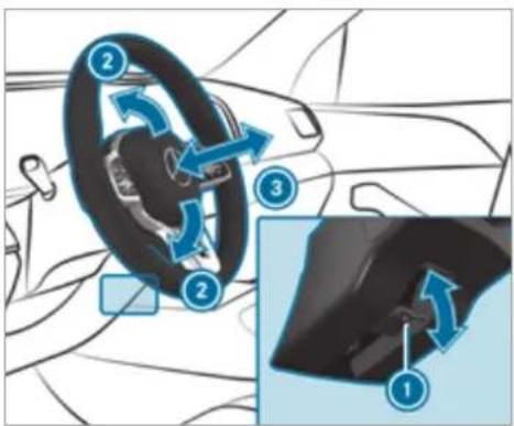
text_image
Diagram illustrating car steering wheel and steering wheel assembly with numbered steps for each componentAdjusting the steering wheel electrically
The steering wheel can be adjusted when the ignition is switched off.
To unlock: push release lever ① down as far as it will go.
Adjust height ② and distance ③ to the steering wheel.
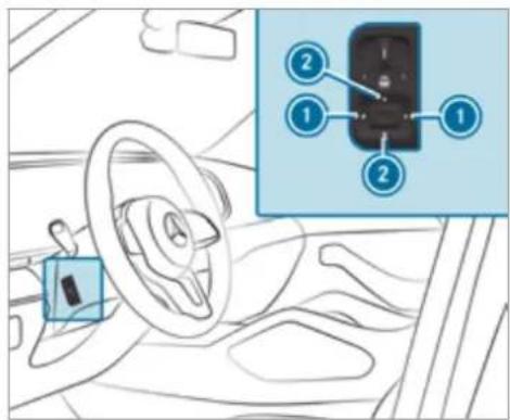
text_image
Diagram of car interior with labeled parts and a zoomed-in view showing a device with numbered indicators.To adjust the distance to the steering wheel
② To adjust the height
Save the settings with the memory function ( page 130).
Switches the steering wheel heater on or off
Requirements:
• The ignition is switched on.
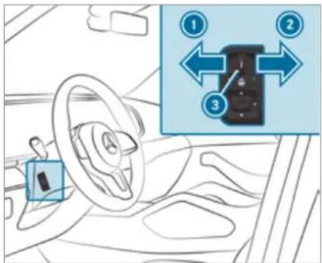
text_image
Diagram showing car interior with steering wheel, dashboard, and three labeled directional arrows indicating movement or flow.
To switch on: push the switch to position

The indicator lamp ③ lights up.

To switch off: push the switch to position

Indicator lamp ③ goes out.
When you switch the ignition off, the steering wheel heater switches off.
Easy entry and exit feature
Using the easy entry and exit feature

WARNING Risk of accident when pulling away during the adjustment process for the easy exit feature
You could lose control of the vehicle.
Always wait until the adjustment process is complete before pulling away.

WARNING Risk of becoming trapped during adjustment of the easy entry and exit feature
You and other vehicle occupants - particularly children - could become trapped.
Ensure that no one has a body part in the sweep of the steering wheel or driver's seat.
If there is a risk of becoming trapped by the steering wheel:
Move the adjustment lever of the steering wheel. The adjustment process will be stopped.
If there is a risk of becoming trapped by the driver's seat:
▶ Press the seat adjustment switch. The adjustment process will be stopped.
▶ Never leave children unattended in the vehicle.
When leaving the vehicle, always take the key with you and lock the vehicle.
You can stop the adjustment process by pressing one of the memory function position switches.
A WARNING Risk of becoming trapped if children activate the easy entry and exit feature-
Children could become trapped if they activate the easy entry- and exit feature, particularly when unattended.
▶ Never leave children unattended in the vehicle.
When leaving the vehicle, always take the key with you and lock the vehicle.
If the easy entry and exit feature is active, the steering wheel will move upwards and the driver's seat will move back in the following situations:
- you switch the ignition off with the driver's door open
- you open the driver's door with the ignition switched off
The steering wheel will then move upwards only if it is not already as high as it will go. The driver's seat will then move backwards
only if it is not already at the rear of the seat adjustment range.
The driver's seat backrest will then move forwards only if it is not already in the front-most position.
The steering wheel and the driver's seat will move back to the last drive position in the following cases:
- you switch the power supply or the ignition on when the driver's door is closed
- you close the driver's door with the ignition switched on
The last drive position will be saved when:
- you switch the ignition off.
- you save the seat settings via the memory function.
If you press one of the memory function memory position switches, the adjustment process will be stopped.
Memory function
Function of the memory function
WARNING Risk of an accident if the memory function is used while driving
If you use the memory function on the driver's side while driving, you could lose control of the vehicle as a result of the adjustments being made.
Only use the memory function on the driver's side when the vehicle is stationary.
WARNING Risk of entrapment when adjusting the seat with the memory function
When the memory function adjusts the seat, you and other vehicle occupants - particularly children - could become trapped.
During the adjustment process of the memory function, make sure that no
one has any body parts in the sweep of the seat.
If someone becomes trapped, press a preset position button or seat adjustment switch immediately.
WARNING Risk of entrapment if the memory function is activated by children
Children could become trapped if they activate the memory function, particularly when unattended.
▶ Never leave children unattended in the vehicle.
When leaving the vehicle, always take the key with you and lock the vehicle.
You can use the memory function when the ignition is switched off.
Seat adjustments for up to three people can be stored and called up using the memory function.
You can save settings for the following systems:
- Front seat
-
Outside mirrors
-
Head-up display
- Steering column
- Seat contour
Operating the memory function
Storing
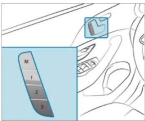
text_image
M 1 2 3Set the desired position for all systems.
Briefly press the M memory button and then press preset position button 1, 2 or 3 within three seconds. An acoustic signal sounds. The settings are stored.
To call up: press and briefly hold preset position button 1, 2 or 3. After releasing the button, all systems are moved into the stored position.
Memory function in the rear compartment
Function of the memory function in the rear passenger compartment
Operating the rear seat
Seat adjustments for the rear seat can be stored and called up using the memory function in the rear passenger compartment.
- Driver's side: two persons
- Front passenger side: one person
You can save the following settings for the rear seat:
- Position of the seat, backrest and head restraint
- Seat heating: distribution of the heated sections of the seat cushion and seat backrest
Operating the front passenger seat and rear seat
Seat adjustments for the front passenger seat and the rear seat can be stored and called up using the rear seat memory function.
You can save the following settings for the front passenger seat:
- Position of the seat, backrest and head restraint
You can save the following settings for the rear seat:
- Position of the seat, backrest and head restraint
- Seat heating: distribution of the heated sections of the seat cushion and seat backrest
Operating the rear seat via the memory function in the rear passenger compartment
Storing

text_image
Diagram showing a car interior with a highlighted control panel labeled '1' and a small icon pointing to the door.Press button ①.
The rear seat is selected if the indicator lamp in the button does not light up.
Adjust the rear seat using the buttons in the door control panel ( page 112).
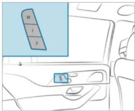
text_image
M 1 2Briefly press memory button M and, within three seconds, press either preset position button 1 or 2.
The settings for the rear seat are stored in the corresponding preset position.
① You cannot store any settings on the button for straightening the fully reclined position.
Calling up
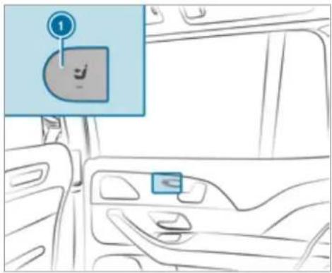
text_image
Diagram showing a car interior with a highlighted control panel labeled '1' and a small icon of a smiling face.
Press button

The rear seat is selected if the indicator lamp in the button does not light up.
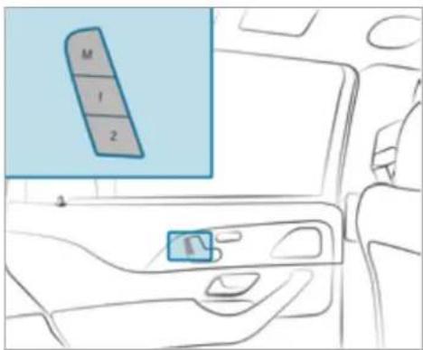
text_image
M I 2
Press corresponding preset position button 1 or 2.
The rear seat will move to the stored position.
Operating the front passenger seat and rear seats via the memory function in the rear compartment
Requirements:
- For selecting the front passenger seat: the power supply is switched on
Storing
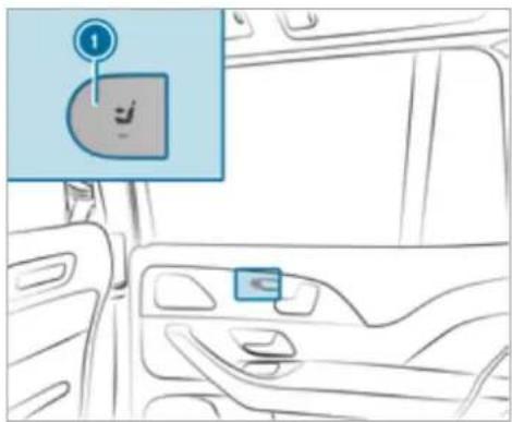
text_image
Diagram of a car interior with a highlighted control panel showing a smiley face and a numbered label '1'Press button ①. The rear seat is selected if the indicator lamp in the button does not light up.
Adjust the rear seat using the buttons in the door control panel ( page 112).
Press button ①.
When the indicator lamp lights up, the front passenger seat is selected.
Adjust the front passenger seat using the buttons on the door operating unit in the rear passenger compartment ( page 107).
Ensure that the indicator lamp in button lights up.
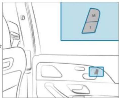
natural_image
Interior view of a car showing the dashboard and seat area with a highlighted panel labeled M and I (no text or symbols beyond labels)Press memory button M and, within three seconds, press preset position button 1. The settings for the front passenger seat and the rear seat are stored in the preset position.
① You cannot store any settings on the buttons for setting and straightening the fully reclined position.
Calling up
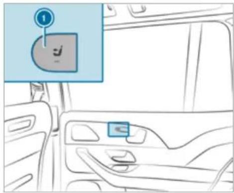
text_image
Diagram showing a car interior with a highlighted control panel labeled '1' and a small icon for 'S' inside the door.Press button ①. When the indicator lamp lights up, the front passenger seat is selected.
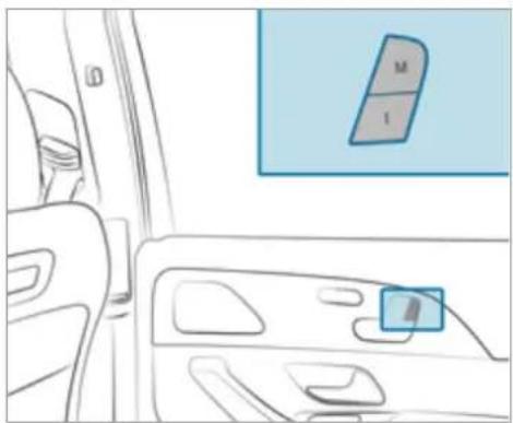
natural_image
Interior view of a car showing the dashboard and seat area with a highlighted panel (no text or symbols)Press preset position button 1. Both seats move into the stored position.
You can use the rear-compartment child safety lock to disable this function ( page 77).
Stowage areas
Notes on loading the vehicle
DANGER Risk of exhaust gas poisoning
Combustion engines emit poisonous exhaust gases such as carbon monoxide. Exhaust gases can enter the vehicle interior if the tailgate is open when the engine is running, especially if the vehicle is in motion.
Always switch off the engine before opening the tailgate.
▶ Never drive with the tailgate open.
WARNING Risk of injury from unsecured items in the vehicle
If objects, luggage or loads are not secured or not secured sufficiently, they could slip, tip over or be thrown around and thereby hit vehicle occupants.
There is a risk of injury, particularly in the event of sudden braking or a sudden change in direction.
Always stow objects in such a way that they cannot be thrown around.
Before the journey, secure objects, luggage or loads against slipping or tipping over.
WARNING Risk of injury due to objects being stowed incorrectly
If objects in the vehicle interior are stowed incorrectly, they can slide or be thrown around and hit vehicle occupants. In addition, cup holders, open stowage spaces and mobile phone brackets cannot always retain all objects they contain.
There is a risk of injury, particularly in the event of braking manoeuvres or abrupt changes in direction.
Always stow objects so that they cannot be thrown around in such situations.
Always make sure that objects do not protrude from stowage spaces, luggage nets or stowage nets.
Close the lockable stowage spaces before starting a journey.
Stow and secure objects that are heavy, hard, pointed, sharp-edged, fragile or too large in the load compartment.
A WARNING Risk of accident from objects in the driver's footwell and front-passenger footwell
Objects in the driver's footwell and front-passenger footwell may impede pedal travel or block a depressed pedal.
This jeopardises the operating and road safety of the vehicle.
Stow all objects in the vehicle securely so that they cannot get into the driver's footwell or front-passenger footwell.
▶ Always fit the floor mats securely and as prescribed in order to ensure that there is always sufficient clearance for the pedals.
Do not use loose floor mats and do not lay multiple floor mats on top of one another.
Vehicles with automatic front passenger airbag shutoff: objects trapped under the front passenger seat may interfere with the function of the automatic front passenger airbag shutoff or damage the system. Please observe the notes on the function of the automatic front passenger airbag shutoff ( page 48).
WARNING - Risk of accident or injury when using the cup holder while the vehicle is in motion
The cup holder cannot hold a container secure while the vehicle is in motion. If you use a cup holder while the vehicle is in motion, the container may be flung around and liquids could be spilled. The vehicle occupants may come into contact with the liquid and if it is hot, they could be scalded. You could be distracted from traffic conditions and you may lose control of the vehicle.
Only use the cup holder when the vehicle is stationary.
Only use the cup holder for containers of the right size.
Always close the container, particularly if the liquid is hot.
NOTE Damage to the cup holder
When the rear armrest is folded back the cup holder could become damaged.
▶ Only fold the rear armrest back when the cup holder is closed.
! NOTE Damage to the rear armrest due to body weight
When folded out, the rear armrest can be damaged by body weight.
Do not sit or support yourself on the rear seat armrest.
WARNING Risk of injury due to an open load compartment floor
If you drive with the load compartment floor open, objects could be flung around and hit vehicle occupants as a result. There is a risk of injury, particularly in the event of sudden braking or a sudden change in direction.
Always close the load compartment floor before a journey.
WARNING - Risk of fire and injury from the hot cigarette lighter
You can burn yourself if you touch the hot heating element or the socket of the cigarette lighter.
In addition, flammable materials may ignite if:
- you drop the hot cigarette lighter
- a child holds the hot cigarette lighter to objects, for example
Always hold the cigarette lighter by the knob.
Always make sure that the cigarette lighter is out of reach of children.
▶ Never leave children unattended in the vehicle.
WARNING Risk of burns from the tailpipe and tailpipe trims
The exhaust tailpipe and tailpipe trims can become very hot. If you come into contact with these parts of the vehicle, you could burn yourself.
Always be particularly careful around the tailpipe and the tailpipe trims and supervise children especially closely in this area.
Allow vehicle parts to cool down before touching them.
The driving characteristics of your vehicle are dependent on the distribution of the load within the vehicle. You should bear the following in mind when loading the vehicle:
- never exceed the permissible gross mass or the permissible axle loads for the vehicle (including occupants).
Information can be found on the vehicle identification plate ( page 427). - the load must not protrude above the upper edge of the seat backrests.
- all vehicles except Mercedes-Maybach vehicles: always use the partition net when transporting objects in the load compartment.
- always place the load behind unoccupied seats if possible.
- secure the load using the tie-down eyes and distribute the load evenly.
Notes on driving with a roof load
- Evenly distribute the roof load, and place heavy objects at the bottom. Also comply with the notes on loading the vehicle (→ page 134).
- Drive attentively, and avoid suddenly pulling away, braking and steering as well as rapid cornering.
- When transporting roof loads and when the vehicle is fully loaded or fully occupied, select drive programs [E] and [C]. The are designed to focus on stability (→ page 205).
Stowage spaces in the vehicle interior
Overview of the front stowage compartments
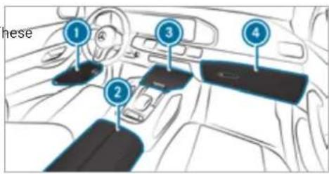
text_image
these 1 2 3 4① Stowage spaces in the doors
2 Stowage compartment in the armrest with USB ports (depending on vehicle equipment)
3 Stowage/telephone compartment with cup holder in the front centre console
Mercedes-Maybach vehicles: stowage/telephone compartment with temperature-controlled cup holder, USB ports (depending on the vehicle equipment) and charging module for wireless charging of mobile phones (depending on the vehicle equipment) in the front centre console
4 Glove compartment
Folding the folding table out or in

WARNING Risk of injury from an open folding table
Vehicle occupants may bump into the folding table and injure themselves.
▶ Close the folding table before each journey.

NOTE Damage to the folding tables when moving the seats back
Open folding tables may be damaged when the seats are moved back.
Make sure that the folding tables are folded in when moving the front seats back.
Folding out
This equipment is available only for Mercedes-Maybach vehicles.
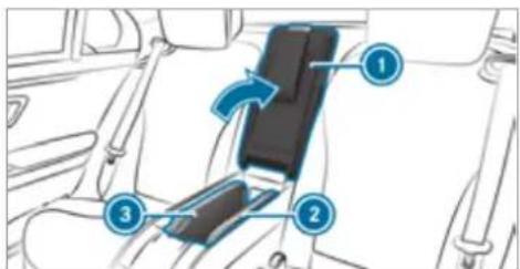
text_image
Diagram of a car seatbelt mechanism with numbered components and directional arrows indicating motionOpen rear armrest ①.
Pull the folding table forwards and upwards by recess ② or ③ and swing outwards.
▶ Fold the table panels apart.
To fold in: fold the table panels together and swing in the folding table.
Opening the stowage box in the backrest in the rear compartment

NOTE Damage to the rear armrest due to body weight
When folded out, the rear armrest can be damaged by body weight.
Do not sit or support yourself on the rear seat armrest.
This equipment is available only for Mercedes-Maybach vehicles.
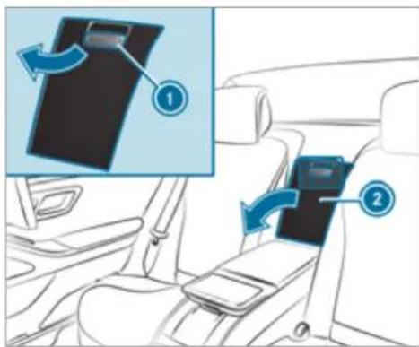
text_image
Diagram showing car seatbelting process with labeled steps ① and ②, illustrating device shift from seatbelt to seatbelt.Vehicles with individual seats (example)
Vehicles with 5-seater variant: fold down the rear armrest.
Pull handle ① and fold down cover ②.
Removing the handset from the stowage compartment in the rear compartment
Opens the drawer
This equipment is available only for Mercedes-Maybach vehicles with individual rear seats.
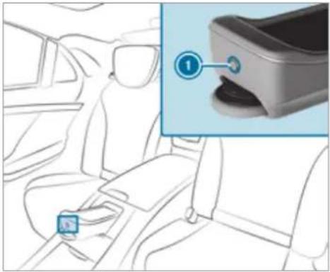
natural_image
Interior view of a car showing seatbelt and dashboard, with a close-up inset highlighting a device component (no text or symbols)Vehicles with individual rear seats

Press button

Remove the handset.
Closing the drawer
Place the handset in the drawer.
Press the handset drawer back until it engages.
Through-loading facility to luggage compartment
Folding the rear seat backrest forwards
⚠ WARNING Risk of becoming trapped when adjusting the seats
When you adjust a seat, you may trap yourself or a vehicle occupant.
When adjusting a seat, make sure that no one has any body parts in the sweep of the seat.

WARNING Risk of accident if the seat and seat backrest are not engaged
The seat and seat backrest can fold forwards.
There is a risk of the following, in particular:
- The vehicle occupant may be pressed against the seat belt. The seat belt cannot protect as intended and could cause additional injury.
- A child restraint system is no longer properly supported or positioned and can no longer fulfil its function as intended.
- The seat backrest cannot restrain objects or goods in the load compartment.
Always ensure that the seat and seat back-rest are engaged, in particular:
- Before persons travel in the vehicle while sitting on a seat with the easy entry and exit feature
• After you have adjusted the seat
• After the easy entry and exit feature has been used
• After the load compartment enlargement has been folded forwards
Always ensure that all vehicle occupants have their seat belts fastened correctly and are sitting properly. Particular attention must be paid to children.
If you no longer require the folded-down rear seat backrest as a load area, fold the backrest back into place.
Make sure that the red marking of the lock verification indicator is no longer visible. Otherwise, the seat backrest will not be locked.
Requirements:
- Vehicles with a centre seat backrest: the centre seat backrest is not in the luggage compartment floor position.
- Vehicles with a folding rear armrest: the rear armrest has been folded up.
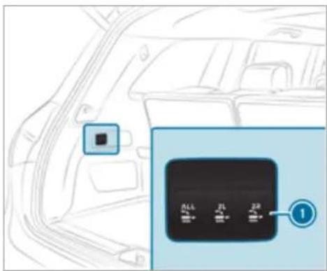
text_image
Diagram showing a car interior with a control panel labeled with three buttons and a numbered marker '1'Seven-seater (example)
To fold the left or right seat backrest forwards: briefly press one of buttons ①.
The head restraint on the seat backrest will move into a suitable position. The rear seat will fold forwards.
Vehicles with a centre seat backrest: the centre seat backrest will fold forwards together with the left seat backrest.
If a seat in the second row of seats is not engaged and locked, this will be shown on the multifunction display on the instrument cluster.
Seven-seaters: all seat backrests can be folded forwards together using the ALL button.
Folding the rear centre seat backrest forwards separately (seven-seaters)
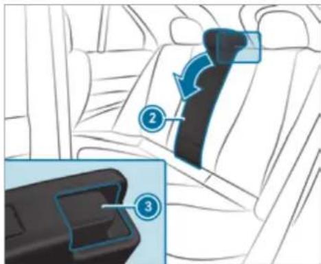
text_image
Diagram showing car seatbelt components with numbered labels indicating different parts of the seatbelt.Fold the rear seat armrest back if necessary.
Press release catch ③.
▶ Fold seat backrest ② forwards.
Folding back the rear seat backrest
NOTE Damage caused by trapping the seat belt when folding back the seat backrest
The seat belt could become trapped and thus be damaged when the seat backrest is folded back.
Make sure that the seat belt is not trapped when folding back the seat back-rest.
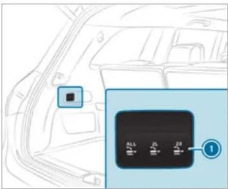
text_image
Diagram showing a car interior with a highlighted square and a control panel labeled with three buttons (1, 2, 3) pointing to the next button.Seven-seater (example)
To fold back the seat backrest: briefly pull one of buttons ①.
The rear seat will fold back.
Vehicles with a centre seat backrest: the centre seat backrest will fold back together with the left seat backrest.
If a seat backrest is not engaged and locke this will be shown on the multifunction display on the instrument cluster.
Seven-seaters: all seat backrests can be folded back together using the ALL button.
Folding back the centre seat backrest separately (seven-seaters)
Swing the seat backrest back until it audibly engages.
Folding the seat backrest on the third row of seats forwards
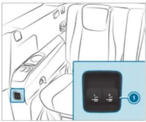
natural_image
Interior view of a car showing the backrest and seatbelt, with a close-up inset highlighting a button labeled '1' (no text or symbols on main components)Left-hand-drive vehicle (example)
In the rear (seven-seater): briefly pull one of buttons ①.
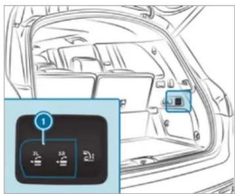
text_image
Diagram of car interior with labeled control buttons and a highlighted button labeled '1'In the load compartment: briefly press one of buttons ①.
Folding back the seat backrest on the third row of seats
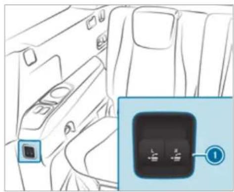
natural_image
Interior view of a car showing the backrest and side profile with a close-up of the right side panel (no text or symbols visible)Left-hand-drive vehicle (example)
In the rear: briefly press one of buttons ①. If a seat backrest is not engaged and locked, this will be shown on the multifunction display on the instrument cluster.
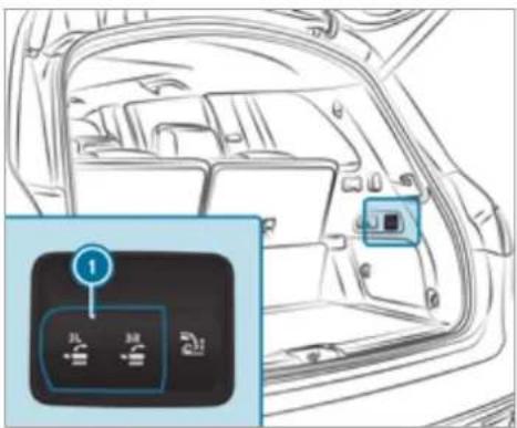
text_image
Diagram of car interior with labeled buttons and a numbered indicator box showing '孔' (back) and '锁' (lock)In the load compartment: briefly pull one of buttons ①. If a seat backrest is not engaged and locked, this will be shown on the multifunction display on the instrument cluster.
EASY-PACK load compartment cover and partitioning net cassette
Notes on the load compartment cover
⚠ WARNING Risk of injury or death due to poorly secured objects
The load compartment cover alone cannot secure or restrain heavy objects, items of luggage or heavy loads.
You could be hit by an unsecured load, particularly in the event of abrupt changes in direction, sudden braking or an accident.
Always stow objects in such a way that they cannot be thrown around.
▶ Secure objects, luggage or loads against slipping or tipping over, e.g. by using lashing material, even if you are using the load compartment cover.
NOTE Damage to the load compartment cover when loading the vehicle
The load compartment cover may be damaged when the vehicle is being loaded.
Do not place any objects above the lower edge of the side windows or on the load compartment cover.
This equipment is available for all vehicles except Mercedes-Maybach vehicles.
Extending/retracting the load compartment cover
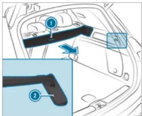
text_image
Diagram of car interior showing labeled parts with numbered annotations and directional arrowsTo extend: pull the load compartment cover back by grab handle ① and clip it into brackets ② on the left and right.
Retracting
- Remove the load compartment cover from the brackets on the left and right. - Guide the load compartment cover forwards using the grab handle until it is fully retracted.
The rolled-up load compartment cover can be used in two positions:
- Folded 45^ upwards for loading (fold down before commencing your journey) - Horizontal position
Fitting or removing the load compartment cover
Requirements:
• The load compartment cover is rolled up.
Removing the load compartment cover
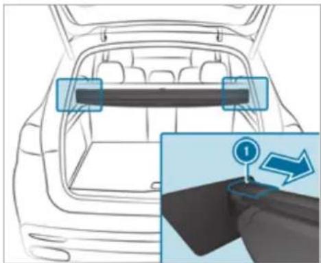
natural_image
Diagram of a car interior showing rearview and side view with a numbered arrow indicating a directional control or movement (no text or symbols present)- Press end cap ① on the left or right inwards. - Pull out the load compartment cover backwards.
Stowing the load compartment cover
The load compartment cover can be stowed beneath the load compartment floor.
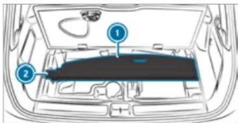
text_image
Diagram of a car interior with numbered components, likely indicating parts of the dashboard or engine compartment.- Open the load compartment floor. - To insert: Place the load compartment cover ① into the brackets ②. Ensure it is seated correctly. - To remove: Take the load compartment cover out of the brackets ②.
Fitting the load compartment cover
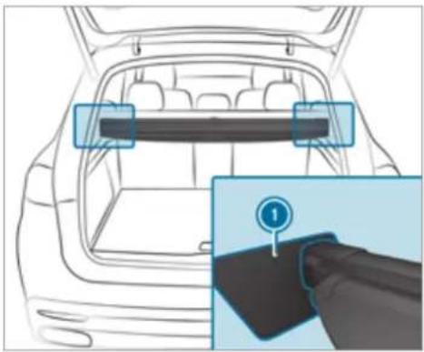
natural_image
Line drawing of a car backrest with a highlighted rectangular panel and a hand pointing to a dark object (no text or symbols)Place the load compartment cover in brackets ① on the left and right. The end caps of the load compartment will engage audibly.
Attaching/removing the partitioning net
WARNING Risk of injury or death due to poorly secured objects
The partitioning net alone cannot secure or restrain heavy objects, items of luggage or heavy loads.
You could be hit by an unsecured load, particularly in the event of abrupt changes in direction, sudden braking or an accident.
Always stow objects in such a way that they cannot be thrown around.
▶ Secure objects, luggage or loads against slipping or tipping over, e.g. by using lashing material, even if you are using the partitioning net.
For safety reasons, always use a partitioning net when transporting a load. The partitioning net can be used with or without load compartment enlargement
Damaged partitioning nets can no longer fulfil their functions and must be replaced. Visit a qualified specialist workshop.
This equipment is available for all vehicles except Mercedes-Maybach vehicles.
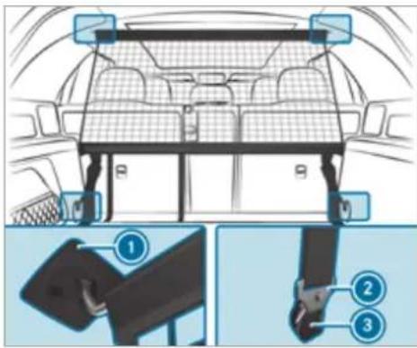
text_image
Diagram of car interior showing seatbelt and seatbelt switch with numbered parts for identificationPartitioning net without load compartment enlargement
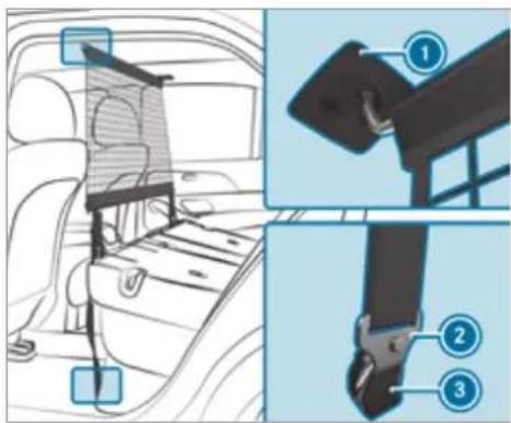
text_image
Diagram of car seatbelt components with numbered labels for identificationPartitioning net with load compartment enlargement
To attach: Extend the partition net.
Attach the top guide rod to the holders ① on the roof lining.
Engage hooks ② in eyelets ③ on the left and right.
Pull on the loose ends of the lashing straps until the partitioning net is tight.
After driving a short distance, check the tension of the partitioning net and re-tension it if necessary.
To remove: Pull the belt clamps until the lashing straps are loose.
Remove hooks ② from eyelets ③ on the left and right.
Remove the top guide rod from holders ①.
Overview of the tie-down eyes in the load compartment
Observe the notes on loading the vehicle ( page 134).
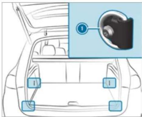
text_image
Diagram of car interior with labeled camera and sensor points, showing front and rear views with numbered annotations① Tie-down eyes
The front tie-down eyes are accessible when the third row of seats is in the luggage compartment floor position ( page 139).
Mercedes-Maybach vehicles: both tie-down eyes on Mercedes-Maybach vehicles are located in the rear load compartment, left and right.
Overview of bag hooks

WARNING Risk of injury when using bag hooks with heavy objects
The bag hooks cannot restrain heavy objects or items of luggage.
Objects or items of luggage may be flung around and hit vehicle occupants.
Only hang light objects on the bag hooks.
▶ Never hang hard, sharp-edged or fragile objects on the bag hooks.
Observe the notes on loading the vehicle ( page 134).
Subject the bag hooks to a maximum load of 3 kg and do not attach any goods to them.
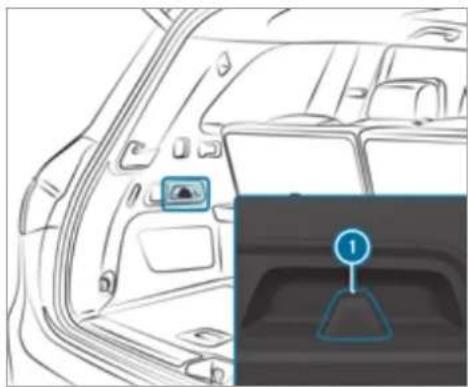
natural_image
Interior view of a car showing the rear and side compartments with a highlighted control panel (no text or symbols visible)1 Bag hook
Coat hook on the tailgate
This equipment is available for all vehicles except Mercedes-Maybach vehicles.
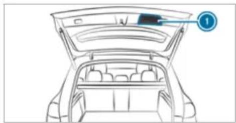
natural_image
Line drawing of a car trunk with an open lid and seat compartments, no text or symbols present① Coat hook on the tailgate
Coat hooks are not suitable for heavy objects. Use the coat hooks only for light objects such as jackets.
Locking and unlocking the load compartment floor
This equipment is available for all vehicles except Mercedes-Maybach vehicles.
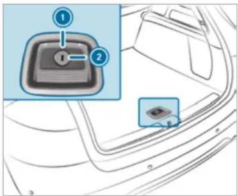
text_image
Diagram showing a car interior with a key inserted into the dashboard, labeled with numbered steps 1 and 2.Turn the emergency key a quarter turn clockwise 2 (to lock) or anti-clockwise 1 (to unlock).
Attaching a roof luggage rack

WARNING Risk of accident due to exceeding the maximum roof load
The vehicle centre of gravity and the usual driving characteristics as well as the steering and braking characteristics alter.
If you exceed the maximum roof load, the driving characteristics, as well as steering and braking, will be greatly impaired.
▶ Never exceed the maximum roof load and adjust your driving style.
You will find information on the maximum roof load in the "Technical data" section.

NOTE Vehicle damage from non-approved roof luggage racks
The vehicle could be damaged by roof luggage racks that have not been tested and approved for Mercedes-Benz.
Use only roof luggage racks tested and approved for Mercedes-Benz.
▶ Depending on the vehicle equipment, ensure that the sliding sunroof can be fully raised when the roof luggage rack is fitted.
Depending on the vehicle equipment, ensure that the tailgate can be fully opened when the roof luggage rack is fitted.
▶ Position the load on the roof luggage rack in such a way that the vehicle will not sustain damage even when it is in motion.

NOTE Damage to the panorama sliding sunroof due to non-approved roof luggage racks
The panorama sliding sunroof may be damaged by the roof luggage rack if you attempt to open it when using a roof luggage rack not tested and approved for Mercedes-Benz.
When a roof luggage rack is fitted, open the panorama sliding sunroof only if this
has been tested and approved for Mercedes-Benz.
The panorama sliding sunroof may be raised to allow ventilation of the vehicle interior.
Notes on driving with a roof load
- Distribute roof load and cargo evenly and place heavy objects at the bottom. You should also observe the notes on loading the vehicle ( page 134).
- Drive carefully, avoiding abrupt pulling away, braking and steering, as well as fast cornering.
- When transporting roof loads and when the vehicle is fully loaded or fully occupied, select drive programs E and C. The are designed to focus on stability (→ page 205).
Secure the roof luggage rack to the roof railing.
Observe the manufacturer's installation instructions.
Cup holders
Switching the cooling or heating function for the temperature-controlled cup holder on or off

WARNING Risk of injury by touching the heating elements
The cup holder's heating elements may be very hot.
You can burn yourself on them.
Do not touch the cup holder's hot heating elements.
Ensure that no children can access the cup holder's hot heating elements.
▶ Never leave children unattended in the vehicle.

NOTE Damage to objects in the temperature-controlled cupholder
If you place objects into the temperature-controlled cup holder, they may become damaged.

Do not place objects into the temperature-controlled cup holder.
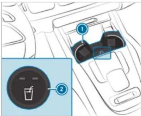
text_image
Diagram showing car interior with two labeled buttons and a circular icon containing a drink.Cup holder in the front centre console
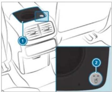
text_image
Diagram showing car interior with labeled parts and a close-up of the dashboard panel with a circular icon.Cup holder in the rear centre console
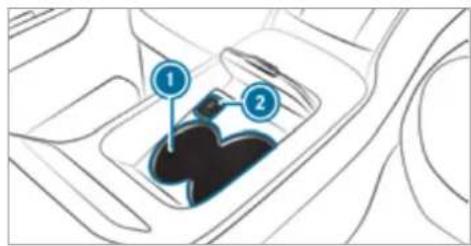
text_image
Diagram of a car gear shift mechanism with labeled parts 1 and 2Cup holder in the rear centre console (Mercedes-Maybach four-seater vehicles)
To switch on: on cup holder ①, press button ② repeatedly until the blue (keep cool) or red (keep warm) indicator lamp on the button lights up. If you use the heating function, the metal insert of the cup holder is heated. Once a certain temperature has been reached, the warning lamp lights up. Do not reach into the cup holder's metal insert when the warning lamp is lit.
To switch off: press button ② repeatedly until the indicator lamp on the button goes out.
i Clean the removable rubber mat only with clean, lukewarm water and the cup holder only with a soft cloth.
Sockets
Using the 12 V socket
Requirements:
- Only connect devices up to a maximum of 240 W (20 A).
Depending on the vehicle equipment, the vehicle has the following 12 V sockets:
- in the stowage compartment in the front centre console
• in the load compartment
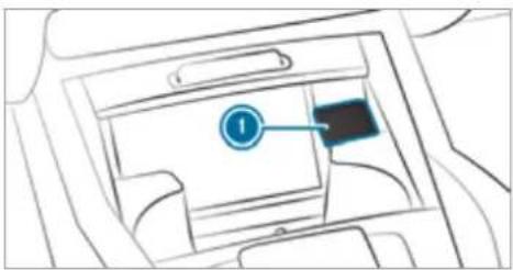
text_image
Diagram of a car interior with labeled component '1' and a blue arrow pointing to the component.Example: 12 V socket in the stowage compartment in the front centre console
Lift up cap ① of the socket and insert the plug of the device.
If you have connected a device to the 12 V socket, leave the cover of the stowage compartment open.
Using the 230 V socket in the rear passenger compartment
DANGER Risk of fatal injury due to damaged connecting cable or socket
You could receive an electric shock when pulling the connecting cable or the 230 V power socket out of the trim, or if it is damaged or wet.
Use only connecting cables that are dry and free of damage.
When the ignition is switched off, make sure that the 230 V power socket is dry.
Immediately have the 230 V power socket checked or replaced at a qualified specialised workshop if it is damaged or has been pulled out of the trim.
▶ Never plug the connecting cable into a 230 V power socket that is damaged or has been pulled out of the trim.
DANGER Risk of fatal injury due to incorrect handling of the socket
You could receive an electric shock in particular:
• if you reach into the socket.
- if you insert unsuitable devices or objects into the socket.
Do not reach into the socket.
▶ Only connect suitable devices to the socket.
Requirements:
- Only connect devices with a suitable plug which conforms to the standards specific to the country you are in.
- Only connect devices up to a maximum of 150 W (0.65 A).
- Do not use multiple socket outlets.
Depending on the vehicle equipment, the design of the centre console and stowage compartment may differ.
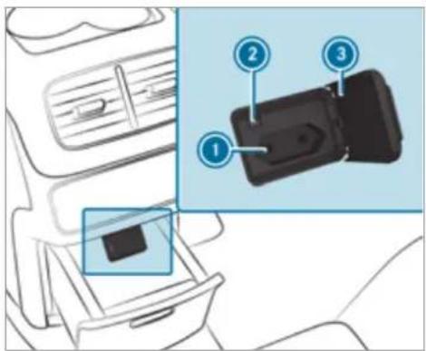
text_image
Diagram showing car interior with labeled parts and a magnified inset highlighting three numbered components.Using the 230 V socket in the centre console of the rear compartment
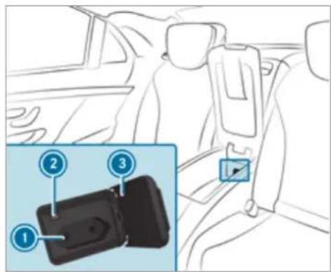
text_image
Diagram showing car seatbelt buckle with labeled parts: 1, 2, and 3, including a blue inset highlighting the seatbelt.230 V socket in the centre console of the rear compartment (Mercedes-Maybach 4-seat vehicles)
Mercedes-Maybach vehicles with individual rear seats: open the stowage compartment of the centre console of the rear compartment.
Open flap 3.
Insert the plug of the device into 230 V socket ①.
When the on-board electrical system voltage is sufficient, indicator lamp ② lights up.
Overview of USB ports
Depending on the vehicle equipment, the vehicle has the following USB ports:
- in the stowage compartment of the cockpit armrest (→ page 137)
- in the front centre console next to the mobile phone stowage compartment
• in the rear centre console - vehicles with Rear Comfort Package: in the centre armrest of the second row of seats in the rear compartment
- Mercedes-Maybach vehicles with 5 seats in the rear compartment: in the centre armrest in the rear compartment
- Mercedes-Maybach vehicles with individual rear seats: in the centre console of the rear compartment
- vehicles with three rows of seats: to the right and left next to the seat
If the ignition is switched on you can charge USB devices, e.g. mobile phones, at USB ports. The charging voltage is approximately 5 V (up to 3 A).
Coolbox
Using the refrigerator box
WARNING Risk of fire due to a covered ventilation grille on the coolbox
If you cover the ventilation grille for the cool-box, it may overheat.
Always make sure that the ventilation grille is not covered.
The vent grille for the refrigerator box is in the boot.
This equipment is available only for Mercedes-Maybach vehicles.
The refrigerator box can bear a maximum load of 3.5 kg.
Store only plastic bottles in the upper compartment of the refrigerator box. The contents of the bottle must be no more than 0.5 litres.
If you do not need to use the refrigerator box for an extended period, switch it off, defrost it and clean it. After doing so, leave the lid open for a time.
More condensation may occur during intensive use. Cleaning may be required.
The refrigerator box will reduce its cooling capacity or switch off in the following cases:
- Too many electrical consumers are turned on.
- The starter battery is not sufficiently charged.
If this is the case, the indicator lamps will flash on the button for switching the refrigerator box on and off. The cooling function will automatically switch back on as soon as there is sufficient voltage.
To install the refrigerator box in the load of compartment or remove it, please contact a qualified specialist workshop.
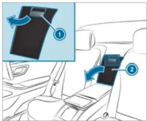
text_image
Diagram showing car seatbelt insertion steps with numbered instructions for lifting a seatbeltExample: vehicles with individual rear seats
▶ Vehicles with 5-seater variant: fold down the rear armrest.
Pull handle on stowage box ① and fold down the cover of stowage box ②.
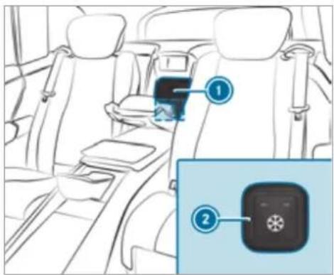
text_image
Diagram of car interior with labeled parts, showing seatbelt and app interface iconsExample: vehicles with individual rear seats
To open: pull the handle on refrigerator box ① and fold down the cover of the refrigerator box.
To switch on: press button ② repeatedly until an indicator lamp (low cooling) lights up or two indicator lamps (high cooling) light up.
To switch off: press button ② repeatedly until both indicator lamps go out.
Wireless charging of the mobile phone and connection with the exterior aerial
Notes on wirelessly charging the mobile phone
WARNING Risk of injury due to objects being stowed incorrectly
If objects in the vehicle interior are stowed incorrectly, they can slide or be thrown around and hit vehicle occupants. In addition, cup holders, open stowage spaces and mobile phone receptacles cannot always retain all objects within.
There is a risk of injury, particularly in the event of sudden braking or a sudden change in direction.
Always stow objects so that they cannot be thrown around in such situations.
Always make sure that objects do not protrude from stowage spaces, luggage nets or stowage nets.
Close the lockable stowage spaces before starting a journey.
Always stow and secure heavy, hard, pointed, sharp-edged, fragile or bulky objects in the boot/load compartment.
Observe the notes on loading the vehicle.
WARNING Risk of fire from placing objects in the mobile phone stowage compartment
Placing other objects in the mobile phone stowage compartment could constitute a fire hazard.
Apart from a mobile phone, do not place any other objects in the mobile phone stowage compartment, especially those made of metal.
NOTE Damage to objects caused by placing them in the mobile phone stowage compartment
If objects are placed in the mobile phone stowage compartment, they may be damaged by electromagnetic fields.
Do not place credit cards, data storage devices, ski passes or other objects sensitive to electromagnetic fields in the mobile phone stowage compartment.
! NOTE Damage to the mobile phone stowage compartment caused by liquids
If liquids enter the mobile phone stowage compartment, the compartment may be damaged.
▶ Ensure that no liquids enter the mobile phone stowage compartment.
Always observe the notes for persons with electronic medical aids ( page 34).
- Depending on the vehicle equipment, the mobile phone is connected to the vehicle's exterior aerial via the charging module.
- The charging function and wireless connection of the mobile phone to the vehicle's exterior aerial are only available if the ignition is switched on.
- Small mobile phones may not be able to be charged in every position of the mobile phone stowage compartment.
- Large mobile phones which do not rest flat in the mobile phone stowage compartment may not be able to be charged or connected with the vehicle's exterior aerial.
- The mobile phone may heat up during the charging process. This may also depend on the applications (apps) currently open in the background.
- To ensure more efficient charging and connection with the vehicle's exterior aerial, remove the protective cover from the mobile phone. Protective covers which are necessary for wireless charging are an exception.
Wireless charging of a mobile phone in the cockpit
Requirements:
- The mobile phone is suitable for wireless charging.
A list of compatible mobile phones can be found at: https://www.mercedes-benzmobile.com/
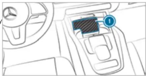
natural_image
Interior view of a car dashboard with steering wheel and gear (no visible text or symbols)Place the mobile phone as close to the centre of mat ① as possible with the display facing upwards. When a message is shown in the multimedi system, the mobile phone is being charged.
Malfunctions detected during the charging process are shown in the multimedia s display.
① The mat can be removed for cleaning, e.g. using clean, lukewarm water.
Radio equipment approval numbers for Brazil
This device operates on a secondary basis, that is to say it has no protection against harmful interference, not even from the same type of stations, and must not cause interference with systems operating on a primary basis.
This product is permitted in accordance with procedure defined in Directive 242/2000 by the Brazilian telecommunications agency ANATEL and meets the applicable technical requirements.
Further information is available on the ANATEL website. www.anatel.gov.br
▶ Further information on the declaration of conformity for vehicle components which receive and/or transmit radio waves.
Wirelessly charging a mobile phone in the rear passenger compartment

NOTE Damage to the drawer in the centre console of the rear compartment due to body weight
When open, the drawer in the centre console of the rear compartment can be damaged by body weight.
Do not support yourself on the open drawer.
Requirements:
- The mobile phone must be suitable for wireless charging.
A list of compatible mobile phones can be found at: https://www.mercedes-benz-mobile.com/
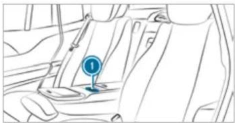
natural_image
Line drawing of a car interior showing a blue circular traffic sign on the seat (no text or symbols)Mat in front of the stowage compartment in the rear armrest
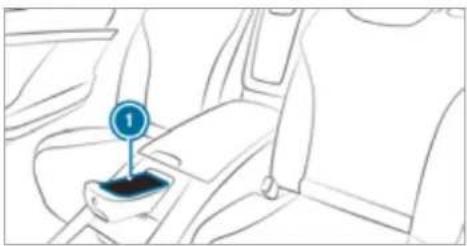
natural_image
Line drawing of a car seatbelt with a blue circular marker labeled '1' (no text or symbols beyond the label)Mat in the centre console of the rear compartment (only Mercedes-Maybach vehicles with individual rear seats)
Place the mobile phone as close to the centre of mat ① as possible with the display facing upwards. When the indicator lamp lights up, the mobile phone is being charged.
Fitting/removing the floor mats
WARNING Risk of accident due to objects in the driver's footwell
Objects in the driver's footwell may impede pedal travel or block a depressed pedal. This jeopardises the operating and road safety of the vehicle.
Stow all objects in the vehicle securely so that they cannot get into the driver's footwell.
▶ Always fit the floor mats securely and as prescribed in order to ensure that there is always sufficient room for the pedals.
Do not use loose floor mats and do not place floor mats on top of one another.
Fitting floor mats
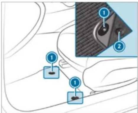
text_image
Diagram showing car seatbelt components with numbered labels and a close-up of the seatbelt detailMove the corresponding seat backwards and lay the floor mat in the footwell.
Press studs ① onto holders ②.
Adjust the corresponding seat.
Vehicles with a third row of seats (all vehicles except Mercedes-Maybach vehicles): To fit the floor mats on the third row of seats, slide the corresponding seat on the second row of seats forwards.
Removing floor mats
Pull the floor mat off holders ②.
Remove the floor mat.
Vehicles with a third row of seats (all vehicles except Mercedes-Maybach vehicles): To remove the floor mats on the third row of seats, slide the corresponding seat on the second row of seats forwards.
Exterior lighting
Notes on adjusting the lights when driving abroad
Vehicles with static LED headlamps: It is not necessary to convert the headlamps. The legal requirements are also met in countries in which traffic drives on the other side of the road.
Vehicles with Intelligent Light System: The headlamps are automatically adjusted when the vehicle enters countries in which traffic drives on the other side of the road.
In the following cases, check the headlamp setting and change it manually if necessary:
- If the Dipped-beam setting (left/right-side traffic) Manual adjustment only display message is displayed.
- If the Check dipped-beam setting (left/right-side traffic) display message is displayed.
Once the headlamps have been converted:
- Oncoming traffic will not be dazzled.
- The edge of the road will not be illuminated as far or as high.
- The "motorway mode" and "enhanced fog light" functions will not be available.
Information about lighting systems and your responsibility
The various lighting systems of the vehicle are only aids. The driver of the vehicle is responsible for correct vehicle illumination in accordance with the prevailing light and visibility conditions, legal requirements and traffic situation.
Light switch
Operating the light switch
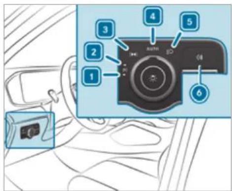
text_image
Diagram of a car interior showing numbered camera mode labels and a close-up of the camera's head.1 ←P ≡ Left-hand parking lights
2 P←→ Right-hand parking lights
3 3005 Standing lights and licence plate lighting
4 AUTO Automatic driving lights (preferred light switch position)



When low beam is activated, the 200 indicator lamp for the standing lights will be deactivated and replaced by the 50 low-beam indicator lamp.

Always park your vehicle safely using sufficient lighting, in accordance with the relevant legal stipulations.

NOTE Battery discharging by operating the standing lights
Operating the standing lights over a period of hours puts a strain on the battery.

Where possible, switch on the right P or left P parking light.
For vehicles that are wider than two metres or longer than six metres, single-sided parking lighting is not permitted in some countries. In this case, the standing lights are also switched on in the parking lights position.
If the battery is insufficiently charged, the standing lights or parking lights will be switched automatically to facilitate the next engine start.
The exterior lighting (except standing and parking lights) will switch off automatically when driver's door is opened.
- Observe the notes on surround lighting ( page 166).
Automatic driving lights function
The standing lights, low beam and daytime running lights are switched on automatically depending on the ignition status and the light conditions.

WARNING Risk of accident when the dipped beam is switched off in poor visibility
When the light switch is set to AUTO, the dipped beam may not be switched on automatically if there is fog, snow or other causes of poor visibility such as spray.
In such cases, turn the light switch to 📋.
- The automatic driving lights are only an aid. You off are responsible for vehicle lighting.
Switching the rear fog lights on or off
the Requirements:
- The light switch is in the ☑ or AUTO position.

Press the ☐ button.
Please observe the country-specific laws on the use of rear fog lamps.
Vehicles with AIRMATIC or E-ACTIVE BODY CONTROL with off-road package: when the rear fog light is switched on, off-road level +3 will not be available. If the rear fog light is switched on and off-road level +3 is activated, the vehicle will be lowered to off-road level +2.
Operating the combination switch for the lights

text_image
Diagram illustrating car seatbelt usage with numbered instructions and directional arrows indicating movement or connection.① High beam
② Turn signal light, right
③ Headlamp flashing
④ Turn signal light, left
Use the combination switch to activate the desired function.
Switches on high beam
Turn the light switch to the 📋 or AUTO position.
Push the combination switch in the direction of arrow ①.
When the high beam is activated, the indicator lamp for low beam will be deactivated and replaced by the indicator lamp for high beam.
Switching off high beam
Push the combination switch in the direction of arrow ① or pull it in the direction of arrow ③.
Headlamp flashing
Pull the combination switch in the direction of arrow 3.
Turn signal light
To indicate briefly: push the combination switch briefly to the point of resistance in the direction of arrow ② or ④. The corresponding turn signal light will flash three times.
To indicate permanently: push the combination switch beyond the point of resistance in the direction of arrow ② or ④.
Activating/deactivating the hazard warning lights
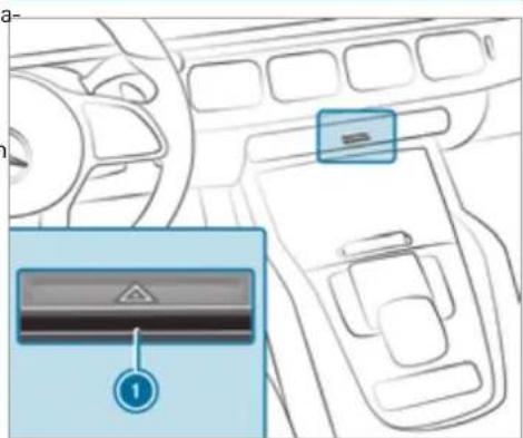
text_image
Diagram of car interior showing dashboard, steering wheel, and control panel with labeled buttonsPress button 1.
The hazard warning lights will switch on automatically if:
• the airbag has been deployed.
- the vehicle is heavily braked from a speed more than 70 km/h to a standstill.
When you pull away again, the hazard warning light system will switch off automatically at approximately 10 km/h. You can also switch off the hazard warning light system using button ⓘ.
When the turn signal indicator is activated, the hazard warning lights will be interrupted.
Intelligent Light System
Intelligent Light System function
The MULTIBEAM LED headlamps adapt to the driving and weather situation and provide extended functions for improved illumination of the road.
The system comprises the following functions:
• Active headlamps ( page 162)
• Cornering light ( page 162)
• Motorway mode (→ page 163)
• Enhanced fog light function ( page 163)
• Off-road light ( page 164)
The system is active only when it is dark.
Active headlamps function
natural_image
Illustration of a road with vehicles and trees, no text or symbols present- The headlamps follow the steering movements.
- Relevant areas are better illuminated during a journey.
The functions are active when the low beam is switched on.
Depending on the vehicle's equipment, the course of the lane in which you are driving will also be evaluated and the active headlamps function will adjust the light in advance.
Cornering light function
natural_image
Illustration of a person standing on a crosswalk beside a road with a car parked nearby (no text or symbols)The cornering light improves the illumination of the carriageway over a wide angle in the turning direction, enabling better visibility on tight bends, for example. It can be activated only when the low beam is switched on.
The function is active under the following conditions:
- At speeds below 40 km/h when the turn signal light is switched on or the steering wheel is turned
- At speeds between 40 km/h and 70 km/h when the steering wheel is turned
Roundabout and junction function: the cornering light will be activated on both sides based on an evaluation of the vehicle's current GPS position. It will remain active until after the vehicle is left the roundabout or the junction.
Motorway mode function
Motorway mode increases the range and brightness of the cone of light, enabling better visibility.
natural_image
Illustration of a multi-lane road with vehicles and trees, no visible text or symbolsThe function will be active if a motorway journey is detected by means of:
- the vehicle's speed
• the multifunction camera
• the GPS
The function will not be active at speeds below 80 km/h.
Enhanced fog light function
The enhanced fog light function reduces self-dazzling and improves the illumination of the edge of the carriageway.
natural_image
Illustration of a road scene with cars and trees, no text or symbols presentThe function is automatically activated under the following conditions:
- At speeds below 70 km/h and when the rear fog light is switched on.
The function is automatically deactivated under the following conditions:
- When speeds greater than 100 km/h are reached.
- When the rear fog light is switched off.
① You can activate the enhanced fog light function up to a speed of 100 km/h by switching on the rear fog light.
Function of the off-road light
The off-road light improves illumination during off-road driving. The low beam is distributed symmetrically and across a wide angle, and brightness is increased slightly. This makes it easier to find your way when driving off-road and to detect obstacles at an early stage. The active headlamps are deactivated during this time so that steering movements do not change the illumination.
The function is active when the low beam is switched on if you are not driving at a speed greater than 50 km/h and the (Offroad) or

(Offroad Plus) drive program has been
Switching the Intelligent Light System on/off
Requirements:
• The ignition is switched on.
Multimedia system:


Intelligent

System

Switch the function on or off.
Adaptive Highbeam Assist Plus
Adaptive Highbeam Assist Plus function

WARNING Risk of accident despite Adaptive Highbeam Assist Plus
Adaptive Highbeam Assist Plus does not react to:
- road users without lights, e.g. pedestrians
• road users with poor lighting, e.g. cyclists - road users whose lighting is obstructed, e.g. by a barrier
On very rare occasions, Adaptive Highbeam Assist Plus may fail to recognise other road users with their own lighting, or may recognise them too late.
In these, or in similar situations, the automatic high beam will not be deactivated or will be activated despite the presence of other road users.

Always observe the road and traffic conditions carefully and switch off the high beam in good time.
Adaptive Highbeam Assist Plus cannot take into account road, weather or traffic conditions.
Detection may be restricted in the following cases:
• In poor visibility, e.g. fog, heavy rain or snow
- if there is dirt on the sensors or the sensors are obscured
Adaptive Highbeam Assist Plus is only an aid. You are responsible for adjusting the vehicle's lighting to the prevailing light, visibility and traffic conditions.
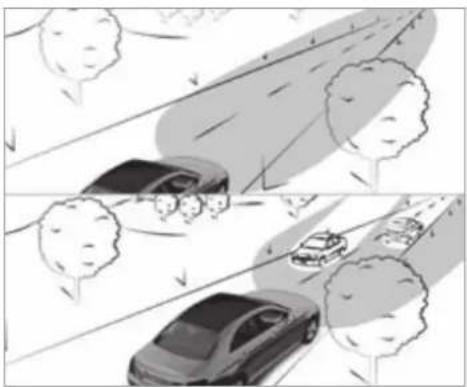
natural_image
Illustration of a road scene with cars and trees, no visible text or symbolsAdaptive Highbeam Assist Plus automatically switches between the following types of light:
- Low beam
- Partial high beam
- High beam
Partial high beam uses the high beam to shine past other road users rather than dazzling them.
The vehicle in front will be illuminated by the low beam.
At speeds greater than 30 km/h:
- If no other road users are detected, the high beam will switch on automatically.
- If other road users are detected, the partial high beam will switch on automatically.
At speeds below 25 km/h or when there is sufficient street lighting:
- The partial high beam will switch off automatically.
• The high beam will switch off automatically.
At speeds greater than approximately 50 km/h:
- The headlamp range of the low beam is regulated automatically based on the distance to other road users.
The system's optical sensor is located behind the windscreen near the overhead control panel.
Switching Adaptive Highbeam Assist Plus on/off
Switching on
Turn the light switch to the AUTO position.
Switch on the high beam using the combination switch.
When the high beam is switched on automatically in the dark, the indicator lamp (the multifunction display will light up.
Switching off
Switch off the high beam using the combination switch.
Setting the low beam (vehicles with MULTI-BEAM LED headlamps only)
Multimedia system:
→ Settings Lights
Dipped-beams
Select Right-side traffic, Left-side traffic or Automatic.
Setting the exterior lighting switch-off delay time
Requirements:
- The light switch is in the AUTO position.
Multimedia system:
Settings Lights
▶ Ext. light. del. sw. off
Set the switch-off delay time. When the vehicle engine is switched off, the exterior lighting will be activated for the set time.
Switching the surround lighting on/off
Multimedia system:
Settings Lights
▶ Surround lighting
When Surround lighting is active, the exterior lighting lights up for 40 seconds after the vehicle is unlocked. When you start the vehicle, the surround lighting is deactivated and the automatic driving lights are activated.
Illuminated running boards: when the surround lighting is switched on, the illumination of the running boards is activated when a door is opened. If the door is not closed, the running board courtesy lighting is automatically deactivated after 40 seconds.
▶ Activate or deactivate the function.
Interior lighting
Adjusting the interior lighting
Front overhead control panel
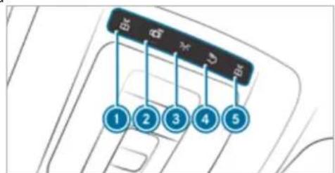
text_image
1 2 3 4 51 Front left reading lamp
2 Automatic interior lighting control
3 Front interior lighting
4 Rear interior lighting
5 Front right reading lamp
To switch on/off: press button ① - ⑤ accordingly.
Control panel in the grab handle
natural_image
Diagram of a car gear shift lever with a blue circular indicator labeled '1' (no text or symbols beyond the label)① Rear reading lamp
To switch on/off: press button ①.
Adjusting the ambient lighting
Multimedia system:
Settings Lights
▶ Ambient lighting
Setting the colour
Select Colour.
Set the desired colour.
Adjusting the brightness
▶ Select Brightness.
Adjust the brightness.
Activating the brightness for zones
Select Brightness.
Select Brightness zones.
The EMPHASIS, AMBIENT and ROOF zones can be set separately.
Activating multi-coloured lighting
Select Colour.
▶ Select Multi-colour.
▶ Select a colour combination.
Activating multi-coloured animation
Select Colour.
Select Multi-colour animat..
The chosen colour combination will change at predefined intervals.
Activating welcome lighting
Select Colour.
Select Welcome. When the vehicle is unlocked, a special ambient lighting sequence will run.
Activating dependency on air conditioning settings
Select Colour.
▶ Select Climate.
If changes are made to the temperature setting in the vehicle, the colour of the ambient lighting will change briefly.
Switching the interior lighting switch-off delay time on/off
Multimedia system:
Settings Lights
Int. light. del. sw. off
Switch the switch-off delay time on or off. When this function is active, the interior lighting lights up for a short time after the vehicle is locked.
Windscreen wipers and windscreen washer system
Switching the windscreen wipers on/off
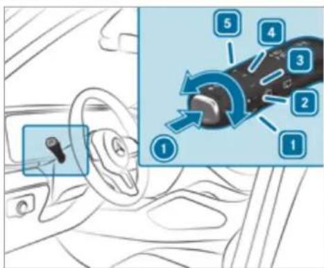
text_image
Diagram illustrating car steering wheel and gear shift mechanism with numbered labels1 0 Windscreen wipers off
2 … Automatic wiping, normal
3 .... Automatic wiping, frequent
4 — Continuous wiping, slow
5 = Continuous wiping, fast
Turn the combination switch to the corresponding position 1 - 5.
Single wipe/washing: push the button on the combination switch in the direction of arrow ①.
- Single wipe
• Wiping with washer fluid
① Observe the notes on washing the vehicle in a car wash ( page 374).
Vehicles with MAGIC VISION CONTROL: in position 2 or 3, the windscreen washing process is automatically triggered if dirt is detected on the windscreen unless the Top up washer fluid message is being displayed.
Switching the rear window wiper on/off
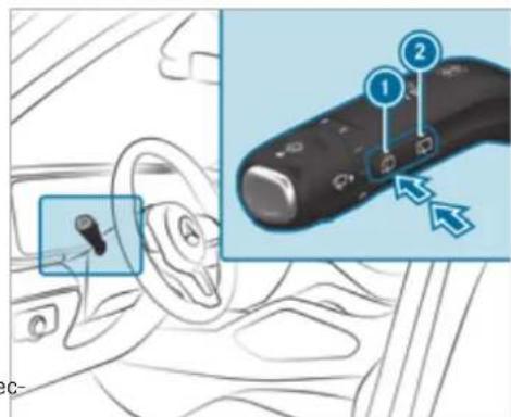
text_image
Diagram showing car interior and dashboard control with labeled parts, including a key inserted into the steering wheel.① Single wipe/washing ② Intermittent wiping
Single wipe: press button ① to the point of resistance.
Wiping with washer fluid: press button ① beyond the point of resistance.
Switching intermittent wiping on/off: press button ②. Vehicles with rain sensor: the wipe interval automatically adapts to the driving conditions. The symbol will appear on the instrument cluster when the rear window wiper is switched on.
Replacing the windscreen wiper blades
WARNING Risk of becoming trapped if the windscreen wipers are switched on while wiper blades are being replaced
If the windscreen wipers begin to move while you are changing the wiper blades, you can be trapped by the wiper arm.
▶ Always switch off the windscreen wipers and ignition before changing the wiper blades.
Moving the wiper arms into the replacement position
Switch the ignition on and then off again immediately.
Within around 15 seconds, press and hold the button on the combination switch for approximately three seconds (→ page 168).
The wiper arms will move into the replacement position.
Removing the wiper blades
Fold the wiper arms away from the wind-screen.
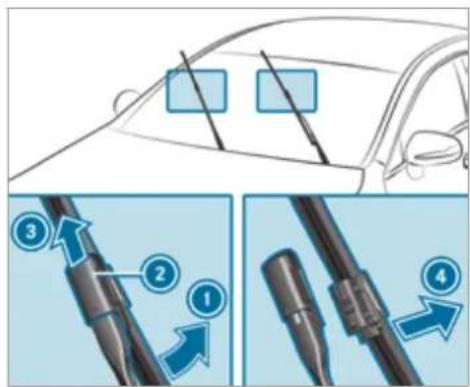
text_image
Diagram illustrating car engine components with numbered parts and directional arrows indicating assembly or repair steps.Hold the wiper arm with one hand. With the other hand, turn the wiper blade away from the wiper arm in the direction of arrow ① as far as it will go.
Slide catch ② in the direction of arrow ③ until it engages in the removal position.
Remove the wiper blade from the wiper arm in the direction of arrow 4.
Fitting the wiper blades
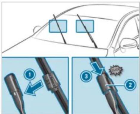
text_image
Diagram illustrating car safety instructions with numbered steps and component illustrationsInsert the new wiper blade into the wiper arm in the direction of arrow ①.
Slide catch ② in the direction of arrow ③ until it engages in the locking position.
Make sure that the wiper blade is seated correctly.
Fold the wiper arms back onto the wind-screen.
▶ Switch on the ignition.
Press the button on the combination switch.
The wiper arms will return to the original position.
▶ Switch the ignition off.
Maintenance display
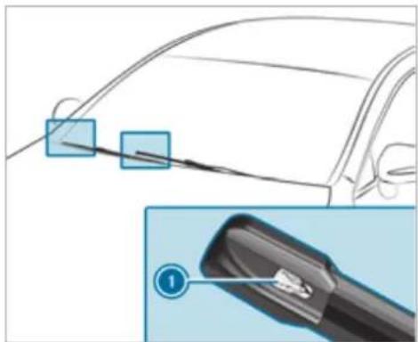
natural_image
Diagram showing a car exterior with two blue square markers and a magnified view of the cable connector (no text or symbols)Remove protective film ① from the maintenance display on the tip of the newly fitted wiper blades.
When the colour of the maintenance display changes from black to yellow, the wiper blades should be replaced.
(i) The duration until the colour changes varies depending on the usage conditions.
Replacing the windscreen wiper blades (MAGIC VISION CONTROL)
Moving the wiper arms into the replacement position
▶ Switch the ignition off.
Within around 15 seconds, press the button on the combination switch (→ page 168).
The wiper arms will move into the replacement position.
Removing the wiper blades
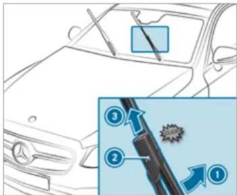
text_image
Diagram showing car exterior with a pen and tool, alongside a close-up of a mechanical component with numbered annotations.To bring the wiper blade into position to be removed: hold the wiper arm firmly in one hand. With the other hand, turn the wiper blade in the direction of arrow beyond the point of resistance. The wiper blade will engage in the removal position with a click.
To remove the wiper blade: press release knob ②, pull the wiper blade in the direction of arrow ③ and remove.
Fitting the wiper blades
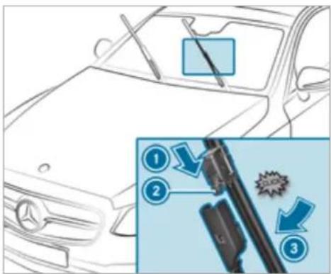
text_image
Diagram showing car interior cleaning steps with numbered instructions and a magnified view of the tool path.▶ Push the new wiper blade onto the wiper a in the direction of arrow ① until release knob ② engages.
Press the wiper blade onto the wiper arm in the direction of arrow ③ beyond the point of resistance.
The wiper blade will engage with a noticeable click and move freely again.
Fold the wiper arm back onto the wind-screen.
Replacing the rear window wiper blade

WARNING Risk of becoming trapped if the windscreen wipers are switched on while wiper blades are being replaced
If the windscreen wipers begin to move while you are changing the wiper blades, you can be trapped by the wiper arm.
Always switch off the windscreen wipers and ignition before changing the wiper blades.
Removing the wiper blade
switch the ignition off.
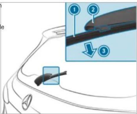
text_image
Diagram showing a car's side profile with labeled parts and an inset highlighting a specific component.Fold wiper arm ② away from the rear window until it engages in the replacement position.
Unclip wiper blade ① from wiper arm ② and remove it in the direction of arrow ③.
Fitting the wiper blade
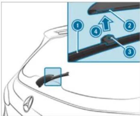
text_image
Diagram showing car door cleaning steps with numbered instructions and a magnified detail of the componentPosition wiper blade ① with both lugs ③ on holder ② on the wiper arm.
Push wiper blade ① in the direction of arrow ④ until it engages in holder ②.
Make sure that wiper blade ① is seated correctly.
Fold the wiper arm from the replacement position back onto the rear window.
Mirrors
Operating the outside mirrors
WARNING Risk of injury if vehicle settings are adjusted while the vehicle is in motion
You could lose control of the vehicle in particular in the following situations:
- If you adjust the driver's seat, the head restraints, the steering wheel or the mirror while the vehicle is in motion.
- If you fasten your seat belt while the vehicle is in motion.
Before starting the engine: adjust the driver's seat, head restraints, steering wheel and mirror in particular and fasten your seat belt.
A WARNING Risk of accident due to mis-judgement of distance when using the outside mirror
The outside mirrors reflect objects on a smaller scale. The objects in view are in fact closer than they appear.
Therefore, always look over your shoulder in order to ensure that you are aware of the actual distance between you and the road users driving behind you.
Folding the outside mirrors in/out
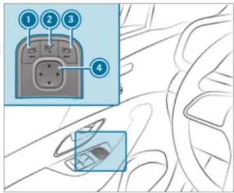
text_image
Diagram showing car interior with labeled buttons and control panel, highlighting key points 1-4Briefly press button 2.
If the battery has been disconnected or has discharged, the outside mirrors must be moved briefly using button ②. Only then will the automatic mirror folding function work properly.
Mercedes-Maybach vehicles: when the outside mirrors fold in, the extendable running boards will retract if they were previously extended.
Adjusting the outside mirrors
Press button ① or ③ to select the outside mirror to be adjusted.
Press button ④ to adjust the position of the mirror glass.
Engaging the outside mirrors
If an outside mirror has been forcibly disengaged, proceed as follows.
▶ Vehicles without electrically folding outside mirrors: manually move the outside mirror into the correct position.
Vehicles with electrically folding outside mirrors: press and hold button ②. You will hear a click and the mirror will audibly click into place. The outside mirror will now be set to the correct position.
Automatic anti-dazzle mirrors function

WARNING Risk of acid burns and poisoning due to the anti-dazzle mirror electrolyte
Electrolyte may escape if the glass in an automatic anti-dazzle mirror breaks.
The electrolyte is hazardous to health and causes irritation. It must not come into contact with your skin, eyes, respiratory organs or clothing or be swallowed.
If you come into contact with electrolyte, observe the following:
- Immediately rinse the electrolyte from your skin with water and seek medical attention.
- If electrolyte comes into contact with your eyes, immediately rinse them thoroughly with clean water and seek medical attention.
- If the electrolyte is swallowed, immediately rinse your mouth out thoroughly. Do not induce vomiting. Seek medical attention immediately.
- Immediately change out of clothing which has been contaminated with electrolyte.
- If an allergic reaction occurs, seek medical attention immediately.
The inside rear-view mirror and the outside mirror on the driver's side will automatically go into anti-dazzle mode if light from a headlamp hits the sensor on the inside rear-view mirror.
System limits
The system will not go into anti-dazzle mode if:
• The engine is switched off.
- Reverse gear is engaged.
• The interior lighting is switched on.
Front-passenger outside mirror parking position function
① The parking position is available only in vehicles with a memory function.
The parking position makes parking easier.
In the following situations, the front-passenger outside mirror will swivel downwards in the direction of the rear wheel on the front passenger's side:
• the parking position is stored ( page 175)
• The front-passenger mirror is selected
- Reverse gear is engaged.
The front-passenger outside mirror will move back to its original position in the following situations:
- You shift the transmission to another transmission position
- You are travelling at speeds greater than 15 km/h
- You press the button for the outside mirror on the driver's side
Storing and calling up the parking position of the front-passenger outside mirror
Storing
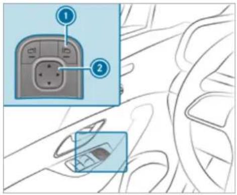
text_image
Diagram showing car interior with labeled buttons and a close-up of the dashboard panelSelect the front-passenger outside mirror using button ①.
Engage reverse gear.
Move the front-passenger outside mirror into the desired parking position using button ②.
Calling up
Select the front-passenger outside mirror using button ①.
Engage reverse gear.
The front-passenger outside mirror will move to the stored parking position.
Activating/deactivating the automatic mirror folding function
Multimedia system:
→ Settings → Vehicle
▶ Switch Automatic fold-in on or off.
Area permeable to radio waves on the windscreen
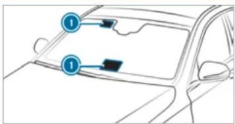
text_image
Diagram of a car's front and rear door with numbered arrows indicating specific components or parts on the dashboard.Infrared-reflective windscreen function
The infrared-reflective windscreen is coated and reduces the build-up of heat in the vehicle interior.
The coating shields the vehicle interior from radio waves.
Radio-controlled equipment, such as toll systems, can be mounted only on areas ① of the windscreen that are permeable to radio waves.
Areas permeable to radio waves ① are best visible from outside the vehicle when the windscreen is illuminated with an external light source.
Note this position for vehicles with:
- Windscreen heating
• Infrared reflective windscreen
Overview of climate control systems
Notes on climate control
An interior air filter in combination with the prefilter in the engine compartment must always be used so that the air conditioning system, pollution level monitoring and the air filtration work correctly. Use filters recommended and approved by Mercedes-Benz. Always have maintenance work carried out at a qualified specialist workshop.
Overview of the air conditioning control panel
The indicator lamps on the buttons indicate that the corresponding function is activated.
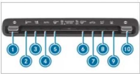
text_image
1 2 3 4 5 6 7 8 9 10THERMOTRONIC air conditioning control panel with stationary heater (example)
Sets the temperature on the driver's side
2 Calls up the air conditioning menu
3 Sets the airflow or switches off climate control
4 AUTO Sets climate control to automatic mode ( page 179)
5 Demists the windscreen
6 REAR Switches the rear window heater on/off
7 Switches air-recirculation mode on/off (→ page 180)
B A/C Switches the A/C function on/off (→ page 178)
Switches residual heat on/off ( page 181, 180)
Vehicles with THERMATIC or THERMOTRONIC control panel with stationary heater: switches stationary heater on/off ( page 183)
Vehicles with THERMATIC or THERMOTRONIC control panel without stationary heater: SYNC switches synchronisation on/off ( page 180)
10 Sets the temperature on the front passenger side
i THERMATIC equipment is available for all vehicles except Mercedes-Maybach vehicles.
Overview of the rear operating unit
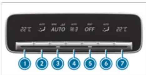
text_image
22℃ AUTO AUTO OFF 1 2 3 4 5 6 7① Sets the temperature, left
② Sets the air distribution, left
③ Sets climate control to automatic mode ( page 179)
④ Setting the airflow
5 Switches climate control on/off ( page 178)
Switches the residual heat on/off ( page 181)
⑥ Sets the air distribution, right
7 Sets the temperature, right
The settings for the second and third row of seats (equipment-dependent) can be made via the rear operating unit, the multimedia system ( page 179) or the MBUX rear tablet depending on the vehicle's equipment.
Operating the climate control system
Switching climate control on/off
To switch on: set the airflow to level 1 or higher using the button.
To switch off: set the airflow to level 0 using the button.
If climate control is switched off, the windows may mist up more quickly. Switch climate control off only briefly.
Switching the climate control in the rear on/off
Press button 5.
When climate control in the second seat row is switched off, the indicator lamp is activated and OFF is shown on the rear display.
Switching the A/C function on/off using the air conditioning control panel
The A/C function heats, cools and dehumidifies the vehicle's interior air.
Press the A/C button.
Switch off the A/C function only briefly; otherwise, the windows may mist up more quickly.
Condensation may drip from the underside of the vehicle when cooling mode is active. This is not indicative of a fault.
Calling up the air conditioning menu
Calling up the air conditioning menu using the multimedia system
Select one of the temperature displays at the lower edge of the media display.
Calling up the air-conditioning menu using the button on the climate control panel
Press the MENU TEST button on the climate control panel.
Activating/deactivating the A/C function via the multimedia system
The A/C function heats, cools and dehumid in the vehicle's interior air.
Call up the air-conditioning menu ( page 178).
▶ Select First row of seats.
Select A/C.
Setting climate control to automatic mode
In automatic mode, the set temperature is controlled and maintained at a constant level by the air supply.
Press the AUTO button.
To switch to manual mode: press the AUTO button.
In automatic mode, you can choose between five different air quantities using the button. Automatic mode is retained.
Automatically controlling the climate control in the rear
In automatic mode, the set temperature is regulated by the temperature of the dispensed air and the airflow.
Press the AUTO button (→ page 178).
Setting the air distribution
Call up the air conditioning menu ( page 178).
Select a row of seats.
To set the air distribution: select 📞, or 🌐.
Set the airflow.
Several air distribution options can be selected at the same time, for example to set the climate control for the windscreen and the footwells simultaneously.
The climate control for the windscreen can only be selected for the first seat row.
Setting climate control for the rear passenger compartment (multimedia system)
Setting the temperature
▶ Call up the air conditioning menu ( page 178).
▶ Select Second row of seats or Third row seats.
For Maybach vehicles: select Second row of seats.
(i) Maybach vehicles are fitted with one and two rows of seats.
Set the temperature.
Setting the airflow
▶ Call up the air conditioning menu ( page 178).
▶ Select Second row of seats or Third row seats.
For Maybach vehicles: select Second row of seats.
(i) Maybach vehicles are fitted with one and two rows of seats.
Set the airflow.
Controlling the rear climate control automatically
Select REAR AUTO. Rear climate control is controlled automatically.
Deactivating rear climate control
▶ Select REAR OFF. Rear climate control is deactivated.
Activating/deactivating the climate control synchronisation function via the air conditioning control panel
Climate control can be set centrally using the synchronisation function. The temperature and air distribution setting for the driver's side will adopt automatically for all climate control zones.
Press the SYNC button.
The synchronisation function will be deactivated Windows misted up on the outside
if the settings for one of the other climate zones are changed.
Activating/deactivating the climate control synchronisation function via the multimedia system
Climate control can be set centrally using the synchronisation function. The driver's settings for temperature, air quantity and air distribution are adopted automatically for all climate zones.
Call up the air conditioning menu ( page 178).
▶ Select First row of seats.
Select SYNC.
Demisting the windows
Windows misted up on the inside
Press the AUTO button.
If the windows continue to mist up: press the button.
▶ Switch on the windscreen wipers.
Press the AUTO button.
Switching air-recirculation mode on/off
Press the 📄 button. The interior air will be recirculated.
Air-recirculation mode automatically switches to fresh air mode after some time.
If air-recirculation mode is switched on, the windows may mist up more quickly. Switch on air-recirculation mode only briefly.
Switches the residual heat on/off
Requirements:
• the vehicle is parked.
It is possible to make use of the residual heat from the engine to continue heating or ventilating the front compartment of the vehicle for approximately 30 minutes, depending on the temperature set.
To activate: press button A/C
Residual heat will be switched off automatically.
Switching the residual heat in the rear on/off
Requirements:
• The vehicle is parked.
When the residual heat of the engine is activated in the rear compartment, you can heat or ventilate the rear compartment for approximately 30 minutes.
Press button ⑤ (→ page 178).
Activating/deactivating ionisation
Ionisation improves the quality of the vehicle's interior air. Ionisation of the interior air is odourless.
Fragrance system
Setting the fragrance system
Requirements:
• Automatic climate control is activated.
• The glove compartment is closed.
The fragrance system distributes a pleasant fragrance throughout the vehicle interior from a flacon located in the glove box.
▶ Call up the air conditioning menu ( page 178).
▶ Select Air quality.
▶ Select AIR FRESHENER.
Keep pressing until the desired intensity is reached.
Inserting or removing the flacon of the fragrance system
WARNING Risk of injury from liquid perfume
If children open the flacon, they could drink the liquid perfume or it could come into contact with their eyes.
Do not leave children unattended in the vehicle.
Consult a doctor immediately if liquid perfume has been drunk.
If liquid perfume comes into contact with your eyes or skin, rinse your eyes with clean water.
If symptoms continue, consult a doctor.
Call up the air conditioning menu ( page 178).
▶ Select Air quality.
▶ Select IONISATION.
Call up the air conditioning menu ( page 178).
▶ Select Air quality.
▶ Select IONISATION.

ENVIRONMENTAL NOTE Environmental damage due to improper disposal of full flacons

Full flacons must not be disposed household waste.


Full flacons must be taken to I substance collection point.
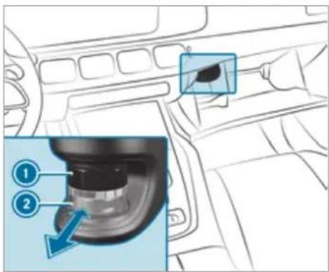
text_image
Diagram showing car interior with a highlighted component and numbered parts, likely illustrating a mechanical or engine assembly.
Cap

Flacon
To insert: slide the flacon into the holder as far as it will go.
To remove: after opening the glove box, wait for approximately seven seconds and pull out the flacon.
If you do not use genuine Mercedes-Benz interior perfumes, observe the manufacturers' safety notices on the perfume packaging.
Dispose of the genuine Mercedes-Benz interior perfume flacon when it is empty and do not refill it.
Refillable flacon
Unscrew the cap of the empty flacon.
Fill the flacon with a maximum of 15 ml.
Screw the cap back on to the flacon.
Always refill the empty refillable flacon with the same perfume. Observe the separate information sheet with the flacon.
Information on the windscreen heater
The windscreen heater is switched on automatically if the MAX button is activated.
In addition, it is automatically switched on when necessary.
Stationary heater/ventilation
Stationary heater/ventilation function
- The air inside the vehicle is heated or ventilated to the set temperature.
- The air inside the vehicle cannot be cooled down to temperatures below the outside temperature.
- If the outside temperature changes, ventilation mode automatically switches to heating mode or heating mode automatically switches to ventilation mode.
The stationary heater and the exhaust gas outlet are situated behind the right-hand front wheel.
Switching the stationary heater/ventilation on/off via the operating unit

DANGER Risk of fatal injury due to poisonous exhaust gases
If the tailpipe is blocked or sufficient ventilation is not possible, poisonous exhaust gases such as carbon monoxide may enter the vehicle. This is the case in enclosed spaces or if the vehicle gets stuck in snow, for example.
▶ Always switch the stationary heater off in enclosed spaces without an air extraction systems, e.g. in garages.
Keep the tailpipe and the area around the vehicle free from snow when the engine or the stationary heater are running.
Open a window on the windward side of the vehicle to ensure an adequate supply of fresh air.

WARNING Risk of fire due to hot stationary heater components and exhaust gases
Flammable materials such as leaves, grass or twigs may ignite.
When the stationary heater is switched on, make sure that:
- hot vehicle parts do not come into contact with flammable materials.
- the exhaust gas can flow out of the stationary heater exhaust pipe unhindered.
- the exhaust gas does not come into contact with flammable materials.

NOTE Battery discharge caused by stationary heater or stationary ventilation operation
Operating the stationary heater or stationary ventilation drains the battery.
After heating or ventilating the vehicle twice, drive for a longer period of time.
Requirements:
• The fuel tank is sufficiently full.
i Please note that if the tank fill level is too low, it can result in function restrictions during auxiliary heating operation.
Set the desired temperature using the button.
Press the button.
The red or blue indicator lamp on the button will light up or go out.
Indicator lamp colours:
• Blue: stationary ventilation is switched on.
• Red: the stationary heater is switched on.
- Yellow: the departure time has been preselected.
The stationary heater/ventilation will switch off automatically after 50 minutes.
Operation using the app: the stationary heater/ventilation can also be operated via the Mercedes me connect app. You can find further information in the separate Owner's Manual at https://moba.i.daimler.com/markets/ece-row/baix/cars/connectme/en_GB/#emotions/Startseite.html.
Setting the stationary heater/ventilation via the multimedia system
To call up the air conditioning menu ( page 178).
▶ Select Auxiliary heating.
Selecting the departure time
Select the time TIME A: XX, TIME B: XX or TIME C: XX.
Setting the departure time
Select the time TIME A: XX, TIME B: XX or TIME C: XX.
▶ Select the pen beside the time.
Set a time.
Setting the stationary heater/ventilation via remote control
Requirements:
• The fuel tank is sufficiently full.
Switching on immediately
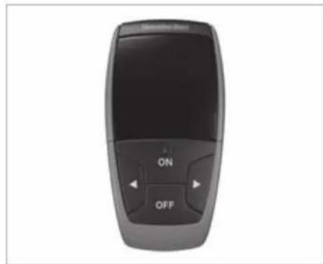
natural_image
Top-down view of a black remote control device with 'ON' and 'OFF' buttons (no visible text or symbols beyond control labels)Press and hold the ON button.
Setting the departure time
Briefly press the ON button.
Press the ◀ or ▷ button repeatedly until the time to be changed appears on the display.
Press the ON and OFF buttons simultaneously.
The ⏻ symbol on the remote control display will flash.
Press the ◀ and ▶ buttons to set the desired departure time.
Press the ON and OFF buttons simultaneously.
The new departure time will be stored.
Up to three departure times can be stored.
To activate the departure time: select the desired departure time and press and hold the ON button. The symbol, the departure time and, depending on the selected departure time, the letter A, B or C will appear on the display.
To deactivate the departure time: select the desired departure time and press and hold the OFF button. OFF will appear on the display.
To check the status of the active stationary heater: briefly press the ON button.
Switching off immediately
Press and hold the OFF button.
Overview of the remote control displays (stationary heater/ventilation)
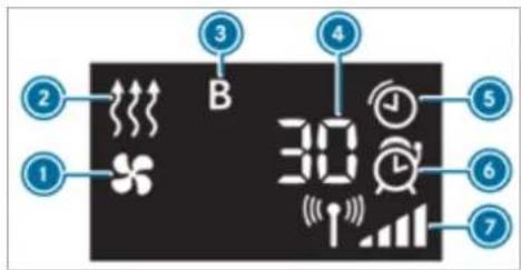
text_image
2 1 B 3 4 5 6 7① Stationary ventilation switched on
② Stationary heater switched on
3 Selected departure time
4 Remaining time for the stationary heater/ventilation (in minutes)
5 Stationary heater/ventilation active
6 Departure time activated
7 Signal strength
Further possible displays:
• Time: the activated departure time.
- Zero minutes: the running time for the stationary heater is extended because the engine has not yet reached operating temperature when it is started.
- OFF: the stationary heater/ventilation is switched off.
Replacing the remote control battery (stationary heater)
DANGER Risk of fatal injuries if batteries are swallowed
Batteries contain toxic and corrosive substances. Swallowing batteries may cause severe internal burns within two hours.
There is a risk of fatal injury.
Keep batteries out of the reach of children.
If the cover and/or lid of the battery compartment does not close securely,
do not use the key and keep it away from children.
If batteries are swallowed, seek medical attention immediately.

ENVIRONMENTAL NOTE Environmental damage due to improper disposal of batteries

Batteries contain toxic and corro- stances.


Take discharged batteries to a specialist workshop or to a point for used batteries.
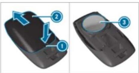
▶ Push a pointed object into recess ①.
Slide battery cover ② backwards in the direction of the arrow and remove the empty battery.
Insert new battery ③ with the lettering facing upwards.
Slide battery cover ② in the opposite direction to the arrow onto the remote control until the battery cover engages.
Problems with the remote control for the stationary heater/ventilation
FAIL (↑) appears on the remote control display
Possible cause:
- The signal transmission between the transmitter and the receiver is malfunctioning.
Change your position in relation to the vehicle, moving closer if necessary.
FAIL appears on the remote control display
Possible cause:
- The starter battery is not sufficiently charged.
Charge the starter battery.
Possible cause:
• The fuel tank is not sufficiently filled.
Refuel at the nearest filling station.
Requirements:
• One CR2450 lithium battery
FAIL 📁 appears on the remote control display
Possible cause:
- There is a malfunction in the stationary heater.
Have the stationary heater checked at a qualified specialist workshop.
Air vents
Adjusting the front air vents
WARNING Risk of burns and frostbite due to being too close to the air vents
Very hot or very cold air can flow from the air vents.
Make sure that all vehicle occupants always maintain a sufficient distance from the air vents.
If necessary, direct the airflow to another area of the vehicle interior.
To guarantee the flow of fresh air through the air vents into the vehicle interior, comply with the following:
- Always keep the vents and ventilation grilles in the vehicle interior clear.
- Keep the air inlet free of residue build-up (→ page 374).
- Optimum climate comfort is achieved with the air vents in the centre position.
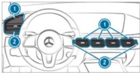
text_image
Diagram of a car interior showing steering wheel, dashboard, and battery pack arrangement with numbered labelsTo open or close centre air vents: turn controller ② up or down as far as it will go.
To open or close side air vents: turn controller ② to the left or right as far as it will go.
To adjust the air direction: hold air vent in the centre and move it up or down or to the left or right.
Adjusting the rear air vents
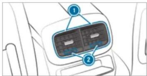
text_image
Diagram of a car interior showing labeled components with numbered annotationsAir vents in the centre console
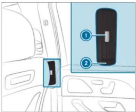
text_image
Diagram showing car interior with labeled components, including a device panel and a close-up of its internal structure.Air vents in the B-pillar
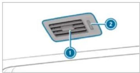
text_image
Diagram of a device with labeled parts, showing a panel with internal compartments and numbered annotations.Air vents above the second and third row of seats (all vehicles except Mercedes-Maybach vehicles)
To set the airflow direction: hold air vent ① in the centre and move it accordingly.
To open or close: turn controller ② as far as it will go.
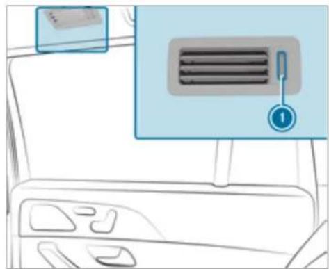
natural_image
Interior view of a car dashboard with a ventilation grille and a numbered indicator (no text or symbols on the main subject)Air vents above the second row of seats, towards the load compartment (Mercedes-Maybach vehicles)
To open or close: turn controller ① as far as it will go.
Opening or closing the air vent in the glove box
! NOTE Damage to temperature-sensitive objects in the glove box
Temperature-sensitive objects stored in the glove box may be damaged by the air vent located inside the glove compartment.
Close the air vent when you heat the vehicle.
At high outside temperatures, open the air vent and switch on the A/C function.
The automatic climate control must be switched on to cool the glove box.
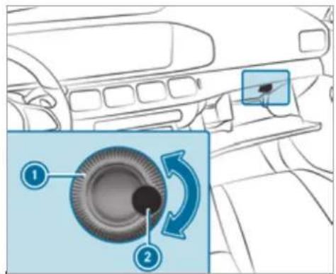
text_image
Diagram showing car interior with labeled parts and directional arrows indicating rotation or adjustmentTo open or close: turn controller ① of air vent ② clockwise or anticlockwise.
Driving
Notes on Mercedes-AMG vehicles
Observe the notes on the following topics in the Supplement, otherwise you may fail to recognise dangers.
The availability of certain functions depends on the equipment and model of the vehicle.
- Emotion Start
• AMG Performance exhaust system
• AMG ceramic high-performance composite brake system
• AMG ACTIVE RIDE CONTROL
• AMG steering-wheel buttons
Switching on the power supply or ignition

WARNING Risk of accident and injury due to leaving children unattended in the vehicle
If children are left unattended in the vehicle, they could, in particular:
- open doors, thereby endangering other persons or road users.
- get out and be struck by oncoming traffic.
• operate vehicle equipment and become trapped, for example.
In addition, the children could also set the vehicle in motion by, for example:
• releasing the parking brake.
- changing the transmission position.
• starting the vehicle.
▶ Never leave children unattended in the vehicle.
When leaving the vehicle, always take the key with you and lock the vehicle.
Keep the vehicle key out of the reach of children.
Requirements:
• The key is in the vehicle and is recognised.
• the brake pedal is not depressed.
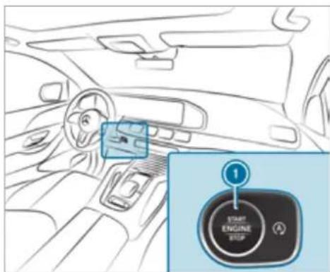
text_image
1 START ENGINE STOPTo switch on the power supply: press the button once.
You can, for example, activate the wind-screen wiper.
The power supply is switched off again if the following conditions are met:
- You open the driver's door.
- You press button ① twice more.
To switch on the ignition: press the ① button twice.
Indicator and warning lamps go on in the instrument cluster.
The ignition is switched off again if one of the following conditions is met:
- You do not start the vehicle within 15 minutes and the transmission is in position P or the electric parking brake is applied.
- You press button ① once.
Starting the vehicle
Starting the vehicle with the start/stop button
DANGER Risk of death caused by exhaust gases
Combustion engines emit poisonous exhaust gases such as carbon monoxide. Inhaling these exhaust gases is hazardous to health and leads to poisoning.
▶ Never leave the engine or, if present, the auxiliary heating running in an enclosed space without sufficient ventilation.
A WARNING Risk of fire due to flammable material in the engine compartment or the exhaust system
Flammable materials may ignite.
Therefore, check regularly that there are no flammable materials in the engine compartment or on the exhaust system.
Requirements:
• The key is in the vehicle and is recognised.
Shift the transmission to position P or N.
Depress the brake pedal and press button once.
If the vehicle does not start: Switch off non-essential consumers and press button once.
If the vehicle still does not start and the display message Place the key in the marked space See Owner's Manual also appears in the multifunction display: Start the vehicle with the key in the marked space (emergency operation mode) (→ page 192).
You can switch off the engine while driving. By pressing button ① for about three seconds or by pressing button ① three times within three seconds. Be sure to observe the safety notes under "Driving tips" (→ page 195).
Observe any information regarding display messages that can be displayed on the multifunction display.
Starting the vehicle with the key in the stowage compartment (emergency operation mode)
If the vehicle does not start and the Place the key in the marked space See Owner's Manual message appears in the multifunction display, you can start the vehicle in emergency operation mode.
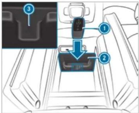
text_image
Diagram of car seatbelt mechanism with labeled parts and zoomed-in detail viewMake sure that the marked space ② is empty.
Remove the key ① from the key ring.
Place the key ① in the marked space ② next to the symbol ③.
The vehicle will start after a short time.
If you remove the key ① from the marked space ②, the engine continues running. For further engine starts however, the key ① must be located in the marked space ② next to the symbol ③ during the entire journey.
Have the key ① checked at a qualified specialist workshop.
If the vehicle does not start:
Place the key ① in the marked space ② and leave it there.
Depress the brake pedal and start the vehicle using the start/stop button.
① You can also switch on the power supply or the ignition with the start/stop button.
Observe any information regarding display messages that can be displayed on the multifunction display.
Starting the vehicle via Remote Online Services
Cooling or heating the vehicle interior before starting the journey
Ensure the following before starting the engine:
- the legal stipulations in the area where your vehicle is parked allow engine starting via smartphone.
- it is safe to start and run the engine where your vehicle is parked.
• the fuel tank is sufficiently full.
• the starter battery is sufficiently charged.
Charging the starter battery before starting the journey
If the vehicle battery is discharged, you can receive a message on your smartphone. You can then start the vehicle with the smartphone to charge the battery. The vehicle is automatically switched off after ten minutes.
Ensure the following before starting the engine:
- the legal stipulations in the area where your vehicle is parked allow engine starting via smartphone.
- it is safe to start and run the engine where your vehicle is parked.
• the fuel tank is sufficiently full.
Starting the vehicle (Remote Online)

WARNING Risk of crushing or entrapment due to unintentional starting of the engine
Limbs could be crushed or trapped if the engine is started unintentionally during service or maintenance work.

Always secure the engine against unintentional starting before carrying out maintenance or repair work.
Requirements:
- Park position is selected.
-
The anti-theft alarm system is not activated.
• The panic alarm is not activated. -
The hazard warning light system is switched off.
• The bonnet is closed.
• The doors are closed and locked.
• The windows and sliding sunroof are closed.
Start the vehicle using the smartphone. After every engine start, the engine runs for ten minutes.
You can carry out a maximum of two consecutive starting attempts. You must start the engine with the key before trying to start the engine again with the smartphone.
You can switch off the engine at any time as follows:
• Via the Smartphone App
- By pressing the ☑ or ☑ key
i Further information can be found in the smartphone app.
Securing the engine against starting before carrying out maintenance or repair work:
Switch on the hazard warning light system.
or
Unlock the doors.
or
▶ Open a side window or the sliding sunroof.
Running-in notes
To preserve the engine during the first 1,500 km:
- Drive at varying road speeds and engine speeds.
- Do not drive at speeds greater than 140 km/h.
-
Drive the vehicle in drive program on the E.
-
Shift to the next highest gear at the very latest when the needle reaches the last third before the red area in the rev counter.
-
Do not shift down a gear manually in order to brake.
-
Avoid overstraining the vehicle, e.g. driving at full throttle.
- Do not depress the accelerator pedal past the pressure point (kickdown).
- Only increase the engine speed gradually accelerates the vehicle to full speed after 1,500 km.
This also applies when the engine or parts of drivetrain have been replaced.
Please also observe the following running-in notes:
- in certain driving and driving safety systems, the sensors adjust automatically while a certain distance is being driven after the vehicle has been delivered or after repairs. Full system effectiveness is not reached until the end of this teach-in process.
- brakepads, brake discs and tyres that are either new or have been replaced only achieve optimum braking effect and grip after several hundred kilometres of driving. Compensate for the reduced braking effect by applying greater force to the brake pedal.
Notes on optimised acceleration
If all necessary requirements and activation conditions are fulfilled, the best possible acceleration can be achieved from a standstill.
Do not use the optimised acceleration on public roads. Individual wheels could spin and you could lose control of the vehicle. There is an increased risk of skidding and/or accident. Be sure to observe the safety notes and information on ESP (→ page 232).
Moving away with optimised acceleration

WARNING Risk of skidding and having an accident from wheels spinning
When you use optimised acceleration, individual wheels could spin and you could lose control of the vehicle.
If ESP ^ is deactivated, there is a risk of skidding and accident!
Make sure that no persons or obstacles are in the close vicinity of your vehicle.
Requirements:
• the vehicle is run in (→ page 193).
• the vehicle and tyres are in good condition.
- you are on a high-grip roadway.
c. the engine and transmission are at normal operating temperature.

NOTE Increased wear due to optimised acceleration
When pulling away with optimised acceleration, all components of the drivetrain are subjected to a very high load.
This can lead to increased component wear.
Do not always pull away with optimised acceleration.
Engage the D drive position ( page 211).
Move the steering wheel to the straight-ahead position.
Select the sportiest available drive program S^+ or S (→ page 207).
Deactivating ESP ^® (→ page 233).
Depress and hold the brake pedal firmly with your left foot.
With your right foot, fully depress the accelerator pedal.
After no more than five seconds, take your left foot quickly off the brake, but keep the accelerator pedal depressed. The vehicle pulls away at maximum acceleration.
Switch on ESP once the acceleration procedure is complete.
Ending optimised acceleration
Remove your foot from the accelerator pedal.
▶ Reactivate the ESP.
After you pull away with optimised acceleration, components of the drivetrain can become very hot, which means that optimised acceleration values may be reached again only after a few minutes.
Notes on driving
WARNING Risk of accident due to objects in the driver's footwell
Objects in the driver's footwell may impede pedal travel or block a depressed pedal. This jeopardises the operating and road safety of the vehicle.
Stow all objects in the vehicle securely so that they cannot get into the driver's footwell.
Always fit the floor mats securely and as prescribed in order to ensure that there is always sufficient room for the pedals.
Do not use loose floor mats and do not place floor mats on top of one another.
WARNING Risk of accident due to incorrect footwear
Incorrect footwear includes, for example:
• shoes with platform soles
- shoes with high heels
- slippers
There is a risk of an accident.
Always wear suitable footwear so that you can operate the pedals safely.
WARNING Risk of accident if the ignition is switched off while driving
If you switch off the ignition while driving, safety functions are restricted or no longer available.
This may affect the power steering system and the brake force boosting, for example. You will need to use considerably more force to steer and brake, for example.
Do not switch off the ignition while driving.

DANGER Risk of death caused by exhaust gases
Combustion engines emit poisonous exhaust gases such as carbon monoxide. Inhaling these exhaust gases is hazardous to health and leads to poisoning.
▶ Never leave the engine or, if present, the auxiliary heating running in an enclosed space without sufficient ventilation.

WARNING Risk of skidding and of an accident due to shifting down on slippery road surfaces
If you shift down on slippery road surfaces to increase the engine braking effect, the drive wheels may lose traction.
Do not shift down on slippery road surfaces to increase the engine braking effect.

DANGER Risk of fatal injury due to poisonous exhaust gases
If the tailpipe is blocked or sufficient ventilation is not possible, poisonous exhaust gases such as carbon monoxide may enter the vehicle. This is the case when the vehicle becomes stuck in snow, for example.
Keep the tailpipe and the area around the vehicle free from snow when the engine or the stationary heater are running.
Open a window on the side of the vehicle facing away from the wind to ensure an adequate supply of fresh air.

WARNING Risk of accident due to the brake system overheating
If you leave your foot on the brake pedal when driving, the brake system may overheat.
This increases the braking distance and the brake system may even cause the brake system failure.
▶ Never use the brake pedal as a footrest.
Do not depress the brake pedal and the accelerator pedal at the same time while driving.

NOTE Engine damage due to excessively high engine speeds
The engine will be damaged if you drive with the engine in the overrevving range.
Do not drive with the engine in the over-revving range.

NOTE Causing wear to the brake linings by permanently depressing the brake pedal
Do not permanently depress the brake pedal while driving.
To use braking effect of the engine, shift to a lower gear in good time.
! NOTE Damage to the drivetrain and engine when pulling away
Do not warm up the engine while the vehicle is stationary. Pull away immediately.
Avoid high engine speeds and driving at full throttle until the engine has reached its operating temperature.
NOTE Damage to the catalytic converter due to non-combusted fuel
The engine is not running smoothly and is misfiring.
Non-combusted fuel may get into the catalytic converter.
Only depress the accelerator pedal slightly.
Have the cause rectified immediately at a qualified specialist workshop.
! NOTE Reduced battery life due to frequent short-distance trips
The 12 V battery may not be sufficiently charged when the vehicle is used only for short-distance trips. This reduces the life of the battery.
▶ Drive longer distances regularly to charge the battery.
Notes on driving with a roof load, trailer or fully laden vehicle
When driving with a loaded roof luggage rack or trailer as well as with a fully laden or fully pied vehicle, the vehicle's driving and steering characteristics change.
You should bear the following in mind:
- Do not exceed the permissible roof load and towing capacity. Also observe the technical data in the printed Owner's Manual.
- Evenly distribute the roof load, and place heavy objects at the bottom. Also comply with the notes on loading the vehicle ( page 134).
- Drive attentively, and avoid suddenly pulling away, braking and steering as well as rapid cornering.
Notes on driving on salt-treated roads
The braking effect is limited on salt-treated roads.
Therefore, observe the following notes:
- due to salt build-up on the brake disks and brakepads, the braking distance can increase considerably or result in braking only on one side
- maintain a much greater safe distance to the vehicle in front
To remove salt build-up:
- brake occasionally while paying attention to the traffic conditions
- carefully depress the brake pedal at the end of the journey and when starting the next journey
Notes on aquaplaning
Aquaplaning can take place once a certain amount of water has accumulated on the road surface.
Observe the following notes during heavy precipitation or in conditions in which aquaplaning may occur:
- reduce speed
- avoid tyre ruts
- avoid sudden steering movements
- brake carefully
Also observe the notes on regularly checking wheels and tyres ( page 405).
Notes on driving through water on the road surface
Water which has entered into the vehicle can damage the engine, electrics and transmission.
Water can also enter the air intake of the engine and cause engine damage.
Observe the following if you must drive through water:
- Observe the maximum permissible fording depth ( page 440).
- Drive at a maximum speed of 10 km/h; water can otherwise enter the vehicle interior or engine compartment.
- Vehicles travelling in front, or oncoming vehicles, can create waves which may exceed the maximum permissible depth of the water.
The braking effect of the brakes is reduced after fording. Brake carefully while paying attention to the traffic conditions until braking power has been fully restored.
Notes on off-road driving
⚠ WARNING Risk of accident if you do not keep to line of fall on inclines
If you drive at an angle or turn on an incline the vehicle could slip sideways, tip and roll-over.
▶ Always drive on inclines in the line of fall (straight up or down) and do not turn.
A WARNING Risk of fire due to flammable materials on hot parts of the exhaust system
Flammable material such as leaves, grass or twigs may ignite if they come into contact with hot parts of the exhaust system.
When driving on unpaved roads or off-road, regularly check the vehicle underside.
Remove trapped plants or other flammable material, in particular.
If there is damage, consult a qualified specialist workshop immediately.
When driving off-road, sand, mud and water or water mixed with oil may get into the brakes.
This may lead to a reduction in braking effect or total brake failure as a result of increased wear.
The braking characteristics will vary depending on the material that has entered the system.
Clean the brakes after driving off-road. If you then notice reduced braking effect or hear scraping noises, have the brake system checked at a qualified specialist workshop. Adapt your driving style to the changed braking characteristics.
NOTE Damage caused by driving over obstacles
The vehicle can be damaged by:
- driving onto high kerbs or unpaved roads.
- quickly driving over obstacles such as kerbs, speed bumps or potholes.
- heavy objects hitting the underbody or chassis components.
Do not drive over obstacles that could damage the vehicle.
▶ Check the vehicle regularly for damage during off-road driving.
Adjust the vehicle speed to suit the road surface conditions.
If there is damage, consult a qualified specialist workshop immediately.
ENVIRONMENTAL NOTE Environmental damage due to non-observance of prohibition signs
Environmental protection has priority. Treat nature with respect.
Be sure to observe prohibition signs.
Checklist before driving off-road
Check the following points before driving off-road:
- Fuel level
- Vehicles with a diesel engine: AdBlue® level
- Engine oil level: fill engine oil to the maximum level to ensure full gradeability ( page 370).
- Tyre-change tool kit and spare wheel
- Tyres and wheels
i Further information about special all-terrain tyres for retrofitting can be obtained from a qualified specialist workshop.
Off-road driving
Read this section before driving your vehicle off-road. Practise by driving over more gentle off-road terrain first.
- Observe the notes on the cross-country ABS ( page 231).
- If necessary, select the 📄 or 🌐 drive program (vehicles with Off-road package) before driving off-road (→ page 207).
- Before driving off-road, shift the transfer case to the LOW RANGE off-road gear (vehicles with Off-road package) (→ page 214).
- Select a vehicle level suitable for off-road terrain ( page 269). To avoid damaging the vehicle, make sure there is always sufficient ground clearance.
-
Always keep the engine running and in gear when driving on downhill gradients and slopes. Observe the notes on driving in mountainous terrain.
-
Do not drive on unknown terrain that is not easily visible and stay on marked routes.
• Always keep the doors and windows closed while the vehicle is in motion. - Deactivate Active Distance Assist DISTRONIC, cruise control and the variable limiter.
- Adapt your driving style to the terrain.
- Do not use the HOLD function on steep downhill or uphill gradients with slippery or loose surfaces.
Driving on sand
When driving on sand, also observe the following instructions:
- Select the drive program.
- Select a higher vehicle level.
- Shift to a lower gear.
- Drive quickly to overcome the rolling resistance; the vehicle may otherwise dig itself in.
-
Drive in the tracks of other vehicles if possible. Make sure that the following prerequisites are met:
-
the tyre ruts are not too deep
- the sand is firm enough
- the ground clearance is sufficient
Fording
Also observe the following information when fording:
- Vehicles with AIR BODY CONTROL: select the highest possible vehicle level ( page 269).
Vehicles with E-ACTIVE BODY CONTROL: select the highest possible vehicle level ( page 278). - Drive no faster than 10 km/h.
- Observe the maximum permissible fording depth ( page 440).
- Switch off automatic climate control (→ page 179).
- Vehicles with stationary heater/ventilation: switch the stationary heater/ventilation off ( page 183).
- Ensure that a bow wave does not form as you drive.
- Do not stop in the water and do not switch off the engine. Ensure the ECO start/stop function is switched off ( page 202).
Driving in mountainous terrain
Also observe the following information when driving in mountainous terrain:
- Observe the values of the approach/departure angle and of the maximum gradient ( page 440).
- Avoid high engine speeds.
- Use the braking power of the engine when driving downhill.
- Shift to a lower gear on uphill gradients and on long, steep downhill gradients.
- Activate DSR before driving downhill, if necessary (→ page 248).
Checklist after driving off-road
Driving off-road places greater demands on your vehicle than driving on normal roads. Check the entire vehicle for damage and foreign bodies every time after driving off-road. Foreign bodies in the wheels or drivetrain can lead to imbalances and therefore vibrations.
- If the 📄 or 🐃 drive program is selected: select another drive program.
- Shift the transfer case to the on-road position HIGH RANGE.
- Deactivate DSR.
- Lower the vehicle level again to a level suitable to the road conditions, e.g. to the normal level.
- Apply the brakes to dry them after fording.
- Check that the service brake is working normally after a long downhill stretch.
- Clean the following components every time after driving off-road:
- licence plate number
- headlamps and tail lamps
- tyres, wheels and wheel arches
- underbody
- After driving through sand, mud, water or gravel, have the following components checked and cleaned:
- brake disks and brakepads
- tyres and wheels
- axle joints
ECO start/stop function
Depending on the engine, the ECO start/stop function is not available in all drive programs. Observe the status display in the multifunction display for this.
Mercedes-Maybach vehicles: The Glide mode function is not available.
The engine is switched off automatically in the following situations if all vehicle conditions for an automatic engine stop are met:
- You brake the vehicle to a standstill in transmission position D or N.
- Vehicles with a 48 V on-board electrical system: You depress the brake pedal when travelling at a low speed.
If the system has detected one of the following situations, the engine will not stop:
- You stop at a stop sign and there is no vehicle in front of you.
- The vehicle that stopped in front of you starts up again.
- You manoeuvre, turn the steering wheel sharply or engage reverse gear.
If the system detects an intelligent stop inhibitor, for example, a stop sign, the engine will not stop.
If you activate the HOLD function or engage the park position P, the engine can be switched off in spite of an intelligent stop inhibitor.
The engine is restarted automatically if:
- You engage transmission position D or R.
- You depress the accelerator pedal.
- An automatic engine start is required by the vehicle.
• You release the brake pedal. - Vehicles with a 48 V on-board electrical system:
- You release the brake pedal on a downhill gradient and the vehicle does not roll.
The vehicle rolls on a downhill gradient and does not automatically enter glide mode at 20 km/h.
ECO start/stop function symbols in the multifunction display:
- The symbol (A) (green) appears when the vehicle is at a standstill: The engine was switched off by the ECO start/stop function.
- The symbol 📂 (yellow) appears when the vehicle is at a standstill: Not all vehicle conditions for an engine stop have been met.
- Neither the symbol Ⓐ nor Ⓐ appears when the vehicle is at a standstill: An intelligent stop inhibitor was detected, for example, a stop sign.
- The symbol ^OFF appears: The ECO start, stop function is deactivated or there is a malfunction.
If the engine was switched off by the ECO start/stop function and you leave the vehicle, a warning tone sounds and the engine is not restarted. In addition, the following display message appears in the multifunction display:
Vehicle is operational Switch off ignition before exiting
If you do not switch off the ignition, it is automatically switched off after three minutes.
Deactivating or activating the ECO start/stop function
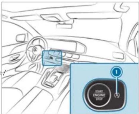
text_image
t/ 1 START ENGINE STOPPress button ①.
A display appears in the instrument cluster when switching the ECO start/stop function off/on.
A continuous [A^*] display appears in the instrument cluster while the ECO start/stop function is deactivated.
ECO display function
The ECO display summarises your driving characteristics from the start of the journey to its completion and assists you in achieving the most economical driving style.
You can influence consumption by doing the following:
• driving with particular care
- driving the vehicle in drive program
• following the gearshift recommendations
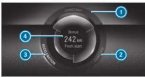
text_image
CONSTAND 1 Bonus 242 km From start 3 4 ACQUISITION 2The lettering in the segment will light up brightly, the outer edge will light up and the segment fill up when the following driving style is adopted:
- 1 Steady speed
• ② Gentle deceleration and rolling
• 3 Moderate acceleration
The lettering in the segment will be grey, the outer edge will be dark and the segment will empty when the following driving style is adopted:
• ① Fluctuations in speed
• Heavy braking
• ③ Sporty acceleration
The ECO display will show you when you have driven economically:
- The three segments will fill up completely at the same time
• The edges around all three segments will light up
The additional range achieved as a result of your driving style in comparison with a driver with a very sporty driving style will be shown in the centre of the display ④. The range displayed centre of the display ④. The range displayed does not indicate a fixed reduction in consumption.
ECO Assist function
Vehicles with a 48 V on-board electrical system (EQ Boost technology):
ECO Assist analyses data for the vehicle's expected route. This allows the system to optimally adjust the driving style for the route ahead, save fuel and recuperate.
ECO Assist is displayed on the Assistance menu(→ page 312).
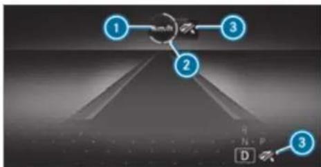
flowchart
graph TD
    A["1"] --> B["Central Node"]
    C["2"] --> B
    D["3"] --> B
    B --> E["D"]
① Event ahead
② Distance display for the event ahead
3 "Foot off the accelerator" prompt
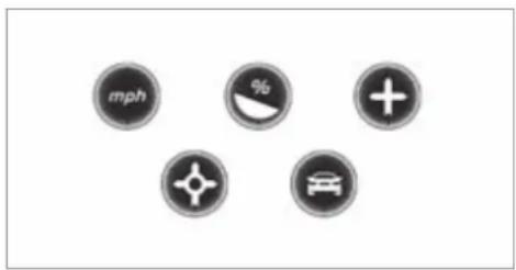
text_image
mph % + × ×Displayable route events ①
The segments of distance display ② show the distance to the event ahead as follows:
- A few segments light up: the event ahead is near.
- Many segments light up: the event ahead is further away.
When the vehicle nears the event, ECO Assist will calculate the optimal speed for maximum fuel economy and recuperative energy based on the distance, speed and gradient. The Foot off the accelerator ③ message will appear on the multifunction display. The first segments in front of the vehicle will turn green. The remaining segments will initially stay white. If you take your foot off the accelerator pedal in good time, the remaining segments on the display will successively turn green until the event shown is reached. The drivetrain will be set for maximum fuel economy. Recuperation will charge the battery. Recuperation will be adapted to the selected drive program.
The event will be shown for a short time after it has been passed. If there is no response to the Foot off the accelerator prompt, the segments will remain white.
If the event involves a vehicle in front, all segments will immediately turn green once there a response to the Foot off the accelerator prompt.
For active ECO Assist in drive program [E], symbol ③ will appear on the multifunction display and on the head-up display beside transmission position [D]. Symbol ③ will also appear when the assistant display is not selected. If the system does not intervene during the event ahead, nothing will be displayed. The system will be passive.
ECO Assist is active only in drive programs E and C.
System limits
ECO Assist can function even more precisely if the route is adhered to when route guidance is active. The basic function is also available without active route guidance. Not all information and traffic situations can be foreseen. The quality depends on the map data.
ECO Assist is only an aid. The driver is responsible for keeping a safe distance from the vehicle in front, for vehicle speed and for braking in good time. The driver must be ready to brake at all times irrespective of whether the system intervenes.
The system may be impaired or may not function in the following situations:
- If visibility is poor, e.g. due to insufficient illumination of the road, highly variable shade conditions, rain, snow, fog or heavy spray.
- If there is glare, e.g. from oncoming traffic, direct sunlight or reflections.
- If there is dirt on the windscreen in the a of the multifunction camera or the camera misted up, damaged or obscured.
- If road signs are hard to detect, e.g. due to dirt, snow or insufficient lighting, or because they are obscured.
- If the information on the navigation system's digital map is incorrect or out of date.
- If signs are ambiguous, e.g. road signs in roadworks or in adjacent lanes.
DYNAMIC SELECT switch
Function of the DYNAMIC SELECT switch

NOTE Mercedes-AMG vehicles

Observe the notes in the Supplement. You could otherwise fail to recognise dangers.
(i) Depending on the engine and equipment, the vehicle has different drive programs.
Use the DYNAMIC SELECT switch to change between the following drive programs.
the drive program selected appears in the multifunction display of the on-board computer.

Individual
- Individual settings

Sport+
• Particularly sporty driving
- Emphasises the vehicle's own oversteering and understeering characteristics for a more active driving style
- Only suitable for good road conditions, a dry road surface and a clear stretch of road

Sport
- Continues to offer stability but with a sporty setup
- Allows the sporty driver a more active driving style
- Only suitable for good road conditions, a dry road surface and a clear stretch of road

Comfort
• Comfortable and economical driving
• Balance between traction and stability
• Recommended for all road conditions

Maybach
• Only for Mercedes-Maybach vehicles
- Highest driving comfort for comfortable and luxurious travel

Eco
• Particularly economical driving
• Balance between traction and stability
• Recommended for all road conditions

Curve
- Only available for vehicles with E-ACTIVE BODY CONTROL
- Comfortable driving with curve inclination function
• Balance between traction and stability
• Recommended for all road conditions

Offroad
- Only available for vehicles with Off-road package
- Intervenes later if there is oversteering or understeering, thus improving traction
- Suitable for easily negotiable off-road terrain, such as dirt tracks, gravel or sandy surfaces
• Not suitable for use on public roads

Offroad+
- Only available for vehicles with Off-road package
- Intervenes later if there is oversteering or understeering, thus improving traction
- Suitable for rough terrain, such as steep and/or uneven terrain or for driving on rocky terrain
• Not suitable for use on public roads
Mercedes-Maybach vehicles: in the drive programs and, the extendible running boards remain retracted or retract if they have already been extended.
Depending on the situation, the cylinder can be briefly deactivated in the drive programs E and C, depending on the engine.
The ESP® settings in the drive programs [E] and [C] are designed for stability. Therefore, choose one of these driving programs, especially when transporting roof loads, in trailer operation and when the vehicle is fully loaded or fully occupied.
Depending on the drive program, the following systems change their characteristics:
- Drive
- Engine and transmission management
- Active Distance Assist DISTRONIC
- ESP®
- Vehicles with AIRMATIC or E-ACTIVE BODY CONTROL:
- Suspension tuning
- Vehicle level
• Electric power steering
Notes on the roof load display
Certain drive programs and ESPsettings are unsuitable for transporting a roof load.
If one of these drive programs is set or selected, the symbol is shown as a warning. When this symbol is shown, the selected drive program is not suitable for transporting a load on the roof.
The following drive programs are affected:
- Sport drive program
- Sport + drive program
- Individual drive program with the ESP® setting Sport or Sport+
The symbol is also shown in the following situations:
- Within the themes if a corresponding drive program is saved
For more information on themes see . - Within the reset display if the previously active drive program is unsuitable for the transport of a roof load
For further information on the reset display, see ( page 207).
Selecting the drive program
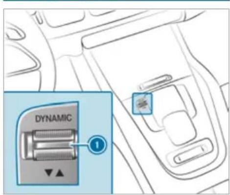
text_image
DYNAMICPress DYNAMIC SELECT switch forwards or backwards. The drive program selected appears in the multifunction display.
Configuring DYNAMIC SELECT (multimedia system)
Multimedia system:
→ Settings → Vehicle → DYNAMIC SELECT
Setting drive program I
▶ Select Individual configuration.
▶ Select and set a category.
Switching the restoration display on or off
▶ Switch Ask when starting on or off.
Function on: the next time the vehicle is started a prompt appears asking whether the last active drive program should be restored. If the ECO start/stop function was deactivated, an additional prompt appears asking if the function should remain deactivated.
The prompt appears only if the previously active settings deviate from the standard settings.
Function off: the next time the vehicle is started the C drive program is set automatically.
The ECO start/stop function is activated automatically.
This function must be activated for each us profile separately. Only when this function is activated will the drive program and Eco start/stop setting for the previous journey be saved for the respective user profile.
Displaying vehicle data
Multimedia system:
Info
▶ Select Vehicle.
The vehicle data is displayed.
Displaying engine data
Multimedia system:
→ Info
Select Engine.
The engine data is displayed.
The actual (maximum) values that can be achieved for engine output and engine torque may deviate from the certified values within the country-specific guidelines for permissible tolerances (basis: UN-ECE No. 85 or country-specific guidelines).
Factors that can influence this are, for example:
- Sea level
- Fuel grade
• Outside temperature - Operating temperature of the engine
The values displayed serve only as orientation. The values for engine output and engine torque shown in the media display may deviate from the actual values.
Calling up the fuel consumption indicator
Multimedia system:
Info
▶ Select Consumption. The current and average fuel consumption is displayed.
Displaying the Offroad Score
Multimedia system:
Info
Use the Offroad Score only for off-road driving and not on public roads. When choosing the route, take into account the vehicle characteristics, the ground conditions and your driving skills. Do not let the system distract you from what is happening on the route.
▶ Select Offroad score. A menu appears. You can start a new trip.
Further functions are available in the lower menu bar:
- Display the current trip via the route symbol.
- Display a list of all notes for the current trip using the list icon.
In the list, a note is displayed with a time stamp, the number of points currently achieved and the note text.
- Display the ranking by clicking on the symbol for the winner's podium.
The ranking list shows the following information:
- Profile name and profile picture (if available)
- The number of points obtained
- Date and time of the completed trip
- The places for gold, silver and bronze
Starting or ending a new trip
The "Start new trip" function is available when the vehicle is stationary and the engine is running.
▶ Select Start new trip.
The display "Trip and tips" appears.
The following information is displayed:
- the vehicle inclination in longitudinal direction in percent (%)
- the lateral inclination of the vehicle in degrees (°)
- the currently achieved score for the ongoing trip
- a tip for the upcoming driving manoeuvre
To stop the display: select End trip. An evaluation of the trip is displayed. It shows the achieved score and a message, example Great job!.
Automatic transmission
DIRECT SELECT lever
Function of the DIRECT SELECT lever
WARNING Risk of accident due to incorrect gearshifting
If the engine speed is higher than the idle speed and you engage the transmission posi-
tion D or R, the vehicle may accelerate sharply.
If you engage the transmission position D or R when the vehicle is at a standstill, always depress the brake pedal firmly and do not accelerate at the same time.
A WARNING Risk of accident and injury due to leaving children unattended in the vehicle
If children are left unattended in the vehicle, they could, in particular:
- open doors, thereby endangering other persons or road users.
• get out and be struck by oncoming traffic.
• operate vehicle equipment and become trapped, for example.
In addition, the children could also set the vehicle in motion by, for example:
• releasing the parking brake.
• changing the transmission position.
• starting the vehicle.
▶ Never leave children unattended in the vehicle.
When leaving the vehicle, always take the key with you and lock the vehicle.
Keep the vehicle key out of the reach of children.
Use the DIRECT SELECT lever to switch the transmission position. The current transmission position is displayed in the multifunction display.
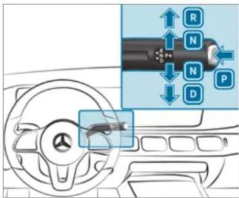
text_image
Diagram showing car steering wheel and dashboard with directional arrows and labeled buttons (R, N, P, D) indicating movement or control points.P Park position
R Reverse gear
N Neutral
D Drive position
Engaging reverse gear R
Depress the brake pedal and push the DIRECT SELECT lever upwards past the first point of resistance.
Engaging neutral N
Depress the brake pedal and push the DIRECT SELECT lever up or down to the first point of resistance.
To shift into neutral N with the ignition on, push the selector lever up or down for several seconds to the first point of resistance.
Subsequently releasing the brake pedal will allow you to move the vehicle freely, e.g. to push it or tow it away.
Proceed as follows if you want the automatic transmission to remain in neutral N, even if the ignition is switched off or the driver's door is opened:
Depress the brake pedal and engage neutral N when the car is stationary.
The message N permanently active Risk of vehicle rolling appears in the instrument cluster.
Release the brake pedal.
▶ Switch the ignition off.
If you then exit the vehicle leaving the key in the vehicle, the automatic transmission remains in neutral N.
The park position P is automatically re-engaged as soon as one of the following conditions is met:
- You switch to transmission position D or R.
- You press the button P.
Engaging park position P
Observe the notes on parking the vehicle ( page 222).
Depress the brake pedal until the vehicle comes to a standstill.
When the vehicle is at a standstill, press button P.
When the transmission position display shows P, the park position is engaged. If no transmission position display P appears, secure the vehicle to prevent it from rolling away.
Depending on the situation, it may take a short time until P is engaged. Therefore, always pay attention to the transmission position display.
Park position P is engaged automatically if one of the following conditions is met:
- You switch off the ignition when the vehicle is stationary and the transmission position is [D] or [R].
- You open the driver's door when the vehicle is at a standstill or when driving at a very low speed and the transmission position is [D] [R].
- You switch off the engine and bring the vehicle to a standstill when the vehicle is rolling and the transmission position is D or R.
- You switch off the engine, bring the vehicle to a standstill and open the driver's door when the vehicle is stationary or when the vehicle is rolling and the transmission position is N.
- Engaging park position P automatically is required by the vehicle.
To manoeuvre with an open driver's door, open the driver's door while at a standstill and engage transmission position D or R again.
Engaging drive position D
Depress the brake pedal and push the DIRECT SELECT lever down past the first point of resistance.
When the automatic transmission is in transmission position [D], it shifts the gears automatically. This depends, among other things, on the following factors:
• The selected drive program
• The position of the accelerator pedal
• The driving speed
Manual gearshifting
Permanent setting (vehicles with Off-Road package or E-ACTIVE BODY CONTROL)
! NOTE Mercedes-AMG vehicles
Observe the notes in the Supplement. You could otherwise fail to recognise dangers.
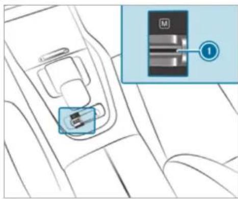
text_image
Diagram showing car seatbelt mechanism with labeled component M and numbered connection point 1Activating/deactivating: Pull rocker switch ①. If indicator lamp is lit, manual shifting is activated. The current gear is displayed in the multifunction display.
Temporary setting
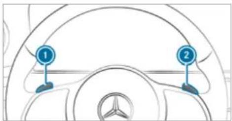
text_image
Diagram of a car steering wheel with numbered components and brand logo at the bottomActivating: Pull steering wheel gearshift paddle ① or ②. Manual shifting is activated for a short time. Transmission position M and the current gear appear in the multifunction display.
Deactivating: Pull steering wheel gearshift paddle ② and hold it in place. ti- The transmission position D appears in the multifunction display. To permanently shift the gears manually in drive program using the steering wheel gearshift paddles, select the M setting for the transmission.
Shifting
Shifting up: Pull steering wheel gearshift paddle ②.
▶ Shifting down: Pull steering wheel gearshift paddle ①.
Gearshift recommendation
The gearshift recommendation assists you in adopting an economical driving style.

text_image
R N P M1 ↑2 S 1If the gearshift recommendation ① appears next to the transmission position display, shift to the recommended gear.
Using kickdown
▶ Maximum acceleration: depress the accelerator pedal beyond the pressure point.
To protect against engine overrev, the automatic transmission shifts up to the next gear when maximum engine speed has been reached.
Glide mode function

NOTE Mercedes-AMG vehicles

Observe the notes in the Supplement. You could otherwise fail to recognise dangers.
① Mercedes-Maybach vehicles: The Glide mode function is not available.
With an anticipatory driving style, Glide mode helps you to reduce fuel consumption.
Glide mode is characterised by the following:
- The combustion engine is disconnected from the drivetrain and continues to run in neutral.
- The transmission position display D is shown in green.
- Vehicles with 48 V on-board electrical system (EQ-Boost technology): The combustion engine can be switched off. All vehicle functions remain active.
Glide mode is activated if the following conditions are met:
- Drive program E is selected.
• The speed is within a suitable range.
- The road's course is suitable, e.g. no steep uphill or downhill inclines or tight bends.
- There is no trailer hitched up to the trailer hitch, and no bicycle rack Fitted.
- You do not depress the accelerator or brake pedal (except for light brake applications).
Glide mode can also be activated if you have selected the "Eco" setting for the drive in the drive program.
Glide mode is deactivated again if one of the conditions is no longer met.
Glide mode can also be prevented by the following parameters:
- Incline
- Downhill gradient
- Temperature
he Height - Speed
• Operating status of the engine - Traffic situation
Transfer case
Function of the transfer case
A WARNING Risk of skidding and having an accident when in LOW RANGE on slippery road surfaces
The wheels can block and thus lose traction on slippery road surfaces, particularly in the following situations:
- if you release the accelerator pedal when the vehicle is in motion.
- if off-road ABS intervenes when braking.
▶ Never select the LOW RANGE off-road gear when driving on slippery road surfaces.
WARNING Risk of accident when the transfer case is in neutral position
The vehicle may roll away unintentionally if you do not wait until the transfer case shift operation is complete.
▶ Wait until the transfer case shift operation is complete.
This function is only available in vehicles with Off-road package.
Shift the transfer case to the on-road position HIGH RANGE or into the LOW RANGE off-road gear.
Do not switch off the engine during shift operation and do not shift the automatic transmission to another position.
Shift ranges
- HIGH RANGE: Road position for all normal on-road driving situations
- LOW RANGE: Off-road gear for driving off-road, when fording and on steep uphill or downhill inclines
Properties of the LOW RANGE off-road gear:
-
reduced maximum permissible speed: 50 km/h
• increased tractive power -
changing the transmission ratio by a factor of about three
- increased drive torque
Do not use LOW RANGE in the following situations:
- when driving on public roads.
Shifting the transfer case
Shifting to the LOW RANGE off-road gear
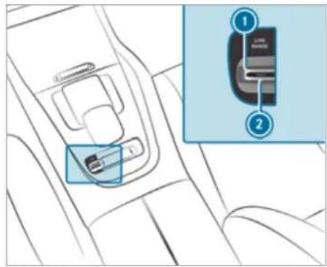
text_image
Diagram showing car seatbelt insertion mechanism with labeled parts and zoomed-in detail viewRequirements:
- You are not driving on a paved or public road.
• The vehicle is stationary.
Pull the LOW RANGE ① rocker switch. Indicator lamp ② will flash. The shift request stays active for a maximum of 30 seconds. If all requirements for shift operation are not fulfilled within this time, the indicator lamp ② switches off again and the shift opera must be started again.
Switch the transmission to position N. If shift operation is successful, the message LOW RANGE on appears in the instrument cluster, an audible signal sounds and indicator lamp ② and an indicator lamp in the instrument cluster light up continuously.
▶ Switch the transmission to position D.
The vehicle stays in LOW RANGE if you park the vehicle in LOW RANGE, even after the engine has been restarted.
You will not be able to switch on LOW RANGE if drive program S or S' is switched on. The vehicle switches to drive program C.
In the on-road position, shift to HIGH RANGE
Requirements:
- The engine is running and you are not driving faster than 50 km/h.
Pull the LOW RANGE 1 rocker switch. The shift request stays active for a maximum of 30 seconds. If all requirements for shift operation have not been fulfilled within this time, shift operation must be started again.
Shift the transmission to position . If shift operation is successful, the message LOW RANGE off appears in the instrument cluster, an audible signal sounds and the indicator lamps go out.
Shift the transmission to position D.
Function of the 4MATIC
4MATIC ensures that all four wheels are driven. Together with ESP and 4ETS, 4MATIC improves the traction of your vehicle whenever a driven wheel spins due to insufficient traction.
If you fail to adapt your driving style, 4MATIC can neither reduce the risk of an accident nor override the laws of physics. 4MATIC cannot take account of road, weather and traffic conditions. 4MATIC is only an aid. You are responsible especially for maintaining a safe distance from the vehicle in front, for vehicle speed, for braking in good time and for staying in lane.
In wintry road conditions, the maximum effect of 4MATIC can be achieved only if you use winter tyres (M+S tyres), with snow chains if necessary.
Refuelling
Refuelling the vehicle
WARNING Risk of fire or explosion from fuel
Fuels are highly flammable.
▶ Fire, naked flames, smoking and creation of sparks must be avoided.
Switch off the ignition and, if available, the stationary heater, before and while refuelling the vehicle.

WARNING Risk of injury from fuels
Fuels are poisonous and hazardous to your health.
Do not swallow fuel or let it come into contact with skin, eyes or clothing.
Do not inhale fuel vapour.
▶ Keep children away from fuel.
Keep doors and windows closed during the refuelling process.
If you or other people come into contact with fuel, observe the following:
Immediately rinse fuel off your skin with soap and water.
If fuel comes into contact with your eyes, immediately rinse them thoroughly with clean water. Seek medical attention immediately.
If you swallow fuel, seek medical attention immediately. Do not induce vomiting.
Change immediately out of clothing that has come into contact with fuel.

WARNING Risk of fire and explosion due to electrostatic charge
Electrostatic charge can ignite fuel vapour.
Before you open the fuel filler cap or take hold of the pump nozzle, touch the metallic vehicle body.
To avoid creating another electrostatic charge, do not get into the vehicle again during the refuelling process.

WARNING Risk of fire from fuel mixture
Vehicles with a diesel engine: If you mix diesel fuel with petrol, the flash point of the fuel mixture is lower than that of pure diesel fuel.
While the engine is running, component parts in the exhaust system may overheat without warning.
▶ Never refuel using petrol.
▶ Never mix petrol with diesel fuel.

NOTE Damage caused by the wrong fuel
Vehicles with a petrol engine: Even small amounts of the wrong fuel could result in damage to the fuel system, the engine and the emission control system.
Only refuel using unleaded, sulphur-free petrol that conforms to European EN 228, or an equivalent specification.
Fuel of this specification may contain up to 10% ethanol. Your vehicle is suitable for use with E10 fuel.
Never refuel with one of the following fuels: • diesel
• regular petrol with an octane number lower than 91 RON
- petrol with more than 10% ethanol by volume, e.g. E15, E20, E85, E100
- petrol with more than 3% methanol by volume, e.g. M15, M30
• petrol with additives containing metal
If you have accidentally refuelled with the wrong fuel:
▶ do not switch the ignition on.
Consult a qualified specialist workshop.
NOTE Damage caused by the wrong fuel
Vehicles with a diesel engine:
Even small amounts of the wrong fuel could result in damage to the fuel system, the engine and the emission control system.
Only refuel using sulphur-free diesel fuel that conforms to European stand-
ard EN 590, or an equivalent specification.
In countries without sulphur-free diesel fuel, refuel using only low-sulphur diesel fuel with a sulphur content less than 50 ppm.
Never refuel using any of the following fuels:
- petrol
- marine diesel
- heating oil
• pure bio-diesel fuel or vegetable oil - paraffin or kerosene
If you accidentally refuel with the wrong fuel:
Do not switch the ignition on.
Consult a qualified specialist workshop.
NOTE Do not use diesel to refuel vehicles with a petrol engine
If you have accidentally refuelled with the wrong fuel:
- do not switch the ignition on. Otherwise fuel can enter the engine.
Even small amounts of the wrong fuel could result in damage to the fuel system and the engine. The repair costs are high.
Consult a qualified specialist workshop.
Have the fuel tank and fuel lines drained completely.
NOTE Do not use petrol to refuel vehicles with a diesel engine
If you have accidentally refuelled with the wrong fuel:
- do not switch the ignition on. Otherwise, fuel can enter the fuel system.
Even small amounts of the wrong fuel could result in damage to the fuel system and the engine. The repair costs are high.
Consult a qualified specialist workshop.
Have the fuel tank and fuel lines drained completely.
NOTE Damage to the fuel system caused by overfilled fuel tanks
Only fill the fuel tank until the pump nozzle switches off.
If you have added too much fuel because of a defective filling pump, for instance:
▶ Do not switch the ignition on.
Consult a qualified specialist workshop.
! NOTE Fuel may spray out when you remove the fuel pump nozzle
▶ Only fill the fuel tank until the pump nozzle switches off.
Requirements:
- The vehicle is unlocked.
Do not get into the vehicle again during the refuelling process. Otherwise, electrostatic charge could build up again.
Observe the notes on operating fluids and fuel.
The recommended octane number for your vehicle can be found on the information label in the fuel filler flap.
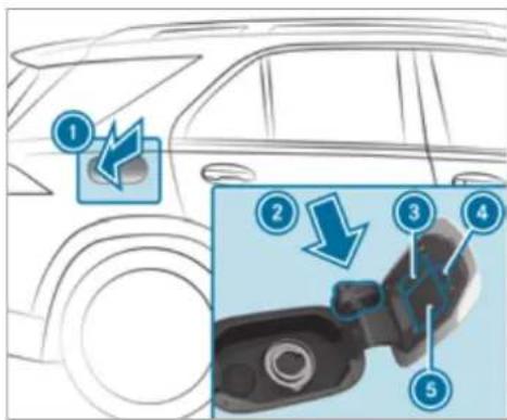
text_image
Diagram illustrating car seatbelting process with numbered steps and directional arrows indicating movementFuel filler flap
② Bracket for fuel filler cap
3 Fuel type
QR code for rescue card
5 Tyre pressure table
Press on the back area of fuel filler flap ①.
Turn the fuel filler cap anti-clockwise and remove it.
Insert fuel filler cap from above into bracket ②.
Completely insert the pump nozzle into the tank filler neck, hook in place and refuel.
Only fill the fuel tank until the pump nozzle switches off.
① Vehicles with a diesel engine: the tank filler neck is designed for refuelling at diesel filling pumps.
① Vehicles with a diesel engine: when the fuel tank is completely empty, top up with at least 5 litres of diesel.
Vehicles with a diesel engine: use a filler neck with a large diameter for vehicles with a diesel engine when topping up fuel from fuel can. Otherwise, the filler neck cannot slide into the tank.
Replace the cap on the filler neck and turn clockwise until it engages audibly.
Close fuel filler flap ①.
AdBlue ^® (vehicles with a diesel engine only)
Notes on refilling AdBlue®
AdBlue ^® is a water-soluble fluid for the NOx exhaust gas aftertreatment of diesel engines. In order for the exhaust gas aftertreatment to function properly, only use AdBlue ^® in accordance with ISO 22241.
AdBlue ^® is characterised by the following:
- non-toxic
• colourless and odourless - non-flammable
If you open the AdBlue ^® tank, small amounts of ammonia vapour may be released. Only fill the AdBlue ^® tank in well-ventilated areas.
Do not let AdBlue ^® come into contact with skin, eyes or clothes. Keep AdBlue ^® away from children.
Do not ingest AdBlue. If AdBlue is swallowed, immediately rinse your mouth out thoroughly. Drink plenty of water. Seek medical attention at once.
Observe the notes on operating fluids ( page 429).
AdBlue ^® is available here:
- AdBlue ^ can be topped up by fast service at a qualified specialist workshop, e.g. a Mercedes-Benz Service Centre.
- AdBlue ^ is available at many filling stations from AdBlue ^ filling pumps.
- Alternatively, AdBlue ^ is available at qualified specialist workshops, e.g. Mercedes-Benz Service Centres, and at many filling stations in AdBlue ^ refill canisters or AdBlue ^ refill bottles.
i Ensure the connection between the refill container and vehicle filler neck does not drip.
Topping up AdBlue®
NOTE Engine damage due to AdBlue® being in the fuel
AdBlue ^® must not be used to fill the fuel tank.
Only use AdBlue ^® to fill the AdBlue ^® tank.
Do not overfill the AdBlue ^® tank.
NOTE Contamination of the vehicle interior due to AdBlue®leakage
After topping up, carefully close the AdBlue® refill container.
Avoid carrying AdBlue ^® refill containers permanently in the vehicle.
Requirements:
- The vehicle is unlocked.
The following messages appear in order in the multifunction display when the AdB®eank requires topping up:
- Refill AdBlue See Owner's ManualThe AdBlue® level has fallen below the reserve range. Top up AdBlue® immediately.
- Top up AdBlue Emergency op. in XXX miles See Owner's Manual The low AdBlue level will lead to limited performance after the remaining distance displayed has been driven. Top up AdBlue immediately.
- XX,X | Top up AdBlue Emer. op.: max. XXX km/h Start not poss. in XXX kmThe low AdBlue® level will lead to limited performance from the speed displayed. After the remaining distance displayed has been covered, it will no longer be possible to start the engine. Top up with at least the amount of AdBlue® displayed.
- XX,X | Top up AdBlue Switch on ignition, wait 60 sec. or eng. start not poss.The AdBlue tank is empty. You can no longer start the engine. Top up with at least the amount of
AdBlue ^® displayed. Switch on the ignition and wait for approximately 60 seconds. Start the engine.
You can see the AdBlue ^® range and level in the Service menu in the multifunction display.
The AdBlue ^® range shown depends strongly on the driving style and operating conditions. The actual range can therefore deviate from the calculated range.
Opening the AdBlue® filler cap
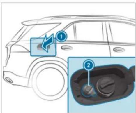
text_image
Diagram showing car interior components with numbered labels and directional arrows indicating movement or flowPress on the back area of fuel filler flap ①.
Turn AdBlue® filler cap ② anti-clockwise and remove it.
pump is available, you can also top up AdBlue® using a canister.
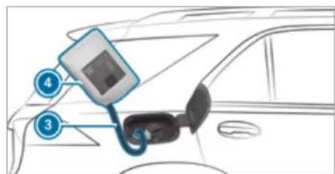
text_image
Diagram showing a car front panel connected to a digital display and cable, with numbered labels pointing to components.Screw on the fastener of AdBlue® refill canister 4.
Screw disposable hose ③ onto the opening of AdBlue® refill canister ④ until hand-tight.
Screw disposable hose ③ onto the filler neck of the vehicle until hand-tight.
Lift up and tip AdBlue® refill canister ④. The filling process stops when the AdBlue® tank is completely full.
AdBlue ^® refill canister ④ can be removed when it has been only partially emptied.
Unscrew and close disposable hose ③ and AdBlue® refill canister ④ in reverse order.
Replace AdBlue ^® filler cap ② and turn it clockwise until it audibly engages.
Close fuel filler flap ①.
Switch on the ignition for at least 60 seconds.
If the engine could not be started due to the AdBlue ^® tank being empty, it can take up to 60 seconds for the top up to be detected.
▶ Start the vehicle.
Avoid storing AdBlue ^® refill containers permanently in the vehicle.
Topping up AdBlue®
Mercedes-Benz recommends topping up AdBlue® at a filling pump. If no AdBlue filing
Parking
Parking the vehicle

WARNING Risk of accident and injury caused by an insufficiently secured vehicle rolling away
If the vehicle is not securely parked sufficiently, it can roll away in an uncontrolled way even at a slight downhill gradient.
On uphill or downhill gradients, turn the front wheels so that the vehicle rolls towards the kerb if it starts moving.
apply the parking brake.
▶ Switch the transmission to position P.

WARNING Risk of fire caused by hot exhaust system parts
Flammable materials such as leaves, grass or twigs may ignite.
Park the vehicle so that no flammable material can come into contact with hot vehicle components.
In particular, do not park on dry grassland or harvested grain fields.

WARNING Risk of accident and injury due to leaving children unattended in the vehicle
If children are left unattended in the vehicle, they could, in particular:
- open doors, thereby endangering other persons or road users.
- get out and be struck by oncoming traffic.
• operate vehicle equipment and become trapped, for example.
In addition, the children could also set the vehicle in motion by, for example:
- releasing the parking brake.
• changing the transmission position.
• starting the vehicle.
Never leave children unattended in the vehicle.
When leaving the vehicle, always take the key with you and lock the vehicle.
Keep the vehicle key out of the reach of children.

NOTE Damage to the vehicle due to it rolling away
Always secure the vehicle against rolling away.

NOTE Damage due to the vehicle lowering
Vehicles with AIRMATIC or E-ACTIVE BODY CONTROL: The vehicle can lower because of temperature differences or longer non-operational times. This can cause damage to parts of the body.
When stopping the vehicle and when driving off, make sure that there are no obstacles such as curbs under or in the immediate vicinity of the body.
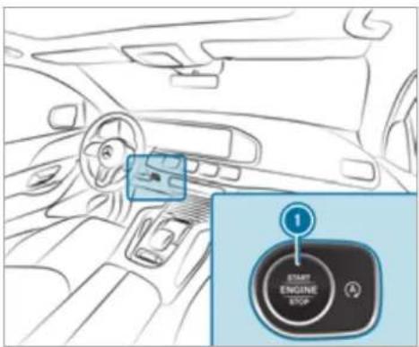
text_image
1 START ENGINE STOPBring the vehicle to a standstill by pressing the brake pedal.
On gradients, turn the front wheels so that the vehicle will roll towards the kerb if it starts moving.
▶ Apply the electric parking brake.
Engage transmission position P in a stationary vehicle with the brake pedal applied (→ page 210).
Switch off the engine and the ignition by pressing the ⏻ button.
Release the service brake slowly.
▶ Get out of the vehicle and lock it.
When you park the vehicle, you can still operate the side windows and the sliding sunroof for approximately four minutes if the driver's door is closed.
When you park the vehicle, you can still operate the side windows and the panoramic sliding sunroof for approximately four minutes if the driver's door is closed.
Garage door opener
Programming buttons for the garage door opener

DANGER Risk of death caused by exhaust gases
Combustion engines emit poisonous exhaust gases such as carbon monoxide. Inhaling these exhaust gases is hazardous to health and leads to poisoning.
▶ Never leave the engine or, if present, the auxiliary heating running in an enclosed space without sufficient ventilation.

WARNING Risk of injury when opening or closing a door with the garage door opener
When you operate or program the door with the integrated garage door opener, persons in the range of movement of the door may become trapped or be struck by the door.
Always make sure that nobody is within the range of movement of the door.
Requirements:
- The vehicle has been parked outside the garage or outside the range of movement of the door.
• The engine is switched off.
• The ignition is switched on.
The garage door opener function is always available when the ignition is switched on.
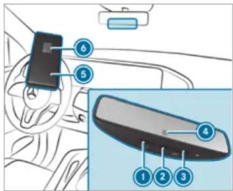
text_image
Diagram of car interior showing steering wheel, rearview mirror, and labeled parts in ChinesePress and hold button ①, ② or ③ that you wish to program.
Indicator lamp ④ flashes yellow.
① It can take up to 20 seconds before the indicator lamp flashes yellow.
Release the previously pressed button. Indicator lamp 4 continues to flash yellow.
Point remote control ⑤ from a distance of 1 cm to 8 cm towards button ①, ② or ③.
Press and hold button ⑥ of remote control
⑤ until one of the following signals appears:
• Indicator lamp ④ lights up green continuously. Programming is complete.
• Indicator lamp ④ flashes green. Programming was successful. Additionally, synchronisation of the rolling code with the door system must also be carried out.
If indicator lamp ④ does not light up or flash green: repeat the procedure.
Release all of the buttons.
The remote control for the door drive is not included in the scope of delivery of the garage door opener.
Synchronising the rolling code
Requirements:
• The door system uses a rolling code.
- The vehicle must be within range of the garage door or door drive.
- The vehicle as well as persons and objects are located outside the range of movement of the door.
▶ Press the programming button on the door drive unit. Initiate the next step within approximately 30 seconds.
Press previously programmed button ①, ② or ③ repeatedly until the door closes. When the door closes, programming is completed.
(i) Please also read the operating instructions for the door drive.
Troubleshooting when programming the remote control
Check if the transmitter frequency of remote control ⑤ is supported.
Replace the batteries in remote control ⑤.
Hold remote control ⑤ at various angles from a distance of 1 cm to 8 cm front of the inside rearview mirror. You should test every position for at least 25 seconds before trying another position.
Hold remote control ⑤ at the same angles at various distances in front of the inside rear view mirror. You should test every position for at least 25 seconds before trying another position.
On remote controls that transmit only for a limited period, press button ⑥ on remote control ⑤ again before transmission ends.
Angle the aerial line of the garage door opener unit towards the remote control.
i Support and additional information on programming:
- On the HomeLink Hotline on (0) 08000 466 354 65 or +49 (0) 6838 907-277
- On the Internet at https://www.homelink.com
Opening or closing the garage door
Requirements:
- The corresponding button is programmed to operate the door.
Press and hold buttons ①, ② or ③ until the door opens or closes.
If indicator lamp ④ flashes yellow after approximately 20 seconds: press and hold the previously pressed button again until the door opens or closes.
Clearing the garage door opener memory
Press and hold buttons ① and ③. Indicator lamp ④ lights up yellow.
If indicator lamp ④ flashes green: release buttons ① and ③. The entire memory has been deleted.
Electric parking brake
Function of the electric parking brake (applying automatically)
A WARNING Risk of accident and injury due to leaving children unattended in the vehicle
If children are left unattended in the vehicle, they could, in particular:
- open doors, thereby endangering other persons or road users.
• get out and be struck by oncoming traffic.
- operate vehicle equipment and become trapped, for example.
In addition, the children could also set the vehicle in motion by, for example:
• releasing the parking brake.
• changing the transmission position.
• starting the vehicle.
▶ Never leave children unattended in the vehicle.
When leaving the vehicle, always take the key with you and lock the vehicle.
Keep the vehicle key out of the reach of children.
The electric parking brake is applied if the transmission is in position P and one of the following conditions is fulfilled:
• The engine is switched off.
- The seat belt tongue is not inserted in the seat belt buckle of the driver's seat and the driver's door is opened.
- The transfer case is in the LOW RANGE position.
To prevent application: pull the handle of the electric parking brake ( page 227).
In the following situations, the electric parking brake is also applied:
- The HOLD function is keeping the vehicle stationary.
- Active Parking Assist is keeping the vehicle stationary.
• Active Distance Assist DISTRONIC is bringing the vehicle to a standstill. -
In addition, one of the following conditions must be fulfilled:
-
The engine is switched off.
- The seat belt tongue is not inserted in the seat belt buckle of the driver's seat and the driver's door is opened.
-
There is a system malfunction.
-
The power supply is insufficient.
- The vehicle is stationary for a lengthy period.
When the electric parking brake is applied, the red indicator lamp lights up in the instrument cluster.
The electric parking brake is not automatically applied if the engine is switched off by the ECO start/stop function.
Function of the electric parking brake (releasing automatically)
The electric parking brake is released when the following conditions are fulfilled:
• The driver's door is closed.
• The engine is running.
- The transmission is in position D or R and you depress the accelerator pedal or you shift from transmission position P to D or R when on level ground.
- If the transmission is in position [R], the tailgate must be closed.
- The seat belt tongue is inserted into the seat belt buckle of the driver's seat.
When the electric parking brake is released, red [P] indicator lamp in the instrument cluster goes out.
Applying/releasing the electric parking brake manually
Applying
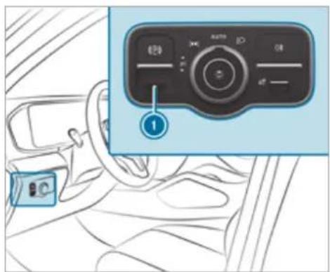
text_image
Diagram showing car interior with a control panel and labeled button, likely for diagnostic or navigation interface.▶ Push handle ①. The red (P) indicator lamp lights up in instrument cluster.
The electric parking brake is only securely applied if the red (P) indicator lamp is lit continuously.
Releasing
▶ Switch on the ignition.
Pull handle ①. The red Ⓓ indicator lamp in the instrument cluster goes out.
Emergency braking
Press and hold handle ①. As long as the vehicle is driving, the Release parking brake message is displayed and the red Ⓓ indicator lamp flashes. When the vehicle has been braked to a standstill, the electric parking brake is applied. The red Ⓓ indicator lamp lights up in the instrument cluster.
Information on collision detection on a parked vehicle
If a collision is detected when the tow-away protection is primed on a locked vehicle, you will receive a notification in the multimedia system when you switch on the ignition.
You will receive information about the following points:
- The area of the vehicle that may have been damaged.
• The force of the impact.
The following situations can lead to inadvertent activation:
- The parked vehicle is moved, e.g. in a two-storey garage.
i Deactivate tow-away protection in order to prevent inadvertent activation. If you deactivate tow-away protection, collision detection will also be deactivated.
System limits
Detection may be restricted in the following situations:
- the vehicle is damaged without impact, e.g. if an outside mirror is torn off or the paint is damaged by a key
- an impact occurs at low speed
• the electric parking brake is not applied
Notes on parking up the vehicle
If you leave the vehicle parked up for longer than six weeks, it may suffer damage through disuse.
The 12 V battery may also be impaired or damaged by heavy discharging.
i Further information can be obtained at a qualified specialist workshop.
Standby mode (extension of the starter battery's period out of use)
Standby mode function
i This function is not available for all models.
If standby mode is activated, energy loss will be minimised during extended periods of non-operation.
Standby mode is characterised by the following:
• The starter battery is preserved.
- The maximum non-operational time appears in the media display.
- The connection to online services is interrupted.
- The ATA (anti-theft alarm system) is unavailable.
- The interior protection and tow-away protection functions are not available.
- The function for detecting collisions on a parked vehicle is not available.
If the following conditions are fulfilled, standby mode can be activated or deactivated using multimedia system:
• The engine is switched off.
• The ignition is switched on.
Exceeding the vehicle's displayed non-operational time may cause inconvenience, i.e. it can-
not be guaranteed that the starter battery will reliably start the engine.
The starter battery must be charged first in the following situations:
- The vehicle's non-operational time must be extended.
- The Battery charge insufficient for standby mode message appears in the media display.
i Standby mode is automatically deactivated when the ignition is switched on.
Activating/deactivating standby mode (parking up the vehicle)
Requirements:
• The engine is switched off.
Multimedia system:
Driving and driving safety systems
Driving systems and your responsibility
Your vehicle is equipped with driving systems which assist you in driving, parking and man-ving the vehicle. The driving systems are only aids. They are not a substitute for your attention to the surroundings and do not relieve you of your responsibility pertaining to road traffic law. The driver is always responsible for maintaining a safe distance to the vehicle in front, for vehicle speed, for braking in good time and for staying in lane. Pay attention to the traffic conditions at all times and intervene when necessary. Be aware of the limitations regarding the safe use of these systems.
Driving systems can neither reduce the risk of accident if you fail to adapt your driving style nor override the laws of physics. They cannot always take into account road, weather or traffic conditions.
Information on vehicle sensors and cameras
Some driving and driving safety systems use cameras as well as radar or ultrasonic sensors to monitor the area in front of, behind or next to the vehicle.
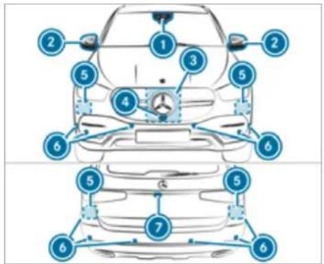
text_image
Diagram of car front view with numbered parts for identification and assembly reference① Multifunction camera
② Cameras in the outside mirrors
3 Front radar
4 Front camera
5 Corner radars
6 Ultrasonic sensors
⑦ Reversing camera
⚠ WARNING Risk of accident due to restricted detection performance of vehicle sensors and cameras
If the area around vehicle sensors or cameras is covered, damaged or dirty, certain driving and safety systems cannot function correctly. There is a risk of an accident.
Keep the area around vehicle sensors or cameras clear of any obstructions and clean.
Have damage to the bumper, radiator grille or stone chipping in the area of the front and rear windows repaired at a qualified specialist workshop.
Particularly, keep the areas around the sensors and cameras free of dirt, ice or slush
(→ page 379). The sensors and cameras must not be covered and the detection ranges around them must be kept free. Do not attach additional licence plate brackets, advertisements, stickers, foils or foils to protect against stone chippings in the detection range of the sensors and cameras. Make sure that there are no overhanging loads protruding into the detection range.
If there is damage to a bumper or the radiator grille, or after an impact, have the function of the sensors checked at a qualified specialist workshop. Have damage or stone chipping in the area of the cameras on the front and rear windows repaired at a qualified specialist workshop.
Overview of driving systems and driving safety systems
• ABS (Anti-lock Braking System)
(→ page 231)
• Off-road ABS ( page 231)
• BAS (Brake Assist System) ( page 231)
- ESP® (Electronic Stability Program) (→ page 232)
- ESP® Crosswind Assist (→ page 233)
- ESP® trailer stabilisation (→ page 233)
• EBD (Electronic Brakeforce Distribution) ( page 234)
• STEER CONTROL ( page 234)
• HOLD function ( page 235)
• Hill Start Assist ( page 236)
• Adaptive Brake Lights ( page 236)
• ATTENTION ASSIST ( page 236)
• Cruise control ( page 238) - Limiter (→ page 239)
• Traffic Sign Assist ( page 259) - Speed Limit Assist (country-dependent) (→ page 258)
• AIRMATIC ( page 267)
• E-ACTIVE BODY CONTROL ( page 274)
• Trailer Manoeuvring Assist ( page 299)
Driving Assistance package
The following functions are part of the Driving Assistance Package. Certain functions are only available in some countries. Some functions are
also available without the Driving Assistance Package, albeit with restricted functionality.
• Active Distance Assist DISTRONIC ( page 241)
• Active Speed Limit Assist (country-dependent) ( page 246)
- Route-based speed adaptation (country-dependent) ( page 246)
- DSR (Downhill Speed Regulation) (→ page 248)
• Active Brake Assist ( page 253)
• Active Steering Assist (country-dependent) ( page 250)
• Active Emergency Stop Assist (country-dependent) ( page 252)
- Active Stop-and-Go Assist (country-dependent) ( page 248)
- Blind Spot Assist and Active Blind Spot Assist with exit warning ( page 262)
• Active Lane Keeping Assist ( page 264)
Parking Package
• Reversing camera (→ page 282)
• 360° Camera (→ page 284)
• Parking Assist PARKTRONIC (→ page 288)
• Active Parking Assist (→ page 293)
Functions of ABS (Anti-lock Braking System)
ABS regulates the brake pressure in critical driving situations:
- During braking, e.g. at maximum full-stop braking or insufficient tyre traction, the wheels are prevented from locking.
• Vehicle steerability while braking is ensured.
If ABS intervenes when braking, you will feel a pulsing in the brake pedal. The pulsating brake pedal can be an indication of hazardous road conditions and can serve as a reminder to take extra care while driving.
System limits
• ABS is active from speeds of approx. 5 km/h.
- ABS may be impaired or may not function if a malfunction has occurred and the yellow ☐ ABS warning lamp lights up contin-
uously in the instrument cluster after the engine is started.
Functions of Off-road ABS
Off-road ABS is activated automatically when you select the 📄 or 🐃 drive program. Off-road ABS is specially adapted for driving off-road:
- The front wheels lock cyclically during braking.
- The braking distance is shortened due to the digging-in effect.
System limits
- Off-road ABS functions at speeds below 40 km/h.
- If Off-road ABS intervenes, the ability to steer may be restricted.
Function of BAS
WARNING Risk of an accident caused by a malfunction in BAS (Brake Assist System)
If BAS is malfunctioning, the braking distance in an emergency braking situation is increased.
Depress the brake pedal with full force in emergency braking situations. ABS prevents the wheels from locking.
The Brake Assist System (BAS) supports your emergency braking situation with additional brake force.
If you depress the brake pedal quickly, BAS is activated:
- BAS automatically boosts the brake pressure.
• BAS can shorten the braking distance.
• ABS prevents the wheels from locking.
The brakes will function as usual once you release the brake pedal. BAS is deactivated.
Functions of ESP®

WARNING Risk of skidding if ESPs deactivated
If you deactivate ESP, ESP cannot carry out vehicle stabilisation.
ESP ^® should only be deactivated in the following situations.

NOTE Mercedes-AMG vehicles
Observe the notes in the Supplement. You could otherwise fail to recognise dangers.
The Electronic Stability Program (ESP) can monitor and improve driving stability and traction in the following situations within physical limits:
- When pulling away on wet or slippery carriageways.
- When braking.
If the vehicle deviates from the direction desired by the driver, ESP can stabilise the vehicle by intervening in the following ways:
• One or more wheels are braked.
- The engine output is adapted according to the situation.
ESP® is deactivated if the OFF ESPOFF warning lamp lights up continuously in the instrument cluster:
- Driving stability will no longer be improved.
• The drive wheels could spin.
• ETS/4ETS traction control is still active.
When ESP ^® is deactivated, you are still assisted by ESP ^® when braking.
If the ESPwarning lamp flashes in the instrument cluster, one or several wheels has reached its grip limit:
- Adapt your driving style to suit the current road and weather conditions.
-
Do not deactivate ESP
-
Only depress the accelerator pedal as far as is necessary when pulling away.
It can be advantageous to deactivate ESP the following situations to improve traction: - When using snow chains.
- In deep snow.
- On sand or gravel.
i Spinning the wheels results in a cutting action, which enhances traction.
If the ESP warning lamp lights up continuously, ESP is not available due to a malfunction. Observe the following information:
• Indicator and warning lamps (→ page 507)
• Display messages (→ page 445)
ETS/4ETS (Electronic Traction System)
ETS/4ETS traction control is part of ESP® and makes it possible to pull away and accelerate on a slippery carriageway.
If you select the 📄 or 🌐 drive program, a special ETS system specifically suited to off-road terrain is automatically activated.
ETS/4ETS can improve the vehicle's traction by intervening in the following ways:
- The drive wheels are braked individually if they spin.
- More drive torque is transferred to the wheel or wheels with traction.
Influence of drive programs on ESP®
The drive programs enable ESP®o adapt to different weather and road conditions as well as the driver's preferred driving style. Depending on the selected drive program, the appropriate ESP® mode will be activated. You can select the drive programs using the DYNAMIC SELECT switch (→ page 207).
Function of ESP® Crosswind Assist
ESP® Crosswind Assist detects sudden gusts of side wind and helps the driver to keep the vehicle in the lane:
- ESP® Crosswind Assist is active at vehicle speeds between approx. 75 km/h and
200 km/h when driving straight ahead or cornering slightly.
- The vehicle is stabilised by means of individual brake application on one side.
Function of ESP® trailer stabilisation
WARNING Risk of accident in poor road and weather conditions
In poor road and weather conditions, the trailer stabilisation cannot prevent lurching of the vehicle/trailer combination. Trailers with a high centre of gravity may tip over before ESP ^® detects this.
▶ Always adapt your driving style to suit the current road and weather conditions.
When driving with a trailer, ESPan stabilise your vehicle if the trailer begins to swerve from side to side:
- ESP® trailer stabilisation is active above speeds of 65 km/h.
- Slight swerving is reduced by means of a targeted, individual brake application on one side.
- In the event of severe swerving, the engine output is also reduced and all wheels are braked.
ESP® trailer stabilisation may be impaired or may not function if:
- The trailer is not connected correctly or is not detected properly by the vehicle.
Activating/deactivating ESP® (Electronic Stability Program) (vehicles without Off-road package)
Multimedia system:
→ Settings ▶ Quick access
i ESP® can only be activated/deactivated using quick access when at least one other function is available in quick access. ESP® can otherwise be found in the Assistance menu.

NOTE Mercedes-AMG vehicles
Observe the notes in the Supplement. You could otherwise fail to recognise dangers.

Select ESP.

Select On

Off.
ESP® is deactivated if the OFF ESOFF warning lamp lights up continuously in the instrument cluster.
Observe the information on warning lamps and display messages which may be shown in the instrument cluster.
Activating/deactivating ESP® (Electronic Stability Program) (vehicles with Off-road package or E-Active Body Control)

NOTE Mercedes-AMG vehicles
Observe the notes in the Supplement. You could otherwise fail to recognise dangers.
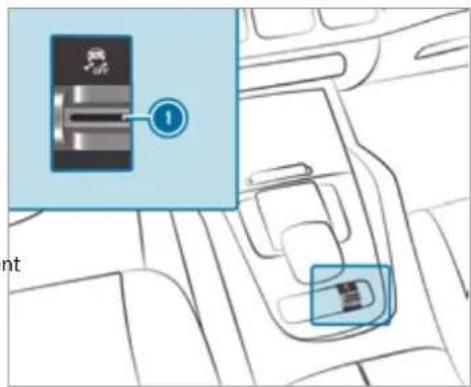
text_image
Diagram showing a car interior with a highlighted switch labeled '1' and a small inset image of the switch.
Pull rocker switch ①.
ESP ^ is deactivated if the ☐ OFF ESOFF warning lamp lights up continuously in the instrument cluster.
Observe the information on warning lamps and display messages which may be shown in the instrument cluster.
Function of EBD
Electronic Breakforce Distribution (EBD) is characterised by the following:
• Monitoring and regulating the brake pressure on the rear wheels.
- Improved driving stability when braking, especially on bends.
Function of STEER CONTROL
STEER CONTROL assists you by transmitting a noticeable steering force to the steering wheel in the direction required for vehicle stabilisation. This steering recommendation is given in the following situations:
- both right wheels or both left wheels are on a wet or slippery road surface when you brake the vehicle starts to skid
System limits
STEER CONTROL may be impaired or may not function in the following situations:
- ESP ^10 is deactivated.
- ESP ^ is malfunctioning.
• The steering is malfunctioning.
If ESP® is malfunctioning, you will be assisted further by the electric power steering.
HOLD function
HOLD function
The HOLD function holds the vehicle at a standstill without requiring you to depress the brake pedal, e.g. while waiting in traffic.
The HOLD function is only an aid. The responsibility for the vehicle safely standing still remains with the driver.
System limits
The HOLD function is only intended to provide assistance when driving and is not a sufficient means of safeguarding the vehicle against rolling away when stationary.
• The incline must not be greater than 30%.
Activating/deactivating the HOLD function
WARNING Risk of an accident due to the HOLD function being active when you leave the vehicle
If the vehicle is only braked with the HOLD function it could, in the following situations, roll away:
- If there is a malfunction in the system or in the power supply.
- If the HOLD function is deactivated by depressing the accelerator pedal or brake pedal, e.g. by a vehicle occupant.
Always secure the vehicle against rolling away before you leave it.
Requirements:
• The vehicle is stationary.
- The driver's door is closed or the seat belt the driver's side is fastened.
- The engine is running or has been automatically switched off by the ECO start/stop function.
• The electric parking brake is released.
• Active Distance Assist DISTRONIC is deactivated.
- The transmission is in position D, R or I
Activating the HOLD function
Depress the brake pedal, and after a short time quickly depress further until the HOLD display appears in the multifunction display.
Release the brake pedal.
Deactivating the HOLD function
▶ Depress the accelerator pedal to pull away. or
Depress the brake pedal until the HOLD display disappears from the multifunction display.
The HOLD function is deactivated in the following situations:
• Active Distance Assist DISTRONIC is activated.
- The transmission is shifted to position .
- The vehicle is secured with the electric parking brake.
In the following situations, the vehicle is held by transmission position P and/or by the electric parking brake:
- The seat belt is unfastened and the driver's door is opened.
- The vehicle is switched off.
- There is a malfunction in the system or the power supply is insufficient.
Function of Hill Start Assist
Hill Start Assist holds the vehicle for a short time when pulling away on a hill under the following conditions:
• The transmission is in position D or R.
• The electric parking brake is released.
This gives you enough time to move your foot from the brake pedal to the accelerator pedal and depress it before the vehicle begins to roll away.

WARNING Risk of accident and injury due to the vehicle rolling away
After a short time, Hill Start Assist no longer holds the vehicle.
Swiftly move your foot from the brake pedal to the accelerator pedal. Do not leave the vehicle when it is being held by Hill Start Assist.
Function of Adaptive Brake Lights
Adaptive Brake Lights warn following traffic in an emergency braking situation with the following actions:
- By flashing the brake lamps
- By activating the hazard warning lights
If the vehicle is braked sharply from speeds above 50 km/h, the brake lamps flash rapidly. This provides traffic travelling behind you with an even more noticeable warning.
If the vehicle is travelling at speeds of more than 70 km/h at the beginning of the brake application, the hazard warning lights switch on once
the vehicle is stationary. When you pull away again, the hazard warning lights will switch off automatically at approximately 10 km/h. You can also switch off the hazard warning lights using the hazard warning button.
ATTENTION ASSIST
Function of ATTENTION ASSIST
ATTENTION ASSIST assists you on long, monotonous journeys, e.g. on motorways and trunk roads. If ATTENTION ASSIST detects indicators of fatigue or increasing lapses in concentration on the part of the driver, it suggests taking a break.
ATTENTION ASSIST is only an aid. It cannot always detect fatigue or lapses in concentration in time. The system is not a substitute for a well-rested and attentive driver. On long journeys, take regular breaks in good time that allow for adequate recuperation.
You can choose between two settings:
• Standard: normal system sensitivity.
- Sensitive: higher system sensitivity. The driver is warned earlier and the attention level detected by ATTENTION ASSIST is adapted accordingly.
If drowsiness or increasing lapses in concentration are detected, the ATTENTION ASSIST: Take a break! warning appears in the Instrument Display. You can acknowledge the message and take a break where necessary. If you do not take a break and ATTENTION ASSIST continues to detect increasing lapses in concentration, you will be warned again after a minimum of 15 minutes.
text_image
Attention Assist Last break 02:35 h agoYou can have the following status information for ATTENTION ASSIST displayed in the assistance menu of the on-board computer:
- The length of the journey since the last break. - The attention level determined by ATTENTION ASSIST:
- the fuller the circle, the higher the attentional level determined - as your attention wanes, the circle in the centre of the display becomes smaller
If ATTENTION ASSIST is unable to calculate the attention level and cannot issue a warning, the System suspended message appears.
If a warning is given in the Instrument Display, the multimedia system offers to search for a rest area. You can select a rest area and start navigation to this rest area. This function can be activated and deactivated in the multimedia system.
If ATTENTION ASSIST is deactivated, the symbol appears in the assistance graphic in the Instrument Display when the engine is running. ATTENTION ASSIST is activated automatically
when the engine is re-started. The last selected sensitivity level remains stored.
System limits
ATTENTION ASSIST is active in the 60 km/h to 200 km/h speed range.
Particularly in the following situations, ATTENTION ASSIST only functions in a restricted manner and warnings may be delayed or not occur:
- If you have been driving for less than approximately 30 minutes.
- If the road condition is poor (uneven road surface or potholes).
• If there is a strong side wind. - If you adopt a sporty driving style (high cornering speeds or high rates of acceleration).
- If Active Steering Assist is activated and active.
• If the time has been set incorrectly. - If you change lanes and vary your speed frequently in active driving situations.
The ATTENTION ASSIST drowsiness or alertness assessment is reset and restarted when continuing the journey in the following situations:
- If you switch off the engine.
- If you unfasten your seat belt and open the driver's door (e.g. to change drivers or take a break).
Setting ATTENTION ASSIST
Multimedia system:
Settings Assistance
▶ Attention Assist
Setting options
▶ Select Standard, Sensitive or Off.
Suggesting a rest area
▶ Select Suggest rest area.
Activate or deactivate the function. If ATTENTION ASSIST detects fatigue or increasing lack of attention, it suggests a rest area in the vicinity.
Select the suggested rest area. You are guided to the selected rest area.
Cruise control and limiter
Function of cruise control
Cruise control regulates the speed to the value selected by the driver.
If you accelerate to overtake, for example, the stored speed is not deleted. If you remove your foot from the accelerator pedal after overtaking, cruise control will resume speed regulation back to the stored speed.
You can store any speed above 20 km/h up to the maximum design speed or up to the set winter tyre limit. When driving in LOW RANGE off-road gear, the adjustable speed is reduced ( page 213).
Observe the notes on driving systems and your responsibility; you may otherwise fail to recognise dangers ( page 229).
Mercedes-AMG vehicles: cruise control is available up to a maximum speed of 250 km/h.
Displays on the multifunction display
- (grey): cruise control is selected but not yet activated.
• (green): cruise control is active.
A stored speed appears along with the ☑ display.
The segments extending from the current stored speed to the end of the scale, or to the set winter tyre limit, light up in the speedometer.
System limits
Cruise control may be unable to maintain the stored speed on uphill gradients. The stored speed is resumed when the gradient evens out.
Change into a lower gear in good time on long and steep downhill gradients. Take particular note of this when driving a laden vehicle. By doing so, you will make use of the engine's braking effect. This relieves the load on the brake system and prevents the brakes from overheating and wearing too quickly.
Do not use cruise control in the following situations:
- In traffic situations which require frequent changes of speed, e.g. in heavy traffic, on winding roads.
- On slippery roads. Accelerating can cause the drive wheels to lose traction and the vehicle could then skid.
• If you are driving when visibility is poor.
Function of the limiter
The limiter restricts the speed of the vehicle. To reduce the speed to the set speed, the limiter applies the brakes automatically.
You can limit the speed as follows:
- Variable: for a short-term speed restriction, e.g. in built-up areas
- Permanent: for a longer-term speed restriction, e.g. in winter tyre mode
You can store any speed above 20 km/h up to the maximum design speed or up to the set winter tyre limit. You can also perform settings while the vehicle is stationary if the vehicle has been started.
Observe the notes on driving systems and your responsibility; you may otherwise fail to recognise dangers ( page 229).
Mercedes-AMG vehicles: the limiter is available up to a maximum speed of 250 km/h.
Displays on the multifunction display
- LIM (grey): variable limiter is selected but not yet activated.
- LIM (flashes grey): variable limiter is temporarily passive.
• LIM (green): variable limiter is activated.
A stored speed appears along with the LIM display. The segments in the speedometer light up, up to the currently stored speed.
If you depress the accelerator pedal beyond the pressure point (kickdown), the variable limiter switches to passive mode. The Limiter passive message appears in the multifunctional display and the LIM display flashes.
The variable limiter is reactivated in the following situations:
- If the vehicle speed drops below the stored speed.
- If the stored speed is called up.
• If you store a new speed.
Operating cruise control or the variable limiter
⚠ WARNING Risk of accident due to stored speed
If you call up the stored speed and this is lower than your current speed, the vehicle decelerates.
Take into account the traffic situation before calling up the stored speed.
Requirements:
Cruise control
• Cruise control is selected.
- ESP® must be activated, but not intervening.
• The vehicle speed is at least 20 km/h.
• The transmission is in position D.
Variable limiter
• The variable limiter is selected.
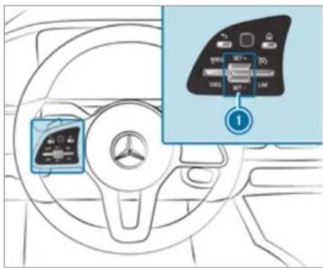
text_image
Diagram showing car dashboard with control panel and infotainment of a device, labeled with number 1To operate cruise control or the variable limiter: press the rocker switch on the steering wheel control unit up or down to the desired position.
Switching between cruise control and the variable limiter
To select cruise control: select ☑ with the right rocker switch.
To select the variable limiter: select LIM with the right rocker switch.
① Vehicles with Active Distance Assist DISTRONIC: the variable limiter is selected by a different button ( page 244).
Activating cruise control or the variable limiter
Press rocker switch ① up SET/+ or down SET/-. The current vehicle speed is stored and the vehicle maintains this speed (cruise control) or does not exceed it (variable limiter).
or
Select [RES/P] with the left rocker switch. The last stored speed is called up and the vehicle maintains this speed (cruise control) or does not exceed it (variable limiter). If the last stored speed has previously been deleted, the current vehicle speed is stored.
When you switch off the vehicle, the last speed stored is deleted.
When you activate cruise control or Active Distance Assist DISTRONIC, the last speed stored for the variable limiter is deleted.
Increasing/decreasing the stored speed
1 km/h: press rocker switch ① up SET/+ or down SET/- to the pressure point, or press and hold (increments of 1 km/h).
or
10 km/h: press rocker switch ① up SET/+ or down SET/- beyond the pressure point, or press and hold (increments of 10 km/h).
or
Accelerate the vehicle to the desired speed and press rocker switch ① up SET/+
Adopting a detected speed
▶ Activate cruise control or the variable limiter.
If a traffic sign has been detected and is displayed in the instrument cluster: select RES/ ^ with the left rocker switch.
The maximum permissible speed shown by the traffic sign is stored and the vehicle maintains or does not exceed this speed.
Deactivating cruise control or the variable limiter
Select CNCL with the left rocker switch.
If you brake, deactivate ESP or if ESP intervenes, cruise control is deactivated. The variable limiter is not deactivated.
Information on the permanent limiter
If the vehicle should never exceed a specific speed (e.g. for driving in winter tyre mode), you can set this speed with the permanent limiter.
You do this by limiting the speed between 160 km/h and 240 km/h in the multimedia system ( page 241).
Shortly before the set speed is reached, it appears in the multifunction display. When you confirm the message, display messages no longer appear until you switch off the vehicle. The speed will only be displayed again once the vehicle has been restarted or if the set speed is changed.
The permanent limiter does not switch to passive mode even during kickdown and the driven speed remains below the set speed.
Setting the limit speed for winter tyres
Multimedia system:

▶ Select a speed or deactivate the function.
Active Distance Assist DISTRONIC
Function of Active Distance Assist ^1 DISTRONIC
Active Distance Assist DISTRONIC maintains the set speed on free-flowing roads. If vehicles in front are detected, the set distance is maintained, if necessary, until the vehicle comes to a halt. The vehicle accelerates or brakes depending on the distance to the vehicle in front and the set speed. The speed and distance to the vehicle in front are set and saved using the steering wheel.
Available speed range:
• Vehicles without Driving Assistance Package: 20 km/h - 200 km/h
• Vehicles with Driving Assistance Package: 20 km/h - 210 km/h
The maximum speed is reduced when drivin in LOW RANGE off-road gear ( page 213).
Other features of Active Distance Assist DISTRONIC:
- Adjusts the driving style depending on the selected drive program (fuel-saving, comfortable or dynamic)
- Initiates acceleration to the stored speed if the turn signal indicator is switched on to change to the overtaking lane
• Vehicles with Driving Assistance Package:
- Reacts to stationary vehicles detected in urban speed ranges (except bicycles and motorcycles)
- Takes one-sided overtaking restrictions into account on motorways or on multi-lane roads with separate carriageways (country-dependent)
Vehicles with Driving Assistance Package and Parking Package: if the vehicle has been braked to a standstill on multi-lane, separate carriageways by Active Distance Assist
DISTRONIC, it can automatically follow the vehicle in front when driving off again within 30 onds. If a critical situation is detected when ing off, a visual and acoustic warning is given indicating that the driver must now take control of the vehicle. The vehicle is not accelerated any further.
Observe the notes on driving systems and your responsibility; you may otherwise fail to recognise dangers ( page 229).
Active Distance Assist DISTRONIC displays in sethe Instrument Display
driv-
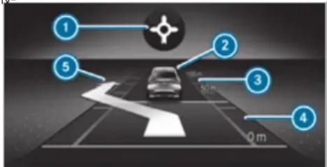
text_image
1 2 3 4 5 0 mAssistant display
Route-based speed adaptation: type of route event ( page 246)
② Vehicle in front
③ Distance indicator
④ Set specified distance
⑤ Active Lane Change Assist lane change display
Permanent status display of Active Distance Assist DISTRONIC
- (white): Active Distance Assist DISTRONIC selected, specified distance set
- (white vehicle, green speedometer): Active Distance Assist DISTRONIC active, specified distance set and vehicle detected
- [green] (green): Active Distance Assist DISTRONIC active, specified distance set and vehicle detected
- [@]: Route-based speed adaptation active (→ page 246).
The stored speed is shown along with the permanent status display and highlighted on the speedometer. When Active Distance Assist DISTRONIC is passive, the speed is greyed out.
On motorways or high-speed major roads, the green vehicle symbol is displayed cyclically when the vehicle is ready to pull away.
If you depress the accelerator pedal beyond the setting of the Active Distance Assist DISTRONIC, the system is switched to passive mode. The suspended message appears in the multifunction display.
Display on the speedometer
The stored speed is highlighted on the speedometer. If the speed of the vehicle in front or the speed adjustment for the route event ahead is less than the stored speed, the segments in the speedometer light up. The multifunction display shows the deactivation of Active Distance Assist DISTRONIC, as well as alterations to the speed due to manual or automatic adoption of the maximum permissible speed.
System limits
The system may be impaired or may not function in the following situations, for example:
- In snow, rain, fog, heavy spray, if there is glare, in direct sunlight or in greatly varying light conditions.
-
If there is swirling dust, e.g. when driving off-road or on sandy surfaces.
-
The windscreen in the area of the camera is dirty, misted up, damaged or covered.
• If the radar sensors are dirty or covered. - In multi-storey car parks or on roads with steep uphill or downhill gradients.
- If there are narrow vehicles in front, such as bicycles or motorcycles.
In addition, on slippery roads, braking or accelerating can cause one or several wheels to lose traction and the vehicle could then skid.
Do not use Active Distance Assist DISTRONIC in these situations.
WARNING Risk of accident from acceleration or braking by Active Distance Assist DISTRONIC
Active Distance Assist DISTRONIC may accelerate or brake in the following cases, for example:
- If the vehicle pulls away using Active Distance Assist DISTRONIC.
- If the stored speed is called up and is considerably faster or slower than the currently driven speed.
- If Active Distance Assist DISTRONIC no longer detects a vehicle in front or does not react to relevant objects.
▶ Always carefully observe the traffic conditions and be ready to brake at all times.
Take into account the traffic situation before calling up the stored speed.
WARNING Risk of accident due to insufficient deceleration by Active Distance Assist DISTRONIC
Active Distance Assist DISTRONIC brakes your vehicle with up to 50% of the possible deceleration. If this deceleration is not sufficient, Active Distance Assist DISTRONIC alerts you with a visual and acoustic warning.
Adjust your speed and maintain a suitable distance from the vehicle in front.
Brake the vehicle yourself and/or take evasive action.
A WARNING Risk of accident if detection function of Active Distance Assist DISTRONIC is impaired
Active Distance Assist DISTRONIC does not react or has a limited reaction:
- when driving on a different lane or when changing lanes
- to pedestrians, animals, bicycles or stationary vehicles, or unexpected obstacles
• to complex traffic conditions
• to oncoming vehicles and crossing traffic
As a result, Active Distance Assist DISTRONIC may neither give warnings nor intervene in such situations.
Always observe the traffic conditions carefully and react accordingly.
Operating Active Distance Assist DISTRONIC
Requirements:
• The electric parking brake is released.
- ESP® is activated and is not intervening.
• The transmission is in position D.
• The driver's door is closed.
- Check of the radar sensor system has been successfully completed.
- Parking Assist PARKTRONIC is not being used to park the vehicle or to exit from a parking space.
- DSR is deactivated.
- Vehicles with Off-road package: the drive program is deactivated.
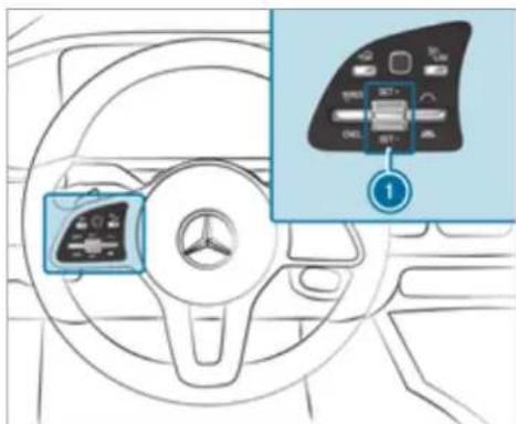
text_image
Diagram of car dashboard with control panel and infotainment view showing a device labeled '1'To operate Active Distance Assist DISTRONIC: press the rocker switches on the steering wheel control unit up or down to the desired position.
Switching between Active Distance Assist DISTRONIC and the limiter
Press the button.
Activating the variable limiter or Active Distance Assist DISTRONIC
To activate without a stored speed: press rocker switch ① up SET/+ or down SET/-, or select RES/ with the left rocker switch.
or
To activate with a stored speed: select [RES]® with the left rocker switch.
Active Distance Assist DISTRONIC: remove your foot from the accelerator pedal. The current vehicle speed is stored and maintained (Active Distance Assist DISTRONIC) or limited (variable limiter) by the vehicle.
Adopting a detected speed limit
Activate Active Distance Assist DISTRONIC.
If a traffic sign has been detected and is displayed in the instrument cluster: select RES/ ^® with the left rocker switch.
The maximum permissible speed on the traffic sign is adopted as the stored speed. The vehicle adapts its speed to that of the vehicle in front, but only up to the stored speed.
Pulling away with Active Distance Assist DISTRONIC
Activate Active Distance Assist DISTRONIC and remove your foot from the brake pedal.
Select RES/1 with the left rocker switch. or
Depress the accelerator pedal briefly and firmly.
The functions of Active Distance Assist
DISTRONIC continue to be carried out.
Deactivating Active Distance Assist DISTRONIC
WARNING Risk of an accident due to Active Distance Assist DISTRONIC being active when you leave the driver's seat
If you leave the driver's seat while the vehicle is being braked by Active Distance Assist DISTRONIC only, the vehicle can roll away.
Always deactivate Active Distance Assist DISTRONIC and secure the vehicle to prevent it from rolling away before you leave the driver's seat.
Select CNCL with the left rocker switch.
① If you brake, deactivate ESP or if ESP intervenes, Active Distance Assist DISTRONIC is deactivated.
Increasing/decreasing the stored speed
1 km/h: press rocker switch ① up SET/+ or down SET/- to the pressure point, or press and hold (increments of 1 km/h).
or
10 km/h: press rocker switch ① up SET/+ or down SET/- beyond the pressure point, or press and hold (increments of 10 km/h).
or
Accelerate the vehicle to the desired speed and press rocker switch ① up SET/+
Changing the specified distance to the vehicle in front
To reduce the specified distance: press the right rocker switch up (☐).
To increase the specified distance: press the right rocker switch down (☐).
Function of Active Speed Limit Assist
If a change in the speed limit of 20 km/h or more is detected and automatic adoption of speed limits is activated, the new speed limit automatically adopted as the stored speed ( page 261).
The driven speed is adjusted when the vehicle is level with the traffic sign at the latest. In the case of signs indicating entry into an urban area, the speed is adapted according to the speed permitted within the urban area. The speed limit display in the Instrument Display is always updated when the vehicle is level with the traffic sign.
If there is no speed restriction on an unlimited stretch of road (e.g. on a motorway), the recommended speed is automatically adopted as the stored speed. The system uses the speed stored on an unlimited stretch of road as the recommended speed. If you do not alter the stored speed on an unlimited stretch of road, the recommended speed is 130 km/h.
If Active Distance Assist DISTRONIC has been put into passive mode by pressing the accelerator pedal, only speed limits which are higher than the set speed are adopted.
Observe the notes on driving systems and your responsibility; you may otherwise fail to recognise dangers ( page 229).
^IS System limits
The system limits of Traffic Sign Assist apply to the detection of traffic signs ( page 259).
Speed limits below 20 km/h are not automatically adopted by the system as the stored speed. Temporary speed restrictions (e.g. for a certain time or due to weather conditions) cannot be properly detected by the system. The maximum permissible speed applying to a vehicle with a trailer is not detected by the system.
Adjust the speed in these situations.

WARNING Risk of accident due to Active Speed Limit Assist adapting the vehicle's speed
The speed adopted by Active Speed Limit Assist may be too high or incorrect in some individual cases, such as:
• at speed limits below 20 km/h
• in wet conditions or in fog
- when towing a trailer
▶ Ensure that the driven speed complies with traffic regulations.
Adjust the driving speed to suit current traffic and weather conditions.
Function of route-based speed adaptation
When Active Distance Assist DISTRONIC is activated, the vehicle speed will be adapted accordingly to the route events ahead. Depending on the drive program selected, the vehicle negotiates a route event ahead in an economical, comfortable or dynamic manner. When the route event has been passed, the vehicle accelerates again to the stored speed. The set distance to the vehicle in front, vehicles detected ahead and speed restrictions ahead are taken into account.
You can activate and deactivate route-based speed adaptation in the multimedia system ( page 248).
The following route events are taken into account:
- Bends
• T-junctions, roundabouts and toll stations - Turns and exits
- Traffic jams ahead (only with Live Traffic Information)
When the toll station is reached, Active Distance Assist DISTRONIC adopts the speed as the stored speed.
Also, the speed is reduced if the turn signal indicator to change lanes is switched on and one of the following situations is detected:
- Turning off at junctions
- Driving on slowing-down lanes
- Driving on lanes adjacent to slowing-down lanes
The driver is responsible for choosing the right speed and observing other road users. This applies in particular to junctions, roundabouts and traffic lights, as route-based speed adaptation does not brake the vehicle to a standstill.
When route guidance is active, the first speed adjustment is carried out automatically. If the turn signal indicator is switched on, the selected route is confirmed and further speed adjustment is activated.
Speed adaptation is cancelled in the following cases:
- If the turn signal indicator is switched off before the route event.
- If the driver depresses the accelerator or brake pedal during the process.
System limits
Route-based speed adaptation does not take right of way regulations into account. The driver is responsible for complying with road traffic regulations and driving at a suitable speed. The speed adaptation made by the system may not always be suitable, particularly in the following situations:
• the road's course not clearly visible
- road narrowing
- varying maximum permissible speeds in individual lanes, for example at toll stations
- wet road surfaces, snow or ice
- when towing a trailer
In these situations the driver must intervene accordingly.
⚠ WARNING Risk of accident in spite of route-based speed adaptation
Route-based speed adaptation can malfunction or be temporarily unavailable in the following situations:
- If the driver does not follow the calculated route
• If map data is not up-to-date or available
• In the event of roadworks
• In bad weather or road conditions
• If the accelerator pedal is depressed - In the event of electronically displayed speed limitations
Adapt the speed to the traffic situation.
Setting route-based speed adaptation
Requirements:
• Active Distance Assist DISTRONIC is activated.
• ECO Assist is active.
Multimedia system:
→ Settings ▶ Assistance
▶ Route-based speed adapt.
▶ Activate or deactivate the function. When the function is active, the vehicle speed is adjusted depending on the route events ahead.
i Further information on the route-based speed adaptation ( page 246).
Function of Active Traffic Jam Assist
Active Traffic Jam Assist helps you when in traffic jams on multi-lane roads with separate carriageways by automatically pulling away within 60 seconds and with moderate steering manoeuvres. It orients itself using the vehicle in front and lane markings. Active Traffic Jam Assist automatically maintains a safe distance from the vehicle in front and vehicles cutting in.
Active Traffic Jam Assist requires you, as the driver, to keep your hands on the steering wheel at all times so that you are able to intervene at any time to correct the course of the vehicle and keep it in lane. Observe the notes on driving systems and your responsibility; you may otherwise fail to recognise dangers ( page 229).
Active Traffic Jam Assist activates automatically as soon as all of the requirements are met: The status display appears in the instrument cluster when the function is active.
Requirements:
- You are in a traffic jam on a motorway or high-speed major road.
- Active Distance Assist DISTRONIC is activated and active ( page 244).
• Active Brake Assist is available ( page 253).
• Active Steering Assist is activated and active ( page 252).
• Active Traffic Jam Assist is activated ( page 248).
• You are travelling no faster than 60 km/h.
System limits
The system limitations of Active Distance Assist DISTRONIC and Active Steering Assist apply to Active Traffic Jam Assist.
Activating/deactivating Active Traffic Jam Assist
Multimedia system:
Settings Quick access
Select
DSR (Downhill Speed Regulation)
Function of DSR (Downhill Speed Regulation)
DSR is an aid to assist you when driving downhill. It keeps the speed of travel at the selected target speed. The steeper the downhill gradient, the greater the DSR braking effect on the vehicle. On flat stretches of road and uphill gradients, the DSR brakes the vehicle minimally or not at all.
When DSR is activated and the transmission is in position [D] , [R] or [N] , DSR controls the driving speed. The target speed can be set to a value between 2 km/h and 18 km/h. By braking or
accelerating, you can drive at a higher or lower Observe the notes on driving systems and your speed than the target speed at any time. responsibility; you may otherwise fail to recog-
DSR is deactivated automatically if you drive speeds greater than 45 km/h or select drive program C or B. The 1 off message then appears in the multifunction display. The status indicator in the multifunction display disappears. You also hear a warning tone.
Mercedes-Maybach vehicles: in drive program C ^12 , the DSR function is likewise not available.
Information on DSR

WARNING Risk of skidding and accident when DSR is activated on slippery road surfaces
If the driven speed and the target speed differ, the wheels may lose traction.
Take into account the road surface and the difference between the driving speed and target speed before activating DSR.
You are always responsible for keeping control of the vehicle and for assessing whether the downhill gradient can be negotiated. Depending on road surface and tyres, DSR may not always be able to keep to the target speed. Select a target speed suitable for the environmental conditions and also apply the brakes yourself if required.
Activating/deactivating DSR (vehicles with Off-road package or E-Active Body Control)
Requirements:
- You are driving at 40 km/h or slower. If the current vehicle speed is too high, the Max. speed 40 km/h message appears in the multifunction display.
- You have not selected drive program C or B.
• Active Distance Assist DISTRONIC is deactivated.
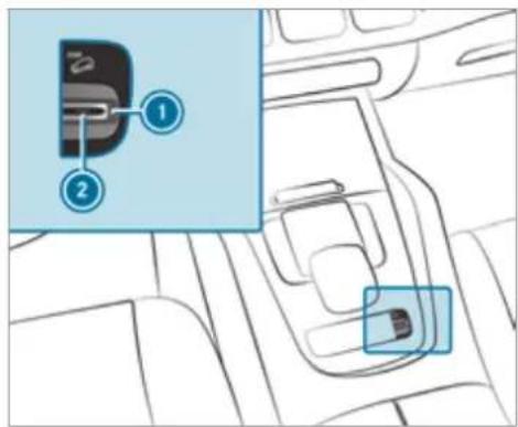
text_image
Diagram showing a car interior with labeled parts and an inset highlighting a device component with blue annotation lines.To activate: pull rocker switch ①. Indicator lamp ② lights up.
The symbol appears in the multifunction display.
To deactivate: pull rocker switch ①. Indicator lamp ② and the i symbol go out.
Activating/deactivating DSR (Downhill Speed Regulation) (vehicles without Off-road package)
Requirements:
- You are driving at 40 km/h or slower. If the current vehicle speed is too high, the Max. speed 40 km/h message appears in the multifunction display.
• Active Distance Assist DISTRONIC is deactivated.
Multimedia system:


Settings

The DSRsymbol appears in the multifunction display when the function is activated.
When you switch to the drive program, the function is automatically activated.

Changing the target speed
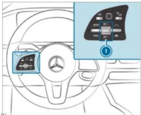
text_image
Diagram of car dashboard with control panel and navigation icon, showing steering wheel and battery status indicatorsTo increase/reduce the target speed: press rocker switch ① up SET/+ or down SET/- to the point of resistance.
The selected target speed increases or decreases by 1 km/h and appears along the symbol in the multifunction display.
Active Steering Assist
Function of Active Steering Assist
Active Steering Assist is only available up to a speed of 210 km/h. The system helps you to stay in the centre of the lane by means of moderate steering interventions. Depending on the speed driven, Active Steering Assist uses the vehicles ahead and lane markings as a reference.
Depending on the country, in the lower speed range Active Steering Assist can use the surrounding traffic as a reference. If necessary, Active Steering Assist can then also provide assistance when driving outside the centre of the lane, for example, to form a rescue lane.
If the detection of lane markings and vehicles ahead is impaired, Active Steering Assist switches to passive mode. The system provides no support in this case.
wiStatus display of Active Steering Assist in the multifunction display

(grey): activated and passive

(green): activated and active
• (red): system limits detected
- (white, red hands): "hands on the steering wheel" prompt
During the transition from active to passive status, the [icon] symbol is shown as enlarged and flashing. Once the system is passive, the [icon] symbol is shown as g the multifunction display.
(i) Depending on the selected vehicle settings, Active Steering Assist may be unavailable.
Steering and touch detection
The driver is required to keep their hands on the steering wheel at all times and be able to intervene at any time to correct the course of the vehicle and keep it in lane. The driver must expect a change from active to passive mode or vice versa at any time.
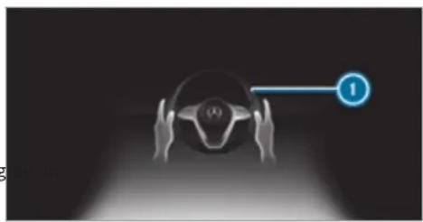
natural_image
Top-down view of a car head with hands holding the steering wheel, connected to a blue circular icon labeled '1' (no text or symbols on the diagram itself)If the system detects that the driver has not steered the vehicle for a considerable period of time or has removed their hands from the steering wheel, display ① appears. If the driver still does not steer the vehicle, a warning tone sounds in addition to the visual warning message.
If the driver does not react to the warning for a considerable period, the system can initiate an emergency stop ( page 252).
The warning is not issued or is stopped when the driver gives confirmation to the system:
• The driver steers the vehicle.
- Depending on the country: the driver presses a steering wheel button or operates Touch Control
If Active Steering Assist detects that a system limit has been reached, a visual warning is issued and a warning tone sounds.
Observe the notes on driving systems and your responsibility; you may otherwise fail to recognise dangers ( page 229).
System limits
Active Steering Assist has a limited steering torque for lateral guidance. In some cases, the steering intervention is not sufficient to keep the vehicle in the lane or to drive through exits.
The system may be impaired or may not functi in the following instances:
- There is poor visibility, e.g. due to snow, rain, fog, heavy spray, greatly varying light conditions or strong shadows on the carriageway.
-
There is glare, e.g. from oncoming traffic, direct sunlight or reflections.
• Insufficient road illumination. -
The windscreen is dirty, misted up, damaged or covered in the vicinity of the camera, e.g. by a sticker.
- No, or several, unclear lane markings are present for one lane, or the markings change quickly, for example, in a construction area or junctions.
- The lane markings are worn away, dark or covered up, e.g. by dirt or snow.
- If the distance to the vehicle in front is too short and thus the lane markings cannot be detected.
• The road is narrow and winding.
• There are obstacles on the lane or projecting out into the lane, such as object markers.
The system does not provide assistance in the following conditions:
- On tight bends and when turning.
- When crossing junctions.
• At roundabouts or toll stations. - When towing a trailer.
- When the tyre pressure is too low.

WARNING Risk of accident if Active Steering Assist unexpectedly stops functioning
If the system limits of Active Steering Assist are reached there is no guarantee that the system will remain active or will keep the vehicle in lane.
Always keep your hands on the steering wheel and observe the traffic carefully.
Always steer the vehicle paying attention to traffic conditions.

WARNING Risk of accident if Active Steering Assist unexpectedly intervenes
The detection of lane markings and objects may malfunction and cause unexpected steering interventions.
▶ Steer according to traffic conditions.
Activating/deactivating Active Steering Assist
Requirements:
- ESP ^® is activated, but is not intervening.
• Active Distance Assist DISTRONIC is activated.
Multimedia system:

Function of Active Emergency Stop Assist
natural_image
Diagram of a car steering wheel with hands and a numbered indicator (1) pointing to the wheel (no text or symbols on the diagram itself)If the system detects that the driver has not steered the vehicle for a considerable period of time or has removed their hands from the steering wheel, display ① appears in the multi-tion display. If the driver still does not steer the vehicle, or gives no confirmation to the system, a warning tone sounds in addition to the visual warning message.
If the driver still does not respond to the warning, the Beginning emergency stop message appears in the multifunction display. If the d still does not respond, Active Distance Assist DISTRONIC reduces the speed. The vehicle is decelerated in stages to a standstill.
Depending on the country, at speeds below 60 km/h the hazard warning lights switch on automatically.
When the vehicle is stationary, the following actions are carried out:
- The vehicle is secured with the electric parking brake.
• Active Distance Assist DISTRONIC is ended
• The vehicle is unlocked.
- If possible, an emergency call is placed to the Mercedes-Benz emergency call centre
The driver can cancel the deceleration at any time by performing one of the following actions:
- Steering
- Braking or accelerating
- Deactivating Active Distance Assist DISTRONIC
Active Brake Assist
Function of Active Brake Assist
Active Brake Assist consists of the following functions:
• Distance warning function
• Autonomous braking function
• Situation-dependent braking assistance
- Vehicles with Driving Assistance Package: Evasive Steering Assist and cornering function
Active Brake Assist can help you to minimise the risk of a collision with vehicles, cyclists or
pedestrians or to reduce the effects of such a collision.
If Active Brake Assist has detected a risk of collision, a warning tone sounds and the distance warning lamp lights up in the instrument cluster.
Vehicles with PRE-SAFE®: depending on the country, an additional haptic warning occurs in the form of slight, repeated tensioning of the seat belt.
If you do not react to the warning, autonomous braking can be initiated in critical situations. In especially critical situations, Active Brake Assist can initiate autonomous braking directly. In this case, the warning lamp and warning tone occur simultaneously with the braking application.
If you apply the brake yourself in a critical situation or apply the brake during autonomous braling, situation-dependent braking assistance occurs. The brake pressure increases up to maximum full-stop braking if necessary.
Observe the notes on driving systems and your responsibility; you may otherwise fail to recognise dangers ( page 229).
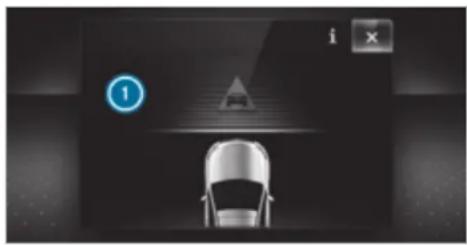
natural_image
Top-down view of a car with navigation icons and a warning sign (no readable text or symbols)If autonomous braking or situation-dependent braking assistance has occurred, display ① appears in the multifunction display and then automatically goes out after a short time.
If the autonomous braking function or the situation-dependent braking assistance is triggered, additional preventive measures for occupant protection (PRE-SAFE®) may also be initiated.

WARNING Risk of an accident caused by limited detection performance of Active Brake Assist
Active Brake Assist cannot always clearly identify objects and complex traffic situations.
In such cases, Active Brake Assist might:
- Give a warning or brake without reason
• Not give a warning or not brake
Active Brake Assist is only an aid. The driver is responsible for maintaining a sufficiently safe distance to the vehicle in front, vehicle speed and for braking in good time.
Always pay careful attention to the traffic situation; do not rely on Active Brake Assist alone.
Be prepared to brake or swerve if necessary.
Also observe the system limits of Active Brake Assist.
The individual subfunctions are available in various speed ranges:
The distance warning function can issue a warning in the following situations:
- From approximately 30 km/h, if over several seconds the distance maintained to the vehicle travelling in front is insufficient for the driven speed, the △ distance warning lamp lights up in the instrument cluster.
- From approximately 7 km/h, if your vehicle is critically close to a vehicle, cyclist or pedestrian, you will hear an intermittent warning tone and the distance warning lamp lights up in the instrument cluster.
Vehicles with PRE-SAFE®: depending on the country, an additional haptic warning occurs in the form of slight, repeated tensioning of the seat belt.
Brake immediately or take evasive action, provided it is safe to do so and the traffic situation allows this.
Distance warning function (vehicles without Driving Assistance Package)
The distance warning function can aid you in the following situations with an intermittent warning tone and a warning lamp:
- at speeds up to approximately 250 km/h when approaching vehicles ahead
- at speeds up to approximately 80 km/h when approaching stationary vehicles, moving pedestrians, and cyclists ahead
- at speeds up to approximately 60 km/h when approaching crossing cyclists
Distance warning function (vehicles with Driving Assistance Package)
The distance warning function can aid you in the following situations with an intermittent warning tone and a warning lamp:
- at speeds up to approximately 250 km/h when approaching vehicles ahead
-
at speeds up to approximately 100 km/h when approaching stationary vehicles
-
at speeds up to approximately 80 km/h when approaching moving pedestrians and cyclists ahead
- at speeds up to approximately 70 km/h when approaching stationary pedestrians, crossing vehicles and stationary and crossing cyclists
Autonomous braking function (vehicles without Driving Assistance Package)
If the vehicle is travelling at speeds above approximately 7 km/h, the autonomous braking function may intervene in the following situations:
- at speeds up to approximately 200 km/h when approaching vehicles ahead
- at speeds up to approximately 80 km/h when approaching cyclists ahead
- at speeds up to approximately 60 km/h when approaching moving pedestrians and crossing cyclists
- at speeds up to approximately 50 km/h when approaching stationary vehicles
Autonomous braking function (vehicles with Driving Assistance Package)
If the vehicle is travelling at speeds above approximately 7 km/h, the autonomous braking function may intervene in the following situations:
- at speeds up to approximately 250 km/h when approaching vehicles ahead
- at speeds up to approximately 100 km/h when approaching stationary vehicles
- at speeds up to approximately 80 km/h when approaching cyclists ahead
- at speeds up to approximately 70 km/h when approaching stationary and moving pedestrians, crossing vehicles and stationary and crossing cyclists
Situation-dependent braking assistance (vehicles without Driving Assistance Package)
The situation-dependent braking assistance can intervene from a speed of approximately 7 km/h in the following situations:
- at speeds up to approximately 250 km/h when approaching vehicles ahead
- at speeds up to approximately 80 km/h when approaching stationary vehicles and vehicles ahead
- at speeds up to approximately 60 km/h when approaching moving pedestrians and crossing cyclists
Situation-dependent braking assistance (vehicles with Driving Assistance Package)
The situation-dependent braking assistance can intervene from a speed of approximately 7 km/h in the following situations:
- at speeds up to approximately 250 km/h when approaching vehicles ahead
-
at speeds up to approximately 100 km/h when approaching stationary vehicles
-
at speeds up to approximately 80 km/h when approaching cyclists ahead
- at speeds up to approximately 60 km/h when approaching stationary and moving pedestrians, crossing vehicles, and stationary and crossing cyclists
Cancelling a brake application of Active Brake Assist
You can cancel a brake application of Active Brake Assist at any time by:
- sharply depressing the accelerator pedal or with kickdown
• releasing the brake pedal
Active Brake Assist may cancel the brake application when one of the following conditions is fulfilled:
- you manoeuvre to avoid the obstacle
• there is no longer a risk of collision - an obstacle is no longer detected in front of your vehicle
Evasive Steering Assist (only vehicles with Driving Assistance Package)
Evasive Steering Assist has the following characteristics:
- The ability to detect stationary or moving pedestrians.
- Assistance through power-assisted steering if it detects a swerving manoeuvre.
- Activation by an abrupt steering movement during a swerving manoeuvre.
- Assistance during swerving and straightening of the vehicle.
- Reaction from a speed of approximately 20 km/h up to a speed of approximately 70 km/h.
You can prevent the assistance at any time by actively steering.
Cornering function (only vehicles with Driving Assistance Package)
If the system detects a risk of a collision with an oncoming vehicle when turning across an oncoming lane, autonomous braking can be initi-
ated at speeds below 15 km/h before you have left the lane in which you are driving.

WARNING Risk of accident despite Evasive Steering Assist
Evasive Steering Assist cannot always recognise objects or complex traffic situations clearly.
Moreover, the steering support provided by Evasive Steering Assist is not sufficient to avoid a collision.
▶ Always pay careful attention to the traffic situation; do not rely on Evasive Steering Assist alone.
Be prepared to brake or swerve if necessary.
End the support by actively steering in non-critical situations.
▶ Drive at an appropriate speed if there are pedestrians close to the path of your vehicle.
System limits
Full system performance is not available for a few seconds after switching on the ignition or after driving off.
If Active Brake Assist is impaired or inoperative due to a malfunction, the warning lamp appears in the multifunction display.
The system may be impaired or may not function, particularly in the following situations:
- In snow, rain, fog, heavy spray, if there is glare, in direct sunlight or in greatly varying light conditions.
- If the sensors are dirty, misted up, damaged or covered.
- If the sensors are impaired due to interference from other radar sources, e.g. strong radar reflections in multi-storey car parks.
- If a loss of tyre pressure or a defective tyre has been detected and displayed.
- If DSR is active.
- In complex traffic situations where objects cannot always be clearly identified.
- If pedestrians or vehicles move quickly into the sensor detection range.
• If pedestrians are hidden by other objects. - If the typical outline of a pedestrian cannot be distinguished from the background.
- If a pedestrian is not detected as such, e.g. due to special clothing or other objects.
- If the driver's seat belt is not fastened.
- On bends with a tight radius.
The Active Brake Assist sensors adjust automatically while a certain distance is being driven after the vehicle has been delivered. Active Brake Assist is unavailable or only partially available during the teach-in process.
Activating/deactivating Active Brake Assist
Requirements:
• The ignition is switched on.
Multimedia system:
Settings Assistance
▶ Active Brake Assist
Select the desired setting. The setting is retained when the drive system is next started.
Deactivating Active Brake Assist
① It is recommended that you always leave Active Brake Assist activated.
Select Off. The distance warning function, the autonomous braking function and the Evasive Assist are deactivated.
When the vehicle is next started, the middle setting is automatically selected.
If Active Brake Assist is deactivated, the symbol appears in the status bar of the multifunction display.
Speed Limit Assist
Function of Speed Limit Assist
Speed Limit Assist detects speed limits with multifunction camera and displays them in the instrument cluster and optionally in the head-up display. The camera also detects speed limits with a restriction indicated by an additional sign (e.g. when wet). The system detects stop signs, thereby preventing the engine from being switched off by the ECO start/stop function.
Observe the notes on driving systems and your responsibility; you may otherwise fail to recognise dangers ( page 229).
Warning when the maximum permissible speed is exceeded
The system can warn you if you unintentionally exceed the maximum permissible speed. To do this, you can specify in the multimedia system by how much the maximum permissible speed can be exceeded before a warning is issued. You can specify whether the warning is to be just a visual warning or an acoustic one as well.
Display in the Instrument Display
The illustrations show the Instrument Display in the widescreen cockpit.
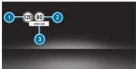
flowchart
graph TD
    A["1"] --> B["120"]
    B --> C["80"]
    C --> D["Software unit"]
    D --> E["3"]
① Permissible speed
2 Permissible speed when there is a restriction
③ Additional sign with restriction
If Speed Limit Assist cannot determine the current maximum permissible speed (e.g. due to missing signs), the following display appears in the Instrument Display:

This is displayed continuously if the vehicle is in a country where Speed Limit Assist is not supported. Speed Limit Assist is not available in all countries.
System limits
The system may be impaired or may not functi in the following situations:
- If there is poor visibility, e.g. due to insufficient illumination of the road, if there are highly variable shade conditions or in rain, snow, fog or heavy spray.
- If there is glare, e.g. from oncoming traffic, direct sunlight or reflections.
- If the windscreen in the area of the multifunction camera is dirty, or if the camera is misted up, damaged or covered.
- If the traffic signs are hard to detect, e.g. due to dirt, snow or insufficient lighting, or because they are covered.
- If you turn sharply when passing traffic signs outside the camera's field of vision.
Setting Speed Limit Assist
Multimedia system:
Settings ▶ Assistance
▶ Speed Limit Assist
Adjusting the type of warning
▶ Select Visual & audible, Visual or None.
'Adjusted the warning threshold
This value determines the speed at which a warning is issued when exceeded.
▶ Select Warning threshold.
Set the desired speed.
If one of the following systems is activated, the speed detected can be manually adopted as the speed limit:
• Active Distance Assist DISTRONIC
- Cruise control
- Variable limiter
Further information ( page 244).
Traffic Sign Assist
Function of Traffic Sign Assist
Traffic Sign Assist detects traffic signs with the multifunction camera ( page 229). It assists you by displaying detected speed limits and overtaking restrictions in the instrument cluster.
Observe the notes on driving systems and your responsibility; you may otherwise fail to recognise dangers ( page 229).
Since Traffic Sign Assist also uses the data stored in the navigation system, it can update the display in the following situations without detecting traffic signs.
If the system detects that you are driving onto a section of road in the wrong direction of travel, it triggers a warning.
The camera also detects traffic signs with a restriction indicated by an additional sign (e.g. when wet). These are only displayed if a restriction applies or if the system cannot clearly determine whether the restriction applies.
Warning when the maximum permissible speed is exceeded
The system can warn you if you unintentionally exceed the maximum permissible speed. To do this, you can specify in the multimedia system by how much the maximum permissible speed can be exceeded before a warning is issued. You can specify whether the warning is to be just a visual warning or an acoustic one as well.
Display in the Instrument Display
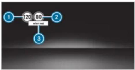
flowchart
graph TD
    A["1"] --> B["120"]
    B --> C["80"]
    C --> D["after user"]
    D --> E["3"]
Instrument Display in the widescreen cockpit
① Maximum permissible speed
② Maximum permissible speed when there is restriction
③ Additional sign with restriction
Vehicles with a standard Instrument Display: a + symbol next to a traffic sign in the Instrument Display indicates that additional traffic signs have been detected. These can also be displayed in the media display and optionally in the head-up display.
If Traffic Sign Assist cannot determine the maximum permissible speed (e.g. due to missing signs), the following display appears in the Instrument Display:

This is displayed continuously if the vehicle is in a country where Traffic Sign Assist is not supported. Traffic Sign Assist is not available in all countries.
Also observe the information on display messages in Traffic Sign Assist ( page 445).
Warning when approaching pedestrian crossings (vehicles with Driving Assistance Package)
The system can warn you if you approach a pedestrian crossing with your vehicle. The Watch for pedestrians message appears in the instrument cluster.
The warning occurs only if appropriate traffic signs or lane markings are detected and pedestrians are present in the danger zone.
System limits
The system may be impaired or may not functi particularly in the following situations:
- If there is poor visibility, e.g. due to insufficient illumination of the road, if there are highly variable shade conditions or in rain, snow, fog or heavy spray.
- If there is glare, e.g. from oncoming traffic, direct sunlight or reflections.
- If the windscreen in the area of the multifunction camera is dirty, or if the camera misted up, damaged or covered.
- If the traffic signs are hard to detect, e.g. due to dirt, snow or insufficient lighting, or because they are covered.
- If the information in the navigation system's digital map is incorrect or out-of-date.
- If the signs are ambiguous, e.g. road signs in roadworks or in adjacent lanes.
- If you turn sharply when passing traffic signs outside the camera's field of vision.
Setting Traffic Sign Assist
on Requirements:
- Only vehicles with Driving Assistance Package:
Active Distance Assist DISTRONIC and ECO Assist must be activated for the automatic adoption of speed limits.
Multimedia system:

Activating or deactivating automatic adoption of speed limits (only vehicles with Driving Assistance Package)
Select Adopt limit.
Switch the function on or off.
The speed limits detected by Traffic Sign Assist are automatically adopted by Active Distance Assist DISTRONIC.
If one of the following systems is activated, the detected speed can be manually adopted as the speed limit:
• Active Distance Assist DISTRONIC
- Cruise control
- Variable limiter
Further information about Active Distance Assist DISTRONIC: ( page 244).
Displaying detected traffic signs in the media display
▶ Select Display in head unit.
▶ Switch the function on or off.
Setting the type of warning
▶ Select Visual & audible, Visual or Off.
Setting the warning threshold
This value determines the speed at which a warning is issued when exceeded.
▶ Select Warning threshold.
▶ Set the desired speed.
Blind Spot Assist and Active Blind Spot Assist with exit warning
Function of Blind Spot Assist and Active Blind Spot Assist with exit warning
Blind Spot Assist and Active Blind Spot Assist use two lateral, rear-facing radar sensors to monitor the area up to 40 m behind and 3 m next to your vehicle.
If a vehicle is detected at speeds above approximately 12 km/h and this vehicle subsequently enters the monitoring range directly next to your vehicle, the warning lamp in the outside mirror lights up red.
Permanent status display in the instrument cluster:
• (grey): system is activated but inoperative
- (green): system is activated and tional
If a vehicle is detected close to your vehicle and you switch on the turn signal indicator in the corresponding direction, a double warning tone sounds and the red warning lamp in the outside mirror flashes. If the turn signal indicator remains switched on, all other detected vehicles are indicated only by the flashing of the red warning lamp.
If you overtake a vehicle quickly, no warning is given.
WARNING Risk of accident despite Blind Spot Assist
Blind Spot Assist does not react to vehicles approaching and overtaking you at a greatly different speed.
Blind Spot Assist cannot warn drivers in this situation.
▶ Always pay careful attention to the traffic situation and maintain a safe distance at the side of the vehicle.
opera- Observe the notes on driving systems and your responsibility; you may otherwise fail to recognise dangers ( page 229).
Exit warning
The exit warning is an additional function of Blind Spot Assist and can warn vehicle occu-
pants about approaching vehicles when leaving the vehicle when stationary.

WARNING Risk of accident despite exit warning
The exit warning neither reacts to stationary objects nor to persons or road users approaching you at a greatly differing speed.
The exit warning cannot warn drivers in these situations.
Always pay particular attention to the traffic situation when opening the doors and make sure there is sufficient clearance.
If there is a vehicle in the monitoring range, this is indicated in the outside mirror. If a vehicle occupant opens the door on the side with the warning, a warning tone sounds and the warning lamp in the outside mirror starts to flash.
This additional function is only available when Blind Spot Assist is active. When the exit warning is activated, it can warn vehicle occupants for up to three minutes after switching the igni-
tion off. The exit warning is no longer available once the warning lamp in the outside mirror flashes three times.
The exit warning is only an aid and not a substitute for the attention of vehicle occupants. The responsibility for opening and closing the doors and for leaving the vehicle remains with the vehicle occupants.
System limits
Blind Spot Assist and Active Blind Spot Assist may be limited in the following situations, in particular:
- if there is dirt on the sensors or the sensors are obscured
- in poor visibility, e.g. due to fog, heavy rain or snow
- if there are narrow vehicles, e.g. bicycles or motorbikes
• if the road has very wide or narrow lanes - if vehicles are not driving in the middle of their lane
Warnings may be issued in error when driving close to crash barriers or similar continuous lane borders. Always make sure that there is sufficient distance to the side for other traffic or obstacles.
Warnings may be interrupted when driving alongside long vehicles, for example lorries, for a prolonged time.
Blind Spot Assist is not operational when reverse gear is engaged.
Blind Spot Assist and the exit warning are not operational when a trailer is coupled to the vehicle and the electrical connection has been correctly established.
The exit warning may be limited in the following situations:
- when the sensors are covered by adjacent vehicles in narrow parking spaces
- when people approach the vehicle
- in the event of stationary or slowly moving objects
Function of brake application (Active Blind Spot Assist)
If Active Blind Spot Assist detects a risk of a side impact in the monitoring range, a course-correcting brake application is carried out. This is designed to help you avoid a collision.
The course-correcting brake application is available in the speed range between approximately 30 km/h and 200 km/h.
A WARNING Risk of accident despite brake application of Active Blind Spot Assist
A course-correcting brake application cannot always prevent a collision.
Always steer, brake or accelerate yourself, especially if Active Blind Spot Assist warns you or makes a course-correcting brake application.
Always maintain a safe distance at the sides.
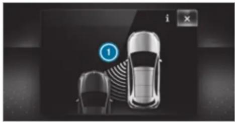
natural_image
Top-down view of two cars with a circular icon labeled '1' and a play button (no text or symbols on the cars themselves)If a course-correcting brake application occurs, the red warning lamp flashes in the outside mirror and a warning tone sounds. In addition, a display ① indicating the danger of a side collision appears in the multifunction display. In rare cases, the system may make an inappropriate brake application. This brake application may be interrupted at any time if you steer slightly in the opposite direction or accelerate.
System limits
Note the system limitations of Active Blind Spot Assist; you may otherwise not recognise the dangers ( page 262).
Either a course-correcting brake application appropriate to the driving situation, or none at all, may occur in the following situations:
- Vehicles or obstacles, e.g. crash barriers, are located on both sides of your vehicle.
• A vehicle approaches too closely on the side. - You have adopted a sporty driving style with high cornering speeds.
- You brake or accelerate significantly.
- A driving safety system intervenes, e.g. ESP ^ or Active Brake Assist.
- ESP® is deactivated.
- A loss of tyre pressure or a defective tyre detected.
- You are driving with a trailer and the electrical connection to the trailer hitch has been correctly established.
Activating/deactivating Blind Spot Assist or Active Blind Spot Assist
Multimedia system:


Settings

Assistance

Activate or deactivate Blind Spot Assist.
or
▶ Activate or deactivate Act. Blind Spot Assist.
Active Lane Keeping Assist
Function of Active Lane Keeping Assist
Active Lane Keeping Assist monitors the area in front of your vehicle by means of the multifunction camera ( page 229). It serves to protect you against unintentionally leaving your lane. You will be warned by vibration pulses in the steering wheel and guided by a course-correcting brake application back into your lane.
Active Lane Keeping Assist is available in the speed range between 60 km/h and 200 km/h.
Active Lane Keeping Assist can neither reduce the risk of an accident if you fail to adapt your driving style nor override the laws of physics. It cannot take into account road, weather or traffic conditions. Active Lane Keeping Assist is only an aid. You are responsible for maintaining a safe distance to the vehicle in front, for vehicle speed, for braking in good time and for staying in lane.
The status of Active Lane Keeping Assist is displayed in the on-board computer:
- // (green): Active Lane Keeping Assist is active and operating.
- // (grey): Active Lane Keeping Assist is active but not operating.
• ☐: Active Lane Keeping Assist is deactivated or there is a malfunction.
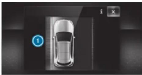
natural_image
Top-down view of a car with a numbered indicator (1) and control buttons, no visible text or symbols on the car itself.If a lane-correcting brake application occurs, display ① appears in the multifunction display.
The system does not apply the brake if you activate the turn signal indicator.
Vehicles with Driving Assistance Package: if the system detects an obstacle, such as another vehicle in the adjacent lane, it will apply the brake regardless of the turn signal indicator.
You are warned by vibrations in the steering wheel in the following circumstances:
Active Lane Keeping Assist detects a lane marking.
- A front wheel drives over this lane marking.
Conditions for a course-correcting brake application (vehicles without Driving Assistance Package)
Depending on the setting, a course-correcting brake application occurs in the following situations ( page 267).
The availability of this setting is dependent on the country. If the function is activated in countries in which this setting is not available, a lane-correcting brake application is initiated in the following situations:
Lane markings were detected on both sides of the lane. The front wheel drives over a continuous lane marking.
Standard setting
- Lane markings were detected on both sides of the lane. The front wheel drives over a continuous lane marking.
- A lane marking and the edge of a firm road surface were detected. The front wheel drives over a lane marking on the edge of firm road surface.
- A lane marking and an oncoming vehicle were detected. The front wheel drives over the lane marking.
Sensitive setting
- All situations described under the Standard setting.
- A continuous lane marking was detected and driven over with the front wheel.
i A brake application may be interrupted at any time if you steer slightly in the opposite direction.
Conditions for a course-correcting brake application (vehicles with Driving Assistance Package)
Depending on the setting, a course-correcting brake application occurs in the following situations ( page 267).
The availability of this setting is dependent on the country. If the function is activated in countries in which this setting is not available, a lane-correcting brake application is initiated in all situations described under Sensitive.
Standard setting
- A lane marking and an approaching vehicle, an overtaking vehicle or vehicles driving parallel to your vehicle were detected in the adjacent lane. The front wheel drives over the lane marking.
Sensitive setting
- The situations described under the Standard setting.
- A continuous lane marking was detected and driven over with the front wheel.
A brake application may be interrupted at any time if you steer slightly in the opposite direction.
System limits
No lane-correcting brake application occurs in the following situations:
- You clearly and actively steer, brake or accelerate.
- If a driving safety system intervenes, such as ESP ^ , Active Brake Assist or Active Blind Spot Assist.
- You have adopted a sporty driving style with high cornering speeds or high rates of acceleration.
- When ESP ^ is deactivated.
- When driving with a trailer, the electrical connection to the trailer has been correctly established.
- If a loss of tyre pressure or a defective tyre detected and displayed.
If you deactivate the Active Lane Keeping Assist warning and the lane markings cannot be clearly
detected, it is possible that no lane-correcting brake application takes place ( page 267).
The system may be impaired or may not function particularly in the following situations:
- If there is poor visibility, e.g. due to insufficient illumination of the road, if there are highly variable shade conditions or in rain, snow, fog or heavy spray.
- If there is glare, e.g. from oncoming traffic, the sun or reflections.
- If the windscreen in the area of the multifunction camera is dirty, or if the camera is misted up, damaged or covered.
- If there are no lane markings, or several unclear lane markings are present for one lane, e.g. around roadworks.
- If the lane markings are worn, dark or covered.
-
If the distance to the vehicle in front is too short and thus the lane markings cannot be detected.
-
If the lane markings change quickly, e.g. lanes branch off, cross one another or merge.
- If the carriageway is very narrow and winding.
- Vehicles with Driving Assistance Package: if the radar sensors in the rear bumper are dirty or covered in snow and an obstacle is detected in your lane, no lane-correcting brake application takes place.
Activating/deactivating Active Lane Keeping Assist
Multimedia system:

▶ Activate or deactivate the function.
Setting Active Lane Keeping Assist
Multimedia system:

Setting the sensitivity
i The availability of this function is dependent on the country.
▶ Select Standard, Sensitive or Off.
Activating or deactivating the haptic warning
Select Warning. Activate or deactivate the function.
AIRMATIC
Function of AIRMATIC
text_image
! NOTE Mercedes-AMG vehicles Observe the notes in the Supplement. You could otherwise fail to recognise dangers.AIRMATIC is an air suspension system with an all-round level control system, which also
ensures the best possible suspension and constant ground clearance, even with a laden vehicle. When driving at speed, the vehicle is lowered automatically to improve driving safety and to reduce fuel consumption. You also have the option of manually adjusting the vehicle level.
AIRMATIC is comprised of the following functions and components:
• All-round air suspension
• Speed-dependent lowering
- Manually selectable high level setting for greater ground clearance which can be adjusted using a level button
- Vehicles with ADS PLUS: also Adaptive Damping System with constant adjustment of damping characteristics for improved driving comfort
Suspension setting and vehicle level per drive program
Drive program C and E:
-
The suspension setting is comfortable.
• The vehicle is set to the normal level. -
When driving at speeds above approximately 140 km/h, the vehicle is lowered.
- When driving at speeds below approximately 40 km/h, the vehicle is raised again.
Drive program (Mercedes-Maybach vehicles only):
• The suspension setting is very comfortable.
• The vehicle is set to the normal level.
- When driving at speeds above approximately 140 km/h, the vehicle is lowered.
- When driving at speeds below approximately 40 km/h, the vehicle is raised again.
Drive program S:
- The suspension setting is firmer.
• The vehicle is lowered to sport level.
Drive program S*:
• The suspension setting is even firmer.
• The vehicle is lowered to Sport + level.
Drive program (vehicles without Off-road package):
- The suspension setting is suitable for easily negotiable off-road terrain.
The vehicle is set to off-road level +1. - When driving at speeds above approximately 80 km/h, the vehicle is lowered.
- When driving at speeds below approximately 45 km/h, the vehicle is raised.
Drive program (vehicles with Off-road package):
- The suspension setting is suitable for easily negotiable off-road terrain.
• The vehicle is set to off-road level +1. - When driving at speeds above approximately 115 km/h, the vehicle is lowered.
- When driving at speeds below approximately 75 km/h, the vehicle is raised.
Drive program (vehicles with Off-road package):
- The suspension setting is suitable for difficult off-road terrain.
The vehicle is set to off-road level +1.
- When driving at speeds above approximately 80 km/h, the vehicle is lowered.
- When driving at speeds below approximately 45 km/h, the vehicle is raised.
Individual suspension settings can be called up in drive program [1] (→ page 207).
Differences between different vehicle levels compared to the normal level
| Vehicle level | Vehicles without Off-road package | Vehicles with Off-road package |
| Car wash | Approx. +90 mm | Approx. +90 mm |
| Off-road level +3 | Unavailable Approx. | +90 mm |
| Off-road level +2 | Unavailable Approx. | +60 mm |
| Off-road level +1 | Mercedes-Maybach vehicles: approx.+50 mmAll other models: approx.+60 mm | Approx.+30 mm |
| Sport | A pprox.-15 mm | Approx.-15 mm |
| Sport + | A pprox.-25 mm | Approx.-25 mm |
If the entry/exit level function is activated, the vehicle is lowered to the Sport + level to facilitate entering/exiting the vehicle. When driving at speeds of approximately 30 km/h or above, the entry/exit level is deactivated and the vehicle is raised ( page 272).
Operation with a trailer or bicycle rack
If transport equipment, for example a trailer or bicycle rack, is attached to the trailer hitch and the electrical connection has been correctly established:
- In drive program and, the vehicle adopts the normal level starting from a speed of 30 km/h.
- In all other drive programs, the vehicle remains at normal level irrespective of speed.
System limits
AIRMATIC may not be available or have only limited availability in the following cases:
- The overheating protection has been activated due to frequent level changes within a short time. The warning lamp appears in the multifunction display.
After the cooling phase, the system is again available without restriction.
Setting the vehicle level (vehicles with AIR-MATIC)
⚠ WARNING Risk of accident because vehicle level is too high
Driving characteristics may be impaired. The vehicle can drift outwards, for example, when steering or cornering.
Choose a vehicle level which is suited to the driving style and the road surface conditions.
⚠ WARNING Risk of entrapment from vehicle lowering
When lowering the vehicle, other people could become trapped if their limbs are between the vehicle body and the tyres or underneath the vehicle.
Make sure no one is underneath the vehicle or in the immediate vicinity of the wheel arches when the vehicle is being lowered.

WARNING Risk of becoming trapped due to the vehicle lowering
Vehicles with AIRMATIC or level control: when you unload luggage or leave the vehicle, the vehicle first rises slightly and then returns to the set level shortly afterwards.
You or anyone else in the vicinity of the wheel arches or the underbody could thus become trapped.
The vehicle can also be lowered after being locked.
When leaving the vehicle, make sure that nobody is in the vicinity of the wheel arches or the underbody.

NOTE Damage due to vehicle lowering
Parts of the body could be damaged when the vehicle is lowered.
Make sure that there are no obstacles such as kerbs underneath or in the immediate vicinity of the body when the vehicle is being lowered.

NOTE Mercedes-AMG vehicles
Observe the notes in the Supplement. You could otherwise fail to recognise dangers.
Requirements:
• The vehicle has been started.
- Vehicles without Off-road package: the vehicle is not moving faster than 65 km/h.
• Vehicles with Off-road package:
- Off-road level +1: the vehicle is not moving faster than 100 km/h.
- Off-road level +2: the vehicle is not moving faster than 65 km/h.
- Off-road level +3: the vehicle is not moving faster than 20 km/h and the rear fog lamp is not switched on.
Raising the vehicle (vehicles without Off-road package)
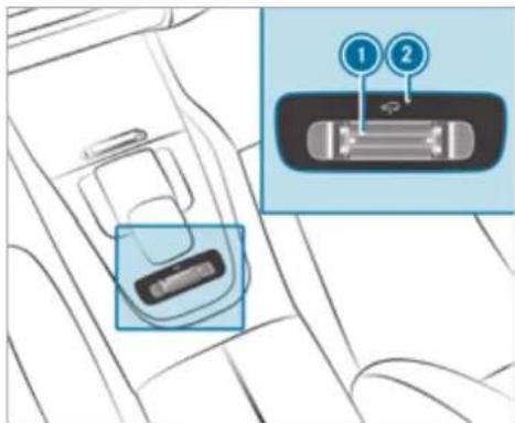
text_image
Diagram showing car seatbelt switch with labeled buttons 1 and 2, highlighting the interior space.
Push rocker switch ① forwards.
Indicator lamp ② flashes while the vehicle is being raised and lights up continuously when it has finished rising.
Your selection is saved. The off-road level set remains stored even after the ignition has been switched off.
The vehicle is lowered again in the following situations:
- When driving faster than 80 km/h.
- When driving briefly between 65 km/h and 80 km/h.
• After selecting a different drive program using the DYNAMIC SELECT switch.
The vehicle is adjusted to the height of the active drive program.
Lowering the vehicle (vehicles without Off-road package)
Pull rocker switch ①. The vehicle is adjusted to the height of the active drive program.
Operation with a trailer or bicycle rack
If the electrical connection has been correctly established to the trailer or bicycle rack:
- From approx. 30 km/h: off-road level +1 can be selected, regardless of drive program.
- From approx. 30 km/h: the vehicle is adjusted to normal level, regardless of drive program.
Raising the vehicle (vehicles with Off-road package)
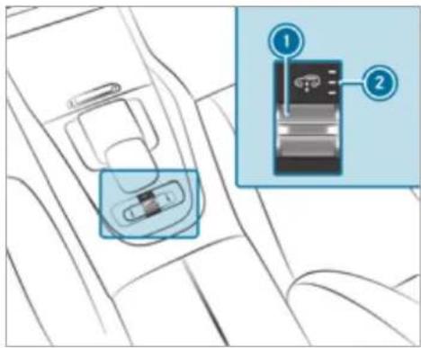
text_image
Diagram showing car seatbelt insertion mechanism with labeled parts 1 and 2▶ Push rocker switch ① forwards.
- Off-road level +1: one indicator lamp lights up continuously when the vehicle has finished rising.
- Off-road level +2: two indicator lamps light up continuously when the vehicle has finished rising.
- Off-road level +3: three indicator lamps ② light up continuously when the vehicle has finished rising.
Your selection is saved. The off-road level set remains stored even after the ignition has been switched off.
The vehicle is lowered again in the following situations:
- Off-road level +3: when driving faster than 20 km/h or when the rear fog lamp is switched on.
The vehicle is lowered to off-road level +2.
- Off-road level +2:
- When driving faster than 80 km/h.
- When driving briefly between 65 km/h and 80 km/h.
The vehicle is lowered to off-road level +1.
- Off-road level +1:
- When driving faster than 115 km/h.
- When driving briefly between 100 km/h and 115 km/h.
The vehicle is lowered to the normal level.
- After selecting a different drive program using the DYNAMIC SELECT switch. The vehicle is adjusted to the height of the active drive program.
Lowering the vehicle (vehicles with Off-road package)
▶ Pull rocker switch ①.
- Off-road level +3: the vehicle is lowered to off-road level +2. Two indicator lamps ② light up continuously when the vehicle has finished lowering.
- Off-road level +2: the vehicle is lowered to off-road level +1. One indicator lamp
② lights up continuously when the vehicle has finished lowering.
- Off-road level +1: the vehicle is lowered to the normal level. No indicator lamp lights up when the vehicle has finished lowering.
Your selection is saved. The off-road level set remains stored even after the ignition has been switched off.
Operation with a trailer or bicycle rack
If the electrical connection has been correctly established to the trailer or bicycle rack:
- Up to approx. 20 km/h: off-road levels +1, +2 and +3 can be selected, regardless of the drive program.
- Up to approx. 30 km/h: off-road levels +1 and +2 can be selected, regardless of the drive program.
- From approx. 30 km/h: the vehicle is adjusted to normal level, regardless of the drive program.
Setting the entering and exiting level (AIRMATIC)
Requirements:
• The engine is running.
- The vehicle is moving at speeds below 30 km/h.
Multimedia system:
Settings
▶ Schnellzugriff (Quick access)
▶ Select Lower when entering On.
The vehicle is lowered to low level -2 to facilitate entering and exiting.
The availability of this function depends on the vehicle equipment.
i Further information on AIRMATIC ( page 267).
Lowering and raising the rear of the vehicle

WARNING Risk of entrapment from vehicle lowering
When lowering the vehicle, other people could become trapped if their limbs are between the vehicle body and the tyres or underneath the vehicle.
Make sure no one is underneath the vehicle or in the immediate vicinity of the wheel arches when the vehicle is being lowered.
Requirements:
- all vehicle doors are closed
• there is no trailer coupled
• there is no bicycle rack fitted - the battery is sufficiently charged (if necessary, start the engine)
Lowering the rear of the vehicle
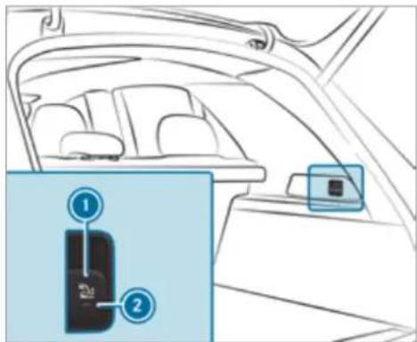
text_image
Diagram of car interior showing seatbelt and door panel with numbered labelsApply the electric parking brake.
Shift the transmission to position P (→ page 210).
Pull switch ① in the load compartment trim briefly.
Indicator lamp ② flashes until the vehicle has been lowered.
The vehicle is lowered at the rear axle by approx. 40 mm. When the vehicle has been lowered, indicator lamp ② remains lit.
Lowering is interrupted in the following situations:
• a vehicle door is opened.
- switch ① is pulled again.
- the vehicle is being driven faster than 2 km/h.
The vehicle is automatically set to the level of the selected drive program if you drive at speeds greater than 2 km/h.
If indicator lamp ② flashes twice and the rear of the vehicle does not lower:
Make sure that the requirements are met.
i Lowering the rear of the vehicle allows the vehicle to be loaded more easily. Observe the notes on loading the vehicle when doing this ( page 134).
Raising the rear of the vehicle
Check if the battery is sufficiently charged. If necessary, start the engine.
Pull switch ① briefly. Indicator lamp ② goes out. The vehicle will be raised to the currently selected level.
The vehicle is automatically set to the level of the selected drive program if you drive at speeds greater than 2 km/h.
If the vehicle cannot be raised:
Ensure that the battery is sufficiently charged; if necessary, start the engine. The raising process continues.
E-ACTIVE BODY CONTROL
Function of E-ACTIVE BODY CONTROL
E-ACTIVE BODY CONTROL is an electrohydraulic suspension system with variable damping for improved driving comfort. The all-round level control system ensures the best possible suspension and constant ground clearance, even with a laden vehicle. When driving at speed, vehicle is lowered automatically to improve driving safety and to reduce fuel consumption. The suspension setting is adjusted depending on the road surface, vehicle load and the drive program selected.
The ROAD SURFACE SCAN function detects areas of unevenness in the road before you drive over them by means of a multifunction camera. This reduces chassis movements.
The damping is adjusted individually to each wheel and depends on the following factors:
- Driving style, e.g. sporty
• Road condition, e.g. bumps - Drive program
E-ACTIVE BODY CONTROL is comprised of the following functions and components:
• Vehicles with Driving Assistance Package: ROAD SURFACE SCAN
• Curve inclination function CURVE
- Recovery mode
• Individual wheel control
e. Air suspension with automatic level control
- Speed-dependent lowering to reduce fuel consumption
- Manual level adjustment
- ADS PLUS: Adaptive Damping System with constant adjustment of damping characteristics
• DYNAMIC SELECT switch and level button
Suspension setting and vehicle level per drive program
Drive program
• The suspension setting is firmer.
• The vehicle is set to Sport level.
• ROAD SURFACE SCAN is deactivated.
• The curve inclination function is deactivated.
Drive program S
• The suspension setting is even firmer.
• The vehicle is set to Sport + level.
• ROAD SURFACE SCAN is deactivated.
• The curve inclination function is active.
Drive program [C]
• The suspension setting is comfortable.
• The vehicle is set to the normal level.
- When driving at speeds above approximately 140 km/h, the vehicle is lowered.
- When driving at speeds below approximately 40 km/h, the vehicle is raised.
• ROAD SURFACE SCAN is active.
• The curve inclination function is deactivated.
Drive program
- The suspension setting is very comfortable.
• The vehicle is set to the normal level. - When driving at speeds above approximately 140 km/h, the vehicle is lowered.
- When driving at speeds below approximately 40 km/h, the vehicle is raised.
• ROAD SURFACE SCAN is active.
• The curve inclination function is active.
Drive program CV
- The suspension setting is comfortable.
• The vehicle is set to the normal level. -
When driving at speeds above approximately 140 km/h, the vehicle is lowered.
-
When driving at speeds below approximately 40 km/h, the vehicle is raised again.
• ROAD SURFACE SCAN is active.
• The curve inclination function is active.
Drive program E
- The suspension setting is comfortable.
• The vehicle is set to the normal level. - When driving at speeds above approximately 140 km/h, the vehicle is lowered.
- When driving at speeds below approximately 40 km/h, the vehicle is raised again.
• ROAD SURFACE SCAN is deactivated.
• The curve inclination function is deactivated.
Drive program
-
The suspension setting is suitable for easily negotiable off-road terrain.
• The vehicle is set to off-road level +1.
• ROAD SURFACE SCAN is deactivated.
• The curve inclination function is deactivated. -
When the necessary conditions are met, recovery mode and individual wheel control can be activated.
• Vehicles without Off-road package: - When driving at speeds above approximately 80 km/h the vehicle is lowered.
- When driving at speeds below approximately 45 km/h, the vehicle is raised.
• Vehicles with Off-road package: - When driving at speeds above approximately 115 km/h, the vehicle is lowered.
- When driving at speeds below approximately 75 km/h, the vehicle is raised.
Drive program
- The suspension setting is suitable for difficult off-road terrain.
• The vehicle is set to off-road level +1. - When driving at speeds above approximately 80 km/h, the vehicle is lowered.
- When driving at speeds below approximately 45 km/h, the vehicle is raised.
• ROAD SURFACE SCAN is deactivated.
• The curve inclination function is deactivated
- Recovery mode or individual wheel control can be activated.
Drive program
- You can call up individual suspension settings here.
Operation with a trailer or bicycle rack
If the electrical connection has been correctly established to the trailer or bicycle rack:
- Drive program C, E, C, CV, I*, S and S*: the vehicle remains at normal level irrespective of speed.
• The curve inclination function is deactivated. - Drive program 📄 and 🌐: the vehicle adopts the normal level starting from a speed of 30 km/h.
Level differences compared to the normal level
| Vehicle level | Vehicles without Off-road package | Vehicles with Off-road package |
| Car wash | Approx. +90 mm | Approx. +90 mm |
| Off-road level +3 | Unavailable Approx. +90 mm | |
| Off-road level +2 | Unavailable Approx. +60 mm | |
| Off-road level +1 | Mercedes-Maybach vehicles: approx. +50 mmAll other models: approx. +60 mm | Approx. +30 mm |
| Vehicle level | Vehicles without Off-road package | Vehicles with Off-road package |
| Sport | A pprox. -15 mm | Approx. -15 mm |
| Sport + | A pprox. -25 mm | Approx. -25 mm |
Function of ROAD SURFACE SCAN
This function is not available in all countries. The ROAD SURFACE SCAN function monitors the road in front of your vehicle using a multifunction camera ( page 229). ROAD SURFACE SCAN detects unevenness in the road surface, e.g. bumps, before the vehicle drives over them. Chassis movements are reduced and driving comfort is increased.
ROAD SURFACE SCAN is automatically activated if the following conditions are met:
- Drive program C or CV is selected.
• The vehicle is set to the normal level.
- You are driving at a speed between 7 km/h. Observe the notes on cleaning the multifunction and 180 km/h. camera (→ page 379).
System limits
ROAD SURFACE SCAN can be impaired in the following situations or can stop functioning:
- If the carriageway is insufficiently lit, e.g. at night.
- In snow, rain, fog, heavy spray, if there is glare, in direct sunlight or in greatly varying light conditions.
- If the windscreen in the area of multifunction camera is dirty, misted up, damaged or covered.
- If the road surface has no optic structure or reflects light.
- If you are driving too close to the vehicle in front.
- If sections of the route have a very small radius of curvature.
- During abrupt driving manoeuvres, e.g. heavy braking or sudden acceleration.
Observe the notes on cleaning the multifunction camera ( page 379).
Function of recovery mode
⚠ WARNING Risk of injury due to the vehicle moving up and down
During recovery mode, the vehicle moves up and down and can cause injuries.
When activating recovery mode, make certain that no one is in the vicinity of the vehicle.
NOTE Risk of damage due to the vehicle moving up and down
When free driving mode is activated, the vehicle moves up and down. Vehicle parts may be damaged if the underbody bottoms out.
▶ Make sure that there is sufficient ground clearance when rocking free mode is activated.
Recovery mode is a function of the suspension which can assist the driver on loose surfaces (e.g. sand, snow) when freeing a vehicle which has become stuck.
The vehicle body rocks in slow, vertical motions when recovery mode has been activated. This temporarily puts the wheels under greater load, which means they have increased traction and the vehicle is freed.
You can activate free driving mode via Off-road Assist ( page 281).
Function of individual wheel control
⚠ WARNING Risk of becoming trapped due to the vehicle lowering
The vehicle can be lowered when the individual wheel control function has been activated. Body parts could become trapped if they are between the vehicle body and the tyres or underneath the vehicle.
Make sure that nobody is under the vehicle or in the immediate vicinity of
the wheel arches when individual wheel control is activated.

NOTE Risk of damage due to the vehicle moving up and down
The vehicle can be lowered or raised on one or more wheels when the individual wheel control function has been activated. Vehicle parts could be damaged due to contact with objects.
Make sure that the vehicle has sufficient room to move when the individual wheel control function has been activated.
Individual wheel control is a function of the suspension, which can be used to set the vehicle level for each wheel individually. This can help to improve alignment of the body when driving off-road.
You can activate individual wheel control via Off-road Assist ( page 281).
Adjusting the vehicle level (vehicles with E-ACTIVE BODY CONTROL)

WARNING Risk of accident because vehicle level is too high
Driving characteristics may be impaired. The vehicle can drift outwards, for example, when steering or cornering.
▶ Choose a vehicle level which is suited to the driving style and the road surface conditions.

WARNING Risk of entrapment from vehicle lowering
When lowering the vehicle, other people could become trapped if their limbs are between the vehicle body and the tyres or underneath the vehicle.
Make sure no one is underneath the vehicle or in the immediate vicinity of the wheel arches when the vehicle is being lowered.

WARNING Risk of becoming trapped due to the vehicle lowering
Vehicles with AIRMATIC or level control: when you unload luggage or leave the vehicle, the vehicle first rises slightly and then returns to the set level shortly afterwards.
You or anyone else in the vicinity of the wheel arches or the underbody could thus become trapped.
The vehicle can also be lowered after being locked.
When leaving the vehicle, make sure that nobody is in the vicinity of the wheel arches or the underbody.
Requirements:
• The vehicle has been started.
- Vehicles without Off-road package: the vehicle is being driven no faster than 65 km/h.
• Vehicles with Off-road package:
- Off-road level +1: the vehicle is not moving faster than 100 km/h.
- Off-road level +2: the vehicle is not moving faster than 65 km/h.
- Off-road level +3: the vehicle is not moving faster than 20 km/h.
Raising the vehicle (vehicles without Off-road package)
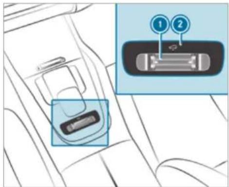
text_image
Diagram showing car seatbelt insertion with labeled buttons 1 and 2, highlighting the component.Push rocker switch ① forwards. Indicator lamp ② flashes while the vehicle is being raised and lights up continuously when it has finished rising.
Your selection is saved. The off-road level set remains stored even after the ignition has been switched off.
The vehicle is lowered again in the following situations:
- When driving faster than 80 km/h.
- When driving briefly between 65 km/h and 80 km/h.
• After selecting a different drive program using the DYNAMIC SELECT switch.
The vehicle is adjusted to the height of the active drive program.
Lowering the vehicle (vehicles without Off-road package)
Pull rocker switch ①. The vehicle is adjusted to the height of the active drive program.
Operation with a trailer or bicycle rack
If the electrical connection has been correctly established to the trailer or bicycle rack:
• From approx. 30 km/h: off-road level +1 can be selected, regardless of drive program.
- From approx. 30 km/h: the vehicle is adjusted to normal level, regardless of drive program.
Raising the vehicle (vehicles with Off-road package)
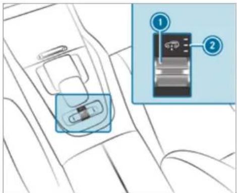
text_image
Diagram showing car seatbelt insertion into a vehicle compartment with labeled parts 1 and 2
Push rocker switch ① forwards.
- Off-road level +1: one indicator lamp lights up continuously when the vehicle has finished rising.
- Off-road level +2: two indicator lamps light up continuously when the vehicle has finished rising.


- Off-road level +3: three indicator lamps ② light up continuously when the vehicle has finished rising.
Your selection is saved. The off-road level set remains stored even after the ignition has been switched off.
The vehicle is lowered again in the following situations:
- Off-road level +3: when driving faster than 20 km/h.
The vehicle is lowered to off-road level +2. - Off-road level +2:
- When driving faster than 80 km/h.
- When driving briefly between 65 km/h and 80 km/h.
- When driving faster than 80 km/h.
- When driving briefly between 65 km/h and 80 km/h.
The vehicle is lowered to off-road level +1.
Off-road level +1:
- When driving faster than 115 km/h.
- When driving briefly between 100 km/h and 115 km/h.
The vehicle is lowered to the normal level.
- After selecting a different drive program using the DYNAMIC SELECT switch. The vehicle is adjusted to the height of the active drive program.
Operation with a trailer or bicycle rack
If the electrical connection has been correctly established to the trailer or bicycle rack:
- Up to approx. 20 km/h: off-road levels +1, +2 and +3 can be selected, regardless of drive program.
- Up to approx. 30 km/h: off-road levels +1, +2 and +3 can be selected, regardless of drive program.
- From approx. 30 km/h: the vehicle is adjusted to normal level, regardless of drive program.
Lowering the vehicle (vehicles with Off-road package)

Pull rocker switch ①.
-
Off-road level +3: the vehicle is lowered to off-road level +2. Two indicator lamps ② light up continuously when the vehicle has finished lowering.
-
Off-road level +2: the vehicle is lowered to off-road level +1. One indicator lamp lights up continuously when the vehicle has finished lowering.
- Off-road level +1: the vehicle is lowered to the normal level. No indicator lamp lights up when the vehicle has finished lowering.
Your selection is saved. The off-road level set remains stored even after the ignition has been switched off.
Setting Off-road Assist
Requirements:
• the vehicle is stationary.
• the vehicle is set to off-road level 1 or 2
- the Off-road or Off-road Plus (only vehicles with Off-road package) drive program has been selected
• the ignition is switched on
- all doors and the bonnet are closed
- the transmission is not engaged in position
P
• there is no trailer coupled
• the vehicle is outdoors
- the detected lateral inclination of the vehicle must not exceed approx. 15°
- the system is within its operating temperature
• the on-board voltage is sufficiently high
Multimedia system:
→ Settings → Assistance Offroad Assist
Recovery mode
Recovery mode assists the driver when pulling away on rough terrain, such as sand or snow.
▶ Select Free driving mode.
Select Start.
Recovery mode is activated.
▶ Select Stop to stop recovery mode.
Recovery mode is automatically deactivated in the following situations:
- you are actually travelling faster than 15 km/h
• after a running time of 30 seconds
- it is detected that an object has hit the underbody of the vehicle hard
• not all conditions are met
(i) Further information on recovery mode ( page 277).
Individual wheel control
Individual wheel control enables the vehicle level to be set separately for each wheel.
▶ Select Individual wheel control.
Set the vehicle level for the desired wheel.
You can also use the touchscreen to set the level for two or more wheels at the same time.
Select Reset to set all wheels to the default setting.
Individual wheel control is automatically deactivated in the following situations:
• you are travelling faster than 15 km/h
- it is detected that an object has hit the underbody of the vehicle hard
• not all conditions are met
(i) Further information on individual wheel control ( page 277).
Reversing camera
Function of the reversing camera
If you have activated the function in the multimedia system ( page 288), the image from the reversing camera is shown in the media display when the reverse gear is engaged. Dynamic guide lines show the path the vehicle will take with the current steering angle. This helps you to orient yourself and to avoid obstacles when reversing.
The reversing camera is only an aid. It is not a substitute for your attention to the surroundings. The responsibility for safe manoeuvring and parking remains with you. Make sure that there are no persons, animals or objects etc., in the manoeuvring area while manoeuvring and parking.
① You can open the cover of the reversing camera manually ( page 288).
The guide lines in the media display show the distances to your vehicle. The distances displayed only apply to road level.
Depending on the vehicle equipment, you can select from the following views:
- Normal view
- Wide-angle view
- Trailer view
The area behind the vehicle is displayed as a mirror image, as in the inside rearview mirror.
Vehicles without Parking Assist PARKTRONIC
The following camera views are available in the multimedia system:
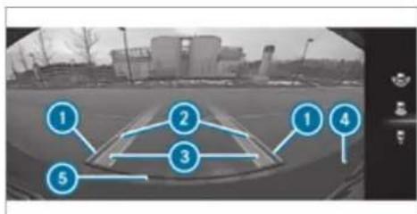
flowchart
graph TD
    1["1"] --> 2["2"]
    2 --> 3["3"]
    3 --> 4["4"]
    4 --> 5["5"]
Normal view
Yellow guide line, vehicle width (driven surface) depending on the current steering angle (dynamic)
② Yellow guide line at a distance of approximately 1.0 m from the rear area
3 Yellow lanes marking the course the tyres will take with the current steering angle (dynamic)
④ Bumper
5 Red guide line at a distance of approximately 0.3 m from the rear area
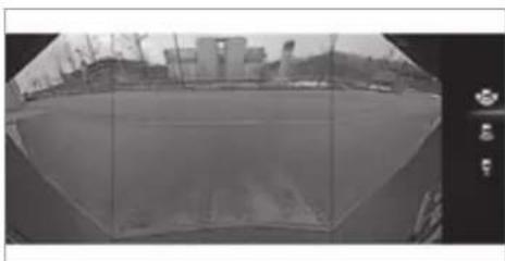
natural_image
Black-and-white fisheye view of a coastal industrial area with buildings and cranes, no visible text or symbolsWide-angle view
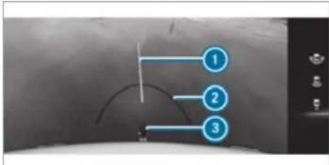
text_image
1 2 3Trailer view (vehicles with a trailer hitch) Yellow guide line, locating aid
② Red guide line at a distance of approximately 0.3 m from the ball head of the trailer
3 Ball head of the trailer hitch
Vehicles with Parking Assist PARKTRONIC
The following camera views are available in the multimedia system:
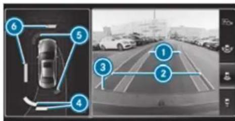
text_image
Diagram showing a car with numbered sensor points and navigation interface, likely for vehicle tracking or navigation.Normal view
Yellow lanes marking the course the tyres will take with the current steering angle (dynamic)
2 Yellow guide line, vehicle width (driven surface) depending on the current steering angle (dynamic)
3 Red guide line at a distance of approximately 0.3 m from the rear area
4 Yellow warning indicator of Parking Assist PARKTRONIC: obstacles at a distance between approximately 0.6 m and 1.0 m
5 Red warning display of Parking Assist PARKTRONIC: obstacles are very close (approximately 0.3 m or less)
6 Orange warning display of Parking Assist PARKTRONIC: obstacles are a medium distance away (between approximately 0.3 m and 0.6 m)
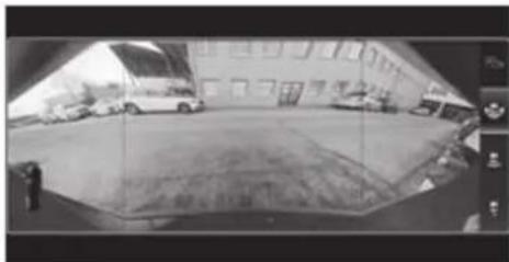
natural_image
Black-and-white photo of a vehicle parked in front of a building with visible signage (no readable text on vehicles or background)Wide-angle view
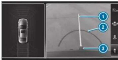
text_image
Diagram showing a car on the left and a curved path with numbered annotations pointing to key points.Trailer view (vehicles with a trailer hitch)
① Yellow guide line, locating aid
2 Red guide line at a distance of approximately 0.3 m from the ball head of the trailer hitch
3 Ball head of the trailer hitch
System failure
If the reversing camera is not operational, the following display appears in the multimedia system.

System limits
The reversing camera will not function or will only partially function in the following situations:
- The tailgate is open.
• There is heavy rain, snow or fog.
• The light conditions are poor, e.g. at night. - Cameras, or vehicle components in which the cameras are fitted, are damaged, dirty or covered. Observe the information on vehicle sensors and cameras ( page 229).
Do not use the reversing camera in these types of situations. You could otherwise injure others or collide with objects when parking the vehicle.
For technical reasons, the standard height of the vehicle may be altered if the vehicle is carrying a heavy load and can result in inaccuracies in guide lines and in the display of the generated images.
The contrast of the display may be impaired by direct sunlight or by other light sources, e.g. when driving out of a garage. In this case, pay particular attention.
i Have the display repaired or replaced if, for example, pixel errors considerably restrict its use.
360° Camera
Function of the 360° Camera
The 360° Camera is a system that consists of four cameras. The cameras cover the immediate vehicle surroundings. The system assists you when you are parking or at exits with reduced visibility, for example.
The views of the 360° Camera are always available when driving forwards up to a speed of approx. 16 km/h and when reversing.
The 360° Camera is only an aid and may show a distorted view of obstacles, show them incorrectly or not show them at all. It is not a substitute for your attention to the surroundings. The responsibility for safe manoeuvring and parking remains with you. Make sure that there are no persons, animals or objects etc., in the manoeuvring area while manoeuvring and parking.
The system evaluates images from the following cameras:
- Reversing camera
- Front camera
- Two side cameras in the outside mirrors
(i) You can open the cover of the reversing camera manually ( page 288).
Views of the 360° Camera
You can select from different views:
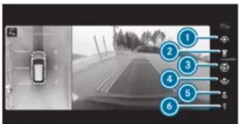
text_image
Camera navigation interface screenshot showing a car on a road with numbered annotations pointing to the lane.① Wide-angle view, front
2 Top view with image from the front camera
3 Top view with images from the side camera in the outside mirrors
④ Wide-angle view, rear
5 Top view with image from the reversing camera
6 Top view with trailer view (vehicles with a trailer hitch)
Top view
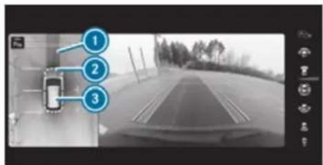
text_image
Screenshot of a car navigation interface with numbered annotations pointing to the vehicle's lane and driving area.Lane indicating the route the vehicle will take at the current steering wheel angle
2 Warning display of Parking Assist PARKTRONIC
3 Your vehicle from above
The colour of the individual segments of warning display ② is based on the distance to the detected obstacle:
- Yellow segments: obstacles at a distance between approx. 0.6 m and 1.0 m
• Orange segments: obstacles at a distance between approx. 0.3 m and 0.6 m - Red segments: obstacles at a very short distance of approx. 0.3 m or less
When Parking Assist PARKTRONIC is operational and no object is detected, the segments of the warning display are shown in grey.
Guide lines
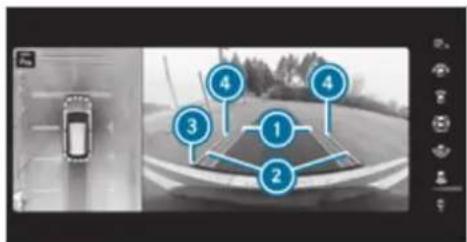
text_image
Diagram showing a car detection system with numbered components and a vehicle image, likely for navigation or tracking.Yellow lane marking the course the tyres will take at the current steering wheel angle (dynamic)
② Yellow guide line, vehicle width (driven surface) depending on the current steering wheel angle (dynamic)
3 Red guide line at a distance of approximately 0.3 m from the rear area
4 Mark at a distance of approx. 1.0 m
When Active Parking Assist is active, lane markings are displayed in green.
The guide lines in the media display show the distances to your vehicle. The distances apply to road level.
In trailer mode, the guide lines are shown at the level of the trailer hitch.
Trailer view (vehicles with a trailer hitch)
If you select trailer view and no trailer is coupled to the vehicle, the following display appears:

text_image
Diagram showing a car interior with three labeled points (1, 2, 3) pointing to a curved road or path.Yellow guide line, locating aid
2 Red guide line at a distance of approximately 0.3 m from the ball head of the trailer hitch
③ Ball head of the trailer hitch
natural_image
Top-down view of a car parked in front of a large refrigerator (no visible text or symbols)When the electrical connection is established between the vehicle and the trailer, the display changes to the side camera view. This view supports manoeuvring procedures with a trailer.
Side view of the mirror cameras
The sides of the vehicle can be seen in this view.
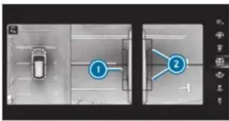
flowchart
graph TD
    A["Top Left: Car"] --> B["Step 1: Node 1"]
    B --> C["Step 2: Node 2"]
    C --> D["End"]
① Guide line of external vehicle dimensions with outside mirrors folded out
2 Marker of the wheel contact points
System failure
If the system is not ready for operation, the following message appears in the media display:

System limits
The 360° Camera will not function or will only partially function in the following situations:
• The doors are open.
• the outside mirrors are folded in.
• The tailgate is open.
• There is heavy rain, snow or fog.
• The light conditions are poor, e.g. at night.
- Cameras, or vehicle components in which the cameras are fitted, are damaged, dirty or covered. Observe the information on vehicle sensors and cameras ( page 229).
Do not use the 360° Camera under such circumstances. You could otherwise injure others or collide with objects when parking the vehicle.
For technical reasons, the standard height of the vehicle may be altered if the vehicle is carrying a heavy load and can result in inaccuracies in the guide lines and in the display of the generated images.
The contrast of the display may be impaired by abrupt, direct sunlight or by other light sources, e.g. when driving out of a garage. In this case, pay particular attention.
i Have the display repaired or replaced if, for example, pixel errors considerably restrict its use.
See the notes on cleaning the 360° Camera ( page 379).
Calling up the view of the 360° Camera using reverse gear
Requirements:
- The Auto reversing camera function is activated in the multimedia system (→ page 288).
Engage reverse gear.
Select the desired view in the multimedia system ( page 284).
If, after shifting to reverse gear, the image of the reversing camera is not shown: switch off the ignition, press and hold the button switch on the ignition and engage reverse gear again.
Switching reversing camera automatic mode on/off
The reversing camera is only an aid. It is not a substitute for your attention to the surroundings. The responsibility for safe manoeuvring and parking remains with you. Make sure that no persons, animals or objects etc. are in the manoeuvring range. Pay attention to your surroundings and be ready to brake at all times.
Multimedia system:

▶ Switch Auto reversing camera on or off.
Opening the camera cover of the reversing camera
Multimedia system:
Settings ▶ Assistance
▶ Camera & parking
▶ Select Open camera cover.
① The camera cover closes automatically after some time or after an ignition cycle.
Parking Assist PARKTRONIC
Function of Parking Assist PARKTRONIC
Parking Assist PARKTRONIC is an electronic parking assistance system with ultrasound. It monitors the area around your vehicle using multiple sensors on the front bumper and on the rear bumper. Parking Assist PARKTRONIC shows you the distance between your vehicle and a detected obstacle visually and audibly.
Parking Assist PARKTRONIC is only an aid. It is not a substitute for your attention to the surroundings. The responsibility for safe manoeuvring and parking remains with you. Make sure that there are no persons, animals or objects the manoeuvring area while manoeuvring and parking in/exiting parking spaces.
In the standard setting, an intermittent warning tone sounds from a distance of approximately 0.3 m to an obstacle in front and approximately 1.0 m to an obstacle behind. A continuous warning tone sounds from a distance of approximately 0.2 m. Using the Warn early all-round setting in the multimedia system, the warning tones for front and side impact protection can
be set to sound at a greater distance of approximately 1.0 m in front and 0.6 m on the sides ( page 293).
① The Warn early all-round setting is always active in the rear of the vehicle.
Parking Assist PARKTRONIC display in the multimedia system
text_image
Au 1 Bluetooth USB Mercedes Music SoundsVehicles without 360° Camera
text_image
Radio 12.5 MHzVehicles with 360° Camera
If you have not selected the Camera & parking menu and an obstacle is detected in the path the vehicle, a pop-up window for Parking Assist PARKTRONIC ① appears in the multimedia system at speeds below 10 km/h.
The colour of the individual segments of the warning display is based on the distance to the detected obstacle:
- Yellow segments: obstacles at a distance between approx. 0.6 m and 1.0 m
- Orange segments: obstacles at a distance between approx. 0.3 m and 0.6 m
- Red segments: obstacles at a very short distance of approx. 0.3 m or less
Display of Parking Assist PARKTRONIC in the head-up display
text_image
Diagram of a car interior with numbered labels pointing to the seating area and vehicle structure.Optionally, obstacles detected by Parking Assist PARKTRONIC from a distance of approximately 1.0 m in front ② and 0.6 m on the sides ③ can also be displayed in the head-up display.
System limits
Parking Assist PARKTRONIC does not necessarily take into account the following obstacles:
- Obstacles below the detection range, e.g. persons, animals or objects.
- Obstacles above the detection range, e.g. overhanging loads, overhangs or loading ramps of lorries.
The sensors must be free of dirt, ice and slust. Otherwise, they may not function correctly. Clean the sensors regularly, especially after driving off-road, taking care not to scratch or damage them ( page 229).
Vehicles with trailer hitch: Parking Assist PARKTRONIC is deactivated for the rear zone when you establish an electrical connection between your vehicle and a trailer.
Problems with Parking Assist PARKTRONIC
natural_image
Two identical 3D-rendered car illustrations shown in top and side views, no text or symbols present.Example: vehicles with 360^ Camera
When rear segments ① or all-round segments ② light up red and the P_0^off symbol appears in the multifunction display, Parking Assist PARKTRONIC may have been deactivated due to signal interference. Start the vehicle again and check if Parking Assist PARKTRONIC is working at a different location.
If a warning tone also sounds for approximately two seconds every time the vehicle is started, it may be due to one of the following causes:
- The sensors are dirty: clean the sensors and observe the notes on care of vehicle parts (→ page 379).
- Parking Assist PARKTRONIC has been deactivated due to a malfunction: restart the vehicle. If the problem persists, consult a qualified specialist workshop.
Function of the passive side impact protection
Passive side impact protection is an additional Parking Assist PARKTRONIC function which warns the driver about obstacles at the side of the vehicle. A warning is issued when obstacles are detected between the front and rear detection range. In order for an object on the side to be detected, the sensors in the front and rear bumper must first detect the object while you are driving past it.
During the parking procedure or manoeuvring, objects are detected as the vehicle drives past. If you steer in the direction of a detected obsta-
cle and there is a risk of a lateral collision, a warning is issued and the segments light up in colour in the display.
The segment colour changes depending on the distance to the detected obstacle:
• Yellow: approximately 30 - 60 cm
• Red: less than approximately 30 cm
In order for lateral front or rear segments to be displayed, the vehicle must first travel a distance of at least half of the vehicle length. Once the vehicle has travelled the length of the vehicle, all of the lateral front and rear segments can be displayed.
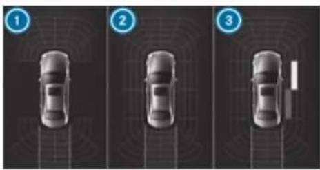
natural_image
Three identical car diagrams showing top-down views of a vehicle with sensor or navigation system (no text or symbols)Parking Assist PARKTRONIC display: vehicles without a 360° Camera
Operational front and rear
② Operational front, rear and sides
3 Obstacle detected at the front right (yellow) and rear (red)
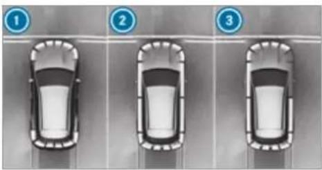
natural_image
Three identical car parking lot scenarios with numbered indicators (1, 2, 3) — no text or symbols on the cars themselves.Parking Assist PARKTRONIC display: vehicles with a 360° Camera
① Operational front and rear
2 Operational front, rear and sides
3 Obstacles detected at the front right (red)
Saved obstacles on the sides are deleted in the following situations, for example:
- You park the vehicle and switch off the ignition.
- You open the doors.
After the engine is restarted, obstacles on the sides must be detected again before a new warning can be issued.
System limits
The system limits for Parking Assist PARKTRONIC apply to passive side impact protection.
The following objects are not detected, for example:
- Pedestrians who approach the vehicle from the side
- Objects placed next to the vehicle
Activating/deactivating Parking Assist PARKTRONIC
NOTE Risk of an accident from objects at close range
Parking Assist PARKTRONIC may not detect certain objects at close range.
When parking or manoeuvring the vehicle, pay particular attention to any objects which are above or below the sensors, e.g. flowerpots or drawbars. The vehicle or other objects could otherwise be damaged.
Vehicles without AIR BODY CONTROL: press the P ^0 button in the centre console.
① Vehicles with AIR BODY CONTROL: you can activate or deactivate Parking Assist PARKTRONIC in the multimedia system (→ page 292).
If the indicator lamp in the P_ij^PT button is n Parking Assist PARKTRONIC is active. If the indicator lamp is lit or the P_ij^PT symbol appears the instrument cluster, Parking Assist PARKTRONIC is not active.
Parking Assist PARKTRONIC is automatically activated when the vehicle is started.
Activating/deactivating Parking Assist PARKTRONIC using the multimedia system
! NOTE Risk of an accident from objects at close range
Parking Assist PARKTRONIC may not detect certain objects at close range.
When parking or manoeuvring the vehicle, pay particular attention to any objects which are above or below the
sensors, e.g. flowerpots or drawbars. The vehicle or other objects could otherwise be damaged.
Requirements:
• The camera menu is open.
t• litOr: Active Parking Assist is active.
• Or: the PARKTRONIC pop-up window in appears.
Tap P in the media display.
If the indicator lamp is lit, Parking Assist PARKTRONIC is active. If the indicator lamp is not lit or the P_y^Off symbol appears in the ment cluster, Parking Assist PARKTRONIC is not active.
Parking Assist PARKTRONIC is automatically activated when the engine is started.
Activating/deactivating Parking Assist PARKTRONIC using the multimedia system
! NOTE Risk of an accident from objects at close range
Parking Assist PARKTRONIC may not detect certain objects at close range.
When parking or manoeuvring the vehicle, pay particular attention to any objects which are above or below the sensors, e.g. flowerpots or drawbars. The vehicle or other objects could otherwise be damaged.
stru-
Requirements:
- The camera menu is open.
• Or: Active Parking Assist is active. - Or: the PARKTRONIC pop-up window appears.
Tap P in the media display.
If the indicator lamp is lit, Parking Assist PARKTRONIC is active. If the indicator lamp is not lit or the P_0^OFF symbol appears in the instru-
ment cluster, Parking Assist PARKTRONIC is not active.
Parking Assist PARKTRONIC is automatically activated when the engine is started.
Alternatively, Parking Assist PARKTRONIC can be activated or deactivated in the quick access menu.
Setting the warning tones of Parking Assist PARKTRONIC
Multimedia system:
Settings Assistance
▶ Camera & parking
Adjusting the volume of the warning tones
▶ Select Warning tone volume.
Set a value.
Adjusting the pitch of the warning tones
▶ Select Warning tone pitch.
Set a value.
Specifying the starting point for the warning tones
You can specify whether the Parking Assist PARKTRONIC warning tones should commence when the vehicle is further away from an obstacle.
▶ Select Warn early all-round.
▶ Switch the function on or off.
Activating/deactivating audio fadeout
You can specify whether the volume of a media source in the multimedia system is to be reduced when Parking Assist PARKTRONIC sounds a warning tone.
▶ Select Audio fadeout during warning tones.
▶ Switch the function on or off.
Active Parking Assist
Function of Active Parking Assist
Active Parking Assist is an electronic parking assistance system, which uses ultrasound with the assistance of the reversing camera and 360° Camera. When you are driving forwards up to approximately 35 km/h, the system automatically measures parking spaces on both sides of the vehicle.
Active Parking Assist offers the following functions:
• Country-dependent: parking in parking spaces parallel to the road
- Parking in parking spaces perpendicular to the road (optionally either forwards or reverse)
- Exiting parking spaces if you have parked using Active Parking Assist
As soon as all requirements are met for searching for parking spaces, the P display appears in the multifunction display.
When Active Parking Assist has detected parking spaces, the P display appears in the menu function display. The arrows show on which side of the road detected parking spaces are located. They are then shown in the media display.
The parking space can be selected as desired. Depending on the location of the parking space, the parking direction (rearwards or forwards) can also be selected as desired.
When Active Parking Assist is activated, the turn signal indicators are activated based on the culated path of your vehicle.
When you are entering or exiting a parking space, the procedure is assisted by acceleration, braking, steering and gear changes.
Active Parking Assist is only an aid. It is not a substitute for your attention to the surroundings. The responsibility for safe manoeuvring and parking remains with you. Make sure that no persons, animals or objects etc. are in the manoeuvring range.
Active Parking Assist will be cancelled in the following situations:
- Parking Assist PARKTRONIC is deactivated.
- You begin steering.
- You apply the parking brake.
- You engage transmission position P.
- ESP® intervenes.
- You open the doors or the tailgate while driving.
System limits
calIf the exterior lighting is malfunctioning, Active Parking Assist is not available.
Objects located above or below the detection range of the sensors, e.g. overhanging loads, overhangs or loading ramps of goods vehicles, or the borders of parking spaces, are not detected during measurement of the parking space. These are also then not taken into account when calculating the parking procedure. In some circumstances, Active Parking Assist may therefore guide you into the parking space incorrectly.

WARNING Risk of accident due to objects located above or below the detection range of Active Parking Assist
If there are objects above or below the detection range, the following situations may arise:
• Active Parking Assist may steer too early.
- The vehicle may not stop in front of these objects.
This could cause a collision.

In these situations, do not use Active Parking Assist.
Extreme weather conditions, such as snow or heavy rain, may lead to a parking space being measured inaccurately. Parking spaces that are partially occupied by trailer drawbars might not be identified as such or be measured incorrectly. Only use Active Parking Assist on level, high-grip ground.
Do not use Active Parking Assist in the following situations:
- In extreme weather conditions such as ice, packed snow or in heavy rain.
- When transporting a load that protrudes beyond the vehicle.
- On steep uphill or downhill gradients of more than approximately 15%.
- When snow chains are fitted.
- When a trailer or bicycle rack is attached.
-
Directly after a tyre change or when spare tyres are fitted.
• If the tyre pressure is too low or too high. -
If the suspension is out of alignment, e.g. after bottoming out on a kerb.
Active Parking Assist may also display parking spaces that are not suitable for parking, such as: - Parking spaces where parking is prohibited.
- Parking spaces on unsuitable surfaces.
Parking with Active Parking Assist
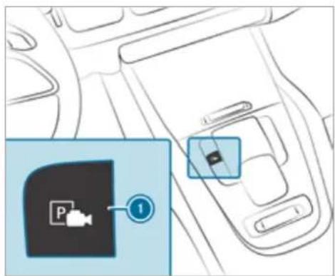
text_image
Diagram showing a car interior with a parking pad icon and a numbered label pointing to the pad.Press button 1.
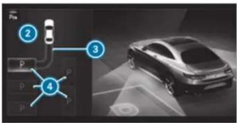
text_image
Diagram showing four labeled components of a parking or parking system, with a car in the background and a control panel interface.The media display shows the view of Active Parking Assist. Area ② displays detected parking spaces ④ and vehicle path ③.
i Vehicle path ③ shown on the media display may differ from the actual vehicle path.
If a parking space is displayed: stop the vehicle.
Select desired parking space ④ and confirm.
If necessary, select the parking direction (forwards or reverse), and confirm. Vehicle path ③ is shown, depending on selected parking space ④ and the parking direction.
The turn signal indicator is switched on automatically when the parking procedure begins.
You are responsible for selecting the turn signal indicator in accordance with the traffic conditions. If necessary, select the turn signal indicator accordingly.
A WARNING Risk of accident due to vehicle swinging out while parking or pulling out of a parking space
While parking or exiting a parking space, the vehicle swings out and can drive onto areas of the oncoming lane.
This could cause you to collide with objects or other road users.
Pay attention to objects and other road users.
Where necessary, stop the vehicle or cancel the parking procedure with Active Parking Assist.
If, for example, the Please engage reverse gear message appears in the media display: select the corresponding transmission position. The vehicle drives into the selected parking space.
During the parking procedure with Active Parking Assist, the lane markings are displayed in green in the camera image.
On completion of the parking procedure, the Parking Assist finished, take control vehicle display message appears. Further manoeuvring may still be necessary.
After completion of the parking procedure, safeguard the vehicle against rolling away. When required by legal requirements or local conditions: turn the wheels towards the kerb.
You can stop the vehicle and change the transmission position during the parking procedure. The system then calculates a new
vehicle path. If no new vehicle path is available, the system can change the transmission position again or cancel the parking procedure.
Exiting a parking space with Active Parking Assist
Requirements:
- The vehicle has been parked with Active Parking Assist.
Please note that you are responsible for the vehicle and surroundings during the entire parking procedure.
Start the vehicle. of
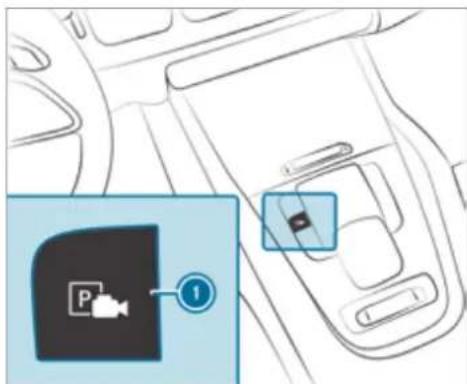
text_image
Diagram showing a car interior with a parking pad icon and a numbered label pointing to the door panel.Press button ①. The media display shows the view of Active Parking Assist.
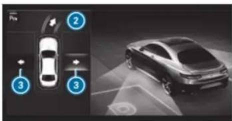
text_image
Diagram showing car sensor placement and 3D perspective view of a car with labeled componentsIf the vehicle has been parked perpendicular to the direction of travel: in area ②, select direction of travel ③ Left or Right.
(i) The vehicle path shown on the media display may differ from the actual vehicle path.
Confirm direction of exit ③ to drive out of the parking space.
① The turn signal indicator is switched on automatically when the exiting procedure begins.
You are responsible for selecting the turn signal indicator in accordance with the traffic conditions. If necessary, select the turn signal indicator accordingly.
A WARNING Risk of accident due to vehicle swinging out while parking or pulling out of a parking space
While parking or exiting a parking space, the vehicle swings out and can drive onto areas of the oncoming lane.
This could cause you to collide with objects or other road users.
Pay attention to objects and other road users.
Where necessary, stop the vehicle or cancel the parking procedure with Active Parking Assist.
If, for example, the Please engage forward gear message appears in the media display: select the corresponding transmission position.
The vehicle moves out of the parking space. The turn signal indicator is switched off automatically.
After the parking space has been exited, a warning tone and the Parking Assist finished,
take control of vehicle message prompt you to take control of the vehicle.
The vehicle is not automatically braked and car roll away. You have to accelerate, brake, steer and change gear yourself again.
Manoeuvring assistant
Function of Drive Away Assist
Drive Away Assist can reduce the severity of an impact when pulling away. If an obstacle is detected in the direction of travel, the vehicle's speed is briefly reduced to approx. 2 km/h. If a critical situation is detected, the △ symbol appears in the media display.
You can cancel an intervention by Drive Away Assist at any time by deactivating Parking Assist PARKTRONIC ( page 292).
WARNING Risk of accident caused by limited detection performance of Drive Away Assist
Drive Away Assist cannot always clearly identify objects and traffic situations.
▶ Always pay careful attention to the traffic situation; do not rely on Drive Away Assist alone.
Be prepared to brake or swerve as necessary, provided the traffic situation permits and that it is safe to take evasive action.
Drive Away Assist is only an aid. It is not a substitute for your attention to the surroundings. The responsibility for safe manoeuvring and parking remains with you. Make sure that no persons, animals or objects etc. are in the manoeuvring range.
A risk of collision may arise in the following situations, for example:
- If the accelerator and brake pedals are interchanged.
- If an incorrect transmission position is engaged.
Drive Away Assist is active under the following conditions:
• If Parking Assist PARKTRONIC is activated.
- If you shift the transmission position to or when the vehicle is stationary.
- If the detected obstacle is less than approx. 1.0 m away.
- If the manoeuvring assistant function is activated in the multimedia system.
System limits
The performance of Drive Away Assist is limited on inclines.
When driving with a trailer, Drive Away Assist is not available.
Also observe the system limits of Parking Assist PARKTRONIC ( page 288).
Function of Cross Traffic Alert
Cross Traffic Alert is only available for vehicles with Blind Spot Assist or Active Blind Spot Assist.
Cross Traffic Alert can warn drivers of any crossing traffic when reversing and manoeuvring out of a parking space. The radar sensors in the bumper also monitor the area adjacent to the vehicle. If a critical situation is detected, the
A symbol appears in the media display and the vehicle can be braked automatically. If the radar sensors are obstructed by vehicles or other objects, detection is not possible.
Cross Traffic Alert is active under the following conditions:
• if the vehicle is reversing at a walking pace.
- manoeuvring assistance is activated (→ page 298).
Also observe the instructions on Blind Spot Assist and Active Blind Spot Assist ( page 262).
System limits
Cross Traffic Alert is not available on inclines. Cross Traffic Alert is not available when driving with a trailer.
Activating/deactivating manoeuvring assistant
Multimedia system:

▶ Activate/deactivate Manoeuvring assistance.
(i) Manoeuvring assistant must be active for the function of Drive Away Assist ( page 297) and Cross Traffic Alert ( page 298).
Trailer Manoeuvring Assist
Function of Trailer Manoeuvring Assist

WARNING Risk of accident due to unsuitable trailers
Trailers with a steered axle or a fifth wheel cannot be used with Trailer Manoeuvring Assist.
Due to this, the trailer cannot be manoeuvred in the desired direction and you can cause a collision or the trailer can overturn.
Only use Trailer Manoeuvring Assist with trailers with fixed drawbars and axles.
! NOTE Damage to trailers with a stabilisation device against swerving
In the case of trailers with a stabilisation device against swerving, the trailer or trailer tow hitch could be damaged.
If a trailer coupling with Trailer Manoeuvring Assist is used, only use trailers without a stabilisation device against swerving.
NOTE Damage due to overhanging loads in front or drawbar installations
The vehicle and the trailer may be damaged during manoeuvring due to overhanging loads at the front of the trailer or drawbar installations.
Pay attention to overhanging loads or drawbar installations while manoeuvring.
Trailer Manoeuvring Assist assists you when reversing with a trailer. By means of a turning angle sensor in the trailer coupling, Trailer
Manoeuvring Assist monitors the articulation angle between the vehicle and trailer and adjusts it to a specified value.
Trailer Manoeuvring Assist is only an aid. It is not a substitute for your attention to the surroundings. The responsibility for safe manoeuvring and parking remains with you. Make sure that there are no persons, animals or objects in the manoeuvring area while manoeuvring and parking in/exiting parking spaces.
You can either enter the articulation angle value directly via the multimedia system or use a straightening manoeuvre. When carrying out a straightening manoeuvre, the system calculates the articulation angle automatically and straightens the vehicle/trailer combination to the trailer's current direction.
Trailer Manoeuvring Assist must be taught-in before it can adjust the articulation angle ( page 300).
Observe the notes on towing a trailer ( page 301).
System limits
Observe the system limits of the following functions:
• Active Parking Assist ( page 293)
• 360° Camera (→ page 284)
• Reversing camera ( page 282)
The system may be impaired or may not function in the following situations:
• The gradient is greater than approximately 15%.
Using Trailer Manoeuvring Assist
Requirements:
- The vehicle has been started and is stationary.
• A trailer has been detected.
• The gradient is less than approximately 15%.
• The electric parking brake is not applied.
Teaching in Trailer Manoeuvring Assist
Drive forwards a short distance with the car/trailer combination. The completed teach-in process is shown in the media display.
The maximum articulation angle depends on the length of the trailer. This is calculated by the system by driving the vehicle forwards, including cornering. Before the length of the trailer has been calculated, the maximum articulation angle is approximately 23°. The longer the trailer is, the higher the maximum articulation angle (max. approximately 60°).
Using Trailer Manoeuvring Assist
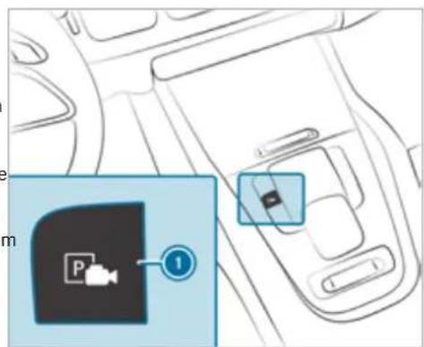
text_image
Diagram showing a car interior with a video camera icon and a numbered label pointing to the camera area.Engage reverse gear R.
Press button ①.
The camera image is shown in the media display.
To adjust the articulation angle: select 📌. Swipe left or right on the media display or touchpad to change the articulation angle.
or
To activate the straightening manoeuvre: select ↓.
The system calculates the articulation angle in such a way that the direction of the trailer at the time of activation is maintained. The is a short countersteering movement of the trailer while the vehicle is reversed, which then guides it back to the desired line. In way, the vehicle is aligned straight with the trailer and, at the same time, the direction the trailer is maintained.
▶ Accelerate and brake as required.
(i) Pay attention to your surroundings and be ready to brake at all times.
Observe the following notes on the tongue weight:
- Do not use a tongue weight that exceeds or falls below the permissible tongue weight
• Use a tongue weight as close as possible to the maximum tongue weight
Do not exceed the following values:
this Permissible towing capacity
of Permissible rear axle load of the towing vehicle
- Permissible gross weight of the towing vehicle
• Permissible gross weight of the trailer
• Maximum permissible speed of the trailer
Ensure the following before starting a journey:
- The tyre pressure on the rear axle of the towing vehicle is set for a maximum load
- The lighting of the connected trailer is operational
In the event of increased rear axle load, the car/trailer combination must not exceed a maximum
speed of 100 km/h for reasons concerning the operating permit. This also applies in countries in which the permissible maximum speed for car/trailer combinations is above 100 km/h.
Vehicles with AIRMATIC or E-ACTIVE BODY CONTROL: if the socket of the trailer hitch is occupied, e.g. by a trailer or rear bicycle rack, the vehicle is set to the normal level regardless of the drive program at speeds greater than 30 km/h.
When you are reversing with a trailer, remember to use the Trailer Manoeuvering Assist function ( page 299).
Extending and retracting the ball neck fully electrically
WARNING Risk of accident due to the ball neck not being engaged
If the ball neck is not engaged, the trailer may come loose.
Make sure that the ball neck securely engages and locks into place.
Trailer hitch
Notes on trailer operation

NOTE Mercedes-AMG vehicles
Observe the notes in the Supplement. You could otherwise fail to recognise dangers.
! NOTE Damage to the all-electric trailer hitch due to additional pressure
The all-electric trailer hitch could be mechanically damaged by applying additional pressure when the ball neck is being extended or retracted.
Do not make the ball neck extend/retract faster by applying additional pressure.
NOTE Increased risk of damage to property due to folded-out ball neck
When the trailer is not coupled or the bicycle rack is attached, fold in the ball neck or, in the case of a fully electric trailer hitch, retract the ball neck.
NOTE Damage to the vehicle due to incorrect use of the trailer hitch
When a trailer hitch is used to recover a vehicle, the vehicle may be damaged in the process.
Use the trailer hitch only for pulling a trailer or attaching approved carrier systems (e.g. a bicycle rack).
Requirements:
• The vehicle is secured against rolling away.
• The swivel range is clear.
- The trailer cables or adapter plugs have been removed.
Extending the ball neck fully electrically
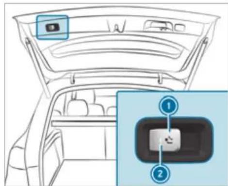
text_image
Diagram of a car interior showing the front compartment with a highlighted camera and a close-up inset highlighting a key component.Pull button ①. Indicator lamp ② will flash and the message Trailer coupling extending... will appear on the multifunction display. The ball neck will extend fully electrically.
Wait until the ball neck has locked in place. When indicator lamp ② is continuously the ball neck is securely locked in place. If the ball neck is not securely locked in place, indicator lamp ② will flash and the message Check trailer hitch lock will appear on the multifunction display.
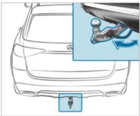
natural_image
Line drawing of a car front view with an inset showing a mechanical lever mechanism (no text or symbols)Retracting the ball neck fully electrically
▶ Pull button ①. Indicator lamp ② will flash and the message Trailer coupling extending... will appear on the multifunction display. The ball neck will retract fully electrically. ▶ Wait until the ball neck has locked in place. When indicator lamp ② goes out, the ball neck is securely locked in place. If the ball neck is not securely locked in place, indicator lamp ② will flash and the message Check trailer hitch lock will appear on the multifunction display.
Observe the information about the displays on the instrument cluster:
• Indicator and warning lamps (→ page 507)
• Display messages (→ page 445)
Extending and retracting the ball neck fully electrically (multimedia system)
WARNING Risk of accident due to the ball neck not being engaged
If the ball neck is not engaged, the trailer may come loose.
Always engage the ball neck as described.
! NOTE Damage to the all-electric trailer hitch due to additional pressure
The all-electric trailer hitch could be mechanically damaged by applying additional pressure when the ball neck is being extended or retracted.
Do not make the ball neck extend/retract faster by applying additional pressure.
Requirements:
• The vehicle is secured against rolling away.
• The swivel range is clear.
- The trailer cable
removed.
Multimedia system:
→ Settings ▶ Quick access
Extending the ball neck fully electrically
Select
The Trailer coupling extending... display message will appear on the multifunction display. The ball neck will extend fully electrically.
▶ Wait until the ball neck has locked in place.
If the ball neck is not securely locked in place, the Check trailer hitch lock message will appear on the multifunction display.
Retracting the ball neck fully electrically
Select
The Trailer coupling extending... display message will appear on the multifunction display. The ball neck will retract fully electrically.
▶ Wait until the ball neck has locked in place.
If the ball neck is not securely locked in place, the Check trailer hitch lock message will on the multifunction display.
Coupling up/uncoupling a trailer
WARNING Risk of injury from the vehicle level being changed
Vehicles with level control system: the vehicle level may be changed unintentionally, e.g. by other persons. You may become trapped if you couple up or uncouple a trailer while the vehicle level is changing. In addition, other people could become trapped if their limbs are between the vehicle body and the tyres or underneath the vehicle.
When coupling up or uncoupling a trailer, make sure that:
The doors or tailgate are not opened or closed.
You do not initiate the level control system and do not operate the DYNAMIC SELECT switch.
Do not lock or unlock the vehicle.
Requirements:
- The ball neck is extended and engaged in a securely locked position.
Trailers with a 7-pin plug can be connected to the vehicle with the following adapters:
- Adapter plug
- Adapter cable
The trailer will be correctly detected by the vehicle only if the following conditions are met:
• The trailer is connected correctly.
- The trailer lighting system is in working order.
The functions of the following systems will be affected by a correctly connected trailer:
- ESP ^ trailer stabilisation
• Trailer Manoeuvering Assist
• Active Lane Keeping Assist - Parking Assist PARKTRONIC
• Active Parking Assist
• Blind Spot Assist or Active Blind Spot Assist
- Drive Away Assist
- Cross Traffic Alert
- Reversing camera
- 360° Camera
- AIRMATIC
• E-ACTIVE BODY CONTROL
Coupling up a trailer
NOTE Damage to the starter battery due to full discharge
Charging the trailer battery using the power supply of the trailer can damage the starter battery.
Do not use the vehicle's power supply to charge the trailer battery.
Remove the cover cap from the ball head and store it in a safe place.
Position the trailer on a level surface behind the vehicle and couple it up to the vehicle.
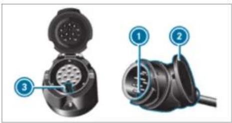
text_image
Technical diagram of a dual-chamber electric plug with labeled parts 1, 2, and 3Open the socket cap.
Insert the plug with lug ① in groove ③ on the socket.
Turn bayonet coupling ② to the right as far as it will go.
Let the cap engage.
Secure the cable to the trailer with cable ties (only if you are using an adapter cable).
Make sure that the cable is always slack for ease of movement during cornering.
Under the following conditions, a message may appear on the multifunction display even if the trailer has been connected correctly:
• LEDs have been installed in the trailer lighting system.
- The current has fallen below the trailer lighting system's minimum current (50 mA).
i Accessories can be connected to the permanent power supply up to 180 W and to the power supply that is switched on via the ignition lock.
Uncoupling a trailer
A WARNING Risk of being crushed and becoming trapped when uncoupling a trailer
When uncoupling a trailer with an engaged inertia-activated brake, your hand may become trapped between the vehicle and the trailer drawbar.
Do not uncouple trailers with an engaged overrun brake.

NOTE Damage when uncoupling in a state of overrun
Uncoupling in a state of overrun can damage the vehicle.
Do not uncouple trailers with an engaged overrun brake.

WARNING Risk of becoming trapped when disconnecting the trailer cable
Vehicles with level control system: The vehicle may lower when the trailer cable is disconnected.
This could result in you or other people becoming trapped if your or their limbs are between the vehicle body and the tyres or underneath the vehicle.
Make sure that nobody is underneath the vehicle or in the immediate vicinity of the wheel arches when you disconnect the trailer cable.

NOTE Damage to the rear bumper from installing adapter cables or adapter plugs
The following parts could be damaged when swiveling the ball neck fully electrically:
- Bumper
- Adapter cable
- Adapter plug
Always remove the adapter cable or adapter plug before swiveling the ball neck fully electrically.
▶ Secure the trailer against rolling away.
Disconnect the electrical connection between the vehicle and the trailer.
▶ Uncouple the trailer.
Place the cover cap on the ball head.
Bicycle rack function

WARNING Risk of an accident when using the bicycle rack incorrectly
The bicycle rack may become detached from the vehicle in the following cases:
- the permissible load capacity of the trailer hitch is exceeded.
• the bicycle rack is used incorrectly. - the bicycle rack is secured to the ball neck beneath the ball head.
Observe the following for your own safety and that of other road users:
• always adhere to the permissible load capacity of the trailer hitch.
- only use the bicycle rack to transport bicycles.
- always mount the bicycle rack properly by attaching to the ball head and the ball neck guide pin, if possible.
- when transporting four bicycles, always use bicycle racks which have additional support on the ball neck guide pin.
- only use bicycle racks approved by Mercedes-Benz.
- always observe the bicycle rack operating instructions.
NOTE Damage to, or cracks on, the trailer hitch due to unsuitable bicycle racks or bicycle racks being used incorrectly
use only bicycle racks approved by Mercedes-Benz.
NOTE Increased risk of damage to property due to folded-out ball neck
When the trailer is not coupled or the bicycle rack is attached, fold in the ball neck or, in the case of a fully electric trailer hitch, retract the ball neck.
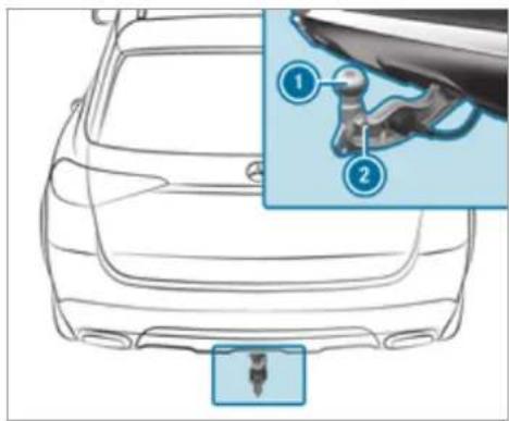
text_image
Diagram of a car's rearview and side profile with labeled parts, showing a connector detail view.Trailer hitch (example with additional guide pin)
Depending on the bicycle rack's design, different numbers of bicycles can be transported.
The following bicycle rack designs are possible:
- When mounted by attaching to ball head ①, the maximum load capacity is 75 kg. You can transport up to three bicycles.
- When mounted on ball head ① and guide pin ②, the maximum load capacity is 100 kg. You can transport up to four bicycles.
The maximum load capacity is calculated from the weight of the bicycle rack and the bicycle rack load.
Observe the notes on driving with a roof load, trailer or fully laden vehicle ( page 195).
When using a bicycle rack, set the tyre pressure for increased load on the rear axle of the vehicle. Further information on the tyre pressure can be found in the tyre pressure table ( page 407).
Notes on loading
The larger the distance between the load's centre of gravity and the ball head, the greater the load on the trailer hitch.
Observe the following notes:
- mount heavy bicycles as close to the vehicle as possible
- always distribute the load on the bicycle rack as evenly as possible across the vehicle's longitudinal axis
Mercedes-Benz recommends removing all detachable parts from bicycles (e.g. baskets, child seats, rechargeable batteries) before loading them onto the bicycle rack. This will improve the aerodynamic resistance and centre of gravity of the bicycle rack.
Always secure the bicycles to prevent them from moving around and check them at regular intervals to ensure that they are secure.
Do not use tarpaulins or other covers. The driving characteristics and rear view may be impaired. In addition, aerodynamic resistance and the load on the trailer hitch will increase.
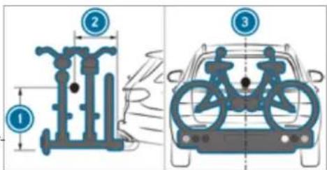
text_image
Diagram illustrating bicycle wheel assembly and rear view with labeled components and motion arrowsLoad distribution on the bicycle rack
1 Vertical distance between centre of gravity and ball head
2 Horizontal distance between centre of gravity and ball head
③ The centre of gravity is on the vehicle's centre axis
Observe the following information when loading the bicycle rack:
Loading the bicycle rack
| 3 bicycles 4 bicycles | ||
| Total weight of bicycle rack and load | Up to 75 kg | Up to 100 kg |
| Max. distance1 | 420 mm | 420 mm |
| Max. distance2 | 300 mm | 400 mm |
When transporting four bicycles or a total weight between 75 kg and 100 kg, always use bicycle racks with additional support on the trailer hitch guide pin.
Vehicle towing instructions
The vehicle is not suitable for the use of tow bar systems that are used for flat towing or dinghy towing, for example. Attaching and using tow bar systems can lead to damage on the vehicle. When you are towing a vehicle with tow bar systems, safe driving characteristics cannot be
Driving and parking 309
guaranteed for the towing vehicle or the towed vehicle. The vehicle-trailer combination may swerve from side to side. Comply with the permitted towing methods ( page 397) and the instructions for towing with both axles on the ground ( page 398).
Notes on the instrument display and on-board computer

WARNING Risk of accident due to an instrument display malfunction
If the instrument display has failed or malfunctioned, the function restrictions applying to safety relevant systems are not visible.
The operating safety of your vehicle may be impaired.
▶ Drive on carefully.
Have the vehicle checked immediately at a qualified specialist workshop.

WARNING Risk of distraction from information systems and communications equipment
If you operate information and communication equipment integrated in the vehicle when driving, you will be distracted from the traffic situation. This could also cause you to lose control of the vehicle.
Only operate this equipment when the traffic situation permits.
If you cannot be sure of this, stop the vehicle whilst paying attention to road and traffic conditions and operate the equipment with the vehicle stationary.

NOTE Mercedes-AMG vehicles
Observe the notes in the Supplement. You could otherwise fail to recognise dangers.
You must observe the legal requirements for the country in which you are currently driving when operating the on-board computer.
The on-board computer shows only display messages and warnings from specific systems on the multifunction display. You must therefore ensure that your vehicle is always reliable.
If the operating safety of your vehicle is impaired, park the vehicle immediately and in accordance with the traffic conditions. Contact a qualified specialist workshop.
Instrument display overview
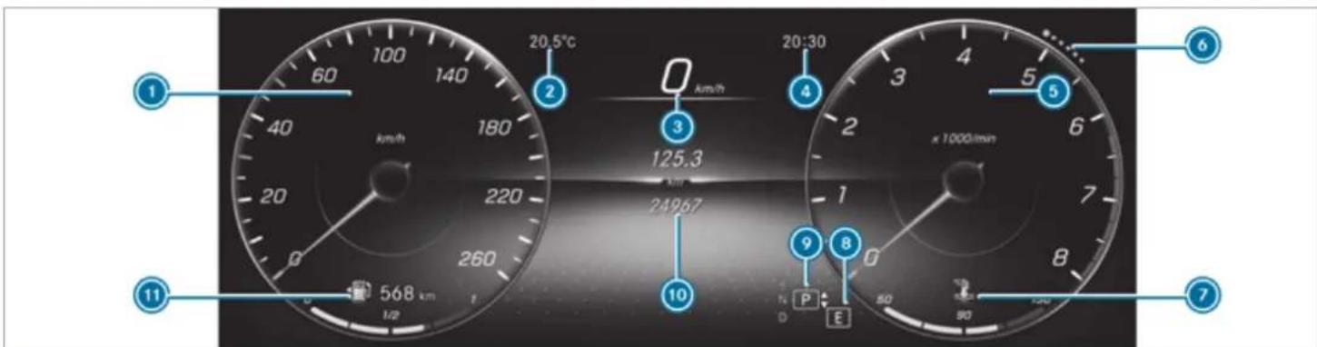
text_image
20.5°C 20:30 125.3 24967 568 km 1/2 km/h km km/h km/h km/h km/h km/h km/h km/h km/h km/h km/h km/h km/h km/h km/h km/h km/h km/h km/h km/h km/h km/h km/h km/h km/h km/h km/h km/h km/h km/h km/h km/h km/h km/h km/h☐ Display content on left (example: speedometer): speedometer / time / date / trip computer From start and From reset / range / audio / angle of incline and approach/ departure
The segments on the speedometer indicate the status of the following systems: cruise
control/limiter/Active Distance Assist DISTRONIC
Outside temperature
3 Digital speedometer
4 Time
5 Display content on right (example: tachometer): tachometer / average fuel consumption / ECO display / navigation / G-meter /
assistant display / 4MATIC / suspension (equipment-dependent)
The fuel supply will be interrupted to protect the engine when the red mark on the rev counter (overrevving range) is reached.
6 Index points
These show the selected display or menu content.
⑦ Coolant temperature display
During normal operation, the coolant temperature display is permitted to rise to 120^ C.
Vehicles with 48 V on-board electrical system: POWER and CHARGE display (electrical drive support and recuperation power of the electric motor)
8 Selected drive program
9 Selected transmission position
10 Multifunction display (example: standard display for trip): Assistance / Telephone / Navigation / Trip / Media / Radio / Styles and displays / Service
⑪ Fuel level, fuel filler flap location indicator, range
Overview of the buttons on the steering wheel
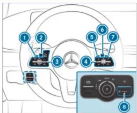
text_image
Diagram of car dashboard with numbered components and a close-up of the control panel showing dial indicator and function buttons.① Computer Back/Home button, on-board com-
Press and hold: shows standard display
② Touch Control, on-board computer
3 Control panel for cruise control/limiter or Active Distance Assist DISTRONIC
4 Control panel for MBUX multimedia system:
LINGUATRONIC
★ Displays favourites
VOL: control knob, adjusts the volume or switches the sound off (press)
Makes/accepts a call
Rejects/ends a call
5 Calls up the home screen
6 Touch Control multimedia system
⑦ Back button
Brightness control to adjust the lighting in the Instrument Display and in the control elements of the vehicle interior
Operating the on-board computer
Observe the legal requirements for the country in which you are currently driving when operating the on-board computer.
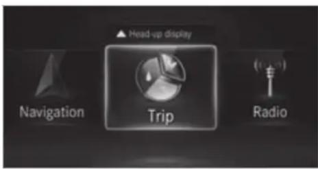
text_image
Head-up display Navigation Trip RadioThe on-board computer is operated using the left-hand Touch Control and the left-hand back/home button.
When the on-board computer is being operated, different acoustic signals will sound as operating feedback, e.g. when the end of a list is reached or when you are scrolling through a list.
The following menus are available:
- Assistance
- Telephone
- Navigation
- Trip
- Radio
• Media
- Styles & display
• Service
You can find information about the possible settings and selections on the menus in Digital Owner's Manual.
To call up the menu bar: briefly press the left-hand back button until the menu bar is displayed.
① Vehicles without Active Distance Assist
DISTRONIC: press the 📋 button to call up the menu bar of the on-board computer.
To scroll on the menu bar: swipe left or right on the left-hand Touch Control.
To call up a menu, submenu or possible settings on the menu, or confirm a selection or setting: press the left-hand Touch Control.
To scroll through displays or lists on the menu, or select display content, a function, an entry or a display: swipe upwards
or downwards on the left-hand Touch Control.
To exit a submenu: press the left-hand back button.
Selecting the head-up display
To switch on the head-up display: switch on the head-up display via the multimedia system or activate it on the menu bar by swiping upwards on the left-hand Touch Control.
The head-up display menu will be selected on the head-up display.
To switch to the head-up display: press the left-hand Touch Control or swipe upwards on the left-hand Touch Control.
To set the three display ranges of the head-up display: swipe upwards or downwards on the left-hand Touch Control.
Full-screen menus
You can display the following menus full-screen on the instrument display:
- Assistance
- Trip
- Navigation
On the corresponding menu, use the left-hand Touch Control to scroll to the end of the list.
Press the left-hand Touch Control. The selected menu will be displayed full-screen.
Overview of what is shown on the multifunction display
Displays on the multifunction display

Active Parking Assist ( page 295)

Parking Assist PARKTRONIC deactivated ( page 292, 291)

DSR ( page 248)

Cruise control ( page 238)

Limiter ( page 239)

Active Distance Assist DISTRONIC ( page 241)

Active Brake Assist ( page 253)

Active Steering Assist ( page 250)

Active Stop-and-Go Assist ( page 248)

Active Lane Keeping Assist ( page 264)

ECO start/stop function ( page 201)

HOLD function ( page 235)

Adaptive Highbeam Assist Plus ( page 164)

Maximum permissible speed exceeded (for certain countries only)
Vehicles with Speed Limit Assist: detected instructions and traffic signs ( page 258).
Vehicles with Traffic Sign Assist: detected instructions and traffic signs ( page 259). For an overview of the indicator and warning lamps, see ( page 507).
Head-up display
Function of the head-up display

NOTE Mercedes-AMG vehicles
Observe the notes in the Supplement. You could otherwise fail to recognise dangers.
The head-up display projects the following information into the driver's field of vision above the cockpit, for example:
- The vehicle speed
• Information from the navigation system
• Information from the driving systems and driving safety systems
• Some warning messages
Depending on the vehicle's equipment, different content can be shown in the three areas of the head-up display ( page 315).
Display content
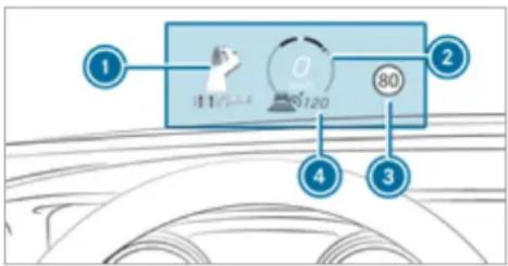
text_image
1 2 4 3 0 $120① Navigation instructions
② Current speed
3 Detected instructions and traffic signs
4 Set speed in the driving system (e.g. cruise control)
System limits
The visibility of the displays will be affected by the following conditions:
- Seat position
• Image position setting -
Light conditions
-
Wet road surface
- Objects on the display cover
• Polarisation in sunglasses
In extreme sunlight, sections of the display may appear washed out. You can correct this by switching the head-up display off and on again.
Setting the head-up display using the on-board computer
On-board computer:
HEAD-UP DISPLAY
The following head-up display settings or displays can be selected or shown:
- Position
- Brightness
- Messages
- Assistance status
- Telephone
- Audio
• LINGUATRONIC
To select the Settings menu: swipe to the right on the left-hand Touch Control. The Settings menu ⑤ will be selected.
To call up the Settings menu: press the left-hand Touch Control.
To adjust the position: swipe upwards or downwards on the left-hand Touch Control.
To adjust the brightness: swipe to the left or right on the left-hand Touch Control.
Setting messages, assistance status, telephone, audio and LINGUATRONIC
▶ Press the left-hand Touch Control.
The list of setting options will be displayed.
Swipe upwards or downwards on the left-hand Touch Control and select a setting by pressing the left-hand Touch Control.
Selecting what the head-up display shows
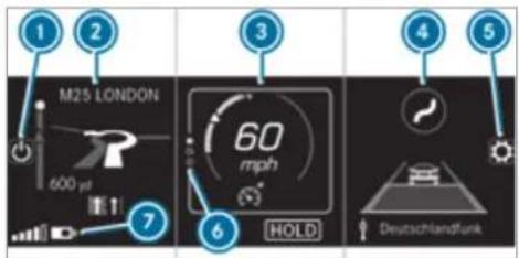
text_image
1 2 M25 LONDON 600 yd 3 60 mph HOLD 4 5 Deutschlandfunk(Example)
Switching the head-up display on/off
2 Left display area
Navigation system
Inclination, gradient and compass
Average consumption
G-meter
Central display area
Speedometer
Set speed in the driver assistance system,
e.g. cruise control
Warnings from driver assistance systems, e.g. distance warning
④ Right display area
Traffic Sign Assist
Vehicle level
Differential
Assistant display
5 To adjust the position, brightness and lower display area
6 Index points
7 Lower display area (example: left display area)
Display areas ② to ④ that are not required can be hidden.
In audio mode, the station name or track will be shown temporarily when the audio source is being actively operated. In addition, the latest calls will be displayed when the telephone list on the instrument display is actively operated.
Swipe upwards on the left-hand Touch Control.
Press the left-hand Touch Control.
Switching the head-up display on/off via the multimedia system
Multimedia system:
Settings Quick access
Select HUD.
The head-up-display is activated.
Overview and operation
Notes on the MBUX multimedia system

WARNING Risk of distraction from information systems and communications equipment
If you operate information and communication equipment integrated in the vehicle when driving, you will be distracted from the traffic situation. This could also cause you to lose control of the vehicle.
Only operate this equipment when the traffic situation permits.
If you cannot be sure of this, stop the vehicle whilst paying attention to road and traffic conditions and operate the equipment with the vehicle stationary.
You must observe the legal requirements for the country in which you are currently driving when operating the multimedia system.
Overview of the MBUX multimedia system
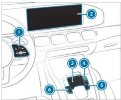
text_image
Diagram of a car interior with numbered components, likely indicating parts of a vehicle or electronics control panel.① Touch Control and control panel for the MBUX multimedia system
② Media display with touch functionality
3 Touchpad
4 Controller
Turn: adjusts the volume
Press briefly: switches the mute function on/off
Press and hold: switches the MBUX multimedia system or media display on or off
⑤ Buttons for navigation, radio/media and telephone
6 Buttons for vehicle functions/system settings and favourites/themes
Further operating options:
- Conducting a voice dialogue with LINGUA-TRONIC.
- Operating functions contact-free with the MBUX Interior Assistant.
① You can find further information about operation as well as about applications and services in the Digital Owner's Manual.
Anti-theft protection
This device is equipped with technical provisions to protect it against theft. More detailed information about anti-theft protection can be obtained at a qualified specialist workshop.
Home screen overview
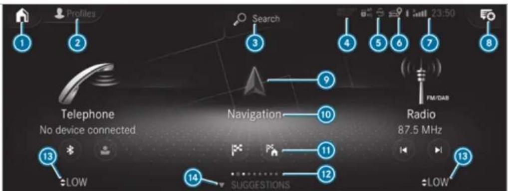
text_image
Profiles Search 4 5 6 7 8 Telephone No device connected Navigation 10 Radio 87.5 MHz 13 LOW 14 SUGGESTIONS 12 - LOWDepending on the display, calls up the first three applications or the home screen
② Calls up the profile
③ Calls up the global search
④ SOS NOT READY (only when the Mercedes-Benz emergency call system is not available)
5 Mercedes me connect active
6 Transmission of vehicle position active
7 Signal strength of the mobile phone network, network display, battery status of the mobile phone connected, time
Calls up the Notifications Centre
⑨ Calls up an application using the symbol
Application and current information
⑪ Quick-access, e.g. enter home address
⑫ Index points and selected display area
⑬ Calls up the air conditioning menu
14 Calls up SUGGESTIONS, THEMES and FAVOURITES
① If Mercedes me connect is active ⑤, the Operating the MBUX multimedia system
vehicle is linked with Mercedes me connect Vehicle data is then transmitted to the back-end system. What data is transmitted depends on which services are activated. Further details can be found in the Mercedes me connect terms and conditions and data protection information. The function is country-dependent.
If Transmission of vehicle position is active, Mercedes me connect services have been activated for this vehicle which access the vehicle's geoposition. In which instances the geoposition is transmitted depends on the particular services. Further details can be found in the Mercedes me connect terms and conditions and data protection information. The function is country-dependent.
Using Touch Control

text_image
Diagram showing car interior with steering wheel and dashboard, alongside a close-up of the dashboard's internal components labeled 1 to 4.① Calls up the home screen
② Touch Control
3 Pressing briefly: returns to the previous display
4 ★ Pressing the rocker switch down briefly: shows favourites
★ Pressing the rocker switch down and holding: adds favourites and themes VOL: control adjusts the volume or switches the sound off (press) Pressing the rocker switch up: ma or accepts a call Pressing the rocker switch down: rejects or ends a call
Navigation through the menus is carried out with Touch Control ② with single-finger swipes.
To select a menu option: swipe and press.
To move the digital map: swipe in any direction.
Using the touchscreen
Select menu options, symbols or characters by pressing briefly.
To navigate in menus: swipe up, down, left or right.
To use handwriting to enter characters: write the character with one finger on the touchscreen.
To zoom in and out of the map: move two fingers together or apart.
To call up the global menu: press and hold on the touchscreen until the OPTIONS menu appears.
Using the touchpad
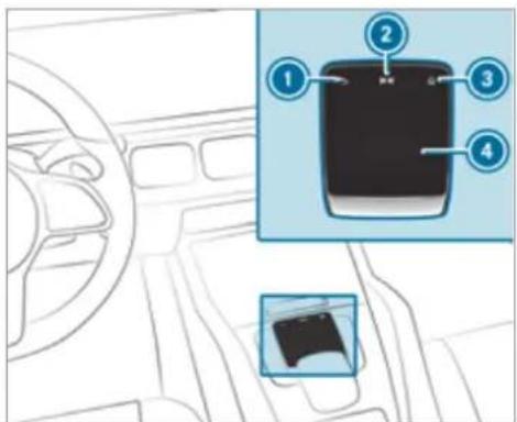
text_image
Diagram showing car interior with labeled parts and a close-up of the device's screen, likely illustrating a diagnostic or testing setup.

Returns to the previous display


Calls up the audio control menu
Swiping to the left of right: selects the previous or next radio station/music track

Calls up the home screen

Touchpad

To select a menu option: swipe and press.

To use handwriting recognition: write a character on the touchpad.

To open or close the Notifications Centre: swipe down or up with two fingers.

To zoom in and out of the map: move two fingers together or apart.
Calling up applications using buttons
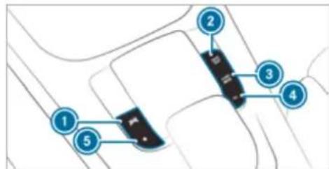
text_image
Diagram showing labeled components of a vehicle or road intersection with numbered points 1 to 5

Calls up vehicle functions


Calls up navigation


Calls up radio or media


alls up the telephone


ress briefly: calls up favourites
Press and hold: adds a favourite or theme

Alternatively, tap

on the touchscreen.

Call up the application ( page 318).
Functions of LINGUATRONIC

WARNING Risk of distraction from information systems and communications equipment
If you operate information and communication equipment integrated in the vehicle when driving, you will be distracted from the traffic situation. This could also cause you to lose control of the vehicle.
Only operate this equipment when the traffic situation permits.
If you cannot be sure of this, stop the vehicle whilst paying attention to road and traffic conditions and operate the equipment with the vehicle stationary.
For your own safety, always observe the following points when operating mobile communications equipment and especially your voice control system:
- Observe the legal requirements for the country in which you are driving.
- If you use the voice control system in an emergency your voice can change and your telephone call, e.g. an emergency call, can thereby be unnecessarily delayed.
- Familiarise yourself with the voice control system functions before starting the journey. With LINGUATRONIC, various applications in the MBUX multimedia system are operable using voice input. LINGUATRONIC is operational approximately thirty seconds after the ignition is switched on and is available for the driver's seat and front passenger seat.
The following multimedia system applications can be operated:
- Telephone
• Text message and e-mail - Navigation
- Address book
- Radio
- Media
• TV - Vehicle functions
Starting LINGUATRONIC
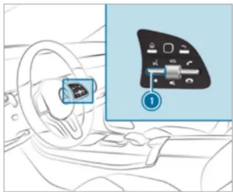
natural_image
Interior view of a car dashboard with steering wheel and control panel (no text or symbols visible)Press rocker switch ① up.
or
▶ Say "Hello Mercedes".
Overview of the MBUX Interior Assistant

WARNING Risk of injury from the camera's laser radiation
This product uses a classification 1 laser system. If the housing is opened or damaged, laser radiation may damage your retina.
Do not open the housing.
Always have maintenance work and repairs carried out by a qualified specialist workshop.
This device is a class 1 laser product in accordance with DIN EN 60825-1:2014
The camera is located in the overhead control panel.
If the vehicle is fitted with the MBUX Interior Assistant, selected functions of the multimedia
system can be operated contact-free. The MBUX Interior Assistant can differentiate between driver and front passenger interactions and detects specific hand positions (poses).
- System limits, display messages and notes for rectification
The system may be impaired or may not function in the following situations:
-
The camera in the overhead control panel may heat up due to operating conditions. As a result the camera may switch off temporarily, particularly during longer periods of operation and at high outside temperatures.
Do not touch or cover the camera and wait until the camera has cooled down and is available again. -
The camera is covered or dirty, misted up or scratched.
Wait until the camera has cooled down before cleaning the camera lens.
Clean the outside of the camera lens with a dry or damp cotton cloth. Do not use microfi-bre cloths. Do not remove the cover when cleaning. - Recognition can be impaired by reflective clothing, an adverse colour of clothing or by accessories, for example.
- Clothing being worn (hat, shawl, scarf) may be limiting the detection area of the camera. Keep the camera's field of vision clear.
- The camera is not operational. Consult a Mercedes-Benz service centre.
The MBUX Interior Assistant supports the following interactions:
| Interaction area Interaction Description | ||
| In front of the media display or above the touchpad | Proximity to the control element | The Interior Assistant recognises the approach of the hand towards a control element.Depending on the active application, the display will be adjusted in the media display. Some functions differentiate between driver and front passenger.No specific hand position is required. |
| Above the centre console | Defined pose | A favourite is called up with a defined pose. |
| Below the inside rearview mirror | Brief up and down movements | With brief vertical up and down movements below the inside rearview mirror the reading light for the driver or the front passenger is switched on and off. |
| Above the front passenger seat | Stretching out a hand above the front passenger seat | By stretching out a hand above the front passenger seat the search light is switched on. If you withdraw a hand from this area, the search light is switched off again. |
Switching the reading light and search light and on or off
Requirements:
- For the reading light: the function is available when it is dark.
- The hand movement takes place in the interaction area below the inside rearview mirror.
- For the search light: the function is available when it is dark.
- The hand movement takes place in the interaction area above the front passenger seat.
- The seat belt on the front passenger seat must not be inserted in the seat belt buckle.
Switching the reading light on and off

natural_image
Illustration of a hand holding a plastic bag (no text or symbols)Briefly move a hand up or down beneath the inside rearview mirror. The reading light is switched on or off for the driver or the front passenger.
Switching the search light on and off
natural_image
Abstract illustration of a hand holding a small object, possibly a tool or device, with no visible text or symbols.To switch on: reach across the front passenger seat with a hand. The search light is switched on for the driver.
To switch off: take a hand back away from the front passenger seat.
The search light is switched off again.
Information on profiles, themes, suggestions and favourites
For electrically adjustable seats observe the following notes.
A WARNING Risk of becoming trapped during adjustment of the driver's seat after calling up a driver profile
Selecting a user profile may trigger an adjustment of the driver's seat to the position saved under the user profile. You or other vehicle occupants could be injured in the process.
Make sure that when the position of driver's seat is being adjusted using the multimedia system, no people or body parts are in the seat's range of movement.
If there is a risk of someone becoming trapped, stop the adjustment process immediately:
a) Tap the warning message on the media display.
or
b) Press a memory position button or a seat adjustment switch on the driver's door. The adjustment process will be stopped.
The driver's seat is equipped with an access venter.
If the driver's door is open, the driver's seat will not be set after calling up the driver's profile.
Profiles store your vehicle settings and settings for the multimedia system. If the vehicle is used by several drivers, the driver can select their own profile without changing the stored profile settings of other drivers.
Information on profiles from Mercedes me connect can be found in the Digital Operator's Manual.
Vehicle settings are, for example, driver's seat, steering wheel and mirror settings, climate control and ambient lighting. For the settings of the multimedia system, you can select, for example, radio stations, previous destinations as well as themes, suggestions and favourites.
For recurring driving situations, such as long drives on the motorway, you can save your preferred settings in a theme in the vehicle. In a theme you can save the display of the digital map, your preferred radio station and preferred drive program, for example.
pre the vehicle can learn the habits of the driver. It then offers suggestions for the most probable navigation destinations, media sources, radio stations or contacts. The pre-requirements for that are the selection of a profile, your consent to the recording of data and sufficient collected data.
Favourites provide quick access to applications that are used often. You can select favourites from categories or add them directly to an application.
Configuring profiles, themes and suggestions
Multimedia system:

Creating a new profile
▶ Select + Create profile .
Select an avatar.
Enter the name and confirm with OK.
Select Continue ▷.
▶ Select Current settings.
Select Save.
Activate Bluetooth® and select Connect phone, to connect a mobile phone with the user profile.
Select Finished.
Selecting profile options
Select ⋯ for a profile.
The following functions are available:
• Editing, resetting or deleting a profile
- Resetting themes or favourites
- Configuring suggestions
Configuring suggestions
Select ⋯ for a profile.
▶ Select Suggestions settings.
Switch Allow destination suggestions, Allow music suggestions and Allow contact suggestions on or off.
To deactivate the learning function for one day: activate Deact. learn. for 24h.
For 24 hours no new actions will be trained and no data recorded for the active profile. Suggestions will continue to be shown.
Example: if the option is switched on and route to a new destination has been calculated, this destination would not be taken into account for the learning function.
Creating new themes
Select
Select THEMES.
▶ Select + Set theme.
The settings which are saved in the theme are shown.
Select Continue ▷.
Select Audio and Navigation (Navigation) and store the active settings in the theme.
Select Continue
▶ Select an entry screen.
Select Continue
Select an image.
Enter the names into the entry field and confirm with OK.
Select Save.
System settings
Overview of the system settings menu
In the system settings menu, you can make settings in the following menus and control elements:
- Display
- Styles
- Instrument lighting
- Display brightness
- Edge lighting
- Day/night design
- Control elements
- Keyboard language and handwriting recognition
- Sensitivity of the touchpad
- Sensitivity of the Touch Controls
• LINGUATRONIC
- Sound
- Entertainment
- Navigation and traffic announcements
- Telephone
Voice amplification to the rear
- Connectivity
Wi-Fi, Bluetooth ^® , NFC
- Time & date
- Language
- Units for distance
- Software updates
- Data import/export
- PIN protection
- System Reset
Information on important system updates
Important system updates may be necessary for the security of your multimedia system's data. Install these updates, or else the security of your multimedia system cannot be ensured.
A system update consists of three steps:
- Downloading or copying of the data required for installation
• Installation of the downloaded system update - Activation of the downloaded system update by restarting the system
If automatic software updates are activated, the system updates will be downloaded automatically.
The multimedia system provides a message when a system update is available.
You have the following selection options:
- Accept and install
The system update will be downloaded in the background.
• Information
Information about the pending system update is displayed.
- Later
The system update can be downloaded manually at a later time.
Deep system updates
Deep system updates access vehicle or system settings and can therefore only be carried out when the vehicle is stationary and the ignition is switched off.
If the download of a deep system update is completed and the downloaded system update is ready for installation, you will be informed of this after the next ignition cycle, for example.
Park the vehicle safely in a suitable location before starting the installation.
Requirements for the installation:
• The ignition is switched off.
- Notes and warnings have been read and accepted.
• The electric parking brake is applied.
If all requirements have been fulfilled, the downloaded system update is installed. The multimedia system cannot be operated while the downloaded system update is being installed and vehicle functions are restricted.
If errors should occur during the installation, the multimedia system automatically attempts to restore the previous version. If restoration of the previous version is not possible, a symbol appears on the media display. Consult a qualified specialist workshop to resolve the problem.
Setting up a Wi-Fi hotspot
Requirements:
- To set up the Wi-Fi connection of the multimedia system with external hotspots: there is no communication module installed
- The device to be connected supports at least one of the types of connection described.
Multimedia system:
→ ▶ Settings ▶ System
Wi-Fi & Bluetooth
Activating/deactivating Wi-Fi
Select Wi-Fi.
Connecting the multimedia system with an external hotspot using Wi-Fi
The type of connection established must be selected on the multimedia system and on the device to be connected.
The connection procedure may differ depending on the device. Follow the instructions that are shown in the display. Further information can be found in the manufacturer's operating instructions.
▶ Select Internet settings.
▶ Select Connect via Wi-Fi.
▶ Select Add hotspot.
Connecting using a security key
Select the options ▶ of the desired Wi-Fi network.
▶ Select Connect using security key.
Have the security key displayed on the device to be connected (see the manufacturer's operating instructions).
Enter this security key on the multimedia system.
▶ Confirm the entry with ok.
Connecting using a WPS PIN
Select the options ▶ of the desired Wi-Fi network.
▶ Select Connect using WPS PIN input. The multimedia system generates an eight-digit PIN.
Enter this PIN on the device to be connected.
▶ Confirm the entry.
Connecting using a button
Select the options ▶ of the desired Wi-Fi network.
▶ Select Connect via WPS PBC.
Select "Connect via WPS PBC" in the option on the device to be connected (see the manufacturer's operating instructions).
Press the WPS button on the device to be connected.
Select Continue in the multimedia system.
Activating automatic connection
▶ Select Connect via Wi-Fi.
Select the options ▷ of the desired Wi-Fi network.
▶ Activate Permanent Internet connection.
Connecting with a known Wi-Fi
▶ Select Connect via Wi-Fi.
Select a Wi-Fi network.
The connection is established again.
Configuring the multimedia system as a Wi-Fi hotspot for external devices
The type of connection established depends on the device to be connected. The function must be supported by the multimedia system and by the device to be connected. The type of connection established must be selected on the multi-
media system and on the device to be connected.
- Select Vehicle hotspot. - Select Connect device to vehicle hotspot.
Connecting using WPS PIN generation
▶ Select Connect using WPS PIN generation.
Enter the PIN shown in the media display on the device to be connected and confirm.
Connecting using WPS PIN entry
▶ Select Connect using WPS PIN input.
Enter the PIN that is shown on the external device's display on the multimedia system.
Connecting using a button
▶ Select Connect via WPS PBC.
Press the push button on the device to be connected (see the manufacturer's operating instructions).
Select Continue.
Connecting using a security key
▶ Select Connect device to vehicle hotspot. A security key is displayed.
Select the vehicle from the device to be connected. The vehicle is displayed with the DIRECT-MBUX XXXXX network name.
Enter the security key which is shown in the media display on the device to be connected.
▶ Confirm the entry.
Connecting using NFC
▶ Select Connect via NFC.
Activate NFC on the mobile device (see the manufacturer's operating instructions).
Hold the device to be connected at the vehicle's NFC interface.
Select Finished.
The mobile device is now connected to the multimedia system hotspot via NFC.
Generating a new security key
▶ Select Vehicle hotspot.
▶ Select Generate security key.
A connection will be established with the newly created security key.
To save a security key: select Save. When a new security key is saved, all existing Wi-Fi connections are then disconnected. If the Wi-Fi connections are being re-established, the new security key must be entered.
System language
Notes on the system language
This function allows you to determine the language for the menu displays and the navigation announcements. The selected language affects the characters available for entry. The navigation announcements are not available in all languages. If a language is not available, the navigation announcements will be in English.
Setting the system language
Multimedia system:

Set the language.
If you are using Arabic map data, the text information can also be shown in Arabic the navigation map. To do so, select العربية as the language from the language list. Navigation announcements are then also made Arabic.
Resetting the multimedia system (reset function)
A WARNING Risk of accidents due to failure of multimedia display functions
While the multimedia system is being reset, its functions such as the reversing camera are not available.
Only reset the multimedia system when the vehicle is stationary.
Multimedia system:
Settings System Reset
Personal data is deleted, for example:
- Station presets
• Connected mobile phones
• Individual user profiles
The guest profile is reset when the settings are restored to the factory settings.
A prompt appears again asking whether you really wish to reset.
Select Yes. The multimedia system is reset to the factory settings. If you have set a PIN for your system, this will also be reset.
Navigation
Notes on navigation
Route guidance with augmented reality
⚠ WARNING Risk of accident and injury as a result of distraction, incorrect depiction or wrong interpretation of the display
The camera image of the augmented reality display is not suitable as a guide for driving.
Always keep an eye on the actual traffic situation.
Avoid extended observation of the camera image.
The navigation menu is hidden if route guidance is active.
To show: tap on the touchscreen. The menu is hidden automatically.
A WARNING Risk of accident and injury due to imprecise positioning of additional information
The additional information from the augmented reality display is not a substitute for observing the actual driving situation.
Always keep an eye on the actual traffic situation when carrying out all driving manoeuvres.
Switching navigation on
Multimedia system:
Navigation (Navigation)
Alternatively: press the NAM MFP button. The map displays the current vehicle position. The navigation menu is shown.
Navigation overview
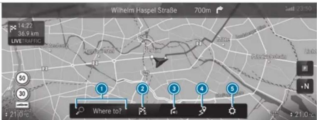
text_image
Wilhelm Haspel Straße 700m 14:22 36.9 km LIVETRAFFIC Where to? 21.0°C 30 50 N 21.0°CExample: digital map with navigation menu
① Enters a POI or address and additional destination entry options
② Cancels active route guidance
3 Repeats a navigation announcement and switch navigation announcements on or off
4 ON ROUTE menu with Route overview, Alternative routes and Report traffic incident (Car-to-X)
TRAFFIC menu with Traffic announcements, Area announcements and Live Traffic Subscription Info
Display Route list
er- POSITION menu with Store position, Compass and Qibla
5 Quick access for Traffic, Parking and Motorway information as well as options for View, Announcements and Route via Advanced
Entering a destination
Multimedia system:
→ Navigation → Where to?
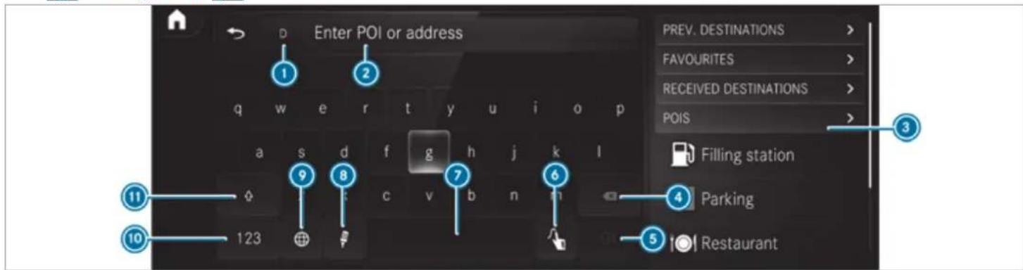
text_image
Enter POI or address PREV. DESTINATIONS > FAVOURITES > RECEIVED DESTINATIONS > POIS > Filling station Parking Restaurant① Country in which the vehicle is located
② Entering a POI or address
3 List with additional destination entry options
4 Deletes an entry
5 OK Confirms an entry
6 Switches to handwriting recognition
7 Enters a space
8 Switches to voice input
9 Sets the written language
10 Switches to digits, special characters and symbols
⑪ Switches to upper-case or lower-case letters
Enter the destination in ②. The entries can be made in any order.
The following entries can be made, for example:
• Town, street, house number
- Street, town
- Postcode
• POI name or POI category, e.g. Parking
- Contact name
Select a search result in list 3.
▶ Calculate the route ( page 334).
You can find further information about destination entry, e.g. 3 word addresses, in the Digital Owner's Manual.
Changing country
Select the country indicator in ①.
Enter the country indicator.
Select the country in ③.
Using online search
Destination entry uses online map services. If the on-board search finds no suitable destinations or if you change countries, the online search is available.
For the destination you can enter an address, a POI or a 3 word address.
▶ Select country indicator ①.
Select the provider for the online service from the countries list.
or
If the on-board search delivers no results, enter the destination in the input line ②.
Select the destination in the list.
The detailed view for the route is displayed.
Calculating a route and using settings for route guidance
Requirements:
• The destination has been entered.
• The destination address is shown.
Multimedia system:
Navigation
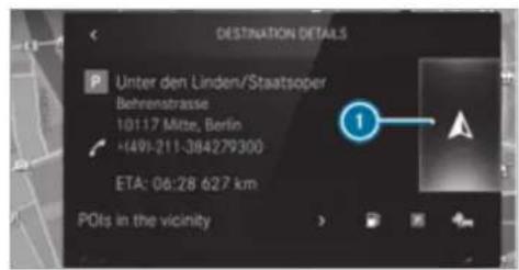
text_image
DESTINATION DETAILS Unter den Linden/Staatsoper Behrenstrasse 10117 Mitze, Berlin +491-211-384279300 ETA: 06:28 627 km POIs in the vicinity① No route yet.
A route has been mapped.
Select ▲. The route to the destination is calculated. Route guidance begins.
or
Select
Select Set as intermediate dest..
The destination address is set as the next intermediate destination.
or
Selecting route settings
Select Start new route guidance. The destination address is set as the new destination. The previous destination and the intermediate destinations are deleted. Route guidance to the new destination begins.
Select
Select Advanced.
Select Route.
Select the route type.
Take traffic information into consideration with Dynamic route guidance >.
▶ Select route options with Avoid options.
Activate Suggest alternative route. Alternative routes are calculated for every route.
Activate Activate commuter route. If the requirements are met, the multimedia system automatically detects that the vehicle is on a commuter route. Route guidance begins without voice output.
Activating route guidance with augmented reality
During route guidance, tap on the camera symbol on the media display. The camera image will be shown instead of the navigation map before a turning manoeuvre and will show additional information. To return to the navigation map: tap on the camera symbol again.
Displaying additional information in the camera image
Select
Select Advanced.
▶ Select Augmented Reality.
Activate Street names and House numbers. During route guidance, street names and house numbers are shown in the camera image.
Using map functions
Multimedia system:
Navigation
Setting the map scale
To zoom in: tap twice quickly with one finger on the media display.
To zoom out: tap with two fingers on the media display.
Moving the map
Move one finger in any direction on the touchscreen.
To reset the map to the current vehicle position: press ☑ briefly.
Selecting map orientation
Tap repeatedly on the compass symbol on the map. The view changes in the sequence 3D, 2D heading up to 2D north up.
Switching motorway information on/off
Select
▶ Switch Motorway information on or off.
Using services
Requirements:
• There is an Internet connection.
- Mercedes me connect is available.
- You have set up a user account in the Mercedes me Portal.
- The vehicle is connected to a user account and you have accepted the conditions of use for the service.
Further information can be found at: https://www.mercedes.me
- The service is available and has been activated.
- The following requirements apply to the Parking service:
The navigation services option is available, subscribed to and activated in the Mercedes me Portal.
- The parking service is within the scope the navigation service.
Multimedia system:
Navigation
Displaying the traffic situation with Live Traffic Information
Select
Activate Traffic.
Select Advanced.
Select View.
Select Map elements.
Switch on Traffic incidents, Free-flowing traffic and Delay.
If traffic information has been received, then traffic incidents such as roadworks, road blocks, local area reports (e.g. fog) and warning messages are displayed.
The traffic delay is displayed for the current route. Traffic delays lasting one minute or longer are taken into consideration.
Displaying hazard warnings with Car-to-X-Communication
df hazard warnings are available these can be shown as symbols on the map. The display
depends on the settings for the Traffic and Traffic incidents options.
Set the options. If Traffic is switched off and Traffic incidents is switched on, the symbols are shown on the prospective route.
Displaying weather information and other map contents
Select
Select Advanced.
Select View.
▶ Select Map elements.
▶ Scroll up and show the ONLINE MAP CONTENTS category.
Switch on a service, e.g. Weather.
Current weather information is displayed on the navigation map, e.g. temperature or cloud cover.
Parking service

WARNING Risk of accident and injury due to not observing the maximum permitted access height
If the vehicle height is greater than the maximum permitted access height for multi-storey and underground car parks, the roof and other parts of the vehicle may be damaged. Vehicle occupants may be injured.
Before entering a multi-storey car park or underground car park, observe the signposted entrance height.
If the vehicle height is greater than the access height, do not enter.

NOTE Before selecting the parking option
The data is based on information provided by the respective service provider.
Mercedes Benz accepts no liability for the accuracy of the information provided relating to the multi-storey car park/parking area.
Always observe the local Information and conditions.
① This service is not available in all countries.
Select and activate Parking.
Tap on P in the map.
Select a parking option.
The map shows the parking options in the vicinity.
The following information is displayed (if available):
-
Destination address, distance from current vehicle position and arrival time
• Information on the multi-storey car park/car park, for example: -
Opening times
- Parking charges
- Current occupancy
- Maximum parking time
Maximum access height
The maximum access height shown by the parking service does not
replace the need for observation of the actual circumstances.
• Available payment options (Mercedes pay, coins, bank notes, cards)
• Details on parking tariffs
• Number of available parking spaces
- Payment method (e.g. at the parking machine)
• Services/facilities at the parking option
- Telephone number
Calculate the route ( page 334).
Notes on the dashcam
NOTE Before using the dashcam
You are legally responsible for operation and use of the dashcam functions. The legal requirements relating to operation and use of the dashcam can vary depending on the country in which the dashcam is operated. Therefore, observe the legal requirements, in
particular the data protection regulations, in your country.
For this reason, before using the dashcam inform yourself about the regulation details for the respective country.
This function is not permitted in all countries.
Observe the country-specific regulations.
Selecting a USB device for a video recording with the dashcam
Requirements:
- At least one USB device is connected with the multimedia system.
Multimedia system:
→ ▶ Mercedes me & Apps
Dashcam
▶ Select the USB device.
When USB devices contain multiple partitions, recorded video files are not always displayed in the recording list.
Mercedes-Benz recommends that you use USB devices with one partition.
Starting or stopping video recording with the dashcam
Requirements:
- A USB device is connected with the multimedia system.
• The ignition is switched on.
Multimedia system:
→ ▶ ➤ Mercedes me & Apps
Dashcam
If several USB devices are connected with the multimedia system, select a USB device ( page 338).
▶ Select the Individual recording or Loop recording recording mode.
If Individual recording is selected and the memory is full the recording stops.
If Loop recording has been selected, several short video files are recorded. When the memory limit is reached, the oldest video file
is deleted and recording is continued automatically.
To start: select Start recording.
The length of the recording is shown. The
Please do not remove the storage medium.
message appears. The video file is stored on
the USB device.
To end: select End recording.
A report may appear in the following cases:
- For the Individual recording recording mode: the memory is full or there are only a few minutes recording time available. The video recording stops or will be stopped imminently.
Change the USB device or delete a video file.
- If a video recording has started and a national border is detected, the National border crossed. Please observe the countryspecific regulations regarding video recording. message appears
This function is not available in all countries.
- The camera is not functional, the Camera unavailable message appears.
Have the camera checked in a Mercedes-Benz service centre.
Telephone
Telephony
Notes on telephony
A WARNING Risk of distraction from operating integrated communication equipment while the vehicle is in motion
If you operate communication equipment integrated in the vehicle when driving, you could be distracted from the traffic situation. This could also cause you to lose control of the vehicle.
Only operate this equipment when the traffic situation permits.
If you cannot be sure of this, stop the vehicle whilst paying attention to road and traffic conditions and operate the equipment with the vehicle stationary.
A WARNING Risk of an accident from operating mobile communication equipment while the vehicle is in motion
Mobile communications devices distract the driver from the traffic situation. This could also cause the driver to lose control of the vehicle.
As the driver, only operate mobile communications devices when the vehicle is stationary.
As a vehicle occupant, only use mobile communications devices in the areas intended for this purpose, e.g. in the rear passenger compartment.
You must observe the legal requirements for the country in which you are currently driving when operating mobile communication equipment in the vehicle.
WARNING Risk of injury due to objects being stowed incorrectly
If objects in the vehicle interior are stowed incorrectly, they can slide or be thrown around and hit vehicle occupants. In addition, cup holders, open stowage spaces and mobile phone receptacles cannot always retain all objects within.
There is a risk of injury, particularly in the event of sudden braking or a sudden change in direction.
Always stow objects so that they cannot be thrown around in such situations.
Always make sure that objects do not protrude from stowage spaces, luggage nets or stowage nets.
▶ Close the lockable stowage spaces before starting a journey.
Always stow and secure heavy, hard, pointed, sharp-edged, fragile or bulky objects in the boot/load compartment.
Observe the additional information on stowing mobile communications devices correctly:
- Loading the vehicle (→ page 134)
Bluetooth ^® connection:
The menu view and the available functions in the telephone menu are in part dependent on the Bluetooth® profile of the connected mobile phone. Full functionality is only available if the mobile phone supports both of the following Bluetooth® profiles:
• PBAP (Phone Book Access Profile)
- The contacts on the mobile phone are shown automatically on the multimedia system.
• MAP (Message Access Profile)
- The mobile phone message functions be used on the multimedia system.
Irrespective of this, Bluetooth ^® audio functionality can be used with any mobile radio unit.
For information on the range of functions of the mobile radio unit to be connected, see the manufacturer's operating instructions.
Network connection:
The following cases can lead to the call being disconnected while the vehicle is in motion:
- You switch into a transmission/reception station, in which no communication channel is free.
- The SIM card used is not compatible with the network available
- A mobile phone with "Twincard" is logged into the network with the second SIM card at the same time
The multimedia system supports calls in HD Voice ^® for improved speech quality. A requirement for this is that the mobile phone and the mobile phone network provider of the person you are calling support HD Voice ^® .
Depending on the quality of the connection, the voice quality may fluctuate.
Further information can be obtained from a Mercedes-Benz service centre or at: https://www.mercedes-benz.com/connect
Telephone menu overview
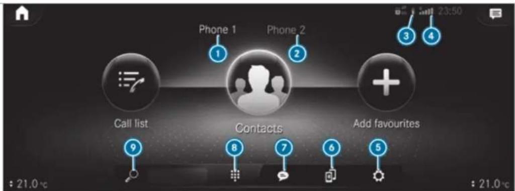
text_image
Phone 1 Phone 2 Call list Contacts Add favourites : 21.0 °C 8 7 6 5 : 21.0 °CBluetooth ^® device name of the currently connected mobile phone/of the mobile phone
Bluetooth® device name of the currently connected mobile phone/of the mobile phone (two phone mode)
3 Battery status of the connected mobile phone
④ Signal strength of the mobile phone network
5 Options
6 Device manager
7 Messages
8 Numerical pad
9 Contact search
Telephony operating modes overview
Depending on your equipment, the following telephony operating modes are available:
- A mobile phone is connected to the multimedia system via Bluetooth
- Two mobile phones are connected with the multimedia system via Bluetooth(two phone mode).
- You can use all the functions of the multi-media system with the mobile phone in the foreground.
- You can receive incoming calls and messages with the mobile phone in the background.
You can interchange the mobile phone in the foreground and background.
- A mobile phone is connected as the car phone.
Connecting a mobile phone
Requirements:
- Bluetooth® is activated on the mobile phone (see the manufacturer's operating instructions).
- Bluetooth® is activated on the multimedia system.
Multimedia system:


Searching for a mobile phone

Select

Select Connect new device.
Connecting a mobile phone
^3 Authorisation follows using secure simple pairing.

Select a mobile phone.
A code is displayed in the multimedia syste and on the mobile phone.

If both codes match, confirm the code on mobile phone.
Functions in the telephony menu
In the telephony menu you have the following functions, for example:

Making calls, e.g.:

Accept a call
End call


Create conferen. call
- Accepting or rejecting a waiting call
• Managing contacts, e.g.:
- Downloading mobile phone contacts
- Managing the format of a contact's name
- Saving a contact as a favourite
- Receiving and sending messages, e.g.:
- Using the read-aloud function
- Dictating a new message
Mercedes me and apps
Mercedes me connect
Information on Mercedes me connect
Mercedes me connect or individual Mercedes me connect services are not available in every country. Find out at a Mercedes-Benz service centre if these functions are available in your country.
Mercedes me connect consists of multiple services.
You can use the following services via the multi-media system and the overhead control panel, for example:
- Accident and Breakdown Management (me button or situation-dependent display in the multimedia system)
- Mercedes-Benz emergency call system (automatic emergency call and SOS button)
The Mercedes me connect Accident and Breakdown Management and the Mercedes-Benz emergency call centre are available to you around the clock.
The me button and the SOS button can be found on the vehicle's overhead control panel ( page 344).
You can also call the Mercedes-Benz Customer Centre using the multimedia system ( page 345).
Please note that Mercedes me connect is a Mercedes-Benz service. In emergencies, first call the national emergency services using the standard national emergency service telephone numbers. In emergencies, you can also use the
Mercedes-Benz emergency call system ( page 353).
Observe the conditions of use for Mercedes me connect and other services. These can be obtained in the Mercedes me Portal: https://me.secure.mercedes-benz.com
-Further information about Mercedes me connect, the provided service scope and operation: https://moba.i.daimler.com/markets/ece-row/baix/cars/connectme/en_GB/#emotions/Startseite.html
Information on Mercedes me connect Accident and Breakdown Management
The Accident and Breakdown Management can include the following functions:
-
Supplement to the Mercedes-Benz emergency call system ( page 353)
If necessary, the contact person at the Mercedes-Benz emergency call centre forwards the call to Mercedes me connect Accident and Breakdown Management. Forwarding the call is however not possible in all countries. -
Breakdown assistance by a technician on location and/or the towing away of the vehicle to the nearest Mercedes-Benz service centre
You may be charged for these services. - Addition to the emergency guide after automatic accident or breakdown detection ( page 345)
In the event of a breakdown or accident, further vehicle data is sent which enables optimal support by the Mercedes-Benz Customer Centre and the authorised service partner or breakdown assistance. - Addition to the Mercedes me connect service Telediagnostics
With the Telediagnostics function, specific wear and failure reports are recorded by the service provider, in so far as these can be clearly interpreted and are available through the monitoring of components that are subject to diagnostics.
If your vehicle detects a breakdown or threat of a breakdown, you may be prompted via the multimedia system to contact the
Mercedes-Benz Customer Centre for further help. This prompt in the multimedia system only appears when the vehicle is stationary.
These services are subject to technical restrictions such as the mobile phone coverage, mobile network quality and the ability of the processing systems to interpret the transferred data. In some circumstances, this can result in delays or the failure of the information to appear in the multimedia system.
More information about Mercedes me connect services can be obtained in the Mercedes me Portal: https://me.secure.mercedes-benz.com
Data transferred during Mercedes me connect call services
The data transferred during a Mercedes me connect call depends on:
• The reason for initiation of the call
- The service that is selected in the voice control system
• The activated Mercedes me connect services
You can find out which data is transferred when using the services in the currently valid Mercedes me connect terms of use and the data protection information for Mercedes me connect. You can find these in your Mercedes me user account.
Mercedes me calls
Making a call via the overhead control panel
① Mercedes me calls are not possible in every country. Find out at a Mercedes-Benz service centre if these functions are available in your country.
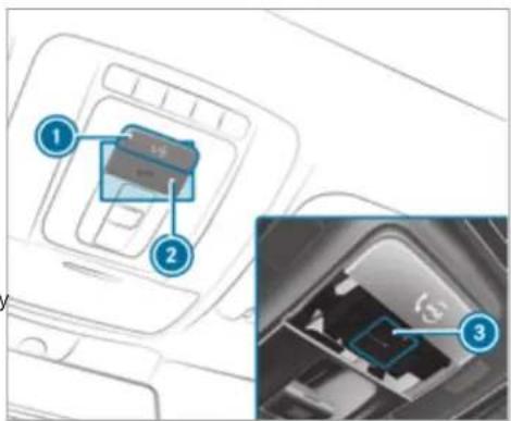
text_image
Diagram showing car interior with labeled components and a close-up of the internal connector detailme button for service or information calls
② SOS button cover
3 SOS button (emergency call system)
Making a Mercedes me call
Press me button ①.
Making an emergency call
To open the cover of SOS button ②, press it briefly.
Press and hold SOS button ③ for at least one second.
If a Mercedes me call is active, an emergency call can still be triggered. This has priority over all other active calls.
Information about the Mercedes me call using the me button
A call to the Mercedes-Benz Customer Centre has been initiated via the me button in the overhead control panel or the multimedia system (→ page 344).
Using the voice dialogue system you access the desired service:
• Accident and Breakdown Management
• Mercedes-Benz Customer Centre for general information about the vehicle
You can find information on the following topics:
• Activation of Mercedes me connect
- Operating the vehicle
• Nearest Mercedes-Benz service centre
- Other products and services from Mercedes-Benz
Data is transferred during the connection to the Mercedes-Benz Customer Centre (→ page 347).
Calling the Mercedes-Benz Customer Centre using the multimedia system
Requirements:
- Access to a mobile phone network is available.
- The contract partner's mobile network coverage is available in the respective region.
- The ignition must be switched on so that vehicle data can be transferred automatically.
Multimedia system:

▶ Call Mercedes me connect. After confirmation, the multimedia system sends the required vehicle data. The data transfer is shown in the media display.
Then, you can select a service and be connect to a specialist at the Mercedes-Benz Customer Centre.
Calling the Mercedes-Benz Customer Centre after automatic accident or breakdown detection
Requirements:
- The vehicle has detected an accident or breakdown situation.
• The vehicle is stationary.
• The hazard warning lights are switched on.
① This function is not available in all countries. The vehicle can detect accident or breakdown situations under certain circumstances.
In the event an accident or breakdown is detected, the emergency guide shows safety notes in the multimedia system display.
After quitting the emergency guide display on the multimedia system, a prompt appears asking whether you would like to get support from the Mercedes-Benz Customer Centre.

Select Call.
- After your agreement, or if the Mercedes me connect service "Accident and Breakdown Management" is active, the vehicle data is transferred automatically (→ page 343).
- The Mercedes-Benz Customer Centre takes your call and organises the breakdown and accident assistance.
You may be charged for these services.
Depending on the severity of the accident, an automatic emergency call can be initiated. This has priority over all other active calls.
In addition, if the Mercedes me connect service "Telediagnostics" is active, a similar prompt can appear after a delay in the event of a breakdown. If you are already in conta with the Mercedes-Benz Customer Centre or have already received support, this prompt can be ignored or declined.
If you answer the prompt for support from the Mercedes-Benz Customer Centre with
Later, the message will be hidden and appear again later. The prompt triggered by the Mercedes me connect service "Telediagnostics", can either be confirmed or declined. After being declined, this will not be shown again.
Arranging a service appointment via a Mercedes me call
If you have activated the maintenance management service, relevant vehicle data is transferred automatically to the Mercedes-Benz Customer Centre. You will then receive individual recommendations regarding the maintenance of your vehicle.
Regardless of whether you have consented to the maintenance management service, the multi-media system reminds you after a certain amount of time that a service is due. A prompt appears asking if you would like to make an appointment.

To arrange a service appointment: select Call.
After your agreement, the vehicle data is transferred and the Mercedes-Benz customer
centre takes your preferred appointment date. The information is then sent to your desired service outlet.
This will contact you to confirm the appointment and if necessary consult about the details.
If you select Later after the service message appears, the message is hidden and reappears at a later time.
Giving consent to data transfer during a Mercedes me call
Requirements:
- There is an active Mercedes me call via the multimedia system or the me button in the overhead control panel (→ page 344).
(i) The prompt to confirm data transfer does not appear in all countries.
If the Accident and Breakdown Management services are not activated on Mercedes me, the Do you want to transmit vehicle data and the vehicle's position to the Mercedes-Benz Customer Centre in order to improve the processing of your request? message is shown.
▶ Select Yes. Relevant identification data is transmitted automatically.
More information on Mercedes me: https://www.mercedes.me
Transferred data during a Mercedes me call
When you make a service call via Mercedes data is transmitted. This enables targeted advice and a smooth service.
The following requirements must be fulfilled for the transfer of the data:
• The ignition is switched on.
- The required data transfer technology is supported by the mobile phone network provider.
- The quality of the mobile connection is sufficient.
Multi-stage transfer depends on the following factors:
• Reason for the initiation of the call
- The available mobile phone transmission technology.
• The activated Mercedes me connect services.
- The service selected in the voice control system.
i A prompt for consent to the data transmission only occurs if the corresponding Mercedes me connect service is not activated.
Data transfer if Mercedes me connect services are not activated
If no Mercedes me connect services are activated and the data protection prompt has been confirmed the following data is transmitted:
• Vehicle identification number
• Time of the call
• Reason for the initiation of the call
• Confirmation of the data protection prompt
• Country indicator of the vehicle
- Set language for the multimedia system
- Telephone number of the communication platform installed in the vehicle
If a call is made for a service appointment via the service reminder, the following data is also transmitted:
• Current mileage and maintenance data
If a call is made after automatic accident or breakdown detection using the multimedia system, the following data is also transmitted:
• Current mileage and maintenance data
• Current vehicle location
If Accident and Breakdown Management is called via the voice control system and no service has been activated, but the data protection query has been confirmed, the following data can also be called up from the vehicle by the Mercedes-Benz Customer Centre:
• Current vehicle location
If the data protection prompt has been rejected, the following data is transmitted to enable targeted advice and an efficient service:
• Reason for the initiation of the call
- Rejection of the data protection prompt
• Country indicator of the vehicle
- Set language for the multimedia system
- Telephone number of the communication platform installed in the vehicle
Data transfer if Mercedes me connect services are activated
Only if the respective service is activated will additional incident-specific data be transmitted in the second stage to enable an optimal service.
An overview of the data transmitted can be found in the respective terms of use for Mercedes me connect services. These can be obtained in the Mercedes me portal: https://me.secure.mercedes-benz.com
Data processing
The data transmitted within the scope of the call is deleted from the processing system after the call is finished, in so far as this data is not being used for other activated Mercedes me connect services.
The incident-specific data is processed and stored in the Mercedes-Benz Customer Centre and, if required to process the incident, forwarded to the service partner authorised by the
Mercedes-Benz Customer Centre. Please take note of the data protection information on the Mercedes me Internet page https://www.mercedes.me or in the recorded message immediately after calling the Mercedes-Benz Customer Centre.
The recorded message is not available in every country.
Overview of the Mercedes me & Apps menu
When you log in with a user account to the Mercedes me Portal, then services and offers from Mercedes-Benz will be available to you.
For more information consult a Mercedes-Benz service centre or visit the Mercedes me portal: https://me.secure.mercedes-benz.com
i Make sure you always keep the Mercedes me apps updated.
You can call up the menu using Mercedes me & Apps in the multimedia system.
In the Mercedes me & Apps menu, the following options can be available:
- Connecting the vehicle with the Mercedes me user account
- Deleting a connection between a Mercedes me user account and the vehicle
- Calling up the Mercedes me services
- Calling up apps such as, In-Car Office or the web browser depending on availability
Overview of In-Car Office
Using In-Car Office, you can connect your online services with the multimedia system.
Requirements for In-Car Office:
- Your mobile phone is connected with the multimedia system.
- You have a user account for the Mercedes me Portal.
- The In-Car Office service is activated in the Mercedes me Portal.
- You have a user account with an online service, e.g. Office 365, and have connected
the online service with your user account in the Mercedes me Portal.
In-Car Office functions:
- Display pending appointments in the calendar
- Reading out calendar entries
- Calling (requirement being that a telephone number is saved)
- Navigating to appointments (requirement being that the appointment contains a navigable destination)
- Deleting a calendar entry
- Display and selection of tasks and calls to complete
- Reading aloud
- Calling (requirement being that a telephone number is saved)
-
Deleting
-
Noting calls
- Declining incoming calls and saving as a task in the Tasks & calls menu
- Marking entry in Tasks & calls as completed √
- Managing e-mails
- Showing/reading e-mails
- Writing and forwarding e-mails
You can start the In-Car Office function using the Mercedes me & Apps menu. Please note that certain functions are only available when the vehicle is stationary.
Web browser overview
The web browser is started using the Mercedes me & Apps menu.
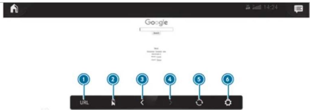
text_image
Google Login 1 2 3 4 5 6 URL① URL entry
2 Bookmarks
③ Web page, back
4 Web page, forwards
5 To refresh/stop
6 Options
① Websites cannot be shown while the vehicle is in motion.
Overview of smartphone integration
With Smartphone Integration, you can use certain functions on your mobile phone via the multimedia system display.
Only one mobile phone at a time can be connected via Smartphone Integration to the multimedia system. Also for use with two phone mode with smartphone integration, only one additional mobile phone can be connected using Bluetooth ^® with the multimedia system.
The full range of functions for Smartphone Integration is only possible with an Internet connection. The appropriate application must be downloaded on the mobile phone to use Smartphone Integration. The mobile phone must be switched on and connected to a USB port with the
symbol on the multimedia system using a suitable cable.
Apps for Smartphone Integration
- Apple CarPlay®
- Android Auto
For safety reasons, the first activation of Smartphone Integration on the multimedia system must be carried out when the vehicle is stationary and the parking brake is applied.
You can start Apple CarPlayer Android Auto from the device manager.
Mercedes-Benz recommends disconnecting the connecting cable only when the vehicle is stationary.
Overview of transferred vehicle data
When using Smartphone Integration, certain vehicle data is transferred to the mobile phone. This enables you to get the best out of selected mobile phone services. Vehicle data is not directly accessible.
The following system information is transmitted:
- Software release of the multimedia system
• System ID (anonymised)
The transfer of this data is used to optimise communication between the vehicle and the mobile phone.
To do this, and to assign several vehicles to the mobile phone, a vehicle identifier is randomly generated.
This has no connection to the vehicle identification number (VIN) and is deleted when the multimedia system is reset ( page 330).
The following driving status data is transmitted:
• Transmission position engaged
- Distinction between parked, standstill, rolling and driving
• Day/night mode of the instrument cluster - Drive type
The transfer of this data is used to alter how content is displayed to correspond to the driving situation.
The following position data is transmitted:
- Coordinates
- Speed
- Compass direction
• Acceleration direction
This data is used by the mobile phone to improve the accuracy of the navigation (e.g. for continuation in a tunnel).
Mercedes-Benz emergency call system
Information on available emergency call systems
Two types of emergency call system are available to you in the vehicle:
• Mercedes-Benz emergency call system
• 112 emergency call system (EU eCall)
The Mercedes-Benz emergency call system is not available in all countries. You can find more information on the regional availability of eCall at: https://www.mercedes-benz-mobile.com/extra/ecall/
The following applies for both emergency call systems:
- The transfer of specific data is required for the intended function of both emergency call
systems. This will be explained in the "Data transfer" section ( page 355).
- Both emergency call systems are included as standard equipment in your vehicle and are activated at the factory.
- The use of both emergency call systems is exempt from charges.
Both emergency call systems only function in areas in which the mobile phone network providers offer mobile phone coverage.
For both systems, insufficient network coverage from the mobile phone network providers can result in an emergency call not being transmitted.
Differences between the Mercedes-Benz emergency call system and 112 emergency call system (EU eCall)
| Mercedes-Benz emergency call system | 112 emergency call system (EU eCall) |
| The Mercedes-Benz emergency call system is permanently logged in to the mobile phone network.Automatic and manual Mercedes-Benz emergency calls are transmitted to a Mercedes-Benz emergency call centre.In the event that the emergency call centre of the Mercedes-Benz emergency call system cannot be reached (e.g. due to a lack of network coverage), the 112 emergency call is carried out automatically. | If you decide to use the 112 emergency call system (EU eCall), then the system only logs in to the mobile phone network after the triggering of a manual or automatic emergency call.The 112 emergency call system (EU eCall) transmits automatic and manual emergency calls directly to public coordination centres. |
The 112 emergency call system (EU eCall) in your vehicle meets the delegated regulation EU 2017/79. Proper and full functionality of the 112 emergency call system (EU eCall) depends on circumstances beyond the influence of Mercedes-Benz AG. This includes
mobile network coverage and the technical infrastructure of the public reception centres in the respective countries.
i Please observe that in the event of a repair genuine Mercedes-Benz batteries must be used which have been certified pursuant to
the delegated regulation EU 2017/79 (Appendix I). Other manufacturers are also permitted provided their batteries are certified according to the delegated regulation EU 2017/79.
There is the option of deactivating the Mercedes-Benz emergency call system and using only the 112 emergency call system (EU eCall). Contact address for carrying out deactivation of the Mercedes-Benz emergency call system are the local dealers.
Mercedes-Benz recommends the activation of the Mercedes-Benz emergency call system for the following reasons:
- In emergency situations when abroad, you can also get support in a language you speak.
- Several transmission technologies are used to accelerate the transfer of the accident data and improve reliability of the transmission.
- The Mercedes-Benz emergency call system permanently logged in to the mobile phone network, which ensures faster placement of the emergency call and faster transfer of the accident data.
Measures for rescue, recovery or towing away can then be initiated in quickly.
- With a Mercedes-Benz emergency call, the accident data is only transferred to the public coordination centre with the approval of the customer.
In the event of an automatically triggered emergency call in which there is no voice contact, the accident data is transmitted immediately to the public emergency call centre. - Should the Mercedes-Benz emergency call centre not be available, the 112 emergency call is carried out automatically.
Overview of emergency call systems
Both the Mercedes-Benz emergency call system is as well as the 112 emergency call system (EU eCall) can help to reduce the time between an accident and the arrival of emergency services at the site of the accident. They help locate an accident site in places that are difficult to access.
Both emergency call systems can initiate an emergency call automatically ( page 354) or manually.
Only make emergency calls if you or others are in need of rescue. Do not make an emergency call in the event of a breakdown or a similar situation.
Messages on the display
The following messages appear in the display of both emergency call systems:
- SOS NOT READY: the ignition is not on or eCall is not available. This does not necessarily indicate complete failure of the emergency call system. Emergency calls call still be transmitted.
The display only refers to the vehicle and does not take account of the availability of mobile phone networks and the Mercedes-Benz emergency call centre.
The functional readiness of the emergency call system on the vehicle can be seen when the SOS NOT READY display disappears on the ignition is switched on.
- SOS: The icon appears in the display durin, an active emergency call.
If there is a malfunction in the emergency call system (e.g. a fault with the speaker, microphone, airbag, SOS button), a corresponding message appears in the multifunction display of the instrument cluster.
Triggering an automatic emergency call
Requirements:
• The ignition is switched on.
• The starter battery is sufficiently charged.
Both the Mercedes-Benz emergency call system as well as the 112 emergency call system (EU eCall) automatically initiate an emergency call after:
- Activation of the restraint systems such as airbags or seat belt tensioners after an accident
The emergency call has been made:
- A voice connection is established with the emergency call centre.
- A message with accident data is transmitted to the emergency call centre.
The SOS button in the overhead control panel flashes until the emergency call is finished.
If no connection can be made to the public emergency services, a corresponding message appears in the display.
Dial the emergency number 112 or an appropriate local emergency call number on your mobile phone.
If an emergency call has been initiated:
- Remain in the vehicle if the road and traffic conditions permit you to do so until a voice connection is established with the emergency call centre.
- On the basis of the call, the emergency call centre decides whether it is necessary to call rescue teams and/or the police to the accident site.
- If no vehicle occupant answers, an ambulance is sent to the vehicle immediately.
Triggering a manual emergency call
To use the SOS button in the overhead control panel: press the SOS button at least one second long ( page 344).
To use voice control: use the LINGUA-TRONIC voice commands.
The emergency call has been made:
- A voice connection is established with an emergency call centre.
- Remain in the vehicle if the road and traffic conditions permit you to do so until a voice connection is established with the emergency call centre.
- On the basis of the call, the emergency call centre decides whether it is necessary to call rescue teams and the police to the accident site.
- A message with accident data is transmitted to the emergency call centre.
If no connection can be made to the public emergency services, a corresponding message appears in the media display.
▶ Dial the emergency number112 or an appropriate local emergency call number on your mobile phone.
Emergency call system data transmission
For both the Mercedes-Benz emergency call system as well as the 112 emergency call system (EU eCall) data is transferred to the Mercedes-
Benz emergency call centre or the public emergency services call centre.
Depending on the emergency call system ( page 351) activated different data is transmitted to the appropriate emergency call centre.
Transmitted data according to activated emergency call system:
| Mercedes-Benz emergency call | 112 emergency call |
| Vehicle's GPS position dataGPS position data on the route(a few hundred metres before the incident)Direction of travelVehicle identification numberDrive type of the vehicle (e.g. petrol, CNG, LPG, electric or hydrogen)Number of people determined to be in the vehicleWhether the emergency call was initiated manually or automaticallyTime of the accidentLanguage setting on the multimedia systemWhether Mercedes me connect is available or notThis is a requirement for the option of forwarding the call to the Mercedes-Benz Customer Centre if necessary. | Vehicle's GPS position dataGPS position data on the route(a few hundred metres before the incident)Direction of travelVehicle identification numberDrive type of the vehicle (e.g. petrol, CNG, LPG, electric or hydrogen)Number of people determined to be in the vehicleWhether the emergency call was initiated manually or automaticallyTime of the accident |
If only the 112 emergency call system (EU eCall) is activated in the vehicle, the accident data is transmitted directly to the public emergency call centre.
For accident clarification purposes, the following measures can be taken up to an hour after the emergency call has been initiated:
- The current vehicle position can be determined.
- A voice connection to the vehicle occupants can be established.
• Emergency call data can be called up.
For Russia: various functions, e.g. receiving traffic information, cannot be performed for up to two hours after sending an emergency call.
Self diagnosis function of the emergency call system
Your car verifies the operability of the emergency call system each time the ignition is ON. In case of system failure, you will be informed with text message on the instrument cluster and with red indicator SOS NOT READY on the display.
Please, make sure, that during 30 seconds after switching ignition ON the red indicator SOS
NOT READY in the upper right corner of display is switched OFF, this means the emergency call system passed diagnostics successfully.
Starting/ending ERA-GLONASS test mode
Requirements:
• The starter battery is sufficiently charged.
• The ignition is switched on.
- The vehicle has been stationary for at least one minute.
The test mode is currently available in the following countries, for example:
- Russia
- Belarus
- Kazakhstan
- Armenia
- Kyrgyzstan
To start the test mode: press and hold the button on the multifunction steering wheel for at least five seconds.
The test mode is started and automatically ends after the language test has been performed.
To end the test mode manually: switch off the ignition.
The test mode is ended.
Information on data processing
Processing of personal data via the Mercedes-Benz emergency call system
All processing of personal data via the Mercedes-Benz emergency call system corresponds with the specifications in the EU Regulation 2016/679 "on the protection of individuals with regard to the processing of personal data (GDPR)".
The data is solely used by the Mercedes-Benz emergency call system for rescue and recovery in the event of an accident.
The owner of a vehicle, that is equipped with a Mercedes-Benz emergency call system in addition to the 112 emergency call system (EU eCall), has the right to use the 112 emergency call system instead of the Mercedes-Benz emergency call system.
Contact address for carrying out deactivation of the Mercedes-Benz emergency call system are the local dealers.
Processing of personal data via the 112 emergency call system (EU eCall)
All processing of personal data via the 112 emergency call system (EU eCall) corresponds with the specifications in the EU Regulation 2016/679 "on the protection of individuals with regard to the processing of personal data (GDPR)" and is based particularly on the necessity of upholding the vital interests of the affected person in accordance with Article 6, Clause 1, Letter d of the GDPR.
The processing of this type of data is strictly limited to the purpose of operating the emergency calls to the standard European emergency call number 112.
Data recipient
The recipients of data that is processed using the 112 emergency call system (EU eCall) are the relevant emergency call inquiry terminals that are specified to first receive and handle emergency calls to the standard European emergency call number 112 by the respective country authorities in whose territory you are located.
Arrangements for data processing
Both emergency call systems are designed so that the following requirements are fulfilled:
- The data contained in the system memory not accessible outside the system prior to the initiation of an emergency call.
- Both emergency call systems cannot be traced and there is no continuous tracking normal operation.
- The data in the system's internal memory automatically and continuously deleted.
- The location data of the vehicle is continuously overwritten in the system's internal memory, so that no more than the last three current locations required for the normal function of the system are available.
- The record of the activity data of both emergency call systems is only kept for as long as is required to fulfil the purpose of handling the emergency call, however for no longer than 13 hours after the time that an emergency call is initiated.
Rights of persons affected by the data processing
The person affected by the data processing (the vehicle owner) has the right to access the data and if applicable can demand the correction, deletion or barring of data that affects him or her and that the processing of which does not correspond with the GDPR regulations. Each correction, deletion or barring carried out according to this regulation must be shared with the third party to which the data has been transmitted, provided this does not prove to be infeasible and is does not incur disproportionate expenditure.
The person affected by the data processing has the right to complain to the appropriate data protection authority should they be of the opinion that their rights have been infringed by the processing of their personal data.
Radio, media & TV
Overview of the symbols and functions in the media menu
| Symbol Designation Function | ||
| Play | Select to start or continue playback. | |
| Rest | Select to pause the playback. | |
| Repeat a track | Select to repeat the current track or the active playlist.Select once: the active playlist is repeated.Select twice: the current track is repeated.Select three times: the function is deactivated. | |
| Random playback | Select to play back the tracks in random order. | |
| Skip forwards/back | Select to skip to the next or to the previous track. | |
| Options Select to show additional options. | ||
| Categories | Select to show or search through available categories (e.g. playback lists, albums, artists, etc.). | |
| Search | Select to search in the active menu. You can search for artists, genres or moods, for example. | |
| Settings | Select to make settings. | |
| Home | Select to return to the home screen. | |
| Messaging Select to call up messaging. | ||
| Full screen | Select to switch to full screen mode. | |
The following functions and settings are available in the media menu:
- Connecting external data storage media with the multimedia system (e.g. using USB or Bluetooth ^® )
- Playing back audio or video files
• Streaming online music - Looking at TV programmes in the TV menu
Additional functions in the TV menu
| Symbol Designation | F | u | n | c | t | i | o |
| Settings | Select to make settings in the TV menu. The following functions can be switched on/off or configured:Channel fixCountry-specific character setAudio languageSubtitlesTeletextPicture format | ||||||
| i | EPG | Select to show current programme information for the channel. | |||||
| Channel list | Select to show a list of available channels with the current programme. | ||||||
Authorising a Bluetooth® audio device for media playback
Requirements:
- Bluetooth® is activated on the multimedia system and audio equipment.
- The audio equipment supports the Bluetooth® audio profiles A2DP and AVRCP.
- The audio equipment is "visible" for other devices.
Multimedia system:

With Bluetooth ^® audio, you can play back music files from an external data storage medium, e.g. your smartphone, using the MBUX multimedia system.
To play back audio files using the multimedia system, authorise the external data storage medium on the MBUX multimedia system.
Authorising a new Bluetooth ^® audio device
▶ Select Connect new device.
▶ Select an audio device.
Authorisation starts. A code is displayed on the multimedia system and on the mobile phone.
If the codes are identical, confirm on the audio equipment.
Select Only as Bluetooth audio device. The Bluetooth® audio equipment is connected with the multimedia system.
Connecting previously authorised Bluetooth® audio equipment
Select a Bluetooth® audio device from the list. The connection is being established.
Receiving TV channels in HD quality

NOTE Damage to the Cl+ module and Smart Card
The Cl+ module is designed for use in the home. The Cl+ module can overheat and be damaged by continuous exposure to high outside temperatures.
Make sure that the Cl+ module is not subject to high temperatures for extended periods of time. If the Cl+ module is damaged, no encrypted channels can be received.
The CI+ module is not available in all countries.
A CI+ module (Common Interface Module), which is not included in the scope of delivery, is used to decrypt HD programmes according to the CI+ standard.
In some countries, an additional smart card is required, which is inserted into the CI+ module (see the manufacturer's operating manual).
The Cl+ module is connected in the Cl+ box in the glove compartment.
To insert the smart card in the Cl+ module: if required (country-dependent), insert the smart card into the Cl+ module slot.
The Cl+ box is designed for operation at temperatures between 0 °C and 65 °C. At operating temperatures that are higher or too low a message appears in the multimedia system and the Cl+ module is switched off automatically. If the Cl+ module is switched off, no encrypted channels can be received.
Overview of the symbols and functions in the radio menu
| Symbol | D | esignation Function |
| Home | Select to return to the home screen. | |
| Messaging Select to call up messaging. | ||
| Skip forwards/back | Select to skip to the next or to the previous station. | |
| Settings | Select to have further options shown. Settings can be made to the following additional functions, for example:Navigation and traffic announcementsFrequency fix functionRadio additional textEmergency warningsThe setting options are country-dependent. | |
| Full screen | Select to switch to the DAB slide show.This function is not available in all countries. | |
| Silent function | Select to switch off the sound. | |
| Store radio stations | Select to save a station in the presets. | |
Symbol Designation Function
| Station list | Select to have the station list shown. | |
| Search | Select to search in the active menu. You can search for artists, genres or moods, for example. |
Additional functions of Tuneln radio
A relatively large volume of data can be transmitted when using Tuneln Radio.
Symbol Designation Function
| Settings | The following additional settings are available in the Tuneln Radio menu:Selecting streamLogging on to or out of the Tuneln account | |
| Favourites | Select during playback to save the station currently set as a favourite. |
Symbol Designation Function
| / | Play/Pause | Select to start, stop or continue playback. |
| Browse | Select to choose a category and then a radio station. |
Depending on the frequency band selected, different functions are available to you.
Select the desired frequency band in the radio menu head runner.
Calling up Tuneln Radio
Requirements:
• A Mercedes me account is available.
- The vehicle is connected with the Mercedes me account.
- The TuneIn Radio service is activated in the Mercedes me Portal.
- The data volume is available.
Depending on the country, data volume may need to be purchased.
- A fast Internet connection for data transmission free of interference.
i Data volume can be purchased directly from a mobile phone network provider via the Mercedes me Portal.
The functions and services are country-dependent. For more information, consult a Mercedes-Benz service centre.
Multimedia system:
→ ▶ Radio
▶ Select Tuneln Radio. The Tuneln menu appears. The last station set starts playing.
The connection quality depends on the local mobile phone reception.
Sound settings
Overview of functions in the sound menu
The setting options and functions available depend on the sound system fitted. You can find out which sound system is fitted in your vehicle in the Digital Owner's Manual.
Standard sound system and Advanced sound system
The following functions are available:
• Equaliser
Treble, mid-range and bass
• Balance and fader
• Volume
- Automatic adjustment
Burmester ^® surround sound system and Burmester ^® high-end 3D surround sound system
The following functions are available:
• Equaliser:
- Treble, mid-range and bass
• Balance and fader
- Sound focus
- VIP seat (Burmester® high-end 3D surround sound system only)
- Sound profiles
• Volume:
- Automatic adjustment
ASSYST PLUS service interval display
Function of the ASSYST PLUS service interval display
The ASSYST PLUS service interval display on the instrument display provides information on the remaining time or distance before the next service due date.
You can hide this service display using the back button on the left-hand side of the steering wheel.
Depending on how the vehicle is used, the ASSYST PLUS service interval display may shorten the service interval, e.g. in the following cases:
• mainly short-distance driving
- when the engine is often left idling for long periods
• in the event of frequent cold start phases
- vehicles with a diesel particulate filter: in the event of frequently interrupted regeneration of the diesel particulate filter
Mercedes-Benz recommends avoiding such operating conditions.
You can obtain information concerning the servicing of your vehicle from a qualified specialist workshop, e.g. a Mercedes-Benz Service Centre.
Displaying the service due date
On-board computer:
Service >> ASSYST PLUS
The next service due date is displayed.
To exit the display: press the back button on the left-hand side of the steering wheel.
Bear in mind the following related topic:
- Operating the on-board computer (→ page 312).
Information on regular maintenance work
NOTE Premature wear through failure to observe service due dates
Maintenance work which is not carried out at the right time or incompletely can lead to increased wear and damage to the vehicle.
Adhere to the prescribed service intervals.
Always have the prescribed maintenance work carried out at a qualified specialist workshop.
Notes on special service requirements
The prescribed service interval is based on normal operation of the vehicle. Have the maintenance work carried out more often than prescribed if operating conditions are difficult or the vehicle is subject to increased stress.
The ASSYST PLUS service interval display is only an aid. The driver of the vehicle bears responsibility as regards to whether maintenance work needs to be performed more often than speci-
fied based on the actual operating conditions and/or loads.
Examples of arduous operating conditions:
- Regular city driving with frequent intermediate stops
• Mainly short-distance driving - Frequent operation in mountainous terrain or on poor road surfaces
- When the engine is often left idling for long periods
- Operation in particularly dusty conditions and/or if air-recirculation mode is frequently used
In these or similar operating conditions, have the interior air filter, air filter, engine oil and oil filter for example, changed more frequently. The tyres must be checked more frequently if the vehicle is operated under increased loads. Further information can be obtained at a qualified specialist workshop.
Battery disconnection periods
The ASSYST PLUS service interval display can calculate the service due date only when the battery is connected.

Note down the service due date displayed on the instrument display before disconnecting the battery ( page 367).
Engine compartment
Opening and closing the bonnet

WARNING Risk of accident due to driving with the bonnet unlocked
The bonnet may open and block your view. ▶ Never release the bonnet when driving.
Before every trip, ensure that the engine bonnet is locked.

WARNING Risk of accident and injury when opening and closing the bonnet
The bonnet may suddenly drop into the end position.
There is a risk of injury for anyone in the engine bonnet's range of movement.
Do not open or close the bonnet if there is a person in the bonnet's range of movement.

WARNING Risk of burns when opening the bonnet
If you open the bonnet when the engine has overheated or when there is a fire in the engine compartment, the following situations may occur:
- You could come into contact with hot gases.
- You could come into contact with other hot, escaping operating fluids.
Before opening the bonnet, allow the engine to cool down.
In the event of a fire in the engine compartment, keep the bonnet closed and call the fire service.
WARNING Risk of injury due to moving parts
Components in the engine compartment may continue running or start up suddenly, even if the ignition is switched off.
Make sure of the following before performing tasks in the engine compartment:
▶ Switch the ignition off.
▶ Never reach into the danger zone surrounding moving components, e.g. the rotation area of the fan.
Remove jewellery and watches.
Keep items of clothing and hair away from moving parts.
WARNING Risk of injury from touching components under voltage
The ignition system and the fuel injection system work under high voltage. You could receive an electric shock.
▶ Never touch components of the ignition system or the fuel injection system when the ignition is switched on.
The live components include the following, for example:
- ignition coils
- fuel injectors
- electric lines to the ignition coils or the fuel injectors
WARNING Risk of burns from hot component parts in the engine compartment
Certain component parts in the engine compartment can be very hot, e.g. the engine, the cooler and parts of the exhaust system.
▶ Allow the engine to cool down and only touch component parts described in the following.
WARNING Risk of injury from using the windscreen wipers while the engine bonnet is open
When the engine bonnet is open, and the windscreen wipers are set in motion, you can be trapped by the wiper linkage.
▶ Always switch off the windscreen wipers and ignition before opening the engine bonnet.
Opening the bonnet
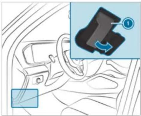
natural_image
Interior view of a car showing steering wheel and dashboard, with an inset close-up highlighting a mechanical component (no text or symbols)To release the bonnet, pull on handle ①.
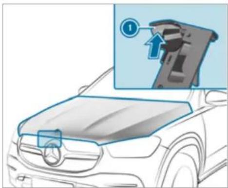
natural_image
Illustration of a car hood with a magnified inset showing a mechanical component (no text or symbols)Push handle ① of the bonnet catch upwards and lift the bonnet until it opens automatically.
Closing the bonnet

NOTE Damage to the bonnet
If the bonnet is closed manually, there is a risk of dents.

Do not close the bonnet manually.
Lower the bonnet to a height of around 20 cm and then allow it to fall, applying a little force as you let it go.
If the bonnet can still be lifted slightly, open the bonnet again and close it with a little more force until it engages correctly.
Engine oil
Checking the engine oil level using the on-board computer
Requirements:
• The engine has been warmed up.
• The vehicle is parked on a level surface.
• The engine is running at idle speed.
• The bonnet is closed.
The engine oil level is determined during driving. Determining the engine oil level can take up to 30 minutes with a normal driving style and even longer with an active driving style.
On-board computer:
→ Service ➤ Engine oil level
One of the following messages will appear on the multifunction display:
• Engine oil level Measuring now: measurement of the oil level is not yet possible.
Repeat the request after a maximum of 30 minutes' driving.
- Engine oil level OK and the bar display for indicating the oil level on the multifunction display is green and is between "min" and "max": the oil level is correct.
- Engine oil level Add 1,0 l and the bar display for indicating the oil level on the multifunction display is orange and is below "min":
▶ Add 1 l of engine oil.
- Reduce engine oil level and the bar display for indicating the oil level on the multifunction display is orange and is above "max":
Drain off any excess engine oil that has been added. To do so, consult a qualified specialist workshop.
• For engine oil level turn on ignition
Switch on the ignition to check the engine oil level.
• Engine oil level System inoperative: The oil level sensor is defective or not connected.
Consult a qualified specialist workshop.
• Engine oil level System currently unavail.
Close the bonnet.
Topping up engine oil
WARNING Risk of burns from hot component parts in the engine compartment
Certain component parts in the engine compartment can be very hot, e.g. the engine, the cooler and parts of the exhaust system.
▶ Allow the engine to cool down and only touch component parts described in the following.
WARNING Risk of fire and injury from engine oil
If engine oil comes into contact with hot component parts in the engine compartment, it may ignite.
Make sure that no engine oil is spilled next to the filler opening.
Allow the engine to cool off and thoroughly clean the engine oil from component parts before starting the vehicle.
! NOTE Engine damage caused by an incorrect oil filter, incorrect oil or additives
Do not use engine oils or oil filters which do not correspond to the specifications explicitly prescribed for the service intervals.
▶ Follow the instructions on the service interval display for changing the engine oil and observe the prescribed change intervals.
Do not use additives.
! NOTE Damage caused by topping up too much engine oil
Too much engine oil can damage the engine or the catalytic converter.
Have excess engine oil removed at a qualified specialist workshop.
Depending on driving style, the vehicle consumes up to 0.8 litre of oil per 1000 km. The oil consumption may be higher than this when the vehicle is new or if you frequently drive at high engine speeds.
① Depending on the engine, the cap may be installed in the engine compartment in different locations.
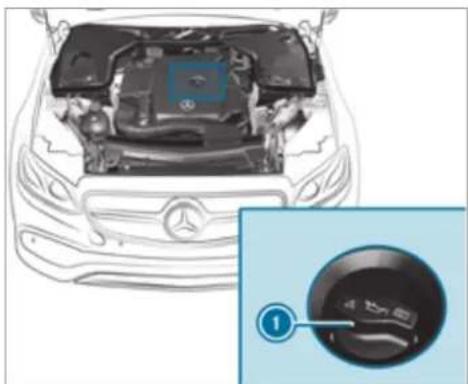
natural_image
Top-down view of a Mercedes-Benz car engine bay with a close-up inset showing the dashboard (no text or symbols visible)▶ Turn cap ⓘ anti-clockwise and remove it.
Top up the engine oil.
Replace cap ① and turn it clockwise until engages.
▶ Check the oil level again ( page 370).
Checking the coolant level
WARNING Risk of burns from hot component parts in the engine compartment
Certain component parts in the engine compartment can be very hot, e.g. the engine, the cooler and parts of the exhaust system.
Allow the engine to cool down and only touch component parts described in the following.
WARNING Risk of scalding from hot coolant
If you open the cap, you could be scalded.
Let the motor cool down before opening the cap.
When opening the cap, wear protective gloves and safety glasses.
Open the cap slowly to release pressure.
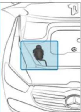
natural_image
Line drawing of a car's front and side view showing a highlighted vehicle (no text or symbols)Continue turning cap ① anti-clockwise and remove it.
The coolant level is correct in the following cases:
- If the engine is cold, the coolant is up to marker bar ②.
- If the engine is warm, the coolant is up to 1.5 cm over the marker bar ②.
If necessary, top up with coolant that has been approved for Mercedes-Benz.
(i) Further information on coolant ( page 437)
Allow the engine to cool down and only touch component parts described in the following.
WARNING - Risk of fire and injury due to windscreen washer concentrate
Windscreen washer concentrate is highly flammable. It could ignite if it comes into contact with hot engine component parts or the exhaust system.
Make sure that no windscreen washer concentrate spills out next to the filler opening.
Park the vehicle on a level surface.
▶ Check the coolant temperature display in the instrument cluster.
The coolant temperature must be below 70^ C.
Slowly turn cap ① anti-clockwise to release overpressure.
Topping up the windscreen washer system
WARNING Risk of burns from hot component parts in the engine compartment
Certain component parts in the engine compartment can be very hot, e.g. the engine, the cooler and parts of the exhaust system.
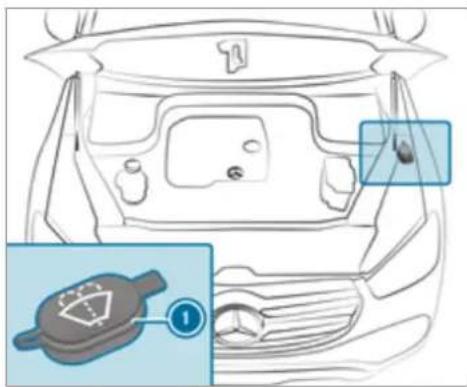
text_image
Diagram of car interior with labeled components and a numbered inset showing a gear-like device component.Remove cap ① by the tab.
Top up the washer fluid.
i Further information about the windscreen washer fluid ( page 437)
Keeping the air-water duct free
Keep the area between the bonnet and the windscreen free of deposits, e.g. ice, snow and leaves.
Cleaning and care
Information on washing the vehicle in a car wash

WARNING Risk of an accident due to reduced braking power after washing the vehicle
Braking efficiency is reduced after washing the vehicle.
After the vehicle has been washed, brake carefully while paying attention to the traffic conditions until braking power has been fully restored.
! NOTE Damage from automatic braking
If one of the following functions is switched on, the vehicle brakes automatically in certain situations:
• Active Brake Assist
• Active Distance Assist DISTRONIC
- HOLD function
• Active Parking Assist
To avoid damage to the vehicle, deactivate these systems in the following or similar situations:
during towing
in a car wash
! NOTE Damage due to unsuitable car wash
Before driving into a car wash make sure that the car wash is suitable for the vehicle dimensions.
▶ Ensure there is sufficient ground clearance between the underbody and the guide rails of the car wash.
▶ Ensure that the clearance width of the car wash, in particular the width of the guide rails, is sufficient.
To avoid damage to your vehicle when using a car wash, ensure the following beforehand:
• Active Distance Assist DISTRONIC is deactivated.
• The HOLD function is switched off.
- The 360° Camera or the reversing camera is switched off.
- The side windows and sliding sunroof are completely closed.
• The outside mirrors are folded in.
- The blower for the ventilation/heating is switched off.
- The windscreen wiper switch is in position 0.
- The key is at a minimum distance of 3 m away from the vehicle. Otherwise the tailgate could open unintentionally.
- In automatic car washes with conveyor systems:
- Neutral N is engaged.
- If you would like to leave the vehicle while it is being washed, make sure the key is located in the vehicle. The park position P is otherwise automatically engaged.
To prevent damage to the tyres and wheels, drive straight and in to the centre of the guide rails of the car wash.
If, after the car wash, you remove the wax from the windscreen and wiper rubbers, this will prevent smearing and reduce wiper noise.
Automatic car wash mode
In car wash mode, the vehicle is prepared for driving into the automatic car wash. Car wash mode can be activated at a speed of up to 20 km/h Activate ( page 376).
The following settings are made when car wash mode is activated:
• The outside mirrors are folded in.
- To prevent the windscreen washer system from starting up automatically, the rain sensor is deactivated.
• The rear window wiper is deactivated.
- The windows and the sliding sunroof are closed.
- Mercedes-Maybach vehicles: the running boards are retracted.
- The air conditioning system is set to air-recirculation mode.
- Parking Assist PARKTRONIC is deactivated.
- Vehicles with 360° Camera: the front image is activated after approx. eight seconds.
- Vehicles with AIRMATIC: the vehicle is raised to the maximum possible chassis level(→ page 269).
If rising takes longer than 25 seconds, the following message appears on the multifunction display:
Preparation for car wash incomplete See media display. After some time, the vehicle automatically continues rising.
- Vehicles with E-ACTIVE BODY CONTROL: the vehicle is raised to the maximum possible chassis level(→ page 278). If rising takes longer than 25 seconds, the following message appears on the multifunction display:
Preparation for car wash incomplete See media display. After some time, the vehicle automatically continues rising.
If one of the settings cannot be selected, this is displayed by a X behind the respective setting.
Above a speed of 20 km/h Car wash mode is automatically deactivated.
The following settings are reset when car wash mode is deactivated:
• The outside mirrors are folded out.
• The rain sensor is activated.
• The rear window wiper is activated.
- The air conditioning system is set to fresh air mode.
- Parking Assist PARKTRONIC is reset to the previously selected setting.
- The windows and the sliding sunroof remain closed.
- Mercedes-Maybach vehicles: the running boards remain retracted.
- Vehicles with 360° Camera: the front image is deactivated at speeds above 18 km/h.
- Vehicles with AIRMATIC: the vehicle is lowered to the previously set chassis level.
- Vehicles with E-ACTIVE BODY CONTROL: the vehicle is lowered to the previously set chassis level.
Activating/deactivating automatic car wash mode
Requirements:
• the vehicle is stationary.
• the engine is running.
Multimedia system:
→ Settings ▶ Quick access
Activating automatic car wash mode
▶ Select Car wash mode.
Select Start.
If one of the settings cannot be selected, this is displayed by a X behind the respective setting.
For an overview of the settings made when activating automatic car wash mode ( page 374).
Deactivating automatic car wash mode
Select Stop.
The automatic car wash settings are reset.
The automatic car wash mode is automatically deactivated as soon as a speed of 20 km/h is exceeded.
Information on using a high-pressure cleaner

WARNING Risk of an accident when using high-pressure cleaners with round-spray nozzles
The water jet can cause externally invisible damage.
Components damaged in this way may unexpectedly fail.
Do not use a high-pressure cleaner with round-spray nozzles.
Have damaged tyres or chassis parts replaced immediately.
To avoid damage to your vehicle, observe the following when using a high-pressure cleaner:
- The key is at a minimum distance of 3 m away from the vehicle. Otherwise the tailgate could open unintentionally.
- Maintain a distance of at least 30 cm to the vehicle.
- Vehicles with decorative foil: Parts of your vehicle are covered with a decorative foil.
Maintain a distance of at least 70 cm between the foil-covered parts of the vehicle and the nozzle of the high-pressure cleaner. Move the high-pressure cleaner nozzle around whilst cleaning. The water temperature of the high-pressure cleaner must exceed 60°C.
- Observe the information on the correct distance in the equipment manufacturer's operating instructions.
- Do not direct the nozzle of the high-pressure cleaner directly at sensitive parts, such as tyres, gaps, electrical components, batteries, light sources and ventilation slits.
Washing the vehicle by hand

NOTE Engine damage due to water ingress
Take care not to point the water jet directly towards the air inlet grille below the bonnet.
observe the legal requirements, e.g. in a number of countries, washing by hand is only permitted in specially designated wash bays.
Use a mild cleaning agent, e.g. car shampoo
Wash the vehicle with lukewarm water using a soft car sponge. When doing so, do not expose the vehicle to direct sunlight.
Carefully hose the vehicle off with water and dry using a chamois.
e ^i Observe the notes on the care of car parts ( page 379).
Notes on paintwork/matt finish paintwork care
Observe the notes on cleaning and care to avoid damaging the paintwork and interfering with the driver assistance systems.
Paint
- Insect remains: soak with insect remover and rinse off the treated areas afterwards.
-
Bird droppings: soak with water and rinse off afterwards.
-
Tree resin, oils, fuels and greases: remove by rubbing gently with a cloth soaked in petroleum ether or lighter fluid.
- Coolant and brake fluid: remove with a damp cloth and clean water.
• Tar stains: use tar remover. - Wax: use silicone remover.
- Do not attach stickers, films or similar materials. Only have film attached to the bumper at a qualified specialist workshop.
- Remove dirt immediately, where possible.
Matt finish
- Only use care products approved for Mercedes-Benz.
- Do not attach stickers, films or similar materials. Only have film attached to the bumper at a qualified specialist workshop.
- Do not polish the vehicle and light-alloy wheels.
-
Only use car washes that correspond to the latest engineering standards.
-
Do not use car wash programmes with a final hot wax treatment.
- Do not use paint cleaners, buffing or polishing products, gloss preservers, e.g. wax.
In the event of paintwork damage:
• Always have paintwork repairs carried out at a qualified specialist workshop. - Make sure the radar sensors function ( page 229).
Notes on cleaning decorative foils
Observe the notes on matt finish care in the chapter "Notes on paintwork/matt finish paint-work care" ( page 377). They also apply to matt decorative foils.
Observe the notes on cleaning decorative foils to avoid vehicle damage.
Cleaning
- For cleaning, use plenty of water and a mild cleaning agent without additives or abrasive substances, e.g. a car shampoo approved for Mercedes-Benz.
Remove dirt immediately, where possible, whilst avoiding rubbing too hard. There is otherwise a risk of damaging the decorative foil irreparably.
- If there is dirt on the finish or if the decorative foil is dull: use the Paint Cleaner recommended and approved for Mercedes-Benz.
- Insect remains: soak with insect remover and rinse off the treated areas afterwards.
- Bird droppings: soak with water and rinse off afterwards.
- To prevent water stains, dry a foil-wrapped vehicle with a soft, absorbent cloth after every car wash.
Avoiding damage to the decorative foil
- The service life and colouring of decorative foils are impaired by:
- sunlight
- temperature, e.g. hot air blower
- weather conditions
- stone chippings and dirt
- chemical cleaning agents
oily products
- Do not use polish on matt decorative foil. Polishing will have the effect of shining the foil-wrapped surface.
- Do not treat matt or structured decorative foils with wax. Permanent stains may occur.
Scratches, corrosive deposits, areas affected by corrosion and damage caused by incorrect care cannot always be completely repaired. In such cases, visit a qualified specialist workshop.
You can obtain more information on care and cleaning products from the manufacturer. In the case of foil-wrapped surfaces, optical differences may occur between the surfaces that were not protected by a decorative foil after removing a decorative foil.
i Have work or repairs to decorative foils carried out at a qualified specialist workshop, e.g. in a Mercedes-Benz Service Centre.
Notes on care of car parts
WARNING Risk of entrapment if the windscreen wipers are switched on while the windscreen is being cleaned
If the windscreen wipers are set in motion while you are cleaning the windscreen or wiper blades, you can be trapped by the wiper arm.
▶ Always switch off the windscreen wipers and the ignition before cleaning the windscreen or wiper blades.
⚠ WARNING Risk of burns from the tailpipe and tailpipe trims
The exhaust tailpipe and tailpipe trims can become very hot. If you come into contact with these parts of the vehicle, you could burn yourself.
Always be particularly careful around the tailpipe and the tailpipe trims and supervise children especially closely in this area.
▶ Allow vehicle parts to cool down before touching them.
To avoid damage to the vehicle, observe the notes on cleaning and care of the following vehicle parts:
Wheels and rims
- Use water and acid-free alloy wheel cleaners.
- Do not use acidic alloy wheel cleaners to remove brake dust. This could damage wheel bolts and brake components.
- To avoid corrosion of the brake disks and brakepads, drive the vehicle for a few minutes after cleaning before parking it. The brake disks and brakepads warm up and dr out.
Windows
- Clean the windows inside and outside with a damp cloth and with a cleaning agent recommended for Mercedes-Benz.
- Do not use dry cloths or abrasive or solvent-based cleaning agents to clean the inside of windows.
After changing the wiper blades or treating the vehicle with wax, clean the windscreen thoroughly with cleaning agents recommended for Mercedes-Benz. Failure to observe the application instructions may result in damage, smear marks or dazzling spots.
Remove external fogging or dirt on the windscreen in front of the multifunction camera. Otherwise, driving systems and driving safety systems may be impaired or not available ( page 229).
Wiper blades
- Move the wiper arms into the replacement position ( page 169).
- With the wiper arms folded out, clean the wiper blades with a damp cloth.
i Make sure that the wiper blades are coated. The coating can leave residues on a cloth. Do not rub the wiper blades excessively or clean them too often.
Exterior lighting
- Clean the lenses with a wet sponge and mild cleaning agent, e.g. car shampoo.
- Only use cleaning agents or cleaning cloths that are suitable for plastic lenses.
Sensors
- Clean the sensors in the front and rear bumpers with a soft cloth and car shampoo ( page 229).
- When using a high-pressure cleaner, maintain a minimum distance of 30 cm.
Running boards
- Use water and acid-free cleaning agents.
- Do not clean the aluminium trim insert of the running board with alkaline or acidic cleaning agents such as wheel cleaners. Do not use acidic alloy wheel cleaners to remove brake dust. The aluminium trim inserts could otherwise be damaged.
Reversing camera and 360° Camera
- Open the camera cover with the multimedia system ( page 288).
- Use clean water and a soft cloth to clean the camera lens.
- Do not use a high-pressure cleaner.
Tailpipes
- Clean with a cleaning agent recommended for Mercedes-Benz, especially in the winter and after washing the vehicle.
- Do not use acidic cleaning agents.
Trailer hitch
- Observe the notes on care in the trailer hitch manufacturer's operating instructions.
- Do not clean the ball neck with a high-pressure cleaner or solvent.
- Remove traces of rust on the ball, for example, with a wire brush.
- Remove dirt with a lint-free cloth.
• After cleaning, lightly oil or grease the ball head.
Before using trailers with anti-torsional coupling, observe the manufacturer's operating instructions.
Notes on care of the interior

WARNING Risk of injury from plastic parts breaking off after the use of solvent-based care products
Care and cleaning products containing solvents can cause surfaces in the cockpit to become porous. When the airbags are deployed, plastic parts may break away.
Do not use any care or cleaning products containing solvents to clean the cockpit.

WARNING Risk of injury or death from bleached seat belts
Bleaching or dyeing seat belts can severely weaken them.
This can, for example, cause seat belts to tear or fail in an accident.
▶ Never bleach or dye seat belts.
To avoid damage to the vehicle, observe the following notes on cleaning and care:
Seat belts
- Clean with lukewarm and soapy water.
- Do not use chemical cleaning agents.
- Do not dry by heating them to over 80^ C or exposing them to direct sunlight.
Display
- Switch off the display and let it cool down.
- Clean the surface carefully with a microfibre cloth and a suitable display care product (TFT-LCD).
- Do not use any other agents.
Plastic trim
- Clean with a damp microfibre cloth.
- For heavy soiling: Use a cleaner recommended for Mercedes-Benz.
- Do not attach stickers, films or similar materials.
- Do not allow cosmetics, insect repellent or sun cream to come in contact with the plastic trim.
Real wood and trim elements
- Clean with a microfibre cloth.
- Black piano-lacquer look: Clean with a damp cloth and soapy water.
- For heavy soiling: Use a cleaner recommended for Mercedes-Benz.
- Do not use solvent-based cleaning agents, polishes or waxes.
Roof lining
- Clean with a brush or dry shampoo.
Carpet
- Use a carpet and textile cleaning agent recommended for Mercedes-Benz.
Steering wheel made of genuine leather or DINAMICA

NOTE Damage caused by wrong cleaners
Do not use solvent-based cleaning agents such as tar remover or wheel cleaner; neither should you use polishes or waxes. Otherwise you may damage the finish.
- Clean with a damp cloth and 1% soapy water solution and then wipe with a dry cloth.
- For heavy soiling: Use a cleaner recommended for Mercedes-Benz.
• Leather care: Use a leather care agent that has been recommended for Mercedes-Benz. - Do not allow the leather to become too damp.
- Do not use a microfibre cloth.
Leather is a natural product. It has natural surface properties, such as differences in structure, marks caused by growth and injury or subtle colour differences.
Imitation leather seat covers
- Clean with a damp cloth and 1% soapy water.
- Do not use a microfibre cloth.
Fabric seat covers
- Clean with a damp microfibre cloth and 1% soapy water and allow to dry.
Genuine leather seat covers
- Clean with a damp cloth and then wipe with a dry cloth.
• Leather care: Use a leather care agent that has been recommended for Mercedes-Benz. - Do not allow the leather to become too damp.
- Do not use a microfibre cloth.
DINAMICA seat covers
- Clean with a damp cloth.
- Do not use a microfibre cloth.
Emergency
Removing the safety vest
The safety vests are located in the safety vest compartments in the driver's and front passenger door stowage compartments.
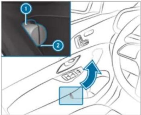
text_image
Diagram of car interior showing dashboard and steering wheel with labeled parts and directional arrow indicating rotation or movement.To remove: pull out safety vest bag ① by loop ②.
Open safety vest bag ① and remove the safety vest.
Additional safety vests can be stored in the stowage space of the rear passenger compartment and in the load compartment.
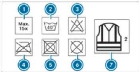
text_image
① Max. 15x ② 40° ③ ④ ⑤ ⑥ ⑦ 2① Maximum number of washes
② Maximum wash temperature
Do not bleach
4 Do not iron
Do not tumble dry
Do not dry clean
⑦ This is a class 2 vest
The requirements defined by the legal standard are only fulfilled if the safety vest is the correct size and is fully closed.
Replace the safety vest in the following cases:
- it is damaged or dirt on the reflective strips can no longer be removed.
- the maximum number of washes is exceeded.
- the fluorescence of the safety jacket has faded.
Warning triangle
Removing the warning triangle
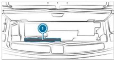
natural_image
Top-down line drawing of a car's rear intake structure showing the vent and dashboard (no text or symbols)Remove warning triangle ①.
Setting up the warning triangle
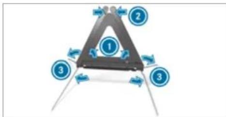
flowchart
graph TD
    A["1"] --> B["2"]
    B --> C["3"]
    C --> D["3"]
Fold side reflectors ① upwards to form a triangle and attach at the top using upper press-stud ②.
Fold legs ③ down and out to the side.
First-aid kit (soft-sided) overview
Mercedes-Maybach vehicles
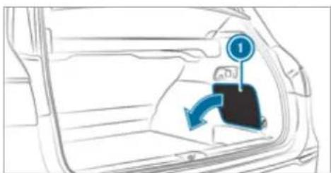
natural_image
Diagram of a car interior showing a directional arrow and a numbered marker (no text or symbols present)In the as-delivered state, the first-aid kit (soft sided) is in the load compartment on the right-hand side behind service flap ①.
All other vehicles
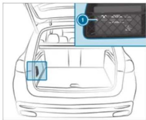
natural_image
Line drawing of a car interior with a highlighted vent and panel array (no text or symbols)Example: first-aid kit (soft sided)
In the as-delivered state, first-aid kit (soft sided) is in the load compartment in the left-hand or right-hand stowage compartment, depending on the model.
Removing the fire extinguisher

WARNING Risk of accident due to an incorrectly secured fire extinguisher in the driver's footwell
A fire extinguisher may impede pedal travel or block a depressed pedal.
This jeopardises the operating and road safety of the vehicle.
The fire extinguisher can be flung around and injure the driver or other vehicle occupants.
Always store and secure the fire extinguisher in the bracket.
Do not remove the fire extinguisher while driving.
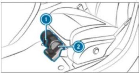
text_image
Diagram of car seatbelt mechanism with numbered components and labeled partsLeft-hand drive vehicle: pull tab
upwards.
Right-hand drive vehicle: pull tab ① downwards.
Remove fire extinguisher ②.
Flat tyre
Notes on flat tyres

WARNING Risk of accident due to a flat tyre
A flat tyre severely affects the driving characteristics as well as the steering and braking of the vehicle.
Tyres without run-flat characteristics:
Do not drive with a flat tyre.
Change the flat tyre immediately with an emergency spare wheel or spare wheel. Alternatively, consult a qualified specialist workshop.
Tyres with run-flat characteristics:
▶ Observe the information and warning notes on MOExtended tyres (run-flat tyres).
In the event of a flat tyre, the following options are available depending on your vehicle's equipment:
- Vehicles with MOExtended tyres: it is possible to continue the journey for a short period of time. Make sure you observe the notes on MOExtended tyres (run-flat tyres) ( page 386).
- Vehicles with a TIREFIT kit: you can repair the tyre so that it is possible to continue the journey for a short period of time. To do this, use the TIREFIT kit ( page 387).
- Vehicles with Mercedes me connect: you can make a call for breakdown assistance via the overhead control panel in the case of breakdown ( page 344).
- All vehicles: change the wheel (→ page 414).
Notes on MOExtended tyres (run-flat tyres)

WARNING Risk of accident when driving in limp-home mode
Driving in emergency mode impairs the handling characteristics of the vehicle.
Do not exceed the permissible maximum speed of the MOExtended tyres.
Avoid any abrupt steering and driving manoeuvres as well as driving over obstacles (kerbs, pot holes, off-road). This applies, in particular, to a loaded vehicle.
▶ Stop driving in the emergency mode if you notice:
- banging noise
- vehicle vibration
• smoke which smells like rubber
• continuous ESP® intervention
• cracks in the tyre sidewalls
After driving in emergency mode, have the rims checked by a qualified special-
ist workshop with regard to their further use.
The defective tyre must be replaced in every case.
With MOExtended tyres (run-flat tyres), you can continue to drive your vehicle even if there is a total loss of pressure in one or more tyres. However, the tyre affected must not show any clearly visible damage.
You can recognise MOExtended tyres by the MOExtended marking which appears on the side wall of the tyre.
Vehicles with tyre pressure monitoring system: MOExtended tyres may only be used in conjunction with an activated tyre pressure monitoring system.
If a pressure loss warning message appears in the multifunction display, proceed as follows:
- Check the tyre for damage.
• If driving on, observe the following notes.
Driving distance possible in emergency mode after the pressure loss warning:
| Load condition Driving distance possible in emergency mode | |
| Partially laden 80 km | |
| Fully laden 30 km | |
The driving distance possible in emergency mode may vary depending on the driving style. Observe the maximum permissible speed of 80 km/h.
If a tyre has gone flat and cannot be replaced with an MOExtended tyre, you can use a standard tyre as a temporary measure.
TREFIT kit storage location
The TREFIT kit is located under the load compartment floor.
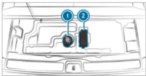
text_image
Diagram of a car interior with labeled components, showing numbered parts 1 and 2 pointing to specific areas.Example: TREFIT kit
① Tyre sealant bottle
② Tyre inflation compressor
Depending on the model, the TREFIT kit may also be located in other places under the load compartment floor.
You can find information on the power category (LK) and/or electrical data on the back of the tyre inflation compressor:
• LK3 - 12 V/20A, 240 W, 1 kg
At a distance of approximately 1 m to the tyre inflation compressor and approximately 1.6 m above the ground, the following sound pressure levels apply:
- Emission sound pressure level A 84 dB (A)
• Sound power level LWA 92 dB (A)
The tyre inflation compressor is maintenance-free. If there is a malfunction, please contact a qualified specialist workshop.
Using the TREFIT kit
Requirements:
- Tyre sealant bottle and tyre inflation compressor ( page 387).
- TREFIT sticker
• Gloves (depending on the vehicle equipment)
You can use TREFIT tyre sealant to seal perforation damage of up to 4 mm, particularly those in the tyre contact surface. You can use TREFIT in outside temperatures down to -20^ C.
WARNING Risk of accident when using tyre sealant
The tyre sealant may be unable to seal the tyre properly, especially in the following cases:
- there are large cuts or punctures in the tyre (larger than damage previously mentioned)
• the wheel rims have been damaged
• after journeys with very low tyre pressure or with flat tyres
Do not continue driving.
Consult a qualified specialist workshop.
WARNING Risk of injury and poisoning from tyre sealant
Tyre sealant is hazardous to health and causes irritation. Do not allow it to come into contact with your skin, eyes or clothing, and do not swallow it. Do not inhale any vapours. Keep the tyre sealant away from children.
Observe the following if you come into contact with the tyre sealant:
Rinse off the tyre sealant from your skin using water immediately.
If tyre sealant gets into your eyes, thoroughly rinse them using clean water immediately.
If tyre sealant has been swallowed, thoroughly rinse out your mouth immediately and drink plenty of water. Do not induce vomiting and seek medical attention immediately.
Change out of clothing which has come into contact with tyre sealant immediately.
If an allergic reaction occurs, seek medical attention immediately.
! NOTE Overheating due to the tyre inflation compressor running too long
Do not run the tyre inflation compressor for longer than ten minutes without interruption.
Comply with the manufacturer's safety notes on the sticker on the tyre inflation compressor.
Have the tyre sealant bottle replaced in a qualified specialist workshop every five years.
Do not remove any foreign objects which have entered the tyre.
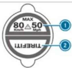
text_image
MAX 80° 50 MinH Mph TREFM ① ②Affix part ① of the TIREFIT sticker to the instrument cluster within the driver's field of vision.
Affix part ② of the TREFIT sticker near the valve on the wheel with the defective tyre.
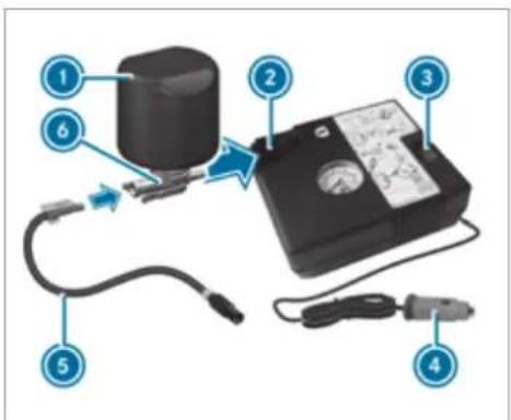
text_image
Diagram of a device with numbered components and labeled parts, including a cylindrical component and connected cables.Pull plug ④ with the cable and hose ⑤ out of the tyre inflation compressor housing.
Push the plug of hose ⑤ into flange ⑥ of tyre sealant bottle ① until the plug engages.
Place tyre sealant bottle ① head downwards into recess ② of the tyre inflation compressor.
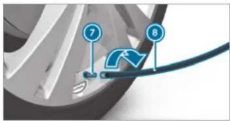
text_image
7 8Remove the valve cap from valve ⑦ on the faulty tyre.
Screw filling hose ⑧ onto valve ⑦.
Insert plug ④ into a 12 V socket in your vehicle.
Switch on the ignition.
Switch on the tyre inflation compressor using On/Off switch ③.
The tyre is inflated. First, tyre sealant is pumped into the tyre. The pressure may briefly rise to approximately 500 kPa (5 bar/73 psi).
Do not switch off the tyre inflation compressor during this phase!
Let the tyre inflation compressor run for a maximum of ten minutes.
The tyre should then have attained a tyre pressure of at least 200 kPa (2.0 bar/29 psi).
If tyre sealant leaks out, make sure you clean affected area as quickly as possible. It is preferable to use clean water.
If you get tyre sealant on your clothing, have it cleaned as soon as possible with perchloroethylene.
If, after ten minutes, a tyre pressure of 200 kPa (2.0 bar/29 psi) has not been attained:
▶ Switch off the tyre inflation compressor.
▶ Unscrew the filling hose from the valve of the defective tyre.
^1 Please note that tyre sealant may leak out when unscrewing the filling hose.
Drive forwards or in reverse very slowly for approximately 10 m.
Pump up the tyre again. After a maximum of ten minutes the tyre pressure must be at least 200 kPa (2.0 bar/29 psi).
A WARNING Risk of accident due to the specified tyre pressure not being attained
If the minimum tyre pressure is not reached after the specified time, the tyre is too badly damaged. The tyre sealant cannot repair the tyre in this instance.
The braking and driving characteristics may be greatly impaired.
Do not continue driving.
Consult a qualified specialist workshop.
If, after ten minutes, a tyre pressure of 200 kPa (2.0 bar/29 psi) has been attained:
▶ Switch off the tyre inflation compressor.
Unscrew the filling hose from the valve of the defective tyre.
WARNING Risk of accident from driving with sealed tyres
A tyre temporarily sealed with tyre sealant impairs the handling characteristics and is not suitable for higher speeds.
Adapt your driving style accordingly and drive carefully.
Do not exceed the maximum speed limit with a tyre that has been repaired using tyre sealant.
Observe the maximum permissible speed for a tyre sealed with tyre sealant 80 km/h.
NOTE Staining from leaking tyre sealant
After use, excess tyre sealant may leak out from the filling hose.
Therefore, place the filling hose in the plastic bag that contained the TREFIT kit.
ENVIRONMENTAL NOTE Environmental pollution caused by environmentally irresponsible disposal
Tyre sealant contains pollutants.
Have the tyre sealant bottle disposed of professionally, e.g. at a Mercedes-Benz Service Centre.
Stow the tyre sealant bottle and the tyre inflation compressor.
▶ Pull away immediately.
Stop driving after approximately ten minutes and check the tyre pressure using the tyre inflation compressor. The tyre pressure must now be at least 130 kPa (1.3 bar/19 psi).
A WARNING Risk of accident due to the specified tyre pressure not being attained
If the specified tyre pressure is not reached, the tyre is too badly damaged. The tyre sealant cannot repair the tyre in this instance.
The braking and driving characteristics may be greatly impaired.
Do not continue driving.
Consult a qualified specialist workshop.
Countries that have Mercedes-Benz
Service24h: you will find a sticker with the telephone number, e.g. on the B-pillar on the driver's side.
To increase the tyre pressure: switch on the tyre inflation compressor.
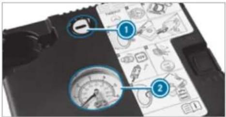
text_image
Diagram showing a device with labeled parts including gauges and a grid of technical diagrams, likely illustrating a measurement or control system.
To reduce the tyre pressure: press pressure release button ① next to manometer
When the tyre pressure is correct, unscrew the filling hose from the valve of the sealed tyre.
Screw the valve cap onto the valve of the sealed tyre.
Pull the tyre sealant bottle out of the tyre inflation compressor.
The filling hose stays on the tyre sealant bottle.
Drive to the nearest qualified specialist workshop and have the tyre, tyre sealant bottle and filling hose replaced there.
Battery (vehicle)
Notes on the 12 V battery
A WARNING Risk of an accident due to work carried out incorrectly on the battery
Work carried out incorrectly on the battery can, for example, lead to a short circuit. This can restrict functions relevant for safety systems and impair the operating safety of your vehicle.
You could lose control of the vehicle in the following situations in particular:
- when braking
- in the event of abrupt steering manoeuvres and/or when the vehicle's speed is not adapted to the road conditions
In the event of a short circuit or a similar incident, contact a qualified specialist workshop immediately.
Do not drive on.
Always have work on the battery carried out at a qualified specialist workshop.
• Further information on ABS (→ page 231)
• Further information on ESP(→ page 232)
For safety reasons, Mercedes-Benz recommends that you only use batteries which have been tested and approved for your vehicle by Mercedes-Benz.
All vehicles except vehicles with a lithium-ion battery

WARNING Risk of explosion due to electrostatic charge
Electrostatic charge can ignite the highly explosive gas mixture in the battery.
To discharge any electrostatic charge that may have built up, touch the metal vehicle body before handling the battery.
The highly flammable gas mixture is created while the battery is charging and during starting assistance.

WARNING Danger of chemical burns from the battery acid
Battery acid is caustic.
Avoid contact with the skin, eyes or clothing.
Do not lean over the battery.
Do not inhale battery gases.
Keep children away from the battery.
Immediately rinse battery acid off thoroughly with plenty of clean water and seek medical attention immediately.
All vehicles

ENVIRONMENTAL NOTE Environmental damage due to improper disposal of batteries

Batteries contain pollutants. It is illegal to dispose of them with the household rubbish.


Dispose of batteries in an environmentally responsible manner. Take discharged batteries to a qualified specialist workshop or to a collection point for used batteries.
If you have to disconnect the 12 V battery, contact a qualified specialist workshop.
Comply with safety notes and take protective measures when handling batteries.

Risk of explosion.

Fire, naked flames and smoking are prohibited when handling the battery. Avoid creating sparks.

Electrolyte or battery acid is corrosive. Avoid contact with the skin, eyes or clothing. Wear suitable protective clothing, in particular gloves, an apron and a face mask. Immediately rinse electrolyte or acid splashes off with clean water. Consult a doctor if necessary.
Wear safety glasses.

Keep children away.

Observe this Owner's Manual.
Observe the following if you do not intend to use the vehicle over an extended period of time:
- Activate standby mode.
- Alternatively: connect the battery to a battery charger approved by Mercedes-Benz or consult a qualified specialist workshop to disconnect the battery.
Notes on starting assistance and charging the 12 V battery
Vehicles with a lithium-ion battery
When charging the battery and during starting assistance, always use the jump-start connection point in the engine compartment.
! NOTE Damage to the battery from over-voltage
When charging using a battery charger without a restriction of the maximum charging voltage, the battery or the on-board electronics can be damaged.
Only use battery chargers with a maximum charging voltage of 14.8 V.
All other vehicles
When charging the battery and during starting assistance, always use the jump-start connection point in the engine compartment.
! NOTE Damage to the battery from over-voltage
When charging using a battery charger without a restriction of the maximum charging voltage, the battery or the on-board electronics can be damaged.
Only use battery chargers with a maximum charging voltage of 14.8 V.

WARNING Risk of explosion from hydrogen gas igniting
There is a danger of hydrogen gas igniting when charging the battery if there is a short circuit or sparks start to form.
Make sure that the positive terminal of the connected battery does not come into contact with vehicle parts.
▶ Never place metal objects or tools on a battery.
The described order of the battery clamps must be observed when connecting and disconnecting the battery.
When giving starting assistance, always make sure that you only connect battery terminals with identical polarity.
During starting assistance, you must observe the described order for connecting and disconnecting the jump lead.
Do not connect or disconnect the battery clamps while the engine is running.
WARNING Risk of explosion during charging process and starting assistance
During the charging process and starting assistance, the battery may release an explosive gas mixture.
Avoid fire, naked flames, creating sparks and smoking.
Make sure there is sufficient ventilation.
▶ Do not lean over a battery.
WARNING Risk of explosion from a frozen battery
A discharged battery may freeze at temperatures slightly above or below freezing point. During starting assistance or battery charging, battery gas can be released.
Always allow a battery to thaw before charging it or performing starting assistance.
If the indicator/warning lamps in the instrument cluster do not light up at low temperatures, it is very likely that the discharged battery has frozen. In this case you may neither jump-start the vehicle nor charge the battery.
The service life of a battery that has been thawed may be dramatically shortened. The starting characteristics may be impaired, especially at low temperatures.
It is recommended that you have a thawed battery checked at a qualified specialist workshop.
All vehicles
NOTE Damage caused by numerous or extended attempts to start the engine
Numerous or extended attempts to start the engine may damage the catalytic converter due to non-combusted fuel.
Avoid numerous and extended attempts to start the engine.
Observe the following points during starting assistance and when charging the battery:
- Only use undamaged jump lead/charging cables with a sufficient cross-section and insulated terminal clamps.
- Non-insulated parts of the terminal clamps must not come into contact with other metal parts while the jump lead/charging cable is connected to the battery/jump-start connection point.
- The jump lead/charging cable must not come into contact with any parts which move when the engine is running.
• Always make sure that neither you nor the battery is electrostatically charged. - Keep away from fire and naked flames.
- Do not lean over the battery.
Observe the additional following points when charging the battery:
- Only use battery chargers tested and approved for Mercedes-Benz.
- Read the battery charger's operating instructions before charging the battery.
Observe the additional following points during starting assistance:
- Starting assistance may only be provided using vehicles, batteries or other jump start devices with a nominal voltage of 12 V.
• The vehicles must not touch. - Vehicles with a petrol engine: jump-start the vehicle only when the engine and exhaust system are cold.
may Starting assistance and charging the 12 V battery
Requirements:
- The vehicle is secured with the electric parking brake.
- Vehicles with automatic transmission: the transmission is in position P.
- The ignition and all electrical consumers are switched off.
• The bonnet is open.
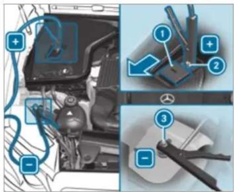
text_image
Diagram showing automotive engine components with numbered annotations indicating parts of the engine and tool assembly.Example: engine compartment
Slide cover ① of positive clamp ② on the jump-starting connection point in the direction of the arrow.
Connect positive clamp ② on your vehicle to the positive pole of the donor battery using the jump lead/charging cable. Always begin
with positive clamp ② on your own vehicle first.
During starting assistance: start the engine of the donor vehicle and run at idle speed.
Connect the negative pole of the donor battery and earth point ③ of your own vehicle by using the jump lead/charging cable. Begin with the donor battery first.
During starting assistance: start the engine of your own vehicle.
During the charging process: start the charging process.
During starting assistance: let the engines run for several minutes.
During starting assistance: before disconnecting the jump lead, switch on an electric consumer in your own vehicle, e.g. the rear window heater or lighting.
When the starting assistance/charging process is complete, perform the following steps:
First, remove the jump lead/charging cable from earth point ③ and the negative pole of the donor battery, then from positive clamp ② and the positive pole of the donor battery. Begin each time with the contacts on your own vehicle first.
After removing the jump lead/charging cable, close cover ① of positive clamp ②.
Further information can be obtained at a qualified specialist workshop.
Replacing the 12 V battery
Observe the notes on the 12 V battery ( page 391).
Mercedes-Benz recommends that you have the 12 V battery replaced at a qualified specialist workshop, e.g. at a Mercedes-Benz Service Centre.
Observe the following notes if you want to replace the battery yourself:
- Always replace a faulty battery with a battery which meets the specific vehicle requirements.
The vehicle is equipped with an AGM technology battery (Absorbent Glass Mat) or a lithium-ion battery. Full vehicle functionality is only guaranteed with an AGM battery or lithium-ion battery. For safety reasons, Mercedes-Benz recommends that you only use batteries which have been tested and approved for your vehicle by Mercedes-Benz. - Carry over detachable parts, such as vent hoses, elbow fittings or terminal covers from the battery being replaced.
- Make sure that the vent hose is always connected to the original opening on the side of the battery.
Fit any existing or supplied cell caps. Otherwise, gases or battery acid could escape.
• Make sure that detachable parts are reconnected in the same way.
Tow-starting or towing away
Overview of the permitted towing methods
NOTE Damage from automatic braking
If one of the following functions is switched on, the vehicle brakes automatically in certain situations:
• Active Brake Assist
• Active Distance Assist DISTRONIC
- HOLD function
• Active Parking Assist
To avoid damage to the vehicle, deactivate these systems in the following or similar situations:
During towing
In a car wash
Mercedes-Benz recommends transporting your vehicle in the case of a breakdown, rather than towing it away.
For towing, use a tow rope or tow bar with both axles on the ground. Do not use tow bar systems.
! NOTE Damage to the vehicle due to towing away incorrectly
▶ Observe the instructions and notes on towing away.
Permitted towing methods
| Vehicle equipment/towing method | |||
| Both axles on the ground | Front axle raised | Rear axle raised | |
| 4MATIC vehicles | Yes, maximum 50 km at 50 km/h | No | No |
Towing away the vehicle with both axles on the ground
Observe the notes on the permitted towing methods ( page 397).
Make sure that the battery is connected and charged.
A discharged battery has the following effects:
• the engine cannot be started
- the electric parking brake cannot be released or applied
- the automatic transmission cannot be shifted to position N or P
If the automatic transmission cannot be shifted to position [N], or the multifunction display in the instrument cluster does not show anything, the vehicle must be transported away (→ page 399). A towing vehicle with lifting equipment is required for vehicle transportation.

NOTE Damage due to towing away at excessively high speeds or over long distances
The drivetrain could be damaged when towing at excessively high speeds or over long distances.
A towing speed of 50 km/h must not be exceeded.
A towing distance of 50 km must not be exceeded.

WARNING Risk of accident when towing a vehicle which is too heavy
If the vehicle being tow-started or towed away is heavier than the permissible gross mass, the following situations can occur:
• the towing eye may become detached.
- the car/trailer combination may swerve or even overturn.
If another vehicle is tow-started or towed away, its weight must not exceed
the permissible gross mass of your own vehicle.
Information on the permissible gross mass of the vehicle can be found on the vehicle identification plate ( page 427).
Do not open the driver's door or front passenger door as the automatic transmission may otherwise shift to position P automatically.
Fit the towing eye ( page 401).
Fasten the tow bar.

NOTE Damage due to incorrect connection of the tow bar
Only connect the tow rope or tow bar to the towing eyes.
① You can also attach the tow bar to the trailer hitch.
Deactivate the automatic locking mechanism ( page 85).
Do not activate the HOLD function.
Deactivate tow-away protection ( page 105).
Deactivate Active Brake Assist ( page 257).
Shift the automatic transmission to position N(→ page 210).
Release the electric parking brake.
A WARNING Risk of accident due to limited safety-related functions during the towing process
Safety-related functions are limited or no longer available in the following situations:
• the ignition is switched off.
- the brake system or power steering system is malfunctioning.
- the energy supply or the on-board electrical system is malfunctioning.
When your vehicle is then towed away, significantly more effort may be required to steer and brake than is normally required.
▶ Use a tow bar.
Make sure that the steering wheel can move freely, before towing the vehicle away.
NOTE Damage due to excessive tractive power
If you pull away sharply, the tractive power may be too high and the vehicles could be damaged.
▶ Pull away slowly and smoothly.
Loading the vehicle for transport
Observe the notes on towing away ( page 398).
Connect the tow bar to the towing eye in order to load the vehicle.
i You can also attach the tow bar to the trailer hitch.
Shift the automatic transmission to position N.
The automatic transmission may be locked in position in the event of damage to the electrics. To shift to , provide the onboard electrical system with power ( page 395).
Load the vehicle onto the transporter.
Shift the automatic transmission to position P.
Use the electric parking brake to secure the vehicle against rolling away.
▶ Only secure the vehicle by the wheels.
Vehicles with ADS PLUS (Adaptive Damping System PLUS)
A WARNING Risk of an accident when transporting vehicles with Adaptive Damping System PLUS
The reduced damping forces on the vehicle being transported can cause the vehicle/trailer combination to start to swing.
As a result, when transporting vehicles with the Adaptive Damping System PLUS, the
vehicle/trailer combination may start to skid. Consequently, you could lose control of your vehicle.
▶ When transporting, ensure that:
- the vehicle has been loaded onto the transporter correctly
- the vehicle is secured at all four wheels with suitable tensioning straps
- the maximum permissible speed of 60 km/h is not exceeded when transporting
! NOTE Damage to the vehicle from securing it incorrectly
After loading, the vehicle must be secured on all four wheels. Otherwise, the vehicle could be damaged.
A minimum distance of 20 cm upwards and 10 cm downwards must be kept to the transport platform.
Secure the vehicle on all four wheels after loading.
4MATIC vehicles/vehicles with automatic transmission
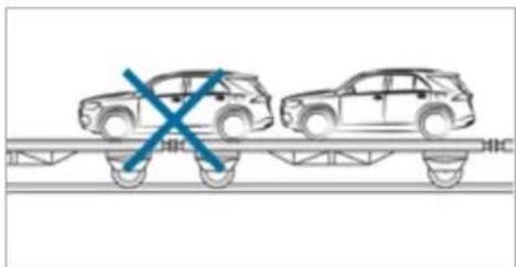
natural_image
Diagram of two cars on a track with a blue X mark indicating a collision or crossing (no text or symbols present)Make sure that the front and rear axles come to rest on the same transportation vehicle.
NOTE Damage to the drivetrain due to incorrect positioning
Do not position the vehicle above the connection point of the transport vehicle.
Towing eye storage location
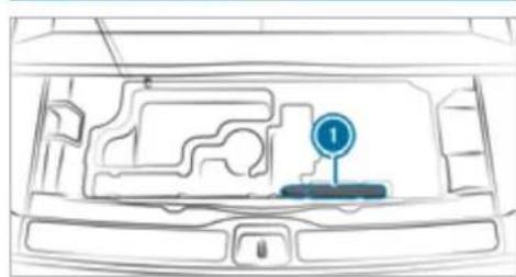
natural_image
Top-down line drawing of a car interior showing structural components and a numbered location marker (no text or symbols)Example: towing eye
Towing eye ① is located under the load compartment floor.
Installing the towing eye
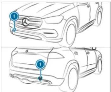
text_image
Technical diagram showing front and side views of a Mercedes-Benz car with labeled parts 1Press the mark on cover ① inwards and remove.
Screw in the towing eye clockwise as far as it will go and tighten.
Vehicles with a trailer hitch: vehicles with a trailer hitch do not have a rear bracket for the
towing eye. Fasten the tow bar to the trailer hitch.
Make sure that cover ① engages in the bumper when you remove the towing eye.
NOTE Damage to the vehicle due to incorrect use of the towing eye or trailer hitch
When a towing eye or trailer hitch is used to recover a vehicle, the vehicle may be damaged in the process.
Only use the towing eye or trailer hitch to tow away or tow start the vehicle.
Do not use the towing eye or trailer hitch to tow the vehicle during recovery.
Tow starting the vehicle (emergency engine start)
Vehicles with automatic transmission
NOTE Damage to the automatic transmission due to tow-starting
The automatic transmission may be damaged in the process of tow-starting vehicles with automatic transmission.
▶ Vehicles with automatic transmission must not be tow-started.
▶ Vehicles with automatic transmission must not be tow-started.
Electrical fuses
Notes on electrical fuses
⚠ WARNING Risk of accident and injury due to overloaded lines
If you manipulate or bridge a faulty fuse or if you replace it with a fuse with a higher
amperage, the electric line could be overloaded.
This could result in a fire.
Always replace faulty fuses with specified new fuses containing the correct amperage.

NOTE Damage due to incorrect fuses
Electrical components or systems may be damaged by incorrect fuses, or their functionality may be significantly impaired.
Only use fuses that have been approved by Mercedes-Benz and which have the correct fuse rating.
Blown fuses must be replaced with fuses of same rating, which you can recognise by the colour and the label. The fuse ratings and further information to be observed can be found in the fuse assignment diagram.
Fuse assignment diagram: on the fuse box in the load compartment ( page 404).

NOTE Damage or malfunctions caused by moisture
Moisture may cause damage to the electrical system or cause it to malfunction.
When the fuse box is open, make sure that no moisture can enter the fuse box.
When closing the fuse box, make sure that the seal of the lid is positioned correctly on the fuse box.
If the newly inserted fuse also blows, have the cause traced and rectified at a qualified specialist workshop.
Ensure the following before replacing a fuse:
e• The vehicle is secured against rolling away.
- All electrical consumers are switched off.
• The ignition is switched off.
The electrical fuses are located in various fuse boxes:
- Fuse box in the engine compartment on the left-hand side of the vehicle, when viewed in the direction of travel ( page 402)
- Fuse box on the driver's side of the cockpit (→ page 403)
- Fuse box in the front passenger footwell (→ page 403)
- Fuse box in the load compartment on the right-hand side of the vehicle, when viewed in the direction of travel (→ page 404)
Opening and closing the fuse box in the engine compartment
Requirement:
• You need a dry cloth and a screwdriver.
Observe the notes on electrical fuses ( page 401).
Opening

WARNING Risk of injury from using the windscreen wipers while the engine bonnet is open
When the engine bonnet is open, and the windscreen wipers are set in motion, you can be trapped by the wiper linkage.
Always switch off the windscreen wipers and ignition before opening the engine bonnet.
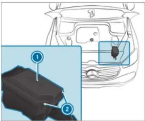
text_image
Diagram showing car interior components with numbered parts and a close-up of the main body part, likely for automotive or diagnostic reference.Remove any existing moisture from the fuse box using a dry cloth.
Loosen screws ② and remove fuse box lid ① from the top.
Closing
Check whether the seal is positioned correctly in the lid.
Insert the lid into the bracket at the rear of the fuse box.
Fold down the lid of the fuse box and tight screws ②.
Close the bonnet.
Opening and closing the fuse box in the cockpit
Requirements:
- Observe the notes on electrical fuses ( page 401).
The fuse box is on the driver's side on the side of the cockpit under a cover.
Contact a Mercedes-Benz Service Centre for further information.
Opening and closing the fuse box in the front passenger footwell
Contact a Mercedes-Benz Service Centre for further information.
Opening and closing the fuse box in the load compartment
Observe the notes on electrical fuses ( page 401).

Open the side cover.
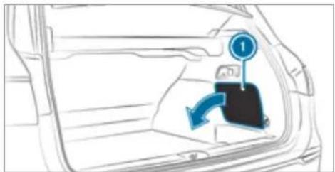
text_image
Diagram showing a car interior with a directional arrow and a numbered marker '1' pointing to the door panel.
Remove cover ①.
The fuse assignment diagram is on the side of the fuse box.
Notes on noise or unusual handling characteristics
Make sure there are no vibrations, noises or unusual handling characteristics when the vehicle is in motion. This may indicate that the wheels or tyres are damaged. Hidden tyre damage could also be causing the unusual handling characteristics.
If you suspect that a tyre is defective, reduce your speed immediately and have the tyres and wheels checked at a qualified specialist workshop.
Notes on regularly inspecting wheels and tyres
WARNING Risk of injury due to damaged tyres
Damaged tyres can cause tyre pressure loss.
▶ Check the tyres regularly for signs of damage and replace any damaged tyres immediately.
WARNING Risk of aquaplaning due to insufficient tyre tread
Insufficient tyre tread will result in reduced tyre grip.
The risk of aquaplaning is increased on wet roads, especially when the speed of the vehicle is not adapted to suit the conditions.
Thus, you should regularly check the tread depth and the condition of the tread across the entire width of all tyres.
Minimum tread depth for:
• Summer tyres: 3 mm
- M+S tyres: 4 mm
For safety reasons, replace the tyres before the legally-prescribed limit for the minimum tread depth is reached.
Carry out the following checks on all wheels regularly, at least once a month or as required, for example, prior to a long journey or driving off-road:
- Check the tyre pressure (→ page 406).
- Visually inspect wheels and tyres for damage.
- Check the valve caps.
- Visual check of the tyre tread depth and the tyre contact surface across the entire width. The minimum tread depth for summer tyres is 3 mm and for winter tyres 4 mm.
Notes on snow chains
WARNING Risk of accident due to incorrect snow chain fitting
If you have fitted snow chains to the front wheels, the snow chains may drag against the vehicle body or chassis components.
This could cause damage to the vehicle or the tyres.
▶ Never fit snow chains on the front wheels.
Only fit snow chains on the rear wheels in pairs.

NOTE Damage to components of the vehicle body or chassis due to fitted snow chains
If you fit snow chains to the front wheels of 4MATIC vehicles, you may damage components of the vehicle body or chassis.
Only fit snow chains to the rear wheels of 4MATIC vehicles.
- Snow chains are only permissible for certain wheel/tyre combinations. You can obtain information about this from a Mercedes-Benz Service Centre.
-
For safety reasons, only use snow chains that have been specifically approved for your vehicle by Mercedes-Benz, or snow chains with the same quality standard.
-
If snow chains are fitted, the maximum permissible speed is 50 km/h.
• Vehicles with Active Parking Assist: do not use Active Parking Assist when snow chains are fitted. - Vehicles with AIRMATIC or E-ACTIVE BODY CONTROL: if snow chains are fitted, only drive at raised vehicle level.
You can permanently limit the maximum vehicle speed for driving with winter tyres ( page 241).
You can deactivate ESP to pull away (→ page 233). This allows the wheels to spin, achieving an increased driving force.
Tyre pressure
Notes on tyre pressure

WARNING Risk of accident due to insufficient or excessive tyre pressure
Tyres with either too low or too high a pressure present the following hazards:
• the tyres could burst
- the tyres could wear excessively and/or unevenly
- the driving characteristics as well as steering and braking characteristics may be severely impaired
Observe the recommended tyre pressures and check the tyre pressures of all tyres including the spare wheel:
- monthly
• if altering the load on the vehicle
• prior to long journeys - if the operating conditions change, for example when driving off-road
Adjust the tyre pressure where necessary.
Tyre pressure which is too high or too low can:
• Shorten the service life of the tyres.
- Cause increased tyre damage.
- Adversely affect driving characteristics and thus driving safety, e.g. due to aquaplaning.
WARNING Risk of accident due to repeated pressure drop in the tyres
The wheels, valves or tyres could be damaged.
Too low a tyre pressure can lead to the tyres bursting.
Examine the tyres for foreign objects.
▶ Check whether the tyre has a puncture or the valve has a leak.
If you are unable to rectify the damage, contact a qualified specialist workshop.
Information on the recommended tyre pressure for the vehicle's factory-fitted tyres can be found
on the tyre pressure table on the inside of the fuel filler flap ( page 407).
Use a suitable pressure gauge to check the tyre pressure. The outer appearance of a tyre does not permit any reliable conclusion about the tyre pressure.
Only correct tyre pressures when the tyres are cold. Conditions for cold tyres:
- The vehicle has been parked with the tyres out of direct sunlight for at least three hours.
• The vehicle has travelled less than 1.6 km.
The vehicle's tyres heat up when driving. As the temperature of the tyres increases, so too does the tyre pressure.
Vehicles with a tyre pressure monitoring system: you can also check the tyre pressure using the on-board computer.
Notes on trailer operation
Always inflate the rear axle tyres to the recommended tyre pressures on the tyre pressure table for increased load.
Tyre pressure table
The tyre pressure table is on the inside of the fuel filler flap.
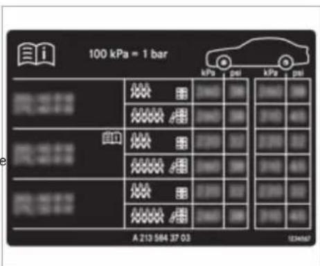
text_image
100 kPa = 1 bar kPa psi kPa psi 风雷器 风雷器 风雷器 A 213 564 37 03 123467If one or more tyre sizes precede a tyre pressure, the following tyre pressure information is only valid for those tyre sizes and their respective load condition.
If the preceding tyre sizes are complemented by The tyre pressure monitoring system is only an On-board computer:
the [1] symbol, the tyre pressure information aid. It is the driver's responsibility to set the tyre following shows alternative tyre pressures. Fuel consumption may then increase slightly. pressure to the recommended cold tyre pressure suitable for the operating situation.
The load conditions "partially laden" and "fully laden" are defined in the table for different numbers of passengers and amounts of luggage. Actual number of seats may differ from this.
Tyre pressure monitoring system
Function of the tyre pressure monitoring system
The system checks the tyre pressure and the tyre temperature of the tyres fitted to the vehicle by means of a tyre pressure sensor.
The tyre pressure and the tyre temperature appear in the on-board computer ( page 40). If there is a substantial pressure loss or if the tyre temperature is excessive, you will be warned with display messages ( page 498) or the warning lamp in the instrument cluster ( page 520).
In most cases, the tyre pressure monitoring tem will automatically update the new reference values after you have changed the tyre pressure. You can, however, also update the reference values by restarting the tyre pressure monitoring system manually ( page 409).
System limits
The system may be impaired or may not function particularly in the following situations:
- incorrect reference values were taught in
- sudden pressure loss caused by a foreign object penetrating the tyre, for example
3). there is a malfunction caused by another radio signal source
Checking the tyre pressure with the tyre pressure monitoring system
Requirements:
• The ignition is switched on.

▶ Service ▶▶ Tyres
One of the following displays appears:
• Current tyre pressure and tyre temperature of the individual wheels:
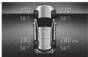
text_image
270 58℃ 270 58℃ 280 58℃ 280 kPa 58℃- Tyre pressures will be displayed after a few minutes of driving
- Tyre pressure monitor active: the teach-in process of the system is not yet complete. The tyre pressures are already being monitored.

Compare the tyre pressure with the recommended tyre pressure for the current operat-
ing condition ( page 407). Observe the notes on tyre temperature ( page 406).
The values displayed in the on-board computer may deviate from those of the tyre pressure gauge as they refer to sea level. At high elevations, the tyre pressure values indicated by a pressure gauge are higher than those shown by the on-board computer. In this case, do not reduce the tyre pressure.
Restarting the tyre pressure monitoring system
Requirements:
- The recommended tyre pressure is correctly set for the respective operating status on all of the wheels ( page 406).
Restart the tyre pressure monitoring system in the following situations:
• The tyre pressure has changed.
- The wheels or tyres have been changed or newly fitted.
On-board computer:
Service ▶ Tyres
Swipe downwards on Touch Control on the left-hand side of the steering wheel. The Use current pressures as new reference values? message is shown in the multifunction display.
To restart, press Touch Control on the left-hand side of the steering wheel. The Tyre press. monitor restarted message shown in the multifunction display.
Current warning messages are deleted and the yellow ⏻ warning lamp goes out.
After you have been driving for a few minutes, the system checks whether the current tyre pressures are within the specified range. The current tyre pressures are then accepted as reference values and monitored.
Be sure to also pay attention to the following related topic:
• Notes on tyre pressure (→ page 406)
Wheel change
Notes on selecting, fitting and replacing tyres
NOTE Mercedes-AMG vehicles
Observe the notes in the Supplement. You could otherwise fail to recognise dangers.
is WARNING Risk of injury through incorrect sizes of wheels and tyres
If wheels and tyres of the wrong size are fitted, the wheel brakes or components in the brake system and in the wheel suspension may be damaged.
Always replace wheels and tyres with those that fulfil the specifications of the original part.
For wheels, pay attention to the following:
- Designation
- Type
For tyres, pay attention to the following:
- Designation
- Manufacturer
- Type
A WARNING Risk of injury through exceeding the specified tyre load-bearing capacity or the permissible speed rating
Exceeding the load-bearing capacity of the tyres can lead to tyre damage and could cause the tyres to explode.
Therefore, only use tyre types and sizes approved for your vehicle model.
▶ Observe the tyre load-bearing capacity rating and speed rating required for your vehicle.
NOTE Vehicle and tyre damage through tyre types and sizes that have not been approved
For safety reasons, only use tyres, wheels and accessories which have been specially approved by Mercedes-Benz for your vehicle.
These tyres are specially adapted to the active safety systems, such as ABS, ESP® and 4MATIC, and marked as follows:
• MO = Mercedes-Benz Original
• MOE = Mercedes-Benz Original Extended (run-flat tyres only for certain wheels)
- MO1 = Mercedes-Benz Original (only certain AMG tyres)
Otherwise, certain properties, such as handling characteristics, vehicle noise emissions, consumption, etc. could be adversely affected. Furthermore, other tyre sizes could result in the tyres rubbing against the body and axle components when loaded. This could result in damage to the tyre or the vehicle.
Only use tyres, wheels and accessories that have been checked and recommended by Mercedes-Benz.
! NOTE Risk to driving safety from retrea- ded tyres
Retreaded tyres are neither tested nor recommended by Mercedes-Benz, since previous damage cannot always be detected on retreaded tyres.
For this reason driving safety cannot be guaranteed.
Do not use used tyres if you have no information about their previous usage.
! NOTE Possible wheel and tyre damage when driving over obstacles
Large wheels have a smaller section width. As the section width decreases, the risk of wheels and tyres being damaged when driving over obstacles increases.
Avoid obstacles or drive especially carefully.
▶ Reduce your speed when driving over kerbs, speed bumps, manhole covers and potholes.
▶ Avoid particularly high kerbs.
NOTE Possible wheel and tyre damage when parking on kerbs or in potholes
Parking on kerbs or in potholes may damage the wheels and tyres.
If possible, park only on flat surfaces.
▶ Avoid kerbs and potholes when parking.
NOTE Damage to electronic component parts from the use of tyre-fitting tools
Vehicles with a tyre pressure monitoring system: electronic component parts are located in the wheel. Tyre-fitting tools should not be applied in the area of the valve.
The tools could damage the electronic component parts.
Have the tyres changed at a qualified specialist workshop only.
NOTE Damage to summer tyres at low ambient temperatures
At low ambient temperatures, tears could form when driving with summer tyres, causing permanent damage to the tyre.
At temperatures below 7 °C use M+S- tyres.
Accessory parts that are not approved for your vehicle by Mercedes-Benz or are not being used correctly can impair the operating safety.
Before purchasing and using non-approved accessories, visit a qualified specialist workshop and enquire about:
- Suitability
- Legal stipulations
• Factory recommendations
WARNING Risk of accident with high performance tyres
The special tyre tread in combination with the optimised tyre compound means that the risk of skidding and hydroplaning on wet roads is increased.
In addition, the tyre grip is greatly reduced at a low outside temperature and tyre running temperature.
Switch on the ESPand adapt your driving style accordingly.
Use M+S tyres at outside temperatures of less than 10 °C.
Only use the tyres for their intended purpose.
Observe the following when selecting, fitting and replacing tyres:
- Country-specific requirements for tyre approval that define a specific tyre type for your vehicle.
- Furthermore, the use of certain tyre types in certain regions and areas of operation can be highly beneficial.
- Only use tyres and wheels of the same type (summer tyres, winter tyres, MOExtended tyres) and the same make.
- Only fit wheels of the same size on one axle (left and right).
It is only permissible to fit a different wheel size in the event of a flat tyre in order to drive to the specialist workshop.
- Do not make any modifications to the brake system, the wheels or the tyres.
The use of shims or brake dust shields is not permitted and may invalidate the vehicle's general operating permit. - Vehicles with a tyre pressure monitoring system: all fitted wheels must be equipped with functioning sensors for the tyre pressure monitoring system.
- At temperatures below 7 °C use winter tyres or all-season tyres marked M+S for all wheels.
Winter tyres provide the best possible grip in wintry road conditions.
- For M+S tyres, only use tyres with the same tread.
- Observe the maximum permissible speed for the M+S tyres fitted.
If the tyre's maximum speed is below that of the vehicle, this must be indicated by an appropriate label in the driver's field of vision.
- Run in new tyres at moderate speeds for the first 100 km.
- Replace the tyres after six years at the latest, not regardless of wear.
- When replacing with tyres that do not feature run-flat characteristics: vehicles
with MOExtended tyres are not equipped with a TIREFIT kit at the factory. Equip the vehicle with a TIREFIT kit after replacing with tyres that do not feature run-flat characteristics, e.g. winter tyres.
① You can permanently limit the maximum vehicle speed for driving with winter tyres (→ page 241).
For more information on wheels and tyres, contact a qualified specialist workshop.
Be sure to also observe the following further related subjects:
• Notes on tyre pressure ( page 406)
• Tyre pressure table ( page 407)
• Notes on the emergency spare wheel
e (→ page 420)
Notes on interchanging wheels

WARNING Risk of injury through different wheel sizes
Interchanging the front and rear wheels can severely impair the driving characteristics.
The disk brakes or wheel suspension components may also be damaged.
Only interchange the front and rear wheels if the wheels and tyres have the same dimensions.
Interchanging the front and rear wheels if the wheels or tyres have different dimensions can render the general operating permit invalid.
The wear patterns on the front and rear wheels differ:
• front wheels wear more on the tyre shoulder
- rear wheels wear more in the centre of the tyre
Do not drive with tyres that have too little tread depth. This significantly reduces traction on wet roads (aquaplaning).
On vehicles with the same front and rear wheel size, you can interchange the wheels every 5000 to 10,000 km, depending on the wear. Ensure the direction of rotation is maintained for the wheels.
Observe the instructions and safety notes on "Changing a wheel" when doing so ( page 414).
Notes on storing wheels
When storing wheels, observe the following notes:
- After removing wheels, store them in a cool, dry and preferably dark place.
- Protect the tyres from contact with oil, grease or fuel.
Overview of the tyre-change tool kit
Apart from some country-specific variants, vehicles are not equipped with a tyre-change tool. For more information on which tools are required and approved to perform a wheel change on your vehicle, consult a qualified specialist workshop.
Required tyre-changing tools may include, for example:
- Jack
- Chock
- Wheel wrench
The jack weighs approximately 3.4 kg.
The maximum load capacity of the jack can be found on the sticker affixed to the jack. The jack is maintenance-free. If there is a malfunction, please contact a qualified specialist workshop.
Tyre-change tool kit ① is located under the load compartment floor.
Depending on the model, the tyre change tool kit may be located in other positions under the load compartment floor.
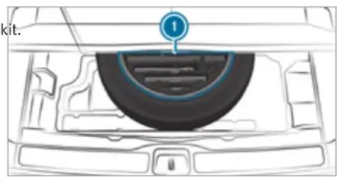
text_image
kit.The tyre-change tool kit includes the following:
- Jack
-
Wheel wrench
-
Wheel studs
- Extension attachment for wheel studs, if necessary (depending on vehicle version)
- Folding chock
- Ratchet ring spanner
Preparing the vehicle for a wheel change
Requirements:
- The required tyre-change tool kit is available. If your vehicle is not equipped with the tyre-change tool kit, consult a qualified specialist workshop to find out about suitable tools.
• The vehicle is not on a slope.
- The vehicle is on solid, non-slippery and level ground.
▶ Apply the electric parking brake manually.
Move the front wheels to the straight-ahead position.
Shift the transmission to position P.
▶ Vehicles with level control system: set the normal vehicle level ( page 269).
▶ Switch off the engine.
Make sure that the engine cannot be started.
Place chocks or other suitable items under the front and rear of the wheel that is diagonally opposite the wheel you wish to change.
Raise the vehicle ( page 415).
Additionally, for Mercedes-Maybach vehicles:
Retract the running boards ( page 88)
To remove stone chipping protective covers ②:
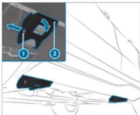
text_image
Diagram showing a mechanical component with labeled parts and directional arrows, likely illustrating motion or assembly.Loosen expansion rivet ① and pull it out.
Fold down and remove stone chipping protective covers ②.
Removing and fitting the wheel trim/hub caps
Requirements:
- The vehicle is prepared for a wheel change (→ page 414).
Plastic hub cap
To remove: turn the centre cover of the hub cap anti-clockwise and remove the hub cap.
To fit: make sure that the centre cover of the hub cap is turned anti-clockwise.
▶ Position the hub cap and turn the centre cover clockwise until the hub cap engages physically and audibly.
Aluminium hub cap
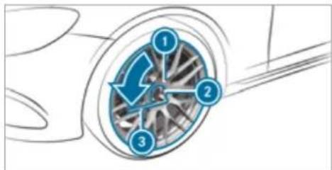
text_image
Diagram showing a car wheel with three labeled components (1, 2, 3) and directional arrows indicating rotation or flow.To remove: position socket ② from the tyre-change tool kit on hub cap ①.
▶ Position wheel spanner ③ on socket ②.
Using wheel spanner ③, turn hub cap ① anti-clockwise and remove it.
To fit: follow the instructions above in reverse order.
① Specified tightening torque: 25 Nm.
Raising the vehicle when changing a wheel
Requirements:
• There are no persons in the vehicle.
- The vehicle has been prepared for a wheel change (→ page 414).
Important notes on using the jack:
- Use only a vehicle-specific jack that has been approved by Mercedes-Benz to raise the vehicle.
- The jack is only designed for raising and holding the vehicle for a short time while a wheel is being changed and not for maintenance work under the vehicle.
- The jack must be placed on a firm, flat and non-slip surface. If necessary, use a large, flat, load-bearing, non-slip underlay.
- The foot of the jack must be positioned vertically under the jack support point.
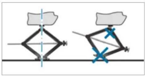
natural_image
Diagram showing two mechanical linkage configurations with blue X marks indicating points of motion (no text or symbols)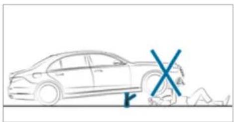
natural_image
Line drawing of a car with a blue X symbol and a small figure lying on the ground (no text or symbols present)Rules of conduct when the vehicle is raised:
-
Never place your hands or feet under the vehicle.
• Never lie under the vehicle. -
Do not start the engine and do not release the electric parking brake.
- Do not open or close any doors or the tail-gate.
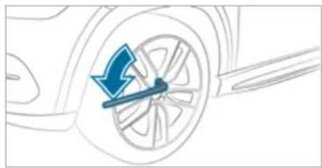
natural_image
Diagram of a car wheel with a blue arrow indicating clockwise motion (no text or symbols)Using the wheel wrench, loosen the wheel bolts on the wheel you wish to change by about one full turn. Do not unscrew the bolts completely.
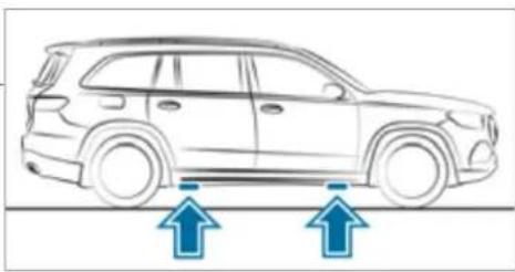
natural_image
Side view of a car with two blue arrows pointing upward, indicating motion or movement (no text or symbols present)Position of jack support points

WARNING Risk of injury from incorrect positioning of the jack
If you do not position the jack correctly at the appropriate jacking point of the vehicle, the jack could tip with the vehicle raised.
Only position the jack at the appropriate jacking point of the vehicle. The base of the jack must be positioned vertically under the jacking point of the vehicle.
NOTE Vehicle damage from the jack
If you do not position the jack correctly at the appropriate jack support point of the vehicle, the jack could tip over with the vehicle raised.
The jack is designed exclusively for jacking up the vehicle at the jack support points.
Take the ratchet ring spanner out of the tyre-change tool kit and place it on the hexagon nut of the jack so that the letters "AUF" are visible.
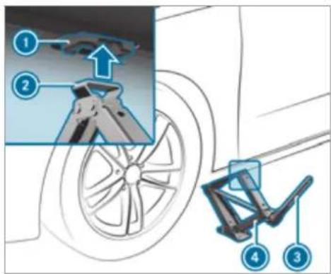
text_image
Diagram illustrating bicycle wheel assembly with numbered parts and a magnified detail showing mechanical components.Position support ② of jack ④ on jack support point ①.
Turn ratchet ring spanner ③ clockwise until jack support ② sits completely on jacking point ① and the base of the jack lies evenly on the ground.
Continue to turn ratchet ring spanner ③ until the tyre is raised a maximum of 3 cm off the ground.
Loosen and remove the wheel ( page 418).
Mercedes-Maybach vehicles:
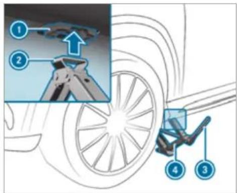
text_image
Diagram illustrating car wheel assembly steps with numbered instructions and a magnified detail showing the process.Requirements:
- The running boards are retracted (→ page 88)
- The stone chipping protective covers are removed ( page 414)
Position support ② of jack ④ on jack support point ①.
Turn ratchet ring spanner ③ clockwise until jack ② sits completely on jacking point ① and the base of the jack lies evenly on the ground.
Continue to turn ratchet ring spanner ③ until the tyre is raised a maximum of 3 cm off the ground.
Loosen and remove the wheel ( page 418).
Removing a wheel
Requirements:
• The vehicle is raised ( page 415).

NOTE Mercedes-AMG vehicles
Observe the notes in the Supplement. You could otherwise fail to recognise dangers.
When changing a wheel, avoid applying any force to the brake discs, as this could impair the level of comfort when braking.

NOTE Damage to threading from dirt on wheel bolts
Do not place wheel bolts in sand or on a dirty surface.
▶ Completely unscrew the wheel bolts.
Remove the wheel.
Fitting a new wheel
Requirements:
• The wheel is removed ( page 418).

NOTE Mercedes-AMG vehicles
Observe the notes in the Supplement. You could otherwise fail to recognise dangers.

WARNING Risk of accident from losing a wheel
Oiled or greased wheel bolts can cause the wheel bolts to come loose, as too can damaged wheel bolts or wheel hub threads.
▶ Never oil or grease the threads.
In the event of damage to the threads, contact a qualified specialist workshop immediately.
Have the damaged wheel bolts or damaged hub threads replaced.
Do not continue driving.
Observe the information on the choice of tyres ( page 409).
For tyres with a specified direction of rotation, an arrow on the side wall of the tyre indicates the correct direction of rotation. Observe the direction of rotation when fitting.
Place the wheel to be fitted on the wheel hub and push it on.

WARNING Risk of injury from tightening wheel bolts and nuts
If you tighten the wheel bolts or wheel nuts when the vehicle is raised, the jack could tip.
Only tighten wheel bolts or wheel nuts when the vehicle is on the ground.
Observe the instructions and safety notes on "Changing a wheel" (→ page 409).
For safety reasons, only use wheel bolts which have been approved by Mercedes-Benz and for the wheel in question.
Tighten the wheel bolts evenly in a diagonal pattern in the order indicated until they are finger-tight.
If the collapsible emergency spare wheel has been fitted, inflate the collapsible emergency spare wheel ( page 424).
▶ Lower the vehicle ( page 419).
Lowering the vehicle after a wheel change
Requirements:
- The new wheel has been fitted (→ page 418).
Observe the information on tyre pressure ( page 406).
Place the ratchet ring spanner onto the hexagon nut of the jack so that the lettering "AB" is visible.
To lower the vehicle: turn the ratchet ring spanner of the jack anti-clockwise.
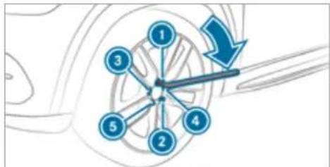
flowchart
graph TD
    A["1"] --> B["2"]
    B --> C["3"]
    C --> D["4"]
    D --> E["5"]
    E --> A
    style A fill:#f9f,stroke:#333
    style B fill:#f9f,stroke:#333
    style C fill:#f9f,stroke:#333
    style D fill:#f9f,stroke:#333
    style E fill:#f9f,stroke:#333
    style_F["Arrow"] --> A
    style_G["Arrow"] --> B
Tighten the wheel bolts evenly in a diagonal pattern in the order indicated ① to ⑤ with a maximum of 80 Nm.
Then tighten the wheel bolts evenly in a diagonal pattern in the order indicated ① to ⑤ to the specified tightening torque of 150 Nm.
WARNING Risk of injury through incorrect tightening torque
The wheels could come loose if the wheel bolts or wheel nuts are not tightened to the prescribed tightening torque.
Make sure the wheel bolts or wheel nuts are tightened to the prescribed tightening torque.
If you are not sure, do not move the vehicle. Consult a qualified specialist workshop and have the tightening torque checked immediately.
Check the tyre pressure of the newly mounted wheel and adjust accordingly.
The following does not apply if the new wheel is an emergency spare wheel.
▶ Vehicles with a tyre pressure monitoring system: restart the tyre pressure monitoring system ( page 409).
Emergency spare wheel
Notes on the emergency spare wheel

WARNING Risk of accident caused by incorrect wheel and tyre dimensions
The wheel or tyre size and the tyre type of the emergency spare wheel or spare wheel and the wheel to be replaced may differ. The emergency spare wheel or spare wheel can significantly impair driving characteristics of the vehicle.
To prevent hazardous situations:
Drive carefully.
▶ Never fit more than one emergency spare wheel or spare wheel that differs in size.
Only use an emergency spare wheel or spare wheel briefly.
Do not deactivate ESP.
Have the emergency spare wheel or spare wheel of a different size replaced at the nearest qualified specialist work-
shop. The new wheel must have the correct dimensions.
The emergency spare wheel is fastened in the load compartment under the load compartment floor.
① Not for Mercedes-Maybach vehicles.
Observe the following notes on fitting an emergency spare wheel:
- Check the tyre pressure of the emergency spare wheel fitted. Correct the pressure as necessary.
- The maximum permissible speed with an emergency spare wheel fitted is 80 km/h.
- Do not fit the emergency spare wheel with snow chains.
- Replace the emergency spare wheel after six years at the latest, regardless of wear.
Vehicles with a tyre pressure monitoring system: if an emergency spare wheel is fitted, the tyre pressure monitoring system cannot function reliably. For a few minutes after an emergency spare wheel is fitted, the
system may still display the tyre pressure of the removed wheel. Only restart the system again when the emergency spare wheel has been replaced with a new wheel.
Be sure to also observe the following further related subjects:
• Notes on tyre pressure (→ page 406)
• Tyre pressure table ( page 407)
• Notes on fitting tyres (→ page 409)
Inflating the emergency spare wheel

NOTE Overheating due to the tyre inflation compressor running too long

Do not run the tyre inflation compressor for longer than ten minutes without interruption.
Requirements:
Comply with the manufacturer's safety notes on the sticker of the emergency spare wheel and on the tyre inflation compressor.
Remove the sticker with the label 80 km/h from the tyre inflation compressor housing and affix it to the instrument cluster within the driver's field of vision.
Remove the tyre inflation compressor from the stowage space under the luggage compartment floor ( page 387).
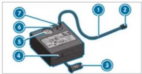
text_image
Labeled diagram of an electrical meter with numbered components for identificationPull filler hose ① and plug ③ out of the tyre inflation compressor housing.
Insert plug ⑦ of filler hose ① in the socket on the tyre inflation compressor and then turn it until plug ⑦ engages.
Unscrew the cap from the valve on the emergency spare wheel.
Screw union nut ② of filler hose ① onto valve.
Make sure on and off switch ④ of the tyre inflation compressor is set to 0.
Insert plug ③ in a socket in your vehicle.
• Cigarette lighter socket
• 12 V socket: (→ page 150)
- Observe the notes on the cigarette lighter in the Digital Owner's Manual
- Observe the notes on sockets: (→ page 150)
Press the start/stop button once to switch on the power supply ( page 190).
Press on and off switch ④ on the tyre inflation compressor to Ⅰ. The tyre inflation compressor is switched on. The tyre is inflated. The tyre pressure appears on manometer ⑤.
Pump the tyre to the specified tyre pressure.
① The specified tyre pressure is stated on the label of the emergency spare wheel.
When the specified tyre pressure has been reached, press on and off switch ④ on the tyre inflation compressor to 0.
The tyre inflation compressor is switched off
Press the start/stop button to switch off the power supply.
If the tyre pressure is higher than the specified pressure, press pressure release valve button ⑥ until the correct tyre pressure has been reached.
Unscrew union nut ② of filler hose ① from the valve.
Screw the valve cap of the emergency spare wheel onto the valve again.
Stow filler hose ① and plug ③ in the lower section of the tyre inflation compressor housing.
Stow the tyre inflation compressor in the vehicle.
Collapsible spare wheel
Notes on the collapsible spare wheel

WARNING Risk of accident caused by incorrect wheel and tyre dimensions
The wheel or tyre size and the tyre type of the emergency spare wheel or spare wheel and the wheel to be replaced may differ. Mounting an emergency spare wheel/spare wheel may severely impair the driving characteristics.
To prevent hazardous situations:
Adapt your driving style accordingly and drive carefully.
▶ Never fit more than one emergency spare wheel or spare wheel that differs in size.
Only use an emergency spare wheel or spare wheel of a different size briefly.
Do not switch off ESP
Have the emergency spare wheel or spare wheel of a different size replaced at the nearest qualified specialist work-
shop. The new wheel must have the correct dimensions.
The collapsible spare wheel is an emergency spare wheel which is only suitable for use for a limited period of time and in a restricted manner in the event of a flat tyre (e.g. until the nearest workshop).
The tyre sidewalls are folded when in transport mode. Before use, the collapsible spare wheel has to be inflated with the accompanying compressor.
Check the tyre pressure of the collapsible spare wheel once fitted. Correct the pressure as necessary.
The maximum permissible speed with a collapsible spare wheel fitted is 80 km/h.
Do not fit snow chains with the collapsible spare wheel.
Replace the collapsible spare wheel after six years at the latest, regardless of wear.
① Vehicles with a tyre pressure monitoring system: if a collapsible spare wheel is fitted the tyre pressure monitoring system cannot
function reliably. For a few minutes after an emergency spare wheel is fitted, the system may still display the tyre pressure of the removed wheel. Only restart the system again when the collapsible spare wheel has been replaced with a new wheel.
Be sure to also observe the following further related subjects:
• Notes on tyre pressure ( page 406)
- Tyre pressure table (→ page 407)
Notes on vehicles with a Burmester sound system

WARNING Risk of injury or death due to an unsecured collapsible spare wheel
If the collapsible spare wheel is not secured correctly, it can slip, tip over or be thrown around.
Vehicle occupants could be hit by an unsecured collapsible spare wheel and be seriously injured as a result, particularly when accelerating, braking, abruptly changing direction or in the event of an accident.
Always store the collapsible spare wheel in the emergency spare wheel bag and attach it to the bracket in the load compartment.
Always ensure that the lashing straps on the emergency spare wheel bag are safely secured on the rear tie-down eyes on the load compartment floor.
Depending on the vehicle's equipment, the collapsible spare wheel is located in an emergency spare wheel bag on a bracket in the load compartment. The collapsible spare wheel in the emergency spare wheel bag and the bracket are lashed with straps and secured using the rear tie-down eyes on the load compartment floor.
Removing the collapsible spare wheel
Vehicles without a Burmester sound system
The collapsible spare wheel is located under load compartment floor.
Observe the information on mounting tyres ( page 409).
▶ Open the tailgate.
▶ Open the load compartment floor.
Remove the collapsible spare wheel.
Vehicles with a Burmester sound system
The collapsible spare wheel is secured in the lapsible spare wheel bag in the load compartment.
Observe the information on mounting tyres ( page 409).
y Open the load compartment.
Loosen the lashing straps.
Unhook the retaining spring hooks of the lashing straps from the brackets.
Remove the collapsible spare wheel bag together with the collapsible spare wheel.
Open the collapsible spare wheel bag and remove the collapsible spare wheel.
Mercedes-Maybach vehicles
Without refrigerator box: the collapsible spare wheel is located in the collapsible spare wheel bag on the load compartment floor.
Observe the information on mounting tyres ( page 409).
Open the load compartment.
Loosen the lashing straps.
Unhook the retaining spring hooks of the lashing straps from the brackets.
Remove the collapsible spare wheel bag together with the collapsible spare wheel.
Open the collapsible spare wheel bag and remove the collapsible spare wheel.
With refrigerator box: the collapsible spare wheel is located in the collapsible spare wheel bag inside the open load compartment floor.
Observe the information on mounting tyres ( page 409).
Open the load compartment.
Loosen the lashing straps.
Unhook the retaining spring hooks of the lashing straps from the brackets.
Remove the collapsible spare wheel bag together with the collapsible spare wheel.
Open the collapsible spare wheel bag and remove the collapsible spare wheel.
Inflating the collapsible spare wheel
Requirements:
- Mount the collapsible spare wheel as described ( page 418).
- Remove the tyre inflation compressor from the stowage well under the boot floor ( page 387).
NOTE Damage to the collapsible spare wheel when lowering the vehicle
Lowering the vehicle without previously inflating the collapsible spare wheel can damage its rim.
▶ Inflate the collapsible spare wheel using the tyre inflation compressor before lowering the vehicle.

NOTE Overheating due to the tyre inflation compressor running too long
Do not run the tyre inflation compressor for longer than ten minutes without interruption.
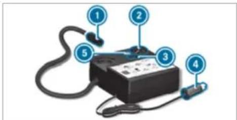
text_image
Diagram of a handheld electronic device with numbered parts labeled 1 to 5Pull connector ④ and the hose out of the housing.
Unscrew the cap from the valve on the collapsible spare wheel.
Screw union nut ① of the hose onto the valve.
Make sure on and off switch ③ of the tyre inflation compressor is set to 0.
Insert connector ④ into the cigarette lighter socket or into a 12 V socket (→ page 150) in your vehicle.
▶ Switch on the power supply ( page 190).
Press on and off switch ③ on the tyre inflation compressor to I.
The tyre inflation compressor is switched on. The tyre is inflated. The tyre pressure is shown on manometer ②.
Pump the tyre to the specified tyre pressure.
The specified tyre pressure is printed on the yellow label of the collapsible spare wheel.
When the specified tyre pressure has been reached, press on and off switch ③ on the tyre inflation compressor to 0.
If the tyre pressure is higher than the specified pressure, press pressure release valve button ⑤ until the correct tyre pressure has been reached.
Notes on technical data

NOTE Mercedes-AMG vehicles
Observe the notes in the Supplement. You could otherwise fail to recognise dangers.
The technical data was determined in accordance with EU Directives. The data stated only applies to vehicles with standard equipment. You can obtain further information from a Mercedes-Benz Service Centre.
Only for certain countries: you can find vehicle-specific vehicle data in the COC documents (CERTIFICATE OF CONFORMITY). These papers are included with the vehicle.
On-board electronics
Notes on tampering with the engine electronics

NOTE Premature wear through improper maintenance
Improper maintenance may cause vehicle components to wear more quickly and the vehicle's operating permit may be invalidated.
Always have work on the engine electronics and related components carried out at a qualified specialist workshop.
Two-way radios
Notes on fitting two-way radios

WARNING Risk of accident due to improper work on two-way radios
If two-way radios are manipulated or retrofitted incorrectly, the electromagnetic radiation from the two-way radios can interfere with
the vehicle electronics and jeopardise the operating safety of the vehicle.
You should have all work on electrical and electronic components carried out at a qualified specialist workshop.

WARNING Risk of accident from incorrect operation of two-way radios
If you use two-way radios in the vehicle improperly, their electromagnetic radiation can disrupt the vehicle's electronics. This is true in the following situations, in particular:
- The two-way radio is not connected to an exterior aerial.
- The exterior aerial is fitted incorrectly or is not a low-reflection aerial.
This could jeopardise the operating safety of the vehicle.
Have the low-reflection exterior aerial fitted at a qualified specialist workshop.
When operating two-way radios in the vehicle, always connect them to the low-reflection exterior aerial.
NOTE Invalidation of the operating permit due to failure to comply with the instructions for installation and use
The operating permit may be invalidated if the instructions for installation and use of two-way radios are not observed.
▶ Only use approved frequency bands.
▶ Observe the maximum permissible output power in these frequency bands.
▶ Only use approved aerial positions.
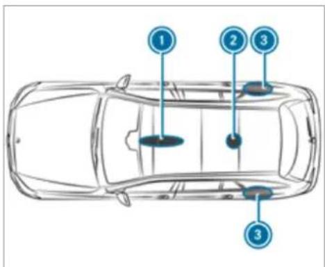
text_image
① ② ③ ③1 Front roof area
② Rear roof area
3 Rear wings
On vehicles with a panoramic sliding sunroof, fitting an aerial to the front or rear roof area is not permitted.
On the rear wings, it is recommended that you fit the aerial on the side of the vehicle closest to the centre of the road.
Use Technical Specification ISO/TS 21609 (Road Vehicles - "EMCs for installation of aftermarket radio frequency transmitting equipment") when retrofitting two-way radios. Comply with the legal requirements for detachable parts.
If your vehicle has fittings for two-way radio equipment, use the power supply and aerial connectors provided in the pre-installation. Observe the manufacturer's supplements when fitting.
Two-way radio transmission output
The maximum transmission output (PEAK) at the base of the aerial must not exceed the values in the following table.
Frequency band and maximum transmission output
| Frequency band Maximum transmission output | |
| Short wave3 - 54 MHz | 100 W |
| 4 m frequency band74 - 88 MHz | 30 W |
| 2 m frequency band144 - 174 MHz | 50 W |
| Terrestrial Trunked Radio (TETRA)380 - 460 MHz | 10 W |
| 70 cm frequency band420 - 450 MHz | 35 W |
| Two-way radio(2G/3G/4G) | 10 W |
The following can be used in the vehicle without restrictions:
- two-way radios with a maximum transmission output of up to 100 mW
- RF transmitters with transmitter frequencies in the 380 - 410 MHz frequency band and a maximum transmission output of up to 2 W (TETRA)
• mobile phones (2G/3G/4G)
There are no restrictions when positioning the aerial on the outside of the vehicle for the following frequency bands:
• Terrestrial Trunked Radio (TETRA)
- 70 cm frequency band
- 2G/3G/4G
Regulatory radio identification of small components
Manufacturer information about radio-based vehicle components can be found using the key phrase "Regulatory radio identification" in the
Digital Operator's Manual in the vehicle, on the internet and in the app.
Vehicle identification plate, VIN and engine number overview
Vehicle identification plate
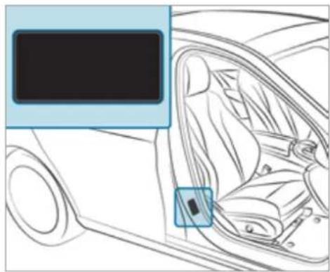
natural_image
Interior view of a car showing the seatbelt and dashboard (no text or symbols visible)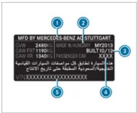
① Vehicle manufacturer
2 Place of manufacture
③ Manufacturing date
4 Paint code
5 VIN
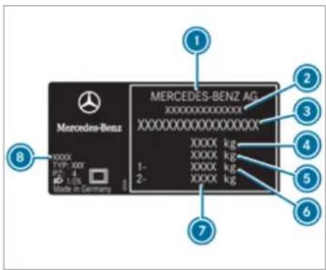
text_image
Mercedes-Benz AG XXXXXXXXXXXXXX XXXXXXXXXXXXXX XXXX kg XXXX kg XXXX kg XXXX kg 1- 2- Made in Germany 8 1 2 3 4 5 6 7Vehicle identification plate (example: all other countries)
① Vehicle manufacturer
② EU general operating permit number (only for certain countries)
③ VIN (vehicle identification number)
4 Maximum permissible gross vehicle weight (kg)
Maximum permissible gross weight of vehicle combination (kg) (for certain countries only, optional)
6 Maximum permissible front axle load (kg)
⑦ Maximum permissible rear axle load (kg)
Paint code
The data shown in the illustration is example data.
VIN in front of the front seat
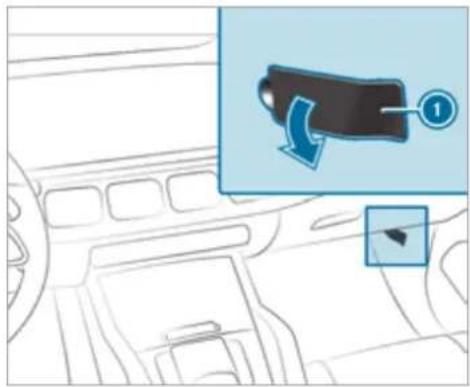
text_image
Diagram showing a car interior with a directional arrow and numbered annotation (1) pointing to a vehicle component.① VIN (vehicle identification number)
VIN at the lower edge of the windscreen
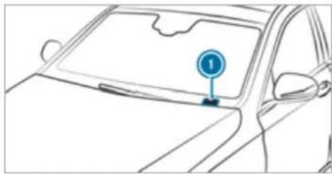
natural_image
Line drawing of a car front view with a circular traffic sign pointing to the side (no text or symbols on the car itself)① VIN (vehicle identification number)
The VIN as a label at the lower edge of the wind-screen is only available in some countries.
Engine number
The engine number is stamped into the crank-case.
① Further information can be obtained at a qualified specialist workshop.
Operating fluids
Notes on operating fluids

NOTE Mercedes-AMG vehicles
Observe the notes in the Supplement. You could otherwise fail to recognise dangers.

WARNING Risk of injury from operating fluids harmful to your health
Operating fluids may be poisonous and harmful to your health.
Observe the text on the original containers when using, storing or disposing of operating fluids.
▶ Always store operating fluids sealed in their original containers.
Always keep children away from operating fluids.

ENVIRONMENTAL NOTE Environmental pollution due to disposing of operating fluids in a non-environmentally responsible manner
Operating fluids include the following:
- fuels
- exhaust gas aftertreatment additives, e.g. AdBlue®
- lubricants
Incorrect disposal of operating fluids can cause considerable damage to the environment.
▶ Dispose of operating fluids in an environmentally responsible manner.
Operating fluids include the following:
- fuels
- DeNOx agent AdBlue® for exhaust gas after-treatment
- lubricants
-
coolant
-
brake fluid
• windscreen washer fluid
• climate control system refrigerant
Only use products approved by Mercedes-Benz. Damage caused by the use of products that have not been approved is not covered by the Mercedes-Benz warranty or goodwill gestures.
The operating fluids approved by Mercedes-Benz can be identified by the following inscriptions on the container:
• MB-Freigabe (e.g. MB-Freigabe 229.51)
• MB-Approval (e.g. MB-Approval 229.51)
Further information on approved operating fluids:
• in the Mercedes-Benz Specifications for Operating Fluids by entering the designation
- at https://bevo.mercedes-benz.com
- in the Mercedes-Benz BeVo App
• at a qualified specialist workshop

WARNING Risk of fire or explosion from fuel
Fuels are highly flammable.
▶ Fire, naked flames, smoking and creation of sparks must be avoided.
Switch off the ignition and, if available, the stationary heater, before and while refuelling the vehicle.

WARNING Risk of injury from fuels
Fuels are poisonous and hazardous to your health.
Do not swallow fuel or let it come into contact with skin, eyes or clothing.
Do not inhale fuel vapour.
Keep children away from fuel.
Keep doors and windows closed during the refuelling process.
If you or other people come into contact with fuel, observe the following:
Immediately rinse fuel off your skin with soap and water.
If fuel comes into contact with your eyes, immediately rinse them thoroughly with clean water. Seek medical attention immediately.
If you swallow fuel, seek medical attention immediately. Do not induce vomiting.
Change immediately out of clothing that has come into contact with fuel.
Flexible-fuel vehicles can be refuelled with the following fuel types:
- unleaded petrol
• E85 fuel
• a mixture of E85 fuel and unleaded petrol
Flexible-fuel vehicles can be identified by the Ethanol up to E85 sticker on the inside of the fuel filler flap.
Depending on the country, the fuels you can use in your vehicle may differ from the information in the Owner's Manual. The fuels that have been
approved for your vehicle can be found on the instruction label on the inside of the fuel filler flap.
Fuel
Information on fuel grades for vehicles with petrol engines
Observe the notes on operating fluids ( page 429).
NOTE Damage caused by the wrong fuel
Even small amounts of the wrong fuel could result in damage to the fuel system, the engine and the emission control system.
Only refuel using unleaded, sulphur-free fuel that conforms to European EN 228, or an equivalent specification.
Fuel of this specification may contain up to 10% ethanol by volume. Your vehicle is suitable for use with E10 fuel.
Never refuel with one of the following fuels:
• diesel
- regular petrol with an octane number lower than 91 RON
- petrol with more than 10% ethanol by volume, e.g. E15, E20, E85, E100
- petrol with more than 3% methanol by volume, e.g. M15, M30
• petrol with additives containing metal
If you have accidentally refuelled with the wrong fuel:
do not switch on the ignition.
consult a qualified specialist workshop.
The following compatibility indications for fuel apply to your vehicle:

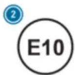
① For petrol with maximum 5% ethanol by volume
For petrol with maximum 10% ethanol by volume
According to European standard EN 16942 you can find the compatibility indications at the following locations:
• on the instruction label on the fuel filler flap
- on the fuel pump or pump nozzle suitable for your vehicle throughout Europe
If the available fuel is not sufficiently low in sulphur, this can produce unpleasant odours.
The recommended octane number for your vehicle can also be found on the instruction label in the fuel filler flap ( page 215).
As a temporary measure, if the recommended fuel is not available, you may also use regular unleaded petrol with at least 91 RON. This may reduce engine output and increase fuel consumption.
Never refuel using petrol with an even lower RON.
Further information on fuel can be obtained filling station or a qualified specialist workshop.
Information on additives in petrol
Observe the notes on operating fluids ( page 429).

NOTE Damage from use of unsuitable additives
Even small amounts of the wrong additive may lead to malfunctions occurring.
Only add cleaning additives recommended by Mercedes-Benz to the fuel.
Mercedes-Benz recommends that you use brand-name fuels with additives.
In some countries, the fuel available may not have sufficient additives. Residue could build up in the fuel injection system as a result. In this case, in consultation with a Mercedes-Benz service centre, mix the fuel with the cleaning additive recommended by Mercedes-Benz. Observe the notes and mixing ratios indicated on the tank.
at Information on fuel grades for vehicles with a diesel engine
General notes
Observe the notes on operating fluids ( page 429).

WARNING Risk of fire from fuel mixture
If you mix diesel fuel with petrol, the flash point of the fuel mixture is lower than that of pure diesel fuel.
▶ Never refuel using petrol in diesel engines.
▶ Never mix petrol with diesel fuel.
NOTE Damage caused by the wrong fuel
Even small amounts of the wrong fuel could result in damage to the fuel system, the engine and the emission control system.
Only refuel using sulphur-free diesel fuel that conforms to European standard EN 590, or an equivalent specification. In countries without sulphur-free diesel fuel, refuel using only low-sulphur diesel fuel with a sulphur content less than 50 ppm.
Never refuel with one of the following fuels:
- petrol
- marine diesel
- heating oil
• pure bio-diesel fuel or vegetable oil - paraffin or kerosene
If you have accidentally refuelled with the wrong fuel:
Do not switch the ignition on.
Consult a qualified specialist workshop.
The following compatibility indication for fuel applies to your vehicle:
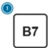
① For diesel fuel with a maximum of 7% by volume bio-diesel (fatty acid methyl ester)
According to European standard EN 16942 you can find the compatibility indications at the following locations:
- on the vehicle on the information label in the fuel filler flap (→ page 215)
- on the fuel pump or pump nozzle suitable for your vehicle throughout Europe
Information on low outside temperatures
Refuel your vehicle with as much winter diesel fuel as possible at the beginning of winter.
Before changing over to winter diesel fuel, the fuel tank should be empty, if possible. When first refuelling with winter diesel fuel, only refuel using a small amount, e.g. to reserve level. The fuel tank can be filled as usual when next refuelling.
Further information on fuel can be obtained at filling station or a qualified specialist workshop.
Tank content and reserve fuel
Model Total capacity
All models 90.0 litres
| Model | of which reserve fuel |
| All models | 9 |
| Mercedes-Maybach | Total capacity |
| Mercedes-MaybachGLS 600 4MATIC | 90.0 litres |
| Mercedes-Maybach | of which reserve fuel |
| Mercedes-MaybachGLS 600 4MATIC | 9.0 litres |
AdBlue ^® (vehicles with a diesel engine only)
Notes on AdBlue®
Observe the notes on operating fluids ( page 429).
AdBlue ^® is a water-soluble fluid for the NOx exhaust gas aftertreatment of diesel engines.
It may be improper or punishable in some countries to operate a vehicle that uses no AdBlue ^® or one that does not comply with the specifications of these operating instructions.
NOTE Malfunctions due to the dilution of AdBlue® or the use of additive-enhanced AdBlue®
The function of the NOx exhaust gas after-treatment can be impaired by the use of unsuitable denoxification agents.
Only use AdBlue® in accordance with ISO 22241.
Do not dilute AdBlue with water.
Do not use additive-enhanced AdBlue®
NOTE Damage and malfunctions due to impurities in AdBlue®
Consequences of impurities in AdBlue
• increased emission values
• damage to the catalytic converter
- NOx exhaust gas aftertreatment malfunctions
▶ Avoid impurities in AdBlue®
AdBlue ^® residues crystallise after a period of time, and contaminate the surfaces with which they come into contact. Clean the dirty surfaces with water as soon as possible.
When you open the AdBlue ^® tank, small amounts of ammonia vapour may escape. Do not inhale any ammonia vapours that may be released. Only fill the AdBlue ^® tank in well-ventilated areas.
AdBlue® capacity
Total capacity of AdBlue ^® tank
| Model | T |
| All models 31.6 litres |
otal
AdBlue® consumption
The average AdBlue ^® consumption is between 1% and 5% of fuel consumption. Like fuel consumption, AdBlue ^® consumption is highly dependent upon driving style and operating conditions. For this reason, your vehicle's actual consumption figures under day-to-day operating conditions may differ from the consumption fig-
ures calculated. The frequency at which you will have to top up AdBlue® will also vary. Have the AdBlue® supply checked at a qualified specialist workshop before making journeys outside of Europe. Before a longer stay outside of Europe, consult a qualified specialist workshop.
AdBlue ^® range and fill level
The AdBlue ^® fill level and range can be displayed via the on-board computer. The AdBlue range shown depends strongly on the driving style and operating conditions. The actual range can therefore deviate from the range currently displayed in the on-board computer. The information supplied in the Owner's Manual regarding the reserve quantity at the first display warning and on the minimum top-up quantity when the tank is empty is also to be understood as guide values.
Engine oil
Notes on engine oil
Observe the notes on operating fluids ( page 429).

text_image
Mercedes-Benz Oil recommendedNOTE Engine damage caused by an incorrect oil filter, incorrect oil or additives
Do not use engine oils or oil filters which do not correspond to the specifications explicitly prescribed for the service intervals.
Do not alter the engine oil or oil filter in order to achieve longer change intervals than prescribed.
Do not use additives.
Have the engine oil renewed at regular intervals.
Mercedes-Benz recommends that you have the oil change carried out at a qualified specialist workshop.
Only use engine oils approved by Mercedes-Benz.
Petrol engines: for certain countries, different engine oils can be used in conjunction with reduced maintenance intervals.
Further information on different engine oils can be obtained at a qualified specialist workshop.
Quality and capacity of engine oil
| Petrol engines | MB-Freigabe or MB-Approval |
| GLS 450 4MATIC 229.51, 229.52, 229.61229.71, 229.72* | |
| GLS 580 4MATIC 229.52229.61* | |
| Mercedes-Maybach | MB-Freigabe or MB-Approval |
| EU countries: | 229.5* |
| Mercedes-Maybach | 229.51 |
| GLS 600 4MATIC | |
| Non-EU countries: | 229.5 |
| Mercedes-Maybach | |
| GLS 600 4MATIC | |
| Diesel engines | MB-Freigabe or MB-Approval |
| All models | 2229.61* |
* recommended for lowest possible fuel consumption (lowest SAE viscosity class in each case; observe possible restrictions of the approved SAE viscosity classes)
To achieve the lowest possible fuel consumption, it is recommended to use the engine oil specifications marked in the table for the lowest SAE viscosity class. Possible restrictions of the
approved SAE viscosity classes must be observed.
Mercedes-Maybach GLS 600 4MATIC: Only use SAE 0W-40 or SAE 5W-40 engine oils.
If the engine oils listed in the table are not available, you may add a maximum of 1.0 litre of the following engine oils once only.
Engine oils for one-time filling only in exceptional cases:
- Petrol engines:
- GLS 450 4MATIC: MB-Freigabe or MB-29.31 Approval 229.31 or ACEA C3
- GLS 580 4MATIC: MB-Freigabe or MB-Approval 229.51 or ACEA C3
- Mercedes-Maybach GLS 600 4MATIC: MB-Freigabe or MB-Approval 229.3 or ACEA A3/B4
• Diesel engines: MB-Freigabe or MB-Approval 229.51 or ACEA C3
The following values refer to an oil change, including the oil filter.
Model Capacity
| GLS 580 4MATIC 9.5 | litres |
| All other models 8.5 | litres |
| Mercedes-Maybach | C | a |
| Mercedes-MaybachGLS 600 4MATIC | 9.5 litres | |
Notes on brake fluid
Observe the notes on operating fluids ( page 429).
A WARNING Risk of an accident due to vapour pockets forming in the brake system
The brake fluid constantly absorbs moisture from the air. This lowers the boiling point of the brake fluid. If the boiling point is too low, vapour pockets may form in the brake system when the brakes are applied hard. This impairs the braking effect.
Have the brake fluid renewed at the specified intervals.
Have the brake fluid regularly replaced at a qualified specialist workshop. Only use a brake fluid approved by Mercedes-Benz according to MB-Freigabe or MB-Approval 331.0.
Coolant
Notes on coolant
Observe the notes on operating fluids ( page 429).
WARNING Risk of fire- and injury from antifreeze
If antifreeze comes into contact with hot component parts in the engine compartment, it may ignite.
Allow the engine to cool down before you top up the antifreeze.
Make sure that no antifreeze spills out next to the filler opening.
Thoroughly clean the antifreeze from component parts before starting the vehicle.
! NOTE Damage caused by incorrect coolant
▶ Only use coolant that has been pre-mixed with the required antifreeze protection.
Information on coolant is available at the following locations:
• in the Mercedes-Benz Specification for Operating Fluids 310.1
- at https://bevo.mercedes-benz.com
- in the Mercedes-Benz BeVo app
• at a qualified specialist workshop
! NOTE Overheating at high outside temperatures
If an inappropriate coolant is used, the engine cooling system is not sufficiently pro-
tected against overheating and corrosion at high outside temperatures.
Always use coolant approved by Mercedes-Benz.
Observe the instructions in the Mercedes-Benz Specifications for Operating Fluids 310.1.
Have the coolant regularly replaced at a qualified specialist workshop.
Proportion of antifreeze concentrate in the engine cooling system:
- a minimum of 50% (antifreeze protection down to approximately -37°C)
- a maximum of 55% (antifreeze protection down to -45°C)
Notes on windscreen washer fluid
Observe the notes on operating fluids ( page 429).

WARNING - Risk of fire and injury due to windscreen washer concentrate
Windscreen washer concentrate is highly flammable. It could ignite if it comes into contact with hot engine component parts or the exhaust system.
Make sure that no windscreen washer concentrate spills out next to the filler opening.

NOTE Damage to the exterior lighting due to unsuitable windscreen washer fluid
Unsuitable windscreen washer fluids may damage the plastic surface of the exterior lighting.
Only use windscreen washer fluids which are also suitable for use on plastic surfaces, e.g. MB SummerFit or MB WinterFit.

NOTE Blocked spray nozzles caused by mixing windscreen washer fluids
Do not mix MB SummerFit and MB WinterFit with other windscreen washer fluids.
Do not use distilled or de-ionised water. Otherwise, the fill level sensor may be triggered erroneously.
Recommended windscreen washer fluid:
• above freezing point: e.g. MB SummerFit
• below freezing point: e.g. MB WinterFit
For the correct mixing ratio, refer to the information on the antifreeze container.
Mix washer fluid with windscreen washer fluid all year round.
Vehicle data
Vehicle dimensions
The heights specified may vary as a result of the following factors:
- tyres
- load
• condition of the suspension - optional equipment
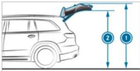
text_image
Diagram showing a car with a roof-mounted sensor and two labeled measurement points (1 and 2) indicating height measurements.Height when opened and headroom
| Model |  Height when opened* Height when opened* |  room* room* |
| Vehicles with AIR-MATIC | 2144 mm-2234 mm | 1929 mm-2019 mm |
| Vehicles with Off-road package | 2144 mm-2274 mm | 1929 mm-2059 mm |
| Mercedes-Maybach | Height when opened* | [IMAGE] room* |
| Mercedes-Maybach GLS 600 4MATIC | 2159 mm-2234 mm | 1944 mm-2019 mm |

Vehicle dimensions
| - All models | |
| Vehicle length | 5 |
| Vehicle length, AMG Styling | 5213 mm |
| Vehicle width including outside mirrors | 2157 mm |
| Vehicle width excluding outside mirrors, min. to max. | 1956 mm - 2030 mm |
| Maximum vehicle height (AIRMATIC) | 1888 mm |
| Maximum vehicle height (Off-road package) | 1928 mm |
| Minimum vehicle height (high-way driving level) | 1823 mm - 1838 mm |
| Wheelbase 3135 mm | |
| Maximum ground clearance (AIRMATIC) | 259 mm |
*When the rear-end lowering is activated, the values are correspondingly lower.
All models
| Maximum ground clearance (Off-road package) | 289 mm |
| Minimum ground clearance (AIRMATIC/Off-road package) | 174 mm |
| Mercedes-Maybach | |
| Vehicle length | 5 |
| Vehicle width including outside mirrors | 2157 mm |
| Vehicle width excluding outside mirrors | 2030 mm |
| Maximum vehicle height 1888 mm | |
| Minimum vehicle height (highway driving level) | 1838 mm |
| Wheelbase 3135 mm | |
| Maximum ground clearance 210 mm | |
| Minimum ground clearance 135 mm | |
Weights and loads
Please note that for the specified vehicle data:
- Items of optional equipment increase the unladen weight and reduce the payload.
- Vehicle-specific weight information can be found on the vehicle identification plate (→ page 427).
Roof load
| All models | |
| Maximum roof load | 100 kg |
Running board
| All models |
| Maximum load 200 kg |
Off-road driving
Angle of approach/departure
The specified values are maximum values for vehicles that are ready to drive - fuel tank full,
all fluids topped up, with driver. The values depend on the vehicle tyres and vehicle weight. Observe the notes on driving in mountainous terrain ( page 198).
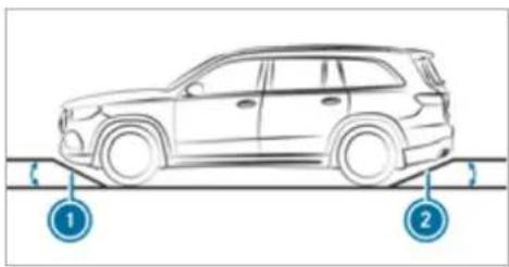
natural_image
Line drawing of a car on a road with two circular indicators labeled 1 and 2 (no text or symbols on the car itself)Angle of approach/departure
| All models (vehicles without AMG Styling) | 1 Front | 2 Rear |
| Vehicles with AIRMATIC* | ||
| Normal level | 2 | 3° 20° |
| Raised level | 27° | 24° |
*Depending on the tyre size
| All models (vehicles without AMG Styling) | 1 Front | 2 Rear |
| Vehicles with Off-road package | ||
| Normal level | 2 | 3° 20° |
| Off-road level 1 | 25° | 22° |
| Off-road level 2 | 27° | 24° |
| Off-road level 3 | 29° | 26° |
| All models (vehicles with AMG Styling) | 1 Front | 2 Rear |
| Vehicles with AIRMATIC | ||
| Normal level | 21° - 22° | 20° - 21° |
| Raised level | 25° | 24° |
| Vehicles with Off-road package | ||
| All models (vehicles with AMG Styling) | 1 Front | 2 Rear |
| Normal level | 21° - 22° | 20° - 21° |
| Off-road level 1 | 23° - 24° | 22° - 23° |
| Off-road level 2 | 25° | 24° |
| Off-road level 3 | 27° - 28° | 25° - 26° |
| Mercedes-Maybach GLS 600 4MATIC | 1 Front | 2 Rear |
| Normal level | 2 | 4° 21° |
| Raised level | 2 | 7° 25° |
Maximum gradient climbing ability
The vehicle's gradient climbing ability depends on the weight distribution in the vehicle, the terrain conditions and the road surface conditions.
The specified value applies when:
- the vehicle is ready to drive – fuel tank full, all fluids topped up, with driver
- the LOW RANGE off-road gear of the transfer case is engaged
- the road surface conditions and thus the traction are good
A gradient climbing ability of 100% corresponds to an incline of 45°.
Observe the notes on driving in mountainous terrain ( page 198).
| Model | Maximum gradient climbing ability |
| Vehicles without Off-road package | 80% |
| Vehicles with Off-road packageWhen LOW RANGE off-road gear is engaged | 100% |
| Mercedes-Maybach | Maximum gradient climbing ability |
| All models | 80% |
Trailer hitch
General notes on the trailer hitch
Modifications to the engine cooling system may be necessary, depending on the vehicle model. The retrofitting of a trailer hitch is only permissi-
ble if a towing capacity is specified in your vehicle documents.
Further information can be obtained at a qualified specialist workshop.
Mounting dimensions
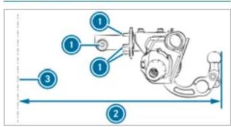
text_image
Technical diagram of a mechanical assembly with numbered components and dimension lines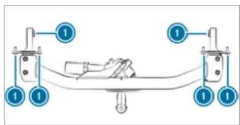
text_image
Diagram showing a mechanical or electrical component with labeled parts and numbered indicatorsFastening points
② Overhang dimension
③ Rear axle centre line
The overhang dimension and fastening points are valid for a trailer hitch installed at the factory.
| Model | Overhang dimension |
| All models | 1 |
| Mercedes-Maybach | Overhang dimension |
| Mercedes-Maybach GLS 600 4MATIC | 1257 mm |
Towing capacity
You will find vehicle-specific weight information in the vehicle documents.
The tongue weight is not included in the towing capacity.
Towing capacity, braked (at a minimum start-off gradeability of 12%)
| Model Towing capacity | |
| 3500 kg (3300 kg)* | |
| All models 3500 kg (3300 kg) | |
| Mercedes-Maybach | Towing capacity3500 kg (3300 kg)* |
| Mercedes-MaybachGLS 600 4MATIC | 3500 kg (3300 kg) |
*Mercedes GLS or Mercedes-Maybach GLS with one or more of the following features: E-ACTIVE BODY CONTROL, OFF-ROAD PACKAGE, UNDERRIDE GUARD, HIGH-END-SOUND, EMERGENCY SPARE WHEEL / COLLAPSIBLE SPARE WHEEL
Towing capacity, unbraked
| Model Towing capacity | |
| All models 750 kg | |
| Mercedes-Maybach | Towing capacity |
| Mercedes-Maybach GLS 600 4MATIC | 750 kg |
Maximum tongue weight and load capacity
| NOTE Damage caused by the trailer coming loose |
| If the tongue weight used is too low, the trailer may come loose. |
| The tongue weight must not be below 50 kg. |
| Use a tongue weight that is as close as possible to the maximum permissible tongue weight. |
NOTE Damage caused by the bicycle rack coming loose
| When using a bicycle rack, both the maximal tongue weight and the maximal load capacity should be observed. |
| Do not exceed the permissible load capacity. |
You will find vehicle-specific weight information in the vehicle documents.
Observe the additional notes on load capacity ( page 306).
Tongue weight
| Model Maximum tongue weight | |
| All models | 140 kg (132 kg)* |
| Mercedes-Maybach | Maximum tongue weight |
| All models | 140 kg (132 kg)* |
*Mercedes GLS or Mercedes-Maybach GLS with one or more of the following features: E-ACTIVE BODY CONTROL, OFF-ROAD PACKAGE, UNDERRIDE GUARD, HIGH-END-SOUND, EMERGENCY SPARE WHEEL / COLLAPSIBLE SPARE WHEEL
Missing values were not available at the time of going to press.
Load capacity
| Model Maximum load | ||
| All models | ||
| Mercedes-Maybach | M | aximum load |
| Mercedes-Maybach GLS 600 4MATIC | ||
Permissible rear axle load (trailer operation)
| Model | Permissible rear axle load during trailer operation |
| Towing capacity3500 kg (3300 kg)* | |
| GLS 4504MATIC | 1920 kg (1960 kg) |
| GLS 5804MATIC | 1900 kg (1950 kg) |
| All other models | 1930 kg (1970 kg) |
| Mercedes-Maybach | Permissible rear axle load during trailer operation |
| Towing capacity3500 kg (3300 kg)* | |
| Mercedes-MaybachGLS 6004MATIC | 1900 kg (1900 kg) |
*Mercedes GLS or Mercedes-Maybach GLS with one or more of the following features: E-ACTIVE BODY CONTROL, OFF-ROAD PACKAGE, UNDERRIDE GUARD, HIGH-END-SOUND, EMERGENCY SPARE WHEEL / COLLAPSIBLE SPARE WHEEL
Display messages
Introduction
Information about display messages
Display messages appear on the multifunction display.
Display messages with graphical symbols are simplified in the Owner's Manual and may differ from the symbols on the multifunction display. The multifunction display shows high-priority display messages in red. Certain display messages are accompanied by a warning tone.
Please act in accordance with the display messages and follow the additional notes in the Owner's Manual.
For some display messages, a symbol will also be shown:
• ⓘ Further information
- × Hide display message
With the left-hand Touch Control, you can select the respective symbol by swiping to the left or right. Press the ⓘ symbol to show further infor-
mation on the media display. Press the symbol to hide the display message.
You can hide low-priority display messages by pressing the ▶ back button or the left-hand Touch Control. The display messages will then be stored in the message memory.
Rectify the cause of a display message as quickly as possible.
High-priority display messages cannot be hidden. The multifunction display shows these display messages continuously until the cause of the display message has been rectified.
Calling up saved display messages
On-board computer:
→ Service ▶ 1 message
If there are no display messages, No messages will appear on the multifunction display.
▶ Scroll through the display messages by swiping upwards or downwards on the left-hand Touch Control.
To exit the message memory: press the back button .
Occupant safety
| Display messages | Possible causes/consequences and ▶ Solutions |
 Restraint sys. malfunction Consult workshop Restraint sys. malfunction Consult workshop | * The restraint system is malfunctioning (→ page 40).⚠ WARNING Risk of injury due to malfunctions in the restraint systemComponents in the restraint system may be activated unintentionally or not deploy as intended in an accident.▶ Have the restraint system checked and repaired immediately at a qualified specialist workshop. |
 Front left malfunction Consult workshop (example) Front left malfunction Consult workshop (example) | * The corresponding restraint system is malfunctioning (→ page 40).⚠ WARNING Risk of injury due to malfunctions in the restraint systemComponents in the restraint system may be activated unintentionally or not deploy as intended in an accident.▶ Have the restraint system checked and repaired immediately at a qualified specialist workshop. |
 Left windowbag malfunction Consult workshop (example) Left windowbag malfunction Consult workshop (example) | * The corresponding restraint system is malfunctioning (→ page 40).⚠ WARNING Risk of injury or fatal injury due to a malfunction in the windowbagThe windowbag might be triggered unintentionally or might not be triggered at all in the event of an accident.▶ Have the windowbag checked and repaired immediately at a qualified specialist workshop. |
| Front-passenger airbag disabled See Owner's Manual | * The front passenger airbag has been disabled even though an adult or a person of adult build is on the front passenger seat. If additional forces are applied to the seat, the weight the system detects may be too low.⚠ WARNING - Risk of injury or even fatal injury when the front passenger airbag is disabledIf the front passenger airbag is disabled, It will not be deployed in the event of an accident and cannot perform its intended protective function.A person in the front passenger seat could then, for example, come into contact with the vehicle interior, especially if the person is sitting too close to the dashboard.▶ Be aware of the status of the front passenger airbag both before and during the journey.▶ Stop the vehicle immediately in accordance with the traffic conditions.▶ Make sure that no objects are trapped under the front passenger seat.▶ Check the status of automatic front passenger airbag actuation (→ page 50).▶ If necessary, consult a qualified specialist workshop immediately. |
| Front-passenger airbag enabled See Owner's Manual | * The front passenger airbag will be enabled while the vehicle is in motion in the following situations:• even when a child, a small adult or an object weighing less than the system weight threshold is located on the front passenger seat• even when the front passenger seat is not occupiedThe system may detect objects or forces that are adding to the weight applied to the seat.⚠ WARNING Risk of injury or death when using a child restraint system while the front passenger airbag is enabledIf you secure a child in a child restraint system on the front passenger seat and the front passenger airbag is enabled, the front passenger airbag can deploy in the event of an accident.The child could be struck by the airbag.▶ Ensure, both before and during the journey, that the status of the front passenger airbag is correct.NEVER use a rearward facing child restraint on a seat protected by an ACTIVE AIRBAG in front of it, DEATH or SERIOUS INJURY to the CHILD can occur. |
| ▶ Stop the vehicle immediately in accordance with the traffic conditions.▶ Make sure that no objects are trapped under the front passenger seat.▶ Check the status of automatic front passenger airbag actuation (→ page 50).▶ If necessary, consult a qualified specialist workshop immediately. | |
| PRE-SAFE inoperative See Owner's Manual | * The PRE-SAFE® functions are malfunctioning.▶ Consult a qualified specialist workshop. |
| PRE-SAFE impulse side inoperative See Owner's Manual | * The PRE-SAFE® Impulse Side system is malfunctioning or inoperative after having already been triggered.▶ Consult a qualified specialist workshop. |
Key
| Display messages | Possible causes/consequences and ▶ Solutions |
 Replace key Replace key | * Have the key replaced.▶ Consult a qualified specialist workshop. |
 Change key batteries Change key batteries | * The key battery is discharged.▶ Replace the battery (→ page 81). |
 Key not detected (white display message) Key not detected (white display message) | * The key is currently undetected.▶ Change the location of the key in the vehicle.▶ If the key is still not recognised, place it in the slot for starting with the key (→ page 192). |
 Key not detected(red display message) Key not detected(red display message) | * The key cannot be detected and may no longer be in the vehicle.The key is no longer in the vehicle and you switch off the engine:You can no longer start the engine.You cannot centrally lock the vehicle.Ensure that the key is in the vehicle.If the key detection function has a malfunction due to a strong radio signal source:Stop the vehicle immediately in accordance with the traffic conditions.Place the key in the slot for starting the engine with the key (→ page 192). |
 Key being initialised Please wait Key being initialised Please wait | * The vehicle is processing in order to teach in the new key.Wait until processing is complete. |
| Place the key in the marked space See Owner's Manual | * Key detection is malfunctioning.Change the location of the key in the vehicle.Place the key in the slot for starting the engine with the key (→ page 192). |
Lights
| Display messages | Possible causes/consequences and ▶ Solutions |
 Left dipped beam (example) Left dipped beam (example) | * The corresponding light source is defective.► Drive on carefully.► Consult a qualified specialist workshop immediately.i LED light sources: the display message for the corresponding light appears only when all the light-emitting diodes in the light are faulty. |
 Malfunction See Owner's Manual Malfunction See Owner's Manual | * The exterior lighting is malfunctioning.► Consult a qualified specialist workshop.* Vehicles with a trailer hitch: a fuse may have blown.► Stop the vehicle in accordance with the traffic conditions.► Check the fuses and replace them if necessary (→ page 401). |
 Automatic driving lights inoperative Automatic driving lights inoperative | * The light sensor for automatic driving lights is malfunctioning.► Consult a qualified specialist workshop. |
 Active Light System inoperative Active Light System inoperative | * T he active headlamps are malfunctioning. ▶ Consult a qualified specialist workshop. |
 Switch on headlamps Switch on headlamps | * Y ou are driving without low-beam headlamps. ▶ Turn the light switch to the ☑ or AUTO position. |
 Switch off lights Switch off lights | * You are leaving the vehicle and the lights are still switched on. ▶ Turn the light switch to the AUTO position. |
 Intelligent Light System inoperative Intelligent Light System inoperative | * The Intelligent Light System is malfunctioning. The lighting system continues to function properly without the functions of the Intelligent Light System. ▶ Consult a qualified specialist workshop. |
| Adaptive Highbeam Assist Plus currently unavailableSee Owner's Manual | * Adaptive Highbeam Assist Plus is temporarily unavailable.The system limits have been reached (→ page 164).Once the cause of the problem is no longer present, the system will be available again. The Adaptive Highbam Assist Plus available again display message will appear.Drive onOperate the high beam manually until Adaptive High Beam Assist Plus is available again. |
| Adaptive Highbam Assist Plus inoperative | * A daptive Highbeam Assist Plus is malfunctioning.Drive onorStop the vehicle in accordance with the traffic conditions and restart the vehicle.If the display message does not disappear: consult a qualified specialist workshop.Until then, operate the high beam manually. |
| Hazard warning lamps malfunctioning | * The hazard warning lamp switch is malfunctioning.Consult a qualified specialist workshop. |
Climate control
| Display messages | Possible causes/consequences and ▶ Solutions |
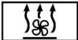 inoperative See Owner's Man. inoperative See Owner's Man. | * The stationary heater is temporarily malfunctioning.When the vehicle is stationary on a level surface and the engine has cooled down, make up to four attempts to switch on the stationary heater, waiting several minutes between each attempt.If the stationary heater does not switch on, consult a qualified specialist workshop. |
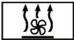 inoperative Battery low inoperative Battery low | * The on-board electrical system voltage is too low.The stationary heater has switched itself off.Drive an extended distance until the battery has reached a sufficient charge level again. |
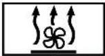 inoperative Refuel vehicle inoperative Refuel vehicle | * There is too little fuel in the fuel tank. The stationary heater cannot be switched on.Refuel the vehicle. |
Vehicle
| Display messages | Possible causes/consequences and ▶ Solutions |
| Update successfully completed | * Installation of the software update has been successfully completed (→ page 327). |
| Update failed Software remains unchanged | * An error occurred during installation of the software update (→ page 327).The previous software release remains in place. |
| Update failed | * An error occurred during installation of the software update (→ page 327).Make a Mercedes me call via the overhead control panel (→ page 344). |
 Vehicle is operationalSwitch off ignition before exiting Vehicle is operationalSwitch off ignition before exiting | * You are leaving the vehicle in a ready-to-drive state.▶ When you leave the vehicle, switch off the ignition, secure the vehicle against rolling away and take the key with you.▶ If you do not leave the vehicle, switch off the electrical consumers, e.g. the seat heating. Otherwise, the 12-V battery may discharge and starting the engine may be possible only with the help of a second battery (jump start). |
 Operation only possible in transmission position P Operation only possible in transmission position P | * The ball neck will not swivel because transmission position D, R or neutral N is selected.▶ Depress the brake pedal.▶ Engage park position [P]. |
 Trailer coupling extending... Trailer coupling extending... | * The ball neck is retracting/extending.Do not attempt to speed up, slow down or initiate the swivel movement using your hand, foot or other aids. During the swivel movement, do not couple a trailer.When the ball neck has reached an operational position, the display message will disappear. |
 Check trailer hitch lock Check trailer hitch lock | * The trailer hitch is not operational during a journey with a trailer.⚠ WARNING Risk of an accident if the ball neck is not lockedThe trailer may become detached.▶ Stop the vehicle immediately in accordance with the traffic conditions. Do not continue driving.▶ Uncouple the trailer and secure it against rolling away.▶ Initiate a new swivel movement and do not re-couple the trailer until the warning/indicator lamp goes out. |
| ▶ Initiate a new swivel movement (→ page 301).▶ When the display message disappears, couple up the trailer and drive on.If the display message does not disappear, the trailer hitch is malfunctioning and the ball neck is not locked.▶ Do not couple up the trailer. Drive on without the trailer. Note the reduced ground clearance due to the unlocked ball neck.▶ Consult a qualified specialist workshop.* The trailer hitch will not be operational when the vehicle is stationary.▸ Uncouple the coupled trailer and secure it against rolling away.▸ If the ball neck has been retracted: initiate a new swivel movement (→ page 301).The ball neck will engage vertically in the locked position and then engage beneath the bumper.▸ If the ball neck has been extended: initiate a new swivel movement (→ page 301).The ball neck will engage beneath the bumper.If the display message does not disappear, the trailer hitch is malfunctioning and the ball neck is not locked.▸ Do not couple up the trailer. Drive on without the trailer. Note the reduced ground clearance due to the unlocked ball neck.▸ Consult a qualified specialist workshop. | |
| Side running board not retracted Observe the excess width of the vehicle | * Mercedes-Maybach vehicles: the running boards are not retracted.The running boards can be retracted via the multimedia system only when the vehicle is stationary (→ page 88).The running boards and the side skirt must be free of dirt, ice and snow. Otherwise, they are unable to retract.Clean the running boards (→ page 379).Repeat the retraction of the running boards (→ page 87).If the running boards cannot be retracted again, consult a qualified specialist workshop.If the running boards are not retracted, check the excess width of the vehicle. |
 Side running board not extended Side running board not extended | * Mercedes-Maybach vehicles: the running boards are not extended.The running boards extend only when the vehicle is stationary.The running boards and the side skirt must be free of dirt, ice and snow. Otherwise, they are unable to extend.Clean the running boards (→ page 379).Repeat the extension of the running boards (→ page 87).If the running boards fail to extend again, consult a qualified specialist workshop.If the running boards are not extended, be particularly careful when getting in or out. |
| Head-up display currently unavailable See Owner's Manual | * The head-up display is temporarily unavailable. Possible causes:malfunctions in the power supplysignal interferenceStop the vehicle in accordance with the traffic conditions and switch the ignition off and on again.If the display message still appears, consult a qualified specialist workshop. |
| Head-up display inoperative | * T he head-up display has an internal error.Consult a qualified specialist workshop. |
Display messages

Steering malfunction Increased physical effort See Owner's Manual

Steering malfunction Stop immediately See Owner's Manual
Possible causes/consequences and ▶ Solutions
* The power steering assistance is malfunctioning.
WARNING Risk of an accident due to altered steering characteristics
If the power assistance of the steering fails partially or completely, you will need to use more force to steer.
▶ If safe steering is possible, drive on carefully.
▶ Visit or consult a qualified specialist workshop immediately.
* The steering is malfunctioning. Steering capability is significantly impaired.
WARNING Risk of accident if steering capability is impaired
If the steering does not function as intended, the vehicle's operating safety is jeopardised.
▶ Pull over and stop the vehicle safely as soon as possible, paying attention to road and traffic conditions. Do not continue driving under any circumstances.
Consult a qualified specialist workshop.
* A t least one door is open.
▶ Close all doors.
| Display messages | Possible causes/consequences and ▶ Solutions |
 | * T he bonnet is open.⚠ WARNING Risk of accident due to driving with the bonnet unlockedThe bonnet may open and block your view.▶ Never release the bonnet when driving.▶ Before every trip, ensure that the engine bonnet is locked. |
| ▶ Stop the vehicle immediately in accordance with the traffic conditions.▶ Close the bonnet. | |
 | * T he tailgate is open.⚠ DANGER Risk of exhaust gas poisoningCombustion engines emit poisonous exhaust gases such as carbon monoxide. Exhaust gases can enter the vehicle interior if the tailgate is open when the engine is running, especially if the vehicle is in motion.▶ Always switch off the engine before opening the tailgate.▶ Never drive with the tailgate open. |
| ▶ Close the tailgate. | |
| LOW RANGE only when vehicle stationary | * One or more shifting conditions have not been met.▶ Stop the vehicle.▸ Engage neutral N.▸ Repeat the gear change. |
| LOW RANGE Shift to position N briefly | * One or more shifting conditions have not been met.▸ Engage neutral N.▸ Repeat the gear change. |
| LOW RANGE Not in drive program "Sport" | * You will not be able to select the LOW RANGE off-road gear if the drive program S or St is switched on.The drive program therefore automatically switches to C.▸ Select the LOW RANGE off-road gear (→ page 214). |
| LOW RANGE Malfunction To park, apply parking brake | * T he transfer case is malfunctioning.▸ Do not shift the transfer case!▸ Use the electric parking brake to secure the vehicle against rolling away.▸ Consult a qualified specialist workshop. |
| LOW RANGE Shifting cancelled Please reactivate | * The transfer case did not perform the gear change.▸ Repeat the gear change.▸ Ensure that all shifting conditions are met (→ page 214). |
| LOW RANGE Malfunction | * T he transfer case is malfunctioning.▸ Do not shift the transfer case!▶ Use the electric parking brake to secure the vehicle against rolling away.▶ Consult a qualified specialist workshop. |
| LOW RANGE Stop Apply parking brake | * T he transfer case is malfunctioning.▶ Stop the vehicle in accordance with the traffic conditions.▶ Apply the electric parking brake.▶ Where necessary, also secure the vehicle against rolling away.▶ Engage park position P. |
| LOW RANGE Max. speed 10 km/h | * The maximum speed of 10 km/h for the gear change has been exceeded.▶ Drive more slowly.▶ Repeat the gear change. |
| LOW RANGE Max. speed 40 km/h | * The maximum speed of 40 km/h for the gear change has been exceeded.▶ Drive more slowly.▶ To deactivate the gear change, press the LOW RANGE button again.▶ Repeat the gear change. |
| Gearbox protection Limit 30 km/h Switch off LOW RANGE | * The oil temperature in the transfer case is too high.▶ In the on-road position, shift to HIGH RANGE. |
| Anti-theft alarm system Malfunction | * The anti-theft alarm system is malfunctioning. ▶ Consult a qualified specialist workshop. |
 Cannot fold 2nd seat row forwards See Owner's Manual Cannot fold 2nd seat row forwards See Owner's Manual | * The seat backrests on the second row of seats cannot be folded forward. ▶ Check the requirements for folding forward the seat backrests on the second row of seats (→ page 114). |
 Top up washer fluid Top up washer fluid | * The washer fluid level in the washer fluid reservoir has dropped below the minimum. ▶ Top up the washer fluid (→ page 373). |
| Wiper malfunctioning | * T he windscreen wiper is malfunctioning. ▶ Restart the engine. If the display message still appears: ▶ Consult a qualified specialist workshop. |
Engine
| Display messages | Possible causes/consequences and ▶ Solutions |
| To switch off the engine, press the Start/Stop button for at least 3 seconds or 3 times. | * You have pressed the start/stop button while the vehicle is in motion.▶ Information about switching off the engine while driving (→ page 191). |
| Cannot start engine See Owner's Manual | * The vehicle cannot be started.▶ Switch the ignition off and switch it back on.▶ If the display message still appears, consult a qualified specialist workshop. |
 Top up coolant See Owner's Manual Top up coolant See Owner's Manual | * The coolant level is too low.■ NOTE Engine damage due to insufficient coolant▶ Avoid long journeys with insufficient coolant.▶ Add coolant (→ page 372).▶ Have the engine cooling system checked at a qualified specialist workshop. |
 Coolant Stop vehicleSwitch engine off Coolant Stop vehicleSwitch engine off | * The coolant is too hot.▶ Stop the vehicle immediately in accordance with the traffic conditions and switch off the engine.⚠ WARNING Risk of burns when opening the bonnetIf you open the bonnet when the engine has overheated or when there is a fire in the engine compartment, the following situations may occur:You could come into contact with hot gases.You could come into contact with other hot, escaping operating fluids.Before opening the bonnet, allow the engine to cool down.In the event of a fire in the engine compartment, keep the bonnet closed and call the fire service. |
| ▶ Wait until the engine has cooled down.Make sure that the air supply to the radiator is not obstructed.Avoiding high loads on the engine, drive to the nearest qualified specialist workshop. In doing so, ensure that the coolant temperature display remains below 120°C. | |
 | * There is a malfunction in the engine cooling system.Avoiding high loads on the engine, drive to the nearest qualified specialist workshop. In doing so, ensure that the coolant temperature display remains below 120°C. |
 Reserve fuel level Reserve fuel level | * The fuel supply has dropped into the reserve range.▶ Refuel. |
 Clean the fuel filter Clean the fuel filter | * Vehicles with diesel engines: the fuel filter is dirty or the water in the fuel filter needs to be drained.▶ Consult a qualified specialist workshop. |
 Replace air cleaner Replace air cleaner | * Vehicles with diesel engines: the engine air filter is dirty and must be replaced.▶ Consult a qualified specialist workshop. |
| Drive system Malfunction Visit workshop | * T he drive system is malfunctioning.▶ Consult a qualified specialist workshop. |
| Drive system Malfunction Stop Switch engine off | * T he drive system is malfunctioning.▶ Stop the vehicle immediately in accordance with the traffic conditions and switch off the engine.▶ Consult a qualified specialist workshop. |
Transmission
| Display messages | Possible causes/consequences and ▶ Solutions |
| Only select Park (P) when vehicle is stationary | * It is possible to select the park position P only if the vehicle is stationary. ▶ Depress the brake pedal to stop. ▶ Shift the transmission to park position P when the vehicle is stationary. |
| Apply brake to deselect Park (P) position | * You have attempted to shift the transmission out of park position P and into another transmission position. ▶ Depress the brake pedal. ▶ Select transmission position D, R or neutral N. |
| To shift out of P or N, depress brake and start engine | * You have attempted to shift the transmission out of park position P or neutral N and into another transmission position. ▶ Depress the brake pedal. ▶ Start the vehicle. ▶ Change the transmission position. |
| Apply brake to select D | or *RYou have attempted to select transmission position D or R. ▶ Depress the brake pedal. ▶ Select transmission position D or R. |
| Apply brake to select R | * You have attempted to select transmission position R. ▶ Depress the brake pedal. ▶ Select transmission position R. |
| Risk of vehicle rollingDriver door open and transmission not in P | * The driver's door is not fully closed and transmission position D, R or neutral N is selected.The vehicle may roll away.▶ Select park position P when switching off the vehicle. |
| N permanently active Risk of vehicle rolling | * Neutral N has been selected while the vehicle is rolling or while you are driving.▶ Depress the brake pedal to stop.▶ Shift the transmission to park position P while the vehicle is stationary.▶ To continue driving, select transmission position D or R. |
| Without changing gear, consult workshop | * The transmission is malfunctioning. It is no longer possible to change the transmission position.▶ If transmission position D is selected, consult a qualified specialist workshop and do not change the transmission position.▶ For all other transmission positions, park the vehicle safely.▶ Consult a qualified specialist workshop. |
| Reversing not poss. Consult workshop | * The transmission is malfunctioning. It is not possible to select transmission position R.▶ Consult a qualified specialist workshop. |
| Transmission Malfunction Stop | * The transmission is malfunctioning. The transmission shifts to neutral N automatically.▶ Stop the vehicle immediately in accordance with the traffic conditions.▶ Depress the brake pedal.▶ Engage park position P.▶ Consult a qualified specialist workshop. |
| Stop vehicle Leave engine running Wait Transmission cooling | * The transmission is overheating. Pulling away may be temporarily impaired or not possible.▶ Stop the vehicle immediately in accordance with the traffic conditions. Do not continue driving.▶ Leave the engine running.▶ Wait until the display message disappears before pulling away. |
| Auxiliary battery malfunction (white display message) | * Vehicles with automatic transmission: The auxiliary battery for the transmission is no longer being charged.▶ Consult a qualified specialist workshop.▶ Vehicles with automatic transmission: Until then, always select park position P manually before you switch off the engine.▶ Before leaving the vehicle, apply the electric parking brake. |
| Auxiliary battery malfunction (red display message) | * Vehicles with automatic transmission: The auxiliary battery for the transmission is no longer being charged.▶ Consult a qualified specialist workshop.▶ Vehicles with automatic transmission: Until then, always select park position P manually before you switch off the engine.▶ Before leaving the vehicle, apply the electric parking brake. |
Brakes
Display messages

Parking brake See Owner's Manual
Possible causes/consequences and ▶ Solutions
* The yellow Ⓓ indicator lamp is lit. The electric parking brake is malfunctioning.
To apply:
▶ Switch the ignition off and switch it back on.
Apply the electric parking brake manually ( page 227).
If it is not possible to apply the electric parking brake:
Consult a qualified specialist workshop.
Where necessary, also secure the parked vehicle against rolling away.
- Consult a qualified specialist workshop. - Where necessary, also secure the parked vehicle against rolling away.
* The yellow (P) indicator lamp and the red (P) indicator lamp are lit. The electric parking brake is malfunctioning.
To release:
▶ Switch the ignition off and switch it back on.
Release the electric parking brake manually ( page 227).
or
Release the electric parking brake automatically ( page 226). If it is still not possible to release the electric parking brake:
Do not continue driving. Consult a qualified specialist workshop.
Display messages
Possible causes/consequences and ▶ Solutions
* The yellow (P) indicator lamp is lit and the red (P) indicator lamp is flashing. The electric parking brake is malfunctioning.
The electric parking brake could not be applied or released.
▶ Switch the ignition off and switch it back on.
To apply:
Release and then apply the electric parking brake manually ( page 227).
To release:
Apply and then release the electric parking brake manually.
If it is not possible to apply the electric parking brake or the red (P) indicator lamp continues to flash:
Do not continue driving. Consult a qualified specialist workshop.
Where necessary, also secure the parked vehicle against rolling away.
* The yellow (P) indicator lamp is lit and the red (P) indicator lamp flashes for approximately ten seconds after the electric parking brake has been applied or released. It then remains lit or goes out. The electric parking brake is malfunctioning.
If the state of charge is too low:
▶ Charge the 12 V battery.
To apply:
| Display messages | Possible causes/consequences and ▶ Solutions |
| ▶ Switch the ignition off.The electric parking brake will be applied automatically.If you do not want the electric parking brake to be applied, e.g. at an automatic car wash or when the vehicle is being towed, leave the ignition switched on. This does not include having the vehicle towed with the rear axle raised.If the electric parking brake is not applied automatically:▶ Switch the ignition off and switch it back on.▶ Release and then apply the electric parking brake manually (→ page 227).If it is still not possible to apply the electric parking brake:▶ Consult a qualified specialist workshop.▶ Where necessary, also secure the parked vehicle against rolling away.To release:▶ If the conditions for automatic release are fulfilled and the electric parking brake is not released automatically, release the electric parking brake manually (→ page 227).If it is still not possible to release the electric parking brake:▶ Do not continue driving. Consult a qualified specialist workshop. | |
 Release parking brake Release parking brake | * The red Ⓓ indicator lamp is flashing.The electric parking brake is applied while you are driving:A condition for automatic release of the electric parking brake has not been fulfilled (→ page 226).You are performing emergency braking using the electric parking brake (→ page 227).▶ Check the conditions for automatic release of the electric parking brake.▶ Release the electric parking brake manually. |
 Turn on the ignition to release the parking brake Turn on the ignition to release the parking brake | * The red Ⓓ indicator lamp is lit.You have attempted to release the electric parking brake with the ignition switched off.▶ Switch on the ignition. |
 Check brake fluid level Check brake fluid level | * There is insufficient brake fluid in the brake fluid reservoir.⚠ WARNING Risk of an accident due to low brake fluid levelIf the brake fluid level is too low, the braking effect and the braking characteristics may be impaired.▶ Stop the vehicle as soon as possible, paying attention to road and traffic conditions. Do not continue driving.▶ Consult a qualified specialist workshop.▶ Do not top up the brake fluid. |
| Check brake pads See Owner's Manual | * The brakepads have reached the wear limit. ▶ Consult a qualified specialist workshop. |
Driving systems
| Display messages | Possible causes/consequences and ▶ Solutions | |
 Off Off | * The HOLD function is deactivated because the vehicle is slipping or a condition for activation is not fulfilled.▶ Reactivate the HOLD function later or check the activation conditions for the HOLD function (→ page 235). | |
 ATTENTION ASSIST inoper-ative ATTENTION ASSIST inoper-ative | * A TTENTION ASSIST is malfunctioning.▶ Consult a qualified specialist workshop. | |
| Display messages | Possible causes/consequences and ▶ Solutions | |
 ATTENTION ASSIST: Take a break! ATTENTION ASSIST: Take a break! | * ATTENTION ASSIST has detected fatigue or an increasing lack of concentration on the part of the driver (→ page 236).▶ If necessary, take a break. | |
 - - - km/h - - - km/h | * Cruise control cannot be activated as not all activation conditions are fulfilled.▶ Observe the activation conditions for cruise control (→ page 239). | |
| Cruise control inoperative | * C ruise control is malfunctioning.▶ Consult a qualified specialist workshop. | |
| Cruise control and Limiter inoperative | * Cruise control and the limiter are malfunctioning.▶ Consult a qualified specialist workshop. | |
| Cruise control off | * C ruise control has been deactivated.If there is an additional warning tone, cruise control has been deactivated automatically (→ page 238). | |
| Display messages | Possible causes/consequences and ▶ Solutions | |
 --- km/h --- km/h | * The limiter can temporarily not be engaged. Once the cause of the problem is no longer present, the system will be available again. | |
| Limiter passive | * If you depress the accelerator pedal beyond the pressure point (kickdown), the limiter is switched to passive mode (→ page 239). | |
| Limiter inoperative | * T he limiter is malfunctioning.► Consult a qualified specialist workshop. | |
 --- km/h --- km/h | * Active Distance Assist DISTRONIC cannot be activated as not all activation conditions are fulfilled.► Comply with the activation conditions of Active Distance Assist DISTRONIC (→ page 244). | |
 suspended suspended | * If you depress the accelerator pedal beyond the setting of Active Distance Assist DISTRONIC, the system will switch to passive mode (→ page 241). | |
| Display messages | Possible causes/consequences and ▶ Solutions | |
 Off Off | * Active Distance Assist DISTRONIC was deactivated. If a warning tone also sounds, Active Distance Assist DISTRONIC has deactivated automatically (→ page 244). | |
| Active Distance Assist currently unavailable See Owner's Manual | * Active Distance Assist DISTRONIC is temporarily unavailable.The ambient conditions are outside the system limits (→ page 241).As soon as the ambient conditions are within the system limits, the system will become available again.Drive on | |
| Active Distance Assist inoperative | * 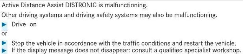 | |
| Display messages | Possible causes/consequences and ▶ Solutions | |
| Active Distance Assist available again | * Active Distance Assist DISTRONIC is operational again.▶ Switch on Active Distance Assist DISTRONIC (→ page 244). | |
| Speed Limit Assist currently unavailable See Owner's Manual | * Speed Limit Assist is temporarily unavailable.▶ Drive onOnce the cause of the problem is no longer present, the system will be available again. | |
| Speed Limit Assist inoperative | * Speed Limit Assist is malfunctioning.▶ Drive onor▶ Stop the vehicle in accordance with the traffic conditions and restart the vehicle.▶ If the display message does not disappear: consult a qualified specialist workshop. | |
 Maximum speed exceeded Maximum speed exceeded | * You have exceeded the maximum permissible speed (for certain countries only).▶ Drive more slowly. | |
| Speed limit (winter tyres) XXX km/h | * You have reached the maximum permissible stored speed for winter tyres. It is not possible to exceed this speed. | |
| Display messages | Possible causes/consequences and ▶ Solutions | |
 inoperative inoperative | * The Downhill Speed Regulation is malfunctioning.► Consult a qualified specialist workshop. | |
 Not possible in current drive program Not possible in current drive program | * The Downhill Speed Regulation is not available in the currently selected drive program.► Change the drive program (→ page 205). | |
 Max. speed 40 km/h Max. speed 40 km/h | * The maximum speed of 40 km/h for the Downhill Speed Regulation has been exceeded.► Drive more slowly. | |
| Active Steering Assist currently unavailable See Owner's Manual | * Active Steering Assist is temporarily unavailable.The ambient conditions are outside the system limits (→ page 250).As soon as the ambient conditions are within the system limits, the system will become available again.► Drive on► Check the tyre pressure if necessary. | |
| Display messages | Possible causes/consequences and ▶ Solutions | |
| Active Steering Assist inoperative | * Active Steering Assist is malfunctioning. Active Distance Assist DISTRONIC remains available.► Drive onor► Stop the vehicle in accordance with the traffic conditions and restart the vehicle.► If the display message does not disappear: consult a qualified specialist workshop. | |
| Active Steering Assist currently unavailable due to multiple emergency stops | * Active Steering Assist is temporarily unavailable due to multiple emergency stops.► Take over the steering and stop in accordance with the traffic conditions.► Switch the ignition off and switch it back on.Active Steering Assist is available once more. | |
| Beginning emergency stop | * Your hands are not on the steering wheel. An emergency stop is being initiated (→ page 252).► Put your hands back on the steering wheel.You can cancel the deceleration at any time by performing one of the following actions:SteeringBraking or acceleratingDeactivating Active Distance Assist DISTRONIC | |
 | * Active Steering Assist has reached the system limits (→ page 250).You have not steered independently for a considerable period of time.► Take over the steering and drive on in accordance with the traffic conditions. | |
| Display messages | Possible causes/consequences and ▶ Solutions | |
| Active Stop-and-Go Assist currently unavailable see Owner's Manual | * Active Stop-and-Go Assist is temporarily unavailable. Active Distance Assist DISTRONIC and Active Steering Assist are still available.The ambient conditions are outside the system limits (→ page 248).As soon as the ambient conditions are within the system limits, the system will become available again.▶ Drive on. | |
| Active Stop-and-Go Assist inoperative See Owner's Manual | * A ctive Stop-and-Go Assist is malfunctioning.Active Stop-and-Go Assist has been deactivated. Active Distance Assist DISTRONIC and Active Steering Assist are still available.▶ Drive on.or▶ Stop the vehicle in accordance with the traffic conditions and restart the vehicle.▶ If the display message does not disappear, consult a qualified specialist workshop. | |
| Traffic Sign Assist currently unavailable See Owner's Manual | * Traffic Sign Assist is temporarily unavailable.Once the cause of the problem is no longer present, the system will be available again.▶ Drive on | |
| Traffic Sign Assist inoperativeDisplay messages | * T raffic Sign Assist is malfunctioning.▶ Drive onor▶ Stop the vehicle in accordance with the traffic conditions and restart the vehicle. | |
| Possible causes/consequences and ▶ Solutions | ||
| ▶ If the display message does not disappear: consult a qualified specialist workshop. | ||
| Blind Spot Assist currently unavailable See Owner's Manual | * Blind Spot Assist is temporarily unavailable.The system limits have been reached (→ page 262).Once the cause of the problem is no longer present, the system will be available again.▶ Drive onor▶ If the display message does not disappear, stop the vehicle in accordance with the traffic conditions and restart the vehicle. | |
| Blind Spot Assist inoperative | * B lind Spot Assist is malfunctioning.▶ Drive onor▶ Stop the vehicle in accordance with the traffic conditions and restart the vehicle.▶ If the display message does not disappear: consult a qualified specialist workshop. | |
| Blind Spot Assist not available when towing a trailer See Owner's Manual | * When you establish the electrical connection to the trailer, Blind Spot Assist will be unavailable.▶ Press the left-hand Touch Control and acknowledge the display message. | |
| Active Blind Spot Assist currently unavailable See Owner's ManualDisplay messages | * Active Blind Spot Assist is temporarily unavailable.The system limits have been reached (→ page 262). | |
| Possible causes/consequences and ▶ Solutions | ||
| Once the cause of the problem is no longer present, the system will be available again.▶ Drive onor▶ If the display message does not disappear, stop the vehicle in accordance with the traffic conditions and restart the vehicle. | ||
| Active Blind Spot Assist inoperative | * Active Blind Spot Assist is malfunctioning.▶ Drive onor▶ Stop the vehicle in accordance with the traffic conditions and restart the vehicle.▶ If the display message does not disappear: consult a qualified specialist workshop. | |
| Active Blind Spot Assist not available when towing a trailer See Owner's Manual | * When you establish the electrical connection to the trailer, Active Blind Spot Assist will be unavailable.▶ Press the left-hand Touch Control and acknowledge the display message. | |
| Active Lane Keeping Assist currently unavailable See Owner's Manual | * Active Lane Keeping Assist is temporarily unavailable.The ambient conditions are outside the system limits (→ page 264).As soon as the ambient conditions are within the system limits, the system will become available again.▶ Drive on | |
| Display messages | Possible causes/consequences and ▶ Solutions | |
| Active Lane Keeping Assist inoperative | * Active Lane Keeping Assist is malfunctioning.► Drive onor► Stop the vehicle in accordance with the traffic conditions and restart the vehicle.► If the display message does not disappear: consult a qualified specialist workshop. | |
 | * Front and corner radar sensors (hereafter "sensors") are malfunctioning. Possible causes:The sensors are dirtyHeavy rain or snowExtended country driving without other traffic, e.g. in the desertDriving systems and driving safety systems may be malfunctioning or temporarily unavailable. The brake system, steering and drive system will continue to function normally.Drive onOnce the causes of the problem are no longer present, the driving systems and driving safety systems will be available again and the corresponding symbols will be switched off.If the display message does not disappear:Stop the vehicle in accordance with the traffic conditions.Clean all sensor covers from outside (→ page 229).Restart the vehicle. | |
| Currently unavailableRadar sensors dirty | ||
Display messages

text_image
Sequence of five icons representing car, road, vehicle, steering wheel, and traffic sign with a license symbolCurrently unavailable Camera view restricted
Possible causes/consequences and ▶ Solutions
* The view of the multifunction camera is restricted. Possible causes:
- Dirt on the windscreen in the field of vision of the multifunction camera
• Heavy rain, snow or fog - Mist on the inside of the windscreen: in certain weather conditions, mist can form on the inside of the windscreen during cold times of year in particular.
This mist on the windscreen will be removed automatically within a short time with the aid of a heater. The restriction is temporary.
Driving systems and driving safety systems may be malfunctioning or temporarily unavailable. The brake system, steering and drive system will continue to function normally.
Drive on
Once the causes of the problem are no longer present, the driving systems and driving safety systems will be available again and the corresponding symbols will be switched off.
If the display message does not disappear:
▶ Stop the vehicle in accordance with the traffic conditions.
Clean the windscreen, especially in the position of the multifunction camera ( page 229).
▶ Restart the vehicle.
| Display messages | Possible causes/consequences and ▶ Solutions |
 | AIRMATIC is functioning only to a limited extent. The vehicle's handling characteristics may be affected.Drive in a manner appropriate for the current level, but do not exceed 80 km/h.Consult a qualified specialist workshop. |
 | * At least one main function of the E-ACTIVE BODY CONTROL system is malfunctioning.The system is outside the operating temperature range or the on-board electrical system voltage is too low.Once the cause of the problem is no longer present, the system will be available again. |
| NOTE The vehicle's suspension and damping behaviour is restricted. The vehicle body may tilt heavily to the side during cornering.Drive on carefully.Reduce speed considerably before taking a bend.Avoid sudden steering movements. | |
| Drive on carefully.Reduce speed considerably before taking a bend.Avoid sudden steering movements. |
Fault Drive at max. 80 km/h
E-ACTIVE BODY CONTROL Function limited See Owner's Manual
Fault Drive at max. 80 km/h
E-ACTIVE BODY CONTROL Function limited See Owner's Manual
Fault Drive at max. 80 km/h
E-ACTIVE BODY CONTROL Function limited See Owner's Manual
Fault Drive at max. 80 km/h
E-ACTIVE BODY CONTROL Function limited See Owner's Manual
Fault Drive at max. 80 km/h
E-ACTIVE BODY CONTROL Function limited See Owner's Manual
Fault Drive at max. 80 km/h
E-ACTIVE BODY CONTROL Function limited See Owner's Manual
Fault Drive at max. 80 km/h
E-ACTIVE BODY CONTROL Function limited See Owner's Manual
Fault Drive at max. 80 km/h
E-ACTIVE BODY CONTROL Function limited See Owner's Manual
Fault Drive at max. 80 km/h
E-ACTIVE BODY CONTROL Function limited See Owner's Manual
Fault Drive at max. 80 km/h
E-ACTIVE BODY CONTROL Function limited See Owner's Manual
Fault Drive at max. 80 km/h
E-ACTIVE BODY CONTROL Function limited See Owner's Manual
Fault Drive at max. 80 km/h
E-ACTIVE BODY CONTROL Function limited See Owner's Manual
Fault Drive at max. 80 km/h
E-ACTIVE BODY CONTROL Function limited See Owner's Manual
Fault Drive at max. 80 km/h
E-ACTIVE BODY CONTROL Function limited See Owner's Manual
Fault Drive at max. 80 km/h
E-ACTIVE BODY CONTROL Function limited See Owner's Manual
Fault Drive at max. 80 km/h
E-ACTIVE BODY CONTROL Function limited See Owner's Manual
Fault Drive at max. 80 km/h
E-ACTIVE BODY CONTROL Function limited See Owner's Manual
Fault Drive at max. 80 km/h
E-ACTIVE BODY CONTROL Function limited See Owner's Manual
Fault Drive at max. 80 km/h
E-ACTIVE BODY CONTROL Function limited See Owner's Manual
Fault Drive at max. 80 km/h
E-ACTIVE BODY CONTROL Function limited See Owner's Manual
Fault Drive at max. 80 km/h
E-ACTIVE BODY CONTROL Function limited See Owner's Manual
Fault Drive at max. 80 km/h
E-ACTIVE BODY CONTROL Function limited See Owner's Manual
Fault Drive at max. 80 km/h
E-ACTIVE BODY CONTROL Function limited See Owner's Manual
Fault Drive at max. 80 km/h
E-ACTIVE BODY CONTROL Function limited See Owner's Manual
Fault Drive at max. 80 km/h
E-ACTIVE BODY CONTROL Function limited See Owner's Manual
Fault Drive at max. 80 km/h
E-ACTIVE BODY CONTROL Function limited See Owner's Manual
Fault Drive at max. 80 km/h
E-ACTIVE BODY CONTROL Function limited See Owner's Manual
Fault Drive at max. 80 km/h
E-ACTIVE BODY CONTROL Function limited See Owner's Manual
Fault Drive at max. 80 km/h
E-ACTIVE BODY CONTROL Function limited See Owner's Manual
Fault Drive at max. 80 km/h
E-ACTIVE BODY CONTROL Function limited See Owner's Manual
Fault Drive at max. 80 km/h
E-ACTIVE BODY CONTROL Function limited See Owner's Manual
Fault Drive at max. 80 km/h
E-ACTIVE BODY CONTROL Function limited See Owner's Manual
Fault Drive at max. 80 km/h
E-ACTIVE BODY CONTROL Function limited See Owner's Manual
Fault Drive at max. 80 km/h
E-ACTIVE BODY CONTROL Function limited See Owner's Manual
Fault Drive at max. 80 km/h
E-ACTIVE BODY CONTROL Function limited See Owner's Manual
Fault Drive at max. 80 km/h
E-ACTIVE BODY CONTROL Function limited See Owner's Manual
Fault Drive at max. 80 km/h
E-ACTIVE BODY CONTROL Function limited See Owner's Manual
[Non-Text]
[Non-Text]
[Non-Text]
[Non-Text]
[Non-Text]
| Display messages | Possible causes/consequences and ▶ Solutions |
 | * At least one main function of the E-ACTIVE BODY CONTROL system is malfunctioning.The system is deactivated. |
| Fault Drive at max. 80 km/h | ! NOTE The vehicle's suspension and damping behaviour has changed significantly, the vehicle body may tilt heavily to the side during cornering. |
| ▶ Reduce vehicle speed. Drive on carefully.▶ Reduce the vehicle speed considerably before taking a curve.▶ Avoid sudden steering movements. | |
| ▶ Continue driving carefully and do not exceed 80 km/h.▶ If possible, stop the vehicle in accordance with the traffic conditions and switch the ignition off and on again.▶ If the display message still appears, consult a qualified specialist workshop. | |
 | * There is a serious malfunction affecting the hydraulics of the E-ACTIVE BODY CONTROL system.The system is deactivated. |
| Fault Stop | ! NOTE The vehicle's driving characteristics have changed significantly. |
| ▶ Stop the vehicle immediately in accordance with the traffic conditions. Do not continue driving. | |
| ▶ Stop the vehicle immediately in accordance with the traffic conditions. Do not continue driving.▶ Consult a qualified specialist workshop. | |
 Lowering Lowering | * The vehicle level will lower for the following reasons:You have selected a different drive program.You have exceeded the speed limit.You have changed the vehicle level by pressing the button.Operation with a trailer or bicycle rack: if an electrical connection has been correctly made, you have exceeded the speed limit.You have switched on the rear fog lamp in the off-road level +3. |
 Vehicle rising Vehicle rising | * Your vehicle is adjusting to the level you have selected. |
 Vehicle rising Please wait Vehicle rising Please wait | * The vehicle level is too low. The vehicle will be raised to the selected vehicle level.▶ Wait until the display message disappears before pulling away. |
 Please reduce speed Please reduce speed | * You are driving too fast for the selected vehicle level.▶ Drive more slowly and then select the desired vehicle level again.You are driving too quickly with a trailer or the trailer hitch socket is being used, e.g. for a rear cycle rack.▶ Read the notes on trailer operation. |
 Compressor is cooling Compressor is cooling | * Due to frequent level changes within a short space of time, the compressor first needs to cool down in order to set the selected vehicle level.When the compressor has cooled down, the vehicle will continue rising to the selected vehicle level.▶ Drive on in a manner appropriate for the current level. Make sure that there is sufficient ground clearance. |
| Cannot reach selected level when rear fog lamp switched on | * You cannot select off-road level +3.is ▶ Switch off the rear fog lamp. |
| Parking Assist and PARKTRONIC inoperative See Owner's Manual | * Vehicles with Active Parking Assist:Active Parking Assist and Parking Assist PARKTRONIC are malfunctioning.Vehicles without Active Parking Assist:Parking Assist PARKTRONIC is malfunctioning.▶ Stop the vehicle in accordance with the traffic conditions and restart the vehicle.▶ If the display message still appears, consult a qualified specialist workshop. |
Driving safety systems
Display messages

currently unavailable See Owner's Manual
Possible causes/consequences and ▶ Solutions
* ABS and ESP are temporarily unavailable.
Other driving systems and driving safety systems (e.g. BAS) may also be temporarily unavailable.
The brake system will continue to operate normally. Braking distance may increase in an emergency braking situation.
WARNING Risk of skidding if ABS and ESPe malfunctioning
The wheels may lock during braking and ^® ESes not perform any vehicle stabilisation.
The steerability and braking characteristics are heavily impaired and the braking distance may increase. In addition, other driving safety systems are switched off.
▶ Drive carefully on a suitable stretch of road, making slight steering movements at a speed above 30 km/h.
If the display message does not disappear, consult a qualified specialist workshop immediately. Drive carefully.
Display messages
inoperative See Owner's Manual
Possible causes/consequences and ▶ Solutions
* ABS and ESP are malfunctioning.
Other driving systems and driving safety systems (e.g. BAS) may also be malfunctioning.
The brake system will continue to operate normally. Braking distance may increase in an emergency braking situation.
⚠ WARNING Risk of skidding if ABS and ESPe malfunctioning
The wheels may block during braking and ^® ES does not perform any vehicle stabilization.
The steerability and braking characteristics are heavily impaired and the braking distance may increase. In addition, other driving safety systems are switched off.
▶ Drive on carefully.
Have ABS and ESP checked immediately at a qualified specialist workshop.
currently unavailable See Owner's Manual
* ESP® is temporarily unavailable.
Other driving systems and driving safety systems (e.g. BAS) may also be malfunctioning.
WARNING Risk of skidding if ESP is malfunctioning®
If ESP ^ is malfunctioning, ESP ^ cannot carry out vehicle stabilisation. In addition, other driving safety systems are switched off.
▶ Drive carefully on a suitable stretch of road, making slight steering movements at a speed above 30 km/h.
| Display messages | Possible causes/consequences and ▶ Solutions |
| ▶ If the display message does not disappear, consult a qualified specialist workshop immediately. Drive carefully. | |
 inoperative See Owner's Manual inoperative See Owner's Manual | * ESP® is malfunctioning.Other driving systems and driving safety systems (e.g. BAS) may also be malfunctioning.The brake system will continue to operate normally. Braking distance may increase in an emergency braking situation. |
| ⚠ WARNING Risk of skidding if ESPs malfunctioning | |
| If ESP® is malfunctioning, ESP cannot carry out vehicle stabilisation. In addition, other driving safety systems are switched off.▶ Drive on carefully.▶ Have ESP® checked at a qualified specialist workshop. |
Display messages
inoperative See Owner's Manual
Active Brake Assist Functions currently limited See Owner's Manual
Possible causes/consequences and ▶ Solutions
* EBD, ABS and ESPare malfunctioning.
Other driving systems and driving safety systems (e.g. BAS) may also be malfunctioning.
WARNING Risk of skidding if EBD, ABS and ^® ESE malfunctioning
The wheels may block during braking and ^® ES does not perform any vehicle stabilization.
The steerability and braking characteristics are heavily impaired and the braking distance may increase. In addition, other driving safety systems are switched off.
▶ Drive on carefully.
Have the brake system checked immediately at a qualified specialist workshop.
* Vehicles with the Driving Assistance Package: Active Brake Assist with cross-traffic function, Evasive Steering Assist or PRE-SAFE PLUS are temporarily unavailable or only partially available.
Vehicles without the Driving Assistance Package: Active Brake Assist is temporarily unavailable.
Drive on
As soon as the ambient conditions are within the system limits, the system will become available again.
or
If the display message does not disappear, stop the vehicle in accordance with the traffic conditions and restart the vehicle.
| Display messages | Possible causes/consequences and ▶ Solutions |
| Active Brake Assist Functions limited See Owner's Manual | * For vehicles with the Driving Assistance Package, the following functions may be temporarily unavailable or only partially available:Active Brake Assist with cross-traffic functionEvasive Steering AssistPRE-SAFE® PLUSVehicles without the Driving Assistance Package: Active Brake Assist is temporarily unavailable or only partially available.Drive onorStop the vehicle in accordance with the traffic conditions and restart the vehicle.If the display message does not disappear: consult a qualified specialist workshop. |
Mercedes-Benz emergency call system
| Display messages | Possible causes/consequences and ▶ Solutions |
 Inoperative Inoperative | * The Mercedes-Benz emergency call system malfunctioning The Mercedes me connect system is also malfunctioning. ▶ Consult a qualified specialist workshop. |
| Device detected at diagnostics connection See Owner's Manual | * The vehicle functions for fault detection are restricted.At least one of the main functions of the Mercedes me connect system is malfunctioning.▶ Observe the notes on the diagnostics connection (→ page 31).▶ Consult a qualified specialist workshop. |
Battery
| Display messages | Possible causes/consequences and ▶ Solutions |
 12 V battery See Owner's Manual 12 V battery See Owner's Manual | * The engine is off and the charge level is too low.▶ Switch off electrical consumers that are not required.To charge the 12 V battery:▶ Leave the engine running for a few minutes, or drive an extended distance.* If the message appears while the engine is running, this indicates an on-board electrical system malfunction.▶ Consult a qualified specialist workshop. |
 See Owner's Manual See Owner's Manual | * The 12 V battery is not being charged. |
| ! NOTE Possible engine damage if you continue driving▶ Do not continue driving under any circumstances. | |
| ▶ Consult a qualified specialist workshop. | |
| ▶ Stop the vehicle immediately in accordance with the traffic conditions and switch off the engine.▶ Consult a qualified specialist workshop. | |
 Stop vehicle See Owner's Manual Stop vehicle See Owner's Manual | * The 12 V battery is no longer being charged and the charge level is too low. |
| ! NOTE Possible engine damage if you continue driving | |
| ▶ Do not continue driving under any circumstances.▶ Consult a qualified specialist workshop. | |
| ▶ Stop the vehicle immediately in accordance with the traffic conditions. Do not continue driving.▶ Switch off the engine.▶ Consult a qualified specialist workshop. | |
 Stop vehicle Leave engine running Stop vehicle Leave engine running | * The 12 V battery charge level is too low. |
| ▶ Stop the vehicle immediately in accordance with the traffic conditions. Do not continue driving.▶ Leave the engine running.▶ If the display message disappears: drive on.▶ If the display message does not disappear: consult a qualified specialist workshop. | |
 48 V battery See Owner's Manual 48 V battery See Owner's Manual | * The 48 V on-board electrical system has function restrictions. Comfort functions may be restricted. ▶ Consult a qualified specialist workshop immediately. |
 Please wait 48 V battery charging Please wait 48 V battery charging | * The 48 V battery is discharged. You have switched on the ignition while the 12 V battery was being charged with a suitable charger or while another vehicle was providing starting assistance.The discharged 48 V battery is charged automatically via the voltage converter. After a few minutes, theMotor can be started againdisplay message will be shown on the multifunction display. ▶ Start the vehicle. ▶ Drive the vehicle for a while to charge the 12 V battery and the 48 V battery after disconnecting the charger from the vehicle.If theMotor can be started againdisplay message does not appear after a few minutes: ▶ Try to start the vehicle. ▶ If the vehicle does not start, consult a qualified specialist workshop. |
| Cannot start engine See Owner's Manual | * The state of charge of the 48 V battery is too low. You can no longer start the vehicle. ▶ Switch off electrical consumers that are not required.▶ Connect a suitable charger approved for Mercedes-Benz with sufficient charge output to the jump-start connection point of the 12 V battery (→ page 395).The 48 V battery is charged via the voltage converter in the vehicle. |
| Motor can be started again * | The 48 V battery has been charged automatically via the voltage converter.▶ Start the vehicle and drive for a while to charge the 12 V battery and the 48 V battery. |
Tyre pressure monitor
| Display messages | Possible causes/consequences and ▶ Solutions |
| Tyre press. monitor currently unavailable | * There is interference from a powerful radio signal source. As a result, no signals from the tyre pressure sensors are being received. The tyre pressure monitoring system is temporarily unavailable.The tyre pressure monitoring system will restart automatically as soon as the cause has been rectified.▶ Drive on. |
| Tyre press. monitor inoperative | * The tyre pressure monitoring system is malfunctioning. |
| ⚠ WARNING There is a risk of an accident if the tyre pressure monitoring system is malfunctioningThe tyre pressure monitoring system cannot issue a warning if there is pressure loss in one or more of the tyres.Tyres with insufficient tyre pressure may impair the driving characteristics as well as steering and braking.▶ Have the tyre pressure monitoring system checked at a qualified specialist workshop. | |
| Tyre press. monitor inoper-ative No wheel sensors | * The wheels fitted do not have suitable tyre pressure sensors. The tyre pressure monitoring system is deactivated.▶ Fit wheels with suitable tyre pressure sensors. |
 Wheel sensor(s) missing Wheel sensor(s) missing | * There is no signal from the tyre pressure sensor of one or more wheels. No pressure value is displayed for the affected tyre.▶ Have the faulty tyre pressure sensor replaced at a qualified specialist workshop. |
 Check tyre(s) Check tyre(s) | * The tyre pressure in one or more tyres has dropped significantly.The wheel position is displayed. A warning tone also sounds.⚠ WARNING Risk of an accident due to insufficient tyre pressure• The tyres can burst.• The tyres can wear excessively and/or unevenly.• The driving characteristics as well as the steering and braking may be greatly impaired.You could then lose control of the vehicle.▶ Observe the recommended tyre pressures.▶ Adjust the tyre pressure if necessary.▶ Stop the vehicle in accordance with the traffic conditions.▶ Check the tyre pressure (→ page 406) and the tyres. |
 Rectify tyre pressure Rectify tyre pressure | * The tyre pressure is too low in at least one of the tyres, or the difference in tyre pressure between the individual wheels is too great.▶ Check the tyre pressure and add air, if necessary.▶ When the tyre pressure is correct, restart the tyre pressure monitoring system (→ page 409). |
 Warning tyre defect Warning tyre defect | * The tyre pressure in one or more tyres has dropped suddenly. The wheel position will be displayed.⚠ WARNING Risk of an accident from driving with a flat tyre• The tyres can overheat and be damaged.• The driving characteristics as well as the steering and braking characteristics may be greatly impaired.You could then lose control of the vehicle.▶ Do not drive with a flat tyre.▶ Do not exceed the maximum permissible driving distance in emergency mode and the maximum permissible speed with a flat MOExtended tyre.▶ Observe the notes on flat tyres. |
| Notes in the event of a flat tyre (→ page 385).▶ Stop the vehicle in accordance with the traffic conditions.▶ Check the tyres. | |
| Tyre(s) overheated | * At least one tyre is overheating. The affected tyres are displayed in red. At temperatures close to the limit value, the tyres are displayed in yellow.⚠ WARNING Risk of an accident from driving with overheated tyresOverheated tyres can burst.▶ Reduce speed so that the tyres cool down. |
| Reduce speed | * At least one tyre is overheating. The affected tyres are displayed in red. At temperatures close to the limit value, the tyres are displayed in yellow.⚠ WARNING Risk of an accident from driving with overheated tyresOverheated tyres can burst.▶ Reduce speed so that the tyres cool down. |
Exhaust gas aftertreatment
| Display messages | Possible causes/consequences and ▶ Solutions |
 Refill AdBlue See Owner's Manual Refill AdBlue See Owner's Manual | * The AdBlue® level has fallen into the reserve range.▶ Top up AdBlue® immediately (→ page 220). |
 Top up AdBlue Emergency op. in XXX miles See Own-er's Manual Top up AdBlue Emergency op. in XXX miles See Own-er's Manual | * The low AdBlue® level will lead to limited performance after the remaining distance displayed has been covered.▶ Top up AdBlue® immediately (→ page 220). |
 XX,X I Top up AdBlue Emer.op.: max. XXX km/h Start not poss. in XXX km XX,X I Top up AdBlue Emer.op.: max. XXX km/h Start not poss. in XXX km | * The low AdBlue® level will lead to limited performance from the speed displayed.After the remaining distance displayed has been covered, it will no longer be possible to start the engine.▶ Add at least the amount of AdBlue® displayed (→ page 220). |
 XX,X I Top up AdBlue Switch on ignition, wait 60 sec. or eng. start not poss. XX,X I Top up AdBlue Switch on ignition, wait 60 sec. or eng. start not poss. | * The AdBlue ^ tank is empty. You can no longer start the engine.▶ Add at least the amount of AdBlue ^ displayed (→ page 220).▶ Switch on the ignition and wait for approximately 60 seconds.▶ Start the engine. |
 AdBlue system fault See Owner's Manual AdBlue system fault See Owner's Manual | * The AdBlue ^ system is malfunctioning.▶ Consult a qualified specialist workshop immediately. |
 AdBlue system fault Emergency op. in XXX miles See Owner's Manual AdBlue system fault Emergency op. in XXX miles See Owner's Manual | * The AdBlue ^ system is malfunctioning. Performance will be reduced once the remaining distance displayed has been covered.▶ Consult a qualified specialist workshop immediately. |
 AdBlue system fault Emer. op.: max. XXX km/h Start not poss. in XXX km AdBlue system fault Emer. op.: max. XXX km/h Start not poss. in XXX km | * Power restriction due to the AdBlue® system fault. After the distance displayed has been covered, it will no longer be possible to start the engine. ▶ Consult a qualified specialist workshop immediately. |
 AdBlue system fault Engine start not possible AdBlue system fault Engine start not possible | * The AdBlue® system is malfunctioning. You can no longer start the engine. ▶ Consult a qualified specialist workshop immediately. |
Engine oil
| Display messages | Possible causes/consequences and ▶ Solutions |
 Add 1 litre engine oil when next refuelling Add 1 litre engine oil when next refuelling | * The engine oil level has dropped to the minimum level. |
| NOTE Engine damage caused by driving with insufficient engine oil | |
| ▸ Avoid long journeys with insufficient engine oil. | |
| ▸ When next refuelling, add 1 litre of engine oil (→ page 371).Notes on engine oil (→ page 435). | |
 Engine oil level Reduce oil level Engine oil level Reduce oil level | * The engine oil level is too high. |
| NOTE Engine damage caused by driving with excess engine oil | |
| ▸ Avoid long journeys with excess engine oil. | |
| ▸ Consult a qualified specialist workshop immediately and have the engine oil level reduced. | |
 Engine oil level Stop vehicle Switch engine off Engine oil level Stop vehicle Switch engine off | * The engine oil level is too low. |
| NOTE Engine damage caused by driving with insufficient engine oil | |
| ▸ Avoid long journeys with insufficient engine oil. | |
| ▸ Stop the vehicle immediately in accordance with the traffic conditions. Do not continue driving.▸ Switch off the engine.▸ Add 1 l of engine oil (→ page 371).▸ Check the engine oil level.Notes on engine oil (→ page 435). | |
 Engine oil pressure StopSwitch off engine Engine oil pressure StopSwitch off engine | * The oil pressure is too low.■ NOTE Engine damage caused by driving with insufficient oil pressure▸ Avoid driving with insufficient oil pressure.▸ Stop the vehicle immediately in accordance with the traffic conditions. Do not continue driving.▸ Switch off the engine.▸ Consult a qualified specialist workshop. |
 Engine oil level cannot be measured Engine oil level cannot be measured | * The electrical connection to the oil level sensor has been interrupted or the oil level sensor is faulty.▸ Consult a qualified specialist workshop. |
Warning and indicator lamps
Overview of indicator and warning lamps
Some systems will perform a self-test when the ignition is switched on. Some indicator and warning lamps may briefly light up or flash. This behaviour is non-critical. These indicator and warning lamps indicate a malfunction only if they light up or flash after the engine has been started or during a journey.
Instrument display
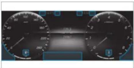
text_image
CNC car dashboard display showing speed, battery, and distance metrics in ChineseDepending on the display setting, the positions of the indicator lamps on the instrument display may differ from the example shown.
Indicator and warning lamps:
Restraint system ( page 508)
Seat belt ( page 508)
Trailer hitch ( page 509)
Power steering ( page 509)
Coolant temperature ( page 511)
Engine diagnostics ( page 511)
700 Vehicles with a diesel engine: pre-glow
Electrical fault ( page 511)
Reserve fuel with fuel filler flap location indicator ( page 511)
(P) Electric parking brake (red) (→ page 514)
Electric parking brake (yellow) (→ page 514)
(①) Brakes (yellow) (→ page 514)
Brakes (red) (→ page 514)
Distance warning (→ page 516)
AIRMATIC / E-ACTIVE BODY CON- TROL (→ page 516)
ABS ( page 518)
ESP ^® (→ page 518)
ESP® OFF (→ page 518)
(1) Tyre pressure monitoring system (→ page 520)
Standing lights (→ page 159)
Low beam (→ page 159)
ED High beam (→ page 161)
Turn signal light (→ page 161)
0‡ Rear fog light (→ page 159)
Occupant safety
| Warning/indicator lamp | Possible causes/consequences and ▶ Solutions |
 Restraint system warning lamp Restraint system warning lamp | * The red restraint system warning lamp is lit while the engine is running.The restraint system is malfunctioning (→ page 40).⚠ WARNING Risk of injury due to malfunctions in the restraint systemComponents in the restraint system may be activated unintentionally or not deploy as intended in an accident.▶ Have the restraint system checked and repaired immediately at a qualified specialist workshop. |
| ▶ Drive on carefully.▶ Note the messages on the multifunction display.▶ Consult a qualified specialist workshop immediately. | |
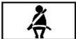 Seat belt warning lamp flashes Seat belt warning lamp flashes | * The red seat belt warning lamp flashes and an intermittent warning tone sounds.The driver or front passenger has not fastened his/her seat belt while the vehicle is in motion.▶ Fasten your seat belt (→ page 43).There are objects on the front passenger seat.▶ Remove the objects from the front passenger seat. |
Warning/indicator lamp
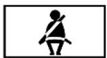
Seat belt warning lamp lights up
Possible causes/consequences and ▶ Solutions
* The red seat belt warning lamp lights up once the engine has started.
In addition, an intermittent warning tone may sound.
The red seat belt warning lamp reminds the driver and front passenger to fasten their seat belts.
▶ Fasten your seat belt ( page 43).
If you have placed objects on the front passenger seat, the red seat belt warning lamp may remain lit.
Vehicle
Warning/indicator lamp

Power steering warning lamp (red)
Possible causes/consequences and ▶ Solutions
* The red power steering system warning lamp is lit while the engine is running.
The power assistance or the steering itself is malfunctioning.
WARNING Risk of accident if steering capability is impaired
If the steering does not function as intended, the vehicle's operating safety is jeopardised.
▶ Pull over and stop the vehicle safely as soon as possible, paying attention to road and traffic conditions. Do not continue driving under any circumstances.
Consult a qualified specialist workshop.
Note the messages on the multifunction display.
Warning/indicator lamp

Trailer tow hitch warning lamp
Possible causes/consequences and ▶ Solutions
* The red trailer hitch warning lamp is lit.
The trailer hitch is not operational or is swivelling.
WARNING Risk of an accident if the ball neck is not locked
The trailer may become detached.
▶ Stop the vehicle immediately in accordance with the traffic conditions. Do not continue driving.
▶ Uncouple the trailer and secure it against rolling away.
Initiate a new swivel movement and do not re-couple the trailer until the warning/indicator lamp goes out.
Note the messages on the multifunction display.
If the trailer hitch is swivelling:
▶ Wait until the ball neck has reached the operational position.
Engine
Warning/indicator lamp

Coolant warning lamp (red)
Possible causes/consequences and ▶ Solutions
* The red coolant warning lamp is lit while the engine is running.
Possible causes:
• The temperature sensor is malfunctioning
• The coolant level is too low
• The air supply to the radiator is obstructed
• The radiator fan is faulty
• The engine coolant pump is faulty
If there is an additional warning tone, the coolant temperature has exceeded 120^ C.
WARNING Risk of burns when opening the bonnet
If you open the bonnet when the engine has overheated or when there is a fire in the engine compartment, the following situations may occur:
- You could come into contact with hot gases.
- You could come into contact with other hot, escaping operating fluids.
Before opening the bonnet, allow the engine to cool down.
In the event of a fire in the engine compartment, keep the bonnet closed and call the fire service.
| Warning/indicator lamp | Possible causes/consequences and ▶ Solutions |
| ▶ Stop the vehicle immediately in accordance with the traffic conditions and switch off the engine. Do not continue driving.▶ Note the messages on the multifunction display.If the coolant temperature display is at the lower end of the temperature scale:▶ Consult a qualified specialist workshop.If the coolant temperature display is at the upper end of the temperature scale:▶ Exit the vehicle and keep a safe distance from it until the engine has cooled down.▶ Check the coolant level (→ page 372).▶ Make sure that the air supply to the radiator is not obstructed.▶ Avoiding high loads on the engine, drive to the nearest qualified specialist workshop. In doing so, ensure that the coolant temperature display remains below 120°C. | |
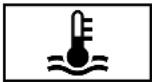 Coolant warning lamp (yellow) Coolant warning lamp (yellow) | * The yellow coolant warning lamp is lit while the engine is running.Possible causes:• The temperature sensor is malfunctioning• The charge air, transmission oil or battery cooling is faulty• The radiator shutters are blocked or defective▶ Avoiding high loads on the engine, drive to the nearest qualified specialist workshop. |
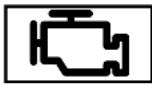 Engine diagnosis warning lamp Engine diagnosis warning lamp | * The yellow engine diagnostics warning lamp is lit while the engine is running.A malfunction has occurred in the engine, the exhaust system or the fuel system.The emissions limit value may have been exceeded and the engine may be running in emergency operation mode.▶ Have the vehicle checked as soon as possible at a qualified specialist workshop.Vehicles with a diesel engine: the fuel tank may have been run dry.▶ Start the engine three to four times after refuelling.If the yellow engine diagnosis warning lamp goes out, emergency operation mode is cancelled. The vehicle need not be checked. |
 Electrical fault warning lamp Electrical fault warning lamp | * The red electrical fault warning lamp is lit.There is a fault in the electrics.▶ Note the messages on the multifunction display. |
 Fuel reserve warning lamp lights up Fuel reserve warning lamp lights up | * The yellow fuel reserve warning lamp lights up while the engine is running.The fuel supply has dropped into the reserve range.▶ Refuel. |
Brakes
| Warning/indicator lamp | Possible causes/consequences and ▶ Solutions |
 Electric parking brake indicator lamp (red) Electric parking brake indicator lamp (red) The electric parking brake (yellow) indicator lamp The electric parking brake (yellow) indicator lamp | * The red electric parking brake indicator lamp flashes or is lit.The yellow electric parking brake indicator lamp is also lit in the event of a malfunction.▶ Note the messages on the multifunction display. |
 Brake system warning lamp (yellow) Brake system warning lamp (yellow) | * The yellow brake system warning lamp is lit while the engine is running.⚠ WARNING Risk of an accident due to a brake system malfunctionIf the brake system is malfunctioning, braking characteristics may be impaired.▶ Drive on carefully.▶ Have the brake system checked immediately at a qualified specialist workshop.▶ Adjust your speed and drive on carefully, leaving a suitable distance to the vehicle in front.▶ If the multifunction display shows a display message, observe it. |
Warning/indicator lamp

Brake system warning lamp (red)
Possible causes/consequences and ▶ Solutions
Consult a qualified specialist workshop.
* The red brake system warning lamp is lit while the engine is running.
Possible causes:
- The brake force boosting is malfunctioning and the braking characteristics may be affected.
- There is insufficient brake fluid in the brake fluid reservoir.
Note the messages on the multifunction display.
WARNING Risk of accident and injury if brake force boosting is malfunctioning
If brake force boosting is malfunctioning, increased brake pedal force may be necessary for braking. The braking characteristics may be impaired. The braking distance can increase in emergency braking situations.
▶ Stop in a safe location immediately. Do not continue driving!
Consult a qualified specialist workshop.
WARNING Risk of an accident due to low brake fluid level
If the brake fluid level is too low, the braking effect and the braking characteristics may be impaired.
▶ Stop the vehicle as soon as possible, paying attention to road and traffic conditions. Do not continue driving.
Consult a qualified specialist workshop.
| Warning/indicator lamp | Possible causes/consequences and ▶ Solutions |
| ▶ Do not top up the brake fluid. |
Driving systems
| Warning/indicator lamp | Possible causes/consequences and ▶ Solutions |
 Warning lamp for distance warning function Warning lamp for distance warning function | * The red distance warning lamp lights up while the vehicle is in motion.The distance to the vehicle in front is too small for the speed selected.If there is an additional warning tone, you are approaching an obstacle at too high a speed.▶ Be prepared to brake immediately.▶ Increase the distance.Function of Active Brake Assist (→ page 253). |
 Active Brake Assist warning lamp Active Brake Assist warning lamp | * The white Active Brake Assist warning lamp is lit.The system is switched off or unavailable.▶ Note the messages on the multifunction display. |
 Suspension warning lamp (yellow) Suspension warning lamp (yellow) | * The yellow AIRMATIC / E-ACTIVE BODY CONTROL warning lamp is lit.A fault has occurred in AIRMATIC / E-ACTIVE BODY CONTROL.▶ Note the messages on the multifunction display. |
 Suspension warning lamp (red) Suspension warning lamp (red) | * The red AIRMATIC / E-ACTIVE BODY CONTROL warning lamp is lit.A fault has occurred in AIRMATIC / E-ACTIVE BODY CONTROL. |
| NOTE The vehicle's driving characteristics will have changed significantly. | |
| Consult a qualified specialist workshop. | |
| Note the messages on the multifunction display. | |
| Consult a qualified specialist workshop. |
Driving safety systems
| Warning/indicator lamp | Possible causes/consequences and ▶ Solutions |
 ABS warning lamp ABS warning lamp | * The yellow ABS warning lamp is lit while the engine is running.ABS is malfunctioning.If an additional warning tone sounds, EBD is malfunctioning.Other driving systems and driving safety systems may also be malfunctioning.▶ Note the messages on the multifunction display.⚠ WARNING There is a risk of skidding if EBD or ABS is malfunctioningThe wheels may lock during braking.The steerability and braking characteristics are heavily impaired and the braking distance may increase. In addition, other driving safety systems are switched off.▶ Drive on carefully.▶ Have the brake system checked immediately at a qualified specialist workshop. |
 ESP® warning lamp flashes ESP® warning lamp flashes | * The yellow ESP warning lamp flashes while the vehicle is in motion.One or more wheels have reached their grip limit (→ page 232).▶ Adapt your driving style to suit the road and weather conditions. |
Warning/indicator lamp
ESP® warning lamp lights up
ESP® OFF warning lamp
Possible causes/consequences and ▶ Solutions
* The yellow ESP ^® warning lamp is lit while the engine is running. ESP ^® is malfunctioning.
Other driving systems and driving safety systems (e.g. BAS) may also be malfunctioning.
Note the messages on the multifunction display.
WARNING Risk of skidding if ESPs malfunctioning
If ESP ^® is malfunctioning, ESP ^® cannot carry out vehicle stabilisation. In addition, other driving safety systems are switched off.
▶ Drive on carefully.
Have ESP ^® checked at a qualified specialist workshop.
* The yellow ESP ^ OFF warning lamp is lit while the engine is running. ESP ^ is deactivated.
Other driving systems and driving safety systems may also be inoperative.
WARNING Risk of skidding when driving with ESP® deactivated
ESP® does not act to stabilise the vehicle. The availability of further driving safety systems is also limited.
▶ Drive on carefully.
▶ Deactivate ESP ^® only for as long as the situation requires.
| Warning/indicator lamp | Possible causes/consequences and ▶ Solutions |
| If ESP® cannot be activated, ESPis malfunctioning.▶ Have ESP® checked immediately at a qualified specialist workshop. | |
| ▶ Observe the notes on deactivating ESP® (→ page 232). |
Tyre pressure monitor
| Warning/indicator lamp | Possible causes/consequences and ▶ Solutions |
 Tyre pressure monitoring system warning lamp flashes Tyre pressure monitoring system warning lamp flashes | *The yellow tyre pressure monitor warning lamp (pressure loss/malfunction) flashes for approximately one minute and then remains lit.The tyre pressure monitor is malfunctioning. |
| ⚠ WARNING There is a risk of an accident if the tyre pressure monitoring system is malfunctioningThe tyre pressure monitoring system cannot issue a warning if there is pressure loss in one or more of the tyres.Tyres with insufficient tyre pressure may impair the driving characteristics as well as steering and braking.▶ Have the tyre pressure monitoring system checked at a qualified specialist workshop. |
Warning/indicator lamp
Tyre pressure monitoring system warning lamp lights up
Possible causes/consequences and ▶ Solutions
* The yellow tyre pressure monitoring system warning lamp (pressure loss/malfunction) is lit. The tyre pressure monitoring system has detected tyre pressure loss in at least one of the tyres.
WARNING Risk of an accident due to insufficient tyre pressure
• The tyres can burst.
- The tyres can wear excessively and/or unevenly.
- The driving characteristics as well as the steering and braking may be greatly impaired.
You could then lose control of the vehicle.
▶ Observe the recommended tyre pressures.
Adjust the tyre pressure if necessary.
▶ Stop the vehicle in accordance with the traffic conditions.
▶ Check the tyre pressure and the tyres.
1, 2, 3 ...
4MATIC
Function.... 215
12 V battery
see Battery (vehicle)
12 V socket
see Socket (12 V)
48 V on-board electrical system
see EQ Boost technology
230 V socket
see Socket (230 V)
360° Camera
Care.... 379
Function 284
Opening the camera cover (reversing camera).... 288
Selecting a view.... 2
Switching automatic operation on/off (reversing camera).... 288
A
A/C function
Activating/deactivating (control
panel).... 178
Activating/deactivating (MBUX multimedia system).... 179
ABS (Anti-lock Braking System).... 231
Acceleration
see Kickdown
Accident and Breakdown Manage-
nt Mercedes me connect.... 343
Acoustic locking verification signal
Activating/deactivating.... 80
Active Blind Spot Assist
Brake application.... 2 63
Function 262
System limitations.... 262
Trailer operation.... 263
Active Brake Assist
Function/notes 253
Setting.... 257
Active Distance Assist DISTRONIC
Active Emergency Stop Assist...... 252
Calling up a speed.... 244
Function.... 241
Increasing/decreasing speed.... 244
Route-based speed adaptation...... 246
Selecting.... 244
Storing a speed.... 244
Switching off/deactivating.... 244
Switching on/activating.... 244
System limitations.... 241
Active Emergency Stop Assist.... 252
Active headlamps.... 162
Active Lane Keeping Assist
Activating/deactivating.... 267
Activating/deactivating the warning..... 267
Function 264
Setting the sensitivity.... 267
System limits.... 264
Trailer operation.... 264
Active Parking Assist
Exiting a parking space.... 296
Function.... 293
Parking 295
System limitations.... 293
Active Service System PLUS
see ASSYST PLUS
Active Speed Limit Assist
Display 246
Function.... 246
Active Steering Assist
Activating/deactivating.... 252
Active Emergency Stop Assist...... 252
Function 250
System limits 250
Active Traffic Jam Assist
Activating/deactivating.... 248
Function.... 248
Adaptive brake lights.... 236
Adaptive cruise control
see Active Distance Assist DISTRONIC
Adaptive functions, MULTIBEAM LED
see Intelligent Light System
Adaptive Highbeam Assist Plus
Function.... 164
Switching on/off.... 165
AdBlue®
Additives.... 434
Capacity.... 434
Notes.... 219
Purity 434
Topping up 220
Additional cushion
Leg rest.... 114
Rear head restraint.... 121
Additional door lock 82
Additives
AdBlue ^® 434
Engine oil.... 435
Fuel.... 432
Additives (AdBlue®)
see AdBlue ^®
Additives (engine oil)
see Additives
Additives (fuel)
see Fuel
ADS PLUS damping system
see AIRMATIC
After-sales service centre
see ASSYST PLUS
Air conditioning menu
Calling up.... 178
Air distribution
Setting.... 177
Setting (MBUX multimedia system)...... 179
Air freshener system
see Fragrance system
Air inlet
see Air-water duct
Air pressure
see Tyre pressure
Air suspension
see AIRMATIC
Air vents
Adjusting (front).... 187
Adjusting (rear)...... 187
Glove box.... 189
Air vents
see Air vents
Air-conditioning system
see Climate control
Air-recirculation mode.... 180
Air-water duct Keeping free.... 374
Airbag Activation.... 40 Cushionbag.... 45 Front airbag (driver, front passenger).... 45 Installation locations.... 45 Knee airbag.... 4 5 Overview.... 45 PASSENGER AIR BAG indicator lamp.... 50 Protection.... 46 Reduced protection.... 47 Side airbag.... 45 Window airbag.... 45
Airflow Setting.... 177
AIRMATIC Setting.... 2 69 Suspension.... 267
Alarm system see ATA (anti-theft alarm system)
All-wheel drive see 4MATIC
Ambient lighting Setting (MBUX multimedia system)..... 167
Android Auto see Smartphone integration
Animals Pets in the vehicle.... 78
Anti-lock braking system see ABS (Anti-lock Braking System)
Anti-skid chains see Snow chains
Anti-theft protection Additional door lock.... 82 Immobiliser.... 104
Anti-theft protection see ATA (anti-theft alarm system)
Anticipatory occupant protection see PRE-SAFE® (anticipatory occupant protection) see PRE-SAFE® PLUS (anticipatory occupant protection plus)
Apple CarPlay® see Smartphone integration
Assistance systems see Driving safety system
ASSYST PLUS Battery disconnection periods.... 368 Displaying the service due date.... 367 Function/notes.... 367 Regular maintenance work.... 367 Special service requirements.... 367
ATA (anti-theft alarm system) Deactivating the alarm.... 104 Function.... 104 Function of interior protection.... 105 Priming/deactivating interior protection.... 106 Priming/deactivating tow-away protection.... 105 Tow-away protection function.... 105
ATTENTION ASSIST Function.... 236 Setting.... 238 System limitations.... 236
Attention assistant see ATTENTION ASSIST
Authorised workshop
see Qualified specialist workshop
Automatic car wash mode
Activating.... 376
Automatic distance control
see Active Distance Assist DISTRONIC
Automatic driving lights.... 160
Automatic engine start (ECO start/
stop function).... 201
Automatic engine stop (ECO start/
stop function).... 201
Automatic front passenger front air-bag deactivation system
see Automatic front passenger front airbag shutoff
Automatic front passenger front air- bag shutoff
Function of the automatic front passenger front airbag deactivation system.... 48
PASSENGER AIR BAG indicator lamp..... 50
Automatic measures after an accident..... 54
Automatic mirror folding function
Activating/deactivating.... 175
Automatic seat adjustment
Setting.... 122
Automatic transmission
DIRECT SELECT lever.... 209
Drive program display.... 207
Drive programs.... 205
DYNAMIC SELECT switch.... 205
Engaging drive position.... 211
Engaging reverse gear.... 210
Kickdown.... 212
Manual gear changing.... 211
Selecting park position.... 210
Steering wheel gearshift paddles...... 211
Transmission position display.... 209
Transmission positions.... 209
Axle load
Permissible.... 427
Trailer operation.... 444
B
Bag hook.... 147
Ball neck
Extending/retracting.... 301
Extending/retracting (MBUX multi-media system).... 303
BAS (Brake Assist System).... 231
Battery
Remote control (stationary heater)...... 185
Battery
see Battery (vehicle)
Battery (key)
Replacing.... 8 1
Battery (vehicle)
Charging.... 395
Charging (Remote Online).... 192
Notes.... 391
Notes (starting assistance and
charging).... 393
Replacing.... 396
Starting assistance.... 395
Belt
see Seat belt
Bicycle rack
Load capacity.... 443
Trailer operation.... 306
Blind Spot Assist
Activating/deactivating.... 264
Function 262
System limitations.... 262
Blower
see Climate control
BlueTEC
see AdBlue®
Boot lid
see Tailgate
Brake Assist System
see BAS (Brake Assist System)
Brake fluid
Notes 436
Brake force distribution
EBD (Electronic Brake force Distribution).... 234
Brakes
ABS (Anti-lock Braking System)...... 2
Active Brake Assist.... 253
Adaptive brake lights.... 236
BAS (Brake Assist System).... 231
Driving tips.... 195
EBD (Electronic Brake force Distribution) 234
HOLD function.... 2
Limited braking effect (salt-treated roads).... 195
New/replaced brake linings/brake discs.... 193
Post-collision brake.... 54
Running-in notes.... 193
Braking assistance
see BAS (Brake Assist System)
Breakdown
Assistance overview.... 18
Tow-starting.... 401
Towing away 398
Transporting the vehicle.... 399
Wheel change 414
Breakdown
see Flat tyre
3Buttons
Steering wheel 312
C
Calls
Mercedes me.... 344
Camera
Dashcam.... 3 38
Camera
see 360° Camera
see Reversing camera
Car key
see Key
Car wash
see Care
Car wash (care) 374
Car-to-X-Communication
Displaying hazard warnings.... 336
Care
360° Camera.... 3 79
Air-water duct 374
Automatic car wash 374
Carpet.... 381
Decorative foil.... 378
Display.... 381
Exterior lighting 379
High-pressure cleaner.... 377
Paintwork.... 377
Plastic trim.... 381
Real wood/trim elements.... 381
Reversing camera.... 379
Roof lining.... 3
Running boards.... 379
Seat belt 381
Seat cover 381
Sensors.... 379
Steering wheel.... 381
Tailpipes.... 379
Trailer hitch.... 379
Washing by hand.... 377
Wheels/rims 379
Windows.... 379
Wiper blades.... 379
Carpet (Care).... 381
Changing gears
Manually.... 211
Changing hub caps.... 415
Charging
Battery (vehicle) 395
Mobile phone (wireless).... 1
USB port.... 1 52
Child safety lock
Rear door.... 7
Rear side windows.... 77
Child seat
Approval categories.... 60
Attaching (notes).... 59
Basic instructions.... 55
Front passenger seat (notes).... 74
Front passenger seat (without automatic airbag shutoff).... 7 3
ISOFIX/i-Size (fitting).... 64
Notes on risks and dangers.... 56
Recommended child restraint systems.... 58
Seats suitable for belt-secured child restraint systems.... 70
Seats suitable for i-Size child
restraint systems.... 64
Seats suitable for ISOFIX child restraint systems.... 62
Securing on the co-driver seat.... 75
Securing on the rear seat.... 72
Top Tether.... 68
54Children
Avoiding dangers in the vehicle.... 56
Basic instructions.... 55
Chock
Storage location.... 413
Chock
see Chock
Cleaning
see Care
Climate control
Activating/deactivating (rear operating unit).... 178
Activating/deactivating the A/C
function (control panel).... 178
Activating/deactivating the A/C
function (MBUX multimedia system)..... 179
Activating/deactivating the synchronisation function (control panel).... 180
Activating/deactivating the synchronisation function (MBUX multimedia system).... 180
Air-recirculation mode.... 180
Automatic control.... 179
Automatically controlling (rear operating unit).... 179
Calling up the air conditioning menu..... 178
Demisting the windscreen.... 177
Demisting windows.... 180
Front air vents.... 187
Glove box air vent 189
Information on the windscreen heater... 182
Inserting/removing the flacon (fra-
Rear operating unit.... 178
Residual heat.... 180
Residual heat (rear operating unit)...... 181
Setting (MBUX multimedia system)..... 178
Setting the air distribution.... 177
Setting the airflow.... 177
Setting the fragrance system.... 181
Setting the vehicle interior tempera-
ture.... 177
Stationary heater/ventilation.... 183
Switching on/off.... 178
Switching the rear window heater
on/off 1 77
THERMATIC control panel.... 177
THERMOTRONIC control panel.... 177
Ventilating the vehicle (convenience opening).... 96
Coat hook.... 147
Cockpit Overview...... 6
Coffee cup symbol see ATTENTION ASSIST
Collapsible spare wheel Inflating.... 424 Notes.... 422 Removing.... 423
Collision detection (parked vehicle) Information...... 227
Combination switch.... 161
Computer see On-board computer
Convenience closing.... 96
Convenience opening.... 96
Coolant (engine) Level check.... 372 Notes..... 437
Cooling see Climate control
Copyright.... 38
Cornering light.... 162
Cover see Roller sunblind
Cross traffic (warning) see Manoeuvring assistance
Cross Traffic Alert.... 298
Crosswind Assist Function/notes.... 233
Cruise control Activating.... 239 Buttons.... 239 Calling up a speed.... 239 Deactivating.... 239 Function.... 238 Requirements:.... 239 Selecting.... 239 Setting a speed.... 239 Storing a speed.... 239 System limitations.... 238
Cup holder
Switching the cooling/heating function on/off.... 1
Cushionbag 45
D
Dashboard
see Cockpit
Dashcam
Notes.... 337
Selecting a USB device.... 3
Starting/stopping video recording...... 338
Data acquisition
Vehicle.... 35
Data protection rights
Data storage.... 38
Data storage
Data protection rights.... 38
Electronic control units.... 35
Online services.... 37
Vehicle.... 35
Deactivating the alarm (ATA).... 104
Dealership
see Qualified specialist workshop
Declaration of conformity
Electromagnetic compatibility.... 26
Jack.... 3 0
Specific absorption rate.... 26
TREFIT kit.... 31
Wireless vehicle components.... 26
Decorative foil (cleaning instructions).... 378
DeNOx agent
3 8 see AdBlue®
Destination entry
Entering a POI or address.... 333
Detecting inattentiveness
see ATTENTION ASSIST
Diagnostics connection.... 31
Diesel
Low outside temperatures.... 432
Notes...... 432
Digital Owner's Manual.... 20
Dinghy towing
see Tow-bar system
DIRECT SELECT lever
Engaging reverse gear.... 210
Engaging drive position.... 211
Engaging neutral.... 210
Engaging park position automatically.... 210
Function.... 209
Selecting park position.... 210
Display (care).... 381
Display (MBUX multimedia system)
Home screen.... 3 18
Operating.... 319
Display (on-board computer)
Displays on the multifunction display.... 314
Display message
Calling up (on-board computer)...... 445
Notes...... 445
Display messages
- - - km/h 476
HM --- km/h 476
--- km/h 475
12 V battery See Owner's Man-
ual.... 495
48 V battery See Owner's Manual 497
Active Light System inoperative... 452
AdBlue system fault Emer. op.:
max. XXX km/h Start not poss. in
XXX km.... 5 0 4
AdBlue system fault Emer-
gency op. in XXX miles See Owner's Manual....
AdBlue system fault Engine
start not possible 504
AdBlue system fault See Own-
er's Manual.... 5 0 3
Add 1 litre engine oil when
next refuelling.... 505
ATTENTION ASSIST inoperative.... 474
ATTENTION ASSIST: Take a
break! 475
Automatic driving lights inoper-
ative.... 451
Cannot fold 2nd seat row forwards See Owner's Manual.... 463
Change key batteries.... 449
(1) Check brake fluid level...... 473
Check trailer hitch lock.... 456
Check tyre(s) 499
Clean the fuel filter 466
Compressor is cooling...... 489
Coolant Stop vehicle Switch
engine off.... 4 6 5
Currently unavailable Camera view restricted.... 485
Currently unavailable Radar sensors dirty.... 484
currently unavailable See Own-
er's Manual.... 4 9 0
currently unavailable See Owner's Manual.... 491
Engine oil level cannot be measured.... 506
Engine oil level Reduce oil level.... 505
Engine oil level Stop vehicle
Switch engine off.... 505
Engine oil pressure Stop
Switch off engine.... 506
Fault Drive at max. 80 km/h
486, 487
Fault Stop 487
Front left malfunction Consult workshop (example).... 446
inoperative Battery low.... 454
inoperative Refuel vehicle.... 454
inoperative See Owner's Man..... 454
inoperative See Owner's Manual 491
inoperative See Owner's Manual 492
EBD inoperative See Owner's Manual 493
SOS Inoperative.... 494
inoperative.... 479
Intelligent Light System inoper-
ative.... 452
Key being initialised Please wait... 450
Key not detected (red display message).... 450
Key not detected (white display message).... 449
Left dipped beam (example)...... 451
Left windowbag malfunction
Consult workshop (example)...... 446
Lowering.... 488
Malfunction See Owner's Manual 451
Max. speed 40 km/h...... 479
120km/h! Maximum speed exceeded.... 478
Not possible in current drive program.... 479
502
Off 477
HOLD Off 474
Operation only possible in transmission position P.... 4 5 5
(P) Parking brake See Owner's Manual.... 470
Please reduce speed.... 489
Please wait 48 V battery charging.... 497
Rectify tyre pressure.... 500
Refill AdBlue See Owner's Manual.... 502
(P) Release parking brake.... 473
Replace air cleaner.... 466
Replace key 449
Reserve fuel level.... 466
Restraint sys. malfunction Consult workshop.... 446
See Owner's Manual.... 495
Side running board not extended.... 458
Steering malfunction Increased physical effort See Owner's Manual..... 459
Steering malfunction Stop immediately See Owner's Manual..... 459
Stop vehicle Leave engine running.... 496
Stop vehicle See Owner's Manual.... 496
suspended.... 476
Switch off lights.... 452
Switch on headlamps.... 4
Top up AdBlue Emergency op. in XXX miles See Owner's Manual.... 502
Top up coolant See Owner's Manual.... 464
Top up washer fluid.... 463
Trailer coupling extending.... 456
(P) Turn on the ignition to release the parking brake.... 473
Vehicle is operational Switch off ignition before exiting.... 455
Vehicle rising Please wait...... 488
Vehicle rising.... 488
Warning tyre defect.... 500
Wheel sensor(s) missing...... 499
XX,X I Top up AdBlue Switch on ignition, wait 60 sec. or eng. start not poss.... 503
Active Blind Spot Assist currently unavailable See Owner's Manual.... 482
Active Blind Spot Assist inoperative..... 483
Active Blind Spot Assist not available when towing a trailer See Owner's Manual.... 483
Active Brake Assist Functions currently limited See Owner's Manual..... 493
Active Brake Assist Functions limited
See Owner's Manual.... 494
Active Distance Assist available again... 478
Active Distance Assist currently unavailable See Owner's Manual.... 477
Active Distance Assist inoperative...... 477
Active Lane Keeping Assist currently unavailable See Owner's Manual.... 483
Active Lane Keeping Assist inoperative.... 484
Active Steering Assist currently unavailable due to multiple emergency stops.... 480
Active Steering Assist currently unavailable See Owner's Manual.... 479
Active Steering Assist inoperative...... 480
Active Stop-and-Go Assist currently unavailable see Owner's Manual.... 481
Active Stop-and-Go Assist inoperative See Owner's Manual.... 481
Adaptive Highbeam Assist Plus currently unavailable See Owner's Manual.... 453
Adaptive Highbeam Assist Plus inoperative.... 4 5 3
Anti-theft alarm system Malfunction..... 463
Apply brake to deselect Park (P) position.... 467
Apply brake to select D or R.... 467
Apply brake to select R.... 467
Auxiliary battery malfunction (red display message).... 4 6 9
Auxiliary battery malfunction (white display message).... 4 6 9
Beginning emergency stop.... 480
Blind Spot Assist currently unavailable See Owner's Manual.... 482
Blind Spot Assist inoperative.... 482
Blind Spot Assist not available when
towing a trailer See Owner's Manual..... 482
Cannot start engine See Owner's Manual.... 464, 497
Index 533
Check brake pads See Owner's Manual.... 474
Cruise control and Limiter inoperative... 475
Cruise control inoperative.... 475
Cruise control off.... 475
Device detected at diagnostics connection See Owner's Manual.... 495
Drive system Malfunction Stop
Switch engine off.... 466
Drive system Malfunction Visit work-
shop.... 466
Front-passenger airbag disabled See Owner's Manual.... 4 4
Front-passenger airbag enabled See Owner's Manual.... 4 4
Gearbox protection Limit 30 km/h
Switch off LOW RANGE.... 462
Hazard warning lamps malfunctioning... 453
Head-up display currently unavailable See Owner's Manual.... 458
Head-up display inoperative.... 458
Limiter inoperative.... 476
Limiter passive.... 476
LOW RANGE Malfunction.... 461
LOW RANGE Malfunction To park, apply parking brake.... 461
LOW RANGE Max. speed 10 km/h..... 462
LOW RANGE Max. speed 40 km/h..... 462
LOW RANGE Not in drive program "Sport" 461
LOW RANGE only when vehicle stationary.... 460
LOW RANGE Shift to position N briefly.. 461
LOW RANGE Shifting cancelled Please reactivate.... 461
LOW RANGE Stop Apply parking brake.... 462
Motor can be started again.... 498
N permanently active Risk of vehicle rolling.... 468
Only select Park (P) when vehicle is stationary.... 467
Parking Assist and PARKTRONIC inoperative See Owner's Manual...... 489
Place the key in the marked space See Owner's Manual.... 450
PRE-SAFE impulse side inoperative See Owner's Manual.... 448
PRE-SAFE inoperative See Owner's Manual.... 448
Reduce speed.... 501
Reversing not poss. Consult work- shop.... 468
Risk of vehicle rolling Driver door open and transmission not in P.... 468
Side running board not retracted Observe the excess width of the
vehicle...... 457
Speed limit (winter tyres) XXX km/h..... 478
Speed Limit Assist currently unavailable See Owner's Manual.... 478
Speed Limit Assist inoperative.... 478
Stop vehicle Leave engine running
Wait Transmission cooling.... 469
To shift out of P or N, depress brake and start engine.... 467
To switch off the engine, press the Start/Stop button for at least 3 seconds or 3 times.... 464
Traffic Sign Assist currently unavailable See Owner's Manual.... 481
Traffic Sign Assist inoperative.... 481
Transmission Malfunction Stop...... 468
Tyre press. monitor currently unavailable.... 498
Tyre press. monitor inoperative.... 498
Tyre press. monitor inoperative No wheel sensors.... 499
Tyre(s) overheated.... 501
Update failed 455
Update failed Software remains unchanged 455
Update successfully completed.... 455
Wiper malfunctioning.... 463
Without changing gear, consult work- shop.... 468
Display on the windscreen see Head-up display
Distance control see Active Distance Assist DISTRONIC
DISTRONIC see Active Distance Assist DISTRONIC
Door
Additional door lock.... 82
Child safety lock (rear door).... 76
Locking/unlocking (emergency key)...... 86
Opening (from inside).... 83
Power closing function.... 85
Unlocking (from inside)...... 8
Door control panel.... 14
Door control panel (rear).... 16
Downhill driving assistance see DSR
Drawbar see Tow-bar system
Drive Away Assist.... 297
Drive position Engaging.... 211
Drive program display.... 207
Drive programs see DYNAMIC SELECT
Driver's seat see Seat
Driving abroad Light adjustment (low beam).... 159
ABS (Anti-lock Braking System)...... 231
Active Brake Assist.... 253
Adaptive brake lights.... 236
BAS (Brake Assist System).... 231
Cameras.... 229
EBD (Electronic Brake force Distribution).... 2 34
ESP® Crosswind Assist.... 233
Driving safety system
ESP ^® trailer stabilisation.... 233
Off-road ABS.... 231
Overview.... 230
Radar and ultrasonic sensors.... 229
Responsibility.... 229
STEER CONTROL.... 234
Driving system
see 360° Camera
see Active Blind Spot Assist
see Active Distance Assist DISTRONIC
see Active Emergency Stop Assist
see Active Lane Keeping Assist
see Active Parking Assist
see Active Speed Limit Assist
see Active Steering Assist
see AIRMATIC
see ATTENTION ASSIST
see Blind Spot Assist
see Cruise control
see Driving safety system
see DSR
see E-ACTIVE BODY CONTROL
see HOLD function
see Limiter
see Parking Assist PARKTRONIC
see Reversing camera
see Speed Limit Assist
see Traffic Sign Assist
Driving tips
Driving abroad (low beam light adjustment).... 1 5
General driving tips.... 195
optimised acceleration.... 194
Running-in notes.... 193
Drowsiness detection
see ATTENTION ASSIST
DSR
Activating/deactivating.... 249, 250
Changing the target speed.... 250
Function 248
Notes.... 249
Dynamic handling control system
see ESP ^® (Electronic Stability Program)
DYNAMIC SELECT
Calling up the fuel consumption indi-
cator.... 2 0
Configuring drive program I.... 207
Displaying engine data.... 207
Displaying vehicle data.... 207
Drive program display.... 207
Drive programs.... 205
Function.... 205
Operating (DYNAMIC SELECT switch).... 207
Selecting the drive program.... 207
9 E
E-ACTIVE BODY CONTROL
Individual wheel control.... 277
Recovery mode.... 277
Setting the level.... 278
Suspension.... 274
E10.... 431
Easy entry feature
Function/notes.... 128
Easy exit feature
Function/notes.... 128
EBD (Electronic Brake force Distribution)
Function/notes.... 234
^8 ECO Assist
Function/notes.... 203
ECO display
Function.... 202
ECO start/stop function
Automatic engine start.... 201
Automatic engine stop.... 201
Switching off/on.... 202
Electric parking brake
Applying automatically.... 225
Applying/releasing manually.... 227
Emergency braking.... 227
Releasing automatically.... 226
Electrical fuses
see Fuses
Electrohydraulic suspension
see E-ACTIVE BODY CONTROL
Electromagnetic compatibility
Declaration of conformity.... 26
Electronic Stability Program
see ESP® (Electronic Stability Program)
Emergency
Assistance overview.... 18
Fire extinguisher.... 385
First-aid kit (soft sided).... 384
Removing the warning triangle.... 383
Safety vest.... 383
Setting up the warning triangle.... 384
Emergency braking.... 227
Emergency braking
see BAS (Brake Assist System)
Emergency engine start.... 401
Emergency key
Inserting/removing.... 81
Locking/unlocking the doors.... 86
Unlocking the tailgate.... 93
Emergency operation mode
Starting the vehicle.... 192
Emergency release
Tailgate.... 93
Emergency spare wheel
Inflating.... 420
Notes 420
Engine
ECO start/stop function.... 201
Engine number 427
Starting (emergency operation mode)... 192
Starting (Remote Online).... 193
Starting (start/stop button).... 191
Starting assistance.... 395
Switching off (start/stop button)...... 222
Engine bonnet
Opening/closing 368
Engine data
Displaying.... 207
Engine electronics
Notes.... 425
Engine number 427
Engine oil
Additives.... 435
Capacity 435
Checking the oil level using the on-board computer.... 370
MB-Freigabe or MB-Approval.... 435
Quality 435
Topping up.... 371
Entering/exiting level
Setting.... 272
EQ Boost technology
Operating safety 24
ERA-GLONASS test mode
Starting/ending.... 357
Error message
see Display message
ESC (Electronic Stability Control)
see ESP® (Electronic Stability Program)
ESP®
Crosswind Assist.... 2 3
Trailer stabilisation.... 233
ESP® (Electronic Stability Program)
Activating/deactivating.... 233
Function/notes.... 232
EU general operating permit number..... 427
Extendable running boards.... 87
Extendable step
see Running boards
Exterior lighting
Care.... 379
Exterior lighting
see Lights
F
Fatigue detection
see ATTENTION ASSIST
Fire extinguisher.... 385
First-aid kit (soft sided).... 384
Flacon
2 Inserting/removing.... 181
Flat towing
see Tow-bar system
Flat tyre
MOExtended tyres.... 386
Notes.... 385
TREFIT kit.... 387
Wheel change.... 414
Floor mats.... 157
Fog light (enhanced).... 163
Foil covering
Radar and ultrasonic sensors.... 229
Folding table.... 137
Fragrance
see Fragrance system
Fragrance system
Inserting/removing the flacon.... 181
Setting.... 181
Free driving mode
Starting.... 281
Free software.... 38
Frequencies
Mobile phone 426
Two-way radio.... 426
Front airbag (driver, front passenger)..... 45
Front passenger seat
Adjusting from the driver's seat...... 110
Adjusting from the rear.... 111
Front passenger seat
see Seat
Fuel
Additives.... 4 3
Diesel 432
E10.... 4 31
Fuel reserve.... 433
Low outside temperatures.... 432
Petrol.... 431
Quality (diesel) 432
Quality (petrol)...... 431
Refuelling.... 215
Sulphur content.... 431
Tank content 433
Fuel consumption indicator
Calling up.... 208
Function seat
see Door control panel
Function seat (rear)
see Seat (rear)
Fuses
Before replacing a fuse.... 401
Fuse assignment diagram.... 401
Fuse box in the engine compartment.... 402
Fuse box in the front passenger foot-
well.... 403
Fuse box in the load compartment..... 404
Fuse box on the dashboard.... 403
Notes...... 401
G
Garage door opener
Clearing the memory.... 225
Programming buttons.... 223
Resolving problems.... 225
Synchronising the rolling code.... 224
Garage door openers
Opening/closing the door 225
Gearshift recommendation.... 212
General operating permit number (EU)... 427
Genuine parts.... 23
Glide mode.... 213
Glove box
Air vent.... 189
H
Handbrake
see Electric parking brake
Handling characteristics (unusual)...... 405
HANDS-FREE ACCESS.... 91
Handset
Stowage compartment.... 139
Hazard warning lights.... 161
Head restraint
Attaching/removing the supplement-
tary cushion.... 121
EASY ADJUST luxury head restraint
(front).... 1 19
Front (adjusting mechanically).... 117
Front (luxury head restraint).... 118
Rear (adjusting).... 119
Rear (fitting/removing).... 120
Rear (luxury head restraint).... 120
Head-up display
Adjusting display elements (on-board computer).... 315
Adjusting the brightness (on-board
computer).... 315
Function 314
Menu (on-board computer).... 315
Operating the memory function.... 130
Setting the position (on-board com-
puter).... 315
Switching on/off 316
Headlamp flashing.... 161
Headlamps
see Automatic driving lights
Heating
see Climate control
Help call
see Mercedes-Benz emergency call system
High beam
Activating/deactivating.... 161
Adaptive Highbeam Assist Plus.... 1
HIGH RANGE
Shifting.... 214
High-pressure cleaner (care).... 377
Hill Start Assist.... 236
HOLD function
Function/notes.... 235
Switching on/off 235
Home screen (media display)
Overview.... 3 18
1
i-Size child seat securing system
Fitting.... 6 4
Seats suitable for attaching.... 64
Identification plate
Engine.... 427
vehicle.... 427
Ignition
Switching on (start/stop button)...... 190
Ignition key
see Key
^6 Immobiliser.... 104
Implied warranty
Vehicle.... 34
In-Car Office
Features.... 348
Indicator lamp
see Warning/indicator lamp
Individual drive program
Configuring.... 207
Selecting.... 207
Inspection
see ASSYST PLUS
Instrument cluster
Function/notes.... 310, 311
Instrument display
Function/notes.... 311
Instrument cluster.... 10
Warning/indicator lamps.... 507
Instrument display and on-board
computer
Function/notes.... 310
Intelligent Light System
Activating/deactivating.... 164
Active headlamps.... 162
Adaptive Highbeam Assist Plus.... 1
Cornering light.... 162
Fog light (enhanced).... 163
Motorway mode.... 163
Overview.... 162
Interior lighting
Adjusting.... 166
Ambient lighting 167
Reading lamp.... 166
Switch-off delay time.... 167
Interior protection
Function.... 105
Priming/deactivating.... 106
Internet radio
see Tuneln
Ionisation
Activating/deactivating (MBUX multimedia system).... 181
iPhone®
see Smartphone integration
ISOFIX child seat anchor
Seats suitable for attaching.... 62
ISOFIX child seat securing system
Fitting.... 64
J
Jack
Declaration of conformity.... 30
Storage location.... 413
Jump-start connection
General notes.... 393
K
Key
Acoustic locking verification signal...... 80
Battery.... 81
Deactivating a function.... 80
Emergency key.... 81
Energy consumption.... 80
Function overview.... 79
Key ring attachment.... 81
Problem...... 82
Unlocking setting.... 80
KEYLESS-GO
Deactivating a function.... 80
Locking/unlocking the vehicle.... 84
Problem.... 84
Unlocking setting.... 80
Kickdown
Using.... 212
Knee airbag.
L
Lamp
see Interior lighting
Lamp (instrument display)
see Warning/indicator lamp
Lane detection (automatic)
see Active Lane Keeping Assist
Lane Keeping Assist
see Active Lane Keeping Assist
Language
Notes.... 330
Setting.... 330
LED light
see Intelligent Light System
Leg rest
Attaching/removing the additional cushion.... 1 14
Level control system
see AIRMATIC
see E-ACTIVE BODY CONTROL
Light adjustment
Low beam (driving abroad).... 159
Light switch
Overview.... 159
Lighting
see Interior lighting
see Lights
Lights
Active headlamps.... 162
Adaptive Highbeam Assist Plus.... 164
Automatic driving lights.... 160
Combination switch.... 1 61
Cornering light.... 162
Driving abroad (low beam light adjustment).... 1 59
Fog light (enhanced).... 163
Hazard warning lights.... 161
Headlamp flashing.... 161
High beam.... 161
Intelligent Light System.... 162
Light switch.... 159
Low beam.... 1 59
Motorway mode.... 163
Off-road light.... 1 64
Parking lights.... 159
Rear fog light.... 159
Responsibility for lighting systems...... 159
Setting low beam.... 165
Setting the exterior lighting switch-off delay time.... 1
Standing lights.... 159
Switching the Intelligent Light System on/off.... 164
Switching the surround lighting on/off.... 1 66
Turn signal indicator.... 161
Limiter
Activating.... 239
Buttons.... 239
Calling up a speed.... 239
Deactivating.... 239
Function 239
Passive mode.... 239
Permanent setting.... 241
Requirements...... 239
Selecting.... 2 39
Setting a speed.... 239
Storing a speed.... 239, 244
Switching off/deactivating.... 244
Switching on/activating.... 244
System limits.... 239
Limiting speed
see Limiter
66 Limiting the opening angle (tailgate).... 93
LINGUATRONIC
Function.... 321
Starting.... 321
Live Traffic Information
Switching the traffic information display on.... 336
Load compartment cover
Extending/retracting.... 143
Notes.... 143
Removing/fitting.... 144
Load compartment floor
Locking/unlocking.... 147
Load protection net
Attaching.... 145
Loading
Bag hook.... 1 47
Coat hook.... 147
Notes.... 134
Roof luggage rack.... 148
Tie-down eyes.... 146
Loading guidelines.... 134
Loads
Securing.... 134
Locking/unlocking
Additional door lock 82
Emergency key.... 86
KEYLESS-GO.... 84
Opening the tailgate.... 88
Switching the automatic locking fea-ture on/off.... 85
Unlocking/opening the doors from the inside.... 8
Low beam
Light adjustment (driving abroad)...... 159
Setting.... 165
Switching on/off.... 159
LOW RANGE
Shifting.... 2 1
Lowering the vehicle
Rear of the vehicle.... 273
Lubricant additives
see Additives
Luggage
Securing.... 1 34
Lumbar support
see Lumbar support (4-way)
Lumbar support (4-way).... 111
M
see Manoeuvring assistance
Manoeuvring Assist
see Trailer Manoeuvring Assist
Manoeuvring assistance
4 Cross Traffic Alert 298
Drive Away Assist.... 297
Manoeuvring assistant
Activating/deactivating.... 298
Map
Displaying online map contents...... 336
Displaying weather information.... 336
Moving.... 335
Selecting the map orientation.... 335
Setting the map scale.... 335
Switching motorway information on/off.... 335
Massage programmes
Overview.... 1 23
Resetting the settings.... 124
Selecting the front seats.... 123
Maximum design speed
see Limiter
Maximum gross vehicle weight...... 427
Maximum permissible gross vehicle
weight 427
MBUX Interior Assistant
Switching the reading light for the driver and front passenger on/off contact-free.... 324
Switching the search light for the driver on/off.... 3 24
MBUX Interior Assistant (multimedia system)
Overview.... 322
MBUX multimedia system
Activating/deactivating standby mode.... 2 28
Collision detection (parked vehicle)...... 227
Configuring drive program I.... 207
Notes.... 317
Operating the touchscreen.... 319
Overview.... 317
Resetting (factory setting).... 330
Setting route-based speed adaptation... 248
Setting the air distribution.... 179
Setting the fragrance system.... 181
Setting the rear climate control.... 179
Setting the stationary heater/venti- lation.... 184
Standby mode function.... 2 : Switching ionisation on/off.... 181
MBUX multimedia system see Display (MBUX multimedia system)
Media Overview of the functions and symbols.... 359
Media mode Connecting Bluetooth ^® audio equipment.... 361
Medical aids.... 34
Memory function Function.... 129 Head-up display - Calling up stored settings.... 130 Head-up display - Storing settings.... 130 Operating.... 1 3 Outside mirrors - Calling up stored settings.... 130 Outside mirrors - Storing settings.... 130 Seat - Calling up stored settings.... 130 Seat - Storing settings.... 130
Memory function in the rear passenger compartment
Function.... 130 Operating rear seats.... 131 Operating the front passenger seat and rear seat.... 132
Menu (on-board computer) Head-up display.... 315 Overview.... 3
Mercedes me app Information...... 348
Mercedes me calls Arranging a service appointment.... 346 Calling the Mercedes-Benz Customer Centre.... 345 Calling the Mercedes-Benz Customer Centre after automatic accident or breakdown detection.... 345 Consenting to data transfer.... 346 Information.... 345 Making a call via the overhead control panel.... 344 Transferred data.... 347
Mercedes me connect Accident and Breakdown Management.... 343 Information.... 342 Transferred data.... 344
Mercedes-AMG vehicles Notes...... 190
Mercedes-Benz emergency call system 2 Automatic emergency call.... 354 Information.... 351 Information on data transfer.... 355, 357 Manual emergency call.... 354 Overview.... 353 Self diagnosis.... 357 Starting/ending ERA-GLONASS test mode.... 357
Mercedes-Benz service centre see Qualified specialist workshop
Message (multifunction display) see Display message
Message memory.... 445 Mirrors see Outside mirrors
Mobile phone
Frequencies.... 426
Transmission output (maximum)...... 426
Wireless charging (rear).... 156
Mobile phone
see Smartphone integration
see Telephone
Model series
see Vehicle identification plate
MOExtended tyres.... 386
Motorway mode.... 163
Moving away
see Driving tips
MULTIBEAM LED
see Intelligent Light System
Multifunction camera
ROAD SURFACE SCAN.... 276
Multifunction display
Overview of the displays.... 314
Multifunction steering wheel
Overview of buttons.... 3 12
Multifunction steering wheel
see Steering wheel
Multimedia system
Activating/deactivating DSR.... 250
Extending/retracting the running
boards.... 88
Multimedia system
see MBUX Interior Assistant (multi-
media system)
see MBUX multimedia system
N
Navigation
Notes.... 330
Overview.... 3 3
Showing/hiding the menu.... 331
Switching on.... 331
Navigation
see Destination entry
see Map
see Route
Neutral
Engaging.... 210
0
Occupant safety
see Airbag
see Automatic front passenger front
airbag shutoff
see Automatic measures after an accident
see Child seat
see Pets in the vehicle
see Post-collision brake
see PRE-SAFE® (anticipatory occu-
pant protection)
see PRE-SAFE® Impulse Side
2
occupant protection plus)
see Restraint system
see Seat belt
Off-road Assist
Setting.... 281
Off-road driving.... 198
Off-road driving
see Off-road driving
Off-road ESP® (Electronic Stability
Program)
Switching on/off 234
Off-road light 164
Offroad Score
Displaying.... 2 0
Oil
see Engine oil
On-board computer
Displaying the service due date.... 367
Head-up display menu.... 315
Multifunction display.... 314
Operating.... 312
Overview of menus.... 3
On-board diagnostics interface
see Diagnostics connection
On-board electronics
Engine electronics.... 425
Notes.... 425
Two-way radios.... 425
Online services
Data storage.... 37
Online services
see In-Car Office
Open-source software.... 38
Opening the tailgate using your foot
HANDS-FREE ACCESS.... 91
^8 Operating fluids
AdBlue ^® 434
Additives (fuel).... 4 3
Brake fluid.... 436
Coolant (engine) 437
Engine oil.... 4 3
Fuel (diesel).... 4 3
Fuel (petrol) 431
Notes...... 429
Windscreen washer fluid.... 437
Operating safety
48 V on-board electrical system.... 24
Declaration of conformity (electromagnetic compatibility).... 26
Declaration of conformity (jack).... 30
Declaration of conformity (TREFIT kit).... 31
Declaration of conformity (wireless vehicle components).... 26
EQ Boost technology.... 24
Information.... 24
Operating system
see On-board computer
Optimised acceleration
Activating.... 194
Outside mirrors
Anti-dazzle mode (automatic).... 174
2 Automatic mirror folding function...... 175
Folding in/out.... 173
Operating the memory function.... 130
5 Parking position.... 174
2 Setting.... 173
Overhead control panel
Overview.... 12
Owner's Manual
Vehicle equipment.... 24
Owner's Manual (digital).... 20
P
Paint code 427
Paintwork (cleaning instructions)...... 377
Panel heating
Setting.... 125
Panorama sliding sunroof
see Sliding sunroof
Park position
Engaging.... 210
Selecting automatically.... 210
Parking
see Electric parking brake
Parking aid
see Parking Assist PARKTRONIC
Parking Assist PARKTRONIC
Activating.... 291, 292
Adjusting warning tones.... 293
Deactivating.... 291, 292
Function.... 288
Side impact protection.... 290
System limitations.... 288
Parking assistance systems
see Active Parking Assist
Parking brake
see Electric parking brake
Parking lights.... 159
Parking option
Selecting.... 3 36
Parking position
Outside mirrors.... 174
Storing the position of the passenger outside mirror using reverse gear.... 175
Parking service
Selecting parking options.... 3
Parking up.... 228
PASSENGER AIR BAG status display
see Automatic front passenger front airbag shutoff
Perfume
see Fragrance system
Perfume vial
see Fragrance system
Period out of use
Activating/deactivating standby mode.... 2 28 Standby mode function.... 228
Permissible axle load.... 427
Permitted towing methods.... 397
Petrol.... 431
Pets in the vehicle.... 78
Plastic trim (Care).... 381
Post-collision brake.... 54
Power closing function
Door.... 85
Power supply
Switching on (start/stop button).... 190
PRE-SAFE® (anticipatory occupant protection)
Function.... 53
PRE-SAFE® Sound.... 53
Reversing measures.... 53
PRE-SAFE ^® Impulse Side
Activation.... 40 Function.... 54
PRE-SAFE® PLUS (anticipatory occupant protection plus)
Function.... 53 Reversing measures.... 53
Preventative occupant protection system
see PRE-SAFE® (anticipatory occupant protection)
see PRE-SAFE® PLUS (anticipatory occupant protection plus)
Profile
Creating a new profile.... 326
Notes.... 324
Selecting profile options.... 326
Programs
see DYNAMIC SELECT
Protection of the environment
Notes.... 22
Take-back of end-of-life vehicles.... 22
Q
QR code
Rescue card.... 3
Qualified specialist workshop.... 33
R
Radar and ultrasonic sensors
Damage.... 229
Radio
Overview of the functions and symbols.... 363
Rain-closing feature
Side windows.... 95
Sliding sunroof.... 101
Raising the vehicle
Rear of the vehicle.... 273
REACH regulation
Reading lamp
see Interior lighting
Reading light
Switching on/off with hand movements.... 324
Real wood (Care).
ar climate control
Setting (MBUX multimedia system)...... 179
Rear door (child safety lock).
Rear fog light
Switching on/off.... 160
Rear of the vehicle
Lowering.... 273
Raising.... 273
Rear seat
Seat.... 112
Rear seat
see Seat
see Third row of seats
Rear seat belt
Status display.... 4 4
Rear seat belt status display.... 44
Rear window
Changing the wiper blade.... 172
Rear window heater.... 177
Rear window wipers
Activating/deactivating.... 168
Rear-view mirror
Anti-dazzle mode (automatic).... 174
Rear-view mirror
see Outside mirrors
Recycling
see Take-back of end-of-life vehicles
Reducing agent
see AdBlue®
Refrigerator box
Using.... 153
Refuelling
Refuelling the vehicle.... 215
Registration
Vehicle.... 33
Regulatory radio identification.... 427
Remote control (stationary heater/ventilation)
Displays.... 185
Problems.... 186
Replacing the battery.... 185
Setting.... 184
Remote Online
Charging the starter battery.... 192
Cooling/heating the vehicle interior..... 192
Starting the vehicle.... 193
Rescue card.... 35
Reserve
Fuel 433
Reset function (MBUX multimedia
system).... 330
Reset function (MBUX multimedia
system)
see Reset function (MBUX multimedia system)
Resetting (factory setting)
see Reset function (MBUX multimedia system)
Residual heat
Rear operating unit.... 181
Restraint system
Basic instructions for children.... 55
Function in an accident.... 40
Functionality.... 39
Malfunction.... 40
Protection.... 39
Reduced protection.... 39
Self-test.... 39
Warning lamp.... 39
Reverse gear
Engaging.... 210
Reversing camera
Care.... 3 79
Function.... 282
Opening the camera cover (360°
Camera).... 288
Switching automatic operation on/off (360° Camera) 288
Rims (care).... 379
ROAD SURFACE SCAN
Multifunction camera.... 276
ROAD SURFACE SCAN
see Camera
Roll away protection
see HOLD function
Roller sunblind
Side windows (electric).... 103
Sliding sunroof.... 98
Roof lining (care).... 381
Roof load 440
Roof load display
Information.... 206
Roof luggage rack
Loading.... 148
Securing.... 148
Route
Calculating.... 334
Selecting options.... 334
Route guidance with augmented reality
Activating.... 334
Displaying street names and house numbers.... 334
Route-based speed adaptation
Function.... 246
Setting.... 248
Run-flat characteristics
MOExtended tyres.... 386
Running boards
Care.... 379
Extending/retracting.... 88
Operation.... 87
Running-in notes.... 193
S
Safety systems
see Driving safety system
Safety vest.... 383
Search light
Switching on/off with hand movements.... 324
Seat
4-way lumbar support.... 111
adjusting (electrically).... 107
Adjusting a reclining rear seat.... 112
Adjusting the front passenger seat from the rear.... 111
Automatic seat adjustment.... 122
Configuring the settings.... 121
Correct driver's seat position.... 107
Folding back the backrest on the third row of seats.... 142
Folding the backrest (rear) back..... 114, 141
Folding the backrest (rear) forwards to get in (third row of seats).... 114
Folding the backrest forwards (rear)..... 139
Folding the backrest on the third row of seats forwards.... 142
Massage programme overview.... 123
Mechanically unlocking the backrest (rear).... 114
Operating the memory function...... 130
Panel heating.... 125
Rear (adjusting electrically).... 112
Rear (seat comfort).... 112
Resetting the settings.... 124
Setting options.... 14
Setting the fully reclined position.... 113
Workout programme overview...... 123
Seat
see Front passenger seat
Seat (rear)
Setting options.... 16
Seat belt
Activating/deactivating seat belt adjustment.... 44
Adjusting the height.... 43
Care.... 381
Fastening.... 43
Protection.... 41
Rear seat belt status display.... 44
Reduced protection.... 42
Releasing.... 4 4
Seat belt adjustment (function)...... 44
Warning lamp 44
Seat belt adjustment
Activating/deactivating.... 44
Function.... 44
Seat belt tensioners
Activation.... 40
Seat belt warning
see Seat belt
Seat cover (Care).... 381
Seat heater
Activating/deactivating.... 124
Seat ventilation
Switching on/off.... 125
Selecting a gear
see Changing gears
Selector lever
see DIRECT SELECT lever
Self-test
Automatic front passenger front air- bag shutoff.... 5 0
Sensors (care).... 379
Service
see ASSYST PLUS
Service centre
see Qualified specialist workshop
Service interval display
see ASSYST PLUS
Setting a speed
see Cruise control
Setting the map scale
see Map
Shift paddles
see Steering wheel gearshift paddles
Shifting gears
Gearshift recommendation.... 212
Side airbag.... 45
Side impact protection.... 290
Side windows
Automatic function.... 95
Child safety lock in the rear.... 77
Closing using the key.... 96
Convenience closing.... 96
Convenience opening.... 96
Opening with the key.... 96
Opening/closing.... 94
Problem.... 97
Rain-closing feature.... 95
Roller sunblind (electric).... 103
Sliding sunroof
Automatic functions.... 101
Closing.... 9 8
Closing using the key 96
Opening.... 98
Opening with the key...... 96
Problem.... 102
Rain-closing feature.... 101
Smartphone
see Smartphone integration
see Telephone
Smartphone integration
Overview.... 350
Snow chains.... 405
Socket (12 V)
Using.... 150
Socket (230 V)
Rear.... 151
Software update
System updates.... 327
Sound
PRE-SAFE® Sound 53
Wheels and tyres.... 4 05
Sound menu
Functions overview.... 365
Spare wheel
see Collapsible spare wheel
see Emergency spare wheel
Specialist workshop
see Qualified specialist workshop
Specific absorption rate.... 26
Speed Limit Assist
Function/notes.... 258
Setting.... 259
System limitations.... 258
Speed limit for winter tyres
Setting.... 241
Standby mode
Activating/deactivating.... 228
Function.... 228
Standing lights.... 159
Start-off assist
see Optimised acceleration
Start/stop button
Parking the vehicle.... 222
Starting the vehicle.... 191
Switching on the power supply/ignition.... 190
Start/stop function
see ECO start/stop function
Starter battery
Charging (Remote Online).... 192
Starting
see Vehicle
Starting assistance
see Jump-start connection
Starting-off aid
see Hill Start Assist
Stationary heater/ventilation
Displays (remote control).... 185
Problems (remote control).... 186
Replacing the battery (remote con-
trol).... 185
Setting (MBUX multimedia system)...... 184
Setting (remote control).... 184
Switching on/off (control panel)..... 183
STEER CONTROL
Function/notes.... 234
Steering wheel
Adjusting (electrically).... 127
Adjusting (manually).... 126
Buttons.... 312
Care.... 381
Steering wheel heater.... 128
Steering wheel gearshift paddles.... 211
Steering wheel heater
Switching on/off.... 128
Step
see Running boards
Stowage areas
see Loading
see Stowage space
Stowage compartment
Folding table.... 137
Handset (rear).... 139
Rear seat backrest.... 1 3
Stowage compartments
see Loading
see Stowage space
Stowage space
Armrest.... 137
Centre console.... 1 3 Door.... 137 Glove compartment.... 137
Street names and house numbers Displaying.... 3 3
Suggestions Configuring.... 326
Sulphur content.... 431
Surround lighting Switching on/off.... 166
Surround View see 360° Camera
Suspension Individual wheel control (E-ACTIVE BODY CONTROL).... 277 Rocking free mode (E-ACTIVE BODY CONTROL).... 277 Setting the suspension level (AIR-MATIC).... 2 6 Setting the suspension level (E-ACTIVE BODY CONTROL).... 278
Suspension see AIRMATIC
7 see E-ACTIVE BODY CONTROL
Suspension level (AIRMATIC) Setting...... 269
Suspension level (E-ACTIVE BODY CONTROL) Setting.... 2 78
SVHC (substances of very high concern).... 33
Switch-off delay time Exterior.... 166 Interior.... 1 67
Synchronisation function Activating/deactivating (control panel).... 180 Activating/deactivating (MBUX multimedia system).... 180
System settings Overview of the system settings 9 menu.... 3 2 Reset function (MBUX multimedia system).... 330
System settings see Language
T
Table
see Folding table
Tailgate
Closing.... 89 Emergency release.... 93
HANDS-FREE ACCESS.... 91
Limiting the opening angle.... 93
Opening.... 88
Opening dimensions.... 438
Unlocking (emergency key).... 93
Tailpipes (care).... 379
Take-back of end-of-life vehicles Protection of the environment.... 22
Tank content
AdBlue ^® 434
Fuel 433
Reserve (fuel).... 433
6Technical data
Axle load (trailer operation)...... 4 44
Fastening points (trailer hitch).... 442
Information.... 425
Mounting dimensions (trailer hitch)...... 442
Notes (trailer hitch).... 441
Overhang dimension (trailer hitch)...... 442
Regulatory radio identification.... 427
Tongue weight.... 443
Towing capacity (trailer operation)...... 442
Telephone
Connecting a mobile phone (Passkey)... 342
Connecting a mobile phone (Secure Simple Pairing).... 342
Functions in the telephone menu...... 342
Notes.... 339
Operating modes.... 341
Telephone menu overview.... 341
Wireless charging (mobile phone in the rear).... 156
Wireless charging (mobile phone)...... 155
Telephony operating modes
Bluetooth® Telephony.... 3 4
Making calls in the vehicle.... 341
Temperature
Setting the vehicle interior temperature.... 177
Themes
Fastening.... 326
Third row of seats
Folding back the backrest on the third row of seats.... 142 Folding the backrest on the third row of seats forwards.... 142 Getting in/out.... 114
Through-loading feature
see Seat see Third row of seats
Tie-down eyes.... 146
TREFIT kit
Declaration of conformity.... 31 Storage location.... 387 Using.... 387
Toll system
Windscreen.... 176
Tongue weight.... 443
Tool
see Vehicle tool kit
Top Tether.... 68
Topping up
Topping up AdBlue ^ 220
Touch Control
On-board computer.... 312 Operating.... 319
Touchpad
Operating.... 3 19
Touchscreen
Operating.... 3 19
Tow-away protection
Function.... 105 Priming/deactivating.... 105
Tow-bar system.... 308
Tow-starting.... 401
Towing away.... 398
Towing eye
Installing.... 401 Storage location.... 400
Towing methods.... 397
Traffic information
Switching on the display.... 336
Traffic Sign Assist
Function/notes.... 259 Setting.... 261
System limits.... 259
Trailer hitch
Axle load.... 4 4
Bicycle rack.... 306
Care.... 379
Coupling up/uncoupling a trailer.... 304
Extending/retracting the ball neck..... 301
Extending/retracting the ball neck
(MBUX multimedia system).... 3
Fastening points.... 442
General notes.... 441
Mounting dimensions.... 442
Notes.... 301
Overhang dimension.... 442
Socket.... 304
Tongue weight 443
Towing capacity.... 4 4
Trailer Manoeuvring Assist.... 299
Trailer Manoeuvring Assist
Function.... 299
Using.... 300
Trailer operation
Active Blind Spot Assist 263
Active Lane Keeping Assist.... 264
Bicycle rack.... 306
Coupling up/uncoupling a trailer.... 304
Extending/retracting the ball neck..... 301
4 Extending/retracting the ball neck
(MBUX multimedia system).... 3
Notes.... 301
Socket 304
Trailer stabilisation
Function/notes 233
Transfer case
HIGH RANGE 213
LOW RANGE 213
Shifting.... 214
Transmission
Engaging neutral.... 2 10
Transmission position display.... 209
Transporting
Vehicle.... 3 9
Trim element (Care).... 381
Tuneln
Calling up.... 3
Turn signal indicator
Activating/deactivating.... 161
TV
Information.... 362
Two-way radios
^3 Frequencies.... 426
Notes on installation 425
Transmission output (maximum)...... 426
Tyre inflation compressor
see TREFIT kit
Tyre pressure
Checking (tyre pressure monitoring system).... 408
Notes 406
Restarting the tyre pressure monitoring system 40
TREFIT kit.... 387
Tyre pressure monitoring system (function).... 408
9 Tyre pressure table.... 407
Tyre pressure monitor
Function 408
Tyre pressure monitoring system
Checking the tyre pressure.... 408
Checking the tyre temperature...... 408
Restarting.... 409
Tyre pressure table.... 407
Tyre temperature
Checking (tyre pressure monitoring system).... 408
Tyre pressure monitoring system (function).... 408
Tyre tread.... 405
Tyre-change tool kit
Overview.... 4 1
Tyres
Checking.... 405
Checking the tyre pressure (tyre pressure monitoring system).... 408 Fitting.... 418
Flat tyre.... 385 Interchanging.... 412
MOExtended tyres.... 386 Noise.... 405
Notes on fitting.... 409 Removing.... 418
Replacing.... 409, 414 Replacing the wheel trim.... 415
Restarting the tyre pressure monitoring system.... 4 09
Selection...... 409
Snow chains.... 405
Storing.... 413 TIREFIT kit.... 387
Tyre pressure (Notes)...... 406
Tyre pressure monitoring system (function).... 408
Tyre pressure table.... 407
Unusual handling characteristics...... 405
3
U
Unlocking
see Locking/unlocking
Unlocking setting.... 80
Updates
Important system updates.... 327
USB port
Front stowage compartment.... 137
Rear.... 152
V
Vehicle
Activating/deactivating standby mode.... 2 28
Additional door lock 82
Collision detection (parking)...... 227
Correct use.... 33
Data acquisition.... 35
Data storage.... 35
Diagnostics connection.... 31
Equipment.... 24
Implied warranty.... 34
Locking (automatically).... 85
Locking/unlocking (emergency key)...... 86
Locking/unlocking (from inside)...... 83
Locking/unlocking (KEYLESS-GO)...... 84
Lowering.... 419
Medical aids.... 34
Parking up.... 228
QR code rescue card.... 35
Qualified specialist workshop.... 33
Raising.... 415
REACH regulation.... 33
Registration.... 33
Standby mode function.... 228
Starting (emergency operation mode)... 192
Starting (Remote Online).... 193
Starting (start/stop button).... 191
SVHC (substances of very high concern).... 33
Switching off (start/stop button)...... 222
Towing.... 3 0
Ventilating (convenience opening)...... 96
Vehicle camera
Information.... 229
Vehicle data
Angle of approach/departure...... 440
Displaying (DYNAMIC SELECT)...... 207
Fording depth.... 440
Maximum gradient climbing ability..... 440
Roof load 440
Vehicle height.... 4 3
Vehicle length 4 3
Vehicle width.... 4 3
Wheelbase 438
Vehicle dimensions.... 438
Vehicle identification number
see VIN
Vehicle identification plate
EU general operating permit number.... 427
Maximum permissible gross vehicle
weight.... 427
Paint code.... 427
Permissible axle load.... 427
VIN.... 427
^8 Vehicle interior
Cooling or heating (Remote Online)...... 192
Vehicle key
see Key
Vehicle level
Setting individual wheel control..... 281
Vehicle maintenance
see ASSYST PLUS
Vehicle sensors
8 Information.... 229
&vehicle tool kit
8 TREFIT kit.... 387
Towing eye.... 400
Ventilating
Convenience opening.... 96
Ventilation
see Climate control
Vents
see Air vents
VIN
Identification plate.... 427
Seat.... 427
Windscreen.... 427
Vision
Demisting windows.... 180
Windscreen heater.... 182
W
Warning lamp
see Warning/indicator lamp
Warning system
see ATA (anti-theft alarm system)
Warning triangle
Removing.... 383
Setting up.... 3 84
Warning/indicator lamp
ABS warning lamp.... 518
Active Brake Assist warning
lamp 516
(1) Brake system warning lamp
(red) 5 15
(1) Brake system warning lamp
(yellow).... 514
Coolant warning lamp (red).... 511
Coolant warning lamp (yellow)..... 512
(P) Electric parking brake indicator lamp (red).... 514
Electrical fault warning lamp...... 513
Engine diagnosis warning lamp..... 513
ESP ^⑩ OFF warning lamp...... 519
ESP® warning lamp flashes...... 518
ESP® warning lamp lights up...... 519
Fuel reserve warning lamp lights up.... 513
Power steering warning lamp
(red).... 509
Restraint system warning lamp.... 508
Seat belt warning lamp flashes.... 508
☐ Seat belt warning lamp lights
up.... 5 09
Suspension warning lamp (red)..... 517
Suspension warning lamp (yellow) 5 17
(P) The electric parking brake (yellow) indicator lamp.... 514
Trailer tow hitch warning lamp..... 510
Tyre pressure monitoring sys-
tem warning lamp flashes.... 520
Tyre pressure monitoring sys-
tem warning lamp lights up.... 521
Warning lamp for distance
warning function.... 516
Overview.... 5 07
Warning/indicator lamps
PASSENGER AIR BAG.... 50
Warranty.... 34
Washer fluid
see Windscreen washer fluid
Washing by hand (care).... 377
Water tank
see Air-water duct
Weather information.... 336
Web browsers
Overview.... 349
Wheel change
Fitting a new wheel 418
Lowering the vehicle.... 419
Preparation.... 414
Raising the vehicle.... 415
Removing a wheel.... 418
Removing/fitting hub caps.... 415
Wheel change
see Emergency spare wheel
Wheel rotation.... 412
Wheels
Care.... 379
Checking.... 405
Checking the tyre pressure (tyre pressure monitoring system).... 40
Fitting.... 418
Flat tyre 385
Interchanging...... 412
MOExtended tyres.... 386
Noise.... 4 05
Notes on fitting.... 409
Removing.... 418
Replacing.... 409, 414
Replacing the hub cap.... 415
Restarting the tyre pressure monitoring system.... 4 0
Selection.... 409
Snow chains 405
Storing 413
TREFIT kit.... 387
Tyre pressure (Notes)...... 406
Tyre pressure monitoring system (function).... 408
Tyre pressure table.... 407
Unusual handling characteristics...... 405
Wi-Fi
Setting.... 328
Window airbag.... 45
Window lifter
see Side windows
Windows
Care.... 379
Windows
see Side windows
Windscreen
Demisting.... 177
Infrared reflective.... 176
Radio waves.... 176
Replacing the wiper blades.... 169
9 Replacing wiper blades (MAGIC VISION CONTROL).... 171
Windscreen
see Windscreen
Windscreen heater.... 182
Windscreen heater
see Windscreen heater
Windscreen washer fluid Notes...... 437
Windscreen washer system
Topping up.... 373
Windscreen wipers
Replacing the wiper blades.... 169
Replacing wiper blades (MAGIC
VISION CONTROL).... 171
Switching on/off.... 168
Winter operation
Snow chains.... 405
Winter tyres
Setting the permanent speed limit...... 241
Wiper blades
Care.... 379
Replacing.... 1 6 9
Replacing (MAGIC VISION CONTROL).... 171
Wireless charging
Function/notes.... 154
Mobile phone.... 1 5 5
Mobile phone (rear).... 156
Wireless vehicle components
Declaration of conformity.... 26
Specific absorption rate.... 26
Workout program
Overview.... 123
Workshop
see Qualified specialist workshop
Publication details
Germany
Internet
Further information about Mercedes-Benz vehicles and about Mercedes-Benz AG can be found on the following websites:
https://www.mercedes-benz.com
https://www.daimler.com
Documentation team
You are welcome to forward any queries or suggestions you may have regarding this Owner's Manual to the technical documentation team at the following address:
Mercedes-Benz AG, HPC: CAC, Customer Service, 70546 Stuttgart, Germany
^② Mercedes-Benz AG: Not to be reprinted, translated or otherwise reproduced, in whole or in part, without written permission from Mercedes-Benz AG.
Vehicle manufacturer
Mercedes-Benz AG
Mercedesstraße 120
70372 Stuttgart
As at 23.09.20

Digital - in the vehicle
Familiarise yourself with the contents of the Owner's Manual directly via the vehicle's multimedia system (menu item "Vehicle information"). Start with the quick guide or broaden your knowledge with practical tips.

Vehicle document wallet
Here you can find comprehensive information about operating your vehicle and about services and guarantees in printed form.

Digital - on the Internet
You can find the Owner's Manual on the Mercedes-Benz home-page.

Digital - as an App
The Mercedes-Benz Guides App is available free-of-charge in familiar App stores.

1675841020Z102
Order no. P167 0438 02 Part no. 167 584 10 20 Z102
Edition ÄJ2021-1a

Apple® iOS

Android™