KE36 - Range hood ZLine - Free user manual and instructions
Find the device manual for free KE36 ZLine in PDF.


User questions about KE36 ZLine
0 question about this device. Answer the ones you know or ask your own.
Ask a new question about this device
Download the instructions for your Range hood in PDF format for free! Find your manual KE36 - ZLine and take your electronic device back in hand. On this page are published all the documents necessary for the use of your device. KE36 by ZLine.
USER MANUAL KE36 ZLine
Proper Venting Regulations
Please verify with your local, city and state regulations on the proper venting method for your hood. Many agencies have CFM rating specifications for your hood as well. You may have to purchase additional items on your own to vent the hood in accordance with your local city and state specifications.
Our ZLINE dual motor range hoods come with an 8" metal transition piece without a backdraft damper and a piece of 4' metal ducting.
Our ZLINE single motor units come with a plastic 6" plastic transition piece with a backdraft damper and a 4' long piece of flexible ducting.
WARRANTY AND DISCLAIMER
Warranty
Three Year Parts Warranty:
For three years from the date of original purchase, we will provide free of charge, non-consumable replacement parts for the components that failed due to manufacturing defects. Subject to the conditions and limitations set forth below at its option, either repair or replace any part of its products that prove defective by reason of improper workmanship or material. Repaired parts or replacement products will be provided by www.therange-hoodstore.com on an exchange basis and will be either new or refurbished to be functionally equivalent to new. The consumer is responsible for shipping costs. Consumable parts not covered by this warranty include but are not limited to: light bulbs, metal, aluminum and charcoal filters.
Who is Covered:
This warranty is extended to the original purchaser for products purchased for ordinary home use in the continental USA.
18
This Warranty Will be Void When:
Product damaged through negligence, improper installation, accident, abuse, misuse, and natural disaster, insufficient or excessive electrical supply. Abnormal mechanical or environmental conditions or any unauthorized disassembly repair, modifications or failure to follow the installation instructions or when product is used commercially or other than its intended purpose or damaged because of improper connection with equipment of other manufacturers. Repaired or modified by anyone other than authorized agents This limited warranty does not apply to any product on which the original identification information has been altered, obliterated or removed, has not been handled or packaged correctly, has been sold as second-hand or resold contrary to the US regulations.
What is Not Covered:
Consumable parts such as light bulbs, metal and charcoal filters. The natural wear of finish, and wear due to improper maintenance, use of corrosion and abrasive cleaning products, pads and cleaning products. Chips, dents or cracks due to abuse, misuse, freight damage (not reported), or improper installation. Damage of product caused by accident, fire, flood or act of God, we are not liable for and is not covered by warranty, any loss of properties or any cost associated with removing, servicing, installing or determining the source of problems with our products.
WARRANTY AND DISCLAIMER IMPORTAN
This warranty is valid in the United States. It is non-transferable and applies only to the purchaser and does not extend to subsequent owners of this product, any applicable implied warranties, including the warranty of merchantability are limited in duration to a period of express warranty as provided herein beginning with the date of original purchase at retail and no warranties, whether express or implied shall be applied to this product. All shipping charges for returns are the responsibility of the purchaser."
Disclaimer
Carefully inspect all items for damages before accepting delivery. Customer should note any damages on the freight bill or express receipt. Request the name and signature of the carrier's agent and keep a copy to support your claim. Upon acceptance of items, owner assumes responsibility for its safe arrival. Report damages to the carrier and file a claim immediately. Failure to do so may result in the denial of your claim. The carrier will furnish you with necessary forms for filing a claim.
Damages caused during transit are not covered under our warranty. Please contact us to file an insurance claim.
Please inspect contents of package(s) carefully upon receiving them! We must be notified of any damages and/or missing parts within (5) days upon your receipt of package(s). Claims will not be accepted after (5) days. NOTE: Items were thoroughly tested and carefully packed in our facility before shipping.
Products must be returned in good working condition with ALL original parts and documentation packed in all original cartons, fillers and shipping cartons. A restocking fee of 15% will be charged for all approved returns. Exchanges or returns may not be accepted if any packaging is missing. Make certain to inspect the hood for damages and defects before installation. Appearance flaws of the hood found after installation and not affecting the hood's performance is not covered under our warranty for returns or exchanges. Service visits not covered under warranty will carry a service charge.
Before Installation: Return for exchange or refund.
After Installation: No exchange or refund.
INSTRUCTIONS
Read all instructions before installing and operating this appliance.
The installation instructions in this manual is intended for qualified installers, service technicians or persons with similar qualified background. Installation and electrical wiring must be done by qualified professionals and in accordance with all applicable codes and standards, including first-rated construction.
DO NOT attempt to install this appliance yourself. Injury could result from installing the unit due to lack of appropriate electrical and technical background.
Range hood may have very sharp edges; please wear protective gloves if it is necessary to remove any parts for installing, cleaning or servicing.
- Activating any switch ON before completing installation may cause ignition or an explosion.
Due to the size and weight of this range hood, two people installation is recommended.
To reduce the risk of fire, electric shock, or injury to persons:
For general ventilating use only. DO NOT use to exhaust hazardous or explosive materials and vapors.
The combustion air flow needed for safe operation of fuel-burning equipment may be affected by this unit's operation. Follow the heating equipment manufacturer's guideline and safety standards such as those published by the National Fire
■ Protection Association (NFPA), and the American Society of Heating, Refrigeration and Air Conditioning Engineers (ASHRAE), and the local code authorities.
Before servicing or cleaning unit, switch power OFF at service panel and lock service panel to prevent power from being switched ON accidentally.
Ducted fans MUST ALWAYS be vented to the outdoors.
- Use only metal ductwork, and this unit MUST be grounded.
- Sufficient air is needed for proper combustion and exhausting of gases through the duct to prevent back drafting.
- When cutting or drilling into a wall or ceiling, be careful not to damage electrical wiring or other hidden utilities.
IMPORTANT SAFETY INSTRUCTIONS
All electrical wiring must be properly installed, insulated and grounded.
Old duct work should be cleaned or replaced, if necessary, to avoid the possibility of a grease fire.
Check all joints on duct work to insure proper connection, all joints should be properly taped.
Use this unit only in the manner intended by the manufacturer. If you have any questions, contact the vendor.
- Keep all fans, baffle, spaces, filter, grease tunnel, oil container and grease-laden surfaces clean. Grease should not be allowed to accumulate on fan, baffle, spaces, filter, grease tunnel or oil container.
Clean grease-laden surfaces frequently. To reduce the risk of fire and to disperse air properly, make sure to vent air outside. DO NOT vent exhaust into spaces between walls, crawl spaces, ceilings, attics or garages.
■ Always turn range hood ON when cooking at high heat or when cooking flaming foods.
Use high settings on cooking range only when necessary.
Never leave surface units unattended at high settings. Bail overs cause smoking and greasy spillovers that may ignite. Heat oils slowly on low or medium settings.
■ Clean ventilating fan frequently.
■ Always use appropriate cookware and utensils size.
■ Always use cookware appropriate for the size of the surface element.
To reduce the risk of injury to persons in the event of a stove top grease fire:
Smother flames with a close fitting lid, cookie sheet or metal tray, then turn OFF the burner. Never pick up a flaming pan—you may be burned.
- Keep flammable or cobustible material away from flames. If the flames do not go out immediately, evacuate and call the fire department.
DO NOT use water, including wet dishcloths or towels—a violent steam explosion will result.
IMPORTANT SAFETY INSTRUCTIONS
Use an extinguisher ONLY if:
You know you have a Class A, B, C extinguisher and you already know how to operate it.
The fire is small and contained in the area where it is started.
The fire department is being called.
You can fight the fire with your back to an exit.
To reduce the risk of injury to persons in the even of gas leaks:
Extinguish any open flame.
DO NOT turn on the lights or any type of appliance.
- Open all doors and windows to disperse the gas. If you still smell gas, call the gas company and fire department.
Your safety and the safety of others is very important. We have provided many important safety messages in this manual and on your appliance. Always read and obey all safety messages. All safety messages will tell you what the potential hazard is, tell you how to reduce the chance of injury, and tell you what can happen if the instructions are not followed.

This is the safety alert symbol. This symbol alerts you to potential hazards that can hurt you and others. All safety messages will follow the safety alert symbol.
WALL RANGE HOOD INSTALLATION
text_image
Technical line drawing of a kitchen oven with labeled dimensions including top, front, and side views.
Installation Tutorial Video
WALL RANGE HOOD INSTALLATION
Please unpack your range hood when it is delivered and inspect to ensure all parts are included.
Parts Supplied
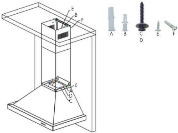
- Main Hood with All Lights and Button 5. Flexible Duct (for 6" or 8") Banks Pre-Installed 6. Packet of Screws and Anchors
- Adjustable Stainless Steel Chimney Cover 7. Top Mounting Bracket
- Transition Piece (for 6" or 8") 8. Grease Cup
- Baffle Filters
text_image
Technical diagram of a mechanical assembly with labeled parts and corresponding exploded view of six different screw components (A–F)* Note: Wall range hoods with single motors will come with a square to 6" round transition piece and will include a back draft damper. The ducting with these range hoods is 6". Dual motor wall hoods will come with a square to 8" round transition piece without a back draft damper. The ducting with these range hoods is 8". Use rigid ducting wherever possible. Try and minimize the use of elbows. More elbows and lon-ger runs create higher static pressure. The hood comes with a grounded three prong plug that can either be direct wired or plugged into a 20 amp circuit.
WALL RANGE HOOD INSTALLATION WALL
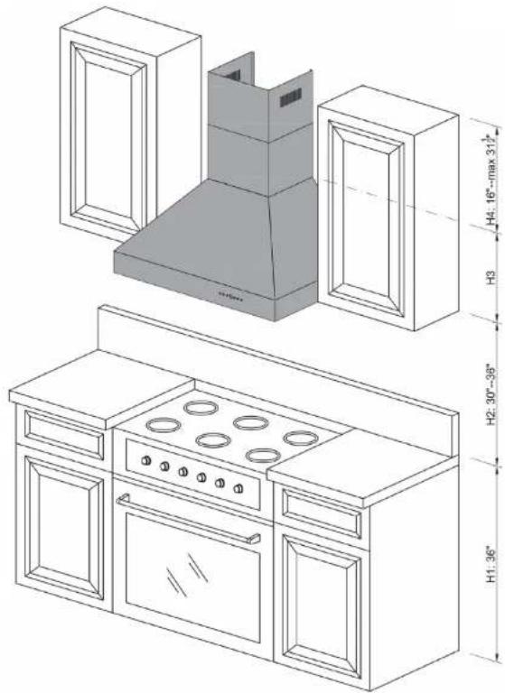
The recommended height to install your hood is 30" minimum and 36" maximum above the cooktop.
For Outdoor (304 Series) hood installation, the unit must be installed at a minimum of 36^ above the grill.
Step 1
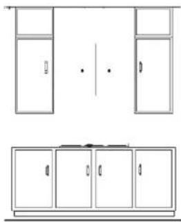
Find the center of the wall where you are installing the hood. Make sure there is sufficient bracing to hold the weight of the hood. Mark your center line and measure out from the center to find your two mounting points. Make sure your mounting points are level when you mark them. It is recommended to install the hood directly into wood supports. Figure 1
Step 2
Mark the mounting points and install the two mounting screws provided leaving the heads out 14 " to mount the hood. Figure 1
Step 3
Mount the main body of the hood to the two screws and screw into place. Figure 2
Step 4
Mount the top chimney mounting bracket centering it above the hood. Figure 3
natural_image
Line drawing of a cabinet layout with front and top views (no text or symbols)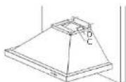
Figure 2
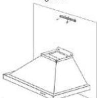
Figure 3 Figure 1
OD INSTALLATION
Step 5
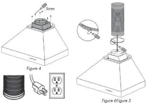
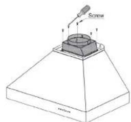
Install the transition piece securing it with the screws provided. Figure 4
Step 6
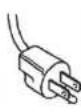
Make your electrical and ducting connections. Try and minimize the use of elbows. More elbows and longer runs create higher static pressure. The hood comes with a grounded three prong plug that can either be direct wire or plugged into a 20 amp circuit. Figure 5
Step 7
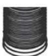
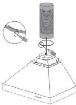
Connect the ducting to the transition piece using a ring to hold it into place. Attach the ducting to the range hood. Figure 6
text_image
Screw Figure 4 Figure 6Figure 5WALL RANGE HOOD INSTALLATION
Before installing baffle filters, make sure that you insert the grease cup under the motor blower.
Step 8
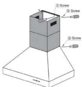
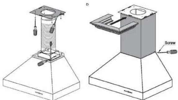
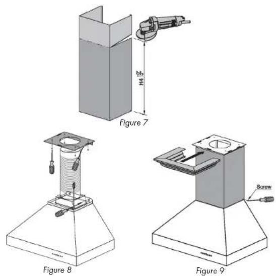
Install the two part chimneys on top of the hood. Slide the inside section up until the vertical vent slots are visible, attach top portion to mounting bracket with screws.
Secure lower chimney portion to the hood with screws provided.
Figure 7
Step 9
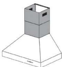
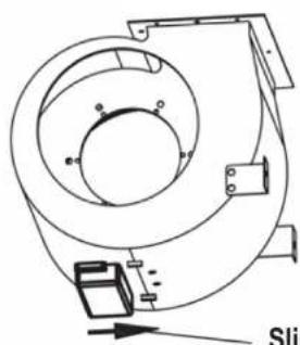
Install plastic drip cup by sliding into brackets located at the bottom of the motor. Install baffle channel and baffle filters. Not all models include baffle channels.
Figure 8
text_image
① Screw ③ Screw ② ScrewFigure 7
natural_image
3D diagram of a chimney with a box and base (no text or symbols)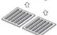
Figure 8
CROWN MOLDING INSTALLATION
If using a crown molding, follow instructions before attaching ducting and chimney sections.
Step 1
Attach crown molding bracket to ceiling using hardware provided.
Step 2
Attach ducting and electrical connections.
Step 3
Attach chimney sections to the range hood, then connect to crown molding bracket.
Step 4
Slide crown molding onto crown bracket and secure into place.
natural_image
Technical diagrams of a laboratory apparatus with labeled components (no text or symbols present)
Installation Tutorial Video
DESIGNER WALL RANGE HOOD INSTALLATION
text_image
H4: max 36" H3 H2: 30"-36" H1: 36"
Installation Tutorial Video
WALL RANGE HOOD INSTALLATION
Please unpack your range hood when it is delivered and inspect to ensure all parts are included.
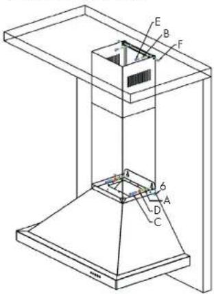
Parts Supplied
- Main Hood with All Lights and Button 6. Packet of Screws and Anchors Banks Pre-Installed 7. Top Mounting Bracket
- Chimney 8. Crown Molding Bracket
- Transition Piece (for 6" or 8") 9. Crown Molding
- Baffle Filters 10. Grease Cup
- Flexible Duct (for 6" or 8")
text_image
Technical diagram of a mechanical or architectural component with labeled parts A, B, C, D, E, F and numbered features 6, 7.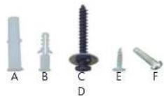
* Note: Wall range hoods with single motors will come with a square to 6" round transition piece and will include a back draft damper. The ducting with these range hoods is 6". Dual motor wall hoods will come with a square to 8" round transition piece without a back draft damper. The ducting with these range hoods is 8". Use rigid ducting wherever possible. Try and minimize the use of elbows. More elbows and lon-ger runs create higher static pressure. The hood comes with a grounded three prong plug that can either be direct wired or plugged into a 20 amp circuit.
DESIGNER WALL RANGE HOOD INSTALLATION
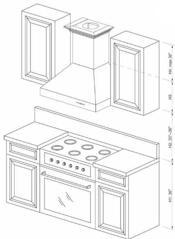
The recommended height to install your hood is 30" minimum and 36" maximum above the cooktop.
For Outdoor (304 Series) hood installation, the unit must be installed at a minimum of 36" above the grill.
Step 1
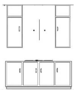
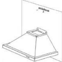
Find the center of the wall where you are installing the hood. Make sure there is sufficient bracing to hold the weight of the hood. Mark your center line and measure out from the center to find your two mounting points. Make sure your mounting points are level when you mark them. It is recommended to install the hood directly into wood supports. Figure 1
Step 2
Mark the mounting points and install the two mounting screws provided leaving the heads out 1/4" to mount the hood. Figure 1
Step 3
Mount the main body of the hood to the two screws and screw into place. Figure 2
Step 4
Mount the crown molding bracket centering it above the hood. Figure 3
natural_image
Pure architectural floor plan lines without any text, numbers, or symbolsFigure 1
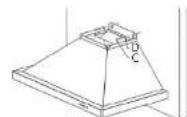
Figure 2
natural_image
Technical line drawing of a conical lamp or fixture with a base and top, shown without any text or symbols.WALL RANGE HOOD INSTALLATION
Step 5
Make your electrical and ducting connections. Try and minimize the use of elbows. More elbows and lon-ger runs create higher static pressure. The hood comes with a grounded three prong plug that can either be direct wire or plugged into a 20amp circuit. Figure 4
Step 6
Install the transition piece securing it with screws provided. Figure 5
Step 7
Connect the ducting to the transition piece using ring to hold into place. Figure 6
text_image
Screw MatterFigure 4

natural_image
Diagram of a laboratory setup with a conical tube mounted on a base, showing a spring and a magnified inset (no text or labels)Figure 6 Figure 5
Step 8
Find the center of the wall where you are installing the hood. Make sure there is sufficient bracing to hold the weight of the hood. Mark your center line and measure out from the center to find your two mounting points. Make sure your mounting points are level when you mark them. It is recommended to install the hood directly into wood supports. Figure 7
Step 9
Mark the mounting points and install the two mounting screws provided leaving the heads out 14 " to mount the hood. Figure 8
Step 10
Mount the main body of the hood to the two screws and screw into place. Figure 9
ISLAND HOOD INSTALLATION DESIGNER WALL
text_image
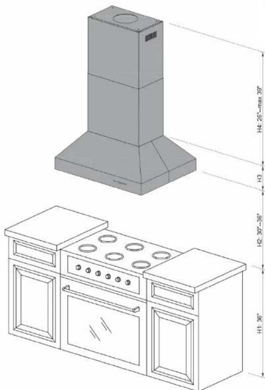
H4: 26"-max 39" H3 H2: 30"-36" H1: 36"
Installation Tutorial Video
DESIGNER WALL RANGE HOOD INSTALLATION
The recommended height to install your hood is 30" minimum and 36" maximum above the cooktop.
For Outdoor (304 Series) hood installation, the unit must be installed at a minimum of 36^ above the grill.
Step 1
Locate the center above the stove where the hood is to be installed. Ensure that the bracket will be secured to solid wood backing. Attach mounting bracket to the ceiling. Figure 1
Step 2
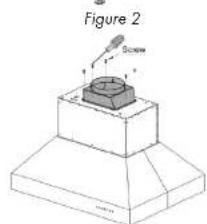
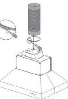
Attach the transition piece and ducting to top of the hood. Figure 1 and 2
Step 3
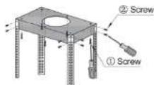
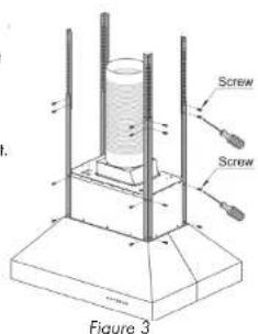
Attach the four long angle iron pieces to the hood's motor housing. Figure 3
text_image
Figure 2 BoschStep 4
Determine desired height and attach the four short angle iron pieces to the long angle iron pieces that are attached to the hood. Figure 3
natural_image
Technical illustration of a mechanical assembly with a cylindrical component and base platform, showing a magnified inset (no text or symbols)Step 5
Install the duct work in the center of the ceiling bracket.
text_image
Screw Screw Figure 3ISLAND HOOD INSTALLATION
Step 6
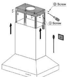
Slide chimney pieces over the angle iron on the hood. Pull the electrical plug to the top of the chimney sections. Figure 4
Step 7
Lift the hood to attach the angle iron to the ceiling bracket. Use screws provided to attach.
Step 8
Make your electrical and ducting connections. Use rigid duct wherever possible. Try and minimize the use of elbows. More elbows and longer runs create higher static pressure. The hood comes with a grounded three prong plug that can either be directly wired or plugged into a 20 amp circuit.
Step 9
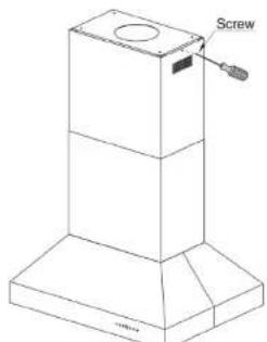
Slide top chimney piece up over the mounting bracket on the ceiling and secure it in place with the provided screws. Figure 5
Step 10
Install stainless steel baffle filters. Before installing baffle filters, make sure that you insert the grease cup under the motor blower.
text_image
② Screw ① ScrewFigure 4
text_image
Screw 10mmFigure 5
UNDER CABINET INSTALLATION
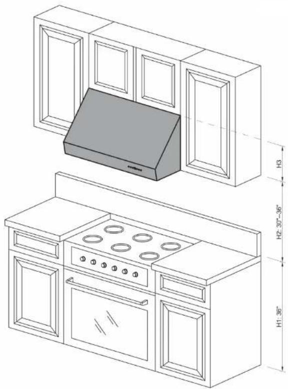
natural_image
Technical line drawing of a kitchen cabinet with an oven and chimney, showing dimensions H1, H2, H3 (no text or symbols on the diagram itself)
Installation Tutorial Video
UNDER CABINET INSTALLATION
Preparation
Decide the location of the venting pipe from the hood to the outside.
Check hood for clearance.
A straight, short vent run will allow the hood to perform more efficiently.
Try to avoid as many transitions, elbows, and long runs as possible. This may reduce the performance of the hood.
For installing under the cabinet with recessed bottom, attach 4-inch wide wood filler strips (not provided) on each side.
Puncture the knockout holes (for mounting under the cabinet) on the hood.
Step 1
Measure distance between stove top and the bottom of the range hood. A distance of 30" to 36" is recommended.
Step 2
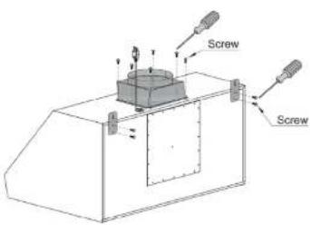
Attach mounting brackets to the back of the hood.
Step 3
Mark the leveling point of the hood. Position two mounting screws on teh wall, leaving 18 " space away from the wall. Make sure that you are mounting the hood to a secure backing to hold the weight of the hood.
Step 4
Tighten ducting (provided) with the hose clamp provided. Use silver or duct tape wherever needed.
text_image
Screw Screw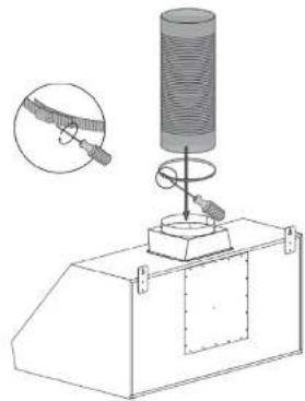
natural_image
Technical diagram of a mechanical testing setup with a cylindrical component and a base, showing a magnified inset (no text or symbols)Step 5
Draw electrical wires through cabinet access opening, center the hood beneath the cabinet.
Step 6
Align hood-mounting brackets to the screws on the wall and hook hood into place. Tighten screws to secure hood to the wall.
Step 7
Connect ducting.

natural_image
Technical diagram of a mechanical testing setup with a cylindrical component and spring-loaded base, showing a magnified inset (no text or symbols)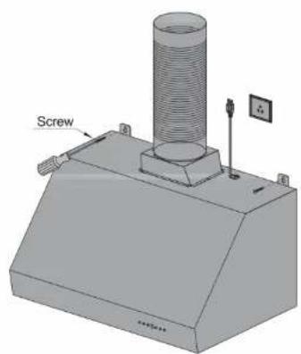
natural_image
3D technical diagram of a mechanical assembly with a cylindrical component and screw base (no text or symbols)UNDER-CAB REAR DUCTING CONVERSION UNDER CA
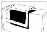
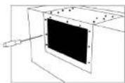
If you need to convert your under cabinet range hood to rear ducting please follow
the instructions below. Please note that converting the undercab to rear ducting is a modification of the standard hood and part of the installation process. It is recommended that the hood is inspected before this procedure. If you are uncomfortable doing this process on your own, you can have our team professionally do it for a \$50 fee* prior to shipping.
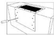
Step 1
First remove the screws from the stainless steel panel. The small screws attach the panel to the range hood while the larger screws attach the panel to the motor.
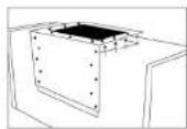
Step 2
Remove the panel from the hood
Step 3
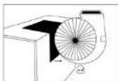
Remove the blower/motor from the range hood. Be careful not to pull and disconnect the attached wiring.
Step 4
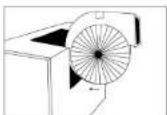
Rotate the blower/motor so that the opening is facing out the rear of the range hood.
Step 5
Replace the panel so that the opening aligns with the opening of the blower/motor.
Step 6
Attach the panel to the range hood then attach the blower/motor to the panel using the larger screws.

RANGE HOOD INSERT INSTALLATION
natural_image
Isometric line drawing of a kitchen cabinet with two doors, a grater rack, and an oven (no text or symbols)
Installation Tutorial Video
RANGE HOOD INSERT INSTALLATION
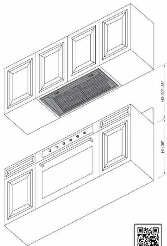
When installing a range hood insert, it is recommended to install the unit at a minimum of 30^ from the cooktop.
For outdoor range hood inserts it is recommended to install the unit at a minimum of 36" from the grill top.
Step 1
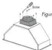
Unpack contents of the hood. Attach transition piece and ducting to the otp of the range hood insert. Figure 1 and 2
Step 2
Using L brackets and screws provided, attach L brackets to each side of the insert.
Step 3
Lift the range hood insert into cabinet or custom hood structure. Figure 3
Step 4
Follow instructions for wall hood mount to mount the range hood.
Due to some installation differences with custom hoods the L brackets may not work. Before installing insert please determine if the insert will work for your installation needs. You may pre-drill holes into the insert unit to accommodate for custom hood installations.
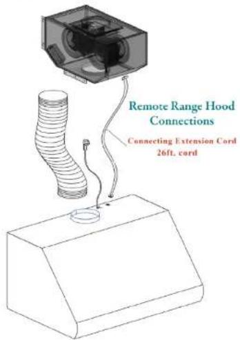
Note: Electrical cord is 26' in length. Make certain to connect the electrical cord to the hood and plug the blower motor in to test the unit.
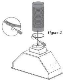
natural_image
Diagram of a scientific apparatus with a cylindrical component and a base, labeled as Figure 2 (no text or symbols on the diagram itself)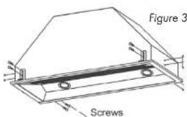
text_image
Figure 3 Screws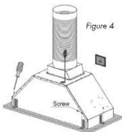
text_image
Figure 4 ScrewREMOTE BLOWER INSTALLATION REMO
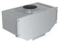
When installing your new remote blower type range hood, follow the instructions for the type of hood you are installing. If you are installing a wall, Island, under cabinet or insert hood then you will follow those instructions. This portion of the manual will explain how to install the remote blower for your range hood.
Step 1
Run duct work into the area that you will install the remote from your range hood.
Step 2
Fasten ducting to the range hood using a hose clamp and silver/duct tape.
Step 3
Use the least amount of elbows as possible.
Step 4
Mount the remote blower to studs only.
text_image
Remote Range Hood Connections Connecting Extension Cord 26ft. cordER INSTALLATION
Step 5
Run electrical cord (provided) back to the range hood (up to 26').
Step 6
Install a regular outlet with a 20 amp circuit.
Step 7
The hood comes with a grounded 3 prong grounded plug.
Step 8
Run duct work to the outside of the house and add a back draft damper outside.
natural_image
Exterior view of a metallic industrial housing unit with a circular top component (no text or symbols visible)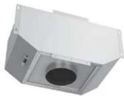
natural_image
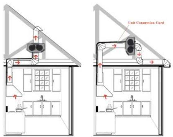
Exterior view of a white industrial enclosure with a circular vent and mounting brackets (no text or symbols visible)NOTE: The remote blower must be kept inside the home, attic or crawl space etc. Never try to install a remote blower outside of the home.
REMOTE BLOWER INSTALLATION
text_image
Unit Connection CordThe Remote Blower is designed for our Remote Range Hoods. This unit is installed remotely in the interior of your home. This provides venting, but with reduced noise.
T85 Remote Blower—Single Motor
(This Blower must be used with Remote Blower Hood)
Airflow 280 / 400 / 580 / 900 (CFM)
Noise Level: 1.2 / 2.6 / 4.2 / 6.5 (Sones)
Dimensions: 26.14 x 14.6 x 13
T95 Remote Blower—Dual Motor
(This Blower must be used with Remote Blower Hood)
Airflow 280 / 460 / 670 / 1200 (CFM)
Noise Level: 1.2 / 2.8 / 5.0 / 7.0 (Sones)
Dimensions: 26.14 x 14.6 x 13
HOW TO CHANGE PARTS
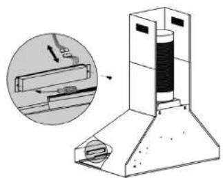
How to Change Out the Button Panel
- Remove baffle/aluminum filters.
- Locate back of button panel.
- Remove screws from each side of the button panel.
- Disconnect button panel from cord connecting to circuit board.
Note: Never work on or clean the range hood while power is ON. Always unplug the unit or switch the electrical breaker to the off position.
natural_image
Technical illustration of a mechanical device with an inset showing a tool interacting with a component (no text or symbols present)
Installation
Tutorial
Video
text_image
Switch 110-120V 60Hz wh bk Transformer 2x12V max 20W wh wh br lbk rd M~ 16μF/250V ar yeHOW TO CHANGE PARTS
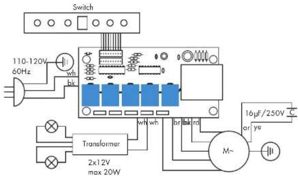
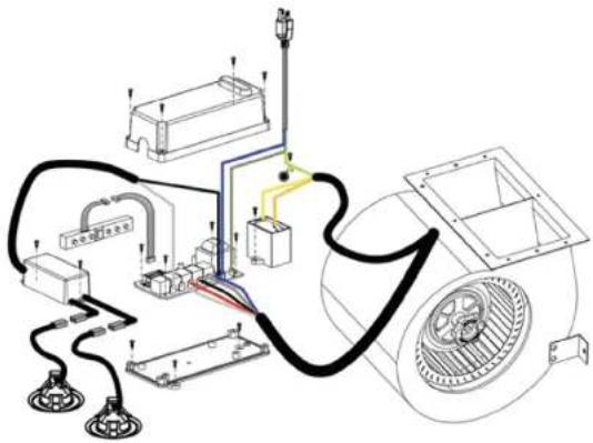
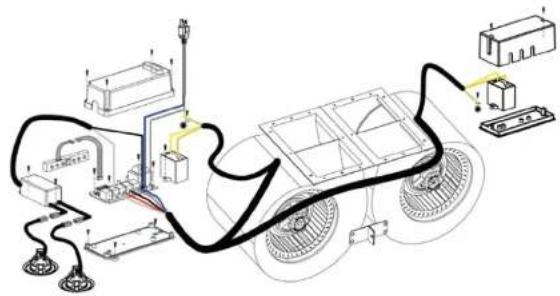
How to Replace the Circuit Board:
- Turn the power off at the breaker and unplug the Range Hood.
- Remove all screws from the top of the circuit board cover.
- Take a picture of the wiring layout (this will help you put the circuit board back together properly).
- Remove the wiring connected to the circuit board.
- Remove the screws from the circuit board.
- Replace the wiring and screws to reassemble the new circuit board per the diagram below.
Note: Never work on or clean the range hood while power is ON. Always unplug the unit or switch the electrical breaker to the off position.
text_image
Technical diagram of an electric motor with labeled components and wiring connections
Installation Tutorial Video
HOW TO CHANGE PARTS
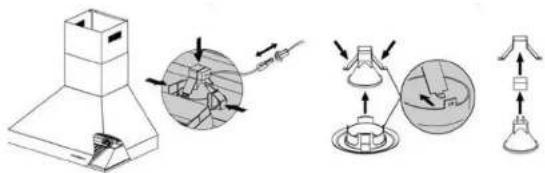
Replacing the Light Bulbs in Your Range Hood:
Use 20 watt MR11 Halogen Bulb or a 2.5 watt LED Bulb for replacement.
natural_image
Technical line drawings of mechanical components including a conical base, clamped parts, and a lamp (no text or symbols)- Remove baffles.
- Gently press light casting out until it falls out of the socket, disconnect the plug wires.
- Press both sides of teh mounting clip to remove the light bulb (be certain not to touch the bulb).
- Pull light from the receptacle plug.
- Press mounting clip back into position.
- Reconnect light plug connection.
- Press light assembly into the socket.
Note: Never work on or clean the range hood while power is ON. Always unplug the unit or switch the electrical breaker to the off position.
text_image
2. Baffle filters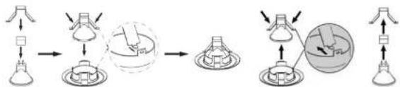
flowchart
graph LR
    A["Top Lamp"] --> B["Lens"]
    B --> C["Mirror"]
    C --> D["Spherical Component"]
    D --> E["Lens"]
    E --> F["Mirror"]
    F --> G["Spherical Component"]
    G --> H["Lens"]
HOW TO CHANGE PARTS
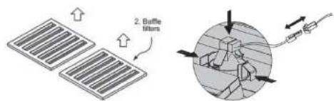
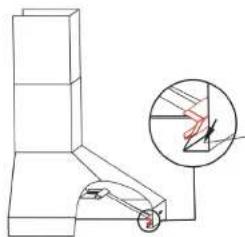
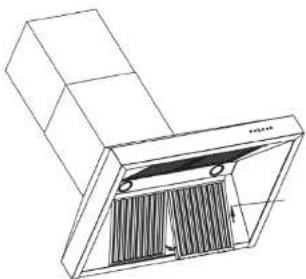
Professional Series Baffle Filter Change:
Covering Models 696 / 697 / 697 Island / KECOM / KECOM Island / 695, 698, and 721 Inserts
Professional series hoods are equipped with 2 removable dishwasher safe baffle channels (one for series 695 and 698 inserts) that the baffle filters sit into. To install the channel, place inside the hood and slide into place with the edge of the hood fitting in between the channel and the installation pieces installed on the back of the channel.
To install filters, first install the removable baffle channel. Next, take the filter and put one end into the permanent baffle channel. Push back into place and pull down sliding the bottom of the filter in.
Note: Never work on or clean the range hood while power is ON. Always unplug the unit or switch the electrical breaker to the off position.
natural_image
Technical line drawing of a mechanical assembly with an inset showing a magnified detail of a component (no text or symbols)
natural_image
Technical line drawing of a cabinet or duct with internal grating and mounting holes (no text or symbols)Installation Tutorial Video
HOW TO CHANGE PARTS
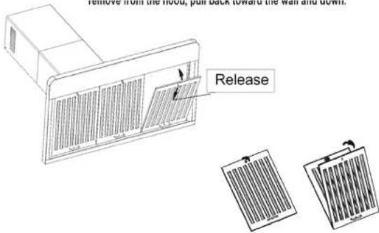
Baffle Filter:
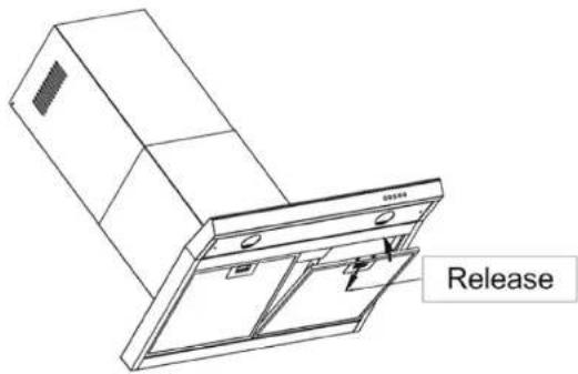
The Baffle Filter is equipped with a spring loaded handle. To remove from the hood, pull back toward the wall and down. The Baffle Filter can also be opened for easy cleaning. To open, unscrew the cylindrical handle and separate the layers to clean.
Remove from the hood, pull back toward the wall and down.
text_image
Remove from the hood, pull back toward the wall and down. ReleaseAluminum Filter:
To remove the filter, pull the spring loaded handle back toward the wall and down.
text_image
ReleaseHOW TO CHANGE PARTS
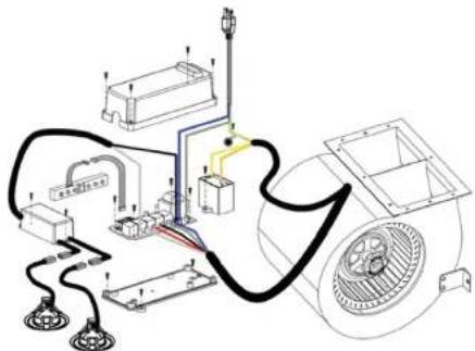
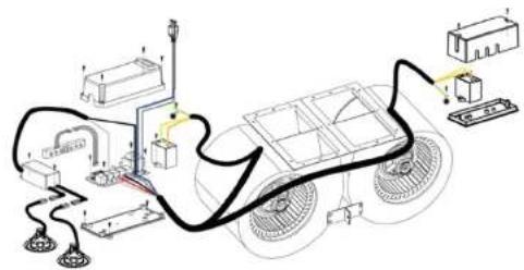
Change/Replace Capacitor:
- Remove screws from the circuit board cover.
- Remove screws from compacitor.
- Remove both wired connections from the capacitor.
- Connect new capacitor with wire connectors.
- Replace screws in cover.
- Repeat operation if dual motor.
Note: Some units have more than one motor. If you have a unit with dual motors, there will be two capacitors.
Note: Never work on or clean the range hood while power is ON. Always unplug the unit or switch the electrical breaker to the off position.
natural_image
Technical line drawing of an electrical or mechanical assembly with no visible text, numbers, or symbols.
Installation
Tutorial
Video
text_image
Diagram of a vehicle's electrical wiring and components, including motors, sensors, and power supply connections.HOW TO CHANGE PARTS
Replace or Change Charcoal Filters:
It is recommended to direct vent the hood whenever possible.
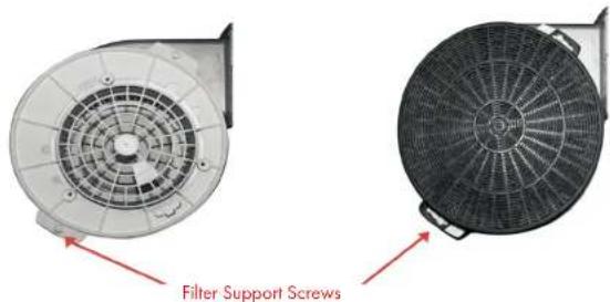
If your situation does not allow for a direct vent install, carbon filters are available to recirculate the air through your hood.
text_image
Filter Support Screws- Remove the stainless steel or aluminum filters from the bottom of the hood.
- Locate the existing raised support screws on each side of the internal motor(s).
- For each motor side, position the filter over its support screw and rotate to lock into place.
Note: Replacement is recommended after 130 hours of cooking or 6 months of operation. Replace more often if your cooking habits generate more grease.
Note: Never work on or clean the range hood while power is ON. Always unplug the unit or switch the electrical breaker to the off position.

Installation Tutorial Video
HOW TO CHANGE PARTS
How to Clean, Install, or Replace the Grease Cup:
A removable grease cup is provided to catch any excess greatse at the bottom of the motor. Remove it every 2 to 3 months, wash it, then re-install it.
Note: Never work on or clean the range hood while power is ON. Always unplug the unit or switch the electrical breaker to the off position.
natural_image
Technical line drawing of a mechanical assembly with no visible text or symbolsSlide into place.

Installation Tutorial Video
HOW TO CHANGE PARTS
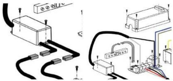
Replace or Change Transformer:
- Remove the screws from the transformer.
- Remove the two connections to the lights.
- Remove the two wired connections from the circuit board (you must remove the circuit board cover).
- Install the new connections from your new transformer (be certain the correct wires are connected).
- Reinstall the cover for the circuit board with screws.
- Replace all screws in the transformer.
- Reconnect the lights to the transformer.
Note: On Units with three or more lights, there will be dual transformers.
Note: Never work on or clean the range hood while power is ON. Always unplug the unit or switch the electrical breaker to the off position.
natural_image
Pure electrical circuit lines without any symbols
Installation Tutorial Video
HOW TO CHANGE PARTS
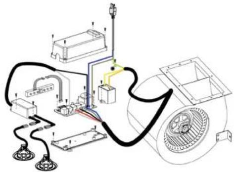
Single Motor Electrical Diagram:
text_image
Technical diagram of an electrical or mechanical system with labeled components and wiring connections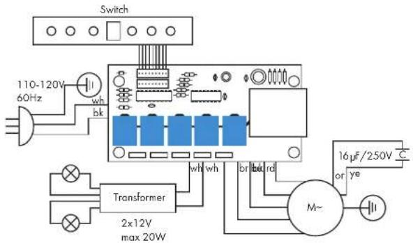
text_image
Switch 110-120V 60Hz wh bk Transformer 2x12V max 20W wh wh br bdr rd M~ 16μF/250V or ye CHOW TO CHANGE PARTS
Dual Motor Electrical Diagram:
text_image
Technical diagram of a vehicle chassis with labeled components and wiring connections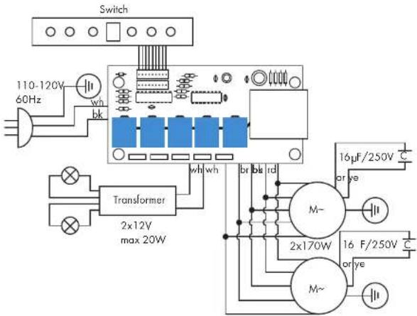
text_image
Switch 110-120V 60Hz wh bk Transformer 2x12V max 20W wh wh br bk rd M~ 2x170W M~ 16 μF/250V C or ye 16 F/250V C or yeHOW TO CHANGE PARTS
Button Control Panel Operation:
text_image
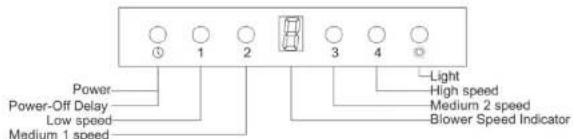
Power Power-Off Delay Low speed Medium 1 speed Light High speed Medium 2 speed Blower Speed IndicatorButton functions
Power: Power ON/OFF the range hood and activate power-off delay timer.
Light: Turns ON/OFF and dim lights.
Blower Speed Indicator: Shows current blower (motor) speed [1-4].
Low Speed-Light frying/boiling
Medium Speed-Frying/wok cooking/heavy boiling
High-Grilling, intensive frying and wok cooking
Controls
Adjusting the blower (motor) speed:
Press power button once to turn on the system.
Press the speed buttons for the desired speed. Speed may be increased and decreased.
The blower speed indicator shows the blower (motor) speed level next to the speed button selected will increase the speed of the blower (motor) from 1 to 4 (quietest to strongest).
Adjusting the timer function:
Turn the hood on at any speed, press the power-off delay button to enter timer mode, a 3 flashes in the display, power-off delay digital timer will
begin countdown. After approximately 3 minutes when it reaches zero, the blower (motor) will shut down.
Adjusting the light:
Press light button once to turn on the lights, and once again to turn off the lights.
TROUBLE SHOOTING AND FAQs
No Power
- Check electrical connections.
- Check that all connections to the circuit board are secure.
- If problem still exists, the circuit board needs to be replaced.
What size hood should I choose for CFM purposes?
- You must determine the output of the cooktop burners of your range; this is measured in British Thermal Units (BTU's).
- You should provide 100 CFM of airflow per linear foot of range. To determine this, divide the BTU rating of your range by 100. This will give you the rating of the Cubic Feet per Minute (CFM's) rating needed of your range hood. For example: If your range is 35,000 BTUs, your range hood should have a rating of 350 CFM's or greater.
- To determine the size of the range hood for satisfactory capture, it is recommended to go at least one size larger than your range, about 3" to 6" wider. At minimum, it should be the same size of your range. The range hood width should cover 100% of the back burners and 50% of the front burners.
- The height of your range hood should be between 30" to 36" above your cooktop. Example: 60,000 BTU's = 600CFM's
How loud is the range hood?
A sone is measure of loudness, the higher the sone rating, the louder the sound of the hood. The sound of one sone is comparable to that of a quiet refrigerator. Keep in mind that other factors such as the size of the blowers can affect the loudness of the range hood. The higher the CFM, the louder the sone rating will be.
Can my hood be ductless?
Ideally, it is better to duct your range hood to the outside, but if this is not possible, ductless is a great alternative. Many of our range hoods do have the capability to be converted to ductless. Ductless is when the air circulates through the carbon filter removing odors, grease, smoke etc. The clean air is re-circulated back into your home through carbon/charcoal filters. These filters are not reusable and will need to be changed out once every six months, de-pending on cooking style and frequency.
TROUBLE SHOOTING AND FAQs
What type of stainless steel are our hoods made of?
Our indoor stainless steel hoods are made with a 430 stainless steel. Our outdoor hoods are made of 304 stainless steel, this type is stronger and more resistant to rust and corrosion.
Do I need a chimney extension or a shortening kit when I purchase my hood?
Your hood will come with a default chimney that has a telescoping chimney to allow for an ad-justable mounting height for a ceiling of up to 9 to 9.5 feet. An extension is needed for a ceiling from 10^ to 12^ tall. A short chimney is recommended for a ceiling height of 8ft, however mea-sure to be certain. All extensions and short kits will come with brackets that go specifically with that chimney.
How many amps?
For dual motors it is up to 6amps. For single motors it is 3 amps.
What type of motor is in the range hoods?
Our hoods have a squirrel cage motor.
Is the width of my range hoods description, the actual size?
No, the actual size of the range hood will be slightly less than the generic description of the range hood. For instance: a 30" range hood will most likely be 29-7/8". Refer to your particular model for the exact width.
How do I clean my grease filter and how often?
Your grease filter should be washed with hot water and detergent once per month or placed in a dishwasher for cleaning. Make certain the filter is completely dry before reinstalling. Re-place the grease filter if it becomes damaged or too dry to clean.
Can I clean my charcoal, odor filter?
No, charcoal odor filters cannot be washed and must be discarded and replaced, when they become noticeably dirty, have stopped filtering the odors, or at least once per year.
TROUBLE SHOOTING AND FAQs
What is the best way to duct my range hood?
To maximize your range hood's performance, match your duct size to the original size of the fan's ducting. Use the shortest amount of ducting as possible and keep the ducting as straight as possible. Do not exceed 40 feet of ducting. For every elbow deduct five feet from the total.
Do I have to exhaust the range hood to the outdoors?
Yes. If installing a range hood that has ductwork connected to it (any hoods that do NOT recirculate the air back into the room), to properly exhaust the air, be sure to duct the air out side. DO NOT vent exhaust air back into the spaces within the walls, ceilings, attics, crawl spaces, or garages. A buildup of humidity and grease could cause damage and/or a fire risk to your home.
My hood is operating but the air is moving slower than normal.
Check the filter for buildup and clean or replace it if needed. If the difficulty still persists, check for obstructions in the ductwork. A common obstruction in buildup in the roof or wall cap, such as: bird nests or other debris.
My hood is making a rattling noise.
This is probably attributed to one of the following:
- The motor is loose—Turn off the power and remove the filter and check that all screws are secure and light around the motor.
- The duct work connection is loose—Turn off the power to the unit and check that the ductwork connection to the pipe is tight. Add duct tape if necessary.
What is make-up air?
When the range hood ventilates the air out of the room, the air vented must be replaced, this is called make-up air. We do not currently provide a make-up air unit. NOTE: Always consult any applicable building codes in your area in regards to minimum and maximum air flow rates. Certain states may require additional items such as make-up air for larger CFM range hoods (typically over 300 CFM).
TROUBLE SHOOTING AND FAQs
How do I order replacement parts?
Replacement parts can be ordered by contacting our customer service department. All hoods have a three year warranty on parts. Have your model number or order number available when calling customer service.
My range hood will not operate.
- Check that there is power to the range hood. The most common issue is that the circuit breaker is off or the fuse has blown.
- Make sure the speed has been selected at the range hood controls.
- Turn off the power to the range hood and check that all wires are properly connected. Refer to your specific model's installation instructions for proper wiring.
natural_image
Interior view of a stainless steel kitchen with a large metal chimney and wooden cabinets, set against a brick wall (no text or symbols visible)Thank you for joining the ZLINE family
natural_image
Modern kitchen oven with mounted appliances and a stone wall, no visible text or symbols
text_image
ZZLINE
KITCHEN AND BATH
Two Locations:
916 Delaware Avenue
Marysville, Ohio 43040
350 Parr Circle
Reno, NV 89512
www.zlinekitchen.com
1-614-777-5004