
SD2X - Security Camera FOSCAM - Free user manual and instructions
Find the device manual for free SD2X FOSCAM in PDF.


| Product Type | Indoor/Outdoor Pan-Tilt Security Camera |
| Resolution | 720p HD (1280 x 720 pixels)@30fps |
| Lens | 3.6 mm, FOV 70° (horizontal) |
| Night Vision | 10 infrared LEDs, up to 10 meters |
| Pan Range | 340° (horizontal) |
| Tilt Range | 90° (vertical) |
| Audio | Two-way audio with built-in microphone and speaker |
| Connectivity | Wi-Fi (802.11 b/g/n) and Ethernet (10/100 Mbps) |
| Power Supply | DC 5V, 2A (power adapter included) |
| Power Consumption | Approx. 6W (max) |
| Dimensions | 11.5 x 10.5 x 10.5 cm (4.5 x 4.1 x 4.1 in) |
| Weight | 350 g (12.3 oz) |
| Storage | microSD card slot (up to 128 GB) |
| Video Compression | H.264 |
| Motion Detection | Yes, with configurable sensitivity and zones |
| Alerts | Email and push notifications with snapshot |
| Protocols | TCP/IP, HTTP, SMTP, FTP, DHCP, UPnP, ONVIF |
| Mobile App | Foscam app for iOS and Android |
| Mounting | Desktop or wall mount (bracket included) |
| Operating Temperature | -10°C to 50°C (14°F to 122°F) |
| Safety | Use only included power adapter; avoid water exposure |
| Maintenance | Wipe gently with a dry cloth; do not use chemicals |
| Spare Parts | Contact Foscam support for replacement parts |
Frequently Asked Questions - SD2X FOSCAM
User questions about SD2X FOSCAM
0 question about this device. Answer the ones you know or ask your own.
Ask a new question about this device
Download the instructions for your Security Camera in PDF format for free! Find your manual SD2X - FOSCAM and take your electronic device back in hand. On this page are published all the documents necessary for the use of your device. SD2X by FOSCAM.
USER MANUAL SD2X FOSCAM
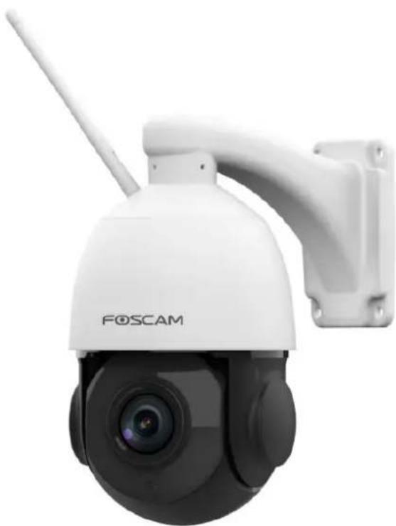
Outdoor IP Security Camera
natural_image
White FOSCAM security camera with antenna and mounted sensor (no visible text or symbols on body)Model: SD2X
Table of Contents
Security Warning....1
1 Overview....2
1.1 Key Features....2
1.2 Read before Use....3
1.3 Packing Contents....3
1.4 Physical Description....3
1.5 SD Card Management....4
1.6 Wall Installation....5
2 Access the IP Camera in Foscam App....6
2.1 Setting Up Your Camera: Wired Connection via Foscam App....6
2.2 Foscam APP Surveillance Window....9
2.3 Watch Live....10
3 Access the Camera in the Web....12
3.1 Hardware Connection & Software Installation.... 12
3.2 Access the Camera in LAN....12
3.3 Access the Camera in WAN....14
3.4 Using the VLC Player....14
3.5 IP Camera Connection to the Server.... 17
3.6 Surveillance Software GUI....17
3.7 Advanced Camera Settings....26
3.8 Playback....60
4 Surveillance Software Foscam VMS....62
4.1 Hardware Connection & Software Installation....62
4.2 Software Installation....62
4.3 Create Account....63
4.4 Add Device....64
4.5 Surveillance Software GUI....67
4.6 Advanced Camera Settings....73
5 Appendix....105
5.1 Frequently Asked Questions....105
5.2 Default Parameters....111
5.3 Specification....111
5.4 CE & FCC....112
5.5 WARRANTY....113
5.6 Statement....115
6 Obtaining Technical Support....117
Security Warning
- Please change the password of your camera regularly, using a combination of numbers, letters and special characters.
- We recommend that you regularly update your camera to the latest available software and firmware versions to help ensure the best experience for your camera.
1 Overview
Foscam Outdoor IP Security Camera is an integrated IP Camera with a color CMOS sensor enabling viewing in High Definition resolution. It combines a high quality digital video camera, with a powerful v server, to bring clear video to your desktop from anywhere on your local network or over the Intern
The IP Camera supports the industry-standard H.264 compression technology, drastically reducing file sizes and conserving valuable network bandwidth.
The IP Camera is based on the TCP / IP standard. There is a WEB server inside which could support Internet Explorer. Therefore the management and maintenance of your device is simplified by using the network to achieve the remote configuration and start-up.
The camera is designed for outdoor surveillance applications such as courtyards, supermarket, and school. Controlling the IP camera and managing images are simplified by using the provided web interface across the network utilizing connectivity.
1.1 Key Features
◆ Standard H.264 video compression algorithm to satisfy the transmission of high definition video in narrow bandwidth network
◆ 2.0 Mega-Pixel
◆ Supports IE / Firefox / Google / Safari browser or any other standard browsers
◆ Supports WPA and WPA2 Encryption
◆ Supports Pan & Tilt
◆ Supports 18x Optical Zoom
◆ 6pcs Infrared-LEDs, night vision range up to 50 metres (164ft)
◆ Supports image snapshot
◆ Supports dual-stream
◆ Supports 2.4G/5G dual band, IEEE802.11b/g/n/ac
◆ Supports IR-Cut and the filter change automatically
◆ Supports remote viewing & record from anywhere anytime
◆ Multi-level users management with password protection
◆ Motion detection alert via email or upload image to FTP
◆ Supports multiple network protocols: IP、TCP、UDP、HTTP、HTTPS、SMTP、FTP、DHCP、RTSP、ONVIF
◆ Providing Video Management Software to manage or monitor multi-cameras
◆ Supports Wide Dynamic Range
◆ Supports sound detection
◆ Supports IP Filtering
◆ Supports Alexa
◆ Supports Google Assistant
◆ Supports 128G Micro SD Card Storage(External)
1.2 Read before Use
Please first verify that all contents received are complete according to the Package Contents listed by Before the Network Camera is installed, please carefully read and follow the instructions in the Quick Setup Guide to avoid damage due to faulty assembly and installation. This also ensures the product used properly as intended.
1.3 Packing Contents
| IP Camera × 1 | Power Adapter × 1 |
| Quick Setup Guide × 1 | Ethernet Cable× 1 |
| Mounting Plate × 1 | Wi-Fi Antenna× 1 |
| Screwdriver × 1 | Tweezers × 1 |
1.4 Physical Description
text_image
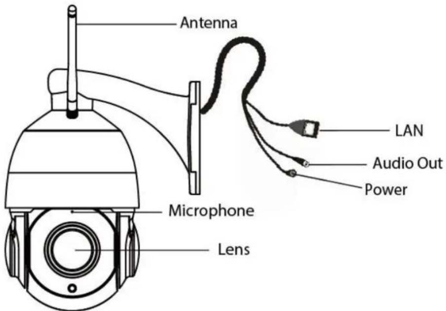
Antenna Microphone Lens LAN Audio Out PowerAntenna: Wireless Antenna
LAN: 10/100M adaptive Ethernet interface. Through this interface, IP camera can be connected with various network devices, such as hub, router, etc.
Microphone: Built-in Microphone.
Audio Out interface: The jack is used to plug external output device such as loud speaker directly. Here speaker cannot directly insert to the interface, it must connect to adapter first.
Power: Connect the external power adapter, request for 12V / 2A power.
Lens: High Definition Color CMOS Sensor with zoom lens.
text_image
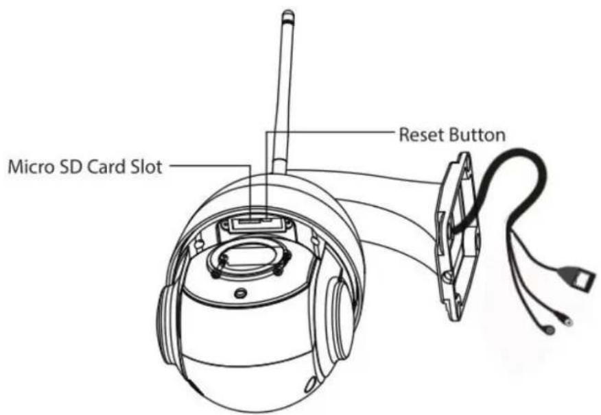
Micro SD Card Slot Reset ButtonReset Button
Press and hold on the reset button for 5 seconds. Releasing the reset button, the password will be the factory default administrator password. The default administrator user is admin with random password.
Micro SD Card slot: Supports up to 128GB SD card for storing the video.
NOTE: There are up to two labels located at the bottom of the camera, this is an important feature of original Foscam cameras. If your camera does not have labels, it may be a clone. Cloned Foscam cameras can not use original firmware and are not eligible for warranty or technical services.
1.5 SD Card Management
text_image
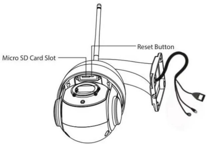
Micro SD Card Slot Reset ButtonThe record files of the IP camera can be stored in the Micro SD Card.
This camera supports Micro SD Card and the max size of Micro SD card must be under 128G. You need open the cover, then plug the Micro SD card into Micro SD card slot inside the IP cam
When you plug in the Micro SD card during the camera work process, please reboot the camera ag or else the Micro SD Card may be cannot work well. When you re-install the cover, please ensure t tightness with the camera.
Warning: Please lock the cover in time after installing the Micro SD card to avoid water or water vapor fall into the equipment then cause damage or lens fog.
1.6 Wall Installation
Please refer to the Quick Setup Guide.
NOTE: Ensure that the rain or water will not reach the connector ports at the end of the pig tail wiring. These connectors are not weather-resistant.
The cable of an outdoor camera should, from the position where the cable is divided into several cables, be fitted dry. Install the cable into a waterproof junction box (1) or bring the cable indoors (2).
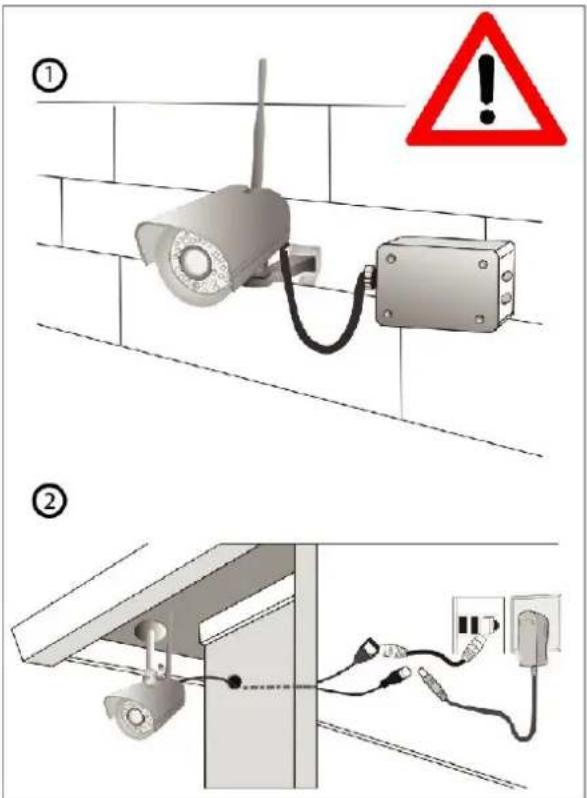
text_image
Diagram showing two types of security camera surveillance: one with warning symbol and another with electrical wiring.2 Access the IP Camera in Foscam App
2.1 Setting Up Your Camera: Wired Connection via Foscam App
Scan the QR code below to download and install the Foscam APP.


text_image
Available on the App Store ANDROID APP ON Google play
Note: For the best experience, please update the APP to the latest version!
Wired Connection
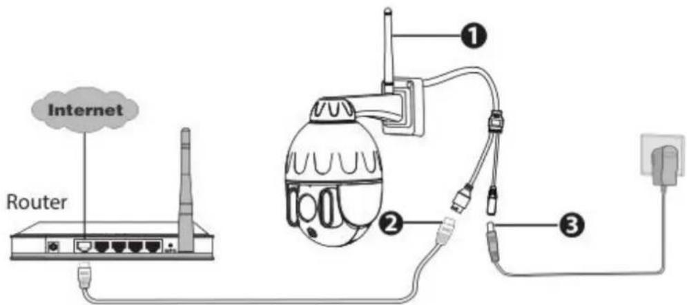
text_image
Internet Router ① ② ③- Please tighten the antenna clockwise and make sure it is in a vertical position.
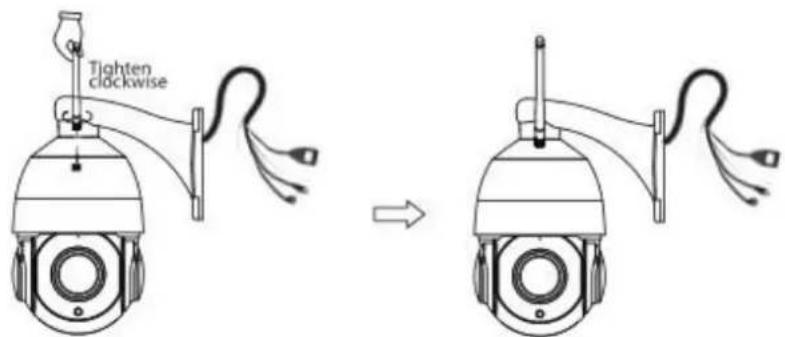
text_image
Tighten clockwise- Connect the camera to your router with an Ethernet cable.
- Plug the power adapter into the camera, and then wait for about 1 minute.
- Make sure your smart phone is connected to the same WiFi network as the camera.
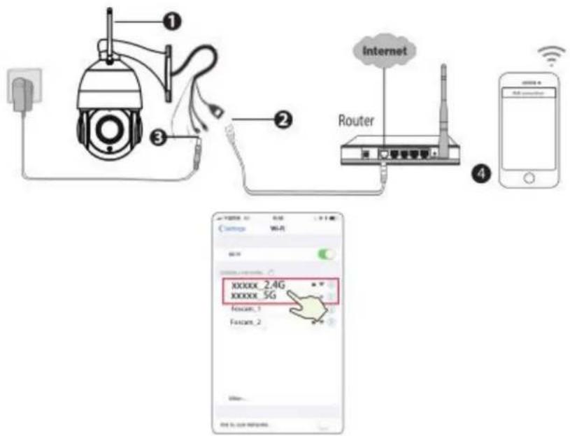
text_image
① ② Internet Router ④ xxxx_2.4G xxxx_5G Fisecan_1 Fisecan_2Tips: The camera supports dual-band 2.4GHz and 5GHz WiFi networks, so you can choose the channel with the stronger signal to use. For example, choose your SSID: XXXXX_2.4G or XXXXX_5G. 5. Open the foscam APP and please register a Foscam account, or sign in if you have one alread 6. After logging into Foscam APP, select “Tap to add a camera” or "+" icon on the upper right corner, then select "Scan the QR code" and scan the QR code that labeled at the bottom of your camera.
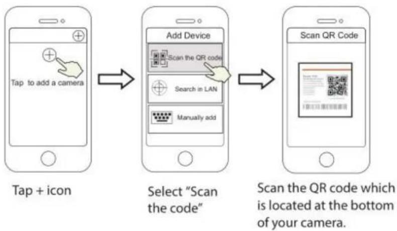
flowchart
graph LR
    A["Tap + icon"] --> B["Select "Scan the code""]
    B --> C["Scan the QR code which is located at the bottom of your camera."]
- There are two options in the following steps, please pay attention to choose the corresponding ac method.
7.1 Please wait for a few seconds, you can tap "Configure WiFi" in "Configure WiFi" interface, then select your WiFi network and enter your WiFi's password. After, you can set the camera name and ta "Save" in "Set name" interface.
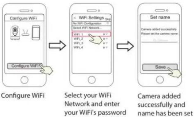
flowchart
graph LR
    A["Configure WiFi"] --> B["Configure WiFi"]
    B --> C["Select your WiFi Network and enter your WiFi's password"]
    C --> D["Camera added successfully and name has been set"]
Note: It is strongly recommended that you choose to configure WiFi at this step.
7.2 Please wait for a few seconds, you can tap "Configure WiFi" in "Configure WiFi" interface, then you tap "Skip" in the "WiFi Settings" interface. After, you can set the camera name and tap "Save" in "Set name" interface.
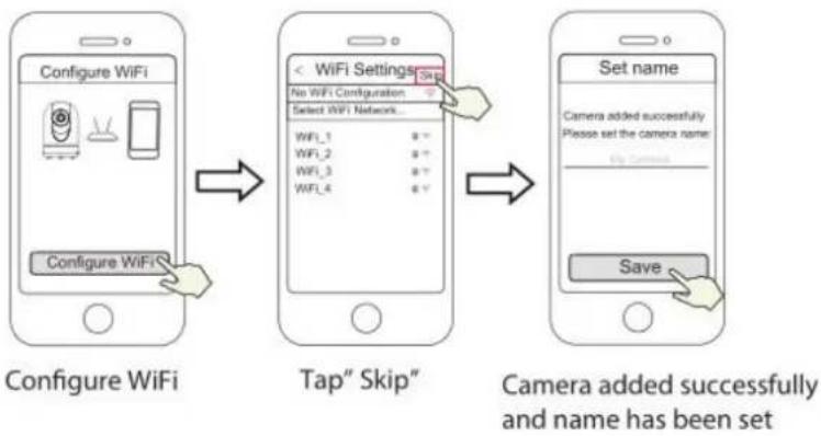
flowchart
graph LR
    A["Configure WiFi"] --> B["Configure WiFi"]
    B --> C[" Tap" Skip" "]
    C --> D[" Set name "]
    D --> E["Save"]
Note: If the adding process fails, please reset your camera and try adding again according to the above method.
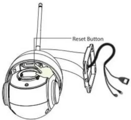
text_image
Reset Button- Tapping on the play button in the video box will jump to the “Camera Login” setting interface. For your security, please set a new username and password for your camera before viewing live video
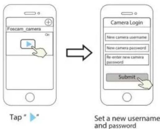
flowchart
graph LR
    A["Foscam_camera On"] --> B["Camera Login"]
    B --> C["New camera username"]
    B --> D["New camera password"]
    B --> E["Re-enter new camera password"]
    B --> F["Submit"]
- After completing the above steps, you can begin using your camera.
Note: If you choose installation step 7.2, please refer to the following steps for configuring WiFi. After setting your WiFi, you can unplug your network cable and the camera works normally.
Configure WiFi
If you selected "Skip" in step 7, click play to enter the camera credentials interface > Tap the “ ” button > tap “WiFi Settings” > select your WiFi network and enter your WiFi’s password. After setting up successfully, you can view live video without the Ethernet cable.
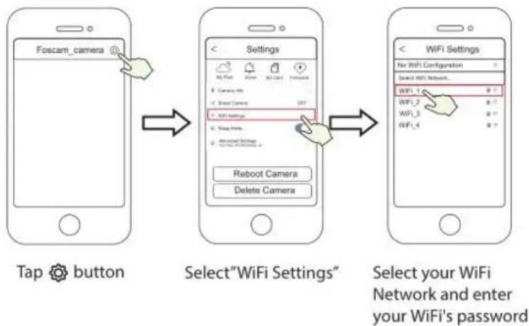
flowchart
graph LR
    A["Tap button"] --> B["Select"WiFi Settings""]
    B --> C["Select your WiFi Network and enter your WiFi's password"]
2.2 Foscam APP Surveillance Window
Please refer to the section 2.1.1 if you install the camera for the first time. You can start to learn software
operation after finish quick installation. When you launch the Foscam App, the devices page displays.
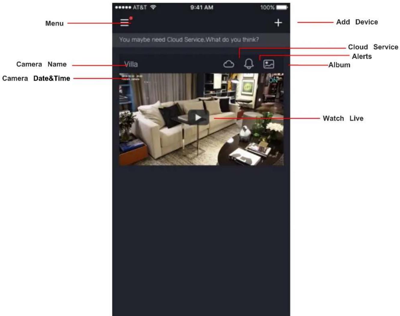
text_image
Menu You maybe need Cloud Service.What do you think? Add Device Cloud Service Alerts Camera Name Villa Album Camera Date&Time Watch LiveCamera Name: A camera name which is displayed in the Foscam Cloud Service.
You can rename your camera's name by tap Live > Camera Settings > Camera Info
OSD: Including camera name and camera time, camera name can not be renamed but camera time be in synchronized with the phone.
Sync Time: Tap Live > Camera Settings > Sync Time
2. 3 Watch Live
Tap Live to view and listen to a live video
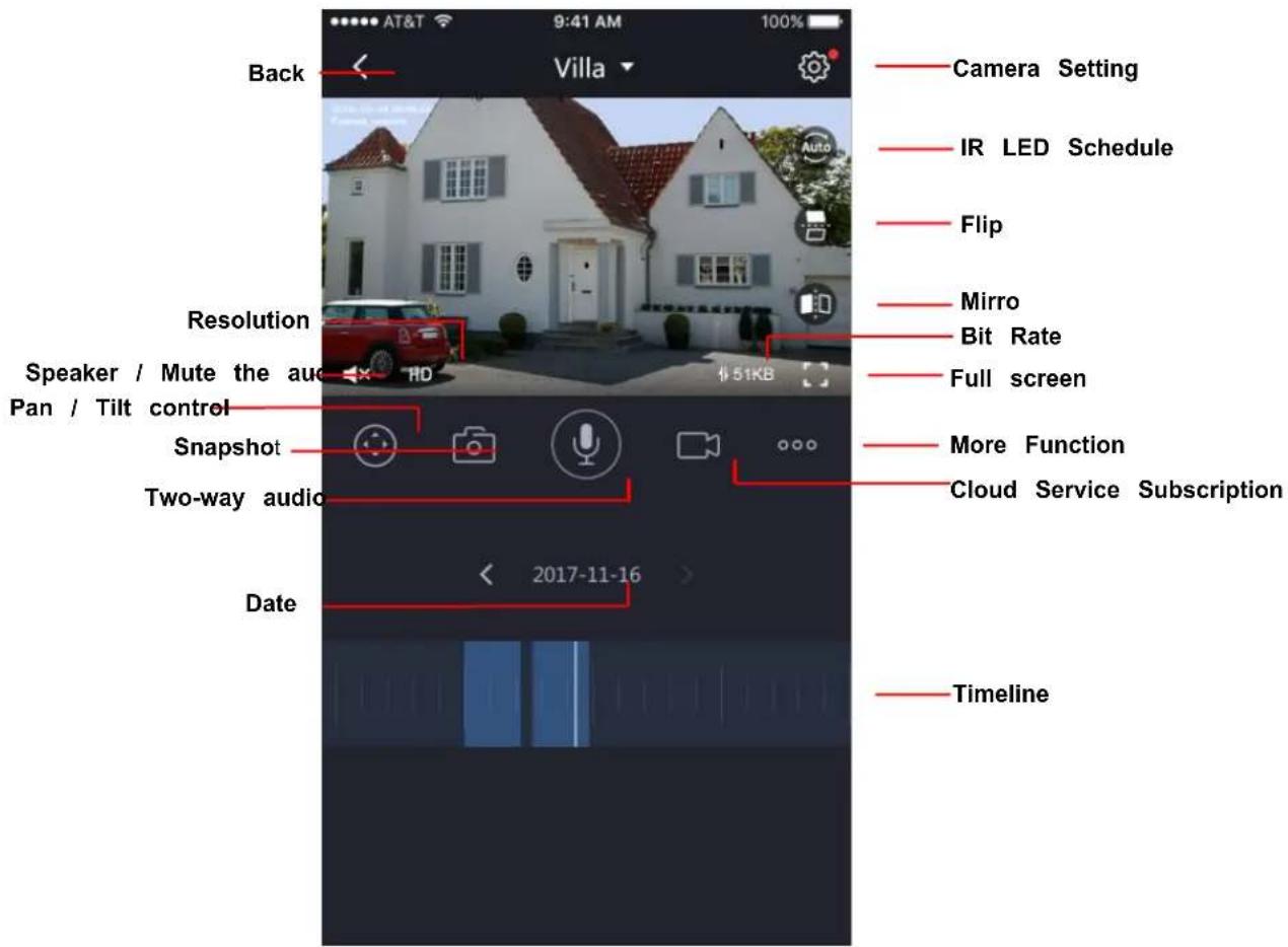
text_image
Back Villa Camera Setting IR LED Schedule Flip Resolution Speaker / Mute the audio Pan / Tilt control Snapshot Two-way audio Date 51KB Mirro Bit Rate Full screen More Function Cloud Service Subscription TimelineBack: To stop viewing and listening to the live feed, tap the Back
Resolution: There are three types to identify different streams you have set. If select the FHD Mode, the clearer video will become, and it will take up more bandwidth; If select the SD Mode, the video will as clear as FHD Mode, and it will take up less bandwidth. The HD Model is a value between FH and SD Mode.
Bit Rate: Generally speaking, the larger the bit rate is, the clearer video will become. But the bit rate configuration should combine well with the network bandwidth. When the bandwidth is very narrow, an bit rate is large, that will lead to video can not play well.
On this screen, you can listen to a live stream, record clips, take a snapshot, activate two-way talk screen.
If you want to catch the smaller details, pinch and drag any image as you do with photos on your smartphone
IR LED Schedule: On this page, you can enable/disable the IR LED, and set the IR auto switch or you can schedule it.
Auot: As default, the IR-Cut auto switch is ON, it means that the IR LED will be OFF during 9:00- and the IR LED will be ON at the other time.
Day: it means that the IR LED will be OFF all the time.
Night: it means that the IR LED will be ON all the time.
Schedule: You can schedule the time to turn the IR LED OFF/ON.
3 Access the Camera in the Web
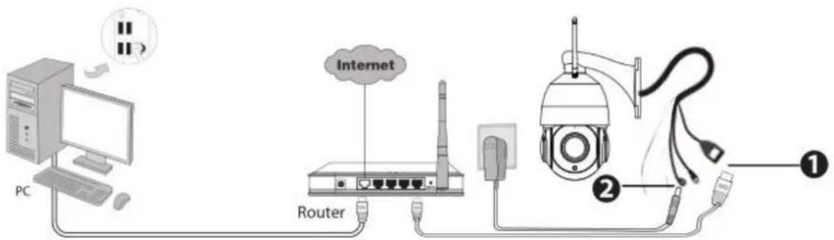
3.1 Hardware Connection & Software Installation
text_image
PC Internet Router ① ②-
Connect the camera to the LAN network (Router or Switch) via network cable.
-
Please connect the power adapter to the camera.
-
Visit Foscam official website http://www.foscam.com, select "Support > Download Center > Software Tools", then you can find the "Equipment Search Tool", download the tool to your comp the icon shows as below:

NOTES:
- If your computer (Windows OS) supports autorun function, you can find the corresponding file in opened control panel.
3.2 Access the Camera in LAN
The camera supports HTTP and HTTPS protocols, you can access the camera in two ways.
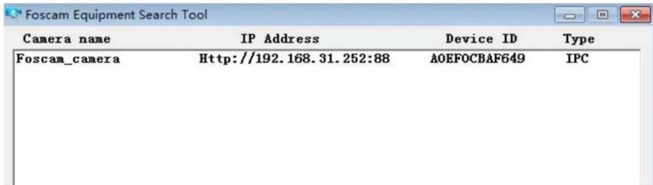
The default HTTP port NO. is 88. Double click the Search Tool icon to run, and it should find the camera's IP address automatically after you plug in the network cable.
text_image
Foscam Equipment Search Tool Camera name IP Address Device ID Type Foscam_camera Http://192.168.31.252:88 AOEFOCBAF649 IPCDouble click the IP address of the camera; the camera login page should be open in your default browser.
(2) Https:// LAN IP + Https Port no.
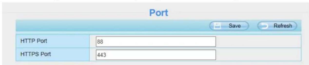
The default HTTPS port NO. is 443. You can use the URL to access the camera: https:// LAN IP HTTPS port NO.
Go to Settings > Network > Port panel, you can see and change the HTTP and HTTPS port I
text_image
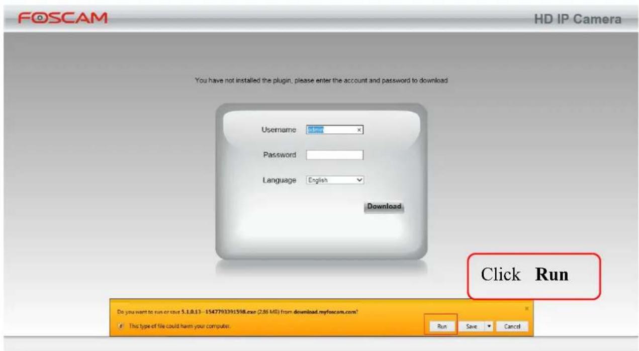
Port HTTP Port 88 HTTPS Port 443 Save RefreshNOTE: When logging in for the first time, you will need to download and install the add-on.
text_image
FOSCAM HD IP Camera You have not installed the plugin, please enter the account and password to download Username : simm Password : Language : English Download Click Run Do you want to run or save 5.1.0.13 - 1547793391598.exe (2.86 Mio) from download.myfoscam.com? This type of file could harm your computer. Run Save Cancel3.3 Access the Camera in WAN
Static IP Addresses
Users with static IP addresses after you have finished connecting the camera using the LAN IP add and port forwarding, you can access the camera directly from Internet using the WAN IP address at port number
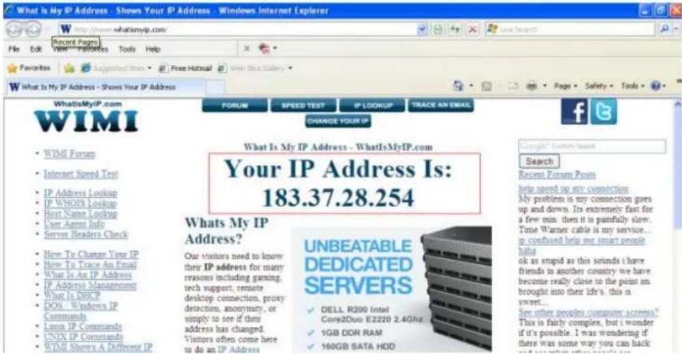
How to Obtain the WAN IP address from a public website?
To obtain your WAN IP address, enter the following URL in your browser:
http://www.whatismyip.com. The web page at this address will show you the current WAN IP.
text_image
What Is My IP Address - Shows Your IP Address - Windows Internet Explorer Recent Pages File Edit Tools Help Favorites Supported Tree Free Hotmail Web Shop Salary What Is My IP Address - Shows Your IP Address WIMI WHAT IS My IP Address - WhatIsMyIP.com CHANGE YOUR IP Your IP Address Is: 183.37.28.254 What's My IP Address? Our visitors need to know their IP address for many reasons including gaming, tech support, remote desktop connection, proxy detection, anonymity, or simply to see if their address has changed. Visitors often come here to do an IP address UNBEATABLE DEDICATED SERVERS DELL R200 Intel Core2Duo E2220 2.4GHz 1GB DDR RAM 160GB SATA HDD Search Recent Forum Posts help speed up my connection My problem is my connection goes up and down. Its extremely fast for a few min. then it is painfully slow. Time Warner cable is my service... up confused help me smart people altah ok as stupid as this sounds i have friends in another country we have become really close to the point im brought into their life's. this is sweet... See other people computer access? This is fairly complex, but i wonder if it's possible. I was wondering if there was some way you can hackAccess your IP Camera from the Internet
You can access the IP Camera from the Internet (remote access). Enter the WAN IP address and | number in your standard browser. For example, you would enter http:// 183.37.28.254:88
3.4 Using the VLC Player
This camera supports RTSP streaming, here you can view the camera using VLC player.
RTSP URL rtsp:// [user name][:password]@IP:port number/videosream
The part in the square brackets may be omitted.
user name & password:
The user name and password to access the camera. This part can be omitted.
IP: WAN or LAN IP address.
port number: If there is the RSTP port number on the Port page, you must only use RTSP port number. otherwise, you must only use http port number.
Videostream: Here support two modes: videoMain and videoSub. When the network speed is bad, here
you had better select videoSub.
For example:
IP: 192.168.1.11
Port number: 88
User name: admin
Password: 123
Here I can enter one of the following URLs in the VLC.
- rtsp://admin:123@192.168.1.11:88/videoMain
- rtsp:// @192.168.1.11:88/videoMain
- rtsp://:123@192.168.1.11:88/videoMain
- rtsp://admin@192.168.1.11:88/videoMain
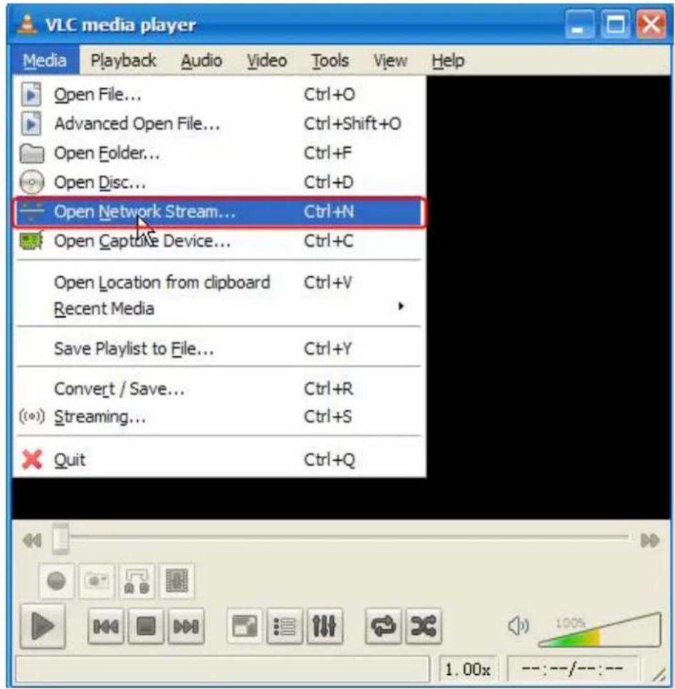
Open the VLC, and go to Media Open Network Stream option, then enter the URL into VLC.
text_image
VLC media player Media Playback Audio Video Tools View Help Open File... Ctrl+O Advanced Open File... Ctrl+Shift+O Open Folder... Ctrl+F Open Disc... Ctrl+D Open Network Stream... Ctrl+N Open Capture Device... Ctrl+C Open Location from clipboard Ctrl+V Recent Media Save Playlist to File... Ctrl+Y Convert / Save... Ctrl+R Streaming... Ctrl+S Quit Ctrl+Q 1.00x --:--/---: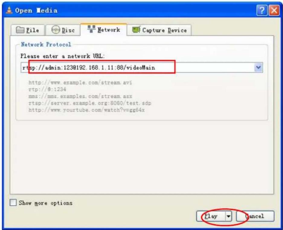
text_image
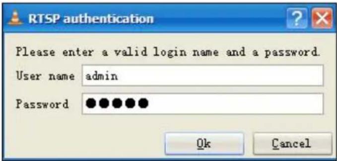
Open Media File Disc Network Capture Device Network Protocol Please enter a network URL: rtsp://admin:123@192.168.1.11:88/videoMain http://www.example.com/stream.avi rtp://0:1234 mms://mms.examples.com/stream.asx rtsp://server.example.org:8080/test.sdp http://www.yourtube.com/watch?v=gg64x Show more options Play CancelSometimes you may need to enter the user name and password again. Click OK and you can see real-time preview.
text_image
RTSP authentication Please enter a valid login name and a password. User name admin Password Ok Cancel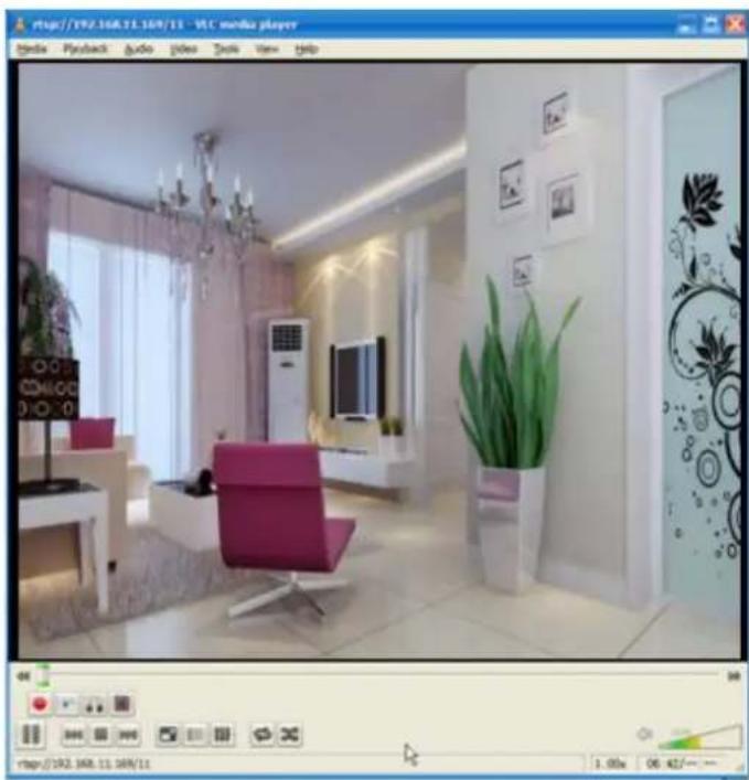
natural_image
Interior view of a modern living room with a pink chair, chandelier, and decorative wall art (no visible text or symbols)NOTE: If you modify the camera's username or password, you had better reboot the camera, or else the new username and password cannot take effect when you enter the authentication in the VLC.
3.5 IP Camera Connection to the Server
Device supports ONVIF 2.2.1 protocol, You can easily access the NVR with ONVIF or server with ON
3.6 Surveillance Software GUI
Please refer to the 3.1 Hardware Connection & Software Installation if you install the camera for the first time. You can start to learn about software operation after finish quick installation.
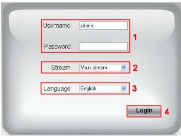
3.6.1 Login Window
text_image
Username admin Password Stream Main stream Language English Login 4Section1 Enter the Username and password
The default administrator username is admin with no password, please change the password at first using and prevent unauthorized users login the camera.
Section2 Stream
The camera supports two stream modes: Main stream and sub stream. If you want to access the c form LAN, here you can select Main stream. If you want to access the camera from Internet, here recommend sub stream.
NOTE: When the network bandwidth is bad you'd better select Sub Stream and the video will be more fluent.
Section3 Select the language
You can select the language you need by clicking on the language dropdown list.
Section4 login the camera
Click Login button.
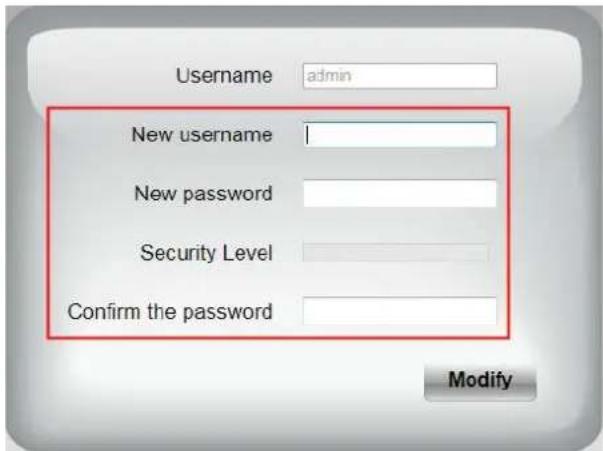
NOTE: When setting up your camera for the first time, it will request that you modify the default username / password if both are still set to default. Input the new username and password, click Modify to complete the modification. You will now use the new username and password to login the camera the future.
text_image
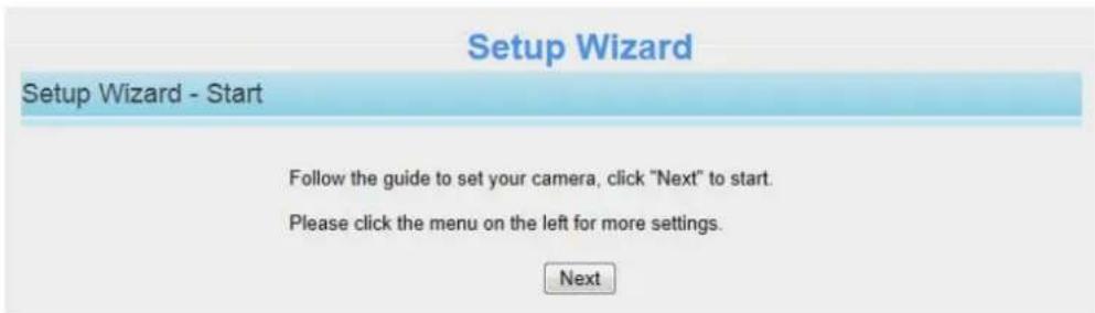
Username admin New username | New password Security Level Confirm the password ModifyAfter logging in for the first time, you will go to Setup Wizard automatically. Here you can set the basic parameters of camera, such as camera name, camera time, IP configuration.
text_image
Setup Wizard Setup Wizard - Start Follow the guide to set your camera, click "Next" to start. Please click the menu on the left for more settings. NextCountry: Select the country.
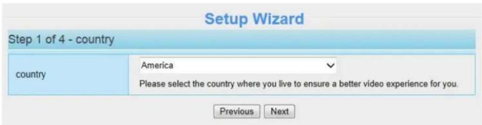
text_image
Setup Wizard Step 1 of 4 - country country America Please select the country where you live to ensure a better video experience for you. Previous NextDevice Name: You could give name for your camera.
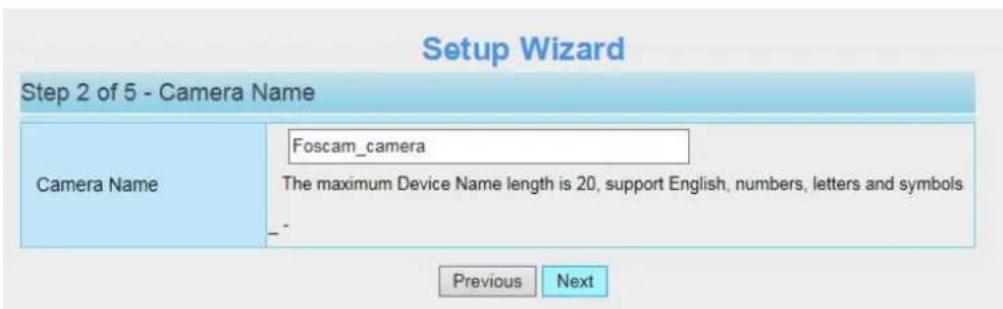
text_image
Setup Wizard Step 2 of 5 - Camera Name Camera Name Foscam_camera The maximum Device Name length is 20, support English, numbers, letters and symbols _- Previous NextSystem Time: Select the time zone you need to set the date, time, format, etc. IP: Set IP address of the camera. You could choose to obtain an IP automatically or set the IP address according to your needs.
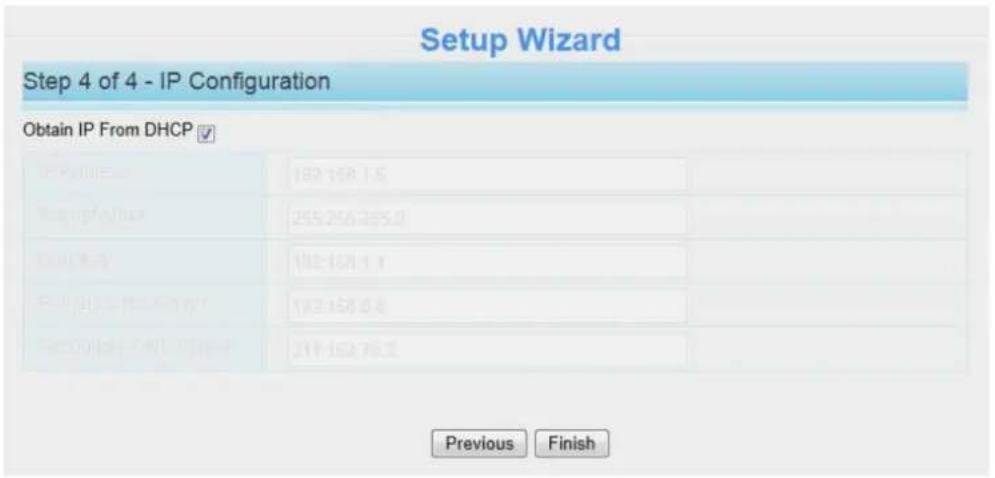
text_image
Setup Wizard Step 4 of 4 - IP Configuration Obtain IP From DHCP IP IP 182.158.1.5 Request other 255.256.255.0 IEI IP 182.158.1.7 IEI IP 182.158.0.8 IEI IP 219.152.76.0 Previous FinishClick Finish to finish setting.
3.6.2 Surveillance Window
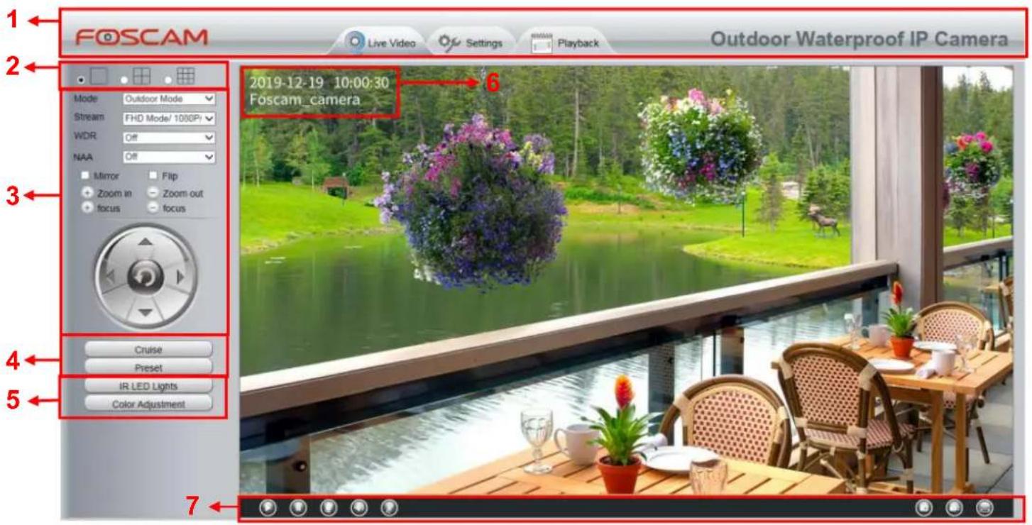
text_image
FOSCAM Live Video Settings Playback Outdoor Waterproof IP Camera 1 2 Mode Outdoor Mode Stream FHD Mode/ 1000P WDR Off NAA Off Mirror Flip Zoom in Zoom out focus focus Cruise Preset IR LED Lights Color Adjustment 6 2019-12-19 10:00:30 Foscam_camera 4 5 7Section 1 Live Video / Settings Buttons / Playback

LiveVideo

Settings
Settings: Path to Administrator Control Panel. Click it, and it will lead to Administrator Control P. and do advanced settings.

Playback
Path to playback window, click it to search / playback the records.
Section 2 Multi-Device Window

The firmware inside the camera supports up to maximum of 9 cameras being monitoring at the same time. You can add other cameras in multi-camera panel.
Section 3 Mode / Stream / WDR / NAA / Mirror / Flip Buttons / Zoom in / out Mode
1) 50Hz ----Indoor surveillance (Region: Europe, China)
2) 60Hz ----Indoor surveillance (Region: USA, Canada)
3) Outdoor Mode----Outdoor surveillance
Stream
The default stream supports multiple modes. For example: HD Mode / 1080P / 25fps / 4M meanings Stream type / Resolution / Maximum frame rate / Bit rate. (Different models support different specific mode.)
1) Stream type no. Identify the stream type.
2) Resolution
The bigger the resolution, the better of the image quality is. If you are accessing the camera via ir and want to get more fluent video streaming, please select resolution VGA.
3) Maximum frame rate
The maximum frame rate is 30 fps. You should lower frame rate when the bandwidth is limited. No when the frame rate above 15, you can achieve fluently video. The maximum frame rate for each r is different.
4) Bit Rate
Generally speaking, the larger the bit rate is, the clearer video will become. But the bit rate configu should combine well with the network bandwidth. When the bandwidth is very narrow, and bit rate is large, that will lead to video cannot play well.
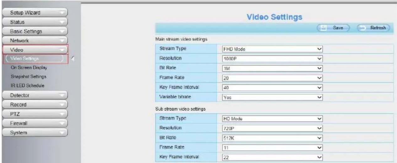
You can reset the stream type on Settings > Video > Video Settings panel.
text_image
Setup Wizard Status Basic Settings Network Video Video Settings On Screen Display Snapshot Settings IR LED Schedule Detector Record PTZ Firewall System Video Settings Main stream video settings Stream Type FHD Mode Resolution 1000P Bit Rate 1M Frame Rate 20 Key Frame Interval 40 Variable bitrate Yes Sub stream video settings Stream Type HD Mode Resolution 720P Bit Rate 512K Frame Rate 11 Key Frame Interval 22WDR: WDR stands for High Dynamic Range. It usually refers to the method of capturing images having "greater dynamic range between the lightest and darkest areas of an image than current standard digit imaging methods or photographic methods". You can select On from the dropdown list under sunlight or with bright background.
NAA: NAA (Network Auto-Adaptability) can make IP Camera changing the real-time rate to adapt different network conditions, which can supply better preview experience. It is OFF as default.
Zoom In or Zoom Out
Device Support 4x zoom feature, click or ,The focal length of the camera lens will be larger or shrink, you can adjust the focus distance to the target object size, access to high-definition screen.
Zoom Control
Zoom in the camera's lens.

Zoom out the camera' lens.
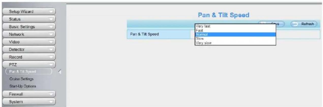
You can adjust the speed of the lens' zoom in Settings--PTZ--Pan & Tilt Speed--Zoom speed panel.
text_image
Setup Wizard Status Basic Settings Network Video Detector Record PTZ Pan & Tilt Speed Cruise Settings Start-Up Options Firewall System Pan & Tilt Speed Very fast Fast Normal Slow Very slowPan/Tilt Control
text_image
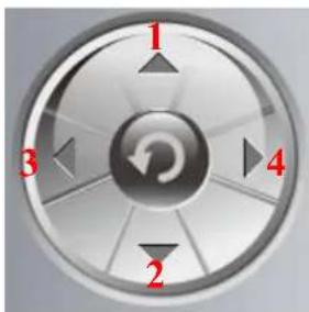
1 3 4 21---- Up control button, 2----Down control button, 3----Left control button, 4----Right control button

Click this button and go to center
Section 4 Cruise / Preset settings
Cruise Settings
text_image
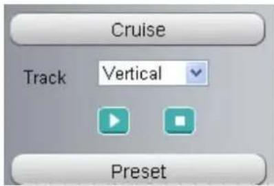
Cruise Track Vertical PresetThe default cruise tracks have two types: Vertical and Horizontal.
Vertical: The camera will rotate from up to down.
Horizontal: The camera will rotate from left to right.

Start cruise. : Stop cruise.
If you want to define or change the cruise trace, please go to Settings → PTZ Preset Settings panel.
How to do cruise?
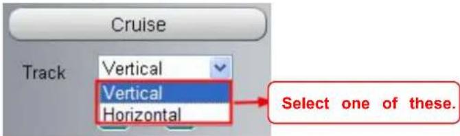
Firstly: Select one track in the track dropdown list.
text_image
Cruise Track Vertical Vertical Horizontal Select one of these.Secondly: Click Start cruise button, the camera will cruise following the predefined path.
Thirdly: Click stop button and finish cruising.
Preset settings
text_image
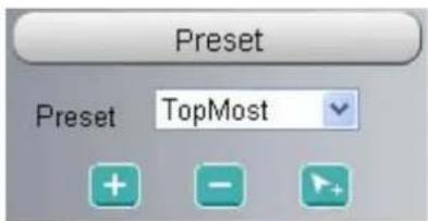
Preset Preset TopMostIPCam supports 16 preset positions, which is considered enough for DIY home & small business surveillance market
The default preset position is Topmost, Bottom most, Left most, right most, you can add other preset positions.

Add Click this icon to save the position you need the camera to remember

Delete Select one preset position and click this button to delete it.

GO Select one preset position in the preset drop-down list and click Go to make the camera move the preset position
How to do preset position?
Firstly, move the camera and stop at a desired place where you want make preset position.
Secondly, click + button and enter a descriptive name for the preset position. The preset position
cannot contain special characters. Then click OK to save it. If you want to reset the preset position Cancel.
After that, you can move the camera and stop at another place, and set another preset position. You do all the 16 preset positions with this method.
If you want to see one preset position you have set, only select the preset position name from the
drop-down list, and click go button, the camera will go to the preset position.
Section 5 IR LED Lights / Color Adjustment
IR LED Lights
text_image
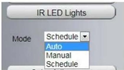
IR LED Lights Mode Schedule Auto Manual ScheduleClick Infra led and there are three modes to adjust the infrared led: Auto, Manual and Schedule.
Auto: Select it and the camera will adjust the infra led (on or off) automatically.
Manual: Select it and turn off the infra led manually.
Schedule: Select it and the IR led light will be off at the schedule period. If you want to define or change
the IR led lights schedule time, please go to Settings > Video > IR LED Schedule page.
Color Adjustment
In this page, you can tune Hue, Brightness, Contrast, Saturation, and Sharpness to get higher quality
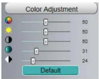
text_image
Color Adjustment 50 50 50 31 24 DefaultSection 6 OSD
If you have added time and camera name in the video, you can see it in the live window.
Go to Settings > Basic settings > Camera name panel, and you can change another device name.
The default device name is anonymous.
Go to Settings > Basic Settings > Camera time panel and adjust the device time.
Go to Settings > Video > On Screen Display panel, you can add or no add OSD.
Section 7 Play / Stop / Snap / Record / Full screen button
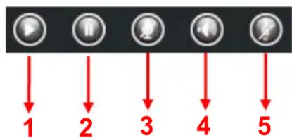
text_image
1 2 3 4 5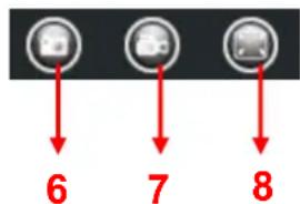
text_image
6 7 81----Play Click it to play the video of the camera
2----Stop Click it to stop the video of the camera
3---- Talk Click the button and the icon will become to, then talk to the microphone that connected with PC, people around the camera can hear your voice if the camera has connected with audio output device. Click the icon again and stop talking.
4---- Audio Click the button and the icon will become to, you can hear the sound around the camera if the camera has connected with other audio input device through the Audio Input port of t camera, Click the icon again and stop audio.
5---- Volume click it to open the volume control.
6---- Snap Click it to make snapshot and it pop up a window which picture you snapshot, right click in the window and save the picture to anywhere you want.
7---- Record Click the icon and the camera start recording, you can see a green dot in the live window. Click again and stop recording. The default storage path is C:\IPCamRecord. You can change the storage path: Go to Settings > Record > Storage Location panel.
8----Full Screen Click it to make full-screen, or you can double click the surveillance screen to make full-screen. Double click again and exit full-screen.
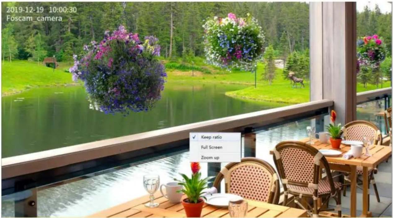
Onscreen Mouse Control
Right click the mouse and you can full screen and Zoom up.
text_image
2019-12-19 10:00:30 Foscam_camera ✓ Keep ratio Full Screen Zoom upFull Screen: Select it and Click it to make full-screen, press ESC and exit full-screen. Zoom Up / Down: Click it and the live view will be digital zoomed up, then click Zoom Down and the live view back to original size.
NOTE: For Mac OS, the plugin cannot support Onscreen Mouse function, so you cannot allow to use it.
3.7 Advanced Camera Settings
Click the button Settings, goes to Administrator Control Panel to make advanced camera settings.
3.7.1 Setup Wizard
After logging in for the first time, you will go to "Setup Wizard" automatically. Here you can set the parameters of camera, such as the camera name, camera time, IP configuration and so on.

text_image
Setup Wizard Setup Wizard - Start Follow the guide to set your camera, click "Next" to start. Please click the menu on the left for more settings. Next3.7.2 Status
Status contains four columns: Device Information, Device Status, Session Status and Log, it will show you various information about your camera.
3.7.2.1 Device Information
Device Information
| Camera Name | Foscam_Camera |
| Camera ID | A0E6EC012F32 |
| Camera Time | 2019/01/13 23:53:16 |
| System Firmware Version | 1.14.2.1 |
| Application Firmware Version | 2.102.2.2 |
| Plug-In Version | 5.0.0.3 |
Camera Name: The Device Name is a unique name that you can give to your device to help you identify it. Click Basic Settings and go to Device Name panel where you can change your camera name. T default device name is anonymous.
Camera ID: Display the MAC address of your camera. For example Device ID is A0E6EC012F32, the same MAC ID sticker is found at the bottom of the camera.
Camera Time: The system time of the device. Click Basic Settings and go to Camera Time panel and adjust the time.
System Firmware Version: Display the System Firmware version of your camera.
Application Firmware Version: Display the application firmware version of your camera.
Plug-In Version: Display the plug-in version of your camera
3.7.2.2 Device Status
On this page you can see device status such as Alarm status, NTP status, IR LED Status and so
Device Status
| Motion alarm status | Detect alarm |
| Sound alarm status | Disabled |
| Human Detection Alarm Status | Disabled |
| Recording Status | Not Recording |
| SD Card Status | No SD card |
| SD Card Free Space | 0KB |
| SD Card Total Space | 0KB |
| NTP Status | Failed |
| WiFi Status | Not connected |
| IR LED Status | Off |
3.7.2.3 Session Status
Session status will display who and which IP is visiting the camera now.
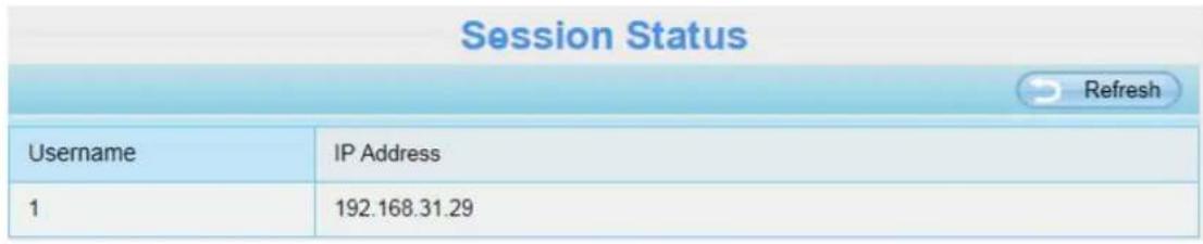
text_image
Session Status Refresh Username IP Address 1 192.168.31.293.7.2.4 Log
The log record shows who and which IP address accessed or logout the camera and when.
| NO. | Time | User | IP | Log |
| 1 | 2016-04-27 06:09:07 | root | 127.0.0.1 | Detected motion alarm |
| 2 | 2016-04-27 05:49:59 | 1 | 192.168.1.102 | Log out |
| 3 | 2016-04-27 05:48:31 | 1 | 192.168.1.102 | Login |
| 4 | 2016-04-27 05:48:17 | 1 | 192.168.1.102 | Log out |
| 5 | 2016-04-27 05:47:12 | 1 | 192.168.1.102 | Login |
| 6 | 2016-04-27 05:46:31 | 1 | 192.168.1.101 | Login |
| 7 | 2016-04-27 05:43:56 | root | 127.0.0.1 | Detected motion alarm |
| 8 | 2016-04-27 05:43:51 | root | 127.0.0.1 | Detected motion alarm |
| 9 | 2016-04-27 05:41:21 | root | 127.0.0.1 | Detected motion alarm |
| 10 | 2016-04-27 05:41:16 | root | 127.0.0.1 | Detected motion alarm |
Reboot the camera and clear the log records.
3.7.3 Basic Settings
This section allows you to configure your Camera Name, Camera Time, Mail, User Accounts and Multi-Device.
3.7.3.1 Camera Name
Default alias is Foscam_camera. You can define a name for your camera here such as apple. Click Save to save your changes. The alias name cannot contain special characters.
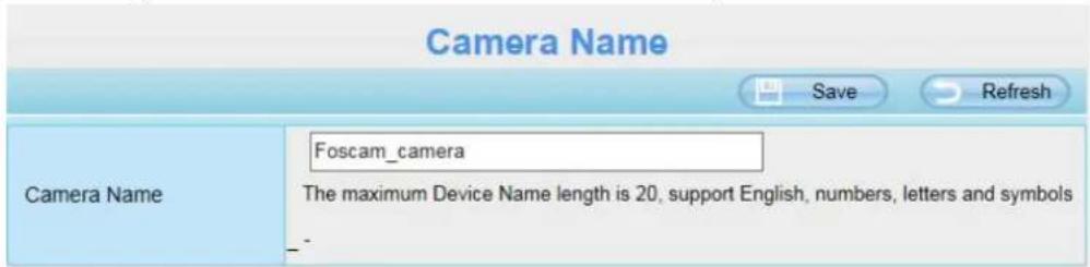
text_image
Camera Name Save Refresh Camera Name Foscam_camera The maximum Device Name length is 20, support English, numbers, letters and symbols -3.7.3.2 Camera Time
This section allows you to configure the settings of the internal system clocks for your camera.
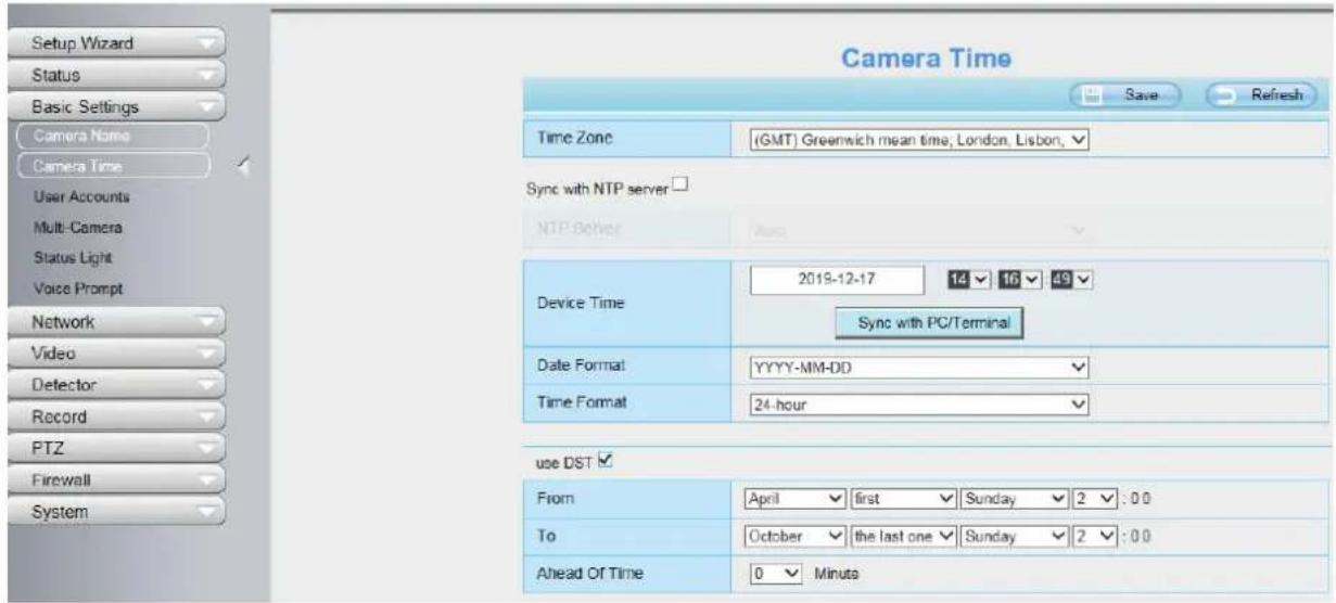
text_image
Setup Wizard Status Basic Settings Camera Name Camera Time User Accounts Multi-Camera Status Light Voice Prompt Network Video Detector Record PTZ Firewall System Camera Time Time Zone (GMT) Greenwich mean time, London, Lisbon. Sync with NTP server □ NTP Server Device Time 2019-12-17 14 16 49 Sync with PC/Terminal Date Format YYYY-MM-DD Time Format 24-hour use DST ✓ From April first Sunday 2 : 0.0 To October the last one Sunday 2 : 0.0 Ahead Of Time 0 MinutesTime Zone: Select the time zone for your region from the drop-down menu.
Sync with NTP server: Network Time Protocol will synchronize your camera with an Internet time ser Choose the one that is closest to your camera.
Sync with PC/Terminal: Select this option to synchronize the date and time of the Network Camera with your computer.
Manually: The administrator can enter the date and time manually. Please select the date and time format.
use DST: Select the use DST, then select the daylight saving time from the drop-down menu.
Click Save button to submit your settings.
NOTE: If the power supply of camera is disconnect, you need set the camera's time again.
3.7.3.3 User Accounts
Here you can create users and set privilege, visitor, operator or administrator. The default administrator user accounts are admin with a blank password.
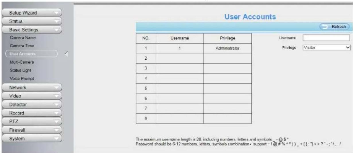
text_image
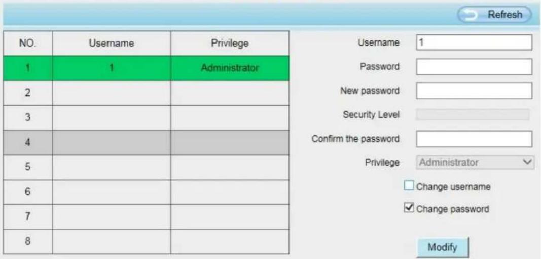
Setup Wizard Status Basic Settings Camera Name Camera Time User Accounts Multi-Camera Status Light Voice Prompt Network Video Detector Record PTZ Firewall System User Accounts NO. Username Privilege 1 1 Administrator 2 3 4 5 6 7 8 Username Privilege Visitor The maximum username length is 20, including numbers, letters and symbols _ - @ $* Password should be 6-12 numbers, letters, symbols combination, support -1 @ # % ^ * () _ + [}: " <> ?" - : '\ . / RefreshHow to change the password?
Firstly, select the account which you want to change the password, then select Change password, enter the old password and the new password, lastly click modify to take effect.
User Accounts
text_image
NO. Username Privilege 1 1 Administrator 2 3 4 5 6 7 8 Username 1 Password New password Security Level Confirm the password Privilege Administrator Change username Change password ModifyThe maximum username length is 20, including numbers, letters and symbols _ - @ \$ * Password should be 6-12 numbers, letters, symbols combination, support \~ ! @ # % ^ * () _ + { }: " | < > ? ' - ; '\ , /
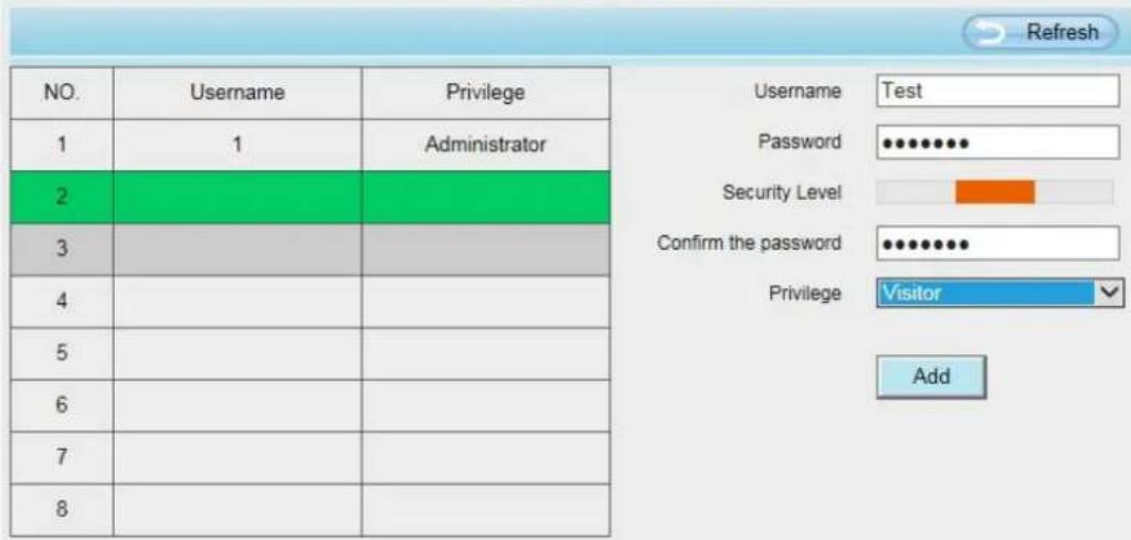
How to add account?
Select one blank column, then enter the new user name, password and privilege, last click Add to the effect. You can see the new added account on the Account list.
User Accounts
text_image
NO. Username Privilege 1 1 Administrator 2 3 4 5 6 7 8 Username Test Password ••••••••• Security Level Confirm the password ••••••••• Privilege Visitor AddThe maximum username length is 20, including numbers, letters and symbols _ - @ \$ * Password should be 6-12 numbers, letters, symbols combination, support \~ ! @ # % ^ * () _ + { }: " | < > ? ' - ; '\ , ./
text_image
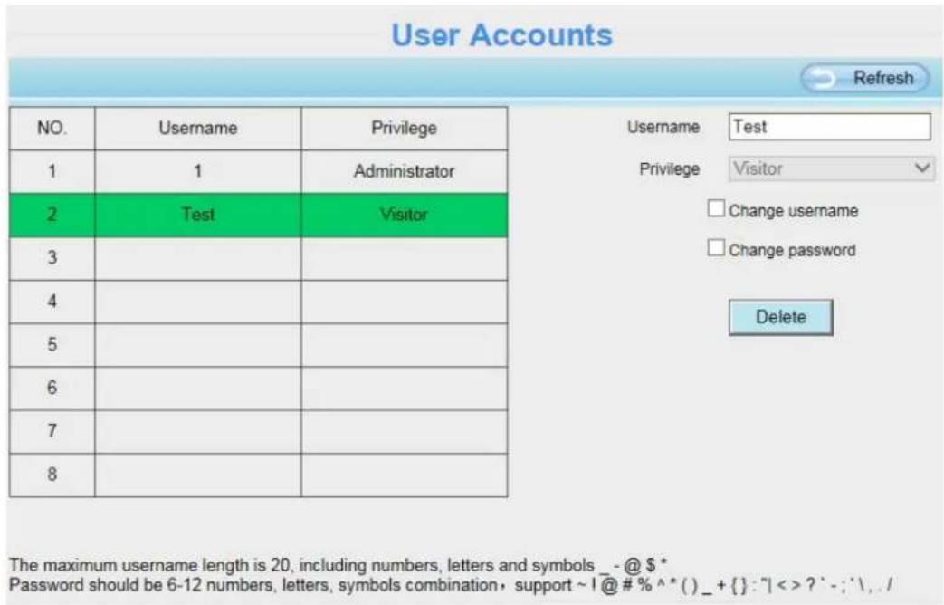
User Accounts NO. Username Privilege 1 1 Administrator 2 Test Visitor 3 4 5 6 7 8 Username Test Privilege Visitor Change username Change password Delete The maximum username length is 20, including numbers, letters and symbols _ @ $ * Password should be 6-12 numbers, letters, symbols combination, support ~!@ # % ^ * () _ + {}: "1 < > ? - ;"; /Delete: Select the account which you want to delete, then click Delete button to take effect.
NOTE: The default administrator account cannot be deleted, but you can add other administrator users.
3.7.3.4 Multi-Camera
If you want to view multi-surveillance screens on one window, you need to login one camera, and as the main device, and do Multi-Device Settings, add other cameras to the first one camera. Before do multi-cams settings, you need to assign different port such as 81, 82, 83, 84, 85, 86, 87, 88 to cameras if there is 8 cameras installed.
The firmware within the camera can support a maximum of 9 devices monitoring all at the same tin. This page you can both add FOSCAM MJPEG and H.264 series cameras to the first camera and v multi-surveillance screen on one window.
Add Cameras on LAN
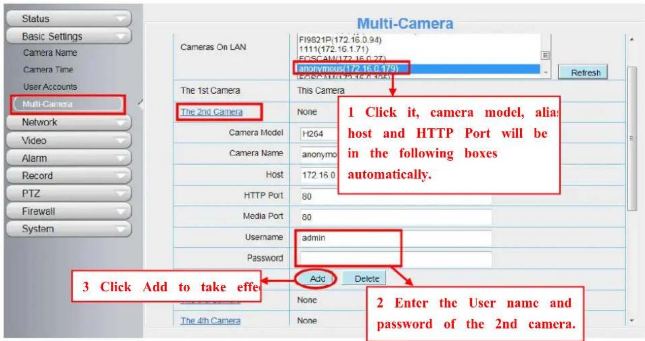
In Multi-Device Settings page, you can see all devices searched in LAN. The 1st Device is the default one. You can add more cameras in the list in LAN for monitoring. The camera's software supports IP Cameras online simultaneously. Click The 2nd Device and click the item in the Device List in LAN,
the Alias, Host and Http Port will be filled in the boxes below automatically. Enter the correct usern and password then click Add. Add more cameras in the same way.
text_image
Multi-Camera Camera On LAN FI9821P(172.16.0.94) 1111(172.16.1.71) ECSCAN(172.16.0.27) anonymous(172.16.0.179) The 1st Camera This Camera The 2nd Camera None Camera Model H264 Camera Name anonymous Host 172.16.0 HTTP Port 80 Media Port 80 Username admin Password Add Delete The 4th Camera None 3 Click Add to take effect 2 Enter the User name and password of the 2nd camera.Camera Model: Our Company produces two series cameras: MJPEG and H.264. Here will show you which series the camera belongs to.
| Cameras On LAN | anonymous(192.168.11.193) FI9821W for ebuyer (192.168.11.241) anonymous(192.168.11.203) anonymous(192.168.11.243) | Refresh |
| The 1st Camera | This Camera | |
| The 2nd Camera | anonymous(192.168.11.203) | |
| The 3rd Camera | FI9821W for ebuyer (192.168.11.241) | |
| The 4th Camera | anonymous(192.168.11.203) | |
| The 5th Camera | None | |
| The 6th Camera | None | |
| The 7th Camera | None | |
| The 8th Camera | None | |
| The 9th Camera | None | |
| Note: If you want to access your camera remotely, make sure you are able to access it separately through a browser. | ||
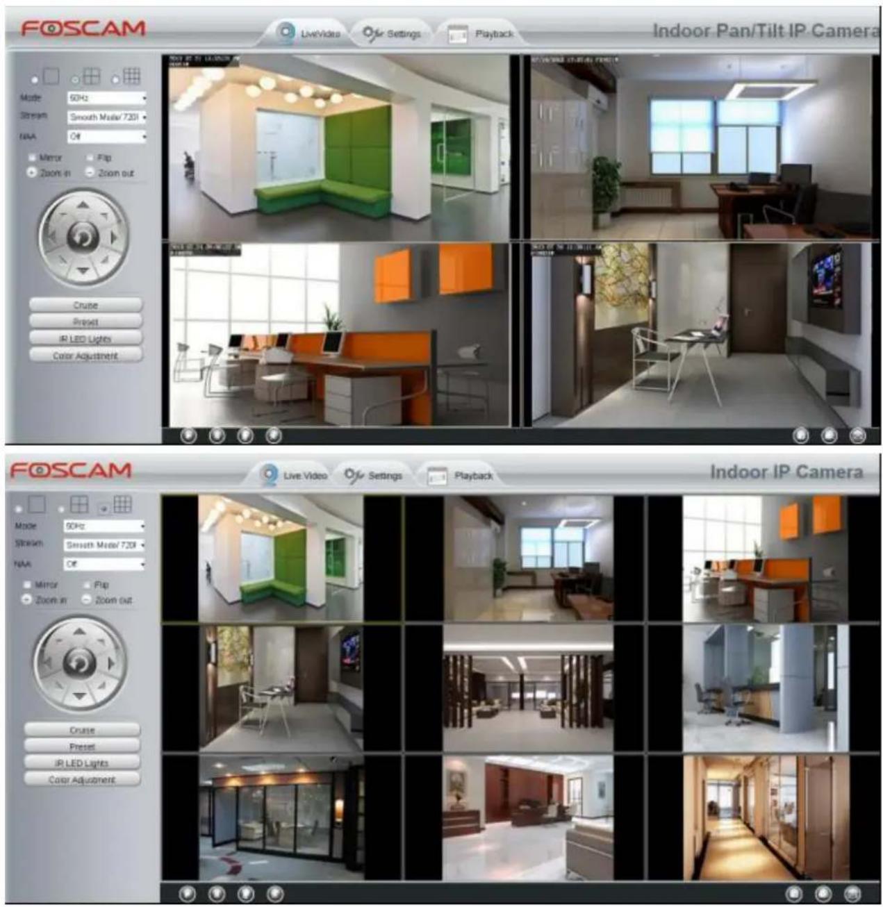
Back to Surveillance Windows, and click Four Windows option, you will see four cameras you added.
text_image
FOSCAM Live Video Settings Playback Indoor Pan/Tilt IP Camera Mode 50Hz Stream Smooth Media/720I NAA Off Mirror Flip Zoom-in Zoom out Cruise Reset IP LED Lights Color Adjustment FOSCAM Live Video Settings Playback Indoor IP Camera Mode 50Hz Stream Smooth Media/720I NAA Off Mirror Flip Zoom-in Zoom out Cruise Reset IP LED Lights Color Adjustment3.7.3.5 Status Light
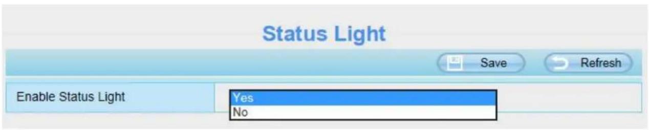
You can enable or disable status light.
text_image
Status Light Save Refresh Enable Status Light Yes No3.7.3.6 Voice Prompt
On this page, you can enable or disable voice prompt. Select "Yes" to enable or select "No" to dis If select "Yes", you can hear the voice prompt after connect the audio output device.

text_image
Voice Prompt Save Refresh Voice Prompt Yes No3.7.4 Network
This section will allow you to configure your camera's IP, Port, Mail Settings and FTP Settings and
3.7.4.1 IP Configuration
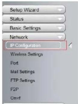
If you want to set a static IP for the camera, please go to IP Configuration page. Keep the camera in the same subnet of your router or computer.
text_image
Setup Wizard Status Basic Settings Network IP Configuration Wireless Settings Port Mail Settings FTP Settings F2P Onvt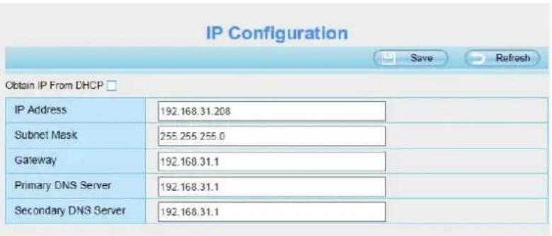
text_image
IP Configuration Obtain IP From DHCP □ IP Address 192.168.31.208 Subnet Mask 255.255.255.0 Gateway 192.168.31.1 Primary DNS Server 192.168.31.1 Secondary DNS Server 192.168.31.1Changing settings here is the same as using the Equipment Search Tool.
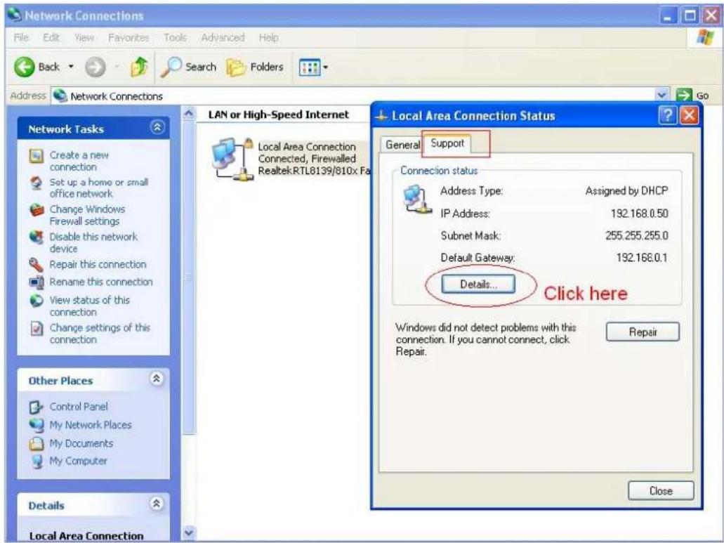
It is recommended that you use the subnet mask, gateway and DNS server from your locally attach PC. If you don't know the subnet mask, gateway and DNS server, you can check your computer's I area connection as follows:
Control Panel > Network Connections > Local Area Connections > Choose Support > Details.
text_image
Network Connections File Edit View Favorites Tools Advanced Help Back Search Folders Address Network Connections LAN or High-Speed Internet Local Area Connection Connected, Firewalled Realtek RTL8139/810x Fa Network Tasks Create a new connection Set up: a home or small office network Change Windows Firewall settings Disable this network device Repair this connection Rename this connection View status of this connection Change settings of this connection Other Places Control Panel My Network Places My Documents My Computer Details Local Area Connection Local Area Connection Status General Support Connection status Address Type: Assigned by DHCP IP Address: 192.168.0.50 Subnet Mask: 255.255.255.0 Default Gateway: 192.168.0.1 Details... Click here Windows did not detect problems with this connection. If you cannot connect, click Repair. Close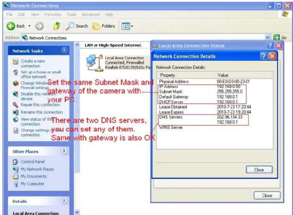
text_image
Network Connections File Edit View Favorites Tools Advanced Help Back Search Folders Address Network Connections LAN or High-Speed Internet Local Area Connection Status Network Connections Details Network Connection Details: Property Value Physical Address 00-E0-D0-00-23-01 IP Address 192.168.0.50 Subnet Mask 255.255.255.0 Default Gateway 192.168.0.1 DHCP Server 192.168.0.1 Lease Obtained 2010-7-23 17:20:44 Lease Expires 2010-7-23 19:20:44 DNS Servers 202.96.134.33 WINS Server Other Places Control Panel My Network Places My Documents My Computer Details Local Area Connection Set the same Subnet Mask and gateway of the camera with your PC. There are two DNS servers, you can set any of them. Same with gateway is also OK Close CloseIf you don't know the DNS server, you can use the same settings as the Default Gateway.
3.7.4.2 Wireless Settings
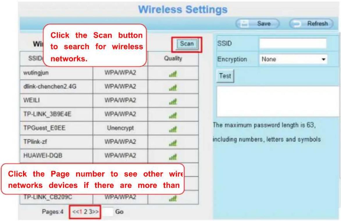
Step 1: Choose "Settings" on the top of the camera interface, and go to the "Network" panel on the left side of the screen, then click "Wireless Settings."
Click the Scan button and the camera will detect all wireless networks around the area. It should also display your router in the list.
text_image
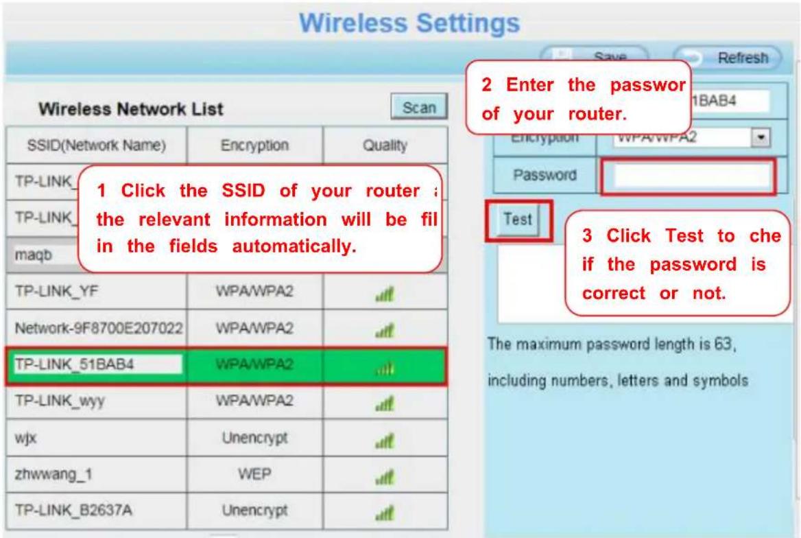
Wireless Settings Click the Scan button to search for wireless networks. Scan SSID Quality wutingjun WPA/WPA2 dlink-chenchen2.4G WPA/WPA2 WEILI WPA/WPA2 TP-LINK_3B9E4E WPA/WPA2 TPGuest_E0EE Unencrypt TPlink-zf WPA/WPA2 HUAWEI-DQB WPA/WPA2 Click the Page number to see other wire networks devices if there are more than TP-LINK_CB209C WPA/WPA2 Pages:4 <<1 2 3>> Go SSID Encryption None Test The maximum password length is 63, including numbers, letters and symbolsStep 2: Click the SSID (name of your router) in the list, the corresponding information related to your network, such as the name and the encryption, will be filled into the relevant fields automatically.
You will only need to fill in the password of your network. Make sure that the SSID, Encryption and password you filled in are exactly the same for your router.
text_image
Wireless Settings Wireless Network List Scan SSID(Network Name) Encryption Quality TP-LINK_ maqb 1 Click the SSID of your router; the relevant information will be fil in the fields automatically. TP-LINK_51BAB4 WPA/WPA2 TP-LINK_wyy WPA/WPA2 wjx Unencrypt zhwwang_1 WEP TP-LINK_B2637A Unencrypt 2 Enter the password of your router. Encryption WPA/WPA2 Password Test 3 Click Test to che if the password is correct or not. The maximum password length is 63, including numbers, letters and symbolsStep 3: Please click on the Save button after all settings have been entered and disconnect the network
cable. Never shut down the power of the camera until the IP camera is able to connect to the wir network.
The LAN IP address will disappear on the window of Equipment Search Tool when the camera is configuring a wireless connection. Wait about 1 minute, the camera should obtain a wireless connection and the LAN IP of the camera will show again on the window of the Equipment Search Tool. The address may have changed after the camera receives a wireless connection; we recommend setting a static local IP address if this IP address changes by right clicking the camera in Equipment Search setting a static IP, and pushing OK.
Congratulations! You have set up the wireless connection of the camera successfully.
NOTE :
If you fail to make a wireless connection, please refer to your seller or contact us directly for assi
3.7.4.3 Port
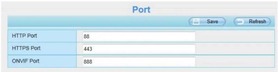
This camera supports HTTP Port. HTTP Port is used to access the camera remotely. If you want to access the camera and view the video, the HTTP Port must both be configured correctly.
text_image
Port HTTP Port 88 HTTPS Port 443 ONVIF Port 888 Save RefreshHTTP port: By default, the HTTP is set to 88. Also, they can be assigned with another port number between 1 and 65535. But make sure they can not be conflict with other existing ports like 25, 21.
Another way to change the HTTP port NO.
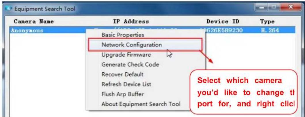
Step 1: Open the Equipment Search Tool, select the camera you would like to change the port of, right click on the IP address, and click on "Network Configuration", this brings up the network configuration box as flowing figures.
text_image
Equipment Search Tool Camera Name IP Address Device ID Type Anonymous Basic Properties 0626E589230 H. 264 Network Configuration Upgrade Firmware Generate Check Code Recover Default Refresh Device List Flush Arp Buffer About Equipment Search Tool Select which camera you'd like to change tl port for, and right clic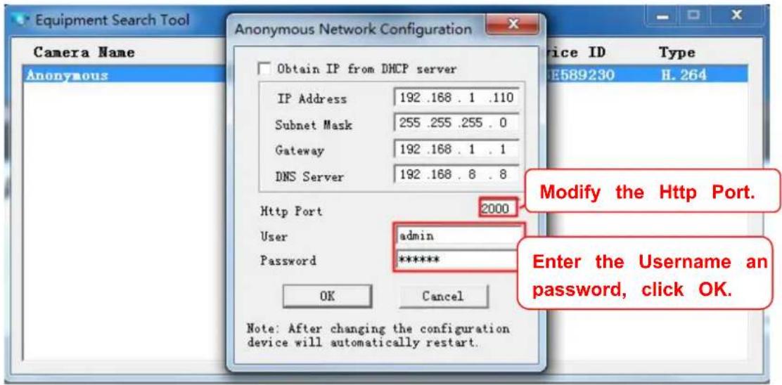
text_image
Equipment Search Tool Camera Name Anonymous Anonymous Network Configuration Obtain IP from DHCP server IP Address 192 .168 . 1 .110 Subnet Mask 255 .255 .255 . 0 Gateway 192 .168 . 1 . 1 DNS Server 192 .168 . 8 . 8 Http Port 2000 User admin Password ***** OK Cancel Note: After changing the configuration device will automatically restart. Modify the Http Port. Enter the Username an password, click OK.Step 2: Enter the username and password of the Administrator (default username is admin with a blank
password), and click "OK" to apply changes.
Step 3: Wait around 10 seconds, you'll see that the camera's LAN IP address has changed. In our example it was changed to 2000, so we see http://192.168.1.110:2000 in Equipment Search Tool. Also the LAN IP address is now fixed at a static IP address of http://192.168.1.110:2000. This IP address not change even if the camera is powered off and back on, the camera will remain on this LAN IP address. This is very important that a static LAN IP address is set, or you may have problems late remote access and seeing the camera remotely if the camera loses power and reconnects on a different LAN IP address. Make sure you set a static LAN IP address!
| Camera Name | IP Address | Device ID | Type |
| Anonymous | Http://192.168.1.110:2000 | 00626E589230 | H. 264 |
If the camera cannot be accessed, please make sure the port forwarding is succeed.
HTTPS port: The default port is 443. You can use the url to access the camera: https://IP+HTTPSport.
ONVIF port: By default, the ONVIF port is set to 888. Also, they can be assigned with another port number between 1 and 65535(except 0 and 65534). But make sure they can not be conflict with ot existing ports.
3.7.4.4 Mail Settings
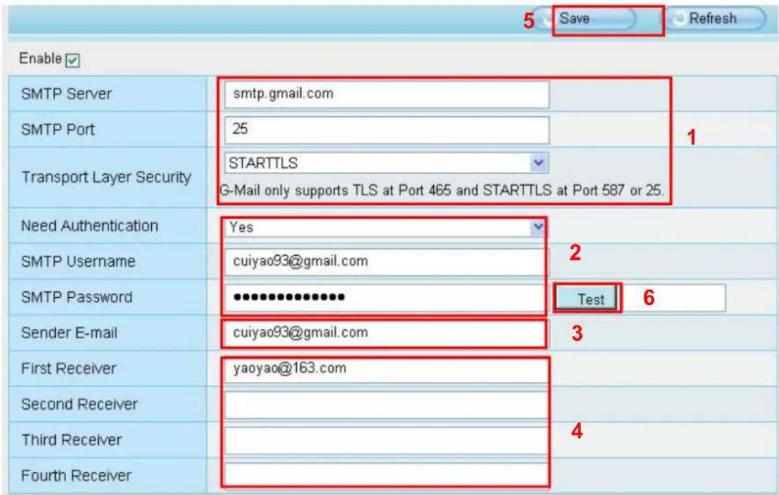
If you want the camera to send emails when motion has been detected, here Mail will need to be configured.
text_image
5 Save Refresh Enable ✓ SMTP Server smtp.gmail.com SMTP Port 25 1 Transport Layer Security STARTTLS G-Mail only supports TLS at Port 465 and STARTTLS at Port 587 or 25. Need Authentication Yes SMTP Username cuiyao93@gmail.com 2 SMTP Password •••••••••••• Test 6 Sender E-mail cuiyao93@gmail.com 3 First Receiver yaoyao@163.com Second Receiver Third Receiver 4 Fourth Receiver1---- SMTP Server / Port / Transport Layer Security Enter SMTP server for sender. SMTP port is usually set as 25. Some SMTP servers have their own port, such as 587 or 465, and Transport Layer Security usually is None. If you use Gmail, Transport Layer Security must be set to TLS or START and SMTP Port must be set to 465 or 25 or 587, which port you choose should be decided by w Transport Layer Security you select.
2----SMTP Username / password ID account and password of the sender email address
3---- Sender E-mail Mailbox for sender must support SMTP
4---- Receiver Mailbox for receiver need not support SMTP, you can set 4 receivers
5---- Save Click Save to take effect
6---- Test Click Test to see if Mail has been successfully configured.
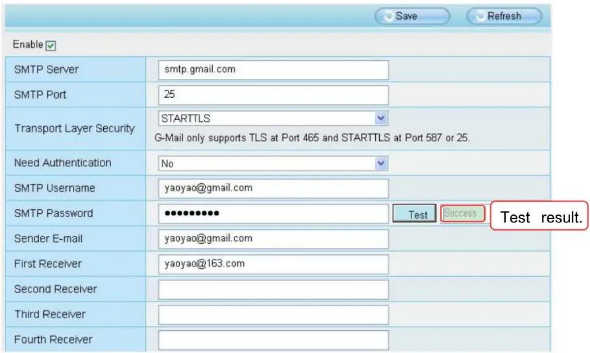
Click Test to see if Mail has been successfully configured.
text_image
Enable SMTP Server smtp.gmail.com SMTP Port 25 Transport Layer Security STARTTLS G-Mail only supports TLS at Port 465 and STARTTLS at Port 587 or 25. Need Authentication No SMTP Username yaoyao@gmail.com SMTP Password ●●●●●●●●● Test Success Test result. Sender E-mail yaoyao@gmail.com First Receiver yaoyao@163.com Second Receiver - Third Receiver - Fourth ReceiverIf the test success, you can see the Success behind the Test, at the same time the receivers will a test mail.
If the test fails with one of the following errors after clicking Test, verify that the information you er correct and again select Test.
1) Cannot connect to the server.
2) Network Error. Please try later.
3) Server Error.
4) Incorrect user or password.
5) The sender is denied by the server. Maybe the server need to authenticate the user, please che and try again.
6) The receiver is denied by the server. Maybe because of the anti-spam privacy of the server.
7) The message is denied by the server. Maybe because of the anti-spam privacy of the server.
8) The server does not support the authentication mode used by the device.
3.7.4.5 FTP Settings
If you want to upload record images to your FTP server, you can set FTP Settings.
| FTP Server | ftp://192.1681.8.150 Example:ftp://192.168.1.103/dir The maximum length of the address is 127, does not support the character & = |
| Port | 21 |
| FTP Mode | PASV |
| Username | user The maximum length of the user name is 63, support numbers, letters and symbols_@ $ * - , . # ! |
| Password | ●●●●●| The maximum password length is 63, including numbers, letters and symbols ~! @ # $ % ^ * () _ + {} : " | <> ? ` - ; ', _ / |
| Test | FTP server address error |
FTP server: If your FTP server is located on the LAN, you can set as Figure as above. If you have an FTP server which you can access on the internet, you can set as below.
| FTP Server | ftp://ftp.mgenseal.com Example:ftp://192.168.1.103/dir The maximum length of the address is 127, does not support the character & = |
| Port | 21 |
| FTP Mode | PASV |
| Username | user The maximum length of the user name is 63, support numbers, letters and symbols_@ $ * - , . # ! |
| Password | ●●●●● The maximum password length is 63, including numbers, letters and symbols ~! @ # $ % ^ * () _ + {}: " | < > ? ` - ; '\ , . / |
| Test | Success |
Port: Default is port 21. If changed, external FTP client program must change the server connection port accordingly.
FTP Mode: Here supports two modes: PORT and PASV.
Username / password: The FTP account and password.
Click Save to take effect.
Click Test to see if FTP has been successfully configured.
3.7.4.6 P2P
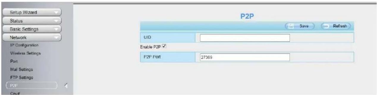
Access the camera by smart phone (Android or iOS operating system), please refer to the Quick Setup Guide.
First of all, you need to open the P2P function of the camera at Settings > Network > P2P.
text_image
Setup Wizard Status Basic Settings Network IP Configuration Wireless Settings Port Mail Settings FTP Settings P2P Cnft P2P UID Enable P2P ✓ P2P Port 27369 Save Refresh3.7.4.7 Onvif
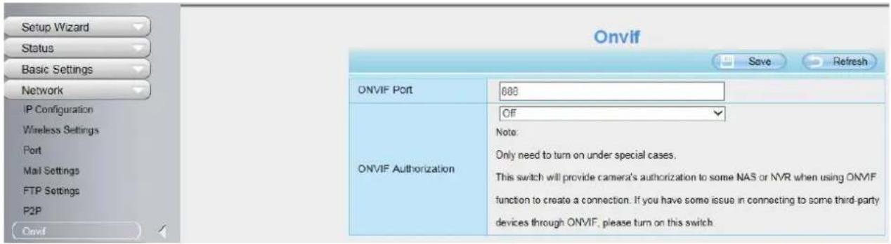
By default, the ONVIF port is set to 888. Also, they can be assigned with another port number bet and 65535(except 0 and 65534). But make sure they can not be conflict with other existing ports.
text_image
Setup Wizard Status Basic Settings Network IP Configuration Wireless Settings Port Mail Settings FTP Settings P2P Onvif Onvif Port 888 ONVIF Authorization Off Note: Only need to turn on under special cases. This switch will provide camera's authorization to some NAS or NVR when using ONVIF function to create a connection. If you have some issue in connecting to some third-party devices through ONVIF, please turn on this switch.3.7.5 Video
This section allows you to configure Video stream settings, On screen display and Snapshot settings.
3.7.5.1 Video Settings
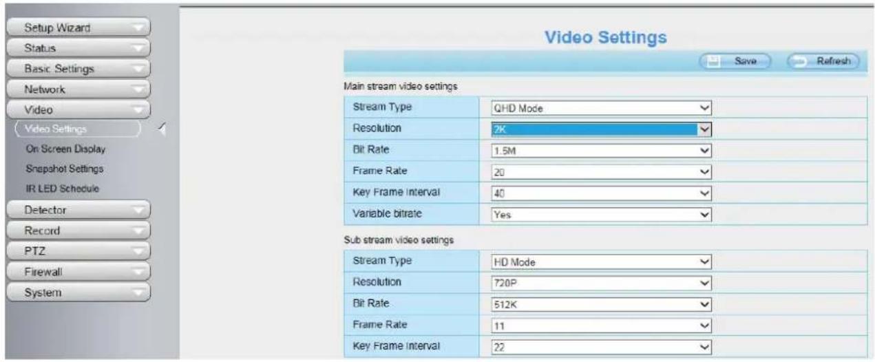
There are two ways to set the stream video settings. They are main stream video settings and substream video settings.
text_image
Setup Wizard Status Basic Settings Network Video Video Settings On Screen Display Snapshot Settings IR LED Schedule Detector Record PTZ Firewall System Video Settings Save Refresh Main stream video settings Stream Type QHD Mode Resolution 2K Bit Rate 1.5M Frame Rate 20 Key Frame Interval 40 Variable bitrate Yes Sub stream video settings Stream Type HD Mode Resolution 720P Bit Rate 512K Frame Rate 11 Key Frame Interval 22Stream Type: There are four types to identify different streams you have set. If select the HD Mode, the clearer video will become, and it will take up more bandwidth.
Resolution: The camera supports multiple types, For example: 2K, 1080P, 720P, VGA. The higher the resolution is, the clearer video will become. But the code flux will become larger too, and it will take more bandwidth. (Different models support different specific types.)
Bit Rate: Generally speaking, the larger the bit rate is, the clearer video will become. But the bit rate configuration should combine well with the network bandwidth. When the bandwidth is very narrow, an bit rate is large, that will lead to video can not play well.
Frame Rate: Note that a larger frame size takes up more bandwidth. You should lower frame rate when the bandwidth is limited. Normally, when the frame rate above 15, you can achieve fluently video. The maximum frame rate for each model is different.
Key Frame Interval: The time between last key frame and next key frame. The shorter the duration, the more likely you will get a better video quality, but at the cost of higher network bandwidth consump
Variable bitrate: The camera will change the video bit rate according to the situation, but will not more than the maximum parameter "Bit Rate". You can select "Yes" or "No" to turn on and off Variable Bitate
3.7.5.2 On Screen Display
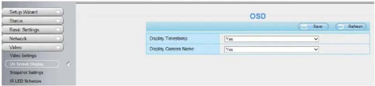
This page is used to add timestamp and device name on the video.
text_image
Setup Wizard Status Basic Settings Network Video Video Settings On Screen Display Snapshot Settings IR LED Schedule OSD Save Refresh Display Timestamp Yes Display Camera Name YesDisplay Timestamp: There are two options: Yes or NO. Select Yes and you can see the system date on the video.
Display Camera Name: There are two options: Yes or NO. Select Yes and you can see the device name
on the video.
3.7.5.3 Snapshot Settings
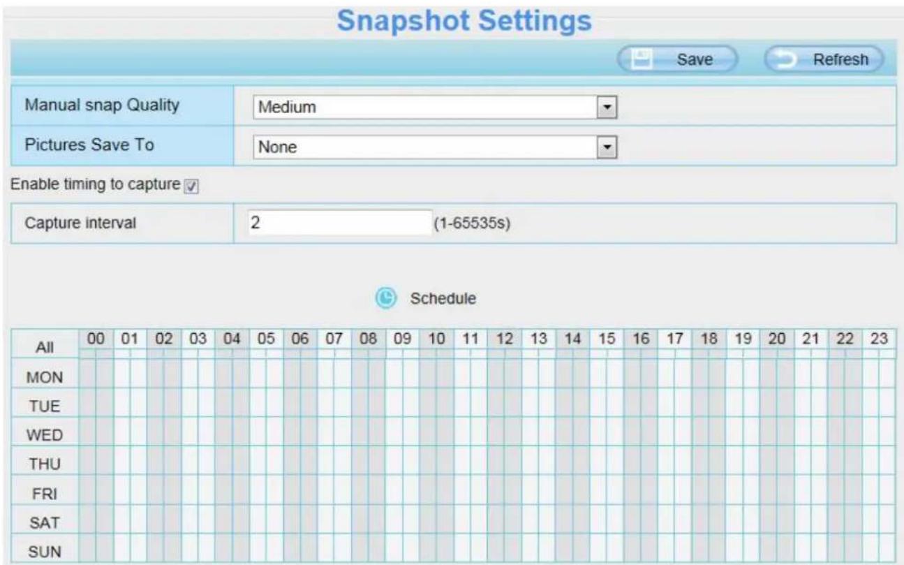
In this page you can set the snapshot pictures' image quality and the storage path.
text_image
Snapshot Settings Save Refresh Manual snap Quality Medium Pictures Save To None Enable timing to capture ✓ Capture interval 2 (1-65535s) Schedule All 00 01 02 03 04 05 06 07 08 09 10 11 12 13 14 15 16 17 18 19 20 21 22 23 MON TUE WED THU FRI SAT SUNManual snap Quality: Low, Middle and High. The higher the quality, the picture will be clearer. Pictures Save To: FTP or SD card. If you have done FTP and Alarm settings, when alarming, the camera will snap pictures to the FTP or SD card automatically.
If you select the FTP, you can set the file name which the picture save to. For example: file name "NAME", the snapshot picture is "NAME_20150605-180000.jpg".
Enable timing to capture
To enable capture interval, follow the steps below:
1 Select Enable timing to capture
2 Capture interval: The interval time between two captures.
3 Select the capture time
- Capture anytime
Click the black button up the MON, you will see all time range turn red. When something moves the detection area at anytime, the camera will capture. - Specify an capture schedule
Click the week day words, the corresponding column will be selected. For example, click TUE, that all column of TUE turns to red, that means during Tuesday whole day, the camera will capture. - Press the left mouse and drag it on the time boxes, you can select the serial area,
4 Click Save button to take effect.
3.7.5.4 IR LED Schedule
On this page you can set the schedule time for switching IR LED lights. When parameter Mode is the Schedule on the Live Video window, At these schedule time, the IR LED lights will be turned off.

text_image
IR LED Schedule Turn the IR LED off From 00:00 00:00 Add Save Refresh3.7.6 Detection
This section allows you to configure Motion Detection and Motion Sound Detection.
3.7.6.1 Motion Detection
IP Camera supports Motion Detection Alarm, when the motion has been detected, it will send emails or upload images to FTP.
text_image
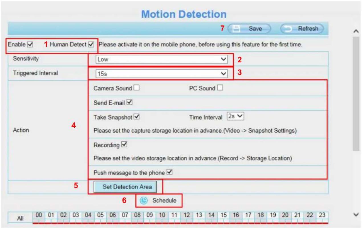
Motion Detection 7 Save Refresh Enable ✓ 1 Human Detect ✓ Please activate it on the mobile phone, before using this feature for the first time. Sensitivity Low 2 Triggered Interval 15s ✓ 3 Action 4 Camera Sound □ PC Sound □ Send E-mail ✓ Take Snapshot ✓ Time Interval 2s ✓ Please set the capture storage location in advance.(Video -> Snapshot Settings) Recording ✓ Please set the video storage location in advance.(Record -> Storage Location) Push message to the phone ✓ 5 Set Detection Area 6 Schedule All 00 01 02 03 04 05 06 07 08 09 10 11 12 13 14 15 16 17 18 19 20 21 22 23To enable motion detection, follow the steps below:
1 Enable Motion detection and Human Detect
2 Sensitivity--- The higher the sensitivity, the camera will be more easily alarmed. Select one motion sensitivity.
3 Trigger interval--- The interval time between two motion detections. Here supports 5s / 6s / 7s / 8s / 9s / 10s / 11s / 12s / 13s / 14s / 15s. Select one interval time.
4 There are some alarm indicators:
A Camera Sound and PC Sound
If the camera has connected with a speaker or other audio output device, if you select Camera Source PC Sound, when the motion has been detected, the people around the camera will hear beep alarm sound.
B Send E-mail
If you want to receive alarm emails when motion is detected, you must select Send E-mail and set Settings first.
C Take Snapshot
If you select this checkbox, when the motion has been detected, the camera will snap the live view window as a still picture and load it to the FTP. Make sure you have set FTP and set FTP as the path in Video > Snapshot settings panel.
Time interval: The interval time between two pictures.
D Recording
If you select this checkbox, when the motion has been detected, the camera will recording and load the FTP server. Make sure you have set FTP and set FTP as the storage path in Video > Snapchat settings panel.
E Push message to the phone
If you select this checkbox, when the motion has been detected, the camera will push the message the phone which has been connected the camera.
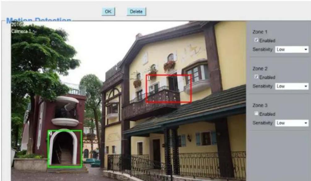
5 Set Detection Area
Click set detect area and it pop up a window, then you can draw the detection area. Click Back b after settings. When something moving in the detection area, the camera will alarm.
text_image
OK Delete Motion Detection 2016-01-01 Camera 1 Zone 1 Enabled Sensitivity Low Zone 2 Enabled Sensitivity Low Zone 3 Enabled Sensitivity Low6 Alarm Schedule
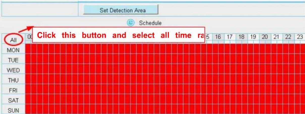
① Alarm anytime when motion is detected
Click the black button up the MON, you will see all time range turn red. When something moving i detection area at anytime, the camera will alarm.
text_image
Set Detection Area Schedule Click this button and select all time ra All 00 5 16 17 18 19 20 21 22 23 MON TUE WED THU FRI SAT SUN② Specify an alarm schedule
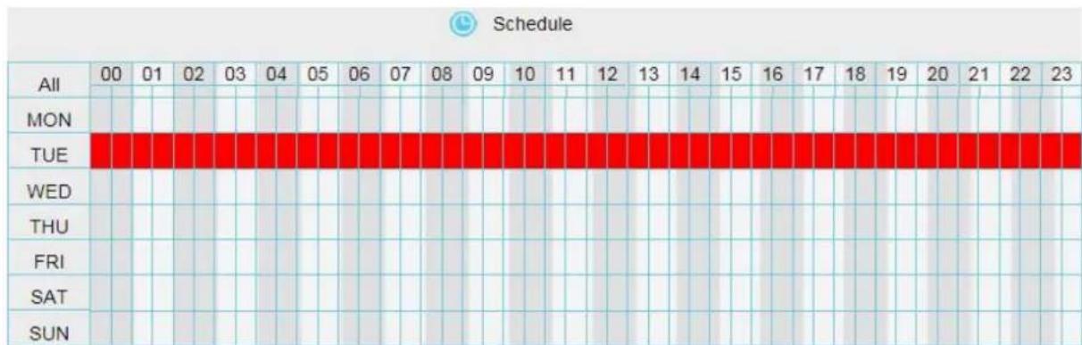
Click the week day words, the corresponding column will be selected. For example, click TUE, the a column of TUE turns to red, that means during Tuesday whole day, when something moving in the detection area, the camera will alarm.
text_image
Schedule All 00 01 02 03 04 05 06 07 08 09 10 11 12 13 14 15 16 17 18 19 20 21 22 23 MON TUE WED THU FRI SAT SUN③ Press the left mouse and drag it on the time boxes, you can select the serial area,

text_image
Set Detection Area Schedule All 00 01 02 03 04 05 06 07 08 09 10 11 12 13 14 15 16 17 18 19 20 21 22 23 MON TUE WED THU FRI SAT SUN When the PC sound alarm is enabled, the PC will make a sound only in Live Video page while the IPC detected an alarm7 Click Save button to take effect. When the motion is detected during the detection time in the detection area, the camera will alarm and adopt the corresponding alarm indicators.
NOTE: You must set the detection area and detection schedule, or else there is no alarm anywhere and anytime.
3.7.6.2 Sound Detection
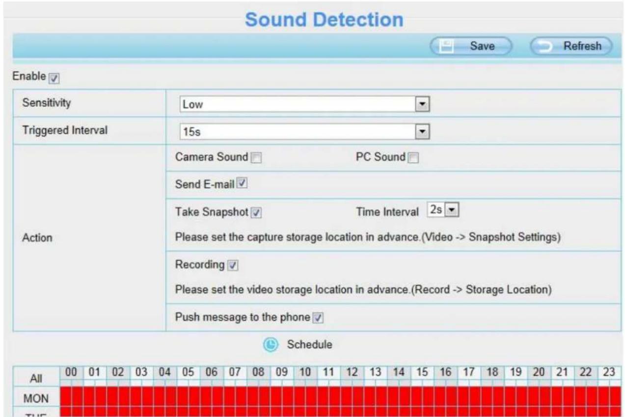
When the ambient sound over a certain decibel, the sound alarm will be triggered.
text_image
Sound Detection Save Refresh Enable ✓ Sensitivity Low Triggered Interval 15s Action Camera Sound PC Sound Send E-mail ✓ Take Snapshot ✓ Time Interval 2s ✓ Please set the capture storage location in advance.(Video -> Snapshot Settings) Recording ✓ Please set the video storage location in advance.(Record -> Storage Location) Push message to the phone ✓ Schedule All 00 01 02 03 04 05 06 07 08 09 10 11 12 13 14 15 16 17 18 19 20 21 22 23 MON ✓ ✓ ✓ ✓ ✓ ✓ ✓ ✓ ✓ ✓ ✓ ✓ ✓ ✓ ✓ ✓ ✓ ✓ ✓ ✓ ✓ ✓ ✓ ✓ ✓ ✓ ✓ ✓ ✓ ✓ ✓ ✓ ✓ ✓ ✓ ✓ ✓ ✓ ✓ ✓ ✓ ✓ ✓ ✓ ✓ ✓ ✓ ✓ ✓ ✓ ✓ ✓ ✓ ✓ ✓ ✓ ✓ ✓ ✓ ✓ ✓ ✓ ✓ ✓ ✓ ✓ ✓ ✓ ✓ ✓ ✓ ✓ ✓ ✓ ✓ ✓ ✓ ✓ ✓ ✓ ✓ ✓ ✓ ✓ ✓ ✓ ✓ ✓ ✓ ✓ ✓ ✓ ✓ ✓ ✓ ✓ ✓ ✓ ✓ ✓✓If the Sensitivity is set to "High", the camera will detect the sound whose more than 55db. If the Sensitivity is set to "Medium", the camera will detect the sound whose more than 65db. If the Sensitivity is set to "Low", the camera will detect the sound whose more than 75db.
If the Sensitivity is set to "Lower", the camera will detect the sound whose more than 85db. If the Sensitivity is set to "Lowest", the camera will detect the sound whose more than 95db.
3.7.7 Record
3.7.7.1 Storage Location
text_image
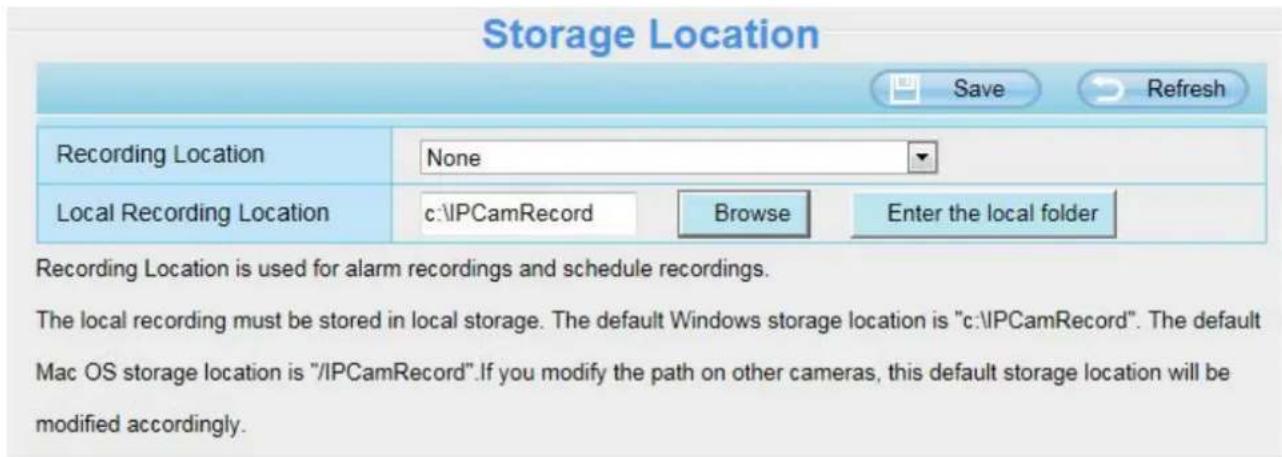
Storage Location Save Refresh Recording Location None Local Recording Location c:\IPCamRecord Browse Enter the local folder Recording Location is used for alarm recordings and schedule recordings. The local recording must be stored in local storage. The default Windows storage location is "c:\IPCamRecord". The default Mac OS storage location is "/IPCamRecord".If you modify the path on other cameras, this default storage location will be modified accordingly.Recording Location: SD card, FTP.
- SD card: The video will be saved in SD card. Make sure the camera has been inserted the SD card. On this page, you can see the available space of the SD card.
- FTP: The video will be saved in FTP. Please refer to 3.7.4.5 FTP Settings.
Local Recording Location: For Windows OS, the manual recording path is C:/ IPCamRecord, you can change another one. For MAC OS, the manual recording path is: / IPCamRecord.
Enter the local folder: Click here, you can enter the local folder.
3.7.7.2 Alarm Recording
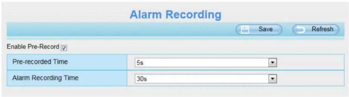
text_image
Alarm Recording Save Refresh Enable Pre-Record Pre-recorded Time 5s Alarm Recording Time 30s3.7.7.3 Local Alarm Recording
On this page you can enable local alarm record, and select the local alarm record time.
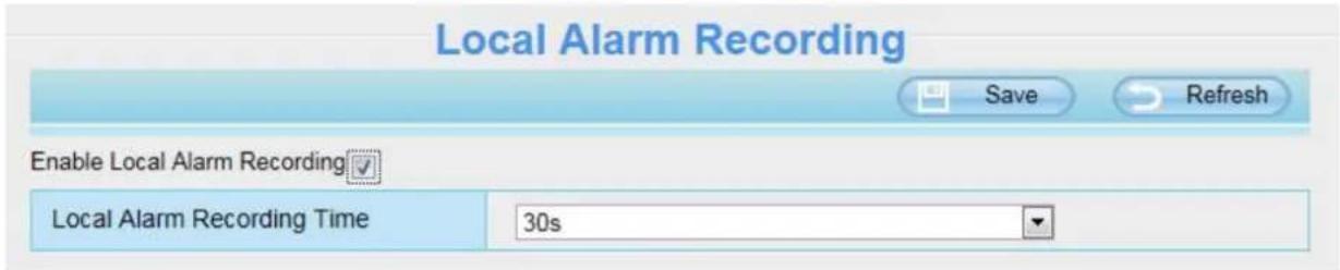
text_image
Local Alarm Recording Save Refresh Enable Local Alarm Recording Local Alarm Recording Time 30s3.7.7.4 Schedule Recording
When the video is selected as FTP, the device supports scheduled recording.
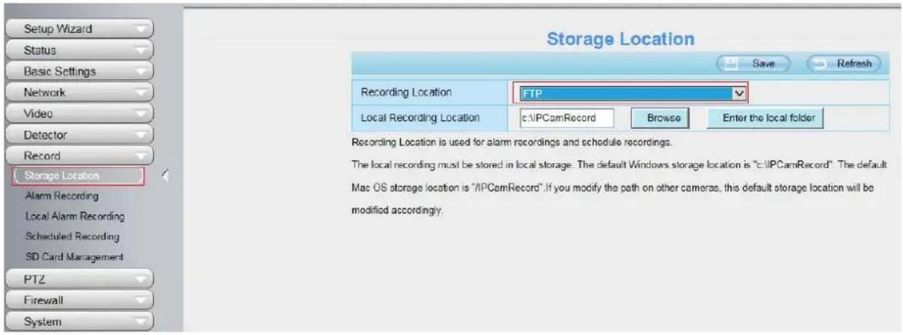
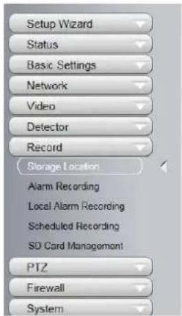
text_image
Setup Wizard Status Basic Settings Network Video Detector Record Storage Location Alarm Recording Local Alarm Recording Scheduled Recording SD Card Management PTZ Firewall System Storage Location Save Refresh Recording Location FTP Local Recording Location c:\IPCamRecord Browse Enter the local folder Recording Location is used for alarm recordings and schedule recordings. The local recording must be stored in local storage. The default Windows storage location is "c:\IPCamRecord". The default Mac OS storage location is "IPCamRecord". If you modify the path on other cameras, this default storage location will be modified accordingly.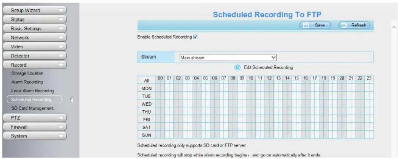
text_image
Scheduled Recording To FTP Enable Scheduled Recording ✓ Stream Main stream Edit Scheduled Recording All 00 01 02 03 04 05 06 07 08 09 10 11 12 13 14 15 16 17 18 19 20 21 22 23 MON TUE WED THU FRI SAT SUN Scheduled recording only supports SD card or FTP server. Scheduled recording will stop while alarm recording begins, and go on automatically after it ends.When the video is selected as SD card, the device supports pumping frame recording.
text_image
Setup Wizard Status Basic Settings Network Video Detector Record Storage Location Alarm Recording Local Alarm Recording Scheduled Recording SD Card Management PTZ Firewall System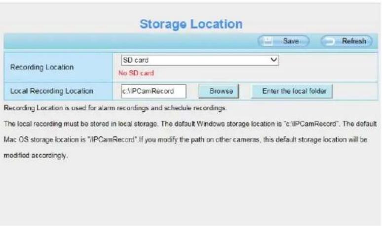
text_image
Storage Location Save Refresh Recording Location SD card No SD card Local Recording Location c:\IPCamRecord Browse Enter the local folder Recording Location is used for alarm recordings and schedule recordings. The local recording must be stored in local storage. The default Windows storage location is "c:\IPCamRecord". The default Mac OS storage location is "IPCamRecord" If you modify the path on other cameras, this default storage location will be modified accordingly.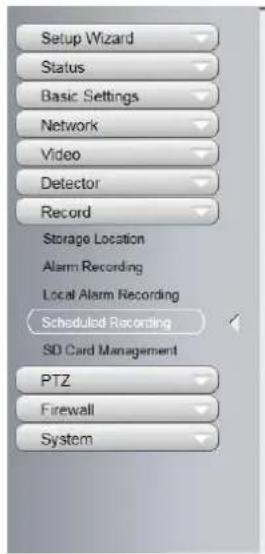
text_image
Setup Wizard Status Basic Settings Network Video Detector Record Storage Location Alarm Recording Local Alarm Recording Scheduled Recording SD Card Management PTZ Firewall System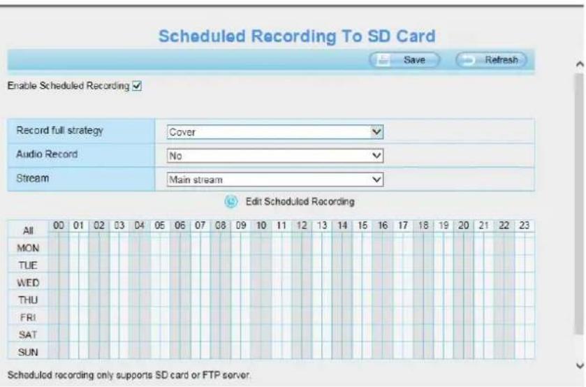
text_image
Scheduled Recording To SD Card Save Refresh Enable Scheduled Recording ✓ Record full strategy Cover ✓ Audio Record No ✓ Stream Main stream ✓ Edit Scheduled Recording All 00 01 02 03 04 05 06 07 08 09 10 11 12 13 14 15 16 17 18 19 20 21 22 23 MON TUE WED THU FRI SAT SUN Scheduled recording only supports SD card or FTP server.Record frame: There are six frame selections, such as 1 / 30, 4 / 30, 8 / 30, 15 / 30, 24 / 30, 30 / 30.
Recommended default is 4 / 30. The greater the Frame rate is, the sharper picture quality is, and greater of storage space is, the shorter the storage time is.
Record full strategy: When the SD card is full, you can choose to cover the previous recording, or stop recording.
NOTES:
- Scheduled recording only supports video saved to the SD card or FTP server.
- The schedule recording will stop while alarm recording is beginning, and it will continue automatically after alarm recording end.
- You can refer to 3.7.6.1 Motion Detection > 5 Alarm Schedule. in Alarm about editing the time of recording Schedule.
3.7.7.5 SD Card Management
The SD card Slot inside the camera, if you want to install or remove the Micro SD card, you need the camera.
When you plug in the Micro SD card during the camera work process, please reboot the camera age or else the SD Card may be cannot work well.
Go to the Settings > Status > Device Status page, you can see the SD card status.
The default storage path of alarm record files is SD card, when the available size of SD card is 16256M, the old record files will be deleted automatically.
3.7.8 PTZ
This page will allow you to change the pan/tilt speed and do cruise tracks settings.
3.7.8.1 Pan & Tilt Speed
There are five Pt speed types: very fast, fast, normal, slow and very slowly. Select the desired PTZ speed type and click save button.
There are three zoom speed types: fast, normal, slow.
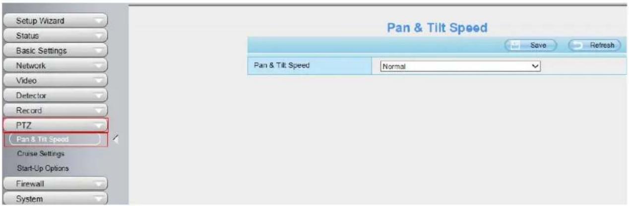
text_image
Setup Wizard Status Basic Settings Network Video Detector Record PTZ Pan & Tilt Speed Cruise Settings Start-Up Options Firewall System Pan & Tilt Speed Save Refresh Pan & Tilt Speed Normal3.7.8.2 Cruise Settings
This section explains how to add/ delete/ alter one cruise track.
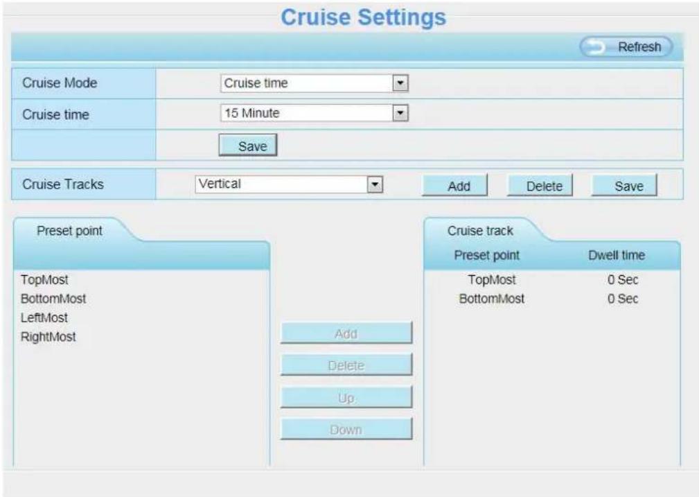
text_image
Cruise Settings Refresh Cruise Mode Cruise time Cruise time 15 Minute Save Cruise Tracks Vertical Add Delete Save Preset point Cruise track TopMost Preset point Dwell time BottomMost TopMost 0 Sec LeftMost BottomMost 0 Sec RightMost Add Delete Up DownSetting the Cruise Mode
Cruise mode:: Cruise time.
Cruise time: Select Cruise time from Cruise Mode drop-down, then you can set the Cruise time of the camera.
Click Save to take effect.
| Cruise Mode | Cruise time |
| Cruise time | 15 Minute |
| Save |
Manage the Cruise Track
There are two default cruise tracks: Vertical and Horizontal.
Vertical: The camera will rotate from up to down
Horizontal: The camera will rotate form left to right.
Add: Add one cruise track, then click save button.
Delete: Select one cruise track and delete it.
Save: After you modify the Dwell time, you should click Save button to take effect.
Example
How to do add cruise tracks?
Firstly, Click Add button and enter a descriptive name to identify the cruise track.
Secondly: On the lower left of the page, you can see all preset points you have added. Select one preset point and click Add button, you can see the preset point has been added to the cruise track cruise track page. You need to add two or more preset points to the cruise track.
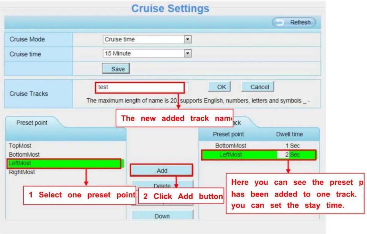
text_image
Cruise Settings Refresh Cruise Mode Cruise time Cruise time 15 Minute Save Cruise Tracks Men test OK Cancel The maximum length of name is 20 supports English, numbers, letters and symbols _ - The new added track name Preset point TopMost BottomMost LeftMost RightMost Add 1 Select one preset point 2 Click Add button Down Preset point Dwell time BottomMost 1 Sec LeftMost 2 Sec Here you can see the preset p has been added to one track. you can set the stay time.Thirdly: Click OK button and the cruise track will take effect.
You can add other cruise track as the same method.
For example: I have added three preset points to the "track 1", that means : When I select the "tr on the surveillance window, the camera moves as the following track: upright then Right Most last d left.
You can add preset on the left of the surveillance window.
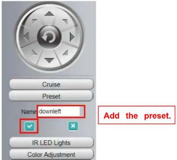
text_image
Cruise Preset Name downleft IR LED Lights Color Adjustment Add the preset.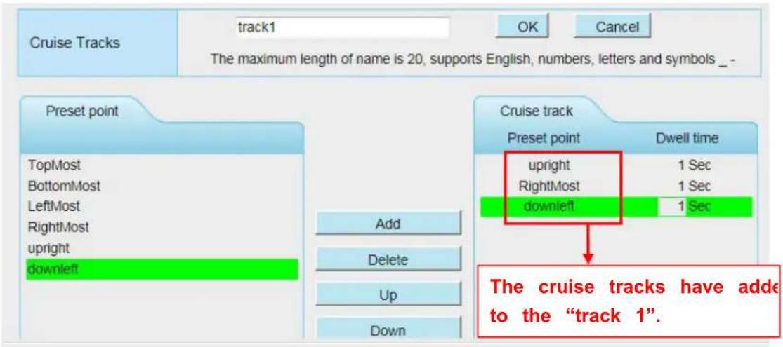
text_image
Cruise Tracks track1 OK Cancel The maximum length of name is 20, supports English, numbers, letters and symbols _ - Preset point TopMost BottomMost LeftMost RightMost upright downleft Add Delete Up Down Cruise track Preset point Dwell time upright 1 Sec RightMost 1 Sec downleft 1 Sec The cruise tracks have added to the "track 1".After add the cruise track, back to the surveillance window, click Cruise, here you can see all cruise tracks you have added.
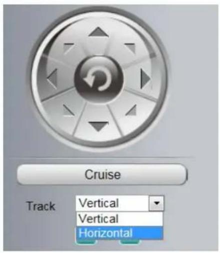
text_image
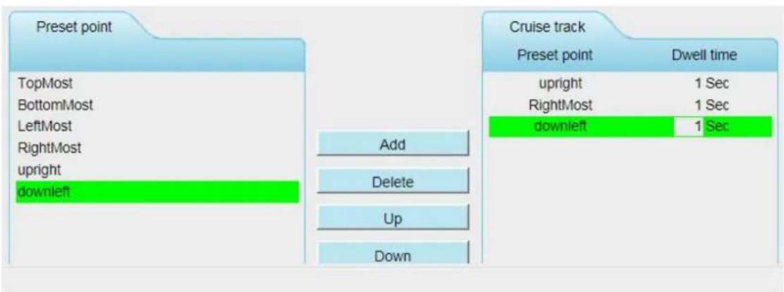
Cruise Track Vertical Vertical HorizontalThere are other buttons between the Preset points and Cruise track, you can use these buttons to the order of preset points or add/delete one preset points in one cruise track.
flowchart
graph TD
    A["Preset point"] --> B["TopMost"]
    A --> C["BottomMost"]
    A --> D["LeftMost"]
    A --> E["RightMost"]
    A --> F["upright"]
    A --> G["downleft"]
    H["Cruise track"] --> I["Preset point"]
    I --> J["Dwell time"]
    J --> K["upright 1 Sec"]
    J --> L["RightMost 1 Sec"]
    L --> M["downleft 1 Sec"]
    N["Add"] --> O["Delete"]
    P["Up"] --> Q["Down"]
Add: Select one preset points and add it to the selected cruise track.
Delete: Select one preset points you have added to one cruise track, click delete.
Move up/ down: Select one cruise track, adjust the order of preset points in one cruise track.
Attention:
Considering the life time and thermal issue of the motor, it's not recommend to do long-time cruise.
3.7.8.3 Start-Up Options
Here section will allow you to set the stop position after the camera reboots.
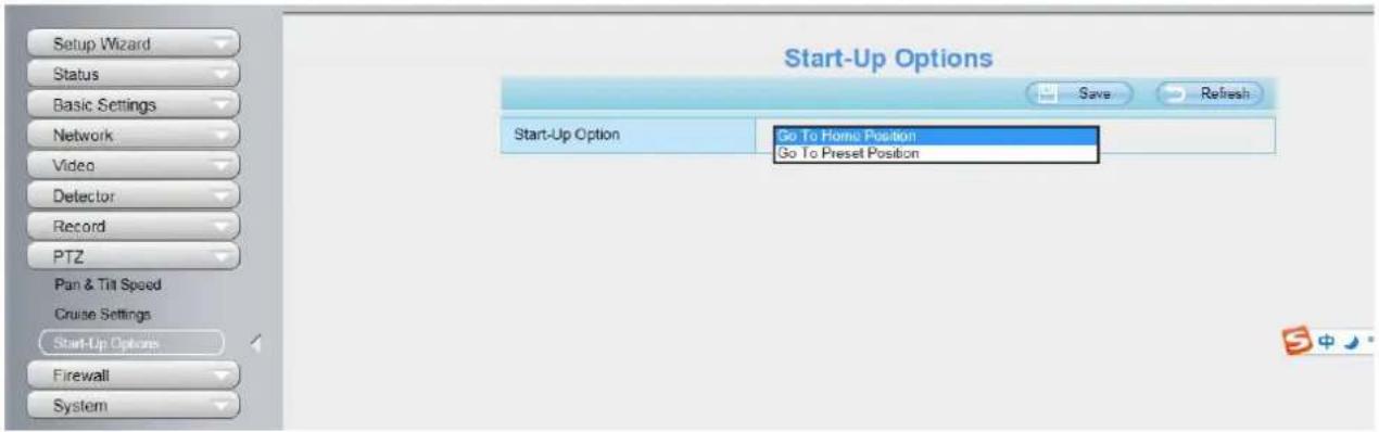
It supports two modes: Go to home position and Go to preset point.
No self test: When rebooting, the camera will not pan / tilt.
Goto home position: When rebooting, the camera will pa Providing Central Management Software to manage or monitor multi-cameras n / tilt and stops at center.
Go to Preset point: Select one preset position and save it. When rebooting, the camera will pan/ tilt and stops at the preset position you have set.
text_image
Setup Wizard Status Basic Settings Network Video Detector Record PTZ Pan & Tilt Speed Cruise Settings Start-Up Options Firewall System Start-Up Options Go To Home Position Go To Preset Position Save Refresh3.7.9 Firewall
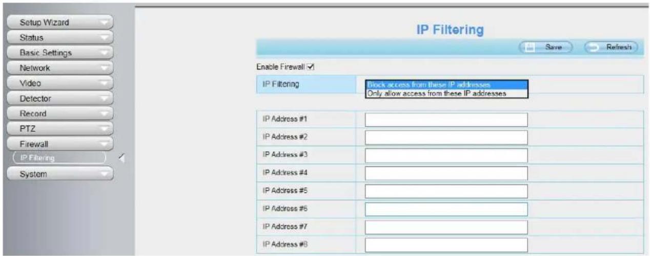
This section explains how to control the access permission by checking the client PC's IP addresses. composed of the following columns: Block access from these IP addresses and Only allow access from these IP addresses.
text_image
Setup Wizard Status Basic Settings Network Video Detector Record PTZ Firewall IP Filtering System IP Filtering Enable Firewall ✓ IP Filtering Block access from these IP addresses Only allow access from these IP addresses IP Address #1 IP Address #2 IP Address #3 IP Address #4 IP Address #5 IP Address #6 IP Address #7 IP Address #8 Save RefreshEnable firewall, If you select Only allow access from these IP addresses and fill in 8 IP addresses most, only those clients whose IP addresses listed in the Only allow access from these IP addresse access the Network Camera. If you select Block access from these IP addresses, only those clients whose IP addresses are in the IP list cannot access the Network Camera.
Click Save to take effect.
3.7.10 System
In this panel, you can backup/restore your camera settings, upgrade the firmware to the latest version restore the camera to default settings and reboot the device.
3.7.10.1 Back-up & Restore
Click Backup to save all the parameters you have set. These parameters will be stored in a bin file future use.
Click Browse and select the parameters file you have stored, then click Submit to restore the restore parameters.
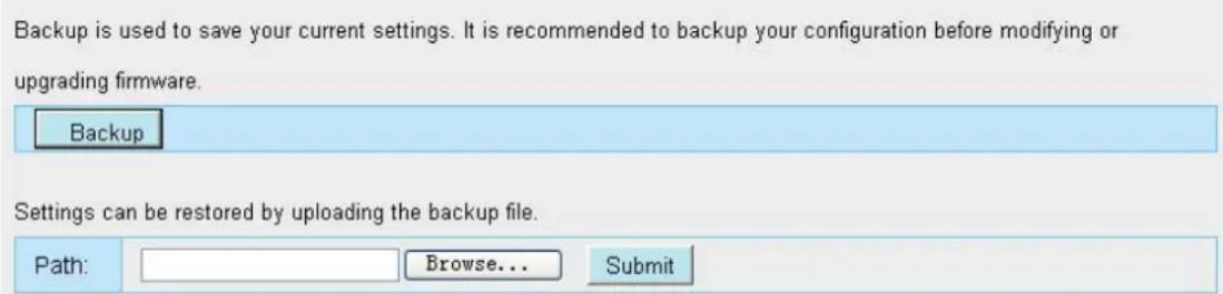
text_image
Backup is used to save your current settings. It is recommended to backup your configuration before modifying or upgrading firmware. Backup Settings can be restored by uploading the backup file. Path: Browse... SubmitNote:
- All current settings will be lost when importing a configuration file. If an incorrect file is loaded, the camera may stop working correctly.
- Keep the power on during this process, or you may damage your camera. Your camera will reboot automatically once restoration is completed.
3.7.10.2 System Upgrade
Click Download the latest firmware, you will see the following screen. And click Save to save the firmware on your computer locally.
Your current firmware version will be displayed on your screen. You may go to the Status > Device Information page to check for the latest firmware versions available.
Click Browse, choose the correct bin file and then click System upgrade.
Don't shut down the power during upgrading. After upgrading, you can see the upgrade result.
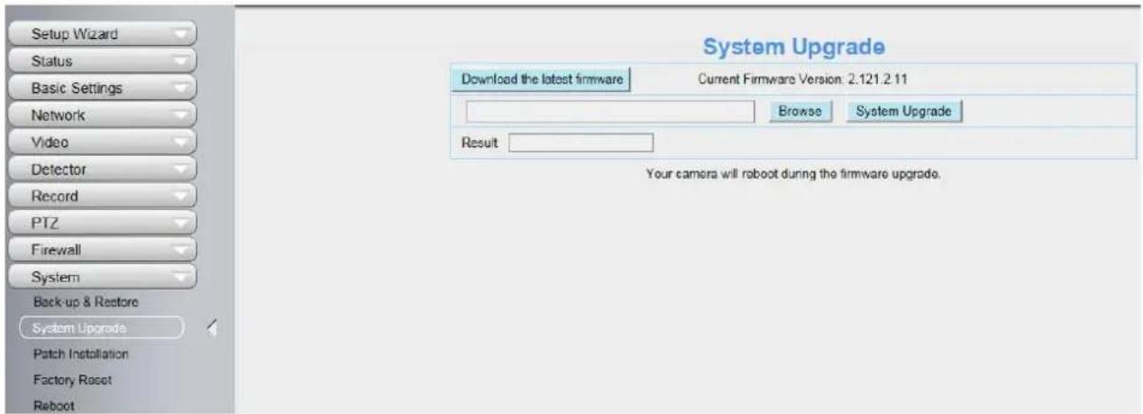
text_image
Setup Wizard Status Basic Settings Network Video Detector Record PTZ Firewall System Back-up & Restore System Upgrade Patch Installation Factory Reset Reboot System Upgrade Download the latest firmware Current Firmware Version: 2.121.2.11 Browse System Upgrade Result Your camera will reboot during the firmware upgrade.Upgrade Firmware by Equipment Search Tool

Double click the Equipment Search Tool shot icon, select the Camera IP that you want to upgrade the firmware. Then select Upgrade Firmware and enter the username and password, choose the firmware file, and upgrade.
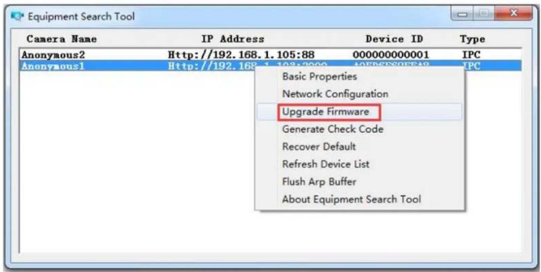
text_image
Equipment Search Tool Camera Name IP Address Device ID Type Anonymous2 Http://192.168.1.105:88 000000000001 IPC Anonymous1 Http://192.168.1.105:88 40E#E#E#E#A# IPC Basic Properties Network Configuration Upgrade Firmware Generate Check Code Recover Default Refresh Device List Flush Arp Buffer About Equipment Search Tool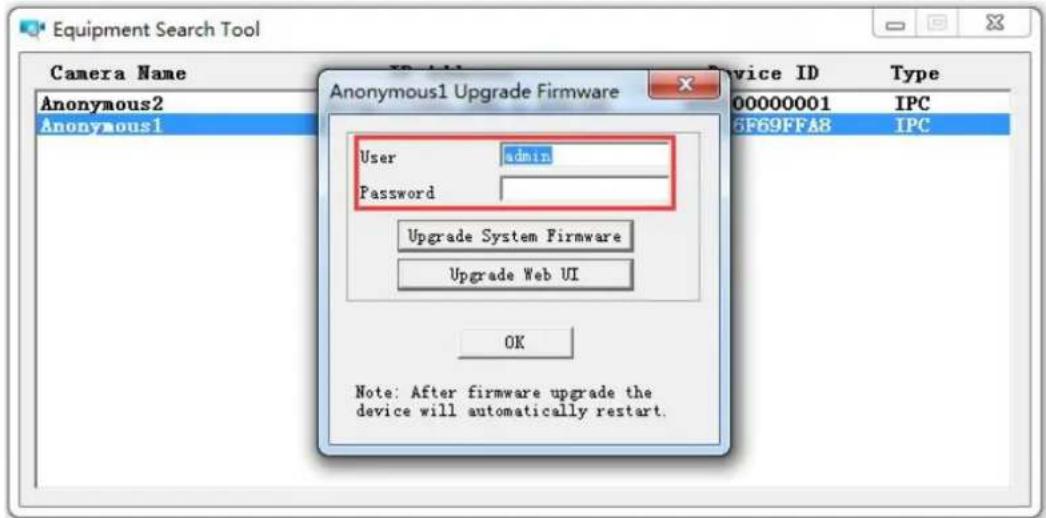
text_image
Equipment Search Tool Camera Name Anonymous2 Anonymous1 Anonymous1 Upgrade Firmware User admin Password Upgrade System Firmware Upgrade Web UI OK Note: After firmware upgrade the device will automatically restart. Device ID Type 00000001 IPC 6F69FFA8 IPCCAUTION:
We recommend that you regularly update your camera to the latest available software and firmware versions to help ensure the best experience for your camera.
NOTE:
1) Please ensure you have download the correct firmware package for your camera before upgrading. Read the upgrade documentation (readme.txt file) in the upgrade package before you upgrade.
2) Upon downloading the firmware check the sizes of the .bin files. They must match the size in the readme.txt file. If not, please download the firmware again until the sizes are the same. Your can will not function correctly if a corrupt .bin file is used.
3) Never shut down the power of the camera during upgrade until the IP camera restart and get connected.
4) After upgrade successfully, please clear the cache of browser, uninstall the old plugin and re-insta then reset the camera to the default factory settings before using the camera.
3.7.10.3 Patch Installation
Click Browse to select the correct patch file, and then click Install Patch to install the patch. Do not turn off the power during it installing. After installing is complete, you will receive a system prompt.
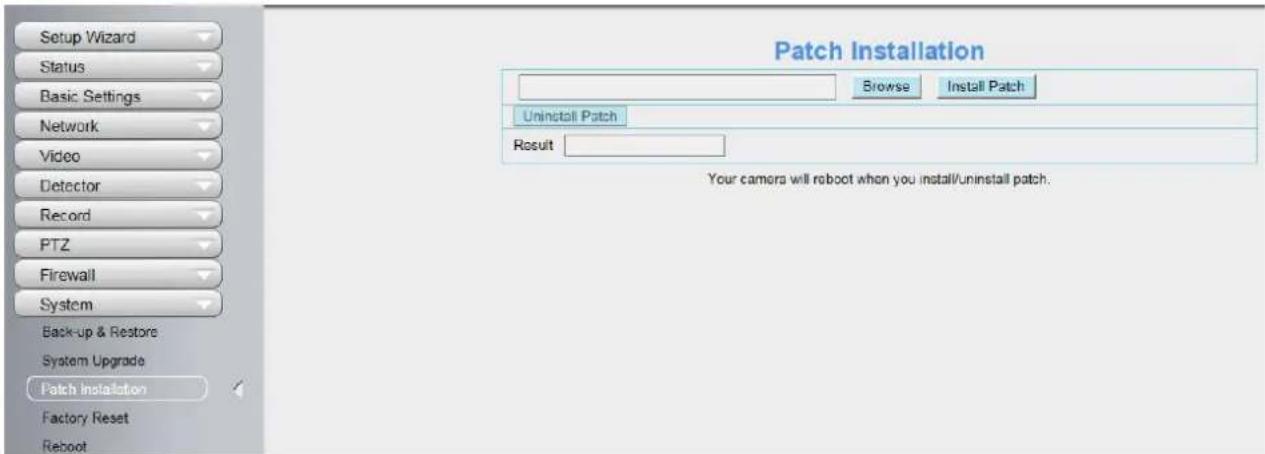
text_image
Setup Wizard Status Basic Settings Network Video Detector Record PTZ Firewall System Back-up & Restore System Upgrade Patch Installation Factory Reset Reboot Patch Installation Browse Install Patch Uninstall Patch Result Your camera will reboot when you install/uninstall patch.The default administrator username is admin with a blank password.
| Factory Reset | Click this button to hard reset the camera to its default factory settings. |
3.7.10.5 Reboot
Click Reboot to reboot the camera. This is similar to unplugging the power to the camera.

text_image
Reboot Click this button to reboot your camera.3.8 Playback
On this page you can view the record files stored in the SD card.
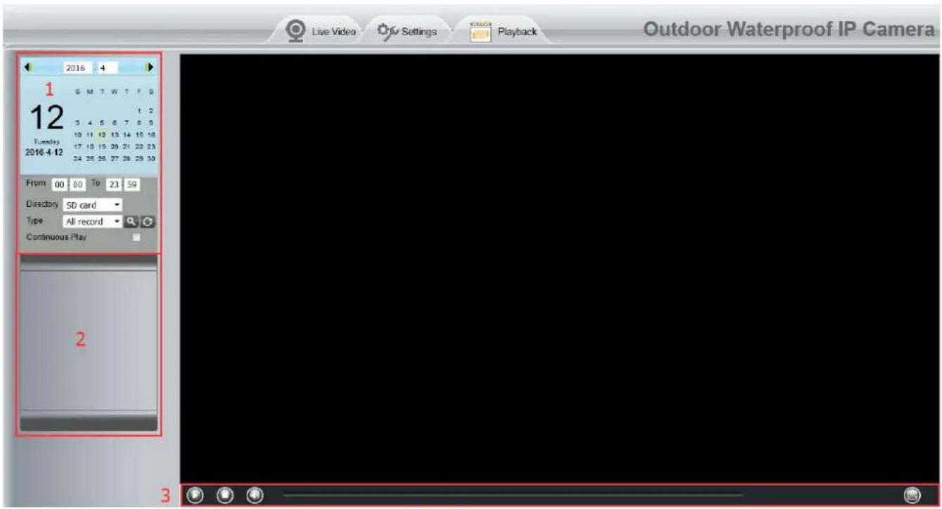
text_image
Live Video Settings Playback Outdoor Waterproof IP Camera 2016 4 1 12 Tuesday 2016-4-12 From 00 00 To 23:59 Directory SD card Type All record Continuous Play 2 3Section 1 Define the Record files time and Type

The storage path of record files
Time All records: Here supports three types: current day, current month and All records. Another way, select the time on the time&date manually.
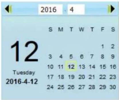
text_image
2016 4 S M T W T F S 12 3 4 5 6 7 8 9 10 11 12 13 14 15 16 Tuesday 2016-4-12 17 18 19 20 21 22 23 24 25 26 27 28 29 30Type All records: The type of records files, Here supports two types: Normal record, Alarm record and All records.
: Click this button to search all record files satisfy the conditions you selected. Continuous Play: Select the checkbox to play continuously all the record files.
Section 2 Search record files
On this panel you can see all record files satisfy the conditions you set.
Section 3 Play / Stop / audio / Full screen Buttons
Please select one record file before use these buttons.

Click this button to play the record files.

Click this button to stop the record files.

Click this button to audio on / mute.

Click this button to make full screen, and double click left mouse to exit full screen.
4 Surveillance Software Foscam VMS
4.1 Hardware Connection & Software Installation
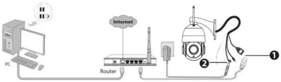
text_image
PC Internet Router ① ②- Connect the camera to the LAN network (Router or Switch) via network cable.
- Visit Foscam official website foscam.com/vms, then you can find the "FoscamVMS_Beta", Please download it
4.2 Software Installation
1) Double click the software and follow the setup wizard to install the program.
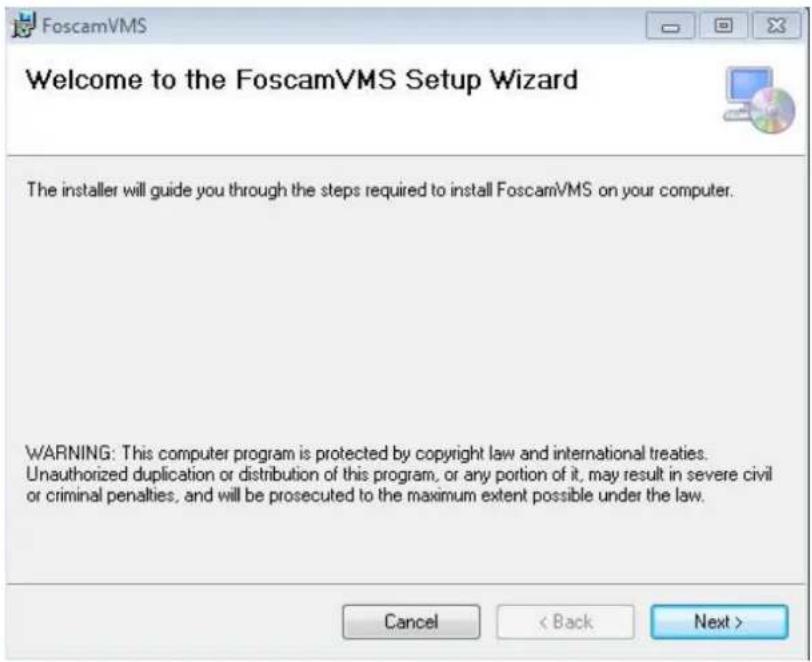
text_image
Welcome to the FoscamVMS Setup Wizard The installer will guide you through the steps required to install FoscamVMS on your computer. WARNING: This computer program is protected by copyright law and international treaties. Unauthorized duplication or distribution of this program, or any portion of it, may result in severe civil or criminal penalties, and will be prosecuted to the maximum extent possible under the law. Cancel < Back Next >2) The FoscamVMS icon will appear on the desktop automatically after a successful installation.
Note:
Sometimes the program will be treated as virus, so before installing, please add the software as trust program on your computer.
4.3 Create Account
For your privacy and security, you can create a lacal administrator account.
Create Account
For your privacy and security, you can create a local administrator account.
Create
Cancel
Do not remind
you haven't created a local administrator account, please click Create Account to create. After creating a local administrator account, you can:
- Use the account to log in to the client to ensure information security.
- Create sub-accounts and assign different permissions for management.
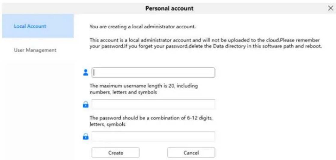
text_image
Personal account Local Account User Management You are creating a local administrator account. This account is a local administrator account and will not be uploaded to the cloud.Please remember your password.If you forget your password,delete the Data directory in this software path and reboot. The maximum username length is 20, including numbers, letters and symbols The password should be a combination of 6-12 digits, letters, symbols Create Cancel4.4 Add Device
4.4.1 LAN Add
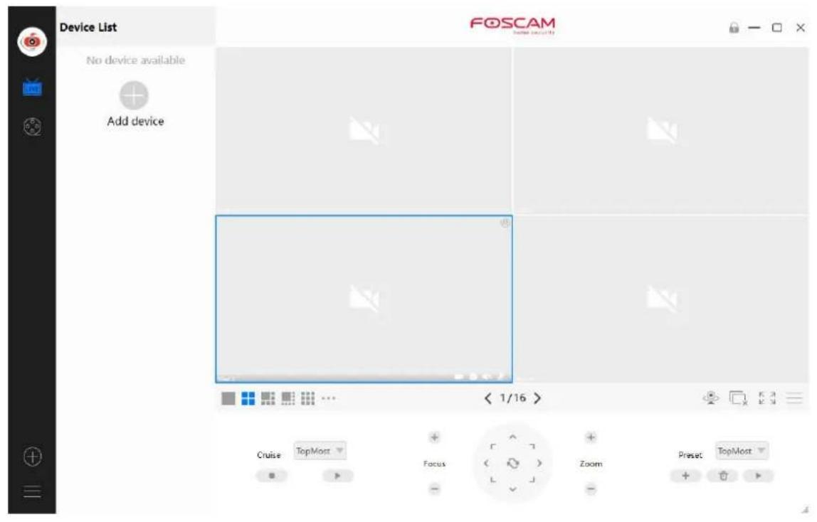
text_image
Device List No device available Add device FOSCAM < 1/16 > Cruise TopMost Focus Zoom Preset TopMostClick Add Device button, then follow below steps:
Step1 Select the device type, the default type is IPC(IP camera).
Step2 Click the IP address of the camera on the list.
Step3 Enter the username and password of the camera.
Step4 Click Add.
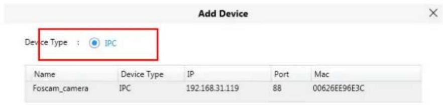
text_image
Add Device Device Type : IPC Name Device Type IP Port Mac Foscam_camera IPC 192.168.31.119 88 00626EE96E3C
text_image
Device Account : Password : 1 Device(s) found Add Cancel Manual AddPlease Note: Make sure the camera and PC are both in the same Local Area Network (LAN).
4.4.2 Manual LAN via IP
You can add the camera use manual LAN also. Click the Manual LAN first, then follow below steps
Step1 Select the IP
Step2 Enter the IP and Port (IP and port can be viewed in Add Device)
Step3 Enter the username and password of the camera.
Step4 Click Add.
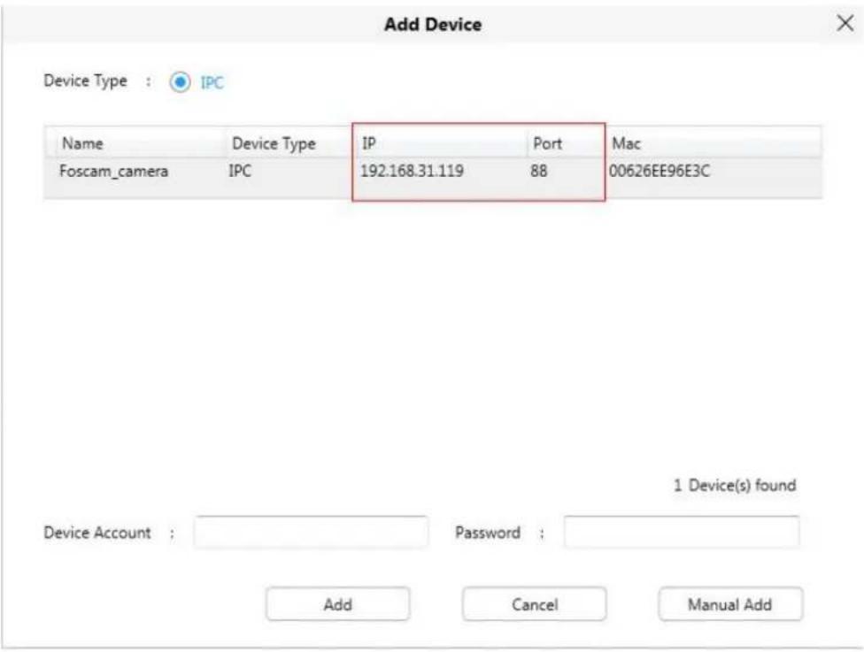
text_image
Add Device Device Type : IPC Name Device Type IP Port Mac Foscam_camera IPC 192.168.31.119 88 00626EE96E3C 1 Device(s) found Device Account : Password : Add Cancel Manual Add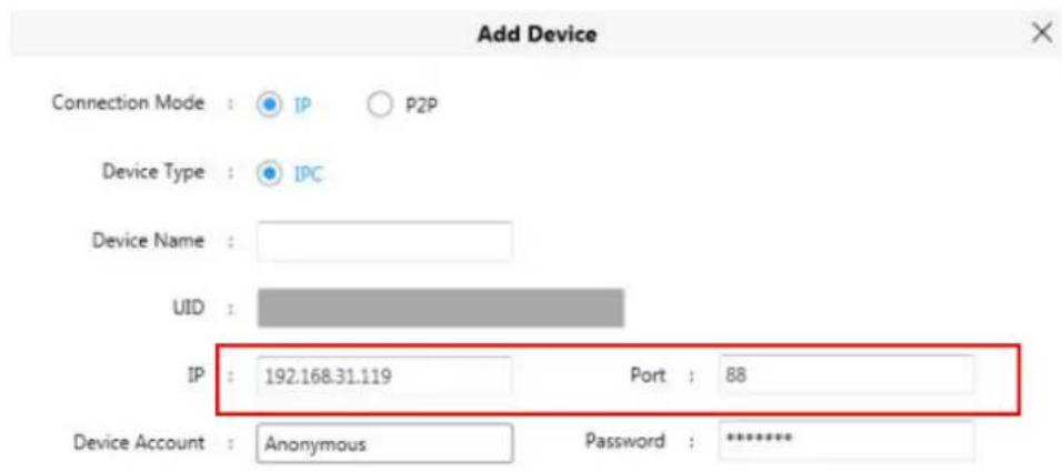
text_image
Add Device Connection Mode : IP P2P Device Type : IPC Device Name : UID : IP : 192.168.31.119 Port : 88 Device Account : Anonymous Password : ********
4.4.3 Manual LAN via P2P
You can add the camera use manual LAN also. Click the Manual LAN first, then follow below steps
Step1 Select the P2P
Step2 Enter the UID (located on your camera)
Step3 Enter the username and password of the camera.
Step4 Click Add.
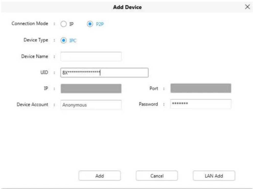
text_image
Add Device Connection Mode : ○ IP ● P2P Device Type : ○ IPC Device Name : UID : 8X********** IP : Port : Device Account : Anonymous Password : ******** Add Cancel LAN Add4.5 Surveillance Software GUI
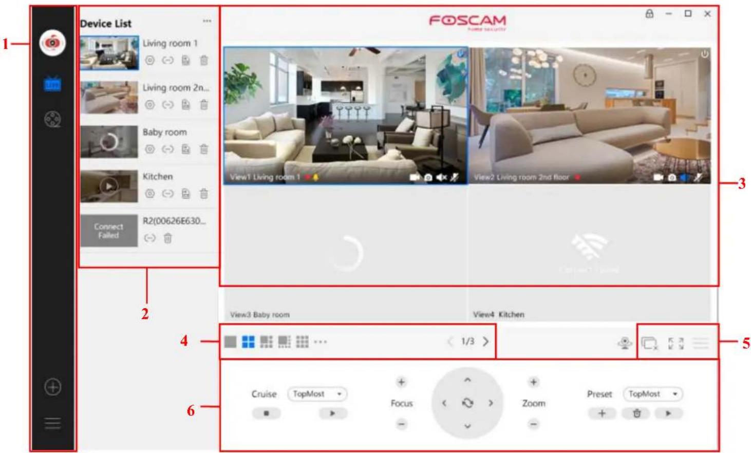
text_image
Device List Living room 1 Living room 2n... Baby room Kitchen Connect Failed R2(00626E630... FOSCAM HOME SECURITY View1 Living room 1 View2 Living room 2nd floor View3 Baby room View4 Kitchen 1/3 > Cruise TopMost Focus Zoom Preset TopMost + - - + - + - + - + - + - + - + - + - + - + - + - + - + - + - + - + - + - + - + - + - + - + - + - + - + - + - + - + - + - + - + - + - + - + - + - + - + - + - + - + - + - + - + - + - + - + - + - + - + - + - + 1 2 3 4 5 6First time you login the software, the whole video window is gray, you need to connect the cameras: add cameras to it.
Section1 Menu Bar

Path to surveillance window. Click this button enter to Device List and back to the surveillance window.

Playback the video recording, you can choose playback type and play video on local or SD card.

Add Device, please refer chapter 3.4 for the detail setting. More, You can Setting Personal Account, Preference, Left Bar and Switch Account.
Section2 Left Bar
Left Bar of Live: You can view the list of connected cameras

text_image
1 2 3 41---- Setup
Click the button Settings, goes to Device Settings Control Panel to make advanced camera settings.
2----Device Connection Account
Click the button Settings, goes to connection Settings
Connection Settings
If the device's username or password is modified outside the vms, please correct it here.
Device Name : Foscam_camera
IP : 192.168.31.119
Port : 88
Device Account :
Password :
Delete
Login Check
Save
Cancel
3----SD Card
If you have an SD card on your device, click this button to enter the SD directory.
4----Delete
Click the button, Delete the device.
Section3 Live Window
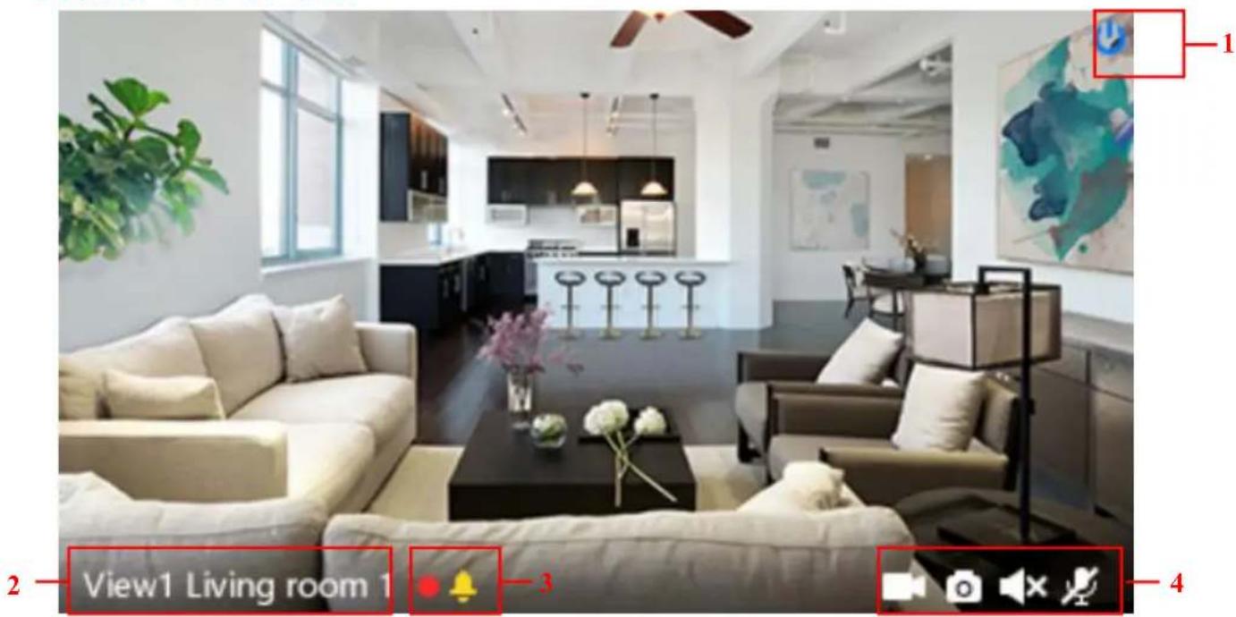
text_image
2 View1 Living room 1 3 41----Close
Click the icon to close this channel live window
2----Device Name
Show view channel and camera name.
3----Recording and Alarm status
This icon will turn to red, it indicates that the camera is recording
This icon will turn to yellow, the motion is detected during the detection time in the detection area, the camera alarm and adopt the corresponding alarm indicators
4---- Record / Snap Shot / Sound / Talk button

natural_image
Four white icons on a dark background: video camera, camera, speaker, and megaphone (no text or symbols)Record Snap Shot Sound Talk
Record ---- Click it and do manually recording. When recording, icon 1 will turn to blue. Click it again and stop recording. The recording files will be stored to C disk automatically
Snap Shot ---- Click it to make snapshot. After snapshot, the button banner will prompt Captured Successfully. And you can find the picture on default path C:\VMS_CAPTURE
SnapShot
Success, Picture:
C:\VMS_CAPTURE
\MDS2010_A0E6FB6FAB01\20191014
\2019-10-14_17_15_46.bmp
Sound ---- Click the icon then you will hear sound captured by the camera's built-in microphone. You may need to plug in earphones or enable the computer speakers to hear from the camera's microph Make sure the camera supports audio. Click again and stop audio.
Talk ---- Click the button, then talk to the microphone that connected with PC, people around the camera can here you voice. Click the icon again and stop talking.
Section4 The number of split-screen
Click this button to select the number of split-screen on one page.

natural_image
Five gray square icons in a row: two solid blue squares, three dotted squares, and one dot (no text or symbols)The client can monitor many cameras at one page, here you can choose the display number. The maximum number is 16.
Section5 Live Cruise / Close All / Full Screen / Hide Bar

Live Cruise ---- Click this button to Live Cruise, you can click button to add a loop page for live
Cruise or click button to reduce the loop page for live Cruise.
- 2 - 2, Max: 11 +

Close All ---- Click this button to close all the cameras

Full Screen ---- Click this button to enter full screen, Click this button to enter full screen, then to exit full screen.

Hide Bar ---- Click this button, Hide and show Pan / Tilt control Bar
Section6 Cruise / Focus buttons / Pan / Tilt control / Zoom buttons/ Preset

text_image
Cruise Vertical Focus Zoom Preset TopMost- Cruise Settings
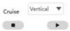
The default cruise tracks have two types: Vertical and Horizontal.
Vertical: The camera will rotate from up to down.
Horizontal: The camera will rotate from left to right.
:Start cruise. : Stop cruise.
If you want to define or change the cruise trace, please go to Device Settings → PTZ → Cruise Settings panel.
How to do cruise?
Firstly: Select one track in the track dropdown list.
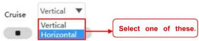
text_image
Cruise Vertical Vertical Horizontal Select one of these.Secondly: Click Start cruise button, the camera will cruise following the predefined path. Thirdly: Click stop button and finish cruising.
- Zoom in" or "Zoom out"
Click or ,The focal length of the camera lens will be larger or shrink, you can adjust the focus distance to the target object size, access to high-definition screen.
Focus: Optical zoom
Zoom: Magic Zoom

text_image
+ Focus - ^ < > Zoom -- Pan/Tilt Control
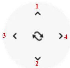
flowchart
graph TD
    A["1"] --> B["2"]
    B --> C["3"]
    C --> D["4"]
    D --> A
1---- Up control button, 2----Down control button, 3----Left control button, 4----Right control button,

Click this button and go to center
Preset settings
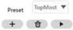
IP Camera supports 16 preset positions, which is considered enough for DIY home & small business surveillance market
The default preset position is Topmost, Bottom most, Left most, right most, you can add other prese positions.

Add Click this icon to save the position you need the camera to remember

Delete Select one preset position and click this button to delete it.

GO Select one preset position in the preset drop-down list and click Go to make the camera
move the preset position
How to do preset position?
Firstly, move the camera and stop at a desired place where you want make preset position.
Secondly, click + button and enter a descriptive name for the preset position. The preset position
cannot contain special characters. Then click OK to save it. If you want to reset the preset position Cancel.
After that, you can move the camera and stop at another place, and set another preset position. You do all the 16 preset positions with this method.
If you want to see one preset position you have set, only select the preset position name from the drop-down list, and click go button, the camera will go to the preset position.
4.6 Advanced Camera Settings
Click the button, goes to Device Settings to make advanced camera settings.
4.6.1 Status
Status contains two columns: Device Information and Logs, it will show you various information about your camera.
4.6.1.1 Device Information
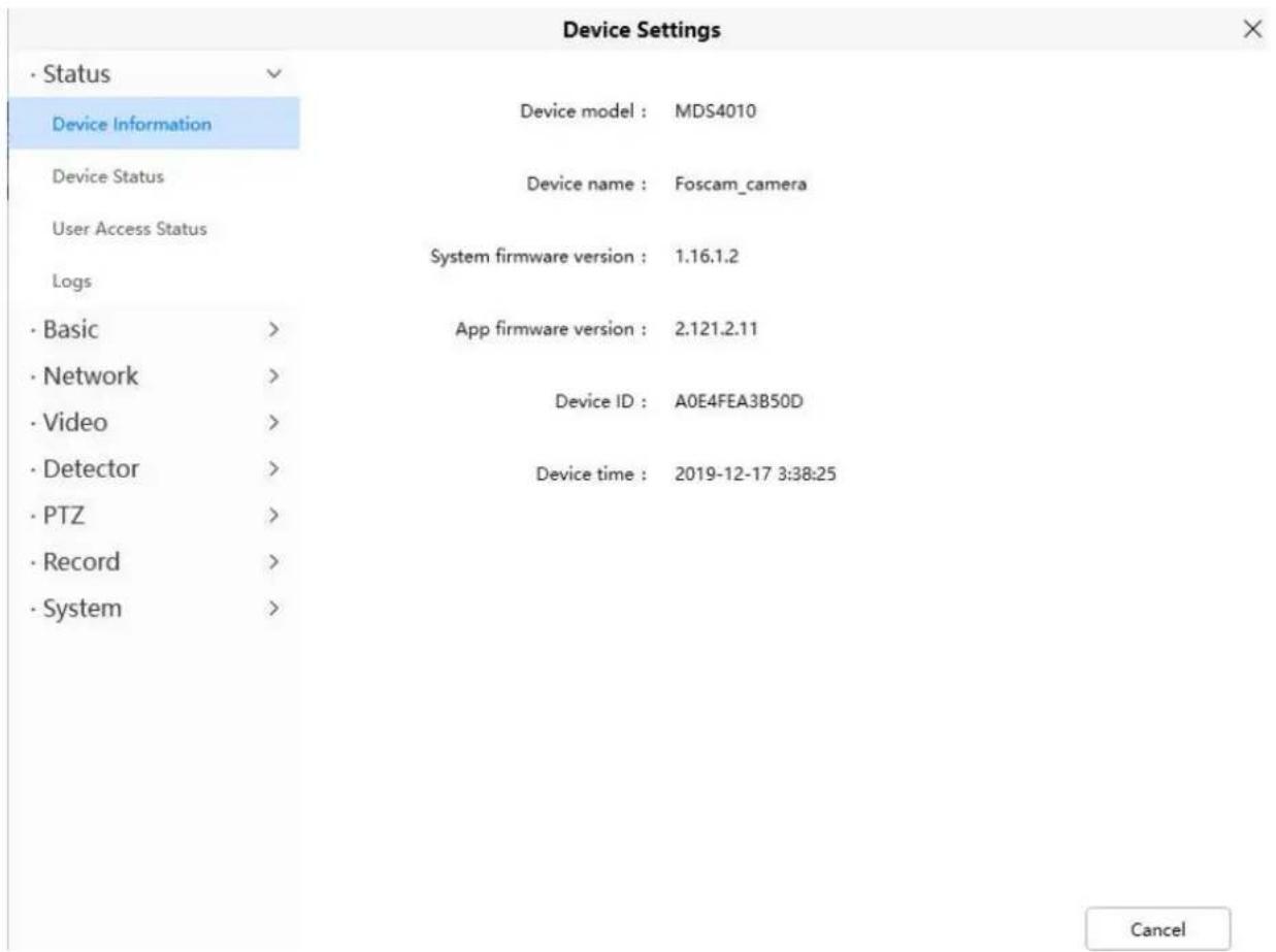
text_image
Device Settings • Status Device Information Device model : MDS4010 Device status Device name : Foscam_camera User Access Status System firmware version : 1.16.1.2 Logs • Basic > • Network > • Video > • Detector > • PTZ > • Record > • System >Device Model: The model of the device.
Device Name: The Device Name is a unique name that you can give to your device to help you identify it.
Click Basic Settings and go to Camera Name panel where you can change your camera name. The d device name is Foscam_camera.
System Firmware Version: Display the System Firmware version of your camera.
App Firmware Version: Display the application firmware version of your camera.
Device ID: Display the MAC address of your camera. For example Device ID is 00626EE96E3C, the same MAC ID sticker is found at the bottom of the camera.
Device Time: The system time of the device. Click Basic Settings and go to Device Time panel and adjust the time.
4.6.1.2 Device Status
On this page you can see device status such as Alarm status, NTP status, IR LED Status and so or
| Device Settings | |
| ·Status | |
| Device Information | Motion alarm status : Enable |
| Device Status | Sound alarm status : Disable |
| User Access Status | |
| Logs | Recording status : Disable |
| ·Basic > | NTP status : Enable |
| ·Network > | |
| ·Video > | SD card status : Disable |
| ·Detector > | SD card free space : 0 KB |
| ·PTZ > | |
| ·Record > | SD card total space : 0 KB |
| ·System > | WiFi status : Disable |
| IR LED status : Disable | |
4.6.1.3 User Access Status
Session status will display who and which IP is visiting the camera now
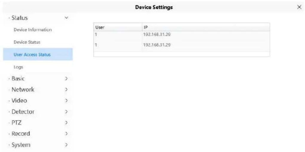
text_image
Device Settings Status Device Information Device Status User Access Status Logs · Basic > · Network > · Video > · Detector > · PTZ > · Record > · System >4.6.1.4 Logs
The log record shows who and which IP address accessed or log out the camera.
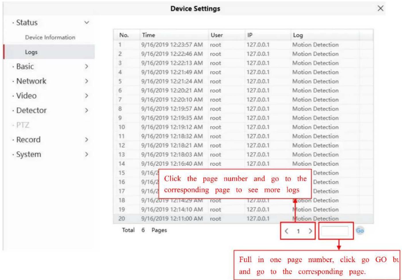
text_image
Device Settings Status Device Information Logs · Basic > · Network > · Video > · Detector > · PTZ · Record > · System > No. Time User IP Log 1 9/16/2019 12:23:57 AM root 127.0.0.1 Motion Detection 2 9/16/2019 12:22:46 AM root 127.0.0.1 Motion Detection 3 9/16/2019 12:22:13 AM root 127.0.0.1 Motion Detection 4 9/16/2019 12:21:49 AM root 127.0.0.1 Motion Detection 5 9/16/2019 12:21:24 AM root 127.0.0.1 Motion Detection 6 9/16/2019 12:20:21 AM root 127.0.0.1 Motion Detection 7 9/16/2019 12:20:10 AM root 127.0.0.1 Motion Detection 8 9/16/2019 12:19:57 AM root 127.0.0.1 Motion Detection 9 9/16/2019 12:19:35 AM root 127.0.0.1 Motion Detection 10 9/16/2019 12:19:12 AM root 127.0.0.1 Motion Detection 11 9/16/2019 12:18:32 AM root 127.0.0.1 Motion Detection 12 9/16/2019 12:18:21 AM root 127.0.0.1 Motion Detection 13 9/16/2019 12:18:03 AM root 127.0.0.1 Motion Detection 14 9/16/2019 12:16:40 AM root 127.0.0.1 Motion Detection 15 9/16/2 Click the page number and go to the corresponding page to see more logs 16 9/16/2 Detection 17 9/16/2 Detection 18 9/16/2019 12:14:29 AM root 127.0.0.1 Motion Detection 19 9/16/2019 12:14:10 AM root 127.0.0.1 Motion Detection 20 9/16/2019 12:11:00 AM root 127.0.0.1 Motion Detection Total 6 Pages < 1 > Go Full in one page number, click go GO but and go to the corresponding page.4.6.2 Basic
This section allows you to configure your Device Name, Time, User Accounts, Status Light and Voice F
4.6.2.1 Camera Name
Default alias is Foscam_camera. You can define a name for your camera here such as apple. Click S save your changes. The alias name cannot contain special characters.

text_image
Device Settings Status > Basic Camera Name Camera Name : Foscam_camera The maximum lenght of device name is 20, support English, numbers, letters and symbols: _- Device Time User Accounts Status Light Voice Prompt4.6.2.2 Device Time
This section allows you to configure the settings of the internal system clocks for your camera.
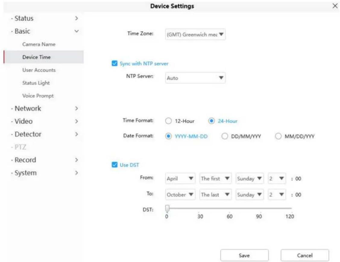
text_image
Device Settings Status > Basic Camera Name Device Time User Accounts Status Light Voice Prompt Network > Video > Detector > PTZ Record > System > Time Zone: (GMT) Greenwich mea Sync with NTP server NTP Server: Auto Time Format: 12-Hour 24-Hour Date Format: YYYY-MM-DD DD/MM/YYYY MM/DD/YYYY Use DST From: April The first Sunday 2 : 00 To: October The last Sunday 2 : 00 DST: 0 30 60 90 120 Save CancelTime Zone: Select the time zone for your region from the dropdown menu.
Sync with NTP server: Network Time Protocol will synchronize your camera with an Internet time server.
Choose the one that is closest to your camera.
Use DST: Select the use DST (Daylight Saving Time, to set the clock ahead of the real-time), then set the start time and end time of the DST, select the daylight saving time from the drop-down menu at last. Click Save button and submit your settings.
4.6.2.3 User Accounts
Here you can create users and set privilege, visitor, operator or administrator. The default administrator accounts are administrator with a blank password.
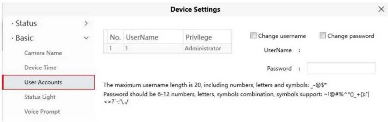
text_image
Device Settings Status > Basic Camera Name Device Time User Accounts Status Light Voice Prompt No. Username Privilege 1 1 Administrator Change username Change password UserName : Password : The maximum username length is 20, including numbers, letters and symbols: _-@$* Password should be 6-12 numbers, letters, symbols combination, symbols support: ~!@#%^*()_+#:| <>?~;\✓How to change the password?
Firstly, select the account which you want to change the password, then select Change password, enter the old password and the new password, lastly click modify to take effect.
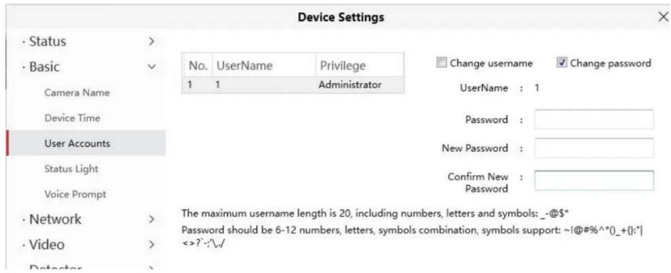
text_image
Device Settings Status > Basic Camera Name Device Time User Accounts Status Light Voice Prompt Network > Video > The maximum username length is 20, including numbers, letters and symbols: _-@$* Password should be 6-12 numbers, letters, symbols combination, symbols support: ~!@#%^*()_+{}:*| <>?^;~\✓How to change the username?
Select the account which you want to change the username, then select Change username, enter the username and the password, lastly click modify to take effect.
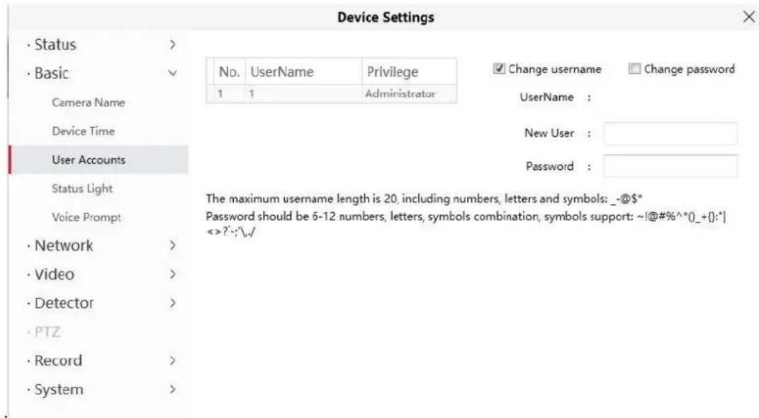
text_image
Device Settings Status > Basic Camera Name Device Time User Accounts Status Light Voice Prompt Network > Video > Detector > PTZ Record > System > No. Username Privilege 1 1 Administrator Change username Change password UserName : New User : Password : The maximum username length is 20, including numbers, letters and symbols: _-@$* Password should be 5-12 numbers, letters, symbols combination, symbols support: ~!@#%^*0_+():*| <>?-;'.\✓4.6.2.4 Status Light
If you have a power and network status light on your camera, you can turn it on and off with this fi camera don't have the status light described above.
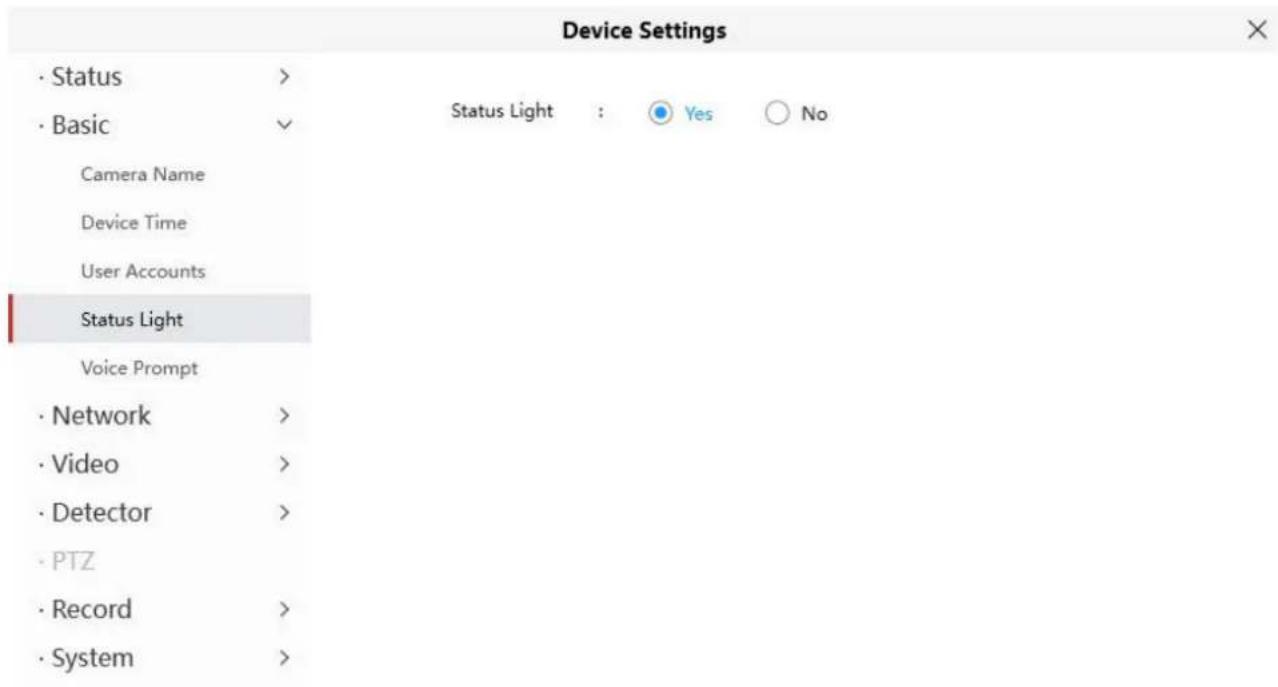
text_image
Device Settings • Status > • Basic Camera Name Device Time User Accounts Status Light Voice Prompt • Network > • Video > • Detector > • PTZ • Record > • System >4.6.2.5 Voice Prompt
You can set the voice prompt on the camera to turn on and off if you connect an external audio device.
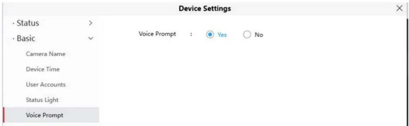
text_image
Device Settings • Status > • Basic Camera Name Device Time User Accounts Status Light Voice Prompt Voice Prompt : Yes No4.6.3 Network
This section will allow you to configure your camera's information.
4.6.3.1 IP
If you want to set a static IP for the camera, please go to IP page. Keep the camera in the same subnet of your router or computer.
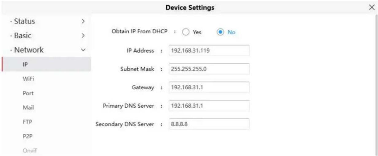
text_image
Device Settings • Status > • Basic > • Network IP WiFi Port Mail FTP P2P Onvif Obtain IP From DHCP : Yes No IP Address : 192.168.31.119 Subnet Mask : 255.255.255.0 Gateway : 192.168.31.1 Primary DNS Server : 192.168.31.1 Secondary DNS Server : 8.8.8.8It is recommended that you use the subnet mask, gateway and DNS server from your locally attached you don't know the subnet mask, gateway and DNS server, you can check your computer's local area connection as follows:
Control Panel--Network Connections--Local Area Connections --Choose Support--Details.
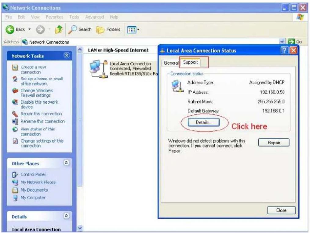
text_image
Network Connections File Edit View Favorites Tools Advanced Help Back Search Folders Address Network Connections LAN or High-Speed Internet Local Area Connection Status General Support Connection status Address Type: Assigned by DHCP IP Address: 192.168.0.50 Subnet Mask: 255.255.255.0 Default Gateway: 192.168.0.1 Details... Click here Windows did not detect problems with this connection. If you cannot connect, click Repair. Repair Close Network Tasks Create a new connection Set up a home or small office network Change Windows Firewall settings Disable this network device Repair this connection Rename this connection View status of this connection Change settings of this connection Other Places Control Panel My Network Places My Documents My Computer Details Local Area Connection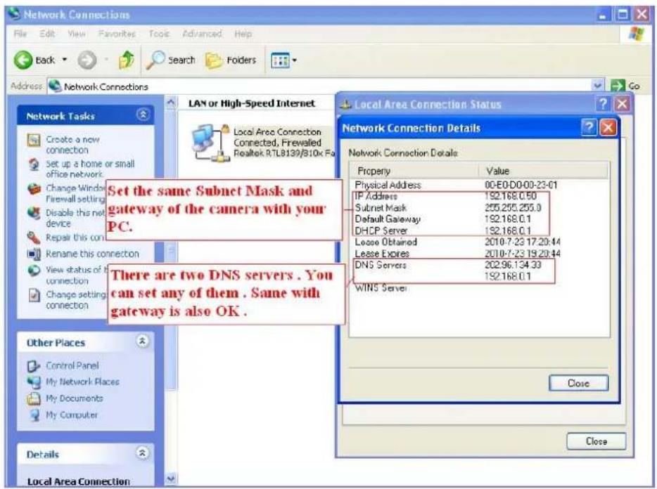
text_image
Network Connections File Edit View Favorites Tools Advanced Help Back Search Folders Address Network Connections LAN or High-Speed Internet Local Area Connection Connected, Firewalled Realtek RTL8139/810x Fa Network Tasks Create a new connection Set up a home or small office network Change Window Firewall setting Disable this net device Repair this con Rename this connection View status of b connection Change setting connection Other Places Control Panel My Network Places My Documents My Computer Details Local Area Connection Set the same Subnet Mask and gateway of the camera with your PC. There are two DNS servers. You can set any of them. Same with gateway is also OK. Local Area Connection Status Network Connection Details Property Value Physical Address 00-E0-D0-00-23-01 IP Address 152.168.0.50 Subnet Mask 255.255.255.0 Default Gateway 152.168.0.1 DHCP Server 152.168.0.1 Lease Obtained 2010-7-23 17:20:44 Lease Expires 2010-7-23 19:20:44 DNS Servers 202.96.134.33 WINS Server 152.168.0.1 Close CloseIf you don't know the DNS server, you can use the same settings as the Default Gateway.
4.6.3.2 WiFi
Step 1: Click the button and the camera will detect all wireless networks around the area. It should also display your router in the list.
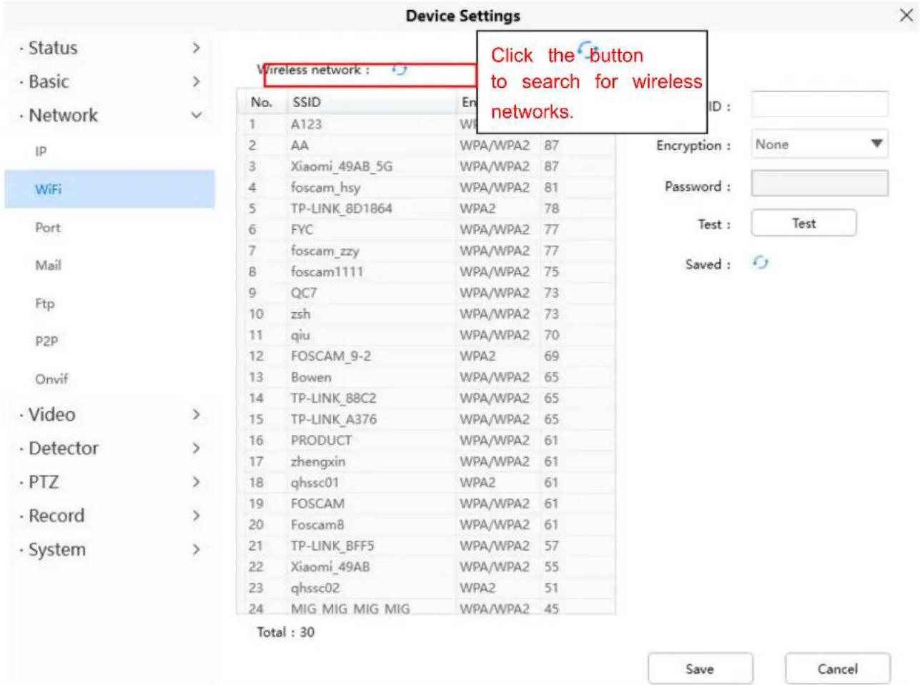
text_image
Device Settings Status > Basic > Network IP WiFi Port Mail Ftp P2P Onvif Video > Detector > PTZ > Record > System No. SSID En 1 A123 WPA/WPA2 87 2 AA WPA/WPA2 87 3 Xiaomi_49AB_5G WPA/WPA2 87 4 foscam_hsy WPA/WPA2 81 5 TP-LINK_8D1864 WPA2 78 6 FYC WPA/WPA2 77 7 foscam_zzy WPA/WPA2 77 8 foscam1111 WPA/WPA2 75 9 QC7 WPA/WPA2 73 10 zsh WPA/WPA2 73 11 qiu WPA/WPA2 70 12 FOSCAM_9-2 WPA2 69 13 Bowen WPA/WPA2 65 14 TP-LINK_88C2 WPA/WPA2 65 15 TP-LINK_A376 WPA/WPA2 65 16 PRODUCT WPA/WPA2 61 17 zhengxin WPA/WPA2 61 18 qhssc01 WPA2 61 19 FOSCAM WPA/WPA2 61 20 Foscam8 WPA/WPA2 61 21 TP-LINK_BFF5 WPA/WPA2 57 22 Xiaomi_49AB WPA/WPA2 55 23 qhssc02 WPA2 51 24 MIG MIG MIG MIG WPA/WPA2 45 Total : 30 Click the button to search for wireless networks. ID : Encryption : None Password : Test : Test Saved :Step 2: Click the SSID (name of your router) in the list, the corresponding information related to your network, such as the name and the encryption, will be filled into the relevant fields automatically.
You will only need to fill in the password of your network. Make sure that the SSID, Encryption and password you filled in are exactly the same for your router.
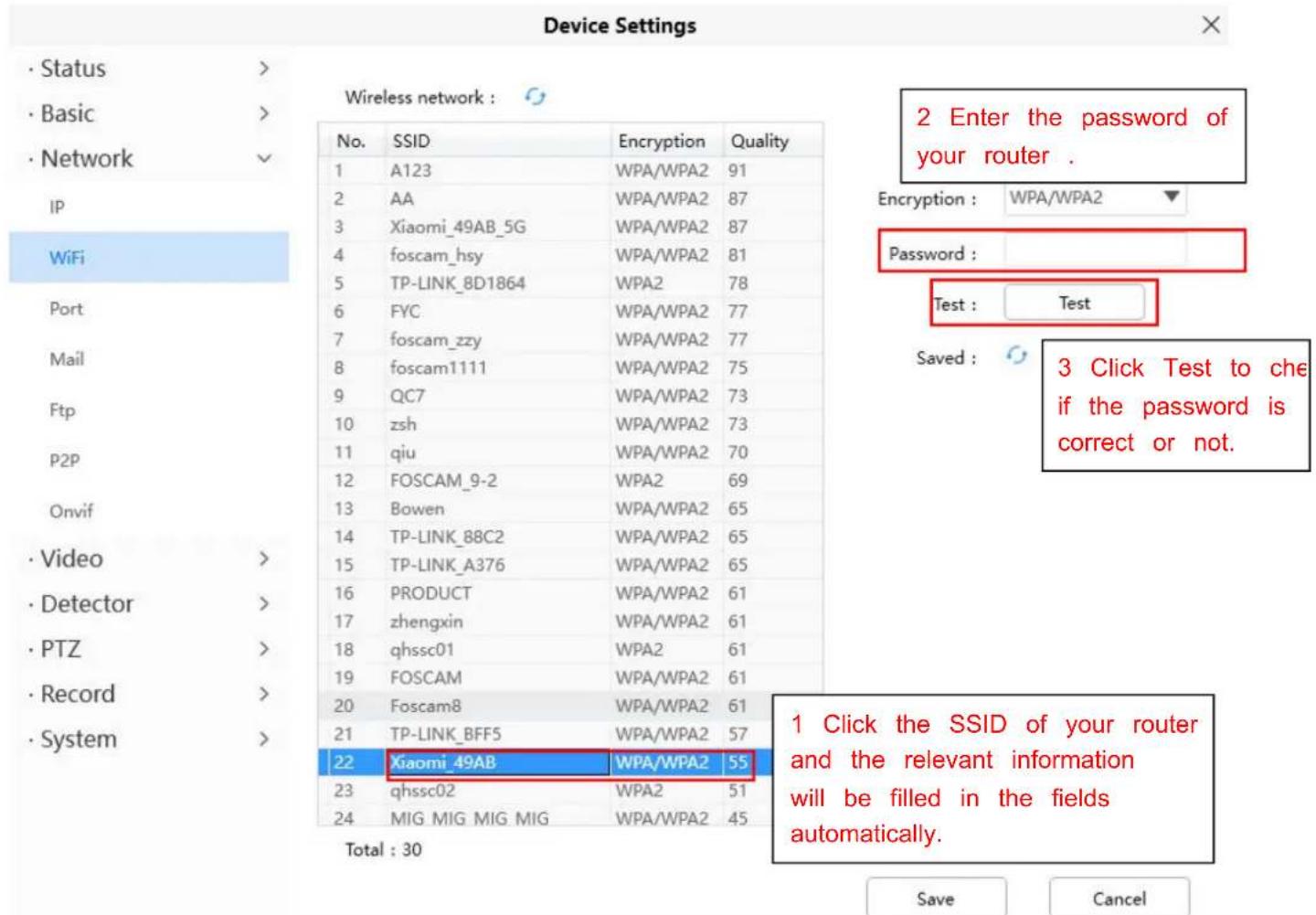
text_image
Device Settings · Status > · Basic > · Network IP WiFi Port Mail Ftp P2P Onvif · Video > · Detector > · PTZ > · Record > · System No. SSID Encryption Quality 1 A123 WPA/WPA2 91 2 AA WPA/WPA2 87 3 Xiaomi_49AB_5G WPA/WPA2 87 4 foscam_hsy WPA/WPA2 81 5 TP-LINK_8D1864 WPA2 78 6 FYC WPA/WPA2 77 7 foscam_zzy WPA/WPA2 77 8 foscam1111 WPA/WPA2 75 9 QC7 WPA/WPA2 73 10 zsh WPA/WPA2 73 11 qiu WPA/WPA2 70 12 FOSCAM_9-2 WPA2 69 13 Bowen WPA/WPA2 65 14 TP-LINK_88C2 WPA/WPA2 65 15 TP-LINK_A376 WPA/WPA2 65 16 PRODUCT WPA/WPA2 61 17 zhengxin WPA/WPA2 61 18 qhssc01 WPA2 61 19 FOSCAM WPA/WPA2 61 20 Foscam8 WPA/WPA2 61 21 TP-LINK_BFF5 WPA/WPA2 57 22 Xiaomi_49AB WPA/WPA2 55 23 qhssc02 WPA2 51 24 MIG MIG MIG MIG WPA/WPA2 45 Total : 30 2 Enter the password of your router . Encryption : WPA/WPA2 Password : Test : Test Saved : 3 Click Test to che if the password is correct or not. 1 Click the SSID of your router and the relevant information will be filled in the fields automatically. Save CancelStep 3: Please click on the Save button after all settings have been entered and disconnect the network cable.
Never shut down the power of the camera until the IP camera is able to connect to the wireless network. The LAN IP address will disappear on the window of Add Device when the camera is configuring a wireless connection. Wait about 1 minute, the camera should obtain a wireless connection, and the LAN the camera will show again on the window of Add Device. The IP address may have changed after the camera receives a wireless connection; we recommend setting a static local IP address if this address changes by right clicking the camera in Equipment Search Tool, setting a static IP, and pushir Congratulations! You have set up the wireless connection of the camera successfully.
NOTE: If you fail to make a wireless connection, please refer to your seller or contact us directly for assistance.
4.6.3.3 Port
This camera supports HTTP Port / HTTPS Port/ ONVIF Port. HTTP Port is used to access the camera remotely.
HTTP port: By default, the HTTP is set to 88. Also, they can be assigned with another port number between 1 and 65535. But make sure they can not be conflict with other existing ports like 25, 21.
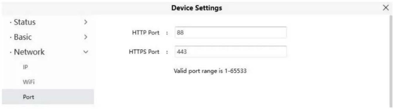
text_image
Device Settings • Status > • Basic > • Network ✓ IP WiFi Port HTTP Port : 88 HTTPS Port : 443 Valid port range is 1-655334.6.3.4 Mail Settings
If you want the camera to send emails when motion has been detected, here Mail will need to be cc
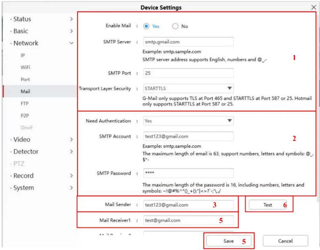
text_image
Device Settings • Status > • Basic > • Network IP WiFi Port Mail FTP P2P Onvif • Video > • Detector > • PTZ • Record > • System Enable Mail : Yes No SMTP Server : smtp.gmail.com Example: smtp.sample.com SMTP server address supports English, numbers and @_. 1 SMTP Port : 25 Transport Layer Security : STARTTLS G-Mail only supports TLS at Port 465 and STARTTLS at Port 587 or 25. Hotmail only supports STARTTLS at Port 587 or 25. Need Authentication : Yes SMTP Account : test123@gmail.com Example: smtp.sample.com The maximum length of email is 63, support numbers, letters and symbols: @_ $*- SMTP Password : **** The maximum length of the password is 16, including numbers, letters and symbols: ~!@#%^*()_+():*|<>?`-:\./ Mail Sender : test123@gmail.com 3 Test 6 Mail Receiver1 : test@gmail.com 5 Save 5 Cancel1---- SMTP Server/ Port /Transport Layer Security Enter SMTP server for sender. SMTP port is usually set as 25. Some SMTP servers have their own port, such as 587 or 465, and Transport Layer Securi is None. If you use Gmail, Transport Layer Security must be set to TLS or STARTTLS and SMTP Po set to 465 or 25 or 587, which port you choose should be decided by which Transport Layer Security select.
2---- SMTP Account/ password ID account and password of the sender email address
3---- E-mail Sender Mailbox for sender must support SMTP
4---- Receiver Mailbox for receiver need not support SMTP, you can set 4 receivers
5---- Save Click Save to take effect
6---- Test Click Test to see if Mail has been successfully configured.
Click Test to see if Mail has been successfully configured.
text_image
Device Can't find smtp log fileIf the test success, you can see the Success behind the Test, at the same time the receivers will receive mail.
If the test fails with one of the following errors after clicking Test, verify that the information you enter correct and again select Test .
1) Cannot connect to the server
2) Network Error. Please try later
3) Server Error
4) Incorrect user or password
5) The sender is denied by the server. Maybe the server need to authenticate the user, please check again
6) The receiver is denied by the server. Maybe because of the anti-spam privacy of the server
7) The message is denied by the server. Maybe because of the anti-spam privacy of the server
8) The server does not support the authentication mode used by the device.
4.6.3.5 FTP
If you want to upload record images to your FTP server, you can set FTP.
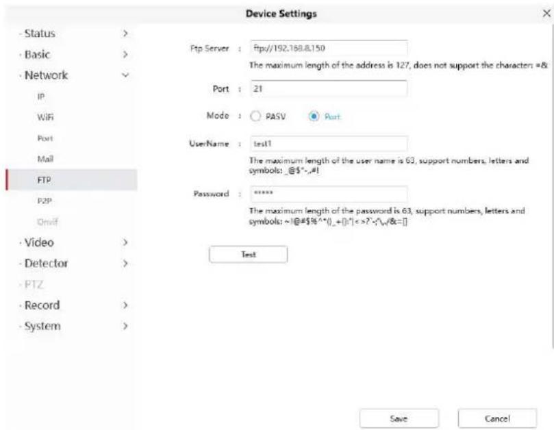
text_image
Device Settings Status > Basic > Network IP WIFI Port Mail FTP P2P Onif Video > Detector > PTZ Record > System > Ftp Server : ftp://192.168.8.150 The maximum length of the address is 127, does not support the character: && Port : 21 Mode : PASV Port UserName : test1 The maximum length of the user name is 63, support numbers, letters and symbols: _@$*-.#! Password : ***** The maximum length of the password is 63, support numbers, letters and symbols: ~1@#$%^*().+[]<=?^.*_&=[] Test Save CancelFTP server: If your FTP server is located on the LAN, you can set as Figure a. If you have an FTP server which you can access on the internet, you can set as Figure b.
Port: Default is port 21. If changed, external FTP client program must change the server connection port accordingly.
Mode: Here supports two modes: PORT and PASV.
Username / password: The FTP account and password.
Click Save to take effect.
Click Test to see if FTP has been successfully configured.
4.6.3.6 P2P
Access the camera by smart phone (Android or iOS operating system)
First of all, you need to open the P2P function of the camera at > Network > P2P.
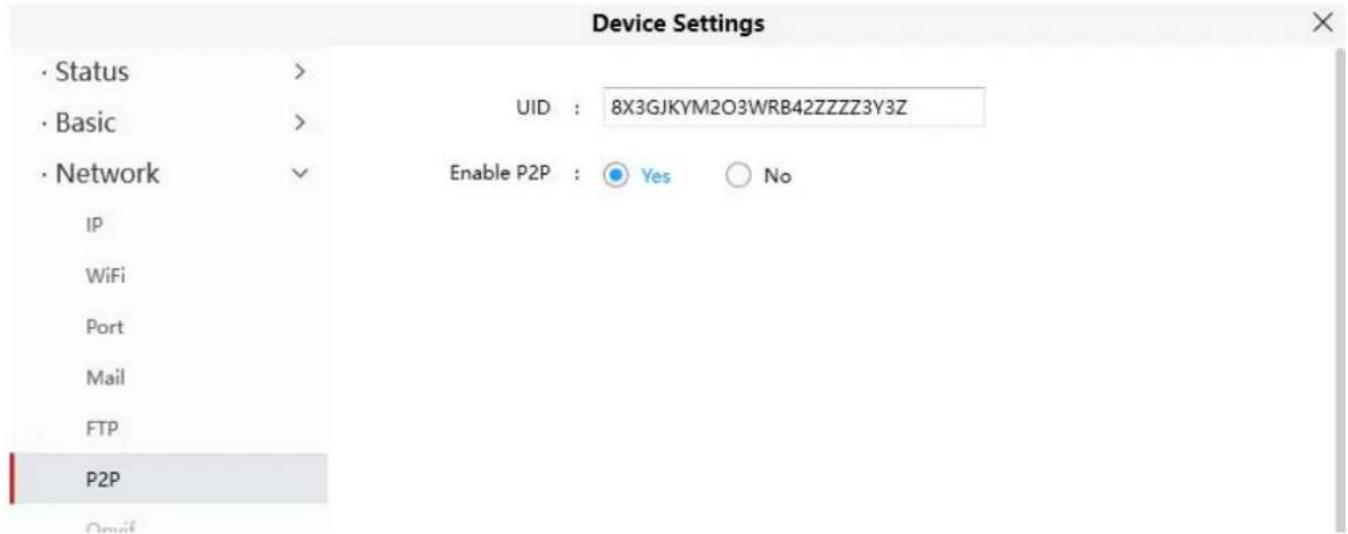
text_image
Device Settings · Status > · Basic > · Network ✓ UID : 8X3GJKYM2O3WRB42ZZZZ3Y3Z Enable P2P : Yes No IP WiFi Port Mail FTP P2P4.6.3.7 Onvif
By default, the ONVIF port is set to 888. Also, they can be assigned with another port number between 1 and 65535 (except 0 and 65534). But make sure they can not be conflict with other existir
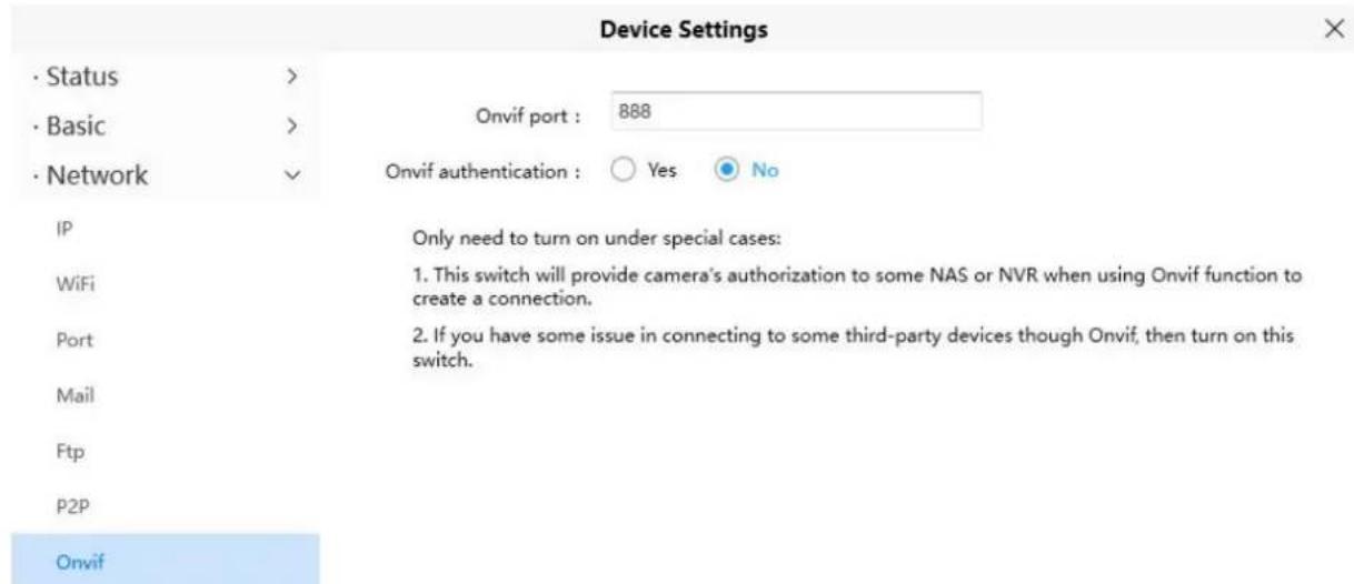
text_image
Device Settings • Status > • Basic > • Network IP WiFi Port Mail Ftp P2P Onvif Onvif port : 888 Onvif authentication : Yes No Only need to turn on under special cases: 1. This switch will provide camera's authorization to some NAS or NVR when using Onvif function to create a connection. 2. If you have some issue in connecting to some third-party devices though Onvif, then turn on this switch.4.6.4 Video
This section allows you to configure Video Encode settings, On screen display, Snapshot and IR LED:
4.6.4.1 Video Encode
This is main Encode video settings.
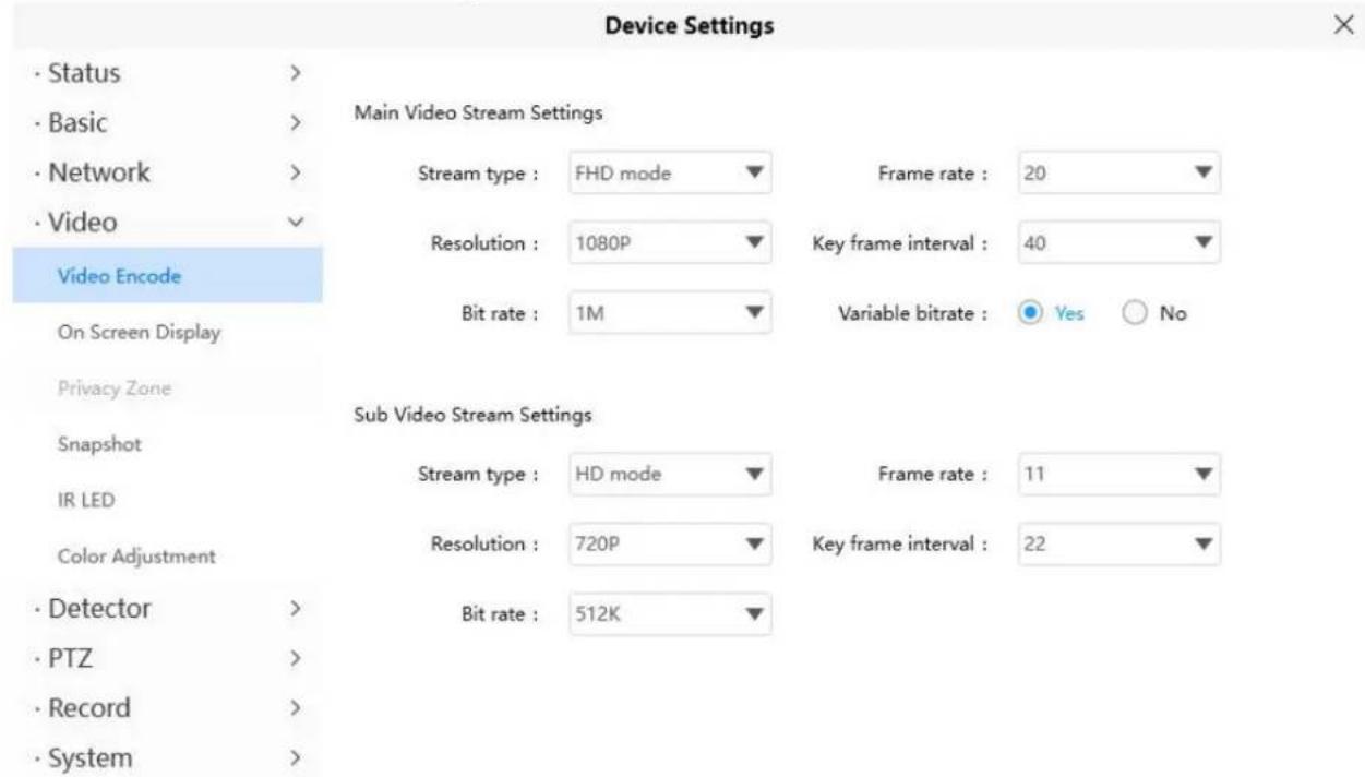
text_image
Device Settings · Status > · Basic > · Network > · Video Video Encode On Screen Display Privacy Zone Snapshot IR LED Color Adjustment · Detector > · PTZ > · Record > · System > Main Video Stream Settings Stream type : FHD mode ▼ Frame rate : 20 ▼ Resolution : 1080P ▼ Key frame interval : 40 ▼ Bit rate : 1M ▼ Variable bitrate : Yes ○ No Sub Video Stream Settings Stream type : HD mode ▼ Frame rate : 11 ▼ Resolution : 720P ▼ Key frame interval : 22 ▼ Bit rate : 512K ▼Stream type: There are four types to identify different streams you have set.
Resolution: The camera supports multiple types. For example: 1080P, 720P, VGA. The higher the resolution is, the clearer video will become. But the code flux will become larger too, and it will take bandwidth. (Different models support different specific types.)
Bit Rate: Generally speaking, the larger the bit rate is, the clearer video will become. But the bit rate configuration should combine well with the network bandwidth. When the bandwidth is very narrow, and is large, that will lead to video can not play well.
Frame Rate: Note that a larger frame size takes up more bandwidth. When the video format is 50Hz, the maximum frame rate is 25 fps. When the video format is 60Hz, the maximum frame rate is 30 fps. Y lower frame rate when the bandwidth is limited. Normally, when the frame rate above 15, you can ach fluently video.
Key Frame Interval: The time between last key frame and next key frame. The shorter the duration, the more likely you will get a better video quality, but at the cost of higher network bandwidth consumption.
Variable Bitrate: Select the Bit rate type to constant or variable. If select Yes, the camera will change the video bit rate according to the situation, but will not more than the maximum parameter "Bit Rate"; If select No, the Bit Rate is unchanged.
4.6.4.2 On Screen Display
This page is used to add timestamp and device name on the video.
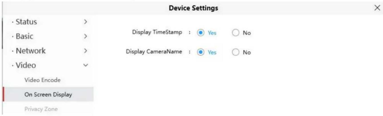
text_image
Device Settings Status > Basic > Network > Video Video Encode On Screen Display Privacy Zone Display TimeStamp : Yes No Display CameraName : Yes NoDisplay Timestamp: There are two options: Yes or NO. Select Yes and you can see the system date on the video,
Display Camera Name: There are two options: Yes or NO. Select Yes and you can see the device name on the video.
4.6.4.3 Snapshot
On this page you can set the snapshot pictures' image quality and the storage path.
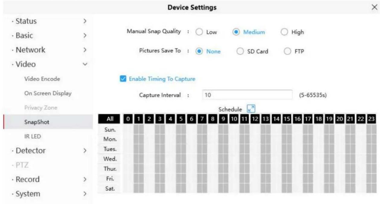
text_image
Device Settings Status > Basic > Network > Video Video Encode On Screen Display Privacy Zone SnapShot IR LED > Detector > PTZ Record > System > Manual Snap Quality : Low Medium High Pictures Save To : None SD Card FTP Enable Timing To Capture Capture Interval : 10 (5-65535s) Schedule All 0 1 2 3 4 5 6 7 8 9 10 11 12 13 14 15 16 17 18 19 20 21 22 23 Sun. Mon. Tues. Wed. Thur. Fri. Sat.Manual Snap Quality: Low, Middle and High. The higher the quality, the picture will be clearer. Pictures Save To: FTP. If you have done FTP and Alarm settings, when alarming, the camera will snap pictures to the FTP automatically. If you select the FTP, you can set the file name which the picture
Enable Timing to Capture
To enable capture interval, follow the steps below:
1 Select Enable timing to capture
2 Capture interval: The interval time between two captures.
3 Select the capture time
- Capture anytime
Click the black button up the MON, you will see all time range turn red. When something moving detection area at anytime, the camera will capture.
- Specify an capture schedule
Click the week day words, the corresponding column will be selected. For example, click TUE, the column of TUE turns to red, that means during Tuesday whole day, the camera will capture.
- Press the left mouse and drag it on the time boxes, you can select the serial area,
4 Click Save button to take effect.
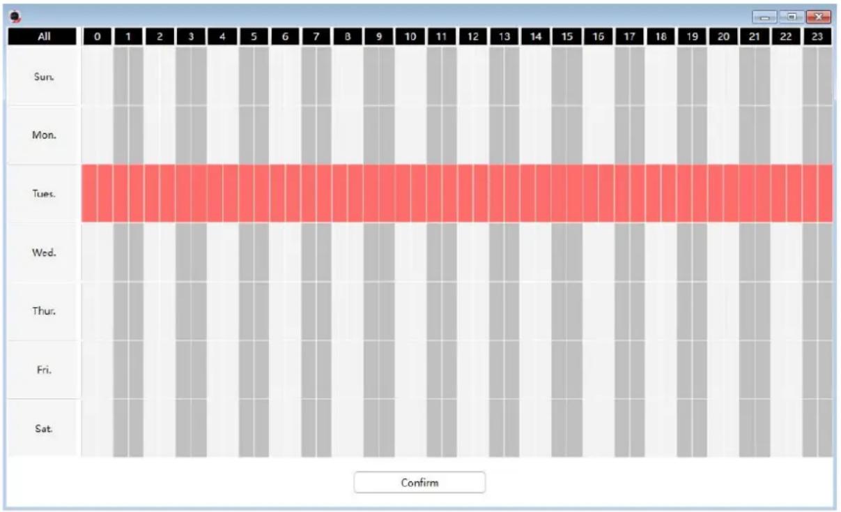
4.6.4.4 IR LED
There are three modes to set the IR LED lights.
Auto: The default mode is auto. On this mode, IR LED lights will be switched automatically depended on the brightness of environment.
Manual: On this mode, you can click On option to turn on the IR LED lights, and click Off option to turn off the IR LED lights.
Schedule: On this mode, IR LED lights will be turned off during the setting schedule. You can set the period of time during which the infrared lamp is turned off to prevent your baby from being influenced during sle can also turn off the infrared lamp on the video preview page at any time.
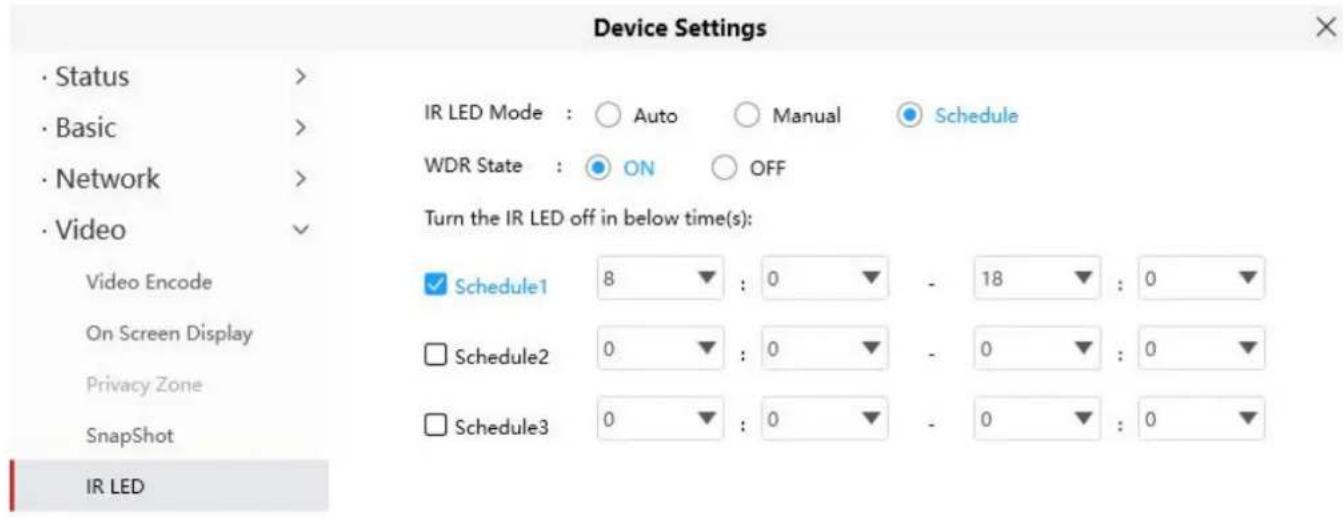
text_image
Device Settings Status > Basic > Network > Video Video Encode On Screen Display Privacy Zone SnapShot IR LED IR LED Mode : ○ Auto ○ Manual ● Schedule WDR State : ON ○ OFF Turn the IR LED off in below time(s): ✓ Schedule1 8 ▼ : 0 ▼ - 18 ▼ : 0 ▼ □ Schedule2 0 ▼ : 0 ▼ - 0 ▼ : 0 ▼ □ Schedule3 0 ▼ : 0 ▼ - 0 ▼ : 0 ▼4.6.4.5 Color Adjustment
You can adjust the settings to your liking.
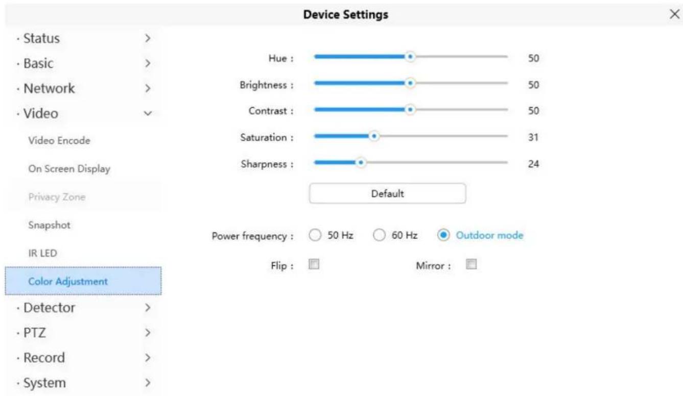
bar
| Device | Value | | --------------- | ----- | | Hue | 50 | | Brightness | 50 | | Contrast | 50 | | Saturation | 31 | | Sharpness | 24 |4.6.5 Detector
4.6.5.1 Motion Detection
IP Camera supports Motion Detection Alarm, when the motion has been detected, it will send emails or upload images to FTP.
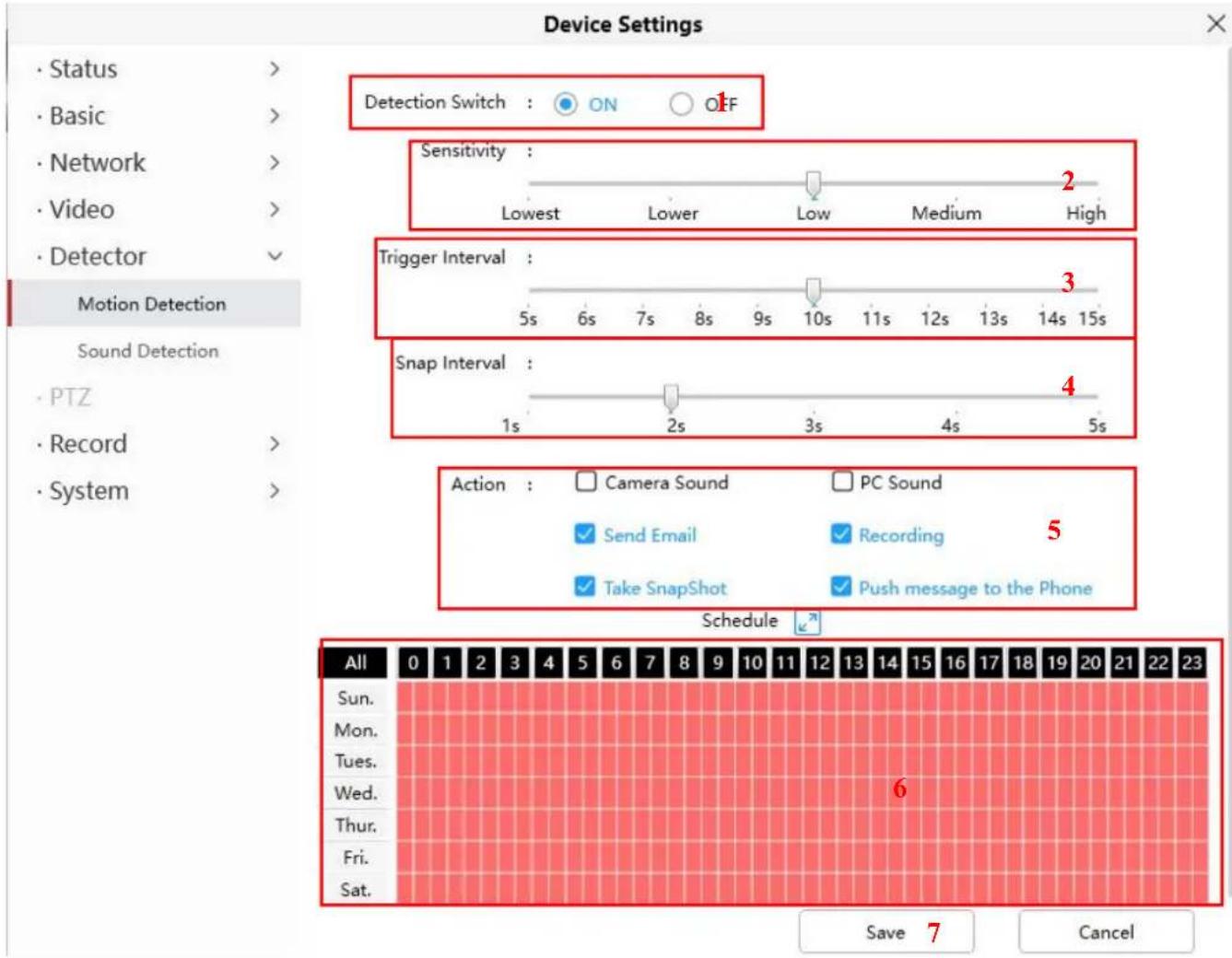
text_image
Device Settings • Status > • Basic > • Network > • Video > • Detector Motion Detection Sound Detection • PTZ • Record > • System > Detection Switch : ON OFF Sensitivity : Lowest Lower Low Medium High Trigger Interval : 5s 6s 7s 8s 9s 10s 11s 12s 13s 14s 15s Snap Interval : 1s 2s 3s 4s 5s Action : Camera Sound PC Sound Send Email Recording 5 Take SnapShot Push message to the Phone Schedule All 0 1 2 3 4 5 6 7 8 9 10 11 12 13 14 15 16 17 18 19 20 21 22 23 Sun. Mon. Tues. Wed. Thur. Fri. Sat. Save 7 CancelTo enable motion detection, follow the steps below:
1 Enable Detection Switch
2 Sensitivity---- It supports three modes: Low, Middle and High. The higher the sensitivity, the camera will be more easily alarmed. Select one motion sensitivity.
3 Trigger Interval----The interval time between two motion detections. Here supports 5s/6s/7s/8s/9s/10s/11s/12s/13s/14s/15s. Select one interval time.
4 Snap Interval---- The interval time between two pictures.
5 Select the alarm indicators
There are some alarm indicators:
A Camera Sound
If you select Camera Sound, when the motion has been detected, the people around the Camera will beep alarm sound, if the device is connected with the audio output device.
B PC Sound
If you select PC Sound, when the motion has been detected, the people around the PC will hear bee sound.
C Send E-mail
If you want to receive alarm emails when motion is detected, you must select Send E-mail and set M Settings first.
D Recording
If you select this checkbox, when the motion has been detected, the camera will recording and load it FTP server. Make sure you have set FTP and set FTP as the storage path in Video->Snapshot setting
E Take Snapshot
If you select this checkbox, when the motion has been detected, the camera will snap the live view w a still picture and load it to the FTP. Make sure you have set the storage path in Video > Snapshot Settings panel.
F Push message to the phone
If you select this checkbox, when the motion has been detected, the camera will push the message to phone which has been connected the camera.
6 Alarm Schedule
- Alarm anytime when motion is detected
Click the black button up the MON, you will see all time range turn red. When something moving in detection area at anytime, the camera will alarm.
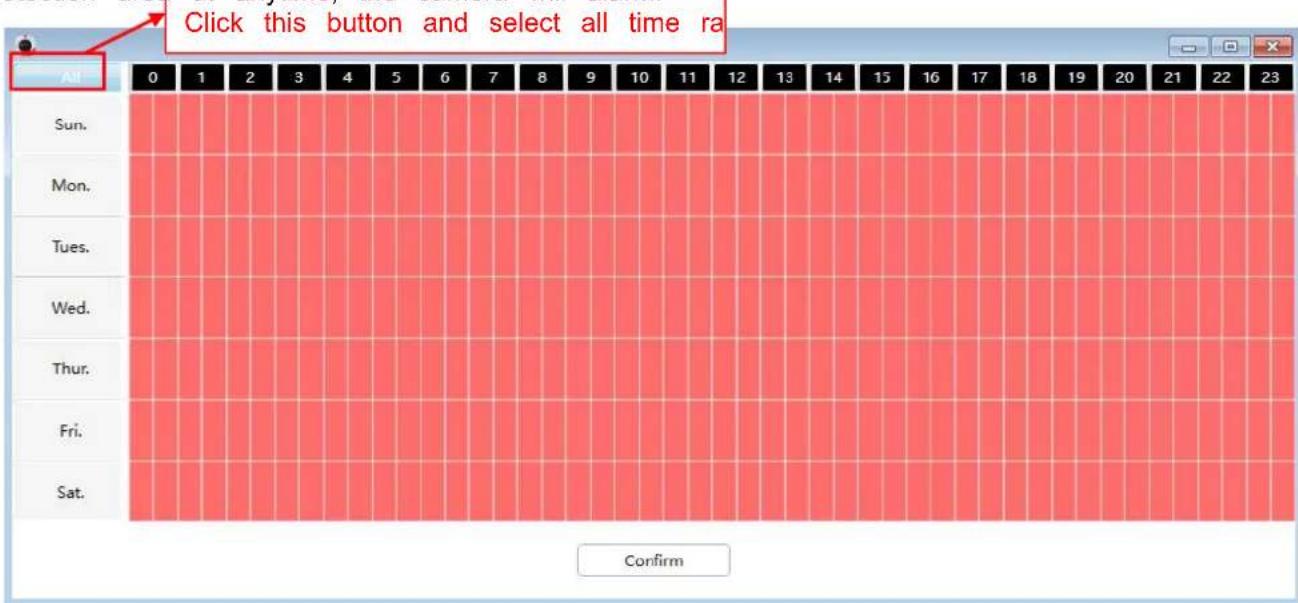
text_image
Click this button and select all time ra All 0 1 2 3 4 5 6 7 8 9 10 11 12 13 14 15 16 17 18 19 20 21 22 23 Sun. Mon. Tues. Wed. Thur. Fri. Sat. Confirm- Specify an alarm schedule
Click the week day words, the corresponding column will be selected. For example, click TUE, the all of TUE turns to red, that means during Tuesday whole day, when something moving in the detection a camera will alarm.
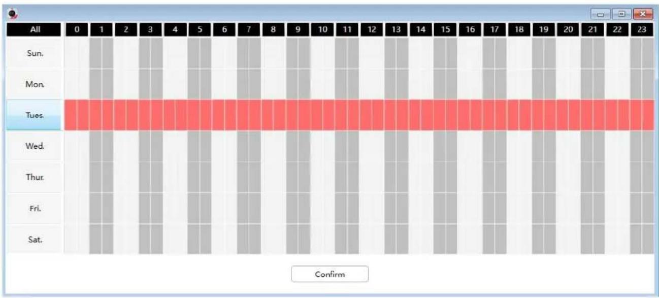
line
| Day | Time (s) | |---|---| | All | 0 | | Sun. | 1 | | Mon. | 2 | | Tues. | 3 | | Wed. | 4 | | Thur. | 5 | | Fri. | 6 | | Sat. | 7 | | All | 8 | | Sun. | 9 | | Mon. | 10 | | Tues. | 11 | | Wed. | 12 | | Thur. | 13 | | Fri. | 14 | | Sat. | 15 | | All | 16 | | Sun. | 17 | | Mon. | 18 | | Tues. | 19 | | Wed. | 20 | | Thur. | 21 | | Fri. | 22 | | Sat. | 23 | | All | Confirm |- Press the left mouse and drag it on the time boxes, you can select the serial area,
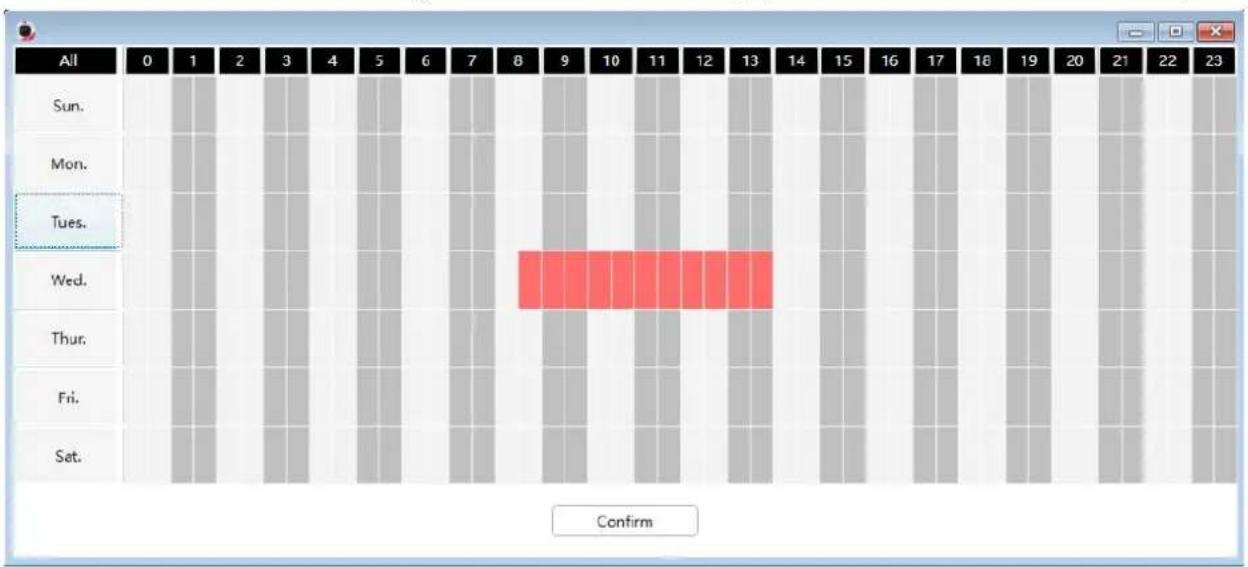
text_image
All 0 1 2 3 4 5 6 7 8 9 10 11 12 13 14 15 16 17 18 19 20 21 22 23 Sun. Mon. Tues. Wed. Thur. Fri. Set. Confirm7 Click Save button to take effect. When the motion is detected during the detection time in the detection area, the camera will alarm and adopt the corresponding alarm indicators.
NOTE: You must set the detection area and detection schedule, or else there is no alarm anywhere and anytime.
4.6.5.2 Sound Detection
When the ambient sound over a certain decibel ,the sound alarm will be triggered.
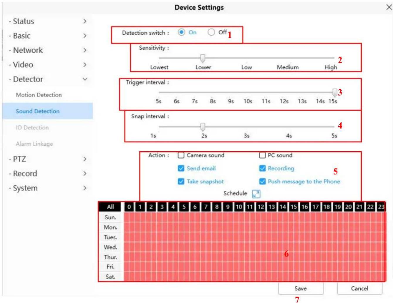
text_image
Device Settings Status > Basic > Network > Video > Detector Motion Detection Sound Detection IO Detection Alarm Linkage PTZ > Record > System > Detection switch : On Off 1 Sensitivity : Lowest Lower Low Medium High Trigger interval : 5s 6s 7s 8s 9s 10s 11s 12s 13s 14s 15s Snap interval : 1s 2s 3s 4s 5s Action : Camera sound PC sound Send email Recording 5 Take snapshot Push message to the Phone Schedule All 0 1 2 3 4 5 6 7 8 9 10 11 12 13 14 15 16 17 18 19 20 21 22 23 Sun. Mon. Tues. Wed. Thur. Fri. Sat. Save Cancel 6 7To enable motion detection, follow the steps below:
1 Enable Detection Switch
2 Sensitivity---- It supports three modes: Low, Middle and High. The higher the sensitivity, the camera will be more easily alarmed. Select one motion sensitivity.
3 Trigger Interval----The interval time between two motion detections. Here supports 5s/6s/7s/8s/9s/10s/11s/12s/13s/14s/15s. Select one interval time.
4 Snap Interval---- The interval time between two pictures.
5 Select the alarm indicators
There are some alarm indicators:
A Camera Sound
If you select Camera Sound, when the sound has been detected, the people around the Camera will alarm sound, if the device is connected with the audio output device.
B PC Sound
If you select PC Sound, when the sound has been detected, the people around the PC will hear beer sound.
C Send E-mail
If you want to receive alarm emails when motion is detected, you must select Send E-mail and set M Settings first.
D Recording
If you select this checkbox, when the sound has been detected, the camera will recording and load it FTP server. Make sure you have set FTP and set FTP as the storage path in Video->Snapshot setting
E Take Snapshot
If you select this checkbox, when the sound has been detected, the camera will snap the live view with still picture and load it to the FTP. Make sure you have set the storage path in Video > Snapshot Settings panel.
F Push message to the phone
If you select this checkbox, when the sound has been detected, the camera will push the message to phone which has been connected the camera.
6 Alarm Schedule
4. Alarm anytime when sound is detected
Click the black button up the MON, you will see all time range turn red. When something moving in detection area at anytime, the camera will alarm.
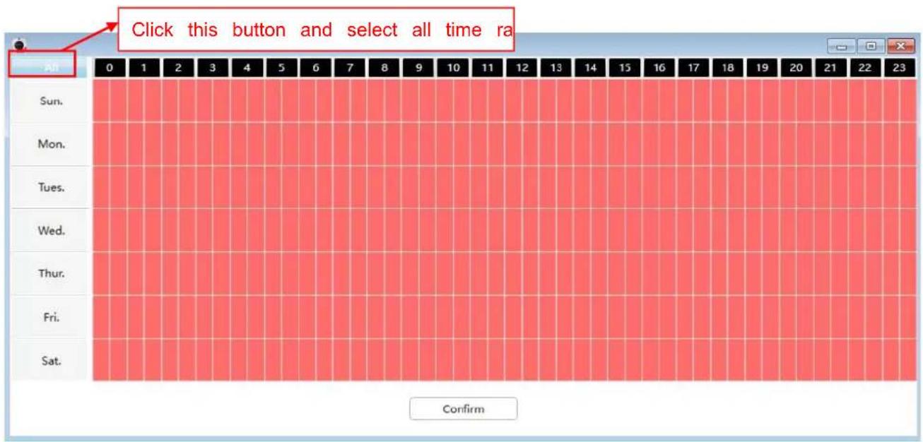
text_image
Click this button and select all time ra All 0 1 2 3 4 5 6 7 8 9 10 11 12 13 14 15 16 17 18 19 20 21 22 23 Sun. Mon. Tues. Wed. Thur. Fri. Sat. Confirm5. Specify an alarm schedule
Click the week day words, the corresponding column will be selected. For example, click TUE, the all of TUE turns to red, that means during Tuesday whole day, when something sound in the detection at camera will alarm.
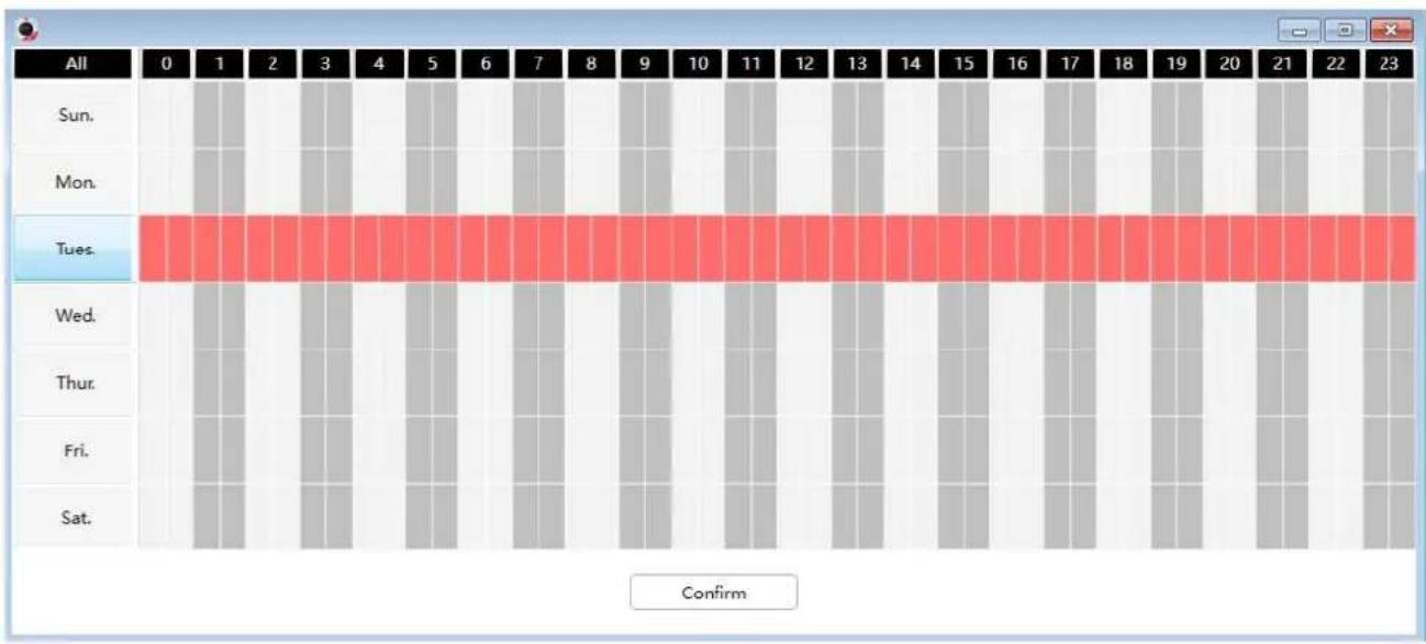
line
| Day | Time (s) | |---|---| | All | 0 | | Sun. | 1 | | Mon. | 2 | | Tues. | 3 | | Wed. | 4 | | Thur. | 5 | | Fri. | 6 | | Sat. | 7 | | All | 8 | | Sun. | 9 | | Mon. | 10 | | Tues. | 11 | | Wed. | 12 | | Thur. | 13 | | Fri. | 14 | | Sat. | 15 | | All | 16 | | Sun. | 17 | | Mon. | 18 | | Tues. | 19 | | Wed. | 20 | | Thur. | 21 | | Fri. | 22 | | Sat. | 23 | | All | Confirm |- Press the left mouse and drag it on the time boxes, you can select the serial area,
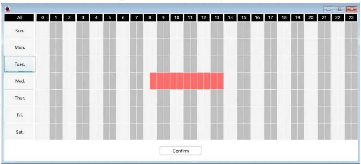
text_image
All 0 1 2 3 4 5 6 7 8 9 10 11 12 13 14 15 16 17 18 19 20 21 22 23 Sun. Mon. Tues. Wed. Thur. Fri. Set. Confirm7 Click Save button to take effect. When the sound is detected during the detection time in the detection area, the camera will alarm and adopt the corresponding alarm indicators.
NOTE: You must set the detection area and detection schedule, or else there is no alarm anywhere and anytime.
4.6.6 PTZ
This page will allow you to change the pan/tilt speed and do cruise tracks settings.
4.6.6.1 PTZ Parameters
Pan & Tilt Speed: There are five PT speed types: very fast, fast, normal, slow and very slowly. Select desired PTZ speed type and click save button.
Start-up Option: Here section will allow you to set the stop position after the camera reboots. It supports two modes: Go to home position and Go to preset point.
Disable Start-up: When rebooting, the camera will not pan / tilt.
Goto home position: When rebooting, the camera will pa Providing Central Management Software to manage or monitor multi-cameras n / tilt and stops at center.
Go to Preset pointion: Select one preset position and save it. When rebooting, the camera will pan/ tilt and stops at the preset position you have set.
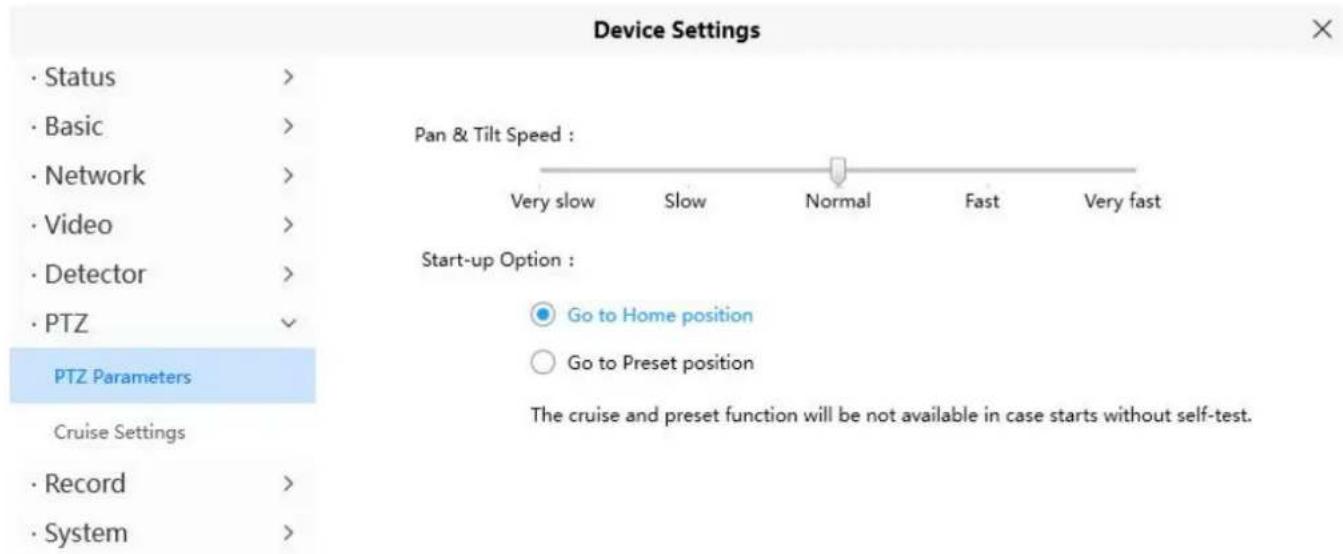
text_image
Device Settings • Status > • Basic > • Network > • Video > • Detector > • PTZ PTZ Parameters Cruise Settings • Record > • System > Pan & Tilt Speed : Very slow Slow Normal Fast Very fast Start-up Option : Go to Home position Go to Preset position The cruise and preset function will be not available in case starts without self-test.4.6.6.2 Cruise Settings
This section explains how to add/ delete/ alter one cruise track.
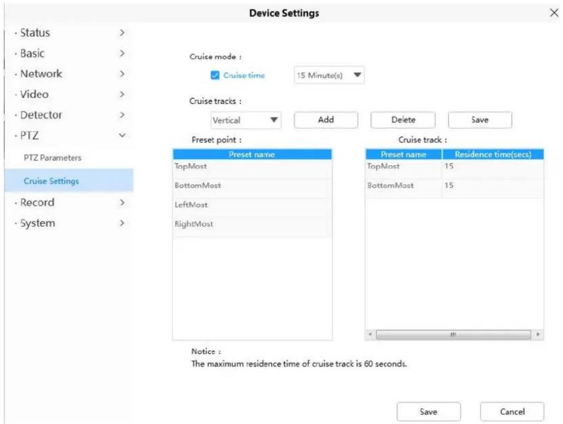
text_image
Device Settings • Status > • Basic > • Network > • Video > • Detector > • PTZ PTZ Parameters Cruise Settings • Record > • System > Cruise mode : Cruise time 15 Minute(s) Cruise tracks : Vertical Add Delete Save Preset point : Cruise track : Preset name TopMost BottomMost LeftMost RightMost Preset name Residence time(secs) TopMost 15 BottomMost 15 Notice : The maximum residence time of cruise track is 60 seconds. Save CancelSetting the Cruise Mode
Cruise mode: Cruise time.
Cruise time: Select Cruise time from Cruise Mode drop-down, then you can set the Cruise time of the camera.
Click Save to take effect.
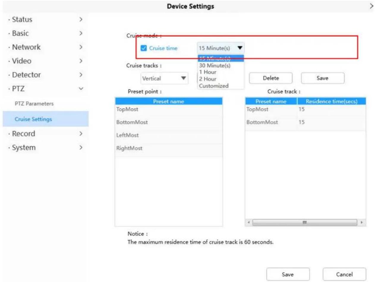
text_image
Device Settings Status > Basic > Network > Video > Detector > PTZ PTZ Parameters Cruise Settings Record > System > Cruise mode : ✓ Cruise time 15 Minute(s) ▼ 15 Minute(s) Cruise tracks : Vertical ▼ 30 Minute(s) 1 Hour 2 Hour Customized Delete Save Preset point : Cruise track : Preset name TopMost BottomMost LeftMost RightMost Cresidence time(secs) TopMost 15 BottomMost 15 Notice : The maximum residence time of cruise track is 60 seconds. Save CancelManage the Cruise Track
There are two default cruise tracks: Vertical and Horizontal.
Vertical: The camera will rotate from up to down
Horizontal: The camera will rotate form left to right.
Add: Add one cruise track, then click save button.
Delete: Select one cruise track and delete it.
Save: After you modify the Dwell time, you should click Save button to take effect.
Example
How to do add cruise tracks?
Firstly, Click Add button and enter a descriptive name to identify the cruise track.
Secondly: On the lower left of the page, you can see all preset points you have added. Select one preset point
and click Add button, you can see the preset point has been added to the cruise track on the cruise You need to add two or more preset points to the cruise track.
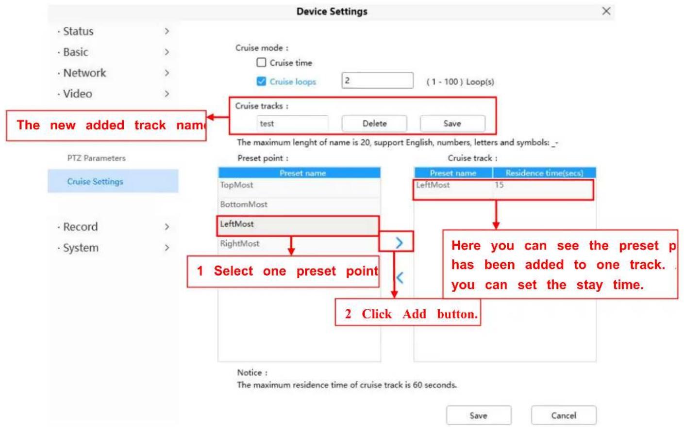
flowchart
graph TD
    A["The new added track name"] --> B["Preset point"]
    B --> C{1 Select one preset point}
    C --> D["2 Click Add button."]
    D --> E["Here you can see the preset p has been added to one track. you can set the stay time."]
    F["PTZ Parameters"] --> G["Cruise Settings"]
    G --> H["Record"]
    G --> I["System"]
    J["Cruise mode"] --> K["Cruise loops 2 (1 - 100) Loop(s)"]
    K --> L["Cruise tracks: test Delete Save"]
    M["Notice"] --> N["The maximum residence time of cruise track is 60 seconds."]
Thirdly: Click Save button and the cruise track will take effect.
You can add other cruise track as the same method.
For example: I have added three preset points to the "track 1", that means : When I select the "track surveillance window, the camera moves as the following track: upright then Right Most last down left. You can add preset on the left of the surveillance window.
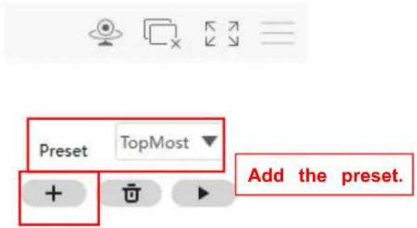
text_image
Preset TopMost + Add the preset.
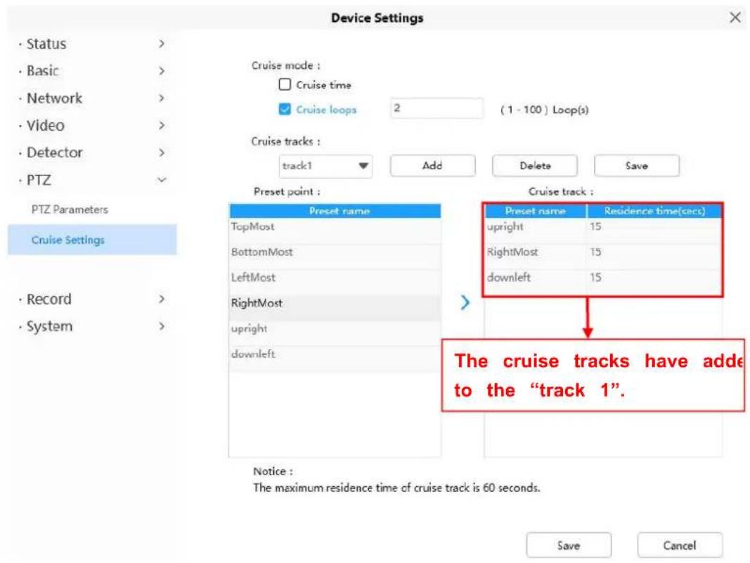
text_image
Device Settings • Status > • Basic > • Network > • Video > • Detector > • PTZ PTZ Parameters Cruise Settings • Record > • System > Cruise mode : □ Cruise time ✓ Cruise loops 2 (1 - 100 ) Loop(s) Cruise tracks : track1 Add Delete Save Preset point : Preset name TopMost BottomMost LeftMost RightMost upright downleft Cruise track : Preset name Residence time(sec) upright 15 RightMost 15 downleft 15 The cruise tracks have added to the "track 1". Notice : The maximum residence time of cruise track is 60 seconds. Save Cancel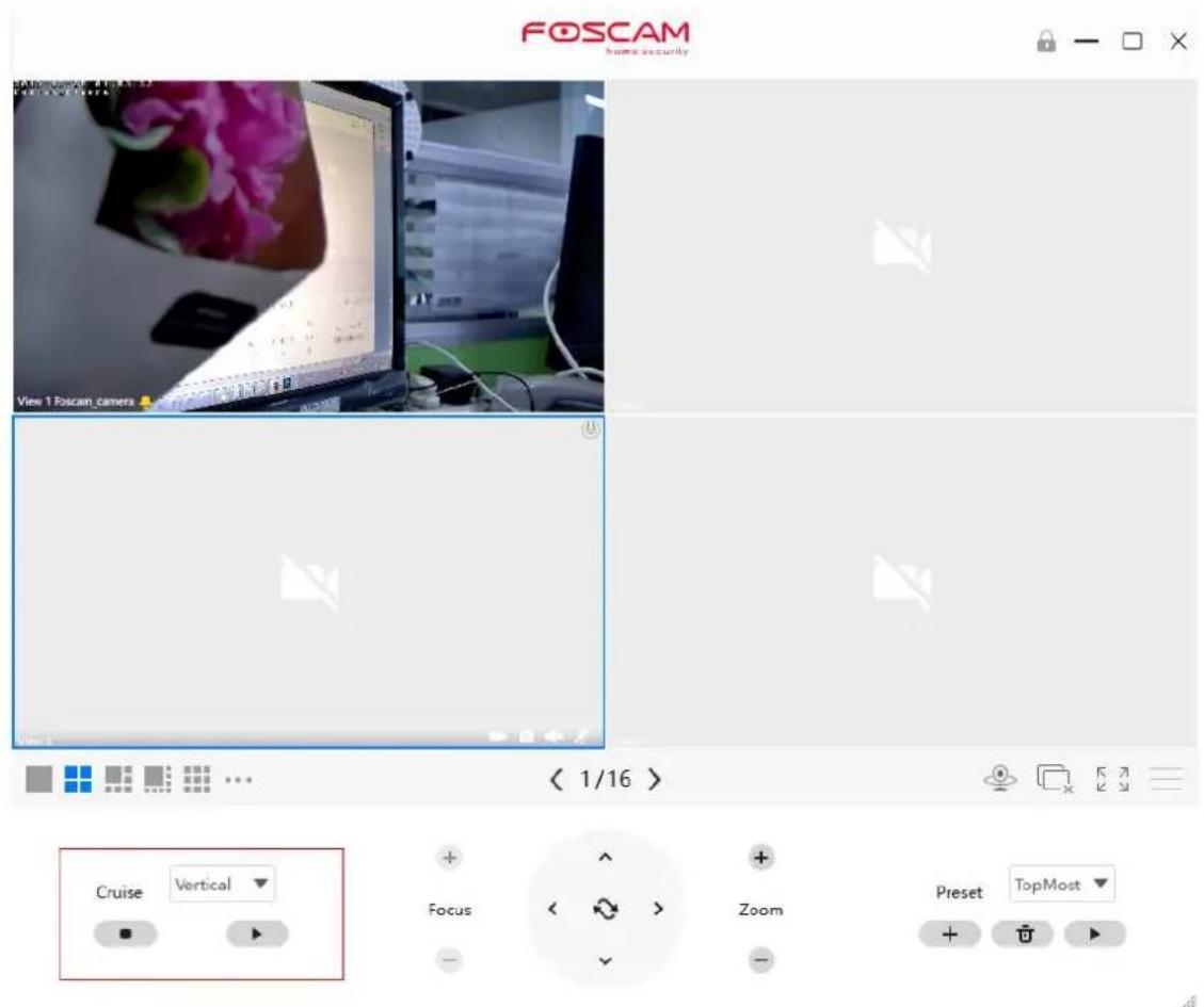
text_image
FOSCAM home security View 1 Foscan camera Cruise Vortical Focus Zoom Preset TopMostAfter add the cruise track, back to the surveillance window, click Cruise, here you can see all cruise I have added.
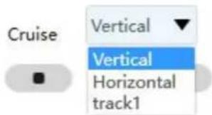
text_image
Cruise Vertical Vertical Horizontal track1There are other buttons between the Preset points and Cruise track, you can use these buttons to adj order of preset points or add/delete one preset points in one cruise track.
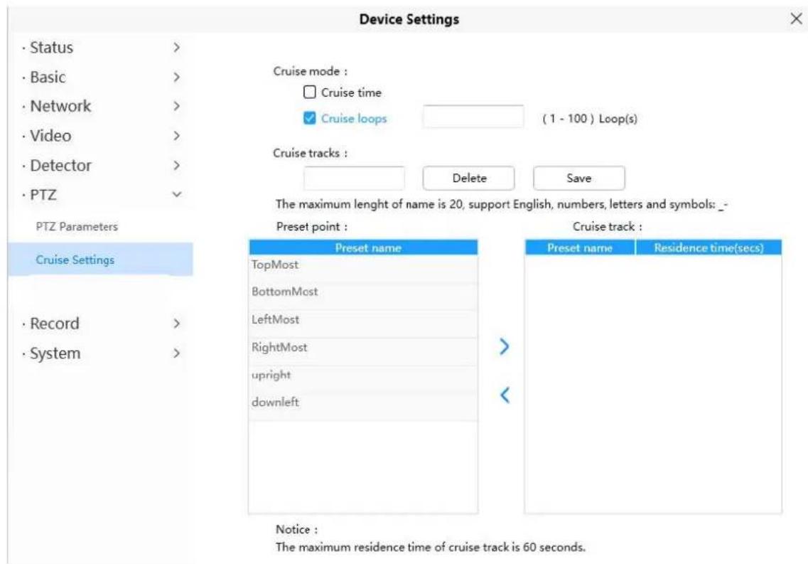
text_image
Device Settings • Status > • Basic > • Network > • Video > • Detector > • PTZ PTZ Parameters Cruise Settings • Record > • System > Cruise mode : □ Cruise time ✓ Cruise loops (1 - 100 ) Loop(s) Cruise tracks : Delete Save The maximum lenght of name is 20, support English, numbers, letters and symbols: _ Preset point : Cruise track : Preset name Residence time(secs) TopMost BottomMost LeftMost RightMost upright downleft Notice : The maximum residence time of cruise track is 60 seconds.: Select one preset points and add it to the selected cruise track.
: Select one preset points you have added to one cruise track, click delete.
Attention:
Considering the life time and thermal issue of the motor, it's not recommend to do long-time cruise.
4.6.7 Record
4.6.7.1 Storage Management
On this page you can choose Record Storage Path. The record storage path default is No Path
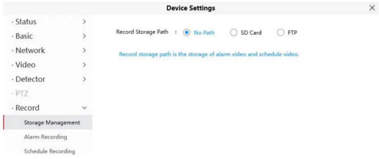
text_image
Device Settings • Status > • Basic > • Network > • Video > • Detector > • PTZ • Record Storage Management Alarm Recording Schedule Recording Record Storage Path : ● No Path ○ SD Card ○ FTP Record storage path is the storage of alarm video and schedule video.4.6.7.2 Alarm Recording
On this page you can configure the Alarm-recording Time, Enable pre-recorded time and Pre-Record Tin
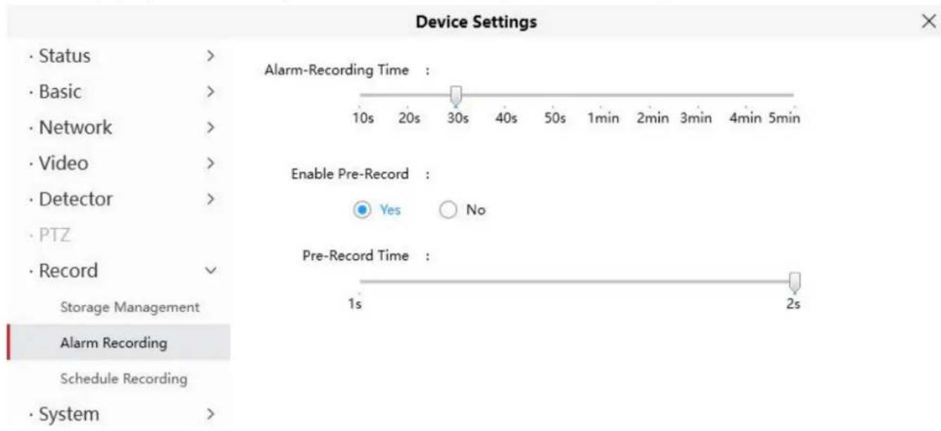
text_image
Device Settings Status > Basic > Network > Video > Detector > PTZ Record Storage Management Alarm Recording Schedule Recording System > Alarm-Recording Time : 10s 20s 30s 40s 50s 1min 2min 3min 4min 5min Enable Pre-Record : Yes No Pre-Record Time : 1s 2s4.6.7.3 Schedule Recording
On the page you can configure the schedule record.
Note: Schedule Recording only supports FTP server. Schedule Recording can only be enabled after the recording path is set Please set the path in the storage management.
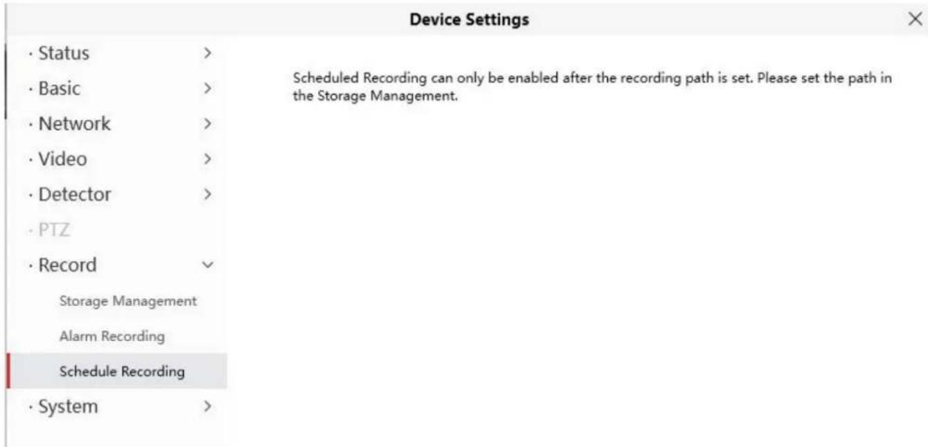
text_image
Device Settings • Status > • Basic > • Network > • Video > • Detector > • PTZ • Record Storage Management Alarm Recording Schedule Recording • System >Click Save button to take effect.
4.6.8 System
In this panel, you can back up/restore your camera settings, upgrade the firmware to the latest version, the camera to default settings and reboot the device.
4.6.8.1 Back-up & Restore
Click Backup to save all the parameters you have set. These parameters will be stored in a bin file if use.
Click Browse and select the parameters file you have stored, then click Submit to restore the restore t parameters.
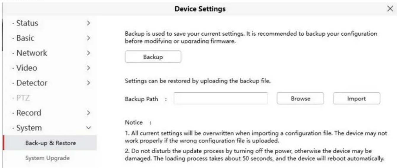
text_image
Device Settings Status > Basic > Network > Video > Detector > PTZ Record > System Back-up & Restore System Upgrade Backup is used to save your current settings. It is recommended to backup your configuration before modifying or upgrading firmware. Backup Settings can be restored by uploading the backup file. Backup Path : Browse Import Notice : 1. All current settings will be overwritten when importing a configuration file. The device may not work properly if the wrong configuration file is uploaded. 2. Do not disturb the update process by turning off the power, otherwise the device may be damaged. The loading process takes about 50 seconds, and the device will reboot automatically.4.6.8.2 System Upgrade
Click Download the Latest Firmware, you will see the following screen. And click Save to save the firmware on your computer locally.
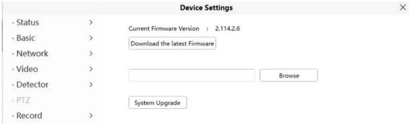
text_image
Device Settings • Status > • Basic > • Network > • Video > • Detector > • PTZ • Record >Your current firmware version will be displayed on your screen. You may go to the Status > Device
Information page to check for the latest firmware versions available.
Click Browse, choose the correct bin file and then click System upgrade.
Don't shut down the power during upgrade. After upgrading, you can see the upgrade result.
Upgrade Firmware by Equipment Search Tool

Double click the IP Camera Tool shot icon , select the Camera IP that you want to upgrade the firmThen select Upgrade Firmware and enter the username and password, choose the firmware file, and up
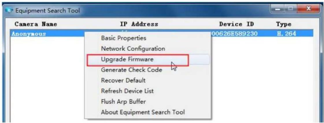
text_image
Equipment Search Tool Camera Name IP Address Device ID Type Anonymous Basic Properties 00626E589230 H. 264 Network Configuration Upgrade Firmware Generate Check Code Recover Default Refresh Device List Flush Arp Buffer About Equipment Search Tool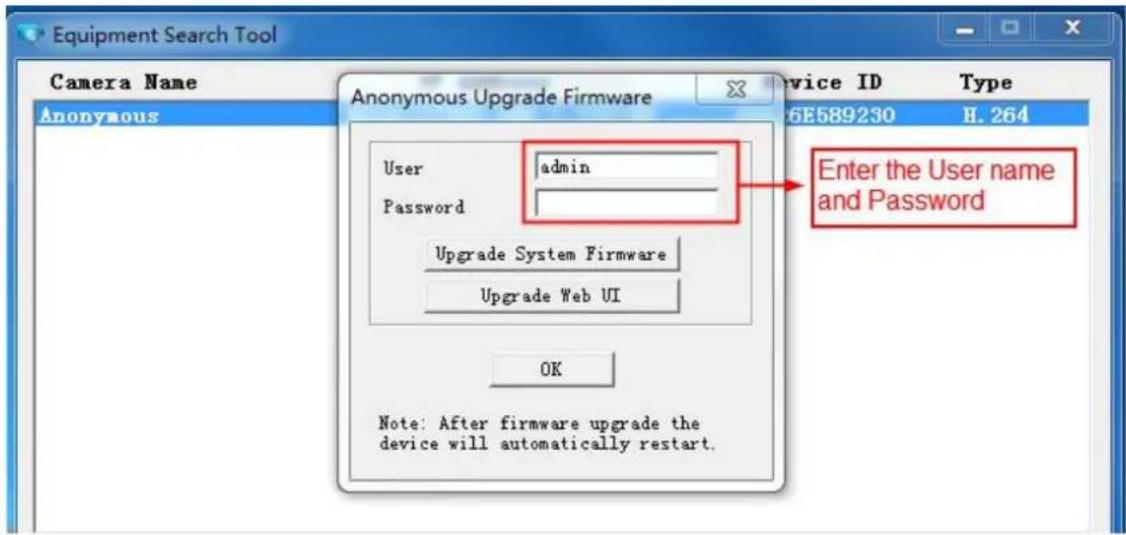
text_image
Equipment Search Tool Camera Name Anonymous Anonymous Upgrade Firmware User admin Password Upgrade System Firmware Upgrade Web UI OK Note: After firmware upgrade the device will automatically restart. Device ID Type 6E589230 H. 264 Enter the User name and PasswordCAUTION: We recommend that you regularly update your camera to the latest available software and firmware versions to help ensure the best experience for your camera.
NOTE:
1) Please ensure you have download the correct firmware package for your camera before upgrading. For the upgrade documentation (readme.txt file) in the upgrade package before you upgrade.
2) Upon downloading the firmware check the sizes of the .bin files. They must match the size in the file. If not, please download the firmware again until the sizes are the same. Your camera will not fun correctly if a corrupt .bin file is used.
3) Never shut down the power of the camera during upgrade until the IP camera restart and get conr
4) After upgrade successfully, please clear the cache of browser, uninstall the old plugin and re-install i reset the camera to the default factory settings before using the camera.
4.6.8.3 Patch Installation
Click "Browse" to select the correct patch file, and then click "Install Patch" to install the patch. Do not turn off the power during it installing. After installing is complete, you will receive a system prompt.
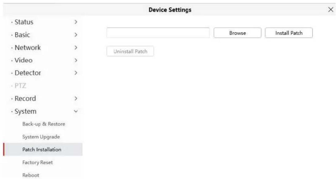
text_image
Device Settings Status > Basic > Network > Video > Detector > PTZ Record > System Back-up & Restore System Upgrade Patch Installation Factory Reset Reboot4.6.8.4 Factory Reset
Click Factory Reset button and all parameters will return to factory settings if selected.
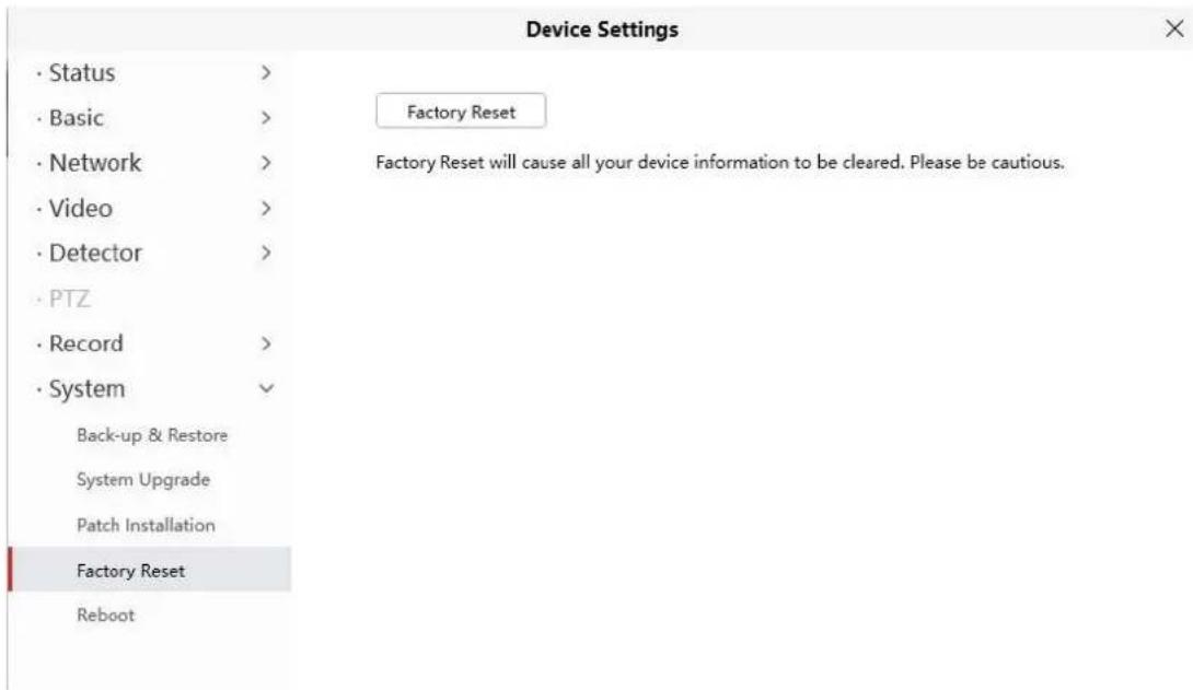
text_image
Device Settings • Status > • Basic > • Network > • Video > • Detector > • PTZ • Record > • System Back-up & Restore System Upgrade Patch Installation Factory Reset Reboot Factory Reset will cause all your device information to be cleared. Please be cautious.4.6.8.5 Reboot
Click Reboot to reboot the camera. This is similar to unplugging the power to the camera.
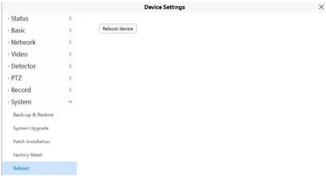
text_image
Device Settings • Status > • Basic > • Network > • Video > • Detector > • PTZ > • Record > • System Back-up & Restore System Upgrade Patch Installation Factory Reset Reboot5 Appendix
5.1 Frequently Asked Questions
NOTE: Any questions you would meet, please check Network connections firstly. Check the working status revealed by the indicators on the network server, hub, and exchange. If abnormal, check the network connections.
5.1.1 Unable to connect to router wirelessly
After setup wireless configuration, and input the wireless password correctly, save the settings. Normally, you disconnect the Ethernet cable, wait for few minutes camera will show up again in Equipment Search (or show up in router's DHCP client list/LAN list) with a new IP address. That indicates your camera's connected wirelessly.
If not, please follow below steps to help camera connect wirelessly.
Step1: Please make sure wireless signal is strong enough to connect with.
(1) Make sure the camera antenna is fixed well;
(2) Best to keep the distance between the camera and router in 2\~3 meters while setup;
(3) There's no interference or obstacles from house appliance or walls;
Step2: Please check if your wireless password contains special characters.
Remove special character in SSID and wireless password to have a try.
Step 3: Reboot camera and router to have a check.
If above are all confirmed, power off and on the camera and router may help camera to connect.
Step 4: Please log-in the router and check if the MAC filter feature is enabled.
Camera has wired and wireless MAC, they are different. If your router has wireless MAC filtering turned block camera to connect. Please turn it off, or add camera's MACs in the allow list.
Step 5: Please change the wireless channel, and the wireless encryption of router to have a try.
Change channel helps reduce influence from nearby WiFi networks, you can try 3,6,or 11 for example. encryption, suggest use WPA2/PSK AES.
Step6: At last reset camera to default, and please try re-configure the wireless settings again.
5.1.2 Forgot camera's user name and password
Camera can be hard reset to default settings, when you forgot camera's login user name and password are the steps:
(1) Keep power on camera;
(2) Press and hold reset button of camera for 30 second, till it reboots. Reset button is on bottom, on end cords of the camera.
(3) Once reset, camera will be restored to default settings. And default username / password will then admin / random password on the MAC sticker. Please save your MAC sticker.
5.1.3 How to setup alarm recording to SD card
For the cameras that support Micro SD card, we can save alarm recording on SD card and below are to set it up:
Step 1: Setup the Motion Detection Settings
Please go to Device Settings > Detector > Motion Detection menu.
(1) Click ON for the Detection switch.
(2) Choose Recording for the Action.
(3) Set the Detection Area
(4) Set a Schedule.
(5) Click Save to save the settings.
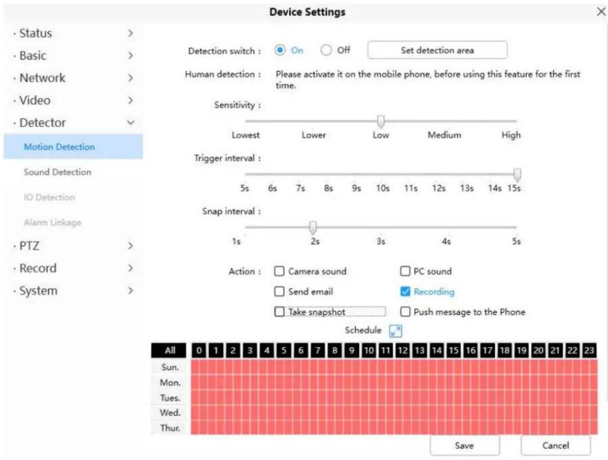
text_image
Device Settings Status > Basic > Network > Video > Detector Motion Detection Sound Detection IO Detection Alarm Linkage PTZ > Record > System > Detection switch : On Off Set detection area Human detection : Please activate it on the mobile phone, before using this feature for the first time. Sensitivity : Lowest Lower Low Medium High Trigger interval : 5s 6s 7s 8s 9s 10s 11s 12s 13s 14s 15s Snap interval : 1s 2s 3s 4s 5s Action : Camera sound PC sound Send email Recording Take snapshot Push message to the Phone Schedule All 0 1 2 3 4 5 6 7 8 9 10 11 12 13 14 15 16 17 18 19 20 21 22 23 Sun. Mon. Tues. Wed. Thur. Save Cancel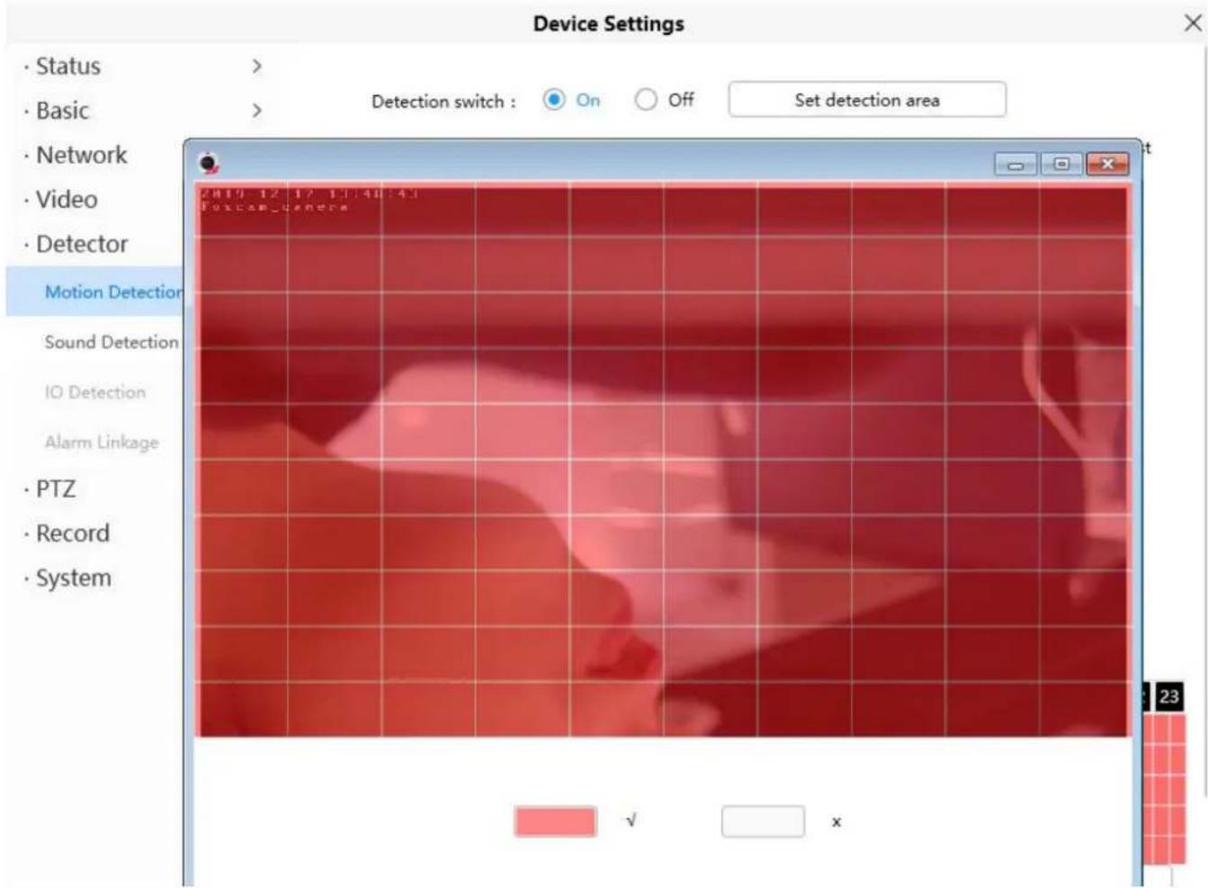
text_image
Device Settings Status > Basic > Network Video Detector Motion Detection Sound Detection IO Detection Alarm Linkage PTZ Record System Detection switch : On Off Set detection area 2019 12 17 1:48:43 FOSCAN_DATAVERAGE 23Note:
1) Please DO NOT forget to set the alarm schedule, the alarm schedule is red.
2) Please make sure your camera time is correct.
3) Please DO NOT forget to set the alarm area, the detected area is covered by the red grids. Or fi models you can setup 3 detection zones in total.
Step 2: Setup the Storage Location
Go to Device Settings > Record > Storage Location, and set the "Recording Location" to "SD card and click Save.
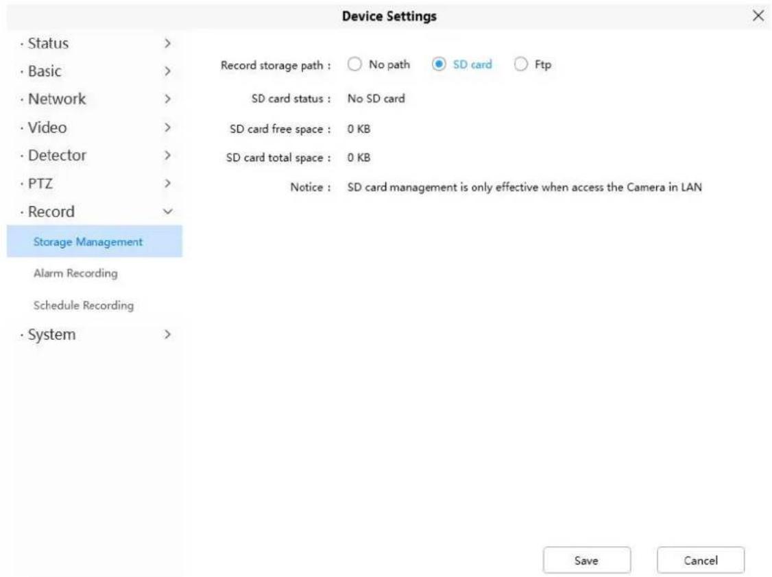
text_image
Device Settings • Status > • Basic > • Network > • Video > • Detector > • PTZ > • Record Storage Management Alarm Recording Schedule Recording • System > Record storage path : ○ No path ● SD card ○ Ftp SD card status : No SD card SD card free space : 0 KB SD card total space : 0 KB Notice : SD card management is only effective when access the Camera in LAN Save CancelNote:
SD card needs format correctly so it'll be identified by camera, and has enough space for saving the It's suggested to use FAT32 for 4G\~128G SD card.
5.1.4 How to setup alarm Emails
Setup alarm Emails, when camera detects a motion it'll send Email with snapshot to inform about the alarm. Steps as below.
Step 1: Setup Mail Settings
Before you set, please make sure that your email for sender enabled SMTP. And get your Email SMT SMTP port, TLS information ready.
Please go to Device Settings > Network > Mail menu to setup your email firstly.
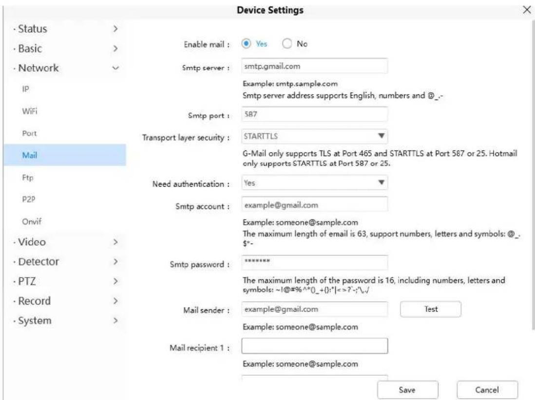
text_image
Device Settings • Status > • Basic > • Network IP WiFi Port Mail Ftp P2P Onvif • Video > • Detector > • PTZ > • Record > • System > Enable mail : Yes No Smtp server : smtp.gmail.com Example: smtp.sample.com Smtp server address supports English, numbers and @_- Smtp port : 587 Transport layer security : STARTTLS G-Mail only supports TLS at Port 465 and STARTTLS at Port 587 or 25. Hotmail only supports STARTTLS at Port 587 or 25. Need authentication : Yes Smtp account : example@gmail.com Example: someone@sample.com The maximum length of email is 63, support numbers, letters and symbols: @_ $*- Smtp password : ******** The maximum length of the password is 16, including numbers, letters and symbols: ~1@#%^*()_+{}:"|<=?-";"./ Mail sender : example@gmail.com Test Example: someone@sample.com Mail recipient 1 : Example: someone@sample.com Save CancelNote:
(1) Please make sure that your sender email supports SMTP;
(2) Please click on Save before you click on Test;
(3) Make sure the test result is success.
(4) After succeed, you will receive a test email in the mailbox of Sender.
Step 2: Setup the Motion Alarm Settings
Please go to Device Settings > Detector > Motion Detection menu:
- Click On,
- Choose Send E-mail for the alarm action,
- set your detection area,
- Set your schedule.
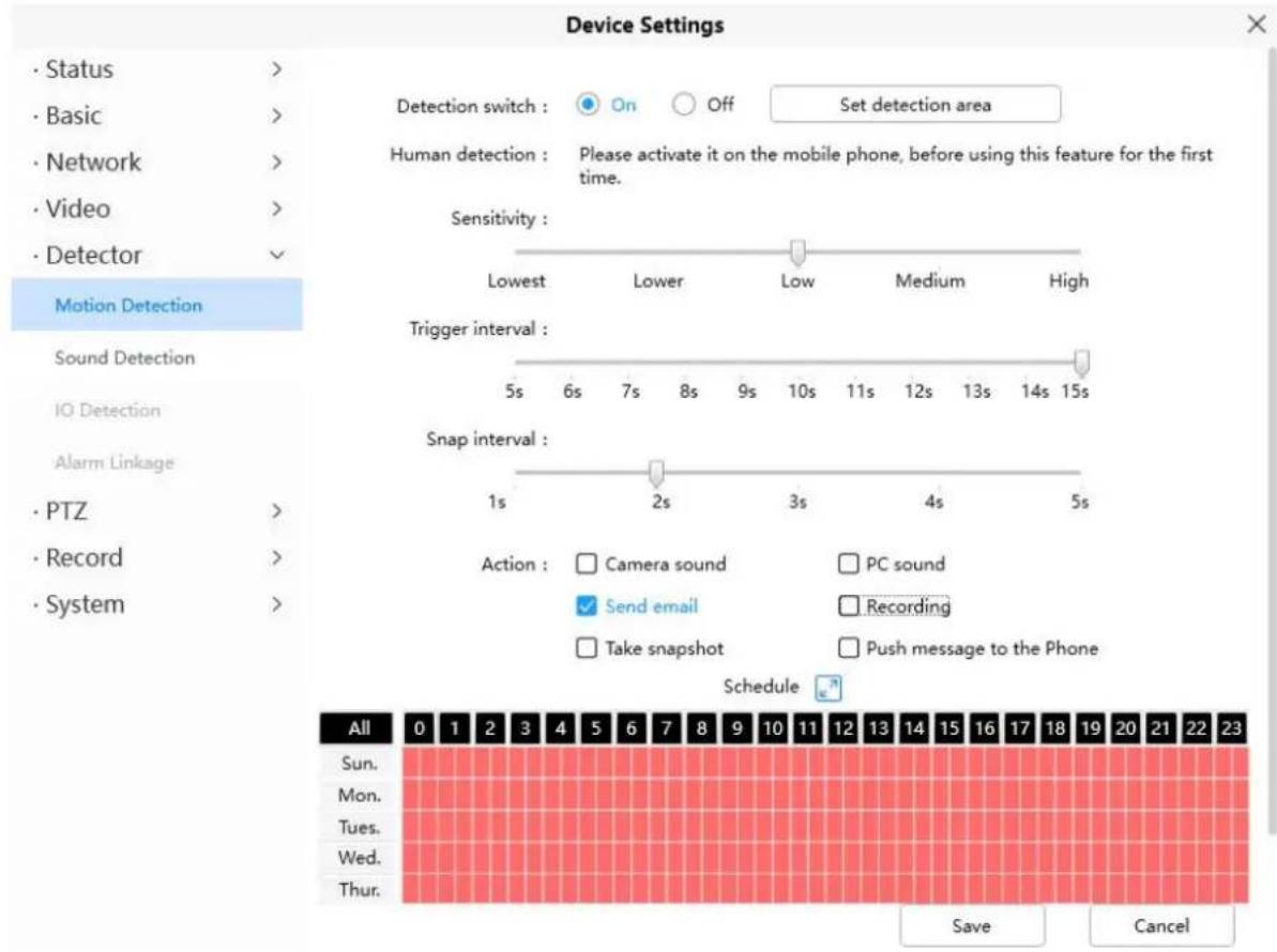
text_image
Device Settings Status > Basic > Network > Video > Detector Motion Detection Sound Detection IO Detection Alarm Linkage PTZ > Record > System > Detection switch : On Off Set detection area Human detection : Please activate it on the mobile phone, before using this feature for the first time. Sensitivity : Lowest Lower Low Medium High Trigger interval : 5s 6s 7s 8s 9s 10s 11s 12s 13s 14s 15s Snap interval : 1s 2s 3s 4s 5s Action : Camera sound PC sound Send email Recording Take snapshot Push message to the Phone Schedule All 0 1 2 3 4 5 6 7 8 9 10 11 12 13 14 15 16 17 18 19 20 21 22 23 Sun. Mon. Tues. Wed. Thur. Save CancelDo not forget to click on Save after you finish settings.
If there is motion trigger, camera will alarm and you can receive alarm emails.
Note:
(1) Please DO NOT forget to set the alarm schedule, the alarm schedule is red.
(2) Please make sure your camera time is correct.
(3) Please DO NOT forget to set the alarm area, the detected area is covered by the red grids. Or models you can setup 3 detection zones in total.
5.1.5 Unable to connect camera remotely using Foscam app
Foscam P2P cameras allow users to connect camera remotely using Foscam app without extract setup port forwarding. When it unable to connect remotely, below tips can help app establish the connection:
(1) Update app and camera's firmware to latest version,
(2) Power off the camera then power back on,
(3) Delete camera from app then re-add it back, also lower camera's resolution.
5.1.6 Camera is added by others
When use myfoscam.com cloud or Foscam app, one camera can only be added to one account at the time. To solve error "This camera has already been added by another account" when add camera to Foscam app or cloud, please send a clear photo of camera's model sticker to Foscam support email support@foscam.com to unbind it.
5.2 Default Parameters
Default network parameters
IP address: obtain dynamically
Subnet mask: obtain dynamically
Gateway: obtain dynamically
Username and password
Default admin username: admin with a random password
5.3 Specification
| Image Sensor | Sensor | High Definition Color CMOS Sensor |
| Display Resolution | 2.0MegaPixels | |
| Min. Illumination | 0 Lux (With IR Illuminator) | |
| Lens | Lens Type | Glass Lens |
| Focal Length | f: 5.4mm-97.2mm | |
| Aperture | F1.7~F3.6 | |
| Angle of View | Horizontal: 3.55°~55.4° Diagonal : :4.05°~62.6° | |
| Video | Image Compression | H.264 |
| Image Frame Rate | 25fps (1080P) /15fps (720P) /, downward adjustable | |
| Resolution | 1080P(1920x1080),720P(1280 x 720), VGA(640 x 48 QVGA(320 x 240) | |
| Stream | Dual stream | |
| Image Adjustment | The hue, brightness, contrast, saturation, sharpness adjustable | |
| Flip Image | flip and mirror | |
| Infrared Mode | Automatic and manual | |
| IR Range | 6pcs Infrared-LEDs, night vision range up to 50 me | |
| Audio | Input/Output | Supports two-way audio |
| Audio Compression | PCM/G.726 | |
| Network | Ethernet | One 10/100Mbps RJ45 port |
| Remote Access | P2P | |
| Data Rate | IEEE802.11b: 11Mbps(Max.); IEEE802.11g: 54Mbps(Max.); IEEE802.11n: 150Mbps(Max.). IEEE802.11ac: 433Mbps(Max.). | |
| Wireless Standard | 2.4G/5G dual band, IEEE802.11b/g/n/ac | |
| Network Protocol | IP、TCP、UDP、HTTP、HTTPS、SMTP、FTP、DHCP、RTSP、ONVIF | |
| System Requirements | Operating System | Microsoft Windows XP, 7, 8;Mac OS;iOS、Android |
| Browser | Microsoft IE8 and above version or compatible brow Mozilla Firefox, Google Chrome, Apple Safari | |
| Other Features | Motion Detection | Alarm via E-Mail, upload alarm snapshot to FTP |
| Sound Detection | Supports sound detection | |
| User Accounts | Three levels user role | |
| Firewall | Supports IP Filtering | |
| AI | AI humen detection | |
| Firewall | Supports IP Filtering | |
| Storage | Micro SD card, FTP and local storage | |
| Intelligent Assistant | Supports Alexa, Google Assistant | |
| Reset | Reset button is available | |
| Power | Power Supply | DC 12V / 2.0A |
| Power Consumption | 20 Watts (Max.) | |
| Physical | Dimension (L * W * | 136 mm x 246 mm x 202 mm / 5.35in * 9.69in * 7.95in |
| Net Weight | 1500g g/ 3.31b | |
| Environment | Operating Temperature | -20°C ~ 60° (-4°F ~ 140°F) |
| Operating Humidity | 20% ~ 85% non-condensing | |
| Storage Temperature | -20°C ~ 60° (-4°F ~ 140°F) | |
| Storage Humidity | 0% ~ 90% non-condensing | |
| Certification | FCC、CE、RoHS、IP66 | |
5.4 CE & FCC
Electromagnetic Compatibility (EMC)
FCC Statement

FCC Warning
This device complies with Part 15 of the FCC Rules. Operation is subject to the following two conditions: This device may not cause harmful interference, and (2) this device must accept any interference receiving including interference that may cause undesired operation. NOTE 1: This equipment has been tested and found to comply with the limits for a Class B digital device, pursuant to part 15 of the FCC Rules. There are designed to provide reasonable protection against harmful interference in a residential installation. This equipment generates, uses and can radiate radio frequency energy and, if not installed and used in accordance with the instructions, may cause harmful interference to radio communications. However, there no guarantee that interference will not occur in a particular installation. If this equipment does cause harmful interference to radio or television reception, which can be determined by turning the equipment off and
user is encouraged to try to correct the interference by one or more of the following measures: - Reo relocate the receiving antenna. - Increase the separation between the equipment and receiver. -Connect equipment into an outlet on a
circuit different from that to which the receiver is connected. -Consult the dealer or an experienced radi technician for help.
This equipment complies with FCC radiation exposure limits set forth for an uncontrolled environment. The equipment should be installed and operated with minimum distance 20cm between the radiator& your bo NOTE 2: Any changes or modifications to this unit not expressly approved by the party responsible for compliance could void the user's authority to operate the equipment.
CE Mark Warning

This is a Class A product. In a domestic environment, this product may cause radio interference, in which the user may be required to take adequate measures.
5.5 WARRANTY
FOSCAM values your business and always attempts to provide you the very best of service.
No limited hardware warranty is provided by FOSCAM unless your FOSCAM product ("product") was purchased from an authorized distributor or authorized reseller. Distributors may sell products to resellers then sell products to end users. No warranty service is provided unless the product is returned to an return center in the region where the product was first shipped by FOSCAM or to the point-of-purchase may have regional specific warranty implications.
If you purchase your FOSCAM product from online store, please contact the point-of-purchase and for return / replacement / repair service.
Limited Hardware Warranty
FOSCAM products are warranted to be free from manufacturing defects in materials and workmanship of from the shipping date of FOSCAM.
This limited hardware warranty does not cover:
- Software, including the software added to the products through our factory-integration system, software, etc.
- Usage that is not in accordance with product instructions.
● Failure to follow the product instructions.
● Normal wear and tear.
Return Procedures
- Please read FOSCAM warranty policy & policy of your reseller first before sending items back to point-of-purchase.
- Customer must first contact point-of-purchase to obtain a Return Merchandise Authorization (RMA) number before returning the product. If the product you received is suspected to be defective and
product warranty has not expired, The RMA number will allow your reseller to track your return mu easier and help them expedite processing your request.
- After receiving your RMA case number, pack the item(s) very well with the original box and all the original accessories included such as power adapters, brackets, cables, manuals.
- Write your RMA number and the return reason (the problem of the product) on the warranty card along with the complete package to send them back.
Replacement Services
- If customers ask for replacement service, please contact point-of-purchase and follow their policy.
- Our technicians will inspect all items returned for replacement requests. If the retuned product is found in working order, we will return the same item received. However customers shall be responsible for a shipping & handling charges incurred for getting the units back to customers.
- If returned products are found defective, we will replace the product and assume the shipping cost for sending back the replacement unit to customers.
- If for any reason, we are unable to provide a replacement of the original returned item(s). You will have a choice for a "Substitute" item at the same equal value.
- We do not provide exchange and replacement due to normal hardware upgrade according the market after 14 days after the product is delivered.
- Our technicians will test the product before send out the replacement, any other demand for more than two times replacement for the same product during replacement limit will be rejected.
● Replaced products are warranted from the balance of the former warranty period.
Warranty Forfeiture
- Warranty is void if purchase from unauthorized distributor or reseller.
- Warranty is void if trade-mark, serial tags, product stickers have been removed, altered or tampered with.
- Warranty is void for mishandling, improper use, or defacing the product.
- Warranty is void for physical damage, altered, either internally or externally, improper or inadequate packaging when returned for RMA purposes.
- Warranty is void if damage has resulted from accident, dismantle, abuse, or service or modification by someone other than the appointed vendor, souse, fission or the spare part has been over the period warranty.
- Warranty is void if product is damaged due to improper working environment or operation. (For example, improper temperature, humidity, unusual physical or electrical stress or interference, failure or fluctuation of electrical power, static electricity, using wrong power adapter, etc.)
● Warranty is void if damaged by the use of parts not manufactured or sold by FOSCAM.
● Damage caused by improper installation of third-party products.
● Warranty is void if damaged for irresistible cause, such as earthquake, fire, lightning, flood, etc.
● Product beyond limited warranty.
Shipping Fee
- If products are defective or damaged under normal use or operation in the replacement limit, distributors or resellers are responsible for the shipping cost the product back to customers, customers should assume the shipping cost send the product to the point-of-purchase.
- During replacement limit, if customers ask for replacement due to the product does not fit for customer's personal expectation, customers should responsible for both shipping fee.
- Customers shall be responsible for both shipping fee if their product beyond the replacement limit but still in warranty limit.
Repair Service Out Of Warranty
- FOSCAM provide extra repair service for product that out of warranty, it is chargeable. The total fee contains device cost and service fee. Device cost (including accessories) is the standard uniform price provide by FOSCAM.
- Different region may have different service fee, please contact the point-of-purchase to confirm that before you ask for this service.
- Our technicians will quote the total price after detect the product, If customers refused to repair after the quotation, customers need pay for the test fee, \$3.5 / hour. If agree with the quotation, test will be
● Repaired product out of warranty will obtains 3-month warranty from the date of the product back to customers.
Limitation of Liability
- FOSCAM is not responsible for other extra warranty or commitment promised by resellers, if your reseller promised some extra commitment or warranty; please ask for written documents to protect your right interests.
- FOSCAM does not offer refunds under any circumstances. Please contact the point-of-purchase and follow their refund / return policy.
- FOSCAM shall not be liable under any circumstances for any consequential, incidental, special or exemplary damages arising out of or in any connection with this agreement or the products, including not limited to lost profits, or any claim based on indemnity or contribution, or the failure of any limited exclusive remedy to achieve its essential purpose or otherwise. Purchaser's exclusive remedy, as against FOSCAM, shall be the repair or replacement of defective parts. If FOSCAM lists a product on its specification in error or that is no longer available for any reason, FOSCAM reserves the right to do without incurring any liability.
All rights reserved. FOSCAM and the FOSCAM logo are trademarks of ShenZhen FOSCAM Intelligent Technology Limited., registered in the U.S. and other countries.
5.6 Statement
You are advised to be cautious in daily life, keep personal account information carefully, do not share account easily. Change passwords of your account and equipment periodically, and upgrade equipment firmware to strengthen security consciousness.
Our company makes no warranty, implied or otherwise, that this product is suitable for any particular price or use. You need to abide by the relevant laws and regulations of the use restrictions when using Fox cameras. Our company takes no responsibility of illegal activities by using our products.
Our company takes no responsibility of the loss by force majeure, such as failure or faults of telecom the Internet network, computer viruses, malicious attacks of hackers, information damage or loss, and fault computer system.
Foscam company does not need to take any responsibility of the special, incidental or corresponding los
the products of our company or any software provide by our company, including but not limited to ope loss, profit or purpose. The company only takes the responsibility applicable to national and local legal requirements.
Our company takes no responsibility of the loss caused by the following at ant time:
1) loss of purchases;
2) loss of intangible property damage, such as data, programs;
3) loss of compensation claimed by third-party customers.
Delete images, format the memory card or other data storage devices does not completely remove the image data. You can restore deleted files from discarded the storage device by commercial software, but will potentially lead to personal image data used maliciously by others. The privacy of the data security to user responsibility, the company takes no responsibility.
Parts mentioned in this statement should not be understood by the configuration description of the product purchased by the customer, the product configuration must accord to the specific models purchased by customer.
Without the prior written permission of Foscam company, all the contents of relevant operating instruction manual affiliated to the product must not be reproduced, transmitted, transcribed or stored in a retrieval or translated into other languages.
Our company will reserve the right to improve and modify the product and corresponding manuals. The company reserves the right of final interpretation on our products.
6 Obtaining Technical Support
While we hope your experience with the IP camera network camera is enjoyable and easy to use, you experience some issues or have questions that this User's Guide has not answered.
If you have problem with FOSCAM IP camera, please first contact FOSCAM reseller for solving the pro If our reseller cannot provide service, please contact our service department:
support@foscam.com

CE Certificate statement Website: https://www.foscam.com/company/ce-certificate.html
Exporter and Importer Information Opened to Public: https://www.foscam.com/company/open-information.html
Manufacturer: Shenzhen Foscam Intelligent Technology Co., Ltd
Addr: Room 901-902, Building 1B, Xingke 1st Street, Shenzhen International Innovation Valley, Nanshan
Shenzhen, 518055, China