SiX - Mixer Solid State Logic - Free user manual and instructions
Find the device manual for free SiX Solid State Logic in PDF.


User questions about SiX Solid State Logic
0 question about this device. Answer the ones you know or ask your own.
Ask a new question about this device
Download the instructions for your Mixer in PDF format for free! Find your manual SiX - Solid State Logic and take your electronic device back in hand. On this page are published all the documents necessary for the use of your device. SiX by Solid State Logic.
USER MANUAL SiX Solid State Logic
natural_image
Close-up of a black Solid State Logic audio workstation instrument with multiple knobs and control knobs (no readable text or symbols)Solid State Logic
OXFORD·ENGLAND
Visit SSL at:
www.solidstatelogic.com
© Solid State Logic
All rights reserved under International and Pan-American Copyright Conventions
SSL ^® and Solid State Logic ^® are Ⓡ registered trademarks of Solid State Logic.
SiX ^TM and SuperAnalogue ^TM are trademarks of Solid State Logic.
All other product names and trademarks are the property of their respective owners and are hereby acknowledged.
No part of this publication may be reproduced in any form or by any means, whether mechanical or electronic, without the written permission of Solid State Logic, Oxford, OX5 1RU, England.
As research and development is a continual process, Solid State Logic reserves the right to change the features and specifications described herein without notice or obligation.
Solid State Logic cannot be held responsible for any loss or damage arising directly or indirectly from any error or omission in this manual.
PLEASE READ ALL INSTRUCTIONS, PAY SPECIAL HEED TO SAFETY WARNINGS.
E&OE
March 2019
Introduction to SiX
In the mid '70s Solid State Logic designed the first A Series Console and Studio Computer. The idea behind the project was to build a system for the company's studio which was buried deep in the Oxfordshire countryside, in a small village called Stonesfield. SSL's development of advanced analogue mixing consoles has been continuous since those early days.
SiX was designed to put forty years of SSL heritage into a studio grade console that would fit into hand luggage, providing engineers and musicians an amazing combination of analogue summing, processing and workflow wherever they need to make a session happen, or raise the bar of a performance to studio level.
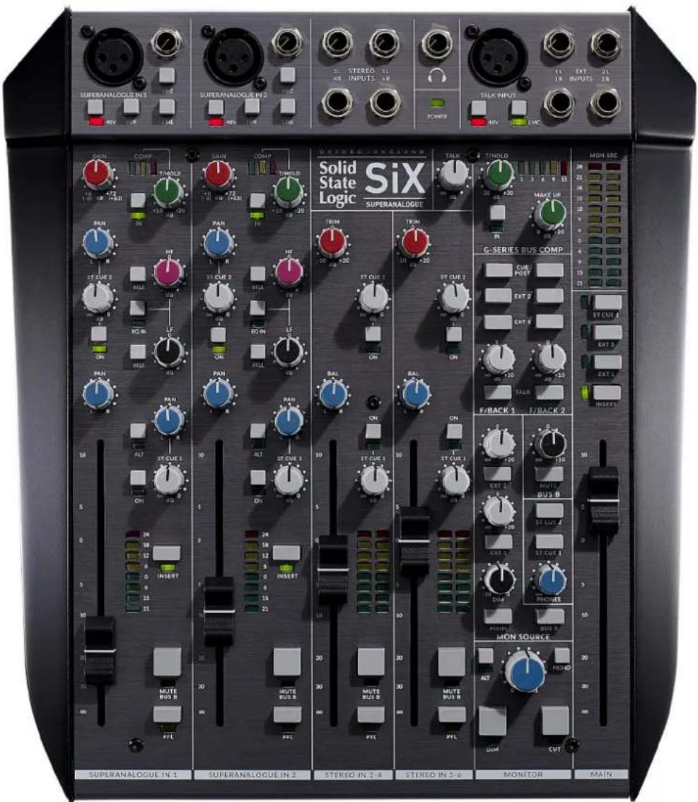
text_image
SUPERANALOGUE IN 1 SUPERANALOGUE IN 2 SUPERANALOGUE IN 3 GAIN COMP STINOLB R R R R R R R R R R R R R R R R R R R R R R R R R R R R R R R R R R R R R R R R R R R R R R R R R R SIX Solid State Logic SUPERANALOGUE TALK TINOLD MAIN SBC MAKE UP G-SERIES BUS COMP CUE POST EXT 2 EXT 3 ST CUE 4 EXT 5 EXT 6 F/BACK 1 F/BACK 2 ST CUR 1 ST CUR 1 ST CUR 1 ST CUR 2 MUTE BUS B ST CUR 2 ST CUR 3 MUTE BUS B ST CUR 4 MON SOURCE MONITOR MAIN SUPERANALOGUE IN 1 SUPERANALOGUE IN 2 STEREO IN 3-4 STEREO IN 5-6 MONITOR MAINSmall is beautiful...
SiX may be small, but it is very serious. What follows are some of the key elements that make it a professional product for the highest quality audio applications.
Fully balanced inputs and outputs
All of SiX's inputs and outputs are fully balanced (with the exception of the Phones output). This means professional equipment with balanced connections can be properly interfaced allowing longer cable lengths without noise/hum pick-up penalties and the best signal to noise performance from the whole signal chain.
Short is beautiful...
To provide the purest audio signal paths, SiX has several features not normally found on small footprint mixing consoles e.g. the channel processing is switched, allowing it to be removed from the signal path if it's not being used. Also, the Insert Sends are always active, meaning that the purest path from Mic Pre to DAW is achieved by using the Insert Send as a direct channel output, with the Dynamics and EQ switched out of circuit. This is one example of how SiX's versatile signal flow can be used. It's definitely worth taking some time to understand the SiX block diagram and reading the examples later in this manual. We hope you'll really unlock the versatility of the console when discovering the many signal paths that are available and the multiple ways they can be used.
Meter scales and response
The upper LED meter points on SiX's main meters have been carefully chosen. The console is designed with a huge +27 dBu headroom and the meters have defined segments for +24 dBu and +18 dBu, this is to match the two most common 0 dB Full Scale (dBFS) alignment standards, i.e. European/EBU at 0 dBFS=+18 dBu and the US/SMPTE standard at 0 dBFS=+24 dBu ensuring optimum performance for converters and proper gain structure throughout the signal chain. The meters in SiX have been designed with a fast 'peak' response (rise time to 60% Full Scale Deflection approx 1 ms @ 1 kHz) and a slower release time to give the ability to meter fast peaks while still being able to show useful signal levels.
Power and power management
You will have noticed that SiX is powered by an external power supply with a locking connector. This significantly helps the design and performance of SiX. It moves the power supply's electromagnetic interference away from the SuperAnalogue circuits inside SiX. This allows us to design the internal electronics to have a bandwidth as wide as possible and thus deliver the great phase and transient response SSL large format console users have come to expect in a very small footprint package. Another thoughtful design feature for an analogue console is how the power rails are ramped on power-up to minimise thumps on monitor and headphone outputs.
About SuperAnalogue
SSL's SuperAnalogue technology is the sum of an applied design philosophy, constant invention, and dedication to optimising every detail of our precision audio products. There are many contributing aspects, including our bespoke circuits, ground-breaking low-noise gain control, servo-coupled amplifier stages, and many more. The design of SiX is unique amongst small footprint mixers in that it uses SuperAnalogue technology to bring large console sonics and processing into a very compact design.
Listed below are some of the main benefits SuperAnalogue philosophy brings to SiX.
Wideband audio
Typically a 20 kHz upper frequency limit is recognised as adequate for audio. A lucky few people can identify frequencies beyond 20 kHz. However, there is a secondary hearing mechanism, directly related to 'rise-time' (the transient performance of components) and evidence to show that even though the basic frequency spectrum of human hearing degrades over time, our sensitivity to rise-times does not. In addition, Transient Intermodulation Distortion (TIM) is a real - if difficult to measure - issue that brings high frequency 'waste' to bear on the audible spectrum in poor or bandwidth-limited designs. Feedback paths in amplifier circuitry are a good example. For fast, accurate rise times and low TIM, SSL implements precision, high-frequency analogue technologies and tests everything to better than 80 kHz. SiX's main signal path frequency response extends to beyond 100 kHz.
Elimination of signal path electrolytic capacitors
The physical construction of electrolytic capacitors means that their performance is imprecise and they are vulnerable to electromagnetic interference so even expensive 'high-quality' electrolytics do not meet our standards. In addition, over time and with temperature variations, electrolytic capacitors degrade and become 'leaky' resulting in significant noise issues, altered sonic character, and shortened product life. SSL avoids using electrolytic capacitors for decoupling between analogue stages wherever possible. Instead we use advanced DC servo coupling techniques for wide bandwidth, low noise and high precision DC offset control.
Discrete design and innovation
Many modern analogue audio products are the result of the 'cookbook' approach where off-the-shelf blocks are strung together to fulfil a practical brief, but lack the additional details that take them from functional to fantastic. To do that, you have to understand how to augment commercially available components with discrete elements, do original research and sometimes even design your own components.
SSL does not do ‘data-sheet design’ and continues to optimise and improve upon data-sheet specifications and ‘serving suggestions’ - we have even licensed our advances back to semiconductor manufacturers. SiX represents the cumulation of over 40 years of experience and expertise in improving the canon of analogue music electronics to continually exceed and progress our own high standards.
Not one component, a whole design philosophy
Our philosophy is simple, we spare nothing in designing and manufacturing the best precision music tools available anywhere. There is no single magic stage in SiX - everything from the pre-amps through the line level electronics, signal processing and output stages plays its part.
Table of Contents
Introduction 1
Unpacking 2
Safety Notices 2
Heat & Ventilation and Rack Mounting Option 2
Console Overview 3
Front panel 3
Rear Panel 4
Detailed Description 5
SuperAnalogue Mono Channels 5
SuperAnalogue Pre-Amp input 5
Mic Input (XLR) 5
Channel EQ 6
Channel Compressor 7
Channel Insert 7
Stereo Cue Sends 8
Channel Fader and Pan 8
Stereo channels 9
SuperAnalogue Stereo Input 9
Stereo Cue Sends 9
Channel Fader and Pan 9
Monitor section 10
MAIN and ALT monitor outputs 10
Headphone (Phones) output 11
Monitor Source section 11
External 1 and 2 Levels 11
Foldback and Stereo Cue Master Section (including Talk Input) 13
Talk Input Pre-amplifier and LMC 13
Talk Input 13
Switching the Stereo Cues from Pre to Post fader 14
Artist Cue Mixes 14
Foldback Outputs as Effects Sends 14
Main Meter 15
Main Bus 15
Main Bus Summing 15
Main Bus Insert 15
G-Series Bus Compressor 16
Application Examples 17
Recording A Singer/Songwriter 17
Recording Drums 18
Music Production - Writing and Tracking 19
Music Production - Mixdown 20
On Stage 21
Post Production 22
Podcasting 23
Troubleshooting & FAQs 24
Troubleshooting Tips 24
Warranty
25
All returns 25
Appendix A - Physical Specification 26
Connector Pinouts 26
Mono Channels 26
Stereo Channels 26
Insert Sends/Returns, Alternate Inputs and Auxiliary Outputs 27
DC Power Inlet 27
Appendix B - Performance Specification 28
Audio Performance 28
SuperAnalogue Channel Microphone Amplifier 28
SuperAnalogue Channel Line Input Amplifier 28
Channel Equaliser 29
Channel Compressor 29
SuperAnalogue Stereo Channel Line Input Amplifier 29
Overall Channel Signal Chain Specifications 30
Overall Console Noise 30
Environmental Requirements 30
Appendix C - SiX Block Diagram 31
Appendix D - Recall Sheet 32
Introduction
SiX is a studio grade, SuperAnalogue mixing console that delivers all of the quality and flexibility audio professionals expect from an SSL console, but in a compact package that is designed to be small enough to fit into hand luggage. Its design doesn't compromise on performance because of its size, but delivers a powerful set of professional features in a small 1/2 rack width package.
Audio Excellence
▶ Two SuperAnalogue wide gain range mic pres for pristine recording quality
▶ Two wide gain range stereo line inputs
▶ Individually switchable phantom power on each Mic Input
Line level input with true HiZ (1 MΩ) impedance switch for passive coil inputs (e.g. guitar pickups)
▶ Two recording channels with fully balanced inserts, simple SSL EQ and Dynamics and true bypass processing switching
▶ Fast, accurate peak response LED meters
Mixing Versatility
12 channel stereo summing - probably more studio grade analogue summing per square inch than any other console
▶ Main bus with fully balanced insert
▶ Simplified SSL Bus Compressor
▶ 100 mm studio grade long throw faders - unique in this form factor
Application Flexibility
A 'proper' foldback section with two stereo send/cue buses with talkback, local monitoring plus two stereo cue feeds
▶ Versatile B-Bus/Mute switching provides record and mix buses for simple overdubs
▶ Useful, flexible signal routing and summing
▶ Versatile 'summing' monitor section with two external source selectors
- 'Listen mic compressor' with flexible routing for studio talkback or more creative applications
Unpacking
The unit has been carefully packed and inside the box you will find the following items.
SiX
SSL Black Book
▶ IEC power cord for your country
▶ External Power Supply with 5-Pin XLR connector
▶ Safety Guide
Quickstart Guide
▶ Registration card
It is always a good idea to save the original box and packaging, just in case you ever need to send the unit in for service.
Safety Notices
IMPORTANT: Please read the safety notice information included in the Safety Guide supplied inside the box before using SiX.
Heat & Ventilation and Rack Mounting Option
SiX packs a lot of SuperAnalogue electronics into its compact size. It is designed to get warm in normal operation. Please consult the operational specifications in Appendix B of this User Guide to make sure that it is used within its designed environmental parameters.
Optional rack mounting kits to fit one or two SiX consoles within a standard 19-inch rack are available.
Whenever rack mounted, or mounted in furniture, please ensure at least 1 inch (2cm) of ventilation space is left available in the front and rear of the console. You will see the ventilation holes in the console chassis - these need to have clear airflow to cool the unit correctly.
Console Overview
This section details the console features of SiX.
Front panel
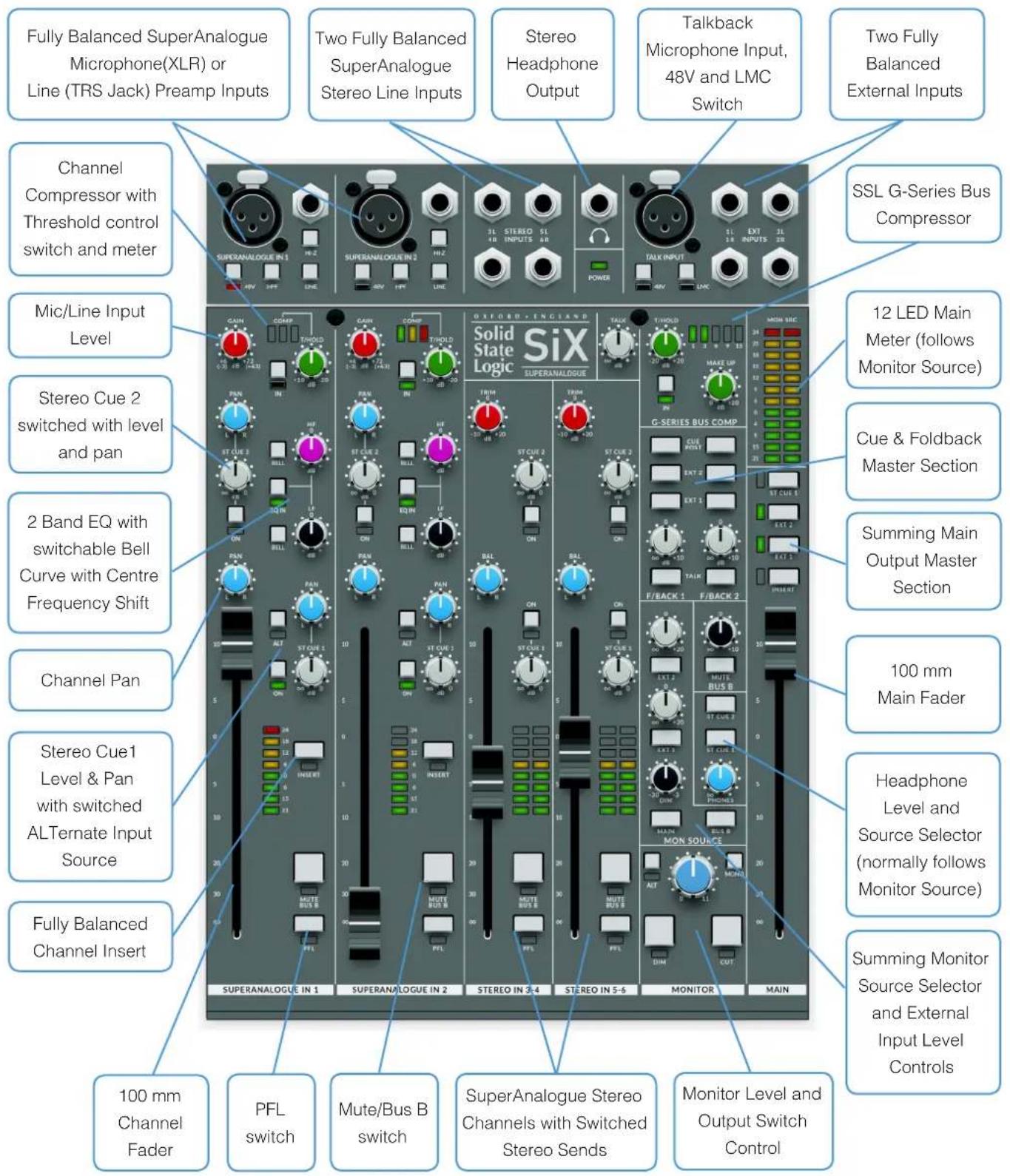
text_image
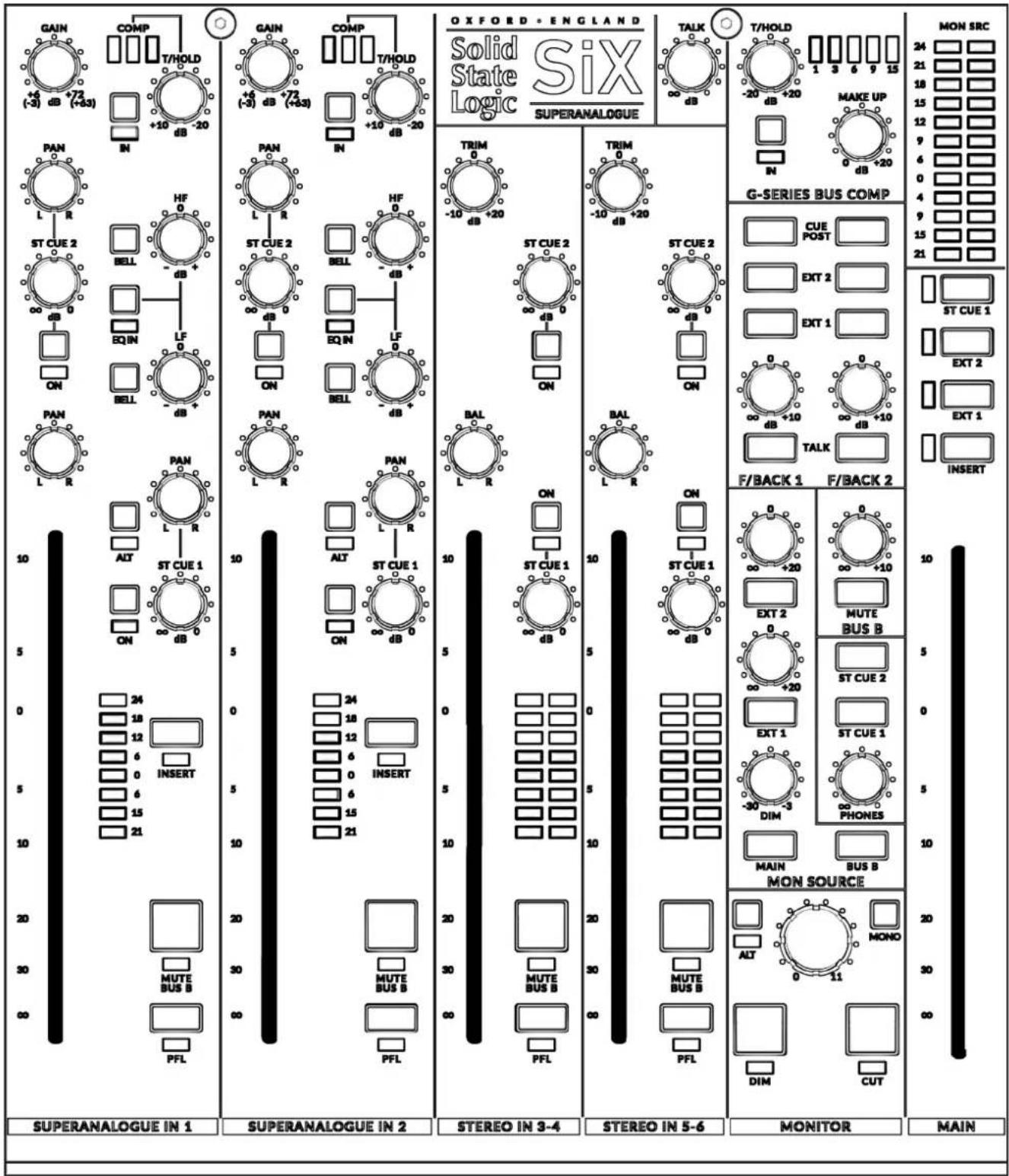
Fully Balanced SuperAnalogue Microphone(XLR) or Line (TRS Jack) Preamp Inputs Two Fully Balanced SuperAnalogue Stereo Line Inputs Stereo Headphone Output Talkback Microphone Input, 48V and LMC Switch Two Fully Balanced External Inputs Channel Compressor with Threshold control switch and meter Mic/Line Input Level Stereo Cue 2 switched with level and pan 2 Band EQ with switchable Bell Curve with Centre Frequency Shift Channel Pan Stereo Cue1 Level & Pan with switched ALternate Input Source Fully Balanced Channel Insert 100 mm Channel Fader PFL switch Mute/Bus B switch SuperAnalogue Stereo Channels with Switched Stereo Sends Monitor Level and Output Switch Control Oxford-England Solid State Logic Six SUPERANALOGUE G-SERIES BUS COMP CUE MODEY EXT 2 EXT 1 EXT 2 F/BACK 1 F/BACK 2 MON SOURCE MONITOR MAIN 12 LED Main Meter (follows Monitor Source) Cue & Foldback Master Section Summing Main Output Master Section 100 mm Main Fader Headphone Level and Source Selector (normally follows Monitor Source) Summing Monitor Source Selector and External Input Level ControlsRear Panel
The rear panel of SiX is shown below. The connectors are identified on a panel that is fitted to the face above the connector panel.
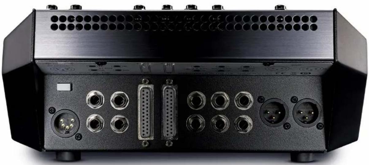
natural_image
Back view of a black electronic device with multiple ports and connectors (no visible text or symbols)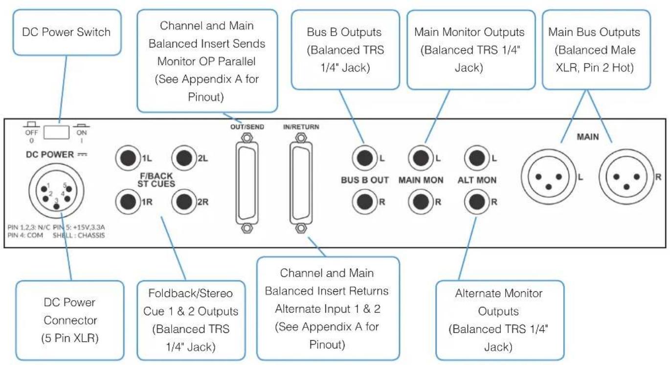
text_image
DC Power Switch Channel and Main Balanced Insert Sends Monitor OP Parallel (See Appendix A for Pinout) Bus B Outputs (Balanced TRS 1/4" Jack) Main Monitor Outputs (Balanced TRS 1/4" Jack) Main Bus Outputs (Balanced Male XLR, Pin 2 Hot) DC POWER OUT/SEND IN/RETURN BUS B OUT MAIN MON ALT MON MAIN DC Power Connector (5 Pin XLR) Foldback/Stereo Cue 1 & 2 Outputs (Balanced TRS 1/4" Jack) Channel and Main Balanced Insert Returns Alternate Input 1 & 2 (See Appendix A for Pinout) Alternate Monitor Outputs (Balanced TRS 1/4" Jack)Detailed Description
SuperAnalogue Mono Channels
There are two SuperAnalogue mono channels on SiX; each channel has identical facilities. This section explains the features found in each.
SuperAnalogue Pre-Amp input
SiX's pre-amp is a new wide gain range SuperAnalogue design, developed from the mic pre-amps of the larger SSL Duality and AWS consoles. In these consoles, line and mic inputs are served by separate pre-amps. In SiX, a new wide gain range, ultra low noise SuperAnalogue design provides both Line and Mic facilities with a "Line" gain range switch to cover a wide range of source levels.
The pre-amp consists of a microphone input (XLR) and line level input ( 14 " TRS Jack Socket).
Mic Input (XLR)
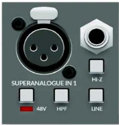
The default microphone input uses SSL's SuperAnalogue design and includes individually switched 48V phantom power. The Mic (XLR) input's nominal impedance is 1.2 kΩ.
text_image
SUPERANALOGUE IN 1 HI-Z 48V HPF LINE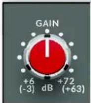
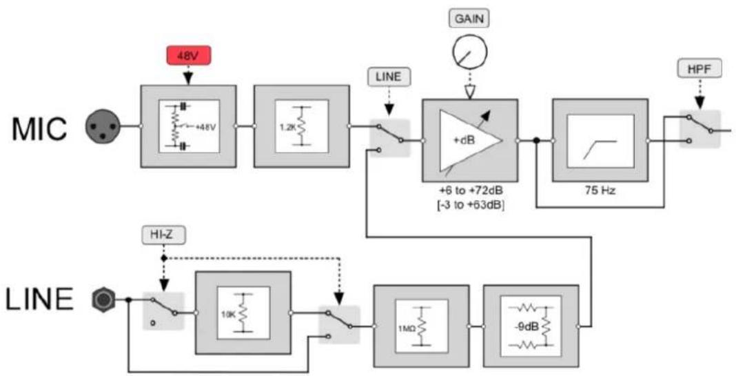
The XLR is the default source input, the source can be switched to the 14 " TRS jack line input by pressing the 'Line' switch on the channel. The nominal Line Input impedance is 10 kΩ this can be changed to 1 MΩ using the Hi-Z switch. This input impedance makes this input suitable for very high impedance sources such as passive guitar pickups without the need for an external DI box.
The Gain control adjusts either the microphone pre-amp gain (+6 dB to +72 dB), or the Line amp gain (-3 dB to +63 dB), depending on the selected input source. Following the pre-amplifier is a switched 12 dB/oct, 75 Hz High Pass Filter (HPF) to reduce unwanted LF such as Microphone Rumble, AC noise etc.
Input Section Block Diagram
flowchart
graph LR
    A["MIC"] --> B["48V"]
    B --> C["+48V"]
    C --> D["1.2K"]
    D --> E["LINE"]
    E --> F["+6 to +72dB [-3 to +63dB"]]
    F --> G["75 Hz"]
    G --> H["HPF"]
    H --> I["Output"]

    J["HI-Z"] --> K["Line"]
    K --> L["10K"]
    L --> M["Line"]
    M --> N["1MΩ"]
    N --> O["-9dB"]
    O --> P["Output"]
Channel EQ
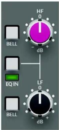
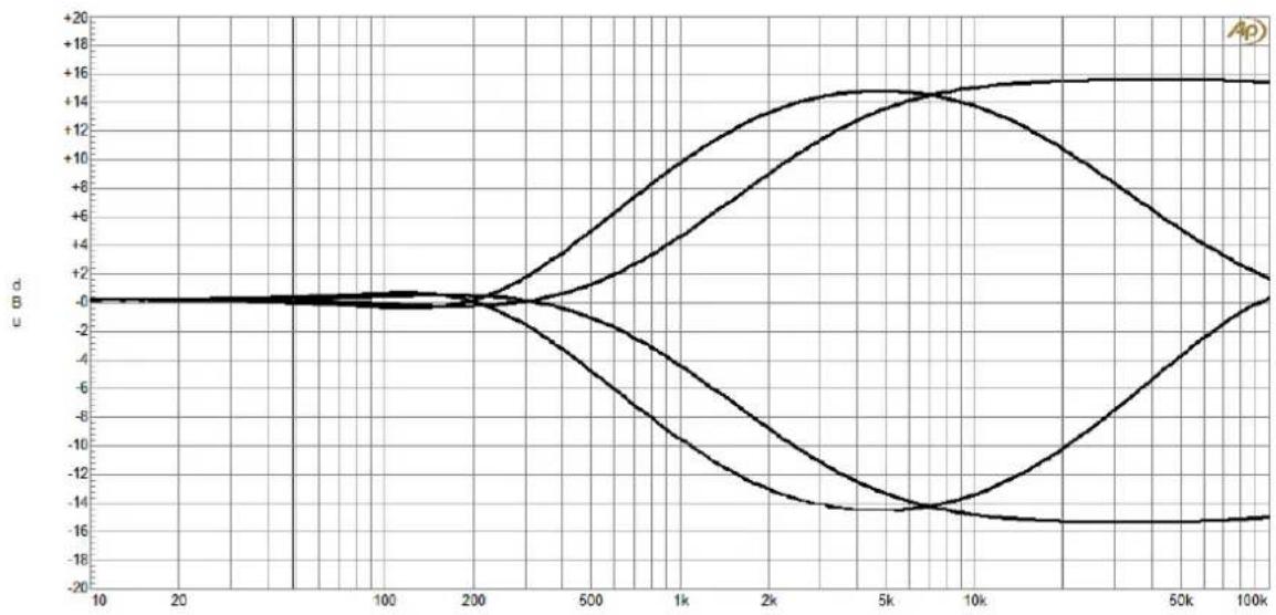
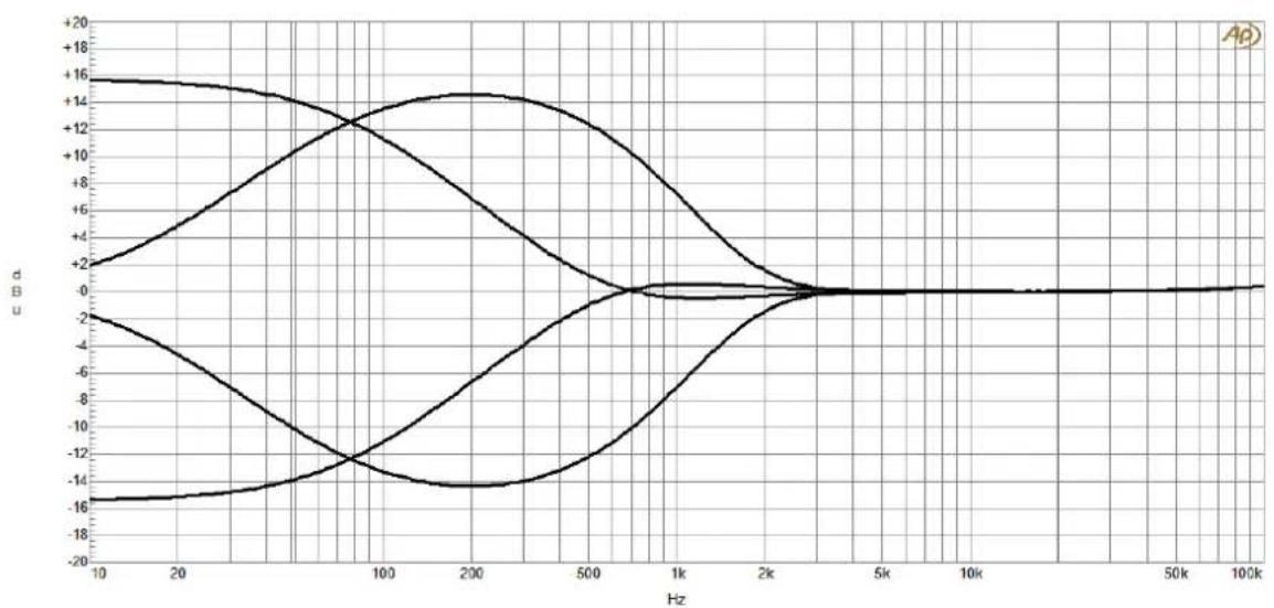
The channel EQ on SiX has its roots in SSL's classic E series EQ. It is a gentle, broad stroke two-band design with high and low shelving filters at 3.5 kHz and 60 Hz, adjustable from +15 dB to -15 dB of gain. Each band can be independently switched between shelving and bell curves using the BELL switch - a feature found on many SSL EQ designs. A useful feature of the bell curves is that they change centre frequency to operate at 5 kHz and 200 Hz giving greater versatility from the two controls.
The EQ is switched 'in' circuit or completely bypassed using the 'IN' switch. This small detail guarantees no influence on the channel's exceptionally flat frequency response from the tolerance of the EQ control centre detent positions.
text_image
HF 0 - dB BELL EQ IN LF 0 - dB BELLEQ HF Frequency Response
line
| x | y1 | y2 | y3 | y4 | | ---- | ------ | ------ | ------ | ------ | | 10 | 0.0 | 0.0 | 0.0 | 0.0 | | 20 | 0.0 | 0.0 | 0.0 | 0.0 | | 50 | 0.0 | 0.0 | 0.0 | 0.0 | | 100 | 0.0 | 0.0 | 0.0 | 0.0 | | 200 | 0.0 | 0.0 | 0.0 | 0.0 | | 500 | 4.0 | -4.0 | -8.0 | -12.0 | | 1k | 8.0 | -8.0 | -12.0 | -14.0 | | 2k | 12.0 | -12.0 | -14.0 | -14.0 | | 5k | 14.0 | -14.0 | -14.0 | -14.0 | | 10k | 14.0 | -14.0 | -14.0 | -14.0 | | 50k | 16.0 | -8.0 | -6.0 | -16.0 | | 100k | 16.0 | -2.0 | -2.0 | -16.0 |EQ LF Frequency Response
line
| Hz | Line 1 | Line 2 | Line 3 | Line 4 | |------|--------|--------|--------|--------| | 10 | +16 | -2 | -16 | -2 | | 20 | +16 | -4 | -14 | -8 | | 100 | +14 | -12 | -12 | -6 | | 200 | +14 | -14 | -14 | -4 | | 500 | +12 | -8 | -12 | -2 | | 1k | +8 | -2 | -8 | 0 | | 2k | +2 | 0 | -2 | 0 | | 5k | 0 | 0 | 0 | 0 | | 10k | 0 | 0 | 0 | 0 | | 50k | 0 | 0 | 0 | 0 | | 100k | 0 | 0 | 0 | 0 |Channel Compressor
The channel compressor on SiX is a new design, inspired by the sophisticated channel dynamics sections of earlier SSL analogue consoles, but with some clever design features to give powerful and versatile performance from its deceptively simple appearance.
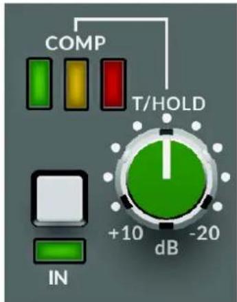
The attack time of the compressor is program dependant and varies between approximately 8 ms and 30 ms. This allows the compressor to operate smoothly when working with a wide variety of content. The release time is approximately 300 ms and the ratio is a gentle 2:1. The single user control is for the compressor Threshold adjustable between +10 and -20 dBu and is accompanied with three LEDs indicating the amount of gain reduction being applied. The circuit has automatic make-up gain to maintain signal level for the full range of threshold settings.
text_image
COMP T/HOLD IN +10 dB -20 dBAs with the EQ circuit, the compressor can be completely bypassed using the IN switch,
providing a simple way to compare the compressed and uncompressed signals. This also prevents component tolerances from influencing the sound of the channel strip when the Threshold is turned to minimum.
Channel Processing Overview
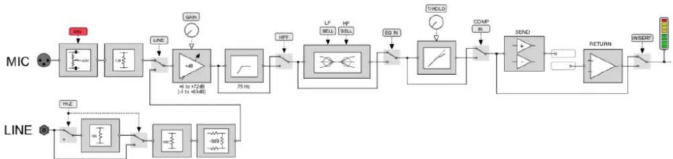
flowchart
graph LR
    A["MIC"] --> B["Line"]
    B --> C["+SB"]
    C --> D["75 Hz"]
    D --> E["HF"]
    E --> F["LF"]
    E --> G["HF"]
    E --> H["BELL"]
    E --> I["BELL"]
    E --> J["EQ N"]
    J --> K["UNOLD"]
    K --> L["COMP IN"]
    L --> M["SEND"]
    M --> N["RETURN"]
    N --> O["INSERT"]
    P["MINI"] --> Q["+SB"]
    R["LINE"] --> S["+SB"]
    T["+SB"] --> U["+SB"]
    V["+SB"] --> W["+SB"]
    X["+SB"] --> Y["+SB"]
    Z["+SB"] --> AA["+SB"]
    AB["+SB"] --> AC["+SB"]
    AD["+SB"] --> AE["+SB"]
    AF["+SB"] --> AG["+SB"]
    AH["+SB"] --> AI["+SB"]
    AJ["+SB"] --> AK["+SB"]
    AL["+SB"] --> AM["+SB"]
    AN["+SB"] --> AO["+SB"]
    AP["+SB"] --> AQ["+SB"]
    AR["+SB"] --> AS["+SB"]
    AT["+SB"] --> AU["+SB"]
    AV["+SB"] --> AW["+SB"]
    AX["+SB"] --> AY["+SB"]
    AZ["+SB"] --> BA["+SB"]
    BB["+SB"] --> BC["+SB"]
    BD["+SB"] --> BE["+SB"]
    BF["+SB"] --> BG["+SB"]
    BH["+SB"] --> BI["+SB"]
    BJ["+SB"] --> BK["+SB"]
    BL["+SB"] --> BM["+SB"]
    BN["+SB"] --> BO["+SB"]
    BP["+SB"] --> BQ["+SB"]
    BR["+SB"] --> BS["+SB"]
    BT["+SB"] --> BU["+SB"]
    BV["+SB"] --> BW["+SB"]
    BX["+SB"] --> BY["+SB"]
    BZ["+SB"] --> BQ
    CC["+SB"] --> BB
    DD["+SB"] --> BC
    EE["+SB"] --> BF
    FF["+SB"] --> BG
    DG["+SB"] --> BH
    DH["+SB"] --> BI
    DI["+SB"] --> AJ
    DJ["+SB"] --> BK
    DK["+SB"] --> BL
    DL["+SB"] --> BM
    DV["+SB"] --> BW
    DW["+SB"] --> BX
    DX["+SB"] --> BQ
Channel Insert
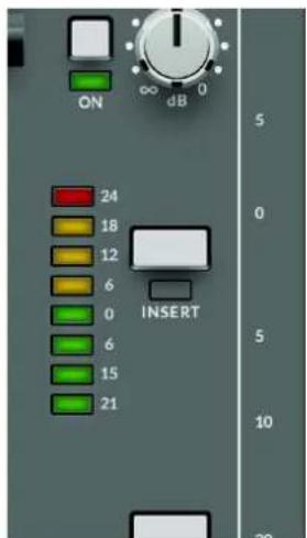
Following the EQ and compressor in the channel signal flow is a fully balanced insert point. In common with larger SSL consoles, the Insert Send is always active, while the Insert Return switches into the signal path when selected.
The primary use of the insert is to bring external processing into the channel signal path. For example, to insert a more surgical EQ or fully featured dynamics unit such as those found in SSL's X-Rack or 500 series modules.
text_image
ON ∞ dB 24 18 12 6 0 6 15 21 INSERT 5 0 5 10 20Another benefit of this configuration and the unity gain design is that the Insert Send can be used as a pre-fade, post-processing direct channel output to act as a record feed for a DAW. This leaves the Insert Return free to be used as a pre-fader/pre-pan path input by selecting the Insert IN switch and feeding a separate line level signal into the Insert Return.
The channel insert sends and returns are found on the rear panel 25 way D-Type connectors. Wiring details are in the Connectors section, later in the document.
Stereo Cue Sends
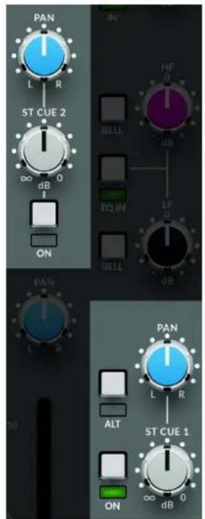
Each mono channel can access two Stereo Cue sends with independent Level and Pan controls. The 'ON' switch sends the channel signal to the cue bus indicated by a green LED.
Both sends are fed from channel pre-fade, post-insert, but can be switched to Post Fader by engaging the corresponding CUE POST switch in the Foldback master section.
The channel signal is unity gain to the Cue Bus when the Send Level control is fully clockwise and the Pan control is hard left or right. The centre Pan level is -4.5 dB from 0 dB to each bus, - a traditional SSL compromise between typical mono -3 and -6 dB centre points for constant perceived level or power.
Stereo Cue 1 can switch source from the channel signal to an alternate input on the DB25 IN/RETURN connector. This source is switched using the ALT switch next to the Cue's Pan control. This allows an additional input per channel to be summed to the Main Mix Bus, with independent Level and Pan controls. This control is also adjacent to the path Fader to ease its use as an additional mix input. Wiring details are in the Connectors section, later in the document.
Channel Fader and Pan
The channel signal level is controlled by a high quality 100mm fader. The Pan pot directly above this pans the signal to the Main Mix Bus. Next to the Fader is the Channel Meter, as well as the channel Mute/Bus B switch and PFL switch.
The Fader law is designed to provide more resolution around the 0 dB point, allowing subtle level changes from modest fader movements. The fader output is unity gain to the bus when the Pan control is hard left or right. The centre Pan level is -4.5 dB from 0 dB to each bus.
The Mute/Bus B switch mutes the channel feed to the Main Mix Bus, whilst also sending the channel signal post-fader to the additional stereo Mix Bus B.
The PFL (Pre Fade Listen) switch sends the channel signal to the PFL bus and interrupts the monitor bus without affecting the main signal output to the Main Mix Bus.
The eight LED Channel Meter is fed from before the fader but after the channel processing. The fast response peak meter has defined segments for +24 dBu and +18 dBu as well as 0 dBu. The meter has a fast 'peak' response (rise time to 60% Full Scale Deflection approx 1 ms @ 1 kHz), and a slower release time to meter peaks while still showing useful signal levels.
text_image
PAN IN L R HF 0 ST CUE 2 BELL dB ∞ dB EQ IN LF 0 ON BELL dB PAN L R ALT ST CUE 1 L R PAN ∞ dB 0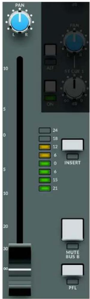
text_image
PAN L R 10 5 0 24 18 12 6 0 6 15 21 INSERT MUTE BUS B PFLStereo channels
There are two stereo channels on SiX - this section describes the features found on each of these stereo channels.
SuperAnalogue Stereo Input
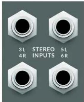
The inputs to the stereo channels are on 1/4" TRS balanced jack connectors. These are labelled 3L, 4R, 5L and 6R for the two pairs of inputs.
text_image
3L STEREO 5L 4R INPUTS 6RThe inputs have an automatic 'Mono From Left' feature, i.e. if only a single jack connector is
used in the Left input, then the same signal is fed to the Right input. When a jack is inserted into the right input, the Left and Right signals are passed separately through the channel. A single jack inserted into the Right input will only pass through the channel on the Right side.
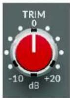
The Trim control adjusts the stereo Line amp gain from -10 to +20 dB with a centre detent at unity gain.
Stereo Cue Sends
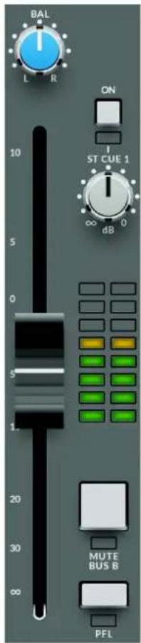
There are two stereo Cue sends on each stereo channel with independent level controls. These can be switched on or off using the 'ON' switch; a green LED indicates that the Cue send is switched on.
Both sends are fed from channel pre-fader post-insert, but can be switched to post fader by engaging the corresponding CUE POST switch(es) in the Foldback master section.
The channel signal is unity gain to the Cue Bus when the Send Level control is fully clockwise.
text_image
BAL L R ON ST CUE 1 ∞ dB 10 5 0 20 30 60 MUTE BUS B PFLChannel Fader and Pan
The channel level is controlled by the 100mm stereo fader, with a Balance control directly above. This adjusts the balance between the left and right input signals to the main mix bus.
The Mute/Bus B switch mutes the channel feed to the Main Mix Bus, whilst also sending the channel signal post-fader to the additional stereo Mix Bus B.
The PFL (Pre Fade Listen) switch sends the channel signal to the PFL bus and interrupts the monitoring to switch to this bus without affecting the signal output to the Main Mix Bus.
The eight LED Stereo Channel Meter is fed before the fader, but after the channel processing.

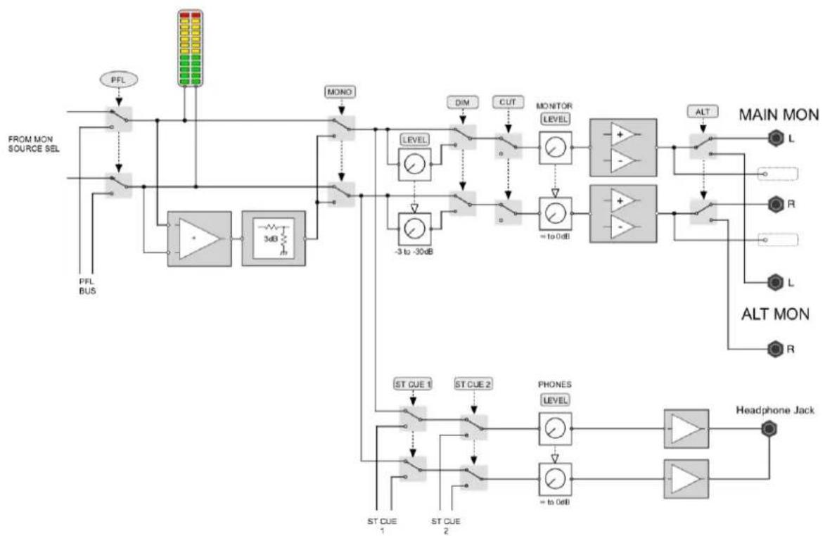
The monitoring facilities in SiX are very comprehensive given the size of the console. The block diagram below shows the structure of the Main Monitor, Alternate Monitor and Headphone outputs.
flowchart
graph TD
    A["FROM MON SOURCE SEL"] --> B["PFL BUS"]
    B --> C["MODA"]
    C --> D["MONO"]
    D --> E["LEVEL"]
    E --> F["3 to -30dB"]
    F --> G["= to 0dB"]
    G --> H["MONITOR LEVEL"]
    H --> I["+"]
    I --> J["ALT"]
    J --> K["MAIN MON L"]
    J --> L["ALT MON R"]
    J --> M["ALT MON L"]
    J --> N["ALT MON R"]
    O["ST CUE 1"] --> P["ST CUE 2"]
    Q["ST CUE 1"] --> R["ST CUE 2"]
    S["ST CUE 2"] --> T["PHONES LEVEL"]
    U["= to 0dB"] --> V["= to 0dB"]
    W["Headphone Jack"] --> X["Output"]
MAIN and ALT monitor outputs
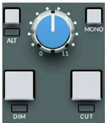
The monitor section has two sets of balanced outputs for loudspeakers labelled MAIN MON and ALT MON (See rear connector layout below). By default, the MAIN MON output is used. Pressing the ALT key on the front panel switches the Monitor feed to the ALT MON output. Both Main and Alt outputs use balanced 14 " jack Sockets on the rear connector panel. In addition to the 14 " jack outputs there is also a parallel of the pre-switched Monitor Output on the 25 way OUT/SEND D-type connector on the rear panel (pre Main/Alt Switch). Connection details are in the Connectors section later in the document.
The Monitor outputs are Off when the Monitor Level is fully anti-clockwise (0) and at unity when fully clockwise (11).
Below the Monitor Level control are buttons for DIM and CUT. The CUT button mutes all of the monitor outputs. The DIM button lowers the monitor output level as controlled by the DIM level knob in the Monitor Source section (see next page).
text_image
ALT 0 11 MONO DIM CUT
text_image
OFF 0 ON 1 DC POWER ≈ 1 L 2 L F/BACK ST CUES 1R 2R OUT/SEND IN/RETURN L BUS B OUT R MAIN MON R ALT MON R MAIN L R PIN 1.2.3: N/C PIN 5: +15V,3.3A PIN 4: COM SHELL: CHASSISSiX Rear Connectors
Headphone (Phones) output

natural_image
Digital icon of a hexagonal device with a black circular button and headphones, labeled 'POWER' at the bottom (no text or symbols on the device itself)In addition to the Main and Alt loudspeaker outputs, SiX has a stereo headphone output on a 14 " Stereo Jack, on the upper connector panel above the Power indicator.
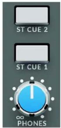
The headphone level is controlled by the PHONES knob which is above the Monitor Level control. By default, the headphone output follows the Monitor SOURCE selection. However, the headphone output can also be switched to monitor Stereo Cue buses 1 & 2 independently of the Monitor selection, using the ST CUE 1 and ST CUE 2 switches above the level controls. These switches intercancel with the uppermost switch taking priority. The Stereo Cue feeds to these switches are before the additional features of the Foldback section, i.e. before Talkback and the External Source selection. This prevents the Talkback feeding back into the
text_image
ST CUE 2 ST CUE 1 ∞ PHONESheadphones when both the Foldback/Talkback Mic and the Headphones are being used.
Monitor Source section
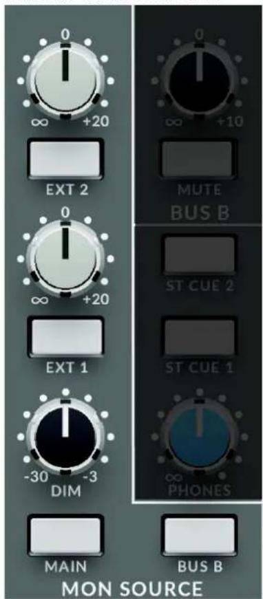
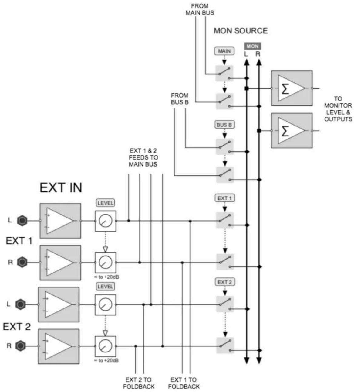
The MON SOURCE section controls the signals fed to the Monitor Level and the Headphone Outputs. A block diagram of this section can be seen on the next page. A powerful and unusual feature of the Monitor Source section is that the sources sum, rather than switch. This allows monitoring of external signals alongside the main mix buses while using these buses to feed audio recorders or other 'clean' feeds.
Buttons in the MON SOURCE section SUM signals into the monitor outputs as follows:
- MAIN - Main Bus - after fader, insert, compressor and source summing
- BUS B - Bus B after the level control and MUTE switch
- EXT 1 - External Input 1 after the level control
- EXT 2 - External Input 2 after the level control
PLEASE NOTE: IF NONE OF THE ABOVE BUTTONS ARE SELECTED, THERE WILL BE NO SIGNAL TO THE MONITORS
External 1 and 2 Levels
Above the EXT 1 and EXT 2 monitor source switches are the level controls for the relevant External inputs. These level controls adjust the External level between off and +20 dB, with a detent at unity. The law of these controls is designed to offer more fine control around unity gain, with a greater degree of tapering in the level control law towards the
end positions. The External level set by these controls affects wherever the Ext signals are fed in the console (e.g. to the external summing into the Main Bus).
The block diagram for the Monitor Source and External Input section is shown on the next page.
flowchart
graph TD
    A["FROM MAIN BUS"] --> B["MON SOURCE"]
    B --> C["MAIN"]
    B --> D["MON"]
    C --> E["Σ"]
    D --> F["Σ"]
    G["EXT IN"] --> H["L"]
    G --> I["R"]
    J["EXT 1"] --> K["LEVEL"]
    K --> L["= to +20dB"]
    M["EXT 2"] --> N["LEVEL"]
    N --> O["= to +20dB"]
    P["EXT 1 & 2 FEEDS TO MAIN BUS"] --> Q["LEVEL"]
    Q --> R["= to +20dB"]
    S["EXT 1 & 2 FEEDS TO MAIN BUS"] --> T["LEVEL"]
    T --> U["= to +20dB"]
    V["EXT 1"] --> W["LEVEL"]
    W --> X["= to +20dB"]
    Y["EXT 2"] --> Z["LEVEL"]
    Z --> AA["= to +20dB"]
    AB["EXT 1 TO FOLDBACK"] --> AC["LEVEL"]
    AD["EXT 1 TO FOLDBACK"] --> AE["LEVEL"]
    AF["TO MONITOR LEVEL & OUTPUTS"] --> AG["Σ"]
Monitor Source and External Inputs
Foldback and Stereo Cue Master Section (including Talk Input)
text_image
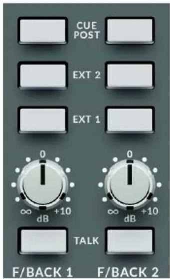
CUE POST EXT 2 EXT 1 0 ∞ dB +10 TALK F/BACK 1 0 ∞ dB +10 F/BACK 2The two Stereo Cue buses in SiX feed the Foldback Master section. This section is split vertically with the left column controlling Foldback 1 and the right controlling Foldback 2.
The knobs in this section control the master level of the individual Foldback outputs. As can be seen in the block diagram on the next page, they are the last controls before the output (i.e. after the switched sources).
Three switches intercancel in order of priority from bottom to top are the TALK, EXT 1 and EXT 2, with the following functions:
- TALK - switches the output of the Talk section to the Foldback Output
- EXT 1 - switches the External Source 1 input to the Foldback Output
- EXT 2 - switches the External Source 2 input to the Foldback Output.
Talk Input Pre-amplifier and LMC
SiX's Talk Input is an additional pre-amplifier and compressor circuit nominally designed to provide talkback facilities to the Stereo Cue/Foldback outputs of the console, but with several other possible applications when the design is explored more fully.

flowchart
graph LR
    A["TALK INPUT"] --> B["+48V"]
    B --> C["+45dB"]
    C --> D["+20dB"]
    D --> E["LMC IN"]
    E --> F["+∞ to 0dB"]
    F --> G["TB LEVEL"]
Talk Input
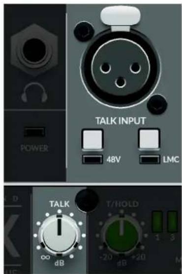
The Talk input is a balanced female XLR connector. Below the connector are switches for Phantom Power and the LMC. LMC is the legendary SSL Listen Mic Compressor (here being used for Talkback, which is arguably its original design purpose).
The Talk Input feeds a fixed +45dB high quality mic pre-amplifier and then optionally the LMC compressor. The LMC adds an additional +20 dB of make-up gain to restore signal level after the severe amount of gain reduction it introduces by design. The output level of the Talk circuit is controlled by the TALK knob.
The LMC circuit is designed to allow a microphone connected to the Talk Input to maintain similar level signals regardless of whether the source is close or distant. i.e. if an engineer is close to the console and another person is sat on a couch behind the engineer, the artist will hear both of their voices legibly and at a similar level.
text_image
TALK INPUT POWER 48V LMC TALK T/HOLD 00 dB -20 dB +20 dB 1 3 MThe TALK key in the Foldback master section latches to allow a secondary use of the Talk Input pre-amplifier and compressor as an effect, using the Foldback send as the output.
Switching the Stereo Cues from Pre to Post fader
By default, both Stereo Cue sends 1 and 2 are sourced pre-fader in the mono and stereo channels. The CUE POST switch at the top of the Foldback Master section allows each CUE send to be sourced post fader (pre balance) to the Stereo Cue mixes.
Artist Cue Mixes
The Foldback features of SiX are designed to provide a separate artist mix from the engineer's monitoring and headphone feed using the Mono and Stereo Channel's Cue Send buses. Typically, the fully balanced outputs will be connected to a dedicated Headphone amplifier or Cue system, although there is enough level to drive many headphones directly with suitable wiring (balanced left and right outputs wired to unbalanced left/right headphone connection).
The EXT 1 and EXT 2 switches in the Foldback master section provide a simple way to feed an external source to the Foldback outputs. These are typically used when it would be useful to play something directly to the artist - for example a rough mix from a phone/DAW.

flowchart
graph TD
    A["TALK INPUT"] --> B["48V"]
    B --> C["+45dB"]
    C --> D["+20dB"]
    D --> E["LMC IN"]
    E --> F["+ to 0dB"]
    F --> G["TB LEVEL"]
    G --> H["= to +10dB"]
    H --> I["ST F/Back 1"]
    I --> J["+"]
    I --> K["ST F/Back 2"]
    K --> L["+"]
    K --> M["ST F/Back 1"]
    M --> N["1L"]
    M --> O["1R"]
    I --> P["ST F/BACK 2"]
    P --> Q["2L"]
    P --> R["2R"]
    style A fill:#f9f,stroke:#333
    style B fill:#ccf,stroke:#333
    style C fill:#cfc,stroke:#333
    style D fill:#fcc,stroke:#333
    style E fill:#cff,stroke:#333
    style F fill:#ffc,stroke:#333
    style G fill:#cfc,stroke:#333
    style H fill:#fcc,stroke:#333
    style I fill:#ffc,stroke:#333
    style J fill:#cfc,stroke:#333
    style K fill:#cfc,stroke:#333
    style L fill:#cfc,stroke:#333
    style M fill:#cfc,stroke:#333
    style N fill:#cfc,stroke:#333
    style O fill:#cfc,stroke:#333
    style P fill:#cfc,stroke:#333
    style Q fill:#cfc,stroke:#333
    style R fill:#cfc,stroke:#333
SiX Foldback Block Diagram
Foldback Outputs as Effects Sends
It is perfectly feasible to use the Foldback Outputs as stereo feeds to external effects processors such as delays and reverbs. Typically, the processor's output would be connected to one of the External returns, then summed to the main bus using the External summing switches to the Main Bus above the Main Fader.
Main Meter
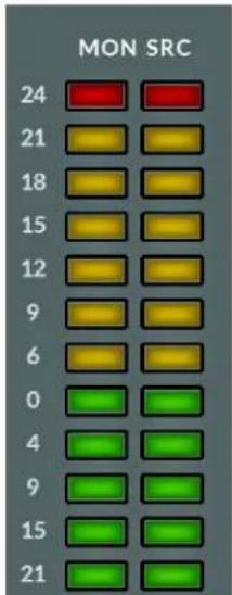
The twelve Segment LED 'main' meter in SiX follows the Monitor Source selector to provide a more versatile output metering solution. The fast response peak meter has specific segments for +24 dBu and +18 dBu as with the channel meters, it also has a +15 dBu segment for other standards as well as 0dBu. The meter has a fast peak response (rise time to 60% Full Scale Deflection approx 1ms @ 1kHz) and a slower release to meter peaks while still showing useful signal levels.
bar
MON SRC | Category | MON | SRC | |---|---|---| | 24 | Red | Red | | 21 | Yellow | Yellow | | 18 | Yellow | Yellow | | 15 | Yellow | Yellow | | 12 | Yellow | Yellow | | 9 | Yellow | Yellow | | 6 | Yellow | Yellow | | 0 | Green | Green | | 4 | Green | Green | | 9 | Green | Green | | 15 | Green | Green | | 21 | Green | Green |
text_image
ST CUE 1 EXT 2 EXT 1 INSERT 10 5 0 5 10 20 30 ∞Main Bus
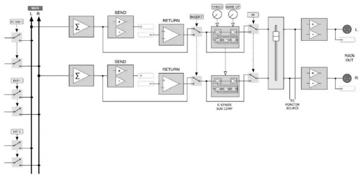
The Main Stereo Bus on SiX connects to dedicated MAIN XLR outputs on the rear connector panel. These are balanced XLR connectors with pin 2 carrying the +ve (hot). Connection details are in the Connectors section, later in the document.
The high quality 100mm Main Bus stereo fader controls the Main Bus level to the Main outputs and has gain up to +10 dB. As with the channel faders, the fader law is designed to provide more resolution around the 0dB point, allowing subtle level changes from modest fader movements.
Main Bus Summing
Above the Main Fader are switches for the Main Bus Insert (See below), EXT 1, EXT 2 and ST CUE 1. These last three switches sum these signals onto the Main bus. This provides the ability to sum six additional signals into the Main bus. An example of how this can be used is to add additional analogue summing from DAW outputs, or to effects return signals into the main mix, or simply cascade additional mixers such as additional SiX consoles.
Main Bus Insert
In the Main Output signal flow is a fully balanced stereo insert. In common with larger SSL consoles, the Insert Send is always active, while the Insert Return switches into the signal path when selected.
The primary use for this is to insert external processing into the Main Bus signal path. For example to insert an analogue colouration processor, such as SSL's Fusion. As the Insert Send is at unity gain, it also provides a useful pre-processing and pre-fader Main Bus split output.
The switched Insert Return also provides a direct, pre-fader input into SiX's Bus Compressor circuit so that this circuit can be used outside of the normal SiX signal flow.
The Main Bus stereo insert send and return are found on the rear panel 25 way D-Type connectors. Wiring details are in the Connectors section, later in the document.
G-Series Bus Compressor
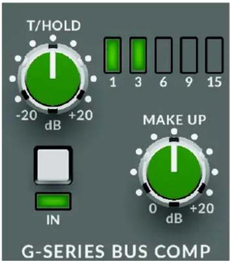
The G Series Bus Comp in Six is a stereo compressor applied across the Main Mix bus, using exactly the same circuit topology as the original design found on the SL4000 G-Series console released in 1989 (which in-turn was evolved from the earlier E-Series consoles).
The T/HOLD pot adjusts the Threshold for the compressor, with five LEDs indicating the amount of gain reduction applied (-1dB, -3dB, -6dB, -9dB, -15dB). The compressor has carefully selected attack and release times to suit a wide variety of mix content and uses the 4:1 ratio setting from the original processor that is preferred by many SSL large format console users. Adjustable MAKE UP gain and a bypass 'IN' switch allow level matching and switching for direct comparisons of the clean and processed signals.
text_image
T/HOLD -20 dB +20 1 3 6 9 15 IN MAKE UP 0 dB +20 G-SERIES BUS COMPThe bus compressor side chain also has a 1st order High Pass Filter at approx
50Hz, a feature of more modern SSL bus compressor designs to give smoother performance from mixes with prominent bass content.
flowchart
graph TD
    A["ST-UE1"] --> B["Σ"]
    C["EXT1"] --> D["Σ"]
    E["EXT2"] --> F["Σ"]
    B --> G["SEND"]
    D --> H["SEND"]
    F --> I["SEND"]
    G --> J["+"]
    H --> K["+"]
    I --> L["+"]
    J --> M["+"]
    K --> N["+"]
    L --> O["+"]
    M --> P["+"]
    N --> Q["+"]
    O --> R["+"]
    P --> S["+"]
    Q --> T["+"]
    R --> U["G SERIES BUS COMP"]
    S --> V["TO MONITOR SOURCE"]
    T --> W["TO MONITOR SOURCE"]
    U --> X["+"]
    V --> Y["+"]
    W --> Z["+"]
    X --> AA["L"]
    Y --> AB["R"]
Main Bus Block Diagram
Application Examples
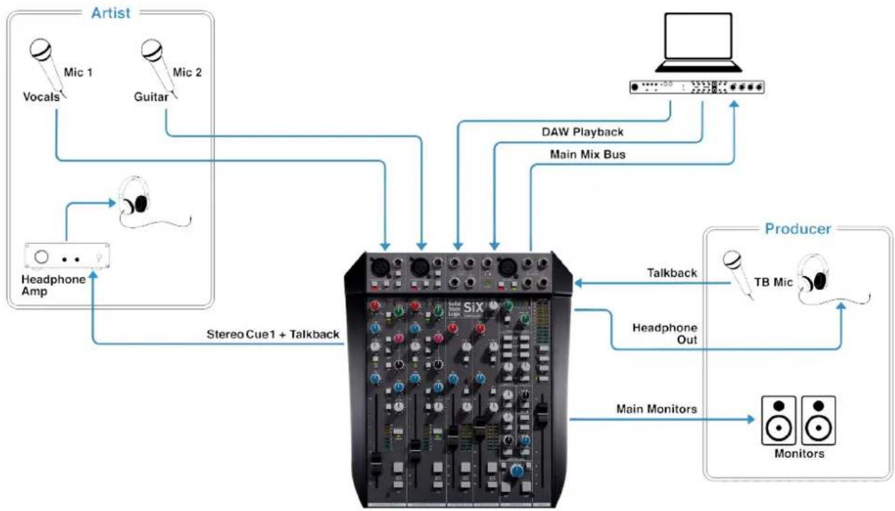
Recording A Singer/Songwriter
flowchart
graph TD
    A["Artist"] --> B["Vocals"]
    A --> C["Mic 1"]
    A --> D["Guitar"]
    A --> E["Headphone Amp"]
    A --> F["Stereo Cue1 + Talkback"]
    G["Producer"] --> H["TB Mic"]
    G --> I["Talkback"]
    G --> J["Headphone Out"]
    G --> K["Main Monitors"]
    G --> L["Monitors"]
    M["Laptop"] --> N["DAW Playback"]
    M --> O["Main Mix Bus"]
    P["Main Monitors"] --> Q["Monitors"]
This is a simple application to record a singer songwriter.
The mics for the vocal and guitar are connected to the SuperAnalogue XLR microphone inputs then processed with the SSL Channel Compression and EQ. The Cue/Foldback 1 output is connected a headphone amplifier to feed the artist. The Cue feed from the channel is by default Pre Fader, allowing the engineer to make mix adjustments without changing the Artist feed.
The mics are recorded to the Digital Audio Workstation (DAW) from the Main mix bus, using the Stereo Bus Compressor to smoothly manage the combined transients.
Using Stereo Cue bus 1 for the artist and the Headphone or Monitor outputs for the producer means each can have independent monitor mixes.
DAW playback is sent into the Stereo Channel, and then to the artists using the Stereo Cue 1 control. If useful, two separate DAW feeds can be used into the two Stereo Channels allowing for separate click-track and playback level controls to the artist's cue feed.
The talkback system keeps the producer in touch with the artist using a phantom powered condenser Mic and the Listen Mic Compressor and TALK level control conveniently manage the talkback levels.
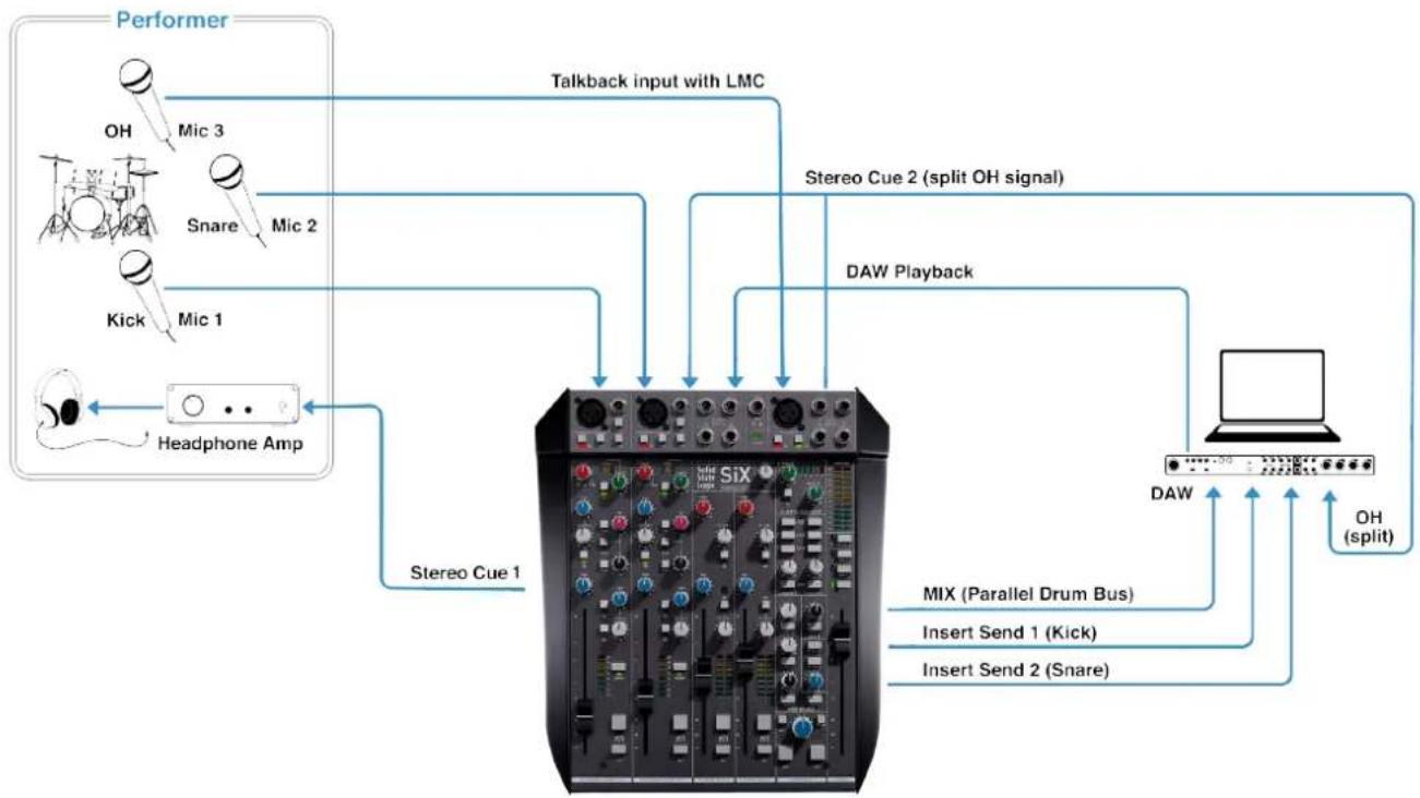
Recording Drums
flowchart
graph TD
    A["Performer"] -->|Talkback input with LMC| B["SiX"]
    B --> C["Headphone Amp"]
    C --> D["Stereo Cue 1"]
    D --> E["DAW Playback"]
    E --> F["DAW"]
    F --> G["OH (split)"]
    B --> H["MIX (Parallel Drum Bus)"]
    B --> I["Insert Send 1 (Kick)"]
    B --> J["Insert Send 2 (Snare)"]
SiX is easily reconfigured for other recording tasks. Here's a slightly more complex example that explores some of the more advanced routing features of SiX to set-up a classic drum recording technique.
Here we have a three mic drum setup; kick, snare and mono overhead.
The kick and snare microphones are connected to the SuperAnalogue XLR mic inputs and processed with the SSL channel compression and EQ. The kick and snare are recorded to individual DAW tracks via the channel one and two Insert Sends (on the Output 25 Way D-type and which are always 'active' on an SSL). The overhead is connected to the Talkback Mic XLR input, so it can be heavily compressed through the LMC (Listen Mic Compressor).
The overhead is sent to the Stereo Cue 2 output jack by selecting the Foldback/Cue using the TALK, which acts as a split. One side is connected to the DAW audio interface for recording. The other side is connected to one of the stereo channels, which automatically sum a left mono connection to the Stereo Mix bus.
All three inputs are mixed down through the Stereo Bus Compressor and recorded as a parallel drum compression bus at the same time as the individual tracks. DAW playback is connected to Stereo Input two.
Music Production - Writing and Tracking
flowchart
graph TD
    A["Guitar"] --> B["Switcher"]
    B --> C["Pedal Board"]
    C --> D["Guitar & FX loop"]
    D --> E["Main Mix Bus"]
    E --> F["External Mix Bus Processing"]
    F --> G["Mix inserts"]
    G --> H["Main Monitors"]
    H --> I["Drum Machine"]
    I --> J["Synth 1"]
    I --> K["Synth 2"]
    I --> L["Synth 3"]
    J --> M["Main Monitors"]
    K --> N["Main Monitors"]
    L --> O["Main Monitors"]
    M --> P["External Mix Bus Processing"]
    N --> P
    O --> P
    C --> Q["DAW 1 & 2 to Alt inputs"]
    Q --> R["SI6"]
    R --> S["Main Monitors"]
    S --> T["Drum Machine"]
    T --> U["Synth 1"]
    T --> V["Synth 2"]
    T --> W["Synth 3"]
    U --> X["Main Monitors"]
    V --> Y["Main Monitors"]
    W --> Z["Main Monitors"]
    X --> AA["External Mix Bus Processing"]
    Y --> AA
    Z --> AA
    AA --> AB["Main Mix Bus"]
    AB --> AC["External Mix Bus Processing"]
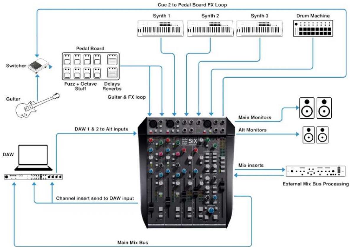
Let's take a look at how SiX might be configured for a writing and tracking session.
A guitarist with a pedalboard is connected to channels one and two, processed through the SSL Channel Compression and EQ.
To process the other sources using the guitar effects and SSL EQ & Dynamics, an FX loop has been created by connecting Stereo Cue Output 2 to the input of the guitar input switcher.
The Insert Sends for channels 1 and 2 are connected to the DAW input to create a direct record path.
DAW outputs 1 and 2 are connected to the Alt inputs on channels 1 and 2 (via the 25 Way D-Type Connector), to allow a switch between live and recorded buses for the guitar and effects system using the ALT switches on the channels.
The synths are connected to the two Stereo Channels and stereo External Input 1, and a drum machine connected to stereo External Input 2 The Main Mix Bus XLR Output is connected to the DAW inputs for recording enhanced by the Stereo Bus Compressor.
The Insert point on the Main Mix Bus is used to incorporate additional processing. Main and Alt monitors as well as the Headphone output offer a range of professional monitoring options.
Music Production - Mixdown
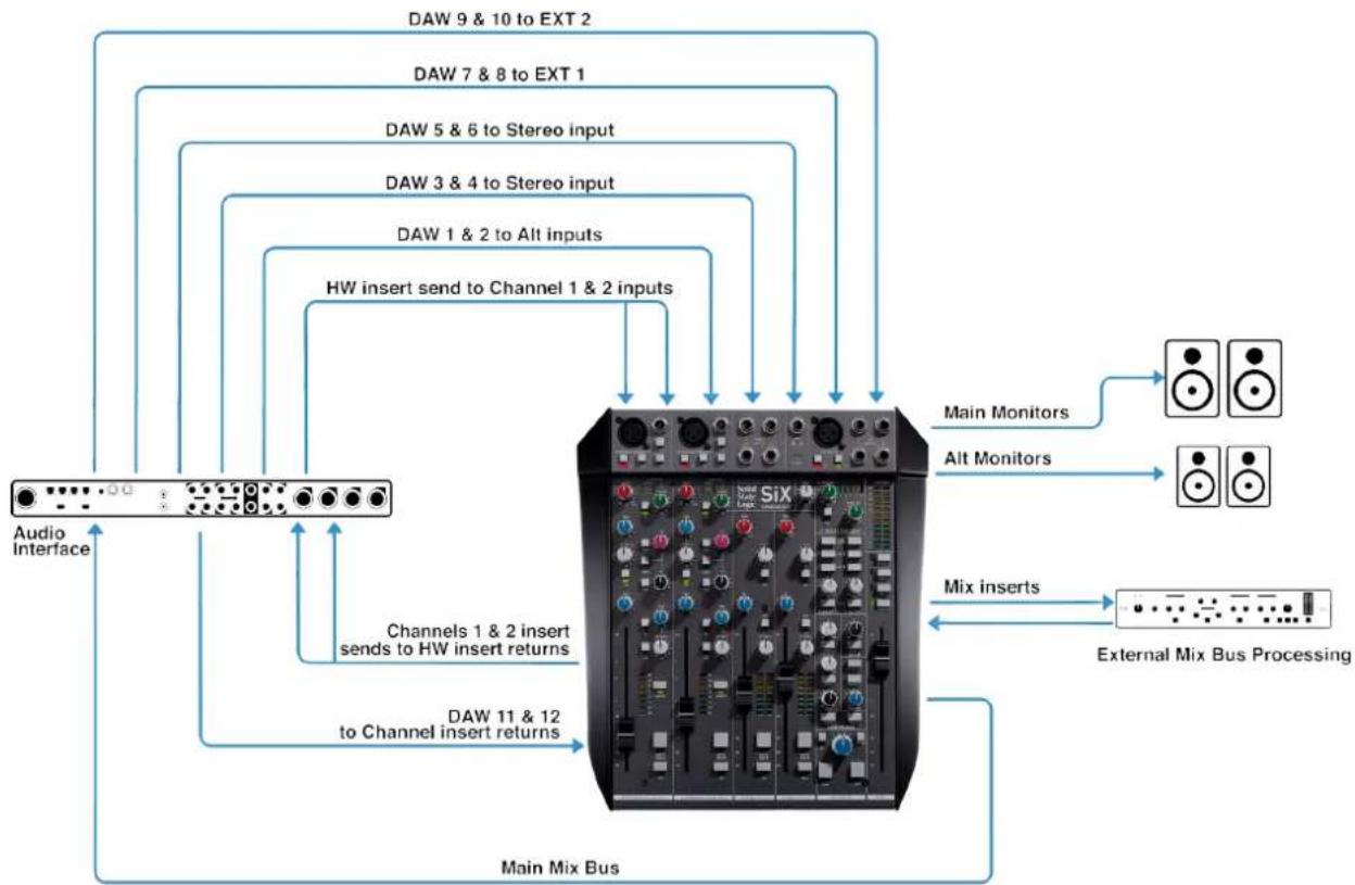
flowchart
graph TD
    A["Audio Interface"] --> B["Main Mix Bus"]
    B --> C["External Mix Bus Processing"]
    C --> D["Main Monitors"]
    C --> E["Alts Monitors"]
    C --> F["Mix inserts"]
    B --> G["DAW 1 & 2 to Channel 1 & 2 inputs"]
    B --> H["DAW 3 & 4 to Stereo input"]
    B --> I["DAW 5 & 6 to Stereo input"]
    B --> J["DAW 7 & 8 to EXT 1"]
    B --> K["DAW 9 & 10 to EXT 2"]
    B --> L["DAW 1 & 2 to Alt inputs"]
    B --> M["HW insert send to Channel 1 & 2 inputs"]
    B --> N["Channels 1 & 2 insert sends to HW insert returns"]
    B --> O["DAW 11 & 12 to Channel insert returns"]
When tracking is finished, SiX is easily reconfigured for mixdown.
In the above diagram twelve channels of SSL analogue summing have been set up. DAW outputs are connected to SiX using Alt inputs, Stereo Line inputs and External inputs. The Alt inputs on channels 1 and 2 are summed straight to the mix bus, bypassing the channel processing.
A hardware insert has been created using the Channel Inserts so a pair of channels can be processed from the DAW through the SiX channel EQ and Dynamics. This is done by connecting a pair of DAW outputs to the main inputs of Channels 1 and 2. Then connecting a return path from the Insert Send on Channels 1 and 2 back to the DAW. The channel insert is taken post processing and returned pre fader. To finish, a pair of DAW outputs is then connected to the channel Insert Returns to provide the final pair of summing inputs.
During mixdown all of the advantages of comprehensive monitoring and processing are still available using the stereo Bus Compressor and the Main Mix Bus Insert.
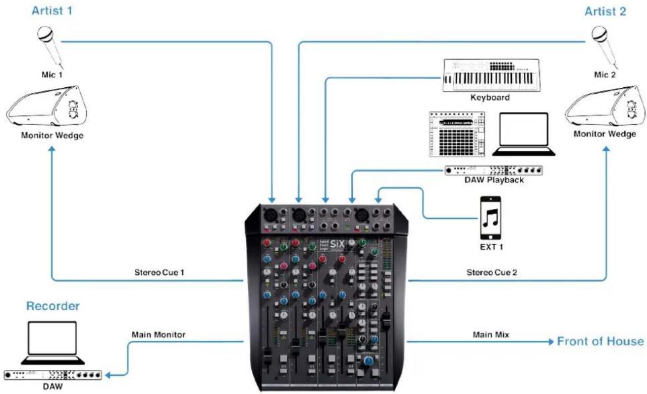
On Stage
flowchart
graph TD
    A["Artist 1"] --> B["Monitor Wedge"]
    C["Artist 2"] --> D["Monitor Wedge"]
    E["Recorder"] --> F["DAW"]
    G["Front of House"] --> H["Main Mix"]
    I["Main Monitor"] --> J["SiX"]
    K["Stereo Cue 1"] --> L["Central System"]
    M["Main Mix"] --> N["Main Monitor"]
    O["XT 1"] --> P["DAW Playback"]
    Q["Keyboard"] --> R["DAW Playback"]
    S["Mic 1"] --> T["Monitor Wedge"]
    U["Mic 2"] --> V["Monitor Wedge"]
SiX is your professional, personal on-stage mixer, delivering true sonic excellence.
Here we have two artists, each with a microphone connected to SiX's high quality SuperAnalogue mic pres and their own SSL channel compression and EQ.
Artist two has a Stage Piano connected to Stereo input one and a DAW playback system connected to Stereo Input two, as well as a phone/tablet connected to an external input.
Each Artist has their own monitor mix using the Cue 1 and Cue 2 stereo sends.
The main mix output delivers a pristine audio feed to main PA system (Front of House) with the classic SSL Stereo Bus Compressor ensuring a controlled and punchy audio performance.
Capture your show using one of the Monitor outputs as a record feed with the Monitor Source selected to 'Main' - with the Monitor level control fully clockwise the output is at unity gain.
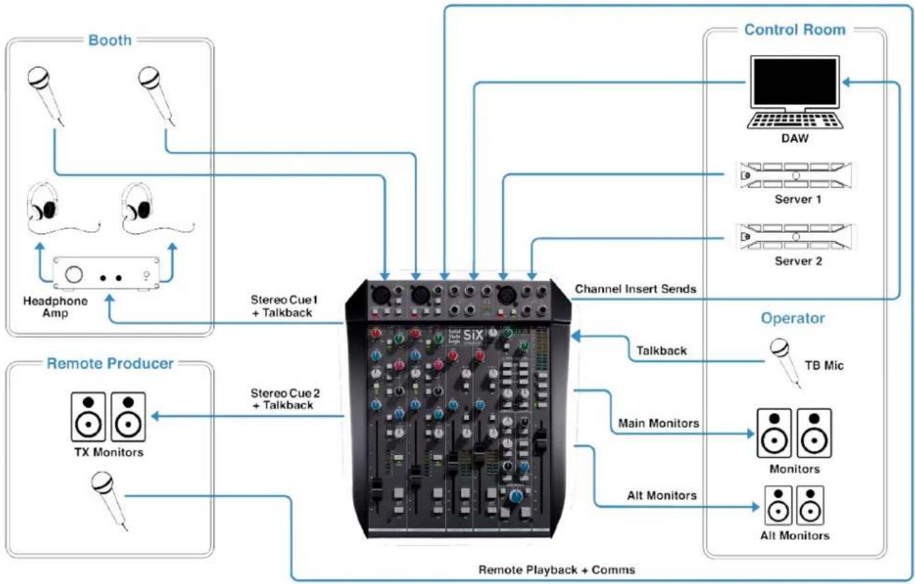
Post Production
flowchart
graph TD
    A["Booth"] --> B["Headphone Amp"]
    C["Booth"] --> D["Stereo Cue1 + Talkback"]
    E["Booth"] --> F["Stereo Cue2 + Talkback"]
    G["Control Room"] --> H["DAW"]
    H --> I["Server 1"]
    H --> J["Server 2"]
    K["Operator"] --> L["Talkback"]
    L --> M["TB Mic"]
    N["Remote Producer"] --> O["TX Monitors"]
    N --> P["Stereo Cue2 + Talkback"]
    Q["Remote Playback + Comms"] --> R["Main Monitors"]
    Q --> S["Alt Monitors"]
    T["Channel Insert Sends"] --> U["SIX"]
    U --> V["Talkback"]
    V --> W["Main Monitors"]
    V --> X["Alt Monitors"]
SiX is a perfect choice for small professional post-production environments designed for dubbing and voice over.
It's ideal for the audio engineer who needs to mix local and remote playback feeds, with local mic inputs whilst also providing comms and zero latency monitoring for the talent, the operator and a remote producer.
SiX offers deceptively powerful connectivity and routing that sets it apart from other desktop mixers. Up to four local and remote playback outputs can connect to the two stereo channels and master section external inputs. We also have two talent mics in the booth connected to SiX's high quality SuperAnalogue mic pres with SSL compression and EQ.
The talent, the operator and the remote producer all have separate monitor mixes. The Cue buses provide talkback from the operator to all destinations. A return voice feed from the remote producer can be connected via External Input 2.
SuperAnalogue audio quality throughout and the SSL stereo Bus Compressor help ensure the delivery of broadcast ready content quickly and easily.
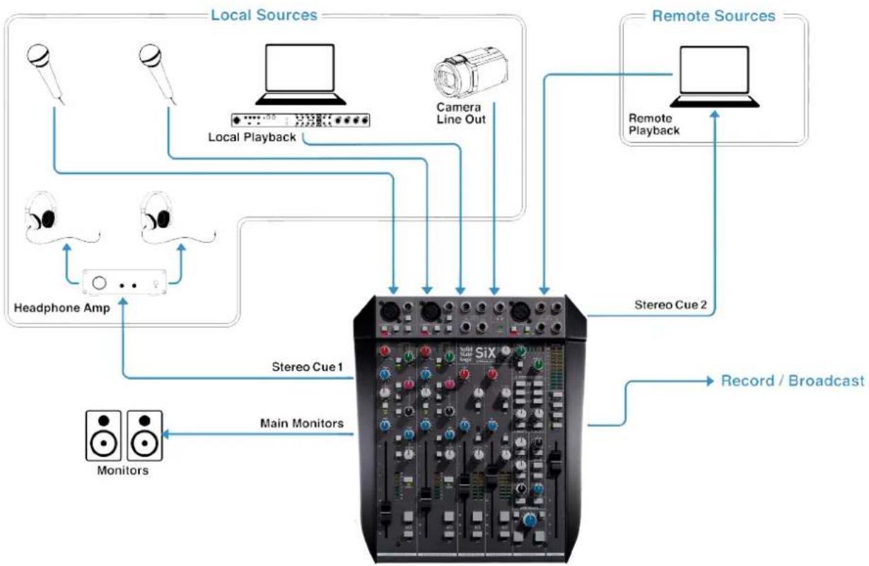
Podcasting
flowchart
graph TD
    A["Local Sources"] --> B["Local Playback"]
    B --> C["Camera Line Out"]
    C --> D["Remote Sources"]
    D --> E["Remote Playback"]
    E --> F["Stereo Cue 2"]
    F --> G["Record / Broadcast"]
    H["Headphone Amp"] --> I["Main Monitors"]
    J["Monitors"] --> K["Main Monitors"]
    L["SiX"] --> M["Main Monitors"]
    N["Radio"] --> O["Radio Headphones"]
    P["Radio Line Out"] --> Q["Radio Headphones"]
    R["Radio Playback"] --> S["Radio Playback"]
    T["Radio Cue 1"] --> U["Main Monitors"]
SiX is a powerful choice for professional online content creation.
It's ideal for vloggers, producers and podcasters who need to achieve high fidelity audio recordings quickly and intuitively.
Here, SiX acts as the nerve centre, with local sources including, two mic inputs connected to SiX's high quality SuperAnalogue mic pre's, with SSL Compression and EQ, local playback connected to one of the Stereo Channels and remote playback feeds connected to the second stereo channel. Additional stereo sources can be incorporated via External Inputs 1 & 2.
There are separate local headphone and monitor mixes and a separate cue mix can be created for remote contributors.
The main mix is enhanced by the stereo Bus Compressor for an upload-ready record feed.
Troubleshooting & FAQs
Frequently Asked Questions and additional support contacts can be found on the Solid State Logic Website at: https://www.solidstatelogic.com/support/six
Troubleshooting Tips
My SiX is warm to the touch
SiX's SuperAnalogue audio circuits are designed to run warm and SiX contains a lot of electronics in a small space. SiX is designed to cool front to back, so ensuring ventilation inlets and outlets (front and rear) have clearance is important to reliable operation.
There is no output from the monitors
Check that there is something selected in the monitor source section of the console (see page 11). A monitor source needs to be selected (typically MAIN) to hear something from the monitor outputs. Also check that the ALT button isn't pressed with nothing connected to the Alternate Monitor connections.
When I connect only to a Left Input, there is also a signal on the Right
This is a feature of the stereo inputs of SiX (see page 9). If an input is only connected to the left input of the stereo input pair (i.e. Stereo Channel inputs and External Inputs) then the signal is automatically sent to both left and right paths.
There is no signal from the B-Bus output
Check that the the B-Bus Mute button is not pressed. This can be found under the B-Bus output level control which is to the left of the Main Fader. This button is a simple way to turn the Mute/B-Bus switches on the channel strips into permanent Mute buttons or simply mute the B-Bus Output if it is being used as a secondary bus output.
There is no signal from the Foldback Outputs
Check that there are no External or Talk buttons selected in the F/Back master sections (see page 13). There is a hierarchy to these switches and they 'replace' the output. For example, if you have EXT 2 selected with no input it will replace the Foldback Bus to the output.
There is no signal from the SuperAnalogue Channels
Check the Channel Insert button. If this is ON with no Insert Return connected to the D-Type connectors then the channel signal will be muted. The Insert Send is always present and only the Insert Return is switched.
There is no signal to the Main Bus
Check the Main Fader Insert button. If this is ON with no Insert Return connected to the D-Type connectors then the Main Fader signal will be muted. The Insert Send is always present and only the Insert Return is switched.
The meters bounce briefly after power on
The bounce is due to the settling of the SuperAnalogue circuits after power is applied. It is normal behaviour. The initial 'all Meter LEDs on' is a feature the console runs when powered on to check all the LEDs are working correctly.
Warranty
Warranty claims will only be accepted if the purchased product has been used for its intended purpose. Any purchased product used for an unintended purpose will not be eligible for warranty protection. For all warranty inquiries or claims please address your claim to the dealer that you purchased the product from or to Solid State Logic if the purchase was directly from Solid State Logic. Claims must be submitted within a period of two months from the date on which you detected its lack of conformity with the terms of the warranty. Please include your original proof of purchase when initiating the claim.
Within the EU: Pursuant to the Solid State Logic Terms and Conditions under European consumer law the purchaser has full statutory warranty rights for two years from the date of purchase of the product. The warranty is valid only in those Member States of the European Union (EU) who have adopted the applicable EU law into their national legislation. The applicable national legislation governing the sale of consumer goods is not affected by this warranty.
Outside of the EU: Outside of the European Union a 12 month warranty from date of purchase is applicable.
All returns
No unit will be accepted for repair by Solid State Logic unless accompanied by a valid RMA (Return Material Authorisation) number, obtainable from Solid State Logic prior to shipping.
All units should be shipped to Solid State Logic in suitable rigid packaging – Solid State Logic cannot be held responsible for any damage caused by shipping units in other packaging.
Appendix A - Physical Specification
| Front to Back Depth 310 mm / 12.2 inches | |
| Height (from table top inc. feet) 120 mm / 4.7 inches | |
| Width 218 mm / 8.6 inches (Excluding Trim) | 270 mm / 10.6 inches (Including Trim) |
| Power 38 Watts | |
| Unboxed Weight 3.5 kg / 7.7 lbs | |
| Boxed Size Depth x Height x Width | 325 mm x 155 mm x 360 mm (12.8" x 6.1" x 14.2") |
| Boxed Weight 6.0 kg / 13.3 lbs | |
Note: All physical specification values are approximate.
Connector Pinouts
Mono Channels
Microphone Inputs
| 3-pin XLR Male | |
| Pin Description | |
| 1 0V Chassis | |
| 2 Signal +ve (Hot) | |
| 3 Signal -ve (Cold) | |
Stereo Channels
Stereo Channel Line Inputs
| 1/4" TRS Jack Socket | |
| Pin Description | |
| Tip Signal +ve (Hot) | |
| Ring Signal -ve (Cold) | |
| Sleeve 0V Chassis | |
Talkback Microphone Input
| 3-pin XLR Female | |
| Pin Description | |
| 1 0V Chassis | |
| 2 Signal +ve (Hot) | |
| 3 Signal -ve (Cold) | |
Line Inputs
| 1/4" TRS Jack Socket | |
| Pin Description | |
| Tip Signal +ve (Hot) | |
| Ring Signal -ve (Cold) | |
| Sleeve 0V Chassis | |
External Inputs
Stereo External Line Inputs
| 1/4" TRS Jack Socket | |
| Pin Description | |
| Tip Signal +ve (Hot) | |
| Ring Signal -ve (Cold) | |
| Sleeve 0V Chassis | |
Foldback/Stereo Cue Outputs
| 1/4" TRS Jack Socket | |
| Pin Description | |
| Tip Signal +ve (Hot) | |
| Ring Signal -ve (Cold) | |
| Sleeve 0V Chassis | |
Main Bus Outputs
| 3-pin XLR Male | |
| Pin Description | |
| 1 0V Chassis | |
| 2 Signal +ve (Hot) | |
| 3 Signal -ve (Cold) | |
Bus B Outputs
| 1/4" TRS Jack Socket | |
| Pin Description | |
| Tip Signal +ve (Hot) | |
| Ring Signal -ve (Cold) | |
| Sleeve 0V Chassis | |
Main Monitor Outputs
| 1/4" TRS Jack Socket | |
| Pin Description | |
| Tip Signal +ve (Hot) | |
| Ring Signal -ve (Cold) | |
| Sleeve 0V Chassis | |
Alternate Monitor Outputs
| 1/4" TRS Jack Socket | |
| Pin Description | |
| Tip Signal +ve (Hot) | |
| Ring Signal -ve (Cold) | |
| Sleeve 0V Chassis | |
Insert Sends/Returns, Alternate Inputs and Auxiliary Outputs
| 25 Way D-type Input | D-Type Output D-Type | ||||
| Circuit # Hot Cold | Scrn | Circuit | Description Circuit Description | ||
| 1 24 | 12 25 M | Main L Insert R | Return | Main L Insert Send | |
| 2 10 23 | 11 Main R Insert R | in R Insert R | return | Main R Insert Send | |
| 3 | 21 | 9 | 22 | Channel 1 Insert Return | Channel 1 Insert Send |
| 4 | 7 | 20 | 8 | Channel 2 Insert Return | Channel 2 Insert Send |
| 5 | 18 | 6 | 19 | Channel 1 Alt Input | Main L Output - (Passive Split, Not Buffered Output) |
| 6 | 4 | 17 | 5 | Channel 2 Alt Input | Main R Output - (Passive Split, Not Buffered Output) |
| 7 | 15 | 3 | 16 | MON L Output** - (Passive Split, Not Buffered Output) | |
| 8 | 1 | 14 | 2 | MON R Output** - (Passive Split, Not Buffered Output) | |
** NOTE: Monitor outputs on D-Sub connector are not muted by 'ALT' speaker switch. The ALT switch only affects the main monitor output on rear TRS Jack connectors.
DC Power Inlet
| 5-pin XLR Male | |
| Pin Description | |
| 1,2,3 | Not Connected |
| 4 0V | Common |
| 5 +15 | V, 3.3 A |
| Shell | Chassis |
Appendix B - Performance Specification
Audio Performance
Default test conditions (unless otherwise stated):
- Source impedance of Test Set: 40 Ω
- Input impedance of Test Set: 200 kΩ
- Reference frequency: 1 kHz
- Reference level: 0 dBu where 0 dBu = 0.775 V into any load
- All unweighted measurements are specified as 22 Hz to 22 kHz band limited RMS and are expressed in units of dBu
- The onset of clipping (for headroom measurements) should be taken as 1% THD
- All distortion measurements are specified with a 36dB/Octave low pass filter at 20 kHz and are expressed as a percentage
- All levels are intended balanced
Unless otherwise quoted all figures have a tolerance of ± 0.5 dB or 5% .
SuperAnalogue Channel Microphone Amplifier
| Measurement Conditions Value | ||
| Gain **dependant on potentiometer tolerances Variable from +6dB to +72dB** | ||
| Input Impedance 1.2kΩ | ||
| Max Input Level 1% THD 21 dBu | ||
| Output Headroom >+27dBu at onset of clipping | ||
| Frequency Response - 20Hz to 20kHz- -3dB high rolloff | - +0.1/-0.3dB- >100kHz | |
| THD+Noise | (-20dBu applied, +30dB gain) @ 1kHz (filter 22Hz to 22kHz) | - < 0.0015% |
| CMRR | (-10dBu applied, +30dB gain) | - >80dB |
| Equivelant Input Noise (EIN) | 150Ω termination, maximum gain | - <-127.5dBu- typically -129dBu |
SuperAnalogue Channel Line Input Amplifier
| Measurement Conditions Value | ||
| Gain **dependant on potentiometer tolerances Variable from -3dB to +63dB** | ||
| Input Impedance 10kΩ | ||
| Hi-Z Input Impedance | 1MΩ | |
| Max Input Level 1% THD >+27dBu before clipping | ||
| Output Headroom >+27dBu at onset of clipping | ||
| Frequency Response - 20Hz to 20kHz- -3dB high rolloff | +0.1/-0.3dB>100kHz | |
| THD+Noise | (-20dBu applied, +30dB gain) @ 1kHz (filter 22Hz to 22kHz) | < 0.0015% |
| CMRR | >70dB | |
| Equivelant Input Noise (EIN) | 150Ω termination, maximum gain | <-110dBu |
Channel Equaliser
Signal applied to line input and measured at the channel insert send. EQ switched in with EQ controls centred in shelf mode.
| Measurement Conditions Value | ||
| Output Headroom >+27dBu at onset of clipping | ||
| THD+Noise +20dBu @ 1kHz (filter 22Hz to 22kHz) < 0.0015% | ||
| Noise <-88dBu |
Channel Compressor
Signal applied to line Input and measured at the channel insert send. Compressor switched into channel path with the compressor's threshold set to +10dB.
| Measurement Conditions Value | ||
| Ratio (slope)ThresholdAttack TimeRelease Time | 2:1+10 to -20 dB (typical)8ms to 30ms300ms | |
| Output Headroom >+26dBu at onset of clipping | ||
| THD+Noise +10dBu @ 1kHz (filter 22Hz to 22kHz)+20dBu @ 1kHz (filter 22Hz to 22kHz) Threshold @-20 | < 0.03%< 0.5% (typical) | |
| Frequency Response - 20Hz to 20kHz +0.9/-0.9dB | ||
| Noise <-90dBu | ||
SuperAnalogue Stereo Channel Line Input Amplifier
Signal applied to stereo channel line input and measured at main output insert send with the stereo channel's input gain trim and balance controls in their indent position with the stereo channel's fader adjusted for unity gain.
| Measurement Conditions Value | ||
| Gain Variable from -10dB to +20dB | ||
| Input Impedance 10kΩ | ||
| Max Input Level 1% THD >+3dBu before clipping | ||
| Output Headroom >+27dBu at onset of clipping | ||
| Frequency Response - 20Hz to 20kHz- -3dB high rolloff | +0.1/-0.3dB>100kHz | |
| THD+Noise | (-20dBu applied, +30dB gain) @ 1kHz (filter 22Hz to 22kHz) | < 0.0007% |
| CMRR | >50dB | |
| Equivelant Input Noise (EIN) | 150Ω termination, maximum gain | <-93dBu |
Overall Channel Signal Chain Specifications
Signal applied to Line Input of a mono channel, and routed to specified output by shortest path. All controls set flat, out or at unity gain as appropriate. Pan set to full left or right.
| Measurement Conditions Value | ||
| Foldback, B-Bus & Main Output | ||
| Output Headroom into 600Ω at | onset of clipping | >24dBu |
| into 10kΩ at onset of clipping | >27.5dBu | |
| THD+Noise +20dBu @ 1kHz (f | iter 22Hz to 22kHz) < 0.0015% | |
| Frequency Response 20Hz to | 20kHz | +0.1/-0.3dB |
| -3dB high rolloff | >100kHz | |
| Output Impedance 100Ω | ||
| Pot centre detent accuracy: +/-1dB, typically <0.5dB | ||
Overall Console Noise
Measured at main outputs, channels routed as required with pans / balance controls centred, using Line input with termination. All controls set flat, out or at unity gain as appropriate, channel and master faders calibrated for 0dB.
| Measurement Conditions Value | ||
| Noise at Main Output 1 mono channel routed (all other muted) | <-90dBu(<-116dB with respect to +26dBu) | |
| All channels routed | <-85dBu(<-111dB with respect to +26dBu) |
Environmental Requirements
Temperature range:
Operating: +1 to 30 degrees Celsius.
Storage: -20 to 50 degrees Celsius.
Appendix C - SiX Block Diagram
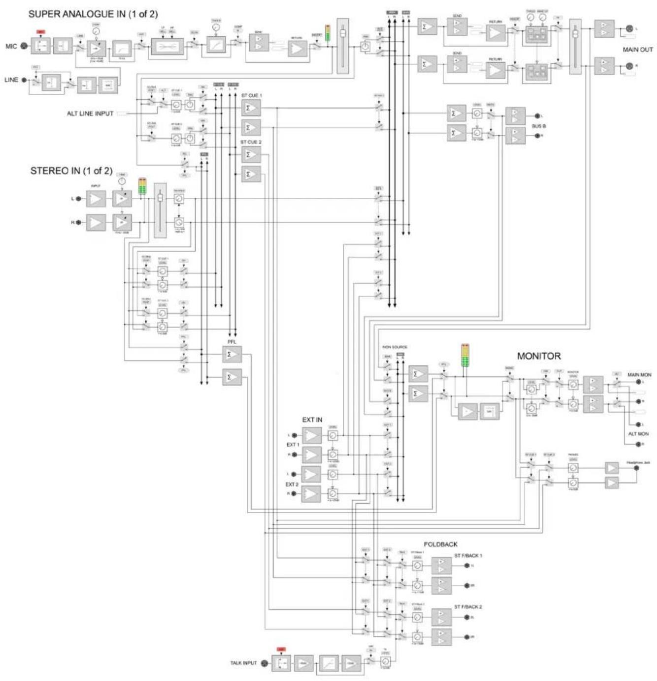
flowchart
graph TD
    subgraph_SUPER_ANALOGUE_IN["SUPER ANALOGUE IN (1 of 2)"]
        A["MIC"] --> B["Line"]
        B --> C["ALT LINE INPUT"]
        C --> D["ST CUE 1"]
        C --> E["ST CUE 2"]
        D --> F["MON SOURCE"]
        E --> G["MON SOURCE"]
        F --> H["MON SOURCE"]
        G --> I["MON SOURCE"]
        H --> J["MON SOURCE"]
        I --> K["MON SOURCE"]
        J --> L["MON SOURCE"]
        K --> M["MON SOURCE"]
        L --> N["FOLDBACK"]
        M --> O["FOLDBACK"]
        N --> P["TALK INPUT"]
        O --> Q["TALK INPUT"]
    end

    subgraph_STEREO_IN["STEREO IN (1 of 2)"]
        R["L"] --> S["INTC"]
        T["R"] --> U["INTC"]
        S --> V["EXT IN"]
        U --> W["EXT IN"]
        V --> X["EXT 1"]
        W --> Y["EXT 1"]
        X --> Z["EXT 2"]
        Y --> AA["EXT 2"]
        Z --> AB["EXT 2"]
        AA --> AC["EXT 2"]
        AB --> AD["EXT 2"]
        AC --> AE["EXT 2"]
        AD --> AF["EXT 2"]
        AE --> AG["EXT 2"]
        AF --> AH["EXT 2"]
    end

    subgraph_MONITOR["MONITOR"]
        AI["MON SOURCE"] --> AJ["MON SOURCE"]
        AK["MON SOURCE"] --> AL["MON SOURCE"]
        AM["MON SOURCE"] --> AN["MON SOURCE"]
        AO["MON SOURCE"] --> AP["MON SOURCE"]
        AQ["MON SOURCE"] --> AR["MON SOURCE"]
        AS["MON SOURCE"] --> AT["MON SOURCE"]
        AU["MON SOURCE"] --> AV["MON SOURCE"]
        AW["MON SOURCE"] --> AX["MON SOURCE"]
        AY["MON SOURCE"] --> AZ["MON SOURCE"]
        BA["MON SOURCE"] --> BB["MON SOURCE"]
        BC["MON SOURCE"] --> BD["MON SOURCE"]
        BE["MON SOURCE"] --> BF["MON SOURCE"]
        BG["MON SOURCE"] --> BH["MON SOURCE"]
        BI["MON SOURCE"] --> BJ["MON SOURCE"]
        BK["MON SOURCE"] --> BL["MON SOURCE"]
        BM["MON SOURCE"] --> BN["MON SOURCE"]
        BO["MON SOURCE"] --> BP["MON SOURCE"]
        BQ["MON SOURCE"] --> BR["MON SOURCE"]
        BS["MON SOURCE"] --> BT["MON SOURCE"]
        BU["MON SOURCE"] --> BV["MON SOURCE"]
        BW["MON SOURCE"] --> BX["MON SOURCE"]
        BY["MON SOURCE"] --> BZ["MON SOURCE"]
        CA["MON SOURCE"] --> CB["MON SOURCE"]
        CC["MON SOURCE"] --> CD["MON SOURCE"]
        CE["MON SOURCE"] --> CF["MON SOURCE"]
        GD["MON SOURCE"] --> DH["MON SOURCE"]
        DI["MON SOURCE"] --> DJ["MON SOURCE"]
        DK["MON SOURCE"] --> DL["MON SOURCE"]
        DM["MON SOURCE"] --> DE["MON SOURCE"]
        EF["MON SOURCE"] --> GF["MON SOURCE"]
        GH["MON SOURCE"] --> GHB["MON SOURCE"]
        IDA["MON SOURCE"] --> IDA
        IDB["MON SOURCE"] --> IDB
        IDC["MON SOURCE"] --> IDC
        IDD["MON SOURCE"] --> IDD
        IDE["MON SOURCE"] --> IDE
        IDF["MON SOURCE"] --> IDF
        IDG["MON SOURCE"] --> IDG
        IDH["MON SOURCE"] --> IDH
        IDI["MON SOURCE"] --> IDI
        IDJ["MON SOURCE"] --> IDJ
        IDK["MON SOURCE"] --> IDK
        IDL["MON SOURCE"] --> IDL
        IDM["MON SOURCE"] --> IDM
        IDN["MON SOURCE"] --> IDN
        IDO["MON SOURCE"] --> IDO
    end

    subgraph_FOLDBACK["FOLDBACK"]
        AF
        BH
        BI
    end

    style SUPER_ANALOGUE_IN fill:#f9f,stroke:#333
    style STEREO_IN fill:#ccf,stroke:#333
Appendix D - Recall Sheet