
NR2101 - Wi-Fi Access Point ZYXEL - Free user manual and instructions
Find the device manual for free NR2101 ZYXEL in PDF.


| Product Type | 5G NR Portable Router / Wi-Fi Access Point |
| Wireless Standards | IEEE 802.11a/b/g/n/ac/ax |
| Frequency Bands | 2.4 GHz and 5 GHz |
| Max Data Rate | Up to 1.2 Gbps (5 GHz) / 574 Mbps (2.4 GHz) |
| Max Concurrent WiFi Clients | 16 |
| Cellular Support | 5G/4G/3G multi-mode |
| Battery | Rechargeable lithium-ion (capacity not specified) |
| Power Supply | USB Type-C charging (included AC adapter) |
| Display | LCD touch screen |
| Interfaces | 1x Ethernet LAN, USB Type-C (power/data) |
| Management | Web configurator (HTTP/HTTPS), LCD touch screen |
| Wireless Security | WPA2-PSK, WPA3/WPA2 mixed, WPA-PSK, MAC filtering, WPS |
| Firewall | Stateful inspection, VPN pass-through |
| NAT | Supports Full Cone, Restricted Cone, Port Restricted, Symmetric |
| Package Contents | NR2101 device, USB Type-C cable, AC charger, Quick Start Guide |
| Certifications | EU RED, CE, SAR compliant |
| Dimensions | Not specified in manual |
| Weight | Not specified in manual |
Frequently Asked Questions - NR2101 ZYXEL
User questions about NR2101 ZYXEL
0 question about this device. Answer the ones you know or ask your own.
Ask a new question about this device
Download the instructions for your Wi-Fi Access Point in PDF format for free! Find your manual NR2101 - ZYXEL and take your electronic device back in hand. On this page are published all the documents necessary for the use of your device. NR2101 by ZYXEL.
USER MANUAL NR2101 ZYXEL
5G NR Portable Router
5G NR Mobile WiFi
Default Login Details
| LAN IP Address http://192.168.225.1 | |
| Username admin | |
| Password admin | |
Version 1.0 Edition 4, 12/2021

natural_image
Abstract geometric illustration of two stylized buildings with varying heights and shading, no text or symbols present.IMPORTANT!
READ CAREFULLY BEFORE USE.
KEEP THIS GUIDE FOR FUTURE REFERENCE.
Screenshots and graphics in this book may differ slightly from your product due to differences in your product firmware. Every effort has been made to ensure that the information in this manual is accurate.
Related Documentation
- Quick Start Guide
The Quick Start Guide shows how to connect and install the NR2101. - More Information
Go to support.zyxel.com to find other information on the NR2101.
Contents Overview
User's Guide 9
Get to Know Your NR2101 10
Web Configurator 35
Setup Wizard 42
Tutorials 46
Status 53
Technical Reference 55
APN & SIM PIN 56
WLAN & WWAN 62
NAT 80
Firewall 86
LAN Settings 92
SMS 94
Maintenance 96
Troubleshooting 101
Table of Contents
Contents Overview ....3
Table of Contents......4
Document Conventions 8
Part I: User's Guide....9
Chapter 1 Get to Know Your NR2101....10
1.1 Overview 10
1.2 Applications 10
1.3 Ways to Manage the NR2101 10
Chapter 3 Setup Wizard....42
3.1 Overview 42
3.2 Access the Setup Wizard 42
3.3 Use the Setup Wizard 42
Chapter 4
Tutorials 46
4.1 Overview 46
4.2 Set Up Your WiFi Network 46
4.3 Connect to the NR2101 WiFi Network 48
4.4 Set Up a WiFi Network Using WPS 50
4.5 Configure the MAC Address Filter 51
Chapter 5
Status....53
5.1 Overview 53
5.2 Status 53
Part II: Technical Reference....55
Chapter 6
APN & SIM PIN....56
6.1 Overview 56
6.1.1 What You Can Do in this Chapter 56
6.1.2 What You Need To Know 56
6.2 APN Settings 58
6.3 SIM PIN Settings 59
6.3.1 SIM Information 60
Chapter 7
WLAN & WWAN....62
7.1 Overview 62
7.1.1 What You Can Do in this Chapter 62
7.1.2 What You Need to Know 63
7.2 SSID Settings(2.4GHz/5GHz) 64
7.3 SSID WiFi QR Code 67
7.3.1 WiFi Security 68
7.4 WPS Settings 72
7.5 MAC Filter 73
7.6 WWAN Settings 74
7.6.1 IPv4/IPv6 WWAN Settings 75
7.6.2 WWAN Statistics 77
Chapter 8
NAT 80
8.1 Overview 80
8.1.1 What You Can Do 80
8.1.2 What You Need to Know 81
8.2 NAT Settings 82
8.3 Technical Reference 83
8.3.1 NAT Port Forwarding: Services and Port Numbers 84
8.3.2 NAT Port Forwarding Example 84
8.3.3 Trigger Port Forwarding 84
8.3.4 Trigger Port Forwarding Example 85
8.3.5 Two Points To Remember About Trigger Ports 85
Chapter 9 Firewall....86
9.1 Overview 86
9.1.1 What You Can Do 86
9.1.2 What You Need To Know 86
9.2 Firewall Settings 87
9.2.1 IPv4/IPv6 Firewall Entry 88
Chapter 10 LAN Settings....92
10.1 Overview 92
10.1.1 What You Can Do 92
10.1.2 What You Need To Know 92
10.2 LAN Settings 92
Chapter 11 SMS....94
11.1 Overview 94
11.1.1 What You Can Do in this Chapter 94
11.2 SMS-Info 94
11.3 Add New Message 95
Chapter 12 Maintenance ....96
12.1 Overview 96
12.1.1 What You Can Do in this Chapter 96
12.2 Firmware Upgrade 96
12.3 Account Configuration 97
12.4 About 98
12.5 Factory Reset 99
12.6 Logout 100
Chapter 13 Troubleshooting....101
Table of Contents
13.1 Overview 101
13.2 Power 101
13.3 NR2101 Access and Login 101
13.4 Internet Access 103
13.5 WiFi Internet Access 104
13.6 WiFi Connections 105
13.7 Getting More Troubleshooting Help 106
Appendix A Customer Support 107
Appendix B Legal Information.... 112
Index 118
Document Conventions
Warnings and Notes
These are how warnings and notes are shown in this guide.
Warnings tell you about things that could harm you or your device.
Note: Notes tell you other important information (for example, other things you may need to configure or helpful tips) or recommendations.
Syntax Conventions
- Product labels, screen names, field labels and field choices are all in bold font.
- A right angle bracket (>) within a screen name denotes a mouse click. For example, WWAN SETTINGS >IPv4 WWAN Settings means you first click WWAN SETTINGS in the navigation panel, and then click the IPv4 WWAN Settings tab to get to that screen.
Icons Used in Figures
Figures in this user guide may use the following generic icons. The NR2101 icon is not an exact representation of your device.
NR2101 Generic Router Switch |  |  |
| Server Firewall Smartphone[HYSK] |  |  |
Tablet Antenna Tower Home |  |  |
Outdoors Printer |  | |
PART I
User's Guide
CHAPTER 1
Get to Know Your NR2101
1.1 Overview
Your NR2101 (A) is a 5G router that allows you to share Internet Access via WiFi anytime. The NR2101 supports 5G/4G/3G multi-mode and complies with the IEEE 802.11a/b/g/n/ac/ax standards. It can provide data rates of up to 1.2 Gbps/574Mbps (2.4 GHz/5 GHz) and support up to 16 simultaneous WiFi clients. The NR2101's slim design is easy to use anywhere anytime and leaves your smartphone's bandwidth and battery free for other purposes.
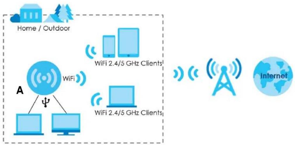
flowchart
graph TD
    A["Home / Outdoor"] --> B["WiFi"]
    B --> C["WiFi 2.4/5 GHz Clients"]
    B --> D["WiFi 2.4/5 GHz Clients"]
    E["Internet"] --> F["Tower Tower"]
    F --> G["Internet"]
    style A fill:#cce5ff,stroke:#333
    style E fill:#cce5ff,stroke:#333
    style B fill:#cce5ff,stroke:#333
    style D fill:#cce5ff,stroke:#333
    style F fill:#cce5ff,stroke:#333
    style G fill:#cce5ff,stroke:#333
1.2 Applications
You can have the following networks with the NR2101:
- Wireless LAN (WiFi): WiFi clients can connect to the NR2101 using the network's SSID and Password. For WPS-compatible devices you can create an instant network connection using WPS (WiFi Protected Security).
- WAN: Connect to a mobile network using an Ethernet cable.
1.3 Ways to Manage the NR2101
- LCD Touch Screen
You can use the LCD touch screen to navigate and manage the NR2101.
- Web Configurator
The Web Configurator is recommended for everyday management by using a supported web browser.
1.4 Hardware Description
The following image shows the front and side panels of the NR2101.
Figure 1 Front/Side Panel
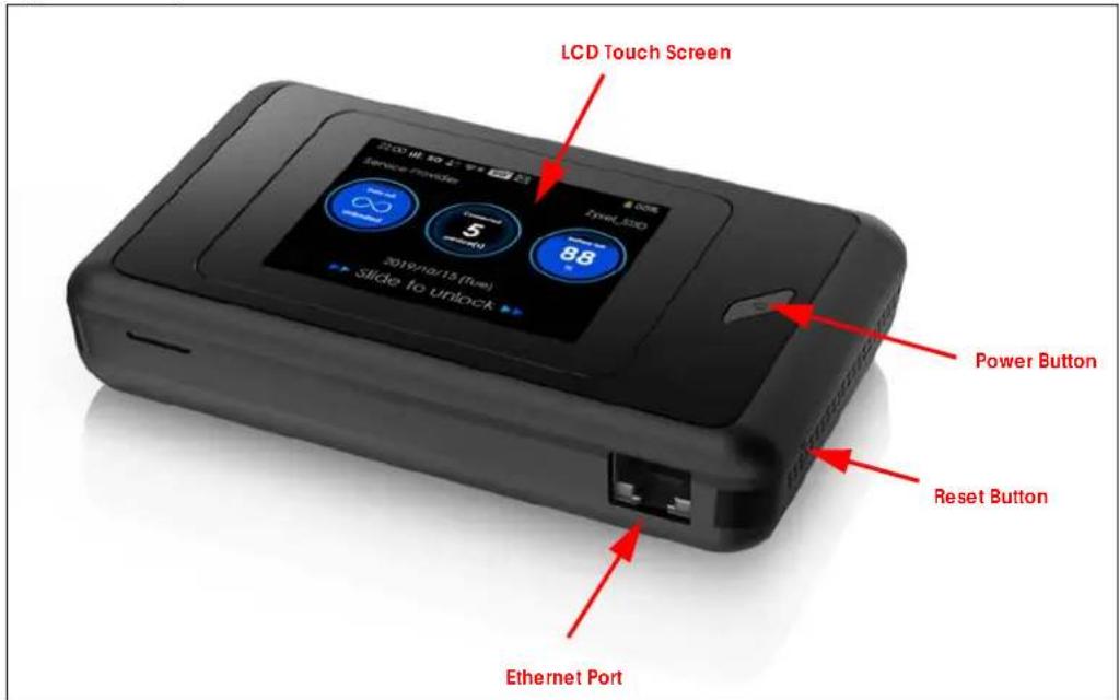
You can use Power Button on the front panel to turn on the NR2101 and use LCD Touch Screen to navigate the NR2101.
1 Press the Power button and then the Home screen appears. (Press the Power button for three seconds and then release the button to turn on or off the NR2101.)
Figure 2 Home Screen
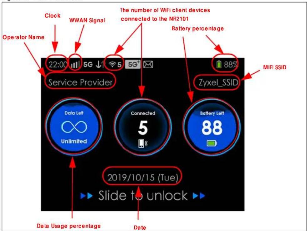
flowchart
graph TD
    A["Service Provider"] --> B["Connected"]
    B --> C["Battery Left"]
    C --> D["Zyxel_SSID"]
    D --> E["88% Battery percentage"]
    F["22:00"] --> G["5G ↓"]
    H["2019/10/15 (Tue)"] --> I["Slide to unlock"]
    J["Clock"] --> K["WWAN Signal"]
    L["Operator Name"] --> M["22:00"]
    N["Data Usage percentage"] --> O["2019/10/15 (Tue)"]
    P["Date"] --> Q["2019/10/15 (Tue)"]
    R["MiFi SSID"] --> S["Battery percentage"]
    T["The number of WiFi client devices connected to the NR2101"] --> U["Battery percentage"]
The following table describes the labels in this screen.
Table 1 NR2101's Home Screen
| LABEL DESCRIPTION | |
| 3G 4G 5G | This displays the type of network your NR2101 is connected to. Your network can be either 3G, 4G, or 5G. |
| This displays the signal strength of the current WWAN of the NR2101. | |
| ↓↑ | This displays when the NR2101 is receiving or transmitting data to/from the Internet. |
| 10 | This displays the WiFi network status. The number indicates how many WiFi client devices are currently connected to the NR2101. |
| This displays when the NR2101 receives a new SMS (Short Message Service) message. | |
| This icon shows the NR2101 battery life. |
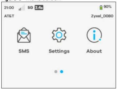
2 To start navigating the NR2101, slide right to unlock the Home screen and then the Menu screen appears as shown next. Tap an icon on the Menu screen to configure the selected setting. Slide left if you want to go to another Menu screen.
Figure 3 Menu Screen
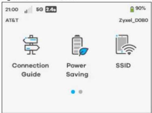
The following table describes the labels in the Menu screen.
Table 2 Menu Screen
| LABEL DESCRIPTION | |
| Connection Guide | Use Connection Guide to activate WPS. If your WiFi client device supports WPS, use WPS to connect to the NR2101. |
| Power Saving | Use Power Saving to change the screen off time. You can also configure WiFi auto-close duration here. |
| SSID | Use SSID to allow WiFi clients to connect (2.4 GHz/5 GHz) to the NR2101 using its SSID and password. Enter a password of 8 to 20 characters, including spaces and special characters. |
| SMS Use SMS to view and delete SMS messages. | Note: You can only create an SMS messages using the Web Configurator. |
| Settings | Use Settings to configure features, such as WPS, WiFi 2.4G/5G, Connected Users, Profile management, Data Usage, Data Roaming, Network Settings, PIN Management, Password Lock, Language, Time Setting, FW upgrade, and Restore Default settings. |
| About | Use About to view the NR2101 hardware/firmware information and notifications. |
1.4.1 Hardware Installation
See your Quick Start Guide for detailed information about hardware installation procedures.
1.5 LCD Screens
This section describes the labels or icons displayed on the LCD screen of your NR2101.
1.5.1 The Home & Menu Screen
Swipe right to unlock the Home screen on the LCD. The Menu screen appears. Tap an icon on the Menu screen to select the setting that you want to configure.
Figure 4 Home Screen
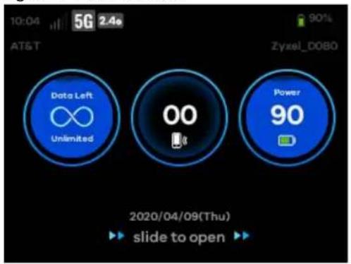
Figure 5 Menu Screen
1.5.2 Connection Guide
To enable a WiFi client device to connect to the NR2101 using WPS, go to Connection Guide > Next > WPS.
- Tap Manual, if you want to enter the WiFi network setting manually. Otherwise, tap WPS to quickly establish a WiFi connection.
Figure 6 Connection Guide
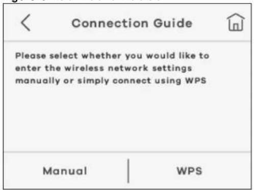
The following table describes the labels in this screen.
Table 3 Connection Guide
| LABEL DESCRIPTION | |
| Manual | Select Manual and then the default WiFi network settings and security modes will appear. Enter the necessary information on the SSID > 2.4G SSID/ 2.4G Password or 5G SSID/ 5G Password screen manually to connect to the NR2101. |
| WPS Select this to connect to | the NR2101 using WPS. |
- Select WPS to connect. Otherwise, tap WPS PIN and enter the PIN code of a four-digit number to start the WiFi connection. Tap the check mark at the upper-right corner to confirm the password.
Figure 7 WPS
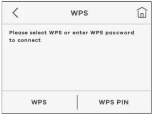
The following table describes the labels in this screen.
Table 4 WPS
| LABEL DESCRIPTION | |
| WPS Select this to connect to the NR2101 using WPS. | |
| WPS PIN Enter the WPS password to enable WPS. | |
1.5.3 Power Saving
Use this screen to configure the time your LCD screen stays on before going to sleep. Go to Power Saving > Screen off time and select from 15s, 30s, 60s, 120s, and 10 minutes. Tap the check mark at the upper-right corner to save the changes made. To configure the time set up for turning off WiFi automatically if no WiFi client device is connected to the NR2101, select Auto-close WiFi and then choose from 10 minutes, 20 minutes, and 30 minutes in the WiFi auto off field. Tap the check mark at the upper-right corner to save the changes made.
Figure 8 Power Saving
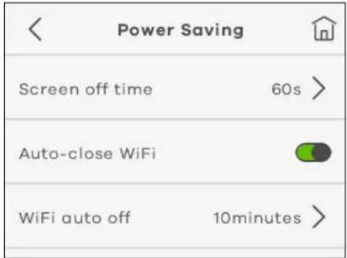
The following table describes the labels in this screen.
Table 5 Power Saving
| LABEL DESCRIPTION | |
| Screen off time | This displays the screen off time on the NR2101. If the NR2101 is not in use for a certain period of time, the system will automatically turn off the screen. |
| Auto-close WiFi | Select this to enable Auto-close WiFi on the NR2101. The NR2101 will automatically turn off Wi-Fi if no WiFi client device is connected to the NR2101 for a certain period of time. |
| WiFi auto off This displays the time length set up to turn off WiFi automatically. | |
1.5.4 SSID
Use this screen to scan the QR code and join the WiFi network of the NR2101.
1 Tap SSID in the Menu screen to go to the SSID setting.
Figure 9 SSID Settings
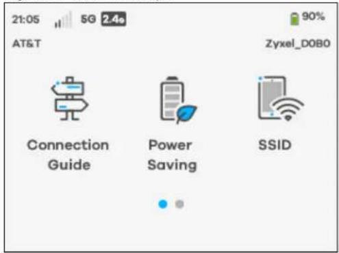
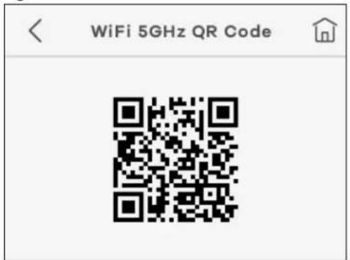
2 Select SSID password visible to view the WiFi 2.4GHz/5GHz SSIDs and passwords. Tap WiFi 2.4GHz/5GHz QR Code in the SSID screen to view the WiFi QR codes.
Figure 10 SSID Password Visible
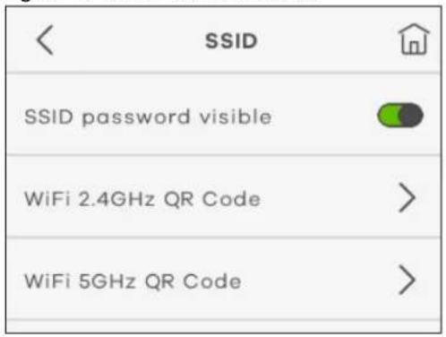
3 The following screen appears. Scan the WiFi 2.4GHz/5GHz QR code to join the WiFi network.
Figure 11 WiFi 2.4GHz QR code
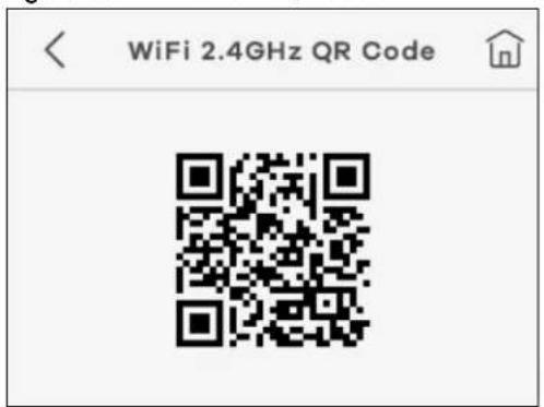
Figure 12 WiFi 5GHz QR code
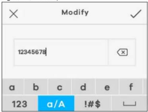
4 To configure the SSID and password (2.4 GHz/5 GHz), tap 2.4G SSID/2.4G Password or 5G SSID/5G Password in the screen and then the Modify screen appears. Enter your user name and a password of 8 to 20 characters, including spaces and special characters. Tap the check mark at the upper-right corner to save the changes made.
Figure 13 Modify
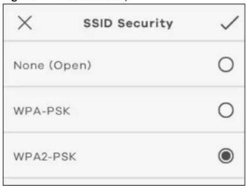
5 To configure the SSID security mode, tap 2.4G Security or 5G Security in the screen and then the SSID Security screen appears. Select a security mode from None (Open), WPA-PSK, WPA2-PSK, and WPA3/WPA2 mixed mode. Tap the check mark at the upper-right corner to save the changes made.
Figure 14 SSID Security
From another device, find this SSID and enter the Password to connect wirelessly to the NR2101.
1.5.5 SMS
SMS (Short Message Service) allows you to view and delete SMS messages that the NR2101 received from mobile devices or Internet Service Provider.
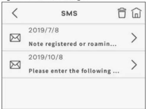
Tap SMS in the Menu screen to go to the SMS setting. The following screen displays.
- Read Message: Use the LCD screen to navigate and select an SMS message to read. Tap the Menu ( ) icon to go back to the Menu screen.
Figure 15 Read Message
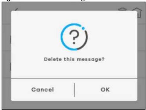
- Delete Message: Use the Delete( ) icon to delete an SMS message. Select OK to delete the message. Otherwise, select Cancel to return to the SMS screen.
Figure 16 Delete Message
Note: You can only create an SMS messages using the Web Configurator.
1.5.6 Settings
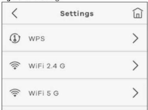
Use the Settings screen to manage and view the following features of the NR2101. Tap Settings and the following screen displays. Scroll up and down the screen to select the feature you want to configure.
Figure 17 Settings
1.5.6.1 WPS
Your NR2101 supports WiFi Protected Setup (WPS), which is an easy way to set up a secure WiFi network. WPS is an industry standard specification, defined by the WiFi Alliance.
WPS allows you to quickly set up a WiFi network with strong security, without having to configure security settings manually. Each WPS connection works between two devices. Both devices must support WPS (check each device's documentation to make sure). When WPS is activated on a device, it has two minutes to find another device that also has WPS activated. Then, the two devices connect and set up a secure network by themselves.
You can use the LCD screen of the NR2101 to activate WPS in order to quickly set up a WiFi network with strong security.
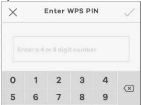
Go to the Settings > WPS screen. The WPS connect field will be available after you enable WPS. Go to WPS connect > WPS to activate WPS or enter WPS PIN to connect. The following screen displays. Tap the check mark at the upper-right corner to save the change made.
Figure 18 Enter WPS PIN
The following table describes the labels in this screen.
Table 6 WPS
| LABEL DESCRIPTION | |
| WPS Use this screen to establish a WPS connection. | |
| WPS PIN Enter the WPS password to enable WiFi clients to connect to the NR2101. | |
Note: You must activate WPS on the NR2101 and on another device within 2 minutes of each other.
1.5.6.2 WiFi 2.4 G
To enable a WiFi client to connect to the 2.4 GHz WiFi band, select WiFi Enable.
- Tap Bandwidth to select a 2.4 GHz bandwidth (20MHz or 20/40 MHz) from the list. Tap the check mark at the upper-right corner to save the change made.
- Tap Hide SSID to hide your SSID from a site survey tool.
Figure 19 2.4 GHz WiFi Bandwidth
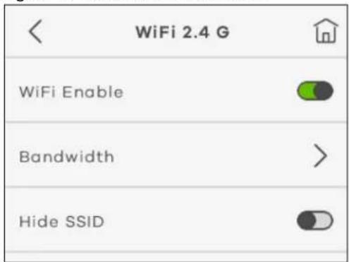
- Select WiFi PMF to improve security for the WiFi connection (WiFi PMF will not be available when WPA3/WPA2 mixed mode is selected in the Security Type field).
Figure 20 2.4 GHz WiFi PMF
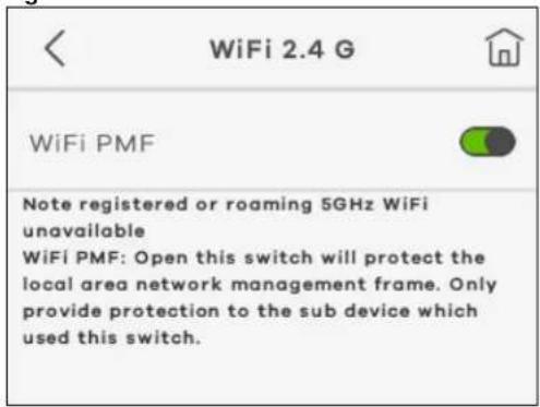
The following table describes the labels in this screen.
Table 7 2.4 GHz WiFi
| LABEL DESCRIPTION | |
| WiFi Enable Select this to enable 2.4 GHz WiFi connections. | |
| Bandwidth | Select whether the NR2101 uses a WiFi channel width of 20MHz or 20/40MHz .A standard 20MHz channel offers transfer speeds of up to 150Mbps whereas a 40MHz channel uses two standard channels and offers speeds of up to 300Mbps.40MHz (channel bonding or dual channel) bonds two adjacent radio channels to increase throughput. The WiFi clients must also support 40MHz. It is often better to use the 20MHz setting in a location where the environment hinders the WiFi signal.Select 20MHz if you want to lessen radio interference with other WiFi devices in your neighborhood or the WiFi clients do not support channel bonding. |
| Hide SSID | Select this to hide the NR2101's 2.4 GHz SSID in the outgoing beacon frame so a station cannot obtain the SSID through scanning using a site survey tool. |
| WiFi PMF | Select this to enable WiFi Protected Management Frame and enhance the security level on the LAN. |
1.5.6.3 WiFi 5G
To enable a WiFi client to connect to the 5 GHz WiFi band, select WiFi Enable. The following screen displays.
- Tap Bandwidth and then select a 5 GHz bandwidth (20MHz, 20/40 MHz, or 20/40/80 MHz) from the list. Tap the check mark at the upper-right corner to save the change made.
- Tap Hide SSID to hide your SSID from a site survey tool.
Figure 21 5GHz WiFi Bandwidth
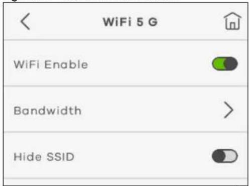
- Select WiFi PMF to improve security for the WiFi connection (WiFi PMF will not be available when WPA3/WPA2 mixed mode is selected in the Security Type field).
Figure 22 5 GHz WiFi PMF
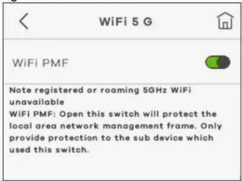
The following table describes the labels in this screen.
Table 8 5 GHz WiFi
| LABEL DESCRIPTION | |
| WiFi Enable Select this to enable 5 GHz WiFi connections. | |
| Bandwidth | Select whether the NR2101 uses a WiFi channel width of 20MHz, 20/40MHz, or 20/40/80MHz.A standard 20MHz channel offers transfer speeds of up to 150Mbps whereas a 40MHz channel uses two standard channels and offers speeds of up to 300Mbps. 40MHz (channel bonding or dual channel) bonds two adjacent radio channels to increase throughput. The WiFi clients must also support 40MHz. It is often better to use the 20MHz setting in a location where the environment hinders the WiFi signal. Select 20MHz if you want to lessen radio interference with other WiFi devices in your neighborhood or the WiFi clients do not support channel bonding. |
Table 8 5 GHz WiFi
| LABEL DESCRIPTION | |
| Hide SSID Select this to hide the | the NR2101's 5 GHz SSID in the outgoing beacon frame so a station cannot obtain the SSID through scanning using a site survey tool. |
| WiFi PMF | Select this to enable WiFi Protected Management Frame and enhance the security level on the LAN. |
1.5.6.4 Connected Users
Use this screen to view or manage the blacklist that blocks WiFi client devices from connecting to the NR2101.
- Select Connected Users to view the WiFi client devices currently connected to the NR2101. Click the Blacklist icon (the view the blocked WiFi client devices.
Figure 23 Connected Users
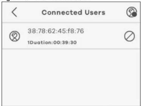
- You can use the Delete icon() to remove a WiFi client device from the blacklist.
Figure 24 Blacklist
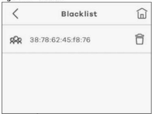
1.5.6.5 Profile management
Use this screen to set up the default APN setting. The NR2101 will automatically use the default APN setting saved in your SIM card for connections.
- Tap Profile Management and the following screen displays. Select Create to add a Profile name. Tap the Edit icon (☑) to modify the profile information. Click Select to choose the profile you want to use. Select Delete to remove a selected profile. Tap the Menu icon( 📋 ) to go back to the Menu screen.
Figure 25 Profile Management
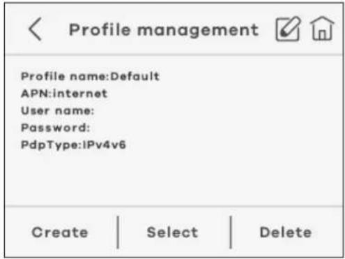
The following table describes the labels in this screen.
Table 9 Profile Management
| LABEL DESCRIPTION | |
| Create Use this to create an | APN profile and enter the APN information provided by ISP. |
| Select Use this to select the | APN profile you want to use. |
| Delete Use this to remove an | APN profile from the profile list. |
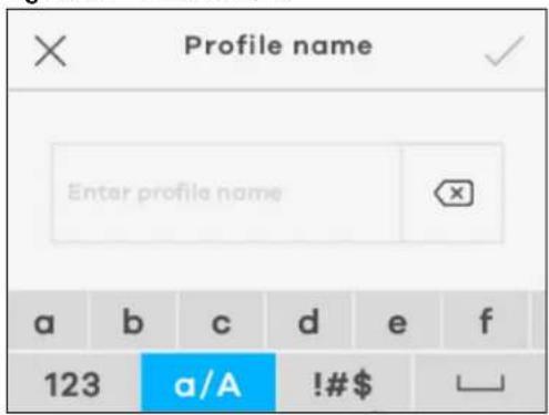
- The following screen appears after you click the Edit icon (☑) or Create in the Profile management screen. Use the Profile name screen to create or modify your APN settings. Enter the user name and password provided by your ISP and select the PDP type (IPv4, IPv6, or IPv4v6). Tap the check mark at the upper-right corner to save the changes made.
Figure 26 Profile Name
1.5.6.6 Data Usage
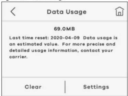
Use this screen to mange your monthly data usage based on your data plan.
- To view the percentage of data used on the WAN, select Settings > Data Usage > Settings. To reset data usage statistics on the NR2101, select Settings > Data Usage > Clear.
Figure 27 Data Usage
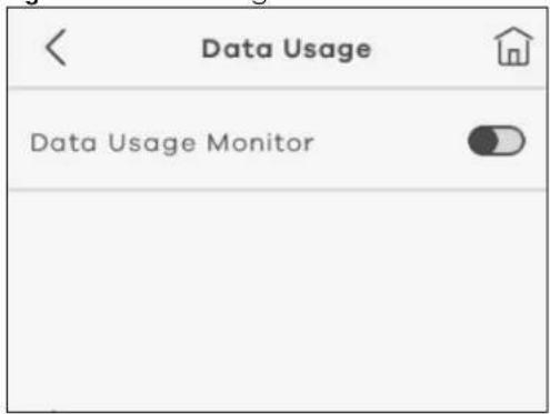
- Select Data Usage Monitor on the Data Usage screen to enable the NR2101 to monitor how much data is used.
Figure 28 Data Usage Monitor
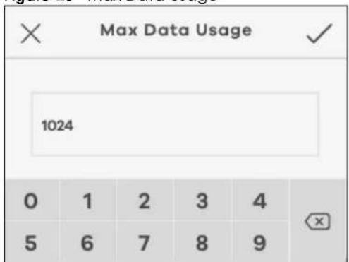
- Select Display data usage on home screen to enable or disable the NR2101 to display the percentage of data used on the Home screen. Tap Max Data Usage to enter the maximum data based on your current data plan. Tap the check mark at the upper-right corner to save the changes made.
Figure 29 Max Data Usage
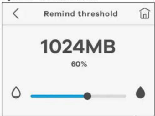
- Select the unit you want to use on the NR2101. Tap Period start date to enter the date of the month your data plan starts. Select Reminds when data usage reaches reminder threshold to enable the reminder and set up a limit (0\~100%) for sending a data usage warning message on the Remind threshold screen.
Figure 30 Remind Threshold
The following table describes the labels in this screen.
Table 10 Data Usage
| LABEL DESCRIPTION | |
| Data Usage Monitor Select this to enable the NR2101 to monitor how much data is used. | |
| Display data usage on home screen | Select this to enable the NR2101 to display the percentage of the data used on the Home Screen. |
| Max Data Usage This displays the maximum data provided by your ISP based on your data plan. | |
| Unit | Use this to select the unit used in megabyte or kilobyte (MB or KB). |
| Period start date Use this to enter the start date on which data usage start counting. | |
| Reminds when data usage reaches reminder threshold | Select this to allow for a warning message for the monthly data usage limit. |
| Remind threshold | Use this to set up when to receive a warning message as a reminder (0~100%). Once you reach that limit, the LCD will show a warning message. |
1.5.6.7 Data Roaming
Use the Data Roaming screen to reset all data usage statistics. Click the switch to enable Data Roaming. The following screen appears. Tap OK to start the resetting process.
Figure 31 Reset Data Usage
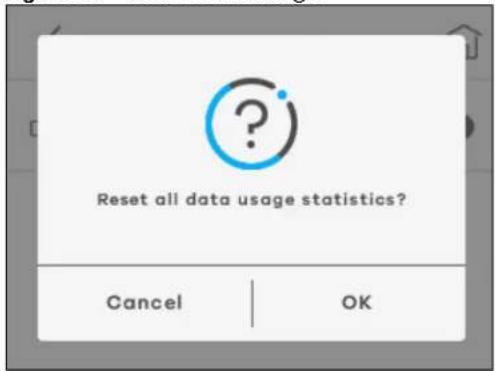
The following table describes the labels in this screen.
Table 11 Data Roaming
| LABEL DESCRIPTION | |
| Data Roaming Select this to reset all data usage statistics on the NR2101. | |
| OK Click OK to reset all data usage statistics. | |
| Cancel Click Cancel to return to the previous page. | |
1.5.6.8 Network Settings
Use this screen to select how the NR2101 finds available networks.
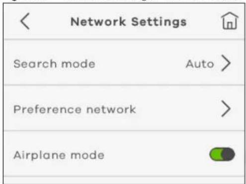
- Tap Search mode and select Auto to enable the NR2101 to find an available network automatically. Otherwise, select Manual.
Figure 32 Network Settings > Search mode
- Tap the check mark at the upper-right corner to save the changes made.
Figure 33 Network Settings > Search mode: Auto/Manual
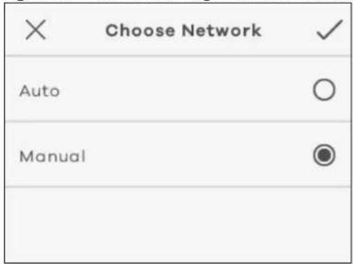
The following table describes the labels in this screen.
Table 12 Network Settings
| LABEL DESCRIPTION | |
| Search mode | |
| Auto | Use this to allow the NR2101 to select a network automatically based onNetwork Settingssaved on the SIM card. |
| Manual Use this to manually select an available network to connect to the Internet. | |
- Go to Network Settings > Preference network to select the network type you prefer to use. The following screen appears. Choices are 3G only, 3G+4G, 4G only, 5G only, 4G+5G, and 3G+4G+5G.
Figure 34 Preference Network List A
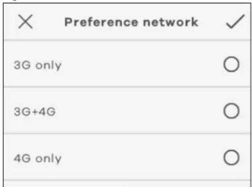
Figure 35 Preference Network List B
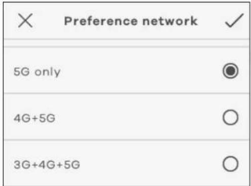
- Select Airplane mode to enable or disable Airplane mode on the NR2101. Enabling Airplane mode will block radio interferences such as WiFi, Bluetooth, telephone call from your mobile device. Click OK to close the window.
Figure 36 Network Settings
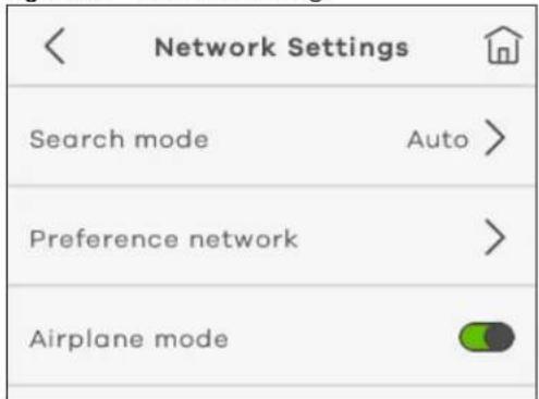
The following table describes the labels in this screen.
Table 13 Network Settings
| LABEL DESCRIPTION | |
| Preference network Use this to select the network type you prefer to use. | |
| Airplane mode Use this to enable or disable the airplane mode. | |
1.5.6.9 PIN Management
Use this screen to verify your identity.
- Select Enable PIN to enable PIN Management. You will be asked to enter your PIN code when you use the NR2101.
Figure 37 PIN Management
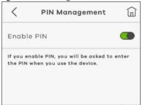
- Select Enable PIN and the following screen appears. Enter the PIN number of a 4 to 8-digit number to activate cellular connections using a SIM card. Tap the check mark at the upper-right corner to save the changes made.
Figure 38 Enable PIN
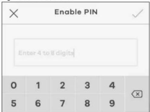
- If you enter incorrect PIN codes over three times, you will need to reset your PIN code using the PUK code of a 8-digit number (10 times is allowed). Tap the check mark at the upper-right corner to save the changes made.
Figure 39 Enable PUK
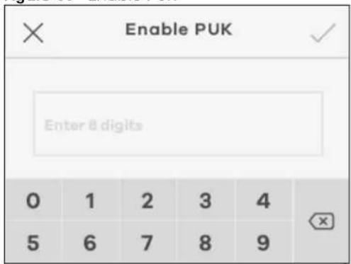
The following table describes the labels in this screen.
Table 14 PIN Management
| LABEL DESCRIPTION | |
| Enable PIN Enter your PIN numbers of a four-to-eight-digit number for PIN management. | |
| Enable PUK | Enter the PUK number if you enter incorrect PIN for three times to reset your PIN. |
1.5.6.10 Password Lock
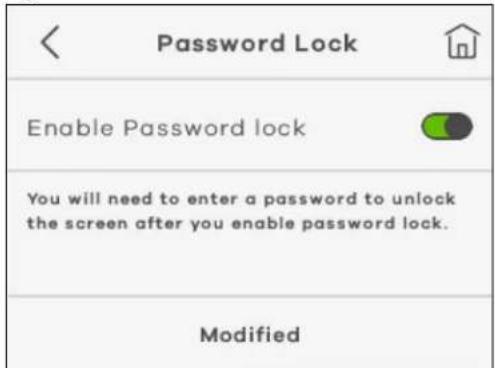
Use this screen to set up a password to lock/unlock the screen. If you select Enable Password lock, you will be asked to enter a password to unlock the screen when you use the NR2101.
- Select Enable Password lock to enable the screen lock.
Figure 40 Password Lock
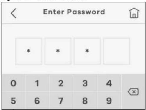
- Enter a password in the Enter Password screen and enter it again in the Confirm Password screen to confirm the changes made.
Figure 41 Enter Password
The following table describes the labels in this screen.
Table 15 Password Lock
| LABEL DESCRIPTION | |
| Enable Password lock Select this to enable the screen lock. | |
| Enter Password Use a password of a 4-digit number to unlock the screen. | |
1.5.6.11 Language
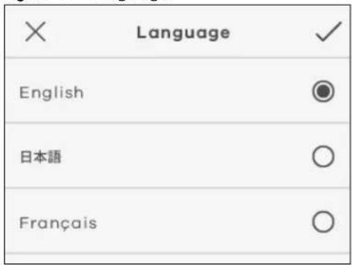
Use this screen to select the language you want to use on the NR2101. Tap Language and select an UI language from the list. The following screen appears. Tap the check mark at the upper-right corner to save the changes made.
Figure 42 Language
1.5.6.12 Time Setting
Use this screen to set up the current time of your location.
- Select Time Setting and the following screen appears. Enter Year, Month & Date, Hour & Minute, and AM/PM to configure the time settings of the NR2101.
Figure 43 Date & Time
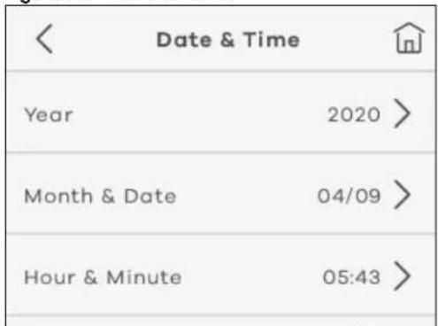
- Enter the number of the Year in the following screen. Tap the check mark at the upper-right corner to save the changes made.
Figure 44 Date & Time > Year
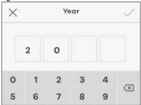
The following table describes the labels in this screen.
Table 16 Time Setting
| LABEL DESCRIPTION | |
| Year Enter the number of the year. | |
| Month & Date Enter the number of the month and date. | |
| Hour & Minute Enter the number of the time. | |
| AM/PM | Select AM or PM for the current time on the NR2101. |
1.5.6.13 FW Upgrade
Use this screen to check and start firmware updates automatically.
- Select Auto check for updates to enable an auto check. Click Check for updates to start the checking process.
Figure 45 FW Upgrade
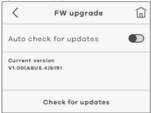
The following table describes the labels in this screen.
Table 17 FW Upgrade
| LABEL DESCRIPTION | |
| Auto check for updates | Select this to enable the NR2101 to check for new updates automatically. |
| Checking for updates | Select this to start the checking process. |
1.5.6.14 Restore Default
Use this screen to restore the settings back to the factory default mode. This means that you will lose all configurations you had, such as SSID and Password.
- Go to Settings >Restore Default and then tap Restore to restore the NR2101 back to the factory default mode.
1.5.7 About Settings
Use this screen to view software/hardware information and notifications on the NR2101.
- Tap About on the Menu screen and then select from Device Information, Help, Open Source Notice, or Third Party Notice.
Figure 47 About
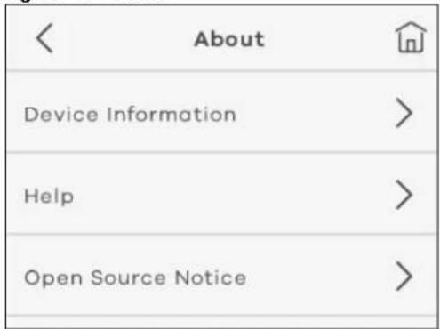
The following table describes the labels in this screen.
Table 18 About
| LABEL DESCRIPTION | |
| Device Information | |
| IMEI This displays the International Mobile Equipment Number (IMEI) which is the serial number of the built-in 3G/4G/5G module. IMEI is a unique 15-digit number used to identify a mobile device. | |
| LAN MAC address This displays the MAC address of the NR2101. | |
| Zyxel Firmware version This displays the present firmware version of your NR2101. | |
| Software version This displays the present software version of your NR2101. | |
| MiFi Software version This displays the present MiFi software version of your NR2101. | |
| Phone number This displays the phone number of your NR2101 | |
| LAN IP address | This displays http://192.168.225.1. Launch your web browser and go to http://192.168.225.1 to access the Web Configurator. |
| WAN IP address This displays the IP address provided by your ISP. | |
| Help This displays the UI icons on your NR2101. | |
| Open Source Notice This displays open source notices for your NR2101. | |
| Third Party Notice This displays third party notices for your NR2101. | |
CHAPTER 2
Web Configurator
2.1 Introduction
The Web Configurator is an HTML-based management interface that allows easy system setup and management through Internet browser. Use a browser that supports HTML5, such as Microsoft Edge, Internet Explorer 11, Mozilla Firefox, or Google Chrome. The recommended minimum screen resolution is 1024 by 768 pixels.
In order to use the Web Configurator you need to allow:
- Web browser pop-up windows from your device.
- JavaScript (enabled by default).
- Java permissions (enabled by default).
2.2 Accessing the Web Configurator
1 Use the included USB Type-C cable to connect your NR2101 to a computer or the included AC charger to charge the NR2101 (refer to the Quick Start Guide).
2 Connect your NR2101 to a computer or laptop using an Ethernet cable.
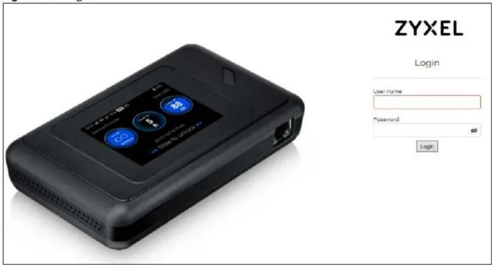
3 Launch your web browser. Go to http://192.168.225.1 (Default username: admin, password: admin). A login screen displays. To access the administrative Web Configurator and manage the NR2101, enter the default username admin, and password admin in the login screen, and then click Login.
Figure 48 Login
4 If this is the first time you have logged into the NR2101, you will be asked to change the default password. Enter a new password, enter it again to confirm, and then click Login.
5 After changing your password, you will be automatically logged out. Log in again with your new password. The Status screen appears. Use this screen to view the NR2101 signal strength, ISP information, WiFi SSID information, and the numbers of the WiFi client devices currently connected to the NR2101.
2.3 Navigating the Web Configurator
The following section summarizes how to navigate the Web Configurator starting from the Status screen.
Figure 49 Status Screen
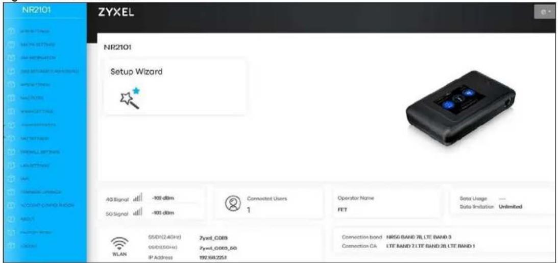
Figure 50 Screen Layout
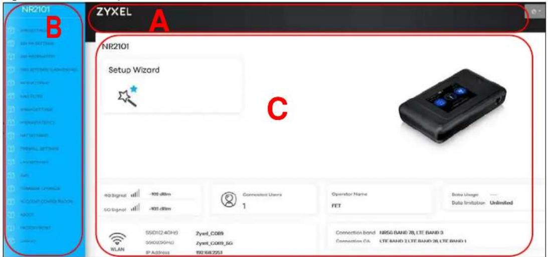
• A - Title Bar
• B - Navigation Panel
• C - Main Window
2.3.1 Title Bar
The title bar allows you to choose your language from the drop-down list at the upper right corner.
Figure 51 Title Bar

2.3.2 The Main Window
The main window displays information and configuration fields. It is discussed in the rest of this document.
After you log in, the Status screen will display. See Chapter 1 on page 10 for more information about the Status screen.
2.3.3 Navigation Panel
Use the menu items in the navigation panel to open screens to configure NR2101 features. The following section introduces the NR2101's navigation panel menus.
Figure 52 Navigation Panel
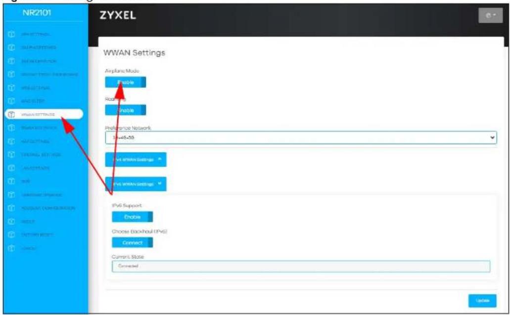
The following table describe each menu item in the screen.
Table 19 Navigation Panel Summary
| LINK TAB DESCRIPTION | |||||
| APN SETTINGS | Profile Name | Use this field to enter a unique profile name to identify the APN file. | |||
| APN This field displays | the Access Profile Name (APN) in the profile. Use this field to enter the name of your Internet Service Provider. | ||||
| User Name | Use this field to enter the user name provided by your Internet Service Provider. | ||||
| Password Use this field | to enter the password provided by your Internet Service Provider. | ||||
| PDP Type Select the P | DP types provided by your Internet Service Provider. | ||||
| SIM PIN Settings | No. of Retry | This field displays the number of retry attempts left to enter your PIN code. | |||
| SIM PIN Lock | Use this field to enable PIN code authentication and enter the PIN code. | ||||
| PIN Code | Use this field to enter the PIN code of your SIM card. | ||||
| SIM INFORMATION S | SIM Status Use this field to view the status of your SIM card. | ||||
| SIM IMSI Use this field to view your IMSI number. | |||||
| SIM MSISDN Use this field to view your MSISDN number. | |||||
| SIM ICCID Use this field to view your ICCID number. | |||||
| SSID SETTINGS (2.4GHz/5GHz) | |||||
| SSID Settings-2.4GHz | WiFi Enable | Use this field to enable or disable 2.4 GHz WiFi. | |||
| SSID | This field displays a descriptive name used to identify the NR2101 in the 2.4 GHz WiFi. | ||||
| Password This field displays the password for the 2.4GHz WiFi. | |||||
| Security Type | This field displays the level of 2.4 GHz WiFi security the NR2101 is using. | ||||
| Bandwidth | This field displays the current bandwidth used in the 2.4 GHz WiFi. | ||||
| Channel | This field displays the channel used in the 2.4 GHz WiFi. | ||||
| SSID Settings-5GHz | WiFi Enable | Use this field to enable or disable 5 GHz WiFi. | |||
| SSID | This field displays a descriptive name used to identify the NR2101 in the 5 GHz WiFi. | ||||
| Password This field displays the password for the 5 GHz WiFi. | |||||
| Security Type | This field displays the level of 5 GHz WiFi security the NR2101 is using. | ||||
| Bandwidth | This field displays the current bandwidth used in the 5 GHz WiFi. | ||||
| Channel | This field displays the channel used in the 5 GHz WiFi. | ||||
| WPS SETTINGS | WPS Enable | Use this field to enable WPS. | |||
| Via the WPS button | Use this field to activate WPS on the NR2101 via the WPS button. | ||||
| WPS | Select this field to enable or disable WPS. | ||||
| Device PIN Use this field to enter a PIN code to enable WPS. | |||||
| MAC FILTER | Serial No | This field displays the serial number of the MAC address entry. | |||
| MAC Address | This field displays the MAC addresses of the WiFi client device that are denied access to the NR2101. | ||||
| Delete | Use this field to delete the MAC address entry. | ||||
| Add New | Use this field to enter the MAC address of the WiFi client device you want to block. | ||||
| LINK | TAB | DESCRIPTION | |||
| WWAN SETTINGS | |||||
| Airplane Mode Use | this field to activate the | airplane mode. | |||
| Roaming Use this field to activate data roaming. | |||||
| Preference Network | Use this field to select the preferred network. | ||||
| IPv4 WWAN Settings | IPv4 Support Use this field to activate the IPv4 support. | ||||
| Choose Backhaul (IPv4) | Use this field to allow the NR2101 to connect to the Internet using IPv4. | ||||
| Current State This field displays the current IPv4 WWAN state. | |||||
| IPv6 WWAN Settings | IPv6 Support Use this field to activate the IPv6 support. | ||||
| Choose Backhaul (IPv6) | Use this field to allow the NR2101 to connect to the Internet using IPv6. | ||||
| Current State This field displays the current IPv6 WWAN state. | |||||
| WWAN STATISTICS | |||||
| IPv4 WWAN Statistics | WWAN Statistics This field displays the information of the IPv4 WWAN Statistics. | ||||
| IPv6 WWAN Statistics | WWAN Statistics This field displays the information of the IPv6 WWAN Statistics. | ||||
| NAT SETTINGS | |||||
| IP Pass-Through | Use this field to enable or disable the NR2101's IP Pass-Through. | ||||
| Select NAT Type Use | this field to select the | NAT Type. | |||
| IPSEC VPN Pass-Through | Use this field to enable or disable the IPSEC VPN passthrough feature. | ||||
| PPTP VPN Pass-Through | Use this field to enable or disable the PPTP VPN passthrough feature. | ||||
| L2TP VPN Pass-Through | Use this field to enable or disable the L2TP VPN passthrough feature. | ||||
| Webserver WWAN Access | Use this field to enable or disable the Webserver WWAN Access. | ||||
| DMZ IP Use this field to enter the IP address of the default server which receives packets from ports. | |||||
| Port Forwarding | Serial | This field displays the serial number of an individual port forwarding server entry. | |||
| Private IP This field displays the IP address of the virtual server. | |||||
| Private Port This field displays the port number from the LAN side. | |||||
| Global Port This field displays the port number from the WAN side. | |||||
| Protocol This field displays the transport layer protocol used for the service. | |||||
| Delete | Use this field to delete an existing port forwarding rule. Note that subsequent address mapping rules move up by one when you take this action. | ||||
| Modify | Use this field to edit an existing port forwarding rule. | ||||
| FIREWALL SETTINGS | |||||
| Firewall | Use this field to activate or deactivate the NR2101's firewall. | ||||
| View Firewall Entries | Use this field to configure IPv4/IPv6 firewall entries. | ||||
| LINK | TAB | DESCRIPTION | |||
| IPv4 Firewall Entries | IP Address Use this field to enter the source device's IPv4 address. | ||||
| IP Subnet | Use this field to enter the IPv4 source subnet mask. | ||||
| Protocol Use this field to select the protocol used to transport packets. | |||||
| Delete Use this field to delete the IPv4 firewall entry. | |||||
| Modify Use this field to edit the IPv4 firewall entry. | |||||
| IPv6 Firewall Entries | IP Address | Use this field to enter the source device's IPv6 address. | |||
| IP Prefix | Use this field to enter the address prefix length. | ||||
| Protocol Use this field to select the protocol used to transport packets. | |||||
| Delete Use this field to delete the IPv4 firewall entry. | |||||
| Modify Use this field to edit the IPv6 firewall entry. | |||||
| LAN SETTINGS LAN G | Gateway IP Use this field to view the LAN IP address. | ||||
| LAN Subnet Mask Use this field to view the subnet mask. | |||||
| LAN DHCP Use this field to enable or disable the NR2101's DHCP server. | |||||
| LAN DHCP Start IP | This field specifies the first of the contiguous addresses in the IP address pool for LAN. | ||||
| LAN DHCP End IP | This field specifies the last of the contiguous addresses in the IP address pool for LAN. | ||||
| LAN DHCP Lease Time | This is the period of time the DHCP-assigned address is used. | ||||
| SMS | Serial No. | Use this field to view the entry number of the SMS messages stored on the NR2101. | |||
| From Use this field to view the telephone number of the sender. | |||||
| Date/Time Use this field to view the time and date of the SMS messages saved on the NR2101. | |||||
| Write New SMS | Use this field to enter a new SMS message. | ||||
| Send to | Use this field to enter the phone number of the message receiver. | ||||
| Content | Use this field to view the content of the SMS messages. | ||||
| FIRMWARE UPGRADE | Current Version | Use this field to view the current firmware version of the NR2101. | |||
| Upgrade From Local | Use this field to upload firmware to the NR2101. | ||||
| Select File | Use this field to select a fie from your local drive to upload to the NR2101. | ||||
| Upgrade From Network | Use this field to upgrade firmware through the Internet. | ||||
| Start Firmware Upgrade | Use this field to start upgrading firmware. | ||||
| LINK TAB DESCRIPTION | |||||
| ACCOUNT CONFIGURATION | Session Timeout (Min) | Use this field to edit the setting of the session timeout. | |||
| Old Password Use this | field to change the password entering the old password. | ||||
| New Password Use this | field to enter a new password of 4 to 20 characters. The new password must contain one numeric, one lower case, one upper case letter and one special character. | ||||
| Confirm New Password | Enter the new password again to confirm the change. | ||||
| ABOUT Zyxel Firmware version | Use this field to view the current firmware version of the NR2101. | ||||
| Software version Use this field to view the current software version of the NR2101. | |||||
| MiFi Software version | Use this field to view the current MiFi software version of the NR2101. | ||||
| Open Source Notices | Use this field to view open source notices information. | ||||
| FACTORY RESET Use | this field to restore the NR2101 back to the factory default mode. | ||||
| LOGOUT Use this field to log out of the NR2101's Web Configurator. | |||||
CHAPTER 3
Setup Wizard
3.1 Overview
This chapter provides information on the setup wizard screens in the Web Configurator.
The Web Configurator's setup wizard helps you configure your NR2101 to access the Internet and change the WiFi settings. Refer to your ISP for your Internet account information. Leave a field blank if you do not have that information.
3.2 Access the Setup Wizard
1 Launch your web browser and go to https://192.168.225.1. Enter "admin" (default) as the user name, "admin" (default) as the password and then click Login.
2 Click the Setup Wizard icon in the navigation panel of the Web Configurator to open the Setup Wizard screen.
Figure 53 Title Bar: Setup Wizard Icon
Setup Wizard

3.3 Use the Setup Wizard
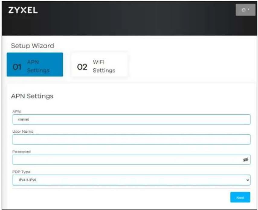
1 The first Setup Wizard screen displays the APN Settings screen. Use this screen to configure the APN (Access Profile Name) provided by your ISP (Internet Service Provider). Enter the user name and password provided by your ISP, and then select your PDP Type (IPv4, IP46, or IPv4 &IPv6). Click Next.
Figure 54 Setup Wizard > APN Settings
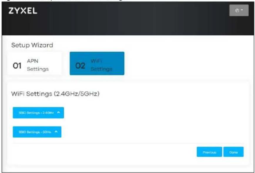
2 The WiFi Settings screen appears. Use this screen to configure the 2.4 GHz/5 GHz WiFi SSID settings and the WiFi security types.
Figure 55 Setup Wizard > WiFi Settings
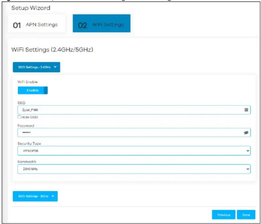
3 Click SSID Settings-2.4GHz to configure the NR2101's 2.4 GHz WiFi setting, and enter the WiFi network name (SSID). Select the Hide SSID check box to hide your SSID from a site survey tool. Enter a password of 8 to 63 case-sensitive characters, including special characters and numbers for data encryption. For the WiFi Setting (2.4GHz) select a security type from WPA-PSK, WPA2-PSK, and WPA3/ WPA2 mixed mode. The 2.4 GHz WiFi client devices which want to associate with this WiFi network must have the same WiFi security settings. Otherwise, select None (Open) to allow any WiFi client device to connect to this network without any data encryption or authentication.
Figure 56 Setup Wizard > WiFi Setting > SSID Settings-2.4GHz
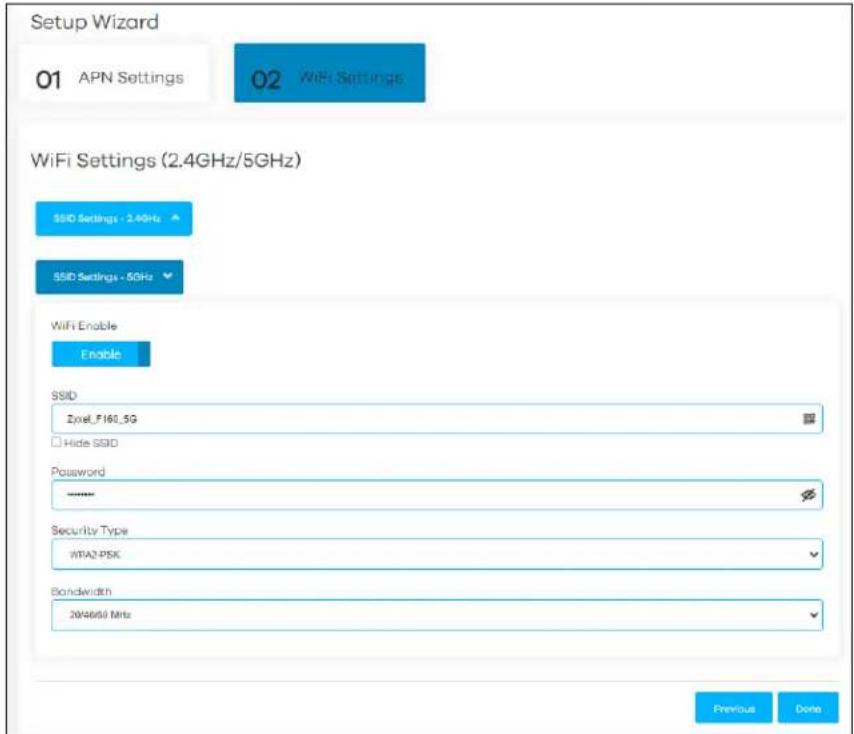
4 Click SSID Settings-5GHz to configure the NR2101's 5 GHz WiFi setting, and enter the WiFi network name (SSID). Select the Hide SSID check box to hide your SSID from a site survey tool. Enter a password of 8 to 63 case-sensitive characters, including special characters and numbers for data encryption. For the WiFi Setting (5GHz), select a security type from WPA-PSK, WPA2-PSK, and WPA3/WPA2 mixed mode. The 5 GHz WiFi client devices which want to associate with this WiFi network must have the same WiFi security settings. Otherwise, select None to allow any WiFi client device to connect to this network without any data encryption or authentication.
Figure 57 Setup Wizard > WiFi Setting > SSID Settings-5GHz
Click Done to save your settings or click Previous to go back to the previous screens. You are now ready to access the Internet and allow WiFi client devices to connect to your NR2101.
CHAPTER 4 Tutorials
4.1 Overview
This chapter shows you how to use the NR2101's various features using the Web Configurator.
- Set Up Your WiFi Network
- Connect to the NR2101 WiFi Network
- Set Up a WiFi Network Using WPS
- Configure the MAC Address Filter
4.2 Set Up Your WiFi Network
You can change the NR2101's WiFi network name and password. It is recommended you change your WiFi password regularly for your WiFi network security. Use a password that is not easy to guess and that consists of different types of characters, such as numbers and letters.
1 Go to the SSID SETTINGS(2.4GHz/5GHz) > SSID SETTINGS-2.4GHz/SSID SETTINGS-5GHz screen to configure the NR2101 WiFi network settings. After changing the SSID settings, select the security type, bandwidth, channel, and then click Update to save your changes.
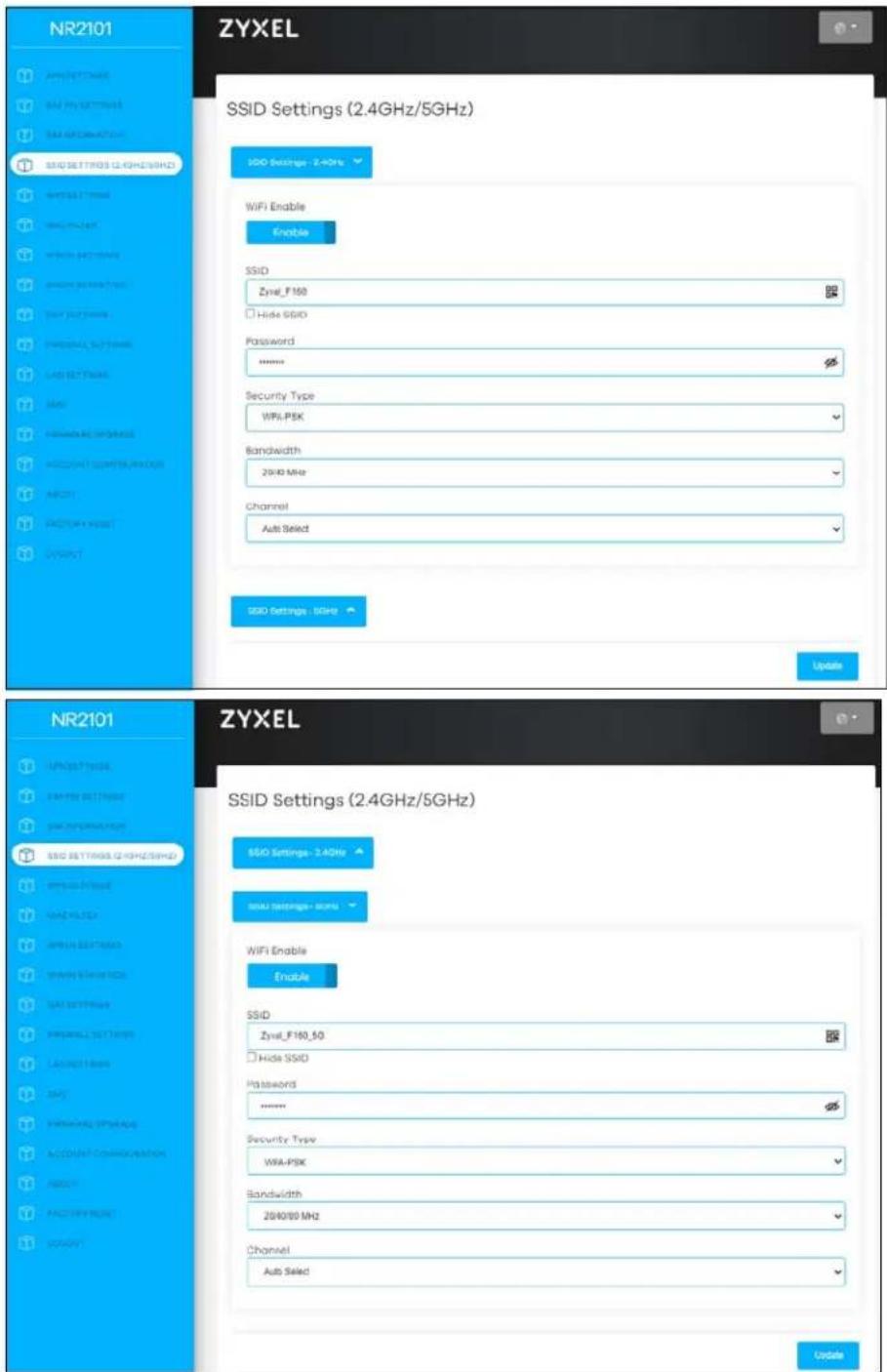
2 When your changes are saved, your WiFi client device will be temporarily disconnected from the NR2101. Connect to the NR2101's WiFi network once again with the new WiFi settings.
4.3 Connect to the NR2101 WiFi Network
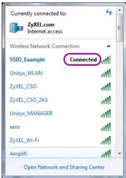
In this example, you have configured the NR2101's WiFi network to the following settings.
| SSID SSID_Example | |
| Channel 6 | |
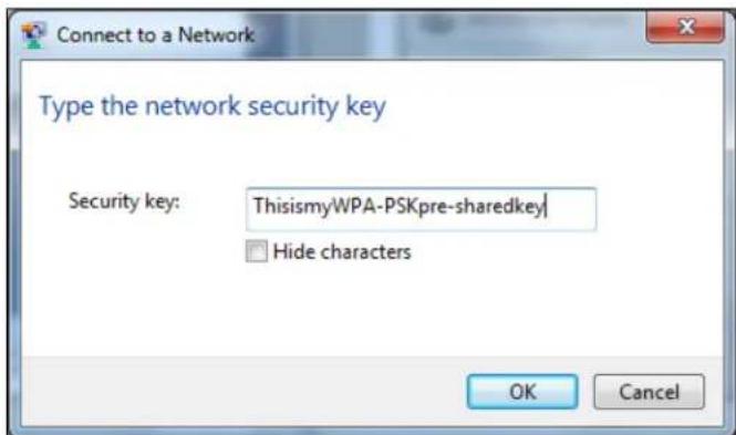
| Security WPA2-PSK | (Pre-Shared Key: ThisismyWPA-PSKpre-sharedkey) |
Note: In this example, we use a Windows 7 laptop that has a built-in WiFi adapter as the WiFi client.
1 The NR2101 supports IEEE 802.11 a/b/g/n/ac/ax WiFi clients. Make sure that your notebook or computer's WiFi adapter supports one of these standards.
2 Click the WiFi icon in your computer's system tray.
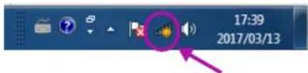
3 The Wireless Network Connection screen displays. Click the refresh button to update the list of the available WiFi APs within range.
4 Select SSID_Example and click Connect.
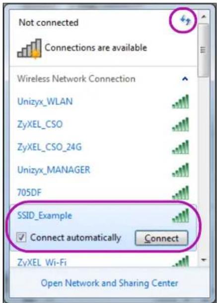
5 Click Connect using a security key instead.
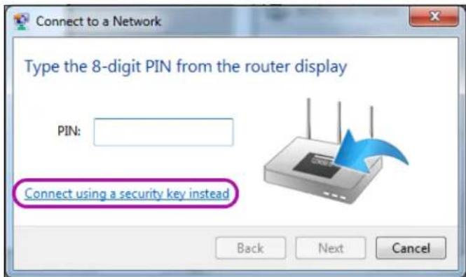
6 Enter the security key in the following screen. Click OK.
7 Check the status of your WiFi connection in the screen below.
8 If the WiFi client device keeps trying to connect to or acquiring an IP address from the NR2101, make sure you entered the correct security key.
If the connection has limited or no connectivity, make sure the DHCP server is enabled on the NR2101.
If your connection is successful, open your Internet browser and enter http://www.zyxel.com or the URL of any other web site in the address bar. If you are able to access the web site, your WiFi connection is successfully configured.
4.4 Set Up a WiFi Network Using WPS
This section gives you an example of how to set up a WiFi network using WPS in the NR2101's Web Configurator. This example uses the NR2101 as the AP and a WPS-enabled Android smartphone as the WiFi client device.
PIN Configuration
When you use the PIN configuration method, you need to check the WiFi client's PIN number and use the NR2101's configuration interface (see Section 7.4 on page 72).
1 Go to your phone settings and turn on WiFi.
2 Log into NR2101's Web Configurator and go to the WPS SETTINGS > WPS Settings screen. Click WPS Enable to enable the PIN configuration.
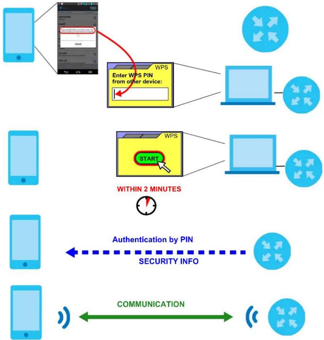
3 Enter the Device PIN of the WiFi client and click the Connect button. Activate WPS function on the WiFi client utility screen within two minutes.
The NR2101 authenticates the WiFi client and sends the proper configuration settings to the WiFi client. This may take up to two minutes. The WiFi client is then able to communicate with the NR2101 securely.
The following figure shows you how to set up WiFi network and security on NR2101 and WiFi client (Android smartphone in this example) by using the PIN method.
Figure 58 Example WPS Process: PIN Method
WiFi Client
flowchart
graph TD
    A["Mobile Phone"] --> B["Enter WPS PIN from other device: WPS"]
    B --> C["Within 2 MINUTES"]
    C --> D["Authentication by PIN"]
    D --> E["SECURITY INFO"]
    E --> F["COMMUNICATION"]
    F --> G["Wireless Signal"]
4.5 Configure the MAC Address Filter
This screen allows you to configure the NR2101 to exclude specific WiFi client devices from accessing the NR2101.
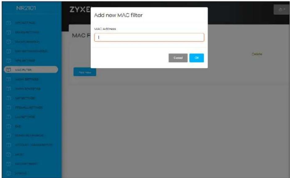
1 Go to the MAC Filter screen, and then click Add New (see Section 7.5 on page 73).
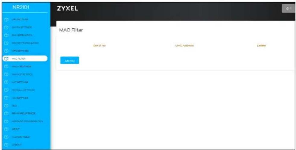
2 Enter the MAC Address of a WiFi client device that you want to block from connecting to the NR2101. Click OK.
CHAPTER 5 Status
5.1 Overview
Use the Status screen to check status information about the NR2101.
5.2 Status
This screen is the first thing you see when you log into the NR2101's Web Configurator. It also appears every time you click NR2101 in the navigation panel. The Status screen displays the NR2101's WiFi information, cellular signal strength and traffic statistics.
Figure 59 Status
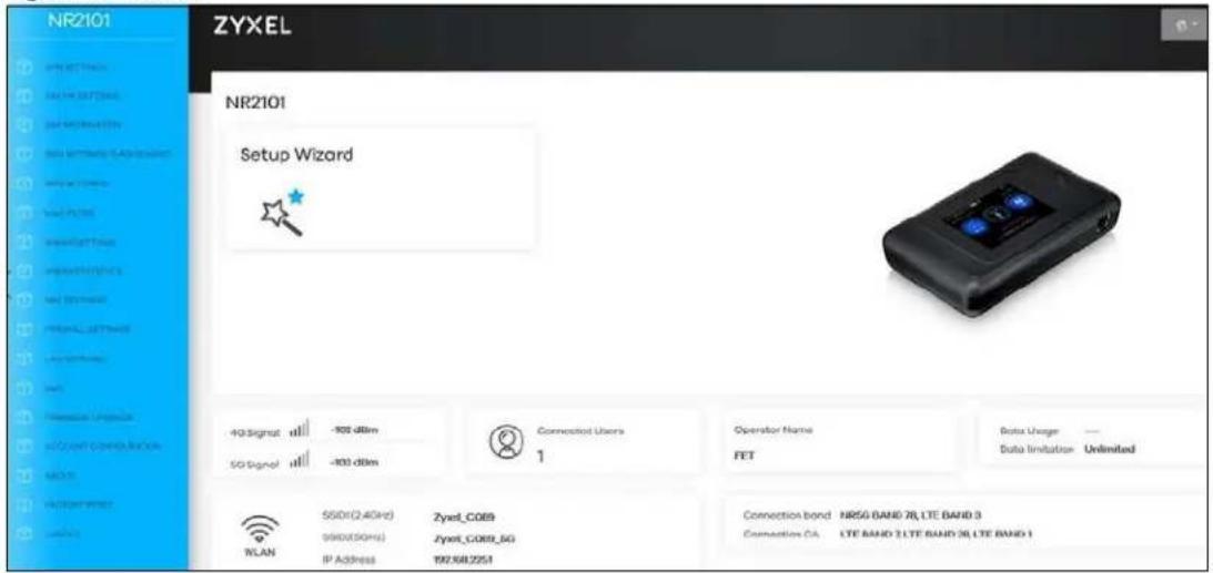
The following table describes the labels in this screen.
Table 20 Home
| LABEL DESCRIPTION | |
| 4G Signal This shows the type and the strength of the mobile network to which the NR2101 is connecting. | |
| 5G Signal This shows the type and the strength of the mobile network to which the NR2101 is connecting. | |
| Connected Users | This displays the total number of the client devices currently connected to the NR2101. |
| Operator Name | This displays the name of the internet service provider. |
| Data Usage This displays the amount of data used by the NR2101. | |
| Data Limitation | This displays the total limiting amount of data that can be used by the NR2101. |
| SSID1 (2.4GHz) | This displays a descriptive name used to identify the NR2101 in the 2.4 GHz WiFi. |
| SSID2 (5GHz) | This displays a descriptive name used to identify the NR2101 in the 5 GHz WiFi. |
| IP Address This field displays the current IPv4 address of the NR2101 in the LAN. | |
| Connection band This field displays the frequency band on which your ISP is operating. | |
| Connection CA | This displays the multiple frequency blocks combined to speed up the data rates. |
PART II
Technical Reference
CHAPTER 6
APN & SIM PIN
6.1 Overview
This chapter discusses the NR2101's APN & SIM PIN settings. Use these screens to configure your NR2101 for Internet access.
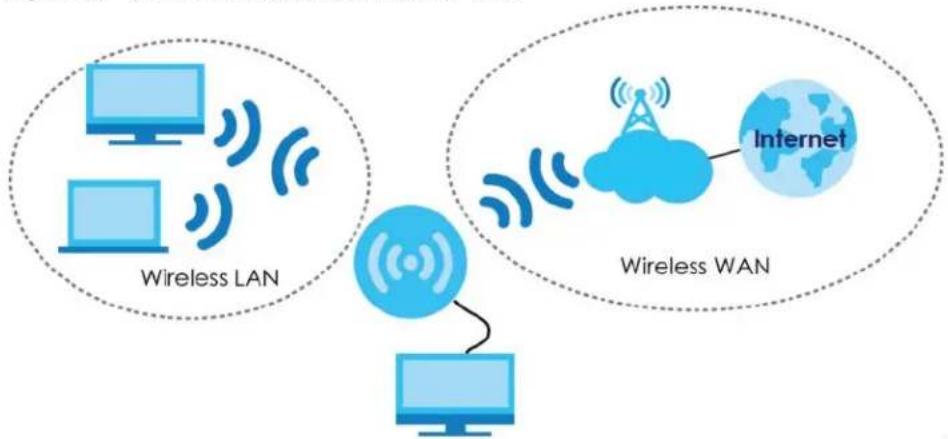
A WAN (Wide Area Network) connection is an outside connection to another network or the Internet. It connects your private networks such as a LAN (Local Area Network) and other networks, so that a device in one location can communicate with devices in other locations.
3G, 4G, and 5G cellular technology standards for the sending and receiving of voice, video, and data in a mobile environment. You can insert a 5G SIM card and set the NR2101 to use the 3G/4G/5G connection as your WAN.
Figure 60 LAN/Wireless LAN and Wireless WAN
flowchart
graph TD
    subgraph Wireless LAN
        A["Computer"] -->|Wireless Signal| B["Internet"]
        C["Computer"] -->|Wireless Signal| B
        D["Computer"] -->|Wireless Signal| B
    end
    subgraph Wireless WAN
        E["Computer"] -->|Wireless Signal| F["Internet"]
        G["Computer"] -->|Wireless Signal| F
    end
6.1.1 What You Can Do in this Chapter
- Use the APN Settings screen to configure the APN (Access Point Name) settings (Section 6.2 on page 58).
- Use the SIM PIN Setting screen to enable SIM PIN lock (Section 6.3 on page 59).
6.1.2 What You Need To Know
3G
3G (Third Generation) is a digital, packet-switched mobile technology. Bandwidth usage is optimized as multiple users share the same channel and bandwidth is only allocated to users when they send data. It allows fast transfer of voice and non-voice data and provides broadband Internet access to mobile devices.
4G
4G is the fourth generation of the mobile telecommunications technology and a successor of 3G. Both the WiMAX and Long Term Evolution (LTE) standards are the 4G candidate systems. 4G only supports all-IP-based packet-switched telephony services and is required to offer gigabit speed access.
5G
5G is the fifth generation of the mobile telecommunications technology that delivers exceptionally high bandwidth and low latency. 5G is expected to bring about a brand new uniform user experience using massive IoT devices.
DNS Server Address Assignment
Use Domain Name System (DNS) to map a domain name to its corresponding IP address and vice versa, for instance, the IP address of www.zyxel.com is 204.217.0.2. The DNS server is extremely important because without it, you must know the IP address of a computer before you can access it.
The NR2101 can get the DNS server addresses in the following ways.
1 The ISP tells you the DNS server addresses, usually in the form of an information sheet, when you sign up. If your ISP gives you DNS server addresses, manually enter them in the IPv6 DNS server fields.
2 If your ISP dynamically assigns the DNS server IP addresses (along with the NR2101's WAN IP address), set the DNS server fields to get the DNS server address from the ISP.
IPv6 Introduction
IPv6 (Internet Protocol version 6), is designed to enhance IP address size and features. The increase in IPv6 address size to 128 bits (from the 32-bit IPv4 address) allows up to 3.4 × 10^38 IP addresses. The NR2101 can use IPv4/IPv6 dual stack to connect to IPv4 and IPv6 networks, and supports IPv6 rapid deployment (6RD).
IPv6 Addressing
The 128-bit IPv6 address is written as eight 16-bit hexadecimal blocks separated by colons (:). This is an example IPv6 address 2001:0db8:1a2b:0015:0000:0000:1a2f:0000.
IPv6 addresses can be abbreviated in two ways:
- Leading zeros in a block can be omitted. So 2001:0db8:1a2b:0015:0000:0000:1a2f:0000 can be written as 2001:db8:1a2b:15:0:0:1a2f:0.
- Any number of consecutive blocks of zeros can be replaced by a double colon. A double colon can only appear once in an IPv6 address. So 2001:0db8:0000:0000:1a2f:0000:0000:0015 can be written as 2001:0db8::1a2f:0000:0000:0015, 2001:0db8:0000:0000:1a2f::0015, 2001:db8::1a2f:0:0:15 or 2001:db8:0:0:1a2f::15.
IPv6 Prefix and Prefix Length
Similar to an IPv4 subnet mask, IPv6 uses an address prefix to represent the network address. An IPv6 prefix length specifies how many most significant bits (start from the left) in the address compose the network address. The prefix length is written as "/x" where x is a number. For example,
2001:db8:1a2b:15::1a2f:0/32
means that the first 32 bits (2001:db8) is the subnet prefix.
IPv6 Subnet Masking
Both an IPv6 address and IPv6 subnet mask compose of 128-bit binary digits, which are divided into eight 16-bit blocks and written in hexadecimal notation. Hexadecimal uses four bits for each character (1 \~ 10, A \~ F). Each block's 16 bits are then represented by four hexadecimal characters. For example, FFFF:FFFF:FFFF:FFFF:FC00:0000:0000:0000.
6.2 APN Settings
Click APN SETTINGS and the screen appears as shown next. Use this screen to configure the APN (Access Profile Name). Enter the credentials (User Name and Password) provided by your ISP and select your PDP (Packet Data Protocol) Type from the drop-down list box. Click Edit to save the changes.
Figure 61 APN SETTINGS
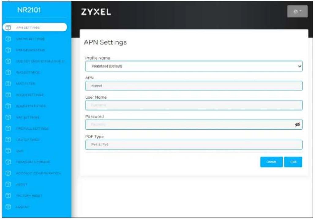
The following table describes the labels in this screen.
Table 21 APN SETTINGS
| LABEL DESCRIPTION | |
| APN Connections with different | APNs (Access Profile Names) may provide different services (such as Internet access or MMS (Multi-Media Messaging Service)) and charge method. |
| User Name | Enter the user name (of up to 64 ASCII printable characters) given to you by your service provider. |
| Password | Enter the password (of up to 64 ASCII printable characters) associated with the user name above. |
| PDP Type Select IPv4 if you want the NR2101 to use IPv4 only.Select IPv6 if you want the NR2101 to use IPv6 only.Select IPv4 & IPv6 to allow the NR2101 to use IPv4 and IPv6 at the same time. | |
| Edit Click Edit to save your changes. | |
| Create Click Create to add an APN entry. | |
6.3 SIM PIN Settings
Click SIM PIN SETTINGS and the screen appears as shown next. Click SIM PIN Lock to enable the PIN code authentication on the installed SIM card. Enter the number of the attempts allowed for wrong PIN codes. Enter the PIN code provided by your ISP. Click Update to save the changes.
Figure 62 SIM PIN SETTINGS
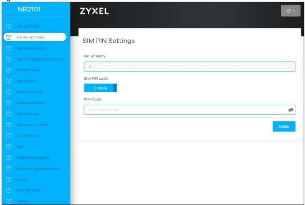
The following table describes the labels in this screen.
Table 22 SIM PIN SETTINGS
| LABEL DESCRIPTION | |
| No. of Retry | This field displays the number of times consecutive wrong passwords can be entered for this account. |
| SIM PIN Lock | Select Enable to enable SIM PIN lock. You need to enter your PIN code every time the NR2101 reboots. To turn off PIN code authentication, enter the PIN code and select Disable. |
| PIN Code | If you select Enable, enter a 4-digit default PIN code (0000 for example) provided by your ISP for the installed SIM card. |
| Update Click Update to save | your changes. |
6.3.1 SIM Information
Click SIM INFORMATION and the screen appears as shown next. Use this screen to view information about the SIM card currently installed on the NR2101.
Figure 63 SIM INFORMATION
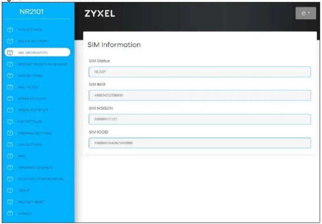
The following table describes the labels in this screen.
Table 23 SIM INFORMATION
| LABEL DESCRIPTION | |
| SIM Status | This displays the status of the installed SIM card. |
| SIM IMSI | This displays the International Mobile Subscriber Identity (IMSI) stored in the SIM card. The IMSI is a unique 15-digit number used to identify a user on a carrier network. |
Table 23 SIM INFORMATION
| LABEL DESCRIPTION | |
| SIM MSISDN | This displays the MSISDN (Mobile Subscriber ISDN) number, the mobile phone number assigned to this SIM card. |
| SIM ICCID This displays the serial number of the SIM card. | |
CHAPTER 7
WLAN & WWAN
7.1 Overview
This chapter discusses how to configure the WiFi network settings in your NR2101.
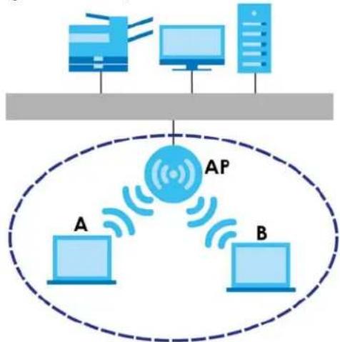
The following figure provides an example of a WiFi network.
Figure 64 Example of a WiFi Network
flowchart
graph TD
    A["Computer 1"] -->|Wireless Signal| AP["AP"]
    B["Computer 2"] -->|Wireless Signal| AP
    C["Computer 3"] -->|Wireless Signal| AP
    AP --> D["Computer 4"]
    style AP fill:#f9f,stroke-dasharray: 5 5
The WiFi network is the part in the blue circle. In this WiFi network, devices A and B are called WiFi clients. The WiFi clients use the access point (AP) to interact with other devices (such as the printer) or with the Internet. Your NR2101 is the AP.
7.1.1 What You Can Do in this Chapter
- Use the SSID Settings screen to configure the WiFi SSID settings (2.4 GHz/5 GHz) and WiFi security modes (Section 7.2 on page 64).
- Use the WPS Settings screen to activate WPS via a PIN code (Section 7.4 on page 72).
- Use the MAC Filter screen to deny WiFi clients using their MAC addresses from connecting to the NR2101 (Section 7.5 on page 73).
- Use the WWAN Settings screen to configure the WWAN settings on the NR2101 for Internet access (Section 7.6 on page 74).
7.1.2 What You Need to Know
Every WiFi network must follow these basic guidelines.
- Every WiFi client in the same WiFi network must use the same SSID.
The SSID is the name of the WiFi network. It stands for Service Set IDentity.
- If two WiFi networks overlap, they should use different channels.
Like radio stations or television channels, each WiFi network uses a specific channel, or frequency, to send and receive information.
- Every WiFi client in the same WiFi network must use security compatible with the AP.
Security stops unauthorized devices from using the WiFi network. It can also protect the information that is sent in the WiFi network.
WiFi Security Overview
The following sections introduce different types of WiFi security you can set up in the WiFi network.
SSID
Normally, the AP acts like a beacon and regularly broadcasts the SSID in the area. You can hide the SSID instead, in which case the AP does not broadcast the SSID. In addition, you should change the default SSID to something that is difficult to guess.
This type of security is fairly weak, however, because there are ways for unauthorized devices to get the SSID. In addition, unauthorized devices can still see the information that is sent in the WiFi network.
MAC Address Filter
Every WiFi client has a unique identification number, called a MAC address. ^1 A MAC address is usually written using twelve hexadecimal characters ^2 ; for example, 00A0C5000002 or 00:A0:C5:00:00:02. To get the MAC address for each WiFi client, see the appropriate User's Guide or other documentation.
You can use the MAC address filter to tell the AP which WiFi clients are allowed or not allowed to use the WiFi network. If a WiFi client is allowed to use the WiFi network, it still has to have the correct settings (SSID, channel, and security). If a WiFi client is not allowed to use the WiFi network, it does not matter if it has the correct settings.
This type of security does not protect the information that is sent in the WiFi network. Furthermore, there are ways for unauthorized devices to get the MAC address of an authorized WiFi client. Then, they can use that MAC address to use the WiFi network.
WPS
WiFi Protected Setup (WPS) is an industry standard specification, defined by the WiFi Alliance. WPS allows you to quickly set up a WiFi network with strong security, without having to configure security settings manually. Depending on the devices in your network, you can either press a button (on the device itself, or in its configuration utility) or enter a PIN (Personal Identification Number) in the devices.
Then, they connect and set up a secure network by themselves. See how to set up a secure WiFi network using WPS in the Section 7.4 on page 72.
7.2 SSID Settings(2.4GHz/5GHz)
Use this screen to configure your WiFi SSID and Password settings and select the WiFi security type, bandwidth, and channel for 2.4 GHz/5 GHz network.
Note: If you change the NR2101's SSID, channel or security settings when a WiFi client device is connected to the WiFi, your WiFi client device will lose its WiFi connection when you press Update to confirm. You must then update the WiFi settings of your WiFi client device to match the NR2101's new settings.
Click SSID SETTINGS(2.4GHz/5GHz) and the following screen displays.
Figure 65 SSID SETTINGS(2.4GHz/5GHz)
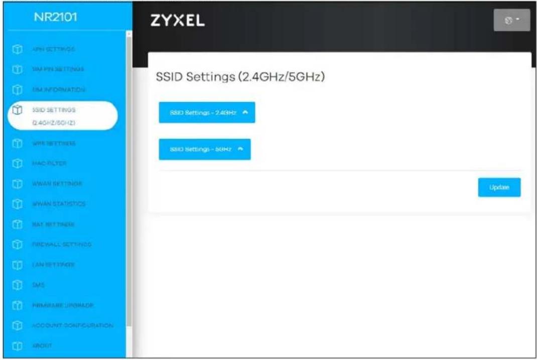
Click SSID SETTINGS-2.4GHz and the screen is shown as next.
Figure 66 SSID SETTINGS(2.4GHz)
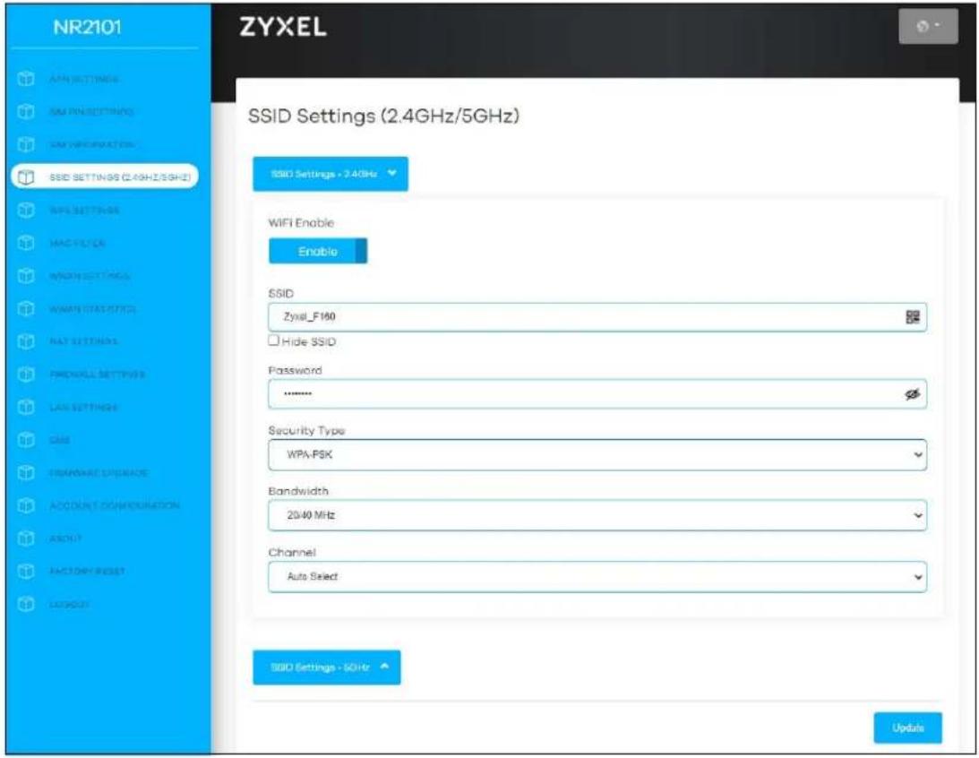
The following table describes the labels in this screen.
Table 24 SSID SETTINGS (2.4GHz)
| LABEL DESCRIPTION | |
| SSID SETTINGS (2.4GHz) | |
| SSID Settings-2.4GHz Click this | button to configure the 2.4GHz SSID Settings on the NR2101. |
| WiFi Enable Select this to enable or disable WiFi. | |
| SSID The SSID (Service Set IDentity) is the name of the WiFi network. WiFi clients use theSSID to identify and connect to the NR2101. Enter a descriptive name (up to 32 ASCII characters, including spaces and special characters) for the NR2101's WiFi network.Click the QR code icon( ) in theSSIDfield and scan the 2,4GHz QR code to join the WiFi network. | |
| Hide SSID | Select this check box to hide the SSID in the outgoing beacon frame so a station cannot obtain the SSID through scanning using a site survey tool. |
| Password | Enter a password (of up to 8-64 characters including spaces and special characters) the WiFi clients need to enter to connect to the WiFi network. |
| Security Type | Select WPA-PSK, WPA2-PSK or WPA3/WPA2 mixed modeto add a layer of security to this WiFi network. The WiFi clients which want to connect to this network must have the same WiFi security settings as the NR2101. SeeSection 7.3.1 on page 68 for detailed information on different security modes. Or you can selectNone (Open) to allow any WiFi client device to connect to this network without authentication. |
| Bandwidth Select an operating frequency depending on your particular region. Choices are 20M or 20/40M. | |
| Channel Select a channel from the drop-down list box. The options vary depending on the frequency band and the country you are in. Choices are Auto Select, 1,2,3,4,5,6,7,8,9,10,and 11. | |
Click SSID SETTINGS-5GHz and the screen is shown as next.
Figure 67 SSID SETTINGS(5GHz)
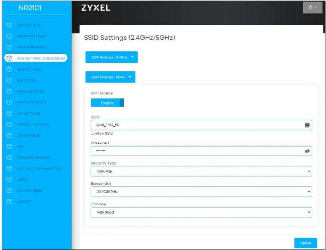
The following table describes the labels in this screen.
Table 25 SSID SETTINGS (5GHz)
| LABEL DESCRIPTION | |
| SSID SETTINGS (5GHz) | |
| SSID Settings-5GHz Click this button to configure the 5GHz SSID Settings on the NR2101. | |
| WiFi Enable Select this to enable or disable WiFi. | |
| SSID | The SSID (Service Set IDentity) is the name of the WiFi network. WiFi clients use the SSID to identify and connect to the NR2101. Enter a descriptive name (up to 32 printable characters found on a typical English language keyboard) for the NR2101's WiFi network.Click the QR code icon( ) in theSSIDfield and scan the 5GHz QR code to join the WiFi network. |
| Hide SSID Select this check box to hide the SSID in the outgoing beacon frame so a station cannot obtain the SSID through scanning using a site survey tool. | |
| Password | Enter a password (of up to 8-64 characters including spaces and special characters) the WiFi stations need to enter to connect to the WiFi network. |
| Security Type | Select WPA-PSK, WPA2-PSK or WPA3/ WPA2 mixed mode to add a layer of security to this WiFi network. The WiFi clients which want to connect to this network must have the same WiFi security settings as the NR2101. See Section 7.3.1 on page 68 for detailed information on different security modes. Or you can select None (Open) to allow any WiFi client device to connect to this network without authentication. |
| Bandwidth Select an operating frequency depending on your particular region. Choices are 20M, 20/40M, or 20/40/80M. | |
| Channel Select a channel from the drop-down list box. The options vary depending on the frequency band and the country you are in. Choice are Auto Select, 36,40,44,48,149,153,157 and161. | |
See the rest of this chapter for information on the other labels in this screen.
7.3 SSID WiFi QR Code
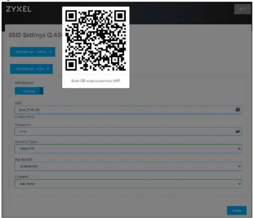
Click SSID SETTINGS(2.4GHz/5GHz) and then click the QR code icon(☐) in the SSID field. The Scan QR code to connect WiFi screen appears. Use this screen to scan the 2,4GHz or 5GHz QR code and join the WiFi network.
Figure 68 SSID SETTINGS-2.4 GHz > SSID
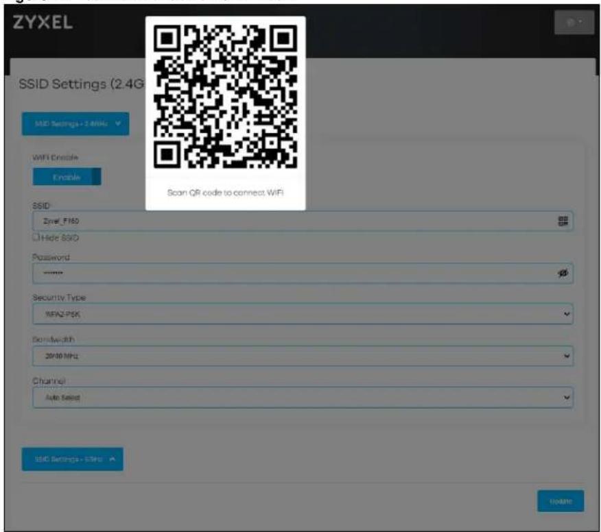
Figure 69 SSID SETTINGS-5 GHz >SSID
7.3.1 WiFi Security
Use this screen to select the WiFi security mode for the 2.4 GHz/5 GHz WiFi network.
7.3.1.1 No Security
Select None (Open) to allow WiFi clients to communicate with the NR2101 without any data encryption.
Note: If you do not enable any WiFi security on your NR2101, your network will be accessible to any WiFi networking device that is within range.
Figure 70 SSID SETTINGS-2.4 GHz > Security Type: None (Open)
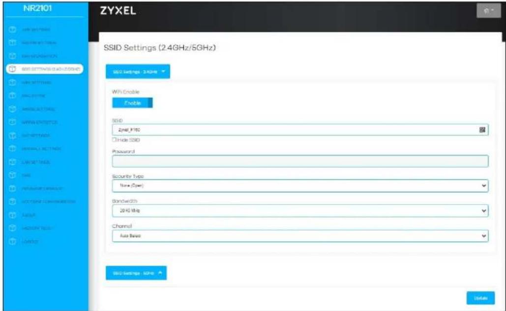
Figure 71 SSID SETTINGS-5 GHz > Security Type: None (Open)
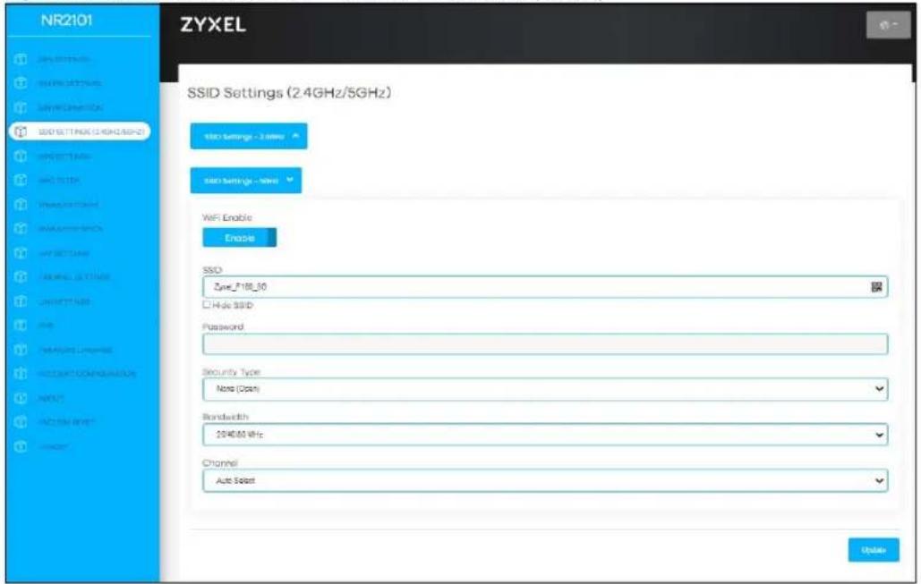
7.3.1.2 WPA-PSK
Select WPA-PSK from the Security Type drop-down list box.
Figure 72 SSID SETTINGS-2.4GHz > Security Type: WPA-PSK
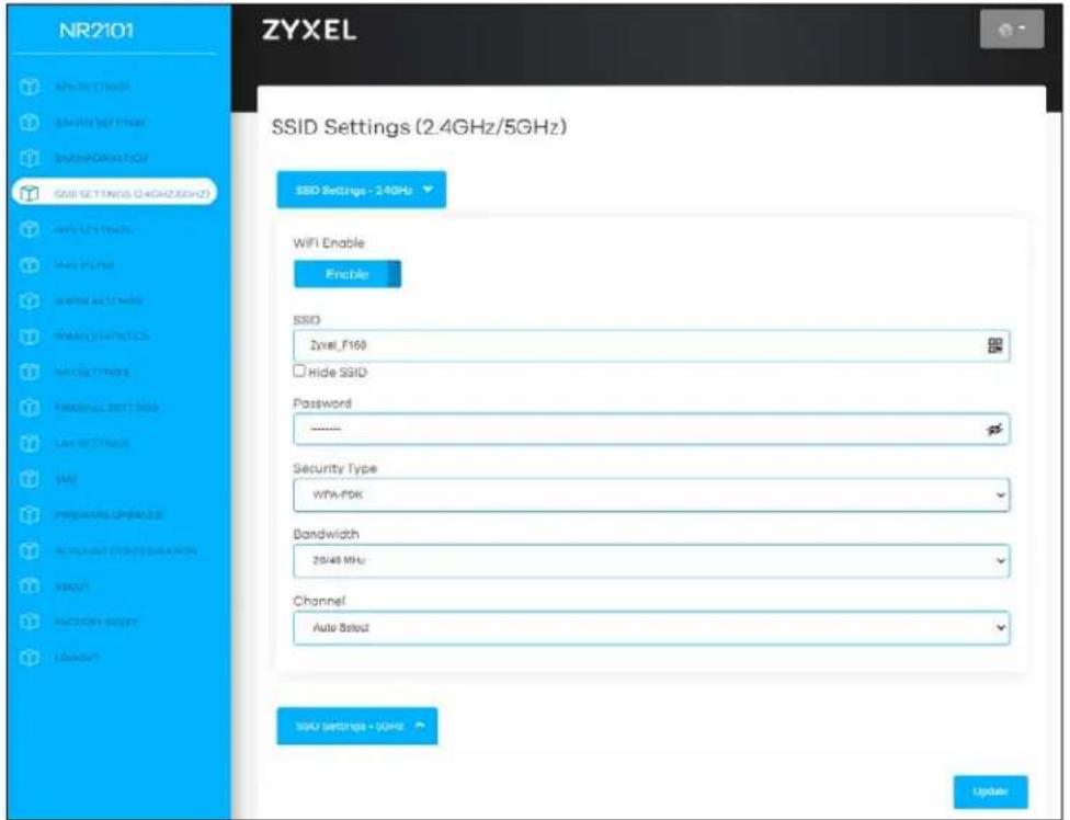
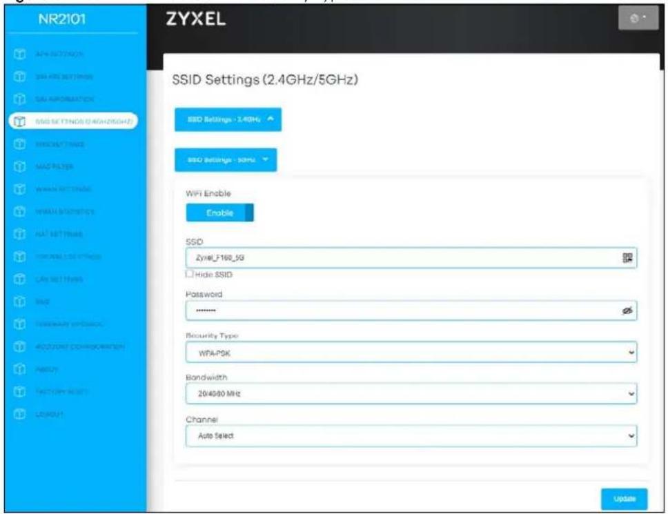
Figure 73 SSID SETTINGS-5GHz > Security Type: WPA-PSK
7.3.1.3 WPA2-PSK
Select WPA2-PSK from the Security Type drop-down list box.
Figure 74 SSID SETTINGS-2.4 GHz > Security Type: WPA2-PSK
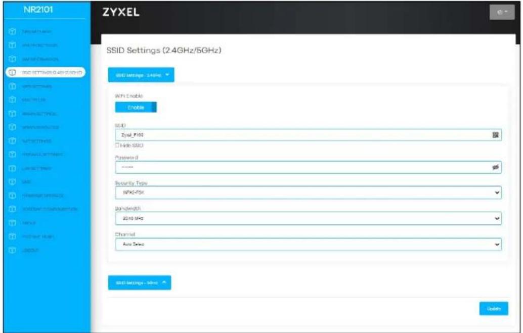
Figure 75 SSID SETTINGS-5 GHz > Security Type: WPA2-PSK
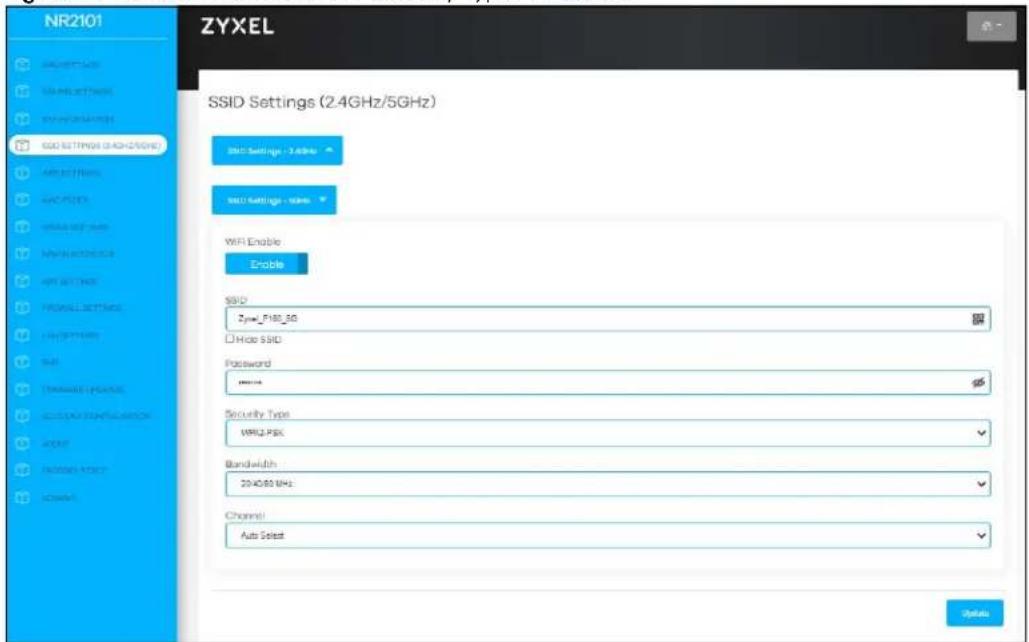
7.3.1.4 WPA3/WPA2 mixed mode
Select WPA3/WPA2 mixed mode from the Security Type drop-down list box.
Figure 76 SSID SETTINGS-2.4 GHz > Security Type: WPA3/WPA2 mixed mode
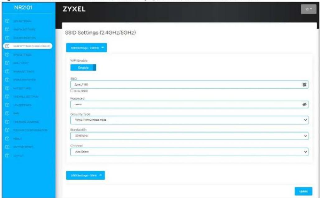
Figure 77 SSID SETTINGS-5 GHz > Security Type: WPA3/WPA2 mixed mode

7.4 WPS Settings
Use this screen to configure WiFi Protected Setup (WPS) on your NR2101.
WPS allows you to quickly set up a WiFi network with strong security, without having to configure security settings manually.
Note: To use the WPS feature, make sure you have WiFi enabled in the SSID SETTINGS (2.4GHz/5GHz) screen.
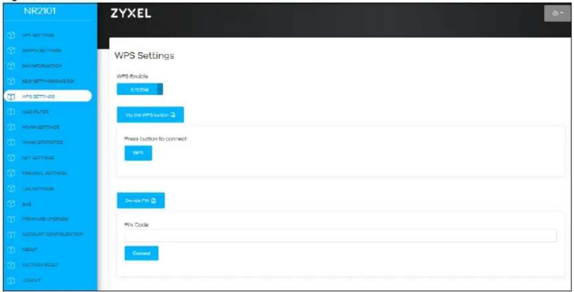
Click WPS SETTINGS and the following screen displays.
Figure 78 WPS SETTINGS
The following table describes the labels in this screen.
Table 26 WPS SETTINGS
| LABEL DESCRIPTION | |
| WPS Enable Click | Enable to enable WPS on the NR2101. |
| Via the WPS button | Click this to activate WPS on the NR2101 via the WPS button. |
| WPS Click this button to connect. | |
| Device PIN | This field is available only when you set WPS Enable to Enable.Enter the PIN Code of the WiFi client device that you are setting up a WPS connection with, and then click Connect to authenticate and add the client device to your WiFi network.You can find the PIN either on the outside of the WiFi client device, or by checking the WiFi client device's settings.Note: You must also activate WPS on that WiFi client device within two minutes to have it present its PIN to the NR2101. |
7.5 MAC Filter
This screen allows you to configure the NR2101 to exclude specific WiFi client devices from accessing the NR2101. Every Ethernet device has a unique MAC (Media Access Control) address. The MAC address is assigned at the factory and consists of six pairs of hexadecimal characters, for example, 00:A0:C5:00:00:02. You need to know the MAC addresses of the WiFi client devices to configure this screen.
Click MAC FILTER and the screen appears as shown. Use this screen to view your NR2101's MAC filter settings and add new MAC filter rules. Click Add New to add a new MAC filer rule.
Figure 79 MAC FILTER
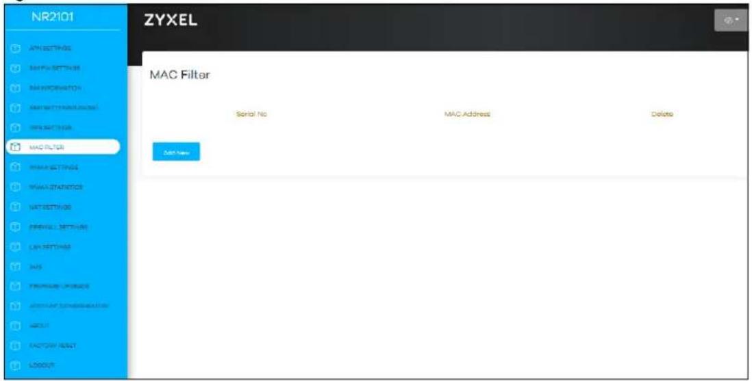
The following table describes the labels in this screen.
Table 27 MAC FILTER
| LABEL DESCRIPTION | |
| Serial No. This field | displays the serial number of the MAC address entry. |
| MAC Address | This field displays the MAC addresses of the WiFi client devices that are denied access to the NR2101.Click Add New to enter the MAC address of the WiFi client devices that are denied access to the NR2101 in this field. Enter the MAC addresses in a valid MAC address format, that is, six hexadecimal character pairs, for example, 12:34:56:78:9a:bc. |
| Delete Click Delete to remove an existing MAC address entry. | |
7.6 WWAN Settings
Click WWAN SETTINGS and the screen appears as shown next. Use this screen to change your NR2101's Internet access settings. Select a network you prefer to use from the Preference Network drop-down list box.
Figure 80 WWAN SETTINGS
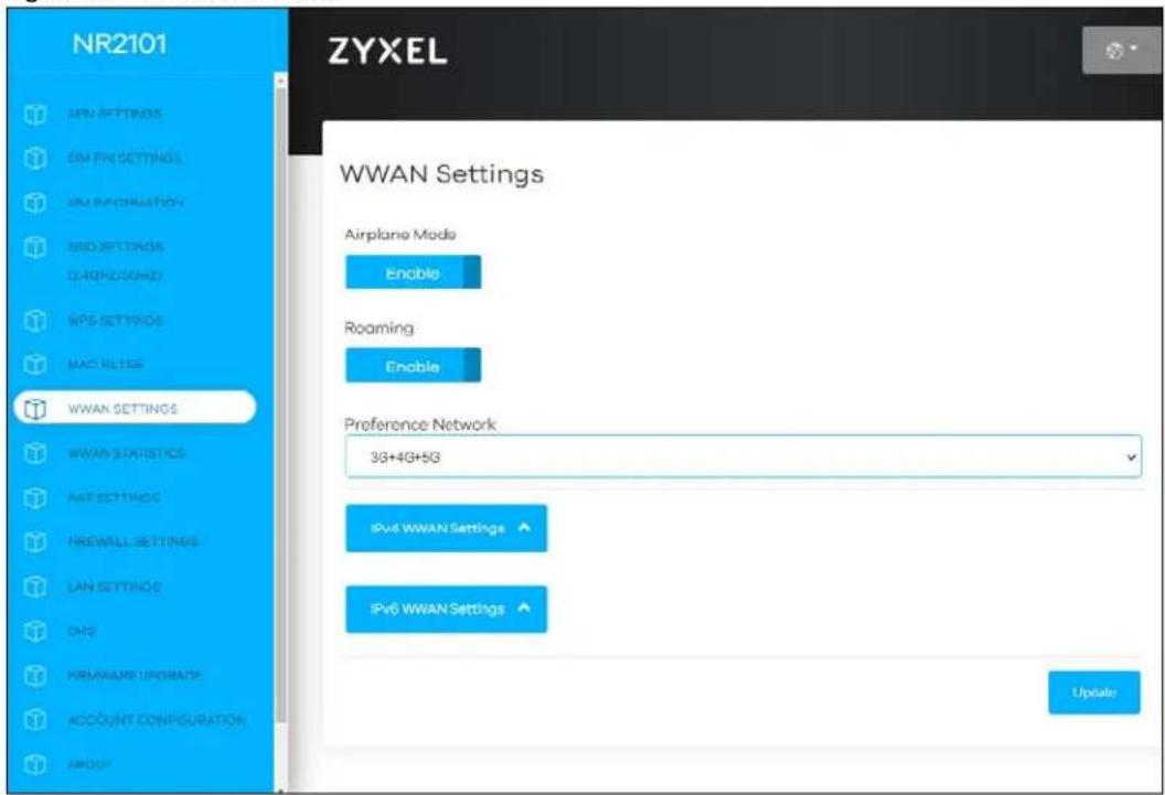
The following table describes the labels in this screen.
Table 28 WWAN SETTINGS
| LABEL DESCRIPTION | |
| WWAN Settings | |
| Airplane Mode | Select Enable to activate the airplane mode. |
| Roaming | Select Enable to activate data roaming. 3G/4G/5G roaming is to use your mobile device in an area which is not covered by your service provider. Enable roaming to ensure that your NR2101 is kept connected to the Internet when you are traveling outside the geographical coverage area of the network to which you are registered. |
| Preference Network | Select the network you want to use. Choices are 3G only, 3G+4G, 4G only, 5G only, and 3G+4G+5G. |
7.6.1 IPv4/IPv6 WWAN Settings
Use this screen to configure your NR2101's IPv4 WWAN and IPv6 WWAN settings. Click WWAN SETTINGS > IPv4 WWAN Settings/ IPv6 WWAN Settings and the screen appears as shown.
Figure 81 WWAN SETTINGS > IPv4 WWAN Settings
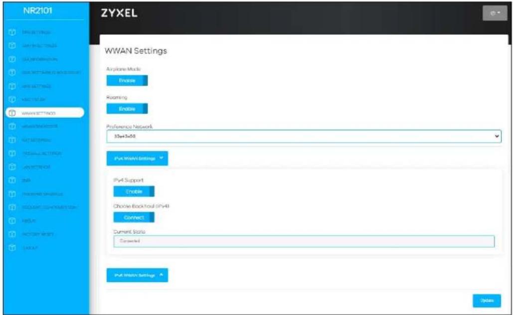
Figure 82 WWAN SETTINGS > IPv6 WWAN Settings
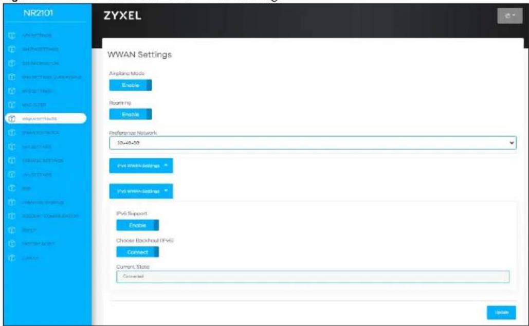
The following table describes the labels in this screen
Table 29 WWAN SETTINGS> IPv4 WWAN Settings/ IPv6 WWAN Settings
| LABEL DESCRIPTION | |
| IPv4 WWAN Settings | |
| IPv4 Support | Select Enable to allow the NR2101 to use IPv4 addresses. Otherwise, select Disable. |
| Choose Backhaul (IPv4) | Select Connect to use Backhaul (IPv4). Otherwise, select Disconnect. |
| Current State | Use this field to view information of the current IPv4 connection state. |
Table 29 WWAN SETTINGS> IPv4 WWAN Settings/ IPv6 WWAN Settings
| LABEL DESCRIPTION | |
| IPv6 WWAN Settings | |
| IPv6 Support | Select Enable to allow the NR2101 to use IPv6 addresses. Otherwise, select Disable. |
| Choose Backhaul (IPv6) | Select Connect to use Backhaul (IPv6). Otherwise, select Disconnect. |
| Current State | Use this field to view information of the current IPv6 connection state. |
7.6.2 WWAN Statistics
Use this screen to view detailed information about the WWAN, such as data sent and received, packets sent and received, and network settings. Click WWAN STATISTICS and the screen appears as shown next.
Figure 83 WWAN STATISTICS
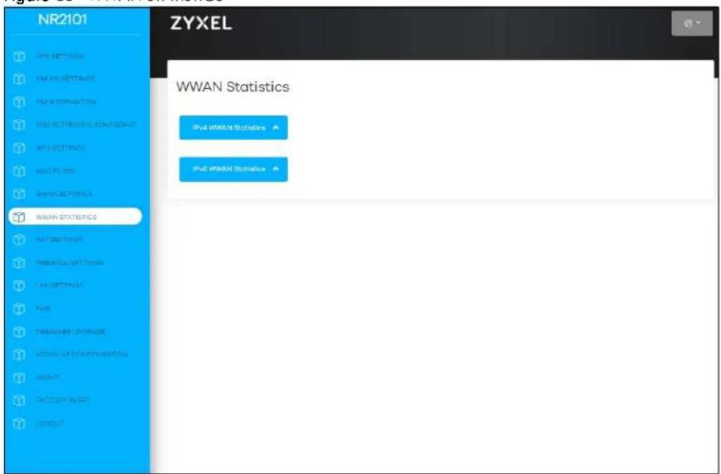
The following table describes the labels in this screen.
Table 30 WWAN STATISTICS
| LABEL DESCRIPTION | |
| IPv4 WWAN Statistics Click this field to view the detailed information of IPv4 WWAN Statistics. | |
| IPv6 WWAN Statistics Click this field to view the detailed information of IPv6 WWAN Statistics. | |
Click IPv4 WWAN Statistics/IPv6 WWAN Statistics and the screen appears as shown next.
Figure 84 IPv4WWAN Statistics
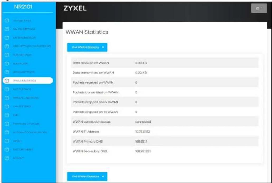
Figure 85 IPv6WWAN Statistics
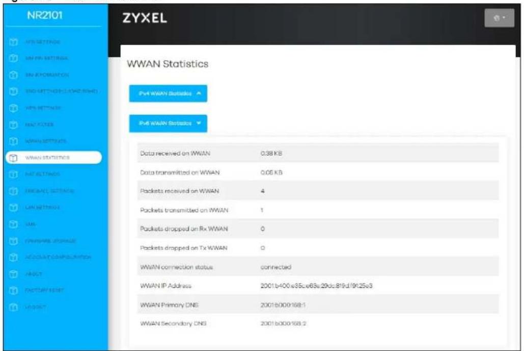
The following table describes the labels in this screen.
Table 31 WWAN Statistics
| LABEL DESCRIPTION | |
| IPv4 WWAN Statistics | |
| Data received on WWAN | This shows the reception count in bytes on this port |
| Data transmitted on WWAN This | shows the transmission count on this port |
| Packets received on WWAN This | is the number of received packets on this port. |
| Packets transmitted on WWAN This | this is the number of transmitted packets on this port. |
| Packets dropped on Rx WWAN | This field displays the number of packets dropped by NR2101's Rx WWAN since it was last connected. |
| Packets dropped on Tx WWAN | This field displays the number of packets dropped by NR2101's Tx WWAN since it was last connected. |
| WWAN connection status This shows the NR2101's WWAN IPv4 connection status. | |
| WWAN IP Address | This shows the NR2101's WWAN IPv4 address, which was assigned by your Internet Service Provider. |
| WWAN Primary DNS | This shows the primary IPv4 Link-local address in the LAN side. This is used by NR2101 when communicating with neighboring devices on the same link. It allows IPv4-capable devices to communicate with each other in the LAN side. |
| WWAN Secondary DNS | This shows the secondary IPv4 Link-local address in the LAN side. This is used by NR2101 when communicating with neighboring devices on the same link. It allows IPv4-capable devices to communicate with each other in the LAN side. |
| IPv6 WWAN Statistics | |
| Data received on WWAN | This shows the reception count in bytes on this port |
| Data transmitted on WWAN This | shows the transmission count in bytes on this port |
| Packets received on WWAN This | is the number of received packets on this port. |
| Packets transmitted on WWAN This | this is the number of transmitted packets on this port. |
| Packets dropped on Rx WWAN | This field displays the number of packets dropped by NR2101's Rx WWAN since it was last connected. |
| Packets dropped on Tx WWAN | This field displays the number of packets dropping by NR2101's Tx WWAN since it was last connected. |
| WWAN connection status This shows the NR2101's WWAN IPv6 connection status. | |
| WWAN IP Address | This shows the NR2101's WWAN IPv6 address, which was assigned by your Internet Service Provider. |
| WWAN Primary DNS This shows the primary IPv6 Link-local address in the LAN side. This is used by NR2101 when communicating with neighboring devices on the same link. It allows IPv6-capable devices to communicate with each other in the LAN side. | |
| WWAN Secondary DNS | This shows the secondary IPv6 Link-local address in the LAN side. This is used by NR2101 when communicating with neighboring devices on the same link. It allows IPv6-capable devices to communicate with each other in the LAN side. |
CHAPTER 8 NAT
8.1 Overview
NAT (Network Address Translation - NAT, RFC 1631) is the translation of the IP address of a host in a packet. For example, the source address of an outgoing packet, used within one network is changed to a different IP address known within another network.
The figure below is a simple illustration of a NAT network. You want to assign ports 21-25 to one FTP, Telnet and SMTP server (A in the example), port 80 to another (B in the example) and assign a default server IP address of 192.168.1.35 to a third (C in the example).
You assign the LAN IP addresses to the devices (A to D) connected to your NR2101. The ISP assigns the WAN IP address. The NAT network appears as a single host on the Internet. All traffic coming from A to D going out to the Internet use the IP address of the NR2101, which is 192.168.1.1.
Figure 86 NAT Example
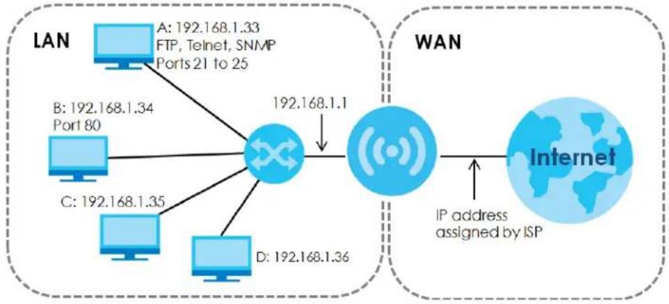
flowchart
graph TD
    subgraph LAN
        A["LAN"] -->|A: 192.168.1.33 FTP, Telnet, SNMP Ports 21 to 25| Network
        B["LAN"] -->|B: 192.168.1.34 Port 80| Network
        C["LAN"] -->|C: 192.168.1.35| Network
        D["LAN"] -->|D: 192.168.1.36| Network
        Network -->|192.168.1.1| Internet
    end
    subgraph WAN
        Internet -->|IP address assigned by ISP| Internet
    end
Note: You must create a firewall rule in addition to setting up NAT, to allow traffic from the WAN to be forwarded through the NR2101.
8.1.1 What You Can Do
- Use the NAT Settings screen to configure your NR2101's VPN pass-through and port forwarding settings (Section 8.2 on page 82).
8.1.2 What You Need to Know
Inside/ Outside
Inside/outside denotes where a host is located relative to the NR2101, for example, the computers of your subscribers are the inside hosts, while the web servers on the Internet are the outside hosts.
Global/Local
Global/local denotes the IP address of a host in a packet as the packet traverses a router, for example, the local address refers to the IP address of a host when the packet is in the local network, while the global address refers to the IP address of the host when the same packet is traveling in the WAN side.
NAT
In the simplest form, NAT changes the source IP address in a packet received from a subscriber (the inside local address) to another (the inside global address) before forwarding the packet to the WAN side. When the response comes back, NAT translates the destination address (the inside global address) back to the inside local address before forwarding it to the original inside host.
NAT Types
This section discusses the following NAT types that are implemented on the NR2101.
- Full Cone: In full cone NAT, the NAT router maps all outgoing packets from an internal IP address and port to a single IP address and port on the external network. The NAT router also maps packets coming to that external IP address and port to the internal IP address and port.
- Address Restricted or Restricted Cone: As in full cone NAT, a restricted cone NAT router maps all outgoing packets from an internal IP address and port to a single IP address and port on the external network. The difference from full cone NAT is in how the restricted cone NAT router handles packets coming in from the external network.
- Port Restricted: Port restricted cone NAT maps all outgoing packets from an internal IP address and port to a single IP address and port on the external network.
- Symmetric: The full, restricted and port restricted cone NAT types use the same mapping for an outgoing packet's source address regardless of the destination IP address and port. In symmetric NAT, the mapping of an outgoing packet's source address to a source address in another network is different for each different destination IP address and port.
The following table summarizes how these NAT types handle outgoing and incoming packets.
Table 32 NAT Types
| FULL CONE | ADDRESS RESTRICTED | PORT RESTRICTED SYMMETRIC | ||
| Incoming Packets | Any external host can send packets to the mapped external IP address and port. | Only external hosts with an IP address to which the internal host has already sent a packet can send packets to the mapped external IP address and port. | Only external hosts with an IP address and port to which the internal host has already sent a packet can send packets to the mapped external IP address and port. | A host on the external network can only send packets to the specific mapped external IP address and port that the NAT router used in sending a packet to the external host's IP address and port. |
| Outgoing Packets | The NAT router maps the internal IP address and port of all outgoing packets to a single IP address and port on the external network. | The NAT router maps the internal IP address and port of each outgoing packet to a different external IP address and port for each different destination IP address and port. | ||
8.2 NAT Settings
Use this screen to enable IP Pass-Through, VPN Pass-Through, PPTP VPN Pass-Through, L2TP Pass-Through, and Webserver WWAN Access protocols. Click NAT SETTINGS to open the following screen.
Note: To select a NAT type from the Select NAT Type drop-down list box or edit DMZ IP, you must disable IP Pass-Through.
Figure 87 NAT SETTINGS
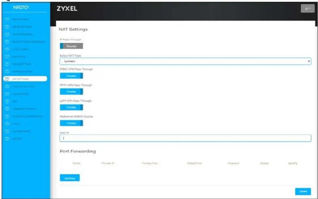
The following table describes the labels in this screen.
Table 33 NAT SETTINGS
| LABEL DESCRIPTION | |
| IP Pass-Through | Select Enable to activate IP Pass-Through. IP Pass-through allows a LAN computer on the local network of the NR2101 to have access to web services using the NR2101's public WWAN IP address. When IP Pass-Through is configured, all traffic is forwarded to the LAN computer and will not go through NAT. |
| Select NAT Type | Select a NAT type from the drop-down list box. Choices are Symmetric, Port Restricted, Full cone, or Address Restricted. |
| IPSEC VPN Pass-Through | Select Enable to allow VPN clients to make outbound IPSec connections. It is required in order to connect to a IPSec VPN account. If IPSEC is disabled, then when a client sends a request to a VPN server, the server will reply to the NR2101 and the NR2101 will drop the request. When IPSEC is enabled, the NR2101 will forward the reply from the VPN server to the client that initiated the request, and the connection will establish successfully. |
| PPTP VPN Pass-Through | Select Enable to allow VPN clients to make outbound PPTP connections. It is required in order to connect to a PPTP VPN account. If PPTP is disabled, then when a client sends a request to a VPN server, the server will reply to the NR2101 and the NR2101 will drop the request. When PPTP is enabled, the NR2101 will forward the reply from the VPN server to the client that initiated the request, and the connection will establish successfully. |
| L2TP VPN Pass-Through | Select Enable to allow VPN clients to make outbound L2TP connections. It is required in order to connect to a L2TP VPN account. If L2TP is disabled, then when a client sends a request to a VPN server, the server will reply to the NR2101 and the NR2101 will drop the request. When L2TP is enabled, the NR2101 will forward the reply from the VPN server to the client that initiated the request, and the connection will establish successfully. |
| Webserver WWAN Access | Select Enable to activate remote web server management. |
| DMZ IP | Enter the IP address of the default server which receives packets from ports that are not specified in the port forwarding table. |
| Port Forwarding | Port forwarding allows you to define the local servers to which the incoming services will be forwarded. You can configure a new schedule rule by clicking Add Entry. You can view the schedule rules by clicking Get Entries.Serial: This field displays the serial number of an individual port forwarding server entry.Private IP: This field displays the IP address of the virtual server on the LAN.Private Port: A private port refers to the port number of a host when the packet is in the LAN side.Global Port: A global port refers to the port number of the host when the same packet is traveling in the WAN side.Protocol: Select the protocol (TCP_UDP, TCP, UDP, or ICMP) used to transport the packets for which you want to apply the rule.Delete: Click Delete to delete an existing port forwarding rule.Modify: Click Modify to edit an existing port forwarding rule. |
8.3 Technical Reference
The following section contains additional technical information about the NR2101 features described in this chapter.
8.3.1 NAT Port Forwarding: Services and Port Numbers
A port forwarding set is a list of inside (behind NAT on the LAN) servers, for example, web or FTP, that you can make accessible to the outside world even though NAT makes your whole inside network appear as a single machine to the outside world.
Use the Port Forwarding screen to forward incoming service requests to the server(s) on your local network. You may enter a single port number or a range of port numbers to be forwarded, and the local IP address of the desired server. The port number identifies a service; for example, web service is on port 80 and FTP on port 21. In some cases, such as for unknown services or where one server can support more than one service (for example both FTP and web service), it might be better to specify a range of port numbers.
In addition to the servers for specified services, NAT supports a default server. A service request that does not have a server explicitly designated for it is forwarded to the default server. If the default is not defined, the service request is simply discarded.
Note: Many residential broadband ISP accounts do not allow you to run any server processes (such as a Web or FTP server) from your location. Your ISP may periodically check for servers and may suspend your account if it discovers any active services at your location. If you are unsure, refer to your ISP.
8.3.2 NAT Port Forwarding Example
Let's say you want to assign ports 21-25 to one FTP, Telnet and SMTP server (A in the example), port 80 to another (B in the example) and assign a default server IP address of 192.168.1.35 to a third (C in the example). You assign the LAN IP addresses and the ISP assigns the WAN IP address. The NAT network appears as a single host on the Internet.
Figure 88 Multiple Servers Behind NAT Example
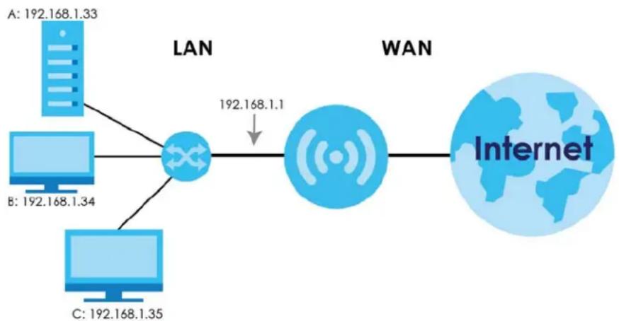
flowchart
graph LR
    A["192.168.1.33"] --> C((Network))
    B["192.168.1.34"] --> C
    D["192.168.1.35"] --> C
    C --> E["192.168.1.1"]
    E --> F["(Internet)"]
8.3.3 Trigger Port Forwarding
Some services use a dedicated range of ports on the client side and a dedicated range of ports on the server side. With regular port forwarding you set a forwarding port in NAT to forward a service (coming in from the server on the WAN) to the IP address of a computer on the client side (LAN). The problem is that port forwarding only forwards a service to a single LAN IP address. In order to use the same service on a
different LAN computer, you have to manually replace the LAN computer's IP address in the forwarding port with another LAN computer's IP address.
Trigger port forwarding solves this problem by allowing computers on the LAN to dynamically take turns using the service. The NR2101 records the IP address of a LAN computer that sends traffic to the WAN to request a service with a specific port number and protocol (a "trigger" port). When the NR2101's WAN port receives a response with a specific port number and protocol ("incoming" port), the NR2101 forwards the traffic to the LAN IP address of the computer that sent the request. After that computer's connection for that service closes, another computer on the LAN can use the service in the same manner. This way you do not need to configure a new IP address each time you want a different LAN computer to use the application.
8.3.4 Trigger Port Forwarding Example
The following is an example of trigger port forwarding.
Figure 89 Trigger Port Forwarding Process: Example
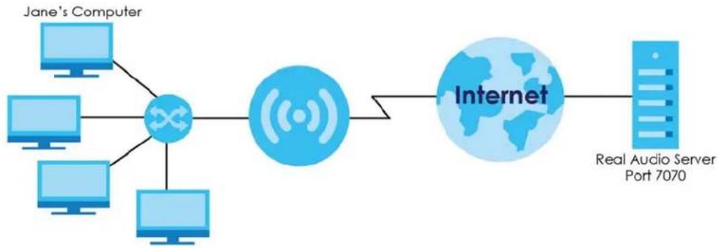
flowchart
graph LR
    A["Jane's Computer"] --> B["Data Link"]
    C["Computer"] --> B
    D["Computer"] --> B
    E["Computer"] --> B
    F["Computer"] --> B
    B --> G["Internet"]
    G --> H["Real Audio Server Port 7070"]
1 Jane requests a file from the Real Audio server (port 7070).
2 Port 7070 is a "trigger" port and causes the NR2101 to record Jane's computer IP address. The NR2101 associates Jane's computer IP address with the "incoming" port range of 6970-7170.
3 The Real Audio server responds using a port number ranging between 6970-7170.
4 The NR2101 forwards the traffic to Jane's computer IP address.
5 Only Jane can connect to the Real Audio server until the connection is closed or times out. The NR2101 times out in three minutes with UDP (User Datagram Protocol), or two hours with TCP/IP (Transfer Control Protocol/Internet Protocol).
8.3.5 Two Points To Remember About Trigger Ports
1 Trigger events only happen on data that is coming from inside the NR2101 and going to the outside.
2 If an application needs a continuous data stream, that port (range) will be tied up so that another computer on the LAN cannot trigger it.
CHAPTER 9 Firewall
9.1 Overview
Use these screens to enable and configure the firewall that protects your NR2101 and your LAN from unwanted or malicious traffic.
Enable the firewall to protect your LAN devices from attacks by hackers on the Internet and control access between the LAN and WAN. By default the firewall:
- Allows traffic that originates from your LAN devices to go to all of the networks.
- Blocks traffic that originates on the other networks from going to the LAN.
The following figure illustrates the default firewall action. User A can initiate an IM (Instant Messaging) session from the LAN to the WAN (1). Return traffic for this session is also allowed (2). However other traffic initiated from the WAN is blocked (3 and 4).
Figure 90 Default Firewall Action
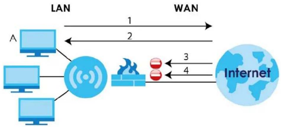
flowchart
graph LR
    A["Computer"] -->|LAN 1| B((Wireless))
    A -->|LAN 2| C["Firewall"]
    D["Computer"] -->|LAN 1| B
    D -->|LAN 2| C
    E["Computer"] -->|LAN 1| B
    E -->|LAN 2| C
    B <-->|WAN 3| F["Internet"]
    C <-->|WAN 4| F
9.1.1 What You Can Do
- Use the Firewall Settings screen to configure predefined Internet services and firewall rules (Section 9.2 on page 87).
9.1.2 What You Need To Know
The following terms and concepts may help as you read through this chapter.
About the NR2101 Firewall
The NR2101's firewall feature physically separates the LAN and the WAN and acts as a secure gateway for all data passing between the networks.
It is a stateful inspection firewall and is designed to protect against Denial of Service attacks when activated (click the General tab under Firewall and then click the Enable check box). The NR2101's purpose is to allow a private Local Area Network (LAN) to be securely connected to the Internet. The NR2101 can be used to prevent theft, destruction and modification of data, as well as log events, which may be important to the security of your network.
The NR2101 is installed between the LAN and a broadband modem connecting to the Internet. This allows it to act as a secure gateway for all data passing between the Internet and the LAN.
The LAN (Local Area Network) connects to a network of computers, which needs security from the outside world. These computers will have access to Internet services such as e-mail, FTP and the World Wide Web. However, "inbound access" is not allowed (by default) unless the remote host is authorized to use a specific service.
Guidelines For Enhancing Security With Your Firewall
1 Change the default password via Web Configurator.
2 Think about access control before you connect to the network in any way, including attaching a modem to the port.
3 Limit who can access your NR2101.
4 Don't enable any local service (such as NTP) that you don't use. Any enabled service could present a potential security risk. A determined hacker might be able to find creative ways to misuse the enabled services to access the firewall or the network.
5 For local services that are enabled, protect against misuse. Protect by configuring the services to communicate only with specific peers, and protect by configuring rules to block packets for the services at specific interfaces.
6 Protect against IP spoofing by making sure the firewall is active.
7 Keep the firewall in a secured (locked) room.
9.2 Firewall Settings
Click FIREWALL SETTINGS to open the following screen. Use this screen to enable or disable the NR2101's firewall, and set up firewall logs. Click View Firewall Entries to view or configure IPv4/IPv6 firewall entries.
Figure 91 FIREWALL SETTINGS
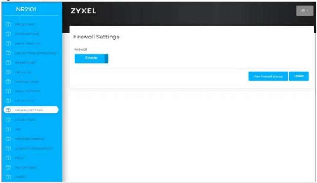
The following table describes the labels in this screen.
Table 34 FIREWALL SETTINGS
| LABEL DESCRIPTION | |
| Firewall | Select Enable to activate the firewall. The NR2101 performs access control when the firewall is activated. |
| View Firewall Entries | Select this to view and configure IPv4/IPv6 firewall entries. |
| Update | Click Update to save the settings. |
9.2.1 IPv4/IPv6 Firewall Entry
Click View Firewall Entries > Add Entry and the following screen appear. To apply the firewall rule to the IPv4 or IPv6 IP address only, select IPv4 or IPv6. To apply the firewall rule to both IPv4 and IPv6 IP address, select IPv4/IPv6 from the drop-down list box. To apply a rule to a specific IP address, enter the IPv4 source address, IPv4 source subnet mask, IPv6 address, IPv6 prefix length, and select the protocol for the service. Click OK to save the changes.
Figure 92 Add Entry
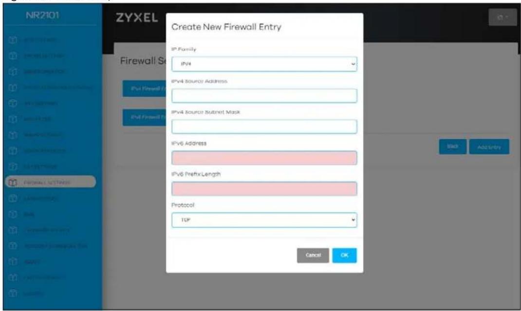
The following table describes the labels in this screen.
Table 35 Create New Firewall Entry
| LABEL DESCRIPTION | |
| IP Family | Select between IPv4 and IPv6. Compared to IPv4, IPv6 (Internet Protocol version 6) is designed to enhance IP address size and features. The increase in IPv6 address size to 128 bits (from the 32-bit IPv4 address) allows up to 3.4 x 1038 IP addresses. The NR2101 can use IPv4/IPv6 dual stack to connect to IPv4 and IPv6 networks, and supports IPv6 rapid deployment (6RD). |
| IPv4 Source Address | If you want the firewall rule to apply to a specific IP address, enter the source device's IPv4 address here. |
| IPv4 Source Subnet mask | If you want the firewall rule to apply to a specific IP address, enter the IPv4 Source subnet mask here. |
| IPv6 Address | If you want the firewall rule to apply to a specific IP address, enter the source device's IPv6 address here. |
| IPv6 Prefix Length | The prefix length indicates what the left-most part of the IP address is the same for all computers in the network, that is, the network address.Enter the address prefix length to specify how many most significant bits in an IPv6 address compose the network address. |
| Protocol | Select the protocol (None, TCP_UDP, TCP, UDP, ICMP, or ESP) used to transport the packets for which you want to apply the rule. |
| Cancel Click this to | exit this screen without saving. |
| OK Click this to save | your changes. |
Click IPv4/IPv6 Firewall Entries to view and configure IPv4/IPv6 settings.
Figure 93 IPv4 Firewall Entries
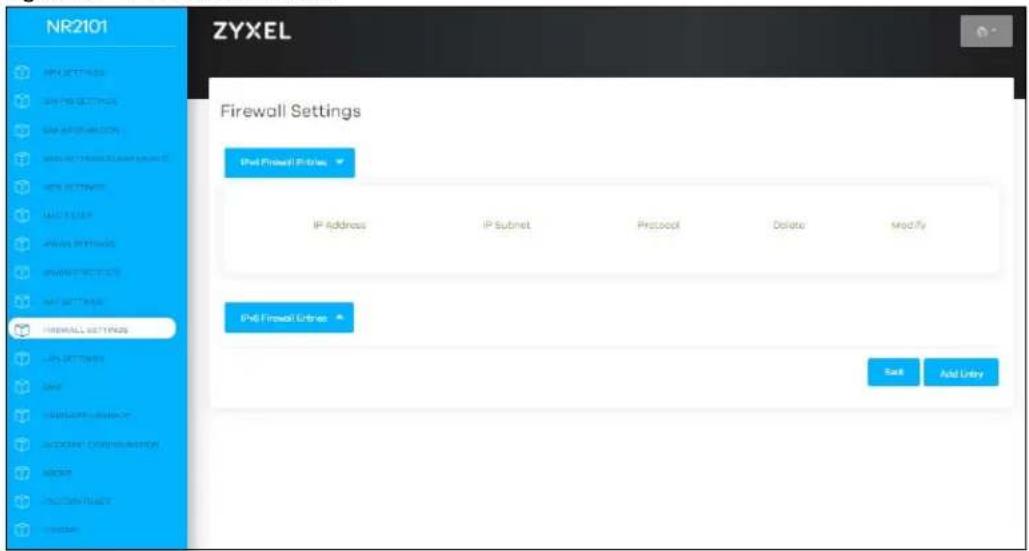
The following table describes the labels in this screen.
Table 36 IPv4 Firewall Entries
| LABEL DESCRIPTION | |
| IPv4 Firewall Entries | |
| IP Address This field displays the source IPv4 addresses to which this rule applies. | |
| IP Subnet This field displays subnet mask of the IPv4 addresses. | |
| Protocol | This field displays the protocol (None, TCP_UDP, TCP, UDP, ICMP, or ESP) used to transport the packets for which you want to apply the rule. |
| Delete | Click Delete to delete an existing firewall rule. |
| Modify | Click Modify to edit the firewall rule. |
| Add Entry | You can add a new schedule rule by clicking Add Entry. |
Figure 94 IPv6 Firewall Entries
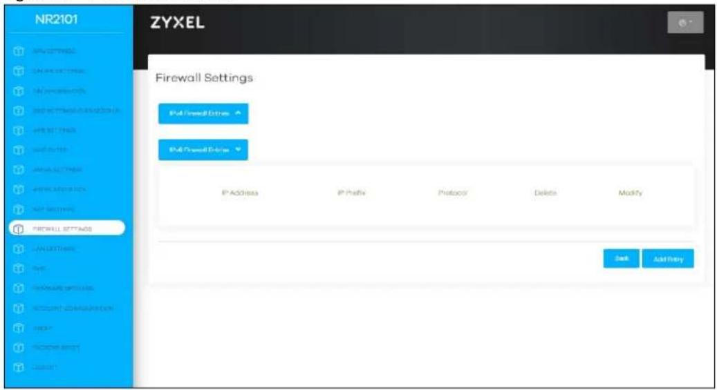
The following table describes the labels in this screen.
Table 37 IPv6 Firewall Entries
| LABEL DESCRIPTION | |
| IPv6 Firewall Entries | |
| IP Address This field displays the source IPv6 addresses to which this rule applies. | |
| IP Prefix | This field displays the IPv6 prefix that the NR2101 will advertise to its clients.Enter the IPv6 prefix for this interface if you want to use a static IP address. |
| Protocol | This field displays the protocol (None, TCP_UDP, TCP, UDP, ICMP, or ESP) used to transport the packets for which you want to apply the rule. |
| Delete | Click Delete to delete an existing firewall rule. |
| Modify | Click Modify to edit the firewall rule. |
| Add Entry | Y Click Add Entry to add a new schedule rule. |
CHAPTER 10 LAN Settings
10.1 Overview
DHCP (Dynamic Host Configuration Protocol, RFC 2131 and RFC 2132) allows individual clients to obtain TCP/IP configuration at start-up from a server. You can configure the NR2101 as a DHCP server or disable it. When configured as a server, the NR2101 provides the TCP/IP configuration for the clients. If DHCP service is disabled, you must have another DHCP server on your LAN, or else the computer must be manually configured.
10.1.1 What You Can Do
- Use the LAN Settings screen to enable the LAN DHCP server and view the current DHCP client information (Section 10.2 on page 92).
10.1.2 What You Need To Know
The following terms and concepts may help as you read through this chapter.
MAC Addresses
Every Ethernet device has a unique MAC (Media Access Control) address. The MAC address is assigned at the factory and consists of six pairs of hexadecimal characters, for example, 00:A0:C5:00:00:02. Find out the MAC addresses of your network devices if you intend to add them to the DHCP Client List screen.
IP Pool Setup
The NR2101 is pre-configured with a pool of 32 IP addresses starting from 192.168.1.33 to 192.168.1.64. This configuration leaves 31 IP addresses (excluding the NR2101 itself) in the lower range (192.168.1.2 to 192.168.1.32) for other server computers, for instance, servers for mail, FTP, TFTP, web, etc., that you may have.
10.2 LAN Settings
The NR2101 has the built-in DHCP server capability that assigns IP addresses to systems that support DHCP client capability. Use this screen to enable the DHCP server function. Click LAN SETTINGS and the following screen displays. Enter the IP address of the default gateway on the LAN. Enter the subnet mask in dotted decimal notation, for example 255.255.255.0. Select Enable or Disable in the LAN DHCP field to enable or disable the DHCP function on the NR2101. Enter the first and the last of the contiguous addresses in the IP address pool. Enter the time length the DHCP server allows the assigned IP address to be used.
Figure 95 LAN SETTINGS
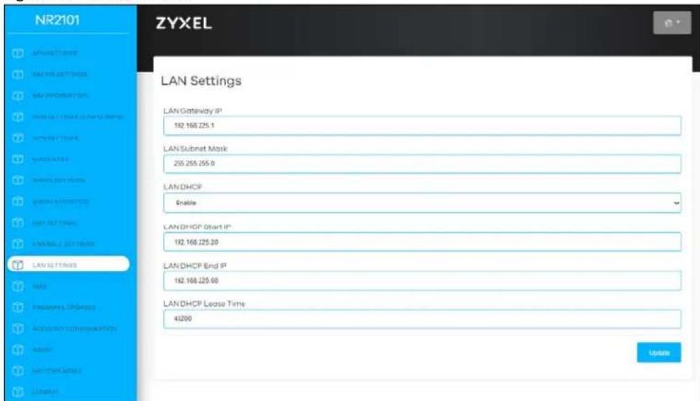
The following table describes the labels in this screen.
Table 38 LAN SETTINGS
| LABEL DESCRIPTION | |
| LAN Gateway IP This shows the LAN port's gateway IP address. | |
| LAN Subnet Mask This shows the LAN port's subnet mask. | |
| LAN DHCP Select Enable | to activate DHCP for LAN.DHCP (Dynamic Host Configuration Protocol, RFC 2131 and RFC 2132) allows individual clients (computers) to obtain TCP/IP configuration at startup from a server. Enable the DHCP server unless your ISP instructs you to do otherwise. Select Disable to stop the NR2101 from acting as a DHCP server. When configured as a server, the NR2101 provides TCP/IP configuration for the clients. If not, DHCP service is disabled and you must have another DHCP server on your LAN, or else the computers must be manually configured. When set as a server, fill in the following three fields. |
| LAN DHCP Start IP | This field specifies the first of the contiguous addresses in the IP address pool for LAN. |
| LAN DHCP End IP | This field specifies the last of the contiguous addresses in the IP address pool for LAN. |
| LAN DHCP Lease Time | This is the period of time the DHCP-assigned IP addresses is used. DHCP automatically assigns IP addresses to client devices when they log in. DHCP centralizes IP address management on central computers that run the DHCP server program. DHCP leases addresses, for a period of time, which means that past addresses are "recycled" and made available for future reassignment to other systems. |
| Update | Click Update to save your changes back to the NR2101. |
CHAPTER 11 SMS
11.1 Overview
This chapter shows you how to view the text messages.
SMS (Short Message Service) allows you to send and view the text messages that the NR2101 received from mobile devices or the service provider.
11.1.1 What You Can Do in this Chapter
- Use the SMS screen to view messages received on the NR2101 (Section 11.2 on page 94).
11.2 SMS-Inbox
Click SMS and then the following screen appears. Use this screen to view messages received by the NR2101.Click Write New SMS to create a new SMS message. Click Delete all to remove all of the previous SMS messages
Note: You can store an approximate total of 500 messages.
Figure 96 SMS
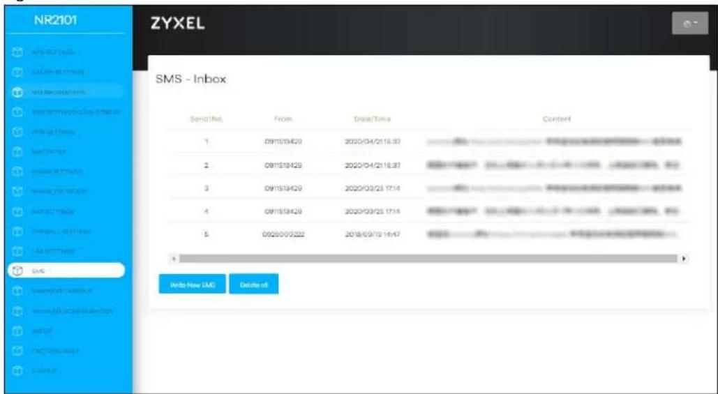
The following table describes the labels in this screen.
Table 39 SMS
| LABEL DESCRIPTION | |
| Serial No. This field displays the serial number of the message entries. | |
| From This field displays the telephone number of the sender. | |
| Date/Time This field displays the date and time the message was received. | |
| Content This field displays the content of the message. | |
11.3 Add New Message
Enter the phone number of the SMS message receiver in the Send to field. Enter your message in the Content filed. Click Send to send the message out.
Figure 97 Add new Message
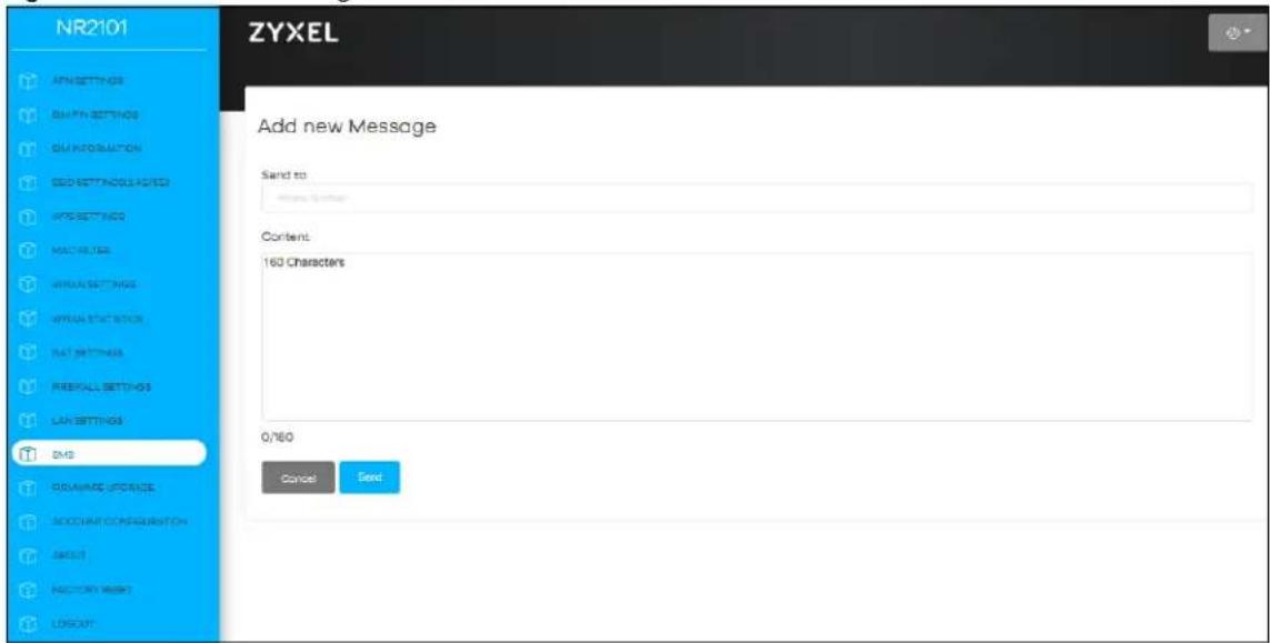
The following table describes the labels in this screen.
Table 40 Add new Message
| LABEL DESCRIPTION | |
| Send to Use this field to enter the phone number of the message receiver. | |
| Content Use this field to enter the content of the message. | |
| Send Click this to send the message. | |
| Cancel Click this to exit this screen without saving. | |
CHAPTER 12
Maintenance
12.1 Overview
Use the system screens to configure general NR2101 settings.
12.1.1 What You Can Do in this Chapter
- Use the Firmware Upgrade screen to upload new firmware to your NR2101 (Section 12.2 on page 96).
- Use the Account Configuration screen to change the NR2101's system password and configure the web configurator's inactive time (Section 12.3 on page 97).
- Use the About screen to view the detailed information of software and firmware on the NR2101 (Section 12.4 on page 98).
- Use the Factory Reset screen to reset your NR2101 settings back to the factory default mode(Section 12.5 on page 99).
- Use the Logout screen to log out of the Web Configurator (Section 12.6 on page 100).
12.2 Firmware Upgrade
This screen allows you to upload new firmware to your NR2101. You can download new firmware releases from your nearest Zyxel FTP site (or www.zyxel.com) to use to upgrade your NR2101's performance.
Only use firmware for your device's specific model.
To access this screen, click Firmware Upgrade. This screen displays the current firmware version and status of the NR2101. Click Upgrade From Local and the Select File tab appears. To update firmware, click Select File to select a file from you local drive to upload to the NR2101.
The upload process uses HTTP (Hypertext Transfer Protocol) and may take up to two minutes. After a successful upload, the system will reboot.
Firmware Over the Air (FOTA) allows for timely and automatic firmware upgrades. You can click Start Firmware Upgrade and check if any update is available.
Do NOT turn off the NR2101 while firmware upload is in progress!
Figure 98 Firmware Upgrade
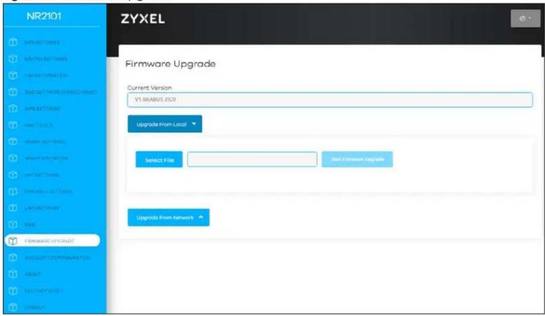
The following table describes the labels in this screen.
Table 41 Firmware Upgrade
| LABEL DESCRIPTION | |
| Current Version | This field displays the current firmware version number of the NR2101. |
| Upgrade From Local | Click this button to upload the firmware file to the NR2101 from a local drive. |
| Select File | Click this button to choose a file. |
| Upgrade From Network | Click this button to check if any new firmware is available online. |
12.3 Account Configuration
Click Account Configuration and the following screen appears. Use this screen to configure the NR2101's admin account settings. Enter your Session Timeout (Min) and then click Update Timeout to save the changes. To change your account password, enter the Old Password, New Password, and then re-enter the New Password to confirm. Click Update to save the changes.
Figure 99 Account Configuration
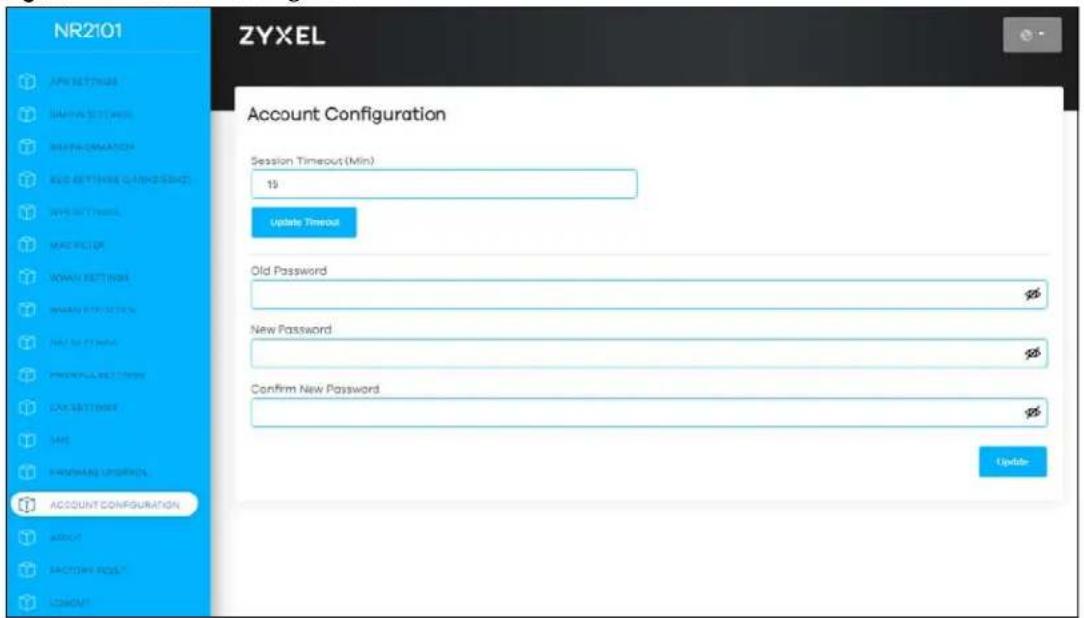
The following table describes the labels in this screen.
Table 42 Account Configuration
| LABEL DESCRIPTION | |
| Session Timeout (Min) | Enter how many minutes a management session can be left idle before the session times out and clickUpdate Timeoutto save your changes back to the NR2101. After it times out you have to log in with your password again. Very long idle timeouts may have security risks. A value of "0" means a management session never times out, no matter how long it has been left idle (not recommended). |
| Old Password | Enter the default password or the existing password you use to access the system in this field. |
| New Password | Enter your new system password of between 4 and 24 characters. Note that as you enter a password, the screen displays as dot (.) for each character you enter. The new password must contain one numeric, one lowercase, one upper case letter and one special character. |
| Confirm New Password | Enter the new password again in this field. |
| Update Click this | button to save your changes back to the NR2101. |
12.4 About
Use this screen to check the software and firmware information of your NR2101.
Figure 100 About
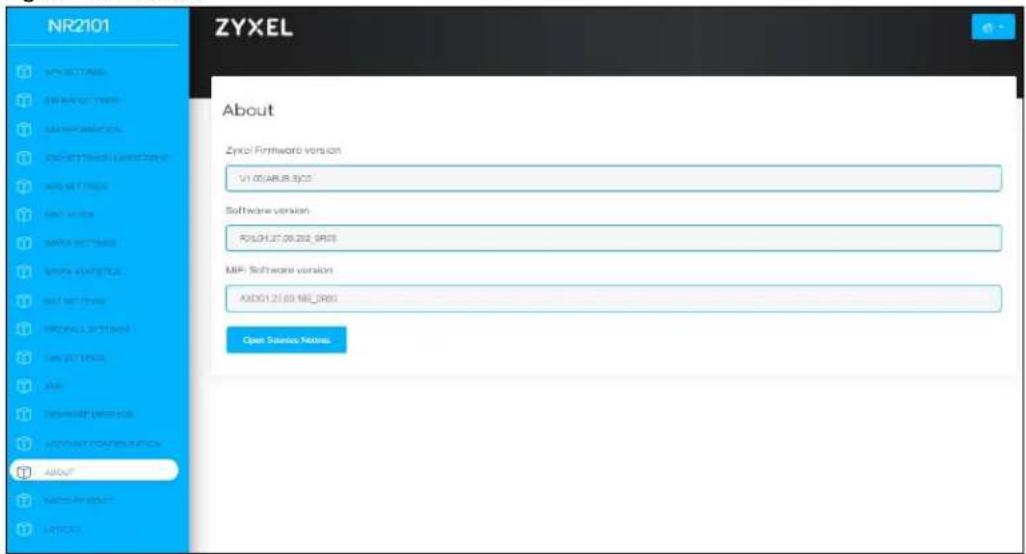
The following table describes the labels in this screen.
Table 43 About
| LABEL DESCRIPTION | |
| Zyxel Firmware version | Use this screen to view the current firmware version of the NR2101. |
| Software version | Use this screen to view the current software version of the NR2101. |
| MiFi Software version | Use this screen to view the current MiFi software version of the NR2101. |
| Open Source Notices | Click this to see the open source notices of the NR2101. |
Note: If you uploaded the default configuration file you may need to change the IP address of your computer to be in the same subnet as that of the default NR2101 IP address (192.168.225.1).
12.5 Factory Reset
Use this screen to reset the NR2101 to the factory default mode. Click FACTORY RESET, and the following pop-up window appears. Click OK to reboot the NR2101. This allows you to reboot the NR2101 without turning the power off. Wait a few minutes until the login screen appears. If the login screen does not appear, enter the default IP address (192.168.225.1) of the NR2101 in your web browser.
Figure 101 FACTORY RESET
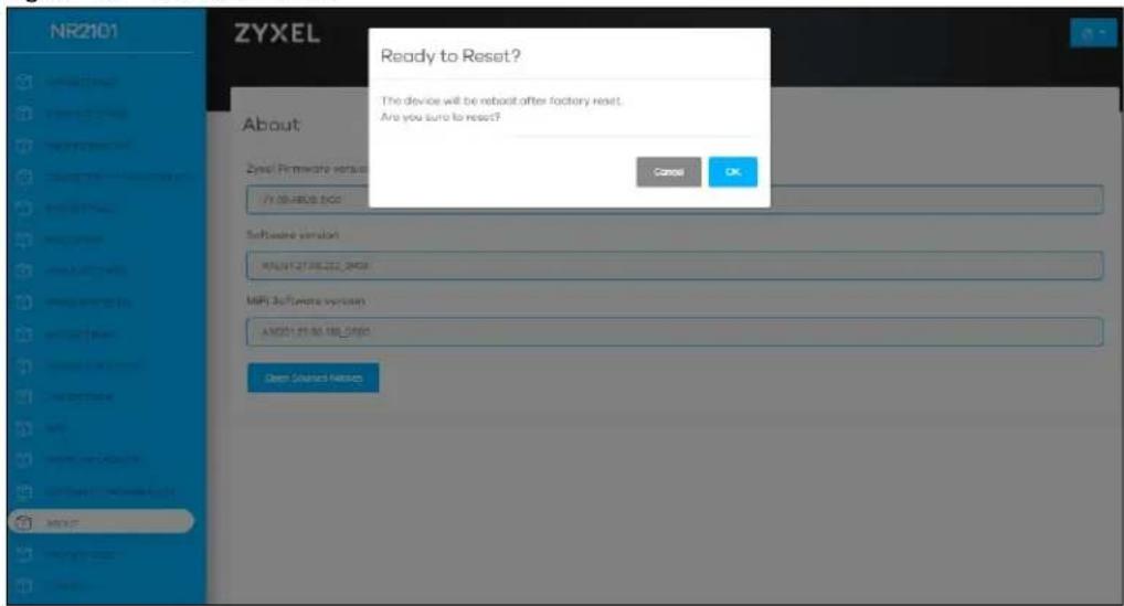
12.6 Logout
Use this screen to log out of the NR2101's web configurator. Click LOGOUT. The following screen appears. Click OK to log out.
Figure 102 Logout
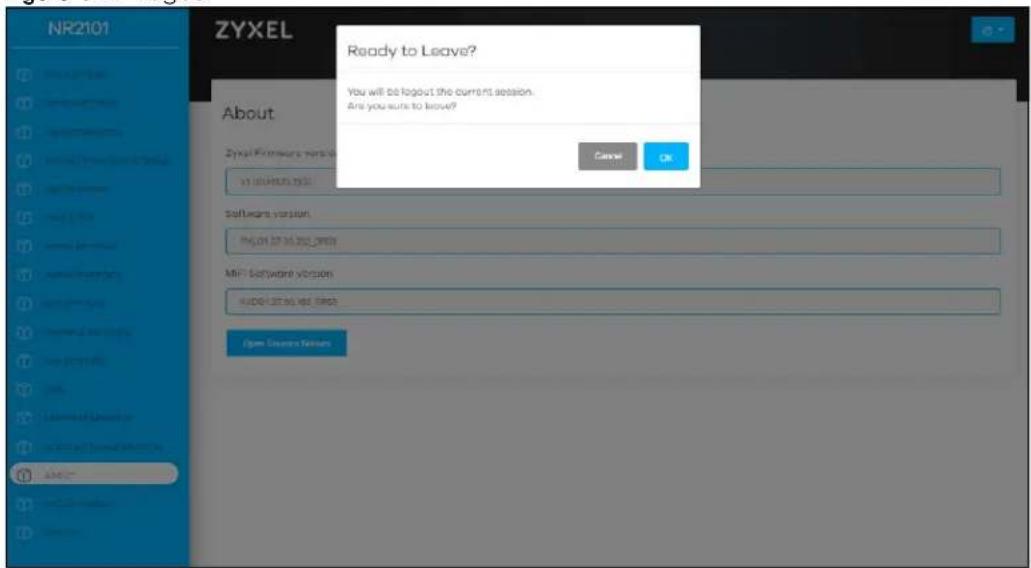
CHAPTER 13
Troubleshooting
13.1 Overview
Here are offers some suggestions to solve problems you might encounter. The potential problems are divided into the following categories.
- Power
• NR2101 Access and Login - Internet Access
- WiFi Internet Access
- WiFi Connections
13.2 Power
The NR2101 does not turn on. The LCD display is not on.
1 Make sure the battery is charged. Press the power button to turn the NR2101 on (Section 1.4 on page 11).
2 If the problem continues, contact the vendor.
13.3 NR2101 Access and Login
I forgot the IP address for the NR2101.
1 The default IP address is 192.168.225.1.
2 If you changed the IP address and have forgotten it, you have to reset the NR2101 to its factory defaults. To reset your NR2101, use the LCD touch screen to go to Settings >Restore Default and then select Restore.
I cannot see or access the Login screen in the Web Configurator.
1 Make sure you are using the correct IP address.
• The default IP address is 192.168.225.1.
- If you changed the IP address, use the new IP address.
- If you changed the IP address and have forgotten it, see the troubleshooting suggestions for I forgot the IP address for the NR2101.
2 Make sure the NR2101 is correctly installed and turned on. See the Quick Start Guide.
3 Make sure your Internet browser does not block pop-up windows and has JavaScripts and Java enabled.
4 Make sure your computer is connected to the NR2101.
5 Make sure the NR2101's WiFi LAN is enabled. You can enable or disable the NR2101's WiFi network using SSID Setting on the NR2101. See Section 7.2 on page 64.
6 Reset the NR2101 to its factory defaults, and try to access the NR2101 with the default IP address. To reset the NR2101, use the LCD touch screen to go to Settings >Restore Default and then select Restore. See Section 1.5.6.14 on page 32.
7 Disconnect your computer from the NR2101 and then connect once again.
8 If the problem continues, contact the vendor.
I forgot the password of the Web Configurator.
1 The default user name is admin. The default password is admin.
2 If this does not work, you have to reset the NR2101 to its factory defaults. Use a thin object to press the RESET button on the NR2101's side panel. Otherwise, use the LCD touch screen to reset your NR2101. Go to the Settings >Restore Default screen and then select Restore.
I can access the Login screen, but I cannot log in to the NR2101.
1 Make sure you have entered the user name and password correctly. The default user name is admin and the default password is admin. These fields are case-sensitive, so make sure [Caps Lock] is not on.
2 This can happen when you fail to log out properly from your last session. Try logging in again after five minutes.
3 Disconnect and connect to the NR2101 again.
4 If this does not work, you have to reset the NR2101 to its factory defaults. To reset your NR2101 use the LCD touch screen to go to Settings >Restore Default and then select Restore.
13.4 Internet Access
I cannot access the Internet through a 3G/4G/5G wireless WAN connection.
1 Make sure you insert a SIM card into the card slot before turning on the NR2101.
2 If your SIM card has a PIN code, connect to the Web Configurator (http://192.168.225.1) using the user name (Default: admin) and password (Default: admin) to unlock your SIM card.
3 Make sure your mobile access information (such as APN) is entered correctly. You can check this in the Web Configurator (http://192.168.225.1). The APN fields are case-sensitive, so make sure [Caps Lock] is not on. Check with your service provider for the correct APN if you do not have it.
4 Make sure your SIM card's account is valid and has an active data plan. Check your service contract or contact your service provider directly.
5 Make sure your data plan has not reached its limit.
6 If you are using a pre-paid SIM card, insert the SIM card on another mobile device to check if the SIM card still works. If the SIM card works without any problems on another mobile device, contact the vendor. Otherwise, contact your service provider.
7 Make sure you are in the ISP's coverage area.
8 If the problem continues, contact your ISP.
I cannot access the Internet anymore. I had access to the Internet (with the NR2101), but my Internet connection is not available anymore.
1 Reboot the NR2101.
2 Make sure the NR2101's WiFi network is enabled. You can enable NR2101's WiFi network on the LCD.
3 Make sure your SIM card's mobile data is enabled. Check this in the Web Configurator. (Section 7.6 on page 74).
4 If you have set a data limit, make sure you have not reached it yet. Check your data left in the Web Configurator.
5 If the problem continues, contact your ISP.
One of my WiFi clients cannot access the Internet anymore. They had access to the Internet (with the NR2101), but the Internet connection is not available anymore.
1 Make sure your WiFi client is not blocked. You can check this on the Web Configurator (See Section 7.5 on page 73).
2 Make sure your SIM card's mobile data is enabled. Check this on the Web Configurator (See Section 6.3 on page 59).
3 If you have set a data limit, make sure you have not reached it yet. You can check your data left in the Web Configurator.
4 Reboot the NR2101.
The Internet connection is slow or intermittent.
1 There might be a lot of traffic on the network. If the NR2101 is sending or receiving a lot of information, try closing some programs that use the Internet, especially peer-to-peer applications.
2 Check the signal strength on the NR2101 LCD screen. If the signal strength is low, try moving the NR2101 closer to the ISP's base station if possible, or try pointing it directly to the ISP's base station. Look around to see if there are any devices that might be interfering with the WiFi network (for example, microwaves, other WiFi networks, and so on).
3 Reboot the NR2101.
4 If the problem continues, contact the network administrator or vendor.
13.5 WiFi Internet Access
What factors may cause intermittent or unstabled WiFi connection? How can I solve this problem? The following factors may cause interference:
- Obstacles: walls, ceilings, furniture, and so on.
• Building Materials: metal doors, aluminum studs.
• Electrical devices: microwaves, monitors, electric motors, cordless phones, and other WiFi devices.
To optimize the speed and quality of your WiFi connection, you can:
- Move your WiFi clientdevice closer to the AP if the signal strength is low.
- Reduce WiFi interference that may be caused by other WiFi networks or surrounding WiFi electronics such as cordless phones.
- Place the AP where there are minimum obstacles (such as walls and ceilings) between the AP and the WiFi client.
- Reduce the number of WiFi clients connecting to the same AP simultaneously, or add additional APs if necessary.
- Try closing some programs that use the Internet, especially peer-to-peer applications. If the WiFi client is sending or receiving a lot of information, it may have too many programs open that use the Internet.
13.6 WiFi Connections
I cannot access the NR2101.
1 Make sure WiFi is enabled on the NR2101. You can enable or disable the NR2101's WiFi network using the SSID Setting on the NR2101. See Section 1.5.4 on page 16.
2 Make sure the WiFi adapter (installed on your computer) is IEEE 802.11 compatible and supports the same WiFi standard as the NR2101's active radio.
3 Make sure your device (with a WiFi adapter installed) is within the transmission range of the NR2101.
4 Make sure you are using the correct WiFi network name and password to connect to your NR2101. Check your WiFi network settings by reexamining the network name Name (SSID) and/or Password in the Web Configurator (Section 7.2 on page 64).
5 If you changed your network WiFi Name (SSID) and/or Password you will be automatically disconnected from the NR2101. Try reconnecting to the network wirelessly with the new network WiFi Name (SSID) and/or Password.
One of my WiFi clients cannot access the NR2101.
1 Make sure the WiFi LAN is enabled on the NR2101. You can enable or disable the NR2101's WiFi network using the SSID Setting on the NR2101. See Section 1.5.4 on page 16.
2 Make sure the WiFi adapter (installed on your computer) is IEEE 802.11 compatible and supports the same WiFi standard as the NR2101's active radio.
3 Make sure your WiFi client's device (with a WiFi adapter installed) is within the transmission range of the NR2101.
4 Make sure your WiFi client is using the correct WiFi network name Name (SSID) and password Password to connect to your NR2101 (Section 7.2 on page 64).
13.7 Getting More Troubleshooting Help
Search for support information for your model at www.zyxel.com for more troubleshooting suggestions.
APPENDIX A
Customer Support
In the event of problems that cannot be solved by using this manual, you should contact your vendor. If you cannot contact your vendor, then contact a Zyxel office for the region in which you bought the device.
For Zyxel Communications offices, see https://service-provider.zyxel.com/global/en/contact-us for the latest information.
For Zyxel Networks offices, see https://www.zyxel.com/index.shtml for the latest information.
Please have the following information ready when you contact an office.
Required Information
- Product model and serial number.
- Warranty Information.
- Date that you received your device.
- Brief description of the problem and the steps you took to solve it.
Corporate Headquarters (Worldwide)
Taiwan
• Zyxel Communications Corporation
- https://www.zyxel.com
Asia
China
• Zyxel Communications (Shanghai) Corp.
Zyxel Communications (Beijing) Corp.
Zyxel Communications (Tianjin) Corp.
- https://www.zyxel.com/cn/zh/
India
• Zyxel Technology India Pvt Ltd
- https://www.zyxel.com/in/en/
Kazakhstan
• Zyxel Kazakhstan
- https://www.zyxel.kz
Korea
• Zyxel Korea Corp.
- http://www.zyxel.kr
Malaysia
• Zyxel Malaysia Sdn Bhd.
- http://www.zyxel.com.my
Pakistan
• Zyxel Pakistan (Pvt.) Ltd.
- http://www.zyxel.com.pk
Philippines
• Zyxel Philippines
- http://www.zyxel.com.ph
Singapore
• Zyxel Singapore Pte Ltd.
- http://www.zyxel.com.sg
Taiwan
• Zyxel Communications Corporation
- https://www.zyxel.com/tw/zh/
Thailand
• Zyxel Thailand Co., Ltd
- https://www.zyxel.com/th/th/
Vietnam
• Zyxel Communications Corporation-Vietnam Office
- https://www.zyxel.com/vn/vi
Europe
Belarus
- Z y x e l B Y
- https://www.zyxel.by
Bulgaria
• Z y x e l България
- https://www.zyxel.com/bg/bg/
Czech Republic
• Zyxel Communications Czech s.r.o
- https://www.zyxel.com/cz/cs/
Denmark
• Zyxel Communications A/S
- https://www.zyxel.com/dk/da/
Finland
• Zyxel Communications
- https://www.zyxel.com/fi/fi/
France
• Zyxel France
- https://www.zyxel.fr
Germany
• Zyxel Communications Italy
- https://www.zyxel.com/it/it/
Netherlands
- Zyxel Benelux
- https://www.zyxel.com/nl/nl/
Norway
• Zyxel Communications
- https://www.zyxel.com/no/no/
Poland
• Zyxel Communications Poland
- https://www.zyxel.com/pl/pl/
Romania
• Zyxel Romania
- https://www.zyxel.com/ro/ro
Russia
• Zyxel Communications Czech s.r.o. organizacna zlozka
- https://www.zyxel.com/sk/sk/
Spain
• Zyxel Turkey A.S.
- https://www.zyxel.com/tr/tr/
UK
• Zyxel Communications UK Ltd.
- https://www.zyxel.com/uk/en/
Ukraine
• Zyxel Ukraine
- http://www.ua.zyxel.com
South America
Argentina
• Zyxel Communications Corporation
- https://www.zyxel.com/co/es/
Brazil
• Zyxel Communications Brasil Ltda.
- https://www.zyxel.com/br/pt/
Colombia
• Zyxel Communications Corporation
- https://www.zyxel.com/co/es/
Ecuador
• Zyxel Communications Corporation
- https://www.zyxel.com/co/es/
South America
• Zyxel Communications Corporation
- https://www.zyxel.com/co/es/
Middle East
Israel
• Zyxel Communications Corporation
- http://il.zyxel.com/
North America
USA
• Zyxel Communications, Inc. - North America Headquarters
- https://www.zyxel.com/us/en/
APPENDIX B
Legal Information
Copyright
Copyright © 2021 by Zyxel and/or its affiliates.
The contents of this publication may not be reproduced in any part or as a whole, transcribed, stored in a retrieval system, translated into any language, or transmitted in any form or by any means, electronic, mechanical, magnetic, optical, chemical, photocopying, manual, or otherwise, without the prior written permission of Zyxel and/or its affiliates.
Published by Zyxel and/or its affiliates. All rights reserved.
Disclaimer
Zyxel does not assume any liability arising out of the application or use of any products, or software described herein. Neither does it convey any license under its patent rights nor the patent rights of others. Zyxel further reserves the right to make changes in any products described herein without notice. This publication is subject to change without notice.
Regulatory Notice and Statement
EUROPEAN UNION

The following information applies if you use the product within the European Union.
Declaration of Conformity with Regard to EU Directive 2014/53/EU (Radio Equipment Directive, RED)
- Compliance information for wireless products relevant to the EU and other Countries following the EU Directive 2014/53/EU (RED). And this product may be used in all EU countries (and other countries following the EU Directive 2014/53/EU) without any limitation except for the countries mentioned below table:
- In the majority of the EU and other European countries, the 5GHz bands have been made available for the use of wireless local area networks (LANs). Later in this document you will find an overview of countries in which additional restrictions or requirements or both are applicable. The requirements for any country may evolve. Zyxel recommends that you check with the local authorities for the latest status of their national regulations for the 5GHz wireless LANs.
- If this device for operation is in the band 5150-5350 MHz. It is for indoor use only.
- The radio wave exposure guidelines use a unit of measurement known as the Specific Absorption Rate, or SAR. The SAR limit for mobile device is 2W/kg. Tests for SAR are conducted using standard operating positions with the device transmitting at its highest certified power level in all tested frequency bands. The highest standalone SAR value for a single frequency band is 1.186W/kg. The highest simultaneous SAR value is 1.977W/kg.
- The maximum RF power operating for each band as follows: - WIFI
The band 2.400 to 2.483.5 MHz is 97.72 mW.
The band 5,150 to 5,250 MHz is 198.15 mW.
WCDMA
The WCDMA Band I is 24dBm.
The WCDMA Band VIII is 24dBm.
• LTE
The LTE Band 1 is 23dBm.
The LTE Band 3 is 23dBm.
The LTE Band 7 is 23dBm.
The LTE Band 8 is 23dBm.
The LTE Band 20 is 23dBm.
The LTE Band 28 is 23dBm.
The LTE Band 38 is 23dBm.
• NR
The NR Band n1 is 23dBm.
The NR Band n3 is 23dBm.
The NR Band n20 is 23dBm.
The NR Band n28 is 23dBm.
The NR Band n77 is 23dBm.
The NR Band n78 is 23dBm.
| Български(Bulgarian) | С настоящото Зyxел декларира, че това оборудване е в съответствие със съществените изисквания и другите приложими разпоредбите на Директива 2014/53/EC.National RestrictionsThe Belgian Institute for Postal Services and Telecommunications (BIPT) must be notified of any outdoor wireless link having a range exceeding 300 meters. Please check http://www.bipt.be for more details.Draadloze verbindingen voor buitengebruik en met een reikwijdte van meer dan 300 meter dienen aangemeld te worden bij het Belgisch Instituut voor postaiensten en telecommunicatie (BIPT). Zie http://www.bipt.be voor meer gegevens.Les liaisons sans fil pour une utilisation en extérieur d'une distance supérieure à 300 mètres doivent être notifiées à l'Institut Belge des services Postaux et des Télécommunications (IBPT). Visitez http://www.ibpt.be pour de plus amples détails. |
| Español(Spanish) | Por medio de la presente Zyxel declara que el equipo cumple con los requisitos esenciales y cualesquiera otras disposiciones aplicables o exigibles de la Directiva 2014/53/UE. |
| Čeština(Czech) | Zyxel fímto prohiašuje, že tento zařízení je ve shodě se základními požadavky a dalšími příslušnými ustanoveními směrnice 2014/53/EU. |
| Dansk (Danish) | Undertegnede Zyxel erklærer herved, at følgende udstyr udstyr overholder de væsentlige krav og øvrige relevante krav i direktiv 2014/53/EU.National RestrictionsIn Denmark, the band 5150 - 5350 MHz is also allowed for outdoor usage.I Danmark må frekvensbåndet 5150 - 5350 også anvendes udendørs. |
| Deutsch(German) | Hiermit erklärt Zyxel, dass sich das Gerät Ausstattung in Übereinstimmung mit den grundlegenden Anforderungen und den Übrigen einschlägigen Bestimmungen der Richtlinie 2014/53/EU befindet. |
| Eesti keel(Estonian) | Käesolevaga kinnitab Zyxel seadme seadmed vastavust direktivi 2014/53/EL põhinõuetele ja nimetatud direktivist tulenevatele teistele asjakohastele sätetele. |
| Ελληνικά(Greek) | ΜΕ ΤΗΝ ΠΑΡΟΥΣΑ Ζyxel ΔΗΛΩΝΕΙ ΟΤΙ εξοπλισμός ΣΥΜΜΟΡΦΩΝΕΤΑΙ ΠΡΟΣ ΤΙΣ ΟΥΣΙΩΔΕΙΣ ΑΠΑΙΤΗΣΕΙΣ ΚΑΙ ΤΙΣ ΛΟΙΠΕΣ ΣΧΕΤΙΚΕΣ ΛΙΑΤΑΞΕΙΣ ΤΗΣ ΟΛΗΓΙΑΣ 2014/53/EE. |
| English | Hereby, Zyxel declares that this device is in compliance with the essential requirements and other relevant provisions of Directive 2014/53/EU. |
| Français(French) | Par la présente Zyxel déclare que l'appareil équipements est conforme aux exigences essentielles et aux autres dispositions pertinentes de la directive 2014/53/UE. |
| Hrvalski(Croatian) | Zyxel ovime izjavljuje da je rodijska oprema lipa u skladu s Direklivom 2014/53/UE. |
| Íslenska(Icelandic) | Hér með lýsir, Zyxel því yfir að þessi búnaður er í samræmi við grunnkröfur og önnur viðeigandi ákvæði třlskipunar 2014/53/UE. |
| Italiano (Italian) | Con la presente Zyxel dichiara che questo attrezzatura è conforme ai requisiti essenziali ed alle altre disposizioni pertinenti stabilite dalla direttiva 2014/53/UE.National RestrictionsThis product meets the National Radio Interface and the requirements specified in the National Frequency Allocation Table for Italy. Unless this wireless LAN product is operating within the boundaries of the owner's property, its use requires a "general authorization." Please check http://www.sviluppoeconomico.gov.it/ for more details.Questo prodotto è conforme alla specifiche di Interfaccia Radio Nazionali e rispetta il Piano Nazionale di ripartizione delle frequenze in Italia. Se non viene installato all 'intemo del proprio fondo, l'utilizzo di prodotti Wireless LAN richiede una "Autorizzazione Generale". Consultare http://www.sviluppoeconomico.gov.it/ per maggiori dettagii. |
| Latviešu valoda(Latvian) | Ar šo Zyxel deklarē, ka iekārtas albilst Direktivas 2014/53/ES būtiskajām prasībām un citiem ar to saislītajiem noteikumiem.National RestrictionsThe outdoor usage of the 2.4 GHz band requires an authorization from the Electronic Communications Office. Please check http://www.esd.lv for more details.2.4 GHz frekvenėu joslas izmantoðanai ārpus telpām nepiecieðama afīauja no Elektronisko sakaru direkcijas. Vairāk informācijas: http://www.esd.lv. |
| Lietuviių kalba(Lithuanian) | Šiuo Zyxel deklaruoja, kad šis jranga alitinka esminius reikalavimus ir kilas 2014/53/ES Direktyvos nuostalas. |
| Magyar(Hungarian) | Alulírott, Zyxel nyilatkozom, hogy a berendezés megfelel a vonatkozó alapvető követelményeknek és az 2014/53/EU irányelv egyéb előírásainak. |
| Malti (Maltese) | Hawnhekk, Zyxel, jiddikjara li dan taghmir jikkonforma mal-ħtiġijiet essenzjali u ma provvedimenti ohrajn relevanti li hemm fid-Dirrettiva 2014/53/UE. |
| Nederlands(Dutch) | Hierbij verklaart Zyxel dat het loestel uitrusting in overeenstemming is met de essenliële eisen en de andere relevante bepalingen van richtlijn 2014/53/EU. |
| Polski (Polish) | Niniejszym Zyxel oświadcza, że sprzęt jest zgodny z zasadniczymi wymogami oraz pozostałymi stosownymi postanowieniami Dyrektywy 2014/53/UE. |
| Português (Portuguese) | Zyxel declara que este equipamento eslá conforme com os requisitos essenciais e outras disposições da Directiva 2014/53/UE. |
| Română (Romanian) | Prin prezenta, Zyxel declară că acest echipament este în conformitate cu cerintele esentiale și alte prevederi relevante ale Directivei 2014/53/UE. |
| Slovenčina (Slovak) | Zyxel lýmto vyhlasuje, že zariadenia spíňa základné požiadavky a všetky príslušné ustanovenia Smernice 2014/53/EÚ. |
| Slovenščina (Slovene) | Zyxel izjavlja, da je ta oprema v skladu z bistvenimi zahtevami in ostalimi relevantnimi določili direktive 2014/53/EU. |
| Suomi (Finnish) | Zyxel vakuuttaa täten että laitteet tyyppinen laite on direktlivin 2014/53/EU oleellisten vaatimusten ja sită koskevien direktlivin muiden ehtojen mukainen. |
| Svenska (Swedish) | Härmed intygar Zyxel all denna ultrusning slår I överensstämmelse med de väsentliga egenskapskrav och övriga relevanta bestämmelser som framgår av direktiv 2014/53/EU. |
| Norsk (Norwegian) | Erklaerer herved Zyxel at dette utstyret er I samsvar med de grunnleggende kravene og andre relevante bestemmelser I direktiv 2014/53/EU. |
Notes:
- Although Norway, Switzerland and Liechtenstein are not EU member states, the EU Directive 2014/53/EU has also been implemented in those countries.
- The regulatory limits for maximum output power are specified in EIRP. The EIRP level (in dBm) of a device can be calculated by adding the gain of the antenna used (specified in dBi) to the output power available at the connector (specified in dBm).
List of national codes
| COUNTRY ISO 3166 2 LETTER CODE COUNTRY ISO 3166 2 LETTER CODE | |||
| Austria AT Liechtenstein LI | |||
| Belgium BE Lithuania LT | |||
| Bulgaria BG Luxembourg | LU | ||
| Croatia | HR | Malta | MT |
| Cyprus | CY | Netherlands | NL |
| Czech Republic | CZ | Norway NO | |
| Denmark | DK | Poland | PL |
| Estonia | EE Portugal | PT | |
| Finland | FI | Romania RO | |
| France | FR Serbia | RS | |
| Germany | DE | Slovakia | SK |
| Greece GR Slovenia | SI | ||
| Hungary | HU | Spain | ES |
| Iceland | IS | Switzerland | CH |
| Ireland | IE | Sweden SE | |
| Italy | IT | Turkey | TR |
| Latvia | LV United Kingdom | GB | |
Safety Warnings
- Do not use this product near water, for example, in a wet basement or near a swimming pool.
- Do not expose your device to dampness, dust or corrosive liquids.
- Do not store things on the device.
- Do not obstruct the device ventilation slots as insufficient airflow may harm your device. For example, do not place the device in an enclosed space such as a box or on a very soft surface such as a bed or sofa.
- Do not install, use, or service this device during a thunderstorm. There is a remote risk of electric shock from lightning.
- Connect ONLY suitable accessories to the device.
- Do not open the device or unit. Opening or removing covers can expose you to dangerous high voltage points or other risks.
• Only qualified service personnel should service or disassemble this device. Please contact your vendor for further information. - Make sure to connect the cables to the correct ports.
- Place connecting cables carefully so that no one will step on them or stumble over them.
• Always disconnect all cables from this device before servicing or disassembling. - Do not remove the plug and connect it to a power outlet by itself; always attach the plug to the power adaptor first before connecting it to a power outlet.
-
Do not allow anything to rest on the power adaptor or cord and do NOT place the product where anyone can walk on the power adaptor or cord.
-
Please use the provided or designated connection cables/power cables/ adaptors. Connect it to the right supply voltage (for example, 110V AC in North America or 230V AC in Europe). If the power adaptor or cord is damaged, it might cause electrocution. Remove it from the device and the power source, repairing the power adapter or cord is prohibited. Contact your local vendor to order a new one.
- Do not use the device outside, and make sure all the connections are indoors. There is a remote risk of electric shock from lightning.
- CAUTION: Risk of explosion if battery is replaced by an incorrect type, dispose of used batteries according to the instruction. Dispose them at the applicable collection point for the recycling of electrical and electronic devices. For detailed information about recycling of this product, please contact your local city office, your household waste disposal service or the store where you purchased the product.
- The following warning statements apply, where the disconnect device is not incorporated in the device or where the plug on the power supply cord is intended to serve as the disconnect device,
- For permanently connected devices, a readily accessible disconnect device shall be incorporated external to the device;
- For pluggable devices, the socket-outlet shall be installed near the device and shall be easily accessible.
Environment Statement
Disposal and Recycling Information
The symbol below means that according to local regulations your product and/or its battery shall be disposed of separately from domestic waste. If this product is end of life, take it to a recycling station designated by local authorities. At the time of disposal, the separate collection of your product and/or its battery will help save natural resources and ensure that the environment is sustainable development.
Various symbols are used in this product to ensure correct usage. To prevent danger to the user and others, and to prevent properly damage. The meaning of these symbols are described below. It is important that you read these descriptions thoroughly and fully understand the contents.
Explanation of the Symbols
| SYMBOL EXPLANATION | |
 | Alternating current (AC):AC is an electric current in which the flow of electric charge periodically reverses direction. |
 | Direct current (DC):DC if the unidirectional flow or movement of electric charge carriers. |
 | Earth; ground:A wiring terminal intended for connection of a Protective Earthing Conductor. |
 | Class II equipment:The method of protection against electric shock in the case of class II equipment is either double insulation or reinforced insulation. |
Viewing Certifications
Go to http://www.zyxel.com to view this product's documentation and certifications.
Zyxel Limited Warranty
Zyxel warrants to the original end user (purchaser) that this product is free from any defects in material or workmanship for a specific period (the Warranty Period) from the date of purchase. The Warranty Period varies by region. Check with your vendor and/or the authorized Zyxel local distributor for details about the Warranty Period of this product. During the warranty period, and upon proof of purchase, should the product have indications of failure due to faulty workmanship and/or materials, Zyxel will, at its discretion, repair or replace the defective products or components without charge for either parts or labor, and to whatever extent it shall deem necessary to restore the product or components to proper operating condition. Any replacement will consist of a new or re-manufactured functionally equivalent product of equal or higher value, and will be solely at the discretion of Zyxel. This warranty shall not apply if the product has been modified, misused, tampered with, damaged by an act of God, or subjected to abnormal working conditions.
Note
Repair or replacement, as provided under this warranty, is the exclusive remedy of the purchaser. This warranty is in lieu of all other warranties, express or implied, including any implied warranty of merchantability or fitness for a particular use or purpose. Zyxel shall in no event be held liable for indirect or consequential damages of any kind to the purchaser.
To obtain the services of this warranty, contact your vendor. You may also refer to the warranty policy for the region in which you bought the device at http://www.zyxel.com/web/support_warranty_info.php.
Registration
Register your product online at www.zyxel.com to receive e-mail notices of firmware upgrades and related information.
Open Source Licenses
This product may contain in part some free software distributed under GPL license terms and/or GPL-like licenses. To request the source code covered under these licenses: for Zyxel Communication products, please go to: https://service-provider.zyxel.com/global/en/gpl-oss-software-notice for Zyxel Network products, please go to: https://www.zyxel.com/form/gpl-oss_software_notice.shlml
Index
A
Address Assignment 57
B
Broadband 56
C
certifications 114
viewing 116
channel 63
contact information 107
copyright 112
current date/time 98
customer support 107
D
date 98
DHCP 92
see also Dynamic Host Configuration Protocol
DHCP server 92
disclaimer 112
DNS Server 57
Domain Name System. See DNS.
Dynamic Host Configuration Protocol 92
E
ESSID 105
F
filters
MAC address 73
Firewall
guidelines 87
firewall
stateful inspection 86
G
General wireless LAN screen 64
|
Internet Protocol version 6 57
IPv6 57
addressing 57
prefix 58
prefix length 58
L
LAN
IP pool setup 92
LEDs 13
M
MAC address 63
filter 73
MAC address filter 63
MAC authentication 73
N
NAT 80
overview 80
port forwarding 84
see also Network Address Translation
server sets 84
Network Address Translation 80
0
overview 10
P
Port forwarding 84
default server 84
example 84
port numbers
services
s
Service Set IDentification 65, 66
Service Set IDentity. See SSID.
SSID 63, 65, 66
stateful inspection firewall 86
status 53
T
TCP/IP configuration 92
time 98
trigger port 85
Trigger port forwarding 85
example 85
process 85
W
WAN (Wide Area Network) 56
warranty 116
note 116
Wi-Fi 62
wireless channel 105
wireless LAN 62, 105
MAC address filter 73
Wireless network
channel 63
MAC address filter 63
security 63
SSID 63
Wireless security 63
overview 63
type 63
wireless security 105
Wireless tutorial 50
Wizard setup 42

- Related Documentation
- Contents Overview
- User's Guide 9
- Technical Reference 55
- Table of Contents
- Chapter 4
- Tutorials 46
- Chapter 5
- Status....53
- Part II: Technical Reference....55
- Chapter 6
- APN & SIM PIN....56
- Chapter 7
- WLAN & WWAN....62
- Chapter 8
- NAT 80
- Chapter 9 Firewall....86
- Chapter 10 LAN Settings....92
- Chapter 11 SMS....94
- Chapter 12 Maintenance ....96
- Chapter 13 Troubleshooting....101
- Document Conventions
- Warnings and Notes
- Warnings tell you about things that could harm you or your device.
- Syntax Conventions
- Icons Used in Figures
- PART I
- User's Guide
- CHAPTER 1
- Get to Know Your NR2101
- Overview
- Applications
- Ways to Manage the NR2101
- - Web Configurator
- Hardware Description
- Hardware Installation
- LCD Screens
- The Home & Menu Screen
- Connection Guide
- Power Saving
- SSID
- SMS
- Settings
- WPS
- WiFi 2.4 G
- WiFi 5G
- Connected Users
- Profile management
- Data Usage
- Data Roaming
- Network Settings
- PIN Management
- Password Lock
- Language
- Time Setting
- FW Upgrade
- Restore Default
- About Settings
- CHAPTER 2
- Web Configurator
- Introduction
- Accessing the Web Configurator
- Navigating the Web Configurator
- Title Bar
- The Main Window
- Navigation Panel
- CHAPTER 3
- Setup Wizard
- Overview
- Access the Setup Wizard
- Use the Setup Wizard
- CHAPTER 4 Tutorials
- Overview
- Set Up Your WiFi Network
- Connect to the NR2101 WiFi Network
- Set Up a WiFi Network Using WPS
- PIN Configuration
- Configure the MAC Address Filter
- CHAPTER 5 Status
- Overview
- Status
- PART II
- Technical Reference
- APN & SIM PIN
- Overview
- What You Can Do in this Chapter
- What You Need To Know
- 3G
- 4G
- 5G
- DNS Server Address Assignment
- IPv6 Introduction
- IPv6 Addressing
- IPv6 Prefix and Prefix Length
- IPv6 Subnet Masking
- APN Settings
- SIM PIN Settings
- SIM Information
- WLAN & WWAN
- Overview
- What You Can Do in this Chapter
- What You Need to Know
- WiFi Security Overview
- SSID
- MAC Address Filter
- WPS
- SSID Settings(2.4GHz/5GHz)
- SSID WiFi QR Code
- WiFi Security
- No Security
- WPA-PSK
- WPA2-PSK
- WPA3/WPA2 mixed mode
- WPS Settings
- MAC Filter
- WWAN Settings
- IPv4/IPv6 WWAN Settings
- WWAN Statistics
- CHAPTER 8 NAT
- Overview
- What You Can Do
- What You Need to Know
- Inside/ Outside
- Global/Local
- NAT
- NAT Types
- NAT Settings
- Technical Reference
- NAT Port Forwarding: Services and Port Numbers
- NAT Port Forwarding Example
- Trigger Port Forwarding
- Trigger Port Forwarding Example
- Two Points To Remember About Trigger Ports
- CHAPTER 9 Firewall
- Overview
- What You Can Do
- What You Need To Know
- About the NR2101 Firewall
- Guidelines For Enhancing Security With Your Firewall
- Firewall Settings
- IPv4/IPv6 Firewall Entry
- CHAPTER 10 LAN Settings
- Overview
- What You Can Do
- What You Need To Know
- MAC Addresses
- IP Pool Setup
- LAN Settings
- CHAPTER 11 SMS
- Overview
- What You Can Do in this Chapter
- SMS-Inbox
- Add New Message
- CHAPTER 12
- Maintenance
- Overview
- What You Can Do in this Chapter
- Firmware Upgrade
- Only use firmware for your device's specific model.
- Account Configuration
- About
- Factory Reset
- Logout
- CHAPTER 13
- Troubleshooting
- Overview
- Power
- NR2101 Access and Login
- I cannot see or access the Login screen in the Web Configurator.
- I forgot the password of the Web Configurator.
- I can access the Login screen, but I cannot log in to the NR2101.
- Internet Access
- WiFi Internet Access
- WiFi Connections
- Getting More Troubleshooting Help
- APPENDIX A
- Customer Support
- Required Information
- Corporate Headquarters (Worldwide)
- Taiwan
- Asia
- China
- India
- Kazakhstan
- Korea
- Malaysia
- Pakistan
- Philippines
- Singapore
- Thailand
- Vietnam
- Europe
- Belarus
- Bulgaria
- Czech Republic
- Denmark
- Finland
- France
- Germany
- Netherlands
- Norway
- Poland
- Romania
- Russia
- Spain
- UK
- Ukraine
- South America
- Argentina
- Brazil
- Colombia
- Ecuador
- Middle East
- Israel
- North America
- USA
- APPENDIX B
- Legal Information
- Copyright
- Disclaimer
- Regulatory Notice and Statement
- EUROPEAN UNION
- Declaration of Conformity with Regard to EU Directive 2014/53/EU (Radio Equipment Directive, RED)
- • NR
- Notes:
- Safety Warnings
- Environment Statement
- Disposal and Recycling Information
- Viewing Certifications
- Zyxel Limited Warranty
- Note
- Registration
- Open Source Licenses
- Index
- A
- B
- C
- D
- E
- F
- G
- |
- L
- M
- N
- 0
- P
- s
- T
- W
Brand : ZYXEL
Model : NR2101
Category : Wi-Fi Access Point