DFH4180 (2019) - Automotive Dongfeng - Free user manual and instructions
Find the device manual for free DFH4180 (2019) Dongfeng in PDF.


User questions about DFH4180 (2019) Dongfeng
0 question about this device. Answer the ones you know or ask your own.
Ask a new question about this device
Download the instructions for your Automotive in PDF format for free! Find your manual DFH4180 (2019) - Dongfeng and take your electronic device back in hand. On this page are published all the documents necessary for the use of your device. DFH4180 (2019) by Dongfeng.
USER MANUAL DFH4180 (2019) Dongfeng
Dongfeng DFH4180 Series Vehicles
SEMI-TRAILER TRACTOR
User's Manual
Dongfeng Commercial Vehicle Co., Ltd.
July 2019
Foreword
Thanks for purchasing and using Dongfeng motor vehicles. We sincerely hope that they will bring you infinite wealth.
It is our common objective to optimize your vehicle, which, however, to a certain extent, depends on your familiarity with the vehicle and careful and comprehensive maintenance. You are appreciated to go through this manual and thus to get familiar with operation procedures therein before you operate the vehicle.
As an integral part of the vehicle, this manual should be kept and used with the vehicle. It shall be noted that, to meet users' demands, Dongfeng Commercial Vehicle Co., Ltd. will constantly improve and perfect the vehicle products. The company reserves the right to modify the product design and technical features at any time. Therefore, the figures and description in this manual are correct upon publication, and no further notice will be made upon the subsequent modification. The parameters concerning the bulletin shall refer to the national bulletin. Thanks for your understanding.
This manual is applicable for DFH4180 series truck. When reading this manual, please refer to the specific configuration of your vehicle. These series have all reached China six emission standard.
For issues related to quality warranty and spare part purchase of our products, please contact the Technical Service Centre (Station) or Customer Service Centre of Dongfeng Commercial Vehicle Co., Ltd.. Sunshine Service Hotline: 0719-8885555 or Free Call: 400-900-5555.
Dongfeng Commercial Vehicle Co., Ltd.
July 2019
Use of Manual
This manual describes the structure & operation, starting & driving, maintenance & adjustment, as well as technical parameters and service & adjustment data for Dongfeng vehicle products. The user should perform the inspection and maintenance work in strict accordance with the maintenance interval mileage specified in the regular maintenance schedule.
Symbols in the manual are specified as follows:

WARNING:
Failure to observe the requirement with a warning mark will result in serious personal injury or property loss.

CAUTION:
Failure to observe the requirement with a caution mark will result in personal injury or damage to component and assembly or complete vehicle.
Declaration
Dongfeng Commercial Vehicle Co., Ltd. shall be relieved of the responsibility for products' reliability, safety or compatibility in case of one of the followings:
- The nameplate and the certificate of the complete vehicle or chassis issued by our company do not match the material object, or are altered.
- Failure to observe the requirements in this manual to properly use and operate the vehicle.
- No regular maintenance (including running-in maintenance and mileage maintenance) is executed at service station in accordance with this manual.
- Failure to use the oil products, coolant, air filter elements, fuel filter elements and oil filter elements designated in this manual.
- The customer repairs the vehicle when it is faulty within the quality guarantee period instead of getting it repaired in the Technical Service Station authorized by Dongfeng Commercial Vehicle Co., Ltd..
- Malfunction caused by altering the original structure of the vehicle without authorization of our company, such as retrofitting, addition or parts modification, namely, room extending, frame strengthening, leaf spring thickening, or tyres layering or widening.
- Malfunction caused by the failure to use the genuine parts recognized by our company when repairing the vehicle.
- Deteriorated successive fault and related components damage caused by continuously driving the vehicle with fault or potential fault which is not eliminated in time.
- The customer handles the traffic accident privately without the duty confirmation executed by involved parties such as public security traffic administrative authority and insurance company.
- The vehicle is operated beyond the load limit or other limits.
-
Impact, burning damage, scratch or chipping caused by external factor rather than the internal fault of the products.
-
Vehicle damage caused by force majeure, such as flood, lightning, storm and hailstone.
- Normal deterioration of the vehicle like noise, vibration, wear and aging.
- Delay loss caused by stopping or refusing the service station to perform regular inspection, analysis and evaluation to the vehicle.
- Vehicles that are no longer in warranty period.
- Other repairs not associated with material, design or manufacturing, or unauthorized modification or conversion of vehicle design.
All rights reserved
Catalogue
Vehicle Identification.... 1
Location of Vehicle Nameplate ....1
Location of VIN 1
Read VIN ....1
Location of Engine Nameplate and Ex-factory Code 2
Precautions 3
China six engine exhaust parts warranty period provisions ....3
Environment-friendly Operation and Adjustment of Engine ....4
Daily Inspection ....5
Running-in of New Vehicle 6
Standard Operation ....7
Safety Precautions 9
Safety Precautions for Brake Pipeline Quick Joint 12
Structure and Operation 13
Arrangement of Instrument and Control Mechanism ....13
Keys 13
Doors 14
Central locking 15
Seats 16
Seat Belts 22
Berth 23
Instrument Panel 24
Indicator and alarm light 27
Multi-information display and adjustment 42
Master power switch ....51
Rocker Switch 51
Combination switch, steering wheel switch 57
Key switch 61
Instructions for ACC switch 62
Integrated door switch 63
Climate Control System 65
Parking warm air system (optional) 68
Gear lever and shift knob 71
Method for Releasing Spring Brake 73
Accessory System 74
Glove box 78
Curtain 82
Rearview mirrors and under-view mirrors 83
Driving recorder 84
Display screen of on-board information terminal 85
Lane departure warning (LDW) 105
Forward collision warning (FCW) 106
Description of tire pressure monitoring system 119
Steering voice alarm 123
Chassis distribution box 124
Fuse box 124
Adjustment of Steering Wheel 126
Towing Hook 126
Front Face Shield 127
Side Spoiler 128
Roof spoiler 129
Fire Extinguisher 130
Refueling 130
Warning Triangle 131
Triangular stop block 131
Reflective vest 131
Inverter instructions 132
Main auxiliary tank changeover valve operation 133
Cab Tilting 135
ECAS operation ....136
Use of Differential lock 139
Post-processing system 140
OBD diagnostic interface 142
Electrical Connection Between Semi-trailer Tractor and Trailer 143
Semi-trailer Tractor Coupling and Operation 144
Operating instructions for rear fender upper cover plate 148
Starting & Driving 150
Engine start (Cummins engine) 150
Steering System Start 152
Transmission Operation 152
Braking Operation 158
Parking operation 159
Auxiliary brake 160
Parking 160
Slope Driving Method 160
Maintenance & Adjustment.... 161
Inspection and Adding of Coolant 161
Draining of Coolant 162
Maintenance of Air Filter 162
Draining of Fuel Tank 163
Maintenance of Cummins Engine 164
Oil filter 165
Fuel filter 166
Fuel Primary Filter (oil-water separator) 166
Bleeding of fuel system 168
Drive belt inspection 168
Supercharger maintenance 169
Inspection of Clutch Fluid Level 171
Check and replace transmission oil 171
Maintenance and Adjustment of Brake 177
Automatic Adjuster 178
Disc Brake 181
Inspection of Brake Pedal Stroke 185
Inspection of Air Dryer 186
Inspection and Change of Power Steering Hydraulic Oil 187
Maintenance of Suspension 188
Inspection of Drive Axle Final Drive Oil Level 190
Use and Maintenance of Tire 191
Tire Rotation 193
Adjustment of Front Wheel Alignment 194
Tire Inflater 195
Maintenance of wheel hub bearing 195
Maintenance of maintenance-free wheel hub 196
Removal and Refitting of Spare Wheel 198
Replacement of Tire 199
Inspection and Maintenance of Battery 200
Fusible Link 200
Adding of Washer Fluid ....200
Arrangement of Lamplight 201
Lamplight Adjusting Method 202
Auxiliary Power Starting 205
Maintenance of Cab Lifting Device 206
Saddle maintenance 207
Regular Maintenance Schedule.... 208
Inspection and Maintenance Term ......208
Maintenance and replacement items 209
Maintenance inspection/cleaning/discharge items 210
Maintenance lubrication items ....219
Regular Replacement Parts 220
Service & Adjustment Data.... 221
Engine 221
Chassis 221
Tightening Torque 222
Bulb 230
Capacity Data 231
Oil Products and Grease 233
Technical Parameters.... 235
Mass Parameters 235
Dimension Parameters ......235
Performance Parameters ......236
Parts not included in the vehicle's overall dimensions ....237
Assembly Structure.... 238
Engine 238
Clutch 238
Transmission 238
Propeller Shaft 238
Front Axle 238
Rear axle 239
Wheels and Tires 239
Frame 239
Suspension 239
Steering System 239
Brake System 240
Electrical System 240
Cab 240
Heater and A/C 241
Traction pin 241
Driver's Tool 241
Electrical Schematic Diagram 241
Vehicle Identification
Location of Vehicle Nameplate
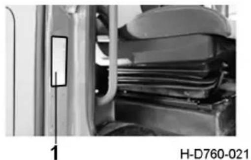
The vehicle nameplate is placed inside the passenger side door in the cab.
natural_image
Close-up of a vehicle's front compartment with visible structural components and a labeled section (no text or symbols on the main subject)- Vehicle nameplate
Location of VIN
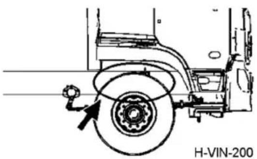
VIN code is the vehicle identification code. It can be engraved on the outside of the front longitudinal center line of the right front wheel. It can also be engraved on the outside of the longitudinal center line of the right front wheel (±500mm).
text_image
H-VIN-200Read VIN
The vehicle VIN code is stored in the electronic control unit (ECU), and the communication baud rate is 500Kbps. The vehicle VIN code can be read through the communication protocol ISO27145. Detection Tool ScanTool (Silver ScanTool software, J2534 interface hardware such as ValueCan) can read the VIN code of dongfeng commercial vehicle. The Tool can be purchased through Beijing yi'an hengrui technology co., LTD or social channels. When reading, the Tool is connected with the vehicle OBD port to run relevant programs.
Location of Engine Nameplate and Ex-factory Code
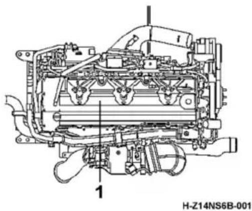
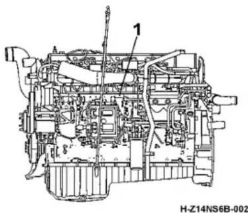
Cummins engine
natural_image
Technical line drawing of an internal combustion engine assembly (no text or labels)- Engine nameplate
natural_image
Technical line drawing of an internal combustion engine (no text or symbols visible)- Location of engine ex-factory code
Precautions
China six engine exhaust parts warranty period provisions
| system | serial number | Part name | Road vehicle/engineering vehicle |
| Air intake system 1 | supercharger | c t o c t o | |
| fuel system | 2 fuel pump | ||
| 3 | i n j e | ||
| 4 High pressure common rail | |||
| 5 pressure regulator | |||
| 6 mixing plant | |||
| 7 | i n j e | ||
| ignition system | 8 spark plug | ||
| 9 Ignition coil assembly | |||
| Exhaust gas recirculation | 10 EGR valve | ||
| 11 EGR cooler | |||
| Post-processing plant | 12 SCR | ||
| 13 DOC | |||
| 14 DPF | |||
| 15 urea nozzle | |||
| 16 Urea metering pump | |||
| 17 urea quality sensor | |||
| 18 hydrocarbon nozzle | |||
| 19 hydrocarbon metering pump | |||
| Crankcase 20 crankcase vent valve | |||
| sensor | 21 NOx sensor | ||
| 22 temperature sensor | |||
| 23 air flowmeter | |||
| 24 differential pressure sensor | |||
| 25 oxygen sensor | |||
| Electronic control unit | 26 ECU | ||
| 27 DCU | |||
Environment-friendly Operation and Adjustment of Engine
- Dongfeng Commercial Vehicle Co., Ltd shall regard any private or unauthorized removal of lead seals of the engine as automatic abandonment of the warranty.
- The engine has been strictly adjusted before delivery and met the requirement of the national environmental laws. The user is not allowed to execute unauthorized alternation or adjustment. The engine can only be adjusted in the service station designated by Dongfeng Commercial Vehicle Co., Ltd. Dongfeng Commercial Vehicle Co., Ltd will regard any private altering or adjustment in any unauthorized service station as automatic abandonment of the warranty.
- Use the oil filter element and fuel filter element designated by the engine manufacturer.
- Strictly observe the following during the operation and maintenance:
a). Perform regular maintenance and replacement of the oil filter, the fuel filter and the air filter.
b). Make sure to apply the designated or recommended model and specification of oil, and change the oil regularly.
c). You must use a qualified conforms to the standard stipulated by the urea solution, not added.
d). Add high quality diesel of different grades under different climate conditions; do not use poor-quality diesel.
e). Always check the level of coolant and lubricating oil regularly, and add if necessary.
f). Check that the connecting pipes for supercharger, intercooler and intake & exhaust pipes are airproof.
g). Before driving, let the engine run idly for 3\~5 min to lubricate sufficiently all its parts, especially the supercharger in order to ensure the normal operation of the supercharged engine. After starting the engine, never warm up it by means of acceleration. Before shutdown, let the engine run idly for 3\~5 min, to cool down normally all its parts, especially the turbine casing of the supercharger, in order to prevent the gumming or carbon deposition of the lubricating oil on the hot component, which will lead to malfunctions like blockage.
- During the warranty period, we should keep the material proof of using qualified oil products and urea (such as the certificate of filling station within one year and the certificate of urea sales at the normal point of sale).
- According to the maintenance provisions of this manual, vehicle maintenance shall be conducted at the service station authorized by dongfeng commercial vehicle co., Ltd. with maintenance records.
- All materials for maintenance, if no longer in use, shall be disposed of in accordance with national or local environmental laws.

CAUTION:
It may be illegal for a vehicle not to use the prescribed fuel and urea.
Daily Inspection
Please check carefully the vehicle before driving.
- Check the coolant level.
- Check the engine lubricating oil level.
- Check for oil leakage, water leakage and air leakage.
- Check and clean the glass and rearview mirror.
- Check the wheel nut for looseness, and check the tire pressure and tread.
- Check steering wheel, transmission control handle and brake status.
- Check the brake pedal for free travel.
- Check the horn.
- Check the lights.
- Check fuel tank capacity.
- Check urea (DEF) level.

CAUTION:
- Drain the fuel filter and fuel primary filter.
a. Drain them every week or drain the water and deposits when the water-in-fuel indicator lamp is on (applicable for the truck with water-in-fuel indication function);
b. For the refueling, it is recommended to drain the water and deposits in the water separator of fuel primary filter after the shutdown each day.
-
Drive in winter and cold areas, or drive continuously from normal temperature areas to high altitude areas, low temperature and cold areas in north China. Before shut-down every day, please push the air storage cylinder pressure to the rated pressure.
-
In winter and cold areas, check the water in the air storage tank every day after receiving the truck. Otherwise, check it once a week. When the ambient temperature is less than 5?, please switch on the air dryer heating switch on the instrument panel.
-
When the friction plate wear indicator lever indicates that the friction plate has moved to the wear limit or is prompted by the instrument, the friction block assembly must be replaced immediately.
-
Normally, the maintenance-free hub oil should be dark. If the oil is white or milk-like, it indicates that the oil has been contaminated.
-
Check that the pipeline connection between the tractor and the trailer is intact and there is no leakage.
Running-in of New Vehicle
The running-in mileage is 1,500-2,500 km, during which attention should be paid to the following items:
- In the first 250 km of running-in, loading is strictly prohibited, and the engine speed can never exceed 2,000 r/min.
- The load shall not exceed 50% of the rated load capacity within the running-in period of 800km and 75% after 800 km.
- Drive the truck on a level and hard road with minor slope throughout the running-in period.
- Run the engine under a proper light load or idly for a while to warm it up after starting it.
- It is strictly prohibited for the engine to idle for a long time, and the idle speed should not exceed 5 minutes before the operation with load, otherwise the engine will be damaged (except when the full-power PTO is selected to operate with load).
- Never drive the truck at a constant speed for a long time.
- Properly use the transmission gears to avoid overloading the engine.
- Often note the indication of the engine oil pressure (check low oil pressure alarm lamp) and the coolant temperature.
- Check the engine lubricating oil level and coolant level regularly.
- For the truck employing flexible cowl in cooling system, check the clamp of flexible cowl for looseness and re-tighten it if necessary.
- Drive the truck properly, avoid abrupt braking, and properly use engine exhaust braking.
- Never shut down the engine abruptly after it has been running at high speed or under heavy load for a long time. Keep the engine running idly after driving, and shut it down after it is cooled.
- Check whether the wheel nuts are loose within running-in, and if so, tighten the nut to the torque of 550-650 N·m.
- In running-in period 200-300km, re-tighten wheel bolt.

CAUTION:
-
Re-fasten the wheel nuts after running 200\~300km.
-
After running-in of the new truck, please perform running-in maintenance in the nearest technical service center (station) authorized by Dongfeng Commercial Vehicle Co., Ltd in accordance with the provisions in Dongfeng Commercial Vehicle Quality Assurance Manual.
Standard Operation
In order to prolong the service life, gain higher economic benefit, and guarantee the travel safety, the following should be noticed during the vehicle operation:
- When operating the truck, turn on the master power switch, and then make sure that the gear lever is at neutral position in the low range.
- See Parts for engine start.
- Do not increase the engine speed too fast if the engine temperature is low; otherwise the wear of engine moving parts will be aggravated.
- Never move the truck before the brake system pressure reaches and exceeds the stipulated pressure (the air pressure gauge pointer not in the red zone) when the parking brake indicator lamp is off.
- The truck under heavy load must be started at first gear.
- It is strictly prohibited to coast the truck at neutral gear with engine stalled.
- Avoid full throttle start and emergency braking. Full throttle start will result in clutch damage or uneven tire wear, while emergency braking will accelerate the wear of tires and brake linings.
- Avoid sharp turn at high speed.
- Never overload the truck since it may shorten its service life.

WARNING:
The user should operate the truck in strict accordance with the User's Manual, and the nominal load capacity and gross mass specified in the manual shall never be exceeded. Overload may result in vehicle malfunction and damage and even personal injury.
- When cleaning the truck, avoid the entry of water into the fuel tank.
- Never turn off the master power switch when the engine is running; make sure to turn off the switch after the truck enters into the yard and stops.
- Before tilting the cab, make sure to check for any object that is easy to get upside down inside the cab. And remove such objects if any.
- When maintaining or adjusting the electrical system, make sure to switch off the main power before replacing any electric elements. Never perform any operation with power on.
- Never replace the fuse or fusible link with copper wire; do use stipulated fuse.
- Never check the electrical system by testing the live wire through short circuit.
- Any removed or replaced assembly must be refitted.
- Protect the electronic control unit of the truck as follows before performing welding on the truck:
For the truck equipped with mechanical master power switch:
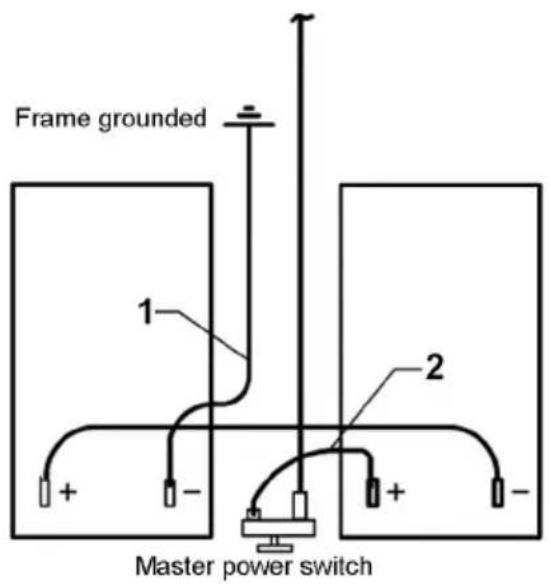
text_image
Frame grounded 1 2 + - + - Master power switcha) Normal installed status
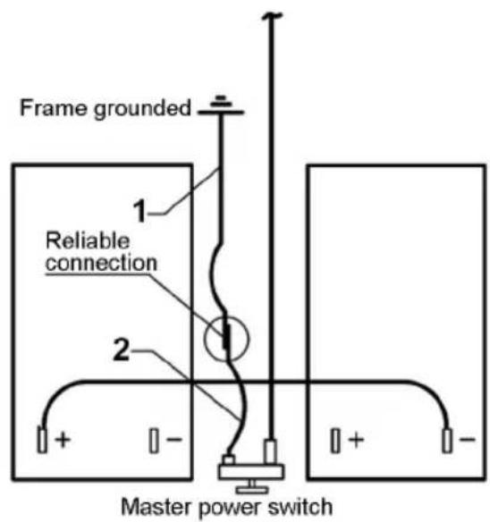
text_image
Frame grounded 1 Reliable connection 2 + - + - Master power switchb) Status prior to welding H-T03-070
- Negative power cable of battery 2. Positive power cable of battery
Specific operation steps:
a). Shut down the engine and disconnect the master power switch.
b). Disconnect the positive and negative power cables of the battery, and connect them reliably as shown in Fig. b.
c). Turn on the master power switch.
d). Perform welding.
e). After the welding work is completed, restore the connection of power cables of battery as shown in Fig. a.

WARNING:
- Prevent power short circuit while disconnecting and connecting the power cables.
2.Restore all wirings after the welding.
- Failure to perform welding in this way may result in irremediable defect of vehicle electronic devices.
Safety Precautions

WARNING:
Failure to observe the requirement with a warning mark will result in serious personal injury or property loss.
- According to article 48 of the road traffic safety law of the People's Republic of China: "the load of a motor vehicle shall conform to the approved load quality, and overload is strictly prohibited". The user should operate the truck in strict accordance with the User's Manual, and the nominal load capacity and gross mass specified in the manual shall never be exceeded. Overload may result in vehicle malfunction and damage and even personal injury.
- Make sure to observe the operation specifications to protect truck electronic equipment during welding; otherwise it will result in damages of the truck electronic devices.
- The seat belt can be used by one person only. Adult and kid are prohibited to share one belt. The whole seat belt should be replaced if any component comes into failure or damage. Make sure that the belt is not intertwined, clear of hard edges and free from chemical pollution. And always adjust the belt length according to the body; otherwise hazard will be caused.
- When parking the truck, be sure to move the manual valve control lever to locking position; otherwise, the truck may move, which will lead to damage or even personal injury. The spring brake can only be released in emergency. After that, the fault must be eliminated and the parking brake shall be restored. The truck without parking brake is dangerous, and it may result in an accident.
- Adjusting the position of the steering wheel is strictly prohibited during driving.
- Always park the truck on a level ground before tilting the cab. Check for sufficient space when tilting the cab inside. Check that the manual valve control lever is at braking position, and gear lever is at neutral position, and chock the tires. Put away the scattered objects inside the cab and those which are easy to fall during cab tilting. The cab must be tilted to proper position, with the center of gravity tilting over the support point to avoid the cab to slide accidentally. Do not turn the reversing handle after cab tilting. It must be in proper position when the cab lowers to the original place.
- Do not touch the gear lever while the engine is running after cab tilting, and do not lower the cab while the engine is running.
- Never connect the cigar lighter for a long period. It must be drawn out manually if it fails to pop out automatically.
- The filler cap of auxiliary water tank can be removed only after the coolant temperature is below 50^ C, otherwise, the spraying of high temperature coolant or steam may cause personal injury. Before removing the coolant filter, please remove the filler cap of auxiliary water tank and close the shutoff valve; otherwise, hot coolant may be sprinkled to cause personal injury.
-
Never replace the fusible link (fuse) with ordinary conducting wire or fusible link of other specifications.
-
Make sure to use only the oils and greases stipulated in this manual; otherwise it may cause the truck malfunction, damage and even personal injury.
- If the alarm lamp stays on or flashes when the engine is running, then it indicates that some part is in trouble. In this case, please contact the Technical Service Center (Station) authorized by Dongfeng Commercial Vehicle Co., Ltd as soon as possible.
- Friction pad and brake disc should use original parts, otherwise it will bring serious consequences;
- Never extend the head and hands outside the window when the power window is rising. In this course, if the body or other objects are nipped between the window and door frame, always move the glass downward immediately. When operating the power glass regulator switch on the passenger's side, the driver shall ensure that there is no obstacle affecting the correct closing of the window.
- Do not place corrosive articles or hard pointed objects into the storage box. And no heavy load is allowed on the storage box cover.

CAUTION:
Failure to observe the requirement with a caution mark will result in personal injury or damage to component assembly or complete vehicle.
-
Observe the truck operation specifications strictly.
-
Check that all doors are closed properly before starting the truck. Always lock the door only with a key when you are outside the vehicle; never lock the door by moving the lock knob forwards while pressing the outer unlocking button to close the door.
-
The master power switch shall never be turned off when the engine is running. Never turn the key to START position when the engine is running to avoid damaging the starter.
-
Never use the washer without washer fluid.
-
When the A/C compressor needs to be restarted after being shut off, please wait for 3-5 min; otherwise, the service life of the compressor will be affected.
-
For the sake of safety, do close the ash tray before leaving the truck.
-
When getting power via the working lamp socket, the electrical load is strictly prohibited to exceed the nominal capacity of the socket.
-
Trailer connection should be done in flat place, make the parking brake working and fix the wheels by triangular stopper. When connecting the connector with tractor, make sure the right pipes are connected.
-
Before adding coolant, check the engine and the radiator for leakage, and repair it if any. It is recommended to use long-life antirust and anti-freeze coolant. Never use the running water or hard water from well or river.
-
Normally do not screw off the pressure valve cap of the auxiliary water tank; if it is necessary to do so, be careful to avoid scalding.
-
Check the engine oil level only when the truck stops. Make sure to drain the lubricating oil off after the engine completely stops. Note the hot oil to avoid scald during the oil draining.
-
When mounting the air filter, make sure to mount the filter element and end cover properly; otherwise dirt may be absorbed, sharply shortening the engine service life. Never clean the filter element with gasoline or water. Check the sealing rings during installation. Tighten the filter element and end cap nut, and install the sealing ring of the end cap properly. Do not remove the air filter when the vehicle is running.
- Do not tighten the fuel primary filter or the fuel filter with fuel primary filter by a filter spanner during installation. Otherwise the threads may deform and the filter may be damaged. When mounting a new filter, note whether its model conforms to that required by this engine. Before the oil filter is installed, it should be filled with oil.
- Bleeding is prohibited when the engine temperature is high. The starting time of the engine must not exceed 30 s, and the interval between starting operations shall be 2 min at least.
- For the manual adjuster, check the brake clearance regularly and adjust it in time if the braking is weak. During the adjustment of brake clearance, never change the push rod travel by screwing the connecting yoke of the brake air chamber push rod. To adjust the rear brake, always park the truck on flat place and ensure the air reservoir pressure is above 700 kPa. Then chock the wheels at the front and back, and after releasing the parking brake, adjust the rear brake clearance.
- For the automatic regulating arm, manual adjustment of brake clearance is prohibited except for special circumstances; Check the wear situation of friction disc regularly to prevent braking failure caused by excessive wear of friction disc. When adjusting the brake clearance manually, it is strictly forbidden to change the stroke of the push rod by turning the brake air chamber push rod to connect the fork. When manually adjusting the rear brake, make sure the vehicle is parked on a flat place and ensure the air pressure of the storage cylinder is above 700kPa. The front and back of the wheel are choked with a triangular pad, and the brake clearance can be adjusted after the parking brake is lifted. In case of abnormal braking conditions, stop immediately to check the working conditions of the automatic regulating arm and other parts of the braking system, and take appropriate measures to eliminate the fault.
- Disc brake can automatically adjust the brake clearance, except for special circumstances, manual adjustment of the brake clearance is prohibited. If the brake clearance is found to be abnormal, check the clearance adjustment mechanism function.
- Auxiliary braking (exhaust braking, engine braking, retarder) is strictly prohibited on wet slippery road surface.
-
For vehicles with ESC (electronic stability control system of vehicle body), ESC self-learning calibration must be carried out at the service station when the steering wheel, steering tie rod, front axle and steering wheel string are replaced. During vehicle restructuring, the position of ESC module shall not be moved or the installation direction of ESC module shall not be changed.
-
Never adjust the pressure of brake air line privately to avoid damaging the parts.
- Never add power steering fluid with engine running.
- Normally, the battery should be removed for charging when it is discharged. Starting by auxiliary power can be allowed only in emergency, and should be carried out in strict accordance with the operation specifications.
- Never let the steering wheel stay at the extreme position for more than 15 s. In such a case, it is required to slightly rotate the steering wheel backwards so as to avoid any damage to the power steering pump.
- When performing the specified maintenance to the truck, the user should shorten the maintenance interval mileage according to the actual operation condition, to ensure more reasonable maintenance and higher reliability of the truck. However, the user should never prolong the maintenance interval mileage.
Safety Precautions for Brake Pipeline Quick Joint

WARNING:
It is strictly prohibited to remove the brake pipeline without authorization; otherwise, air leakage may be caused. If necessary, always remove hoses with special tools at the service station specified by Dongfeng Commercial Vehicle Co., Ltd, and no sharp tools such as the slotted screwdriver can be used for removal.

CAUTION:
Quick connector and hose should be repeatedly removed at most 5 times, or they must be replaced.
All the quick connectors and hoses shall be the ones designated by Dongfeng Commercial Vehicle Co., Ltd, whose surfaces should be smooth without any burr, bump, scratch or other defects and should be kept clean.
Structure and Operation
Arrangement of Instrument and Control Mechanism
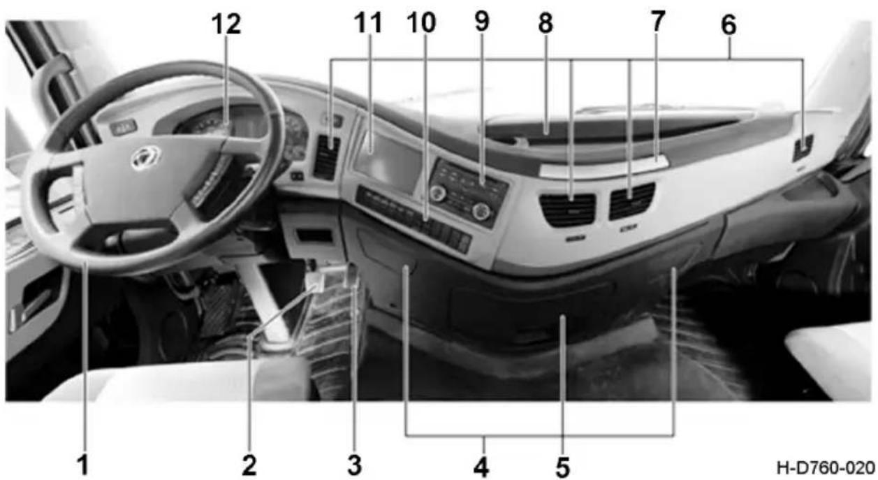
text_image
1 2 3 4 5 6 7 8 9 10 11 12 H-D760-020- Steering wheel
- Brake pedal
- Accelerator pedal
- Cigarette lighter and ashtray
- Middle storage box
- Air conditioning outlet
-
Tray Table
-
Storage platform
- Thermostatic air conditioning controller
10.Rocker switch set - Display panel assembly of on-board information terminal
- Instrument panel
Keys
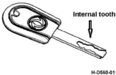
Please record to the detailed specification of the vehicle purchased.
Normal Keys
Keys are used to control the starter switch of the vehicle, and to lock and unlock the door.
Remote Keys
text_image
Internal tooth H-D560-011Keys are used to control the starter switch of the vehicle, and to lock the door, fuel tank cap or urea tank cap.
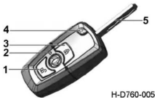
text_image
4 3 2 1 5 H-D760-005- Remote unlocking.
- indicator lamp
- Remote locking
- Mechanical key release button
- Mechanical key
Doors
From the outside
Open and close doors by normal key
Insert the key into the lockhole and turn the key towards the position of 1 (the head of the truck) to unlock the door; contrarily, the door will be locked; after the door is unlocked, press down the door outside release button to open the door.
Open and close doors by remote key
The key with remote system can lock and unlock the vehicle in 5 m.
When press unlock button, doors from both sides will be unlocked at the same time and cornering lamp will flicker twice. Pull door handle to open the door.
To lock the door, press lock button, doors from both sides will be locked at the same time and cornering lamp will flicker twice.
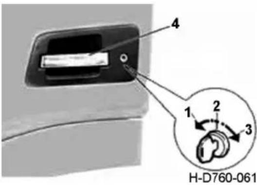
text_image
4 1 2 3 H-D760-061- Unlocking position
- Key inserting position
- locking position
- Door handle

CAUTION:
- Lock the door with mechanical key or remote control function, and check whether the door is completely closed.
- When the engine is running, using the remote control key outside the car cannot lock the door.
From the inside
When the door is closed, pull the lock knob forward to locking position to lock the door; contrarily, the door will be unlocked; pull the door inside handle to open the door.

CAUTION:
-
It is very dangerous to drive the truck with the door ajar. Please check if the door ajar alarm lamp is on.
-
The door can never be opened when the truck runs.

natural_image
Interior view of a car dashboard with a white handle and control panel, labeled H-D760-037 (no text or symbols on the main subject)- Door handle
Central locking
Please refer to the specific configuration of your vehicle.
From the inside
When both the driver and the passenger are in the vehicle, the passenger's door will be locked also after the door lock knob on driver's side is turned to locking position. If the door lock knob on passenger's side is turned to locking position, then only the passenger's door instead of the driver's door can be locked.
From the outside
When unlocking the driver's door with a key, the passenger's door will be also unlocked; pressing the door outside unlocking button can open the driver's door and passenger's door separately. If only the passenger's door is unlocked with a key, pressing the outside unlocking button can open the passenger's door instead of the driver's door.
If the driver's door is locked by key, the passenger's door will also be locked. If only the passenger's door is locked with a key, then only the passenger's door instead of the driver's door can be locked.
Seats
Please refer to the specific configuration of the model purchased.
Driver's seat
Airbag shockabsorbing seat (for deluxe models)
The airbag shockabsorbing type seat is designed for the high-end commercial vehicle, of which the sponge in the seatback and cushion conforms to the ergonomics to bring you more comfort. The seat is equipped with airbag shockabsorbing suspension which can reduce or offset the harmful vibration, reducing the fatigue during driving, and improving the driving comfort.
-
Lift the front and rear sliding handle of the seat, adjust the seat back and forth to the comfortable driving position, release the front and rear sliding handle of the seat and lock the seat;
-
According to different driving conditions, the adjustable damping handle can be adjusted. When the road condition is good, the damping adjustment handle can be raised to a comfortable position; when the road condition is bad, the damping adjustment handle can be lowered to a comfortable position to meet the driving comfort under different road conditions;
-
Pull the seat cushion tilt adjustment handle to adjust the seat cushion tilt angle. When the seat cushion is adjusted to a comfortable position, release the adjustment handle and keep it lock;
-
After sit, the user can adjust suspension height adjustment handle up and down according to his/her driving posture to inflate the seat to the comfortable height of the driver;
-
When using airbag shockabsorbing seat, first confirm whether the seat is in the inflatable state with rapid air charging and releasing. If the button with rapid air charging and releasing is in the deflating state, press the button to inflate the seat, and the airbag suspension is working to reduce the vibration;
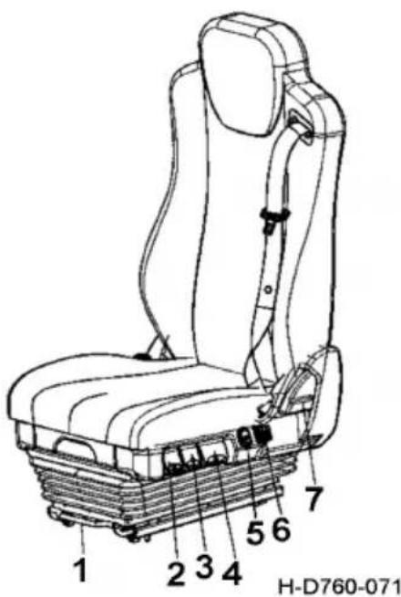
text_image
H-D760-071 1 2 3 4 5 6 7-
Seat forward and backward sliding handle
-
Seat damping adjustment handle
-
Seat cushion tilt angle adjustment handle
-
Seat suspension height lifting handle
-
Seat fast inflation and deflation handle
-
Seat back air bag waist adjustment handle
-
Seat back forward and backward flip handle
-
Press the button for adjusting the backrest waist support to adjust the front and rear height of the backrest waist to the comfortable position of the waist.
- Pull the backrest angle adjustment handle to adjust the backrest angle to the appropriate position. Release the handle and lock the backrest angle.
- Adjust the front knob of the handrail to adjust the angle of the handrail freely.

CAUTION:
- Please adjust the seat in case of driving safety.
- For front and rear adjustment and angle adjustment, the handle should be pulled in place to ensure complete separation of the mechanism before adjustment.
- After the completion of the whole process, all handles should be in place to ensure the locking of all parts is reliable.
- When encountering a particularly bumpy road surface, please turn the seat damping adjustment wrench to the lowest end to keep the seat balanced.
Airbag shockabsorbing seat (for standard models)
-
Lift the front and rear sliding handle of the seat, adjust the seat back and forth to the comfortable driving position, release the front and rear sliding handle of the seat and lock the seat;
-
According to different driving conditions, the adjustable damping handle can be adjusted. When the road condition is good, the damping adjustment handle can be raised to a comfortable position; when the road condition is bad, the damping adjustment handle can be lowered to a comfortable position to meet the driving comfort under different road conditions;
-
Pull the seat cushion tilt adjustment handle to adjust the seat cushion tilt angle. When the seat cushion is adjusted to a comfortable position, release the adjustment handle and keep it lock;
-
After sit, the user can adjust the height of the suspension handle up and down according to his/her driving posture to inflate the seat to the comfortable height of the driver;
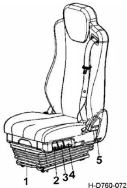
text_image
1 2 3 4 5 H-D760-072- Seat forward and backward sliding handle
- Seat damping adjustment handle
- Seat cushion tilt angle adjustment handle
-
Seat suspension height lifting handle
-
Pull the backrest angle adjustment handle to adjust the backrest angle to the appropriate position. Release the handle and lock the backrest angle.

CAUTION:
-
Please adjust the seat in case of driving safety.
-
For front and rear adjustment and angle adjustment, the handle should be pulled in place to ensure complete separation of the mechanism before adjustment.
-
After the completion of the whole process, all handles should be in place to ensure the locking of all parts is reliable.
-
When encountering a particularly bumpy road surface, please turn the seat damping adjustment wrench to the lowest end to keep the seat balanced.
Driver seat cushion depth
- The seat slide rail is in the last position;
- On the basis of graphic method, adjust backrest angle to 11^ , this is normal driving position.
- On the basis of 1 and 2, the seat cushion depth shall be measured according to the requirements of the drawing.
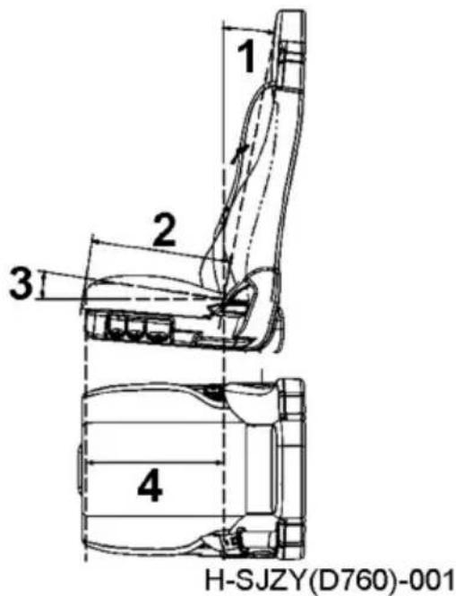
text_image
1 2 3 4 H-SJZY(D760)-001- Normal use and back angle of seat depth measurement
- Seat cushion depth
- Seat cushion tilt angle
- Measure along the center line of the seat
Passenger seat
Please refer to the specific configuration of the purchased model.
Air bag seat (for deluxe models)
-
Pull the seat back adjustment handle to adjust the front and rear angle of the seat back. Adjust the angle of the seat back to the appropriate position according to the passenger's sitting posture to make the seat comfortable.
-
When using the seat with airbag vibration reduction, make sure that the locking handle of the seat suspension is in a horizontal position, and the airbag suspension is used for vibration reduction;
-
Lift the front and rear sliding handle of the seat, adjust the seat back and forth to the comfortable driving position, release the front and rear sliding handle of the seat and lock the seat.
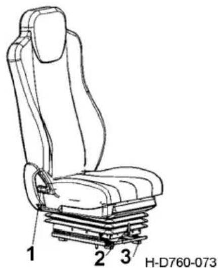
text_image
1 2 3 H-D760-073-
Seat back forward and backward flip handle
-
Seat suspension locking handle
-
Seat forward and backward sliding handle

CAUTION:
-
Adjust the seat to ensure driving safety.
-
Adjust the front and rear angles by pulling the handle in place to ensure complete separation of the mechanism before adjustment;
-
After adjustment, handle return shall be in place to ensure reliable locking of all parts;
-
When encountering a particularly bumpy road surface or the air source fails to support the weight of the driver, please adjust the seat suspension lock handle from the horizontal position to the vertical position and lock the seat suspension.
Fixed seat (normal)
- Pull the seat back adjustment handle to adjust the front and rear angle of the seat back. Adjust the angle of the seat back to the appropriate position according to the passenger's sitting posture to make the seat comfortable.
- When using the airbag shock-absorbing seat, make sure that the locking handle of the seat suspension is in a horizontal position, and the airbag suspension is used for vibration reduction;
- The passenger seat is equipped with a storage box. Press the lock button on the lock latch of the box cover, and the lock latch can be detached from the lock button to open the seat storage box.

text_image
1 2 3 H-D760-074- Seat back forward and backward flip handle
- Seat suspension locking handle
- Seat forward and backward sliding handle

CAUTION:
- Adjust the seat to ensure driving safety;
- Adjust the front and rear angles by pulling the handle in place to ensure complete separation of the mechanism before adjustment;
- After adjustment, handle return should be in place to ensure reliable locking of all parts.
Swivel seat (optional)
Please check the specific configuration of the purchased product.
-
Pull the adjusting handle of the seat back to adjust the Angle of the back. Adjust the Angle of the back to the appropriate position according to the passenger's sitting posture to make the seat comfortable.
-
The seat can be rotated 90^ counterclockwise by flipping the rotation adjustment handle to improve the rest comfort.
-
Pull the seat forward and backward by sliding the handle, adjust the seat forward and backward to the comfortable driving position, and release the seat forward and backward by sliding the handle to lock the seat.
-
Pull the adjusting handle of the storage box, open the storage box under the seat, and store shoes, tools and other items with the car.

CAUTION:
- Adjust the seat while driving safely.
-
Before using the rotation function, please slide the seat forward for more than 100mm to ensure that the seat can rotate normally.
-
For front and rear Angle adjustment, the handle should be pulled into place to ensure complete separation of the mechanism before adjustment.
-
After the adjustment, the return position of the handle should be in place to ensure reliable locking of all parts.
-
The storage box under the seat shall not store more than 3kg of heavy items to avoid damage to the cover of the storage box during the cab roll-over
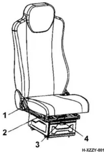
text_image
1 2 3 4 H-XZZY-001-
Turn the adjusting handle of the backrest
-
Seat rotation adjustment handle
-
Seat front and rear adjusting handle
-
Adjusting handle of seat storage box
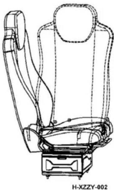
natural_image
Line drawing of a car seat assembly with no text or symbolsSeat rotates 90 degrees
Driver seat cushion depth
- The seat slide rail is in the last position;
- On the basis of graphic method, adjust backrest angle to 12^ , this is normal driving position.
- On the basis of 1 and 2, the seat cushion depth shall be measured according to the requirements of the drawing.
Seat Belts
Driver's and passenger's seat belts
- To use the seat belt: pull the belt out slowly, put it between the shoulder and the base of neck and make it pass through the proper position of the chest. Then insert the latch plate into the buckle until a click is heard, and adjust the belt to your comfort.
- To unfasten the safety belt: press the button on the buckle to release the latch plate and put the belt back slowly.

WARNING:
- Make sure that the belt is untwisted, clear of hard edges and free from chemical pollution.
- The seat belt can be used by one person only. Adult and kid are prohibited to share one belt.
- The whole seat belt should be replaced if any component comes into failure or damage.
- The seat belt should be replaced if the retractor is blocked.
- Always adjust the belt length according to the body; otherwise hazard will be caused.
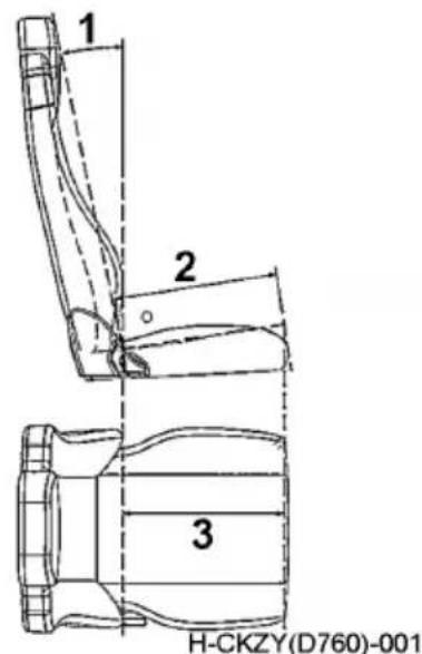
text_image
1 2 3 H-CKZY(D760)-001- Normal use and back angle 12^ of seat depth measurement
- Seat cushion depth
- Measure along the center line of
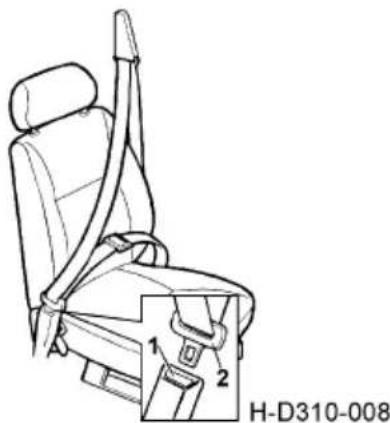
text_image
H-D310-008- Buckle
- Latch plate
Berth
Operation instruction of upper berth
-
To use the upper berth for a rest, firstly insert the safety belt latch plate into the buckle until a click is heard.
-
After entering the upper berth, deploy the guard curtain, and press the safety belt clip at the needed height to lock the guard curtain.
-
To adjust the berth from horizontal position to non-horizontal position, firstly insert the safety belt latch plate into the buckle, then press the knob by two hands, lift up the aluminum alloy rail to tilt it up, and release the button at any angle to lock the berth.
-
To tilt the non-horizontal berth, press the two knobs on the aluminum alloy rail to the required position, and release the knob to lock the berth.
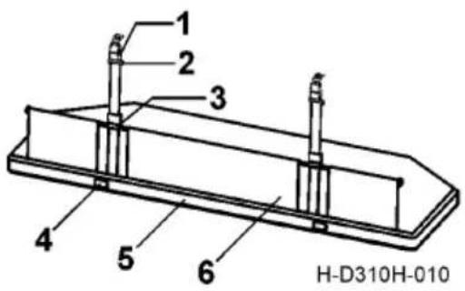
text_image
1 2 3 4 5 6 H-D310H-010-
Seat belt buckle
-
Seat belt latch plate
-
Seat belt snap
-
Knob
-
Aluminum alloy beam
-
Protective curtai

CAUTION:
After tilting the berth, the berth shall be supported by two straps with button together; otherwise the abnormal noise may be caused due to vibration. Adjusting method: press the rail at the tensioned strap, lift up the rail where the strap is slack by the other hand till a click is heard. At this moment, the straps are locked.

WARNING:
After entering the upper berth, make sure to deploy the guard curtain and lock the be It buckle to hazards.
Lower berth
Lower berth with guardrail, pull up the guardrail after enter the lower berth. Press the unlock button on the guardrail and push the guardrail horizontally to put it away.
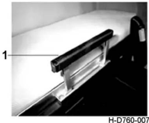
natural_image
Close-up of a mechanical device with a labeled component (1) and identifier H-D760-007, no readable text or symbols on the device itself.- Guardrail
Instrument Panel
Please refer to detailed specification of the vehicle purchased.
text_image
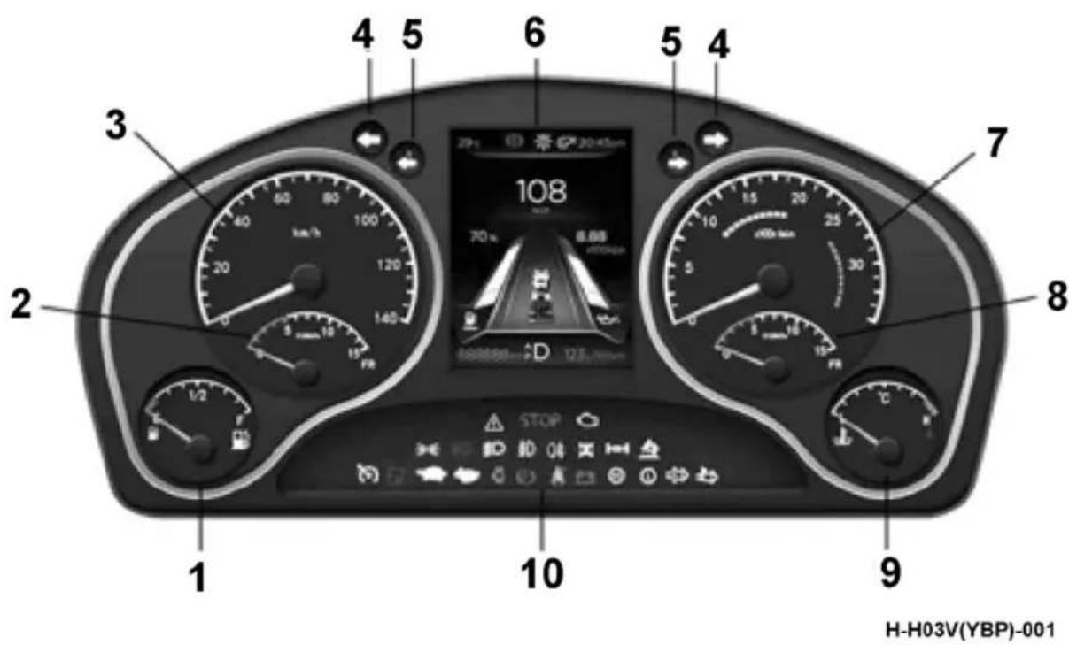
1 2 3 4 5 6 7 8 9 10 H-H03V(YBP)-001- Fuel gauge, urea gauge
- Front axle barometer
- Speedometer
- Turn signal indicator lamp
-
Trailer turn signal indicator lamp
-
Muti-information display screen
- Engine tachometer
- Rear axle barometer
- Water thermometer
- Indicator lamp and warning lamp
Fuel gauge
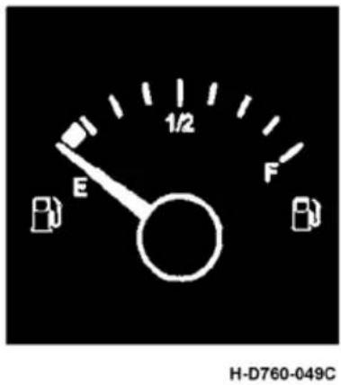
A fuel gauge is used to indicate how much fuel is stored in the fuel tank. The watch is active when the key switch is in the ON position. When the pointer is located at 0, the yellow alarm light near E in the dial is on, it should be filled with clean qualified fuel as soon as possible.
text_image
E 1/2 F H-D760-049CF: Full
E:Emp
2:1/2 of
Water thermometer
This meter indicates the temperature of the engine coolant. This meter works when the key switch is in the ON position.
When the engine cooling water temperature is equal to or higher than 107^ C, the dial in H near the red alarm lamp light, buzzer alarm, at the same time in the LCD screen prompts "engine water temperature high".
H: 107^ C
CAUTION:
When the coolant temperature is too high, the indicator light will be lit; when the temperature is too high, and the buzzer on the meter will sound an alarm. If the vehicle continues to drive when coolant temperature is too high, engine overheating damage will be caused.
Turn signal indicator lamp
This indicator is used to indicate the working condition of the turn signal lamp of the tractor. Its normal flashing means all the turn signal lamps work normally; fast flashing means that at least one turn signal lamp at the same side is in trouble.
Trailer turn signal indicator lamp
This indicator lamp is used to indicate the working conditions of the trailer turn signal lamps. Its normal flashing means all the turn signal lamps work normally; fast flashing means that at least one turn signal lamp at the same side is faulty; and staying off means no connection to the trailer.
Speedometer
The speedometer indicates the running speed of the truck in km/h.
Air pressure gauge
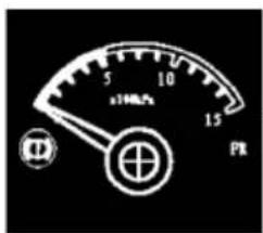
The air pressure gauge indicates the air pressure in the air reservoir. Front axle air pressure gauge (with the sign FR) detects the pressure of the front axle air reservoir, and (middle)rear axle air pressure gauge (with the sign RR) detects the pressure of the (middle) rear axle air reservoir.
text_image
±100kPa 15 PR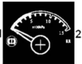
text_image
5 10 1.5 ±100kPa E 2H-D760-052
- Front axle air pressure gauge
- (middle)rear axle air pressure gauge

WARNING:
Never start the vehicle when the pointer is in the red zone.
Engine tachometer
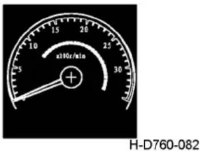
The tachometer pointer indicates the revolutions per minute of the engine. The green area of the tachometer is the economic speed area, and the red area is the alarm area for overspeed.
Cummins Z14EVID520 engine economic speed is 1000\~1600r/min, alarm speed is above 2300r/min.
text_image
x100r/min H-D760-082
CAUTION:
Cummins ISZ series engine has the function of rapid warm-up. When the coolant temperature is low, the engine will start successfully and the engine will run at a higher speed (higher than the standard idle speed), which will rapidly increase the coolant temperature.
Indicator and alarm light
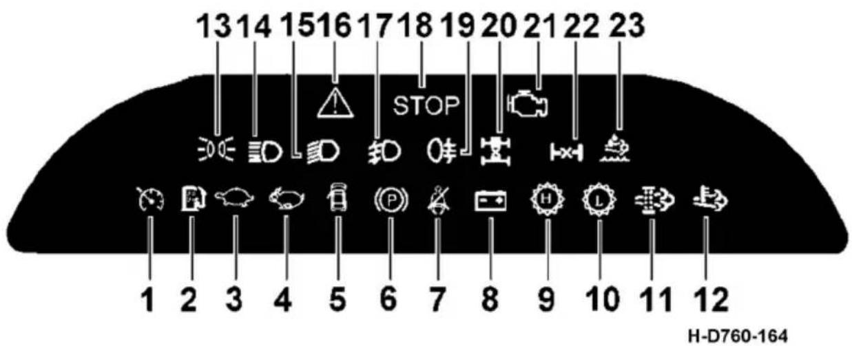
Please refer to the specific configuration of the products purchased.
text_image
1314151617181920212223 STOP H-D760-164- Cruise light
- Low indicator light for urea level
- Low transmission indicator
- High grade indicator for transmission
- Door opening alarm light
- Parking brake indicator
- The safety belt is not connected with the alarm indicator
- No charge indicator
- Transmission high-half indicator light
- Low half transmission indicator
11.DPF indicator light - Exhaust system high temperature indicator
-
Position light indication
-
High beam indication
15.Low light indicator - Repair alarm lamp
- Front fog lamp indication
- Stop alarm lamp
- Rear fog lamp indication
- Shaft differential lock indicator light
- MIL indicator light
- Inter-wheel differential lock indicator light
23.Driver's warning light

CAUTION:
The work indicator and alarm lights will be different depending on the vehicle type.
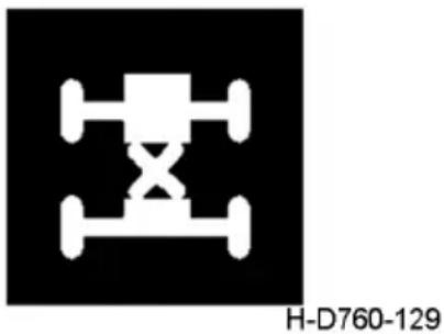
Bogie differential lock indicator lamp
When the bogie differential lock switch is connected, the buzzer will sound. The bogie differential will work, and then this indicator lamp will be on.

CAUTION:
The differential lock indicator lamp should not be on when the truck runs normally. Never use the differential lock for long time; otherwise, the differential may be damaged, resulting in excessive wear of tire.
natural_image
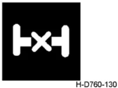
Pure electrical circuit symbol for a three-phase motor (no text or labels)Inter-wheel differential lock indicator light
It is only suitable for vehicles equipped with inter-wheel differential lock.
When the inter-wheel differential lock switch is switched on, the buzzer sounds and the inter-wheel differential lock is activated, the indicator light is on.
text_image
H-D760-130
CAUTION:
When the vehicle is running normally, the differential lock indicator light should not be on. Do not use differential lock for a long time, otherwise it will damage the differential and cause excessive tire wear.
Air dryer heater indicator
This indicator lamp will come on when the air dryer heater switch is connected.
natural_image
Simple line drawing of a hairdryer with label H-D310-110 (no text or symbols on the diagram itself)Auxiliary brake indication
The auxiliary brake indicator light is normally on by default. n represents the auxiliary braking gear in use. If the auxiliary braking is not used, there is no digital display. Auxiliary brake operation.
Transmission half gear higher indicator light
Please refer to the specific configuration of the purchased model.
The indicator light is on when the transmission is in the higher half-gear zone.
text_image
(⊕)n H-D760-078
text_image
H H-D310-118ALow gear indicator light of transmission
Please refer to the specific configuration of the purchased model.
The indicator lights up when the transmission is in the lower half - gear zone.
text_image
L H-D310-120AEngine over-speed alarm light
Please refer to the specific configuration of the purchased model.
At the time of 2300r/min, the indicator light is on to remind the driver to reduce the speed
(only applicable to models and products equipped with sound-light alarm device).
natural_image
Pure electrical circuit symbol for a meter (no text or labels)Low water indicator
When the coolant level in the engine auxiliary water tank is below the specified limit height, the indicator light is on. At the same time, the buzzer on the meter sounded.
natural_image
Simple line drawing of a container with wavy bottom and side bars, no text or symbols present.H-D310-125

CAUTION:
If the coolant is insufficient and the engine continues to run, it will cause overheating and damage to the engine.
Air filter clog warning lamp
When this lamp is on, it means large intake resistance of engine air filter, clogged intake air flow, worse dynamic property and economic efficiency of the engine, causing the vehicle unable to continue running. In this case, the vehicle should be stopped for cleaning or replacement of the air filter until the lamp goes out.
natural_image
Symbolic icon of a funnel with a downward arrow, no text or numbers presentH-D310-122

CAUTION:
Make sure to clean and replace the air filter element according to the maintenance cycle if this lamp is not on. Where this lamp is on, do not perform maintenance according to the maintenance cycle, but clean and replace the element immediately.
Filament detection warning lamp
Except for the trailer, this indicator lamp will be on when any filament of rear fog lamp, rear position lamp and brake lamp is faulty. This function gives the driver a hint of the working condition of the tail lamp.
Door ajar warning lamp
This lamp will be on when any door is open.
natural_image
Simple warning icon with exclamation mark inside a circle on black background (no text or symbols)H-D310-104
natural_image
White line drawing of a car on a black background (no text or symbols)H-D310-114
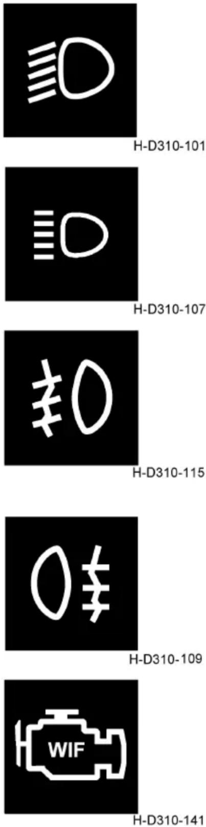
Low beam indicator lamp
This indicator lamp will come on when the combination switch right handle is at low beam position.
High beam indicator lamp
When the lamplight combination switch is turned to high beam position, this indicator lamp will be on; it is also on during the dimming operation.
Front fog lamp indicator lamp
After the clearance lamp is turned on, this indicator lamp will be on when the front fog lamp is switched on. The installation of this indicator lamp depends on the configurations of specific vehicle.
Rear fog lamp indicator lamp
After either the front fog lamp or high beam or low beam is turned on, this indicator lamp will be on when the rear fog lamp is switched on.
Water oil mixing indicator lamp
The light indicates that the oil-water separator contains too much water and needs to discharge the oil-water separator of the fuel prefilter.
text_image
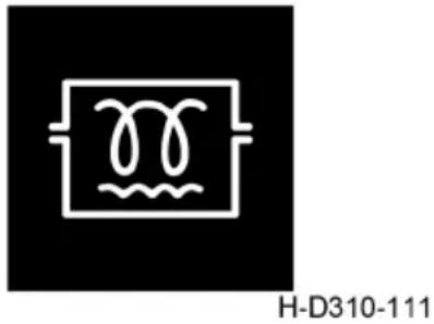
H-D310-101 H-D310-107 ≠0 H-D310-115 H-D310-109 WIF H-D310-141Fuel preheating indicator lamp
This indicator lamp will be on when the glow plug is electrified.
The installation of this indicator lamp depends on the configurations of specific vehicle.
Preheating indicator lamp
This indicator lamp is provided for facilitating the start of the engine in cold weather. When the preheating device is electrified, this indicator lamp will be on. The installation of this indicator lamp depends on the configurations of specific vehicle.
Wait for start light
If the vehicle is started by the cooler condition under low ambient temperature, the indicator light will be ON when the key switch is in the ON position. The light indicates that the engine is preheating. The lower the ambient temperature, the longer the light will remain on (up to 30 seconds). When the light is off, the key switch will be placed in the START position to START the engine.
Parking brake indicator lamp
When the driver pulls the manual valve control lever backwards to the brake locking position, this lamp will be on to remind the driver that the truck is in braking mode. After this control lever is pulled upwards to the release position, if the brake air pressure is lower than (540 ± 30) kPa, this indicator lamp will be on; otherwise it will go out. When starting the vehicle, it is necessary to check if the indicator lamp goes out and the spring parking brake is released.
Water temperature too high indicator light
natural_image
Pure electrical circuit symbol for a pot (no text or labels)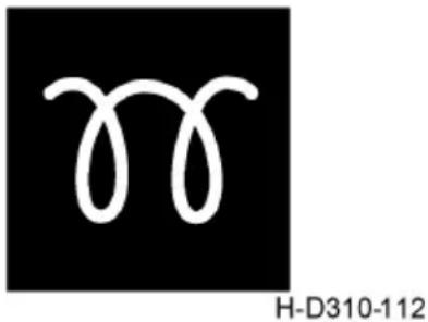
natural_image
Abstract white wavy line design on black background, no text or symbols present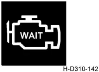
text_image
WAIT H-D310-142
text_image
(P) H-D310-103When the key switch switches from OFF to ON, the light goes out after 3 seconds. When the cooling liquid temperature is too high, the indicator light is on, and the buzzer on the instrument alarm.

CAUTION:
If the water temperature is too high and you continue driving, you can cause the engine to overheat and damage.
Low fuel alarm
The indicator lights up when the fuel tank is about to run out of fuel.
Urea level alarm indicator light
The urea level is used to indicate the amount of urea in the urea tank. This meter works when the key switch is in the ON position.
When the level of urea is low (less than 12%), the blue indicator lights up.
Low tire pressure alarm light
The indicator lights up when the tire pressure is too low.

natural_image
Simple line drawing of a thermometer above water waves, no text or symbols present
text_image
B H-D760-079
text_image
Ad Blue H-NSYW-001
text_image
H-D760-139ECAS warning light (yellow)
ECAS alarm indicator light is on: it means the air suspension air bag pressure is less than 6.5bar, and the indicator light flashes alarm.
If the indicator light is always on, it means that the air suspension air bag is not at the normal height; if the indicator light flashes, it means that the air suspension air source is under pressure.
ECAS failure light (red)
When red indicator light is always on, indicating that the fault is not serious; When the red indicator light flashes, indicating that the fault is serious. Please contact the manufacturer for troubleshooting.
ESC fault indicator light
When the indicator light is always on, indicating that the ESC system fails. When the ESC function is activated, the indicator light flashes.
Brake air pressure too low alarm lamp
After starting the engine of the vehicle, if the air pressure in the air storage reservoir is lower than the alarm pressure, the alarm light will be on. If the air pressure is too low, and the buzzer will sound an alarm. The vehicle can only be started after the indicator light. If the indicator light is on during driving, stop immediately for troubleshooting.
text_image
ECAS H-D310-117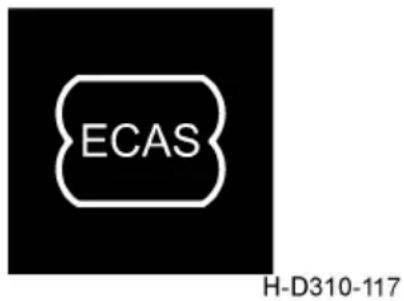
text_image
ECAS H-D310-117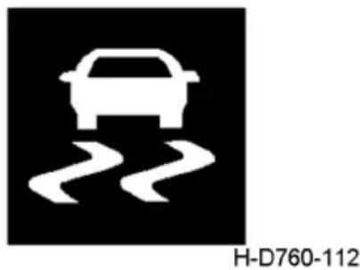
natural_image
White car icon depicting a road with two curved trails, no text or symbols present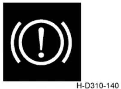
text_image
(●) H-D310-140Brake shoe wear indicator light
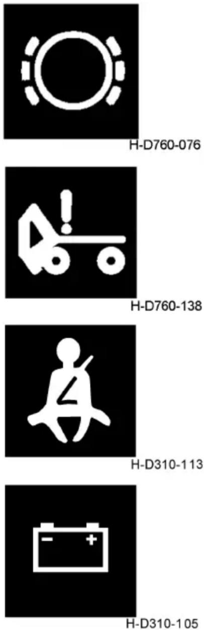
Indicates that the brake shoe or friction disc has been overused, and the thickness of the shoe or friction disc has been lower than the specified requirements. At this time, the brake effect is poor, affecting the safety of driving, and the indicator is on.
Cab lock not in place indication
When the cab lock is not in place, the indicator light is on.

CAUTION:
Do not continue driving when the light is on.
Safety belt indicator light
When the driver does not fasten the safety belt, the indicator light is on to remind the driver to fasten the safety belt.
Charging indicator lamp
This indicator lamp will be on when the key switch is turned to ON position. And it will go out when the engine is started and the alternator works normally. When the alternator does not work due to a fault during driving, this lamp will be on.

CAUTION:
Never drive the vehicle for a long time with this indicator lamp on.
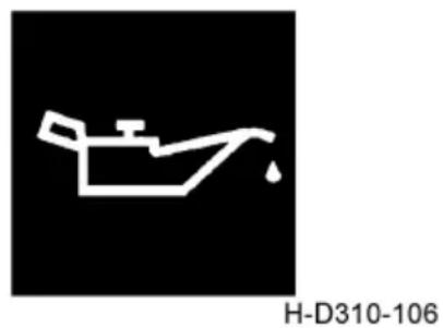
Low oil pressure warning lamp
This indicator lamp will be on when the key switch is turned to ON position, and will go out when the engine is started. And when the oil pressure reduces abnormally in the course of engine running, this lamp will be on to send an alarm.

CAUTION:
Never keep driving when the low oil pressure alarm lamp is on.
ASR system indicator light /ABS system fault flashing code indicator
light
This indicator lights up when the ASR system fails or the ASR system functions. Please contact the technical service center (station) authorized by Dongfeng Commercial Vehicle Co., Ltd. on time to check and repair the vehicle.

text_image
(ASR)H-D310-121
Tractor ABS malfunction indicator lamp
It is for the truck with ABS.
When the tractor ignition switch is at ON position, the ABS will make self-inspection (the ABS solenoid valves make pull-in sound successively), and then this indicator lamp will be on for about 3 s and then go out. If this indicator lamp stays on, it indicates that the ABS is faulty. In that case, press and hold the ABS flashing code diagnostic switch for 1\~3 s, and the ABS fault flashing code indicator lamp will flash the fault code. Please contact the Technical Service Center (Station) authorized by Dongfeng Commercial Vehicle Co., Ltd. for the truck inspection and maintenance in time.

text_image
(ABS)H-D310-123
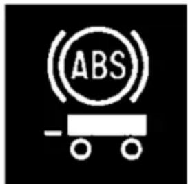
Trouble indicator light of trailer ABS system
If this indicator light is normally on, it indicates that the trailer ABS system has a fault. Whether this indicator light is used depends on the trailer configuration. Please refer to the trailer manual.
text_image
(ABS -H-D310-124A
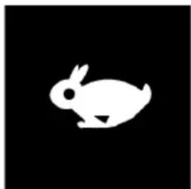
Transmission high gear indicator light
Please refer to the specific configuration of the purchased product.
When the transmission is in the high half block or high block area, the indicator light is on.
natural_image
White silhouette of a rabbit on black background (no text or symbols)H-D310-118
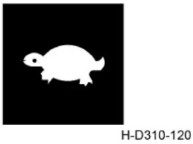
Transmission low gear indicator light
Please refer to the specific configuration of the products purchased.
When the transmission is in low gear, the light is on.
Whether the lamp is installed depends on the product configuration of the specific model.
Cruise lamp
When the cruise function is activated, the indicator light is on
Suitable only for vehicles equipped with cruise system.
Transmission fault indication
The indicator lights up when the transmission fails.
MIL indicator lamp
When the key switch turns to 'ON' position, the MIL light turns on. After the engine starts, if there is no OBD failure, the MIL lamp will be off within 10 seconds. If there is an OBD fault, MIL will continue to light or blinking, if found MIL light, instrument of the LCD panel will display the corresponding fault information (such as lack of reactant, NOx sensor failure, see the fault list), please immediately to solve the fault, otherwise the engine will enter the falling torque mode, vehicle can't use normally.
natural_image
White silhouette of a turtle on black background, labeled H-D310-120 (no other text or symbols)
text_image
H-D310-127
text_image
H-D760-077
text_image
=!→ H-D310(K40H)-001EBS system failure indicator
If this indicator is on, the EBS system is down. Please contact the authorized technical service center (station) of dongfeng commercial vehicle co., LTD to inspect and repair the vehicle.

text_image
EBSH-D760-193
AEBS system failure indicator
If the indicator light is on, the ABES system is out of order. Please contact the authorized technical service center (station) of dongfeng commercial vehicle co., LTD to inspect and repair the vehicle.
natural_image
Pure white road sign icon on black background, no text or symbols presentH-D760-194
ACC system failure indicator
If the indicator light is on, the ACC system is out of order. Please contact the authorized technical service center (station) of dongfeng commercial vehicle co., LTD to inspect and repair the vehicle.
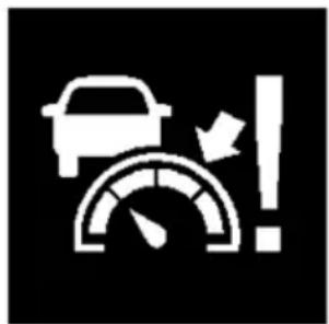
natural_image
Stylized white icon showing a car, speedometer, and warning sign (no text or symbols)H-D760-195
LDWS system failure indicator
If this indicator light is on, it indicates that the LDWS system is out of order. Please contact the authorized technical service center (station) of dongfeng commercial vehicle co., LTD to inspect and repair the vehicle.
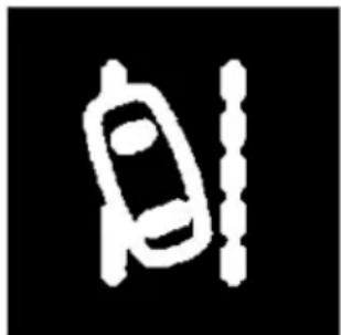
natural_image
Simple white line drawing of a car on a black background (no text or symbols)H-D760-196
Exhaust system high temperature (HEST)
indicator light
When the lamp appears, the exhaust temperature will be higher. At this point, regeneration may be under way.

CAUTION:
When this indicator light is on, make sure the outlet of the exhaust pipe does not point directly to anything that can melt or burn An explosive object or person.
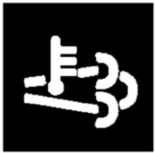
natural_image
Abstract white line drawing on black background with no text or symbolsH-HEST-001
driver warning lights
When the light appears, the driver's warning system starts, and the vehicle will limit the torque or speed after a certain time.

natural_image
Simple white icon depicting a boat with water and a droplet, no text or symbols presentH-JSYJGD-001
DPF regeneration indicator light
When the lamp appeared, the DPF carbon load level had reached a certain level and needed to be regenerated.
At this point, the driver is required to provide conditions conducive to active/passive regeneration, such as a sustained speed greater than 70km/h for 30-45min. You can also choose to carry out parking regeneration or go to the service station authorized by dongfeng commercial vehicle co., LTD for processing.
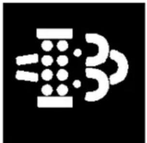
natural_image
Abstract black-and-white graphic with white geometric shapes (no text or symbols)H-DPFZSZSD-002
When the lamp appeared, the DPF carbon load level had reached a certain level and needed to be regenerated.
At this point, the driver is required to reactivate or go to the service station authorized by dongfeng commercial vehicle co., LTD.
natural_image
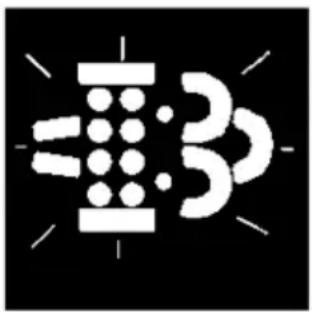
Abstract black-and-white graphic with geometric shapes and radiating lines (no text or symbols)H-DPFZSZSD-003
When the lamp appeared, DPF carbon load levels had reached a high level and needed to be regenerated.
At this point, the driver needs to go to the service station authorized by dongfeng commercial vehicle co., LTD.

natural_image
Two white line-art icons on black background: one with a gear-like head and arrow, the other with a valve-like handle (no text or symbols)H-DPFZSZSD-004
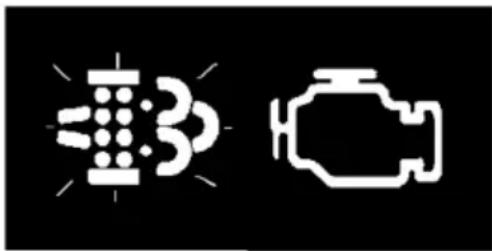
When the lamp appeared, the DPF carbon load level had reached a certain level and needed to be regenerated.
natural_image
Two white line drawings of a car head and its side profile, no text or symbols present.H-DPFZSZSD-005
At this point, the driver dongfeng commercial vehicle co., LTD. Authorized service station for processing.

CAUTION:
- During regeneration, the turbocharger will make a slight "tut" sound, which is a normal phenomenon.
- During regeneration, the temperature is relatively high. Please avoid gas stations, gas stations and other places with flammable materials, schools and other places with dense personnel.
- The use of inferior fuel will significantly shorten the regeneration cycle and cleaning mileage, which will lead to the increase of fuel consumption and maintenance costs.
Instrument buzzer alarm
The safety belt is not connected with the alarm, the water temperature is too high, the water level is too low and the air pressure is too low. While the buzzer is alarming, there are corresponding alarm lights on the instrument.
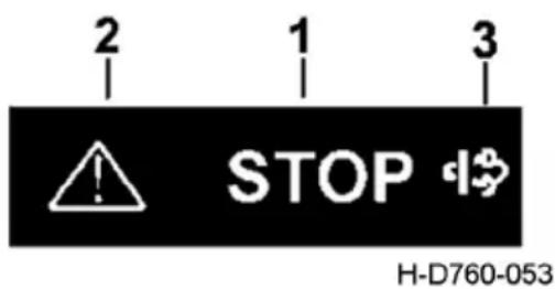
Engine stop and maintenance alarm lamp
When the key switch is switched from OFF to ON, the engine is shut down and the engine maintenance alarm lamp is switched ON for 3 seconds.
Engine stop alarm indicator: the indicator continues to light, indicating a major fault in the engine electronic control system.
If the light is on during driving, you should immediately find a safe place to stop and contact dongfeng commercial vehicle technical service center to check and repair the engine.
text_image
2 1 3 ! STOP H-D760-053- Engine stop alarm indicator light
- Engine maintenance alarm indicator lamp
- MIL indicator light
Engine maintenance alarm indicator light: this indicator light keeps on, indicating that there is no major fault in the electric control system of the engine. At this time, the engine can still work, but the electric control system will adjust the power, speed and other operating parameters of the engine according to the influence of the fault. If this indicator light continues to light up during the use of the vehicle, please contact the technical service center (station) authorized by Dongfeng Commercial Vehicle Co., Ltd. to check and maintain the engine.
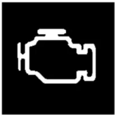
MIL indicator light
When the key switch is switched to "ON", the MIL light is lit. After the engine starts, if there is no OBD fault, the MIL lamp will be off within 10s; If there is a OBD fault, MIL will continue to light or blinking, if found MIL light, instrument of the LCD panel will display the corresponding fault information (such as lack of reactant, NOx sensor fault, etc.), please the driver immediately to solve the fault, otherwise the engine will enter the fall when a serious fault torsional mode, vehicle can't normal use.
natural_image
White silhouette of a car or vehicle inside a container, on black background (no text or symbols)H-D760-164A
Multi-information display and adjustment
1, startup interface
Startup interface: the ignition lock is placed in ON gear, the instrument is self-checked, and the LCD displays the interface of dongfeng logo 3s.
natural_image
Abstract circular logo design with no text or symbols on the shape itself2, Running interface
After the self-inspection, enter the driving interface
- Ambient temperature display: display the current outdoor temperature, display "--" in case of overrange or failure.
-
The air pressure of the front circuit, ranging from 0 to 1.30mpa, is 10 grids, with 0.13mpa for each grid, and the display accuracy is 0.01mpa.
-
Total mileage: display range 0-999999km
-
Automatic transmission gear, A/M, E/P mode.
-
Instantaneous fuel consumption: display range: 0-60.0l /100Km, over-range display --.
-
Air pressure in the back loop, ranging from 0 to 1.30mpa, with a total of 10 light columns, each 0.13mpa, with a display accuracy of 0.01mpa.
-
Speed display: when the real-time speed of the vehicle has a fault, this position will display the fault.
-
Time display: display the current time, menu can choose 12h system, or 24h system
-
Alarm icon, one group can display 4
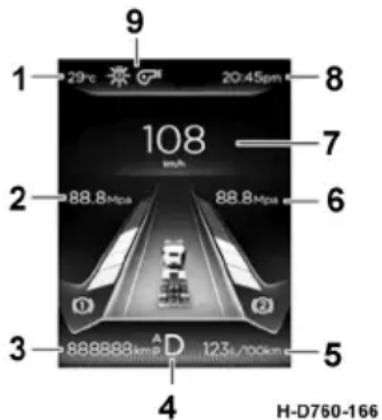
text_image
1 29pc 20:45pm 108 insh 8 7 6 3 88.8Mpa 88.8Mpa D 123s/100km 4 H-D760-166The default driving interface displays the total mileage + average fuel consumption. When stopping, press "return" button for less than 1 second to switch to the display of subtotal mileage + fuel consumption.
Interface switching 1
Axial load and ambient temperature: if there is an axial load display function, the axial load (driving shaft) will be displayed for 10 seconds after power on, and then the ambient temperature will be displayed.
1.
- Speed, fault code, reminder, etc.: text and icon display, used for fault alarm and prompt display, multiple simultaneous triggers, according to the priority display.
- Air pressure in the front circuit, air pressure in the parking circuit and oil pressure: long press the return button for 1\~3 seconds. When releasing, the picture column will be switched.
- Total mileage and subtotal mileage: short press return button <1s, switch when releasing, display range of subtotal mileage is 0\~9999.9km.
- Instantaneous fuel consumption and subtotal fuel consumption:
A. The total mileage + urea level is displayed on power, and the return button can be cut to the total mileage + instantaneous fuel consumption, subtotal mileage + subtotal fuel consumption;
B. Automatically switch to total mileage + instantaneous fuel consumption after engine start, only cut once; You can still loop through using the return button.
- Air pressure and battery voltage in the back circuit: long press the return key 1\~3s, switch the diagram column when releasing, and the display range of urea level is 0\~100% with an accuracy of 1%; Battery voltage display range 12\~32v, accuracy 0.1v.
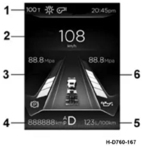
text_image
1 100 T 20:45pm 2 108 km/h 88.8 Mpa 88.8 Mpa 3 6 4 888888 kmPa AD 123 L/100km 5 H-D760-167Interface switching 2
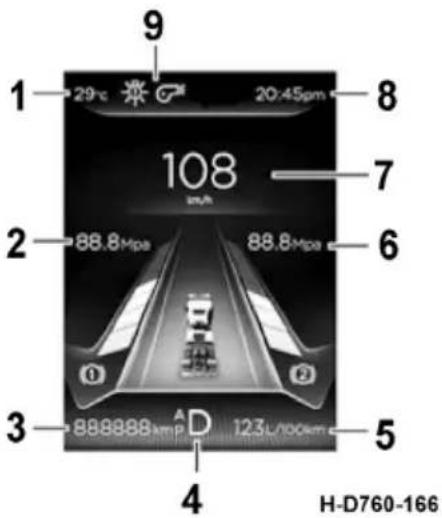
text_image
1 29°C 求 20:45pm 108 mA 2 88.8Mpa 88.8Mpa 3 888888A D 123L/100cm 4 H-D760-166
text_image
29°C 100 T 20:45pm 车道左偏离 88.8Mpa 88.8Mpa ① ② 888888kmD 123L/100km H-D760-169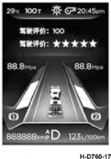
text_image
29°C 100T 20:45pm 驾驶评价:100 驾驶评价:★★★★★ 88.8Mpa 88.8Mpa ① ② 888888A D 123L/100km H-D760-17
text_image
29°C 100T 前方碰撞提醒 88.8Mpa 88.8Mpa ① ② 8888884mP D 123L/100km H-D760-1713, alarm interface popover
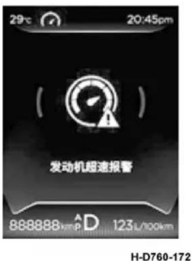
text_image
29°C 20:45pm ( ) 发动机超速报警 888888 km P A D 123L/100km H-D760-172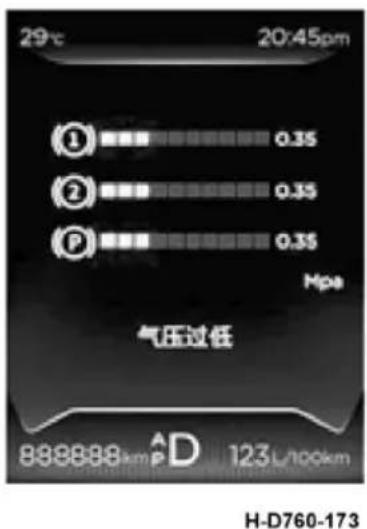
text_image
29°C 20:45pm ① 0.35 ② 0.35 P 0.35 Mpa 气压过低 889888 km^D 123 L/100km H-D760-173- Alarm ICONS are divided into two categories: alarm and indication:
a). nalarm: large icon + small icon display. After 1.5s, the large icon disappears while the small icon remains
b). Indicator class: small icon display.
- Alarm icon description:
a). the alarm icon is divided into small icon and large icon, and the color is divided into red, yellow, blue, green and white (arranged in order of priority from high to low);
b). Display priority ordering, the former icon is displayed, and the latter icon appears;
c). Four small ICONS can be displayed at the same time. When there are more than one small icon, it will be displayed in a 10s cycle;
d). When the large icon appears, the corresponding small icon appears simultaneously. After 1.5s, the large icon disappears and only the small icon is displayed.
4, menu interface
When stopping, press "confirm" less than 1s to enter the menu interface, and select the content through "up" and "down" keys.
Menu interface 2
- Vehicle information
Under "vehicle information", "K value", "braking system information" and "tire pressure monitoring system" can be inquired.
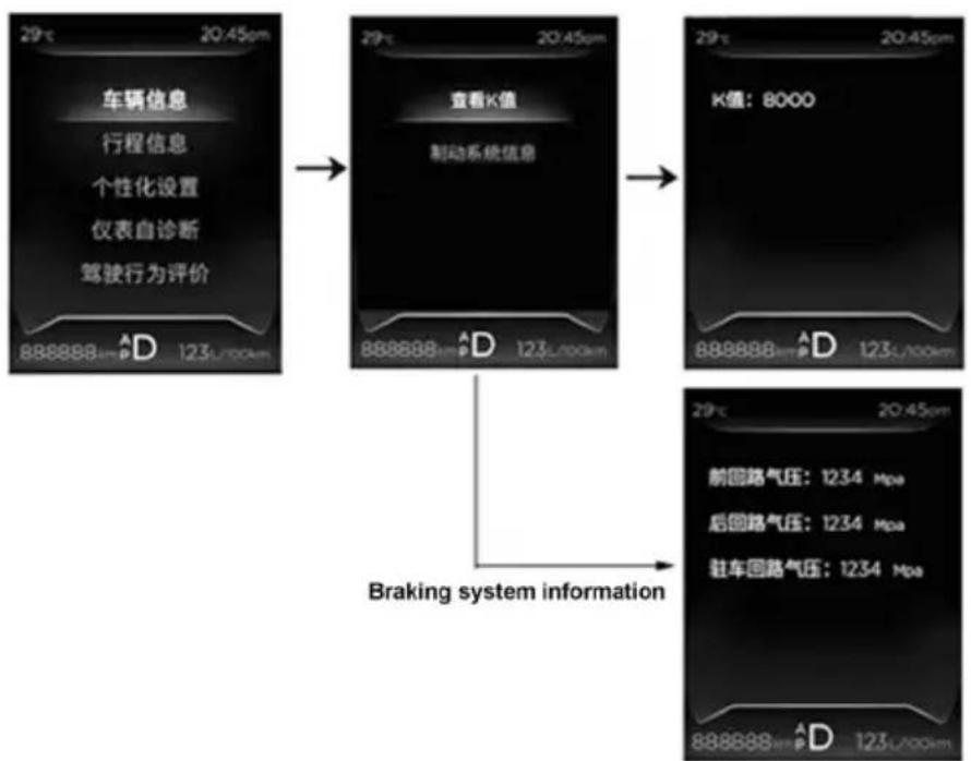
flowchart
graph TD
    A["车辆信息\n行程信息\n个性化设置\n仪表自诊断\n驾驶行为评价"] --> B["查看K值\n制动系统信息"]
    B --> C["K值: 8000"]
    C --> D["前回路气压: 1234 Mpa\n后回路气压: 1234 Mpa\n驻车回路气压: 1234 Mpa"]
    D --> E["Braking system information"]
H-D760-174
2. Itinerary information
Under "trip information", you can find "mileage", "fuel consumption", "working hours", "average speed" and "date and time".
2.1 "total mileage" and "subtotal mileage" can be inquired under "mileage";
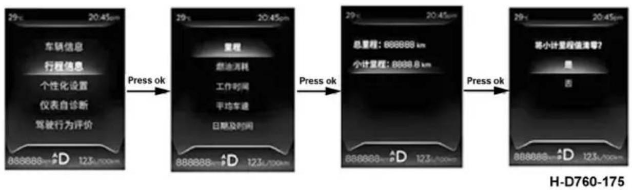
flowchart
graph LR
    A["车辆信息"] -->|Press ok| B["里程"]
    C["行程信息"] -->|Press ok| D["燃油消耗"]
    E["个性化设置"] -->|Press ok| F["工作时间"]
    G["仪表自诊断"] -->|Press ok| H["平均车速"]
    I["驾驶行为评价"] -->|Press ok| J["日期及时间"]
    B -->|Press ok| K["总里程: 888888 km"]
    D -->|Press ok| L["小计里程: 8888.8 km"]
    K --> M["将小计里程值清零?"]
    L --> M
    M --> N["是"]
    M --> O["否"]
2.2 "average fuel consumption", "subtotal fuel consumption" and "total fuel consumption" can be inquired under "fuel consumption";
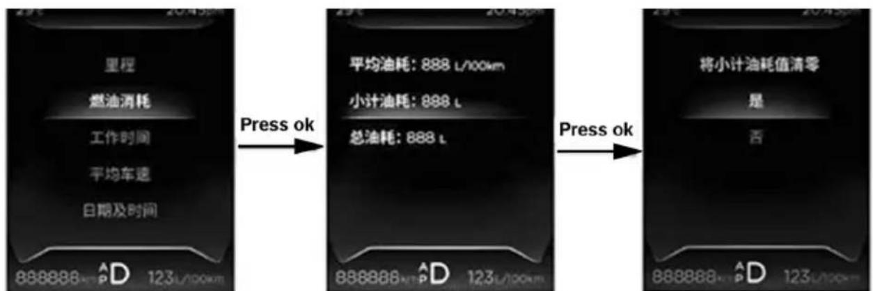
2.3 working hours: search "engine working hours" and "idle time";
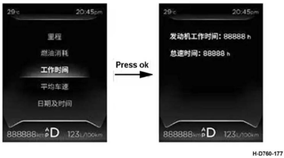
2.4 average vehicle speed: check the "cumulative average vehicle speed" and "short-range average vehicle speed";
2.5 date and time: the date and time can be checked and adjusted. It is not available with the driving recorder.
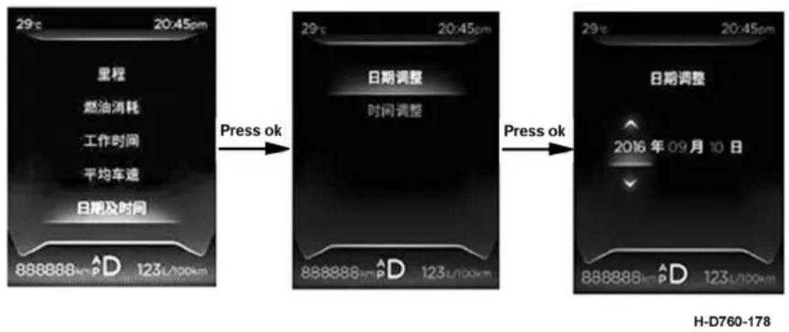
Under "personalization", you can query "language", "unit of measurement", "display effect" and "time display mode".
3.1 language: switch between Chinese and English (not yet implemented);
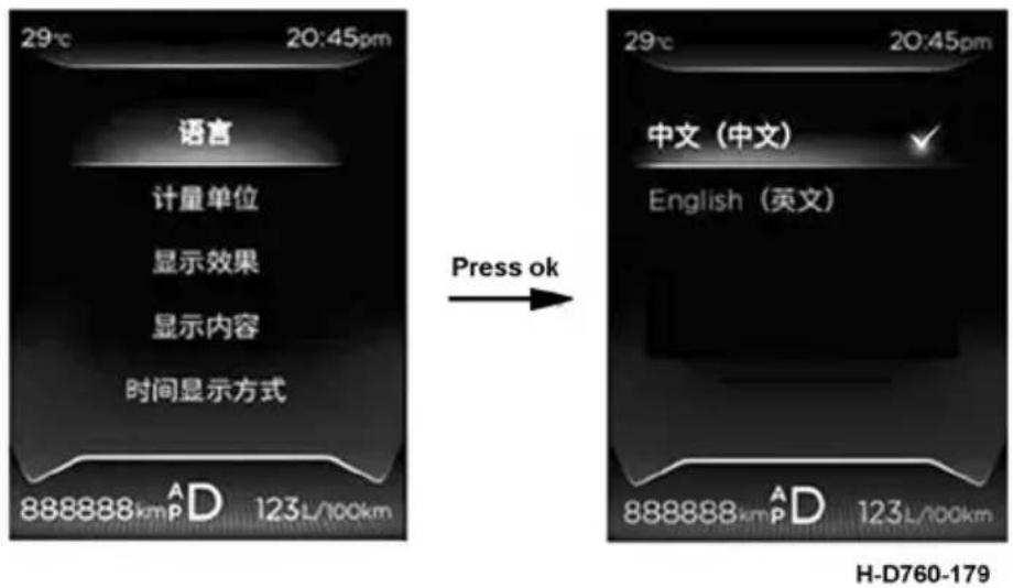
3.2 units of measurement: switch between "distance", "speed", "fuel consumption", "temperature" and "pressure";
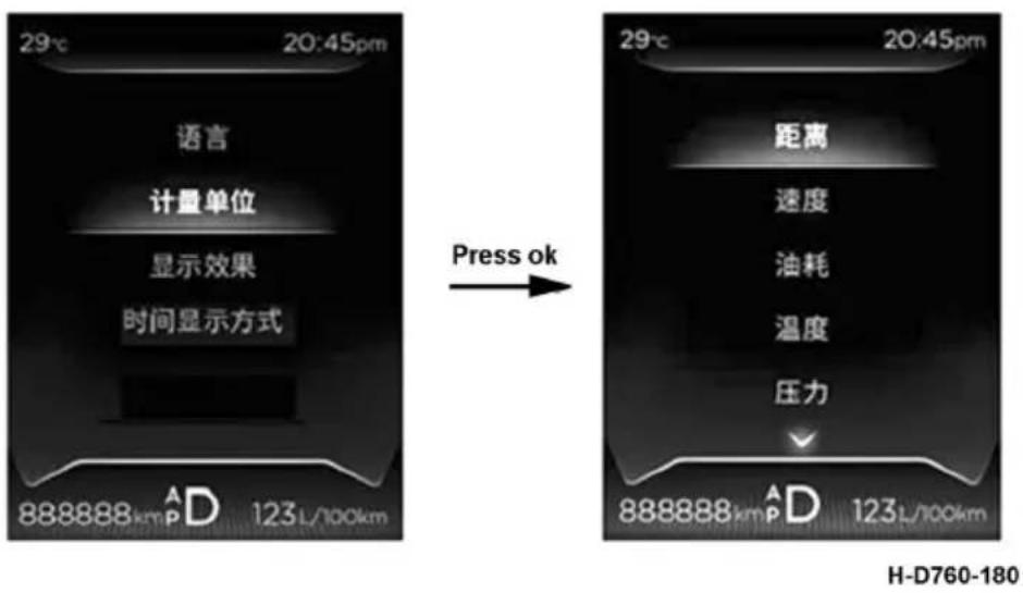
3.3 Display effect: LED, backlight, LCD brightness adjustment;
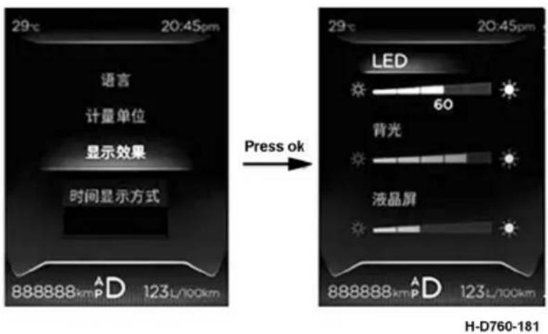
3.4 time display: 24 hours and 12 hours are optional.
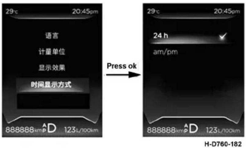
- Instrument self-diagnosis
Under "instrument self-diagnosis", you can choose to diagnose information including pointer, alarm lamp, buzzer, LCD display and sensor.
4.1 pointer: pointer self-test can be carried out, zero - full - zero;
4.2 alarm light: LED self-check, all LED are bright;
4.3 loudspeaker: self-check three times;
4.4 LCD: LCD self-test;
4.5. sensor information: sensor power supply and signal information query.
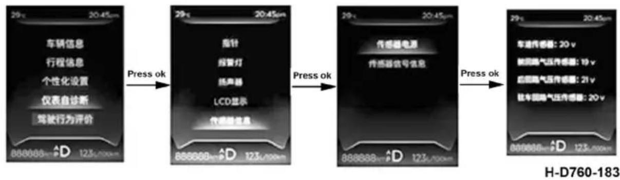
flowchart
graph LR
    A["车辆信息<br>行程信息<br>个性化设置<br>仪表自诊断<br>驾驶行为评价"] -->|Press ok| B["指针<br>报警灯<br>扬声器<br>LCD显示<br>传感器信息"]
    B -->|Press ok| C["传感器电源<br>传感器信号信息"]
    C -->|Press ok| D["车油传感器: 20 v<br>航空排气压传感器: 19 v<br>航空排气压传感器: 21 v<br>航空排气压传感器: 20 v"]
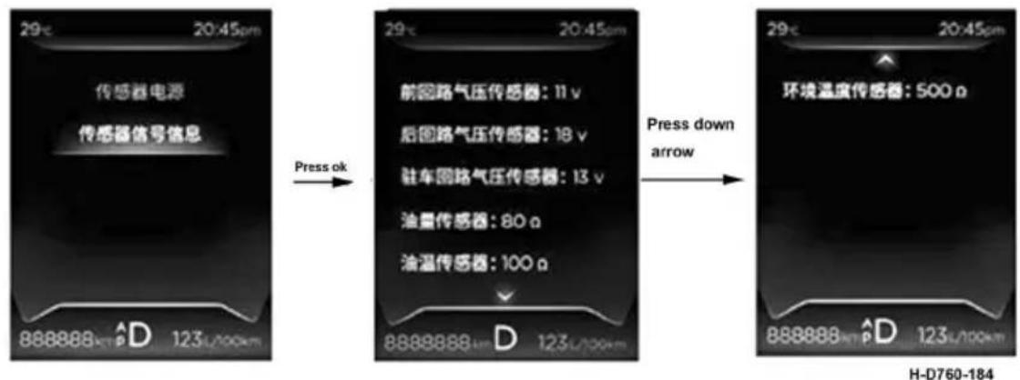
text_image
29c 20:45pm 传感器电源 传感器信号信息 Press ok 29c 20:45pm 前回路气压传感器: 11 v 后回路气压传感器: 18 v 驻车回路气压传感器: 13 v 油量传感器: 80 a 油温传感器: 100 a Press down arrow 环境温度传感器: 500 a 888888 km^D 123 L/100km H-D760-184- Under "driving assistance", you can query or set "mode record query", "subtotal mode", "mile-age mode", "time mode" and "automatic record".
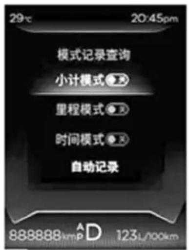
Please refer to the specific configuration of your vehicle.
Mechanical
Turning this switch can connect or disconnect the main power of the complete vehicle. Power should be cut off during the servicing and maintenance of electrical system of the vehicle to protect electrical equipment.
Find the master power switch handle in the vehicle tool and plug it into the battery switch, as shown in figure 1.
Turn the handle to horizontal position: close; Turn the handle to vertical position: open.
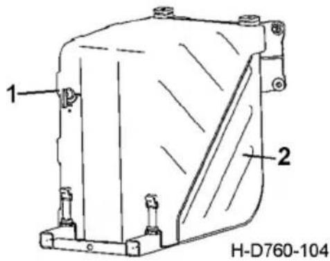
text_image
1 2 H-D760-104- Master power switch
- Battery bracket

CAUTION:
- It is strictly prohibited to disconnect the master power switch when the engine is running.
- After switching the power supply, please pay attention to pulling out the switch handle and receiving it.
Rocker Switch
Please refer to the specific configuration of your vehicle.
Danger alarm light switch
Press the danger alarm switch: all the turn signals are flashing at the same time to remind other vehicles to pay attention. At the same time, the danger alarm switch also has a flashing light indication
Air horn selection switch
The default is the electric horn, press the air horn selection switch to select the air horn.
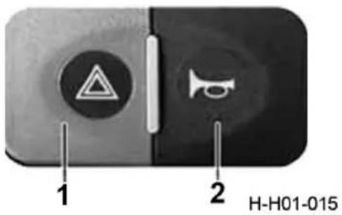
text_image
1 2 H-H01-015- Danger alarm light switch
- Air horn selection switch
Ceiling lamp switch
Press the ceiling lamp switch to turn on the light. Press the switch again to turn off the light.
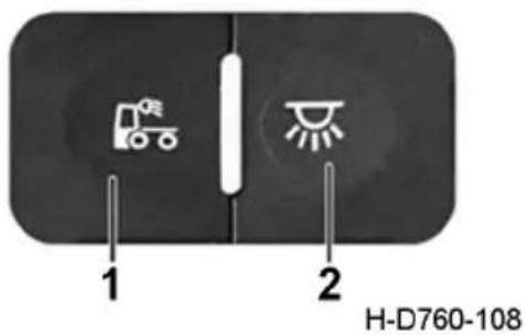
text_image
1 2 H-D760-108- Rear light switch
- Ceiling lamp switch
Electric sunroof switch
This switch is used to open and close of the cab electric sunroof.
Automatically open/close the sunroof
Press the open switch to automatically open the sunroof; Press the close switch to automatically close the s sunroof.
Manually open/close the sunroof
Long press on/off switch: the sunroof glass or sunshade starts to move, and the action time depends on the operation time of the switch. The sunroof stops when the switch is released.
Automatic window closing function
After the power of the whole vehicle is turned off, the sunroof will automatically close after a delay of 5 seconds.
Air dryer heating switch
This switch controls the heater of the dryer, the freezing of dryer exhaust outlet will damage air compressor and other parts. When the switch is in the on position, the dryer heating indicator lights up at the same time. When the ambient temperature is lower than 5 degrees, please turn on the switch. When the ambient temperature is higher than 10 degrees, turn off the switch. Dryer heater is with temperature control switch, if the ambient temperature is higher than the disconnect temperature, the heater will automatically disconnect.
text_image
H-D760-131
text_image
H-D760-132Fuel preheater switch
Turning on this switch at low temperature can preheat fuel at a cold start.
The installation of this switch depends on the configurations of specific vehicle.
Bogie differential lock switch
This switch is a differential lock control switch for middle and rear drive axle bogie differentials. When this switch is turned on and the bogie differential lock starts to work, the bogie differential lock indicator lamp will be on, and meanwhile the buzzer will sound.
natural_image
Simple line drawing of a refrigerator with a gas pump icon on top (no text or symbols)H-D760-133
natural_image
Simple diagram of a divided rectangle with a central circular symbol (no text or labels)H-D760-136

CAUTION:
- Never press the differential lock switch when the truck is running normally.
- Never use the differential lock for long time; otherwise, the differential may be damaged, resulting in excessive wear of tire.
Inter-wheel differential lock switch
This switch is a differential lock operating switch for middle/rear drive axle inter-wheel differential. Press the switch to connect the differential lock. When the inter-wheel differential lock works, the inter-wheel differential lock indicator lamp will be on, and meanwhile the buzzer will sound.
text_image
Diagram showing a door with a circular symbol containing 'H-X' and a horizontal line below it.H-D760-069

CAUTION:
- Never press the differential lock switch when the truck is running normally.
- Never use the differential lock for long time; otherwise, the differential may be damaged, resulting in excessive wear of tire.
E, P mode switch
The switch is used to switch the dynamic mode and economic mode of the vehicle.
E: economic model
P: dynamic mode
ASR function cancel switch
It is suitable for vehicle models equipped with ASR function release switch.
On vehicles equipped with ASR function, the ASR function can be turned off by the ASR function switch. The specific operation is as follows:
text_image
E/PH-D760-018
H-D760-148
Press the ASR function off switch >0.3 seconds, then disconnect, the ASR function is off, the instrument ASR light is on. Press the ASR function > 0.3 seconds again to close the switch, then disconnect, and the ASR function will be restored. The ASR function will be automatically activated when the power supply is re-energized after shut down. This switch is recommended for use on dry and flat surfaces or differential locks.
Retarder disengage switch
After using this switch, the retarder function is turned off.
natural_image
Simple diagram of a domino with a cross symbol inside, no text or labels presentH-D760-149
Auxiliary brake linkage closing switch
After using this switch, the auxiliary brake linkage is closed, and only the main brake comes into effect after stepping on the brake pedal. It is recommended to use this switch when driving on rain-snow slippery road or when driving on separate tractor.
H-D760-149
LDWS, FCWS transfer switch
Open or close the function of LDWS and FCWS by pressing the key.
Main and auxiliary tank change-over switch
The switch allows you to choose whether to use the main tank or the auxiliary tank. The amount of oil in the main and auxiliary fuel tanks is indicated by the fuel gauge. By means of the switch, the fuel gauge can display the amount of oil in the main and auxiliary fuel tanks respectively.

CAUTION:
After switching from the main tank to the auxiliary tank, switch from the auxiliary tank to the main tank at an interval of more than 3 seconds.
text_image
H-D760-188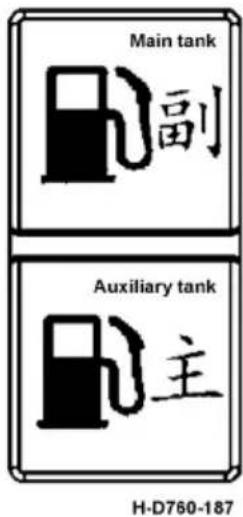
text_image
Main tank 副 Auxiliary tank 主 H-D760-187Light knob switch
Knob switch
The knob is shown in figure 6 of H-D760-016. You can rotate and push buttons. When rotating, the position light and headlight gear can be selected, and the fog light can be switched on and off by pressing down and pulling up.
Light knob - position light
When the knob is rotated to this position, all position lights (front lamps) will be lit, including the following lamps:
Front position light, front end-outline light, rear position light, rear end-outline light, side marker light, license plate light.
When the knob is turned to this point, the
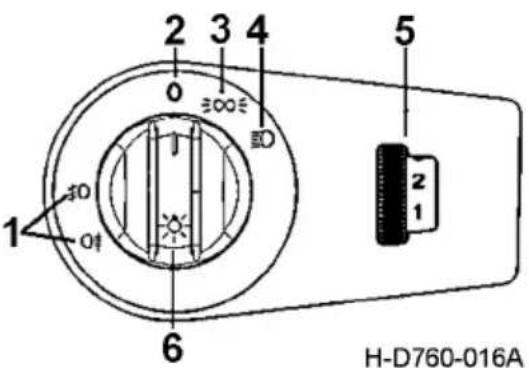
text_image
2 3 4 0 300 5 1 30 01 6 2 1 H-D760-016A- Front and rear fog lamp and backlight
- Light knob OFF gear
- Light knob position light gear
- Light knob headlamp gear
- Front headlight electric adjusting switch
- Knob
default is to turn on the low beam light. To switch to the high beam light, you need to lift the combination switch.
Fog lamp operation
The light knob switch must be in position light or headlight gear.
Press the button to turn on the front fog light and press it again to turn on the rear fog light; The button is pulled up to turn off the rear fog light and pulled up again to turn off the front fog light.
Electric adjustment of front headlights
When the vehicle is empty, adjust the light to the specified position, and the switch gear is at 0. After loading the vehicle, the light inclination angle will rise, adjust the switch 1, 2 and 3 gears downward, and then the inclination angle will drop to meet the regulations.
Switching visibility
The light knob switch has backlight
The headlight switch has backlight
Electric adjustable headlight switch
When the vehicle is under no-load operation, adjust the light to the standard position. At this time, the switch position should be set at 0. After the vehicle is loaded, the lighting angle will rise, adjust the switch to 1,2, and the tilt angle will drop to comply with the regulations.
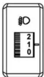
text_image
D 2 1 0H-DTKG-001
Combination switch, steering wheel switch
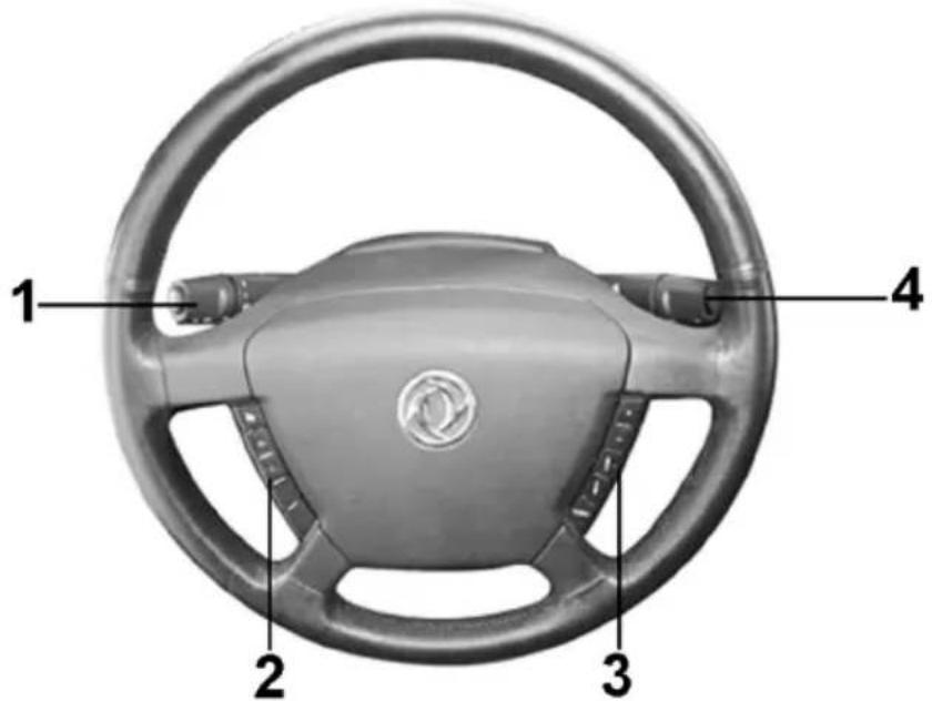
text_image
1 2 3 4H-D760-022
- Wiper, horn, low and high beam switch
-
Cruise switch, bluetooth phone (optional)
-
Audio and volume switch
- Auxiliary brake, AMT shift switch
Steering wheel switch
Cruise operation:
It is applied for the vehicle with cruise system.
The cruise function is off by default
The cruise system allows you to keep the vehicle above 30km/h without stepping on the throttle pedal. When the speed is higher than 30km/h, press the cruise ON/OFF switch to turn ON the cruise function. At this time, the cruise indicator light flashes and press the s-switch to enter the cruise. At this time, the cruise indicator light is always on.
After entering the cruise, every time clicking "R+", the speed will increase by 1km/h; Long press "R+", the speed will continue to increase. Click "S-" every time, the speed decreases by 1km/h; Long press "S-", the speed will continue to decrease. If the vehicle has entered cruise during operation, if it exits, press "R+" to resume the last cruise.
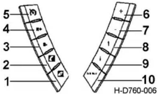
text_image
5 4 3 2 1 6 7 8 9 10 H-D760-006- Bluetooth phone hang up switch (optional)
- Bluetooth phone pickup switch (optional)
- Cruise S-switch
- Cruise R+ switch
- Cruise ON/OFF switch
- Volume + switch
- Volume - switch
- Track + switch
- Track - switch
- Mode selection switch
Exit in one of the following ways Cruise:
- Step on the brake pedal;
- Use engine brake;
- Press the cruise ON/OFF switch again;
- The speed is lower than 20km/h;
- Step on the throttle to exit cruise temporarily, release the throttle to cruise again;
- If you press the clutch pedal, the cruise function will exit. If you release the pedal, the cruise function will resume (only applicable to models with manual transmission).

CAUTION:
-
"S-" means setting speed/reducing speed; "R+" means to restore speed/increase speed.
-
If the cruise system fails, the cruise system function will be automatically cancelled and the cruise indicator light on the instrument will be off.

Warning:
Do not use the cruise control system when the vehicle is driving in the following situations, or it may cause the vehicle to lose control and cause an accident.
-
When it is impossible to keep the vehicle running at a constant speed.
-
When the vehicle is driving in a bad traffic environment.
-
When the vehicle is driving under the condition that it needs to change its speed frequently.
-
When the vehicle is driving in a windy environment.
-
When driving on curved roads or mountains.
-
When the vehicle is on a smooth road surface (rain, snow, ice, etc.).
Low idle speed adjustment
Only applicable to vehicles equipped with cruise system devices.
Operate the cruise switch for 3 cycles within 2 seconds (i.e., OFF-ON-OFF-ON-OFF-ON) to adjust the idle speed, press "R+", and the engine speed will continue to rise; Press "S-" and the engine speed continues to drop.
The Cummins ISZ engine of this series is equipped with a low idle speed of 700r/min. Low idle speed adjustment range is 600\~800r/min.
Audio switch operation:
Operation volume + switch: volume increases
Operate volume - switch: reduce volume
Operation track + switch: track up turn
Operation track - switch: track down turn
Operation mode selection switch: the default mode for switching in FM1/FM2/AM is FM1 mode, and the cycle is in order of FM1, FM2 and AM
Horn switch
By default, press the horn switch and the electric horn will ring. To switch the air horn, press the air horn selection switch.
Turn signal lamp
When the left handle of the combination switch is pushed forward, the right front turn signal light, the right rear turn signal light and the right turn signal light will be lit; When the left handle of the combination switch is turned back, the left front turn signal light, the left rear turn signal light and the left turn signal light are lit.
Switching between low and high beam light
When the light knob is in front of the light, the near light is turned on.
When the combination switch is operated to the "middle" position, the high beam light will be lit; Switch back to the original light state.
When the combination switch is operated to the "up" position, the high beam light will be lit; After the switch is back in position, the light completes a switch.
Idle stop
Cummins series engine has idling stop characteristics.
By idling the engine for a period of time (without driving operation), idling stop can reduce fuel consumption and extend engine life. Before stopping, the engine maintenance alarm light flashes for about 30 seconds, warning the driver of impending shutdown. The driver can cancel the stop and simply step on the brake, clutch or accelerator pedal during the warning period.
Windshield wiper and washer switch
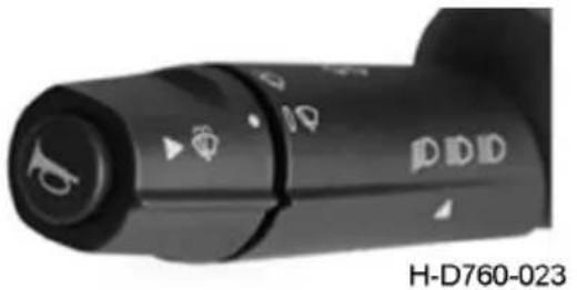
natural_image
Close-up of a black DDD-branded device control knob with indicator lights (no readable text or symbols beyond branding)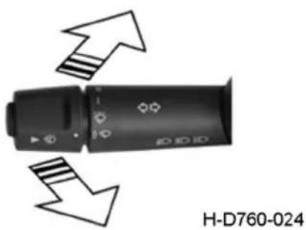
natural_image
Device with directional arrows indicating movement or change, no visible text or symbols on the device itself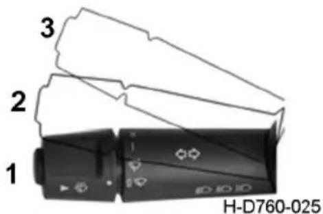
text_image
1 2 3 H-D760-025- Original position
- Middle position
- Up position
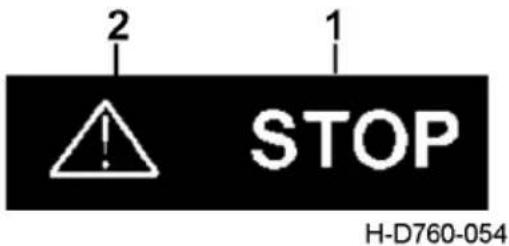
text_image
2 1 STOP H-D760-054- Engine stop warning indicator
-
Engine maintenance warning indicator
-
The wiper knob switch to intermittent gear: the wiper works intermittently;
- Turn the wiper knob switch to low speed gear: the wiper works at low speed;
- Turn the wiper knob switch to high speed gear: wiper works at high speed.
- Press the washer switch: start spraying water, and the wiper works at a low speed;
- Release the washing switch: then stop spraying water, and the wiper will continue to work for 2 cycles before stopping.
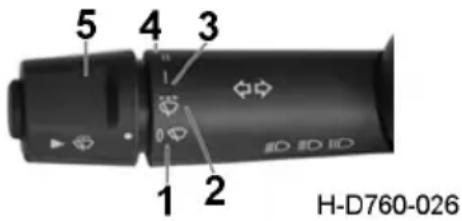
text_image
5 4 3 1 2 H-D760-026- Wiper OFF gear
- Intermittent wiper
- Low speed gear of wiper
- High speed gear wipers
- Washer switch

CAUTION:
- Please use the wiper together with the washer so as to prevent windshield scratch.
- Never use the washer without washer fluid.
Use of auxiliary brake
Please refer to the specific configuration of purchased products.
In any case, the combination switch is pushed forward to enter the auxiliary brake. The combination switch is pushed forward as "add gear", when the gear is the highest gear, then add gear operation is no response. The combination switch is pushed backward to "reduce gear". When the gear position is the lowest, the auxiliary brake will be closed if the gear reduction operation is carried out.
The instrument shows the working position of the auxiliary brake.
When adding or reducing gear, only one gear can be used step by step, but the auxiliary brake can be directly turned off by the switch button.
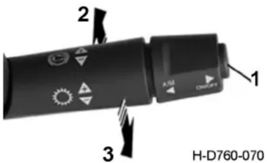
text_image
2 A/RJ CRC/CFR 1 3 H-D760-070- Auxiliary brake switch button
- "Add gear" operation
- "Reduce gear" operation
Auxiliary brake classification:
Please refer to the specific configuration of purchased products.
Match engine brake + exhaust brake + retarder
Gear number: 4.
Position description:
1 gear: constant speed gear;
2\~4 gears: auxiliary brake gear (braking capacity increases step by step)
Match engine brake + exhaust brake or separate engine brake
Gear number: 2.
Position description:
Gear 1: braking force output;
Gear 2: full braking power output
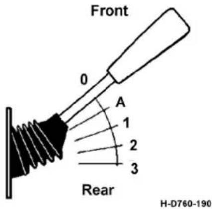
text_image
Front 0 A 1 2 3 Rear H-D760-190
CAUTION:
-
Use on wet and slippery roads carefully, and no auxiliary braking is allowed on low adhesion roads such as snow and ice.
-
When the auxiliary brake works, if the accelerator pedal is pressed or the ABS is activated, the auxiliary brake will be closed. When the above conditions disappear, the auxiliary brake will return to the original working state.
Key switch
-
lock (locking position): the key can only be inserted and taken off at lock position.
-
ACC (accessory position): when the key is turned clockwise to ACC position, the related accessories will be electrified.
-
ON (ignition position): when the key is turned clockwise to ON position, the ignition status is activated and the instruments will start working.
-
START (start position): when the key is turned clockwise to START position, the engine will be started. When released, the key will return to ON position automatically.
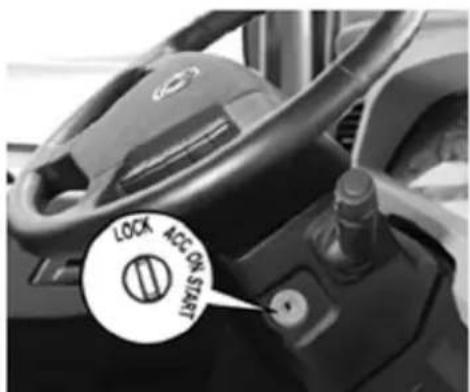
text_image
LOCK ACC ON STARTH-D760-027

CAUTION:
- It is forbidden to turn the key to START position when the engine is running to avoid engine damage.
- Do not start for a long time or frequently; otherwise battery electricity loss or starter damage will be caused.
- The time for starting the engine each time should not exceed 30 seconds. The interval of two starts should be no less than 2 minutes.
- For the sake of safety, always depress the clutch pedal when starting the engine.
- The main power must be shut off after 20s of engine stopped.
Instructions for ACC switch
- ACC mode needs to be entered from cruise mode.
- After pressing the cruise (CC) button, press either R+ or S- to enter the cruise mode. At this point, the default speed is the actual speed when entering cruise.
- Under the premise of entering cruise mode, press the ACC button to enter adaptive cruise mode. Under adaptive cruise mode, press the ACC button again to exit adaptive cruise and return to cruise mode.
Integrated door switch
The driver's side
Window regulating
Manual: long press the up/down button of the switch, and the glass will rise/fall accordingly; Release the up/down button and the glass will stop.
Automatic: short press the down button of the switch to automatically lower the glass; During the descent, press the up/down button again, and the glass stops until the switch is operated again.
Door unlock and lock
Press the unlock button, the two doors are locked, and the cab door handle is automatically changed to the locking position. Press the lock button to unlock both doors, and the cab door handle is automatically changed to unlock position.
Rearview mirror adjustment
First you need to select the rearview mirror. Press "L" to select the left mirror; Press "R" to select right
Mirror. Press each direction key of the rearview mirror direction adjustment button to adjust the direction of the rearview mirror. Release the switch to stop adjustment.
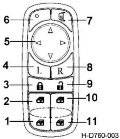
text_image
6 5 4 3 2 1 7 8 9 10 11 H-D760-003- Driver's side glass "lift" switch
- Driver's side glass "drop" switch
- Door lock switch
- Left rearview mirror selection switch
- Rearview mirror direction adjustment button
- Rearview mirror heating indicator light
- Rearview mirror heating switch
- Right rearview mirror selection switch
- Door unlock switch
10.Passenger side glass "lift" switch
11.Passenger side glass "drop" switch
Rearview mirror heated
Click the switch to heat the rearview mirror, and the rearview mirror will automatically heat for 20 minutes before stopping. When in the heating state, press the switch again and the heating stops.

CAUTION:
Continuous or frequent operation of window regulator to a certain number of times, may appear glass lifting function temporarily malfunction. This is more likely to happen in warmer environments. This is not a fault, but the window regulator motor overheating into the protective state. Just wait patiently for a few minutes, when the motor temperature drops naturally, the glass lifting function will automatically return to normal.
Passenger side
There is only window regulator switch on the passenger side:
Manual: long press the up/down button of the switch, and the glass will rise/fall accordingly; Release the up/down button and the glass will stop.
Automatic: short press the down button of the switch to automatically lower the glass; During the descent, press the up/down button again, and the glass stops until the switch is operated again.
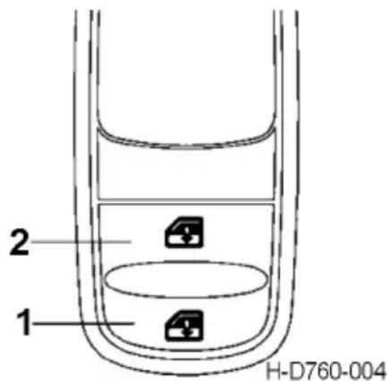
text_image
1 2 H-D760-004- Passenger side glass "lift" switch
- Passenger side glass"drop"switch

Warning:
- During the operation of the window, if contact occurs, the window must be moved in the opposite direction.
- When the driver operates the electric window regulator switch on the passenger side, he must ensure that there is no obstacle preventing the windows from closing properly.
- The driver must ensure that passengers use the electric window regulator switch correctly.
- Don't put your head and hands out of the window when the electric window is going up.
Climate Control System Thermostatic air conditioning controller
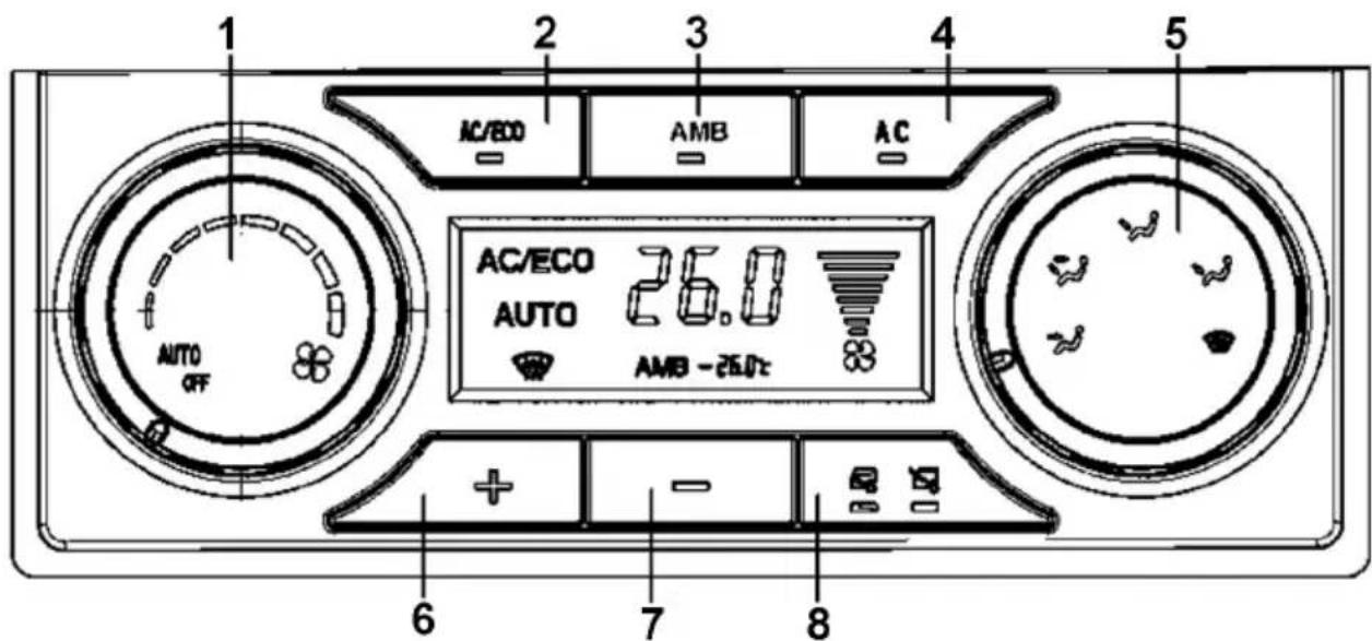
text_image
1 2 3 4 5 AC/ECO AMB AC AC/ECO AUTO 26.0 AMB -26.0°C AUTO OFF + - 7 8- Wind speed control knob
- AC/ECO button
- AMB button
-
Air conditioning button
-
Mode control knob
- Temperature setting + button
- Temperature setting - button
- Internal and external circulation button
Wind speed control knob
Rotate the wind speed control knob, when the knob is in the OFF position, the fan stops the air output; When the knob is in the AUTO position, the air conditioning system is in the automatic operation state. According to the temperature set by the user and the ambient temperature, the air conditioning automatically
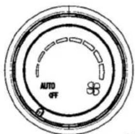
text_image
AUTO OFFH-D760-031
adjusts the wind speed and determines the refrigeration and heating state. When the knob is rotated away from the AUTO position, the wind speed is in the manual state, and the wind speed is adjustable from 1 to 8 gears.
AC/ECO button
- On the premise that the air conditioning blower is turned on;
- Press the button, and the air conditioning system (compressor) starts to operate. The system operates in economic refrigeration mode. Button work indicator light is on, AC/ECO is displayed on the screen; And A/C work indicator light is off, screen A/C display is off.
- Press the button again, the air conditioning system (compressor) stops running, the button indicator light goes out, and the screen shows AC/ECO goes out.
-
If the blower is not running, it is invalid to press the button.
-
Press the button under AUTO state to exit AUTO adjustment of temperature and enter AC/ECO state. If the wind speed knob is still in AUTO state, the LCD displays AUTO and AC/ECO. Press the button again to enter the previous state.
Outdoor temperature button
When the air conditioner is turned on, press the AMB button to display the outdoor temperature; After 15 seconds, it will be returned to no display. If the AMB key is pressed again within 15 seconds, the outdoor temperature will no longer be displayed.
When the air conditioner is switched OFF (OFF), press the AMB button, the indicator light is on, and the outdoor temperature is often displayed. Press the AMB again, the indicator light is OFF, and the outdoor temperature is not displayed.
Air conditioning button
On state (light on) : refrigeration (compressor working)
Off state (light off) : no refrigeration
Mode control knob
- Face blowing gear: blow face
- Face and feet blowing gear: blow face and feet at the same time
- Feet blowing gear: blow feet
-
Feet blowing, defrosting and defogging gear: blow feet meanwhile defrost and defog the glass
-
Defrost and defog gear: defrost and defog the glass
Set the temperature and press the button
- Operate the button function only when it is turned on.
- Press the button once, set temperature increased by 0.5^ C.
- Press the button for 2 seconds and the setting temperature will continue to increase until the button is released and the setting temperature will stop to increase.
- When the set temperature is greater than 32^ C, screen display of Hi, press the button again, the control panel will be no response.
- When the temperature is adjusted to Hi, the mixing damper is fully opened for the hottest working mode.
Set the temperature minus button
- Operate the button function only when it is turned on.
- Press the button once, set temperature decreased by 0.5^ C.
- Press the button and do not move for 2 seconds. The setting temperature will continue to decrease until the button is released.
- When the set temperature is less than 18^ C, screen display Lo, press the button again, the control panel will be no response.

natural_image
Simple circular diagram with internal lines and small symbols, no text or labels presentH-D760-032
- When the temperature is adjusted to Lo, the mixing damper is completely closed for the coldest working mode.
Inner and outer loop button
The operation is effective at startup; When the ignition key is in ON gear under shutdown state, the button operation is effective; when ignition key out of ON gear, the operation will be invalid.
In the AUTO state, the system automatically adjusts the intake mode, and the internal and external circulation indicator light is not on. Under AUTO state, other functions of the system are still in the automatic running state when the air inlet mode is forced to change manually. Press this button, first internal circulation starts, the internal circulation light is on; The second time, execute the external circulatin, the external circulation light is on; The third time, circulation mode enters AUTO state again. Under the manual state, press one internal and external circulation to change the state of internal and external circulation, and the corresponding indicator light is on.
Heating method
When using the heating function, perform the following operations:
- Press the set temperature button to increase the setting temperature.
- Set the fan control button to gear other than AUTO.
If you want to increase the heating rate, you can take the following measures:
- Set the temperature to the maximum heating position.
- Set the wind speed control button to higher wind speed.
- Press the internal and external circulation button (make the indicator light on).
Cooling method
When using the refrigeration function, perform the following operations:
- Press the button of set the temperature to lower the setting temperature.
- Adjust the fan control button to other gear except AUTO.
- Press the air conditioning button (make the indicator light on).
To increase the cooling rate, the following measures can be taken:
- Set the temperature to the maximum refrigeration position.
- Set the fan control button to higher wind speed.
- Press the internal and external circulation button (make the indicator light on).
Natural ventilation
- Set the temperature to Lo.
- Set the fan control knob to other gear other than AUTO.
- AC and AC/ECO are not on.
The windshield defrosted and defogged
Adjust the mode knob to defrost, the wind can blow to the glass for defrosting and defogging. The system has the maximum default air volume, which can be adjusted according to the actual demand.
Notes for use of air conditioning system
- The heating device uses the coolant temperature of the engine to warm the air, so the coolant temperature is not high, and the temperature of the warm air will not rise.
- Do not use the warm air device for too long when the engine stops or idles. Otherwise, it will cause the too large battery consumption, affect the normal running.
- Adjust the temperature control knob to the refrigeration area to reduce the blowing air volume. In this case, press the internal and external circulation button or increase the air volume.
- When heating indoors, the air conditioning switch must be disconnected to improve the heating efficiency and reduce the energy consumption of the engine; Press the air conditioning switch to switch on, and then press to switch off again.

CAUTION:
-
When using the refrigeration function, please start the fan first and then press the air conditioning switch, otherwise the refrigeration function cannot be started (the indicator light on the air conditioning switch is not on).
-
When turning off the air conditioner, please press the air conditioner switch first (make the indicator light on the air conditioner switch in the off state) and wait for 2-3 minutes before turning off the fan. If the fan is turned off first, the air conditioning switch will be disconnected at the same time.
- When the air conditioning compressor needs to be reopened after being turned off, please wait for 3-5 minutes, otherwise the service life of the compressor will be affected.
Air outlet adjustment
By rotating the lever, the wind can be adjusted in the direction of up and down, left and right; The air volume can be adjusted by rotating the thumbwheel of air outlet.
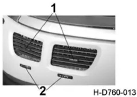
text_image
1 2 H-D760-013- Shifter lever 2. Thumbwheel
Parking warm air system (optional)
Please refer to the specific configuration of the purchased model.
Turn on heater
-
Heating mode: use the heating button 1, start the heater in the heating operation mode (continuous operation), and the indicator light of heater operation (red) lights up. At the same time, the required temperature can be adjusted by using the pre-selected temperature knob 7;
-
Ventilation mode: use the ventilation button 5, start the heater in the ventilation operation mode (continuous operation), and the ventilation operation indicator light (blue) lights up. At this time, knob 7 has no adjustment function in the ventilation operation.
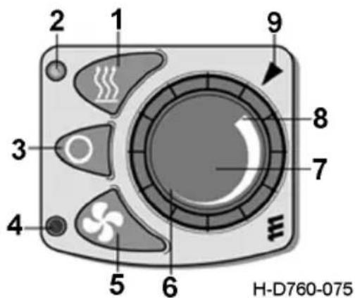
text_image
2 1 9 3 8 7 4 5 6 H-D760-075- Heating button
- Heating operation display light (red)
- Close button
- Ventilation operation display light (blue
- Ventilation button
- Lowest temperature
- Preselected temperature knob
- Highest temperature
- Temperature indicating arrow
Turn off the heater
Use the close button 3, the heating or ventilation operation ends, the corresponding indicator light goes out, the heater runs 240s, the system stops working.
Precautions of using parking warm air
- The heater must be turned off when refueling.
- Do not use heater in closed rooms such as garages or parking buildings; The use of heater in the formation of flammable vapors or dust is not permitted, such as fuel warehouse, carbon warehouse, wood warehouse, granaries and similar sites.
- The heater shall not operate in the area where the exhaust emission device is located during the operation of the heater. If it is necessary to operate in the exhaust emission device, the heater shall be turned off first until all parts are completely cooled and protective gloves are put on when necessary. Inlet and outlet pipe shall not be blocked by dirt and snow.
- The fuel usage shall conform to the provisions on diesel fuel in GB 252.
- Operating altitude requirements of heater:
When the heater operates at a height below 1500m, it can operate without limit.
Alpine pump kits must be added when the heater is operating at an altitude above 1500m.
- Control and safety devices
If the heater does not ignite within 90 seconds of starting fuel delivery, the starting process will be repeated. If the heater does not ignite again within 90 seconds after starting to deliver fuel, the fault will be shut down, that is, stop delivering fuel, fan will be cooled for about 4 minutes. After more than the permitted number of startup attempts and repeated failures, the controller will be locked. If the flame is automati-
cally extinguished during operation, it will be restarted first. If the heater does not ignite within 90 seconds after the restart of fuel delivery, or even if it is started, but it is extinguished within 15 minutes, it will fail to shut down, that is, stop the fuel delivery, and the fan will cool down for about 4 minutes. Failure shutdown problem can be eliminated by restarting after a brief shutdown. There should be no more than two attempts to restart after a brief shutdown. When overheating occurs, the combined sensor (flame sensor/overheat sensor) reacts, fuel supply is interrupted, and a fault shutdown occurs. After eliminating the cause of overheating, you can restart the heater by shutting it down and restarting it. After more than the permitted number of startup attempts (about 10) and repeated failed attempts, the controller will be locked. 7. In case of failure, shutdown should be checked as follows:
When the heater does not start up after operated, shut down and then restart; The heater is still not started, so you should check whether there is fuel in the tank; Whether the fuse is normal; Whether the circuit, connection and joint are in good condition; Whether the combustion air duct or exhaust pipe is safe, if all above are normal, and the heater is still out of order, or other functional failure, please contact the maintenance station designated by Dongfeng Commercial Vehicles Co., Ltd.
Maintenance instructions
The heater should be put into trial operation before the warm season. Close the heater and remove the fuse if smoke is present for a long period of time, abnormal combustion sounds or obvious smell of fuel or overheating of electrical/electronic components. In this case, professional maintenance personnel should be the first to check. After long-term idling, check the openings of combustion air duct, combustion air supply pipe and exhaust pipe, and clean them when necessary.
Gear lever and shift knob
Please refer to the specific configuration of the purchased model.
ZF 12-speed automatic transmission
The ZF 12-speed automatic transmission has no gear lever, and the shift knob is matched, as shown in figure H-ZF12AMT-001. The functions of each shift are as follows:
N gear: the vehicle is in neutral;
D gear: forward gear, use the gear when the vehicle is moving normally;
DM block: forward slow-speed gear; Use when the vehicle is moving at a short distance and slow speed;
R gear: reverse gear, use the gear when the vehicle is normally reversing;
RM block: reverse slow-speed gear; Use for short distance and slow speed reversing.
Manual Valve Control Lever
The manual valve controlled spring air chamber acts on rear axle brakes as parking brake or emergency brake.
When the manual valve control lever is at Position 1, the parking brake will be in release status; during transfer from Position 1 to Position 2, the parking braking force of the tractor and the service braking force of the trailer will increase gradually; when the lever is at Position 2, the parking brake of the tractor and the service brake of the trailer will be in working status; during transfer from Position 2 to Position 3, the parking brake of the tractor will be working continuously, and the service brake of the trailer will be released;
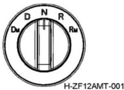
text_image
D N R DM RM H-ZF12AMT-001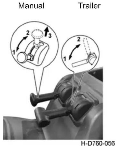
text_image
Manual Trailer H-D760-056- Service position
- Parking position
- Inspection position
- Emergency braking position between 1 and 2

Warning:
When parking the vehicle, be sure to move the manual valve control lever to locking position; otherwise, the vehicle may move, which will lead to damage or even personal injury.
Trailer brake manual valve
The trailer brake manual valve is located beside the parking brake manual valve. Pulling backwards (tail of vehicle) this lever can apply the trailer brake and pushing it forwards can release the brake.
When driving the vehicle down a hill with small gradient, the tractor can be braked through the engine brake while the trailer can be braked by pulling the trailer brake lever intermittently.

Warning:
To park it on a slope, it is required to start the parking brake of the trailer and wedge the wheels with triangular blocks.
Method for Releasing Spring Brake
Please refer to the specific configurations of your vehicle.
Where the vehicle cannot be released from parking brake and cannot start, it may be caused by the pressure drop of spring brake air chamber, which makes the spring brake operate automatically. In such case, check the pipeline system or valves for air leakage first; and timely eliminate the leakage, if any. If the elimination is not possible, please contact a Technical Service Center (Station) authorized by DONG-FENG COMMERCIAL VEHICLE CO.,LTD..
Methods to release dual diaphragm type spring brake air chamber
-
Remove release screw from the bracket, open the rubber dust cap at the rear part of air chamber, insert the hook end of release screw into air chamber spring cavity and rotate to a degree, and confirm the tray is hooked;
-
Install washer and nut, rotate the nut with hand, and rotate the nut till the screw is out by about 40mm with a wrench. The spring braking is then released.
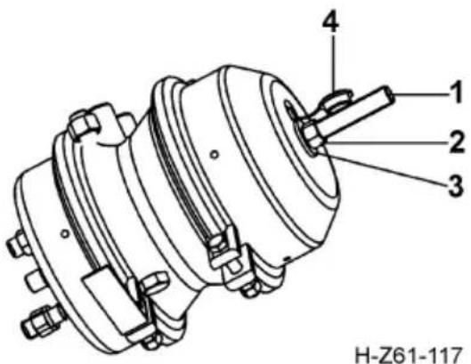
text_image
H-Z61-117- Manual bolt
- Nut
- Washer
- Dustproof plug

WARNING:
- Manual release of parking brake of spring brake air chamber is limited to emergency only. Running the vehicle without parking brake is quite dangerous and may result in injury.
- Ensure that the vehicle will not slide automatically before taking the above steps! The vehicle will lose parking braking function temporarily after the above steps are taken!
- Afterwards you must find out the reason for insufficient spring brake air pressure for prompt repair. After troubleshooting, be sure to remove the release screw from air chamber spring cavity to restore the parking braking function. And refit the release screw to the bracket and tighten it for next use.
Piston type spring brake air chamber
The spring brake can be released by rotating the spring brake release bolt with a spanner counterclockwise until the bolt cannot be tightened any more.

WARNING:
-
Manual release of parking brake of spring brake chamber is limited to emergency only. Running the vehicle without parking brake is quite dangerous and may result in serious accidents.
-
Afterwards you must find out the reason for insufficient spring brake air pressure for prompt repair. After troubleshooting, refit the bolts to restore the parking braking function.
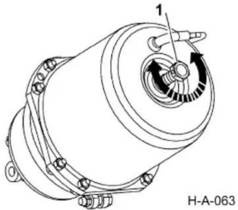
natural_image
Technical line drawing of a mechanical component with labeled parts (no text or symbols beyond labels)- Spring brake release bolt
Accessory System
Please refer to the specific configurations of your vehicle.
Cigar lighter
To use the cigar lighter, press it directly and wait for 10s after releasing it; then the resistance wire in its front will be heated red and pop out and return to the original position automatically. At this moment, you can pull it out to light the cigar. Put it back in place after using it.

natural_image
Circular icon with a stylized white symbol resembling a phone handset and a document, enclosed in a black border (no text or numbers)H-B69B-060

WARNING:
Never connect the cigar lighter for a long period. It must be drawn out manually if it fails to pop out automatically.
Ash tray
When using it, first press the cover to pop it out, and then push it back to close it. When cleaning it, first open the cover, and then pull the whole ash tray out upward.

CAUTION:
For the sake of safety, always close the ash tray before leaving the vehicle.
Front reading lamps
They are installed on inner front roof. Pressing the left and right switches will turn on the left and right reading lamps, and pressing the switches again will turn off the lamps.
DOOR position: when the switch is turned to DOOR position, the interior lamp will turn on in case any door is opened, and it will turn off in case door on both sides are closed;
ON position: the interior lamp will turn on once the switch is turned to ON position regardless of the position of the door;
OFF position: the interior lamp will turn off once the switch is turned to OFF position regardless of the position of the door.
Side reading lamp
Pressing the switch can turn on the side reading lamp.
Pressing the switch again can pop up the switch to turn off the side reading lamp.

CAUTION:
the berth reading lamp is designed with a rotating lamp holder, so the light direction can be adjusted as needed.
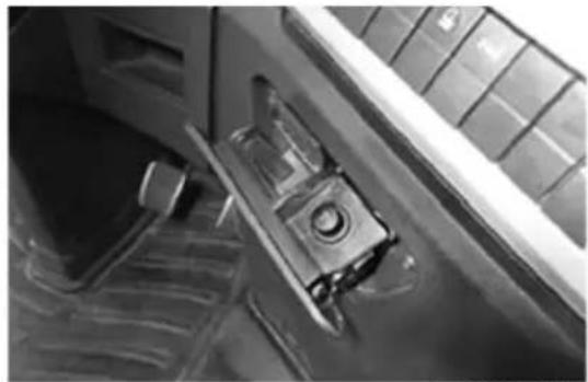
natural_image
Close-up of a mechanical component with a handle and lever mechanism (no visible text or symbols)H-D760-055
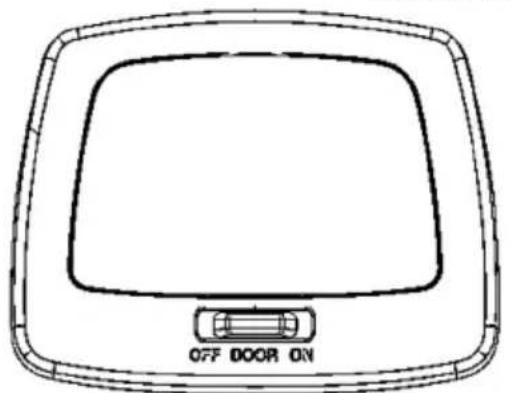
natural_image
Line drawing of a car's front panel with 'OFF DOOR ON' label (no other text or symbols)H-D760-038
natural_image
Simple line drawing of a rectangular device with a circular lens and rectangular top (no text or symbols)H-D760-039
1. Switch
Sunroof
Automatic opening/closing sunroof
Press the opening switch to automatically open the sunroof; Press the closing switch to automatically close the sunroof.
Manual opening/closing sunroof
Press and hold the opening/closing switch: the sunroof or the sunshade will begin to move, and the time for movement depends on the operation time of the switch.
The sunroof will stop moving when the switch is released. Automatic closing of sunroof.
If the sunroof or the sunshade is at the opening position, the sunroof can automatically return to the initial closing status after the onboard power supply is off for 5s.
Reset method of sunroof:
Operate the sunroof as follows: open the sunshade, flip the glass up, and open the glass
outer slide rail and close it (no interruption is allowed during operation); when closing is done in place, press and hold the closing button for 40-60s to realize automatic learning and memorizing.
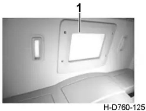
natural_image
Interior view of a vehicle showing a skylight cover and dashboard (no text or symbols visible)- Sunroof
natural_image
Simple line drawing of a refrigerator with an up arrow and down arrow symbol (no text or labels)H-D760-131

CAUTION:
- With respect to the sunroof, the following circumstances may occur due to powerful electromagnetic interference or other factors:
- The sunroof moves for a short distance or does not move after the closing button has been pressed, while the sunroof can make progressive movement if the closing button is pressed and held;
- The sunroof can move, but in disorder after the closing button has been pressed or pressed and held;
- The sunshade can close in place after the closing button has been pressed;
- The sunroof can automatically open after the key switch has been turned off.
- In case the circumstances above occur, please reset the sunroof; after this operation, if the fault has not been eliminated, please operate the sunroof and turn off the power key when the sunroof is operating, and then turn on the key after 10s, and finally reset the sunroof. In case the fault has not been eliminated, please drive your vehicle to the After-sale Service Station of DONGFENG COMMERCIAL VEHICLE CO., LTD. for related inspection.
Ceiling lamp
The ceiling lamp, located at the interior top of the cab can be controlled by three switches which work separately:
Instrument panel ceiling lamp switch
Upper berth ceiling lamp switch
Lower berth ceiling lamp switch
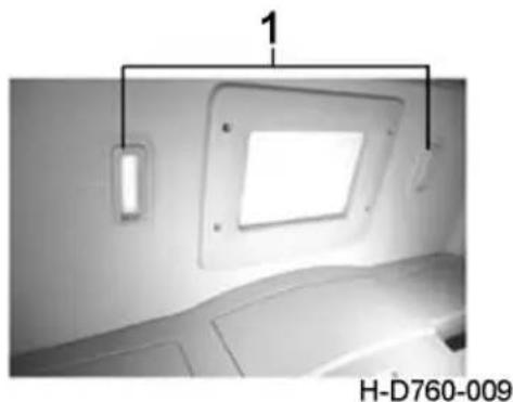
natural_image
Interior view of a vehicle showing a mounted panel with a light fixture and a numbered label (1) in the top left corner, no readable text or symbols on the main subject.- Ceiling lamp
Berth reading lamp
The upper and lower berths are designed with reading lamps,
when the switch is turned to ON, the berth reading lamp will turn on;
when the switch is turned to OFF, the berth reading lamp will turn off;

CAUTION:
the berth reading lamp is designed with a rotating lamp holder, so the light direction can be adjusted as needed.
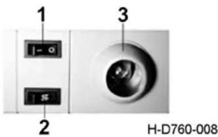
text_image
1 2 3 H-D760-008- Berth reading lamp switch
- Ceiling lamp switch
- Berth reading lamp
Step lamps
They are installed on the inner sides of doors and used for step lighting. The left and right step lamps are controlled by left and right door switches respectively. When the door is open, the step lamp at corresponding side will be turned on; and when the door is closed, the step lamp at corresponding side will go out.
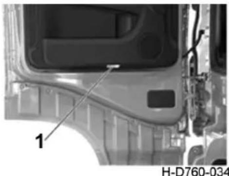
natural_image
Close-up of a car's front panel showing internal components and a numbered marker (1), with no readable text or symbols beyond the label.- Step lamp
Maintenance lamp
It is installed on the inner side of front wall for front wall maintenance lamp.
Glove box
Please refer to the specific configurations of your vehicle.
Front roof glove box
The front roof glove box is composed of a central glove box, a left glove box and a right glove box, which are used for storing large objects.
To open the central glove box, pull the buckle to separate it from the central lock pin, and tilt the box cover upwards.
To open the left and right glove boxes, press the buckles downwards, and tilt the box covers upwards.
To close the glove boxes, tilt the box covers downwards until the buckles are pressed into the central lock pins.
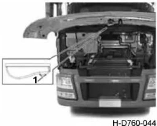
natural_image
Front view of a truck head with open hood and internal components, showing engine compartment (no text or symbols visible)- Maintenance lamp switch
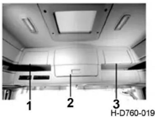
text_image
1 2 3 H-D760-019- Left glove Box
- Central glove box
- Right glove Box

CAUTION:
- Please do not place too small, fragile articles or the objects prone to shed dust into the glove box so as to avoid the serviceability of the glove box being affected.
- Please confirm that the glove box cover is closed properly when using the glove box.
WARNING:
- Do not place corrosive articles or hard pointed objects into the glove box;
2.Do not place heavy articles on the glove box cover.

Central glove box
This glove box is located at the center of the console and used to keep carry-on tools and small articles.
Opening: pull the glove box handle upwards and pull the glove box backwards to open it.
Closing: push the glove box to close it.
Small tray table
It is located in the center of the console, and used for temporary writing, dinning, etc.
Opening: press the small table to pop it up.
Closing: push the small table back to close it.
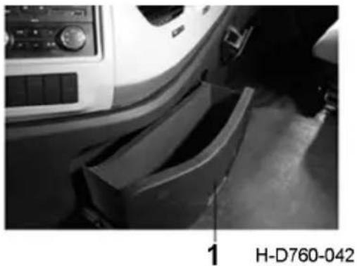
natural_image
Interior view of a car showing dashboard, steering wheel, and side-mounted storage unit (no visible text or symbols)- Glove box handle
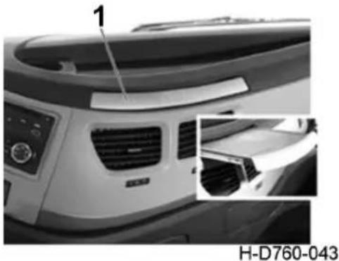
natural_image
Close-up of a car's front grille and dashboard, showing air vent and control panel (no text or symbols visible)- Glove box handle
The refrigerator
Please refer to the specific configuration of the purchased model. The refrigerator is located at the bottom of the lower berth and is used to cool food, etc.
On and off
Open: open the refrigerator button hand, clockwise rotation knob, refrigerator began to cool.
Close: turn the knob to "0" to close.
Temperature setting
MAX position: about -2 c inside.
MIN position: about 12 ? inside.
Defrost
Take food or other items out of the refrigerator if necessary and store them in other refrigeration facilities.
Turn off the refrigerator and wipe off the frost.
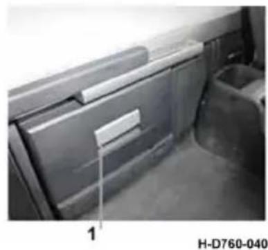
natural_image
Interior view of a mechanical or electronic device with labeled component '1' and identifier 'H-D760-040' (no readable text beyond label)- refrigerator clasp hands
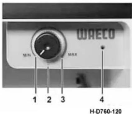
text_image
WAECO MIN MAX 1 2 3 4 H-D760-120-
MIN
-
The MAX
-
0 position
-
Light
Side tool kit
Out-opening tool kits are provided for driver's side and passenger's side in the D760 cab, and they are equipped with lamps for easy taking of objects by readers. The lamp is equipped with a contact switch which will be triggered to make the lamp to turn off in case the box cover is closed; when the glove box cover pops up, the switch will automatically pop up to turn on the lamp.
Opening/closing method of side tool kit
- Opening: pull the side tool kit ring at the back of seat as shown in Fig. H-D760-011 to unlock the side tool kit of which the cover will pop up for an angle; in this case, pull the cover along the lower edge of the side tool kit cover to open the tool kit;

CAUTION:
In case the lock is not completely unlocked and the side tool kit cover can not be opened as the ring is pulled, please keep the operation of pulling the ring to open the side tool kit cover, so as to open the side tool kit.
- Closing: pull the cover downward along the lower edge of the side tool kit cover until it is located as a lower position, and give the cover a hard covering; during closing, a clamping sound of the buckle can be heard, and after closing, the cover should be lower than the cab surrounding plane; if the cover is flush with the surrounding plane or slightly protruding, it may be caused by un-tight locking of the tool kit; in this case, please close the tool kit cover again.
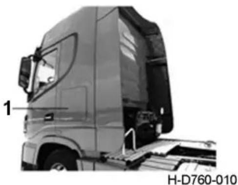
natural_image
Side view of a semi-truck cab with visible side door and front compartment, labeled H-D760-010 (no text on the truck itself)- Side tool kit
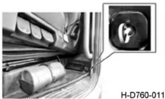
natural_image
Interior view of a vehicle charging station with a close-up inset showing a plug socket (no text or symbols visible)Cup holder
The cup holder is located below the transmission shift console.
Opening: press the cup holder to pop the cup up.
Closing: push the cup holder back to close it.
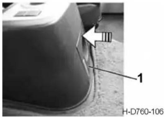
text_image
H-D760-106 1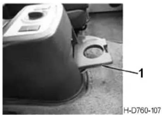
natural_image
Close-up of a mechanical device with a labeled component (1) and reference number H-D760-107, no readable text or symbols beyond labels.- Cup holder
220V power socket
The 220V power socket, located at back of driver's seat and passenger's seat, can be powered on by pulling the handle and pressing the power switch until the green lamp turns on.
This socket, used for supplying of external power, is not controlled by the ignition switch but the master power switch of the complete vehicle. The rated load of this socket is 220V, 360W.
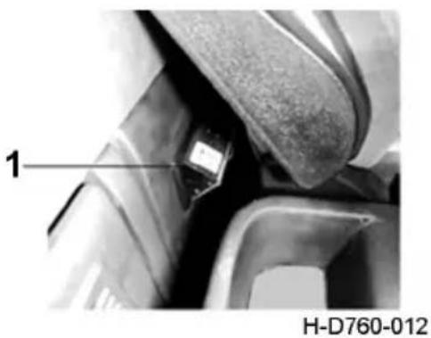
text_image
1 H-D760-012- 220V power socket

CAUTION:
When getting power via this socket, the load is strictly prohibited to exceed the nominal capacity of the socket.
Curtain
- Upon extending curtain, put the rings on curtain into corresponding hooks on the guide rail, then evenly extend it along the guide rail, overlap curtains with nylon buckle, and clip metal fasteners at lower part of side/rear curtain onto plastic buckles on the protection board.
- Upon collecting curtain, first release the nylon buckle, then evenly collect the curtain along the guide rail, and bind it with the fastener.

CAUTION:
Do not apply force to the lower end of the curtain when extending the curtain, or stamp on it.
Coat and hat hook
The coat and hat hook is located in the rear quarter trim.
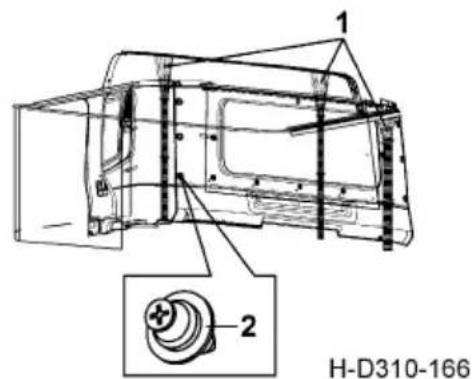
text_image
1 2 H-D310-166- Curtain 2. Buckle
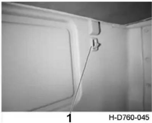
natural_image
Interior view of a refrigerator with a wall-mounted door and a hanging handle, labeled H-D760-045 (no text or symbols on the main subject)- Coat and hat hook
Rearview mirrors and under-view mirrors
The main exterior rearview mirror and wide-angle mirror are installed on driver's left and right sides, and the front under-view mirror and close-proximity rearview mirror are installed on the passenger's side. The driver can adjust the main exterior rearview mirror, wide-angle mirror, front under-view mirror and close-proximity rearview mirror to realize best rearview and down view effects.
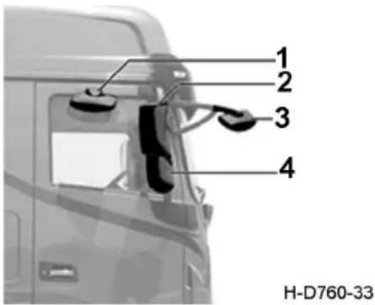
text_image
1 2 3 4 H-D760-33Microwave window
It is recommended to place it in the front area of the driver's side instrument panel without affecting the position of the driving vision.
- Close-proximity rearview mirror
- Exterior rearview mirror
- Front under-view mirror
- Wide-angle mirror
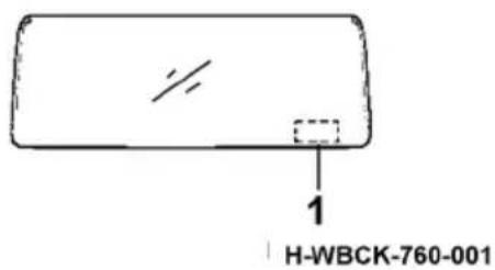
text_image
H-WBCK-760-001- Microwave window position
Driving recorder
The operating manual of driving recorder is provided separately.
Front panel
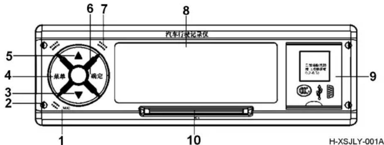
- MIC
- Keyhole: used to remove the recorder from the bracket
- Scroll down to select functions or data column items
- Menu: switch between the default display interface and the menu interface, and return the subdirectory to the root directory
-
Flip up and select to complete the selection of function or data column items
-
Confirmation: to confirm the function or data column item, press the button for 3s continuously in the default display interface to trigger the printing function
- Speaker hole for internal sound output
- Dot matrix LCD screen
- Compartment door cover, which contains 3C label, USB screen printing, DB9 screen printing, and USB interface and DB9 interface inside
10.IC card slot

CAUTION:
-
Press the "▲" and "▼" combination buttons for 2s to trigger SOS alarm, and the alarm information is automatically uploaded to the monitoring platform.
-
When the device deviates from the horizontal line more than 30 degrees, the device will generate a rolver-over alarm, and the alarm information will be automatically uploaded to the monitoring platform.
Display screen of on-board information terminal
Product introduction
Video entertainment system assembly
Front panel
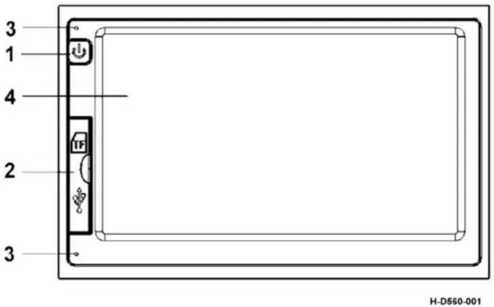
text_image
3 1 4 2 3 H-D560-001- Power/standby button
- Hatch cover with USB screen
- MIC port
- LCD panel
|
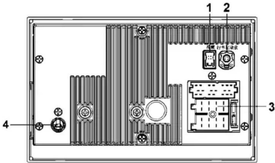
text_image
1 2 3 4 凸模 行车记录仪H-D560-CZXXZD-002
- Video (camera) connector
-
Hd dash CAM (camera) connector
-
Electrical connector
- Receiver antenna connector
Product parameters
- Nominal voltage: 24V DC
- Working voltage: 16\~32V DC
- Rated working current: less than 5A
- Static current: less than 10mA
- Operating temperature: -30 °C \~+70 °C
- Storage temperature: -40 °C \~+85 °C
| Name | Item Specification | |
| Radio | AM band Frequency range: 522kHz~1620kHz | |
| FM band Frequency range: 87.5MHz~108MHz | ||
| Number of stations stored manually FM18, AM6 | ||
| Number of stations stored automatically FM6, AM6 | ||
| Pre-set radio browsing playback FM6, AM6 | ||
| Signal-to-noise ratio FM:50dB Over AM:40dB Over | ||
| MP3 R | Readable audio file format MP3/MP3pro/WMA | |
| MP5 | Video format supported | RW V B/R M /MPEG 1 /MPEG 2 /MPEG4/ASF/MOV and other common formats |
| Resolution 1280*720P | ||

CAUTION:
Please read this instruction carefully before use.
-
Please make sure all devices and wires are connected correctly before connecting to the power supply of the display screen. Do not install or remove the screen while it is powered. If you find any missing wire or wrong connection, please cut off the power supply first, otherwise it is easy to damage the equipment.
-
Please install the equipment at the designated installation site. If any abnormality is found during the use, please immediately go to the designated maintenance site for maintenance. The equipment damage caused by installation or maintenance at a non-designated installation site or maintenance site is not covered by the product warranty.
-
In order to avoid electromagnetic interference or configuration incompatibility, please stop using the equipment at the place with notice as required.
-
In order to avoid electromagnetic interference or configuration incompatibility, please stop using the equipment at the place with notice as required.
-
If the contents in this manual are inconsistent with your products, please refer to the actual display screen.
The main function
Radio function
-
FM radio
-
AM radio
Music playback function
- Play audio files in USB
Video playback function
-
Play video files in USB
-
Play video files in SD card
bluetooth
-
Answer calls via bluetooth
-
Bluetooth music playing
Image recognition function
E-book reading function
Driving auxiliary
-
Video display
-
Astern view
Product instructions
Boot interface
The master power switch of the vehicle is turned on and the ignition lock is set to ACC, and the display screen conducts self-inspection. At the same time, the system enters the startup animation interface, as shown in the figure:
natural_image
Abstract glowing circular logo design on black background (no text or symbols)H-CZXXZD-003
After the self-check of the display screen is successful, it enters the main interface. If the self-check of the display screen fails, it cannot enter the main interface. Please contact the after-sales service center for maintenance.
Main interface
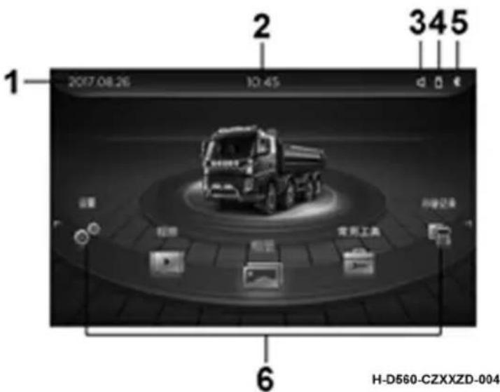
text_image
1 2017.08.26 10:45 345 6 H-D560-CZXXZD-004-
Date Menu
-
USB device
-
Time
-
Bluetooth
-
Volume
-
Function menu
- Date: year - month - day - week, display the current date, subject to GPS positioning time.
· Time: hour-minute, displaying the current time.
- USB device:
| Icon Instructions | |
| ☐ (highlighted) | The display screen is connected to the USB device successfully |
| ☐ (gray) or none | The display screen is not connected to the USB device |
- Bluetooth:
| Icon Instructions | |
| *(highlighted) | The display screen has a bluetooth connection |
| (gray) | The display screen has no bluetooth connection |
- Volume:
Click the sound button to enter the volume adjustment interface.
- Function Menu:
Slide the screen to rotate the icon, click the function icon to enter the corresponding function.
Standby interface
Enter the standby interface by pressing the power/standby button on the display (< 3s).
text_image
2017-09-08 12 9 3 6H-D560-CZXXZD-005
After entering the standby interface, can be any point by clicking on the screen, inserted U disk, or wake up the screen steering wheel buttons, normal work into the interface.
Functional interface
Music
Click the function icon "music" icon to enter music playback interface, can under the function of music broadcast, the support to the audio files stored in a USB device to broadcast and mobile phone bluetooth music playback, as shown in figure:
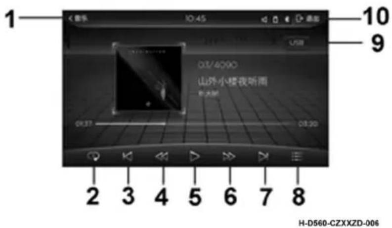
text_image
1 2 3 4 5 6 7 8 H-D560-CZXXZD-006 10 9 山外小楼夜听画 北大街- Return
- Play mode
- Last song
-
Fast return
-
Play/pause
- Fast forward
- Next song
-
Menu list
-
BT/USB audio source switching
-
Quit
When the external mobile storage device is successful, click "menu list" in the music interface. When the song catalog in the current storage device is exported, it is divided into all songs, folders, artists and albums. Click enter the corresponding category playlist and list. Click the corresponding song name to select the song, as shown in the picture:
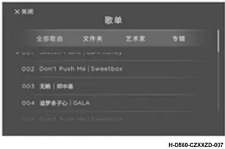
- When the media device contains audio files, it will automatically jump to the music playing interface;
- Click button 3p return to the main interface, but the program continues to run in the background. Click [music] control again and enter the interface before returning;
- Supports MP3, ACC, FLAC, APE, PCM and ADPCM music files in formats;
Recorder
Click [recorder] to enter the interface of the recorder. This interface is mainly used for communication between the display screen and hd driving recorder. Through this interface, related functions such as vehicle information query and vehicle information setting can be performed, as shown in the figure below:
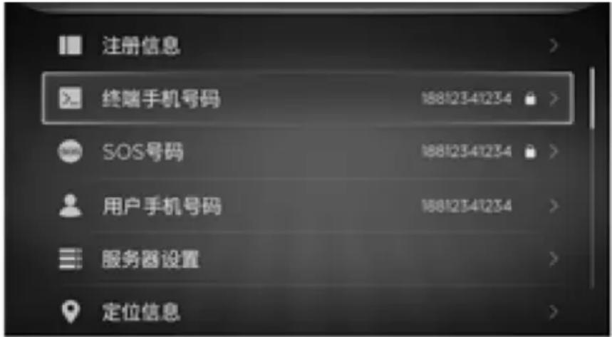
Registration information (refer to this process for the input interface)
Click [registration information] to enter the information interface of the host computer, in which vehicle VIN, terminal ID and license plate number can be inquired. The license plate color, provincial ID, municipal ID and vehicle classification can be inquired and set.
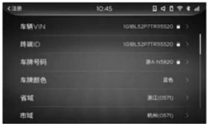
Take the setting of license plate color as an example. Click the color of license plate to enter the interface shown below. Click the color of license plate to set to exit.
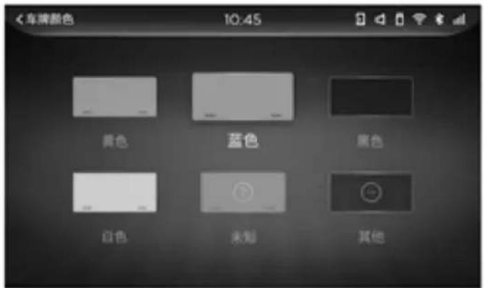
Province ID, city ID, vehicle classification operation can refer to the license plate color Settings.
Click [user's mobile phone number] to enter the user password 12345678 (all interfaces are valid during the ignition after one input) to enter the user's mobile phone number query interface. Under this function, you can query and set the current terminal number, as shown in the figure below:
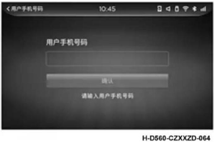
Terminal mobile phone number, SOS number query changes refer to this.
server
Click "server Settings" to enter the server selection interface. Click the corresponding server to query and set the APN, port number, domain name and IP of the server. The user password 12345678 should be entered for server 1, as shown in the figure:
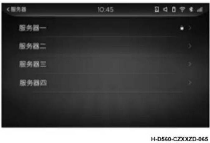
Location information
Click "location information" to enter the location mode interface. Under this function, you can query the current host location mode, as shown in the figure:
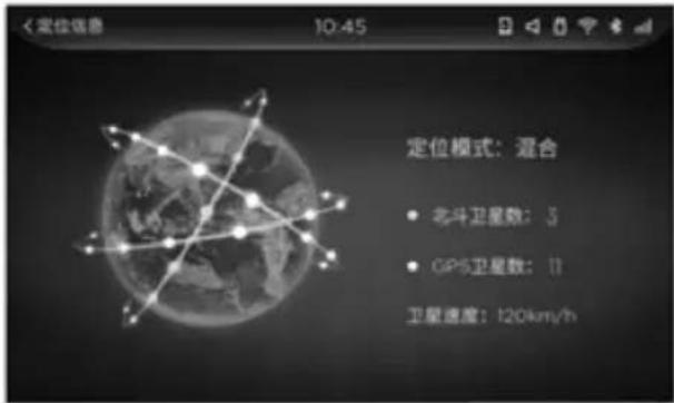
Tired driving enquiry
Click "fatigue driving query" to enter the interface of fatigue driving query. This function can query the driving license number and the corresponding starting and ending time of fatigue driving according to the driving time.
text_image
<搜寻驾驶查询 10:45 驾驶证号 开始时间 结束时间 3.325221988050403W 2017-12-20 08:08 2017-12-20 08:08 3.325221988050403W 2017-12-20 08:08 2017-12-20 08:08 3.325221988050403W 2017-12-20 08:08 2017-12-2O 08:08 3.325221988050403W 2017-12-20 08:08 2017-12-20 08:08 3.325221988050403W 2017-12-20 08:08 201T-12-20 08:08 3.325221988050403W 2017-12-20 08:08 2017-12-20 08:08H-D560-CZXXZD-067
Host state
Click [host state] to enter the query interface of host state. Under this function, you can query the current host information. The highlighted figure shows that the function module is open and running, as shown in the figure below:
Some of the functions are reserved.
Load condition
Click [load state] to enter the load state interface, which can be set according to the actual load of the current vehicle, as shown in the figure:

Vehicle impulse coefficient
The current vehicle pulse coefficient can be viewed under the function list of recorder.
Query of mileage information
The current mileage information can be viewed under the recorder function list.
Picture
Click [picture] on the main interface to enter the picture interface. Under this function, pictures can be played. At present, pictures stored in USB devices can be played. As shown in figure:
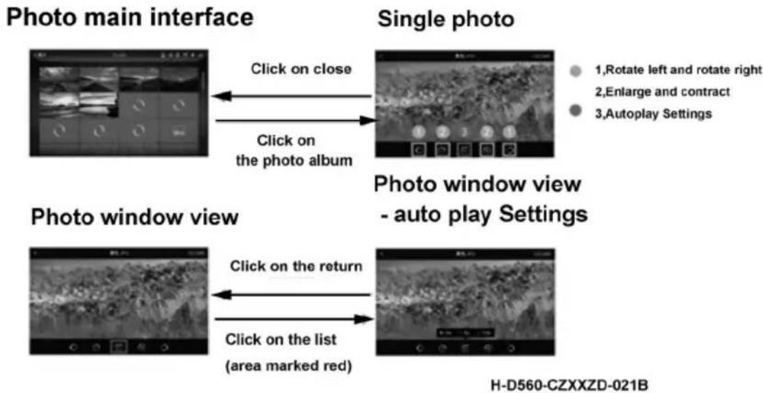
text_image
Photo main interface Click on close Click on the photo album Single photo 1,Rotate left and rotate right 2,Enlarge and contract 3,Autoplay Settings Photo window view Click on the return Click on the list (area marked red) Photo window view - auto play Settings H-D560-CZXXZD-021B
CAUTION:
Support resolution not more than 2048*2048 JPEG, GIF, BMP, PNG images.
Video
Click the function list interface [video] to enter the video playback interface. Under this function, video can be played. Currently, it supports playing video files stored in USB devices. As shown in figure:
Main interface
text_image
Black-and-white photo of a truck on a circular platform with Chinese UI elements, including battery, fuel cell, and parking-related icons.The top left corner is the return function
Upper right corner in
and out for exit background
Click on the radio icon
Video main interface
natural_image
Black-and-white action photo of a character in dynamic pose, possibly from a video or film editing interface (no visible text or symbols)Video main interface

natural_image
Black-and-white action photo of a character in a mountainous setting, no visible text or symbolsClick on close
Click on the list (area marked red)
List feature
Switch to each other

Switch to each other
Video list - folder
-
In order to ensure the driving safety of drivers, when the driving speed is more than 5km/h and it lasts for more than 10s, the video will not be able to be played. If this function needs to be enabled, it is necessary to enter the setting interface to set the safety mode;
-
Supports video file playback in formats of H264, H263, MPEG2, MPEG4, AVI, FLV, ASF/WMV, MP4, MKV and TS.
E-books
Click the [e-book] icon to enter the e-book reading interface, as shown in the picture:
Click the "radio" icon to enter the radio interface, as shown in the picture:
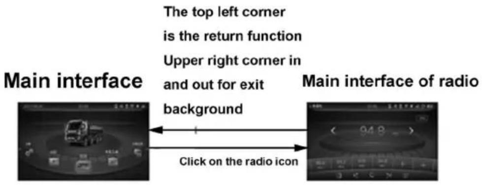
text_image
The top left corner is the return function Upper right corner in and out for exit background Click on the radio icon Main interface of radio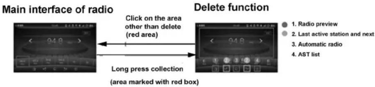
flowchart
graph LR
    A["Main interface of radio"] --> B["Delete function"]
    B --> C["Long press collection (area marked with red box)"]
    C --> D["Click on the area other than delete (red area)"]
    D --> E["Radio preview"]
    D --> F["Last active station and next"]
    D --> G["Automatic radio"]
    D --> H["AST list"]
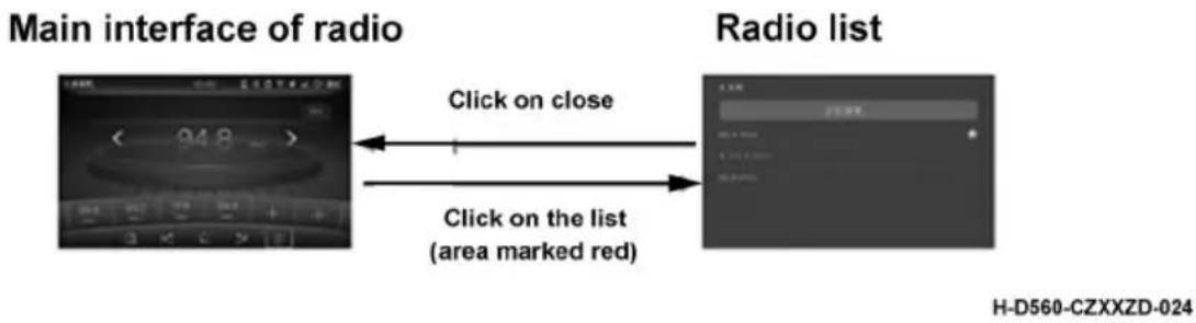
text_image
Main interface of radio Radio list Click on close Click on the list (area marked red) H-D560-CZXXZD-024After entering this menu, adjust the channel by clicking the "left" and "right" fine-tuning controls or adjust the channel by "up and down" buttons on the steering wheel. Click to play the corresponding channel in the selected storage area, or press the channel area for more than 3 seconds to save the currently playing channel to the corresponding location. Interface details:
Fine-tuning button:


The same function can also be realized by pressing [up and down buttons] on the upper disk of the radio frequency band;
Radio mode: FM
Display the current radio mode, including FM and AM. Click the toggle mode.
- Last channel:
Click the button, jump to the previous channel of the current channel, or press the "up button" on the steering wheel to achieve the same function; (picture, video, music).
- Next channel:
Click the button to skip to the next channel of the current channel, or press the "down button" on the steering wheel to achieve the same function; (picture, video, music).
Commonly used tools
The calculator
Click [calculator] to enter the calculator interface. Under this function, data operation and query can be carried out. The query only supports the calculation history record with calculation results during the ignition, and the number is less than or equal to 5 times.
text_image
<计算器 10:45 91 查询 C 7 8 9 ÷ √ 4 5 6 × CE % 1 2 3 — 1/x ± 0 . + =H-D560-CZXXZD-025
Calendar
Click the "calendar" icon to enter the calendar interface. In the interface, the selected date is displayed on the right side of the corresponding week, lunar calendar and other information, as shown in the picture:.
Click the "help" icon to enter the help interface, and you can view common questions and solutions, as shown in the figure:
Click the "bluetooth" icon and enter the dial-up interface. Under this function, you can make and receive calls between the display screen and the mobile phone. At the same time, you can also make and hang up calls through the bluetooth on the steering wheel to realize the bluetooth call function.
text_image
<电话 1 2 3 ABC OKF 4 5 6 OKS 7 8 9 PQRS RHY WXYZ * 0 # 请输入您要拨打的号码H-D560-CZXXZD-026
Call records
Click the "call record" icon to enter the caller id interface. In this interface, you can query the current incoming call, missed call, outgoing call record and delete functions, as shown in the figure:
Click the "contact" icon to enter the contact interface, and the contact person in the bluetooth device (such as mobile phone) connected to the real screen can be synchronized, as shown in the figure:
Click the "driving assistance" icon to enter the driving assistance interface, where there is video display (video display can realize reversing image or right blind area display, specific functions need to enter the Settings, through the setting of the driving assistance function to select the function) function..
Click "Settings" to enter the setting interface. Under this function, you can set brightness, background, key tone, sound, sound balance, sound balance, volume comfort, language, bluetooth, WIFI, system time, safe driving mode, system upgrade, factory Settings and driving assistance. As shown in figure:
Click "brightness setting" to enter the brightness setting interface. Under this function, the user can adjust the current brightness of the display screen. The brightness of the display screen can be adjusted in three gears: 10%, 30% and 50% at night, and 20%, 40%, 60%, 80% and 100% in day mode.
Background
Click "background" to enter the background setting interface. Under this function, the user can set the background. There are two backgrounds available.
Key tone
Click [key tone] to enter the setting interface of key tone. Under this function, the user can set the key tone.
Voice
Click [sound] to enter the sound setting interface. Under this function, the user can set the sound of the display screen.
Sound and balanced
Click "sound balance" to set the sound effect. There are seven modes: soft, rock, pop, live, dance, classical and custom, among which the user can adjust the mode by himself.
Sound balance
Click "sound balance" to adjust the output intensity of the speaker in each position. When the adjustment point is in the center of the screen, the output intensity of each speaker is the same. If the adjustment point is placed in the corresponding position on the diagram, the sound intensity of the corresponding position on the vehicle becomes stronger, while other areas become weaker.
Volume comfort
The volume comfort value is supported by 40 volume levels. When the comfort switch is turned on, such as the volume value of the current adjustment ≥ the comfort value, the adjusted volume value will be played during the ignition. But when the ACC OFF is restarted, the system volume value will be changed to the set comfort value. If the volume currently adjusted is less than or equal to the comfort value, the system will save the adjusted value no matter what state it is in.
Language
The system supports Chinese and English languages for users to switch, default is Chinese.
Bluetooth
Bluetooth is named DFCV-BT, the name can be edited, the maximum support for 20 characters of the setting, more than the length of the byte can not be entered. The default matching password is 0000, editable, with a maximum length of 6 digits. Bluetooth supports PIN and SSP authentication. The default is SSP authentication. When bluetooth connection does not support SSP authentication, it can automatically switch to PIN authentication. When the bluetooth switch is turned on, the paired device is automatically connected when it enters the connectable range.
System time
The display supports setting the time and time display format. The time format can be set to 24h and AM/PM. The date display format can be set to xxx-yy-dd and dd-yy-xxxx.
Safe driving mode
Safe driving mode refers to the bus speed ≤ 5km/h and lasts for 10s. Safe driving mode can be manually selected to open and close, factory default open, close the need for user password. When safe mode opens, under the condition of the safety (bus speed of 5 km/h, or for 10 s), and display in a video broadcast, e-book reading, image recognition, pop-up prompts "vehicle, do not use to watch the video (do not use e-book reading function/do not watch picture)", to suspend play video, click on the hint to exit the current function interface.
System upgrade
The system supports U disk upgrade, insert U disk with upgrade program, automatically enter the upgrade prompt interface after ACC ON, click "confirm" and then the upgrade action can be carried out, otherwise the upgrade action will not be carried out, and the upgrade progress can be checked through the progress bar during the upgrade process.
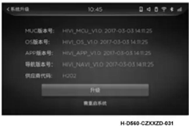
text_image
MUC版本号: HIVI_MCU_V1.0 2017-03-03 14:11:25 OS版本号: HIVI_OS_V1.0 2017-03-03 14:11:25 APP版本号: HIVI_APP_V1.0 2017-03-03 14:11:25 导航版本号: HIVI_NAVI_V1.0 2017-03-03 14:11:25 供应商代码: H202 升级 重重启系统 H-D560-CZXXZD-031
CAUTION:
The usb flash drive with the upgrade procedure is required for upgrade. It does not support online upgrade. The power will be kept on during the upgrade process.
Factory data reset
The factory Settings will restore all system memory items and application memory items to the factory state, including navigation, voice recognition, calendar, calculator, e-book and other applications. User password is required to restore factory Settings.
Lane departure warning (LDW)
Please refer to the specific configuration of the purchased model.

CAUTION:
The lane departure warning (LDW) function only serves as a reminder and the driver is always responsible for the condition of the vehicle.
Turn the key switch to "ACC" and the lane departure warning function will be turned on automatically. The switch on the right side of the dashboard can control the function to be turned off or on.
In the process of vehicle driving, based on the image collected by the front view camera, the lane departure warning function can identify the current visible lane line and send an alarm message to remind the driver when the vehicle has an unconscious lane departure.
- When the vehicle speed is less than 50km/h, the LDW function is in standby state and will not send alarm; When the vehicle speed is ≥ 50km/h,
LDW function is activated to detect the current visible lane line in real time.
-
LDW alarm prompt includes sound alarm and indicator alarm icon flashing prompt.
-
The color of lane line supported by LDW function includes white and yellow; When only one lane line exists, this feature supports only pairs of lanes
Alarm on one side of the line; And LDW function is suitable for standard lane with road radius ≥ 250m.
- When the following conditions exist, the LDW function alarm will be suppressed, and the function cannot issue the alarm.
a). Quick line change and continuous line change;
b). The turn signal corresponding to the lane departure direction is in the state of being turned on;
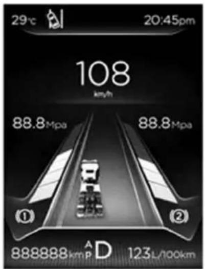
text_image
29°C 20:45pm 108 km/h 88.8Mpa 88.8Mpa ① ② 888888 kmPa D 123L/100kmH-D560-CZXXZD-052
Lane departure alarm icon (left)
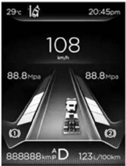
text_image
29°C 16° 20:45pm 108 km/h 88.8Mpa 88.8Mpa ① ② 888888 kmP A D 123 L/100kmH-D560-CZXXZD-053
Lane departure warning icon (right)
c). The alarm lasts longer than 2 minutes;
d). vehicle riding line;
When the system is shut down, the system will not give lane departure warning and alarm during the ignition. If the vehicle key is put in LOCK gear and the key is put in ACC gear, the system will automatically restore to the open state.

Warning:
This function only detects the visible lane line in the camera field of view, which may cause false alarm when no lane deviation occurs. In addition, although the vehicle has occurred a lane deviation, there may be no alarm situation. The recognition capability of the camera may be limited in the following situations, where the image acquired by the camera may be unclear, which may cause LDW function to fail to recognize lane lines or make wrong identification.
-
Severe weather conditions lead to poor visibility, such as fog, haze, rain, snow, etc.;
-
Insufficient light in the camera field;
-
Bright light ahead;
-
The view of the camera is blocked by dirt, water or other objects;
-
Sharp changes in light, such as in and out of a tunnel;
-
Violent jolting and shaking;
-
After the road surface is reflected by the light, the abnormal status of the lane line or the road may also affect the LDW function. The LDW function may not be able to identify the following abnormal lane lines or make wrong identification of these abnormal lane lines;
-
When a vehicle enters an area without lane lines from an area with lane lines;
-
When the direction of lane line of the lane in which the vehicle is located changes greatly;
-
Damaged, blurred or covered lane lines;
-
Construction marking (marking chaos);
-
There are objects on the road surface similar to lane lines.
Forward collision warning (FCW)

CAUTION:
The lane departure warning (LDW) function only serves as a reminder and the driver is always responsible for the condition of the vehicle.
The key switch turns to the "ACC" file, and the forward collision warning function is automatically turned on. The switch 🖱️ on the right side of the dashboard can control this function to turn off or on.
There are two alarm levels of the forward collision warning function, namely, keeping vehicle distance warning and imminent collision warning. Please refer to the following table for details:
| Alarm level Start the speed prompt meaning | |||
| Keep distance reminders | 60 km/h | Frequency response | At this point the driving speed is faster, and close to the car in front of the trend |
| Impending collision alarm | 30 km/h shortness | Too close to the car ahead, please slow down | |
-
When the vehicle speed does not reach the starting speed, the FCW function is in standby state and will not send alarm; When the vehicle speed reaches the starting speed, the FCW function is activated. At this time, the front of the vehicle can be detected in real time, and the alarm information can be sent out in case of collision risk. When the alarm is raised, the alarm icon on the dashboard is flashing.
-
FCW function supports the detection of target vehicles including cars, suvs, trucks, buses, etc.; FCW function is suitable for standard lanes with road radius ≥ 250m.
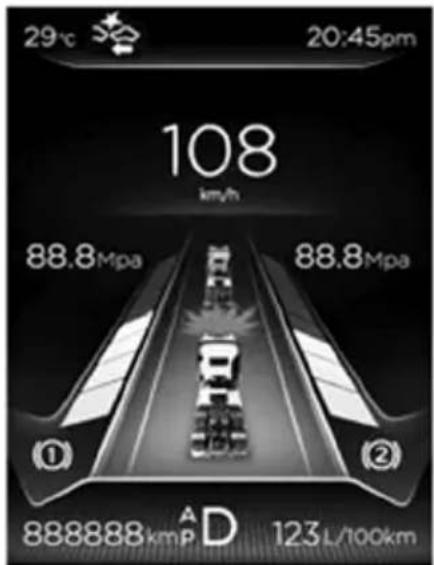
text_image
29°C 20:45pm 108 km/h 88.8Mpa 88.8Mpa ① ② 888888 kmp A D 123 L/100kmH-D560-CZXXZD-054

Warning:
This function only detects the target vehicle in the camera's field of view and may give a false alarm when there is no danger of collision. In addition, although there is a collision risk, there may be no alarm. The recognition capability of the camera may be limited in the following situations, where the image collected by the camera may be unclear, which may cause the FCW function to fail to identify the target vehicle or make an error identification.

Warning:
- Severe weather conditions lead to poor visibility, such as fog, haze, rain, snow, etc.;
- Insufficient light in the camera field, such as no street lamp at night; 3. Bright light ahead;
- The view of the camera is blocked by snow, ice, dirt, water or other objects;
- Sharp changes in light, such as in and out of a tunnel;
- Violent jolting and shaking

Warning:
In the following cases, when the target vehicle is in abnormal state or there is a disturbance ahead, the FCW function may be interfered with, which may cause the target vehicle to be unable to be identified, or make a wrong identification.
- There are stationary or slow-moving vehicles at the curve ahead of the vehicle;
- Quick line change;
- The shape of the target vehicle is abnormal, such as special models (forklift, crane, etc.);
- There are vehicles moving rapidly from other lanes to the front of the vehicle.
System failure
When the system is not calibrated or the internal controller, camera and shielding wire are not in good contact or damaged, the system will enter the failure alarm. When the failure alarm is given, the alarm icon of the instrument will be always on, and there will be a fault code prompt.
System shut down
When the LDWS is closed, the meter displays when FCWS is off, the
meter displays

Impact of camera on lane departure warning and forward collision warning system
The lane departure warning and forward collision warning functions were previously based on the image recognition of the camera, and only when the camera was in normal state could the system function be in the best state. Do not place or paste any objects in the field of view in front of the camera. In addition, if the windshield is replaced and the camera is reinstalled, please go to the service station to calibrate the lane departure warning and forward collision warning.

Warning:
In the following cases, abnormal state of the forward-looking camera may cause abnormal lane departure warning and forward collision warning function.
- If the camera is affected by external forces and its position or Angle changes, it shall return to the service station to calibrate the camera again;
- There is a foreign body on the glass surface covering the camera's field of view, which may affect the camera's field of view;
- The windshield area in the camera's field of view is covered with film;
- Wiper on.
Blind spot detection (BSD)
Blind spot detection function when the vehicle is driving at a low speed, based on the image collected by the right view camera, the target in the blind spot on the right side of the vehicle is detected, and the target in danger of collision is alerted and reminded to the driver.

Warning:
The BSD function can only serve as a reminder, not in all cases, and cannot replace the judgment of the driver, who is always responsible for safe driving.
The BSD function is on by default, and the control function on the vehicle is on or off. After the function is off, the indicator light on the instrument will be on and the BSDS system will be turned off.
When the BSD function is turned on and the speed is between 5 and 30km/h, the BSD function is activated to detect the target object in the blind area on the right side or close to it, and to distinguish the driver's steering intention for different alarms.
| Driving intention To distinguish the way Alarm way | |
| No turning, straight ahead Right turn signal not on First alarm | |
| turning Turn on the right signal The secondary alarm |
The function of BSD is mainly applied to low-speed highways such as urban, suburban and national highways under normal weather and illumination. In some special conditions, the correctness of function alarm cannot be guaranteed.

CAUTION:
The normal use of the system may be affected under the following circumstances:
- Severe weather conditions lead to poor visibility, such as fog, haze, rain, snow, etc.;
- Insufficient light in the camera field, such as no street lamp at night;
- The view of the camera is blocked by snow, ice, dirt, water or other objects;
- Sharp changes in light, such as in and out of a tunnel;
- Violent jolting and shaking;
- There are stains on the surface of the camera lens;
- The color of the target vehicle is similar to the background color;
- Vehicles driving on steep uphill or steep downhill sections;
- The vehicle is running on the bridge mouth of the viaduct, and there is a driving lane under the guardrail on the right side of the viaduct;
- The road reflects heavily after being exposed to strong light.
The horizontal detection range supported by BSD can cover 3m on the right side of the vehicle, and the vertical detection range can cover 1.5m in front of the camera and 18m behind the camera. It can detect the target objects such as bicycles, electric bicycles and vehicles that are close to each other within the detection range. BSD function is suitable for roads with road radius ≥ 125m.

CAUTION:
In the following cases, the BSD function may be interfered with in the presence of distractor on the right side, which may cause the target vehicle to be unable to be identified, or make a false identification.
- There are pedestrians within the alarm range;
- There are vehicle shadows, shadows, reflections, stationary vehicles and other suspected target vehicles within the alarm range;
- The vehicles drive on the continuous up and down roads;
- There are guardrails, trees, bushes and other similar continuous objects within the alarm range.
When BSD detects a fault, the instrument will prompt "fault detection function in blind area", the indicator light will be on, and an alarm sound will be issued (some models have no warning). If the system continues to indicate that the fault cannot be automatically restored, it is recommended to drive to the nearby dongfeng commercial vehicle service station for repair.
Blind spot surveillance (BSM)
When the vehicle is moving, the controller outputs the video signal of the right view camera to the vehicle, which controls the display of the image of the right view camera on the vehicle according to the input of the right turn signal.

Warning:
The BSD function can only serve as a reminder, not in all cases, and cannot replace the judgment of the driver, who is always responsible for safe driving.
Circular landscape image (AVM)

CAUTION:
- The main engine is suitable for the 24V power supply system. Do not connect to the power supply system higher than 32V, otherwise it may cause the main engine and system failure.
2.270 degree circle view camera is suitable for 9-16v power supply system, please be sure to connect to the power supply system higher than 16V, otherwise the camera may be damaged.
-
If there is oil or mud stains attached to the surface of the camera lens, use a soft cloth with detergent solution and wring to wipe, and then dry with a dry soft cloth. Do not use gasoline, paint thinners or other chemicals to clean the lens.
-
Do not rub the camera lens with bricks, knives or keys. Otherwise, the camera lens may be worn, resulting in poor display.
-
If the camera needs to be replaced due to fault, please contact the manufacturer or 4S service station for replacement. Please do not use the non-original camera without permission.
-
SD has wipe writing life (usually 1-2 years). In case the SD card does not know anything else, please pull out the SD card in the host machine and format the SD. If the SD card is damaged, please replace the SD card, please purchase Kingston, sandie, samsung and other mainstream brands. After replacing the SD, please cover the SD card to prevent moisture from entering and causing damage to the SD card or the host.
System function
Provide users with images of objects around the vehicle under different operating conditions, such as starting idle speed, going straight and turning.
Circular display:
-
When the vehicle is going straight, the system will display the front view +270° viewing Angle by default.
-
The front view is provided with the yellow static track line (2m in length), the width of which is the safe driving distance of the vehicle, and the red line is 1m away from the front of the vehicle.
-
Ruler line can be manually clicked to enter the Settings menu to cancel.
-
At this time, the 270^ circular view shows the distance of about 3 meters in front of the vehicle.

natural_image
Two black-and-white photos showing a road with lane markings and a vehicle on a road (no visible text or symbols)H-HJYX-001
-
When the vehicle turns right, the right rear view +270° viewing Angle will be displayed by default. At this time, the 270° viewing Angle will display multiple right side areas, and the single view will switch to the right rear display screen. (default Settings)
-
When the vehicle turns left, the left rear view +270° viewing Angle will be displayed by default. At this time, the 270° viewing Angle will display multiple left areas, and the single view will switch to the right rear display screen. (default Settings)
Video playback function
- Video playback and set menu buttons
Click any position on the screen, the display screen will pop up the following two function buttons.
| icon instructions | |
 | Video playback function button, through this function menu, you can set the channel of ringed image recording, as well as video playback of recorded video. |
 | Set menu button·configure and disable auxiliary lanes.·when the vehicle is configured to go straight, the viewing Angle will display the screen.·when the vehicle is configured to turn left and right, the viewing Angle will be displayed.·configure the record menu. |
2. Video playback level 1 menu
The following figure shows the first-level menu for video playback. The first-level menu shows the day, month and year corresponding to the recorded video.
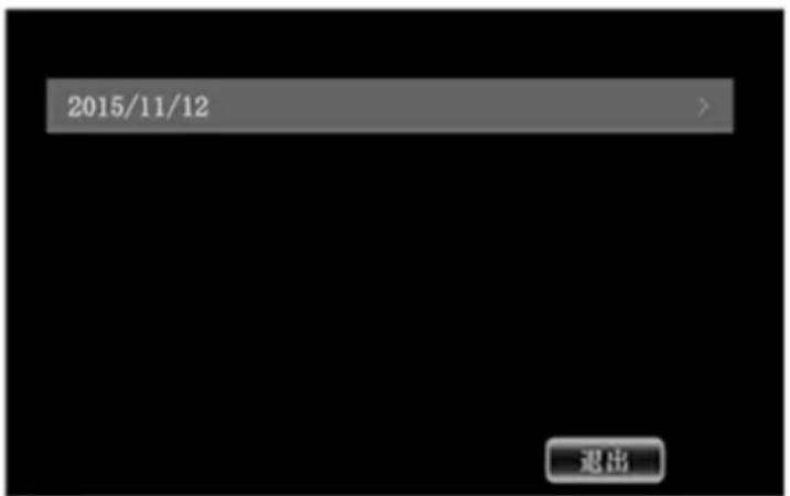
text_image
2015/11/12 退出H-HJYX-002
2. Video playback menu 1
The following figure shows the first-level menu for video playback. The first-level menu shows the day, month and year corresponding to the recorded video.
3. Video playback of secondary menu
The second level menu of the video file displays a corresponding hourly interval information called recording.
- Replay the three-level menu
The three-level menu of the video file corresponds to the time and second information of the beginning of recording video.
- Video recording and playing interface
As shown in the figure below, it is the recorded video screen (video recording is conducted in the form of 6 grids by default), and the single video screen can be touched to zoom in and out of the single video.

CAUTION:
The upper right corner of the recorded video shows the time, speed and information. Key functions are shown in the following table.
| icon instructions | |
 | Return to the video menu list. |
 | Set menu button |
 | Fast rewind button |
 | Fast forward button |
Set menu interface
The following figure shows the logical migration diagram of the video recording interface, which can be configured for the display mode of straight line and steering, and the channel of video recording.
1. Set auxiliary line when going straight
If shown as "√", the auxiliary line is open; if shown as "×", the auxiliary line is closed.
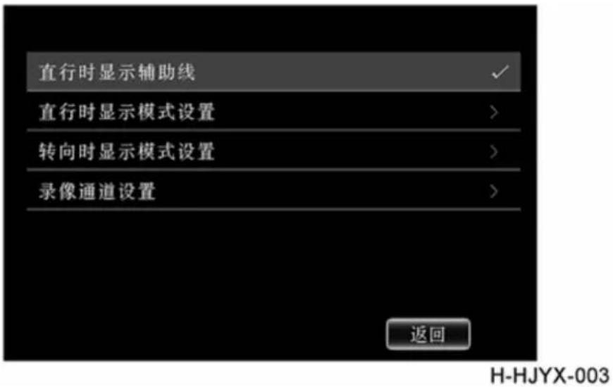
2. Display mode Settings when going straight
Display mode Settings for straight lines can be set to forward view + panorama (default), and forward view.
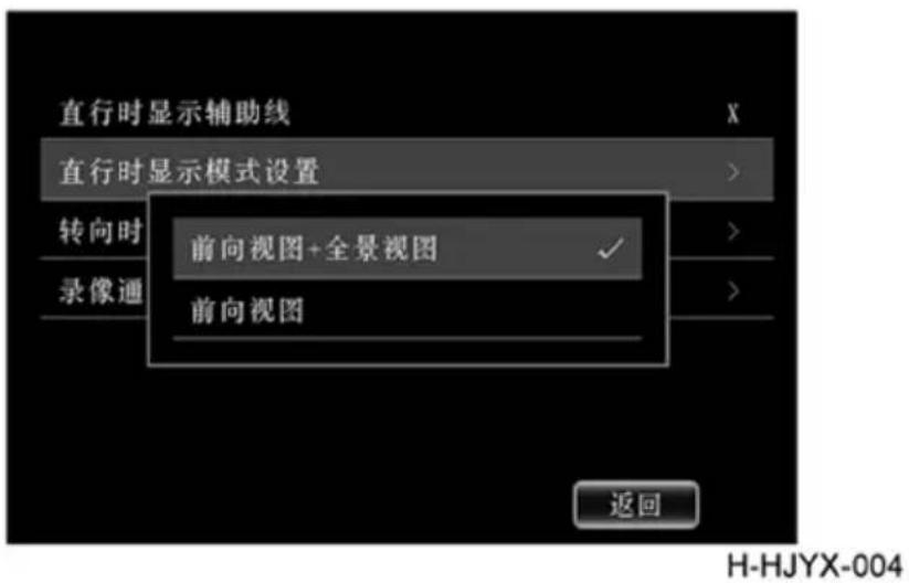
When turning, the display mode can be set to left/right rear view + panorama view (default setting), left/right front view + panorama view, left/right front view + left/right rear view, left/right front view, left/right rear view, right/left rear view.
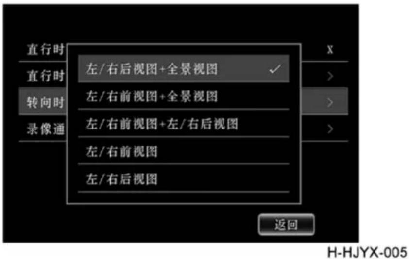
- Video channel setting
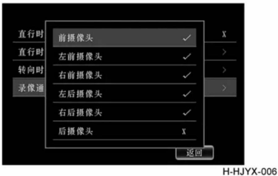
Video locked and non-locked state Settings
As shown in the figure below, the video recorded by long press can pop up the operation screen, and the user can set the corresponding video to be "locked" video. The so-called locked video means that the system will not automatically cover and delete the locked video when the SD card storage space is full.
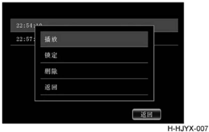
Locked behind the video files will appear a lock icon, lock video must manually unlock before can be deleted.
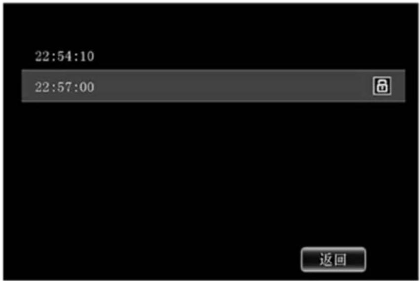
text_image
22:54:10 22:57:00 返回H-HJYX-009

CAUTION:
AVM is only intended to assist driving and is not applicable in all situations. The driver is always responsible for driving safely. The normal use of the system may be affected under the following circumstances:
- Severe weather conditions lead to poor visibility, such as fog, haze, rain, snow, etc.;
- Insufficient light in the camera field, such as no street lamp at night;
- The camera is blocked by snow, ice, dirt, water or other objects;
- Sharp changes in light, such as in and out of a tunnel;
- Violent jolting and shaking;
- There are stains on the surface of the camera lens;
- The road reflects heavily after being exposed to strong light.
Description of tire pressure monitoring system
System function
- Check the pressure and temperature of each tire through the instrument menu key;
- The tire pressure is too high or too low to alarm; Tire high temperature alarm;
- System fault indication (support sensor battery low, sensor signal loss and other fault codes);
- Manual learning of tire pressure sensor ID;
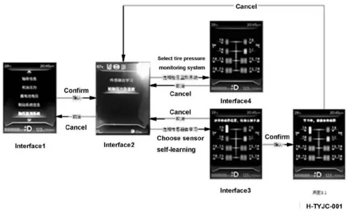
flowchart
graph TD
    A["Interface1"] -->|Confirm| B["Interface2"]
    B -->|Select tire pressure monitoring system| C["Interface4"]
    C -->|Cancel| B
    B -->|Choose sensor self-learning| D["Interface3"]
    D -->|Confirm| E["Interface4"]
    E -->|Cancel| B
    C -->|Select tire pressure monitoring system| F["Interface4"]
    F -->|Cancel| B
    style A fill:#f9f,stroke:#333
    style B fill:#ccf,stroke:#333
    style C fill:#cfc,stroke:#333
    style D fill:#fcc,stroke:#333
    style E fill:#cff,stroke:#333
    style F fill:#ffc,stroke:#333
When there is an alarm or fault, it will pop up in the main interface and disappear after 5s on the 4-tire pressure interface. The fault will be displayed as a small icon until the fault disappears.
-
When the tire pressure is too low, too high or the temperature is too high, the tire will show red, and the fault data will also show red without flashing.
-
When a wheel message timeout, the value display "--".
-
When there is a fault, the alarm position interface pops up on the main interface and disappears 5 seconds later. It is displayed on the main interface in the form of TPMS fault light until the fault disappears.
Manual learning function introduction
- Manual learning provides a convenient way for the driver to update the tire pressure sensor ID. The driver can complete the learning through the sub-menu of "self-learning sensor" of the instrument without the help of after-sales diagnosis instrument. This feature is often used in two situations:
A. When the tire is replaced and a new sensor is replaced, it is necessary to relearn the sensor ID of the position;
B. The tires of two positions on the same vehicle are switched, and no new sensor is replaced;
This function selects the sub-menu of "self-learning sensor" by the driver, selects the tire position that needs to be learned, and presses the confirm button to trigger learning. Next, the driver can trigger the sensor in 5 minutes. The driver can trigger the sensor in two ways. The first is triggered by the use of hand-held low-frequency tools provided by the 4S store, and the second is triggered by the opening of the valve valve core to deflate the tire. There will be continuous text reminders on the instrument interface of learning progress, success and failure, and the driver can return to the cockpit after the sensor is triggered
Get feedback on learning outcomes. After successful learning, the newly replaced sensor ID will be recorded to the corresponding location of the TPMS control unit assembly; If the learning fails, please check the reason for the failure according to the corresponding text reminder, then exit the sub-menu of "self-learning sensor" and re-enter and re-learn.
- Safety conditions for manual learning before manual learning, drivers must check whether the vehicle meets the following conditions:
A. The vehicle is at rest (the speed is 0 and the engine speed is 0);
B. The ignition key is in the ON gear (the engine is not started);
C. The sub-menu of "tire pressure monitoring system" works normally;
3. Operating instructions
Replace the new sensor before left
A. Confirm that the vehicle meets the safety conditions for manual learning;
B. Enter the sub-menu of "self-learning sensor" of the instrument, select the left front wheel and click OK to confirm;
C. If the menu of the interface shows "in learning, please activate the sensor". Please get off the bus within 5 minutes and complete the trigger of the sensor on the left front wheel. The trigger means are hand-held low-frequency tool trigger and valve outlet trigger.
D. After completing c, the pilot returns to the cockpit to check the text reminder of the instrument. If the interface menu shows successful learning, please exit the sub-menu to complete the learning process (if you need to continue learning other sensors, please repeat a, b, c, d);
E. If the learning failure is displayed in the interface menu, please check whether the safety conditions and precautions for manual learning are met according to the failure reasons.
Left front and right front switch, no new sensor is replaced
A. Confirm that the vehicle meets the safety conditions for manual learning;
B. Enter the sub-menu of "self-learning sensor" of the instrument after the switch is completed, select the left front wheel and click OK to confirm;
C. If the menu of the interface shows "in learning, please activate the sensor". Please get off the bus within 5 minutes and complete the trigger of the sensor on the left front wheel. The trigger means are hand-held low-frequency tool trigger and valve outlet trigger.
D. After completing c, the pilot returns to the cockpit to check the text reminder of the instrument. If the screen menu shows successful learning, please exit the sub-menu. Then enter the sub-menu of "self-learning sensor" again, select the right front wheel and click OK to confirm. If the menu of the interface displays "in learning, please activate the sensor". Please get off the bus within 5 minutes and complete the trigger of the sensor on the right front wheel.
E. If the interface display is successful, the tire switching learning process is successfully completed. If the learning failure is displayed in the interface menu, please check whether the safety of manual learning and precautions are met according to the reason of failure.

CAUTION:
- The single learning operation process can only learn a single position sensor ID. If there are multiple sensors to be learned, please exit the "self-learning sub-menu" after completing one learning and repeat the operation;
- After selecting the tire position and clicking OK, the instrument interface will display "please activate the sensor while learning", and the driver is required to activate the corresponding position sensor within 5 minutes;
- If the reason for the learning failure is "sensor ID conflict", that is, the twin sensors are activated at the same time, there are two possible reasons. One is to use a handheld low-frequency tool to trigger when the twin sensor is closer to being simultaneously
Trigger, therefore, it is necessary to keep the straight distance between the valve mouth of the twin as far as possible (that is, the valve mouth of the twin is 180 degrees opposite), and try to be close to the valve mouth of the position to be learned when triggering, and away from the other side of the valve mouth; Second, when the deflator is triggered, there are other vehicles nearby to learn to deflate at the same time;

-
If the reason for failure is "engine speed is not 0", please turn off the engine and keep the ignition key in ON gear;
-
If the reason for failure is "the speed is not 0", please check whether the vehicle is in the running state. If so, please exit the "self-learning sensor sub-menu" and start self-learning after parking;
-
If the reason for failure is "learning timeout", please exit the "self-learning sensor sub-menu", please check whether the sensor was successfully triggered within 5 minutes after the study began. If not, please re-enter the study and trigger the corresponding position sensor within 5 minutes;
-
When the bleed is triggered, pay attention to the bleed rate to meet certain requirements, that is, the pressure difference of 22Kpa is reached within the sensor sampling period. Screw the valve nut, hold the valve core with a tool and let off air for about 15s. If the instrument has a long sound of 3 seconds, it means that the learning is successful. If not, continue to deflate. (it is suggested that the tire that needs to learn the position should be inflated to about 50Kpa above the nominal tire pressure after replacing the new sensor, so that the tire pressure can just recover to the nominal tire pressure after the completion of the deflating trigger and complete the learning);
-
If the reason for the failure is "learning failure" and there is no prompt for the corresponding reason, please turn off the ON gear and cut off the power supply of the vehicle, then turn ON the power supply and ON gear again for self-learning. If the learning failure is still shown, please seek help from 4S shop professionals for diagnosis;
After all the learning is completed, the on-file signal and vehicle power supply can be turned off, and then the power supply and on-file signal can be turned ON to restart TPMS.
Steering voice alarm
When the vehicle is in motion, pull the handle of the right turn signal, and the vehicle will turn right when it makes a voice alarm to remind other road users to pay attention to the movement state of the vehicle turning right in time. Vehicles to resume straight line stop alarm work.
Taillight detection function (for main vehicle only, except trailer)
Because the taillight is LED, it is impossible to judge the damage of single side lamps, so the filament alarm function is the rear fog light and brake light. When the lamps on both sides of the rear position light are damaged, the filament detection indicator light on the instrument will be lit. This function is used to indicate the working status of the driver's taillights.
Door open alarm function
When the light is turned on and either door is open and the ignition lock is in OFF gear, the buzzer alarms. This function is used to remind drivers to turn off the lights when they leave the car.
Differential alarm
When the differential switch is pressed, the differential lock starts to work, and the buzzer alarms to remind the driver to close the differential switch in time when driving out of the fault road surface. Otherwise, the differential will be damaged, resulting in excessive tire wear.
Chassis distribution box
located in the battery box.
Chassis distribution box is used for main circuit fuse of electrical distribution system. When replacing the fuse or relay of the main circuit, it is necessary to confirm the load of the fuse or relay used and find out the corresponding fuse or relay through the mark on the label of the central distribution box.
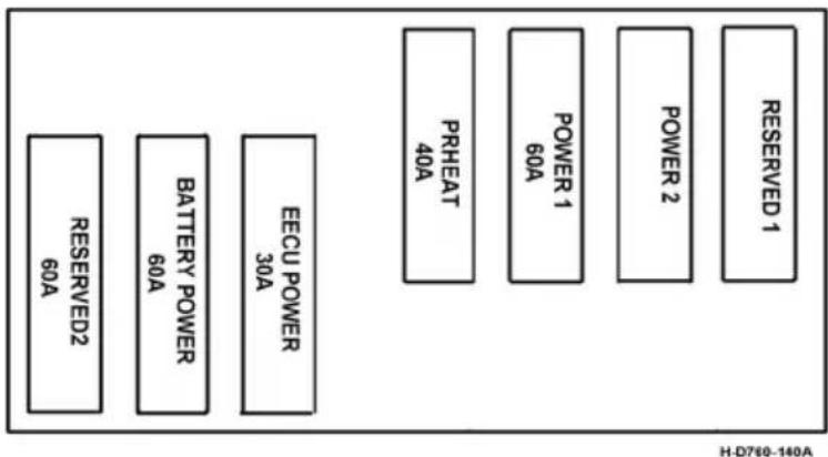
text_image
RESERVED 1 POWER 2 POWER 1 60A PRHEAT 40A BATTERY POWER 60A EECU POWER 30A RESERVED2 60A H-D760-140AFuse box
When replacing a fuse or relay, it is necessary to confirm the load of the fuse or relay used. Find the corresponding fuse or relay according to the mark on the name-plate of the central distribution box.
Please refer to the specific configuration of the purchased model.
Fuse box label
| 15 | 14 | 13 | 12 | 11 | 10 | 9 | 8 | 7 | 6 | 5 | 4 | 3 | 2 | 1 | |
| 15A | 20A | 5A | 15A | 10A | 10A | 5A | 30A | 5A | 20A | 10A | 15A | 10A | 20A | 10A | |
| BCAS 1 | BCM 3 | Mainten ance lamp | Wiper& Washer | Electric horn | Compressed air dyer | Heater& parking2 | Cab lift | BCM 8 | BCM 6 | Heaters/ parking1 | Insulation ran 1 | Indoor lamp | DC-AC inverter | Ignition switch | |
| 30 | 29 | 28 | 27 | 26 | 25 | 24 | 23 | 22 | 21 | 20 | 19 | 18 | 17 | 16 | Always Replen A Fuse By Another Fuse With The Same Rating FUSE EXTRACTOR 15A 20A |
| 5A | 5A | 5A | 15A | 15A | 5A | 5A | 5A | 5A | 5A | 10A | 5A | 5A | 5A | 5A | |
| Oil tank heat | Air-condition2 | LOWS ECU2 | High beam | Low beam | Retarder2 | BCM 7 | Instrument panel2 | AMT SCU2 | ECAB 2 | Master ABS/EBSI3 | Trailer AIN/EBSI2 | Urea injection pump | Stopping switch | VECU | |
| 45 | 44 | 43 | 42 | 41 | 40 | 39 | 38 | 37 | 36 | 35 | 34 | 33 | 32 | 31 | |
| 10A | 5A | 15A | 15A | 15A | 15A | 5A | 20A | 5A | 20A | 15A | 5A | 5A | 5A | 5A | |
| NOx sensor | Tachograph 2 | Front fog lamp | Position lamp | Rear lighting lamp | Insulation ram2 | Starter | Cigar lighter2 | DC-DC2 | Cigar lighter1 | Auxiliary headlamp | Oil preheat | Power sunroof2 | MP3/CD2 | BCM 9 | |
| 60 | 59 | 58 | 57 | 56 | 55 | 54 | 53 | 52 | 51 | 50 | 49 | 48 | 47 | 46 | |
| 15A | 20A | 10A | 25A | 10A | 25A | 10A | 15A | 10A | 10A | 15A | 10A | 10A | 30A | ||
| Subwoofer | DC-DC1 | Electronic pump. Air-condition 1 | |||||||||||||
H-3722025-C6106-a

CAUTION:
The fuse box label is located on the inside of the middle and lower guard on the passenger side.
Relay box label
| 位置 | 名称 | 适用 |
| 1 | Ignition switch ON relay1 | |
| 2 | Ignition switch ON relay2 | |
| 3 | Ignition switch ON relay3 | |
| 4 | Ignition switch ON relay4 | |
| 5 | Ignition switch ON relay5 | |
| 6 | Ignition switch ON relay6 | |
| 7 | Neutral relay1 | |
| 8 | Neutral relay2 | |
| 9 | VECU relay | |
| 10 | EECU relay | |
| 11 | Electric horn relay | |
| 12 | SCR relay | |
| 13 | Ignition switch ACC relay1 | |
| 14 | Ignition switch ACC relay2 | |
| 15 | Ignition switch ACC relay3 | |
| 16 | Ignition switch ACC relay4 | |
| 17 | Urea piping heat relay1 | |
| 18 | Urea piping heat relay2 | |
| 19 | ||
| 20 | Position lamp relay | |
| 21 | Stop relay | |
| 22 | Rear lighting lamp relay | |
| 23 | Urea piping heat relay3 | |
| 24 | Front fog lamp relay |

CAUTION:
The relay label is located on the inside of the middle and lower guard on the passenger side.
Adjustment of Steering Wheel
Angle adjustment
- Hold the steering wheel by right hand;
- Press the upper unlock button on the pneumatic valve switch by left hand;
- Adjust the fore-and-aft angle of the steering wheel as needed;
- Keep it at a proper position until locking exhausting sound is heard or press the upper lock button on pneumatic valve switch.
UP-DOWN adjustment
- Press the upper unlock button on the pneumatic valve switch by left hand;
- Hold the steering wheel to a proper position by both hands;
- Adjust the steering wheel upward and downward as needed;
- Keep it at a proper position until locking exhausting sound is heard or press the upper lock button on pneumatic valve switch.

CAUTION:
Ensure that you can hear locking exhausting sound of pneumatic valve switch.
Ensure to adjust the steering wheel when the air pressure of the complete vehicle is more than 0.4Mpa.

WARNING:
Adjusting the position of the steering wheel is strictly prohibited during driving.
Towing Hook
Before using the towing hook, remove its pin cover as follows:
Removal method for towing hook pin cover at driver's side
-
Use a screwdriver to remove the two bolts on towing hook cover, and take the towing hook pin cover out from the slot.
-
Take the towing hook from the toolkit and screw into the hook threaded holes.

text_image
1 2 H-D760-105- Bolt
- Tow hook pin cover
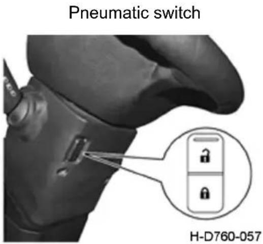
text_image
Pneumatic switch H-D760-057After using the towing hook, reinstall its pin cover properly by the steps opposite to the above.

CAUTION:
-
The front towing hook of the vehicle is only used under the normal driving road surface. If the vehicle is equipped with two front towing hooks, double towing hooks must be used to ensure that the force of the double towing hooks is uniform.
-
When using the front towing hook, it is required that the tractor must remove the trailer; Trucks and engineering vehicles shall be empty as much as possible (or the weight shall not exceed the rated load mass).
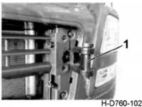
natural_image
Close-up of mechanical components with no visible text or symbols- Towing hook
Front Face Shield
Opening of front face shield
- Pull the primary lock handle under the driver's side instrument panel in the cab to unlock the primary lock;
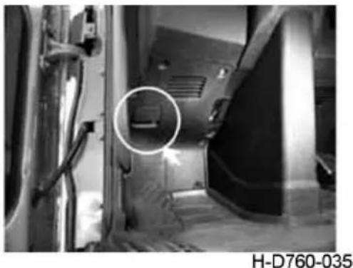
natural_image
Interior view of a vehicle showing a door, vent, and structural elements with a circled detail (no visible text or symbols)-
Primary lock handle of face shield
-
Pull the secondary lock handle which is located at the lower edge of the left face shield outside the cab from rightward to leftward by right hand, and hold the middle lower edge of the front face shield by left hand to pull the face shield in heading direction of the vehicle, in this case, the shield can be unlocked.
Closing of front face shield
When the front face shield is in opening status, hold the middle lower edge (or rope) of the shield to lock the shield.
Side Spoiler
The left side spoiler can be opened and closed. The spoiler shown in the top-right figure is in the closing status, but that shown in the opening status.
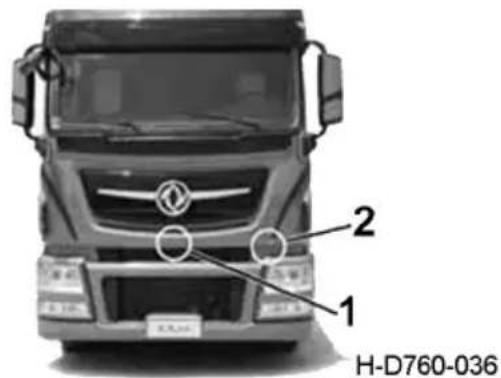
text_image
2 1 H-D760-036-
Pull the front face shield forward by left hand.
-
Unlock the secondary lock by left hand.
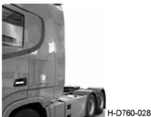
natural_image
Side profile of a semi-truck truck with visible frame and side trailer (no text or symbols)Closing status of side

natural_image
Side view of a semi-truck truck with visible side brackets and front livery (no text or symbols)Opening status of side
Opening of side spoiler
Hold the rear inner pipe of the lower side spoiler to pull it outward in the heading direction, in this case, the lower side spoiler can be opened.
Closing of side spoiler
Push the front edge of the lower side spoiler inward and rearward to close the lower side spoiler.
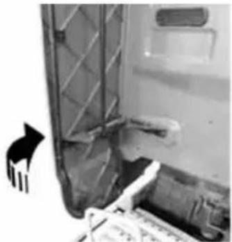
natural_image
Close-up of a door with visible mechanical components and a hand pointing to the left side (no text or symbols)H-D760-058
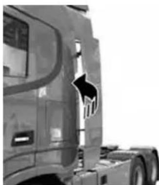
natural_image
Side view of a truck's front bumper with a black arrow pointing to the side (no visible text or symbols)H-D760-066
Roof spoiler
The roof spoiler is equipped with a height adjusting mechanism which can meet requirements of different heights of the cargo body. Adjustment method:
-
Release the adjusting knob and press it downward to disconnect the stop block from the long adjusting lever, in this case, the adjusting knob can slide upward and downward in the adjusting groove.
-
Push the roof spoiler upward or downward, and after the height of the roof spoiler is determined, release the adjusting knob to complete adjustment.
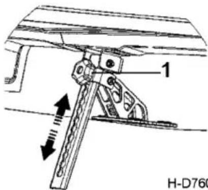
text_image
1 H-D760H-D760-059
1. Adjusting knob

CAUTION:
-
During adjustment of the roof spoiler, it is required to adjust the adjusting levers on left and right sides, and it is not allowed for adjusting levers to have different lengths; otherwise, the roof spoiler may suffer twist, causing damage to the spoiler.
-
Tighten the adjusting knob after adjustment. The lower adjusting lever should be pressed against the upper adjusting lever; otherwise noise may be heard during driving, causing damages to the parts.
Fire Extinguisher
The fire extinguisher is located under the driver's seat. For the detailed operations, refer to the instructions on the fire extinguisher body.
Refueling
Open the fuel tank cap and add clean fuel of the specified grade up to the 95% of its volume at maximum.
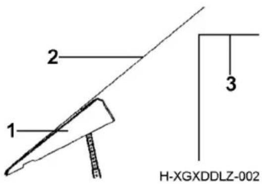
text_image
1 2 3 H-XGXDDLZ-002- Roof spoiler
- Roof spoiler extension line
- Cargo body
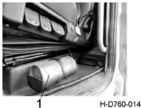
natural_image
Interior view of a vehicle showing a cylindrical component inserted into a car trunk, with no visible text or symbols.- Fire extinguisher
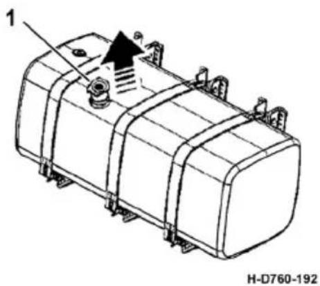
text_image
1 H-D760-192- Fuel tank cap
Warning Triangle
Warning triangle should be placed 50 m away from the stopped truck, easily being noticed by the drivers of the vehicles behind.

text_image
1 50m H-T04-074B1- Warning triangle
Triangular stop block
Compare the specific configuration of purchased model products.
When the vehicle is parked on the ramp, a triangular stop block is placed under the drive wheel to act as an auxiliary stop brake.
Each car is equipped with 2 triangular stop blocks, usually in a black cloth bag, placed under the sleeper cab.
When the vehicle stops on the ramp below 18%, the driver pulls up the handbrake and leaves the cab. He inserts the two triangular stop blocks under the left and right drive wheels to observe that the vehicle does not move and slide before leaving.
Iron triangular brake block
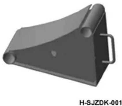
natural_image
3D rendered mechanical component with cylindrical and rectangular features, no visible text or symbolsPlastic triangle brake block
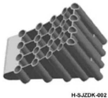
natural_image
3D rendering of a layered structure made of cylindrical rods, labeled H-SJZDK-002 (no text or symbols on the structure itself)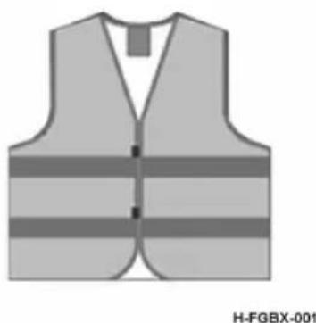
natural_image
Illustration of a safety vest with horizontal stripes (no text or symbols)Reflective vest
Reflective vest is made of high visibility reflective material, can be in the night or special weather conditions play a warning role, prevent the occurrence of accidents, to ensure their own safety.
Each car is equipped with a reflective vest, usually in a black cloth bag, placed under the cab sleeper.
Inverter instructions
Indicator status
- Green light: normal operation;
- Red light flashing: overload protection, short-circuit protection, overvoltage protection, overtemperature protection, constant power protection, leakage protection, etc.;
- Light not on: under voltage protection.
The rated power of the inverter is 300W, which can adapt to the electrical appliances below 600W. When the power of the using electrical appliances is between 300W and 600W, the inverter enters the constant power output mode.

CAUTION:
- Electrical appliances with power of >600W are prohibited;
- When the electric appliance is finished, pull out the electric appliance in time;
- When using, please pay attention to the safety of electricity, do not allow children to contact the socket, pay attention to the high voltage danger;
- Do not insert your finger or conductive object into the socket socket, and pay attention to high-voltage electric shock;
- Please place the liquid and other items far away from the socket.
- The inverter belongs to the heating body. Users are prohibited to place heat-resisting or flammable articles such as clothes on the inverter body, which may affect the heat dissipation of the inverter or cause fire
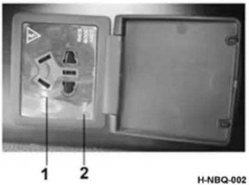
text_image
1 2 H-NBQ-002- Inverter socket
- The indicator light
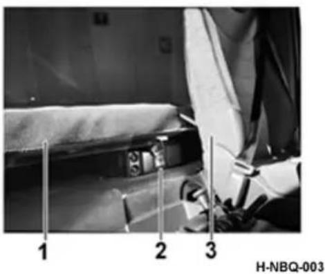
text_image
1 2 3 H-NBQ-003- The sleeper
- Inverter socket
- The seat
Main auxiliary tank changeover valve operation
Instructions for oil route switching
- When the handle is in the "main fuel tank" position, the fuel inlet of the main fuel tank communicates with the fuel inlet of the engine; The main tank oil return port communicates with the engine oil return port;
- When the handle is in the position of "auxiliary fuel tank", the inlet of auxiliary fuel tank is communicated with the inlet of engine; The fuel return port of the auxiliary tank is communicated with the engine return port;
Operating instructions
- When two tanks are filled with the same brand of fuel, the user can switch according to the amount of fuel remaining in the fuel tank or the user's demand.
a. Under the condition that the vehicle is stopped, the operation without flameout can be realized.
b. If the user needs to stop the vehicle during driving, then manually operate the handle at the switch valve of the main and auxiliary fuel tank and rotate the handle to the fuel tank mark that needs to be used. - When two tanks hold different grades of fuel, if the ambient temperature is higher than 0 degree, switch the handle to the corresponding mark of the valve according to the user's requirements, and then use the corresponding fuel tank.
a. Under the condition that the vehicle is stopped, the operation without flameout can be realized.
b. If the user needs to stop the vehicle during driving, then manually operate the handle at the switch valve of the main and auxiliary fuel tank and rotate the handle to the fuel tank mark that needs to be used.
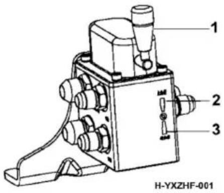
text_image
1 2 3 H-YXZHF-001- Handle
- The main tank
- Drop tank
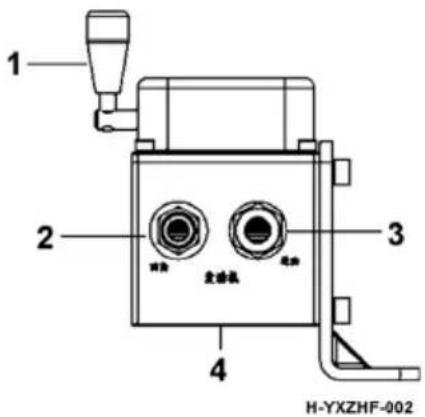
text_image
1 2 3 4 H-YXZHF-002- Handle
- Oil return
- oil intake
-
Engine
-
When fuel of different grades is stored in two tanks, if the ambient temperature is lower than 0 degree and the fuel is easy to wax, it is necessary to fill the fuel pipeline with high-grade fuel before flaring in order to avoid the problem that the engine cannot be started after long-term flaring.

CAUTION:
The auxiliary tank is filled with high grade fuel oil which can withstand low temperature.
Operation method
- 3 minutes before the vehicle shuts off, the vehicle stops, the user gets off and rotates the handle to the mark of "auxiliary fuel tank" to fill the fuel pipeline with high-grade fuel and prevent wax.
- Before starting the vehicle, check that the switch handle is at the mark of "auxiliary fuel tank". If so, it can be started normally. If not, rotate the handle to the "fuel tank" mark
- Since there is no fuel heating device in the main fuel tank, users should judge by themselves whether the fuel in the main fuel tank is waxed and whether the waxing degree meets the normal operation of the vehicle. The user decides whether to switch to no. 0 fuel in the main tank according to the judgment.

CAUTION:
- The valve body of this product is strictly forbidden to be removed;
- After the conversion from the main oil tank to the auxiliary oil tank, the interval shall be more than 3 seconds, and then from the auxiliary oil tank to the main oil tank. The continuous conversion operation shall not be longer than 10 minutes;
- In low temperature weather, in order to prevent the switch and the pipeline from freezing and being unable to start the fire, please switch the oil line to low-temperature oil before getting off the bus, so that the oil line and the switch are filled with low-temperature oil;
Cab Tilting
Please refer to the specific configurations of your vehicle.

CAUTION:
Check that the cab door is locked and objects in the cab put in order, so as to avoid objects falling off during cab tilting, damaging the cab.
Always open the front face shield prior to tilting the cab; otherwise the shield may be damaged.
Tilting of electric cab
Open the front face shield and keep it opening during tilting.
-
Cab lift: adjust the reversing handle to the lifting position, remove the electric lift switch, stand on the side of the cab, and press the switch. (or insert rocker, rocker swings back and forth around the center axis) to achieve lifting in place.
-
Cab back down: adjust the reversing handle to the back down position, hold down the electric lift switch, and replace the electric lift switch after completion. (or insert a joystick that swings back and forth around the center axis) to fall back into place.
-
When the cab is not locked and in position, the indicator light on the instrument will give warning
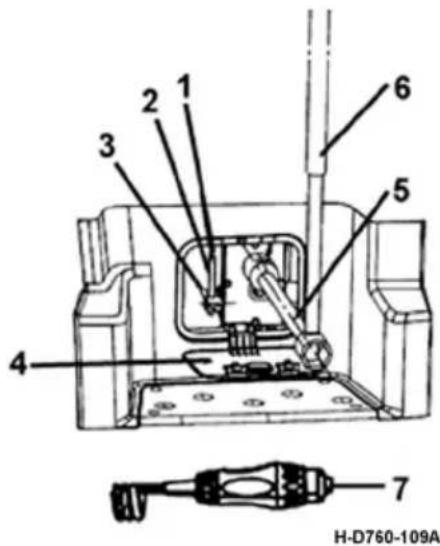
text_image
1 2 3 4 5 6 7 H-D760-109A-
Reversing handle
-
Electric tilting and lifting switch
-
End cap
-
Socket and center axis
-
Control lever
-
Extension lever
-
Electric lift switch (front)

WARNING:
-
Before tilting the cab, it is required to stop the vehicle, shut the engine down, and shift into neutral, and it is prohibited to tilt the cab on a slope or do other operations before the cab it tilted in place.
-
During tilting of the cab, ensure that the shield is opened, and there is no person or objects in front of or around the cab, so as to avoid accidents.
-
During driving, the reversing handle should be set at the Return position.
-
During tilting of the cab, the hydraulic locking sensor may make a tisket sound under normal conditions, and the red tilting display figure on the instrument panel in the cab will be illuminated; when the cab is lowered in place, the tisket sound may disappear, at the same time, the tilting display figure on the instrument panel may disappear; it is only possible to start the engine and move the vehicle when it is confirmed that the cab is locked in place.
ECAS operation
Please refer to the specific configurations of your vehicle (this section is only applicable to the model with air suspension).
The rear air suspension system is designed with the international advanced and mature electronically controlled air suspension (ECAS). The air suspension, a complex system element assembly, can bring the elasticity effect by air in the compressive and tensile rubber airbag. Therefore, its stiffness will change as the load changes. Compared to the traditional leaf spring, this suspension features low inherent frequency, long service life and light weight, and it can ensure the body height when the load changes. The air suspension has an outstanding feature, that is, it can ensure that the vehicle height keeps unchanged under no-load and full-load conditions.
Working principle of ECAS
The working principle of ECAS is as shown in Fig. H-T01-026.
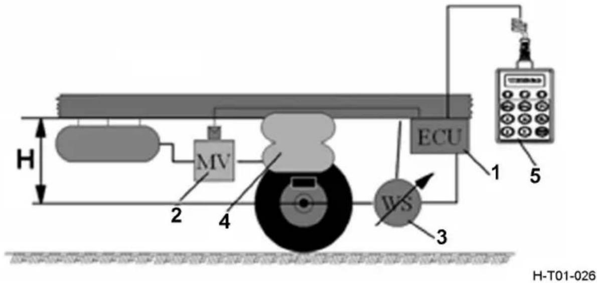
text_image
H MV IVS ECU 1 5 3 H-T01-026-
ECU
-
Solenoid valve
-
Height sensor
-
Airbag
-
Remote controller
H: Design index
Based on a constant comparison between reading provided by the height sensor and design index height H stored in ECU, ECAS can identify the current height of the vehicle at any time; once the difference between current height and design index height (H) exceeds the tolerance range, the solenoid valve will be activated, and opening or closing the corresponding valve will increase or decrease pressure of the airbag, so it is required to adjust the actual height of the vehicle to the initial design index height.
ECAS has powerful functions; it can not only control the normal height (i.e., design index height), but also control preset height. ECU, regarded as the heart of ECAS, has the following functions:
- Continuously monitoring input signal
- Comparing input valve and index value
- Converting signal into internal counting
- Assessing required control response in case of deviation
- Activating solenoid valve to operate
- Managing and storing different index values (normal height, fault memory, etc.)
- Regularly monitoring operability of all components
- Monitoring axle load (with the help of pressure sensor)
- Checking possibility of received signal for fault detection
- Finding system fault
Indicator light:
The security and fault diagnosis of ECAS system are displayed by indicator light. Two ECAS indicator lights are installed on the dashboard. One is a red failure light and one is a yellow warning light. When the ignition switch is turned on, the indicator light will be on for 2 seconds to inform the driver that the ECAS system is working normally.
Simple fault judgment:
Red indicator light is always on, indicating that the fault is not serious;
The red indicator light flashes, indicating that the fault is serious.
The yellow indicator light is always on, indicating that the vehicle is not running at the normal height. The reset button of the remote control can be used for reset. In the process of vehicle driving, if the vehicle height is at the position of non-driving height, ECAS will automatically adjust the vehicle height to the driving height to ensure the safety of the vehicle after the speed exceeds 30km/h; If you find that ECAS system does not have this function in the process of driving, please contact the manufacturer for troubleshooting. The yellow indicator light flashes, indicating that the system pressure is insufficient, please start the vehicle to make the air compressor work, and the air pressure of the storage cylinder is sufficient.
ECAS is an inspection-free system, and the fault path of the system ensures that the system can conduct self-monitoring without additional system checks. Detected faults are stored in the ECU's permanent memory. Except for the parts not controlled by ECU in the inspection system (sensor linkage, indicator light, etc.), when the ECU detects a fault, the indicator light will flash, and only at this time need to go to the maintenance workshop for inspection. The best way to check is to use a diagnostic instrument that not only provides the type of fault, but also the frequency of the occurrence of the fault and whether the fault is present.

CAUTION:
ECAS system failure need to use special instruments to detect and adjust. Be sure to contact the vehicle manufacturer and do not replace parts, especially ECU. When the ECU is replaced, if the parameter setting is wrong, the system will not have any function.
Use of remote controller
For easy use and operation by the driver, ECAS is equipped with a remote controller. The remote controller of this vehicle is installed on left side of the driver's seat.
The remote controller can be operated as follows:
-
After the vehicle has been started by igniting, the remote controller can not be activated. It can be activated only when the remote controller switch is pressed. When the switch is pressed, the indicator lamp right above it will turn on for indicating, at this time, the remote controller can work. The indicator lamp will turn off when the switch is pressed again; at this time, the remote controller can not work.
-
M1 and M2 are used for storing two frequently-adopted heights. After the height has been stored, the vehicle can reach the preset height (H1) by pressing M1; the vehicle can reach the preset height (H2) by pressing M2. The height memory switch plays an important role in
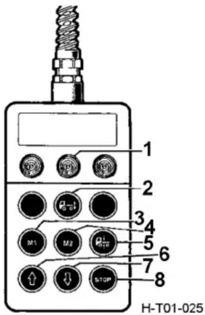
text_image
1 2 3 4 5 6 7 8 H-T01-025- Indicator lamp
- Remote controller switch
- M1 height memory switch
- M2 height memory switch
- Reset switch
- UP switch
- DOWN switch
- STOP switch
connection or disconnection of tractor and trailer. In case the trailer connected to the tractor keeps unchanged, at the first try of connecting or disconnecting the tractor and trailer, store the heights of two tractor frames by using the M1 and M2 height memory switch. It will be very easy to carry out next connection and disconnection (second connection of tractor and trailer can be realized by pressing M1, and second disconnection of tractor and trailer can be realized by pressing M2. See Point 5 "Operation of STOP Button" for height storage method.
- Pressing the reset switch can realize the initial design index height of the vehicle.
- Operating the "↑" switch and "↓" switch can realize manual adjustment of vehicle height. The vehicle will continuously go up or down when the "↑" switch or "↓" switch is pressed and held.
- The "STOP" switch, designed as a red stop switch, has two functions: one is that pressing this switch can stop height adjustment of ECU and remote controller, and the other one is that operating this switch can store the height value with the help
of M1 and M2. For example, pressing "↑" switch to lift the vehicle to the required height, and with the "STOP" switch and M1 pressed, the height will be stored by M1. In the same way, the height value can be memorized by M2.

CAUTION:
- Before driving, please make sure the airbag height is normal.
- After the operation of the remote control, please press the reset button to make the vehicle return to the normal height.
- Operate the vehicle to rise or fall through the remote control. Since the ECAS solenoid valve is charged and vented rapidly, it is necessary to pay attention to the safety of the system when the air is overloaded and vented.
- Frequent operation may lead to insufficient air supply to the air storage cylinder and make the remote control operate out of order. At this point can start the vehicle, so that the compressor work, play enough air storage cylinder pressure, or has not been flameout.
Use of Differential lock
Please refer to the specific configurations of your vehicle.
Differential lock should be used when the vehicle is stopped or runs at a speed equivalent to walking. In case that the vehicle is running on the muddy and uneven road, causing slipping of intermediate/rear driving axle and vehicle stranding, the vehicle can be driven out of the defective road surface smoothly through differential lock.
In case that the cab instrument panel is equipped with an inter-wheel differential lock switch, when driving on a muddy road with a tire slipping one side, depress the clutch pedal and turn on the inter-wheel differential lock switch. When the inter-wheel differential lock indicator lamp comes on, the inter-wheel differential lock of rear axle will be engaged at the same time. Engage the transmission at proper gear, release the clutch pedal and then the vehicle can drive away from the defective road.
Turn off the two differential lock switches immediately after driving out of defective road.
text_image
Diagram of a vehicle door with a circular symbol labeled 'H-X' and a horizontal bar at the bottom.H-D760-069

natural_image
Pure electrical circuit symbol for a fuse (no text or labels)H-D760-13
Inter-wheel differential lock switch and indicator light

CAUTION:
-
Never press the differential lock switch when the vehicle is running normally. Never use the differential lock for long time; otherwise, it may damage the differential and result in excessive wear of tire.
-
Differential lock switch must be pressed after the vehicle is stopped fully; otherwise, the differential may be damaged.
Post-processing system
The hardware architecture principle of the post-processing system is shown in the figure below:
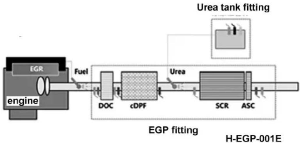
flowchart
graph LR
    A["engine"] --> B["EGR"]
    B --> C["Fuel"]
    C --> D["DOC"]
    D --> E["cDPF"]
    E --> F["Urea"]
    F --> G["SCR"]
    G --> H["ASC"]
    H --> I["Urea tank fitting"]
    I --> J["H-EGP-001E"]
EGP assembly includes:
- Diesel oxidation catalytic converter: DOC refers to the device installed in the exhaust system of diesel vehicles, oxidizing (burning) hydrocarbons (diesel) injected into DOC to provide a high temperature environment for DPF regeneration.
- Diesel particulate filter: DPF for short, refers to the device that filters in the exhaust system to reduce particulate matter (PM) in the exhaust.
- Selective catalytic reductor: referred to as SCR, it refers to the device that catalyzes selective catalytic reduction of urea solution and NOx in the exhaust emission system of diesel vehicles.

Warning:
In order for the engine reprocessing system to work properly, use the required grade of engine oil in this manual, as well as ultra-low sulfur diesel with a sulfur content of 10ppm or less to maintain the specified oil change interval without risk of engine damage.
Urea tank complement
Urea tank assembly includes urea tank, metering pump, urea quality/level/temperature sensor and other components.
Control function
The control system has complete SCR, DPF control and OBD functions. All post-processing functions are integrated into the ECU, as shown below.
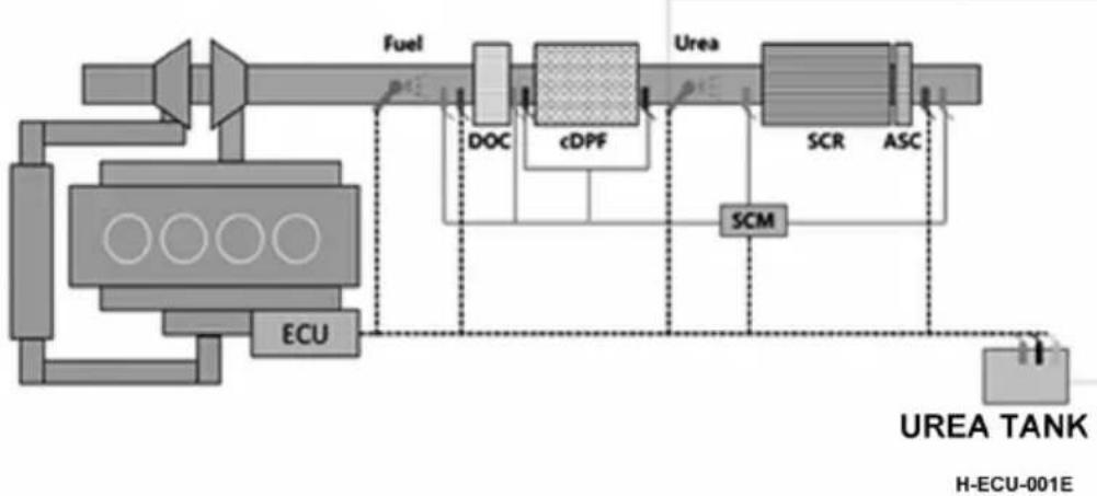
flowchart
graph LR
    A["ECU"] --> B["Fuel"]
    B --> C["cDPF"]
    C --> D["Urea"]
    D --> E["SCR"]
    D --> F["ASC"]
    C --> G["SCM"]
    G --> H["UREA TANK H-ECU-001E"]
    style A fill:#f9f,stroke:#333
    style H fill:#ccf,stroke:#333
Urea filling
During the normal maintenance interval, vehicle users are required to add urea water solution according to actual needs. Urea water solution shall use urea water solution permitted by dongfeng commercial vehicle.
Filling steps:
-
Clean the mouth of the urea tank to prevent foreign bodies from falling into the tank after opening the cap of the urea tank;
-
Unlock and open the cap of urea tank;
-
Open the urea filling hole cover;
-
Use special urea filling tools, such as containers, funnels, urea filling guns, etc. Ensure that the filling tool is clean and cannot be mixed with other liquids, such as fuel oil and oil. The filling speed should be no more than 40 ~l / min , and the overflow of each filling should not exceed 30 ml .
-
Close the filling hole cover;
-
Close the lid as soon as the filling is finished.

Warning:
-
Keep the urea solution out of your eyes. If it gets into your eyes, rinse immediately with plenty of water for at least 15 minutes. Don't take it internally. If urea solution is accidentally inhaled, seek medical attention immediately.
-
Do not use inferior urea or other solutions instead of urea solutions. Do not try to mix agricultural grade urea with water to make diesel engine exhaust treatment solution. Agricultural grade urea does not meet the required technical specifications, all of which may damage the reprocessing system.
OBD diagnostic interface
OBD diagnostic interface the diagnostic instrument can access the fault information through the OBD diagnostic interface equipped with the vehicle. Open the cover plate and dock the diagnostic instrument interface with the OBD diagnostic interface to realize the diagnosis of the vehicle.
OBD diagnostic system has the function of monitoring and analyzing the faults related to emissions. Once the automobile exhaust exceeds the standard, the indicator light of the instrument (MIL) will be on and inform the driver. In the event of serious failure, the engine torque limiter will be activated. The electronic control unit (EECU) of the engine records the fault information and related codes, and displays the relevant fault on the LCD screen of the instrument, so that the maintenance personnel can quickly and accurately determine the nature and location of the fault. In case of vehicle breakdown, please contact the local service station for inspection and troubleshooting.
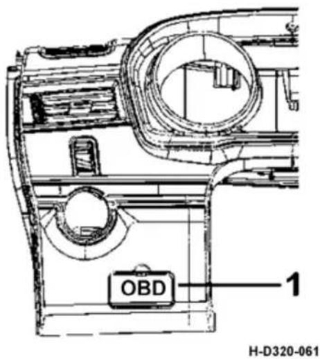
text_image
OBD 1 H-D320-061- OBD diagnostic interface and cover plate
Electrical Connection Between Semi-trailer Tractor and Trailer
When connecting the semi-trailer tractor with the trailer, the 7-pin socket shall be used along with the corresponding plug.
Socket
See Fig. H-GCCZ-001 for internal pin code of socket and the List of Trailer Light Distribution for functions of corresponding pins.
Plug
See Fig. H-GCCT-001 for internal jack code of socket and the List of Trailer Light Distribution for functions of corresponding jacks.
For the semi-trailer tractor with 7-core trailer cable assembly at delivery, when connecting it with the trailer, it is only required to pull the plug at one end of the 7-core trailer cable assembly out of the socket on the semi-trailer tractor and then insert it into the socket on the trailer.
If the semi-trailer tractor is not equipped with the 7-core trainer cable assembly at delivery, facturer.
Product type in DONGFENG COMMERCIAL VEHICLE CO.,LTD. (7-pin trailer cable assembly): 3730060-H0100.
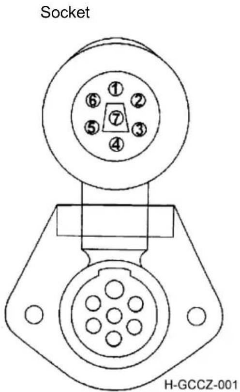
text_image
Socket H-GCCZ-001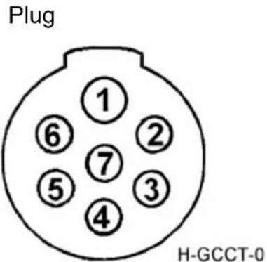
text_image
Plug ① ⑥ ② ⑦ ⑤ ③ ④ H-GCCT-0Arrangement of trailer power socket outlet contacts
| Terminal No. Wire No. Usage | Maximum available power of trailer(W) | ||
| 1 100 Ground wire - | |||
| 2 8239 | Clearance lamp and marker lamp | 200 | |
| 3 9321 Left turn signal lamp 85 | |||
| 4 2533 Brake lamp 85 | |||
| 5 9322 Right turn signal lamp 85 | |||
| 6 9243 Rear fog lamp 85 | |||
| 7 2433 Reversing lamp 85 |
Semi-trailer Tractor Coupling and Operation
Coupling
The coupling for semi-trailer tractor is installed behind the cab
Jumper hose joint
This hose is used to convey the compressed air to the trailer. Seen from back to front of the vehicle, the red one is the gas supply hose joint and the yellow one is the control signal connector.
Jumper spiral pipe
Seen from back of the vehicle, the red brake air supply spiral pipe for supplying compressed air to the trailer is located on right side, and the yellow brake control spiral pipe for sending brake signal to the trailer is located on left side.
Jumper power
Jumper cable is used for supplying power to trailer. It is divided into ordinary power cable and ABS power cable. When disconnected from the trailer, the cable connector may be fixed onto the spare socket.
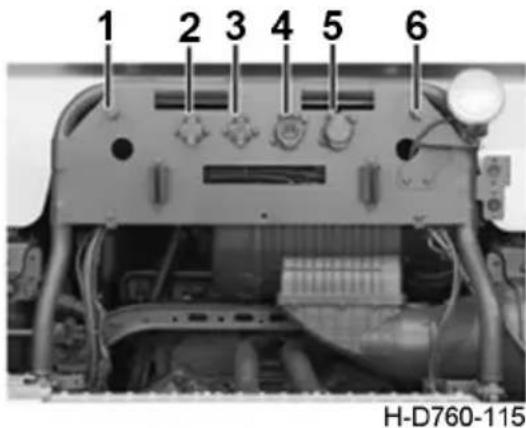
text_image
1 2 3 4 5 6 H-D760-115- Brake control spiral pipe joint
- Trailer power cable socket
- Trailer power cable empty socket
- Trailer EBS/ABS Power cable empty socket
- Trailer EBS/ABS Power cable socket
- Brake air supply spiral pipe joint
Connecting device

CAUTION:
-
Before the saddle is used for the first time, be sure to add sufficient grease.
-
The gap adjustment must be made before the saddle is used for the first time;
-
The lever must be pulled out until the notch can be stuck on the edge bayonet of the saddle shell, otherwise the inclined wedge and locking hook will be damaged;
-
After the mounting, the lock card should be automatically reset and locked at the side of the handle lever. Otherwise, it will be easy to cause the automatically detach to vehicle after starting.
Gap adjustment method:
-
Make sure that there are no impurities between the opening end cover of the saddle and the traction pin of semi-trailer, and then make a splice.
-
Loosen the lock nut and turn the adjusting screw at least 5cm outward;
-
Tap the handle lever inward to make the wedge inward until you feel that the handle cannot move inward (that is, the lock hook has been wedged), stop hitting the handle;
-
Rotate the adjusting screw inward by one person and hold the handle by another until he see or feels that the handle is moving outward (that is, the adjusting screw is in contact with the wedge) and then rotate the adjusting screw inward by 1.5 turns.
-
When the adjusting screw is not moving, fix the locking nut and the adjustment is completed.
Connection operation method
- Preparation before mounting: adjust the supporting leg of the semitrailer so that the towing pin plate of the semitrailer is appropriate to the height of the saddle. It is advisable to place the traction pin plate of semi-trailer about 10\~30mm lower than the center position of the saddle of tractor.
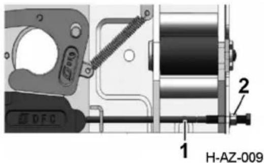
text_image
DFC 1 2 H-AZ-009- Adjust screw 2. lock nut
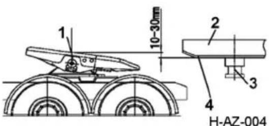
text_image
1 10-30mm 2 3 4 H-AZ-004-
Saddle surface
-
The semi-trailer
-
The traction pin
-
Traction pin plate
-
Connect a hang:
a). Turn the latch spring upward and dial it to the horizontal;
b). Pull the lever assembly outward and clip the notch on the handle bar to the bayonet on the edge of the saddle shell (the traction seat is in the pre-hung state);
c). Drive the tractor slowly backwards so that the semi-trailer pin enters the opening of the lock hook;
d). Pull pin pushes the lock hook to rotate, and when the handle lever returns to its original position, the lock card is automatically reset and locked, that is, the attachment is completed.
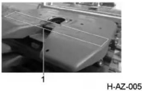
natural_image
Close-up of a mechanical component with a highlighted section and label 'H-AZ-005' (no readable text or symbols on the main subject)- The position contacted with saddle during connection process
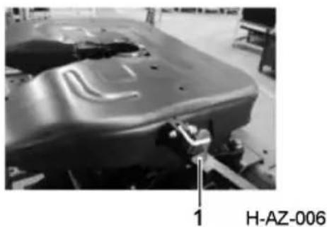
natural_image
Close-up of a car body panel with mounting bracket and structural details, labeled H-AZ-006 (no readable text beyond label)- Pre-hanging state: the handle bar is stuck on the bayonet at the edge of the saddle shell, and the lock car is in a horizontal state
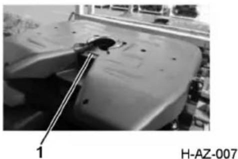
natural_image
Close-up of a mechanical component with a tool inserted, labeled '1' and 'H-AZ-007' (no readable text or symbols beyond labels)- Completion status of the joint: reset the handle lever, and seal the v-shape with inclined wedge
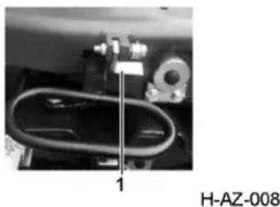
natural_image
Close-up of a mechanical component with a curved pipe and housing, labeled H-AZ-008 (no readable text or symbols beyond label)- Completion status: The lock pin is automatically reset and locked at the side of the handle lever
e). Open the cable socket cover of the trailer, and then align the protruding portion of the cable across the socket with the socket's notch so that the plug is fully inserted into the socket. Finally close the socket and the plug is fixed. Pre-hanging state: the handle bar is stuck on the bayonet at the edge of the saddle shell, and the lock car is in a hori
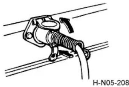
natural_image
Technical line drawing of a mechanical clamp or spring assembly mounted on a cable (no text or symbols)f). If the trailer is equipped with ABS braking system, connect the trailer with ABS cable. g). Please connect the two hose connectors for the delivery of compressed air from the tractor to the trailer respectively with the connector corresponding to the trailer.
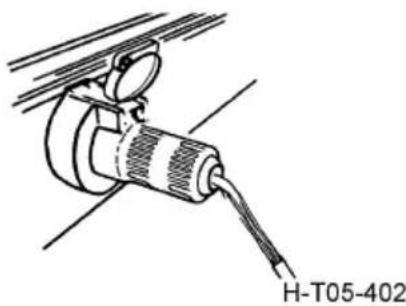
natural_image
Technical line drawing of a mechanical device with labeled part H-T05-402 (no other text or symbols)
CAUTION:
Never connect wrong hose connectors.
h). Make sure the trailer's gas path and circuit are working properly.
i). Pull up the supporting pin of the trailer.
j). Remove the parking brake of the trailer and remove the triangle plank.
- Hang off:
1). Lower and support the supporting feet of the trailer.
2). Remove jumper cables and hoses. After the hose is removed, the trailer is automatically stopped, and the exhaust valve of the trailer's air storage cylinder is opened to vent the air.
3). Pull out the lever assembly;
4). Place the notch on the handle bar on the bayonet at the edge of the saddle shell (the traction seat is in the pre-hanging state);
5). drive the tractor slowly forward so that the semitrailer's towing pin is completely free from the lock hook through the saddle V port.
Operating instructions for rear fender upper cover plate

CAUTION:
The upper cover plate of the. fender should be removed when the tractor is carrying a trailer.
Upper cover plate of fender
Double rear axles: 4
Single rear axles: 2
When the tractor is carrying a trailer, please remove the upper cover plate above the middle axle and the rear axle (the single rear axle model only has the rear axle). Otherwise, interference between the bottom of the trailer and the upper cover plate of the fender may occur under certain limit conditions, resulting in damage to the upper cover plate.
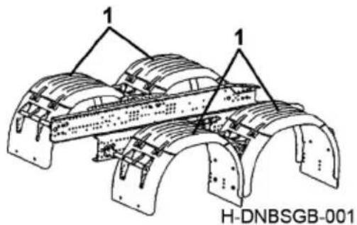
text_image
1 1 H-DNBSGB-001- Upper cover plate
Operation instructions for removing the upper cover plate of fender:
-
Clamp the outer end of the rubber band with pliers and stretch it towards the direction of arrow a.
-
If the pliers are not loose, then raise them along the direction of arrow b to the rubber band, so that it is free from the fender clasp. The rubber band fails to fastens the upper cover plate.
-
Pull the upper cover plate along the direction of arrow c, and the fixation point of the upper cover plate of the fender will fail. After repeated operation of other rubber bands, the upper cover plate can be taken down.
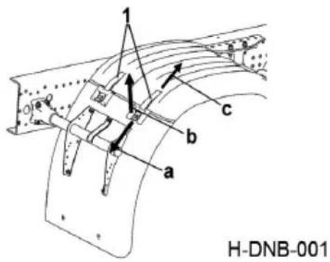
text_image
H-DNB-001- Rubber band
Operation instructions for installing upper cover plate of fender:
-
Align the upper cover plate with the fender.
-
Insert the rubber band into the limit hole of the fender.
-
Clamp the end of rubber band with pliers, and stretch the rubber band along the direction of arrow a. When the pliers are clamped and stretched, press the rubber band down (direction b) into the fender clasp to tighten. At this point, the rubber band clamping operation is completed, and other rubber band can be repeated.
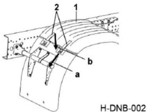
text_image
H-DNB-002-
Upper cover plate
-
Rubber band
Starting & Driving
Please refer to the specific configurations of your vehicle.
Engine start (Cummins engine)
- Carry out daily inspection.
- Verify that the gear lever is at the neutral position of the low range, or at the neutral position of the automatic transmission.
- Turn on the master power switch.
- Turn the ignition switch to "ON" position, and the engine stop and maintenance warning lamp, WARNING lamp, high water temperature indicator lamp, low oil pressure alarm lamp and MIL will be on; if the engine is running normally, the engine stop and maintenance alarm lamps, WARNING lamp and the high water temperature indicator lamp will stay on for 3s and then go out. If no OBD fault exists, the MIL will go out within 10s, and if any OBD fault exists, the MIL will stay on or flash.
- If your vehicle is equipped with intake preheater, the device will automatically detect if the intake preheating is required according to the environmental conditions. During cold start of the vehicle at low ambient temperature, when the ignition switch is at ON position, the wait to start indicator lamp will be on, indicating that the engine intake pipe is being preheated. The lower the ambient temperature, the longer this indicator lamp stays on (up to 30s). After it goes out, turn the ignition switch to START position to start the engine.
- If the vehicle is equipped with fuel primary filter with glow plug, the electric heater of the fuel primary filter should be activated to help the engine cold start when the ambient temperature is below 7^ C. Turn on the fuel preheater switch on the instrument panel, then the fuel preheating indicator lamp will be on, the temperature-controlled heater of the fuel primary filter will heat the fuel, and when the fuel temperature rises to the specified value, the heater will stop working automatically. Turn off the fuel preheater switch and then the indicator lamp will go out. When the ambient temperature is above 7^ C, turn off this switch.
- If the vehicle is equipped with fuel tank heating device, please switch on the fuel tank heating switch.
- Dongfeng Commercial Vehicles Co., Ltd. only provides the electrical interface of fuel tank heating device on the chassis, please consult the manufacturer of the final stage of the whole vehicle for the specific use method.
-
Depress the clutch pedal instead of the accelerator pedal to the floor, and turn the key to "START" position to start the engine. Air in the fuel system may lead to start difficulty, so it is better to exhaust the fuel system. Please refer to the attached Operation and Maintenance Manual of Cummins Engine.
-
After the engine starts, release the key immediately to let the engine enter the idle running status. Be sure to observe the engine oil pressure within 15s.
- Cummins engine has the function of quick warm-up, and when the coolant temperature is low, the engine will be, after starting successfully, warmed up automatically at a high speed (higher than idle speed), to make the coolant temperature rise fast.
- Run the engine at an idle speed for 3-5min before running it under load.
- If the engine is not started three times, check whether the fuel supply system is working properly.

CAUTION:
- The time to start the engine by starter each time should not exceed 30s. The interval of two starts should be 2 min at least.
- Do not start for a long time or frequently; otherwise battery electricity loss or starter damage will be caused.
- For the sake of safety, always depress the clutch pedal when starting the engine.
- Never run the engine at idle speed for long time. Cummins engine can never run at idle speed for more than 10min, or the engine will be damaged.
Starting with cab tilted
- Move the manual valve control lever backward to brake locking position, and turn the key switch to "ON".
- Move the transmission gear lever at the neutral position; clear those overturn-prone articles inside cab.
- chock the wheels.
- Follow the specified safe operation pr°Cedures to tilt the cab.
- Press the starting switch (black) on the engine start and shutdown switch box to start the engine.
- To stop the running engine, press the shutdown switch (red), so the engine shuts down.
- Shut-down switch
- Start switch

WARNING:
- Do not touch the gear lever while the engine is running after cab tilting.
2.Do not lower the cab with engine running.
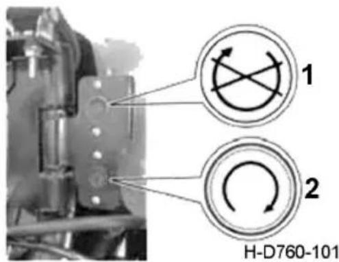
text_image
1 2 H-D760-101Steering System Start
To start the truck at the ambient temperature less than 10^ C, idle the engine for more than 30 s, and rotate the steering wheel only after the temperature of steering fluid rises, so as to avoid hard steering or damaging the power steering pump.
Transmission Operation
Please refer to the specific configurations of your vehicle.
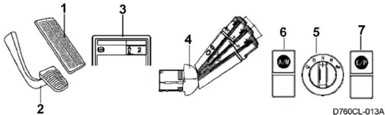
text_image
1 2 3 4 5 6 7 D760CL-013A- Electronic throttle pedal
- Brake pedal
- Instrument display screen
-
Combination switch - RH
-
AMT gearshift rotary switch
- A/M mode switch
- E/P mode switch
Operation of ZF12 AMT
Gearshift knob
N: neutral;
D: normal driving of vehicle;
DM: slow driving of vehicle in a short distance;
R: normal reversing of vehicle;
RM: slow reversing of vehicle in a short distance. 108
A/M gearshift
When the engine has not been started, M mode is default mode.
When the engine has been started, A mode is default mode.
Pressing the selector switch can select A/M mode.
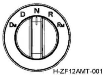
text_image
D N R Dm Rm H-ZF12AMT-001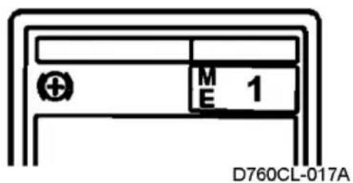
text_image
M E 1 D760CL-017A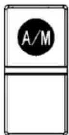
text_image
A/MH-D760-141
1. A/M selector switch
Regardless of AT or MT, A or M may be displayed. "M" displayed for MT. "A" displayed for AT.
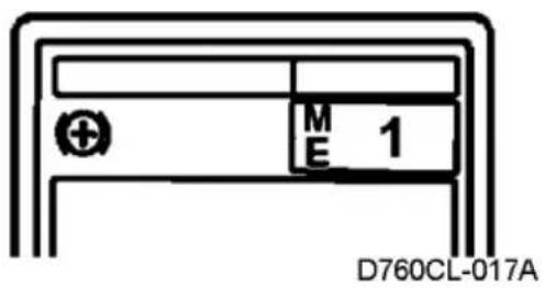
text_image
M E 1 D760CL-017AMT operation
Shift the transmission to M gearshift mode.
Uplift the gear lever for uplifting; if time for uplifting is not more than 1.5s, one gear will be increased, if more than 1.5s, two gears will be increased, and if uplifting is kept, two gears will be increased until the highest gear is reached.
text_image
M E 1 D760CL-017APress the gear lever downward for downshift; if time for uplifting is not more than 1.5s, one gear will be decreased, if more than 1.5s, two gears will be decreased, and if down-pressing is kept, two gears will be decreased until the lowest gear is reached.
AT operation
Shift the transmission to A gearshift mode.
-
Auto selection of transmission system: STRAT, UPSHIFT and DOWNSHIFT, and the clutch and gearshift can be completed automatically.
-
Manual interference on gearshift can be realized, and in "A" mode, direct uplifting and downpressing of the gear lever can realize direct gearshift.
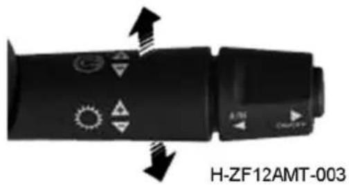
text_image
H-ZF12AMT-003Combination switch for upshift and downshift

CAUTION:
-
It is possible to turn the gear lever to "N" position from any position at any time;
-
The engine is under the automatic control of the transmission, so it is not necessary to release the throttle pedal during gearshift;
-
The transmission has protection function, so it will not perform incorrect gearshift;
-
During driving, observe the tachometer display; in order to guarantee economic driving, ensure that the engine speed is within the economic speed range and drive in the high range as much as possible, but downshift in advance is required before driving up or down on a slope.
E and P gearshift mode
E: economic mode
P: power mode
It defaults the initial mode to E mode, and it will change to P mode by pressing the switch, and return to E mode by pressing the switch again, and so on.
Note: E/P shown on the selection mode instrument indicates operation of accelerator pedal.
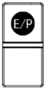
text_image
E/PH-D760-018
When depressing the accelerator pedal, it is required to adjust the accelerator position flexibly based on road conditions and vehicle speed, avoiding fluctuation in the speed which may increase fuel consumption during driving;
During automatic gearshift of the transmission, never release the accelerator pedal and keep it stable;
Depress the accelerator pedal to a small or medium extent as much as possible, and drive at a constant speed, avoiding fast acceleration;
text_image
M 1 E D760CL-017AThe transmission gearshift is selected by
TCU according to working conditions, while the driver can pay all attention on determination of road conditions and keeping driving at a constant speed.
Starting instructions
- Pull up the hand brake to ensure that the rotary switch is turned to "N".
- Start the engine, and do self-inspection on transmission pr°Cedures; afterwards, "N" will be displayed.
- When the rotary switch is turned to "D", it will automatically engage at START gear (if necessary, the START gear can be corrected manually), at this time, the clutch disengages.
- Release the brake and depress the accelerator pedal (clutch engages) to start the vehicle. When the accelerator pedal is not depressed, the vehicle will not run, because the clutch under control of the transmission disengages.
Operation of accelerator pedal
Do not change the position of accelerator pedal during gearshift.
During gearshift, the working conditions of engine will be under control of output signal from transmission shift actuator.
Operation of clutch release mechanism will be under control of transmission shift actuator.
- When depressing the accelerator pedal, keep the pedal stable as much as possible and avoid frequent change of accelerator and fluctuation in the speed.
- During automatic gearshift of the transmission, never release the accelerator pedal and keep it stable.
- In case of driving on smooth road or at no load, depress the accelerator pedal to a small or medium extent as much as possible, and drive at a constant speed, avoiding fast acceleration;
- When driving upward on a slope (especially large slope) at full load, it is necessary to depress the accelerator pedal to a large or full extent (control of throttle opening is the same with that of MT).
- The gearshift is automatically selected by TCU based on working conditions, and the driver is not required to pay more attention on the gearshift points and schedule, etc.
Overdrive switch
In order to make use of engine power to the largest extent, you can depress the accelerator pedal to the end to trigger the kick-down switch or signal of full throttle with CAN (it is generally used in overdriving), in this case, delayed upshift or downshift can be realized.
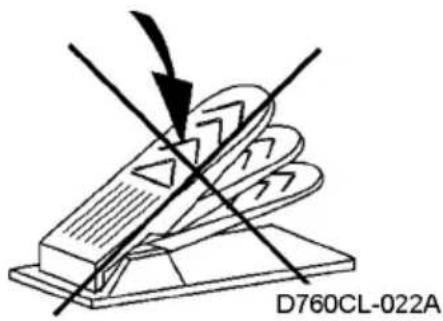
text_image
D760CL-022A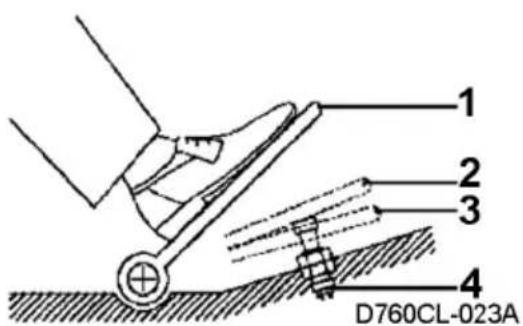
text_image
1 2 3 4 D760CL-023A- Accelerator pedal
- Kick-down position
- Full-throttle position
- Overdrive switch
Hill-start assist function
-
The hill-start assist function is only applicable to the vehicle with EBS; in case of vehicle with ABS, starting can be done by pressing the hill-start assist function enable switch with the help of parking brake lever;
-
Depress the foot brake pedal;
- Release the foot brake pedal to activate this function, and depress the accelerator pedal to start on a slope.

WARNING:
When this function is activated, the accelerator pedal shall be depressed within 3s; otherwise this function will be in failure, causing slope sliding.
natural_image
Simple line drawing of a refrigerator with an open refrigerator icon (no text or symbols)H-D760-017
Parking
- Release the accelerator pedal and depress the brake pedal to decrease speed till the vehicle stops completely.
- The clutch will disengage automatically before the vehicle stops to ensure that the engine does not shut down.
- In case of long-time parking, it is necessary to shift at neutral.
- Keep the brake and parking brake when the vehicle is stationary.

CAUTION:
In case the vehicle is stationary and the engine is still running, after engaging a gear, the vehicle will start driving by depressing the accelerator pedal, so it is necessary to apply the parking brake.
In case you may leave the vehicle when the engine is running, you must shift to Neutral and apply the parking brake.
When driving on a slippery road, applying parking brake may cause engine shutdown and steering booster will not function.
Kick down
In case of overdriving or driving down on a slope, in order to get full power of the engine, it is possible to depress the accelerator pedal to the end to activate kick down, in this case, the throttle is in full opening, and the transmission will do downshift or delay upshift according to the program-calculated load directive.
Kick down of the accelerator pedal can only be realized by depressing the pedal to the forced position in "A" mode, but in "M" mode, it cannot be realized by depressing the pedal to the forced position.
Linkage mode
The linkage mode is also known as creeping mode.
In the linkage mode, the engine torque is under control of the transmission, and the clutch is in half-engaged status.
In the linkage mode, the engine speed is between idle speed and low speed range (1,000rpm).
RM
RM (lower reverse speed can be realized by analog of manual control of reverse speed can be applied in case of reversing in complex road conditions, or as required by actual conditions (such as coupling of trailer).
DM
DM can be applied in case of starting, following the vehicle ahead during traffic jam, a lot of vehicles and people or narrow road section, etc., or driving at a speed lower than the idle speed.

CAUTION:
- It is better to drive the vehicle in linkage mode for a short time as much as possible. In linkage mode, clutch wear is considered as abnormal wear, so it is required to shorten the driving time in linkage mode as much as possible.
2.2. The vehicle should be stopped before application of linkage mode, and the engine speed should be between idle speed and low speed range (1,000 rpm).
3.3. Before driving in creeping mode, shift the transmission into "N", "2", "1" or "R", direct shift into linkage mode is not allowed at other gears due to the protection function.
-
In linkage mode, manual operation of the gear lever by the driver will be ineffective, that is no manual interference on gearshift is allowed.
-
It is allowed to shift from DM to D, but it is prohibited to shift from RM to R.
-
With regard to the model with AMT of Dongfeng, it is specified that D, N and R shall be displayed on the instrument, but display of RM and DM on the instrument is not required.
Braking Operation
Please refer to the specific configurations of your vehicle.
Antilock braking system (ABS)
The Antilock Braking System (ABS for short) is a mechanical-electrical integration system designed to prevent the locking of wheel due to large braking force (especially on smooth road) to get the most effective brake and brake operation stability, and further to avoid traffic accidents and to reduce the damage from accidents.

text_image
(ABS)Tractor ABS MIL
H-D310-123
The system keeps the control of the vehicle traveling direction in emergency braking, reduces traffic accidents, improves driving safety, and lessens tire wear and cost of maintenance.
When the tractor ignition switch is at ON position, the ABS will make self-inspection (the solenoid valves may make “pull-in” sound in turn), and the tractor ABS malfunction indicator lamp will stay on for about 3s and then go out. If the tractor ABS malfunction indicator lamp stays on, it indicates that the ABS is faulty. In this case, please contact the Technical Service Center (Station) authorized by Dongfeng Commercial Vehicle Company immediately for troubleshooting.
Electronically Controlled Brake System (EBS)
Compared to the traditional brake system, the electronically controlled brake system (EBS for short), designed with an electronically controlled air brake, can eliminate the defects, such as slow response of mechanical brake, poor braking comfort, etc. In case the electronically controlled return circuit of EBS is in failure, the air pressure control circuit of EBS, as the standby control circuit, can guarantee braking performance of the brake system.
EBS is designed with brake management, ABS, ASR and EBS diagnostic functions, and also with optional ESC, etc. as auxiliary function platform.
Electronic Stability Control System (ESC)
The electronic stability control system (ESC for short) is designed as an active safety system for assisting the driver to control the vehicle. It can strengthen stability of the vehicle under bad driving conditions and increase the control range of driver, so that the vehicle can still be under control in case dangerous and unpredictable conditions.
ESC can determine the driver's intension via various sensors, and automatically interfere with stability of the vehicle before the stability reaches the critical status, that is, it will control the output torque of the engine, and apply braking force on one or
more than one wheels, so as to control the vehicle attitude effectively and guarantee driving stability. ESC strengthens protection on rollover, sideslip and folding.
As the key switch is turned on, ESC functions will be activated automatically.
CAUTION: ESC cannot exceed the physical limit and should adjust driving status according to road and traffic conditions; no bad driving habit due to safety guaranteed by ESC is allowed.

CAUTION:
- ESC cannot exceed the physical limit and should adjust driving status according to road and traffic conditions; no bad driving habit due to safety guaranteed by ESC is allowed.
Parking operation
To stop the vehicle smoothly, operate the brake pedal as follows:
- Depress the brake pedal by 1/2-2/3 travel at the point 25-35m away from the expected parking position.
- Begin to release the pedal gradually at the point 5-6m away from the expected parking position.
- Depress the brake pedal gently to stop the vehicle completely when approaching the parking position.

CAUTION:
-
Normally, never depress the brake pedal suddenly to the end and depress it all the time other than in emergency. The sudden braking may result in personal injury or vehicle part damage.
-
Avoid depressing the brake pedal repeatedly for times in a short period; otherwise, a lot of compressed air in the air reservoir will be consumed, and thus the braking effect of vehicle will be affected, making the vehicle out of control.
-
Apply the foot brake to stop the vehicle normally.
-
Do not apply the emergency braking except for emergency. In particular, in raining days when the road surface is slippery, applying the emergency braking may result in lateral sliding or other hazardous conditions.
-
After the vehicle is washed or passes through a deep water pit, water may enter the brake drum and reduce the braking efficiency. Depress the brake pedal for several times while driving the vehicle at a low speed to drain the water so as to guarantee the normal operation of brake.
Auxiliary brake
See Structure and Operation for auxiliary braking operation
Parking
- Turn the rotary switch of AT back to N position.
- After the vehicle stops, shift the gear lever of AT to neutral position of low range, and turn the manual valve control lever to parking brake position.
- Do not shut down the engine immediately when stopping the vehicle. The engine must run idly for 3-5min till the engine coolant temperature reduces. In particular, run the engine idly after the vehicle runs under heavy load or at a high speed to prevent engine scuffing or turb°Charger damage.
- Turn off all switches, especially the power switch after shut down of the engine.
Slope Driving Method
- When driving down a slope, you should apply the auxiliary brake effectively to keep the vehicle speed within the safe range.
- When the vehicle runs at low gear or runs down a slope, make sure that the engine speed does not exceed the maximum allowable speed.
- Test whether the service brake works normally before running down a steep or long slope.
- When gearshift from high range to low range is performed, the speedometer must be monitored to check the speed, and the engine speed should be monitored with engine tachometer.
Maintenance & Adjustment
To prolong the service life of vehicle, guarantee the safety and pleasure of driving, always perform careful and periodic maintenance on the vehicle. This manual describes some common maintenance and adjustment methods. As for more detailed information about inspection and adjustment as well as the parts replacement, please contact the nearest Technical Service Centre (Station) of Dongfeng Commercial Vehicle Company of Dongfeng Motor Co., Ltd.
Please refer to the attached Operation and Maintenance Manual of Cummins Engine for the maintenance schedule.
Please refer to the specific configurations of your vehicle.
Inspection and Adding of Coolant
- To check the coolant level, turn the ignition key to ON position and check whether the low water level warning lamp comes on. If the lamp comes on and the buzzer sends out warning signal, please add coolant. Alternatively, observe the coolant level from the auxiliary water tank behind the cab. If the level is below the "MIN" mark indicated on the tank, please add coolant.
- Open the cab front face shield.
- Tilt the cab front face shield and add the coolant from the filler of auxiliary water tank behind the cab until the level reaches the
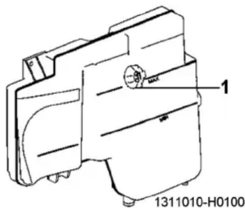
text_image
1 1311010-H0100- Filler cap and pressure valve cap
filler lower edge. Never add the coolant too fast through unscrewing the filler cap (the filler cap, pressure valve and vacuum valve are integrated); otherwise, it will be difficult to drain out the air in the engine water jacket.
- After coolant top-up, warm up the engine to check the level again. If the tank is not full, top up it again.
- Check the sealing and working conditions of the filler cap and the pressure valve cap.

CAUTION:
- Before adding coolant, check the engine and the radiator for leakage, and repair it if any.
- Tighten the filler cap of auxiliary water tank after filling. Otherwise, cavitation is liable to °Ccur on the engine cylinder liner.
- Normally, do not remove the pressure valve cap. Remove the pressure valve only after the coolant temperature is below 50^ C; otherwise, the spraying of high temperature coolant or steam may cause personal injury. Remove the pressure valve cap slowly to release the cooling system pressure.
- It is recommended to use dedicated long-life anti-rust and anti-freeze coolant. Never use the running water or hard water from well or river.
Draining of Coolant
Open the drain valve under the radiator to drain off the coolant in the cooling system.

CAUTION:
Before adding coolant, check the engine and the radiator for leakage, and repair it if any.
Maintenance of Air Filter
Inspection and cleaning cycle of filter element
When the air filter block alarm light is on, maintain the filter element. Generally can only clean the main filter core, safety filter core can not be maintained, can only be replaced..
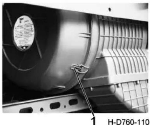
natural_image
Close-up of a mechanical component with fan and ventilation grilles, no visible text or symbols- Clip
Replacement cycle
Please refer to page 208 for the maintenance period. Or when the main filter is cleaned and maintained for more than four times, the internal and external filter elements must be replaced simultaneously.
Replacement of air filter element
-
Pull the six clips and hold them by hands to pull the end cover.
-
Gently shake the outer element leftward and rightward by hands to pull it out slowly.
-
If it is necessary to replace the inner element, gently shake the inner element leftward and rightward by hands to pull it out slowly.
-
Wipe the contact of cap and carriage clean, so as not to affect the installation and sealing effect.
-
Refit each component following the pr°Cedures reverse to removal.
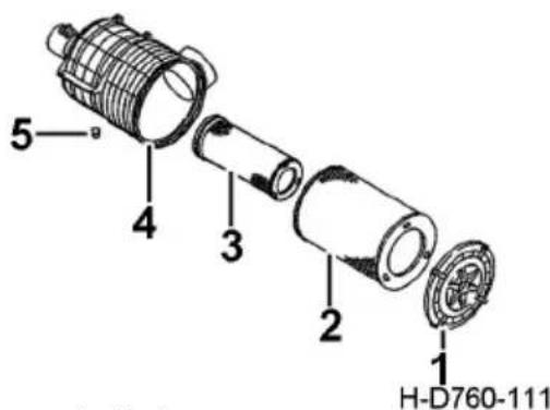
text_image
5 4 3 2 1 H-D760-111-
End cap
-
Outer element
-
Inner element
-
Housing
-
Drain valve
Cleaning method of filter element
Blow the filter element clean with the compressed air of 0.5MPa or lower from inside to outside.
Inspection method of filter element
Illumine the lamp and place it inside the filter element to check for damage and pinhole. And check whether the washer is damaged, and replace it upon any abnormality.
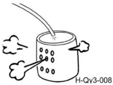
text_image
H-Qy3-008Check the inner element for dust, if any, replace the air filter assembly.

CAUTION:
- Ensure that the filter element and end cap are mounted properly; otherwise dirt may be absorbed in, sharply shortening the engine service life.
- Never clean the filter element with gasoline or water.
- When cleaning cyclone hood, observe if it is damaged.
- Check the sealing rings during installation.
- Never remove the air filter while the vehicle is running.
- Tighten the filter element and end cap nut, and install the sealing ring of the end cap properly. Prevent the entry of rain water into the filter.
Draining of Fuel Tank
If there is too much sediment in the fuel tank, a great deal of impurities will enter the pipe and accelerate the pollution of fuel primary filter, and even clog the oil line. Therefore it is necessary to drain the sediment out from the fuel tank in time.
Remove the drain valve from the bottom of fuel tank, drain off the sediment and fluid at the bottom of fuel tank, and then refit and tighten the drain valve.
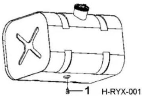
text_image
H-RYX-001 1- Drain valve
Maintenance of Cummins Engine
Inspection and replacement of engine oil
Check the maintenance period refer to page 208.
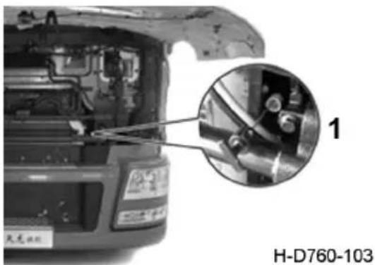
natural_image
Close-up of a car engine compartment with a magnified inset showing mechanical components (no text or symbols visible)- Oil dipstick

CAUTION:
- The lubricating oil new vehicle and lubricating oil used for follow-up maintenance or replacement have different grade, which cannot mix and change the oil replacement mileage.
Inspection method of engine lubricating oil level
- Stop the truck on flat ground, and check the oil level after the engine is warmed up and then shut down for 5 min. Take the oil dipstick out, wipe it up with a piece of clean rag, and fit to its original position.
- Pull the oil dipstick out again and observe the oil level. The oil level should be between the two scale lines. Add clean lubricating oil if insufficient. Drain the excessive oil from the oil drain plug.
Change of engine oil
- Drain off the lubricating oil from the oil sump when the engine is hot. If the engine is cold, warm it up before changing the oil. Run the engine until the coolant temperature is up to 60°C, shut down the engine, remove the drain plug immediately to drain off all the oil and suspended pollutants in the engine.
- Clean around the oil filter seat and remove the oil filter with the oil filter wrench.

- Upper marking
- Lower marking
H-DCEC-003
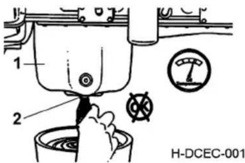
text_image
1 2 H-DCEC-001-
Oil sump 2. Oil drain port
-
Before installing the new oil filter, add clean oil to the filter and apply a thin layer of clean oil to the sealing surface of the gasket..
- Install the oil filter on the filter seat. Tighten the oil filter until the gasket touches the filter seat surface.
- Install and tighten oil drain plug of oil sump.
- Open the oil filler cap on the engine and refill the engine with clean oil to the upper scale of the oil gauge.
- Idle the engine for about 5 minutes to allow oil to flow from the upper parts of the engine back to the sump.
- Check the oil level again. If necessary, add or drain the oil to the scale on the oil gauge.

CAUTION:
- Always drain the oil after the engine completely stops and the coolant temperature drops below 60^ C.
2.Upon oil drainage, pay attention to the oil temperature to avoid scalding. - The oil pressure must be displayed on the instrument within 15 seconds of starting the engine. If oil pressure is not shown within 15 seconds, shut down the engine immediately to avoid damage. Verify that the oil level in the oil sump is correct.
Oil filter
Check the maintenance period refer to page 208
Replacement method
-
Select the oil and oil filter specified by Dongfeng and fill the oil filter with clean oil. Apply a thin layer of clean oil to the sealing surface of the gasket before installing the new oil filter.
-
Install the oil filter on the filter seat. Tighten the oil filter until the sealing pad touches the surface of the filter holder.
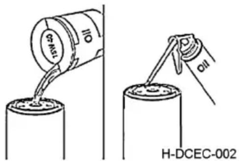
text_image
H-DCEC-002
CAUTION:
- Do not tighten the filter with a filter spanner during the installation. Otherwise the threads may deform and the filter may be damaged.
- When mounting a new filter, note whether its model conforms to that required by this engine.
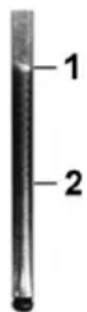
H-DCEC-003
Fuel filter
Check the maintenance period refer to page 208
Replacement method
Please refer to the attached Operation and Maintenance Manual of Cummins Engine.

CAUTION:
- Do not tighten the filter with a filter spanner during the installation. Otherwise the threads may deform and the filter may be damaged.
- Tighten the drain valve by hand instead of any tools.
- Do not open the drain valve completely when draining water.
Fuel Primary Filter (oil-water separator)
Check the maintenance period refer to page 208
Fuel prefilter oil water separator discharge
Turn the ignition to LOCK and stop the engine.
When the engine stops working for more than 30 minutes, release the drain plug and release the water from the drain plug. After draining, tighten the draining plug firmly.

CAUTION:
- When the water reaches the alarm height of the fuel filter water level sensor and the water in the oil alarm light is on, do not continue driving. Otherwise it will cause engine damage.
- For safety reasons, be sure to put the fuel in the tray and do not dirty the floor.
- If any oil spills on other accessories, wipe off the oil thoroughly.
- After unscrewing the filter element, a clean oil storage tool must be prepared to prevent the siphon caused by full tank from leaking a lot of fuel.
Replace the filter element of the Fuel-water separator
Fuel and water separator disassembling operation method
-
Make the engine inoperative for more than 30min, and unscrew the water drain plug and drain water through the water drain plug.
-
Drain the fuel and water separator clean. Unplug the sensor connected to the collecting cup (depending on actual model) of sensor connected to the water collector, and use a special tool to unscrew the transparent water collector which may be used again and its accessories. Clear oil contamination or foreign matters in the water collector, and check the water collector for damage, if any, replace it. If the water collector is damaged, place it properly after cleaning.
-
Clean the base, especially the junction of base and water separator. Unscrew the filter housing with a special tool, and clear fuel contamination at junction of base and water separator.
- Screw a new water separator housing to the base by hands till the seal ring contacts the base, and then tighten the water separator for 270^ (according to print requirements for the water separator subject to the model) with a special tool.
- Place a new seal ring into the water collector seal ring slot and lubricate the surface of seal ring. Screw a water collector to the water separator by hands till the seal ring contacts the water separator, and then tighten the water collector and water separator for 180^ (according to print requirements for the water separator subject to the model) with a special tool.
- Refit the quick-fitting s°Cket of sensor connected to the water collector, unscrew the air drain bolts on the base and press it with a hand pump till the water separator is filled with fuel, and then drain air through the air drain bolts.

WARNING:
Fuel leakage may cause fire, so be sure to install the filter element firmly to avoid fuel leakage.
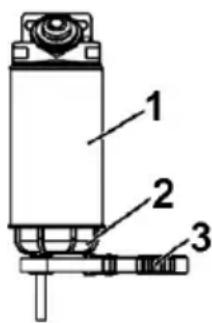
text_image
1 2 3H-D760-121
- Water separator assembly
- Water collector
Precautions for removal and refitting
- When replacing the water separator, it is necessary to handle the drained fuel properly to avoid environmental contamination.
- When pumping fuel with a hand pump, always unscrew the air drain bolts to avoid damage to the hand pump.
- It is prohibited to place the filter near high temperature or open fire to avoid damage to the water collector and water separator.
- It is prohibited to wildly operate or kn°Ck the water separator by using a tool to avoid damage to the water collector and threads.
- According to the maintenance requirements, drain filtered water from the water separator on a regular basis.
- Upon completion of a new water separator, before first use, always press the hand pump for 15-30 times to ensure full flow of fuel and normal start of the engine. In winter or low-temperature area, after first use of the water separator, it is required to press the hand pump frequently with more than 30 times for each pressing.

CAUTION:
- Do not tighten the fuel filter and water separator with the water separator spanner during installation; otherwise the threads may deform and the filter may be damaged.
- Tighten the drain valve by hand instead of any tools.
- Do not open the drain valve completely when draining water.
Please refer to the attached Operation and Maintenance Manual of Cummins Engine for the engine assembly.
Bleeding of fuel system
Please refer to the Cummins engine operation and maintenance manual accompanying the vehicle.

CAUTION:
- Bleeding is strictly prohibited when the engine temperature is very high.
- Each starting time of the engine shall not exceed 30 seconds, and the starting interval shall be at least 2 minutes.
Drive belt inspection
Please refer to the Cummins engine operation and maintenance manual accompanying the vehicle.
Supercharger maintenance
Please refer to the Cummins engine operation and maintenance manual accompanying the vehicle.
Maintenance of urea tank
Periodic maintenance cycle
Check the maintenance period refer to page 208
- Clean the vent valve with compressed air.
- After injecting urea, the rubber plug should be blocked to prevent urea spillage.
- There is a drain port at the bottom of the urea tank to discharge the sediment.
Filter element for urea tank
Replacement cycle
Check the maintenance period refer to page 208
Replacement method:
-
The filter in the vehicle urea tank is used to prevent foreign matters that may be suspended in the vehicle urea from entering the injection system. Debris may cause permanent damage and premature failure to the post-treatment metering pump.
-
The filter in the vehicle urea tank is located inside the vehicle urea tank, below the liquid level temperature sensor.
-
Urea tank filter element
CAUTION:
- Before using containers or funnel for distributing, treating or storing vehicle urea, make sure to thoroughly wash away any impurities with water and then rinse with distilled water.
- Do not use tap water for rinsing instruments or vehicle urea tanks for transporting vehicle urea. Tap water will contaminate vehicle urea.
- If distilled water is not available, rinse with tap water and then rinse with urea in the car.
- Failure to carry out maintenance as required may result in torque limit or speed limit.
Urea pump maintenance
During the use of the jet system, attention should be paid to:
- After stopping the car and shutting down the engine, the battery power cannot be cut off immediately, and the post-processing system needs to complete the emptering process, which lasts about 5 minutes (depending on the situation of the vehicle traveling far before stopping), that is, the power cannot be cut off within 90 seconds after stopping the car.
- Regularly check whether there is any leakage or white crystallite at the quick plug joint of the post-treatment jet unit. If there is any leakage or crystallite, please replace the new joint in time.
- The metering pump filter is used to prevent foreign matters that may be suspended in vehicle urea from entering the injection system. Debris may cause permanent damage to urea pumps or urea nozzles and premature failure.
Urea pump filter
Replacement cycle
Check the maintenance period refer to page 208
- Urea pump injection unit
- Filter element of urea pump filter
- Filter shell of urea pump
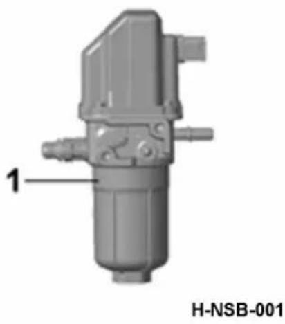
natural_image
3D mechanical component diagram labeled H-NSB-001, showing internal components and a numbered annotation (1), no readable text or symbols beyond label.- Urea pump
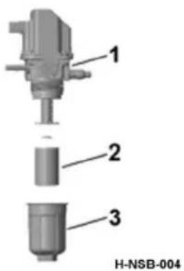
text_image
1 2 3 H-NSB-004- Urea pump injection unit
- Filter element of urea pump filter
- Filter shell of urea pump
Inspection of Clutch Fluid Level
This inspection is not required for model with AMT.
Normal replacement
Check the maintenance period refer to page 208
The clutch reservoir is located inside the front face shield in the cab. Under normal conditions, the level of the fluid reservoir should be near the MAX mark. Add fluid if the level is below MIN mark. Check the pipeline system for leakage before filling. If any leakage presents, please repair it before filling.
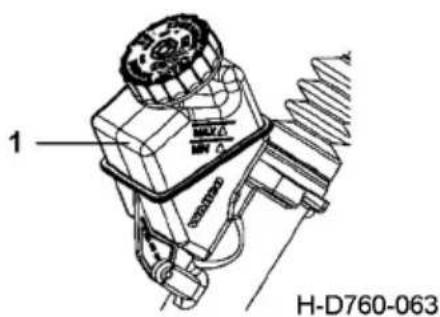
text_image
1 MAXO H-D760-063- Clutch fluid reservoir

CAUTION:
- Never use the brake fluid of different quality or different grades.
- It is strictly prohibited to use mineral oil as brake fluid, and confirm that the clean brake fluid is used.
- Never have the brake fluid contact any painted surface so as to avoid damage to paint film.
- Pay special attention to sealing and preservation.
- Never allow dirt or dust into the reservoir.
Check and replace transmission oil
ZF12 AMT
Replacement period of transmission fluid
In order to ensure safe and reliable operation of the transmission, it is required to replace the fluid within the specified period.
Normal replacement
Every 240,000km or 24 months
Filling volume
The filling volume of transmission fluid is noted on the nameplate. Do replacement of fluid
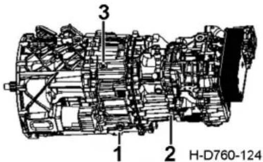
text_image
3 1 2 H-D760-124- Drain plug
- Drain plug
- Filler
as required by the fluid replacement pr°Cedures to ensure correct filling volume.
Replacement of transmission fluid
Always park the vehicle on the flat ground and shut the engine down before fluid replacement.
It is proper to replace the fluid when the vehicle is still hot after long-distance driving, because the fluid at this time is still at the working temperature and has a low viscosity, allowing for easy flow.

WARNING:
Avoid scalding due to hot transmission fluid and parts and avoid fire caused by contact to the fire source.
- Remove the drain plug and place it into a proper container. Handle the fluid according to environmental protection requirements.
- Clean the drain plug 2 with magnet.
- Replace seal rings of drain plug and filler.
- Tighten the drain plugs 1 and 2 to the specified torque (60 Nm).
Add oil
-
Add the transmission fluid through the filler.
-
It indicates that the transmission is filled with fluid when the level reaches to the lower end of the filler, in this case, continuous adding may cause overflow of fluid out from the filler.
-
Tighten the filler to the specified torque (60 Nm).

CAUTION:
Check the transmission for fluid leakage when checking the level.
Check and replace retarder oil (ZF)
Check the oil level

CAUTION:
Insufficient oil in the transmission will lead to transmission damage and accident risk

WARNING:
Insufficient oil in the transmission will lead to the retarder failure, brake. torque weakening or failure. Please use the auxiliary brake carefully when continuing to drive, or maintain the transmission.
Operation method:
-
When checking the oil level, the retarder must be closed before stopping, which can ensure the correct oil quantity in the transmission
-
In order to prevent incorrect inspection, the oil level of the transmission with retarder must be checked according to the following methods:
1). Horizontal positioning of vehicles
2). engine flameout
3). the transmission oil temperature drop to below 40^ C
-
Check the transmission oil level regularly
-
Confirm whether there is oil leakage in the following parts when checking the oil level
1). transmission
2). retarder
3). Oil/water heat exchanger
4). Relevant cooling piping
Check the oil level
- Stop the vehicle, and pull on the hand brake, be careful not to use the retarder
- Loosen the overflow port screw plug
- If the oil level is lower than the overflow port, continue to fill the oil until the oil overflows.
- Replace the new gasket and tighten the relief plug
Oil drain
- Collect transmission oil into appropriate containers and dispose according to environmental regulations;
- Please change the oil after a long drive, when the oil temperature is still high and the oil viscosity is low;
- Park the vehicle in a horizontal position and turn off the engine;
- When oil draining, loosen the oil draining plug of the transmission and the oil draining plug of the retarder;
- After oil draining, the oil drain screw plug (magnetic) must be cleaned and replaced with a new gasket;
- Install new filter element;
- Finally, tighten the drain screw plug.

CAUTION:
Contact with hot transmission or transmission oil may cause burns. Please take protective measures.

WARNING:
-
When checking the oil level, the retarder must be turned off before stopping.
-
Please tighten the oil drain plug according to the torque specified in the technical parameters section, otherwise the transmission may be damaged.
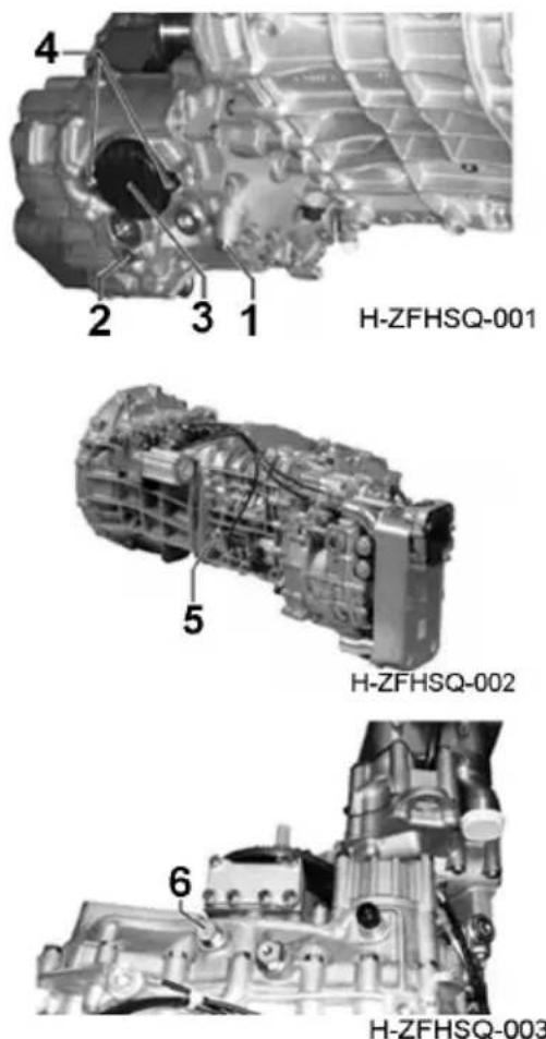
text_image
H-ZFHSQ-001 H-ZFHSQ-002 H-ZFHSQ-003- Oil drain plug of transmission
- Oil drain plug of retarder
- Oil absorption filter element
- Install filter element bolts
- Oil spill port and oil changing port
- Refueling port after maintenance
Filter element replacement
Drain the oil first and then replace the filter element.
Please use the new filter element every time you change the oil.
- Loosen the oil absorption filter element bolt;
- Remove the oil absorption filter element
- Lubricate the new O-ring on the new filter element
- Load the new filter element into the retarder shell
- Tighten the bolts and fix the filter element
Tightening torque: 23 ± 2 Nm
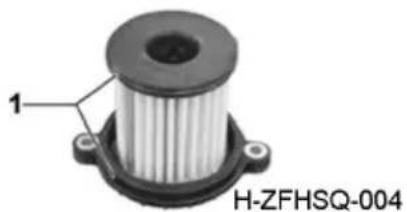
natural_image
Close-up of a mechanical component with labeled part 1 and identifier H-ZFHSQ-004 (no other text or symbols visible)- O ring

CAUTION:
There will be some residual oil in the retarder!
Add oil
Add oil after regular oil change
- Add oil to the transmission and check the oil level can be done only after the vehicle is horizontally parked and the engine is turned off.
- For vehicle with transmission installed horizontally, the transmission shall be placed horizontally before refueling, otherwise the quantity of refueling is not accurate;
- Please use a new filter element every time after you change the oil;
- For oil grade and oil change cycle, please consult ZF TE-ML oil table according to the transmission nameplate information;
- The amount of fuel added is only a reference value, which may vary with the type of transmission and installation angle;
- For refueling quantity and tightening torque, please refer to the technical parameters section;
- If PTO is assembled, the amount of refueling shall be considered;
- If the heat exchanger and retarder are installed separately, please consider the amount of oil in the connecting pipe.

CAUTION:
Insufficient oil in the transmission will lead to transmission damage and accident risk

WARNING:
Insufficient oil in the transmission will result in retarder failure, brake torque weakening or failure.
-
Loosen the screw plug at the oil spill port, add oil from the oil spill port until overflow, install the gasket and tighten the screw plug at the oil spill port.
-
Test run the vehicle (at a speed of about 10 km/h for at least 1 minute), briefly run the retarder (the highest gear) at the beginning, and then cancel it.
- Engine shut down;
- Loosen the screw plug at the oil drain plug;
- Check the oil level, and fill the oil until it overflows if necessary;
- After using the new gasket, tighten the oil spill port screw plug.
CAUTION:
- Please check the oil level below 40^ C temperature.
- The correct position of the oil surface is at the bottom of the overflow port, that is, the oil overflow position.
- Check the oil level after the test drive, which is the correct refueling process, so as to ensure the accurate refueling volume and the split heat exchanger. Check after the test drive for about 5 minutes, to prevent the heat exchanger idling.
Add oil after maintenance
- Add oil to the transmission and check the oil level can be done only after the vehicle is horizontally parked and the engine is turned off.
- For vehicles with transmissions installed horizontally, the transmissions shall be placed horizontally before refueling, otherwise the quantity of refueling is not accurate;
- For oil grade and oil change cycle, please consult ZF TE-ML oil table according to the transmission nameplate information;
- The amount of fuel added is only a reference value, which may vary with the type of transmission and installation angle;
- For refueling quantity and tightening torque, please refer to the technical parameters section;
- If PTO is assembled, the amount of refueling shall be considered;
- If the heat exchanger and retarder are installed separately, please consider the amount of oil in the connecting pipe.
CAUTION:
Insufficient oil in the transmission will lead to transmission damage and accident risk
WARNING:
Insufficient oil in the transmission will result in retarder failure, brake torque weakening or failure.
-
Loosen the screw plug at the oil spill port, add oil from the oil spill port to the overflow, install the gasket and tighten the screw plug at the oil spill port.
-
Test run the vehicle (at a speed of about 10 km/h for at least 1 minute), briefly run the retarder (the highest gear) at the beginning, and then cancel it.
-
Engine shut down;
-
Loosen the screw plug at the oil spill port;
-
Check the oil level, and fill the oil until it overflows if necessary;
- After using the new gasket, tighten the oil spill port screw plug.

CAUTION:
- Please check the oil level below 40°C temperature.
- The correct position of the oil surface is at the bottom of the overflow port, that is, the oil overflow position.
- Check the oil level after the test run, which is the correct refueling process, so as to ensure the accurate refueling volume and the split heat exchanger. Check after the test run for about 5 minutes, to prevent the heat exchanger idling.
Drain the residual coolant

WARNING:
Touch hot gearbox or engine coolant may cause burns, please take precautions.
Residual coolant can only be removed when the temperature sensor is removed
- Loosen the bolt;
- Remove the temperature sensor;
- After draining, use the new O-ring, then install the temperature sensor back and tighten the bolts
Tightening torque: 9.5 ± 1 Nm
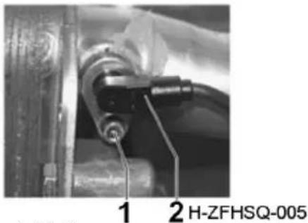
text_image
1 2 H-ZFHSQ-005- Bolts
- Temperature sensor
Maintenance and Adjustment of Brake
Manual adjuster
Check the maintenance period refer to page 208
Normal inspection
Every 5,000km
Clearance between friction plates of brake drum and brake shoe:
At the center of brake shoe: 0.3-0.5 mm
Limit wear of brake drum: 2mm;
See the limit marks on both sides of the friction sheet.
Method of local adjustment
-
Fit the ring spanner over the worm shaft head, rotate the worm shaft to make the friction plate contact the brake drum, and then rotate the worm shaft in reverse direction by 1/2 turn. The brake drum should rotate freely without contacting any part at this moment.
-
Check that the push rod travel of the brake chamber is within 25 ± 5 mm.
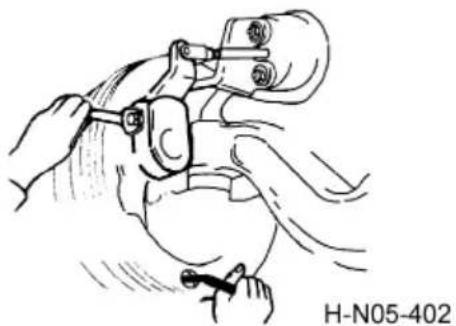
natural_image
Illustration of a medical procedure involving a tool and tubing (no text or symbols)
CAUTION:
-
Check the brake clearance frequently and adjust it in time if the braking is weak. Attention should be paid to the followings during adjustment:
-
Never change the push rod travel by tightening the connecting fork of brake chamber.
-
To adjust the rear brake, always park the vehicle on flat place and ensure the air reservoir pressure is above 700 kPa.
-
Use the triangular blocks to chock the wheels at the front and back, and after releasing the parking brake, adjust the rear brake clearance.
Automatic Adjuster
Please refer to the specific configurations of your vehicle.
If the brake is equipped with an automatic adjuster, the clearance between the brake shoe and brake drum can be adjusted smaller automatically when the friction lining is worn and the clearance exceeds the set value, so as to reduce the maintenance time and ensure driving safety.
During normal operation, add lubricating grease from the grease nipple every 20,000km. Check the reverse adjusting torque every 20,000km, namely by rotating the worm shaft counterclockwise (repeat three times); if the torque is less than 18N·m, make sure to replace the adjuster, and check if the parts and assemblies of the brake return smoothly without seizure during operation.
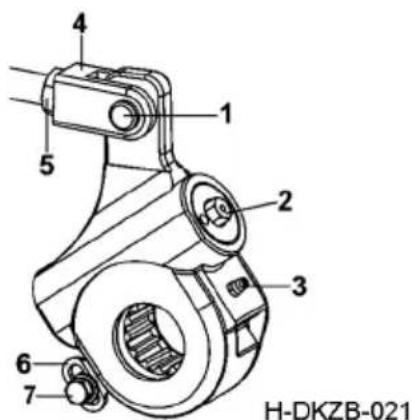
text_image
4 1 5 2 3 6 7 H-DKZB-021- Shaft pin
- Worm shaft
- Grease nipple
- Connecting yoke
- locking nut
- Control arm
- Fastening bolt
Check the brake friction lining for wear regularly, so as to avoid degradation of the braking performance and damage to other parts due to excessive wear of friction lining.
To replace the brake shoe, rotate the worm shaft to keep the camshaft at the minimum opening position. After the friction lining is replaced, depress the brake pedal about 30-40 times with the complete vehicle air pressure no less than 300kPa to reduce the brake clearance. When the vehicle is in service, the shoe friction lining clearance will be adjusted automatically and continuously along with the pr°Ceeding of running-in, till it is kept within the designed reserved clearance range.
Method for manual adjustment of brake clearance
For new vehicles or vehicles whose friction lining has been replaced, if the normal operation is affected as the clearance between brake shoe and drum is incorrect or the clearance becomes smaller due to thermal expansion of new friction lining or running in hilly region (frequent braking), the brake clearance can be adjusted larger manually.
- Fit the double offset ring spanner over the worm shaft head, rotate the worm shaft to make the friction lining contact the brake drum, and then rotate the worm shaft in reverse direction by 1/2-2/3 turn (a click will be heard during rotation in reverse
direction); the brake drum should rotate freely without contacting any part at this moment.
- In case the worm shaft cannot rotate because the automatic adjuster has been in service for a long time or has not been maintained, lubricated in time, remove the fastening bolt of the control arm and follow step 1 to put it into service. In this case, the adjuster loses automatic adjusting function, and you should go to the service station to have the automatic adjuster repaired or replaced in time.

CAUTION:
-
Never adjust the brake clearance by hand except for the above-mentioned condition;
-
Check the wear condition of friction lining regularly to prevent braking failure due to overworn friction lining.
-
During manual adjustment of brake clearance, never change the push rod stroke by tightening the connecting yoke of brake chamber push rod;
-
To adjust the rear brake, always park the vehicle on a flat place and ensure the air reservoir pressure is above 700kPa.
-
Adjust the rear brake clearance only after the wheels are chocked at the front and back, and the parking brake is released.
-
In case the automatic adjuster is abnormal, make sure to stop the vehicle immediately to check the automatic adjuster and other components of the brake system, and take necessary measures to eliminate the fault.
-
Before tightening the fastening bolt of control arm, rotate the control arm around camshaft in the direction of arrow marked on the automatic adjuster housing.
Automatic adjuster with control arm
Maintenance of automatic adjuster
-
Add lithium base grease (DFCV-C20-L) to adjuster every 20,000 km.
-
Rotate the worm hexagonal head anticlockwise every 20,000 km, then measure if the rotating torque is higher than 18 Nm, and repeat measurement for three times. If the torque measured is less than 18 Nm, replace the adjuster assembly immediately.
Common faults & countermeasures
Improper adjustment of brake clearance (like brake drag during driving) is usually caused by the fault of brake system rather than automatic adjuster as the automatic adjuster can only adjust brake clearance smaller. This problem is likely to °Ccur under the following conditions, and please take corresponding measures; otherwise driving safety might be affected due to large clearance:
- Running-in of new vehicle
During the running-in period, improper adjustment of brake clearance is likely to °Ccur as the initial thermal expansion of new friction lining is great, which may reduce brake clearance. In this case, adjust the brake clearance larger manually for 2-3 times.
2. Replacement of friction lining
After replacement with a new friction lining, check the contact between brake shoe and drum, and make sure the difference of upper and lower shoe symmetric point clearance falls in the acceptable range (below 0.3mm). Try to keep the upper and lower shoes contact the drum simultaneously while braking, so as to avoid large clearance due to braking with one shoe. If the difference of symmetric point clearance is too large, turn the excircle of brake shoe friction lining or polish the projection of friction lining with sand paper.
3. Thermal expansion of brake drum
When braking is frequently applied (like on long downhill at mountain area), the brake drum will expand with heat, and the enlarged clearance (brake drum expansion) will be adjusted smaller by automatic adjuster, and brake drag may °Ccur after the brake drum is cooled. In such case, users can adjust brake clearance larger manually after the brake is cooled.
Method for disabling automatic adjustment function
If the worm shaft cannot be rotated to adjust too small brake clearance larger during brake drag, users can disable the automatic adjustment function for some time, and use it as a manual adjuster. Specific method: for automatic adjuster with control arm, remove the fixing bolt of control arm; for automatic adjuster without control arm, remove the small pin shaft and gear rack, rotate the worm shaft to make the shoe friction lining contact the brake drum, and then rotate the worm shaft in reverse direction by 1/3-2/3 turn, and use a feeler gauge to check that the clearance is 0.5-0.8mm.
After the automatic adjustment function is disabled, please check and replace the part at Dongfeng service station immediately.
Disc Brake

WARNING:
Never use pneumatic or electric wrench during all the processes.

CAUTION:
Expertise is required for the inspection and maintenance of disc brake, so please go to Dongfeng franchised service station to do related maintenance.
Working principle
Floating caliper is adopted, and the wear of friction lining is compensated automatically through mechanical adjuster. Driven by the brake chamber, this adjuster pushes the inner brake pad to contact the brake disc, such that the brake caliper moves horizontally along the sliding pin, making outer brake pad contact the brake disc and realizing braking function.
Automatic adjuster ensures proper clearance between brake pad and brake disc.
Method for manual adjustment of disc brake clearance
Park the vehicle safely, remove the tires, and pull the caliper body toward the outside of wheel until it cannot be moved, and then use a feeler gauge to check the clearance between outer brake pad and brake disc. If the clearance falls out of the acceptable range, please do maintenance for the automatic adjuster. Clearance: 0.6-1.2mm.
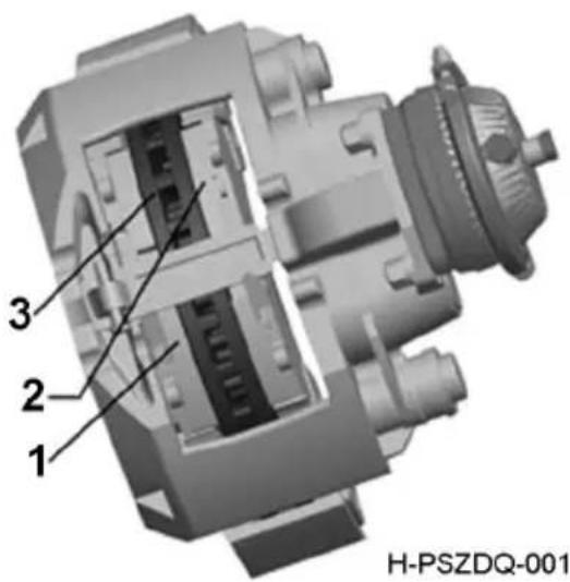
text_image
1 2 3 H-PSZDQ-001Inspection of sliding function
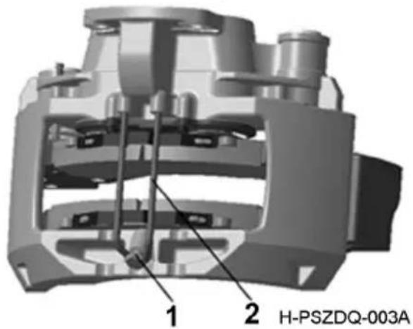
text_image
1 2 H-PSZDQ-003A- locking bolt
- Pressure plate
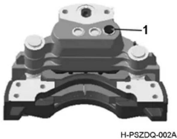
natural_image
Mechanical component diagram with labeled part '1' and identifier H-PSZDQ-002A (no readable text or symbols beyond label)- Plug
Applicable to Haldex disc brake only.
- Park the vehicle safely, and remove wheels of the brake axles to be inspected;
- Remove the brake pad;
- Grasp the brake caliper with hand firmly at the position easy for pushing and pulling it to move axially;
- Push and pull the brake caliper with hand to check if it can slide smoothly;
- If the brake caliper can slide smoothly, it works normally; otherwise, perform troubleshooting of the brake.
Inspection of sliding pin rubber sleeve
Applicable to Haldex disc brake only.
Check protective sleeves and 6 silicon rubber sleeves at both ends, as well as the protective cover. If any cracks or other damages are found, replace the part immediately.
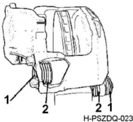
text_image
1 2 2 1 H-PSZDQ-023- Protective cover
- Silicon rubber sleeve
Inspection of adjusting screw rubber sleeve
Applicable to Haldex disc brake only.
Use an 8mm wrench to rotate the adjusting shaft until the push plate is pushed out completely and about 45-50 mm from the cover plate.
The maximum pushing distance of push plate from bottom plate is 50 mm. Check the helical spring sleeve and rubber sleeve for any obvious cracks or other damages; if any, replace them immediately.
Rotate the adjusting shaft in reverse direction to the limit. Check if the helical spring sleeve can return completely, to ensure there is no fold interference or damage.
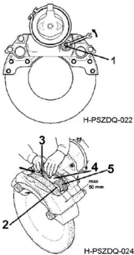
text_image
H-PSZDQ-022 H-PSZDQ-024 1 3 4 5 max 50 mm 2 3 4 5- Adjusting shaft
- Push plate
- Rubber sleeve
- Bottom plate
- Helical spring sleeve
Inspection of sliding function of brake caliper
- Park the vehicle safely, remove the tires, then push/pull caliper with hand to check if it can slide smoothly;
- If the brake caliper can slide smoothly, the sliding function is normal; otherwise, perform troubleshooting of the brake.
- If the maximum sliding resistance is exceeded, check if there is any dust or foreign matters that impede the sliding of brake caliper.
Maximum sliding resistance: 100 N.
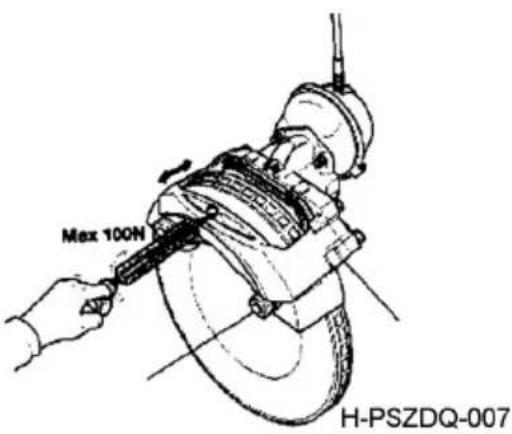
text_image
Max 100N H-PSZDQ-007Inspection of brake pad
Inspection of brake pad wear
Measure the distance from bottom plate A to friction surface B.
Inspection of uneven wear of brake pad
Maximum uneven wear: 1mm (measure 4 points)
If the wear is uneven, check if the brake caliper can slide properly on the sliding pin, if there is dust between the brake pad and push pate, and if the automatic adjuster functions normally.
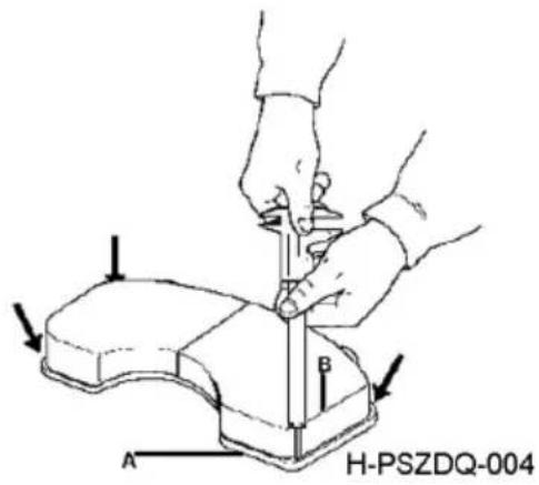
text_image
A B H-PSZDQ-004Wear of brake pad:
| Disc brake Haldex | |
| Thickness of new brake pad friction material (mm) 22 | |
| Minimum thickness of residual friction material (mm) 2 |

CAUTION:
-
Slightly depressing the brake pedal may accelerate wear of inner brake pad.
-
While replacing the brake pad, all brake pads of the two brakes at the same axle must be replaced together.
Inspection of brake disc
Inspection of brake disc dimension
A= Thickness of a new brake disc
B= Thickness of brake disc worn to the limit; the brake disc must be replaced at this moment.
Brake disc parameters:
| Disc brake Haldex | |
| Thickness of a new brake disc (mm) 45 | |
| Thickness of brake disc worn to the limit (mm) | 37 |
| Maximum thickness difference (mm) 1 | |
| Uneven wear at one side shall be no more than 4 mm | |
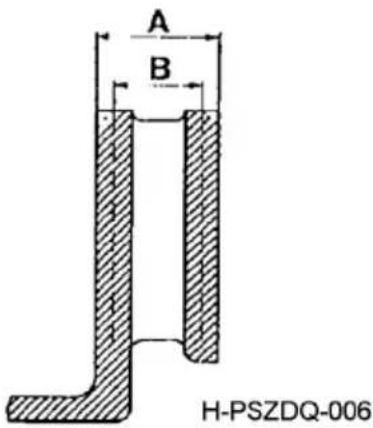
text_image
A B H-PSZDQ-006Inspection of brake disc cracks
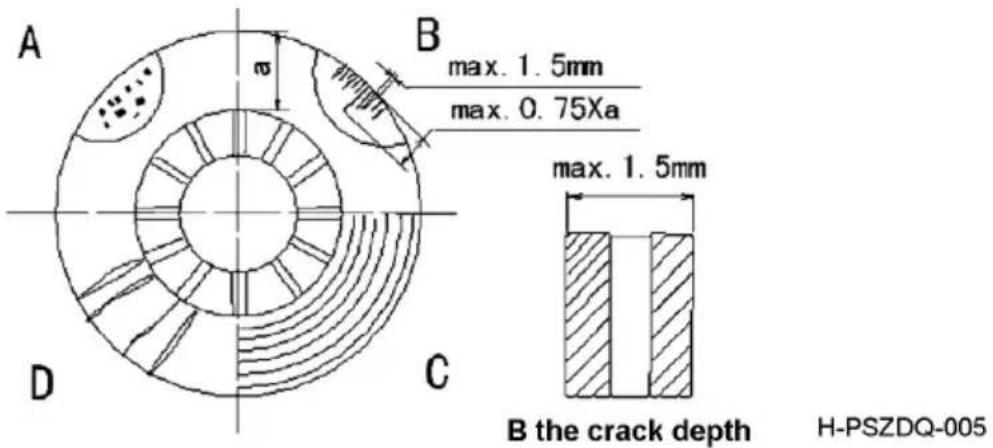
text_image
A B max. 1.5mm max. 0.75Xa D C max. 1.5mm B the crack depth H-PSZDQ-005B indicates the cracking depth
a= Width of friction lining contact face
A= Small spots distributed on the surface; continuous use is allowed
B= Radial cracks with depth and width less than 1.5 mm, and length less than 3/4 the width of friction lining contact face; continuous use is allowed
C= Cracks with annular groove and; continuous use is allowed depth less than 1.5 mm
D= Radial through cracks; continuous use is not allowed

CAUTION:
While replacing the brake disc, all brake discs of the two brakes at the same axle must be replaced together.
Inspection of friction lining wear
As friction lining is worn to the limit or faulty, the wear indicator will be on. Please replace the friction lining at this moment.
natural_image
Pure electrical circuit symbol for a diode (no text or labels)Inspection of Brake Pedal Stroke
-
Step on the brake pedal slightly to check if the free stroke is within 12-18 mm.
-
There should be no seizure when the brake pedal is depressed to the floor.
-
There should be an exhausting sound when the pedal is released.
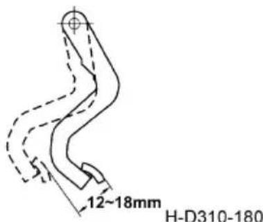
text_image
12~18mm H-D310-180Inspection of Air Dryer
The air dryer is used to dry the compressed air from compressor, thus supplying dry and clean air to the air reservoir.
Replacement cycle
Cylinder or desiccant of air dryer: every 100,000km or 12 months, or shorter if the vehicle always runs under adverse conditions (such as moist or hilly area).
Inspection of water logging
Check the air reservoir for water logging at the end of driving each day in winter or in chilly area, or otherwise once a week. For this purpose, pull the water drain valve under the air reservoir or the steel hook under the reservoir frame. If any water is found, drain off the water, and replace the cylinder or desiccant at Dongfeng service station immediately.
Air dryer heater switch
natural_image
Simple diagram of a door with a circular icon and vertical lines, no text or symbols present.H-D760-132
Air dryer heating indicator lamp
natural_image
Simple line drawing of a handheld electric shaver (no text or symbols)H-D310-110
Inspection of exhaust outlet
If air leakage is detected at the exhaust outlet of the air dryer assembly during inflation before vehicle start, please check the exhaust valve. If the exhaust outlet fails to be closed tightly due to foreign matters, oil dirt or others, please clean the exhaust valve.the upper limit, it is normal that the air dryer exhaust outlet will exhaust for pressure relief. Only when the air pressure is consumed down to the lower limit will the exhaust valve close, and the pipeline system will be re-inflated.
Heating of air dryer
If the ambient temperature is lower than 5^ C, activate the electric heater of the air dryer to prevent inoperative dryer due to icing at exhaust outlet. Turn on the air dryer heater switch on the instrument panel, and the air dryer heating indicator lamp will be on simultaneously.

CAUTION:
The sliver cylinder is provided with oil-filtration function and can filter most oil in the compressed air to prolong the service life of parts of the brake system. The sliver cylinder must be replaced together with the drying cylinder.
Replacement of air drying cylinder
- Before replacing the air dryer, make sure that the internal pressure has been removed completely;
- Screw off the air dryer with hand;
- Apply grease to the sealing ring and threaded sleeve before installing a new air dryer;
- Screw up the dryer reservoir with hand (maximum torque: 15Nm).
Inspection and Change of Power Steering Hydraulic Oil
|
Check the maintenance period refer to page 208
Frequently check the oil in the tank for level and deterioration when the vehicle is in service, and add or change oil in time upon detection of any abnormal conditions. Wipe the oil tank clean when checking the oil level. Then unscrew the oil dipstick assembly, clean and refit the oil dipstick, then remove it and observe oil level. If the oil level is not between MAX and MIN marks of oil dipstick, hydraulic oil of the same grade should be added.
Air drying cylinder
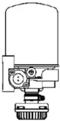
natural_image
Technical line drawing of a mechanical device with no visible text or symbolsH-D760-143
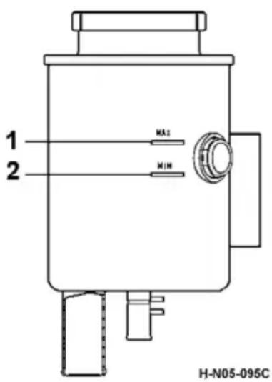
text_image
1 2 MAX MIN H-N05-095C- Filler cap with dipstick
Replacement method
-
Wedge the front and rear of the rear wheels with triangular blocks, engage the
transmission at neutral gear, and jack the front axle to raise the tires of both sides off the ground, or disengage the drag link from the pitman. -
Wipe the oil tank clean first, unscrew the tank cover fastening nut to open the tank cover, unscrew the drain bolt of the steering gear and turn the steering wheel repeatedly to both limits, so as to drain the residual oil out of the oil pump and oil tank. Keep the engine running at an idle speed when necessary, and turn the steering wheel to the leftmost and rightmost for several times until no oil flows out of the port.
-
Tighten the drain bolt after confirming that the oil in system has been drained completely, and replace or clean the oil tank filter element.
-
Add clean oil to the oil tank, run the engine at an idle speed for 3-5 s, and then stop the engine to check the oil level again and add oil. Repeat the above pr°Cedures for three times at least. During the oil addition, make sure that oil level will not drop too fast or there is no oil in the tank to prevent the system from absorbing any air.
- Run the engine at an idle speed for 2 min, and then stop the engine to check if the oil level meets the requirement.
- Run the engine, turn the steering wheel from left limit to right limit and repeat this for many times until the oil level stops dropping and no bubbles °Ccur. Add the oil to the level required (that is, between the upper and lower marks of the oil dipstick). Repeat this step several times until the hydraulic oil level is between MAX and MIN marks of oil dipstick.

CAUTION:
- Do not add the hydraulic oil with engine running.
- Make sure to replenish with the hydraulic oil of the same grade.
- With engine idling, turn the steering wheel to the left and right to facilitate bleeding air from the system.
- Always shut down the engine when checking the oil level.
- Never let the steering wheel stay at the extreme position for more than 15 s. In such a case, it is required to slightly rotate the steering wheel backwards so as to avoid any damage to the power steering pump.
- Before starting the vehicle for the first time at the ambient temperature below 10^ C, run the engine at an idle speed for more than 30 s, and rotate the steering wheel when the steering fluid temperature rises, so as to avoid hard steering or any damage to the power steering pump.
Maintenance of Suspension
Maintenance of balanced suspension
Before the first guarantee of the new car enters the station for maintenance, clean and check whether the leaf spring and spring clamp are loose or deformed every 500\~1000km, tighten the u-type bolt and retighten it twice. Check for looseness and deformation during the station maintenance and tighten the torque as required.
In the process of driving and maintenance, it is forbidden to hammer the side and surface of the leaf spring with an iron tool, otherwise the hammer hammer scar will become the source of fatigue, and early crack and gradually expand, leading to early fracture of the leaf spring.
Maintenance of air suspension
Air spring is a complicated system assembly. It realizes the elastic effect by compressing and stretching the air in the rubber bellows, so its rigidity may change with the load. Compared with the traditional leaf spring, it features lower natural frequency, and has the ability to ensure body height as load changes, and the advantages such as long service life, light weight, etc. Air spring assembly is mainly composed of upper connecting plate, inner buffer block, rubber bellows body and lower connecting plate (usually called as the piston). Upper connecting plate can be of mounting type or vulcanized top plate type, and this vehicle model employs the vulcanized top plate. Rubber bellows body is composed of the external rubber protective layer and internal cord - rubber fiber reinforced composite layer.
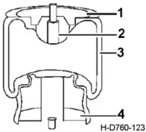
text_image
1 2 3 4 H-D760-123- Upper connecting plate
- Inner buffer block
- Rubber bellows body
- Lower connecting plate
Air pressure in the air spring should not exceed 100Pa/7bar, and the working temperature of air spring should be -40^-70^ .
- Do not drive vehicles equipped with air spring suspension system on bad roads. It is required to regularly check the shockabsorber for failure and if the levelling valve is in proper position, as either shockabsorber failure or incorrect position of levelling valve will result in air spring overstretching, causing separation of upper/lower connecting metal plate from the rubber bellows body.
- Rubber bellows body of air spring assembly may be corroded and damaged by hydraulic fluid, lubricant and other chemical solvents. While driving the complete vehicle, never let the rubber bellows body of air spring contact corrosive liquids; check and clean the air spring regularly; and the cleaning can be done with clean water only. And meanwhile, avoid too much oil in the air supply system.
- If mixed with foreign matters during operation, the rubber bellows body may be worn out as air spring moves up and down. Therefore, it is required to check and clean foreign matters in the rubber bellows body regularly.
- Do not use air spring assembly under no internal pressure.
- Check the rubber bellows body of air spring for leakage due to scratching by stones, metals and other sharp foreign matters, and replace it if necessary.
- Check if air suspension system exterior stoppers are missing or damaged regularly. Missing stoppers may cause metal installing parts, like air spring piston base, to be damaged due to overloading.
- Overloading of air spring is prohibited. Piston base may be crushed under overload condition.
- Normal fatigue crack of air spring assembly appears at the folded edge of bottom piston. The rubber bellows body of air spring should be replaced every 3-4 years.
ECAS system
- Working temperature range of ECU: -40^ - +75^ .
- When charging the vehicle with external power supply, be sure to disconnect ECU power supply, so as to protect ECU from being damaged by the external high voltage.
- When electric welding is required for the vehicle, please disconnect the ECU. Do not use the multimeter to measure ECU.
- The removal of all parts connected to ECU should be conducted with power off, and all parts clean and dry.
- Do not change the fuse capacity without permission.
- If the indicator is damaged, replace it immediately.
- When cleaning the vehicle, ECU should be free of water.
Inspection of Drive Axle Final Drive Oil Level
Please refer to the specific configuration of your vehicle.
Wheel reduction axle
Initial replacement
Check the maintenance period refer to page 208
Inspection method
The oil level of intermediate axle should be flush with the lower edge of transition tank access hole, and add the oil if insufficient. The oil level of rear axle should be flush with the lower edge of the oil filler, check and clean the breather plug.
Normal replacement
Check the Maintenance period see "Maintenance and replacement items"
Rear axle
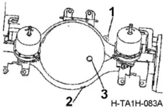
text_image
1 2 3 H-TA1H-083A- Breather plug
- Rear axle draining screw
- Rear axle oil inspection hole
The replacement cycle should be shortened when the vehicle is under heavy load or in heavily polluted environment.
Replacement method
Replace the final drive oil under hot vehicle condition. When replacing, first screw down the oil plug, drain the oil plug, clean the oil plug and install it, add the new oil from the surface inspection hole until the oil surface and the lower plane of the oil port is equal.

CAUTION:
-
Keep dirt or dust out of the final drive when adding oil, and always keep the breather plug in a good condition.
-
Oil should be kept at a normal level. Otherwise, the use of oil may be affected by too high or too low oil level.
Use and Maintenance of Tire
Selection of tire
| Model Dump truck, etc. Cargo truck and tractor, etc. | |||
| Service Conditions | Low speed, poor road conditions, overload exceeding 50% | High speed, good road conditions, overload not exceeding 50% | High speed, good road conditions, overload not exceeding 30% |
| Tubeless tire Forbidden Allowed Preferred | |||
| Meridian tire Allowed Preferred Allowed | |||
| Bias tire Preferred Not recommended | Forbidden | ||
Never overload the vehicle
Vehicle overload will increase the tire heat-up and accelerate the wear of tire tread; which may increase the tire bead stress, cause tire bead damage and early fatigue of casing ply, and reduce the service life of tire.
Select proper tread patterns
Longitudinal pattern: low rolling resistance and good guiding performance;
Dual-purpose and transverse pattern: high tear resistance and good driving performance; Select longitudinal pattern for guide wheels and trailer wheels; select dual-purpose and transverse pattern for driving wheels
| Model Dump truck | ||
| Position Steering shaft Driving shaft | ||
| National highway | Longitudinal pattern | Longitudinal pattern or dual purpose pattern |
| General road conditions | Longitudinal grooved pattern or dual purpose pattern | Off-road pattern or transverse pattern |
| Poor road conditions | Transverse pattern or dual-purpose pattern | Off-road pattern or transverse pattern |
| Model Cargo truck | ||
| Position Steering shaft Driving shaft | ||
| National highway | Longitudinal pattern | Longitudinal pattern |
| General road conditions | Longitudinal grooved pattern or longitudinal pattern | Longitudinal grooved pattern or dual purpose pattern |
| Poor road conditions | Longitudinal grooved pattern or dual purpose pattern | Off-road pattern or transverse pattern |
| Model Tractor | ||
| Position Steering shaft Driving shaft | ||
| National highway | Longitudinal pattern | Longitudinal pattern or dual purpose pattern |
| General road conditions | Longitudinal grooved pattern or dual purpose pattern | Longitudinal grooved pattern or transverse pattern |
| Poor road conditions | - | - |
Replacement of tire
Tire specifications and relevant parameters are as follows
| Tire category | Tire specification | External dimensions Width* diameter*static loaded radius/rolling radius(mm) | Wheel specification | Bearing capacity, single/tire(kg) | Standard pressure, single/dual tire(kPa) |
| Bias tire with inner tube | 12.00-2018PR 31 | 5*1125*536/536 8.5- | 20 3750/3350 | 810/740 | |
| 11.00-2018PR 29 | 3*1085*517/517 8.0- | 20 3650/3150 | 910/840 | ||
| 11.00-2016PR 29 | 3*1085*517/517 8.0- | 20 3350/2900 | 810/740 | ||
| 10.00-2018PR 27 | 8*1055*502/502 7.5- | 20 3350/2900 | 910/840 | ||
| 10.00-2016PR 27 | 8*1055*502/502 7.5- | 20 3000/2650 | 810/740 | ||
| 9.00-2016PR 259 | *1018*485/485 7.0-20 | 20 2900/2500 | 880/810 | ||
| 9.00-2014PR 259 | *1018*485/485 7.0-20 | 20 2575/2300 | 770/700 | ||
| 9.00-2012PR 259 | *1018*485/485 7.0-20 | 20 2360/2060 | 670/600 | ||
| 9.00-2010PR 259 | *1018*485/485 7.0-20 | 20 2120/1850 | 560/490 | ||
| 8.25-2014PR 236 | *974*464/464 6.5-20 | 2240/1950 | 810/740 | ||
| Meridian tire | 12.00R2018PR 31 | *1125*516/534 8.5- | 20 3750/3450 | 830/830 | |
| 11.00R2018PR 29 | *1085*499/517 8.0- | 20 3550/3250 | 930/930 | ||
| 11.00R2016PR 29 | *1085*499/516 8.0- | 20 3350/3075 | 830/830 | ||
| 10.00R2018PR 27 | *1054*486/502 7.5- | 20 3250/3000 | 930/930 | ||
| 10.00R2016PR 27 | *1054*486/502 7.5- | 20 3250/3000 | 930/930 | ||
| 9.00R2016PR 259 | *1019*471/485 7.0-20 | 20 2800/2650 | 900/900 | ||
| 9.00R2014PR 259 | *1019*471/485 7.0-20 | 20 2575/2430 | 790/790 | ||
| 8.25R2014PR 236 | *974*452/464 6.5-20 | 2240/2120 | 830/830 | ||
| Tubeless tire (British system) | 13R22.518PR | 320*1124*521 9.7 | 5*22.5 3750 | 3450 830/830 | |
| 12R22.518PR | 300*1085*504 9.0 | 0*22.5 3550 | 3250 930/930 | ||
| 11R22.516PR | 279*1054*491 8.2 | 5*22.5 3000 | 2725 830/830 | ||
| 10R22.514PR | 254*1018*476 7.5 | *22.5 2575/2 | 430 790/790 | ||
| Tubeless tire (metric system) | 315/80R22.518PR | 312*1076*500 9.00*2 | 2.5 3750/3450 | 830/830 | |
| 295/80R22.516PR | 298*1044*487 9.00*2 | 2.5 3350/3075 | 830/830 | ||
| 275/80R22.516PR | 276*1012*473 8.25*2 | 2.5 3075*2800 | 830/830 | ||
| 255/80R22.516PR | 255*930*435 | 7.5*22.5 | 2500*2300 | 830/830 |
The principle of tire replacement should refer to the bearing capacity parameters. Under the equivalent bearing capacity, the diameter of metric tubeless tire is smaller than that of tire with inner tube, which can reduce the height of complete vehicle and enhance the vehicle stability.
For example: 315/80R22.5 18PR tire can replace 12.00R20 18PR or 11.00R20 18PR tire.
Inspection of tire pressure and tire tread
- Use an air pressure gauge to check whether each tire pressure meets the requirements, and inflate the tire if insufficient.
- Check if there is any foreign matter attached to the tire tread and remove it if any.
- Check the depth of tread pattern. Make sure to replace the tire if the depth is less than 1.6 mm (less than 2.4 mm on the freeway). Measure this value at not less than six points along the tire circle.
- Under normal operation conditions, inflate the tire according to standard pressure.
Tire Rotation
During the maintenance every 10,000 km, do tire rotation as illustrated. Principles of tire rotation:
- For rear axle twin tires, the difference between the outside diameters of the tires should not exceed 12 mm and the smaller one should be mounted inside.
- The front wheels should be equipped with tires of the same model with even and less wear. Do the dynamic balance test on the newly assembled front tires or front tires whose positions have been changed newly where possible.
- After tire rotation, the rotating direction of tire should be reverse to that before tire rotation. The new tires must be used in pairs.
- The same axle must be equipped with tires of the same specification and tread; otherwise, pulling to one side while braking, vehicle body swing, and loss of steering control may °Ccur.
- Check the threads of wheel hub bolt and wheel nut for scratches. For the sake of safety, replace the nuts and bolts in pairs if the thread of either one has been damaged, since the other one may be damaged as well.
- Check the contact face (spherical face) and mounting holes of wheel rim, and if any deformation or damage is found, replace it. If the spherical face of tire nut also has damage, replace the nut.
- Check the wheel rim and replace it if any crack is found.
- Separate the valve cores of inside and outside tires for easy inflation during installation of twin tires.
Requirements for wheel dynamic balance
| Tire specification | Wheel assembly unbalance amount (g.cm) | Tire specification | Wheel assembly unbalance amount (g.cm) |
| 12.00-2018PR | ≤8000 | 9.00R2016PR | ≤5000 |
| 11.00-2018PR | ≤8000 | 8.25R1614PR | ≤3000 |
| 10.00-2016PR | ≤5000 | 12R22.518PR | ≤5000 |
| 10.00-2018PR | ≤5000 | 315/80R22.518PR | ≤5000 |
| 9.00-2016PR | ≤5000 | 295/80R22.516PR | ≤5000 |
| 12.00R2018PR | ≤8000 | 295/80R22.518PR | ≤5000 |
| 12.00R2418PR | ≤8000 | 275/80R22.516PR | ≤3000 |
| 11.00R2018PR | ≤8000 | 235/75R17.516PR | ≤3000 |
| 10.00R2016PR | ≤5000 | 315/70R22.518PR | ≤5000 |
| 10.00R2018PR | ≤5000 | 255/70R22.516PR | ≤5000 |
| 9.00R2014PR | ≤5000 | 245/70R19.516PR | ≤5000 |
Replacement and repair of wheels
When replacing the wheels, it is recommended that the wheel supplier and model be the same to those of original vehicle. It is recommended to have the tire repaired by a professional tire repair shop.
Adjustment of Front Wheel Alignment
Before the vehicle leaves the factory, front wheel alignment, e.g., front axle toe-in and tire parallelism at axle II, has been adjusted and approved. The detection and adjustment of front axle toe-in and tire parallelism with traditional measuring tape can lead to great error. Therefore, the users are not allowed to perform front wheel alignment without permission. Under normal operating conditions, consequences includ-
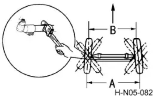
text_image
B A H-N05-082ing front wheel alignment out-of-tolerance and abnormal wear of tires due to adjustment of front wheel alignment without permission of Technical Service Centre (Station) authorized by Dongfeng Commercial Vehicle Co., Ltd. of should be taken by the user.
The adjustment of front axle toe-in and tire parallelism with traditional measuring tape can lead to great error. If any deformation, damage and other defects °Ccur to tie rod and drag link, Service Station will perform adjustment considering the following values:
- Front axle toe-in: 1-3 mm;
- Tire parallelism at axle II: 0±5 mm.
Tire Inflater
Tier inflater is a kind of equipment using the inflation valve to take air from the air reservoir directly.
Operation pr°Cedures are as follows:
- Unscrew the plug of air inflation valve, connect the tire inflation hose with air inflation valve and tighten the joint.
- Start the engine to operate the air compressor. Keep engine running at a medium speed during the inflation.
- After the pressure inside the air reservoir rises to 6.5 × 100 kPa, align the other end of inflation hose with the tire valve to inflate, and measure the pressure with a manometer to ensure that the tire pressure reaches the specified value;
- Remove the inflation hose, tighten the air inflation valve cap, and then stop the engine.
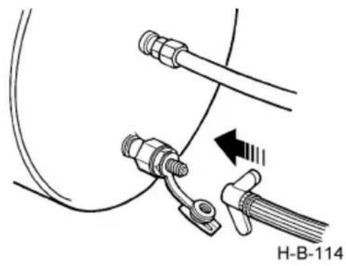
natural_image
Diagram of a mechanical assembly with hoses and connectors, no text or symbols present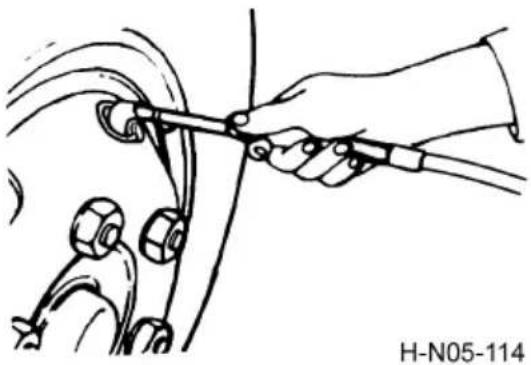
natural_image
Line drawing of a hand using a tool to tie or adjust cable, with no visible text or symbolsMaintenance of wheel hub bearing
Please refer to the specific configuration of the purchased model.
Check the maintenance period refer to page 208
Carry out wheel hub bearing maintenance. Remove the wheel and brake drum, clean the hub bearing, then clean the dirty deteriorated grease in the inner chamber of the hub, fill the gap between the inner seat ring of the bearing and the cage roller with the new grease, and coat the inner and outer surface of the bearing with a thin layer of grease to assemble.
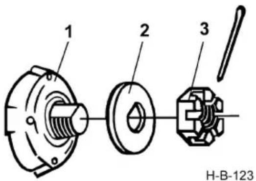
text_image
1 2 3 H-B-123-
Wheel hub
-
Friction lining
-
lock nut
Adjustment of front wheel hub bearing (axle above 5T)
- Tighten the lock nut to 200 N·m and rotate the hub 2-3 turns to fit the bearing completely.
- Tighten the lock nut to 200 N·m.
- It's allowed to turn the lock nut for 30^ back to insert the split pin and get the correct hub bearing pretension force.
- Rotate the hub 2-3 turns and the measured tangential force at hub bolt should be 20-55 N.
- Insert the split pin for locking.
Adjustment of rear wheel hub bearing
- Tighten the adjusting nut and rotate the wheel so as to move the bearing to the correct position.
- Tighten the adjusting nut to 500 N·m or more, and then loosen it by 1/4-1/6 turn.
- At this moment, the wheel should rotate freely without visible axial play or swing. Fit lock plate and fastening screw.
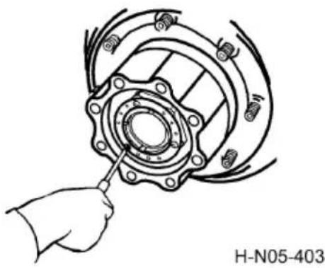
natural_image
Hand using a tool to adjust or install a mechanical component, no text or symbols visible
CAUTION:
Align the lock plate screw with the adjusting nut to ensure the minimum looseness of adjusting nut.
Maintenance of maintenance-free wheel hub
Please refer to the specific configuration of the model purchased.
Conmet maintenance-free wheel hub
Check the maintenance period refer to page 208
To the nearest Dongfeng Commercial Vehicle Co., Ltd., Authorized technical service center (station) for the following appearance inspection, no disassembly is allowed under the condition of non-fault:
- Visual inspection
1). Check fasteners, hub caps, oil plug for loose, damaged, or missing.
2). Check the hub cover, half axle flange, filling plug and oil seal for leakage.
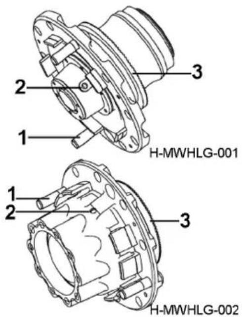
text_image
H-MWHLG-001 H-MWHLG-002- Wheel fastening bolts
- Oil filling port
- ABS gear ring (optional)
3). Visually inspect the oil for contamination and use a magnetic probe to insert it from the filling hole. Adjust the oil level if necessary.
- If it is necessary to rise the vehicle axle during other maintenance, the following inspection items can be carried out in order:
1). Check whether the wheels rotate smoothly;
2). Use the pry bar to reach the bottom of the wheel to move the wheel up and down. Check whether the bearing is loose or the wheel is with excessive displacement.
Installation precautions:
- Clean and wipe the axle shaft tube and apply lubricant slightly;
- The oil seal ring is pressed into the shaft tube and against the shaft shoulder, and the o-ring enters the groove formed by the oil seal ring and shaft head;
- Push the hub assembly directly into the shaft tube by using the spreader, until it reaches the seat ring;
- With 400 N. m torque: tighten the locking nut and rotate the hub at the same time.
- If the lock washer locating hole is not aligned with the lock nut hole, please continue to tighten the lock nut until it is aligned. It is forbidden to loosen the lock nut back.
- Fill the wheel hub with gear oil through the filling holes on the wheel hub cover or the side wall of the wheel hub, until the indicated scale of oil level (fuel capacity of steering axle is about 0.5l/single side, and fuel capacity of drive axle is about 1L/ single side).
- There is no need to check the clearance at the conmet wheel end during inspection and installation. If you need to check the clearance, please go to the technical service center (station) authorized by Dongfeng Commercial Vehicle Co., Ltd., to check with special equipment. The clearance specification is less than or equal to 0.15mm.
Schaeffler FAG maintenance-free hub
The maintenance-free product does not need daily maintenance.
Check the maintenance period refer to page 208. Carry out a more comprehensive examination.
Major items include:
1. Pre-test
Visually inspect the structure of the center nut of the shaft head to check whether it is reliable and normal; Torque wrench can be used to test the locking torque of the center nut's anti-loose/anti-retreat structure; If the torque declines, tighten it to the required torque. Front hub 700-800 Nm, rear hub 1250-1350Nm;
2. Noise test
Lift the axle and rotate the tire in the positive and negative directions by hand. If the tire is not smooth and there is obvious noise, it indicates that the bearing is damaged and needs to be replaced. If the noise increases with the increase of tire rotation speed, it indicates that the bearing has been worn and needs to be replaced;
3. Axial clearance test
Fix the magnetic seat indicator in the relative fixed position of the axle housing, the pointer on the end surface of the brake disc or brake drum (or clean and smooth processing surface), adjust the indicator to the zero position, push and pull the wheel end repeatedly, and measure the axial clearance of the hub bearing; Axial clearance less than 0.2mm is normal; If the axial clearance is greater than 0.2mm, the bearing shall be replaced.

Caution for disassemble and assemble:
-
After the lock nut in the center of the shaft head is unscrewed, the hub assembly shall be pulled out straight from the axle shaft tube and placed in a dry place with good sanitation. Never remove the clamps/oil seals and other parts; The O-ring at the clip groove of the inner ring of the inner bearing shall not be lost during disassembly. If it is accidentally dropped out, it can be manually put into the clip groove after cleaning.
-
After axle shaft tube is cleaned and wiped clean, lightly coated with lubricating oil, and the hub assembly is pushed straight into the axle shaft tube by spreader until it reaches the axle shoulder; Note that the O-ring at the clip groove of the inner ring of the inner bearing shall not fall off. If it does, please timely reset it.
-
Apply lubricating oil to the thread and compression end surface of the locking nut, and pretighten with the fix-torque tool. In the pretightening process, keep slowly rotating the wheel hub until the pretightening torque is fixed; Then rotate the hub again for about 10 rounds, and check the locking torque;
Removal and Refitting of Spare Wheel
Spare wheel hook
- Unscrew the nut fixing the spare tire and take it off for use.
- Install the spare tire in reverse sequence.
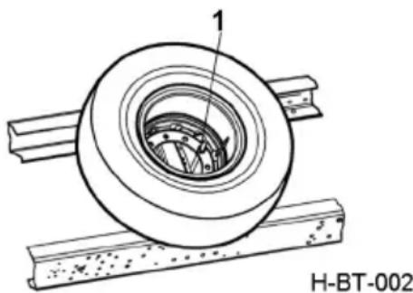
natural_image
Technical line drawing of a mechanical component with labeled part 1, resting on a base (no text or symbols beyond label)- Nut
Replacement of Tire
Removal of tire
- Wedge the front and rear of the rear wheels (front wheels) with triangular blocks to remove the front wheels (rear wheels).
- Unscrew the wheel nuts by the wheel nut s°Cket spanner in the driver's tools.
- Jack one end of the axle to raise the wheel off the ground a little.
- Rinse the tire bolts and nuts with clean water and soak them in engine oil or apply some grease.
- Remove the wheel nuts.

CAUTION:
-
When removing the nuts, if the threads contain silt or dirt, clear the silt away with water or oil, apply a little grease on the exposed threads, and then remove the nuts. This is to avoid thread loosening or locking in case of greater removal torque.
-
To refit a nut, apply grease or oil on it so as to guarantee screw thread pair's normal service and avoid loosening or locking.
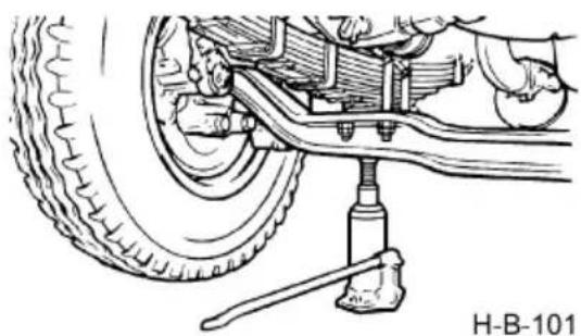
natural_image
Mechanical assembly diagram showing a car wheel and suspension components (no text or symbols)Jack up the front axl
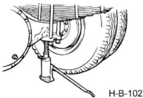
natural_image
Mechanical diagram showing a car brake system with suspension components and tire assembly (no text or symbols)Jack up the rear wheel
Refitting of tire
- Fit the wheel rim bolt hole over the wheel hub bolt by a pry bar.
- Adjust the wheel hub bolt to the center of bolt hole and tighten the wheel nut.
- Lower the jack slowly until the tire contacts the ground.
- Tighten the wheel nuts to 550-650 N·m in three steps diagonally.
- After refitting the wheel nuts, within the first 200-500 km or 1-2 days, re-tighten the nuts to the torque of 550-650 N·m.
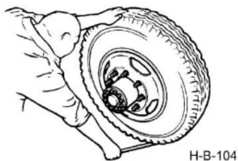
natural_image
Illustration of a hand adjusting a tire with a brake caliper (no text or symbols)Inspection and Maintenance of Battery
Turn off the power master switch before inspection and maintenance of battery.
Check the electrolyte level
Replace the battery every 2 years.
There is no need to add distilled water to the maintenance-free battery.
Fusible Link
Confirm the specification of fusible link (fuse) used before replacing the fusible link. If the new fusible link is very easy to be burnt out, then find out the fault cause and eliminate it. In case of troubleshooting failure, contact the nearest Technical Service Centre (Station) authorized by Dongfeng Commercial Vehicle Company.
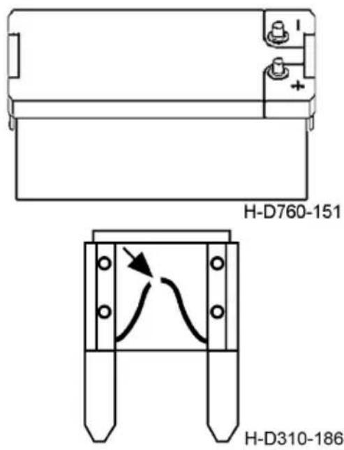
text_image
H-D760-151 H-D310-186
WARNING:
Never replace the fusible link with ordinary conducting wire or fusible link of other specifications.
Adding of Washer Fluid
Washer fluid reservoir is located in the cab front face shield. Park the vehicle on a flat ground before adding washer fluid. Any washer fluid other than the one specified is not acceptable.
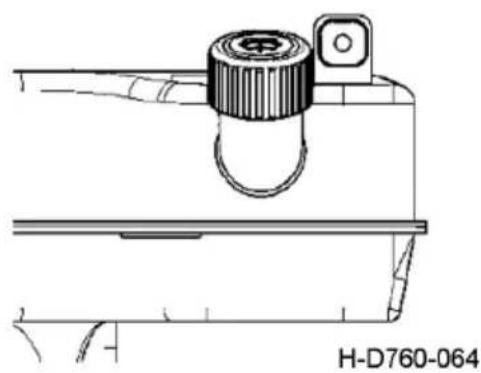
natural_image
Technical line drawing of a mechanical component with no visible text or symbolsArrangement of Lamplight
Please refer to the specific configurations of your vehicle.

text_image
H-D760-046A 1 2 3 4 5-
Front fog lamp
-
Side turn signal lamp
-
Front combination lamp
-
Side marker lamp
-
Front end-outline marker lamp
-
Front fog lamp: two pieces, with the left one symmetric to the right one;
- Front combination lamp: two pieces, with the left one symmetric to the right one (including the front turn signal lamp, front position lamp, low/high beam and daytime running lamp);
- Front end-outline marker lamp: two pieces, with the left one symmetric to the right one;
- Side turn signal lamp: two pieces, with the left one symmetric to the right one;
- Side marker lamp: four pieces, with the left one symmetric to the right one;
Front combination lamp
- Daytime running lamp
- Front position lamp
- High beam
- Low beam
- Front turn signal lamp
Rear combination lamp
- Left rear end-outline marker lamp
- Left rear turn signal lamp
- Left brake lamp
- Left position lamp
- Left rear fog lamp
- Left reversing lamp
- Side retroreflector
- License plate lamp (only for left rear combination lamp)
- Side marker lamp
The right rear combination light is weighed relative to the left.
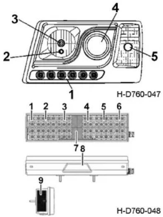
text_image
H-D760-047 1 2 3 4 5 6 7 8 9 H-D760-048Lamplight Adjusting Method Front combination lamp
Structure description: reflector of front combination lamp assembly is the low/high beam combined reflector, which is regulated through adjusting screw and light adjusting motor (manual adjusting section). Lamplight adjustment should be done strictly in accordance with the figure.
-
Rotate the adjusting screw clockwise, and the reflector will move leftward; rotate the adjusting screw anticlockwise, and the reflector will move rightward.
-
Rotate the light adjusting motor (manual adjusting section) clockwise, and the reflector will move downward; rotate the light adjusting motor (manual adjusting section) move upward.
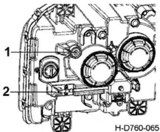
text_image
1 2 H-D760-065-
Adjusting screw
-
Light adjusting motor
anticlockwise, and the reflector will

CAUTION:
-
As per design requirements: if the diameter of cross slot on light adjusting tool is not less than 6.5 mm, the tool may fail to reach adjusting screw gear or even damage the light adjusting guide slot on lamp housing, leading to light adjustment failure.
-
If the diameter of cross slot on light adjusting tool is less than 5.5 mm, the tool may be prone to slide in the guide slot, leading to light adjustment failure. Before light beam adjustment, please set the electric control switch for lamp motor as per complete vehicle design to "ZERO" position, otherwise, the following problems may occur during light adjustment: The light beam of lamp is barely regulated to the lower limit of acceptable range required by testing equipment, but when users try to adjust the light beam by controlling the lamp motor through electric control switch after purchasing the vehicle, the light beam deflects, resulting in visual non-conformity. B: After light adjusting angle exceeds the design limit, the light beam still cannot be regulated to the acceptable range required by the testing equipment. Excessive adjustment will cause reflector damage, ball joint falling and other defects.
-
It is recommended to perform light adjustment with manual screwdriver.
Preparations
- The site for light adjustment should be flat and the screen used should be vertical to the site.
- The vehicle should be unloaded with one driver seated and tire pressure kept normal.
- The vehicle should be vertical to the screen and the reference center of the headlamp should be 10m away from the screen.
- Draw a horizontal reference line on the screen. The height of the reference line should be the same as the headlamp center ground clearance. Record this height as H. Mark the position line for the left and right headlamp reference center on the horizontal reference line according to the position of the vehicle headlamp.
Adjustment of low beam lighting position
Project the low beam to the screen in accordance with the following requirements:
Cover the right front combination lamp first to let no beam leak out, and adjust the upward/downward light adjusting mechanism to make the height of the cut-off line angle or the center point of the low beam of the left lamp be 0.6 H - 0.8 H; adjust the leftward/rightward light adjusting mechanism to make the leftward horizontal deflection of the low beam within 170 mm and the rightward deflection within 350 mm.
After the adjustment of the left low beam, cover the left front combination lamp to let no beam leak out, and adjust the low beam of the right lamp to make the height of the cut-off line angle or the center point of the low beam of the right lamp be 0.6 H - 0.8 H; the leftward horizontal deflection of the low beam should be within 170 mm and the rightward deflection should be within 350 mm.
Adjustment of high beam lighting position
Project the high beam to the screen in accordance with the following requirements:
Cover the right front combination lamp first to let no beam leak out, and adjust the upward/downward light adjusting mechanism to make the height of the high beam of the left lamp be 0.8 H - 0.95 H; adjust the leftward/rightward light adjusting mechanism to make the leftward horizontal deflection of the high beam within 170 mm and the rightward deflection within 350 mm.
The adjusting method for the single high beam of the left lamp is the same as that for high/low beam.
After the adjustment of the left high beam, cover the left front combination lamp first to let no beam leak out, and adjust the high beam of the right lamp to make the height of the high beam of the right lamp be 0.8 H - 0.95 H; both the leftward horizontal and rightward deflection of the high beam should be within 350 mm. The adjusting method for the single right high beam is the same as that above.
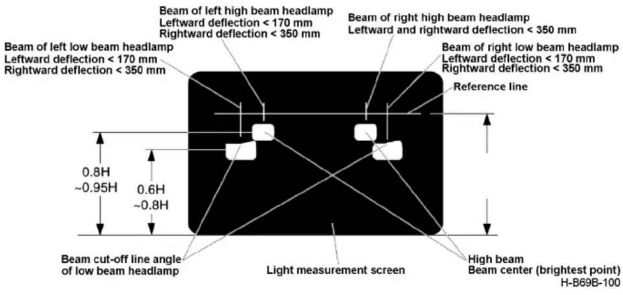
text_image
Beam of left low beam headlamp Leftward deflection < 170 mm Rightward deflection < 350 mm Beam of left high beam headlamp Leftward deflection < 170 mm Rightward deflection < 350 mm Beam of right high beam headlamp Leftward and rightward deflection < 350 mm Beam of right low beam headlamp Leftward deflection < 170 mm Rightward deflection < 350 mm Reference line 0.8H ~0.95H 0.6H ~0.8H Beam cut-off line angle of low beam headlamp Light measurement screen High beam Beam center (brightest point) H-B69B-100Auxiliary Power Starting
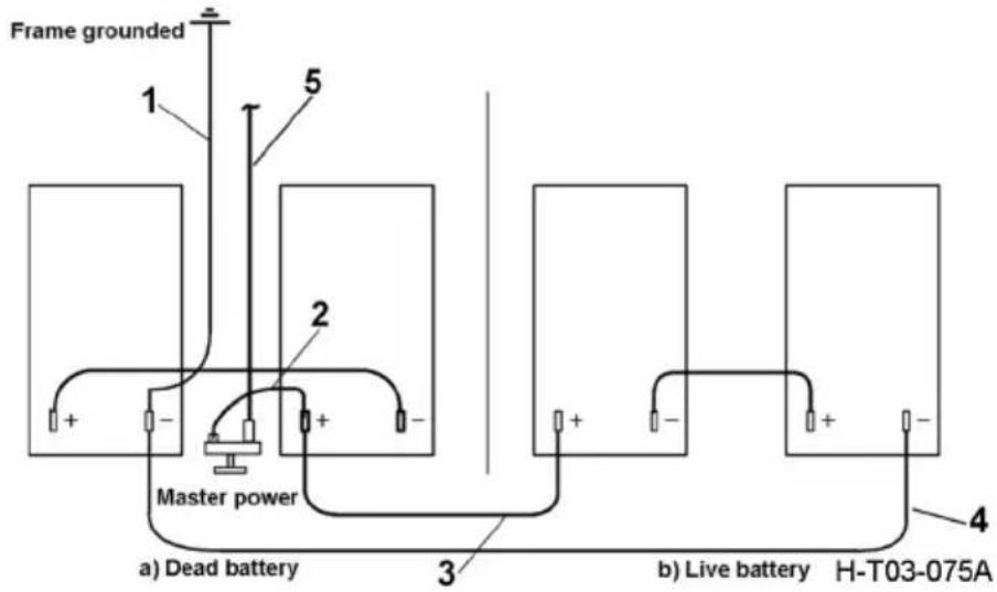
text_image
Frame grounded 1 5 2 + - Master power a) Dead battery 3 b) Live battery H-T03-075A 4- Negative power cord
- Positive power cord
- Booster cable (red)
- Booster cable (black)
- Starter power
In case the battery is discharged and the engine cannot be started, start the vehicle by auxiliary power. The connecting pr°Cedures are as follows:
- Shut down the engine of the vehicle equipped with a well charged battery.
- Connect one end of the booster cable (red) to the positive terminal of the dead battery, and the other end to the positive terminal of the live battery. Connect one end of another booster cable (black) to the negative terminal of the well charged battery, and the other end to the chassis frame of the vehicle equipped with dead battery and keep it far from the battery.
- After connecting the booster cables, start the engine of the vehicle equipped with the dead battery.
- After the engine being started, remove the cables in the pr°Cedures reverse to the wiring pr°Cedures.

CAUTION:
-
This way can be used in emergency only because it is liable to cause fuse burning of charging circuit. Under normal conditions, dismount the battery to charge it when the battery is out of power.
-
Prevent power short circuit during removal and refitting of booster cable.
3.Failing to observe the above rules in the event of auxiliary power starting may damage the vehicle electronic devices. - Do not start the vehicle with the battery of 36 V, 48 V or higher voltage in any case; otherwise, these batteries will damage electronic devices directly. The driver and service staff must observe this rule.
Maintenance of Cab Lifting Device
Please refer to the specific configuration of the purchased model..
The system adopts No. 10 aviation hydraulic oil, which is replaced once a year, and the oil is filtered by more than 200 mesh stainless steel filter net.
Under general service condition, use the cab tilting and lifting device to tilt the cab once a week at least; and under severe service condition (like cement mixer or dump truck on construction road), tilt the cab once a day at least. Under severe working conditions, it is required to clean the surface of electric pump assembly, hand pump assembly and cylinder assembly every day, especially the dirt's at vent plug O-ring, to ensure that the vent hole of vent plug in oil pump assembly is unblockedMotor overheating will cause motor burnout. Therefore, after the electric pump has been used for 3-5 times successively, thermal protection function will be activated automatically and the motor will shut down, which is not a fault. In that case, please wait until it cools down before reusing it.
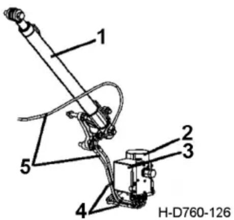
text_image
1 2 3 4 5 H-D760-126- Cylinder
- Electric pump assembly
- Hand pump assembly
- Strap assembly
- Oil pipe
Saddle maintenance
Initial maintenance
Check the Maintenance period see "Maintenance and replacement items"
Add lubricating oil and grease to the surface of saddle hook housing, wedge and arc plate of saddle in 10,000km.
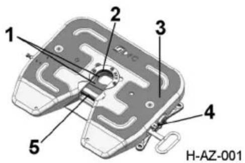
text_image
1 2 3 4 5 H-AZ-001- lock hook
- Open end cover
- Surface of shell
- Twist spring
- wedge
Maintenance interval
Check the Maintenance period see "Maintenance and replacement items"
Inspect Torque of hex bolt (measured with torque wrench, torque value: 140-160Nm).
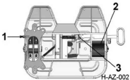
text_image
1 2 3 H-AZ-002- Adjusting screw
- Arc bearing plate
- Split pin
- Adjusting screw
- Arc bearing plate
- Split pin
Check the Maintenance period see "Maintenance and replacement items"
| Saddle No. 50# 90# | ||
| Inner surface wear limit of open end cover (mm) | 34.5~35.5 | 36.5~37.5 |
| Innerl surface wear limit dimension (mm) | 51~55 | 89~93 |
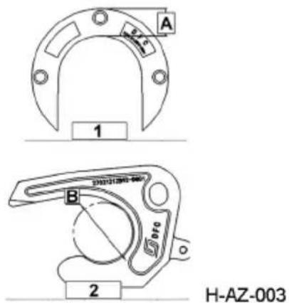
text_image
A 1 B 2 H-AZ-003
CAUTION:
The open-end cover and lock hook shall be replaced when they exceed the limit size as above.
- Open end cover
A:wear on the inner surface of the open-end cover - lock hook
B: wear amount on the inner surface of the hook
Regular Maintenance Schedule
The regular maintenance schedule of this manual is the general maintenance schedule, please refer to the specific vehicle configuration when using. Disassembly of large assembly shall be carried out as required to facilitate maintenance of the technical status of the vehicle.
This table interval is only for standard working conditions, and the maintenance interval for severe working conditions is halved.
Cummins engine maintenance plan shall be carried out in accordance with this manual. Please also refer to the cummins engine operation and maintenance manual brought with the vehicle.
Please refer to the specific configuration of the purchased model.
Inspection and Maintenance Term
This maintenance schedule shows the inspection and maintenance items and term of the first cycle; for the second cycle, the maintenance items are the same except the running-in maintenance is not required. The inspection and maintenance term is expressed in the driving mileage and/or months whichever comes first. The user should carry out the maintenance according to the maintenance parts and interval mileage or months strictly.

CAUTION:
When performing the vehicle maintenance in accordance with the specified maintenance items, the user should shorten the maintenance interval mileage and add the required maintenance items according to the vehicle functions and local operating conditions, to ensure more reasonable maintenance and better performance of your vehicle, however, the user should never extend the maintenance interval mileage.
The relevant definitions in the maintenance schedule are as follows:
- Project classification: divided into three categories.
The first category is the replacement category item.
The second category is inspection/cleaning/discharge items
The third category is lubrication items
User self-inspection items, except the first guarantee and inbound maintenance items, the daily or regular inspection, cleaning and lubrication items are user self-inspection items. Grease replenishment and replacement shall be performed at a technically qualified service station or facility.
- First guarantee: the mileage unit of maintenance is 10,000km/month, whichever comes first;
-
Inbound maintenance interval: the mileage unit of maintenance is 10,000km/month, whichever comes first;
-
User self-inspection interval: the maintenance mileage unit is 10,000km/month. First come shall prevail;
- Running maintenance: " ☆ " labeling, the new car driving 2,500\~5,000 kilometers or 1 month, whichever comes first;
Maintenance and replacement items
| Maintenance and replacement items | Running-in maintenance | The first confirmed (10,000 km/month) | Inbound maintenance interval (10,000 km/month) |
| Replace transmission oil and filter element | — | — | 24/24 |
| Replace retarder oil | — | — | 24/24 |
| Change engine oil and oil filter | — | 5/6 5/6 | |
| Replace the fuel filter | — | — | 5/6 |
| Replace coolant | — | — | 20/24 |
| Replace the fuel prefilter (oil-water separator) | — | — | 5/6 |
| Replace the filter screen at the inlet of the urea temperature level sensor(bottom of sensor) and clean urea tank | — | — | 10/12 |
| Replace the main filter element assembly of urea pump | — | — | 20/36 |
| Replace the fuel prefilter (oil-water separator) | — | — | 5/6 |
| Check and clean air filter element, if necessaryReplace (alarm light on cleaning filter element, cleaning 4 times,Replace the filter element) | — | — | 5/6 |
| Replace air dryer dryer or desiccant | — | — | 10/12(for KNORR blue can / WABCO)5/6(for KNORR black cans/others) |
| Replace steering hydraulic oil and tank filter core | ☆ | — | 5/12 |
| Replace the main drive axle reducer lubricating oil (single stage) | ☆ | — | 10/12 |
| Replace the hydraulic oil of cab lifting device | — | — | /12 |
| Replace clutch hydraulic fluid | — | — | 10/2 |
Maintenance inspection/cleaning/discharge items
Engine
| Maintenance and replacement items | Running-in maintenance | The first confirmed (10,000 km/month) | Inbound maintenance interval (10,000 km/month) |
| Charging system automatic belt tensioner for charger | — | — | 10/12 |
| Air leakage faults in the intake and exhaust systems | — | — | 5/6 |
| Check the viscous shock absorber for silicone oil loss, pits, etc | — | — | 40/48 |
| Check air compressor exhaust pipe | — | — | 40/48 |
| Check and adjust engine overhead mechanism, adjust or tighten as needed | — | — | 5/6 |
| Crankshaft pulley | — | — | 10/12 |
| Cold start auxiliary device | — | — | 10/12 |
| Check the axial clearance of belt driven fan hub bearing and adjust as needed | — | — | 40/48 |
| Check and clean cooling fan belt tensioner | — | — | 10/12 |
| Check whether the assembly torque of important parts meets the requirements (inlet manifold screw, preheater connection nut, inlet transition pipe (exhaust side) and supercharger connection clamp, exhaust manifold mounting bolt, supercharger mounting bolt, exhaust brake valve bracket connection bolt, exhaust butterfly valve connection nut) | — — | 10/12 |
Engine system
| Maintenance and replacement items | Running-in maintenance | The first confirmed (10,000 km/month) | Inbound maintenance interval (10,000 km/month) | User maintenance interval (10,000 km/month) |
| Check and tighten engine front and rear suspension bolts for looseness and tighten as required | — | — | /12 | The first and subsequent users are retightened every 10,000 kilometers for a total of 3 times. Every 6 Check monthly and retighten as needed |
| Check the height of lubricating oil level and coolant level | — | — | 5/6 weekly | |
| Check the fuel prefilter (oil-water separator) for sediment and water, and discharge regularly | — | — | /3 weekly | |
| Check whether the fan, fan flange and mounting bolts are loose and retighten as required | — | — | 5/12 | The first and subsequent users are retightened every 10,000 kilometers for a total of 3 times. Every 6 Check monthly and retighten as needed |
| Check and tighten the ring hoop of the flexible wind shield, and retighten as required (according to configuration) | — | — | /12 | |
| Clean and check the fastening condition of inlet and exhaust system, clamp, pipe and bracket, and retighten as needed | — | — | /12 | |
| Check whether there is displacement in the fuel tank and urea tank. Tighten the bolts of the fuel tank and urea tank band as required | — | — | 5/6 | Aluminum alloy oil tank: check and retighten according to the label on the oil tank. |
| Clean pest control net (according to configuration) | — | — | /12 /6 |
Engine aftertreatment system
| Maintenance and replacement items | Running-in maintenance | The first confirmed (10,000 km/month) | Inbound maintenance interval (10,000 km/month) |
| Clean the vent valve of urea tank and release the sediment of urea tank | — | — | 5/6 |
| Clean the filter screen at the filling port of urea tank | — | — | 10/12 |
| DPF soot cleaning | — | — | First cleaning: 20/Second cleaning: 18/Third cleaning: 16/The fourth time: 14/ replace DPF and cycle according to the cycle above. |
Clutch system
| Maintenance and replacement items | Running-in maintenance | The first confirmed (10,000 km/month) | Inbound maintenance interval (10,000 km/month) |
| Check the working state of clutch as required (including checking the clutch pedal for free travel) | — | — | 10/12 |
| Check the clutch hydraulic system, main pump and booster for oil leakage | — | — | 5/3 |
| Check the level of hydraulic oil in clutch storage tank | — | — | 5/3 |
Transmission
| Maintenance and replacement items | Running-in maintenance | The first confirmed (10,000 km/month) | Inbound maintenance interval (10,000 km/month) | User maintenance interval (10,000 km/month) |
| Oil level and leakage inspection | — | — | 5/3 Per month | |
| Check the outside of the transmission with the vent plug (vent tube) for cleanliness | ☆ | — | 5/12 Per month | |
Braking system
| Maintenance and replacement items | Running-in maintenance | The first confirmed (10,000 km/month) | Inbound maintenance interval (10,000 km/month) | User maintenance interval (10,000 km/month) |
| Check the brake pedal for free travel | — | — | /12 — | |
| Check running and parking brake efficiency, check and adjust brake clearance as required | ☆ | — | 5/3 2/1 | |
| Air storage tank water check, if there is water to replace the drying cylinder or desiccant | ☆ | — | 5/3 weekly | |
| Check front axle, middle and rear axle disc brakes to indicate lever travel (according to configuration) | — | — | 5/3 2/1 | |
| Check the front axle, middle and rear axle drum brake automatic adjusting arm reverse adjusting torque | — | — | 5/3 2/1 | |
| Check the wear of front axle, middle and rear axle brake drum and friction disc (drum brake) | ☆ | — | 5/3 2/1 | |
| Check clearance self-adjusting function of front axle, middle and rear axle disc brakes (according to configuration) | ☆ | — | 5/3 2/1 | |
| Check front axle, middle and rear axle disc brake brake block, brake disc wear (according to configuration) | ☆ | — | 5/3 2/1 | |
| Check front axle, middle and rear axle brake disc for cracks (according to configuration) | ☆ | — | 5/3 2/1 | |
| Check the dust cover damage of front axle, middle and rear axle disc brake (according to configuration) | ☆ | — | 5/3 2/1 | |
| Check the front axle, middle and rear axle brake clamp sliding function (according to configuration) | ☆ | — | 5/3 2/1 |
Steering system
| Maintenance and replacement items | Running-in maintenance | The first confirmed (10,000 km/month) | Inbound maintenance interval (10,000 km/month) | User maintenance interval (10,000 km/month) |
| Check the oil level of the power steering system and tighten the drain plug | — | — | — | |
| Check the fastening condition of the free travel of the steering wheel and the connecting bolts of the steering system and tighten it as required (including checking the connection condition of various parts of the steering system, the connection condition of each ball head of the steering bar, the tightness condition of steering mechanism and bracket, the tightness condition of the steering knuckle arm and the hanging arm) | ☆ | — | 10/6 — | |
| Check wheel bolt fastening and retighten as needed (fastening) | ☆ | — | 5/3 | Retighten twice before the first holding station, with an interval of 500~1000km, and retighten according to the prescribed force moment |
| Check for fastening of half shaft bolts | — | 5/3 2/ | ||
| No maintenance wheel end inspection | — | — | 10/6 — | |
| Check the tire for abnormal wear. If there is abnormal wear, check the rim (mainly visual inspection). | ☆ | — | 5/3 Per month | |
| Clean and check tire pressure | ☆ | — | — | 0.5/ |
| Tyre transposition | — | — | — | 1/ |
Suspension system
| Maintenance and replacement items | Running-in maintenance | The first confirmed (10,000 km/month) | Inbound maintenance interval (10,000 km/month) | User maintenance interval (10,000 km/month) |
| Check air suspension (including clean air spring airbags, check air spring assembly status, check system external limit block, check height sensor position if equipped) | — | — | 5/3 Per month | |
| Check and tighten all thrust rod fixing bolts for middle and rear axle (including v-type thrust rod, transverse thrust rod and lower thrust rod) | ☆ | — | 5/3 2/ | |
| Clean and check leaf spring and spring clamp for loose-ness and deformation, tighten u-bolt | ☆ | — | 5/3 | Re-tighten twice before the first guaranteed entry station, with an interval of 500~1000km, according to the regulation |
| Check and tighten the fixing balance shaft support, air suspension bracket beam, air suspension lower thrust rod support, guide arm support fastening bolts | ☆ | — | 5/3 2/ | |
| Check and tighten V push bracket, plate spring bracket, plate spring pin positioning bolt | ☆ | — | 5/3 2/ | |
| Clean and inspect guide arms, tighten guide arms with u-bolts (if equipped) | ☆ | — | 5/3 | Re-tighten twice before the first guaranteed entry station, with an interval of 500~1000km, according to the regulation |
| Fastening bolts (if equipped) at the connection between the fixed guide arm and the beam, and at the connection between the fixed guide arm and the guide arm bracket. | ☆ | 5/3 2/ |
Transmission system
| Maintenance and replacement items | Running-in maintenance | The first confirmed (10,000 km/month) | Inbound maintenance interval (10,000 km/month) | User maintenance interval (10,000 km/month) |
| Check the transmission shaft (including connection parts and cross shaft bearing is loose, there is no deviation, and the middle support of the transmission shaft is loose) | — | — | 5/3 2/ | |
| Check whether the connecting bolt of the transmission shaft is loose and tighten as required | — | — | 5/3 2/ | |
| Check whether the middle support of the transmission shaft is loose and retightened as required | — | — | 5/3 2/ |
Bridge system
| Maintenance and replacement items | Running-in maintenance | The first confirmed (10,000 km/month) | Inbound maintenance interval (10,000 km/month) | User maintenance interval (10,000 km/month) |
| Clean the drive axle vent plug or vent tube | — | — | 5/3 Per month | |
| Check the rim of the process, the wheel end of the middle and rear axle, and the main reducer assembly for oil leakage | — | — | 5/3 Per month |
Saddle
| Maintenance and replacement items | Running-in maintenance | The first confirmed (10,000 km/month) | Inbound maintenance interval (10,000 km/month) | User maintenance interval (10,000 km/month) |
| Check the fastening of the connecting bolts between the traction seat and the bottom plate and the bottom plate and the frame | ☆ | 5/3 | ||
| Check the wear of the saddle bearing shaft | ☆ | 5/3 | ||
| Check for wear of rubber bushing on saddle support shaft | ☆ | 5/3 | ||
| Check the wear of traction pin and pin shaft clamp | ☆ | — | 5/3 |
Electrical system
| Maintenance and replacement items | Running-in maintenance | The first confirmed (10,000 km/month) | Inbound maintenance interval (10,000 km/month) | User maintenance interval (10,000 km/month) |
| Check battery indicator and terminal voltage | — | — | /6 |
Cab
| Maintenance and replacement items | Running-in maintenance | The first confirmed (10,000 km/month) | Inbound maintenance interval (10,000 km/month) | User maintenance interval (10,000 km/month) |
| Check for dust accumulation in the condenser and flush properly | — | — | 5/3 — | |
| Check the air conditioning filter element and replace as needed | — | — | /3 — | |
| Check whether the wiper can be scraped clean, and replace the wiper if necessary and clean the foreign body on the glass surface | — | — | 5/3 2/ | |
| Check whether there is obvious friction between the lock and the lock body and adjust the lock position if necessary | — | — | 5/3 2/ | |
| Check whether the bridge suspension joints are loose and tighten as required | — | — | 5/3 — | |
| Check for leakage and sealing of hydraulic system | — | — | 10/12 Per month | |
| Check whether the bridge lifting cylinder and the upper and lower supports of the cylinder are connected reliably and whether the bolts are loose. Tighten them as required | — | — | 10/12 Per month | |
| Check the leakage, damage and looseness of the shock absorber in the cab (front) and rear, and replace it if necessary | — | — | 10/12 Per month | |
| Check the condition of the rubber sleeve assembly in front of cab and replace if necessary | — | — | 10/12 — | |
| Check the condition of the sus-pension spring assembly in front (rear) of the cab and replace if necessary | — | — | 10/12 — | |
| Check the brake pedal (check the pedal rubber cover for serious wear or deformation; Check the free travel of the brake pedal, the normal value is 12~18mm, can normally trigger the brake light switch; Check whether there is acerbity when the brake pedal is pressed to the end, and whether there is exhaust sound after the pedal is released; Adjust or replace in case of abnormality. | — | — | 5/12 weekly | |
| Check whether the pedal return spring state is normal | — | — | 10/12 Per month | |
| Check whether all switches in the pedal assembly are pressed properly | — | — | 10/12 Per month | |
| Check the steering wheel up and down, front and back adjustment and lock function is normal | — | — | 10/12 Per month | |
| Whether the light adjustment of the front combination lamp is in place | — | — | 10/12 — | |
| Check whether the washing liquid in the washing kettle is sufficient and replenish it if necessary | — | — | 5/3 weekly | |
| Check the air conditioning goggles to make sure the refrigerant is sufficient and refill if necessary | — | — | 5/3 Per month |
Maintenance lubrication items
| Maintenance and replacement items | Running-in maintenance | The first confirmed (10,000 km/month) | Inbound maintenance interval (10,000 km/month) | User maintenance interval (10,000 km/month) |
| Grease is added to front axle, middle and rear axle air chamber support, brake floor and brake adjusting arm | — | — | 5/3 2/1 | |
| Grease on the knuckle kingpin and steering lever | — | — | 5/3 2/ | |
| Maintenance-free wheel end lubrication | — | — | 50/36 is suitable for independent oil chamber (FAG) | — |
| — | — | Synchronous replacement with the axle gear oil, suitable for connecting the oil chamber (and the rear axle gear oil chamber) | — | |
| Maintainable hub bearing grease replacement | — | — | 5/3 Per month | |
| Before and after the plate spring pin, lifting lug pin, balance bearing hub (if there is a nozzle) grease | ☆ | — | 5/3 2/ | |
| Grease (if grease nozzle) | — | — | 5/3 2/ | |
| Grease is added to the surface of the saddle shell, the contact between the saddle and the traction pin and the lubrication hole of the support | ☆ | — | 5/3 — | |
| Saddle lock, wedge, arc bearing plate grease | — | — | 5/3 — | |
| Lubricated cab front suspension /6 | 2/ | |||
| After turning the lock mechanism in the cab, grease is added to the suspension latch | — | — | /6 2/ | |
| Front mask movement and lock teeth meshing part, spring position lubrication | — | — | 10/12 Per month |
Regular Replacement Parts
Regular replacement part means a part that must be replaced by reliable part to guarantee driving safety because its service performance will certainly decrease over time and its performance cannot be predicted to ensure safe driving during general regular servicing and inspection.
| Replacement interval (years) 1 2 3 | |||
| Rubber hose of power steering hydraulic system √ √ | √ | √ | |
| Rubber hoses of brake system √ √ √ | |||
| Rubber cup and sealing ring of brake chamber √ √ | √ | √ | |
| Rubber hose of air compressor √ √ √ | |||
| Fuel nylon hose √ | |||
| Gas metal hose √ | |||
| All oil pipes of hydraulic lifting system √ | |||
| Seals of cab lifting device √ |
Service & Adjustment Data
Engine
Please refer to the attached Operation and Maintenance Manual of Cummins Engine for relevant data.
Chassis
Please refer to the specific configurations of your vehicle.
| Free stroke of steering wheel 15° | ||
| Toe-in 1-3mm | ||
| Brake pedal free travel 12-18mm | ||
| Push rod stroke of front and rear brake chambers Manual adjuster | 20~30mm | |
| Clearance between front/rear brake shoe and brake drum (in the middle of brake shoe) | Manual adjuster 0.3~0.5mm | |
| Tensile force after adjustment of front hub bearing (at the tire nut) | 25-55N | |
| Tensile force after adjustment of rear hub bearing (at the tire nut) | 29-88N | |
| Differential bearing pre-tightening load (excluding the pre-tightening load of driving bevel gear bearing) | At driven gear bolt 68-78N | |
| Pre-tightening load of driving gear bearing (at coupling flange bolt holes for rear axle) | Excluding oil seal resistance | 20-44N |
| Including oil seal resistance 30-60N | ||
| Clearance between driving and driven gears of final drive 0.3-0.4mm | ||
| Differential gear backlash | Dongfeng 460 axle 0.25-0.33mm | |
| Dongfeng 435 axle 0.25-0.33mm | ||
| For Dongfeng 300 wheel reducer | 0.18-0.23mm | |
| Dongfeng 500 axle 0.25-0.45mm | ||
| Fore-and-aft adjustment angle range of steering wheel 32° | ||
| Upward and downward adjustment distance of steering wheel 50mm | ||
Tightening Torque
Please refer to the specific configurations of your vehicle.
Engine
Please refer to the attached Operation and Maintenance Manual of Cummins Engine for the relevant data.
Tightening torque of critical parts of chassis (applicable for D760 models) CAUTION:

This standard provides the tightening torque of critical parts of vehicles manufactured by DONGFENG COMMERCIAL VEHICLE CO., LTD. and is applicable for the critical parts' threaded fasteners for which the tightening torque is not given in the vehicle product diagram and the technical specifications.
Tightening torque of critical parts of engine mounting
| Bolted position | Thread specification | Reference tightening torque(N·m) | Remarks |
| Front and rear suspension bracket and frame fastening bolt | M14 190±15% -- | ||
| Mounting bolts between engine front/rear mounting cushion and auxiliary mounting cushion | M14 170±15% -- | ||
| M20 | 170±15% -- | ||
| Engine and front mount bracket/fly-wheel housing and rear mount bracket fastening bolts | M18 375±15% | ||
Tightening torque of critical parts of cooling and inter-cooling systems
| Bolted position | Thread specification | Reference tightening torque(N·m) | Remarks |
| Fastening bolts of fan assembly flange and engine | M08(Grade 8.8) 20-26 -- | ||
| M08(Grade 10.9) 25-30 -- | |||
| M12(Grade 8.8) 65-75 -- | |||
| M12(Grade 10.9) 90-110 -- | |||
| Fastening bolts of fan and fan buffer block | M10(Grade 8.8) 38-50 -- | ||
| M10(Grade 10.9) 45-55 -- | |||
| Fastening bolts of fan flange and fan buffer block | M12(Grade 8.8) 65-75 -- | ||
| M12(Grade 10.9) 90-110 -- | |||
| Fastening bolts of brace and engine | M12(Grade 8.8) 65-75 -- | ||
| M12(Grade 10.9) 90-110 -- | |||
| M10(Grade 8.8) 38-50 -- | |||
| Fastening bolts of brace and air spoiler | M10(Grade 10.9) 45-55 -- | ||
| M08(Grade 8.8) 20-26 -- | |||
| M08(Grade 10.9) 25-30 -- | |||
| M10(Grade 8.8) 38-50 -- | |||
| M10(Grade 10.9) 45-55 -- | |||
Tightening torque of critical parts of driveline
| Bolted position | Thread specification | Reference tightening torque(N·m) | Remarks |
| The tightening method shall refer to Specifications for Installation and Adjustment of Φ430 Pull-type Clutch Assembly and Control System. | M10 (grade 8.8) non-flange bolt | 40-60 | Connecting stud bolts of clutch pressure plate & cap assembly and engine flywheel |
| M10 (grade 10.9) non-flange bolt | 55-75 | ||
| Connecting bolts of clutch housing and flywheel housing | M10 (grade 8.8) non-flange bolt | 40-60 | Pre-tighten them cross-wise and then tighten them with torque spanner. |
| M10 (grade 10.9) non-flange bolt | 55-75 | ||
| M10 (grade 10.9) flange bolt | 55-75 | ||
| Connecting bolts of drive shaft (including connection with transmission and axle) | M14 190±15% | Pre-tighten them cross-wise and then tighten them with torque spanner (after road test, tightening torque shall not drop by more than 10%; otherwise, re-tighten them to the speci-fied torques) |
Tightening torque of critical parts of frame
| D760 First cross member | M12 90-130 | |
| M14 150-210 | ||
| M16 210-280 |
Tightening torque of critical parts of suspension system
| Bolted position | Control position | Thread specification | Reference tightening torque(N·m) | Remarks |
| Front suspension and single rear axle suspension | Subassembly of front & rear leaf spring and axle - U-bolt assembly | M18 280-350 | 1. Adopt coarse | se thread, U-bolt of grade 10.9 + flange nut of grade 10;2. Thread specifications: M18/M20 for front suspension, and M20/ M22 / M24 for single rear axle suspension3. The tightening torque of M24 is different for single rear axle suspension and balanced suspension |
| M20 380-460 | ||||
| M22 400-480 | ||||
| M24 450-540 | ||||
| Balanced suspension | M24 600-720 | |||
| M27 860-1000 | ||||
| Connection of balance shaft support and vehicle frame - fastening bolt assembly | Balanced suspension | M16X1.5 210 | -280 | Adopt fine thread, bolt of grade 10.9 + nut of grade 10 |
| M18X1.5 350 | -470 | |||
| M20X1.5 430 | -550 |
Tightening torque of critical parts of whee
|
| Bolted position Thread specification | Reference tightening torque(N·m) | Remarks | |
| Wheel bolts | 31F58-* 550-650 | Central hole locating | |
| 3103057-KD400 550-650 | |||
| 31N-* 420-490 | Spherical surface locating | ||
| 31C-*, 31Q02-* 320-420 | |||
Tightening torque of critical parts of steering system
| Bolted position Thread specification | Reference tightening torque(N·m) | |
| Steering gear and its bracket | M16 210-280 | |
| M18 320-420 | ||
| Follower bracket and follower fixing bolt | M20 380-500 | |
| M22 440-560 | ||
| Steering pitman arm /intermediate pitman arm | 34Z63-01011(M36) 400-550 | |
| 34Z61-02011(M42) 400-550 | ||
| M45 400-550 | ||
| M16 210-260 | ||
| M18 320-420 | ||
| 34N-01012(M20) 380-500 | ||
| Lever ball pin nut | All the lever ball pin nuts shall be tightened to 250-310N·m firstly, and then fitted with the split pins. Never loosen the nuts when aligning the pin holes. | |
Tightening torque of critical parts of electrical system
| Bolted position Thread specification | Reference tightening torque(N·m) | |
| Fastening bolt of SMJ connector M6 | 5.5-6.5 | |
| Alternator | M6 5.5-6.5 | |
| M8 6.4-9.6 | ||
| Starter power terminal M10 13.5-15.8 | ||
| Starter control terminal M5 2-2.5 | ||
| ECU fastening bolt M6 4.9-7.8 | ||
| Auxiliary start switch M6 6-10 | ||
| Air filter clog sensor M6 6-10 | ||
| Fuel level sensor M5 2-2.5 | ||
| Rear combination lamp M8 19-24 | ||
| Battery cover strip M8 | The double nuts are used for lock-ing; the tightening torque of the first nut is 7-9N.m, and that of the second nut is 19-24N.m | |
| Master power switch connector | M8 19-24 | |
| Chassis ground point | M8 19-24 | |
| Power wiring terminal in distribution box of chassis | M5 1.8-2.2 | |
| M6 5.5-6.5 | ||
| Fastening nut of chassis distribution box cover | M5 1.8-2.2 | |
| After-treatment unit inlet temperature sensor | M12 30 | |
| After-treatment unit outlet temperature sensor | M12 30 | |
| NOx sensor | M20 50 |
Tightening torque of critical parts of cab
| Bolted position | Thread specification | Reference tightening torque(N·m) |
| Steering wheel M20 130-150 | ||
| D760 vehicle body mounting connecting parts | M18 320-430 | |
| M16 230-290 (assembly of cab rear mounting) | ||
| M16 | 220-80(fixing bolts for left/right tilting bracket of rear mounting cross member, shock absorber lower bracket, shock absorber bellow upper pin, shock absorber bellow lower pin) | |
| M14 140-180 | ||
| M12 110-130 | ||
| M10 47-63 | ||
| Positive and negative power cable of starter | M12 24.5-27.5 | |
Tightening torque of other parts of chassis (applicable to D760 models)
| Tightening position | Tightening Torque (N.m) |
| Connecting bolts of steering gear and steering knuckle fork 30-50 | |
| Connecting stud bolts of steering upper arm and steering knuckle 280-350 | |
| Fastening nut of steering lower arm 350-450 | |
| Lock nut of steering stop bolt 80-100 | |
| Connecting nuts of steering knuckle arm and ball pin 250-310 | |
| Locking nut of steering kingpin thrust pin 24-40 | |
| Connecting nut of lower arm and ball pin | 245-340 |
| Clamp nut of tie rod | 38-42 |
| Locking bolts and nuts of steering drop arm and rocker shaft, M45 | 350-450 |
| Kingpin upper cap fixing nuts | 40-59 |
| Lock nuts of ball pin for drag link, M24 | 250-310 |
| Upper/lower fixing bolts of steering gear bracket and frame, M20 | 420-450 |
| Lower fixing bolts of steering gear bracket and frame M22 490-520 | |
| Steering wheel lock nuts | 130-150 |
| Lock bolts of front and rear shoe shafts | 72-87 |
| Fixing nuts of front air chamber | 39-59 |
| Fixing nuts of rear air chamber | 170-190 |
| Fastening nuts of front brake bottom plate 156-206 | |
| Fastening nuts of rear brake bottom plate 160-220 | |
| Disc brake and steering connecting bolts 385-415 | |
| 4.5T axle | |
| Front wheel nuts 320-420 | |
| Fastening nuts of drag link arm 280-350 | |
| Fastening nuts of left/right steering knuckle arm 350-450 | |
| Ball pin nuts 180-250 | |
| Nuts of tie rod clamp bolts 50-60 | |
| Kingpin plug screw 40-60 | |
| Wedge-shaped lock pin nuts 55-70 | |
| Steering stop bolts and nuts 80-100 | |
| Fastening bolts of brake bottom plate 160-220 | |
| Fastening nuts of shoe shaft 130-170 | |
| Fixing nuts of air chamber bracket 55-70 | |
| Dongfeng 435 rear axle | |
| Fastening bolt of axle shaft | 140-180 |
| Fastening bolts of bearing cap of drive gear of rear axle | 120-140 |
| Fastening bolts of differential housing for rear axle | 220-280 |
| Fastening bolts of differential bearing cap | 440-490 |
| Fastening bolts of final drive driven gear and differential housing | 600-700 |
| Fixing bolts of final drive housing for rear axle | 130-150 |
| Locking nuts of drive gear flange yoke of final drive of rear axle | 400-540 |
| Fastening bolts of reducer housing of center axle | 130-150 |
| Cylindrical drive gear bearing seat | 80-90 |
| Bolts of cylindrical gear housing of center axle | 80-90 |
| Bearing seat bolts of driving bevel gear for center axle | 120-140 |
| Bolts of oil seal casing of center axle | 30-50 |
| Bolts of bearing cap of center axle | 450-500 |
| Nuts of driving bevel gear of center axle | 650-850 |
| Nuts of through shaft for center axle | 400-500 |
| Nuts of bogie differential housing of center axle | 120-140 |
| Nuts of bogie differential housing cover of center axle | 80-90 |
| Drain plug of bogie differential housing cover of center axle | 90-120 |
| Bolts of oil level hole of differential housing for center axle | 90-120 |
| Bolts of oil seal seat of output end of center axle | 60-70 |
| Fastening nuts of idler shaft of center axle | 350-400 |
| Fastening bolts of front flange yoke of center axle 120-140 | |
| Fastening bolts of oil seal seat of bogie differential of center axle 30-50 | |
| Dongfeng 460 rear axle | |
| Screw plug for checking lubricating oil level of final drive M24X2 130-195 | |
| Drain plug of rear axle housing, Z1/2 60-80 | |
| Fastening bolts of rear brake bottom plate, M16 X 1.5 230-265 | |
| Axle shaft bolts, M16 X 1.5 140-234 | |
| Fastening bolts of driving bevel gear bearing seat of rear axle, M16X1.5 214-252 | |
| Fastening bolts of differential housing for rear axle, M18X1.5 350-450 | |
| Fastening bolts of differential bearing cap for rear axle M24X2 500-550 | |
| Fastening bolts of driven bevel gear and differential of final drive, M24X1.5 750-850 | |
| Fastening bolt of final drive housing of rear axle, M14X1.5 200-235 | |
| Locking bolt of driving bevel gear flange yoke of rear axle, M45X2 600-700 | |
| Fastening bolt of final drive of center axle, M14X1.5 200-235 | |
| Bolts of cylindrical drive gear bearing seat, M12X1.25 94-114 | |
| Bolts of cylindrical gear housing, M14X1.5 | 160-204 |
| Bearing seat bolts of driving bevel gear for center axle M14X1.5 160-204 | |
| Bolts of (inter-wheel) differential bearing cap of center axle, M24X2 | 500-550 |
| Large nuts of driving bevel gear of center axle, M45X2 | 600-700 |
| Large nut of through shaft of center axle, M42X2 | 650-800 |
| Bolts of bogie differential housing of center axle, M14X1.5 160-204 | |
| Bolts of bogie differential housing of center axle, M14X1.5 160-204 | |
| Filler and drain plugs of bogie differential housing of center axle, M24X2 | 130-195 |
| Bolts of oil level hole of center axle reducer, M24X2 | 130-195 |
| Bolts of oil seal seat at output end of center axle, M14X1.5 | 130-195 |
| Fastening nuts of front flange yoke of center axle, M45X2 | 600-700 |
| Fastening bolts of oil seal seat of bogie differential of center axle M14X1.5 | 160-204 |
| bolts of bogie differential lock case, M10X1.25 | 19-21 |
| Dongfeng 500 rear axle | |
| Screw plug for checking lubricating oil level of final drive, M24X2 | 130-150 |
| Drain plug of rear axle housing, Z1/2 | 130-150 |
| Fastening bolts of rear brake bottom plate, M16 X 1.5 230-265 | |
| Axle shaft bolts, M18 X 1.5 220-260 | |
| Fastening bolts of driving bevel gear bearing seat of rear axle, M14X1.5 214-252 | |
| Fastening bolts of differential housing for rear axle, M18X1.5 350-450 | |
| Fastening bolts of differential bearing cap for rear axle M24X2 500-550 | |
| Fastening bolts of driven bevel gear and differential of final drive, M24X1.5 750-880 | |
| Fastening bolt of final drive housing of rear axle, M14X1.5 200-235 | |
| Locking bolt of driving bevel gear flange yoke of rear axle, M45X2 600-740 | |
| Dongfeng wheel reduction axle | |
| Connecting bolts of Dongfeng wheel-side rear axle final drive | |
| Connecting bolts of bearing seat, M14X1.5-6g 200-235 | |
| Connecting bolts of inter-wheel differential housing, M14X1.5-6g 200-235 | |
| Connecting bolts of Dongfeng wheel-side center axle final drive | |
| Connecting bolts of cylindrical gear housing and reducer housing, M14X1.5-6g | 200-235 |
| Connecting bolts of bogie differential housing and cylindrical gear housing, M12X1.25-6g | 120-150 |
| Input end oil seal seat, M165X1.25-6h 450-600 | |
| Connecting bolts of bogie differential housing, M14X1.5-6g 200-235 | |
| Connecting bolts of Dongfeng wheel-side axle assembly | |
| Connecting bolts of reducer assembly and axle housing, M14X1.5-6g 200-235 | |
| Connecting bolts of brake bottom plate and axle housing, M16X1.5-6g 290-330 | |
| Connecting bolts of frame assembly and end cap assembly, M10-6g 37-75 | |
| Connecting bolts of air chamber (cam) bracket, M14X1.5-6g 200-235 | |
| Connecting bolts at both ends of upper thrust bar support, M16X1.5-6g 290-330 | |
| Center connecting bolts of upper thrust bar support, M20X1.5-6g 500-590 | |
| Oil seal seat at output end of center axle, M114X1.5-6g 350-400 | |
| Hande wheel reduction axle | |
| Input flange nuts of rear axle | 750-800 |
| Input/output flange nuts of center axle | 750-800 |
| Fastening nuts of differential housing of center &rear axle | 195 |
| Fastening bolts of differential bearing cap | 200-230 |
| Bearing seat bolts of driving bevel gear | 110-135 |
| Self-locking nuts for fastening final drive assembly | 105-115 |
| Left bolts of camshaft | 130-150 |
| Connecting bolts of brake bottom plate | 290-310 |
| Round nuts of axle head | 300-400 |
| Tightening bolts of wheel-side end cover | 49-60 |
| Fixing bolts of air chamber bracket | 600-620 |
| Spring slide bolts | 570 |
| Fastening bolts of differential and conical driven gear of centre/rear axle | 315-340 |
| Fixing nuts of shock absorber and upper bracket | 88-118 |
| Fastening nuts of shock absorber and lower pin | 134-167 |
| Fixing nuts of shock absorber lower pin and bracket 134-167 | |
| Locking bolts of leaf spring pin 54-69 | |
| Center bolts of rear leaf spring 170-200 | |
| Fastening bolts and nuts of trunnion bracket and vehicle frame 220-280 | |
| Safety bolts of fifth wheel friction ring 220-280 | |
Bulb
Please refer to the specific configurations of your vehicle.
| Position Model | ||
| Front combination lamp | High beam H7 70W | |
| Low beam H7 70W | ||
| Front turn signal lamp P21W | ||
| Front position lamp W5W | ||
| Auxiliary high beam H7 70W | ||
| Front fog lamp H3 (70W) | ||
| Side turn signal lamp P21W | ||
| Step lamp W5W | ||
| End-outline marker lamp LED | ||
| Marker lamp | LED | |
| Cab dome lamp | LED | |
| Front reading lamp | C5W | |
| Side reading lamp | R10W | |
| Berth reading lamp | R10W | |
| Instrument cluster | Alarm indicator lamp | LED |
| Instrument illuminating lamp | LED | |
| Rear combination lamp | Rear end-outline marker lamp | LED |
| Turn signal lamp | LED | |
| Brake lamp | LED | |
| License plate lamp | LED | |
| Position lamp | LED | |
| Rear fog lamp | LED | |
| Reversing lamp | LED | |
| Side marker lamp | LED | |
| Side marker lamp | LED | |
| Maintenance lamp | LED | |
Capacity Data
Please refer to the specific configuration of your vehicle.
| Oiled position Designation of grease Filling volume (L) | ||
| Cummins ISZ engine (sump capacity) | API or CES20086 CK - 4Or ACEAE6 and E9 | 39.5 |
| Fuel tank | EN590:2013+A1: 2017(E) | Main 550/ sub 550 |
| Transmission ZF TE-ML 02L/02E | 23.5 (ZF AMT) | |
| Clutch system | Brake fluid conforming to DOT 3 and above | |
| (Middle)Rear axle SAE | J2360API or GL - 5 | For Dongfeng 485 single wheel reduction axle, final drive 18(FAG free-maintenance hub);Final drive 18(each 1 for two wheel sides, 20 in total)(Conmet free-maintenance hub,Maintainable hub)(reference value, the actual value shall be subject to the lower edge of the observation hole added to the oil surface) |
| Power steering gear | Dexron III and aboveAutomatic transmission oil | 4.5 |
| Clutch system | DFCV-B30 clutch system brake fluidQC/T670-2000 standard | 1.0 |
| Cooling system | ASTMD 6210Standard for heavy duty engine coolants for ethylene glycol and propylene glycol | 79.3 (with retarder)55.5 (without retarder) |
| Urea tank | Urea to ISO 22241-1 or DIN70070 | 45 |
| AC R1234yf | 755±15g | |
| Grease | NLGI gc-lb grease of consistency 2 or 3 | |
| Cab tilting oil pump | HV hydraulic oil in accordance with ISO11158 standard | 1.5 |
Designation and service environment of oil, grease and fluid recommended by Dongfeng Commercial Vehicle Co., Ltd
| Oil product brand and the fill-ing position | Product brand | Applicable ambient temperature | |
| Engine Cummins Engine | API or CES20086 CK - 4 Or ACEAE6 and E9 | -25°C~40°C | |
| Fuel tank | 5# ≥8°C | ||
| 0# ≥4°C | |||
| -10# ≥-5°C | |||
| -20# ≥-14°C | |||
| -35# ≥-29°C | |||
| -50# ≥ -44°C | |||
| Transmission (ZF/AMT) | ZF TE-ML 02L/02E | ≥-20°C | |
| Drive axle SAE J2360API or GL - 5 | ≥-20°C | ||
| Power steering | Dexron III / V / VI Automatic transmission oil | ≥-30°C | |
| Clutch | Brake fluid conforming to DOT 3 and above | ≥-30°C | |
| Chassis and wheel hub | NLGI gc-lb grease of consis-tency 2 or 3 | ≥-30°C | |
| Cooling fluid | ASTMD 6210 Standard for heavy duty engine coolants for ethylene glycol and propylene glycol | ≥-40°C | |
| Tilting lifter | HV hydraulic oil in accordance with ISO11158 standard | ≥-30°C | |
| SCR post-processing system | ISO 22241-1: 2006、DIN70070:2005 | ≥-11°C | |

CAUTION:
-
Cummins engine oil refilling please refer to the cummins engine operation and maintenance manual accompanying the vehicle.
-
Vehicle urea solution should meet the ISO 22241-1 or DIN70070; The product should be stored in a sealed chamber at the recommended temperature of -5^ 30^ .
Oil Products and Grease
Engine lubricating oil (Cummins)
Please select the oil specified by our company based on local climate and take care of the oil change mileage. Please refer to the attached Operation and Maintenance Manual of Cummins Engine.
Designated products Genuine Dongfeng spare parts Dongfeng Commercial Vehicle Co., Ltd. (Special oil for Dongfeng vehicles)
Power steering lubricating oil
use DFCV-S11 power steering lubricating oil
Designated products Genuine Dongfeng spare parts Dongfeng Commercial Vehicle Co., Ltd. (Special oil for Dongfeng vehicles)
Transmission lubricating oil
Users can choose the transmission oil of different viscosity grades according to the local atmospheric temperature.
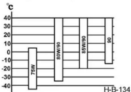
bar
| Category | Value (°C) | |---|---| | 75W | 5 | | 80W/90 | -35 | | 85W/90 | -25 | | 90 | -15 | H-B-134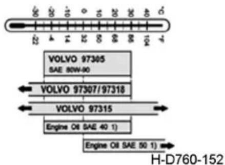
text_image
VOLVO 97305 SAE 80W-90 VOLVO 97307/97318 VOLVO 97315 Engine O8 SAE 40 1) Engine O8 SAE 50 1) H-D760-152Designated products Genuine Dongfeng spare parts Dongfeng Commercial Vehicle Co., Ltd. (Special oil for Dongfeng vehicles)
Fuel
Only use the automobile diesel fuel conforming to national standards, and the user can choose diesel fuel of different grades according to the local atmospheric temperature.
Recommended operating temperature range:
| Fuel designation 5# 0# -10# -20# -35# -50# | |||||
| Applicable ambient temperature (atmospheric temperature) | ≥8°C | ≥4°C | ≥-5°C | ≥-14°C | ≥-29°C |
Oil of cab lifting device
The oil pump use No. 10 aviation hydraulic oil.
(Middle) rear axle lubricating oil
User can select gear oil different viscosity grades based on the local atmospheric temperature.
Designated products Genuine Dongfeng spare parts Dongfeng Commercial Vehicle Co., Ltd. (Special oil for Dongfeng vehicles)
Grease
It is recommended to use lithium base grease for hubs and points to be lubricated. NLGI gc-lb grease of consistency 2 or 3
Designated products Genuine Dongfeng spare parts Dongfeng Commercial Vehicle Co., Ltd. (Special oil for Dongfeng vehicles)
Clutch brake fluid
Brake fluid conforming to DOT 3 and above
Designated products Genuine Dongfeng spare parts Dongfeng Commercial Vehicle Co., Ltd. (Special oil for Dongfeng vehicles)

WARNING:
-
Mixing of brake fluids produced by different manufacturers is prohibited strictly.
-
Mixing of brake fluids of different types from the same manufacturer is also prohibited strictly.
Retarder oil (Shaanchi)
The recommended selection of retarder oil is as follows:
| Environment temperature / °C Oil type | |
| >-25 | 10W40 |
| <-25 | 0W40 or 5W40 |
Engine coolant (Cummins)
Always apply the DF-4 (D+)organic acid type heavy duty coolant. Change the fluid every 2 years or 200,000 km (running time or mileage, whichever comes first). The engine cylinder liner will be cavitated seriously and thereafter the engine will be damaged if specified coolant is not used or the coolant used is blended with other coolants.
| Specification of antifreeze and antirust fluid -20# | -40# | |
| Min. applicable ambient temperature -20°C | -40°C |

WARNING:
The freezing point of anti-freeze liquid used in extremely cold regions shall be 10^ C lower than the local minimum ambient temperature.
Do not mix anti-freeze or anti-rust liquid of different grades.
Technical Parameters
Mass Parameters
| Mass parameters (kg) DFH4180 | ||
| No load | Curb weight | 8270 |
| Axle load | 5200/3070 | |
| Full load | Total mass | 18000 |
| Axle load | 6500/1150 | |
| Saddle loading mass | 9600 | |
| Allowable trailer towing mass | 33600 | |
Dimension Parameters
| Dimension parameters (mm) DFH4180 | ||
| Total length | 6360 | |
| Total width | 2524 | |
| Total height | 3960 | |
| Wheelbase | 3800 | |
| Tread | Front wheel | 2010 |
| Rear wheel | 1880 | |
| Overhang | Front overhang | 1480 |
| Rear overhang | 1080 | |
Performance Parameters
| Performance Parameters DFH4180 | |
| Drive mode 4 × 2 | |
| Max. vehicle speed (km/h) 89 | |
| Max. gradability (%) ≥ 30 | |
| Parking slope (%) ≥ 18 | |
| Approach angle (°) | 13 |
| Departure angle (°) | 15 |
| Min. ground clearance (mm) | 168 |
| Min. turning diameter (m) 16 | |
| Vehicle start pressure (kPa) 590 ± 30 | |
| Rated working pressure of air storage cylinder (kPa) | Front air storage cylinder: 1250Rear air storage cylinder: 1250Parking air storage cylinder: 850 |
| Step on the brake pedal to the most unfavorable brake air chamber response time A (s) | 0.5 |
| Response time B (s) at the end of the air pressure control pipe joint between the brake pedal and the main hanger | 0.4 |

CAUTION:
-
Curb weight of a vehicle includes the weights of lubricating oil, coolant, fuel, spare wheel and driver's tools.
-
Total weight of full-loaded truck includes the mass of 3 persons in the cab (195 kg).
-
The minimum turning diameter of vehicle is measured from the center of front external wheel track.
-
The front wheel tread is measured from the front wheel ground contact centers and the rear wheel tread is measured from the twin tires centers.
-
The minimum ground clearance refers to the ground clearance of rear axle under full load.
-
The total height is measured, under no load, from the compartment front bumper for complete vehicle and from the highest point of cab roof for chassis.
-
Maximum climbing slope refers to the climbing ability of a bicycle or a full load.
-
The vehicle can be equipped with a speed limit function. When this function is in effect, the maximum speed of the vehicle will be limited to no more than the preset speed.
Parts not included in the vehicle's overall dimensions
| Name Location | |
| External rearview mirror and lower view mirror Two sides of cab | |

natural_image
Front view of a white semi-truck cab with front headlights and grille (no visible text or symbols)H-QYC-001
- External rearview mirror and lower view mirror
Assembly Structure
Please refer to the specific configuration of your vehicle.
Engine
| Manufacturer Dongfeng Cummins E | Engine Co., Ltd. |
| Type | Liquid-cooled, in-line, six-cylinder, supercharged medium - cooled diesel engines |
| Type of fuel injection High pressure | common rail |
| Model Z14EVID520 | |
| Maximum net power/speed(kW/r/min) | 381/1800 |
| Max. torque/speed(N·m/r/min) 2470/1100 | |
| Cylinder bore × stroke(mm × mm) | 135× 157 |
| Displacement (L) | 13.48 |
| Compression ratio | (18.4 ± 0.5):1 |
| Ignition sequence 1-5-3-6-2-4 | |
| Fuel (In accordance with EN590:2013 + A1:2017 (E) standard): Summer: 0# automobile diesel fuel; winter: acceptable automobile diesel fuel according to ambient temperature | |
Clutch
Φ430 mm pull-type diaphragm spring clutch, hydraulic control with air booster.
Transmission
Assemble ZF12 manual automatic AMT transmission;
Propeller Shaft
Open-type, cardan universal joint propeller shaft.
Front Axle
Forged steel part, I-shaped section.
| Front wheel alignment angle | Front wheel camber 1° | |
| Kingpin inclination angle 7° | ||
| Kingpin caster angle 3° | ||
| Max. turning angle of front wheel | Internal wheel 42° | |
| External wheel 34° |
Rear axle
Dongfeng 485 axle, stamping welding axle housing, single level reduction. Final drive ratio is2.69.
Rated load of rear axle is 13T.
Wheels and Tires
11 tires for each vehicle, including 1 spare tire.
Rim: 9.00X22.5;
Tire model: 315/70R22.5.
Frame
Stamping riveting structure, the maximum longitudinal beam section size is 280mm × 80mm × 8 + 4mm .
The front width of the frame is 1080mm and the rear width is 850mm.
Suspension
Front suspension: few leaf spring, leaf spring suspension, 3 or 2 PCS of front spring in total.
Rear suspension: complete air suspension or balanced suspension, 4 PCS in total.
Steering System
Power steering system, integral power steering gear, vane steering hydraulic pump.
Brake System
a). Main components: air compressor, air reservoir. Valves: foot brake valve, manual brake valve, trailer control valve, APU, air dryer, differential valve set, quick release valve, exhaust brake valve, pipe connector set (including one-way valve), trailer valve, ABS solenoid valve and fast connection-plug, etc.
b). Driving brake: adopt four-circuit, pendant brake valve and disc wheel brake.
c). Parking brake: the manual valve controlled spring brake air chamber and acts on the driving wheel.
d). Auxiliary brake: butterfly valve electric-pneumatic operated engine braking.
e). Trailer braking: the trailer manual brake valve controls the trailer brake separately.
Electrical System
24 V circuit system is applied. Negative ground.
Main electric equipment and instrument parameters
| Battery | 12V 180A·h (2 pcs)12V 200A·h (2 pcs) |
| Alternator | 28 V,80 A |
| Starter | 24V,8.5kW |
Instruments: Speedometer, tachometer, water temperature gauge, fuel gauge, urea gauge and air pressure gauges.
Lamps: front combination lamp, front fog lamp, rear combination lamp, side turn signal lamp, front end-outline marker lamp, etc.
Indoor lamps: roof lamp, front reading lamp, side reading lamp, sleeper reading lamp, etc.
Indicator and warning lamp: Refer to the specific configuration of cab.
Switches: Refer to the specific configuration of cab.
Cab
The high roof cab is of tiltable cab-over-engine type, adopting hydraulic tilting mechanism. It has a three-stage boarding step. In the front row inside the cab are the driver's seat, central storage box and passenger's seat. The driver's seat is a airbag sh°Ck-absorbing seat, backrest angle of which allows front and back adjustment. The passenger's seat also allows front and back adjustment of backrest angle. The rear row is provided with double berth: the dimension of lower berth is 2140mm × 730mm, the dimension of upper berth is 1950mm × 690mm. The cab is also equipped with heat insulation carpet, storage box, tray table, cup holder, cigar lighter, radio & CD
player, sun visor, coat hook and curtain rail. Both doors are equipped with lock and window regulator while window door glass can be lifted or lowered. It is equipped with tiltable face shield, side spoiler, roof deflector and bumper. The front windshield is equipped with electric wiper and washer; there are exterior rear-view mirror, front lower-view mirror, close-proximity exterior rearview mirror and wide-angle lens outside the door.
Heater and A/C
The cab is equipped with heater and A/C. An environment-friendly fluoride-free A/C system is used as the cab cooling system, which applies R134a as refrigerant.
Traction pin
Standard size 50, select 90 towing pin.
Driver's Tool
Each vehicle is equipped with one set of driver's tools.
Electrical Schematic Diagram
The electrical schematic diagram attached in this manual is a general electrical schematic diagram. Refer to the specific configuration when using it.