 — Automotive — Mode d'emploi PDF")
Zoe (2020) - Automotive RENAULT - Free user manual and instructions
Find the device manual for free Zoe (2020) RENAULT in PDF.

| Type of product | Electric vehicle (automobile) |
| Brand | Renault |
| Model | Zoe (2020) |
| Dimensions (length x width x height) | 4.087 m x 1.730 m x 1.562 m |
| Wheelbase | 2.588 m |
| Kerb weight | Approx. 1500 kg |
| Maximum authorised mass (MAM) | Varies, see vehicle identification plate |
| Traction battery voltage | 400 V |
| Secondary battery voltage | 12 V |
| Charging cord types | Standard (cord A) and occasional (cord B) for domestic or wall socket |
| Main functions | Electric propulsion, regenerative braking, programmable charging, remote air conditioning activation |
| Driving mode | Automatic transmission, ECO mode available |
| Safety systems | Airbags (front, side, anti-submarining), pretensioners, ISOFIX, ABS, ESP |
| Child safety | Rear-facing child seat allowed only with passenger airbag deactivated |
| Key system | RENAULT card with hands-free and remote control functions |
| Maintenance intervals | Refer to service sheets in manual; check brake fluid, coolant, 12V battery |
| Replacement parts | Original parts from authorised dealer recommended |
| Warranty | Anti-corrosion check required to maintain warranty |
| User manual pages | 224 pages in English |
Frequently Asked Questions - Zoe (2020) RENAULT
User questions about Zoe (2020) RENAULT
0 question about this device. Answer the ones you know or ask your own.
Ask a new question about this device
Download the instructions for your Automotive in PDF format for free! Find your manual Zoe (2020) - RENAULT and take your electronic device back in hand. On this page are published all the documents necessary for the use of your device. Zoe (2020) by RENAULT.
USER MANUAL Zoe (2020) RENAULT
natural_image
Blue ZOE electric car driving on a curved road with green hills and a city skyline in the background (no visible text or symbols)Renault ZOE
Vehicle user manual

RENAULT
Welcome to your new electric vehicle
This driver's handbook contains the information necessary:
- for you to familiarise yourself with your vehicle, to use it to its best advantage and to benefit fully from the all the functions and the technical developments it incorporates.
- to ensure that it always gives the best performance by following the simple, but comprehensive advice concerning regular maintenance.
- to enable you to deal quickly with minor faults not requiring specialist attention.
It is well worth taking a few minutes to read this handbook to familiarise yourself with the information and guidelines it contains about the vehicle and its functions and new features. If certain points are still unclear, our Network technicians will be only too pleased to provide you with any additional information.
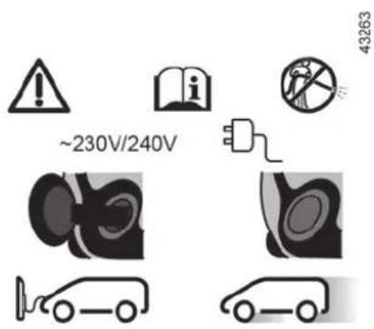
To help you, you will find the following symbols:
visible in the vehicle, indicate that you should consult the manual for detailed information and/or limits on opera-
tions with respect to your vehicle's equipment.

anywhere in the manual indicates a hazard, danger or a safety recommendation.
The descriptions of the models given in this handbook are based on the technical specifications at the time of writing. This handbook covers all items of equipment (both standard and optional) available for these models but whether or not these are fitted to the vehicle depends on the version, options selected and the country where the vehicle is sold.
This handbook may also contain information about items of equipment to be introduced later in the model year.
Enjoy driving your new vehicle.
Translated from French. Copying or translation, in part or in full, is forbidden unless prior written permission has been obtained from the vehicle manufacturer.
CONTENTS
Sections
Getting to know your vehicle ....
1
Driving
2
Your comfort ....
3
Maintenance
4
Practical advice ....
5
Technical specifications ....
6
Alphabetical index
7
Section 1: Getting to know your vehicle
Electric vehicle: introduction 1.2
Important recommendations 1.7
Electric vehicle: charging.... 1.8
programming 1.17
RENAULT card: general information, use, deadlocking 1.19
Doors.... 1.28
Locking, unlocking the opening elements 1.30
Automatic locking when driving 1.32
Front seat 1.33
Seat belts. 1.34
Methods of restraint in addition to the child seat belts. 1.38
to the rear seat belts 1.42
side protection 1.43
Child safety: General information 1.45
choosing a child seat mounting 1.48
fitting a child seat 1.50
deactivating, activating the front passenger airbag 1.56
Steering wheel/Power-assisted steering 1.59
Driving position 1.60
Warning lights 1.64
Displays and indicators 1.67
Trip computer 1.69
Clock and outdoor temperature.... 1.77
Rear view mirrors 1.79
Audible and visual signals 1.80
Pedestrian horn.... 1.81
Exterior lighting and signals.... 1.82
Headlight beam adjustment.... 1.85
Washers, wipers 1.86
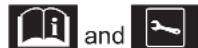
ELECTRIC VEHICLE: introduction (1/5)
35774
1 Electric charging connection
2 Electric motor
3 Secondary 12V battery
4 400 V traction battery
5 Orange electrical power cables
ELECTRIC VEHICLE: introduction (2/5)
Electric vehicles have special features, but operate in a similar manner to conventional vehicles.
The main difference in electric vehicles is the exclusive use of electric energy instead of fuel, as used in convention vehicles.
We therefore recommend that you read these instructions describing your electric vehicle carefully.
flowchart
graph TD
    A["①"] --> B["②"]
    B --> C["③"]
    C --> D["③"]
    D --> E["③"]
    style A fill:#f9f,stroke:#333
    style B fill:#ccf,stroke:#333
    style C fill:#cfc,stroke:#333
    style D fill:#fcc,stroke:#333
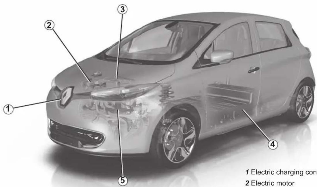
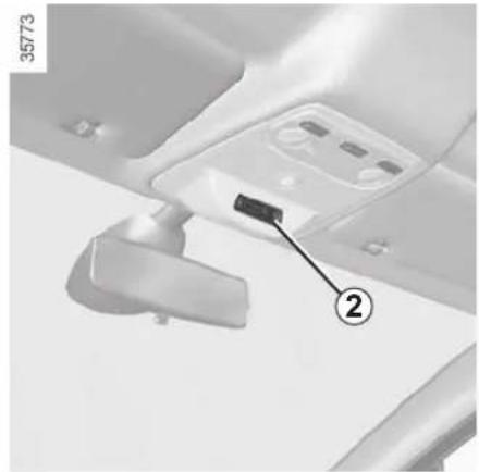
Connected services
(depending on vehicle)
Your electric vehicle has connected services that provide information and/or control:
- your vehicle's charging status;
- the traction battery charging programming, based on certain choices on offer;
- air-conditioning remote programming (please see the information on "Air-conditioning: remote activation" in Section 3);
- ...
You can access these services by:
- digital devices (mobile telephones 2, your computer 3, etc);
- multimedia display 1.
For further information, please contact an authorised dealer.
You can subscribe to a connected service or extend it at any time by consulting an authorised dealer.
ELECTRIC VEHICLE: introduction (3/5)
Batteries
Your electric vehicle has two types of battery:
- a 400V traction battery;
– secondary 12 V battery.
400 V traction battery
This battery stores the energy necessary to operate the motor in your electric vehicle properly. As with any battery, it discharges after use, and must be regularly recharged.
You do not have to wait until the traction battery hits the reserve level in order to recharge it.
Charging times vary depending on the type of specific wall unit socket or public terminal you connect to.
Your vehicle range will depend on the charge level of the traction battery, and also on your driving style.
Please refer to information on "Vehicle range: recommendations" in Section 2.
Secondary 12V battery
The second battery on your vehicle is a secondary 12 V battery: this supplies the energy required to operate vehicle equipment (lights, windscreen wipers, ABS, etc).
ELECTRIC VEHICLE: introduction (4/5)
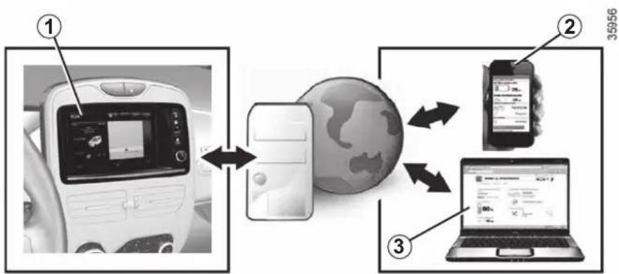
A
The A symbol denotes the electrical elements of your vehicle which may present health risks.
33436
natural_image
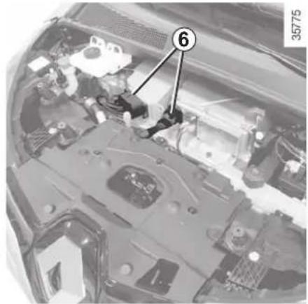
Close-up of a car's engine bay with numbered component (6), no visible text or symbols beyond the number and label400 volt electrical circuit
The 400 V electrical circuit is denoted by orange cables 6 and parts bearing the Ⓗ symbol.

The vehicle drive system in an electric vehicle uses a direct voltage of approximately 400 volts. This
system can get hot during and after switching off the ignition. Respect warning messages given on the labels in the vehicle.
All interventions or modifications to the 400V electrical system (components, cables, connectors, traction battery) are strictly prohibited due to the risks they present to your safety. Please contact an authorised dealer.
The risk of serious burns or electric shocks can lead to death.
ELECTRIC VEHICLE: introduction (5/5)
Driving
As with a car with an automatic gearbox, you will have to get used to not using your left foot, and not using this foot to brake.
When driving, if you lift your foot off the accelerator pedal or depress the brake pedal, the motor generates electrical current during deceleration, and this energy is used to brake the vehicle and recharge the traction battery. Please refer to the information on the "Charge meter" in Section 2.
Special feature:
After a maximum charge of the battery and during the first few miles of using the vehicle, the engine brake will be temporarily reduced. Please adapt your driving style appropriately.

The engine brake should under no circumstances be used as a substitute for the brake pedal.
Bad weather, flooded roads:
Do not drive through floods if the depth of water is above the lower edge of the wheel rims

Obstructions to the driver
On the driver's side, only use mats suitable for the vehicle, attached with the pre-fitted components, and check the fitting regularly. Do not lay one mat on top of another.
There is a risk of wedging the pedals

Your electric vehicle is silent, so when you get out, place the gear selector on P, engage the handbrake tch off the ignition.
RISK OF SERIOUS INJURY
Noise
Electric vehicles are particularly quiet. You will not yet necessarily be used to it, and neither will other road users. It is difficult for them to hear the vehicle when it is moving.
We would therefore recommend that you are aware of the horn and make use of it, especially when driving in a built-up area or when manoeuvring.
Please refer to the information on the "Pedestrian horn" in Section 1.
As the motor is silent, you will hear noises that you are not used to hearing (aerodynamic noises, tyre noise, etc.)
When charging, the vehicle may emit noises (fan, relays, etc).
When the vehicle is stopped, the heating system may start automatically for self-maintenance.
IMPORTANT RECOMMENDATIONS

Please read these instructions carefully. Failure to follow these instructions may lead to a risk of fire, serious injury or electric shock which may present a risk to life.
In the event of an accident or impact
In the event of an accident or an impact to the underside of the vehicle (e.g.: striking a post, raised kerb or other street furniture), this may damage the electric circuit or the traction battery.
Have the vehicle checked by an authorised dealer.
Never touch the "400 volt" components or orange cables which are exposed and visible inside or outside the vehicle.
In the event of serious damage to the traction battery, leaks may occur:
– never touch the liquids (fluids, etc.) coming from the traction battery;
– in the event of contact with the body, wash the affected area with plenty of water and consult a doctor as soon as possible.
In the event of an impact, even slight, against the charging flap and/or valve, have them checked by an authorised dealer as soon as possible.
In the event of fire
In the event of fire, make everyone evacuate the vehicle immediately and contact the emergency services, informing them that this is an electric vehicle.
Only use extinguishing agents ABC or BC that are permitted for use with electrical fires. Do not use water or other extinguishing agents.
In the event of damage to the electrical circuit, please call an authorised dealer.
All towing operations
Please refer to the information on "Towing, breakdowns" in Section 5.
Washing the vehicle
Never wash the engine compartment, the charging connection or the traction battery with a high-pressure jet.
This risks damaging the electric circuit.
Never wash the vehicle while it is charging.
Risk of electric shock and a risk to life.
ELECTRIC VEHICLE: charging (1/9)
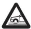
Charging schematic diagram
1 Electric charging connection
2 Charging cord
3 Specific wall socket or recharging terminal
If you have any questions regarding the equipment needed for charging, please ask an authorised dealer.
ELECTRIC VEHICLE: charging (2/9)

Important recommendations for charging your vehicle
Please read these instructions carefully. Failure to follow these instructions may lead to a risk of fire, serious injury or electric shocks which could result in death.
Charging
Do not do anything to the vehicle during charging (washing, working in the engine compartment, etc.).
In the event of the presence of water, signs of corrosion or foreign bodies in the charging cord connector or in the vehicle charging socket, do not charge the vehicle. Fire hazard.
Do not attempt to touch the cord contacts, the domestic socket or the vehicle charging socket, or introduce objects into them.
Never plug the charging cord into an adapter, multiple socket or extension lead.
The use of generators is prohibited.
Do not remove or change the vehicle charging socket or the charging cord. Fire hazard.
Do not modify or perform any action on the installation during charging.
In the event of an impact, even slight, against the charging socket or valve, have them checked by an authorised dealer as soon as possible.
Take care of the cord: do not tread on it, immerse it in water or pull on it or let anything knock against it.
Check regularly that the charging cord is in good condition.
Do not use in the event of any damage to the charging cord (corrosion, discolouring, cuts, etc.) or to the unit. Please see an authorised dealer for a replacement.
ELECTRIC VEHICLE: charging (3/9)
natural_image
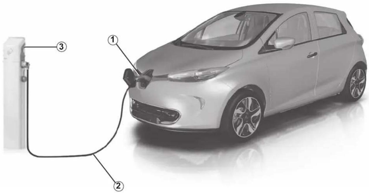
Coiled electric vehicle cable with two connectors and a labeled point A (no text or symbols beyond labels)Charging cord A
This cord, designed for specific wall sockets or public terminals, enables the standard charge of the traction battery.
We recommend that you use a charging cord that enables a standard charge to charge the traction battery.
Each charging cord is stored in a bag in the boot of the vehicle.
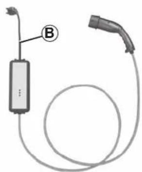
natural_image
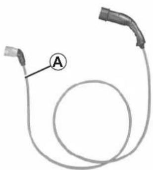
Diagram of a medical or laboratory device with a labeled component (B) connected to a cylindrical tube and a separate plug (no text or symbols present)Charging cord B
This cord allows:
- standard charge, on a socket used only for the vehicle (14A / 16A charge);
- occasional charge using a domestic socket, when you are not at home, for example (10A charge).
Sockets must be fitted as stated in the instructions in the instructions supplied with the charging cord B.
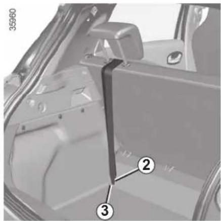
35906
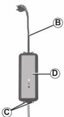
Always read the charging cord instructions carefully before using it B.
Never leave the socket hanging by the cord. Use the hooks C to attach it.
If a charging cord malfunctions during the charging process (red warning light on the unit D), stop charging immediately. Please refer to the cord instructions.
ELECTRIC VEHICLE: charging (4/9)

Important recommendations for charging your vehicle
Please read these instructions carefully. Failure to follow these instructions may lead to a risk of fire, serious injury or electric shocks which could result in death.
Choice of charging cord
The standard charging cords supplied with the vehicle have been designed specifically for this vehicle. It is designed to protect you against the risks of electric shock that can lead to death or fire.
For safety reasons, the use of a charging cord not recommended by the manufacturer is strictly forbidden. Failure to follow this instruction can lead to risks of fire or electric shock that can prove fatal. For information on a charging cord suited to your vehicle, please consult an authorised dealer.
Installation
For a standard charge
- Using the charging cord A
Have a special wall socket installed by a qualified professional. - Using the charging cord B
The socket used to charge electric vehicles (14A / 16A charge) must be fitted by a qualified professional. Read the instructions provided with this product carefully.
For occasional charging (charging cord B)
With a domestic socket (10A charge)
Have a professional check that each socket to which you intend to connect the charging cord complies with the standards and regulations in force in your country.
Please read the instructions that come with the charging cord carefully to learn about precautions you must take when using the product and the technical specifications required when fitting the socket.
ELECTRIC VEHICLE: charging (5/9)
35780
natural_image
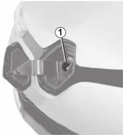
Close-up of a car's front and side view showing a blue racing gear with a numbered component (1) pointing to the center area.Electric charging connection 1
Note: If in a snowy environment, remove snow from the vehicle charging area before plugging in or disconnecting. Snow in the socket may block the insertion of the charging cord plug.
The vehicle has a charging connection located at the front of the vehicle.
Avoid charging and parking your vehicle in extreme temperatures (hot or cold).
Under extreme conditions, charging may take several minutes before starting (time required for the traction battery to cool down or warm up).
When the vehicle is parked for more than seven days in temperatures below about -25^ , charging the traction battery can become impossible.
When the vehicle is parked for more than three months with near zero charge, charging the battery can become impossible.
To preserve the service life of your traction battery, avoid parking the vehicle for more than one month with high charge, especially when the weather is very hot.
In the absence of any protection against overvoltage, you are recommended not to charge the vehicle in stormy weather (lightning, etc).
Favour charging the traction battery after driving and/or in mild temperatures. Otherwise, charging may take a longer period of time or even become impossible.
Recommendations
- In high temperatures, try to park and recharge the vehicle in a shaded/covered location.
- Charging can be performed in the rain or snow.
- Activating the air-conditioning increases the charge duration period.
ELECTRIC VEHICLE: charging (6/9)
Recharging the traction battery
With the vehicle stationary, ignition off and gear lever in position P:
- take the charging cord located in the boot of your vehicle;
- remove it from its storage bag;
- plug in the end of the cord to the power supply;

Do not use an extension lead, multiple socket or adapter.
Fire hazard.
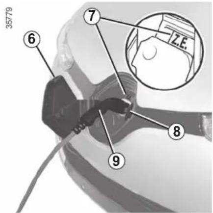
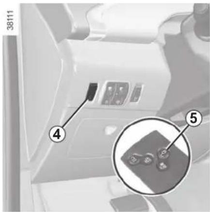
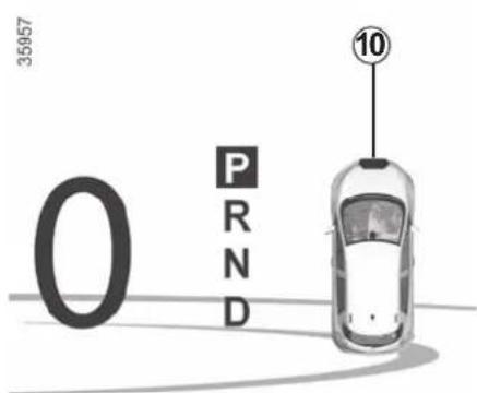
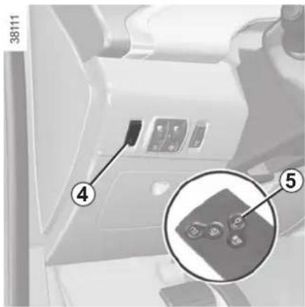
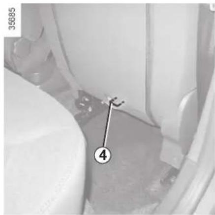
- press the button 5 on the RENAULT card or on the switch 4 to unlock the charging flap 6.
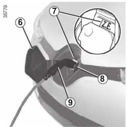
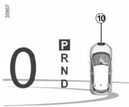
On the instrument panel, a red warning light 10 comes on and the Z.E. warning light 7 comes on in blue;
- open valve 8;
- grab the handle 9;
- plug in the vehicle cord. The Z.E. warning light 7 flashes rapidly;
- after you hear a locking click, check that the charging cord is properly plugged in. To check the locking, pull gently on the handle 9.
The charging cord is automatically locked with the vehicle. This will make it impossible to unplug the cord from your vehicle.
Make sure you fully uncoil the charging cord to limit its heating.
ELECTRIC VEHICLE: charging (7/9)
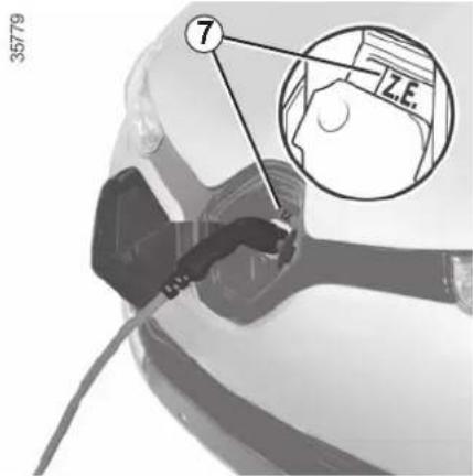
During charging, the Z.E. warning light 7 slowly flashes blue.
During charging, the following information is displayed on the instrument panel:
- the energy level on the battery warning light 11;
- the battery refill rate;
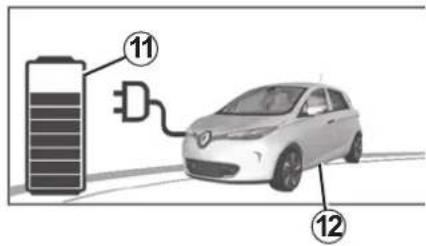
- an estimate of the remaining charging time (this is not displayed after about 95% charge);
- the instrument panel background flashes blue;
- the warning light 12 indicates that the vehicle is connected to a power supply.
The traction battery charging time depends on the amount of energy remaining and the power delivered by the charging terminal. The information is displayed on the instrument panel during charging. Please see the information on "Displays and indicators" in Section 1.
In the event of a problem, we recommend that you replace it with an identical cord. Please see an authorised dealer.
At the end of a full charge, the Z.E. warning light 7 will remain blue. After a few seconds, the whole display switches off on the instrument panel.
You do not need to wait until the charge is at reserve levels to recharge your vehicle.
Operating fault
Impossible to charge the battery
This can be due to charging programmed at a time that conflicts with your instantaneous load demand.
Cancel the charging programming (refer to the information on "Electric vehicle: charging programming" in Section 1).
If no charge is programmed, contact an authorised dealer.
ELECTRIC VEHICLE: charging (8/9)
Precautions to take when removing from the socket
It is imperative to follow the unplugging steps in order.
- Press the button 5 on the RENAULT card or press the switch 4 to unlock the vehicle charging cord;
- grab the handle 9;
- unplug the charging cord from the vehicle;
- the valve 8 must be closed;
- the charging flap 6 must be closed. Press down to lock it. The red warning light 10 on the instrument panel goes off;
- unplug the cord from the power supply;
– store the cord in its storage bag and put away in the boot.
Note: immediately after a long charge of the traction battery, the cable may be hot. Please use the handles.
After pressing the charging cord un-locking button, you have 30 seconds to unplug it before it locks again.
ELECTRIC VEHICLE: charging (9/9)
natural_image
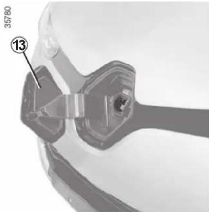
Close-up of a mechanical component with numbered annotation (13) and number 35780, no readable text or symbols beyond the label.Label 13
The label 13 on the charging flap re-minds you of the instructions for the opening and closing of the flap:
– with the vehicle stationary, the valve and the charging flap can be open;
- when the vehicle is being driven, the valve and the charging flap must be closed.

To avoid disturbing the charging monitoring system, do not install any antistatic strip to the vehi-
cle.
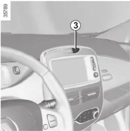
ELECTRIC VEHICLE: charging programming (1/2)

natural_image
Interior view of a car dashboard with digital display and steering wheel (no visible text or symbols)This function sets the start time for charging.
From the multimedia display 1
(depending on the vehicle)
Programming the function start time
Select "Menu", "Vehicle", "Electrical vehicle", "Charge scheduler".
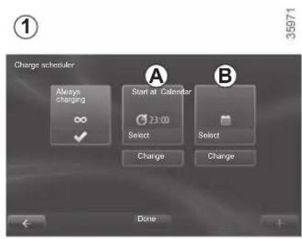
You can choose:
- an instant charge start;
- a daily schedule;
- a weekly schedule.
Confirm your choice by selecting "Done".
Daily
On the menu A, press "Change" and set the charging start and end times, then press "Select" to confirm.
Weekly
On the menu B, press "Change" and set the charging start and end times for each weekday, then press "Select" to confirm.
NB: When the programming is confirmed, the warning light comes on on the instrument panel.
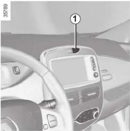
ELECTRIC VEHICLE: charging programming (2/2)
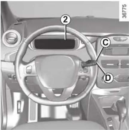
On the instrument panel 2
(depending on the vehicle)
Programming the function start time
You can programme a single time.
- briefly press button C or D to access the menu "PROGRAMMING";
-
press and hold button C or D to confirm;
-
briefly press button C or D to access the menu "SETTINGSSTART LOAD";
- press and hold button C or D to confirm;
- briefly press button C or D to access the clock settings;
- hold down button C or D - the hours flash;
- press buttons C and D to set the hour;
- hold down button C or D to confirm the hour setting;
- the minutes flash - press buttons C and D to set the minutes;
- hold down button C or D to confirm the minutes setting. Your settings are now saved.
NB: When the programming is con-
firmed, the warning light comes on on the instrument panel.
Charge start
Charging starts at the set time:
- if the ignition is switched off;
- The gear lever should be in position P;
- if the vehicle is connected to a power supply.
RENAULT CARDS: general information (1/2)
35782
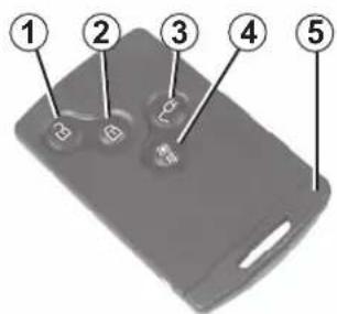
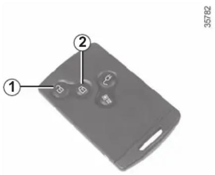
1 Unlocking the doors and boot.
2 Locking the doors and boot.
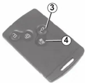
3 Unlocking the charging cord/opening the charging flap.
4 Activation of the air-conditioning
5 Integrated key.
When the battery is flat, you can still lock/unlock and start your vehicle. Refer to the information on "Locking/unlocking the doors" in Section 1 and "Starting the engine" in Section 2.
The RENAULT card is used for:
- locking/unlocking the doors and boot. Refer to the following pages;
- opening the charging flap, please see the information on "Electric vehicle: charging" in Section 1;
- unlocking the charging cord. Please refer to the information on "Electric vehicle: charging" in Section 1;
- activation of the air-conditioning. Please refer to the information on "Air-conditioning" in Section 3.
- starting the engine; refer to the information on "Starting the engine" in Section 2.
RENAULT card operating range
This varies according to the surroundings: when handling the RENAULT card, it is important to make sure that you do not lock or unlock the doors by inadvertently pressing the buttons.

Driver's responsibility when parking or stopping the vehicle
Never leave an animal, child or adult who is not self-sufficient alone in your vehicle, even for a short time.
They may pose a risk to themselves or to others by starting the engine, activating equipment such as the electric windows or locking the doors, for example.
Also, in hot and/or sunny weather, please remember that the temperature inside the passenger compartment increases very quickly.
RISK OF DEATH OR SERIOUS INJURY.
RENAULT CARDS: general information (2/2)
Battery life
Make sure that the correct battery type is being used, and that the battery is in good condition and inserted correctly. Its service life is approximately two years: replace it when the message "Keycard battery low" appears on the instrument panel (refer to the information on the "RENAULT card: battery" in section 5).
Replacement: need for an additional RENAULT Card
If you lose your RENAULT card or require another, you can obtain one from an approved dealer.
If a RENAULT card is replaced, it will be necessary to take the vehicle and all of its RENAULT cards to an approved dealer to initialise the system.
You may use up to four RENAULT cards per vehicle.
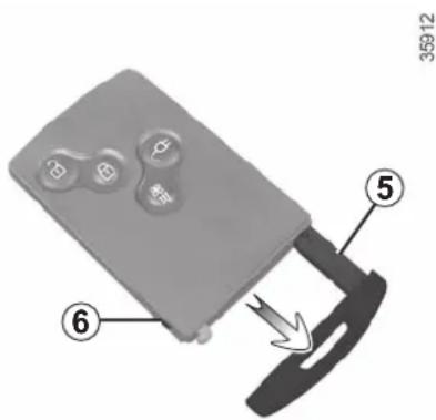
Integrated key 5
The integrated key is used to lock or unlock the front left-hand door if the RENAULT card does not work:
- the card battery RENAULT is drained, flat 12 V battery, etc.
- use of devices using the same frequency as the card;
- if the vehicle is located in a zone of high electromagnetic radiation;
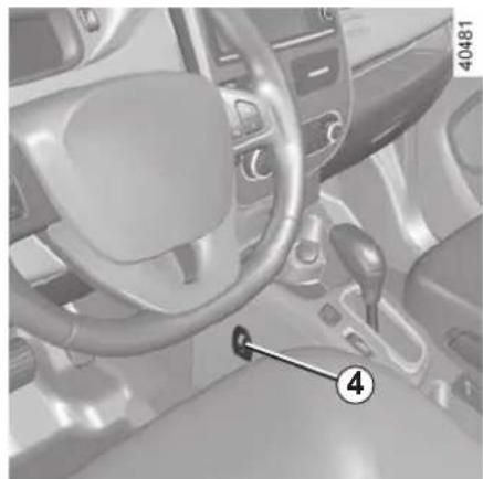
Access to key 5
Press button 6 and pull on key 5 then release the button.
Using the key
Refer to the information on "Locking/unlocking the doors".
Once you have accessed the vehicle using the integrated key, replace it in its housing in the RENAULT card, then insert the RENAULT card into the card reader to start the vehicle.
Advice
Avoid leaving the card in hot, cold or humid areas.
Do not keep the RENAULT card in a place where it could be bent or damaged accidentally, such as in a back pocket of a garment.
REMOTE CONTROL RENAULT CARD: use (1/2)
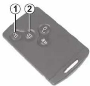
Unlocking the doors and tailgate
Press button 1.
The hazard warning lights flash once to indicate that the doors have been unlocked.
If the vehicle has been unlocked but neither the doors or tailgate are open, it locks again automatically after approximately two minutes.
Locking the doors and luggage compartment
Press the locking button 2. The hazard warning lights flash twice to indicate that the doors have locked. If a door or the luggage compartment is open or not properly shut, or if a RENAULT card is still in the reader, the doors and luggage compartment lock then quickly unlock and the hazard warning lights do not flash.
The card buttons are deactivated when the engine is running.
The flashing status of the hazard warning lights informs you of the vehicle status:
- one flash indicates that the vehicle is completely unlocked;
- two flashes indicate that the vehicle is completely locked.

Driver's responsibility when parking or stopping the vehicle
Never leave an animal, child or adult who is not self-sufficient alone in your vehicle, even for a short time.
They may pose a risk to themselves or to others by starting the engine, activating equipment such as the electric windows or locking the doors, for example.
Also, in hot and/or sunny weather, please remember that the temperature inside the passenger compartment increases very quickly.
RISK OF DEATH OR SERIOUS INJURY.
REMOTE CONTROL RENAULT CARD: use (2/2)
35782
RENAULT card not detected alarm
The message "Keycard not detected" and a beep will warn you if you open a door with the engine running and the card is not in the reader. The warning disappears when the card is inserted in the reader again.
Opening the charging flap or unlocking the vehicle charging cord
Press the button 3 either to open the charging flap or to unlock the charging cord.
Activation of the air-conditioning
A long press on the button 4 activates the air-conditioning for a period of approximately 5 minutes. This enables you to obtain a comfortable temperature prior to using the vehicle. Please see the information on "Air conditioning: remote activation" in Section 3.
HANDS-FREE RENAULT CARD: use (1/4)
35785
natural_image
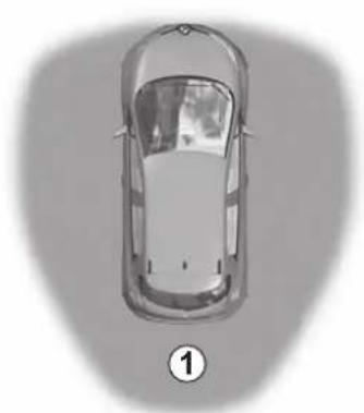
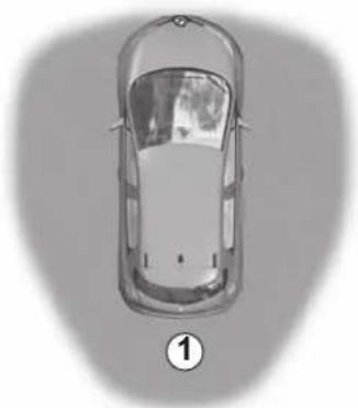
Top-down view of a car with a numbered label (1) on the side, no visible text or symbols on the car itself.Use
On equipped vehicles, in addition to the functions of the above-mentioned remote control RENAULT card, it can be used to lock/unlock without using the RENAULT card, when it is in access zone 1.
Do not store the RENAULT card anywhere it may come into contact with other electronic equipment (computer, PDA, phone, etc.) as this could hinder its operation.

Driver's responsibility when parking or stopping the vehicle
Never leave an animal, child or adult who is not self-sufficient alone in your vehicle, even for a short time.
They may pose a risk to themselves or to others by starting the engine, activating equipment such as the electric windows or locking the doors, for example.
Also, in hot and/or sunny weather, please remember that the temperature inside the passenger compartment increases very quickly.
RISK OF DEATH OR SERIOUS INJURY.
HANDS-FREE RENAULT CARD: use (2/4)
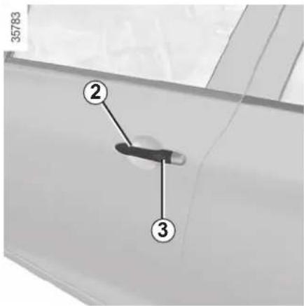
Unlocking the vehicle
With the RENAULT card in zone 1 and the vehicle locked, press button 3 on handle 2 on one of the two front doors: the vehicle will unlock.
Pressing button 4 also unlocks all the doors and the tailgate.
The hazard warning lights flash once to indicate that the doors have been unlocked.
Note: The vehicle cannot be locked again for approximately three seconds after unlocking by pressing button 3.
After unlocking the vehicle or the boot only using the buttons of the RENAULT card, remote locking and unlocking in hands-free mode are deactivated.
To reactivate the hands-free mode: restart the vehicle.
HANDS-FREE RENAULT CARD: use (3/4)
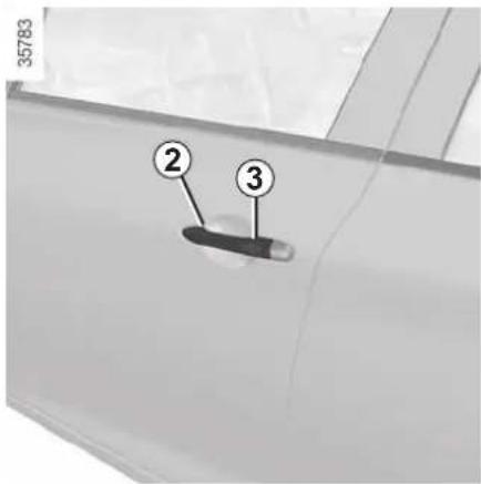
Locking the vehicle
There are three ways to lock the vehicle: remotely, using button 3, or using the RENAULT card.
Remote locking
With the RENAULT card on you, and doors and tailgate closed, move away from the vehicle: it will lock automatically once you have left zone 1.
Note: the distance at which the vehicle locks depends on the surroundings.
35785
natural_image
Top-down view of a car with visible roof and side door, marked with number 1 (no text or symbols on the car itself)The hazard warning lights flash twice and a beep sounds to indicate that the doors have locked.
The beep may be switched off. Please contact an authorised dealer.
If a door or the tailgate is open or not properly shut, or a card is in the passenger compartment (or the card reader) the vehicle will not lock. In this situation, no beep sounds and the hazard warning lights do not flash.
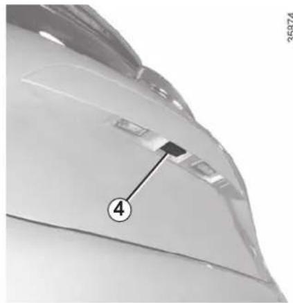
Locking using button 3
With the doors and boot closed, press button 3 on one of the front door handles. The vehicle will lock. If a door or the boot is open or not closed properly, the vehicle will quickly lock/unlock.
NB:
- the card RENAULT must be within the vehicle's access zone (1 zone) to be able to use the button for locking;
- the vehicle cannot be unlocked again for approximately three seconds after locking by pressing button 3.
HANDS-FREE RENAULT CARD: use (4/4)
natural_image
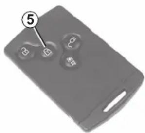
Close-up of a gray remote control device with three buttons and a labeled digit '5' (no text or symbols on the device itself)35782
Locking using the RENAULT card
With the doors and luggage compartment closed, press button 5: the vehicle will lock.
The hazard warning lights flash twice to indicate that the doors have locked.
Note: the maximum distance at which the vehicle locks depends on the surroundings.
35865
natural_image
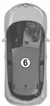
Top-down view of a car with the number 6 marked on the side (no text or symbols on the car itself)Special note:
The vehicle will not lock if:
- a door or the tailgate is open or not properly closed;
- a card is still in zone 6 (or in the card reader) and no other card is in the external detection zone.
With the engine running, if, after having opened and closed a door, the card is no longer in the passenger compartment, the message "Keycard not detected" (accompanied by a beep when the speed passes a certain level) warns you that the card is no longer in the vehicle. This avoids you driving away after having dropped off a passenger who has the card, for example.
The warning disappears when the card is detected again.
After locking/unlocking the vehicle and the tailgate only using the buttons on the RENAULT card, remote locking and unlocking in hands-free mode are deactivated.
To reactivate the "hands-free" mode: restart the vehicle.
RENAULT CARD: deadlocking
35782
If the vehicle is equipped with a dead-locking function, this allows you to lock the opening elements and to prevent the doors from being unlocked using the interior handles (for example, by breaking the window and then trying to open the door from the inside).

Never use deadlocking if someone is still inside the vehicle.
To activate deadlocking
Deadlocking can be activated in one of two ways:
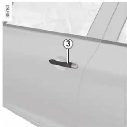
- press button 2 twice in quick succession;
- or, press the button on the driver's door handle 3 twice in quick succession.
The hazard warning lights flash five times to indicate locking.
To deactivate deadlocking
Unlock the vehicle using button 1 on the RENAULT card.
The hazard warning lights flash once to indicate that the doors have been unlocked.
After activating the deadlocking function using button 2, remote locking and unlocking in hands-free mode are deactivated.
To reactivate the "hands-free" mode: restart the vehicle.
OPENING AND CLOSING THE DOORS (1/2)
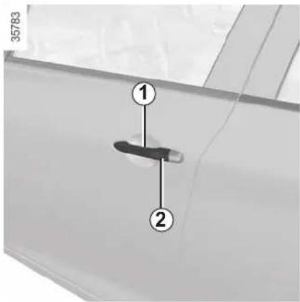
Opening the doors from the outside
Front doors
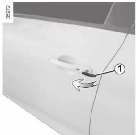
With the doors unlocked, pull handle 1.
Special feature of the RENAULT "hands-free" card
With the doors locked, press the button 2 on the handle 1 of one of the two front doors and pull towards you.
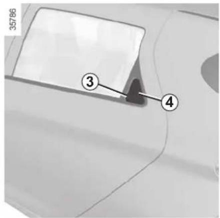
Rear doors
With the doors unlocked:
- press on recess 3 to move the handle 4;
- slide your hand into the handle 4 and pull towards you.

As a safety precaution, the doors should only be opened or closed when the vehicle is stationary.
natural_image
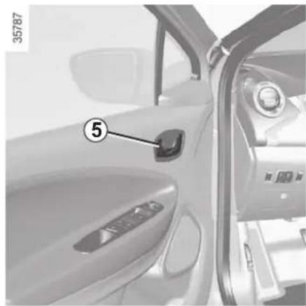
Interior view of a car showing the door panel and side door, with no visible text or symbols.Opening from the inside
Pull handle 5.
Lights-on reminder buzzer
A warning beep sounds when the driver's door is opened to warn you that the lights are still on.
Card reminder buzzer
A beep will let you know if you have left the remote control RENAULT card in the reader when you open the driver's door, and the "Please remove keycard" message will appear on the instrument panel.
OPENING AND CLOSING THE DOORS (2/2)
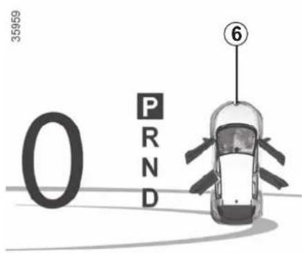
Door/tailgate open buzzer
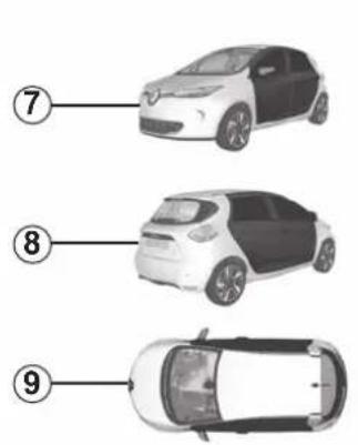
When stationary, the warning light 6, along with the warning light ⚠, comes on when a door, the boot or the charging flap is open or not closed properly.
When the vehicle is travelling at around 12 mph, the 7, 8 or 9 warning light indicates that one or more of the openings (door, boot or charging flap) is open or not closed properly.
Special note
Once the engine has been switched off, the lights and accessories (radio, etc.) will continue to operate until the driver's door is opened.
35958
natural_image
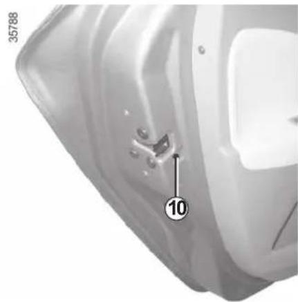
Close-up of a white plastic container with a numbered mark and annotation (no readable text or symbols)Child safety
To make it impossible for the rear doors to be opened from the inside, move the lever 10 and check from the inside that the doors are securely locked.

Driver's responsibility when parking or stopping the vehicle
Never leave an animal, child or adult who is not self-sufficient alone on your vehicle, even for a short time.
They may pose a risk to themselves or to others by starting the engine, activating equipment such as the electric windows or by locking the doors. Also, in hot and/or sunny weather, please remember that the temperature inside the passenger compartment increases very quickly.
RISK OF DEATH OR SERIOUS INJURY.
LOCKING, UNLOCKING THE DOORS (1/2)
Locking/Unlocking the doors from the outside
This is done using the RENAULT Card; see the "RENAULT Card" information in Section 1.
In certain cases, the RENAULT card may not work:
- the card battery RENAULT is drained, flat 12 V battery, etc.
- if equipment operating on the same frequency as the card (mobile phones, etc.) is used;
– vehicle located in a high electromagnetic radiation zone.
It is then possible:
- to use the key integrated into the card to unlock the front left-hand door;
– to lock each of the doors manually; - to use the interior door locking/un-locking control (refer to the following pages).
Using the key integrated in the RENAULT card
Insert key 1 into the lock in the driver's door and lock or unlock.
natural_image
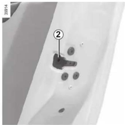
Close-up of a mechanical component with numbered annotation (2) and circular features, no readable text or symbols present.Locking the doors manually
Turn screw 2 with the door open (using the end of the key) and close the door.
This means that the doors are then locked from the outside.
The doors may then only be opened from the inside or by using the key in the front left-hand door.
LOCKING, UNLOCKING THE DOORS (2/2)
natural_image
Interior view of a car dashboard with a digital display and numbered component (no visible text or symbols)Interior locking/unlocking door control
Switch 3 simultaneously controls the doors and the boot.
If a door or the tailgate is open or not closed properly, the doors and tailgate lock/unlock quickly.
If you need to transport objects with the boot open, the other opening elements can still be locked: with the engine stopped, press the switch 3 for more than five seconds to lock the other openings.
Locking the doors without the RENAULT card
For example, in the event of a discharged battery or the RENAULT card temporarily not working, etc.
With the engine switched off and an opening (door or boot) open, press and hold the switch 3 for more than five seconds.
When the door is closed, all the doors and tailgate will be locked.
Unlocking the vehicle from the outside is only possible with the RENAULT card in the vehicle's access zone or using the key integrated in the RENAULT card.
After locking/unlocking the vehicle and the tailgate only using the buttons on the RENAULT card, remote locking and unlocking in hands-free mode are deactivated.
To reactivate the "hands-free" mode: restart the vehicle.
Door and tailgate status indicator
With the ignition on, the warning light integrated in switch 3 informs you of the locking status of the opening elements:
– indicator light on, the doors and tail-gate are locked,
– indicator light off, the doors and tail-gate are unlocked.
When you lock the doors, the indicator light remains lit and then goes out.

Never leave your vehicle with the RENAULT card inside.

Driver's responsibility
If you decide to keep the doors locked when you are driving, remember that it
may be more difficult for those assisting you to gain access to the passenger compartment in the event of an emergency.
AUTOMATIC LOCKING WHEN DRIVING
natural_image
Interior view of a car dashboard with steering wheel and digital display (no visible text or symbols)Operating principle
After the vehicle is started, the system automatically locks the doors when you are driving at approximately 6 mph (10 km/h) and over.
The door can be unlocked:
- by pressing the door unlocking button 1.
- by opening a front door (vehicle stationary).
NB: if a door is opened or closed, it will automatically lock again when the vehicle reaches a speed of 6 mph (10 km/h).
Activating/deactivating the function
With the engine running, press button 1 for approximately five seconds until you hear a beep.

Driver's responsibility
If you decide to keep the doors locked when you are driving, remember that it may be more difficult for those assisting you to gain access to the passenger compartment in the event of an emergency.
Operating faults
If you experience an operating fault (no automatic locking, the indicator light incorporated in button 1 does not light up when trying to lock the opening elements, etc.), firstly check that the opening elements are properly closed. If they are properly closed, contact an authorised dealer.
FRONT SEATS
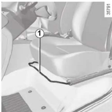
natural_image
Interior view of a car seatbelt with a numbered marker and vehicle details (no readable text or symbols)To move the seat forwards or back
Lift handle 1 to unlock. Release the handle once the seat is in the correct position and ensure that the seat is fully locked into position.
To adjust the lumbar support on the driver's seat
(depending on vehicle)
Lower handle 2 to increase the support and lift it to decrease it.
natural_image
Interior view of a car dashboard and steering wheel (no visible text or symbols)To tilt the seatback
Turn control knob 3 to the required position.
Heated seats
Turn control 4 to either position 1, 2 or 3 (depending on the temperature required). The 📄/ indicator light on the instrument panel comes on once the front seat heating system is operating.
The system, which has a thermostat, regulates the heating level.
To switch off the heated seat function, turn control 4 to the OFF position.

For safety reasons, carry out any adjustments when the vehicle is not being driven.
We would advise you not to recline the seatbacks too far to ensure that the effectiveness of the seat belts is not reduced.
No object should be placed on the floor (in front of the driver). Nothing should be placed around the driver's feet as such objects may slide under the pedals during sudden braking manoeuvres and obstruct their use.
SEAT BELTS (1/4)
Always wear your seat belt when travelling in your vehicle. You must also comply with the legislation of the particular country you are in.

Incorrectly adjusted or twisted seat belts may cause injuries in the event of an accident.
Use one seat belt per person, whether child or adult.
Even pregnant women should wear a seat belt. In this case, ensure that the lap belt is not exerting too much pressure on the abdomen, but do not allow any slack.
Before starting, first adjust your driving position, then ask all occupants to adjust their seat belts to ensure optimum protection.
Adjusting your driving position
- Sit well back in your seat (having removed your coat or jacket etc.). This is essential to ensure your back is positioned correctly;
- adjust the distance between the seat and the pedals. Your seat should be as far back as possible while still allowing you to fully depress the pedals. The seatback should be adjusted so that your arms are slightly bent when you hold the steering wheel;
- adjust the position of the steering wheel.
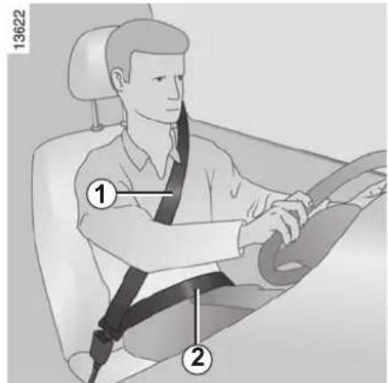
Adjusting the seat belts
Sit with your back firmly against the seatback.
The shoulder strap 1 should be as close as possible to the base of the neck but not on it.
Lap belt 2 should be worn flat over the thighs and against the pelvis.
The seat belt must be worn as close to the body as possible. Eg: avoid wearing heavy clothing or keeping bulky objects under the belts, etc.
SEAT BELTS (2/4)
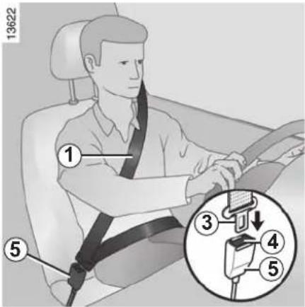
Locking
Unwind the belt slowly and smoothly and ensure that buckle 3 locks into catch 5 (check that it is locked by pulling on buckle 3). If the belt jams, allow it to return slightly before attempting to unwind it again.
If your seat belt is completely jammed, pull slowly, but firmly, so that just over 3 cm unwinds. Allow it to return slightly before attempting to unwind it again.
If there is still a problem, contact an approved dealer.
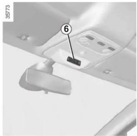
natural_image
Interior view of a vehicle ceiling with a numbered component (6) pointing to a mounted device, no visible text or symbols beyond the number.Front seat belt reminder warning light on display 6 It lights up when the engine is started and, if the driver's seat belt is not fastened, the light flashes and a beep sounds for about two minutes when the vehicle reaches a speed of approximately 12 mph (20 km/h).
NB: an object placed on the passenger seat cushion may activate the warning light in some cases.
natural_image
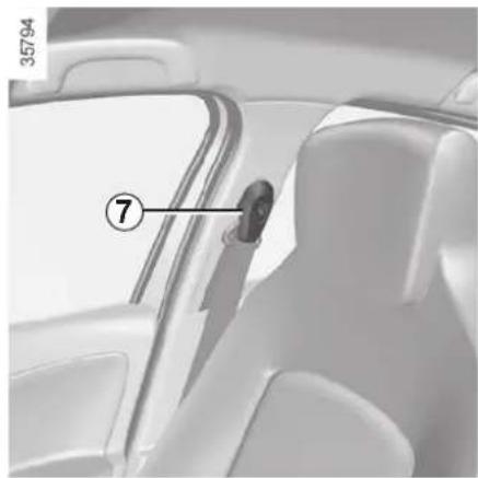
Interior view of a car showing the seatbelt and dashboard panel (no text or symbols visible)Adjusting the height of the front seat belts
Press the button 7 to adjust the seat belt height, so that the shoulder strap 1 is worn as shown previously. Press the button 7 and raise or lower the seat belt. Make sure that the seat belt is locked in position correctly after you have adjusted it.
Unfastening
Press button 4 and the seat belt will be rewound by the inertia reel. Guide the belt into position.
SEAT BELTS (3/4)
natural_image
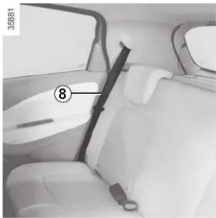
Interior view of a car showing seatbelt, rear seats, and dashboard (no visible text or symbols)Rear side seat belts 8
The belts are locked, unlocked and adjusted in the same way as the front belts.
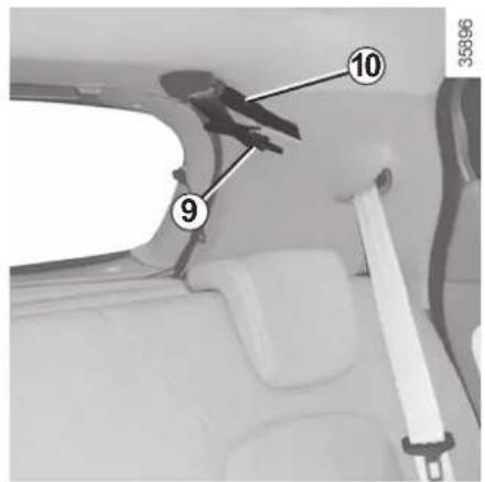
Rear centre seat belt
Unwind belt 9 slowly from its housing, then fasten buckle 10 into the corresponding black catch 12.
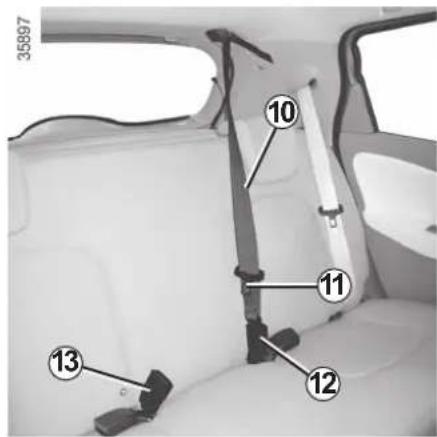
Fasten sliding buckle 11 into the corresponding red catch 13.

Check that the rear seat belts are positioned and operating correctly each time the rear bench seat is
moved.
SEAT BELTS (4/4)
The following information applies to the vehicle's front and rear seat belts.

- No modification may be made to the component parts of the originally fitted restraint system: seat belts, seats and their mountings. For special operations (e.g. fitting child seats), contact an authorised dealer.
- Do not use devices which allow any slack in the belts (e.g. clothes pegs, clips, etc.): a seat belt which is worn too loosely may cause injury in the event of an accident.
- Never wear the shoulder strap under your arm or behind your back.
- Never use the same belt for more than one person and never hold a baby or child on your lap with your seat belt around them.
- The belt should never be twisted.
- Following an accident, have the seat belts checked and replaced if necessary. Always replace your seat belts as soon as they show any signs of wear.
- When the rear bench seat is being put back, make sure that the seat belts and buckles are correctly positioned so that they can be used properly.
- Make sure that the buckle is inserted into the appropriate catch.
- Ensure that no objects are placed in the area around the seat belt catch as they could prevent it from being properly secured.
- Make sure the seat belt catch is properly positioned (it should not be hidden away, crushed or flattened by people or objects).
METHODS OF RESTRAINT IN ADDITION TO THE FRONT SEAT BELTS (1/4)
These are made up of:
- seat belt inertia reel pretensioners;
- chest-level load limiters;
- airbags anti-submarining;
- airbags - Driver and passenger front
These systems are designed to act independently or together when the vehicle is subjected to a frontal impact.
Depending on the severity of the impact, the system can trigger:
- seat belt locking;
- the seat belt inertia reel pretensioner (which engages to correct seat belt slack);
- the front airbag.
natural_image
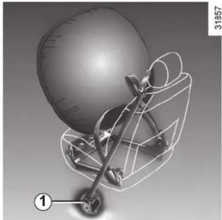
3D wireframe model of a helmet with a gear mechanism, no text or symbols presentPretensioners
The pretensioners hold the seat belt against the body, holding the occupant more securely against the seat, thus increasing the seat belt's efficiency.
With the ignition on, following a significant frontal impact and depending on the severity of the impact, the system may trigger the seat belt inertia reel pretensioner 1, which instantly retracts the seat belt.

- Have the entire restraint system checked following an accident.
- No operation whatsoever is permitted on any part of the system (pretensioners, airbags, computers, wiring) and the system components must not be reused on any other vehicle, even if identical.
- Only qualified personnel from our Network may work on the airbags; otherwise the system may trigger accidentally and cause injury.
- The electric trigger system may only be tested by a specially trained technician using special equipment.
- When the vehicle is scrapped, contact an approved dealer for disposal of the pretensioner and airbags gas generators.
METHODS OF RESTRAINT IN ADDITION TO THE FRONT SEAT BELTS (2/4)
Load limiter
Above a certain severity of impact, this mechanism is used to limit the force of the belt against the body so that it is at an acceptable level.
Airbaganti-submarining
Located on each of the front seats, it deploys in order to prevent the occupant from sliding under the seat belt.
Driver and passenger front airbags
Fitted to the driver and passenger side.
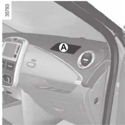
The presence of this equipment is indicated by the word "Airbag" on the steering wheel, dashboard (in area airbag A) and, depending on the vehicle, a label on the lower section of the windscreen.
Each airbag system consists of:
- an airbag and gas generator fitted on the steering wheel for the driver and in the dashboard for the passenger;
- an electronic unit for system monitoring which controls the gas generator electrical trigger system;
- remote sensors;
- a single warning light on the instrument panel.
natural_image
Interior view of a car dashboard with labeled air vent (A), no visible text or symbols beyond the label
The airbag system uses pyrotechnic principles. This explains why, when the airbag inflates, it will gener-
ate heat, produce smoke (this does not mean that a fire is about to start) and make a banging noise. In a situation where an airbag is required, it will inflate immediately and this may cause some minor, superficial grazing to the skin or other problems.
METHODS OF RESTRAINT IN ADDITION TO THE FRONT SEAT BELTS (3/4)
natural_image
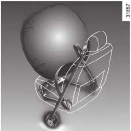
3D wireframe model of a mechanical device with a spherical component and curved components (no text or symbols)Operation
This system is only operational when the ignition is switched on.
In a severe frontal impact, the airbags inflate rapidly, cushioning the impact of the driver's head and chest against the steering wheel and of the front passenger against the dashboard. The airbags then deflate immediately so that the passengers are not in any way hindered from leaving the vehicle.
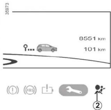
This warning light 2 will light up on the instrument panel when the ignition is switched on and then go out after a few seconds.
If it does not light up when the ignition is switched on, or comes on when the engine is running, there is a fault in the system.
Contact your approved Dealer as soon as possible. Your protection will be reduced until this fault is rectified.
METHODS OF RESTRAINT IN ADDITION TO THE FRONT SEAT BELTS (4/4)
All of the warnings below are given so that the airbag is not obstructed in any way when it is inflated and also to prevent the risk of serious injuries caused by items which may be dislodged when it inflates.

Warnings concerning the driver's airbag
- Do not modify the steering wheel or the steering wheel boss.
- Do not cover the steering wheel boss under any circumstances.
- Do not attach any objects (badge, logo, clock, telephone holder, etc.) to the steering wheel boss.
- The steering wheel must not be removed (except by qualified personnel from our Network).
- When driving, do not sit too close to the steering wheel. Sit with your arms slightly bent (see the information on "Adjusting your driving position" in Section 1). This will allow sufficient space for the air bag to deploy correctly and be fully effective.
Warnings concerning the passenger airbag
- Do not attach or glue any objects (badge, logo, clock, telephone holder, etc.) to the dashboard on or near the airbag.
- Do not place anything between the dashboard and the passenger (pet, umbrella, walking stick, parcels, etc.).
- The passenger must not put his or her feet on the dashboard or seat as there is a risk that serious injuries may occur. In general, parts of the body should be kept away from the dashboard (knees, hands, head, etc.).
- The devices in addition to the front passenger seat belt should be reactivated as soon as a child seat is removed, to ensure the protection of the passenger in the event of an impact.
A REAR-FACING CHILD SEAT MUST NOT BE FITTED TO THE FRONT PASSENGER SEAT UNLESS THE ADDITIONAL RESTRAINT SYSTEMS, I.E. THE PASSENGER AIR BAG, ARE DEACTIVATED.
(refer to the information on "Child safety: deactivating/activating the front passenger airbag" in Section 1)
Warnings concerning the anti-submarining airbag
Do not let a child under the age of 12 sit in this seat. When triggered, the anti-submarining airbag may project objects left on the seat base with a great deal of force.
Risk of serious injury.
METHODS OF RESTRAINT IN ADDITION TO THE REAR SIDE SEAT BELTS
Force limiter
Above a certain severity of impact, this mechanism is used to limit the force of the belt against the body so that it is at an acceptable level.

- Have the entire restraint system checked following an accident.
- No operation whatsoever is permitted on any part of the system (air bags, electronic control units, wiring) and the system components must not be reused on any other vehicle, even if identical.
- Only qualified personnel from our Network may work on the air bags; otherwise the system may trigger accidentally and cause injury.
SIDE PROTECTION DEVICES
Side air bags
These air bags are fitted to the front seats and are activated at the sides of the seats (door side) to protect the occupants in the event of a severe side impact.
Depending on the vehicle, a marking on the windscreen informs you of the presence of additional means of restraint (airbags, pretensioners, etc.) in the passenger compartment.

Warnings concerning the side air bag
- Fitting seat covers: seats equipped with an air bag require covers specifically designed for your vehicle. Contact an approved Dealer to find out if these covers are available. The use of any covers other than those signed for your vehicle (and including those designed for another vehicle) affect the operation of the air bags and reduce your protection.
- Do not place any accessories, objects or even pets between the seatback, the door and the internal fittings. Do not cover the seatback with any items such as clothes or accessories. This may prevent the air bag from operating correctly or cause injury when the air bag is deployed.
- No work or modification whatsoever may be carried out on the seat or internal fittings, except by qualified personnel from an approved dealer.
- The area between the rear bench seatback and the trim is the area of air bag operation: no objects must be placed here.
ADDITIONAL METHODS OF RESTRAINT
All of the warnings below are given so that the air bag is not obstructed in any way when it is inflated and also to prevent the risk of serious injuries caused by items which may be dislodged when the air bag inflates.

The air bag is designed to complement the action of the seat belt. Both the air bags and seat belts are integral parts of the same protection system. It is therefore essential to wear seat belts at all times. If seat belts are not worn, the occupants are exposed to the risk of serious injury in the event of an accident. It may also increase the risk of minor superficial injuries occurring when the air bag is deployed, although such minor injuries are always possible with air bags.
If the vehicle should overturn or suffer a rear impact, however severe, the pretensioners and air bags are not always triggered. Shocks to the underbody of the vehicle, e.g. from pavements, potholes or stones, can all trigger these systems.
- No work or modification whatsoever may be carried out on any part of the air bag system (air bags, pretensioners, computer, wiring harness, etc.), except by qualified personnel from an approved dealer.
- To ensure that the system is in good working order and to avoid accidental triggering of the system which may cause injury, only qualified Network personnel may work on the air bag system.
- As a safety precaution, have the air bag system checked if your vehicle has been involved in an accident, or is stolen or broken into.
- When selling or lending the vehicle, inform the user of these points and hand over this driver's handbook with the vehicle.
- When scrapping your vehicle, contact your approved dealer for disposal of the gas generator(s).
CHILD SAFETY: General information (1/2)
Carrying children
Please ensure that you comply with the legislation of your country.
Children, and adults, must be correctly seated and strapped in for all journeys. The children being carried in your vehicle are your responsibility.
A child is not a miniature adult. Children are at risk of specific injuries as their muscles and bones have not yet finished growing. The seat belt alone would not provide suitable protection. Use an approved child seat and ensure you use it correctly.

To prevent the doors being opened, use the “Child safety” device (refer to the information on “Opening
and closing the doors" in Section 1).

A collision at 30 mph (50 km/h) is the same as falling a distance of 10 metres.
Transporting a child without a restraint is the equivalent of allowing him or her to play on a fourth-floor balcony without railings.
Never travel with a child held in your arms. In the event of an accident, you will not be able to keep hold of the child, even if you yourself are wearing a seat belt.
If your vehicle has been involved in a road accident, replace the child seat and have the seat belts and ISOFIX anchorage points checked.

Driver's responsibility when parking or stopping the vehicle
Never leave an animal, child or adult who is not self-sufficient alone on your vehicle, even for a short time.
They may pose a risk to themselves or to others by starting the engine, activating equipment such as the electric windows or by locking the doors.
Also, in hot and/or sunny weather, please remember that the temperature inside the passenger compartment increases very quickly.
RISK OF DEATH OR SERIOUS INJURY.
CHILD SAFETY: General information (2/2)
Using a child seat
The level of protection offered by the child seat depends on its ability to re-strain your child and on its installation. Incorrect installation compromises the protection it offers the child in the event of harsh braking or an impact.
Before purchasing a child seat, check that it complies with the regulations for the country you are in and that it can be fitted in your vehicle. Consult an approved dealer to find out which seats are recommended for your vehicle.
Before fitting a child seat, read the manual and respect its instructions. If you experience any difficulties during installation, contact the manufacturer of the equipment. Keep the instructions with the seat.
Set a good example by always fastening your seat belt and teaching your child:
– to strap themselves in correctly;
- to always get in and out of the car at the kerb, away from busy traffic.
Do not use a second-hand child seat or one without an instruction manual.
Check that there are no objects in the vicinity of the child seat which could impede its operation.

Never leave a child unattended in the vehicle.
Check that your child is always strapped in and that
the belt or safety harness used is correctly set and adjusted. Avoid wearing bulky clothing which could cause the belts to slacken.
Never let your child put their head or arms out of the window.
Check that the child is in the correct position for the entire journey, especially if asleep.
CHILD SAFETY: choosing a child seat
natural_image
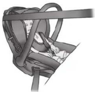
Medical illustration of a car seatbelt device with no visible text or symbolsRear-facing child seats
A baby's head is, proportionally, heavier than that of an adult and its neck is very fragile. Transport the child in this position for as long as possible (until the age of 2 at the very least). It supports both the head and the neck.
Choose a bucket type seat for best side protection and change it as soon as the child's head is higher than the shell.
natural_image
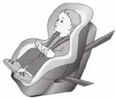
Illustration of a child sitting in a car seat, no text or symbols presentForward-facing child seats
The child's head and abdomen need to be protected as a priority. A forward-facing child seat which is firmly attached to the vehicle will reduce the risk of impact to the head. Ensure your child travels in a forward-facing seat with a harness for as long as their size permits.
Choose a bucket type seat for optimum side protection.
natural_image
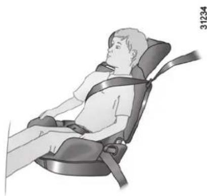
Illustration of a person seated in a car seatbelt chair, no text or symbols presentBooster cushions
From 15 kg or 4 years, the child can travel using a booster seat, which will enable the seat belt to be adapted to suit his/her size and shape. The booster seat cushion must be fitted with guides to position the seat belt on the child's thighs rather than the stomach. It is recommended that you use a seat-back fitted with a belt strap guide which can be adjusted in terms of height to position the seat belt in the centre of the shoulder. It must never rest on the neck or on the arm.
Choose a bucket type seat for optimum side protection.
CHILD SAFETY: choosing a child, baby seat mounting (1/2)
There are two ways of attaching child seats: via the seat belt or using the ISOFIX system.
Attachment via the seat belt
The seat belt must be adjusted to ensure that it is effective in the event of harsh braking or an impact.
Ensure that the strap paths indicated by the child seat manufacturer are respected.
Always check that the seat belt is correctly fastened by pulling it up, then pulling it out fully whilst pressing on the child seat.
Check that the seat is correctly held by moving it from side to side and back to front: the seat should remain firmly fixed.
Check that the child seat has not been installed at an angle and that it is not resting against a window.

No modifications may be made to the component parts of the restraint system (ISOFIX seat belts, seats in mountings) originally fitted.

Do not use the child seat if it may unfasten the seat belt restraining it: the base of the seat must not rest onkle and/or catch of the seat

The seat belt must never be twisted or the tension relieved. Never pass the shoulder strap under the behind the back.
Check that the seat belt has not been damaged by sharp edges. If the seat belt does not operate normally, it will not protect the child. Consult an approved dealer. Do not use this seat until the seat belt has been repaired.
Attachment using the ISOFIX system
Authorised ISOFIX child seats are approved in accordance with regulation ECE-R44 in one of the three following scenarios:
– ISOFIX universal 3-point forward-facing seat
- ISOFIX semi-universal 2-point seat - specific
For the latter two, check that your child seat can be installed by consulting the list of compatible vehicles.
Attach the child seat with the ISOFIX locks, if these are provided. The ISOFIX system allows quick, easy, safe fitting. The ISOFIX system consists of 2 rings and, in some cases, a third ring.

Before using an ISOFIX child seat that you purchased for another vehicle, check that its installation is
authorised. Consult the list of vehicles which can be fitted with the seat from the equipment manufacturer.
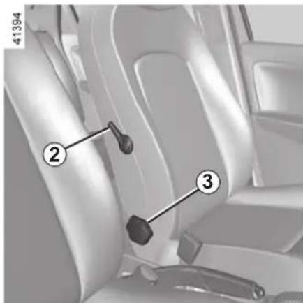
CHILD SAFETY: choosing a child, baby seat mounting (2/2)
natural_image
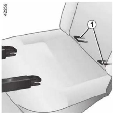
Mechanical component diagram showing a base with two clamps and a numbered feature (no text or symbols)The two rings 1 are located between the seatback and the seat base of the seat and are identified by a marking.
The third ring is used to attach the upper strap on some child seats: you must attach hook 2 on ring 3 for a rear seat and ring 4 for a front seat, then tighten the strap.

The ISOFIX anchorage points have been exclusively designed for child seats with the ISOFIX system. Never fit a different type of child seat, seat belt or other objects to these anchorage points.
Check that nothing is obstructing the anchorage points.
If your vehicle has been involved in a road accident, have the ISOFIX anchorage points checked and replace your child seat.
CHILD SAFETY: fitting a child seat (1/6)
Some seats are not suitable for fitting child seats. The diagram on the following page shows you how to attach a child seat.
The types of child seats indicated may not be available. Before using a different child seat, check with the manufacturer that it can be fitted.

Fit the child seat in a rear seat wherever possible.
Check that when installing the child seat in the vehicle
it is not at risk of coming loose from its base.
If you have to remove the headrest, check that it is correctly stored so that it does not come loose under harsh braking or impact.
Always attach the child seat to the vehicle even if it is not in use so that it does not come loose under harsh braking or impact.
In the front seat
The laws concerning children travelling in the front passenger seat differ in every country. Consult the legislation in force and follow the indications on the diagram on the following page.
Before fitting a child seat in this seat (if authorised):
– lower the seat belt as far as possible;
- move the seat as far back as possible;
- gently tilt the seatback away from vertical (approximately 25^ );
– on equipped vehicles, raise the seat base as far as possible.
After installing the child seat, when this is possible, you can move the vehicle seat forward if necessary (so as to leave enough space in the rear seats for passengers or other child seats). For a rear-facing child seat, do not let it touch the dashboard or move it to the furthest forward position.
Do not change these settings after the child seat is installed.

RISK OF DEATH OR SERIOUS INJURY: before
fitting a rear-facing child seat in this position, check the airbag has been deacti-refer to the information on safety: deactivating/activat-front passenger airbag" in 1).
CHILD SAFETY: fitting a child seat (2/6)
In the rear side seat
A carrycot can be installed across the vehicle and will take up at least two seats. Position the child with his or her feet nearest the door.
Move the front seat as far forward as possible to install a rear-facing child seat, then move back the seat in front as far as it will go, although without allowing it to come into contact with the child seat.
For the safety of the child in the forward-facing seat, do not move the seat in front back past the middle of the runner, do not tilt the seatback too far (maximum of 25°) and raise the seat as much as possible.
Always remove the headrest from the rear seat used for the child seat (see "Rear headrests" in Section 3). If necessary, position the rear seat as far back as possible. This must be done before fitting the child seat. Check that the child seat is resting against the back of the rear seat.
Rear centre seat
Check that the belt is suitable for securing your child seat. Consult an approved dealer.

Make sure that the child seat or the child's feet do not prevent the front seat from locking correctly. Refer
to the information on the "Front seat" in Section 1.

A child seat with a floor support must never be installed on the rear centre seat.
RISK OF DEATH OR SERIOUS INJURY.

When fitting a child seat (Group 2 or 3 booster seat), check that the seat belts operate (wind) correctly: refer
to Section 1 "Rear seat belts". If necessary, adjust the position of the vehicle seat.
CHILD SAFETY: fitting a child seat (3/6)
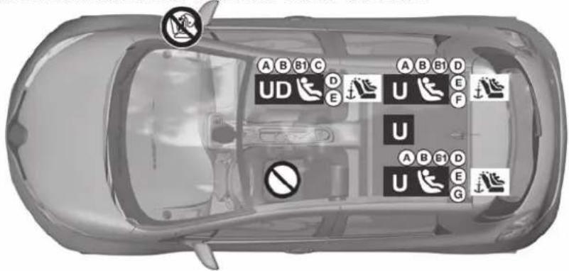
Visual installation of the five-door version
43959

Check the status of the air bag
before fitting a child seat or allowing a passenger to use the seat.

RISK OF DEATH OR
SERIOUS INJURY: before installing a rear-facing child ger seat, make sure the air bag has been deactivated (refer to the information on "Child safety: front passenger airbag deactivation/activation" in Section 1).

Seat not suitable for fitting child
Child seat attached using the belt

Seat which allows a child seat "Universal" approval to be at- I by a seat belt.

Seat which only allows a rear-standardised "Universal" seat to called using a seat belt.
Child seat attached using the ISOFIX mounting

Seat which allows an ISOFIX seat to be fitted.

The seats ISOFIX are fitted an anchorage point which allows hard-facing ISOFIX child seat with "rsal" approval to be attached.
The anchorage points are located in the boot for the rear seats, and on the seat back for the front seat.
The size of the ISOFIX child seat is indicated by a letter:
- A, B and B1: for forward-facing seats in group 1 (9 to 18 kg);
- C and D: shell seat or rear-facing seats in group 0+ (less than 13 kg) or group 1 (9 to 18 kg);
- E: rear-facing shell seats in group 0 (less than 10 kg) or 0+ (less than 13 kg);
- F and G: carrycots in group 0 (less than 10 kg).

Using a child safety system which is not approved for this vehicle will not correctly protect the baby or child. They risk serious or even fatal injury.
CHILD SAFETY: fitting a child seat (4/6)
The table below summarises the information already shown on the diagram on the previous page, to ensure the regulations in force are respected.
| Type of child seat | Weight of the child | Seat size | Front passenger seat (5) (1) | Rear side seats | Rear centre seat |
| Carrycot fitted across the vehicleGroup 0 | < 10 kg F, G X U - | IL (2) X | |||
| Rear-facing shell seatGroup 0 or 0+ | < 10 kg and < 13 kg | E U - IL | U - IL (3) U (3) | ||
| rear-facing seatGroup 0+ and 1 | < 13 kg and 9 to 18 kg | C U - IL | U (3) | U (3) | |
| D U - IL | U - IL (3) U (3) | ||||
| Forward-facing seatGroup 1 | 9 to 18 kg | A, B, B1 | IUF - IL | U - IUF - IL (4) | U (4) |
| Booster seatGroup 2 and 3 | 15 to 25 kg and 22 to 36 kg | - | X | U (4) | U (4) |
X = Seat not suitable for fitting child seats.
U = Seat which allows a child seat with "Universal" approval to be installed using a seat belt; check that it can be fitted.
IUF/IL = On equipped vehicles, seat which allows an approved "Universal/semi-universal" or vehicle specific child seat to be attached using the ISOFIX system; check that it can be fitted.
(1) raise the seat to the maximum and position it as far back as possible, tilting the seatback slightly (approximately 25°).
(2) A carrycot can be installed across the vehicle and will take up at least two seats. Position the child with his or her feet nearest the door.
(3) Move the front seat as far forward as possible to install a rear-facing child seat, then move back the seat in front as far as it will go, although without allowing it to come into contact with the child seat.
(4) Forward-facing child seat; position the seatback of the child seat in contact with the seatback of the vehicle seat. Adjust the headrest, or remove it if necessary. Do not push the front seat more than halfway back on its runners and do not recline the seatback more than 25^ .

(5) RISK OF DEATH OR SERIOUS INJURY: before installing a rear-facing child seat in the front passenger seat, make sure the airbag has been deactivated (refer to the information on “Child safety: front passenger airbag deactivation/activation” in Section 1).
CHILD SAFETY: fitting a child seat (5/6)

Check the status of the airbag
before fitting a child seat or allowing a passenger to use the seat.

RISK OF DEATH OR
SERIOUS INJURY: before installing a rear-facing child ger seat, make sure the airbag has been deactivated (refer to the information on "Child safety: front passenger airbag deactivation/activation" in Section 1).

Seat not suitable for fitting child seats.
Child seat attached using the belt

Seat which allows a rearfacing seat with "universal" approval only to be attached with a seat belt.
Child seat fitted using the ISOFIX mounting

seat which allows an ISOFIX child to be fitted.

The passenger seat is fitted with an anchorage point for attaching a universal ISOFIX forward-facing child seat. The anchorage point is on the seatback.
The size of the ISOFIX child seat is indicated by a letter:
- A, B and B1: for forward-facing seats in group 1 (9 to 18 kg);
- C and D: shell seat or rear-facing seats in group 0+ (less than 13 kg) or group 1 (9 to 18 kg);
- E: rear-facing shell seats in group 0 (less than 10 kg) or 0+ (less than 13 kg);

Using a child safety system which is not approved for this vehicle will not correctly protect the baby or child. They risk serious or even fatal injury.
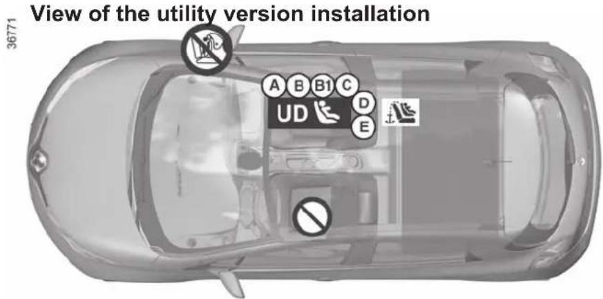
CHILD SAFETY: fitting a child seat (6/6)
The table below summarises the information already shown on the diagram on the previous page, to ensure the regulations in force are respected.
| Utility version | |||
| Type of child seat | Weight of the child | Seat size ISOFIX | Front passenger seat (1) (2) |
| Rear-facing shell seatGroups 0 or 0 + | < 10 kg and < 13 kg | E U - IL | |
| Shell seat/rear-facing seatGroups 0+ and 1 | < 13 kg and 9 to 18 kg | C, D U - IL | |
| Forward-facing seatGroup 1 | 9 to 18 kg A, B, B1 | IUF - IL | |
| Booster seatGroups 2 and 3 | 15 to 25 kg and 22 to 36 kg | - | X |

(1) RISK OF DEATH OR SERIOUS INJURY: before installing a rear-facing child seat in the front passenger seat, make sure the airbag has been deactivated (refer to the information on “Child safety: front passenger airbag deactivation/activation” in Section 1).
U = Seat which allows a child seat with "Universal" approval to be installed using a seat belt; check that it can be fitted.
UD = Seat which only allows a rear-facing standardised "Universal" seat to be installed using a seat belt.
IUF/IL = On equipped vehicles, seat which allows an approved "Universal/semi-universal" or "vehicle specific" child seat to be attached using the ISOFIX system; check that it can be fitted.
(2) Raise the seat to the maximum and position it as far back as possible, tilting the seatback slightly (approximately 25^ ).
CHILD SAFETY: deactivating, activating the front passenger airbag (1/3)
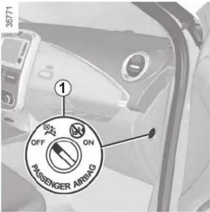
Deactivating the front passenger airbag
Before installing a child seat on the front passenger seat:
- check that the child seat can be installed on this seat;
- it is essential to deactivate the airbag for a rear-facing child seat.
natural_image
Close-up of a car interior showing a black sensor or connector labeled with number 2, no readable text or symbols present.To deactivate the airbag: with the vehicle stationary, push and turn the lock 1 to the OFF position.
With the ignition on, you must check
that the 2 warning light on the central display 2 is well lit and, (depending on the vehicle), that the message "airbag passenger deactivated" is displayed.
This light remains permanently lit to let you know that you can fit a child seat.

The passenger airbag must only be deactivated or activated when the vehicle is stationary.
If it is interfered with when the vehicle is being driven, indicator lights

and will come on.
Switch the ignition off then on again to reset the airbag in accordance with the lock position.
CHILD SAFETY: deactivating, activating the front passenger airbag (2/3)
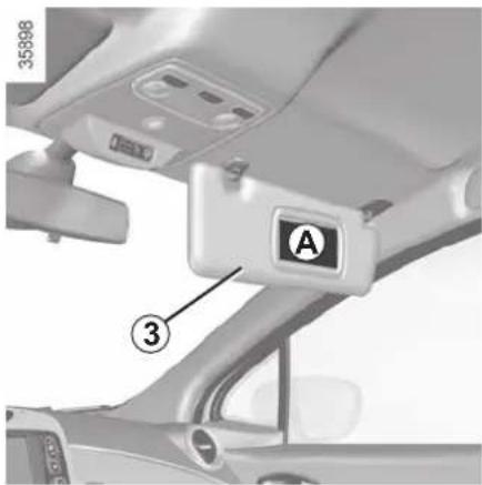

DANGER
Since operation of the front passenger airbag is not compatible with the position of a rear-facing child seat, NEVER fit a rear-facing child restraint system in a seat protected by an ACTIVATED front AIRBAG. This can lead to the DEATH of the CHILD or SERIOUS INJURY.


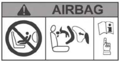
The markings on the dashboard and labels A on each side of the passenger sun visor 3 (example: label shown above) remind you of these instructions.
CHILD SAFETY: deactivating, activating the front passenger airbag (3/3)
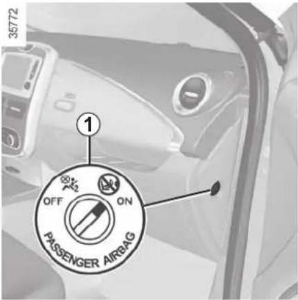
Activating the front passenger airbag
You should reactivate the airbag as soon as you remove the child seat from the front passenger seat to ensure the protection of the front passenger in the event of an impact.
To reactivate theairbag: with the vehicle stationary, push and turn the lock 1 to the ON position.
With the ignition switched on, you must check that warning light 2 on the dis-
play 2 is switched off and that the
indicator light 📄 appears on the display after each start-up for approximately one minute. The front passenger airbag has been activated.
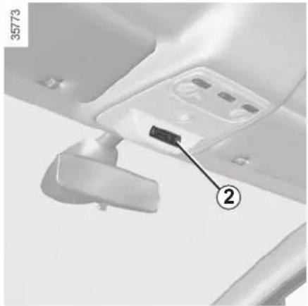
natural_image
Close-up of a car interior component with a numbered annotation pointing to a black object (no readable text or symbols)Operating faults
It is forbidden to fit a rear-facing child seat to the front passenger seat if the airbag activation/deactivation system is faulty.
Allowing any other passenger to sit in that seat is not recommended.
Contact your approved dealer as soon as possible.

DANGER
Since operation of the front passenger airbag is not compatible with the po-
sition of a rear-facing child seat, NEVER fit a rear-facing child restraint system in a seat protected by an ACTIVATED front AIRBAG. This can lead to the DEATH of the CHILD or SERIOUS INJURY.

The passenger airbag must only be deactivated or activated when the vehicle is stationary.
If it is interfered with when the vehicle is being driven, indicator lights

and will come on.
Switch the ignition off then on again to reset the airbag in accordance with the lock position.
STEERING WHEEL/POWER-ASSISTED STEERING
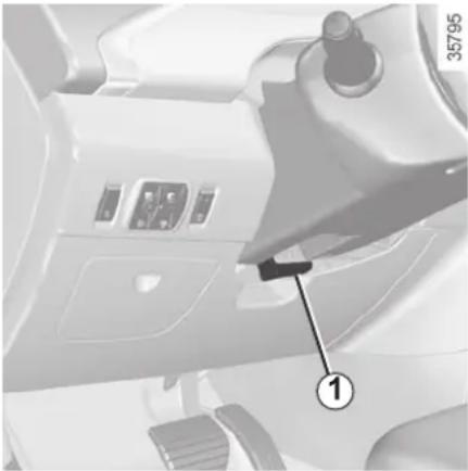
natural_image
Interior view of a vehicle dashboard with control panel and labeled component (no readable text or symbols)Height and reach adjustment
Pull lever 1 and move the steering wheel to the required position.
Then, push the lever back fully, beyond the point of resistance to lock the steering wheel.
Make sure that the steering wheel is correctly locked.

For safety reasons, only adjust the steering wheel when the vehicle is stationary.
Power-assisted steering
The variable power-assisted steering system is equipped with an electronic control system which alters the level of assistance to suit the vehicle speed.
Steering is made easier during parking manoeuvres (for added comfort) whilst the force needed to steer increases progressively as the speed rises (for enhanced safety at high speeds).

Never switch off the ignition when travelling downhill, and avoid doing so in normal driving (assistance provided).
Never leave the steering wheel on full lock when the vehicle is stationary.
With the engine switched off, or if there is a system fault, it is still possible to turn the steering wheel. The force required will be greater.
A noise may be heard when the steering wheel is moved quickly. This is normal.
DRIVING POSITION: LEFT-HAND DRIVE (1/2)
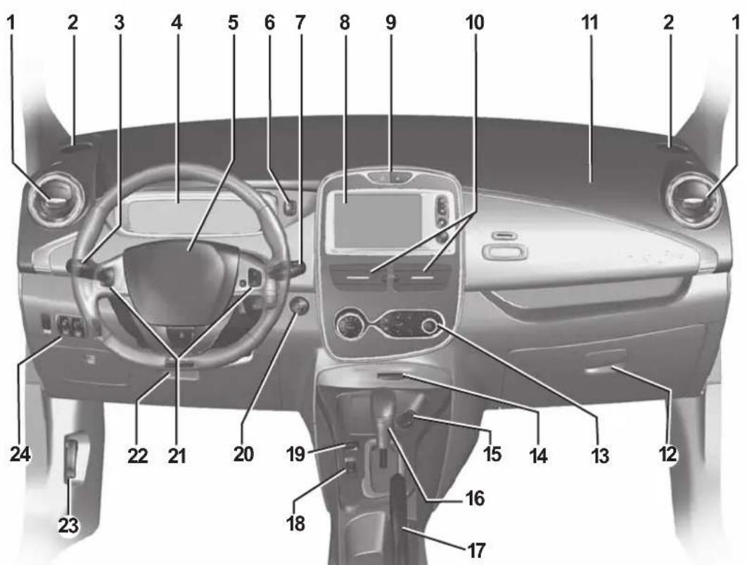
DRIVING POSITION: LEFT-HAND DRIVE (2/2)
The equipment fitted, described below, DEPENDS ON THE VERSION AND COUNTRY.
1 Side air vent.
2 Side window demister outlet.
3 Stalk for:
– direction indicator lights,
- exterior lights,
- rear fog light.
4 Instrument panel.
5 Driver airbag and horn location.
6 Ambiance selection switch.
7 – Windscreen wiper/washer stalk,
- On-board computer information readout control and vehicle settings personalisation menu.
8 Multimedia touch screen or radio.
9 - Central door locking/unlocking controls.
– Hazard warning lights switch.
10 Centre air vents.
11 Passenger airbag location.
12 Glove compartment.
13 Air-conditioning control.
14 Card reader RENAULT.
15 Accessories socket.
16 Gearstick.
17 Handbrake.
18 Main switch for:
- speed limiter;
- cruise control.
19 ECO mode activation/deactivation control.
20 Engine start/stop button.
21 Cruise control/speed limiter controls.
22 Control for adjusting steering wheel height.
23 Bonnet release control.
24 Controls for:
– unlocking the charging flap and the charging socket;
- headlight beam height remote adjustment;
– lighting dimmer for control instruments;
- activation/deactivation and selection of pedestrian warning noise.
DRIVING POSITION: RIGHT-HAND DRIVE (1/2)
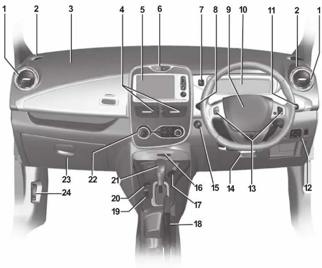
DRIVING POSITION: RIGHT-HAND DRIVE (2/2)
The equipment fitted, described below, DEPENDS ON THE VERSION AND COUNTRY.
1 Side air vent.
2 Side window demister outlet.
3 Passenger airbag location.
4 Centre air vents.
5 Multimedia touch screen or radio.
6 - Central door locking/unlocking controls.
– Hazard warning lights switch.
7 Ambiance selection switch.
8 Stalk:
– direction indicator lights,
- exterior lights,
- rear fog light.
9 Driver airbag and horn location.
10 Instrument panel.
11 – Windscreen wiper/washer stalk,
- On-board computer information readout control and vehicle settings personalisation menu.
12 Controls for:
– unlocking the charging flap and the charging socket;
- headlight beam height remote adjustment;
– lighting dimmer for control instruments;
- activation/deactivation and selection of pedestrian warning noise.
13 Cruise control/speed limiter controls.
14 Control for adjusting steering wheel height.
15 Engine start/stop button.
16 Card reader RENAULT.
17 Accessories socket.
18 Handbrake.
19 Main switch for:
- speed limiter;
- cruise control.
20 ECO mode activation/deactivation control.
21 Gearstick.
22 Air-conditioning control.
23 Glove compartment.
24 Bonnet release control.
WARNING LIGHTS (1/3)
The presence and operation of the warning lights DEPEND ON THE EQUIPMENT AND COUNTRY.
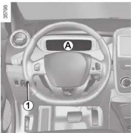
natural_image
Interior view of a car dashboard with labeled components (A and 1), no readable text or symbols beyond labelsInstrument panel A: lights up when the headlamps are switched on. The brightness can be adjusted by turning the control knob 1.
In some cases, the appearance of a warning light is accompanied by a message.
The warning light means you should drive very carefully to an approved dealer as soon as possible. If you fail to follow this recommendation, you risk damaging your vehicle.

Side light tell-tale light

Main beam headlight tell-tale light

Dipped beam headlight tell-tale light

Rear fog light tell-tale light

Left-hand direction indicator tell-tale light

Right-hand direction indicator tell-tale light

The STOP warning light requires you to stop immediately, for your own safety, as soon as traffic conditions allow. Switch off the engine and do not restart it. Contact an Authorised Dealer.

Air bag warning light
This comes on when the ignition is switched on and goes out after a few seconds.
If it does not light up when the ignition is switched on, or if it lights up when the engine is running, it indicates a fault in the system.
Contact your approved Dealer as soon as possible.

Handbrake "on" warning light
Please refer to "Handbrake" section in Section 2.

If no lights or sounds are apparent, this indicates a fault in the instrument panel. This indicates that it is essential to stop immediately (as soon as traffic conditions allow). Ensure that the vehicle is correctly immobilised and contact an approved Dealer.
WARNING LIGHTS (2/3)
The presence and operation of the warning lights DEPEND ON THE EQUIPMENT AND COUNTRY.
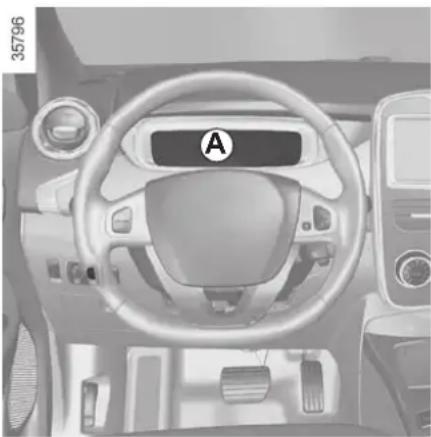
natural_image
Interior view of a car dashboard with steering wheel and dashboard (no visible text or symbols)
STOP light
STOP This lights up when the ignition is switched on and goes out as soon as the engine is started. It comes on with other warning lights and/or messages, and is accompanied by a beep.
It requires you to stop immediately, for your own safety, as soon as traffic conditions allow. Switch off the engine and do not restart it.
Contact an approved Dealer.

Brake circuit fault warning light
If it comes on during braking and is ac-
companied by the STOP warning light and a beep, it indicates that the fluid level in the circuit is low or that there is a braking system fault. Stop as soon as traffic conditions allow and contact an authorised dealer.

Secondary 12 V battery charge warning light
If it comes on together with the STOP warning light and a beep, this means that the electrical circuit is overcharged or discharged.


Warning light
This lights up when the ignition is switched on and goes out as soon as the engine is started. It can light up in conjunction with other warning lights and/or messages on the instrument panel.
It means you should drive very carefully to an approved dealer as soon as possible. If you fail to follow this recommendation, you risk damaging your vehicle.

Front seat belt reminder warning light
It lights up on the central display when the engine is started and, if the driver's seat belt is not fastened, the light flashes and a beep sounds for about two minutes when the vehicle reaches a speed of approximately 12 mph (20 km/h).


Cruise control and speed limiter indica-
tor lights
Refer to the information on "Cruise control/speed limiter" in Section 2.
WARNING LIGHTS (3/3)
The presence and operation of the warning lights DEPEND ON THE EQUIPMENT AND COUNTRY.
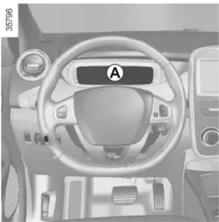
natural_image
Interior view of a car dashboard with steering wheel and dashboard (no visible text or symbols)
Anti-lock braking warning light
This lights up when the ignition is switched on and goes out after a few seconds.
If it does not go out after the ignition is switched on, or lights up when driving, there is a fault with the ABS. Braking will then be as normal, without the ABS. Contact an approved Dealer as soon as possible.

Electrotechnical system warning light
When the warning light comes on, this indicates that the traction battery temperature is too low or that the engine or traction battery temperature is too high. Opt for a calmer driving style.
The warning light can lead to a drop in vehicle performance.
If it comes on when you start the vehicle, this indicates a fault in the secondary 12 V battery.

Low traction battery level warning light
It flashes when the traction battery charge level has reached the reserve threshold. Please see the information on "Displays and indicators" in Section 1.

ECO mode function light
This lights up when the function is activated.

Electrotechnical system warning light
If it lights up while driving, this means there is an electrotechnical fault in the "400 Volt" electrical circuit. Please see an authorised dealer as soon as possible.

Electronic Stability Program (ESC) and traction control warning light
There are several reasons for the warning light coming on: please refer to the information on "Driver correction devices and aids" in Section 2.

Tyre pressure loss warning
Please refer to the information Tyre pressure loss warning" in 2.

Seat heating indicator light
Refer to the information on the
"Front seats" in Section 1.

Door(s) open warning light
DISPLAYS AND INDICATORS (1/2)
The presence and operation of the display and indicators DEPENDS ON THE LEVEL OF EQUIPMENT AND THE COUNTRY.
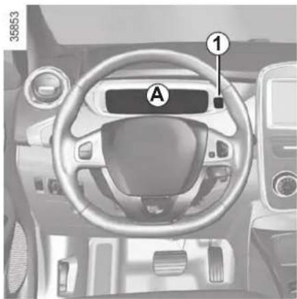
natural_image
Interior view of a car dashboard with labeled components (A, 1), no readable text or symbols beyond labelsYou may customise your instrument panel A with content and colours of your choice.
Press the switch 1 repeatedly to obtain the desired display.
Charge meter 2
Please refer to the information on the "Charge meter" in Section 2.
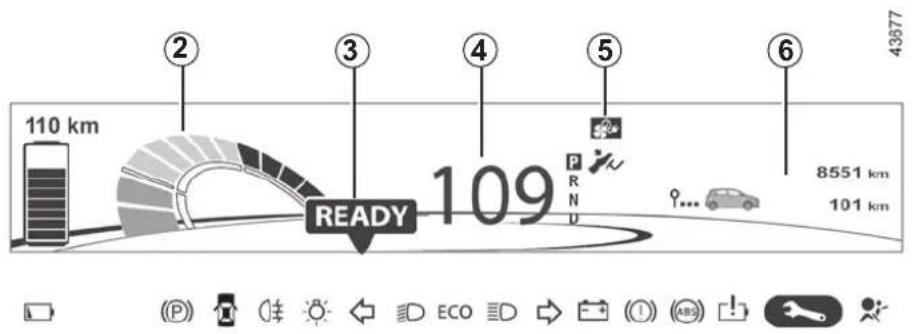
Message indicating vehicle ready for driving 3
The message READY comes on when the engine is started.
Speedometer 4
Vehicle speed is limited to approximately 80 mph (135 km/h).
Indicator of charging programming and/or air conditioning 5
On-board computer display 6
Please refer to the information on the "Trip computer: general information" in Section 1.
Instrument panel in miles
It is possible to switch to km/h. On the multimedia display, select "Menu", "System", "System settings", "Set units" and confirm. To return to the previous mode, repeat the same operation.
DISPLAYS AND INDICATORS (2/2)
The presence and operation of the display and indicators DEPENDS ON THE LEVEL OF EQUIPMENT AND THE COUNTRY.
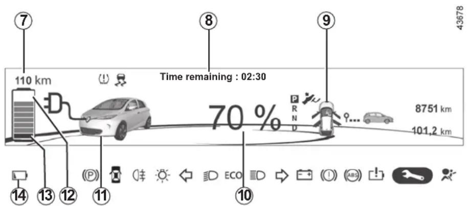
Estimated range 7
Remaining charge time 8
from about 95% charge, the remaining charge time is no longer displayed.
Opening element warning light 9
Shows when a door, the tailgate or charging flap is open or not closed properly.
Traction battery charge load 10
Charging cable "Plugged In" warning light 11
This comes on when the charging cord is plugged into the vehicle.
Charge level 12
The gauge indicates the level of energy remaining.
Reserve level 13
This means the traction battery charge has reached approximately 7% or, depending on the vehicle, approximately 12%. The 14 warning light comes on and a beep sounds. The charge level 12 and range 7 turn to orange. To optimise your range, please see the information on “Recommendations: saving energy” in Section 2.
Immobilisation threshold imminent
When the charge level reaches 4.5% or, depending on the vehicle, approximately 6%, a beep is heard and the warning light 14 flashes.
When the charge level reaches 3.5% or, depending on the vehicle, approximately 5%, the range value is no longer displayed. Motor performance gradually decreases until the vehicle comes to a stop.
Refer to the information on "Towing" in Section 5.
TRIP COMPUTER: general information (1/2)
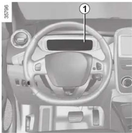
natural_image
Interior view of a car dashboard with steering wheel and dashboard (no visible text or symbols)Trip computer 1
Depending on the vehicle, this includes the following functions:
- distance travelled;
- journey parameters;
- information messages;
- operating fault messages (connected to the warning light);
- warning messages (connected to the STOP warning light).
All these functions are described on the following pages.
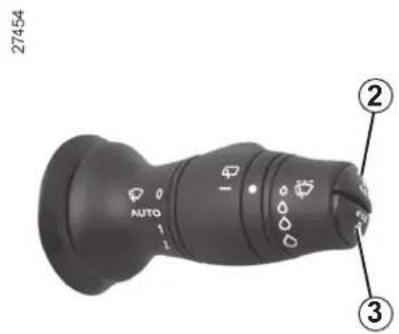
Display selection keys 2 and 3
Scroll through the following information upwards (key 2) or downwards (key 3) by pressing briefly and successively (the display depends on the vehicle equipment and country).
a) total mileage and trip mileage recorder;
b) journey parameters:
– current energy consumption;
– total energy consumption and distance travelled since the last reset;
– average energy consumption and average speed.
c) service interval;
d) tyre pressure reset;
e) trip log, operating faults and information message readout;
f) depending on the vehicle and only when stopped, settings customisation menu:
- clock;
- language;
- automatic locking of the doors while driving;
– rear windscreen wiping in reverse gear;
– switching off the instrument panel when charging;
g) depending on the vehicle and only when stopped, programming menu:
- charging; activation and setting the start time;
– Air conditioning; activation and setting the start time.
TRIP COMPUTER: general information (2/2)
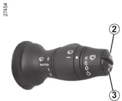
Trip mileage resetting
With "trip mileage recorder" selected on the display, press the button 2 or 3 until the mileage recorder resets to zero.
Resetting the journey parameters (reset button)
with the display showing one of the journey parameters, press button 2 or 3 until the display is reset.
Automatic resetting of the journey parameters
Resetting occurs automatically when the maximum value of any of the parameters is exceeded.
Reading energy consumption values
Some vehicle equipment items consume energy: the energy consumed by the vehicle may therefore differ from the energy consumed on the electric counter.
Interpreting some of the values displayed after resetting
The values showing average energy consumption and average speed will become more stable and reliable the further you have travelled since the last time the Reset button was pressed.
Resetting the estimated range
After a full recharge of the traction battery, you can select two types of resetting: manual or automatic.
Manual reset
With one of the trip parameters selected on the display, press and hold one of buttons 2 or 3 to reset the range.
Automatic reset
The range is automatically reset at the end of a full recharge of the traction battery to a value calculated based on the energy consumption over the last 125 miles (200 km).
Some on-board computer information appears on the navigation system display.
Resetting the mileage recorder, the trip settings, etc. is done simultaneously on the on-board computer and the navigation system.
ON-BOARD COMPUTER: trip settings (1/3)
The display of information shown below DEPENDS ON THE VEHICLE EQUIPMENT AND COUNTRY.
| Examples of selections Interpreting the display selected | |
| 101778 km112.4 km |  a) Total mileage and trip mileage recorder. a) Total mileage and trip mileage recorder. |
Totals20 kWh Energy concentration since the last reset. 522 km 522 km | b) Journey parameters. |
| Averages14,6 kWh/100km48 km/h | Distance travelled since the last reset. |
| Direct consump'n12 kW | From last reset.Average energy consumption.The value is displayed after having travelled at least 400 metres since the last reset.Average speed since the last reset.The value is displayed after driving 400 metres. |
 | |
| Current energy consumption. | |
ON-BOARD COMPUTER: trip settings (2/3)
The display of information shown below DEPENDS ON THE VEHICLE EQUIPMENT AND COUNTRY.
| Examples of selections Interpreting the display selected | |
| Service in1,210 milesor 3 months | c) Service interval. Distance remaining until the next service (displayed in miles/kilometres), then when the service nears, several scenarios are possible: - distance/time remaining less than 900 miles (1,500 km) or one month: the message “Service in” is displayed accompanied by the distance or time; - imminent service: the message “Schedule a service” is displayed, accompanied by the nearest term (distance or time); - mileage before service equal to 0 km/miles or service date reached: the message “Carry out service” is displayed accompanied by warning light The vehicle requires a service as soon as possible. |
| Resetting the display after the service in accordance with the maintenance schedule.The service interval must only be reset after a service which complies with the recommendations in the maintenance schedule.Special note: To reset the service interval, press and hold one of the display reset buttons for approximately 10 seconds until the display shows the mileage permanently. | |
ON-BOARD COMPUTER: trip settings (3/3)
The display of information shown below DEPENDS ON THE VEHICLE EQUIPMENT AND COUNTRY.
| Examples of selections Interpreting the display selected | |
| LEARNING THE TYRE PRESSURE | d) Reset the tyre pressure. Please refer to the information on the “Tyre pressure loss warning” in Section 2. Please refer to the information on the “Tyre pressure loss warning” in Section 2. |
| Passenger airbag off | e) Trip log. Successive display:– information messages;– operating fault messages. Successive display:– information messages;– operating fault messages. |
TRIP COMPUTER AND WARNING SYSTEM: information messages
These can help in the vehicle starting phase, or give information about a selection or a driving status. Examples of information messages are given in the following pages.
| Examples of messages Interpreting the display selected | |
| «Disconnect cable to start up» | Indicates that the charging cord is still plugged into the vehicle. |
| «Please insert keycard» Indicates that the cardRENAULT is not in the reader. | |
| «Steering wheel not locked» Indicates that the steering column has not been locked. | |
| «Apply brakes» Follow these instructions: risk of damage to the motor. | |
| «Check connections» | Unplug, then plug in the vehicle.If the message still shows, this may be caused by the external charging conditions or by the home installation. |
| «Check charging post» | Indicates a possible electrical fault or a defective charging cable: change the charging terminal or location or have the cable checked. |
| «Power cut while charging» | Indicates an electrical fault while charging. Restart charging.If this does not work, have the electrical installation checked. |
| «Charging refused no contract» | Charging prohibited by your battery rental organisation. Rectify the situation. |
TRIP COMPUTER AND WARNING SYSTEM: operating fault messages
These appear with the warning light and mean that you should drive very carefully to an authorised dealer as soon as possible. If you fail to follow this recommendation, you risk damaging your vehicle.
They disappear when the display selection key is pressed or after several seconds and are stored in the computer log. The warning light stays on. Examples of operating fault messages are given in the following pages.

| Examples of messages Interpreting the display selected | |
| «Check airbag» | Indicates a fault in the restraint system in addition to the seat belts. In the event of an accident, it is possible that they may not be triggered. |
| «Elec. System to check» | Indicates a fault on one of the pedal sensors or in the 12 V battery management system. |
| «Check braking system» Indicates wear | or the need to check the braking system. |
| «Vehicle plug to be checked» | Indicates overheating at the vehicle-side charging socket. Wait for about 20 minutes and try again. If this does not work, contact an authorised dealer. |
| «Elec. System to check» Indicates a fault in the traction system. | |
| «Always charging» Indicates a fault on the traction battery recharge system. | |
TRIP COMPUTER AND WARNING SYSTEM: warning message
These appear with the warning light STOP and require you to stop immediately, for your own safety, as soon as traffic conditions allow. Stop your engine and do not restart it. Contact an Authorised Dealer.
Examples of warning messages are given in the following pages. Note: the messages appear on the display either individually or alternately (when there are several messages to be displayed), and may be accompanied by a warning light and/or a beep.
| Examples of messages Interpreting the display selected | |
| «Braking system fault» Indicates a fault in the braking system. | |
| «Power steering fault» Indicates a fault in the steering. | |
| «Electrical motor fault» Indicates that the vehicle is losing power. | |
| «Electrical fault danger» Indicates a fault in the electric system. | |
| “ PUNCTURE “ Indicates that at least one wheel is punctured or severely underinflated. |
CLOCK AND EXTERIOR TEMPERATURE (1/2)
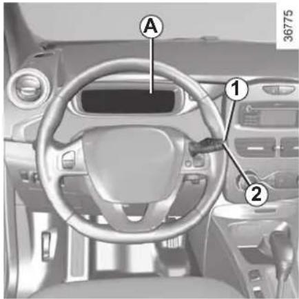
Resetting the clock A
To access the display 3 for setting the time:
- press button 1 or 2 a few times to obtain the menu "Time settings". Wait for a few seconds.
- hold down button 1 or 2 - the hours flash;
- press buttons 1 and 2 to set the hour;
- hold down button 1 or 2 to confirm the hour setting;
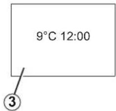
- the minutes flash - press buttons 1 and 2 to set the minutes;
- hold down button 1 or 2 to confirm the minutes setting. Your settings are now saved.
If the power supply is cut (battery disconnected, supply wire cut, etc.), the clock must be reset.
We recommend that you do not adjust these settings while driving.
CLOCK AND EXTERIOR TEMPERATURE (2/2)
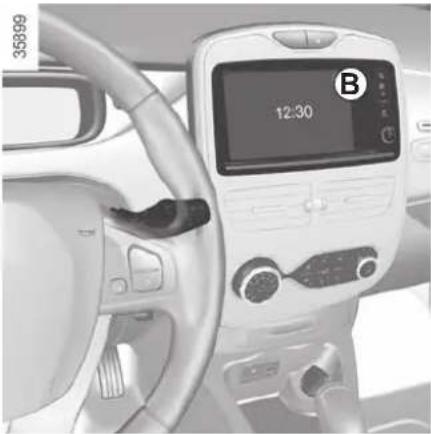
natural_image
Interior view of a car dashboard with a digital display showing 12:30, no visible text or symbols on the device itself.Resetting the clock B
The time setting is done automatically. You may, however, change this.
On the display B, select "Menu", "System" then "Time settings". Set the hours and minutes. Then confirm your choice.
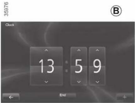
External temperature indicator
Special note:
When the outside temperature is -3^ to +3^ , the ^ characters flash (signalling a risk of ice on the road).

External temperature indicator
As ice formation is related to climatic exposure, local air humidity and temperature, the external temperature alone is not sufficient to detect ice.
REAR-VIEW MIRRORS
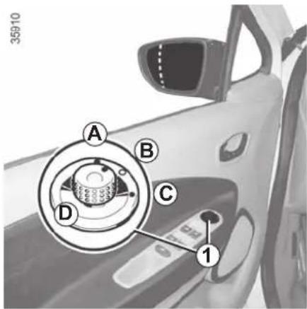
Door mirrors with electrical adjustment:
With the ignition on, turn button 1:
- position A to adjust the left-hand door mirror;
- position C to adjust the right-hand door mirror;
B is the inactive position.
Heated door mirrors
When the engine is started, mirror de-icing is activated with the rear screen de-icing/demisting.
Move button 1 to position D to fold the door mirrors in. To reset them for driving, return to position B.
If you fold the door mirrors in manually before resetting them to driving position B, you must first turn button 1 to position D.

Objects observed in the door mirror glass are actually closer than they appear.
For your safety, take this into account in order to correctly assess the distance before any manoeuvre.
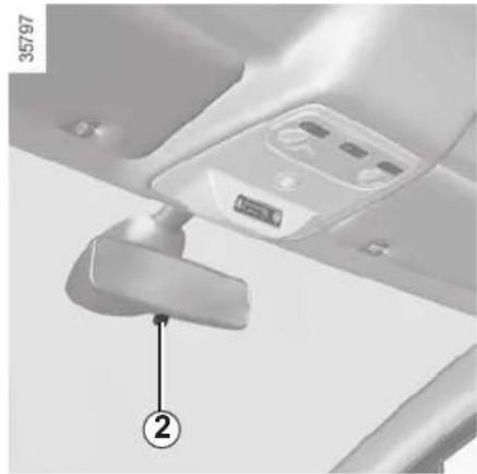
natural_image
Close-up of a mechanical component with labeled parts (no readable text or symbols)Interior rear view mirror
Its position can be adjusted.
When driving at night, to avoid being dazzled by the headlights of the vehicle behind, depress the little lever located behind rear view mirror 2.

For safety reasons, carry out any adjustments when the vehicle is stationary.
AUDIBLE AND VISUAL SIGNALS
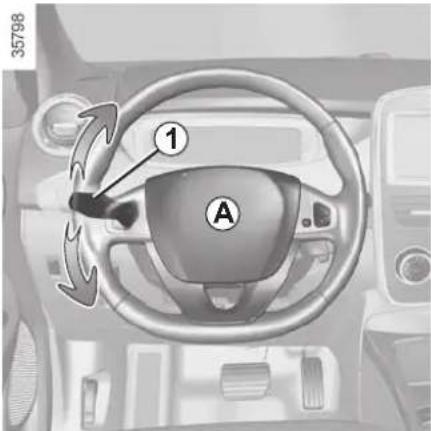
Horn
Press steering wheel boss A.
Headlight flasher
Pull stalk 1 towards you to flash the headlights.
Direction indicators
Move stalk 1 parallel to the steering wheel and in the direction you are going to turn it.
One-touch mode
When driving, it is possible that the steering wheel may not be turned sufficiently to return the stalk automatically to its starting position.
In this case, briefly turn stalk 1 to the intermediate position, then release it: the stalk returns to its original point and the indicator light flashes three times.
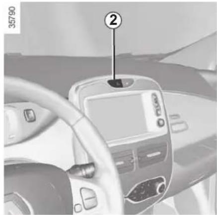
natural_image
Interior view of a car dashboard with steering wheel and digital display (no visible text or symbols)
Hazard warning lights
Press switch 2. This switch il-
luminates all four direction indicators and the side-mounted indicator lights simultaneously. It must only be used in an emergency to warn drivers of other vehicles that you have had to stop in an area where stopping is prohibited or unexpected or that you are obliged to drive under special conditions.
Depending on the vehicle, the hazard warning lights may come on automatically under heavy deceleration. You can switch them off by pressing switch 2.
PEDESTRIAN HORN
Electric vehicles are particularly quiet. This system enables you to warn people of your presence – especially pedestrians and cyclists.
The system is activated automatically when the engine is started. The sound triggers when the vehicle speed is between 1 and 20 mph.
Deactivating the system
With the engine running, press the switch 1 to deactivate the function. The warning light 2 in the switch 1 comes on.
Activating the system
With the engine running, press the switch 1 to activate the function. The warning light 2 in the switch 1 goes out.
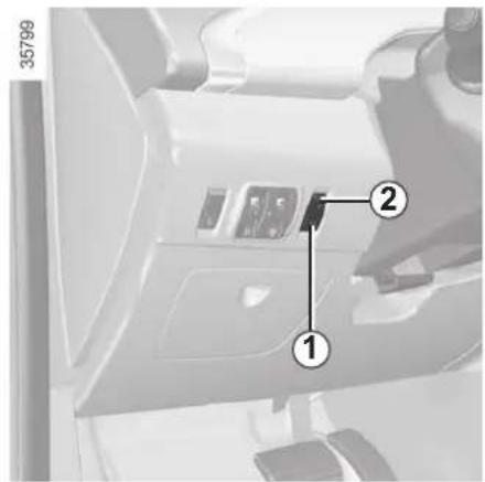
System activated:
- it goes on standby automatically when the vehicle speed is above approximately 20 mph (30 km/h);
- The system is activated automatically when the vehicle is being driven at a speed below approximately 20 mph (30 km/h).
Warning noise selection
- Keep switch 1 pressed down.
The various sounds will be played in succession; - release switch 1 on the sound of your choice.
EXTERIOR LIGHTING AND SIGNALS (1/3)
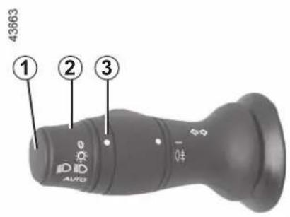

Side lights
Turn the ring 2 until the symbol is opposite mark 3. This indicator light on the instrument panel comes on.
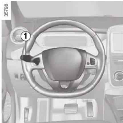
natural_image
Interior view of a car dashboard with steering wheel and dashboard (no visible text or symbols)Daytime running lights
The daytime running lights come on automatically with no action on stalk 1 when the engine is started, and they go off once the engine is switched off.

Before driving at night, check that the electrical equipment is operating correctly and adjust the headlight beams (if your vehicle is not carrying its normal load). As a general precaution, check that the lights are not obscured (by dirt, mud, snow or objects being transported).

Dipped beam headlights
Manual operation
Turn the ring 2 until the symbol is opposite mark 3. This indicator light on the instrument panel comes on.
Automatic operation
(depending on vehicle)
Turn ring 2 until the AUTO symbol is opposite mark 3: with the engine running, the dipped beam headlights switch on or off automatically depending on the brightness of the light outside, without any action on stalk 1.
If driving on the left in a left-hand drive vehicle (or vice versa), drivers must have the lights adjusted by an authorised dealer for the duration of the trip.
EXTERIOR LIGHTING AND SIGNALS (2/3)
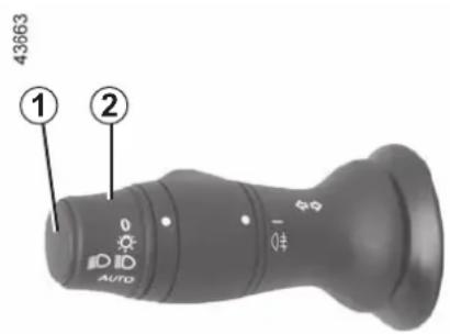

Main beam headlights
With the dipped beam headlights lit, pull stalk 1 towards you. This indicator light on the instrument panel comes on.
To return to the dipped headlight position, pull stalk 1 towards you again.
Switching off the lights
There are two possibilities:
- manually, move ring 2 to position 0; - the lights will go out automatically when the engine is switched off, the driver's door is opened or the vehicle is locked. In this case, the next time the engine is started the lights will be switched back on according to the position of the ring 2.
NB: if the fog lights are lit, the lights are not switched off automatically.
Lights-on reminder buzzer
A warning beep sounds when the driver's door is opened to warn you that the lights are still on.
"See-me-home lighting" function
Depending on the vehicle, this function allows you to briefly switch on the dipped beam headlights (to provide light when opening a gate, etc.).
With the engine and lights switched off and the ring 2 in position 0, pull the stalk 1 towards you: the dipped beam headlights come on for approximately thirty seconds. To increase this duration, you may pull the stalk up to four times (total time restricted to approximately two minutes).
To switch off the lights before they go out automatically, turn ring 2 to any position, then return it to position 0.
EXTERIOR LIGHTING AND SIGNALS (3/3)
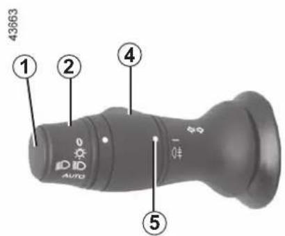

Rear fog light
Turn centre ring 4 on the stalk until the symbol faces mark 5, then release it.
Operation of the fog lights depends on the exterior lighting selected, and an indicator light will light up on the instrument panel.
To avoid inconveniencing other road users, remember to switch off the rear fog light when it is no longer needed.
Switching off the lights
Turn the central ring 4 again to align marker 5 with the symbol. The warning light on the instrument panel goes out.
The rear fog lights switch off when the exterior lights are switched off.
When driving in fog or snow, or when transporting objects which are higher than the roof, the headlights do not come on automatically.
The driver remains in full control of switching on the fog lights: the indicator lights on the instrument panel inform you whether the fog lights are lit (indicator light on) or not (indicator light off).
HEADLIGHT BEAM ADJUSTMENT
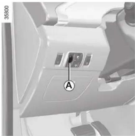
natural_image
Interior view of a vehicle's air vent with labeled component A (no text or symbols beyond label)On vehicles fitted with this function, control A allows you to adjust the height of the beams according to the load.
Turn control A downwards to lower the headlights and upwards to raise them.
For vehicles not fitted with control A, adjustment is automatic.
| For manual settingsExamples of positions for adjusting control A according to the load | |
| 0 Driver | alone or with front passenger |
| 1 | Driver with one front passenger and two or three rear passengers |
| 2 | Driver with one front passenger, three rear passengers and luggage |
| 2 | Driver with luggage or load reaching the maximum authorised load weight |
| 3 | Driver and luggage (reaching the maximum permissible all-up weight) |
| 4 Do not use | |
The table below gives some examples. In all cases, adjust control A according to the vehicle load so that the road can be seen and other drivers are not dazzled.
If driving on the left in a left-hand drive vehicle (or vice versa), drivers must have the lights adjusted by an authorised dealer for the duration of the trip.
WINDSCREEN WASH, WIPE (1/2)
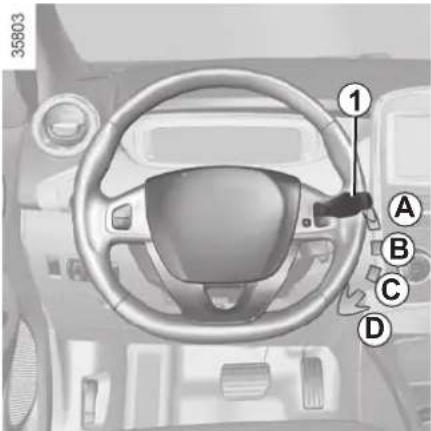
Vehicle fitted with intermittent windscreen wipers
A park
B intermittent wiping
The wipers will pause for several seconds between sweeps. It is possible to change the time between sweeps by turning ring 2.
C normal wiping speed
D fast wiping speed
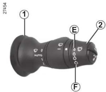
Special note
When driving the vehicle, the wiping speed slows down whenever the vehicle stops. For example, fast wiping speed will slow to normal wiping speed. As soon as the vehicle moves off, wiping will return to the speed originally selected.
If stalk 1 is operated, it overrides and cancels the automatic function.
For all vehicles, position C can be accessed with the ignition on and positions B and D can only be accessed with the engine running.
Vehicles with automatic wiper function
A park
B automatic wiper function.
When this position is selected, the system detects water on the wind-screen and triggers the wipers at a suitable wiping speed. It is possible to change the triggering threshold and the time sweeps by turning ring 2:
- E : minimum sensitivity
- F: maximum sensitivity
NB: in foggy weather or during snowfalls, the wiping is not automatically triggered and remains under the driver's control.
C normal wiping speed
D fast wiping speed
WINDSCREEN WASH, WIPE (2/2)
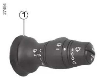
Windscreen washer
With the ignition on, pull stalk 1 then release.
A brief pull will trigger a single sweep of the wipers, in addition to the wind-screen washer.
A longer pull will trigger three sweeps of the wipers followed, a few seconds later, by a fourth, in addition to the wind-screen washer.
Efficiency of a wiper blade
Check the condition of the wiper blades. How long they last depends on you:
- it must remain clean: clean the blade and the screen regularly with soapy water;
- do not use it when the screen is dry;
- free it from the screen when it has not been used for a long time.
Replace wiper blades as soon as their performance starts to diminish: Approximately every year (refer to the information on "Wiper blades" in section 5).
Precautions for using the wipers
- In freezing or snowy weather, clear the screen before starting the wipers (risk of motor overheating);
- ensure that no objects are obstructing the travel of the blade.
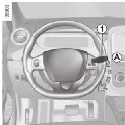
natural_image
Interior view of a vehicle dashboard with steering wheel and control panel (no visible text or symbols)
When working in the engine compartment, ensure that the windscreen wiper stalk is in position A (park).
Risk of injury.

Before any action on the windscreen (washing the vehicle, de-icing, cleaning the windscreen, etc.) return to position A (off).
Risk of injury and/or damage.
REAR SCREEN WASH, WIPE
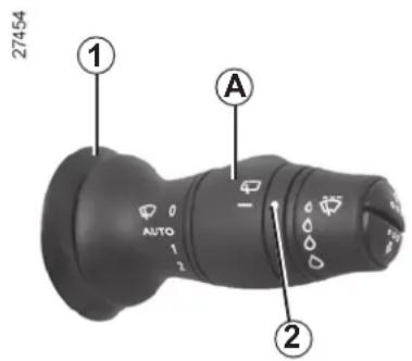

Rear screen wiper
With the ignition on, turn ring A on stalk 1 to align the symbol with mark 2 then release it.
To stop the operation, pivot ring A again.
Wiping frequency varies with vehicle speed.

Rear screen washer/wiper
With the ignition on, push the stalk.
Do not use the wiper arm to open or close the tailgate.
Efficiency of a wiper blade
Check the condition of the wiper blades. How long they last depends on you:
- it must remain clean: clean the blade and the screen regularly with soapy water;
– do not use it when the screen is dry;
– free it from the screen when it has not been used for a long time.
Replace wiper blades as soon as their performance starts to diminish: Approximately every year (refer to the information on "Wiper blades" in section 5).
Precautions for using the wipers
- In freezing or snowy weather, clear the screen before starting the wipers (risk of motor overheating);
- ensure that no objects are obstructing the travel of the blade.
Section 2: Driving
(Advice on use relating to fuel economy and the environment)
Starting, stopping the engine.... 2.2
Gear control.... 2.5
Handbrake 2.6
Driving advice, Eco-driving 2.7
Vehicle range: advice 2.10
Environment 2.12
Tyre pressure loss warning 2.13
Driving correction devices 2.16
Speed limiter 2.21
Cruise control 2.24
Parking distance control 2.28
Reversing camera 2.30
2.1
STARTING, STOPPING THE ENGINE (1/3)
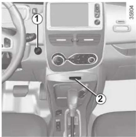
Remote control RENAULT card
When you get into the vehicle, insert the RENAULT card fully into card reader 2.
To start
- position the gear lever to the position P only;
- press button 1. The message READY comes on, on the instrument panel, along with a beep.
The message disappears when the vehicle speed is above approximately 3.1 mph (5 km/h).
35865
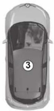
natural_image
Top-down view of a car with the number 3 marked on the front wheel (no text or symbols on the car itself)Hands-free RENAULT card
The RENAULT card must be inserted in card reader 2 or in detection zone 3.
To start
- position the gear lever to the position P only;
- depress the brake pedal;
- press button 1. The message READY comes on, on the instrument panel, along with a beep.
The message disappears when the vehicle speed is above approximately 3.1 mph (5 km/h).
The vehicle can only be started if the charging cord is unplugged from the vehicle.
The vehicle can only be started if the selection lever is at P. Please see the information on "Gear control" in Section 2.
STARTING, STOPPING THE ENGINE (2/3)
Operating faults
In certain cases, the hands-free RENAULT card may not work:
- the card battery RENAULT is drained, flat 12 V battery, etc.
- near to appliances operating on the same frequency as the card (monitor, mobile phone, video game, etc.);
- vehicle located in a high electromagnetic radiation zone.
The message "Please insert keycard" appears on the instrument panel.
Insert the RENAULT card fully into card reader 2.

Driver's responsibility when parking or stopping the vehicle
Never leave an animal, child or adult who is not self-sufficient alone in your vehicle, even for a short time.
They may pose a risk to themselves or to others by starting the engine, activating equipment such as the electric windows or locking the doors, for example.
Also, in hot and/or sunny weather, please remember that the temperature inside the passenger compartment increases very quickly.
RISK OF DEATH OR SERIOUS INJURY.
STARTING, STOPPING THE ENGINE (3/3)
Conditions for stopping the engine
The vehicle must be stationary, with the lever positioned to N or P.

Driver's responsibility when parking or stopping the vehicle
Never leave an animal, child or adult who is not self-sufficient alone in your vehicle, even for a short time.
They may pose a risk to themselves or to others by starting the engine, activating equipment such as the electric windows or locking the doors, for example.
Also, in hot and/or sunny weather, please remember that the temperature inside the passenger compartment increases very quickly.
RISK OF DEATH OR SERIOUS INJURY.
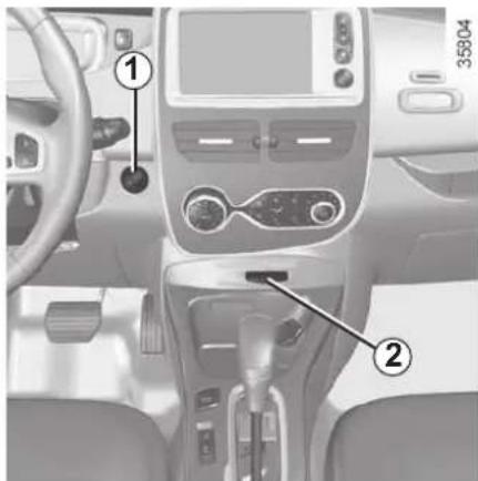
Remote control RENAULT card
With the card in reader 2, press button 1: the engine will stop. The message READY goes out on the instrument panel.
Removing the card from the reader locks the steering column.
Special note
If the card is no longer in the reader when you try to switch the engine off, the message "No keycard Press and hold" will appear on the instrument panel: press the button 1 for longer than two seconds.
Hands-free RENAULT card
With the card in the vehicle, press button 1: the engine switches off and the message READY goes out on the instrument panel. The steering column is locked when the driver's door is opened or the vehicle is locked.
If the card is no longer in the passenger compartment when you try to switch the engine off, the message "No key-card Press and hold" appears on the instrument panel: press the button 1 for longer than two seconds.
With the engine switched off, any accessories being used (radio, etc.) will continue to function for approximately 10 minutes.
When the driver's door is opened, the accessories stop working.

Never switch off the ignition before the vehicle has stopped completely. Once the engine has stopped, the
brake servo, power-assisted steering, etc. and the passive safety devices such as air bags and pretensioners will no longer operate.
GEAR CONTROL (1/2)
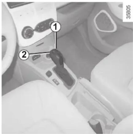
Operates similar to an automatic gearbox.
Selector lever 1
The display 3 on the instrument panel indicates the gear lever position.
P: park
R: reverse
N: neutral
D: forward drive
The vehicle can only be started if the charging cord is unplugged from the vehicle.
35806
③


Operation
To start the engine, please refer to the information on "Starting/Stopping the engine" in Section 2.
To move out of position P, you must depress the brake pedal before pressing unlocking button 2.
With the foot on the brake pedal (warning light 📋 on the display 3 goes out), move the lever out of position P.
The vehicle can only start of the gear selector is in position P.
Only engage D or R when the vehicle is stopped, with your foot on the brake and the accelerator pedal released.
Driving
Put the lever 1 to position D or R. The vehicle moves forward once you release the brake pedal (without pressing on the accelerator pedal).
While driving, press the accelerator pedal to achieve the desired speed.
The reversing lights will come on as soon as reverse gear is selected (with the ignition on).

Obstructions to the driver
On the driver's side, only use mats suitable for the vehicle, attached with the
pre-fitted components, and check the fitting regularly. Do not lay one mat on top of another. There is a risk of wedging the pedals
GEAR CONTROL (2/2)/HANDBRAKE
Parking the vehicle
When the vehicle is at a standstill, place the lever in position P: the drive wheels are mechanically locked by the transmission.
Apply the handbrake.

In the event of an impact to the underside of the vehicle (e.g.: striking a post, raised kerb or other street furniture), this may result in damage to the vehicle (e.g.: twisted axle), the electrical circuit or the traction battery.
Do not touch the circuit elements or any fluids or liquids.
To prevent any risk of accident, have your vehicle checked by an authorised dealer.
Risk of serious injury or electric shock and risk to life.
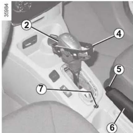
Operating fault
When setting off, if the lever is locked in position P, even though you are depressing the brake pedal and pressing the unlocking button 2, the lever can still be released manually. To do this, unclip the cover 4 at the base of the lever. Simultaneously press at the location 7 and the unlocking button 2 on the lever.
Handbrake
To release:
Pull the lever 6 up slightly, press button 5 and then lower the lever to the floor.
To apply:
Pull lever 6 upwards and make sure the vehicle is immobilised.

Make sure that the hand-brake is properly released when driving (red indicator light off), otherwise over-
heating may occur.

When stationary and depending on the slope and/or vehicle load, it may be necessary to pull up the hand-
brake at least two extra notches and engage position P.
DRIVING ADVICE, ECO-DRIVING (1/3)
Fuel consumption is accredited in accordance with a standard regulatory method. Identical for all manufacturers, this enables vehicles to be compared with one another. Consumption in real time depends on vehicle usage conditions, equipment fitted and the user's driving style. To optimise fuel consumption, please refer to the following advice.
Depending on the vehicle, you will have various functions which enable you to lower your fuel consumption:
- charge meter;
– the driving style indicator;
– the journey record and eco-driving advice via the multimedia display; - ECO mode – activated by the ECO button.
If fitted on the vehicle, the navigation system provides additional information.
The presence and display of this information depends on the type of ambiance selected. Please see the information on "Displays and indicators" in Section 1.
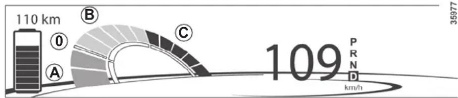
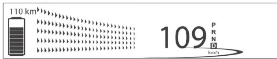
Charge meter
(on the instrument panel)
The charge meter gives the driver a real-time view of the vehicle's energy consumption.
Blue "Energy recovery" A usage zone
When driving, if you lift your foot off the accelerator pedal or apply the brake, the motor generates electrical current during deceleration, and this energy is used to slow down the vehicle and recharge the traction battery.
"Neutral" 0 usage zone
Indicates nil consumption.
Green "recommended consumption" B usage zone
The traction battery supplies the electrical energy required for the motor to move the vehicle.
Yellow "Consumption not recommended" C usage zone
Indicates high energy consumption.
DRIVING ADVICE, ECO-DRIVING (2/3)
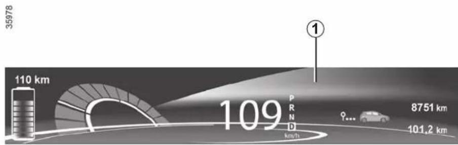
Driving style indicator
Lets you know about the driving style adopted (speed and anticipation). You are notified by the colour in the zone 1 on the instrument panel.
- Green: measured, economical driving;
- Blue: for less flexible driving;
– Purple: driving too fast.
Journey log (Driving ECO ^2 Score)
When the engine is switched off, "Journey record" shows on the multi-media display 2, for equipped vehicles, letting you see information about your last journey.
This indicates:
– average energy consumption;
– number of miles/kilometres travelled.
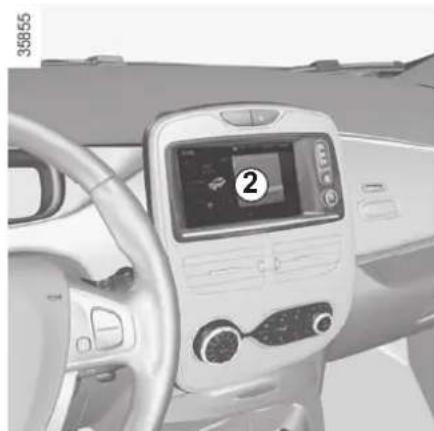
natural_image
Interior view of a car dashboard with touchscreen and steering wheel (no visible text or symbols)The instrument panel or multimedia display 2 shows:
- an overall grade taking into account acceleration, braking anticipation and your skill in managing speed;
– recommendations to enable you to improve your rating (please see the equipment instructions).
Navigation system
Using the information available on your navigation system (traffic information, nearest charging station, etc.) makes it easy to manage your journey.
DRIVING ADVICE, ECO-DRIVING (3/3)
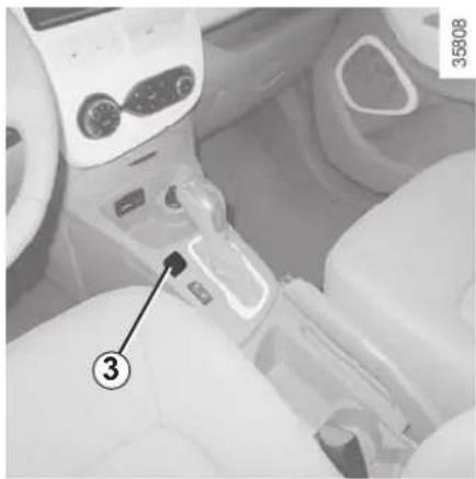
natural_image
Close-up of a car headset with a numbered component (3) pointing to a mechanical arm, no visible text or symbols.ECO mode
ECO mode is a function which optimises vehicle range. It acts upon certain power consuming systems in the vehicle (heating, air conditioning, power-assisted steering etc.) and on certain driving actions (acceleration, cruise control, deceleration etc.).
Activating the function
Press switch 3.
The warning light 5 ECO is displayed on the instrument panel and the lower part of the instrument panel 4 goes green.
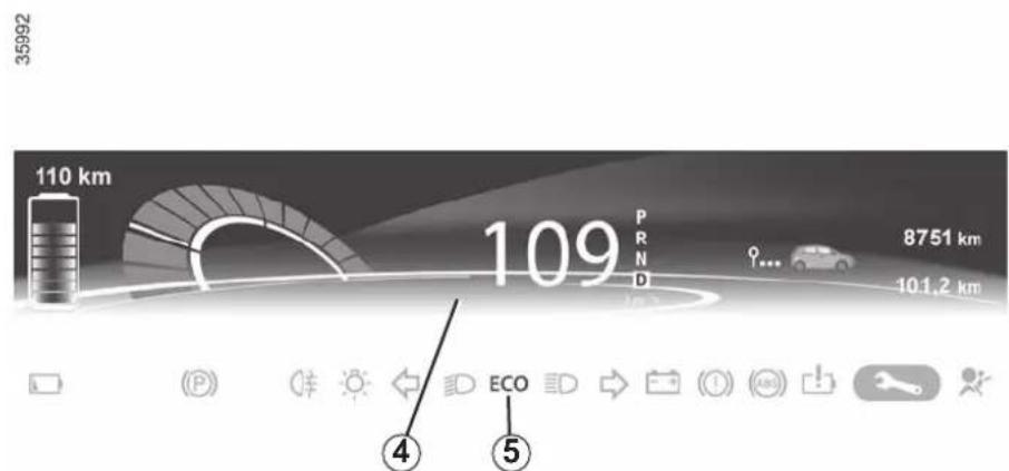
While driving, it is possible to leave the ECO mode temporarily in order to improve engine performance.
To do this, press the accelerator pedal firmly and fully.
ECO mode is reactivated when you take pressure off the accelerator pedal.
With ECO mode activated, the vehicle speed is limited to approximately 56 mph (90 km/h).
Disabling the function
Press switch 3.
The warning light 5 ECO goes off on the instrument panel and the lower part of the instrument panel 4 goes blue.
The cruise control switches to standby each time the ECO mode is activated or deactivated. Please refer to the information on "Cruise control/speed limiter: cruise control function" in Section 2.
VEHICLE RANGE: recommendations (1/2)
The vehicle range is approved for a mixed NEDC cycle (New European Driving Cycle).
In real usage, the range of an electric vehicle may vary depending on several factors over which you have partial control, which may make a considerable difference to the vehicle range. These factors are:
– speed and driving style;
- type of road;
- heating level;
- tyres;
– use of electrical accessories;
- vehicle loading.
Furthermore, activating ECO mode enables the vehicle to automatically take charge of all energy consuming elements (engine power, heating, etc.) to reduce their consumption to the fullest possible extent. Please refer to the information on "Eco-driving" in Section 2.
Speed and driving style
High speeds will reduce your vehicle's range.
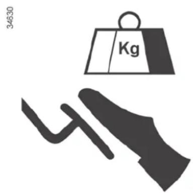
A "sporty" driving style reduces your vehicle range: opt for a "lighter" driving style.
Advice:
– drive at a constant speed.
- keep an eye on the tools available to you to view the road conditions (charge meter, current consumption, journey log, etc). Please refer to the information on "Eco-driving" in Section 2;
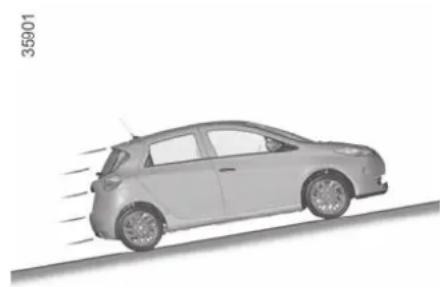
natural_image
Side view of a silver car with motion lines indicating speed, no visible text or symbols– adapt your driving style to avoid excessive energy consumption
- favour power recovery: anticipate traffic changes by lifting your foot off the accelerator pedal or by braking gradually.
Road type
Do not try to maintain the same speed up a hill, accelerate no more than you would on the level. Keep your foot in the same position on the accelerator pedal.
VEHICLE RANGE: recommendations (2/2)
34629
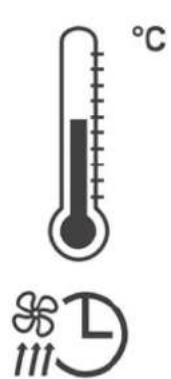
Heating levels
The use of heating or air-conditioning reduces vehicle range. To maintain your vehicle range, you are recommended to favour:
- before using the vehicle, the "programming" mode (please refer to the information in "Air-conditioning: programming" in Section 3).
- while driving, the ECO mode (please see information about "ECO driving" in Section 2).
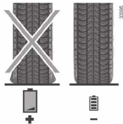
Tyres
An under-inflated tyre increases energy consumption. Comply with the specified tyre pressures for your vehicle. When driving, use tyres made by the same manufacturer, with the same dimensions, type and structure as the original tyres. The use of non-regulation tyres significantly reduces vehicle range. Please see the information on "Tyre pressure" in Section 4.
Vehicle loading
Avoid pointlessly overloading your vehicle.
ENVIRONMENT
Your vehicle has been designed with respect for the environment in mind for its entire service life: during production, use and at the end of its life.
This commitment is illustrated by the Renault eco ^2 group signature.
Manufacture
Your vehicle has been manufactured at an industrial site which uses a progress policy to reduce environmental impacts on rivers and natural areas (reduction of water and energy consumption, visual and noise pollution, atmospheric emissions and waste water, sorting and reusing waste).
Please make your own contribution towards protecting the environment too
- Worn parts replaced in the course of routine vehicle maintenance (secondary 12 V battery, batteries, etc.) must be disposed of through specialist organisations.
- At the end of the vehicle's service life, it should be sent to approved centres to ensure that it is recycled.
– In all cases, comply with local legislation.
Recycling
Your vehicle is 85% recyclable and 95% recoverable.
To achieve these objectives, many of the vehicle components have been designed to enable them to be recycled. The materials and structures have been carefully designed to allow these components to be easily removed and reprocessed by specialist companies.
In order to preserve raw material resources, this vehicle incorporates numerous parts made from recycled plastics or renewable materials (vegetable or animal-derived materials such as cotton or wool).
TYRE PRESSURE LOSS WARNING (1/3)
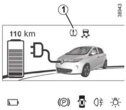
When fitted to the vehicle, this system notifies the driver if one or more tyres lose pressure.
Operating principle
Each wheel (except for the emergency spare wheel) has a sensor in the inflation valve which periodically measures the tyre pressure while driving.
Warning light 1 comes on to alert the driver in the event of insufficient pressure (deflated wheel, punctured tyre, etc.).
Resetting the standard level for the tyre pressures
This should be done:
- when the standard tyre pressure needs to be changed to adapt to usage conditions (empty, carrying a load, motorway driving, etc.);
- after swapping a wheel (however this practice is not recommended);
- after changing a wheel.
It should always be done after checking the tyre pressure of all four tyres when cold.
Tyre pressures must correspond to the current usage of the vehicle (empty, carrying a load, motorway driving, etc.).

This function is an additional driving aid.
However, the function does not take the place of the driver. It cannot, therefore, under any circumstances replace the vigilance or the responsibility of the driver.
Check the tyre pressures, including the emergency spare wheel, once a month.
TYRE PRESSURE LOSS WARNING (2/3)
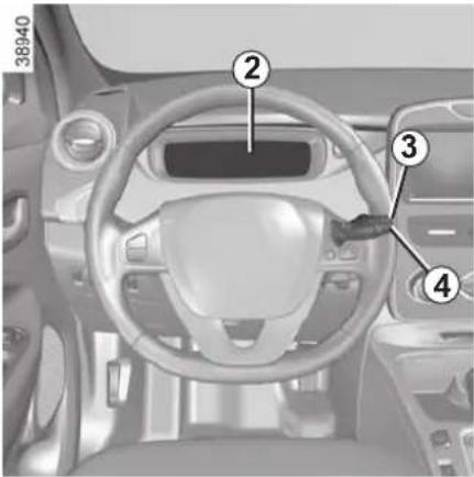
Resetting procedure
With the ignition on:
– repeatedly press button 3 or 4 to select the "LEARNING THE TYRE PRESSURE" function on the display 2;
- press and hold (around 3 seconds) button 3 or 4 to start initialisation. Display of the message "Pressure ref ongoing" indicates that the reset request for the tyre pressure reference value has been taken into account.
Reinitialisation is carried out after a few minutes' driving.
Note:
The standard tyre pressure cannot be less than that recommended and indicated on the door frame.
Display
Display 2 on the instrument panel informs you of any tyre pressure faults (flat tyre, punctured tyre, etc.).
Warning light comes on, along with the message «ADJUST TYRE PRESSURE».
These indicate that at least one tyre is flat.
Check and, if necessary, readjust the pressures of the four wheels when cold.
The warning light ⚠️ goes off after a few minutes' driving.
The sudden loss of pressure in a tyre (burst tyre, etc.) cannot be detected by the system.
« PUNCTURE »
The warning light

comes on
steady, accompanied by the message "PUNCTURE" and a beep.
This message appears along with the
STOP warning light.
They indicate that at least one wheel is punctured or severely underinflated. Replace it or contact an approved dealer if it is punctured. Top up the tyre pressure if the wheel is deflated.

Warning light STOP requires you to stop immediately, for your own safety, as soon as traffic conditions
allow.
TYRE PRESSURE LOSS WARNING (3/3)
"CHECK TYRE PRESSURE SENSORS
The warning light [icon] flashes for several seconds, then stays on, along with the message "CHECK TYRE PRESSURE SENSORS".
This message appears along with the warning light.
They indicate that at least one tyre is not fitted with sensors (e.g. emergency spare wheel). Otherwise, consult an authorised dealer.
Readjustment of tyre pressures
The tyre pressures must be adjusted when cold (please refer to the label located on the edge of the driver's door). If tyre pressures cannot be checked when the tyres are cold, the recommended pressures must be increased by 0.2 to 0.3 bar (3 PSI).
Never deflate a hot tyre.
Replacing wheels/tyres
This system requires specific equipment (wheels, tyres, hubcaps, etc.). Please see the information on "Tyres" in Section 5.
Contact an approved Dealer to fit new tyres and to find out about available accessories compatible with the system and available from your dealer network: the use of any other accessory could affect the correct operation of the system or damage a sensor.
Emergency spare wheel
If the vehicle is equipped with an emergency spare wheel, it will not have a sensor. When it is fitted on the vehicle,
the warning light [icon] flashes for several seconds, then stays on, together with the warning light [icon] and the message "CHECK TYRE PRESSURE SENSORS" appears on the instrument panel.
Tyre repair product and inflation kit
Because the valves are specially designed, only use equipment approved by the approved network. Please refer to "Tyre inflation kit" in Section 5.

Changing a wheel
The system may take several minutes depending on use for the new wheel pres-
sures to be recognised; check the tyre pressures after all operations.
DRIVER CORRECTION DEVICES, AIDS (1/5)
These include:
- the ABS (anti-lock braking system);
– the electronic stability program ESC with understeer control and traction control;
– emergency braking assistance with (depending on the vehicle) braking anticipation; - regenerative braking system.

These functions are an additional aid in the event of critical driving conditions, enabling the vehicle behaviour to be adapted to suit the driving conditions.
However, the functions do not take the place of the driver. They do not increase the vehicle's limits and should not encourage you to drive more quickly. Therefore, they can under no circumstances replace the vigilance or responsibility of the driver when manoeuvring the vehicle (the driver must always be ready for sudden incidents which may occur when driving).
ABS (anti-lock braking system)
Under heavy braking, the ABS prevents the wheels from locking, allowing the stopping distance to be managed and keeping control of the vehicle.
Under these circumstances, the vehicle can be steered to avoid an obstacle whilst braking. In addition, this system can increase stopping distances, particularly on roads with low surface grip (wet ground etc.).
You will feel a pulsation through the brake pedal each time the system is activated. The ABS does not in any way improve the vehicle's physical performance relating to the road surface and roadholding. It is still essential to follow the rules of good driving practice (such as driving at a safe distance from the vehicle in front etc.).
In an emergency, apply firm and continuous pressure to the brake pedal. There is no need to pump it repeatedly. The ABS will modulate the force applied in the braking system.
Operating faults
- and (ABS) lit up on the instrument panel, (depending on the vehicle) alongside messages "Check ABS", "Check braking system" and "Check ESC": ABS, ESC and emergency brake assist are deactivated. Braking is always enabled;
- (ABS), (!), and STOP lit up on the instrument panel alongside the message "Braking system fault": this indicates a fault in the braking system.
In both cases, please consult an Authorised Dealer.

Your braking systems are partially operational. However, it is dangerous to brake suddenly and
it is essential to stop immediately, as soon as traffic conditions allow. Contact an approved dealer.
DRIVER CORRECTION DEVICES, AIDS (2/5)
Electronic stability program ESC with understeer control and traction control
Electronic stability control ESC
This system helps you to keep control of the vehicle in critical driving conditions (avoiding an obstacle, loss of grip on a bend, etc.).
Operating principle
A sensor in the steering wheel detects the direction selected by the driver.
Other sensors throughout the vehicle measure the actual direction.
The system compares driver input to the actual trajectory of the vehicle and corrects the trajectory if necessary by controlling the braking of certain wheels and/or engine power. In the event that the system is engaged, indicator light

flashes on the instrument panel.
Understeer control
This system optimises the action of the ESC in the case of pronounced understeer (loss of front axle road holding).
Traction control
This system helps to limit wheelspin of the drive wheels and to control the vehicle when pulling away accelerating or decelerating.
Operating principle
Using the wheel sensors, the system measures and compares the speed of the drive wheels at all times and slows down their over-rotation. If a wheel is starting to slip, the system brakes automatically until the drive supplied becomes compatible with the level of grip under the wheel again.
Operating faults
When the system detects an operating fault the message "Check ESC" and warning light appear on the instrument panel. In this case, the ESC and traction control system are deactivated.
Consult an approved dealer.
DRIVER CORRECTION DEVICES, AIDS (3/5)
Emergency brake assist
This system supplements the ABS and helps reduce vehicle stopping distances.
Operating principle
The system is for detecting an emergency braking situation. In this case, the braking assistance immediately develops maximum power and may trigger ABS regulation.
ABS braking is maintained as long as the brake pedal is applied.
Hazard warning lights switching on
These may light up in the event of rapid deceleration.
Braking anticipation
Depending on the vehicle, when you rapidly release the accelerator, the system anticipates the braking manoeuvre in order to reduce stopping distances.
Special cases
When using the cruise control:
- if you use the accelerator, when you release it, the system may be triggered;
- if you do not use the accelerator, the system will not be triggered.
Operating faults
When the system detects an operating fault the message "Check braking system" appears on the instrument panel along with the warning light.
Consult an approved dealer.
DRIVER CORRECTION DEVICES, AIDS (4/5)
Hill start assistance
Depending on the gradient of the incline, this system assists the driver when starting on a hill. It prevents the vehicle from rolling backwards by automatically applying the brakes when the driver lifts his/her foot off the brake pedal to depress the accelerator pedal.
System operation
It only operates when the gear lever is in a position other than neutral (other than N or P) and the vehicle is completely stationary (brake pedal depressed).
The system holds the vehicle for approximately 2 seconds. The brakes are then gradually released (the vehicle will move according to the slope).

The hill start assistance system cannot completely prevent the vehicle from rolling backwards in all sit-
uations (extremely steep gradients, etc.).
In all cases, the driver may depress the brake pedal to prevent the vehicle from rolling backwards.
The hill start assistance function should not be used for prolonged stops: use the brake pedal.
This function is not designed to immobilise the vehicle permanently.
If necessary, use the brake pedal to stop the vehicle.
The driver must remain particularly vigilant when driving on slippery or low-grip surfaces.
Risk of serious injury.
DRIVER CORRECTION DEVICES, AIDS (5/5)
Regenerative braking system
When braking, the regenerative braking system can convert the energy produced by the vehicle deceleration into electric energy.
This will recharge the 400V traction battery and gain greater vehicle range.
Operating faults
- lights up on the instrument panel, alongside the message "Check braking system": braking assistance is available at all times.
Under these conditions, the feel of applying the brake pedal may be different.
You are recommended to apply strong continuous pressure to the pedal.
Please see an authorised dealer.
- STOP lights up on the instrument panel, alongside the message "Braking system fault": this indicates a fault in the braking system. Please call an authorised dealer.

The STOP warning light requires you to stop immediately, for your own safety,
as soon as traffic conditions allow. Switch off the engine and do not restart it. Contact an Authorised Dealer.
SPEED LIMITER (1/3)

natural_image
Interior view of a car headrest with a numbered component (1) pointing to a keyway, no visible text or symbols beyond the number and label.The speed limiter function helps you stay within the driving speed limit that you choose, known as the limit speed.
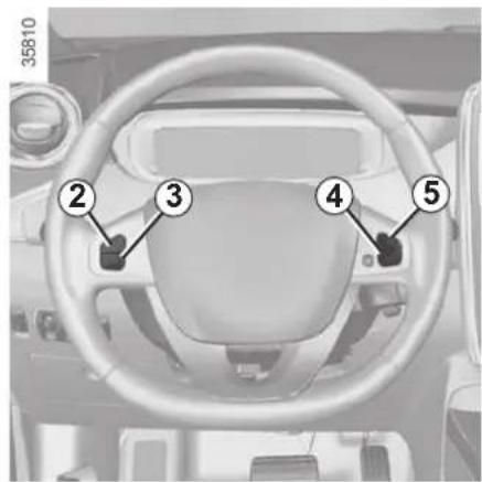
Controls
1 Main "On/Off" switch.
2 Limit speed activation, storage and increase switch (+).
3 Decrease limit speed (-).
4 Speed limiter function standby (with limited speed memory) (O).
5 Activation and recall of stored limit speed (R).
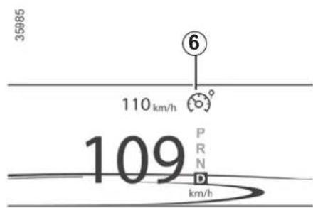
Switching on
Press the side switch 1. The warning light 6 comes on, lit orange, and the message "Speed limiter" appears on the instrument panel, accompanied by dashes to indicate that the speed limiter function is activated and waiting to store a limit speed.
To store the current speed, press switch 2 (+): the limit speed replaces the dashes and the activation of the speed limiter is confirmed by the warning light

on an orange background.
The minimum stored speed is 20 mph (30 km/h).
SPEED LIMITER (2/3)
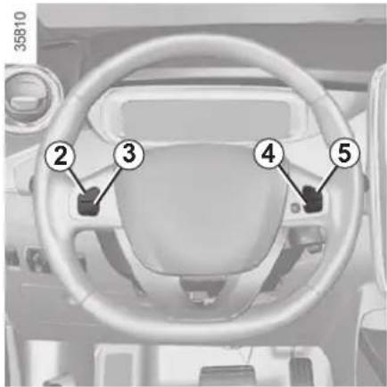
Driving
When a limited speed has been stored and this speed is not reached, driving is similar to driving a vehicle without the speed limiter function.
Once you have reached the stored speed, no effort on the accelerator pedal will allow you to exceed the programmed speed except in an emergency (refer to information on "Exceeding the limit speed").
Varying the limit speed
The limit speed may be changed by repeatedly pressing:
- switch 2 (+) to increase speed;
- switch 3 (-) to reduce speed.

The speed limiter function is in no way linked to the braking system.
Exceeding the limit speed
It is possible to exceed the limit speed at any time. To do this: press the accelerator pedal firmly and fully (beyond the resistance point).
If the speed is exceeded, the limited speed flashes on the instrument panel and a beep sounds.
Then, release the accelerator: the speed limiter function will return as soon as you reach a speed lower than the stored speed.
Limited speed cannot be maintained
If driving up or down a steep gradient, the system is unable to maintain the limit speed: the stored speed will flash on the instrument panel information display to inform you of this situation.
SPEED LIMITER (3/3)
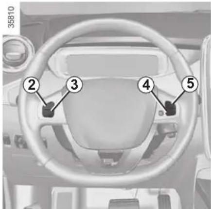
Putting the function on standby
The speed limiter function is suspended when you press switch 4 (O). In this case, the speed limit remains stored and the message "Memorised" accompanied by this speed appears on the instrument panel.
Standby is confirmed when the warn-
ing light 📋 on the orange back-ground goes out and the warning light 🌐 comes on.
Recalling the limit speed
If a speed has been saved, it can be recalled by pressing switch 5 ((R)).
When the stored speed is recalled, activation of the speed limiter is confirmed by the illumination of the warning light

on an orange background.
When the speed limiter is put on standby, pressing switch 2 (+) reactivates the function without taking into account the stored speed: it is the speed at which the vehicle is moving that is taken into account.
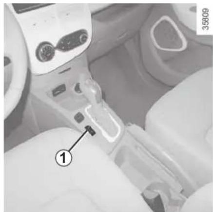
natural_image
Interior view of a car gear shift lever with labeled component (1), no visible text or symbols beyond the number and numberSwitching off the function
The speed limiter function is deactivated if you press switch 1: in this case a speed is no longer stored. The warn-
ing light ( ) or ( ) on the instrument panel going out confirms that the function is stopped.
CRUISE CONTROL (1/4)
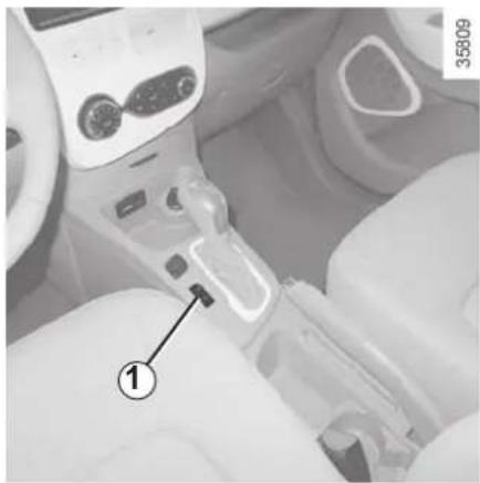
natural_image
Close-up of a car interior showing a hand operating a car gear shift lever, with no visible text or symbols.The cruise control function helps you to maintain your driving speed at a speed that you choose, called the cruising speed.
This cruising speed may be set at any speed above 20 mph (30 km/h).

The cruise control function is in no way linked to the braking system.

This function is an additional driving aid. The function does not take the place of the driver. Therefore, it can under no circumstances replace the driver's responsibility to respect speed limits and to be vigilant (the driver must always be ready to brake). Cruise control must not be used in heavy traffic, on winding or slippery roads (black ice, aquaplaning, gravel) and during bad weather (fog, rain, side winds etc.).
There is a risk of accidents.
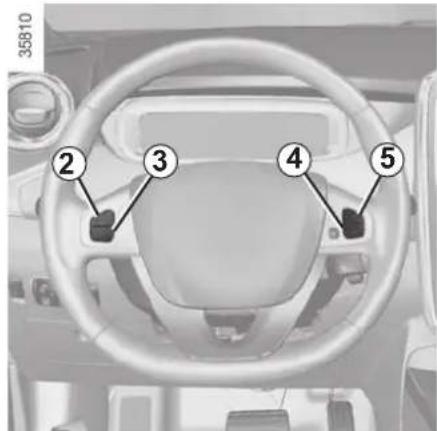
Controls
1 Main "On/Off" switch.
2 Limit speed activation, storage and increase switch (+).
3 Decrease cruising speed (-).
4 Switch the function to standby (with cruising speed saved) (O).
5 Activation with recall of stored governed cruising speed (R).
CRUISE CONTROL (2/4)
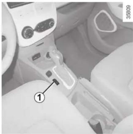
natural_image
Interior view of a car gear shift lever with labeled component (1), no visible text or symbols beyond the number and number.Switching on
Press switch 1 side Ⓞ.
The warning light 📞 6 comes on, lit green, and the message "Cruise ctrl" appears on the instrument panel, accompanied by dashes to indicate that the cruise control function is activated and waiting to store a cruising speed.
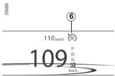
Activating cruise control
At a steady speed (above 18 mph (30 km/h approximately)) press switch 2 or (+): the function is activated and the current speed is saved.
The cruising speed replaces the dashes and the cruise control is confirmed by the appearance of the warning light

on a green background.
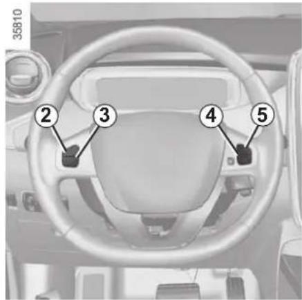
Driving
Once a cruising speed is stored and the cruise control function is active, you may lift your foot off the accelerator pedal.

Please note that you must keep your feet close to the pedals in order to be ready to react in an emergency.
CRUISE CONTROL (3/4)
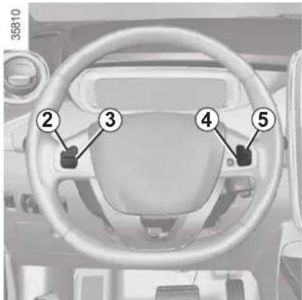
Adjusting the cruising speed
The cruising speed may be changed by pressing the following repeatedly:
- switch 2 (+) to increase the speed,
- switch 3 (-) to decrease the speed.

The cruise control function is in no way linked to the braking system.
Exceeding the cruising speed
The cruising speed may be exceeded at any time by depressing the accelerator pedal. While it is being exceeded, the cruising speed flashes on the instrument panel.
Then, release the accelerator: after a few seconds, the vehicle will automatically return to its set cruising speed.
Cruising speed cannot be maintained
When driving down a steep gradient, the system is unable to maintain the cruising speed: the stored speed will flash on the instrument panel information display to inform you of this situation.
Putting the function on standby
The function is set to standby if you:
- use the switch 4 (O);
- the brake pedal;
- move to neutral position;
- ECO mode switch.
In all four cases, the cruising speed remains stored and the message "Memorised" appears on the instrument panel.
Standby is confirmed when the warn-
ing light 📋 on the green back-ground goes out and the warning light Ⓧ comes on.
The cruise control switches to standby each time the ECO mode is activated or deactivated. Please refer to the information on "Ecodriving" in Section 2.
CRUISE CONTROL (4/4)
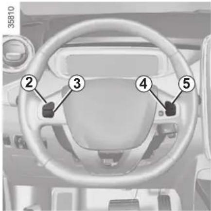
Returning to the cruising speed
If a speed is stored, it can be recalled, once you are sure that the road conditions are suitable (traffic, road surface, weather conditions, etc.). Press switch 5 (R) if the vehicle speed is above 20 mph (30 km/h).
When the stored speed is recalled, activation of the cruise control is confirmed by the illumination of the warning light

on a green background.
NB: if the speed previously stored is much higher than the current speed, the vehicle will accelerate more rapidly to reach this threshold.
When the cruise control function is put on standby, pressing switch 2 (+) reactivates the cruise control function without taking into account the stored speed: it is the speed at which the vehicle is moving that is taken into account.
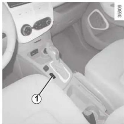
natural_image
Interior view of a car headrest with a hand valve and numbered component (no visible text or symbols)Switching off the function
The cruise control function is deactivated if you press switch 1: in this case a speed is no longer stored. The warn-
ing light ( Ⓤ ) or ⏻ ) on the instrument panel going out confirms that the function is stopped.

Putting the cruise control on standby or switching it off does not cause a rapid reduction in speed: you
must brake by depressing the brake pedal.
PARKING DISTANCE CONTROL (1/2)
Operating principle
Ultrasonic detectors, installed in the rear bumper (depending on the vehicle), measure the distance between the vehicle and an obstacle whilst reversing.
This measurement is indicated by beeps which become more frequent the closer you come to the obstacle, until they become a continuous beep when the vehicle is approximately 30 centimetres from the obstacle.
NB: the display 1 shows the vehicle surroundings in conjunction with the beeps.
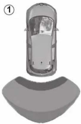
natural_image
Top-down view of a car with a curved roof and two side rear seats, labeled with number 1 (no text or symbols on the car itself)35969
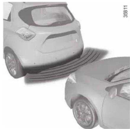
natural_image
Two cars with visible tire tracks, one on the side and one on the side (no text or symbols)Operation
When reverse gear is selected, most objects which are less than approximately 1.20 metres from the rear of the vehicle are detected, a beep sounds and the display 1 lights up.

This function is an additional aid that indicates the distance between the vehicle and an obstacle whilst reversing, using sound signals.
Under no circumstances should it replace the driver's care or responsibility whilst reversing.
The driver should always be ready for sudden incidents while driving: always ensure that there are no small, narrow moving obstacles (such as a child, animal, pushchair, bicycle, stone, post, etc.) in the blind spot when manoeuvring.
PARKING DISTANCE CONTROL (2/2)
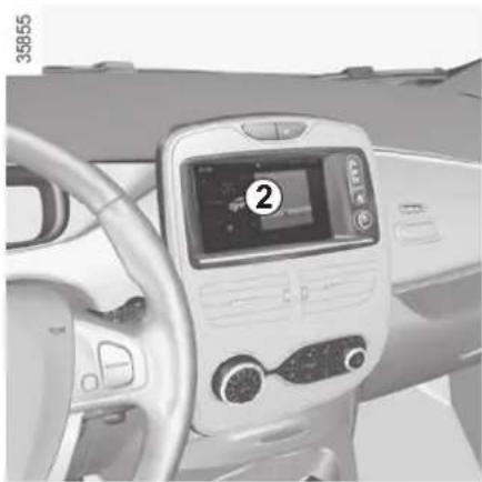
natural_image
Interior view of a car dashboard with digital display and steering wheel (no visible text or symbols)Adjusting the parking distance control volume
Certain settings can be adjusted from the multimedia display 2. Please see the equipment instructions for further information.
Select "Menu", "Settings", "Park Assist", then adjust the parking distance control volume by pressing + or -.
35988
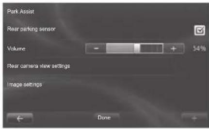
Deactivating the system
You can deactivate the parking distance control from the multimedia display.
Select "Menu", "Settings", "Park Assist" then "Rear parking sensor". Activate or deactivate the parking distance control and confirm your choice by selecting "Done".
Operating faults
Depending on the vehicle, when the system detects an operating fault, the message "check parking distance control" appears on the instrument panel, accompanied by the warning light
and a beep lasting approximately 5 seconds. Please contact an authorised dealer.
Special features
Make sure that the ultrasonic sensors are not obscured (by dirt, mud, snow etc.).

In the event of an impact to the underside of the vehicle (e.g.: striking a post, raised kerb or other street furni-
ture), this may result in damage to the vehicle (e.g.: twisted axle), the electrical circuit or the traction battery.
To avoid any risk of accident, have your vehicle checked by an approved dealer.
REVERSING CAMERA (1/2)
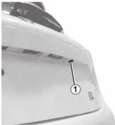
natural_image
Close-up of a white car rear bumper with a numbered arrow pointing to the front panel (no text or symbols visible)Operation
When reversing, the camera 1 on the boot lid transmits a view of the surroundings to the rear of the vehicle to the multimedia display 2 accompanied by two clearance gauges 3 and 4 (mobile and fixed).
This system is initially used with the aid of several gauges (mobile for trajectory and fixed for distance). When the red zone is reached, use the bumper image to stop accurately.
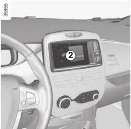
natural_image
Interior view of a car dashboard with digital display and steering wheel (no visible text or symbols)3 moving guide line:
This is shown in blue on screen 2. It indicates the vehicle trajectory according to the position of the steering wheel.
Fixed gauge 4
The fixed clearance gauge comprises coloured markers A, B and C, indicating the distance behind the vehicle:
- A (red) approximately 30 centimetres from the vehicle;
- B (yellow) approximately 70 centimetres from the vehicle;
- C (green) approximately 150 centimetres from the vehicle.
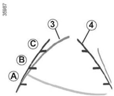
This gauge remains fixed and indicates the vehicle trajectory if the wheels are in line with the vehicle.
Special feature
Make sure that the camera is not obscured (by dirt, mud, snow, condensation etc.).
REVERSING CAMERA (2/2)

natural_image
Interior view of a car dashboard with touchscreen and steering wheel (no visible text or symbols)Activating/deactivating the reversing camera
From the multimedia display 2, select "Menu", "Settings", "Parking distance control" then "Rear camera settings". Activate or deactivate the reversing camera and confirm your choice by selecting "End".
35988
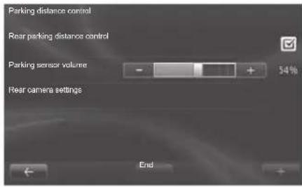
You can also adjust the camera image settings (brightness, contrast, etc.)
The screen shows a reverse image.
The frames are a representation projected onto flat ground; this information must not be taken into account when superimposed on a vertical object or an object on the ground.
Objects which appear on the edge of the screen may be deformed.
In very bright light (snow, vehicle in sunshine etc.), the camera vision may be adversely affected.
If the boot is open or poorly closed, the message "Boot open" appears and the camera display disappears.

This function is an additional aid. It cannot, therefore, under any circumstances replace the vigilance or the responsibility of the driver.
The driver should always be ready for sudden incidents while driving: always ensure that there are no small, narrow moving obstacles (such as a child, animal, pushchair, bicycle, stone, post, etc.) in the blind spot when manoeuvring.
Section 3: Your comfort
Air Vents 3.2
Manual air conditioning 3.4
Automatic climate control 3.7
Air conditioning: remote activation. 3.11
Air conditioning: programming.... 3.12
Air ioniser. 3.16
Air conditioning: information and advice on use 3.17
Electric windows 3.19
Interior lighting 3.21
Sun visor 3.21
Passenger compartment storage/fittings 3.22
Ashtray 3.25
Accessories socket 3.25
Rear bench seat: functions 3.27
Rear parcel shelf 3.28
Luggage cover.... 3.29
Luggage compartment. 3.30
Spoiler 3.30
Transporting objects in the luggage compartment 3.31
Multimedia equipment 3.32
AIR VENTS: air outlets (1/2)
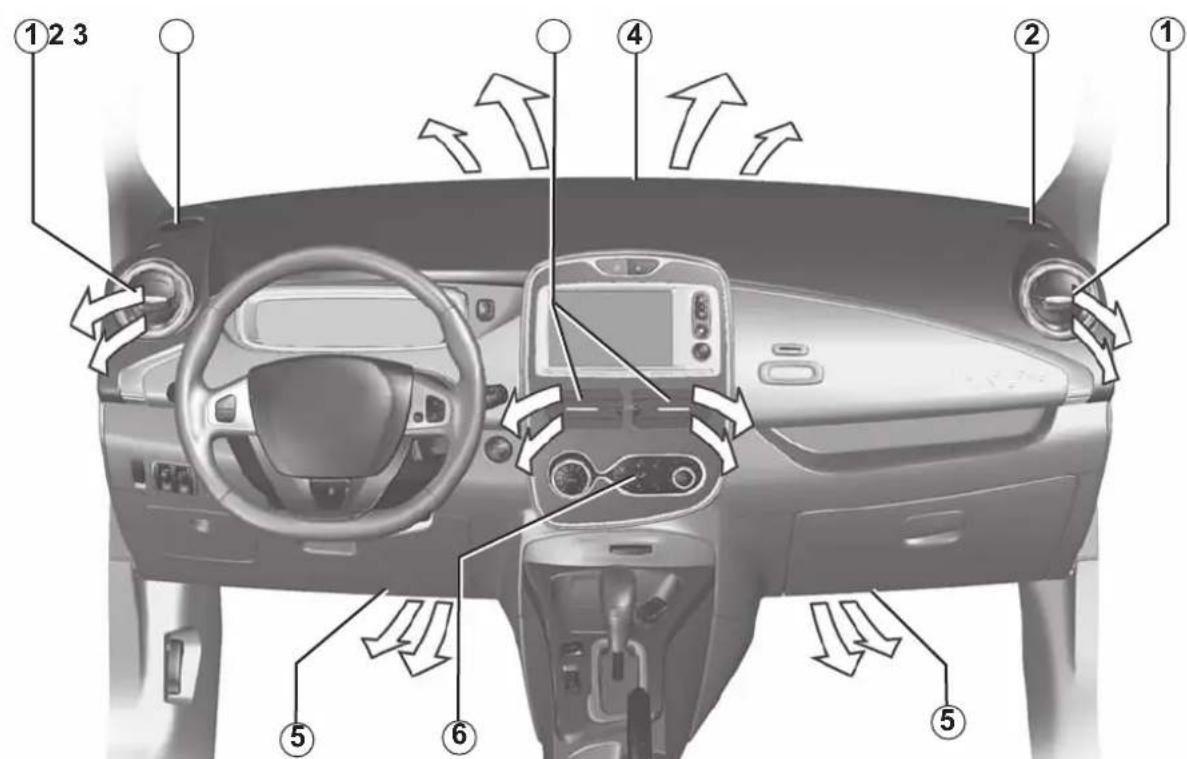
35857
1 side air vent.
2 side window demister outlet.
3 centre air vents.
4 windscreen demisting vents.
5 passenger footwell heater outlets.
6 control panel.
AIR VENTS: air outlets (2/2)
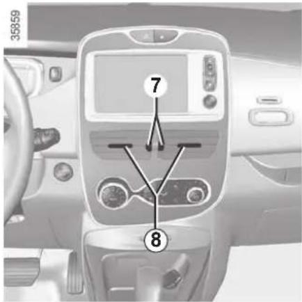
Centre air vents.
Air flow
Move the cursors 7 (beyond the resistance point).
Upwards: opened to maximum.
Down: closed.
Direction
Move cursors 8 to the required position.
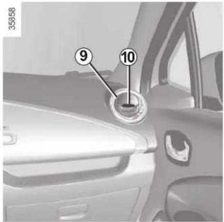
Side air vents
Air flow
To open air vent 9, press on the air vent (point 10) until it is open as far as required.
Direction
To direct the air flow, swivel side air vent 9.
To remove bad odours from your vehicles, only use the systems designed for this purpose. Consult an approved Dealer.

Do not add anything to the vehicle's ventilation circuit (for example, to remove bad odours).
There is a risk of damage or of fire.
MANUAL AIR CONDITIONING (1/3)
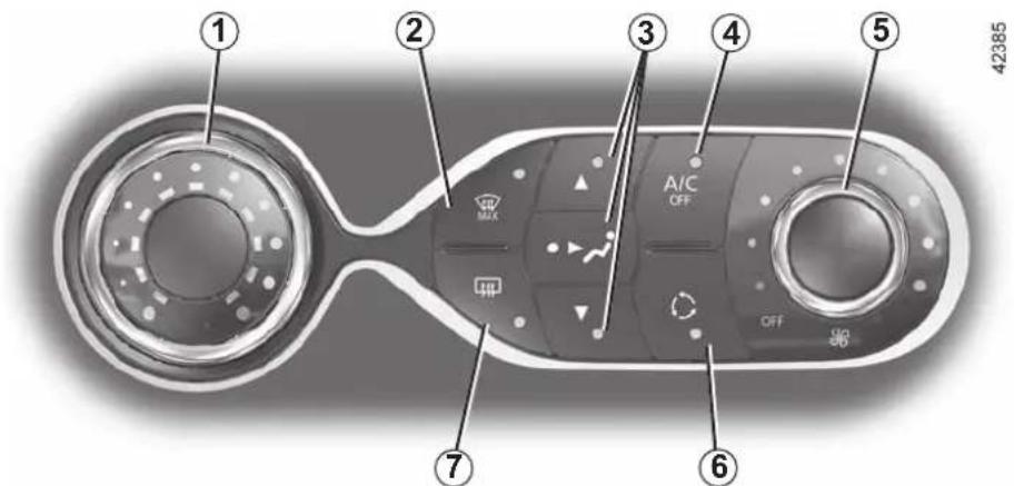
The controls
1 Adjusting the air temperature.
2 "Clear View" function.
3 Passenger compartment air distribution adjustment.
4 Air-conditioning deactivation control.
5 Adjusting the fan speed until the system switches off.
6 Air recirculation.
7 De-icing/demisting of the rear screen and, depending on the vehicle, the door mirrors.
Heating or air-conditioning can only be used while the engine is running.
Switching air conditioning on or off
(depending on vehicle)
The air conditioning is switched on (indicator light on) or off (indicator light off) using button 4.
Activation is not possible if control 5 is set to OFF.
The air conditioning system is used for:
– lowering the temperature inside the passenger compartment;
- eliminating condensation more quickly.
Advice: to optimize vehicle range, deactivate the air conditioning when the outside temperature is comfortable.
Adjusting the ventilation speed
Turn the control 5 to one of the eight positions to start the ventilation system and adjust the power.
Position OFF
In this position:
– the air conditioning switches off automatically;
– the ventilation speed of air in the passenger compartment is zero;
– there is, however, a slight flow of air when the vehicle is moving.
This position should not normally be used.
Some buttons have an operating tell-tale which indicates the operating status.
MANUAL AIR CONDITIONING (2/3)
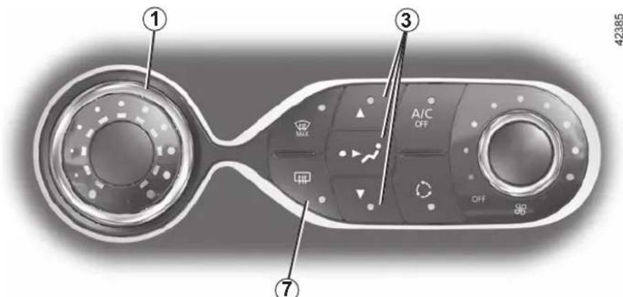
Adjusting the air temperature
Turn control 1 to obtain the desired temperature. The further towards the red the slide is, the higher the temperature will be.
When the air conditioning system is used for long periods, it may begin to feel cold. To increase the temperature, turn control 1 to the right.
Adjusting the distribution of air in the passenger compartment
Press one of the buttons 3 to select the air distribution. The integrated warning light in the button comes on.
It is possible to combine two positions simultaneously – press both buttons 3.

The air flow is distributed between demisting air vents of
the front side-window and the wind-screen demisting vents.

All the air flow is directed to the dashboard vents.

The air flow is directed mainly towards the footwells.
Rear screen de-icing/ demisting
Press the 7 button: the integrated indicator light comes on. This function enables rapid demisting or de-icing of the rear screen and de-icing of the door mirrors (on equipped vehicles).
To exit this function, press button 7 again. Demisting automatically stops.
Recommendations
In the event of freezing, manually de-ice the windscreen using a scraper rather than the de-icing/de-misting function in order to reduce your energy consumption.
MANUAL AIR CONDITIONING (3/3)
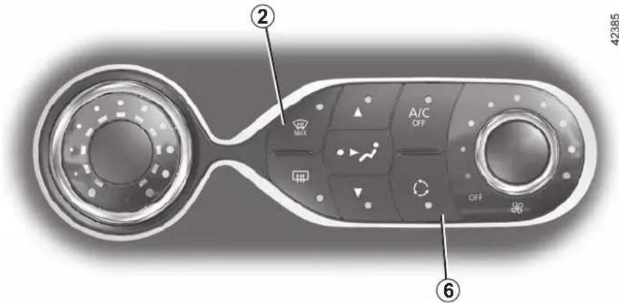
Clear View function
Press the 2 button: the integrated indicator light comes on.
This system quickly demists and de- ices the windscreen and the front side windows. It requires the automatic usage of the air-conditioning or the heating.
To exit this function, select one of the adjustments (distribution, ventilation speed, temperature, recycling) required.
Switching the air recirculation on
Press button 6: the integrated indicator light comes on. In these conditions, air is taken from the passenger compartment and is recycled, with no air being taken from outside the vehicle.
The demisting/de-icing will still take priority over the air recirculation.
Air recirculation is for:
- isolating the vehicle from the external atmosphere (driving in polluted areas, etc.);
– lowering the passenger compartment temperature as quickly as possible.
Prolonged use of air recirculation can lead to condensation forming on the side windows and windscreen, and discomfort due to the use of non-renewed air in the passenger compartment. We therefore advise you to return to normal mode (external air) as soon as the air recirculation function is no longer required, by pressing the button 6 again.
AUTOMATIC AIR-CONDITIONING (1/4)
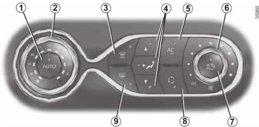
The controls
1 Automatic mode.
2 Air temperature adjuster.
3 "Clear View" function.
4 Passenger compartment air distribution adjustment.
5 Air-conditioning deactivation control.
6 Adjusting the fan speed until the system switches off.
7 Depending on the vehicle, quick access control to the "Air conditioning programming" menu or activation control for air conditioning programming.
8 Air recirculation.
9 De-icing/demisting of the rear screen and, depending on the vehicle, the door mirrors.
Heating or air-conditioning can only be used while the engine is running.
Automatic mode
The automatic climate control system guarantees comfort in the passenger compartment and good visibility (except in the event of extreme conditions), while optimising consumption.
The system controls the fan speed, air distribution, air recirculation, starting and stopping the air conditioning, the heating and air temperature.
AUTO: allows the selected comfort level to be best attained, depending on the exterior conditions. Press button 1.
Adjusting the air temperature
Turn control 2 to obtain the desired temperature. The further the pointer is away from the heating stop position, the higher the temperature will be. If the outdoor temperature is too high, the heating decreases automatically. This limits energy consumption and maintains the range of the vehicle.
Special note: the highest and lowest settings allow the system to produce maximum hot or cold temperature levels ("LOW" and "HIGH" indicated on the multimedia display).
Some buttons have an operating tell-tale which indicates the operating status.
AUTOMATIC AIR-CONDITIONING (2/4)
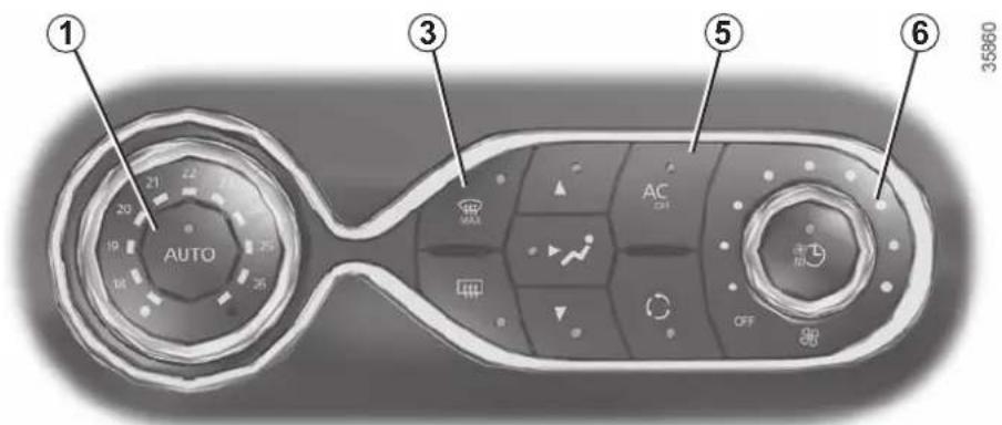
Deactivating the air-conditioning
The button 5 stops (warning light on) the operation of the air-conditioning.
To activate the air-conditioning, press the button 1. The integrated warning light in the button 5 will go out.
The air conditioning system is used for:
– lowering the temperature inside the passenger compartment;
- eliminating condensation more quickly.
The air conditioning does not operate when the exterior temperature is low.
Advice: to optimize vehicle range, deactivate the air conditioning when the outside temperature is comfortable.
Clear View function
Press button 3 – the integrated indicator light comes on.
This system quickly demists and de- ices the windscreen and the front side windows. It requires the automatic usage of the air-conditioning or the heating.
To exit this function, press the button marked 3.
The displayed temperature values show a comfort level.
When starting the engine, increasing or decreasing the value displayed will not allow the comfort level to be reached any more quickly. The system will always optimise the temperature increase or decrease (the ventilation system does not start instantly at maximum speed: it gradually increases). This may take several minutes.
Generally speaking, unless there is a particular reason not to, the dashboard air vents should remain open.
Preferably, use automatic mode. In automatic mode (the button's warning light 1 is lit), all heating and air-conditioning functions are controlled by the system.
You can always modify the choice of system; in this case, the warning light in the button 1 goes out.
AUTOMATIC AIR-CONDITIONING (3/4)
Adjusting the ventilation speed
Turn the control 6 to one of the eight positions to start the ventilation system and adjust the power.
Position OFF
In this position:
– the air conditioning switches off automatically;
- the ventilation speed of air in the passenger compartment is zero;
– there is, however, a slight flow of air when the vehicle is moving.
This position should not normally be used.
Adjusting the distribution of air in the passenger compartment
Press one of the buttons 4 to select the air distribution. The integrated warning light in the button comes on. It is possible to combine two positions simultaneously – press both buttons 4.

The air flow is distributed between demisting air vents of
the front side-window and the wind-screen demisting vents.
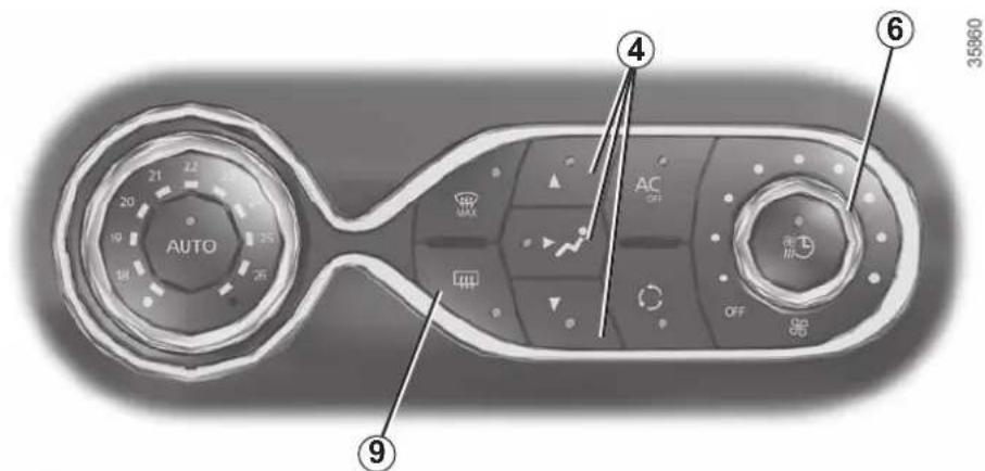

All the air flow is directed to the dashboard vents.

The air flow is directed mainly towards the footwells.
Rear screen de-icing/ demisting
Press button 9 – the integrated indicator light comes on. This function enables rapid demisting or de-icing of the rear screen and de-icing of the door mirrors (on equipped vehicles).
To exit this function, press button 9 again. Demisting automatically stops.
Recommendations
In the event of freezing, manually de-ice the windscreen using a scraper rather than the de-icing/de-misting function in order to reduce your energy consumption.
AUTOMATIC AIR-CONDITIONING (4/4)
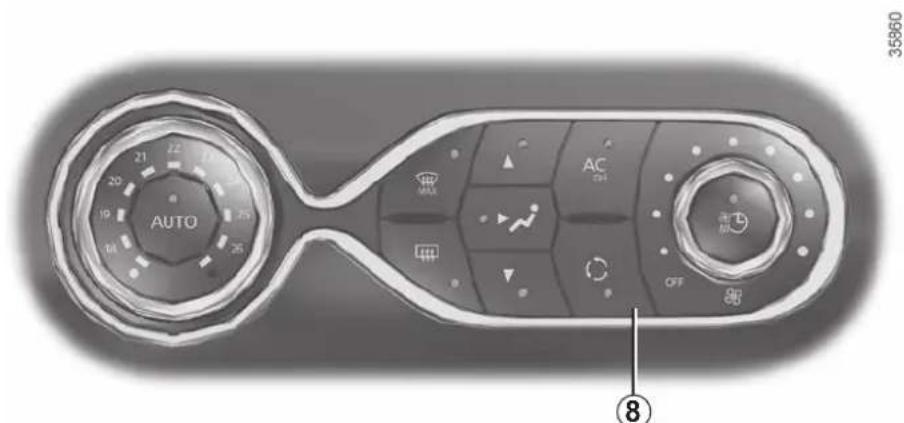
Air recirculation (isolation of the passenger compartment)

This function is managed automatically but you can also activate it manually. In this case, the operation is confirmed by a warning light on the button 8.
Depending on the vehicle, the system determines whether or not air recirculation is used, based on the quality of the outside air.
The air quality is confirmed by the appearance of one of the following warning lights on the multimedia display (for the cleanest and the least clean air respectively):


The demisting/de-icing will still take priority over the air recirculation.
NB:
- during recirculation, air is taken from the passenger compartment and is recycled, with no air being taken from outside the vehicle;
- air recirculation allows the external atmosphere to be cut off (when driving in polluted areas, etc.);
- the recirculation of air makes it possible to reach the desired passenger compartment temperature quicker.
Manual use
Press button 8 – the integrated indicator light comes on.
Prolonged use of this position may lead to odours, caused by non-renewal of air, and the formation of condensation on the windows.
We therefore advise you to return to automatic mode as soon as air recirculation is no longer needed, by pressing button 8.
Stopping the function manually
Press the button 8 to stop the function. Air recirculation is then automatic.
AIR CONDITIONING: remote activation
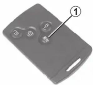
natural_image
Close-up of a gray remote control device with four buttons and a labeled button (no text or symbols beyond the number 1)The air-conditioning can be activated using the card RENAULT or by the connected services.
This function enables you to bring your vehicle to a comfortable temperature before using it.
Advice: to optimize vehicle range, use this function when the vehicle is plugged in.
Operating condition
– the engine must be switched off;
– the traction battery charge level must be greater than 25% or, depending on the vehicle, 45%
Activating the function
It is carried out by:
- a long press on the button 1 of the card RENAULT (make sure you are within the card's field of action - please see the information on "Card RENAULT : general information" in Section 1);
- connected services.
Activating the function is visualised by
- constant illumination of the hazard warning lights and the side repeaters for 3 seconds;
- the warning lights in the buttons
and AUTO on the air-conditioning control are lit.
Switching off the function
– automatically, after a period of approximately 5 minutes;
– upon starting the engine;
- if you press on the "automatic mode" controls, the "clear view" function, the fan settings or quick access to the "air-conditioning programming" menu;
- if the energy taken exceeds 5% of the traction battery level.

Driver's responsibility when parking or stopping the vehicle
Never leave an animal, child or adult who is not self-sufficient alone on your vehicle, even for a short time.
In hot and/or sunny weather, please remember that the temperature inside the passenger compartment increases very quickly.
RISK OF DEATH OR SERIOUS INJURY.
AIR CONDITIONING: programming (1/4)
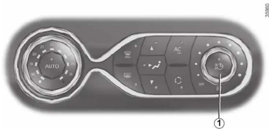
Adjusting the programming
With the vehicle connected to a power source, this function enables:
- a comfortable temperature prior to using the vehicle;
- optimisation of the vehicle range.
The programmable air-conditioning is triggered the hour before the programmed hour in order to reach a comfortable temperature.

Driver's responsibility when parking or stopping the vehicle
Never leave an animal, child or adult who is not self-sufficient alone on your vehicle, even for a short time.
In hot and/or sunny weather, please remember that the temperature inside the passenger compartment increases very quickly.
RISK OF DEATH OR SERIOUS INJURY.
Operating conditions
– the ignition must be switched off;
- the vehicle must be locked;
- the traction battery charge level must be greater than 25% or, depending on the vehicle, 45% for the function to be triggered;
- the vehicle has to be plugged into the mains;
- programming should be done at least 2 hours prior to departure;
and
- air-conditioning programming must be activated.
Depending on the vehicle, the programming is done from:
– the multimedia display;
or
– the vehicle settings customisation menu.
The integrated warning light in
button 1 and warning light come on.

AIR CONDITIONING: programming (2/4)
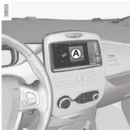
natural_image
Interior view of a car dashboard with digital display and steering wheel (no visible text or symbols)From the multimedia display A
Setting the start time for the function
You can set two different times.
- press button 1 for quick access to the programming menu on display A;
- select "Change" on one of the two set times;
- adjust the hours then the minutes, then confirm.
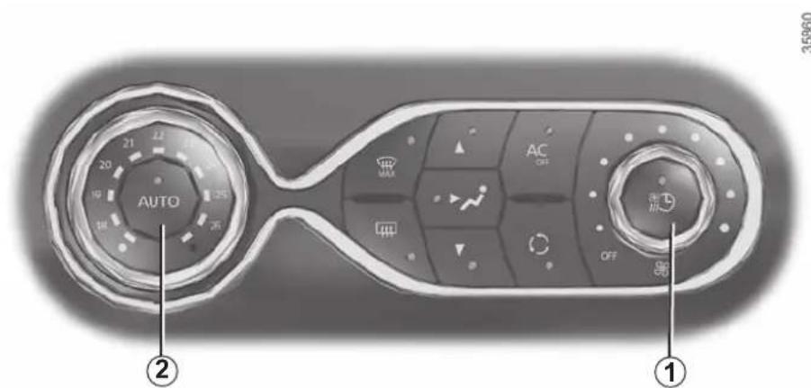
"Programme" activation
- With the ignition switched on and the air-conditioning operating (please refer to the information on "Automatic air-conditioning" in Section 3);
- select the programme to be activated from menu "Comfort timer";
- make sure one of the programmes is confirmed.
- switch off the engine;
- plug the vehicle into a power source;
- lock the vehicle.
The function is triggered one hour prior to the programmed time to reach a comfortable temperature.
The warning lights integrated in the button 1, the AUTO button 2 and the
warning light 📁 on the instrument panel are lit up.
The two programmed times cannot be activated simultaneously.
AIR CONDITIONING: programming (3/4)
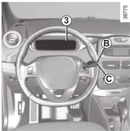
From the vehicle settings customisation menu 3
Setting the start time for the function
You can programme a single time.
- briefly press button B or C to access the menu "PROGRAMMING";
-
press and hold button B or C to confirm;
-
briefly press button B or C to access the menu "Warm up cabin for";
- press and hold button B or C to confirm;
- briefly press button B or C to access the clock settings;
- hold down button B or C - the hours flash;
- press buttons B and C to set the hour;
- hold down button B or C to confirm the hour setting;
- the minutes flash - press buttons B and C to set the minutes;
- hold down button B or C to confirm the minutes setting. Your settings are now saved.
AIR CONDITIONING: programming (4/4)
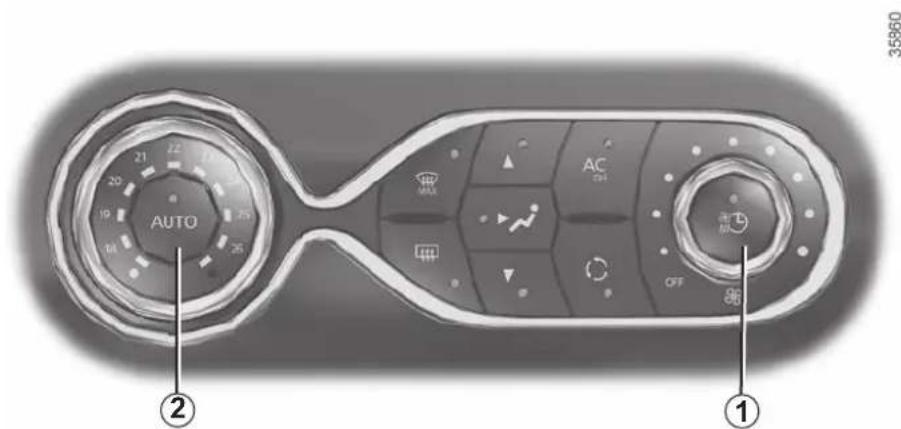
"Programme" activation
- With the ignition switched on and the air-conditioning operating (please refer to the information on "Automatic air-conditioning" in Section 3);
- press the button 1.
The function is triggered two hours prior to the programmed time so that a comfortable temperature is reached.
The warning lights integrated in the button 1, the AUTO button 2 and the
warning light 📁 on the instrument panel are lit up.
Stopping the programmed air conditioning
The air conditioning stops automatically around ten minutes after the set end time.
However, the function can be deactivated if:
– the charging socket is disconnected;
- the "Remote Activation" function is activated – please see the information on "Air conditioning: remote activation" in Section 2;
- the traction battery charging level is lower than 15% or, depending on the vehicle, 30%
Connected services
The air conditioning can also be activated using the connected services. For more information regarding the operating conditions, please contact an authorised dealer.

Driver's responsibility when parking or stopping the vehicle
Never leave an animal, child or adult who is not self-sufficient alone on your vehicle, even for a short time.
In hot and/or sunny weather, please remember that the temperature inside the passenger compartment increases very quickly.
RISK OF DEATH OR SERIOUS INJURY.
AIR IONIZER
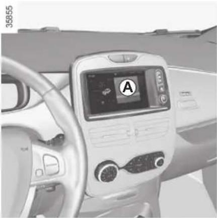
natural_image
Interior view of a car dashboard with digital display and steering wheel (no visible text or symbols)Selecting the operating mode
Air conditioning in operation, on the display A, select "Menu", "Vehicle", "Care" then "Ioniser".
Select one of the two modes or stop diffusion:
- CLEAN : helps to reduce bacteria and allergenic particles present in the air;
- RELAX: provides a clean and relaxing driving environment by emitting ions;
- Stop (stop diffusion).
Activating the ioniser in CLEAN mode at each engine start-up
To activate CLEAN mode at each engine start-up, check the line "Start ioniser at each vehicle start" and confirm.
NB:
- if the fan control is set to position 0 (stop), activating the ioniser at each engine start-up will automatically operate the fan for at least around 10 seconds.
- if the air distribution setting does not feed air to the central air vents, the ioniser is not activated.
Do not close the vents while the ioniser is activated. This enables a uniform distribution of ions.
AIR CONDITIONING: information and operating instructions (1/2)
Advice on use
In some situations, (air conditioning off, air recirculation activated, ventilation speed at zero or low, etc.) you may notice that condensation starts to form on the windows and windscreen.
If there is condensation, use the “Clear View” function to remove it, then use the air conditioning in automatic mode to stop it forming again.
Maintenance
Refer to the Maintenance Document for your vehicle for the inspection frequency.
Range
It is normal to notice an increase in energy usage when the air conditioning is operating.
Use the air conditioning system regularly, even in cold weather, running it at least once a month for approximately 5 minutes.
Recommendations to limit energy consumption and maintain the range of the vehicle:
Drive with the air vents open and the windows closed. If the vehicle has been parked in the sun, open the doors for a few moments to let the hot air escape before starting the engine.
Favour:
- before departure, the use of the air-conditioning programming or remote activation. Please refer to the information on "Air-conditioning: programming" and "Air-conditioning: remote activation" in Section 2);
- during your journeys, using ECO mode. Please see information about "ECO mode function" in Section 2.
Vehicles equipped with modeECO
Once activated, ECO mode may reduce air conditioning performance. Please refer to the information on "Driving advice, Eco-driving" in Section 2.
Operating faults
As a general rule, contact your approved dealer in the event of an operating fault.
- Reduction in de-icing, demisting or air conditioning performance. This may be caused by the passenger compartment filter cartridge becoming clogged.
- No hot or cold air is being produced. Check that the controls are set correctly and that the fuses are sound. Otherwise, switch off the system.
Presence of water under the vehicle
After prolonged use of the air conditioning system, it is normal for water to be present under the vehicle. This is caused by condensation.

Do not open the refrigerant fluid circuit. The fluid may damage eyes or skin.
AIR CONDITIONING: information and operating instructions (2/2)
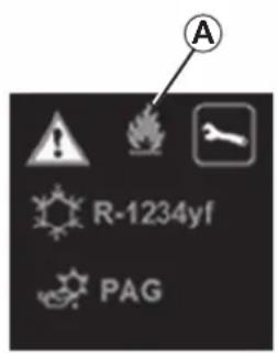
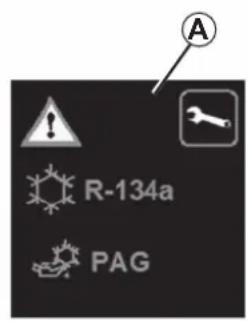
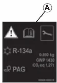
The refrigerant circuit may contain fluorinated greenhouse gases.
Depending on the vehicle, you will find the following information on label A affixed inside the engine compartment.
The presence and location of the information on label A depends on the vehicle.

Do not open the refrigerant fluid circuit. The fluid may damage eyes or skin.

Before performing any action in the engine compartment, the ignition must be switched off (please see
the information on "Starting, stopping the engine" in Section 2).

Type of refrigerant fluid

Type of oil in the air conditioning circuit

Inflammable product

Consult the driver's handbook

Maintenance
x.xxx kg
Quantity of refrigerant fluid present in the vehicle.
GWP xxxxx
Glo bal Warm ing Potential (CO2 equivalent).
CO2 eq x.xx t
Quantity in weight and in CO2 equivalent.
ELECTRIC WINDOWS (1/2)
These systems operate with the ignition on or off, until one of the front doors is opened (limited to about 3 minutes).

Safety of rear occupants
The driver can prevent operation of the rear elec- tric windows by pressing
switch 4. A confirmation message is displayed on the instrument panel.
Driver's responsibility
Never leave your vehicle with the RENAULT card inside, and never leave a child, adult who is not self-sufficient or a pet, even for a short while. They may pose a risk to themselves or to others by starting the engine or activating equipment (such as the gear lever or electric windows). If any part of the body becomes trapped, reverse the direction of the window immediately by pressing the relevant switch. Risk of serious injury.
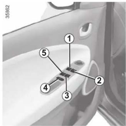
Electric windows
Press or pull the switch to raise or lower a window to the desired height (the rear windows do not open fully);
One-touch mode
(depending on vehicle)
This mode works in addition to the operation of the electric windows described previously. It can be fitted to the driver's window.
Briefly press or pull the window switch fully: the window is fully lowered or raised. Pressing the switch again stops the window moving.
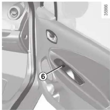
natural_image
Close-up of a car door with a numbered component (6) pointing to the interior panel, no visible text or symbols beyond the number.From the driver's seat, use switch:
1 for the driver's side;
2 for the front passenger side;
3 and 5 for the rear passenger windows.
From the passenger seats, use switch 6.
Note: if the window detects resistance when closing (e.g.: branch of a tree, etc.) it stops and then lowers again by a few centimetres.
Avoid resting any objects against a half-open window: there is a risk that the electric window could be damaged.
ELECTRIC WINDOWS (2/2)/MANUAL WINDOW WINDERS
Operating faults
If a fault occurs when closing a window, the system switches to normal mode: lift the switch concerned as many times as necessary until the window is fully closed, release it. Press the switch again (still on the closing side) for approximately one second to reset the system.
If necessary, contact an approved Dealer.
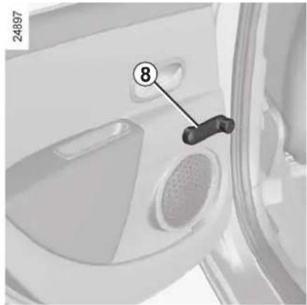
natural_image
Close-up of a car door panel with a numbered component (8) and label '24897' (no readable text or symbols beyond the number)Manual window winder controls
Turn handle 8.

When closing the windows, ensure that no part of the body (arm, hand, etc.) is protruding from the vehicle.
Risk of serious injury.
INTERIOR LIGHTING/SUN VISOR
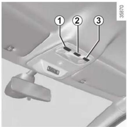
Courtesy light
Tilt switch 2 to move it to the position for:
- permanent lighting;
- lighting controlled by opening one of the doors. This switches off after a time delay, once the doors concerned have been closed correctly;
- immediate switching off.
Map reading lights
Move switches 1 or 3.
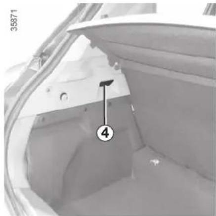
natural_image
Interior view of a vehicle showing the hood and seat area with numbered annotation (4), no readable text or symbols beyond the number.Luggage compartment light
Light 4 comes on when the boot is opened.
When the doors or luggage compartment are unlocked and opened the courtesy and footwell lights come on temporarily.
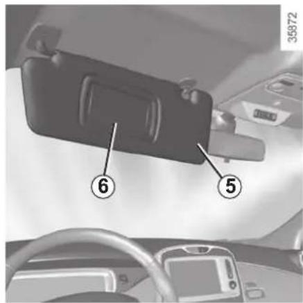
Sun visor
Lower the sun visor 5 over the wind-screen or unclip it and turn it over the side window.
Courtesy mirrors
Depending on the vehicle, lift or slide the cover 6.

When driving, ensure the courtesy mirror cover is closed. Risk of injury.
PASSENGER COMPARTMENT STORAGE, FITTINGS (1/3)
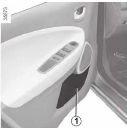
natural_image
Interior view of a car showing the door, control panel, and side door (no text or symbols visible)Front door storage compartments 1
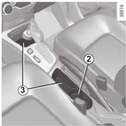
Cup holder 2 and 4 Centre console storage compartment 3
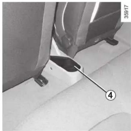
natural_image
Close-up of a car seatbelt component with a numbered arrow pointing to part 4 (no text or symbols on the main subject)e storage compartment 3

When turning corners, accelerating or braking, ensure that the receptacle being held by the cup is not dislodged.
There is a risk of burning if hot liquid escapes.

No object should be placed on the floor (in front of the driver). Such objects may slide under the pedals sudden braking manoeuvres construct their use.
PASSENGER COMPARTMENT STORAGE, FITTINGS (2/3)
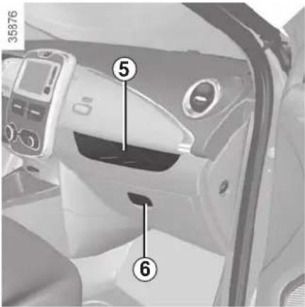
Dashboard storage compartment 5
Glove box
Pull handle 6 to open it.
It can hold A4 size documents, a large bottle of water, etc.
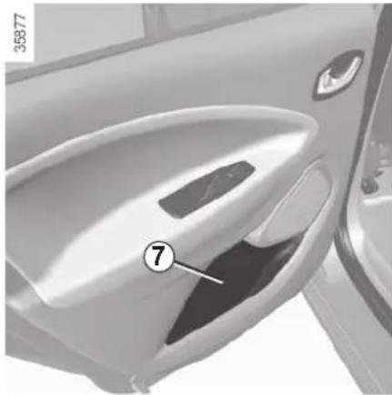
natural_image
Close-up of a car's side panel showing the door, vent, and handle (no text or symbols visible)Rear door storage compartment 7

Ensure that no hard, heavy or pointed objects are placed in the "open" storage compartments in such a
way that they may fall onto passengers during sudden turning, braking or in the event of an accident.
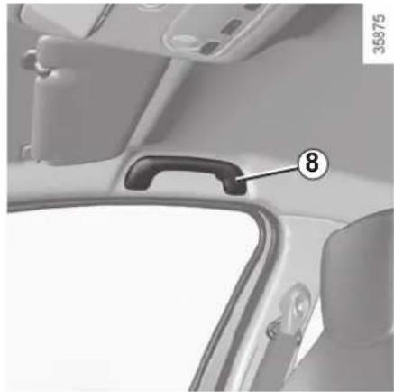
natural_image
Interior view of a car showing the rearview handle and seat, with no visible text or symbols.Grab handle 8
This offers support and can be held when the vehicle is being driven.
Do not use it for getting into or out of the vehicle.
PASSENGER COMPARTMENT STORAGE, FITTINGS (3/3)
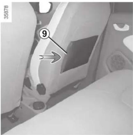
Storage pocket 9 with side opening
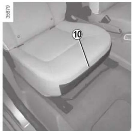
natural_image
Interior view of a car seat with numbered label (10) and number 35879 visible, no readable text or symbols beyond the number.10 storage pocket Sun visor storage 11
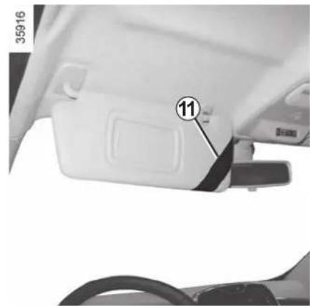
natural_image
Close-up of a car's side panel showing a component labeled '11' and part number 35916 (no readable text or symbols beyond labels)Can be used to hold motorway toll tick-ets, maps, etc.

Ensure that no hard, heavy or pointed objects are placed in the "open" storage compartments in such a
way that they may fall onto passengers during sudden turning, braking or in the event of an accident.
ASHTRAY, ACCESSORIES SOCKET
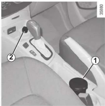
natural_image
Interior view of a car gear shift lever with labeled parts (1 and 2), no visible text or symbols beyond labelsAshtray 1
To open, lift the cover. To empty, pull the ashtray towards you and it will be released from its housing.
If your vehicle does not have an ashtray, you can purchase one from an approved dealer.
Accessories socket 2
It is provided for connecting accessories approved by our Technical Department.

Connect accessories with a maximum power of 120 watts (12 V) only.
When several accessory sockets are used at the same time, the total power of the connected accessories must not exceed 180 watts.
Fire hazard.
REAR HEADRESTS
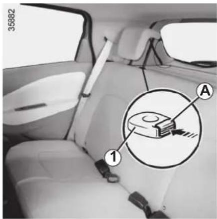
Position for use
Raise or lower the headrest while pulling it towards the front of the vehicle.
To remove the headrest
Press the button A on the switch 1 and remove the headrest.
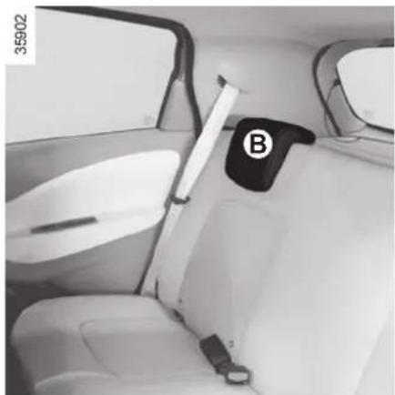
natural_image
Interior view of a car showing seatbelt, white driver seat, and large parking door (no visible text or symbols)To refit the headrest
Insert the headrest rods into the holes, and lower the headrest to the first notch. Check that it is correctly locked.
Storage position
Press the button A and lower the head-rest completely.
When the headrest is set at the lowest position (position B), this is for storage only: it should not be in this position when a seat is occupied.
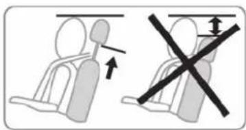

The headrest is a safety component; check that it is fitted and in the correct position. The top of the head-
rest should be as close as possible to the top of the head.
REAR BENCH SEAT: functions
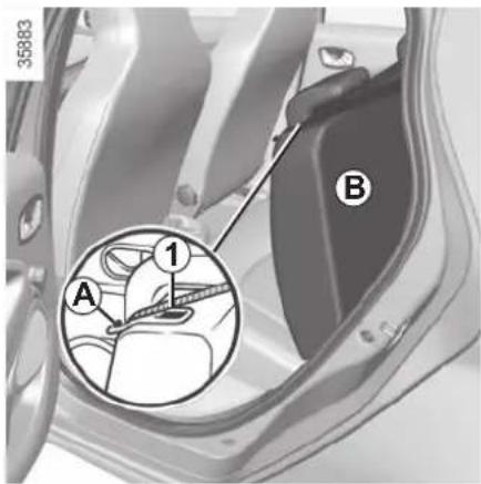
The seatback may be folded down to allow bulky objects to be transported.
To fold down the seatback
Ensure that the front seats are far enough forward.
Lower the headrests fully.
Place the seat belts in their guides A.
Press button 1 and lower the seat-back B.
Before moving the seatback, put the seat belt in belt guide A to avoid damaging it.

When moving the rear seats, ensure that nothing obstructs the anchorage points (passenger's arm or
leg, a pet, gravel, cloth, toys, etc.).

For safety reasons, carry out any adjustments when the vehicle is not being driven.
The configuration of the two-seat bench with the small seatback B pulled down, does not allow the central seat to be used as it would be impossible to buckle the seat belt (belt buckles inaccessible).
To replace the seatback, proceed in the reverse order to removal.
Refit the seatback and click it back into place.

When refitting the seat-back, make sure it is correctly locked in place.
If seat covers are fitted,
make sure these do not prevent the seatback latch from locking in.
Make sure that the seat belts are positioned correctly.
Reposition the headrests.
REAR PARCEL SHELF
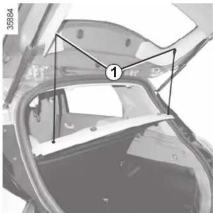
natural_image
Top-down view of a car interior with structural elements and a numbered marker (1), no readable text or symbols present.Rear parcel shelf
To remove:
– lower the rear headrests;
- unhook both straps 1;
- lift the shelf 2 upwards to unclip;
Maximum weight on rear parcel shelf: 2 kg, evenly distributed.
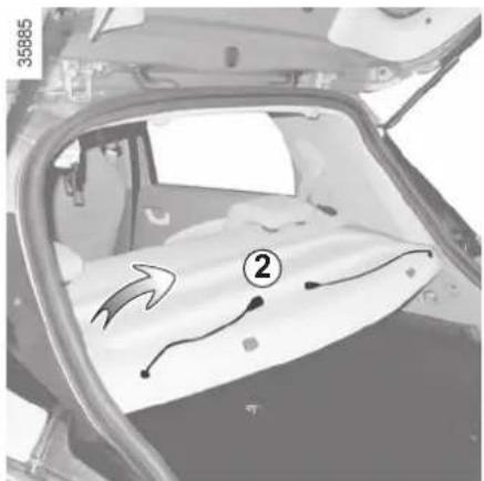
- push the shelf 2 inwards and turn it;
– pull the shelf towards you.
To refit, proceed in the reverse order to removal.

Do not place any objects, especially heavy or hard objects, on the parcel shelf.
These may pose a risk to the vehicle occupants if the driver has to brake suddenly or if the vehicle is involved in an accident.
LUGGAGE COMPARTMENT COVER: utility versions
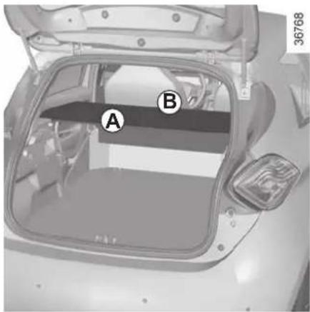
The luggage compartment cover consists of a rigid section A and a folding section B.
The luggage cover is in the unfolded position.

Do not place any objects, especially heavy or solid objects on the luggage compartment cover. These
may pose a risk to the vehicle occupants if the driver has to brake suddenly or if the vehicle is involved in an accident.
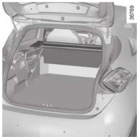
natural_image
Interior view of a car trunk with open lid and side-mounted door, showing structural components (no text or symbols)The luggage compartment cover is in the folded position.
To fold it:
- lift shelf A slightly and pull it towards you to remove;
- then fold section B back on itself.
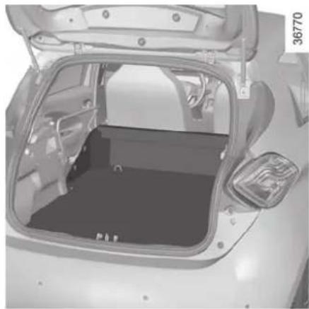
natural_image
Interior view of a car trunk with open lid and visible structural components (no text or symbols)The luggage compartment cover is removed.
To remove it: with the cover in the folded position and holding it horizontally:
- pull one side of the luggage compartment cover towards you, pivoting it slightly;
- then pull the other side of the luggage compartment cover to completely detach it from its housing.
BOOT/SPOILER
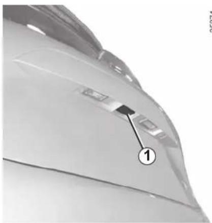
natural_image
Close-up of a car's side panel with a numbered marker (1) pointing to a specific component, no visible text or symbols.Opening
Press button 1 and lift the boot lid
Closing
Lower the boot lid using the handle inside the boot (depending on the vehicle) to assist you.
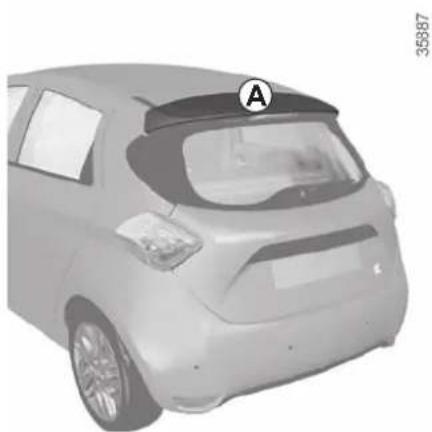
natural_image
3D rendering of a car rear view with visible license plate and window (no text or symbols)Spoiler
It is forbidden to attach objects and/or accessories (bike rack, etc.) to spoiler A.
TRANSPORTING OBJECTS IN THE LUGGAGE COMPARTMENT
Always position the objects transported so that the largest surface is against:
- The rear bench seatback for normal loads (example A).
- The front seatbacks with the rear seatbacks folded down, as is the case for maximum loads (example B).
If you have to place objects on the folded seatback, it is necessary that you lower the headrests before folding the seatback so that it can be folded as flat as possible against the seat.
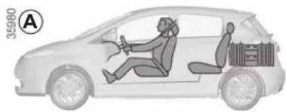
natural_image
Diagram of a car showing two people inside, one seated and one standing, with no visible text or symbols.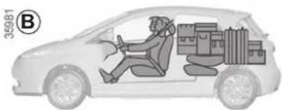
natural_image
Side view of a car with a driver inside and cargo boxes on the side, no text or symbols present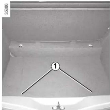
natural_image
Interior view of a vehicle cabin with a numbered point and decorative elements (no visible text or symbols)
Always position the heaviest items directly on the floor. Use the lashing points 1 on the boot floor, if
these are fitted to the vehicle. The luggage should be loaded in such a way that no items will be thrown forward and strike the occupants if the driver has to brake suddenly. Fasten the rear seat belts, even if the seats are not occupied.
MULTIMEDIA EQUIPMENT
The presence and location of this equipment depends on the vehicle version.
1 Multimedia touchscreen display;
2 Multimedia sockets;
3 Voice commands;
4 Steering column control;
5 Microphone.
Refer to the equipment instructions for information on how to operate this equipment.

Using the telephone
We remind you of the need to conform to the legislation in force concerning the use
of such equipment.
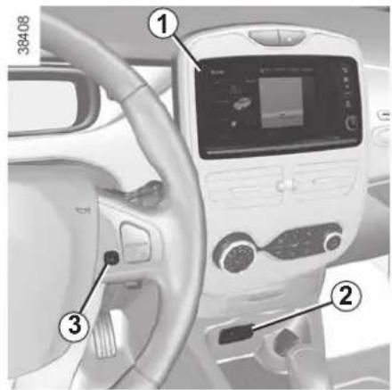
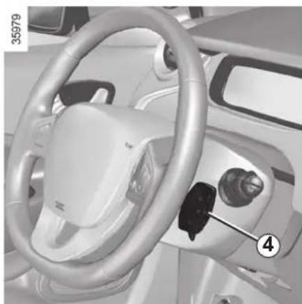
natural_image
Interior view of a car dashboard and steering wheel (no visible text or symbols)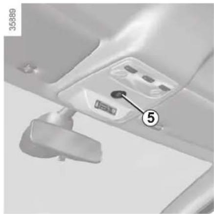
natural_image
Close-up of a car interior panel with a numbered component (5) and a small lock, no visible text or symbols.Section 4: Maintenance
Bonnet 4.2
Levels 4.4
coolant 4.4
brake fluid. 4.5
windscreen washer reservoir 4.5
Secondary 12V battery 4.6
Tyre Pressure 4.8
Bodywork maintenance 4.9
Interior trim maintenance.... 4.12
4.1
BONNET (1/2)
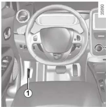
natural_image
Interior view of a car dashboard and steering wheel (no visible text or symbols)To open, pull handle 1, located on the left-hand side of the dashboard.
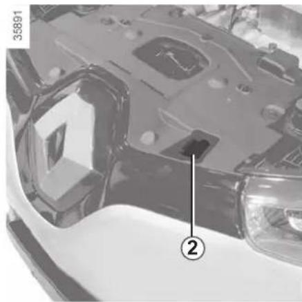
natural_image
Close-up of a car's front bumper with numbered annotation (2) and part number 35891 visible, no readable text or symbols beyond annotations.Unlocking the bonnet catch
Lift the bonnet by several centimetres and push lever 2 to the left.

Please note when working close to the engine that it may be hot. The engine cooling fan may also start
at any moment. The warning light in the engine compartment reminds you of this.
Risk of injury.

Do not do any work under the bonnet when the vehicle is charging or when the ignition is switched on.

In the event of even a slight impact involving the radiator grille or bonnet, have the bonnet lock checked by an
authorised dealer as soon as possible.

When working in the engine compartment, ensure that the windscreen wiper stalk is in the park position.
Risk of injury.
BONNET (2/2)
Opening the bonnet
Lift the bonnet; you will need to guide it as it is held by a strut.

Do not press down on the bonnet: there is a risk that the bonnet will close inadvertently.

After carrying out any work in the engine compartment, check that nothing has been left behind (cloth, tc.).
Otherwise, this may lead to engine damage.
Closing the bonnet
Check that nothing has been left in the engine compartment.
To close the bonnet again, hold the bonnet in the middle and guide it down, allowing a 30 cm gap before it is closed, then release it. It will latch automatically under its own weight.

Ensure that the bonnet is properly locked.
Ensure that nothing is preventing locking (grit, cloths,
etc.).
LEVELS (1/2)
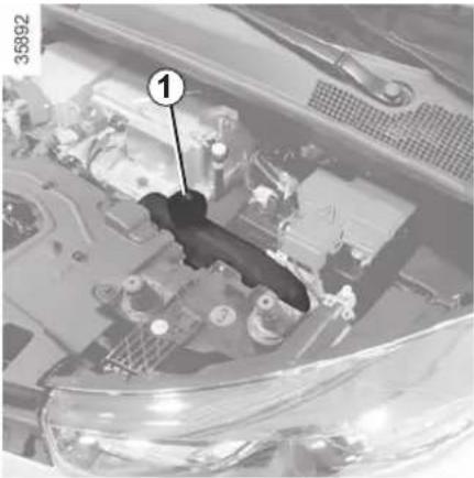
natural_image
Close-up of a car engine bay with a numbered component (1) and no visible text or symbols
Coolant
The level is checked with the engine switched off and on flat ground. The level when cold must be between the "MINI" and "MAXI" marks on the coolant reservoir 1.
Top this level up when cold before the "MINI" mark is reached.

Do not do any work under the bonnet when the vehicle is charging or when the ignition is switched on.
Checking intervals
Check the coolant level regularly (very severe damage is likely to be caused to the engine if it runs out of coolant).
If the level needs to be topped up, only use products approved by our Technical Department which ensure:
– protection against freezing;
- anticorrosion protection of the cooling system.
Consult your approved dealer at once if you notice an abnormal or repeated drop in any of the fluid levels.

No operations should be carried out on the cooling circuit when the engine is hot.
Risk of burns.
Replacement intervals
Refer to the Maintenance Document for your vehicle.

When working in the engine compartment, ensure that the windscreen wiper stalk is in the park position.
Risk of injury.

Please note when working close to the engine that it may be hot. The engine cooling fan may also start
at any moment. The 📋 label in the engine compartment reminds you of this.
Risk of injury.
LEVELS (2/2)
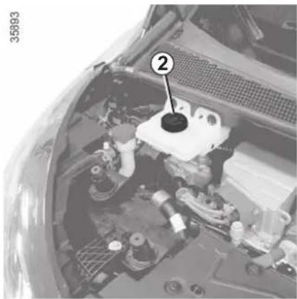
natural_image
Interior view of a car engine bay with numbered component (no visible text or symbols)
Brake fluid
The level should be read with the engine switched off and on level ground. This should be checked frequently, and immediately if you notice even the slightest loss in braking efficiency.
Consult your approved dealer at once if you notice an abnormal or repeated drop in any of the fluid levels.
Topping up
After any operation on the hydraulic circuit, a specialist must replace the fluid. Only use fluids approved by our Technical Department (and taken from a sealed container).
Replacement intervals
Refer to the Maintenance Document for your vehicle.
Level 2
It is normal for the level to drop as the linings become worn, but it should never drop below the "MIN" warning line.
If you wish to check the disc wear yourself, you should obtain the document explaining the checking procedure from our network or from the manufacturer's website.

When working in the engine compartment, certain parts may be hot. In addition, the engine cooling fan can at any moment.
Risk of burns or serious injury.
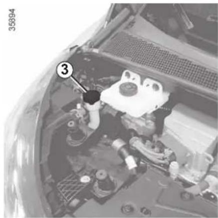
natural_image
Interior view of a car engine bay with numbered component (3), no visible text or symbols
Windscreen washer
reservoir
Topping up
Open cap 3, fill until you can see the fluid, then refit the cap.
Liquid
Screen wash product (product with antifreeze in winter).
Jets
Use a tool such as a needle to adjust the height of the windscreen washer jets.
SECONDARY 12 V BATTERY (1/2)
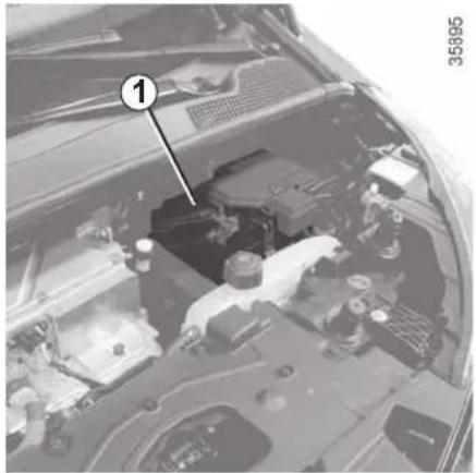
natural_image
Interior view of a car's engine bay with visible components and a numbered annotation (1), no readable text or symbols beyond the label.The secondary battery is a 12 V battery: this supplies the energy required to operate vehicle equipment (lights, windscreen wipers, audio system, etc) and certain safety systems, such as ABS.
You should not open it or add any fluid.
Maintenance/replacement
The charge status of the 12 volt battery 1 can decrease, especially if you use your vehicle:
- when the outside temperature drops;
- after extended use of energy-consuming devices with the engine switched off.

For your own safety and for the proper operation of the vehicle's electrical equipment (lights, windscreen
wipers, ABS, etc.), any intervention on the secondary 12 V battery (removal, disconnection, etc.) must categorically be performed by a specialist professional.
Risk of serious burns or electric shocks.
Respect categorically the replacement intervals (without exceeding them) as stated in the maintenance document.
The battery is a specific type. Please ensure it is replaced with the same type.
Contact an Authorised Dealer.

Do not do any work under the bonnet when the vehicle is charging or when the ignition is switched on.

Please note when working close to the engine that it may be hot. The engine cooling fan may also start
at any moment. The 📋 label in the engine compartment reminds you of this.
Risk of injury.
SECONDARY 12 V BATTERY (2/2)
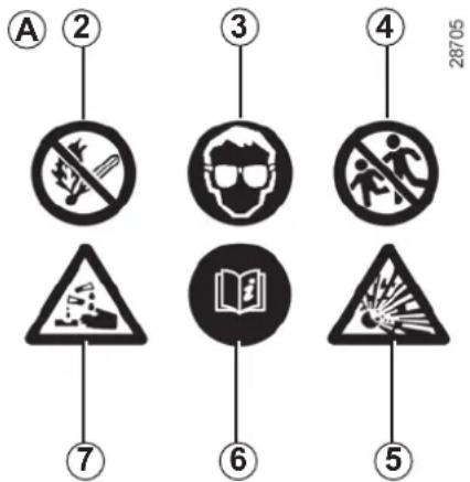
Label A
Observe the indications on the battery.
2 naked flames and smoking are forbidden;
3 eye protection required;
4 keep away from children;
5 explosive materials;
6 please consult the driver's handbook;
7 corrosive substances.
Breakdown recovery
To avoid damaging your vehicle, do not recharge the secondary 12 V battery using:
– an external battery charger;
- a battery from another vehicle.
Please contact an Authorised Dealer.

Do not disconnect the secondary 12 V battery.
Risk of serious burns or electric shocks.
Do not use your electric vehicle to restart the 12 volt battery in another vehicle. The 12 volt electric power of an electric vehicle is not enough to perform such an operation. Risk of damage to vehicle
TYRE PRESSURE
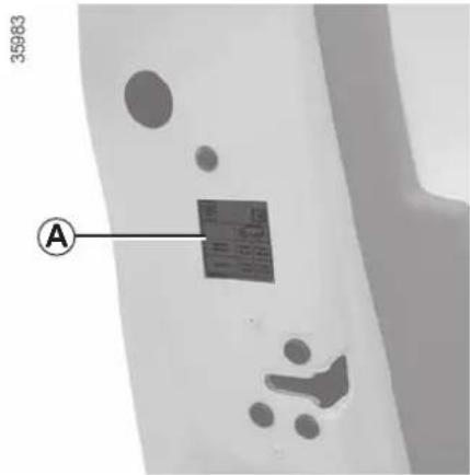
Label A
Open the driver's door to read it.
Tyre pressures should be checked when the tyres are cold.
If the tyre pressures cannot be checked when the tyres are cold, increase the pressures from 0.2 to 0.3 bar (or 3 PSI). Never deflate a hot tyre.
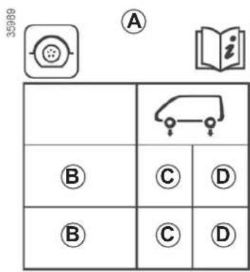
B : dimension of the tyres fitted to the vehicle.
C : tyre pressures for the front wheels.
D : tyre pressures for the rear wheels.
Tyre safety and use of snow chains
Refer to the information on "Tyres" in Section 5 for the servicing conditions and, depending on the version, the use of chains.
Vehicle fitted with a tyre pressure loss warning system
If under-inflated (puncture, low pres-
sure, etc.), the warning light ⚠️ on the instrument panel comes on. See «Tyre pressure loss warning» in chapter 2.

For your safety, please respect the speed limit.
When they need to be replaced, only tyres of the make, size, type and profile be used on a single axle.
They must: either have a load capacity and speed rating at least equal to those of the original tyres, or conform to those recommended by an authorised dealer. Failure to heed these instructions could endanger your safety and affect your vehicle's roadworthiness.
Risk of loss of control of the vehicle.
BODYWORK MAINTENANCE (1/3)
A well-maintained vehicle will last longer. It is therefore recommended to maintain the exterior of the vehicle regularly.
Your vehicle has been treated with very effective anti-corrosion products. It is nevertheless subject to various outside influences.
Corrosive agents in the atmosphere
– atmospheric pollution (built-up and industrial areas),
– saline atmospheres (near the sea, particularly in hot weather),
- seasonal and damp weather conditions (e.g. road salt in winter, water from road cleaners, etc.).
Minor impacts
Abrasive action
Dust and sand in the air, mud, road grit thrown up by other vehicles, etc.
You should take a number of minor precautions in order to safeguard your vehicle against such risks.
You should
Wash your car frequently, with the engine off, with cleaning products recommended by the manufacturer (never use abrasive products). Rinse thoroughly beforehand with a jet:
- spots of tree resin and industrial grime;
- mud in the wheel arches and underneath the body which forms damp patches;
- bird droppings, which cause a chemical reaction with the paint that rapidly discolours paintwork and may even cause the paint to peel off;
wash the vehicle immediately to remove these marks since it is impossible to remove them by polishing; - salt, particularly in the wheel arches and underneath the body after driving in areas where the roads have been gritted.
Withdraw the vegetable falls (resin, film etc.) from the vehicle regularly.
Observe the vehicle stopping distances when driving on gravelled surfaces to prevent paint damage.
Repair, or have repaired quickly, areas where the paint has been damaged, to prevent corrosion spreading.
Remember to visit the body shop periodically in order to maintain your anti-corrosion warranty. Refer to the Maintenance Document.
Respect local regulations about washing vehicles (e.g. do not wash your vehicle on a public highway).
If it is necessary to clean mechanical components, hinges, etc., spray them with products approved by our Technical Department to protect them after they have been cleaned.
We have selected special products to care for your vehicle and you can obtain these from the manufacturer's accessory outlets.
BODYWORK MAINTENANCE (2/3)
What you should not do
Wash the vehicle in bright sunlight or freezing temperatures.
Do not scrape off mud or dirt without pre-wetting.
Allow dirt to accumulate on the exterior.
Allow rust to form following minor impacts.
Do not use solvents not approved by our Technical Department to remove stains as this could damage the paint-work.
Do not drive in snow or muddy conditions without washing the vehicle, particularly under the wheel arches and body.

Degrease or clean using high-pressure cleaning equipment or by spraying on products not approved by our Technical Department:
- mechanical components (e.g.: engine compartment);
- underbody;
- parts with hinges (e.g.: inside the doors);
- painted plastic external fittings (e.g.: bumpers).
Doing this could give rise to corrosion or operational faults.
BODYWORK MAINTENANCE (3/3)
Vehicles with a matte paint finish
This type of paint requires certain precautions.
Do not do the following
Use wax-based products (polishing).
Rub too hard.
Wash the vehicle in a roller-type car wash.
Wash the vehicle using a high-pressure device.
Attach stickers to the paintwork (risk of leaving marks).

Wash the vehicle using a high-pressure cleaning device.
You should do the following
Wash the vehicle by hand using plenty of water, using a soft cloth or a gentle sponge.
Using a roller type car wash
Return the windscreen wiper stalk to the Park position (refer to the information on the "Windscreen washer, wiper" in Section 1). Check the mounting of external accessories, additional lights and mirrors, and ensure that the wiper blades are secured with adhesive tape. Remove the radio aerial mast if your vehicle is fitted with this equipment. Remember to remove the tape and refit the antenna after washing.

Washing the vehicle
Never wash the engine compartment, the charging connection or the traction battery with a high-pressure jet.
This risks damaging the electric circuit.
Never wash the vehicle while it is charging.
Risk of electric shock and a risk to life.
Cleaning the headlights
As the headlights are made of plastic "glass", use a soft cloth or cotton wool to clean them. If this does not clean them properly, moisten the cloth with soapy water, then wipe clean with a soft damp cloth or cotton wool.
Finally, carefully dry off with a soft dry cloth.
Do not use cleaning products containing alcohol or utensils (e.g.: a scraper).
INTERIOR TRIM MAINTENANCE (1/2)
A well-maintained vehicle will last longer. It is therefore recommended to maintain the interior of the vehicle regularly.
A stain should always be dealt with swiftly.
Whatever type of stain is on the trim, use cold (or warm) soapy water with natural soap.
Detergents (washing-up liquid, powdered products, alcohol-based products) should not be used.
Use a soft cloth.
Rinse and soak up the excess.
Glass instrument panel
(e.g. instrument panel, clock, exterior temperature display, radio display, etc.)
Use a soft cloth (or cotton wool).
If this does not clean them properly, use a soft cloth (or cotton wool) slightly moistened with soapy water and then wipe clean with another soft damp cloth or cotton wool.
Finally, carefully dry off with a soft dry cloth.
Do not use products containing alcohol and/or spray fluids on the area.
Seat belts
These must be kept clean.
Use products selected by our Technical Department (Approved outlets) or warm, soapy water and a sponge and wipe with a dry cloth.
Detergents or dyes must not be used under any circumstances.
Textiles (seats, door trim, etc)
Vacuum-clean the textiles regularly.
Liquid stain
Use soapy water.
Dab lightly (never rub) with a soft cloth, rinse and remove the excess.
Solid or pasty stain
Carefully remove the excess solid or pasty material immediately with a spatula (working from the edges to the centre to avoid spreading the stain).
Clean as for a liquid stain.
Special instructions for sweets or chewing gum
Put an ice cube on the stain to solidify it, then proceed as for a solid stain.
For further recommendations for maintaining the interior, and/or for any unsatisfactory results, please see an authorised dealer.
INTERIOR TRIM MAINTENANCE (2/2)
Removal/replacing removable equipment originally fitted in the vehicle
If you need to remove equipment in order to clean the passenger compartment (for example, mats), always ensure that they are correctly refitted and are the right way around (the driver's mat should be fitted on the driver's side, etc.) and fit them with the components supplied with the equipment (for example, the driver mat should always be fixed using the pre-fitted mounting components).
With the vehicle stationary, always ensure that nothing will impede driving (anything obstructing the pedals, heel wedged by the mat etc.).
You should not:
Position objects such as deodorants, scents etc. near air vents as this could damage your dashboard trim.

Use high-pressure cleaning equipment or sprays inside the passenger compartment:
without careful use, this equipment could impair the correct functioning of the electrical or electronic components in the vehicle, or have other detrimental effects.
Section 5: Practical advice
Tool kit 5.2
Tyre inflation kit 5.3
Tyres (tyre and wheel safety, use in winter) 5.6
Headlights (changing bulbs) 5.9
Rear lights (changing bulbs) 5.10
Indicator lights (changing bulbs) 5.11
Interior lighting: changing bulbs. 5.12
"Hands-free" card: battery 5.13
"Hands-free" card: battery 5.14
Fuses.... 5.15
Fitting a radio. 5.17
Accessories 5.18
Wipers (replacing blades) 5.19
Towing/breakdown. 5.20
Operating faults 5.23
TOOL KIT
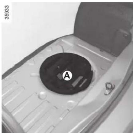
natural_image
Close-up of a mechanical component with a circular hole labeled 'A' and part number 35933 visible (no readable text or symbols beyond label)The tools included in the tool kit depend on the vehicle.
Tool kit A is located in the tray under the luggage compartment carpet.
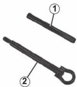
natural_image
Two black mechanical tools with labeled parts (1 and 2), no text or symbols present.Lever 1
This locks or unlocks the wheel bolts and tow eye.
Tow eye 2
Refer to the information on "Towing" in Section 5.
35934

Never leave tools unsecured in the vehicle: there is a risk that they may be thrown about during brak-
ing. After use, check that all the tools are correctly clipped into the tool kit, then position it correctly in its housing: there is a risk of injury. If wheel bolts are supplied in the tool kit, only use these bolts for the emergency spare wheel: refer to the label affixed to the emergency spare wheel.
TYRE PRESSURE KIT (1/3)
32788
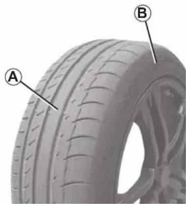
natural_image
Close-up of a car tire with labeled points A and B, showing tread pattern and surface texture (no text or symbols beyond labels)
The kit repairs tyres when tread A has been damaged by objects smaller than 4 mm. It cannot repair
all types of puncture, such as cuts larger than 4 mm, or cuts in tyre sidewall B.
Ensure also that the wheel rim is in good condition.
Do not pull out the foreign body causing the puncture if it is still in the tyre.

Do not attempt to use the inflation kit if the tyre has been damaged as a result of driving with a puncture.
You should therefore carefully check the condition of the tyre sidewalls before any operation.
Driving with underinflated, flat or punctured tyres can be dangerous and may make the tyre impossible to repair.
This repair is temporary.
A tyre which has been punctured should always be inspected (and repaired, where possible) as soon as possible by a specialist.
When taking a tyre which has been repaired using this kit to be replaced, you must inform the specialist.
When driving, vibration may be felt due to the presence of the repair product injected into the tyre.

The kit is only approved for inflating the tyres of the ve- hicle originally equipped with the kit.
It must never be used to inflate the tyres of another vehicle, or any other inflatable object (rubber ring, rubber boat, etc.).
Avoid spillage on skin when handling the repair product bottle. If droplets do leak out, rinse them off with plenty of water.
Keep the repair kit away from children.
Do not dispose of the empty bottle in the countryside. Return it to your approved dealer or to a recycling organisation.
The bottle has a limited service life which is indicated on its label. Check the expiry date.
Contact an approved dealer to replace the inflation tube and repair product bottle.
TYRE PRESSURE KIT (2/3)
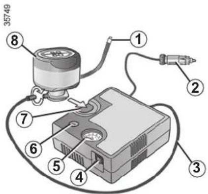
Depending on the vehicle, in the event of a puncture, use the kit located in the boot or underneath the luggage compartment carpet.
Vehicle fitted with a tyre pressure loss warning system
If under-inflated (puncture, low pres-
sure, etc.), the warning light lights up on the instrument panel. See "Tyre pressure loss warning" in Section 2.
With the engine running and the parking brake applied,
– unroll the hose from the container;
- connect the compressor hose 3 to the container's inlet 8;
– depending on the vehicle, connect the container 8 to the compressor from the container recess 7;
- unscrew the valve cap on the relevant wheel and screw on the container's inflation adapter 1;
- disconnect any accessories previously connected to the vehicle's accessories sockets;
– adapter 2 must be connected to the vehicle accessories socket;

Before using this kit, park the vehicle at a sufficient distance from traffic, switch on the hazard warning
lights, apply the handbrake, ask all passengers to leave the vehicle and keep them away from traffic.
- press switch 4 to inflate the tyre to the recommended pressure (please refer to the information in the section on "Tyre pressure");
- after a maximum of 15 minutes, stop inflating and read the pressure (on pressure gauge 5).
Note: while the container is emptying (approximately 30 seconds), the pressure gauge 5 will briefly indicate a pressure of up to 6 bar. The pressure will then drop. - adjust the pressure: to increase it, continue inflation with the kit; to reduce it, press button 6.

If the vehicle is parked on the hard shoulder, you must warn other road users of your vehicle's presence
with a warning triangle or with other devices as per the legislation applying to the country you are in.
TYRE PRESSURE KIT (3/3)
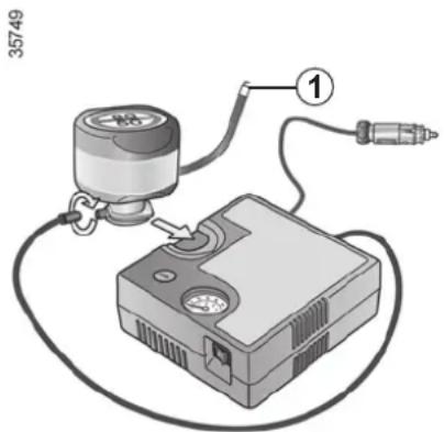
If a minimum pressure of 1.8 bar is not reached after 15 minutes, repair is not possible; do not drive the vehicle but contact an approved dealer.

Nothing should be placed around the driver's feet as such objects may slide under the pedals during
sudden braking manoeuvres and obstruct their use.
Once the tyre is correctly inflated, remove the kit: slowly unscrew the inflation adapter 1 to prevent any repair product from escaping and store the container in plastic packaging to prevent the product from escaping.
- Affix the driving recommendation label to the dashboard where it can easily be seen by the driver;
- Put the kit away.
- At the end of this initial inflation operation, air will still escape from the tyre. You must drive a short distance in order to seal the hole.
- Start immediately and drive at between 12 and 40mph (20 and 60km / h ) in order to distribute the product evenly in the tyre and, after driving for 2 miles (3km) , stop and check the pressure.
- If the pressure is greater than 1.3 bar but less than the recommended pressure (refer to the label affixed to the edge of the driver's door), readjust it. Otherwise, please contact an authorised dealer: the tyre cannot be repaired.
Precautions when using the kit
The kit should not be operated for more than 15 consecutive minutes.

Please be aware that a poorly tightened or missing valve cap can make the tyres less airtight and may pressure loss.
Always use valve caps identical to those fitted originally and tighten them fully.

Following repair with the kit, do not travel further than 120 miles (200 km). In addition, reduce your speed and
under no circumstances exceed 48 mph (80 km/h). The sticker, which you must affix in a prominent position on the dashboard, reminds you of this.
Depending on the country or local legislation, a tyre repaired with the inflation kit may need to be replaced.
TYRES (1/3)
The tyres are the only contact between the vehicle and the road, so it is essential to keep them in good condition. You must make sure that your tyres conform to local road traffic regulations.
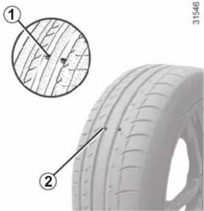
Maintaining the tyres
The tyres must be in good condition and the tread form must have sufficient depth; tyres approved by our Technical Department have wear warning strips 1 that are indicators moulded into the tread at several points.
When the tyre tread has been worn to the level of the wear indicators, they become visible 2: it is then necessary to replace your tyres because the tread rubber is no more than 1.6 mm deep, resulting in poor roadholding on wet roads.
An overloaded vehicle, long journeys by motorway, particularly in very hot weather, or continual driving on poorly surfaced minor roads will lead to more rapid tyre wear and affect safety.

Incidents which occur when driving, such as striking the kerb, may damage the tyres and wheel rims, and could
also lead to misalignment of the front or rear axle geometry. In this case, have the condition of these checked by an approved dealer.
TYRES (2/3)
Tyre pressures
Adhere to the tyre pressures. The tyre pressures should be checked at least once a month and additionally before any long journey (refer to the label affixed to the edge of the driver's door). Please refer to the information on "Tyre pressures" in Section 4.

Incorrect tyre pressures lead to abnormal tyre wear and unusually hot running.
These are factors which
may seriously affect safety and lead to:
– poor road holding,
– risk of bursting or tread separation.
The pressure depends on the load and the speed of use. Adjust the pressure according to the conditions of use (refer to the label affixed to the edge of the driver's door).
Pressures should be checked when the tyres are cold; ignore higher pressures which may be reached in hot weather or following a fast journey.
If tyre pressures cannot be checked when the tyres are cold, the normal pressures must be increased by 0.2 to 0.3 bar (or 3 PSI).
Never deflate a hot tyre.

Please be aware that a poorly tightened or missing valve cap can make the tyres less airtight and lead ure loss.
Always use valve caps identical to those fitted originally and tighten them fully.
Vehicle fitted with a tyre pressure loss warning system
If under-inflated (puncture, low pressure, etc.), the warning light 🖱️ on the instrument panel comes on. See "Tyre pressure loss warning" in chapter 2.
TYRES (3/3)
Changing wheels around
This practice is not recommended.
Fitting new tyres

For your safety, please respect the speed limit.
When they need to be replaced, only tyres of the same make, size, type and profile should be used on a single axle.
They must: either have a load capacity and a speed capacity at least equal to the original tyres, or correspond to those recommended by your authorised dealer.
Failure to heed these instructions could endanger your safety and affect your vehicle's roadworthiness.
Risk of loss of control of the vehicle.
Use in winter
Chains
For safety reasons, fitting snow chains to the rear axle is strictly forbidden.
Chains cannot be fitted to tyres which are larger than those originally fitted to the vehicle.
Snow or Winter tyres
We would recommend that these be fitted to all four wheels to ensure that your vehicle retains maximum adhesion.
Warning: These tyres sometimes have a specific direction of rotation and a maximum speed index which may be lower than the maximum speed of your vehicle.
Studded tyres
This type of equipment may only be used for a limited period and as laid down by local legislation. It is necessary to observe the speed specified by current legislation.
These tyres must, at a minimum, be fitted to the two front wheels.
NB:
The use of snow tyres, winter tyres or studded tyres significantly reduces the vehicle range.
In all cases, we would recommend that you contact an approved Dealer who will be able to advise you on the choice of equipment which is most suitable for your vehicle.

Chains may only be fitted to tyres of the same size as those originally fitted to your vehicle.
Chains may be fitted, provided that they are specific chains. We would advise you to consult an approved dealer.
FRONT HEADLIGHTS: changing bulbs
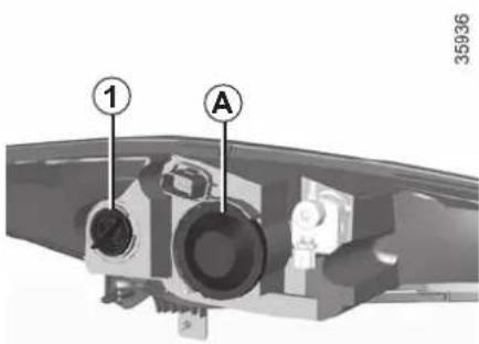
The bulbs detailed below can be replaced. However, we would advise you to have them replaced by an authorised dealer if it proves difficult.

The bulbs are under pressure and can break when replaced.
Risk of injury.
Obtain an emergency kit containing a set of spare bulbs and fuses from an approved Dealer.
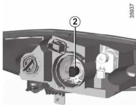
natural_image
Mechanical component diagram showing internal parts with numbered annotation (2), no readable text or symbols present.Direction indicators
Unscrew bulb holder 1 a quarter of a turn, then replace the bulb.
Bulb type: PY21W.

Please note when working close to the engine that it may be hot. The engine cooling fan may also start
at any moment. The 🎨 label in the engine compartment reminds you of this.
Risk of injury.
Main beam/dipped headlights
Remove cover A.
Unscrew bulb holder 2 and remove the set from its housing.
Disconnect the bulb.
Bulb type: H7.
It is essential to use anti U.V. 55W bulbs so as not to damage the plastic on the headlights.
Do not touch the bulb glass.
When the bulb has been changed, make sure you refit the cover correctly. During re-assembly, make sure you do not trap the wiring with the bulb holder.
Daytime running lights
Please contact an authorised dealer.

Do not do any work under the bonnet when the vehicle is charging or when the ignition is switched on.
REAR LIGHTS AND SIDE LIGHTS: changing bulbs (1/2)
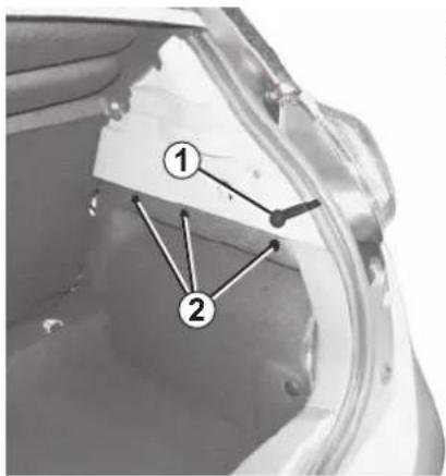
Direction indicator lights/brake and side lights
- Open the boot;
- unclip the head of the upper clips 2 to unlock;
- unclip 2 on the trim;
- release trim;
- unscrew 1;
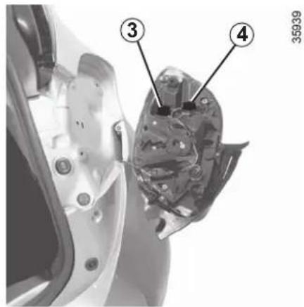
- release the light assembly from outside the vehicle by pulling towards the rear;
- unscrew bulb holder 3 (parking light and brake light) or 4 (direction indicator), then replace the bulb.
Side light and brake light 5 Bulb type: PR21W.
Direction indicator lights 6 Bulb type: PY21W.
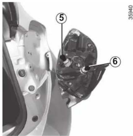
Refitting
To refit, proceed in the reverse order, taking care not to damage the wiring.

The bulbs are under pressure and can break when replaced.
Risk of injury.
REAR AND SIDE LIGHTS: changing bulbs (2/2)
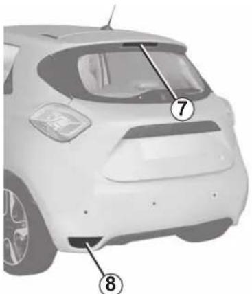
natural_image
Front view of a white car with numbered annotations pointing to the rear window (no text or symbols on the car itself)High-level brake light 7
Consult an approved dealer.
Reversing lights and rear fog lights 8
Access bulb holder via the underneath of the vehicle, then unscrew it by turning towards the centre of the vehicle.
Fog light
Bulb type: PR21W.
Reversing light
Bulb type: P21W.
35941
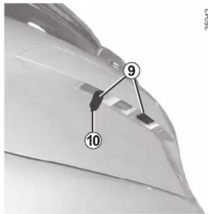
Number plate lights 9
- Unclip light 9 by pressing tab 10; - remove the light cover to gain access to the bulb.
Bulb type: W5W.

The bulbs are under pressure and can break when replaced.
Risk of injury.
35942
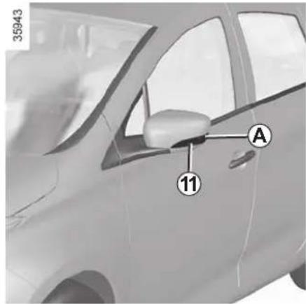
Side indicator lights 11
- Unclip indicator light 11 (using a flat-blade screwdriver type tool positioned at A to move the indicator light towards the front of the vehicle);
- Turn the bulb holder a quarter of a turn and take out the bulb.
Bulb type: W5W.
INTERIOR LIGHTING: changing bulbs
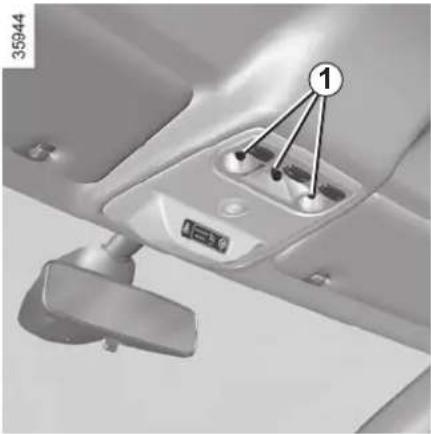
natural_image
Interior view of a vehicle's seat and dashboard with labeled components (no readable text or symbols)Courtesy light
Unclip the lens (using a flat-blade screwdriver or similar).
Remove the bulb concerned.
Bulb type 1: W5W.
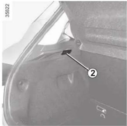
natural_image
Interior view of a vehicle showing a door, seat, and window (no visible text or symbols)Luggage compartment light
Unclip light 2 by pressing the tabs on each side (using a flat-blade screw-driver or similar).
Disconnect the light.

The bulbs are under pressure and can break when replaced.
Risk of injury.
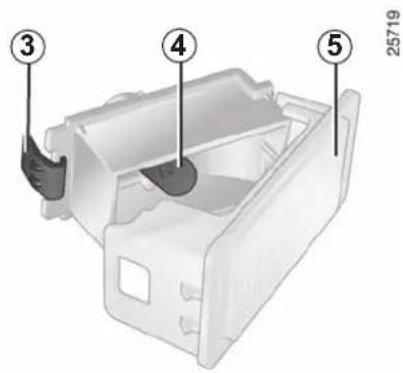
Disconnect the light.
Press tab 3 to release the lens 5 and access bulb 4.
Bulb type: W5W.
"HANDS-FREE" CARD: battery (1/2)
Operating faults
If the battery is too weak to ensure correct operation, you can still start (insert the RENAULT card in the card reader) and lock/unlock the vehicle (refer to the information on "Locking/unlocking the doors" in Section 1).

If they need to be replaced, be sure to use the same or equivalent type of battery (consult an Approved
Dealer).

When replacing:
- make sure that the batteries are correctly inserted.
There is a risk of explo-
sion.
- if the flap does not close correctly, do not use and keep out of reach of children.
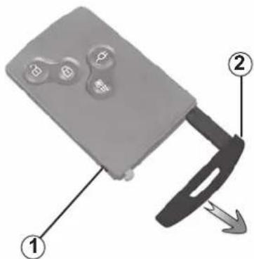
Replacing the battery
When the message "Keycard battery low" appears on the instrument panel, replace the battery in the card:
- press the 1 button while pulling on the emergency key 2;
- unclip the cover 3 using the tab 4;
– remove the battery by pressing on one side (movement A), and lifting the other (movement B);
35912
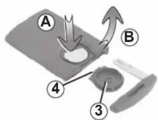
- replace it according to the direction and template indicated inside the cover. 3.
When refitting, proceed in the reverse order, then depending on the vehicle, press one of the buttons on the card four times, close to the vehicle: the message will disappear.
Check that the cover is clipped shut.
The batteries are available from approved Dealers, and their service life approximately two years. Check that there is no dye on the battery: risk of an incorrect electrical contact.
"HANDS-FREE" CARD: battery (2/2)

Precautions relating to batteries:
- keep (new or used) batteries out of reach of children;
– not to swallow the batteries.
Risk of chemical burns which may led to death.
- if ingested or inserted into any part of the body, consult a doctor as soon as possible.
Do not throw away your used batteries; give them to an organisation responsible for collecting and recycling batteries.
FUSES (1/2)
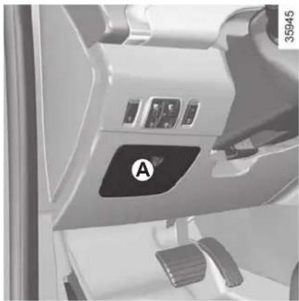
natural_image
Interior view of a car dashboard with labeled control panel (A), no visible text or symbols beyond the labelFuse box
If any electrical component does not work, check the condition of the fuses.
Unclip the access flap A.
In accordance with local legislation or as a precautionary measure:
Obtain an emergency kit containing a set of spare bulbs and fuses from an approved Dealer.
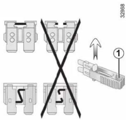
Tweezers 1
Remove the fuse using tweezers 1, located at the back of flap A.
To remove the fuse from the tweezers, slide the fuse to the side.
It is not advisable to use the free fuse locations.

Check the fuse in question and replace it, if necessary, by a fuse of the same rating.
If a fuse is fitted where the rating is too high, it may cause the electrical circuit to overheat (risk of fire) in the event of an item of equipment using an excessive amount of current.
FUSES (2/2)
2
15A
6
15A
3
10A
7
10A
8
20 A
10
10 A
4
20 A
⑨
15A
11
10A
12
5A
13
25 A
①
10A
5
15A
Allocation of fuses
(the presence and location of fuses depends on the vehicle equipment level)
1 Brake light;
2 Horn;
3 Instrument panel;
4 Automatic door locking;
5 Direction indicator lights;
6 Cigarette lighter;
7 Windscreen washer;
8 Radio;
9 Rear windscreen wiper;
10 Front ceiling light and boot light;
11 Pedestrian horn;
12 Brake switch;
13 Driver's window winder;
14 Heated door mirrors.
35947

Check the fuse in question and replace it, if necessary, by a fuse of the same rating.
If a fuse is fitted where the rating is too high, it may cause the electrical circuit to overheat (risk of fire) in the event of an item of equipment using an excessive amount of current.
FITTING A RADIO
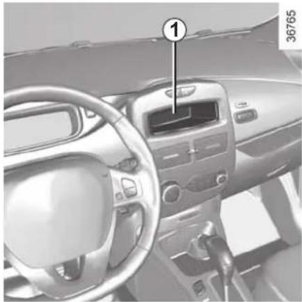
natural_image
Interior view of a car dashboard and steering wheel (no visible text or symbols)Radio location 1
Unclip the blanking cover. The aerial, + and - supply and speaker wire connections are located behind it.
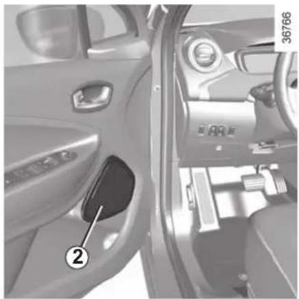
natural_image
Interior view of a car showing the door, vent, and dashboard (no visible text or symbols)Door speakers 2
To install any equipment, please consult an authorised dealer.
- In all cases, it is very important to follow the manufacturer's instructions carefully.
- The specifications of the brackets and wires (available from our network) vary depending on the equipment level of your vehicle and the type of radio.
Consult an approved Dealer to find out the correct part number.
- No work may be carried out on the vehicle's electrical or radio circuits, except by approved dealers: an incorrectly connected system may result in damage being caused to the electrical equipment and/or the components connected to it.
ACCESSORIES

Electrical and electronic accessories
Before installing this type of accessory (particularly for transmitters/receivers: frequency bandwidth, power level, position of the aerial, etc.), make sure it is compatible with your vehicle. You can get advice from an authorised dealer.
Connect accessories with a maximum power of 120 Watts only. Fire hazard. When several accessory sockets are used at the same time, the total power of the connected accessories must not exceed 180 watts.
No work may be carried out on the vehicle's electrical or radio circuits, except by approved Dealers: an incorrectly connected system may result in damage being caused to the electrical equipment and/or the components connected to it.
If the vehicle is fitted with any aftermarket electrical equipment, make sure that the installation is correctly protected by a fuse. Establish the rating and position of this fuse.
Using the diagnostic socket
The use of electronic accessories on the diagnostic socket may cause serious disturbance to the vehicle's electronic systems. For your safety we recommend that you use only electronic accessories approved by the manufacturer, consult an Approved Dealer. Serious accident risk.
Use of transmission/receiving devices (telephones, CB equipment etc.).
Telephones and CB equipment with integrated aerials may cause interference to the electronic systems originally fitted to the vehicle: it is advisable only to use equipment with an external aerial. Furthermore, we remind you of the need to conform to the legislation in force concerning the use of such equipment.
Fitting after-market accessories
If you wish to install accessories on the vehicle: please contact an authorised dealer. Also, to ensure the correct operation of your vehicle, and to avoid any risk to your safety, we recommend that you use only accessories specifically designed for your vehicle, which are the only accessories for which the manufacturer will provide a warranty.
If you are using an anti-theft device, only attach it to the brake pedal.
Obstructions to the driver
On the driver's side, only use mats suitable for the vehicle, attached with the pre-fitted components, and check the fitting regularly. Do not lay one mat on top of another. There is a risk of wedging the pedals
WINDSCREEN WIPER BLADES
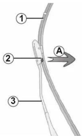
25516
Replacing wiper blades 1
With the ignition on and the engine switched off, lower the windscreen wiper stalk completely: they stop slightly away from the bonnet.
Lift wiper arm 3, pull tab 2 (movement A) and push the blade upwards.
To refit
Slide the blade along the arm until it clips on. Make sure that the blade is correctly locked in position. Return the windscreen wiper stalk to the park position.
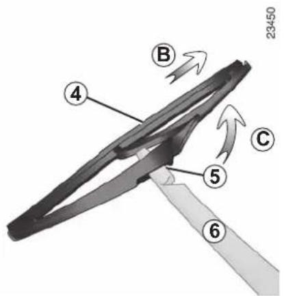
Rear screen wiper blade 4
- Lift wiper arm 6;
- pivot blade 4 until some resistance is met (movement C);
– depending on the vehicle, press tab 5, then remove the blade by pulling it (movement B).
To refit
To refit the wiper blade, proceed in reverse order to removal. Make sure that the blade is correctly locked in position.
Keep monitoring the condition of the wiper blades. How long they last depends on you:
- clean the blades and the wind-screen regularly with soapy water;
- do not use them when the wind-screen is dry;
- free them from the windscreen when they have not been used for a long time.

- In frosty weather, make sure that the wiper blades are not stuck by ice (to avoid the risk of the motor heating).
- Check the condition of the wiper blades. They should be replaced as soon as they become less efficient: approximately once a year.
When changing the blade, when it has been removed, do not let the wiper arm fall against the window: risk of breaking the window.
TOWING, BREAKDOWN (1/3)
Choice of breakdown service
In the event of an energy fault
In the event of a fully discharged traction battery, any type of towing is permitted: towing on a flatbed truck or towing on the road using the tow eye (please see following pages). It is essential to wait approximately 5 minutes after locking the doors to start towing.
All other cases
Only towing on a flatbed truck is per- mitted.
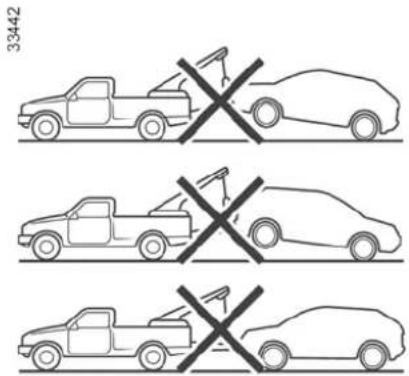
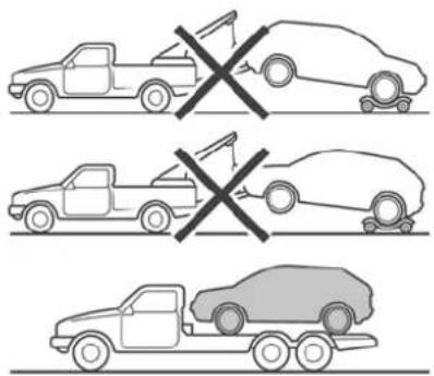
Towing on a flatbed truck
Breakdown recovery must be performed on a flat surface under all circumstances except where the vehicle is immobilised following a full discharge of the traction battery. In the event of a total energy loss, please see the following pages.
Before any recovery, unlock the steering column: with the clutch pressed, engage the lever in position N, insert the card in the reader then press the engine starting button for approximately two seconds.
The regulations in force for breakdown recovery must always be observed.
TOWING, BREAKDOWN (2/3)
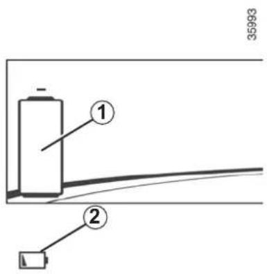
In the event of an energy fault: towing
In the event of a fully discharged traction battery:
- the warning light 2 flashes;
- the indicator 1 shows an empty battery.
It is possible to recover on a flatbed truck or tow the vehicle using the tow eye, following the instructions below.

When the engine is stopped, steering and braking assistance are not operational.
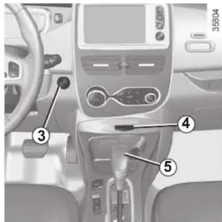
Before towing, unlock the steering column: engage the lever 5 in position N, insert the card in the reader 4 then press the engine starting button 3 for approximately two seconds.
The column is unlocked, the accessory functions are supplied: the vehicle lights can be used (hazard warning lights, brake lights etc.). The towed vehicle's lights must be switched on at night.
The speed specified by current legislation for towing must always be observed.
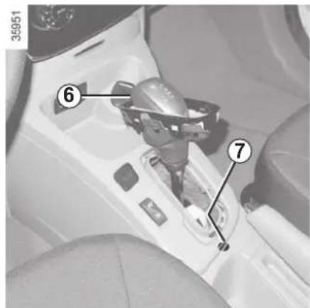
Once you have finished towing, press the engine start button twice (risk of running down the 12 V battery).
If the lever is stuck in P, even though you are depressing the brake pedal, the lever can be released manually.
To do this, unclip the cover at the base of the lever.
Simultaneously press at the location7 and the unlocking button 6 on the lever.
TOWING, BREAKDOWN (3/3)
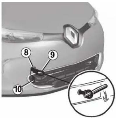
35950
Access to the towing point
Only use the front and rear towing points 8.
This towing point may only be used for towing: never use it for lifting the vehicle directly or indirectly.

Do not remove the card RENAULT from the reader when the vehicle is being towed.
Unclip the cover 10 by inserting a flat-blade screwdriver or similar under the cover.
Tighten towing hitch 9 fully: as much as possible by hand at first, then finish tightening it using the lever.
Use only the towing hitch 9 and the lever located under the luggage compartment carpet in the tool kit (please refer to the information on the "Tool kit" in Section 5).
NB: Please do not use a damaged tow eye.

Do not leave the tools unsecured inside the vehicle as they may come loose under braking.
After use, check that all the tools are correctly clipped into the tool kit, then, depending on the vehicle, position it correctly in its housing. Risk of injury.
OPERATING FAULTS (1/4)
The following advice will enable you to carry out quick, temporary repairs. For safety reasons you should always contact an approved dealer as soon as possible.
FAULTS POSSIBLE CAUSES WHAT TO DO
| Impossible to charge the traction battery.The charging flap warning light flashes red. | The outdoor temperature is lower than -26°C. | Recharge your vehicle in a more suitable environment. If necessary, please refer to the information on “Towing: breakdown recovery” in Section 5. |
| No electrical current in the wall socket or poor connection of cable to domestic socket. | Check your installation (circuit breaker, programmer, etc.).Check the connections (socket, etc.).Please refer to the information on “Electric vehicle: charging” in Section 1. | |
| The cord is defective. Please see an authorised dealer to replace it. | ||
| Impossible to charge the traction battery.The charging flap warning light flashes blue. | The charging cord is not correctly locked to the vehicle. | Plug the charging cord correctly to the vehicle. Refer to the information on “Electric vehicle: charging” in Section 1. |
| The activation of the air conditioning using the card RENAULT fails to work. | The card RENAULT is outside its area of action. | Step closer to the vehicle. |
| One of the usage conditions is not complied with. | Please refer to the information on “Air-conditioning: remote control activation” in Section 3. | |
OPERATING FAULTS (2/4)
FAULTS POSSIBLE CAUSES WHAT TO DO
| The programmable air conditioning fails to work. | One of the usage conditions is not complied with (the traction battery is not charged, etc). | Please refer to the information on “Air-conditioning: programming” in Section 3. |
| The remote control does not lock or unlock the doors. | The remote control battery is flat. Use the emergency key. | |
| Use of appliances operating on the same frequency as the remote control (mobile phone, etc.). | Stop using the devices or use the key. | |
| Vehicle located in a high electro-magnetic radiation zone.Secondary 12 V battery discharged. | Replace the battery or have it replaced. You can still lock/unlock and start your vehicle (refer to the information on “Locking, unlocking the opening elements” in Section 1 and “Starting, stopping the engine” in Section 2). | |
| The steering column remains locked. | Steering wheel locked. Move the steering wheel while pressing the engine start button (refer to Section 2 “Starting the engine”). | |
| Vibrations. | Tyres not inflated to correct pressures, incorrectly balanced or damaged. | Check the tyre pressures. If this is not the problem, have them checked by an approved Dealer. |
OPERATING FAULTS (3/4)
Electrical equipment POSSIBLE CAUSES ACTION REQUIRED
The wipers do not work. Wiper blades stuck. Free the blades before using the wipers.
Broken windscreen wiper fuse. Consult an approved dealer.
Blown rear screen wiper fuse (intermittent, permanently stopped).
Replace the fuse or have it replaced; refer to the information on "Fuses" in section 5.
Motor fault. Consult an approved dealer.
The wiper does not stop. Faulty electrical controls. Consult an approved dealer.
Direction indicators flashing more quickly. Blown bulb. Replace the bulb or have it replaced.
| The indicators are not working. | On one side only: | Blown bulb. Replace the bulb or have it replaced. | |
| On both sides: | - fuse blown, | Replace the fuse or have it replaced; refer to the information on “Fuses” in section 5. | |
| - faulty flasher unit. | Needs replacing: please see an authorised dealer. | ||
OPERATING FAULTS (4/4)
Electrical equipment POSSIBLE CAUSES ACTION REQUIRED
| The headlights are not working. | Only one: – blown bulb, Replace the bulb or have it replaced. | |
| – disconnected wire or incorrectly-positioned connector, | Check and reconnect the wire or the connector. | |
Both: - if the circuit is fused. Check and replace if necessary.
The headlights do not switch off. Faulty electrical controls. Consult an approved dealer.
| Traces of condensation in the headlights or rear lights. | This is not a fault. Traces of condensation in the lights is a natural phenomenon caused by variations in temperature and humidity.These traces soon disappear when the lights are switched on. |
Section 6: Technical specifications
Vehicle identification plates 6.2
Engine identification plate 6.3
Engine specification.... 6.3
Weights 6.4
Dimensions 6.5
Replacement parts and repairs 6.6
Service sheets 6.7
Anticorrosion check 6.13
6.1
VEHICLE IDENTIFICATION PLATES
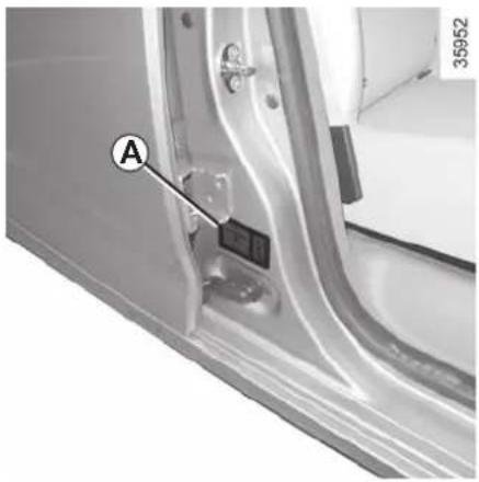
natural_image
Close-up of a car door panel with labeled component A, showing no visible text or symbols beyond the label.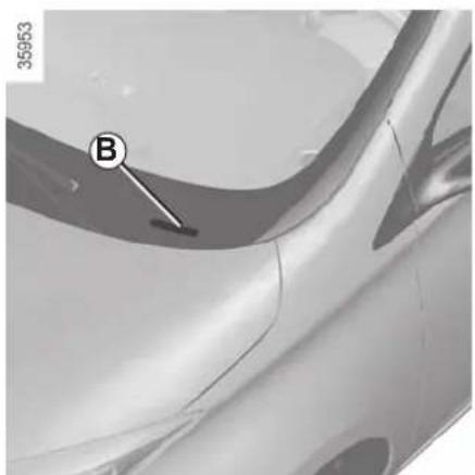
natural_image
Close-up of a car's side profile with a curved handle and labeled point B (no text or symbols beyond label)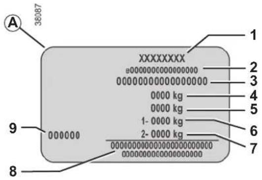
The information shown on the vehicle identification plate should be quoted on all correspondence or orders.
Vehicle identification plate A
1 Manufacturer name.
2 EC design number or approval number.
3 Identification number.
Depending on the vehicle, this information is also given on marking B.
4 MAM (Maximum Authorised Mass).
5 GTW (Gross train weight: vehicle fully loaded, with trailer).
6 MPAW (Maximim Permissible Weight) for front axle.
7 MPAW on rear axle.
8 Reserved for related or additional entries.
9 Paint reference (colour code).
ENGINE IDENTIFICATION PLATE/ENGINE SPECIFICATION
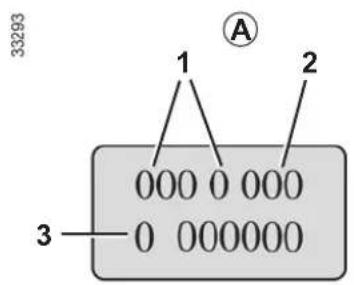
Please quote the information on the engine plate or label A in all correspondence or orders.
(Location varies depending on engine)
1 Engine type.
2 Engine suffix.
3 Engine number.
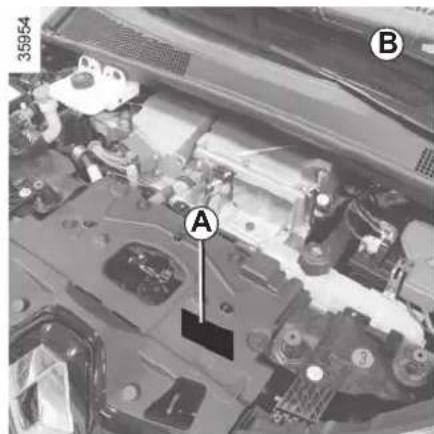
natural_image
Close-up of a car engine bay with labeled components (A and B), no readable text or symbols beyond labelsEngine specification
B : Engine type: 5AM
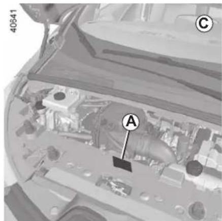
C : Engine type: 5AQ
WEIGHTS (in kg)
The weights indicated for a basic vehicle without options: they vary depending on the your vehicle's equipment. Consult your approved Dealer.
| Maximum permissible all-up weight (MMAC)Total train weight (MTR) | Weights are indicated on the vehicle identification plate (refer to the information on “Vehicle identification plates” in Section 6) |
| Braked Trailer Weight Prohibited | |
| Unbraked Trailer Weight Prohibited | |
| Permissible nose weight Prohibited | |
| Permissible load on the roof with the carrying device Prohibited |
DIMENSIONS (in metres)
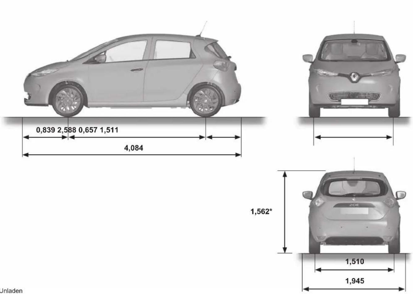
* Unladen
REPLACEMENT PARTS AND REPAIRS
Original parts are based on strict specifications and are subject to highly-specialised tests. Therefore, they are of at least the same level of quality as the parts fitted originally.
If you always fit genuine replacement parts to your vehicle, you will ensure that it performs well. Furthermore, repairs carried out within the manufacturer's Network using original parts are guaranteed according to the conditions set out on the reverse of the repair order.
SERVICE SHEETS (1/6)
VIN:
| Date: Miles (Km): Invoice number: Comments/miscellaneous | |
| Type of operation: StampService □...... □ | |
| Anti-corrosion check:OK □ Not OK* □*See specific page | |
| Date: Miles (Km): Invoice number: Comments/miscellaneous | |
| Type of operation: StampService □...... □ | |
| Anti-corrosion check:OK □ Not OK* □*See specific page | |
| Date: Miles (Km): Invoice number: Comments/miscellaneous | |
| Type of operation: StampService □...... □ | |
| Anti-corrosion check:OK □ Not OK*□*See specific page | |
SERVICE SHEETS (2/6)
VIN:
| Date: Miles (Km): Invoice number: Comments/miscellaneous | |
| Type of operation: StampService □...... □ | |
| Anti-corrosion check:OK □ Not OK* □*See specific page | |
| Date: Miles (Km): Invoice number: Comments/miscellaneous | |
| Type of operation: StampService □...... □ | |
| Anti-corrosion check:OK □ Not OK* □*See specific page | |
| Date: Miles (Km): Invoice number: Comments/miscellaneous | |
| Type of operation: StampService □...... □ | |
| Anti-corrosion check:OK □ Not OK*□*See specific page | |
SERVICE SHEETS (3/6)
VIN:
| Date: Miles (Km): Invoice number: Comments/miscellaneous | |
| Type of operation: StampService □...... □ | |
| Anti-corrosion check:OK □ Not OK* □*See specific page | |
| Date: Miles (Km): Invoice number: Comments/miscellaneous | |
| Type of operation: StampService □...... □ | |
| Anti-corrosion check:OK □ Not OK* □*See specific page | |
| Date: Miles (Km): Invoice number: Comments/miscellaneous | |
| Type of operation: StampService □...... □ | |
| Anti-corrosion check:OK □ Not OK*□*See specific page | |
SERVICE SHEETS (4/6)
VIN:
| Date: Miles (Km): Invoice number: Comments/miscellaneous | |
| Type of operation: StampService □...... □ | |
| Anti-corrosion check:OK □ Not OK* □*See specific page | |
| Date: Miles (Km): Invoice number: Comments/miscellaneous | |
| Type of operation: StampService □...... □ | |
| Anti-corrosion check:OK □ Not OK* □*See specific page | |
| Date: Miles (Km): Invoice number: Comments/miscellaneous | |
| Type of operation: StampService □...... □ | |
| Anti-corrosion check:OK □ Not OK*□*See specific page | |
SERVICE SHEETS (5/6)
VIN:
| Date: Miles (Km): Invoice number: Comments/miscellaneous | |
| Type of operation: StampService □...... □ | |
| Anti-corrosion check:OK □ Not OK* □*See specific page | |
| Date: Miles (Km): Invoice number: Comments/miscellaneous | |
| Type of operation: StampService □...... □ | |
| Anti-corrosion check:OK □ Not OK* □*See specific page | |
| Date: Miles (Km): Invoice number: Comments/miscellaneous | |
| Type of operation: StampService □...... □ | |
| Anti-corrosion check:OK □ Not OK*□*See specific page | |
SERVICE SHEETS (6/6)
VIN:
| Date: Miles (Km): Invoice number: Comments/miscellaneous | |
| Type of operation: StampService □...... □ | |
| Anti-corrosion check:OK □ Not OK* □*See specific page | |
| Date: Miles (Km): Invoice number: Comments/miscellaneous | |
| Type of operation: StampService □...... □ | |
| Anti-corrosion check:OK □ Not OK* □*See specific page | |
| Date: Miles (Km): Invoice number: Comments/miscellaneous | |
| Type of operation: StampService □...... □ | |
| Anti-corrosion check:OK □ Not OK*□*See specific page | |
ANTICORROSION CHECK (1/5)
If the continuation of the warranty is subject to repair, it is indicated below.
VIN: ....
| Corrosion repair operation to be carried out: | 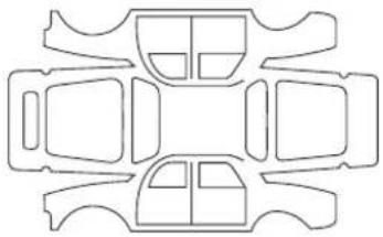 | Stamp |
| Date of repair: | ||
| Repair to be carried out: |  | Stamp |
| Date of repair: | ||
| Repair to be carried out: | 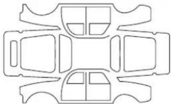 | Stamp |
| Date of repair: | ||
ANTICORROSION CHECK (2/5)
If the continuation of the warranty is subject to repair, it is indicated below.
VIN: ....
| Corrosion repair operation to be carried out: | 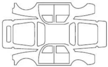 | Stamp |
| Date of repair: | ||
| Repair to be carried out: | 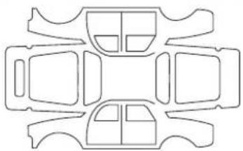 | Stamp |
| Date of repair: | ||
| Repair to be carried out: | 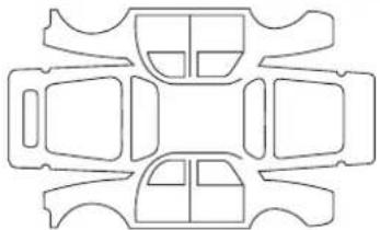 | Stamp |
| Date of repair: | ||
ANTICORROSION CHECK (3/5)
If the continuation of the warranty is subject to repair, it is indicated below.
VIN:
| Corrosion repair operation to be carried out: | | Stamp |
| Date of repair: | ||
| Repair to be carried out: | | Stamp |
| Date of repair: | ||
| Repair to be carried out: | 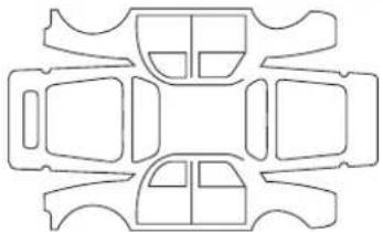 | Stamp |
| Date of repair: | ||
ANTICORROSION CHECK (4/5)
If the continuation of the warranty is subject to repair, it is indicated below.
VIN: ....
| Corrosion repair operation to be carried out: |  | Stamp |
| Date of repair: | ||
| Repair to be carried out: | 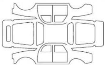 | Stamp |
| Date of repair: | ||
| Repair to be carried out: |  | Stamp |
| Date of repair: | ||
ANTICORROSION CHECK (5/5)
If the continuation of the warranty is subject to repair, it is indicated below.
VIN:
| Corrosion repair operation to be carried out: | | Stamp |
| Date of repair: | ||
| Repair to be carried out: | | Stamp |
| Date of repair: | ||
| Repair to be carried out: | 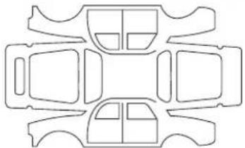 | Stamp |
| Date of repair: | ||
ALPHABETICAL INDEX (1/5)
A
ABS 2.16 → 2.20
accessories.... 5.18
accessories socket 3.25
additional methods of restraint 1.38 → 1.41, 1.44
side protection 1.43
to the front seat belts 1.38 → 1.41
to the rear seat belts 1.38 → 1.42
adjusting your driving position 1.34
air bag....1.38 → 1.44
activating the front passenger air bags 1.58
deactivating the front passenger air bags 1.56
air conditioning ....1.21 - 1.22, 3.4 → 3.11, 3.17 - 3.18
air vents 3.2 - 3.3
anti-corrosion check 6.13 → 6.17
anti-corrosion protection 4.9
anti-lock braking system: ABS 2.16 → 2.20
armrest: front 3.23
ashtray 3.25
audible and visual signals.... 1.80
B
battery.... 1.65
12 volt battery maintenance 4.6 - 4.7
12 volt battery 1.2 → 1.6, 4.6 – 4.7
bonnet.... 4.2 - 4.3
brake fluid 4.5
bulbs changing .... 5.10 – 5.11
C
card: battery.... 5.13 – 5.14, 5.14
C
central door locking 1.27, 1.30 → 1.32
changing a bulb 5.10 - 5.11
changing gear 2.5 - 2.6
charge meter 1.68, 2.7
charging cord 1.8 → 1.16, 1.21 – 1.22
charging flap 1.8 → 1.16
charging socket ....1.2 → 1.6, 1.8 → 1.16
child restraint/seat 1.45 - 1.46, 1.48 → 1.58
child safety..1.19 - 1.20, 1.25, 1.29, 1.45 - 1.46, 1.48 → 1.58, 3.19 - 3.20
child seats....1.45 – 1.46, 1.48 → 1.55
children 1.19 – 1.20, 1.28 – 1.29, 1.45 – 1.46
children (safety) 1.25, 3.19 – 3.20
cleaning: inside the vehicle 4.12 – 4.13
clock 1.77 - 1.78
closing the doors 1.28 → 1.31
connected services 1.3
control instruments ....1.64 → 1.70
controls 1.60 → 1.63
coolant 4.4
courtesy light 3.21, 5.12
courtesy mirrors 3.21
cruise control 1.65, 2.21 → 2.27
cruise control-speed limiter....2.21 → 2.27
D
dashboard....1.60 → 1.63
daytime running lights.... 1.82, 5.9
deadlocking the doors 1.27
display 1.60 → 1.68, 2.29, 3.32
doors.... 1.28 - 1.29, 1.32
doors/tailgate 1.27 - 1.29, 1.32
driver's position 1.60 → 1.66
driving 2.2 → 2.6, 2.10 – 2.11, 2.13 → 2.29
ALPHABETICAL INDEX (2/5)
driving position
settings 1.34 → 1.37
driving recommendations 2.7 → 2.11
E
»ECO» mode function 2.9
ECO driving 2.7 → 2.9
ECO mode 2.9
electric beam height adjustment 1.85
»400 volt» electrical circuit ....1.2 → 1.6
electric vehicle
vehicle range 2.10 - 2.11
noise 1.6
charge 1.8 → 1.16
driving 1.6, 2.10 - 2.11
presentation 1.2 → 1.6
important recommendations 1.7
electric windows 3.19 - 3.20
Electronic Stability Program: ESP 2.16 → 2.20
emergency brake assist....2.16 → 2.20
emergency braking 2.16 → 2.20
emergency key 1.19 - 1.20
energy
»ECO» mode 2.9
saving 2.10
charge meter (function) 2.7
range 2.7 → 2.9
energy saving 2.7 → 2.11
energy consumption 1.67 - 1.68, 2.10 - 2.11
energy recovery 2.10
engine specifications 6.3
environment 2.12
ESP: Electronic Stability Program ....2.16 → 2.20
external temperature 1.77 - 1.78
F
faults operating faults ....5.23 → 5.26
fitting a radio 5.17
fittings 3.22 → 3.24
front passenger air bag deactivation 1.56
front seat adjustment 1.33
front seats adjustment ....1.33 → 1.37
with manual controls 1.33
fuses 5.15 - 5.16
G
gear lever.... 2.5 - 2.6
glove box 3.24
H
»hands-free» card: battery 5.13 – 5.14, 5.14
»hands-free» card: use.... 5.13 – 5.14, 5.14
H
handbrake 2.6
hands-free telephone integrated control 3.32
hazard warning lights signal 1.80, 1.82
headlight beam adjustment 1.85
headlight flashers 1.80
headlight washer 1.87
headrest.... 3.26
heating and air conditioning system 3.17
heating, air conditioning: programming .....2.11, 3.12 → 3.15
heating system 3.4 → 3.10, 3.12 → 3.15
heating/air conditioning programming ....3.12 → 3.15
horn 1.80
horn:
flash 1.80
sounding the horn 1.80
ALPHABETICAL INDEX (3/5)
hubcap tool 5.2
|
indicators 1.80, 5.9
indicators: direction indicators .... 1.80, 5.9 exterior temperature indicator .... 1.77 instrument panel .... 1.64 → 1.70
instrument panel 1.64 → 1.76, 1.82
instrument panel messages....1.69 → 1.76
interior trim maintenance 4.12 – 4.13
ionizer 3.16
L
levels: brake fluid .... 4.5 coolant .... 4.4 windscreen washer reservoir .... 4.5
lighting: exterior ....1.82 → 1.84 instrument panel ....1.82 interior ....3.21, 5.12
lights adjustment .... 1.85
lights: adjusting ..... 1.85 brake lights ..... 5.10 – 5.11 dipped beam headlights ..... 1.64, 1.82, 5.9 direction indicators ..... 1.64, 1.80, 5.9 – 5.10 fog lights ..... 1.64, 1.84, 5.11 hazard warning ..... 1.80 indicator lights ..... 5.11 main beam headlights ..... 1.64, 1.83, 5.9 number plate lights ..... 5.11 reversing lights ..... 5.11
side lights 1.82, 5.10
locking the doors ....1.19 → 1.29, 1.32
M
maintenance: bodywork ....4.9 → 4.11 interior trim ....4.12 – 4.13 mechanical ....4.2 – 4.3, 6.7 → 6.12 map reading lights ....3.21 methods of restraint in addition to the seat belts ...1.38 → 1.44 multimedia (equipment) ....3.32 multimedia equipment ....3.32, 5.17
N
navigation 3.32
navigation system 3.32
0
opening the doors ....1.28 → 1.31 operating faults ....1.75, 5.23 → 5.26
P
paintwork maintenance ....4.9 → 4.11 parking distance control....2.28 → 2.31 pedestrian warning system ....1.81 power-assisted steering....1.59 practical advice ....2.10 – 2.11 presentation of the electric vehicle important recommendations ....1.7 pretensioners ....1.38 → 1.41
R
radio....3.32 range of the traction battery....2.7 → 2.9 rear bench seat....3.27
ALPHABETICAL INDEX (4/5)
rear parcel shelf 3.28
rear seats functions 3.27
rear view camera 2.30 - 2.31
rear view mirrors 1.79
RENAULT ANTI-INTRUDER DEVICE (RAID) 1.32
RENAULT card use ....1.19 → 1.27, 3.11
replacement parts 6.6
reverse gear selecting 2.5 – 2.6
reversing sensor 2.28 - 2.29
S
screen wash/wipe 1.88
seat belt pretensioners ....1.38 → 1.41 front seat belt ....1.38 → 1.41
seat belts 1.34 → 1.41, 1.43 – 1.44, 1.65
see-me-home lighting 1.83, 1.85
service sheets....6.7 → 6.12
side protection devices 1.43
signals and lights 1.82 → 1.85
speakers location 5.17
speed control 2.5-2.6
speed limiter 1.65, 2.21 → 2.23
spoiler 3.30
starting 2.2 → 2.4
starting the engine 2.2 → 2.4
steering wheel adjustment 1.59
stopping the engine 2.4
storage compartment....3.22 → 3.24
storage compartments ....3.22 → 3.24
sun visor 3.21
T tailgate 3.30
tanks and reservoirs brake fluid .... 4.5 coolant .... 4.4
tanks and reservoirs: windscreen washer 4.5
technical specifications 6.6
telephone 3.32
temperature regulation ....3.4 → 3.10
tool kit 5.2
towing in the event of energy failure ....5.20 → 5.22 breakdown ....5.20 → 5.22
towing hitch....5.2, 5.21 - 5.22
towing rings 1.48 - 1.49, 3.31
traction battery 1.2 → 1.6
traction battery charge 1.8 → 1.16
traction control 2.16 → 2.20
transporting children 1.45 - 1.46, 1.48 → 1.58
transporting objects in the luggage compartment .... 3.30 – 3.31
trip computer and warning system....1.69 → 1.76
tyre inflation kit....5.3 → 5.5
tyre pressure....2.13 → 2.15, 4.8, 5.7
tyre pressure loss warning....2.13 → 2.15
tyre pressures 4.8
tyres 2.13 → 2.15, 4.8, 5.6 → 5.8
U unlocking the doors .... 1.30 – 1.31
V vehicle range ....2.7 → 2.11 ventilation ....3.4 → 3.10
ALPHABETICAL INDEX (5/5)
W
warning buzzer 1.28 - 1.29, 1.80, 1.83
warning lights....1.64 → 1.66, 1.69 – 1.70
washing 4.9 → 4.11
weights 6.4
wheels (safety) 5.6 → 5.8
windscreen washer 1.86 → 1.88, 4.5
windscreen washer/wiper 1.86 - 1.87
wiper blades 5.19
wipers 1.86 → 1.88
blades 5.19
RENAULT S.A.S. SOCIETÉ PAR ACTIONS SIMPLIFIÉE AU CAPITAL DE 533 941 113 € / 13-15, QUAI LE GALLO 92100 BOULOGNE-BILLANCOURT R.C.S. NANTERRE 780 129 987 - SIRET 780 129 987 03591 / TÉL : 0810 40 50 60 NU 979-14 - 99 91 051 085 - 10/2018 - Edition anglaise
M4
-


- Renault ZOE
- Welcome to your new electric vehicle
- CONTENTS
- Sections
- Section 1: Getting to know your vehicle
- ELECTRIC VEHICLE: introduction (1/5)
- ELECTRIC VEHICLE: introduction (2/5)
- Connected services
- ELECTRIC VEHICLE: introduction (3/5)
- Batteries
- V traction battery
- Secondary 12V battery
- ELECTRIC VEHICLE: introduction (4/5)
- ELECTRIC VEHICLE: introduction (5/5)
- Driving
- Special feature:
- Obstructions to the driver
- Noise
- IMPORTANT RECOMMENDATIONS
- In the event of an accident or impact
- In the event of fire
- All towing operations
- Washing the vehicle
- ELECTRIC VEHICLE: charging (1/9)
- Charging schematic diagram
- ELECTRIC VEHICLE: charging (2/9)
- Important recommendations for charging your vehicle
- Charging
- ELECTRIC VEHICLE: charging (3/9)
- Charging cord A
- Charging cord B
- ELECTRIC VEHICLE: charging (4/9)
- Choice of charging cord
- Installation
- For a standard charge
- For occasional charging (charging cord B)
- With a domestic socket (10A charge)
- ELECTRIC VEHICLE: charging (5/9)
- Electric charging connection 1
- Recommendations
- ELECTRIC VEHICLE: charging (6/9)
- Recharging the traction battery
- ELECTRIC VEHICLE: charging (7/9)
- Operating fault
- Impossible to charge the battery
- ELECTRIC VEHICLE: charging (8/9)
- Label 13
- ELECTRIC VEHICLE: charging programming (1/2)
- From the multimedia display 1
- Programming the function start time
- Daily
- Weekly
- ELECTRIC VEHICLE: charging programming (2/2)
- Charge start
- RENAULT CARDS: general information (1/2)
- The RENAULT card is used for:
- RENAULT card operating range
- Driver's responsibility when parking or stopping the vehicle
- RISK OF DEATH OR SERIOUS INJURY.
- RENAULT CARDS: general information (2/2)
- Battery life
- Replacement: need for an additional RENAULT Card
- Integrated key 5
- Access to key 5
- Using the key
- Advice
- REMOTE CONTROL RENAULT CARD: use (1/2)
- Unlocking the doors and tailgate
- Locking the doors and luggage compartment
- REMOTE CONTROL RENAULT CARD: use (2/2)
- RENAULT card not detected alarm
- Opening the charging flap or unlocking the vehicle charging cord
- Activation of the air-conditioning
- HANDS-FREE RENAULT CARD: use (1/4)
- Use
- HANDS-FREE RENAULT CARD: use (2/4)
- Unlocking the vehicle
- HANDS-FREE RENAULT CARD: use (3/4)
- Locking the vehicle
- Remote locking
- Locking using button 3
- NB:
- HANDS-FREE RENAULT CARD: use (4/4)
- Locking using the RENAULT card
- Special note:
- RENAULT CARD: deadlocking
- To activate deadlocking
- To deactivate deadlocking
- OPENING AND CLOSING THE DOORS (1/2)
- Front doors
- Special feature of the RENAULT "hands-free" card
- Rear doors
- Lights-on reminder buzzer
- Card reminder buzzer
- OPENING AND CLOSING THE DOORS (2/2)
- Door/tailgate open buzzer
- Special note
- Child safety
- LOCKING, UNLOCKING THE DOORS (1/2)
- Locking/Unlocking the doors from the outside
- LOCKING, UNLOCKING THE DOORS (2/2)
- Interior locking/unlocking door control
- Locking the doors without the RENAULT card
- Door and tailgate status indicator
- Driver's responsibility
- AUTOMATIC LOCKING WHEN DRIVING
- Operating principle
- Activating/deactivating the function
- Operating faults
- FRONT SEATS
- Heated seats
- SEAT BELTS (1/4)
- Adjusting your driving position
- Adjusting the seat belts
- SEAT BELTS (2/4)
- Locking
- Adjusting the height of the front seat belts
- Unfastening
- SEAT BELTS (4/4)
- METHODS OF RESTRAINT IN ADDITION TO THE FRONT SEAT BELTS (1/4)
- Pretensioners
- METHODS OF RESTRAINT IN ADDITION TO THE FRONT SEAT BELTS (2/4)
- Load limiter
- Airbaganti-submarining
- Driver and passenger front airbags
- METHODS OF RESTRAINT IN ADDITION TO THE FRONT SEAT BELTS (3/4)
- Operation
- METHODS OF RESTRAINT IN ADDITION TO THE FRONT SEAT BELTS (4/4)
- Warnings concerning the driver's airbag
- Warnings concerning the passenger airbag
- A REAR-FACING CHILD SEAT MUST NOT BE FITTED TO THE FRONT PASSENGER SEAT UNLESS THE ADDITIONAL RESTRAINT SYSTEMS, I.E. THE PASSENGER AIR BAG, ARE DEACTIVATED.
- Warnings concerning the anti-submarining airbag
- METHODS OF RESTRAINT IN ADDITION TO THE REAR SIDE SEAT BELTS
- Force limiter
- SIDE PROTECTION DEVICES
- Side air bags
- Warnings concerning the side air bag
- ADDITIONAL METHODS OF RESTRAINT
- CHILD SAFETY: General information (1/2)
- Carrying children
- CHILD SAFETY: General information (2/2)
- Using a child seat
- CHILD SAFETY: choosing a child seat
- Rear-facing child seats
- Forward-facing child seats
- Booster cushions
- CHILD SAFETY: choosing a child, baby seat mounting (1/2)
- Attachment via the seat belt
- Attachment using the ISOFIX system
- CHILD SAFETY: choosing a child, baby seat mounting (2/2)
- CHILD SAFETY: fitting a child seat (1/6)
- In the front seat
- CHILD SAFETY: fitting a child seat (2/6)
- In the rear side seat
- Rear centre seat
- CHILD SAFETY: fitting a child seat (3/6)
- Visual installation of the five-door version
- RISK OF DEATH OR
- Child seat attached using the belt
- Child seat attached using the ISOFIX mounting
- CHILD SAFETY: fitting a child seat (4/6)
- CHILD SAFETY: fitting a child seat (5/6)
- Child seat fitted using the ISOFIX mounting
- CHILD SAFETY: fitting a child seat (6/6)
- CHILD SAFETY: deactivating, activating the front passenger airbag (1/3)
- Deactivating the front passenger airbag
- CHILD SAFETY: deactivating, activating the front passenger airbag (2/3)
- DANGER
- CHILD SAFETY: deactivating, activating the front passenger airbag (3/3)
- Activating the front passenger airbag
- STEERING WHEEL/POWER-ASSISTED STEERING
- Height and reach adjustment
- Power-assisted steering
- DRIVING POSITION: LEFT-HAND DRIVE (2/2)
- DRIVING POSITION: RIGHT-HAND DRIVE (2/2)
- WARNING LIGHTS (1/3)
- WARNING LIGHTS (2/3)
- STOP light
- Brake circuit fault warning light
- Secondary 12 V battery charge warning light
- Warning light
- Front seat belt reminder warning light
- Cruise control and speed limiter indica-
- tor lights
- WARNING LIGHTS (3/3)
- Electrotechnical system warning light
- The warning light can lead to a drop in vehicle performance.
- Low traction battery level warning light
- ECO mode function light
- Electronic Stability Program (ESC) and traction control warning light
- Tyre pressure loss warning
- Seat heating indicator light
- Door(s) open warning light
- DISPLAYS AND INDICATORS (1/2)
- Charge meter 2
- Message indicating vehicle ready for driving 3
- Speedometer 4
- On-board computer display 6
- Instrument panel in miles
- DISPLAYS AND INDICATORS (2/2)
- Estimated range 7
- Remaining charge time 8
- Opening element warning light 9
- Traction battery charge load 10
- Charging cable "Plugged In" warning light 11
- Charge level 12
- Reserve level 13
- Immobilisation threshold imminent
- TRIP COMPUTER: general information (1/2)
- Trip computer 1
- Display selection keys 2 and 3
- TRIP COMPUTER: general information (2/2)
- Trip mileage resetting
- Resetting the journey parameters (reset button)
- Automatic resetting of the journey parameters
- Reading energy consumption values
- Interpreting some of the values displayed after resetting
- Resetting the estimated range
- Manual reset
- Automatic reset
- ON-BOARD COMPUTER: trip settings (1/3)
- ON-BOARD COMPUTER: trip settings (2/3)
- ON-BOARD COMPUTER: trip settings (3/3)
- TRIP COMPUTER AND WARNING SYSTEM: information messages
- TRIP COMPUTER AND WARNING SYSTEM: operating fault messages
- TRIP COMPUTER AND WARNING SYSTEM: warning message
- CLOCK AND EXTERIOR TEMPERATURE (1/2)
- Resetting the clock A
- CLOCK AND EXTERIOR TEMPERATURE (2/2)
- Resetting the clock B
- External temperature indicator
- REAR-VIEW MIRRORS
- Door mirrors with electrical adjustment:
- Heated door mirrors
- Interior rear view mirror
- AUDIBLE AND VISUAL SIGNALS
- Headlight flasher
- Direction indicators
- One-touch mode
- Hazard warning lights
- PEDESTRIAN HORN
- Deactivating the system
- Activating the system
- Warning noise selection
- EXTERIOR LIGHTING AND SIGNALS (1/3)
- Side lights
- Daytime running lights
- Dipped beam headlights
- Manual operation
- Automatic operation
- EXTERIOR LIGHTING AND SIGNALS (2/3)
- Main beam headlights
- Switching off the lights
- "See-me-home lighting" function
- EXTERIOR LIGHTING AND SIGNALS (3/3)
- Rear fog light
- HEADLIGHT BEAM ADJUSTMENT
- WINDSCREEN WASH, WIPE (1/2)
- Vehicles with automatic wiper function
- WINDSCREEN WASH, WIPE (2/2)
- Windscreen washer
- Efficiency of a wiper blade
- Precautions for using the wipers
- REAR SCREEN WASH, WIPE
- Rear screen wiper
- Rear screen washer/wiper
- Section 2: Driving
- STARTING, STOPPING THE ENGINE (1/3)
- Remote control RENAULT card
- To start
- Hands-free RENAULT card
- STARTING, STOPPING THE ENGINE (2/3)
- STARTING, STOPPING THE ENGINE (3/3)
- Conditions for stopping the engine
- GEAR CONTROL (1/2)
- Selector lever 1
- GEAR CONTROL (2/2)/HANDBRAKE
- Parking the vehicle
- Handbrake
- To release:
- To apply:
- DRIVING ADVICE, ECO-DRIVING (1/3)
- Charge meter
- Blue "Energy recovery" A usage zone
- Green "recommended consumption" B usage zone
- Yellow "Consumption not recommended" C usage zone
- Driving style indicator
- Journey log (Driving ECO 2 Score)
- Navigation system
- DRIVING ADVICE, ECO-DRIVING (3/3)
- ECO mode
- Activating the function
- Disabling the function
- VEHICLE RANGE: recommendations (1/2)
- Speed and driving style
- Advice:
- Road type
- VEHICLE RANGE: recommendations (2/2)
- Heating levels
- Tyres
- Vehicle loading
- ENVIRONMENT
- Manufacture
- Please make your own contribution towards protecting the environment too
- Recycling
- TYRE PRESSURE LOSS WARNING (1/3)
- Resetting the standard level for the tyre pressures
- TYRE PRESSURE LOSS WARNING (2/3)
- Resetting procedure
- Note:
- Display
- « PUNCTURE »
- TYRE PRESSURE LOSS WARNING (3/3)
- Readjustment of tyre pressures
- Replacing wheels/tyres
- Emergency spare wheel
- Tyre repair product and inflation kit
- Changing a wheel
- DRIVER CORRECTION DEVICES, AIDS (1/5)
- ABS (anti-lock braking system)
- DRIVER CORRECTION DEVICES, AIDS (2/5)
- Electronic stability program ESC with understeer control and traction control
- Electronic stability control ESC
- Understeer control
- Traction control
- DRIVER CORRECTION DEVICES, AIDS (3/5)
- Emergency brake assist
- Hazard warning lights switching on
- Braking anticipation
- Special cases
- DRIVER CORRECTION DEVICES, AIDS (4/5)
- Hill start assistance
- System operation
- DRIVER CORRECTION DEVICES, AIDS (5/5)
- Regenerative braking system
- SPEED LIMITER (1/3)
- Controls
- Switching on
- SPEED LIMITER (2/3)
- Varying the limit speed
- Exceeding the limit speed
- Limited speed cannot be maintained
- SPEED LIMITER (3/3)
- Putting the function on standby
- Recalling the limit speed
- Switching off the function
- CRUISE CONTROL (1/4)
- CRUISE CONTROL (2/4)
- Activating cruise control
- CRUISE CONTROL (3/4)
- Adjusting the cruising speed
- Exceeding the cruising speed
- Cruising speed cannot be maintained
- CRUISE CONTROL (4/4)
- Returning to the cruising speed
- PARKING DISTANCE CONTROL (1/2)
- PARKING DISTANCE CONTROL (2/2)
- Adjusting the parking distance control volume
- Special features
- REVERSING CAMERA (1/2)
- moving guide line:
- Fixed gauge 4
- Special feature
- REVERSING CAMERA (2/2)
- Activating/deactivating the reversing camera
- Section 3: Your comfort
- AIR VENTS: air outlets (2/2)
- Air flow
- Direction
- MANUAL AIR CONDITIONING (1/3)
- The controls
- Switching air conditioning on or off
- The air conditioning system is used for:
- Adjusting the ventilation speed
- Position OFF
- Adjusting the air temperature
- Adjusting the distribution of air in the passenger compartment
- Rear screen de-icing/ demisting
- Clear View function
- Switching the air recirculation on
- Air recirculation is for:
- Automatic mode
- Deactivating the air-conditioning
- AUTOMATIC AIR-CONDITIONING (3/4)
- AUTOMATIC AIR-CONDITIONING (4/4)
- Air recirculation (isolation of the passenger compartment)
- Manual use
- Stopping the function manually
- AIR CONDITIONING: remote activation
- Operating condition
- AIR CONDITIONING: programming (1/4)
- Adjusting the programming
- Operating conditions
- AIR CONDITIONING: programming (2/4)
- From the multimedia display A
- Setting the start time for the function
- "Programme" activation
- AIR CONDITIONING: programming (3/4)
- From the vehicle settings customisation menu 3
- AIR CONDITIONING: programming (4/4)
- Stopping the programmed air conditioning
- AIR IONIZER
- Selecting the operating mode
- Activating the ioniser in CLEAN mode at each engine start-up
- AIR CONDITIONING: information and operating instructions (1/2)
- Advice on use
- Maintenance
- Range
- Recommendations to limit energy consumption and maintain the range of the vehicle:
- Favour:
- Vehicles equipped with modeECO
- Presence of water under the vehicle
- AIR CONDITIONING: information and operating instructions (2/2)
- ELECTRIC WINDOWS (1/2)
- Safety of rear occupants
- Electric windows
- ELECTRIC WINDOWS (2/2)/MANUAL WINDOW WINDERS
- INTERIOR LIGHTING/SUN VISOR
- Courtesy light
- Map reading lights
- Luggage compartment light
- Sun visor
- Courtesy mirrors
- PASSENGER COMPARTMENT STORAGE, FITTINGS (1/3)
- PASSENGER COMPARTMENT STORAGE, FITTINGS (2/3)
- Glove box
- Grab handle 8
- PASSENGER COMPARTMENT STORAGE, FITTINGS (3/3)
- ASHTRAY, ACCESSORIES SOCKET
- Ashtray 1
- Accessories socket 2
- REAR HEADRESTS
- To remove the headrest
- Storage position
- REAR BENCH SEAT: functions
- To fold down the seatback
- REAR PARCEL SHELF
- LUGGAGE COMPARTMENT COVER: utility versions
- Opening
- Closing
- Spoiler
- TRANSPORTING OBJECTS IN THE LUGGAGE COMPARTMENT
- MULTIMEDIA EQUIPMENT
- Using the telephone
- Section 4: Maintenance
- BONNET (1/2)
- BONNET (2/2)
- Opening the bonnet
- Closing the bonnet
- LEVELS (1/2)
- Coolant
- Checking intervals
- Replacement intervals
- LEVELS (2/2)
- Brake fluid
- Topping up
- Level 2
- reservoir
- Liquid
- Jets
- SECONDARY 12 V BATTERY (1/2)
- Maintenance/replacement
- SECONDARY 12 V BATTERY (2/2)
- Label A
- Breakdown recovery
- TYRE PRESSURE
- Tyre safety and use of snow chains
- Vehicle fitted with a tyre pressure loss warning system
- BODYWORK MAINTENANCE (1/3)
- Corrosive agents in the atmosphere
- Minor impacts
- Abrasive action
- You should
- BODYWORK MAINTENANCE (2/3)
- What you should not do
- BODYWORK MAINTENANCE (3/3)
- Vehicles with a matte paint finish
- Do not do the following
- You should do the following
- Using a roller type car wash
- Cleaning the headlights
- INTERIOR TRIM MAINTENANCE (1/2)
- Glass instrument panel
- Seat belts
- Textiles (seats, door trim, etc)
- Liquid stain
- Solid or pasty stain
- Special instructions for sweets or chewing gum
- INTERIOR TRIM MAINTENANCE (2/2)
- Removal/replacing removable equipment originally fitted in the vehicle
- You should not:
- Section 5: Practical advice
- TOOL KIT
- Lever 1
- Tow eye 2
- TYRE PRESSURE KIT (1/3)
- This repair is temporary.
- TYRE PRESSURE KIT (2/3)
- TYRE PRESSURE KIT (3/3)
- Precautions when using the kit
- TYRES (1/3)
- Maintaining the tyres
- TYRES (2/3)
- Tyre pressures
- TYRES (3/3)
- Changing wheels around
- Fitting new tyres
- Use in winter
- Chains
- Snow or Winter tyres
- Studded tyres
- FRONT HEADLIGHTS: changing bulbs
- Main beam/dipped headlights
- Bulb type: H7.
- REAR LIGHTS AND SIDE LIGHTS: changing bulbs (1/2)
- Direction indicator lights/brake and side lights
- Side light and brake light 5 Bulb type: PR21W.
- Refitting
- REAR AND SIDE LIGHTS: changing bulbs (2/2)
- Reversing lights and rear fog lights 8
- INTERIOR LIGHTING: changing bulbs
- "HANDS-FREE" CARD: battery (1/2)
- Replacing the battery
- "HANDS-FREE" CARD: battery (2/2)
- Precautions relating to batteries:
- Risk of chemical burns which may led to death.
- FUSES (1/2)
- Fuse box
- Tweezers 1
- FUSES (2/2)
- Allocation of fuses
- FITTING A RADIO
- ACCESSORIES
- Electrical and electronic accessories
- Using the diagnostic socket
- Use of transmission/receiving devices (telephones, CB equipment etc.).
- Fitting after-market accessories
- WINDSCREEN WIPER BLADES
- Replacing wiper blades 1
- To refit
- Rear screen wiper blade 4
- TOWING, BREAKDOWN (1/3)
- Choice of breakdown service
- In the event of an energy fault
- All other cases
- Towing on a flatbed truck
- TOWING, BREAKDOWN (2/3)
- In the event of an energy fault: towing
- TOWING, BREAKDOWN (3/3)
- Access to the towing point
- OPERATING FAULTS (1/4)
- OPERATING FAULTS (3/4)
- Electrical equipment POSSIBLE CAUSES ACTION REQUIRED
- OPERATING FAULTS (4/4)
- Section 6: Technical specifications
- VEHICLE IDENTIFICATION PLATES
- Vehicle identification plate A
- ENGINE IDENTIFICATION PLATE/ENGINE SPECIFICATION
- WEIGHTS (in kg)
- REPLACEMENT PARTS AND REPAIRS
- SERVICE SHEETS (1/6)
- SERVICE SHEETS (2/6)
- SERVICE SHEETS (3/6)
- SERVICE SHEETS (4/6)
- SERVICE SHEETS (5/6)
- SERVICE SHEETS (6/6)
- ANTICORROSION CHECK (1/5)
- ANTICORROSION CHECK (2/5)
- ANTICORROSION CHECK (3/5)
- ANTICORROSION CHECK (4/5)
- ANTICORROSION CHECK (5/5)
- ALPHABETICAL INDEX (1/5)
- A
- B
- C
- D
- ALPHABETICAL INDEX (2/5)
- E
- F
- G
- H
- ALPHABETICAL INDEX (3/5)
- |
- L
- M
- N
- 0
- P
- R
- ALPHABETICAL INDEX (4/5)
- S
- ALPHABETICAL INDEX (5/5)
- W
Brand : RENAULT
Model : Zoe (2020)
Category : Automotive