
XLi 800 - Receiver CROWN - Free user manual and instructions
Find the device manual for free XLi 800 CROWN in PDF.


User questions about XLi 800 CROWN
0 question about this device. Answer the ones you know or ask your own.
Ask a new question about this device
Download the instructions for your Receiver in PDF format for free! Find your manual XLi 800 - CROWN and take your electronic device back in hand. On this page are published all the documents necessary for the use of your device. XLi 800 by CROWN.
USER MANUAL XLi 800 CROWN
XLi Series Operation Manual
Models: XLi 800, XLi 1500, XLi 2500, XLi 3500
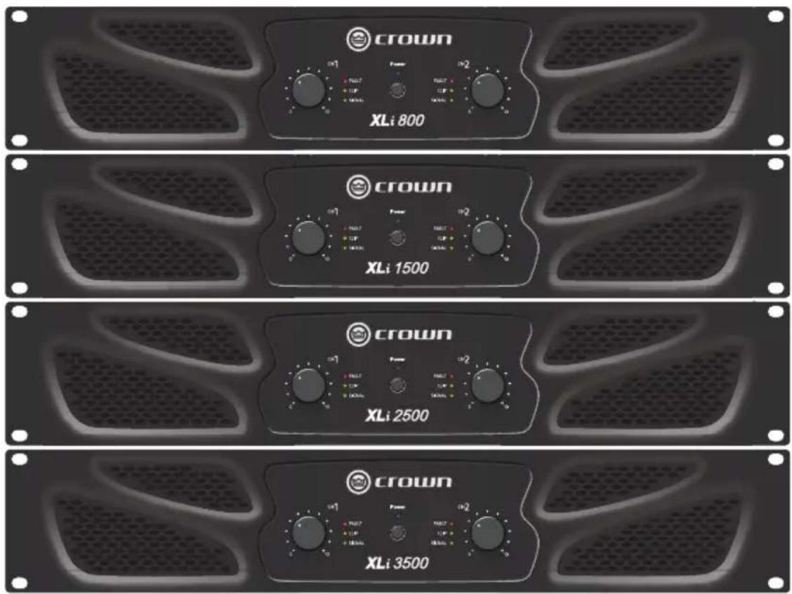
text_image
CROWN XLi 800 CROWN XLi 1500 CROWN XLi 2500 CROWN XLi 3500Obtaining Other Language Versions: To obtain information in another language about the use of this product, please contact your local Crown Distributor. If you need assistance locating your local distributor, please contact Crown at 574-294-8000.
This manual does not include all of the details of design, production, or variations of the equipment. Nor does it cover every possible situation which may arise during installation, operation or maintenance.
The information provided in this manual was deemed accurate as of the publication date. However, updates to this information may have occurred. To obtain the latest version of this manual, please visit the Crown website at www.crownaudio.com.
Later versions of this manual and additional information about this product may be available at the Crown website at www.crownaudio.com.
Trademark Notice: Crown and Crown Audio are registered trademarks of Crown International. Other trademarks are the property of their respective owners.
©2012 by Harman International. 1718 W. Mishawaka Rd., Elkhart, Indiana 46517-9439 U.S.A. Telephone: 574-294-8000
Important Safety Instructions
- Read these instructions.
- Keep these instructions.
- Heed all warnings.
- Follow all instructions.
- Do not use this apparatus near water.
- Clean only with a dry cloth.
- Do not block any ventilation openings. Install in accordance with the manufacturer's instructions.
- Do not install near any heat sources such as radiators, heat registers, stoves, or other apparatus (including amplifiers) that produce heat.
- Do not defeat the safety purpose of the polarized or grounding-type plug. A polarized plug has two blades with one wider than the other. A grounding-type plug has two blades and a third grounding prong. The wide blade or the third prong is provided for your safety. If the provided plug does not fit into your outlet, consult an electrician for replacement of the obsolete outlet.
- Protect the power cord from being walked on or pinched, particularly at plugs, convenience receptacles, and the point where they exit from the apparatus.
- Only use attachments/accessories specified by the manufacturer.

-
Use only with a cart, stand, tripod, bracket, or table specified by the manufacturer, or sold with the apparatus. When a cart is used, use caution when moving the cart/ apparatus combination to avoid injury from tip-over.
-
Unplug this apparatus during lightning storms or when unused for long periods of time.
-
Refer all servicing to qualified service personnel. Servicing is required when the apparatus has been damaged in any way, such as power-supply cord or plug is damaged, liquid has been spilled or objects have fallen into the apparatus, the apparatus has been exposed to rain or moisture, does not operate normally, or has been dropped.
-
Use the mains plug to disconnect the apparatus from the mains.
-
WARNING: TO REDUCE THE RISK OF FIRE OR ELECTRIC SHOCK, DO NOT EXPOSE THIS APPARATUS TO RAIN OR MOISTURE.
-
WARNING: THIS APPLIANCE SHALL BE CONNECTED TO A MAINS SOCKET OUTLET WITH A PROTECTIVE EARTHING CONNECTION.

-
DO NOT EXPOSE THIS EQUIPMENT TO DRIPPING OR SPLASHING AND ENSURE THAT NO OBJECTS FILLED WITH LIQUIDS, SUCH AS VASES, ARE PLACED ON THE EQUIPMENT.
-
THE MAINS PLUG OF THE POWER SUPPLY CORD SHALL REMAIN READILY OPERABLE.

TO PREVENT ELECTRIC SHOCK DO NOT REMOVE TOP OR BOTTOM COVERS. NO USER SERVICEABLE PARTS INSIDE. REFER SERVICING TO QUALIFIED SERVICE PERSONNEL.

TO COMPLETELY DISCONNECT THIS EQUIPMENT FROM THE AC MAINS, DISCONNECT THE POWER SUPPLY CORD PLUG FROM THE AC RECEPTACLE. THE MAINS PLUG OF THE POWER SUPPLY CORD SHALL
REMAIN READILY OPERABLE.
WARNING: PAY ATTENTION TO A PROCEDURE, PRACTICE, CONDITION OR THE LIKE, IF NOT CORRECTLY PERFORMED OR ADHERED TO. COULD RESULT IN PERSONAL INJURY OR DEATH.
CAUTION: PAY ATTENTION TO PROCEDURE, PRACTICE, CONDITION OR THE LIKE, IF NOT CORRECTLY PERFORMED OR ADHERED TO, COULD RESULT IN DAMAGE OR DESTRUCTION TO PART OR ALL OF THE COMPONENT.
WATCH FOR THESE SYMBOLS:

The lightning bolt triangle is used to alert the user to the risk of electric shock.

The exclamation point triangle is used to alert the user to important operating or maintenance instructions.


This device is designed and evaluated under the condition of 2000 meters tall above sea level; and, it can be only used in locations below 2000 meters tall above sea level. Using the device above 2000 meters altitude would result in high safety risk.

The device is designed and evaluated under the condition of non-tropical climate; and, it can be only used in locations in non-tropical climate areas. Using the device in tropical climate areas would result in high safety risk.
IMPORTANT
XLi Series amplifiers require Class 2 output wiring.
MAGNETIC FIELD
CAUTION! Do not locate sensitive high-gain equipment such as preamplifiers or tape decks directly above or below the unit. Because this amplifier has a high power density, it has a strong magnetic field which can induce hum into unshielded devices that are located nearby. The field is strongest just above and below the unit.
If an equipment rack is used, we recommend locating the amplifier(s) in the bottom of the rack and the preamplifier or other sensitive equipment at the top.
FCC COMPLIANCE NOTICE
This device complies with part 15 of the FCC rules. Operation is subject to the following two conditions: (1) This device may not cause harmful interference, and (2) this device must accept any interference received, including interference that may cause undesired operation.
CAUTION: Changes or modifications not expressly approved by the party responsible for compliance could void the user's authority to operate the equipment.
NOTE: This equipment has been tested and found to comply with the limits for a Class B digital device, pursuant to part 15 of the FCC Rules. These limits are designed to provide reasonable protection against harmful interference in a residential installation. This equipment generates, uses, and can radiate radio frequency energy and, if not installed and used in accordance with the instruction manual, may cause harmful interference to radio communications. However, there is no guarantee that interference will not occur in a particular installation. If this equipment does cause harmful interference to radio or television reception, which can be determined by turning the equipment off and on, the user is encouraged to try to correct the interference by one or more of the following measures:
- Reorient or relocate the receiving antenna.
- Increase the separation between the equipment and receiver.
- Connect the equipment into an outlet on a circuit different from that to which the receiver is connected.
- Consult the dealer or an experienced radio/TV technician for help.
DECLARATION OF CONFORMITY
Issued By: Harman International.
1718 W. Mishawaka Rd.
Elkhart, IN 46517 U.S.A.
European Representative's Name and Address:
David J. Budge
10 Harvest Close
Yateley
GU46 6YS
United Kingdom
Equipment Type: Commercial Audio Power Amplifiers
Family Name: XLi
Model Names: XLi 800, XLi 1500, XLi 2500, XLi 3500
EMC Standards:
EN 55103-1:1997 Electromagnetic Compatibility - Product Family Standard for Audio, Video, Audio-Visual and Entertainment Lighting Control Apparatus for Professional Use, Part 1: Emissions
EN 55103-1:1997 Magnetic Field Emissions-Annex A @ 10 cm and 20 cm
EN 61000-3-2:2001 Limits for Harmonic Current Emissions (equipment input current less than or equal to 16 A per phase)
EN 61000-3-3:2002 Limitation of Voltage Fluctuations and Flicker in Low-Voltage Supply Systems Rated Current less than or equal to16A
EN 55022:2003 Limits and Methods of Measurement of Radio Disturbance Characteristics of ITE: Radiated, Class B Limits; Conducted, Class A
EN 55103-2:1997 Electromagnetic Compatibility - Product Family Standard for Audio, Video, Audio-Visual and Entertainment Lighting Control Apparatus for Professional Use, Part 2: Immunity
EN 61000-4-2:2001 Electrostatic Discharge Immunity (Environment E2-Criteria B, 4k V Contact, 8k V Air Discharge)
EN 61000-4-3:2001 Radiated, Radio-Frequency, Electromagnetic Immunity (Environment E2, criteria A)
EN 61000-4-4:2001 Electrical Fast Transient/Burst Immunity (Criteria B)
EN 61000-4-5:2001 Surge Immunity (Criteria B)
EN 61000-4-6:2003 Immunity to Conducted Disturbances Induced by Radio-Frequency Fields (Criteria A)
EN 61000-4-11:2001 Voltage Dips, Short Interruptions and Voltage Variation
Safety Standard:
IEC 60065: 2001 7th Ed. Safety Requirements - Audio Video and Similar Electronic Apparatus
I certify that the product identified above conforms to the requirements of the EMC Council Directive 89/336/EEC as amended by 92/31/EEC, and the Low Voltage Directive 73/23/EES as amended by 93/68/EEC.92/31/EEC, and the Low Voltage Directive 73/23/EES as amended by 93/68/EEC.
Signed
Terry Davenport
Director of Manufacturing
Date of Issue: March 1, 2012
Due to line current harmonics, we recommend that you contact your supply authority before connection.
Front Panel Features
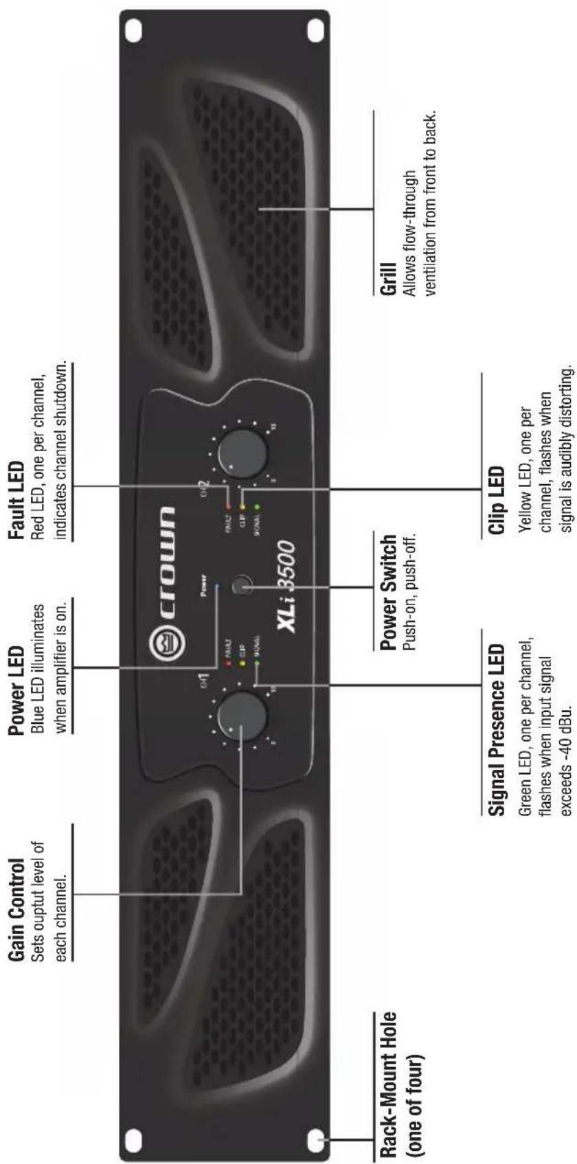
text_image
Gain Control Sets output level of each channel. Power LED Blue LED illuminates when amplifier is on. Fault LED Red LED, one per channel, indicates channel shutdown. CROWN XLi 3500 Rack-Mount Hole (one of four) Signal Presence LED Green LED, one per channel, flashes when input signal exceeds -40 dBu. Power Switch Push-on, push-off. Clip LED Yellow LED, one per channel, flashes when signal is audibly distorting. Grill Allows flow-through ventilation from front to back.Back Panel Features
text_image
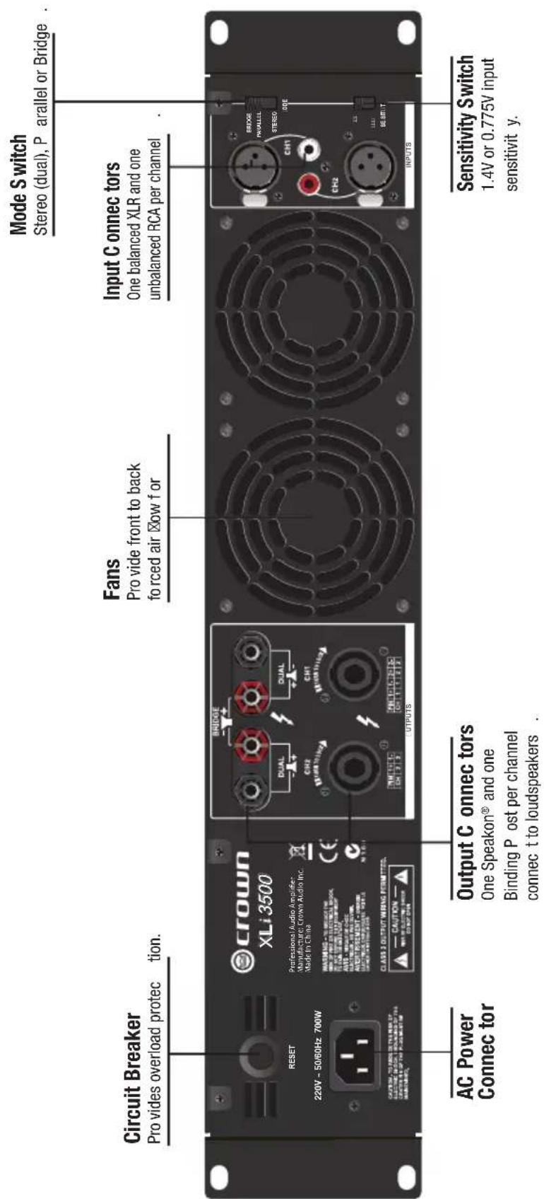
Circuit Breaker Pro vides overload protection. RESET 220V ~ 50/60Hz 700W AC Power Connect tor Professional Audio Amplifier Manufacture Crown Audio Inc. Made in China BRIDGE DUAL CH2 DUAL CH1 PROVIDENCE OUTPUTS CLASS 2 OUTPUT WIRING PERMITTED. CAUTION WHIP POWER CONTROL COMPONENT Output C onnc tors One Speakon® and one Binding P ost per channel connec t to loudspeakers . Fans Pro vide front to back forced air ☑ow f or Mode S switch Stereo (dual), P parallel or Bridge . Input C onnc tors One balanced XLR and one unbalanced RCA per channel . BRIDGE PANUELL STEREO CH1 CH2 INPUTS Sensitivity Switch 1.4V or 0.775V input sensitivit y.Cordset rating: 10A, 250V Cable Coating Material: Environmental Protection PVC, copper core PBT
Setup
Unpack and Install Your Amplifier
Please unpack and inspect your amplifier for any damage that may have occurred during transit. If damage is found, notify the transportation company immediately. Only you can initiate a claim for shipping damage. Crown will be happy to help as needed. Save the shipping carton as evidence of damage for the shipper's inspection.
We also recommend that you save all packing materials so you will have them if you ever need to transport the unit. Never ship the unit without the factory pack.
YOU WILL NEED (not supplied):
- Input wiring cables
- Output wiring cables
- Ethernet cables
- Rack for mounting amplifier (or a stable surface for stacking)

WARNING: Before you start to set up your amplifier, make sure you read and observe the Important Safety Instructions found at the beginning of this manual.
CAUTION: Before you begin, make sure your amplifier is disconnected from the power source, with the power switch in the "off" position and all level controls turned completely down (counterclockwise).
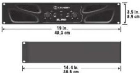
Use a standard 19-inch (48.3 cm) equipment rack (EIA RS-310B). See below figure for amplifier dimensions.
text_image
3.5 in. 8.9 cm 19 in. 48.3 cm 14.4 in. 36.6 cmNOTE: When transporting, amplifiers should be supported at both front and back.
MAGNETIC FIELD

CAUTION! Do not locate sensitive high-gain equipment such as preamplifiers or tape decks directly above or below the unit. Because this amplifier has a high power density, it has a strong magnetic field which can induce hum into unshielded devices that are located nearby. The field is strongest on the right side and right bottom of the amplifier (facing the amplifier).
If an equipment rack is used, we recommend locating sensitive equipment at least 20 cm (8 inches) away from the amplifier.
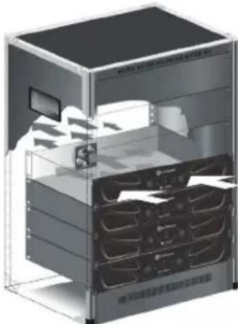
When using an equipment rack, mount units directly on top of each other. Close any open spaces in rack with blank panels. DO NOT block front or rear air vents. The side walls of the rack should be a minimum of two inches (5.1 cm) away from the amplifier sides, and the back of the rack should be a minimum of four inches (10.2 cm) from the amplifier back panel.
natural_image
3D rendering of a server rack unit with visible internal components and ventilation ducts (no text or symbols)Wiring
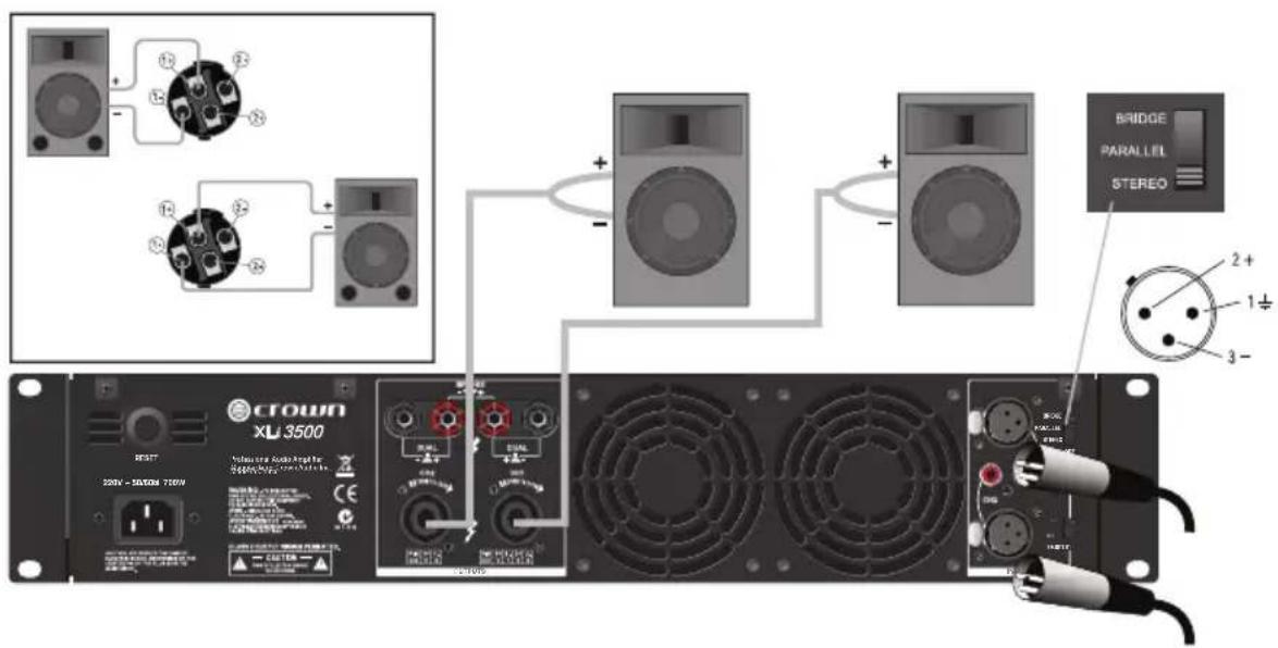
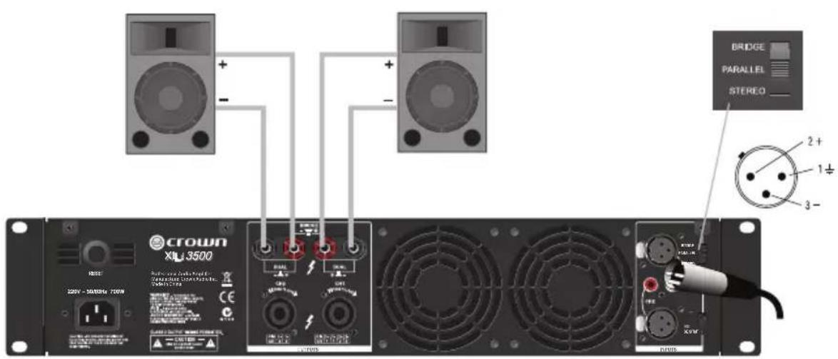
Stereo (Dual) Wiring Using the Speakon® Connectors
- See Figure 3. On the back panel, set the Output Mode Switch to STEREO.
- Wire the speakers to the Speakon ^® connectors as shown.
text_image
CROWN XL 3500 RESET 200V - 56500M 7200V Volume Audio Amplifier 2600V/56500M 7200V BRIDGE PARALLEL STEREO 2+ 1+ 3-Stereo (Dual) Wiring Using the Binding Post Connectors
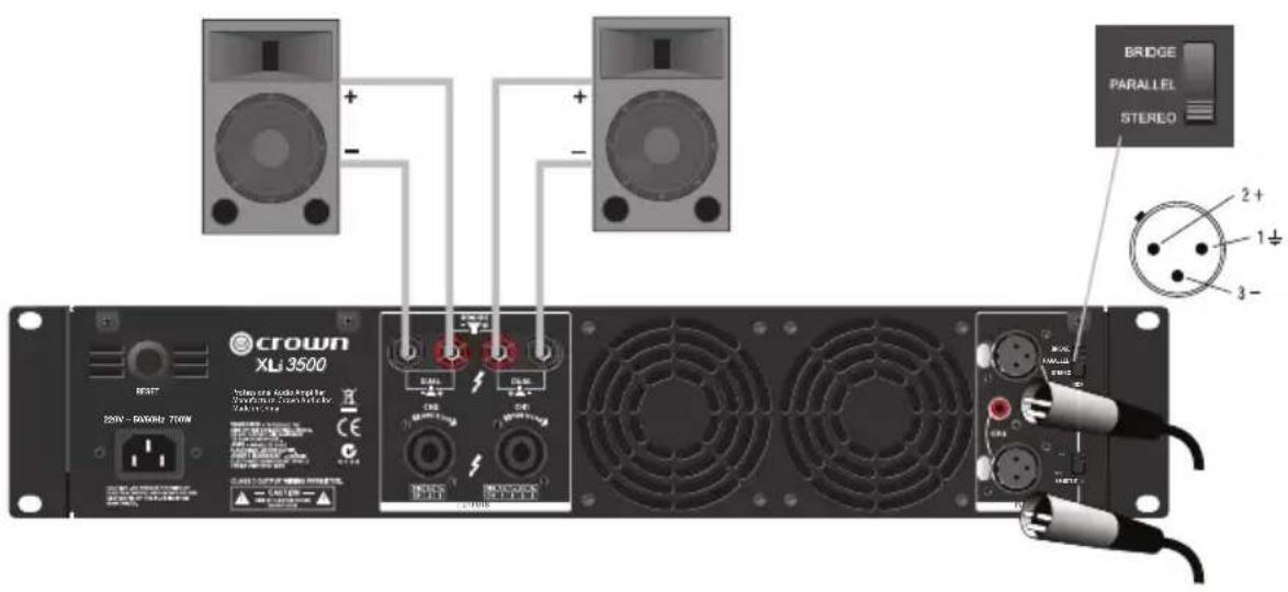
- See Figure 4. On the back panel, set the Output Mode Switch to STEREO.
- Wire the speakers to the binding post connectors as shown.
text_image
CROWN XLJ 3500 BRIDGE PARALLEL STERLO 2+ - 1+ 3-Wiring
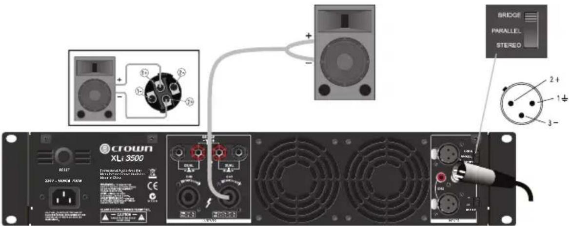
Bridge-Mono Wiring Using the Speakon® Connectors
Bridge-mono mode doubles the output power of the amplifier.
- See Figure 5. On the back panel, set the Output Mode Switch to BRIDGE.
- Wire the speaker to the Speakon ^® connector as shown.
- Only the Channel 1 Gain Control works in Bridge-mono mode.
text_image
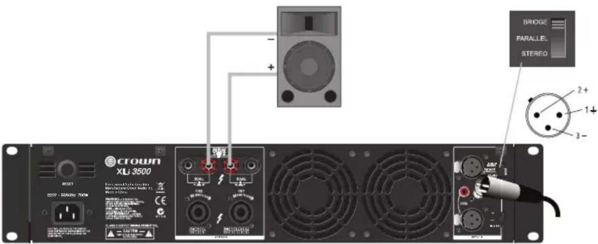
CROWN XLt 3500 RESET 220V - 3000W / 700W Functional Audio & Audio Rscaler & Control Mixer Of Chro BRIDGE PARALLEL STEREO 2+ 1+ 3-Bridge-Mono Wiring Using the Binding Post Connectors
Bridge-mono mode doubles the output power of the amplifier.
- See Figure 5. On the back panel, set the Output Mode Switch to BRIDGE.
- Wire the speaker to the binding post connectors as shown.
- Only the Channel 1 Gain Control works in Bridge-mono mode.
text_image
CROWN XL1 3500 RESET 220V - 60V/Hz 700W Forward Detection Signal Receiver Audio FC RMS 124 BRIDGE PARALLEL STEREO 2+ 1+ 3-Wiring
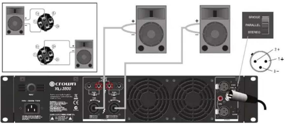
Parallel Wiring Using the Speakon® Connectors
With this wiring, a signal sent to one of the input connectors is paralleled to both channels so that it is reproduced by both speakers.
- See Figure 7. On the back panel, set the Output Mode Switch to PARALLEL.
- Wire the speakers to the Speakon ^® connectors as shown.
text_image
BRIDGE PARALLEL STEREO 2+ 1- 3- CROWN XL1 3500 350V - 3500V 750W CROWN XL1 3500 BRIDGE PARALLEL STEREO BRIDGE XL1 3500V BRIDGE PARALLEL STEREOParallel Wiring Using the Binding Post Connectors
With this wiring, a signal sent to one of the input connectors is paralleled to both channels so that it is reproduced by both speakers.
- See Figure 8. On the back panel, set the Output Mode Switch to PARALLEL.
- Wire the speakers to the binding post connectors as shown.
text_image
CROWN XLJ 3500 BRIDGE PARALLEL STEREO 2+ 1- 3-Specifications
| Guaranteed Minimum Power | XLi 800 | XLi 1500 | XLi 2500 | XLi 3500 |
| 1 kHz (EIA) with 0.5% THD | ||||
| 4 Ω stereo (per channel) | 300W | 450W | 750W | 1350W |
| 8 Ω stereo (per channel) | 200W | 330W | 500W | 1000W |
| 8 Ω bridge mono | 600W | 900W | 1500W | 2700W |
| Performance | ||||
| Frequency Response (at 1 Watt) 20Hz - 20kHz, +0/-1dB | ||||
| Total Harmonic Distortion (THD) < 0.5%, 20 Hz - 20 kHz | ||||
| Intermodulation Distortion (IMD)60 Hz and 7 kHz at 4:1, from full rated output to -30 dB | ≤ 0.35% | |||
| Slew Rate >10V/us | ||||
| Voltage Gain 29dB 31dB 33dB 36dB | ||||
| Damping Factor (8 Ω), 10 Hz - 400 Hz | >200 | |||
| Signal-to-Noise Ratio (below rated power,20 Hz to 20 kHz, A-weighted) | >100 dB | |||
| Crosstalk (below rated power)At 1 kHz | -75 dB | |||
| At 20 kHz | -59 dB | |||
| Input Sensitivity for full rated power at 8 Ω | 0.775V or 1.4V | |||
| Input Impedance (nominal)BalancedUnbalanced | 20 kΩ10 kΩ | |||
| Connectors, Controls and Indicators | ||||
| Input Connectors One balanced XLR and one unbalanced RCA per channel | ||||
| Output Connectors (Speaker Connectors) 4-POLE Speakon®and one pair Binding Post per channel | ||||
| Front Panel Controls Power on/off switch, one gain control per channel | ||||
| Rear Panel Controls Output mode switch: stereo (dual), parallel or bridgeInput sensitivity switch: 0.775V or 1.4V | ||||
| Power Indicator One blue LED | ||||
| Signal Indicator One green LED per channel | ||||
| Clip (peak) Indicator One yellow LED per channel | ||||
| Fault Indicator One red LED per channel | ||||
| Construction | ||||
| Protection Protection against short circuits, no-load, on/off muting,RF interference. Stable into reactive or mismatched loads | ||||
| Ventilation | Flow-through ventilation from front to back | |||
| Cooling | Internal heat sinks with forced air. Fan cooled,speed regulated, thermal protection | |||
| Dimensions (W x H x D) | 19" x 3.5" x 12.4"(482 mm x 89 mm x 315 mm) | 19" x 3.5" x 14.4"(482 x 89 x 366 mm) | ||
| Net Weight | 25.1 lb (11.4 kg) | 28.0 lb (12.7 kg) | 29.7 lb (13.5 kg) | 43.0 lb (19.5 kg) |
| Shipping Weight | 29.5 lb (13.4 kg) | 32.4 lb (14.7 kg) | 34.2 lb (15.5 kg) | 47.4 lb (21.5 kg) |
Warranty – USA Only
SUMMARY OF WARRANTY
Crown International, 1718 West Mishawaka Road, Elkhart, Indiana 46517-4095 U.S.A. warrants to you, the ORIGINAL PURCHASER and ANY SUB SEQUENT OWNER of each NEW Crown1 product, for a period of one (1) year from the date of pur chase by the original purchaser (the "warranty period") that the new Crown product is free of defects in materials and workmanship, and we further warrant the new Crown product regardless of the reason for failure, except as excluded in this Warranty.
Warranty is only Valid within the United States of America. For information on Warranty outside of the U.S.A, please contact your local distributor.
ITEMS EXCLUDED FROM THIS CROWN WARRANTY
This Crown Limited Warranty is in effect only for failure of a new Crown product which occurred within the Warranty Period. It does not cover any product which has been damaged because of any intentional misuse, accident, negligence, or loss which is covered under any of your insurance contracts. This Crown Warranty also does not extend to the new Crown product if the serial number has been defaced, altered, or removed.
WHAT THE WARRANTOR WILL DO
We will remedy any defect, regardless of the reason for failure (except as excluded), by repair, replacement, or refund. We may not elect refund unless you agree, or unless we are unable to provide replacement, and repair is not practical or cannot be timely made. If a refund is elected, then you must make the defective or malfunctioning product available to us free and clear of all liens or other encumbrances. The refund will be equal to the actual purchase price, not including interest, insurance, closing costs, and other finance charges less a reasonable depreciation on the product from the date of original purchase. Warranty work can only be performed at our authorized service centers or at the factory. We will remedy the defect and ship the product from the service center or our factory within a reasonable time after receipt of the defective product at our authorized service center or our factory. All expenses in remedying the defect, including surface shipping costs in the United States, will be borne by us. (You must bear the expense of shipping the product between any foreign country and the port of entry in the United States including the return shipment, and all taxes, duties, and other customs fees for such foreign shipments.)
HOW TO OBTAIN WARRANTY SERVICE
You must notify us of your need for warranty service within the warranty period. All components must be shipped in a factory pack, which, if needed, may be obtained from us free of charge. Corrective action will be taken within a reasonable time of the date of receipt of the defective product by us or our authorized service center. If the repairs made by us or our authorized service center are not satisfactory, notify us or our authorized service center immediately.
DISCLAIMER OF CONSEQUENTIAL AND INCIDENTAL DAMAGES
YOU ARE NOT ENTITLED TO RECOVER FROM US ANY INCIDENTAL DAMAGES RESULTING FROM ANY DEFECT IN THE NEW CROWN PRODUCT. THIS INCLUDES ANY DAMAGE TO ANOTHER PRODUCT OR PRODUCTS RESULTING FROM SUCH A DEFECT. SOME STATES DO NOT ALLOW THE EXCLUSION OR LIMITATIONS OF INCIDENTAL OR CONSEQUENTIAL DAMAGES, SO THE ABOVE LIMITATION OR EXCLUSION MAY NOT APPLY TO YOU.
WARRANTY ALTERATIONS
No person has the authority to enlarge, amend, or modify this Crown Warranty. This Crown Warranty is not extended by the length of time which you are deprived of the use of the new Crown product. Repairs and replacement parts provided under the terms of this Crown Warranty shall carry only the unexpired portion of this Crown Warranty.
DESIGN CHANGES
We reserve the right to change the design of any product from time to time without notice and with no obligation to make corresponding changes in products previously manufactured.
LEGAL REMEDIES OF PURCHASER
THIS CROWN WARRANTY GIVES YOU SPECIFIC LEGAL RIGHTS, YOU MAY ALSO HAVE OTHER RIGHTS WHICH VARY FROM STATE TO STATE. No action to enforce this Crown Warranty shall be commenced after expiration of the warranty period.
THIS STATEMENT OF WARRANTY SUPERSEDES ANY OTHERS CONTAINED IN THIS MANUAL FOR CROWN PRODUCTS. 5/11

CROWN®
by HARMAN