
SK 9000 - Microphone SENNHEISER - Free user manual and instructions
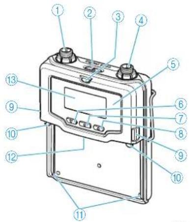
Find the device manual for free SK 9000 SENNHEISER in PDF.

| Product Type | Bodypack Transmitter |
| Brand | Sennheiser |
| Model | SK 9000 |
| Frequency Range | 470-798 MHz (divided into 4 ranges: A1-A4, A5-A8, B1-B4, B5-B8) |
| RF Output Power | HD mode: 10 mW rms / 50 mW peak; LR mode: 25 mW rms / 50 mW peak |
| Tuneability | 25 kHz steps |
| Frequency Stability | < 5 ppm |
| Audio Frequency Response | 30 Hz – 20 kHz (line-in); 60 Hz – 20 kHz (mic) |
| Input Gain Range | Mic: 0 to +42 dB (3 dB steps); Line/Instrument: -6 to +42 dB (3 dB steps) |
| Input Impedance | Mic: 22 kΩ; Line/Instrument: 1 MΩ |
| Low Cut Filter | Selectable: 30, 60, 80, 100, 120 Hz |
| Transmission Modes | HD (High Definition, uncompressed) and LR (Long Range, SeDAC codec) |
| Encryption | Yes (digital audio encryption) |
| Power Supply | BA 61 Li-ion accupack (3.7 V, 2030 mAh) or B 61 battery pack (3x AA) |
| Operating Time | Up to 6.5 hours with BA 61 accupack |
| Power Consumption | Max. 960 mW |
| Dimensions (H x W x D) | 76 x 62 x 20 mm (with BA 61 accupack) |
| Weight | Approx. 147 g (with BA 61 accupack and belt clip) |
| Antenna Connection | Coax socket (supplied antenna) |
| Microphone Input | 3-pin special audio socket for Sennheiser microphones and CI 1-4 cable |
| Display | Yes, with status indicators (frequency, charge, encryption, etc.) |
| Infra-red Interface | Yes, for synchronization with receiver |
| Belt Clip | Included |
| Accessories | KA 9000 COM command adapter (optional), MKE 1/2, ME 102/104/105, HSP 2/4 microphones |
| Cleaning | Use a soft, dry cloth; clean contacts with dry cloth |
| Safety | Read manual; avoid exposure to rain/moisture; use only specified accessories and batteries |
| Regulatory Compliance | FCC, IC, CE |
Frequently Asked Questions - SK 9000 SENNHEISER
User questions about SK 9000 SENNHEISER
0 question about this device. Answer the ones you know or ask your own.
Ask a new question about this device
Download the instructions for your Microphone in PDF format for free! Find your manual SK 9000 - SENNHEISER and take your electronic device back in hand. On this page are published all the documents necessary for the use of your device. SK 9000 by SENNHEISER.
USER MANUAL SK 9000 SENNHEISER
Important safety instructions ....6
Digital 9000 – System overview ...... 11
EM 9046 receiver ....12
Antennas and antenna boosters 12
SKM 9000 radio microphone/
SK 9000 bodypack transmitter ....13
L 60 charger ....13
Delivery includes 14
EM 9046 receiver ....14
EM 9046 CAB cable set ....14
Antennas and antenna boosters 14
GZL 9000 antenna cables ....14
SKM 9000/SKM 9000 COM radio microphone ....15
Microphone heads for the SKM 9000 radio microphone ....15
SK 9000 bodypack transmitter ....15
Microphones for the SK 9000 bodypack transmitter .....15
KA 9000 COM command adapter for the
SK 9000 bodypack transmitter ....15
CI 1-4 line/instrument cable for the
SK 9000 bodypack transmitter ....15
B 60/B 61 battery packs ....16
BA 60/BA 61 accupack ....16
L 60 charger ....16
Product overview 17
EM 9046 receiver ....17
Antennas and antenna boosters 21
GZL 9000 antenna cable ....22
SKM 9000/SKM 9000 COM radio microphone ....22
SK 9000 bodypack transmitter ....24
KA 9000 COM command adapter for the SK 9000 bodypack transmitter ....26
BA 60 accupack ......26
BA 61 accupack ....27
B 60 battery pack ....27
B 61 battery pack ....28
L 60 charger ....29
Preparing the Digital 9000 system for use 31
Preparing the EM 9046 receiver for use 32
Setting up the receiver or mounting it into a 19" rack ....32
Connecting devices to the analog audio outputs ....33
Connecting devices to the digital audio outputs ....34
Daisy chaining receivers 35
Connecting external word clock signals 36
Connecting receivers in a network ....36
Connecting the receiver to the mains ....38
Connecting headphones 38
Preparing the A/AB/AD 9000 antennas and/or antenna boosters for use .... 39
Positioning the receiving antennas ....39
Connecting the receiving antennas/antenna boosters ....40
Adjusting the receiving antennas/antenna boosters ....40
Preparing the SKM 9000 radio microphone for use ....40
Changing the microphone head 42
Preparing the SK 9000 bodypack transmitter for use ....42
Connecting the antenna 45
Connecting the KA 9000 COM command adapter ....45
Preparing the L 60 charger for use ....46
Cascading several chargers 46
Setting up or mounting the charger ....46
Using the EM 9046 49
Using the EM 9046 receiver ....50
Switching the receiver on/off 50
"sys", "ch", "live" – operating modes at a glance ....51
Basic functions of the Sennheiser operating menu ....51
Displays of the Sennheiser operating menu 52
Error and warning messages ....54
"sys" operating mode – Configuring the system ....55
Overview of the "sys" menu 55
Main menu "System setup" 56
Extended menu "Service setup" 67
"ch" operating mode – Configuring channels .....76
Overview of the "ch" menu 76
Main menu "Channel setup" 77
Extended menu "Transmitter setup" 81
"live" operating mode – Using a configured system 84
Using the SKM 9000 85
Switching the SKM 9000 on/off 86
Activating/deactivating the automatic lock mode (Autolock) 87
Basic functions of the Sennheiser operating menu 88
Overview of the status displays 88
Overview of the menu items 89
Using the SK 9000 93
Switching the SK 9000 on/off 94
Activating/deactivating the automatic lock mode (Autolock) 95
Basic functions of the Sennheiser operating menu 96
Overview of the status displays 97
Overview of the menu items 97
Using the L 60 ....101
Cleaning and maintaining the Digital 9000 system .....105
If a problem occurs ... 109
EM 9046 receiver ....110
SKM 9000 radio microphone ....111
SK 9000 bodypack transmitter ....111
L 60 charger ....112
Specifications 113
Digital 9000
Important safety instructions
flowchart
graph TD
    A["WSM"] --> B["EM 9046"]
    B --> C["EM 9046 AAO EM 9046 DAO"]
    B --> D["EM 9046 CAB"]
    B --> E["SKM 9000 SKM 9000 COM"]
    E --> F["ME 9002 ME 9004 ME 9005 ..."]
    E --> G["B 60 BA 60"]
    E --> H["L 60"]
    E --> I["B 61 BA 61"]
    E --> J["KA 9000 COM"]
    J --> K["MKE 1 MKE 2 ... CI 1-4"]
Important safety instructions
- Read these instructions.
- Keep these instructions. Always include these instructions when passing the apparatus on to third parties.
-
Heed all warnings.
-
Follow all instructions.
-
Do not use this apparatus near water.
-
Clean only with a dry cloth.
-
Do not block any ventilation openings. Install in accordance with the manufacturer's instructions.
-
Do not install near any heat sources such as radiators, heat registers, stoves, or other apparatus (including amplifiers) that produce heat.
-
Do not defeat the safety purpose of the polarized or grounding-type plug. A polarized plug has two blades with one wider than the other. A grounding type plug has two blades and a third grounding prong. The wide blade or the third prong are provided for your safety. If the provided plug does not fit into your outlet, consult an electrician for replacement of the obsolete outlet.
-
Protect the power supply cord from being walked on or pinched, particularly at plugs, convenience receptacles, and the point where it exits from the apparatus.
-
Only use attachments, accessories and spare parts specified by the manufacturer.
-
Use only with the cart, stand, tripod, bracket, or table specified by the manufacturer, or sold with the apparatus. When a cart is used, use caution when moving the cart/apparatus combination to avoid injury from tip-over.
-
Unplug this apparatus during lightning storms or when unused for long periods of time.
-
Refer all servicing to qualified service personnel. Servicing is required when the apparatus has been damaged in any way, such as power supply cord or plug is damaged, liquid has been spilled or objects have fallen into the apparatus, when the apparatus has been exposed to rain or moisture, does not operate normally, or has been dropped.
-
To completely disconnect this apparatus from the AC mains, disconnect the power supply cord plug from the AC receptacle.
-
WARNING: To reduce the risk of fire or electric shock, do not expose this apparatus to rain or moisture.
-
Do not expose this equipment to dripping or splashing and ensure that no objects filled with liquids, such as vases, are placed on the equipment.
-
The mains plug of the power supply cord shall remain readily accessible.


Hazard warnings on the rear of the receiver
The label shown on the left is attached to the rear of the EM 9046.
The symbols on this label have the following meaning:
Presence of uninsulated dangerous voltage within the EM 9046's enclosure that may be of sufficient magnitude to constitute a risk of electric shock.
Never open the EM 9046 as there is a risk of electric shock. There are no user serviceable parts inside. Never attempt to change the modules of the EM 9046 yourself. Always refer repairs, servicing and the change of the modules to your authorized Sennheiser service partner.
Read and follow the safety and operating instructions contained in the instruction manual.
Risk of fire due to overloading
Do not overload wall outlets and extension cables as this may result in fire and electric shock.
Danger of hearing damage due to high volumes
This is a professional receiver. Commercial use is subject to the rules and regulations of the trade association responsible. Sennheiser, as the manufacturer, is therefore obliged to expressly point out possible health risks arising from use.
This receiver is capable of producing sound pressure levels exceeding 85 dB(A). 85 dB(A) is the sound pressure corresponding to the maximum permissible volume which is by law (in some countries) allowed to affect your hearing for the duration of a working day. It is used as a basis according to the specifications of industrial medicine. Higher volumes or longer durations can damage your hearing. At higher volumes, the duration must be shortened in order to prevent hearing damage. The following are sure signs that you have been subjected to excessive noise for too long a time:
- You can hear ringing or whistling sounds in your ears.
- You have the impression (even for a short time only) that you can no longer hear high notes.
Intended use
Intended use of the Digital 9000 system components includes:
- having read and understood this instruction manual, especially the chapter "Important safety instructions",
- using the products within the operating conditions and limitations described in this instruction manual.
"Improper use" means using the products other than as described in these instructions, or under operating conditions which differ from those described herein.
This instruction manual is also available at www.sennheiser.com.

flowchart
graph LR
    A["?"] --> B["WWW"]
    B --> C["Manual"]
Safety instructions for A/AB/AD 9000 antennas/antenna boosters
Use safety wires to protect the receiving antennas against tipping/dropping. The safety wires, rope terminations and coupling links must comply in their dimensioning and condition with the regulations and standards of the country in which they are used!
Safety instructions for lithium-ion rechargeable batteries
If abused or misused, the rechargeable batteries of the SK 9000/SKM 9000 may leak. In extreme cases, they may even present a risk of

- explosion,
- fire development,
- heat generation,
• smoke or gas development.
Sennheiser does not accept any liability for damage arising from abuse or misuse.

Keep away from children. Only charge

rechargeable batteries with a charger recommended by Sennheiser.

Observe correct polarity. Pack/store charged

rechargeable batteries so that the terminals cannot contact each other – danger of shorting out/fire hazard.

Do not expose to moisture. Switch rechargeable

battery-powered products off after use.

Only charge rechargeable batteries at ambient temperatures between 10 °C/50 °F and 40 °C/104 °F.

When not using rechargeable batteries for extended periods of time, charge them regularly (about every three months).

Do not mutilate or dismantle. Do not heat above

60 °C/140 °F, e.g. do not expose to sunlight or throw into a fire.

Immediately remove rechargeable batteries from an obviously defective product.

Do not continue to use defective rechargeable batteries.
 | Only use rechargeable batteries specified by Sennheiser. |  | Dispose of rechargeable batteries at special collection points or return them to your specialist dealer. |
 | Store the product in a cool and dry place at room temperature (approx. 20 °C/68 °F). | [427C] | Remove the rechargeable batteries if the product will not be used for extended periods of time. |
Digital 9000
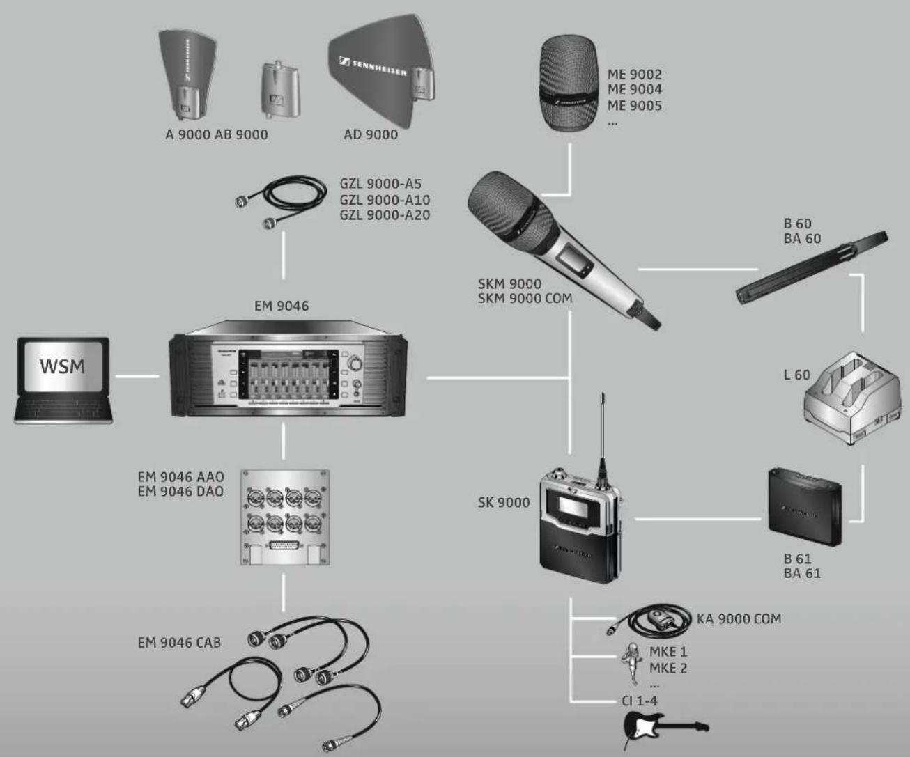
Digital 9000 – System overview
System overview System overview
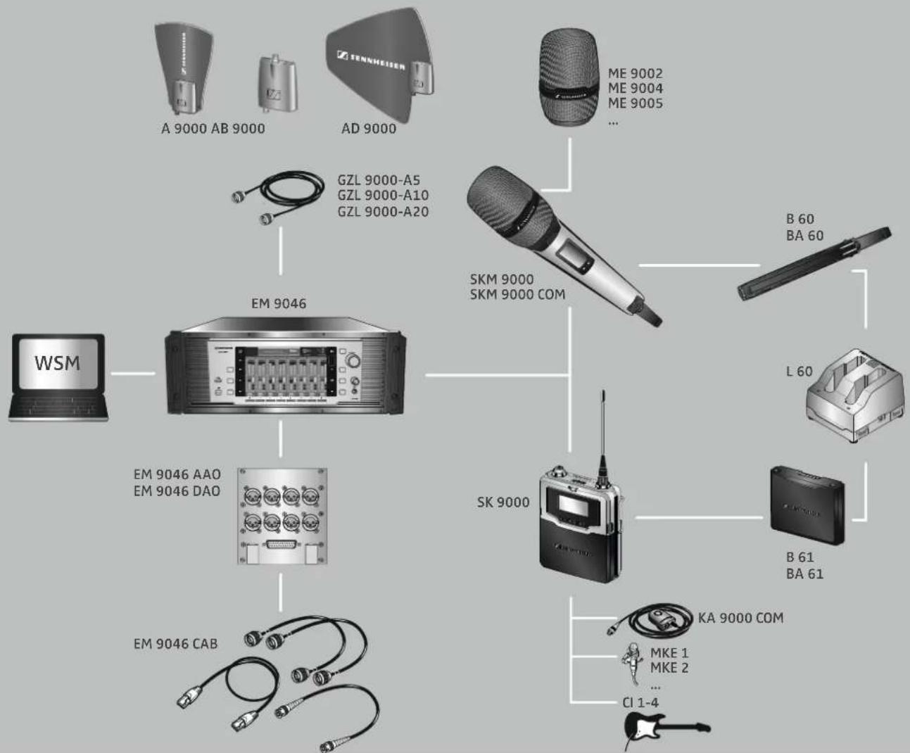
flowchart
graph TD
    A["TENNHEISEN"] --> B["A 9000 AB 9000"]
    A --> C["AD 9000"]
    A --> D["GZL 9000-A5 GZL 9000-A10 GZL 9000-A20"]
    A --> E["ME 9002 ME 9004 ME 9005 ..."]
    A --> F["EM 9046"]
    F --> G["WSM"]
    F --> H["EM 9046 AAO EM 9046 DAO"]
    F --> I["EM 9046 CAB"]
    A --> J["SKM 9000 SKM 9000 COM"]
    J --> K["B 60 BA 60"]
    J --> L["L 60"]
    J --> M["B 61 BA 61"]
    J --> N["KA 9000 COM"]
    N --> O["MKE 1 MKE 2 ... CI 1-4"]
Digital 9000 – System overview ...... 11
EM 9046 receiver 12
Antennas and antenna boosters 12
SKM 9000 radio microphone/
SK 9000 bodypack transmitter 13
L 60 charger 13
Delivery includes 14
EM 9046 receiver 14
EM 9046 CAB cable set 14
Antennas and antenna boosters 14
GZL 9000 antenna cables 14
SKM 9000/SKM 9000 COM radio microphone ..... 15
Microphone heads for the SKM 9000 radio
microphone 15
SK 9000 bodypack transmitter 15
Microphones for the SK 9000 bodypack transmitter 15
KA 9000 COM command adapter for the
SK 9000 bodypack transmitter 15
CI 1-4 line/instrument cable for the
SK 9000 bodypack transmitter 15
B 60/B 61 battery packs 16
BA 60/BA 61 accupack 16
L 60 charger 16
Product overview 17
EM 9046 receiver 17
Antennas and antenna boosters 21
GZL 9000 antenna cable 22
SKM 9000/SKM 9000 COM radio microphone ..... 22
SK 9000 bodypack transmitter 24
KA 9000 COM command adapter for the SK 9000
bodypack transmitter 26
BA 60 accupack 26
BA 61 accupack 27
B 60 battery pack 27
B 61 battery pack 28
L 60 charger 29
The Digital 9000 system
The Digital 9000 system is characterized by its high transmission reliability and easy of use. The large switching bandwidth as well as various different connection possibilities offer great flexibility in daily use.
- Outstanding sound quality due to digital transmission technology
• Efficient use of the available frequency spectrum
• Frequencies tuneable in 25 kHz steps - Switching bandwidth across the entire UHF range (470 MHz to 798 MHz)
- Encryption of the digital audio signal
- Intuitive, icon-based operating menu
- Modular system
• Infra-red synchronization of receivers and transmitters
- WSM-assisted
EM 9046 receiver
- Scan function
• True bit diversity technology
• Audio output level adjustable in 1 dB steps - Configurable Command audio output
- EM 9046 receiver can be equipped with up to 8 EM 9046 DRX receiver modules for 8 individually adjustable channels
- Optional audio modules: transformer balanced analog or digital (AES3)
- Up to 4 receivers can be RF daisy chained
- Up to 8 receivers can be connected in a network
• High quality antenna splitters with booster supply - Internal and external word clock synchronization of digital audio outputs
- Ethernet socket for connection to a PC and/or for connection of several receivers in a network
• Headphone output with high gain reserve
Antennas and antenna boosters
- A 9000 active, intelligent, omni-directional antenna
- AD 9000 active, intelligent, directional antenna
• AB 9000 active, intelligent antenna booster
• Power supply via EM 9046 - EM 9046-controlled preselection of booster frequency ranges "A1" ... "A8" or "B1" ... "B8" (24 MHz respectively)
• Automatic calibration of cable attenuation - Can also be used with other receivers with booster supply voltage (e.g. EM 3732-II)
SKM 9000 radio microphone/ SK 9000 bodypack transmitter
The SKM 9000 and SK 9000 transmitters offer great ease of use and can easily be adapted to any transmission situation:
- Rugged housing
- Input gain adjustable in 3 dB steps
- Switchable 1 kHz test tone, useful for level matching the system and for the walk test
- High accuracy of charge status display (B/BA 60/61) or remaining operating time display (B 60/61)
- Detection and support of the type of microphone head being used, incl. Neumann microphone heads
- Switchable low cut filter for filtering out low frequency components
• Frequencies tuneable in 25 kHz steps
SKM 9000 radio microphone
- Power supply optionally via BA 60 lithium-ion accupack or B 60 battery pack (2 AA size alkaline batteries or 2 AA size lithium batteries)
- Different microphone heads for different areas of application (see page 23)
- Optionally available with command function (SKM 9000 COM)
SK 9000 bodypack transmitter
- Power supply optionally via BA 61 lithium-ion accupack or B 61 battery pack (3 AA size alkaline batteries or 3 AA size lithium batteries)
- Automatic detection of the input signal type (mic, line, instrument) when Sennheiser accessories are used
- Emulation of different instrument cable lengths
- Different clip-on microphones for different areas of application (see page 25)
- Command function via KA 9000 COM command adapter
L 60 charger
- Simultaneous charging of up to two BA 60/BA 61 accupacks
- Up to four chargers can be cascaded together
Delivery includes
You can make up your own Digital 9000 system with the following components:
EM 9046 receiver
1 EM 9046 receiver
fixedly equipped with
- PSU power supply unit
- CCC core clock controller
- ASP antenna splitter
- AUX blanking plate
optionally equipped with
- up to eight EM 9046 DRX receiver modules and
- AAO/DAO analog/digital audio out modules
3 mains cables (with EU, UK and US plug)
1 CAT 5 Ethernet cable
1 instruction manual
1 CD ROM with
- "Wireless Systems Manager" (WSM) software
- WSM instruction manual
1 CD ROM with instruction manual for the Digital 9000 system

The optional EM 9046 DRX, AAO and DAO modules can be purchased from and must be assembled by your Sennheiser service partner.
EM 9046 CAB cable set
2 RF patch cable (type N, 50 Ω)
1 Ethernet patch cable (RJ45 connectors, CAT 5)
1 Word clock patch cable (BNC, 75 Ω)
Antennas and antenna boosters
1 A 9000 omni-directional antenna or
1 AD 9000 directional antenna or
1 AB 9000 antenna booster
1 supplement
GZL 9000 antenna cables
1 GZL 9000-A5 antenna cable (length 5 m) or
1 GZL 9000-A10 antenna cable (length 10 m) or
1 GZL 9000-A20 antenna cable (length 20 m)
SKM 9000/SKM 9000 COM radio microphone
1 SKM 9000 radio microphone or
1 SKM 9000 COM radio microphone
1 MZQ 9000 microphone clamp
1 supplement "Framework requirements and restrictions on frequency usage in Europe"
1 instruction manual

You additionally require microphone heads as well as a BA 60 accupack and/or a B 60 battery pack. If you are using the BA 60 accupack, you will also require an L 60 charger.
Microphone heads for the SKM 9000 radio microphone
1 microphonehead
1 MZQ 9000 microphone clamp
1 instruction manual

For an overview of all microphone heads for the SKM 9000 radio microphone, refer to page 23.
SK 9000 bodypack transmitter
1 SK 9000 bodypack transmitter
1 supplement "Framework requirements and restrictions on frequency usage in Europe"
1 instruction manual

You additionally require microphones or the CI 1-4 line/instrument cable as well as a BA 61 accupack and/or a B 61 battery pack. If you are using the BA 61 accupack, you will also require an L 60 charger
Microphones for the SK 9000 bodypack transmitter
1 microphone
1 instruction manual

For an overview of all microphones for the SK 9000 bodypack transmitter, refer to page 25.
KA 9000 COM command adapter for the SK 9000 bodypack transmitter
1 command adapter
1 instruction manual
CI 1-4 line/instrument cable for the SK 9000 bodypack transmitter
1 CI 1-4 line/instrument cable
1 instruction manual
B 60/B 61 battery packs
1 B 60 battery pack for SKM 9000 radio microphone or
1 B 61 battery pack for SK 9000 bodypack transmitter
1 instruction manual
BA 60/BA 61 accupack
1 BA 60 accupack for SKM 9000 radio microphone or
1 BA 61 accupack for SK 9000 bodypack transmitter
1 instruction manual
L 60 charger
1 L 60 charger for BA 60/BA 61 accupacks
1 instruction manual

For powering the L 60 charger, you require the NT 3-1 mains unit with a country-specific mains cable (EU, UK or US version).
One NT 3-1 mains unit can power up to four chargers.

A list of accessories can be found on the Digital 9000 product page at www.sennheiser.com. For information on suppliers, contact your local Sennheiser partner: www.sennheiser.com >"Service & Support".
Product overview
EM 9046 receiver
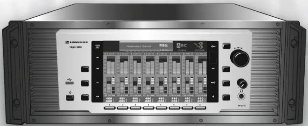
Overview of the front panel
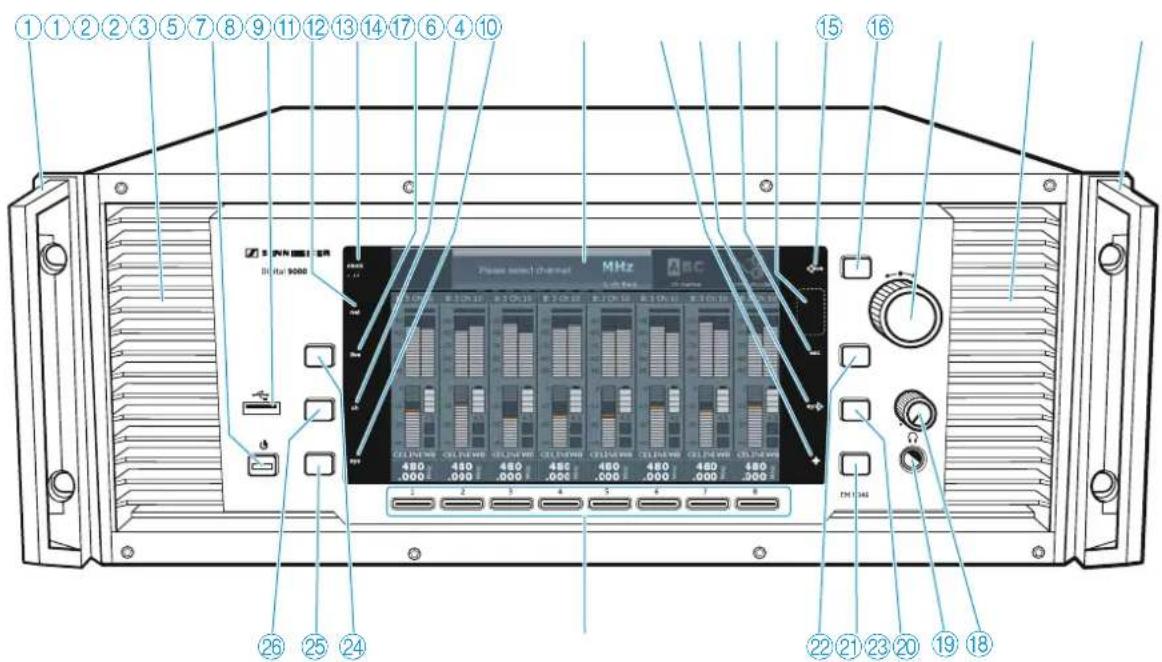
text_image
①①②②③⑤⑦⑧⑨⑪⑫⑬⑭⑮⑯⑰⑱⑲ 15 16 Piano mini channel MHz 1 2 3 4 5 6 7 8 480 480 480 480 480 480 480 .000 .000 .000 .000 .000 .000 .000 1 2 3 4 5 6 7 8 26 25 24 22 21 23 20 19 18 RJ: 9000① Rack-mount "ear" with handle
② Ventilation openings
③ Standby button ⏻
④ USB socket
⑤ net LED (network)
⑥ clock LED 📌 (external word clock synchronization)
⑦ live LED
⑧ ch LED
⑨ sys LED
⑩ Display panel
⑪ + LED
⑫ sync LED
⑬ esc LED
⑭ Infra-red interface
15 save LED
⑯ save button
⑰ Jog dial for menu control
18 Headphone volume control
19 Headphone socket ⚙, ¼" (6.3 mm) jack socket
⑳ sync button
②1 Multiple channel selection button +
⑳ esc button
②3 Channel 1 to 8 button
24 live button (for selecting the "live" operating mode)
⑳ sys button
(for configuring the system)
②6 ch button
(for configuring the channels)
Overview of the rear panel
The overview of the rear panel shows an EM 9046 receiver equipped with the fixed PSU, CCC and ASP modules and the optional DRX, DAO and AAO modules. The configuration shown is an example configuration. The interchangeable modules are highlighted in color.
Your Sennheiser service partner can configure the EM 9046 as follows:
• 1 to 8 EM 9046 DRX receiver modules H
• 1 AAO analog audio out module D and 1 DAO digital audio out module E or
• 2 AAO analog audio out modules D or
• 2 DAO digital audio out modules
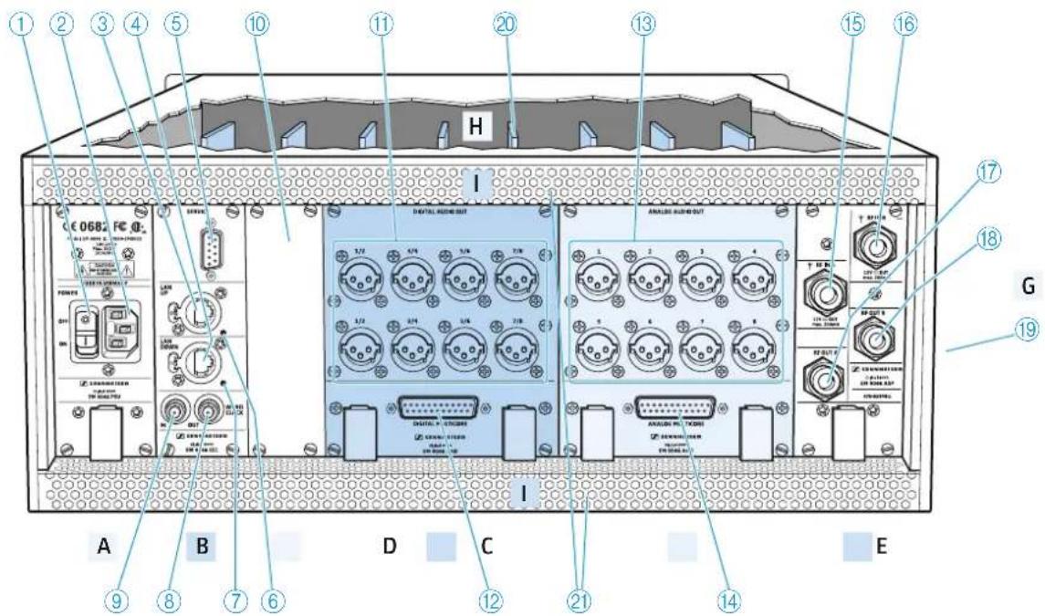
text_image
① ② ③ ④ ⑤ ⑩ ⑪ ⑫ ⑬ ⑭ ⑮ ⑯ ⑰ ⑱ ⑲ ⑳ ⑮ ⑯ H I DIGITAL RADIO OUT ANALAWA RADIO OUT T1 T2 T3 T4 T5 T6 T7 T8 T9 T10 T11 T12 T13 T14 T15 T16 T17 T18 T19 T20 T21 G ⑲ ⑳ ④ ⑦ ⑧ ⑨ A B C D E D C ⑪ ⑫ ⑬ ⑭ ⑮ ⑯ C1000000000000000000000000000000000000000000000000000000000000000000000000000000000000000000000A | PSU – power supply unit
① ON/OFF switch
② IEC mains socket, 3-pin
B | CCC – clock core controller
③ LAN UP socket
④ LAN DOWN socket
⑤ SERVICE interface
⑥ LAN UP LED
⑦ LAN DOWN LED
⑧ WORD CLOCK OUT socket (BNC), looped-through output (75 Ω)
⑨ WORD CLOCK IN socket (BNC), input (75 Ω)
C | Aux opening for optional extensions
⑩ Blanking plate for aux opening
D | DAO – digital audio out
⑪ XLR-3 sockets (male) for digital audio outputs 1/2 to 7/8, balanced, AES3
⑫ DIGITAL MUTLICORE socket (sub-D, 25-pin), digital, balanced
E | AAO – analog audio out
⑬ XLR-3 sockets (male) for analog audio outputs 1 to 8, transformer balanced
⑭ ANALOG MULTICORE socket (sub-D, 25-pin), analog, transformer balanced
F | ASP – antenna splitter
⑮ RF IN A socket (N-type), antenna input, 12 V --- out, max. 200 mA, 50 Ω
⑯ RF IN B socket (N-type), antenna input, 12 V — out, max. 200 mA, 50 Ω
⑰ RF OUT A socket (N-type), daisy chain output
⑱ RF OUT B socket (N-type), daisy chain output
G | Type plate
⑲ EM 9046 type plate
H | DRX – receiver modules
⑳ DRX receiver modules 1 ... 8
I | Ventilation openings
② Ventilation openings

For the pin assignment of the XLR-3 and sub-D sockets of the EM 9046, refer to the chapter "Specifications" on page 123.
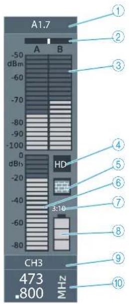
Overview of the displays and the clock LED
text_image
A1.7 -50 dBm -60 -70 -80 -90 -100 0 dBfs HD -20 -40 -60 -80 3:10 CH3 473 .800 MHz 1 2 3 4 5 6 7 8 9 10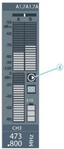
text_image
A1.7A1.7A -50 dBm -60 -70 -80 -90 -100 0 dBfs -20 -40 -60 -80 3:10 CH3 473 MHz .800
text_image
CALIBRATING CH3CH3 473 .800 MHZ
text_image
SCANNING 473 .800 MHz① Frequency preset display
A1.7
A Selected booster (type A or type B)
1 Selected booster frequency range (1 ... 8) (bandwidth: 24 MHz)
7 Frequency preset (1 ... 40)
In addition, channel-related warnings are displayed in alternation with the frequency preset display:
range
low bat.
no signal
peak
booster
sync fail
encryption
The frequency range set is outside the booster frequency range
Charge status of accupack/battery pack is critical
No evaluable RF signal
Audio signal is overmodulated
No booster connected to one or both RF IN A/B N-type sockets
Infra-red synchronization has failed
Audio signal of this channel is bound to the EM 9046
② Diversity evaluation display (true bit diversity)
③ Antenna signal display (dBm)
④ "HD" / "LR" and "Command" display
⑤ "Encryption" display
⑥ Audio level display (dBfs)
⑦ Display for remaining operating time of the transmitter
⑧ Display for charge status of accupack/battery pack
⑨ Channel name display
⑩ Receiving channel display
⑪ Channel status displays (examples)
The clock LED
The clock LED 📌 ⑥ provides information on the following states:
| clock LED Meaning | |
| lights up The receiver's digital audio output is synchronized with an external word clock signal. | |
| flashes | The "Word clock" menu item is set to "external", but the EM 9046 receiver cannot find an external word clock signal and generates its own word clock signal. The word clock rate of this signal corresponds to the last set or active word clock rate. As soon as an external word clock signal is present at the WORD CLOCK IN BNC socket 9, the digital audio output of the EM 9046 automatically synchronizes with it and the clock LED NR 6 lights up constantly. |
| if off The EM 9046 receiver generates its own word clock signal. | |
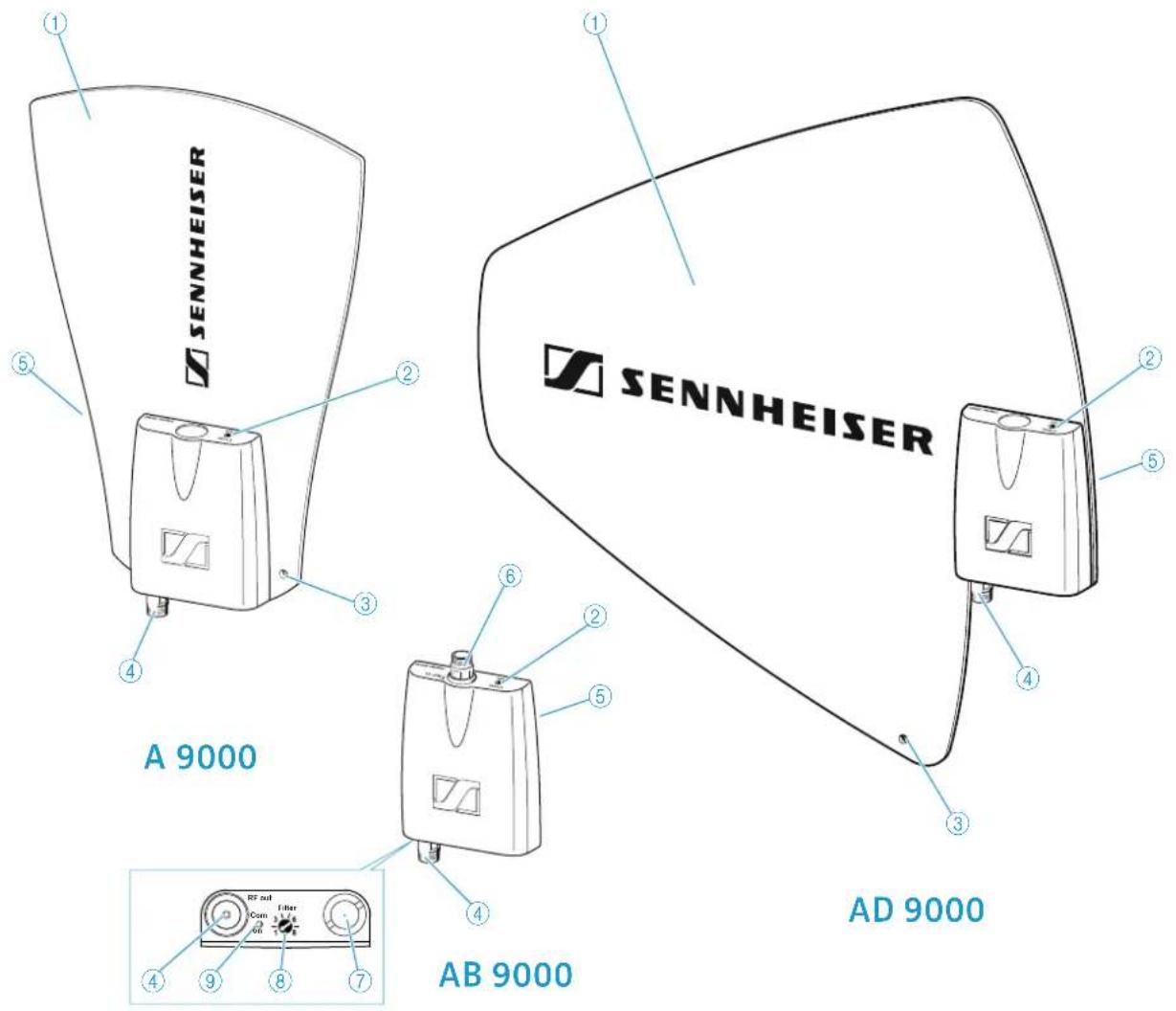
Antennas and antenna boosters
text_image
SENNHEISER A 9000 AD 9000 AB 9000① Antenna surface
② and ⑨: "Com" and "On" LED
- red: error
- green: manual mode
- blue: automatic mode (EM 9046-controlled)
- white: firmware update in progress
③ Hole for connection of safety wires
④ RF out socket (N-type)
If you are using the antennas/antenna booster with the EM 9046, the "Filter" rotary switch has no function because the frequency range is automatically set. If you are not using the antennas/antenna booster with the EM 9046, the "Filter" rotary switch allows you to set the desired frequency range ("A1" ... "A8" or "B1" ... "B8").
⑤ Type plate (not visible here)
⑥ RF in socket (N-type) (AB 9000 only)
⑦ Stand adapter
⑧ "Filter" rotary switch (see below)
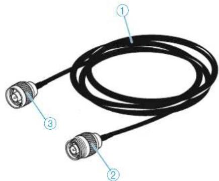
GZL 9000 antenna cable
natural_image
Coiled black cable with three labeled connectors (no text or symbols beyond labels)① GZL cable, available in lengths of 5 m, 10 m and 20 m
③ N-type socket
② N-type connector
SKM 9000/SKM 9000 COM radio microphone
text_image
1 2 3 4 5 6 7 8 9 10 11 12 13 SENNHEISER NEESENKNAS① Microphone head
② Contacts of microphone head
③ Contacts of radio microphone
④ COMMAND button* (SKM 9000 COM)
⑤ Display panel
⑥ Infra-red interface
⑦ Accupack or battery pack for 2 AA size cells
⑧ Body of radio microphone
⑨ DOWN button

⑩ UP button
* The function of the COMMAND button can be configured via the menu of the EM 9046 receiver; refer to "Cmd mode" – Configuring the audio and command outputs" in the system instructions
⑪ SET button

⑫ ON/OFF button
with ESC function (cancel)
- lights up constantly: radio microphone is operational
⑬ Antenna
⑭ Catches for accupack/battery pack
Overview of the standard display after switch-on
After switch-on, the radio microphone displays the currently selected standard display (here: "Frequency"). For an overview of all standard displays, refer to page 90.
text_image
①③⑤④⑥② 3:59 480.000 MHz① Display for charge status of the accupack/battery pack
② Operating time display (only when used with the BA 60 accupack)
③ Frequency/channel/name display, switchable
④ "Encryption" display
⑤ Lock mode icon
⑥ Transmission mode display: "HD" (High Definition Audio) or "LR" (Long Range Audio)
Recommended microphone heads for the SKM 9000 radio microphone
| Microphone head Pick-up pattern Transducer principle | |
| ME 9002 omni-directional condenser | |
| ME 9004 cardioid condenser | |
| ME 9005 super-cardioid condenser | |
| MD 9235 super-cardioid dynamic | |
| MMD 935-1 cardioid dynamic | |
| MMD 945-1 super-cardioid dynamic | |
| MMK 965-1 cardioid/super-cardioid, switchable | permanently polarized |
| KK 204 (Neumann) cardioid condenser | |
| KK 205 (Neumann) super-cardioid condenser | |
You can also use your radio microphone together with the microphone heads of the ew G3 and 2000 series.
SK 9000 bodypack transmitter
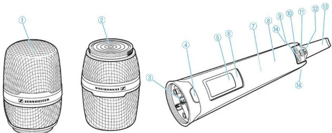
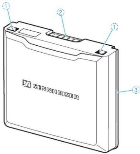
text_image
Labeled diagram of a device with numbered parts for identification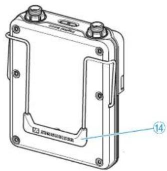
natural_image
Technical line drawing of a mechanical housing or enclosure with mounting holes and a labeled component (no text or symbols present)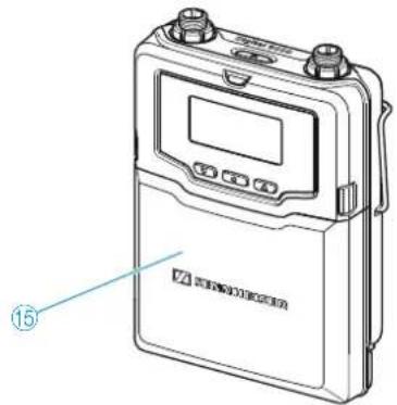
text_image
Technical line drawing of a handheld electronic device with labeled component '15'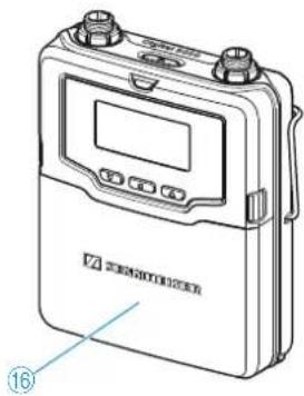
natural_image
Line drawing of a portable electronic device with two knobs and a digital display (no text or symbols visible)① 3-pin special audio socket for
- Sennheiser microphones
- Cl 1-4 Sennheiser instrument cable
- KA 9000 COM command adapter
② ON/OFF button ☑ with ESC function (cancel)
③ ON LED
- lights up constantly: transmitter is operational
- flashes regularly: remaining operating time is less than 30 minutes
- flashes with high levels: audio signal is excessively high
④ Antenna socket
⑤ Infra-red interface
⑥ DOWN button


⑦ SET button
⑧ UP button
⑨ Catches for accupack/battery pack
⑩ Snap-in elements for accupack/battery pack
⑪ Guide rails for accupack/battery pack
⑫ Contacts
for supply voltage and
data contacts
⑬ Display panel
⑭ Belt clip
⑮ Battery pack for 3 AA size cells
⑯ Accupack
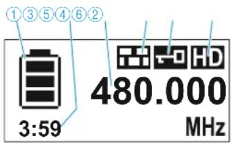
Overview of the standard display after switch-on
After switch-on, the bodypack transmitter displays the currently selected standard display (here: "Frequency"). For an overview of all standard displays, refer to page 99.
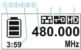
text_image
①③⑤④⑥② 3:59 480.000 MHz① Display for charge status of the accupack/battery pack
② Operating time display (only when used with the BA 61)
③ Frequency/channel/name display, switchable
④ "Encryption" display
⑤ Lock mode icon
⑥ Transmission mode display: "HD" (High Definition Audio) or "LR" (Long Range Audio)
Microphones for the SK 9000 bodypack transmitter
| Microphone Pick-up pattern | |
| MKE 1 omni-directional | |
| MKE 2 cardioid | |
| ME 102 omni-directional | |
| ME 104 cardioid | |
| ME 105 super-cardioid | |
| HSP 2 omni-directional | |
| HSP 4 cardioid | |
Sennheiser CI 1-4 line/instrument cable
1/4'' (6.3 mm) jack plug (silent plug) to 3-pin special audio connector
KA 9000 COM command adapter for the SK 9000 bodypack transmitter
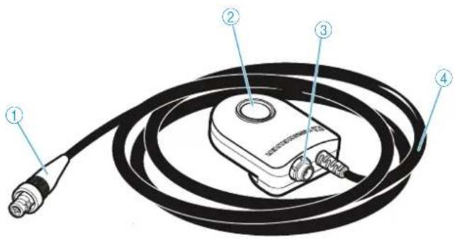
text_image
Diagram of a medical or laboratory device with numbered parts labeled 1 to 4, showing a coiled cable and connector.① 3-pin special audio connector
② COMMAND button
③ 3-pin special audio socket
④ Connection cable, length: 1.6 m
BA 60 accupack
text_image
Technical diagram of a mechanical component with numbered parts labeled 1, 2, and 3.① Charging and data contacts
② Snap-in elements
③ Antenna
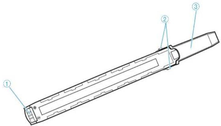
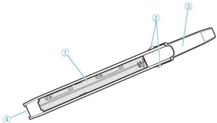
BA 61 accupack
text_image
① ② ① ③ SENSHEISER① Snap-in elements
③ Guide rail
② Charging and data contacts
B60 battery pack
text_image
Technical diagram of a mechanical component with numbered parts labeled 1 to 4① Battery compartment for 2
③ Antenna
AA size batteries
④ Data contacts
② Snap-in elements
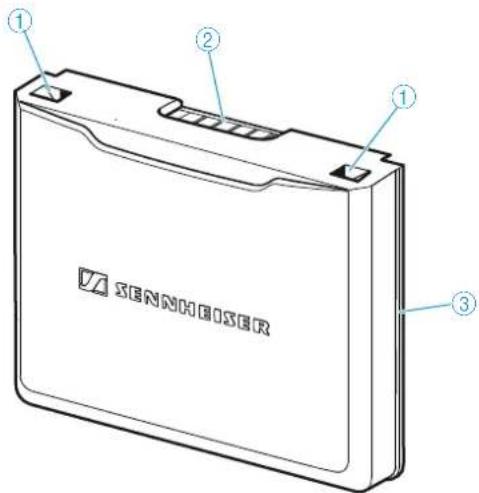
B 61 battery pack
text_image
① ② ① ③ SENNIEUSER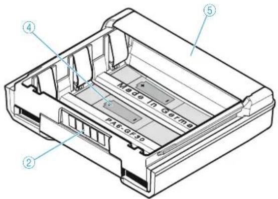
text_image
Made in Germs PAS-GE30① Snap-in elements
② Data contacts
③ Guide rail
④ Battery compartment for 3 AA size batteries
⑤ Cover
L 60 charger
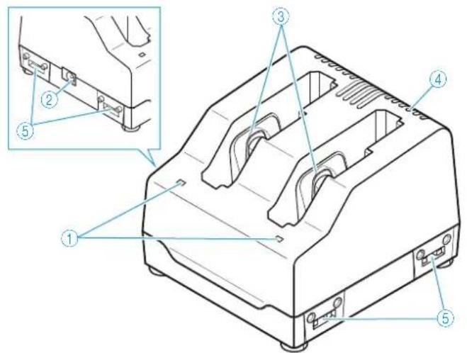
text_image
Technical diagram of a device housing with numbered components and an inset view showing a bracket assembly.① Status LED
② DC input socket for connection of NT 3-1 mains unit
③ Charging compartments for BA 61 or BA 60 accupacks
④ Ventilation openings
⑤ Rails for cascading up to 4 chargers
Indications of the status LED
| Status LED 1 Meaning | |
| off Standby mode/no connection to the mains | |
| red Accupack is being charged, capacity obtained is approx. 0-70% | |
| orange Accupack is being charged, capacity obtained is approx. 70-100% | |
| green Accupack is fully charged, capacity is continuously monitored | |
| flashing red Error, charging is aborted (accupack is e.g. defective or overheated) |
Digital 9000
Preparing for use
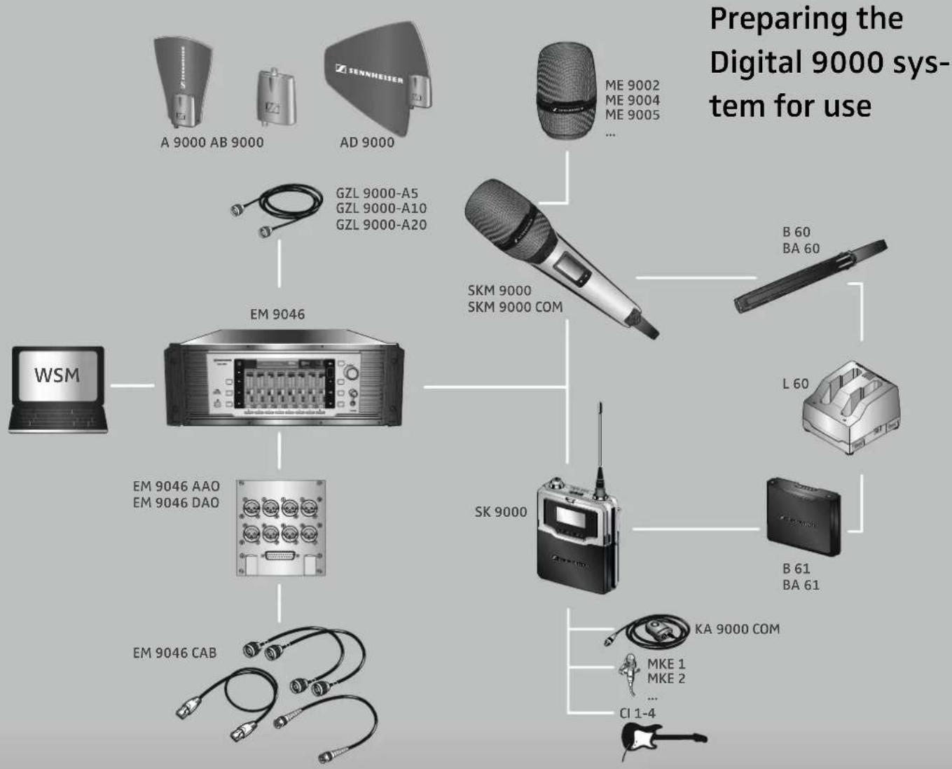
flowchart
graph TD
    A["Preparing the Digital 9000 system for use"] --> B["WSM"]
    B --> C["EM 9046"]
    C --> D["EM 9046 AAO EM 9046 DAO"]
    C --> E["EM 9046 CAB"]
    C --> F["SKM 9000 SKM 9000 COM"]
    F --> G["ME 9002 ME 9004 ME 9005 ..."]
    F --> H["B 60 BA 60"]
    F --> I["L 60"]
    F --> J["B 61 BA 61"]
    F --> K["KA 9000 COM"]
    K --> L["MKE 1 MKE 2 ... CI 1-4"]
Preparing the Digital 9000 system for use .....31
Preparing the EM 9046 receiver for use ....32
Setting up the receiver or mounting it into a 19" rack ....32
Connecting devices to the analog audio outputs .....33
Connecting devices to the digital audio outputs .....34
Daisy chaining receivers ....35
Connecting external word clock signals ....36
Connecting receivers in a network 36
Connecting the receiver to the mains 38
Connecting headphones 38
Preparing the A/AB/AD 9000 antennas and/or antenna boosters for use ....39
Positioning the receiving antennas ....39
Connecting the receiving antennas/antenna boosters ....40
Adjusting the receiving antennas/antenna boosters .40
Preparing the SKM 9000 radio microphone for use ....40
Changing the microphone head 42
Preparing the SK 9000 bodypack transmitter for use ....42
Connecting the antenna 45
Connecting the KA 9000 COM command adapter .....45
Preparing the L 60 charger for use ....46
Cascading several chargers 46
Setting up or mounting the charger ....46
Preparing the EM 9046 receiver for use
Setting up the receiver or mounting it into a 19" rack
Setting up the receiver on a flat surface
CAUTION
Risk of staining of furniture surfaces!
Furniture surfaces can be treated with varnish, polish or synthetics which might cause stains when they come into contact with other synthetics. Despite a thorough testing of the synthetics used by us, we cannot rule out the possibility of staining.
Do not place the receiver on delicate surfaces.
The receiver is supplied with 4 self-adhesive soft rubber feet to ensure that it cannot slip on the surface on which it is placed.

Do not fit the device feet when rack mounting the receiver.
▶ Ensure that the base of the receiver is clean and free from grease before fitting the device feet.
▶ Fit the device feet.
Place the receiver on a flat, horizontal surface.
Mounting the receiver into a 19" rack

CAUTION
Danger of material damage and personal injury when rack mounting the receiver!
When installing the EM 9046 in a closed or multi-rack assembly, please consider that
- the ambient temperature may increase considerably,
• high mechanical loadings occur.
▶ Always make sure that the ambient temperature within the rack does not exceed the permissible temperature limit specified in the specifications. If necessary, provide additional ventilation.
▶ Do not obstruct the air flow through the ventilation openings on the front and rear of the EM 9046.
▶ Always mount the receiver on rack rails.
▶ Make sure that the mechanical loading of the rack is even to avoid, for example, tipping of the rack.
Make sure that the rack is sufficiently stable.
▶ Avoid circuit overloading. If necessary, provide overcurrent protection.
Make sure that the mains cable of the EM 9046 as well as connected multi-outlet power strips or extension cables have protective ground contacts.
▶ Always ground the rack via an additional ground connection.
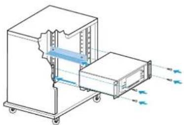
natural_image
Technical line drawing of a mechanical device with internal components and directional arrows indicating flow or movement (no text or symbols)To mount the receiver into a 19" rack:
Mount rack rails that are designed to carry the total weight of the EM 9046.
Slide the receiver onto the rack rails and screw it to the front of the rack using 2 screws per side (screws to be ordered separately).
Connecting devices to the analog audio outputs
When equipped with an AAO analog audio out module, the EM 9046 receiver has 8 analog transformer balanced audio outputs.
Connect the analog audio inputs of an external device to the XLR-3 sockets ⑬ or the sub-D socket ⑭ (multicore, Tascam) of the EM 9046.
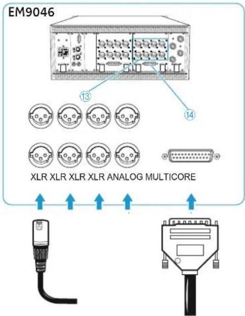
text_image
EM9046 13 14 XLR XLR XLR XLR ANALOG MULTICOREConnecting devices to the digital audio outputs
When equipped with an DAO digital audio output module, the EM 9046 receiver has 8 digital balanced audio outputs. The signals are output in AES3 format.
Connect the digital audio inputs of an external device to the XLR-3 sockets ⑪ or the sub-D socket ⑫ of the EM 9046.
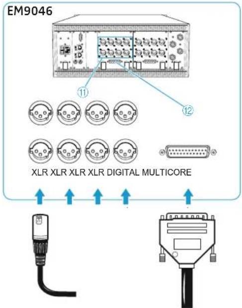
text_image
EM9046 ⑪ ⑫ XLR XLR XLR XLR DIGITAL MULTICOREIf you are using the XLR-3 sockets ⑪:
Use a special double-shielded 110 Ω AES3 cable. This prevents that the digital data transmission interferes with RF reception.
For the pin assignment of the XLR-3 and sub-D sockets of the EM 9046, refer to the chapter "Specifications" on page 123.
Ready-made AES3 cables are available from Sennheiser (optional accessories).
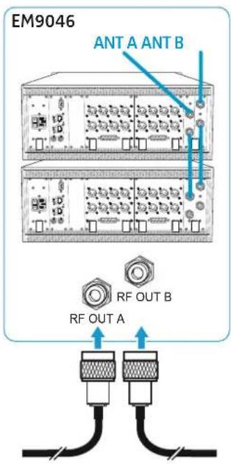
text_image
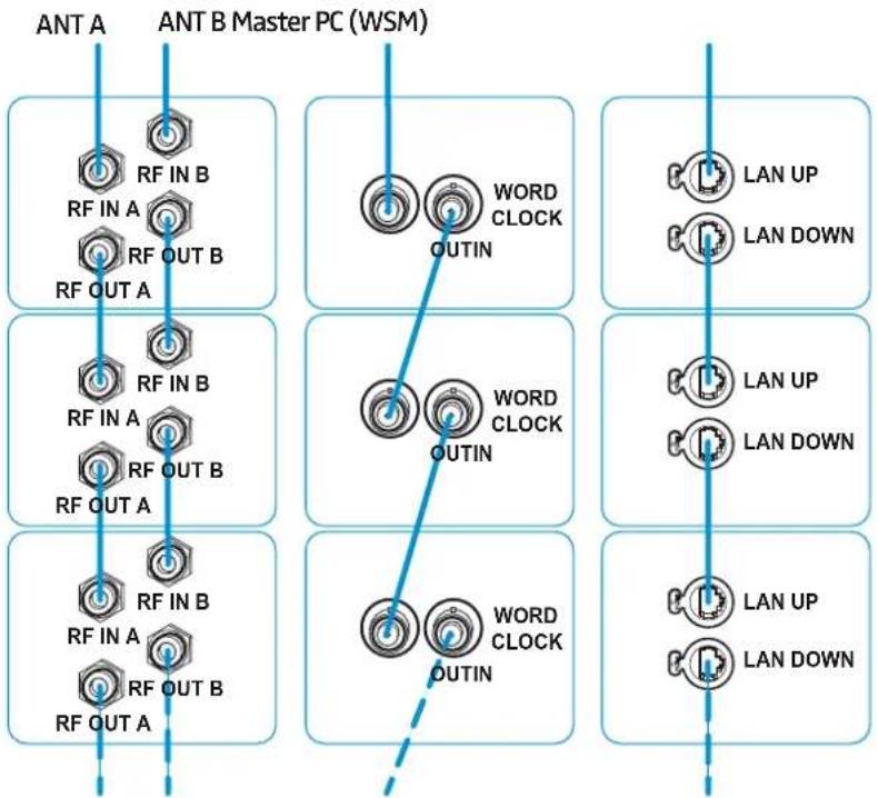
EM9046 ANT A ANT B RF OUT A RF OUT BDaisy chaining receivers
The EM 9046 receivers feature an integrated antenna splitter so that up to four receivers can be daisy chained. This allows you to use two antennas/antenna boosters for up to four receivers. In this case, all receivers have to use the same booster frequency range.
▶ Use GZL 9000 antenna cables to connect two antennas via antenna boosters to the RF IN N-type sockets 15 and 16 of the first receiver.
Connect the RF OUT N-type sockets of the first receiver to the RF IN N-type sockets of an additional receiver. To do so, use the RF patch cables from the EM 9046 CAB cable set.
▶ Repeat the previous steps for up to four receivers.
The length of the RF patch cables from the EM 9046 CAB cable set allows a distance of 1 height unit (HU) between two EM 9046 in a 19" rack.
If you want to pass on word clock signals between daisy chained receivers and/or if you want to connect daisy chained receivers in a network (see the following chapters):
Connect the receivers in the same order in which you connected the RF N-type sockets. Always connect the network sockets from LAN DOWN to LAN UP and word clock sockets from OUT to IN.
flowchart
graph TD
    subgraph_ANT_A["ANT A"]
        A1["RF IN A"] --> A2["RF OUT A"]
        A2 --> A3["RF OUT B"]
        A3 --> A4["RF IN B"]
    end
    subgraph_ANT_B["ANT B Master PC (WSM)"]
        B1["WORD CLOCK OUTIN"] --> B2["WORD CLOCK OUTIN"]
    end
    subgraph_LAN_UP["LAN UP"]
            C1["LAN DOWN"]
    end
    subgraph_LAN_UP["LAN UP"]
            D1["LAN DOWN"]
    end
    subgraph_LAN_UP["LAN UP"]
            E1["LAN DOWN"]
    end
    subgraph_LAN_UP["LAN UP"]
            F1["LAN DOWN"]
    end
    A1 --> B1
    A2 --> B2
    A3 --> B3
    A4 --> B4
    B1 --> B2
    B2 --> B3
    B3 --> B4
    B4 --> B5
    B5 --> B6
    B6 --> B7
    B7 --> B8
    B8 --> B9
    B9 --> B10
    B10 --> B11
    B11 --> B12
    B12 --> B13
    B13 --> B14
    B14 --> B15
    B15 --> B16
    B16 --> B17
    B17 --> B18
    B18 --> B19
    B19 --> B20
    B20 --> B21
    B21 --> B22
    B22 --> B23
    B23 --> B24
    B24 --> B25
    B25 --> B26
    B26 --> B27
    B27 --> B28
    B28 --> B29
    B29 --> B30
    B30 --> B31
    B31 --> B32
    B32 --> B33
    B33 --> B34
    B34 --> B35
    B35 --> B36
    B36 --> B37
    B37 --> B38
    B38 --> B39
    B39 --> B40
    B40 --> B41
    B41 --> B42
    B42 --> B43
    B43 --> B44
    B44 --> B45
    B45 --> B46
    B46 --> B47
    B47 --> B48
    B48 --> B49
    B49 --> B50
    B50 --> B51
    B51 --> B52
    B52 --> B53
    B53 --> B54
    B54 --> B55
    B55 --> B56
    B56 --> B57
    B57 --> B58
    B58 --> B59
    B59 --> B60
* If you have installed a MAN card in the first receiver of the daisy chain and if you use the card's word clock as the external master, the connection to the external word clock generator is no longer required (see next section).
** This diagram illustrates a convenient way of daisy chaining the receivers. Sennheiser recommends using an external switch to connect the receivers in a star topology (see "Connecting receivers in a network" on page 36).
text_image
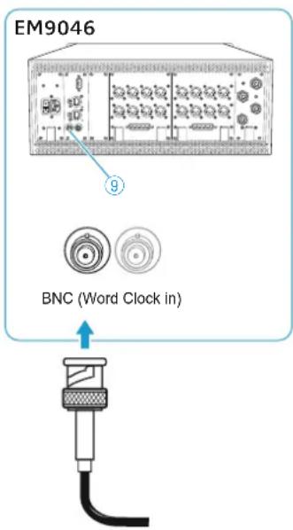
EM9046 BNC (Word Clock in)Connecting external word clock signals
The EM 9046 receiver supports external word clock sampling rates of 44.1 kHz, 48 kHz, 88.2 kHz and 96 kHz. If you have installed a MAN card, you can alternatively use the card's word clock as external word clock generator.
(This step is not required if you use the word clock signal of a built-in MAN card.)
Use a shielded 75 Ω coaxial BNC cable to connect the word clock output of an external word clock generator to the BNC socket ⑨ of the EM 9046.
Connect the BNC sockets of the receivers.
If you have daisy chained your receivers (see page 35):
Connect the BNC sockets of the receivers in the order shown on page 35.

For an overview of the states of the clock LED, refer to page 20.
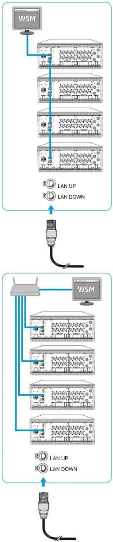
Connecting receivers in a network
The EM 9046 has two network sockets LAN UP ③ and LAN DOWN ④, allowing you to connect additional EM 9046 or other network-compatible Sennheiser receivers in a network.
All receivers in the network can be controlled via the Wireless Systems Manager (WSM) software. In addition, interconnected receivers allow you to simultaneously headphone monitor the channels of all receivers and the stream arbitrary channels to an external audio player or to the WSM.
There are two ways to connect several EM 9046 in a network:
- Ethernet daisy chaining:
flowchart
graph TD
    A["WSM"] --> B["Server 1"]
    B --> C["Server 2"]
    C --> D["Server 3"]
    D --> E["Server 4"]
    E --> F["Server 5"]
    F --> G["Server 6"]
    G --> H["Server 7"]
    H --> I["Server 8"]
    I --> J["Server 9"]
    J --> K["Server 10"]
    K --> L["Server 11"]
    L --> M["Server 12"]
    M --> N["Server 13"]
    N --> O["Server 14"]
    O --> P["Server 15"]
    P --> Q["Server 16"]
    Q --> R["Server 17"]
    R --> S["Server 18"]
    S --> T["Server 19"]
    T --> U["Server 20"]
    U --> V["Server 21"]
    V --> W["Server 22"]
    W --> X["Server 23"]
    X --> Y["Server 24"]
    Y --> Z["Server 25"]
    Z --> AA["Server 26"]
    AA --> AB["Server 27"]
    AB --> AC["Server 28"]
    AC --> AD["Server 29"]
    AD --> AE["Server 30"]
    AE --> AF["Server 31"]
    AF --> AG["Server 32"]
    AG --> AH["Server 33"]
    AH --> AI["Server 34"]
    AI --> AJ["Server 35"]
    AJ --> AK["Server 36"]
    AK --> AL["Server 37"]
    AL --> AM["Server 38"]
    AM --> AN["Server 39"]
    AN --> AO["Server 40"]
    AO --> AP["Server 41"]
    AP --> AQ["Server 42"]
    AQ --> AR["Server 43"]
    AR --> AS["Server 44"]
    AS --> AT["Server 45"]
    AT --> AU["Server 46"]
    AU --> AV["Server 47"]
    AV --> AW["Server 48"]
    AW --> AX["Server 49"]
    AX --> AY["Server 50"]
- You use both network sockets (LAN UP and LAN DOWN) of the receivers. This causes the receivers to act as a switch. You do not require an external switch.
- The Spanning Tree Protocol (STP) and/or the Rapid Spanning Tree Protocol, (RSTP) are used to detect and deactivate redundant paths in the local network. Redundant paths are caused by faulty cabling (unintentional cabling loops).
- STP and RSTP exchange configuration packets and, as a result, induce a higher network load. Individual switches in your local network can be set to a standby mode so that a loop-free network topology results. This makes your network faster and more efficient.
If a connection fails, STP and RSTP automatically attempt to reestablish the failed connection (e.g. by reactivating switches). This can cause network outages of up to 50 seconds.
Connect the first EM 9046 to a switch, PC or laptop. We recommend using a CAT5 Ethernet cable with crush-resistant Neutrik EtherCon connectors.
Connect the receivers to one another using the CAT5 Ethernet cables from the EM 9046 CAB cable set. Always connect the network sockets from LAN DOWN to LAN UP.
If you have daisy chained your receivers (see page 35):
Connect the network sockets of the receivers in the order shown on page 35.
-
Connecting the receivers in a star topology (recommended):
-
You only use the LAN UP network socket of the receivers. This deactivates STP and RSTP.
- You require an external switch.
- Your network uses a star topology
Connect all EM 9046 to a switch using the CAT5 Ethernet cables from the EM 9046 CAB cable set
Connect the switch to a computer or laptop. We recommend using a CAT5 Ethernet cable with crush-resistant Neutrik EtherCon connectors.
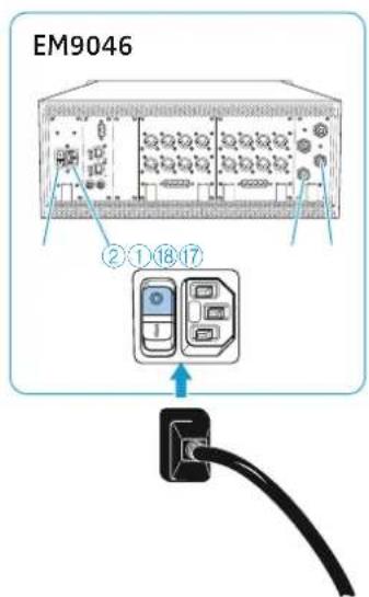
Connecting the receiver to the mains

CAUTION
Damage to the device due to electric current!
If you connect the receiver to an unsuitable power supply, this can cause damage to the device.
▶ Use the supplied mains cable to connect the receiver to the mains (100 to 240 V AC, 50 or 60 Hz).
▶ Ensure a reliable mains ground connection of the receiver – especially when you are using multi-outlet power strips or extension cables.
text_image
EM9046 ②①⑱⑰⑰To connect the receiver to the mains:
Set the ON/OFF switch ① to position "0".
Connect the supplied mains cable to the 3-pin mains socket ②.
Plug the mains connector into the wall socket.
▶ Set the ON/OFF switch ① to position "1".
To disconnect the receiver from the mains:
▶ Set the ON/OFF switch ① to position "0".
All daisy chained signals are interrupted, i.e.:
- the antenna signals at the daisy chain outputs ⑰ and ⑱,
– the booster supply voltage,
– the signal of the external word clock generator.
▶ Pull out the mains connector from the wall socket to completely disconnect the receiver from the mains.
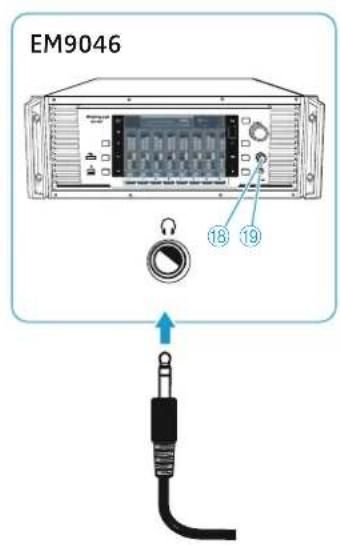
text_image
EM9046 18 19Connecting headphones

WARNING
Danger of hearing damage due to high sound pressure levels!
The headphones connected to the headphone socket are capable of producing very high sound pressure levels, which can cause permanent hearing damage.
▶ Always turn the headphone volume control ^18 counterclockwise to the minimum
– before connecting headphones and putting them on;
– before you change to a different channel.
▶ First turn the headphone volume control ^18 counterclockwise to the minimum.
Connect headphones with a 14 " (6.3 mm) stereo jack plug to the headphone socket ^19 .

For information on headphone monitoring of channels, refer to page 84.
Preparing the A/AB/AD 9000 antennas and/or antenna boosters for use
Antennas and antenna boosters of the Digital 9000 series are available in two variants: A1–A8 and B1–B8.
Select the booster variant (A1–A8 or B1–B8) whose frequency range matches that of your transmitters:
| Booster variant A1-A8 | B1-B8630-798MHz | |||||||||||||||
| Booster frequency ranges | A1 | A2 | A3 | A4 | A5 | A6 | A7 | A8 | B1 | B2 | B3 | B4 | B5 | B6 | B7 | B8 |
| Bandwidth MHz | 470-494 | 494-518 | 510-534 | 534-558 | 550-574 | 574-598 | 590-614 | 614-638 | 630-654 | 654-678 | 670-694 | 694-718 | 710-734 | 734-758 | 750-774 | 774-798 |
| Transmitter | type A1-A4470-558 MHz | type A5-A8550-638 MHz | type B1-B4630-718 MHz | type B5-B8710-798 MHz | ||||||||||||
Use two A 9000 receiving antennas or two AD 9000 receiving antennas or two passive antennas together with AB 9000 antenna boosters:
Product name Type Radiation pattern
A 9000 active, intelligent omni-directional
AD 9000 active, intelligent directional
AB 9000 antenna booster depending on the passive antenna used
If both antenna boosters are connected or replaced, the EM 9046 automatically measures the cable attenuation between the antenna boosters and the antenna inputs and compensates for it. During the measurement, the channel status display displays "Calibrating" for each channel. If only one antenna booster is connected or replaced, the cable attenuation will not be measured. You can also manually initiate the compensation of the cable attenuation (see ""Cable attn" - Displaying the cable attenuation and automatically compensating for it" on page 64).
Positioning the receiving antennas

CAUTION
Material damage and personal injury due to tipping/dropping of the antennas!
If you do not protect the antennas against tipping/dropping, they can cause material damage and personal injury.
Use safety wires to protect the receiving antennas against tipping/dropping. The safety wires, rope terminations and coupling links must comply in their dimensioning and condition with the regulations and standards of the country in which they are used!
▶ Position the receiving antennas in the same room in which the transmission takes place! Maintain a minimum distance of 1 m between the two receiving antennas/antenna boosters and a minimum distance of 50 cm between the antennas/antenna boosters and metal objects (including reinforced concrete walls).
Connecting the receiving antennas/antenna boosters
▶ Use GZL 9000 antenna cables.
Sennheiser GZL 9000 antenna cables are available in lengths of 5 m, 10 m and 20 m.
A/AB/AD 9000:
Connect the RF out sockets ④ of the antennas/antenna boosters used to the N-type sockets RF IN A ⑮ and RF IN B ⑯ of your EM 9046.
AB 9000:
Connect the RF IN socket ⑥ of the two antenna boosters to one antenna each.
▶ Use short cables to keep the cable attenuation as low as possible.
Adjusting the receiving antennas/antenna boosters
The EM 9046 receiver controls the preselection of the booster frequency ranges. No further settings need to be made on the A/AB/AD 9000 antennas/antenna boosters.
You can also use the antennas/antenna boosters with other receivers if the following conditions are met:
▶ Use a receiver with booster supply voltage (e.g. EM 3732-II).
Use a cable whose length and attenuation match the amplification of 17 dB of the A/AD/AB 9000 antennas and antenna boosters.
▶ Use the "Filter" rotary switch ⑧ to manually set the booster frequency range (see table on page 39).
Preparing the SKM 9000 radio microphone for use
Selecting the accupack/battery pack
For powering the SKM 9000 radio microphone, you can use:
• t h e BA 60 accupack
- the B 60 battery pack for 2 AA size batteries (1.5 V)
Charge the BA 60 accupack before using it for the first time (see page 102).
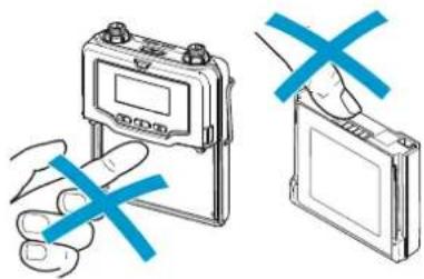
CAUTION
Damage to the radio microphone and/or the accupack/battery pack!
If you touch the following contacts, they can become dirty or damaged:
- charging and data contacts ① of the BA 60 accupack
- data contacts ④ of the B 60 battery pack
Do not touch the contacts of the BA 60 accupack nor the contacts of the B 60 battery pack.
natural_image
Simple line drawing of a hand holding a tool with a blue X mark, no text or symbols presentInserting batteries into the B 60 battery pack
Insert the batteries (see diagram). Observe correct polarity when inserting the batteries.
text_image
Diagram illustrating battery charging process with labeled components and directional arrowsOnly insert high-quality AA size batteries (e.g. lithium or alkaline batteries) into the B 60 battery pack. Do not insert individual rechargeable batteries such as NiMH cells.
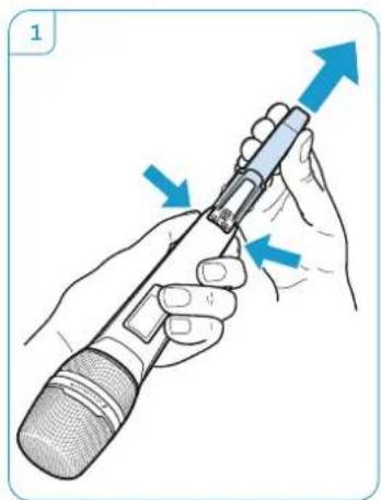
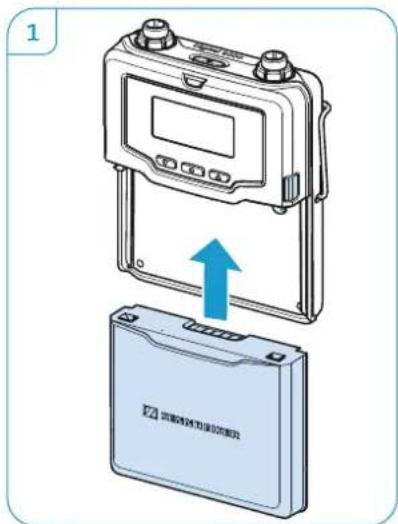
Removing and inserting the accupack/battery pack
To remove the accupack/battery pack:
▶ Push the two catches for accupack/battery pack ^14 and pull the accupack/battery pack out of the radio microphone's body (see diagram 1).
When removing the accupack/battery pack, the settings of the radio microphone are retained.
To attach the accupack/battery pack:
Push the accupack/battery pack into the radio microphone's body until it locks into place with an audible click (see diagram 2).
natural_image
Illustration of hands holding a microphone with blue arrows indicating movement or force (no text or symbols)
text_image
2 CLICK!

Changing the microphone head
CAUTION
Damage to the microphone head!
If you touch contacts, they can become dirty or damaged.
Do not touch the contacts of the radio microphone nor the contacts of the microphone head.
▶ Unscrew the microphone head ①.

natural_image
Illustration of a hand holding a microphone with a blue arrow indicating motion (no text or symbols)
With some microphone heads, the upper part of the sound inlet basket can be unscrewed. To fully unscrew the microphone head, always hold it as shown.
For an overview of suitable microphone heads, refer to the product overview on page 23.
Screw the desired microphone head to the radio microphone. The radio microphone is operational again.

text_image
Diagram showing a hand holding a medical device with a blue arrow indicating direction and labeled point ①
When unscrewing the microphone head ① during operation, the muting function is automatically activated.
Preparing the SK 9000 bodypack transmitter for use
Selecting the accupack/battery pack
For powering the SK 9000 bodypack transmitter, you can use:
• t h e BA 61 accupack
• the B 61 battery pack for 3 AA size batteries (1.5 V)

Charge the BA 61 accupack before using it for the first time (see page 102).
natural_image
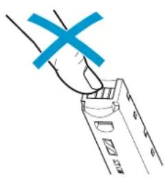
Illustration of a hand holding a digital multimeter and a device with blue X marks (no text or symbols)CAUTION
Damage to the bodypack transmitter and/or the accupack/battery pack! If you touch the following contacts, they can become dirty or damaged:
- Contacts for supply voltage and data contacts of the bodypack transmitter
- Charging and data contacts of the BA 61 accupack
• Data contacts of the B 61 battery pack
Do not touch the contacts of the bodypack transmitter nor the contacts of the BA 61 accupack/B 61 battery pack.
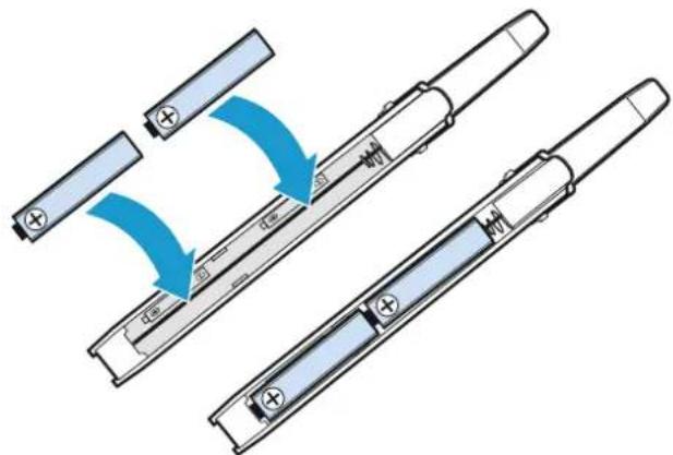
Inserting batteries into the B 61 battery pack
Insert the batteries (see diagram). Observe correct polarity when inserting the batteries.
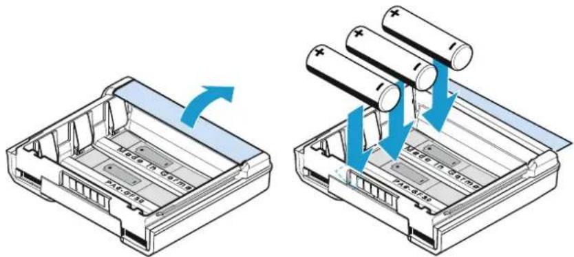
text_image
Made in Series AC-0716 Made in Series AC-0716Only insert high-quality AA size batteries (e.g. lithium or alkaline batteries) into the B 61 battery pack. Do not insert individual rechargeable batteries such as NiMH cells.
When removing the accupack/battery pack, the settings of the radio microphone are retained.
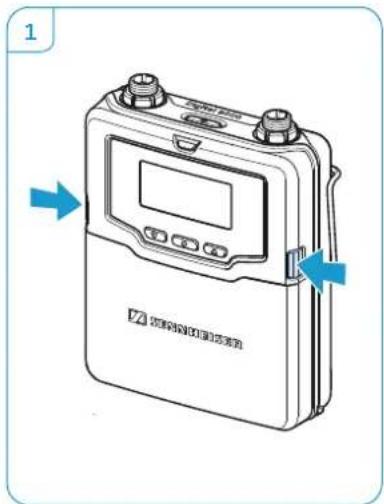
Removing and inserting the accupack/battery pack
To remove the accupack/battery pack:
▶ Push the two catches and pull the accupack/battery pack away from the bodypack transmitter as shown in diagram 2.
text_image
Diagram of a digital testing device with labeled ports and directional arrows indicating measurement or operation.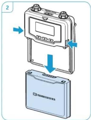
text_image
Diagram showing device components with blue arrows indicating process flow, including a digital display and a battery case.To attach the accupack/battery pack:
Slide the accupack/battery pack onto the guide rails of the bodypack transmitter until it locks into place with an audible click. The bodypack transmitter is then ready for operation.
text_image
1 2000000000000000000000000000000000000000000000000000000000000000000000000000000000000000000000000000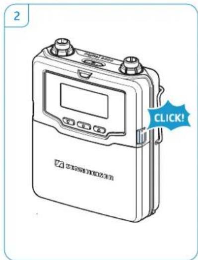
text_image
2 CLICK!When removing the accupack/battery pack, the settings of the radio microphone are retained.
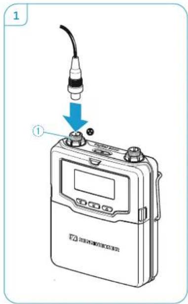
Connecting microphones and audio sources
The audio input is designed for the connection of both pre-polarized condenser microphones and other audio sources. DC powering of the condenser microphones is via the 3-pin special audio socket ①.
Use one of the recommended Sennheiser microphones or the Sennheiser Cl 1-4 line/instrument cable.
For an overview of suitable microphones, refer to the product overview on page 25.
Connect the 3-pin special audio connector of the Sennheiser microphone or the Sennheiser CI 1-4 line/instrument cable to the 3-pin special audio socket ①.
Lock the connector by screwing down the coupling ring.
text_image
1 ①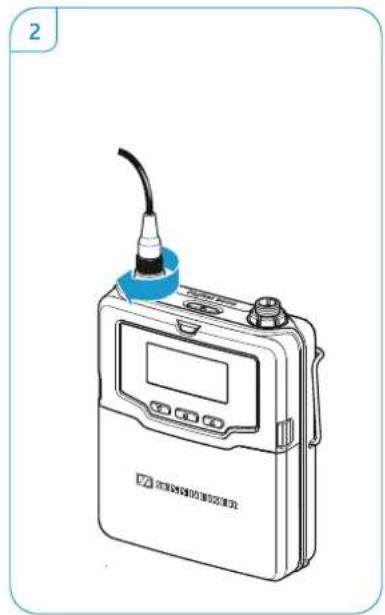
natural_image
Illustration of a handheld electronic device with a blue cap and control panel (no text or symbols visible)Connecting the antenna
▶ Only use the supplied antenna.
▶ Connect the antenna as shown:
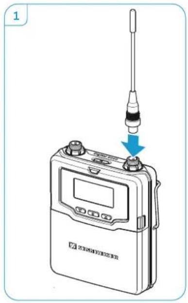
text_image
1 STANDARDER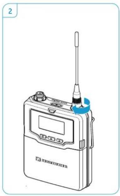
natural_image
Line drawing of a portable electronic device with a screwdriver and control panel (no text or symbols)Connecting the KA 9000 COM command adapter
Using the KA 9000 COM command adapter, you can change the audio channel on the EM 9046 receiver via remote control, e.g. for stage directions.
Connect the 3-pin special audio connector ① of the KA 9000 COM to the 3-pin special audio socket ① of the SK 9000.
Connect the 3-pin special audio connector of the Sennheiser microphone or the Sennheiser CI 1-4 line/instrument cable to the 3-pin special audio socket ③ of the KA 9000 COM.
Preparing the L 60 charger for use
Cascading several chargers
Up to 4 L 60 charger can be cascaded together and can be powered by the NT 3-1 mains unit.
Prepare the L 60 chargers:
- Make sure that the chargers are disconnected from the mains.
- Unscrew the two screws ⑥ at the bottom of one charger.
- Til t the charger to the side and slide out the rails ⑤ completely.
- Tighten the two screws ⑥.
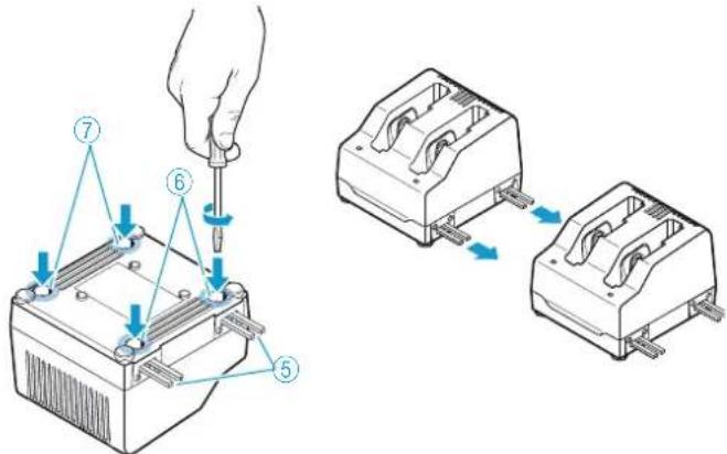
text_image
Technical diagram showing a hand using a screwdriver to adjust or install an electronic component, with numbered parts and blue arrows indicating assembly steps.▶ Unscrew the two screws ⑦ at the bottom of a second charger.
Slide the second charger onto the rails ⑤ of the first charger and tighten the two screws⑦.
▶ Repeat for the other chargers.
Setting up or mounting the charger
CAUTION
Risk of staining of surfaces!
Surfaces can be treated with varnish, polish or synthetics which might cause stains when they come into contact with other materials. Despite a thorough testing of the materials used by us, we cannot rule out the possibility of staining.
Do not place the L 60 charger on delicate surfaces.
To fix the charger securely in place:
Fix the charger by screwing screws (fillister head self-tapping screws as per DIN 7049, ST 3.5 x 32) through the four holes ⑧ at the bottom of the charger.
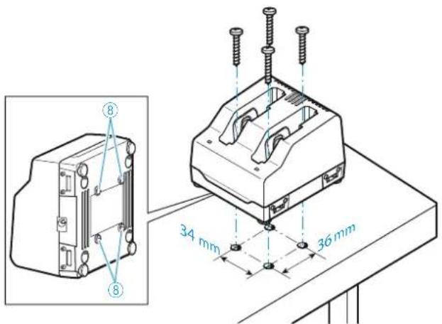
text_image
34 mm 36 mmTo ensure reliable operation of the L 60 and efficient charging of the BA 60/61:
Make sure that the ambient temperature of the charger is within the operating temperature range (see page 122).
Do not place the charger in direct sunlight or near any heat sources such as radiators, stoves, or other devices (including amplifiers) that produce heat.
▶ Ensure sufficient ventilation; if necessary, provide additional ventilation.
Digital 9000
Using the EM 9046
text_image
SENNMEISER Digital 8000 Please select channel MHz AC SNM 480 .0001 480 .0001 480 .0001 480 .0001 480 .0001 480 .0001 480 .0001 EN 354GUsing the EM 9046 49
Using the EM 9046 receiver .... 50
Switching the receiver on/off 50
“sys”, “ch”, “live” – operating modes at a glance ... 51
Basic functions of the Sennheiser operating menu . 51
Displays of the Sennheiser operating menu 52
Error and warning messages 53
"sys" operating mode – Configuring the system ..... 55
Overview of the "sys" menu 55
Main menu "System setup" 56
Extended menu "Service setup" 67
"ch" operating mode – Configuring channels .....76
Overview of the "ch" menu 76
Main menu "Channel setup" 77
Extended menu "Transmitter setup" 81
"live" operating mode – Using a configured system 84
text_image
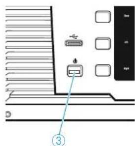
Diagram showing a device panel with labeled ports and a numbered annotation pointing to a component.Using the EM 9046 receiver
Switching the receiver on/off
To switch the receiver on:
Make sure the ON/OFF switch ① is set to position "1".
▶ Press the standby button ⏻ ③.
The receiver's operating system is loaded. During loading, the LED of the standby button ⏻ ③ flashes red and the display panel shows the Sennheiser start screen. Then, an automatic calibration of the cable attenuation is performed (see page 64).
Once the operating system is fully loaded, the receiver is in "live" operating mode.
To switch the receiver to standby mode:
Keep the standby button ⏻ ③ pressed for approx. 4 seconds until the display panel goes completely off.
The receiver is in standby mode. All the interferences levels recorded during the frequency scans are deleted. The activated booster frequency range and the frequency presets assigned to the channels are stored.
To completely switch the receiver off and disconnect it from the mains:
▶ Set the ON/OFF switch ① to position "0".
All daisy chained signals are interrupted, i.e.:
- the antenna signals at the daisy chain outputs ⑰ and ⑱,
- the booster supply voltage,
– the signal of the external word clock generator.
▶ Pull out the mains plug from the wall socket to completely disconnect the receiver from the mains.
"sys", "ch", "live" – operating modes at a glance
"live" operating mode – Live transmission
In this mode, you can check, among other things, the following parameters during transmission:
- R F l e v e l
• True bit diversity evaluation - Audio level
- Charge status of the BA/B 60/61 accupack/battery pack
- Remaining operating time of the BA 60/61 accupack
More information on the "live" operating mode can be found from page 84 onwards.
"ch" operating mode – Setting up channels
In this mode, you can configure channels on the receiver and then synchronize the transmitters and the receiver. More information on the "ch" operating mode can be found from page 76 onwards.
"sys" operating mode – Configuring the system
In this mode, you can configure transmitters and the receiver. More information on the "sys" operating mode can be found from page 55 onwards.
Basic functions of the Sennheiser operating menu
A special feature of the Sennheiser 9000 series is the straightforward, intuitive operating concept. As a result, you can act quickly and precisely – even in stressful situations, for example on stage or during a live show or presentation.
Selecting the operating mode
▶ Press the respective button to select the desired operating mode.
Calling up and selecting menu items, changing and storing settings, cancelling an entry
In "ch" and "sys" operating mode, the following operating elements are available:

Jog dial


▶ Turn the jog dial to select a different menu item or a different setting.
▶ Press the jog dial to call up a menu item or to confirm a selection.
▶ Turn the jog dial to select a different menu item or a different setting.
▶ Press the jog dial to call up a menu item or to confirm a selection.


esc button

▶ Press the save button ⑯ to store settings.
▶ Press the esc button to cancel entries.
Channel 1–8 button and multiple channel selection button +
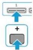
In addition, in "ch" operating mode, the channel 1–8 button ②3 and the multiple channel selection button + ②1 are available:
Select a channel or press the multiple channel selection button + ② and then select several channels simultaneously.
The channel 1–8 button ② and the multiple channel selection button + ② are also available in "live" operating mode.
Displays of the Sennheiser operating menu
The Sennheiser operating menu consists of the menu selection in the upper part, where you can select and call up menu items, and the main screen in the lower part:
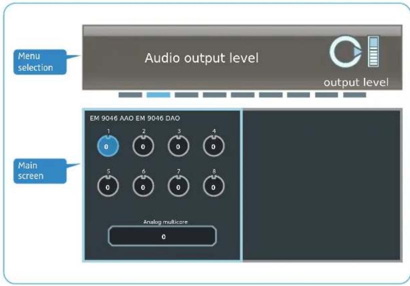
text_image
Audio output level output level Menu selection EM 9046 AAO EM 9046 DAO Main screen Analog multicare 0Menu selection
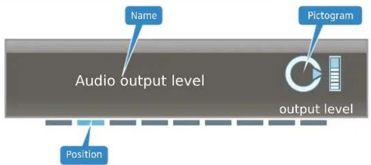
text_image
Name Audio output level Pictogram output level PositionThe name of the menu item, a pictogram and the position of the menu item in the current operating menu are displayed in the menu selection.
If you call up a menu item by pressing the jog dial ⑰, the menu selection is framed in blue:
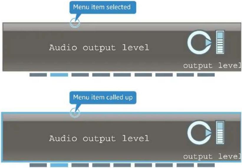
text_image
Menu item selected Audio output level output level Menu item called up Audio output level output levelWhen a menu item has only a few options to choose from, this can be done directly via the menu selection (see for example the "word clock" menu item on page 64).
When a menu item has extended options, the settings are adjusted on the main screen (here by way of example of the "Audio output level" menu item):
Main screen
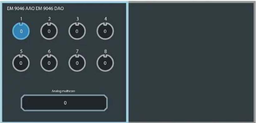
text_image
EM 9046 AAO EM 9046 DAO 1 0 2 0 3 0 4 0 5 0 6 0 7 0 8 0 Analog multimeter 0Error and warning messages
Error and warning messages are displayed in white letters. The display panel is highlighted in orange.
Example: "Frequency out of booster range" warning message
Frequency out of booster range
You can hide error/warning messages by pressing the esc button ②. In order to check if errors or warnings are still present, you can call up the "System check" menu item in the extended menu "Service setup" of the system menu. For more information, refer to page 70.
"sys" operating mode – Configuring the system
In "sys" operating mode, you can configure the transmitters and the receiver.
Overview of the "sys" menu
| Main menu “System setup” Page | |||
 | Frequency scan | Performs a frequency scan of all 8 frequency ranges | 56 |
 | Range detail scan | Performs a frequency scan of the active frequency rangeAssigns frequency presets to the channels | 60 |
 | Audio output level | Adjusts the output level 63 | |
 | Word clock Configures | the word clock 64 | |
 | Cable attn Displays | the cable attenuation between booster output and RF input of the EM 9046 and compensates for it | 64 |
 | Load config Loads a configuration 65 | ||
 | Save config Saves a configuration 65 | ||
| [6ZS3] | Network Configures | the network 66 | |
 | Brightness Adjusts the brightness 66 | ||
 | Screensaver | Selectable settings: ON/OFFThe default setting of the “Screensaver” menu item is ON | 67 |
 | Service setup | Calls up the extended menu “Service setup” | 56 |
| Extended menu “Service setup” Page | |||
 | System setup | Calls up the main menu“System setup” | 56 |
 | Factory reset | Loads the factory default settings | 68 |
 | Date & time | Adjusts the date and time | 69 |
| [XXCS] | Op hours | Displays the operating hours | 69 |
 | Log | Displays the event logs | 69 |
 | System check | Displays the system status | 70 |
| Extended menu "Service setup" Page | |||
| HW setup | Displays the hardware configuration and status | 70 | |
| vXX | Firmware Displays the firmware versions and updates the firmware of the transmitters and boosters | 73 | |
| Legal License and copyright information | 75 | ||
Main menu "System setup"
To get into the main menu:
▶ Select the "sys" operating mode.
"Frequency scan" – Performing a frequency scan of all 8 frequency ranges
The main menu contains two menu items that allow you to perform a frequency scan:
-
First, use the "Frequency scan" menu item to find and activate a suitable booster frequency range.
-
Then use the "Range detail scan" menu item to assign frequency presets from the activated booster frequency range to the channels. Optionally, you can perform a new frequency scan of the activated booster frequency range.
You can then adjust the settings to be transferred to your transmitters and synchronize the transmitters and the receiver via infra-red.
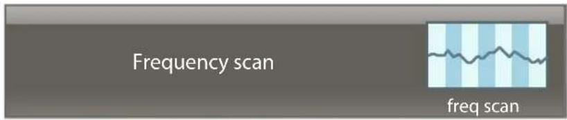
text_image
Frequency scan freq scanDuring the frequency scan ("Frequency scan" menu item), the interference levels received by the antennas are recorded and displayed for the booster frequency ranges 1 to 8.
Before performing a frequency scan, carry out the following steps:
Switch off all transmitters that you want to wirelessly connect to the EM 9046.
Switch on all possible sources of interference (e.g. light sources, intercom links, video walls) and all other transmission links.
To perform a frequency scan:
▶ Call up the "Frequency scan" menu item.
If a frequency scan has already been performed, the last activated booster frequency range is highlighted in blue.
▶ Turn the jog dial ⑰ until the text "start scan" at the bottom margin of the screen is highlighted in blue:
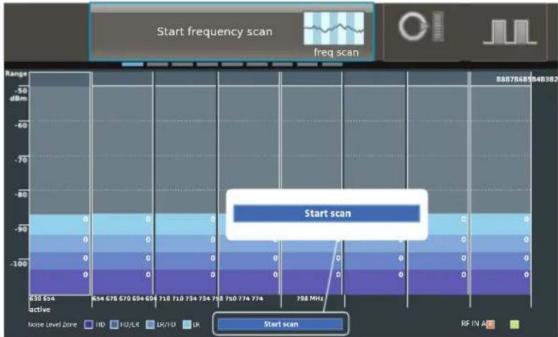
bar
| Frequency Band | Start scan (dBm) | |---|---| | 630-654 | -100 | | 634-678 | -90 | | 670-694 | -80 | | 694-728 | -70 | | 728-750 | -60 | | 750-774 | -50 | | 774-798 | -40 | | 798 MHz | -30 | | Range | -50 to -90 dBm | | Noise Level Zone: HD | -100 to -90 dBm | | Noise Level Zone: HD/LR | -100 to -90 dBm | | Noise Level Zone: LR/TO | -100 to -90 dBm | | Noise Level Zone: LR | -100 to -90 dBm | | RF IN AID: Start scan | 0 |▶ Start the frequency scan by pressing the jog dial ⑰. Please note: All audio outputs will be muted!
The duration of the frequency scan depends on the number of the built-in EM 9046 DRX receiver modules. The more modules you use, the faster the frequency scan is performed.
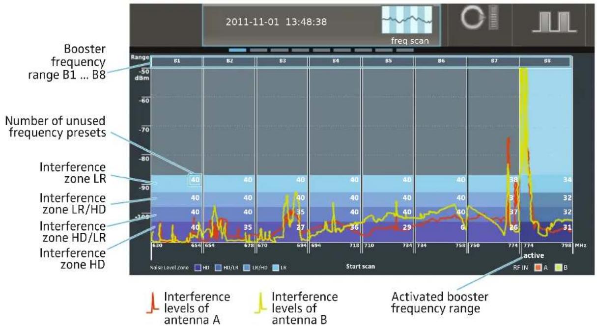
The interference levels received by the antennas are recorded and displayed. The interference levels are divided into four interference zones: "HD", "HD/LR", "LR/HD" and "LR". The lower the zone, the lower the received interference level.
In addition, the number of unused frequency presets is displayed per booster frequency range and per interference zone. The number of unused frequency presets depends on the number, the height and the frequency of the received interference levels.
The selection of a suitable booster frequency range depends on several factors:
- Required number of transmission links
- Sufficient number of unused frequency presets
- Sufficient number of transmitters of the correct type (in this example, transmitters of type B1–B4 or B5–B8, see page 39)
- Recommended transmission mode "HD" or "LR":
"HD (High Definition)": Transmission of an audio signal without audio data compression. As a result, the audio signal remains pure and unadulterated. In "HD" transmission mode, the range can be restricted compared to "LR" transmission mode.
"LR (Long Range)": Transmission of an audio signal whose bit rate is reduced – before transmission – by an audio data compression technique (SeDAC, Sennheiser Digital Audio Codec). This compression technique provides excellent audio quality and a large transmission range. The sensitivity to interference is reduced compared to "HD" transmission mode.
| Interference levels of antenna A/B in interference zone | [TYSC] "HD" | [KDZZ] "HD/LR" | [YSAW] "LR/HD" |  [4X8C] [4X8C] |
 |  |  |  |  |
* Transmission mode can be used with a restricted range
** It might be that the transmission mode can only be used with a severely restricted range
Let us assume that you want to set up 8 transmission links and transmit in "HD" transmission mode with the maximum possible transmission range.
Have a look at interference zone "HD" (see also above diagram): All booster frequency ranges except for B6 provide a sufficient number of unused frequency presets.
| Booster frequency ranges | B1 B2 B3 B4 B5 B6 B7 B8 |
| Number of unused frequency presets in interference zone “HD” | 40 35 27 36 29 6 26 31 |
| Can the booster frequency range be used? | √ √ √ √ √ - √ √ |
Example 1: 8 transmitters of type B1–B4
Let us assume that you have 8 transmitters of type B1-B4:
| Is there a sufficient number of transmitters of the correct type? | √ | √ | √ | √ | ---- |
You can use any of the booster frequency ranges B1–B4 but you should select the booster frequency range with the highest number of unused frequency presets: B1.
Example 2: 6 transmitters of type B1–B4, 8 transmitters of type B5–B8
Let us assume that you have only 6 transmitters of type B1–B4 but 8 transmitters of type B5–B8.
Is there a sufficient number of transmitters of the correct type?

The number of transmitters is sufficient but the booster frequency range B6 does not provide a sufficient number of unused frequency presets in interference zone "HD". You could therefore use the booster frequency ranges B5, B7 or B8 but you should select the booster frequency range with the highest number of unused frequency presets: B8.
In this example, there was a sufficient number of unused frequency presets available for interference zone "HD", allowing you to adjust the "HD" transmission mode for all channels. If this is not the case, you can, in a later step, also adjust the "LR" transmission mode for individual channels.
To activate the booster frequency range:
▶ Select a suitable booster frequency range by turning the jog dial ⑰. The frequency range is highlighted in blue.
▶ Activate the booster frequency range by pressing the jog dial ⑰. "active" appears below the activated booster frequency range (see above diagram). You can still change your selection by choosing a different booster frequency range and then pressing the jog dial ⑰ again.
▶ Finish the frequency scan and store the previously activated range by pressing the button ⑯.
▶ Assign frequency presets to the channels as described in the next section.
"Range detail scan" – performing an optional frequency scan of the active frequency range and assigning frequency presets to the channels
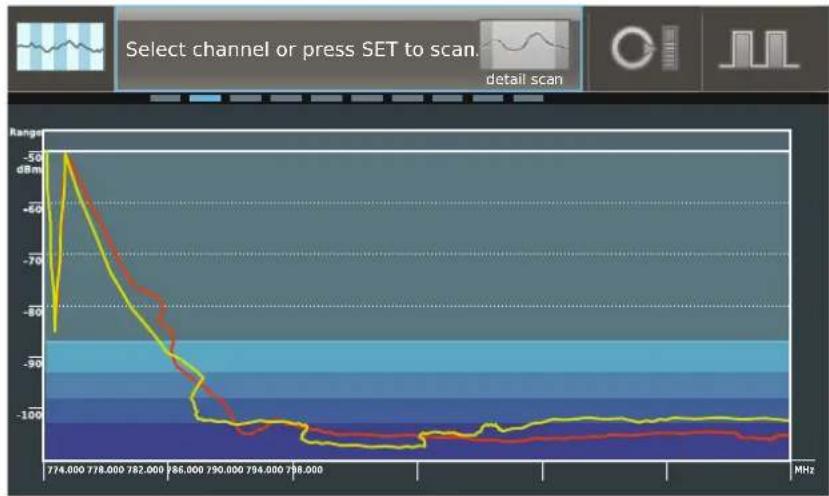
▶ Call up the "Range detail scan" menu item.
The activated booster frequency scan and the result of the last frequency scan ("Frequency scan" or Range detail scan") are displayed. "Select channel or press SET to scan" appears in the menu selection.
line
| Frequency (MHz) | Ranges (dBm) | | --------------- | ------------ | | 774.000 | -50 | | 778.000 | -60 | | 782.000 | -70 | | 786.000 | -80 | | 790.000 | -90 | | 794.000 | -100 | | 798.000 | -100 |You can now perform a new frequency scan of the activated booster frequency range (optional) or immediately assign frequency presets to the channels.
Performing a frequency scan
To perform a new frequency scan of the activated booster frequency range (optional):
▶ Start the frequency scan by pressing the jog dial ⑰. Please note: All audio outputs will be muted!
Assigning frequency presets to the channels
To assign frequency presets to the channels:
Select one of the channels 1–8 by pressing its channel button 23. A mark with a flag and a channel number appears.
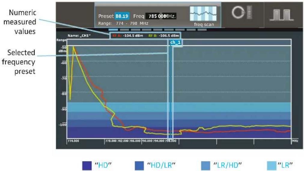
line
| Frequency (MHz) | Value (dBm) | | --------------- | ----------- | | 774,000 | -50 | | 778,000 | -90 | | 782,000 | -100 | | 786,000 | -100 | | 790,000 | -100 | | 794,000 | -100 | | 798,000 | -100 |Automatically selecting a frequency preset
There are three ways to assign a frequency preset or a frequency to a channel:
- You can automatically select the frequency preset with the lowest interference level. This is the quickest and most convenient way of assigning a frequency to a channel.
- You can manually select a frequency preset.
- You can manually set an arbitrary frequency.
To automatically select the frequency preset with the lowest interference level, proceed as follows:
▶ Turn the jog dial until "auto" appears.
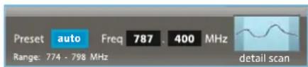
text_image
Preset auto Freq 787 . 400 MHz Range: 774 - 798 MHz detail scanAfter the frequency scan, the receiver automatically creates an ordered list containing the 32 frequency presets with the lowest interference levels. The frequency presets in the list are ordered according to increasing interference levels.
The first frequency level in the list has the lowest interference levels. The mark automatically snaps into position on this frequency preset and the corresponding frequency value is displayed.
The numeric values of the measured interference levels for antenna A and antenna B are additionally displayed at the top margin of the screen.
▶ Press the jog dial.
The selected channel is assigned the frequency preset with the lowest interference level.

Please note that the frequency presets are assigned in the order of increasing interference levels:
- The first channel is assigned the frequency preset with the lowest interference levels.
- The second channel is assigned the frequency preset with the next higher interference levels.
- The last channel is assigned the frequency preset with the highest interference levels.
You should therefore use the first channel for the most important transmission link in your multi-channel system.
Each new frequency scan creates a new frequency preset list.
Manually selecting a frequency preset
To manually select an unused frequency preset, proceed as follows:
▶ Move the mark by turning the jog dial ⑰.
The mark snaps into position on the frequency presets.
▶ Select a frequency preset.
The numeric values of the measured interference levels for antenna A and antenna B are additionally displayed at the top margin of the screen.
The interference levels of both antennas should be within or below the interference zone that is required or useful for this channel (see page 56 and 58) and should be as low as possible.
Manually setting a frequency
If you do not want to use a frequency preset but you want to set a frequency yourself, proceed as follows:
▶ Press the jog dial.
Each time you press the jog dial, you switch between
- the "Preset" settings,
– the frequency setting in MHz steps and
– the frequency setting in kHz steps.
▶ First set the frequency in MHz steps by turning the jog dial. Press the jog dial to confirm your setting.
▶ First set the frequency in kHz steps by turning the jog dial. Press the jog dial to confirm your setting.
Maintain a frequency spacing of at least 600 kHz in order to avoid intermodulation interference.
Please observe the flag position of the selected frequency preset: If the flag appears on the left or right margin and is pointing outwards, the frequency is outside the selected booster frequency range.
Assigning frequencies to the remaining channels
▶ Select the next channel 1 ... 8 by pressing the channel 1–8 button ^23 and proceed as described above.
All frequencies assigned to a channel are displayed by means of a mark with a flag and a channel number. If you have daisy chained several receivers (see “Daisy chaining receivers” on page 35), their frequency settings are also displayed in contrasting colors. This allows an overview over up to 32 channels.
Once you have selected a frequency preset for all desired channels, press the button 16.
Your settings are stored and the receiver switches to the main menu "System setup".
To switch to the main menu without storing your settings:
▶ Press the esc button ②.
To configure your transmitters:
Change to the "ch" operating mode on the EM 9046 (see page 76).
▶ Select one of the channels for which you have stored frequency presets.
▶ Call up the extended menu "Transmitter setup" and then call up the "RF mode" menu item.
Adjust the transmission mode ("HD" or "LR") depending on the interference zone of the channel (see also table on page 59).
Configure your channels as described from page 76 onwards.
▶ Synchronize the transmitters and the receiver as described on page 77.
▶ Repeat for the other channels.
▶ Perform a walk test to check the reliability of your transmission links (see page 80).
Change the transmission mode for the channels with reception problems and then synchronize the transmitters and the receiver again.
If the reception problems persist, select a different booster frequency range.
"Audio output level" – Adjusting the analog output levels

text_image
Audio output level output level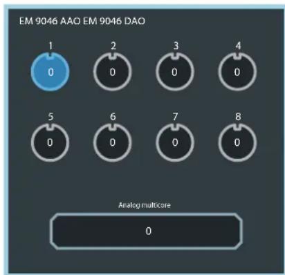
text_image
EM 9046 AAO EM 9046 DAO 1 0 2 0 3 0 4 0 5 0 6 0 7 0 8 0 Analog multicore 0
natural_image
Solid dark gray image with no visible content, text, or symbols.Via the "Audio output level" menu item, you can adjust the level of all or individual channels of the Analog Audio Out (AAO) module.
▶ Call up the "Audio output level" menu item.
The installed audio modules are displayed as follows:
- digital audio modules: "Slot digital";
- analog audio modules: "Slot analog";
- not installed audio modules: "Slot not available".
▶ Select individual or all channels of the AAO module by turning the jog dial to the left/right. Selected channels are highlighted in blue.
▶ Call up the level adjustment by pressing the jog dial. The outer ring of the channel is highlighted in blue.


If you call up the level adjustment of all channels, the smallest value adjusted for a channel is displayed in the menu selection. By turning the jog dial, you can adjust the level of all channels to the value displayed in the menu selection.
Adjust the level.
The setting becomes effective immediately.
▶ Press the jog dial to confirm your setting and to return to the channel selection.
Adjust the level of further channels.
Press the save button ⑯. Your settings are stored and the receiver then switches to the main menu.
To change to the main menu without storing your settings:
▶ Press the esc button 22.
"Word clock" – Configuring the word clock
internal: 44.1kHz

word clock
Via the "word clock" menu item, you can ...
- switch between the following word clock signals:
- internally generated word clock signal
- external word clock signal
– word clock signal of a built-in MAN card
- adjust the sampling rate (44.1 kHz, 48.0 kHz, 88.2 kHz or 96.0 kHz) with which – with an internally generated word clock signal – analog signals are digitalized and output at the XLR-3 sockets ^⑪ .
"Cable attn" – Displaying the cable attenuation and automatically compensating for it
RF IN A:
OK
RF IN B:
OK

cable attn
The EM 9046 receiver measures the cable attenuation between the antenna boosters and the antenna inputs 15 and 16 and automatically compensates for it:
• during the boot routine
- if both antenna boosters are connected or replaced
If only one antenna booster is connected or replaced, the cable attenuation will not be measured.
To manually initiate the compensation of the cable attenuation:
In "sys" operating mode, turn the jog dial until "cable attn" appears.
Press the jog dial. "Press SAVE to calibrate" is displayed on the display panel.
Pres the button. During the measurement, the channel status display ⑪ displays "Calibrating" for each channel. The receiver is muted for approx. 10 seconds. Then the result of the measurement is displayed as follows:
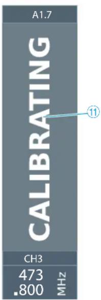
text_image
A1.7 CALIBRATING CH3 473 ■800 MHZ ⑪Display Status of the cable attenuation
"ok" The cable attenuation has been measured and is automatically compensated for.
"Too high" The cable attenuation has been measured and is too high. It cannot be automatically compensated for. The reception of weaker signals is compromised.
▶ Check and optimize the installation between the EM 9046 and the antenna boosters.

Always use GZL 9000 system cables to obtain optimum attenuation values.
"Load config" – Loading a configuration

text_image
defaults modified load configThe "load config" menu item allows you to load up to 10 saved settings of your system configuration (see also the "save config" menu item).
In addition, you can ...
- load the last configuration saved ("last").
- load the default configuration ("defaults"). In this case, the settings of the menu items mentioned in the section "save config" are reset to their factory defaults.
"Save config" – Saving a configuration
Via the "save config" menu item, you can save your system configuration on up to 10 storage memories.
The settings of the following menu items are saved:
| Menu Menu item Page | ||
| Main menu“System setup” | Output level 63 | |
| Word clock 64 | ||
| Network | name of the network 66 | ||
| Network | IP settings 66 | ||
| Brightness 66 | ||
| Extended menu“Service setup” | Date & time | selected time zone | 69 |
| Main menu“Channel setup” | Frequency 77 | |
| Name 78 | ||
| Cmd mode 78 | ||
| Encryption 79 | ||
| Gain 82 | ||
| Low cut 82 | ||
| Display 83 | ||
| Lock 83 | ||
| Cable 83 |
The following settings/values are not saved:
- time and date settings of the "Date & time" menu item (see page 69) and
- operating hours (displayable via the "op hours" menu item, see page 69).
"Network" – Configuring the network

text_image
Name EM 9046 IPv4 address 169.254.92.238 network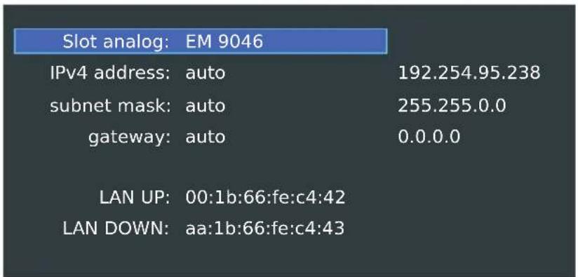
text_image
Slot analog: EM 9046 IPv4 address: auto 192.254.95.238 subnet mask: auto 255.255.0.0 gateway: auto 0.0.0.0 LAN UP: 00:1b:66:fe:c4:42 LAN DOWN: aa:1b:66:fe:c4:43Via the "Network" menu item, you can assign the receiver a network name and select whether to obtain an IP address automatically or to enter the IP address manually. In addition, this menu item displays the unchangeable MAC addresses of the network interfaces of your receiver.
"Brightness" – Adjusting the brightness

text_image
brightnessVia the "Brightness" menu item, you can adjust the brightness in 8 steps. This also adjusts the brightness of the LED lighting.
"Screensaver"

The "Screensaver" menu item adjusts the "Brightness" to the lowest (menu-selectable) value, independent of the user-set "Brightness" value.
The "Screensaver" is activated after 30 minutes if the following conditions are met:
- The "Screensaver" menu item is set to ON.
- No entry via button or jog dial for 30 minutes.
- No RXD card connected to a transmitter for 30 minutes.
The described "Screensaver" state is deactivated and the 30 minutes timer is restarted if:
- a button is pressed (the function of the button is also performed)
- the jog dial is turned or pressed (the function of the jog dial is also performed)
- the Standby button ⏻ ③ is pressed
- a transmitter is switched on and its signal is received by an RXD card. The timer remains deactivated as long as the RXD card is connected to the transmitter
- an error message is displayed over the whole screen. The timer remains deactivated until the error message is confirmed and is quit using the esc button ②
The described screensaver state remains unchanged if:
- the headphone volume control is turned, i.e. the "Screensaver" remains active and the screen will not brighten since the headphone volume control is considered a pure volume control not related to the screen
The "Screensaver" timer is inactive as long as one of the following conditions is met:
- The "Screensaver" menu item is set to OFF.
- An RXD card is connected to a transmitter.
- An error message is displayed over the whole screen.
Extended menu "Service setup"
To get into the extended menu "Service setup":
In "sys" operating mode, turn the jog dial until "Service setup" appears.
▶ Press the jog dial.
The extended menu "Service setup" appears.
To change from the extended menu back to the main menu:
▶ Turn the jog dial until "System setup" appears.
▶ Press the jog dial.
You are back to the main menu "System setup" of the "sys" operating mode.
In the extended menu, you can adjust the following settings:
"Factory reset" – Resetting the receiver to the factory defaults
Factory reset

factory reset
Via the "factory reset" menu item, you can reset your receiver to the factory default settings. To do so, follow the prompt on the main screen to press the button 16 for 5 seconds.
The following menu items are reset to their factory default settings:
| Menu | Menu item | Factory default setting | Page |
| Main menu “System setup” | Output level 0 dB 63 | ||
| Word clock 96 kHz 64 | |||
| Network | name of the network | EM9046_1 66 | ||
| Network | IP settings | Auto 66 | ||
| Brightness Medium level 66 | |||
| Extended menu “Service setup” | Date & time | selected time zone | Amsterdam, Berlin, Bern, Rome, Stockholm, Vienna | 69 |
| Main menu “Channel setup” | Frequency | Without connected boosters: 470.000 MHzWith connected boosters: A1.1-A1.8 or B1.1-B1.8, allocated to the channels 1-8 | 77 |
| Name | Ch1-Ch6 | 78 | |
| Cmd mode Toggle | 78 | ||
| Encryption Off | 79 | ||
| Gain | 0 dB 82 | ||
| Low cut | 30 Hz | 82 | |
| Display | Name | 83 | |
| Lock | Off | 83 | |
| Cable | Line | 83 | |
- In addition, all configurations saved in the "save config" menu item are deleted.
- The event log is deleted and then the deleting itself is logged.
The following settings/values are not deleted:
- time and date settings of the "Date & time" menu item (see page 69) and
- operating hours (displayable in the "op hours" menu item, see page 69).
"Date & time" – Adjusting the date and time

text_image
16:30:41 2011-06-14 date & timeVia the "Date & time" menu item, you can select your time zone and then adjust the date and time:

text_image
Timezone Dublin, Edinburgh, Lisbon, London Network time: on Date: 2011-07-25 Time: 15:46:32"Op hours" – Displaying the operating hours

text_image
20 h 00:00 op hoursThe "op hours" menu item displays the operating hours of the EM 9046.
"Logfile" – Displaying the event logs

text_image
Logfile logThe EM 9046 receiver logs user actions and erroneous and suspicious system states. The log records the last 1000 events.
The log entries contain the following information:
- Timestamp ( format "YYYY-MM-DD hh:mm:ss")
- Degree of severity ("info", "warning" or "error")
- Message
The following events are logged:
- System starts and (controlled) stops
- System error messages (error screens)
- Channel warnings
• Each synchronization with a transmitter - Software updates
• Each storing of settings with specification of the changed values
• Each modification of values via the WSM software
"System check" – Displaying current error and warning messages

text_image
System check: system checkVia the "system check" menu item, you can display current error and warning messages.
If, for example, a booster is removed during operation or if it is missing when the EM 9046 is started, the following warning message appears:

text_image
RF-IN B: no booster connectedIf you hide this warning message by pressing the esc button ②, the missing booster continues to be displayed in the "system check" menu item.
The menu selection changes its appearance when a warning message is present:
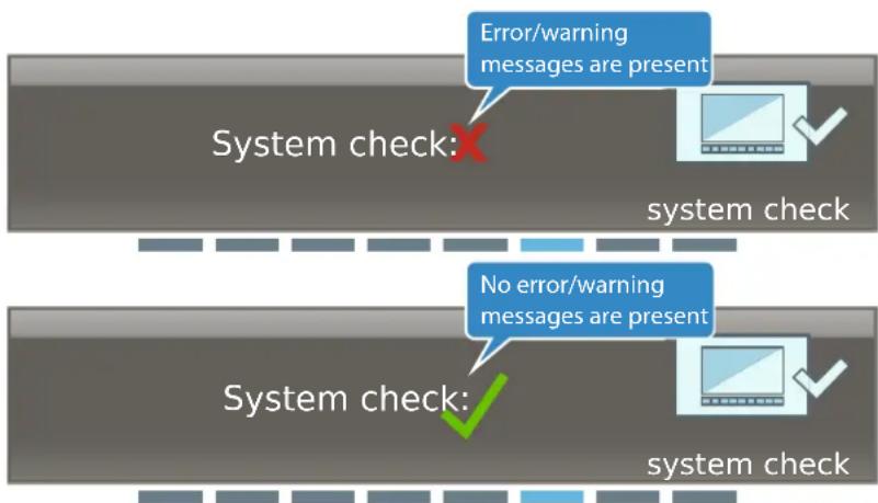
text_image
Error/warning messages are present System check: No error/warning messages are present System check: system checkCall up this menu item to get detailed information on error and warning messages.
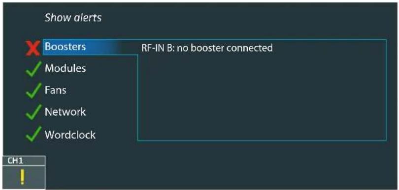
text_image
Show alerts Boosters RF-IN B: no booster connected ✓ Modules ✓ Fans ✓ Network ✓ Wordclock CH1If you call up the first menu entry "Show alerts", the warning message is displayed again and the display panel is highlighted in orange.
"Hw setup" – Displaying the EM 9046's hardware configuration and confirming a modified configuration
Modules ok

Hw setup
While the operating system of the EM 9046 starts up, it checks the receiver's hardware configuration for modifications. Modifications of the hardware configuration are indicated by warning messages.
If, for example, a DAO module has been removed, the following warning message appears:
Modules missing
If you hide this warning message by pressing the esc button ②, the missing module is displayed in the "hw setup" menu item with the status "missing":
Hardware setup
Press SET to confirm
Slot
Module
type
RX1 EM 9046 DRX ok
RX2 EM 9046 DRX ok
RX3 EM 9046 DRX ok
RX4 EM 9046 DRX ok
RX5 EM 9046 DRX ok
RX6 EM 9046 DRX ok
RX7 EM 9046 DRX ok
RX8 EM 9046 DRX ok
OUT1 EM 9046 AAO ok
OUT2 EM 9046 DAO missing
If you have extended the EM 9046's hardware configuration, this is displayed in the "hw setup" menu item with the status "added":
| Slot | Module | Type |
| RX1 EM 9046 DRX ok | ||
| RX2 EM 9046 DRX ok | ||
| RX3 EM 9046 DRX ok | ||
| RX4 EM 9046 DRX ok | ||
| RX5 EM 9046 DRX ok | ||
| RX6 EM 9046 DRX ok | ||
| RX7 EM 9046 DRX ok | ||
| RX8 EM 9046 DRX ok | ||
| OUT1 EM 9046 AAO ok | ||
| OUT2 EM 9046 DAO added |
In both cases, the "Press SET to confirm" button is highlighted in blue.
In the "hw setup" menu item, you confirm modifications as follows:
▶ Press the jog dial.
The "Press SET to confirm" button is framed in blue and "Press save to confirm hw setup" appears in the menu selection.
▶ Press the button ⑯.
"Firmware" – Displaying the hardware versions/firmware versions and updating the firmware
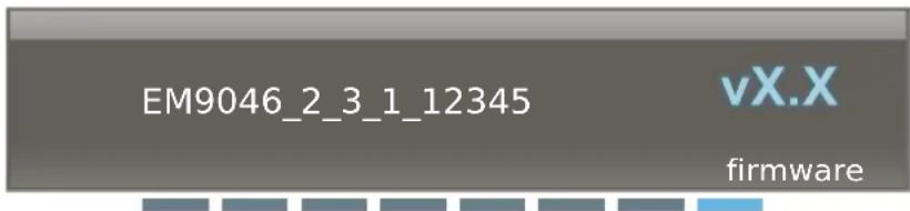
text_image
EM9046_2_3_1_12345 vX.X firmware| Antenna booster Update to firmware: 10-11-30-11 RF IN A: AB9000_2 Firmware: 10-08-10-10 RF IN B: AB9000_2 Firmware: 10-08-10-10 | Transmitter Start update Transmitter: Firmware: New firmware |
If you update the EM 9046 receiver's firmware using the WSM software, the current firmware versions of the 9000 series boosters and transmitters are also stored on the receiver.
Via the "Firmware" menu item, you can display the firmware versions of the receiver, the boosters and the transmitters and update the firmware of the boosters and the transmitters.
The currently installed firmware version of the EM 9046 is displayed in the menu selection (see above).
The currently installed firmware version and the installable firmware ("Update to Firmware") of connected boosters/transmitters are displayed in the "Antenna Booster" area of the main screen.
To update the firmware of the boosters:
Using the jog dial, select the "Antenna Booster" area of the main screen. The "Antenna Booster" area is highlighted in blue.
▶Press the jog dial.
The firmware is updated. The update process can take up to 40 seconds.
Do not interrupt the transmission during the update process.
To read out and, if necessary, update the firmware of your transmitters:
Make sure the accupacks of your transmitters are fully charged.
Using the jog dial, select the "Transmitter" area of the main screen. The "Transmitter" area is highlighted in blue.
▶Press the jog dial.
The infra-red interface ^14 is activated and flashes blue, the “Start update” menu entry is highlighted in blue:
| Antenna booster Update to firmware: 10-11-30-11 RF IN A: AB9000_2 Firmware: 10-08-10-10 RF IN B: AB9000_2 Firmware: 10-08-10-10 | Transmitter Start update SCAN MODE Transmitter: ... Firmware: ... New firmware ... |
Place the infra-red interface of a transmitter in front of the infra-red interface ⑭ of the EM 9046.
The currently installed firmware version of the transmitter and the installable firmware are displayed.
▶ Press the jog dial.
First, the transmitter is read out and "Scanning transmitter ..." appears in the menu selection of the receiver's display panel. Then, the transmitter firmware is updated: the infra-red interface flashes faster, "Updating transmitter ... (ca. xx s)" appears in the menu selection of the receiver's display panel together with a time specification in seconds. Do not interrupt the transmission during the update process.
During the update, the following icon appears on the display panel of your transmitter:

If the firmware update was successful, this icon disappears and "Transmitter fw update successful" appears in the menu selection of the receiver's display panel.
If the update fails, the following icon appears on the display panel of your transmitter:

FAIL
In addition, the error message "Error: Transmitter fw update failed" briefly appears in the menu selection of the receiver's display panel.
In this case, place the infra-red interface of the transmitter in front of the infra-red interface ^14 of the EM 9046 and update the transmitter firmware without interrupting the infra-red transmission.
To read out and, if necessary, update the firmware of additional transmitters:
Place the infra-red interface of the transmitters in front of the infra-red interface ^14 of the EM 9046, one after the other, and proceed as described above.
To return to the main menu:
▶ Press the esc button 22.
"Legal"
Here license and copyright information on the software used in the EM 9046 are shown. The license and copyright information are shown in the display of the EM 9046.
Source code
You can request the source code of the software free of charge by sending an e-mail to opensource@sennheiser.com, in so far as the respective license information grants the provision of the source code.
"ch" operating mode – Configuring channels
In "ch" operating mode, you can configure channels. Some of the settings that can be made can be synchronized via infra-red between the receiver and the transmitters. These settings are marked with a in the syncumn (see also next page).
In "ch" operating mode, you can also select channels for headphone monitoring. To do so, proceed as described on page 84.
Overview of the "ch" menu
| Main menu “Channel setup” Page | sync | |||
 | Frequency | Selects a frequency preset or sets the frequency manually | √ | 77 |
 | Name Enters a | channel name 78 | √ | |
 | CMD mode | Configures audio and command outputs | 78 | |
 | Ch standby Mutes the channels 79 | |||
 | Encryption | Binds the audio signal to the receiver and protects against eavesdropping | √ | 79 |
 | RF level rec | Records the antenna signals and the diversity evaluation | 80 | |
 | Transmitter setup | Calls up the extended menu “Transmitter setup” | - | |
| Extended menu “Transmitter setup” Page | sync | |||
 | Channel setup | Calls up the main menu “Channel setup” | - | |
 | RFmode | Adjusts the transmission mode | √ | 82 |
 | Gain | Adjusts the transmitter's input gain | √ | 82 |
 | Low cut | Sets the transmitter's low-cut filter | √ | 82 |
 | Display | Selects the transmitter's standard display | √ | 83 |
 | Lock | Activates/deactivates the transmitter's lock mode | √ | 83 |
 | AF source Displays the microphone head (SKM)/audio source and cable emulation (SK) | 83 | ||
 | Cable | Emulates different instrument cable lengths (SK) | √ | 83 |
To synchronize the settings with your transmitters via infra-red:
▶ Select one of the channels 1–8.
▶ Switch on the transmitter to which you want to assign this channel.
▶ Press the sync button ⑳ on the EM 9046.
The receiver switches to synchronization mode and the sybC ^12 flashes.
Place the transmitter's infra-red interface in front of the infra-red interface ^14 of the receiver. Maintain a distance of approx. 10–20 cm between the infra-red interfaces.
The transmitter and receiver are synchronized:
- After pressing the sync button ⑳, the receiver's infra-red interface searches for a suitable transmitter infra-red signal for 12 seconds.
- You can interrupt the synchronization at any time by pressing the sync button ⑳ again.
- If a problem occurs during the synchronization process, read the chapter "If a problem occurs ..." on page 110.
▶ Repeat the above steps for the remaining transmitters.
Main menu "Channel setup"
To get into the main menu:
▶ Select the "ch" operating mode.
▶ Select one or several channels (see page 52).
▶ Call up the menu items described in the following and adjust your settings.
If no channel is selected, "Please select Channel" is displayed in the menu selection.
▶ Press the button to store your settings.
▶ Synchronize your settings via infra-red (see page 77).
"Frequency" – Selecting a frequency preset or setting a frequency manually syn
Preset A1.1 Freq 470.200 MHz
Range: 470 - 494 MHz
MHz
frequency
Via the "Frequency" menu item, you can select a frequency preset for the active booster frequency range or set the frequency manually. In the above diagram, range "A1" is active. The frequency range is from "470-494 MHz". For information on how to activate a booster frequency range, refer to page 59.
Either select a frequency preset ("A1.1" ... "A1.40" in the above diagram) or set the frequency manually ("U"). If you set the frequency manually, make sure to set a frequency within the current 24 MHz booster frequency range and maintain a frequency spacing of 600 kHz to avoid intermodulation interference.
If you manually set the frequency to a value outside the current 24 MHz booster frequency range and confirm you setting by pressing the save button 16, the following error message appears:

text_image
Frequency out of booster range
"Name" – Entering a channel name syn

text_image
G U I T A R 1 ABC nameVia the "Name" menu item, you can enter freely selectable names. The channel name can consist of up to 8 characters from the following character set:
+','-'|/'0'1'2'3'4'5'6'7'8'9'*';'<='='space'#A'B'C'D'E'F'G'H'I'J'K'L'M'MN'O'P'Q'R'S'T'U'V'W'X'Y'Z
"Cmd mode" – Configuring the audio and command outputs

text_image
toggle cmd modeYou can use the command function e.g. for stage directions.
For this, you require the SKM 9000 COM radio microphone or the SK 9000 bodypack transmitter together with the KA 9000 COM command adapter.
By pressing the COMMAND button on the SKM 9000 COM or KA 9000 COM, you can influence the routing of the audio signal of the receiver's XLR-3 sockets ⑬ and sub-D socket ⑭.
The following settings are possible:
| Setting Effect | |
| “on” | The transmitter’s audio signal is output via both its audio channel (XLR-3 sockets 13 1 ... 8) and the corresponding channel of the sub-D socket 14. Pressing the COMMAND button on the SKM 9000 COM or KA 9000 COM has no effect. |
| “add” | The transmitter’s audio signal is output via its audio channel (XLR-3 sockets 13 1 ... 8). Pressing the COMMAND button on the SKM 9000 COM or KA 9000 COM has the effect that the audio signal is additionally output via the corresponding channel of the sub-D socket 14. |
| “mute” | The transmitter’s audio signal is output via both its audio channel (XLR-3 sockets 13 1 ... 8) and the corresponding channel of the sub-D socket 14. Pressing the COMMAND button on the SKM 9000 COM or KA 9000 COM mutes both the audio channel (XLR-3 sockets 13 1 ... 8) and the corresponding channel of the sub-D socket 14. |
| “toggle” | The transmitter’s audio signal is output via either its audio channel (XLR-3 socket 13 1 ... 8) or the corresponding channel of the sub-D socket 14. Pressing the COMMAND button on the SKM 9000 COM or KA 9000 COM switches between the two channels. |
"Ch standby" – Muting channels

text_image
Ch standby ch standbyThe "Ch standby" menu item allows you to mute selected channels. When muted, the channels do not output any audio signal, neither via the Analog Audio Out (AAO)/Digital Audio Out (DAO) modules, nor via headphones.
"Encryption" – Binding the audio signal to the EM 9046 receiver sync

text_image
off encryptionVia the "Encryption" menu item, you can protect the audio signal against eavesdropping from other receivers by binding the transmitters to the EM 9046 receiver. In this case, other receivers can receive the RF signal of the transmitters but cannot evaluate the audio signal.
To protect the audio signal against eavesdropping from other receivers:
In the "Encryption" menu item, select "On" and press the save button to store your setting.
▶ Synchronize the setting via infra-red (see page 77).
"RF level recorder" – Recording the antenna signals and the diversity evaluation (walk test)
RF level recorder

rf level rec
The "RF level recorder" menu item allows you to record the antenna signals and the diversity evaluation (walk test) in order to check the reception quality of your transmission link within the operating environment.
Before performing the walk test, switch on all possible sources of interference (e.g. light sources, intercom links, video walls) and all other transmission links.
Switch on all transmitters that you want to use for the walk test.
Change to the "ch" operating mode on the EM 9046.
▶ Establish transmission links between the channels of the EM 9046 and the transmitters.
▶ Select a channel and call up the "RF level recorder" menu item.
▶ Start the walk test by pressing the jog dial.
- You can cancel the walk test at any time by pressing the button ⑯ or the esc button ⑫ on the EM 9046. In doing so, the recorded data is deleted.
- Use one or several transmitters to walk the operating environment. While performing the walk test, the diversity evaluation and the antenna signals for all channels are recorded. You can switch between the channels by pressing one of the channel 1 to 8 buttons ②3.
- If you are using an SKM 9000 COM or an SK 9000 together with the KA 9000 COM command adapter, you can set markers by pressing the COMMAND button at critical locations.
- You can additionally activate the 1 kHz test tone on your transmitter (see page 90 and page 99) and monitor the signal quality of the test tone via loudspeakers while walking the operating environment.
- If you perform the walk test as a pair, the second person can monitor the signal quality of the test tone by means of headphones connected to the EM 9046.
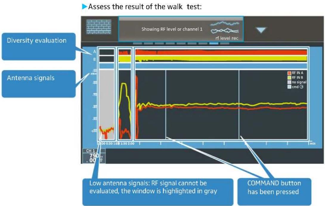
text_image
Assess the result of the walk test: Diversity evaluation Antenna signals Low antenna signals: RF signal cannot be evaluated, the window is highlighted in gray COMMAND button has been pressedInterference due to extraneous RF signals and low antenna signals can impede the evaluation of a transmitter's RF signal. In this case, the window displaying the recorded antenna signals is highlighted in light gray.
▶ Reposition the antennas to minimize interference and to optimize the reception of transmission signals.
▶ Call up the "RF level recorder" menu item again and repeat the walk test.
Extended menu "Transmitter setup"
Via the extended menu "Transmitter setup", you can adjust the transmitter settings and then synchronize them via infra-red.
The menu items allow you to adjust settings over the entire value range of the Digital 9000 transmitters. Please note, however, that the actual values are determined by the hardware configuration of your transmitters (frequency range, type of microphone head being used (SKM), type of Sennheiser microphone or cable being used (SK), etc.).
If you adjust settings that are not supported by the transmitters' current hardware configuration, the value actually adopted by the transmitter is written back to the menu item of the extended menu "Transmitter setup".
If you transfer a frequency range that is not supported by your transmitter, "Sync Fail" is displayed in the menu selection of the receiver's display panel.
Modifications made via the "Transmitter setup" menu item of the EM 9046 must be synchronized via infra-red.
Modifications made directly on the transmitters have direct effect on the menu items of the extended menu "Transmitter setup" of the EM 9046.
For details on the adjustment ranges of your transmitters, refer to the description of the transmitters' operating menu.
"RF mode" – Adjusting the transmission mode sync
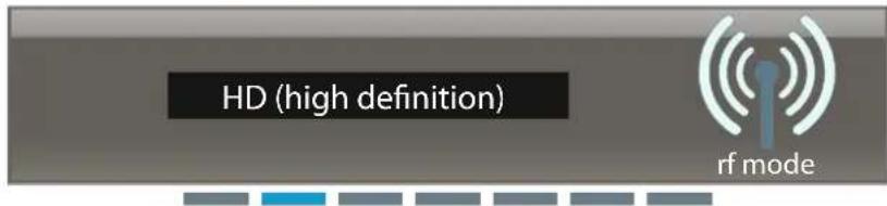
text_image
HD (high definition) rf modeThe "RF mode" menu item allows you to adjust the transmission mode:
"HD (High Definition)": Transmission of an audio signal without audio data compression. As a result, the audio signal remains pure and unadulterated. In "HD" transmission mode, the range can be restricted compared to "LR" transmission mode.
"LR (Long Range)": Transmission of an audio signal whose bit rate is reduced – before transmission – by an audio data compression technique (SeDAC, Sennheiser Digital Audio Codec). This compression technique provides excellent audio quality and a large transmission range. The sensitivity to interference is reduced compared to "HD" transmission mode.
The selection of the transmission mode depends on the result of the frequency scan. For more information, refer to the chapter "Frequency scan" – Performing a frequency scan of all 8 frequency ranges from page 56 onwards.
"Gain" – Adjusting the input gain sync

text_image
0 dB gainThe "Gain" menu item allows you to adjust the input gain of selected channels, independent of whether the transmitter to be synchronized supports the adjusted value. The factory preset is -6 dB. The adjustment range is from -6 dB to +60 dB.
After synchronization with the transmitter, the value actually adopted by the transmitter is written back to the menu item.
If you select "line" in the "Cable" menu item (see page 83), the input gain in the "Gain" menu item is set to the fixed value of -6 dB.
"Low cut" – Setting the low-cut filter syn

text_image
Hz30 low cutVia the "Low cut" menu item, you can set the transmitter's low-cut filter. Possible settings: 30 Hz to 120 Hz.
You can adjust this setting independent of whether the transmitter to be synchronized supports the adjusted value.
After synchronization with the transmitter, the value actually adopted by the transmitter is written back to the menu item.
"Display" – Selecting the standard display for the transmitters sync

text_image
frequency displayThe "Display" menu item allows you to activate one out of 3 standard displays: "Name", "Preset" or "Frequency". The "Name" standard display is factory preset.
"Lock" – Activating/deactivating the lock mode sync

text_image
off lockVia the "Lock" menu item, you can activate or deactivate the lock mode for your transmitters.
"AF source" – Displaying the audio source

text_image
SK 9000 line af sourceThe "AF source" menu item allows you to display the type of microphone head being used (SKM), the type of audio source being used (SK: "micro", "line") and the emulation of instrument cables (SK: "type1", "type2", "type3"). This information is transmitted along with the SKM/SK 9000's RF signal to the receiver.
The information is displayed until the transmitter is switched off or the carrier frequency is changed. When the SKM/SK transmits again on the carrier frequency, the corresponding microphone head/audio source is displayed once again in the menu item.
If a transmitter is switched off or transmits on a different carrier frequency, "No TX detected" is displayed.
"Cable" – Emulating different instrument cable lengths sync

text_image
type1 cableVia the "Cable" menu item, you can emulate the lengths of instrument cables in 3 steps: "type1", "type2" and "type3". If you select "line", no emulation takes place.
"live" operating mode – Using a configured system
In "live" operating mode, you can select channels for headphone monitoring and synchronize the transmitters and the receiver.
To prepare headphone monitoring:
Connect headphones as described on page 38.
▶ Observe the warnings given there.
To select channels for headphone monitoring:
▶ Select a channel by pressing the channel 1–8 button ② or press the multiple channel selection button + and then select several channels simultaneously.
If you have daisy chained several receivers (see "Daisy chaining receivers" on page 35), you can monitor any channel of the daisy chain via any headphone socket in the daisy chain.
In "live" operating mode, you can also activate channels for synchronization:
▶ Select a channel by pressing the channel 1–8 button ② .
▶ Proceed as described on page 77.
Channel 1–8 button and multiple channel selection button +
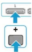
Digital 9000
Using the SKM 9000
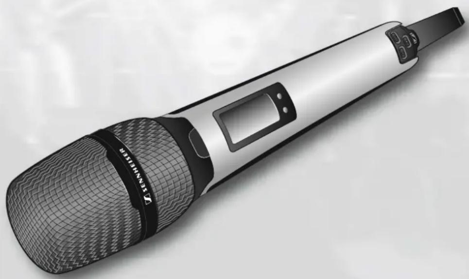
natural_image
Illustration of a modern wireless microphone with mesh grille and black handle (no text or symbols)Using the SKM 9000 85
Switching the SKM 9000 on/off 86
Activating/deactivating the automatic lock mode
(Autolock) 87
Basic functions of the Sennheiser operating menu. 88
Overview of the status displays 88
Overview of the menu items 89
Using the SKM 9000

Before using your radio microphone, ask the relevant wireless regulatory authority for the exact frequency allocations and apply for an individual license if necessary.
The supplied supplement "Framework requirements and restrictions on frequency usage in Europe" provides an overview of the different European framework requirements and restrictions on frequency usage. If there is no entry in the supplement, ask the relevant wireless regulatory authority for the current rules governing frequency usage.
Switching the SKM 9000 on/off

When the SKM 9000 is switched on for the first time, it contains the first frequency preset of the transmitter frequency range (e.g. A1.1:470.200 MHz). Via the "ch" menu of the EM 9046 receiver, set the desired frequency preset and adjust the settings of other menu items and then synchronize the transmitter and the receiver (see page 77). In doing so, all frequency presets of the transmitter frequency range will be transferred to the SKM 9000.
We recommend you to always adjust the transmitter settings via the EM 9046 receiver and then to synchronize the transmitter and the receiver.
To switch the SKM 9000 on:
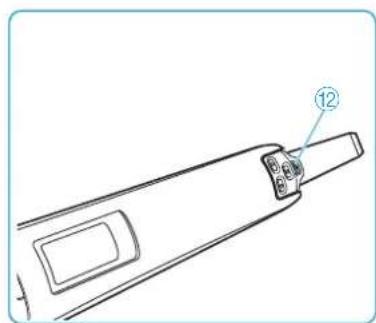
natural_image
Technical line drawing of a mechanical component with labeled part (12), no readable text or symbols presentKeep the ON/OFF button ☑ ⑫ pressed until the Sennheiser logo appears on the display panel ⑤.
The ON/OFF button ☐ is backlit in blue and the standard display (here: "Frequency", see page 90) appears on the display panel ⑤. The radio microphone transmits an RF signal and the transmission mode display "HD"/"LR" lights up constantly:
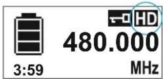
text_image
3:59 480.000 MHzTo switch the SKM 9000 off:
Keep the ON/OFF button ☐ ⑫ pressed until the display panel goes off.
Remove the accupack/battery pack when the radio microphone will not be used for extended periods of time (see page 40).
To switch the SKM 9000 off with the lock mode activated:
▶ Press t he ON/OFF button ☐ ⑫ while the standard display is shown. "LOCK" appears on the display panel because the lock mode is activated.
▶ Press the UP button ▲ or the DOWN button ▼.
"UNLOCK" appears on the display panel.
▶ Press the SET button 🔒.
The lock mode is temporarily deactivated, the lock mode icon ⑤ flashes.
▶ Within the next 2 seconds, press the ON/OFF button ☐ and keep it pressed until the display panel goes off.
If you switch on the SKM 9000, the lock mode is activated again.
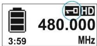
text_image
3:59 480.000 MHzSwitching on the SKM 9000 on and checking the set frequency before the RF signal is activated
Switch on the SKM 9000 by keeping the ON/OFF button ☑ ⑫ pressed until the "Name" standard display appears.
The RF signal is not activated and the transmission mode display "HD"/"LR" flashes.
If you call up the "Tune" or "Preset" menu item within the next 10 seconds, the RF signal remains deactivated until you exit the menu item. If you do not call up one of the mentioned menu items, the RF signal is automatically activated after 10 seconds.
To check the set frequency/the selected frequency preset:
▶ Call up the operating menu and press the UP button ▶/DOWN button ◀ until the "Tune" or "Preset" menu item appears.
The set frequency/the selected frequency preset is displayed.
If the displayed value is the desired one:
▶ Wait for 10 seconds to pass.
The RF signal is automatically activated and the transmission mode display "HD"/"LR" lights up constantly.
If the displayed value is not the desired one:
▶ Call up the "Tune" or "Preset" menu item.
The RF signal remains deactivated until you exit the menu item.
The RF signal remains deactivated until you exit the menu item.
▶ Set the frequency ("Tune" menu item) or select a frequency preset ("Preset" menu item) and store your setting.
The RF signal is activated and the radio microphone transmits an RF signal on the set frequency.
Activating/deactivating the automatic lock mode (Autolock)
The radio microphone has an automatic lock mode that can be activated or deactivated via the "LOCK" menu item (see page 87).
To permanently activate the automatic lock mode:
▶ Call up the "LOCK" menu item and select "On".
Store your setting by pressing the SET button.
The automatic lock mode is activated and the lock mode icon ⑤ appears on the standard display.
When the automatic lock mode is activated, you can still call up the operating menu, use the UP button ▶/DOWN button ◀ to select menu items (read-only function) and call up the "LOCK" menu item in order to deactivate the automatic lock mode. If, however, you try to call up any other menu item, the following display appears on the display panel:

text_image
LOCKWhile this display is shown (about 2 seconds), you can temporarily deactivate the lock mode:
▶ Press the UP button ▶ or the DOWN button ◀. The following display appears on the display panel:

text_image
UNLOCK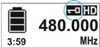
text_image
3:59 480.000 MHzPress the SET button 🔒. The lock mode is temporarily deactivated. The lock mode icon ⑤ flashes. - If you do not press a button, the lock mode is activated again after 2 seconds. The lock mode icon ⑤ lights up constantly again. - If you continue navigating the operating menu or if you call up a menu item, the lock mode is activated 2 seconds after the last button press. - If you exit a called up menu item, the lock mode is activated immediately after exiting the menu item.
To permanently deactivate the automatic lock mode:
- Call up the "LOCK" menu item and select "Off". - S tore your setting by pressing the SET button
Basic functions of the Sennheiser operating menu
A special feature of the Sennheiser 9000 series is the straightforward, intuitive operating concept. As a result, you can act quickly and precisely – even in stressful situations, for example on stage or during a live show or presentation.
Calling up and selecting menu items, changing and storing settings, cancelling an entry


- Press the SET button ☐ to call up the operating menu or a menu item, to switch between the selection areas of a menu item and to store your settings. - Press the UP button ▶/DOWN button ◀ to select menu items and to change the settings of a menu item. - Press the ON/OFF button ☑ to exit a menu item without storing your settings or to change from the operating menu to the standard display.
When keeping the UP button ▶/DOWN button ◀ pressed within a menu item, you continuously adjust the next/previous setting of the menu item. Keep the buttons pressed for a longer time to accelerate the speed.
Overview of the status displays
| Status display Meaning | |
 | SKM 9000 switches on |
 | SKM 9000 switches off |
| 6:592:204:40 | BA/B 60 accupack/battery pack:charge status ≤ 100% | ≤ 70% | ≤ 30%BA 60 accupack: remaining operating time in h:mm |
 | Accupack/battery pack is completely discharged,transmitter is not operational |
 | Setting is being stored |
 | Firmware is being updated |
 | Firmware update has failed |
Overview of the menu items
| Icon Name | Function Page | ||
 | Tune | Sets a frequency | 89 |
 | Preset | Selects a frequency preset | 90 |
 | Name | Enters a name | 90 |
 | Gain | Adjusts the input gain | 90 |
 | Low cut | Sets the low-cut filter | 90 |
 | RF mode Adjusts the transmission mode 90 | ||
 | Display | Selects a standard display | 90 |
 | Lock | Activates/deactivates the lock mode | 90 |
 | Test tone | Activates the test tone for level matching the system and for the walk test | 90 |
 | Reset | Resets the factory default settings | 91 |
 | Information Displays the firmware version and frequency range | 91 | |

"Tune"- Setting a frequency
Via the "Tune" menu item, you can set a frequency. The frequencies are tuneable in 25 kHz steps. If you store your setting, the set frequency is automatically assigned to the user-defined frequency preset "U". The radio microphone then changes from the currently set frequency preset to the frequency preset "U" and transmits on the set frequency.

"Preset" – Selecting a frequency preset
Via the "Preset" menu item, you can select a frequency preset from the active booster frequency range or the frequency preset "U" (see also the "Tune" menu item).

To activate a different booster frequency range:
Proceed as described from page 56 onwards. You first activate the booster frequency range on the EM 9046. If you then synchronize the transmitter and the receiver, the booster frequency range on the transmitter will also be activated.

"Name" – Entering a name
Via the "Name" menu item, you can enter a freely selectable name for the radio microphone. The name can consist of up to 6 characters from the following character set:
' + ' , - ' | / ' 0 ' 1 ' 2 ' 3 ' 4 ' 5 ' 6 ' 7 ' 8 ' 9 '*' ; < ' = ' > ' space ' # ' A ' B ' C ' D ' E ' F ' G ' H ' I ' J ' K ' L ' M ' N ' O ' P ' Q ' R ' S ' T ' U ' V ' W ' X ' Y ' Z

"Gain" – Adjusting the input gain
Via the "Gain" menu item, you can adjust the input gain in 3 dB steps.

The radio microphone automatically detects the type of microphone head being used and changes the adjustment range of the "Gain" menu item accordingly.

"Low cut" – Setting the low-cut filter
Via the "Low cut" menu item, you can set the low-cut filter. Settings: "80 Hz", "100 Hz", "120 Hz".

"RF mode" - Adjusting the transmission mode
The "RF mode" menu item allows you to adjust the transmission mode. Settings: "HD", "LR".

"Display" – Selecting a standard display
The "Display" menu item allows you to select one out of 3 standard displays.
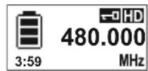
"Frequency"
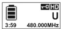
"Preset"

"Name"

"Lock" – Activating/deactivating the lock mode
Via the "Lock" menu item, you can activate or deactivate the lock mode. For more information on how to activate or deactivate the lock mode, refer to page 87.

"Test tone" – Activating the 1 kHz test tone
Via the "Test tone" menu item, you can activate a 1 kHz test tone. This test tone is transmitted instead of the input signal. You can use this function for level matching your system or for the walk test.

"Reset" – Resetting the factory default settings
Via the "Reset" menu item, you can reset the radio microphone to its factory default settings.

"Information" – Displaying the firmware version and frequency range
Via the "Information" menu item, you can display the firmware version and the transmitter's frequency range.
Digital 9000
Using the SK 9000
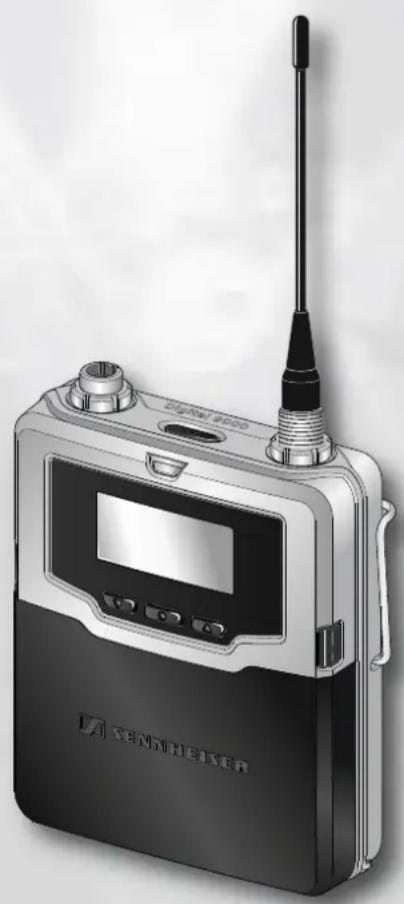
natural_image
Exterior view of a modern wireless earless device (no visible text or symbols on body)Using the SK 9000 93
Switching the SK 9000 on/off 94
Activating/deactivating the automatic lock mode
(Autolock) 95
Basic functions of the Sennheiser operating menu. 96
Overview of the status displays 97
Overview of the menu items 97
Using the SK 9000

Before using your bodypack transmitter, ask the relevant wireless regulatory authority for the exact frequency allocations and apply for an individual license if necessary.
The supplied supplement "Framework requirements and restrictions on frequency usage in Europe" provides an overview of the different European framework requirements and restrictions on frequency usage. If there is no entry in the supplement, ask the relevant wireless regulatory authority for the current rules governing frequency usage.
Switching the SK 9000 on/off

When the SK 9000 is switched on for the first time, it contains the first frequency preset of the transmitter frequency range (e.g. A1.1:470.200 MHz). Via the "ch" menu of the EM 9046 receiver, set the desired frequency preset and adjust the settings of other menu items and then synchronize the transmitter and the receiver (see page 77). In doing so, all frequency presets of the transmitter frequency range will be transferred to the SK 9000.
We recommend you to always adjust the transmitter settings via the EM 9046 receiver and then to synchronize the transmitter and the receiver.
To switch the SK 9000 on:
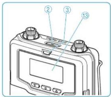
text_image
Technical diagram of a device with numbered components labeled ②, ③, and ⑬ pointing to ports and buttons.Keep the ON/OFF button ☐ ② pressed until the Sennheiser logo appears on the display panel ⑬.
The ON LED ③ lights up and the standard display (here: "Frequency", see page 99) appears on the display panel ⑬. The bodypack transmitter transmits an RF signal and the transmission mode display "HD"/"LR" lights up constantly:
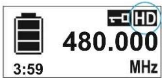
text_image
3:59 480.000 MHzTo switch the SK 9000 off:
▶ Ke ep the ON/OFF button ☑ ② pressed until the display panel goes off.
Remove the accupack/battery pack when the transmitter will not be used for extended periods of time (see page 43).
To switch the SK 9000 off with the lock mode activated:
▶ Press t he ON/OFF button ☐ ⑫ while the standard display is shown. "LOCK" appears on the display panel because the lock mode is activated.
▶ Press the UP button ▶ or the DOWN button ▼. "UNLOCK" appears on the display panel.
▶ Press the SET button .
The lock mode is temporarily deactivated, the lock mode icon ⑤ flashes.
▶ Within the next 2 seconds, press the ON/OFF button ☐ and keep it pressed until the display panel goes off.
If you switch on the SK 9000, the lock mode is activated again.
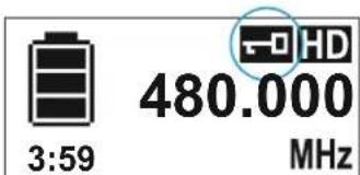
text_image
3:59 480.000 MHzSwitching on the SK 9000 on and checking the set frequency before the RF signal is activated
Switch on the SK 9000 by keeping the ON/OFF button ☐ ② pressed until the "Name" standard display appears.
The RF signal is not activated and the transmission mode display "HD"/"LR" flashes.
If you call up the "Tune" or "Preset" menu item within the next 10 seconds, the RF signal remains deactivated until you exit the menu item. If you do not call up one of the mentioned menu items, the RF signal is automatically activated after 10 seconds.
To check the set frequency/the selected frequency preset:
▶ Call up the operating menu and press the UP button ▲ /DOWN button ▼ until the "Tune" or "Preset" menu item appears.
The set frequency/the selected frequency preset is displayed.
If the displayed value is the desired one:
▶ Wait for 10 seconds to pass.
The RF signal is automatically activated and the transmission mode display "HD"/"LR" lights up constantly.
If the displayed value is not the desired one:
▶ Call up the "Tune" or "Preset" menu item.
The RF signal remains deactivated until you exit the menu item.
▶ Set the frequency ("Tune" menu item) or select a frequency preset ("Preset" menu item) and store your setting.
The RF signal is activated and the bodypack transmitter transmits an RF signal on the set frequency.
Activating/deactivating the automatic lock mode (Autolock)
The bodypack transmitter has an automatic lock mode that can be activated or deactivated via the "LOCK" menu item (see page 95).
To permanently activate the automatic lock mode:
▶ Call up the "LOCK" menu item and select "On".
Store your setting by pressing the SET button.
The automatic lock mode is activated and the lock mode icon appears on the standard display.
When the automatic lock mode is activated, you can still call up the operating menu, use the UP button ▲ /DOWN button ▼ to select menu items (read-only function) and call up the "LOCK" menu item in order to deactivate the automatic lock mode. If, however, you try to call up any other menu item, the following display appears on the display panel:

text_image
LOCKWhile this display is shown (about 2 seconds), you can temporarily deactivate the lock mode:
Press the UP button ▲ or the DOWN button ▼. The following display appears on the display panel:

text_image
UNLOCK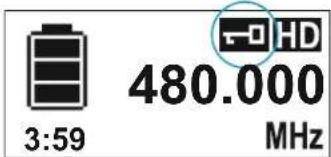
text_image
3:59 480.000 MHzPress the SET button . The lock mode is temporarily deactivated. The lock mode icon ⑤ flashes.
- If you do not press a button, the lock mode is activated again after 2 seconds. The lock mode icon ⑤ lights up constantly again.
- If you continue navigating the operating menu or if you call up a menu item, the lock mode is activated 2 seconds after the last button press.
- If you exit a called up menu item, the lock mode is activated immediately after exiting the menu item.
To permanently deactivate the automatic lock mode:
▶ Call up the "LOCK" menu item and select "Off".
▶ S tore your setting by pressing the SET button 📄.
Basic functions of the Sennheiser operating menu
A special feature of the Sennheiser 9000 series is the straightforward, intuitive operating concept. As a result, you can act quickly and precisely – even in stressful situations, for example on stage or during a live show or presentation.
Calling up and selecting menu items, changing and storing settings, cancelling an entry


▶ Press the SET button ● to call up the operating menu or a menu item, to switch between the selection areas of a menu item and to store your settings.
▶ Press the UP button ▶/DOWN button ▼ to select menu items and to change the settings of a menu item.
▶ Press the ON/OFF button ☑ to exit a menu item without storing your settings or to change from the operating menu to the standard display.
When keeping the UP button ▲ /DOWN button ▼ pressed within a menu item, you continuously adjust the next/previous setting of the menu item. Keep the buttons pressed for a longer time to accelerate the speed.
Overview of the status displays
| Status display Meaning | |
 | SK 9000 switches on |
 | SK 9000 switches off |
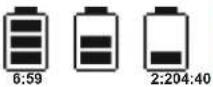 | BA/B 61 accupack/battery pack:charge status ≤ 100% | ≤ 70% | ≤ 30%BA 61 accupack: remaining operating time in h:mm |
 | Accupack/battery pack is completely discharged,transmitter is not operational |
 | Setting is being stored |
 | Firmware is being updated |
 | Firmware update has failed |
Overview of the menu items
| Icon Name | Function Page | ||
 | Tune | Sets a frequency | 98 |
 | Preset | Selects a frequency preset | 98 |
 | Name | Enters a name | 98 |
 | Gain | Adjusts the input gain | 98 |
 | Low cut^a | Sets the low-cut filter 98 | |
 | Cable^b | Emulates different instrument cable lengths | 99 |
 | RF mode Adjusts the transmission mode 99 | ||
 | Display | Selects a standard display | 99 |
 | Lock | Activates/deactivates the lock mode | 99 |
 | Test tone | Activates the test tone for level matching the system and for the walk test | 99 |
 | Reset | Resets the factory default settings | 99 |
 | Information Displays | the firmware version and frequency range | 99 |
a. If you are using the Sennheiser CI 1-4 line/instrument cable, this menu item is hidden
b. If you are using the Sennheiser CI 1-4 line/instrument cable, this menu item is shown

"Tune"—Setting a frequency
Via the "Tune" menu item, you can set a frequency. The frequencies are tuneable in 25 kHz steps. If you store your setting, the set frequency is automatically assigned to the user-defined frequency preset "U". The bodypack transmitter then changes from the currently set frequency preset to the frequency preset "U" and transmits on the set frequency.

"Preset" – Selecting a frequency preset
Via the "Preset" menu item, you can select a frequency preset from the active booster frequency range or the frequency preset "U" (see also the "Tune" menu item).

To activate a different booster frequency range:
Proceed as described from page 56 onwards. You first activate the booster frequency range on the EM 9046. If you then synchronize the transmitter and the receiver, the booster frequency range on the transmitter will also be activated.

"Name" – Entering a name
Via the "Name" menu item, you can enter a freely selectable name for the bodypack transmitter. The name can consist of up to 6 characters from the following character set:
| +‘’,‘-’|‘/’0‘1‘2‘3‘4‘5‘6‘7‘8‘9‘*’;‘<’=‘> |
| 'space'#‘A‘B‘C‘D‘E‘F‘G‘H‘I‘J‘K‘L‘M‘N‘O‘P’ |
| 'Q‘R‘S‘T‘U‘V‘W‘X‘Y‘Z’ |

"Gain" – Adjusting the input gain
Via the "Gain" menu item, you can adjust the input gain in 3 dB steps from -6 to +42 dB.

"Low cut" – Setting the low-cut filter
Via the "Low cut" menu item, you can set the low-cut filter. The bodypack transmitter automatically detects the type of input signal present and changes the settings of the "Low cut" menu item accordingly. If you are using the Sennheiser CI 1-4 line/instrument cable, the "Low cut" menu item is hidden.
| Cable type Settings | |
| Sennheiser microphone cable | “60 Hz”, “80 Hz”, “100 Hz”, “120 Hz” |
| Sennheiser CI 1-4line/instrument cable | “30 Hz”, the “Low cut” menu item is hidden |

"Cable" – Emulating different instrument cable lengths
Via the "Cable" menu item, you can emulate the lengths of instrument cables in 3 steps. If you are using the Sennheiser CI 1-4 line/Instrument cable, the "Cable" menu item is shown.

"RF mode" - Adjusting the transmission mode
The "RF mode" menu item allows you to adjust the transmission mode. Settings: "HD", "LR".

"Display" – Selecting a standard display
The "Display" menu item allows you to select one out of 3 standard displays.
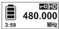
"Frequency"
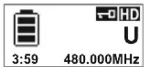
"Preset"

"Name"

"Lock" – Activating/deactivating the lock mode
Via the "Lock" menu item, you can activate or deactivate the lock mode. For more information on how to activate or deactivate the lock mode, refer to page 95.

"Test tone" – Activating the 1 kHz test tone
Via the "Test tone" menu item, you can activate a 1 kHz test tone. This test tone is transmitted instead of the input signal. You can use this function for level matching your system or for the walk test.

"Reset" – Resetting the factory default settings
Via the "Reset" menu item, you can reset the bodypack transmitter to its factory default settings.

"Information" – Displaying the firmware version and frequency range
Via the "Information" menu item, you can display the firmware version and the transmitter frequency range.
Digital 9000
Using the L 60
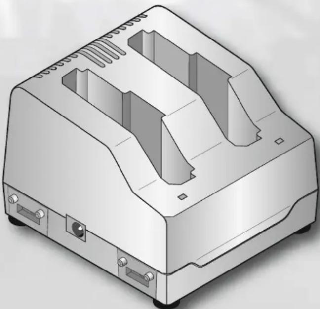
natural_image
3D rendering of a mechanical device housing with internal compartments and mounting points (no text or symbols)Using the L 60
Connecting the mains unit and switching on the L 60
Connect the DC connector of the NT 3-1 mains unit to the DC input socket ② of the L 60 charger.
Connect the mains plug (EU, UK or US version) of the mains unit to the mains.
The charger switches on and goes to standby mode.
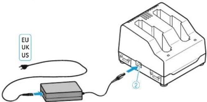
text_image
EU UK US ②NT 3-1
Switching off the L 60 and disconnecting it from the mains
If no accupacks are inserted into the L 60, the charger is in standby mode. To switch off the charger and the NT 3-1 mains unit and to disconnect them from the mains:
▶ Unplug the mains plug of the mains unit.
Charging the BA 60/BA 61 accupack
Charge the BA 60/BA 61 accupack fully before using it for the first time or if you have not used it for an extended period of time.
The L 60 charger allows you to simultaneously charge ...
... 2 BA 60 or
... 2 BA 61 or
... 1 BA 60 and 1 BA 61.
Insert the accupack into one of the charging compartments ③ and make sure that it locks into place with an audible click.
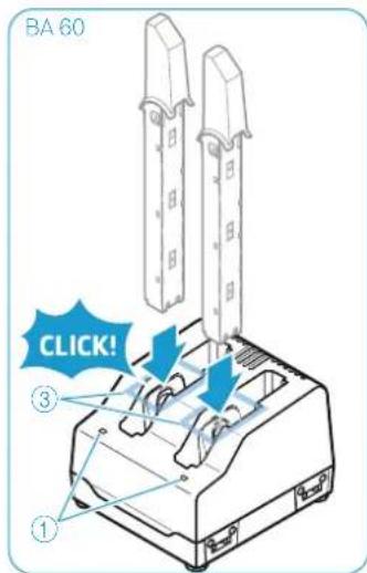
text_image
BA 60 ③ ① CLICK!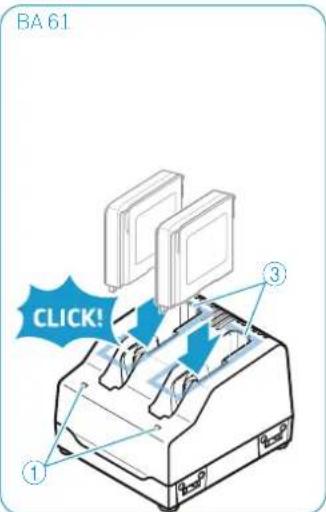
text_image
BA 61 ① ③ CLICK!The accupack is being charged. The status LED ① lights up. It is normal for the accupack to get warm during charging.

For an overview of the indications of the status LED ①, refer to page 16.
Charging times
With a completely discharged accupack and at room temperature (approx. 20 °C/68 °F), the charging times are as follows:
Capacity obtained Charging time
approx. 100 % approx. 180 min
approx. 70 % approx. 60 min
However, charging may take longer under the following circumstances:
- The accupack is deep-discharged and first has to be reconditioned by a deep discharge recovery charge.
- The ambient temperature is close to or over 35 °C/95 °F; in order to protect the accupack, the charging power will be reduced until the accupack temperature has dropped to an admissible value.
Charging will be aborted and the status LED ① will start flashing red under the following circumstances:
- The accupack temperature is too low or too high (see page 122), charging starts automatically when the accupack temperature is within the charging temperature range.
- The accupack cannot be fully charged within approx. 8 hours, e.g. due to overaged cells.
Cleaning and maintaining the
Digital 9000 system
Cleaning and maintaining the Digital 9000 system
CAUTION
Liquids can damage the electronics of the products!
Liquids entering the housing of the products can cause a short-circuit and damage the electronics.
Keep all liquids away from the products.
Do not use any solvents or cleansing agents.
Disconnect the products from the mains. Remove the rechargeable batteries or batteries before cleaning.
▶ Only use a soft, dry cloth to clean the products.
Cleaning the sound inlet basket of the microphone head
▶ Unscrew the upper sound inlet basket from the microphone head by turning it counterclockwise (see diagram).

natural_image
Illustration showing a hand holding a microphone and interacting with a device, with a close-up of the device being processed (no text or symbols present)Remove the foam insert.
There are two ways to clean the sound inlet basket:
- Use a slightly damp cloth to clean the upper sound inlet basket from the inside and outside.
- Scrub with a brush and rinse with clear water.
If necessary, clean the foam insert with a mild detergent or replace the foam insert.
Dry the upper sound inlet basket and the foam insert.
▶ Reinsert the foam insert.
Replace the sound inlet basket on the microphone head and screw it tight.
You should also clean the contacts of the microphone head from time to time:
Wipe the contacts of the microphone head with a soft and dry cloth.
Cleaning the contacts of the SK 9000 bodypack transmitter
Wipe the contacts with a dry cloth.
Cleaning the L 60 charger
Remove all accupacks from the charging compartments.
Before cleaning, disconnect the NT 3-1 mains unit from the mains.
▶ Use a dry cloth for cleaning.
▶ Use a brush or similar to remove dust from the charging compartments.
Clean the charging contacts from time to time using e.g. a cotton swab.
If a problem occurs ...
Digital 9000
If a problem occurs ...
If a problem occurs ...
If a problem occurs ...
EM 9046 receiver
| Problem Possible cause Possible solution | ||
| No operation indication | No mains connection, the ON/OFF 1 switch is set to position "0" | Check the connections of the mains cable. Set the ON/OFF 1 switch to position "1". |
| No RF signal | Transmitter and receiver operate in different frequency ranges | Perform a frequency scan (see page 56) and then synchronize transmitter and receiver. |
| The transmission range is exceeded | Reduce the distance between transmitter and receiver. | |
| Frequency cannot be transferred to the transmitter | The transmitter is not within the range of the infra-red interface | Place the transmitter at a distance of approx. 10–20 cm in front of the infra-red interface. |
| The infra-red interface of the receiver is not yet ready for transferring the frequency, the receiver is still in scan mode | Keep placing the transmitter in front of the infra-red interface. | |
| The transmitter is from a different frequency range | Use a transmitter that matches the frequency range of the receiver. | |
| Audio signal has a high level of background noise | Input gain of the transmitter/audio output level of the receiver is adjusted too low. | Adjust the input gain of the transmitter/audio output level of the receiver correctly. |
| Audio signal is distorted | Input gain of the transmitter/audio output level of the receiver is adjusted too high. | Adjust the input gain of the transmitter/audio output level of the receiver correctly. |
| The display does not switch on | The receiver is in standby mode | Press the jog dial 17. |
| syn ➔ button does not seem to function | Wrong operating mode | Call up the "live" or "ch" operating mode before pressing the syn ➔ button. |
SKM 9000 radio microphone
| Problem Possible cause Possible solution | ||
| Transmitter cannot be operated, "LOCK" appears on the display panel | Lock mode is activated | Deactivate the lock mode (see page 90). |
| No operation indication | Batteries are flat or accupack is flat | Replace the batteries or recharge the accupack (see page 94). |
| No RF signal at the receiver | Transmitter and receiver are not on the same frequency | Perform a frequency scan (see page 56) and then synchronize the transmitter and receiver. |
| Transmission range is exceeded | Reduce the distance between transmitter and receiving antennas. | |
| Transmitter's RF signal is deactivated ("RF Mute") | Activate the RF signal (see page 78). | |
| Audio signal has a high level of background noise or is distorted | Transmitter input gain is too low/too high | Adjust the input gain (see page 82). |
SK 9000 bodypack transmitter
| Problem Possible cause Possible solution | ||
| Transmitter cannot be operated, “LOCK” appears on the display panel | Lock mode is activated | Deactivate the lock mode (see page 99). |
| No operation indication | Batteries are flat or accupack is flat | Replace the batteries or recharge the accupack (see page 94). |
| No RF signal at the receiver | Transmitter and receiver are not on the same frequency | Perform a frequency scan (see page 56) and then synchronize the transmitter and receiver. |
| Transmission range is exceeded | Reduce the distance between transmitter and receiving antennas. | |
| Transmitter’s RF signal is deactivated (“RF Mute”) | Activate the RF signal (see page 86). | |
| Audio signal has a high level of background noise or is distorted | Transmitter input gain is too low/too high | Adjust the input gain (see page 90). |
L 60 charger
| Problem Possible cause Possible solution | ||
| The LED 1 does not light up | Charger is not connected to the mains | Check if the L 60 is connected to the NT 3-1 mains unit and if the mains unit is connected to the mains (see page 102). |
| Cascaded L 60 chargers are not correctly connected to one another | Check if a maximum of four L 60 are correctly connected to one another (see page 46). | |
| More than four chargers are cascaded | ||
| Unstable voltage of the mains unit | Replace the defective mains unit or mains cable with a new one. | |
| Mains unit or mains cable is defective | ||
| No contact with the accupack | Insert the accupack correctly into the charging compartment (see page 102). | |
| Contacts of the accupack or contacts of the charging compartments are dirty | Clean the charging contacts of the accupack and of the charging compartments (see page 107). | |
| Accupack is defective (overaged or defective rechargeable battery cells) | Replace the defective accupack with a new one. | |
| The LED 1 flashes red | Wrong accupack/ individual rechargeable batteries/batteries (primary cells) have been inserted | Only charge BA 60 or BA 61 accupacks with the L 60 charger. |
| Accupack temperature is too low or too high/ air humidity too high | Always recharge the accupack within the operating temperature range and the air humidity range stated in the specifications (see page 122). | |
| Accupack is defective (overaged or defective rechargeable battery cells) | Replace the defective accupack with a new one. | |
If a problem occurs that is not listed in the above table or if the problem cannot be solved with the proposed solutions, please contact your local Sennheiser partner for assistance.
Specifications
Specifications
System characteristics
| Frequency ranges 470 to 798 MHz, expandable to 934 MHz, divided into 24 MHz booster frequency ranges (see page 40) | ||
| EM 9046 DRX TX variant Booster variant A1-A8 | ||
| A1-B8 | A1-A4 | A1 470-494 MHz |
| 470-798 MHz (expandable to 934 MHz) | 470-558 MHz | A2 494-518 MHz |
| A3 510-534 MHz | ||
| A4 534-558 MHz | ||
| A5-A8 | A5 550-574 MHz | |
| 550-638 MHz | A6 574-598 MHz | |
| A7 590-614 MHz | ||
| A8 614-638 MHz | ||
| B1-B4 | B1 630-654 MHz | |
| 630-718 MHz | B2 654-678 MHz | |
| B3 670-694 MHz | ||
| B4 694-718 MHz | ||
| B5-B8 | B5 710-734 MHz | |
| 710-798 MHz | B6 734-758 MHz | |
| B7 750-774 MHz | ||
| B8 774-798 MHz | ||
Transmission method digital modulation
"HD" mode:without audio data compression
"LR" mode:SeDAC (Sennheiser Digital Audio Codec)
Audio frequency response 30 Hz to 20 kHz (3 dB) with SK 9000 line-in
60 Hz to 20 kHz (3 dB) with SK 9000 mic
80 Hz to 20 kHz (3 dB) with SKM 9000
Dynamic range "HD" mode:112 dB(A)
"LR" mode: 101 dB(A)
Latency Analog Audio Out: 3.2 ms
Digital Audio Out: 3 ms (AES-EBU)
THD "HD" mode: < 0.01 % (at 1 kHz)
"LR" mode: < 0.03 % (at 1 kHz)
Operating conditions
| Ambient temperature -10 °C to +50 °C | |
| Relative humidity max. 85 % at 40 °C (non-condensing) | |
| Protection against dripping and light splashing of liquids | the product must not be exposed to dripping and splashing (IP2X) |
Storage and transport conditions
| Ambient temperature -25 °C to +70 °C | |
| Relative humidity max. 90 % at 40 °C | |
| Protection against dripping and light splashing of liquids | the product must not be exposed to dripping and splashing (IP2X) |
| Shock resistance as per IEC 68 or EN 60068, T2-27 | |
EM 9046 characteristics
RF characteristics
| Frequency range 470 to 934 MHz |
| Receiving channels up to 8 |
| Receiver principle double superheterodyne |
| Diversity true bit diversity |
| Sensitivity “HD” mode: -86 dBm, "LR" mode: -100 dBm |
| Antenna inputs 2 N-type sockets (50 Ω) |
| Daisy chain outputs 2 N-type sockets (50 Ω), amplification: 11 dB ±0.5 dB (related to booster input) |
| Daisy chainable receivers (HF) max. 4 EM 9046 (32 channels) |
Audio characteristics
| Audio output voltage | XLR balanced, -10 dBu to +18 dBu in 1 dB steps (2 kΩ) |
| Headphone output 2 x 100 mW at 32 Ω, short-circuit proof | |
| Digital audio output AES3-2003, XLR-3, 44.1 kHz; 48 kHz; 88.2 kHz or 96 kHz, 24 bit, externally synchronizable8 XLR-3 sockets and 1 multicore/sub-D socket (25-pin) | |
| Audio output sockets | can be equipped with 2 audio modules, analog (AAO), digital (DAO) or mixed8 XLR-3 sockets and 1 multicore/sub-D socket (25-pin) per audio module |
Other characteristics
| Power consumption | max. 250 W |
| Power supply | 100 to 240 V~, 50/60 Hz |
| Mains connector | 3-pin, protection class I as per IEC/EN 60320-1 |
| Dimensions | 177 x 449 x 496 mm (H x W x D, without handles) |
| Weight | approx. 17 kg (fully equipped with 1 AAO, 1 DAO, 8 DRX) |
Booster supply 12 V DC via antenna socket
max. 200 mA each, short-circuit proof
LAN IEEE 802.3-2002 (10/100 Mbit/s), shielded RJ 45 socket
Word clock input BNC, 75 Ω, transformer balanced, AC-coupled
input voltage range: 200 mV ... 5 Vpp
max. input voltage: 15 V (DC + AC)
Word clock output BNC, 75 Ω, AC-coupled
output voltage: 3.0 Vpp ±500 mV at 75 Ω source impedance
Word clock sampling rates 44.1 kHz; 48 kHz; 88.2 kHz or 96 kHz
In compliance with
Europe EMC: EN 301489-1/-9

Radio: EN 300422-1/-2
Safety: EN 60065
USA

47 CFR 15 subpart B
Approved by
Canada Industry Canada
RSS-123, IC: 2099A-EM9000
A/AB/AD 9000 characteristics
RF characteristics
| Frequency ranges 470 MHz to 798 MHz, | |
| divided into 2 ranges: | |
| A1-A8: 470 MHz to 638 MHz | |
| B1-B8: 630 MHz to 798 MHz(see page 114) | |
| Directivity | A 9000: omni-directionalAD 9000: directional |
| Amplification | typ. 17 dB (constant) |
| Antenna input (AB 9000 only) | N-type socket (50 Ω) |
| Antenna output | N-type socket (50 Ω) |
| Antenna gain | A 9000: 3.2 dBiAD 9000: 4.6 dBi |
| Apex angle AD 9000 | approx. 100° (-3 dB) |
| Front-to-back ratio AD 9000 | ≥ 14 dB |
| OIP3 | ≥ 35 dBm |
| Preselection 24 MHz | automatic or manual (without EM 9046) via rotary switch |
Other characteristics
| Current consumption max. 160 mA at 12 V | |
| Voltage range 9 to 18 V | |
| DC feed via antenna cable from EM 9046 | |
| Mounting connection 3/8" or 5/8" thread | |
| Dimensions A 9000: 250 x 165 x 23 mm (H x W x D) | |
| AB 9000: 80 x 64 x 24 mm (H x W x D) | |
| AD 9000: 329 x 322 x 23 mm (H x W x D) | |
| Weight A 9000: approx. 390 g | |
| AB 9000: approx. 265 g | |
| AD 9000: approx. 625 g | |
| In compliance with | |
| Europe EMC: EN 301489-1/-9 | |
| CE | Radio: EN 300422-1/-2 |
| Safety: EN 60065 | |
| USA | FC 47 CFR 15 subpart B |
| Approved by | |
| Canada Industry Canada | |
| RSS-123, IC: 2099A-EM9000 | |
SK 9000 characteristics
RF characteristics
| Frequency ranges 470 MHz to 798 MHz, divided into 4 ranges: A1-A4: 470-558 MHz A5-A8: 550-638 MHz B1-B4: 630-718 MHz B5-B8: 710-798 MHz (see page 114) | |
| Frequency ranges USA 550 MHz to 698 MHz, divided into 2 ranges: A5-A8: 550-607.9 MHz and 614.1-638 MHz B1-B4: 630-697.9 MHz (see page 114) | |
| Switching bandwidth 88 MHz | |
| RF output power "HD" mode:10 mW rms, 50 mW peak "LR" mode: 25 mW rms, 50 mW peak | |
| Frequency stability < 5 ppm | |
| Tuneability in steps of 25 kHz | |
| Antenna output coax socket | |
| Audio characteristics | |
| Mic/line input 3-pin special audio socket | |
| Audio gain mic: adjustable in 3 dB steps from 0 dB to +42 dB | |
| instruments: adjustable in 3 dB steps from -6 dB to +42 dB | |
| line: adjustable in 3 dB steps from -6 dB to +42 dB | |
| Input impedance mic: 22 kΩ | |
| instruments/line: 1 MΩ | |
| Lower cut-off frequency (-3 dB) | mic: 30 Hz, 60 Hz, 80 Hz, 100 Hz, 120 Hz |
| instruments/line: 30 Hz, 60 Hz, 80 Hz, 100 Hz, 120 Hz | |
| Instrument cable emulation | cable length adjustable in 3 steps |
| Other characteristics | |
| Operating time | 6.5 hrs (with BA 61 accupack) |
| Power consumption | max. 960 mW |
| Dimensions | 76 x 62 x 20 mm (H x W x D, with BA 61 accupack) |
| Weight | approx. 147 g (with BA 61 accupack and belt clip) |
In compliance with
Europe EMC: EN 301489-1/-9

Radio: EN 300422-1/-2
Safety: EN 60065
EN 62311 (SAR)
Approved by
USA
FC Part 74
FCC-ID: DMOSK9000
limited to 698 MHz
Canada Industry Canada
RSS-123, IC: 2099A-SK9000
limited to 698 MHz
SKM 9000 characteristics
RF characteristics
| Frequency ranges 470 MHz to 798 MHz, divided into 4 ranges: A1-A4: 470-558 MHz A5-A8: 550-638 MHz B1-B4: 630-718 MHz B5-B8: 710-798 MHz (see page 114) | |
| Frequeny ranges USA 550 MHz to 698 MHz, divided into 2 ranges: A5-A8: 550-607.9 MHz and 614.1-638 MHz B1-B4: 630-697.9 MHz (see page 114) | |
| Switching bandwidth 88 MHz | |
| RF output power “HD” mode:10 mW rms, 50 mW peak “LR” mode: 25 mW rms, 50 mW peak | |
| Frequency stability < 5 ppm | |
| Tuneability in steps of 25 kHz | |
| Audio characteristics | |
| Audio gain adjustable in 3 dB steps from 0 dB to +62 dB (depending on microphone head) | |
| Lower cut-off frequency (-3 dB) adjustable: 60 Hz, 80 Hz, 100 Hz, 120 Hz | |
| Other characteristics | |
| Operating time 5.5 hrs (with BA 60 accupack) | |
| Power consumption max. 960 mW | |
| Dimensions | 270 x 40 mm (L x ∅) |
| Weight | approx. 350 g (with BA 60 accupack and ME 9005 microphone head) |
| In compliance with | |
| Europe | EMC: EN 301489-1/-9 |
| CE | Radio: EN 300422-1/-2 |
| Safety: EN 60065 EN 62311 (SAR) | |
| Approved by | |
| USA | FC Part 74 FCC-ID: DMOSKM9000 limited to 698 MHz |
| Canada | Industry Canada RSS-123, IC: 2099A-SKM9000 limited to 698 MHz |
BA 60/61 characteristics
Other characteristics
BA 60 BA 61
Nominal voltage 3.7 V 3.7 V
Nominal capacity 1,600 mAh 2,030 mAh
Nominal energy 5.9 Wh 7.5 Wh
In compliance with
Europe EMC: EN 301489-1/-9

EN 61000-6-2
EN 61000-6-3
Safety: IEC 60950
IEC 62133
USA/Canada Safety: UL 2054
UL listing MH 16707
L 60 characteristics
| Input voltage 12 to 15 V | --- |
| Input current max. 900 mA | |
| Pin assignment of DC input hollow jack socket | |
| Charging voltage max. 4.2 V | --- |
| Charging current max. 2 x 1,000 mA | |
| Charging principle • CC CV method (Li-Ion charging method)Deep discharge recovery chargeCapacity monitoringAccupack temperature monitoringOver/undercharge detectionCharging time limit (approx. 8 hours) | |
| Compatible Sennheiser accupacksBA 60 (3.7 V, 1,600 mAh, Li-Ion)BA 61 (3.7 V, 2,030 mAh, Li-Ion) | |
| Charging time with a completely discharged accupack and at room temperature (approx. 20 °C/68°F):100%= approx. 180 min70%= approx. 60 minautomatic security switch-off after approx. 8 hours | |
| Dimensions approx. 80 x 87 x 62 mm (W x D x H) | |
| Weight approx. 160 g (without mains unit) | |
| Operating conditions | |
| Ambient temperature 0 °C to +35 °Cwith reduced charging power: 0 °C to +45 °C | |
| Relative humidity 25 % to 95 % (non-condensing) | |
| Protection against dripping and light splashing of liquids | the product must not be exposed to dripping and splashing (IP2X) |
| Storage and transport conditions | |
| Ambient temperature -20 °C to +70 °C | |
| Relative humidity 5 % to 95 % (non-condensing) | |
| Protection against dripping and light splashing of liquids | the product must not be exposed to dripping and splashing (IP2X) |
| In compliance with | |
| Europe EMC: EN 61000-6-2CEEN 61000-6-3Safety: EN 60065 | |
| USA FCC 47 CFR Part 15 B | |
| Canada Industry Canada ICES 003 | |
Pin assignment of the sockets of the EM 9046
XLR-3 socket (analog & digital)
Pin assignment
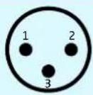
Pin 1: ground Pin 2: out + (P) Pin 3: out - (N)
Sub-D socket (25-pin) multicore, digital, balanced
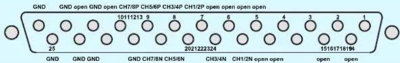
text_image
GND GND open GND open CH7/8P CH5/6P CH3/4P CH1/2P open open open open 10111213 9 8 7 6 5 4 3 2 1 25 2021222324 15161718194 GND GND GND CH7/8N CH5/6N CH3/4N CH1/2N open open open open openSub-D socket (25-pin) multicore, analog, transformer balanced
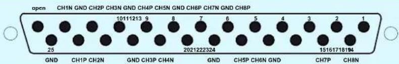
text_image
open CH1N GND CH2P CH3N GND CH4P CH5N GND CH6P CH7N GND CH8P 25 10111213 9 8 7 6 5 4 3 2 1 GND CH1P CH2N GND CH3P CH4N GND CH5P CH6N GND CH7P CH8N 2021222324 15161718194Pin assignment of the 3-pin special audio socket of the SK 9000
Socket Pin assignment
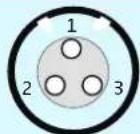
Pin 1 and thread: ground Pin 2: line/Instrument Pin 3: microphone
Frequency ranges for Japan
The Japanese version of the SK 9000 and SKM 9000 transmitters is available in three frequency ranges.
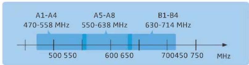
bar
| Category | Range (MHz) | |---|---| | A1-A4 | 470-558 | | A5-A8 | 550-638 | | B1-B4 | 630-714 |Japanese Radio Law and Japanese Telecommunications Business Law Compliance
This device is granted pursuant to the Japanese Radio Law () and and the Japanese Telecommunications Business Law ().
This device should not be modified. Otherwise the granted designation number will become invalid.
JAP
Japan

SK 9000 202-LSB007
SKM 9000 202-LSB008
Frequency ranges for Korea
The Korean version of the SK 9000 and SKM 9000 transmitters is available in three frequency ranges.
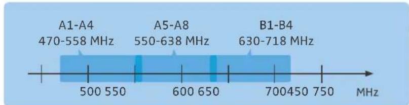
bar
| Frequency Range (MHz) | Label | |---|---| | 470-558 | A1-A4 | | 550-638 | A5-A8 | | 630-718 | B1-B4 | | 470-558 | 500-550 | | 550-638 | 600-650 | | 630-718 | 700-450-750 |

SENNHEISER
Sennheiser electronic GmbH & Co. KG
Am Labor 1, 30900 Wedemark, Germany
www.sennheiser.com
Publ. 06/17