
Skymax - Telescope Sky-Watcher - Free user manual and instructions
Find the device manual for free Skymax Sky-Watcher in PDF.


User questions about Skymax Sky-Watcher
0 question about this device. Answer the ones you know or ask your own.
Ask a new question about this device
Download the instructions for your Telescope in PDF format for free! Find your manual Skymax - Sky-Watcher and take your electronic device back in hand. On this page are published all the documents necessary for the use of your device. Skymax by Sky-Watcher.
USER MANUAL Skymax Sky-Watcher
natural_image
Technical line drawings of three tripod-mounted surveying instruments, one with a mounted device and the other with a camera (no text or symbols present)CONTENT
Parts Diagram
PART I : SETTING UP THE AZGTi MOUNT
1.1 Setting up on a Skywatcher Tripod ....4
1.2 Attaching the AZGTi Mount to a camera tripod ....5
1.3 Installing the Telescope....5
PART II : ELECTRONIC CONTROL INTERFACE
2.1 Control Panel 6
2.2 Panel Interface Components ....6
2.3 Pinout of The Interfaces ....7
2.4 DSLR Control Cables ....7
2.5 Power Supply Requirements ....7
PART III : USING THE AZGTi MOUNT
3.1 Manually Rotating the Mount ....8
3.2 Control with a SynScan Hand Control ....8
3.3 Control with a Mobile Device ....8
3.4 Wi-Fi Connection ....8
3.5 Freedom Find Function ......10
3.6 Firmware Update ....10
APPENDIX I : SPECIFICATIONS
Dimensions 11
Specifications ....11
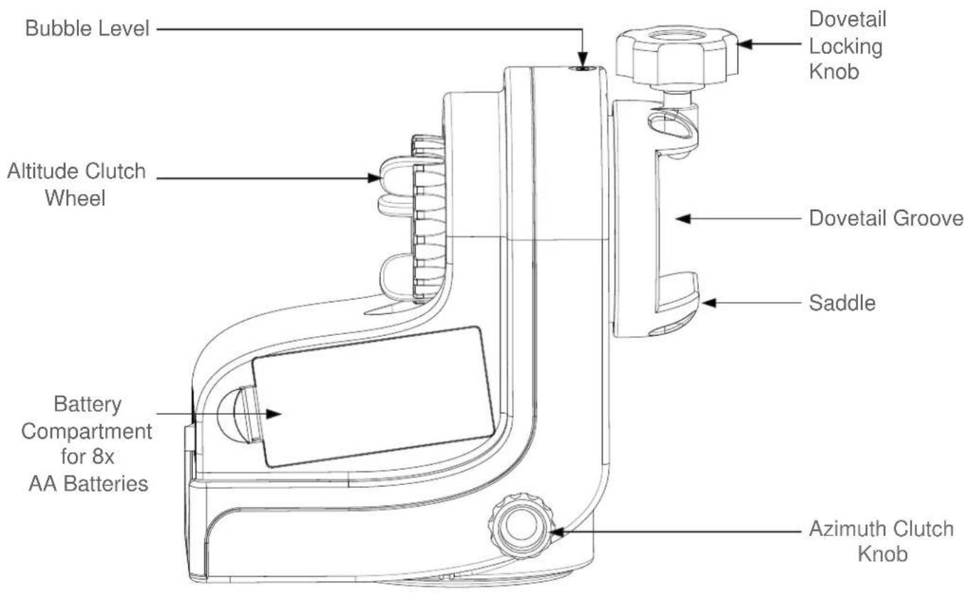
Parts Diagram
text_image
Bubble Level Altitude Clutch Wheel Battery Compartment for 8x AA Batteries Dovetail Locking Knob Dovetail Groove Saddle Azimuth Clutch Knob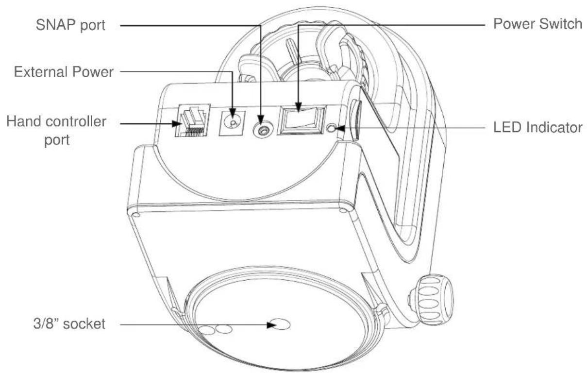
text_image
SNAP port External Power Hand controller port 3/8" socket Power Switch LED IndicatorPART I : SETTING UP THE AZGTi MOUNT
1.1 Setting Up on a Skywatcher Tripod
- Fully expand the three legs of the tripod on level ground.
-
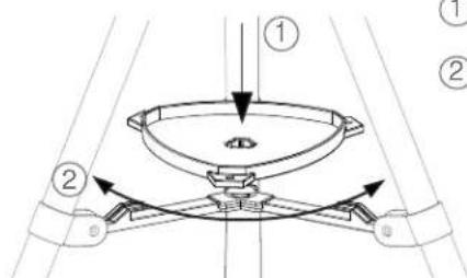
Install the accessory tray on the tripod as shown in Fig. 1.1a.
-
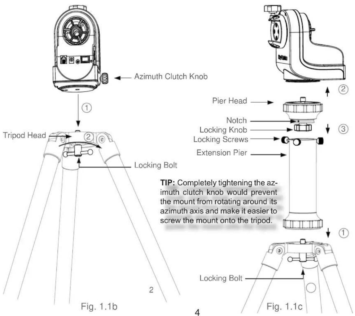
If using a short tube telescope, which does not hit the tripod legs when it points high up, with the AZGTi mount, the mount can be installed onto the tripod directly. Align the 3/8" socket at the base of the mount with the locking bolt on the tripod head. Lock the mount on the tripod by tightening the bolt (Fig. 1.1b).
text_image
Technical diagram showing a mechanical assembly with labeled components and directional arrows indicating motion or force.Fig. 1.1a
① Align the accessory tray and push down on it while holding onto the bottom supports.
② Rotate the tray to lock it into place.
WARNING: The accessory tray of a Skywatcher tripod ensures that the tripod legs are firmly expanded, which prevents the tripod from accidentally tipping over. When using the AZGTi mount on a Skywatcher tripod, an accessory tray should always be used to ensure stability.
text_image
Azimuth Clutch Knob ① Tripod Head Locking Bolt Pier Head Notch Locking Knob Locking Screws Extension Pier TIP: Completely tightening the azimuth clutch knob would prevent the mount from rotating around its azimuth axis and make it easier to screw the mount onto the tripod. Fig. 1.1b 4 Fig. 1.1c- If using a long tube telescope with AZGTi mount, an extension pier should be inserted between the tripod and the AZGTi mount to prevent the telescope from hitting the tripod legs when it points high up(Fig. 1.1c).
1) Attach the extension pier to the tripod and tighten the locking bolt.
2) Remove the pier head from the extension pier by loosening the three locking screws.
3) Attach the pier head to the AZGTi mount and tighten the locking knob.
4) Place the pier head back on the extension pier, align the notch with one of the three locking screws. Tighten the three locking screws to lock the pier head.
1.2 Attaching the AZGTi Mount to a Camera Tripod
- Fully expand the legs of the tripod on level ground. Make sure that the tripod is stable.
- Screw the AZGTi mount to the 3/8" bolt on the tripod head's mounting plate, tighten the bolt MODERATELY.
Caution: Over-tightening the mount may cause damage to the internal mechanical parts. - Most camera tripods' mounting plate comes with 1 to 3 locking screws. Firmly tighten the locking screws from underneath the plate to secure the AZGTi mount in place.
- Raise the camera tripod's central pole to the desired height, and make sure that it also prevents the telescope from hitting the tripod legs when the telescope points high up.
- Adjust the lengths of the legs to center the bubble level on the mount.
1.3 Installing The Telescope
text_image
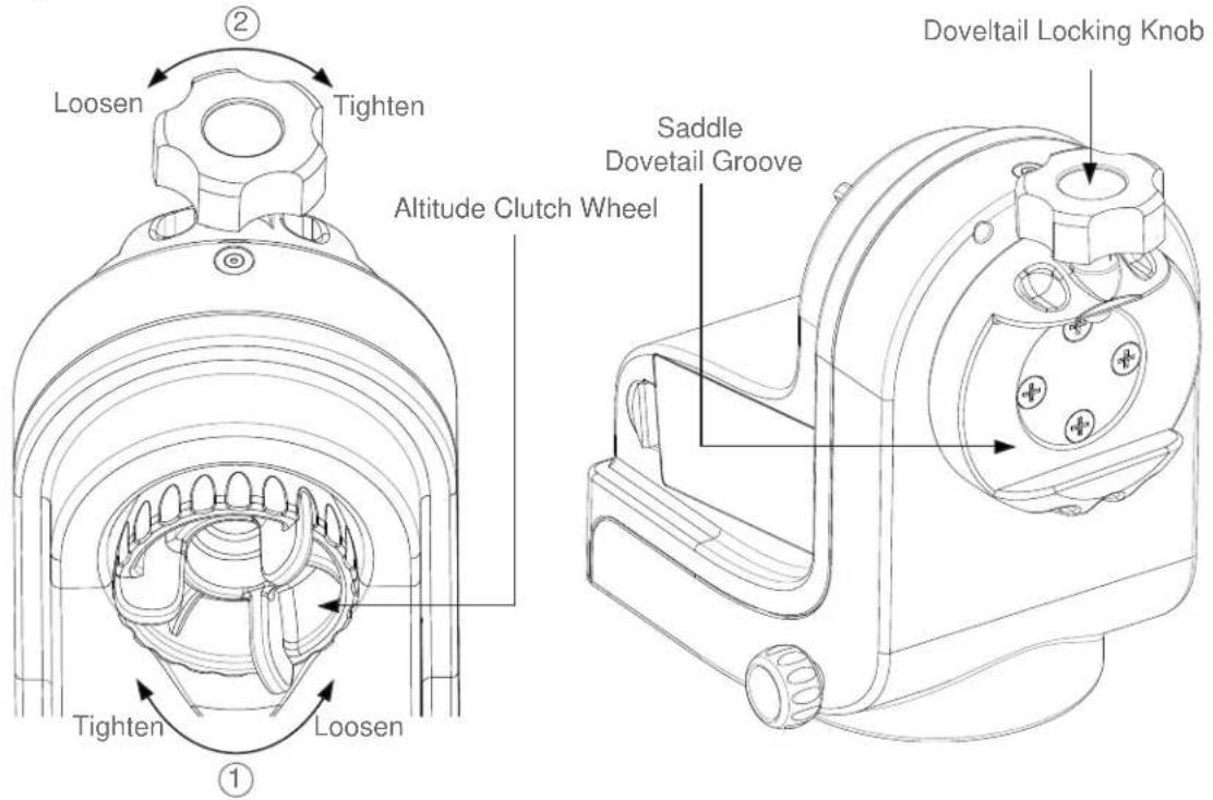
Loosen ② Tighten Altitude Clutch Wheel Saddle Dovetail Groove Doveltail Locking Knob Tighten Loosen ①Fig. 1.3a Fig. 1.3b
- Loosen the altitude clutch wheel and rotate the saddle until the dovetail groove is horizontal, then tighten the altitude clutch wheel again (Fig 1.3a).
- Loosen the dovetail locking knob until nothing is obstructing the dovetail groove in the saddle (Fig 1.3b).
- Hold the telescope horizontally and slide the dovetail bar of the telescope into the dovetail groove of the saddle (Fig 1.3b).
- Tighten the dovetail locking knob until the bar is securely locked in the groove. DO NOT LET GO OF THE TELESCOPE UNTIL YOU ARE SURE IT IS FIRMLY ATTACHED TO THE SADDLE
- While holding the telescope tube, fully loosen the altitude clutch to check the balance.
- Repeat the above steps to adjust the position of the dovetail bar back and forth to reach good balance in the altitude axis.
PART II : ELECTRONIC CONTROL INTERFACE
2.1 Control Panel
The control panel of the AZGTi mount is shown below:
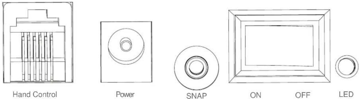
Fig. 2.1
2.2 Panel Interface Components:
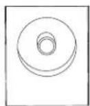
POWER: This is an input for external power to avoid running on the 8 AA batteries in the AZGTi mount battery compartment.
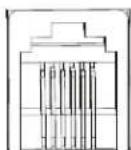
HAND CONTROL: This RJ-12 6-pins outlet is for connecting the SynScan hand controller.

SNAP: This is a stereo jack outlet to connect with a camera's shutter control port. The SynScan hand control can control the camera to take pictures automatically via this interface.
ON/OFF Switch: Turns the power to the mount and hand controller on and off.

Power LED: The power LED serves as a power-on indicator and provides other statuses.
- Steady on: Internal Wi-Fi is off.
- Intermittent one flash: Internal Wi-Fi is on.
- Intermittent two flashes: App has connected to internal Wi-Fi.
- Intermittent three flashes: Internal control board has entered firmware update mode.
2.3 Pinout of The Interfaces:
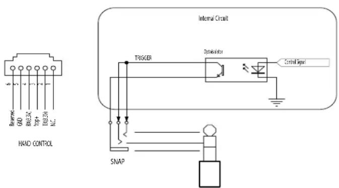
text_image
Reserve QND R012V V4P+ TR12V A.C. HAND CONTROL Internal Circuit TIGGER Distributor Control Signal SNAPNote:
The SNAP port provides two trigger signals to the stereo plug. For a camera which only needs a shutter-release signal, either trigger signals will work. For a camera which requires an extra “Focus” signal, both signals should be connected properly.
Fig. 2.3
2.4 DSLR Control Cable
Available for Canon, Nikon, Olympus and Sony cameras. See the table below to select the appropriate cable for your camera model; it can be ordered from the local Skywatcher dealer.
| Part Number | Camera Interface Style | Controller Interface | Compatible Camera Models |
| AP-R1C | Canon remote (E3 type) | Canon RS-60E3 | Canon EOS 100D, 300D/350D, 400D/450D, 500D/550D, 600D/650D, 700D, 60D/60Da, 70D |
| AP-R3C | Canon remote (N3 type) | Canon RS-80N3, TC-80N3 | Canon EOS 5D/6D/7D, 10D/20D/30D/40D/50D, 1V, 1D, 1Ds Mark III, 5D Mark III |
| AP-R1N | Nikon 10-pin remote terminal | Nikon MC-22, MC-30, MC-36 | Nikon D1/D2/D3/D4 D200/D300/D700/D800 |
| AP-R2N | Nikon remote cord connector | Nikon MC-DC1 Nikon D70S, D80 | |
| AP-R3N | Nikon accessory terminal | Nikon MC-DC2 | Nikon D90, D600, D3000/D3100/D3200/D3300, D5000/D5100/D5200/D5300, D7000/D7100 |
| AP-R1S Sony | remote terminal | Sony RM-S1AM, RM-L1AM | Sony a100, a200, a300, a350, a450, a550, a560 a700, a850, a900 |
| AP-R3L | Olympus multi-connector | RM-UC1 | Olympus E-P1/E-P2, E-PL2/E-PL3, E510/E520/E550/E620, E400/E410/E420, SP-570UZ/SP-590UZ |
2.5 External Power Supply Requirements
- Output Voltage: DC 7.5V (minimum) to DC 14V (maximum). Voltage not in this range might cause permanent damage to the motor controller or the hand controller.
- Output Plug: Barrel type with 2.0mm I.D and 5.5mm O.D. Must be central positive.
• Output Current: At least 750mA. - Do not use an unregulated AC-to-DC adapter. When choosing an AC adapter, a switching power supply with 12V output voltage and minimum 750mA output current is recommended.
- If the power voltage is too high, the motor controller will stop the motors automatically.
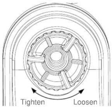
3.1 Manually Rotating The Mount
Refer to the following diagrams:
text_image
Tighten Loosen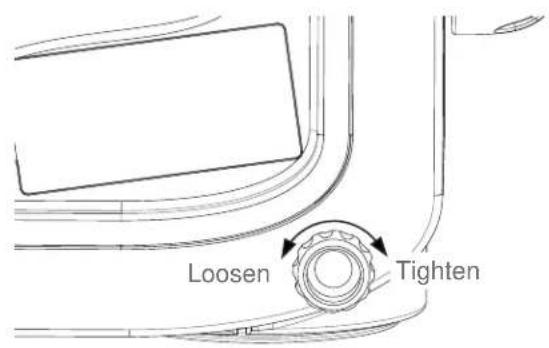
text_image
Loosen TightenFig. 3.1a Fig. 3.1b
- Loosen the Alt clutch wheel to manually rotate the telescope vertically.
- Loosen the Azimuth adjustment knob to manually rotate the telescope horizontally.
Tips:
- Fully tighten the clutches for all motor driven applications. This will give the best pointing accuracy.
- Half engage the clutches to manually point the telescope while preventing it from moving freely without external force.
• Fully loosen the clutches to move the telescope quickly.
3.2 Control with a SynScan Hand Control
Plug in the SynScan hand control into the hand control port in order to control the telescope and mount for astronomical observation. Please refer to the SynScan hand control manual for operation instructions.
3.3 Control with an Mobile Device
Users can download the free "SynScan" App from the App Store( for iOS devices) or Google Play (for Android Devices) for astronomical observation. Skywatcher will also provide apps for photography. Please check the stores for availability.
3.4 Wi-Fi Connection
- User must connect to the mount's Wi-Fi within 15 minutes after turning on power. The Wi-Fi will be turned off automatically if no connection is established within 15 minutes, .
- By default, the SSID of the built-in Wi-Fi is "SynScan_xxxx" and there is no password. User can download Skywatcher's "SynScan" app from App Store or Google Play to configure the mount's built-in Wi-Fi.
- Reset Wi-Fi configuration to factory default by turning on the power without the SynScan hand control connected and no App operations via the Wi-Fi connection for 4 hours.
3.5 Freedom Find™ Function
The AZGTi mount is equipped with auxiliary encoders on both the azimuth axis and altitude axis. Therefore, the mount can keep track of its current position even when a user unlocks the clutches and rotates the mount in azimuth axis and altitude axis manually.
With this feature, a user can manually operate the mount anytime without worrying about losing the mount's alignment status. When the user wants to operate the mount with the SynScan hand control again, no alignment is required and all that is needed to be done is to re-lock the clutches.
This feature can be disabled with the SynScan hand controller or the SynScan App. If an user does not need to rotate the mount manually after alignment, it is recommended to disable this feature to obtain the best pointing accuracy.
3.6 Firmware Update
When a new firmware for the control board inside the mount is available, Skywatcher will release it on www.skywatcher.com. Users can visit this website to download the firmware and the necessary application to update the firmware.
APPENDIX I : SPECIFICATIONS
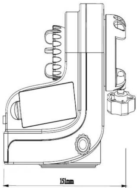
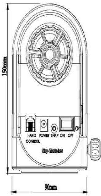
Dimensions:
natural_image
Technical line drawing of a mechanical device with dimension标注 (151mm), showing internal components and mounting bracket (no text or symbols beyond measurement)Mount
text_image
150mm HAND POWER SNAP ON OFF CONTROL Stop-Labeler 90mm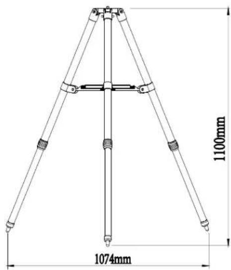
text_image
1100mm 1074mmTripod
Specifications:
| Product Name AZGTi Mount | |
| Mount Type Altitude-azimuth Mount | |
| Payload 5 kg | |
| Mount's Weight 1.3 kg | |
| Tripod + Extension Pier Weight 1.9 kg + 0.5kg | |
| Power Requirement DC7.5~14V, 0.75A | |
| Motor DC Servo Motor | |
| Gear Ratio 6480 | |
| Resolution 2073600 Counts/Rev., 0.625 arc-second | |
| Resolution of Aux. R.A./Dec. Axis Encoders 1068 | Counts/Rev., approx. 20 arc-minutes |
| Default Wi-Fi Access Point SSID SynScan_xxxx | |
| Access Point IP Address 192.168.4.1 | |
| Network Protocol UDP, Port 11880 | |
Note: The above specifications may be changed without prior notice.
AZGTi Mount

NEVER USE YOUR TELESCOPE TO LOOK DIRECTLY AT THE SUN. PERMANENT EYE DAMAGE WILL RESULT. USE A PROPER SOLAR FILTER FIRMLY MOUNTED ON THE FRONT OF THE TELESCOPE FOR VIEWING THE SUN. WHEN OBSERVING THE SUN, PLACE A DUST CAP OVER YOUR FINDERSCOPE OR REMOVE IT TO PROTECT YOU FROM ACCIDENTAL EXPOSURE. NEVER USE AN EYEPIECE-TYPE SOLAR FILTER AND NEVER USE YOUR TELESCOPE TO PROJECT SUNLIGHT ONTO ANOTHER SURFACE, THE INTERNAL HEAT BUILD-UP WILL DAMAGE THE TELESCOPE OPTICAL ELEMENTS.