
Europower EP2000 - Receiver BEHRINGER - Free user manual and instructions
Find the device manual for free Europower EP2000 BEHRINGER in PDF.

| Product Type | Professional Stereo Power Amplifier |
| Brand | Behringer |
| Model | Europower EP2000 |
| RMS Output Power (8Ω) | 350 W per channel (both channels driven) |
| RMS Output Power (4Ω) | 500 W per channel |
| RMS Output Power (2Ω) | 650 W per channel |
| Bridged RMS Power (8Ω) | 1000 W |
| Bridged RMS Power (4Ω) | 1300 W |
| Peak Output Power (8Ω) | 400 W per channel |
| Peak Output Power (4Ω) | 750 W per channel |
| Peak Output Power (2Ω) | 1000 W per channel |
| Bridged Peak Power (8Ω) | 1500 W |
| Bridged Peak Power (4Ω) | 2000 W |
| Distortion (THD) | < 0.01% |
| Frequency Response | 20 Hz - 20 kHz (+0/-1 dB); -3 dB at 5 Hz - 50 kHz |
| Damping Factor | > 300 at 8 Ω |
| Input Sensitivity (8Ω) | 1.15 V RMS (+3.4 dBu) |
| Input Impedance | 10 kΩ unbalanced, 20 kΩ balanced |
| Voltage Gain | 40x (32 dB) |
| Controls | Front: Power switch, gain control (ch 1 & 2); Rear: 10 DIP switches |
| Indicators | Power (green), Clip (red per channel), Signal (yellow per channel) |
| Input Connectors | Balanced XLR and 1/4" TRS per channel |
| Output Connectors | Touch-proof binding posts and professional speaker connectors (Speakon compatible) |
| Cooling | Continuously variable speed fan, back-to-front air flow |
| Protection | Full short circuit, open circuit, thermal, HF protection; Turn-on/off muting, AC coupling |
| Output Circuit | Class AB complementary linear |
| Power Supply | 100-120 V~ 50/60 Hz (15 A breaker) or 220-230 V~ 50/60 Hz (8 A breaker) |
| Power Consumption | 1600 W |
| Dimensions (H x W x D) | 3.5 x 19 x 15.8" (88 x 483 x 402 mm) |
| Weight | 34.6 lbs (15.7 kg) |
| Mains Connector | Standard IEC receptacle |
| Warranty | 1 year limited warranty |
| Special Features | ATR Technology; Clip limiter per channel; Low-cut filter (30/50 Hz); Operating modes: Stereo, Parallel, Mono-bridged; Bi-amping |
Frequently Asked Questions - Europower EP2000 BEHRINGER
User questions about Europower EP2000 BEHRINGER
0 question about this device. Answer the ones you know or ask your own.
Ask a new question about this device
Download the instructions for your Receiver in PDF format for free! Find your manual Europower EP2000 - BEHRINGER and take your electronic device back in hand. On this page are published all the documents necessary for the use of your device. Europower EP2000 by BEHRINGER.
USER MANUAL Europower EP2000 BEHRINGER
natural_image
Black-and-white collage of six diverse scenes: smiling musicians playing accordion, playing radio, laughing with bandaged band, playing guitar, smiling woman with headphones, and smiling child (no text or symbols visible)EUROPOWER EP4000/EP2000
Professional 4,000 and 2,000-Watt Stereo Power Amplifier with ATR (Accelerated Transient Response) Technology
EN
Table of Contents
Thank you 2
Important Safety Instructions .... 3
Legal Disclaimer 3
Limited Warranty 3
- Introduction......5
1.1 Before you get started .... 5
- Control Elements......5
2.1 Front panel....5
2.2 Rear panel 6
2.3 Configuration switches (MODE SWITCHES)....6
- Applications....7
3.1 Differences between 2-channel, parallel and mono-bridged operating modes ....7
3.2 Bi-amping....9
- Installation....10
4.1 Connections....10
4.2 Audio connections.... 11
- Specifications.... 11
Thank you
Thank you for choosing a BEHRINGER EUROPOWER amplifier. This piece of high-end gear was developed for professional use in live applications, and its many features make it a useful and dependable part of your sound system.
The EUROPOWER amps feature an input filter for each channel, enabling you to remove the low-frequency portion of the signal, if desired. Additionally, there is a limiter that protects your loudspeakers. Various operating modes, such as parallel or mono-bridged mode, open up various possibilities for effective implementation with the rest of your audio equipment for almost any application.
This manual first describes the controls and connection points so that you fully understand the EUROPOWER amplifier and its functions. Then it delves into the various applications where the EUROPOWER amp can be used, and finishes with more details on installing and making the connections to the amplifier.
Have fun with your new amplifier.
EN
Important Safety Instructions

CAUTION
RISK OF ELECTRIC SHOCK!
DO NOT OPEN!
ATTENTION
RISQUE D'ÉLECTROCUTION !
NE PAS OUVRIR !


Terminals marked with this symbol carry electrical current of sufficient magnitude to constitute risk of electric shock.
Use only high-quality professional speaker cables with 14 " TS or twist-locking plugs pre-installed. All other installation or modification should be performed only by qualified personnel.
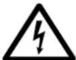
This symbol, wherever it appears, alerts you to the presence of uninsulated dangerous voltage inside the
enclosure - voltage that may be sufficient to constitute a risk of shock.

This symbol, wherever it appears, alerts you to important operating and maintenance instructions in the
accompanying literature. Please read the manual.

Caution
To reduce the risk of electric shock, do not remove the top cover (or the rear section).
No user serviceable parts inside. Refer servicing to qualified personnel.

Caution
To reduce the risk of fire or electric shock, do not expose this appliance to rain and
moisture. The apparatus shall not be exposed to dripping or splashing liquids and no objects filled with liquids, such as vases, shall be placed on the apparatus.

Caution
These service instructions are for use by qualified service personnel only.
To reduce the risk of electric shock do not perform any servicing other than that contained in the operation instructions. Repairs have to be performed by qualified service personnel.
- Read these instructions.
- Keep these instructions.
- Heed all warnings.
- Follow all instructions.
- Do not use this apparatus near water.
-
Clean only with dry cloth.
-
Do not block any ventilation openings. Install in accordance with the manufacturer's instructions.
-
Do not install near any heat sources such as radiators, heat registers, stoves, or other apparatus (including amplifiers) that produce heat.
-
Do not defeat the safety purpose of the polarized or grounding-type plug. A polarized plug has two blades with one wider than the other. A grounding-type plug has two blades and a third grounding prong. The wide blade or the third prong are provided for your safety. If the provided plug does not fit into your outlet, consult an electrician for replacement of the obsolete outlet.
- Protect the power cord from being walked on or pinched particularly at plugs, convenience receptacles, and the point where they exit from the apparatus.
- Use only attachments/accessories specified by the manufacturer.

natural_image
Silhouette of a person pushing a large cart with a ladder, enclosed in a circular frame (no text or symbols)- Use only with the cart, stand, tripod, bracket, or table specified by the manufacturer, or sold with the apparatus. When a cart is used, use caution when moving the cart/apparatus combination to avoid
injury from tip-over.
- Unplug this apparatus during lightning storms or when unused for long periods of time.
- Refer all servicing to qualified service personnel. Servicing is required when the apparatus has been damaged in any way, such as power supply cord or plug is damaged, liquid has been spilled or objects have fallen into the apparatus, the apparatus has been exposed to rain or moisture, does not operate normally, or has been dropped.
- The apparatus shall be connected to a MAINS socket outlet with a protective earthing connection.
- Where the MAINS plug or an appliance coupler is used as the disconnect device, the disconnect device shall remain readily operable.

LEGAL DISCLAIMER
TECHNICAL SPECIFICATIONS AND APPEARANCES ARE SUBJECT TO CHANGE WITHOUT NOTICE AND ACCURACY IS NOT GUARANTEED. BEHRINGER IS PART OF THE MUSIC GROUP (MUSIC-GROUP.COM). ALL TRADEMARKS ARE THE PROPERTY OF THEIR RESPECTIVE OWNERS. MUSIC GROUP ACCEPTS NO LIABILITY FOR ANY LOSS WHICH MAY BE SUFFERED BY ANY PERSON WHO RELIES EITHER WHOLLY OR IN PART UPON ANY DESCRIPTION, PHOTOGRAPH OR STATEMENT CONTAINED HEREIN. COLORS AND SPECIFICATIONS MAY VARY FROM ACTUAL PRODUCT. MUSIC GROUP PRODUCTS ARE SOLD THROUGH AUTHORIZED FULLFILLERS AND RESELLERS ONLY. FULLFILLERS AND RESELLERS ARE NOT AGENTS OF MUSIC GROUP AND HAVE ABSOLUTELY NO AUTHORITY TO BIND MUSIC GROUP BY ANY EXPRESS OR IMPLIED
UNDERTAKING OR REPRESENTATION. THIS MANUAL IS COPYRIGHTED. NO PART OF THIS MANUAL MAY BE REPRODUCED OR TRANSMITTED IN ANY FORM OR BY ANY MEANS, ELECTRONIC OR MECHANICAL, INCLUDING PHOTOCOPYING AND RECORDING OF ANY KIND, FOR ANY PURPOSE, WITHOUT THE EXPRESS WRITTEN PERMISSION OF MUSIC GROUP IP LTD.
ALL RIGHTS RESERVED.
© 2011 MUSIC Group IP Ltd.
Trident Chambers, Wickhams Cay, P.O. Box 146, Road Town, Tortola, British Virgin Islands
LIMITED WARRANTY
§ 1 Warranty
This limited warranty is valid only if you purchased the product from a MUSIC Group Authorized Reseller in the country of purchase. A list of authorized resellers can be found on BEHRINGER's website behringer. com under "Where to Buy", or you can contact the MUSIC Group office closest to you.
2 MUSIC Group* warrants the mechanical and electronic components of this product to be free of defects in material and workmanship if used under normal operating conditions for a period of one (1) year from the original date of purchase (see the Limited Warranty terms in § 4 below), unless a longer minimum warranty period is mandated by applicable local laws. If the product shows any defects within the specified warranty period and that defect is not excluded under § 4, MUSIC Group shall, at its discretion, either replace or repair the product using suitable new or reconditioned product or parts. In case MUSIC Group decides to replace the entire product, this limited warranty shall apply to the replacement product for the remaining initial warranty period, i.e., one (1) year (or otherwise applicable minimum warranty period) from the date of purchase of the original product.
3 Upon validation of the warranty claim, the repaired or replacement product will be returned to the user freight prepaid by MUSIC Group.
4 Warranty claims other than those indicated above are expressly excluded.
PLEASE RETAIN YOUR SALES RECEIPT. IT IS YOUR PROOF OF PURCHASE COVERING YOUR LIMITED WARRANTY. THIS LIMITED WARRANTY IS VOID WITHOUT SUCH PROOF OF PURCHASE.
§ 2 Online registration
Please do remember to register your new BEHRINGER equipment right after your purchase at behringer. com under "Support" and kindly read the terms and conditions of our limited warranty carefully. Registering your purchase and equipment with us helps us process your repair claims quicker and more efficiently. Thank you for your cooperation!
§ 3 Return materials authorization
To obtain warranty service, please contact the retailer from whom the equipment was purchased. Should your MUSIC Group Authorized Reseller not be located in your vicinity, you may contact the MUSIC Group Authorized Fulfiler for your country listed under
EN
"Support" at behringer. com. If your country is not listed, please check if your problem can be dealt with by our "Online Support" which may also be found under "Support" at behringer. com. Alternatively, please submit an online warranty claim at behringer. com BEFORE returning the product. All inquiries must be accompanied by a description of the problem and the serial number of the product. After verifying the product's warranty eligibility with the original sales receipt, MUSIC Group will then issue a Return Materials Authorization ("RMA") number.
☐ Subsequently, the product must be returned in its original shipping carton, together with the return authorization number to the address indicated by MUSIC Group.
3 Shipments without freight prepaid will not be accepted.
§ 4 Warranty Exclusions
This limited warranty does not cover consumable parts including, but not limited to, fuses and batteries. Where applicable, MUSIC Group warrants the valves or meters contained in the product to be free from defects in material and workmanship for a period of ninety (90) days from date of purchase.
This limited warranty does not cover the product if it has been electronically or mechanically modified in any way. If the product needs to be modified or adapted in order to comply with applicable technical or safety standards on a national or local level, in any country which is not the country for which the product was originally developed and manufactured, this modification/adaptation shall not be considered a defect in materials or workmanship. This limited warranty does not cover any such modification/adaptation, regardless of whether it was carried out properly or not. Under the terms of this limited warranty, MUSIC Group shall not be held responsible for any cost resulting from such a modification/adaptation.
3 This limited warranty covers only the product hardware. It does not cover technical assistance for hardware or software usage and it does not cover any software products whether or not contained in the product. Any such software is provided "AS IS" unless expressly provided for in any enclosed software limited warranty.
4 This limited warranty is invalid if the factory- applied serial number has been altered or removed from the product.
⑤ Free inspections and maintenance/repair work are expressly excluded from this limited warranty, in particular, if caused by improper handling of the product by the user. This also applies to defects caused by normal wear and tear, in particular, of faders, crossfaders, potentiometers, keys buttons, guitar strings, illuminants and similar parts.
6 Damage/defects caused by the following conditions are not covered by this limited warranty:
- improper handling, neglect or failure to operate the unit in compliance with the instructions given in BEHRINGER user or service manuals;
- connection or operation of the unit in any way that does not comply with the technical or safety regulations applicable in the country where the product is used;
- damage/defects caused by acts of God/Nature (accident, fire, flood, etc) or any other condition that is beyond the control of MUSIC Group.
7 Any repair or opening of the unit carried out by unauthorized personnel (user included) will void the limited warranty.
8 If an inspection of the product by MUSIC Group shows that the defect in question is not covered by the limited warranty, the inspection costs are payable by the customer.
9 Products which do not meet the terms of this limited warranty will be repaired exclusively at the buyer's expense. MUSIC Group or its authorized service center will inform the buyer of any such circumstance. If the buyer fails to submit a written repair order within 6 weeks after notification, MUSIC Group will return the unit C.O.D. with a separate invoice for freight and packing. Such costs will also be invoiced separately when the buyer has sent in a written repair order.
⑩ MUSIC Group Authorized Resellers do not sell new products directly in online auctions. Purchases made through an online auction are on a "buyer beware" basis. Online auction confirmations or sales receipts are not accepted for warranty verification and MUSIC Group will not repair or replace any product purchased through an online auction.
§ 5 Warranty transferability
This limited warranty is extended exclusively to the original buyer (customer of authorized reseller) and is not transferable to anyone who may subsequently purchase this product. No other person (reseller, etc.) shall be entitled to give any warranty promise on behalf of MUSIC Group.
§ 6 Claim for damage
Subject only to the operation of mandatory applicable local laws, MUSIC Group shall have no liability to the buyer under this warranty for any consequential or indirect loss or damage of any kind. In no event shall the liability of MUSIC Group under this limited warranty exceed the invoiced value of the product.
§ 7 Limitation of liability
This limited warranty is the complete and exclusive warranty between you and MUSIC Group. It supersedes all other written or oral communications related to this product. MUSIC Group provides no other warranties for this product.
§ 8 Other warranty rights and national law
1 This limited warranty does not exclude or limit the buyer's statutory rights as a consumer in any way.
2 The limited warranty regulations mentioned herein are applicable unless they constitute an infringement of applicable mandatory local laws.
3 This warranty does not detract from the seller's obligations in regard to any lack of conformity of the product and any hidden defect.
§ 9 Amendment
Warranty service conditions are subject to change without notice. For the latest warranty terms and conditions and additional information regarding MUSIC Group's limited warranty, please see complete details online at behringer.com.
* MUSIC Group Macao Commercial Off shore Limited of Rue de Pequim No. 202-A, Macau Finance Centre 9/J, Macau, including all MUSIC Group companies
1. Introduction
Honestly, who really likes to read manuals? We know you want to get started right away, but please read this manual carefully and keep it for future reference. It is only after reading these instructions that you will fully understand and be able to use all the features your EUROPOWER amplifier has to offer.
1.1 Before you get started
1.1.1 Shipment
Your EUROPOWER was carefully packed at the factory, and the packaging is designed to protect the unit from rough handling. Nevertheless, we recommend that you carefully examine the packaging and its contents for any signs of physical damage, which may have occurred during transit.
If the unit is damaged, please do NOT return it to BEHRINGER, but notify your dealer and the shipping company immediately. Otherwise, claims for damage or replacement may not be granted.
1.1.2 Initial operation
Please make sure the unit is provided with sufficient ventilation, and never place your EUROPOWER amp on top of other heat-emanating equipment or in the vicinity of a heater to avoid the risk of overheating.
The mains connection is made via the enclosed power cord and a standard IEC receptacle. It meets all international safety certification requirements.
Please make sure that all units have a proper ground connection. For your own safety, never remove or disable the ground conductor from the unit or the AC power cord.
The sound quality may diminish within the range of powerful broadcasting stations and high-frequency sources. Increase the distance between the transmitter and the device and use shielded cables for all connections.
1.1.3 Online registration
Please register your new BEHRINGER equipment right after your purchase by visiting http://behringer.com and read the terms and conditions of our warranty carefully.
Should your BEHRINGER product malfunction, it is our intention to have it repaired as quickly as possible. To arrange for warranty service, please contact the BEHRINGER retailer from whom the equipment was purchased. Should your BEHRINGER dealer not be located in your vicinity, you may directly contact one of our subsidiaries. Corresponding contact information is included in the original equipment packaging (Global Contact Information/European Contact Information). Should your country not be listed, please contact the distributor nearest you. A list of distributors can be found in the support area of our website (http://behringer.com).
Registering your purchase and equipment with us helps us process your repair claims more quickly and efficiently.
Thank you for your cooperation!
2. Control Elements
2.1 Front panel
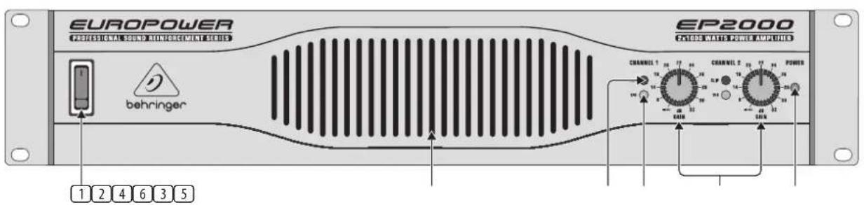
Fig. 2.1: Front panel control elements
Since control elements of both the EP2000 and the EP4000 are identical, we have used the EP2000 as the model represented in the illustrations to assure simplicity.
① The MAIN SWITCH is used to power up the amp.
Merely switching the unit off does not mean that it is fully disconnected from the mains. When not using the unit for prolonged periods of time, please unplug the unit's power cord from the power outlet.
2 VENTILATION openings are located at the front of the unit, so that hot air is prevented from being trapped inside the unit, thus causing faulty operation or even damage.
3 The CLIP LED lights up when the signal is distorted. Should distortion occur, reduce the input level, so that the CLIP LED stops lighting up.
④ The SIGNAL LED lights up as long as a signal is present at the input.
5 The GAIN control (channels 1 and 2) is used for setting up the input gain.
6 The POWER LED lights up as soon as the unit is powered up.
EN
2.2 Rear panel
flowchart
graph TD
    A["INPUT"] --> B["OUTPUT 1"]
    B --> C["OUTPUT 2"]
    C --> D["BREAKER"]
    D --> E["POWER"]
    E --> F["EUROPOWER MODEL EP2000"]
    F --> G["SERIAL NUMBER"]
    G --> H["DATE CODE"]

    subgraph INPUT
        I["INPUT 1: -300 TANEO & CLAS, 2.5 THO & TAIC, 2.7 THO & TAIC, 2.8 THO & TAIC, 2.9 THO & TAIC, 3.0 THO & TAIC, 3.1 THO & TAIC, 3.2 THO & TAIC, 3.3 THO & TAIC, 3.4 THO & TAIC, 3.5 THO & TAIC, 3.6 THO & TAIC, 3.7 THO & TAIC, 3.8 THO & TAIC, 3.9 THO & TAIC, 4.0 THO & TAIC, 4.1 THO & TAIC, 4.2 THO & TAIC, 4.3 THO & TAIC, 4.4 THO & TAIC, 4.5 THO & TAIC, 4.6 THO & TAIC, 4.7 THO & TAIC, 4.8 THO & TAIC, 4.9 THO & TAIC, 5.0 THO & TAIC, 5.1 THO & TAIC, 5.2 THO & TAIC, 5.3 THO & TAIC, 5.4 THO & TAIC, 5.5 THO & TAIC, 5.6 THO & TAIC, 5.7 THO & TAIC, 5.8 THO & TAIC, 5.9 THO & TAIC, 6.0 THO & TAIC<br>    end<br>    <br>    subgraph OUTPUT<br>        U[OUTPUT 2: PROSET SWITCHER INPUT 1: -300 TANEO & CLAS, 2.5 THO & TAIC, 2.7 THO & TAIC, 2.8 THO & TAIC, 2.9 THO & TAIC, 3.0 THO & TAIC, 3.1 THO & TAIC, 3.2 THO & TAIC, 3.3 THO & TAIC, 3.4 THo & TAIC, 3.5 THO & TAIC, 3.6 THO & TAIC, 3.7 THO & TAIC, 3.8 THO & TAIC, 3.9 THO & TAIC, 4.0 THO & TAIC<br>    end<br>    <br>    subgraph OUTPUT_1<br>        V[OUTPUT 1: PROSET SWITCHER INPUT 2: -300 TANEO & CLAS, 2.5 THO & TAIC, 2.7 THO & TAIC, 2.8 THO & TAIC, 2.9 THO & TAIC, 3.0 THO & TAIC, 3.1 THO & TAIC, 3.2 THO & TAIC, 3.3 THo & TAIC, 3.4 THo & TAIC, 3.5 THo & TAIC<br>    end<br>    <br>    subgraph OUTPUT_2<br>        W[OUTPUT 2: PROSET SWITCHER INPUT 3: -300 TANEO & CLAS, 2.5 THO & TAIC, 2.7 THO & TAIC, 2.8THO & TAIC, 2.9THO & TAIC, 3.0THO & TAIC, 3.1THO & TAIC, 3.2THo & TAIC, 3.3THo & TAIC, 3.4THo & TAIC<br>    end<br>    <br>    subgraph OUTPUT_3<br>        X[OUTPUT 3: PROSET SWITCHER INPUT 4: -300 TANEO & CLAS, 2.5THO & TAIC, 2.7THO & TAIC, 2.8THO & TAIC, 2.9THO & TAIC, 3.0THo & TAIC, 3.1THo & TAIC, 3.2THo & TAIC<br>    end<br>    <br>    subgraph OUTPUT_4<br>        Y[OUTPUT 4: PROSET SWITCHER INPUT 5: -300 TANEO & CLAS, 2.5THO & TAIC, 2.7THO & TAIC, 2.8THO & TAIC, 2.9THo & TAIC, 3.0THo & TAIC, 3.1THo & TAIC<br>    end<br>    <br>    subgraph OUTPUT_5<br>        Z[OUTPUT 5: PROSET SWITCHER INPUT 6: -300 TANEO & CLAS, 2.5THO & TAIC, 2.7THO & TAIC, 2.8THO & TAIC, 2.9THo & TAIC, 3.0THo & TAIC<br>    end<br>    <br>    subgraph OUTPUT_6<br>        AA[OUTPUT 6: PROSET SWITCHER INPUT 7: -300 TANEO & CLAS, 2.5THO & TAIC, 2.7THO & TAIC, 2.8THo & TAIC, 2.9THo & TAIC<br>    end<br>    <br>    subgraph OUTPUT_7<br>        AB[OUTPUT 7: PROSET SWITCHER INPUT 8: -300 TANEO & CLAS, 2.5THO & TAIC, 2.7THO & TAIC, 2.8THo & TAIC, 2.9THo & TAIC<br>    end<br>    <br>    subgraph OUTPUT_8<br>        AC[OUTPUT 8: PROSET SWITCHER INPUT 9: -300 TANEO & CLAS, 2.5THO & TAIC, 2.7THO & TAIC, 2.8THo & TAIC<br>    end<br>    <br>    subgraph OUTPUT_9<br>        AD[OUTPUT 9: PROSET SWITCHER INPUT"] --> AE["OUTPUT 10: PROSET SWITCHER INPUT"]
    end

    subgraph OUTPUT_10
        AF["OUTPUT 11: PROSET SWITCHER INPUT"]
    end

    subgraph OUTPUT_11
        AG["OUTPUT 12: PROSET SWITCHER INPUT"]
    end

    subgraph OUTPUT_12
        AH["OUTPUT 13: PROSET SWITCHER INPUT"]
    end

    subgraph OUTPUT_13
        AI["OUTPUT 14: PROSET SWITCHER INPUT"]
    end

    subgraph OUTPUT_14
        AJ["OUTPUT 15: PROSET SWITCHER INPUT"]
    end

    subgraph OUTPUT_15
        AK["OUTPUT 16: PROSET SWITCHER INPUT"]
    end

    subgraph OUTPUT_16
        AL["OUTPUT 17: PROSET SWITCHER INPUT"]
    end

    subgraph OUTPUT_17
        AM["OUTPUT 18: PROSET SWITCHER INPUT"]
    end

    subgraph OUTPUT_18
        AN["OUTPUT 19: PROSET SWITCHER INPUT"]
    end

    subgraph OUTPUT_19
        AO["OUTPUT 20: PROSET SWITCHER INPUT"]
    end

    subgraph OUTPUT_20
        AP["OUTPUT 21: PROSET SWITCHER INPUT"]
    end

    subgraph OUTPUT_21
        AQ["OUTPUT 22: PROSET SWITCHER INPUT"]
    end

    subgraph OUTPUT_22
        AR["OUTPUT 23: PROSET SWITCHER INPUT"]
    end

    subgraph OUTPUT_23
        AS["OUTPUT 24: PROSET SWITCHER INPUT"]
    end

    subgraph OUTPUT_24
        AT["OUTPUT 25: PROSET SWITCHER INPUT"]
    end

    subgraph OUTPUT_25
        AU["OUTPUT 26: PROSET SWITCHER INPUT"]
    end

    subgraph OUTPUT_26
        AV["OUTPUT 27: PROSET SWITCHER INPUT"]
    end

    subgraph OUTPUT_27
        AW["OUTPUT 28: PROSET SWITCHER INPUT"]
    end

    subgraph OUTPUT_28
        AX["OUTPUT 29: PROSET SWITCHER INPUT"]
    end

    subgraph OUTPUT_29
        AY["OUTPUT 30: PROSET SWITCHER INPUT"]
    end

    subgraph OUTPUT_30
        AZ["OUTPUT 31: PROSET SWITCHER INPUT"]
    end

    subgraph OUTPUT_31
        BA["OUTPUT 32: PROSET SWITCHER INPUT"]
    end

    subgraph OUTPUT_32
        BB["OUTPUT 33: PROSET SWITCHER INPUT"]
    end

    subgraph OUTPUT_33
        BC["OUTPUT 34: PROSET SWITCHER INPUT"]
    end

    subgraph OUTPUT_34
        BD["OUTPUT 35: PROSET SWITCHER INPUT"]
    end

    subgraph OUTPUT_35
        BE["OUTPUT 36: PROSET SWITCHER INPUT"]
    end

    subgraph OUTPUT_36
        BF["OUTPUT 37: PROSET SWITCHER INPUT"]
    end

    subgraph OUTPUT_37
        BG["OUTPUT 38: PROSET SWITCHER INPUT"]
    end

    subgraph OUTPUT_38
        BH["OUTPUT 39: PROSET SWITCHER INPUT"]
    end

    subgraph OUTPUT_39
        BI["OUTPUT 40: PROSET SWITCHER INPUT"]
    end

    subgraph OUTPUT_40
        BJ["OUTPUT 41: PROSET SWITCHER INPUT"]
    end

    subgraph OUTPUT_41
        BK["OUTPUT 42: PROSET SWITCHER INPUT"]
    end

    subgraph OUTPUT_42
        BL["OUTPUT 43: PROSET SWITCHER INPUT"]
    end

    subgraph OUTPUT_43
        BM["OUTPUT 44: PROSET SWITCHER INPUT"]
    end

    subgraph OUTPUT_44
        BN["OUTPUT 45: PROSET SWITCHER INPUT"]
    end

    subgraph OUTPUT_45
        BO["OUTPUT 46: PROSET SWITCHER INPUT"]
    end

    subgraph OUTPUT_46
        BP["OUTPUT 47: PROSET SWITCHER INPUT"]
    end

    subgraph OUTPUT_47
        BQ["OUTPUT 48: PROSET SWITCHER INPUT"]
    end

    subgraph OUTPUT_48
        BR["OUTPUT 49: PROSET SWITCHER INPUT"]
    end

    subgraph OUTPUT_49
        BS["OUTPUT 50: PROSET SWITCHER INPUT"]
    end

    subgraph OUTPUT_50
        BT["OUTPUT 51: PROSET SWITCHER INPUT"]
    end

    subgraph OUTPUT_51
        BU["OUTPUT 52: PROSET SWITCHER INPUT"]
    end

    subgraph OUTPUT_52
        BV["OUTPUT 53: PROSET SWITCHER INPUT"]
    end

    subgraph OUTPUT_53
        BW["OUTPUT 54: PROSET SWITCHER INPUT"]
    end

    subgraph OUTPUT_54
        BX["OUTPUT 55: PROSET SWITCHER INPUT"]
    end

    subgraph OUTPUT_55
        BY["OUTPUT 56: PROSET SWITCHER INPUT"]
    end

    subgraph OUTPUT_56
        BZ["OUTPUT 57: PROSET SWITCHER INPUT"]
    end

    subgraph OUTPUT_57
        CA["OUTPUT 58: PROSET SWITCHER INPUT"]
    end

    subgraph OUTPUT_58
        CB["OUTPUT 59: PROSET SWITCHER INPUT"]
    end

    subgraph OUTPUT_59
        CC["OUTPUT 60: PROSET SWITCHER INPUT"]
    end

    subgraph OUTPUT_60
        CD["OUTPUT 61: PROSET SWITCHER INPUT"]
    end

    subgraph OUTPUT_61
        CE["OUTPUT 62: PROSET SWITCHER INPUT"]
    end

    subgraph OUTPUT_62
        CF["OUTPUT 63: PROSET SWITCHER INPUT"]
    end

    subgraph OUTPUT_63
        CG["OUTPUT 64: PROSET SWITCHER INPUT"]
    end

    subgraph OUTPUT_64
        CH["OUTPUT 65: PROSET SWITCHER INPUT"]
    end

    subgraph OUTPUT_65
        CI["OUTPUT 66: PROSET SWITCHER INPUT"]
    end

    subgraph OUTPUT_66
        CJ["OUTPUT 67: PROSET SWITCHER INPUT"]
    end

    subgraph OUTPUT_67
        CK["OUTPUT 68: PROSET SWITCHER INPUT"]
    end

    subgraph OUTPUT_68
        CR["OUTPUT 69: PROSET SWITCHER INPUT"]
    end

    subgraph OUTPUT_69
        CS["OUTPUT 70: PROSET SWITCHER INPUT"]
    end

    subgraph OUTPUT_70
        CT["OUTPUT 71: PROSET SWITCHER INPUT"]
    end

    subgraph OUTPUT_71
        CU["OUTPUT 72: PROSET SWITCHER INPUT"]
    end

    subgraph OUTPUT_72
        DV["OUTPUT 73: PROSET SWITCHER INPUT"]
    end
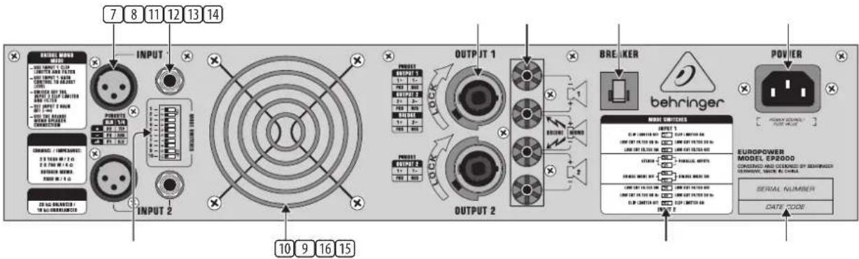
Fig. 2.2: Rear panel control elements
⑦ These are the balanced XLR inputs (channels 1 and 2).
These are the stereo 14 " TRS inputs (channels 1 and 2). They can also be used with unbalanced plugs.
9 These are the MODE switches, used to alter the operating modes as well as to set the limiters and high-pass filters (see chapter 2.3).
10 The unit's fan is located here. Fan speed adjusts automatically to assure trouble-free operation.
To prevent faulty operation, please assure that the unit is kept at a distance from other appliances emanating heat.
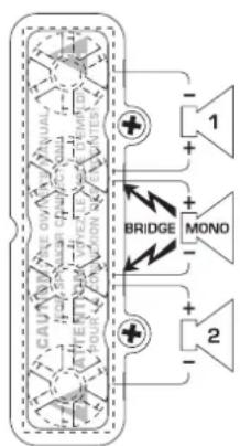
⑪ These are the SPEAKER OUTPUTS (channels 1 and 2). When running the unit in mono-bridged mode (see chapter 2.3.5), please use the channel 1 output exclusively. For further information on the connectors please refer to chapter 4.1.
⑫ These are the OUTPUT TERMINALS (channels 1 and 2). When running in mono, please make sure to use both middle connectors to connect your loudspeaker.
13 BREAKER (automated fuse). After eliminating the cause of faulty operation, simply depress the BREAKER and power up the unit again. The BREAKER acts in place of common discardable fuses.

Caution
Before engaging the BREAKER switch, you should power down the unit (POWER switch set to OFF)!
14 POWER is supplied via an IEC connector. The matching cable is provided with the unit.
15 SERIAL NUMBER of your EUROPOWER.
16 Here you can find a detailed overview of the individual MODE SWITCHES functions 9).
2.3 Configuration switches (MODE SWITCHES)
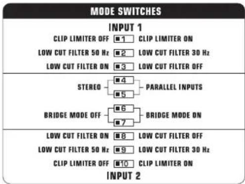
Fig. 2.3: Dip-switches
2.3.1 Clip limiter
When the input signal connected to your amp is too high, you end up with a distorted output signal. To prevent this, both channels of your EUROPOWER feature a clip limiter that can be engaged or disengaged selectively. The limiters automatically recognize distortion and lower amplification until distortion is reduced to a tolerable level. To preserve the dynamic characteristics of the signal when low distortion levels are occurring, the clip limiters function with moderate suppression. Use switches 1 (ch. 1) and 10 (ch. 2) to activate the clip limiters.
When using broadband loudspeaker systems, the clip limiter reduces high frequency distortions which occur when an amplifier is overloaded. The drivers are thus protected from being damaged.
2.3.2 Input filter
The LF (high-pass) filter removes frequencies below 30 and 50 Hz respectively. The reproduction of the signal's bass portion is thus optimized, since ultra-low, distracting frequencies are eliminated, and more power is available for the reproduction of the wanted segment of the signal. Engaging and disengaging the filters is done by using the switches 3 (ch. 1) and 8 (ch. 2). Switches 2 (ch. 1) and 9 (ch. 2) determine the cut-off frequency. As long as the filter is disengaged, frequencies below 5 Hz are cut to prevent damage.
You should set up the filters so they best suit the frequency response of your speakers, since some speakers (e.g. bass reflex speakers) are particularly sensitive to over-excision below the listed frequency range.
The 50 Hz filter should be engaged when using broadband speakers because the filter provides a moderate amplification in the 100-Hz range, resulting in a fuller sound. The 30 Hz filter is ideally suited for subwoofer operation as well as for broadband cabinets. The "Off" setting should be used only for special applications (e.g. studio applications), in which recognizing and subsequently removing infra-sound is important.
2.3.3 2-channel mode (Stereo)
Both channels of your amp function independently from one another in this operating mode, and each has its own input signal. Two independent speakers are connected at the outputs. To activate this operating mode, please set the MODE SWITCHES 4 and 5 to "STEREO".
When running the unit in two-channel mode, the switches for mono-bridged mode must be disengaged (dip switches 6 and 7 in left position).
2.3.4 Parallel mode
Running in parallel mode enables you to feed a signal via one of the inputs into both outputs. Each channel drives its own loudspeaker with independent amplification, filter and limit characteristics. To link the inputs, set the MODE SWITCHES 4 and 5 to "PARALLEL INPUTS".
◇ Mono-bridged mode switches must be disengaged when running in parallel mode.
With inputs set to parallel, you can use the remaining input connectors to feed the signal into additional amplifiers. This means that the channel 2 inputs function as outputs.
The parallel mode is well-suited for applications in which driving two speakers with the same signal but with separate amplification, filter and limiter settings is desired.
2.3.5 Mono-bridged mode
This operating mode enables you to add up the respective voltage of both channels and use it to drive a single loudspeaker. The voltage is therefore doubled, the peak power is quadrupled, and program power is roughly three times as high as that of the individual channels. The input, output, gain, filter and limiter controls belonging to channel 1 are used when running in mono-bridged mode. The controls belonging to channel 2 are not used. To prevent signal cancellation due to internal phase inversion, the GAIN control belonging to channel 2 must be turned to its left-most position.
Use this operating mode to route the power from both channels to a single 8-Ohm or 4-Ohm load. To do so, set up the switches 6 and 7 to "BRIDGE MODE ON". To use the binding posts as your output, you MUST use the two middle posts only.
The mono-bridged mode puts added demands on amplifier and speakers. Excessive distortion may occasionally completely mute the amp's outputs as well as cause permanent damage to the speakers. Please assure that your speakers (minimal impedance 4 Ohms) as well as the cables used can handle the extra power generated in this mode.
3. Applications
Running EUROPOWER amplifiers in conjunction with 8-Ohm speakers with a power rating of at least 2 x 400 Watts (EP2000) and 2 x 750 Watts (EP4000) is recommended to assure optimal operation.
3.1 Differences between 2-channel, parallel and mono-bridged operating modes
2-channel mode is the most common operating mode of amplifiers. Both channels operate fully independently from one another. There is always a separate input signal as well as a separate output signal.
Examples:
• 2-channel (stereo) playback
• Two independent mono signals, e.g. instrument signal and monitor mix
- Bi-amp operation, whereby bass frequencies are run on channel 1, and high frequencies on channel 2 (see chapter 3.2 "Bi-amping")
flowchart
graph TD
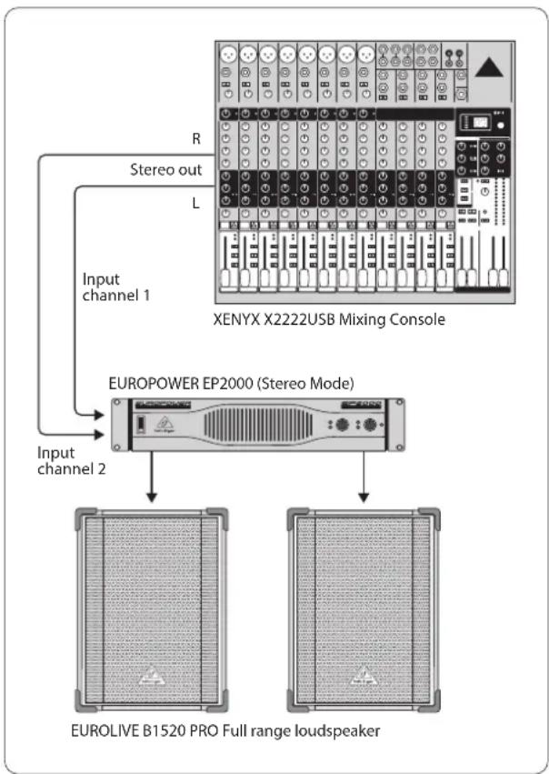
A["Input channel 1"] -->|R Stereo out| B["XENYX X2222USB Mixing Console"]
C["Input channel 2"] --> D["EUROPOWER EP2000 (Stereo Mode)"]
B --> E["EUROLIVE B1520 PRO Full range loudspeaker"]
D --> E
Fig. 3.1: 2-channel mode
EN
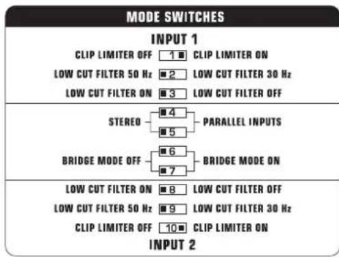
Fig. 3.2: DIP switch positions for 2-channel operation
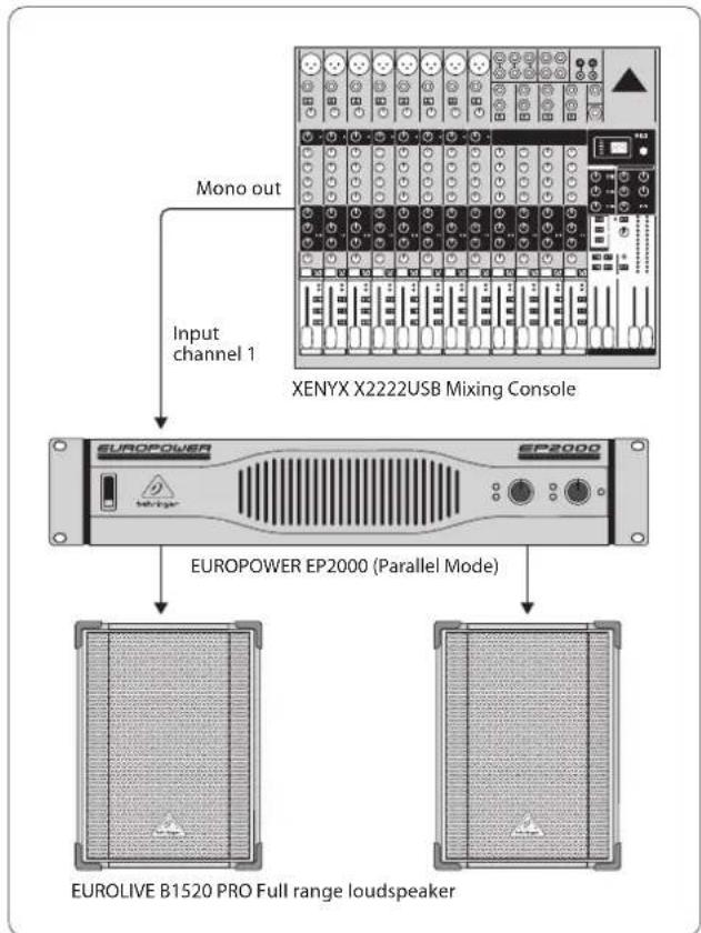
Parallel mode is identical to 2-channel mode, except for the inputs of both channels are internally connected in parallel. One input signal routes parallel both channels, while their filters etc. are independently controlled.
Examples:
- A mono signal is fed into both channels, whereby amplification of each channel is controlled separately
- Parallel mode (as described above) with connection of an additional amp via the remaining free input connector. The input signal is present there and may be connected to further equipment
- When connecting a balanced input signal, please make sure to exclusively use balanced cables for passing the signal further on. Otherwise, a single unbalanced cable can turn the entire signal unbalanced
flowchart
graph TD
    A["Input channel 1"] --> B["XENYX X2222USB Mixing Console"]
    C["Mono out"] --> B
    B --> D["EUROPOWER EP2000 (Parallel Mode)"]
    D --> E["EUROLIVE B1520 PRO Full range loudspeaker"]
Fig. 3.3: Parallel operation
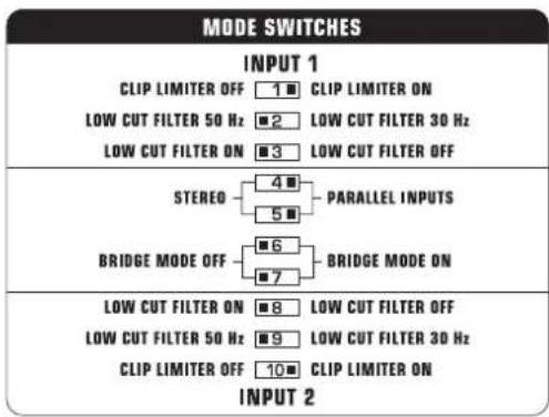
Fig. 3.4: DIP switch positions for parallel operation
When running in mono-bridged mode, the voltage of both channels is added up and fed into a single loudspeaker system. There is one input and one output signal respectively, and only the controls of channel 1 (and not of channel 2) are used.
However, should the DIP switches 4 and 5 still be in PARALLEL INPUTS position while in mono-bridged mode, the signal on the free input (input channel 2) can be forwarded to an additional amp.
Examples:
• Driving a single 8-Ohm loudspeaker
• Driving a single 4-Ohm loudspeaker
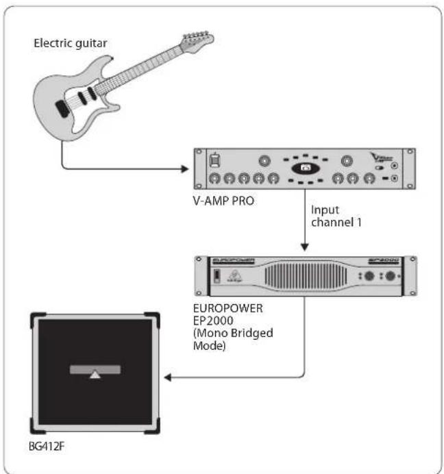
flowchart
graph TD
    A["Electric guitar"] --> B["V-AMP PRO"]
    B --> C["Input channel 1"]
    C --> D["EUROPOWER EP2000 (Mono Bridged Mode)"]
    D --> E["BG412F"]
Fig. 3.5: Mono-bridged mode
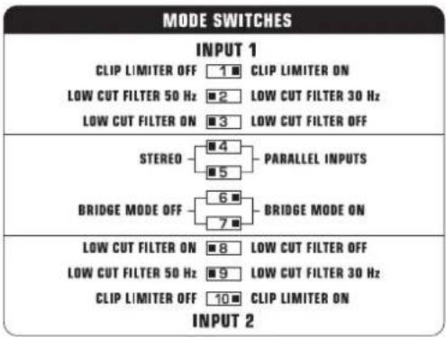
Fig. 3.6: DIP switch positions for mono-bridged mode
When the amp is overdriven for longer periods of time, the output signal may occasionally be muted for several seconds. In certain situations, excessive overdriving may trigger off the automated fuse. To avoid overdriving the amp, please continually make sure that an appropriate volume level is applied.

Caution
◇ 2-Ohm loads should never be applied when in mono-bridged mode.
When connecting a balanced input signal, please make sure to exclusively use balanced cables for passing the signal further on. Otherwise, a single unbalanced cable can turn the entire signal unbalanced.
Safety precautions for mono-bridged operation
Running your amp in mono-bridged mode can quickly result in excessive overdriving and premature shutting down of the unit itself. In the worst-case scenario, your loudspeakers may be damaged permanently. Therefore, you should always make sure that the speakers you use can indeed handle the power load fed into them.
A voltage of up to 100 V RMS is present between the output connectors of the EP4000. Always implement appropriate safety precautions when connecting your speakers to avoid the risk of electric shock.
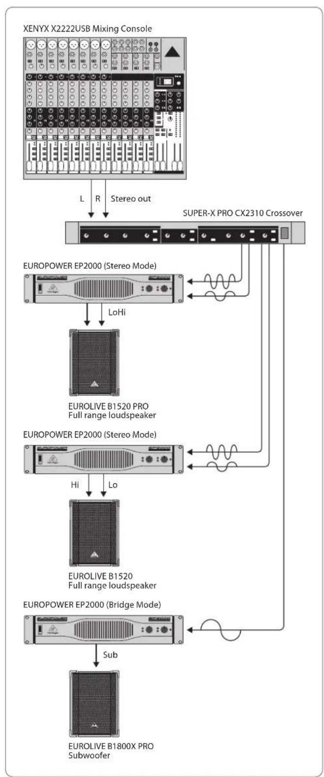
3.2 Bi-amping
By using an active crossover, you can divide up the frequency range into several bands. For example, in doing so you can split a mono signal into upper-frequency and lower-frequency ranges. These two signals can then be hooked up to the inputs of your amp, so that channel 1 amplifies the lows and channel 2 amplifies the highs (2-channel operation). The outputs are connected to a 2-way speaker, whereby the output signal 1 drives the woofer and output signal 2 runs the drivers. Of course, you can use two separate speakers instead of a single 2-way speaker.
A stereo signal can also be split up analogous to the example described above. However, to do that you need two 2-way speakers or 4 separate speakers, two EUROPOWER amps and an active 2-way stereo crossover. The BEHRINGER SUPER-X PRO CX2310 is optimally suited for this task and offers additionally a single mono-subwoofer output. By deploying a third EP2000 amp (preferably in mono-bridged mode) and a subwoofer, you have a perfect setup that adds a low-frequency system to the stereo bi-amp application (see fig. 3.7). The amp's input filters for the high/mid-frequency ranges should in this case be engaged and set at 50 Hz. To remove low, disturbing frequencies from the signal, the input filter for the subwoofer signal should be set at 30 Hz.
The BEHRINGER EUROLIVE SERIES loudspeakers are an outstanding solution for expanding your P.A. system, because each frequency range/application has a speaker type that optimally suits its characteristics.
◇ Extreme clip limiter settings in bi-amp operating mode can result in balance shifting.
flowchart
graph TD
    A["XENYX X2222USB Mixing Console"] -->|L R Stereo out| B["SUPER-X PRO CX2310 Crossover"]
    B --> C["EUROPOWER EP2000 (Stereo Mode)"]
    C -->|LoHi| D["EUROLIVE B1520 PRO Full range loudspeaker"]
    C --> E["EUROPOWER EP2000 (Stereo Mode)"]
    E -->|Hi Lo| F["EUROLIVE B1520 Full range loudspeaker"]
    E --> G["EUROPOWER EP2000 (Bridge Mode)"]
    G -->|Sub| H["EUROLIVE B1800X PRO Subwoofer"]
Fig. 3.7: Stereo bi-amp mode with a separate subwoofer
EN
4. Installation
Your EUROPOWER can be installed into a 19" rack and requires two rack units. Please use four attaching screws and washers for installation. Reinforce the back end, especially for on-the-road use. Please assure that enough cool air reaches the rack, especially when other rack equipment emanates a lot of heat. In the case of the EUROPOWER EP2000 and EP4000, hot air circulates at the front of the unit to thermally relieve the rack enclosure.
☐ Fan speed adjusts automatically and assures safe operation. Never block ventilation openings. Should internal temperature reach extreme values, the unit will shut down automatically.
4.1 Connections
Inputs
Each channel features balanced XLR and 14 " TRS stereo jack inputs, with input impedances of 20 kΩ (balanced) and 10 kΩ (unbalanced). In general, balanced signals cause less noise than unbalanced signals.
For balanced input signals, use the XLR and 1/4" TRS stereo inputs. For unbalanced input signals, use the unused pin of the XLR connector with grounding. No alteration is necessary on mono jack connectors.
Should you register distractive signals such as noise or hissing, we recommend separating the amp input from the signal source. This way, you can quickly determine if the noise originates in the equipment connected to the amp. Always make sure to completely lower amplification of both channels before powering up the amp (GAIN control turned all the way leftward). Otherwise, permanent damage to your speakers may occur.
Outputs
Your EUROPOWER offers several output connection possibilities: two professional speaker connectors and two pairs of touch-safe binding posts. The professional speaker connectors were especially developed for driving high-power speakers. They snap in securely, prevent electric shock and assure correct polarity. The upper connector drives either one or both channels, and is therefore well-suited for mono-bridged operation (1+/2+). The lower connector carries the signals from channel 2 only.
Professional speaker connector (compatible with Neutrik Speakon connectors)
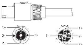
front view rear view
Fig. 4.1: Professional speaker connectors
- Whenever possible, use thick and short speaker cables to minimize power losses. Never lay output cables near input cables.
4.1.1 Using the binding posts
To connect the loudspeakers to the amplifier's binding posts, please do the following:
1) Switch off the amp and disconnect it from the mains (unplug mains connector).
2) Remove the protective plastic covers shielding the binding posts by loosening the two screws on the right-hand side of the connections and lift the plastic cover upwards.
3) Attach the terminal of your loudspeaker cable to the corresponding binding post.
4) Place the protective plastic covers into its original upright position on each binding post and replace the two screws.
◇ Never operate the device without the protective plastic covers in place!
flowchart
graph TD
    A["CAUTIONS CACITOR"] --> B["BRIDGE"]
    B --> C["MONO"]
    C --> D["Output"]
    style A fill:#f9f,stroke:#333
    style B fill:#ccf,stroke:#333
    style C fill:#cfc,stroke:#333
    style D fill:#fcc,stroke:#333
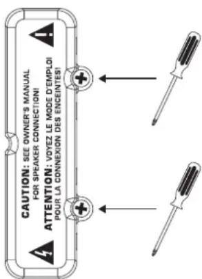
Fig. 4.2: Protective plastic covers shielding the binding posts
When using binding post connectors, please make sure that insulation on cables is not removed too high. Insert the naked part of the cable fully so that no metal is visible. Cable clamps must be isolated to avoid the possibility of electric shock. When running the amp in mono-bridged mode, always use the middle two binding post connectors, paying attention to correct polarity.

Caution
If you notice naked cable endings on the binding post connectors, do not power up the amp because of the risk of electric shock.
4.1.2 Connecting to the mains
Always connect your EUROPOWER amplifier to the voltage specified on the rear of the device. Connecting the amp to an incorrect voltage can permanently damage your amp.
Before powering up the amplifier, double-check all connections and fully lower the gain setting.
4.2 Audio connections
Various cables are needed for different types of applications. The following illustrations show the correct wiring. Always use high-grade cables.
When connecting a balanced input signal, please make sure to exclusively use balanced cables for passing the signal further on. Otherwise, one single unbalanced cable can turn the entire signal unbalanced.
Balanced use with XLR connectors
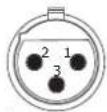
input
1 = ground/shield
2=hot(+ve)
3 = cold (-ve)
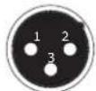
output
For unbalanced use, pin 1 and pin 3
have to be bridged
Fig. 4.3: XLR connectors
Unbalanced 14 " TS connector
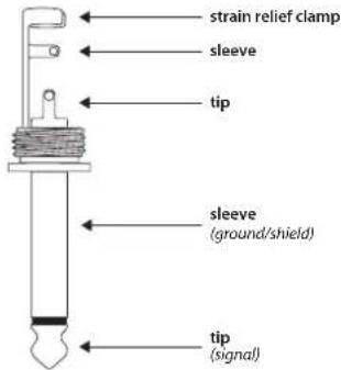
Fig. 4.4: ¼" TS connector
Balanced 14 " TRS connector
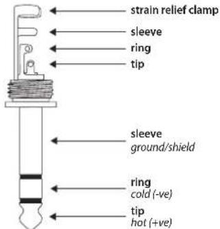
For connection of balanced and unbalanced plugs, ring and sleeve have to be bridged at the stereo pl
Fig. 4.5: ¼" TRS connector
5. Specifications
Output Power
RMS @ 1% THD (Sine Wave), Both Channels Driven
| EP4000 |
| 8 Ω per channel 550 W |
| 4 Ω per channel 950 W |
| 2 Ω per channel 1250 W |
| EP2000 |
| 8 Ω per channel 350 W |
| 4 Ω per channel 500 W |
| 2 Ω per channel 650 W |
RMS @ 1% THD (Sine Wave), Bridged Mode
| EP4000 |
| 8Ω 1750 W |
| 4Ω 2400 W |
| EP2000 |
| 8Ω 1000 W |
| 4Ω 1300 W |
Peak Power, Both Channels Driven
| EP4000 |
| 8 Ω per channel 750 W |
| 4 Ω per channel 1400 W |
| 2 Ω per channel 2000 W |
| EP2000 |
| 8 Ω per channel 400 W |
| 4 Ω per channel 750 W |
| 2 Ω per channel 1000 W |
Peak Power, Bridged Mode
| EP4000 |
| 8Ω 2800 W |
| 4Ω 4000 W |
| EP2000 |
| 8Ω 1500 W |
| 4Ω 2000 W |
EN
Distortion
EP4000 < 0.02%
EP2000 < 0.01%
Frequency Response
at 10 dB below rated output power 20 Hz - 20 kHz, +0/-1 dB
at -3 dB points 5 Hz - 50 kHz
Damping Factor
EP4000/EP2000 > 300 @ 8 Ω
Noise
unweighted, 20 Hz to 20 kHz -100 dB
Voltage Gain
EP4000 50x (34 dB)
EP2000 40x (32 dB)
Input Sensitivity
V RMS (@ 8 Ω) EP2000 1.15 V (+3.4 dBu)
EP4000 1.23 V (+4.0 dBu)
Input Impedance
EP4000/EP2000 10 k Ω unbalanced, 20 k Ω balanced
Controls
Front Power switch, gain control (channels 1 and 2)
Rear DIP switches (10x)
Indicators
POWER green LED
CLIP red LED, 1 per channel
SIGNAL yellow LED, 1 per channel
Connectors
Inputs Balanced XLR and
14 " TRS connectors
Outputs Touch-Proof binding posts and
professional speaker connectors
Cooling
EP4000/EP2000 Continuously variable speed fan, back-to-front air flow
Amplifier Protection
EP4000/EP2000 Full short circuit, open circuit, thermal and HF protection Stable into reactive or mismatched loads
Load Protection
EP4000/EP2000 Turn-on/off muting, AC coupling
Output Circuit Type
EP4000 Class H complementary linear output EP2000 Class AB complementary linear output
Power Supply
Mains Voltage/Breaker
| 100 - 120 V~, 50/60 Hz | 15 A |
| 220 - 230 V~, 50/60 Hz | 8 A |
Power Consumption
| EP4000 2600 W | |
| EP2000 1600 W | |
| Mains connector | Standard IEC receptacle |
Dimensions/Weight
Dimensions (H x W x D)
| EP4000/EP2000 approx. 3.5 x 19 x 15.8" |
| approx. 88 x 483 x 402 mm |
Weight
| EP4000 approx. 36.6 lbs / 16.6 kg |
| EP2000 approx. 34.6 lbs / 15.7 kg |
BEHRINGER makes every effort to ensure the highest standard of quality. Necessary modifications are carried out without notice. Thus, the specifications and design of the device may differ from the information given in this manual.
FEDERAL COMMUNICATIONS COMMISSION COMPLIANCE INFORMATION

BEHRINGER
PRODUCT FAMILY MODEL/MODEL/MODEL
Responsible Party Name: MUSIC Group Services US Inc.
Address: 18912 North Creek Parkway,
Suite 200 Bothell, WA 98011, USA
Phone/Fax No.: Phone: +1 425 672 0816
Fax: +1 425 673 7647
PRODUCT FAMILY MODEL/MODEL/MODEL
complies with the FCC rules as mentioned in the following paragraph:
This equipment has been tested and found to comply with the limits for a Class B digital device, pursuant to part 15 of the FCC Rules. These limits are designed to provide reasonable protection against harmful interference in a residential installation. This equipment generates, uses and can radiate radio frequency energy and, if not installed and used in accordance with the instructions, may cause harmful interference to radio communications. However, there is no guarantee that interference will not occur in a particular installation. If this equipment does cause harmful interference to radio or television reception, which can be determined by turning the equipment off and on, the user is encouraged to try to correct the interference by one or more of the following measures:
• Reorient or relocate the receiving antenna.
• Increase the separation between the equipment and receiver.
- Connect the equipment into an outlet on a circuit different from that to which the receiver is connected.
- Consult the dealer or an experienced radio/TV technician for help.
This device complies with Part 15 of the FCC rules. Operation is subject to the following two conditions:
(1) this device may not cause harmful interference, and
(2) this device must accept any interference received, including interference that may cause undesired operation.
Important information:
Changes or modifications to the equipment not expressly approved by MUSIC Group can void the user's authority to use the equipment.

natural_image
Person applying facial massage to the ear with hands (no text or symbols visible)We Hear You