
DWR-R02D - Receiver SONY - Free user manual and instructions
Find the device manual for free DWR-R02D SONY in PDF.


User questions about DWR-R02D SONY
0 question about this device. Answer the ones you know or ask your own.
Ask a new question about this device
Download the instructions for your Receiver in PDF format for free! Find your manual DWR-R02D - SONY and take your electronic device back in hand. On this page are published all the documents necessary for the use of your device. DWR-R02D by SONY.
USER MANUAL DWR-R02D SONY
Before using this software, please read this manual thoroughly and retain it for future reference.
DWR-R01D/R02D/R02DN/R03D
DWX
DIGITAL WIRELESS
NOTICE TO USERS
© 2010, 2011, 2012, 2013, 2014, 2015, 2016, 2017, 2018, 2019, 2020, 2021, 2022, 2023, 2025 Sony Corporation. All rights reserved. This manual or the software described herein, in whole or in part, may not be reproduced, translated or reduced to any machine readable form without prior written approval from Sony Corporation.
SONY CORPORATION PROVIDES NO WARRANTY WITH REGARD TO THIS MANUAL, THE SOFTWARE OR OTHER INFORMATION CONTAINED HEREIN AND HEREBY EXPRESSLY DISCLAIMS ANY IMPLIED WARRANTIES OF MERCHANTABILITY OR FITNESS FOR ANY PARTICULAR PURPOSE WITH REGARD TO THIS MANUAL, THE SOFTWARE OR SUCH OTHER INFORMATION. IN NO EVENT SHALL SONY CORPORATION BE LIABLE FOR ANY INCIDENTAL, CONSEQUENTIAL OR SPECIAL DAMAGES, WHETHER BASED ON TORT, CONTRACT, OR OTHERWISE, ARISING OUT OF OR IN CONNECTION WITH THIS MANUAL, THE SOFTWARE OR OTHER INFORMATION CONTAINED HEREIN OR THE USE THEREOF.
Sony Corporation reserves the right to make any modification to this manual or the information contained herein at any time without notice.
The software described herein may also be governed by the terms of a separate user license agreement.
Table of Contents
Using This User's Guide......4
Notations Used in This User's Guide ...... 4
About the Window Displays in This User's Guide 4
Important Notes on Operation ....4
Features ....5
Preparing the Software and Devices......6
System Requirements 6
Installing the Software....7
Setting Up the Network 8
Connecting to the Network.... 10
Parts Identification....12
Menus ....14
Basic Operations....16
Device Detection and Monitoring ..... 16
If Problems Occur during Monitoring ..... 17
Selecting Channel Plans 18
Pairing Receiver Channels and Transmitters.... 20
Controlling Devices.... 21
Recording the Signal Environment during Operation.... 23
Using Settings Files 23
Customizing the Screen Display.... 26
Behavior of Wireless Studio when SEARCH RX is Executed.... 28
[Device List] Window ......29
Main Window 32
Status Viewer and Meter Icons.... 32
Receiver Channel Numbering.... 34
About the Frequency Direct Input Function.... 36
Sub Window....37
[Message Log] Tab 37
[Property List] Tab 39
[RF Chart Grapher] Tab.... 40
[RF Chart Analyzer] Tab 47
[Spectrum Analyzer] Tab 48
[Simple Status Viewer] Tab.... 50
[BC-DWX Viewer] Tab 53
Setup Windows....55
[Property] Window 55
[Channel Plan Adviser] Window...... 59
[Omit IP address list] Window 65
[Setting lock] Window.... 65
[Receiver CH Label Settings] Window ..... 66
[GP/CH display setting] Window...... 67
[Display settings] Window 68
[Other settings] Window.... 70
[Network settings] Window.... 71
[Network interface settings] Window...... 71
[Startup settings] Window 73
[Region setting] Window.... 74
Effects of the Diversity Setting on Wireless Studio Displays 74
About the Wireless Studio Display when OUTPUT SWAP is Enabled ...... 76
Dante Audio Monitoring.... 77
Trademarks....82
Open Source Software....82
Using This User's Guide
This guide describes how to use the Wireless Studio software for the DWR-R01D, DWR-R02D,
DWR-R02DN, and DWR-R03D Digital Wireless
Receivers. (These four models are herein referred to collectively as the “receivers.”)
To fully understand this guide, read it in conjunction with the Operating Instructions supplied with the receivers.
Notations Used in This User's Guide
- Clicking a menu or button and then selecting a sub-menu is expressed as follows: Select [Menu (or button)] > [Sub-menu name].
Example: Select [File] menu > [Open].
- Holding down one key on the keyboard while pressing another is indicated by a “+” sign between the two keys.
Example: Press Ctrl + P.
About the Window Displays in This User's Guide
The window displays that appear in this guide may differ from those on your PC, due to differences in the operating system being used.
Important Notes on Operation
Network security
Depending on the operating environment, unauthorized third parties on the network may be able to access the unit. When connecting the unit to the network, be sure to confirm that the network is protected securely. SONY WILL NOT BE LIABLE FOR DAMAGES OR DATA LEAKS OF ANY KIND RESULTING FROM UNAUTHORIZED THIRD-PARTY ACCESS OR SECURITY PROBLEMS OF ANY KIND.
Features
The Wireless Studio software allows you monitor and control a digital wireless system via a network.
The digital wireless system can be accessed from up to six computers.
Note
Up to three computers can be connected at the same time when using DWR-R03D software version earlier than v1.10.
Wireless Studio has the following features.
Device monitoring
The software includes a status viewer for monitoring the operation statuses of the receivers, RMU-01 Remote Control Units, and transmitters.
The status viewer allows you to monitor a list of information that is identical to the information that appears on the initial display of the receiver.
The simple status viewer is also available for efficient monitoring of transmitter operation statuses.
The simple status viewer narrows down the information displayed for each receiver channel to a certain few items, such as the RF meter, QL meter, and alerts, providing a more simplified view.
In addition, the BC-DWX Viewer is available for monitoring and controlling battery chargers.
The BC-DWX Viewer allows you to monitor the charging statuses of the batteries in each charger and configure the charge mode.
Channel plan selection function
Select a channel plan that is suitable for your signal environment to ensure stable operations.
[Channel Plan Adviser] allows you to select a channel plan while taking into account factors such as other TV broadcast waves (that you researched beforehand), frequencies used by other wireless devices in the area, and frequencies detected via the channel scan.
Error logging function
The software automatically saves log files of problems that occur during operation. You can review the error histories at a later time by using a text editor to view the stored log files.
Device control function
The software allows you to control the receivers and the transmitters that are paired with the receivers. Control operations are performed from the [Property] window and the [Property List] tab.
The [Property] window allows you to control a single receiver and its paired transmitter while viewing their operation statuses.
The [Property List] tab allows you to display the settings of multiple receivers and transmitters in a list, and perform fast control operations such as applying the same settings to all the devices simultaneously.
Recalling stored settings and monitoring information
Information such as the setting values of devices and the arrangement of devices in the status viewer can be saved as a file.
You can recall such information in Wireless Studio at a later time by loading these stored files.
The setting values recalled in Wireless Studio can be applied to all the devices.
Pairing-assist function
The software includes a pairing wizard to assist in pairing, an operation that is necessary to enable remote control of transmitters via wireless remote control.
Save and analyze functions for signal environment timelines
The [RF Chart Grapher] function allows you to monitor and save the signal environment and alert information on a timeline, and the [RF Chart Analyzer] function allows you to reference the files saved with the [RF Chart Grapher].
Save and analyze functions for all frequency band signal environments
The [Spectrum Analyzer] function allows you to use the receivers to perform scanning. The scanning results are displayed as a graph, allowing you to visually confirm the existence of interference on frequency bands. The scanning results can be saved as a file which can be used when comparing scanning results.
Preparing the Software and Devices
System Requirements
A computer that meets the following requirements is required to run Wireless Studio.
| Item Requirements | |
| OS Windows | 10 (64-bit) or Windows 11 (64-bit) |
| CPU/RAM CPU | U: Core i5 2.5 GHz or higherRAM: 8 GB or higher |
| Graphics card | Video memory of 128 MB or higher is recommended |
| Disk space 8 | GB or more |
| Monitor 1280 | × 1024 dots or more recommended |
| Other English | display support100Base-TX LAN cardCD-ROM drive |
Operating environment
For details about the recommended operating environment and usage precautions, refer to the release notes for this software on the Sony Professional Products website. You can download software and documentation from the following site.
Sony professional products website:
Japan https://www.sony.jp/pro-audio
All other countries
https://pro.sony/product-resources/product-resources-search/ *
* Click [Change Country, Region or Language] at the bottom of the page and select the region and language. You can also download software and documentation by searching for the name of the target model (for example, "DWR-R03D").
Recommended power settings
We recommend disabling sleep mode as follows on the computer that will run Wireless Studio.
Doing so prevents interruptions in monitoring resulting from network disconnections between Wireless Studio and the digital wireless system caused by the computer entering sleep mode.
For details on how to configure power settings, refer to the operating instructions for your computer and operating system.
For Windows 10
Set [Sleep] to [Never].
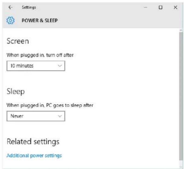
text_image
Settings POWER & SLEEP Screen When plugged in, turn off after 10 minutes Sleep When plugged in, PC goes to sleep after Never Related settings Additional power settingsFor Windows 11
Set [When plugged in, put my device to sleep after] to [Never].
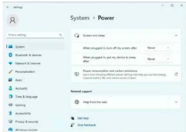
text_image
Settings System > Power Find a setting Screen and sleep System Bluetooth & devices Network & internet Personalization Apps Accounts Time & language Gaming Accessibility Privacy & security Windows Update When plugged in, turn off my screen after Never When plugged in, put my device to sleep after Never Power consumption and carbon emissions Learn how choosing efficient power settings can help you use text energy, Improve battery file, and reduce carton impact Related support Help from the web Get help Give feedbackRecommended display settings
We recommend configuring display settings as follows on the computer that will run Wireless Studio. Running the software under other display settings may result in distorted screen displays.
For details on how to configure display settings, refer to the operating instructions for your computer and operating system.
For Windows 10
Select [100%], [125%], or [150%].
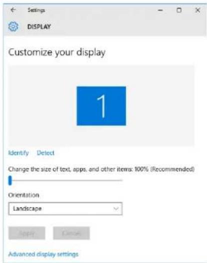
text_image
Settings DISPLAY Customize your display 1 Identify Detect Change the size of text, apps, and other items: 100% (Recommended) Orientation Landscape Apply Cancel Advanced display settingsSelect from [Windows Default Themes] for the theme.
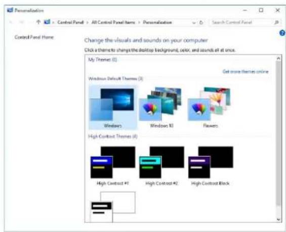
text_image
Personalization Control Panel Here: Change the visuals and sounds on your computer Click a theme to change the desktop background, color, and sounds all at once. My Theme (I) Windows Default Themes (I) Get more themes online Windows Windows X Flowers High Contrast Themes (I) High Contrast #1 High Contrast #2 High Contrast BlackFor Windows 11
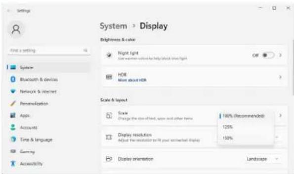
Select [100%], [125%], or [150%].
text_image
System > Display Brightness & color First a setting Night light Light weather colour to help block time light OFF System Bluetooth & devices HOI More about HDR Network & internet Personalization Apps Accounts Time & language Gaming Accessibility Scale & layout Scraw Change the size of fixed, space and other items 100% (Recommended) Display resolution Adjust the resolution to fit your connected display 125% 100% Display orientation LandscapeSelect from the Windows default themes for the theme.
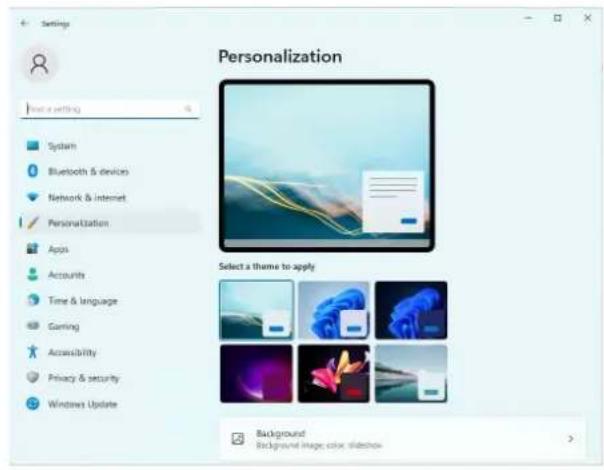
text_image
Settings Personalization Select a theme to apply Background Background image color shadowInstalling the Software
Notes
- If the older version of Wireless Studio is already installed in the PC, uninstall it (see page 8).
- Quit all applications before installing the software.
- Be sure to log in as the administrator.
- Before installing the software, perform Windows Update to update to the latest operating system.
Notes on installation
The installation procedure below describes the operation on the PC that runs Windows 10. Note that the procedure may vary according to the operating system.
1 Download the installer for the latest version of Wireless Studio from the following URL.
Japan https://www.sony.jp/pro-audio All other countries
https://pro.sony/product-resources/product-resources-search/
For details about the above site, see “Operating environment” (page 6).
2 Extract the downloaded compressed file, and double-click "setup.exe."
InstallShield Wizard starts.
3 Select the language, and click [OK].
The [Welcome to the InstallShield Wizard for Wireless Studio] screen appears.
- When an older version of Wireless Studio is already installed:
Uninstallation of the older version is not necessary. - When reinstalling Wireless Studio 5:
Uninstall the existing instance of Wireless Studio 5 before reinstalling.
For details on uninstallation, see “To uninstall the software” (page 8).
If .NET Framework 4.8 is not installed
If .NET Framework 4.8 is not installed, an installation dialog box will appear. Follow its instructions, and perform installation.
4 Click [Next].
5 Read the user agreement for the software, select [I accept the terms in the license agreement], and click [Next].
6 Click [Next].
The [Choose an area] screen appears.
7 Select your region, and click [Next].
8 Confirm the installation location, and change it if necessary.
To change the location, click [Change...] and specify the installation location in the dialog box that appears.
9 Click [Next].
10 Click [Install].
Installation starts.
When the necessary files are copied to the hard disk, the [InstallShield Wizard Completed] screen appears.
11 Click [Finish].
To uninstall the software
Note
The uninstallation procedure below describes the operation on the PC that runs Windows 10. Note that the procedure may vary according to the operating system.
Click and select [Add or Remove Programs] in the Windows Control Panel, then select [Wireless Studio] from the list, and then delete it.
Setting Up the Network
Configure the network connection settings for the receivers, RMU-01, battery chargers, and computer.
IP addresses and subnet masks
- If you are not using a standard network line connection, configure the following private address. Configure values that are unique within the network for the “*” value.
IP Address: 192.168.0.*
Subnet Mask: 255.255.255.0 (fixed length)
- If you are using a standard line connection, consult your network administrator.
Gateways
- If you are using a router, configure the gateway address for the router.
- Specify appropriate settings for the DWR-R03D and BC-DWX1 gateway settings.
For details on configuring the DWR-R03D gateway setting, refer to the Operating Instructions supplied with the DWR-R03D.
For details on configuring the BC-DWX1 gateway setting, refer to the User's Guide for BC-DWX Setting Tool.
Notes
- Version 1.30 or later is required in order to configure the gateway for the DWR-R03D.
- Version 1.10 or later is required in order to configure the gateway for the BC-DWX1.
Receiver network settings
Make settings on the front panel of the receiver.
For details on making the settings, refer to the Operating Instructions supplied with the receiver.
RMU-01 network settings
Make settings by using the Setting Tool software supplied with the RMU-01.
For details on making the settings, refer to the User's Guide supplied with the RMU-01 Setting Tool.
Battery charger network settings
Make settings by using the BC-DWX Setting Tool software.
For details, refer to the User's Guide for BC-DWX Setting Tool.
You can download BC-DWX Setting Tool from the following website.
Japan https://www.sony.jp/pro-audio
All other countries
https://pro.sony/product-resources/product-resources-search/
For details about the above site, see “Operating environment” (page 6).
PC network settings
The following procedure explains the setting operations using the Windows 10 operating system.
For details on how to make network settings with other operating systems, refer to the help of the operating system that you use.
1 Select [Start] > [Windows System] > [Control Panel].
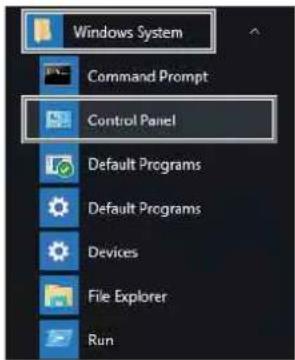
text_image
Windows System Command Prompt Control Panel Default Programs Default Programs Devices File Explorer Run2 Click [View network status and tasks].
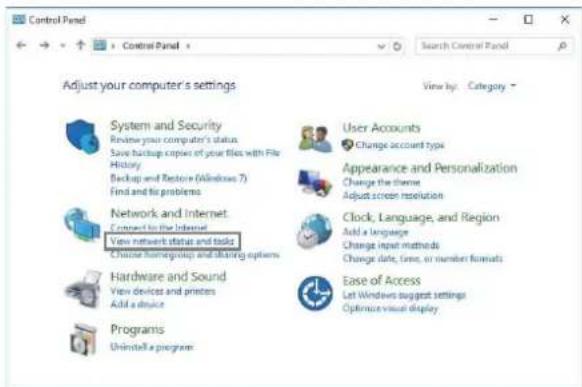
text_image
Control Panel Adjust your computer's settings System and Security Resume your computer's status Save backup copies of your files with File History Backup and Restore (Windows 7) Find and fix problems Network and Internet Connect to the Internet View network status and tasks Choose homegroup and sharing options Hardware and Sound View devices and printers Add a device Programs Uninstall a program View by: Category - User Accounts Change account type Appearance and Personalization Change the theme Adjust screen resolution Clock, Language, and Region Add a Language Change input methods Change date, time, or number formats Ease of Access Let Windows suggest settings Optimize visual display3 Click [Change adapter settings].
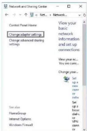
text_image
Network and Sharing Center Control Panel Home Change adapter settings Change advanced sharing settings View your basic network information and set up connections View your ac... You are curre... Change your... Set up a new cons or note Set up a broad dial-s or VPN conn or See also HomeGroup Internet Options Windows Firewall4 Right-click the [Ethernet] icon, and click [Properties].
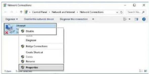
text_image
Network Connections Control Panel > Network and Internet > Network Connections Organize Disable this network device Diagnose this connection Ethernet Disable Diagnose Bridge Connections Create Shortcut Delete Rename Properties 1 item 1 item selectedIf the “Do you want to allow this app to make changes to your device” dialog appears, click [Yes].
5 Double-click [Internet Protocol Version 4 (TCP/IPv4)].
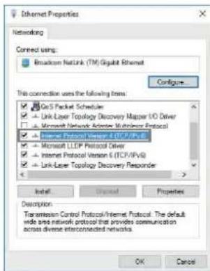
text_image
Ethernet Properties Networking Connect using: Broadcom NetLink (TM) Gigabit Ethernet Configure This connection uses the following items: GoS Packet Scheduler Link Layer Topology Discovery Maps I/O Driver Microsoft Network Articles Multilevel Protocol Internet Protocol Version 4 (TCP/IPv3) Microsoft LLTP Protocol Driver Internet Protocol Version 6 (TCP/IPv5) Link-Layer Topology Discovery Responder Install Ordered Properties Description Transmission Control Protocol/Internet Protocol. The default wide area network protocol that provides communication across diverse interconnected networks. OK CancelThe Internet protocol (TCP/IPv4) properties window appears.
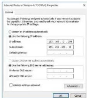
text_image
Internet Protocol Version 4 (TCP/IPv4) Properties General You can get IP settings assigned automatically if your network supports this capability. Otherwise, you need to ask your network administrator for IP appropriate IP settings. Obtain on IP address automatically Use the following IP address: IP address: 192, 268, 0, 300 Submit ready: 255, 255, 255, 0 Default gateway: Obtain DNS server address automatically Use the following DNS server addresses: Preferred DNS server: Alternate DNS server: Validate settings upon exit: Advanced... OK Cancel6 Click [Use the following IP address], and then enter the IP address in the IP address field.
Note
Make sure not to use an IP address that is already assigned to another device on the network.
7 Enter the subnet mask into the subnet mask field.
Note
If you configure a value other than "255 255 255 0," the search for the receiver on the network will take a long time.
8 If configuring a gateway, enter the gateway address in the default gateway field.
9 Click [OK] to close the internet protocol (TCP/IPv4) properties window.
10 Click [Close] to close the local area connection properties window.
Connecting to the Network
When not using a router
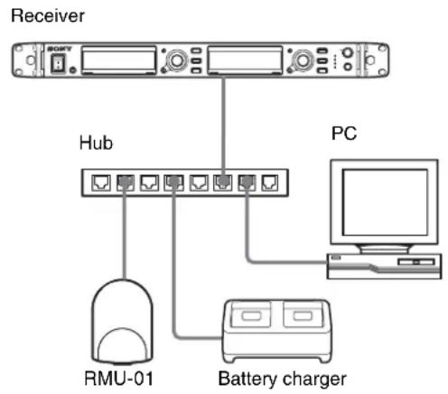
flowchart
graph TD
    A["Receiver"] --> B["PGY"]
    A --> C["Hub"]
    A --> D["PC"]
    B --> E["RMU-01"]
    C --> F["Battery charger"]
    D --> F
    style A fill:#f9f,stroke:#333
    style B fill:#ccf,stroke:#333
    style C fill:#cfc,stroke:#333
    style D fill:#fcc,stroke:#333
    style E fill:#ffc,stroke:#333
    style F fill:#fcc,stroke:#333
Use straight LAN cables to connect the receivers, RMU-01, battery chargers, and computer via a hub. When the network connection is correctly made, the LED on the LAN connector area at the rear of the receiver lights up green.
Connect the devices required for system operation to the rear panel of the receiver.
When using a router
The following shows IP address, subnet mask, and default gateway configuration examples.
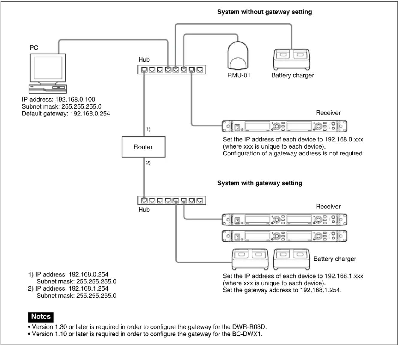
flowchart
graph TD
    A["PC"] --> B["IP address: 192.168.0.100\nSubnet mask: 255.255.255.0\nDefault gateway: 192.168.0.254"]
    B --> C["Router"]
    C --> D["Hub"]
    D --> E["RMU-01"]
    D --> F["Battery charger"]
    C --> G["Hub"]
    G --> H["Receiver"]
    H --> I["Set the IP address of each device to 192.168.0.xxx (where xxx is unique to each device).\nConfiguration of a gateway address is not required."]
    G --> J["Receiver"]
    G --> K["Battery charger"]
    style A fill:#f9f,stroke:#333
    style B fill:#ccf,stroke:#333
    style C fill:#cfc,stroke:#333
    style D fill:#fcc,stroke:#333
    style E fill:#cff,stroke:#333
    style F fill:#ffc,stroke:#333
    style G fill:#fcf,stroke:#333
    style H fill:#cff,stroke:#333
    style I fill:#ffc,stroke:#333
    style J fill:#cff,stroke:#333
    style K fill:#ffc,stroke:#333
For details on connecting devices, refer to the Operating Instructions supplied with the receiver.
Notes
- If the LED on the LAN connector area at the rear of the receiver does not light up green, check the connection.
- For connections, use a category 5 or superior LAN cable with a maximum length of 100m (330 ft). If the connection requires a total cable length exceeding 100m (330 ft), use a hub between the PC and the device.
- Use the cross cables when directly connecting the PC and the devices.
- Do not touch the LAN connector directly with your hands. The transfer of static electricity may result in malfunction of the unit. As static electricity can discharge from your body and clothes, be sure to remove any static electricity before connecting or disconnecting the LAN cable.
Parts Identification
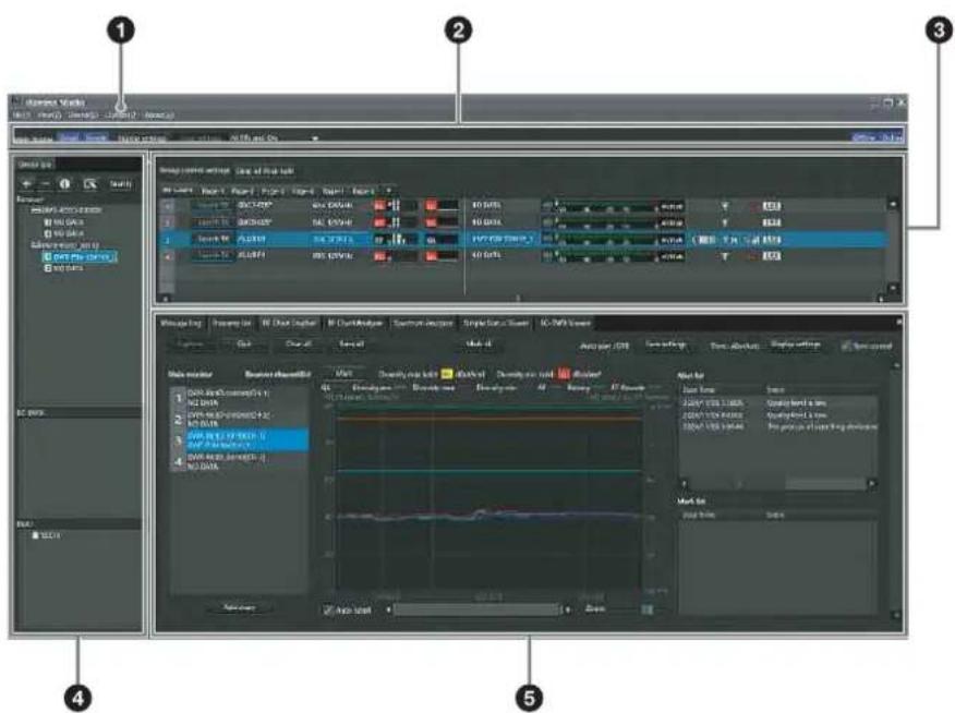
text_image
Screenshot of video editing software interface showing multiple audio and audio waveform panels with labeled UI elements.①Menus
Click on a menu to display the commands in that menu.
For details, see "Menus" (page 14).
②Toolbar
The following settings are available on the toolbar.
Main display: Selects the display mode for the main window.
When [Detail] is selected, the status viewer is displayed in the main window. This allows detailed status monitoring of each channel.
When [Simple] is selected, the simple status viewer is displayed in the main window. This allows basic status monitoring of each channel. The display size for each channel's information can also be changed.
Note
When [Main display] is set to [Simple], the following operations cannot be performed.
- Registering receiver channels to pages other than the [All tuners] page.
- Changing the display positions of receiver channels in pages other than the [All tuners] page.
- Adding, deleting, or renaming pages.
For details, see "Changing the display mode of the main window" (page 26).
Display settings: Opens the [Display settings] window.
Use this to specify whether to display certain setting items and buttons.
For details, see “[Display settings] Window” (page 68).
Load settings: Executes the selected function ([All Rxs], [All Rxs and Txs], or [Select Rxs and Txs]).
All Rxs: Applies the settings to all digital wireless receivers.
All Rxs and Txs: Applies the settings to all digital wireless receivers and transmitters.
Select Rxs and Txs: Applies the settings to the selected digital wireless receivers and transmitters.
Offline / Online: Switches between online mode and offline mode.
③Main window
When [Main display] is set to [Detail] or [Simple], the status viewer or the simple status viewer is displayed, respectively. Information obtained from the receivers is displayed, regardless of the display mode. This allows you to monitor signal reception, audio levels, and other status information for the receivers.
Also, frequency direct input is supported in the frequency display area.
For details, see "Main Window" (page 32).
The following settings are also available.
Group control settings: Changes the setting of each respective button for all the receiver channels displayed in the status viewer at one time.
Note
This does not appear under factory default settings.
All muting: Enables audio output muting for all the receiver channels displayed in the status viewer.
All unmuting: Disables audio output muting for all the receiver channels displayed in the status viewer.
Clear AF Peak hold: Releases the hold status of the AF level meters that appear in the status viewer.
For details, see “[Other settings] Window” (page 70).
You can select whether to display or hide [All muting], [All unmuting], and [Clear AF Peak hold] in the [Display settings] window.
For details, see “[Display settings] Window” (page 68).
④[Device List] window
Lists the receivers, RMU-01 units, and battery chargers that exist on the network.
The devices in the list can be registered to the status viewer for monitoring, or controlled by opening their [Property] windows.
For details, see “[Device List] Window” (page 29).
⑤Sub window
Consists of the following tabs:
[Message Log] tab
Displays warnings and error messages that occurred for devices. The warnings and error messages that appear here are automatically saved as log files.
For details, see “[Message Log] Tab” (page 37).
[Property List] tab
Displays a list of setting values for multiple receivers and transmitters. The devices displayed here are those that are registered to the pages displayed in the status viewer. You can control the receivers and transmitters by selecting the cells in the list and modifying the settings.
For details, see “[Property List] Tab” (page 39).
[RF Chart Grapher] tab
Records the signal reception status obtained from the receivers and up to 24 hours worth of warnings related to the reception status.
For details, see “[RF Chart Grapher] Tab” (page 40).
[RF Chart Analyzer] tab
Allows you to view the information saved in the RF Chart Grapher tab.
For details, see “[RF Chart Analyzer] Tab” (page 47).
[Spectrum Analyzer] tab
Allows you to confirm the signal reception status of the used frequency bands obtained from the receivers.
For details, see “[Spectrum Analyzer] Tab” (page 48).
[Simple Status Viewer] tab
Allows you to narrow down the receiver channel information registered to each status viewer page to a certain few items, such as the RF meter, QL meter, and alerts, and display only those items.
For details, see “[Simple Status Viewer] Tab” (page 50).
[BC-DWX Viewer] tab
Allows you to monitor the charging statuses of the battery chargers on the network and control the charge mode.
For details, see “[BC-DWX Viewer] Tab” (page 53).
Menus
[File] menu
This menu allows you to load existing setting files and save settings.
The [File] menu has the following commands.
Notes
- The [New], [Open], and [Save] commands can only be used in offline mode.
- Setting files created in Wireless Studio 2.01 or later can be used in Wireless Studio 5.1x.
- If you open a settings file created using Wireless Studio 3.02 or earlier in Wireless Studio 5.1x or later, all the transmitter settings are restored to the DWT-B01 default values. Reconfigure the settings before applying the settings to the transmitters.
- If a settings file created in Wireless Studio 5.30 is opened in Wireless Studio 5.00 to 5.22, the settings are not applied correctly. Use version 5.30 or later for files created in Wireless Studio 5.30.
- If a settings file created in Wireless Studio 4.10 to 4.52 is opened in Wireless Studio 5.30, the message “Wireless Studio cannot read Channel Plan Adviser and Spectrum Analyzer information because of file error.” will appear. In this case, re-save the file using Wireless Studio 5.30.
- If [Load settings] is implemented using a dwl file in Wireless Studio 5.50 or earlier, the CHANNEL LABEL setting for DWR-R03D is disabled. Open the [File] menu, specify a name in the [Property] window or [Channel Label] in [Property List], and then reconfigure settings. Or, reconfigure [Receiver channel label] in [Receiver CH Label Setting] after executing [Load settings].
New: Creates a new settings file.
Open: Opens a setting file.
Save: Saves the current settings to a setting file that is already open by overwriting the contents of the file. For setting files that are still unnamed, this command can be used in the same way as the [Save as] command to add a name to a setting file before saving it.
Save as: Adds a name to the current settings and saves them to a setting file (file extension: dw13).
Exit: Exits the Wireless Studio software.
[View] menu
This menu allows you to show or hide each window, and restore the size and layout of each window to their default state from immediately after installation.
The [View] menu has the following commands:
Default Size and Layout: Restores the size and layout of windows to their default state from immediately after installation.
Device List: Shows or hides the [Device List].
Status Viewer: Shows or hides the status viewer.
Message Log: Shows or hides the [Message Log] tab of the sub window.
Property List: Shows or hides the [Property List] tab of the sub window.
RF Chart Grapher: Shows or hides the [RF Chart Grapher] tab of the sub window.
RF Chart Analyzer: Shows or hides the [RF Chart Analyzer] tab of the sub window.
Spectrum Analyzer: Shows or hides the [Spectrum Analyzer] tab of the sub window.
Simple Status Viewer: Shows or hides the [Simple Status Viewer] tab of the sub window.
BC-DWX Viewer: Shows or hides the [BC-DWX Viewer] tab of the sub window.
[Device] menu
This menu allows you to make network connection settings for each device.
The [Device] menu has the following commands:
Online monitoring and control: Switches between online mode and offline mode. The system is in online mode when the check mark appears next to the command, and offline mode when the check mark is cleared.
Load settings: Applies the setting values configured in Wireless Studio to the receivers and transmitters (available in offline mode only).
For details, see "Using Settings Files" (page 23).
Add a new device: Opens the [Add a new device] window. Use this when entering IP addresses to add devices to the device window manually.
For details, see “Manually adding a receiver/battery charger/RMU-01 to the [Device List] window” (page 30).
Search devices: Automatically detects the digital wireless receivers, RMU-01 units, and battery chargers on the same subnet (available in online mode only).
Omit IP address list: Opens the [Omit IP address list] window (available in offline mode only).
For details, see “[Omit IP address list] Window” (page 65).
Setting lock: Opens the [Setting lock] window. Use this to disable or enable the modification of receiver and transmitter settings from Wireless Studio.
For details, see “[Setting lock] Window” (page 65).
Pairing wizard: Opens the [Pairing Wizard] dialog box. Use this to pair receiver channels and transmitters.
For details, see “Pairing Receiver Channels and Transmitters” (page 20).
Channel Plan Adviser: Opens the [Channel Plan Adviser] window. Use this to select channel plans using [Channel Plan Adviser].
For details, see “Selecting Channel Plans” (page 18) and “[Channel Plan Adviser] Window” (page 59).
[Option] menu
The [Option] menu has the following commands: Receiver CH Label Settings: Opens the [Receiver CH Label Settings] window. Use this to configure labels for each receiver channel.
For details, see “[Receiver CH Label Settings] Window” (page 66).
GP/CH Display settings: Opens the [GP/CH display setting] window. Use this to configure the settings for the groups and channels displayed on Wireless Studio.
For details, see “[GP/CH display setting] Window” (page 67).
Display settings: Opens the [Display settings] window. Use this to specify whether to display certain setting items and buttons.
For details, see “[Display settings] Window” (page 68).
Other settings: Opens the [Other settings] window. Configure the peak level hold condition of the AF/PEAK level meter, reception level units, and the ATT/Gain display of the transmitter.
For details, see “[Other settings] Window” (page 70).
Network settings: Opens the [Network settings] window. Displays the network settings of the receivers, battery chargers, and RMU-01 units on the network.
For details, see “[Network settings] Window” (page 71).
Network interface settings: Opens the [Network interface settings] window. You can set network interface card settings and the IP address range of devices to monitor using this software. You can also configure network interface card settings for Dante Virtual Soundcard from Audinate.
For details, see “[Network interface settings] Window” (page 71).
Startup settings: Opens the [Startup settings] window. Use this to configure startup operations for Wireless Studio.
For details, see “[Startup settings] Window” (page 73).
Region setting: Opens the [Region setting] window. Use this when you want to use a receiver model from a region other than the region selected during Wireless Studio installation.
For details, see “[Region setting] Window” (page 74).
[About] menu
The [About] menu has the following commands:
Link to Message Log: Opens the folder in which log files for warnings and error messages are stored. Messages that appear in the [Message Log] tab of the sub window are automatically saved as log files.
System version information: Opens the [System version information] window. Displays the versions of the receivers, battery chargers, and RMU-01 units on the network, and the transmitter versions received from the transmitters by the receivers.
Version information: Indicates the version of the Wireless Studio software.
Basic Operations
Wireless Studio operates in one of two modes, online mode and offline mode.
Online mode
Online mode is used to enable real-time communication between the receivers, battery chargers, and RMU-01 units via the network, and allow monitoring and control of the devices.
Device Detection and Monitoring (page 16)
Locate the receivers, battery chargers, and RMU-01 units on the network, and enable monitoring for these devices. This operation is necessary for the pairing and device control operations that follow.

Selecting Channel Plans (page 18)
Scan the signal environment using the channel scan function of the receiver, and view the results while selecting the channel plan.

Pairing Receiver Channels and Transmitters (page 20)
Pairing is necessary to enable control of the transmitters via wireless remote control. Use the pairing wizard in Wireless Studio to pair receivers and transmitters.

Controlling Devices (page 21)
Perform device controls from the [Property] window and the [Property List] tab of the sub window.

Recording the Signal Environment during Operation (page 23)
Record the signal levels and changes in QL for each receiver. Warnings related to signal reception and QL will also be recorded.
Offline mode
Offline mode is used for settings file operations (saving, recalling, etc.), and applying the settings displayed in Wireless Studio to all devices simultaneously.
Using Settings Files (page 23)
Setting values for receivers and transmitters can be saved as files. You can recall previously used setting values by opening a stored settings file and applying it to the devices.
Device Detection and Monitoring
1 Select [Start] > [Sony] > [Wireless Studio].
2 Place a check mark next to [Online monitoring and control] in the [Device] menu.
The system enters online mode, and the receivers, battery chargers, and RMU-01 units are automatically detected and added to the [Device List] window. Receivers that are added to the device list are automatically registered to the [All tuners] page of the status viewer where they can then be monitored.
For more information on window contents, see "Status Viewer and Meter Icons" (page 32).
Note
The Windows firewall or your security software's firewall may prevent devices from being detected automatically. If the devices are not detected automatically, disable the firewall settings.
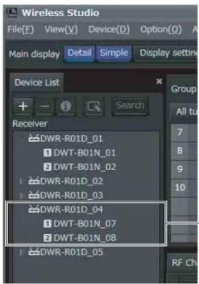
text_image
Wireless Studio File(E) View(V) Device(D) Option(O) Main display Detail Simple Display setting Device List + - Search Receiver DWR-R01D_01 DWT-B01N_01 DWT-B01N_02 DWR-R01D_02 DWR-R01D_03 DWR-R01D_04 DWT-B01N_07 DWT-B01N_08 DWR-R01D_05 Group All tu 7 8 9 10 RF ChClick the ▶ icon to the left of a receiver icon to display the receiver channels.
To monitor a particular set of receiver channels
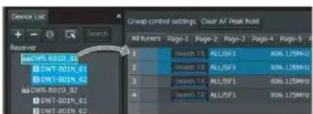
Display a page in the status viewer other than the [All tuners] page, and register receiver channels manually to monitor only the receiver channels that you select. You can view the receiver channel that is selected in the device list in the status viewer by dropping it in the status viewer via your mouse.
text_image
Device List Receiver DWR-801D_01 DWT-501N_01 DWT-801N_02 DWR-801D_02 DWT-501N_03 DWT-801N_04 Group control settings. Clear AF Peak hold All tunters Page-1 Page-2 Page-3 Page-4 Page-5 1 Search FX ALL/DFI 806.125MHz 2 Search FX ALL/DFI 806.125MHz 3 Search FX ALL/DFI 806.125MHz 4 Search FX ALL/DFI 806.125MHzThe following methods are available for selecting receiver channels.
- When you click a single receiver channel, that receiver channel is selected.
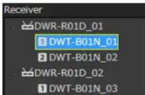
text_image
Receiver DWR-R01D_01 DWT-B01N_01 DWT-B01N_02 DWR-R01D_02 DWT-B01N_03- When you click a receiver, the two receiver channels that are built into that receiver are selected.
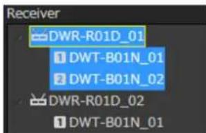
text_image
Receiver DWR-R01D_01 DWT-B01N_01 DWT-B01N_02 DWR-R01D_02 DWT-B01N_01Note
In version 5.50 and later, receiver channels can be registered on pages other than the All tuners page even when [Main display] is set to [Simple] and the simple status viewer is displayed in the main window.
If Problems Occur during Monitoring
See the following table to remedy the problem.
| Problem Cause | Remedy | |
| The receiver is not recognized. | The host name or IP address is already assigned to another device. | Check the host name or IP address settings. |
| It takes long until the receiver is recognized. | If the network has a PC that is connected to a broadband router or the Internet, it may take several minutes to recognize the receiver. | Construct a separate network apart from the one containing the PC with the broadband router or the Internet connection. |
| In the dialog box indicating the receiver detection results, an abnormal value appears in the IP address field. | If your PC is equipped with or connected to a modem or ISDN router, the Wireless Studio software may not function properly when you start it up when either of the conditions described below exist. This is because the PC will attempt to detect device through the modem or router.The receiver is turned off.The LAN cable is disconnected. | Turn on the receiver and make sure the LAN cable is connected. |
| The receiver is not detected automatically. | The Windows firewall or your security software's firewall may prevent devices from being detected automatically. | Disable the firewall settings on the computer. |
| The “Wireless Studio detected version unmatch with DWR-R01D. Please update the firmware of DWR-R01D to ver.1.20 or later” message appears, and monitoring is disabled. | Wireless Studio Ver. 3.0 or later supports Ver. 1.20 or later of the DWR-R01D firmware. | Update the firmware of the receivers. For details, contact your Sony dealer. |
| After switching to online mode or executing [Load settings], the “The network interface card is disabled, please confirm network interface settings in Option menu or the network adapter setting in control panel for OS.” message appears. | When [Layer 3 switching] in [Network interface settings] is set to [Not available]: The network interface card of the PC is disabled.When [Layer 3 switching] in [Network interface settings] is set to [Available]: The network interface selected in [Network interface settings] in the [Option] menu is disabled. | When [Layer 3 switching] in [Network interface settings] is set to [Not available]: Open the network adapter settings in the control panel, and check that at least one network interface card is enabled.When [Layer 3 switching] in [Network interface settings] is set to [Available]: Check that the network interface selected in [Network interface settings] in the [Option] menu is enabled in the network adapter settings in the control panel. |
| After switching to online mode or executing [Load settings], the “Please input at least one IP range for your devices, please confirm network interface settings in Option menu.” message appears. | [IP address range settings] in [Network interface settings] in the [Option] menu is not configured. | Enter the IP address range of the devices being used in [IP address range settings] in [Network interface settings] in the [Option] menu. |
Selecting Channel Plans
To ensure stable operations, select a channel plan that is suitable for your signal environment.
In Wireless Studio, you can ensure more stable operations by performing the procedure found in [Channel Plan Adviser] to select channel plans.
The following modes are available in [Channel Plan Adviser].
Basic mode: This mode allows you to select a channel plan that avoids signal interferences detected by the receiver's channel scan function.
Advanced mode: In addition to performing channel scan as in basic mode, this mode allows you to select a channel plan while taking into account frequencies that are being used by known TV broadcasts or other wireless devices.
For details, see “[Channel Plan Adviser] Window” (page 59).
This section describes how to select channel plans using the simpler basic mode.
For details on selecting channel plans using advanced mode, see “Selecting the channel plan” (page 61).
1 Place a check mark next to [Online monitoring and control] in the [Device] menu.
The system enters online mode, and the receivers are automatically detected and added to the [Device List] window.
2 Select [Device] menu > [Channel Plan Adviser].
The following screen appears, and [Channel Plan Adviser] starts.
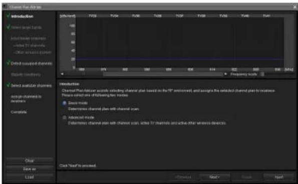
text_image
Channel Plan Options Introduction Select based Lands Installable channels - selected TV channels - Other wireless devices Debit insured channels Signal Modifiers Select analysis channels Assign channels to access Compatible Clear Save as Load 100 50 40 30 20 10 0 VY RQ SW OK EAD SFF TLE FREQ Frequency fields Introduction Channel Plan/Driver audio selecting channel plan based on the RF environment, and assigns the selected channel plan to access. Please select one of following fan modes: • Basic mode • Different channel plans with channel uses • Advanced mode • Different channel plans with channel uses, also TV channels and active other wireless devices. Click "Read" to access Close Send Next Next3 Select [Basic mode], and click [Next>].
The following screen appears.

text_image
Channel Plan Advisor Description Select target channels Input channels: Channels Select active channels Select accepted channels Show available channels Assign channels in numbers Compliance Select accepted channels Please select relevant channels to select active channels, so needed, please adjust "Scan condition" Then click "Scan user" button to test channel type. View Scan data from Spectrum Analyzer Scan Endotores Report size: Frequency format: 1.00 % Direct Detection level: 00 % Stop transmission when scanning Start size: Clear Cancel Save Load Click "Next" to prevent + Previous Next > Next > ResetThe receivers for which channel scan will be performed will be displayed here for each frequency band.
4 Click [Start scan].
Channel scan is performed, and the results are plotted on the frequency spectrum display in the upper part of the screen.
5 Click [Next>].
The following screen appears.
text_image
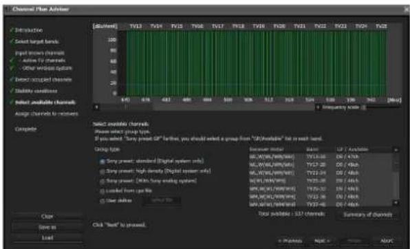
Channel Plan Advisor Introduction Select target bands Input channels Active F2 channels Other window options Connect received channels Stability conditions Select available channels Average channels to members Compute Select available channels Please select group types. If you select "Sony" peak 0% further, you should select a group from "USB/available" list in each band. Group type Sony peak: standard (Digital system only) Sony peak: high density (Digital system only) Sony peak: (Shiny audio system) Locked from type file Other options Summary mode: 80.0V/16W/16W/16W 75.0V/16W/16W/16W 70.0V/16W/16W/16W 75.0V/16W/16W/16W 75.0V/16W/16W/16W 75.0V/16W/16W/16W 75.0V/16W/16W/16W Total possible: 337 channels Summary of channels Clear Save as Load + Process Next > NextCandidate channel plans and the number of receivers that can use the channel plans at the same time will be displayed here for each frequency band.
6 Select the [Group type] to use for each frequency band.
Select the group type based on the device configuration.
Sony preset: standard [Digital system only]: Select this when only Sony digital wireless systems are used (up to 48-ch channel plans are supported).
Sony preset: high density [Digital system only]:
Select this when only Sony digital wireless systems are used (up to 64-ch channel plans are supported).
Sony preset GP [With Sony analog system]: Select this when the configuration also includes Sony analog wireless systems.
Loaded from cpa file: Select this to use channel plans that were selected during previous uses of [Channel Plan Adviser].
User define: Select this to use user defined channel plans.
Note
The recommended channel plan when “Sony preset: high density [Digital system only]” is selected cannot be assigned to the DWR-R01D, DWR-R02D, or DWR-R02DN.
7 Click [Next>].
The following screen appears.
text_image
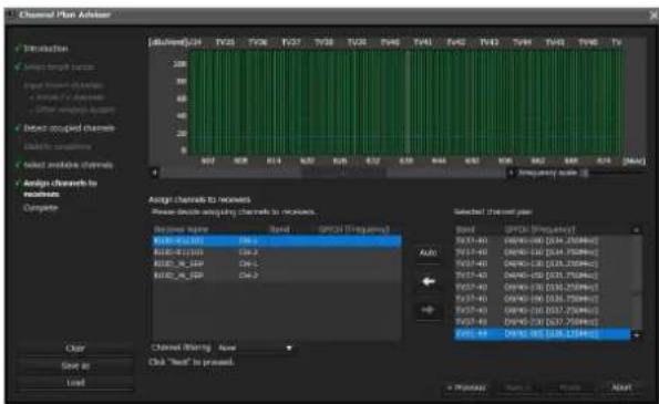
Channel Plan Advisor Introduction Select length channels Input vector channels Select F1 channels Select output channels Select acquired channels Delete sequences Select available channels Assign channels to receive Complete Assign channels to receive Show select acquiring channels to receive. Received source: BND_01237 BND_01238 BND_01239 BND_01240 BND_01241 BND_01242 BND_01243 BND_01244 BND_01245 BND_01246 BND_01247 BND_01248 BND_01249 BND_01250 BND_01251 BND_01252 BND_01253 BND_01254 BND_01255 BND_01256 BND_01257 BND_01258 BND_01259 BND_01260 BND_01261 BND_01262 BND_01263 BND_01264 BND_01265 BND_01266 BND_01267 BND_01268 BND_01269 BND_01270 BND_01271 BND_01272 BND_01273 BND_01274 BND_01275 BND_01276 BND_01277 BND_01278 BND_01279 BND_01280 BND_01281 BND_01282 BND_01283 BND_01284 BND_01285 BND_01286 BND_01287 BND_01288 BND_01289 BND_01290 BND_01291 BND_01292 BND_01293 BND_01294 BND_01295 BND_01296 BND_01297 BND_01298 BND_01299 BND_01300 Selected channel pair: Band: PDCY-463 (D: 3.75MHz) PDCY-464 (D: 3.75MHz) PDCY-465 (D: 3.75MHz) PDCY-466 (D: 3.75MHz) PDCY-467 (D: 3.75MHz) PDCY-468 (D: 3.75MHz) PDCY-469 (D: 3.75MHz) PDCY-470 (D: 3.75MHz) PDCY-471 (D: 3.75MHz) PDCY-472 (D: 3.75MHz) PDCY-473 (D: 3.75MHz) PDCY-474 (D: 3.75MHz) PDCY-475 (D: 3.75MHz) PDCY-476 (D: 3.75MHz) PDCY-477 (D: 3.75MHz) PDCY-478 (D: 3.75MHz) PDCY-479 (D: 3.75MHz) PDCY-480 (D: 3.75MHz) PDCY-481 (D: 3.75MHz) PDCY-482 (D: 3.75MHz) PDCY-483 (D: 3.75MHz) PDCY-484 (D: 3.75MHz) PDCY-485 (D: 3.75MHz) PDCY-486 (D: 3.75MHz) PDCY-487 (D: 3.75MHz) PDCY-488 (D: 3.75MHz) PDCY-489 (D: 3.75MHz) PDCY-490 (D: 3.75MHz) PDCY-491 (D: 3.75MHz) PDCY-492 (D: 3.75MHz) PDCY-493 (D: 3.75MHz) PDCY-494 (D: 3.75MHz) PDCY-495 (D: 3.75MHz) PDCY-496 (D: 3.75MHz) PDCY-497 (D: 3.75MHz) PDCY-498 (D: 3.75MHz) PDCY-499 (D: 3.75MHz) PDCY-500 (D: 3.75MHz) Color: Save as: Load: Channel Timing: New Click "Read" to proceed. Preview: Save: Next: NextThe selected channel plan is assigned to the receivers here.
When [Receiver's band block] or [Receiver's band] is selected in [Channel filtering], a channel plan is extracted according to the [BAND BLOCK] or [BAND] setting of the digital wireless receiver. This allows you to assign a channel plan without changing the [BAND BLOCK] or [BAND] setting of the digital wireless receiver.
For details on the [Channel filtering] setting, see "Extracting a channel plan" (page 63).
8 Click [Auto].
The channel plan is assigned automatically.
Note
You can also assign channels one at a time by selecting the receiver and frequency, and clicking the ← button.
9 Click [Next>].
Configuration of the assigned channel plan starts for the receivers.
If the receivers are already paired with transmitters, the configuration is also sent to the transmitters.
The following screen appears.
text_image
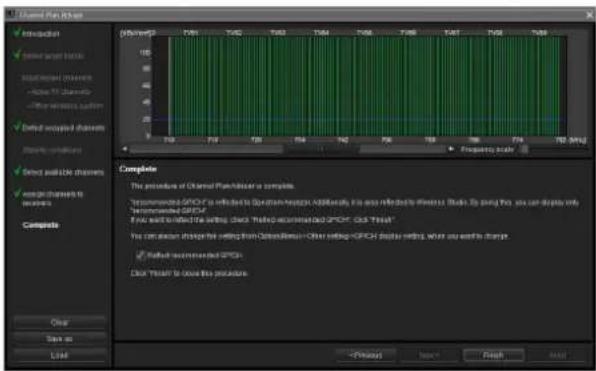
Channel Plan Options ✓ Introduction ✓ Power target channels ✓ Integrated channels ✓ Active TV Channels ✓ Other wireless patterns ✓ Default backup channels ✓ Security channels ✓ Default suitable channels ✓ Open channels to messages Composite Complete The procedure of Channel Plan/Cluster is portable. Parameters: GFCH is reflected in Qwen-ram Hadoop. Add information is also reflected in the server. Shift Up going this, you can display only 'Recommended GFCH' If we will be reflected in the writing, check 'Testing-Recommended GFCH'. Click 'Refresh' You can access disaster setting from Qwen-ramHadoop+Other settings+GFCH disaster setting, what you want to change. ✓ Default recommended GFCHs Click 'Refresh' to locate this procedure.10 If necessary, enable or disable [Reflect recommended GP/CH], and then click [Finish].
[Channel Plan Adviser] closes. If the [Reflect recommended GP/CH] checkbox is selected, only the groups and channels recommended by [Channel Plan Adviser] will be selectable on Wireless Studio. The groups and channels recommended by [Channel Plan Adviser] will be displayed in the [Spectrum Analyzer] tab of the sub window.
Pairing Receiver Channels and Transmitters
To enable remote control of transmitters via wireless remote control, each receiver channel must be paired with a transmitter.
By using the pairing wizard in Wireless Studio to perform this operation, you can perform pairing for multiple channels with ease.
Perform pairing with the pairing wizard as follows.
1 Place a check mark next to [Online monitoring and control] in the Device menu.
The system enters online mode, and the receivers, battery chargers, and RMU-01 units are automatically detected and added to the device list window.
2 Select [Device] menu > [Pairing wizard].
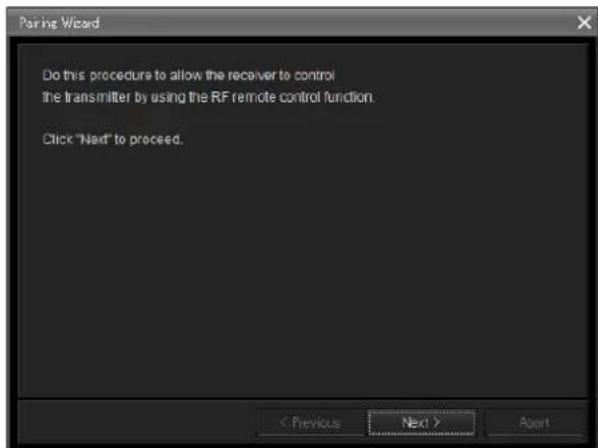
The following screen appears, and the pairing wizard starts.
text_image
Pairing Wizard Do this procedure to allow the receiver to control the transmitter by using the RF remote control function. Click "Next" to proceed. < Previous Next > Agent3 Click [Next>].
The following screen appears.
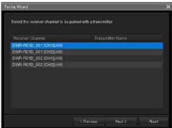
text_image
Pairing Wizard Select the receiver channel to be paired with a transmitter. Receiver Channel Transmitter Name DWR-R01D_001 [CH1] DWR-R01D_001 [CH2] DWR-R01D_002 [CH1] DWR-R01D_002 [CH2] < Previous Next > AbortThe receiver channels for all the receivers that appear in the device list appear here.
4 Select the receiver channel for pairing, and click [Next>].
The following screen appears.
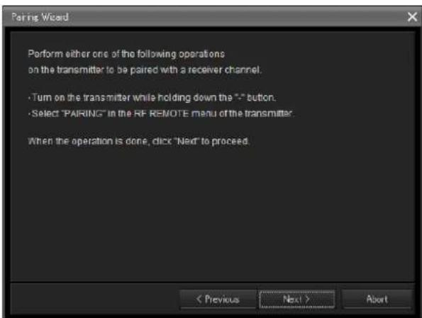
text_image
Pairing Wizard Perform either one of the following operations on the transmitter to be paired with a receiver channel. • Turn on the transmitter while holding down the '*' button. • Select "PAIRING" in the RF REMOTE menu of the transmitter. When the operation is done, click "Next" to proceed. < Previous Next > Abort5 Operate the transmitter for pairing to set it to pairing mode, and click [Next>].
When the transmitter is detected, the following screen appears.
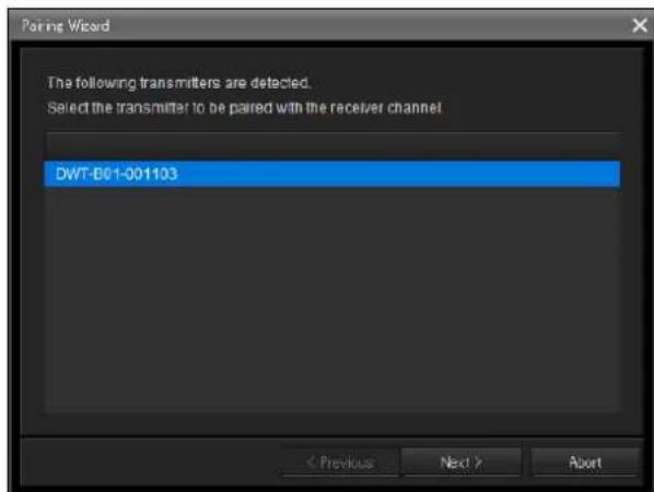
text_image
Pairing Wizard The following transmitters are detected. Select the transmitter to be paired with the receiver channel. DWT-B01-001103 < Previous Next > Abort6 Select the transmitter for pairing, and click [Next>].
Information regarding remote control is exchanged between the receiver and the transmitter.
When the information exchange is complete, the following screen appears.
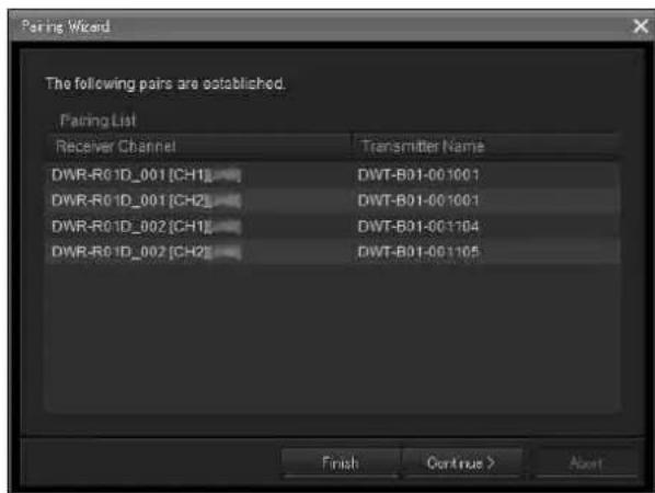
text_image
Pairing Wizard The following pairs are established. Pairing List Receiver Channel Transmitter Name DWR-R0 1D_001 [CH1] DWT-B01-001001 DWR-R0 1D_001 [CH2] DWT-B01-001001 DWR-R0 1D_002 [CH1] DWT-B01-001104 DWR-R0 1D_002 [CH2] DWT-B01-001105 Finish Continue > AbortThe names of receiver channels and transmitters that have already been paired appear here.
The [Transmitter Name] column to the right of the receiver channels will be blank for receivers that have not yet been paired.
If receiver channels that have not yet been paired exist, click [Continue] and pair the channels by repeating the above procedure from step 3.
7 When all necessary pairings are complete, click [Finish].
The wizard closes.
The receiver channels and transmitters are now paired, and remote control via wireless remote control is enabled.
Controlling Devices
You can control devices from the [Property] window and the [Property List] tab of the sub window in Wireless Studio.
The [Property] window displays information about the selected receiver. You can configure settings in the [Property] window while viewing the meter icons in the upper part of the window.
The [Property List] tab of the sub window displays a list of settings for the receiver channels and transmitters displayed in the status viewer. You can configure settings for multiple receiver channels and transmitters simultaneously in the [Property List] tab.
Controlling devices from the [Property] window
Perform the following to control devices from the [Property] window.
1 Place a check mark next to [Online monitoring and control] in the [Device] menu.
The system enters online mode, and the receivers are automatically detected and added to the device list window.
2 Perform one of the following to open the [Property] window.
- Select a receiver or receiver channel in the device list, and click the [Property] window button in the upper part of the device list window.
![SONY DWR-R02D - Controlling devices from the [Property] window - 1](/content/2026/05/760390/images/4ff3620e05c6b92a4e6b81fbaa5b870dc236c43d6ac06b673427c6e329dcc6ab.jpg)
text_image
Device List + - Search Receiver DWR-R01D_01 DWT-B01N_01 DWT-B01N_02 DWR-R01D_02 DWT-B01N_03 DWT-B01N_04- Right-click a receiver or receiver channel in the device list, and select [Property] in the context menu that appears.
![SONY DWR-R02D - Controlling devices from the [Property] window - 2](/content/2026/05/760390/images/7586c35ddaffbfa50ac9c62e8a318e62241e35524d9f5c3bd0551a3dc89849d6.jpg)
text_image
Receiver Property Device information Add to Status Viewer Connect Save Single Settings Load Single Settings- Right-click the meter icons that appear in the status viewer, and select [Property] in the context menu that appears.
![SONY DWR-R02D - Controlling devices from the [Property] window - 3](/content/2026/05/760390/images/430365fbebaccb424703da4bf5151ae0deeec16379e14099bafb33e382b02108.jpg)
text_image
All tuners Page-1 Property Delete- Right-click the meter icons that appear in the simple status viewer, and select [Property] in the context menu that appears.
![SONY DWR-R02D - Controlling devices from the [Property] window - 4](/content/2026/05/760390/images/51c0280a4761e68dffad7670d60ea90f574b9c2a62292330fe9409b0bd2358f3.jpg)
text_image
1 LABEL1 TX1 QL 2 LABEL TX1 QL Property a a- On the [Device List] tab, select and double-click a digital wireless receiver or receiver channel.
![SONY DWR-R02D - Controlling devices from the [Property] window - 5](/content/2026/05/760390/images/a8f5a37589637ea5d2e509a53f07fce68924de5583350de8235a88313dc2d197.jpg)
text_image
Device List + - Search Receiver DWR-R03D-812104 DWT-B01-001104 NO DATA- Select and double-click the meter icons displayed in the status viewer.
![SONY DWR-R02D - Controlling devices from the [Property] window - 6](/content/2026/05/760390/images/928e1bb43867afa8ab578c40ad7e57bcad4004019a1ad08bc0528617631dbc35.jpg)
text_image
All tuners Page-1 Page-2 Page-3 Page-4 Page 1 Search TX B-A/BA5 809.750MHz 2 Search TX B-A/BA4 809.000MHz- Select and double-click the meter icons displayed in the simple status viewer.
![SONY DWR-R02D - Controlling devices from the [Property] window - 7](/content/2026/05/760390/images/c93948ae3c745f69e223ea68da8c0287ecacdd0a6c5b43b5628d9725b6a325bd.jpg)
text_image
1 Search TX DWT-B01- QL 2 Search TX NO DATA QL a b RF3 Configure the settings in the [Property] window.
Changes to the settings are sent to receiver channels and transmitters immediately and applied.
![SONY DWR-R02D - Configure the settings in the [Property] window. - 1](/content/2026/05/760390/images/b746a312b56fef7c22ed55d6223aef774abb255c4a6cab779cfcfc11ba41d83e.jpg)
text_image
DWR-R03D-812104 Lock Settings 1 B-D/BD1 806.250MHz DWT-B01-001104 OUT1 QL A/R/WK OUT2 B-C/BC1 806.625MHz NO DATA RF CL OFF Utility 1 2 Receiver BAND GP/CH Frequency Encryption Codes mode BAL Out Level Main Out Level UNBAL Out ATT Ground Lift AF Output Search TX Channel Label BAND B-D/BD1 Active Channel Scan Clear Channel Scan OFF MODE1 NO FUNCTION MIC(58dBu) NO FUNCTION GROUND UNMUTING Search DWT-B01-001104 Transmitter Type DWT-B01 Transmitter Name DWT-B01-001104 Power Save ACTIVE RF Power Low TrimW Input Level MIC ATT 12dB LCF OFF +48V Battery Remain NO DATA Time 12:41 Reset Internal SG OFF Lock UNLOCK Power SW State ON RF Remote ON OFF RF Remote PairingFor details on the settings in the [Property] window, see "[Property] Window" (page 55).
Controlling devices from the [Property List] tab of the sub window
Perform the following to control devices from the [Property List] tab of the sub window.
1 Place a check mark next to [Online monitoring and control] in the [Device] menu.
The system enters online mode, and the receivers are automatically detected and added to the device list window.
2 Click the [Property List] tab in the sub window.
The [Property List] tab appears. Receiver channels that are registered to the status viewer appear in the [Property List] tab. If the receiver channel for which you want to configure settings does not appear in the [Property List] tab, display the page on which the receiver channel is registered in the status viewer, or register the receiver channel to the status viewer.
For details on changing the page displayed in the status viewer, see "Status Viewer and Meter Icons" (page 32).
For details on how to register receiver channels to the status viewer, see “To monitor a particular set of receiver channels” (page 16).
3 Click a cell displayed in the list of setting values in the [Property List] tab, and configure the setting.
Changes to the settings are sent to receivers and transmitters immediately and applied.
![SONY DWR-R02D - Place a check mark next to [Online monitoring and control] in the [Device] menu. - 1](/content/2026/05/760390/images/2cc5044843cc3298ac8b7e186bd2c8d45295963da7dd8269720239906e18ad2e.jpg)
text_image
M 0051-01 710.200MHz 0051-02 710.200MHz 0051-03 Device Device List RF Chart Graph1 RF Chart Analysis Display mode Event Log Data Type: Device Event 2016/12/28 14:52:41 DVB-RGB_2-DVD-1 Gally out 4 sec. 2016/12/28 14:52:41 DVB-RGB_2-DVD-1 Gally out 4 sec.For details on the settings in the [Property List] tab and how to change them, see “[Property List] Tab” (page 39).
Recording the Signal Environment during Operation
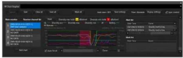
You can use the [RF Chart Grapher] in Wireless Studio to record information on the signal environment and any alerts that occurred during operation. This allows you to determine the cause-and-effect relationship between the signal environment and specific alerts. This section describes the process between starting the signal environment monitoring and saving.
For further details on operations, see “[RF Chart Grapher] Tab” (page 40).
1 Place a check mark next to [Online monitoring and control] in the [Device] menu.
The system enters online mode, the receivers are automatically detected and added to the device list window, and monitoring of the signal environment starts.
text_image
Mtl Chart Display Main waveform Reverse channel bp Input: Quality run hit Default run hit Quality run hit Default run hit Auto scan: 017 Time settings Time: Disksink Delay settings Z/Spn control Auto Type Event DHTVDC20000004 Quality profile line DHTVDC20000004 Quality profile line Auto Time Event2 When you are finished with operations, click [Save all] to save the acquired RF and QL data.
The following dialog box appears.

text_image
Browse For Folder Please select the location where you want to save the capture files. The capture files are saved in the location where you select by clicking OK button. Desktop My Documents My Music My Pictures Wireless Studio MSG_LOG 20120224 20120310 20120310_2 20120310_3 10.2543 My Computer My Network Flaces Make New Folder OK Cancel3 Select the folder in which you want to save the data, and click [OK].
The RF and QL data for all the receiver channels is saved under the selected folder. You can display the saved data in the [RF Chart Analyzer].
For details on the [RF Chart Analyzer], see “[RF Chart Analyzer] Tab” (page 47).
Using Settings Files
Wireless Studio allows you to save device settings as files. By recalling the settings stored in a file and applying them to devices using the [Load settings] function, you can reuse previously configured settings. After recalling settings from a file, you can also edit the setting values in Wireless Studio without connecting to the devices on the network. You can create new system configurations that are based on previous setting environments by applying the settings edited in Wireless Studio to the devices.
The following items are stored in a settings file.
- Setting values for each device that appears in the device list.
- Positions of meter icons registered in the status viewer.
- Omit IP address list settings
- List of settings in [IP address range settings] in [Network interface settings]
Saving the settings as files
1 Remove the check mark next to [Online monitoring and control] in the [Device] menu.
The system enters offline mode.
2 Select [File] menu > [Save as].
The current configurations are saved as a settings file.
Note
When saving transmitter settings, make sure that the transmitters are active and that signals are received properly. If the information is not received properly from a transmitter, the factory default settings of that transmitter will be saved.
Opening files and editing settings
1 Remove the check mark next to [Online monitoring and control] in the [Device] menu.
The system enters offline mode.
2 Select [File] menu > [Open].
3 Select the previously saved file, and click [OK].
The information stored in the file is displayed on the Wireless Studio screen.
4 Edit the setting values.
Settings values can be edited in the [Property] window or the [Property List] tab of the sub window.
For details on changing the settings, see “[Property List] Tab” (page 39) and “[Property] Window” (page 55).
When you are finished editing, save the settings to a file if necessary.
Note
You can change the [Receiver Model] and [Transmitter Type] settings when editing settings in offline mode. However, if you specify a setting that differs from the actual setting of the device, an inconsistency will occur when you apply the setting using the [Load settings] function. The cells for these [Receiver Model] and [Transmitter Type] settings will be displayed in yellow. Make sure to use the actual model name and type of the device when changing the [Receiver Model] and [Transmitter Type] settings.
Opening files and applying settings
1 Remove the check mark next to [Online monitoring and control] in the [Device] menu.
The system enters offline mode.
2 Select [File] menu > [Open].
3 Select the previously saved file, and click [OK].
The information stored in the file is displayed on the Wireless Studio screen.
Edit the settings here if necessary.
4 Select [All Receiver's settings], [All Receiver's and All Transmitter's settings], or [Select Receiver's and Transmitter's settings] from [Device] menu > [Load settings].
The settings are applied to the devices. The devices to which the settings are applied will depend on the option you selected.
If [All Receiver's settings] is selected
The settings are applied to all the receivers that appear in the device list.
If [All Receiver's and All Transmitter's settings] is selected
The settings are applied to all the receivers that appear in the device list and their paired transmitters.
If [Select Receiver's and Transmitter's settings] is selected
The [Load settings] window. The settings are applied to the digital wireless receivers and transmitters selected in the [Load settings] window.
![SONY DWR-R02D - If [Select Receiver's and Transmitter's settings] is selected - 1](/content/2026/05/760390/images/2d45044d7bbf60719881a40e842fa955226c4f6c8cd87d99ec802988fbff5309.jpg)
text_image
Load settings Please check Receivers and Transmitters you want to load settings. ✓ DWR-R02DN-G1 ✓ DWT-B01N_WH2 ✓ DWM-03N_WH2 ✓ DWR-R03D_W1 ✓ DWT-B03R_WL2 ✓ DWM-03N_WL2 OK CancelIf for some reason the stored values could not be applied to a setting item, the cell for that item will be displayed in yellow in the [Property List] tab. In such cases, make sure to check the status and setting values of the devices.
Notes
- The following conditions must be met for the settings to be applied to the receivers.
- The IP addresses of the receivers that appear in the device list must be the actual IP addresses of the units.
- The [Receiver Model] settings must be the actual models of the receivers.
- The following conditions must be met for the settings to be applied to the transmitters.
- The transmitters are paired.
- The [Transmitter Type] settings must be the actual types of the paired transmitters.
- The transmitters are within the wireless remote control service area.
Using individual settings files for individual devices
Wireless Studio allows you to save individual settings files for individual devices. You can recall previous settings by loading settings that were previously saved to a file and applying them to a device.
Note
Only the setting values of a device are stored to the file.
To save the individual settings of a device to a file
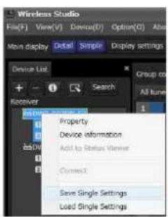
1 Right-click the device for which you want to save settings in the device list, and select [Save Single Settings] in the context menu that appears.
text_image
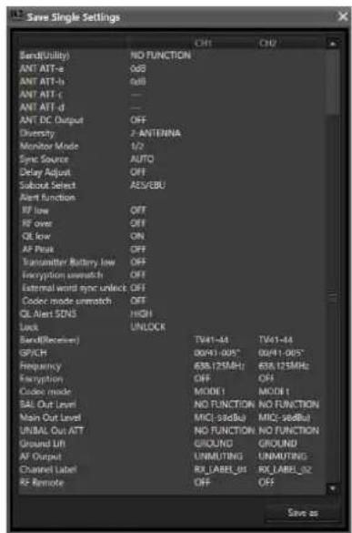
Wireless Studio File(F) View(V) Device(F) Option(O) About Mon display Detail Simple Display settings Device List Search Group to + - 1 All tunes Receiver Property Device information Add to Status Viewer Connect Save Single Settings Load Single Settings2 Click the [Save as] button in the [Save Single Settings] window that appears.
text_image
Save Single Settings Band(Utility) NO FUNCTION ANT ATT-a 0dB ANT ATT-b 0dB ANT ATT-c — ANT ATT-d — ANT DC Output OFF Diversity 2-ANTENNA Monitor Mode 1/2 Sync Source AUTO Delay Adjust OFF Subout Select AES/EBU Alert function RF low OFF RF over OFF QL low ON AF Peak OFF Transmitter Battery low OFF Encryption unwatch OFF External word sync unlock OFF Codec mode unwatch OFF QL Alert SDNS HIGH Lock UNLOCK Band(Receiver) TV41-44 TV41-44 GPICH 00/41-005* 00/41-005* Frequency 638.125MHz 638.125MHz Encryption OFF OFF Codec mode MODE 1 MODE 1 BAL Out Level NOD FUNCTION NOD FUNCTION Main Out Level MIC(93dBμ) MIC(94dBμ) UNBAL Out ATT NOD FUNCTION NOD FUNCTION Ground U/R GROUND GROUND AF OUTPUT UNMUTING UNMUTING Channel Label RX_LABEL_01 RX_LABEL_02 RF Remote OFF OFF Save as3 Enter a file name in the file save dialog box that appears, and click the [Save] button.
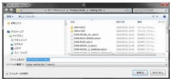
When saving transmitter settings, make sure that the transmitter is turned on and that the signals can be received properly. If the information from the transmitter is not received properly, the factory default settings of that transmitter will be saved.
To open a previously saved individual settings file and apply its settings
1 Right-click the device to which you want to apply the settings in the device list, and select [Load Single Settings] in the context menu that appears.
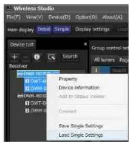
text_image
Wireless Studio File(F) View(V) Device(D) Options(O) About(A) Main display Detail Simple Display settings Device List + - Receiver DWM-8023 DWT-8023 DWM-8023 DWM-8023 DWT-8023 DWM-8023 Search Property Device Information Add to Status Viewer Connect Save Single Settings Load Single Settings Group control set All users Page 1 Search2 Select the individual settings file and click the [Open] button in the file selection dialog box that appears.
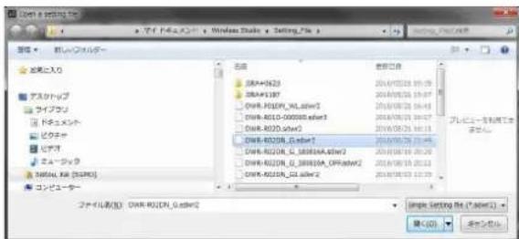
3 Verify the content of the selected individual setting file and click the [Load Settings] button in the [Load Single Settings] window that appears.
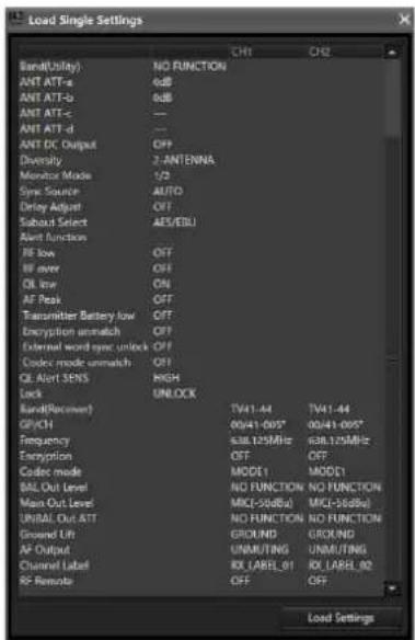
text_image
Load Single Settings Signal(Ubity) NO FUNCTION ANT ATT-a 6dB ANT ATT-b 6dB ANT ATT-c — ANT ATT-d — ANT DC Output OFF Diversity 2 ANTENNA Monitor Mode 1/2 Sync Source:AUTO Delay Adjust OFF Subbat Select:AES/EBU Alert Function RF low OFF RF over OFF QL low ON AF Peak OFF Transmitter Battery low OFF Encryption unmatch OFF External word sync unlock OFF Codec mode unmatch OFF QL Alert SENS RIGH Lock UNLOCK Band(Recomer) TW41-44 TW41-44 GPICH 00/41-0057 00/41-0057 Frequency 638.125MHz 638.125MHz Encryption OFF OFF Codec mode MODE1 MODE1 BAL Out Level NOD FUNCTION NO FUNCTION Main Out Level MIC(50Hz) MIC(50Hz) UNRAL Out ATT NOD FUNCTION NO FUNCTION Ground Lift GROUND GROUND AF Output UNM/TING UNM/TING Channel Label RX LABEL_01 RX LABEL_02 RF Remote OFF OFF Load SettingsNote
If [Load settings] is implemented using an sdwr file in Wireless Studio 5.50 or earlier, the CHANNEL LABEL setting for DWR-R03D is disabled. To use files for Wireless Studio 5.50 or earlier, reconfigure [Receiver channel label] in [Receiver CH Label Setting] after executing [Load settings].
4 Click [Yes] in the confirmation dialog box for applying the settings to the device.
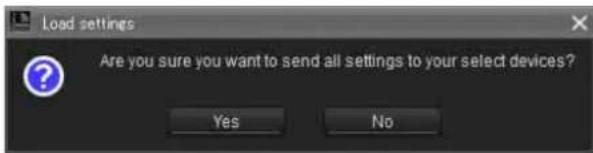
text_image
Load settings Are you sure you want to send all settings to your select devices? Yes NoThe settings saved to the individual settings file are applied to the device.
Settings that could not be applied to the device for whatever reason will appear in yellow in the [Property
List] tab, so be sure to check the device's status and settings.
Customizing the Screen Display
Changing the display mode of the main window
You can change the display mode for the main window via the [Main display] setting on the toolbar.
Detail: Displays the status viewer in the main window.
When [Detail] is selected, you can view the status viewer and simple status viewer at the same time by selecting the [Simple Status Viewer] tab in the sub window.
In addition, as each tab of the sub window can be displayed in a window that is separate from Wireless Studio, you can display Wireless Studio on your main monitor and display the separated simple status viewer on a different monitor.
For details on separating sub-window tabs, see "To separate a sub-window tab from Wireless Studio" (page 27).
Simple: Displays the simple status viewer in the main window. This mode is ideal for basic monitoring on a single monitor, as the simple status viewer cannot be separated from Wireless Studio (which is possible when [Detail] is selected).
Note
When you switch from [Detail] to [Simple], the screen layout of Wireless Studio is stored and only the main window switches to simple display mode. When you switch from [Simple] to [Detail], the main window switches to detailed display mode and the stored screen layout is restored. As a result, if you change the screen layout of Wireless Studio during simple display mode, the changes will not be reflected when you switch back to detailed display mode.
Displaying the sub-window tabs in different locations
To display a sub-window tab in the main window
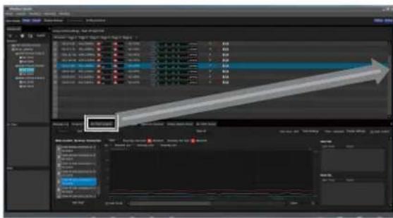
You can move individual sub-window tabs to the left right, or below the status viewer in the main window. This section describes how to moving the [RF Chart Grapher] tab to the right of the status viewer.
1 Select a sub-window tab, and drag it near the status viewer.
An icon appears.
Note
Do not release the mouse button.
text_image
Screenshot of video editing software interface showing timeline, layers, and playback controls with a highlighted arrow pointing to the 'After 5000s' button.
text_image
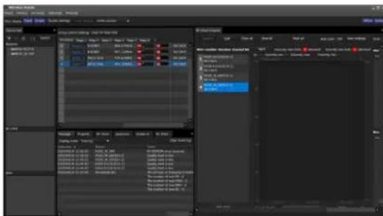
Data Analysis - Project Data - Results File Edit View Insert Tools Help Name: 12345678 Size: 12345678 Date: 01/01/2023 Time: 01/01/2023 Capacity: 12345678 Size: 12345678 Date: 01/01/2023 Capacity: 12345678 Size: 12345678 Date: 01/01/2023 Capacity: 12345678 Size: 12345678 Date: 01/01/2023 Capacity: 12345679 Size: 12345679 Date: 01/01/2023 Capacity: 12345679 Size: 12345679 Date: 01/01/2023 Capacity: 12345680 Size: 12345680 Date: 01/01/2023 Capacity: 12345681 Size: 12345681 Date: 01/01/2023 Capacity: 12345682 Size: 12345682 Date: 01/01/2023 Capacity: 12345683 Size: 12345683 Date: 01/01/2023 Capacity: 12345684 Size: 12345684 Date: 01/01/2023 Capacity: 12345685 Size: 12345685 Date: 01/01/2023 Capacity: 12345686 Size: 12345686 Date: 01/01/2023 Capacity: 12345687 Size: 12345687 Date: 01/01/2023 Capacity: 12345688 Size: 12345688 Date: 01/01/2023 Capacity: 12345689 Size: 12345689 Date: 01/01/2023 Capacity: 12345690 Size: 12345690 Date: 01/01/2023 Capacity: 12345691 Size: 12345691 Date: 01/01/2023 Capacity: 12345692 Size: 12345692 Date: 01/01/2023 Capacity: 12345693 Size: 12345693 Date: 01/01/2023 Capacity: 12345694 Size: 12345694 Date: 01/01/2023 Capacity: 12345695 Size: 12345695 Date: 01/01/2023 Capacity: 12345696 Size: 12345696 Date: 01/01/2023 Capacity: 12345697 Size: 12345697 Date: 01/01/2023 Capacity: 12345698 Size: 12345698 Date: 01/01/20232 Drop the tab on one of the buttons that appear on the icon.
text_image
Video Project Track View Action Play View Action Play Action Play Action Play Action Play Action Play Action Play Action Play Action Play Action Play Action Play Action Play Action Play Action Play Action Play Action Play Action Play Action Play Action Play Action Play Action Play Action Play Action Play Action Play Action Play Action Play Action File Edit View Help Tools Help Tools Help Tools Help Tools Help Tools Help Tools Help Tools Help Tools Help Tools Help Tools Help Tools Help Tools Help Tools Help Tools Help Tools Help Tools Help Tools Help Tools Help Tools Help Tools Help Tools Help Tools Help Tools Help Tools Help Tools Help Tools Help Tools Help Tools Help Tools Help Tools Help Tools Help Tools Help Tools Help Tools Help Tools Help Tools Help Tools Help Tools Help Tools Help Tools Help Tools Help Tools Help Tools Help Tools Help Tools Help Tools Help Tools Help Tools Help Tools Help Tools Help Tots Help Tools Help Tools Help Tools Help Tools Help Tools Help Tools Help Tools Help Tools Help Tools Help Tools Help Tools Help Tools Help Tools Help Tools Help Tools Help Tools Help Tools Help Tools Help Tools Help Tools Help Tools Help Tools Help Tools Help Tools Help Tools Help Tools Help Tools Help Tools Help Tools Help Tools Help Tools Help Tools Help Tools Help Tools Help Tools Help Tools Help Tools Help Tools Help Tools Help Tools Help Tools Help Tools Help Tools Help Tools Help Tools Help Tools Help Tools Help Tools Help Tools Help Tasks Help Tasks Help Tasks Help Tasks Help Tasks Help Tasks Help Tasks Help Tasks Help Tasks Help Tasks Help Tasks Help Tasks Help Tasks Help Tasks Help Tasks Help Tasks Help Tasks Help Tasks Help Tasks Help Tasks Help Tasks Help Tasks Help Tasks Help Tasks Help Tasks Help Tasks Help Tasks Help Tasks Help Tasks Help Tasks Help Tasks Help Tasks Help Tasks Help Tasks Help Tasks Help Tasks Help Tasks Help Tasks Help Tasks Help Tasks Help Tasks Help Tasks Help Tasks Help Tasks Help Tasks Help Tasks Help Tasks Help Tasks Help Tasks Help Tasks Help Tots help Tots help Tots help Tots help Tots help Tots help Tots help Tots help Tots help Tots help Tots help Tots help Tots help Tots help Tots help Tots help Tots help Tots help Tots help Tots help Tots help Tots help Tots help Tots help Tots help Tots help Tots help Tots help Tots help Tots help Tots help Tots help Tots help Tots help TotalTo separate a sub-window tab from Wireless Studio
You can display individual sub-window tabs in a window that is separate from Wireless Studio.
To separate a tab, select the sub-window tab, and then drag and drop it outside of the Wireless Studio window.
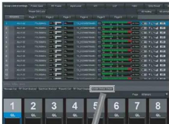
text_image
Group control settings Power Data PF Power PBF Level MT LCP HRS Total Value Power Data Page 1 Page 2 Page 3 Page 4 Page 5 All values ALL-02 TTLR000000 TTLR000000 TTLR000000 TTLR000000 TTLR000000 TTLR000000 TTLR000000 TTLR000000 TTLR000000 TTLR000000 TTLR000001 TTLR000001 TTLR000001 TTLR000001 TTLR000001 TTLR000001 TTLR000001 TTLR000001 TTLR000001 TTLR000001 TTLR000002 TTLR000002 TTLR000002 TTLR000002 TTLR000002 TTLR000002 TTLR000002 TTLR000011 TTLR1288976488 TTLR1288976488 TTLR1288976488 TTLR1288976488 TTLR1288976488 TTLR1288976488 TTLR1288976488 TTLR1288976488 S&P 5.5x 5.5x 5.5x 5.5x 5.5x 5.5x 5.5x 5.5x 5.5x 5.5x 5.5x 5.5x 5.5x 5.5x 5.5x 5.5x 5.5x 5.5x 5.5x 5.5x 5.5m ALL-1288976488 ALL-1288976488 ALL-1288976488 ALL-1288976488 ALL-1288976488 ALL-1288976488 ALL-1288976488 ALL-1288976488 ALL-1288967488 ALL-1288967488 ALL-1288967488 ALL-1288967488 ALL-1288967488 ALL-1288967488 ALL-1288967488 ALL-1288967488 ALL-12B RCLN ALL-12B RCLN ALL-12B RCLN ALL-12B RCLN ALL-12B RCLN ALL-12B RCLN ALL-12B RCLN ALL-12B RCLN ALL-12B RCLN ALL-12B RCLN ALL-12B RCLN ALL-12B RCLN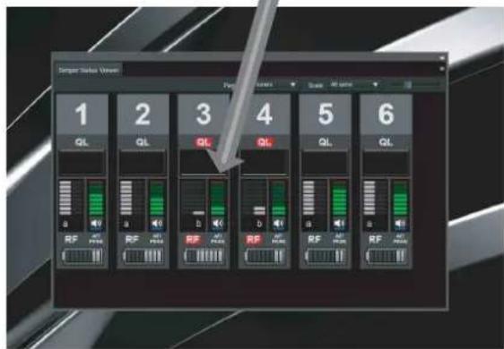
text_image
Sanger Horizon Window 1 2 3 4 5 6 QL QL QL QL QL QL a b a b a b RF RF RF RF RF RF RFBy dragging and dropping the [Simple Status Viewer] tab within the screen of a second monitor and maximizing its display, you can monitor Wireless Studio on your first monitor and monitor the simple status viewer on your second monitor at the same time.
- First monitor
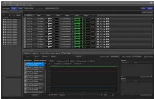
text_image
Screenshot of a video editing software interface showing timeline, layers, and audio track controls with Chinese labels.- Second monitor
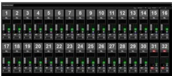
text_image
1 2 3 4 5 6 7 8 9 10 11 12 13 14 15 16 17 18 19 20 21 22 23 24 25 26 27 28 29 30 31 32To return a tab to the sub window
1 Select the tab in the main window or the separated tab, and drag it near the sub window.
An icon appears.
Note
Do not release the mouse button.
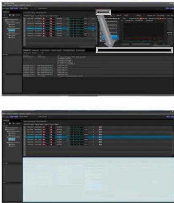
text_image
Screenshot of a video editing software interface showing two panels with timeline, track controls, and a zoomed-in view of the video frame.2 Drop the tab onto the displayed icon.
The tab returns to the sub window.
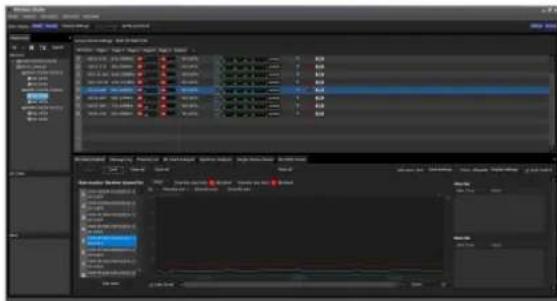
text_image
Screenshot of a video editing software interface showing timeline, track controls, and audio tracks with Chinese labels.Behavior of Wireless Studio when SEARCH RX is Executed
When the SEARCH RX function is executed on transmitters equipped with that function, the receiver channels on Wireless Studio will blink.
Meter icons in the status viewer
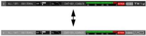
text_image
ALL / BF1 806125MHz RF 3Ω CWT-BF1.1346579 T M 5pV ALL / BF1 806125MHz RF 3Ω CWT-BF1.00000 T M 5pVMeter icons in the [Property] window

text_image
53-A53-150 713.750MHz DWT-80IN-684213 RF TM Sd 40 -26 -20 -10 00/10K 0.5V 53-A53-150 713.750MHz DWT-80IN-684213 RF TM Sd 40 -26 -20 -10 00/10K 0.5VSimple status viewer
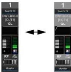
text_image
1 Search TX DWT-820.0 [OUT1] QL RF MP PUM Monitor 1 Search TX DWT-820.0 [OUT1] QL RF MP PUM Monitor[Device List] Window
This window lists in a table all of the receivers, battery chargers, and RMU-01 units on the network and two receiver channels of each receiver as operating channel information. It also displays icons that indicate the status of each device.
![SONY DWR-R02D - [Device List] Window - 1](/content/2026/05/760390/images/aea40375f6479de5c0d5169a00879560cd3fb3e0dccc9616f519a0a2427707e6.jpg)
text_image
Device List + - Search Receiver DWR_R02DN_003002 NO_DATA NO_DATA BC-DWX BC_DWX1_00000 RMU RMU-01_SAITOU ① ② ③ ④ ⑤ ⑥ ⑦ ⑧ ⑨①[+] (add) button
Opens the [Add a new device] window. Add a device to the device list by specifying its type and IP address.
For details, see "Manually adding a receiver/battery charger/RMU-01 to the [Device List] window" (page 30).
②[-] (delete) button
Deletes the selected device or receiver channel from the list (available in offline mode only).
③Device information button
Opens the [Device information] window. This allows you to view device type and IP address information for devices selected in the list.
For details, see "Confirming the device types and IP addresses of devices registered in the [Device List] window" (page 30).
④ Property button
Opens the [Property] window. Use this to check or modify the settings for the currently selected receiver or the transmitter that is paired with that receiver.
For details, see “[Property] Window” (page 55).
⑤[Search] (automatic detection) button
Automatically detects and adds to the list receivers, RMU-01 units, and battery chargers on the same subnet (available in online mode only).
⑥Receiver display
Indicates receiver names obtained from receivers on the network that were added to the device list.
⑦Receiver channel display
Indicates the receiver channels of the receivers and transmitter names obtained by metadata received from the transmitter.
⑧Battery charger display
Indicates battery charger names obtained from battery chargers on the network that were added to the device list.
⑨RMU display
Indicates the name of the remote controlled units obtained from RMU-01 units on the network that were added to the device list.
Icons used to indicate status
The following icons are displayed to indicate the status of the receivers, RMU-01 units, and battery chargers on the network.
| Device Icon | Meaning | |
| Receiver Operating normally | ||
RMU-01 Operating normally  | ||
| [57xx] No communication with RMU-01.If operating in online mode, the RMU-01 may be turned off, IP addresses may be overlapping, a network connection error may have occurred, etc. Check the status of each device.This icon also appears in offline mode. | ||
| Battery charger | [0x80] | Operating normally |
| [0xxx] | No communication with battery charger. If operating in online mode, the battery charger may be turned off, IP addresses may be overlapping, a network connection error may have occurred, etc. Check the status of each device.This icon also appears in offline mode. | |
Confirming the device types and IP addresses of devices registered in the [Device List] window
Display the [Device information] window using one of the following methods.
- Select a device in the device list, and click the device information button in the upper part of the [Device List] window.
- Right-click a device in the device list, and select [Device information] in the context menu that appears.
![SONY DWR-R02D - Confirming the device types and IP addresses of devices registered in the [Device List] window - 1](/content/2026/05/760390/images/f3771c200a9340757539de6d9b8a3706d078d99e5bf4e9ad09200abf7f7434fe.jpg)
text_image
Device Information Type Device type IP Address OK CancelManually adding a receiver/battery charger/RMU-01 to the [Device List] window
Display the [Add a new device] window using one of the following methods.
- Click the [+] button in the upper part of the [Device List] window.
- Select [Device] menu > [Add a new device].
After entering the following items in the window that appears, click [OK] to close the window.
The receiver/battery charger/RMU-01 unit is added to the device list window.
Type: Selects the type (Receiver, RMU, BC-DWX) of the device to add to the [Device List] window. The options
available for [Device type] vary depending on the selected type.
| Type Device type | |
| Receiver DWR-R01D | |
| RMU RMU-01 | |
| BC-DWX BC-DWX1 |
![SONY DWR-R02D - Manually adding a receiver/battery charger/RMU-01 to the [Device List] window - 1](/content/2026/05/760390/images/c1fa50b0f6a331df8fa523f41097108f0269a7cfbd2d3d5b6a93c740f0e0764d.jpg)
text_image
Add a new device Type Receiver Device type DWR-R02DN IP Address 192 . 163 . 0 . 2 OK CancelDevice type: Selects the model to add to the [Device List] window.
IP Address: Enter the IP address of the receiver/battery charger/RMU-01 to be added.
To cancel the addition of a receiver/battery charger/RMU-01 unit
Click [Cancel].
Context window
Right-click on a node in the [Device List] window to display the context window.
Property: Displays the [Property] window for the selected device.
For details on the [Property] window, see “[Property] Window” (page 55).
Device information: Displays information about the selected device.
For more information on the contents, see “Confirming the device types and IP addresses of devices registered in the [Device List] window” (page 30).
Add to Status Viewer: Adds the selected receiver channel to the status viewer in the main window.
When you right-click a receiver, the receiver channel for that receiver is added to the status viewer.
Connect: Reconnects to receivers, battery chargers, and RMU-01 units for which communication with Wireless Studio has been interrupted.
Save Single Settings: Saves the settings of the selected device to a file.
For details, see "To save the individual settings of a device to a file" (page 25).
Load Single Settings: Loads settings that are saved to a file to the selected device.
For details, see “To open a previously saved individual settings file and apply its settings” (page 25).
Reconnecting with a disconnected digital wireless receiver/battery charger/RMU-01
If the power supply of a device is turned off when using Wireless Studio in online mode, the device is displayed as offline in the [Device List] window and cannot be monitored.
In Wireless Studio 5.4x and later, even if the device is displayed as offline, the device can be automatically connected and monitoring can continue as long as communication with the device can be established.
To reconnect manually, press the [Search] (automatic detection) button or select [Connect] from the context menu.
Main Window
The status viewer is displayed in the main window.
Status Viewer and Meter Icons
The status viewer displays meter icons that allow you to monitor the status of receiver channels.
The information indicated by each receiver channel meter icon is identical to the initial display of the receiver.
A total of seven pages, the [All tuners] page and [Page-1] to [Page-6], are available in the status viewer by default when you first start up Wireless Studio. You can change the page that is displayed by using the tabs in the upper part of the status viewer.
The [All tuners] page allows you to monitor the status of all receiver channels, as all the channels displayed in the device list are automatically registered to this page.
[Page-1] to [Page-6] allow you to customize. Up to 82 receiver channels can be registered to each page, and you can choose which receiver channels to monitor from the device list and arrange them in any order.
A red meter icon appears for devices that are or may be experiencing operational trouble.
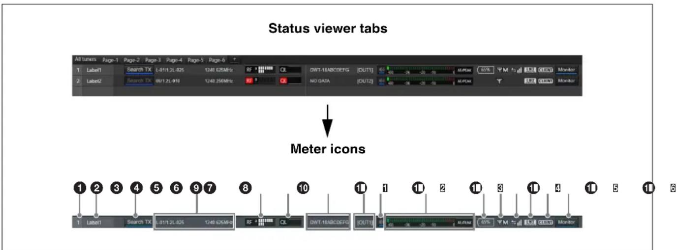
text_image
Status viewer tabs All tuners Page-1 Page-2 Page-3 Page-4 Page-5 Page-6 1 1 Label1 Search TX L-01/1.2L-025 1248 625MHz RF QL DWT-18ABCDEFG [OUT1] ALPAM 65% YM 4.5 GBND Monitor 2 Label2 Search TX 09/1.2L-010 1248 250MHz NO DATA [OUT2] ALPAM Y 4.5 GBND Monitor Meter icons 1 Label1 Search TX L-01/1.2L-025 1248 625MHz RF QL DWT-18ABCDEFG [OUT1] ALPAM 65% YM 4.5 GBND Monitor 1 Label1 Search TX L-01/1.2L-025 1248 625MHz RF QL DWT-18ABCDEFG [OUT1] ALPAM 65% YM 4.5 GBND Monitor①Number
Displays the receiver channel number.
②Label
Displays the label configured in the [Receiver CH Label Settings] window.
③Search TX
Makes the screens for transmitters that are paired with the receiver blink.
Notes
- This function is not supported on the DWR-R01D, DWR-R02D, and DWR-R02DN.
- This function is only available on combinations of 3rd generation or later digital wireless receivers (such as the DWR-R03D) and digital wireless transmitters (such as the DWT-B03R). In addition, when using an RMU-01
for Cross Remote connection, the RMU-01 must be version 1.27 or later.
④ Reception channel information
Indicates the group, channel and frequency information for the receiving signal.
You can also edit the frequency in the frequency display area of the receive channel information.
For details, see “About the Frequency Direct Input Function” (page 36).
⑤RF (radio wave) level meter/diversity indication
Indicates the radio wave input level according to eight levels. The number of segments that light up depends on the input level.
The diversity selection result appears on the left side of the level meter.
“RF” on the left side of the level meter lights up red when the level drops.
When the RF input level is high, “RF” lights up yellow. When you are configuring channels at equal intervals during digital multi-channel operations, we recommend adjusting receiver and antenna settings so that “RF” does not light yellow.
⑥QL (signal quality level) meter
Indicates the quality of the received data in a meter. This meter allows you to monitor quality deterioration of received signals caused by reduced RF signal reception sensitivity that may occur when the receiver is too far from the transmitter or when there is signal interference. "QL" on the left side of the graph lights up red when the audio data quality is low.
⑦Transmitter name
Indicates the name of the transmitter according to the meta data that the receiver receives from that transmitter.
⑧ Output channel display
Displays the audio output destination of the receiver. In normal operation, channel 1 is output from OUT 1, and channel 2 is output from OUT 2. When the OUTPUT SWAP setting is enabled, channel 1 is output from OUT 2, and channel 2 is output from OUT 1. The settings are also highlighted on the display.
Note
OUTPUT SWAP is available only on the DWR-R03D version 1.20 or later.
⑨Audio output control/indicator
Indicates the status of audio output for the receiver channel. Clicking the icon toggles the status of audio output.
: Audio output is enabled. Clicking the icon will enable muting of the audio output.
: Audio output muting is enabled. Clicking the icon will disable muting of the audio output.
Note
This setting can only be changed if the [Individual muting/unmuting] checkbox is selected in the [Display settings] window.
For details, see “[Display settings] Window” (page 68).
⑩AF/PEAK (audio input/peak) level meter/indicator
Indicates the level of audio signal input to the transmitter according to 32 levels. When a signal exceeding the peak audio level is input, “AF/PEAK” appears to the right of the level meter.
⑪Battery condition display
The display varies depending on the transmitter model.
- When receiving radio waves from models other than the DWT-B03R digital wireless transmitter, this indicates the remaining battery charge of the transmitter in 8 levels based on metadata received by the receiver from the transmitter. When the remaining charge is low, the battery icon turns red.
- When receiving radio waves from the DWT-B03R digital wireless transmitter, this functions according to the BATTERY REMAIN setting of the transmitter.
When set to ICON: Indicates the remaining battery charge of the transmitter in 8 levels based on metadata received by the receiver from the transmitter. When the remaining charge is low, the battery icon turns red.
When set to PERCENT: Indicates the remaining battery charge of the transmitter as a percentage based on metadata received by the receiver from the transmitter. When the remaining charge is low, the battery icon turns red.
When set to TIME: Indicates the remaining operating time of the transmitter based on metadata received by the receiver from the transmitter.
⑫RF transmission power display
Indicates the transmission power setting of the transmitter based on metadata received from the transmitter.
H: Transmission power is 50 mW, 25 mW, or 10 mW
M: Transmission power is 10 mW
L: Transmission power is 1 mW or 2 mW
⑬ Wireless remote control condition display
Indicates the communication status of the paired transmitter according to four levels.
→: Good transmission
←: Somewhat good transmission
_1 : Somewhat poor transmission
← : Poor transmission
(red indication): Unable to communicate with paired transmitter
Note
This icon does not appear when the RF REMOTE function on the receiver is turned off.
⑭Digital output synchronization display
Indicates the synchronization status of the output signal from the DIGITAL OUT connector of the receiver.
INT: The output signal is synchronized to the internal clock.
EXT: The output signal is synchronized to the signal input from the WORD SYNC IN connector.
15 Auto Frequency change status display
Displays the status of the receiver's AUTO FREQ CHANGE setting.
HOST: Displayed when the receiver is operating as the HOST. It scans the RF spectrum for a good frequency for use by a CLIENT.
CLIENT: Displayed when the receiver finds the HOST and is operating as a CLIENT. Depending on the RF environment of the transmitter, the frequency automatically switches to the viable frequency detected by the HOST.
The display flashes if the HOST cannot be found.
Note
This function is available only on the DWR-R03D version 1.20 or later.
⑯Dante audio monitoring
Monitors Dante IP audio.
Monitor : Dante IP audio is being monitored on a computer. Monitor : Dante IP audio is not being monitored on a computer.
Note
The DWR-R03D and optional Dante Virtual Soundcard software from Audinate are required to use this function. Monitor is displayed on computers that do not have Dante Virtual Soundcard installed, hence Dante IP audio cannot be monitored by computer.
Operating the pages in the status viewer
You can add, delete, and rename pages in the status viewer.
Notes
• The same name cannot be used for more than one page.
• Page names must consist of alphanumeric characters only.
- Be careful when deleting pages, as deleted pages cannot be restored.
- The [All tuners] page cannot be renamed or deleted.
To add a status viewer page
Click the [+] tab at the far right in the upper part of the status viewer. You can also right-click within a tab and select [Add a new page] in the context menu that appears. After you enter a name and click [OK] in the dialog box that appears, the new page is added.
To rename a status viewer page
Click a tab in the upper part of the status viewer to display the page you want to rename.
Right-click within the tab and select [Change name of
After you enter a new name and click [OK] in the dialog box that appears, the page is renamed.
To delete a status viewer page
Click a tab in the upper part of the status viewer to display the page you want to delete.
Right-click within the tab and select [Delete
Receiver Channel Numbering
Each receiver channel is numbered from 1 to 82 in the status viewer display.
In Wireless Studio version 4.2 and earlier, the numbering displayed in each page of the status viewer was independent and not related to each other.
In version 4.3x and later, if the same receiver channel is registered to multiple pages, it will be assigned the same number in each page.
For example, if receiver channel A is registered to [Page-1], the number assigned to receiver channel A in the [All tuners] page will also appear on [Page-1].
This allows you to manage receiver channels by their numbers.
Example: When receiver channels 5 to 8 are registered to [Page-1]
When monitoring four receivers, each receiver channel will be numbered from 1 to 8.
Note
The numbers will not appear on [Page-1] to [Page-6] until you display the receiver channels.
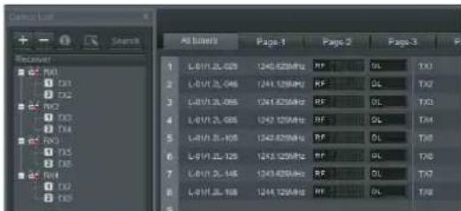
text_image
Cnclustor + - Search All About Page 1 Page 2 Page 3 P 1 L-BV1.2L-025 1245 825MHz RF OL TX1 2 L-BV1.2L-046 1241 125MHz RF OL TX2 3 L-BV1.2L-055 1241 825MHz RF OL TX3 4 L-BV1.2L-066 1242 125MHz RF OL TX4 5 L-BV1.2L-109 1243 825MHz RF OL TX5 6 L-BV1.2L-129 1243 125MHz RF OL TX6 7 L-BV1.2L-146 1243 825MHz RF OL TX7 8 L-BV1.2L-168 1244 125MHz RF OL TX8When you register a receiver channel to [Page-1], it will be assigned the same number as on the [All tuners] page.
For details on registering receiver channels to [Page-1] to [Page-6], see “To monitor a particular set of receiver channels” (page 16).
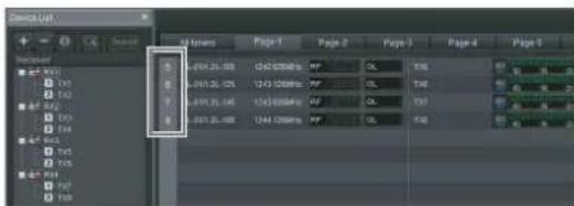
text_image
Search List File Numbers Page 1 Page 2 Page 3 Page 4 Page 5 1.019-25.00 1243.000000 MP OL T36 1.019-25.00 1243.000000 MP OL T36 1.019-25.00 1243.000000 MP OL T36 1.019-25.00 1243.000000 MP OL T36The same number will also appear in the [Simple Status Viewer] tab of the sub window.
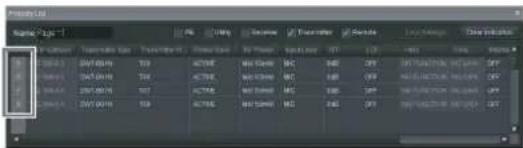
text_image
Normal Ctrl Name: 01 Parameters Name Transaction Code Document Page Format Display Set Help Help Tools Help Tools Help Tools Help Tools Help Tools Help Tools Help Tools Help Tools Help Tools Help Tools Help Tools Help Tools Help Tools Help Tools Help Tools Help Tools Help Tools Help Tools Help Tools Help Tools Help Tools Help Tools Help Tools Help Tools Help Tools Help Tools Help Tools Help Tools Help Tools Help Tools Help Tools Help Tools Help Tools Help Tools Help Tools Help Tools Help Tools Help Tools Help Tools Help Tools Help Tools Help Tools Help Tools Help Tools Help Tools Help Tools Help Tools Help Tools Help Tools Help Tools Help Tots 1.0000000000000000000000000000000000000000000000000000000000000000000000000000000000000000000000000000 1.256758439999999999999999999999999999999999999999999999999999999999999999999999999999999999999999999999999999 1.51337433333333333333333333333333333333333333333333333333333333333333333333333333333333333333333333333333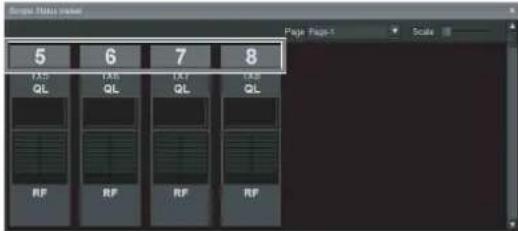
text_image
5 FAS QL 6 FAS QL 7 FAS QL 8 FAS QL RP RP RP RPChanging the position of receiver channels within a page
In the status viewer, you can change the position of registered receiver channels as desired on pages other than the [All tuners] page.
In all of the following examples, Page-1 of the status viewer and simple status viewer is displayed.
Example 1: Changing the position of receiver channel 1
To move receiver channel 1 in the status viewer, drag and drop the channel to the area in which you want to move it (drag and drop to the dotted-line position in the following example).
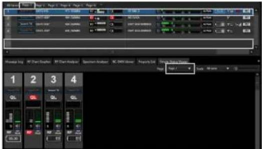
text_image
1 2 3 4 1 2 3 4 GL GL GL 05.80The position of receiver channel 1 changes to the drop position. The position of receiver channel 1 also changes in the simple status viewer, linked to the movement in the status viewer.
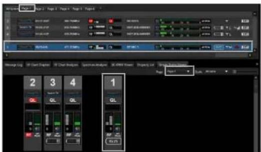
text_image
2 3 4 1Example 2: Changing the position of receiver channels with [Diversity] setting of 4-ANTENNA to two empty channel areas
To move the position of 4-ANTENNA receiver channels, two empty channel areas are required.
If the areas are available, you can change the position using drag and drop as in example 1 (drag and drop to the dotted-line position in the following example).
![SONY DWR-R02D - Example 2: Changing the position of receiver channels with [Diversity] setting of 4-ANTENNA to two empty channel areas - 1](/content/2026/05/760390/images/4ddb2944457203806ec22c838d920b5cd9bce831a3992d5cff66141cd5b76b47.jpg)
text_image
1 2 3 4 1 2 3 4The position of receiver channel 1 changes to the drop position. The position of receiver channel 1 also changes in the simple status viewer, linked to the movement in the status viewer.
![SONY DWR-R02D - Example 2: Changing the position of receiver channels with [Diversity] setting of 4-ANTENNA to two empty channel areas - 2](/content/2026/05/760390/images/d5aec9c49810eca651102170c706efa4afa5404a1f1957a7abf482c538d7b0f0.jpg)
text_image
3 4 1Example 3: Changing the position of receiver channels with [Diversity] setting of 4-ANTENNA to one empty channel area
If two empty channel areas are not available when moving the position of 4-ANTENNA receiver channels, you can drag and drop to the closest empty area (dotted-line position in the following example).
![SONY DWR-R02D - Example 3: Changing the position of receiver channels with [Diversity] setting of 4-ANTENNA to one empty channel area - 1](/content/2026/05/760390/images/dfadb686fcdfdb38d854fd85f6c2dc57a2ef63ceadcf14b98d07e219ecacfa7e.jpg)
text_image
1 2 3 4Repositioned in the two closest empty channel areas without moving to the drag and drop area. The position of receiver channel 1 also changes in the simple status viewer, linked to the movement in the status viewer.
![SONY DWR-R02D - Example 3: Changing the position of receiver channels with [Diversity] setting of 4-ANTENNA to one empty channel area - 2](/content/2026/05/760390/images/25091a64e6518b034294cfa9cc51e6978edc48dc1154f783ac4ffe647e1a9cbf.jpg)
text_image
3 4 1In version 5.50 and later in the simple status viewer, you can change the position of registered receiver channels as desired on pages other than the [All tuners] page (moving to dotted-line position in the following example).
![SONY DWR-R02D - Example 3: Changing the position of receiver channels with [Diversity] setting of 4-ANTENNA to one empty channel area - 3](/content/2026/05/760390/images/bc285689898abf2731a8e80661fc7a005f16b2446fe6c5edf52018e8c02dbdf7.jpg)
text_image
1 2 3 4 Page 1 GL GL GL 05.00 05.00 05.00 05.00 05.00 05.00 05.00 05.00 05.00 05.00 05.00 05.00 05.00 05.00 05.00 05.00 05.00 05 05.00 05.00 05.00 05.00 05.00 05.00 05.00 05.00 05.00 05.00 05.00 05.00 05.00 05.00 05.00 05.00 05. GL GL GL GL GL GL GL GL GL GL GL GL GL GL GL GL GL GL GL GL GL GL GL GL GL GL GL GL GL GL GL GL GL GL GL GL GL GL GL GL GL GL GL GL GL GL GL GL GL GL GLThe position of receiver channel 1 changes to the drop position. The position of receiver channel 1 also changes in the status viewer, linked to the movement in the simple status viewer.
![SONY DWR-R02D - Example 3: Changing the position of receiver channels with [Diversity] setting of 4-ANTENNA to one empty channel area - 4](/content/2026/05/760390/images/3228f4a4226f01b75921a79f0cce1f3f39d364966c1e0511dd9dc6ddbddd0ec9.jpg)
text_image
1 2 3 4 1About the Frequency Direct Input Function
This function allows you to set the frequency of the receiver channel selected in the status viewer using keyboard entry.
You can set a frequency in 125kHz increments within the frequency range set by the band block of the digital wireless receiver.
For details about the band block of each device, see the band block vs. band table in “DWR-R02DN” (page 49) or “DWR-R03D” (page 49), and “[Property] Window” (page 55).
If you connect to a receiver in online mode and then connect to a transmitter using RF Remote and set the frequency using the frequency direct input function, the receiver and transmitter will be set to the same frequency. If the frequency was set using the direct frequency input function and the transmitter and receiver were not connected using RF Remote, connect the transmitter to the receiver and then set the transmitter to the same frequency.
Switching to frequency direct input mode
You must switch to frequency direct input mode in order to enter a frequency. To switch to frequency direct input mode, first set online mode and then select a receiver channel in the status viewer and press the Ctrl+E keys. Alternatively, right-click and select [Edit Frequency] (you can set online mode and switch to frequency direct input mode even if the receiver is not connected to a network).
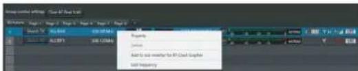
text_image
Add to a new server for IP Cloud System Set FrequencyEntering a frequency
After switching to frequency direct input mode, a frame is displayed in the frequency display area for the selected receiver channel (blue row) and numeric input is enabled. If you want to enter the frequency of a receiver channel in a lower row without changing the selected frequency, use Alt + ↓ to move the frame in the frequency display area. You can also press Alt + ↑ to move the frame in the frequency display area to an upper row.

text_image
Video control settings Cass All Save Auto Layer 1 Layer 2 Layer 3 Layer 4 Layer 5 Layer 6 Layer 7 Layer 8 Layer 9 Layer 10 Layer 11 Layer 12 Layer 13 Layer 14 Layer 15 Layer 16 Layer 17 Layer 18 Layer 19 Layer 20 Layer 21 Layer 22 Layer 23 Layer 24 Layer 25 Layer 26 Layer 27 Layer 28 Layer 29 Layer 30 Layer 31 Layer 32 Layer 33 Layer 34 Layer 35 Layer 36 Layer 37 Layer 38 Layer 39 Layer 40 Layer 41 Layer 42 Layer 43 Layer 44 Layer 45 Layer 46 Layer 47 Layer 48 Layer 49 Layer 50 Layer 51 Layer 52 Layer 53 Layer 54 Layer 55 Layer 56 Layer 57 Layer 58 Layer 59 Layer 60 Layer 61 Layer 62 Layer 63 Layer 64 Layer 65 Layer 66 Layer 67 Layer 68 Layer 69 Layer 70 Layer 71 Layer 72 Layer 73 Layer 74 Layer 75 Layer 76 Layer 77 Layer 78 Layer 79 Layer 80 Layer 81 Layer 82 Layer 83 Layer 84 Layer 85 Layer 86 Layer 87 Layer 88 Layer 89 Layer 90 Layer 91 Layer 92 Layer 93 Layer 94 Layer 95 Layer 96 Layer 97 Layer 98 Layer 99 Layer100When entering a frequency, the available frequency options within the configured band block are displayed. Move between frequency options using the ↓ or ↑ cursor key. Press the Enter key to apply the selected value.
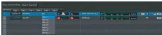
text_image
Image: 100% format Timeline: Page 1 - Page 2 - Page 3 - Page 4 - Page 5 - Page 6 Name: Image1 Size: 100% Layer: 100% Layer 1 Layer 2 Layer 3 Layer 4 Layer 5 Layer 6 Layer 7 Layer 8 Layer 9 Layer 10 Layer 11 Layer 12 Layer 13 Layer 14 Layer 15 Layer 16 Layer 17 Layer 18 Layer 19 Layer 20 Layer 21 Layer 22 Layer 23 Layer 24 Layer 25 Layer 26 Layer 27 Layer 28 Layer 29 Layer 30 Layer 31 Layer 32 Layer 33 Layer 34 Layer 35 Layer 36 Layer 37 Layer 38 Layer 39 Layer 40 Layer 41 Layer 42 Layer 43 Layer 44 Layer 45 Layer 46 Layer 47 Layer 48 Layer 49 Layer 50If a receiver is connected to a network, pressing the Enter key will set the frequency (GP/CH) to the corresponding receiver channel. The frequency (GP) to be configured is Group 00. After setting the frequency, the frequency input area frame moves to the next receiver channel. If you enter a frequency that does not exist in the band block (i.e. not a valid frequency value), the following error dialog appears, the frequency input area frame does not move, and the value in the frequency display area will return to the previous value.
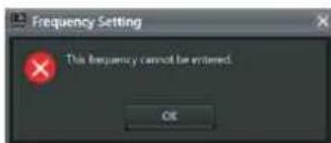
Exiting from frequency direct input mode
Press the Esc key to exit from frequency direct input mode. Alternatively, left-click a point outside the frame. If a receiver is connected to a network or if you are connected to a transmitter using RF Remote, set the
frequency (GP/CH) for all receiver channels displayed in the status viewer.
The following progress bar dialog is displayed while the frequencies are being set, and then the dialog closes automatically after the frequencies for all receiver channels have been set.
When exiting frequency input mode, the following warning message will appear if any band block setting is different between the transmitter and receiver. The number after “All tuners number” indicates the “All tuners” number on the left side of the status viewer.
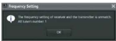
text_image
Frequency Setting The frequency setting of receiver and the transmitter is unmatch. All users number 1 OKSub Window
The sub window consists of the [Message Log] tab, [Property List] tab, [RF Chart Grapher] tab, [RF Chart Analyzer] tab, [Spectrum Analyzer] tab, [Simple Status Viewer] tab, and [BC-DWX Viewer] tab.
[Message Log] Tab
The [Message Log] tab displays a list of warnings and error messages. There are two display modes available, and you can switch between the modes depending on what you want to display.
If there are items for which the lighting of the ALERT indicator has been disabled on a receiver, the corresponding warning messages will not be displayed. To display these warning messages, change the lighting conditions for the ALERT indicator in the alert function settings of the [Property] window.
For details, see “[Property] Window” (page 55).
![SONY DWR-R02D - [Message Log] Tab - 1](/content/2026/05/760390/images/701bb15e3f5416d90976174269126752bedc7c7a90f459d1b7d473afa1367d2b.jpg)
text_image
1 2 3 4 Name: 10000000000000000000000000000000000000000000000000000000000000000000000000000000000000000000000000000 Name: 1.1.1.1.1.1.1.1.1.1.1.1.1.1.1.1.1.1.1.1.1.1.1.1.1.1.1.1.1.1.1.1.1.1.1.1.1.1.1.1.1.1.1.1.1.1.1.1.1.1.1 Name: 2.2.2.2.2.2.2.2.2.2.2.2.2.2.2.2.2.2.2.2.2.2.2.2.2.2.2.2.2.2.2.2.2.2.2 Name: 3.3.3.3.3.3.3.3.3.3.3.3.3.3.3.3.3.3.3.3.3.3.3.3.3.3.3 Name: 4.4.4.4.4.4.4.4.4.4.4.4.4.4.4.4.4.4.4.4.4. Name: 5.5.5.5.5.5.5.5.5.5.5.5.5. Name: 6.6.6.6.6.6.6.6.6 Name: 7.7.7 Name: 8 Name: 9 Name: 10 Name: 11 Name: 12 Name: 13 Name: 14 Name: 15 Name: 16 Name: 17 Name: 18 Name: 19 Name: 20 Name: 21 Name: 22 Name: 23 Name: 24 Name: 25 Name: 26 Name: 27 Name: 28 Name: 29 Name: 30 Name: 31 Name: 32 Name: 33 Name: 34 Name: 35 Name: 36 Name: 37 Name: 38 Name: 39 Name: 40 Name: 41 Name: 42 Name: 43 Name: 44 Name: 45 Name: 46 Name: 47 Name: 48 Name: 49 Name: 50 Name: 51 Name: 52 Name: 53 Name: 54 Name: 55 Name: 56 Name: 57 Name: 58 Name: 59 Name: 60 Name: 61 Name: 62 Name: 63 Name: 64 Name: 65 Name: 66 Name: 67 Name: 68 Name: 69 Name: 70 Name: 71 Name: 72 Name: 73 Name: 74 Name: 75 Name: 76 Name: 77 Name: 78 Name: 79 Name: 80 Name: 81 Name: 82 Name: 83 Name: 84 Name: 85 Name: 86 Name: 87 Name: 88 Name: 89 Name: 90 Name: 91 Name: 92 Name: 93 Name: 94 Name: 95 Name: 96 Name: 97 Name: 98 Name: 99 Name: 100①[Display mode]
Switches the display mode of the message log.
Event log: This mode displays a list of warnings, error messages, and other event messages that have occurred since operation was started. The messages displayed will be recorded as a log file. Log recording begins from the time online mode is entered, and the recording is automatically stored as a csv-format file.
To view a stored log, select [Start] > [My Documents] > [Wireless Studio] and open the log file using a text editor.
Unsolved problems: This mode displays a list of warnings and errors that are currently occurring.
②[Date Time]
Displays the date and time at which the warning, error, or event occurred.
③[Device]
Displays the device and channel on which the warning, error, or event occurred.
④[Event]
Displays the contents of each message.
The functions unique to each mode are as follows.
[Event log] mode
![SONY DWR-R02D - ④[Event] - 1](/content/2026/05/760390/images/b7fefdc211368cb927bc5746175f4976f4f4ba47a02d5a5b0bce1b2cfd06bd75.jpg)
text_image
Event Event Pre pmsun of changing in Online route was reached the number of new RVM. 2 the number of user (RVM). 1 Quality: Status: 0 Pf: New or Live Pf: New or Live Quality: Status: 0 Pf: New or Live Pf: New or Live Clear Evening ①①[Clear Event log]
Deletes the warnings, error messages, and other event messages that are currently displayed.
[Unsolved problems] mode
![SONY DWR-R02D - ①[Clear Event log] - 1](/content/2026/05/760390/images/ed7a8f6bdcb04ae51eacf562fc098496b63fecc18b271faefb022168fc515889.jpg)
text_image
Message Log Message List Property List RF Order Location RF Order Analysis Distance mode Unselected procedure Current state Next state Case Type Device Entry 20120000 20:48:56 VM-RFDB_GATG[3x2-x] Quality Severity Note 20120000 20:49:56 VM-RFDB_GATG[3x2-x] PI Week 6 Time 20120000 20:49:56 VM-RFDB_GATG[3x2-x] Quality Severity Note 20120000 20:50:56 VM-RFDB_GATG[3x2-x] PI Week 6 Time①[Current state]
Indicates in real time whether warnings or error messages exist.
Alert exist: At least one warning or error message currently exists.
No problem: No warning or error message currently exists.
Error messages
The following table shows the error messages that are displayed.
| Message Meaning | |
| Word sync is lost synchronization. | No input can be detected at the WORD SYNC IN connector. |
| PLL is out of order. PLL malfunction. | |
| Cooling fan is out of order. | The cooling fan is out of order. |
| Left channel of headphone output is over load. | There has been an overload in the headphone output. |
| Right channel of headphone output is over load. | |
| Both channels of headphone output are over load. | |
| Message Meaning | |
| ANT DC OUT terminal is over current. | There has been a current overload at the ANTENNA a/b IN connector. |
| Transmitter's battery level is low. | The transmitter's battery is weak. |
| Receiver cannot decrypt the encrypted signal. | Encrypted transmission settings on the receiver and the transmitter do not match. |
| RF level is excessive. The signal reception level is excessively high. | |
| RF level is low. The signal reception level has dropped. | |
| Quality level is low. The quality of received audio data is deteriorated. | |
| Audio signal is reached clipping level. | The audio input level on the transmitter is excessive. |
| Communication time-out occurred. | The number of retries has exceeded the limit and a timeout error has occurred. |
| CPU EEPROM error occurred. | A CPU EEPROM error has occurred. |
| RF EEPROM error occurred. | An RF circuit EEPROM error has occurred. |
| Receiver's codec mode is mismatched with Transmitter's codec mode. | The codec modes of the transmitter and receiver do not match. |
| Dante monitoring function has become disabled. | The Dante monitoring function is not available. |
| Dante virtual sound card has become disabled. | Dante Virtual Soundcard is not available. |
| Band unmatch occurred | The band block settings of the transmitter and receiver are different. |
| Band unmatch resolved | The band block settings of the transmitter and receiver were configured correctly. |
Other event messages
The messages that appear are as follows.
| Message Meaning | |
| Communication was enabled. | Recovered from a communication timeout. |
| The process of loading settings was finished. | Loading of settings is complete. |
| The process of loading settings was failed. | Loading of settings has failed. |
| The process of changing in Online mode was finished. | Transition into online mode is complete. |
| The process of changing in Online mode was failed. | Transition into online mode has failed. |
| The process of changing in Offline mode was finished. | Transition into offline mode is complete. |
| The process of searching devices was finished. | Search processing is complete. |
| The number of new DWR: XX | XX number of DWR units have been newly detected. |
| The number of new RMU: XX | XX number of RMU units have been newly detected. |
| The number of new BC:XX | XX number of BC units have been newly detected. |
| Battery charger detected low temperature. | The battery charger detected an abnormal temperature (low temperature). |
| Battery charger detected high temperature. | The battery charger detected an abnormal temperature (high temperature). |
| Battery charger detected overvoltage. | The battery charger detected an overvoltage condition. |
| Charging error occurred. | A charging error occurred. |
| Wireless Studio detected region error. | A receiver for a different region was detected. |
| Communication was enabled automatically. | Recovered automatically from a communication timeout. |
| Wireless Studio failed to change Dante audio monitoring channel. | Configuration of Dante Virtual Soundcard failed. |
| Dante monitoring function has become enabled. | The Dante monitoring function is available. |
| Wireless Studio detected region error. Please select the correct region from “Region setting” in “Option” menu. | A receiver for a different geographical region was detected upon automatic connection. |
[Property List] Tab
This tab displays a list of settings for the receiver channels displayed in the status viewer. When you change the page displayed in the status viewer, this change is also reflected in the settings displayed in the [Property List] tab.
You can change setting values in the [Property List] tab by selecting the cells. By selecting multiple cells, you can change the setting values for multiple receiver channels as a group.
![SONY DWR-R02D - [Property List] Tab - 1](/content/2026/05/760390/images/43df1619e944c9e0cd5b9d1a3cc8f46ce8139d545f2d6c2d92d351656e9e479f.jpg)
text_image
1 3 4 5 2 Name: A10000 C: 00000000000000000000000000000000000000000000000000000000000000000000000000000000000000000000 1.1.1.1.1.1.1.1.1.1.1.1.1.1.1.1.1.1.1.1.1.1.1.1.1.1.1.1.1.1.1.1.1.1.1.1.1.1.1.1.1.1.1.1.1.1.1.1.1.1.1 2.2.2.2.2.2.2.2.2.2.2.2.2.2.2.2.2.2.2.2.2.2.2.2.2.2.2.2.2.2.2.2.2.2.2.2 3.3.3.3.3.3.3.3.3.3.3.3.3.3.3.3.3.3.3.3.3.3.3.3.3.3.3.3.3.3.3.3 4.4.4.4.4.4.4.4.4.4.4.4.4.4.4.4.4.4.4.4.4.4. 5.5 5 5 5 5 5 5 5 5 5 5 5 5 5 5 5 6 6 6 6 6 6 6 6 6 6 6 6 6 6 6 6 6 7 7 7 7 7 7 7 7 7 7 7 7 7 7 7 7 7 8 8 8 8 8 8 8 8 8 8 8 8 8 8 8 8 9 9 9 9 9 9 9 9 9 9 9 9 9 9 9 10 10 10 10 10 10 10 10 10 10 10 MUSTAVEL REDUCE REFLECTOR RED MUSTAVEL REDUCE REFLECTOR RED MUSTAVEL REDUCE REFLECTOR RED MUSTAVEL REDUCE REFLECTOR RED MUSTAVEL REDUCE REFLECTOR RED MUSTAVEL REDUCE REFLECTOR RED MUSTAVEL REDUCE REFLECTOR RED MUSTAVEL REDUCE REFLECTOR RED MUSTAVEL REDUCE REFLECTOR RED MUSTAVEL REDUCE REFLECTOR RED①[Name] field
Displays the name of the page currently displayed in the status viewer.
②Settings list
Displays a list of settings for the device displayed in the status viewer.
You can change setting values by selecting the cells in the list. When you click a cell and select a value from the list of options that appears, the setting value is applied to the respective receivers and transmitters.
Cells displayed in yellow indicate that the wireless remote control signal strength is low or that setting values failed to be applied for the respective receiver channels. In such cases, try configuring the settings again. When the settings are successfully configured, the cell will change from yellow to the standard color. You can also clear the yellow indications by clicking the [Clear Indication] button.
You can also select multiple cells using any of the following methods. When multiple cells are selected, the setting values for the selected receiver channels can be changed simultaneously.
- Click and drag over the cells.
- Click the cells one at a time while holding down the Ctrl key.
- Click two cells that are not neighboring while holding down the Shift key.
③Displayed setting items checkboxes
Select whether to display or hide setting items in the [Property] window by category.
For details on the [Property] window, see “[Property] Window” (page 55).
Utility: Select this to display the [Utility] tab in the [Property] window.
Receiver: Select this to display the [Receiver] menu in the tabs for channels 1 and 2 in the [Property] window.
Transmitter: Select this to display the [Transmitter] menu in the tabs for channels 1 and 2 in the [Property] window.
Remote: Select this to display the [Remote] menu in the tabs for channels 1 and 2 in the [Property] window.
④[Unlock Settings] / [Lock Settings] button
When setting modification is disabled due to the [Setting lock] function, click this button and enter the password to temporarily enable setting modification.
Click the button again to relock settings.
For details on the [Setting lock] function, see "[Setting lock] Window" (page 65).
⑤[Clear Indication] button
Clears the yellow indications that appear when setting values for receivers and transmitters fail to be applied. Use this when the indications are no longer necessary.
Changing settings for multiple receiver channels as a group
1 Select the GP/CH item for multiple receiver channels in the [Property List] tab.
[...] appears for the cells.
2 Click [...].
The [GP/CH Selection] dialog box appears.

text_image
RIS/CH Selection Recovery Name Help CI/CN (Frequency) DWR-RE10_001 CH1 TV30-33 DWR-RE10_001 CH2 TV30-33 DWR-RE10_002 CH1 TV30-33 DWR-RE10_002 CH2 TV30-33 DWR-RE10_003 CH1 TV30-33 DWR-RE10_003 CH2 TV30-33 DWR-RE10_004 CH1 TV30-33 DWR-RE10_004 CH2 TV30-33 DWR-RE10_005 CH1 TV30-33 DWR-RE10_005 CH2 TV30-33 DWR-RE10_006 CH1 TV30-33 (9) 88 Change: 26-01 2587.1258E- 26-02 2587.2558E- 26-03 2587.3758E- 26-04 2587.5558E- 26-05 2587.6258E- 26-06 2587.7558E- 26-07 2587.8758E- 26-08 2587.9958E- 26-09 2587.1258E- 26-10 2587.1558E- 26-11 2587.1758E- 26-12 2587.2058E- OK Cancel3 Select a frequency group under [GP] in the upper-right part of the [GP/CH Selection] dialog box.
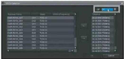
text_image
RF/CFI Selection Receiver Name Base ON/OFFrequency DWR-RF03_001 CH1 TY-03 DWR-RF03_002 CH2 TY-03 DWR-RF03_003 CH1 TY-03 DWR-RF03_004 CH2 TY-03 DWR-RF03_005 CH1 TY-03 DWR-RF03_006 CH2 TY-03 DWR-RF03_007 CH1 TY-03 DWR-RF03_008 CH1 TY-03 CFI CFI CFI CFI CFI CFI CFI CFI CFI CFI CFI CFI CFI CFI CFI CFI CFI CFI CFI CFI CFI CFI CFI CFI CFI CFI CFI CFI CFI CFI CFI CFI CFI CFIA list of frequency channels that belong to the selected frequency group appears under the [Channel] column.
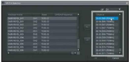
text_image
CPQ 01 Pacifier Name Stand CPQ(01/Frequency) DWR-RS10_001 CH1 TV30-27 DWR-RS10_002 CH2 TV30-33 DWR-RS10_003 CH1 TV30-33 DWR-RS10_004 CH2 TV30-33 DWR-RS10_005 CH1 TV30-27 DWR-RS10_006 CH2 TV30-33 DWR-RS10_007 CH1 TV30-33 Chancal 39-27 258/75/88#- 39-16 258/75/88#- 39-10 258/75/88#- 39-14 257/75/88#- 39-16 258/75/88#- 39-22 258/75/88#- 39-26 258/75/88#- 39-10 258/75/88#- 39-24 257/75/88#- 39-18 257/75/88#- 39-42 257/75/88#- 39-46 257/75/88#- Cancel4 Select the receiver channel for which you want to change settings from the receiver channel list in the left part of the [GP/CH Selection] dialog box.
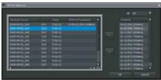
text_image
OVAR Selection Name Name State OP/OFF (Frequency) OVAR-RSD_001 CH1 TX0-33 C190-32(288.250MHz) OVAR-RSD_001 CH2 TX0-33 OVAR-RSD_002 CH1 TX0-33 OVAR-RSD_002 CH2 TX0-33 OVAR-RSD_003 CH1 TX0-33 OVAR-RSD_003 CH2 TX0-33 OVAR-RSD_004 CH1 TX0-33 OVAR-RSD_004 CH2 TX0-33 OVAR-RSD_005 CH1 TX0-33 OVAR-RSD_006 CH1 TX0-33 OP Dt Channel: 30-42 7567.250MHz 30-49 7567.750MHz 30-10 7567.250MHz 30-14 7567.750MHz 30-19 7567.250MHz 30-22 7567.750MHz 30-26 7567.250MHz 30-30 7567.750MHz 30-34 7570.250MHz 30-38 7570.750MHz 30-42 7571.250MHz 30-46 7571.750MHz OK Cancel5 Select the frequency channel that you want to assign to the selected receiver channel from the [Channel] column, and click [<--].
The group and channel are assigned to the receiver channel.
To cancel group and channel assignments, click [-->].
6 Repeat steps 4 to 5 to assign frequency channels to other receiver channels, and click [OK].
The changed settings are applied.
[RF Chart Grapher] Tab
You can use the [RF Chart Grapher] in Wireless Studio to record information on the signal environment and any alerts that occurred during operation. This allows you to determine the cause-and-effect relationship between the signal environment and specific alerts.
By specifying a receiver channel as a sub monitor channel, you can view graphs for multiple receiver channels simultaneously on a single screen.
![SONY DWR-R02D - [RF Chart Grapher] Tab - 1](/content/2026/05/760390/images/aca110b60f5dd8faf79cb32834215635106611be964a316d490011b9d5eca440.jpg)
text_image
Screenshot of a software interface with labeled panels and tool panels, showing audio waveform graphs and control panels.①Control items
Capture: Starts acquisition and graph display of RF and QL data for all receiver channels displayed in the receiver channel list.
Quit: Stops acquisition and graph display of RF and QL data for all receiver channels displayed in the receiver channel list.
Clear all: Clears the RF and QL data acquired for all receiver channels displayed in the receiver channel list and clears the graph display.
Save all: Saves the RF and QL data acquired for all receiver channels displayed in the receiver channel list to a file.
Mark all: Allows you to add memos to the graphs of all the receiver channels displayed in the receiver channel list.
For details, see "Mark function" (page 45).
Auto save: Indicates whether the signal environment status obtained via the [RF Chart Grapher] for each receiver channel is automatically saved.
Save settings: Click this button to open the [Save settings] screen. You can configure the timing for automatic saving and the save destination in the [Save settings] screen.
For details, see “[Save settings] screen” (page 43).
Time: Indicates the display mode of time information.
Display settings: Click this button to open the [Display Settings] screen. The [Display Settings] screen allows you to configure display settings for RF level, alert, QL, and time.
For details, see “[Display Settings] screen ([RF Chart Grapher], [RF Chart Analyzer])” (page 43).
Sync control: Select this checkbox to sync the scrolling and zoom controls for the graphs of all the displayed receiver channels.
②Main monitor area
Receiver channel list: Displays a list of receiver channels. The information of the receiver channel selected here is displayed in the graph display area, alert list, and mark list.
Add chart: Click this button to specify the receiver channel selected in the receiver channel list as a sub monitor channel.
③Graph display area
Displays the monitoring results for the signal environment selected in the receiver channel list as a graph.
Mark: Allows you to insert memos into the graph.
For details, see "Mark function" (page 45).
Diversity max hold: Displays the maximum diversity value for the RF data displayed in the graph.
Diversity min hold: Displays the minimum diversity value for the RF data displayed in the graph.
Auto Scroll: Select this checkbox to scroll the graph automatically to always display the most recent data.
Zoom: Zoom in or zoom out on the graph.
Scroll bar: Scrolls across the time axis.
④Alert list
Displays problems that occurred during signal environment monitoring.
When a problem occurs, a portion of the graph display area will be displayed in red. When you click the red portion, the corresponding portion in the alert list will be highlighted.
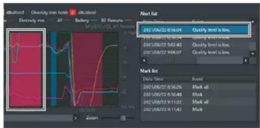
text_image
dikuVord Diversity min holds dikuVend Diversity min AF Battery RF Remote 2021/06/22 8:56:04 Quality level is low. Mark Dot Data Time Event 2021/06/22 8:56:26 Mark all 2021/06/22 8:56:48 Mark 2021/06/22 9:11:22 Mark all 2021/06/22 9:11:42 MarkThe messages that appear in [RF Chart Grapher] are as follows.
If there are items for which the lighting of the ALERT indicator has been disabled on a receiver, the corresponding warning messages will not be displayed. To display these warning messages, change the lighting conditions for the ALERT indicator in the alert function settings of the [Property] window.
For details, see “[Property] Window” (page 55).
| Message Meaning | |
| Rf level is excessive. The signal reception level is excessively high. | |
| Rf level is low. The signal reception level has dropped. | |
| Quality level is low. The quality of received audio data is deteriorated. | |
| Communication time-out occurred. | The number of retries has exceeded the limit and a timeout error has occurred. |
| The process of searching devices was executed. | Search processing is complete. |
| WirelessStudio was not able to acquire data before updating graph. | RF data and QL data could not be acquired within the graph update cycle.NoteData is updated every second in [RF Chart Grapher]. However, if the processing load on the PC is high or if network communication is heavy, the data may not be acquired. |
⑤Mark list
Displays the memos added during signal environment monitoring.
When a memo is added to the graph, a portion of the graph display area will be displayed in blue or green. When you
click the blue or green portion, the corresponding portion in the mark list will be highlighted.

text_image
2021/06/22 8:56:34 Quality level is low. 2021/06/22 8:56:54 Quality level is low. 2021/06/22 8:02:43 Quality level is low. 2021/06/22 9:08:07 Quality level is low. Mark list Date Time Event 2021/06/22 8:56:32 Mark all 2021/06/22 8:56:48 Mark 2021/06/22 9:11:22 Mark all 2021/06/22 9:11:42 Mark⑥Sub monitor area
Displays the name and various information of the receiver channel specified in the main monitor area.
↑ and ↓ buttons: When multiple receiver channels are specified as sub monitor channels, pressing these buttons switches the display position of the current sub monitor with that of the sub monitor immediately above or below. The display position cannot be switched with that of the main monitor.
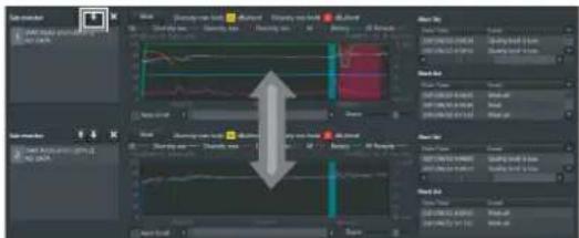
text_image
Screenshot of a software interface showing a multi-panel dashboard with line graphs and a highlighted arrow indicating a transition or transformation.× button: Closes the sub monitor.
Note
The functions of the other areas are identical to those of the alert list and mark list.
Displaying multiple receiver channels simultaneously
By specifying receiver channels as sub monitor channels, you can view multiple receiver channels simultaneously. Up to 11 sub monitor receiver channels can be specified.
To specify using the [Add chart] button
1 Select the receiver channel you want to specify as a sub monitor channel in the main monitor area's receiver channel list, and click the [Add chart] button.
The selected receiver channel is displayed in a sub monitor.
![SONY DWR-R02D - To specify using the [Add chart] button - 1](/content/2026/05/760390/images/a6a9b9575272103e17e7118fbd0640aaa83644cc97a68d236f03f335458a4fbf.jpg)
text_image
Audio waveform Main mode: Audio Channel 0 Audio Channel 1 Audio Channel 2 Audio Channel 3 Audio Channel 4 Audio Channel 5 Audio Channel 6 Audio Channel 7 Audio Channel 8 Audio Channel 9 Audio Channel 10 Audio Channel 11 Audio Channel 12 Audio Channel 13 Audio Channel 14 Audio Channel 15 Audio Channel 16 Audio Channel 17 Audio Channel 18 Audio Channel 19 Audio Channel 20 Audio Channel 21 Audio Channel 22 Audio Channel 23 Audio Channel 24 Audio Channel 25 Audio Channel 26 Audio Channel 27 Audio Channel 28 Audio Channel 29 Audio Channel 30 Audio Channel 31 Audio Channel 32 Audio Channel 33 Audio Channel 34 Audio Channel 35 Audio Channel 36 Audio Channel 37 Audio Channel 38 Audio Channel 39 Audio Channel 40 Audio Channel 41 Audio Channel 42 Audio Channel 43 Audio Channel 44 Audio Channel 45 Audio Channel 46 Audio Channel 47 Audio Channel 48 Audio Channel 49 Audio Channel 50 Audio Channel 51 Audio Channel 52 Audio Channel 53 Audio Channel 54 Audio Channel 55 Audio Channel 56 Audio Channel 57 Audio Channel 58 Audio Channel 59 Audio Channel 60 Audio Channel 61 Audio Channel 62 Audio Channel 63 Audio Channel 64 Audio Channel 65 Audio Channel 66 Audio Channel 67 Audio Channel 68 Audio Channel 69 Audio Channel 70 Audio Channel 71 Audio Channel 72 Audio Channel 73 Audio Channel 74 Audio Channel 75 Audio Channel 76 Audio Channel 77 Audio Channel 78 Audio Channel 79 Audio Channel 80 Audio Channel 81 Audio Channel 82 Audio Channel 83 Audio Channel 84 Audio Channel 85 Audio Channel 86 Audio Channel 87 Audio Channel 88 Audio Channel 89 Audio Channel 90 Audio Channel 91 Audio Channel 92 Audio Channel 93 Audio Channel 94 Audio Channel 95 Audio Channel 96 Audio Channel 97 Audio Channel 98 Audio Channel 99 Audio Channel 1002 Select a different receiver channel in the main monitor area's receiver channel list.
The information of the selected receiver channel is displayed in the right side of the main monitor area.
![SONY DWR-R02D - To specify using the [Add chart] button - 2](/content/2026/05/760390/images/2182616e3491421d412cdcc9cc37b3e2fd142c7f8f5d43a9e8f98aafdc8921a1.jpg)
text_image
Screenshot of a software interface displaying multiple audio waveform graphs and control panels with Chinese labels.To specify using the status viewer and simple status viewer
1 Right-click a receiver channel in the status viewer, and select [Add to sub monitor for RF Chart Grapher] in the context menu that appears.
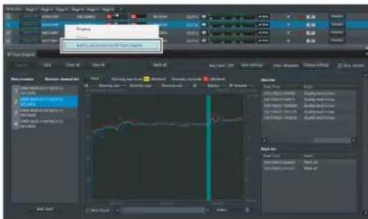
The selected receiver channel is displayed in a sub monitor.
2 Select a different receiver channel in the main monitor area's receiver channel list.
The information of the selected receiver channel is displayed in the right side of the main monitor area.
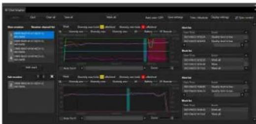
text_image
Screenshot of a software interface displaying multiple audio or signal processing panels with waveform graphs and control buttons.[Display Settings] screen ([RF Chart Grapher], [RF Chart Analyzer])
As both excessively high and excessively low RF levels can result in audio loss, appropriate levels must be maintained. You can switch between RF level displays in the [RF Chart Grapher] screen to monitor whether proper RF levels are maintained.
You can also configure how alert, mark, QL, AF level, transmitter battery level, RF remote received signal strength level, and time information are displayed on the graph as well as how the [Mark] button, RF information, and graph legend are displayed.
![SONY DWR-R02D - [Display Settings] screen ([RF Chart Grapher], [RF Chart Analyzer]) - 1](/content/2026/05/760390/images/50ae65f3c7f6ffd90075ae60576c0f0546dd2faa7c0a8c44f40930c34ca3b04d.jpg)
text_image
RF Chart Grapher Display Settings Graph data RF Level Overview Diversity ✓ ave level ✓ max level ✓ min level Detail Individual max ✓ a-branch ✓ b-branch ✓ c-branch* ✓ d-branch* ✓ diversity Individual min ✓ a-branch ✓ b-branch ✓ c-branch* ✓ d-branch* ✓ diversity *for 4-diversity use QL ON AF ON Battery ON RF Remote ON Time Absolute Alert Alert list ON Mark list ON Others ✓ Mark, Diversity max hold, Diversity min hold ✓ Graph legends Close[RF Level]
Specify the method of RF level monitoring.
Overview: Monitors the RF level for the selection made under [Diversity]. This display mode allows you to monitor excessively high and low RF levels. You can specify what to monitor by selecting or clearing the [ave level], [max level], and [min level] checkboxes.
Detail: Monitors RF levels by antenna. This allows a more detailed monitoring of RF levels when compared to [Overview] mode. The [Individual max] display mode is used for monitoring excessively high RF levels. The [Individual min] display mode is used for monitoring excessively low RF levels. For either display mode, you can specify what to monitor by selecting or clearing the [a-branch], [b-branch], and [diversity] checkboxes. In addition, when using a DWR-R03D and DIVERSITY is set to 4-ANTENNA, you can monitor the RF levels for [c-branch] and [d-branch].
QL
Shows or hides QL information in the graph display area.
AF
Shows or hides AF level information in the graph display area.
Battery
Shows or hides transmitter battery level information in the graph display area.
RF Remote
Shows or hides RF remote received signal strength level information in the graph display area.
Time
Specifies the display mode for time axis in the graph display area.
Absolute: Displays the time.
Relative: Displays the amount of time that has elapsed from the display start time.
Alert, Alert list
Shows or hides alert information in the graph display area, and shows or hides the alert list.
Mark list
Shows or hides the mark list.
Mark, Diversity max hold, Diversity min hold
Shows or hides the [Mark] button, diversity max hold, and diversity min hold in the graph display area. When you specify to hide, the graph's vertical size will increase accordingly.
Graph legends
Shows or hides the graph legends. When you specify to hide, the graph's vertical size will increase accordingly.
[Save settings] screen
You can automatically save the signal environment status obtained via the [RF Chart Grapher] for each receiver channel to a file.
![SONY DWR-R02D - [Save settings] screen - 1](/content/2026/05/760390/images/ba158c3b73abf4ee993d8d24ec3e501252a638b98073fc3795a420ca7d37571d.jpg)
text_image
RF Chart Grapher Save settings Auto save OFF ON Save timing Interval 01:00 Absolute time 00:00 00:00 00:00 00:00 00:00 Save folder Default C:\Users\Wirent Studio\MSC_LOG#20211221 Custom Browse Other ✓ Clear the graph after saving files ✓ Output csv files Close[Auto save]
Selects whether to save automatically. When this is set to [ON], automatic saving will be performed according to the configurations of the following settings. In addition, automatic saving will be performed when exiting Wireless Studio.
[Save timing]
Specifies the timing for automatic saving.
Interval: Specify the interval at which to perform automatic saving. You can specify an interval from 1 minute (00:01) to 24 hours (24:00) in minutes.
Absolute time: Specify specific times at which to perform automatic saving. You can specify up to five times from 00:00 to 23:59 in minutes. Each specified time can be enabled by selecting the checkbox to the left of the respective field.
Note
When entering values using a keyboard, enter a 4-digit value, and press the Enter key to apply it.
If you enter 3 digits or less and apply the value, the following will occur.
- When "123" is entered, "01:23" will be configured.
- When "12" is entered, "00:12" will be configured.
- When "1" is entered, "00:01" will be configured.
[Save folder]
Specifies the save destination for automatic saving.
Default: Creates a folder named with the time (HHMMSS) in the default path of Wireless Studio, and saves the signal environment status for all the receiver channels to a file inside the folder.
Custom: Creates a folder named with the time (HHMMSS) in a location that you specify, and saves the signal environment status for all the receiver channels to a file inside the folder. Click the [Browse] button to specify the save location.
[Other]
Clear the graph after saving files: Select this checkbox to clear the graph after saving files.
Output csv files: Place a check mark here to also save a csv format file in addition to the binary format file (*srd4 file).
Content saved in csv file
A csv format file saves the information contained in the binary format file (*srd4 file) in text format.
This allows you to check the RF, QL, and other information without using the [RF Chart Analyzer] function.
The file contains the following items.
| Information | Item Display content | |
| Header information | Version Displays | the file format version. |
| Data information | Time Displays the data acquisition time (yyyy/mm/dd hh:mm:ss). | |
| Enable/Disable | Displays whether the data is enabled or disabled.0: Enabled1: Disabled | |
| RF-a_ave Displays the maximum value, minimum value, and average value of the RF level for each antenna.0 to 99: 0 to 99 dBuV emf255: Data not acquired | ||
| RF-a_max | ||
| RF-a_min | ||
| RF-b_ave | ||
| RF-b_max | ||
| RF-b_min | ||
| RF-c_ave | ||
| RF-c_max | ||
| RF-c_min | ||
| RF-d_ave | ||
| RF-d_max | ||
| RF-d_min | ||
| RF-diver_ave | ||
| RF-diver_max | ||
| RF-diver_min | ||
| QL Displays the QL data.0 to 5: The higher the number, the higher the quality.255: Data not acquired | ||
| AF Displays the AF data.0 to 60: 0 dBFs to -60 dBFs61: -∞255: Data not acquired | ||
| Battery Displays the remaining capacity of the transmitter battery.0 to 100: 0% to 100%255: Data not acquired | ||
| RF Remote Displays the RF remote signal strength.0 to 254: The higher the number, the stronger the signal.255: Data not acquired | ||
| Alert information | Time Displays the alert acquisition time (yyyy/mm/dd hh:mm:ss). | |
| Alert code The following alert codes are supported.10: Rf level is low.11: Quality level is low.13: Communication time-out occurred.14: Rf level is excessive.17: Wireless Studio was not able to acquire data before updating graph.18: The process of searching devices was executed. | ||
| Alert text Displays the alert information. | ||
| [Mark] information | Time Displays the [Mark] configuration time (yyyy/mm/dd hh:mm:ss). | |
| msec Displays the [Mark] configuration time in milliseconds. | ||
| Number Displays the [Mark] number. | ||
| Enable/Disable | Displays whether the [Mark] is enabled or disabled.0: Enabled1: Disabled | |
| Text Displays the content for the [Mark]. | ||
| [Mark all] information | Time Displays the [Mark all] configuration time (yyyy/mm/dd hh:mm:ss). | |
| msec Displays the [Mark all] configuration time in milliseconds. | ||
| Number Displays the [Mark all] number. | ||
| Enable/Disable | Displays whether [Mark all] is enabled or disabled.0: Enabled1: Disabled | |
| Text Displays the content for [Mark all]. | ||
Note
When opening a csv file created in Wireless Studio in Microsoft Excel, the time information may not be displayed in yyyy/mm/dd hh:mm:ss format. If this occurs, use a function in Microsoft Excel to set the Time area display to yyyy/mm/dd hh:mm:ss format.
Location of saved csv file
The save location of the file saved by [Save settings] changes depending on whether the [Auto save] setting is ON or OFF.
When [Auto save] is ON, the file is saved in "RF_Chart_Grapher_csv_files" within [Save folder] specified by [Save settings].
When [Auto save] is OFF, the file is saved within the selected folder. However, if [Save all] is pressed without changing the save location, the files are saved in "RF_Chart_Grapher_csv_files" within [Save folder].
When [Save all] is pressed with a save location specified, the csv file is saved at the same level in the hierarchy as the srd file (binary file) directly under the specified location. One csv file is created and a separate binary format file (*srd4 file) is saved for each receiver channel.
Mark function
In addition to displaying alerts that occur during signal environment monitoring, you can also insert memos within the graph in the [RF Chart Grapher].
You can add the same memos to all receiver channels or add memos to specific receiver channels individually.
Green marks are displayed in the graph display area for memos added to all receiver channels, while blue marks are displayed for individually added memos.
To add the same memo to all receiver channels
1 Click the [Mark all] button at the top of the [RF Chart Grapher].
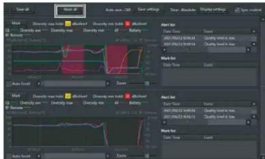
text_image
Sound at Sound at Audio user - Old Save settings Sound: Absolute Preview settings All: Sync control Mark: Diversity rate max, offset Diversity rate max, offset B1 Diversity rate max, offset Diversity rate max, offset B2 Diversity rate max, offset Diversity rate max, offset B3 Diversity rate max, offset Diversity rate max, offset B4 Diversity rate max, offset Diversity rate max, offset B5 Diversity rate max, offset Diversity rate max, offset B6 Diversity rate max, offset Diversity rate max, offset B7 Diversity rate max, offset Diversity rate max, offset B8 Diversity rate max, offset Diversity rate max, offset B9 Diversity rate max, offset Diversity rate max, offset B10 Diversity rate max, offset Diversity rate max, offset B11 Diversity rate max, offset Diversity rate max, offset B12 Diversity rate max, offset Diversity rate max, offset B13 Diversity rate max, offset Diversity rate max, offset B14 Diversity rate max, offset Diversity rate max, offset B15 Diversity rate max, offset Diversity rate max, offset B16 Diversity rate max, offset Diversity rate max, offset B17 Diversity rate max, offset Diversity rate max, offset B18 Diversity rate max, offset Diversity rate max, offset B19 Diversity rate max, offset Diversity rate max, offset B20 Diversity rate max, offset Diversity rate max, offset B21 Diversity rate max, offset Diversity rate max, offset B22 Diversity rate max, offset Diversity rate max, offset B23 Diversity rate max, offset Diversity rate max, offset B24 Diversity rate max, offset Diversity rate max, offset B25 Diversity rate max, offset Diversity rate max, offset B26 Diversity rate max, offset Diversity rate max, offset B27 Diversity rate max, offset Diversity rate max, offset B28 Diversity rate max, offset Diversity rate max, offset B29 Diversity rate max, offset Diversity rate max, offset B30 Diversity rate max, offset Diversity rate max, offset B31 Diversity rate max, offset Diversity rate max, offset B32 Diversity rate max, offset Diversity rate max, offset B33 Diversity rate max, offset Diversity rate max, offset B34 Diversity rate max, offset Diversity rate max, offset B35 Diversity rate max, offset Diversity rate max, offset B36 Diversity rate max, offset Diversity rate max, offset B37 Diversity rate max, offset Diversity rate max, offset B38 Diversity rate max, offset Diversity rate max, offset B39 Diversity rate max, offset Diversity rate max, offset B40 Diversity rate max, offset Diversity rate max, offset B41 Diversity rate max, offset Diversity rate max, offset B42 Diversity rate max, offset Diversity rate max, offset B43 Diversity rate max, offset Diversity rate max, offset B44 Diversity rate max, offset Diversity rate max, offset B45 Diversity rate max, offset Diversity rate max, offset B46 Diversity rate max, offset Diversity rate max, offset B47 Diversity rate max, offset Diversity rate max, offset B48 Diversity rate max, offset Diversity rate max, offset B49 Diversity rate max, offset2 Enter the content of the memo in the dialog box that appears, and click the [OK] button.
You can enter up to 64 alphanumeric characters.
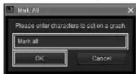
Green marks appear in the graph display area of each receiver channel, and the memo information is reflected in the mark list.
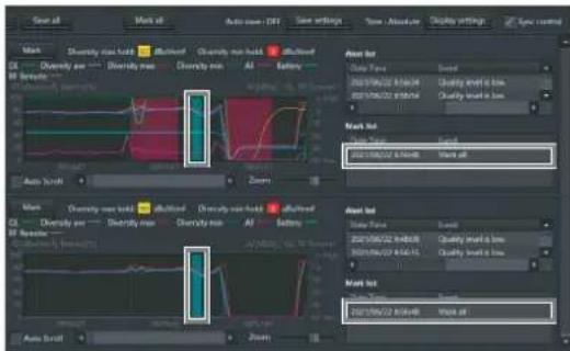
text_image
Wave at Audio scroll - 100% Auto scroll - 100% Time settings Time: Absolute Display settings Type control Mark Diversity max hold Efficient Diversity max hold Efficient All Battery Auto scroll Zoom Zoom Mark Diversity max hold Efficient Diversity max hold Efficient All Battery Auto scroll Zoom Zoom Peak at Data Type: Speed 2021/06/22 9:34:04 Quality level is low: 2021/06/22 9:34:04 Quality level is low: 2021/06/22 9:34:04 Work at Track Time: Speed: 2021/06/22 9:34:04 Work at Track at Track Time: Speed: 2021/06/22 9:34:04 Quality Level is low: 2021/06/22 9:34:15 Quality Level is low: Track at: Track Time: Speed: 2021/06/22 9:34:04 Work atTo add a memo to a specific receiver channel individually
1 Click the [Mark] button in the graph display area of the receiver channel for which you want to add the memo.
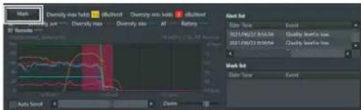
text_image
Main Diversity size beta 0.017500000000000000000000000000000000000000000000000000000000000000000000000 B: Remode State Type Event 2021/16/23 8:54:54 Quality factor loss 2021/16/23 8:54:54 Quality factor loss Mark Int State Type Event2 Enter the content of the memo in the dialog box that appears, and click the [OK] button.
You can enter up to 64 alphanumeric characters.
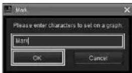
A blue mark appears in the graph display area of the respective receiver channel, and the memo information is reflected in the mark list.
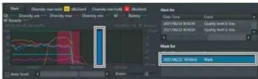
text_image
Mark Diversity max mode difficult Diversity max hold difficult Ch Diversity max Diversity max Aff Battery Alert Bit Data Time Event 2021/06/22 9:54:34 Quality level is low Quality level is high Mark Bit 2021/06/22 9:54:33 MarkTo view memo content
Place the mouse cursor on a green or blue mark to display the content of the memo as a tooltip.
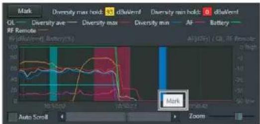
text_image
Mark Diversity max hold: 35 dBuWemf Diversity min hold: 0 dBuWemf OL Diversity ave Diversity max Diversity min AF Battery RF Remote RF (dBuWemf) Battery(1) Auto Scroll Zoom Algorithm (QL, RF Promoter)To edit memo content
1 Right-click the mark in the graph of the memo you want to edit, and select [Edit] in the context menu that appears.
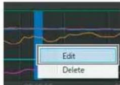
text_image
Edit Delete2 Edit the content of the memo in the dialog box that appears, and click the [OK] button.
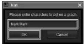
Note
When you edit the content of a memo with a green mark, the edited content will be applied to same memos that appear for the other receiver channels.
To delete memos
1 Right-click the mark in the graph of the memo you want to delete, and select [Delete] in the context menu that appears to delete the memo.
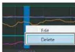
text_image
Edit DeleteNote
When you delete a memo with a green mark, the same memos that appear for the other receiver channels will also be deleted.
To move memos
Drag the mark in the graph of the memo you want to move to your desired position.
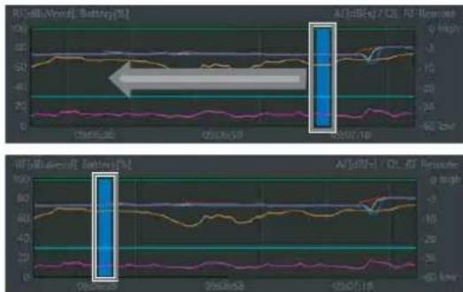
line
| Time Point | Aβ (pBc) / C5, AF Response (%) | | ---------- | ------------------------------ | | CHN260 | 0 | | CHN261 | 0 | | CHN261/18 | 0 |Note
When you move a memo with a green mark, the same memos that appear for the other receiver channels will also be moved.
Scrolling a graph using the hand tool
In Wireless Studio Ver. 5.61 or later, when you move the mouse cursor within a graph, the cursor display changes into a hand and you can then scroll the graph using drag and drop.
Move the mouse cursor within a graph to change the cursor into a hand.
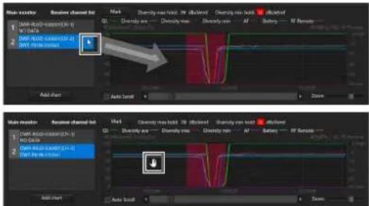
text_image
Main monitor Receiver channel list Main Diversity max load 30 dB Diversity max load 10 dB Diversity max load 5 dB Diversity max load 20 dB Diversity max load 10 dB Diversity max load 5 dB Diversity max load 20 dB Diversity max load 10 dB Diversity max load 5 dB Diversity max load 20 dB Diversity max load 10 dB Add start Auto lock Zoom Main monitor Receiver channel list Main Diversity max load 30 dB Diversity max load 10 dB Diversity max load 5 dB Diversity max load 20 dB Diversity max load 10 dB Diversity max load 5 dB Diversity max load 20 dB Diversity max load 10 dB Diversity max load 5 dB Diversity max load 20 dB Diversity max level Auto lock ZoomClick and hold the mouse button and move the mouse left/right to scroll the graph.
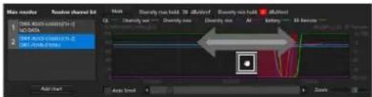
text_image
Max channels Receive channel list Name: Audio track Audio max Audio max Audio max Audio max Audio max Audio max Audio max Audio max Audio max Audio max Audio max Audio max Audio max Audio max Audio max Audio max Audio max Audio max Audio max Audio max Audio max Audio max Audio max Audio max Audio max Audio max Audio max Audio max Audio max Audio max Audio max Audio max Audio max Audio maxNote
If you move the mouse cursor over a blue mark or green mark, the cursor does not change into a hand and you cannot scroll the graph using the hand tool.
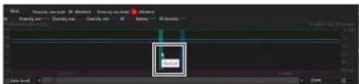
text_image
OK OKChanging the display areas
In Wireless Studio Ver. 5.61 or later, you can change the display areas for the Receiver channel list, graphs, and Alert list/Mark list using the mouse.
Place the mouse cursor over one of the dotted lines in the following diagram to change the cursor to “<-->” and then click and drag the mouse to change the display areas.
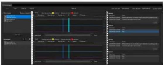
text_image
Screenshot of video editing software interface showing timeline, channel controls, and track layers with Chinese labelsThe following example shows a window with resized display areas.
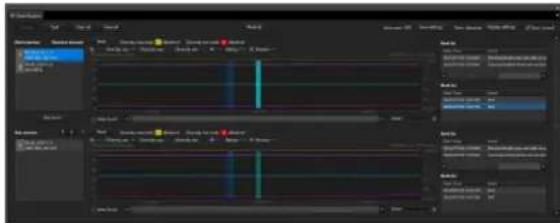
text_image
Screenshot of video editing software interface showing timeline, channel controls, and track layers with Chinese labels[RF Chart Analyzer] Tab
In the [RF Chart Analyzer] tab, you can view the contents of files recorded with the [RF Chart Grapher]. This allows you to analyze the results of signal environment monitoring. You can also use the mark function to add memos to the monitoring results.
![SONY DWR-R02D - [RF Chart Analyzer] Tab - 1](/content/2026/05/760390/images/073832fb975d22b4c8af095735cf47e202c38f0073f4058551acdff0be3837da.jpg)
text_image
1 2 Open Close Close off Set off Hind off Case Abstomy Delete Enriched All New content Main source 0x 0x 0x 0x 0x 0x 0x 0x 0x 0x 0x 0x 0x 0x 0x 0x 0x 0x 0x 0x 0x 0x 0x 0x 0x 0x 0x 0x 0x 0x 0x 0x 0x 0x 0x 0x 0x 1.5x 1.5x 1.5x 0x 1.5x 1.5x 1.5x 0x 1.5x 1.5x 1.5x 0x 1.5x 1.5x 1.5x 0x 1.5x 1.5x 1.5x 0x 1.5x 1.5x 1.5x 0x 1.5x 1. 0x 1.5x 1. 0x 1.5x 1. 0x 1.5x 1. 0x 1.5x 1. 0x 1.5x 1. 0x 1.5x 1. 0x 1.5x 1. 0x 1.5x 1. 0x 1.5x 1. 0x 1.5x 1 0.0 x 0.0 x 0.0 x 0.0 x 0.0 x 0.0 x 0.0 x 0.0 x 0.0 x 0.0 x 0.0 x 0.0 x 0.0 x 0.0 x 0.0 x 0.0 x 0.0 x 0.0 x 0.0 x 0.0 x 0.0 x 0.0 y 0.0 x 0.0 y 0.0 x 0.0 y 0.0 x 0.0 y 0.0 x 0.0 y 0.0 x 0.0 y 0.0 x 0.0 y 0.0 x 0.0 y 0.0 x 0.0 y 0.0 x 0.0 y 0.0 x 0.0 z 0.0 x 0.0 z 0.0 x 0.0 z 0.0 x 0.0 z 0.0 x 0.0 z 0.0 x 0.0 z 0.0 x 0.0 z 0.0 x 0.3y 0.3y 3687424444444444444444444444444444444444444444444444444444444444444444444444444444444444444444444444444444 Main source Main source Main source Main source Main source Main source Main source Main source Main source Main source Main source Main source Main source Main source Main source Main source Main source Main source Main source Main source Main source Main source Main source Main source Main source Main source Main source Main source①Control items
Open: Registers the file to the file list. Only files created using the [RF Chart Grapher] can be registered to the file list.
Save as: Saves the information of the file selected in the file list.
Close: Deletes the file selected in the file list from the file list.
Close all: Deletes all the files registered to the file list from the file list.
②Main monitor area
File list: Displays the list of loaded files. The information of the file selected here is displayed in the graph display area, alert list, and mark list.
Note
The other items function identically to those in the [RF Chart Grapher] tab. However, the [Auto save] and [Auto Scroll] functions do not exist in the [RF Chart Analyzer] tab.
For details, see "[RF Chart Grapher] Tab" (page 40).
[Spectrum Analyzer] Tab
The [Spectrum Analyzer] tab allows you to perform a spectrum scan of a specified frequency band using the receivers. This allows you to visually confirm the existence of interference on the frequency bands in use. In addition, if you configure the optimal groups and channels using [Channel Plan Adviser] beforehand, the [Channel Plan Adviser] settings can be applied to [Spectrum Analyzer]. This allows you to visually confirm the existence of interference on the groups and channels recommended by [Channel Plan Adviser].
![SONY DWR-R02D - [Spectrum Analyzer] Tab - 1](/content/2026/05/760390/images/3f1fc6e038577d253d166bb21d3b9cf6b8e3395eb9a0adf507c16f3be3eb996c.jpg)
text_image
Spectrum Analyzer Scan options Scan parameters Channel Rate Adjuster Wave Impedance values matching Frequency select Signal Output Signal Output Signal Output Signal Output Signal Output Signal Output Signal Output Signal Output Signal Output Signal Output Signal Output Signal Output Signal Output Signal Output Signal Output Signal Output Signal Output Signal Output Signal Output Signal Output Signal Output Signal Output Signal Output Signal Output Signal Output Signal Input①[Start scan] / [Stop scan] button
When you click the [Start scan] button, a confirmation dialog box appears.
![SONY DWR-R02D - ①[Start scan] / [Stop scan] button - 1](/content/2026/05/760390/images/40c48a64d065ec4e0dcfed4417d6adbbf914d36c862cd0646565cd8de14af65d.jpg)
text_image
Spectrum Analyzer Do you want to start scanning? Yes NoWhen you click the [Yes] button here, scanning starts and the button name changes to [Stop scan]. When you click the [Stop scan] button, scanning stops and the button name changes to [Start scan].
②[Scan parameter...] button
Allows you to select and configure detailed settings for the receiver that will perform scanning.
For details, see “[Scan parameter] window” (page 49).
③Channel Plan Adviser
Opens [Channel Plan Adviser].
④[Sleep transmitters while scanning] checkbox
If this is selected, any transmitters that can be controlled remotely will automatically be set to sleep mode before scanning starts.
⑤ Frequency spectrum display area
Many of the items and functions displayed here are identical to those of [Channel Plan Adviser].
For details, see “[Channel Plan Adviser] Window” (page 59).
However, the following functions are unique to [Spectrum Analyzer].
When you place the mouse cursor on the graph, the frequency and electric field strength is displayed.
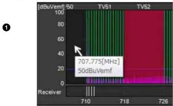
bar
| Channel | Frequency (MHz) | | :--- | :--- | | [dBuVemf] / 50 | 707.775 | | TV51 | 50 | | TV52 | 707.775 |The frequencies configured for the receivers are displayed as white lines in the receiver area. When you place the mouse cursor on a white line, the receiver name, channel number, and frequency are displayed.
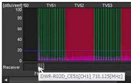
text_image
[dBuVemf] 50 TV51 TV52 TV53 Receiver 71 DWR-R02D_CE51[CH1] 710.125[MHz]⑥[Scan list]
Displays scanning results in a list after scanning is complete.
Save button: Saves the scanning result selected in the scan list as a file.
Delete button: Deletes the scanning result selected in the scan list from the list.
⑦[File list]
When you open a scanning results file, the scanning results stored in the file are added to the list.
Open button: Displays the dialog box for selecting scanning results files. The scanning results stored in the file selected here are added to the file list.
Delete button: Deletes the scanning result selected in the file list from the list.
⑧Data items
Select the scanning results to display in the frequency spectrum display area in [Data1] and [Data2].
You can select from [new spectrum], the scanning results in the scan list and file list, and [Do not display]. When [new spectrum] is selected, the most recent scanning results are displayed. When [Do not display] is selected, scanning results are not displayed.
⑨[Top layer]
Select the scanning results that will be displayed on the top layer of the graph.
[Scan parameter] window
This appears when you click the [Scan parameter...] button in [Spectrum Analyzer].
![SONY DWR-R02D - [Scan parameter] window - 1](/content/2026/05/760390/images/00e6d605c40bab50b9fc059752353a0cbfdd65e589224d79f85007be05c34868.jpg)
text_image
Scan parameter Detect occupied channels Please select recoveries that scan to detect active frequency. An neoked, please adjust "Scan conditions". Then click "Start scan" button to run off the first scan. Send Frequency Target: 1/43-44 (538-007MA) 1/43-46 (562-065MA) 1/49-52 (586-70MA) 3E(732-714MA) 8 BAND (500-810MA) 12H (5240-526MA) 12M (5240-525MA) 12H (5253-526MA) Recent scan: DMR-RD3D-B12704 DMR-RD3D-B12704 DMR-RD3D-B12704 DMR-RD3D-B12704 DMR-RD3D-B12704 DMR-RD3D-B12704 DMR-RD3D-B12704 DMR-RD3D-B12704 Scan all frequency Minimum recovers Multiple recovers (reversible scan time) Auto Analog: Clear Scan Conditions Continuous scan Specified count scan Repeat counts: 1 Frequency Interval: 123 MHz Read full: 0 ns Close①Target receiver selection
Allows you to select the receivers that will perform scanning for each frequency band. Scanning will not be performed for frequency bands for which [Do not scan] is selected.
When the [Reflect recommended GP/CH] checkbox is selected in the [Channel Plan Adviser] window and you apply the settings to the [Spectrum Analyzer] tab, the receivers that will perform scanning will be selected automatically.
In such cases, if multiple receivers that correspond to a frequency band exist, the receiver with the earliest IP address will be selected. However, if a DWR-R02DN is included, it will be selected regardless of its IP address.
Scanning is performed on CH1 of each receiver. The operations will vary depending on the model of the receiver.
DWR-R01D/R02D
To receive the transmitter signal on CH2, configure the same band setting as that for CH1 scanning. If different bands are selected for CH1 and CH2, audio interruption will occur on CH2.
DWR-R02DN
To receive the transmitter signal on CH2, configure the same band block setting as that for CH1 scanning. If different band blocks are selected for CH1 and CH2, audio interruption will occur on CH2.
• Example for North American models:
To prevent audio interruption when the frequency band setting for CH2 is set to TV14-17, set the frequency band that will be used for CH1 scanning to a band that belongs to band block U14(TV14-25) (TV14-17, TV18-21, or TV22-25).
| Band block Band | |
| U14(TV14-25) TV14-17 | |
| TV18-21 | |
| TV22-25 | |
| U30(TV30-41) TV30-33 | |
| TV34-36 | |
| TV38-41 | |
| U42(TV42-51) TV42-45 | |
| TV46-49 | |
| TV50-51 |
• Example for European models:
To prevent audio interruption when the frequency band setting for CH2 is set to TV21-23, set the frequency band that will be used for CH1 scanning to a band that belongs to band block CE21(TV21-29) (TV21-23, TV24-26, or TV27-29).
| Band block Band | |
| CE21(TV21-29) TV21-23 | |
| TV24-26 | |
| TV27-29 | |
| CE33(TV33-40) TV33-35 | |
| TV36-37 | |
| TV38-40 | |
| CE42(TV42-50) TV42-44 | |
| TV45-47 | |
| TV48-50 |
DWR-R03D
To receive the transmitter signal on CH2, configure the same band block setting as that for CH1 scanning. If different band blocks are selected for CH1 and CH2, audio interruption will occur on CH2.
• Example for North American models:
To prevent audio interruption when the frequency band setting for CH2 is set to TV14-17, set the frequency band that will be used for CH1 scanning to a band that belongs to band block TV14-25 (TV14-17, TV18-21, or TV22-25).
| Band block Band | |
| TV14-25 TV14-17 | |
| TV18-21 | |
| TV22-25 | |
| TV26-38 TV26-29 | |
| TV30-33 | |
| TV34-36 | |
| TV38 |
• Example for European models:
To prevent audio interruption when the frequency band setting for CH2 is set to TV21-23, set the frequency band that will be used for CH1 scanning to a band that belongs to band block TV21-29 (TV21-23, TV24-26, or TV27-29).
| Band block Band | |
| TV21-29 TV21-23 | |
| TV24-26 | |
| TV27-29 | |
| TV30-41 TV30-32 | |
| TV33-35 | |
| TV36-37 | |
| TV38 | |
| TV38-40 | |
| TV41 | |
| TV42-51 TV42-44 | |
| TV45-47 | |
| TV48-50 | |
| TV51 |
② Scanning receiver assignments
Minimum receivers: Assign scanning receivers with as few receivers as possible. The scan time will be longer, but does support scanning with a limited number of receivers.
Multiple receivers: Assign scanning receivers with as many receivers as possible. Requires many receivers, but the scan time will be shorter.
Auto Assign
Assigns scanning receivers using either [Minimum receivers] or [Multiple receivers].
Clear
Clears scanning receiver assignments.
③Scan count setting
Continuous scan: After scanning starts, it is performed continuously until the [Stop scan] button is clicked.
Specified count scan: After scanning starts, scanning is performed the number of times specified in [Repeat count].
④ Other settings
Frequency Interval: Select from 125 kHz or 25 kHz as the interval at which to scan.
[Peak hold]
Select whether to hold and display scanning result values for each frequency.
ON: The highest RF level of a set of scanning sessions (during [Continuous scan] or when [Repeat count] is set to 2 or higher for [Specified count scan]) is displayed in the graph.
OFF: The most recent RF level of a set of scanning sessions (during [Continuous scan] or when [Repeat count] is set to 2 or higher for [Specified count scan]) is displayed in the graph.
⑤Close button
Closes the [Scan parameter] window.
[Simple Status Viewer] Tab
The [Simple Status Viewer] tab allows you to narrow down the information registered to each page of the status viewer to a certain few items, such as the RF meter, QL meter, and alerts, and display only those items for easier monitoring.
By reducing the number of items displayed, the display area for each channel is increased, making the simplified status viewer ideal for systems with fewer channels to manage.
![SONY DWR-R02D - [Simple Status Viewer] Tab - 1](/content/2026/05/760390/images/bcac7768fe06e4ea6ed955f0c27214ea8b21e05116cd2fe8a14a290bef58a37c.jpg)
text_image
Simple Status Viewer 1 Search TX DWT-B30-0 QL 2 Search TX DWT-B30-0 QL 3 Search TX NO DATA QL 4 Search TX NO DATA QL a RF b RF RF RF RF RF RF RF RF RF RF RF RF RF RF RF RF RF RF RF RF RF RF RF RF RF RF RF RF RF RF RF RF RF RF RF RF RF RF RF RF RF RF RF RF RF RF RF RF RF RF No Data①[Page]
Select the status viewer page.
The content registered to the selected page will appear in the status display area.
②[Scale]
The [Scale] setting has a drop-down list on the left and a slide bar on the right.
You can select whether to set a common receiver channel size or independent sizes within the simple status viewer using the drop-down list on the left.
All same: Set a common size using the slide bar on the right.
Individual: Enable independent sizes for receiver channels.
Note
When set to [Individual], the size cannot be changed using the slide bar on the right.
Switch the display size ([Tiny], [Small], [Medium], [Large]) of the information items displayed for each receiver channel in the status display area using the slider bar on the right.
When displaying the simple status viewer in full screen on a monitor under the following conditions, the numbers of receiver channels that can be displayed simultaneously are as follows.
Display conditions
| Resolution 1920× | 1080 |
| Display settings Number, TX Name, QL alert, QL meter, RF meter, RF alert, Battery status only displayed | |
Number of receiver channels that can be displayed
| Tiny Small | Medium Large | ||
| 82 51 34 8 |
When [Scale] is set to [Individual], use the following method to change the size of receiver channels within the simple status viewer.
Example 1: Changing the #2 channel [Scale] setting from [Tiny] to [Small]
Display the context menu for #2 receiver channel, and select [Change scale] > [Small].
![SONY DWR-R02D - Example 1: Changing the #2 channel [Scale] setting from [Tiny] to [Small] - 1](/content/2026/05/760390/images/1818727c8693302f05d78832f0e5aa80884e9f7a671bd910dcb641fad54a6e40.jpg)
text_image
Simple Status Viewer Page Page-1 Scale Individual 1 2 3 4 5 6 7 NO DATA QL NO DATA QL NO DATA QL NO DATA QL NO DATA QL NO DATA QL NO DATA QL RF INT PEAK RF INT PEAK RF INT PEAK RF INT PEAK RF INT PEAK RF INT Property Add to sub monitor for RF Chart Grapher Change scale Tiny Small Medium Large 8 NO DATA QL NO DATA QL NO DATA QL RF INT PEAK RF INT PEAK RF INT PEAK RF INT PEAK RF INT PEAKThe size of #2 channel changes.
![SONY DWR-R02D - Example 1: Changing the #2 channel [Scale] setting from [Tiny] to [Small] - 2](/content/2026/05/760390/images/435a6bd15848576b220d55f988400010fb899730ae8834455d9d033b18f1fbb3.jpg)
text_image
Simple Status Viewer Page Page-1 Scale Individual 1 2 NO DATA QL NO DATA QL RF AMI PLAK RF AMI FLR AMI PEAK MRK 3 4 5 6 NO DATA QL NO DATA QL NO DATA QL NO DATA QL RF AMI PLAK RF AMI PLAK RF AMI PLAK RF AMI MRK 7 8 9 10 NO DATA QL NO DATA QL NO DATA QL NO DATA QLExample 2: Changing multiple channel [Scale] settings from [Tiny] to [Small]
Select multiple channels (#2, #4, and #6 in the following diagram) using the Ctrl key, display the context menu for the receiver channels, and select [Change scale] > [Small].
![SONY DWR-R02D - Example 2: Changing multiple channel [Scale] settings from [Tiny] to [Small] - 1](/content/2026/05/760390/images/ad784ab893518e07c9b13c948b5a6738560b4ac54c193c39ba3041d29f5371c8.jpg)
text_image
Simple Status Viewer Page Page-1 Scale Individual 1 2 3 4 5 6 7 NO DATA QL NO DATA RF OPT PCAR RF OPT PCAR RF OPT PCAR RF OPT PCAR RF OPT PCAR RF OPT PCAR Property Add to sub monitor for RF Chart Grapher Change scale Tiny Small Medium Large 8 NO DATA QL NO DATA RF OPT PCAR RF OPT PCAR RF OPT PCAR NO DATA QL NO DATA RF OPT PCAR RF OPT PCAR RF OPT PCARThe size of #2, #4, and #6 channels change.
![SONY DWR-R02D - Example 2: Changing multiple channel [Scale] settings from [Tiny] to [Small] - 2](/content/2026/05/760390/images/010e26dcbf5f4e8da8735a961b5f8a4678c7bc0ed3410e9eda6e0648d379aac1.jpg)
text_image
Simple Status Viewer 1 NO DATA QL 2 NO DATA QL 3 NO DATA QL 4 NO DATA QL 5 NO DATA QL 6 NO DATA QL 7 NO DATA QL 8 NO DATA QL 9 NO DATA QL 10 NO DATA QLNote
When [Scale] is set to [All same], [Change scale] cannot be selected in the context menu.
③Maximize / restore button
Displays the simple status viewer in full screen window size, or returns it to normal size.
- Simple status viewer in normal window size
Click the button to maximize the window size.
- Simple status viewer in maximum window size
Click the button to return the window to the size before maximization.
Note
The maximize / restore button only appears when the [Simple Status Viewer] tab is separated from Wireless Studio.
For details on separating the [Simple Status Viewer] tab from Wireless Studio, see "To separate a sub-window tab from Wireless Studio" (page 27).
④Status display area
Displays information on each receiver channel.
You can select whether to display or hide each information item in the [Display settings] window.
For details, see “[Display settings] Window” (page 68).
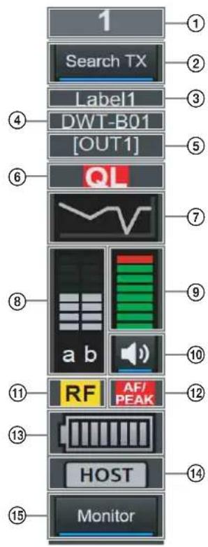
text_image
1 Search TX Label1 DWT-B01 [OUT1] QL a b RF AF/PEAK HOST Monitor①Number
Displays the receiver channel number.
②Search TX
Makes the screens for transmitters that are paired with the receiver blink.
Notes
- This function is not supported on the DWR-R01D, DWR-R02D, and DWR-R02DN.
- This function is only available on combinations of 3rd generation or later digital wireless receivers (such as the DWR-R03D) and digital wireless transmitters (such as the DWT-B03R). In addition, when using an RMU-01 for Cross Remote connection, the RMU-01 must be version 1.27 or later.
③Label
Displays the label configured in the [Receiver CH Label Settings] window.
④Transmitter name
Displays the name of the transmitter.
⑤Output channel display
Displays the audio output destination of the receiver. In normal operation, channel 1 is output from OUT 1, and channel 2 is output from OUT 2.
When the OUTPUT SWAP setting is enabled, channel 1 is output from OUT 2, and channel 2 is output from OUT 1. The settings are also highlighted on the display.
Note
OUTPUT SWAP is available only on the DWR-R03D version 1.20 or later.
⑥QL (signal quality level) alert
Lights red when the quality of the received data decreases.
⑦QL (signal quality level) meter
Indicates the quality of the received data in a meter.
⑧RF (radio wave) level meter
Indicates the radio wave input level according to eight levels.
⑨AF level meter
Indicates the level of the audio signal input to the transmitter according to eight levels.
⑩Audio output control/indicator
Indicates the status of audio output for the receiver channel. Clicking the icon toggles the status of audio output.
: Audio output is enabled. Clicking the icon will enable muting of the audio output.
: Audio output muting is enabled. Clicking the icon will disable muting of the audio output.
Note
This setting can only be changed if the [Individual muting/unmuting] checkbox is selected in the [Display settings] window.
For details, see “[Display settings] Window” (page 68).
⑪RF (radio wave) level alert
Lights red when the radio wave input level decreases. When the radio wave input level is high, this lights yellow.
⑫AF/PEAK (audio input/peak) alert
Lights red when the level of audio signal input to the transmitter exceeds the transmitter's maximum input level setting.
⑬Battery condition display
Indicates the transmitter's battery condition. The display varies depending on the transmitter model.
- When receiving radio waves from models other than the DWT-B03R digital wireless transmitter, this indicates the remaining battery charge of the transmitter in 8 levels based on metadata received by the receiver from the transmitter. When the remaining charge is low, the battery icon turns red.
- When receiving radio waves from the DWT-B03R digital wireless transmitter, this functions according to the BATTERY REMAIN setting of the transmitter.
When set to ICON: Indicates the remaining battery
charge of the transmitter in 8 levels based on metadata received by the receiver from the transmitter. When the remaining charge is low, the battery icon turns red.
When set to PERCENT: Indicates the remaining battery charge of the transmitter as a percentage based on metadata received by the receiver from the transmitter. When the remaining charge is low, the battery icon turns red.
When set to TIME: Indicates the remaining operating time of the transmitter based on metadata received by the receiver from the transmitter.
⑭Auto Frequency change status display
Displays the status of the receiver's AUTO FREQ CHANGE setting.
HOST: Displayed when the receiver is operating as the HOST. It scans the RF spectrum for a good frequency for use by a CLIENT.
CLIENT: Displayed when the receiver finds the HOST and is operating as a CLIENT. Depending on the RF environment of the transmitter, the frequency automatically switches to the viable frequency detected by the HOST.
The display flashes if the HOST cannot be found.
Note
This function is available only on the DWR-R03D version 1.20 or later.
⑮Dante audio monitoring
Monitors Dante IP audio.
Monitor : Dante IP audio is being monitored on a computer.
Monitor : Dante IP audio is not being monitored on a computer.
Note
The DWR-R03D and optional Dante Virtual Soundcard software from Audinate are required to use this function.
Monitor is displayed on computers that do not have Dante Virtual Soundcard installed, hence Dante IP audio cannot be monitored by computer.
[BC-DWX Viewer] Tab
The [BC-DWX Viewer] tab displays BC-DWX1 battery chargers detected by Wireless Studio (sorted by IP address) and allows you to monitor and control each BC-DWX1.
Monitoring: Display the charge statuses of batteries and error occurrences.
Control: Switch the charge mode and enables indicators for identifying BC-DWX1 units.
![SONY DWR-R02D - [BC-DWX Viewer] Tab - 1](/content/2026/05/760390/images/4128ffcecaede9c52401c8466925859a148a57ec39b9dea1423bc5e96cce5bb1.jpg)
text_image
BC-DWX Viewer BC-DWX1_01 CHG Mode STORAGE BC-DWX1_02 CHG Mode STORAGE BC-DWX1_03 CHG Mode STORAGE BC-DWX1_04 CHG Mode STORAGE BC-DWX1_05 CHG Mode STORAGE BC-DWX1_06 CHG Mode STORAGE BC-DWX1_07 CHG Mode STORAGE BC-DWX1_08 CHG Mode STORAGE BC-DWX1_09 CHG Mode STORAGE BC-DWX1_10 CHG Mode STORAGE BC-DWX1_11 CHG Mode STORAGE BC-DWX1_12 CHG Mode STORAGE BC-DWX1_13 CHG Mode STORAGE BC-DWX1_14 CHG Mode STORAGE BC-DWX1_15 CHG Mode STORAGE BC-DWX1_16 CHG Mode STORAGE BC-DWX1_17 CHG Mode STORAGE BC-DWX1_18 CHG Mode STORAGE BC-DWX1_19 CHG Mode STORAGE BC-DWX1_20 CHG Mode STORAGE BC-DWX1_21 CHG Mode STORAGE BC-DWX1_22 CHG Mode STORAGE BC-DWX1_23 CHG Mode STORAGE BC-DWX1_24 CHG Mode STORAGE BC-DWX1_25 CHG Mode STORAGE BC-DWX1_26 CHG Mode STORAGE BC-DWX1_27 CHG Mode STORAGE BC-DWX1_28 CHG Mode STORAGE BC-DWX1_29 CHG Mode STORAGE BC-DWX1_30 CHG Mode STORAGE BC-DWX1_31 CHG Mode STORAGE BC-DWX1_32 CHG Mode STORAGE BC-DWX1_33 CHG Mode STORAGE BC-DWX1_34 CHG Mode STORAGE BC-DWX1_35 CHG Mode STORAGE BC-DWX1_36 CHG Mode STORAGE BC-DWX1_37 CHG Mode STORAGE BC-DWX1_38 CHG Mode STORAGE BC-DWX1_39 CHG Mode STORAGE BC-DWX1_40 CHG Mode STORAGE BC-DWX1_41 CHG Mode STORAGE BC-DWX1_42 CHG Mode STORAGE BC-DWX1_43 CHG Mode STORAGE BC-DWX1_44 CHG Mode STORAGE BC-DWX1_45 CHG Mode STORAGE BC-DWX1_46 CHG Mode STORAGE BC-DWX1_47 CHG Mode STORAGE BC-DWX1_48 CHG Mode STORAGE BC-DWX1_49 CHG Mode STORAGE BC-DWX1_50 CHG Mode STORAGE①Name
Displays the name of the battery charger.
②CHG Mode
Allows you to configure the charge mode.
③Slot number and remaining batter indicator / error display
Displays the statuses of slots 1 and 2 as follows.
- When batteries are inserted
When no error has occurred: Remaining battery indicator
When an error or warning has occurred: Error or warning icon
- When batteries are not inserted No Battery
④[Blink] button
Enables indicators for identifying each slot.
Display example for the [BC-DWX Viewer] tab
The following is displayed when the battery charge is 100%.
![SONY DWR-R02D - Display example for the [BC-DWX Viewer] tab - 1](/content/2026/05/760390/images/e79d6d321da9ebf397ee11e710d2881b417baab7a9dc60964c632cc333b2cf71.jpg)
text_image
BC-DWX1_01 CHG Mode STORAGE 1 100% 2 10% Blink BlinkThe display is highlighted as follows when a battery charger is selected in the [Device List] or [BC-DWX Viewer].
![SONY DWR-R02D - Display example for the [BC-DWX Viewer] tab - 2](/content/2026/05/760390/images/314da97dc679f4fb30b18b7c7ccaaa9e72ae459a6ad58eff9093cecbd656ceb3.jpg)
text_image
BC-DWX1_01 CHG Mode STORAGE ▼ 1 33% 2 Error Blink BlinkThe following is displayed when an error or warning occurs.
![SONY DWR-R02D - Display example for the [BC-DWX Viewer] tab - 3](/content/2026/05/760390/images/0fa67c36ea00e9716a8e9565daf2ac717b83d732fbfbe068d8039fa70950415b.jpg)
text_image
BC-DWX1_01 CHG Mode STORAGE 1 Error 2 Warning Blink BlinkError: Overvoltage or charging error detected Warning: Abnormal temperature (high or low) detected
“No Battery” is displayed when a battery is not inserted.
![SONY DWR-R02D - Display example for the [BC-DWX Viewer] tab - 4](/content/2026/05/760390/images/0a1ad7ad5179372ce5c4f1d31e4b2d309c4672f2cd073e7ccbb274d98dfb80a0.jpg)
text_image
BC-DWX1_01 CHG Mode STORAGE ▼ 1 10% 2 No Battery Blink BlinkSetup Windows
Wireless Studio includes the following setup windows:
• [Property] window
• [Channel Plan Adviser] window
• [Omit IP address list] window
- [Setting lock] window
• [Receiver CH Label Settings] window
• [GP/CH display setting] window
• [Display settings] window
• [Other settings] window
• [Network settings] window
• [Startup settings] window
• [Region setting] window
[Property] Window
This window allows you to view and change settings for receivers and their paired transmitters.
![SONY DWR-R02D - [Property] Window - 1](/content/2026/05/760390/images/0576a1ecd6eb1b1bf6f26454df8bac4ffe3c2b81975bce9c5e8e8cc0f70a1b7c.jpg)
text_image
R2001.CAN LOCK SETTINGS 1 8041-000* 638 125MHz NO DATA RF 0 0 10 10 10 10 10 10 10 10 10 10 10 10 10 10 10 10 10 10 10 10 10 10 10 10 10 10 10 10 10 10 10 10 10 12 8041-000* 638 125MHz NO DATA RF 0 0 10 10 10 10 10 10 10 10 10 10 10 10 10 10 10 10 10 10 10 10 10 10 10 10.123M R2001.CAN Utility Receiver Type: DWR-R33D Network setting: Receiver Name: DWR-R33D_0001 Dante ID Mode: FREE ID Dante ID: SONY_0001 View Advanced settings: RF setting: Band Block: VH(TV41.63) Band: NO FUNCTION: ANT ATT: 5 dB ANT CC Output: 9V Diversity: 2 ANTENNA Audio setting: Monitor Mode: IP MIX Sync Source: AUTO Delay Adjust: ON OFF System Delay: 1 0: --ms A: --ms 2 0: --ms A: --ms Subout Select: AESIEBU Receiver Mode: (AVYL/ASTEN) Alert function settings: RF low: RF over: OL low: AF Peak: Transmitter Battery low: Encryption unmatch: External word sync unlock: Codec mode unmatch: OL Alert SENS MD Lock UNLOCK Close①[Unlock Settings] / [Lock Settings] button
When setting modification is disabled due to the [Setting lock] function, click this button and enter the password to temporarily enable setting modification.
Close the [Property] window or click the button again to relock settings.
For details on the [Setting lock] function, see “[Setting lock] Window” (page 65).
②Meter icons
These function identically to the meter icons in the status viewer.
③Property tabs
These consist of the [Utility] tab and tabs for channels 1 and 2.
For details on the setting items in each tab, see “[Utility] tab” (page 55) and “Channel tabs 1/2” (page 57).
④[Close] button
Closes the [Property] window.
[Utility] tab
Displays setting items that are equivalent to those in the UTILITY menu of the receiver.
For details on each setting item, refer to the Operating Instructions supplied with the receiver.
![SONY DWR-R02D - [Utility] tab - 1](/content/2026/05/760390/images/e63338fd5c7fd441aad94f239687a7f84330b1188516ef441a7f40842f6d7345.jpg)
text_image
Ustery 1 2 Receiver Type DWR-R03D Network setting Receiver Name DWR-R03D_0001 Dante ID Mode FREE ID Dante ID SONY_0001 View Advanced settings... RF setting BandBlock WH(TV41-53) Band NO FUNCTION ANT ATT 5dB 5dB 6 6 ANT DC Output IN Diversity Z-ANTENNA Audio setting Monitor Mode IP MIX Sync source AUTO Delay Adjust ON OFF System Delay D: -ms A: -ms D: -ms A: -ms Subout Select AES/EBU Receiver Model WORAM/MMA Alert function settings RF low RF over QL low AF Peak Transmitter Battery low Encryption unmatch External word sync unlock Codec mode unmatch QL Alert SEN3 MID Lock UNLOCKReceiver Type: In online mode, this displays the device information acquired from the receiver and cannot be changed. The device information can be changed in offline mode.
Receiver Model: In online mode, this displays the frequency band acquired from the receiver and cannot be changed. The frequency band can be changed in offline mode. Specify a frequency band that corresponds to the actual device.
Receiver Name: Sets a name for the receiver.
Dante ID Mode: Displays the receiver's Dante ID mode.
Note
This function is not supported on the DWR-R01D, DWR-R02D and DWR-R02DN.
Dante ID: Specifies the receiver's Dante ID.
Note
This function is not supported on the DWR-R01D, DWR-R02D and DWR-R02DN.
View Advanced setting...: Displays the receiver's network settings. Click the button to display the following screen.
Note
This function is not supported on the DWR-R01D, DWR-R02D and DWR-R02DN.
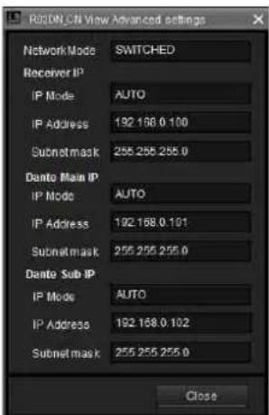
text_image
RORDN CNV View Advanced settings Network Mode SWITCHED Receiver IP IP Mode AUTO IP Address 192.168.0.100 Subnetmask 255.255.255.0 Danto Main IP IP Mode AUTO IP Address 192.168.0.101 Subnetmask 255.255.255.0 Danto Sub IP IP Mode AUTO IP Address 192.168.0.102 Subnetmask 255.255.255.0 CloseNetwork Mode: Specifies the receiver's network mode.
[Receiver IP]
IP Mode: Specifies the receiver unit's IP mode.
IP Address: Specifies the receiver unit's IP address.
Subnetmask: Specifies the receiver unit's subnet mask.
[Dante Main IP]
IP Mode: Specifies the IP mode for the receiver's Dante Main IP.
IP Address: Specifies the IP address for the receiver's Dante Main IP.
Subnetmask: Specifies the subnet mask for the receiver's Dante Main IP.
[Dante Sub IP]
IP Mode: Specifies the IP mode for the receiver's Dante Sub IP.
IP Address: Specifies the IP address for the receiver's Dante Sub IP.
Subnetmask: Specifies the subnet mask for the receiver's Dante Sub IP.
Band Block: Selects the frequency band to use (the largest is 72 MHz).
When a receiver is connected to a network and connected to a transmitter using RF Remote, the frequency display area in the status viewer is displayed in red if the band block settings of the transmitter and receiver are different. To restore a frequency displayed in red to the original value, set the transmitter and receiver to the same band block and set the frequency on the transmitter and receiver using the GP/CH settings or using direct frequency input.
![SONY DWR-R02D - [Dante Sub IP] - 1](/content/2026/05/760390/images/f079ee09f9b61fe4553115c01a92cd691f327e37717cba5566e4e9fa12729c66.jpg)
Note
This function is not supported by the DWR-R01D and DWR-R02D.
Band: Selects the frequency band to use.
ANT ATT: Sets the attenuator for the receiver's antenna input.
ANT DC Output: Sets the DC power supply for the antennas connected to the receiver's ANTENNA a/b IN connectors.
Diversity: Specifies the receiver's diversity setting.
Notes
- This function is not supported on the DWR-R01D, DWR-R02D, and DWR-R02DN.
- Some screen displays will change depending on the [Diversity] setting. For details, see “Effects of the Diversity Setting on Wireless Studio Displays” (page 74).
Monitor Mode: Specifies the receiver's headphone monitor setting.
Note
This function is not supported on the DWR-R01D, DWR-R02D, and DWR-R02DN.
Sync Source: Sets the sync signal source for the receiver.
Delay Adjust: Selects whether to correct differences in audio delay time that may occur between receiver channels 1 and 2.
Alert function settings: Specifies the conditions under which to light the ALERT indicator on the receiver. You can select the following conditions as triggers for lighting the ALERT indicator.
• RF low (RF level too low)
• RF over (RF level too high)
- QL low (QL too low)
• AF Peak (audio output level too high)
• Transmitter Battery low (remaining battery on transmitter is low)
- Encryption unmatch (password or encryption key for the encrypted communication function does not match)
- External word sync unlock (external word clock signal not synchronized)
- Code mode unmatch (codec modes of transmitters and receivers do not match)
Note
If lighting of the ALERT indicator is disabled for an item, warning messages will not be displayed in the alert list under the [Message Log] tab and [RF Chart Grapher] tab
of Wireless Studio for that item. In addition, such items will not be recorded in the log file.
QL Alert SENS: Specifies the level at which the quality of the received signal is determined to be low. If the quality of the received signal drops below the level specified here, the ALERT indicator of the digital wireless receiver lights.
Note
The QL Alert SENS function is available for the following receiver versions.
DWR-R01D: Version 1.29 or later
DWR-R02D: Version 1.09 or later
DWR-R02DN: Version 1.14 or later
DWR-R03D: Version 1.00 or later
Lock: Sets the receiver's setting lock function.
Note
This function is not supported on the DWR-R01D, DWR-R02D, and DWR-R02DN.
Channel tabs 1/2
Displays setting items that are equivalent to those in the RECEIVER, TRANSMITTER, and RF REMOTE menus of the receiver.
For details on the setting items in each menu, refer to the Operating Instructions supplied with the receiver.
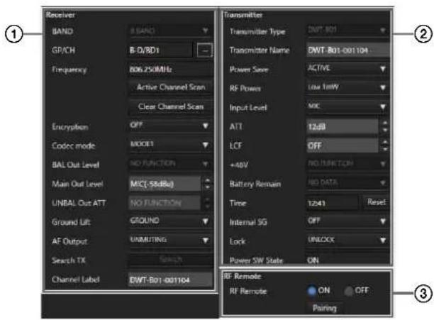
text_image
Receiver BAND GP/CH Frequency 806.250MHz Active Channel Scan Clear Channel Scan Encryption OFF Codec mode MODE1 BAL Out Level NO FUNCTION Main Out Level MIC(-58dBq) UNBAL Out ATT NO FUNCTION Ground Lift GROUND AF Output UNMITING Search TX Search Channel Label DWT-B01-001104 Transmitter Transmitter Type DWT-B01 Transmitter Name DWT-B01-001104 Power Save ACTIVE RF Powers Low 1mW Input Level MIC ATT 12dB LCF OFF +40V RUMINCTION Battery Remain RED DATA Time 1241 Reset Internal SG OFF Lock UNLOCK Power SW State ON RF Remote RF Remote ON OFF Pairing ① ② ③① [Receiver] menu
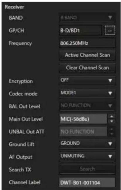
text_image
Receiver BAND 8 BAND GP/CH B-D/BD1 Frequency 806.250MHz Active Channel Scan Clear Channel Scan Encryption OFF Codec mode MODE1 BAL Out Level NO FUNCTION Main Out Level MIC(-58dBu) UNBAL Out ATT NO FUNCTION Ground Lift GROUND AF Output UNMUTING Search TX Search Channel Label DWT-B01-001104BAND: Specifies the frequency band to use.
Note
This function is not supported by the DWR-R01D and DWR-R02D.
GP/CH: Displays the frequency group and channel configured for the receiver channel.
Note
When setting GP/CH, the following dialog appears if in online mode and the transmitter is not connected using RF Remote. Click [Yes] to set GP/CH for the receiver only. Click [No] to cancel the GP/CH settings (including for the receiver).
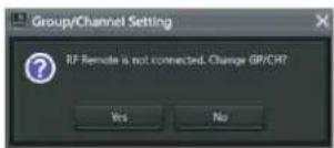
text_image
Group/Channel Setting RF Remote is not connected. Change GR/CH? Yes NoFrequency: Displays the frequency configured for the receiver channel.
...: Press this button to display the [Group/Channel Setting] dialog box. You can select the reception frequency from the channel plan configured for the receiver in the [Group/Channel Setting] dialog box.
Active Channel Scan: Press this button to execute the receiver's active channel scan function. You can select the channel for receiving from the detected channels.
Clear Channel Scan: Press this button to execute the receiver's clear channel scan function. You can select the channel for receiving from the detected channels.
Encryption: Configure settings for the receiver's encrypted communication function.
Codec mode: Configure settings for the receiver's codec mode.
Note
This function is not supported by the DWR-R01D and DWR-R02D.
BAL Out Level: Configure settings for the receiver's analog audio output level.
Note
This function is not supported on the DWR-R01D, DWR-R02D, and DWR-R02DN.
Main Out Level: Adjusts the receiver's main out level.
Note
This function is not supported on the DWR-R01D, DWR-R02D, and DWR-R02DN.
UNBAL Out ATT: Configure attenuator settings for the UNBALANCED OUTPUT 1/2 connector.
Note
This function is not supported on the DWR-R01D.
Ground Lift: Configure whether to connect the GROUND (XLR 1 pin) of the BALANCED OUTPUT 1/2 connector to a chassis GROUND. You can avoid hum, buzz, and other noise caused by GROUND LOOP by selecting [LIFT] to lift GROUND (XLR 1 pin) from the chassis GROUND.
Note
This function is not supported on the DWR-R01D.
AF Output: Controls the audio output for the receiver channel. When [MUTING] is selected, audio output muting will be enabled for the respective receiver channel. While muting is enabled, the “muting” indicator on the AF/PEAK level meter will blink red. When [UNMUTING] is selected, audio output muting will be disabled for the respective receiver channel.
Note
This function is available under the following conditions.
DWR-R01D: Version 1.26 or later
DWR-R02D: Version 1.06 or later
Search TX: Makes the screens for transmitters that are paired with the receiver blink.
Notes
- This function is not supported on the DWR-R01D, DWR-R02D, and DWR-R02DN.
- This function is only available on combinations of 3rd generation or later digital wireless receivers (such as the DWR-R03D) and digital wireless transmitters (such as the DWT-B03R). In addition, when using an RMU-01 for Cross Remote connection, the RMU-01 must be version 1.27 or later.
Channel Label: Sets the receiver channel label.
Note
This function is supported in the following case.
DWR-R03D: Version 1.31 or later
② [Transmitter] menu
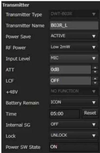
text_image
Transmitter Transmitter Type DWT-B03R Transmitter Name B03R_L Power Save ACTIVE RF Power Low 2mW Input Level MIC ATT 0dB LCF OFF +48V NO FUNCTION Battery Remain ICON Time 05:00 Reset Internal SG OFF Lock UNLOCK Power SW State ONTransmitter Type: In online mode, this setting cannot be changed. Specify the model of the transmitter paired with the receiver in offline mode.
Transmitter Name: Sets the name for the transmitter.
Power save: Configure settings for the transmitter's power-saving function.
RF Power: Configure settings for the transmitter's transmitted power.
Notes
- If the maximum transmission power setting of the transmitter is changed, execute pairing. It may not be possible to set the transmission power using the wireless remote control function. - On 3rd-generation or later digital wireless transmitters (such as the DWT-B03R), [RF Power] cannot be set to a value higher than 10mW when [Band] is set to TV38 (North American models only).
Input Level: Displays the transmitter's audio input level. ATT: Sets the attenuator for the transmitter. You can only change this setting when [Input Level] is set to [MIC].
LCF: Configure settings for the transmitter's low-cut filter.
+48V: Configure settings for the transmitter's +48 V power supply.
Battery Remain: Switches the transmitter's battery display.
Notes
- This function is not supported on the DWR-R01D, DWR-R02D, and DWR-R02DN. - This function is only available on combinations of 3rd generation or later digital wireless receivers (such as the DWR-R03D) and the DWT-B03R. In addition, when using an RMU-01 for Cross Remote connection, the RMU-01 must be version 1.27 or later.
Time: Displays the total usage time for the transmitter. Clicking the [Reset] button clears the total usage time.
Internal SG: Specifies whether to generate internal signals on the transmitter.
Lock: Sets the transmitter's POWER switch lock and setting lock functions.
Notes
- The setting lock function is not supported on the DWR-R01D, DWR-R02D, and DWR-R02DN. - The setting lock function is only available on combinations of 3rd generation or later digital wireless receivers (such as the DWR-R03D) and digital wireless transmitters (such as the DWT-B03R). In addition, when using an RMU-01 for Cross Remote connection, the RMU-01 must be version 1.27 or later.
Power SW State: Displays the status of the POWER switch on the transmitter. This setting cannot be changed.
③ [RF Remote] menu
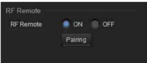
text_image
RF Remote RF Remote ON OFF PairingRF Remote: Configure settings for the wireless remote control function.
Pairing: Press this button to start pairing receiver channels to transmitters.
[Channel Plan Adviser] Window
This window allows you to enter signal environment information and use the receiver's channel scan function to select a channel plan that is suitable for the signal environment.
The signal environment information entered and the signals detected with the channel scan are displayed in the spectrum graph in the upper part of the screen. This allows you to select the channel plan while viewing signal usage in the spectrum graph.
The following modes are available in [Channel Plan Adviser].
Basic mode: This mode allows you to select a channel plan that avoids signal interferences detected by the receiver's channel scan function. This is a simplified method that omits information entry other than the channel scan.
Advanced mode: In addition to performing channel scan as in basic mode, this mode allows you to enter various information you obtained beforehand to select an appropriate channel plan. You can enter the following information.
• Interference resulting from TV broadcasts
• Interference resulting from other wireless devices
• Interference detected by the channel scan
- The amount of frequency clearance to leave between interference when selecting the channel plan
For details on selecting channel plans using basic mode, see “Selecting Channel Plans” (page 18).
![SONY DWR-R02D - [Channel Plan Adviser] Window - 1](/content/2026/05/760390/images/72e09a7b90dd55c934a0ee94f6992c0b9274cc33157a74e309d8b0b07c51afe2.jpg)
text_image
1 2 3 Channels P Solution • Introduction • Select target coordinates • Select distance from the source • Select TV signal output • Other window system • Select received channel • Security conditions • Select position from the source Range: 0.0000 to 0.0000 Complete Close Save in Reset Select target coordinates • Select target coordinates • Select target coordinates • Select target coordinates • Select target coordinates • Select target coordinates • Select target coordinates • Select target coordinates • Select target coordinates • Select target coordinates • Select target coordinates • Select target coordinates • Select target coordinates • Select target coordinates • Select target coordinates • Select target coordinates • Select target coordinates • Select target coordinates • Select target coordinates • Select target coordinates • Select target coordinates • Selection of the target frequency based. • Select (Frequency Based) • Select (Frequency Based) • Select (Frequency Based) • Select (Frequency Based) • Select (Frequency Based) • Select (Frequency Based) • Select (Frequency Based) • Select (Frequency Based) • Select (Frequency Based) • Select (Frequency Based) • Select (Frequency Based) • Select (Frequency Based) • Select (Frequency Based) • Select (Frequency Based) • Select (Frequency Based) • Select (Frequency Based) • Select (Frequency Based) • Select (Faster) selected. • Select (Faster) selected. • Select (Faster) selected. • Select (Faster) selected. • Select (Faster) selected. • Select (Faster) selected. • Select (Faster) selected. • Select (Faster) selected. • Select (Faster) selected. • Select (Faster) selected. • Select (Faster) selected. • Select (Faster) selected. • Select (Faster) selected. • Select (Easter) selected. • Select (Easter) selected. • Select (Easter) selected. • Select (Easter) selected. • Select (Easter) selected. • Select (Easter) selected. • Select (Easter) selected. • Select (Easter) selected. • Select (Easter) selected. • Select (Easter) selected. • Select (Easter) selected. • Select (Easter) selected. • Select (Easter) selected. 3① Contents area
Displays the steps to perform when using [Channel Plan Adviser] and allows you to save or load a work file.

text_image
Introduction Select target bands Input known channels -Active TV channels -Other wireless system Detect occupied channels Stability conditions Select available channels Assign channels to receivers Complete Clear Save as Load①Completion mark
Displays a check mark for completed steps. This allows you to view your progress and check for missed steps.
②Procedure items
Displays the list of steps to perform in [Channel Plan Adviser].
The items also act as shortcuts to each step, so you can click an item to jump directly to the target step operation. Certain steps are omitted in basic mode. These omitted steps cannot be selected.
③Save and load work files
When you click the [Clear] button, the [Channel Plan Adviser] configurations will be cleared. The configurations that were applied to the [Spectrum Analyzer] will also be cleared at the same time.
When you click the [Save as] button, the file save dialog box appears.
This allows you to save your progress and the information you entered to a file.
When you click the [Load] button, the file load dialog box appears.
This allows you to load a previously saved file from which to continue the channel plan selection process.
Note
User defined files created in Wireless Studio version 4.00 or earlier cannot be loaded correctly. Use the latest version to create files.
For details on work files, see "Work files" (page 64).
②Frequency spectrum display area
Displays the information entered for each step on a frequency spectrum graph.
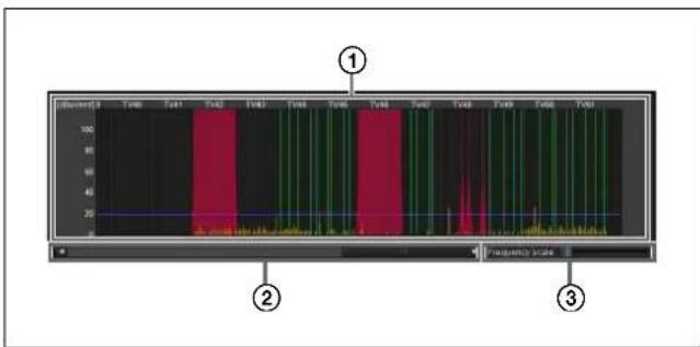
text_image
1 2 3①Frequency spectrum
Displays the information entered for each step in a graph. TV broadcast waves and interference from other wireless devices are displayed in red.
Interference detected with the channel scan function is displayed in yellow.
The threshold value for determining interference is displayed as a blue line.
The usable channels in the selected channel plan are displayed in green. Channels that are unusable due to interference or other reasons are displayed in dark green.
②Display range scroll bar
Scrolls through the frequency range display.
③Display scale
Changes the scale of the frequency display.
③ Wizard area
Information necessary for channel selection is entered here according to the step that is displayed.
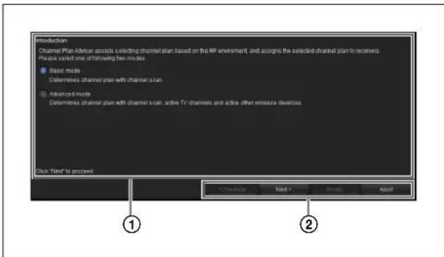
text_image
Introduction Channel Plan Advisor selects a selecting channel plan based on the RF environment, and acgris the selected channel plan to receivers. Please select one of following two modes. ● Basic mode ● Counterless channel plan with channel scan. ● Advanced mode ● Counterless channel plan with channel scan, active TV channels and active other wireless devices. Pick "Next" to proceed. ① ②①Information entry area
Enter information according to the content displayed.
②Operation buttons
Previous: Go back to the previous step.
Next: Go to the next step.
Finish: Complete the procedure, and close [Channel Plan Adviser].
Abort: Discard any operation progress, and close [Channel Plan Adviser].
Selecting the channel plan
The section describes how to select channel plans using the advanced mode.
For details on selecting channel plans using basic mode, see "Selecting Channel Plans" (page 18).
1 Select [Advanced mode], and click [Next>].
You can select whether to select the channel plan using basic or advanced mode here.
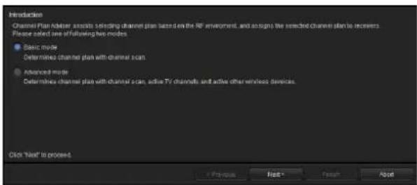
text_image
Introduction Channel Plan Adapter assists sending channel plan based on the RF environment, and assigns the selected channel plan to receivers. Please select one of following two modes: ● Basic mode Determined channels plan with channel scan ● Advanced mode Determined channels plan with channel scan, active TV channels and active other wireless devices. Click "Next" to proceed + Cancel Next Cancel Apply2 Select the frequency bands, and click [Next>].
Select the frequency bands from which you will select the channel plan.
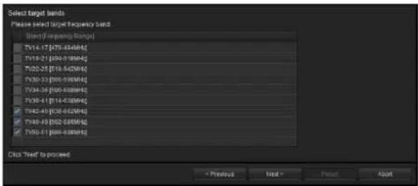
text_image
Select target bands Please select target frequency band: Start (Frequency Range) TV14-17 [470-436MHz] TV18-21 [500-519MHz] TV20-25 [510-542MHz] TV30-33 [500-508MHz] TV34-36 [500-508MHz] TV38-41 [514-536MHz] TV42-45 [536-562MHz] TV48-49 [562-588MHz] TV50-51 [588-608MHz] Click "Next" to proceed < Previous Next > Reset AboutThe frequency bands that appear are identical to those that can be selected for the receiver's BAND setting. In the steps that follow, the channel plan can only be selected from the bands selected here.
3 Specify any TV channels, and click [Next>].
You can specify TV channels by placing check marks in the list.
The specified TV channels will be plotted in the frequency spectrum display area.
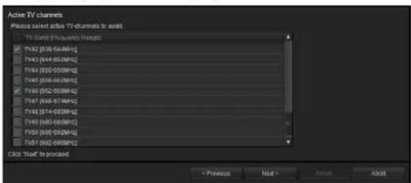
text_image
Active TV channels Please select active TV channels to exit TV Group Frequency Range TV42 (036-048MHz) TV43 (044-052MHz) TV44 (000-020MHz) TV45 (016-022MHz) TV46 (020-030MHz) TV47 (068-078MHz) TV48 (074-082MHz) TV49 (090-100MHz) TV50 (100-110MHz) TV51 (110-120MHz) Click "Read" to proceed < Previous Next > Cancel AbortThe TV broadcast waves selected here will be classified as interference, and the respective frequencies will be removed from the candidates available during channel plan selection.
4 Specify any frequencies used by other wireless devices, and click [Next >].
Specify the frequencies assigned to other wireless devices being used in the same area.
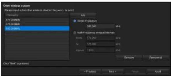
text_image
Other wireless system Please input active other wireless devices frequency to assist Frequency 577.00MHz 578.00MHz 582.00MHz Add Single Frequency 590.00Hz Multi-Flagency at output intervals From: 576.00Hz In: 575.00Hz Format: 1.00Hz Remove Remove All Click "Input" to process + Produce Next - Finish AboutThe frequencies selected here will be classified as interference and removed from the candidates available during channel plan selection. The specified frequencies will be plotted in the frequency spectrum display area.
To add frequencies
Enter the frequency (MHz), and click the [Add] button.
You can use one of the following methods to add frequencies.
Single Frequency: Adds the frequency entered in the text box.
Multi-Frequency at equal intervals: Adds all the frequencies between the frequencies entered for [From] and [To] at the interval specified in [Interval].
To remove frequencies
Remove: Removes the frequency selected in the list. Remove All: Removes all the frequencies in the list.
5 Select [Scan] to run a channel scan, or select [Scan data from Spectrum Analyzer] to use the scan result obtained using the Spectrum Analyzer function.
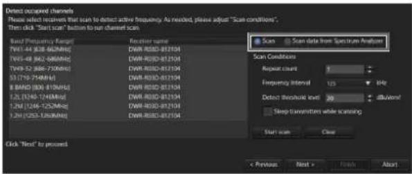
text_image
Detect occurred channels Please select receivers that scan to detect active frequency. As needed, please adjust "Scan conditions", Then click "Start scan" button to run channel scan. Band Frequency Range: F41-44 838-625MHz F45-48 842-640MHz F49-52 846-730MHz (13/19) 75MHz 8 BAND (806-812MHz) 12L (1345-1246MHz) 12M (1346-1252MHz) 12N (253-1260MHz) Scan Data from Spectrum Analyzer Scan Conditions Repeat count Frequency Interval 125 84K Detect threshold level 20 dBV/Hz Sleep transmissions while scanning Start scan Clear Click "Next" to present < Previous Next > Finish AboutWhen [Scan] is selected
Frequencies that are likely to be interference are detected by the receiver's channel scan function. The detected frequencies will be plotted in the frequency spectrum display area.
![SONY DWR-R02D - When [Scan] is selected - 1](/content/2026/05/760390/images/b182d64aa5187259cf9fdb6cfc6d2afca4fe557636f1b4e83a89c1034a49442a.jpg)
text_image
Detect occurred channels Please select viewers that scan to detect active frequency. As needed, please adjust "Scan conditions". Then click "Start scan" button to run channel scan. Band Frequency Range: Fourier name 19V 48 838-620MHz DNR-RSDC-8170M 19V-48 842-600MHz DNR-RSDC-8170M 19V-52 886-710MHz DNR-RSDC-8170M 51(710-714MHz) DNR-RSDC-8170M 8 BAND-006-810MHz DNR-RSDC-8170M 12L (1246-1264MHz) DNR-RSDC-8170M 12M (1246-1252MHz) DNR-RSDC-8170M 12H (1252-1260MHz) DNR-RSDC-8170M Scan Conditions Repeat count: Frequency Interval: 15 Hz Detect threshold level: 30 dB Sleep transmissions while scanning Start scan Close Click "Next" to proceed < Previous Next > Break AboutTo specify the receiver that will perform the scan
Select the receiver that will perform the frequency band scan.
If you select [Do not scan] instead of a receiver, channel scan will not be performed for that frequency band.
To adjust scan conditions
Repeat count: Specify the number of times to repeat the scan. You can specify a number from 1 to 10.
Frequency Interval: Specify the frequency interval. You can specify an interval of 125 kHz or 25 kHz.
Detect threshold Level: Specify an RF level to use as a threshold for determining interference. You can specify a level from 5 to 30 dBuVemf in 1 dB steps.
Note
Receiver models manufactured for use in Japan cannot perform scanning at 25 kHz intervals in the following bands.
• FPU-1CH to FPU-4CH
• B BAND
To start scanning
Click [Start scan].
Scanning starts. When scanning is complete, the results of the previous scan will be removed and updated with the new results.
If the [Sleep transmitters while scanning] checkbox is selected, any transmitters that can be controlled remotely will be automatically set to sleep mode during the scan.
To clear scan results
Click [Clear].
The scan results up to this point will be cleared.
When [Scan data from Spectrum Analyzer] is selected
The scan result obtained using the Spectrum Analyzer function is plotted in the frequency spectrum display area.
![SONY DWR-R02D - When [Scan data from Spectrum Analyzer] is selected - 1](/content/2026/05/760390/images/7237d8c063bb932ee868343a3a36050de59b15edfb476479f5af055022129cfb.jpg)
text_image
Direct occupied channels Please select recipients that scan to detect active frequency. As needed, please adjust "Scan condition". Then click "Start scan" button to run channel size. Band Frequency Range: Receiver name TV1-44 (638-662MHz) DWR-R30D-812104 TV5-84 (642-668MHz) DWR-R30D-812104 TV9-52 (664-700MHz) DWR-R30D-812104 537719-714MHz DWR-R30D-812104 8 BAND 806-817MHz DWR-R30D-812104 12L (3349-7248MHz) DWR-R30D-812104 12M (1246-1252MHz) DWR-R30D-812104 12H (1253-1260MHz) DWR-R30D-812104 Scan Scan data from Spectrum Analyzer scan_161848 scan_161848.dots Scan Clear Click "Next" to proceed < Previous Next > About6 Specify conditions for avoiding interference, and click [Next>].
Specify the amount of frequency clearance to leave between each type of interference when selecting the channel plan.
![SONY DWR-R02D - Specify conditions for avoiding interference, and click [Next>]. - 1](/content/2026/05/760390/images/4ae135116d127243aea7ae6b581aea894aaeeff5d02c4ecaf1bb5db1f4e557fc.jpg)
text_image
Stability conditions Please select "Stability conditions" to adjust conditions avoiding from interference Stability conditions: Custom Condition parameter ✓ Active TV channels Guard band 250 kHz ✓ Other wireless devices Guard band 500 kHz ✓ Selected spectrum Guard band 125 kHz Click "Next" to proceed + Printout Next- Finish NextSelect a value for [Stability condition] to specify the condition setting.
To specify a preset condition
Select one of the three preset condition settings: [Stable], [Standard], and [More Frequency].
Stable: Selects the channel plan while leaving a wide frequency clearance between interference. Although this condition setting ensures high stability, it also limits the number of channels available for selection.
Standard: Selects the channel plan while leaving standard frequency clearance.
More Frequency: Selects the channel plan while leaving a small frequency clearance between interference.
To customize the condition
Select [Custom].
When you place a check mark next to an item, the respective frequency will be classified as interference and that frequency will not be a candidate during channel plan selection.
When classifying as interference, specify the amount of clearance to leave above and below the respective frequency.
Active TV Channels: Treats specified TV broadcasts as interference and avoids them.
Other wireless device: Treats other wireless devices as interference and avoids them.
Detected spectrum: Treats signals detected via channel scan as interference and avoids them.
7 Select the channel plan.
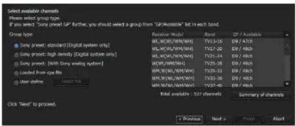
text_image
Select available channels Please select group type. If you select "Sony preset GP" further, you should select a group from "GP/Available" list in each band. Group type ■ Sony preset: standard [Digital system only] ■ Sony preset: high density [Digital system only] ■ Sony preset: With Sony analog system ■ Loaded from cpu file ■ User define Select the Receiver Model Band GP / Available WL/W(LW/WH/WH) TV13-16 D9 / 47ch WL/W(LW/WH/WH) TV17-20 D9 / 48ch WL/W(LW/WH/WH) TV21-24 D9 / 48ch WL/W(WH/WH) TV25-28 D9 / 48ch WL/W(LW/WH/WH) TV29-32 D9 / 48ch WL/W(LW/WH/WH) TV33-36 D9 / 48ch WL/W(LW/WH/WH) TV37-40 D9 / 48ch Total available : 527 channels Summary of channels Click "Next" to proceed. * Previous Next > Finish AbortSelect a channel plan for each frequency band based on the information entered up to this point.
Specifying a channel plan type
Select the [Group type] based on the device configuration.
Sony preset: standard [Digital system only]: Select this when only Sony digital wireless systems are used. Channel plans are listed with preset channel plans suited for digital wireless systems prioritized.
Sony preset: high density [Digital system only]:
Select this when only Sony digital wireless systems are used with more channels than the “Sony preset: standard [Digital system only]” setting.
Sony preset GP [With Sony analog system]: Select this when the configuration also includes Sony analog wireless systems.
Select from preset channel plan candidates that can be used with mixed configurations that include analog wireless systems.
Loaded from cpa file: Load a work file, and use a channel plan that is saved to that work file.
For details on work files, see "Work files" (page 64).
User define: Click [Select file], and specify a user defined frequency list.
For details on user defined frequency lists, see "User defined files" (page 64).
Note
The recommended channel plan when “Sony preset: high density [Digital system only]” is selected cannot be assigned to the DWR-R01D, DWR-R02D, or DWR-R02DN.
Specifying channel plans for each frequency band
Of the channel plans selected with the [Group type] setting, frequencies that may experience interference are excluded and only the channel numbers that can be used are displayed for each frequency band.
If there are multiple channel plan candidates, select the channel plan you want to use for each frequency band.
Viewing the current frequency list
Click [Summary of channels].
The frequencies available for use in the selected channel plan are listed for each frequency band.
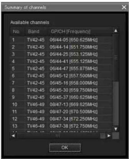
text_image
Summary of channels Available channels No Band GP/CH [Frequency] 1 TV42-45 06/44-05 [650.625MHz] 2 TV42-45 06/44-14 [651.750MHz] 3 TV42-45 06/44-25 [653.125MHz] 4 TV42-45 06/44-41 [655.125MHz] 5 TV42-45 06/44-47 [655.875MHz] 6 TV42-45 06/45-12 [657.500MHz] 7 TV42-45 06/45-16 [658.000MHz] 8 TV42-45 06/45-30 [659.750MHz] 9 TV42-45 06/45-37 [660.625MHz] 10 TV46-49 08/47-13 [669.625MHz] 11 TV46-49 08/47-20 [670.500MHz] 12 TV46-49 08/47-34 [672.250MHz] 13 TV46-49 08/47-38 [672.750MHz] OK8 Assign the selected channel plan to the receiver.
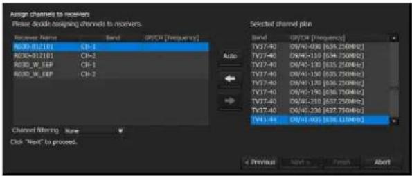
text_image
Assign channels to receivers Please divide assigning channels to receivers. Receiver Name Band GP/CH [Frequency] RG00-812101 CH-1 RG00-812102 CH-2 RG00_W_EEP CH-1 RG00_W_EEP CH-2 Selected channel plan Band GP/CH [Frequency] TV37-40 D0/40-036 [634.250MHz] TV37-40 D0/40-130 [634.750MHz] TV37-40 D0/40-130 [635.250MHz] TV37-40 D0/40-130 [635.750MHz] TV37-40 D0/40-130 [636.250MHz] TV37-40 D0/40-130 [636.750MHz] TV37-40 D0/40-230 [637.250MHz] TV37-40 D0/40-230 [637.750MHz] TV41-40 D0/41-005 [638.125MHz] Auto Channel Filtering: New Click "Next" to process. Previous Next > Finish AbortExtracting a channel plan
You can extract a channel plan using the [Channel filtering] setting. This allows you to assign a channel plan without changing the [BAND BLOCK] or [BAND] setting of the digital wireless receiver.
None: All usable channel plans can be assigned.
Receiver's band block: Extract only the channel plan matching the [BAND BLOCK] setting of the selected receiver channel from among the usable channel plans.
Receiver's band: Extract only the channel plan matching the [BAND] setting of the selected receiver channel from among the usable channel plans.
Note
[Channel filtering] is supported in Wireless Studio version 5.22 or later.
Automatic assignment
Click [Auto].
Starting with the lowest-frequency plans in the channel plan list, the frequencies are automatically assigned to the receiver's receiver channels.
Individual assignment
Select a receiver channel from the receiver channel list and click a green line in the graph, or select the frequency you want to assign in [Selected channel plan].
Click the ← button to assign the frequency to the receiver channel.
To cancel an assignment
Select the respective receiver channel in the receiver channel list, and click the button to cancel the assignment.
9 When you finish assignments for all the receiver channels, click [Next>].
The frequency assignment settings are sent to the receiver.
![SONY DWR-R02D - When you finish assignments for all the receiver channels, click [Next>]. - 1](/content/2026/05/760390/images/df051e9e39d501bb91d0edf29c97d7bc86742526108c520d08214c4306d83277.jpg)
text_image
Complete The procedure of Channel Plan Advisor is complete. "recommended GPICH is reflected in Spectrum Analyzer. Additionally, it is also reflected to Wireless Studio. By doing this, you can display only "recommended GPICH" If you want to reflect the setting, check "Reflect recommended GPICH", click "Finish". You can always change the setting from Option/Menu<>Other setting=>GPICH display setting, when you want to change. ✓ Reflect recommended GPICH Click "Finish" to close this procedure < Previous Next > Finish Cancel10 If necessary, enable or disable [Reflect recommended GP/CH], and then click [Finish].
[Channel Plan Adviser] closes.
If the [Reflect recommended GP/CH] checkbox is selected, only the groups and channels recommended by [Channel Plan Adviser] will be selectable on Wireless Studio. The groups and channels recommended by [Channel Plan Adviser] will be displayed in the [Spectrum Analyzer] tab of the sub window. In addition, the receivers that will perform scanning for the frequency band selected in step 2 will be selected automatically in the [Scan parameter] window.
For details, see “Target receiver selection” in “[Scan parameter] window” (page 49).
Note
The [Reflect recommended GP/CH] setting can be changed at any time in the [GP/CH display setting] window.
For details, see “[GP/CH display setting] Window” (page 67).
Work files
In [Channel Plan Adviser], you can save the information entered for each step to a work file (.cpa) and load the work file whenever necessary.
The following is saved to a work file.
- Target frequency bands (entered in step 2 of “Selecting the channel plan”)
- TV Channels (entered in step 3 of “Selecting the channel plan”)
- Frequencies used by other wireless devices (entered in step 4 of “Selecting the channel plan”)
- Channel scan conditions and scan results (entered in step 5 of “Selecting the channel plan”)
- Conditions for avoiding interference (entered in step 6 of “Selecting the channel plan”)
- Selected channel plan (entered in step 7 of “Selecting the channel plan”)
For details, see "Selecting the channel plan" (page 61).
User defined files
You can use a frequency list from a user defined file (.chplan) to specify a user defined channel plan.
Load the user defined file in [Channel Plan Adviser], and determine frequencies while referring to the signal environment information from scan results, etc.
To create user defined files
Use a text editor such as Notepad to create the file. Be sure to specify “.chplan” as the file extension.
Define one frequency per row.
Note
When the “#” sign is entered, text that is entered after the “#” in that row will be considered comments.
Example: When defining a 12-ch plan that connects group D1 of TV42-45 (US Model) for simultaneous operation.
# User define Channel Plan
# TV42-45 / D1 Group
638.250#42-02
638.750#42-06
639.250#42-10
639.750#42-14
640.250#42-18
640.750 # 42-22
641.250#42-26
641.750 # 42-30
642.250#42-34
642.750 # 42-38
643.250#42-42
643.750 # 42-46
Note
Only the frequencies indicated in the frequency list supplied with the receiver can be used.
[Omit IP address list] Window
When you register an IP address in this list, the IP address is excluded from automatic detection and will not appear in the device list window.
Use this function when multiple systems are connected on the same subnet, and you do not want to display the devices from other systems.
To display the [Omit IP address list] window, select [Device] menu > [Omit IP address list].
The [Omit IP address list] command can only be used in offline mode.
![SONY DWR-R02D - [Omit IP address list] Window - 1](/content/2026/05/760390/images/8f9c747b78e51d00795084277460ee9321ce509aaf46970e16e6f6c5dc5cf622.jpg)
text_image
Omit IP address list 192.168.1.10 192.168.1.12 Add Edit Delete CloseAdding an IP address to the list for exclusion from automatic detection
Click [Add], enter the IP address you wish to exclude from detection, and then click [Close].
Changing an IP address on the list
Click the IP address you wish to change, click [Edit], make the desired changes, and then click [Close].
Removing an IP address from the list
Click the IP address you wish to delete, click [Delete], and then click [Close].
[Setting lock] Window
You can prohibit the modification of receiver and transmitter settings from Wireless Studio. An administrator password must be configured to use this function.
When setting modification is prohibited (i.e., locked), you can temporarily enable setting changes by clicking the lock release buttons in the [Property] window, and then entering the administrator password.
Click [Setting lock] in the [Device] menu.
The following screen appears if the settings are not locked.
![SONY DWR-R02D - [Setting lock] Window - 1](/content/2026/05/760390/images/fd615e7449d324343c7796b93a69c7f0e874684db254fcbaaa636d93322be0b9.jpg)
text_image
Setting key Lock Settings Checked Checked OK CancelLocking settings
1 Select [Enabled].
2 On the screen which appears, place a check mark in the checkbox for items whose settings you want to lock.
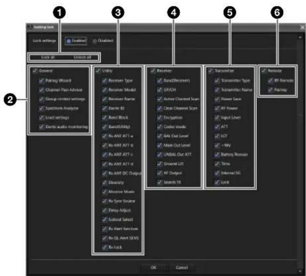
text_image
Lock settings Lock all Unlock all General Pairing Wizard Channel Plan Address Group control settings Spectrum Analyzer Load settings Dents audio monitoring Utility Receiver Type Receiver Model1 Receiver Name Dents ID Band Block BandURLing1 Ex ANT ATT -e Ex ANT ATT -b Ex ANT ATT -c Ex ANT ATT -d Ex ANT DC Output Diversity Monitor Mode Ex Sync Source Delay Adjust Sudan Select Ex Alert Function Ex QL Alert SENS Re Lock Receiver BandBufferlet GFCH Active Channel Scan Clear Channel Scan Encryption Codec mode BAT Out Level Main Out Level UNBAL Out ATT Ground Lift AF Output Search TX Retrosion Transmitter Type Transmitter Name Power Save RF Power Input Level ATT UCF + MHz Battery Romain Time Internal SiC Lock Remote RF Remote Pairing OK Cancel①Deny or allow changes to settings for all items.
[Lock all] button: Place a check mark in the checkbox for all items.
[Unlock all] button: Clear the check mark from the checkbox for all items.
②Deny or allow changes to settings for grouped functions.
[General]: Place a check mark here to place a check mark in all sub-items to lock all the settings. Clear the check mark here to clear the check mark from all sub-items to unlock all the settings.
[Pairing Wizard]: Place a check mark here to disable selection of [Pairing Wizard] in the [Device] menu. Clear the check mark to enable selection.
[Channel Plan Adviser]: Place a check mark here to lock the following settings. Clear the check mark to unlock the settings.
• [Device] menu > [Channel Plan Adviser]
- Spectrum Analyzer tab > [Channel Plan Adviser] button [Group control settings]: Place a check mark here to lock [Group control settings] (excluding the [Clear AF Peak hold] button) at the top of the status viewer from the [View] menu. Clear the check mark to unlock the buttons (excluding the [Clear AF Peak hold] button).
[Load settings]: Place a check mark here to lock the following settings. Clear the check mark to unlock the settings.
• [Device] menu > [Load settings]
- Status viewer > [Load settings] button
- Context menu [Load Single Settings]
[Dante audio monitoring]: Place a check mark here to lock the following settings. Clear the check mark to unlock the settings.
- Status viewer > [Monitor] button
- Simple status viewer > [Monitor] button
③Deny or allow changes to settings in the UTILITY menu of the digital wireless receiver.
[Utility]: Place a check mark here to place a check mark in all sub-items to lock all the settings. Clear the check mark here to clear the check mark from all sub-items to unlock all the settings.
For details about each item, see “[Property] Window” (page 55).
Note
Dante ID Mode cannot be changed from Wireless Studio, so it is not subject to the deny/allow changes setting.
④ Deny or allow changes to settings in the RX menu of the digital wireless receiver.
[Receiver]: Place a check mark here to place a check mark in all sub-items to lock all the settings. Clear the check mark here to clear the check mark from all sub-items to unlock all the settings.
For details about each item, see “[Property] Window” (page 55).
⑤Deny or allow changes to settings in the TX menu of the digital wireless receiver.
[Transmitter]: Place a check mark here to place a check mark in all sub-items to lock all the settings. Clear the check mark here to clear the check mark from all sub-items to unlock all the settings.
For details about each item, see “[Property] Window” (page 55).
⑥ Deny or allow changes to settings in the REMOTE menu of the digital wireless receiver.
[Remote]: Place a check mark here to place a check mark in all sub-items to lock all the settings. Clear the check mark here to clear the check mark from all sub-items to unlock all the settings.
For details about each item, see “[Property] Window” (page 55).
3 Click the [OK] button.
The following screen appears.
![SONY DWR-R02D - Click the [OK] button. - 1](/content/2026/05/760390/images/dc9fcb6821006ff01e85541e14b5d35cd0ad17b8053d1e25a217742f7db0c395.jpg)
text_image
Setting lock Administrator Password Confirm Password OK Cancel4 Set the password and click the [OK] button.
The following screen appears, and the lock settings are completed.
![SONY DWR-R02D - Set the password and click the [OK] button. - 1](/content/2026/05/760390/images/f40771c1df4bdf1a3525a53a50efcc77bcec5352c38717d862d0cd056cc50637.jpg)
text_image
Setting lock Setting lock is completed. OKNote
Settings can be configured without entering a password.
Locking/unlocking settings
Click [Setting lock] in the [Device] menu.
The following screen appears.
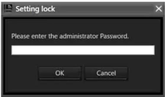
text_image
Setting lock Please enter the administrator Password. OK CancelEnter the configured password and click the [OK] button to display the settings screen.
To unlock settings, select [Disabled] and click the [OK] button.
To unlock individual items, leave [Enabled] selected, change the lock settings of items, and click the [OK] button.
[Receiver CH Label Settings] Window
The [Receiver CH Label Settings] window allows you to configure a label for each receiver channel. You can also set [CHANNEL LABEL] on the DWR-R03D. This makes
channel identification easier in situations where a transmitter's frequency cannot be received, for example.
Note
The [Receiver Name] and [Transmitter Name] settings cannot be changed in this window. To change these settings, use the [Property] window.
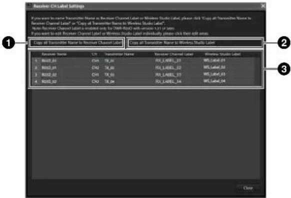
text_image
Receive CH Label Settings 1 You want to receive Transmitter Name as Receiver Channel Label or Wireless Studio Label, please click "Copy all Transmitter Name to Receiver Channel Label" or "Copy all Transmitter Name to Wireless Studio Label". 2 Audio Resource Channel Label is enabled only by Shift-RSOS with audio track or lens. 3 You want to exit Receiver Channel Label or Wireless Studio Label individually, please click their add areas. 4 Copy all Transmitter Name to Receiver Channel Label 5 Copy all Transmitter Name to Wireless Studio Label 1 Host_01 CHI TR_01 RU_LABEL_01 WS Label_01 2 Host_01 CHI TR_02 RU_LABEL_02 WS Label_02 3 Host_02 CHI TR_03 RU_LABEL_03 WS Label_03 4 Host_02 CHI TR_04 RU_LABEL_04 WS Label_04 3 Copy①[Copy all Transmitter Name to Receiver Channel Label]
Copies transmitter names to [CHANNEL LABEL] of the corresponding receiver channels.
Note
This function is supported in the following case.
DWR-R03D: Version 1.31 or later
This function is available only when Wireless Studio is used in online mode.
②[Copy all Transmitter Name to Wireless Studio Label]
Copies transmitter names to the labels of the corresponding receiver channels.
③Setting item list
Receiver Name: Displays the receiver's name.
CH: Displays the receiver's channel information.
Transmitter Name: Displays the name of the transmitter that is communicating with the receiver.
Receiver Channel Label: Displays the CHANNEL
LABEL setting for a digital wireless receiver. The setting can also be changed. To set a name, enter the name and press the Enter key.
Note
This function is supported in the following case.
DWR-R03D: Version 1.31 or later
The setting for this function can be changed only when Wireless Studio is used in online mode.
Wireless Studio Label: Allows you to set a name for each receiver channel. To set a name, enter the name and press the Enter key.
[GP/CH display setting] Window
This window allows you to configure display settings for Wireless Studio groups and channels.
![SONY DWR-R02D - [GP/CH display setting] Window - 1](/content/2026/05/760390/images/f6a62229f7eb74b6f42a09f9bd2f6b9ee52b09aa1cb368b6db04a2b9e06e033d.jpg)
text_image
GP/CH display setting You can change a display setting for GP/CH by using "recommended GP/CH" that Channel Plan Adviser calculates GP/CH display setting All GP/CH Only recommended GP/CH recommended GP/CH OK Cancel[GP/CH display setting]
All GP/CH: All groups and channels will be displayed as candidates when configuring groups and channels. [All GP/CH] is selected under factory default settings.
Only recommended GP/CH: Only the recommended groups and channels as determined by the [Channel Plan Adviser] will be displayed as candidates when configuring groups and channels. When the [Reflect recommended GP/CH] checkbox is selected in the last screen of the [Channel Plan Adviser] before closing it, this setting changes to [Only recommended GP/CH].
For details, see “[Channel Plan Adviser] Window” (page 59).
[recommended GP/CH...] button
Displays the recommended groups and channels as determined by the [Channel Plan Adviser] in a separate window. Only the groups and channels displayed here will be displayed as candidates when configuring groups and channels.
![SONY DWR-R02D - [recommended GP/CH...] button - 1](/content/2026/05/760390/images/c32d33163c5a01882b1af1b76fa5e3f0dd59970a7a7c6e2f6526a2e90dc60b61.jpg)
text_image
Recommended GP/CH Recommended GP/CH No Band GP/CH [Frequency] 1 TV51-53 D6/51-01 [710.125MHz] 2 TV51-53 D6/51-05 [710.625MHz] 3 TV51-53 D6/51-09 [711.125MHz] 4 TV51-53 D6/51-13 [711.625MHz] 5 TV51-53 D6/51-17 [712.125MHz] 6 TV51-53 D6/51-21 [712.625MHz] 7 TV51-53 D6/51-25 [713.125MHz] 8 TV51-53 D6/51-29 [713.625MHz] 9 TV51-53 D6/51-33 [714.125MHz] 10 TV51-53 D6/51-37 [714.625MHz] 11 TV51-53 D6/51-41 [715.125MHz] 12 TV51-53 D6/51-45 [715.625MHz] 13 TV51-53 D6/51-49 [716.125MHz] OK[Display settings] Window
Use this to specify whether to display certain setting items and buttons. When you select the checkboxes of the items in each tab and click the [OK] button, the corresponding items and buttons will be displayed.
[Display] tab
This tab allows you to specify whether to display certain items in the [Device List] window, status viewer, [Simple Status Viewer] tab, etc.
![SONY DWR-R02D - [Display] tab - 1](/content/2026/05/760390/images/2bae8dabbf53d7cb3436fa0c5156502c2ffef46830d935b6668d65a082f20726.jpg)
text_image
Display settings You can configure display settings in Wireless Studio. Display Group control Other Please select here you want to display on Wireless Studio. Device list Label To Name Property list Number Label Property window Label RF Chart Grapher Label To Name Status Viewer Number Search To button Label GPIO Frequency RF alert RF meter CLK alert CLK meter To Name Output channel Individual muting/annotating RF meter RF Peak alert Battery status RF power status RF remote status Wind sync status Auto Freq change status Data audio monitoring Single Status Viewer Number Search To button Label To Name Output channel CL alert CL meter RL meter RF meter RF alert AF/Peak alert Individual outgroup/modging AF meter Battery status Auto Freq change status Data audio monitoring OK CancelNumber: Select whether to display the receiver channel number.
Search Tx button: Select whether to display the button that makes the screens for transmitters that are paired with the receiver blink.
Notes
- This function is not supported on the DWR-R01D, DWR-R02D, and DWR-R02DN.
- This function is only available on combinations of 3rd generation or later digital wireless receivers (such as the DWR-R03D) and digital wireless transmitters (such as the DWT-B03R). In addition, when using an RMU-01 for Cross Remote connection, the RMU-01 must be version 1.27 or later.
Label: Select whether to display the label configured in the [Receiver CH Label Settings] window.
GP/CH: Select whether to display the group/channel settings for reception channels.
Frequency: Select whether to display the reception channel frequency.
RF alert: Select whether to display an alert when the radio wave input level decreases or becomes too high.
RF meter: Select whether to display a meter that indicates the radio wave input level.
QL alert: Select whether to display an alert when the quality of the received data decreases.
QL meter: Select whether to display a meter that indicates the quality of the received data.
Tx Name: Select whether to display the name of the transmitter.
Output channel: Sets whether to display the audio output destination of the receiver.
Individual muting/unmuting: Select whether to display the audio output status for receiver channels.
AF meter: Select whether to display a meter that indicates the audio level.
AF/Peak alert: Select whether to display AF/PEAK (audio input/peak) alerts.
Note
In version 5.50 and later, the [Individual muting/unmuting], [AF meter], [AF/Peak alert] display settings of the simple status viewer are replaced by a single setting.
Battery status: Select whether to display the transmitter's battery condition.
RF power status: Select whether to display the transmitter's transmitted power.
RF remote status: Select whether to display the transmitter's wireless remote control condition.
Word sync status: Select whether to display the sync status of the signal output from the receiver's DIGITAL OUT connector.
Auto Freq change status: Sets whether to display the status of the AUTO FREQ CHANGE setting of the receiver.
Note
This function is available only on the DWR-R03D version 1.20 or later.
Dante audio monitoring: Select whether to display the Dante IP audio monitoring control buttons.
Note
This function can be used only on a computer with Dante Virtual Soundcard from Audinate installed.
Display example for the [Device List] window
- Both Label and Tx Name displayed
![SONY DWR-R02D - Display example for the [Device List] window - 1](/content/2026/05/760390/images/cbd0544fdce6877dd7577493a371ab9283cf2584e5da368fbdbd7940a23846ce.jpg)
text_image
Receiver RX1 1 LABEL1 : TX1 2 LABEL2 : TX2- Only Tx Name displayed (factory default setting)
![SONY DWR-R02D - Display example for the [Device List] window - 2](/content/2026/05/760390/images/b00f3bfcd9844ec155544c968e05f00ae1efeb3d67f767dad4a159ec30d022c7.jpg)
text_image
Receiver RX1 1 TX1 2 TX2- Only Label displayed
![SONY DWR-R02D - Display example for the [Device List] window - 3](/content/2026/05/760390/images/6063d17e435b5cf1a6d92114c5a2c28797572c884a0e0a840215b03a361b172e.jpg)
text_image
Receiver RX1 1 LABEL1 2 LABEL2Display example for the [Property] window
- Label displayed
![SONY DWR-R02D - Display example for the [Property] window - 1](/content/2026/05/760390/images/95af4c59c4123c40e06f9e6bf690a8fe19e6963c584e877cb13fd03ea2c298ea.jpg)
text_image
2 Label2 D1/13-110 472.750MHz CLIENT B03R_WL_SUB [OUT2] RF b QL Y L -60 -36 -20 -10 0 AF/PEAK- Label not displayed (factory default setting)
![SONY DWR-R02D - Display example for the [Property] window - 2](/content/2026/05/760390/images/4932c9eadcbdbff01211b4fedcd3d3326a5bb82c2b4db3161a2f13b3d57e3d1f.jpg)
text_image
2 D1/13-110 472.750MHz CLIENT B03R_WL_SUB [OUT2] RF b QL YL -60 -36 -20 -10 0 AF/PEAKDisplay example for the [RF Chart Grapher] tab
- Both Label and Tx Name displayed
![SONY DWR-R02D - Display example for the [RF Chart Grapher] tab - 1](/content/2026/05/760390/images/6c326accb8ee2a6f49871413020e32b7a03872647e0ee0a9667ef2b8e2268b93.jpg)
text_image
Receiver channel list RX1[CH-1] LABEL1 : TX1- Only Tx Name displayed (factory default setting)
![SONY DWR-R02D - Display example for the [RF Chart Grapher] tab - 2](/content/2026/05/760390/images/8ba731b487faa5b0c874b6014f84683543273418fb0108b9070bec130e061364.jpg)
text_image
Receiver channel list RX1[CH-1] TX1- Only Label displayed
![SONY DWR-R02D - Display example for the [RF Chart Grapher] tab - 3](/content/2026/05/760390/images/1fe618c3310f750e156bbc2a9f78218562a992662ff62c787e8aafc6d7da2375.jpg)
text_image
Receiver channel list RX1[CH-1] LABEL1 RX1[CH-2]Display example for the status viewer
- All items displayed

text_image
• All items except Label displayed • All items except Tx Name displayedDisplay example for the [Simple Status Viewer] tab
- All items displayed
![SONY DWR-R02D - Display example for the [Simple Status Viewer] tab - 1](/content/2026/05/760390/images/881d5351d58311704c99aeaad716b33042300f473ee4c6d8f21515e3e18c6e30.jpg)
text_image
Search TX Label1 DWT-B30-0 [OUT1] QL a RF AFI PEAK CLIENT Monitor- All items except Label and Tx Name displayed
![SONY DWR-R02D - Display example for the [Simple Status Viewer] tab - 2](/content/2026/05/760390/images/9a7bbf773b3a1f31054f2c51eccac7d0400e2859ea94339b183b107107c0f40a.jpg)
text_image
1 Search TX [OUT1] QL a RF AF/ PEAK CLIENT Monitor- All items except Label, Tx Name, AF/Peak alert, and Individual muting/unmuting displayed
![SONY DWR-R02D - Display example for the [Simple Status Viewer] tab - 3](/content/2026/05/760390/images/bdb09bb798733a3db27272f5f88376f0a9080b7d1662e5ab10ac2531284fe1c9.jpg)
text_image
Search TX [OUT1] QL a RF CLIENT Monitor[Group control] tab
This tab allows you to specify whether to display or hide the buttons that allow changing of receiver channel transmitter settings in groups or the shortcut buttons for [All muting], [All unmuting], and [Clear AF Peak hold], for example, at the top of the status viewer. Only [Clear AF Peak hold] will be displayed under factory default settings.
![SONY DWR-R02D - [Group control] tab - 1](/content/2026/05/760390/images/107020ae3d205e2c4a46f1afc598d25a7853a566451d0b419eafd90b1c9bdb21.jpg)
text_image
Display settings You can configure the following settings in Windows Tools: Category Group control Other Please select the Function group to default in a network or network environment. [ ] Power Tree [ ] Alt Street [ ] Alt Node [ ] Alt [ ] Alt [ ] Alt [ ] Alt [ ] Alt [ ] Alt [ ] Alt [ ] Alt [ ] Alt [ ] Alt [ ] Alt [ ] Alt [ ] Alt [ ] Alt [ ] Alt [ ] Alt [ ] Alt [ ] Alt [ ] Alt [ ] Alt [ ] Alt [ ] Alt [ ] Alt [ ] Alt [ ] Alt [ ] Alts [ ] Alt [ ] Alt [ ] Alt [ ] Alt [ ] Alt [ ] Alt [ ] Alt [ ] Alt [ ] Alt [ ] Alt [ ] Alt [ ] Alt [ ] Alt [ ] Alt [ ] Alt [ ] Alt [ ] Alt [ ] Alt [ ] Alt [ ] Alt [ ] Alt [ ] Alt [ ] Alt [ ] Alt [ ] AllWhen you click a group control setting button at the top of the status viewer and select a setting value from the dropdown menu, the settings for all the receiver channels displayed in the status viewer will change.
![SONY DWR-R02D - [Group control] tab - 2](/content/2026/05/760390/images/0249173a0711beea3ffa166aeb7ccd8d6c629a841fda744bc14cee1beae209c7.jpg)
text_image
Group control settings Power Save RF Power Input Level ATT LCP +48V Battery Remain Time Reset Internal SC Lock AF muting AF unmuting Clear AF Risk hold AF Turners Page 1 Page 2 Page 3 Page 4 Page 5 Page 6 + 3 Search 70 D/11-030 471.2509Hz NO DATA [OUT1] 4 Search 70 D/11-078 471.7509Hz NO DATA [OUT2]![SONY DWR-R02D - [Group control] tab - 3](/content/2026/05/760390/images/053d30f7e55c9058c6246aea92cdcce034a988cce26a33de484c0dc7b8bc1587.jpg)
text_image
Group control settings Power Save ACTIVE nor Input Level ATT U.F. +RF Battery Remain Time Reset ALBP -4 SG Lock All muting All unmuting Clear AF Peak hold All timers Page-1 Page-2 Page-3 Page-4 Page-5 Page-6 3 Signal TX 01/13-030 471.250MHz 4 Signal TX 01/13-070 471.750MHz NO DATA [OUT]1 NO DATA [OUT]2[Other] tab
This tab allows you to enable or disable audio output control. It is disabled under factory default settings. When the checkbox is selected, you can enable or disable audio output by clicking the audio output control / indicators for each receiver channel in the status viewer.
![SONY DWR-R02D - [Other] tab - 1](/content/2026/05/760390/images/072be6546b8fc7329657e5697c70f1d7b428ecb33ca7648e553b2ce084d69f8d.jpg)
text_image
Display setting You can configure display settings in Wireless Studio Display Group control Other Please select the function you want to control on Binary Viewer □ Individual testing / unmitting OK Cancel- Checkbox cleared
![SONY DWR-R02D - [Other] tab - 2](/content/2026/05/760390/images/e73e97bf04f5b7f73b296ed0c2fefd92417683b77a438671cd6383e72f9a0964.jpg)
- Checkbox selected
![SONY DWR-R02D - [Other] tab - 3](/content/2026/05/760390/images/02c8cc72e86cf90aa1bab4e42d1ba9cc958884baf12fc38bc3d34bd027e948e7.jpg)
[Other settings] Window
In the [Other settings] window, you can configure hold settings for the peak levels of the AF level meters that appear in the status viewer, switch the RF level display units, and switch the transmitter ATT/Gain display.
![SONY DWR-R02D - [Other settings] Window - 1](/content/2026/05/760390/images/455387b4d2591a8bc6dcaf5eb4c0a5d6a3cf26cb217717347e216bfef5c70661.jpg)
text_image
Other settings AF peak hold setting 2sec The unit of RF level dBuMemf Display setting for ATT/Gain ATT OK Cancel[AF peak hold setting]
Configures hold settings for the peak levels of the AF level meters that appear in the status viewer.
2sec: Holds for 2 second.
HOLD: Hold is maintained until it is released.
[The unit of RF level]
Selects the units (dBuVemf or dBm) for the RF level that appears in the [RF Chart Grapher] tab and the [Channel Plan Adviser] window.
[Display setting for ATT/Gain]
Configures whether to display items in the transmitter menu as an ATT value or as a Gain value. The ATT/Gain value range changes according to this setting.
ATT: 0 to 48 dB (3 dB steps)
Gain: 0 to -48 dB (-3 dB steps)
Releasing the hold status
Peak levels that are being held can be released in the main page of Wireless Studio.
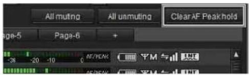
text_image
All muting All umuting Clear AF Peak hold Page-5 Page-6 + -38 -20 -10 0 AF/PEAK AF/PEAK 平M与 平M与Clicking [Clear AF Peak hold] in the status viewer releases the hold status of the peak levels for all the receiver channels displayed.
[Network settings] Window
This windows displays the network settings of the receivers, battery chargers, and RMU-01 units on the network.
![SONY DWR-R02D - [Network settings] Window - 1](/content/2026/05/760390/images/7917ed028e0ef715cb48052255334f9bea029c30699f10f43cdb5df073d15610.jpg)
text_image
Screenshot of a software interface showing file management panel with Chinese labels and file list boxes① Receivers list
Displays the values of the receiver's network settings. Type: Displays the receiver's type.
Name: Displays the value of the receiver's RECEIVER NAME setting.
Network mode: Displays the value of the receiver's NETWORK MODE setting.
IP Mode: Displays the value of the receiver's IP MODE setting.
IP Address: Displays the value of the receiver's ADDRESS setting.
Subnetmask: Displays the value of the receiver's SUBNETMASK setting.
Dante Main IP Mode: Displays the value of the receiver's DANTE MAIN IP MODE setting.
Dante Main IP Address: Displays the value of the receiver's DANTE MAIN IP ADDRESS setting.
Dante Main Subnetmask: Displays the value of the receiver's DANTE MAIN SUBNETMASK setting.
Dante Sub IP Mode: Displays the value of the receiver's DANTE SUB IP MODE setting.
Dante Sub IP Address: Displays the value of the receiver's DANTE SUB IP ADDRESS setting.
Dante Sub Subnetmask: Displays the value of the receiver's DANTE SUB SUBNETMASK setting.
Note
"NO FUNCTION" is displayed for the following items for receivers other than the DWR-R03D.
- Network Mode
- IP Mode
- Subnet Mask
• Dante Main IP Mode
• Dante Main IP Address
• Dante Main Subnetmask
• Dante Sub IP Mode
• Dante Sub IP Address
• Dante Sub Subnetmask
②Others list
Displays the network settings of battery chargers and RMU-01 units.
Type: Displays the type of device.
Name: Displays the value of the NAME setting of the device.
IP Mode: Displays the value of the IP MODE setting of the device.
Note
"NO FUNCTION" is displayed for battery chargers and RMU-01 units.
IP Address: Displays the value of the IP ADDRESS setting of the device.
Subnetmask: Displays the value of the SUBNETMASK setting of the device.
Note
"NO DATA" is displayed for RMU-01 units.
[Network interface settings] Window
In the [Network interface settings] window, you can set network interface card settings for a digital wireless system and the IP address range of devices to monitor using this software.
You can also configure network interface card settings for Dante Virtual Soundcard.
After configuring each setting, click the [OK] button to apply the settings.
[for DWX] tab
The [for DWX] tab is used to configure settings for a digital wireless system.
[Layer 3 switching]
Configure the availability of network functions for use in Wireless Studio. Switch the setting to specify whether you are using a router.
Not available: Select this for systems that do not use a router (systems where the PC and digital wireless system are on the same segment).
![SONY DWR-R02D - [Layer 3 switching] - 1](/content/2026/05/760390/images/9111334d7a36e84fd49c142e38f46147f66dbe06bc78d31b47b4bbde5b2f8ade.jpg)
text_image
Network interface settings for DWX for Dante Layer 3 switching Not available OK CancelAvailable: Select this for systems that use a router (systems where the PC and digital wireless system are on different segments).
![SONY DWR-R02D - [Layer 3 switching] - 2](/content/2026/05/760390/images/e7f77fda6ae1d3b742bbaaad34b731de083582c210e6bab357f3673a6df850d1.jpg)
text_image
Network interface settings for DWX for Dante Layer 3 switching Available Network interface ASIX AX887728 USB2.0 to Fast Ethernet Adapter IP address range settings Add Delete In order to add IP range, please input IP addresses, e.g. 192.168.0.11-192.168.0.20 Type IP range Receiver 192.168.0.2-192.168.0.10 Receiver 192.168.1.2-192.168.1.10 Receiver 192.168.2.2-192.168.2.10 BC-DWX 192.168.0.11-192.168.0.20 BC-DWX 192.168.1.11-192.168.1.20 BC-DWX 192.168.2.11-192.168.2.20 OK Cancel[Network interface]
Specify the network interface card of the PC using this software.
Note
This setting is enabled when [Layer 3 switching] is set to [Available].
[IP address range settings]
Register the IP addresses of devices that you want to monitor and control using this software. You can also register IP addresses of devices located beyond a router.
Notes
- This setting is enabled when [Layer 3 switching] is set to [Available].
- In systems using a router, appropriate values for the PC default gateway setting, router setting, and gateway settings to each digital wireless system device are required.
- [IP address range settings] configuration is not stored in Wireless Studio. To use the same settings subsequently, you should configure the [Network interface settings] settings and then save them to a file.
For details on saving settings, see "Saving the settings as files" (page 24).
- The devices supporting a gateway setting are the DWR-R03D and DB-DWX1.
- Version 1.30 or later is required in order to configure the gateway for the DWR-R03D.
- Version 1.10 or later is required in order to configure the gateway for the BC-DWX1.
Registering an IP address
1 Click [Add].
"Receiver" is displayed in [Type].
2 Select one of the following models.
- Receiver
• RMU
• B C - D W X
3 Specify the address range (see below), and press the Enter key.
For example, to specify a range from 192.168.0.1 to 192.168.0.10, enter “192.168.0.1-192.168.0.10” (where the start address is followed by a hyphen which is followed by the end address).
Notes
- Specify the same value for the start address segment and end address segment (for example, "192.168.0" portion).
- Specify a start address that is a lower number than the end address.
- A large address range can be configured, but the larger the address range the longer the time required to detect devices. Where possible, specify a short address range.
For example, enter the IP range shown below according to the device configuration.
| Device configuration IP range | entry | ||
| Device IP address Type IP range | |||
| DWR-R03D 192.168.0.1 Receiver 192.168.0.1- | 0.1-192.168.0.2 | ||
| DWR-R03D 192.168.0.2 | |||
| RMU-01 192.168.0.11 RMU 192.168.0.11- | 192.168.0.12 | ||
| RMU-01 192.168.0.12 | |||
| BC-DWX1 192.168.0.21 BC-DWX 192.168.0.24 | |||
| BC-DWX1 192.168.0.22 | |||
| BC-DWX1 192.168.0.23 | |||
| BC-DWX1 192.168.0.24 | |||
Deleting a registered IP range
1 Click the IP range you want to delete.
The selected IP range is highlighted.

text_image
Type IP range Receiver 192.168.0.4-192.168.0.4 BC-DWX 192.168.0.8-192.168.0.82 Click the [Delete] button.
The IP range is deleted.

text_image
Type IP range Receiver 192.168.0.4-192.168.0.4Changing the registered type or IP range
Click the type or IP range that you want to change, and specify a new value.
[for Dante] tab
The [for Dante] tab is used to configure settings for Dante Virtual Soundcard.
Notes
- Settings cannot be changed on computers that do not have Dante Virtual Soundcard installed.
- Select separate network interface cards for [Primary interface] and [Secondary interface].
- Wireless Studio does not use the [Secondary interface] setting. When using the DWR-R03D in combination with Dante Virtual Soundcard, set [Secondary interface] to [None].
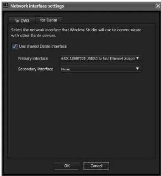
text_image
Network interface settings for DWX for Dante Select the network interface that Wireless Studio will use to communicate with other Dante devices. ✓ Use shared Dante interface Primary interface ASIX AX88772B USB2.0 to Fast Ethernet Adaptr Secondary interface None OK Cancel[Use shared Dante interface]
Controls whether or not to use the network interface card settings used by other Dante applications.
When a check mark is placed in the checkbox, the information for the network interface cards used by other Dante applications are displayed as candidates. When the check mark is cleared, the information for the network interface cards used by the computer are displayed as candidates.
[Primary interface]/[Secondary interface]
Selects the network interface cards for the primary interface and secondary interface for communication with Dante Virtual Soundcard.
[Startup settings] Window
You can configure startup settings in the [Startup settings] window.
![SONY DWR-R02D - [Startup settings] Window - 1](/content/2026/05/760390/images/4c68507bd35bf228e25aa29d496307f4be3e23134a8042cd2ba16c6e1ae9ff8b.jpg)
text_image
Startup settings Select the startup option. Startup from EXE file ✓ Always work by below setting ● Offline mode ● Online mode Startup from dwI file ✓ Always work by below setting ● Offline mode ● Load all receiver's settings then startup Online mode ● Load all receiver's and transmitter's settings then startup Online mode OK Cancel①[Startup from EXE file] setting
Specify the startup mode used when starting Wireless Studio from the start menu.
Select the [Always work by below setting] checkbox to always start Wireless Studio using the specified mode.
Offline mode: Start Wireless Studio in offline mode.
Online mode: Start Wireless Studio in online mode.
②[Startup from dwl file] setting
Specify the startup mode used when you start Wireless Studio by double-clicking a settings file (.dwl2 or .dwl3). Select the [Always work by below setting] checkbox to always start Wireless Studio using the specified mode.
Offline mode: Start Wireless Studio in offline mode. Load all receiver's settings then startup Online mode: Apply the settings of the settings file to the receivers, and then start Wireless Studio in online mode.
Load all receiver's and transmitter's settings then startup Online mode: Apply the settings of the settings file to the receivers and transmitters, and then start Wireless Studio in online mode.
For details on settings files, see "Using Settings Files" (page 23).
[Region setting] Window
In the [Region setting] window, you can change the region setting that was selected during installation of Wireless Studio.
Notes
- The [Region setting] window can only be opened when Wireless Studio is running in offline mode.
- Restart Wireless Studio to apply changes to the region setting.
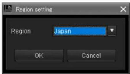
text_image
Region setting Region Japan OK Cancel[Region]
Select the region in which Wireless Studio will be used. Japan: Select this for use in Japan.
North America: Select this for use in North America.
Europe: Select this for use in Europe.
China: Select this for use in China.
Effects of the Diversity Setting on Wireless Studio Displays
Whenever you switch between the 2-ANTENNA and 4-ANTENNA options for the [Diversity] setting in the receiver's [Property] window, the displays in Wireless Studio will change as follows.
Status viewer
When you change the [Diversity] setting to 4-ANTENNA for receiver channels 1 and 2, "1" and "2" will be
consolidated as "1" and the RF level meters will display 4 lines.
When you change the [Diversity] setting to 2-ANTENNA for receiver channels 1 and 2, "1" splits into "1" and "2" and the RF level meters will display 2 lines for each.
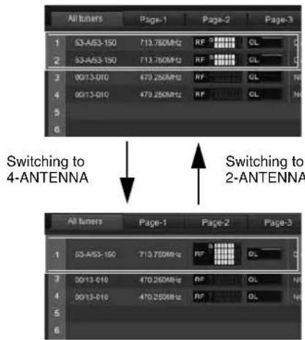
text_image
All tuners Page-1 Page-2 Page-3 1 53-A53-150 713.750MHz RF GL 2 53-A53-150 713.750MHz RF GL 3 00/13-010 479.250MHz RF GL 4 00/13-010 479.250MHz RF GL 5 6 Switching to 4-ANTENNA Switching to 2-ANTENNA All tuners Page-1 Page-2 Page-3 1 53-A53-150 713.750MHz RF GL 2 00/13-010 479.250MHz RF GL 3 00/13-010 479.250MHz RF GL 4 00/13-010 479.250MHz[Simple Status Viewer] tab
When you change the [Diversity] setting to 4-ANTENNA for receiver channels 1 and 2, the display for "2" disappears and the RF level meters will display 4 lines. When you change the [Diversity] setting to 2-ANTENNA for receiver channels 1 and 2, the display for "2" reappears and the RF level meters will display 2 lines each.
![SONY DWR-R02D - [Simple Status Viewer] tab - 1](/content/2026/05/760390/images/bb7ea478557dce22e6a0bb226630842ec46a8545efbdfb0dd5a3a2a1eb4ac3b1.jpg)
flowchart
graph TD
    A["Switching to 4-ANTENNA"] --> B["Switching to 2-ANTENNA"]
    B --> C["Channel selection: Channel 1, Channel 2, Channel 3, Channel 4 with NO DATA indicators"]
    C --> D["Output: Signal/Video Output"]
[Property] window
When you change the [Diversity] setting to 4-ANTENNA for receiver channels 1 and 2, the display and tab for "2" disappear and the RF level meters will display 4 lines. When you change the [Diversity] setting to 2-ANTENNA for receiver channels 1 and 2, the display and tab for "2" reappear and the RF level meters will display 2 lines each.
![SONY DWR-R02D - [Property] window - 1](/content/2026/05/760390/images/b1a37b5bffb4104f0cde3d064c883ae9e2f49435cfdb237f18712d13ac466a10.jpg)
flowchart
graph TD
    A["Switching to 4-ANTenna"] --> B["Switching to 2-ANTenna"]
    B --> C["Output: 1"]
[Device list] window
When you change the [Diversity] setting to 4-ANTENNA for receiver channels 1 and 2, the display for “2” disappears.
When you change the [Diversity] setting to 2-ANTENNA for receiver channels 1 and 2, the display for "2" reappears.
![SONY DWR-R02D - [Device list] window - 1](/content/2026/05/760390/images/67f4f38d89d037cd059e8c9c6366f00f867c76d8211496861943f0dca20ac0db.jpg)
flowchart
graph TD
    A["Device Port"] -->|Switching to 4-ANTENNA| B["Device Port"]
    B -->|Switching to 2-ANTENNA| A
[Property List] tab
When you change the [Diversity] setting to 4-ANTENNA for receiver channels 1 and 2, the display for “2” disappears.
When you change the [Diversity] setting to 2-ANTENNA for receiver channels 1 and 2, the display for "2" reappears.
![SONY DWR-R02D - [Property List] tab - 1](/content/2026/05/760390/images/e4d358bfd142e8411ce421d49971b20f6ca5af986311ccf4861680ecfe46c9b7.jpg)
text_image
Switching to 4-ANTENNA Switching to 2-ANTENNA[RF Chart Grapher] tab
When you change the [Diversity] setting to 4-ANTENNA for receiver channels 1 and 2, the display for “2” disappears.
When you change the [Diversity] setting to 2-ANTENNA for receiver channels 1 and 2, the display for "2" reappears.
![SONY DWR-R02D - [RF Chart Grapher] tab - 1](/content/2026/05/760390/images/f2ee297f381962da8ba1634d683db4095402b0f6c2aca17044f4b0782f5cfbf5.jpg)
text_image
RF Chart Grapher Capture Quit Clear all Main monitor Receiver channel list 1 DWR-R02DN-G3[CH-1] DWT-R02N_WH2 2 DWR-R02DN-C1[CH-2] DWM-03N_WH2 3 DWR-R03D_W1[CH-1] DWT-R03R_WL2 4 DWR-R03D_W1[CH-2] DWM-03N_WL2 Add chart Switching to 4-ANTENNA Switching to 2-ANTENNA RF Chart Grapher Capture Quit Clear all Main monitor Receiver channel list 1 DWR-R02DN-G1[CH-1] DWT-R02N_WH2 2 DWR-R02DN-G1[CH-2] DWM-03N_WH2 3 DWR-R03D_W1[CH-1] DWT-R03R_WL2 Add chart[Receiver CH Label Settings] window
If the [Receiver CH Label Settings] window is opened when the [Diversity] setting of receiver channels 1 and 2 is 2-ANTENNA, both 1 and 2 are displayed.
![SONY DWR-R02D - [Receiver CH Label Settings] window - 1](/content/2026/05/760390/images/df32a7517db31cde0a595939dc3f7330b7f689f2569b85e0d0f6cddc92f02307.jpg)
text_image
Receiver Oil Label Settings If you want to name Transmitter Name as Receiver Channel Label or Wireless Studio Label, please click "Copy all Transmitter Name to Receiver Channel Label" or "Copy all Transmitter Name to Wireless Studio Label". Note Receiver Channel Label is modified only for DNS 80.00 with version 1.21 or less. If you want to add Receiver Channel Label or Wireless Studio Label instead with please click then add ones. Copy all Transmitter Name to Receiver Channel Label Copy all Transmitter Name to Wireless Studio Label Receiver Name CN Examiner Name Recovery Channel Label Wire Studio Label 1 8000_60 CN1 TX_03 RX_LABEL_51 WS Label_01 2 8000_64 CN2 TX_02 RX_LABEL_02 WS Label_02 3 8000_60 CN3 TX_03 RX_LABEL_03 WS Label_03 4 8000_62 CN4 TX_04 RX_LABEL_04 WS Label_04If the [Receiver CH Label Settings] window is opened when the [Diversity] setting of receiver channels 1 and 2 is 4-ANTENNA, only 1 is displayed.
![SONY DWR-R02D - [Receiver CH Label Settings] window - 2](/content/2026/05/760390/images/63324f9a3d29c42b03cafc5bb363c7f57e022861a4a4f25f3f864c3730f9f235.jpg)
text_image
Receiver Oil Label Settings If you want to name Transmitter Name to Receiver Channel Label or Wireless Studio Label, please click "Copy all Transmitter Name to Receiver Channel Label" or "Copy all Transmitter Name to Wireless Studio Label". Name Receiver Channel Label is deleted only for DNS R032 with version. List or less. If you want to edit Receiver Channel Label or Wireless Studio Label individually, please click their edit areas. Copy all Transmitter Name to Receiver Channel Label Copy all Transmitter Name to Wireless Studio Label 1 Basic: 61 CH1 TX 94 RW_LABEL_81 WR_LABEL_81 2 R032: 62 CH1 TX 93 RW_LABEL_82 WR_LABEL_82 3 R032: 62 CH2 TX 94 RW_LABEL_84 WR_LABEL_84[Pairing wizard] window
If the [Pairing wizard] window is opened when the [Diversity] setting of receiver channels 1 and 2 is 2-ANTENNA, both 1 and 2 are displayed.
![SONY DWR-R02D - [Pairing wizard] window - 1](/content/2026/05/760390/images/8a4e6d08ad5f8178be7d86d4dff6001d925f22891d6e26f8c9532cb28208c889.jpg)
text_image
Pairing Wizard Select the receiver channel to be paired with a transmitter. Receiver Channel Transmitter Name DWR-R02DN-G1(CH1)[G(WH/B/1.2G)] DWT-B01N_WH2 DWR-R02DN-G1(CH2)[G(WH/B/1.2G)] DWM-03N_WH2 DWR-R03D_W1(CH1)W(WL/WM/WH) DWT-HC8R_WL2 DWR-R03D_W1(CH2)W(WL/WM/WH) DWM-03N_WL2 < Previous Next > AbortIf the [Pairing wizard] window is opened when the [Diversity] setting of receiver channels 1 and 2 is 4-ANTENNA, only 1 is displayed.
![SONY DWR-R02D - [Pairing wizard] window - 2](/content/2026/05/760390/images/027a7ccff8895d530ab0a3b5de7194b74d38816666bfc20d88b1de5b1ef7c41e.jpg)
text_image
Pairing Wizard Select the receiver channel to be paired with a transmitter: Receiver Channel Transmitter Name DWR-R02DN-G1(CH1)[G(WW/B/1.2G)] DWT-B02N_WH2 DWR-R02DN-G1(CH2)[G(WW/B/1.2G)] DWM-D3N_WH2 DWR-R03D_W1(CH1)[G(WW/WM/WH)] DWT-B03R_WL2 < Previous Next > Abort[System version information] window
If the [System version information] window is opened when the [Diversity] setting of receiver channels 1 and 2 is 2-ANTENNA, both 1 and 2 are displayed.
![SONY DWR-R02D - [System version information] window - 1](/content/2026/05/760390/images/3782087d30e65f750108e3d85a2be95d148edaeb445ad0da7e4af7116d19c325.jpg)
text_image
System version Receivers, Transmitters and Base units Type IP Address OH Transmitter Type Name Viewion DWR-802N 192.158.0.18 DWR-802N_G1 1.19 OH1 DWT-803N DWT-BEIN_WH2 1.13 OH2 DWT-803N DWT-BEIN_WH2 1.13 DWR-803D 192.158.0.51 DWT-803D_W1 1.10 OH3 DWT-803R DWT-BEIN_WL2 1.02 OH2 DWT-803N DWT-BEIN_WL2 1.12If the [System version information] window is opened when the [Diversity] setting of receiver channels 1 and 2 is 4-ANTENNA, only 1 is displayed.
![SONY DWR-R02D - [System version information] window - 2](/content/2026/05/760390/images/a714cecca50724a9da68af0475fe8fad361534341fba08e41c5748f7a771a4c9.jpg)
text_image
System version Receivers, Transmitters and Base units Type IP Address OH Transmitter Type None rvon DWR-802N 192.168.0.10 DWR-802N_G1 1.18 OH1 DWT-801N DWT-801N_WH2 1.13 OH2 DWT-803N DWT-803N_WH2 1.13 DWR-803D 192.168.0.51 DWT-803D_W1 1.18 OH1 DWT-803R DWT-803R_WL2 1.02About the Wireless Studio Display when OUTPUT SWAP is Enabled
Whenever you enable the OUTPUT SWAP setting of the receiver to swap channels, the displays in Wireless Studio will change as follows.
Status Viewer
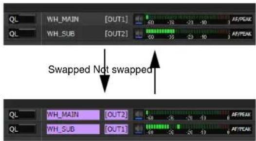
text_image
QL WH_MAIN [OUT1] WH_SUB [OUT2] AF/PEAK 0 0 -35 -20 -10 0 0 -35 -20 -10 0 AF/PEAK Swapped Not swapped QL WH_MAIN [OUT2] WH_SUB [OUT1] AF/PEAK 0 0 -35 -20 -10 0 0 -35 -20 -10 0 AF/PEAK[Simple Status Viewer] tab
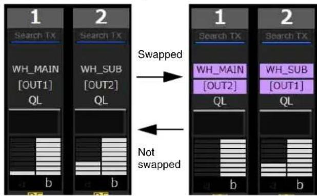
flowchart
graph LR
    A["1 Search TX"] -->|Swapped| B["2 Search TX"]
    B -->|Not swapped| C["1 Search TX"] -->|Swapped| D["2 Search TX"]
    style A fill:#f9f,stroke:#333
    style B fill:#ccf,stroke:#333
    style C fill:#cfc,stroke:#333
[Property] window
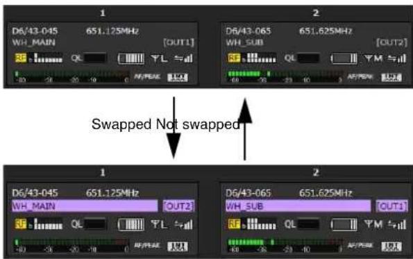
text_image
1 D6/43-045 651.125MHz [OUT1] WH_MAIN 2 D6/43-065 651.625MHz [OUT2] WH_SUB 2 D6/43-045 651.125MHz OUT2 WH_MAIN 2 D6/43-065 651.625MHz OUT1 WH_SUB 2 WL 2 SWapped Not swapped 1 D6/43-045 651.125MHz WH_MAIN OUT2 WH_MAIN 2 WL 2 WL 2 SWapped Not swappedAbout the swap color
As individual receiver channels are swapped, the display color is assigned in the following order. If nine or more units have channels in the swapped state, the color assignments are repeated starting from color 1.
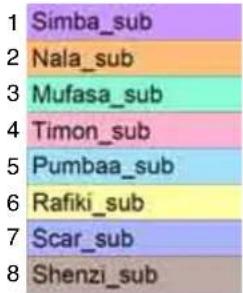
text_image
1 Simba_sub 2 Nala_sub 3 Mufasa_sub 4 Timon_sub 5 Pumbaa_sub 6 Rafiki_sub 7 Scar_sub 8 Shenzi_subDante Audio Monitoring
In Wireless Studio 5.4x and later, you can use Dante Virtual Soundcard from Audinate to monitor the IP audio of the DWR-R03D.
Notes
- The DWR-R03D and optional Dante Virtual Soundcard software from Audinate are required to use this function.
- When using Dante Virtual Soundcard, use in an environment with the Dante Virtual Soundcard recommended specifications.
- Only DWR-R03D IP audio can be controlled using Wireless Studio.
- If the DWR-R03D is added to a domain created using Dante Domain Manager from Audinate, you will not be able to control the IP audio in Wireless Studio. In this case, use Dante Controller from Audinate for control.
Computer configuration
1 Select [Control Panel] > [Hardware and Sound] > [Sound].
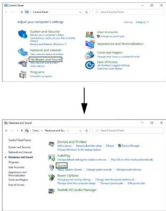
text_image
Control Panel Control Panel Search Control Panel Adjust your computer's settings View by: Category * System and Security Return your computer's status Save backbox copies of your files with File History Backup and Features (Windows T) Network and Internet View network status and basic Hardware and Sound Hardware and Sound Add a device Programs Uninstall a program User Accounts Change account type Appearance and Personalization Clock and Region Change data, time, or calendar format Ease of Access Let Windows suggest settings Optimize a load display Hardware and Sound Control Panel Home System and Security Network and Internet Hardware and Sound Programs User Accounts Appearance and Personalization Clock and Region Ease of Access Devices and Printers Add a device Advanced printer setup Mouse Device Manager Change Windows To Go startup options AutoPlay Change default settings for media or devices Play CDs or other media automatically Sound! Adjust system volume Change system sounds Manage audio devices Power Options Change power-saving settings Change what the power buttons do Change when the computer shops Choose a power plan Edit power plan Realtek HD Audio Manager2 On the [Recording] tab, select "DVS Receive 1-2", click [Set Default], and click [Properties].
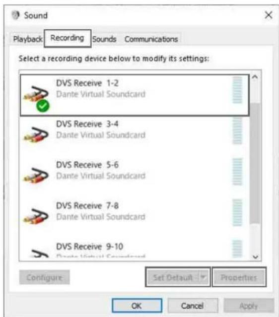
text_image
Sound Playback Recording Sounds Communications Select a recording device below to modify its settings: DVS Receive 1-2 Dante Virtual Soundcard DVS Receive 3-4 Dante Virtual Soundcard DVS Receive 5-6 Dante Virtual Soundcard DVS Receive 7-8 Dante Virtual Soundcard DVS Receive 9-10 Dante Virtual Soundcard Configure Set Default Properties OK Cancel Apply3 On the [Listen] tab, select the device you want to use, click [Apply], and click [OK].
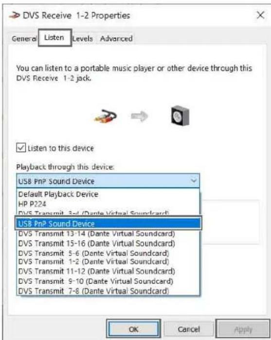
text_image
DVS Receive 1-2 Properties General Listen Levels Advanced You can listen to a portable music player or other device through this DVS Receive 1-2 jack. Listen to this device Playback through this device: USB PnP Sound Device Default Playback Device HP P224 DVS Transmit 3-4 (Dante Virtual Soundcard) USB PnP Sound Device DVS Transmit 13-14 (Dante Virtual Soundcard) DVS Transmit 15-16 (Dante Virtual Soundcard) DVS Transmit 5-6 (Dante Virtual Soundcard) DVS Transmit 1-2 (Dante Virtual Soundcard) DVS Transmit 11-12 (Dante Virtual Soundcard) DVS Transmit 9-10 (Dante Virtual Soundcard) DVS Transmit 7-8 (Dante Virtual Soundcard) OK Cancel ApplyIP audio monitoring method
IP audio monitoring can be switched using the status viewer or simple status viewer.
This section describes the status viewer screen as an example.
1 Click the [Monitor] button for the receiver channel you want to monitor.

text_image
DWT-801-601194 NO DATA AF/PEAK Monitor MonitorThe [Monitor] button display changes as shown below during monitoring, and the IP audio can be heard from the computer.

text_image
DWT-861-001104 NO DATA REPEAK Monitor REPEAK MonitorNote
If the [Monitor] button is not displayed in the status viewer or simple status viewer, change the setting of [Dante audio monitoring] on the [Display settings] window to display the Dante IP audio monitoring control buttons.
For details, see “[Display settings] Window” (page 68).
IP audio monitoring connection examples
The following are examples of the connections and configurations for each NETWORK MODE setting of the DWR-R03D.
Notes
- The connection diagrams show LAN cable connections between computer and the DWR-R03D.
- The connection diagrams show connections within the computer specified using [Network interface].
NETWORK MODE = SWITCHED
This connection method combines the communication between DWX devices with the Dante network communication.
This method is recommended when you want to operate with a simple system.
- Connection example
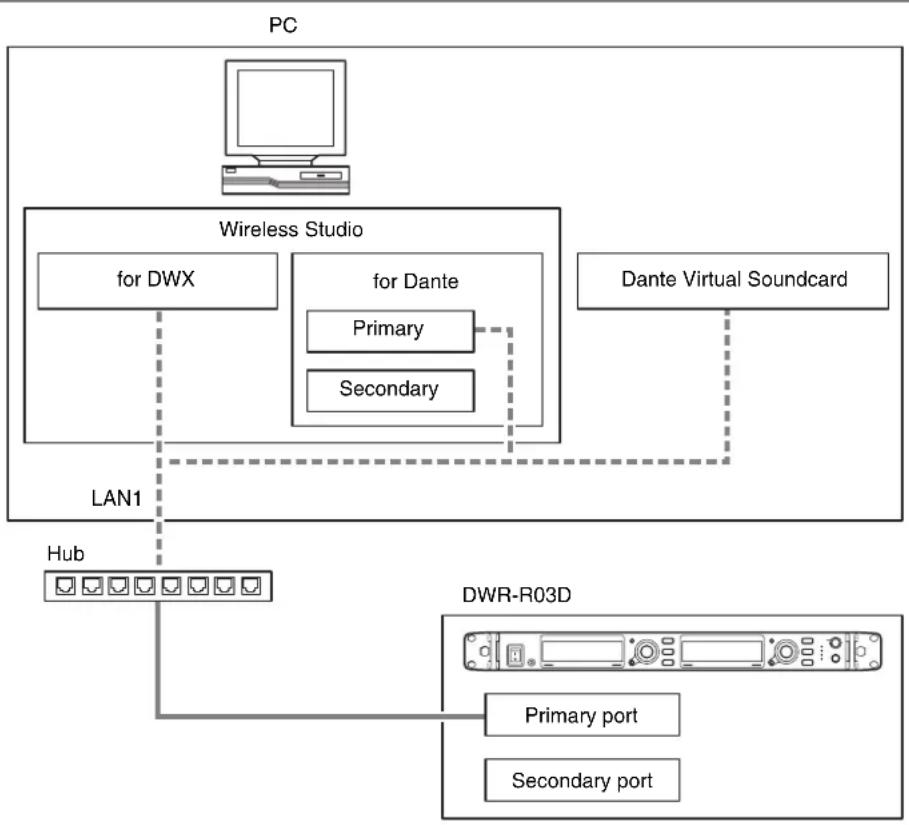
flowchart
graph TD
    PC["PC"] --> WirelessStudio["Wireless Studio"]
    WirelessStudio -->|for DWX| Hub["Hub"]
    WirelessStudio -->|for Dante| DWT["DWR-R03D"]
    DWT -->|Primary port| LAN1["LAN1"]
    DWT -->|Secondary port| LAN1
    DWT -.->|Dante Virtual Soundcard| LAN1
- Settings
| Computer LAN1 IP address | 192.168.0.220 | |||
| Subnet mask 255.255.255.0 | ||||
| Wireless Studio [for DWX] | LAN1 specified in [Network interface] | |||
| [for Dante] Primary LAN1 specified in [Network interface] | ||||
| DWR-R03D RECEIVER IP | address 192.168.0.102 | |||
| Subnet mask 255.255.255.0 | ||||
| DANTE MAIN IP address 192.168. | 0.106 | |||
| Subnet mask 255.255.255.0 | ||||
| DANTE SUB IP address - | ||||
| Subnet mask - | ||||
| Dante Virtual Soundcard | LAN1 specified in [Network interface] | |||
NETWORK MODE = SEPARATE
This connection method separates the communication between DWX devices from the Dante network communication, reducing the network load. This method is recommended when you want to operate Dante Audio and Wireless Studio with greater stability.
- Connection example
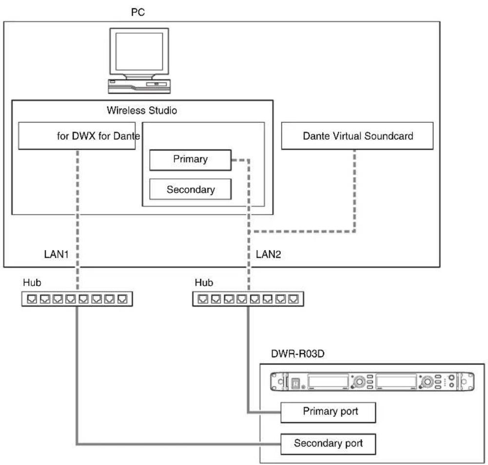
flowchart
graph TD
    PC["PC"] --> WirelessStudio["Wireless Studio"]
    WirelessStudio -->|LAN1| Hub1["Hub"]
    WirelessStudio -->|LAN2| Hub2["Hub"]
    WirelessStudio -->|LAN1| DWR-R03D["DWR-R03D"]
    DWR-R03D -->|Primary port| PC
    DWR-R03D -->|Secondary port| PC
    WirelessStudio -->|for DWX for Dante| PC
    WirelessStudio -->|Primary| DWR-R03D
    WirelessStudio -->|Secondary| PC
    DWR-R03D -->|Dante Virtual Soundcard| PC
- Settings
| Computer LAN1 IP address | 192.168.0.220 | |||
| Subnet mask 255.255.255.0 | ||||
| LAN2 IP address 192.168.1.220 | ||||
| Subnet mask 255.255.255.0 | ||||
| Wireless Studio [for DWX] | LAN1 specified in [Network interface] | |||
| [for Dante] Primary LAN2 specified in [Network interface] | ||||
| DWR-R03D RECEIVER IP | address 192.168.0.102 | |||
| Subnet mask 255.255.255.0 | ||||
| DANTE MAIN IP address 192.168. | 1.106 | |||
| Subnet mask 255.255.255.0 | ||||
| DANTE SUB | IP address – | |||
| Subnet mask – | ||||
| Dante Virtual Soundcard | LAN2 specified in [Network interface] | |||
NETWORK MODE = REDUNDANT
This connection method uses Dante network communication for both the Primary and Secondary in cases where Dante Audio is interrupted or delayed. Use this method when you want to provide redundancy.
- Connection example (requires DHCP server)
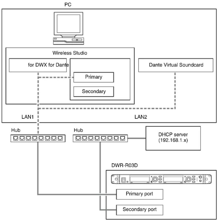
flowchart
graph TD
    PC["PC"] --> WirelessStudio["Wireless Studio"]
    WirelessStudio -->|LAN1| Hub1["Hub"]
    WirelessStudio -->|LAN2| DHCP["DHFCP server (192.168.1.x)"]
    DHCP --> DHR-DWR03D["DWR-R03D"]
    DHR-R03D -->|Primary port| Node1["Node 1"]
    DHR-R03D -->|Secondary port| Node2["Node 2"]
    WirelessStudio -->|for DWX for Dante| Node3["Node 3"]
    WirelessStudio -->|Primary| Node4["Node 4"]
    WirelessStudio -->|Secondary| Node5["Node 5"]
    DHFCP --> Node6["Node 6"]
    DHR-R03D --> Node7["Node 7"]
    DHR-R03D --> Node8["Node 8"]
- Settings
| Computer LAN1 IP address | 192.168.0.220 | |||
| Subnet mask 255.255.255.0 | ||||
| LAN2 IP address DHCP | ||||
| Subnet mask | ||||
| Wireless Studio [for DWX] | LAN1 specified in [Network interface] | |||
| [for Dante] Primary LAN1 specified in [Network interface] | ||||
| DWR-R03D RECEIVER IP | address 192.168.0.102 | |||
| Subnet mask 255.255.255.0 | ||||
| DANTE MAIN IP address 192.168.0.106 | 0.106 | |||
| Subnet mask 255.255.255.0 | ||||
| DANTE SUB | IP address DHCP | |||
| Subnet mask | ||||
| Dante Virtual Soundcard | LAN1 specified in [Network interface] | |||
Trademarks
Cross Remote is a trademark of Sony Corporation. Dante is a registered trademark of Audinate Pty Ltd. Windows is a registered trademark of Microsoft Corporation in the United States and other countries.
Open Source Software
Wireless Studio uses the following open source software.
Appendix A-1 LIST OF OPEN SOURCE SOFTWARE AND APPLICABLE LICENSE
AvalonDock
Copyright (c) 2007-2013, Xceed Software Inc. All rights reserved.
Redistribution and use in source and binary forms, with or without modification, are permitted provided that the following conditions are met:
* Redistributions of source code must retain the above copyright notice, this list of conditions and the following disclaimer.
* Redistributions in binary form must reproduce the above copyright notice, this list of conditions and the following disclaimer in the documentation and/or other materials provided with the distribution.
THIS SOFTWARE IS PROVIDED BY THE COPYRIGHT HOLDERS AND CONTRIBUTORS "AS IS" AND ANY EXPRESS OR IMPLIED WARRANTIES, INCLUDING, BUT NOT LIMITED TO, THE IMPLIED WARRANTIES OF MERCHANTABILITY AND FITNESS FOR A PARTICULAR PURPOSE ARE DISCLAIMED. IN NO EVENT SHALL THE COPYRIGHT HOLDER OR CONTRIBUTORS BE LIABLE FOR ANY DIRECT, INDIRECT, INCIDENTAL, SPECIAL, EXEMPLARY, OR CONSEQUENTIAL DAMAGES (INCLUDING, BUT NOT LIMITED TO, PROCUREMENT OF SUBSTITUTE GOODS OR SERVICES; LOSS OF USE, DATA, OR PROFITS; OR BUSINESS INTERRUPTION) HOWEVER CAUSED AND ON ANY THEORY OF LIABILITY, WHETHER IN CONTRACT, STRICT LIABILITY, OR TORT (INCLUDING NEGLIGENCE OR OTHERWISE) ARISING IN ANY WAY OUT OF THE USE OF THIS SOFTWARE, EVEN IF ADVISED OF THE POSSIBILITY OF SUCH DAMAGE.
MVVM Light
Copyright (c) 2009-2016 Laurent Bugnion (GalaSoft), laurent@galasoft.ch
Permission is hereby granted, free of charge, to any person obtaining a copy of this software and associated documentation files (the "Software"), to deal in the Software without restriction, including without limitation
the rights to use, copy, modify, merge, publish, distribute, sublicense, and/or sell copies of the Software, and to permit persons to whom the Software is furnished to do so, subject to the following conditions:
The above copyright notice and this permission notice shall be included in all copies or substantial portions of the Software.
THE SOFTWARE IS PROVIDED "AS IS", WITHOUT WARRANTY OF ANY KIND, EXPRESS OR IMPLIED, INCLUDING BUT NOT LIMITED TO THE WARRANTIES OF MERCHANTABILITY, FITNESS FOR A PARTICULAR PURPOSE AND NONINFRINGEMENT. IN NO EVENT SHALL THE AUTHORS OR COPYRIGHT HOLDERS BE LIABLE FOR ANY CLAIM, DAMAGES OR OTHER LIABILITY, WHETHER IN AN ACTION OF CONTRACT, TORT OR OTHERWISE, ARISING FROM, OUT OF OR IN CONNECTION WITH THE SOFTWARE OR THE USE OR OTHER DEALINGS IN THE SOFTWARE.
Apache log4net
Apache log4net Copyright 2004-2017 The Apache Software Foundation
This product includes software developed at The Apache Software Foundation (http://www.apache.org/).
Apache License Version 2.0, January 2004 http://www.apache.org/licenses/
TERMS AND CONDITIONS FOR USE, REPRODUCTION, AND DISTRIBUTION
- Definitions.
"License" shall mean the terms and conditions for use, reproduction, and distribution as defined by Sections 1 through 9 of this document.
"Licensor" shall mean the copyright owner or entity authorized by the copyright owner that is granting the License.
"Legal Entity" shall mean the union of the acting entity and all other entities that control, are controlled by, or are under common control with that entity. For the purposes of this definition, "control" means (i) the power, direct or indirect, to cause the direction or management of such
entity, whether by contract or otherwise, or (ii) ownership of fifty percent (50%) or more of the outstanding shares, or (iii) beneficial ownership of such entity.
"You" (or "Your") shall mean an individual or Legal Entity exercising permissions granted by this License.
"Source" form shall mean the preferred form for making modifications, including but not limited to software source code, documentation source, and configuration files.
"Object" form shall mean any form resulting from mechanical transformation or translation of a Source form, including but not limited to compiled object code, generated documentation, and conversions to other media types.
"Work" shall mean the work of authorship, whether in Source or Object form, made available under the License, as indicated by a copyright notice that is included in or attached to the work (an example is provided in the Appendix below).
"Derivative Works" shall mean any work, whether in Source or Object form, that is based on (or derived from) the Work and for which the editorial revisions, annotations, elaborations, or other modifications represent, as a whole, an original work of authorship. For the purposes of this License, Derivative Works shall not include works that remain separable from, or merely link (or bind by name) to the interfaces of, the Work and Derivative Works thereof.
"Contribution" shall mean any work of authorship, including the original version of the Work and any modifications or additions to that Work or Derivative Works thereof, that is intentionally submitted to Licensor for inclusion in the Work by the copyright owner or by an individual or Legal Entity authorized to submit on behalf of the copyright owner. For the purposes of this definition, "submitted" means any form of electronic, verbal, or written communication sent to the Licensor or its representatives, including but not limited to communication on electronic mailing lists, source code control systems, and issue tracking systems that are managed by, or on behalf of, the Licensor for the purpose of discussing and improving the Work, but excluding communication that is conspicuously marked or otherwise designated in writing by the copyright owner as "Not a Contribution."
"Contributor" shall mean Licensor and any individual or Legal Entity on behalf of whom a Contribution has been received by Licensor and subsequently incorporated within the Work.
-
Grant of Copyright License. Subject to the terms and conditions of this License, each Contributor hereby grants to You a perpetual, worldwide, non-exclusive, no-charge, royalty-free, irrevocable copyright license to reproduce, prepare Derivative Works of, publicly display, publicly perform, sublicense, and distribute the Work and such Derivative Works in Source or Object form.
-
Grant of Patent License. Subject to the terms and conditions of this License, each Contributor hereby grants to You a perpetual, worldwide, non-exclusive, no-charge, royalty-free, irrevocable (except as stated in this section) patent license to make, have made, use, offer to sell, sell, import, and otherwise transfer the Work, where such license applies only to those patent claims licensable by such Contributor that are necessarily infringed by their Contribution(s) alone or by combination of their Contribution(s) with the Work to which such Contribution(s) was submitted. If You institute patent litigation against any entity (including a cross-claim or counterclaim in a lawsuit) alleging that the Work or a Contribution incorporated within the Work constitutes direct or contributory patent infringement, then any patent licenses granted to You under this License for that Work shall terminate as of the date such litigation is filed.
-
Redistribution. You may reproduce and distribute copies of the Work or Derivative Works thereof in any medium, with or without modifications, and in Source or Object form, provided that You meet the following conditions:
(a) You must give any other recipients of the Work or Derivative Works a copy of this License; and
(b) You must cause any modified files to carry prominent notices stating that You changed the files; and
(c) You must retain, in the Source form of any Derivative Works that You distribute, all copyright, patent, trademark, and attribution notices from the Source form of the Work, excluding those notices that do not pertain to any part of the Derivative Works; and
(d) If the Work includes a "NOTICE" text file as part of its distribution, then any Derivative Works that You distribute must include a readable copy of the attribution notices contained within such NOTICE file, excluding those notices that do not pertain to any part of the Derivative Works, in at least one of the following places: within a NOTICE text file distributed as part of the Derivative Works; within the Source form or documentation, if provided along with the Derivative Works; or, within a display generated by the Derivative Works, if and wherever such third-party notices normally appear. The contents of the NOTICE file are for informational purposes only and do not modify the
License. You may add Your own attribution notices within Derivative Works that You distribute, alongside or as an addendum to the NOTICE text from the Work, provided that such additional attribution notices cannot be construed as modifying the License.
You may add Your own copyright statement to Your modifications and may provide additional or different license terms and conditions for use, reproduction, or distribution of Your modifications, or for any such Derivative Works as a whole, provided Your use, reproduction, and distribution of the Work otherwise complies with the conditions stated in this License.
-
Submission of Contributions. Unless You explicitly state otherwise, any Contribution intentionally submitted for inclusion in the Work by You to the Licensor shall be under the terms and conditions of this License, without any additional terms or conditions. Notwithstanding the above, nothing herein shall supersede or modify the terms of any separate license agreement you may have executed with Licensor regarding such Contributions.
-
Trademarks. This License does not grant permission to use the trade names, trademarks, service marks, or product names of the Licensor, except as required for reasonable and customary use in describing the origin of the Work and reproducing the content of the NOTICE file.
-
Disclaimer of Warranty. Unless required by applicable law or agreed to in writing, Licensor provides the Work (and each Contributor provides its Contributions) on an "AS IS" BASIS, WITHOUT WARRANTIES OR CONDITIONS OF ANY KIND, either express or implied, including, without limitation, any warranties or conditions of TITLE, NON-INFRINGEMENT, MERCHANTABILITY, or FITNESS FOR A PARTICULAR PURPOSE. You are solely responsible for determining the appropriateness of using or redistributing the Work and assume any risks associated with Your exercise of permissions under this License.
-
Limitation of Liability. In no event and under no legal theory, whether in tort (including negligence), contract, or otherwise, unless required by applicable law (such as deliberate and grossly negligent acts) or agreed to in writing, shall any Contributor be liable to You for damages, including any direct, indirect, special, incidental, or consequential damages of any character arising as a result of this License or out of the use or inability to use the Work (including but not limited to damages for loss of goodwill, work stoppage, computer failure or malfunction, or any and all other commercial damages or losses), even if such Contributor has been advised of the possibility of such damages.
-
Accepting Warranty or Additional Liability. While redistributing the Work or Derivative Works thereof, You may choose to offer, and charge a fee for, acceptance of support, warranty, indemnity, or other liability obligations and/or rights consistent with this License. However, in accepting such obligations, You may act only on Your own behalf and on Your sole responsibility, not on behalf of any other Contributor, and only if You agree to indemnify, defend, and hold each Contributor harmless for any liability incurred by, or claims asserted against, such Contributor by reason of your accepting any such warranty or additional liability.
END OF TERMS AND CONDITIONS
APPENDIX: How to apply the Apache License to your work.
To apply the Apache License to your work, attach the following boilerplate notice, with the fields enclosed by brackets "[]" replaced with your own identifying information. (Don't include the brackets!) The text should be enclosed in the appropriate comment syntax for the file format. We also recommend that a file or class name and description of purpose be included on the same "printed page" as the copyright notice for easier identification within third-party archives.
Copyright [yyyy] [name of copyright owner]
Licensed under the Apache License, Version 2.0 (the "License"); you may not use this file except in compliance with the License.
You may obtain a copy of the License at
http://www.apache.org/licenses/LICENSE-2.0
Unless required by applicable law or agreed to in writing, software distributed under the License is distributed on an "AS IS" BASIS, WITHOUT WARRANTIES OR CONDITIONS OF ANY KIND, either express or implied. See the License for the specific language governing permissions and limitations under the License.
Libcurl
https://github.com/curl/curl/blob/curl-7_74_0/COPYING
COPYRIGHT AND PERMISSION NOTICE
Copyright (c) 1996 - 2020, Daniel Stenberg, daniel@haxx.se, and many contributors, see the THANKS file.
All rights reserved.
Permission to use, copy, modify, and distribute this software for any purpose with or without fee is hereby granted, provided that the above copyright notice and this permission notice appear in all copies.
THE SOFTWARE IS PROVIDED "AS IS", WITHOUT WARRANTY OF ANY KIND, EXPRESS OR IMPLIED, INCLUDING BUT NOT LIMITED TO THE WARRANTIES OF MERCHANTABILITY, FITNESS FOR A PARTICULAR PURPOSE AND NONINFRINGEMENT OF THIRD PARTY RIGHTS. IN NO EVENT SHALL THE AUTHORS OR COPYRIGHT HOLDERS BE LIABLE FOR ANY CLAIM, DAMAGES OR OTHER LIABILITY, WHETHER IN AN ACTION OF CONTRACT, TORT OR OTHERWISE, ARISING FROM, OUT OF OR IN CONNECTION WITH THE SOFTWARE OR THE USE OR OTHER DEALINGS IN THE SOFTWARE.
Except as contained in this notice, the name of a copyright holder shall not be used in advertising or otherwise to promote the sale, use or other dealings in this Software without prior written authorization of the copyright holder.
Libsodium
https://github.com/jedisct1/libsodium/blob/1.0.18/LICENSE
ISC License
Copyright (c) 2013-2019
Frank Denis
Permission to use, copy, modify, and/or distribute this software for any purpose with or without fee is hereby granted, provided that the above copyright notice and this permission notice appear in all copies.
THE SOFTWARE IS PROVIDED "AS IS" AND THE AUTHOR DISCLAIMS ALL WARRANTIES WITH REGARD TO THIS SOFTWARE INCLUDING ALL IMPLIED WARRANTIES OF MERCHANTABILITY AND FITNESS. IN NO EVENT SHALL THE AUTHOR BE LIABLE FOR ANY SPECIAL, DIRECT, INDIRECT, OR CONSEQUENTIAL DAMAGES OR ANY DAMAGES WHATSOEVER RESULTING FROM LOSS OF USE, DATA OR PROFITS, WHETHER IN AN ACTION OF CONTRACT, NEGLIGENCE OR OTHER TORTIOUS ACTION, ARISING OUT OF OR IN CONNECTION WITH THE USE OR PERFORMANCE OF THIS SOFTWARE.
Jansson
https://github.com/akheron/jansson/blob/v2.13.1/LICENSE
Copyright (c) 2009-2020 Petri Lehtinen petri@digip.org
Permission is hereby granted, free of charge, to any person obtaining a copy of this software and associated documentation files (the "Software"), to deal in the Software without restriction, including without limitation the rights to use, copy, modify, merge, publish, distribute, sublicense, and/or sell copies of the Software, and to permit persons to whom the Software is furnished to do so, subject to the following conditions:
The above copyright notice and this permission notice shall be included in all copies or substantial portions of the Software.
THE SOFTWARE IS PROVIDED "AS IS", WITHOUT WARRANTY OF ANY KIND, EXPRESS OR IMPLIED, INCLUDING BUT NOT LIMITED TO THE WARRANTIES OF MERCHANTABILITY, FITNESS FOR A PARTICULAR PURPOSE AND NONINFRINGEMENT. IN NO EVENT SHALL THE AUTHORS OR COPYRIGHT HOLDERS BE LIABLE FOR ANY CLAIM, DAMAGES OR OTHER LIABILITY, WHETHER IN AN ACTION OF CONTRACT, TORT OR OTHERWISE, ARISING FROM, OUT OF OR IN CONNECTION WITH THE SOFTWARE OR THE USE OR OTHER DEALINGS IN THE SOFTWARE.
OpenSSL
https://github.com/openssl/openssl/blob/OpenSSL_1_1_1i/LICENSE
LICENSE ISSUES
The OpenSSL toolkit stays under a double license, i.e. both the conditions of the OpenSSL License and the original SSLeay license apply to the toolkit. See below for the actual license texts.
OpenSSL License
/*
* Copyright (c) 1998-2019 The OpenSSL Project. All rights reserved.
*
* Redistribution and use in source and binary forms, with or without
* modification, are permitted provided that the following conditions
* are met:
*
* 1. Redistributions of source code must retain the above copyright
* notice, this list of conditions and the following disclaimer.
*
* 2. Redistributions in binary form must reproduce the above copyright
* notice, this list of conditions and the following disclaimer in
* the documentation and/or other materials provided with the
* distribution.
*
* 3. All advertising materials mentioning features or use of this
* software must display the following acknowledgment:
* "This product includes software developed by the OpenSSL Project
* for use in the OpenSSL Toolkit. (http://www.openssl.org/)
*
* 4. The names "OpenSSL Toolkit" and "OpenSSL Project" must not be used to
* endorse or promote products derived from this software without
* prior written permission. For written permission, please contact
*
* 5. Products derived from this software may not be called "OpenSSL"
* nor may "OpenSSL" appear in their names without prior written
* permission of the OpenSSL Project.
*
* 6. Redistributions of any form whatsoever must retain the following
* acknowledgment:
* "This product includes software developed by the OpenSSL Project
* for use in the OpenSSL Toolkit (http://www.openssl.org/)"
*
* THIS SOFTWARE IS PROVIDED BY THE OpenSSL PROJECT ``AS IS'' AND ANY
* EXPRESSED OR IMPLIED WARRANTIES, INCLUDING, BUT NOT LIMITED TO, THE
* IMPLIED WARRANTIES OF MERCHANTABILITY AND FITNESS FOR A PARTICULAR
* PURPOSE ARE DISCLAIMED. IN NO EVENT SHALL THE OpenSSL PROJECT OR
* ITS CONTRIBUTORS BE LIABLE FOR ANY DIRECT, INDIRECT, INCIDENTAL,
* SPECIAL, EXEMPLARY, OR CONSEQUENTIAL DAMAGES (INCLUDING, BUT
* NOT LIMITED TO, PROCUREMENT OF SUBSTITUTE GOODS OR SERVICES;
* LOSS OF USE, DATA, OR PROFITS; OR BUSINESS INTERRUPTION)
* HOWEVER CAUSED AND ON ANY THEORY OF LIABILITY, WHETHER IN CONTRACT,
* STRICT LIABILITY, OR TORT (INCLUDING NEGLIGENCE OR OTHERWISE)
* ARISING IN ANY WAY OUT OF THE USE OF THIS SOFTWARE, EVEN IF ADVISED
* OF THE POSSIBILITY OF SUCH DAMAGE.
*
*
* This product includes cryptographic software written by Eric Young(eay@cryptsoft.com). This product includes software written by Tim Hudson(tjh@cryptsoft.com).
*
Original SSLeay License
/* Copyright (C) 1995-1998 Eric Young
* All rights reserved.
*
* This package is an SSL implementation written
* by Eric Young.
* The implementation was written so as to conform with Netscapes SSL.
*
* This library is free for commercial and non-commercial use as long as
* the following conditions are aheared to. The following conditions
* apply to all code found in this distribution, be it the RC4, RSA,
* lhash, DES, etc., code; not just the SSL code. The SSL documentation
* included with this distribution is covered by the same copyright terms
* except that the holder is Tim Hudson.
*
* Copyright remains Eric Young's, and as such any Copyright notices in
* the code are not to be removed.
* If this package is used in a product, Eric Young should be given attribution
* as the author of the parts of the library used.
* This can be in the form of a textual message at program startup or
* in documentation (online or textual) provided with the package.
** Redistribution and use in source and binary forms, with or without
* modification, are permitted provided that the following conditions
* are met:
* 1. Redistributions of source code must retain the copyright
* notice, this list of conditions and the following disclaimer.
* 2. Redistributions in binary form must reproduce the above copyright
* notice, this list of conditions and the following disclaimer in the
* documentation and/or other materials provided with the distribution.
* 3. All advertising materials mentioning features or use of this software
* must display the following acknowledgement:
* "This product includes cryptographic software written by
* Eric Young"
* The word 'cryptographic' can be left out if the rouines from the library
* being used are not cryptographic related :-).
* 4. If you include any Windows specific code (or a derivative thereof) from
* the apps directory (application code) you must include an acknowledgement:
* "This product includes software written by Tim Hudson *
* THIS SOFTWARE IS PROVIDED BY ERIC YOUNG "AS IS" AND
* ANY EXPRESS OR IMPLIED WARRANTIES, INCLUDING, BUT NOT LIMITED TO, THE
* IMPLIED WARRANTIES OF MERCHANTABILITY AND FITNESS FOR A PARTICULAR PURPOSE
* ARE DISCLAIMED. IN NO EVENT SHALL THE AUTHOR OR CONTRIBUTORS BE LIABLE
* FOR ANY DIRECT, INDIRECT, INCIDENTAL, SPECIAL, EXEMPLARY, OR CONSEQUENTIAL
* DAMAGES (INCLUDING, BUT NOT LIMITED TO, PROCUREMENT OF SUBSTITUTE GOODS
* OR SERVICES; LOSS OF USE, DATA, OR PROFITS; OR BUSINESS INTERRUPTION)
* HOWEVER CAUSED AND ON ANY THEORY OF LIABILITY, WHETHER IN CONTRACT, STRICT
* LIABILITY, OR TORT (INCLUDING NEGLIGENCE OR OTHERWISE) ARISING IN ANY WAY
* OUT OF THE USE OF THIS SOFTWARE, EVEN IF ADVISED OF THE POSSIBILITY OF
* SUCH DAMAGE.
*
* The licence and distribution terms for any publicly available version or
* derivative of this code cannot be changed. i.e. this code cannot simply be
* copied and put under another distribution licence
* [including the GNU Public Licence.]
*/
zlib
https://github.com/madler/zlib/blob/v1.2.11/zlib.h
/* zlib.h -- interface of the 'zlib' general purpose compression library version 1.2.11, January 15th, 2017
Copyright (C) 1995-2017 Jean-loup Gailly and Mark Adler
This software is provided 'as-is', without any express or implied warranty. In no event will the authors be held liable for any damages arising from the use of this software.
Permission is granted to anyone to use this software for any purpose, including commercial applications, and to alter it and redistribute it freely, subject to the following restrictions:
- The origin of this software must not be misrepresented; you must not claim that you wrote the original software. If you use this software in a product, an acknowledgment in the product documentation would be appreciated but is not required.
- Altered source versions must be plainly marked as such, and must not be misrepresented as being the original software.
- This notice may not be removed or altered from any source distribution.
Jean-loup Gailly Mark Adler
jloup@gzip.org madler@alumni.caltech.edu
The data format used by the zlib library is described by RFCs (Request for
Comments) 1950 to 1952 in the files http://tools.ietf.org/html/rfc1950
(zlib format), rfc1951 (deflate format) and rfc1952 (gzip format).
*/
Asio
https://www.boost.org/LICENSE_1_0.txt
Boost Software License - Version 1.0 - August 17th, 2003
Permission is hereby granted, free of charge, to any person or organization obtaining a copy of the software and accompanying documentation covered by this license (the "Software") to use, reproduce, display, distribute, execute, and transmit the Software, and to prepare derivative works of the Software, and to permit third-parties to whom the Software is furnished to do so, all subject to the following:
The copyright notices in the Software and this entire statement, including the above license grant, this restriction and the following disclaimer, must be included in all copies of the Software, in whole or in part, and all derivative works of the Software, unless such copies or derivative works are solely in the form of machine-executable object code generated by a source language processor.
THE SOFTWARE IS PROVIDED "AS IS", WITHOUT WARRANTY OF ANY KIND, EXPRESS OR IMPLIED, INCLUDING BUT NOT LIMITED TO THE WARRANTIES OF MERCHANTABILITY, FITNESS FOR A PARTICULAR PURPOSE, TITLE AND NON-INFRINGEMENT. IN NO EVENT SHALL THE COPYRIGHT HOLDERS OR ANYONE DISTRIBUTING THE SOFTWARE BE LIABLE FOR ANY DAMAGES OR OTHER LIABILITY, WHETHER IN CONTRACT, TORT OR OTHERWISE, ARISING FROM, OUT OF OR IN CONNECTION WITH THE SOFTWARE OR THE USE OR OTHER DEALINGS IN THE SOFTWARE.