USER MANUAL PXW-X400 SONY
Solid-State Memory Camcorder
Operating Instructions
PXW-X400 / PXW-X400KC / PXW-X400KF
Software Version 6.1
XDCAM
SXS
mPEG HD422
mPEGlmx
HDMI
XAVC
DVCAM
Exmor
FULL HD 3CMOS
© 2015 Sony Corporation
Table of Contents
1. Overview
Name and Function of Parts 3
Screen Display....13
Supplied Lens and Viewfinder....20
2. Preparation
Preparing a Power Supply 23
Attaching a Viewfinder 74
Using the Camcorder for the First Time....26
Mounting and Adjusting the Lens....27
Preparing the Audio Input System....29
Attaching and Adjusting Peripheral Devices....30
Handling SxS Memory Cards....31
Handling SD Cards for Saving Configuration Data ....33
Using a Media Adaptor 34
3. Settings and Adjustments
Format Settings 35
Expansion of Imaging Dynamic Range 38
Adjusting the Black Balance and White Balance .....39
Setting the Electronic Shutter....41
Setting Auto Iris 42
Adjusting the Focus ....(4)
Adjusting the Audio Level 45
Setting Time Data ....47
4. Shooting
Basic Operations....49
Advanced Operations....51
Proxy Data 55
Planning Metadata 57
Obtaining Location Information (GPS)....59
5. Network Configuration
Network Functions Supported by the Camcorder.....60
Connecting Devices using Wireless LAK....61
Connecting to the Internet 65
Transferring Files....69
Transmitting Streaming Video and Audio ....73
Streaming High Quality Video....74
Using Wi-Fi Remote Control....75
Configuring from the Web Menu....77
Supported Network Functions and Operating Limitations....82
6. Clip Operations
Clip Operations on the Thumbnail Screen....83
Thumbnail Menu 89
7. Menu Display and Settings
Setup Menu Organization....90
Basic Setup Menu Operations....92
Editing the User Menu 94
User Menu (Factory Default Configuration) 96
Operation Menu 97
Paint Menu 106
Maintenance Menu....111
File Menu....122
Assigning Functions to Assignable Switches....124
8. Saving and Loading User Configuration Data
User Configuration Data....127
User Files 128
ALL Files 129
Scene Files 130
Reference Files 131
Lens Files 132
Gamma Files 133
9. Connecting External Devices
Connecting a Remote Control Unit....134
Connecting an External Monitor....138
Managing/Editing Clips with a Computer ....139
Configuring a Shooting and Recording System....141
Recording External Input Signals....143
10. Maintenance and Inspection
Maintenance 144
Error/Warning System 145
11. Appendix
Messages Displayed During Operation....148
Items Saved in User Data....154
Special Recording Support by Recording Format ..... 164
Picture Cache Rec Mode Settings 165
Media Recording and Playback Time....166
Usage Precautions....167
Specifications 169
Name and Function of Parts
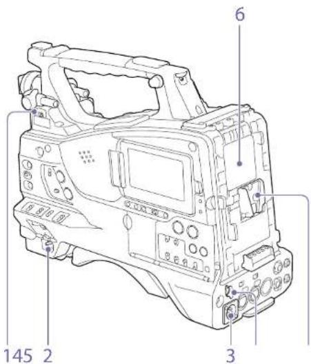
Power Supply
text_image
Technical diagram of a digital camera with numbered parts labeled 1, 2, 3, and 6.
1. LIGHT (video light) switch
Determines how a video light connected to the LIGHT connector (page 4) is turned on and off.
AUTO: When the POWER switch of the video light is in the on position, the video light is turned on automatically while the camcorder is recording.
MANUAL: You can turn the video light on or off manually, using its own switch.
[Note]
When the camcorer is set for recording in Picture Cache Rec mode, it is not possible to turn on the light before operation to start recording is carried out (or while data is being stored in memory).
2. POWER switch
Turns the main power supply on (1) and off (2).
-
DC IN (DC power input) connector (XLR type, 4-pin, male)
-
DC OUT 12V (DC power output) connector (4-pin, female)
Supplies power for the CBK-DL1 USB Adaptor and HDVI -1.750 Viewfinder (maximum 1.8 A).
5. Battery attachment shoe
Attach a BP-GL95B Battery Pack. Alternatively, you can attach an AC-DN10A AC Adaptor to operate the camcorder from an AC power supply.
"Preparing a Power Supply" (page 23)
[Note]
For your safety, and to ensure proper operation of the caricorder, Sony recommends the use of the BP-GI 958 Battery Pack.
6. Camera adaptor connector
Enables connection of a CA-TX70/FB70 HD Camera Adaptor. To connect an adaptor, remove the cover.
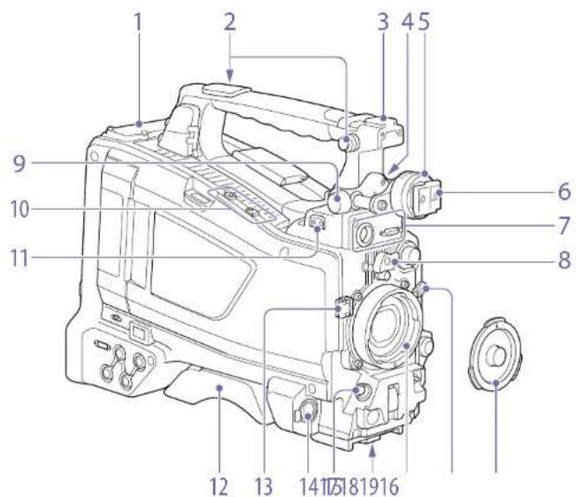
Accessory Attachments
text_image
1
2
3 4 5
9
10
11
6
7
8
12 13 14 15 16
- Wireless receiver Insertion slot (page 29)
"Attaching a Wireless Receiver" (page 79)
- Shoulder strap fitting (page 30)
- Accessory shoe (page 30)
- Viewfinder front-to-back positioning lever (page 25)
- Viewfinder left-to-right positioning ring (page 24)
-
Viewfinder attachment shoe (page 24)
-
VF (viewfinder) connectors (26-pin, rectangular and 20-pin, round)
The analog interface connector (20-pin) is for connection of an HDVF series viewfinder, and the digital interface connector (26-pin) is for connection of a CHK-VI 02 HD viewfinder. Connect a viewfinder connection cable to the connector compatible with the viewfinder being used.
[Notes]
- Do not connect viewfinders to both connectors at the same time.
- When connecting or disconnecting an interface cable to this connector, power off the camcorer first.
- Lens mount securing rubber
After locking the lens in position using the lens locking lever, fit this rubber over the lower of the two projections. This fixes the lens mount, preventing it from coming loose.
- Viewfinder front-to-back positioning knob (page 24)
- Attachment for optional microphone holder (page 29) and attachment for supplied guard (page 61)
- LIGHT (video light) connector (2-pin, female) (page 30)
- Shoulder pad (page 30)
- Lens cable clamp
Clamps the lens cable.
- MIC IN (microphone input) (+48 V) connector (XLR type, 5-pin, female)
Connect a stereo microphone to this connector. The power (+48 V) is supplied via this connector
- LENS connector (12-pin) (page 27)
[Note]
When connecting or disconnecting the lens cable to this connector, power off the camcorder first.
- Tripod mount
When using the camcorder on a tripod, attach the tripod adaptor (optional).
- Lens mount (special bayonet mount) (page 27)
- Lens locking lever (page 27)
- Lens mount cap
Remove by pushing the lens locking lever up. When no lens is mounted, keep this cap fitted for protection from dust.
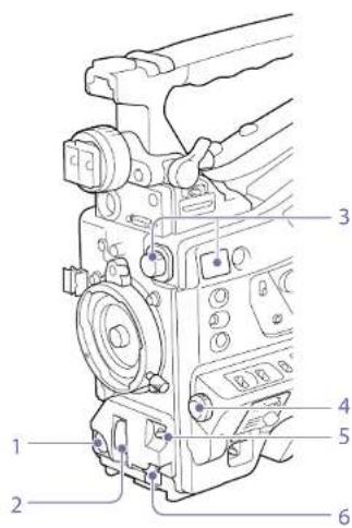
Controls Near the Lens
text_image
Technical diagram of a camera module with numbered parts labeled 1 through 6
- REC START (recording start) button
Press to start recording. Press it again to stop recording. The operation is the same as that of the VTR button on the lens.
- SHUTTER switch
Set to ON to use the electronic shutter. Push to SELECT to switch the shutter speed or shutter mode setting. When this switch is operated, the new setting appears on the viewfinder screen for about three seconds.
"Setting the Electronic Shutter" (page 41)
- Overview: Name and Function of Parts
[Note]
If Flash Band Reduce is On, setting the SHUTTER switch to ON turns of the Flash Band Reduce function and the HBR indicator disappears from the viewfinder screen. Subsequently, setting the SHUTTER switch to OFF turns on the Flash Band Reduce function and the HBR indicator reappears on the viewfinder screen.
3. FILTER knob
Switches between four ND filters built into this camcorder.
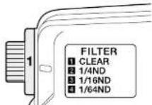
When this selector is used, the new setting appears on the viewfinder screen for about three seconds.
| FILTER knob setting | ND filter |
| 1 CLEAR |
| 2 1/4 ND (attenuates light to approximately 1/4) |
| 3 1/16 ND (attenuates light to approximately 1/16) |
| 4 1/64 ND (attenuates light to approximately 1/64) |
You can change a Maintenance menu setting so that different white balance settings can be stored for different FILTER knob positions. This allows you to automatically obtain optimum white balance for the current shooting conditions in linkage with the filter selection.
'Adjusting the White Balance' (page 39)
5. AUTO W/B BAL (automatic white/black balance adjustment) switch
Activates the automatic white/black balance adjustment functions.
WHITE: Adjust the white balance automatically. If the WHITE BAL switch (page 6) is set to A or B, the white balance setting is stored in the corresponding memory. If the WHITE BAL switch is set to PRST, the automatic white balance adjustment function does not operate.
BLACK: Adjust the black set and black balance automatically.
You can use the AUTO W/B BAL switch even when the ATW (Auto Tracing White Balance) function is operating.
If you push the switch to the WHITE side once more during the automatic white balance adjustment, the adjustment is canceled and the white balance setting returns to the original setting.
If you push the switch to the BLACK side once more during the automatic black balance adjustment, the adjustment is canceled and the black balance setting returns to the original setting.
- MIC (microphone) LEVEL knob (page 45)
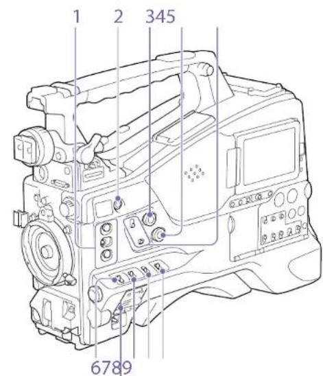
LCD Monitor Side (1)
text_image
1
2
345
6789
text_image
101212
STATUS
OFF
11
MENU
GNCUL/PAT
CHANGE
13
UTILTY 5D
14
- ASSIGN. (assignable) 1/2/3 switches You can assign a function using Operation >Assignable Switch in the setup menu (page 124).
The ASSIGN. 1/3 switches are provided with an indicator to show whether a function is assigned to the switch (ON) or not (OFF).
When network client mode or the streaming function is assigned to this button, press and hold until the indicator is lit orange. Then, press the button again, turning the indicator blue, to enable network client mode or the streaming function. To exit the enabled function, press and hold the button until the indicator turns off.
The button can also be used as an assignable switch when assigned with functions other than those above (page 125).
3. ALARM (alarm tone volume adjustment) knob
Controls the volume of the warning tone that is output via the built-in speaker or optional earphones. When the knob is turned to the minimum position, no sound can be heard. However, if Maintenance >Audio >Min Alarm Volume in the setup menu is set to [Seq], the alarm tone is audible even when this volume control is at the minimum position.

Minimum Maximum
4. MONITOR (monitor volume adjustment) knob
Controls the volume of the sound other than the warning tone that is output via the built-in speaker or earphones. When the knob is turned to the minimum position, no sound can be heard.
- MONITOR (audio monitor selection) switches
By means of combinations of the two switches,
you can select audio that you want to hear
through the built-in speaker or earphones.
When the lower switch is set to CH 1/2
Upper switch Audio output
CH-1/CH-3 Channel 1 audio
MIX Channels 1 and 2 mixed audio
(stereo)
CH 2/CH 4 Channel 2 audio
When the lower switch is set to CH-3/4
Upper switch Audio output
CH-1/CH-3 Channel 3 audio
MIX Channels 3 and 4 mixed audio
(stereo)
CH-2/CH-4 Channel 4 audio
a) By connecting stereo headphones to the EARPHONE jack, you can hear the audio in stereo. (Maintenance >Audio >Headphone Out in the setup menu must be set to Stereo.)
6. ASSIGN. (assignable) 0 switch
You can assign a function using Operation >Assignable Switch in the setup menu (page 124).
Off is assigned to these switches when the camcorder is shipped from the factory. This is a momentary type switch. Each press of the switch turns the function assigned to this switch on or off.
7. GAIN switch
Switches the gain of the video amplifier to match the lighting conditions during shooting. The gain values corresponding to the L, M, and H settings can be selected using Operation >Gain Switch in the setup menu (page 101) (factory settings are L=0 dB, M=6 dB, and H=12 dB).
When this switch is adjusted, the new setting appears on the viewfinder screen for about three seconds.
8. OUTPUT/DCC (output signal/dynamic contrast control) switch
Switches the video signal output from the camera module, between the following two.
BARS: Output the color bar signal.
CAM: Output the video signal being shot. When this is selected, you can switch DCC ^1 on and off.
1) DCC (Dynamic Contrast Control): Against a very bright background with the its opening adjusted to the subject objects in the background will be lost in the glare. The DCC function will suppress the high intensity and restore much of the lost detail. It is particularly effective for shooting in the following cases:
- Shooting people in the shade on a sunny day
- Shooting a subject indoors, against a background
through a window
• Any high contrast scene
- WHITE BAL (white balance memory) switch Controls adjustment of the white balance.
PRST: Adjust the color temperature to the preset value (the factory default setting: 3200K). Use this setting when you have no time to adjust the white balance.
A or B: Recall the white balance adjustment settings already stored in A or B. Push the AUTO W/B BAL switch (page 5) to the WHIII position to automatically adjust the white balance and save the adjustment settings in memory A or memory B.
B (ATW): When this switch is set to B and Operation > White Setting > White Switch is set to [ATW] in the setup menu, ATW is activated.
You can use the AUTO W/B BAL switch even when ATW is in use.
When this switch is adjusted, the new setting appears on the viewfinder screen for about three seconds.
1) ATW (Auto Tracing White balance): The white balance of the picture being shot is adjusted automatically for varying lighting conditions.
[Note]
It may not be possible to adjust to the appropriate colors using A\~W, depending on the lighting and subject conditions.
Examples:
- When a single color dominates the subject, such as sky, sea, ground, or flowers.
- When the subject is under a light source of extremely high or extremely low color temperature.
If execution of automatic tracing by the ATW function takes an unacceptably long time or only results in an inadequate effect, then execute the AWB function.
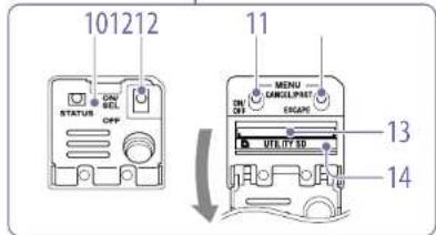
10. Switch cover
Open this cover to use the MENU ON/OFF switch or the MENU CANCEL/PRST/ESCAPE switch.
To use the switch, open the cover.
This switch is used to display the menu on the viewfinder screen or the test signal screen. Each time the switch is pushed down, the menu screen is turned on and off.
The function of this switch is the same as that of the MENU button in the thumbnail screen operations section.
[Note]
It is not possible to turn off the menu screen by closing the cover.
- MENU CANCEL/PRST (preset) /ESCAPE switch To use the switch, open the cover.
This switch has different functions depending on whether or not a menu is displayed
Use the switch in the following way when the menu is displayed.
CANCEL/PRST: Pushing this switch up to this position after a setting is changed in the setup menu displays the message to confirm whether the previous settings are canceled. Pushing this switch up to this position again cancels the previous settings. Pushing this switch up to this position before a setting is changed in the setup menu or after a setting change is canceled in the setup menu displays the message to confirm whether the setting is reset to the initial value. Pushing
this switch up to this position again resets the settings to the initial value.
ESCAPE: Use this switch when the menu page, which has a hierarchical structure, is opened. Each time the switch is pushed to this position, the page returns to one stage higher in the hierarchy.
Use the switch in the following way when the menu is not displayed.
CANCEL/PRST: Each time this switch is pushed upward, a window to confirm the menu settings and status of the camcorder appears on the viewfinder screen (page 13). The window consists of several pages, which are switched each time the switch is pushed upward.
ESCAPE: To clear the page, push this switch down to the OFF position.
- UTILITY SD card slot
Insert an SD card for saving camcorder settings.
- ACCESS indicator
Lights up orange when the SD card is being accessed.
LCD Monitor Side (2)
text_image
[1]
[2]
789
F REV
FLAT/RUSE
F FWD
PREV
STOP
NEXT
10
1112
1
2
3
4
5
6
13
1415
1617
DISP SEL HOLD RESET DISPLAY BRIGHT
EXPAND RETURN COUNTER TC U-BIT
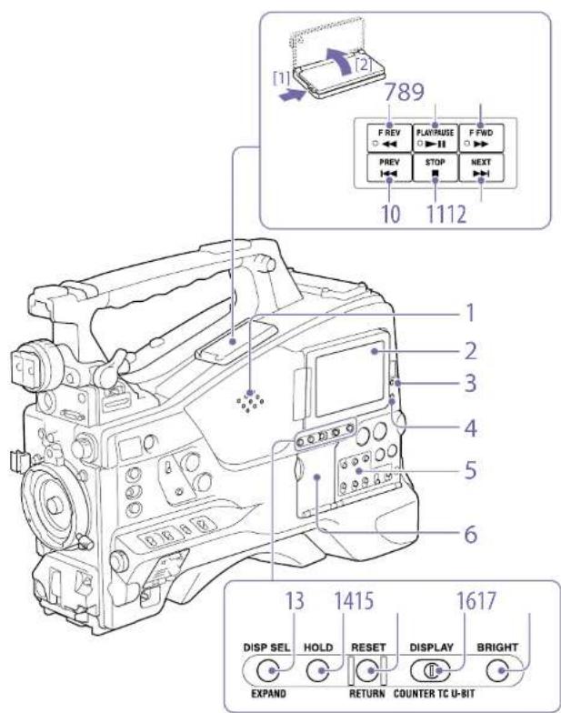
1. Built-in speaker
The speaker can be used to monitor E-E ^™ sound during recording, and playback sound during playback. The speaker also sounds alarms to reinforce visual warnings (page 143). If you connect earphones to the EARPHONE Jack, the speaker output is suppressed automatically.
1) E-E Abbreviation of "Electric-to-Electric." In E-E mode, video and audio signals input to the camcorder are output after passing through internal electric circuits only. This can be used to check input signals.
2. LCD monitor
Displays remaining battery capacity, remaining media capacity, audio levels, time data, and so on. It also allows you to check camera and playback pictures (page 13).
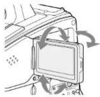
You can adjust the position and angle of the LCD monitor.
natural_image
Diagram of a device mounted on a panel, showing mechanical components and motion arrows (no text or symbols)
3. WARNING indicator
Lights up or flashes when an abnormality occurs (page 145).
4. ACCESS indicator
Lights up in blue when data is written to or read from the recording media.
5. Audio control section (page 9)
6. Thumbnail screen operation section (page 9)
- F REV (fast reverse) button and indicator
This plays back at high speed in the reverse direction. The playback speed changes in the order x4 x15 x24 with each press of the button.
The indicator lights during high-speed playback in the reverse direction.
Press this button to view playback video images using the viewfinder screen or the LCD monitor. The indicator lights during playback.
Press this button again during playback to pause, outputting a still image. At this time the indicator flashes at a rate of once per second.
Pressing the F REV or F FWD button during playback or pause starts high speed playback in the forward or reverse direction.
This plays back at high speed in the forward direction. The playback speed changes in the order ×4×15×24 with each press of the button. The indicator lights during high-speed playback in the forward direction.
This jumps to the first frame of the current clip. If you press this together with the F REV button, the jump is to the first frame of the first recorded clip on the recording media.
If you press this button twice in rapid succession, the jump is to the first frame of the preceding clip (or the first frame of the current clip when no preceding clips exist).
Press this button to stop playback.
This jumps to the first frame of the next clip. If you press this together with the F FWD button, the jump is to the last frame of the last recorded clip on the recording media.
With each press of this button, the display in the LCD monitor changes as follows.
| Display indication Description |
| Video with superimposed information (CIAR) | The LCD monitor displays the same text information as the viewfinder. |
| Display indication Description |
| Video without superimposed information (MONI) | Only the video appears. |
| Status display (STATUS)(page 13) | Counter indications, warnings, audio levels, and similar information appear. No video image appears. |
The EXPAND button function will be supported in a future upgrade.
Pressing this button instantly freezes the time data displayed in the LCD monitor. (The timecode generator continues running.) Pressing this button again releases the hold.
For details about the time data display, see page 13.
Resets the value shown in the time data display in the LCD monitor. According to the settings of the PRI-SI1/RIGEN/CLOCK switch (page 9) and the F-RUN/SET/R RUN switch (page 9), this button resets the display as follows.
| Switch settings RESET/RETURN button operation |
| DISPLAY switch: COUNTER | Reset counter to 00:00:00.00. |
| DISPLAY switch: TC | Reset timecode to 00:00:00.00. |
| PRESET/REGEN/CLOCK switch: PRESET | |
| F RUN/SET/B RUN switch: SFT | |
| Switch settings RESET/RETURN button operation |
| DISPLAY switch: | Reset user bits data ^st to 00:00:00:00. |
| U BIT |
| PRESET/REGEN/ |
| CLOCK switch: |
| PRESET |
| F-RUN/SET/F-RUN switch: |
| SET |
a) Of the timecode bits for every frame recorded on the media, those bits which can be used to record useful information for the user such as scene number, shooting place, etc.
'Setting Time Data' (page 47)
This button returns to the previous screen when pressed during thumbnail screen display or essence mark thumbnail screen display.
16. DISPLAY switch
This cycles the data displayed in the time data display in the LCD monitor through the sequence COUNTER, TC, and U-BIT (page 13). COUNTER: Display recording/playback duration counter.
TC: Display timecode
U-BIT: Display user bits data
Switches the brightness of the LCD monitor backlight.
Each press of the button selects the next setting in the order shown in the following table. If you press the button with the LCD monitor off, the LCD backlight comes on in the H state.
| Setting LCD monitor backlight |
| H High (select this to view the LCD monitor outdoors in the daytime) |
M Brightness between H and L
L Low (select this to view the LCD
monitor indoors or outdoors at night)
OFF Off (the display is also off)
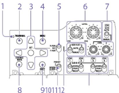
Thumbnail screen operations section and audio control section
text_image
1
2
3
4
5
6
7
8
9101112
1. Thumbnail indicator
This lights when the thumbnail screen is displayed.
Press this button to display the thumbnail screen (page 83) and to carry out a thumbnail operation.
Press once more to return to the original display.
Use these buttons to make timecode and user bit settings, and for thumbnail screen operations. When the menu is displayed, press this button to select an item or to confirm the setting change.
Each press of this button turns the setup menu display on and off.
The function of this button is the same as that of the MENU ON/OFF switch.
5. F-RUN/SET/R-RUN (free run/set/recording run) switch
Selects the operating mode of the internal timecode generator. The operating mode is set as explained below, depending on the position of the switch.
F-RUN: Timecode keeps advancing, regardless of whether the camcorder is recording. Use this setting when synchronizing the timecode with external timecode.
SET: Sets the timecode or user bits.
R-RUN: Timecode advances only during recording.
Use this setting to have a consecutive
timecode on the recording media.
"Setting the Timecode" (page 47)
"Setting the User Bits" (page 47)
6. LEVEL CH1/CH2/CH3/CH4 (audio channel 1/2/3/4 recording level) knobs
Adjust the audio levels to be recorded on channels 1, 2, 3, and 4 when the AUDIO SELECT CH1/CH2 and AUDIO SELECT CH 3-4 switches are set to MANUAL.
7. AUDIO SELECT CH 3-4 (audio channel 3/4 adjustment method selection) switches
Select the audio level adjustment method for audio channels 3 and 4.
AUTO: Automatic adjustment
MANUAL: Manual adjustment
By pressing this button when a thumbnail display is on the screen, you can view the following thumbnail displays of the essence-marked frames of the selected clip, depending on the item selected in a list displayed on the screen.
All: Thumbnail display of all frames marked with essence marks.
Rec Start: Thumbnail display of frames marked with Rec Start marks and of the first frames of clips (when the first frames are not marked with Rec Start marks).
Shot Mark1: Thumbnail display of the frames marked with Shot Mark 1.
Shot Mark2: Thumbnail display of the frames marked with Shot Mark 2.
You can also select Shot Mark 0 and Shot Mark 3 to Shot Mark 9.
If a clip is recorded using planning metadata that defines names for shot mark 0 to shot mark 9, the selection options in the list are displayed by the defined names.
Use this in combination with other buttons.
- PRESET/REGEN (regeneration)/CLOCK switch
Selects the type of timecode to record.
PRESET: Record new timecode on the media.
REGEN: Record timecode continuous with the existing timecode recorded on the media. Regardless of the setting of the F-RUN/SET/R-RUN switch, the camcorder operates in R-RUN mode.
CLOCK: Record timecode synchronized to the internal clock. Regardless of the setting of the F-RUN/SET/R-RUN switch, the camcorder operates in F-RUN mode.
11. AUDIO SELECT CH1/CH2 (audio channel 1/2 adjustment method selection) switches
Select the audio level adjustment method for audio channels 1 and 2.
AUTO: Automatic adjustment
MANUAL: Manual adjustment
Select the audio input signals to be recorded on audio channels 1, 2, 3 and 4.
FRONT: Audio input signals from the microphone connected to the MIC IN connector
REAR: Audio input signals from an audio device connected to the AUDIO IN CH-1/CH-2 connectors
WIRELESS: Audio input signals from the UHF portable tuner if it is attached
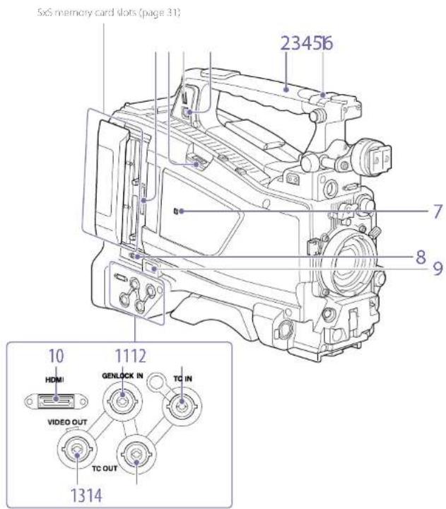
Handle and Memory Card Slot Side
text_image
SixS memory card slots (page 31)
23456
7
8
9
10
1112
HDMI
GENLOCK IN
TC IN
VIDEO OUT
TC OUT
1314
1. ASSIGNABLE 4/5 switches
You can assign a function using Operation >Assignable Switch in the setup menu (page 125).
Off is assigned to these switches when the camcorder is shipped from the factory.
2. GPS module
Contains a built-in GPS module.
"Obtaining Location information (GPS)" (page 59)
[Note]
Do not grasp this part of the camcorder when the GPS function is in use.
3. PC connector
Used to put this camcorder into USB connection mode and use it as an external storage device for a computer. When a computer is connected to this connector, every memory card inserted in the camcorder is recognized as a drive on the computer.
4. External device connector
Connect to a PSZ-HA/HB/HC series Portable Storage HDD (option), PSZ SA25 Portable Storage SSD (option), a general-purpose external USB HDD, or USB flash drive to copy clips from the recording media inserted in an SxS card slot of the camcorder to USB media.
[Note]
This connector should be used only for connecting the type of devices above. It cannot be used for connecting a USB hub or other devices.
5. USB wireless LAN module connector
Connect to an IFU-WLM3 USB Wireless LAN Module (supplied), CBK-WA02 Wireless LAN Adaptor (option), CBK NAI Network Adaptor Kit (option), or modem (option) to enable communications with wireless LAN devices and networks.
"Connecting Devices using Wireless LAN" (page 61)
"Connecting to the Internet" (page 65)
6. PROXY SD card slot (page 55)
Insert an SD card for recording proxy data.
7. (RFC) mark
A built in NFC antenna is provided.
When 5x5 memory cards are loaded in both card slots A and B, press this button to select the card you want to use (page 31).
9. Network connector
Connects to a network via a wired LAN connection using a LAN cable (sold separately).
[CAUTION]
- For safety, do not connect the connector for peripheral device wiring that might have excessive voltage to this port.
Follow the instructions for this port.
- When you connect the LAN cable of the unit to peripheral device, use a shielded-type cable to prevent malfunction due to radiation noise.
"Connecting to the Internet" (page 65)
10. HDMI connector
Connect an HDMI device, such as a monitor or recording unit, to output HD or SD HDMI video and audio signals.
This connector inputs a reference signal when the camcorder is to be genlocked or when timecode is to be synchronized with external equipment. The supported reference signals vary depending on the current system frequency as shown in the following table.
System frequency Supported reference signals
59.94i 1080/59.94i, 480/59.94i
59.94P 1080/59.94i, 480/59.94i
5011080/50i, 576/50i
50P 1080/50, 576/50
29.97P 1080/59.94, 480/59.94I
25° 1080/50, 576/50
23.98P 1080/23.98PsF
- TC IN (timecode input) connector (BNC type) To apply an external lock to the timecode of the camcorder, input the reference timecode.
"Setting the Timescode" (page 17)
13. VIDEO OUT connector (BNC type)
Outputs video signals for monitoring.
14. TC OUT (timecode output) connector (BNC type)
To lock the timecode of an external VTR to the timecode of this camcorder, connect this connector to the external VTR's timecode input connector.
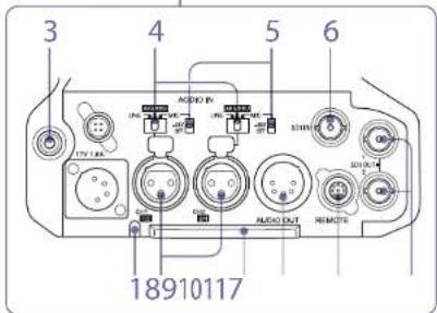
Tally Indicator and Connector Section

text_image
Technical line drawing of a digital camera with labeled parts 1 and 2
text_image
3
4
5
6
18910117
AUDIO IN
AUDIO OUT
AUDIO OUT
REMOTE
1. TALLY (back tally) indicator (red)
Lights up during recording. It will not light if the TALLY switch is set to OFF. It also flashes when the WARNING indicator operates. The tally indicator on the front of the viewfinder and the REC indication on the viewfinder screen light or flash in the same manner.
"Error/Warning System" (page 145)
2. TALLY switch
Set to ON to activate the |ALL Y indicator function.
You can monitor the E-E sound during recording and playback sound during playback. When an alarm is indicated, you can hear the alarm sound through the earphone. Plugging an earphone into the jack automatically cuts off the built-in speaker. You can select monaural or stereo using Maintenance >Audio >Headphone Out in the setup menu.
[Notes]
• Use monaural (2-pole) or stereo (3-pole) type earphones.
Use of other earphones may damage the camcorder.
• Use earphones with 16Ω impedance
4. AUDIO IN selector switch
Select the audio source you connect to the AUDIO IN CH1/CH2 connectors.
LINE: When connecting a stereo amplifier or other external audio signal source
AES/EBU: When connecting an external digital audio signal source
MIC: When connecting a microphone.
5. +48V/OFF (+48V external power source on/off) switch
Switch between the following settings, according to the microphone used for audio input.
+48V: Microphone requiring external power source (phantom power)
OH: Microphone using internal power source or not requiring a power source
Connector used when connecting an external SDI signal source to the camcorder.
-
Overview: Name and Function of Parts
-
AUDIO IN CH-1/CH-2 (audio channel 1 and channel 2 input) connectors (XLR type, 3-pin, female)
Connect to audio equipment or a microphone.
- Bottom cover
This is provided for protecting the cables connected to the connectors on the rear panel. By loosening the screws which retain the cover to the bottom of the camcorder, you can adjust the position of the cover depending on the size and shape of the microphone or audio cable plugs.
After adjusting the position, tighten the screws to secure the cover.
- AUDIO OUT connector (XLR type, 5-pin, male)
Outputs the audio signals recorded on audio channels 1 and 2 or audio channels 3 and 4. The audio signals are selected by the MONITOR switch.
- REMOTE connector (8-pin)
Connect a remote control unit to control the camcorder remotely.
[Note]
Before connecting/disconnecting the Remote Control Unit to/from the camcorder, be sure to turn off the camcorder POWER switch.
- SDI OUT 1/2 connectors (BNC type)
Outputs an HD SDI or SDI SDI signal (with embedded audio). The output signal from this connector can be turned on/off using Operation >Input/Output >SDI Out1 Output or SDI Out2 Output in the setup menu.
[Note]
Make sure that the ground connection between the camcorder and external device is securely established before turning the power on.
(It is recommended that the camcorder and external device be turned on after connecting the 75 Ω coaxial cable.) If the external device must be connected to the camcorder while the camcorder is on, connect the 75 Ω coaxial cable to the external device first and then connect it to the camcorder.
Screen Display
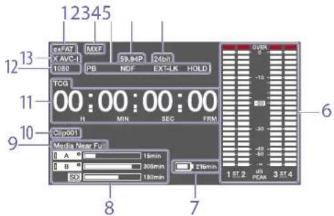
The LCD monitor information screen is displayed by pressing the DISP SEL/EXPAND (display select/expand) button (page 8).
text_image
12345
exFAT
MXE
59.84P
24pt
X AVC-1
1080
PB
NDF
EXT-LK
HOLD
TCG
00:00:00:00
H
MIN
SEC
FRM
Clip001
Media Near Full
A
B
16min
305min
216min
29
180min
1 ST.2
PCAM
3 ST.4
6
7
8
-
File system indicator
-
File format indicator
-
Status display
PB: Appears during media playback.
NDF: Appears when non-croo-frame Limecode is selected.
EXT-LK: Appears when the internal timecode generator is locked to an external signal input to the TC IN (timecode input) connector.
HOLD: Appears when the operation mode of the internal timecode generator is set to R-RUN and sloped.
- System frequency indicator
Indicates the system frequency of video being currently played or recorded.
- Audio format indicator
Indicates the audio recording format or the audio format of clip being currently played.
Indicator Recording format
16bit HD420 HQ
DVCAM
MPEG MX 50
24bit D422 50
MPEG MX 50
XAVC Intra
XAVC Long
- Audio level meters
Indicates the audio recording or playback levels of channels 1 to 4.
- Remaining battery capacity indicator
Displays the battery remaining capacity icon and the remaining recording time.
- Remaining media capacity indicator
Shows bar segments indicating the remaining capacity of recording media in the slots.
- Warning indicator area
Displays warnings when trouble with recording occurs.
For details, see "Error/Warning System" (page 145).
- Clip name display
Displays the name of the clip currently recording when recording, or displays the name of the next clip to be recorded during recording standby.
- Time data display
Switches displays of duration, timecode, and user bits data, depending on the position of the DISPLAY switch.
Displays the type of data currently shown in the time data display, as follows.
TCG: Recorded timecode
TCR: Playback timecode
UBG: Recorded user bits
UBR; Playback user bits
CNT: Counter
DUR: Duration
CLK: Time display (when the PRESET/REGEN/CLOCK switch is set to CLOCK)
When the HOLD button is pressed to hold the timecode value, the timecode is displayed in the format shown below. When the HOLD button is pressed again to release the hold, the timecode is displayed in the normal format.
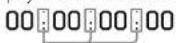
The three dots indicate that the timecode and counter progress are in hold mode.
- Resolution indicator
Indicates the resolution of the output video.
- Recording format indicator
Indicates the current recording format or the recording format of clip being currently played.
Status Screens
The status screens allow you to check camcorder settings and various types of status information. When no menu is displayed, push the MENU CANCEL/PRST/ESCAPE switch up to the CANCEL/PRST position to display the status screen. Each push selects the next status screen.
The following status screens can be displayed:
Status screen Display Indication
Camera Status screen Settings and status information related to shooting
Audio Status screen Settings and status information related to audio input and output
System Status screen Settings and status information related to recording
Video Output Status
screen
Settings and status
information related to
video output
Assignable Button Status
screen
Names of functions
assigned to assignable
switches
Battery Status screen Status of the battery mounted on the camcorder
Media Status screen Status information about recording media
Network Status 1 screen Settings and status information related to the network
Network Status 2 screen Settings and status information related to streaming
Camera Status screen
| Camera Status |
| Gain 18dB | Color On (80%) | Wx FS.6 | |
| Shutter Ctrl | Color On (102%) | Radial Length 75.2mm | |
| Gamma STOS R708 | HFR Setting HLO(Natural) | Vacuum Distance 4.3m | |
| White Preset | | Depth: 0/Fall 2.5~5.8m | |
| Gain Split L0, M-9, H-18 | | Zoom Speed 25 | |
Display item Description
Gain Gain level in dB units
Shutter Electronic shutter status
Gamma Gamma category and curve
White White balance mode setting
Gain Switch GAIN switch status
Zebra Zebra pattern status
Iris Iris f stop value
Focal Length Focal length
Focus Distance Focus distance
Depth Of Field Depth of field
Zoom Speed Zoom speed configured for the
lens ZOOM button
HDR Selling HDR settings
[Note]
Displayed only when using
CBKZ SLHLT HDR LICENSEL (option).
Audio Status screen
| Audio Status |
| Level | Source | Rate | Wind Filter |
| GH1 | [IMAGE] | Front Mic | -40dB | On |
| GH2 | [IMAGE] | GH2 Line | +4dB | Off |
| GH3 | [IMAGE] | AES/EBU | --- | --- |
| GH4 | [IMAGE] | AES/EBU | --- | --- |
Display item Description
| CH 1/CH 2/ | Audio level, input source, |
| CH 3/CH 4 | reference input level, and windnoise reduction filter settings foreach channel |
System Status screen
| System Status |
| System Frequency23.98 | Police Size1920x1080 | GentraSTD |
| Res FormalAVC-I | Res FunctionS&Q 26/24 | |
| Fire Systemext AT | Off Continuous ResOff | |
| SimulierOff | Picture Cache ResOff | Proxy Recording ModeOff |
| The PathABCDEF | Number00017 | |
Display item Description
| System Frequency | System frequency |
| File System File system |
| Rec Format Recording format |
| Clip Continuous Rec function on | Clip Continuous Rec function on |
| Continuous off setting |
| Rec |
Title Prefix Clip name prefix
| Picture Size Picture size |
| Simul Rec | Simul Rec function on/off |
| Rec Function | Enabled special recording format and settings |
| Picture Cache Rec | Picture Cache Rec function on/off setting |
| Number | Clip name suffix |
Gamma Gamma category in use
| Proxy | Proxy data recording function on/off setting |
| Recording |
| Mode |
Video Output Status screen
| Video Output Status |
| Picture Size | C Space | Free | Super |
| 801 | 1920x1080P(Level A) | YPbPr | 3G | — |
| 802 | 1920x1080P(Level A) | YPbPr | 3G | On |
| 803 | 1920x1080P | YPbPr | 1.5G | On |
| View | HD Sync | YPbPr | — | On |
Display item Description
| SDI | SDI OUT connector output settings (output picture size, output form, output rate, superimposition) |
| HDMI | HDMI connector output settings (output picture size, output form, output rate, superimposition) |
| Video | VIDEO OUT connector output settings (output picture size, superimposition) |
Assignable Button Status screen
| 0 | ATW Hold | 1 | Zoom Wide |
| 1 | Zebra | Online | CC5600K |
| 2 | Front Mic | Lens RET | Lens RET |
| 3 | Marker | |
| 4 | Zoom Tele | |
Battery Status screen
| Battery Status |
| Detected BatteryBP-GLS | Manufacture DateJan/18/2014 |
| Remaining | 54% | |
| Charge Count | 52 | |
| Capacity | 1.93Ah | Power SourceDC In |
| Voltage | 13.2V | Supplied Voltage12.8V |
Display item Description
| Detected Battery | Detected type of the battery |
| Remaining | Remaining capacity (%) |
| Charge Count | Number of recharges |
| Capacity | Remaining capacity (Ah) |
| Voltage | Voltage |
| Manufacture Date | Date of battery manufacture |
| Power Source | Power supply source |
| Supplied Voltage | Supplied power source voltage |
Media Status screen
| Media Status |
| Remaining | Life |
| 1stA | 210min | 100% |
| 1stB | 92min | 54% |
| 3D | 188min | |
| 3D | 2.7GB | |
Display item Description
| SxSA | Remaining capacity (bar graph and remaining time display) and media life of media in slot A (0% to 100% indication. Replacement recommended at 0%. Displayed only for media that supports this function.) |
| SxSB | Remaining capacity (bar graph and remaining time display) and media life of media in slot B (0% to 100% indication. Replacement recommended at 0%. Displayed only for media that supports this function.) |
Display item Description
| SD Proxy Remaining capacity (bar graph and remaining time display) and media life (displayed only if available) of media in PROXY SD card slot |
| SD Utility Remaining capacity (bar graph and remaining capacity) and media life (displayed only if available) of media in UTILITY SD card slot |
A mark is displayed if the media is protected.
Network Status 1 screen
| Network Status 1 |
| Setting | | |
| On | | |
| Wireless Network Wi-Fi AP | Greeble Network Modem | Wind LAN Enable |
| Device Name IFU-WLM3 | Device NameXXXXXXX | Wire LAN Remote Off |
| IP Address(Wire) 192.168.1.1 | IP Address(Minward) 192.168.3.131 | IP Address(Minward) 192.168.1.50 |
| MAC Array (Wireless) at G1/2, $7.96.47 | | |
Display item Description
| Setting Network setting status |
| Wireless Network Wireless network setting status |
| Device Name Name of attached USB wireless LAN module device |
| IP Address (Wireless) | IP address of wireless LAN connection |
| MAC Addr. (Wireless) | MAC address of device attached the USB wireless LAN module connector |
Wireless Network Modem setting status
| Device Name Name of attached modern device |
| IP | IP address of attached modem |
| Address(Modem) | device |
| Wirec LAN Wired LAN network connection status |
Display item Description
| Wired LAN Remote | Remote control enabled/disabled state when connected using a LAN cable |
| IP Address (Wired) | IP address of wired LAN connection |
Network Status 2 screen
| Network Status 2 |
| NW Client Name Status Off | Streaming Type MPEG-2 TS/UDP | Number of Distribution 1 |
| COM Name++ | Streaming Dept. Add 43.0 134.23 | File Transfer 40% |
| Streaming Status Distributing | Streaming Dept. Add 1234 | Transfer to Sony CI |
| Streaming Size 1280x720 | | |
| Streaming Rate 9Mbps | | |
Display item Description
| NW Client Mode Status | Network client mode status For details about the status, see "Network client mode status" (page 15). |
| CCM Name | Name of the connected CCM when using network client mode |
| Streaming | Streaming distribution status |
Streaming Size Picture size of the currently selected streaming setting
| Streaming Bit Rate | Bit rate of the currently selected streaming setting |
| Streaming Type | Type of the currently selected streaming setting |
| Streaming DesL. Add. | Streaming destination address |
Streaming
Dest. Port
Streaming destination port
| Number of Distribution | Number of streaming distribution destinations |
File Transfer File transfer progress status
| Transfer to: Server name of file transfer destination |
Network client mode status
| Status display | State Description |
| Off CCM not connected | Network client mode is off. |
| Connected CCM connected Network client mode is on, CCM is connected, and CCM control is enabled. |
| Connecting | Connecting to CCM (disconnected) | Attempting to connect to CCM (or disconnecting). Wait until connection (disconnection) is successful. If the status does not change from "Connecting," the CCM address setting may be incorrect. Check that the address is set correctly. |
| Awaiting | CCM connection standby | Network client mode is on, but the network setting is off. Enable the network setting to connect to the CCM. |
| Address Error | CCM address error | The host name or IP address of the CCM to connect may be incorrect. Check that the setting is correct. |
| Auth. Failed | CCM user name/ password error | The user name or password used to connect to the CCM may be incorrect. Check that the setting is correct. |
| Status display | State Description |
| No Inet Access | Internet connection error | Cannot connect to the network. The network settings may be incorrect. Check the network settings. |
| Cert not Valid | CCM certification not valid error | The CCM certificate is not valid. The date setting may be invalid. Check the date setting. |
Viewfinder Screen
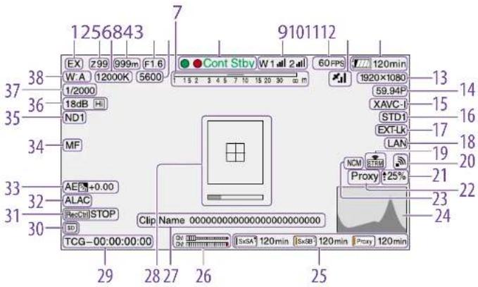
The viewfinder screen displays images during shooting (recording or recording standby) and playback with camcorder information superimposed on the display.
You can toggle the display of information on/off
using the DISPLAY switch.
The information to display is linked to the settings in Operation >Super Impose in the setup menu, and the settings of the corresponding switches.
text_image
1256843
7
9101112
EX 299 999m F1.6
W:A 12000K 5600
Cont Stby W1 all 2 all
60 FPS
120min
1920×1080
13
38
37
36
35
34
33
32
31
30
AE +0.00
ALAC
ResCtrl STOP
ID
Clip Name 000000000000000000000000000000000000000000000000000000000000000000000000000000000000000000
TCG-00:00:00:00
29 28 27 26 25
Ex 299 999m F1.6
W:A 12000K 5600
1/2000
18dB
ND1
MF
NCM
Proxy: +25%
15
XAVC-I
STD-I
EXT-LK
LAN
19
21
22
23
24
1. Extender indicator
Displays the status of the digital extender function and lens extender function.
EX: Appears when the lens extender function is ON
X2D: Appears when the digital extender function (×2) is ON
X3D: Appears when the digital extender function (×3) is ON
X4D: Appears when the digital extender function (×4) is ON
EX2D: Appears when both the lens extender function and digital extender function (×2) are ON
EX3D: Appears when both the lens extender function and digital extender function (×3) are
ON
EX4D: Appears when both the lens extender
function and digital extender function (×4) are ON
Turn the digital extender on/off using an assignable switch assigned with the Digital Extender function.
[Note]
The digital extender cannot be turned on when Slow & Quick Motion is enabled.
- Zoom position indicator (with lens mounted) Displays the zoom position of the zoom lens in the range 0 to 99.
The values displayed will vary with the lens used.
3. Color temperature indicator
Displays the color temperature of the white balance.
-
Focus position indicator (with lens mounted) Displays the focus position as a distance to the subject (unit: meters).
-
Iris position indicator (with lens mounted) Displays the iris position setting.
-
Electric color temperature filter indicator Appears when the CC5600K function is on.
-
Depth of field indicator (serial lens mounted)
Displays the depth of field using a bar. The units for display are set using Operation >Display On/Off
Lens Info in the setup menu, and can be set to meters or feet.
8. Recording mode indicator
Displays the following recording operation states of the camcorder.
Indicator Meaning
| ●Rec | During recording |
| Siby Recording standby |
| ●Cont Rec | Clip continuous recording in progress |
| Cont Siby Recording standby in clip continuous recording mode |
| ●S&Q Rec | Recording in progress in Slow & Quick Motion mode |
| S&Q Stby Recording standby in Slow & Quick Motion mode |
| ●Rec | Recording in Picture Cache Rec mode |
| ●Cache | Recording standby in Picture Cache Rec mode |
| ●Int Rec | Recording in progress in interval Rec mode |
| Int Stay Recording standby in Interval Rec mode |
| ●Int S.by | Recording paused in interval Rec mode (during pause intervals) |
| Indicator Meaning |
| ●Sml Rec | Recording in progress in Simul Rec mode |
| 5ml Siby | Recording standby in Simul Rec mode |
| CALL | Call received from external connected device |
Green tally is displayed when the camcorder is in the following states.
- Maintenance >Camera Config >HD SDI Remote /F is set to Green Tally in the setup menu and a recording control signal is output from the SDI OUT connector.
- Green tally signal received (when a camera adaptor is mounted on the camcorder and a camera extension unit is connected)
9. Wireless receiver function indicator
Displays "W" when a slot-in receiver is attached to the camcorder, and displays the reception level for each channel that can be used by the receiver (1ch, 2ch, or 4ch).
Normal: Displays the strength of the received signal level by the number of white segment indicators.
Analog receiver muting/Digital receiver error rate warning: Displays the strength of the received signal level by the number of gray segment indicators.
If the received level exceeds the peak: Displays "P" in place of the indicator. ^11
If the transmitter is in power-save mode: "S" is displayed.
Receiver battery is low: The corresponding channel number and indicators flash. ^10
1) When using the DWR-S02DN
10. S&Q Motion (Slow & Quick) frame rate indicator
Displays the shooting frame rate when the camcorder is set to Slow & Quick Motion recording mode.
11. GPS indicator (page 59)
12. Battery capacity/voltage display
Displays the following indicators according to the type of battery power source.
| Battery type indicator |
| Info battery Battery remaining capacity |
| icon and remaining recording time |
| Anlon/Bauer battery | Remaining battery capacity (% Indicator) |
| Other batteries Input voltage |
Displays the picture size of clips recorded onto 5x5 memory cards.
Displays the currently configured camcorder system frequency and the recording format scan method.
Displays the format name of clips recorded onto SxS memory cards.
16. Gamma Indicator
Displays the gamma setting.
| Mono settings Indicator |
| Operation | Pair1 >Gamma setting |
| >Display | Gamma | Gamma | Gamma |
| On/Off | | Category | Select |
| >Gamma | | | |
| Menu settings Indicator |
| Operation | Paint >Gamma setting |
| Display | Gamma | Gamma | Gamma |
| On/OFF Gamma Category Select |
| On/OFF — Gamma Off |
| On STD STD1 DVW STD1 |
| | STD2 x4.5 STD2 |
| | STD3 x3.5 STD3 |
| | STD4 240M/5*D4 |
| | STD5 R/09 STD5 |
| | STD6 x5.0 STD6 |
| HC HG1 | | HG1 |
| | 3250G36 |
| | HG2 | HG2 |
| | 4600G30 |
| | HG3 | HG3 |
| | 3250G40 |
| | HG4 | HG4 |
| | 4600G33 |
| User User 1 User 1 |
| | User 2 User 2 |
| | User 3 User 3 |
| | User 4 User 4 |
| | User 5 User 5 |
The gamma indicator is "ILG" when Operation >Base Setting >Shooting Mode is set to HDR in the setup menu.
17. Timecode external lock indicator
Displays timecode lock when the timecode is input from an external source.
18. Wired LAN/Modem connection status indicator
Displays icons for the wired LAN network or modem settings/connection status.
Wired LAN settings/connection status
| State | Network connection state/Inon |
| Operation >Display On/Off >Network Condition | Maintenance >Network >Setting | Maintenance >Network >Wired LAN |
| Off |
| On | Off | - | - |
| On | | |
| | Disable | |
| | Enable Connecting to LAN | |
| | | LAN (flashing) |
| | | Connected to LAN |
| | | LAN |
| | | LAN |
| | | Connection error |
| | | LAN3 |
3G/4G modem settings/connection status
| State | Network connection state/iron |
| Operation | Maintenance | Maintenance |
| >Display Only | >Network | >Network |
| Off >Network Condition | >Setting | >Modern |
| Off | - | - | - |
| State | Network connection status |
| Operation >Display On/Off >Network Condition | Maintenance >Network >Setting | Maintenance >Network >Modem |
| On | Off | - | - |
| On | - | - |
| Off | - |
| On | Modem connecting (facing) |
| | Modem connected |
| | Modem connection error |
19. Streaming indicator
Displays the status of streaming using icons.
| State | Streaming status/Icon |
| Operation | Maintenance | Maintenance |
| >Display | >Streaming | >Network |
| On/OFF | >Sooling | Clin. Mode |
| >Streaming Status | | >Sooling | |
| OIT | — | — | — |
| On Off | Off |
| On | Off | Not streamingSTRM |
| | | StreamingSTRM |
| | | ErrorSTRM |
The following icons are displayed when streaming from a CCM.
| State Streaming | state/icon |
| Donation | Maintenance | Maintenance |
| >Display | >Streaming | >Network |
| On/Off | >Setting | Client Mode |
| >Streaming | | >Setting |
| Status | | |
| On Off On Not | streamingSTRM |
| StreamingSTRM |
[Note]
Icons are not displayed before streaming starts.
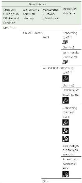
20. Wi-Fi mode status indicator
Displays the wireless LAN settings and connection status using icons.
| State Network | connection state/icon |
| Operation | Maintenance | Maintenance |
| >Display On/Off >Network | >Network | >Network |
| >Setting | >Wi-Fi Mode | |
| Condition | | |
| DT--- | | |
text_image
State Network
Operation
>Display On/
Off >Network
Condition
Mainance
>Network
>Setting
Maintenance
>Network
>Wi-Fi Mode
connection
status/icon
On Off = -
On Wi-Fi Access
Point
Connecting
to Wi-Fi
AP
(flashing)
Wi-Fi standby
(Connected)
AP
Wi-Fi Station Connecting
to Wi-Fi
(flashing)
Searching for
access points
Connecting
to access
point
Icon changes
due to signal
strength
Access point
connection
error
Off -
21. File transfer status indicator
Displays ▲ and transfer rate (%) during file transfer.
When transfer finishes, disappears to indicate
100% transfer.
22. Proxy indicator
Displays "Proxy" when proxy recording is on (Operation >Proxy Recording Mode >Setting in the setup menu is set to On). During setup, "Proxy" blinks. "Proxy Rec" is displayed during proxy recording.
23. Network client mode indicator
Displays the status of the connection to the CCM (Connection Control Manager) of either a Network RX Station or C3 Portal using icons when network client mode is on.
| State Icon |
| Operation >Display On/OF >NW Client Mode Status | Maintenance >Network Client Mode >Scluing | |
| Off — — — |
| On Off — — |
| On CCM | NCM |
| Connecting to NCM (disconnected) |
| CCM connection standby |
| CCM connection error |
24. Video signal indicator
Displays the output video signal in realtime as a waveform, vectorscope, or histogram.
| State Video signal | Inc. error |
| Operation >Input/ | Operation >HDR |
| Output >Output | Setting |
| Format >SDI Out |
| 1570C ORD HD 4sec/Out setting Indicator Using |
| (362×SHI THOR LICENSE) | |
| HDR (1G) HDR (1G) | |
| SOR SDR | |
25. Recording media state/remaining capacity indicator for each media slot
Displays the state and remaining capacity of the media in SxS slot A, SxS slot B, and the PROXY SD card slot.
SxS slot icon indicator
^3 SxS slot A (SxSA) example. The icons for SxS slot B are labeled SxSB.
| Icon Media state |
| — Media not inserted or not mounted |
| [sa4] | Media mounted |
| [sa4](flashing) | Media mounting |
| [sa4](orange bar) | Recording (active) |
| [sa4](green indicator) | Playback (active) |
| [sa4](orange bar+ green indicator) | Recording/playback (active) |
SD card (for proxy data recording) icon indicator
| Icon Media state |
| Media not inserted or not mounted |
Icon Media state
| Proxy | Media mounted |
| Proxy(flushing) | Media mounting |
| Proxy(orange bar) | Recording (active) |
The remaining recording time is displayed numerically.
26. Audio level meter indicators
Displays the levels of audio channels 1 and 2.
27. Clip name display
Displays the name of the clip currently recording when recording, or displays the name of the next clip to be recorded during recording standby.
28. Focus assist indicator
Displays a detection frame (focus area marker) indicating the area for detection of degree of focus, and a level bar (focus assist indicator) indicating the degree of focus within that area.
29. Time data display
Displays the remaining recording/playback time, timecode, user bits, etc., as selected by the DISPLAY switch (page 8).
30. SD card indicator for saving configuration data
Displays the state of the SD card (for saving configuration data) inserted in the UTILITY SD card slot.
Icon Media state
| — SD card not inserted or not mounted |
| SD | SD card mounted |
| SD | Mounted SD card is protected |
| SD(fashing) | SD card mounting |
31. SDI output REC trigger indicator
Displays the superimposition state of the recording command sent to the SDI connector output. It is displayed when Maintenance >Camera Config >HD SDI Remote I/I is set to "Characters" in the setup menu.
32. ALAC indicator
Displays "ALAC" when the ALAC (Auto Lens Aberration Correction) function is set to be performed automatically.
ALAC will be performed automatically when an ALAC compatible lens is attached, the ALAC function is enabled, and Maintenance >Camera Config >ALAC is set to "Auto" in the setup menu.
33. AE (auto iris) mode indicator
Displays the current operating mode of the auto iris function using an icon and auto iris override level.
Icon Meaning
| Backlight mode |
| Standard mode |
| Spotlight mode |
34. Auto focus mode indicator (when an auto focus lens is attached only)
Displays the focus adjustment mode of the camcorder.
• AF (auto focus)
• MF (manual focus)
- MF* (manual focus with MF assist function on)
• Full MF (full manual focus)
35. ND filter indicator
Displays the position number of the currently selected ND filter (page 5).
When "Electrical CC" is assigned to an assignable switch, the position (A/B/C/D) of the electrical CC filter is displayed on the right of the ND filter indicator (1 to 4).
36. Gain Indicator
Displays the gain setting (dB), set using the GAIN switch, of the video amplifier.
37. Shutter mode/shutter speed indicator/Flash Band Reduce status Indicator
Displays the shutter mode or shutter speed.
"Setting the Electronic Shower" (page 41)
If Flash Band Reduce (page 105) is set to On in the Operation menu, I BR is displayed when the shutter is in a non-operating state.
38. White balance mode indicator
Displays the currently selected white balance automatic adjustment memory.
ATW: ATW (Auto Tracing White Balance) mode
W:A: Memory A mode
W:B: Memory B mode
W.C: Memory C mode
W.P: Preset mode
3200K: Appears when an assignable switch assigned with Color Temp SW 3200K is on
4300K: Appears when an assignable switch assigned with Color Temp SW 4300K is on 5600K: Appears when an assignable switch assigned with Color Temp SW 5600K is on
6300K: Appears when an assignable switch assigned with Color Temp SW 6300K is on
Supplied Lens and Viewfinder
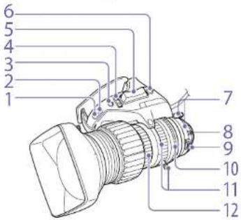
Lens Supplied with the PXW-X400KC
The PXW-X400KC is supplied with a lens.
text_image
1
2
3
4
5
6
7
8
9
10
11
12
text_image
Technical diagram of an industrial device with numbered parts labeled 13 through 18
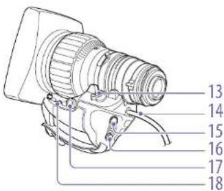
- DIP switches (page 20)
Used for the shuttle shot function.
-
Iris gain adjustment trimmer (page 43)
-
Iris push auto switch
When the iris mode switch is in the M (manual) position, press this switch for instantaneous auto iris adjustment. The iris is automatically adjusted while the switch is held down.
- Iris mode switch
A (auto): The iris is adjusted automatically.
M (manual): Adjust the iris with the iris ring
- Zoom seesaw switch
This is enabled when the zoom servo/manual knob is in the SERVO position. Set to the W (wide angle) position when you want wide-angle, and set to the T (telephoto) side when you want telephoto.
Press the switch harder for a faster zoom action, or softer for slower zoom action.
- RET switch
While pressed, the last few seconds recorded appear on the viewfinder screen (Rec Review) (page 21).
-
F.B. lock screw / F.B. adjustment ring (page 43)
-
Positioning pin
When attaching the lens, align this pin with the recess in the top center of lens mount on the camcorder.
- Macro button / macro ring
Press and hold the macro button and turn the macro ring to adjust the focus (minimum focus distance: 10 mm).
- Iris ring
For manual iris adjustment, set the iris mode switch to the M (manual) position, then turn this ring.
Note
Always se, the iris mode switch to the M (manual) position first and then adjust the iris.
- Zoom lever / zoom ring
For manual zoom adjustment, set the zoom servo/manual switch to the MANU position, then operate the lever/ring.
- Focus ring
Turn this ring to adjust the focus.
- Zoom servo / manual knob
SERVO (servo): Selects power zoom. Operate the zoom with the zoom seesaw switch.
MANU (manual): Selects manual zoom. Operate the zoom with the zoom lever/zoom ring.
- Power/iris control cable
Connect to the LENS connector on the camcorder.
- VTR switch
Use this to start and stop recording. Press once to start recording, then press once more to stop.
- Shtl (shuttle) switch (page 20)
Used for the shuttle shot function.
- Zoom remote control connector
Connect to an optional zoom servo controller to enable remote control of zooming.
- Memo switch (page 20)
Used for the shuttle shot function.
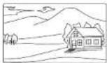
About shuttle shot
Shuttle shot is a shooting function for rapidly moving to a preset zoom position set by the user.
1 Set the DIP switch 1 to ON.
2 Set the zoom position that you want to register.
3 Press and hold the Memo switch and press the 5ntl (shuttle) switch.
The zoom position is registered as the shuttle position.
To move rapidly to the shuttle position, press and hold the Shtl (shuttle) switch.
The zoom rapidly returns to the previous zoom position when the Shtl (shuttle) switch is released.
Current zoom position
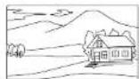

Press and hold Shtl (shuttle) switch
Shuttle position


Release Shtl (shuttle) switch
Original zoom position
Lens Supplied with the PXW-X400KF
The PXW-X400KF is supplied with a lens.
text_image
1
2
3
4
5
6
7
8
9
text_image
10
11
12
13
14
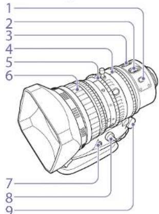
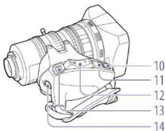
When adjusting focus in manual mode, pressing this button enables auto focus adjustment on the subject.
Press the button to activate auto focus, and release the button when the subject is in focus.
2. FOCUS (adjustment mode) switch
A (Auto): Activates the normal auto focus function. You can also adjust the focus manually using the focus ring, even when the switch is in the "A" position.
M (manual): Selects manual mode for focus adjustment with the focus ring.
In manual mode, auto focus adjustment is also possible, by pressing the PUSH AF button.
3. MACRO switch
When this switch is in the ON position, macro
mode is enabled, allowing focusing over the whole range (5 cm ^1 to ≈) including the macro range (from 5 cm ^1 to 80 cm from the front of the lens).
This operation is independent of whether the focus adjustment mode is auto or manual.
1) At the wide-angle setting
4. Iris ring
For manual iris adjustment, set the IRIS switch to the M (manual) position, then turn this ring.
5. Zoom ring
For manual zoom adjustment, set the ZOOM switch to the MANUAL position, then turn this ring.
6. Focus ring
Turn this ring to adjust the focus.
When the ring is set to AF/MF mode, the faster you turn ring the faster the focusing mechanism
operates, minimizing the amount of turning required for focusing.
When you slide the focus ring back (toward the camcorder), the focus mode is set to Full MF mode, in which all focus adjustments are manual (page 44).
Press this to adjust the flange focal length (the distance from the lens mounting flange plane to the focusing plane) (page 27).
8. Zoom control connector (8-pin)
Connect to an optional zoom servo controller to enable remote control of zooming.
9. ZOOM switch
SERVO: Selects power zoom. Operate the zoom with the power zoom lever.
MANUAL (manual): Selects manual zoom. Operate the zoom with the zoom ring.
When the IRIS switch is in the M position for manual adjustment, press this button for instantaneous auto adjustment. The iris is automatically adjusted while the button is held down.
11. IRIS (adjustment mode) switch
A (auto): The iris is adjusted automatically.
M (manual): Adjust the iris with the iris ring.
12. Power zoom lever
This is enabled when the ZOOM switch is in the SERVO position. Set to the W (wide angle) position when you want wide-angle, and set to the T (telephoto) side when you want telephoto. Press the lever harder for a faster zoom action, or softer for slower zoom action.
Notes about auto focus
- It may be difficult to focus on the subject in the following cases. If this does happen, use manual focusing
If the subject has no contrast
- if the subject is moving rapidly
- When shooting point light sources, under street lighting or at night
When there are very bright objects close to the subject
- When shooting through a glass window
- If there are a number of objects within the screen at close and far range, the focus may not be on the intended subject. In this case, with the subject on which you want to focus in the center of the screen, press the PUSH AF button.
- After focusing with the PUSH AF button, if you operate the zoom or adjust the iris, the depth of field may become shallower, losing crisp focus. In such cases, press the PUSH AF button once more.
- If you focus at wide-angle then zoom to telephoto, the subject may no longer be in focus.
- It may take time until the image is in focus while using the slow shutter mode.
You can assign a function and use this as an assignable switch (page 12/).
When "Lens RET" is assigned to this button (factory default setting), press this after recording stops to review the last few seconds recorded on the viewfinder screen (Rec Review) (page 49). Press this button (single click) during recording or playback to record a Shot Mark 1 mark, or double-click to record a Shot Mark 2 mark (page 51).
Use this to start and stop recording. Press once to start recording, then press once more to stop.
Viewfinder Supplied with the PXW-X400KC/PXW-X400KF
text_image
1
2
3
4
5
6
7
8
9
10
11
12
13
14
15
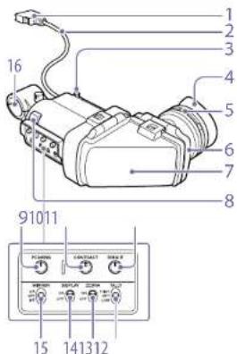
1. Connector
Connect to the VF connector (26-pin) on the camcorder.
2. Viewfinder cable
3. Slide stopper
Prevents the viewfinder from coming off the camcorder when it is slid from side to side.
4. Eyecup
5. Diopter adjustment ring
Turn this ring to adjust the image until it is in sharpest focus.
6. Eyepiece
You can raise this up when required by the situation.
7. Viewfinder barrel
You can raise this up or rotate when required by the situation.
8. Tally indicator
Lights up when recording is started by a press of the REC START button on this camcorder, the VTR button on the lens, or the START/STOP button on the remote control unit.
When an abnormality occurs, the tally indicator flashes to indicate a warning.
9. PEAKING knob
Turning this knob clockwise adjusts the picture sharpness, and makes focusing easier. This control has no effect on the output signals of the camcorder.
10. CONTRAST knob
Adjusts the contrast of the screen. This control has no effect on the output signals of the camcorder.
11. BRIGHT knob
Adjusts the brightness of the screen. This control has no effect on the output signals of the camcorder.
12. TALLY switch
Controls the tally indicator located on the front of the viewfinder.
HIGH: The tally indicator brightness is set to high.
OFF: The tally indicator is disabled.
LOW: The tally indicator brightness is set to low.
13. ZEBRA (zebra pattern) switch
Controls the zebra pattern display.
ON: Display a zebra pattern.
OFF: Do not display a zebra pattern.
14. DISPLAY switch
ON: Display text information.
OFF: Do not display text information.
15. MIRROR switch
The image display on the monitor screen becomes reversed horizontally or vertically when the viewfinder barrel is raised up or rotated.
L/R: Reverse the image horizontally.
OFF: Do not reverse the image.
B/T: Reverse the image vertically.
16. Microphone holder
Preparing a Power Supply
For safety, use only the Sony battery packs and AC adaptors listed below.
• BP-GL958 Lithium-ion Battery Pack
[CAUTION]
Danger of explosion if battery is incorrectly replaced. Replace only with the same or equivalent type recommended by the manufacturer. When you dispose of the battery, you must obey the law in the relative area or country.
For details on the battery charging procedure, refer to the battery charger operation manual.
Note on using the battery pack
A warm battery pack may not be able to be fully recharged.
Using a Battery Pack
Press the battery pack against the back of the camcorder, aligning the line on the side of the battery pack with the line on the camcorder. Then slide the battery pack down until its "LOCK" arrow aligns with the line on the camcorder. To detach the battery pack, pull the battery pack up by holding the release button in.
Notes
- If the battery pack is not attached correctly, the terminals may become damaged.
- During recording and playback (while the ACCESS lamp on the right-side panel is lit in blue and the ACCESS lamp in the card slot section is lit in orange), be careful never to remove the battery pack.
Doing so may corrupt the data recorded on the card.
• Make sure to power the car/rorder of before replacing the battery pack.
When a BP-CL95B Battery Pack is used, the camcorder will operate continuously for approximately 195 minutes.
[WARNING]
Batteries shall not be exposed to excessive heat such as sunshine, fire or the like.
[Note]
The battery pack operating time depends on the frequency of use of the battery pack, and the ambient temperature when used.
Before use, charge the battery pack with a charger suitable for each battery.
Using AC Power
Mount an AC DN10A on the camcorder in the same way as a battery pack, then connect to the AC power supply.
- Preparation
Attaching a Viewfinder
This section describes the viewfinder supplied with the PXW-X400KC/PXW-X400KF models.
[CAUTION]
When the viewfinder is attached, do not leave the car-order with the eyepiece lens facing the sun.
Direct sunlight can enter through the lens, be focused in the viewfinder and cause fire.
[Note]
A viewfinder is supplied with the PXW-X400KC/PXW-
X400KF models. A viewfinder for the PXW X400 is available separately.
Attaching the Supplied Viewfinder
[Note]
When attaching a viewfinder, take note of the following points.
- Be sure to the power of the camcorder before coupling the viewfinder connector to the camcorder's V-connector (26-pin). If you make this connection when the camcorder power is on, the viewfinder may not function properly.
- Couple the viewfinder connector firmly to the camcorder's VF connector (26-pin). If the coupling is loose, noise may appear on the video or the tally light may not operate properly.
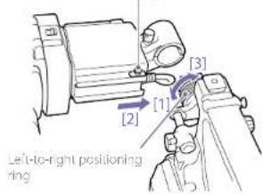
1 [1] Loosen the viewfinder left-to-right positioning ring, [2] attach the viewfinder to the viewfinder fitting shoe, and [3] tighten the viewfinder left-to-right positioning ring.
Slide stoppe
text_image
[1]
[2]
[3]
Left-to-right positioning ring
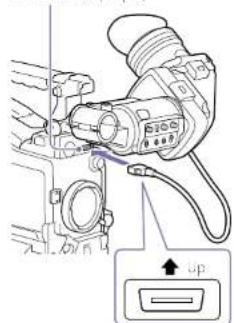
2 Couple the viewfinder connector to the VF connector (26-pin)
VF connector (26-pin)
text_image
Technical diagram of a camera with labeled components and an 'Up' button indicator
You can detach the viewfinder by following the attaching procedure in reverse order. But, when detaching the viewfinder from the attachment shoe, pull up the stopper.
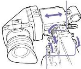
Adjusting the Viewfinder Position
To adjust the viewfinder left-right position, loosen the left-right positioning ring, and to adjust the front-back position, loosen the front-to-back positioning knob.
Viewfinder left-to-right positioning ring
natural_image
Technical line drawing of a mechanical device with directional arrows indicating motion (no text or symbols)
Viewfinder front-to-back positioning knob
Adjusting the Viewfinder Angle
You can adjust the angle of the viewfinder.
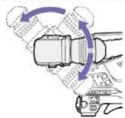
Reversing the Display (image/text indication) Vertically
The viewfinder can be rotated as much as 180 degrees toward the direction facing the subject. When you do this, the picture and other information displayed in the viewfinder appear upside down.
To restore the normal display, set the MIRROR switch on the rear panel of the viewfinder to B/T.
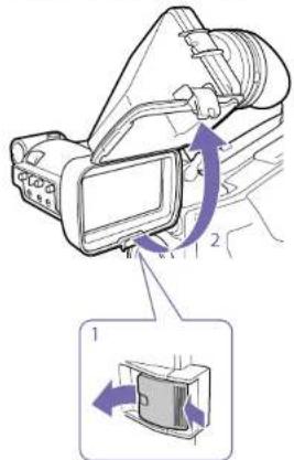
Lifting Up the Viewfinder Barrel and Eyepiece
You can view the LCD screen inside the viewfinder or its mirrored image by lifting up the viewfinder barrel or the eyepiece.
1 Push the clip on the bottom to release and flip up the viewfinder barrel.
2 It locks at the 120-degree position.
text_image
Diagram showing a device with labeled parts and directional arrows indicating motion or movement, including a zoomed-in inset view.
Normally use it in the locked position. Although you can open it farther from the lock position, you must return it to the closed position to lock it at the 120-degree position again.
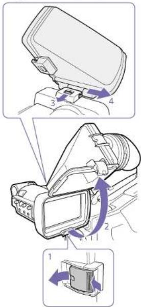
Detaching the Viewfinder Barrel
1 Push the clip on the bottom to release.
2 Flip up the viewfinder barrel
3 Slide the knob on the top to the opposite side of the viewfinder barrel.
4 Detach the viewfinder barrel by horizontally slicing it.
text_image
Diagram illustrating camera setup with labeled parts and directional arrows indicating motion or movement.
Reversing the Display (image/text indication) Horizontally
By setting the MIRROR switch on the rear panel of the viewfinder to L/R, you can reverse the picture and other information displayed in the viewfinder horizontally.
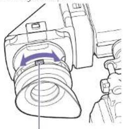
Adjusting the Diopter
Turn the diopter adjustment ring until the viewfinder image is sharpest.
natural_image
Technical line drawing of a mechanical assembly with a purple arrow indicating direction (no text or symbols)
Diopter adjustment ring
You can also attach a commercially available protection filter, close-up lens, etc. that is 52 mm in diameter.
Adjusting the Screen
Adjust the brightness, contrast, and peaking of the viewfinder screen with the controls shown below. Outlines: Adjust using the PEAKING knob. Contrast: Adjust using the CONTRAST knob. Brightness: Adjust using the BRIGHT knob.
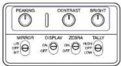
Attaching the BKW-401 Viewfinder Rotation Bracket
By fitting an optional BKW-401 Viewfinder Rotation Bracket, you can rotate the viewfinder out of the way so that your right leg does not hit the viewfinder while you are carrying the camcorder.
1 Loosen the front-to-back viewfinder positioning levers and the front-to-back viewfinder positioning knobs, and then pull the viewfinder slide assembly forward.
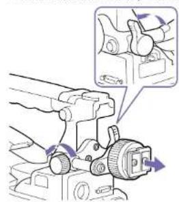
natural_image
Mechanical assembly diagram showing a clamping tool interacting with a motor (no text or symbols visible)
2 Using a 2.5 mm diameter hexagonal wrench, detach the viewfinder slide assembly.
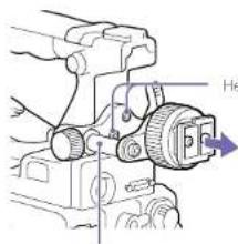
text_image
He
Hex socket bolts
Viewfinder side assembly
3 Attach the BKW-401 with the supplied bolts. Bolts supplied with the BKW-401
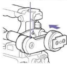
natural_image
Mechanical assembly diagram showing a clamping mechanism with no visible text or symbols
4 Adjust the front-to-back position so that the arm of the BKW-401 does not touch the handle when it is raised.
Adjust position so that arm does not touch handle
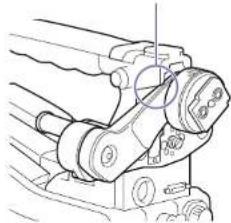
natural_image
Technical line drawing of a mechanical clamp or crimping tool (no text or symbols visible)
Using the Camcorder for the First Time
When using the camcorder for the first time, configure the following settings in the menu. For details about menu operations, see "Basic Setup Menu Operations" (page 57).
Setting the Time Zone
Set the time zone for the region of use. The default value is "UTC Greenwich."
1 Select Operation >Time Zone >Time Zone in the setup menu.
2 Select the time zone to use.
Setting the Date and Time of the Internal Clock
Set the year, month, day, and day-of-week of the internal clock.
1 Select Maintenance >Clock Set >Date in the setup menu.
The Date screen appears.
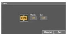
2 Turn the MENU knob to select the year, month, or day, and then press the knob. The selected year, month, or day becomes editable.
3 Turn the MENU knob to set the year, month, or day, and then press the knob.
4 Repeat steps 2 and 3 to set the remaining digits.
5 Press the SET button.
The internal clock is set to the date set in steps 2 to 4.
Next, set the time.
6 Select Maintenance >Clock Set >Time in the setup menu.
The Time screen appears.

7 Set the time in the same way as when setting the date.
8 Press the SET button.
The time is registered in the internal clock.
To cancel the setting, press the Cancel button.
Mounting and Adjusting the Lens
[Note]
When connecting or disconnecting the lens cable to this connector, power off the camcorder first.
Attaching a Lens
This section describes how to attach the lens supplied with the PXW-X400KF as an example.
1 Push the lens locking lever up and remove the lens mount cap from the lens mount.
2 Align the center pin on the lens with the center slot in the lens mount, and insert the lens into the mount.
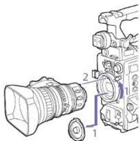
text_image
Diagram of a DSLR camera with labeled parts showing lens, aperture, and screen interface
3
Holding the lens in place, push the lens locking lever down to lock the lens.
[CAUTION]
If the lens is not firmly locked, it may come off while the camcorder is being used. This could cause a serious accident. Make sure the lens is firmly locked. It is recommended that the lens mount securing rubber be put on the lens locking lever as illustrated below.
Lens mount securing rubber
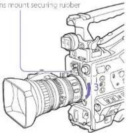
text_image
Mount securing rubber
4 Connect the lens cable to the LENS connector.
5 Secure the lens cable with the cable clamp.
If an aberration correction lens is attached
The aberration correction function is activated automatically. Starting the camcorter with an aberration correction lens may require more time than normal because of data loading at start-up. The lens supplied with the PXW-X400 is an aberration correction lens. Contact a Sony sales or service representative for information about other aberration correction lenses.
1) The aberration correction function does not operate if Maintenance >Camera Config >ALAC in the setup menu is set to Off.
Adjusting the Flange Focal Length
If the lens does not stay in focus properly as you zoom from telephoto to wide angle, adjust the flange focal length (the distance from the plane of the lens mounting flange to the imaging plane, also called flange-back).
Make this adjustment just one time after mounting or changing the lens.
When carrying out the adjustment, use a flange focal length adjustment chart as the subject.
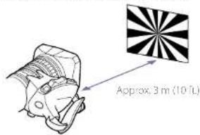
text_image
Approx. 3 m (10 mL)
Notes
- If you use a subject with insufficient contrast, or move the camcorder or subject during adjustment, this will cause an adjustment error.
- Place the subject (the flange focal length adjustment chart) so that it appears at the center of the screen at the telephoto end. Arrange it so that no nearby object (no object closer to the camera than the chart) enters the screen at the wide-angle end.
Adjusting the flange focal length on the lens supplied with the PXW-X400KC
1 Place a subject (Siemens star chart, for example) 3 m (10 ft) in front of the camera.
2 Open the iris.
The depth-of-field is reduced when the iris is open, making adjustment easier.
3 Set the lens zoom to T (telephoto).
4 Adjust the focus on the subject.
5 Set the lens zoom to W (wide angle).
6 Loosen the F.B. lock screw on the lens, and turn the F.B. adjustment ring to adjust the focus.
7 Repeat steps 3 to 6 until the proper focus is achieved at both ends of the zoom ring.
8 When the optimum position of the F.B. adjustment ring is achieved, tighten the F.B. lock screw.
Adjusting the flange focal length on the lens supplied with the PXW-X400KF
With an auto focus lens, zoom and focus operations automatically adjust the flange focal length.
1 Place the supplied focal length adjustment chart about 3 m (10 ft) in front of the camera.
2 Open the iris.
The depth-of-field is reduced when the iris is open, making adjustment easier.
3 Set the ZOOM switch to SERVO (power zoom mode).
4 Hold down the flange focal length adjustment button for 3 seconds.
The following message appears on the viewfinder screen.
Auto FB Adjust
Executing.
After successful adjustment, the message on the viewfinder screen changes to the following.
Auto FB Adjust
OK
If the flange focal length adjustment is not successful
Check the subject and lighting conditions, and repeat the adjustment.
Adjusting the flange focal length on manual lenses other than the lens supplied with the PXW-X400KC/PXW-X400KF
1 Set the iris to manual.
2 Place the supplied flange focal length adjustment chart about 3 m (10 ft) in front of the camera.
3 Open the iris.
The depth-of-field is reduced when the iris is open, making adjustment easier.
4 Loosen the fixing screws on the F.f or F.B ring (flange focal length adjustment ring).
5 Use manual or power zoom to set the lens to telephoto.
6 Point the camcorder at the chart by turning the focus ring and focus on it.
7 Set the zoom ring to wide angle.
8 Turn the E.f or F.B ring until the chart is in focus, being careful not to disturb the focus ring.
9 Repeat steps 5 to 8 until the chart stays in focus all the way from wide angle to telephoto.
10 Tighten the F.f or F.B ring fixing screws.
Connecting a Microphone to the MIC IN Connector
Attach the supplied microphone to the microphone holder of the supplied viewfinder.
1 Loosen the screw and open the microphone holder clamp.
Microphone holder clamp
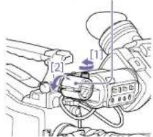
text_image
Technical diagram showing mechanical assembly with labeled parts and directional arrows indicating motion or movement
2 Place the microphone in the microphone holder.
[1] Place the microphone in the holder so that "UP" is at the top.
[2] Close the microphone holder.
[3] Tighten the screw.
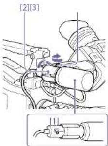
text_image
[2][3]
[1]
On how to attach the microphone, refer to the operation manual for the microphone.
3 Plug the microphone cable into the MIC IN connector, then set the AUDIO IN switch for the channel on which you want to record the audio from this microphone to FRONT.
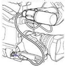
natural_image
Technical line drawing of a mechanical assembly with hoses and components (no text or symbols)
4 Secure the microphone cable with the cable clamp.
Connecting Microphones to the AUDIO IN Connectors
You can connect up to two monaural microphones to the AUDIO IN CH-1/CH-2 connectors, using an optional CAC-12 Microphone Holder.
Supported microphones: ECM-674/678 electret. condenser microphone
For details about attaching the microphone holder and microphone, refer to the instruction manual of each product.
Attaching a Wireless Receiver
To use a Sony wireless microphone system, power the camcorder off and then attach a wireless receiver.
- DWR-S02DN/DWR-S03D Digital Wireless Receiver
• URX S03D UHF Synthesized Tuner Unit
For details about attaching a wireless receiver, refer to the instruction manual of each product
Equipment
1 Connect the audio output connector of the audio equipment that supplies the line input signal to the AUDIO IN CH-1 or CH-2 connector.
2 Set the AUDIO IN selector for the channel to which the audio signal source is connected to LINE.
XLR connection automatic detect function
- With the XLR connection automatic detection function switched off (the factory default setting). Set the AUDIO IN CH1/CH2/CH3/CH4 switch to REAR for the channels to which the audio equipment is connected.
- With the XLR connection automatic detection function switched on: When a cable is connected to the AUDIO IN CH-1 or CH-2 connector, the input from that connector is automatically selected for audio recording, regardless of the setting of the AUDIO IN CH1/CH2/CH3/CH4 switch
- When the AUDIO IN selector switch is set to LINE or MIC, the type of audio recorded on audio
channels 3 and 4 does not depend on the XLR automatic detection function. It is determined by the switch selection only.
The XLR connection automatic detection function can be switched on/off using Maintenance >Audio >Rear XLR Auto in the setup menu.
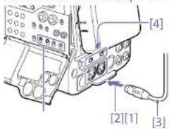
text_image
[4]
[2][1]
[3]
[1] AUDIO IN CH1/CH2/CH3/CH4 switches
[2] To AUDIO IN CH-1 or CH-2 connector
[3] Monaural microphone
[4] AUDIO IN selector switches
Attaching and Adjusting Peripheral Devices
Mounting on a Tripod
1 Attach the optional VCT-14/U14 Tripod Adaptor to the tripod.
2 Mount the camcorder on the tripod adaptor.
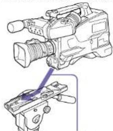
natural_image
Line drawing of a video camera and its internal components (no text or symbols)
Slide the camcorder forward along the groove in the adaptor until it clicks.
3 Make sure that the camcorder is securely attached by moving it back and forth.
To remove the camcorder from the tripod attachment, hold down the red button and pull the lever in the direction of the arrow.
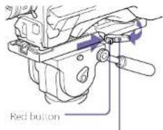
text_image
Red button
Lever
|Note|
The tripod adaptor pin may remain in the engaged position even after the camcorder is removed. If this napoens, press the red button and move the lever as shown above until the pin returns to the stowed position. If the pin remains in the engaged position, you will not be able to mount the camcorder on the tripod adaptor.
Connecting a Video Light
With this camcorder, you can use the Anton Bauer Ultralight 2 or equivalent video light (powered by 12 V with maximum power consumption of 50 W).
- If you connect the video light to the LIGHT connector on the camcorder and set the LIGIT switch to AUTO, you can turn the light on and off automatically as you start and stop recording on this camcorder.
- The output of the LIGHT connector on the camcorder is regulated to 12 V even when the camcorder is supplied with over 12 V power (through the DC IN connector or battery pack). The brightness or color temperature of the light will not change in response to voltage increase.
[Notes]
- Do not connect video lights with power consumption of 50 W or greater.
- The brightness or color temperature of the light will change when the voltage (supplied through the DC IN connector or from the battery pack) is less than 12 V.
To attach a video light, fit the video light to the accessory shoe on the camcorder grip, and connect the video light cable to the LIGHT connector.
[Note]
The accessory shoe on the camcorer is of the 1/4-inch tapped hole type. If you want to replace this with a slide-type shoe, use the supplied cold shoe k.t.
Attaching the Shoulder Strap
1 Fit one of the clips to a shoulder strap fitting. Pull up the strap to lock the fitting.
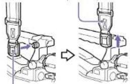
natural_image
Mechanical assembly diagram showing a valve mechanism with directional arrows (no text or labels)
Clip
2 Fit the other clip to the shoulder strap fitting on the other side of the grip in the same way.
To remove the shoulder strap, refer to the following diagram.
Press here and pull in the direction shown by the arrow to release.
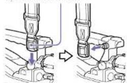
natural_image
Mechanical assembly diagram showing two stages of a tool or component being inserted (no text or symbols visible)
Adjusting the Shoulder Pad Position
You can slide the shoulder pad back and forth within a 40 mm range. This adjustment helps you get the best balance for shooting with the camcorder on your shoulder.
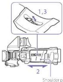
text_image
1,3
2
Shoulder pa
1 Raise the lever in the center of the shoulder pad to unlock the shoulder pad.
2 Slide the shoulder pad backward or forward until it is in the most convenient position.
3 Bring down the lever to lock the shoulder pad in the selected position.
Handling SxS Memory Cards
This camcorder records video and audio on SxS memory cards (not supplied) loaded into one or both of its memory card slots.
In addition to SxS memory cards, you can also use XQD memory cards (not supplied) with the QDA-EX1 XQD ExpressCard Adaptor (optional) or SDXC/SDHC cards (not supplied) with the MEAD-SD02 Media Adaptor (optional) in the camcorder to make recordings.
The file system supported by each type of media is given below.
Memory card File system
exFAT JDF FAT
SxS memory cards Yes Yes No
XQD memory cards Yes Yes No
SDXC cards Yes No No
SDHC cards No No Yes
About SxS Memory Cards
SxS memory cards
Use Sony SxS memory cards (SxS PRO X, SxS PRO+, SxS PRO, or SxS-1) with this camcorder.
SxS PRO X series
SxS PRO+ series
SxS PRO series
SxS-1 series
The memory cards listed above comply with the ExpressCard memory card standard.
- SxS, SxS PRO X, SxS PRO+, SxS PRO, and SxS 1 are trademarks of Sony Corporation.
• The ExpressCard label and logo are the property of the Personal Computer Memory Card International Association (PCMCIA) and are licensed to Sony Corporation. All other
trademarks and trace names are the property of their respective owners.
Inserting SxS Memory Cards
1 Slide the cover to the left to open.
2 Insert an SxS memory card into a card slot.
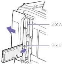
text_image
Slot A
Slot B
[Note]
Make sure to insert the SxS card in the correct orientation. Hold the card with the arrow on one side facing the direction shown in the diagram, and then insert the card.
The ACCESS indicator lights in orange, and then lights in green to indicate that the memory card is usable.
3 Close the cover.
ACCESS indicator status
Card slots A and B each have an ACCESS indicator that indicate the slot status.
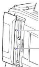
Slot A access indicator
Slot B access indicator
indicator Slot status
| Lights in orange | Accessing the 5x5 memory card (lights during data reading and writing) |
| Lights in green | Standby (the loaded 5x5 memory card is ready for recording or playback) |
| Not it No 5x5 memory card is loaded.An unusable card is loaded.An 5x5 memory card is loaded, but the other slot is selected. |
Ejecting SxS Memory Cards
1 Open the cover, and then press the EJCT button to release the lock and extract the button.
Press the button once to release the lock.
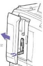
2 Press the ELECT button again to eject the card.
[No.c]
When you press the ELECT button, take care not to impede the SxS memory card. If the movement of the SxS memory card is impeded, the lock may fail to release.
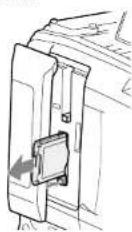
[Note]
Data integrity cannot be guaranteed if you power the camcorder off or remove a memory card while the card is being accessed. All data recorded on the card may be discarded. Always make sure that the ACCESS indicator is ill green or not ill before you power the camcorder off or remove a memory card.
Selecting the SxS Memory Card to Use
When SxS memory cards are loaded in both slot A and slot B, you can press the SLOT SELECT button to select the SxS memory card to use.
When the remaining recording time on the recording SxS memory card falls below 60 seconds, the remaining capacity indicator for the corresponding media slot flashes on the
viewfinder screen to indicate that the camcorder will switch SxS memory cards soon.
Subsequently, the camcorder switches
automatically to the other card when the selected card becomes full, and recording continues.
[Note]
The S/OI SHHC button is disabled during playback. The memory cards are not switched even if you press the button. Button operations are enabled when a thumbnail screen (page 83) is displayed.
When an unformatted SxS memory card or an SxS memory card formatted in another specification is inserted, a message notifying you that the media has a different file system appears. In this case, format the memory card in the following way. SxS memory cards are formatted in exFAT or FAT by factory default.
[Note]
SxS memory cards must be formatted on an XDCAM device that supports the exHA or UDP file system or on this camcorer. Cards in other formats cannot be used.
1 Select Operation >Format Media in the setup menu.
2 Select Media(A) (slot A) or Media(B) (slot B).
3 Turn the MENU knob to select [Execute], then press the knob.
A confirmation screen prompting whether to format the card appears.
4 Turn the MENU knob to select [Execute] on the confirmation message screen, then press the knob.
Formatting begins.
During formatting, a message is displayed, and the ACCESS indicator is lit orange.
When formatting ends, a completion message appears. Press the MENU knob to dismiss the message.
A format operation may fail because the SxS memory card is write protected, or because it is not the type of card specified for use with this camcorder.
In this case, an error message appears. Follow the instructions in the error message and exchange the card for an 5x5 memory card that can be used with this camcorder.
[Notes]
- Formatting a memory card erases all data, including recorded video data and setup files.
- Use the format function of this camicorder to format six5 memory cards for use on this camicorder. The formats of cards formatted on other devices are not recognized as valid formats, making it necessary to format them again on this camicorder.
Even while recording, the 5x5 memory card loaded in the other card slot can be formatted.
Notes
- Formatting is not supported during playback or when the thumbnail screen is displayed.
- During formatting, recording to an SixS memory card loaded in the other card slot cannot be started.
Checking the Remaining Recording Time
You can check the remaining capacity of the SxS memory cards loaded in the two slots by checking the recording media remaining capacity indicator in the viewfinder.
The remaining recording time is calculated from the remaining capacity of the media in each slot and the current video format (recording bit rate), and is displayed in units of minutes.
You can check the remaining capacity on a bar graph by displaying the Media Status screen (page 14).
Note
A mark appears when a memory card is write protected.
When to exchange SxS memory cards
- The warning message "Media Near Full" appears, the WARNING indicator and the PIC indication on the viewfinder screen flash, and the buzzer sounds when the total remaining recording time of the two memory cards falls to five minutes during recording. Exchange one of the cards for media with available recording capacity.
- If you continue recording, the message "Media Full" appears and recording stops when the total remaining recording time falls to 0.
[No]
About up to 600 clips can be recorded on one Six5 memory card.
The display of remaining recording time changes to '0' and the message "Media Full" appears when the clip limit is reached.
Restoring SxS Memory Cards
If for any reason an error should occur in a memory card, the card must be restored before use. When you load an SxS memory card that needs to be restored, a message appears in the viewfinder to ask whether you want to restore it.
To execute the restore, turn the MENU knob to select [Execute], and then press the knob. The restoration starts.
During restoration, a message is displayed, and the ACCESS indicator is lit orange.
When restoration ends, a completion message appears. Press the MENU knob to dismiss the message.
If restoration fails
- Write protected SxS memory cards and cards on which memory errors have occurred cannot be restored. A warning message appears for such cards. Follow the instructions in the message and unprotect the card or replace it with another card.
- 5x5 memory cards on which memory errors have occurred may become usable if they are reformatted.
- In some cases, some clips can be restored while others cannot. The restored clips can be played normally.
- If the message "Could not Restore Some Clips" keeps appearing after repeated attempts at restoration, it may be possible to restore the SxS memory card with the following procedure.
[1] Use the application software (page 1/2) to copy the required clips to another SxS memory card.
[2] Format the unusable 5x5 memory card on the camcorder.
[3] Copy the required clips back to the newly formatted SxS memory card.
[Note]
For restoration of media recorded with this camcorder, be sure to use this camcorder. Media recorded with a device other than this camcorder or with another camcorder of different version (even of the same model) may not be restored using this camcorder.
Handling SD Cards for Saving Configuration Data
The following SD cards can be used for saving configuration data.
SDHC memory cards* (Speed Class: 4 or higher, non-UHS, Capacity: 4 GB to 32 GB)
* Referred to as "SD cards" in this manual.
SD cards must be formatted the first time they are used in the camcorder.
SD cards for use in the camcorder should be formatted using the format function of the camcorder. If a message appears when the SD card is inserted into the camcorder, format the SD card.
1 Select Operation >Format Media >SD
Card(Utility) in the setup menu.
A confirmation screen prompting whether to
format the card appears.
2 Turn the MENU knob to select [Execute], then press the knob.
Formatting begins.
During formatting, a message is displayed, and the ACCESS indicator is lit orange.
When formatting ends, a completion message appears. Press the MENU knob to dismiss the message.
[Note]
Formatting an SD card erases all data on the card. The card cannot be restored.
Checking the Remaining Capacity
You can check the remaining capacity on an SD card on the Media Status screen (page 14). To use an SD card formatted on the camcorder in the slot of another device, make a backup of the card, then reformat the card in the device to be used.
Notes
- For professional applications, the use of other media will not provide the same high reliability and durability that is obtained using S&S memory cards.
- Not all memory cards are guaranteed to work with this camercorder. For compatible memory cards, contact your Sony dealer.
XQD Memory Cards
By using an optional QDA-EX1 XQD ExpressCard Adaptor, you can insert an XQD memory card into an SxS memory card slot and use it instead of an SxS memory card for recording and playback.
For details about using a QDA-FX1-XQO ExpressCard Adaptor, refer to the instruction manual supplied with the adaptor.
[Note]
The following operations may not be available depending on the type of XOD memory cards used.
• High-speed playback
- Slow & Quick Motion shooting
XOD memory cards must be formatted the first time they are used in the camcorder.
XOD memory cards for use in the camcorder should be formatted using the format function of the camcorder. If a message appears when the XOD memory card is inserted into the camcorder, format the XOD memory card.
If an unformatted XQD memory card or an XQD memory card that was formatted in a different specification is inserted, a message asking for confirmation to format media or a message notifying you that the media has a different file system appears.
1 Select Operation >Format Media in the setup menu.
2 Select Media(A) (slot A) or Media(B) (slot B).
3 Turn the MENU knob to select [Execute], then press the knob.
A confirmation screen prompting whether to format the card appears.
4 Turn the MENU knob to select [Execute] on the confirmation message screen, then press the knob.
Formatting begins.
During formatting, a message is displayed, and the ACCESS indicator is lit orange.
When formatting ends, a completion message appears. Press the MENU knob to dismiss the message.
[Note]
Formulating an XCD memory card erases all data on the card, including projected video. The data cannot be restored.
Connection between the camcorder and a computer
Insert the recorded XQD memory card into a slot in the camcorder, and connect the camcorder to a computer using a USB cable.
First, make a backup of the card, then reformat the card in the device to be used.
SD Cards
By using an optional MEAD-SD02 Media Adaptor, you can insert an SD card into an 5x5 memory card slot and use it for recording and playback.
[Note]
If an SD card and other media are inserted in their respective memory card slots, only the first inserted media is recognized and the last inserted media is not recognized.
The following SD cards are supported.
SDXC memory cards (SD speed class: Class 10) ^1 SDHC memory cards (SD speed class: Class 10) ^2 1) Supported if the file system is cxFAI.
2) Supported if the file system is FA ^3 .
For details about using on MLAD SDO2 Media Adaptor, refer to the instruction manual supplied with the adaptor.
[Notes]
- High-speed playback may not be properly achieved with an SD card.
- Seamless playback across clip boundaries is not supported.
- Recording and playback using SD cards is not supported when shooting in XAVC-I format.
- Slow motion recording using the Slow & Quick Motion recording function cannot be used with an SDXC card.
SD cards must be formatted the first time they are used in the camcorder.
SD cards for use in the camcorder should be formatted using the format function of the camcorder. If a message appears when the SD card is inserted into the camcorder, format the SD card. If an unformatted SD card or an SD card that was formatted in a different specification is inserted, a message asking for confirmation to format media or a message notifying you that the media has a different file system appears.
Format the card using the following procedure.
1 Select Operation >Format Media in the setup menu.
2 Select Media(A) (slot A) or Media(B) (slot B).
3 Turn the MENU knob to select [Execute], then press the knob.
A confirmation screen prompting whether to format the card appears.
4 Turn the MENU knob to select. [Execute] on the confirmation message screen, then press the knob.
Formatting begins.
During formatting, a message is displayed, and the ACCESS indicator is lit orange.
When formatting ends, a completion message appears. Press the MENU knob to dismiss the message.
[Note]
Formatting an SD card erases all data on the card, including protected video. The data cannot be restored.
Connection between the camcorder and a computer
Insert the recorded SD card into a slot in the camcorder, and connect the camcorder to a computer using a USB cable.
First, make a backup of the card, then reformat the card in the device to be used.
You can set the file system, system frequency, and video format using Operation >Format in the setup menu.
For details about menu operations, see "Basic Setup Menu Operations" (page 97).
Selecting the File System
You can select the file system.
1 Select Operation >Format >File System in the setup menu.
2 Turn the MENU knob to select a file system, then press the knob.
A confirmation screen appears.
3 Select [Execute] to execute, or select [Cancel] to cancel, and then press the MINU knob. The camcorder will reboot automatically after executing [Execute].
[Note]
The file system cannot be changed during recording/playback or while the thumbnail screen is displayed.
Switching the System Frequency
You can switch the system frequency as required.
Notes
- The system frequency cannot be changed during recording/playback or while the thumbnail screen is displayed.
- After switching between 29.97 and 59.94 or between 25 and 50, the camcorder does not reboot automatically.
- Switching the system frequency will automatically switch the video format to the format used previously at that frequency.
1 Select Operation >Format >Frequency in the setup menu.
2 Turn the MENU knob to select the system frequency, and press the knob. A confirmation screen appears.
3 Select [Execute] to execute, or select [Cancel] to cancel, and then press the MENU knob. The camcorder will reboot automatically after executing [Execute].
Refer to "Video Formats" (page 35) as required when switching the video format.
1 Select Operation >Format >Rec Format in the setup menu.
2 Turn the MENU knob to change the video format, and press the knob.
A confirmation screen appears.
3 Select [Execute] to execute, or select. [Cancel] to cancel, and then press the MENU knob.
The following recording formats can be selected for different combinations of video resolution and system frequency.
| System frequency (Operation >Format >Frequency in setup menu) | File system (Operation >Format >File System in setup menu) exFAT UDT FAT | Video format (Operation >Format >Rec Format in setup menu) | Picture size |
| 59.94/50 Yes -- XAVC-1 1920x1080P 1920x1080 |
| Yes -- XAVC-1 1920x1080i |
| Yes -- XAVC-1 1280x720P 1280x720 |
| Yes -- XAVC-L 50 1920x1080P 1920x1080 |
| Yes -- XAVC-L 50 1920x1080i |
| Yes -- XAVC-L 50 1280x720P 1280x720 |
| Yes -- XAVC-L 35 1080P 1920x1080 |
| Yes -- XAVC-L 35 1080i |
| Yes -- XAVC-L 25 1080i |
| Yes Yes - HD422 50 1080i 1920x1080 |
| Yes Yes - HD422 50 720P 1280x720 |
| Yes Yes Yes HQ 1920x1080i 1920x1080 |
| Yes Yes Yes HQ 1440x1080i 1440x1080 |
| Yes Yes Yes HQ 1280x720P 1280x720 |
| -- Yes SP 1440x1080i 1440x1080 |
| Yes Yes - MPEG IMX 50 720x486/720x576 |
| Yes Yes - DVCAM 720x480/720x576 |
| 29.97/25/23.98 | Yes -- XAVC-L 1920x1080P 1920x1080 |
| Yes -- XAVC-L 50 1920x1080P 1920x1080 |
| Yes -- XAVC-L 35 1080P |
| Yes Yes - HD422 50 1080P 1920x1080 |
| Yes Yes - HD422 50 720P 1280x720 |
| Yes Yes Yes HQ 1920x1080P 1920x1080 |
SDI OUT Connector and HDMI Output Connector Output Formats
The signals that can be output from the SDI OUT connector and HDMI output connector are shown in the following table according to the Operation >Format setting in the setup menu.
| Operation menu |
| Format Input/Output |
| Frequency Rec Format (code omitted) Output Format |
| SDI HDMI |
| 59.94 1920×1080P 1920×1080P (Level A) 1920×1080P |
| 1920×1080P (Level B) No signal |
| 1920×1080i 1920×1080i |
| 720×486i 720×480i |
| 1920×1080i 1920×1080i 1920×1080i |
| 720×486i 720×480i |
| 1440×1080i 1920×1080i 1920×1080i |
| 720×486i4 | 720×480i4 |
| 1280×720P 1280×720P 1280×720P |
| 720×486i 720×480i |
| 720×480i /20×486i /20×480i |
| No signal 720×480P |
| 29.97 1920×1080P 1920×1080PsF 1920×1080i |
| 720×486i 720×480i |
| 1280×720P 1280×720P 1280×720P |
| 720×486i 720×480i |
| 23.98 1920×1080P 1920×1080PsF | No signal |
| 1920×1080i (2-3PD) | 1920×1080i (2-3PD) |
| 720×486i (2-3PD) | 720×480i (2-3PD) |
| 1280×720P 1280×720P (2-3PD) | 1280×720P (2-3PD) |
| 720×486i (2-3PD) | 720×480i (2-3PD) |
| Operation menu |
| Format Input/Output |
| Frequency Rec Format (code omitted) Output Format |
| SDI HDMI |
| 50 1920×1080P 1920×1080P (Level A) | | 1920×1080P |
| 1920×1080P (Level B) | No signal |
| 1920×1080i | 1920×1080i |
| 720×576i | 720×576i |
| 1920×1080i 1920×1080i | | 1520×1080i |
| 720×576i | 720×576i |
| 1440×1080i 1920×1080i | | 1920×1080i |
| 720×576i* | 720×576i* |
| 1280×720P 1280×720P | | 1280×720P |
| 720×576i | 720×576i |
| 720×576i 720×576i | | 720×576i |
| No signal | 720×576i* |
| 25 1920×1080P 1920×1080P*F | | 1520×1080i |
| 720×576i | 720×576i |
| 1280×720P 1280×720P | | 1280×720P |
| 720×576i | 720×576i |
a) Switches to 1920×1060i when proxy recording or wireless LAN connection function is on.
VIDEO Connector Output Formats
The signals that can be output from the VIDEO connector are shown in the following table according to the Operation >Format setting in the setup menu.
| Operation menu VIDEO OUT signal format |
| Format |
| Frequency Rec Format (codec omitted) Proxy recording/Wireless LAN connection function |
| OFF ON |
| 59.94 1920x1080P HD-Y HD-Y | |
| HD-Y HD-Y |
| HD-Y HD-Y |
| Composite Composite |
| 1920x1080i HD Y HD Y | |
| Composite Composite |
| 1440x1080i HD-Y HD-Y | |
| Composite - |
| 1280x720P HD Sync | ^a HD Sync ^b |
| Composite Composite |
| 720x480i Composite Composite | ^c |
| Composite HD-Y |
| 29.97 1920x1080P HD-Y HD-Y | |
| Composite Composite |
| 1280x720P HD-Y | ^b HD-Y ^b |
| Composite Composite |
| 23.98 1920x1080P HD-Y | |
| HD-Y |
| HD-Y |
| Composite |
| 1280x720P HD Y | ^a HD-Y ^b |
| Composite |
| Operation menu VIDEO OUT signal format |
| Format |
| Frequency Rec Format (code omitted) Proxy recording/Wireless LAN connection function |
| OFF ON |
| 50 1920x1080P HD Y | | HD-Y |
| HD-Y | HD-Y |
| HD-Y | HD-Y |
| Composite | Composite ^3 |
| 1920x1080i HD Y | | HD Y |
| Composite | Composite ^3 |
| 1440x1080i HD-Y | | HD-Y |
| Composite | - |
| 1280x720P HD Sync | ^4 | HD Sync ^4 |
| Composite | Composite ^4 |
| 720x576i Composite | | Composite ^4 |
| Composite | HD-Y |
| 25 1920x1080P HD-Y | | HD-Y |
| Composite | Composite ^4 |
| 1280x720P HD-Y | ^b | HD-Y ^b |
| Composite | Composite ^4 |
a) 1080 sync signal output.
b) 1080Ps signal output.
c) Character information (superimposed) turns on/off in sync with the SDI OUT2/HDMI character information display switching.
Expansion of Imaging Dynamic Range
You can set the imaging dynamic range to High Dynamic Range (HDR) mode to record and output images with BT.2020 equivalent color space and increased dynamic range when the recording format is HD. This function requires the CBKZ SLHL1 HDR LICENSE (option).
[Notes]
- Not supported for MPEG IMX and DVCAM file formats.
- An SD format signal cannot be output when HDR is configured. If the signal format is SD and then HDR is selected, the image is output in the default HD format
- Change the dynamic range mode setting with the Picture Cache Rec function set to Off.
Operation >Rec Function >Picture Cache Rec >Off
assist function is automatically applied when HDR Setting >HD Rec/Out is set to HDR(HLG). You can also assign the gamma display assist function to an assignable switch, and then turn the function on/off with a single button touch as required.
[Note]
This function is applied to the image in the viewfinder and LCD monitor. It is not applied to the recorded image or output image.
Setting the Dynamic Range
1 Select Operation >Base Setting >Shooting Mode in the setup menu.
2 Turn the MENU knob to select the dynamic range mode.
Select HDR to set to High Dynamic Range or SDR to set to standard dynamic range.
Checking HDR settings
You can check the settings using Operation >HDR Setting in the setup menu. For details, see page 97.
Gamma display assist function
When the HDR(HLG) function is used, the contrast of the video shown in the viewfinder and on the LCD monitor is lower than when using conventional dynamic range, making the picture harder to see. In this case, you can adjust the contrast of the image displayed in the viewfinder and LCD monitor to an appropriate level using the gamma display assist function. The gamma display
Adjusting the Black Balance and White Balance
To ensure excellent image quality when using this camcorder, conditions may require that both the black balance and the white balance be adjusted. Black balance and white balance adjustment values that are automatically set by the camcorder and the various settings are stored in the camcorder memory and retained even when the power is turned off.
Adjusting the Black Balance
The black balance will require adjustment in the following cases.
- When the camcorder is used for the first time
- When the camcorder has not been used for a long time
- When the camcorder is used under conditions in which the surrounding temperature has changed greatly
- When the GAIN selector (L/M/H/Turbo) values have been changed with Operation >Gain Switch in the setup menu.
It is not usually necessary to adjust the black balance when using the camcorder after it has been off.
In automatic black balance mode, adjustments are performed in the following order: black set and black balance. Manual black balance adjustment can be selected from the setup menu.
Automatic black balance adjustment is disabled in the following cases.
• During recording
• During special recording modes
- When the shutter mode is SLS
1 Set the OUTPUT/DCC switch to CAM.
2 Push the AUTO W/B BAL switch to BLACK and release the switch.
The message "Executing..." appears during execution, and changes to "OK" when the adjustment finishes.
Adjustment values are saved to memory automatically.
[Notes]
- During the black balance adjustment, the nis is automatically closed.
- During the black balance adjustment, the gain selection circuit is automatically activated so you may see flickering on the viewfinder screen, but this is not a fault.
If automatic black balance adjustment cannot be made
If the black balance adjustment cannot be completed normally, an error message will appear for about three seconds on the viewfinder screen.
| Error message | Meaning |
| NG: Iris not. Closed The lens iris did not close;adjustmen, was impossible. |
| NG: Timeout Adjustment could not becompleted within thestandard number ofattempts. |
If any of the above error messages is displayed, retry the black balance adjustment.
If the error message occurs again, an internal check is necessary.
For information about the internal check, refer to the Maintenance Manual (option).
[Note]
If the lens cable is not firmly connected to the FNS connector, it may not be possible to adjust the lens iris. If this happens, the black balance will be incorrect.
Adjusting the White Balance
Always readjust the white balance when the lighting conditions change.
1 Set the switches and selectors as shown below.
- GAIN switch: L (set to a gain value that is as small as possible)
- OUTPUT/DCC switch: CAM
- WHITE BAL switch: A or B ^1
1) Adjustment values are saved to memory B only when Operation >White Setting >White Switch<0> in the setup menu is set to Memory.
2 Set the FILTER knob to suit the lighting conditions as follows.
3 Place a white test card under the same lighting conditions as the subject to be shot and zoom in on it. Alternatively, any white object such as a cloth or a wall can be used. The absolute minimum white area is as follows.
Rectangle centered on the screen
The lengths of the sides are 70% of the length and width of the screen, 10% or more of the surface area of the image within the rectangular area must be white.
[Note] Make sure there are no bright spots in the rectangle.
4 Adjust the lens iris.
Iris adjusted manually: Set the iris to an appropriate setting.
Iris adjusted using auto iris: Set the automatic/manual switch on the lens to automatic.
5 Push the AUTO W/O BAL switch to WHITE and then release the switch.
The message "Executing..." appears during execution, and changes to "OK (color temperature of subject)" when the adjustment finishes.
The adjustment values are saved automatically in the memory selected in step 1 (A or B).
[Note] The iris may hunt during the adjustment, to prevent this, adjust the iris gain knob (indicated as IG, IS, or S) on the lens.
1) Hunting: Repeated brightening and darkening of the image, resulting from repeated response to automatic iris control.
For details, refer to the lens operation manual.
If the automatic white balance adjustment cannot be made.
If the white balance adjustment cannot be completed normally, an error message will appear for about three seconds on the viewfinder screen.
| Error message Meaning |
| NG: Low Light The white video level is too low. Either open the lens iris or increase the gain. |
| NG: High Light The white video level is too high. Either stop down the lens iris or change the ND filter. |
| NG: Color Temp. High | The color temperature of the subject lighting is too high, and could not be adjusted. Adjust the color temperature of the lighting, then update memory. |
Error message Meaning
| NG: Color Temp.Low | The color temperature of the subject lighting is too low, and could not be adjusted. Adjust the color temperature of the lighting, then update memory. |
| NG: Out of Range Value could not be adjusted because the difference between the current value and reference value exceeds the adjustment range. |
| NG: Poor White Area | The white surface of the subject is too narrow, and could not be adjusted. |
| NG: Timeout Adjustment could not be completed within the specified time. |
If any of the above error messages is displayed, retry the white balance adjustment. If the error message occurs again, an internal check is necessary.
For information about this internal check, refer to the Maintenance Manual.
If you have no time to adjust the white balance
Set the WHITE BAL switch to PRST.
Changing the color temperature when the ND filter is switched
You can assign electrical CC (color correction) filters to ND filters (page 5) allowing you to change the color temperature automatically when the ND filter is switched.
1 Set Maintenance >White Filter >ND Filter C. Temp to On in the setup menu (page 115).
2 To assign an electrical CC filter to FILTER knob position number 1, select [ND FLT C. Temp<1>]. To assign it to positions 2 to 4, select [ND FLT C.Temp<2-4>].
3 Turn the MENU knob to select the desired color temperature.
4 Repeat steps 2 and 3 as required.
Switching electrical CC filters with an assignable switch
You can assign the function that switches between electrical CC filters to an assignable switch. This allows you to switch between color temperatures (3200K/4300K/5600K/6300K) that have been assigned using up to four positions (A to D) with each press of the assignable switch.
1 Select Maintenance >White Filter in the setup menu.
2 Select the position to which to assign a CC filter by selecting one of [Electrical CC] to [Electrical CC ], and then turn the MENU knob to select the desired color temperature. Select "----" with Electrical CC or selected.
When the assignable switch is pressed, the setting for that position is not displayed. For example, if "----" is set for one position, then switching between the remaining three positions is carried out.
3 Repeat step 2 as required.
4 Assign the electrical CC filter switching function (ELECTRICAL CC) to an assignable switch (page 126).
White balance memory
Values stored in memory are held until the white balance is next adjusted, even if the camcorder power is turned off.
The camcorder has two white balance memories, A and B. You can automatically save adjustment values for each ND filter in the memory that corresponds to the WHITE BAL switch setting (A or B). The camcorder has four built-in ND filters, allowing you to save a total of eight adjustment values (4x2). However, the contents of the memories are not linked to ND filter settings in the following case.
- When the number of memories allocated to each of A and B is limited to one by setting Operation >White Setting >Filter White Memory in the setup menu to Off.
Also, when Operation >White Setting >White Switch in the setup menu is set to [ATW (Auto Tracing White Balance)], and the WHITE BAI switch is set to B, the ATW function is activated to automatically adjust the white balance of the picture being shot for varying lighting conditions.
Setting the Electronic Shutter
Shutter Modes
The shutter modes that can be used with the electronic shutter and the shutter speeds that can be selected are listed below.
[Note]
When a remote control unit, such as the RM-B170, is connected, only standard mode (Speed) can be selected.
Standard mode.
Select this mode for shooting fast-moving subjects with little blurring.
You can set the shutter speed in one of two shutter modes: Speed mode, in which the speed is set in seconds, and Angle mode, in which the speed is set in degrees.
Speed mode
| System frequency | Shutler speed (r/min seconds) |
| 59.94i | 1/60, 1/100, 1/120, 1/125, 1/250, 1/300, |
| 59.94P | 1/1000, 1/2000 |
| 50i | |
| 50P | |
| 29.97P 1/40 | ^a , 1/50 ^a , 1/60, 1/100, 1/120, 1/125, 1/250, 1/300, 1/1000, 1/2000 |
| 25P 1/33 | ^a , 1/50 ^a , 1/60, 1/100, 1/120, 1/125, 1/250, 1/300, 1/1000, 1/2000 |
| 23.98P 1/32 | ^a , 1/48 ^a , 1/50 ^a , 1/60, 1/96, 1/100, 1/120, 1/125, 1/250, 1/500, 1/1000, 1/2000 |
a) This speed cannot be selected when the camcorder is in Slow & Quick Motion mode and Operation >Rec Function >Frame Rate in the setup menu is set to a value that is greater than the system frequency.
Angle mode
180°, 90°, 45°, 22.5°, 11.25°
ECS (Extended Clear Scan) mode
Select this mode for obtaining images with no horizontal bands of noise when shooting subjects such as monitor screens.
As shown in the following tables, the range of shutter speeds that can be set varies depending on whether the Slow & Quick Motion (S&Q) function is on or off.
| System frequency | Shutter speed (unit: Hz) |
| S&Q; Off S&Q; On |
| 59.94F 60.00 to 7000 — |
| 59.94P 60.00 to 8000 60.00 to 8000 |
| 29.97P 30.00 to 8000 30.00 to 8000 |
| 23.98P 23.99 to 6000 30.01 to 6000 |
| 50 P 50.00 to 7000 — |
| 50 P 50.00 to 7000 50.00 to 7000 |
| 25 P 25.02 to 7000 30.00 to 7000 |
SLS (slow speed shutter) mode
This mode is used to shoot subjects with low illumination. The number of accumulated frames shot when using the slow speed shutter function can be set to 2, 3, 4, 5, 6, 7, 8, 16 using Operation >Slow Shutter >Number of Frames in the setup menu.
[Notes]
- SLS mode cannot be used when the camcorder is in Slow & Quick Motion mode.
- It is not possible to turn the S. S mode on or off, or charge the number of accumulated frames when recording.
Setting the Shutter Mode and Shutter Speed
[Notes]
- When the automatic Iris is used, she iris opens wider as the shutter speed increases, thus reducing the depth of field.
- The selectable shutter speeds vary depending on the current system frequency.
Switching between Speed mode and Angle mode
1 Select Operation >Shutter >Mode in the setup menu.
2 Turn the MENU knob to select [Speed] or [Angle], and then press the knob.
Setting the shutter mode and shutter speed (standard mode)
Once the shutter speed is selected, it is retained even when the camcorder power is turned off.
1 Push the SHUTTER switch from ON to SELECT. The current shutter setting indication appears in the viewfinder for about three seconds.
2 Before the shutter setting in step 1 disappears, push the SHUTTER switch down to SELECT again. Repeat this step until the desired mode or speed appears.
When all modes and speeds are displayed, the display changes in the following order
Speed Mode (with system frequency 59.94i)

Note
Depending on the frame rate setting (page 52), some shutter speeds cannot be selected in Snow & Quick Motion mode. These speeds are replaced by the slowest selectable shutter speed.
Example when shooting in XAVC-I 1080P/29.97P, frame rate of 60, and Slow & Quick Motion:
- Slow & Quick Motion mode: Off
1/40→1/50→1/60→1/100→...
- Slow & Quick Motion mode: On 1/60→1/100→...
Setting the shutter speed (ECS mode)
1 Set the shutter mode to ECS (see the previous item).
2 Turn the MENU knob to select the desired frequency or number of frames.
Setting the shutter speed (SLS mode)
1 Select Operation >Slow Shutter >Setting in the setup menu and set the shutter mode to On.
2 Select Operation >Slow Shutter >Number of Frames in the setup menu and select the desired number of frames.
Setting Auto Iris
The reference value for automatic iris adjustment can be changed to aid the shooting of clear pictures of back-lit subjects, or to prevent brown-out highlights.
Setting the Auto Iris Operating Mode
Set the operating mode used when adjusting levels using auto iris.
1 Select Operation >Auto Iris >Mode in the setup menu.
2 Turn the MENU knob to select the operating mode, then press the knob.
| Operating mode | Description |
| Backlight Mode for shooting in backlight conditions |
| Standard Standard mode |
| Spotlight Mode for reducing blown out highlights when there are spotlights centered on a subject. |
Set the target convergence level for auto iris
1 Select Operation >Auto Iris >Level in the setup menu.
2 Turn the MENU knob to select the level in the range -99 to +99, then press the knob.
1 Select Operation >Auto Iris >Level in the setup menu.
2 Turn the MENU knob to select the level in the range -99 to +99, then press the knob.
| Convergence | Description |
| level |
| -99 Sets the iris 2 f-stops or more darker |
| ±0 Reference level |
| -99 Sets the iris 2 f-stops or more lighter |
Setting the auto iris speed
Set the operating speed when adjusting levels using auto iris.
1 Select Operation >Auto Iris >Speed in the setup menu.
2 Turn the MENU knob to select the speed in the range -99 (slowest) to +99 (fastest), then press the knob.
Changing the Reference Value of the Lens Iris
The reference value for the lens iris can be set within the following range with respect to the standard value.
- +0.25 to -1 (increments of 0.25): About 0.25 to 1 stop further open
- -0.25 to -1 (increments of 0.25): About 0.25 to 1 stop further closed
Also you can set the area where light detection occurs.
1 Set Operation >Auto Iris >Iris Override in the setup menu to On.
2 Set the MENU ON/OFF switch to OFF.
3 Turn the MENU knob to change the reference value.
[Note] Be sure to confirm that the current shutter model is not ECS.
The current reference value is shown by the iris position indicator (page 16) on the viewfinder screen.
- To open the iris slightly, turn the MENU knob counterclockwise as seen from the front of the camcorder.
Select one of +0.25, +0.5, +0.75, or +1.
• To close the iris slightly, turn the MENU knob clockwise as seen from the front of the camcorder.
Select one of 0.25, 0.5, 0.75, or 1.
The changed reference value is retained until the power of the camcorder is turned off. Even if the reference value is changed, it reverts to the standard value every time the power is turned on.
Setting the Auto Iris Detection Window
1 Set Operation >Auto Iris >Detect Window Indication in the setup menu to On. The current automatic Ins window appears on the viewfinder screen.
If it is not necessary to display the auto iris window on the screen, set to Off.
2 Select Operation >Auto Iris >Detect Window in the setup menu.
3 Turn the MENU knob until the desired auto iris window appears, and then press the knob.

The shaded parts indicate the area of light detection.
If you select Var, the following items become effective and you can set the window of the desired size. Set Operation >Auto Iris >Iris Var Width, Iris Var Height, Iris Var, Iris Var H Position, and Iris Var V Position in the setup menu.
| Item Setting |
| ris Var Width The width of the window |
| ris Var Height The height of the window |
| ris Var H Position | The position of the window in the horizontal direction |
| ris Var V Position | The position of the window in the vertical direction. |
When you exit the menu, the auto iris window selected in step 3 appears.
Unless you need to keep this window displayed, set Operation >Auto Iris >Detect Window Indication in the setup menu to Off.
Reducing the Effect of Bright Highlights
If the subject is too bright, the iris may close too much, leaving the overall image dark, a condition known as clipped blacks. In such cases, switching the clip highlight function on will clip the signal above a certain level, reducing the effects of the auto iris.
Set Operation >Auto Iris >CTip High Light in the setup menu to On.
Adjusting the Iris Gain on the Lens Supplied with the PXW-X400KC
1 Set the iris mode switch to the A (auto) position.
2 Flip off the rubber cap of the iris gain adjustment trimmer.
3 Turn the iris gain adjustment trimmer using a screwdriver, or similar object, to adjust the gain.
Turn clockwise to increase the gain. Turn counterclockwise to decrease the gain. Adjust while watching the iris ring on the lens body.
4 Reattach the rubber cap.
Adjusting the Focus
This section describes the focus adjustment when using the lens supplied with the PXW-X400KF.
[Note]
The lens is designed with an extra margin at the infinity position ( ), to compensate for focus drifting due to variations in temperature. When shooting a subject at infinity in MF or Full MF mode, check the picture in the viewfinder as you focus.
One-push Auto Focus
Press the PUSH AF button. The auto focus activates temporarily.
The one-push auto focus stops when the subject comes into focus.
Adjusting in Full MF Mode
When you slide the focus ring back (toward the camcorder), the focus mode is set to Full MF mode for full manual focus adjustment.
[Note]
When you slide the focus ring back, the focus instantly moves to the marker position.
Focus by turning the focus ring while viewing the viewfinder.
The distance indications on the ring are valid in Full MF mode. The distances where the picture is in focus correspond to absolute positions of the focus ring.
Peaking
You can turn the PEAKING knob on the viewfinder to use the peaking function. Edges are emphasized in the monitor picture, which facilitates manual focusing.
The recorded video signals are not affected.
MF Assist Function
When the MF assist function is on (page 125), auto focus is activated after you stop focusing using the focus ring and provides fine control adjustment of the focus of the subject in the center of the display (focus tracking).
When fine adjustment stops, the MF assist auto focus operation ends.
Adjusting in AF Mode
When you slide the focus ring forward and set the FOCUS switch to A (auto), the focus mode becomes AF mode, in which auto focus is available continuously.
The distance indications on the ring are invalid in AF mode.
Using the Focus Ring
Adjust the focus by turning the focus ring while viewing the viewfinder.
The distance indications on the ring are invalid in MF mode.
Using Macro Mode
When the focus mode is MF or AF, set the MACRO switch to the ON position to enable macro mode. Macro mode allows you to adjust the focus over a range that includes the macro area.
Macro mode is disabled in Full MF mode.
Adjusting the Audio Level
When you set the AUDIO SELECT switch to AUTO, the input levels of analog audio signals recorded on each channel are adjusted automatically. You can also make manual adjustments.
[Note]
Even if you set the AUDIO SELECT switch to AUTO, the input levels of digital audio signals are not adjusted automatically.
Target Audio Level for Manual Adjustment
Make adjustment using -20 dB as the target level. If the audio level meter shows a maximum level of 0 dB, then it indicates that the input audio level is excessive.
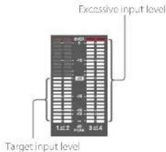
text_image
Excessive input level
Target input level
1 To adjust the signal input to the AUDIO IN CI1-1 or CI1-2 connector, set the AUDIO IN CI1-1 or CI2 switch to REAR.
To adjust both input signals, set both switches to REAR.
2 Set the AUDIO SELECT switch(es) corresponding to the channel(s) selected in step 1 to MANUAL.
3 With the LEVEL knob(s) for the channel(s) selected in step 1, adjust so that the audio level meter shows up to 20 dB for a normal input volume.
Selecting the knob used for adjusting the recording level
In Maintenance >Audio in the setup menu, you can select which audio level control controls the audio recording level of the input to each of the AUDIO IN CH-1/CH-2 connectors. The correspondences between the settings of the menu items and the controls are as follows.
[Note]
If an AES/EBU digital audio signal is input, the recording level cannot be adjusted using the camcorder.
Rear1/WRR Level: Channel 1 recording level
Setting Knob
Side1 LEVEL (CH1) knob
Front MIC LEVEL knob
Front+Side1 LEVEL (CH1) knob and MIC LEVEL knob (inked operation)
Rear2/WRR Level: Channel 2 recording level
Setting Knab
Side2 LEVEL (CH2) knob
Front: MIC LEVEL knob
Front+Side2 LEVEL (CH2) knob and MIC LEVEL knob (inked operation)
[Note]
When you have operation of the LEVEL (CI 1/CI 2) knobs and MIC LEVEL knob linked together, if the MIC LEVEL knob is set to 0, the audio signals or channels 1 and 2 cannot be recorded. Check the position of the MIC LEVEL knob before adjusting the LEVEL (CI 1/CI 2) knobs.
Manually Adjusting the Audio Level of the MIC IN Connector
1 Set either or both of the AUDIO IN switch(es) to FRONT.
2 Set the AUDIO SELECT switch(es) for the desired channel(s) selected in step 1 to MANUAL.
3 Turn the MIC LEVEL knob, and adjust so that the audio level meter shows up to 20 dB for a normal input volume.
Selecting the knob used for adjusting the recording level
In Maintenance >Audio in the setup menu, you can select which audio level control controls the audio recording level of the front microphone input. The correspondences between the settings of the menu items and the controls are as follows. MIC CH1 Level: Channel 1 recording level
Setting Knob
Side1 LEVEL (CH1) knob
Front MIC LEVEL knob
Front Side LEVEL (CHI) knob and MIC LEVEL knob (linked operation)
MIC CH2 Level: Channel 2 recording level
Setting Knob
Side2 LEVEL (CH2) knob
Front MIC LEVEL knob
Front+Side2 LEVEL (CH2) knob and MIC LEVEL knob (linked operation)
[Note]
When you have operation of the MIC1-FVH knob and I-VH (CH1/CH2) knobs linked together, if the LEVEL (CH1/CH2) knobs are set to 0, the audio signals on channels 1 and 2 cannot be recorded. Check the position of the LEVEL (CH1/CH2) knobs before adjusting the MIC1-FVH knob.
Recording Audio on Channels 3 and 4
1 Select the audio recorded on audio channels 3 and 4 with the AUDIO IN CH3/CH4 switches.
CHS switch Channel 3 recording target
FRONT Front microphone audio
REAR Audio signal input to AUDIO IN CH1 connector
WIRELESS Wireless microphone audio
CH4 switch Channel 4 recording target
FRONT Front microphone audio
REAR Audio signal input to AUDIO IN CH2 connector
WIRELESS Wireless microphone audio
2 To adjust automatically, set the AUDIO SELECT CH 3-4 switch to AUTO.
To adjust manually, set the AUDIO SELECT CH 3-4 switch to MANUAL.
3 Select the knobs that adjust the audio levels with the Audio CH3 Level and Audio CH4 Level items under Maintenance >Audio in the setup menu.
Audio CH3 Level Channel 3 recording level
Setting Knob
Side3 LEVEL (CH3) knob
Front MIC LEVEL knob
- Settings and Adjustments: Adjusting the Audio Level
Setting Knob
Front1 Side3 LEVEL (CH3) knob and MIC
LEVEL knob (linked operation)
Audio CH4 Level: Channel 4 recording level
Setting Knob
Side4 LEVEL (CH4) knob
Front MIC LEVEL knob
Front+Side4 LEVEL (CH4) knob and MIC
LEVEL knob (linked operation)
You can now adjust the levels of audio channels 3 and 4 with the knobs selected here.
Setting Time Data
Setting the Timecode
The timecode setting range is from 00:00:00:00 to 23:59:59:29 (hours:minutes:seconds:frames).
1 Press the DISP SEL/EXPAND button to switch the display in the LCD monitor to status display.
2 Set the DISPLAY switch to TC.
3 Set the PRESET/REGEN/CLOCK switch to PRESET.
4 Set the F-RUN/SET/R-RUN switch to SET. The first (leftmost) digit of the timecode flashes.
5 Use the up and down arrow buttons to change values, and use the left and right arrow buttons to move the flashing digit. Repeat until all digits are set.
To reset the value to 00:00:00:00, press the RESET/RETURN button.
6 Set the F-RUN/SET/R-RUN switch to F-RUN or R-RUN.
F-RUN: Free run (timecode generator keeps running)
R-RUN: Recording run (timecode generator runs only while recording)
[Note]
When Picture Cache Rec mode is active, time data cannot be set by switching the F-RUN/SET/R-RUN switch to SET. To set time data, turn Picture Cache Rec mode off.
Switching between DF and NDF
You can select the drop frame (DF) mode or non-drop frame (NDF) mode using Maintenance >Timecode >DF/NDF in the setup menu.
To make the timecode consecutive
When the F-RUN/SET/R-RUN switch is set to R-RUN, recording a number of scenes on the media normally produces consecutive timecode. However, once you remove the media and record on another media, the timecode will no longer be consecutive when you use the original media again for recording
In this case, to make the timecode consecutive, set the PRESET/REGEN/CLOCK switch to REGEN.
Saving the real time in the timecode
Setting the PRESET/REGEN/CLOCK switch to CLOCK saves the real time in the timecode. The time of the camcorder internal clock is applied as the real time.
For details about adjusting the internal clock, see "Setting the Date and Time of the Internal Clock" (page 25).
Setting the User Bits
By setting the user bits (up to 8 hexadecimal digits), you can record user information such as the date, time, or scene number on the timecode track.
1 Press the DISP SEL/EXPAND button to switch the display in the LCD monitor to status display.
2 Set the DISPLAY switch to U-BIT.
3 Set the F-RUN/SET/R-RUN switch to SET. The first (leftmost) digit flashes.
4 Use the up and down arrow buttons to change values, and use the left and right arrow buttons to move the flashing digit. Repeat until all digits are set
To reset the value to 00 00 00 00, press the RESET/RETURN button.
5 Set the F-RUN/SET/R-RUN switch to F-RUN or R-RUN, corresponding to the desired operating mode for the Timecode generator.
User bit memory function
The user bit setting (apart from the real time) is automatically retained in memory even when the power is turned off.
Synchronizing the Timecode to an External Source
You can synchronize the internal timecode generator of this camcorder with an external generator. You can also synchronize the timecode generators of other camcorders/VTRs with the internal generator of this camcorder.
1 Connect both the reference video signal and the external Limecode as illustrated below. Example 1: Synchronizing with an external signal

text_image
[2][1]
External timeframe
Reference video signal
[1] GENLOCK IN connector
[2] TCIN connector
Example 2: Interconnecting a number of camcorders with one camcorder as reference
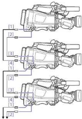
text_image
[1]
[2]
[3]
[4]
[1]
[2]
[3]
[4]
[1]
[2]
to next camccorder
11 VIDEO OUT connector
21 TC OUT connector
[3] TC IN connector
[4] GENLOCK IN connector
2 Turn on the POWER switch.
3 Set the PRESET/REGEN/CLOCK switch to PRESET.
4 Set the F-RUN/SET/R-RUN switch to F-RUN.
5 Set the DISPLAY switch to TC.
6 Supply a timecode signal and a reference video signal, complying with the SMPTE standard and in proper phase relationship, to the TC IN connector and to the GENLOCK IN connector, respectively. This operation synchronizes the internal
timecode generator with the external
timecode. Once about ten seconds have
elapsed after the timecode locks, the external
lock state is maintained even if the external
timecode source is disconnected.
To release the external synchronization, first stop the external timecode input, then set the F-RUN/SET/R-RUN switch to R-RUN.
[Notes]
- When you finish the above procedure, the internal timecode is immediately synchronized with the external timecode and the time data display will show the value of the external timecode. However, wait for a few seconds until the sync generator stabilizes before recording.
- If the frequency of the reference video signal is not the same as the system frequency of the camcorder, the camcorder cannot be correctly genlocked. If this occurs, the timecode will not acquire successful lock with the external timecode.
User bit settings during synchronization
When the timecode is synchronized to an external signal, only the time data is synchronized with the external timecode value.
Note on changing the power supply from the battery pack to an external power supply during external synchronization
To maintain a continuous power supply, connect the external power supply to the DC IN connector before removing the battery pack. You may lose timecode external synchronization if you remove the battery pack first.
Camcorder genlock during external synchronization
During external synchronization, the camcorder is genlocked to the reference video signal input from the GENLOCK IN connector.
Basic Operations
This section explains the basic shooting and recording procedures.
Before starting to shoot, inspect the camera system to verify that it is operating properly.
1 Attach a fully charged battery pack (page 23).
2 Load one or two SxS memory cards (page 31).
If you load two cards, the camcorder switches automatically to the second card when the first card becomes full.
3 Set the camcorder's POWER switch (page 3) to ON.
4 Make the following settings.
Marker display: On (page 100)
Iris: Auto (page 42)
Zoom: Auto
Camera output: Select the picture currently being shot (camera picture), and turn the DCC function on (page 6)
Timecode advance mode: F-RUN (Free Run) or R-RUN (Rec Run) (page 47)
Audio input channel selection: Auto (page 9)
5 Push the AUTO W/B BAL switch to the BLACK position to adjust the black balance (page 39).
6 Select a filter according to the lighting conditions, and adjust the white balance (page 39).
7 Point the camcorder at the subject, and adjust the focus and zoom.
8 If you are using the electronic shutter, select an appropriate shutter mode and speed (page 41).
9 Do one of the following to start recording.
- Press the REC START button (page 4).
- Press the VTR button on the lens.
- Turn on the assignable switch to which the Rec function has been assigned (page 124).
During recording, the TALLY indicators, the tally indicator on the front panel of the viewfinder, and the REC indicator on the viewfinder screen light. Adjust the zoom and focus as required.
[Notes]
- Never remove the battery pack while the camcorder is recording (while the ACCESS indicator on the right side panel is lit in blue and the ACCESS indicator in the card slot section is lit in orange). Doing so risks the loss of several seconds of data before the recording was interrupted, because internal processing will not end normally.
- The playback control buttons (FJ-Cl, F REV, F HWD, NEXT, PREV, FLAY/PAUSE, STOP) do not function during recording.
10 To stop recording, perform one of the operations listed in step 9.
The TALLY indicators, the tally indicator on the front panel of the viewfinder, and the REC indicator on the viewfinder screen go out, and camcorder enters recording standby (Stby) mode.
A clip is created from the video and audio data and the metadata recorded between steps 9 and 10.
To review the recording (rec review)
With the camcorder in recording standby mode, press an assignable switch assigned with the Rec Review function to play back the last two seconds of the clip at normal speed. Press and hold an assignable switch assigned with the Rec Review function for one second or longer to start play back from the frame two seconds prior to the last frame at four times speed in the reverse direction. Then, release the button to play the clip from that point at
normal speed. The clip is played to the end, then Rec Review ends and the camcorder returns to Stby mode.
When the Rec Review function is assigned to the RET button on the lens, you can also conduct a review by using the RET button.
11 Repeat steps 9 and 10 to continue recording. With each repetition, another clip is created on the memory card.
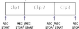
[Notes]
- You cannot resume recording for about one second after stopping recording.
- The maximum number of clips that can be recorded on one memory card is 600. Even if the memory card has enough free capacity to record more clips, when 600 clips have been recorded, no further recording is possible.
- Clips shorter than 2 seconds cannot be created. For example, even if recording is started and then stopped within 2 seconds, the recording continues for a duration of 2 seconds. Also, if recording is started, immediately stopped, and then restarted within 2 seconds of the initial recording start, two clips are created.
- The maximum continuous recording time spanning several memory cards is 24 hours. When 24 hours have elapsed, recording stops.
Clip names
Eight-character clips names (consisting of a four-character prefix and a four-digit number) are generated automatically for clips recorded by this camcorder.
Example: ABCD0001
You can also use Operation >Clip >Title Prefix in the setup menu to set the clip name prefix to a user specified string of characters (four to 46 characters in length). (A user specified prefix cannot be changed after recording.) The four-digit number at the end of clip names is generated automatically, incrementing as clips are recorded.
Playing Recorded Clips
1 Insert the SxS memory card to play (page 31).
2 Press the PREV button (page 8) or the F REV button (page 7) to cue up the clip to play.
3 Press the PLAY/PAUSE button.
The PLAY/PAUSE indicator lights, and the playback picture appears in the viewfinder.
Seamless playback
Seamless playback across clip boundaries is supported if each clip recorded on an SxS PRO+, SxS PRO X, or XQD-G series memory card has the following status.
- Video format is XAVC-I/XAVC-L and clip length is 4 seconds or longer
• Video format is MPEG HD and clip length is 2 seconds or longer
[Notes]
- For SxS-1 cards, double the length described above is required.
- Seamless playback not supported for SD cards.
Pausing playback
Press the PLAY/PAUSE button.
The PLAY/PAUSE indicator flashes while play is paused.
Press the button again to return to play mode.
High-speed playback
Press the F FWD button (page 8) or the F REV button (page 7).
To return to normal playback, press the PLAY/PAUSE button.
Stopping playback
Press the STOP button: Playback stops, and the camcorder enters E-E mode.
Press the THUMBNIL button: Playback stops and the thumbnail screen (page 83) appears in the viewfinder.
Playback also stops and the timecode screen appears in the viewfinder when you start recording during playback, and when you eject an SxS memory card.
Switching between memory cards
When two memory cards are loaded, press the SLOT SELECT button (page 31) to select the active slot.
It is not possible to switch between memory cards during playback.
Advanced Operations
Recording Shot Marks
On this camcorder, two types of shot marks are available. You can record them at user specified positions to make it easier for editors to cue up those positions.
The maximum number of shot marks per clip is 999.
You can also use the Thumbnail menu to add and delete shot marks in clips. For details, see "Adding/Deleting Essence Marks in Clips" (page 8/).
To record shot marks, turn on an assignable switch assigned with the Shot Mark 1 or Shot Mark 2 function.
When a shot mark is recorded, a "Shot Mark 1" or "Shot Mark 2" indication appears in the viewfinder for about three seconds near the timecode indicator.
[Note]
An SD card inserted in an SxS card slot using the MEAD-SD02 Media Adaptor (option) cannot be used for recording.
Setting Clip Flags
To make it easier for editors to select good clips, you can set clip flags in recorded clips.
Clip flags are set in the Thumbnail menu. For details, see "Adding Clip Flags to Clips" (page 8/7) and "Deleting a Clip Flag" (page 8/7).
[Note]
An SD card inserted in an SxS card slot using the MEAD-SD02 Media Adaptor (option) cannot be used for recording.
Recording Retroactive Images (Picture Cache Rec Function)
The camcorder always maintains a cache of video and audio data for a set interval (maximum of 15 seconds) in internal storage memory when shooting, allowing you to record several seconds of footage before the start of recording. For details about the video formats supported for this function, see "Special Recording Support by Recording Format" (page 164).
To start recording in Picture Cache Rec mode, Picture Cache Rec mode and the storage time of images in memory (Picture Cache Rec time) must be set beforehand in the Operation menu. When recording is started, the duration of footage that can be recorded retroactively is determined by the Picture Cache Rec time. The duration that can be recorded retroactively may be reduced in some circumstances, as described in [Notes] below.
[Notes]
- The storage of video in memory starts when Picture Cache Rec mode is selected. However, if recording is started immediately after selecting this mode, a portion of the images shot immediately prior to selecting Picture Cache Rec mode will not be recorded.
- Images are not stored in memory during playback, recording review, or thumbnail display, so recording of images during these periods is not supported.
Setting the Picture Cache Rec time
1 Select Operation >Rec Function >Picture Cache Rec in the setup menu.
2 Turn the MENU knob to select [On], then press the knob.
3 Select Operation > Rec Function > Cache Rec Time in the setup menu.
4 Turn the MENU knob to select the Picture Cache Rec time setting, then press the knob. The options will vary depending on the recording format and system frequency settings. See "Picture Cache Rec Mode Settings" (page 165) in the Appendix.
Once Picture Cache Rec mode is selected, it is maintained until the settings are changed. Alternatively, instead of performing steps 1 and 2, you can also select Picture Cache Rec mode using an assignable switch (page 124) which has been assigned with the Picture Cache Rec function.
[Notes]
- Only one special recording function, such as Picture Cache Res, can be used at any one time.
If another special recording mode is enabled while Picture Cache Rec is in use, Picture Cache Rec is automatically released.
- Changing system settings, such as the video format, clears all images stored in memory. Consequently, images shot just before changing settings cannot be recorded, if recording is started immediately after changing settings. Picture Cache Rec mode is automatically released.
- The Picture Cache Rec time cannot be set during recording.
Starting Picture Cache Rec recording
Shoot as described in "Basic Operations" (page 49).
When recording starts, the "Cache" indication in the viewfinder changes to the "Rec" indication. The TALLY indicators and the tally indicator on the front panel of the viewfinder light as they do during normal recording.
To exit, stop the recording.
Canceling Picture Cache Rec mode
In recording standby mode, set Operation >Rec Function >Picture Cache Rec in the setup menu to Off.
Device operation when recording in Picture Cache Rec mode
The recording procedure is essentially the same, except for the following points where operation varies from normal.
- If recording is started while accessing media, the actual start point of recording may be delayed even longer than the set Picture Cache Rec time. The delay increases with the number of recorded clips, so stopping recording and quickly restarting recording should be avoided in Picture Cache Rec mode.
- Regardless of the setting of the F-RUN/SET/R-RUN switch, the camcorder operates in F-RUN mode.
- In Picture Cache Rec mode, time data cannot be set by switching the F-RUN/SET/R-RUN switch to SET.
To set time data, first stop Picture Cache Rec mode.
- If the remaining recording time of the media in the currently selected slot is shorter than the Picture Cache Rec time, images are recorded to the media (if there is sufficient remaining recording time) in the non-selected slot. However, images are not recorded if there is no media in the non-selected slot or if the media in the slot has insufficient remaining recording time. (A message notifying you that there is insufficient remaining recording time will appear on the viewfinder screen.)
- Shot marks are not recorded, even if the shot marks are set before the recording start operation.
If the camcorder is turned off during recording
- If the POWER switch on the camcorder is set to the OFF position, the media is accessed for several seconds to record the images stored in memory up till that moment, and then the power turns off automatically.
- If the battery is removed, the DC cable disconnected, or the AC adaptor turned off
during recording, the video and audio data stored in memory is erased, and images up till that point are not recorded. Care should be exercised when exchanging the battery.
Recording Time-lapse Video (Interval Rec Function)
The camcorder's Interval Rec function allows you to capture time-lapse video to the camcorder's internal memory. This function is an effective way to shoot slow-moving subjects.
When you start recording, the camcorder automatically records a specified number of frames at a specified interval time.
This function is enabled when the camcorder is set to any of the following video formats (page 35):
XAVC-I
XAVC-L
MPI.G HD 422
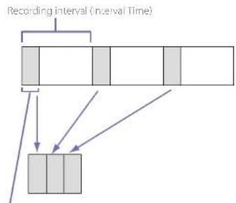
flowchart
graph TD
    A["Recording interval (interval Time)"] --> B["1"]
    A --> C["2"]
    A --> D["3"]
    A --> E["4"]
    A --> F["5"]
    B --> G["3"]
    C --> H["4"]
    D --> I["5"]
    E --> J["6"]
    F --> K["7"]
Number of frames in one take (Number of Frames)
A pre-lighting function is available when Interval Rec is enabled. This function automatically turns on the video light before recording starts, which
allows you to record pictures under stable light and color temperature conditions.
[Notes]
- Only one special recording function, such as Interval Rec recording, can be used at any one time. If another special recording mode is enabled while Interval Rec is in use, for example, Interval Rec is automatically released.
- Interval Rec settings cannot be changed during recording
Setting Interval Rec
1 Select Operation >Rec Function >Interval Rec in the setup menu.
2 Turn the MENU knob to select [On], then press the knob.
The camcorder enters interval Rec mode, and "Int Siby" appears at the REC indicator position on the viewfinder screen. (The green tally indicator in the HDVF series viewfinder also flashes.)
3 Select [Number of Frames], turn the MENU knob to select the number of frames to record in one take, and then press the knob.
You can select 2, 6, or 12 when the format is 50P or 59.9P.
You can select 1, 3, 6, or 9 when the format is 23.98P, 25P, 29.97P, 50I, or 59.94I.
4 Select [Interval Time], turn the MENU knob to select the desired interval, and then press the knob.
You can select 1 to 10/15/20/30/40/50 sec, 1 to 10/15/20/30/40/50 min, or 1 to 4/6/12/24 hour.
5 As required, select [Pre-Lighting], turn the MENU knob to select the length of lighting time before recording starts, and then press the knob.
You can select 2, 5, 10 seconds, or Off.
[Notes]
- If you want to turn the video light on before the start of recording, set the camcorder's LIGHT switch to AUTO. The video light switch must also be turned on. When this is done, the video light turns on and off automatically. However, the video light remains lit if the time that it would be off is five seconds or less.
- If you set the LIGHT switch to MANUAL and turn the video light switch on, the video light is always lit. (The video light does not turn on and off automatically.)
The camcorder exits Interval Rec mode when it is powered off, but the number of frames, interval time, and pre-lighting settings are maintained. You do not need to set them again the next time you shoot in Interval Rec mode.
Starting Interval Rec recording
Make the settings and preparations described in "Basic Operations" (page 49), secure the camcorder so that it does not move, and begin shooting.
When Interval Rec mode is set to On, "Int Stby" appears at the REC position on the viewfinder screen. When you start recording, "●Int Rec" and
"Int Stay" are displayed alternately. The TALLY indicators and the tally indicator on the front panel of the viewfinder light as they do during normal recording. (The green tally indicator in the IIDVF series viewfinder also flashes at high speed.) If you are using the pre-lighting function, the video light comes on before recording starts.
To exit, stop the recording.
When shooting ends, the video data stored in memory up to that point is written to the media.
Canceling Interval Rec mode
Do one of the following
- Set the POWER switch to OFF.
- In recording standby mode, set Operation >Rec Function >Interval Rec in the setup menu to Off.
[Note]
Restarting the carreorder automatically releases Interval Rec mode
Limitations during recording
- Regardless of the setting of the F-RUN/SET/R RUN switch, the advance mode of the internal timecode generator is always R-RUN.
- Audio is not recorded.
- Reviewing the recording (Rec Review) is not possible.
• Genlock is not possible
If the camcorder is turned off during recording
- If the POWER switch on the camcorder is set to the OFF position, the media is accessed for several seconds to record the images stored in memory up till that moment, and then the power turns off automatically.
- If power is lost because the battery was removed, the DC power cord was disconnected, or the power was turned off on the AC adaptor side, then the video and audio data shot up to that point may be lost (maximum 10 seconds). Care should be exercised when exchanging the battery.
Shooting with Slow & Quick Motion
You can specify a recording frame rate that is different from the playback frame rate.
[Note]
When shooting in XAVC recording format, use SxS PRO+ type SxS memory cards.
| Recording format | System frequency S&Q frame rate |
| XAVC-L 1080P | 59.94P/50P/29.97P/23.98P/25P | 1 FPS to 60 FPS(1 FPS units) |
| XAVC-L 501080P | 59.94P/50P/29.97P/23.98P/25P | |
| XAVC-L 351080P | 59.94P/50P/29.97P/23.98P/25P | |
| HD422 501080P* | 29.97P 1 FPS to 30 FPS23.98P | (1 FPS units) |
| 25P 1 FPS to 25 FPS | (1 FPS units) |
e) Supported for ex-A1 and UID files systems. Only ex-A1 is supported for other recording formats.
By shooting with a frame rate that differs from the playback frame rate, you can obtain slow and quick motion effects that are smoother than low-speed or high-speed playback of content recorded at the normal frame rate
Setting Slow & Quick Motion
1 Select Operation >Rec Function >Slow & Quick Motion in the setup menu.
2 Turn the MENU knob to select [On], then press the knob.
Slow & Quick Motion starts, and "S&Q S/by" appears in the recording status indicator area in the viewfinder.
Next, set the frame rate.
3 Select Operation >Rec Function >Slow & Quick Motion >Frame Rate in the setup menu.
4 Turn the MENU knob to select the frame rate, then press the knob.
When you finish making these settings, the system frequency and the frame rate appear at the top of the viewfinder screen. You can change the frame rate while viewing the display in the viewfinder by turning the MI NU knob.
The Slow & Quick Motion mode setting and the frame rate are retained even after the camcorder is powered off.
[Notes]
- Only one special recording function, such as Slow & Quick Motion, can be used at any one time.
- If another special recording function is enabled while using Slow & Quick Motion, Slow & Quick Motion is automatically canceled.
- Slow & Quick Motion cannot be set during recording, playback, or while the thumbnail screen is displayed.
- Slow & Quick Motion cannot be set if the slow shutter function is set.
Starting Slow & Quick Motion recording
Shoot as described in "Basic Operations" (page 49)
When recording starts, the "S&Q Stby" indication in the viewfinder changes to the "●S&Q Rec" indication. The TALLY indicators and the tally indicator on the front panel of the viewfinder light as they do during normal recording.
To exit, stop the recording.
[Note]
It takes longer than normal for recording to stop when the frame rate is set to a low value (for a slow frame rate).
Canceling Slow & Quick Motion mode
With the camcerder in recording standby mode, set Operation >Rec Function >Slow & Quick in the setup menu to Off.
Limitations during recording
- Regardless of the setting of the F-RUN/SET/R RUN switch, the advance mode of the internal timecode generator is always R-RUN.
• Audio cannot be recorded when the recording and playback frame rates differ.
- Reviewing the recording (Rec Review) is not possible.
- If you change the recording frame rate to a value faster than the current shutter speed, the shutter speed is changed to the slowest value for which shooting is possible.
Example: If the frame rate is 32 and the shutter speed is 1/40, and you change the frame rate to 55, then the shutter speed is changed to 1/60. It is not possible to select a shutter speed that is slower than the recording frame rate.
- Genlock is not possible.
Recording with the Clip Continuous Rec Function
Normally, a clip is created as an independent file each time that you start and stop recording. But this function allows you to start and stop recording while continuously recording to the same clip, for as long as the function remains enabled. This is convenient when you do not want to generate a large number of short clips, and when you want to record without worrying about exceeding the clip limit.
It is still easy to find recording start points, because a Rec Start essence mark is recorded at the recording start point each time you start recording. This function is enabled when the camcorder is set to any of the following video formats (page 35).
XAVC-I
XAVCI
MPEG HD 422
Setting Clip Continuous Rec
1 Select Operation >Rec Function >Clip Continuous Rec in the setup menu.
2 Turn the MENU knob to select [On], then press the knob.
"Cont Stay" appears in the viewfinder, and the function is enabled.
[Notes]
- Only one special recording function, such as Clip Continuous Rec, can be used at any one time.
- If another special recording mode is enabled while Clip Continuous Rec is in use, for example, the currently selected mode is automatically released.
You can assign the Clip Continuous Rec on/off function to one of the ASSIGN. 1/2/3 switches, ASSIGNABLE 4/5 switches, or the ONLINE button.
For details, see "Assigning Functions to Assignable Switches" (page 124).
Starting Clip Continuous Rec recording
Shoot as described in "Basic Operations" (page 49).
When recording starts, the "Cont Stby" indication in the viewfinder changes to "●Cont Rec" indication.
The TALLY indicators and the tally indicator on the front panel of the viewfinder light as they do during normal recording.
[Note]
During recording or in recording standby mode (when "Cont Stay" indication is displayed), if you remove the media, the battery, or the power source, the media needs to be restored. It is not possible to restore media on a device other than this camconder.
Exit C tip Continuous Rec mode (page 54) and then remove the media.
When "Cont Stay" indication is flashing (once per second), you can remove the media.
To exit, stop the recording.
Incl
Stop the recording after recording for two or more seconds.
Canceling Clip Continuous Rec mode
With the camcorder in recording standby mode, set Operation >Rec Function >Clip Continuous Rec in the setup menu to Off.
Limitations during recording
A single continuous clip cannot be created if you perform one of the following operations while the camcorder is in recording or recording standby mode. (A new clip will be created when you next start recording.)
- Operate on a clip (lock, delete, or rename a clip)
- Switch slots
- Change the recording format
- Turn off the POWER switch
- Playback
- Switch to the thumbnail screen
Recording Video Simultaneously to Two SxS Memory Cards (Simul Rec)
When the video format (page 35) is set to one of the options in the following table, you can record the same video to two SixS memory cards. This function is useful for making a video backup while shooting.
[Notes]
| Operation >Format | Operation >Format |
| >Rec Format in the setup menu | >Frequency in the setup menu |
| XAVC-1 1920×1080P 59.94/59/29.97/25/23.98 |
| XAVC-1 1920×10801 59.94/50 |
| Operation >Format>Rec Format in the setup menu | Operation >Format>Frequency in the setup menu |
| XAVC L 501920×1080P | 59.94/50/29.97/25/23.98 |
| XAVC-L 501920×1080I | 59.94/50 |
| XAVC-L 50 1280×720P 59.94/50 |
| XAVC-L 35 1080P 59.94/50/29.97/25/23.98 |
| XAVC-L 35 1080I 59.94/50 |
| XAVC-L 25 1080I 59.94/50 |
| HD 422 50 1080P 29.97/25/23.98 |
| HD 422 50 1080I 59.94/50 |
| HD 422 50 720P 59.94/50/29.97/25/23.98 |
| HQ 1920×1080P 29.97/25/23.98 |
| HQ 1920×1080I 59.94/50 |
| HQ 1440×1080I 59.94/50 |
| HQ 1280×720P 59.94/50 |
Setting Simul Rec
1 Select Operation >Rec Function >Simul Rec in the setup menu.
2 Turn the MENU knob to select [On], then press the knob.
[Notes]
- Only one special recording function, such as Simul Rec,
can be used at any one time.
- If another special recording mode is enabled while using
Simul Rec, Simul Rec is automatically released.
- Simul Rec cannot be set during recording, playback, or while the thumonell screen is displayed.
Starting Simul Rec recording
1 Insert SxS memory cards in both memory slots A and B.
The ACCESS indicators for Sx5 slots A and B are lit. Also, icons for Sx5 slots A and B appear in the viewfinder (page 18).
2 Shoot as described in "Basic Operations" (page 49).
Notes
- Simultaneous recording is not possible if either of the media is defective or if the media is write protected.
- During simultaneous recording, if either of the media becomes full or an error occurs and recording cannot continue, recording to that media stops but recording to the other media continues.
To exit, stop the recording
Canceling Simul Rec mode
In recording standby mode, set Operation >Rec Function >Simul Rec in the setup menu to Off.
Proxy Data
Proxy data is made up of low-resolution video data (HL264) and audio data (AAC-LC). This lightweight proxy data can be used in the same way as the original data, but it can be transferred more quickly, for more efficient viewing and editing. During clip recording, proxy data is recorded onto the SD card inserted into the PROXY SD card slot.
PROXY SD card slot
By importing proxy data recorded on the SD card into a computer, you can quickly check the recorded content or perform rapid offline editing. You can record proxy data not only simultaneously when recording on SxS memory cards, but also independently from recording to SxS memory cards.
Proxy Recording using the Camcorder
- When recording simultaneously, proxy recording will not start unless an SxS memory card is inserted.
- When the camcorder has been turned on for about 35 seconds, the Proxy icon (media status indicator for Proxy SID slot) turns on in the LCD monitor and viewfinder screen to indicate that proxy recording is enabled. If you start shooting while the Proxy icon is flashing or is not lit, proxy files are not recorded
- Before removing an SD card from the camcorder, always check that the ACCESS
indicator for the PROXY SD card slot is not lit, then turn off the camcorder or turn off the proxy recording/wireless LAN connection function. To turn off the proxy recording/wireless LAN connection function, make the following settings in the setup menu
- Set Operation >Proxy Recording Mode >Setting to Off.
- Set Maintenance >Network >Setting to
- Attempting to remove the SD card while either the proxy recording or wireless LAN connection function is enabled may display a warning (191 100) in some cases. If the warning appears while recording, data is still recorded correctly to the 5x5 memory cards, but proxy files are not recorded. The warning message can be cleared by turning the camcorder off and then on again
- Proxy recording will not start if Picture Cache Rec, Interval Rec, Slow & Quick Motion, or streaming is enabled.
SD Cards
SD cards supported for recording proxy data
- SDHC memory cards ^x (Speed Class: 4 or higher, non-UHS, Capacity: 4 GB to 32 GB)
- SDXC memory cards* (Speed Class: 4 or higher, non-UHS, Capacity: 64 GB to 256 GB)
* Referred to as "5D cards" in this manual.
SD cards must be formatted the first time they are used in the camcorder.
SD cards for use in the camcorder should be formatted using the format function of the camcorder. If a message appears when the SD card is inserted into the camcorder, format the SD card.
1 Select Operation >Proxy Recording Mode >Setting in the setup menu.
2 Turn the MENU knob to select [On], then press the knob.
3 Select Operation >Format Media >SD Card(Proxy) in the setup menu.
4 Turn the MENU knob to select [Execute], then press the knob.
A confirmation screen prompting whether to format the card appears.
5 Turn the MENU knob to select [Execute], then press the knob.
Formatting begins.
During formatting, a message and progress state (%) is displayed and the ACCLSS indicator is lit orange.
When formatting ends, a completion message appears. Press the MENU knob to dismiss the message.
[Note]
Formatting an SD card erases all data on the card. The card cannot be restored.
Checking the remaining recording capacity
You can check the remaining capacity on an SD card on the Media Status screen (page 14).
First, make a backup of the card, then reformat the card in the device to be used.
Recording Proxy Data
To record proxy data simultaneously
You can record proxy data to an SD card simultaneously as the recording to SxS memory cards.
1 Select Operation >Proxy Recording Mode >Setting in the setup menu.
2 Turn the MENU knob to select [On], then press the knob.
3 Insert an SD card for recording proxy data into the PROXY SD card slot.
4 Start recording
The proxy data file is saved in the */PRIVATE/PXROOT/Clip* directory of the SD card at the same time as the original data is being recorded onto an SxS memory card.
Proxy data recording automatically stops when you stop recording.
To record proxy data separately from recording original data
You can record proxy data to an SD card independent of the SxS memory cards.
[Notes]
- If simultaneous proxy recording is started while recording proxy data independently is in progress, the proxy data recording continues without interruption. Subsequently, when simultaneous recording is stopped, proxy data recording also stops.
- Proxy recording cannot be stopped independently during simultaneous proxy recording.
Proxy recording limitations
Proxy recording is not supported in the following cases.
- During streaming (Maintenance >Streaming >Setting in the setup menu set to On)
- During Interval Rec (Operation >Rec Function >Interval Rec in the setup menu set to On)
- During Picture Cache Rec (Operation >Rec Function >Picture Cache Rec in the setup menu is set to On)
- During Slow & Quick Motion (Operation >Rec Function >Slow & Quick Motion in the setup menu set to On)
- When network client mode is enabled (Maintenance >Network Client Mode >Setting in the setup menu is set to On) and Maintenance >Network Client Mode >Preset 1, Preset 2, or Preset 3 >NCM with Proxy in the setup menu is set to Disable.
- When Operation >Format >Frequency in the setup menu is set to 23.98P and Operation >Proxy Recording Mode >Size is set to HD Auto(9Mbps) or HD Auto(6Mbps)
- When power is being supplied to the external device connector (Operation >USB in the setup menu).
- The maximum number of clips that can be recorded is 600.
About the recorded files
- The file name extension is ".mp4".
- The timecode is also recorded simultaneously.
- A still image of the first frame is also recorded simultaneously.
- Location information and a Log file are recorded simultaneously if the GPS function is enabled. The Log file is saved in "Root/PRIVATE/SONY/GPS."
Canceling proxy data recording
Set Operation >Proxy Recording Mode >Setting in the setup menu to Off.
When there is insufficient remaining capacity on an SD card
A warning is displayed to indicate that there is insufficient free space.
Changing proxy recording settings
Select Operation >Proxy Recording Mode >Size and Audio Channel in the setup menu to change the settings for the size of the proxy recording format and the audio channel for proxy recording, respectively.
[Note]
When Operation >XAVC Proxy Rec Mode >Size in the setup menu is set to HD Auto(9Mbps) or HD Auto(6Mbps) and the system frequency is set to 29.97 or 25, the proxy data picture size will be set to 1920×1080 even if the picture size of the recording video format is set to 1280×720.
Checking proxy recording settings
Select Operation >Proxy Recording Mode >Frame Rate and Bit Rate in the setup menu to view the settings for the video frame rate and video bit rate, respectively.
Planning metadata is information about shooting and recording plans, recorded in an XML file. You can shoot using clip names and shot mark names defined in advance in a planning metadata file.
You can send and receive planning metadata using the "Content Browser Mobile" application.
[Note]
Use a font set that is compatible with the language set using Maintenance > Language in the setup menu when defining clip names and shot-mark names. Using fonts for a language that is different from the language setting on the camcorder may cause characters to be displayed abnormally.
1 Save the planning metadata file on an SxS memory card beforehand.
Planning metadata files are stored in the "General/Sony/Planning" directory.
2 Insert an SxS memory card in slot A or B.
3 Select Operation >Planning Metadata >Load from Media(A) or Load from Media(B) in the setup menu.
A file list screen appears.
Up to ≥12 planning metadata files are displayed in the list.
You can change the file list sort order using Operation >Planning Metadata > Sort by in the menu.
"Sort by" setting Sort order
| Date/Time (0-9) Sort the file list in ascending order in the Date/Time column (oldest creation date at the top). |
'Sort by' setting Sort order
| Date/Time (9 0) Sort the file list in descending order in the Date/Time column (newest creation date at the top). |
4 Turn the MENU knob to select a file to load and press the knob.
5 Turn the MENU knob to select [Load] and press the knob, then select [Execute] and press the knob again.
[Note]
Planning metadata files can be loaded from SDXC cards using an optional ML AD SDO2 Media Adaptor. However, data cannot be loaded from SDHC/SD cards.
After loading planning metadata into the camcorder, you can check the detailed information that it contains, such as file names, date and time of creation, and titles.
1 Select Operation > Planning Metadata > Properties in the setup menu.
2 Turn the MENU knob to select [Execute], and then press the knob.
The planning metadata information is displayed.
Item Information
File Name File name
Assign ID Assign ID
Created Date and time of creation
Item Information
| Modified Date and time of most recent modification |
| Modified by Name of person who modified the file |
| Title Title1 specified in file (ASCII format clip name) |
| Title2 Title2 specified in file (UTF-8 format clip name) |
| Material Group Number of material groups |
| Shot Mark0 to Shot Mark9 | Names defined in file for Shot Mark 0 to Shot Mark 9 |
a) Valcria group: A group of clips recorded with the same planning metadata.
You can turn the MENU knob to scroll the list.
1 Select Operation >Planning Metadata >Clear Memory in the setup menu.
2 Turn the MENU knob to select (l xecute), and then press the knob.
Deletion starts.
When the deletion ends, the following message appears.
Clear Planning Metadata File
Done
The following two types of clip name strings can be written in a planning metadata file.
- An ASCII format name that appears in the viewfinder
- A UTF-8 format name that is actually registered as the clip name
You can select which type of clip name is displayed with Operation >Planning Metadata >Clip Name Disp in the setup menu. When a clip name is set with planning metadata, the clip name is displayed.
[Note]
When you define both an ASCII format name and a UTF-8 format name with planning metadata, the UTF-8 format string is used as the clip name string. If you define either an ASCII format name or a UTF-8 format name with planning metadata, the defined format name is displayed though it is not selected by menu setting.
Clip name string example
Use a text editor to modify the two fields in the
tag that contain the clip name strings. The shaded fields in the example are clip name strings. 'Typhoon' is described in ASCII format (up to 44 characters). 'Typhoon_Strikes_Tokyo' is described in UTF-8 format (up to 44 bytes). 'sp' indicates a space and indicates a carriage return.</p>
<p><?xml version='1.0' encoding="UTT-8"></p>
<p><PlanningMetadata, xmlns="http://xmlns.sony.net/pro/metadata/</p>
<p>planningmetadata"assignId="P0001"creationDate="</p>
<p>2016-11-30T17:00:00+09:00*
lastUpdate="</p>
<p>2016-12-06T17:00:00+09:00'
version="1.00"></p>
<p><Properties _sp propertyid="assignment" _sp update='2016-12-06T17:00:00-09:00' _sp modifiedBy="Chris"></p>
<p><Title usAscii='Typhoon'</p>
<p>xml:lang="en">Typhoon_Strikes_Tokyoe >Network Client ModeMakes settings related to network client mode for connection with C3 Portal or Sony Network RX Station.[Note]Network client mode cannot be set if values are not entered for all items.</td></p>
<table>
<table>
<p>[Notes]</p>
<p>- When you create a file, enter each statement as a single line with a CRI E only after, he last character in the statement line, and do not enter spaces except where specified.</p>
<p>- The following characters cannot be used in clip names. If they are used, they are replaced by an underscore character (____).</p>
<p>- Up to 44 bytes (or characters) can be entered for the clip name.</p>
<p>If the UTF-8 format string exceeds 44 bytes, the first 44 bytes are used as the clip name.
If only an ASCII format name is specified, a 44 character string is used as the clip name.</p>
<p>When neither an ASCII format name string for JIT 8 format name string can be used, the standard format clip</p>
<p>name is used.</p>
<h1 id="setting-clip-names">Setting clip namesches">
<p>1 Load a planning metadata file that contains clip names into camcorder memory (page 104). <br />
2 Set Operation >Clip >Clip Naming in the setup menu to Plan.</p>
<p>Each time that you record a clip, the camcorder automatically generates a name consisting of the clip name defined in the planning metadata file, with the addition of an underbar (.) and a five-digit serial number (00001 to 99999).</p>
<p>Examples: Typhoon_Strikes_Tokyo_00001, Typhoon_Strikes_Tokyo_00002,... After the number reaches 99999, the next increment returns the number to 00001.</p>
<p>[Note]</p>
<p>When you load another planning metadata file, the serial number continues incrementing. You can change the numbering using Operation >Clip>Number Set in the setup menu.</p>
<h1 id="selecting-the-clip-name-display-format">Selecting the clip name display formatAssigned to the ASSIGN. 2 Switch</h1>
<p>When names are defined in both ASCII format and UTF-8 format, you can use Operation >Planning Metadata >Clip Name Disp in the setup menu to select which of the names to display on the LCD monitor and on the viewfinder screen.</p>
<p>To display ASCII format names:</p>
<p>Select Title1(ASCII).</p>
<p>The clip name becomes 'Typhoon_Surikes_Tokyo_SerialNumber', but 'Typhoon_SerialNumber' is displayed on the screen.</p>
<p>To display UTF-8 format names:</p>
<p>Select Title2(UTF-8).</p>
<p>The clip name becomes 'Typhoon_Strikes_Tokyo_SerialNumber', and the same name is displayed on the screen.</p>
<h1 id="defining-shot-mark-names-in-planning-metadata">Defining Shot Mark Names in Planning MetadataSource Switches the signals to be recorded between the camera picture and external
Input (if the camcorder is currently recording or playing, the switch takes effect
after recording or playback ends.)
<table>
<p>When you use planning metadata to set shot marks, you can define names for Shot Mark 0 to Shot Mark 9.</p>
<p>When you record shot marks, you can add the shot mark name strings defined in the planning metadata.</p>
<p>[Note]</p>
<p>Only Shot Mark 1 and Shot Mark 2 can be recorded on the camcorder.</p>
<h1 id="shot-mark-name-string-example">Shot mark name string examplecation (x2) function on/off.</td>
<p>Use a text editor to modify the fields in the <Meta name> tag.</p>
<p>The shaded fields in the example are essence mark name strings. Names can be either in ASCII format (up to 32 characters) or UTF-8 format (up to 16 characters).</p>
<p>"sp" indicates a space and indicates a carriage return.</p>
<p>[Note]</p>
<p>If a name string contains even one non-ASCI character, the maximum length of that string is 16 characters.</p>
<p><?xml version="1.0" encoding="UTF-8"?</p>
<p><PlanningMetadata xmlns="http://</p>
<p>xmlns.sony.net/pro/metadata/</p>
<p>planningmetadata* assignId="</p>
<p>H00123" creation Date="</p>
<p>2016 11 30108:00:00Z' lastUpdate=</p>
<p>2016-11-30T15:00:00Z ^'_x version="1.00"></p>
<p><Properties propertyid=</p>
<p>"assignment" class="original"</p>
<p>update="2016-11-30T15:00:00Z"</p>
<p>modifiedBy="Chris"></p>
<p><Title usAscii="Football</p>
<p>Game"xml:lang="en"></p>
<p>Football Game 30/11/2016</</p>
<p>Title></p>
<p><Meta\_name='ShotMark1' content="Goal"/></p>
<p><Meta\_name='ShotMark2' content="Shoot"/></p>
<p><Meta\_name='\_ShotMark3', content='Corner Kick' /></p>
<p><Meta\_name='ShotMark4' content='Free Kick' /></p>
<p><Meta _F name="\_ShotMarkS" _F content="Goal Kick"/></p>
<p><Meta\_name='ShotMark6' content="Tou"/></p>
<p><Meta\_name='5hotMark7' content='PK'></p>
<p><Meta, name='ShotMark8', content="1st Hall"/></p>
<p><Meta\_name='ShotMark9' content='2nd half/></p>
<p><Meta, name='ShotMark0', content='Kick Off' /></p>
<p>Scene files can also be loaded into the camcorder.</p>
<h1 id="reference-files">
<h1 id="reference-files">
<p>[Note]</p>
<p>When you create a definition file, enter each statement as a single line with a CRLF only after the last character in the statement line, and do not enter spaces except where specified, except with in essence mark name strings.</p>
<h1 id="obtaining-location-information-gps">Obtaining Location Information (GPS)save the data as a lens file. You can save up to 32 lens files in the camcorder's internal memory and up to 64 lens files on an SD card.
<table>
<p>Location and time information of video shot when positioning is enabled is recorded by the camcorder.</p>
<p>The GPS function is set to Off by factory default.</p>
<h1 id="supported-formats-for-gps-recording">Supported formats for GPS recordinge) in internal memory.
<h1 id="user-files-2">
<p>GPS recording is supported in XAVC-I and XAVC-L recording formats.</p>
<p>When a recording format that does not support GPS recording is set, location information can still be obtained on an SDI output if SDI output is set to On (Operation >Input/Output >SDI Out1 Output or SDI Out2 Output set to On).</p>
<h1 id="note-27">[Note]le >
<p>Location information is not output when the format is SD SDL. Nor is it output during playback.</p>
<p>1 Check that the camcorder is in standby state.</p>
<p>2 Set Operation >GPS to On in the setup menu. ✗ is displayed in the viewfinder when the camcorder is seeking GPS satellites. When positioning is established, location information is recorded when shooting video.</p>
<p>The icon displayed in the viewfinder varies, depending on the signal reception from the GPS satellites.</p>
<table><tr><td rowspan="2">Positioning statuse MENU knob to select a file to load, then press the knob.
A confirmation screen appears.
3 Turn the MENU knob to select [Execute], then press the knob.
[Note]
The camcorder will reboot automatically after loading configuration data.
<h1 id="changing-the-file-id"><td colspan="2">Display GPS reception state the knob.
A confirmation screen appears.
3 Turn the MENU knob to select [Execute], then press the knob.
[Note]
The camcorder will reboot automatically after loading configuration data.
<h1 id="changing-the-file-id">knob.
A confirmation screen appears.
3 Turn the MENU knob to select [Execute], then press the knob.
[Note]
The camcorder will reboot automatically after loading configuration data.
<h1 id="changing-the-file-id"><tr><td colspan="2">Off No display GPS is set to Off or an error occurred.], then press the knob.
[Note]
The camcorder will reboot automatically after loading configuration data.
<h1 id="changing-the-file-id">en press the knob.
[Note]
The camcorder will reboot automatically after loading configuration data.
<h1 id="changing-the-file-id"><tr><td>Positioning not availableer will reboot automatically after loading configuration data.
<h1 id="changing-the-file-id"><td>eboot automatically after loading configuration data.
<h1 id="changing-the-file-id"><td>Location information could not be obtained because GPS signal could not be received. Move to a location with a clear view of the sky. ID in the setup menu.
A screen for editing the File ID appears.
2 Select characters and enter the File ID.
3 Turn the MENU knob to select [Done], then press the knob.
The File ID is updated.
<h1 id="all-files-2">n the setup menu.
A screen for editing the File ID appears.
2 Select characters and enter the File ID.
3 Turn the MENU knob to select [Done], then press the knob.
The File ID is updated.
<h1 id="all-files-2"><tr><td>Searching for satellitesg the File ID appears.
2 Select characters and enter the File ID.
3 Turn the MENU knob to select [Done], then press the knob.
The File ID is updated.
<h1 id="all-files-2"><td>e ID appears.
2 Select characters and enter the File ID.
3 Turn the MENU knob to select [Done], then press the knob.
The File ID is updated.
<h1 id="all-files-2"><td>Searching for GPS satellites. Several minutes may be required to acquire satellites. [Done], then press the knob.
The File ID is updated.
<h1 id="all-files-2">e], then press the knob.
The File ID is updated.
<h1 id="all-files-2">hen press the knob.
The File ID is updated.
<h1 id="all-files-2">
<table><tr><td>Positioning status
3 Turn the MENU knob to select [Execute], then press the knob.
[Note]
The camcorder will reboot automatically after loading configuration data.
<h1 id="changing-the-file-id"><td colspan="2">Display GPS reception statepress the knob.
[Note]
The camcorder will reboot automatically after loading configuration data.
<h1 id="changing-the-file-id"> the knob.
[Note]
The camcorder will reboot automatically after loading configuration data.
<h1 id="changing-the-file-id"><tr><td rowspan="3">Positioningl reboot automatically after loading configuration data.
<h1 id="changing-the-file-id"><td>automatically after loading configuration data.
<h1 id="changing-the-file-id"><td>A weak GPS signal is being received.a.
<h1 id="changing-the-file-id">h1 id="changing-the-file-id"><tr><td>ng-the-file-id"><td>A GPS signal is being received. Location information can be acquired.n the setup menu.
A screen for editing the File ID appears.
2 Select characters and enter the File ID.
3 Turn the MENU knob to select [Done], then press the knob.
The File ID is updated.
<h1 id="all-files-2"> setup menu.
A screen for editing the File ID appears.
2 Select characters and enter the File ID.
3 Turn the MENU knob to select [Done], then press the knob.
The File ID is updated.
<h1 id="all-files-2"><tr><td>A screen for editing the File ID appears.
2 Select characters and enter the File ID.
3 Turn the MENU knob to select [Done], then press the knob.
The File ID is updated.
<h1 id="all-files-2"><td>A strong GPS signal is being received. Location information can be acquired.D.
3 Turn the MENU knob to select [Done], then press the knob.
The File ID is updated.
<h1 id="all-files-2">
3 Turn the MENU knob to select [Done], then press the knob.
The File ID is updated.
<h1 id="all-files-2">rn the MENU knob to select [Done], then press the knob.
The File ID is updated.
<h1 id="all-files-2">
<ul>
<li>It may take some time to start acquiring location information after turning on the camcorder. </li>
<li>If a positioning icon is not displayed after several minutes, there may be a problem with signal reception. Start shooting without location information, or move to an area with a clear view of the sky. Shooting when a positioning icon is not displayed means that location information will not be recorded. </li>
<li>The GPS signal may not be received when indoors or near tall structures. Move to a location with a clear view of the sky. </li>
<li>The recording of location information may be interrupted, depending on the strength of the received signal, even if a positioning icon is displayed.</li>
</ul>
<h1 id="network-functions-supported-by-the-camcorder">Network Functions Supported by the Camcorder
2 Select characters and enter the File ID.
3 Turn the MENU knob to select [Done], then press the knob.
The File ID is updated.
<h1 id="all-files-2">
<p>The camcorder supports various network functions. This section provides an overview and detailed description of the network connections and functions.</p>
<p>Configure a password in order to use network functions using Access Authentication >Password.</p>
<h1 id="notes-16">Notes:L Files</h1>
<p>- The Access Authentication >Password setting is blank when network functions are used for the first time and after updating the software to version 5.0 or later from a version prior to version 5.0 or updating to version 6.1 or later from a version on prior to version 6.1.</p>
<p>- If a password is not configured, the Network menu items in the setup menu are isolated (grayed out), and network settings cannot be configured.</p>
<h1 id="network-connection-overview">Network Connection Overview2 Turn the MENU knob to select a destination, then press the knob.
You can save files in rows with a File ID of "No File." Selecting a row with a specified File ID name will overwrite the selected file.
The File ID is generated automatically, but you can modify it.
3 Turn the MENU knob to select [Execute] on the confirmation message screen, then press the knob.
[Note]
The current values and preset values are stored in an ALL file.
<h1 id="if-an-error-message-appears">
<h1 id="connecting-devices-using-wireless-lan">Connecting devices using wireless LANfied File ID name will overwrite the selected file.
The File ID is generated automatically, but you can modify it.
3 Turn the MENU knob to select [Execute] on the confirmation message screen, then press the knob.
[Note]
The current values and preset values are stored in an ALL file.
<h1 id="if-an-error-message-appears">
<p>The camcorder can connect to smartphones, tablets, and other devices using wireless LAN connection using the IFU-WLM3 USB Wireless LAN Module (supplied) or CBK-WA02 Wireless LAN Adaptor (option).</p>
<p>1 Select the wireless connection device:
IFU-WLM3 USB Wireless LAN Module
(supplied) => (page 61)
CBK-WA02 Wireless LAN Adaptor (option)
⇒ (page 61)</p>
<p>2 Select the wireless LAN access mode. Wi-Fi Access Point mode => (page 62) Wi-Fi Station mode => (page 63)</p>
<h1 id="connecting-to-the-internet-using-a-lan-cable">Connecting to the Internet using a LAN cablee setup menu. A screen for editing the File ID appears.
2 Select characters and enter the File ID.
3 Turn the MENU knob to select [Done], then press the knob.
The File ID is updated.
<h1 id="loading-configuration-data">
<p>Connect the camcorder to the Internet via a router using the network connector.</p>
<p>1 Connect the camcorder and router using a LAN cable.
⇒(page 65)</p>
<h1 id="connecting-to-the-internet-using-wireless-lan">Connecting to the Internet using wireless LANct File >
<p>Connect the camcorder to the Internet using the IFU WLM3 USB Wireless LAN Module (supplied), CBK-WA02 Wireless LAN Adaptor (option), or modem (option).</p>
<h1 id="note-28">Notele >
<p>The CBK-NA1 Network Adaptor Kit (option) is required if connecting using a CBK-WA02 Wireless LAN Adaptor (option) or modern (option).</p>
<h1 id="when-using-the-ifu-wlm3-supplied">When using the IFU-WLM3 (supplied)s-37">
<p>1 Attach the IFU-WLM3 to the camcorder
⇒(page 61)</p>
<p>2 Set the wireless LAN access mode to Wi-Fi Station mode and connect to the Internet. (page 67)</p>
<h1 id="when-using-the-cbk-wa02-option">When using the CBK-WA02 (option)ta.
<h1 id="if-an-error-message-appears-2">
<p>1 Attach the CBK WA02 to the camcorder.
⇒(page 61)</p>
<p>2 Set the wireless LAN access mode to Wi-Fi Station mode and connect to the Internet. (page 67)</p>
<h1 id="using-a-modern">Using a moderns-to-preset-values">
<p>1 Attach the USB extension adaptor of the CBK-NA1 (option).
⇒(page 65)</p>
<p>2 Connect the modem. (page 66)</p>
<h1 id="network-function-overview">Network Function Overviewlect [Execute], then press the knob.
<h1 id="saving-all-current-settings-as-preset-values">
<h1 id="transferring-files-recorded-on-the-camcorder-to-a-server-on-the-internet">Transferring files recorded on the camcorder to a server on the Internet setup menu.
A confirmation screen appears.
2 Turn the MENU knob to select [Execute], then press the knob.
[Note]
The camcorde will reboot automatically by after executing.
<h1 id="resetting-current-settings-and-preset-values-to-factory-default-settings">
<p>You can transfer proxy files recorded on an SD card and original files recorded on SxS memory cards to a server on the Internet when connected via a 3G/4G/LT. network, access point, wired LAN router.
⇒(page 69)</p>
<h1 id="transmitting-streaming-video-and-audio">Transmitting streaming video and audioill reboot automatically by after executing.
<h1 id="resetting-current-settings-and-preset-values-to-factory-default-settings">
<p>You can transmit the video and audio captured/ played back with the camcorder via the Internet or local network.</p>
<p>Streaming using the streaming settings on the camcorder
⇒(page 73)</p>
<p>High-quality streaming using the Connection Control Manager (CCM) of either a Sony Network RX Station (option) or C3 Portal
⇒(page 74)</p>
<h1 id="using-wi-fi-remote-control">Using Wi-Fi remote control
[Note]
The camcorder will reboot automatically after executing
<h1 id="scene-files-2">
<p>You can access the Wi-Fi remote control built into the camcorder from a smartphone, tablet, or other device over a wireless LAN connection.
⇒(page 75)</p>
<h1 id="configuring-from-the-web-menu">Configuring from the web menue-in-internal-memory">
<p>The web menu of the camcorder appears when the camcorder is accessed from a browser on a device connected using a wireless LAN connection.
⇒(page 77)</p>
<h1 id="supported-network-functions-and-operating-limitations">Supported network functions and operating limitations is set to "Standard" destination, preconfigured standard settings are saved.
2 Turn the MENU knob to select a destination, then press the knob.
The scene file is saved, overwriting any existing file, in the selected destination.
3 Turn the MENU knob to select [Execute] on the confirmation message screen, then press the knob.
<h1 id="saving-a-scene-file-on-an-sd-card">
<p>⇒(page 82)</p>
<h1 id="connecting-devices-using-wireless-lan-2">Connecting Devices using Wireless LAN
3 Turn the MENU knob to select [Execute] on the confirmation message screen, then press the knob.
<h1 id="saving-a-scene-file-on-an-sd-card">
<p>The camcorder can connect to smartphones, tablets, and other devices using wireless LAN connection by attaching the IFU-WLM3 USB Wireless LAN Module (supplied) or CBK-WA02 Wireless LAN Adaptor (option). The following operations can be performed between the camcorder and devices connected using a wireless LAN.</p>
<h1 id="note-29">[Note]ile >
<p>USB wireless LAN modules/adaptors other than the IFU-WLM3 or CDK-WAC2 cannot be used.</p>
<h1 id="remote-operation-via-wireless-lan">Remote operation via wireless LAN a specified File ID name will overwrite the selected file.
The File ID is generated automatically, but you can modify it.
3 Turn the MI-NU knob to select [Execute] on the confirmation message screen, then press the knob.
<h1 id="changing-the-file-id-3">
<p>The camcorder can be operated remotely from a smartphone, tablet, or computer that is connected using a wireless LAN.</p>
<h1 id="file-transfer-via-wireless-lan">File transfer via wireless LANle >
<p>Proxy files (low-resolution files) stored on the camcorder SD card and original files (high-resolution files) recorded on the camcorder can be transferred to a server via a wireless LAN.</p>
<h1 id="monitoring-video-via-wireless-lan">Monitoring video via wireless LAN [Done], then press the knob.
The File ID is updated.
<h1 id="loading-a-scene-file-from-internal-memory">
<p>You can create a stream (H.264) of the camera picture or playback picture of the camcorder for monitoring from a device via wireless LAN using the "Content Browser Mobile" application.</p>
<p>"Content Browser Mobile" is an application that can operate the camcorder remotely on the device screen, while streaming content, and can be used to configure the camcorder.</p>
<p>You can also transfer a cutout part of a file by specifying In and Out points in the proxy file (page 70).</p>
<p>Always check that you have the latest version of the "Content Browser Mobile" application.</p>
<p>For details about the "Content Browser Mobile" application, contact your Sony sales or service representative.</p>
<h1 id="notes-17">Notesle-from-an-sd-card">
<p>- Proxy files (low-resolution files) recorded on the SD card in the camcorder can be streamed via a wireless LAN.</p>
<ul>
<li>Streaming is not supported when the video forma, is set to MPEG IMX or DVCAN. </li>
<li>Obstructions and electromagnetic interference between the camcorder and wireless LAN access point or terminal device, or the ambient environment (such as wall materials) could shorten the communication range or prevent connections altogether. If you experience these problems, check the connection/communication status after moving the camcorder to a new location, or bring the camcorder and access point/terminal device closer together.</li>
</ul>
<h1 id="compatible-devices">Compatible Devices press the knob.
Reference Files
<table>
<p>You can use a smartphone, tablet, or computer to configure and operate the camcorder. The supported devices, OS, and browsers are shown in the following table.</p>
<table><tr><td colspan="2">Device OS Browsereset Values</td>Values</td><tr><td colspan="2">Smartphone Android 11/12 Chrome/td>/tr><tr><td> Select File >Reference File >Store Reference in the setup menu.A confirmation screen appears.2 Turn the MENU knob to select [Execute], then press the knob.</td><td>iOS 15x Safarince File >Store Reference in the setup menu.A confirmation screen appears.2 Turn the MENU knob to select [Execute], then press the knob.</td>ile >Store Reference in the setup menu.A confirmation screen appears.2 Turn the MENU knob to select [Execute], then press the knob.</td><tr><td colspan="2">Table, Android 10/11 Chrometion screen appears.2 Turn the MENU knob to select [Execute], then press the knob.</td>screen appears.2 Turn the MENU knob to select [Execute], then press the knob.</td><tr><td>s.2 Turn the MENU knob to select [Execute], then press the knob.</td><td>iPadOS 15x Safariselect [Execute], then press the knob.</td>t [Execute], then press the knob.</td><tr><td>Computer Microsoftb.</td><td>Chromelect File >Reference File >Load Reference(SD Card) in the setup menu.A confirmation screen appears.2 Turn the MENU knob to select [Execute], then press the knob.</td>File >Reference File >Load Reference(SD Card) in the setup menu.A confirmation screen appears.2 Turn the MENU knob to select [Execute], then press the knob.</td><tr><td>rence File >Load Reference(SD Card) in the setup menu.A confirmation screen appears.2 Turn the MENU knob to select [Execute], then press the knob.</td><td>Windows 10/11ference(SD Card) in the setup menu.A confirmation screen appears.2 Turn the MENU knob to select [Execute], then press the knob.</td>ce(SD Card) in the setup menu.A confirmation screen appears.2 Turn the MENU knob to select [Execute], then press the knob.</td><tr><td>n the setup menu.A confirmation screen appears.2 Turn the MENU knob to select [Execute], then press the knob.</td><td>macOS 12x Safarimation screen appears.2 Turn the MENU knob to select [Execute], then press the knob.</td>n screen appears.2 Turn the MENU knob to select [Execute], then press the knob.</td>een appears.2 Turn the MENU knob to select [Execute], then press the knob.</td>
<h1 id="notes-18">[Notes]s Files</h1>
<ul>
<li>The picture may not be depicted correctly, depending on the version of your browser. <br />
Operation with the following browser versions has been verified. <br />
Safari: 15 <br />
Chrome 103 </li>
<li>Playback may not be supported, depending on the operating system of the terminal device used and the browser version. If this occurs, use "Content Browser Modics."</li>
</ul>
<h1 id="attaching-the-ifu-wlm3">Attaching the IFU-WLM3dify it.
3 Turn the MENU knob to select [Execute] on the confirmation message screen, then press the knob.
<h1 id="saving-a-lens-file-on-an-sd-card">
<p>1 Open the cover of the USB wireless LAN module connector.</p>
<p><img alt="" src="images/c010d42d673892676a35c43b056d4c372ebf48c2739092ce207d9531dfa9334d.jpg" /></p>
<details>
<summary>text_imageb to select a destination, then press the knob.
You can save files in rows with a File ID of "No File." Selecting a row with a specified File ID name will overwrite the selected file.
The File ID is generated automatically, but you can modify it.
3 Turn the MENU knob to select [Execute] on the confirmation message screen, then press the knob.
<h1 id="changing-the-file-id-4">
Guard (supplied)
3 Turn the MENU knob to select [Execute] on the confirmation message screen, then press the knob.
<h1 id="changing-the-file-id-4">
<p>2 Attach the protective cap to the I-U-WI M3.</p>
<p><img alt="" src="images/8fbfde98d116860c03cc0964f9a7e355f760858228de6ad51e4e1280cc6eac49.jpg" /></p>
<p>3 Plug the IFU-WLM3 into the connector.</p>
<p><img alt="" src="images/943571fbb29b47df92b8fe83b2d649863223b298f4302b64d481b7c800de5390.jpg" /></p>
<details>
<summary>natural_imageile >
Technical line drawing of a mechanical device with no visible text or symbols
2 Turn the MENU knob to select a file to load, then press the knob.
A confirmation screen appears
3 Turn the MENU knob to select [Execute], then press the knob.
<h1 id="loading-a-lens-file-from-an-sd-card">
<h1 id="note-30">[Note] select [Execute], then press the knob.
<h1 id="loading-a-lens-file-from-an-sd-card">
<p>Always turn the camcorder off before connecting or removing the IFU-WLM3.</p>
<h1 id="if-not-using-the-ifu-wlm3">If not using the IFU-WLM3lens file list screen appears.
2 Turn the MENU knob to select a file to load, then press the knob.
A confirmation screen appears.
3 Turn the MENU knob to select [Execute], then press the knob.
<h1 id="loading-a-lens-file-automatically">
<p>Unscrew the two screws, remove the guard, and close the connector cover.</p>
<h1 id="attaching-the-cbk-wa02">Attaching the CBK-WA02 to select [Execute], then press the knob.
<h1 id="loading-a-lens-file-automatically">
<p>1 Attach the attachment bracket to the handle in the position shown in the following diagram. For attachment of the attachment bracket (Service Part No. A-2092-367-), contact a Sony service representative.</p>
<p>Attachment bracket</p>
<p><img alt="" src="images/ea9f5d5174673097a4405d6ebf181b74a865ff58d45f04113d2f0c68fa34f8f8.jpg" /></p>
<details>
<summary>natural_imagens Auto Recall function. On (Lens Name): Load the lens file that corresponds to the lens model name.
On (Serial Number): Load the lens file that corresponds to the lens model name and serial number (when the lens supports communication of the serial number).
If the lens does not support communication of the serial number, even when set to On (Serial Number), load the lens file that corresponds to the lens model name.
Gamma Files
<table>
Technical line drawing of a mechanical component with no visible text or symbols
If the lens does not support communication of the serial number, even when set to On (Serial Number), load the lens file that corresponds to the lens model name.
Gamma Files
<table>
<p>2 Attach the USB extension adaptor, supplied with the CBK-WA02 (option), to the attachment bracket.</p>
<p>3 Turn the fixing screw clockwise to secure the USB extension adaptor.</p>
<p><img alt="" src="images/2be385972d9b17d0b5e463fdaaa643789d0ad4092aa25bb3fb18a88e0a7b14d6.jpg" /></p>
<details>
<summary>text_imageote Control Unit, RCP-1001/1501 Remote Control Panel, or other control unit is connected, some camcorder functions can be controlled from that unit. You can also operate the menu and monitor the picture on a monitor screen connected to the MONITOR connector on the RM-B170.
<h1 id="connecting-a-remote-control-unit-2">
Fixing screw
USB extension adaptor
Using a remote control cable, connect between the REMOTE connector (8-pin) of the camcorder and the camera connector of the remote control unit.
When you turn on the camcorder after making the connection, the camcorder enters remote control mode, enabling menu operations and shooting operations.
Notes:
- Remote control operator is not supported if USB connection to the camcorer is enabled.
- If a JSB connection to the camcorder is enabled during remote control, remote control mode is released.
- Do not connect or disconnect the remote control unit when the camcorder is on.
- A remote control cable is not supplied with the RCP 1001/1501 Remote Control Panel.
The following switches of the camcorder are disabled when a remote control unit is connected.
• GAIN switch
- WHITE BAL switch
• AUTO W/B BAL switch
- SHUTTER switch
• OUTPUT/DCC switch
- ASSIGN. 1/3 switches, ASSIGNABLE 4/5 switches, and the ONLINE button to which the Turbo Gain or ATW function has been assigned
<h1 id="releasing-remote-control-mode">
<p>You can adjust the position of the USB extension adaptor over the range shown in the following diagram. <br />
<img alt="" src="images/2316477ca55d371211d34735220e2f331d878bfe27222f4205ef785ad89be530.jpg" /></p>
<details>
<summary>natural_imagetor is not supported if USB connection to the camcorer is enabled.
- If a JSB connection to the camcorder is enabled during remote control, remote control mode is released.
- Do not connect or disconnect the remote control unit when the camcorder is on.
- A remote control cable is not supplied with the RCP 1001/1501 Remote Control Panel.
The following switches of the camcorder are disabled when a remote control unit is connected.
• GAIN switch
- WHITE BAL switch
• AUTO W/B BAL switch
- SHUTTER switch
• OUTPUT/DCC switch
- ASSIGN. 1/3 switches, ASSIGNABLE 4/5 switches, and the ONLINE button to which the Turbo Gain or ATW function has been assigned
<h1 id="releasing-remote-control-mode">
Diagram of a car interior showing a seatbelt mechanism with directional arrows indicating rotation (no text or labels)
- A remote control cable is not supplied with the RCP 1001/1501 Remote Control Panel.
The following switches of the camcorder are disabled when a remote control unit is connected.
• GAIN switch
- WHITE BAL switch
• AUTO W/B BAL switch
- SHUTTER switch
• OUTPUT/DCC switch
- ASSIGN. 1/3 switches, ASSIGNABLE 4/5 switches, and the ONLINE button to which the Turbo Gain or ATW function has been assigned
<h1 id="releasing-remote-control-mode">
<p>4 Attach the protective cap (supplied) to the USB connector of the USB extension adaptor. <br />
<img alt="" src="images/7bb542c28f656a5422f2a8720d7c77272859bdf8fefa39dfabf5393d5df1046e.jpg" /><br />
5 Open the cover of the USB wireless LAN module connector.</p>
<p><img alt="" src="images/989816ff6ca605cffd486012595f00f240bd65cbf74b9896b075ab1d7eb022d9.jpg" /></p>
<details>
<summary>text_imagehes, ASSIGNABLE 4/5 switches, and the ONLINE button to which the Turbo Gain or ATW function has been assigned
<h1 id="releasing-remote-control-mode">
Guard (supplied)
Turn off the camcorder and disconnect the remote control unit.
The switch settings on the camcorder become enabled.
<h1 id="connecting-a-monitor-to-an-rm-b170">
<p>6 Plug the USB connector of the USB extension adaptor into the USB wireless LAN module connector. <br />
<img alt="" src="images/4b4aed01a3027da9ba7246fa6e28b4cfab9099530271ab8b387243961f210e91.jpg" /></p>
<details>
<summary>natural_image (BNC type) of the RM-B1/0 outputs the same signal as the output from the VIDEO OUT connector.
To connect a monitor to the MONITOR connector on the RM-B170, set the VIDEO OUT connector of the camcorder to Composite signal, and use the black cable supplied with the RM-B170.
<h1 id="image-quality-adjustment-when-an-rm-b170-is-connected">
Diagram of a car electrical plug with a cable and arrow indicating downward motion (no text or symbols)
To connect a monitor to the MONITOR connector on the RM-B170, set the VIDEO OUT connector of the camcorder to Composite signal, and use the black cable supplied with the RM-B170.
<h1 id="image-quality-adjustment-when-an-rm-b170-is-connected">
<p>7 Plug the CBK WA02 into the USB connector of the USB extension adaptor. <br />
<img alt="" src="images/7870c0130338a778362150b3505956612b36e2fcdeb4003c23af50bca5d5cc73.jpg" /></p>
<details>
<summary>natural_imagecording-startstop-buttons-when-an-rm-b170-is-connected">
Diagram of a mechanical device with a downward arrow indicating a component (no text or symbols present)
The functions of the buttons for the RM Rec Start
settings are given below.
Button RM Rec Start setting
RM Camera PARA
Camcorder REC Disabled Enabled Enabled START button
Lens VIR button Disabled Enabled Enabled
ASSIGN 1/3 Disabled Enabled Enabled switches.
ASSIGNABLE 4/5
switches, and ONLINE button assigned with recording start/
stop function
RM-B170 MEDIA Enabled Disabled Enabled START button
<h1 id="data-structure-of-image-quality-adjustment-data">
<p>8 Set the wireless LAN channel in Maintenance >Network>Channel in the setup menu (page 11/7).</p>
<p>For details about using the CBK-WA02, refer to the instruction manual supplied with the CBK-WA02.</p>
<h1 id="notes-19">[Notes]r REC Disabled Enabled Enabled START button
Lens VIR button Disabled Enabled Enabled
ASSIGN 1/3 Disabled Enabled Enabled switches.
ASSIGNABLE 4/5
switches, and ONLINE button assigned with recording start/
stop function
RM-B170 MEDIA Enabled Disabled Enabled START button
<h1 id="data-structure-of-image-quality-adjustment-data">
<p>- Always turn the camcorder off before connecting or removing the CDK-WAC2.</p>
<ul>
<li>Attaching the CBK-WA02 and selecting Wi-Fi Station in Maintenance >Network >Wi-Fi Mode in the setup menu enables connection to a 5 GHz access point </li>
<li>The Ch setting "Auto(5GHz)" in Wi-Fi Access Point mode may not be displayed, depending on the CBK-WAD7 used. </li>
<li>"Auto(5GHz)" is not displayed in the menu if use of the CBK-WA07 in the 5 GHz band is prohibited for outdoor use in your country or region. Check that the use of the CBK-WA07 is permitted in your country or region. For details, refer to the CBK-WA07 operation manual.</li>
</ul>
<h1 id="if-not-using-the-cbk-wa02">If not using the CBK-WA02ording start/
stop function
RM-B170 MEDIA Enabled Disabled Enabled START button
<h1 id="data-structure-of-image-quality-adjustment-data">
<p>Unscrew the two screws, remove the guard, and close the connector cover.</p>
<h1 id="connecting-using-wireless-lan-access-point-wi-fi-access-point-mode">Connecting using Wireless LAN Access Point (Wi-Fi Access Point Mode)justment Data</h1>
<p>The camcorder can connect to devices that are set up as an access point.</p>
<p><img alt="" src="images/523cb87094c0163aa82e0c00d1cac72188b237081b30b8e22f813c0b8d1728e9.jpg" /></p>
<details>
<summary>text_image>
Smartphone/
Tablet
Computer
<pre><code class="language-mermaid">graph TD
A["Camcorder setup menu"] --> B["Main data block"]
B --> C["Master BLACK"]
B --> D["Master GAMMA"]
B --> E["KNEE POINT"]
B --> F["DETAIL LEVEL"]
B --> G["R/B GAIN"]
B --> H["R/B BLACK"]
I["RM 6170"] --> J["Remote control data block"]
J --> K["MASTER BLACK"]
J --> L["MASTER GAMMA"]
J --> M["KNEE POINT"]
J --> N["DETAIL LEVEL"]
J --> O["R/B GAIN"]
J --> P["R/B BLACK"]
Q["Camera unit hardware"] --> R["Camcorder non-volatile memory"]
R --> S["Main data block"]
</code></pre>
</details>
<p>Install "Content Browser Mobile" on the device to connect before starting the connection configuration.</p>
<p>[Note]</p>
<p>The default. Wi-Fi Access Foin1 password should not be used as is. Use a password generated using the following procedure. <br />
† Set Maintenance >Network >Setting to On <br />
7 Se. Maintenance > Network > Wi-Fi Mode to Wi-Fi Access Point <br />
3. Execute Maintenance >Network >Regenerate Password.</p>
<p>One-touch connection using NFC-equipped devices</p>
<p>Devices that support NFC can be connected by one touch using NFC.</p>
<p>1 Select [Settings] on the device and enable the [NFC] function.</p>
<p><img alt="" src="images/4ff7c616f311baa4120e94b63ed7188523e07a172a2a0675355ae2acf555ff72.jpg" /></p>
<p>2 Turn the camcorder on, and set Maintenance >Network >Setting to On. <br />
3 Set Maintenance > Network > Wi-Fi Mode to Wi-Fi Access Point. <br />
4 Activate the NFC function.
Set NFC connection mode by executing Maintenance >Network >NFC in the setup menu or by pressing and holding an assignable switch that has been assigned with the NFC function for three seconds.
The NFC function can be used only when 📄 is displayed on the screen.</p>
<p>[Note]
It may take some time (30 seconds to 90 seconds) for N appear on the screen. Wait until the network "A2" (access point) wireless network indicator (page 18) stops flashing on the viewfinder screen.</p>
<p>5 Touch the device against the camcorder. The device connects to the camcorder, and "Content Browser Mobile" launches.</p>
<p><img alt="" src="images/fb518fb1c3fdc1b746df2369165781282bff5d2cc7c92869deb728aaac8ac4c0.jpg" /></p>
<details>
<summary>text_imageindicated by the following.
Yes: Available
: Not available
Item Sub-item Settings Function RCP-1001 RCP-1501 RM-B170
Panel Active Panel Active On/Off Turns panel operation on/off. Yes Yes Yes
Bars Bars On/Off Turns color bar output on/off. Yes Yes Yes
<table>
Diagram showing car door panel with N symbols indicating parts of the door panel
Yes: Available
: Not available
Item Sub-item Settings Function RCP-1001 RCP-1501 RM-B170
Panel Active Panel Active On/Off Turns panel operation on/off. Yes Yes Yes
Bars Bars On/Off Turns color bar output on/off. Yes Yes Yes
<table>
<h1 id="notes-20">[Notes]-item Settings Function RCP-1001 RCP-1501 RM-B170
Panel Active Panel Active On/Off Turns panel operation on/off. Yes Yes Yes
Bars Bars On/Off Turns color bar output on/off. Yes Yes Yes
<table>
<ul>
<li>Wake a sleeping device and unlock the lock screen beforehand. </li>
<li>Continue to hold the device against the camercorder without moving it until "Content Browser Mobile" launches (1 to 2 seconds). </li>
<li>If a device with identical SSID has already been registered, the device may not be able to be connected, depending on the OS version of the device. In this case, you can connect the device by deleting the registered SSID from the device.</li>
</ul>
<p>Connecting using WPS-equipped devices</p>
<p>Devices that support WPS can be connected using WPS.</p>
<p>1 Set Maintenance >Network >Setting to On. <br />
2 Set Maintenance >Network >Wi-Fi Mode to Wi-Fi Access Point.</p>
<p>[Not</p>
<p>It may take some time (30 seconds to 90 seconds) to enable access point mode. Wait until the network "AP" (access point) indicator (page 18) stops flashing on the LCD monitor or in the viewfinder. <br />
3 Select Maintenance >Network >WPS in the setup menu. <br />
4 Turn the MI NU knob to select [Execute], then press the knob.</p>
<p>5 Open the device Network Settings or Wi-Fi Settings, and turn Wi-Fi on. <br />
6 Select the camcorder SSID from the Wi-Fi network SSID list, display Option, and select WPS Push Button.</p>
<p>[Note] The steps will vary depending on the device used.</p>
<p>Connecting using SSID and password on the device</p>
<p>Connect by entering the SSID and password on the device.</p>
<p>1 Set Maintenance >Network >Setting to On. <br />
2 Set Maintenance >Network >Wi-Fi Mode to Wi-Fi Access Point. <br />
[Note] <br />
It may take some time (30 seconds to 90 seconds) to enable access point mode. Wait until the network "AP" (access point) indicator (page 18) stops flashing on the LCD monitor or in the viewfinder. <br />
3 Open the device Network Settings or Wi-Fi Settings, and turn Wi-Fi on. <br />
4 Select the camcorder SSID from the Wi-Fi network SSID list, then enter a password to connect.
For the camcorder SSID and password, see Maintenance >Network >SSID & Password (page 117) in the setup menu. <br />
[Note]
The steps will vary depending on the device used.</p>
<h1 id="connecting-using-wireless-lan-station-mode-wi-fi-station-mode">Connecting Using Wireless LAN Station Mode (Wi-Fi Station Mode)x576i.
<h1 id="sdi-out-connector-bnc">
<p>The camcorder can connect to an existing wireless LAN access point as a client.</p>
<p>The device connects via the access point. The connection can be established using the setup menu or the web menu. This section describes the method using the WPS function in the setup menu.</p>
<p>For details about connecting using the web menu, see "Connecting to an access point in station mode without using WPS" (page 79).</p>
<p>For details about connecting using the network auto detection function or by manual entry, see "Connecting to an Access Point using the Setup Menu" (page 67).</p>
<p><img alt="" src="images/370113519ed22edce8d075fe5f61d4cc2d0517b305696a4dfb30157aa88ce6ba.jpg" /></p>
<details>
<summary>flowchart changes in conjunction with the setting of Operation >
<pre><code class="language-mermaid">graph TD
A["Smartphone/ Tablet"] --> B["Computer"]
B --> C["Access point"]
C --> D["Campler"]
</code></pre>
of that external device to match the analog composite signal setting for the VIDEO OUT connector.
To input camcorder output audio to an external device such as a monitor, VTR, or other recording device, connect the audio output of the AUDIO OUT connector to the audio input of that external device.
For connection, use a BNC cable (not supplied).
<h1 id="hdmi-out-connector-type-a-connector">
<h1 id="connecting-to-an-access-point-using-wps">Connecting to an access point using WPSecording device, connect the audio output of the AUDIO OUT connector to the audio input of that external device.
For connection, use a BNC cable (not supplied).
<h1 id="hdmi-out-connector-type-a-connector">
<p>If an access point supports the WPS function, you can connect using a basic setting.</p>
<p>1 Turn the access point on. <br />
2 Turn the camcorder on. <br />
3 Set Maintenance >Network >Setting to On. <br />
4 Set Maintenance >Network >Wi-Fi Mode to Wi-Fi Station.</p>
<h1 id="note-31">[Note]ilable HDMI cable for connection.
<h1 id="managingediting-clips-with-a-computer">
<p>It may take some time (30 seconds to 1 minute) to enable station mode. Wait until the network indicator (page 18) signal strength iron stops flashing on the LCD monitor or in the viewfinder.</p>
<p>5 Select Maintenance >Network >WP5 in the setup menu.</p>
<p>6 Turn the MENU knob to select [Execute], then press the knob.</p>
<p>7 Press the access point WPS button.
For details about WPS button operation, refer to the instruction manual for the access point. When the connection is successful, the network indicator (page 18) signal strength icon will show a strength of 1 or higher on the LCD monitor or in the viewfinder.</p>
<h1 id="note-32">[Note]re mounted in the camcorder, they are recognized as two independent extended drives by the computer.

<details>
<p>If the connection fails, perform the procedure again from step 1.</p>
<p>8 Connect the device to the access point. For details about how to connect, refer to the instruction manual for each device.</p>
<h1 id="connecting-to-the-internet">Connecting to the Internet/h1>
<p>You can connect to the Internet using a wired LAN or wireless LAN.</p>
<p>For wired LAN, connect a LAN cable (not supplied) to the network connector on the camcorder, and connect to the Internet via a router.</p>
<p>For wireless LAN, connect to the Internet using the IFU-WLM3 USB Wireless LAN Module (supplied),</p>
<p>CBK-WA02 Wireless LAN Adaptor (option), or modem (option).</p>
<h1 id="required-device-for-network-connection">Required device for network connectionputer to the PC connector with a USB cable (not supplied), the message "Connect USB Now?" is displayed to prompt you to confirm that you wish to enable the USB connection.
If you select "Cancel" or push the MENU CANCEL/PRST/ESCAPE switch down to the ESCAPE position, or if you disconnect the USB cable, the message "Connect USB Now?" disappears.
If you select "Execute" and press the MENU knob, the USB connection is enabled and the camcorder is recognized as an extension drive.
If the USB connection is enabled during recording/ playback operation, the operation is stopped and the message "USB Connecting" appears on the viewfinder screen.
At this time, the output signal from the VIDEO OUT connector and SDI OUT 1/2 connectors changes to a black signal.
<h1 id="notes-39">
<h1 id="wireless-lan-connection">Wireless LAN connectionUSB cable (not supplied), the message "Connect USB Now?" is displayed to prompt you to confirm that you wish to enable the USB connection.
If you select "Cancel" or push the MENU CANCEL/PRST/ESCAPE switch down to the ESCAPE position, or if you disconnect the USB cable, the message "Connect USB Now?" disappears.
If you select "Execute" and press the MENU knob, the USB connection is enabled and the camcorder is recognized as an extension drive.
If the USB connection is enabled during recording/ playback operation, the operation is stopped and the message "USB Connecting" appears on the viewfinder screen.
At this time, the output signal from the VIDEO OUT connector and SDI OUT 1/2 connectors changes to a black signal.
<h1 id="notes-39">
<p>One of the following devices is required.</p>
<ul>
<li>IFU-WLM3 USB Wireless LAN Module (supplied)</li>
<li>CBK-WA02 Wireless LAN Adaptor (option) – CBK-NA1E USB Extension Adaptor supplied with the CBK-NA1 Network Adaptor Kit (option) </li>
<li>Modem (option) + CBK-NA1E USB Extension Adaptor supplied with the CBK-NA1 Network Adaptor Kit (option)</li>
</ul>
<h1 id="wired-lan-connection">Wired LAN connectionT connector and SDI OUT 1/2 connectors changes to a black signal.
<h1 id="notes-39">
<p>• LAN cable (not supplied)</p>
<p>[Notes]</p>
<ul>
<li>The wireless LAN module may not be available in some countries/regions. </li>
<li>The frequency band for the wireless LAN module is shared by various devices. Depending on the use environment, transmission speed and distance may be decreased, or communication may be disconnected, by using other devices. <br />
• To use the 3G/4G/11+ services, you need to contract with a cell phone company </li>
<li>For details about the required compatible device for the network connection, contact your Sony dealer or a Sony service representative.</li>
</ul>
<h1 id="limitations-on-simultaneous-use-of-network-connection-function">Limitations on simultaneous use of network connection functionthat for removing a device from the computer.
To enable the USB connection again, first disconnect the USB cable and then reconnect it. The message "Connect USB Now?" appears again.
<h1 id="to-remove-an-sxs-memory-card">
<p>The camcorder can connect to a network using wireless LAN or wired LAN methods.</p>
<p>However, there are limits on the simultaneous use of these connection functions.</p>
<p>For details, see "Limitations on Simultaneous Use of Network Functions" (page 82).</p>
<h1 id="connecting-using-a-lan-cable-wired-lan-connection">Connecting Using a LAN Cable (Wired LAN Connection)uter.
2 Select "Safely remove SxS Memory Card - Drive(X)" from the displayed menu.
3 Check that the "Safe To Remove Hardware" message appears, then remove the card.
<h1 id="on-macintosh">
<p>You can connect to the Internet using a wired LAN connection via a router connected to the network connector on the camcorder.</p>
<h1 id="notes-21">[Notes]xS Memory Card - Drive(X)" from the displayed menu.
3 Check that the "Safe To Remove Hardware" message appears, then remove the card.
<h1 id="on-macintosh">
<ul>
<li>For safety, do not connect the connector for peripheral device wiring that might have excessive voltage to this port. Follow the instructions for this port. </li>
<li>When you connect the LAN cable of the unit, to peripheral device, use a shielded-type cable to prevent malfunction due to radiation noise.</li>
</ul>
<p><img alt="" src="images/a4b88c269431f49fc8826b98735fff45995ebfa5f12e43005a04beb87bfe5a11.jpg" /></p>
<details>
<summary>flowcharte-application-software">
<pre><code class="language-mermaid">graph TD
A["Computer"] --> B["Router"]
B --> C["Internet"]
D["Video Camera"] --> B
</code></pre>
Although the data regarding recorded materials are stored over multiple files and folders, you can easily handle the clips without considering such data and directory structure by using the dedicated application software.
<h1 id="note-39">
<p>1 Connect the network connector of the camcorder and a router using a LAN cable.</p>
<p><img alt="" src="images/04b67e6ca5d46db379089d274c4fba59da5a6d838ee1744cf679c119e2e79ee4.jpg" /></p>
<details>
<summary>natural_imageg system, editing software (option) that supports the formats recorded by the camcorder is required.
Store the clips to be edited on the HDD of your computer in advance, using the supplied application software.
Some editing software may not operate properly. Be sure to confirm before use that it conforms to the recording formats used with this camcorder.
<h1 id="connecting-portable-storageusb-media">
Diagram of a car's rear panel showing cable and connector (no text or symbols)
Store the clips to be edited on the HDD of your computer in advance, using the supplied application software.
Some editing software may not operate properly. Be sure to confirm before use that it conforms to the recording formats used with this camcorder.
<h1 id="connecting-portable-storageusb-media">
<p>2 Set Maintenance >Network >Setting to On. <br />
3 Set Maintenance >Network >Wired LAN to Enable.
An IP address is automatically assigned to the camcorder.</p>
<h1 id="notes-22">Notesion folder for copying clips in Operation >
<ul>
<li>It may take some time (30 seconds to 1 minute) for the wired LAN connection to become enabled. Wait until the network status indicator (page 18) LAN icon stops flashing on the LCD screen or in the viewfinder. </li>
<li>To transfer original files/proxy files recorded on the camcorder, use Wi-Fi remote control, operate the web menu, or monitor output using the "Content Browser Mobile" application, set Maintenance >Network >Wired LAN Remote in the setup menu to On (page 118). </li>
<li>When connected to a network, using a LAN cable, that will not be used to connect to the Internet, it is recommended that Wired LAN Remote be set to On to prevent unauthorized access from the Internet. When connecting to the Internet, check that the network connection is to a secure network before use. </li>
<li>A wired LAN connection is not possible if a modem (option) is attached to the USB wireless LAN module connector. For wired LAN connection, first remove the modem (option). </li>
<li>When connected to the Internet using Wi-Fi Station mode and the wired LAN is not connected to the Internet, a network error may occur and Internet-related functions may not operate. In this case, set Wired LAN to Disable, and connected to the Internet using Wi-Fi Station mode only.</li>
</ul>
<h1 id="preparation-for-connection-to-the-internet-using-a-modem">Preparation for Connection to the Internet Using a Modemia inserted in slot A.
Media(B) to USB: Copy all clips from the recording media inserted in slot B.
Media(A)(B) to USB: Copy all clips from the recording media inserted in slot A and slot B.
<h1 id="note-41">
<p>You can connect the camcorder to the Internet via a 3C/4G network by connecting an optional modem to the unit.</p>
<p>You can connect the CBK NATI USB Extension Adaptor, supplied with the CBK NATI Network Adaptor Kit (option), to the USB wireless</p>
<p>LAN module connector on the camcorder in preparation for connection using the following procedure.</p>
<p>You can also connect to the Internet using a smartphone network by attaching a USB cable to the USB wireless LAN module connector of the unit and connecting a smartphone.</p>
<p>1 Attach the attachment bracket to the handle in the position shown in the following diagram.</p>
<p>For attachment of the attachment bracket (Service Part No. A-2092-367-), contact a Sony service representative.</p>
<p>Attachment bracket</p>
<p><img alt="" src="images/6526564150358e6431b274fecfd9c4a70552bc26f499304587e68f0d89ff3157.jpg" /></p>
<details>
<summary>natural_imaget of the clips on portable storage/USB media using Operation >
Technical line drawing of a mechanical component with no visible text or symbols
<h1 id="renaming-a-folder-on-portable-storageusb-media">
<p>2 Attach the USB extension adaptor to the attachment bracket.</p>
<p>3 Turn the fixing screw clockwise to secure the USB extension adaptor.</p>
<p><img alt="" src="images/60a55222cd62c6ad36b6e84395739f34274e40939a2774961c714d5d28d700f7.jpg" /></p>
<details>
<summary>text_imageed.
<h1 id="checking-for-copy-read-errors">
Fixing screw
USB extension adaptor
You can check for read errors after writing clips by setting Operation >
<p>You can adjust the position of the USB extension adaptor over the range shown in the following diagram.</p>
<p><img alt="" src="images/28018589c9335997858fd79414d1951271b20b3acf69e4b3bdc8eac4a948582e.jpg" /></p>
<details>
<summary>natural_imageo select [Execute], then press the knob.
Initialization (formatting) begins.
3 When the formatting is completed, a message appears on the screen. Select [OK].
<h1 id="checking-free-space-on-portable-storageusb-media">
Mechanical component diagram showing a rotating lever mechanism with directional arrows (no text or symbols)
<h1 id="checking-free-space-on-portable-storageusb-media">
<p>4 Attach the protective cap (supplied) to the USB connector of the USB extension adaptor.</p>
<p><img alt="" src="images/64f07df35bdfae5d94df91f787413177d0cb85e648a9baae3b1861adc4bfe7b7.jpg" /></p>
<p>5 Open the cover of the USB wireless LAN module connector.</p>
<p><img alt="" src="images/496214d4b5669a16a7a3990aaf323de992fbde0b7be43c185e4eacdf196c642f.jpg" /></p>
<details>
<summary>text_imageable>
Guard (supplied)
<h1 id="notes-40">
<p>6 Plug the USB connector of the USB extension adaptor into the USB wireless LAN module connector.</p>
<p><img alt="" src="images/8e988cfe12b29e1b9cd785b9c984ff8a6c9b497a27d7e6438e4ff5c2e16d63c4.jpg" /></p>
<details>
<summary>natural_image70/TX70 HD Camera Adaptor to the camcorder and connect a Camera Control Unit (CCU).
This allows you to configure a shooting and recording system consisting of multiple camcorders with camera extension units connected to a remote control unit.
For more information about the CA-H870 and CA-IX70, refer to their respective operation manuals.
<h1 id="notes-41">
Diagram of a car interior with a valve and cable, showing a downward arrow indicating a movement or force (no text or symbols present)
This allows you to configure a shooting and recording system consisting of multiple camcorders with camera extension units connected to a remote control unit.
For more information about the CA-H870 and CA-IX70, refer to their respective operation manuals.
<h1 id="notes-41">
<h1 id="connecting-using-a-modem">Connecting Using a Modemto their respective operation manuals.
<h1 id="notes-41">
<p>You can connect the camcorder to the Internet via a 3G/4G network by attaching a modem (option) to the camcorder using a CBK-NA1 Network Adaptor Kit (option).</p>
<p><img alt="" src="images/eedbac504c70e7ca8cdb41570ae11531bf5c71389f03ff4e573d0b60e4a27cb6.jpg" /></p>
<details>
<summary>text_imageicators
The tally and call indicators for a system are as follows.
<table>
Internet
CBK-NA1
+ Modem
<h1 id="note-43">
<h1 id="connecting">Connectingally indicator in the warning display are not displayed while a CA-FS70/TX70 Camera Adaptor is connected.
Supported Formats and Limitations of Shooting/Recording Systems
<table>
<p>1 Connect the modem (option) to the USB connector of the CBK NATE USB extension adaptor.</p>
<p><img alt="" src="images/8126f221a1b4c180d3fb455908075383181b783c61465bafc93491c2367225e4.jpg" /></p>
<details>
<summary>natural_image="2">
Diagram of a mechanical assembly with a component and a downward arrow indicating motion (no text or symbols)
[Note]
In a shooting/recording system, special recording functions, such as wireless LAV connection function or Slow & Quick Motion, cannot be used simultaneously.
<h1 id="recording-external-input-signals">
<p>For details about connecting a modem, refer to the instruction manual supplied with the modem.</p>
<p>2 Set Maintenance > Network > Setting to On.</p>
<p>3 Set Maintenance >Network >Modern to On
(Notes)</p>
<p>- Always turn the camcorder off before connecting or removing the CBK-NA1 and modem.</p>
<p>- It may take some time (30 seconds to 1 minute) to enable modem mode. Wait until the 3G/4G modem settings/ connection status indicator (page 17) steps flashing on the LCD screen or in the viewfinder.</p>
<h1 id="connecting-using-the-network-setup-assist-tool">Connecting Using the Network Setup Assist Tooltically resumes when the input signal returns to normal.
- Not supported for proxy recording and wireless LAN connection functions.
Supported External Input Signal Formats and Camcorder Recording Formats
<table>
<p>Using the network setup assist tool, you can create a QR code with the information required to access the camcorder via a C3 Portal connection. Loading the created QR code onto a smartphone allows you to quickly connect to the camcorder via C3 Portal connection.</p>
<p>To use this function, first install the C3 Portal dedicated app on your smartphone using the following procedure.</p>
<p>1 Plug the USB cable connected to a smartphone into the USB wireless LAN module connector.</p>
<p>2 Turn the camcorder on.</p>
<p>3 Select Maintenance >Setup for Mobile App >Setup in the menu
A screen appears showing the settings that will be changed automatically to enable connection with C3 Portal.</p>
<p>[Note]
Setup cannot be executed when both Maintenance >Network Client Mode is set to On in the menu and streaming is in progress.</p>
<p><img alt="" src="images/db789712fb2a5bc1acd402ad43b33485b9f511bb9a412a08e69853c9e7a35d74.jpg" /></p>
<p><img alt="" src="images/7fab45b02d1e164eb468f2ac2165bdec8dba28929d0e383fea597d801b9dafb8.jpg" /></p>
<p>Check the settings and select OK.
The configuration starts. A "Processing" message appears while configuration is in progress.
When the configuration is completed, the required information and a QR code for accessing the unit is displayed.</p>
<p><img alt="" src="images/d5c291dac20a6e0f4968e8205e21a1d33229fdf1c4ef9006f1236d15b179297a.jpg" /><br />
[Notes]</p>
<p>- Take care that the password cannot be viewed and the QR code image cannot be copied by others.</p>
<p>- The QR code screen appears on the LCD monitor, but it is not displayed when the LCD monitor is set to "Video without superimposed information (MONI)" or "Status display (STATUS)" mode. Switch to "Video with superimposed information (CHAR)" mode using the DISP SEL button (page 8).</p>
<p><img alt="" src="images/9a5aa9e2081d94cabc86e98f4b9fe111be8e041547eceb4bc905c8e026138164.jpg" /></p>
<p>Launch the C3 Portal dedicated app installed on your smartphone, and scan the QR code using the camera of the smartphone. For details about using the dedicated app, refer to the dedicated app Help Guide.</p>
<p>The required information for accessing the carncorder is loaded into the smartphone.</p>
<p>For details about the dedicated app, visit the C3 Portal site.
https://www.c3p.sony.net</p>
<h1 id="connecting-using-wireless-lan-station-mode-wi-fi-station-mode-2">Connecting Using Wireless LAN Station Mode (Wi-Fi Station Mode)wing display occurs.</td>
<p>You can connect to the Internet using Wi-Fi station mode by attaching the IFU-WLM3 USB Wireless LAN Module (supplied) or CBK-WA02 Wireless LAN Adaptor (option) to the camcorder, and using a 3G/4G/LTE compatible access point (option) or using device tethering. For details about attaching devices, see "Attaching the IFU-WI M3" (page 61) and "Attaching the CBK-WA02" (page 61).</p>
<p><img alt="" src="images/e941c5e08627dc37b49b3ce71e7f48d067f77d1906eeb7779ab721a9f3bea9d8.jpg" /></p>
<details>
<summary>flowchartlspan="2">
<pre><code class="language-mermaid">graph TD
A["Smartphone/Tablet"] -->|Wireless Signal| B["Access point"]
B -->|Wireless Signal| C["Internet"]
C --> D["Cam/TV Device"]
D -->|Wireless Signal| E["Smartphone/Tablet"]
E -->|Wireless Signal| F["Internet"]
</code></pre>
1) "(B)" is displayed for cards in slot B.
<h1 id="messages-displayed-during-operation">
<h1 id="connecting-using-a-device">Connecting Using a Deviceyed During Operation</h1>
<p>If the access point and device supports WPS, connect using the procedure in "Connecting to an access point using WPS" (page 64). If WPS is not supported, connect using the procedure in "Connecting to an access point in station mode without using WPS" (page 79).</p>
<p>First, turn the access point and device on, and configure the device tethering function if planning to use tethering.</p>
<h1 id="connecting-to-an-access-point-using-the-setup-menu">Connecting to an Access Point using the Setup Menud when an operation is attempted while a menu item cannot be selected (grayed out) are not described.
Operation Message Meaning and possible cause
<table>
<p>You can connect to an access point using the setup menu.
The connection can be established using the network auto detection function or by manual entry.</p>
<h1 id="connection-using-network-auto-detection-function">Connection using network auto detection functioning media in an SixS card slot.</td>
<p><img alt="" src="images/8dec2d8a0d540f1f78929696718281df121af0a309fd3badb8cff90bdb85440f.jpg" /></p>
<p>Perform steps 1 to 4 in "Connecting to an access point using WPS" (page 64).</p>
<p><img alt="" src="images/2047e415420fb64c1a762f53c0cc0be7e7a4623193fcb5973d6328288c9308a5.jpg" /></p>
<p>Select Maintenance >Network >Wi-Fi Station
Detail Settings >Scan Networks in the setup menu, then select [Execute].
The camcorder starts detection of connection destinations. Detected destinations for connection are displayed in the Scan Networks result list.</p>
<p>Note</p>
<p>Close the list display first if you want to turn the camcorder off.</p>
<p><img alt="" src="images/b6b9aeb72aa0c04f4c013306d47a2f836dc17aeff5a4a44678513ef080afd1b8.jpg" /></p>
<p>Turn the MENU knob to select a destination to which to connect, then press the knob. When the connection is established, the Password input screen appears.</p>
<p><img alt="" src="images/cb0f9f48470dd5279bc8cb95e2b08582cd29afb8dc922a8512afbd8c15c10171.jpg" /></p>
<p>Set the password on the Password input screen.
After setting the password, the display returns to the Wi-Fi Station Detail Settings screen. If information about a previous connected destination is stored in the device history,</p>
<p>selecting the SSID for that destination displays the Wi-Fi Station Detail Settings screen.</p>
<p>5</p>
<table><tr><td colspan="2">Configure the following connection settings on the Wi-Fi Station Detail Settings screen.ll Scene Reference Lens</td>ene Reference Lens</td><tr><td colspan="2">Item Descriptionan="13">3"><tr><td colspan="2">DHCP Enables/disables DHCP.When set to On, an IP address is automatically assigned to the camcorder.To enter the camcorder IP address manually, set to Off.>Yes Yes No</td><tr><td colspan="2">IP Address Enter the IP address of the camcorder.Enabled only when DHCP is [Off]./td>td colspan="4"><tr><td colspan="2">Subnet mask Enter the subnet mask of the camcorder.Enabled only when DHCP is [Off].ase</td>td><tr><td colspan="2">Gateway Enter the gateway for the access point.Enabled only when DHCP is [Off].d>r><tr><td colspan="2">DNS Auto Obtains DNS address automatically.When set to On, the address of the DNS server is obtained automatically.r>><tr><td>Primary DNS Servern="4"><td>Enter the primary DNS server for the access point.Enabled only when DNS Auto is [Off].tr>r><tr><td>Secondary DNS Serverspan="4"><td>Enter the secondary DNS server for the access point.Enabled only when DNS Auto is [Off]./td>td colspan="4">lspan="4">
<p>6</p>
<p>When finished, select Set >Execute to apply the settings.</p>
<h1 id="notes-23">Notesble>
<ul>
<li>If the connection settings are charged, always select Set >Execute. If Execute is not selected, the configured settings are not applied. </li>
<li>It may take some time (30 seconds to 1 minute) to enable station mode. Wait until the network indicator (page 18) signal strength icon stops flashing on the LCD monitor or in the viewfinder. </li>
<li>The connection station setup information is stored in the history. The history can be cleared using ALL Reset and Network Reset.</li>
</ul>
<h1 id="connection-by-manual-entry">Connection by manual entrye</td>
<p>1 Perform steps 1 to 4 in "Connecting to an access point using WPS" (page 64). <br />
2 Configure the following connection settings using Maintenance >Network >Wi-Fi Station Detail Settings in the setup menu.</p>
<p>Item Description </p>
<table><tr><td>SSID Enter the SSID for thedestination to which toconnect.lspan="4">="4"><tr><td>Password Enter the password for theaccess point to connect. Theentered password isdisplayed using asterisks. Theentered characters are visiblewhile the SHIFT key ispressed."6">reset Select Yes* No No No</td><tr><td>DHCP Enables/disables DHCP.When set to On, an IP addressis automatically assigned tothe camcorder.To enter the camcorder IPaddress manually, set to Off.No No</td></td><tr><td>IP Address Enter the IP address of thecamcorder.Enabled only when DHCP is[Off].s</td>><tr><td>Subnet mask Enter the subnet mask of thecamcorder.Enabled only when DHCP is[Off].o No</td>/td>/tr>
<p>Item Description </p>
<table><tr><td colspan="2">Gateway Enter the gateway for the access point. Enabled only when DHCP is [Off].e Lens</td>s</td><tr><td colspan="2">DNS Auto Obtains DNS address automatically.When set to On, the address of the DNS server is obtained automatically.> ID No No No No</td><tr><td>Primary DNS Servertr><td>Enter the primary DNS server for the access point. Enabled only when DNS Auto is [Off].><td><tr><td>Secondary DNS Serverd><td>Enter the secondary DNS server for the access point. Enabled only when DNS Auto is [Off].>Yes No No No</td>o No No</td>
<p>3</p>
<p>3 When finished, select Set >Execute to apply the settings.</p>
<p>[Notes]</p>
<ul>
<li>If the connection settings are changed, always select Set >Execute. If Execute is not selected, the configured settings are not applied. </li>
<li>It may take some time (30 seconds to 1 minute) to enable station mode. Wait until the network indicator (page 18) signal strength icon stops flashing on the LCD monitor or in the viewfinder.</li>
</ul>
<h1 id="transferring-files">Transferring Filesat in the setup menu Cache Rec Time</td>
<p>You can transfer proxy files recorded on an SD card and original files recorded on SxS memory cards to a server on the Internet when connected to the Internet via a 3G/4G/LTE network, access point, or wired LAN router.</p>
<h1 id="setting-a-transfer-destination">Setting a Transfer Destinationng as a single clip. The actual times may be shorter, depending on the number of clips recorded.
<table>
<p>1 Connect the camcorder to the Internet using the procedures in "Connecting Devices using Wireless LAN" (page 61) and "Connecting to the Internet" (page 65). <br />
2 You must first register a server to which you want to transfer files.
For details about registering a server, see "To register a destination server" (page 80).</p>
<h1 id="configuring-the-transfer-destination-using-the-dedicated-app-smartphone-connection">Configuring the Transfer Destination Using the Dedicated App (smartphone connection)eplacement cycle will be about 5 years. However, this replacement cycle represents only a general guideline and does not imply that the life expectancy of these parts is guaranteed. For details on parts replacement, contact your dealer.
The life expectancy of the AC adaptor and the electrolytic capacitor is about 5 years under normal operating temperatures and normal usage (8 hours per day; 25 days per month). If usage exceeds the above normal usage frequency, the life expectancy may be reduced correspondingly.
<h1 id="use-and-storage">
<p>You can send the settings required for file transfer from a smartphone to the camccorder when connected to C3 Portal using a smartphone (page 66). <br />
1 Send the file transfer information to the camcorder using the dedicated app on a smartphone. For details about using the dedicated app, refer to the dedicated app Help Guide. If the camcorder receives the file transfer information successfully, the following message appears.</p>
<p><img alt="" src="images/bc213d1181da3941617782a6a737ff532092b379c06876efa25119a540b131fa.jpg" /></p>
<p>2 Select OK</p>
<p>The setup information starts loading.
When the setup is loaded successfully, a "Network File loaded," message appears.
Items configured automatically
For items configured automatically, see "To register a destination server" (page 80).
[None]
Service, Show Password, and Load Certification are not included in the items that are configured automatically.</p>
<p>For details about the dedicated app, visit the C3 Portal site.
https://www.c3p.sony.net</p>
<h1 id="transferring-proxy-files-using-the-web-menu">Transferring Proxy Files using the Web Menutery pack
<h1 id="shipping">
<p>You can upload proxy files recorded on an SD card to a server using the web menu.</p>
<p>1 Connect the camcorder and device using a LAN connection, then launch a browser on the device to access the camcorder. <br />
2 Display a file list screen to select files. <br />
3 Tap and select [Media Info], then tap [SD Card]
The SD Card screen appears.</p>
<p><img alt="" src="images/d58649079ed8aaf5b6b8886a7328b45da77330d8ab4d97c090e02b76132bf94b.jpg" /></p>
<details>
<summary>text_imaget from the surfaces of the lenses or optical filters using a blower. Do not attempt to clean the interior of the camera using a blower. Any dust particles in the air that enter components may cause a malfunction. If the body of the camcorder is dirty, clean it with a soft, dry cloth. In extreme cases, use a cloth moistened in a little neutral detergent, then wipe dry. Do not use organic solvents such as alcohol or thinners, as these may cause discoloration or other damage to the finish of the camcorder.
<h1 id="in-the-event-of-operating-problems">
文件名(N):
类型(T):
文件名(N):
类型(T):
文件名(N):
类型(T):
文件名(N):
类型(T):
文件名(N):
类型(T):
文件名(N):
类型(T):
文件名(N):
类型(T):
文件名(N):
类型(T):
文件名(N):
类型(T):
文件名(N):
类型(T):
文件名(N):
类型(T):
文件名(N):
类型(T):
工作簿
工作簿
工作簿
工作簿
工作簿
工作簿
工作簿
工作簿
工作簿
工作簿
工作簿
工作簿
工作簿
工作簿
工作簿
工作簿
工作簿
工作簿
工作簿
工作簿
工作簿
工作簿
工作簿
工作簿
工作簿
工作簿
工作簿
工作簿
工作簿
工作簿
工作簿
工作簿
工作簿
工作簿
工件箱
工件箱
工件箱
工件箱
工件箱
工件箱
工件箱
工件箱
工件箱
工件箱
工件箱
工件箱
工件箱
工件箱
工件箱
工件箱
工件箱
工件箱
工件箱
工件箱
工件箱
工件箱
工件箱
工件箱
工件箱
工件柜
工件柜
工件柜
工件柜
工件柜
工件柜
工件柜
工件柜
工件柜
工件柜
工件柜
工件柜
工件柜
工件柜
工件柜
工件柜
工件柜
工件柜
工件柜
工件柜
工件柜
工件柜
工件柜
Changing the password regularly is also recommended.
- Do not browse any other website in the Web browser while making settings or after making settings.
Since the login status remains in the Web browser, close the Web browser when you complete the settings to prevent unauthorized third parties from using the unit or harmful programs from running.
<h1 id="about-gps">
<p>Using "Content Browser Mobile" application version 2.0 or later, you can quickly display a thumbnail for a proxy file on an SD card by using the still image of the first frame.</p>
<p>4 Select the files you want to transfer.</p>
<p>Tap a file to select it. Tap a file a second time to de-select it. You can double-tap a file to play the file to check its content.</p>
<p>5 Tap [Transfer].</p>
<p>The default destination server specified in [Default Setting] appears (see "To register a destination server" (page 80)). To change the destination server, tap the destination server to display a list and then select a different server. Enter the directory of the destination server, as required.
You can select a transfer destination using Maintenance >File Transfer >Default Upload Server In the setup menu.</p>
<p><img alt="" src="images/cf10bf0c04365d6f099a4ea1f583a34e6ba30bf101bb0908dac5c389967529d4.jpg" /></p>
<p>6 Tap [Transfer].</p>
<p>Transfer of the selected files begins. To cancel file transfer, tap [Cancel].</p>
<h1 id="transferring-proxy-files-using-the-thumbnail-screen">Transferring Proxy Files using the Thumbnail Screen magnetic fields are generated, such as near high voltage cables.
- Near devices that generate radio signals of the same frequency band as the camcorder near 1.5 GHz band mobile telephones, etc.
\- If you upload and share the images which are recorded when the setting "GPS" is "On," the record location may be exposed on the Internet even if you do not intend to do so. If you do not want to record location information, select "Off" for "GPS" (page 104).
<h1 id="on-triangulating-errors">
<p>You can upload proxy files recorded on an SD card to a server using the thumbnail screen of the camcorder.</p>
<h1 id="transferring-a-specific-proxy-file">Transferring a specific proxy fileto another location right after setting "GPS" to "On" in the menu, it may take a longer time for the camcorder to start triangulating, compared to when you stay in the same place.
- Error caused by the position of GPS satellites. The camcorder automatically triangulates your current location when the camcorder receives radio signals from 3 or more GPS satellites. The triangulating error allowed by the GPS satellites is about 10m (33 feet). Depending on the environment of the location, the triangulating error can be greater. In this case, your actual location may not match the location on the map based on the GPS information. Meanwhile, the GPS satellites are controlled by the United States Department of Defense, and the degree of accuracy may be changed intentionally.
- Error during the triangulating process
The camcorder acquires location information periodically during triangulating.
<h1 id="on-the-restriction-of-use-of-gps">
<p>1 Select a transfer destination previously registered in the web menu. You can select a transfer destination using the web menu or using Maintenance >File Transfer >Default Upload Server in the setup menu. <br />
2 Press the THUMBNAIL button to display the thumbnail screen. <br />
3 Select Thumbnail >Transfer Clip(Proxy) >Select Clip in the setup menu.
A transfer file selection screen appears. <br />
4 Turn the MENU knob to move the cursor to a file (clip) to be transferred, then press the knob. A check mark is attached to the selected clip. To clear the check mark from a selected clip, press the MENU knob again. <br />
5 Press and hold the SHIFT button, and press the SET button.
A confirmation screen appears. <br />
6 Turn the MENU knob to select [Execute] on the confirmation message screen, then press the knob.
The selected file is registered in the job list, and a registration completed message appears.</p>
<h1 id="transferring-all-proxy-files">Transferring all proxy filesrdinate system</h1>
<p>You can transfer all proxy files recorded on an SD card at the same time.</p>
<p>Notes</p>
<ul>
<li>Proxy files for which there are no original files cannot be selected for transfer on the thumbnail screen. </li>
<li>Proxy files that are not displayed on the transfer file selection screen cannot be transferred. <br />
1 Select Thumbnail >Transfer Clip(Proxy) >All Clips in the setup menu. <br />
2 Turn the MENU knob to select [Execute], then press the knob.
A confirmation screen appears. <br />
3 Turn the MENU knob to select [Execute], then press the knob.
All files are registered in the job list, and a registration completed message appears. The file transfer starts transferring files in the order the files were registered in the job list. You can check the registered files by displaying the transfer job list using Maintenance >File Transfer >View Job List in the setup menu.</li>
</ul>
<h1 id="transferring-automatically-when-recording-finishes">Transferring automatically when recording finishesac9023729152aa3f00dc625f261f67320ee71c0dc5a484a.jpg)
1) The values for dimensions are approximate.
Power requirements
12 V (11 V to 17.0 V) DC
Power consumption
Approx. 22 W (body only, when
recording in XAVC, with LCD
monitor on)
Approx. 24 W (CBK-VF02 viewfinder,
lens, microphone, when recording
in XAVC, with LCD monitor on)
[Notes]
\- Do not connect video lights with power consumption of 50 W or greater.
\- When using a battery (BP-GI 95B), do not allow the total power consumption of connected peripherals to exceed 5.0 W.
\- When using the AC-DN 10A, do not allow the total power consumption of connected peripherals to exceed 50 W.
\- Connect only devices with current consumption of 1.8 A or lower to the DC OUT connector.
Operating temperature
0°C to 40°C (32°F to 104°F)
Storage temperature
20℃ to +60℃ (-4°F to +140°F)
File system
cxFAT, UDF, FAT
Continuous operating time
Approx. 195 minutes (using BP-GL95B)
Recording format (video)
XAVC intra
XAVC-I: CBG, 223 Mbps (max), MPEG-4
AVC/H.264
XAVC Long
XAVC L 50: VBR, 50 Mbps (max),
MPEG-4 AVC/H264
XAVC-L 35: VBR, 35 Mbps (max),
MPEG-4 AVC/H.264
XAVC-L 25: VBR, 25 Mbps (max),
MPEG-4 AVC/H.264
MPEG-2 Long GOP
MPEG HD422: CBR, 50 Mbps, MPEG-2
422P@HI
MPEG HD420 HQ: VBR, 35 Mbps (max),
MPEG 2 MP@1L
MPEG HD420 SP: CBR, 25 Mbps.
MPEG-2 MP@H-14
MPEG MX
CBR, 50 Mbps
DVCAM
CBR, 25 Mbps
Proxy
AVC/11264 Main Profile 4:2:0 Long GOP
1280×720:9 Mbps, 6 Mbps
640×360/3 Mbps
480×270/1 Mbps, 500 kbps (VBR)
Recording format (audio)
XAVC intra
LPCM 24-bit, 48 kl z, 4-channel
XAVC Long
1PCM 24-bit, 48 kHz, 4-channel
MPEG 2 Long GOP
MPEG HD422: LPCM 24-bit, 48 kHz.
4-channel
MPEG HD420 HQ: LPCM 16-bit, 48 kHz
4-channel
MPEG IMX
LPCM 16/24-bit, 48 kHz, 4-channel
DVCAM
LPCM 16 bit, 48 kHz, 4 channel
Proxy
AAC-LC, 128 kops, 2-channel
Recording/playback time
See "Media Recording and Playback Time"
(page 166)
Recording frame rate
XAVC Intra
XAVC
1920×1080/59.94P, 50P, 59.94i, 50i,
29.97P, 23.98P, 25P
1280×720/59.94P, 50P
XAVC Long
XAVC-L50
1920×1080/59.94P, 50°, 59.94i, 50i,
29.97P, 23.98P, 25P
1280×720/59.94P, 50P
XAVC 135
1920×1080/59.94P, 50°, 59.94i, 50i,
29.97P, 23.98P, 25P
XAVC-L75
1920×1080/59.94i, 50i
MPEG-2 Long GOP
MPEG HD422
1920×1080/59.94i, 50i, 29.9/P, 23.98P
25P
1280×720/59.94P, 50P, 29.97P, 23.98P,
25P
MPEG HD420 HQ
1920×1080/59.94i, 50i, 29.97P, 23.98P,
25P
1440×1080/59.94i, 50i
1280×720/59.94P, 50P
MPEG HD420 SP
1440×1080/59.94i, 50i
MPEGIMX
720×486/59.94i
720×576/501
DVCAM
720×480/59.94
720×576/501
Proxy
Main line 1920×1080: 79.97P, 25P,
23.98P
Main line 1280×720:59.94P, 50P
29.97P, 25P, 23.98P
<h1 id="inputoutput-section">
<p>If Maintenance >File Transfer >Auto Upload(Proxy) in the setup menu is set to On beforehand, the file is automatically uploaded to the specified server when proxy recording finishes.</p>
<p>If a proxy file with an identical duration as the original file, inheriting the information from the original file, is recorded based on planning metadata, a folder is created on the transfer destination with a name defined by the content of the <Title> tag of the planning metadata file, and the proxy file is transferred to that folder. When transferring, the ID of the recording media is automatically appended to the file name of the</p>
<p>planning metadata file.</p>
<h1 id="transferring-parts-of-proxy-files">Transferring parts of proxy filesrecording in XAVC, with LCD
monitor on)
Approx. 24 W (CBK-VF02 viewfinder,
lens, microphone, when recording
in XAVC, with LCD monitor on)
[Notes]
\- Do not connect video lights with power consumption of 50 W or greater.
\- When using a battery (BP-GI 95B), do not allow the total power consumption of connected peripherals to exceed 5.0 W.
\- When using the AC-DN 10A, do not allow the total power consumption of connected peripherals to exceed 50 W.
\- Connect only devices with current consumption of 1.8 A or lower to the DC OUT connector.
Operating temperature
0°C to 40°C (32°F to 104°F)
Storage temperature
20℃ to +60℃ (-4°F to +140°F)
File system
cxFAT, UDF, FAT
Continuous operating time
Approx. 195 minutes (using BP-GL95B)
Recording format (video)
XAVC intra
XAVC-I: CBG, 223 Mbps (max), MPEG-4
AVC/H.264
XAVC Long
XAVC L 50: VBR, 50 Mbps (max),
MPEG-4 AVC/H264
XAVC-L 35: VBR, 35 Mbps (max),
MPEG-4 AVC/H.264
XAVC-L 25: VBR, 25 Mbps (max),
MPEG-4 AVC/H.264
MPEG-2 Long GOP
MPEG HD422: CBR, 50 Mbps, MPEG-2
422P@HI
MPEG HD420 HQ: VBR, 35 Mbps (max),
MPEG 2 MP@1L
MPEG HD420 SP: CBR, 25 Mbps.
MPEG-2 MP@H-14
MPEG MX
CBR, 50 Mbps
DVCAM
CBR, 25 Mbps
Proxy
AVC/11264 Main Profile 4:2:0 Long GOP
1280×720:9 Mbps, 6 Mbps
640×360/3 Mbps
480×270/1 Mbps, 500 kbps (VBR)
Recording format (audio)
XAVC intra
LPCM 24-bit, 48 kl z, 4-channel
XAVC Long
1PCM 24-bit, 48 kHz, 4-channel
MPEG 2 Long GOP
MPEG HD422: LPCM 24-bit, 48 kHz.
4-channel
MPEG HD420 HQ: LPCM 16-bit, 48 kHz
4-channel
MPEG IMX
LPCM 16/24-bit, 48 kHz, 4-channel
DVCAM
LPCM 16 bit, 48 kHz, 4 channel
Proxy
AAC-LC, 128 kops, 2-channel
Recording/playback time
See "Media Recording and Playback Time"
(page 166)
Recording frame rate
XAVC Intra
XAVC
1920×1080/59.94P, 50P, 59.94i, 50i,
29.97P, 23.98P, 25P
1280×720/59.94P, 50P
XAVC Long
XAVC-L50
1920×1080/59.94P, 50°, 59.94i, 50i,
29.97P, 23.98P, 25P
1280×720/59.94P, 50P
XAVC 135
1920×1080/59.94P, 50°, 59.94i, 50i,
29.97P, 23.98P, 25P
XAVC-L75
1920×1080/59.94i, 50i
MPEG-2 Long GOP
MPEG HD422
1920×1080/59.94i, 50i, 29.9/P, 23.98P
25P
1280×720/59.94P, 50P, 29.97P, 23.98P,
25P
MPEG HD420 HQ
1920×1080/59.94i, 50i, 29.97P, 23.98P,
25P
1440×1080/59.94i, 50i
1280×720/59.94P, 50P
MPEG HD420 SP
1440×1080/59.94i, 50i
MPEGIMX
720×486/59.94i
720×576/501
DVCAM
720×480/59.94
720×576/501
Proxy
Main line 1920×1080: 79.97P, 25P,
23.98P
Main line 1280×720:59.94P, 50P
29.97P, 25P, 23.98P
<h1 id="inputoutput-section">
<p>Using "Content Browser Mobile" application version 2.0 or later, you can specify In/Out points in proxy files to cut out and transfer the cutout parts. You can also transfer the cutout portions of multiple files using the Storyboard.</p>
<p>[Notes]</p>
<ul>
<li>Margins of up to 15 frames are added before and after the cutout region in the created file. </li>
<li>Files created from cutouts from proxy files recorded using network function software (V1.25 or earlier) may not be imported into non-linear editors. </li>
<li>When partial transfer is performed using the Storyboard, the file for sending Storyboard information to a non-linear editor is displayed in the Job List. </li>
<li>When transferring, a General /Sony/Imp folder is created automatically on the SD card. The file is temporarily stored in this folder, and is automatically deleted after the file transfer is completed. </li>
<li>Files cannot be transferred under the following conditions.
When Maintenance >Network >Wi-Fi Mode is set to Wi-Fi Access Point, and Wired LAN is set to Disable in the setup menu</li>
<li>When the streaming function is enabled (Maintenance >Streaming >Setting is set to On)</li>
<li>When network client mode is enabled and high-quality streaming is in progress (streaming when Maintenance >Network Client Mode >Setting is set to On)</li>
</ul>
<h1 id="transferring-original-files-using-the-web-menu">Transferring Original Files using the Web Menuattery (BP-GI 95B), do not allow the total power consumption of connected peripherals to exceed 5.0 W.
\- When using the AC-DN 10A, do not allow the total power consumption of connected peripherals to exceed 50 W.
\- Connect only devices with current consumption of 1.8 A or lower to the DC OUT connector.
Operating temperature
0°C to 40°C (32°F to 104°F)
Storage temperature
20℃ to +60℃ (-4°F to +140°F)
File system
cxFAT, UDF, FAT
Continuous operating time
Approx. 195 minutes (using BP-GL95B)
Recording format (video)
XAVC intra
XAVC-I: CBG, 223 Mbps (max), MPEG-4
AVC/H.264
XAVC Long
XAVC L 50: VBR, 50 Mbps (max),
MPEG-4 AVC/H264
XAVC-L 35: VBR, 35 Mbps (max),
MPEG-4 AVC/H.264
XAVC-L 25: VBR, 25 Mbps (max),
MPEG-4 AVC/H.264
MPEG-2 Long GOP
MPEG HD422: CBR, 50 Mbps, MPEG-2
422P@HI
MPEG HD420 HQ: VBR, 35 Mbps (max),
MPEG 2 MP@1L
MPEG HD420 SP: CBR, 25 Mbps.
MPEG-2 MP@H-14
MPEG MX
CBR, 50 Mbps
DVCAM
CBR, 25 Mbps
Proxy
AVC/11264 Main Profile 4:2:0 Long GOP
1280×720:9 Mbps, 6 Mbps
640×360/3 Mbps
480×270/1 Mbps, 500 kbps (VBR)
Recording format (audio)
XAVC intra
LPCM 24-bit, 48 kl z, 4-channel
XAVC Long
1PCM 24-bit, 48 kHz, 4-channel
MPEG 2 Long GOP
MPEG HD422: LPCM 24-bit, 48 kHz.
4-channel
MPEG HD420 HQ: LPCM 16-bit, 48 kHz
4-channel
MPEG IMX
LPCM 16/24-bit, 48 kHz, 4-channel
DVCAM
LPCM 16 bit, 48 kHz, 4 channel
Proxy
AAC-LC, 128 kops, 2-channel
Recording/playback time
See "Media Recording and Playback Time"
(page 166)
Recording frame rate
XAVC Intra
XAVC
1920×1080/59.94P, 50P, 59.94i, 50i,
29.97P, 23.98P, 25P
1280×720/59.94P, 50P
XAVC Long
XAVC-L50
1920×1080/59.94P, 50°, 59.94i, 50i,
29.97P, 23.98P, 25P
1280×720/59.94P, 50P
XAVC 135
1920×1080/59.94P, 50°, 59.94i, 50i,
29.97P, 23.98P, 25P
XAVC-L75
1920×1080/59.94i, 50i
MPEG-2 Long GOP
MPEG HD422
1920×1080/59.94i, 50i, 29.9/P, 23.98P
25P
1280×720/59.94P, 50P, 29.97P, 23.98P,
25P
MPEG HD420 HQ
1920×1080/59.94i, 50i, 29.97P, 23.98P,
25P
1440×1080/59.94i, 50i
1280×720/59.94P, 50P
MPEG HD420 SP
1440×1080/59.94i, 50i
MPEGIMX
720×486/59.94i
720×576/501
DVCAM
720×480/59.94
720×576/501
Proxy
Main line 1920×1080: 79.97P, 25P,
23.98P
Main line 1280×720:59.94P, 50P
29.97P, 25P, 23.98P
<h1 id="inputoutput-section">
<p>You can upload original files recorded on an SXS memory card to a server using the web menu.</p>
<p>1 Connect the camcorder and device using a LAN connection, then launch a browser on the device to connect to the camcorder "Connecting Devices using Wireless LAN" (page 61). <br />
2 Select Maintenance >File Transfer >File Transfer in the setup menu. <br />
3 Turn the MENU knob to select [Execute], then press the knob.
Original file transfer mode is initiated. <br />
4 Display a file list screen to select files in the browser on the device. <br />
5 Tap and select [Media Info], then tap Slot A (for files recorded on media in slot A) or Slot B (for files recorded on media in slot B). The Slot A or Slot B screen appears. Example: Slot A screen</p>
<p><img alt="" src="images/b4130e87b426b8bff55e46994670af52849c483969c22e71eb6f9e34f3fefa5a.jpg" /></p>
<p>6 Select the files you want to transfer.
Tap a file to select it. Tap a file a second time to de-select it.</p>
<p>7</p>
<p>Tap [Transfer].
The default destination server specified in [Default Setting] appears (see "To register a destination server" (page 80)).
To change the destination server, tap the destination server to display a list and then select a different server.
Enter the directory on the destination server in [Directory].
You can select a transfer destination using Maintenance >File Transfer >Default Upload Server in the setup menu.</p>
<p><img alt="" src="images/9fe95f351ad904de48e158c5384b1977659f2e94fc0da07cbac2d185b2d20ea6.jpg" /></p>
<p>8</p>
<p>Tap [Transfer].
Transfer of the selected files begins. To cancel file transfer, tap [Cancel].
When the transfer of all files is completed, transfer mode is automatically released, and the display returns to the camera shooting screen.</p>
<h1 id="transferring-original-files-using-the-thumbnail-screen">Transferring Original Files using the Thumbnail Screen64
XAVC-L 25: VBR, 25 Mbps (max),
MPEG-4 AVC/H.264
MPEG-2 Long GOP
MPEG HD422: CBR, 50 Mbps, MPEG-2
422P@HI
MPEG HD420 HQ: VBR, 35 Mbps (max),
MPEG 2 MP@1L
MPEG HD420 SP: CBR, 25 Mbps.
MPEG-2 MP@H-14
MPEG MX
CBR, 50 Mbps
DVCAM
CBR, 25 Mbps
Proxy
AVC/11264 Main Profile 4:2:0 Long GOP
1280×720:9 Mbps, 6 Mbps
640×360/3 Mbps
480×270/1 Mbps, 500 kbps (VBR)
Recording format (audio)
XAVC intra
LPCM 24-bit, 48 kl z, 4-channel
XAVC Long
1PCM 24-bit, 48 kHz, 4-channel
MPEG 2 Long GOP
MPEG HD422: LPCM 24-bit, 48 kHz.
4-channel
MPEG HD420 HQ: LPCM 16-bit, 48 kHz
4-channel
MPEG IMX
LPCM 16/24-bit, 48 kHz, 4-channel
DVCAM
LPCM 16 bit, 48 kHz, 4 channel
Proxy
AAC-LC, 128 kops, 2-channel
Recording/playback time
See "Media Recording and Playback Time"
(page 166)
Recording frame rate
XAVC Intra
XAVC
1920×1080/59.94P, 50P, 59.94i, 50i,
29.97P, 23.98P, 25P
1280×720/59.94P, 50P
XAVC Long
XAVC-L50
1920×1080/59.94P, 50°, 59.94i, 50i,
29.97P, 23.98P, 25P
1280×720/59.94P, 50P
XAVC 135
1920×1080/59.94P, 50°, 59.94i, 50i,
29.97P, 23.98P, 25P
XAVC-L75
1920×1080/59.94i, 50i
MPEG-2 Long GOP
MPEG HD422
1920×1080/59.94i, 50i, 29.9/P, 23.98P
25P
1280×720/59.94P, 50P, 29.97P, 23.98P,
25P
MPEG HD420 HQ
1920×1080/59.94i, 50i, 29.97P, 23.98P,
25P
1440×1080/59.94i, 50i
1280×720/59.94P, 50P
MPEG HD420 SP
1440×1080/59.94i, 50i
MPEGIMX
720×486/59.94i
720×576/501
DVCAM
720×480/59.94
720×576/501
Proxy
Main line 1920×1080: 79.97P, 25P,
23.98P
Main line 1280×720:59.94P, 50P
29.97P, 25P, 23.98P
<h1 id="inputoutput-section">
<p>You can upload original files recorded on an 5x5 memory card to a server using the thumbnail screen.</p>
<h1 id="transferring-an-original-file">Transferring an original file Mbps (max),
MPEG-4 AVC/H.264
XAVC-L 25: VBR, 25 Mbps (max),
MPEG-4 AVC/H.264
MPEG-2 Long GOP
MPEG HD422: CBR, 50 Mbps, MPEG-2
422P@HI
MPEG HD420 HQ: VBR, 35 Mbps (max),
MPEG 2 MP@1L
MPEG HD420 SP: CBR, 25 Mbps.
MPEG-2 MP@H-14
MPEG MX
CBR, 50 Mbps
DVCAM
CBR, 25 Mbps
Proxy
AVC/11264 Main Profile 4:2:0 Long GOP
1280×720:9 Mbps, 6 Mbps
640×360/3 Mbps
480×270/1 Mbps, 500 kbps (VBR)
Recording format (audio)
XAVC intra
LPCM 24-bit, 48 kl z, 4-channel
XAVC Long
1PCM 24-bit, 48 kHz, 4-channel
MPEG 2 Long GOP
MPEG HD422: LPCM 24-bit, 48 kHz.
4-channel
MPEG HD420 HQ: LPCM 16-bit, 48 kHz
4-channel
MPEG IMX
LPCM 16/24-bit, 48 kHz, 4-channel
DVCAM
LPCM 16 bit, 48 kHz, 4 channel
Proxy
AAC-LC, 128 kops, 2-channel
Recording/playback time
See "Media Recording and Playback Time"
(page 166)
Recording frame rate
XAVC Intra
XAVC
1920×1080/59.94P, 50P, 59.94i, 50i,
29.97P, 23.98P, 25P
1280×720/59.94P, 50P
XAVC Long
XAVC-L50
1920×1080/59.94P, 50°, 59.94i, 50i,
29.97P, 23.98P, 25P
1280×720/59.94P, 50P
XAVC 135
1920×1080/59.94P, 50°, 59.94i, 50i,
29.97P, 23.98P, 25P
XAVC-L75
1920×1080/59.94i, 50i
MPEG-2 Long GOP
MPEG HD422
1920×1080/59.94i, 50i, 29.9/P, 23.98P
25P
1280×720/59.94P, 50P, 29.97P, 23.98P,
25P
MPEG HD420 HQ
1920×1080/59.94i, 50i, 29.97P, 23.98P,
25P
1440×1080/59.94i, 50i
1280×720/59.94P, 50P
MPEG HD420 SP
1440×1080/59.94i, 50i
MPEGIMX
720×486/59.94i
720×576/501
DVCAM
720×480/59.94
720×576/501
Proxy
Main line 1920×1080: 79.97P, 25P,
23.98P
Main line 1280×720:59.94P, 50P
29.97P, 25P, 23.98P
<h1 id="inputoutput-section">
<p>1 Select a transfer destination previously registered in the web menu. You can select a transfer destination using the web menu or using Maintenance >File Transfer >Default Upload Server in the setup menu. <br />
2 Press the THUMBNAIL button to display the thumbnail screen. <br />
3 Select Thumbnail >Transfer Clip >Select Clip in the setup menu.
A transfer file selection screen appears. <br />
4 Turn the MENU knob to move the cursor to a file (clip) to be transferred, then press the knob. A check mark is attached to the selected clip. To clear the check mark from a selected clip, press the MENU knob again. <br />
5 Press and hold the SHIFT button, and press the SET button.
A confirmation screen appears. <br />
6 Turn the MENU knob to select [Execute] on the confirmation message screen, then press the knob.
The selected file is registered in the job list, and a registration completed message appears.</p>
<h1 id="transferring-all-original-files">Transferring all original filesHQ: VBR, 35 Mbps (max),
MPEG 2 MP@1L
MPEG HD420 SP: CBR, 25 Mbps.
MPEG-2 MP@H-14
MPEG MX
CBR, 50 Mbps
DVCAM
CBR, 25 Mbps
Proxy
AVC/11264 Main Profile 4:2:0 Long GOP
1280×720:9 Mbps, 6 Mbps
640×360/3 Mbps
480×270/1 Mbps, 500 kbps (VBR)
Recording format (audio)
XAVC intra
LPCM 24-bit, 48 kl z, 4-channel
XAVC Long
1PCM 24-bit, 48 kHz, 4-channel
MPEG 2 Long GOP
MPEG HD422: LPCM 24-bit, 48 kHz.
4-channel
MPEG HD420 HQ: LPCM 16-bit, 48 kHz
4-channel
MPEG IMX
LPCM 16/24-bit, 48 kHz, 4-channel
DVCAM
LPCM 16 bit, 48 kHz, 4 channel
Proxy
AAC-LC, 128 kops, 2-channel
Recording/playback time
See "Media Recording and Playback Time"
(page 166)
Recording frame rate
XAVC Intra
XAVC
1920×1080/59.94P, 50P, 59.94i, 50i,
29.97P, 23.98P, 25P
1280×720/59.94P, 50P
XAVC Long
XAVC-L50
1920×1080/59.94P, 50°, 59.94i, 50i,
29.97P, 23.98P, 25P
1280×720/59.94P, 50P
XAVC 135
1920×1080/59.94P, 50°, 59.94i, 50i,
29.97P, 23.98P, 25P
XAVC-L75
1920×1080/59.94i, 50i
MPEG-2 Long GOP
MPEG HD422
1920×1080/59.94i, 50i, 29.9/P, 23.98P
25P
1280×720/59.94P, 50P, 29.97P, 23.98P,
25P
MPEG HD420 HQ
1920×1080/59.94i, 50i, 29.97P, 23.98P,
25P
1440×1080/59.94i, 50i
1280×720/59.94P, 50P
MPEG HD420 SP
1440×1080/59.94i, 50i
MPEGIMX
720×486/59.94i
720×576/501
DVCAM
720×480/59.94
720×576/501
Proxy
Main line 1920×1080: 79.97P, 25P,
23.98P
Main line 1280×720:59.94P, 50P
29.97P, 25P, 23.98P
<h1 id="inputoutput-section">
<p>You can transfer all original files recorded on an 5x5 memory card at the same time.</p>
<p>1 Select Thumbnail >Transfer Clip >All Clips in the setup menu. <br />
2 Turn the MENU knob to select [Execute], then press the knob.
A confirmation screen appears.</p>
<p>3 Turn the MINU knob to select [Execute], then press the knob.
All files are registered in the job list, and a registration completed message appears. The file transfer starts transferring files in the order the files were registered in the job list. You can check the registered files by displaying the transfer job list using Maintenance >File Transfer >View Job List in the setup menu.</p>
<p>If Maintenance >File Transfer >Remote File Transfer in the setup menu is set to Enable beforehand, original file transfer mode is initiated automatically without having to set file transfer mode.</p>
<h1 id="note-33">[Note]
CBR, 50 Mbps
DVCAM
CBR, 25 Mbps
Proxy
AVC/11264 Main Profile 4:2:0 Long GOP
1280×720:9 Mbps, 6 Mbps
640×360/3 Mbps
480×270/1 Mbps, 500 kbps (VBR)
Recording format (audio)
XAVC intra
LPCM 24-bit, 48 kl z, 4-channel
XAVC Long
1PCM 24-bit, 48 kHz, 4-channel
MPEG 2 Long GOP
MPEG HD422: LPCM 24-bit, 48 kHz.
4-channel
MPEG HD420 HQ: LPCM 16-bit, 48 kHz
4-channel
MPEG IMX
LPCM 16/24-bit, 48 kHz, 4-channel
DVCAM
LPCM 16 bit, 48 kHz, 4 channel
Proxy
AAC-LC, 128 kops, 2-channel
Recording/playback time
See "Media Recording and Playback Time"
(page 166)
Recording frame rate
XAVC Intra
XAVC
1920×1080/59.94P, 50P, 59.94i, 50i,
29.97P, 23.98P, 25P
1280×720/59.94P, 50P
XAVC Long
XAVC-L50
1920×1080/59.94P, 50°, 59.94i, 50i,
29.97P, 23.98P, 25P
1280×720/59.94P, 50P
XAVC 135
1920×1080/59.94P, 50°, 59.94i, 50i,
29.97P, 23.98P, 25P
XAVC-L75
1920×1080/59.94i, 50i
MPEG-2 Long GOP
MPEG HD422
1920×1080/59.94i, 50i, 29.9/P, 23.98P
25P
1280×720/59.94P, 50P, 29.97P, 23.98P,
25P
MPEG HD420 HQ
1920×1080/59.94i, 50i, 29.97P, 23.98P,
25P
1440×1080/59.94i, 50i
1280×720/59.94P, 50P
MPEG HD420 SP
1440×1080/59.94i, 50i
MPEGIMX
720×486/59.94i
720×576/501
DVCAM
720×480/59.94
720×576/501
Proxy
Main line 1920×1080: 79.97P, 25P,
23.98P
Main line 1280×720:59.94P, 50P
29.97P, 25P, 23.98P
<h1 id="inputoutput-section">
<ul>
<li>Files cannot be transferred under the following conditions.</li>
<li>During recording, playback, or when displaying the thumbnail screen </li>
<li>When both Maintenance >Network >Wireless Network is set to Wi-Fi Access Point and Wired LAN >Disable is set to Disable in the setup menu. </li>
<li>When the streaming function is enabled (Maintenance >Streaming >Setting is set to On) </li>
<li>When network client mode is enabled and high-quality streaming is in progress (streaming when Main tenance >Network Client Mode >Setting is set to On)</li>
</ul>
<h1 id="transferring-parts-of-original-files">Transferring parts of original filess
640×360/3 Mbps
480×270/1 Mbps, 500 kbps (VBR)
Recording format (audio)
XAVC intra
LPCM 24-bit, 48 kl z, 4-channel
XAVC Long
1PCM 24-bit, 48 kHz, 4-channel
MPEG 2 Long GOP
MPEG HD422: LPCM 24-bit, 48 kHz.
4-channel
MPEG HD420 HQ: LPCM 16-bit, 48 kHz
4-channel
MPEG IMX
LPCM 16/24-bit, 48 kHz, 4-channel
DVCAM
LPCM 16 bit, 48 kHz, 4 channel
Proxy
AAC-LC, 128 kops, 2-channel
Recording/playback time
See "Media Recording and Playback Time"
(page 166)
Recording frame rate
XAVC Intra
XAVC
1920×1080/59.94P, 50P, 59.94i, 50i,
29.97P, 23.98P, 25P
1280×720/59.94P, 50P
XAVC Long
XAVC-L50
1920×1080/59.94P, 50°, 59.94i, 50i,
29.97P, 23.98P, 25P
1280×720/59.94P, 50P
XAVC 135
1920×1080/59.94P, 50°, 59.94i, 50i,
29.97P, 23.98P, 25P
XAVC-L75
1920×1080/59.94i, 50i
MPEG-2 Long GOP
MPEG HD422
1920×1080/59.94i, 50i, 29.9/P, 23.98P
25P
1280×720/59.94P, 50P, 29.97P, 23.98P,
25P
MPEG HD420 HQ
1920×1080/59.94i, 50i, 29.97P, 23.98P,
25P
1440×1080/59.94i, 50i
1280×720/59.94P, 50P
MPEG HD420 SP
1440×1080/59.94i, 50i
MPEGIMX
720×486/59.94i
720×576/501
DVCAM
720×480/59.94
720×576/501
Proxy
Main line 1920×1080: 79.97P, 25P,
23.98P
Main line 1280×720:59.94P, 50P
29.97P, 25P, 23.98P
<h1 id="inputoutput-section">
<p>Using "Content Browser Mobile" application version 2.0 or later, you can specify In/Out points in original files recorded by the camcorder to cut</p>
<p>out and transfer the cutout parts.
You can also transfer the cutout portions of multiple files using the Storyboard.
The following formats of original files are supported.</p>
<p>• XAVCI <br />
• XAVC-L <br />
- HD422 (exFAT/UDF) <br />
• HD420HQ (ex|A1/UDF)</p>
<h1 id="note-34">Notebit, 48 kl z, 4-channel
XAVC Long
1PCM 24-bit, 48 kHz, 4-channel
MPEG 2 Long GOP
MPEG HD422: LPCM 24-bit, 48 kHz.
4-channel
MPEG HD420 HQ: LPCM 16-bit, 48 kHz
4-channel
MPEG IMX
LPCM 16/24-bit, 48 kHz, 4-channel
DVCAM
LPCM 16 bit, 48 kHz, 4 channel
Proxy
AAC-LC, 128 kops, 2-channel
Recording/playback time
See "Media Recording and Playback Time"
(page 166)
Recording frame rate
XAVC Intra
XAVC
1920×1080/59.94P, 50P, 59.94i, 50i,
29.97P, 23.98P, 25P
1280×720/59.94P, 50P
XAVC Long
XAVC-L50
1920×1080/59.94P, 50°, 59.94i, 50i,
29.97P, 23.98P, 25P
1280×720/59.94P, 50P
XAVC 135
1920×1080/59.94P, 50°, 59.94i, 50i,
29.97P, 23.98P, 25P
XAVC-L75
1920×1080/59.94i, 50i
MPEG-2 Long GOP
MPEG HD422
1920×1080/59.94i, 50i, 29.9/P, 23.98P
25P
1280×720/59.94P, 50P, 29.97P, 23.98P,
25P
MPEG HD420 HQ
1920×1080/59.94i, 50i, 29.97P, 23.98P,
25P
1440×1080/59.94i, 50i
1280×720/59.94P, 50P
MPEG HD420 SP
1440×1080/59.94i, 50i
MPEGIMX
720×486/59.94i
720×576/501
DVCAM
720×480/59.94
720×576/501
Proxy
Main line 1920×1080: 79.97P, 25P,
23.98P
Main line 1280×720:59.94P, 50P
29.97P, 25P, 23.98P
<h1 id="inputoutput-section">
<p>To transfer a part of an original file using 'Content Browser Mobile' a proxy file with the same file name as the original file is required.</p>
<p>Enable the creation of proxy files before you start to record. The relevant settings are shown below.</p>
<ul>
<li>Set Operation >Proxy Recording Mode >Setting in the setup menu to On. </li>
<li>When network client mode is enabled, set Maintenance >Network Client Mode >Preset 1, Preset 2, or Preset 3 >NCM with Proxy in the setup menu to Enable.</li>
</ul>
<h1 id="checking-the-status-of-file-transfer">Checking the Status of File Transfer16-bit, 48 kHz
4-channel
MPEG IMX
LPCM 16/24-bit, 48 kHz, 4-channel
DVCAM
LPCM 16 bit, 48 kHz, 4 channel
Proxy
AAC-LC, 128 kops, 2-channel
Recording/playback time
See "Media Recording and Playback Time"
(page 166)
Recording frame rate
XAVC Intra
XAVC
1920×1080/59.94P, 50P, 59.94i, 50i,
29.97P, 23.98P, 25P
1280×720/59.94P, 50P
XAVC Long
XAVC-L50
1920×1080/59.94P, 50°, 59.94i, 50i,
29.97P, 23.98P, 25P
1280×720/59.94P, 50P
XAVC 135
1920×1080/59.94P, 50°, 59.94i, 50i,
29.97P, 23.98P, 25P
XAVC-L75
1920×1080/59.94i, 50i
MPEG-2 Long GOP
MPEG HD422
1920×1080/59.94i, 50i, 29.9/P, 23.98P
25P
1280×720/59.94P, 50P, 29.97P, 23.98P,
25P
MPEG HD420 HQ
1920×1080/59.94i, 50i, 29.97P, 23.98P,
25P
1440×1080/59.94i, 50i
1280×720/59.94P, 50P
MPEG HD420 SP
1440×1080/59.94i, 50i
MPEGIMX
720×486/59.94i
720×576/501
DVCAM
720×480/59.94
720×576/501
Proxy
Main line 1920×1080: 79.97P, 25P,
23.98P
Main line 1280×720:59.94P, 50P
29.97P, 25P, 23.98P
<h1 id="inputoutput-section">
<h1 id="monitoring-using-the-web-menu">Monitoring using the web menubit, 48 kHz
4-channel
MPEG IMX
LPCM 16/24-bit, 48 kHz, 4-channel
DVCAM
LPCM 16 bit, 48 kHz, 4 channel
Proxy
AAC-LC, 128 kops, 2-channel
Recording/playback time
See "Media Recording and Playback Time"
(page 166)
Recording frame rate
XAVC Intra
XAVC
1920×1080/59.94P, 50P, 59.94i, 50i,
29.97P, 23.98P, 25P
1280×720/59.94P, 50P
XAVC Long
XAVC-L50
1920×1080/59.94P, 50°, 59.94i, 50i,
29.97P, 23.98P, 25P
1280×720/59.94P, 50P
XAVC 135
1920×1080/59.94P, 50°, 59.94i, 50i,
29.97P, 23.98P, 25P
XAVC-L75
1920×1080/59.94i, 50i
MPEG-2 Long GOP
MPEG HD422
1920×1080/59.94i, 50i, 29.9/P, 23.98P
25P
1280×720/59.94P, 50P, 29.97P, 23.98P,
25P
MPEG HD420 HQ
1920×1080/59.94i, 50i, 29.97P, 23.98P,
25P
1440×1080/59.94i, 50i
1280×720/59.94P, 50P
MPEG HD420 SP
1440×1080/59.94i, 50i
MPEGIMX
720×486/59.94i
720×576/501
DVCAM
720×480/59.94
720×576/501
Proxy
Main line 1920×1080: 79.97P, 25P,
23.98P
Main line 1280×720:59.94P, 50P
29.97P, 25P, 23.98P
<h1 id="inputoutput-section">
<p>Tap [Job List] on the SD Card, Slot A, or Slot B screen to display the Job List screen to check the status of the file transfer (page 81).</p>
<h1 id="monitoring-using-the-setup-menu">Monitoring using the setup menu 48 kHz, 4-channel
DVCAM
LPCM 16 bit, 48 kHz, 4 channel
Proxy
AAC-LC, 128 kops, 2-channel
Recording/playback time
See "Media Recording and Playback Time"
(page 166)
Recording frame rate
XAVC Intra
XAVC
1920×1080/59.94P, 50P, 59.94i, 50i,
29.97P, 23.98P, 25P
1280×720/59.94P, 50P
XAVC Long
XAVC-L50
1920×1080/59.94P, 50°, 59.94i, 50i,
29.97P, 23.98P, 25P
1280×720/59.94P, 50P
XAVC 135
1920×1080/59.94P, 50°, 59.94i, 50i,
29.97P, 23.98P, 25P
XAVC-L75
1920×1080/59.94i, 50i
MPEG-2 Long GOP
MPEG HD422
1920×1080/59.94i, 50i, 29.9/P, 23.98P
25P
1280×720/59.94P, 50P, 29.97P, 23.98P,
25P
MPEG HD420 HQ
1920×1080/59.94i, 50i, 29.97P, 23.98P,
25P
1440×1080/59.94i, 50i
1280×720/59.94P, 50P
MPEG HD420 SP
1440×1080/59.94i, 50i
MPEGIMX
720×486/59.94i
720×576/501
DVCAM
720×480/59.94
720×576/501
Proxy
Main line 1920×1080: 79.97P, 25P,
23.98P
Main line 1280×720:59.94P, 50P
29.97P, 25P, 23.98P
<h1 id="inputoutput-section">
<p>Select Maintenance >File Transfer >View Job List in the setup menu to display the Job List screen. You can check the status of file transfer on the Job List screen.</p>
<p><img alt="" src="images/c46ad0cee6f1f7c8c1999ef3fc605d117120d18b1931b1e4c29b3c2eb09b286b.jpg" /><br />
Item Description</p>
<p>Src. Transfer clip source media indicator
A: Slot A media
B: Slot B media
P: PROXY SD card slot m</p>
<p>Clip Name Name of transfer clip</p>
<p>Destination Transfer clip destination server</p>
<h1 id="item-description">Item Descriptioning and Playback Time"
(page 166)
Recording frame rate
XAVC Intra
XAVC
1920×1080/59.94P, 50P, 59.94i, 50i,
29.97P, 23.98P, 25P
1280×720/59.94P, 50P
XAVC Long
XAVC-L50
1920×1080/59.94P, 50°, 59.94i, 50i,
29.97P, 23.98P, 25P
1280×720/59.94P, 50P
XAVC 135
1920×1080/59.94P, 50°, 59.94i, 50i,
29.97P, 23.98P, 25P
XAVC-L75
1920×1080/59.94i, 50i
MPEG-2 Long GOP
MPEG HD422
1920×1080/59.94i, 50i, 29.9/P, 23.98P
25P
1280×720/59.94P, 50P, 29.97P, 23.98P,
25P
MPEG HD420 HQ
1920×1080/59.94i, 50i, 29.97P, 23.98P,
25P
1440×1080/59.94i, 50i
1280×720/59.94P, 50P
MPEG HD420 SP
1440×1080/59.94i, 50i
MPEGIMX
720×486/59.94i
720×576/501
DVCAM
720×480/59.94
720×576/501
Proxy
Main line 1920×1080: 79.97P, 25P,
23.98P
Main line 1280×720:59.94P, 50P
29.97P, 25P, 23.98P
<h1 id="inputoutput-section">
<p>Status Transfer status</p>
<p>Completed: Transfer completed</p>
<p>Transferring: Transfer in progress</p>
<p>Aborted: Transfer aborted</p>
<p>Waiting: Transfer pending</p>
<p>Server Cap. Over: Transfer</p>
<p>destination server capacity</p>
<p>exceeded (E03-006 ^® displayed</p>
<p>in Job List (page 81) in the</p>
<p>web menu)</p>
<p>Upload Error: Transfer destination</p>
<p>server upload error ('E03-003')</p>
<p>displayed in Job List</p>
<p>(page 81) in the web menu</p>
<p>Dest. Auth. Failed: Transfer</p>
<p>destination server</p>
<p>authentication error ("E03-005")</p>
<p>displayed in Job List</p>
<p>(page 81) in the web menu)</p>
<p>Dest. Cert. Err: Transfer destination</p>
<p>certificate error (E03-008)</p>
<p>displayed in Job List</p>
<p>(page 8') in (the web menu)</p>
<h1 id="deleting-transfer-files-on-the-job-list-screen-of-the-camcorder">Deleting Transfer Files on the Job List Screen of the Camcorder9.94i, 50i
MPEGIMX
720×486/59.94i
720×576/501
DVCAM
720×480/59.94
720×576/501
Proxy
Main line 1920×1080: 79.97P, 25P,
23.98P
Main line 1280×720:59.94P, 50P
29.97P, 25P, 23.98P
<h1 id="inputoutput-section">
<p>You can select and delete any registered transfer files on the Job List screen.</p>
<p>[Note]</p>
<p>Delete files one at a time. Multiple files cannot be deleted simultaneously.</p>
<p>On the Job List screen, turn the MENU knob to move the cursor to a file you want to delete.</p>
<p>2 Press the MENU knob.</p>
<p>A confirmation message appears, asking if you want to delete.</p>
<p><img alt="" src="images/b54842ea76ee200c6f54c82cbdc0aeade8eb56fdc9e091eec9960f50be2654fd.jpg" /></p>
<p>3 Turn the MENU knob to select [Execute], then press the knob.</p>
<p>A deletion completion message appears.</p>
<p>Deleting all registered transfer files</p>
<p>Tap [Clear All jobs] on the Job List screen.</p>
<p>Deleting all completed transfer jobs</p>
<p>Tap [Clear Completed jobs] on the Job List screen.</p>
<h1 id="transmitting-streaming-video-and-audio-2">Transmitting Streaming Video and Audio, 25P, 23.98P
<h1 id="inputoutput-section">
<p>You can transmit the video and audio captured/played back with the camcorder via the Internet or local network.</p>
<h1 id="preparation-for-streaming">Preparation for Streaming
<h1 id="inputoutput-section">
<h1 id="transmission">Transmission.97P, 25P, 23.98P
<h1 id="inputoutput-section">
<p>1 Connect the camcorder to the Internet using the procedures in "Connecting Devices using Wireless LAN" (page 61) and "Connecting to the Internet" (page 65). <br />
2 Select Preset1 (or Preset2, Preset3) in Maintenance >Streaming in the setup menu. The streaming connection destination setup screen appears. <br />
3 Set Size, Bit Rate, Type, and items according to Type on the screen.
For details and limitations about settings, see "Streaming Settings" (page 78). <br />
4 Select Preset1 (or Preset2, Preset3), set in steps 1 and 2, in Maintenance >Streaming >Preset Select in the setup menu.</p>
<h1 id="starting-streaming">Starting Streamingalanced
TC IN: BNC type, 0.5 V to 18 Vp-p, 10 kilohms
AUDIO IN CH1/CH2
XLR type, 3-pin, female
LINE / AES/FBU / MIC / MIC + 48V
switchable
LINE: +4, 0, -3 dBu
AI S/I BU: AI S3 compliant
MIC: -70 dBu to -30 dBu
MIC IN: XLR type, 5-pin, female, -70 dBu to
-30 dBu
WRR: D-sub 15-pin
Analog CH1: 40 dBu
Digital CH1/CH2: -40 dBFS
SDI IN: SMPTE ST292-1/259 standard
compliant
4-channel audio
<h1 id="outputs">
<p>1 Set Maintenance >Streaming >Setting in the setup menu to On. Streaming starts according to the settings. You can assign Streaming to an assignable switch. For details about assignment, see "Assigning Functions to Assignable Switches" (page 124).</p>
<h1 id="notes-24">[Notes]pe, 0.5 V to 18 Vp-p, 10 kilohms
AUDIO IN CH1/CH2
XLR type, 3-pin, female
LINE / AES/FBU / MIC / MIC + 48V
switchable
LINE: +4, 0, -3 dBu
AI S/I BU: AI S3 compliant
MIC: -70 dBu to -30 dBu
MIC IN: XLR type, 5-pin, female, -70 dBu to
-30 dBu
WRR: D-sub 15-pin
Analog CH1: 40 dBu
Digital CH1/CH2: -40 dBFS
SDI IN: SMPTE ST292-1/259 standard
compliant
4-channel audio
<h1 id="outputs">
<ul>
<li>Streaming cannot be started under the following menu settings. </li>
<li>When Maintenance > Network > Setting in the setup menu is set to Off </li>
<li>When Maintenance >Network Client Mode >Setting in the setup menu is set to On <br />
When Maintenance >Network >Setting in the setup menu is set to On, but Maintenance >Network >Wi-Fi Mode is set to Off and Maintenance >Network >Wired LAN is set to Disable </li>
<li>It may take several tens of seconds to stream actual video or audio after starting streaming. </li>
<li>You cannot start streaming when playing back an SD format clip. </li>
<li>If you set the streaming transmission destination is set incorrectly or the camcorder does not connect to the network, "X" appears on the screen as the streaming status indicator. </li>
<li>Streaming in network client mode (page 74), monitoring, proxy recording, and file transfer are not available after switching to streaming mode. </li>
<li>Starting streaming while monitoring, proxy recording, or transferring files will stop the corresponding function.</li>
</ul>
<h1 id="stopping-streaming">Stopping Streamingt
MIC: -70 dBu to -30 dBu
MIC IN: XLR type, 5-pin, female, -70 dBu to
-30 dBu
WRR: D-sub 15-pin
Analog CH1: 40 dBu
Digital CH1/CH2: -40 dBFS
SDI IN: SMPTE ST292-1/259 standard
compliant
4-channel audio
<h1 id="outputs">
<p>Set Maintenance >Streaming >Setting to Off to stop streaming.</p>
<p>When Streaming is On, streaming can also be stopped by pressing the assignable switch to which Streaming has been assigned.</p>
<p>When the camcorder is connected to a device via Wireless LAN (page 61) or is connected to the Internet using wireless LAN station mode (page 63), you can also set the streaming transmission destination and start/stop streaming from the web menu (page 77).</p>
<h1 id="streaming-high-quality-video">Streaming High Quality Video40 dBFS
SDI IN: SMPTE ST292-1/259 standard
compliant
4-channel audio
<h1 id="outputs">
<p>High-quality streaming using Sony QoS technology is supported by enabling network client mode and connecting to the Connection Control Manager (CCM) of either a Sony Network RX Station (option) or C3 Portal. Higher quality, stable streaming can be achieved using multiple networks.</p>
<h1 id="notes-25">[Notes]al CH1/CH2: -40 dBFS
SDI IN: SMPTE ST292-1/259 standard
compliant
4-channel audio
<h1 id="outputs">
<p>• Use V1.18.2 or later for the Network FX Station</p>
<p>- To stream stably using multiple networks, use a different carrier line for each network.</p>
<p>- When using multiple networks, the target bit rate may be exceeded depending on the scene being shot.</p>
<p>- C3 Portal is a cloud service that is provided by Sony. To use this service, registration is required.
C3 Portal is not provided in some regions. For details on areas where the service is provided, refer to the following site.</p>
<p>https://www.csp.sony.net
In addition, refer to the following sites for the privacy policy of C3 Portal.</p>
<p>- terms of service</p>
<p>https://www.c3p.sony.net/site/tos_eu.html</p>
<p>- C3 Portal privacy policy</p>
<p>https://www.c3p.sony.net/site/c3p_privacy_policy.html</p>
<p>Professional ID privacy policy</p>
<p>https://www.pro-ic.sony.net/4/privacyPolicy</p>
<p>- For more details, contact a Sony professional sales representative.</p>
<p>1 Connect the camcorder to the network. For details, see "Connecting Devices using Wireless LAN" (page 61) and "Connecting to the Internet" (page 65).</p>
<p>2 Configure the network settings of the destination to which to connect in Maintenance >Network Client Mode >Preset 1, Preset 2, or Preset 3 in the setup menu. You can save network settings of a destination to which to connect as a preset in Preset 1, Preset 2, or Preset 3.</p>
<p>Item Description </p>
<table><tr><td>CCM Address Enter the IP address of the CCM to connect. (Host name or IP address)ce level output
maximum monitor volume.
16-ohm load)
HDMI: Type A, 19-pin
<h1 id="other">vel output
maximum monitor volume.
16-ohm load)
HDMI: Type A, 19-pin
<h1 id="other">utput
maximum monitor volume.
16-ohm load)
HDMI: Type A, 19-pin
<h1 id="other">
<p>Item Description </p>
<table><tr><td>CCM Port Enter the port number of the CCM to connect.mum monitor volume.
16-ohm load)
HDMI: Type A, 19-pin
<h1 id="other">onitor volume.
16-ohm load)
HDMI: Type A, 19-pin
<h1 id="other">r volume.
16-ohm load)
HDMI: Type A, 19-pin
<h1 id="other">
<p>User Name Enter the user name. </p>
<table><tr><td>Password Enter the password.: Type A, 19-pin
<h1 id="other">e A, 19-pin
<h1 id="other"><tr><td>The entered password is displayed using asterisks. The entered characters are visible while the SHIFT key is pressed.
1.8 A maximum rated current
LENS: 12-pin, lens power source (11 V to 17 V
DC, 1.0 A maximum rated currenti
REMOTE: 8-pin
LIGHT: 2-pir
USB: 4-pin (type A) (2), 4-pin (type B)
VF: Square type 26-pin (for CBK-VF02),
round type 20-pin (for HDVF series)
Network connector:
RJ45 type, 100BASE-TX (IEEE 802.3u),
10BASE-T (IEEE 802.3)
<h1 id="camera-section">A maximum rated current
LENS: 12-pin, lens power source (11 V to 17 V
DC, 1.0 A maximum rated currenti
REMOTE: 8-pin
LIGHT: 2-pir
USB: 4-pin (type A) (2), 4-pin (type B)
VF: Square type 26-pin (for CBK-VF02),
round type 20-pin (for HDVF series)
Network connector:
RJ45 type, 100BASE-TX (IEEE 802.3u),
10BASE-T (IEEE 802.3)
<h1 id="camera-section">imum rated current
LENS: 12-pin, lens power source (11 V to 17 V
DC, 1.0 A maximum rated currenti
REMOTE: 8-pin
LIGHT: 2-pir
USB: 4-pin (type A) (2), 4-pin (type B)
VF: Square type 26-pin (for CBK-VF02),
round type 20-pin (for HDVF series)
Network connector:
RJ45 type, 100BASE-TX (IEEE 802.3u),
10BASE-T (IEEE 802.3)
<h1 id="camera-section">
<table><tr><td>NCM with Proxy Enable/disable proxy recording when connected with a CCM.male, 11 V to 17 V DC
DC OUT: Round type 4-pin, 11 V to 17 V DC,
1.8 A maximum rated current
LENS: 12-pin, lens power source (11 V to 17 V
DC, 1.0 A maximum rated currenti
REMOTE: 8-pin
LIGHT: 2-pir
USB: 4-pin (type A) (2), 4-pin (type B)
VF: Square type 26-pin (for CBK-VF02),
round type 20-pin (for HDVF series)
Network connector:
RJ45 type, 100BASE-TX (IEEE 802.3u),
10BASE-T (IEEE 802.3)
<h1 id="camera-section"> 11 V to 17 V DC
DC OUT: Round type 4-pin, 11 V to 17 V DC,
1.8 A maximum rated current
LENS: 12-pin, lens power source (11 V to 17 V
DC, 1.0 A maximum rated currenti
REMOTE: 8-pin
LIGHT: 2-pir
USB: 4-pin (type A) (2), 4-pin (type B)
VF: Square type 26-pin (for CBK-VF02),
round type 20-pin (for HDVF series)
Network connector:
RJ45 type, 100BASE-TX (IEEE 802.3u),
10BASE-T (IEEE 802.3)
<h1 id="camera-section"> to 17 V DC
DC OUT: Round type 4-pin, 11 V to 17 V DC,
1.8 A maximum rated current
LENS: 12-pin, lens power source (11 V to 17 V
DC, 1.0 A maximum rated currenti
REMOTE: 8-pin
LIGHT: 2-pir
USB: 4-pin (type A) (2), 4-pin (type B)
VF: Square type 26-pin (for CBK-VF02),
round type 20-pin (for HDVF series)
Network connector:
RJ45 type, 100BASE-TX (IEEE 802.3u),
10BASE-T (IEEE 802.3)
<h1 id="camera-section">
<table><tr><td>Camera Control Enable/cisable camera control when a CCM is connected.to 17 V DC
DC OUT: Round type 4-pin, 11 V to 17 V DC,
1.8 A maximum rated current
LENS: 12-pin, lens power source (11 V to 17 V
DC, 1.0 A maximum rated currenti
REMOTE: 8-pin
LIGHT: 2-pir
USB: 4-pin (type A) (2), 4-pin (type B)
VF: Square type 26-pin (for CBK-VF02),
round type 20-pin (for HDVF series)
Network connector:
RJ45 type, 100BASE-TX (IEEE 802.3u),
10BASE-T (IEEE 802.3)
<h1 id="camera-section"> V DC
DC OUT: Round type 4-pin, 11 V to 17 V DC,
1.8 A maximum rated current
LENS: 12-pin, lens power source (11 V to 17 V
DC, 1.0 A maximum rated currenti
REMOTE: 8-pin
LIGHT: 2-pir
USB: 4-pin (type A) (2), 4-pin (type B)
VF: Square type 26-pin (for CBK-VF02),
round type 20-pin (for HDVF series)
Network connector:
RJ45 type, 100BASE-TX (IEEE 802.3u),
10BASE-T (IEEE 802.3)
<h1 id="camera-section">
DC OUT: Round type 4-pin, 11 V to 17 V DC,
1.8 A maximum rated current
LENS: 12-pin, lens power source (11 V to 17 V
DC, 1.0 A maximum rated currenti
REMOTE: 8-pin
LIGHT: 2-pir
USB: 4-pin (type A) (2), 4-pin (type B)
VF: Square type 26-pin (for CBK-VF02),
round type 20-pin (for HDVF series)
Network connector:
RJ45 type, 100BASE-TX (IEEE 802.3u),
10BASE-T (IEEE 802.3)
<h1 id="camera-section">
<table><tr><td>Camera Setting Enable/disable ALL file handling when a CCM is connected. type 4-pin, 11 V to 17 V DC,
1.8 A maximum rated current
LENS: 12-pin, lens power source (11 V to 17 V
DC, 1.0 A maximum rated currenti
REMOTE: 8-pin
LIGHT: 2-pir
USB: 4-pin (type A) (2), 4-pin (type B)
VF: Square type 26-pin (for CBK-VF02),
round type 20-pin (for HDVF series)
Network connector:
RJ45 type, 100BASE-TX (IEEE 802.3u),
10BASE-T (IEEE 802.3)
<h1 id="camera-section"> 4-pin, 11 V to 17 V DC,
1.8 A maximum rated current
LENS: 12-pin, lens power source (11 V to 17 V
DC, 1.0 A maximum rated currenti
REMOTE: 8-pin
LIGHT: 2-pir
USB: 4-pin (type A) (2), 4-pin (type B)
VF: Square type 26-pin (for CBK-VF02),
round type 20-pin (for HDVF series)
Network connector:
RJ45 type, 100BASE-TX (IEEE 802.3u),
10BASE-T (IEEE 802.3)
<h1 id="camera-section">n, 11 V to 17 V DC,
1.8 A maximum rated current
LENS: 12-pin, lens power source (11 V to 17 V
DC, 1.0 A maximum rated currenti
REMOTE: 8-pin
LIGHT: 2-pir
USB: 4-pin (type A) (2), 4-pin (type B)
VF: Square type 26-pin (for CBK-VF02),
round type 20-pin (for HDVF series)
Network connector:
RJ45 type, 100BASE-TX (IEEE 802.3u),
10BASE-T (IEEE 802.3)
<h1 id="camera-section">
<h1 id="notes-26">[Notes]ale, 11 V to 17 V DC
DC OUT: Round type 4-pin, 11 V to 17 V DC,
1.8 A maximum rated current
LENS: 12-pin, lens power source (11 V to 17 V
DC, 1.0 A maximum rated currenti
REMOTE: 8-pin
LIGHT: 2-pir
USB: 4-pin (type A) (2), 4-pin (type B)
VF: Square type 26-pin (for CBK-VF02),
round type 20-pin (for HDVF series)
Network connector:
RJ45 type, 100BASE-TX (IEEE 802.3u),
10BASE-T (IEEE 802.3)
<h1 id="camera-section">
<ul>
<li>Network client mode cannot be set if values are not entered for all items. </li>
<li>Setting Maintenance >Network Client Mode >Preset 1, Preset 2, or Preset 3 >NCM with Proxy in the setup menu to Enable enables proxy recording, even when network client mode is enabled. To enable the NCM with Proxy setting, set Operation >Proxy Recording Mode >Setting in the setup menu to On. </li>
<li>If Maintenance >Network Client Mode >Preset 1, Preset 2, or Preset 3 >NCM with Proxy in the setup menu is set to Disable, proxy recording steps if network client mode is set to On during recording. If original file recording is continuing, set both to Off to result proxy recording. </li>
<li>If Operation >Proxy Recording Mode >Proxy File >Size in the setup menu is set to HD Auto(9Mbps) or HD Auto(6Mbps), NCM with Proxy cannot be enabled.</li>
</ul>
<p>If HD Auto(9Mbps) or HD Auto(6Mbps) is set after NCM with Proxy is set to Enable, the setting is maintained, but proxy recording is not performed.</p>
<p>3 Select one of the presets, set in step 1, in Maintenance >Network Client Mode >Preset Select in the setup menu.</p>
<p>4 Set Maintenance >Network Client Mode >Setting in the setup menu to On. Network client mode is enabled, and the camcorder connects to the Network RX Station or C3 Portal.</p>
<p>Live streaming starts in response to Network RX Station operation. An ALL file can also be saved/loaded using remote control of the unit by the Network RX Station.
For details about operation, refer to the instruction manual for the Network RX Station or the Help Guide for C3 Portal.
You can assign Setting (On/Off) for Network Client Mode to an assignable switch. For details about assignment, see "Assigning Functions to Assignable Switches" (page 124).</p>
<h1 id="notes-27">[Notes]DVF series)
Network connector:
RJ45 type, 100BASE-TX (IEEE 802.3u),
10BASE-T (IEEE 802.3)
<h1 id="camera-section">
<p>- Changing to network client mode during normal streaming (page 73) is not possible.</p>
<ul>
<li>After changing to network client made, normal streaming (page 73) and monitoring are not available. </li>
<li>Changing to network client mode while monitoring will stop the monitoring. </li>
<li>File transfer is not supported during streaming in network client mode. File transfer is supported after stopping streaming. </li>
<li>If streaming in network client mode is started during file transfer, the file transfer stops. File transfer restarts after stopping streaming. </li>
<li>The available streaming bit rates that can be configured by the Network RX Station are limited to the following, depending on the proxy recording format.</li>
</ul>
<p>- if the proxy recording format is 1280×720</p>
<p>9Mbps/8Mbps, the streaming bit rate is set to 1 Mbps or lower.</p>
<p>- If the proxy recording format is 640x360.3Mbps, the streaming bit rate is set to 3 Mbps or lower.</p>
<ul>
<li>The proxy format cannot be changed in network client mode. To change the format, first set Network Client Vode to Off </li>
<li>Network client mode cannot be set to On when Maintenance >Network >Modem Remote is set to On in the menu.</li>
</ul>
<p>Transferring files in network client mode</p>
<p>You can transfer files to a server set by a CCM by connecting the camcorder in network client mode</p>
<p>to the CCM of either a Network RX Station or C3 Portal.</p>
<p>1 Select the files you want to transfer.</p>
<ul>
<li>To transfer a proxy recording. Follow steps 1 to 5 in "Transferring Proxy Files using the Web Menu" (page 69). </li>
<li>To transfer original files: Follow steps 1 to 6 in "Transferring Original Files using the Web Menu" (page 70).</li>
</ul>
<p>2 Tap [Transfer].</p>
<p>"NCM: RX Server" is displayed as a destination. Specify "NCM: RX Server" as the destination.</p>
<p>3 Tap [Transfer].</p>
<p>Transfer of the selected files to the server specified on the CCM starts.</p>
<h1 id="note-35">|Note|0.013 lx (F1 4 +42 dB 16-frame
accumulation)
Image S/N ratio
62 dB (Noise Suppression On) (Typical)
Horizontal resolution
1000 TVL (TV lines) or higher
Black level 3 ±1% (Black set to [±0] in the setup
menu)
Shutter speed
59.94i/P, 50i/P: 1/60 to 1/2000 sec
29.97P: 1/40 to 1/2000 sec
25P: 1/33 to 1/2000 sec
23 94P: 1/32 to 1/2000 sec
Slow shutter
2 to 8.16 frames
Dynamic range
600%
Smear -135 dB
<h1 id="audio-section">
<p>The destination can also be set to "NCIM: RX Server" when not in network client mode. <br />
In this case, transfer is placed on hold, and then transfer to the server specified on the CCM starts after connecting to the CCM in network client mode.</p>
<p>[Non-Text]</p>
<p>[Non-Text]</p>
<p>[Non-Text]</p>
<p>[Non-Text]</p>
<p>[Non-Text]</p>
<p>[Non-Text]</p>
<p>[Non-Text]</p>
<p>[Non-Text]</p>
<p>[Non-Text]</p>
<p>[Non-Text]</p>
<p>[Non-Text]</p>
<p>[Non-Text]</p>
<p>[Non-Text]</p>
<p>[Non-Text]</p>
<p>[Non-Text]</p>
<p>[Non-Text]</p>
<p>[Non-Text]</p>
<p>[Non-Text]</p>
<p>[Non-Text]</p>
<p>[Non-Text]</p>
<p>[Non-Text]</p>
<h1 id="using-wi-fi-remote-control-2">Using Wi-Fi Remote Control), EBUL
Frequency response
20 Hz to 20 kHz (±3 dB or less)
Dynamic range
90 dB (typical)
Distortion 0.08% or lower (-40 dBu input level)
Built-in speaker
Monaural, 300 mW output
<h1 id="display-section">
<p>You can access the Wi-Fi remote control built into the camcorder from a smartphone, tablet, or other device over a wireless LAN connection. Using the Wi-Fi remote control allows you to operate the camcorder remotely. This allows you to start/stop recording or configure settings remotely, and is useful in applications where the camcorder is fixed in a remote location or mounted on a crane, for example.</p>
<h1 id="displaying-the-wi-fi-remote-control">Displaying the Wi-Fi Remote Control 20 kHz (±3 dB or less)
Dynamic range
90 dB (typical)
Distortion 0.08% or lower (-40 dBu input level)
Built-in speaker
Monaural, 300 mW output
<h1 id="display-section">
<p>The Wi-Fi Remote screen is automatically resized to match the screen size of the connected device.</p>
<p>1 Connect the camcorder to the Internet using the procedures in "Connecting Devices using Wireless LAN" (page 61) and "Connecting to the Internet" (page 65). <br />
2 Launch a browser on the device and enter "http://IP_address> /rm.htm" in the URL bar, where "<IP\_address>" is the IP address (Maintenance >Network >IP Address (Wireless) in the setup menu) of the camcorer. For example, if the IP address is 192.168.1.1, enter "http://192.168.1.1/rm.htm" in the URL bar. <br />
3 Enter the user name and password (Maintenance >Access Authentication (page 116) in the setup menu) on the browser screen.
When connection is successful, the Wi-Fi Remote screen appears on the device.
You use the Wi-Fi Remote screen to operate the camcorder.
You can disable the RFC button operation by slicing the Lock knob to the right on the screen.
You can also display the Wi-Fi remote control</p>
<p>using [Cam Remote Control] (page 77) from the web menu.</p>
<h1 id="notes-28">[Notes]l, 300 mW output
<h1 id="display-section">
<ul>
<li>to display the page for a smartphone, change "rm.html" to "rms.html" in the URL. To display the page for a tablet, change "m.html" to "rm.html" in the URL. When "rm.html" is entered, the page automatically switches for display on the corresponding device. However, the appropriate page may not be displayed, depending on the device. </li>
<li>The Wi-Fi Remote screen may not match the camcorder settings under the following circumstances. If this occurs, reload the browser window.</li>
</ul>
<p>If the camcorder is restarted while connected
- If the camcorder is operated directly while connected
If the device has been reconnected</p>
<p>- If the browser Forward/Back buttons have been used
- The Wi-Fi remote control may not function if the wireless signal strength becomes weak.</p>
<h1 id="wi-fi-remote-screen-smartphones">Wi-Fi Remote Screen (Smartphones)tion">
<p>Main screen <br />
<img alt="" src="images/d213610ba94a5a762c79116cf001a14521a5b646ef630d07bc8c9f85a02cf5a6.jpg" /></p>
<details>
<summary>text_image<h1 id="media-section">
Camera Control
Size: 15.40 48.10
Resolution: 100%
Angle: 90°
Photo:
Photo:
Photo:
Photo:
Photo:
Photo:
Photo:
Photo:
Photo:
Photo:
Photo:
Photo:
Photo:
Photo:
Photo:
Photo:
Photo:
Photo:
Photo:
Photo:
Photo:
Photo:
Photo:
Photo:
Photo:
Photo:
Photo:
Photo:
Photo:
Photo:
Photo:
Photo:
Photo:
Photo:
Photo:
Photo:
Photo:
Photo:
Photo:
Photo:
Photo:
Photo:
Photo:
Photo:
Photo:
Photo:
Photo:
Photo:
Photo:
Photo:
Photo:
Filter diameter
M82 mm, 0.75 mm pitch
Macro ON/OFF selectable
<h1 id="lens-section-pxw-x400kf">
<p>- Status display
- Shooting settings
Iris, Focus, Zoom, S&Q EPS,
Shutter, White, Gamma, Auto-
Iris, Gain, ATW, Color Bars, Auto-
Black, Auto White</p>
<p>Playback screen <br />
<img alt="" src="images/69abba352c3a761982a00511b0b6b631e5bb29eeb5d4bbad83db6f552db4c55e.jpg" /></p>
<p>Cursor screen <br />
<img alt="" src="images/b3bff7cc130059de14766e78877ffe2c3653dd2a0f15b5ca4275d52594281312.jpg" /></p>
<p>- Status indicators
- Cursor control buttons, menu/status display
Up, Left, Set, High, Down, Cancel/Back, Menu, Status, Thumbnail, Option (SHIFT + SET)</p>
<p>Assign screen <br />
<img alt="" src="images/30877d686db375f0ca9a62072566d1a4f257daf8f01635ba22632d2a037eb516.jpg" /></p>
<p>- Status display
- Assignable switches
Assignable switch 0, 1, 3, 4, 5</p>
<h1 id="wi-fi-remote-screen-tablets">Wi-Fi Remote Screen (Tablets)to F16 and C (Close)
Focus range
Auto/Manual switchable
Range
800 mm to ∞ (macro OFF)
50 mm to ∞ (macro ON, wide
angle)
732 mm to ∞ (macro ON,
telephoto)
Filter diameter
M82 mm, 0.75 mm pitch
Macro ON/OFF selectable
<h1 id="supplied-accessories">
<p>Main screen <br />
<img alt="" src="images/12d711316114dfbd0f736c191d09c82504fcc1a817cc3c6432bcbfec0d633bc7.jpg" /></p>
<details>
<summary>text_image(Close)
Focus range
Auto/Manual switchable
Range
800 mm to ∞ (macro OFF)
50 mm to ∞ (macro ON, wide
angle)
732 mm to ∞ (macro ON,
telephoto)
Filter diameter
M82 mm, 0.75 mm pitch
Macro ON/OFF selectable
<h1 id="supplied-accessories">
Camera Control
Time: 03:22:22:19
P16.0
0.0m
22
Auto Back
Frequency Cancel
Frequency
Speed
Balance
Temp
Balance
Balance
Balance
Balance
Balance
Balance
Balance
Balance
Balance
Balance
Balance
Balance
Balance
Balance
Balance
Balance
Balance
Balance
Balance
Balance
Balance
Balance
Balance
Balance
Balance
Balance
Balance
Balance
Balance
Balance
Balance
Balance
Balance
Balance
Balance
Balance
Balance
Balance
Balance
Balance
Balance
Balance
Balance
Balance
Balance
Balance
Balance
Balance
Balance
Balance
22
Auto Back
<h1 id="power-supply-and-related-equipment">
<ul>
<li>Status display </li>
<li>Assignable switches <br />
Assignable switch 0, 1, 3, 4, 5 </li>
<li>Shooting settings <br />
S&Q EPS, Shutter, White, Gamma, Auto Iris, Cain, ATW, Color Bars, Auto Black, Auto White</li>
</ul>
<p>Playback screen <br />
<img alt="" src="images/2df4f1146db58068603f877f4c7757bc6ee3eb6af16c4fa5296991bb10bfc71c.jpg" /></p>
<details>
<summary>text_imagens-viewfinder-and-related-equipment">
Camera Control
03:24:17:14
Assign
Main
Coordinates
Cursor
File
4.00
10
5.00
1.00
2.00
3.00
4.00
5.00
6.00
7.00
8.00
9.00
10.00
11.00
12.00
13.00
14.00
15.00
16.00
17.00
18.00
19.00
20.00
21.00
22.00
23.00
24.00
25.00
26.00
27.00
28.00
29.00
30.00
31.00
32.00
33.00
34.00
35.00
36.00
37.00
38.00
39.00
40.00
41.00
42.00
43.00
44.00
45.00
46.00
47.00
48.00
49.00
50.00
51.00
52.00
53.00
54.00
55.00
56.00
57.00
58.00
59.00
60.00
61.00
62.00
63.00
64.00
65.00
66.00
67.00
68.00
69.00
70.00
71.00
72.00
73.00
74.00
75.00
76.00
77.00
78.00
79.00
80.00
81.00
82.00
83.00
84.00
85.00
86.00
87.00
88.00
89.00
90.00
91.00
92.00
93.00
94.00
95.00
96.00
97.00
98.00
99.00
100.0
\- Always make a test recording, and verify that it was recorded successfully.
SONY WILL NOT BE LIABLE FOR DAMAGES OF ANY KIND INCLUDING, BUT NOT LIMITED TO, COMPINSATION OR REIMBURSEMENT ON ACCOUNT OF FAILURE OF THIS UNIT OR ITS RECORDING MEDIA, EXTERNAL STORAGE SYSTEMS OR ANY OTHER MEDIA OR STORAGE SYSTEMS TO RECORD CONTENT OF ANY TYPE
\- Always verify that the unit is operating properly before use. SONY WILL NOT BE LIABLE FOR DAMAGES OF ANY KIND INCLUDING, BUT NOT LIMITED TO, COMPENSATION OR REIMBURSEMENT ON ACCOUNT OF THE LOSS OF PRESENT OR PROSPECTIVE PROFITS DUE TO FAILURE OF THIS UNIT, EITHER DURING THE WARRANTY PERIOD OR AFTER EXPIRATION OF THE WARRANTY, OR FOR ANY OTHER REASON WHAT SOLVIR.
\- SONY WILL NOT BE LIABLE FOR CLAIMS OF ANY KIND MADE BY USERS OF THIS UNIT OR MADE BY THIRD PARTIES.
\- SONY WILL NOT BE LIABLE FOR THE LOSS, REPAIR, OR REPRODUCTION OF ANY DATA RECORDED ON THE INTERNAL STORAGE SYSTEM, RECORDING MEDIA, EXTERNAL STORAGE SYSTEMS OR ANY OTHER MEDIA OR STORAGE SYSTEMS.
\- SONY WILL NOT BE LIABLE FOR THE TERMINATION OR DISCONTINUATION OF ANY SERVICES RELATED TO THIS UNIT THAT MAY RESULT DUE TO CIRCUMSTANCES OF ANY KIND.
<h1 id="software-downloads">
<ul>
<li>Status display </li>
<li>Playback control buttons </li>
<li>Rev, Play/Pause, + Fwd, Prev, Stop, Next</li>
</ul>
<p>Cursor screen <br />
<img alt="" src="images/cf184c27c9716bf173ef7566095fbd9ea274686b579addceb2135162e8393f13.jpg" /></p>
<details>
<summary>text_image LIABLE FOR THE TERMINATION OR DISCONTINUATION OF ANY SERVICES RELATED TO THIS UNIT THAT MAY RESULT DUE TO CIRCUMSTANCES OF ANY KIND.
<h1 id="software-downloads">
Camera Control
03:24:22:14
Assign Main Playback Cancel
Playback
Play
Play
Play
https://pro.sony/ (click [Change Country, Region or Language] at the bottom of the page and select the region and language)
Sony Creative Software, software download page: http://www.sonycreativesoftware.com/download/software\_for\_sony\_equipment.
<h1 id="chart-of-peripheral-devices-and-accessories">
<ul>
<li>Status display </li>
<li>Cursor control buttons, menu/status display
Up, Left, Set, Right, Down, Cancel/Back, Menu, Status,
Thumbnail, Option (SHIFT + SET)</li>
</ul>
<p>Assign screen <br />
<img alt="" src="images/f8c5816a769c82ae1444370354d7882c2f24cf482d14a00315de3b76088173d0.jpg" /></p>
<details>
<summary>text_imagetails>
Camera Control
03:22:37:15
Image
Main
Playback
Center
OFF
OFF
OFF
OFF
OFF
OFF
<h1 id="important">
<ul>
<li>Assignable switches
Assignable switch 0, 1, 2, 4, 5</li>
</ul>
<h1 id="configuring-from-the-web-menu-2">Configuring from the Web Menu"). This EULA governs your rights and obligations regarding the software of SONY and/or its third party licensors (including SONY's affiliates) and their respective affiliates (collectively, the "IHIRD-PARTY SUPPLCERS") contained in the camcorner, together with any updates/ upgrades provided by SONY, any printers, or line or other electronic documentation for such software, and any data files created by creation of such software (collectively, the "SOFTWARE").
Notwithstanding the foregoing, any software in the SOFTWARE having a separate end user license agreement (including, but not limited to, GNU General Public license and Lesser/Library General Public License) shall be covered by such applicable separate end user license agreement in lieu of the terms of this DULA to the extent required by such separate end user license agreement ("EXCLUDED SOFTWARE").
<h1 id="software-license">
<p>The web menu of the camcorder appears when the camcorder is accessed from a browser on a device connected using a wireless LAN connection. Using the web menu, you can configure settings related to wireless functions, transfer files, and perform other actions.</p>
<h1 id="displaying-the-web-menu">Displaying the Web MenuTWARE is licensed, not so d. The SOFTWARE is protected by copyright and other intellectual property laws and international treaties.
<h1 id="copyright">
<p>1 Connect the camcorder to the Internet using the procedures in "Connecting Devices using Wireless LAN" (page 61) and "Connecting to the Internet" (page 65). <br />
2 Launch a browser on the device and enter "http://192.168.1.1:8080/index.html" in the URL bar.
The user name and password entry screen appears. <br />
3 Enter a user name and password, then select [OK]
For the user name and password for access authentication, see Maintenance >Access Authentication (page 116) in the setup menu.</p>
<h1 id="setup-menu">Setup MenuT OF LICENSE</h1>
<p>Launch a browser on the device and enter "http://<IP\_address>8080" in the URL bar, where "<IP\_address>" is the IP address (Maintenance >Network >IP Address in the setup menu) of the camcorder, to display the Media Info >SD Card screen of the camcorder.
Tapping ☐ in the top left of the web menu screen will display the configuration menus. Tap the item you want to configure.</p>
<p>The menu has the following items: Settings, Media Info, Job List, and Cam Remote Control.</p>
<h1 id="settings">Settings-and-open-source-components">
<p>Used to configure the camcorder. This screen has the following items.</p>
<table><tr><td colspan="3">Item Description Seeials">><tr><td>Wireless Module >Screaming Format
The SOFTWARE may be capable of being used by you to view, store, process and/or use content created by you and/or third parties. Such content may be protected by copyright, other intellectual property laws, and/or agreements. You agree to use the SOFTWARE only in compliance with all such laws and agreements that apply to such content. You acknowledge and agree that SONY may take appropriate measures to protect the copyright of content stored, processed or used by the SOFTWARE. Such measures include, but are not limited to, counting the frequency of your backup and restoration through certain SOFTWARE features, refusal to accept your request to enable restoration of data, and termination of this IUIA in the event of your illegitimate use of the SOFTWARE.
<h1 id="content-service"><td>Streaming format settingsing used by you to view, store, process and/or use content created by you and/or third parties. Such content may be protected by copyright, other intellectual property laws, and/or agreements. You agree to use the SOFTWARE only in compliance with all such laws and agreements that apply to such content. You acknowledge and agree that SONY may take appropriate measures to protect the copyright of content stored, processed or used by the SOFTWARE. Such measures include, but are not limited to, counting the frequency of your backup and restoration through certain SOFTWARE features, refusal to accept your request to enable restoration of data, and termination of this IUIA in the event of your illegitimate use of the SOFTWARE.
<h1 id="content-service"><td>Streaming Format Settings (page 77)or use content created by you and/or third parties. Such content may be protected by copyright, other intellectual property laws, and/or agreements. You agree to use the SOFTWARE only in compliance with all such laws and agreements that apply to such content. You acknowledge and agree that SONY may take appropriate measures to protect the copyright of content stored, processed or used by the SOFTWARE. Such measures include, but are not limited to, counting the frequency of your backup and restoration through certain SOFTWARE features, refusal to accept your request to enable restoration of data, and termination of this IUIA in the event of your illegitimate use of the SOFTWARE.
<h1 id="content-service">e content created by you and/or third parties. Such content may be protected by copyright, other intellectual property laws, and/or agreements. You agree to use the SOFTWARE only in compliance with all such laws and agreements that apply to such content. You acknowledge and agree that SONY may take appropriate measures to protect the copyright of content stored, processed or used by the SOFTWARE. Such measures include, but are not limited to, counting the frequency of your backup and restoration through certain SOFTWARE features, refusal to accept your request to enable restoration of data, and termination of this IUIA in the event of your illegitimate use of the SOFTWARE.
<h1 id="content-service"><tr><td>Wireless Module >Proxy Format. Such content may be protected by copyright, other intellectual property laws, and/or agreements. You agree to use the SOFTWARE only in compliance with all such laws and agreements that apply to such content. You acknowledge and agree that SONY may take appropriate measures to protect the copyright of content stored, processed or used by the SOFTWARE. Such measures include, but are not limited to, counting the frequency of your backup and restoration through certain SOFTWARE features, refusal to accept your request to enable restoration of data, and termination of this IUIA in the event of your illegitimate use of the SOFTWARE.
<h1 id="content-service"><td>Proxy format settingsd by copyright, other intellectual property laws, and/or agreements. You agree to use the SOFTWARE only in compliance with all such laws and agreements that apply to such content. You acknowledge and agree that SONY may take appropriate measures to protect the copyright of content stored, processed or used by the SOFTWARE. Such measures include, but are not limited to, counting the frequency of your backup and restoration through certain SOFTWARE features, refusal to accept your request to enable restoration of data, and termination of this IUIA in the event of your illegitimate use of the SOFTWARE.
<h1 id="content-service"><td>Proxy Format Settings (page 78)rty laws, and/or agreements. You agree to use the SOFTWARE only in compliance with all such laws and agreements that apply to such content. You acknowledge and agree that SONY may take appropriate measures to protect the copyright of content stored, processed or used by the SOFTWARE. Such measures include, but are not limited to, counting the frequency of your backup and restoration through certain SOFTWARE features, refusal to accept your request to enable restoration of data, and termination of this IUIA in the event of your illegitimate use of the SOFTWARE.
<h1 id="content-service">aws, and/or agreements. You agree to use the SOFTWARE only in compliance with all such laws and agreements that apply to such content. You acknowledge and agree that SONY may take appropriate measures to protect the copyright of content stored, processed or used by the SOFTWARE. Such measures include, but are not limited to, counting the frequency of your backup and restoration through certain SOFTWARE features, refusal to accept your request to enable restoration of data, and termination of this IUIA in the event of your illegitimate use of the SOFTWARE.
<h1 id="content-service"><tr><td>Wireless Module >System SettingsTWARE only in compliance with all such laws and agreements that apply to such content. You acknowledge and agree that SONY may take appropriate measures to protect the copyright of content stored, processed or used by the SOFTWARE. Such measures include, but are not limited to, counting the frequency of your backup and restoration through certain SOFTWARE features, refusal to accept your request to enable restoration of data, and termination of this IUIA in the event of your illegitimate use of the SOFTWARE.
<h1 id="content-service"><td>Load Network Client Mode Settings certificate (execute using Load button of Load Certification)nd agree that SONY may take appropriate measures to protect the copyright of content stored, processed or used by the SOFTWARE. Such measures include, but are not limited to, counting the frequency of your backup and restoration through certain SOFTWARE features, refusal to accept your request to enable restoration of data, and termination of this IUIA in the event of your illegitimate use of the SOFTWARE.
<h1 id="content-service"><td>System Settings (page 78)riate measures to protect the copyright of content stored, processed or used by the SOFTWARE. Such measures include, but are not limited to, counting the frequency of your backup and restoration through certain SOFTWARE features, refusal to accept your request to enable restoration of data, and termination of this IUIA in the event of your illegitimate use of the SOFTWARE.
<h1 id="content-service"> measures to protect the copyright of content stored, processed or used by the SOFTWARE. Such measures include, but are not limited to, counting the frequency of your backup and restoration through certain SOFTWARE features, refusal to accept your request to enable restoration of data, and termination of this IUIA in the event of your illegitimate use of the SOFTWARE.
<h1 id="content-service"><tr><td>Wireless LAN >Station Settingsstored, processed or used by the SOFTWARE. Such measures include, but are not limited to, counting the frequency of your backup and restoration through certain SOFTWARE features, refusal to accept your request to enable restoration of data, and termination of this IUIA in the event of your illegitimate use of the SOFTWARE.
<h1 id="content-service"><td>Wireless LAN settingshe SOFTWARE. Such measures include, but are not limited to, counting the frequency of your backup and restoration through certain SOFTWARE features, refusal to accept your request to enable restoration of data, and termination of this IUIA in the event of your illegitimate use of the SOFTWARE.
<h1 id="content-service"><td>Wireless LAN Station Settings (page 79)limited to, counting the frequency of your backup and restoration through certain SOFTWARE features, refusal to accept your request to enable restoration of data, and termination of this IUIA in the event of your illegitimate use of the SOFTWARE.
<h1 id="content-service">ed to, counting the frequency of your backup and restoration through certain SOFTWARE features, refusal to accept your request to enable restoration of data, and termination of this IUIA in the event of your illegitimate use of the SOFTWARE.
<h1 id="content-service"><tr><td>Wireless LAN >Statusr backup and restoration through certain SOFTWARE features, refusal to accept your request to enable restoration of data, and termination of this IUIA in the event of your illegitimate use of the SOFTWARE.
<h1 id="content-service"><td>Wireless LAN settings statusain SOFTWARE features, refusal to accept your request to enable restoration of data, and termination of this IUIA in the event of your illegitimate use of the SOFTWARE.
<h1 id="content-service"><td>Checking wireless LAN settings (page 79)uest to enable restoration of data, and termination of this IUIA in the event of your illegitimate use of the SOFTWARE.
<h1 id="content-service">to enable restoration of data, and termination of this IUIA in the event of your illegitimate use of the SOFTWARE.
<h1 id="content-service"><tr><td>Wired LAN >Wired LAN Settingsn of this IUIA in the event of your illegitimate use of the SOFTWARE.
<h1 id="content-service"><td>Wired LAN settings of your illegitimate use of the SOFTWARE.
<h1 id="content-service"><td>Wired LAN Settings (page 79)WARE.
<h1 id="content-service">
<h1 id="content-service"><tr><td>Wired LAN >StatusT SERVICE</h1><td>Wired LAN settings statusHAT THE SOFTWARE WAY BE DESIGNED TO B. USE WITH CONTENT AVAILABLE THROUGH ONE OR MORE CONTENT SERVICES ("CONTENT SERVICE"). USE OF THE SERVICE AND THAT CONTENT IS SUBJECT TO THE TERMS OF SERVICE OF THAT CONTENT SERVICE, IF YOU DECLARE TO ACCEPT THOSE TERMS, YOUR USE OF THE SOFTWARE WILL BE INVITED. You acknowledge and agree that certain content and services available through the SOFTWARE may be provided by third parties over which SONY has no control. USE OF THE CONTENT SERVICE REQUIRES AN INTERNET CONNECTION. THE CONTENT SERVICE MAY BE DISCONTINUED AT ANY TIME.
<h1 id="internet-connectivity-and-third-party-services"><td>Checking wired LAN settings (page 80)H CONTENT AVAILABLE THROUGH ONE OR MORE CONTENT SERVICES ("CONTENT SERVICE"). USE OF THE SERVICE AND THAT CONTENT IS SUBJECT TO THE TERMS OF SERVICE OF THAT CONTENT SERVICE, IF YOU DECLARE TO ACCEPT THOSE TERMS, YOUR USE OF THE SOFTWARE WILL BE INVITED. You acknowledge and agree that certain content and services available through the SOFTWARE may be provided by third parties over which SONY has no control. USE OF THE CONTENT SERVICE REQUIRES AN INTERNET CONNECTION. THE CONTENT SERVICE MAY BE DISCONTINUED AT ANY TIME.
<h1 id="internet-connectivity-and-third-party-services">TENT AVAILABLE THROUGH ONE OR MORE CONTENT SERVICES ("CONTENT SERVICE"). USE OF THE SERVICE AND THAT CONTENT IS SUBJECT TO THE TERMS OF SERVICE OF THAT CONTENT SERVICE, IF YOU DECLARE TO ACCEPT THOSE TERMS, YOUR USE OF THE SOFTWARE WILL BE INVITED. You acknowledge and agree that certain content and services available through the SOFTWARE may be provided by third parties over which SONY has no control. USE OF THE CONTENT SERVICE REQUIRES AN INTERNET CONNECTION. THE CONTENT SERVICE MAY BE DISCONTINUED AT ANY TIME.
<h1 id="internet-connectivity-and-third-party-services"><tr><td>Upload SettingsR MORE CONTENT SERVICES ("CONTENT SERVICE"). USE OF THE SERVICE AND THAT CONTENT IS SUBJECT TO THE TERMS OF SERVICE OF THAT CONTENT SERVICE, IF YOU DECLARE TO ACCEPT THOSE TERMS, YOUR USE OF THE SOFTWARE WILL BE INVITED. You acknowledge and agree that certain content and services available through the SOFTWARE may be provided by third parties over which SONY has no control. USE OF THE CONTENT SERVICE REQUIRES AN INTERNET CONNECTION. THE CONTENT SERVICE MAY BE DISCONTINUED AT ANY TIME.
<h1 id="internet-connectivity-and-third-party-services"><td>Transfer settingsCONTENT SERVICE"). USE OF THE SERVICE AND THAT CONTENT IS SUBJECT TO THE TERMS OF SERVICE OF THAT CONTENT SERVICE, IF YOU DECLARE TO ACCEPT THOSE TERMS, YOUR USE OF THE SOFTWARE WILL BE INVITED. You acknowledge and agree that certain content and services available through the SOFTWARE may be provided by third parties over which SONY has no control. USE OF THE CONTENT SERVICE REQUIRES AN INTERNET CONNECTION. THE CONTENT SERVICE MAY BE DISCONTINUED AT ANY TIME.
<h1 id="internet-connectivity-and-third-party-services"><td>Transfer (Upload) Settings (page 80)T CONTENT IS SUBJECT TO THE TERMS OF SERVICE OF THAT CONTENT SERVICE, IF YOU DECLARE TO ACCEPT THOSE TERMS, YOUR USE OF THE SOFTWARE WILL BE INVITED. You acknowledge and agree that certain content and services available through the SOFTWARE may be provided by third parties over which SONY has no control. USE OF THE CONTENT SERVICE REQUIRES AN INTERNET CONNECTION. THE CONTENT SERVICE MAY BE DISCONTINUED AT ANY TIME.
<h1 id="internet-connectivity-and-third-party-services">TENT IS SUBJECT TO THE TERMS OF SERVICE OF THAT CONTENT SERVICE, IF YOU DECLARE TO ACCEPT THOSE TERMS, YOUR USE OF THE SOFTWARE WILL BE INVITED. You acknowledge and agree that certain content and services available through the SOFTWARE may be provided by third parties over which SONY has no control. USE OF THE CONTENT SERVICE REQUIRES AN INTERNET CONNECTION. THE CONTENT SERVICE MAY BE DISCONTINUED AT ANY TIME.
<h1 id="internet-connectivity-and-third-party-services">IS SUBJECT TO THE TERMS OF SERVICE OF THAT CONTENT SERVICE, IF YOU DECLARE TO ACCEPT THOSE TERMS, YOUR USE OF THE SOFTWARE WILL BE INVITED. You acknowledge and agree that certain content and services available through the SOFTWARE may be provided by third parties over which SONY has no control. USE OF THE CONTENT SERVICE REQUIRES AN INTERNET CONNECTION. THE CONTENT SERVICE MAY BE DISCONTINUED AT ANY TIME.
<h1 id="internet-connectivity-and-third-party-services">
<h1 id="media-info">Media Infof being used by you to view, store, process and/or use content created by you and/or third parties. Such content may be protected by copyright, other intellectual property laws, and/or agreements. You agree to use the SOFTWARE only in compliance with all such laws and agreements that apply to such content. You acknowledge and agree that SONY may take appropriate measures to protect the copyright of content stored, processed or used by the SOFTWARE. Such measures include, but are not limited to, counting the frequency of your backup and restoration through certain SOFTWARE features, refusal to accept your request to enable restoration of data, and termination of this IUIA in the event of your illegitimate use of the SOFTWARE.
<h1 id="content-service">
<p>Displays media information and is used to select files to transfer from media.</p>
<p>- SD Card: Media inserted into the PROXY SD card slot of the camcorder.
Double-clicking a file will start playback of the selected file.</p>
<p>|Note|</p>
<p>Playback may not be supported, depending on the operating system of the terminal device used and the browser version. If this occurs, use "Content Browser" Mobile."</p>
<ul>
<li>Slot A: Media inserted into card slot A of the camcorder </li>
<li>Slot B: Media inserted into card slot B of the camcorder</li>
</ul>
<h1 id="job-list">Job Listies">
<p>Displays the Job List screen for managing file transfers (page 81).</p>
<h1 id="cam-remote-control">Cam Remote ControlCLUSION OF WARRANTY ON SOFTWARE</h1>
<p>Displays the Wi-Fi remote control screen (page 75).</p>
<h1 id="oss-information">OSS InformationERS for purposes of this Section, SONY and each of the THIRD-PARTY SUPPLIERS shall be collectively referred to as "SONY'S -XPR-SSY DISCU A'W ALL WARRAN ITS, DU IIPS OR CONDITIONS, EXPRESS OR IMPLIED, INCLUDING, BUT NOT LIMITED TO THE IMPLD WARRANTIES OF MERCHANTABILITY, NON INFR INGEVENT AND FITNESS FOR A PARTICULAR PURPOSE, SONY DOES NOT WARRANT OR MAKE ANY CONDITIONS OR REPRESENTATIONS (A) THAT THE FUNCTIONS CONTAINED IN ANY OF THE SOFTWARE WILL MILL YOUR REQUIREMENTS OR THAT THEY WILL BE UPDATED. (B) THAT THE OPERATION OF ANY OF THE SOFTWARE WILL BE CORRECT OR ERROR STILL OR THAT ANY DEFECTS WILL BE CORRECTED. (C) THAT THE SOFTWARE WILL NOT DAVAGE ANY OTHERS SOFTWARE, IF ENDWARD OR DATA, (D) THAT ANY SOFTWARE, NETWORK SERVICES, INCLUDING THE INTERNET PRODUCT IS (OTHER THAN IT'S SOFTWARE) UPON WHICH IT'S SOFTWARE'S PERFORMANCE. DENDS WILL CONTINUE TO BE AVAILABLE, UNINTERRUPTED OR UNMODIFIED, AND (E) REGARDING THE USE OR THE RESULTS OF THE USE OF THE SOFTWARE IN THMS OF ITS CORRECTNESS, ACCURACY, RH LIABILITY, OR OTHERWISE.
NO OPAL OR WRITTEN INFORMATION OR ADVICE GIVEN BY SONY OR AN AUTHORIZED REPRESENTATIVE OF SONY SHALL CREATE A WARRANTY, DUTY OR CONDITION OR IN ANY WAY INCREASE THE SCOPE OF THIS WARRANTY. SHOULD THE SOFTWARE PROVE DEFECTIVE YOU ASSUME THE ENTIRE COST OF ALL NECESSARY SERVICING REPAIR OR CONNECTION SOME JURISDICTIONS DO NOT ALLOW THE EXCLUSION OF IMPLIED WARRANTIES, SO THESE EXCLUSIONS MAY NOT APPLY TO YOU.
<h1 id="limitation-of-liability">
<p>Displays copyright information.</p>
<h1 id="streaming-format-settings">Streaming Format Settings1>
<p>You can configure the stream for monitoring by devices, and set the format and transmission destination of the stream for streaming via the Internet or local network.</p>
<h1 id="video">Videouse-of-non-personal">
<p>• AVC/H.264 Main Profile, 4:20 Long GOP <br />
- Size is selected in the following settings.</p>
<h1 id="audio">Audioagree that SONY and its affiliates, partners and agents may read, collect, transfer, process and store certain information collected from the SOFTWARE, including but not limited to information about (1) the SOFTWARE and (ii) the software applications, contents and peripheral devices that interact with your camcorder and the SOFTWARE ("Information"). Information includes, but is not limited to: (1) unique identifiers relating to your camcorder and its components; (2) performance of the camcorder, the SOFTWARE and their components; (3) configurations of your camcorder, the SOFTWARE and the software applications, contents and peripheral devices that interact with the camcorder and the SOFTWARE; (4) use and frequency of use of the functions of (a) the SOFTWARE, and (b) the software applications, contents and peripheral devices that interact with the SOFTWARE; and (5) location data, as indicated below, SONY and its affiliates, partners and agents may use and disclose information subject to applicable laws. In order to improve its products and services or to provide products or services to you. Such uses include, but are not limited to: (a) administering the functionalities of the SOFTWARE; (b) to improve, service, upgrade or upgrade the SOFTWARE; (c) improving, developing and enhancing the current and future products and services of SONY and other parties; (d) to provide you with information about the products and services offered by SONY and other parties; (e) complying with applicable laws or regulators, and (f) to the extent offered, providing you with location based services of SONY and other parties, as indicated below. In addition, SONY retains the right to use information to protect like and third parties from illegal, criminal or harmful conduct.
Certain services available through the SOFTWARE may rely upon location information, including, but not limited to, the geographic location of the carcomstock. You acknowledge that for the purpose of providing such services, SONY, the THIRD PARTY SUPPLIERS or their partners may collect, archive, process and use such location data, and that such services are governed by the privacy policies of SONY or such third party. By using any such services, you agree that you have reviewed the privacy policy applicable to such services and consent to such activities.
SONY, its affiliates, partners and agents will not intentionally use information to personally identify the owner or user of the SOFTWARE without, your knowledge or consent. Any use of Information will be in accordance with the privacy policies of SONY or such third party. Please contact applicable contact address of each area or country for SONY's current privacy policy.
Please contact applicable third parties for privacy policies relating to personally identifiable and other information you provide when you use or access third party software or services.
Information may be processed, stored or transferred to SONY, its affiliates or agents which are located in countries outside of your country of residence. Data protection and information privacy laws in certain countries may not offer the same level of protection as your country of residence and you may have fewer legal rights in relation to Information processed and stored in, or transferred to, such countries. SONY will use reasonable efforts to take appropriate technical and organizational steps to prevent unauthorized access to or disclosure of information, but does not warrant it will eliminate all risk of misuse of such information.
<h1 id="automatic-update-feature">
<ul>
<li>AAC-LC compression <br />
• Sampling frequency: 48 kHz <br />
• Bit rate: 128 kbps for stereo</li>
</ul>
<p><img alt="" src="images/1388ff356b09262a1ba0debc91a834fe07fd4aee4a273d81ddbfe111f0dd02b4.jpg" /></p>
<details>
<summary>text_imageupdate-feature">
Settings
Background Settings
Name: 01234567
Size: 100%
Name: 01234567
Name: 01234567
Name: 01234567
Name: 01234567
Name: 01234567
Name: 01234567
Name: 01234567
Name: 01234567
Name: 01234567
Name: 100%
Name: 01234567
Name: 01234567
Name: 01234567
Name: 01234567
Name: 01234567
Name: 01234567
Name: 01234567
Name: 01234587
Name: 01234567
Name: 01234567
Name: 01234567
Name: 01234567
Name: 01234567
Name: 01234567
Name: 01234567
Name: 01234567
Name:
Name:
Name:
Name:
Name:
Name:
Name:
Name:
Name:
Name:
Name:
Name:
Name:
Name:
Name:
Name:
Name:
Name:
Name:
Name:
Name:
Name:
Name:
Name:
Name:
Name:
Name:
Name:
Name:
Name:
Name:
Name:
Name:
Name:
Name:
Name:
Name:
Name:
Name:
Name:
Name:
Name:
Name:
Name:
Name:
Name:
Name:
Name:
Name:
Name:
Name:
</details>
<h1 id="monitoring-settings">Monitoring Settings</h1>
<p>You can set the format for monitoring by devices.</p>
<table><tr><td colspan="3">Item Description Setting</td></tr><tr><td>Monitoring Size</td><td>Sets the video size and bit rate for monitoring.</td><td>480x270(1Mbps)/480x270(0.5Mbps)</td></tr><tr><td>Monitoring Frame Rate</td><td>Displays the video frame rate for monitoring.</td><td>23.98fps/25fps/29.97fps/50fps/59.94fps</td></tr><tr><td>Monitoring Bit Rate</td><td>Displays the video bit rate for monitoring.</td><td>1Mbps(VBR)/0.5Mbps(VBR)</td></tr></table>
<p>[Notes] <br />
- The bit rate is an average value, so this value may be exceeded at times. <br />
• A video frame rate of 24 fps is not supported. <br />
- 640×360 (3Mbps /VSR) is not supported for Monitoring Size.</p>
<p>Streaming Settings </p>
<table><tr><td>You can set the format and transmissiondestination for streaming. Up to three settings canbe preset.</td></tr></table>
<table><tr><td colspan="2">Item Description Setting</td></tr><tr><td>On/Off Switches streaming</td><td>On/Off</td></tr><tr><td colspan="2">transmission on/off.</td></tr></table>
<table><tr><td>Preset Selects the preset from Preset 1 to Preset 3. You can edit Preset by tapping Edit.</td><td>Preset 1/Preset2/ Preset3</td></tr></table>
<table><tr><td>Type Selects the type of video for streaming.</td><td>MPEG-2 TS/UDP/MPEG-2 TS/RTP</td></tr></table>
<table><tr><td>Size Sets the size of video for streaming. When HD Auto is selected, the size is set to 1920x1080 or 1280x720, according to the setting of the recording format recorded on the Six memory card or the format of the clip to be played back.</td><td>HD Auto/1280x720/640x360/480x270/320x180</td></tr></table>
<table><tr><td colspan="2">Bit Rate Sets the bit rate of video for streaming. The selectable bit rate varies depending on the Size setting.</td><td>9Mbps/6Mbps/3Mbps/2Mbps/1Mbps/0.5Mbps/0.3Mbps(Mono L)/0.3Mbps(Mono R)/0.2Mbps(Mono L)/0.2Mbps(Mono R)</td></tr><tr><td>Destination Address</td><td>Enter the address of the transmission destination server for streaming data.</td><td>Host name or IP address</td></tr></table>
<p>Item Description Setting </p>
<table><tr><td>Destination Port</td><td>Enter the port number of the transmission destination server used for streaming.</td><td>1 to 65535</td></tr><tr><td>Audio Channel Select</td><td>Selects the audio channels for the streaming output.</td><td>Ch-1 & Ch-2/ Ch-3 & Ch-4</td></tr></table>
<h1 id="notes-29">[Notes]</h1>
<ul>
<li>When Streaming is set to On, the monitoring function cannot be used. </li>
<li>Audio/video data is transmitted as is via the Internet. Accordingly, the data may potentially be exposed to other parties. <br />
Always check that the transmission destination can receive the streaming data.
The data may be sent to an unintended party if the address or other settings are configured incorrectly. </li>
<li>Not all frames may be played, depending on the status of the network. </li>
<li>The picture quality may deteriorate in scenes with excessive motion. </li>
<li>Not all frames may be played when the stream is set to a large size with a small bit rate. </li>
<li>To reduce this, select a smaller size for the Size setting.</li>
<li>If a network with bandwidth of less than 500 kbps is used, Size and Bit Rate are set to the following.</li>
</ul>
<p>When Size is 480×270, Bit Rate is set to 0.3Mbps(Mono L), 0.3Mbps(Nano R), 0.2Mbps(Nano L), or 0.2Mbps(Mono H).</p>
<p>- When Size is 320x'80, B1 Rate is set to 0.2Mbps(Mono I) or 0.7Mbps(Mono R).
When this occurs, video is set to a frame rate of 10 fps, and audio is set in a sampling frequency of 48 kHz and a bit rate of 56 kbps Mono.</p>
<p>- When Bi. Rate is 0.3Vbps(Mono 1) or 0.2Mbps(Mono 1), Audio Channel Select >Ch-1 & Ch-2 is set to Ch-1 or Ch-3 & Ch-4 is set to Ch-3.</p>
<p>When Bit Rate is 0.3Vbps(Mono R) or 0.2Vbps(Mono R), Audio Channel Select >Ch-1 & Ch-2 is set to Ch-2 or Ch-3 & Ch-4 is set to Ch-4.</p>
<h1 id="proxy-format-settings">Proxy Format Settings</h1>
<p>You can set the format of the proxy file that is recorded on the SD card of the camcorder.</p>
<h1 id="video-2">Video</h1>
<p>• XAVC Proxy (AVC/H.264 Main Profile, 4:2:0 Long GOP) <br />
- Size is selected in the following settings.</p>
<h1 id="audio-2">Audio</h1>
<p>• AAC-LC compression</p>
<p>• Sampling frequency: 48 kHz</p>
<p>• Bit rate: 128 kbps for stereo</p>
<p><img alt="" src="images/6abc5a0f6e713eea97f0ac117a20b55881e8af98f3b2b900d6eb19f5beefe76f.jpg" /></p>
<details>
<summary>text_image</summary>
Image export
Material: 100%
Color: 100%
Size: 5 px
Distance: 5 px
Width: 5 px
Height: 5 px
Source:
Export:
Export to Image
Export to Image
Export to Image
Export to Image
Export to Image
Export to Image
Export to Image
Export to Image
Export to Image
Export to Image
Export to Image
Export to Image
Export to Image
Export to Image
Export to Image
Export to Image
Export to Image
Export to Image
Export to Image
Export to Image
Export to Image
Export to Image
Export to Image
Export to Image
Export to Image
Export to Image
</details>
<p>Item Description Setting </p>
<table><tr><td>Proxy File recording</td><td>Sets the video size and bit rate for proxy files.</td><td>HD Auto(9Mbps)/ HD Auto(6Mbps)/ 1280x720(9Mbps)/ 1280x720(5Mbps)/ 640x360(3Mbps)/ 480x270(1Mbps)/ 480x270(0.5Mbps)</td></tr></table>
<table><tr><td>Proxy File</td><td>Displays the video</td><td>23.98fps/</td></tr><tr><td>recording</td><td>frame rate for proxy</td><td>25fps/</td></tr><tr><td>>Frame</td><td>files</td><td>29.97fps/</td></tr><tr><td>Rate</td><td></td><td>50fps/</td></tr><tr><td></td><td></td><td>59.94fps</td></tr></table>
<table><tr><td>Proxy File recording >Bit Rate</td><td>Displays the video bit rate for proxy files.</td><td>9Mbps(VBR)/6Mbps(VBR)/3Mbps(VBR)/1Mbps(VBR)/0.5Mbps(VBR)</td></tr></table>
<p>Item Description Setting </p>
<table><tr><td>Proxy File recording</td><td>Sets the audio channel to record to proxy data.</td><td>Ch 1 & Ch 2/ Ch-3 & Ch-4</td></tr><tr><td>>Audio Channel Select</td><td></td><td></td></tr></table>
<h1 id="notes-30">[Notes]</h1>
<ul>
<li>The bit rate is an average value, so this value may be exceeded at times. <br />
• 24 fps is not supported. </li>
<li>When H.D. Auto is selected for Size in the proxy format settings, the proxy format is set according to the setting of the recording format recorded on the SixS memory card or the format of the clip to be played back. </li>
<li>Proxy files recorded with Size set to HD Auto in the proxy format settings may not be able to be played in a browser or Content Browser Mobile. Inscn. SD cards for recording proxy files directly into a computer to play the files.</li>
</ul>
<h1 id="system-settings">System Settings</h1>
<p><img alt="" src="images/4339dbc49e596cfd230116b46171a06a8b5b8c2adb653091067dc09d9070fb61.jpg" /></p>
<details>
<summary>text_image</summary>
Send-up
Send-Down
Send-up Options
Send-Down Options
Send-Down Options
Send-Down Options
Send-Down Options
Send-Down Options
Send-Down Options
Send-Down Options
Send-Down Options
Send-Down Options
Send-Down Options
Send-Down Options
Send-Down Options
Send-Down Options
Send-Down Options
Send-Down Options
Send-Down Options
Send-Down Options
Send-Down Options
Send-Down Options
Send-Down Options
Send-Up Options
Send-Up Options
Send-Up Options
Send-Up Options
Send-Up Options
Send-Up Options
Send-Up Options
Send-Up Options
Send-Up Options
Send-Up Options
Send-Up Options
Send-Up Options
Send-Up Options
Send-Up Options
Send-Up Options
Send-Up Options
Send-Up Options
Send-Up Options
Send-Up Options
Send-Up Options
Send-Down Options
Send-Down Options
Send-Down Options
Send-Down Options
Send-Down Options
Send-Down Options
Send-Down Options
Send-Down Options
Send-Down Options
Send-Down Options
Send-Down Options
Send-Down Options
Send-Down Options
Send-Down Options
Send-Down Options
Send-Down Options
Send-Down Options
Send-Down Options
Send-Down Options
Send- Down Options
Send- Down Options
Send- Down Options
Send- Down Options
Send- Down Options
Send- Down Options
Send- Down Options
Send- Down Options
Send- Down Options
Send- Down Options
Send- Down Options
Send- Down Options
Send- Down Options
Send- Down Options
Send- Down Options
Send- Down Options
Send- Down Options
Send- Down Options
Send- Down Options
Send- Down Options
Send- Up Options
Send-Up Options
</details>
<p>Use to load the Network Client Mode Settings certificate.</p>
<h1 id="network-client-mode-settings">Network Client Mode Settings</h1>
<p><img alt="" src="images/ff16dd5f531b7a71d50e587d4ddae1bc3b320f0f217ee510299d8fdf8442c9df.jpg" /></p>
<details>
<summary>text_image</summary>
Network Client Window Settings
Load Customers
Load
OK
Cancel
</details>
<p>- Load Certification: Load button
Write the "CCM_certification.pem" CCM certificate to be loaded to the root directory of an SD card beforehand. For details about CCM certificates, contact a Sony professional sales representative.</p>
<h1 id="wireless-lan-station-settings">Wireless LAN Station Settings</h1>
<p>Use this screen to make settings for connecting the camcorder to a wireless LAN.</p>
<p><img alt="" src="images/eaaf05546d116779aa0927a9aee6a5462cd5d51a30fbca5cfd8ce40c530e8a0a.jpg" /></p>
<details>
<summary>text_image</summary>
Settings
Name:
Drawing Format
Auto
Form Settings
System Settings
Model Settings
Color Mode
ISO
IP Substrate
Dialysis
Dialysis Mode
Dialysis Mode
Dialysis Mode
Dialysis Mode
Dialysis Mode
Dialysis Mode
Dialysis Mode
Dialysis Mode
Dialysis Mode
Dialysis Mode
Dialysis Mode
Dialysis Mode
Dialysis Mode
Dialysis Mode
Dialysis Mode
Dialysis Mode
Dialysis Mode
Dialysis Mode
Dialysis Mode
Dialysis Mode
Dialysis mode
Dialysis mode
Dialysis mode
Dialysis mode
Dialysis mode
Dialysis mode
Dialysis mode
Dialysis mode
Dialysis mode
Dialysis mode
Dialysis mode
Dialysis mode
Dialysis mode
Dialysis mode
Dialysis mode
Dialysis mode
Dialysis mode
Dialysis mode
Dialysis mode
Dialysis mode
Dialysis modes
Dialysis modes
Dialysis modes
Dialysis modes
Dialysis modes
Dialysis modes
Dialysis modes
Dialysis modes
Dialysis modes
Dialysis modes
Dialysis modes
Dialysis modes
Dialysis modes
Dialysis modes
Dialysis modes
Dialysis modes
Dialysis modes
Dialysis modes
Dialysis modes
Dialysis modes
Dialysis mode
Dialysis mode
Dialysis mode
Dialysis mode
Dialysis mode
Dialysis mode
Dialysis mode
Dialysis mode
Dialysis mode
Dialysis mode
Dialysis mode
Dialysis mode
Dialysis mode
Dialysis mode
Dialysis mode
Dialysis mode
Dialysis mode
Dialysis mode
Dialysis mode
Dialysis state
</details>
<p>Item Description</p>
<p>Host Name Name of the camcorder (can be modified)</p>
<p>SSID Displays the SSID selected in [Access Point].</p>
<p>Key Enter the password for the access point.</p>
<p>Item Description</p>
<p>Show Key When set to On, entered characters are displayed.</p>
<p>DHCP Enables/disables DHCP,
When set to [On], an IP address is automatically assigned to the camcorder.
To enter the camcorder IP address manually, set to [Off].</p>
<p>IP Address Enter the IP address of the camcorder. Enabled only when DHCP is [Off].</p>
<p>Subnet mask Enter the subnet mask of the camcorder.
Enabled only when DHCP is [Off].</p>
<p>Gateway Enter the gateway for the access point.
Enabled only when DHCP is [CIF].</p>
<p>DNS Auto Obtains DNS address automatically.
When set to On, the address of the DNS server is obtained automatically.</p>
<p>Primary DNS Server Enter the primary DNS server for the access point. Enabled only when DNS Auto is [Off].</p>
<p>Secondary DNS Server Enter the secondary DNS server for the access point. Enabled only when DNS Auto is [OII].</p>
<p>Submit Applies the wireless LAN settings.</p>
<p>Connecting to an access point in station mode without using WPS</p>
<p>1 Connect the camcorder and device using access point mode (page 62)</p>
<p>2 Configure settings on the Station Settings screen.
Configure settings to match the settings of the access point connection.
For details about access point settings, refer to the instruction manual for the access point. <br />
3 Tap [Submit]. The specified settings are applied. <br />
4 Select Maintenance >Network >Wi-Fi Mode in the setup menu. <br />
5 Turn the MENU knob to select (Wi-Fi Station), then press the knob.
This step connects the camcorder to the access point in station mode. Proceed to step 9 in "Connecting to an access point using WPS" (page 64) to access the camcorder from the device.</p>
<h1 id="checking-wireless-lan-settings">Checking wireless LAN settings</h1>
<p>Use the Wireless LAN >Status tab to monitor the wireless LAN status.</p>
<p>The displayed settings will vary depending on the wireless LAN mode of the camcorder.</p>
<p>Access point mode </p>
<table><tr><td>Category</td><td>Name</td><td>Date</td></tr><tr><td>Balance Sheet</td><td>Net Asset Balance Sheet</td><td>01-03-2014</td></tr><tr><td>Balance Sheet</td><td>Net Cashflow</td><td>04/06/2015 07:37</td></tr><tr><td>Balance Sheet</td><td>Cash Flow</td><td>01-Mar-2014</td></tr><tr><td>Balance Sheet</td><td>Short Term Debt</td><td>01-Mar-2014</td></tr><tr><td>Balance Sheet</td><td>Short Term Debt</td><td>01-Mar-2014</td></tr><tr><td>Balance Sheet</td><td>Short Term Debt</td><td>01-Mar-2014</td></tr><tr><td>Balance Sheet</td><td>Short Term Debt</td><td>01-Mar-2014</td></tr><tr><td>Balance Sheet</td><td>Short Term Debt</td><td>01-Mar-2014</td></tr><tr><td>Balance Sheet</td><td>Short Term Debt</td><td>01-Mar-2014, 01-Mar-2015, 01-Mar-2016</td></tr><tr><td>Balance Sheet</td><td>Short Term Debt</td><td>01-Mar-2014</td></tr><tr><td>Balance Sheet</td><td>Short Term Debt</td><td>01-Mar-2014</td></tr></table>
<p>Station mode <br />
<img alt="" src="images/64795a461867d77fe61d37ea38b90c38e66ac0b80752f55ecb26b9d58b1f1c56.jpg" /></p>
<details>
<summary>text_image</summary>
Settings
Quality
Quality Parameters
Quality Method
Quality Settings
Quality Quality
Quality
Quality
Quality
Quality
Quality
Quality
Quality
Quality
Quality
Quality
Quality
Quality
Quality
Quality
Quality
Quality
Quality
Quality
Quality
Quality
Quality
Quality
Quality
Quality
Quality
Quality
Quality
Quality
Quality
Quality
Quality
Quality
Quality
Quality
Quality
Quality
Quality
Quality
Quality
Quality
Quality
Quality
Quality
Quality
Quality
Quality
Quality
Quality
Quality
Quality
Severity:
Severity:
Severity:
Severity:
Severity:
Severity:
Severity:
Severity:
Severity:
Severity:
Severity:
Severity:
Severity:
Severity:
Severity:
Severity:
Severity:
Severity:
Severity:
Severity:
Severity:
Severity:
Severity:
Severity:
Severity:
Severity:
Severity:
Severity:
Severity:
Severity:
Severity:
Severity:
Severity:
Severity:
Severity:
Severity:
Severity:
Severity:
Severity:
Severity:
Severity:
Severity:
Severity:
Severity:
Severity:
Severity:
Severity:
Severity:
Severity:
Severity:
Severity: 100%
100%
100%
100%
100%
100%
100%
100%
100%
100%
100%
100%
100%
100%
100%
100%
100%
105%
105%
105%
105%
105%
105%
105%
105%
105%
105%
105%
105%
105%
105%
105%
105%
105%
246.4.3.3.3.3.3.3.3.3.3.3.3.3.3.3.3.3.3.3.3.3.3.3.3.3.3.3.3.3.3.3.3.3.3.3.3.3.3.3.3.3.3.3.3.3.3.3.3.3.3.3.78%
</details>
<h1 id="wired-lan-settings">Wired LAN Settings</h1>
<p>Use this screen to make settings for connecting the camcorder to a wired LAN.</p>
<p><img alt="" src="images/4fd45b591554912c019825fe51c1e430ba4fe173fd3bbcb67d19848239819f98.jpg" /></p>
<details>
<summary>text_image</summary>
Settings
Background Image
Noise Level
Noise Mode
Noise Color
Noise Mode
Noise Mode
Noise Mode
Noise Mode
Noise Mode
Noise Mode
Noise Mode
Noise Mode
Noise Mode
Noise Mode
Noise Mode
Noise Mode
Noise Mode
Noise Mode
Noise Mode
Noise Mode
Noise Mode
Noise Mode
Noise Mode
Noise Mode
Noise Mode
Noise Mode
Noise Mode
Noise Mode
Noise Mode
Noise Mode
Noise Mode
Noise Mode
Noise Mode
Noise Mode
Noise Mode
Noise Mode
Noise Mode
Noise Mode
</details>
<p>Submit Sets the wired LAN settings. <br />
Item Description </p>
<table><tr><td colspan="2">DHCP Enables/disables DHCP.When set to IOnl, an IP addressis automatically assigned to thecamcorder.To enter the camcorder IPaddress manually, set to IOff.</td></tr><tr><td colspan="2">IP Address Enter the IP address of thecamcorder.Enabled when DHCP is [Off].</td></tr><tr><td colspan="2">Subnet mask Enter the subnet mask of thecamcorder. Enabled whenDHCP is [Off].</td></tr><tr><td colspan="2">Gateway Enter the gateway for the accesspoint.Enabled when DHCP is [Off].</td></tr><tr><td colspan="2">Item Description</td></tr><tr><td colspan="2">DNS Auto Obtains DNS address automatically.When set to On, the address of the DNS server is obtained automatically.</td></tr><tr><td>Primary DNS Server</td><td>Enter the primary DNS server of the router.Enabled when DNS Auto is [Off].</td></tr><tr><td>Secondary DNS Server</td><td>Enter the secondary DNS server of the router. Enabled when DNS Auto is [Off].</td></tr><tr><td>Web/Cam Remote</td><td>Enables/disables access to the camcorder web menu and Wi-Fi remote control.When set to On, access is permitted.</td></tr></table>
<h1 id="note-36">[Note]</h1>
<p>To prevent unauthorized access from the Internet, it is recommended that Web/Cam Remote be set to On only when the wired LAN network is not connected to the Internet. When connecting to the Internet, check that the network connection is a secure network before use.</p>
<h1 id="checking-wired-lan-settings">Checking wired LAN settings</h1>
<p>Use the Wired LAN >Status tab to monitor the wired LAN status.</p>
<p><img alt="" src="images/56b7dbf37d0cd7e369a823d19e7aa7585ec20b4af0bbd72c324a2c744eb006e0.jpg" /></p>
<details>
<summary>text_image</summary>
Settings
Previewing Settings
Show Image
Show Color
Show Mask
Show Text
Show Image
Show Color
Show Text
Show Mask
Show Text
Show Mask
Show Text
Show Mask
Show Text
Show Mask
Show Text
Show Mask
Show Text
Show Mask
Show Text
Show Mask
Show Text
Show Mask
Show Text
Show Mask
Show Text
Show Mask
Show Text
Show Mask
Show Text
Show Mask
Show Text
Show Mask
Show Text
Show Mask
Show Text
Show Mask
Show Text
Show Mask
Show Text
Show Mask
Show Text
</details>
<h1 id="transfer-upload-settings">Transfer (Upload) Settings</h1>
<p>You can register and set servers for transferring proxy files or original files recorded on the camcorder.</p>
<p><img alt="" src="images/7781a98aa284818d08c13a4e9087d65add259ec3ba2fc8c6fe7b266b3d58622c.jpg" /></p>
<details>
<summary>text_image</summary>
Settings
Visual Studio
Locking Format
Photo Frame
System Settings
Video Settings
Noise
Audio
Image
Auto
Audio Settings
Noise
Audio Settings
</details>
<h1 id="auto-transfer-onoff">Auto transfer ON/OFF</h1>
<p>If [Auto upload] is [On] and an Internet connection exists, proxy files are automatically transferred to the default server specified on the Upload Settings tab when recording ends.</p>
<p>"Sony Ci," "NCMi: RX Server," "Server Settings1," "Server Settings2," and "Server Settings3" are registered as transfer destination servers. The default value is "Sony Ci."</p>
<p>"Sony CI" is the Media Cloud Services provided by Sony. You can transfer files to the "Sony CI" cloud service.</p>
<h1 id="notes-31">[Notes]</h1>
<p>• The service may not be available in some regions.</p>
<p>- A subscription is required in order to use the "Sony C" cloud service. For details, visit www.SonyMCS.com/wireless.</p>
<p>For details about the Sony CI privacy policy, visit the following sites.</p>
<p>- terms of service</p>
<p>https://www.sonymcs.com/terms/</p>
<p>- Usage policy</p>
<p>https://www.sonyms.com/use/</p>
<p>- Privacy policy</p>
<p>https://www.sonymcs.com/privacy/</p>
<p>- The name of the transfer destination folder is specified in [Destination Directory]. If not specified, a folder name with the current date is used. To change the setting, see "To change registered server settings" (page 81).</p>
<p>Use the following procedure to register with "Sony Cl."</p>
<p>For details about registering, visit www.SonyMCS.com/wireless.</p>
<p>1 Check that "Sony Ci" is displayed on the [Upload Settings] tab, then click [Edit]. The "Sony Ci" setup screen appears.</p>
<p><img alt="" src="images/8f8d31671160263d51bbe254b8841ec46a4baf9b0d386e5ec1e0951293f6cfd1.jpg" /></p>
<details>
<summary>text_image</summary>
Settings
Name:
Size: 100
Name:
Size: 100
Description:
Size: 100
Load: 100
Load: 100
Load: 100
Load: 100
Load: 100
Load: 100
Load: 100
Load: 100
Load: 100
Load: 100
Load: 100
Load: 100
Load: 100
Load: 100
Load: Not Applicable
</details>
<p>2 Enter a user name in User, and a password in Password.</p>
<p>The entered characters are visible when Show Password is set to On.</p>
<p>Load Certification: Load button
Write the "CI_certification.pem" CI certificate to be loaded to the root directory of an SD card beforehand. For details about CI certificates, contact a Sony professional sales representative.</p>
<h1 id="3-tap-link">3 Tap [Link].</h1>
<p>A completion message appears after a short while.</p>
<p>[Link] associates the user with the camcorder. An internet connection is required to execute [Link].</p>
<h1 id="4-tap-ok">4 Tap [OK].</h1>
<p>After registering with "Sony Ci," [Unlink] appears on the Settings screen. Tapping [Unlink] releases the user account to enable other user accounts to link with the camcorder.</p>
<h1 id="to-register-a-destination-server">To register a destination server</h1>
<p>You can select "Server Settings1," "Server Settings2," or "Server Settings3" (registered in Upload Server) as the destination server. Select the server settings, tap Edit, and configure the server information on the displayed screen (below).</p>
<p><img alt="" src="images/fe945249352fef0fda34dd209a695cdeb739063b057aba6c8ca4a0f9ebc0e98d.jpg" /></p>
<details>
<summary>text_image</summary>
Settings
Background
Background
Background
Background
Background
Background
Background
Background
Background
Background
Background
Background
Background
Background
Background
Background
Background
Background
Background
Background
Background
Background
Background
Background
Background
Background
Background
Background
Background
Background
Background
Background
Background
Background
Background
Background
Background
Background
Background
Background
Background
Background
Background
Background
Background
Background
Background
Background
Background
Background
Environmental
Environmental
Environmental
Environmental
Environmental
Environmental
Environmental
Environmental
Environmental
Environmental
Environmental
Environmental
Environmental
Environmental
Environmental
Environmental
Environmental
Environmental
Environmental
Environmental
Environmental
Environmental
Environmental
Environmental
Environmental
</details>
<p>After specifying settings, tap [OK] to apply the settings. Tapping [Cancel] discards the settings.</p>
<p>Item Description </p>
<table><tr><td>Default Server Set to [On] to set the default file destination server. (Displayed at the top of the server list for file transfers.)</td></tr><tr><td>Display Name Enter the name of the server to display in the list.</td></tr><tr><td>Service Displays the type of server.FTP: FTP server</td></tr><tr><td>Host Name Enter the address of the server.[Note]It a port number other than the default number of '21 is used, append a colon and the port number at the end of the address (for example, '41'28').</td></tr></table>
<p>User Enter the user name. <br />
Password Enter the password. <br />
Snow Password When set to On, entered characters are displayed. <br />
PASV Mode Enable/disable PASV mode.</p>
<table><tr><td colspan="2">Item Description</td></tr><tr><td rowspan="2">Destination Directory</td><td>Specify the destination directory.</td></tr><tr><td>[Note]If an invalid character is entered in the directory name, the directory is not created and files are transferred to the top level of the default transfer destination directory.</td></tr><tr><td>Using Secure Protocol</td><td>Set whether to use secure FTP.</td></tr><tr><td rowspan="6" colspan="2">Load Certification Load an Intermediate CA certificate.Displayed when Using Secure Protocol is set to On.</td></tr><tr></tr><tr></tr><tr></tr><tr></tr><tr></tr></table>
<h1 id="note-37">[Note]</h1>
<p>Communication using FTP is not encrypted. The use of FTPS is recommended.</p>
<h1 id="to-change-registered-server-settings">To change registered server settings</h1>
<p>Select the server whose settings you want to change on the Upload Settings screen, then tap [Edit]. Change the setting on the displayed configuration screen.</p>
<p>For details about items, see "To register a destination server".</p>
<h1 id="monitoring-file-transfers-job-list">Monitoring File Transfers (Job List)</h1>
<p>You can monitor file transfer status, manage files in the transfer file list, and start/stop file transfers. The camcorder supports the FTP resume function (for continuing file transfer if transfer stops).</p>
<p><img alt="" src="images/027ee2fa6a66331ac6192e237be33b428218f922c4497342c76cdb148e2927c8.jpg" /></p>
<details>
<summary>text_image</summary>
File Path: Book 14
Book name: Book1
Book name: Book2
File Path: Book3
Name: Book1
Version: 000-000-000
Help
OK
</details>
<h1 id="item-description-2">Item Description</h1>
<p>Total Progress status of the transfer</p>
<p>of all files</p>
<p>Status Progress status of the file</p>
<p>being transferred</p>
<p>Remain Time Predicted remaining transfer</p>
<p>time</p>
<p>Transfer data rate Transfer rate</p>
<h1 id="to-stoprestart-file-transfer-or-delete-a-file-from-the-transfer-list">To stop/restart file transfer or delete a file from the transfer list</h1>
<p>1 Select a file.</p>
<p>2 Tap ■ on the top right of the screen. Select a menu item.</p>
<ul>
<li>Abort selected: Stop file transfer. </li>
<li>Delete from list: Delete the file from the transfer list. </li>
<li>5art selected: 5art file transfer. </li>
<li>Select All: Select all files in the list. </li>
<li>Clear completed: Delete all files that have been transferred from the list.</li>
</ul>
<h1 id="loading-certificates-troubleshooting">Loading Certificates Troubleshooting</h1>
<p>Symptom Solution </p>
<table><tr><td>"Invalid certification file," appears.</td><td>The certificate being loaded is invalid.Check the certificate.</td></tr><tr><td>"Certification file not found," appears.</td><td>Check that the file name of the certificate file is correct.</td></tr></table>
<h1 id="supported-network-functions-and-operating-limitations-2">Supported Network Functions and Operating Limitations</h1>
<h1 id="network-functions-and-network-connection-settings">Network Functions and Network Connection Settings</h1>
<p>The supported network functions and corresponding network connection settings (Maintenance >Network >Wi-Fi Mode, Modem, and Wired LAN settings) are shown below.</p>
<p>To enable the network functions, set Maintenance >Network >Setting in the setup menu to On.</p>
<table><tr><td colspan="4">Network function Maintenance >Network >Wi-Fi Mode Maintenance>Network>Modem</td><td colspan="2">Maintenance >Network >Wired LAN in the setup menu</td></tr><tr><td></td><td>Wi-Fi Access Point</td><td colspan="4">Wi-Fi Station Off On Off Enable Disable</td></tr><tr><td>Proxy recording (page 55)</td><td colspan="5">Yes Yes Yes Yes Yes Yes</td></tr><tr><td>Proxy playback (page 77)</td><td>Yes ^a </td><td>Yes ^b </td><td>No No No Yes</td><td></td><td> ^c No</td></tr><tr><td>File transfer (page 69)</td><td>No Yes</td><td> ^d </td><td>No Yes ^e No Yes</td><td></td><td> ^f No</td></tr><tr><td>Streaming transmission (page 73)</td><td colspan="5">No Yes No Yes No Yes No</td></tr><tr><td>Monitoring (page 77)</td><td>Yes ^a </td><td>Yes ^b </td><td>No No No Yes</td><td></td><td> ^g No</td></tr><tr><td>Network client mode (page 74)</td><td colspan="5">No Yes No Yes No Yes No</td></tr><tr><td>Camcorder remote control (page 75)</td><td>Yes ^a </td><td>Yes ^b </td><td>No No No Yes</td><td></td><td> ^h No</td></tr></table>
<p>1) Proxy recording is enabled when Operation >Proxy Recording Mode >Setting in the setup menu is set to On.</p>
<p>2) Supports carboxer and network-connected device functions.</p>
<h1 id="limitations-on-simultaneous-use-of-network-functions">Limitations on Simultaneous Use of Network Functions</h1>
<p>The following limitations apply to the simultaneous use of network functions.</p>
<table><tr><td>Wireless LAN connection</td><td>Wired LAN connection</td><td>Operation</td></tr><tr><td>None</td><td>Disabled</td><td>Network function stopped</td></tr><tr><td>USB wireless LAN module</td><td>Disabled</td><td>USB wireless LAN module operating</td></tr><tr><td>3G/4G/LTE USB modem</td><td>Disabled</td><td>3G/4G/LTE USB modem operating</td></tr><tr><td>None</td><td>Enabled</td><td>Wired LAN operating</td></tr><tr><td>USB wireless LAN module</td><td>Enabled</td><td>USB wireless LAN module and wired LAN operating*</td></tr></table>
<p>1) Streaming and file transfer operate using wired LAN. The USB wireless LAN module is reserved for Wi-Fi remote control operation. <br />
[Note] <br />
Wired LAN connection is not possible when the USB extension adaptor of the CBK-NA1R Ethernet Adaptor, supplied with the CBK-NA1 (option), is attached to the USB wireless LAN module on the carrier.</p>
<h1 id="clip-operations-on-the-thumbnail-screen">Clip Operations on the Thumbnail Screen</h1>
<p>Thumbnail Screen <br />
<img alt="" src="images/b50f77c045d0f9002d2946dd587c4f9503222e90e4e08116e3a7dfb7184f1cce.jpg" /></p>
<details>
<summary>text_image</summary>
Cursor
(yellow)
1234
Clip
6578
106/ 250 960min
TCR 00:00:00:00
TCR 00:00:00:12
TCR 00:00:00:15
TCR 00:00:00:34
TCR 00:00:01:22
TCR 00:00:01:56
TCR 00:00:02:02
TCR 00:00:02:35
TCR 00:00:03:33
TCR 00:00:04:45
TCR 00:00:04:57
TCR 00:00:05:21
Clip0006
XAVC-1 1920x1080 59.94i
S&Q 60/24
30 Nov 2016 12:20 AM
Dur 00:00:01:56
910111213
</details>
<p>The thumbnail screen appears if you press the THUMBNAIL button in E-E or playback mode. Thumoral screens display lists of the index pictures of clips stored on SxS memory cards as thumonails.
You can select any clip (page 84) on the thumoral screen and start playback of that clip (page 84).
You can also add a clip flag to any clip on the thumoral screen to filter clips according to the flags. You can also switch to the Essence Mark thumoral screen from the thumoral screen an add essence marks (for example, shot marks) to any frame in the clip.</p>
<p>To hide the thumbnail screen, press the THUMBNAIL button.</p>
<ol>
<li>Thumbnail (index picture)
When a clip is recorded, its first frame is automatically displayed as the index picture. You can change the index picture to any frame (page 88). </li>
<li>Selected media icon/media status
A mark is displayed if the media is protected. If two SxS memory cards are inserted in the camcorder, you can switch between them using the SLOT SELECT button. </li>
<li>
<p>Clip number / total number of clips</p>
</li>
<li>
<p>Battery / Voltage status </p>
</li>
<li>Playback disabled indicator </li>
<li>Clip status
Displays the clips status using an icon.</li>
</ol>
<table><tr><td>Icon</td><td>Meaning</td></tr><tr><td>S, OK, NG, KP</td><td rowspan="2">Essence mark or clip flag attached to a clip</td></tr><tr><td>Icons</td></tr><tr><td>Lock icon</td><td>Clip is locked (protected)</td></tr></table>
<ol>
<li>Clip select checkbox</li>
</ol>
<p>Place a check mark in the checkbox to select a clip (thumbnail).</p>
<ol>
<li>Thumbnail information
Displays thumbnail information. The displayed information varies according to the Customize View setting (page 89). </li>
<li>Clip name / title
Displays the name or title of the selected clip. </li>
<li>
<p>Recording video format</p>
</li>
<li>
<p>Special recording information</p>
</li>
</ol>
<p>Displays the recording mode if the clip was recorded using a special recording mode (Slow & Quick Motion). For Slow & Quick Motion clips, the [Recording frame rate/Playback frame rate] are displayed on the right.</p>
<ol>
<li>
<p>Clip duration</p>
</li>
<li>
<p>Creation date</p>
</li>
</ol>
<h1 id="selecting-clips">Selecting Clips</h1>
<p>To select a clip thumbnail, do one of the following to move the yellow cursor to the thumbnail that</p>
<p>you want to select.</p>
<p>- Press the , , , buttons.</p>
<p>- Turn the MENU knob.</p>
<p>- Press the PREV or NEXT button.</p>
<h1 id="selecting-the-first-thumbnail">Selecting the First Thumbnail</h1>
<p>Press and hold the PREV button, and press the PREV button.</p>
<h1 id="selecting-the-last-thumbnail">Selecting the Last Thumbnail</h1>
<p>Press and hold the F FWD button, and press the NEXT button.</p>
<h1 id="playing-clips-sequentially-starting-from-the-selected-clip">Playing Clips Sequentially Starting from the Selected Clip</h1>
<p>1 Select the thumbnail of the clip that you want to play first.</p>
<p>2 Press the PLAY/PAUSE button.
Playback begins from the start of the selected clip.</p>
<p>It plays all clips sequentially starting from the selected clip.</p>
<p>When playback of the last clip finishes, the camcorder switches to the camera image or external input state.</p>
<p>Press the THUMBNAIL button to return to the thumbnail screen.</p>
<p>[Notes]</p>
<p>- Not all clips may be played back sequentially if the clips on the SixS memory cards were recorded with a mixture of different recording formats.</p>
<p>- Clips with an playback disabled icon (page 83) displayed on the thumbnail screen are not played. The corresponding clips are skipped and sequential playback continues.</p>
<p>- There may be momentary picture breakup or still image display at the boundary between clips. During this time, the play controls and the THUVSNAT button cannot be evaporated.</p>
<p>- When you select a clip in the thumbnail screen and begin playback, there may be momentary picture breakup at the start of the clip. To view the start of the clip without breakup, put the camcorer into playback mode, pause, use the PRV button to return to the start of the clip, and start play again.</p>
<h1 id="pausing-playback-2">Pausing Playback</h1>
<p>Press the PLAY/PAUSE button.</p>
<p>The PLAY/PAUSE indicator flashes while play is paused.</p>
<p>Press the button again to return to play mode.</p>
<h1 id="playing-at-high-speed">Playing at High Speed</h1>
<p>Press the I-FWD button (page 8) or the I-RLV button (page 7).</p>
<p>To return to normal playback, press the PLAY/PAUSE button.</p>
<h1 id="returning-to-the-start-of-the-current-clip">Returning to the Start of the Current Clip</h1>
<p>Press the PREV button.</p>
<ul>
<li>During playback, this jumps to the start of the current clip and starts playback. </li>
<li>During FWD, this jumps to the start of the current clip and pauses playback. </li>
<li>During F REV or pause, this jumps to the start of the current clip and displays a still image. <br />
• Each subsequent press of the button moves to the previous clip.</li>
</ul>
<h1 id="playing-from-the-start-of-the-first-clip">Playing from the Start of the First Clip</h1>
<p>Simultaneously press the PREV and F REV buttons. This jumps to the start of the first clip on the SxS memory card.</p>
<h1 id="jumping-to-the-start-of-the-next-clip">Jumping to the Start of the Next Clip</h1>
<p>Press the NEXT button.</p>
<ul>
<li>During playback, this jumps to the start of the next clip and starts playback. </li>
<li>During F FWD, this jumps to the start of the next clip and pauses playback. During playback of the last clip, this jumps to the end of the clip and pauses playback. </li>
<li>During F REV or pause, this jumps to the start of the next clip and displays a still image. <br />
• Each subsequent press of the button moves to the next clip.</li>
</ul>
<h1 id="jumping-to-the-last-clip">Jumping to the Last Clip</h1>
<p>Simultaneously press the FWD and NEXT buttons. This jumps to the last frame of the last clip recorded on the SxS memory card.</p>
<h1 id="adding-a-shot-mark-during-playback">Adding a Shot Mark during Playback</h1>
<p>You can add shot marks to clips during playback by using the same method used during recording (page 51).</p>
<p>[Note]</p>
<p>Shot marks cannot be recorded when the SixS memory card is write protected.</p>
<h1 id="stopping-playback-2">Stopping Playback</h1>
<p>Press the STOP button: Playback steps, and the camcorder enters E-E mode.</p>
<p>Press the THUMBNAIL button: Playback stops and the thumbnail screen (page 83) appears in the viewfinder.</p>
<p>Play a so stops if you eject the memory card. In this case, the camera picture appears in the viewfinder.</p>
<h1 id="basic-thumbnail-menu-operations">Basic Thumbnail Menu Operations</h1>
<p>The Thumonail menu is used to protect/delete clips, check properties, add/delete clip flags and essence marks to frames in a clip, and other tasks.</p>
<p>1 Press the THUMBNAIL button. The thumbnail screen appears. <br />
2 Set the MENU ON/OFF switch to ON, or press the MENU button.
The menu screen appears. <br />
3 Turn the MENU knob to select [Thumbnail], then press the knob.
You can also press the ↑ or ↓ button to select [Thumbnail], and press the SET button.</p>
<p><img alt="" src="images/52af87ee7ea5c41122694f2077abbef561631b5eb671df7448943edff65d8688.jpg" /></p>
<p>To hide the Thumbnail menu, press the MENU button again.</p>
<p>To select a menu item/sub-item, do one of the following.</p>
<p>- Turn the MINU knob to select an item or sub-item, then press the knob.</p>
<p>- Press the arrow buttons (↑, ↓, ⇌, ⇒) to select an item or sub-item, then press the SET button. A selection list or a clip properties screen appears (page 87) according to the selected item or sub-item.</p>
<p>To return to the previous screen, push the MENU CANCEL/PRST/ESCAPE switch down to the ESCAPE position.</p>
<p>Notes</p>
<ul>
<li>When an SxS memory card is write protected, it is not possible to copy, delete, change index pictures, or add and delete clip flags marks and shot marks. </li>
<li>Some items cannot be selected, depending on the state when the menu was displayed.</li>
</ul>
<p>For details about the thumbnail screen structure, see "Thumbnail Menu" (page 89).</p>
<h1 id="protecting-clips">Protecting Clips</h1>
<p>You can protect a specified clip or all clips to protect the clips from being deleted.
① is added to the thumbnails of protected clips. Clips can be protected on the thumbnail screen or the filtered clip thumbnail screen (page 87).
[Note]
This function is not available when the file system is set to FAT.</p>
<h1 id="protecting-a-specific-clip">Protecting a specific clip</h1>
<p>1 Select Thumbnail >Lock/Unlock Clip >Select Clip in the setup menu. <br />
2 Turn the MENU knob to select [Execute], then press the knob.
The clip selection screen appears. <br />
3 Turn the MENU knob to select a clip to protect, then press the knob.
A check mark is attached to the selected clip. <br />
4 Simultaneously press the SET button and SHIFT button.
A confirmation screen appears.</p>
<p>5 Turn the MENU knob to select [Execute], then press the knob.
The clip is protected, and a completion message appears.</p>
<p>6 Press the MENU knob to dismiss the message.</p>
<h1 id="protecting-all-clips">Protecting all clips</h1>
<p>1 Select Thumbnail >Lock/Unlock Clip >Lock All Clips in the setup menu.</p>
<p>2 Turn the MENU knob to select [Execute], then press the knob.
A confirmation screen appears. <br />
3 Turn the MENU knob to select [Execute], then press the knob.
All clips are protected, and a completion message appears. <br />
4 Press the MENU knob to dismiss the message. <br />
1 Select Thumbnail >Lock/Unlock Clip >Unlock All Clips in the setup menu. <br />
2 Turn the MENU knob to select [Execute], then press the knob.
A confirmation screen appears. <br />
3 Turn the MENU knob to select [Execute], then press the knob.
All clips are unlocked, and a completion message appears. <br />
4 Press the MENU knob to dismiss the message.</p>
<h1 id="unlocking-all-clips">Unlocking all clips</h1>
<h1 id="copying-clips">Copying Clips</h1>
<p>You can copy clips to another SxS memory card. Clips are copied to destination on SxS memory cards using the same names as the original clips.
[Notes]</p>
<p>- If a clip with the same name already exists at the copy destination SxS memory card, a one-digit number in parentheses is added to the original name.
The number in parentheses is the smallest number that does not exist at the copy destination.</p>
<p>Example:
ABCD0002→ABCD0002(1)
ABCD0002(1)→ABCD0002(2)
ABCD0005(3)→ABCD0005(4)</p>
<ul>
<li>If the parenthetical numbers (1) to (999) already exist at the copy destination, because a clip has been copied more than 1000 times, it is not possible to copy any more clips under that name. </li>
<li>A message appears if there is not enough free space on the copy destination SxS memory card. Exchange the card for one with more free space. </li>
<li>When multiple clips are recorded on the source SxS memory card, it may not be possible to copy all clips even when the source and destination memory cards have the same capacity, depending on the memory characteristics and usage of the memory cards.</li>
</ul>
<h1 id="copying-a-specific-clip">Copying a specific clip</h1>
<p>1 Select Thumbnail >Copy Clip >Select Clip in the setup menu. <br />
2 Turn the MENU knob to select [Execute], then press the knob.
The clip selection screen appears. <br />
3 Turn the MENU knob to select a clip to copy, then press the knob.
A check mark is attached to the selected clip. <br />
4 Simultaneously press the SET button and SHIFT button.
A confirmation screen appears. <br />
5 Turn the MENU knob to select [Execute], then press the knob.
The clip is copied, and a completion message appears. <br />
6 Press the MENU knob to dismiss the message.</p>
<h1 id="copying-all-clips">Copying all clips</h1>
<p>You can copy all clips stored on the same SxS memory card at the same time to another SxS memory card.</p>
<p>1 Select Thumbnail >Copy Clip >All Clips in the setup menu. <br />
2 Turn the MENU knob to select [Execute], then press the knob.
A confirmation screen appears. <br />
3 Turn the MENU knob to select [Execute], then press the knob.
All clips are copied, and a completion message appears. <br />
4 Press the MENU knob to dismiss the message.</p>
<h1 id="deleting-clips">Deleting Clips</h1>
<p>You can delete clips from SxS memory cards. Clips can be deleted on the thumbnail screen or the filtered clip thumbnail screen (page 87).</p>
<p>1 Select Thumbnail >Delete Clip >Select Clip in the setup menu. <br />
2 Turn the MENU knob to select [Execute], then press the knob.
The clip selection screen appears. <br />
3 Turn the MENU knob to select a clip to delete, then press the knob.
A check mark is attached to the selected clip. <br />
4 Simultaneously press the SET button and SHIFT button.
A confirmation screen appears.</p>
<p>5 Turn the MENU knob to select [Execute], then press the knob. <br />
The clip is deleted, and a completion message appears. <br />
6 Press the MENU knob to dismiss the message. <br />
The clips below the deleted clip on the thumbnail screen move up one position. <br />
You can delete all clips stored on the same SxS memory card at the same time. <br />
[Notes] <br />
- Deleted clips cannot be restored. <br />
- If the media or clip is protected, this function is disabled. <br />
1 Select Thumbnail >Delete Clip >All Clips in the setup menu. <br />
2 Turn the MENU knob to select [Execute], then press the knob. <br />
A confirmation screen appears. <br />
3 Turn the MENU knob to select [Execute], then press the knob. <br />
All clips are deleted, and a completion message appears. <br />
4 Press the MENU knob to dismiss the message.</p>
<h1 id="deleting-all-clips">Deleting all clips</h1>
<h1 id="transferring-clips">Transferring Clips</h1>
<p>Clips (original files) recorded on SxS memory cards and proxy files recorded on SD cards can be uploaded to a server using Thumbnail >Transfer Clip and Transfer Clip(Proxy), respectively, in the setup menu.</p>
<p>For the Thumbnail >Transfer Clip procedure, see "Transferring Original Files using the Thumbnail Screen" (page 71).</p>
<p>For the Thumbnail >Transfer Clip(Proxy) procedure, see "Transferring Proxy Files using the Thumbnail Screen" (page 69).</p>
<h1 id="displaying-clip-properties">Displaying Clip Properties</h1>
<p>The clip properties screen for the selected clip appears when you select Thumbnail >Display Clip Properties in the setup menu.</p>
<p><img alt="" src="images/90fbf4b8f6b392c260d9c31860125835600354eeef8836aea0b5f7b0fdee760e.jpg" /></p>
<details>
<summary>text_image</summary>
Clip Properties
1
TC Index 00:05:00:02
Start 00:05:00:00
End 00:08:19:23
Duration 00:03:19:23
Created
Nov-30-2016 10:58:42
Modified
Dec-1-2016 08:50:25
Clip0001c
Video Codec XAVC-L
Size 1920x1080
FPS 59.94P
Audio Codec LPCM
Ch/Bit 4ch 24bit
Rec Mode S&Q 60/60c
Rec Device PXW-X400(SN00001014)
4
5
6
7
</details>
<ol>
<li>Current clip image</li>
</ol>
<p>Displays the index picture and status of the selected clip.</p>
<ol>
<li>Timecode display</li>
</ol>
<p>TC Index: Timecode of the displayed image<br />
Start: Timecode of the recording start point<br />
End: Timecode of the recording end point<br />
Duration: Duration between start and end points</p>
<ol>
<li>
<p>Creation date and modified date</p>
</li>
<li>
<p>Clip name</p>
</li>
<li>
<p>Recording format</p>
</li>
</ol>
<p>Video Codec: Video codec</p>
<p>Size: Picture size</p>
<p>FPS: Frame rate</p>
<p>Audio Codec: Audio codec</p>
<p>Ch/Bit: Audio recording channel/Number of bits for audio recording</p>
<ol>
<li>
<p>Special recording information</p>
</li>
<li>
<p>Recording device name</p>
</li>
</ol>
<p>To hide the clip properties screen, do one of the following.</p>
<p>Press the RESET/RETURN button: Returns to the Thumbnail menu screen.
Press the THUMBNAIL button: Sets the camcorder to E-E mode and displays the camera picture.
Press the PLAY/PAUSE button: Starts playback of the selected clip.</p>
<h1 id="adding-clip-flags-to-clips">Adding Clip Flags to Clips</h1>
<p>You can add clip flags (OK, NG or KP marks) to clips to filter the display of clips based on the clip flags. You can perform this operation on the thumbnail screen or the filtered clip thumbnail screen (page 87).</p>
<p>[Note]</p>
<p>This function is not available when the file system is set to FAT.</p>
<p>1 Select the thumbnail for the clip to which you want to add the clip flag, then select Thumbnail >Set Clip Flag in the setup menu.</p>
<p>2 Turn the MENU knob to select a clip flag, then press the knob.</p>
<p>Setting Added clip flag</p>
<p>Add OK OK</p>
<p>Aod NG NG</p>
<p>Add KEEP KP</p>
<p>The clip flag is added to the thumbnail of the selected clip.</p>
<p>You can also use an assignable switch assigned with the clip flag function to add clip flags (page 124).</p>
<h1 id="deleting-a-clip-flag">Deleting a Clip Flag</h1>
<p>1 Select the thumbnail for the clip from which you want to delete a clip flag, then select Thumbnail >Set Clip Flag >Delete Clip Flag in the setup menu.
The clip flag is deleted.</p>
<h1 id="filtering-the-clips-displayed-using-the-filtered-clip-screen">Filtering the Clips Displayed using the Filtered Clip Screen</h1>
<p>[Note]</p>
<p>It's function is not available when the file system is set to FAT.</p>
<p>1 Select Thumbnail >Filter Clips in the setup menu.</p>
<p>2 Turn the MENU knob to select a clip flag used to filter clips, then press the knob.</p>
<p>Setting Filter clip flag</p>
<p>OK OK</p>
<p>NG NG</p>
<p>KEEP KP</p>
<p>None (Clips are not filtered)</p>
<p>The clip screen appears showing the clips filtered by the selected clip flag. This screen is referred to as the filtered clip screen.</p>
<p>To cancel filtering, do one of the following.</p>
<p>- Press the RESET/RETURN button</p>
<p>- Select Thumbnail >Thumbnail View >All in the setup menu.</p>
<h1 id="addingdeleting-essence-marks-in-clips">Adding/Deleting Essence Marks in Clips</h1>
<p>You can add (and delete) essence marks (shot marks, recording start marks) to any frame in a clip. You add/delete essence marks on the essence mark thumbnail screen.</p>
<p>[Note]</p>
<p>This function is not available when the file system is set to FAT.</p>
<h1 id="adding-a-shot-mark">Adding a shot mark</h1>
<p>1 Select Thumbnail > Thumbnail View > Essence Mark Thumbnail in the setup menu.</p>
<p>2 Turn the MENU knob to select [AI], and then press the knob.</p>
<p>3 Select the thumbnail for the frame to which you want to add the essence mark on the essence mark thumbnail screen, then select. Thumbnail >Set Shot Mark in the setup menu.</p>
<table><tr><td>Setting</td><td>Operation</td></tr><tr><td>Add Shot Mark1</td><td>Adds Shot Mark 1</td></tr><tr><td>Add Shot Mark2</td><td>Adds Shot Mark 2</td></tr></table>
<h1 id="deleting-a-shot-mark">Deleting a shot mark</h1>
<p>1 Select Thumbnail > Thumbnail View > Essence Mark Thumbnail in the setup menu. <br />
2 Select the type of shot mark to delete. <br />
3 Select the thumbnail for the frame from which you want to delete a shot mark on the essence mark thumbnail screen, then select Thumbnail >Set Shot Mark in the setup menu. <br />
4 Turn the MENU knob to select one of the following, then press the knob.
Setting Operation
Delete Shot Mark1 Deletes Shot Mark 1
Delete Shot Mark2 Deletes Shot Mark 2
The shot mark is deleted from the selected frame.</p>
<h1 id="filtering-clips-frames-using-the-essence-mark-thumbnail-screen">Filtering Clips (Frames) using the Essence Mark Thumbnail Screen</h1>
<p>The essence mark thumbnail screen displays only those frames in a clip where an essence mark has been recorded in thumbnail view. Display the thumbnail screen, then other press the LSSENCE MARK button (page 9) or use the following procedure to display the essence mark thumbnail screen.</p>
<p>[Note]
This function is not available when the file system is set to FAT.</p>
<p>1 Select Thumbnail >Thumbnail View >Essence Mark Thumbnail in the setup menu. <br />
2 Turn the MENU knob to select an essence mark used to filter frames, then press the knob.</p>
<table><tr><td>Setting</td><td>Description</td></tr><tr><td colspan="2">All All frames with added essence marks</td></tr></table>
<table><tr><td>Rec Start Frames with a recording start mark and the first frame of clips that do not have a recording start mark</td></tr></table>
<table><tr><td>Shot Mark0 to Shot Mark9</td><td>Frames with each shot mark</td></tr></table>
<p>The essence mark thumbnail screen appears filtered by the selected essence mark.</p>
<p>If a clip is recorded using planning metadata that defines names for shot mark 0 to shot mark 9, the selection options in the list are displayed by the defined names.</p>
<h1 id="changing-the-index-picture-of-a-clip">Changing the Index Picture of a Clip</h1>
<p>You can set the frame selected on the essence mark thumbnail screen as the index picture for the clip.</p>
<p>Select the thumbnail of the frame you want to set as the index picture for the clip, then select Thumbnail >Set Index Picture in the setup menu.</p>
<p>Thumbnail Menu </p>
<table><tr><td colspan="3">Default values are shown underlined and in bold text.</td></tr><tr><td colspan="3">Item Sub item setting Description</td></tr><tr><td colspan="3">Display Clip Properties Displays clip properties (page 87).</td></tr><tr><td colspan="3">Set Index Picture - Sets/changes the index picture of a clip (page 88).</td></tr><tr><td rowspan="2">Thumbnail View Changes the thumbnail screen displayed.</td><td>Essence Mark Thumbnail All/Rec Start/Shot Mark1/Shot Mark2/Shot Mark3/Shot Mark4/Shot Mark5/Shot Mark6/Shot Mark7/Shot Mark8/Shot Mark9/Shot Mark0</td><td>Displays the essence mark thumbnail screen with clips filtered by essence mark (page 88).</td></tr><tr><td colspan="2">Clip Thumbnail Displays the thumbnail screen (clip thumbnail screen) (page 83).</td></tr><tr><td rowspan="4">Set Shot Mark Adds/deletes shot marks.</td><td colspan="2">Add Shot Mark1 Adds Shot Mark 1 to a frame (page 87).</td></tr><tr><td colspan="2">Delete Shot Mark1 Deletes Shot Mark 1 (page 88).</td></tr><tr><td colspan="2">Add Shot Mark2 Adds Shot Mark 2 to a frame (page 87).</td></tr><tr><td colspan="2">Delete Shot Mark2 Deletes Shot Mark 2 (page 88).</td></tr><tr><td rowspan="4">Set Clip Flag Adds/deletes clip flags.</td><td colspan="2">Add OK Adds an OK flag to a clip (page 87).</td></tr><tr><td colspan="2">Add NG Adds an NG flag to a clip (page 87).</td></tr><tr><td colspan="2">Add KEEP Adds a KP (Keep) flag to a clip (page 87).</td></tr><tr><td colspan="2">Delete Clip Flag Deletes a clip flag (page 87).</td></tr><tr><td rowspan="3">Lock/Unlock Clip Protects/unlocks a clip.</td><td colspan="2">Select Clip Selects the clip to protect (page 85).</td></tr><tr><td colspan="2">Lock All Clips Protects all clips on the media (page 85).</td></tr><tr><td colspan="2">Unlock All Clips Unlocks all clips on the media (page 85).</td></tr><tr><td rowspan="2">Copy Clip Copies clips.</td><td colspan="2">Select Clip Selects the clip to copy (page 85).</td></tr><tr><td colspan="2">All Clips Copies all clips on the media (page 86).</td></tr><tr><td rowspan="2">Delete Clip Deletes clips.</td><td colspan="2">Select Clip Selects the clip to delete (page 86).</td></tr><tr><td colspan="2">All Clips Deletes all clips on the media (page 86).</td></tr><tr><td rowspan="2">Transfer Clip Registers original files to transfer in the job list.</td><td colspan="2">Select Clip Selects the original file to transfer (page 71).</td></tr><tr><td colspan="2">All Clips Selects all the original files in media to transfer (page 71).</td></tr><tr><td rowspan="2">Transfer Clip(Proxy) Registers proxy files to transfer in the job list.</td><td colspan="2">Select Clip Selects the proxy file to transfer corresponding to the selected original file (page 69).</td></tr><tr><td colspan="2">All Clips Selects all the proxy files in media to transfer corresponding to the original files (page 70).</td></tr></table>
<table><tr><td colspan="3">item Sub-item setting Description</td></tr><tr><td rowspan="4">Filter Clips Filters the display of clips by clip flag.</td><td>OK</td><td>Filters the display of clips by OK flags (page 87).</td></tr><tr><td>NG</td><td>Filters the display of clips by NG flags (page 87).</td></tr><tr><td>KEE ^2 </td><td>Filters the display of clips by KP (Keep) flags (page 87).</td></tr><tr><td>None</td><td>Clips are not filtered (page 87).</td></tr><tr><td>Customize View</td><td>Thumbral Caption Date Time/Time Code/ Duration/Sequential Number</td><td>Selects the information displayed beneath clip thumbnails. Date Time: Displays the date and time. Time Code: Displays the timecode. Duration: Displays the duration of the clip. Sequential Number: Displays a sequential number for each clip.</td></tr></table>
<h1 id="setup-menu-organization">Setup Menu Organization</h1>
<p>On this camcorder, settings for shooting and playback are made in the setup menu, which appears in the viewfinder.</p>
<p>The setup menu can also be displayed on an external video monitor (page 138).</p>
<p><img alt="" src="images/6603b633b27cbfc981be740bee6bbe67da7692b27e8c244ac8d335db9ba65b1b.jpg" /></p>
<h1 id="menu-structure">Menu Structure</h1>
<p>User menu</p>
<p>Menu used to arrange items from the setup menu in any chosen order (page 94).</p>
<p>Operation menu</p>
<p>Menu used to make settings related to shooting (excluding settings related to picture quality).</p>
<p>Paint menu</p>
<p>Menu used to make settings related to picture quality.</p>
<p>Thumbnail menu</p>
<p>Menu used to make settings related to clip thumbnails (page 89).</p>
<p>[Note]</p>
<p>The Thumbnail menu can be used only when a thumbnail screen (page 83) is displayed. It is disabled when the thumbnail screen is not displayed.</p>
<p>Maintenance menu</p>
<p>Menu used to make settings related to camcorder maintenance and system management.</p>
<p>Ele men.</p>
<p>Menu used to make perform operations on files.</p>
<h1 id="menu-items">Menu Items</h1>
<p>Operation menu </p>
<table><tr><td colspan="2">Item Description</td><td>Page</td></tr><tr><td colspan="3">Format System settings 97</td></tr><tr><td colspan="2">Base Setting Dynamic range mode settings</td><td>97</td></tr><tr><td colspan="2">HDR Setting Displays HD recording format and output system during HDR operation</td><td>97</td></tr><tr><td colspan="3">Format Media Media format settings 98</td></tr><tr><td colspan="2">Input/Output Input/output signal settings</td><td>98</td></tr><tr><td colspan="2">Super Impose Superimposition settings</td><td>98</td></tr><tr><td colspan="3">LCD LCD monitor settings 98</td></tr><tr><td colspan="2">Rec Function Special recording mode settings</td><td>99</td></tr><tr><td>Proxy Recording Mode</td><td>Proxy data settings 99</td><td></td></tr><tr><td>Assignable Switch</td><td>Assign functions to assignable switches</td><td>99</td></tr><tr><td colspan="2">VF Setting Viewfinder settings</td><td>100</td></tr><tr><td>Marker</td><td>Marker settings</td><td>100</td></tr><tr><td>Gain Switch</td><td>Gain value settings</td><td>101</td></tr><tr><td colspan="2">Auto Iris Auto Iris settings</td><td>101</td></tr><tr><td>Zebra</td><td>Zebra pattern settings</td><td>101</td></tr><tr><td>Display On/Off</td><td>Viewfinder display item settings</td><td>101</td></tr><tr><td>T LED</td><td>Viewfinder "I" settings</td><td>102</td></tr><tr><td>White Setting</td><td>White balance settings</td><td>103</td></tr><tr><td>Offset White</td><td>Offset white settings</td><td>103</td></tr><tr><td>Shutter</td><td>Shutter settings</td><td>103</td></tr><tr><td>Slow Shutter</td><td>Slow shutter settings</td><td>103</td></tr></table>
<table><tr><td colspan="2">Item Description</td><td>Page</td></tr><tr><td>Time Zone</td><td>Time settings</td><td>103</td></tr><tr><td>Clip</td><td>Clip settings</td><td>104</td></tr><tr><td>Update Media</td><td>Update media management information</td><td>104</td></tr><tr><td>GPS</td><td>Location information (GPS) settings</td><td>104</td></tr><tr><td>Planning Metadata</td><td>Planning metadata settings</td><td>104</td></tr><tr><td>USB</td><td>Copy to USB media settings</td><td>104</td></tr><tr><td>Flash Band Reduce</td><td>Flashband correction settings</td><td>105</td></tr></table>
<p>Paint menu </p>
<table><tr><td colspan="2">Item Description</td><td>Page</td></tr><tr><td>Switch Status</td><td>Correction functions and test signal on/off settings</td><td>106</td></tr><tr><td>HDR Paint Setting</td><td>HDR settings</td><td>106</td></tr><tr><td>White</td><td>Color temperature settings</td><td>106</td></tr><tr><td>Black</td><td>Black level settings</td><td>106</td></tr><tr><td>Flare</td><td>Flare correction settings</td><td>106</td></tr><tr><td>Gamma(HDR)</td><td>HDR gamma display 107</td><td></td></tr><tr><td>Gamma</td><td>Gamma correction settings</td><td>107</td></tr><tr><td>Black Gamma</td><td>Black gamma correction settings</td><td>107</td></tr><tr><td colspan="2">Knee Knee correction settings</td><td>108</td></tr><tr><td>White Clip</td><td>White clip settings</td><td>108</td></tr><tr><td>Detail(HD)</td><td>Detail settings 108</td><td></td></tr><tr><td>Detail(SD)</td><td>Detail settings 108</td><td></td></tr><tr><td>Aperture</td><td>Aperture correction settings</td><td>108</td></tr><tr><td colspan="2">Skin Detail Skin detail correction settings</td><td>109</td></tr><tr><td colspan="2">Matrix Matrix correction settings</td><td>109</td></tr><tr><td colspan="2">Multi Matrix Multi matrix correction settings</td><td>109</td></tr><tr><td colspan="2">V Modulation V modulation shading correction settings</td><td>109</td></tr><tr><td>Low Key Saturation</td><td>Low key saturation correction settings</td><td>110</td></tr><tr><td>Saturation Mode</td><td>Sauradion correction settings</td><td>110</td></tr><tr><td>Noise Suppression</td><td>Noise suppression settings</td><td>110</td></tr></table>
<p>Maintenance menu </p>
<table><tr><td colspan="2">Item Description</td><td>Page</td></tr><tr><td colspan="2">White Shading White shading correction settings</td><td>111</td></tr><tr><td colspan="2">Black Shading Black shading correction settings</td><td>111</td></tr><tr><td colspan="2">Battery Battery settings 111</td><td></td></tr><tr><td>DC Voltage Alarm</td><td>External DC source voltage alarm settings</td><td>111</td></tr><tr><td colspan="2">Audio Audio settings 111</td><td></td></tr><tr><td colspan="2">WRR Setting Wireless tuner settings 113</td><td></td></tr><tr><td colspan="2">Time Code Timecode settings 114</td><td></td></tr><tr><td colspan="2">Essence Mark Essence mark settings</td><td>114</td></tr><tr><td>Camera Config</td><td>Camccorder operation settings</td><td>114</td></tr><tr><td>Preset White</td><td>Preset white settings</td><td>115</td></tr><tr><td>White Filter</td><td>Filter settings</td><td>115</td></tr><tr><td>DCC Adjust</td><td>DCC settings</td><td>115</td></tr><tr><td>Flicker Reduce</td><td>Flicker correction settings</td><td>116</td></tr><tr><td>Genlock</td><td>Genlock settings</td><td>116</td></tr></table>
<table><tr><td colspan="2">Item Description</td><td>Page</td></tr><tr><td>Auto Shading</td><td>Auto black shading correction settings</td><td>116</td></tr><tr><td>APR</td><td>APR settings</td><td>116</td></tr><tr><td>Setup for Mobile App</td><td>Connection settings using the network setup assist tool</td><td>116</td></tr><tr><td>Access Authentication</td><td>Access au.henication settings</td><td>116</td></tr><tr><td>Network</td><td>Network connection settings</td><td>117</td></tr><tr><td>Network Client Mode</td><td>Network client mode settings</td><td>118</td></tr><tr><td colspan="2">File Transfer Wi-Fi transfer settings</td><td>119</td></tr><tr><td>Streaming</td><td>Streaming settings</td><td>119</td></tr><tr><td>Clock Set</td><td>Internal clock settings</td><td>120</td></tr><tr><td>Language</td><td>Display language settings</td><td>120</td></tr><tr><td colspan="2">Hours Meter Digital time counter settings</td><td>120</td></tr><tr><td>Network Reset</td><td>Network reset</td><td>120</td></tr><tr><td>Fan Control</td><td>Fan control settings</td><td>120</td></tr><tr><td>VF Display Setting</td><td>Viewfinder display settings</td><td>120</td></tr><tr><td colspan="2">Option Software option settings</td><td>120</td></tr><tr><td>Version</td><td>Version settings</td><td>121</td></tr></table>
<p>File menu </p>
<table><tr><td colspan="2">Item Description</td><td>Pages</td></tr><tr><td>User File</td><td>User file settings 122</td><td></td></tr><tr><td>All File</td><td>ALL file settings</td><td>122</td></tr><tr><td>Scene File</td><td>Scene file settings</td><td>122</td></tr><tr><td colspan="3">Reference File Reference file settings 122</td></tr><tr><td>Lens File</td><td>Lens file settings</td><td>123</td></tr><tr><td>User Gamma</td><td>Gamma file settings</td><td>123</td></tr></table>
<h1 id="basic-setup-menu-operations">Basic Setup Menu Operations</h1>
<h1 id="displaying-the-setup-menu">Displaying the Setup Menu</h1>
<p>Set the MENU ON/OFF switch to ON, or press the MENU button.</p>
<p>The camcorder enters menu mode and the menu list appears on the screen.</p>
<p>The following example shows the cursor positioned at the Operation menu</p>
<p><img alt="" src="images/616f0b42e6d8992cd081fcb71bac3e500f3844f764d7b476ba9ab182002c5446.jpg" /></p>
<details>
<summary>text_image</summary>
Menu list
User
Operation
Paint
Thumbnail
Maintenance
File
Operation
Back
Format
Format Media
input/Output
Super Impose
LCD
Rec Function
Proxy Ordering Mode
Menu item selection an
</details>
<p>[Note]</p>
<p>The setup menu cannot be used when the camcorder is in focus magnification mode. Exit focus magnification mode by pressing the assignable switch to which the Focus Mag function has been assigned.</p>
<h1 id="making-menu-settings">Making Menu Settings</h1>
<p>1 Turn the MENU knob, or press the ↑ or ↓ button, to move the cursor to the desired menu. <br />
A list of selectable menu items appears in the menu item selection area to the right of the menu list. <br />
2 Press the MENU knob or the SET button. The menu item selection screen appears. You can also display the menu item selection screen by pressing the button.</p>
<p>- The menu item selection area displays a maximum of seven lines. You can scroll through menus with more than seven lines by moving the cursor up and down.</p>
<p><img alt="" src="images/baf7bcec48eca7133c9ea0308b81d50867b0316dedb517128c8d3506013f02e0.jpg" /></p>
<details>
<summary>text_image</summary>
Operation
Back
Format
Format Media
Input/Output
Super Impose
LCD
Rec Function
Proxy Recording Mode
Frequency
99.94
File System
exFAT
Rec Format
XAVC-1
Impact Mode 01
Audio Length (M)
100%
Displayed when there are further
menu items below.
</details>
<p>Menu item selection area</p>
<p>■ If the selected item has sub-items, they appear on the right. <br />
■ If there are no sub-items, the current setting appears on the right. <br />
- Select [Back] to return to the previous level.</p>
<p>3 Turn the MENU knob, or press the ↑ or ↓ button, to move the cursor to the menu item that you want to set, and then confirm by pressing the MENU knob or the SET button. The sub-items area appears to the right of the menu item selection area, and the cursor moves to the first sub-item.</p>
<p><img alt="" src="images/ce5d1972aa5aa3006bddad382c0b5b2a99775f3851a856fd721d0003e9ee8a9c.jpg" /></p>
<p>Setings area</p>
<p>• Displays sub-items and their current settings <br />
- To return to the previous level, select [Back], press the button, or push the MENU CANCEL/PRST/ESCAPE switch down to the ESCAPE position.</p>
<p>4 Turn the MENU knob, or press the ↑ or ↓ button, to move the cursor to the sub-item that you want to set, and then confirm by pressing the MENU knob or the SET button. The settings of the selected sub-item appear, and the cursor moves to the currently selected value.</p>
<p><img alt="" src="images/3958590d1d5e9396a9668443fa80194c0d0efb5568bf83306d479313a9e1fc51.jpg" /></p>
<details>
<summary>text_image</summary>
Operation
Format
Back
Frequency
50
File System
29.97
Rec Format
25
Aspect Ratio (SD)
23.98
Audio Length (RMM)
10.0
99.94
Settings areas
</details>
<ul>
<li>The settings area displays a maximum of nine lines. You can scroll through menus with more than nine sub-items by moving the cursor up and down. </li>
<li>For sub-items with a large settings range (for example, -99 to +99), the settings area is not displayed. The current setting is highlighted to indicate that the value can be changed.</li>
</ul>
<p>5 Turn the MENU knob, or press the ↑ or ↓ button, to select the value to set, and then confirm by pressing the MENU knob or the SET button.</p>
<p>The setting is changed, and the display is updated to show the new setting. If you select [Execute] for an executable item, the corresponding function is executed.</p>
<p>If an item requires confirmation before execution, selecting the item in step 3 hides the menu and a confirmation message appears. Follow the instructions in the message to execute or cancel the operation.</p>
<h1 id="entering-text">Entering Text</h1>
<p>When you select an item, such as a file name, which requires character entry, the character entry screen appears.</p>
<p><img alt="" src="images/1cbb9a740866f31e2beb8cfac733a7038495c75b9bce1eb861c0d64520417273.jpg" /></p>
<details>
<summary>text_image</summary>
User File: File ID
ABC abc 123 int
b c d e f g h i j k l m
n o p q r s t u v w x y z
Space → BS Done
</details>
<p>1 Press the MENJ knob to select the type of character to enter, then press the MENJ knob or SET button. <br />
ABC: Uppercase alphabetic characters abc: Lowercase alphabetic characters 123: Numeric characters <br />
14\$: Special characters</p>
<p>2 Select a character from the selected character type, then press the knob.</p>
<p>The cursor moves to the next field.
Space: Enters a space character at the cursor position.</p>
<p>←/→: Moves the position of the cursor.
BS: Deletes the character on the left of the cursor (backspace).</p>
<p>3 When finished, select [Done] and press the dial.</p>
<p>The character string is confirmed and the character entry screen disappears.</p>
<h1 id="canceling-changes-to-settings">Canceling Changes to Settings</h1>
<p>1 Push the MENU CANCEL/PRST/ESCAPE switch down to the ESCAPE position.</p>
<h1 id="exiting-the-menu">Exiting the Menu</h1>
<p>1 Set the MENU ON/OFF switch to OFF or press the MENU button.
The normal camera picture reappears.</p>
<h1 id="lockingunlocking-the-menu">Locking/Unlocking the Menu</h1>
<p>You can lock the setup menu so that only the User menu is displayed.</p>
<h1 id="locking-the-menu">Locking the menu</h1>
<p>1 Press and hold the MENU knob and press the MENU ON/OFF switch down to display the setup menu.</p>
<p>2 Display Maintenance >Camera Config >User Menu with Lock in the setup menu.</p>
<h1 id="notes-32">|Notes|</h1>
<p>- When you press and hold the MENU knob and press the MENU ON/OFF switch down, Camera Config >User Menu Only changes to User Menu with Lock.</p>
<p>- If you press the MENU ON/OFF switch down without pressing the MENU knob or you press the MENU button to display the menu. Camera Config >User Menu with Lock is not displayed.</p>
<p>3 Select "On," then press the MENU knob. The viewfinder screen display switches to the passcode number input screen.</p>
<p>4 Enter an arbitrary passcode number. The valid input range is 0000 to 9999. The default value is 0000. Enter a number and press the MENU knob to move the cursor to the next digit. When all digits have been entered, move the cursor to [Set].</p>
<p>5 With [Set] selected, press the MENU knob.
The entry is applied.
A confirmation message appears.
Subsequently, only the User menu is displayed.</p>
<h1 id="notes-33">[Notes]</h1>
<p>- If the menu is locked without registering the following setup menu items in the User menu, assigning the menu function to an assignable switch is not possible.
- If some of the following setup menu items are assigned to an assignable switch when the menu is locked, the setting for the functions assigned to assignable switches are forcibly set to Off when the menu is locked.</p>
<table><tr><td colspan="2">Setup menu Functions assignable to assignable switches</td></tr><tr><td>Operation >Rec Function >Picture Cache Rec</td><td>Picture Cache Rec</td></tr><tr><td>Operation >Rec Function >Clip Continuous Rec</td><td>Clip Continuous Rec</td></tr><tr><td>Operation >Rec Function >Slow & Quick Motion</td><td>Slow & Quick Motion</td></tr><tr><td>Operation >VF Setting >Color Mode</td><td>VF Mode</td></tr><tr><td>Operation >Display On/Off >Video Signal Monitor</td><td>Video Signal Monitor</td></tr><tr><td>Operation >Display On/Off >Lens Info</td><td>Lens Info</td></tr><tr><td rowspan="2">Operation >Auto iris >Mode</td><td>Spotlight</td></tr><tr><td>Backlight</td></tr><tr><td>Operation >Marker >Setting</td><td>Marker</td></tr><tr><td>Maintenance >Audio >Front MIC Select</td><td>Front MIC</td></tr><tr><td>Maintenance >Network Client Mode >Setting</td><td>Network Client Mode</td></tr></table>
<p>Maintenance >File Transfer Auto Upload(Proxy) >Auto Upload(Proxy)</p>
<h1 id="unlocking-the-menu">Unlocking the menu</h1>
<p>1 Press and hold the MENU knob and press the MENU ON/OFF switch down to display the setup menu. <br />
2 Display User >Camera Config >User Menu with Lock in the setup menu.</p>
<h1 id="notes-34">[Notes]</h1>
<ul>
<li>When you press and hold the MENU knob and press the MENU ON/O++ switch down, Camera Config <blockquote>
<p>User Menu Only changes to User Menu with Lock. </p>
</blockquote>
</li>
<li>If you press the MENU ON/O+F switch down without pressing the MENU knob or you press the MENU button to display the menu. Camera Config >User Menu with Lock is not displayed.</li>
</ul>
<p>3 Select "Off," then press the MENU knob. The viewfinder screen display switches to the passcode number input screen. <br />
4 Enter the passcode number used to lock the menu.
The valid input range is 0000 to 9999.
Enter a number and press the MENU knob to move the cursor to the next digit.
When all digits have been entered, move the cursor to [Set]. <br />
5 With [Set] selected, press the MENU knob. The entry is applied.
If the entered passcode number matches the passcode number used to lock the menu, a confirmation message appears and the display of all menus is enabled.</p>
<h1 id="notes-35">[Notes]</h1>
<p>- If the entered passcode number does not match the passcode number used to lock the menu, the menu is not unlocked.</p>
<p>- I is recommended that you leave a record of the basscode nearby, just in case it is forgotten. If you do forget the basscode number, contact your Sony service representative.</p>
<h1 id="editing-the-user-menu">Editing the User Menu</h1>
<p>You can edit the User menu, such as adding items, deleting items, and rearranging items, to make the User menu more useful using Edit User Menu. You can select items in the Operation menu, Paint menu, Maintenance menu, and some items in the File menu, and add them to the User menu. Up to 20 items can be registered in the User menu. There are six items registered in the User menu by factory default, one of which must always be present, allowing you to add up to 19 new items.
[Note] Editing is unavailable when the menu is locked.</p>
<h1 id="displaying-the-edit-user-menu-screen">Displaying the Edit User Menu Screen</h1>
<p>You edit the User menu on the Edit User Menu screen.</p>
<p>1 Turn the MENU knob to select User >Edit User Menu, then press the knob.</p>
<p><img alt="" src="images/52003561008273f613923042a95143aca72faa19af4eeaa5c73c9cf56e9c4138.jpg" /></p>
<p>The Edit User Menu screen appears. <br />
<img alt="" src="images/6d0ec04d3a12792892d91b2a2ffbcac64194512c7763d05f53324baf8dc2302b.jpg" /></p>
<h1 id="adding-items-and-sub-items">Adding Items and Sub-Items</h1>
<p>1 Turn the MENU knob to select Edit User Menu >Add Item, then press the knob.
The items that can be added are displayed.</p>
<p>2 Turn the MENU knob to select an item, then press the knob.
A screen for selecting sub-items to add appears.</p>
<p><img alt="" src="images/52e025d8ca259ab80e0e42e1d890c2e9de33d2d6af80e5604b573390283a178c.jpg" /></p>
<p>3 Turn the MENU knob to select a sub-item, then press the knob.
Place a check mark in the All checkbox to add all sub-items.
Place a check mark in the individual checkboxes to specify which sub-items to add.</p>
<p>4 Turn the MENU knob to select [OK], then press the knob.
The item/sub-item(s) are added.</p>
<p>[Note]
The same item or sub-item cannot be registered twice. Also, the name of the item or sub-item cannot be charged.</p>
<h1 id="editing-sub-items">Editing Sub-Items</h1>
<p>You can specify the sub-items to display.</p>
<p>1 Display the Edit User Menu screen.</p>
<p>2 Turn the MENU knob to select an item to edit, then press the knob.
The edit function list appears.</p>
<p>3 Turn the MENU knob to select Edit Sub Item in the edit function list, then press the knob.</p>
<p><img alt="" src="images/63fae73a9bd18afe0c87beaafae79c6d261521a5b669c7b9a73f2ed1e2a47cde.jpg" /></p>
<p>The Edit Sub Item screen appears <br />
<img alt="" src="images/72e0d56871dd141adc32fcf1ea7f708005f7a7debced328a1f2082e6a4ef8d98.jpg" /></p>
<p>All sub-items are checked when the screen is first opened (function to display all sub-items). Remove the check marks for the sub items you do not want to display in the User menu.</p>
<p>4 Turn the MENU knob to select [OK], then press the knob.
Editing is completed.</p>
<h1 id="deleting-items">Deleting Items</h1>
<p>1 Display the Edit User Menu screen.</p>
<p>2 Turn the MENU knob to select an item to edit, then press the knob.
The edit function list appears.</p>
<p>3 Turn the MENU knob to select Delete in the edit function list, then press the knob.</p>
<p><img alt="" src="images/13fd6916754ce361f44932bd1ef8f8f05604c0cbf64a6eaed2b9199de16076ee.jpg" /><br />
The item is deleted.</p>
<h1 id="moving-items">Moving Items</h1>
<p>1 Display the Edit User Menu screen.</p>
<p>2 Turn the MENU knob to select an item to move, then press the knob.
The edit function list appears.</p>
<p>3 Turn the MENU knob to select Move in the edit function list, then press the knob.</p>
<p><img alt="" src="images/4b076fa252f03572b1c9b2296f7d234887cce76131864ed369ed284383c978f0.jpg" /></p>
<p>The item to move is highlighted, and a triangle mark and line indicate the destination position. <br />
<img alt="" src="images/b524a149581b6b6b50647b22546bdbd5e376572f85c1c352f0f78cb7af3737f4.jpg" /><br />
Triangle mark and line indicating move destination</p>
<p>4 Turn the MENU knob to move the triangle and line to the desired destination, then press the knob.</p>
<p>The item is moved.</p>
<p><img alt="" src="images/8fe3cf28550aebf97047582b68e8c0bc2489fc8528274b3c2be0c79271211822.jpg" /></p>
<h1 id="restoring-the-user-menu-to-factory-default-state">Restoring the User Menu to Factory Default State</h1>
<p>1 Turn the MENU knob to select Edit User Menu >Customize Reset, then press the knob. The Customize Reset screen appears. <br />
2 Turn the MENU knob to select [Reset], then press the knob.
A confirmation screen appears. <br />
3 Turn the MENU knob to select [Execute], then press the knob.
The User menu is restored to the factory default state.</p>
<h1 id="user-menu-factory-default-configuration">User Menu (Factory Default Configuration)</h1>
<p>The User menu consists of the following items when it is in the factory default state.</p>
<p>• Format Media (page 98) <br />
- Rec Function (page 99) <br />
• Input/Output (page 98) <br />
- Clip (page 104) <br />
- Assignable Switch ^1 (page 99) <br />
- Camera Config ^21 (page 114)</p>
<p>1) Excluding sub-item 0</p>
<p>2) Contains only User Menu Only as sub-item</p>
<p>For details about editing the User menu, see "Editing the User Menu" (page 94).</p>
<p>Operation Menu </p>
<table><tr><td colspan="3">Default values are shown underlined and in bold text.</td></tr><tr><td colspan="3">Operation >FormatSets the system frequency, file system, recording format, and recording aspect ratio.</td></tr><tr><td colspan="3">Item Setting Description</td></tr><tr><td>Frequency</td><td colspan="2">59.94/50/29.97/25/23.98 Selects the system frequency (execute by selecting Execute).[Note]:Switching the system frequency also switches the Rec Format setting to the value configured previously at that frequency.</td></tr><tr><td colspan="3">File System exFAT/UDT/FAT Switches the file system (execute by selecting Execute).</td></tr><tr><td colspan="2">Rec Format Settings vary according to the system frequency setting.</td><td>Selects the recording format (execute by selecting Execute).</td></tr><tr><td rowspan="3"></td><td>XAVC-I 1920x1080PXAVC-L 1920x1080iXAVC-I 1280x720PXAVC-L 50 1920x1080PXAVC-L 50 1920x1080iXAVC-L 50 1280x720PXAVC-L 35 1080PXAVC-L 35 1080iXAVC-L 25 1080iHD422 50 1080iHD422 50 720PHQ 1920x1080iHQ 1440x1080iHQ 1280x720PMFEC IMX 50DVCAM</td><td rowspan="2">When the file system is exFAT and the system frequency is 59.94 or 50.</td></tr><tr><td>XAVC-I 1920x1080PXAVC-L 50 1920x1080iXAVC-L 35 1080iHD422 50 1080iHD422 50 720PHQ 1920x1080iHQ 1440x1080iHQ 1280x720PMFEC IMX 50DVCAM</td></tr><tr><td>HD422 50 1080iHD422 50 720PHQ 1920x1080iHQ 1440x1080iHQ 1280x720PMFEC IMX 50DVCAM</td><td>When the file system is exFAT and the system frequency is 29.97, 25, or 23.98.</td></tr></table>
<table><tr><td colspan="3">Operation >FormatSets the system frequency, file system, recording format, and recording aspect ratio.</td></tr><tr><td colspan="3">Item Setting Description</td></tr><tr><td rowspan="3">Rect Format</td><td>HD422 50 1080PHD422 50 /20PHQ 1920x1080P</td><td>When the file system is UDF and the systemfrequency is 23.97, 25, or 23.98.</td></tr><tr><td>HQ 1920x1080iHQ 1440x1080iHQ 1280x720PS ^2 1440x1080i</td><td>When the file system is FAT and the systemfrequency is 59.94 or 50.</td></tr><tr><td colspan="2">HQ 1920x1080P When the file system is FAT and the systemfrequency is 29.97, 25, or 23.98.</td></tr><tr><td>Aspect Ratio (SD)</td><td colspan="2">16:9/4:3 Selects the SD mode aspect ratio.</td></tr><tr><td>Audio Length</td><td colspan="2">24bit/16bit Selects the audio bit rate for recording in IMX format.</td></tr><tr><td colspan="3">Operation >Base SettingSets the dynamic range for imaging.[Note]Displayed only when using CRKZ-S H11 HDR ICHNSF (option).</td></tr><tr><td colspan="3">Item Setting Description</td></tr><tr><td>Shooting Mode</td><td colspan="2">SDB/HDR SDR Sets conventional standard dynamic rangemode,HDR Sets High Dynamic Range mode.</td></tr><tr><td colspan="3">Operation >HDR SettingDisplays the HD recording format and output system during HDR operation.[Note]Displayed only when using C3KZ SJ-LLT HDR LICENSE (option).</td></tr><tr><td colspan="3">Item Setting Description</td></tr><tr><td colspan="3">HD Rec/Out HDR(HLG)/SDR Displays HDR(HLG) when Operation >Base Setting>Shooting Mode is set to HDR Displays SDRwhen set to SDR.</td></tr><tr><td colspan="3">Color Space BT.2020/BT.709 Displays BT.2020 when Operation >Base Setting>Color Space is set to HDR Displays BT.709 whenset to SDR.</td></tr><tr><td colspan="3">Operation >Format MediaFormats the media.</td></tr><tr><td colspan="3">Item Setting Description</td></tr><tr><td colspan="3">Media(A) Execute/Cancel initializes the SxS memory card in slot A (executeby selecting execute).</td></tr><tr><td colspan="3">Media(B) Execute/Cancel initializes the SxS memory card in slot B (executely selecting execute).</td></tr><tr><td colspan="3">SD Card(Uffity) Execute/Cancel initializes the SD card in the UTILITY SD card slot(execute by selecting Execute).</td></tr><tr><td colspan="3">SD Card(Proxy) Execute/Cancel initializes the SD card in the PROXY SD card slot(execute by selecting Execute).</td></tr><tr><td colspan="3">Operation >Input/OutputSets input/output signals.</td></tr><tr><td colspan="3">Item Setting Description</td></tr><tr><td>Output Format Settings vary according to the system frequency setting.</td><td colspan="2">Selects the output format (execute by selecting Execute).Settings vary according to the recording format setting (page 36).</td></tr><tr><td>Source Select</td><td colspan="2">Camera/External Selects the camera picture (Camera) or SDI INconnector input signal for the video input source.</td></tr><tr><td>SDI Out1 Output</td><td colspan="2">On/Off Turns the output signal from the SDI OUT1connector on/off.</td></tr><tr><td>SDI Out2 Output</td><td colspan="2">On/Off Turns the output signal from the SDI OUT2connector on/off.</td></tr><tr><td>HDMI Output</td><td colspan="2">On/Off Turns the output signal from the HDMI connectoron/off.</td></tr><tr><td>SDI Out2/HDMI Super</td><td colspan="2">Off/On Turns character information (superimposed) fromthe SDI OUT2 and HDMI connectors on/off.</td></tr><tr><td>Video Out Super</td><td colspan="2">Off/On Turns character information (superimposed) fromthe VIDEO OUT connector on/off.</td></tr><tr><td>Down Converter</td><td colspan="2">Edge Crop/Letter Box/Squeeze Selects the signal conversion mode for output ofSD signals.Edge Crop: Crops the edges of the 16:9 picture foroutput as a 4:3 picture.Letter Box: Masks the top and bottom of the 4:3picture and displays a 16:9 picture in thecenter of the screen.Squeeze: Squeeze the 16:9 picture horizontallyfor output as a 4:3 picture.</td></tr></table>
<table><tr><td colspan="2">Operation >Input/OutputSets input/output signals.</td></tr><tr><td colspan="2">Item Setting Description</td></tr><tr><td>Wide ID</td><td>Through/Auto Selects whether to add a wide ID signal to the SD output signal;Through: Outputs without adding a wide ID signal.Auto: Adds and outputs a wide ID signal to the video signal when the wide ID signal is set to Squeeze.</td></tr><tr><td>Wide Mode(Ex.)</td><td>Auto/16.9 When the input signal is SD, sets the method that determines wide screen information.Auto: Records with 16.9 aspect ratio when the wide screen information of the input signal is Squeeze. Otherwise, records with 4.3 aspect ratio.16.9: Records with 16.9 aspect ratio.</td></tr><tr><td colspan="2">Operation >Super ImposeSets character information/markers to be superimposed.</td></tr><tr><td colspan="2">Item Setting Description</td></tr><tr><td>Super(VF Display)</td><td>On/Off When Input/Output >SDI Out2/HDMI Super or</td></tr><tr><td>Super(Menu)</td><td>On/Off</td></tr><tr><td colspan="2">Super(Marke) On/Off When Input/Output >SDI Out2/HDMI Super orInout/Output >Video Out Super is set to On, this turns superimposition of character information on the output from the SDI OUT connector or VIDEO OUT connector on/off, respectively.</td></tr><tr><td colspan="2">Operation >LCDSets the LCD monitor.</td></tr><tr><td colspan="2">Item Setting Description</td></tr><tr><td>LCD Color</td><td>-99 to ± 0 to +99 Adjusts the color depth of the LCD monitor.</td></tr><tr><td>LCD Marker&Zebra</td><td>On/Off Turns the marker and zebra pattern display on the LCD monitor on/off.</td></tr></table>
<table><tr><td colspan="3">Operation >Rec FunctionSets the special recording mode.</td></tr><tr><td colspan="3">Item Setting Description</td></tr><tr><td>Slow & Quick Motion</td><td colspan="2">On/Off Turns Slow & Quick Motion on/off. (When set to On, the settings for other special recording modes are set to Off.)</td></tr><tr><td rowspan="5" colspan="2">Frame Rate Settings vary according to the recording format setting:</td><td>When Slow & Quick Motion is On, selects the Frame rate for Slow & Quick Motion shooting.</td></tr><tr><td>1 to 60 When the file system is exFAT, and the recording format is XAVC Intra or XAVC Long.</td></tr><tr><td>1 to 50 When the file system is UDF, and the recording format is MPEG HD 422 50M (1280x720), 50P/25P.</td></tr><tr><td>1 to 30 When the file system is exFAT or LDF, and the recording format is MPEG HD 422 50M (1920x1080), 29.97P/23.98P.</td></tr><tr><td>1 to 25 When the file system is exFAT or LDF, and the recording format is MPEG HD 422 50M (1920x1080), 25P.</td></tr><tr><td>Clip Continuous Rec</td><td colspan="2">On/Off Turns Clip Continuous Rec mode on/off. (When set to On, the settings for other special recording modes are set to Off.)</td></tr><tr><td>Picture Cache Rec</td><td colspan="2">On/Off Turns Picture Cache Rec mode on/off. (When set to On, the settings for other special recording modes are set to Off.)</td></tr><tr><td colspan="2">Cache Rec Time Settings vary according to the recording format setting:</td><td>Sets the Picture Cache Rec time, when Picture Cache Rec is set to On.For details, see "Picture Cache Rec Mode Settings" (page 165) in the Appendix.</td></tr><tr><td colspan="3">Interval Rec On/Off Turns Interval Rec mode on/off. (When set to On,the settings for other special recording modes are set to Off.)</td></tr><tr><td rowspan="3" colspan="2">Number of Frames The available settings vary depending on the Format.>Frequency setting:</td><td>When Interval Rec is set to On, this sets the number of frames to shoot in one Interval Rec take.</td></tr><tr><td>2frames/6frames/12frames When the recording format frame rate is 50P or 59.94P.</td></tr><tr><td>1frame/3frames/6frames/9frames When the recording format frame rate is 23.98P, 25P, 29.97P, 50P, or 59.94P.</td></tr></table>
<table><tr><td colspan="3">Operation >Rec FunctionSets the special recording mode.</td></tr><tr><td colspan="3">Item Setting Description</td></tr><tr><td>Interval Time</td><td>1/2/3/4/5/6/7/8/9/10/15/20/30/40/50 (sec)1/2/3/4/5/6/7/8/9/10/15/20/30/40/50/ (min)1/2/3/4/6/12/24 (hour)</td><td>When Interval Rec is set to On, this sets the interval for Interval Rec shooting.</td></tr><tr><td>Pre-Lighting</td><td colspan="2">Off/2sec/5sec/10sec Sets the number of seconds that the video light is turned on prior to the start of Interval Rec shooting. To not turn the video light, on, select. Off.</td></tr><tr><td>Simul Rec</td><td colspan="2">On/Off Turns simultaneous recording to slots A and 8 on/off.</td></tr><tr><td colspan="3">Operation >Proxy Recording ModeSets proxy recording.</td></tr><tr><td colspan="3">Item Setting Description</td></tr><tr><td>Setting</td><td colspan="2">On/Off Turns proxy recording on/off.</td></tr><tr><td>Size</td><td>HD Auto(9Mbps)/HD Auto(6Mbps)/1280x720(9Mbps)/1280x720(6Mbps)/640x360(3Mbps)/480x270(1Mbps)/480x270(0.5Mbps)</td><td>Selects the size of the proxy recording format..</td></tr><tr><td colspan="2">Frame Rate 23.96fps/25fos/29.97fos/50fps/59.94fps</td><td>Selects the frame rate of the proxy recording format.</td></tr><tr><td colspan="2">8lt Rate 9Mbps/6Mbps/3Mbps/1Mbps/0.5Mbps</td><td>Selects the bit rate of the proxy recording format..</td></tr><tr><td>Audio Channel</td><td colspan="2">CH1/CH2/CH3/CH4 Selects the audio channel to record to proxy data.</td></tr><tr><td colspan="3">Operation >Assignable SwitchAssigns functions to assignable switches.For details about assigning functions, see "Assigning Functions to Assignable Switches" (page 124).</td></tr><tr><td colspan="3">Item Setting Description</td></tr><tr><td colspan="3"><0> page 124 Assigns a function to the ASSIGN. 0 switch.</td></tr><tr><td colspan="3"><1> page 125 Assigns a function to the ASSIGN. 1 switch.</td></tr><tr><td colspan="3"><2> page 124 Assigns a function to the ASSIGN. 2 switch.</td></tr><tr><td colspan="3"><3> page 125 Assigns a function to the ASSIGN. 3 switch.</td></tr><tr><td colspan="3"><4> page 125 Assigns a function to the ASSIGNABLE 4 switch.</td></tr><tr><td colspan="3"><5> page 125 Assigns a function to the ASSIGNABLE 5 switch.</td></tr><tr><td colspan="3">Operation >Assignable SwitchAssigns functions to assignable switches.For details about assigning functions, see "Assigning Functions to Assignable Switches" (page 124)</td></tr><tr><td colspan="3">Item Setting Description</td></tr><tr><td colspan="3">Lens RET page 126 Assigns a function to RET button on the lens.</td></tr><tr><td colspan="3">Online page 125 Assigns a function to the ONLINE button.</td></tr><tr><td>Zoom Speed</td><td colspan="2">0 to 20 to 99 When Zoom has been assigned to the ASSIGNABLE 4 or 5 switch, this sets the zoom speed.</td></tr><tr><td colspan="3">Operation >VF SettingSets the viewfinder screen.</td></tr><tr><td colspan="3">Item Setting Description</td></tr><tr><td>Color</td><td colspan="2">-69 to ±0 to +99 Adjusts the color depth of the viewfinder image.</td></tr><tr><td>Color Mode</td><td colspan="2">Color/B&W Selects the viewfinder display mode (when using CBK-VF02).Color: ColorB&W: Black & white</td></tr><tr><td>Peaking Type</td><td colspan="2">Normal/Color Selects the type of peaking (when using CBK-VF02).Normal: Normal peakingColor: Color peaking</td></tr><tr><td>Peaking Frequency</td><td colspan="2">Normal/High When Peaking Type is set to Normal, this selects Normal or High peaking frequency (when using CBK-VF02).</td></tr><tr><td>Peaking Color</td><td colspan="2">B&W/Red/Yellow/Blue Selects the peaking color when Peaking Type is set to Color (when using CBK-VF02).B&W: Black & whiteRed: RedYellow: YellowBlue: Blue</td></tr><tr><td>VF Data Level</td><td colspan="2">69 to ±0 to +99 Sets the detail level (set on the camcorder) of the viewfinder (when using HDV=-20A).</td></tr></table>
<table><tr><td colspan="3">Operation >MarkerSets the marker display in the viewfinder.</td></tr><tr><td colspan="3">Item Setting Description</td></tr><tr><td rowspan="2">Setting</td><td colspan="2">On/Off Turns the display of all markers on/off.</td></tr><tr><td></td><td>[Note]When Marker is assigned to the ASSIGN, 2 switch, this setting is disabled.</td></tr><tr><td colspan="2">Color White/Yellow/Cyan/Green/Magenta/Red/Blue</td><td>Selects the marker display color.</td></tr><tr><td>Center Marker</td><td colspan="2">1/2/3/4/Off When the center marker is displayed, selects the type. Select Off if you do not want to display the marker.</td></tr><tr><td>Safety Zone</td><td colspan="2">On/Off Turns the safety zone indicator on/off.</td></tr><tr><td>Safety Area</td><td colspan="2">80%/90%/92.5%/95% Selects the safety zone range.</td></tr><tr><td>Aspect Marker</td><td>Line/Mask/Off</td><td>When an aspect marker is to be displayed, selects the display method. Select Off if you do not want to display the marker.Line: Show as white lines.Mask: Displays a lower video signal level for areas outside the marker area.</td></tr><tr><td>Aspect Select</td><td>15.9/14.9/13.9/4.3/1.66:1/1.85:1/2.35:1/2.4:1</td><td>Selects the aspect radio of the marker.</td></tr><tr><td>Aspect Mask</td><td>0% to 12% to 15%</td><td>When the Aspect Marker setting is Mask, this sets the video signal level of areas outside the marker area as a percentage value relative to the video signal level of areas inside the marker area.</td></tr><tr><td>Aspect Safety Zone</td><td colspan="2">On/Off Turns the aspect safety zone marker on/off.</td></tr><tr><td>Aspect Safety Area</td><td colspan="2">80%/90%/92.5%/95% Selects the size of the aspect safety zone marker (as a percentage of total screen size).</td></tr><tr><td>100% Marker</td><td colspan="2">On/Off Turns the 100% safety zone marker indicator on/off.</td></tr><tr><td>User Box</td><td colspan="2">On/Off Turns the box cursor display on/off.</td></tr><tr><td>User Box Width</td><td>40 to 500 to 999</td><td>Sets the box cursor width (distance from the center to the left and right edges).</td></tr><tr><td>User Box Height</td><td>70 to 500 to 999</td><td>Sets the box cursor height (distance from the center to the top and bottom edges).</td></tr><tr><td>User Box H Position</td><td>-479 to 0 to 479</td><td>Sets the horizontal position of the box cursor center.</td></tr><tr><td>User Box V Position</td><td>-464 to 0 to 464</td><td>Sets the vertical position of the box cursor center.</td></tr><tr><td colspan="3">Operation >Gain SwitchSets the gain value switch settings.</td></tr><tr><td colspan="3">Item Setting Description</td></tr><tr><td>Gain < L> </td><td>-3dB/0dB/3dB/6dB/9dB/12dB/18dB/24dB/30dB/36dB/42dB</td><td>Selects the gain value for the L position of the GAIN switch.</td></tr><tr><td>Gain < M> </td><td>-3dB/0dB/3dB/6dB/9dB/12dB/18dB/24dB/30dB/36dB/42dB</td><td>Selects the gain value for the M position of the GAIN switch.</td></tr><tr><td>Gain < H> </td><td>-3dB/0dB/3dB/6dB/9dB/12dB/18dB/24dB/30dB/36dB/42dB</td><td>Selects the gain value for the H position of the GAIN switch.</td></tr><tr><td>Gain < Turbo> </td><td>-3dB/0dB/3dB/6dB/9dB/12dB/18dB/24dB/30dB/36dB/42dB</td><td>Selects the gain value when the Turbo Gain function is assigned to an assignable switch.</td></tr><tr><td>Shockless Gain</td><td colspan="2">On/Off Turns snockless gain (function that switches the gain smoothly when the gain is switched) on/off.</td></tr><tr><td colspan="3">Operation >Auto IrisSets the auto iris.</td></tr><tr><td colspan="3">Item Setting Description</td></tr><tr><td>Iris Override</td><td colspan="2">On/Off Turns iris override (setting opens or closes the iris more than normal) on/off.</td></tr><tr><td>Mode</td><td colspan="2">Backlight/Standard/Spotlight Selects the control mode of the auto iris.Backlight: Backlight mode (mode for reduced darkening of a subject when the subject is backlit).Standard: Standard mode (cannot be selected when using optional remote control connection)Spotlight: Spotlight mode (mode for reduced blown out highlights when subject is it by spotlighting)</td></tr><tr><td>Level</td><td colspan="2">-39 to ±0 to +99 Sets the convergence target level (larger values increase brightness.)</td></tr><tr><td>Speed</td><td colspan="2">-39 to ±0 to +99 Sets the control speed (speed of response to changes in the video). (Larger values specify cuicker reaction times.)</td></tr><tr><td>Clip High light</td><td colspan="2">On/Off Turns the function that ignores brightest areas to provide a flatter reaction to high luminance on/off.</td></tr><tr><td>Detect Window</td><td colspan="2">1/2/3/4/5/6/Var Selects the type of auto iris detection window.Var. Variable</td></tr><tr><td>Detect Window Indication</td><td colspan="2">On/Off Turns the function that displays the auto iris detection window frame using a marker on/off.</td></tr></table>
<table><tr><td colspan="2">Operation >Auto IrisSets the auto iris.</td></tr><tr><td colspan="2">Item Setting Description</td></tr><tr><td>Iris APL Ratio</td><td>-99 to +0 to +99 if the Mode setting for Auto Iris is set to Standard,sets the mix ratio of peak to mean auto Iris detection value.</td></tr><tr><td>Iris Var Width</td><td>40 to 500 to 999 Sets the width of the window when Iris Window is set to Var.</td></tr><tr><td>Iris Var Height</td><td>70 to 500 to 999 Sets the height of the window when Iris Window is set to Var.</td></tr><tr><td>Iris Var H Position</td><td>-179 to 0 to 179 Sets the horizontal position of the window when Iris Window is set to Var.</td></tr><tr><td>Iris Var V Position</td><td>464 to 0 to 464 Sets the vertical position of the window when Iris Window is set to Var.</td></tr><tr><td colspan="2">Operation >ZebraSets the zebra display for video displayed in the viewfinder.[Note]The gamma display assist effect is not applied.</td></tr><tr><td colspan="2">Item Setting Description</td></tr><tr><td>Zebra Select</td><td>1/2/Both Selects the zebra pattern type (Zebra 1, Zebra 2, Both).</td></tr><tr><td>Zeora1 Level</td><td>0% to 70% to 107% Sets the Zeora 1 display level</td></tr><tr><td>Zeora1 Aperture Level</td><td>1% to 10% to 20% Sets the Zeora 1 aperture level.</td></tr><tr><td>Zeora2 Level</td><td>1% to 100% to 109% Sets the Zeora 2 display level.</td></tr><tr><td colspan="2">Operation >Display On/OffSelects the items to display in the viewfinder.</td></tr><tr><td colspan="2">Item Setting Description</td></tr><tr><td>Video Level Warning</td><td>On/Off Turns the warnings that appear when the video level is too bright or too dark on/off.</td></tr><tr><td>Shutter Setting</td><td>On/Off Turns the shutter mode and shutter speed indicators on/off.</td></tr><tr><td>ND Filter Position</td><td>On/Off Turns the ND filter setting indicator on/off.</td></tr><tr><td>Gain Setting</td><td>On/Off Turns the gain setting indicator on/off.</td></tr><tr><td>Rec/Play Status</td><td>On/Off Turns the recording and playback indicators on/off.</td></tr><tr><td>Color Temp.</td><td>On/Off Turns the color temperature indicator on/off.</td></tr><tr><td>Frame Rate/Interval</td><td>On/Off Turns the special recording mode indicator on/off.</td></tr><tr><td colspan="2">Operation >Display On/OffSelects the items to display in the viewfinder.</td></tr><tr><td colspan="2">Item Setting Description</td></tr><tr><td>Battery Remain</td><td>Auto/Voltage/OFF Sets the mode of the remaining battery capacity and input voltage indicatorsAuto: Displays the remaining capacity, according to the battery typeVoltage: Displays the input voltage, regardless of the battery type.Off No display.</td></tr><tr><td>Timecode</td><td>On/OFF Turns the display of time data (timecode, user bits, counter, duration) on/off.</td></tr><tr><td>Audio Level Meter</td><td>On/Off Turns the display of the audio level meter on/off.</td></tr><tr><td>Media Status</td><td>On/Off Turns the media status indicator on/off.</td></tr><tr><td>SD Card(Utility)</td><td>On/Off Turns the SD card (Utility) indicator on/off.</td></tr><tr><td>Focus Position</td><td>Meter/Feet/OIT Turns the lens focus position indicator on/off and selects the display units.</td></tr><tr><td>Iris Position</td><td>On/Off Turns the lens iris position indicator on/off.</td></tr><tr><td>Zoom Position</td><td>On/OIT Turns the lens zoom position indicator on/off.</td></tr><tr><td>Extender</td><td>On/OIT Turns the lens and extender indicator on/off.</td></tr><tr><td>AI AC</td><td>On/OFF Turns the lens aberration correction indicator on/off.</td></tr><tr><td>AE Mode</td><td>On/Off Turns AE mode and the AE level setting indicator on/off.</td></tr><tr><td>Focus Mode</td><td>On/Off Turns the focus mode indicator on/off.</td></tr><tr><td>White Balance Mode</td><td>On/Off Turns the white balance mode indicator on/off.</td></tr><tr><td>CC5600K</td><td>On/OFF Turns the CC5600K indicator on/off.</td></tr><tr><td>Rec Format</td><td>On/OFF Turns the recording format indicator on/off.</td></tr><tr><td>Gamma</td><td>On/Off Turns the selected gamma type indicator on/off.</td></tr><tr><td>Timecode Lock</td><td>On/OFF Turns the timecode indicator on/off.</td></tr><tr><td>Network Condition</td><td>On/OFF Turns the network connection status indicator on/off.</td></tr><tr><td>Proxy Status</td><td>On/OIT Turns the proxy status indicator on/off.</td></tr><tr><td>NW Client Mode Status</td><td>On/OIT Turns the network client mode indicator on/off.</td></tr><tr><td>Streaming Status</td><td>On/Off Turns streaming transmission on/off.</td></tr><tr><td>GPS</td><td>On/Off Turns the GPS reception status indicator on/off.</td></tr></table>
<table><tr><td colspan="2">Operation >Display On/OffSelects the items to display in the viewfinder.</td></tr><tr><td colspan="2">Item Setting Description</td></tr><tr><td>Video Signal Monitor</td><td>Off/Waveform/Vector/Histogram Turns the output video signal status indicator on/off, and selects the type of video signal to display (page 18).[Notes]Not displayed in the following circumstances.When Operation >Input/Output >SDI Out1 Select and SDI Out2 Select in the setup menu are both set to OffWhen Operation >Input/Output >Output Format in the setup menu is set to /20x480? or /20x5/6P.</td></tr><tr><td colspan="2">Clip Name On/OFF Turns the clip name display on/off.</td></tr><tr><td>Focus Assist Indicator</td><td>On/Off Turns the focus assist indicator on/off.</td></tr><tr><td>Focus Area Marker</td><td>On/Off Turns the focus area marker indicator on/off.</td></tr><tr><td>Lens Info</td><td>Meter/Feet/Off Selects whether to display depth of field and the units to display.</td></tr><tr><td>WRR RF Level</td><td>On/Off Turns the wireless tuner reception status indicator on/off.</td></tr><tr><td>Clip Number</td><td>On/Off Turns the clip information display on/off.</td></tr><tr><td colspan="2">Operation >*1"LEDSets the "1" indicator in the viewfinder. (enabled when using HDMI-20A).</td></tr><tr><td colspan="2">Item Setting Description</td></tr><tr><td>Gain <></td><td>On/Off Turns the function to light the ! indicator on/offwhen the gain is set to other than 0 dB.</td></tr><tr><td>Shutter <></td><td>On/Off Turns the function to light the ! indicator on/offwhen the SHUTTER switch is set to ON.</td></tr><tr><td>White Preset <></td><td>On/Off Turns the function to light the ! indicator on/offwhen the WHITE BAL switch is set to PRST.</td></tr><tr><td>ATW Run <></td><td>On/Off Turns the function to light the ! indicator on/offwhen ATW is used.</td></tr><tr><td>Extender <></td><td>On/Off Turns the function to light the ! indicator on/offwhen the digital extensor function or lens extender is used.</td></tr><tr><td>Filter <></td><td>On/Off Turns the function to light the ! indicator on/offwhen the ND filter is set to other than 1.</td></tr><tr><td>Iris Override <></td><td>On/Off Turns the function to light the ! indicator on/offwhen the auto iris override is not set to Standard.</td></tr><tr><td colspan="2">Operation >White SettingMakcs settings related to white balance adjustment.</td></tr><tr><td colspan="2">Item Setting Description</td></tr><tr><td>White Switch<8></td><td>Memory/ATW Sets the operating mode selected by the Bposition of the WHITE BAL switch.Memory: Auto white balanceATW: Auto tracing white balance</td></tr><tr><td>Shockless White</td><td>Off/1/2/3 Selects the transition time when the WHITE BALSwitch setting is changed (1 is fastest).</td></tr><tr><td>ATW Speed</td><td>1/2/3/4/5 Selects the ATW (auto tracing white) transitionspeed (1 is fastest).</td></tr><tr><td>ATW Mode</td><td>Natural/Pure Sets the ATW (Auto tracing white balance) mode.Natural: Automatically adjusts ATW to obtain an natural ambiance according to the lighting of the scene.Pure: Automatically adjusts the ATW to obtain a result closer to primary colors without residual bluish or reddish colors.</td></tr><tr><td>AWB Fixed Area</td><td>On/Off Runs AWB (auto white balance) for the center of the screen.</td></tr><tr><td>Filter White Memory</td><td>On/Off Sets the white balance memory area for each FILTER knob position number when White Balance is set to Preset or ATW.When Electrical CC is assigned to an assignable switch, this sets independent while balance memory areas for Electrical CC A, B, C, and D settings.When Electrical CC is not assigned to an assignable switch, this sets white balance memory areas for each FILTER knob position number.</td></tr><tr><td colspan="2">Operation >Offset WhiteMakcs settings related to white balance offset values.</td></tr><tr><td colspan="2">Item Setting Description</td></tr><tr><td>Offset White</td><td>On/Off Selects whether to add (On) or not to add (Off) an offset value to the white balance in memory A.</td></tr><tr><td>Warm Cool</td><td>Approximate color temperature display(Approx. 1600K to 3200K to 16000K)When Offset, White<A> is set to On, this specifies the offset, (as a color temperature) to add to the white balance in memory A. (Note that the error increases for higher offset, color temperatures, Adjust while viewing the actual image.)</td></tr></table>
<table><tr><td colspan="3">Operation >Offset WhiteMakos settings related to white balance offset values.</td></tr><tr><td colspan="3">Item Setting Description</td></tr><tr><td>Warm CoolBalance</td><td colspan="2">-99 to +0 to +99 Specifies a more precise color temperature, foruse when a satisfactory image cannot beobtained with the Warm CoolseLing.</td></tr><tr><td>Offset White</td><td colspan="2">On/Off When this is set, to On, the offset adjusted here isadded to the white balance of channel B.</td></tr><tr><td>Warm Cool <B></td><td>Approximate color temperature display(Aprox. 1600K to 3200K to16000K)</td><td>When Offset White<8>is set to On, this specifiesthe offset (as a color temperature) to add to thewhite balance in memory A. (Note that the errorincreases for higher offset color temperatures.Adjust while viewing the actual image.)</td></tr><tr><td>Warm CoolBalance</td><td colspan="2">-99 to +0 to +99 Specifies a more precise color temperature, foruse when a satisfactory image cannot beobtained with the Warm Cool<8> setting.</td></tr><tr><td colspan="3">Operation >ShutterSets the shutter operating mode.</td></tr><tr><td colspan="3">Item Setting Description</td></tr><tr><td>Mode</td><td colspan="2">Speed/Angle Selects the operating mode of the electronicshutter.Speed Sets the shutter speed as a time (units:seconds).Angle Sets the shutter speed as an angle (units:degrees).</td></tr><tr><td colspan="3">Operation >Slow ShutterSets the slow shutter.</td></tr><tr><td colspan="3">Item Setting Description</td></tr><tr><td>Setting</td><td colspan="2">On/Off Turns the slow shutter function on/off.</td></tr><tr><td>Number of Frames</td><td colspan="2">2/3/4/5/6/7/8/16 Sets the number of accumulated frames for theslow shutter function.</td></tr><tr><td colspan="3">Operation >Time ZoneSets the time zone.</td></tr><tr><td colspan="3">Item Setting Description</td></tr><tr><td>Time Zone</td><td>UTC +14:00 to UTC Greenwichto UTC -12:00</td><td>Selects the difference in time from UTC(Greenwich Mean Time) in units of 30 minutes.</td></tr></table>
<table><tr><td colspan="2">Operation >ClipMakes settings relating to clip names and management.[Note]Do not assign clip names that begin with the "1" (period) symbol. Clips with names in which the first character is "1" cannot be viewed in the application software on a computer.</td></tr><tr><td colspan="2">Item Setting Description</td></tr><tr><td>Clip Naming</td><td>Title/Plan Selects the clip naming formatTitle: Name specified by Title Prefix.Plan Name specified in planning metadata (if no name is specified in planning metadata, the name specified by Title Prefix is used.)</td></tr><tr><td colspan="2">Title Prefix Text Input Sets the title part (4 to 46 alphanumeric characters) of clip titles using a character stringentry screen (page 92).</td></tr><tr><td>Number Set Settings vary according to the Clip Naming setting.</td><td>Sets the numeric portion of the clip name.When Clip Naming is set to Title:0001 to 9999When Clip Naming is set to Plan and a planning metacala file is loaded:00001 to 99999</td></tr><tr><td colspan="2">Operation >Update MediaUpdates the media's management file.[Note]This function is not available when the file system is set to FAT.</td></tr><tr><td colspan="2">Item Setting Description</td></tr><tr><td colspan="2">Media(A) Execute/Cancel updates the management information of the SxS memory card in slot A (execute by selecting Executs).</td></tr><tr><td colspan="2">Media(B) Execute/Cancel updates the management information of the SxS memory card in slot B (execute by selecting Executs).</td></tr><tr><td colspan="2">Operation >GPSTurns location information (GPS) on/off.</td></tr><tr><td colspan="2">Item Setting Description</td></tr><tr><td>GPS</td><td>On/Off Turns the GPS function on/off.</td></tr></table>
<table><tr><td colspan="2">Operation >Planning MetadataMakes settings relating to planning metadata operations.</td></tr><tr><td colspan="2">Item Setting Description</td></tr><tr><td colspan="2">Load from Media(A) Execute/Cancel Loads planning metadata from the SxS memorycard in slot A.Execute to display a list of planning metadata filesstored on the SxS memory card in slot A. Select afile to display the properties screen.[Note]This item is not displayed when the file system is set to -A1.</td></tr><tr><td colspan="2">Load from Media(B) Execute/Cancel Loads planning metadata from the SxS memorycard in slot B.Execute to display a list of planning metadata filesstored on the SxS memory card in slot B. Select afile to display the properties screen.[Note]This item is not displayed when the file system is set to -A1.</td></tr><tr><td colspan="2">Properties Execute/Cancel Displays the planning metadata content loaded inthe camcorder (execute by selecting Execute).</td></tr><tr><td colspan="2">Clear Memory Execute/Cancel Clears the planning metadata loaded in thecamcorder (execute by selecting Execute).</td></tr><tr><td>Clip Name Disp</td><td>Title1(ASCII)/Title2(UTF-8); Selects the display format if the clip name isspecified in planning metadata (page 5/7).</td></tr><tr><td>Sort by</td><td>Date/Time (0-9)/Date/Time (9-0) Date/Time (0-9): Sort the file list in ascending order in the Date/Time column (oldest creation date at the top).Date/Time (9-0): Sort the file list in descending order in the Date/Time column (newest creation date at the top).</td></tr><tr><td colspan="2">Operation >USBMakes settings related to copying clips from the recording media inserted in an SxS card slot of the camcorder to USB media.</td></tr><tr><td colspan="2">Item Setting Description</td></tr><tr><td colspan="2">Select Folder Selects a folder on the USB media.</td></tr><tr><td colspan="2">Create a new folder on the USB media.</td></tr><tr><td colspan="2">View Clip List Displays a list of clips on the USB media.</td></tr><tr><td>Rename Folder</td><td>Renames a folder on the USB media.</td></tr><tr><td>Error Check</td><td>On/Off Selects whether to perform error checking when copying clips from the recording media inserted in an SxS card slot of the camcorder to USB media.</td></tr></table>
<table><tr><td colspan="3">Operation >USBMakes settings related to copying clips from the recording media inserted in an SxS card slot of the camcorder to USB media.</td></tr><tr><td colspan="3">Item Setting Description</td></tr><tr><td colspan="3">Format USB Execute/Cancel Formats the USB media (execute by selecting Execute).</td></tr><tr><td>Copy to USB</td><td>Media(A) to USB/Media(B) to USB/Media(A)(B) to USB</td><td>Selects the target slot when copying all clips from an SxS card slot.Media(A) to USB: Copy all clips from the recording media inserted in slot A.Media(B) to USB: Copy all clips from the recording media inserted in slot B.Media(A)(B) to USB: Copy all clips from the recording media inserted in slot A and slot B.</td></tr><tr><td colspan="2">Media Remain (Free space: numeric display and bar display)</td><td>Displays the remaining free space on the USB media.</td></tr><tr><td colspan="3">Operation >Flash Band ReduceCorrects the flashband phenomena.[Note]This item is disable (grayed out) during recording and when Slow&Quick is set to On.</td></tr><tr><td colspan="3">Item Setting Description</td></tr><tr><td>Setting</td><td colspan="2">On/Off Turns the flashband reduction function on/off.[Notes]Momentary noise may occur due to discontinuous video and audio when switching Flash Band Reduce on/off.Even when Flash Band Reduce is set to On, the function does not operate if the SHUTTER switch is set to ON.The setting returns to the default value when power is switched off.</td></tr></table>
<h1 id="paint-menu">Paint Menu</h1>
<p>Default values are shown underlined and in bold text.</p>
<p>Paint >Switch Status </p>
<table><tr><td colspan="2">Turns various correction functions and the test signal on/off.</td></tr><tr><td colspan="2">Item Selling Description</td></tr><tr><td>Gamma</td><td>On/Off Turns the gamma function on/off.</td></tr><tr><td>Black Gamma</td><td>On/Off Turns the black gamma function on/off.</td></tr><tr><td>Matrix</td><td>On/OIT Turns the matrix function on/off.</td></tr><tr><td>Knee</td><td>On/OIT Turns the knee function on/off.</td></tr><tr><td>White Clip</td><td>On/Off Turns the white clip function on/off.Note]If set to Off, it is reset to On when power is next turned on.</td></tr><tr><td colspan="2">Detail On/Off Turns the detail function on/off.</td></tr><tr><td>Aperture</td><td>On/Off Turns the aperture function on/off.</td></tr><tr><td>Flare</td><td>On/OIT Turns the flare correction function on/off.</td></tr><tr><td>Test Saw</td><td>On/Off Turns the test signal on/off.</td></tr></table>
<p>Paint >HDR Paint Setting </p>
<table><tr><td colspan="2">Sets HDR settings when Shooting Mode is set to HDR.</td></tr><tr><td colspan="2">[Note] Displayed only when using C3X2-S1H.1-HDR LICENSE (option).</td></tr><tr><td colspan="2">Item Setting Description</td></tr><tr><td>HLG Lock</td><td>Natural/Mild/Live Sets the HLG type in HDR mode.Natural Characteristic conforming to ITU-RBT.2100(HLG)Mild Characteristic conforming to ITU-RBT.2100(HLG) that delivers milder overall picture quality than Live Look.Live Characteristic conforming to ITU-RBT.2100(HLG) that delivers improved HDR performance.</td></tr><tr><td>HDR Black Offset</td><td>-95 to ±0 to +103 Sets the HDR black offset relative to the SDR setting (Master Black) in HDR mode.</td></tr><tr><td>HDR Knee</td><td>On/Off Turns the HDR signal knee correction function on/off when in HDR mode.</td></tr><tr><td>HDR Knee Point</td><td>-99 to ±0 to +99 Sets the knee point for HDR signals when HDR Knee is set to On.</td></tr><tr><td>HDR Knee Slope</td><td>-99 to ±0 to +99 Sets the knee slope for HDR signals when HDR Knee is set to On.</td></tr><tr><td>HDR Black Compression</td><td>On/Off Turns the function to compress the Back level of the HDR video to match the SDR video on/off.</td></tr></table>
<p>Paint >White <br />
Sets the color temperature, and adjusts white balance manually. </p>
<table><tr><td colspan="2">Item Setting Description</td></tr><tr><td>Color Temp</td><td>1500K to 3200K to 50000K Displays the white balance color temperature saved in memory A.</td></tr><tr><td>Color Temp Balance</td><td>-99 to ±0 to +99 Sets the white balance gain value saved in memory A (linked to R gain and B gain).</td></tr><tr><td>R Gain</td><td>-99 to ±0 to +99 Sets the white balance R gain value saved in memory A.</td></tr><tr><td>B Gain</td><td>-99 to ±0 to +99 Sets the white balance B gain value saved in memory A.</td></tr><tr><td>Color Temp</td><td>1500K to 3200K to 50000K Displays the white balance color temperature saved in memory B.</td></tr><tr><td>Color Temp Balance</td><td>-99 to ±0 to +99 Sets the white balance gain values saved in memory B (linked R gain and B gain).</td></tr><tr><td>R Gain</td><td>-99 to ±0 to +99 Sets the white balance R gain value saved in memory B.</td></tr><tr><td>B Gain</td><td>-99 to ±0 to +99 Sets the white balance B gain value saved in memory B.</td></tr></table>
<p>Paint >Black</p>
<p>Sets the black level (image level without lighting). </p>
<table><tr><td colspan="2">You can achieve a desired look by adjusting the black level for deeper or shallower blacks.</td></tr><tr><td colspan="2">Item Setting Description</td></tr><tr><td>Master Black</td><td>-99 to ±0 to +99 Sets the master black level.</td></tr><tr><td>R Black</td><td>-98 to ±0 to +99 Sets the R black level.</td></tr><tr><td>B Black</td><td>99 to ±0 to +99 Sets the B black level.</td></tr><tr><td colspan="2">Paint >FlareMakes settings related to flare correction.Flare is a phenomenon where the video level increases across the entire image due to the effects of bright regions in the image, increasing the brightness of darker regions and reducing contrast. It is caused by reflected light inside the lens.</td></tr><tr><td colspan="2">Item Setting Description</td></tr><tr><td>Setting</td><td>On/Off Turns the flare correction function on/off.</td></tr><tr><td>Master Flare</td><td>-99 to ±0 to +99 Sets the master flare correction level.</td></tr><tr><td>R Flare</td><td>-99 to ±0 to +99 Sets the R flare correction level.</td></tr><tr><td>G Flare</td><td>-99 to ±0 to +99 Sets the G flare correction level.</td></tr><tr><td>B Flare</td><td>-99 to ±0 to +99 Sets the B flare correction level.</td></tr><tr><td colspan="2">Paint >Gamma(HDR)Displays HDR gamma settings.[KoiC]Displayed only when using C3X2 SLH.1 HDR1.KI.NSL (option);</td></tr><tr><td colspan="2">Item Setting Description</td></tr><tr><td>Gamma Select HLG(Natural)HLG(Mild)---</td><td>HDR gamma settings (display only)</td></tr><tr><td colspan="2">Paint >GammaMakes settings related to gamma correction.Gamma correction allows you to adjust the contrast of the image to significantly alter the impression of an image.</td></tr><tr><td colspan="2">Item Setting Description</td></tr><tr><td>Setting</td><td>On/Off Turns the gamma correction function on/off.</td></tr><tr><td>Step Gamma</td><td>0.35 to 0.45 to 0.90Sets a gamma correction value in 0.05 steps.(0.05 steps)</td></tr><tr><td>Master Gamma</td><td>-99 to ±0 to +99 Sets the master gamma level.</td></tr><tr><td>R Gamma</td><td>99 to ±0 to +99 Sets the R gamma level.</td></tr><tr><td>G Gamma</td><td>-99 to ±0 to +99 Sets the G gamma level.</td></tr><tr><td>B Gamma</td><td>-99 to -0 to +99 Sets the B gamma level.</td></tr><tr><td>Gamma Category</td><td>STD/HG/User Select is the gamma category.STD: Standard gamma curve for video signals HG: Gamma curve that imitates gradation and color reproduction of shooting with filmUser: User-defined gamma curve created using CvpFileEditorTM V4.2</td></tr></table>
<table><tr><td colspan="2">Paint >GammaMakes settings related to gamma correction.Gamma correction allows you to adjust the contrast of the image to significantly alter the impression of an image.</td></tr><tr><td colspan="2">Item Setting Description</td></tr><tr><td>Gamma Select Settings vary according to the Gamma Category setting.</td><td>Selects the gamma table used for gamma correction.</td></tr><tr><td colspan="2">When Gamma Category is STD:STD1 DVW: DVW camcorder equivalentSTD2 x4.5: x4.5 gainSTD3 x3.5: x3.5 gainSTD4 240M: SMPTE 240M equivalentSTD5 R709: ITU R709 equivalentSTD6 x5.0: x5.0 gain</td></tr><tr><td colspan="2">When Gamma Category is HIGHG1 3250G36: Compresses 325% video input to 100% video output.HG2 4600G30: Compresses 460% video input to 100% video output.HG3 3259G40: Compresses 325% video input to 109% video output.HG4 4609G33: Compresses 460% video input to 109% video output.</td></tr><tr><td colspan="2">When Gamma Category is UserUser 1: Gamma table registered in User1User 2: Gamma table registered in User2User 3: Gamma table registered in User3User 4: Gamma table registered in User4User 5: Gamma table registered in User5</td></tr></table>
<table><tr><td colspan="2">Paint >Black GammaMakes settings related to black gamma correction.Black gamma correction allows you to reproduce gradations and colors in black or near-black (dark) parts of the picture.</td></tr><tr><td colspan="2">Item Setting Description</td></tr><tr><td>Setting</td><td>On/Off Turns the black gamma correction function on/off.[Note]To enable the black gamma function, set SaturationMade to Low Key.</td></tr><tr><td colspan="2">Range Low/L.Mid/H.Mid Select is the effective range of the black gamma correction.Low: 0 to 3.6%L.Mid: 0 to 7.2%L.Mid: 0 to 14.4%</td></tr><tr><td>Master Black Gamma</td><td>-93 to ±0 to +99 Sets the master black gamma level.</td></tr></table>
<p>Paint >Knee </p>
<table><tr><td colspan="2">Knee Correction is processing that prevents blown out highlights by compressing the bright parts of the image in response to the upper limit for the dynamic range of the recorded/output image. The signal level where knee processing begins is called the "knee point," and the slope of knee compression is called the "knee slope."</td></tr><tr><td colspan="2">Item Setting Description</td></tr><tr><td>Setting</td><td>On/Off Turns the knee correction function on/off.</td></tr><tr><td>Point</td><td>75% to 95% to 109% Sets the knee point when the DCC function is off.</td></tr><tr><td>Slope</td><td>-99 to ±0 to +99 Sets the knee slope when the DCC function is off.</td></tr><tr><td>Knee Saturation</td><td>On/Off Turns the knee saturation function on/off.(Note)To enable the knee saturation function, set Saturation Move to knee.</td></tr><tr><td>Knee Saturation Level</td><td>-99 to +0 to +99 Sets the knee saturation level.</td></tr></table>
<p>Paint > White Clip </p>
<table><tr><td colspan="3">Maks settings related to white clip adjustment.</td></tr><tr><td colspan="3">White clip processing limits the maximum level of video output signals. The maximum video output signal value is called the "white clip level."</td></tr><tr><td colspan="3">Item Setting Description</td></tr><tr><td>Setting</td><td colspan="2">On/Off Turns the white clip adjustment function on/off.</td></tr><tr><td>Level 90.0% to 109.0%</td><td>The default setting varies according to the system frequency setting.</td><td>Sets the white clip levelThe default setting is 106.0% when the system frequency is 59.94, 29.97, 24, or 23.98. The setting is 105.0% when the system frequency is 50.25.</td></tr></table>
<p>Paint >Detail(HD)/Detail(SD) </p>
<table><tr><td colspan="2">Makes settings related to detail adjustments in HD mode and SD mode. Detail adjustment processing improves the clarity of images by adding a detail signal to the outline of the subject.</td></tr><tr><td colspan="2">Item Setting Description</td></tr><tr><td>Setting</td><td>On/OIT Turns the detail adjustment function on/off.</td></tr><tr><td>Level</td><td>99 to ±0 to +99 Sets the detail level.</td></tr><tr><td>H/V Ratio</td><td>-99 to ±0 to +99 Sets the mix ratio between the H detail level and the V detail level.</td></tr><tr><td>Crispening</td><td>-99 to ±0 to +99 Sets the crispening level.</td></tr><tr><td>Level Depend</td><td>On/OIT Turns the level dependence adjustment function on/off.</td></tr><tr><td>Level Depend Level</td><td>-99 to ±0 to +99 Sets the level dependence level.</td></tr><tr><td>Frequency</td><td>-99 to ±0 to +99 Sets the center frequency of the H detail signal (larger values give finer detail).</td></tr></table>
<p>Paint >Detail(HD)/Detail(SD) </p>
<table><tr><td colspan="2">Item Setting Description</td></tr><tr><td>Knee Aperture</td><td>On/Off Turns the knee aperture correction function on/off.</td></tr><tr><td>Knee Aperture Level</td><td>-99 to ±0 to +99 Sets the knee aperture level.</td></tr><tr><td>Limit</td><td>-99 to ±0 to +99 Sets the detail limiter for both the white-side and black-side directions.</td></tr><tr><td>White Limit</td><td>99 to ±0 to +99 Sets the white side detail limiter.</td></tr><tr><td>Black Limit</td><td>-99 to ±0 to +99 Sets the black-side detail limiter.</td></tr><tr><td>V Black Limit</td><td>-99 to ±0 to +99 Sets the black side V detail limiter.</td></tr><tr><td>V Detail Creation</td><td>NAM/Y/G/G+R Selects the source signal used to generate the V detail signal.NAM: V detail signal created from the R signal, V detail signal created from the G signal, or V detail signal created from the B signal, whichever signal has the highest level Y:Y signalG:G signalG+R: Mixed signal comprising the G signal and R signal in a 1:1 ratio</td></tr><tr><td>Cross Color Suppress (SD mode)</td><td>-99 to ±0 to +99 Sets the cross color suppression level of the detail.[Note]This setting is disabled if the detail adjustment function's Off, and when Coeration Format Frequency in the setup monu is set to 50 or 25.</td></tr><tr><td colspan="2">Paint >ApertureMakes settings related to aperture correction.Aperture correction processing improves resolution by adding high-frequency aperture signals to the video signal, which corrects deterioration due to high-frequency characteristics.</td></tr><tr><td colspan="2">Item Setting Description</td></tr><tr><td>Setting</td><td>On/Off Turns the aperture correction function on/off.</td></tr><tr><td>Level</td><td>-99 to ±0 to +99 Sets the aperture level.</td></tr></table>
<p>Paint >Skin Detail </p>
<table><tr><td>Makes settings related to skin detail correction.</td></tr><tr><td>Skin detail correction processing increases or decreases the detail level of a specified color range, for the purpose of obtaining attractive reproduction of skin tones.</td></tr></table>
<p>Item Selling Description </p>
<table><tr><td>Setting</td><td>On/Off Turns the skin detail correction function on/off.</td></tr><tr><td colspan="2">Area Detection Execute/Cancel Displays a color detection screen for detecting colors for skin detail correction (execute by selecting Execute).</td></tr><tr><td>Area Indication</td><td>On/Off Turns the display of a zebra pattern in areas targeted for skin detail correction on/off.</td></tr><tr><td>Level</td><td>-99 to ±0 to +99 Sets the skin detail level.</td></tr><tr><td>Saturation</td><td>-99 to ±0 to +99 Sets the saturation of the color targeted for skin detail correction.</td></tr><tr><td>Hue</td><td>0 to 359 Sets the hue of the color targeted for skin detail correction.</td></tr><tr><td>Width</td><td>0 to 40 to 90 Sets the range for the hue of the color targeted for skin detail correction.</td></tr></table>
<p>Paint >Matrix </p>
<table><tr><td>Makes settings related to matrix correction.</td></tr><tr><td>Adjusts the hue and vividness of the image using matrix correction.</td></tr><tr><td>You can select a matrix to achieve a specific purpose from a parameter set predefined in "Preset Matrix."</td></tr><tr><td>You can also define arbitrary parameters yourself in a "User Matrix." The "Adaptive Matrix" function adjusts the matrix to control color reproduction.</td></tr></table>
<p>Item Setting Description </p>
<table><tr><td>Setting</td><td colspan="2">On/Off Turns the matrix correction function on/off.</td></tr><tr><td>Adaptive Matrix</td><td colspan="2">On/Off Turns the adaptive matrix function on/off.</td></tr><tr><td>Preset Matrix</td><td colspan="2">On/Off Turns the preset matrix function on/off.</td></tr><tr><td rowspan="7">Preset Select</td><td>1: SMPTE 240M</td><td>Selects a preset matrix.</td></tr><tr><td>2: ITU-709</td><td>1: SMPTE 240M; SMPTE-240M equivalent.</td></tr><tr><td>3: SMPTE Wide</td><td>2: ITU-709; ITU-709 equivalent.</td></tr><tr><td>4: NTSC</td><td>3: SMPTE Wide; SMPTE WIDE equivalent.</td></tr><tr><td>5: EBU</td><td>4: NTSC; NTSC equivalent.</td></tr><tr><td>6: PAL</td><td>5: EBU; EBU equivalent.</td></tr><tr><td></td><td>6: PAL; PAL equivalent.</td></tr><tr><td>User Matrix</td><td colspan="2">On/Off Turns the user matrix correction function on/off.</td></tr><tr><td>Level</td><td colspan="2">-99 to ±0 to +99 Sets the saturation of the color of the entire image.</td></tr><tr><td>Phase</td><td colspan="2">-99 to ±0 to +99 Sets the color tone (phase) of the entire image.</td></tr><tr><td>User Matrix R G</td><td colspan="2">99 to ±0 to +99 Sets a user defined R G user matrix.</td></tr><tr><td>User Matrix R B</td><td colspan="2">99 to ±0 to +99 Sets a user defined R B user matrix.</td></tr></table>
<p>Paint >Matrix </p>
<table><tr><td colspan="2">Makes settings related to matrix correction.
Adjusts the hue and vividness of the image using matrix correction.
You can select a matrix to achieve a specific purpose from a parameter set predefined in "Preset Matrix."
You can also define arbitrary parameters yourself in a "User Matrix." The "Adaptive Matrix" function adjusts
the matrix to control color reproduction.</td></tr><tr><td colspan="2">Item Setting Description</td></tr><tr><td>User Matrix G-B</td><td>-99 to ±0 to +99 Sets a user-defined G-R user matrix.</td></tr><tr><td>User Matrix G-B</td><td>-99 to ±0 to +99 Sets a user-defined G-B user matrix.</td></tr><tr><td>User Matrix B-R</td><td>-99 to ±0 to +99 Sets a user-defined B-R user matrix.</td></tr><tr><td>User Matrix B-G</td><td>-99 to ±0 to +99 Sets a user-defined B-G user matrix.</td></tr></table>
<p>Paint >Multi Matrix </p>
<table><tr><td colspan="2">Makes settings related to multi matrix correction.Multi-matrix correction sets the saturation using a 16-axis hue space.</td></tr><tr><td colspan="2">Item Setting Description</td></tr><tr><td>Setting</td><td>On/Off Turns the multi matrix correction function on/off.</td></tr><tr><td>Area Indication</td><td>On/Off Turns the display of a zebra pattern in the colorarea targeted for multi matrix correction on/off.</td></tr><tr><td colspan="2">Color Detection Execute/Cancel D splays a color detection screen for detectingcolors for multi matrix correction (execute byselecting Execute).</td></tr></table>
<p>Reset Execute/Cancel Sets all hue and saturation on each axis to default </p>
<table><tr><td></td><td colspan="2">values (execute by selecting execute).</td></tr><tr><td>Axis</td><td>B/3+/MG-/MG/MG+/R/R+/YL-/ YL/YL+/G-/G/C+/CY/CY+/B-</td><td>Sets the color targeted for multi matrix correction (16-axis mode)</td></tr><tr><td>Hue</td><td colspan="2">-99 to ± 0 to +99 Sets the hue of the color targeted for multi matrix correction for each 16-axis mode.</td></tr><tr><td>Saturation</td><td colspan="2">-99 to ± 0 to +99 Sets the saturation of the color targeted for multi matrix correction for each 16-axis mode.</td></tr></table>
<p>Paint >V Modulation </p>
<table><tr><td colspan="2">Makes settings related to V modulation shading correction.V modulation shading corrects the vertical slope of the sensitivity arising from the relationship between the lens and prism.</td></tr><tr><td colspan="2">Item Selling Description</td></tr><tr><td>Setting</td><td>On/Off Turns the V modulation shading correction function on/off.</td></tr><tr><td>Master V Modulation</td><td>-99 to ±0 to +99 Sets the master V modulation level.</td></tr><tr><td>R V Modulation</td><td>-99 to ±0 to +99 Sets the V modulation level of the R signal.</td></tr><tr><td>G V Modulation</td><td>-99 to ±0 to +99 Sets the V modulation level of the G signal.</td></tr><tr><td>B V Modulation</td><td>-99 to ±0 to +99 Sets the V modulation level of the B signal.</td></tr><tr><td colspan="2">Paint >Low Key SaturationMakes settings related to low key saturation correction.Corrects the saturation of colors in dark parts of the image.</td></tr><tr><td colspan="2">Item Setting Description</td></tr><tr><td>Setting</td><td>On/Off Turns the low key saturation correction functionon/off.[Note]To enable the low key saturation function, set SaturationMode to Low Key.</td></tr><tr><td colspan="2">Level -99 to ±0 to +39 Sets the saturation of colors in low luminance areas.</td></tr><tr><td>Range</td><td>Low/L,Mid/H,Mid Selects the luminance level for which low keysaturation is enabled.</td></tr><tr><td colspan="2">Paint >Saturation ModeMakes settings related to saturation correction.</td></tr><tr><td colspan="2">Item Setting Description</td></tr><tr><td>Saturation Mode</td><td>Knee/Low Key Selects whether the saturation function operatesat high levels (Knee) or low levels (low Key).</td></tr><tr><td>Knee Saturation</td><td>On/Off Turns the knee saturation function on/off.</td></tr><tr><td>Black Gamma</td><td>On/Off Turns the black gamma correction function on/off.</td></tr><tr><td>Low Key Saturation</td><td>On/Off Turns the low key saturation function on/off.</td></tr><tr><td colspan="2">Paint >Noise SuppressionMakes settings related to noise suppression (noise compression).This allows you to effectively suppress noise components while preserving fine edge components of the subject.</td></tr><tr><td colspan="2">Item Setting Description</td></tr><tr><td>Setting</td><td>On/Off Turns the noise suppression function on/off.</td></tr><tr><td>Level</td><td>Low/Mid/High Selects the noise suppression level.</td></tr></table>
<h1 id="maintenance-menu">Maintenance Menu</h1>
<p>Default values are shown underlined and in bold text.</p>
<p>Maintenance >White Shading </p>
<table><tr><td>Makes settings related to white shading correction.</td></tr><tr><td>White shading is required for each different lens to correct luminance and color irregularities in bright areas arising from lens characteristics.</td></tr></table>
<p>Item Setting Description </p>
<table><tr><td>Channel Select</td><td>Red/Green/Blue Selects the target for white shading correction.</td></tr><tr><td>White H Saw</td><td>-99 to ±0 to +99 Sets the SAW white shading correction value for the horizontal direction.</td></tr><tr><td>White H Para</td><td>-99 to ±0 to +99 Sets the parabola white shading correction value for the horizontal direction.</td></tr><tr><td>White V Saw</td><td>99 to ±0 to +99 Sets the SAW white shading correction value for the vertical direction.</td></tr><tr><td>White V Para</td><td>-99 to ±0 to +99 Sets the parabola white shading correction value for the vertical direction.</td></tr><tr><td>White Saw/Para</td><td>On/Off Turns the white shading SAW/parabola correction function on/off.</td></tr></table>
<p>Maintenance >Black Shading </p>
<table><tr><td colspan="2">Makes settings related to black shading correction.</td></tr><tr><td colspan="2">Item Setting Description</td></tr><tr><td>Channel Select</td><td>Red/Green/Blue Selects the target for black shading correction.</td></tr><tr><td>Black H Saw</td><td>-99 to ±0 to +99 Sets the SAW black shading correction value for the horizontal direction.</td></tr><tr><td>Black H Para</td><td>39 to ±0 to +99 Sets the parabola black shading correction value for the horizontal direction.</td></tr><tr><td>Black V Saw</td><td>89 to ±0 to +99 Sets the SAW black shading correction value for the vertical direction.</td></tr><tr><td>Black V Para</td><td>89 to ±0 to +99 Sets the parabola black shading correction value for the vertical direction.</td></tr><tr><td>Black Saw/Para</td><td>On/Off Tums the black shading SAW/parabola correction function on/off.</td></tr><tr><td>Master Black</td><td>-99 to ±0 to +99 Sets the master black level.</td></tr><tr><td>Master Gain (TMP)</td><td>-3dB/0dB/3dB/6dB/9dB/12dB/18dB/24dB/30dB/36dB/42dB Sets a temporary master gain value.</td></tr></table>
<p>Maintenance >Battery <br />
Makes settings related to batteries. </p>
<table><tr><td colspan="3">Item Setting Description</td></tr><tr><td>Near Endinfo Battery</td><td>5%/10%/15%~95%/100%</td><td>Sets the threshold value for displaying the "Battery Near End" warning when using a BP-FLX/5/ GL65A/GL95A/GL95B battery pack.</td></tr><tr><td colspan="3">End Info Battery 0%/1%/2%/3%/4%/5% Sets the threshold value for displaying the "Battery End" warning when using a BP-FLX/5/GL65A/ GL95A/GL95B battery pack.</td></tr><tr><td>Near EndSony Battery</td><td>11.5V to 17V (0.1V steps)</td><td>Sets the threshold value for displaying the "Battery Near End" warning when using a BP-L60S/L80S battery pack.</td></tr><tr><td>End Sony Battery</td><td>11.0V to 12.5V (0.1V steps)</td><td>Sets the threshold value for displaying the "Battery End" warning when using a BP-L60S/L80S battery pack.</td></tr><tr><td>Near EndOther Battery</td><td>11.5V to 11.8V to 17.0V (0.1V steps)</td><td>Sets the threshold value for displaying the "Battery Near End" warning when using a non-Sony battery pack.</td></tr><tr><td>EndOther Battery</td><td>11.0V to 14.0V (0.1V steps)</td><td>Sets the threshold value for displaying the "Battery End" warning when using a non-Sony battery pack.</td></tr><tr><td colspan="2">Detected Battery Sony Info Battery/ Sony Battery/Other Battery/DC IN</td><td>Displays the result of automatic battery pack type detection.</td></tr></table>
<p>Maintenance >DC Voltage Alarm</p>
<p>Sets alarms relating to external DC supply voltage. </p>
<table><tr><td colspan="3">Item Setting Description</td></tr><tr><td>DC Low Voltage1</td><td>11.5V to 17V(0.1V steps)</td><td>Sets the threshold value for displaying the "Battery Near End" warning when using an external power source connected to the DC IN connector.</td></tr><tr><td>DC Low Voltage2</td><td>11.0V to 14.0V(0.1V steps)</td><td>Sets the threshold value for displaying the "Battery End" warning when using an external power source connected to the DC IN connector.</td></tr></table>
<p>Maintenance >Audio</p>
<p>Makes settings related to audio. </p>
<table><tr><td colspan="2">Item Setting Description</td></tr><tr><td>Front MIC Select</td><td>Mono/Stereo Selects whether the front microphone is monaural (Mono) or stereo (Stereo).</td></tr><tr><td>Rear XLR Auto</td><td>On/Off Turns the automatic detection function on/off for detecting cable connections on the AUDIO-N CH 1/CH 2 connectors on the rear panel.</td></tr></table>
<table><tr><td colspan="3">Maintenance >AudioMakes settings related to audio.</td></tr><tr><td colspan="3">Item Setting Description</td></tr><tr><td>Front MIC CH1 Ref</td><td>-70dB/-60dB/-50dB/-40dB/-30dB</td><td>Selects the reference level of the front microphone for channel 1.</td></tr><tr><td>Front MIC CH2 Ref</td><td>-70dB/-60dB/-50dB/-40dB/-30dB</td><td>Selects the reference level of the front microphone for channel 2.</td></tr><tr><td>Rear MIC CH1 Ref</td><td>-70dB/-60dB/-50dB/-40dB/-30dB</td><td>Selects the reference input level when the AUDIO IN CH1 switch is set to MIC.</td></tr><tr><td>Rear MIC CH2 Ref</td><td>-70dB/-60dB/-50dB/-40dB/-30dB</td><td>Selects the reference input level when the AUDIO IN CH2 switch is set to MIC.</td></tr><tr><td>Line Input Ref</td><td colspan="2">±4dB/0dB/-3dB/EBUL Selects the reference input level when the AUDIO IN CH1 and AUDIO IN CH2 switches are set to LINE.</td></tr><tr><td>Min Alarm Volume</td><td colspan="2">Off/Set Selects the volume when the ALARM knob is turned all the way down..Off InaudibleSet: Audible</td></tr><tr><td>Speaker Attenuate</td><td colspan="2">Off/3dB/6dB/9dB/12dB Selects the volume from the monitor speakers (does not affect earphone volume).</td></tr><tr><td>Headphone Out</td><td colspan="2">Mono/Stereo Selects whether the earphones are monaural (Mono) or stereo (Stereo).</td></tr><tr><td>Reference Level</td><td>-20dB/-18dB/-16dB/-12dB/EBUL</td><td>Sets the reference input level, it also sets the output level of the 1 kHz test signal.</td></tr><tr><td>Reference Out</td><td colspan="2">14dB/0dB/3dB/EBUL Sets the output level relative to the reference input level.</td></tr><tr><td>CH1&2 AGC Mode</td><td colspan="2">Mono/Stereo Automatically adjusts the input level of analog audio signals recorded on channels 1 and 2, and selects whether to make the adjustments separately for each channel (Mono) or in stereo mode (Stereo).</td></tr><tr><td>CH3&4 AGC Mode</td><td colspan="2">Mono/Stereo Automatically adjusts the input level of analog audio signals recorded on channels 3 and 4, and selects whether to make the adjustments separately for each channel (Mono) or in stereo mode (Stereo).</td></tr><tr><td>AGC Spec</td><td>-6dB/-9dB/-12dB/-15dB/-17dB</td><td>Selects the AGC characteristic (saturation level).</td></tr><tr><td>Limiter Mode</td><td>Off/6cB/9cB/12cB/-15dB/-17dB</td><td>Selects the Limitor characteristic (saturation level) for large input signals when adjusting the audio input level manually. Select Off if not using the limiter.</td></tr></table>
<table><tr><td colspan="2">Maintenance >AudioMakes settings related to audio.</td></tr><tr><td colspan="2">Item Setting Description</td></tr><tr><td>Output Limiter</td><td>On/Off Turns the audio output limiter on/off.</td></tr><tr><td>CH1 Wind Filter</td><td>On/Off Turns the channel 1 wind noise reduction filter on/off.</td></tr><tr><td>CH2 Wind Filter</td><td>On/Off Turns the channel 2 wind noise reduction filter on/off.</td></tr><tr><td>CH3 Wind Filter</td><td>On/Off Turns the channel 3 wind noise reduction filter on/off.</td></tr><tr><td>CH4 Wind Filter</td><td>On/Off Turns the channel 4 wind noise reduction filter on/off.</td></tr><tr><td>1kHz Tone on Color Bars</td><td>On/Off/Auto Sees whether to output (On) or not output (Off) a 1 kHz test signal in color bar mode.Auto: Outputs a test signal only when the AUDIO SELECT CH1 switch is set to AUTO.</td></tr><tr><td>MIC CH1 Level</td><td>Side1/Front/Front+Side1 Selects the knob for adjusting the audio level when recording input audio from the front microphone on channel 1.Side1: LEVEL knob (left) on the side panelFront: MIC LEVEL knob on the front panelFront+Side1: LEVEL knob (left) and MIC LEVEL knob (linked control)</td></tr><tr><td>MIC CH2 Level</td><td>Side2/Front/Front+Side2 Selects the knob for adjusting the audio level when recording input audio from the front microphone on channel 2Side2: LEVEL knob (right) on the side panelFront: MIC LEVEL knob on the front panelFront+Side2: LEVEL knob (right) and MIC LEVEL knob (linked control)</td></tr><tr><td>Rear1/WRR Level</td><td>Side1/Front/Front+Side1 Selects the knob for adjusting the audio level of a wireless microphone or a device connected to the AUDIO IN CH-1 connector on the rear panel.Side1: LEVEL knob (left) on the side panelFront: MIC LEVEL knob on the front panelFront+Side1: LEVEL knob (left) and MIC LEVEL knob (linked control)</td></tr><tr><td>Rear2/WRR Level</td><td>Side2/Front/Front+Side2 Selects the knob for adjusting the audio level of a wireless microphone or a device connected to the AUDIO IN CH-2 connector on the rear panel.Side2: LEVEL knob (right) on the side panelFront: MIC LEVEL knob on the front, panelFront+Slide2: LEVEL knob (right) and MIC LEVEL knob (linked control)</td></tr><tr><td>Audio CH3 Level</td><td>Side3/Front/Front+Side3 Selects the knob for adjusting the audio level recorded on channel 3.Side3: LEVEL knob on the side panelFront: MIC LEVEL knob on the front panelFront+Slide3: LEVEL knob and MIC LEVEL knob (linked control)</td></tr><tr><td>Audio CH4 Level</td><td>Side4/Front/Front +Side4 Selects the knob for adjusting the audio level recorded on channel 4.Side4: LFVTL knob on the side panelFront: MIC LEVEL knob on the front, panelFront+Slide4: LFVTL knob and MIC LEVEL knob (linked control)</td></tr><tr><td colspan="2">Maintenance >WRR SettingMakes settings related to the wireless tuner.</td></tr><tr><td colspan="2">Item Setting Description</td></tr><tr><td>WRR Valid CH Se</td><td>All/CH1 Selects whether to enable channels 1 and 2 of the wireless tuner (All) or channel 1 only (CH1).</td></tr><tr><td>WRR CH Select</td><td>TX1/TX2 Selects the reception channel for display in the menu,TX1: Displays channel 1,TX2: Displays channel 2.</td></tr><tr><td>WRR Delay Comp</td><td>On/OIT Selects whether to enable (On) or disable (Off) the delay compensation function for wireless input audio. (When On is selected, all z=0 output audio is delayed by about 8 ms.)</td></tr><tr><td colspan="2">TX --- Displays the name of the transmitter whose signals are being received on the channel selected by WRR CH Select.</td></tr><tr><td>TX Audio Peak</td><td>---/Peak Displays whether the A5 level of the transmitter whose signals are being received on the channel selected by WRR CH Select are over peak.</td></tr></table>
<table><tr><td colspan="2">Maintenance >WRR SettingMakes settings related to the wireless tuner.</td></tr><tr><td colspan="2">Item Setting Description</td></tr><tr><td>TX Input Level</td><td>—/Mic/Line Displays whether the input level of the transmitter whose signals are being received on the channel selected by WRR CH Select is set to microphone (Mic) or line (Line).</td></tr><tr><td colspan="2">TX ATT Level --- Sets the ATT level of the transmitter whose signals are being received on the channel selected by WRR CH Select. (The setting range varies depending on the transmitter.)</td></tr><tr><td colspan="2">TX LCF Frequency --- Sets the low cut filter frequency of the transmitter whose signals are being received on the channel selected by WRR CH Select. (The setting range varies depending on the transmitter.)</td></tr><tr><td>TX System Delay</td><td>Auto/0.0ms to 8.0ms Sets the amount of audio delay.Auto: Automatically corrects for the amount of delay so that, the delay in the audio from the wireless tuner is zero.0.0ms to 8.0ms: Sets the amount of estimated wireless system delay, for cases in which several wireless systems are being used via a device such as an audio mixer.</td></tr><tr><td>TX RF Power High (Power value) mW/Mid (Power value) mW/Low (Power value) mW</td><td>Sets the RF power level of the transmitter communicating on the channel selected by WRR CH Select. (The setting range varies depending on the transmitter.)</td></tr><tr><td colspan="2">TX Power Save Active/Sleep Sets the power saving mode of the transmitter whose signals are being received on the channel selected by WRR CH Select.Active: Set the transmitter to startup mode.Sloop: Set the transmitter to power saving mode.</td></tr><tr><td>TX Cam Power Sync</td><td>Off/On Sets whether the transmitter power save state is also switched in sync with the POWER switch of the camcorder.</td></tr><tr><td colspan="2">Maintenance >Time CodeMakes settings related to timecode.</td></tr><tr><td colspan="2">Item Setting Description</td></tr><tr><td>TC Out</td><td>Auto/Generator Selects the timecode output.Auto: Outputs the timecode generator value during recording, and the Timecode reader value during playback.Generation: Outputs the timecode generator value during recording and playback.</td></tr><tr><td>DF/NDF</td><td>DF/NDF Selects drop-frame mode (DF) or non-drop-frame mode (NDF).</td></tr><tr><td>LTC UBT</td><td>Fix/Time Sets the data recorded in LTC user bits.Fix: Records user-specified data.Time: Records the current time.</td></tr><tr><td>Counter Display</td><td>Counter/Duration Select the method used to reset the counter value displayed on the viewfinder screen.Counter: Continue to increment until the RESET button is pressed.Duration: Reset each time that recording is started.</td></tr><tr><td colspan="2">Maintenance >Essence MarkMakes settings related to essence marks.</td></tr><tr><td colspan="2">Item Setting Description</td></tr><tr><td>Find Mode</td><td>Clip/Rec Start Sets the operation when the NEXT/PREV button is pressed.Rec Start: Moves to the next or the previous recording start mark, respectively.Clip: Moves to the start of the next clip when the NEXT button is pressed. Moves to the start of the current clip when the PREV button is pressed for moves to the start of the previous clip if the PREV button is pressed at the start of the clip).</td></tr></table>
<table><tr><td colspan="3">Maintenance >Camera ConfigMakes settings related to various camcorder operations.</td></tr><tr><td colspan="3">Item Setting Description</td></tr><tr><td>HD SDI Remote I/F</td><td>Off/Characters/Green Tally/Red Tally</td><td>Sets whether to enable the recording control function for an external device connected to the SDI OUT 1/2 connector (HD SDI output) of the camcorder. If enabled, it selects the indicator used to display the recording state of the external device.Off: Recording control function is disabled.Chara: Displayed using the external device control indicator on the status display in the viewfinder.G-Tally: Displayed using the TALLY indicator (green tally) in the viewfinder.R-Tally: Displayed using the REC indicator (recording red tally)' in the viewfinder.</td></tr><tr><td>Color Bars Select</td><td colspan="2">ARUB/100%/75%/SMPTE Selects the color bar type.</td></tr><tr><td>User Menu Only</td><td colspan="2">On/Off Selects whether to display the User menu only(On) or display the menu list (Off) when the camcorder is displaying the menu.</td></tr><tr><td>User Menu with Lock</td><td colspan="2">On/Off Selects whether to lock the menu display,showing the User menu only.On: Enter an arbitrary passcode number to lock the menu display. (Only the User menu is displayed.)Off: enter the passcode number entered when "On" was selected to unlock the menu display. (When unlocked, the normal menu list is displayed.)[Note]n normal menu display operation, this item is not displayed.-for details about menu display operation, see page 93.</td></tr><tr><td colspan="3">RM Common Memory On/Off Selects whether to share (On) or not share (Off)settings between when using a remote control unit connection and when the camcorder is operated locally.</td></tr><tr><td colspan="3">Maintenance >Camera ConfigMakcs settings related to various camcorder operations.</td></tr><tr><td colspan="3">Item Setting Description</td></tr><tr><td>RM Rec Start</td><td colspan="2">RM/Camera/PARA Selects which of the recording start/stop buttonsare enabled when a remote control unit is connected.RM: Remote control unitCamera: CamcorderPARA: Both</td></tr><tr><td>SET Key on Thumbnail</td><td colspan="2">Pause/Play Selects the operation when the MENU knob ispressed with only one thumbnail selected.</td></tr><tr><td>ALAC</td><td colspan="2">Auto/Off Sets whether to execute ALAC (Auto LensAberration Correction) automatically.Auto: Execute ALAC automatically when anALAC compatible lens is attached and ALACis enabled.Off: Do not executo.NoalDepending on the aberration correction lens, the aberration correction function may not be activated. Immediately ("ALAC" does not appear on the viewfinder screen) after turning the power on, even when this setting is set to Auto. If this occurs, turn the lens zoom ring and focus ring to the end stop and back, and check whether the "ALAC" indicator appears on the viewfinder screen.Contact a Sony service representative for information about aberration correction lenses.</td></tr><tr><td colspan="3">Maintenance >Preset WhiteMakes settings related to white balance preset values.</td></tr><tr><td colspan="3">Item Setting Description</td></tr><tr><td colspan="3">Color Temp1.500K to 3200K to 50000K Sets the white balance preset value.</td></tr><tr><td colspan="3">Color TempBalance-99 to ±0 to +99 Sets the fine color temperature settings, for usewhen a satisfactory image cannot be obtained using Color Temp.</td></tr><tr><td colspan="3">R Gain-99 to ±0 to +99 Sets the R gain preset value.</td></tr><tr><td colspan="3">B Gain-99 to ±0 to +99 Sets the B gain preset value.</td></tr><tr><td colspan="3">AWB EnableOn/Off Turns execution of the AWB (auto white balance)Function on/off when the WHITE BAL switch is set to FRST.</td></tr></table>
<table><tr><td colspan="2">Maintenance >White FilterMakes settings related to filters.</td></tr><tr><td colspan="2">Item Setting Description</td></tr><tr><td>ND Filter C Temp</td><td>On/Off Turns the function that assigns electrical CC filters to ND filters on/off.</td></tr><tr><td>ND FLT C Temp<1></td><td>3200K/4300K/5600K/6300K Selects the color temperature when electrical CC filters are assigned to ND filters (filter 1).</td></tr><tr><td>ND FLT C Temp<2-4></td><td>3200K/4300K/5600K/6300K Selects the color temperature when electrical CC filters are assigned to ND filters (filters 2 to 4).</td></tr><tr><td>Electrical CC</td><td>3200K/4300K/5600K/6300K Selects the color temperature when the electrical CC filter switching function is assigned to an assignable switch.</td></tr><tr><td>Electrical CC</td><td>3200K/4300K/5600K/6300K Selects the color temperature when the electrical CC filter switching function is assigned to an assignable switch.</td></tr><tr><td>Electrical CC</td><td>3200K/4300K/5600K/6300K/--- Selects the color temperature when the electrical CC filter switching function is assigned to an assignable switch. Selecta---if not using C.</td></tr><tr><td>Electrical CC</td><td>3200K/4300K/5600K/6300K/--- Selects the color temperature when the electrical CC filter switching function is assigned to an assignable switch. Selecta---if not using D.</td></tr><tr><td colspan="2">Maintenance >DCC AdjustMakes settings related to DCC (dynamic contrast control).</td></tr><tr><td colspan="2">Item Setting Description</td></tr><tr><td>DCC Function Select</td><td>DCC/Fix Selects the setting method for the knee pointwhen the OUTPUT/DCC switch is set to CAM with DCC on.DCC: Automatically adjusts the knee point to match the luminance of the subject.Fix Sets the knee point to a fixed value.</td></tr><tr><td>DCC D Range</td><td>400%/450%/500%/550%/600% Sets the dynamic range when the OUTPUT/DCC switch is set to CAM with DCC on.</td></tr><tr><td>DCC Point</td><td>99 to ±0 to +99 Sets the DCC minimum knee point.</td></tr><tr><td>DCC Gain</td><td>-99 to ±0 to +99 Sets the gain relative to the DCC detected value.</td></tr><tr><td>DCC Delay Time</td><td>-99 to ±0 to +99 Sets the DCC control speed (speed of response to changes in the video).</td></tr><tr><td>DCC Peak Filter</td><td>-99 to ±0 to +99 Adjusts the response sensitively relative to the peaks in DCC detected values.</td></tr></table>
<table><tr><td colspan="3">Maintenance >Flicker ReduceMakes settings related to the flicker correction function.You can correct the flicker created when shooting a subject under lighting where the brightness varies periodically, such as fluorescent lighting, due to the relationship between the frequency and the recording frame rate.</td></tr><tr><td colspan="3">Item Setting Description</td></tr><tr><td>Mode</td><td colspan="2">Auto/On/Off Sets the operation of the flicker correction function.On: Always operatingAuto: Operates when flicker is detectedQFF: Does no, operate.</td></tr><tr><td colspan="3">Frequency 60Hz/50Hz Synchronizes with the power supply frequency oflighting causing flicker.The factory setting is 60Hz when SystemFrequency is set to 59.94, 29.97, or 23.98.The factory setting is 50Hz when SystemFrequency is set to 50 or 25.</td></tr><tr><td colspan="3">Maintenance >GenlockMakes settings related to genlock.</td></tr><tr><td colspan="3">Item Setting Description</td></tr><tr><td>Genlock</td><td colspan="2">On/Off Turns the genlock function on/off.</td></tr><tr><td>Reference</td><td>Internal/External(HD)/External(SD)/SDI IN/CA</td><td>Displays the type of reference signal used by the camcorder.</td></tr><tr><td colspan="3">Maintenance >Auto ShadingExecutes auto black shading correction.</td></tr><tr><td colspan="3">Item Setting Description</td></tr><tr><td colspan="3">Auto Black Shading Execute/Cancel Executes auto black shading correction (execute by selecting Execute).</td></tr><tr><td colspan="3">Reset Black Shading Execute/Cancel Clears the black shading correction value (execute by selecting Execute).</td></tr><tr><td>Master Gain (TMP)</td><td>3dB/0dB/3dB/6dB/3dB/12dB/18dB/24dB/30dB/36dB/42dB</td><td>Sets a temporary master gain value. (The value is the same as the value selected with the GAIN switch.)</td></tr></table>
<table><tr><td colspan="3">Maintenance >APRMakes settings related to automatic pixel noise reduction.</td></tr><tr><td colspan="3">Item Setting Description</td></tr><tr><td colspan="3">APR Execute/Cancel Executes the automatic pixel noise reduction function to suppress white flecks in SLS mode (execute by selecting Execute).</td></tr><tr><td colspan="3">Reset Execute/Cancel Delettes while flecks data that were added by execution of the APR and automatic black balance adjustment functions (execute by selecting Execute).</td></tr><tr><td colspan="3">Maintenance >Setup for Mobile AppConfigures connection settings using the network setup assist tool.</td></tr><tr><td colspan="3">Item Setting Description</td></tr><tr><td colspan="3">Setup Starts configuring connection settings using thenetwork setup assist tool.</td></tr><tr><td colspan="3">Maintenance >Access AuthenticationMakes settings related to access authentication.</td></tr><tr><td colspan="3">Item Setting Description</td></tr><tr><td colspan="3">User Name (Displays the current user name.) Sets the user name (arbitrary name for access authentication). Set to "admin" by factory default.</td></tr><tr><td colspan="3">Password ***** Sets the password for access authentication. Valid passwords must be a character or longer, and contain at least one alphanumeric character and at least one numeric character.The entered password is displayed using asterisks. The entered characters are visible while the SHIFT key is pressed.[Note]The password acting is reset when updating the firmware of the unit from a version prior to 5.0 to version 5.0 or later, or a version prior to 6.1 to version 6.1 or later. In this case, set the password again.</td></tr><tr><td colspan="3">Generate Password Execute/Cancel Automatically generates a password for access au.hen.jication.</td></tr><tr><td colspan="3">Show Settings Displays the user name and password for access au.hen.jication.</td></tr><tr><td colspan="3">Maintenance >NetworkMakes settings related to network connections.</td></tr><tr><td colspan="3">Item Setting Description</td></tr><tr><td>Setting</td><td colspan="2">On/Off Turns the network function on/off.</td></tr><tr><td>Wi-Fi Mode</td><td>Wi-Fi Access Point/Wi-Fi Station/Off</td><td>Sets the operating mode for wireless LANconnections.</td></tr><tr><td colspan="3">NFC Execute/Cancel Initiates a one-touch connection using NFC(execute by selecting Execute).</td></tr><tr><td colspan="3">WPS Execute/Cancel Stars Wi-Fi Protected Setup (WPS) (execute byselecting Execute).</td></tr><tr><td>Channel</td><td>Auto(5GHz)/Auto/CH1/CH2/CH3/CH4/C=5/CH6/CH7/C=8/CH9/CH10/CH11</td><td>Sets the wireless LAN channel.[Note]"Auto(5GHz)" may not be displayed, depending on the wireless LAN module user.</td></tr><tr><td colspan="2">SSID & Password (SSID display)(Password display)</td><td>Displays the SSID and password.</td></tr><tr><td colspan="3">SSID (SSID display) Displays the SSID of the access point of thedestination to which to connect in Wi-Fi Station mode.</td></tr><tr><td>Wi-Fi Station Remote</td><td colspan="2">On/Off Enables/disables operation from a Wi-Fi remotecontrol, web menu, and the "Content BrowserMobile" application when connected to a networkusing Wi-Fi Station mode.</td></tr><tr><td rowspan="2">Wi-Fi Station Detail Settings</td><td colspan="2">Scan Networks (Execute/Cancel) Starts auto detection of network destinations forconnection (execute by selecting Execute).</td></tr><tr><td colspan="2">SSID (SSID of access point) Enter the SSID of the access point of thedestination to which to connect in Wi-Fi Station mode.The following characters are valid.Alphabetic (upper case): A to ZAlphabetic (lower case): a to zNumeric: 0 to 9Symbols: !#$%&*=/_/<->?[]^|~</td></tr></table>
<table><tr><td colspan="3">Maintenance >NetworkMakes settings related to network connections.</td></tr><tr><td colspan="3">Item Setting Description</td></tr><tr><td rowspan="8">Wi-Fi Station Detail Settings</td><td>Password (password of access point)</td><td>Enter the password of the access point of the destination to which to connect in Wi-Fi Station mode.The entered password is displayed using asterisks.The entered characters are visible while the SHIFT key is pressed.The following characters are valid:Al phabetic (upper case): A to ZAl phabetic (lower case): a to zNumeric: 0 to 9Symbols: !*#$%&*+/_;x=>?|\^|{}|-</td></tr><tr><td colspan="2">DHCP (On/Off) Sets DHCP in Wi-Fi Station mode.When set to On, an IP address is automatically assigned to the camcorder. To enter the camcorder IP address manually, set to Off.</td></tr><tr><td>IP Address (DHCP/On: obtain automatically, DHCP/Off: 192.168.1.50)</td><td>Enter the IP address of the camcorder.Enabled only when DHCP is Off.</td></tr><tr><td>Subnet Mask (DHCP/On: obtain automatically, DHCP/Off: 255.255.255.0)</td><td>Enter the subnet mask of the camcorder. Enabled only when DHCP is Off.</td></tr><tr><td>Gateway (DHCP/On: obtain automatically, DHCP/Off: 0.0.0.0)</td><td>Enter the gateway for the access point. Enabled only when DHCP is Off.</td></tr><tr><td colspan="2">DNS Auto (On/Off), Enables/disables automatic DNS.When set to On, the address of the DNS server is obtained automatically.</td></tr><tr><td>Primary DNS Server (DNS Auto/ On: obtain automatically, DNS Auto/Off: 0.0.0.0)</td><td>Enter the primary DNS server for the router. Enabled only when DNS Auto is Off.</td></tr><tr><td>Secondary DNS Server (DNS Auto/On: obtain automatically, DNS Auto/Off: 0.0.0.0)</td><td>Enter the secondary DNS server for the router. Enabled only when DNS Auto is Off.</td></tr></table>
<table><tr><td colspan="2">Device Name (Wi-Fi) Displays the name of network device attached tothe USB wireless LAN module connector</td></tr><tr><td colspan="2">IP Address (Wi-Fi) Displays the IP address when connected to awireless LAN.</td></tr><tr><td colspan="2">Subnet Mask (Wi-Fi) Displays the subnet mask when connected to awireless LAN.</td></tr><tr><td colspan="2">MAC Address (Wi-Fi) Displays the MAC address of the USB Wireless LANModule attached to the camcorder.</td></tr><tr><td colspan="2">Maintenance >NetworkMakes settings related to network connections.</td></tr><tr><td colspan="2">Item Setting Description</td></tr><tr><td colspan="2">Regenerate Password Execute/Cancel Regenerates a password (execute by selecting Execute).</td></tr><tr><td colspan="2">Modern On/Off Enables/disables the network connection using a 3G/4G modem or USB tethering.</td></tr><tr><td colspan="2">Modern Remote On/Off Enables/disables the web UI, Wi-Fi remote control,and CBM, remote control when a modem is connected.[Note]The functions are disabled regardless of this setting which a 3G/4G modem is connected.</td></tr><tr><td colspan="2">Public Key Creation Execute/Cancel Generates a public key/private key.[Note]the generated public key/private key will be deleted when Maintenance >Network Reset is executed.</td></tr><tr><td colspan="2">Public Key Clear Execute/Cancel Clears a public key/private key.</td></tr><tr><td colspan="2">Create Key Date Displays the creation date of the public key/private key.</td></tr><tr><td colspan="2">Wired LAN Enable/Disable enables/disables wired LAN connection.</td></tr><tr><td colspan="2">Wired LAN Remote On/Off if connected to a network using a LAN cable,operation from a Wi-Fi remote control, web menu, and "Content Browser Mobile" is enabled.</td></tr></table>
<table><tr><td colspan="3">Maintenance >NetworkMakes settings related to network connections.</td></tr><tr><td colspan="3">Item Setting Description</td></tr><tr><td rowspan="7">Wired LAN Detail Settings</td><td>DHCP (On/Off) Enables/disables DHCP.</td><td>When set to On, an IP address is automatically assigned to the camcorder.To enter the camcorder IP address manually, set to Off.</td></tr><tr><td>IP Address (DHCP/On: obtain automatically, DHCP/Off: 192.168.2.50)</td><td>Enter the IP address of the camcorder.Enabled only when DHCP is Off.</td></tr><tr><td>Subnet Mask (DHCP/On: obtain automatically, DHCP/Off: 255.255.255.0)</td><td>Enter the subnet mask of the camcorder. Enabled only when DHCP is Off.</td></tr><tr><td>Gateway (DHCP/On: obtain automatically, DHCP/Off: 0.0.0.0)</td><td>Enter the gateway for the access point. Enabled only when DHCP is Off.</td></tr><tr><td>DNS Auto (On/Off): Enables/disables automatic DNS.</td><td>When set to On, the address of the DNS server is obtained automatically.</td></tr><tr><td>Primary DNS Server (DNS Auto/ On: obtain automatically, DNS Auto/Off: 0.0.0.0)</td><td>Enter the primary DNS server for the router. Enabled only when DNS Auto is Off.</td></tr><tr><td>Secondary DNS Server (DNS Auto/On: obtain automatically, DNS Auto/Off: 0.0.0.0)</td><td>Enter the secondary DNS server for the router. Enabled only when DNS Auto is Off.</td></tr></table>
<table><tr><td colspan="3">Maintenance >Network Client ModeMakes settings related to network client mode for connection with C3 Portal or Sony Network RX Station.[Note]Network client mode cannot be set if values are not entered for all items.</td></tr><tr><td colspan="3">Item Setting Description</td></tr><tr><td>Setting</td><td>On/Off Turns network client mode on/off.</td><td>[Note]When set to On, the firmware version cannot be updated.</td></tr><tr><td>Preset Select</td><td>Preset 1/Preset 2/Preset 3</td><td>Selects preset settings (Preset 1/Preset 2/Preset 3)comprising network client mode connectionsettings configured beforehand.</td></tr></table>
<table><tr><td colspan="2">Maintenance >Network Client ModeMakes settings related to network client mode for connection with C3 Portal or Sony Network RX Station.(Note)Network client mode cannot be set if values are not entered for all items.</td></tr><tr><td colspan="2">Item Setting Description</td></tr><tr><td colspan="2">Preset 1 (Preset name display) Enter the preset name.</td></tr><tr><td rowspan="7"></td><td>CCM Address Sets the address of the CCM to connect.Host name or IP address</td></tr><tr><td>CCM Port (1 to 65535 (8443)) Sets the port number of the CCM to connect</td></tr><tr><td>User Name Sets the user name for authentication of the CCM to connect.</td></tr><tr><td>Password Sets the password of the CCM to connect.The entered password is displayed using asterisks.The entered characters are visible while the SHIFT key is pressed.</td></tr><tr><td>NCM with Proxy (Enable/Disable) Enable: Enable proxy recording when connected with a CCM.Disable: Disable proxy recording when connected with a CCM.</td></tr><tr><td>Camera Control (Enable/Disable) Enables/disables camera control operation when connected with a CCM.</td></tr><tr><td>Camera Setting (Always/ Onetime/Off) Enables/disables ALL file operations when connected with a CCM.Always: Enable ALL file operations all the time.OneTime: Enable ALL file operations one Time.OIT: Disable ALL file operations.</td></tr><tr><td colspan="2">Preset 2 Same as Preset 1 Same as Preset 1</td></tr><tr><td colspan="2">Preset 3 Same as Preset 1 Same as Preset 1</td></tr><tr><td colspan="2">Maintenance >File TransferMakes settings related to network transfer of data on SxS memory cards in the camcorder.</td></tr><tr><td colspan="2">Item Setting Description</td></tr><tr><td colspan="2">File Transfer Execute/Cancel Switches to transfer mode (execute by selecting Execute).</td></tr></table>
<table><tr><td colspan="3">Maintenance >File TransferMakes settings related to network transfer of data on SxS memory cards in the camcorder.</td></tr><tr><td colspan="3">Item Setting Description</td></tr><tr><td>Remote File Transfer</td><td>Enable/Disable</td><td>Sets whether to enable/disable switching to transfer mode to transfer original files recorded on the camcorder by remote operation over a networkEnable Enable switching to transfer mode by remote operation over a network.It is not necessary to execute a transfer using Maintenance >File Transfer.Disable: Disable switching to transfer mode by remote operation over a network.It is necessary to execute a transfer using Maintenance >File Transfer.</td></tr><tr><td>Auto Upload (Proxy)</td><td colspan="2">Off/On Turns proxy file auto transfer on/off.</td></tr><tr><td>Default Upload Server</td><td>Sony CI/NCM/RX Server/Server Settings1/Server Settings2/Server Settings3</td><td>Selects the destination server for uploading original files and proxy files.For Server Settings1 to 3, the name of the servers entered in Display Name on the Upload Settings page of the web menu are displayed. For data is, see "To register a destination server" (page 80).</td></tr><tr><td colspan="3">Clear Completed Jobs Execute/Cancel Clears the transfer completed jobs from the job list.</td></tr><tr><td colspan="3">Clear All Jobs Execute/Cancel Clears all jobs registered in the job list.</td></tr><tr><td colspan="3">View Job List Displays the transfer job list.</td></tr><tr><td colspan="3">Maintenance >StreamingMakes settings related to streaming.</td></tr><tr><td colspan="3">Item Setting Description</td></tr><tr><td>Setting</td><td colspan="2">On/Off Turns streaming transmission on/off.[Notes]This setting is set to Off when you turn the power on again.When set to On, the monitoring function of Content Browser Mobile is not available.</td></tr><tr><td>Preset Select</td><td>Preset 1/Preset 2/Preset 3</td><td>Selects a screaming preset.The settings are common to Preset 1/Preset 2/Preset 3. See below for descriptions for the settings in a preset.</td></tr><tr><td colspan="3">Maintenance >StreamingMakes settings related to streaming.</td></tr><tr><td colspan="3">Item Setting Description</td></tr><tr><td>Size</td><td>HD Auto/1280x/20/640x360/480x270/320x180</td><td>Sets the size of video for streaming.When "HD Auto" is selected, the size is set to 1920x1080 or 1280x/20, according to the setting of the recording format recorded on the SixS memory card or the format of the clip to be played back.</td></tr><tr><td>Bit Rate</td><td>9Mbps/6Mbps/3Mbps/2Mbps/1Mbps/0.5Mops/0.5Mops(Mono L)/0.3Mops(Mono R)/0.2Mops(Mono L)/0.2Mops(Mono R)</td><td>Sets the bit rate of video for streaming.The selectable bit rate varies depending on the Size setting.(Notes)Audio/Video data is transmitted as-is via the Internet. Accordingly, the data may potentially be exposed to other parties. Always check that the transmission destination can receive the streaming data.The data may be sent to an unintended party if the address or other settings are configured incorrectly.Not all frames may be played, depending on the status of the network.The picture quality may deteriorate in scenes with excessive motion.Not all frames may be played when the stream is set to a large size with a small bit rate. To reduce this, select a smaller size for the Size setting.</td></tr><tr><td colspan="2">Type MPEG-2 TS/UDP/MPEG-2 TS/RTP</td><td>Selects the type of video for streaming.</td></tr><tr><td>Destination Address</td><td colspan="2">Character string (0.0.0.0) Enter the address of the transmission destination server for streaming data.</td></tr><tr><td>Destination Port</td><td colspan="2">1 to 65545 (1234) Enter the port number of the transmission destination server used for streaming.</td></tr><tr><td>Audio Channel</td><td colspan="2">CH1/CH2/CH3/CH4 Selects the audio channel for the streaming output.</td></tr><tr><td colspan="3">Maintenance >Clock SetSets the internal clock.</td></tr><tr><td colspan="3">Item Setting Description</td></tr><tr><td>Date Mode</td><td colspan="2">YYMMDD/MMDDYY/DDMMYY Selects the display format for dates.</td></tr><tr><td>12H/24H</td><td colspan="2">12H/24H Selects the clock display format.</td></tr><tr><td colspan="3">Date Displays the date setting screen.</td></tr><tr><td colspan="3">Time Displays the time setting screen.</td></tr></table>
<table><tr><td colspan="3">Maintenance >LanguageSelects the display language for messages.</td></tr><tr><td colspan="3">Item Setting Description</td></tr><tr><td>Select</td><td>English/中文(简)/日本語Espanol/Pyccxh</td><td>Selects the display language for messages.</td></tr><tr><td colspan="3">Maintenance >Hours MeterMakes settings related to the digital hours meter.</td></tr><tr><td colspan="3">Item Setting Description</td></tr><tr><td>Hours (System) xxxH</td><td>(xxxx hours)</td><td>Displays the cumulative hours of use (cannot be reset).</td></tr><tr><td>Hours (Reset) xxxH</td><td>(xxxx hours)</td><td>Displays the cumulative hours of use (can be reset).</td></tr><tr><td colspan="3">Reset Execute/Cancel Resets the Hours (Reset) display to 0 (execute by selecting Execute).</td></tr><tr><td colspan="3">Maintenance >Network ResetReturns network related settings to their factory default state.</td></tr><tr><td colspan="3">Item Setting Description</td></tr><tr><td colspan="3">Reset Execute/Cancel Resets network related settings (execute by selecting Execute).[Note]The public key/private key generated using Maintenance >Network >Public Key Creation will be deleted when this item is executed.</td></tr><tr><td colspan="3">Maintenance >Fan ControlSets the fan control mode.</td></tr><tr><td colspan="3">Item Setting Description</td></tr><tr><td>Setting</td><td>Auto/Minimum/Off in Rec</td><td>Selects the fan control mode.</td></tr><tr><td colspan="3">Maintenance >VF Display SettingMakes settings related to the viewfinder display.</td></tr><tr><td colspan="3">Item Setting Description</td></tr><tr><td>Chara/Marker Brightness</td><td>5/4/3/2/1</td><td>Sets the brightness of character strings, icons, and markers superimposed in the viewfinder image.</td></tr><tr><td colspan="3">Maintenance >OptionPerforms checks and actions on software options.</td></tr><tr><td colspan="3">Item Setting Description</td></tr><tr><td>Type 1</td><td>(Option model name)</td><td>Displays the model name of the first installed option.</td></tr><tr><td>Type 2</td><td>(Option model name)</td><td>Displays the model name of the second installed option.</td></tr></table>
<table><tr><td colspan="2">Maintenance >OptionPerforms checks and actions on software options.</td></tr><tr><td colspan="2">Item Setting Description</td></tr><tr><td colspan="2">Type 3 (Option model name), Displays the model name of the third installed option.</td></tr><tr><td colspan="2">Install Option Execute/Cancel Displays the screen for insalling options (execute by selecting execute).</td></tr><tr><td colspan="2">Maintenance >VersionDisplays the version of the camcorder, and updates the camcorder.</td></tr><tr><td colspan="2">Item Setting Description</td></tr><tr><td colspan="2">Number Displays the software version of the camcorder (Vxxx).</td></tr><tr><td colspan="2">Version Up Execute/Cancel Updates the software version of the camcorder, using a card in the UTILITY SD card slot (execute by selecting Execute).The following SD cards are supported.SDHC memory cards (Speed Class: 4 or higher non-UHS, Capacity: 4 GB to 32 GB)[Note]Cannot be selected when the version updater SD card is not inserted or when Network Client Mode >Setting in the Maintenance menu is set to On.</td></tr><tr><td>Net-Func Version Number</td><td>Displays the firmware version of the wireless LAN connection function of the camcorder (Vxxx).[Note]Not displayed when Proxy Recording Mode >Setting in the Operation menu is set to Off and Network >Setting in the Maintenance menu is set to Off.</td></tr><tr><td colspan="2">Net-Func Ver.Up Execute/Cancel Updates the software for the wireless LAN connection function of the camcorder, using a card in the PROXY SD card slot (execute by selecting Execute).The following SD cards are supported.SDHC memory cards (Speed Class: 4 or higher non-UHS, Capacity: 4 GB to 32 GB)SDXC memory cards (Speed Class: 4 or higher non-UHS, Capacity: 64 GB to 256 GB)[Note]Cannot be selected when Network Client Mode >Setting in the Maintenance menu is set to On.</td></tr></table>
<p>File Menu <br />
Default values are shown underlined and in bold text. </p>
<table><tr><td colspan="2">File >User FileMakes settings relating to user file operations.</td></tr><tr><td colspan="2">Item Setting Description</td></tr><tr><td colspan="2">Load SD Card Displays a screen for loading user file settings from an SD card.</td></tr><tr><td colspan="2">Save SD Card Displays a screen for saving user file settings onto an SD card.</td></tr><tr><td colspan="2">File ID Displays a screen for displaying/editing the file ID of user files.</td></tr><tr><td colspan="2">Recall User Preset Execute/Cancel Returns the value of menu items registered in the User menu to the preset values (execute by selecting [Execute]).</td></tr><tr><td colspan="2">Store User Preset Execute/Cancel Stores the value of menu items registered in the User menu items as the preset values (execute by selecting [Execute]).</td></tr><tr><td colspan="2">Clear User Preset, Execute/Cancel Returns the current settings and preset values of menu items registered in the User menu to the factory default values (execute by selecting [Execute]).</td></tr><tr><td colspan="2">Load Customize Data On/Off Sets whether to load User menu customized information when [Load SD Card] is executed.</td></tr><tr><td colspan="2">Load White Data On/Off Sets whether to load while balance information when [Load SD Card] is executed.</td></tr><tr><td colspan="2">File >All FileMakes settings related to ALL file operations.</td></tr><tr><td colspan="2">Item Setting Description</td></tr><tr><td colspan="2">Load SD Card Displays a screen for loading All File settings from an SD card.</td></tr><tr><td colspan="2">Save SD Card Displays a screen for saving All File settings onto an SD card.</td></tr><tr><td colspan="2">File ID Displays a screen for displaying/editing the file ID of All Files.</td></tr><tr><td colspan="2">All Preset Execute/Cancel Returns all items to their preset values (execute by selecting Execute).</td></tr><tr><td colspan="2">Store All Preset Execute/Cancel Stores the current settings of all items as the preset values (execute by selecting [Execute]).</td></tr><tr><td colspan="2">Clear All Preset Execute/Cancel Returns the current settings and presets of All file menu items to their factory default values (execute by selecting Execute).</td></tr></table>
<table><tr><td colspan="3">File >All FileMakes settings related to ALL file operations.</td></tr><tr><td colspan="3">Item Setting Description</td></tr><tr><td>3Sec Clear Preset</td><td colspan="2">On/Off Turns the function that clears the currents settingsand presets of each item on/off, when the MENCANCEL/PRST/ESCAPE switch is pushed up andheld for three seconds in the CANCEL/PRSTposition.</td></tr><tr><td colspan="3">File >Scene FileMakes settings related to scene file operations.</td></tr><tr><td colspan="3">Item Setting Description</td></tr><tr><td colspan="3">Recall Internal Memory Displays a screen for recalling scene files frominternal memory.</td></tr><tr><td colspan="3">Store Internal Memory Displays a screen for storing scene files in internalmemory.</td></tr><tr><td colspan="3">Load SD Card Displays a screen for loading scene files from anSD card.</td></tr><tr><td colspan="3">Save SD Card Displays a screen for saving scene files onto an SDCard.</td></tr><tr><td colspan="3">File ID Displays a screen for displaying/editing the file IDof scene files.</td></tr><tr><td>Scene White Data</td><td colspan="2">On/Off Sets whether to reflect the while balance data ofscene files when recalling scene files.</td></tr><tr><td colspan="3">File >Reference FileMakes settings related to reference file operations.</td></tr><tr><td colspan="3">Item Setting Description</td></tr><tr><td colspan="3">Store Reference Execute/Cancel Stores the current settings of reference file targetmenu items as the preset values (execute byselecting [Execute]).</td></tr><tr><td colspan="3">Clear Reference Execute/Cancel Returns the current settings and preset values ofreference file target menu items to the factorydefault values (execute by selecting [Execute]).</td></tr><tr><td>Load Reference(SDCard)</td><td colspan="2">Execute/Cancel Loads reference file settings from and SD card andsets the preset values (execute by selecting[Execute]).</td></tr><tr><td>Save Reference(SDCard)</td><td colspan="2">Execute/Cancel Stores the preset values of reference file targetmenu items to an SD card (execute by selecting[Execute]).</td></tr><tr><td colspan="3">File ID Displays a screen for displaying/editing the file IDof reference files.</td></tr><tr><td colspan="3">File >Lens FileMakes settings related to lens file operations.</td></tr><tr><td colspan="3">Item Setting Description</td></tr><tr><td>Display Mode</td><td colspan="2">Model Name/Lens ID Selects the items to display in the list box that appears when saving or loading a file</td></tr><tr><td colspan="3">Recall Internal Memory Displays a screen for recalling lens files from internal memory.</td></tr><tr><td colspan="3">Store Internal Memory Displays a screen for storing lens files in internal memory.</td></tr><tr><td colspan="3">Load SD Card Displays a screen for loading lens files from an SD card.</td></tr><tr><td colspan="3">Save SD Card Displays a screen for saving lens files onto an SD card.</td></tr><tr><td colspan="3">File ID Displays a screen for displaying/editing the file ID of lens files.</td></tr><tr><td colspan="3">File Source Displays the number of the selected file.</td></tr><tr><td colspan="3">Clear Lens Offset Execute/Cancel Clears the lens file (execute by selecting Execute).</td></tr><tr><td>Lens Auto Recall</td><td>Off/On/Lens Name/On(Serial Number)</td><td>Sets whether to automatically recall a lens file when a lens that supports serial communication is attached.</td></tr><tr><td colspan="3">Lens Serial Number Displays the serial number of the attached lens (lenses that support serial communication only).</td></tr><tr><td colspan="3">Lens Name Displays the model name of the attached lens (lenses that support serial communication only).</td></tr><tr><td colspan="3">Lens Manufacturer Displays the name of the manufacturer of the attached lens (lenses that support serial communication only).</td></tr><tr><td>Master V Modulation</td><td colspan="2">-99 to ±0 to +99 Sets the SAW shading correction value in the vertical direction in the lens file.</td></tr><tr><td>Lens Center H</td><td colspan="2">-40 to ±0 to +40 Sets the horizontal position of the center marker in the lens file.</td></tr><tr><td>Lens Center V</td><td colspan="2">-40 to ±0 to +40 Sets the vertical position of the center marker in the lens file.</td></tr><tr><td>R Flare</td><td colspan="2">-99 to ±0 to +99 Sets the R flare level in the lens file.</td></tr><tr><td>G Flare</td><td colspan="2">-99 to ±0 to +99 Sets the G flare level in the lens file.</td></tr><tr><td>B Flare</td><td colspan="2">-99 to ±0 to +99 Sets the B flare level in the lens file.</td></tr><tr><td>White Offset R</td><td colspan="2">-99 to ±0 to +99 Sets the white balance offset R channel correction value for the lens in the lens file.</td></tr><tr><td>White Offset B</td><td colspan="2">69 to ±0 to +99 Sets the white balance offset B channel correction value for the lens in the lens file.</td></tr></table>
<table><tr><td colspan="2">File >Lens FileMakes settings related to lens file operations.</td></tr><tr><td colspan="2">Item Setting Description</td></tr><tr><td>Shading Ch Select</td><td>Red/Green/Blue Selects the target for white shading correction</td></tr><tr><td>Shading H SAW</td><td>-99 to ±0 to +99 Sets the SAW white shading correction value inthe horizontal direction in the lens file.</td></tr><tr><td>Shading H PARA</td><td>-99 to ±0 to +99 Sets the parabola white shading correction valuein the horizontal direction in the lens file.</td></tr><tr><td>Shading V SAW</td><td>-99 to ±0 to +99 Sets the SAW white shading correction value inthe vertical direction in the lens file.</td></tr><tr><td>Shading V PARA</td><td>-99 to ±0 to +99 Sets the parabola white shading correction valuein the vertical direction in the lens file.</td></tr></table>
<table><tr><td colspan="3">File >User GammaMakes settings related to user gamma.</td></tr><tr><td colspan="3">Item Setting Description</td></tr><tr><td colspan="2">Current Settings</td><td>Displays a list screen of the current user gamma file settings (file names).</td></tr><tr><td colspan="2">Load SD Card Displays a screen for loading User Gamma</td><td>settings from an SD card.</td></tr><tr><td>Reset</td><td>1/2/3/4/5/All</td><td>Resets the settings in the selected user gamma file (execute by selecting Execute).Select All to reset all user gamma files.</td></tr></table>
<h1 id="assigning-functions-to-assignable-switches">Assigning Functions to Assignable Switches</h1>
<p>Using the Assignable Switch item of the Operation menu, you can assign user-specified functions to the ASSIGN. 0 to 3 switches, the ASSIGNABLE 4 and 5 switches, the ONLINE button, and the RET button on the lens.</p>
<p>The following tables lists the functions that are assigned when the camcorder is shipped from the factory.</p>
<table><tr><td>Switch or button Function Assignable Switch setting</td></tr><tr><td>ASSIGN. 0 switch No assignment Off</td></tr><tr><td>ASSIGN. 1 switch No assignment Off</td></tr><tr><td>ASSIGN. 2 switch No assignment Off</td></tr><tr><td>ASSIGN. 3 switch No assignment Off</td></tr><tr><td>ASSIGNABLE 4 switch No assignment Off</td></tr><tr><td>ASSIGNABLE 5 switch No assignment Off</td></tr><tr><td>RET button Rec Review (if playback is allowed) Lens RET</td></tr><tr><td>ONLINE button Auto transfer proxy clip Network Client Mode</td></tr></table>
<p>Functions That Can Be Assigned to the ASSIGN. 0 Switch </p>
<table><tr><td colspan="3">Assignable Switch setting Function State when camcorder is next powered on</td></tr><tr><td colspan="3">Off No assignment. —</td></tr><tr><td colspan="3">Marker Turns the display of all markers on/off. Setting retained</td></tr><tr><td colspan="3">ATW Hold Holds the white balance setting in the ATW (auto-racking white balance) mode —</td></tr><tr><td colspan="3">Picture Cache Rec Turns Picture Cache Rec mode on/off. Setting retained</td></tr><tr><td colspan="3">Focus Magnifier Turns the focus magnification function on/off. Setting not retained</td></tr><tr><td>Zebra</td><td>Turns zebra display on/off.</td><td>Setting not retained</td></tr><tr><td>Shot Mark1</td><td>Writes Shot Mark1.</td><td></td></tr><tr><td>Shot Mark2</td><td>Writes Shot Mark2.</td><td></td></tr><tr><td>Clip Flag OK</td><td>Adds/Clears an CK mark to/from the clip being recorded or played.</td><td>Setting not retained</td></tr><tr><td>Clip Flag NG</td><td>Adds/Clears an NG mark to/from the clip being recorded or played.</td><td>Setting not retained</td></tr><tr><td>Clip Flag Keep</td><td>Adds/Clears a KP (keep) mark to/from the clip being recorded or played.</td><td>Setting not retained</td></tr><tr><td>Flash Band Reduce ^© </td><td>Turns the flashband correction function on/off.</td><td>Setting not retained</td></tr></table>
<p>1) Even when Flash Band Reduce is so, to On, the function does not operate if the SHU1 FR switch's set to ON.</p>
<h1 id="functions-that-can-be-assigned-to-the-assign-2-switch">Functions That Can Be Assigned to the ASSIGN. 2 Switch</h1>
<p>[Note]</p>
<p>Immediately after you assign a function to the ASSIGN. 2 switch or you switch the recording format, the setting of the switch at that point may not match the camcorder's internal state. After assigning a function, switch the ASSIGN. 2 switch or power the camcorder off and on again.</p>
<p>Assignable Switch setting Function</p>
<p>Of No assignment.</p>
<p>Front Mic Switches between stereo and monaural when a stereo microphone is connected.</p>
<p>Marker Turns the display of all markers on/off.</p>
<p>Picture Cache Rec ^1 Turns Picture Cache Rec mode on/off.</p>
<p>Zebra Turns zebra display on/off.</p>
<p>Clip Continuous Rec Turns Clip Continuous Rec mode on/off.</p>
<p>Rec Source Switches the signals to be recorded between the camera picture and external</p>
<p>Input (if the camcorder is currently recording or playing, the switch takes effect</p>
<p>after recording or playback ends.)</p>
<table><tr><td>Digital Extender x2</td><td>Turns the screen magnification (x2) function on/off.</td></tr><tr><td>Digital Extender x3</td><td>Turns the screen magnification (x3) function on/off.</td></tr><tr><td>Digital Extender x4</td><td>Turns the screen magnification (x4) function on/off.</td></tr><tr><td>TX Power Save</td><td>Switches the wireless transmitter power saving mode.</td></tr></table>
<p>1) When Picture Cache Rec is assigned, Operation >Rec Function is disabled (grayed out) and cannot be set.</p>
<p>Functions That Can Be Assigned to the ASSIGN. 1 and 3 Switches, the ASSIGNABLE 4 and 5 Switches, and the ONLINE Button </p>
<table><tr><td colspan="2">Assignable Switch setting Function State when camcorder is</td><td>next powered on</td></tr><tr><td colspan="2">Off No assignment. —</td><td></td></tr><tr><td colspan="2">Front Mic Switches between stereo (On) and monaural (Off)when a stereo microphone is connected.</td><td>Setting retained</td></tr><tr><td colspan="2">Marker Turns the display of all markers on/off. Setting retained</td><td></td></tr><tr><td colspan="2">Last Clip Delete Deletes the last recorded clip.</td><td></td></tr><tr><td colspan="2">ATW Turns ATW (auto tracing white balance) mode on/off.</td><td>Setting not retained</td></tr><tr><td colspan="2">ATW Hold Hold the white balance setting in the ATW mode.</td><td></td></tr><tr><td colspan="2">Turbo Gain Executes Turbo Gain according to the setting ofOperation >Gain Switch >Gain.</td><td>Setting not retained</td></tr><tr><td colspan="2">Rec Review Executes recording review.</td><td></td></tr><tr><td>Rec Starts or stops recording.</td><td>—</td><td></td></tr><tr><td>NFC Executes the NFC function.</td><td>—</td><td></td></tr><tr><td>Network Client Mode</td><td>Turns network client mode on/off.</td><td>Setting retained</td></tr><tr><td>Streaming</td><td>Turns streaming transmission on/off.</td><td>Setting not retained</td></tr><tr><td>Auto Upload(Proxy)</td><td>Turns proxy file auto transfer on/off.</td><td>Setting retained</td></tr><tr><td>Picture Cache Rec</td><td>Turns Picture Cache Rec mode on/off.</td><td>Setting retained</td></tr><tr><td>Spotlight</td><td>Turns the spotlight function in auto iris mode on/off.</td><td>Setting retained</td></tr><tr><td>Backlight</td><td>Turns the backlight function in auto iris mode on/off.</td><td>Setting retained</td></tr><tr><td>VF Mode</td><td>Switches the viewfinder screen between B&W(On) and color (Off).</td><td>Setting retained</td></tr><tr><td>Video Signal Monitor</td><td>Switches the video signal monitor displayfunction.</td><td>Setting retained</td></tr><tr><td>Lens info</td><td>Switches the depth of field indication betweenoff, displayed in meters, and displayed in feet.</td><td>Setting retained</td></tr></table>
<table><tr><td colspan="2">Assignable Switch setting Function State when camcorder is</td><td>next powered on</td></tr><tr><td>Zoomr Tele/Wide</td><td>When a lens that supports serial communication is installed, assigns the Zoom Tele function to ASSIGNABLE 4, and assigns the Zoom Wide function to ASSIGNABLE 5 (displayed only when <4> and <5> are set).[Note]Do not modify the assignment during independent proxy recording.</td><td>—</td></tr><tr><td>Zoomr Wide/Tele</td><td>When a lens that supports serial communication is installed, assigns the Zoom Wide function to ASSIGNABLE 4, and assigns the Zoom Tele function to ASSIGNABLE 5 (displayed only when <4> and <5> are set).[Note]Do not modify the assignment during independent proxy recording.</td><td>—</td></tr><tr><td>Manual Focus Assist</td><td>Turns the manual focus assist function on/off.</td><td>Setting retained</td></tr><tr><td>Focus Magnifier</td><td>Turns the focus magnification function on/off.</td><td>Setting not retained</td></tr><tr><td>Zebra</td><td>Turns zebra display on/off.</td><td>Setting not retained</td></tr><tr><td>Lens RET</td><td>Displays return video signal.When a camera extension unit is not connected:Rec Review (if playback is allowed)</td><td>—</td></tr><tr><td>Return Video</td><td>Displays the return 1 video signal.</td><td>—</td></tr><tr><td>Return Video2</td><td>Displays the return 2 video signal.</td><td>—</td></tr><tr><td>Return Video3</td><td>Displays the return 3 video signal.</td><td>—</td></tr><tr><td>Return Video4</td><td>Displays the return 4 video signal.</td><td>—</td></tr><tr><td colspan="3">Shot Mark1 Writes Shot Mark1. —</td></tr><tr><td colspan="3">Shot Mark2 Writes Shot Mark2.</td></tr><tr><td>Clip Flag OK</td><td>Aids/Clears an OK mark to/from the clip being recorded or p ayed.</td><td>Setting not retained</td></tr><tr><td>Clip Flag NG</td><td>Aids/Clears an NG mark to/from the clip being recorded or p ayed.</td><td>Setting not retained</td></tr><tr><td>Clip Flag Keep</td><td>Aids/Clears a KP (Keep) mark to/from the clip being recorded or p ayed.</td><td>Setting not retained</td></tr><tr><td>Color Temp SW 3200K</td><td>Adjusts white balance using 3200K preset value.</td><td>Setting retained</td></tr><tr><td>Color Temp SW 4300K</td><td>Adjusts white balance using 4300K preset value.</td><td>Setting retained</td></tr><tr><td>Color Temp SW 5600K</td><td>Adjusts white balance using 5600K preset value.</td><td>Setting retained</td></tr><tr><td>Color Temp SW 6300K</td><td>Adjusts white balance using 6300K preset value.</td><td>Setting retained</td></tr></table>
<table><tr><td colspan="2">Assignable Switch setting Function State when camcorder is</td></tr><tr><td></td><td>next powered on</td></tr><tr><td>Electrical CC Function that switches the electrical CC filter(3200K/4300K/5600K/6300K) applied to white balance adjustment values.Sequence with each press of the switch/button:3200K→4300K→5600K→6300KCan be changed using menu settings (Electrical CC < A> < B> < C> < D }).[Note]The function is not available when Maintenance >White Filter >ND Filter CTemp in the setup menu is set to ON.If you set ND Filter CTemp to On after assigning the function, the assignable switch ceases to function.</td><td>Setting retained</td></tr><tr><td>CC5600K Applies a 5600K electrical CC filter to white balance adjustment values.</td><td>Setting retained</td></tr><tr><td colspan="2">Clip Continuous Rec Turns Clip Continuous Rec mode on/off. Setting not retained</td></tr><tr><td colspan="2">Slow & Quick Motion Turns Slow & Quick Motion on/off. Setting retained</td></tr><tr><td>Slot Select When recording media is loaded in both card slots A and B, selects the card you want to use.</td><td>—</td></tr><tr><td>Digital Extender ×2 Turns the screen magnification (×2) function on/off.</td><td>Setting not retained</td></tr><tr><td>Digital Extender ×3 Turns the screen magnification (×3) function on/off.</td><td>Setting not retained</td></tr><tr><td>Digital Extender ×4 Turns the screen magnification (×4) function on/off.</td><td>Setting not retained</td></tr><tr><td>Digital Extender ×2×3×4</td><td>Switches the magnification of the screen magnification function.Each press of the switch or button switches in the order Off→×2→×3→×4→Off.</td></tr><tr><td>TX Power Save Switches the wireless transmitter power saving mode.</td><td>Setting not retained</td></tr><tr><td>Flash Band Reduce</td><td>Turns the flashband correction function on/off.[Note]Even when Flash Band Reduce is set to On, the function does not operate. The SHL.TTHI switch is set to ON.</td></tr><tr><td colspan="2">Proxy Recording Mode Turns the proxy data recording function on/off. Setting retained</td></tr><tr><td colspan="2">Proxy Rec Start/Stop Starts/Stops proxy recording. Setting not retained</td></tr><tr><td>Gamma Display Assist. Adjusts the display on the LCD monitor and viewfinder to the appropriate contrast for HLG.[Note]Not available in SDR mode or during playbeck</td><td>Setting not retained</td></tr></table>
<p>Functions That Can Be Assigned to the RET Button on the Lens</p>
<table><tr><td colspan="3">Assignable Switch setting Function State when camcorder is</td></tr><tr><td></td><td></td><td>next powered on</td></tr><tr><td>Off</td><td>No assignment.</td><td>—</td></tr><tr><td>Lens RET</td><td>Displays return video signal.When a camera extension unit is not connected:Rec Review (if playback is allowed)</td><td>—</td></tr><tr><td>Return Video</td><td>Displays return video signal.</td><td>—</td></tr><tr><td>Rec Review</td><td>Executes recording review.</td><td></td></tr><tr><td>Shot Mark1</td><td>Writes Shot Mark1.</td><td></td></tr><tr><td>Shot Mark2</td><td>Writes Shot Mark2.</td><td></td></tr><tr><td>Clip Flag OK</td><td>Aids/Clears an OK mark to/from the clip being recorded or played.</td><td>Setting not retained</td></tr><tr><td>Clip Flag NG Adds/Clears an NG mark to/from the clip being recorded or played.</td><td></td><td>Setting not retained</td></tr><tr><td>Clip Flag Keep</td><td>Aids/Clears a KP (Keep) mark to/from the clip being recorded or played.</td><td>Setting not retained</td></tr><tr><td>Focus Magnifier</td><td>Turns the focus magnification function on/off.</td><td>Setting not retained</td></tr><tr><td>Digital Extender ×2 Tums the screen magnification (×2) function on/off.</td><td></td><td>Setting not retained</td></tr><tr><td>Digital Extender ×3 Tums the screen magnification (×3) function on/off.</td><td></td><td>Setting not retained</td></tr><tr><td>Digital Extender ×4 Tums the screen magnification (×4) function on/off.</td><td></td><td>Setting not retained</td></tr><tr><td>Digital Extender ×2×3×4</td><td>Switches the magnification of the screen magnification function.Each press of the switch or button switches in the order Off→×2→×3→×4→Off.</td><td>Setting not retained</td></tr><tr><td colspan="3">Proxy Rec Start/Stop Start/Skops proxy recording. Setting not retained</td></tr><tr><td>Gamma Display Assist Adjusts the display on the LCD monitor and viewfinder to the appropriate contrast for I.L.G.</td><td>Not available in SDR mode or during playback.</td><td>Setting not retained</td></tr></table>
<h1 id="user-configuration-data">User Configuration Data</h1>
<p>You can save setup menu settings in the camcorder's internal memory and on SD cards. This allows you to quickly recall an appropriate set of menu settings for the current situation. To save setup data on an SD card, insert a writable SD card (page 33) into the UTILITY SD card slot before proceeding. For details about the settings saved in each file, see "Items Saved in User Data" (page 154).</p>
<h1 id="inserting-an-sd-card-for-saving-configuration-data">Inserting an SD card (for saving configuration data)</h1>
<p>1 Open the switch cover. <br />
2 Insert the SD card (for saving configuration data) in the UTILITY SD card slot. <br />
3 Close the switch cover.</p>
<h1 id="ejecting-an-sd-card-for-saving-configuration-data">Ejecting an SD card (for saving configuration data)</h1>
<p>1 Open the switch cover. <br />
2 Press the SD card in slightly, then remove the card.</p>
<h1 id="notes-36">[Notes]</h1>
<ul>
<li>If the camcorder is turned off or the SD card is removed while the SD is being accessed, the integrity of data on the card cannot be guaranteed. All data recorded on the card may be discarded. Always make sure the ACCESS indicator is off before turning off the camcorder or removing the SD card. </li>
<li>Take caution to prevent the SD card from flying out when inserting/ejecting the card.</li>
</ul>
<p>The following user data is supported.</p>
<h1 id="user-files">User Files</h1>
<p>User files save the setting items and data of the customizable User menu. You can save up to 64 files on an SD card. By loading this file into the camcorder memory, you can customize the setup of the User menu.</p>
<h1 id="all-files">ALL Files</h1>
<p>ALL files save the configuration data of all menus. You can save up to 64 files on an SD card.
[Note]
Device specific data (shading, output levels, and other data that requires adjustment for the specific device) is not saved.</p>
<h1 id="scene-files">Scene Files</h1>
<p>Scene files save adjustments to Paint menu items for the purpose of shooting a particular scene. You can save up to five files in the camcorder's internal memory and up to 64 files on an SD card.</p>
<p>Scene files allow you to save the following types of data.</p>
<p>• Values set in the Paint menu <br />
- Shutter speeds set in standard mode or ECS mode <br />
- White balance data <br />
The data that is saved and loaded depends on the setting of File >Scene File >Scene White Data in the setup menu.</p>
<p>Scene files can be stored in internal memory on the camcorder or on an SD card.</p>
<p>Scene files can also be loaded into the camcorder.</p>
<h1 id="reference-files">Reference Files</h1>
<p>Reference files save the scene file standard settings (when File ID is Standard). You can save one file in the camcorder's internal memory and one file on an SD card.</p>
<h1 id="lens-files">Lens Files</h1>
<p>You can set the following data for correcting for the lens characteristics, and save the data as a lens file. You can save up to 32 lens files in the camcorder's internal memory and up to 64 lens files on an SD card.</p>
<table><tr><td>Configuration data</td><td>Sub-lics</td></tr><tr><td>V modulation shading correction values</td><td>M V Modulation</td></tr><tr><td colspan="2">Center marker position Lens Center H Lens Center V</td></tr><tr><td rowspan="3">Flare level R/Flare</td><td></td></tr><tr><td>G Flare</td></tr><tr><td>B Flare</td></tr><tr><td>White balance correction value</td><td>White Offset R White Offset B</td></tr><tr><td>White shading correction value</td><td>Shading Ch Select Shading H SAW Shading H PARA Shading V SAW Shading V PARA</td></tr></table>
<h1 id="gamma-files">Gamma Files</h1>
<p>You can save up to five user-defined gamma table data files (User Gamma Data File) in internal memory.</p>
<h1 id="user-files-2">User Files</h1>
<h1 id="saving-a-user-file">Saving a User File</h1>
<p>1 Select File > User File > Save SD Card in the setup menu.
A screen for selecting a user file save destination appears. <br />
2 Turn the MENU knob to select a destination, then press the knob.
You can save files in rows with a File ID of "No File." Selecting a row with a specified File ID name will overwrite the selected file.
The File ID is generated automatically, but you can modify it. <br />
3 Turn the MENU knob to select [Execute] on the confirmation message screen, then press the knob.</p>
<h1 id="loading-a-user-file">Loading a User File</h1>
<p>1 Select File >User File >Load SD Card in the setup menu.
A user file list screen appears. <br />
2 Turn the MENU knob to select a file to load, then press the knob.
A confirmation screen appears. <br />
3 Turn the MENU knob to select [Execute], then press the knob.</p>
<p>[Note]
The camcorder will reboot automatically after loading configuration data.</p>
<h1 id="changing-the-file-id">Changing the File ID</h1>
<p>1 Select File >User File >File ID in the setup menu.
A screen for editing the File ID appears. <br />
2 Select characters and enter the File ID. <br />
3 Turn the MENU knob to select [Done], then press the knob.
The File ID is updated.</p>
<h1 id="all-files-2">ALL Files</h1>
<p>Saving Configuration Data as an ALL File</p>
<p>1 Select File >All File >Save SD Card in the setup menu.
A screen for selecting an ALL file save destination appears. <br />
2 Turn the MENU knob to select a destination, then press the knob.
You can save files in rows with a File ID of "No File." Selecting a row with a specified File ID name will overwrite the selected file.
The File ID is generated automatically, but you can modify it. <br />
3 Turn the MENU knob to select [Execute] on the confirmation message screen, then press the knob.</p>
<p>[Note]
The current values and preset values are stored in an ALL file.</p>
<h1 id="if-an-error-message-appears">If an error message appears</h1>
<p>One of the following error messages may appear during execution of the save, or as soon as you select [Execute]. In this case, the file is not saved.</p>
<table><tr><td>Error message</td><td colspan="2">Problem Solution</td></tr><tr><td>File Access NG</td><td>No recordable media is inserted.</td><td>Insert recordable media.</td></tr></table>
<h1 id="changing-the-file-id-2">Changing the File ID</h1>
<p>1 Select File >All File >File ID in the setup menu. A screen for editing the File ID appears.</p>
<p>2 Select characters and enter the File ID. <br />
3 Turn the MENU knob to select [Done], then press the knob.
The File ID is updated.</p>
<h1 id="loading-configuration-data">Loading Configuration Data</h1>
<p>1 Select File >All File >Load SD Card in the setup menu.
An ALL file list screen appears. <br />
2 Turn the MENU knob to select a file to load, then press the knob.
A confirmation screen appears. <br />
3 Turn the MENU knob to select [Execute], then press the knob.</p>
<h1 id="notes-37">[Notes]</h1>
<p>- When you load a file from an SD card, the current values and preset values saved in the camcorer's internal memory are overwritten.</p>
<ul>
<li>Do not load a file on a device that is an older version than the device from which the file was saved. Doing so could cause a malfunction. </li>
<li>The camcorder will reboot automatically after ceasing configuration data.</li>
</ul>
<h1 id="if-an-error-message-appears-2">If an error message appears</h1>
<p>One of the following error messages may appear during execution of the load, or as soon as you select (Execute). In this case, the file is not loaded.</p>
<table><tr><td>Error message</td><td colspan="2">Problem Solution</td></tr><tr><td>File AccessNG</td><td>There is no readable mediaThe specified file does not exist on the media</td><td>Insert the media that contains the file you want.</td></tr></table>
<h1 id="restoring-all-current-settings-to-preset-values">Restoring All Current Settings to Preset Values</h1>
<p>In this document, initial setup menu settings configured/saved by the user are referred to as "preset values." <br />
Even after loading files to set up the camcorder, and overwriting original files with new settings, you can reset the contents of the files by recovering the preset values.</p>
<p>1 Select File >All File >All Preset in the setup menu.
A confirmation screen appears. <br />
2 Turn the MENU knob to select [Execute], then press the knob.</p>
<h1 id="saving-all-current-settings-as-preset-values">Saving All Current Settings as Preset Values</h1>
<p>1 Select File >All File >Store All Preset in the setup menu.
A confirmation screen appears. <br />
2 Turn the MENU knob to select [Execute], then press the knob.</p>
<p>[Note]</p>
<p>The camcorde will reboot automatically by after executing.</p>
<h1 id="resetting-current-settings-and-preset-values-to-factory-default-settings">Resetting Current Settings and Preset Values to Factory Default Settings</h1>
<p>1 Select File >All File >Clear All Preset in the setup menu.
A confirmation screen appears. <br />
2 Turn the MENU knob to select [Execute], then press the knob.</p>
<p>[Note]</p>
<p>The camcorder will reboot automatically after executing</p>
<h1 id="scene-files-2">Scene Files</h1>
<h1 id="saving-a-scene-file-in-internal-memory">Saving a Scene File in Internal Memory</h1>
<p>1 Select File >Scene File >Store Internal Memory in the setup menu.
A scene file list screen appears.
If the File ID is set to "Standard" destination, preconfigured standard settings are saved. <br />
2 Turn the MENU knob to select a destination, then press the knob.
The scene file is saved, overwriting any existing file, in the selected destination. <br />
3 Turn the MENU knob to select [Execute] on the confirmation message screen, then press the knob.</p>
<h1 id="saving-a-scene-file-on-an-sd-card">Saving a Scene File on an SD Card</h1>
<p>1 Select File >Scene File >Save SD Card in the setup menu.
A scene file save destination screen appears. <br />
2 Turn the MINU knob to select a destination, then press the knob.
You can save files in rows with a File ID of "No File." Selecting a row with a specified File ID name will overwrite the selected file.
The File ID is generated automatically, but you can modify it. <br />
3 Turn the MI-NU knob to select [Execute] on the confirmation message screen, then press the knob.</p>
<h1 id="changing-the-file-id-3">Changing the File ID</h1>
<p>1 Select File >Scene File >File ID in the setup menu.
A screen for editing the File ID appears. <br />
2 Select characters and enter the File ID. <br />
3 Turn the MENU knob to select [Done], then press the knob.
The File ID is updated.</p>
<h1 id="loading-a-scene-file-from-internal-memory">Loading a Scene File from Internal Memory</h1>
<p>1 Select File >Scene File >Recall Internal Memory in the setup menu.
A scene file list screen appears. <br />
2 Turn the MENU knob to select a file to load, then press the knob.
A confirmation screen appears <br />
3 Turn the MENU knob to select [Execute], then press the knob.</p>
<h1 id="load-a-scene-file-from-an-sd-card">Load a Scene File from an SD Card</h1>
<p>1 Select File >Scene File >Load SD Card in the setup menu.
A scene file list screen appears.</p>
<p>2 Turn the MENU knob to select a file to load, then press the knob.
A confirmation screen appears. <br />
3 Turn the MENU knob to select [Execute], then press the knob.</p>
<p>Reference Files </p>
<table><tr><td>Saving Current Settings as Preset Values</td><td>Loading a Reference File from an SD Card</td></tr><tr><td>1 Select File >Reference File >Store Reference in the setup menu.A confirmation screen appears.2 Turn the MENU knob to select [Execute], then press the knob.</td><td>1 Select File >Reference File >Load Reference(SD Card) in the setup menu.A confirmation screen appears.2 Turn the MENU knob to select [Execute], then press the knob.</td></tr><tr><td>Saving Current Settings as Preset Values on an SD Card</td><td>Resetting Current Settings and Preset Values to Factory Default Settings</td></tr><tr><td>1 Select File >Reference File >Save Reference(SD Card) in the setup menu.A confirmation screen appears.2 Turn the MENU knob to select [Execute], then press the knob.</td><td>1 Select File >Reference File >Clear Reference in the setup menu.A confirmation screen appears.2 Turn the MENU knob to select [Execute], then press the knob.</td></tr><tr><td>Changing the File ID</td><td></td></tr><tr><td>1 Select File >Reference File >File ID in the setup menu.A screen for editing the File ID appears.2 Select characters and enter the File ID.3 Turn the MENU knob to select [Done], then press the knob.The File ID is updated.</td><td></td></tr></table>
<h1 id="lens-files-2">Lens Files</h1>
<h1 id="saving-a-lens-file-in-internal-memory">Saving a Lens File in Internal Memory</h1>
<p>1 Select File >Lens File >Store Internal Memory in the setup menu.
A lens file list screen appears. <br />
2 Turn the MENU knob to select a destination, then press the knob.
You can save files in rows with File ID of "No offset." Selecting a row with a specified File ID name will overwrite the selected file.
The File ID is generated automatically, but you can modify it. <br />
3 Turn the MENU knob to select [Execute] on the confirmation message screen, then press the knob.</p>
<h1 id="saving-a-lens-file-on-an-sd-card">Saving a Lens File on an SD Card</h1>
<p>1 Select File >Lens File >Save SID Card in the setup menu.
A lens file save destination screen appears <br />
2 Turn the MENU knob to select a destination, then press the knob.
You can save files in rows with a File ID of "No File." Selecting a row with a specified File ID name will overwrite the selected file.
The File ID is generated automatically, but you can modify it. <br />
3 Turn the MENU knob to select [Execute] on the confirmation message screen, then press the knob.</p>
<h1 id="changing-the-file-id-4">Changing the File ID</h1>
<p>1 Select File >Lens File >File ID in the setup menu.
A screen for editing the File ID appears. <br />
2 Select characters and enter the File ID. <br />
3 Turn the MENU knob to select [Done], then press the knob.
The File ID is updated.</p>
<h1 id="loading-a-lens-file-from-internal-memory">Loading a Lens File from Internal Memory</h1>
<p>1 Select File >Lens File >Recall Internal Memory in the setup menu.
A lens file list screen appears. <br />
2 Turn the MENU knob to select a file to load, then press the knob.
A confirmation screen appears <br />
3 Turn the MENU knob to select [Execute], then press the knob.</p>
<h1 id="loading-a-lens-file-from-an-sd-card">Loading a Lens File from an SD Card</h1>
<p>1 Select File >Lens File >Load SD Card in the setup menu.
A lens file list screen appears.</p>
<p>2 Turn the MENU knob to select a file to load, then press the knob.
A confirmation screen appears. <br />
3 Turn the MENU knob to select [Execute], then press the knob.</p>
<h1 id="loading-a-lens-file-automatically">Loading a Lens File Automatically</h1>
<p>When you are using a lens that supports serial communication, you can set up the camcorder by automatically loading the lens file that corresponds to the lens settings (Lens Auto Recal function).</p>
<p>To use the Lens Auto Recall function, set File >Lens File >Lens Auto Recall in the setup menu to one of the following.</p>
<p>Off: Do not use the Lens Auto Recall function. On (Lens Name): Load the lens file that corresponds to the lens model name.</p>
<p>On (Serial Number): Load the lens file that corresponds to the lens model name and serial number (when the lens supports communication of the serial number).</p>
<p>If the lens does not support communication of the serial number, even when set to On (Serial Number), load the lens file that corresponds to the lens model name.</p>
<p>Gamma Files </p>
<table><tr><td>Checking the Current Gamma File Settings (File Names)</td><td>Using User Gamma Files Created Using CvpFileEditorTM V4.3</td></tr><tr><td>Select File >User Gamma >Current Settings in the setup menu to display a list of the currently configured user gamma files.</td><td>Save created user gamma files to be loaded in the "PRIVATE/SONY/PRO/CAMERA/HD_CAM" directory of the SD card.</td></tr><tr><td>Loading a User Gamma File from an SD Card</td><td>Resetting a User Gamma File to Initial State</td></tr><tr><td>1 Select File >User Gamma >Load SD Card in the setup menu.A user gamma file list screen appears.</td><td>1 Select File >User Gamma >Reset in the setup menu.A gamma file number reset screen appears.</td></tr><tr><td>2 Turn the MENU knob to select a file to load, then press the knob.A confirmation screen appears.</td><td>2 Turn the MENU knob to select the number of the gamma file to reset (1 to 5).To reset all gamma files, select [All].A confirmation screen appears.</td></tr><tr><td>3 Turn the MENU knob to select [Execute], then press the knob.</td><td>3 Turn the MENU knob to select [Execute], then press the knob.</td></tr></table>
<h1 id="connecting-a-remote-control-unit">Connecting a Remote Control Unit</h1>
<p>When an RM-B170 Remote Control Unit, RCP-1001/1501 Remote Control Panel, or other control unit is connected, some camcorder functions can be controlled from that unit. You can also operate the menu and monitor the picture on a monitor screen connected to the MONITOR connector on the RM-B170.</p>
<h1 id="connecting-a-remote-control-unit-2">Connecting a Remote Control Unit</h1>
<p>Using a remote control cable, connect between the REMOTE connector (8-pin) of the camcorder and the camera connector of the remote control unit.</p>
<p>When you turn on the camcorder after making the connection, the camcorder enters remote control mode, enabling menu operations and shooting operations.</p>
<p>Notes:</p>
<ul>
<li>Remote control operator is not supported if USB connection to the camcorer is enabled. </li>
<li>If a JSB connection to the camcorder is enabled during remote control, remote control mode is released. </li>
<li>Do not connect or disconnect the remote control unit when the camcorder is on. </li>
<li>A remote control cable is not supplied with the RCP 1001/1501 Remote Control Panel.</li>
</ul>
<p>The following switches of the camcorder are disabled when a remote control unit is connected.
• GAIN switch</p>
<ul>
<li>WHITE BAL switch <br />
• AUTO W/B BAL switch </li>
<li>SHUTTER switch <br />
• OUTPUT/DCC switch </li>
<li>ASSIGN. 1/3 switches, ASSIGNABLE 4/5 switches, and the ONLINE button to which the Turbo Gain or ATW function has been assigned</li>
</ul>
<h1 id="releasing-remote-control-mode">Releasing Remote Control Mode</h1>
<p>Turn off the camcorder and disconnect the remote control unit.</p>
<p>The switch settings on the camcorder become enabled.</p>
<h1 id="connecting-a-monitor-to-an-rm-b170">Connecting a Monitor to an RM-B170</h1>
<p>The MONITOR connector (BNC type) of the RM-B1/0 outputs the same signal as the output from the VIDEO OUT connector.</p>
<p>To connect a monitor to the MONITOR connector on the RM-B170, set the VIDEO OUT connector of the camcorder to Composite signal, and use the black cable supplied with the RM-B170.</p>
<h1 id="image-quality-adjustment-when-an-rm-b170-is-connected">Image Quality Adjustment when an RM-B170 is Connected</h1>
<p>When the RM-B170 is connected, the parameters for camera image quality adjustment items (paint data) are set to the parameters that were specified the last time that the RM-B170 was connected.</p>
<h1 id="function-of-recording-startstop-buttons-when-an-rm-b170-is-connected">Function of Recording Start/Stop Buttons when an RM-B170 is Connected</h1>
<p>Set the function of the buttons using Maintenance >Camera Config >RM Rec Start in the setup menu.</p>
<p>The functions of the buttons for the RM Rec Start</p>
<p>settings are given below.</p>
<p>Button RM Rec Start setting</p>
<p>RM Camera PARA</p>
<p>Camcorder REC Disabled Enabled Enabled START button</p>
<p>Lens VIR button Disabled Enabled Enabled</p>
<p>ASSIGN 1/3 Disabled Enabled Enabled switches.
ASSIGNABLE 4/5
switches, and ONLINE button assigned with recording start/
stop function</p>
<p>RM-B170 MEDIA Enabled Disabled Enabled START button</p>
<h1 id="data-structure-of-image-quality-adjustment-data">Data Structure of Image Quality Adjustment Data</h1>
<p>The non volatile memory of the camcorder used for storing camera image quality adjustment data (paint data) consists of the two regions shown below: a "main data block" that is used when a remote control unit is not connected, and a "remote control data block" that is used when a remote control unit is connected. Paint adjustment data is automatically selected and output to the camera section depending on whether or not a remote control unit, such as the RM-B170, is connected.</p>
<p><img alt="" src="images/833e44666873870b004ee2dc7aaa3fa08235263d22062476a1001d544b7fa8e9.jpg" /></p>
<details>
<summary>flowchart</summary>
<pre><code class="language-mermaid">graph TD
A["Camcorder setup menu"] --> B["Main data block"]
B --> C["Master BLACK"]
B --> D["Master GAMMA"]
B --> E["KNEE POINT"]
B --> F["DETAIL LEVEL"]
B --> G["R/B GAIN"]
B --> H["R/B BLACK"]
I["RM 6170"] --> J["Remote control data block"]
J --> K["MASTER BLACK"]
J --> L["MASTER GAMMA"]
J --> M["KNEE POINT"]
J --> N["DETAIL LEVEL"]
J --> O["R/B GAIN"]
J --> P["R/B BLACK"]
Q["Camera unit hardware"] --> R["Camcorder non-volatile memory"]
R --> S["Main data block"]
</code></pre>
</details>
<p>RM B 70 connected</p>
<p>- - -0 RM-B170 not connected</p>
<p>When a remote control unit is connected, the "remote control data block" is selected as the current paint data block, and the paint adjustment parameters that were in effect the last time the remote control unit was used are loaded. However, when the settings of absolute value controls ^1 and absolute value switches ^2 , are set on the remote control unit, the settings on the remote control unit override the settings on the camcorder.</p>
<p>When the remote control unit is disconnected from the camcorder, the 'main data block' is re-enabled, and the camcorder returns to the settings that were in effect before the remote control unit was connected.</p>
<p>1) Absolute value controls: Data corresponding to the angular position of the control is output. Controls for which data corresponding to the amount of rotation is output are called relative value controls. <br />
2) Absolute value switches: Switches (or knobs), such as toggle switches or slide switches (except most momentary switches) whose positions must coincide with their functions are called absolute value switches.</p>
<p>When Maintenance >Camera Config >RM
Common Memory in the setup menu is set to [On], you can use settings of the paint adjustment</p>
<p>data stored in the main data block even if a remote control unit is connected. In this case, the settings stored in the main data block will be updated when you change the settings on the remote control unit. Thus, the settings of the paint data made with the remote control unit will be retained even after the remote control unit is removed. However, if the switch position on the remote control unit differs from the one on the camcorder, the switch position on the camcorder takes precedence.</p>
<p>Also, it is possible to keep the settings that are in effect before you connect the remote control unit. In this case, you must set the control knobs to relative value mode on the remote control unit.</p>
<p>For details, refer to the operation manual supplied with the remote control unit.</p>
<h1 id="operating-the-menu-from-the-rm-b170">Operating the Menu from the RM-B170</h1>
<p>1 Press the CHARACTER button on the RM-B170, turning it on, then press the MENU button. The menu is displayed on the monitor connected to the MONITOR connector of the RM-B170. <br />
2 Select and set menu items using the adjustment knob and CANCEL/ENTER button. <br />
3 When finished, set the MENU button to OFF to exit the menu.</p>
<h1 id="major-functions-supported-on-the-rcp-10011501-rm-b170">Major Functions Supported on the RCP-1001/1501, RM-B170</h1>
<h1 id="table-legend">Table legend</h1>
<p>Signal support is indicated by the following.</p>
<p>Yes: Available</p>
<p>: Not available</p>
<p>Item Sub-item Settings Function RCP-1001 RCP-1501 RM-B170</p>
<p>Panel Active Panel Active On/Off Turns panel operation on/off. Yes Yes Yes</p>
<p>Bars Bars On/Off Turns color bar output on/off. Yes Yes Yes</p>
<table><tr><td colspan="3">Call Call On/Off Calls camcorder from RCP/RM.</td><td>Yes Yes</td><td>Yes</td><td></td><td></td><td></td></tr><tr><td>Standard</td><td>Standard</td><td>On/Off</td><td></td><td>Turns standard mode on/off.</td><td>Yes</td><td>Yes</td><td>Yes1</td></tr><tr><td>ND Filter</td><td>ND Filter</td><td>1/2/3/4</td><td></td><td>Displays the selected ND filter.</td><td>Yes</td><td>Yes</td><td>Yes</td></tr><tr><td>CC Filter</td><td>CC Filter</td><td>A/B/C/D</td><td></td><td>Displays the selected CC filter.</td><td></td><td></td><td></td></tr><tr><td>Gain Step Gain</td><td colspan="2">-6/-3/0/3/6/9/12/18/24/30/36/42dB</td><td></td><td>Master gain setting</td><td>Yes Yes Yes</td><td></td><td></td></tr><tr><td rowspan="4">White Balance</td><td>AWB</td><td>Start/Stop</td><td></td><td>Starts auto white balance.During execution, this stops auto white balance.</td><td>Yes Yes Yes</td><td></td><td></td></tr><tr><td>White Memory</td><td>A/3/PRESET</td><td></td><td>Switches the white balance preset memory.</td><td>Yes</td><td>Yes</td><td>Yes</td></tr><tr><td>ATW</td><td>On/OIT Turns ATW on/off.</td><td></td><td>Yes</td><td>1</td><td>Yes</td><td>Yes1</td></tr><tr><td>5600X</td><td>On/OIT</td><td></td><td>Turns electrical color temperature conversion on/off.</td><td>Yes</td><td>Yes</td><td>Yes1</td></tr><tr><td>Black</td><td>ABB</td><td>Start/Stop</td><td></td><td>Starts black balance auto adjustment.During execution, this stops black balance.</td><td>Yes Yes Yes</td><td></td><td></td></tr><tr><td>Knee</td><td>Point</td><td>75% to 90% to 109%</td><td></td><td>Sets the knee point.</td><td>-</td><td>Yes</td><td>Yes1</td></tr><tr><td>Detail</td><td>Level</td><td>99 to ±0 to +99</td><td></td><td>Sets the HD detail level.</td><td>Yes</td><td>Yes</td><td>Yes</td></tr><tr><td rowspan="6">Shutter</td><td>Shutter Setting</td><td>On/Off</td><td></td><td>Turns the shutter on/off.</td><td></td><td>Yes</td><td>Yes</td></tr><tr><td>Shutter Speed</td><td></td><td></td><td>Sets the shutter speed.</td><td></td><td>Yes</td><td>Yes</td></tr><tr><td>ECS Setting</td><td>On/Off</td><td></td><td>Turns ECS mode on/off.</td><td></td><td>Yes</td><td>Yes</td></tr><tr><td>ECS Frequency</td><td></td><td></td><td>Sets the ECS mode frequency.</td><td></td><td>Yes</td><td>Yes</td></tr><tr><td>SLS Setting</td><td>On/Off</td><td></td><td>Turns SLS mode on/off.</td><td></td><td>Yes</td><td>Yes</td></tr><tr><td>SLS Speed</td><td></td><td></td><td>Sets the SLS mode speed (number of frames)</td><td></td><td>Yes</td><td>Yes</td></tr><tr><td rowspan="3">Iris</td><td>Iris Mode</td><td>Auto/Manual</td><td></td><td>Sets the iris mode.</td><td>Yes</td><td>Yes</td><td>Yes</td></tr><tr><td>Iris Level</td><td>-99 to ±0 to +99</td><td></td><td>Adjusts the auto iris target level.</td><td>Yes</td><td>Yes</td><td>Yes</td></tr><tr><td>Close</td><td>On/Off</td><td></td><td>Turns iris control closing on/off.</td><td>Yes</td><td>Yes</td><td></td></tr></table>
<table><tr><td colspan="6">Switch Status Gamma On/Off Turns the gamma correction function on/off... Yes Yes</td></tr><tr><td rowspan="7"></td><td colspan="3">Black Gamma On/Off Turns the black gamma correction function on/off. Yes</td><td>Yes Yes</td><td>1</td></tr><tr><td colspan="3">Matrix On/OIT Turns the matrix function on/off. - Yes Yes</td><td></td><td>2</td></tr><tr><td>Knee</td><td>On/OIT Turns the knee correction function on/off.</td><td>- Yes Yes</td><td></td><td>3</td></tr><tr><td>White Clip</td><td>On/OIT</td><td>Turns the white clip adjustment function on/off.</td><td>-</td><td>Yes</td></tr><tr><td>Detail</td><td>On/OIT</td><td>Turns the detail adjustment function on/off.</td><td>-</td><td>Yes</td></tr><tr><td>Flare</td><td>On/OIT Turns the flare correction function on/off.</td><td>- Yes Yes</td><td></td><td>4</td></tr><tr><td>Test Saw</td><td>On/Off Turns the test signal on/off.</td><td>- Yes Yes</td><td></td><td>5</td></tr><tr><td rowspan="2">White</td><td>R Gain</td><td>-99 to ±0 to +99</td><td>Sets the white balance R gain value.</td><td>Yes</td><td>Yes</td></tr><tr><td>B Gain</td><td>-99 to ±0 to +99</td><td>Sets the white balance B gain value.</td><td>Yes</td><td>Yes</td></tr><tr><td rowspan="3">Black</td><td>Master Black</td><td>-99 to ±0 to +99</td><td>Sets the master black level.</td><td>Yes</td><td>Yes</td></tr><tr><td>R Black</td><td>-99 to ±0 to +99</td><td>Sets the 3 channel black level.</td><td>Yes</td><td>Yes</td></tr><tr><td>B Black</td><td>-99 to +0 to +99</td><td>Sets the 3 channel black level.</td><td>Yes</td><td>Yes</td></tr><tr><td rowspan="3">Camcorder Menu</td><td>Menu</td><td>On/OIT</td><td rowspan="3">Displays the camcorder menu.</td><td>-</td><td>-</td></tr><tr><td>Cancel/Preset</td><td>Cancel/Preset</td><td>-</td><td>-Yes</td></tr><tr><td>Select/Set</td><td>Select(Up/Down)/Set</td><td>-</td><td>-Yes</td></tr><tr><td rowspan="8">Media</td><td>Rec</td><td>Start/Stop</td><td>Starts/stops recording.</td><td>-</td><td>-</td></tr><tr><td>Play</td><td>Play/Pause</td><td>Starts playback.</td><td>-</td><td>-</td></tr><tr><td>FRTV</td><td>-</td><td>Fast reverse playback</td><td>-</td><td>-</td></tr><tr><td>FTWD</td><td>-</td><td>Fast forward playback</td><td>-</td><td>-</td></tr><tr><td>STOP</td><td>-</td><td>Stops playback.</td><td>-</td><td>-</td></tr><tr><td>Rec Review</td><td>-</td><td>Starts recording review.</td><td>-</td><td>-</td></tr><tr><td>PREV</td><td>-</td><td>Jumps to the start of the current clip.</td><td>-</td><td>-</td></tr><tr><td>NEXT</td><td>-</td><td>Jumps to the start of the next clip.</td><td>-</td><td>-</td></tr><tr><td rowspan="2">Shot Mark</td><td>Shot Mark1</td><td>-</td><td>Sets shot mark 1.</td><td>-</td><td>-</td></tr><tr><td>Shot Mark2</td><td>-</td><td>Sets shot mark 2.</td><td>-</td><td>-</td></tr><tr><td>7OOM</td><td>-</td><td>-</td><td>Zoom operation (with compatible lens)</td><td>-</td><td>-</td></tr><tr><td>FOCUS</td><td>-</td><td>-</td><td>Focus operation (with compatible lens)</td><td>-</td><td>-</td></tr></table>
<p>1) Operator supported when the function is assigned to an assignable switch on the RCP/RM.
2) Camcorcer menu operation supported from the PM.</p>
<h1 id="connecting-an-external-monitor">Connecting an External Monitor</h1>
<p>Select the output signal and use an appropriate cable for the monitor to be connected.</p>
<p><img alt="" src="images/4193a98cc95050b962cfb912c0110bf627c9b82d3b759af2e7c5aeb168bc3fca.jpg" /></p>
<details>
<summary>text_image</summary>
BNC cable (not supplied)
SDI OUT
1/2
SDI IN
VIDEO IN
VIDEO OUT
</details>
<p>BNC cable (not supplied)</p>
<p>Regardless of whether the signal is HD or SD, the same status information and menus can be displayed on the external monitor as those on the viewfinder screen.</p>
<h1 id="note-38">[Note]</h1>
<p>The SD signal down-converted output is enabled when Operation >Input/Output >Output Format in the setup menu is set to 720x186i or 720x576i.</p>
<h1 id="sdi-out-connector-bnc">SDI OUT Connector (BNC)</h1>
<p>The SDI OUT connector can be used to connect a device that supports SDI. The device type can be a monitor, switcher, VIR, or other recording device. The output signal from this connector can be turned on and off using Operation >Input/Output</p>
<blockquote>
<p>SDI Out1 Output/SDI Out2 Output in the setup menu (page 98).</p>
</blockquote>
<p>For connection, use a BNC cable (not supplied).</p>
<h1 id="video-out-connector">VIDEO OUT Connector</h1>
<p>The VIDEO OUT connector can be used to connect a device that supports analog composite signals. The device type can be a monitor, VTR, or other recording device.</p>
<p>The output signal changes in conjunction with the setting of Operation >Input/Output >Output Format in the setup menu.</p>
<p>To input the VIDEO OUT connector output signal to an external analog composite device, it may be necessary to change the input signal setting</p>
<p>of that external device to match the analog composite signal setting for the VIDEO OUT connector.</p>
<p>To input camcorder output audio to an external device such as a monitor, VTR, or other recording device, connect the audio output of the AUDIO OUT connector to the audio input of that external device.</p>
<p>For connection, use a BNC cable (not supplied).</p>
<h1 id="hdmi-out-connector-type-a-connector">HDMI OUT Connector (Type A Connector)</h1>
<p>You can turn the output signal from the camcorder on/off using Operation >Input/Output >HDMI Output in the setup menu.</p>
<p>The output signal format is set using Operation >Input/Output >Output Format in the setup menu.</p>
<p>Use a commercially available HDMI cable for connection.</p>
<h1 id="managingediting-clips-with-a-computer">Managing/Editing Clips with a Computer</h1>
<p>The clips recorded on SxS memory cards with this camcorder can be controlled on a computer or edited using optional nonlinear editing software. You can copy clips on SxS memory cards to portable storage or other USB media if portable media/USB media is connected to the external device connection connector.</p>
<h1 id="usb-connection-with-a-computer">USB Connection with a Computer</h1>
<p>When you connect the camcorder to a computer using a USB cable (not supplied), the memory card in the slot is recognized as an extended drive by the computer.</p>
<p>When two memory cards are mounted in the camcorder, they are recognized as two independent extended drives by the computer.</p>
<p><img alt="" src="images/0d3ccc30d76af7f4d1e3ff2c8491548521e0f6d4cb86715bae564c91dea480ca.jpg" /></p>
<details>
<summary>text_image</summary>
USB cable
(not supplied)
</details>
<h1 id="notes-38">Notes</h1>
<ul>
<li>Turn the camcorder on and wait until the image and information are displayed on the screen, then connect the USB cable to the camcorder. </li>
<li>When connecting the USB cable to the computer, be careful to check the form and direction of the USB connector. </li>
<li>The camcorcer does not work on the bus power from the computer.</li>
</ul>
<h1 id="to-start-usb-connection">To start USB connection</h1>
<p>When you connect a computer to the PC connector with a USB cable (not supplied), the message "Connect USB Now?" is displayed to prompt you to confirm that you wish to enable the USB connection.</p>
<p>If you select "Cancel" or push the MENU CANCEL/PRST/ESCAPE switch down to the ESCAPE position, or if you disconnect the USB cable, the message "Connect USB Now?" disappears.</p>
<p>If you select "Execute" and press the MENU knob, the USB connection is enabled and the camcorder is recognized as an extension drive.</p>
<p>If the USB connection is enabled during recording/ playback operation, the operation is stopped and the message "USB Connecting" appears on the viewfinder screen.</p>
<p>At this time, the output signal from the VIDEO OUT connector and SDI OUT 1/2 connectors changes to a black signal.</p>
<h1 id="notes-39">Notes</h1>
<ul>
<li>The camcorder cannot be operated for recording, playback, and so on while the message "USB Connecting" is displayed. </li>
<li>When the computer accesses the media loaded in the camcorder, do not try to carry out the following operations.</li>
</ul>
<p>Operating the camcorder (turning the power on/off, switching the operating mode, etc.)
- Removing or loading a media from an active site, (being accessed from the computer)
- Removing or connecting the USB cable</p>
<h1 id="releasing-the-usb-connection">Releasing the USB connection</h1>
<p>To release the USB connection, follow the same procedure as that for removing a device from the computer.</p>
<p>To enable the USB connection again, first disconnect the USB cable and then reconnect it. The message "Connect USB Now?" appears again.</p>
<h1 id="to-remove-an-sxs-memory-card">To remove an SxS memory card</h1>
<h1 id="on-windows">On Windows</h1>
<p>1 Click on the "Safely Remove Hardware" icon on the task bar of the computer. <br />
2 Select "Safely remove SxS Memory Card - Drive(X)" from the displayed menu. <br />
3 Check that the "Safe To Remove Hardware" message appears, then remove the card.</p>
<h1 id="on-macintosh">On Macintosh</h1>
<p>Drag the SxS memory card icon on the desktop to the Trash.</p>
<p>If the SxS memory card icon is displayed in the Finder, click on the eject icon.</p>
<h1 id="to-use-the-application-software">To use the application software</h1>
<p>To copy clips to the local disk of your computer, the dedicated application software must be downloaded and installed on your computer. For details about downloading software, see "Software Downloads" (page 172).</p>
<p>Although the data regarding recorded materials are stored over multiple files and folders, you can easily handle the clips without considering such data and directory structure by using the dedicated application software.</p>
<h1 id="note-39">Note</h1>
<p>If you perform operations on clips, such as copying the clips on the SxS memory card using Explorer (Windows) or Finder (Macintosh), the subsidiary data contained by the clips may not be maintained.</p>
<h1 id="to-use-a-nonlinear-editing-system">To use a nonlinear editing system</h1>
<p>In a nonlinear editing system, editing software (option) that supports the formats recorded by the camcorder is required.</p>
<p>Store the clips to be edited on the HDD of your computer in advance, using the supplied application software.
Some editing software may not operate properly. Be sure to confirm before use that it conforms to the recording formats used with this camcorder.</p>
<h1 id="connecting-portable-storageusb-media">Connecting Portable Storage/USB Media</h1>
<p>When portable storage, USB HDD, or similar media is connected to the external device connection connector, you can copy clips from the recording media inserted in an SxS card slot of the camcorder to USB media.</p>
<p>1 Specify the destination folder for copying clips in Operation >USB >Select Folder in the setup menu. <br />
You can also select [New] on the screen to create a new folder. <br />
If a folder is not specified, a folder is automatically created with a folder name the same as the creation date of the first clip to be copied, and clips are copied to that folder.</p>
<h1 id="note-40">[Note]</h1>
<p>2 Select Operation >USB >Copy to USB in the setup menu.</p>
<p>3 Select the slot in which the target recording media is inserted.
Media(A) to USB: Copy all clips from the recording media inserted in slot A.
Media(B) to USB: Copy all clips from the recording media inserted in slot B.
Media(A)(B) to USB: Copy all clips from the recording media inserted in slot A and slot B.</p>
<h1 id="note-41">Note</h1>
<p>When a copy destination folder is specified in step 1 and Media(A;B) to USB is selected, slot A clips are copied to the specified destination folder. Slc. B clips are copied to a folder that is automatically created with a folder name: the same as the creation date of the first clip.</p>
<h1 id="4-turn-the-menu-knob-to-select-execute-then-press-the-knob">4 Turn the MENU knob to select [Execute], then press the knob.</h1>
<p>All clips on the target recording media are copied to the USB media.</p>
<h1 id="note-42">[Note]</h1>
<p>If a clip with the same file name as the clip to copy already exists in the destination folder, the clip is not copied.</p>
<h1 id="displaying-a-list-of-clips-on-portable-storageusb-media">Displaying a list of clips on portable storage/USB media</h1>
<p>You can display a list of the clips on portable storage/USB media using Operation >USB >View Clip List in the setup menu.</p>
<h1 id="renaming-a-folder-on-portable-storageusb-media">Renaming a folder on portable storage/USB media</h1>
<p>You can rename a folder using Operation >USB</p>
<blockquote>
<p>Rename Folder in the setup menu.</p>
</blockquote>
<p>1 Select Operation >USB >Rename Folder in the setup menu. <br />
2 Select the folder to rename, and press the SET button. <br />
A file name input screen appears. <br />
3 Enter a folder name, and select [Done] on the screen. <br />
The folder is renamed.</p>
<h1 id="checking-for-copy-read-errors">Checking for copy read errors</h1>
<p>You can check for read errors after writing clips by setting Operation >USB >Error Check in the setup menu to On.</p>
<h1 id="formatting-portable-storageusb-media">Formatting portable storage/USB media</h1>
<p>You can format portable storage/USB media in exFAT format using Operation >USB >Format USB in the setup menu.</p>
<p>1 Select Operation >USB >Format USB in the setup menu. <br />
2 Turn the MENU knob to select [Execute], then press the knob.
Initialization (formatting) begins. <br />
3 When the formatting is completed, a message appears on the screen. Select [OK].</p>
<h1 id="checking-free-space-on-portable-storageusb-media">Checking free space on portable storage/USB media</h1>
<p>The free space on portable storage/USB media is displayed in the Media Remain row on the screen displayed when Operation >USB in the setup menu is selected.</p>
<h1 id="about-power-supply-to-portable-storageusb-media">About power supply to portable storage/USB media</h1>
<p>Power is supplied to portable storage/USB media from the external device connector automatically when performing an operation in Operation >USB in the setup menu.</p>
<p>However, power supply is not started under the following conditions, even when performing an operation in Operation >USB in the setup menu. To start the supply of power, perform the solution shown in the table.</p>
<p>State Solution </p>
<table><tr><td>During clip recording, playback, thumbnail display, proxy recording, streaming, proxy transfer, or live transfer mode</td><td>Terminate the previous operation.</td></tr><tr><td>Network Client Mode is On</td><td>Set Network Client Mode to Off.</td></tr><tr><td>Camera adaptor is connected</td><td>Unmount the camera adaptor connection.</td></tr></table>
<h1 id="notes-40">[Notes]</h1>
<ul>
<li>Clips on portable storage or other USB media cannot be copied to recording media inserted in an SxS card slot. </li>
<li>Clips cannot be recorded while power is supplied to the external device connector. To start recording clips terminate the Operation >USB operation in the setup menu.</li>
</ul>
<h1 id="configuring-a-shooting-and-recording-system">Configuring a Shooting and Recording System</h1>
<p>You can mount a CA-FB70/TX70 HD Camera Adaptor to the camcorder and connect a Camera Control Unit (CCU).</p>
<p>This allows you to configure a shooting and recording system consisting of multiple camcorders with camera extension units connected to a remote control unit.</p>
<p>For more information about the CA-H870 and CA-IX70, refer to their respective operation manuals.</p>
<h1 id="notes-41">[Notes]</h1>
<ul>
<li>When using the camcorder in this system, do not connect a video light to the camcorder. <br />
• Supported only for XAVC and MPCG HD recording. </li>
<li>Not supported for proxy recording and wireless LAN connection function.</li>
</ul>
<p>Tally and Call Indicators <br />
The tally and call indicators for a system are as follows. </p>
<table><tr><td colspan="7">Data received from system HDVF LED indicators Text display on viewfinder screen</td></tr><tr><td>Tally GreenTally</td><td>CA call Non-CA call</td><td>REC/TALLY LED</td><td>GREEN TALLY LED</td><td>●</td><td>●</td><td>CALL</td></tr><tr><td colspan="7">OFF OFF OFF OFF Not lit Not lit No display No display No display</td></tr><tr><td colspan="4">OFF OFF OFF ON Lit Not lit</td><td>●</td><td></td><td>No display CALL</td></tr><tr><td colspan="7">OFF OFF ON OFF Not lit Not lit No display No display CALL</td></tr><tr><td colspan="4">OFF OFF ON ON Lit Not lit</td><td>●</td><td></td><td>No display CALL</td></tr><tr><td colspan="6">OFF ON OFF OFF Not lit Lit No display</td><td>● No display</td></tr><tr><td colspan="4">OFF ON OFF ON Lit Lit</td><td>●</td><td>●</td><td>CALL</td></tr><tr><td colspan="6">OFF ON ON OFF Not lit Lit No display</td><td>● CALL</td></tr><tr><td colspan="4">OFF ON ON ON Lit Lit</td><td>●</td><td>●</td><td>CALL</td></tr><tr><td colspan="4">ON OFF OFF OFF Lit Not lit</td><td>●</td><td></td><td>No display No display</td></tr><tr><td colspan="7">ON OFF OFF ON Not lit Not lit No display No display CALL</td></tr><tr><td colspan="4">ON OFF ON OFF Lit Not lit</td><td>●</td><td></td><td>No display CALL</td></tr><tr><td colspan="7">ON OFF ON ON Not lit Not lit No display No display CALL</td></tr><tr><td colspan="4">ON ON OFF OTT Lit Lit</td><td>●</td><td>●</td><td>No display</td></tr><tr><td colspan="6">ON ON OFF ON Not lit Lit No display</td><td>● CALL</td></tr><tr><td colspan="4">ON ON ON ON OTT Lit Lit</td><td>●</td><td>●</td><td>CALL</td></tr><tr><td colspan="6">ON ON ON ON Not lit Lit No display</td><td>● CALL</td></tr></table>
<h1 id="note-43">[Note]</h1>
<p>Alarm indications using the tally indicator in the warning display are not displayed while a CA-FS70/TX70 Camera Adaptor is connected.</p>
<p>Supported Formats and Limitations of Shooting/Recording Systems </p>
<table><tr><td colspan="2">Operation menu System format of</td><td rowspan="3">camera adaptor /camera control unit</td><td>Camcorder limitation</td></tr><tr><td colspan="2">Format input/Output Return video</td><td rowspan="2">display</td></tr><tr><td colspan="2">Frequency Rec Format Output Format</td></tr><tr><td></td><td>SDI</td><td></td><td></td></tr><tr><td colspan="4">59.94 XAVCI 1920×1080P 1920×1080i 1920×1080 59.94i No</td></tr><tr><td></td><td>XAVC-L 50 1920×1080P</td><td></td><td></td></tr><tr><td></td><td>XAVC-L 35 1080P</td><td></td><td></td></tr><tr><td></td><td colspan="3">XAVC-I 1920×1080i 1920×1080i 1920×1080 59.94i Yes</td></tr><tr><td></td><td>XAVC-L 50 1920×1080i</td><td></td><td></td></tr><tr><td></td><td>XAVC-L 35 1080i</td><td></td><td></td></tr><tr><td></td><td>XAVC-I 25 1080i</td><td></td><td></td></tr><tr><td></td><td>HQ-22 50 1080i</td><td></td><td></td></tr><tr><td></td><td>HQ 1920×1080i</td><td></td><td></td></tr><tr><td></td><td>HQ 1440×1080i</td><td></td><td></td></tr><tr><td></td><td>SP 1440×1080i</td><td></td><td></td></tr><tr><td></td><td colspan="3">XAVC-I 1280×720P 1280×720P 1280×720 59.94P Yes</td></tr><tr><td></td><td>XAVC-L 50 1280×720P</td><td></td><td></td></tr><tr><td></td><td>HD-22 50 720P</td><td></td><td></td></tr><tr><td></td><td>HQ 1280×720P</td><td></td><td></td></tr><tr><td colspan="2">29.97 XAVCI 1920×1080P 1920×1080PSF 1920×1080 29.97PSF</td><td rowspan="5">1920×1080 59.94</td><td rowspan="5">Yes</td></tr><tr><td></td><td>XAVC-I 50 1920×1080P</td></tr><tr><td></td><td>XAVC-L 35 1080P</td></tr><tr><td></td><td>HD-22 50 1080P</td></tr><tr><td></td><td>HQ 1920×1080P</td></tr><tr><td></td><td colspan="3">HD-22 50 720P 1280×720P 1280×720 59.94P No</td></tr><tr><td colspan="2">23.98 XAVCI 1920×1080P 1920×1080i</td><td rowspan="5">(2-3PD)</td><td rowspan="5">1920×1080 59.94i No</td></tr><tr><td></td><td>XAVC-L 50 1920×1080P</td></tr><tr><td></td><td>XAVC-L 35 1080P</td></tr><tr><td></td><td>HD-22 50 1080P</td></tr><tr><td></td><td>HQ 1920×1080P</td></tr><tr><td></td><td>HD-22 50 720P 1280×720P</td><td>(2-3PD)</td><td>1280×720 59.94P No</td></tr></table>
<table><tr><td colspan="2">Operation menu System format of</td><td rowspan="3">camera adaptor / camera control unit</td><td>Camcorder limitation</td></tr><tr><td colspan="2">Format Input/Output Return video</td><td rowspan="2">display</td></tr><tr><td>Frequency Rec Format Output Format</td><td>SDI</td></tr><tr><td colspan="2">50 XAVC-I 1920×1080P 1920×1080I 1920×1080 50i No</td><td></td><td></td></tr><tr><td colspan="2">XAVC-L 50 1920×1080P</td><td></td><td></td></tr><tr><td colspan="2">XAVC-L 35 1080P</td><td></td><td></td></tr><tr><td colspan="2">XAVC-I 1920×1080I 1920×1080i 1920×1080 50i Yes</td><td></td><td></td></tr><tr><td colspan="2">XAVC-L 50 1920×1080i</td><td></td><td></td></tr><tr><td colspan="2">XAVC-L 35 1080i</td><td></td><td></td></tr><tr><td colspan="2">XAVC-L 25 1080i</td><td></td><td></td></tr><tr><td colspan="2">HD422 50 1080i</td><td></td><td></td></tr><tr><td colspan="2">HQ 1920×1080i</td><td></td><td></td></tr><tr><td colspan="2">HQ 1440×1080i</td><td></td><td></td></tr><tr><td colspan="2">SP 1440×1080i</td><td></td><td></td></tr><tr><td colspan="2">XAVC-I 1280×720P 1280×720P 1280×720 50P Yes</td><td></td><td></td></tr><tr><td colspan="2">XAVC-L 50 1280×720P</td><td></td><td></td></tr><tr><td colspan="2">HD422 50 720P</td><td></td><td></td></tr><tr><td colspan="2">HQ 1280×720P</td><td></td><td></td></tr><tr><td colspan="2">25 XAVC-I 1920×1080P 1920×1080PsF 1920×1080 25PsF</td><td rowspan="2">1920×1080 50i</td><td rowspan="2">Yes</td></tr><tr><td colspan="2">XAVC-L 50 1920×1080P</td></tr><tr><td colspan="2">XAVC-L 35 1080P</td><td></td><td></td></tr><tr><td colspan="2">HD422 50 1080P</td><td></td><td></td></tr><tr><td colspan="2">HQ 1920×1080P</td><td></td><td></td></tr><tr><td colspan="2">HD422 50 720P 1280×720P 1280×720 50P No</td><td></td><td></td></tr></table>
<p>a): A Pst setting is recommended when a CA-IX70 Camera Adaptor is connected. <br />
[Note] <br />
In a shooting/recording system, special recording functions, such as wireless LAV connection function or Slow & Quick Motion, cannot be used simultaneously.</p>
<h1 id="recording-external-input-signals">Recording External Input Signals</h1>
<p>You can record SDI signals from devices connected to the SDI IN connector of the camcorder.</p>
<p>To output and record input signals instead of the camera picture, set Operation >Input/Output >Source Select in the setup menu to [External].</p>
<h1 id="notes-42">Notes:</h1>
<ul>
<li>External input signals cannot be recorded in Slow & Quick Motion mode. When a special recording mode, such as Slow & Quick Motion mode, is selected, the recording mode is canceled when you set Operation >Input/Output >Source Select in the setup menu to [External]. </li>
<li>Execution of automatic adjustment functions, such as automatic black balance, and operations, such as playback. Rec Review, and thumbnail display, will end when Operation >Input/Output >Source Select in the setup menu is set to [External]. The cam-corder enters stop mode and then the camera picture switches to external input. </li>
<li>Recording may stop if the input signal is disturbed while recording external input. Recording automatically resumes when the input signal returns to normal. </li>
<li>Not supported for proxy recording and wireless LAN connection functions.</li>
</ul>
<p>Supported External Input Signal Formats and Camcorder Recording Formats </p>
<table><tr><td>HD/SD Operation >Format >Rec Format in the setup menu</td><td>Operation >Format >Frequency In the setup menu</td><td>Supported external input signal formats</td></tr><tr><td rowspan="4" colspan="2">HD XAVC-I 1920x1080i 59.94 HD 1920x1080 29.97PsF/59.94i</td><td></td></tr><tr><td>HD 1280x720 59.94P</td></tr><tr><td>50 HD 1920x1080 25PsF/50I</td></tr><tr><td>HD 1280x720 50P</td></tr><tr><td rowspan="3" colspan="2">XAVC I 1280x720P 59.94 HD 1920x1080 29.97PsF/59.94i</td><td>HD 1280x720 59.94P</td></tr><tr><td>50 HD 1920x1080 25PsF/50I</td></tr><tr><td>HD 1280x720 50P</td></tr><tr><td rowspan="6" colspan="2">XAVC L 50 1920x1080i 59.94 HD 1920x1080 29.97PsF/59.94i</td><td>HD 1280x720 59.94P</td></tr><tr><td>50 HD 1920x1080 25PsF/50I</td></tr><tr><td>HD 1280x720 50P</td></tr><tr><td>XAVC-L 50 1280x720P 59.94 HD 1920x1080 29.97PsF/59.94i</td></tr><tr><td>50 HD 1920x1080 25PsF/50I</td></tr><tr><td>HD 1280x720 50P</td></tr><tr><td rowspan="3" colspan="2">HD422 50 1080i 59.94 HD 1920x1080 29.97PsF/59.94i</td><td>HD 1280x720 59.94P</td></tr><tr><td>50 HD 1920x1080 25PsF/50I</td></tr><tr><td>HD 1280x720 30P</td></tr></table>
<table><tr><td>HD/SD Operation >Format >Rec Format in the setup menu</td><td>Operation >Format >Frequency in the setup menu</td><td>Supported external input signal formats</td></tr><tr><td rowspan="4">HD HD427 50 720P 59.94 HD 1920×1080 29.97PsF/59.94i</td><td></td><td></td></tr><tr><td></td><td>HD 1280×720 59.94P</td></tr><tr><td>50 HD 1920×1080 25PsF/50i</td><td></td></tr><tr><td></td><td>HD 1280×720 50P</td></tr><tr><td rowspan="3">HQ 1920×1080 59.94 HD 1920×1080 29.97PsF/59.94i</td><td></td><td>HD 1280×720 59.94P</td></tr><tr><td>50 HD 1920×1080 25PsF/50i</td><td></td></tr><tr><td></td><td>HD 1280×720 50P</td></tr><tr><td rowspan="3">HQ 1440×1080 59.94 HD 1920×1080 29.97PsF/59.94i</td><td></td><td>HD 1280×720 59.94P</td></tr><tr><td>50 HD 1920×1080 25PsF/50i</td><td></td></tr><tr><td></td><td>HD 1280×720 P0P</td></tr><tr><td rowspan="3">3P 1440×1080 59.94 HD 1920×1080 29.97PsF/59.94i</td><td></td><td>HD 1280×720 59.94P</td></tr><tr><td>50 HD 1920×1080 25PsF/50i</td><td></td></tr><tr><td></td><td>HD 1280x720 50P</td></tr><tr><td rowspan="3">HQ 1280x720P 59.94 HD 1920×1080 29.97PsF/59.94i</td><td></td><td>HD 1280x720 59.94P</td></tr><tr><td>50 HD 1920×1080 25PsF/50i</td><td></td></tr><tr><td></td><td>HD 1280x720 50P</td></tr><tr><td rowspan="2">SD MPEG IMX 50 59.94 SD 486 59.94i</td><td></td><td></td></tr><tr><td>50 SD 576 50i</td><td></td></tr><tr><td rowspan="2">DVCAM</td><td>59.94 SD 486 59.94i</td><td></td></tr><tr><td>50 SD 576 50i</td><td></td></tr></table>
<h1 id="maintenance">Maintenance</h1>
<h1 id="cleaning-the-viewfinder">Cleaning the Viewfinder</h1>
<p>Use a dust blower to clean the CRT screen and mirror inside the viewfinder barrel. Clean the lens and protecting filter with a commercially available lens cleaner.</p>
<p>[Note]
Never use organic solvents such as thinners.</p>
<h1 id="note-about-the-battery-terminals">Note about the Battery Terminals</h1>
<p>The battery terminal of this unit (the connector for battery packs and AC adaptors) is a consumable part.</p>
<p>Power may not be supplied to the unit properly if the pins of the battery terminal are bent or deformed by shock or vibrations, or if they become corroded due to prolonged outdoor use.</p>
<p>Periodic inspections are recommended to keep the unit working properly and to prolong its usable lifetime.</p>
<p>Contact a Sony service or sales representative for more information about inspections.</p>
<h1 id="exchanging-the-battery-of-the-internal-clock">Exchanging the Battery of the Internal Clock</h1>
<p>The camcorder's internal clock is powered by a lithium battery. If the message "BackUp Battery End" appears in the viewfinder, this battery must be exchanged. Contact a Sony service representative.</p>
<h1 id="errorwarning-system">Error/Warning System</h1>
<p>If a warning, caution, or operating condition that requires confirmation occurs on the camcorder, a message is displayed in the viewfinder, the corresponding indicators start flashing, and a warning sound is emitted. You can adjust the volume of the warning sound using the ALARM knob. If the ALARM knob is set to minimum, the warning sound will not be audible.</p>
<p>Error Display </p>
<table><tr><td colspan="2">The camcorder will stop operation when the following kind of display occurs.</td></tr><tr><td>Error message Warning sound WARNING indicator</td><td>Tally/REC indicator Cause and Solution</td></tr><tr><td colspan="2">E + error code Continuous – High-speed flashing indicates an abnormality in the camcorder.Turn off the camcorder, and check for any problem with connected devices, cables, or media.(If the camcorder does not turn off when the POWER switch is set to OFF, remove the battery or disconnect the AC supply.)If the error persists when the camcorder is turned on again, contact your Sony service representative.</td></tr></table>
<p>1) "(3)" is displayed for cards in slot B. <br />
Warning Display </p>
<table><tr><td colspan="5">Follow the instructions provided if the following display occurs.</td></tr><tr><td colspan="3">Warning message Warning sound WARNING indicator</td><td colspan="2">Tally/REC indicator Cause and Solution</td></tr><tr><td colspan="5">Media Near Full Intermittent Flashing Flashing The remaining capacity on the SxS memory card is getting low.</td></tr><tr><td colspan="4"></td><td>Replace at the earliest convenience.</td></tr><tr><td>Media Full</td><td>Continuous</td><td>On</td><td>High-speed flashing</td><td>Clips could not be recorded, copied, or split because there is no remaining capacity on the SxS memory card. Replace immediately.</td></tr><tr><td colspan="5">Battery Near End Intermittent Flashing Flashing The remaining capacity of the battery pack is getting low.</td></tr><tr><td colspan="4"></td><td>Recharge at the earliest convenience.(The battery indicator flashes in the viewfinder.)</td></tr><tr><td colspan="5">Battery End Continuous On High-speed flashing The battery pack is dead.</td></tr><tr><td colspan="4"></td><td>Recording is disabled.Connect a power source to DC IN and allow the battery pack to recharge without attempting to operate the camcorder.(The battery indicator flashes in the viewfinder.)</td></tr><tr><td colspan="5">Temperature High Intermittent Flashing Flashing The internal temperature is high.</td></tr><tr><td colspan="4"></td><td>Turn off the camcorder and allow it to cool down before operating it again.</td></tr><tr><td>Voltage Low</td><td colspan="3">Intermittent Flashing Flashing The DC IN voltage is low (level 1).</td><td>Check the power source.</td></tr><tr><td>Insufficient Voltage</td><td>Continuous</td><td>On</td><td>High-speed flashing</td><td>The DC IN voltage is too low (level 2).Recording is disabled.Connect a different power source.(The battery indicator flashes in the viewfinder.)</td></tr><tr><td colspan="3">Warning message Warning sound WARNING</td><td colspan="2">Tally/REC indicator Cause and Solution</td></tr><tr><td colspan="2"></td><td>Indicator</td><td colspan="2"></td></tr><tr><td>Clips Full</td><td>Continuous</td><td>On</td><td>High-speed flashing</td><td>The maximum number of clips that can be recorded on an SxS memory card has been reached. Recording or copying more clips is not possible. Replace immediately.</td></tr><tr><td>Last Clip Recording</td><td>Intermittent</td><td>Flashing</td><td>Flashing</td><td>The clip currently recording is the last clip that can be recorded, as the maximum number of clips has been reached. Prepare a new SxS memory card.</td></tr><tr><td>Clips Near Full</td><td>Intermittent</td><td>Flashing</td><td>Flashing</td><td>The number of additional clips that can be recorded on the SxS memory card is getting low. Replace at the earliest convenience.</td></tr><tr><td>Media(Proxy) Full</td><td>Continuous</td><td>On</td><td>High-speed flashing</td><td>Proxy data cannot be recorded because there is no remaining free space on the proxy data SD card. Replace immediately.</td></tr><tr><td>Clips(Proxy) Full</td><td>Continuous</td><td>On</td><td>High-speed flashing</td><td>The maximum number of clips that can be recorded on the proxy data SD card has been reached. Recording more clips is not possible. Replace immediately.</td></tr><tr><td colspan="5">Media(Proxy) Near Full Intermittent Flashing Flashing The remaining free space on the proxy data SD card is getting low. Replace at the earliest convenience.</td></tr><tr><td>Last Clip(Proxy) Rec</td><td>Intermittent</td><td>Flashing</td><td>Flashing</td><td>The proxy data currently recording is the last clip that can be recorded, as the maximum number of clips has been reached. Prepare a new proxy data SD card.</td></tr><tr><td>Clips(Proxy) Near Full</td><td>Intermittent</td><td>Flashing</td><td>Flashing</td><td>The number of additional clips that can be recorded on the proxy data SD card is getting low. Replace at the earliest convenience.</td></tr><tr><td colspan="5">Media(A) ^th Full Continuous On High-speed flashing When using the Simul Rec function</td></tr><tr><td colspan="5">Media(A) ^th Clips Full Continuous On High-speed flashing When using the Simul Rec function</td></tr><tr><td colspan="5">Media(A) ^th Near Full Intermittent Flashing Flashing When using the Simul Rec function</td></tr><tr><td colspan="5">Media(A) ^th Last Clip Rec Intermittent Flashing Flashing When using the Simul Rec function</td></tr></table>
<p>Caution and Operation Confirmation Display <br />
The following caution and operation messages may appear in the center of the screen. Follow the instructions provided to resolve the issue. </p>
<table><tr><td colspan="2">Display Indication Cause and Solution</td></tr><tr><td>Battery ErrorPlease Change Battery</td><td>An error was detected in the battery pack.Replace with a normal battery pack.</td></tr><tr><td>Backup Battery EndPlease Change</td><td>The remaining capacity of the backup battery is insufficient.Replace the backup battery.</td></tr><tr><td>Unknown Media(A)1Please Change</td><td>A memory card that has been partitioned or a memory carocantaining more clips that can be handled by the camcorderwas inserted.An 5x5 care was inserted when the file system is set to FAT.An SDHC card was inserted when the file system is set toexFAT or UDF.The card cannot be used in the camcorder, and must bereplaced.</td></tr><tr><td>Media ErrorMedia(A)1Needs to be Restored</td><td>An error occurred on the memory card, and the card must bereostored.Eject and then re-insert, the card, then repair the card</td></tr><tr><td>Media ErrorCannot Record to Media(A)1</td><td>The memory card may be damaged, and can no longer be usedfor recording.Playback may be possible, so making a copy and replacing thememory card is recommended.</td></tr><tr><td>Media ErrorCannot Use Media(A)1</td><td>The memory card may be damaged, and can no longer be usedfor recording or playback.The card cannot be used in the camcorder, and must bereplaced.</td></tr><tr><td>Cannot Use Media(A)1Unsupported File System</td><td>A card using a different file system or an unformatted card wasinserted.The card cannot be used in the camcorder, and must bereplaced or formatted using the camcorder.</td></tr><tr><td>Media(A)1ErrorPlayback Halted</td><td>Cannot continue playback because an error occurred whilereading from the memory card.If the problem persists, make a copy and replace the memorycard.</td></tr><tr><td colspan="2">Media(A)1Error Recording is stopped because an error occurred on the memorycard.If the problem persists, replace the memory card.</td></tr></table>
<table><tr><td colspan="2">Display Indication Cause and Solution</td></tr><tr><td>Different Media is InsertedCannot Use Media(A)11</td><td>Different media was inserted. Eject the inserted card, and insert a card of the same type as the previously inserted card.</td></tr></table>
<p>1) "(B)" is displayed for cards in slot B.</p>
<h1 id="messages-displayed-during-operation">Messages Displayed During Operation</h1>
<p>This section describes the meaning of messages that may be displayed in response to button, switch, or knob operation.</p>
<p>[Notes]</p>
<ul>
<li>Covers only the messages displayed about possible causes in response to an operation. </li>
<li>Messages displayed when an operation is attempted while a menu item cannot be selected (grayed out) are not described.</li>
</ul>
<p>Operation Message Meaning and possible cause </p>
<table><tr><td colspan="3">REC button was pressed Media not exist Cannot record because there is no recording media in an SixS card slot.</td></tr><tr><td rowspan="4"></td><td>Media(Proxy)Cannot RecordNo Media in Slot(Proxy)</td><td>Proxy data recording mode is set to On, but cannot record proxy data because the proxy SD card is not inserted.</td></tr><tr><td>Media(Proxy)Cannot RecordMedia(Proxy) Error</td><td>Cannot record proxy data because cannot write to the proxy SD card due to a media error.</td></tr><tr><td>Media(Proxy)Cannot RecordMedia(Proxy): Write Protected</td><td>Cannot record proxy data because the proxy SD card is write protected.</td></tr><tr><td>Media(Proxy)Cannot RecordNG: Preparing</td><td>Cannot record proxy data because the proxy data recording circuitry initialization is not completed.</td></tr><tr><td rowspan="4">Assignable switch assigned with Proxy Rec Start/Stop was operated</td><td>Media(Proxy)Cannot RecordNo Media in Slot(Proxy)</td><td>Cannot record proxy data because the proxy SD card is not inserted.</td></tr><tr><td>Media(Proxy)Cannot RecordMedia(Proxy) Error</td><td>Cannot record proxy data because cannot write to the proxy SD card due to a media error.</td></tr><tr><td>Media(Proxy)Cannot RecordMedia(Proxy): Write Protected</td><td>Cannot record proxy data because the proxy SD card is write protected.</td></tr><tr><td>Media(Proxy)Cannot RecordNG: Preparing</td><td>Cannot record proxy data because the proxy data marking circuitry initialization is not completed.</td></tr><tr><td>PRFV button was pressed</td><td>First Clip Top!</td><td>Cannot execute because the playback position is at the first frame of the first clip.</td></tr><tr><td>F RFV button was pressed</td><td>First Clip Top!</td><td>Cannot execute because the playback position is at the first frame of the first clip.</td></tr><tr><td>PRFV + F RFV buttons were pressed</td><td>First Clip Top!</td><td>Cannot execute because the playback position is at the first frame of the first clip.</td></tr><tr><td>PLAY button was pressed</td><td>Last Clip End!</td><td>Cannot execute because the playback position is at the last frame of the last clip.</td></tr><tr><td>NEXT button was pressed</td><td>Last Clip End!</td><td>Cannot execute because the playback position is at the last frame of the last clip.</td></tr><tr><td>F FWD button was pressed</td><td>Last Clip End!</td><td>Cannot execute because the playback position is at the last frame of the last clip.</td></tr><tr><td>NEXT + F FWD buttons were pressed</td><td>Last Clip End!</td><td>Cannot execute because the playback position is at the last frame of the last clip.</td></tr><tr><td colspan="3">Media slot was changed Cannot Switch Slots Cannot change slots during playback.</td></tr><tr><td>Recording media was removed</td><td>Media removed</td><td>Media was removing while reading from recording media or while writing to recording media (ACCESS indicator is lit).</td></tr><tr><td>GAIN switch was operated</td><td>Gain:xxdB(where "xx" is the gain value)</td><td>Gain setting was changed.</td></tr><tr><td colspan="3">Operation Message Meaning and possible cause</td></tr><tr><td colspan="3">DCC switch was operated DCC: On DCC was set to On.</td></tr><tr><td rowspan="2"></td><td colspan="2">DCC: Off DCC was set to Off.</td></tr><tr><td colspan="2">Fixed By Hyper Gamma | Cannot set DCC to On because Gamma Category is set to HG or User.</td></tr><tr><td colspan="2" rowspan="4">White balance switch was operated White Preset xxxk (where "xxxx" is the color temperature value)</td><td>White balance was changed to the preset value.</td></tr><tr><td>White balance was changed to the memory A value.</td></tr><tr><td>White balance was changed to the memory B value.</td></tr><tr><td>White balance mode was changed to ATW.</td></tr><tr><td colspan="2" rowspan="3">SHUTTER switch was operated Shutter 1/xxx (where "xxxx" is the shutter value)</td><td>Shutter speed was changed (standard, Speed mode settings).</td></tr><tr><td>Shutter speed was changed (standard, Angle mode settings).</td></tr><tr><td>Shutter speed was changed (ECS mode).</td></tr><tr><td colspan="2" rowspan="2">Menu knob was turned ECS: xxxkHz (where "xxx" is the frequency value)</td><td>Shutter speed was changed (ECS mode).</td></tr><tr><td>Iris override: +xxx (where "xxx" is a numeric value)</td></tr><tr><td rowspan="9">Auto black switch was operated Color Bars</td><td>Cannot Proceed</td><td>Cannot execute because a color bar signal is being output.</td></tr><tr><td>Test Saw</td><td>Cannot execute because a test signal is being output.</td></tr><tr><td>Cannot Proceed</td><td>Cannot execute because recording is in progress.</td></tr><tr><td>Not Available</td><td>Cannot execute because playback is in progress.</td></tr><tr><td>Recording</td><td>Cannot execute because the thumbnail screen is displayed.</td></tr><tr><td>Not Available</td><td>Cannot execute because a color bar signal is being output.</td></tr><tr><td>Playing back</td><td>Cannot execute because playback is in progress.</td></tr><tr><td>Not Available</td><td>Cannot execute because the thumbnail screen is displayed.</td></tr><tr><td>Displaying Thumbnails</td><td>Cannot execute because the thumbnail screen is displayed.</td></tr><tr><td rowspan="6">Auto white switch was operated Color Bars</td><td>Cannot Proceed</td><td>Cannot execute because a color bar signal is being output.</td></tr><tr><td>Not Available</td><td>Cannot execute because playback is in progress.</td></tr><tr><td>Playing back</td><td>Cannot execute because the thumbnail screen is displayed.</td></tr><tr><td>Not Available</td><td>Cannot execute because the thumbnail screen is displayed.</td></tr><tr><td>Displaying Thumbnails</td><td>Cannot execute because the thumbnail screen is displayed.</td></tr><tr><td colspan="2">White Balance Preset Cannot execute because the white balance is set to the preset value.</td></tr><tr><td rowspan="2">Assignable switch assigned with ATW Hold function was operated</td><td colspan="2">ATW Hold ATW Hold function was enabled.</td></tr><tr><td colspan="2">ATW Hold Off ATW Hold function was disabled.</td></tr><tr><td rowspan="2">Assignable switch assigned with Clip Continuous Rec was operated</td><td>Cannot Proceed Recording</td><td>Cannot execute because recording is in progress.</td></tr><tr><td colspan="2">Cannot Proceed Cannot execute because a CA-FB70/TX70 Camera Adaptor is connected to the CCU.</td></tr><tr><td rowspan="2">Assignable switch assigned with Picture Cache Rec was operated</td><td>Cannot Proceed Recording</td><td>Cannot execute because recording is in progress.</td></tr><tr><td colspan="2">Cannot Proceed Cannot execute because of the following conditions.Playback is in progressThumbnail screen is displayedCA-FB70/TX70 Camera Adaptor is connected to the CCU.</td></tr><tr><td rowspan="5">Assignable switch assigned with Streaming was operated</td><td>Cannot Proceed Network Client Mode Setting is "On"</td><td>Cannot execute because network client mode is enabled.</td></tr><tr><td>Cannot Proceed Network Function is Disabled</td><td>Cannot execute because network connection setting is set to Off.</td></tr><tr><td>Cannot Proceed Network Client Mode Setting is "On"Network Function is Disabled</td><td>Network client mode is set to On, but cannot execute because network connection is unavailable.</td></tr><tr><td>Cannot Start Streaming Streaming Disabled Temporarily</td><td>Cannot execute because of the following conditions.Proxy data playback is in progress1280x720 clip playback is in progress with recording format set to 1920x10801920x1080 clip playback is in progress with recording format set to 1280x720</td></tr><tr><td>Cannot Start Streaming Please stop Recording or Playback</td><td>Cannot execute because recording/playback was started while wireless function circuitry was initializing (including thumbnail display).Stop recording/playback (including thumbnail display) to enable execution.</td></tr><tr><td rowspan="8">Assignable switch assigned with Streaming was operated while network client mode is enabled</td><td>Cannot Proceed Streaming Setting is "On"</td><td>Cannot configure because streaming is in progress.</td></tr><tr><td>Cannot Connect to CCM Network Function is Disabled</td><td>Cannot connect to Connection Control Manager because network connection is unavailable.</td></tr><tr><td>Cannot Record Proxy</td><td>Cannot record proxy data, when proxy data recording is started, because Maintenance >Network Client Mode >Preset 1,Preset 2, or Preset 3 >NCM with Proxy in the setup menu is set to Disable.</td></tr><tr><td>Proxy Recording will be Stopped</td><td>Proxy data recording will stop because Maintenance >Network Client Mode >Preset 1, Preset 2, or Preset 3 >NCM with Proxy in the setup menu is set to Disable.</td></tr><tr><td>Cannot Connect to CCM Cannot Record Proxy</td><td>Cannot connect to Connection Control Manager because network connection is unavailable.Cannot record proxy data, when proxy data recording is started, because Maintenance >Network Client Mode >Preset 1,Preset 2, or Preset 3 >NCM with Proxy in the setup menu is set to Disable.</td></tr><tr><td>Cannot Connect to CCM Proxy Recording will be Stopped</td><td>Cannot connect to Connection Control Manager because network connection is unavailable.Proxy data recording will stop because Maintenance >Network Client Mode >Preset 1, Preset 2, or Preset 3 >NCM with Proxy in the setup menu is set to Disable.</td></tr><tr><td>Cannot Connect to CCM Invalid User Name or Password</td><td>Connection Control Manager authentication error occurred.</td></tr><tr><td>Cannot Connect to CCM Invalid Address or Port Number</td><td>Cannot connect to Connection Control Manager because the Connection Control Manager address or port number settings is incorrect.</td></tr><tr><td>Assignable switch assigned with Auto Upload(Proxy) was operated</td><td>Cannot Proceed Network Function is Disabled</td><td>Cannot execute because proxy data recording circuitry and wireless function circuitry initialization are not completed.</td></tr><tr><td>ONLINE button was pressed and held</td><td>Cannot Proceed</td><td>Cannot execute because wireless function circuitry is switching mode or power supply is switching off.</td></tr><tr><td>Assignable switch assigned with Zebra was operated or ZEBRA switch on viewfinder was changed</td><td>Zebra: On Zebra was set to On.Zebra: Off Zebra was set to Off.</td><td></td></tr><tr><td colspan="3" rowspan="3">ZEBRA switch on viewfinder was operated Zebra: On Zebra was set to On.</td></tr><tr></tr><tr></tr><tr><td rowspan="2">Assignable switch assigned with Master was operated</td><td colspan="2" rowspan="2">Marker: On Marker was set to On.</td></tr><tr></tr><tr><td rowspan="2">Assignable switch assigned with Video Signal Monitor was operated</td><td colspan="2" rowspan="2">Marker: Off Marker was set to Off.</td></tr><tr></tr><tr><td rowspan="2">OUTPUT switch was moved to the BARS position (color bar display)</td><td colspan="2" rowspan="2">Cannot Proceed Cannot execute because of the following conditions.• Operation >Input/Output >SDI Out1 Select and SDI Out2 Select in the setup menu are both set to Off• Operation >Input/Output >Output Format in the setup menu is set to 720x480P or 720x576P</td></tr><tr></tr><tr><td rowspan="2">Assignable switch assigned with digital extender was operated</td><td rowspan="2">Not Available S&Q Motion: On</td><td rowspan="2">Cannot execute because S&Q motion recording mode is enabled.</td></tr><tr></tr><tr><td rowspan="3">ND filter was changed 2: 1/4ND xxxxK</td><td colspan="2">Cannot Proceed Cannot execute because of the following conditions.• Playback is in progress• Thumbnail screen is displayed• External input state• Color bars or test signal output is in progress</td></tr><tr><td>(where "2: 1/4ND" is the ND filter type and "xxx" is (the color temperature value)</td><td>ND filter was changed.</td></tr><tr><td>ND3 CC: x xxxxK(where "ND3" is the selected ND filter type and "CC: x xxxx" is the selected CC filter and color temperature value after electrical color temperature conversion)</td><td>ND filter was changed with ND Filter C.Temp set to Off and Electrical CC assigned to an assignable switch.</td></tr><tr><td rowspan="2">Assignable switch assigned with Color Temp SW 3200K was operated</td><td colspan="2">Color Temp SW 3200K Color Temp SW 3200K was enabled.</td></tr><tr><td>Cannot Proceed ND Filter C.Temp: On</td><td>Cannot change because ND Filter C.Temp is set to On.</td></tr><tr><td rowspan="2">Assignable switch assigned with Color Temp SW 4300K was operated</td><td colspan="2">Color Temp SW 4300K Color Temp SW 4300K was enabled.</td></tr><tr><td>Cannot Proceed ND Filter C.Temp: On</td><td>Cannot change because ND Filter C.Temp is set to On.</td></tr><tr><td rowspan="2">Assignable switch assigned with Color Temp SW 5600K was operated</td><td colspan="2">Color Temp SW 5600K Color Temp SW 5600K was enabled.</td></tr><tr><td>Cannot Proceed ND Filter C.Temp: On</td><td>Cannot change because ND Filter C.Temp is set to On.</td></tr><tr><td rowspan="2">Assignable switch assigned with Color Temp SW 6300K was operated</td><td colspan="2">Color Temp SW 6300K Color Temp SW 6300K was enabled.</td></tr><tr><td>Cannot Proceed ND Filter C.Temp: On</td><td>Cannot change because ND Filter C.Temp is set to On.</td></tr><tr><td rowspan="2">Assignable switch assigned with Electrical CC was operated</td><td>ND:3 CC: x xxxxK(where "ND:3" is the selected ND filter type and "CC: x xxxx" is the selected CC filter and color temperature value after electrical color temperature conversion)</td><td>Electrical CC filter was changed.</td></tr><tr><td colspan="2">Cannot Proceed Cannot change because ND Filter CTemp is set to On.</td></tr><tr><td rowspan="2">Assignable switch assigned with CC5600K was operated</td><td colspan="2">CC 5600K 5600K setting was selected.</td></tr><tr><td colspan="2">Cannot Proceed Cannot execute because of the following conditions.ND Filter CTemp is set to OnElectrical CC is assigned to an assignable switch, but 5600K is not assigned to Electrical CC.</td></tr><tr><td rowspan="3">Assignable switch assigned with Shot Mark1 was operated</td><td>Shot Mark1(arbitrary character string when defining planning metadata)</td><td>Shot mark 1 was added.</td></tr><tr><td>Cannot Record Essence Mark Reached Essence Mark Limit</td><td>Cannot add because the maximum number of essence marks has been reached.</td></tr><tr><td colspan="2">Cannot Proceed Cannot add because of the following conditions.Cannot write because the media on which to record clips is write-protectedPicture Cache Rec function is set to OnInterval Rec recording is in progressMedia is write-protectedTarget clip is recorded on an SD card</td></tr><tr><td rowspan="3">Assignable switch assigned with Shot Mark2 was operated</td><td>Shot Mark2(arbitrary character string when defining planning metadata)</td><td>Shot mark 2 was added.</td></tr><tr><td>Cannot Record Essence Mark Reached Essence Mark Limit</td><td>Cannot add because the maximum number of essence marks has been reached.</td></tr><tr><td colspan="2">Cannot Proceed Cannot add because of the following conditions.Cannot write because the media on which to record clips is write-protectedPicture Cache Rec function is set to OnInterval Rec recording is in progressMedia is write-protectedTarget clip is recorded on an SD card</td></tr><tr><td rowspan="3">Assignable switch assigned with Clip Flag OK was operated</td><td colspan="2">OK Clip Flag Clip flag (OK mark) was added.</td></tr><tr><td colspan="2">Delete Clip Flag Clip flag (OK mark) was deleted (by pressing the switch twice).</td></tr><tr><td colspan="2">Cannot Proceed Cannot execute because of the following conditions.Media is write-protectedTarget clip is recorded on an SD card</td></tr><tr><td rowspan="3">Assignable switch assigned with Clip Flag NG was operated</td><td colspan="2">NG Clip Flag Clip flag (NG mark) was added.</td></tr><tr><td colspan="2">Delete Clip Flag Clip flag (NG mark) was deleted (by pressing the switch twice).</td></tr><tr><td colspan="2">Cannot Proceed Cannot execute because of the following conditions. Media is write-protectedTarget clip is recorded on an SD card</td></tr><tr><td rowspan="3">Assignable switch assigned with Clip Flag Keep was operated</td><td colspan="2">KEEP Clip Flag Clip flag (KEEP mark) was added.</td></tr><tr><td colspan="2">Delete Clip Flag Clip flag (KEEP mark) was deleted (by pressing the switch twice).</td></tr><tr><td colspan="2">Cannot Proceed Cannot execute because of the following conditions. Media is write-protectedTarget clip is recorded on an SD card</td></tr><tr><td rowspan="2">Assignable switch assigned with Flash Band Reduce was operated</td><td colspan="2">Flash Band Reduce: On Flash Band Reduce was set to On.</td></tr><tr><td colspan="2">Flash Band Reduce: Off Flash Band Reduce was set to Off.</td></tr><tr><td colspan="3">SLOT SELECT button was operated Switched Slot Recording media to use was changed.</td></tr><tr><td>An assignable button assigned with Slow & Quick Motion was operated in a recording format that does not support Slow & Quick Motion.</td><td colspan="2">Cannot Proceed Slow & Quick Motion cannot be used due to unsupported format.S&O Unsupported Rec Format.</td></tr></table>
<h1 id="items-saved-in-user-data">Items Saved in User Data</h1>
<p>Table legend </p>
<table><tr><td>Yes: Saved</td></tr><tr><td>Yes*: Saved (not cleared using Clear All Preset)</td></tr><tr><td>No: Not saved</td></tr><tr><td>- Not saved (temporary setting)</td></tr><tr><td>Default: Not saved in Reference file, but saved as default menu preset when File >Reference in the setup menu is executed.</td></tr></table>
<p>User Menu</p>
<table><tr><td>Item Sub-item File type</td><td>All Scene Reference Lens</td></tr><tr><td>Edit User Menu – Yes No No No</td><td></td></tr></table>
<p>Operation Menu </p>
<table><tr><td colspan="2">Item Sub-Item File Type</td><td colspan="4">All Scene Reference Lens</td></tr><tr><td colspan="6">Format Frequency Yes* No No No</td></tr><tr><td rowspan="4"></td><td>File System Yes* No No No</td><td colspan="4"></td></tr><tr><td>Rec Format</td><td colspan="4">Yes No No No</td></tr><tr><td>Aspect Ratio (SD)</td><td colspan="4">Yes No No No</td></tr><tr><td>Audio Length (MX)</td><td colspan="4">Yes No No No</td></tr><tr><td colspan="2">Base Setting Shooting Mode</td><td colspan="4">Yes No No No</td></tr><tr><td rowspan="2">HDR Setting</td><td>HD Rec/Out</td><td>-</td><td>-</td><td>-</td><td>-</td></tr><tr><td>Color Space</td><td>-</td><td>-</td><td>-</td><td>-</td></tr><tr><td rowspan="4">Format Media</td><td>Media(A)</td><td>-</td><td>-</td><td>-</td><td>-</td></tr><tr><td>Media(B)</td><td>-</td><td>-</td><td>-</td><td>-</td></tr><tr><td>SD Card(Utility)</td><td>-</td><td>-</td><td>-</td><td>-</td></tr><tr><td>SD Card(Proxy)</td><td>-</td><td>-</td><td>-</td><td>-</td></tr></table>
<table><tr><td colspan="2" rowspan="2">Item Sub item File type</td><td></td></tr><tr><td>All Scene Reference Lens</td></tr><tr><td rowspan="10">Input/Output</td><td>Output Format</td><td>Yes No No No</td></tr><tr><td>Source Select</td><td>Yes No No No</td></tr><tr><td>SD: Out1 Output</td><td>Yes No No No</td></tr><tr><td>SD: Out2 Output</td><td>Yes No No No</td></tr><tr><td>HDMI Output</td><td>Yes No No No</td></tr><tr><td>SD: Out2/HDMI Super</td><td>Yes No No No</td></tr><tr><td>Video Out Super</td><td>Yes No No No</td></tr><tr><td>Down Converter</td><td>Yes No No No</td></tr><tr><td>Wide ID</td><td>Yes No No No</td></tr><tr><td>Wide Mode(Ext.)</td><td>Yes No No No</td></tr><tr><td rowspan="3">Super Impose</td><td>Super(MF Display)</td><td>Yes No No No</td></tr><tr><td>Super(Menu)</td><td>Yes No No No</td></tr><tr><td>Super(Marker)</td><td>Yes No No No</td></tr><tr><td rowspan="2">LCD</td><td>LCD Color</td><td>Yes No No No</td></tr><tr><td>LCD Marker&Zeora</td><td>Yes No No No</td></tr><tr><td colspan="2">Rec Function Slow & Quick Motion</td><td>Yes No No No</td></tr><tr><td rowspan="9"></td><td>Frame Rate</td><td>Yes No No No</td></tr><tr><td>Clip Continuous Rec</td><td>Yes No No No</td></tr><tr><td>Picture Cache Rec</td><td>Yes No No No</td></tr><tr><td>Cache Rec Time</td><td>Yes No No No</td></tr><tr><td>Interval Rec</td><td>No No No No</td></tr><tr><td>Number of Frames</td><td>Yes No No No</td></tr><tr><td>Interval Time</td><td>Yes No No No</td></tr><tr><td>Pre-Lighting</td><td>Yes No No No</td></tr><tr><td>Simul Rec</td><td>Yes No No No</td></tr><tr><td rowspan="5">Proxy Recording Mode</td><td>Setting</td><td>Yes* No No No</td></tr><tr><td>Size</td><td>Yes* No No No</td></tr><tr><td>Frame Rate</td><td>- - - -</td></tr><tr><td>Bit Rate</td><td>- - - -</td></tr><tr><td>Audio Channel</td><td>Yes* No No No</td></tr><tr><td colspan="3">Assignable Switch <0> Yes No No No</td></tr><tr><td rowspan="8"></td><td><1> Yes No No No</td><td></td></tr><tr><td><2> Yes No No No</td><td></td></tr><tr><td><3> Yes No No No</td><td></td></tr><tr><td><4> Yes No No No</td><td></td></tr><tr><td><5> Yes No No No</td><td></td></tr><tr><td>Lens RET Yes No No No</td><td></td></tr><tr><td>Online Yes No No No</td><td></td></tr><tr><td>Zoom Speed Yes No No No</td><td></td></tr><tr><td colspan="3">VF Setting Color Yes No No No</td></tr><tr><td rowspan="5"></td><td>Color Mode Yes No No No</td><td></td></tr><tr><td>Peaking Type Yes No No No</td><td></td></tr><tr><td>Peaking Frequency</td><td>Yes No No No</td></tr><tr><td>Peaking Color</td><td>Yes No No No</td></tr><tr><td>VF Detail Level</td><td>Yes No No No</td></tr><tr><td rowspan="16">Marker</td><td>Setting</td><td>Yes No No No</td></tr><tr><td>Color Yes No No No</td><td></td></tr><tr><td>Center Marker</td><td>Yes No No No</td></tr><tr><td>Safety Zone Yes No No No</td><td></td></tr><tr><td>Safety Area</td><td>Yes No No No</td></tr><tr><td>Aspect Marker</td><td>Yes No No No</td></tr><tr><td>Aspect Select</td><td>Yes No No No</td></tr><tr><td>Aspect Mask</td><td>Yes No No No</td></tr><tr><td>Aspect Safety Zone</td><td>Yes No No No</td></tr><tr><td>Aspect Safety Area</td><td>Yes No No No</td></tr><tr><td>100% Marker Yes No No No</td><td></td></tr><tr><td>User Box</td><td>Yes No No No</td></tr><tr><td>User Box Width</td><td>Yes No No No</td></tr><tr><td>User Box Height</td><td>Yes No No No</td></tr><tr><td>User Box H Position</td><td>Yes No No No</td></tr><tr><td>User Box V Position</td><td>Yes No No No</td></tr><tr><td rowspan="5">Gain Switch</td><td>Gain</td><td>Yes No No No</td></tr><tr><td>Gain</td><td>Yes No No No</td></tr><tr><td>Gain</td><td>Yes No No No</td></tr><tr><td>Gain</td><td>Yes No No No</td></tr><tr><td>Shockless Gain</td><td>Yes No No No</td></tr></table>
<table><tr><td colspan="2">Item Sub item File type</td><td>All Scene Reference Lens</td></tr><tr><td colspan="2">Auto Iris Iris Override</td><td>Yes No No No</td></tr><tr><td rowspan="11"></td><td>Mode</td><td>Yes No No No</td></tr><tr><td>Level</td><td>Yes No No No</td></tr><tr><td>Speed</td><td>Yes No No No</td></tr><tr><td>Clip High light</td><td>Yes No No No</td></tr><tr><td>Detect Window</td><td>Yes No No No</td></tr><tr><td colspan="2">Detect Window Indication No No No No</td></tr><tr><td>Iris APL Ratio</td><td>Yes No No No</td></tr><tr><td>Iris Var Width</td><td>Yes No No No</td></tr><tr><td>Iris Var Height</td><td>Yes No No No</td></tr><tr><td>Iris Var H Position</td><td>Yes No No No</td></tr><tr><td>Iris Var V Position</td><td>Yes No No No</td></tr><tr><td rowspan="4">Zebra</td><td>Zebra Select</td><td>Yes No No No</td></tr><tr><td>Zebra1 Level</td><td>Yes No No No</td></tr><tr><td>Zebra1 Aperture Level</td><td>Yes No No No</td></tr><tr><td>Zebra2 Level</td><td>Yes No No No</td></tr><tr><td rowspan="20">Display On/Off</td><td>Video Level Warning</td><td>Yes No No No</td></tr><tr><td>Shutter Setting</td><td>Yes No No No</td></tr><tr><td>ND Filter Position</td><td>Yes No No No</td></tr><tr><td>Gain Setting</td><td>Yes No No No</td></tr><tr><td>Rec/Play Status</td><td>Yes No No No</td></tr><tr><td>Color Temp.</td><td>Yes No No No</td></tr><tr><td>Frame Rate/Interval</td><td>Yes No No No</td></tr><tr><td>Battery Remain</td><td>Yes No No No</td></tr><tr><td>Timecode</td><td>Yes No No No</td></tr><tr><td>Audio Level Meter</td><td>Yes No No No</td></tr><tr><td>Media Status</td><td>Yes No No No</td></tr><tr><td>SD Card(Utility)</td><td>Yes No No No</td></tr><tr><td>Focus Position</td><td>Yes No No No</td></tr><tr><td>Iris Position</td><td>Yes No No No</td></tr><tr><td>Zoom Position</td><td>Yes No No No</td></tr><tr><td>Extender</td><td>Yes No No No</td></tr><tr><td>ALAC</td><td>Yes No No No</td></tr><tr><td>AE Mode</td><td>Yes No No No</td></tr><tr><td>Focus Mode</td><td>Yes No No No</td></tr><tr><td>White Balance Mode</td><td>Yes No No No</td></tr><tr><td colspan="2" rowspan="2">Item Sub item File type</td><td></td></tr><tr><td>All Scene Reference Lens</td></tr><tr><td colspan="3">Display On/Off CC5600K Yes No No No</td></tr><tr><td rowspan="15"></td><td>Rec Format Yes No No No</td><td></td></tr><tr><td>Gamma Yes No No No</td><td></td></tr><tr><td>Timecode Lock Yes No No No</td><td></td></tr><tr><td>Network Condition Yes No No No</td><td></td></tr><tr><td>Proxy Status Yes No No No</td><td></td></tr><tr><td>NW Client Mode Status Yes No No No</td><td></td></tr><tr><td>Streaming Status Yes No No No</td><td></td></tr><tr><td>GPS</td><td>Yes No No No</td></tr><tr><td>Video Signal Monitor</td><td>Yes No No No</td></tr><tr><td>Clip Name</td><td>Yes No No No</td></tr><tr><td>Focus Assist Indicator</td><td>Yes No No No</td></tr><tr><td>Focus Area Marker</td><td>Yes No No No</td></tr><tr><td>Lens Info Yes No No No</td><td></td></tr><tr><td>WRR RF Level</td><td>Yes No No No</td></tr><tr><td>Clip Number</td><td>Yes No No No</td></tr><tr><td colspan="3" rowspan="81">*ST LED GainYes No No No</td></tr><tr></tr><tr></tr><tr></tr><tr></tr><tr></tr><tr></tr><tr></tr><tr></tr><tr></tr><tr></tr><tr></tr><tr></tr><tr></tr><tr></tr><tr></tr><tr></tr><tr></tr><tr></tr><tr></tr><tr></tr><tr></tr><tr></tr><tr></tr><tr></tr><tr></tr><tr></tr><tr></tr><tr></tr><tr></tr><tr></tr><tr></tr><tr></tr><tr></tr><tr></tr><tr></tr><tr></tr><tr></tr><tr></tr><tr></tr><tr></tr><tr></tr><tr></tr><tr></tr><tr></tr><tr></tr><tr></tr><tr></tr><tr></tr><tr></tr><tr></tr><tr></tr><tr></tr><tr></tr><tr></tr><tr></tr><tr></tr><tr></tr><tr></tr><tr></tr><tr></tr><tr></tr><tr></tr><tr></tr><tr></tr><tr></tr><tr></tr><tr></tr><tr></tr><tr></tr><tr></tr><tr></tr><tr></tr><tr></tr><tr></tr><tr></tr><tr></tr><tr></tr><tr></tr><tr></tr><tr></tr></table>
<table><tr><td rowspan="2" colspan="2">Item Sub item File type</td><td colspan="3"></td></tr><tr><td colspan="3">All Scene Reference Lens</td></tr><tr><td rowspan="2">Slow Shutter</td><td>Setting</td><td>Yes</td><td>Yes No No</td><td></td></tr><tr><td>Number of Frames</td><td>Yes</td><td>Yes No No</td><td></td></tr><tr><td>Time Zone</td><td>Time Zone</td><td>Yes No No No</td><td></td><td></td></tr><tr><td rowspan="3">Clip</td><td>Clip Naming</td><td>Yes No No No</td><td></td><td></td></tr><tr><td>Title Prefix</td><td>Yes No No No</td><td></td><td></td></tr><tr><td>Number Set</td><td>No No No No</td><td></td><td></td></tr><tr><td rowspan="2">Update Media</td><td>Media(A)</td><td>-</td><td>-</td><td>-</td></tr><tr><td>Media(B)</td><td>-</td><td>-</td><td>-</td></tr><tr><td>CPS</td><td>GPS</td><td>Yes No No No</td><td></td><td></td></tr><tr><td rowspan="6">Planning Metadata</td><td>Load from Media(A)</td><td>-</td><td>-</td><td>-</td></tr><tr><td>Load from Media(B)</td><td></td><td></td><td></td></tr><tr><td>Properties -</td><td>-</td><td>-</td><td></td></tr><tr><td>Clear Memory</td><td>-</td><td>-</td><td>-</td></tr><tr><td>Clip Name Disp</td><td>Yes No No No</td><td></td><td></td></tr><tr><td>Sort by</td><td>Yes No No No</td><td></td><td></td></tr><tr><td rowspan="7">USB</td><td>Select Folder</td><td>-</td><td>-</td><td>-</td></tr><tr><td>View Clip List</td><td>-</td><td>-</td><td>-</td></tr><tr><td>Rename Folder</td><td>-</td><td>-</td><td>-</td></tr><tr><td>Error Check</td><td>Yes No No No</td><td></td><td></td></tr><tr><td>Format USB</td><td>-</td><td>-</td><td>-</td></tr><tr><td>Copy to USB</td><td>-</td><td>-</td><td>-</td></tr><tr><td>Media Remain</td><td>-</td><td>-</td><td>-</td></tr><tr><td>Flash Band Reduce</td><td>Setting</td><td>No No No No</td><td></td><td></td></tr></table>
<p>Paint Menu </p>
<table><tr><td rowspan="2" colspan="2">Item Sub-Item File Type</td><td></td></tr><tr><td>All Scene Reference Lens</td></tr><tr><td colspan="3">Switch Status Gamma Yes Yes Default No</td></tr><tr><td rowspan="8"></td><td>Black Gamma Yes Yes Yes No</td><td></td></tr><tr><td>Matrix Yes Yes Yes No</td><td></td></tr><tr><td>Knee Yes Yes Yes No</td><td></td></tr><tr><td>White Clip No Yes No No</td><td></td></tr><tr><td>Detail</td><td>Yes Yes Default No</td></tr><tr><td>Aperture</td><td>Yes Yes Default No</td></tr><tr><td>Flare</td><td>Yes Yes Default No</td></tr><tr><td>Test Saw</td><td>Yes No No No</td></tr><tr><td rowspan="6">HDR Paint Setting</td><td>HLG Lock</td><td>Yes Yes Yes No</td></tr><tr><td>HDR Black Offset</td><td>Yes Yes Yes No</td></tr><tr><td>HDR Knee Yes Yes Yes No</td><td></td></tr><tr><td>HDR Knee Point</td><td>Yes Yes Yes No</td></tr><tr><td>HDR Knee Slope</td><td>Yes Yes Yes No</td></tr><tr><td>HDR Black Compression</td><td>Yes Yes Yes No</td></tr><tr><td rowspan="8">White</td><td>Color TempYes Yes Yes No</td><td></td></tr><tr><td>Color Temp BalanceYes Yes Yes No</td><td></td></tr><tr><td>R GainYes Yes Yes No</td><td></td></tr><tr><td>B GainYes Yes Yes No</td><td></td></tr><tr><td>Color TempYes Yes Yes No</td><td></td></tr><tr><td>Color Temp BalanceYes Yes Yes No</td><td></td></tr><tr><td>R GainYes Yes Yes No</td><td></td></tr><tr><td>B GainYes Yes Yes No</td><td></td></tr><tr><td rowspan="3">Black</td><td>Master Black</td><td>Yes Yes Yes No</td></tr><tr><td>R Black</td><td>Yes Yes Yes No</td></tr><tr><td>B Black</td><td>Yes Yes Yes No</td></tr><tr><td rowspan="5">Flare</td><td>Setting</td><td>Yes Yes Default No</td></tr><tr><td>Master Flare</td><td>Yes Yes Yes No</td></tr><tr><td>R Flare</td><td>Yes Yes Yes No</td></tr><tr><td>C Flare</td><td>Yes Yes Yes No</td></tr><tr><td>B Flare</td><td>Yes Yes Yes No</td></tr><tr><td>Gamma(HDR)</td><td>Gamma Select</td><td>No No No No</td></tr></table>
<table><tr><td colspan="2">Item Sub item File type</td><td>All Scene Reference Lens</td></tr><tr><td rowspan="8">Gamma Setting</td><td colspan="2">Yes Yes Default No</td></tr><tr><td>Step Gamma</td><td>Yes Yes Yes No</td></tr><tr><td>Master Gamma</td><td>Yes Yes Yes No</td></tr><tr><td>B Gamma</td><td>Yes Yes Yes No</td></tr><tr><td colspan="2">G Gamma Yes Yes Yes No</td></tr><tr><td>B Gamma</td><td>Yes Yes Yes No</td></tr><tr><td>Gamma Category</td><td>Yes Yes Yes No</td></tr><tr><td>Gamma Select</td><td>Yes Yes Yes No</td></tr><tr><td rowspan="3">Black Gamma</td><td>Setting</td><td>Yes Yes Yes No</td></tr><tr><td>Range</td><td>Yes Yes Yes No</td></tr><tr><td>Master Black Gamma</td><td>Yes Yes Yes No</td></tr><tr><td rowspan="5">Knee</td><td>Setting</td><td>Yes Yes Yes No</td></tr><tr><td>Point</td><td>Yes Yes Yes No</td></tr><tr><td>Slope</td><td>Yes Yes Yes No</td></tr><tr><td>Knee Saturation</td><td>Yes Yes Yes No</td></tr><tr><td>Knee Saturation Level</td><td>Yes Yes Yes No</td></tr><tr><td rowspan="2">White Clip Setting</td><td colspan="2">No Yes No No</td></tr><tr><td>Level</td><td>Yes Yes Yes No</td></tr><tr><td rowspan="14">Detail(HD) Setting</td><td colspan="2">Yes Yes Default No</td></tr><tr><td>Level</td><td>Yes Yes Yes No</td></tr><tr><td>H/V Ratio</td><td>Yes Yes Yes No</td></tr><tr><td>Crispening</td><td>Yes Yes Yes No</td></tr><tr><td>Level Depend</td><td>Yes Yes Yes No</td></tr><tr><td>Level Depend Level</td><td>Yes Yes Yes No</td></tr><tr><td>Frequency</td><td>Yes Yes Yes No</td></tr><tr><td>Knee Aperture</td><td>Yes Yes Yes No</td></tr><tr><td>Knee Aperture Level</td><td>Yes Yes Yes No</td></tr><tr><td colspan="2">Limit Yes Yes Yes No</td></tr><tr><td>White Limit</td><td>Yes Yes Yes No</td></tr><tr><td>Black Limit</td><td>Yes Yes Yes No</td></tr><tr><td>V Black Limit</td><td>Yes Yes Yes No</td></tr><tr><td>V Detail Creation</td><td>Yes Yes Yes No</td></tr></table>
<table><tr><td rowspan="2" colspan="2">Item Sub item File type</td><td colspan="4"></td></tr><tr><td colspan="4">All Scene Reference Lens</td></tr><tr><td colspan="6">Detail (SD) Setting Yes Yes Default No</td></tr><tr><td rowspan="14"></td><td>Level Yes Yes Yes No</td><td colspan="4"></td></tr><tr><td>H/V Ratio Yes Yes Yes No</td><td colspan="4"></td></tr><tr><td>Crispening Yes Yes Yes No</td><td colspan="4"></td></tr><tr><td>Level Depend Yes Yes Yes No</td><td colspan="4"></td></tr><tr><td>Level Depend Level Yes Yes Yes No</td><td colspan="4"></td></tr><tr><td>Frequency</td><td colspan="4">Yes Yes Yes No</td></tr><tr><td>Knee Aperture</td><td colspan="4">Yes Yes Yes No</td></tr><tr><td>Knee Aperture Level</td><td colspan="4">Yes Yes Yes No</td></tr><tr><td>Limit</td><td colspan="4">Yes Yes Yes No</td></tr><tr><td>White Limit</td><td colspan="4">Yes Yes Yes No</td></tr><tr><td>Black Limit</td><td colspan="4">Yes Yes Yes No</td></tr><tr><td>V Black Limit</td><td colspan="4">Yes Yes Yes No</td></tr><tr><td>V Detail Creation</td><td colspan="4">Yes Yes Yes No</td></tr><tr><td>Cross Color Suppress</td><td colspan="4">Yes Yes Yes No</td></tr><tr><td rowspan="2">Aperture</td><td>Setting Yes Yes Default No</td><td colspan="4"></td></tr><tr><td>Level Yes Yes Yes No</td><td colspan="4"></td></tr><tr><td colspan="6">Skin Detail Setting Yes Yes Yes No</td></tr><tr><td rowspan="6"></td><td>Area Detection -</td><td>-</td><td>-</td><td colspan="2">-</td></tr><tr><td>Area Indication</td><td>No</td><td>No</td><td>No</td><td>No</td></tr><tr><td>Level Yes Yes Yes No</td><td colspan="4"></td></tr><tr><td>Saturation</td><td colspan="4">Yes Yes Yes No</td></tr><tr><td>Hue</td><td colspan="4">Yes Yes Yes No</td></tr><tr><td>Width</td><td colspan="4">Yes Yes Yes No</td></tr></table>
<table><tr><td rowspan="2" colspan="2">Item Sub item File type</td><td colspan="4"></td></tr><tr><td colspan="4">All Scene Reference Lens</td></tr><tr><td rowspan="13">Matrix</td><td>Setting Yes Yes Yes No</td><td colspan="4"></td></tr><tr><td>Adaptive Matrix</td><td colspan="4">Yes Yes Yes No</td></tr><tr><td>Preset Matrix</td><td colspan="4">Yes Yes Yes No</td></tr><tr><td>Preset Select</td><td colspan="4">Yes Yes Yes No</td></tr><tr><td>User Matrix</td><td colspan="4">Yes Yes Yes No</td></tr><tr><td>Level Yes Yes Yes No</td><td colspan="4"></td></tr><tr><td>Phase</td><td colspan="4">Yes Yes Yes No</td></tr><tr><td>User Matrix B-G</td><td colspan="4">Yes Yes Yes No</td></tr><tr><td>User Matrix B-B</td><td colspan="4">Yes Yes Yes No</td></tr><tr><td>User Matrix G-R</td><td colspan="4">Yes Yes Yes No</td></tr><tr><td>User Matrix G-B</td><td colspan="4">Yes Yes Yes No</td></tr><tr><td>User Matrix B-R</td><td colspan="4">Yes Yes Yes No</td></tr><tr><td>User Matrix B-G</td><td colspan="4">Yes Yes Yes No</td></tr><tr><td rowspan="7">Multi Matrix</td><td>Setting Yes Yes Yes No</td><td colspan="4"></td></tr><tr><td>Area Indication</td><td>No</td><td>No</td><td>No</td><td>No</td></tr><tr><td>Color Detection</td><td>-</td><td>-</td><td>-</td><td>-</td></tr><tr><td>Reset</td><td>-</td><td>-</td><td>-</td><td>-</td></tr><tr><td>Axis</td><td>No</td><td>No</td><td>No</td><td>No</td></tr><tr><td>Hue</td><td colspan="4">Yes Yes Yes No</td></tr><tr><td>Saturation</td><td colspan="4">Yes Yes Yes No</td></tr><tr><td rowspan="5">V Modulation</td><td>Setting Yes No Default No</td><td colspan="4"></td></tr><tr><td>Master V Modulation</td><td colspan="4">Yes Yes Default No</td></tr><tr><td>RV Modulation</td><td colspan="4">Yes Yes Default No</td></tr><tr><td>GV Modulation</td><td colspan="4">Yes Yes Default No</td></tr><tr><td>BV Modulation</td><td colspan="4">Yes Yes Default No</td></tr><tr><td rowspan="3">Low Key Saturation</td><td>Setting Yes Yes Yes No</td><td colspan="4"></td></tr><tr><td>Level Yes Yes Yes No</td><td colspan="4"></td></tr><tr><td>Range</td><td colspan="4">Yes Yes Yes No</td></tr><tr><td rowspan="4">Saturation Mode</td><td>Saturation Mode</td><td colspan="4">Yes Yes Yes No</td></tr><tr><td>Knee Saturation</td><td colspan="4">Yes Yes Yes No</td></tr><tr><td>Black Gamma</td><td colspan="4">Yes Yes Yes No</td></tr><tr><td>Low Key Saturation</td><td colspan="4">Yes Yes Yes No</td></tr><tr><td rowspan="2">Noise Suppression</td><td>Setting Yes Yes Yes No</td><td colspan="4"></td></tr><tr><td>Level Yes Yes Yes No</td><td colspan="4"></td></tr></table>
<p>Thumbnail Menu </p>
<table><tr><td rowspan="2" colspan="2">Item Sub-Item File type</td><td colspan="4"></td></tr><tr><td colspan="4">All Scene Reference Lens</td></tr><tr><td>Display Clip Properties</td><td>----</td><td colspan="4"></td></tr><tr><td>Set Index Picture</td><td>----</td><td colspan="4"></td></tr><tr><td rowspan="2">Thumbnail View Essence Mark Thumbnail</td><td>----</td><td colspan="4"></td></tr><tr><td>Clip Thumbnail</td><td>----</td><td colspan="3"></td></tr><tr><td rowspan="4" colspan="2">Set Shot Mark Add Shot Mark1</td><td colspan="4"></td></tr><tr><td>Delete Shot Mark1</td><td colspan="4"></td></tr><tr><td>Add Shot Mark2</td><td colspan="4"></td></tr><tr><td>Delete Shot Mark2</td><td>----</td><td colspan="3"></td></tr><tr><td rowspan="4">Set Clip Flag Add OK</td><td>----</td><td colspan="4"></td></tr><tr><td>Add NG</td><td>----</td><td colspan="3"></td></tr><tr><td>Add KEEP</td><td>----</td><td colspan="3"></td></tr><tr><td>Delete Clip Flag</td><td>----</td><td colspan="3"></td></tr><tr><td rowspan="3">Lock/Unlock Clip</td><td>Select Clip</td><td>----</td><td colspan="3"></td></tr><tr><td>Lock AI Clips</td><td>----</td><td colspan="3"></td></tr><tr><td>Unlock AI Clips</td><td>----</td><td colspan="3"></td></tr><tr><td rowspan="2">Copy Clip</td><td>Select Clip</td><td colspan="4"></td></tr><tr><td>All Clips</td><td>----</td><td colspan="3"></td></tr><tr><td rowspan="2">Delete Clip</td><td>Select Clip</td><td>----</td><td colspan="3"></td></tr><tr><td>All Clips</td><td>----</td><td colspan="3"></td></tr><tr><td rowspan="2" colspan="2">Transfer Clip Select Clip</td><td>----</td><td colspan="3"></td></tr><tr><td>All Clips</td><td>----</td><td colspan="2"></td></tr><tr><td rowspan="2">Transfer Clip(Proxy)</td><td>Select Clip</td><td>----</td><td colspan="3"></td></tr><tr><td>All Clips</td><td>----</td><td colspan="3"></td></tr><tr><td rowspan="4">Filter Clips</td><td>OK</td><td>----</td><td colspan="3"></td></tr><tr><td>NG</td><td>----</td><td colspan="3"></td></tr><tr><td>KEEP</td><td>----</td><td colspan="3"></td></tr><tr><td>None</td><td>----</td><td colspan="3"></td></tr><tr><td>Customize View</td><td>Thumbnail Caption</td><td>Yes</td><td>Yes</td><td>No</td><td>No</td></tr></table>
<p>Maintenance Menu </p>
<table><tr><td rowspan="2" colspan="2">Item Sub-Item File type</td><td colspan="4"></td></tr><tr><td colspan="4">All Scene Reference Lens</td></tr><tr><td rowspan="6">White Shading</td><td>Channel Select</td><td>Yes</td><td>No</td><td>Default</td><td>No</td></tr><tr><td>White H Saw</td><td>No</td><td>No</td><td>No</td><td>No</td></tr><tr><td>White H Para</td><td>No</td><td>No</td><td>No</td><td>No</td></tr><tr><td>White V Saw</td><td>No</td><td>No</td><td>No</td><td>No</td></tr><tr><td>White V Para</td><td>No</td><td>No</td><td>No</td><td>No</td></tr><tr><td>White Saw/Para</td><td>Yes</td><td>No</td><td>Default</td><td>No</td></tr><tr><td rowspan="8">Black Shading</td><td>Channel Select</td><td>Yes</td><td>No</td><td>Default</td><td>No</td></tr><tr><td>Black H Saw</td><td>No</td><td>No</td><td>No</td><td>No</td></tr><tr><td>Black H Para</td><td>No</td><td>No</td><td>No</td><td>No</td></tr><tr><td>Black V Saw</td><td>No</td><td>No</td><td>No</td><td>No</td></tr><tr><td>Black V Para</td><td>No</td><td>No</td><td>No</td><td>No</td></tr><tr><td>Black Saw/Para Yes</td><td>No</td><td>Default</td><td>No</td><td></td></tr><tr><td>Maxler Black</td><td>Yes</td><td>Yes</td><td>Yes</td><td>No</td></tr><tr><td>Maxler Gain (TMP)</td><td colspan="4">----</td></tr><tr><td rowspan="7">Battery</td><td>Near End: Info Battery</td><td>Yes</td><td>No</td><td>No</td><td>No</td></tr><tr><td>End: Info Battery</td><td>Yes</td><td>No</td><td>No</td><td>No</td></tr><tr><td>Near End: Sony Battery</td><td>Yes</td><td>No</td><td>No</td><td>No</td></tr><tr><td>End: Sony Battery Yes</td><td>No</td><td>No</td><td>No</td><td></td></tr><tr><td>Near End: Other Battery</td><td>Yes</td><td>No</td><td>No</td><td>No</td></tr><tr><td>End: Other Battery</td><td>Yes</td><td>No</td><td>No</td><td>No</td></tr><tr><td>Detected Battery</td><td colspan="4">----</td></tr><tr><td rowspan="2">DC Voltage Alarm</td><td>DC Low Voltage1</td><td>Yes</td><td>No</td><td>No</td><td>No</td></tr><tr><td>DC Low Voltage2 Yes</td><td>No</td><td>No</td><td>No</td><td></td></tr></table>
<table><tr><td colspan="2">Item Sub item File type</td></tr><tr><td></td><td>All Scene Reference Lens</td></tr><tr><td colspan="2">Audio Front MIC Select Yes No No No</td></tr><tr><td colspan="2">Bear XLR Auto Yes No No No</td></tr><tr><td colspan="2">Front MIC CH1 Ref Yes No No No</td></tr><tr><td colspan="2">Front MIC CH2 Ref Yes No No No</td></tr><tr><td colspan="2">Bear MIC CH1 Ref Yes No No No</td></tr><tr><td colspan="2">Bear MIC CH2 Ref Yes No No No</td></tr><tr><td colspan="2">Line Inout Ref Yes No No No</td></tr><tr><td colspan="2">Min Alarm Volume Yes No No No</td></tr><tr><td colspan="2">Speaker Attenuate Yes No No No</td></tr><tr><td colspan="2">Headphone Out Yes No No No</td></tr><tr><td>Reference Level</td><td>Yes No No No</td></tr><tr><td>Reference Out</td><td>Yes No No No</td></tr><tr><td colspan="2">CH1&2 AGC Mode Yes No No No</td></tr><tr><td colspan="2">CH3&4 AGC Mode Yes No No No</td></tr><tr><td>AGC Spec</td><td>Yes No No No</td></tr><tr><td>Limiter Mode</td><td>Yes No No No</td></tr><tr><td>Output Limiter</td><td>Yes No No No</td></tr><tr><td>CH1 Wind Filter</td><td>Yes No No No</td></tr><tr><td>CH2 Wind Filter</td><td>Yes No No No</td></tr><tr><td>CH3 Wind Filter</td><td>Yes No No No</td></tr><tr><td>CH4 Wind Filter</td><td>Yes No No No</td></tr><tr><td>1kHz Tone on Color Bars</td><td>Yes No No No</td></tr><tr><td>MIC CH1 Level</td><td>Yes No No No</td></tr><tr><td>MIC CH2 Level</td><td>Yes No No No</td></tr><tr><td>Rear1/AWR Level</td><td>Yes No No No</td></tr><tr><td>Rear2/AWR Level</td><td>Yes No No No</td></tr><tr><td>Audio CH3 Level</td><td>Yes No No No</td></tr><tr><td>Audio CH4 Level</td><td>Yes No No No</td></tr></table>
<table><tr><td colspan="2" rowspan="2">Item Sub item File type</td><td colspan="4"></td></tr><tr><td colspan="4">All Scene Reference Lens</td></tr><tr><td colspan="2">WRR Setting WRR Valid CH Sol</td><td colspan="4">Yes No No No</td></tr><tr><td rowspan="11"></td><td>WRR CH Select</td><td colspan="4">No No No No</td></tr><tr><td>WRR Delay Comp</td><td colspan="4">Yes No No No</td></tr><tr><td>TX</td><td>-</td><td>-</td><td>-</td><td>-</td></tr><tr><td>TX Audio Peak</td><td>-</td><td>-</td><td>-</td><td>-</td></tr><tr><td>TX Input Level</td><td>-</td><td>-</td><td>-</td><td>-</td></tr><tr><td>TX ATT Level</td><td>-</td><td>-</td><td>-</td><td>-</td></tr><tr><td>TX LCF Frequency</td><td>-</td><td>-</td><td>-</td><td>-</td></tr><tr><td>TX System Delay</td><td colspan="4">Yes No No No</td></tr><tr><td>TX RF Power</td><td>-</td><td>-</td><td>-</td><td>-</td></tr><tr><td>TX Power Save</td><td colspan="4"></td></tr><tr><td>TX-Cam Power Sync</td><td colspan="4">Yes No No No</td></tr><tr><td rowspan="4">Timecode</td><td>TC Out</td><td colspan="4">Yes No No No</td></tr><tr><td>DF/NDF</td><td colspan="4">Yes No No No</td></tr><tr><td>LTC UBI</td><td colspan="4">Yes No No No</td></tr><tr><td>Counter Display</td><td colspan="4">Yes No No No</td></tr><tr><td>Essence Mark</td><td>Find Mode</td><td colspan="4">Yes No No No</td></tr><tr><td rowspan="8">Camera Config</td><td colspan="5">HD SDI Remote I/F Yes No No No</td></tr><tr><td>Color Bars Select</td><td colspan="4">Yes No No No</td></tr><tr><td>User Menu Only</td><td colspan="4">Yes No No No</td></tr><tr><td>User Menu with Lock</td><td colspan="4">No No No No</td></tr><tr><td>RM Common Memory</td><td colspan="4">Yes No No No</td></tr><tr><td>RM Rec Start</td><td colspan="4">Yes No No No</td></tr><tr><td>SET Key on Thumbnail</td><td colspan="4">Yes No No No</td></tr><tr><td>ALAC</td><td colspan="4">Yes No No No</td></tr><tr><td rowspan="5">Preset White</td><td>Color TempYes No No No</td><td colspan="4">Yes No No No</td></tr><tr><td>C.Temp BALYes No No No</td><td colspan="4">Yes No No No</td></tr><tr><td>B GainYes No No No</td><td colspan="4">Yes No No No</td></tr><tr><td>B GainYes No No No</td><td colspan="4">Yes No No No</td></tr><tr><td>AWB EnableNo No No No</td><td colspan="4">No No No No</td></tr><tr><td rowspan="6">White Filter</td><td>ND Filter C.Temp</td><td colspan="4">Yes No No No</td></tr><tr><td>ND FLT CTemp<1></td><td colspan="4">Yes No No No</td></tr><tr><td>ND FLT CTemp<2-4></td><td colspan="4">Yes No No No</td></tr><tr><td>Electrical CCYes No No No</td><td colspan="4">Yes No No No</td></tr><tr><td>Electrical CCYes No No No</td><td colspan="4">Yes No No No</td></tr><tr><td>Electrical CCYes No No No</td><td colspan="4">Yes No No No</td></tr><tr><td colspan="2" rowspan="2">Item Sub item File type</td><td colspan="4" rowspan="2">All Scene Reference Lens</td></tr><tr></tr><tr><td colspan="6">DCC Adjust DCC Function Select Yes No No No</td></tr><tr><td rowspan="5"></td><td>DCC D Range Yes No No No</td><td colspan="4"></td></tr><tr><td>DCC Point Yes No No No</td><td colspan="4"></td></tr><tr><td>DCC Gain Yes No No No</td><td colspan="4"></td></tr><tr><td>DCC Delay Time Yes No No No</td><td colspan="4"></td></tr><tr><td>DCC Peak Filter Yes No No No</td><td colspan="4"></td></tr><tr><td colspan="6">Flicker Reduce Mode Yes No No No</td></tr><tr><td></td><td>Frequency</td><td colspan="4">Yes No No No</td></tr><tr><td>Genlock Genlock</td><td>Reference</td><td colspan="4">Yes No No No</td></tr><tr><td rowspan="3">Auto Shading</td><td>Auto Black Shacing</td><td colspan="4"></td></tr><tr><td>Reset Black Shading</td><td>-</td><td>-</td><td>-</td><td>-</td></tr><tr><td>Master Gain (TIMP)</td><td>-</td><td>-</td><td>-</td><td>-</td></tr><tr><td rowspan="2">APR</td><td>APR</td><td>-</td><td>-</td><td>-</td><td>-</td></tr><tr><td>Reset</td><td>-</td><td>-</td><td>-</td><td>-</td></tr><tr><td>Setup for Mobile App</td><td>Setup</td><td>-</td><td>-</td><td>-</td><td>-</td></tr><tr><td rowspan="4">Access Authentication</td><td>User Name</td><td colspan="4">No No No No</td></tr><tr><td>Password</td><td colspan="4">No No No No</td></tr><tr><td>Generate Password</td><td>-</td><td>-</td><td>-</td><td>-</td></tr><tr><td>Show Settings</td><td>-</td><td>-</td><td>-</td><td>-</td></tr></table>
<table><tr><td rowspan="2" colspan="3">Item Sub item File type</td><td colspan="3"></td></tr><tr><td colspan="3">All Scene Reference Lens</td></tr><tr><td rowspan="30">Network</td><td colspan="2">Setting</td><td>Yes*</td><td>No No No</td><td></td></tr><tr><td colspan="2">Wi-Fi Mode</td><td>Yes*</td><td>No No No</td><td></td></tr><tr><td colspan="2">NFC</td><td>-</td><td>-</td><td>-</td></tr><tr><td colspan="2">WPS</td><td>-</td><td>-</td><td>-</td></tr><tr><td colspan="2">Channel</td><td>Yes*</td><td>No No No</td><td></td></tr><tr><td colspan="2">SSID & Password</td><td>-</td><td>-</td><td>-</td></tr><tr><td colspan="2">SSID</td><td>-</td><td>-</td><td>-</td></tr><tr><td colspan="2">Wi-Fi Station Remote</td><td>Yes*</td><td>No No No</td><td></td></tr><tr><td rowspan="10">Wi-Fi Station Detail Settings</td><td>Scan Networks</td><td></td><td></td><td></td></tr><tr><td>SSID</td><td>No No No No</td><td></td><td></td></tr><tr><td>Password</td><td>No No No No</td><td></td><td></td></tr><tr><td>DHCP</td><td>Yes*</td><td>No No No</td><td></td></tr><tr><td>IP Address</td><td>Yes*</td><td>No No No</td><td></td></tr><tr><td>Subnet Mask</td><td>Yes*</td><td>No No No</td><td></td></tr><tr><td>Gateway</td><td>Yes*</td><td>No No No</td><td></td></tr><tr><td>DNS Auto Yes*</td><td>No No No</td><td></td><td></td></tr><tr><td>Primary DNS Server</td><td>Yes*</td><td>No No No</td><td></td></tr><tr><td>Secondary DNS Server</td><td>Yes*</td><td>No No No</td><td></td></tr><tr><td colspan="5">Device Name (Wi-Fi)</td></tr><tr><td colspan="5">IP Address (Wi-Fi)</td></tr><tr><td colspan="2">Subnet Mask (Wi-Fi)</td><td>-</td><td>-</td><td>-</td></tr><tr><td colspan="2">MAC Address (Wi-Fi)</td><td>-</td><td>-</td><td>-</td></tr><tr><td colspan="2">Regenerate Password -</td><td>-</td><td>-</td><td>-</td></tr><tr><td colspan="2">Modem</td><td>Yes*</td><td>No No No</td><td></td></tr><tr><td colspan="2">Modem Remote -</td><td>-</td><td>-</td><td>-</td></tr><tr><td colspan="2">Public Key Creation</td><td>-</td><td>-</td><td>-</td></tr><tr><td colspan="2">Public Key Clear</td><td>-</td><td>-</td><td>-</td></tr><tr><td colspan="2">Create Key Date</td><td>-</td><td>-</td><td>-</td></tr><tr><td colspan="2">Wired LAN</td><td>Yes*</td><td>No No No</td><td></td></tr><tr><td colspan="2">Wired LAN Remote</td><td>Yes*</td><td>No No No</td><td></td></tr></table>
<table><tr><td colspan="3">Item Sub item File type</td><td>All Scene Reference Lens</td></tr><tr><td rowspan="7">Network Wired</td><td rowspan="7">LAN Detail Settings</td><td colspan="2">DHCP Yes* No No No</td></tr><tr><td colspan="2">IP Address Yes* No No No</td></tr><tr><td colspan="2">Subnet Mask Yes* No No No</td></tr><tr><td colspan="2">Gateway Yes* No No No</td></tr><tr><td colspan="2">DNS Auto Yes* No No No</td></tr><tr><td>Primary DNS Server</td><td>Yes* No No No</td></tr><tr><td>Secondary DNS Server</td><td>Yes* No No No</td></tr><tr><td rowspan="12">Network Client Mode</td><td colspan="3">Setting Yes* No No No</td></tr><tr><td colspan="3">Preset Select Yes* No No No</td></tr><tr><td colspan="3">Preset 1 Display Name Yes* No No No</td></tr><tr><td></td><td>CCM Address</td><td>Yes* No No No</td></tr><tr><td></td><td>CCM Port</td><td>Yes* No No No</td></tr><tr><td></td><td colspan="2">User Name No No No No</td></tr><tr><td></td><td colspan="2">Password No No No No</td></tr><tr><td></td><td>NCM with Proxy</td><td>Yes* No No No</td></tr><tr><td></td><td>Camera Control</td><td>Yes* No No No</td></tr><tr><td></td><td>Camera Setting</td><td>No No No No</td></tr><tr><td colspan="2">Preset 2</td><td>Same as Preset 1</td></tr><tr><td colspan="2">Preset 3</td><td>Same as Preset 1</td></tr><tr><td rowspan="7">File Transfer</td><td colspan="3">File Transfer</td></tr><tr><td colspan="2">Remote File Transfer</td><td>Yes* No No No</td></tr><tr><td colspan="2">Auto Upload (Proxy)</td><td>Yes* No No No</td></tr><tr><td colspan="2">Default Upload Server</td><td>Yes* No No No</td></tr><tr><td colspan="2">Clear Completed Jobs</td><td>-</td></tr><tr><td colspan="2">Clear All Jobs</td><td>-</td></tr><tr><td colspan="2">View Job List</td><td>-</td></tr></table>
<table><tr><td rowspan="2" colspan="3">Item Sub item File type</td><td colspan="4"></td></tr><tr><td colspan="4">All Scene Reference Lens</td></tr><tr><td rowspan="10">Streaming</td><td colspan="2">Setting</td><td colspan="4">No No No No</td></tr><tr><td colspan="6">Preset Select Yes* No No No</td></tr><tr><td rowspan="5">Preset1</td><td>Size</td><td colspan="4">Yes* No No No</td></tr><tr><td>Bit Rate</td><td colspan="4">Yes* No No No</td></tr><tr><td>Type</td><td colspan="4">Yes* No No No</td></tr><tr><td>Destination Address</td><td colspan="4">Yes* No No No</td></tr><tr><td>Destination Port</td><td colspan="4">Yes* No No No</td></tr><tr><td colspan="3">Preset2</td><td colspan="3">Same as Preset1</td></tr><tr><td colspan="3">Preset3</td><td colspan="3">Same as Preset1</td></tr><tr><td colspan="2">Audio Channel</td><td colspan="4">Yes* No No No</td></tr><tr><td rowspan="4">Clock Set</td><td colspan="2">Date Mode</td><td>Yes</td><td colspan="3">No No No</td></tr><tr><td colspan="2">12H/24H</td><td>Yes</td><td colspan="3">No No No</td></tr><tr><td colspan="6">Date</td></tr><tr><td colspan="2">Time</td><td>-</td><td>-</td><td>-</td><td>-</td></tr><tr><td>Language</td><td colspan="2">Select</td><td>Yes</td><td colspan="3">No No No</td></tr><tr><td rowspan="3">Hours Meter</td><td colspan="2">Hours (System)</td><td>-</td><td>-</td><td>-</td><td>-</td></tr><tr><td colspan="2">Hours (Reset)</td><td>-</td><td>-</td><td>-</td><td>-</td></tr><tr><td colspan="2">Reset</td><td>-</td><td>-</td><td>-</td><td>-</td></tr><tr><td>Network Reset</td><td colspan="2">Reset</td><td>-</td><td>-</td><td>-</td><td>-</td></tr><tr><td>Fan Control</td><td colspan="2">Setting</td><td>Yes</td><td colspan="3">No No No</td></tr><tr><td>V7 Display Setting</td><td colspan="2">Chara/Marker Brightness</td><td>Yes</td><td>No</td><td>No</td><td>No</td></tr><tr><td rowspan="4">Option</td><td colspan="2">Type 1</td><td>-</td><td>-</td><td>-</td><td>-</td></tr><tr><td colspan="2">Type 2</td><td>-</td><td>-</td><td>-</td><td>-</td></tr><tr><td colspan="2">Type 3</td><td>-</td><td>-</td><td>-</td><td>-</td></tr><tr><td colspan="2">Install Option</td><td>-</td><td>-</td><td>-</td><td>-</td></tr><tr><td rowspan="4">Version</td><td colspan="2">Number</td><td>-</td><td>-</td><td>-</td><td>-</td></tr><tr><td colspan="2">Version Up</td><td>-</td><td>-</td><td>-</td><td>-</td></tr><tr><td colspan="2">Net-Func Version Number</td><td>-</td><td>-</td><td>-</td><td>-</td></tr><tr><td colspan="2">Net-Func Ver Up</td><td>-</td><td>-</td><td>-</td><td>-</td></tr></table>
<p>File Menu </p>
<table><tr><td rowspan="2" colspan="2">Item Sub-Item File Type</td><td></td></tr><tr><td>All Scene Reference Lens</td></tr><tr><td colspan="3">User File Load SD Card ----</td></tr><tr><td rowspan="7"></td><td>Save SD Card ----</td><td></td></tr><tr><td>File ID No No No No</td><td></td></tr><tr><td>Recall User Preset ----</td><td></td></tr><tr><td>Store User Preset</td><td></td></tr><tr><td>Clear User Preset ----</td><td></td></tr><tr><td>Load Customize Data Yes No No No</td><td></td></tr><tr><td>Load White Data</td><td>Yes No No No</td></tr><tr><td rowspan="7">All File</td><td>Load SD Card ----</td><td></td></tr><tr><td>Save SD Card ----</td><td></td></tr><tr><td>File ID</td><td>Yes No No No</td></tr><tr><td>All Preset</td><td>----</td></tr><tr><td>Store All Preset</td><td>----</td></tr><tr><td>Clear All Preset</td><td>----</td></tr><tr><td>3Sec Clear Preset</td><td>No No No No</td></tr><tr><td rowspan="6">Scene File</td><td>Recall Internal Memory</td><td>----</td></tr><tr><td>Store Internal Memory ----</td><td></td></tr><tr><td>Load SD Card ----</td><td></td></tr><tr><td>Save SD Card ----</td><td></td></tr><tr><td>File ID No Yes No No</td><td></td></tr><tr><td>Scene White Data</td><td>Yes No No No</td></tr><tr><td rowspan="5">Reference File</td><td>Store Reference</td><td>----</td></tr><tr><td>Clear Reference</td><td>----</td></tr><tr><td>Load Reference(SD Card)</td><td>----</td></tr><tr><td>Save Reference(SD Card)</td><td>----</td></tr><tr><td>File ID No No Yes No</td><td></td></tr></table>
<table><tr><td rowspan="2" colspan="2">Item Sub item File type</td><td></td></tr><tr><td>All Scene Reference Lens</td></tr><tr><td rowspan="25">Lens File</td><td>Display Mode</td><td>No No No No</td></tr><tr><td>Recall Internal Memory</td><td>----</td></tr><tr><td>Store Internal Memory ----</td><td></td></tr><tr><td>Load SD Card ----</td><td></td></tr><tr><td>Save SD Card ----</td><td></td></tr><tr><td>File ID No No No Yes</td><td></td></tr><tr><td>File Source</td><td>----</td></tr><tr><td>Clear Lens Offset ----</td><td></td></tr><tr><td>Lens Auto Recall Yes No No No</td><td></td></tr><tr><td>Lens Serial Number</td><td>----</td></tr><tr><td>Lens Name</td><td></td></tr><tr><td>Lens Manufacturer</td><td>----</td></tr><tr><td>Master V Modulation</td><td>No No No Yes</td></tr><tr><td>Lens Center H</td><td>No No No Yes</td></tr><tr><td>Lens Center V</td><td>No No No Yes</td></tr><tr><td>B Flare</td><td>No No No Yes</td></tr><tr><td>G Flare</td><td>No No No Yes</td></tr><tr><td>B Flare</td><td>No No No Yes</td></tr><tr><td>White Offset R</td><td>No No No Yes</td></tr><tr><td>White Offset B</td><td>No No No Yes</td></tr><tr><td>Shading Cn Select</td><td>Yes No No No</td></tr><tr><td>Shading H SAW</td><td>No No No Yes</td></tr><tr><td>Shading H PARA</td><td>No No No Yes</td></tr><tr><td>Shading V SAW</td><td>No No No Yes</td></tr><tr><td>Shading V PARA No No No Yes</td><td></td></tr><tr><td rowspan="3">User Gamma</td><td>Current Settings</td><td>----</td></tr><tr><td>Load SD Card ----</td><td></td></tr><tr><td>Reset</td><td>----</td></tr></table>
<p>Special Recording Support by Recording Format </p>
<table><tr><td rowspan="2" colspan="2">Format Normal recording</td><td colspan="4">Special recording1</td></tr><tr><td>Picture Cache Rec Interval Rec</td><td>Slow & Quick Motion</td><td>Clip Continuous Rec</td><td>2 slot Simul Rec</td></tr><tr><td colspan="2">HD XAVC-I HD exFAT Yes Yes Yes Yes Yes Yes</td><td></td><td></td><td></td><td></td></tr><tr><td></td><td>XAVC-L 50 Yes Yes Yes Yes Yes Yes</td><td></td><td></td><td></td><td></td></tr><tr><td></td><td>XAVC-L 35 Yes Yes Yes Yes Yes Yes Yes</td><td></td><td></td><td></td><td></td></tr><tr><td></td><td>XAVC-L 25 Yes Yes Yes - Yes Yes</td><td></td><td></td><td></td><td></td></tr><tr><td></td><td>MPEG HD472 exFAT Yes Yes Yes Yes Yes</td><td></td><td></td><td></td><td></td></tr><tr><td></td><td></td><td>UDF Yes Yes Yes Yes Yes -</td><td></td><td></td><td></td></tr><tr><td></td><td>MPEG HD420 HQ exFAT Yes Yes Yes</td><td></td><td></td><td></td><td></td></tr><tr><td></td><td></td><td>UDF Yes Yes</td><td></td><td></td><td></td></tr><tr><td></td><td></td><td>FAT Yes Yes - - - -</td><td></td><td></td><td></td></tr><tr><td></td><td>MPEG HD420 SP</td><td>Yes Yes - - - -</td><td></td><td></td><td></td></tr><tr><td>SD</td><td>MPEG IMX 50 exFAT Yes Yes</td><td></td><td></td><td></td><td></td></tr><tr><td></td><td></td><td>UDF Yes Yes</td><td></td><td></td><td></td></tr><tr><td></td><td>DWCAM</td><td>oxFAT Yes</td><td></td><td></td><td></td></tr><tr><td></td><td></td><td>UDF Yes - - - - -</td><td></td><td></td><td></td></tr></table>
<p>1) For details about supported image size, frame rate, and functions, see "Advanced Operations" (page 5.1).</p>
<p>Picture Cache Rec Mode Settings </p>
<table><tr><td colspan="2">Operation >Format in the setup menu Cache Rec Time</td></tr><tr><td colspan="2">Frequency Rec Format 0 2 sec 2 4 sec 4 6 sec 6 8 sec 8 10 sec 10 12 sec 12 14 sec 13 15 sec</td></tr><tr><td>59.94</td><td>XAVC I 1920x1080P Yes Yes</td></tr><tr><td rowspan="7">50 (6 3/4)</td><td>XAVC-I 1920x1080i Yes Yes Yes Yes - - - -</td></tr><tr><td>XAVC-I 1280x720P Yes Yes Yes Yes - - - -</td></tr><tr><td>XAVC-L 50/35/25 Yes Yes Yes Yes Yes Yes Yes Yes</td></tr><tr><td>MPEG HD422 Yes Yes Yes Yes Yes Yes Yes Yes</td></tr><tr><td>MPEG HD420 HQ/SP Yes Yes Yes Yes Yes Yes Yes Yes</td></tr><tr><td>MPEG IMX50 Yes Yes Yes Yes Yes Yes Yes Yes</td></tr><tr><td>DVCAM - - - - - - - - - - - - - - - - - - - - - - - - - - - - - - - - - - - - - - - - - - - - - - - - - - - - - - - - - - - - - - - - - - - - - - - - - - - - - - - - - - - - - - - - - - - - - - - - - - - -</td></tr><tr><td>29.97</td><td>XAVC I 1920x1080P Yes Yes Yes Yes - - - - - - - - - - - - - - - - - - - - - - - - - - - - - - - - - - - - - - - - - - - - - - - - - - - - - - - - - - - - - - - - - - - - - - - - - - - - - - - - - - - - - - - - - - - - - - - - - - - .</td></tr><tr><td>25</td><td>XAVC L 50/35 Yes Yes Yes Yes Yes Yes Yes Yes</td></tr><tr><td rowspan="2">23.98</td><td>MPEG HD422 Yes Yes Yes Yes Yes Yes Yes Yes Yes</td></tr><tr><td>MPEG HD420 HQ Yes Yes Yes Yes Yes Yes Yes Yes</td></tr></table>
<h1 id="media-recording-and-playback-time">Media Recording and Playback Time</h1>
<p>[Note]</p>
<p>The recording and playback times are for a continuous recording as a single clip. The actual times may be shorter, depending on the number of clips recorded.</p>
<table><tr><td colspan="6">Format No. of pixels/Frame rate Maximum bit rate Recording/playback time</td></tr><tr><td colspan="4"></td><td colspan="2">SBP 240F SBS 128G1C</td></tr><tr><td rowspan="4" colspan="6">XAVC Intra XAVC IHD 1920x1080 / 59.94P, 50P 222 Mbps Approx. 115 minutes Approx. 57 minutes</td></tr><tr><td colspan="2">1920x1080 / 29.97P, 25P, 59.94I, 50i 111 Mbps Approx. 220 minutes Approx. 105 minutes</td></tr><tr><td colspan="2">1920x1080 / 23.98P 89 Mbps Approx. 270 minutes Approx. 135 minutes</td></tr><tr><td colspan="2">1280x720 / 59.94P, 50P 112 Mbps Approx. 215 minutes Approx. 105 minutes</td></tr><tr><td rowspan="3">XAVC Long</td><td>XAVC-L 50</td><td>-</td><td>50 Mbps</td><td>Approx. 470 minutes</td><td>Approx. 230 minutes</td></tr><tr><td>XAVC-L 35</td><td>-</td><td colspan="3">35 Mbps Approx. 635 minutes Approx. 315 minutes</td></tr><tr><td>XAVC-L 25</td><td>-</td><td colspan="3">25 Mbps Approx. 850 minutes Approx. 420 minutes</td></tr><tr><td rowspan="2">MPEG-2 Long GOP</td><td>MPEG HD422</td><td>-</td><td>50 Mbps</td><td>Approx. 445 minutes</td><td>Approx. 220 minutes</td></tr><tr><td>MPFG HD420 IQ</td><td>-</td><td colspan="3">35 Mbps Approx. 685 minutes Approx. 340 minutes</td></tr><tr><td>MPEG IMX</td><td></td><td></td><td>50 Mbps</td><td>Approx. 430 minutes</td><td>Approx. 215 minutes</td></tr><tr><td>DVCAM</td><td></td><td></td><td colspan="3">25 Mbps Approx. 820 minutes Approx. 405 minutes</td></tr></table>
<h1 id="usage-precautions">Usage Precautions</h1>
<p>The fan and battery are consumable parts that will need periodic replacement. When operating at room temperature, a normal replacement cycle will be about 5 years. However, this replacement cycle represents only a general guideline and does not imply that the life expectancy of these parts is guaranteed. For details on parts replacement, contact your dealer.</p>
<p>The life expectancy of the AC adaptor and the electrolytic capacitor is about 5 years under normal operating temperatures and normal usage (8 hours per day; 25 days per month). If usage exceeds the above normal usage frequency, the life expectancy may be reduced correspondingly.</p>
<h1 id="use-and-storage">Use and storage</h1>
<p>Do not subject the camcorder to severe shocks</p>
<ul>
<li>The internal mechanism may be damaged or the body warped. </li>
<li>If an accessory mounted on the accessory shoe is subjected to severe shock, the accessory shoe may be damaged. In such a case, stop using it and contact your dealer or a Sony service representative.</li>
</ul>
<p>Do not cover the camcorder while operating
Putting a cloth, for example, over the camcorder can cause excessive internal heat build-up.</p>
<h1 id="after-use">After use</h1>
<p>Always turn off the POWER switch.</p>
<p>Before storing the camcorder for a long period Remove the battery pack</p>
<h1 id="shipping">Shipping</h1>
<p>- Remove the media before transporting the camcorder.</p>
<p>- If sending the camcorder by truck, ship, air, or other transportation service, pack it in the shipping carton of the camcorder.</p>
<h1 id="care-of-the-camcorder">Care of the camcorder</h1>
<p>Remove dust and dirt from the surfaces of the lenses or optical filters using a blower. Do not attempt to clean the interior of the camera using a blower. Any dust particles in the air that enter components may cause a malfunction. If the body of the camcorder is dirty, clean it with a soft, dry cloth. In extreme cases, use a cloth moistened in a little neutral detergent, then wipe dry. Do not use organic solvents such as alcohol or thinners, as these may cause discoloration or other damage to the finish of the camcorder.</p>
<h1 id="in-the-event-of-operating-problems">In the event of operating problems</h1>
<p>If you should experience problems with the camcorder, contact a Sony service representative.</p>
<h1 id="do-not-place-this-product-close-to-medical-devices">Do not place this product close to medical devices.</h1>
<p>This product (including accessories) has magnet(s) which may interfere with pacemakers, programmable shunt valves for hydrocephalus treatment, or other medical devices. Do not place this product close to persons who use such medical devices.</p>
<p>Consult your doctor before using this product if you use any such medical device.</p>
<h1 id="use-and-storage-locations">Use and storage locations</h1>
<h1 id="store-in-a-level-ventilated-place">Store in a level, ventilated place.</h1>
<p>Avoid using or storing the camcorder in the following places.</p>
<ul>
<li>In excessive heat or cold (operating temperature range: 0 °C to 40 °C (32 °F to 104 °F)). Remember that in summer in warm climates the temperature inside a car with the windows closed can easily exceed 50 °C (122 °F). <br />
• In damp or dusty locations </li>
<li>
<p>Locations where the camcorder may be exposed to rain</p>
</li>
<li>
<p>Locations subject to violent vibration</p>
</li>
<li>Near strong magnetic fields </li>
<li>Close to radio or TV transmitters producing strong electromagnetic fields. <br />
• In direct sunlight or close to heaters for extended periods</li>
</ul>
<h1 id="to-prevent-electromagnetic-interference-from-portable-communications-devices">To prevent electromagnetic interference from portable communications devices</h1>
<p>The use of portable telephones and other communications devices near this camcorder can result in malfunction and interference with audio and video signals.</p>
<p>It is recommended that the portable communications devices near this camcorder be powered off.</p>
<h1 id="note-on-laser-beams">Note on laser beams</h1>
<p>Laser beams may damage the CMOS image sensor. If you shoot a scene that includes a laser beam, be careful not to expose the CMOS image sensor to the laser beam or any reflected light and scattered light from the laser beam.</p>
<h1 id="condensation">Condensation</h1>
<p>If the unit is suddenly taken from a cold to a warm location, or if ambient temperature suddenly rises, moisture may form on the outer surface of the unit and/or inside of the unit. This is known as condensation. If condensation occurs, turn off the unit and wait until the condensation clears before operating the unit. Operating the unit while condensation is present may damage the unit.</p>
<h1 id="fitting-the-zoom-lens">Fitting the zoom lens</h1>
<p>It is important to fit the lens correctly, as otherwise damage may result. Be sure to refer to the section "Mounting and Adjusting the Lens" (page 27).</p>
<h1 id="viewfinder">Viewfinder</h1>
<p>Do not leave the camcorder with the eyepiece lens pointing directly at the sun.
The eyepiece lens can concentrate the sun's rays and melt the interior of the viewfinder.</p>
<h1 id="about-the-lcd-panels">About the LCD panels</h1>
<p>The LCD panel fitted to this unit is manufactured with high precision technology, giving a functioning pixel ratio of at least 99.99%. Thus a very small proportion of pixels may be "stuck", either always off (black), always on (red, green, or blue), or flashing. In addition, over a long period of use, because of the physical characteristics of the liquid crystal display, such "stuck" pixels may appear spontaneously. These problems are not a malfunction. Note that any such problems have no effect on recorded data.</p>
<h1 id="phenomena-specific-to-cmos-image-sensors">Phenomena specific to CMOS image sensors</h1>
<p>The following phenomena that may appear in images are specific to CMOS (Complementary Metal Oxide Semiconductor) image sensors. They do not indicate malfunctions.</p>
<h1 id="white-flecks">White flecks</h1>
<p>Although the CMOS image sensors are produced with high-precision technologies, fine white flecks may be generated on the screen in rare cases, caused by cosmic rays, etc. This is related to the principle of image sensors and is not a malfunction.</p>
<p>The white flecks especially tend to be seen in the following cases:</p>
<ul>
<li>When operating at a high environmental temperature </li>
<li>When you have raised the master gain (sensitivity) </li>
<li>When operating in Slow-Shutter mode The problem may be alleviated by executing automatic black balance adjustment.</li>
</ul>
<h1 id="aliasing">Aliasing</h1>
<p>When fine patterns, stripes, or lines are shot, they may appear jagged or flicker.</p>
<h1 id="flicker">Flicker</h1>
<p>If recording is made under lighting produced by discharge tubes, such as fluorescent, sodium, or mercury vapor lamps, the screen may flicker, colors may vary, or horizontal stripes may appear distorted.</p>
<p><img alt="" src="images/c4d75ae8707d68f90ac75e25680ab50a14632cca8e4b3c40e7c5187d313aae3d.jpg" /></p>
<details>
<summary>natural_image</summary>
Close-up of a staircase railing with hanging metal railings (no text or symbols visible)
</details>
<p>In such cases, set the flicker-reduction function to auto mode (page 116).</p>
<p>If the frame rate selected for recording is close to the power-supply frequency, flicker may not be reduced sufficiently even if you activate the Flicker-Reduction function. In such cases, use the electronic shutter.</p>
<h1 id="focal-plane">Focal plane</h1>
<p>Owing to the characteristics of the pickup elements (CMOS image sensors) for reading video signals, subjects that quickly move across the screen may appear slightly skewed.</p>
<h1 id="flashband">Flashband</h1>
<p>The luminance at the top and bottom of the screen may change when shooting a flashlight beam or a light source that quickly flashes. You can use the supplied application software to correct clips that contain frames with flash bands.</p>
<h1 id="fragmentation">Fragmentation</h1>
<p>If pictures cannot be recorded/reproduced properly, try formatting the recording media.</p>
<p>While repeating picture recording/playback with a certain recording media for an extended period, files in the media may be fragmented, disabling proper recording/storage. In such a case, make a backup of clips in the media then perform formatting of the media using Operation >Format Media (page 98) in the setup menu.</p>
<h1 id="notes-on-security">Notes on security</h1>
<ul>
<li>SONY WILL NOT BE LIABLE FOR DAMAGES OF ANY KIND RESULTING FROM A FAILURE TO IMPLEMENT PROPER SECURITY MEASURES ON TRANSMISSION DEVICES, UNAVOIDABLE DATA LEAKS RESULTING FROM TRANSMISSION SPECIFICATIONS, OR SECURITY PROBLEMS OF ANY KIND. </li>
<li>Depending on the operating environment, unauthorized third parties on the network may be able to access the unit. When connecting the unit to the network, be sure to confirm that the network is protected securely. </li>
<li>Communication content may be unknowingly intercepted by unauthorized third parties in the vicinity of the signals. When using wireless LAN communication, implement security measures properly to protect the communication content. </li>
<li>From a safety standpoint, when using the unit connected with the network, it is strongly recommended to access the Control window via a Web browser and change the access limitation settings from the factory preset values (page 77). <br />
Changing the password regularly is also recommended. </li>
<li>Do not browse any other website in the Web browser while making settings or after making settings. <br />
Since the login status remains in the Web browser, close the Web browser when you complete the settings to prevent unauthorized third parties from using the unit or harmful programs from running.</li>
</ul>
<h1 id="about-gps">About GPS</h1>
<p>The GPS (Global Positioning System) is a system that calculates geographical location from highly accurate US space satellites. This system allows you to pinpoint your exact location on the earth. The GPS satellites are located in 6 orbits, 20,000 km above the earth. The GPS system consists of 24 or more GPS satellites.</p>
<p>A GPS receiver receives radio signals from the satellites, and calculates the current location of the receiver based on the orbital information (almanac data) and travel time of the signals, etc.</p>
<p>Determining a location is called "triangulating." A GPS receiver can determine the location's latitude and longitude by receiving signals from 3 or more satellites.</p>
<ul>
<li>As the positions of GPS satellites vary constantly, it may take longer to determine the location or the receiver may not be able to determine the location at all, depending on the location and time you use the camcorder. </li>
<li>"GPS" is a system for determining geographic location by triangulating radio signals from GPS satellites. Avoid using the camcorder in places where radio signals are blocked or reflected, such as a shadowy place surrounded by buildings or trees, etc. Use the camcorder in open sky environments. </li>
<li>You may not be able to record location information at locations or in situations where radio signals from the GPS satellites do not reach the camcorder as follows.</li>
</ul>
<p>– In tunnels, indoors or under the shade of buildings.</p>
<ul>
<li>Between tall buildings or at narrow streets surrounded by buildings. </li>
<li>In underground locations, locations surrounded by dense trees, under an elevated bridge, or in locations where magnetic fields are generated, such as near high voltage cables. </li>
<li>Near devices that generate radio signals of the same frequency band as the camcorder near 1.5 GHz band mobile telephones, etc.</li>
</ul>
<p>- If you upload and share the images which are recorded when the setting "GPS" is "On," the record location may be exposed on the Internet even if you do not intend to do so. If you do not want to record location information, select "Off" for "GPS" (page 104).</p>
<h1 id="on-triangulating-errors">On triangulating errors</h1>
<ul>
<li>If you move to another location right after setting "GPS" to "On" in the menu, it may take a longer time for the camcorder to start triangulating, compared to when you stay in the same place. </li>
<li>Error caused by the position of GPS satellites. The camcorder automatically triangulates your current location when the camcorder receives radio signals from 3 or more GPS satellites. The triangulating error allowed by the GPS satellites is about 10m (33 feet). Depending on the environment of the location, the triangulating error can be greater. In this case, your actual location may not match the location on the map based on the GPS information. Meanwhile, the GPS satellites are controlled by the United States Department of Defense, and the degree of accuracy may be changed intentionally. </li>
<li>Error during the triangulating process
The camcorder acquires location information periodically during triangulating.</li>
</ul>
<h1 id="on-the-restriction-of-use-of-gps">On the restriction of use of GPS</h1>
<p>Use GPS in accordance with the regulations of the situation, the countries/regions of use.</p>
<h1 id="on-the-geographic-coordinate-system">On the geographic coordinate system</h1>
<p>The "WGS-84" geographic coordinate system is used.</p>
<h1 id="specifications">Specifications</h1>
<h1 id="general">General</h1>
<p>Mass Approx. 3.6 kg (7 lb 15 oz) (bocy only)</p>
<p>Dimensions (Unit: mm (inch), excluding</p>
<p>protrusions, body only)</p>
<p><img alt="" src="images/79afa152b4618b6e3405860bb14f45da43c3627e616392790d0daf34064128f4.jpg" /></p>
<p><img alt="" src="images/2a456193ffa4f7102ac9023729152aa3f00dc625f261f67320ee71c0dc5a484a.jpg" /></p>
<p>1) The values for dimensions are approximate.</p>
<p>Power requirements</p>
<p>12 V (11 V to 17.0 V) DC</p>
<p>Power consumption</p>
<p>Approx. 22 W (body only, when</p>
<p>recording in XAVC, with LCD</p>
<p>monitor on)</p>
<p>Approx. 24 W (CBK-VF02 viewfinder,</p>
<p>lens, microphone, when recording</p>
<p>in XAVC, with LCD monitor on)</p>
<p>[Notes]</p>
<p>- Do not connect video lights with power consumption of 50 W or greater.</p>
<p>- When using a battery (BP-GI 95B), do not allow the total power consumption of connected peripherals to exceed 5.0 W.</p>
<p>- When using the AC-DN 10A, do not allow the total power consumption of connected peripherals to exceed 50 W.</p>
<p>- Connect only devices with current consumption of 1.8 A or lower to the DC OUT connector.</p>
<p>Operating temperature</p>
<p>0°C to 40°C (32°F to 104°F)</p>
<p>Storage temperature</p>
<p>20℃ to +60℃ (-4°F to +140°F)</p>
<p>File system</p>
<p>cxFAT, UDF, FAT</p>
<p>Continuous operating time</p>
<p>Approx. 195 minutes (using BP-GL95B)</p>
<p>Recording format (video)</p>
<p>XAVC intra</p>
<p>XAVC-I: CBG, 223 Mbps (max), MPEG-4</p>
<p>AVC/H.264</p>
<p>XAVC Long</p>
<p>XAVC L 50: VBR, 50 Mbps (max),</p>
<p>MPEG-4 AVC/H264</p>
<p>XAVC-L 35: VBR, 35 Mbps (max),</p>
<p>MPEG-4 AVC/H.264</p>
<p>XAVC-L 25: VBR, 25 Mbps (max),</p>
<p>MPEG-4 AVC/H.264</p>
<p>MPEG-2 Long GOP</p>
<p>MPEG HD422: CBR, 50 Mbps, MPEG-2</p>
<p>422P@HI</p>
<p>MPEG HD420 HQ: VBR, 35 Mbps (max),</p>
<p>MPEG 2 MP@1L</p>
<p>MPEG HD420 SP: CBR, 25 Mbps.</p>
<p>MPEG-2 MP@H-14</p>
<p>MPEG MX</p>
<p>CBR, 50 Mbps</p>
<p>DVCAM</p>
<p>CBR, 25 Mbps</p>
<p>Proxy</p>
<p>AVC/11264 Main Profile 4:2:0 Long GOP</p>
<p>1280×720:9 Mbps, 6 Mbps</p>
<p>640×360/3 Mbps</p>
<p>480×270/1 Mbps, 500 kbps (VBR)</p>
<p>Recording format (audio)</p>
<p>XAVC intra</p>
<p>LPCM 24-bit, 48 kl z, 4-channel</p>
<p>XAVC Long</p>
<p>1PCM 24-bit, 48 kHz, 4-channel</p>
<p>MPEG 2 Long GOP</p>
<p>MPEG HD422: LPCM 24-bit, 48 kHz.</p>
<p>4-channel</p>
<p>MPEG HD420 HQ: LPCM 16-bit, 48 kHz</p>
<p>4-channel</p>
<p>MPEG IMX</p>
<p>LPCM 16/24-bit, 48 kHz, 4-channel</p>
<p>DVCAM</p>
<p>LPCM 16 bit, 48 kHz, 4 channel</p>
<p>Proxy</p>
<p>AAC-LC, 128 kops, 2-channel</p>
<p>Recording/playback time</p>
<p>See "Media Recording and Playback Time"</p>
<p>(page 166)</p>
<p>Recording frame rate</p>
<p>XAVC Intra</p>
<p>XAVC</p>
<p>1920×1080/59.94P, 50P, 59.94i, 50i,</p>
<p>29.97P, 23.98P, 25P</p>
<p>1280×720/59.94P, 50P</p>
<p>XAVC Long</p>
<p>XAVC-L50</p>
<p>1920×1080/59.94P, 50°, 59.94i, 50i,</p>
<p>29.97P, 23.98P, 25P</p>
<p>1280×720/59.94P, 50P</p>
<p>XAVC 135</p>
<p>1920×1080/59.94P, 50°, 59.94i, 50i,</p>
<p>29.97P, 23.98P, 25P</p>
<p>XAVC-L75</p>
<p>1920×1080/59.94i, 50i</p>
<p>MPEG-2 Long GOP</p>
<p>MPEG HD422</p>
<p>1920×1080/59.94i, 50i, 29.9/P, 23.98P</p>
<p>25P</p>
<p>1280×720/59.94P, 50P, 29.97P, 23.98P,</p>
<p>25P</p>
<p>MPEG HD420 HQ</p>
<p>1920×1080/59.94i, 50i, 29.97P, 23.98P,</p>
<p>25P</p>
<p>1440×1080/59.94i, 50i</p>
<p>1280×720/59.94P, 50P</p>
<p>MPEG HD420 SP</p>
<p>1440×1080/59.94i, 50i</p>
<p>MPEGIMX</p>
<p>720×486/59.94i</p>
<p>720×576/501</p>
<p>DVCAM</p>
<p>720×480/59.94</p>
<p>720×576/501</p>
<p>Proxy</p>
<p>Main line 1920×1080: 79.97P, 25P,</p>
<p>23.98P</p>
<p>Main line 1280×720:59.94P, 50P</p>
<p>29.97P, 25P, 23.98P</p>
<h1 id="inputoutput-section">Input/Output Section</h1>
<p>Inputs</p>
<p>GENLOCK IN:</p>
<p>BNC type, 1.0 Vp-p, 75 ohms,</p>
<p>unbalanced</p>
<p>TC IN: BNC type, 0.5 V to 18 Vp-p, 10 kilohms</p>
<p>AUDIO IN CH1/CH2</p>
<p>XLR type, 3-pin, female</p>
<p>LINE / AES/FBU / MIC / MIC + 48V</p>
<p>switchable</p>
<p>LINE: +4, 0, -3 dBu</p>
<p>AI S/I BU: AI S3 compliant</p>
<p>MIC: -70 dBu to -30 dBu</p>
<p>MIC IN: XLR type, 5-pin, female, -70 dBu to</p>
<p>-30 dBu</p>
<p>WRR: D-sub 15-pin</p>
<p>Analog CH1: 40 dBu</p>
<p>Digital CH1/CH2: -40 dBFS</p>
<p>SDI IN: SMPTE ST292-1/259 standard</p>
<p>compliant</p>
<p>4-channel audio</p>
<h1 id="outputs">Outputs</h1>
<p>VIDEO OUT:</p>
<p>BNC type, SD analog composite/HD-Y</p>
<p>switchable</p>
<p>SDI OUT 1/2:</p>
<p>BNC type, 0.8 Vp-p, unbalanced (3G</p>
<p>HD/1.5G HD/SD switchable)</p>
<p>SMPTE ST424/425 Level-A/B, ST292-</p>
<p>1/259 standard compliant</p>
<p>4-channel audio</p>
<p>AUDIO OUT:</p>
<p>XLR type, 5-pin, male, +4/0/-3 dBu</p>
<p>(balanced)</p>
<p>TC OUT: BNC type, 1.0 Vp-p, 50 ohms</p>
<p>EARPHONE (stereo, mini jack):</p>
<p>-11 dBu (reference level output</p>
<p>maximum monitor volume.</p>
<p>16-ohm load)</p>
<p>HDMI: Type A, 19-pin</p>
<h1 id="other">Other</h1>
<p>DC IN: XLR type, 4-pin, male, 11 V to 17 V DC</p>
<p>DC OUT: Round type 4-pin, 11 V to 17 V DC,</p>
<p>1.8 A maximum rated current</p>
<p>LENS: 12-pin, lens power source (11 V to 17 V</p>
<p>DC, 1.0 A maximum rated currenti</p>
<p>REMOTE: 8-pin</p>
<p>LIGHT: 2-pir</p>
<p>USB: 4-pin (type A) (2), 4-pin (type B)</p>
<p>VF: Square type 26-pin (for CBK-VF02),</p>
<p>round type 20-pin (for HDVF series)</p>
<p>Network connector:</p>
<p>RJ45 type, 100BASE-TX (IEEE 802.3u),</p>
<p>10BASE-T (IEEE 802.3)</p>
<h1 id="camera-section">Camera Section</h1>
<p>Imaging element</p>
<p>2/3-inch type, "Exmor" Full HD CMOS</p>
<p>image sensor</p>
<p>1920 (H) × 1080 (V)</p>
<p>Type 3-chip RGB</p>
<p>Optical system</p>
<p>F1.4 prism system</p>
<p>ND filters</p>
<p>1: Clear</p>
<p>2:1/4 ND</p>
<p>3:1/16 ND</p>
<p>4:1/64 ND</p>
<p>Sensitivity F12 (system frequency: 59.94i) (Typical)</p>
<p>(2000 lx, 89.9% reflectance, 3200K)</p>
<p>Minimum illumination</p>
<p>0.013 lx (F1 4 +42 dB 16-frame</p>
<p>accumulation)</p>
<p>Image S/N ratio</p>
<p>62 dB (Noise Suppression On) (Typical)</p>
<p>Horizontal resolution</p>
<p>1000 TVL (TV lines) or higher</p>
<p>Black level 3 ±1% (Black set to [±0] in the setup</p>
<p>menu)</p>
<p>Shutter speed</p>
<p>59.94i/P, 50i/P: 1/60 to 1/2000 sec</p>
<p>29.97P: 1/40 to 1/2000 sec</p>
<p>25P: 1/33 to 1/2000 sec</p>
<p>23 94P: 1/32 to 1/2000 sec</p>
<p>Slow shutter</p>
<p>2 to 8.16 frames</p>
<p>Dynamic range</p>
<p>600%</p>
<p>Smear -135 dB</p>
<h1 id="audio-section">Audio Section</h1>
<p>Sampling frequency</p>
<p>48 kHz</p>
<p>Quantization</p>
<p>16/24-bit</p>
<p>Headroom</p>
<p>20 dB (factory default) (20, 18, 16,</p>
<p>12 dB), EBUL</p>
<p>Frequency response</p>
<p>20 Hz to 20 kHz (±3 dB or less)</p>
<p>Dynamic range</p>
<p>90 dB (typical)</p>
<p>Distortion 0.08% or lower (-40 dBu input level)</p>
<p>Built-in speaker</p>
<p>Monaural, 300 mW output</p>
<h1 id="display-section">Display Section</h1>
<p>LCD monitor</p>
<p>Screen size</p>
<p>8.8 cm (3.5 inch) diagonal</p>
<p>Aspect ratio</p>
<p>16:9</p>
<p>Number of pixels</p>
<p>960 (H) × 540 (V)</p>
<h1 id="media-section">Media Section</h1>
<p>SxS card slots</p>
<p>Form factor: Express Card/34</p>
<p>Number of slots: 2</p>
<p>Connector: PCMCIA Express Card</p>
<p>compliant</p>
<p>Write rate: 50 Mbps or higher</p>
<p>Read rate: 50 Mbps or higher</p>
<p>SD card slots</p>
<p>Proxy (1), Utility (1)</p>
<h1 id="lens-section-pxw-x400kc">Lens Section (PXW-X400KC)</h1>
<p>Lens mount</p>
<p>Sony 2/3-inch bayonet mount</p>
<p>Focal length</p>
<p>8.2 mm to 164 mm</p>
<p>Zoom Manual</p>
<p>Zoom factor</p>
<p>20</p>
<p>Maximum aperture ratio</p>
<p>1:1.9</p>
<p>Iris Auto/Manual switchable</p>
<p>F1.9 to F16 and C (Close)</p>
<p>Focus range</p>
<p>Auto/Manual switchable</p>
<p>Range</p>
<p>900 mm to ∞ (macro OFF)</p>
<p>10 mm to ∞ (macro ON, wide</p>
<p>angle)</p>
<p>Filter diameter</p>
<p>M82 mm, 0.75 mm pitch</p>
<p>Macro ON/OFF selectable</p>
<h1 id="lens-section-pxw-x400kf">Lens Section (PXW-X400KF)</h1>
<p>Lens mount</p>
<p>Sony 2/3-inch bayonet mount</p>
<p>Focal length</p>
<p>8 mm to 128 mm</p>
<p>(35 mm equivalent: 31.5 mm to</p>
<p>503 mm)</p>
<p>Zoom Power/Manual switchable</p>
<p>Zoom factor</p>
<p>15</p>
<p>Maximum aperture ratio</p>
<p>1:1.9</p>
<p>Iris Auto/Manual switchable</p>
<p>F1.9 to F16 and C (Close)</p>
<p>Focus range</p>
<p>Auto/Manual switchable</p>
<p>Range</p>
<p>800 mm to ∞ (macro OFF)</p>
<p>50 mm to ∞ (macro ON, wide</p>
<p>angle)</p>
<p>732 mm to ∞ (macro ON,</p>
<p>telephoto)</p>
<p>Filter diameter</p>
<p>M82 mm, 0.75 mm pitch</p>
<p>Macro ON/OFF selectable</p>
<h1 id="supplied-accessories">Supplied Accessories</h1>
<p>Shoulder belt (1)</p>
<p>Cold shoe kit (1)</p>
<p>Lens mount cap</p>
<p>USB wireless LAN module (IFU-WLM3)</p>
<p>Protective cap (1)</p>
<p>Guard (1)</p>
<p>Before Using This Unit (1)</p>
<p>Operating Instructions (CD-ROM) (1)</p>
<p>Lens (supplied with PXW-X400KC) (1)</p>
<p>Autofocus lens (supplied with PXW-X400KF) (1)</p>
<p>Flange focal length (flange back) adjustment chart (1)</p>
<p>Stereo microphone (supplied with PXW-X400KC/PXW-X400KF) (1)</p>
<p>Viewfinder (supplied with PXW-X400KC)</p>
<p>PXW-X400KF (1)</p>
<p>Stereo microphone windscreen (supplied with</p>
<p>PXW-X400KC/PXW-X400KF (1)</p>
<h1 id="related-equipment">Related Equipment</h1>
<h1 id="upgrade-license">Upgrade license</h1>
<p>CBKZ-SLHL1 (HDR LICENSE)</p>
<h1 id="power-supply-and-related-equipment">Power supply and related equipment</h1>
<p>AC adaptor</p>
<p>AC DN10A</p>
<p>Battery pack</p>
<p>BP-GL95B</p>
<p>Battery charger</p>
<p>BC-L70A</p>
<h1 id="lens-viewfinder-and-related-equipment">Lens, viewfinder and related equipment</h1>
<p>Lens 2/3-inch bayonet mount lens only</p>
<p>Viewfinder</p>
<p>HDVI-20A/L750/EL20/EL30</p>
<p>Viewfinder rotation bracket</p>
<p>BKW-401</p>
<h1 id="equipment-for-remote-control">Equipment for remote control</h1>
<p>Remote control unit</p>
<p>RM B170</p>
<p>RCP-1000/1500/1530</p>
<p>RCP-1001/1501</p>
<p>[Note]</p>
<p>Command network unit (CKU) is not supported.</p>
<h1 id="hd-camera-adaptor">HD camera adaptor</h1>
<p>CA FB70/1X70</p>
<p>(Note)</p>
<p>If SDI OUT2 is used when the CA-FB70 is attached, use an</p>
<p>L-shaped adaptor</p>
<h1 id="media-adaptor">Media adaptor</h1>
<p>MEAD-SD02 (for SD cards)</p>
<h1 id="xqd-expresscard-adaptor">XQD ExpressCard adaptor</h1>
<p>QDA-EX1 (for XQD memory cards)</p>
<h1 id="recording-media">Recording media</h1>
<p>SxS memory cards</p>
<p>SxS PRO X series</p>
<p>SxS PRO+ series</p>
<p>Sx5 PRO series</p>
<p>SxS-1 series</p>
<h1 id="audio-equipment">Audio equipment</h1>
<p>Microphone</p>
<p>ECM-678/674/673/6805</p>
<p>Microphone holder</p>
<p>CAC-12</p>
<p>Digital wireless receiver</p>
<p>DWR-S02DN/DWR-S03D</p>
<p>UHF synthesized tuner unit</p>
<p>URX-503D</p>
<h1 id="other-peripheral-devices">Other peripheral devices</h1>
<p>Tripod attachment</p>
<p>VCT-14/U14</p>
<p>Video light</p>
<p>UC-D200A (Nippon Video System -</p>
<p>NIPROS)</p>
<p>Ultralight (Anton Bauer)</p>
<p>Pad CBK-SP01 soft-type shoulder pad</p>
<p>Wireless LAN adaptor</p>
<p>CBK-WA02</p>
<p>Network adaptor kit</p>
<p>CBKNA1</p>
<p>USB adaptor</p>
<p>CBK-DL1</p>
<h1 id="products-for-maintenance-ease-of-usehandling">Products for maintenance, ease of use/handling</h1>
<p>Attachment bracket</p>
<p>A-2092-367-</p>
<p>Design and specifications are subject to change without notice.</p>
<p>- Always make a test recording, and verify that it was recorded successfully.</p>
<p>SONY WILL NOT BE LIABLE FOR DAMAGES OF ANY KIND INCLUDING, BUT NOT LIMITED TO, COMPINSATION OR REIMBURSEMENT ON ACCOUNT OF FAILURE OF THIS UNIT OR ITS RECORDING MEDIA, EXTERNAL STORAGE SYSTEMS OR ANY OTHER MEDIA OR STORAGE SYSTEMS TO RECORD CONTENT OF ANY TYPE</p>
<p>- Always verify that the unit is operating properly before use. SONY WILL NOT BE LIABLE FOR DAMAGES OF ANY KIND INCLUDING, BUT NOT LIMITED TO, COMPENSATION OR REIMBURSEMENT ON ACCOUNT OF THE LOSS OF PRESENT OR PROSPECTIVE PROFITS DUE TO FAILURE OF THIS UNIT, EITHER DURING THE WARRANTY PERIOD OR AFTER EXPIRATION OF THE WARRANTY, OR FOR ANY OTHER REASON WHAT SOLVIR.</p>
<p>- SONY WILL NOT BE LIABLE FOR CLAIMS OF ANY KIND MADE BY USERS OF THIS UNIT OR MADE BY THIRD PARTIES.</p>
<p>- SONY WILL NOT BE LIABLE FOR THE LOSS, REPAIR, OR REPRODUCTION OF ANY DATA RECORDED ON THE INTERNAL STORAGE SYSTEM, RECORDING MEDIA, EXTERNAL STORAGE SYSTEMS OR ANY OTHER MEDIA OR STORAGE SYSTEMS.</p>
<p>- SONY WILL NOT BE LIABLE FOR THE TERMINATION OR DISCONTINUATION OF ANY SERVICES RELATED TO THIS UNIT THAT MAY RESULT DUE TO CIRCUMSTANCES OF ANY KIND.</p>
<h1 id="software-downloads">Software Downloads</h1>
<p>When the unit is used with a PC connection, download any device drivers, plug ins, and application software you require from the following websites.</p>
<p>Sony Professional products website:</p>
<p>Japan https://www.sony.jp/professional/All other countries</p>
<p>https://pro.sony/ (click [Change Country, Region or Language] at the bottom of the page and select the region and language)</p>
<p>Sony Creative Software, software download page: http://www.sonycreativesoftware.com/download/software_for_sony_equipment.</p>
<h1 id="chart-of-peripheral-devices-and-accessories">Chart of Peripheral Devices and Accessories</h1>
<p><img alt="" src="images/c9d847439739772c0533ab2da4747c74748bcb87b2cd8fe8a103c5ebf7303ea8.jpg" /></p>
<details>
<summary>flowchart</summary>
<pre><code class="language-mermaid">graph TD
A["TCM-S805/678/674/673 Microphone"] --> B["HD monitor/SD monitor"]
C["CAC-12 Microphone holder"] --> B
D["CBK VT02 Viewfinder"] --> B
E["HDV-20A/L750/EL20/EL30 Viewfinder"] --> B
F["PXW-X100"] --> G["QA EX1 XQD ExpressCard Adaptor"]
H["RM-B170 RCP-1000/1500/1530 RCP-1001/1501 Remote Control Unit"] --> G
I["VCT-14 Tripod attachment"] --> G
J["UPX-503D UHF Synthesized Tuner Unit"] --> K["UIRX-S03D Digital Wireless Receiver"]
L["SXS memory cards SBS-3XG1C, SBS-64G1C, SBS-12BG1C, SBP-64T, SBP-12BT, SBP-256F, SBP-120F, SBP-240F"] --> K
M["CA-FB70 HD Camera Adaptor"] --> N["CA-FB70 HD Camera Adaptor"]
O["CA-TX70 HD Camera Adaptor"] --> N
P["3P-GL95B Battery Pack"] --> Q["BC L70A Battery Charger"]
R["AC-DN10A AC Adaptor"] --> Q
B --> K
B --> L
B --> N
B --> Q
style B fill:#f9f,stroke:#333
style K fill:#ccf,stroke:#333
style L fill:#cfc,stroke:#333
style N fill:#fcc,stroke:#333
</code></pre>
</details>
<h1 id="mpeg-4-avc-patent-portfolio-license">MPEG-4 AVC Patent Portfolio License</h1>
<p>THIS PRODUCT IS LICENSED UNDER THE AVC. PATENT PORTO, JO LICENSE FOR THE PERSONAL USE OF A CONSUMER OR OTHER USES IN WHICH IT DOES NOT RECEIVE REMUNERATION TO (i) ENCODE VIDEO IN COMPLIANCE WITH THE AVC STANDARD ("AVC VIDEO") AND/OR (ii) DECODE AVC VIDEO THAT WAS ENCODED BY A CONSUMER ENGAGED IN A PERSONAL ACTIVITY AND/OR WAS OBTAINED FROM A VIDEO PROVIDER LICENSED TO PROVIDE AVC VIDEO.</p>
<p>NO LICENSE IS GRANTED OR SHALL BE IMPLIED FOR ANY OTHER USE. ADDITIONAL INFORMATION MAY BE OBTAINED FROM MPEG LA, LLC.
SEE HTTP://WWW.MPEGLA.COM.</p>
<h1 id="end-user-license-agreement">END USER LICENSE AGREEMENT</h1>
<h1 id="important">IMPORTANT:</h1>
<p>RIFORF USING THE SOFTWARE CONTAINED IN THE CANCORDER, PLEASE READ THIS END USER LICENSE AGREEMENT ("FUL A") CAREFULLY, BY USING THE SOFTWARE. YOU ARE ACCEPTING THE TERMS OF THIS EULA. IF YOU DO NOT ACCEPT THE TERMS OF THIS EULA, YOU MAY NOT PUSH THE SOFTWARE.</p>
<p>This EULA is a legal agreement between you and Sony Corporation ("SONY"). This EULA governs your rights and obligations regarding the software of SONY and/or its third party licensors (including SONY's affiliates) and their respective affiliates (collectively, the "IHIRD-PARTY SUPPLCERS") contained in the camcorner, together with any updates/ upgrades provided by SONY, any printers, or line or other electronic documentation for such software, and any data files created by creation of such software (collectively, the "SOFTWARE").</p>
<p>Notwithstanding the foregoing, any software in the SOFTWARE having a separate end user license agreement (including, but not limited to, GNU General Public license and Lesser/Library General Public License) shall be covered by such applicable separate end user license agreement in lieu of the terms of this DULA to the extent required by such separate end user license agreement ("EXCLUDED SOFTWARE").</p>
<h1 id="software-license">SOFTWARE LICENSE</h1>
<p>The SOFTWARE is licensed, not so d. The SOFTWARE is protected by copyright and other intellectual property laws and international treaties.</p>
<h1 id="copyright">COPYRIGHT</h1>
<p>All right and title in and to the SOFTWARE (including, but not limited to, any images, photographs, animation, video, audio, music, text and "apalets" incorporated into the SOFTWARE), is owned by SONY or one or more of the THIRD-PARTY SUPPIERS.</p>
<h1 id="grant-of-license">GRANT OF LICENSE</h1>
<p>SONY grants you a limited license to use the SOFTWARE solely in connection with the camcorner and only for your individual use. SONY and the THIRD PARTY SUPPLIERS expressly reserve all rights, title and interest (including, but not limited to, all intellectual property rights) in and to the SOFTWARE that this HU A does not specifically grant to you.</p>
<h1 id="requirements-and-limitations">REQUIREMENTS AND LIMITATIONS</h1>
<p>You may not copy, publish, adapt, redistribute, attempt to derive source code, modify, reverse engineer, decomplic, or disassemble any of the SOFTWARE, whether in whole or in part, or creates any derivative works from or of the SOFTWARE unless such derivative works are intentionally facilitated by the SOFTWARE. You may not modify or tamperich any digital rights management functionality of the SOFTWARE. You may not bypass, modify, defeat or circumvent any of the functions or projections of the SOFTWARE or any mechanisms operatively linked to the SOFTWARE. You may not separate any individual component of the SOFTWARE for use on more than one camcorner unless expressly authorized to do so by SONY. You may not remove, a ter, cover or deface any trademarks or notices on the SOFTWARE. You may not share, distribute, rent, lease, sublicense, assign, transfer or sell the SOFTWARE. The software, network services or other products other than SOFTWARE upon which the SOFTWARE's performance depends might be interrupted or discontinued at the discretion on the suppliers (software suppliers, service suppliers, or SONY), SONY and such suppliers do not warrant that the SOFTWARE, network services, concerns or other products will continue to be available, or will operate without interruption or modification.</p>
<h1 id="excluded-software-and-open-source-components">EXCLUDED SOFTWARE AND OPEN SOURCE COMPONENTS</h1>
<p>Notwithstanding the foregoing limited license grant, you acknowledge that the SOFTWARE may include EXCLUDED SOFTWARE. Certain EXCLUDED SOFTWARE may be covered by open source software licenses ("Open Source Components"), which means any software licenses approved as open source licenses by the Open Source Initiative or any substantially similar licenses, including but not limited to any license that, as a condition of distribution of the software licenses under such license, requires that the distributor make the software available in source code format... If find to the extent disclosure is required, please visit www.sony.com/intinux or other SONY designated web sites for a list of applicable OPEN SOURCE COMPONENTS included in the SOFTWARE. Form time to time, and the applicable terms and conditions governing its use. Such terms and conditions may be changed by the applicable third party at any time without liability to you. To the extent required by the licenera covering EXCLUDED SOFTWARE, the terms of such licenses will apply in lieu of the terms of this EULA. To the extent the terms of the licenses applicable to EXCLUDED SOFTWARE prohibit any of the restrictions in this EULA with respect to such EXCLUDED SOFTWARE, such restrictions will not apply to such EXCLUDED SOFTWARE. To the extent the terms of the licenses applicable to Open Source Components require SONY to make an offer to provide source code in connection with the SOFTWARE, such offer is hereby made.</p>
<h1 id="use-of-software-with-copyrighted-materials">USE OF SOFTWARE WITH COPYRIGHTED MATERIALS</h1>
<p>The SOFTWARE may be capable of being used by you to view, store, process and/or use content created by you and/or third parties. Such content may be protected by copyright, other intellectual property laws, and/or agreements. You agree to use the SOFTWARE only in compliance with all such laws and agreements that apply to such content. You acknowledge and agree that SONY may take appropriate measures to protect the copyright of content stored, processed or used by the SOFTWARE. Such measures include, but are not limited to, counting the frequency of your backup and restoration through certain SOFTWARE features, refusal to accept your request to enable restoration of data, and termination of this IUIA in the event of your illegitimate use of the SOFTWARE.</p>
<h1 id="content-service">CONTENT SERVICE</h1>
<p>FLAASE ALSO NOTE THAT THE SOFTWARE WAY BE DESIGNED TO B. USE WITH CONTENT AVAILABLE THROUGH ONE OR MORE CONTENT SERVICES ("CONTENT SERVICE"). USE OF THE SERVICE AND THAT CONTENT IS SUBJECT TO THE TERMS OF SERVICE OF THAT CONTENT SERVICE, IF YOU DECLARE TO ACCEPT THOSE TERMS, YOUR USE OF THE SOFTWARE WILL BE INVITED. You acknowledge and agree that certain content and services available through the SOFTWARE may be provided by third parties over which SONY has no control. USE OF THE CONTENT SERVICE REQUIRES AN INTERNET CONNECTION. THE CONTENT SERVICE MAY BE DISCONTINUED AT ANY TIME.</p>
<h1 id="internet-connectivity-and-third-party-services">INTERNET CONNECTIVITY AND THIRD PARTY SERVICES</h1>
<p>You acknowledge and agree that access to certain SOFTWARE features may require an Internet connection for which you are solely responsible. Further, you are solely responsible for payment of any third party fees associated with your Internet connection, including but not limited to Internet service provider or airline charges. Operation of the SOFTWARE may be limited or restricted depending on the capabilities, below- or technical limitations of your Internet connection and service. The provision, quality and security of such Internet connectivity are the sole responsibility of the third party providing such service.</p>
<h1 id="export-and-other-regulations">EXPORT AND OTHER REGULATIONS</h1>
<p>You agree to comply with all applicable escort and re-export restrictions and regulations of the area or country in which you reside, and not to transfer, or authorize the transfer, of the SOFTWARE to a prohibited country or otherwise in violation of any such restrictions or regulations.</p>
<h1 id="high-risk-activities">HIGH RISK ACTIVITIES</h1>
<p>The SOFTWARE is not fault-tolerant and is not designed, manufactured or intended for use or resale as on line control equipment in hazardous environments requiring fall-rate performance, such as in the operation of nuclear facilities, aircraft navigation or communication systems, at traffic control, direct life support machines, or weapons systems, in which the failure of the SOFTWARE could lead to death, personal injury, or severe physical or environmental damage ("HIGH RISK ACTIVITIES"). SOXY, each of the I-HIR 3-PARTY SUPPLIERS, and each of their respective affiliates specifically disclaim any express or implied warranty, duty or condition of fitness for HIGH RISK ACTIVITIES.</p>
<h1 id="exclusion-of-warranty-on-software">EXCLUSION OF WARRANTY ON SOFTWARE</h1>
<p>You acknowledge and agree that use of the SOF-WARF is at your sole risk and that you are responsible for use of the SOF-WARF. The SOF-WARF is provided "AS IS," without warranty, duty or condition of any kind.</p>
<p>SONY AND EACH OF THE THIRD-PARTY SUPPLIERS for purposes of this Section, SONY and each of the THIRD-PARTY SUPPLIERS shall be collectively referred to as "SONY'S -XPR-SSY DISCU A'W ALL WARRAN ITS, DU IIPS OR CONDITIONS, EXPRESS OR IMPLIED, INCLUDING, BUT NOT LIMITED TO THE IMPLD WARRANTIES OF MERCHANTABILITY, NON INFR INGEVENT AND FITNESS FOR A PARTICULAR PURPOSE, SONY DOES NOT WARRANT OR MAKE ANY CONDITIONS OR REPRESENTATIONS (A) THAT THE FUNCTIONS CONTAINED IN ANY OF THE SOFTWARE WILL MILL YOUR REQUIREMENTS OR THAT THEY WILL BE UPDATED. (B) THAT THE OPERATION OF ANY OF THE SOFTWARE WILL BE CORRECT OR ERROR STILL OR THAT ANY DEFECTS WILL BE CORRECTED. (C) THAT THE SOFTWARE WILL NOT DAVAGE ANY OTHERS SOFTWARE, IF ENDWARD OR DATA, (D) THAT ANY SOFTWARE, NETWORK SERVICES, INCLUDING THE INTERNET PRODUCT IS (OTHER THAN IT'S SOFTWARE) UPON WHICH IT'S SOFTWARE'S PERFORMANCE. DENDS WILL CONTINUE TO BE AVAILABLE, UNINTERRUPTED OR UNMODIFIED, AND (E) REGARDING THE USE OR THE RESULTS OF THE USE OF THE SOFTWARE IN THMS OF ITS CORRECTNESS, ACCURACY, RH LIABILITY, OR OTHERWISE.</p>
<p>NO OPAL OR WRITTEN INFORMATION OR ADVICE GIVEN BY SONY OR AN AUTHORIZED REPRESENTATIVE OF SONY SHALL CREATE A WARRANTY, DUTY OR CONDITION OR IN ANY WAY INCREASE THE SCOPE OF THIS WARRANTY. SHOULD THE SOFTWARE PROVE DEFECTIVE YOU ASSUME THE ENTIRE COST OF ALL NECESSARY SERVICING REPAIR OR CONNECTION SOME JURISDICTIONS DO NOT ALLOW THE EXCLUSION OF IMPLIED WARRANTIES, SO THESE EXCLUSIONS MAY NOT APPLY TO YOU.</p>
<h1 id="limitation-of-liability">LIMITATION OF LIABILITY</h1>
<p>SONY AND EACH OF THE THIRD-PARTY SUPPLIERS for purposes of this Section, SONY and each of the THIRD-PARTY SUPPLIERS shall be collectively referred to as "SONY" SHALL NOT BE LIABLE FOR ANY INCIDENTAL OR CONSEQUENTIAL DAMAGES FOR BREACH OF ANY EXPRESS OR IMPLIED WARRANTY, BREAK OF CONTRACT, NEUGEIGNIC, STRICT LIABILITY OR UNDER ANY OTHER LEGAL THEORY BI AUTH TO THE SOFTWARE, INCLUDING, BUT NOT LIMITED TO, ANY DAMAGES ARISING OUT OF LOSS OF PRIOR IS, LOSS OF REVENUE, LOSS OF DATA, LOSS OF USE OF THE SOFTWARE OR ANY ASSOCIATED HARDWARE, DOWN TIME AND USER'S TIME, EVEN IF ANY OF THEM HAVE BEEN ADVISED OF THE POSSIBILITY OF SUCH DAMAGES. IN ANY CASE, EACH AND ALL OF THEIR AGGREGATE LIABILITY UNDER ANY PROVISION OF THIS EULA SHALL BE LIMITED TO THE AMOUNT ACTUARY FAID FOR THE PRODUCT. SOVERJISDICTIONS DO NOT ALLOW THE EXCLUSION OR LIMITATION OF INCIDENTAL OR CONSEQUENTIAL DAMAGES, SO THE ABOVE-EXCLUSION OR LIMITATION MAY NOT APPLY TO YOU.</p>
<h1 id="consent-to-use-of-non-personal">CONSENT TO USE OF NON-PERSONAL</h1>
<h1 id="information-location-data-data-security">INFORMATION, LOCATION DATA, DATA SECURITY</h1>
<p>You acknowledge and agree that SONY and its affiliates, partners and agents may read, collect, transfer, process and store certain information collected from the SOFTWARE, including but not limited to information about (1) the SOFTWARE and (ii) the software applications, contents and peripheral devices that interact with your camcorder and the SOFTWARE ("Information"). Information includes, but is not limited to: (1) unique identifiers relating to your camcorder and its components; (2) performance of the camcorder, the SOFTWARE and their components; (3) configurations of your camcorder, the SOFTWARE and the software applications, contents and peripheral devices that interact with the camcorder and the SOFTWARE; (4) use and frequency of use of the functions of (a) the SOFTWARE, and (b) the software applications, contents and peripheral devices that interact with the SOFTWARE; and (5) location data, as indicated below, SONY and its affiliates, partners and agents may use and disclose information subject to applicable laws. In order to improve its products and services or to provide products or services to you. Such uses include, but are not limited to: (a) administering the functionalities of the SOFTWARE; (b) to improve, service, upgrade or upgrade the SOFTWARE; (c) improving, developing and enhancing the current and future products and services of SONY and other parties; (d) to provide you with information about the products and services offered by SONY and other parties; (e) complying with applicable laws or regulators, and (f) to the extent offered, providing you with location based services of SONY and other parties, as indicated below. In addition, SONY retains the right to use information to protect like and third parties from illegal, criminal or harmful conduct.</p>
<p>Certain services available through the SOFTWARE may rely upon location information, including, but not limited to, the geographic location of the carcomstock. You acknowledge that for the purpose of providing such services, SONY, the THIRD PARTY SUPPLIERS or their partners may collect, archive, process and use such location data, and that such services are governed by the privacy policies of SONY or such third party. By using any such services, you agree that you have reviewed the privacy policy applicable to such services and consent to such activities.</p>
<p>SONY, its affiliates, partners and agents will not intentionally use information to personally identify the owner or user of the SOFTWARE without, your knowledge or consent. Any use of Information will be in accordance with the privacy policies of SONY or such third party. Please contact applicable contact address of each area or country for SONY's current privacy policy.</p>
<p>Please contact applicable third parties for privacy policies relating to personally identifiable and other information you provide when you use or access third party software or services.</p>
<p>Information may be processed, stored or transferred to SONY, its affiliates or agents which are located in countries outside of your country of residence. Data protection and information privacy laws in certain countries may not offer the same level of protection as your country of residence and you may have fewer legal rights in relation to Information processed and stored in, or transferred to, such countries. SONY will use reasonable efforts to take appropriate technical and organizational steps to prevent unauthorized access to or disclosure of information, but does not warrant it will eliminate all risk of misuse of such information.</p>
<h1 id="automatic-update-feature">AUTOMATIC UPDATE FEATURE</h1>
<p>From time to time, SONY or the THIRD-PARTY SUPPLIERS may automatically update or otherwise modify the SOFTWARE, including, but not limited to, for purposes of enhancement of security functions, error correction and improvement of functions, at such time as you interact with SONY's or third parties' servers, or otherwise. Such updates or modifications may delete or change the nature of features or other aspects of the SOFTWARE, including, but not limited to, functions you may rey upon. You acknowledge and agree that such activities may occur at SONY's sole discretion on and that SONY may condition continued use of the SOFTWARE upon your complete installation or acceptance of such update or modifications. Any updates/modifications shall be deemed to be, and shall constitute part of the SOFTWARE for purposes of this EULA. By acceptance of this EULA, you consent to such update/modification.</p>
<h1 id="entire-agreement-waiver-severability">ENTIRE AGREEMENT, WAIVER, SEVERABILITY</h1>
<p>This EUA A and SONY's privacy policy, each as amended and modified from time to time, together constitute the entire agreement between you and SONY with respect to the SOFTWARE. The failure of SONY to exercise or enforce any right or provision of this EUA A shall not constitute a waiver of such right or provision. If any part of this EUA is held invalid, illegal, or unenforceable, that provision shall be enforced to the maximum extent permissible so as to maintain the intent of this EUA A, and the other parts will remain in full force and effect.</p>
<h1 id="governing-law-and-jurisdiction">GOVERNING LAW AND JURISDICTION</h1>
<p>The United Nations Convention on Contracts for the International Sale of Goods shall not apply to this EULA. This FUI A shall be governed by the laws of Japan, without regards to conflict of laws provisions. Any dispute arising out of this FUI A shall be subject to the exclusive venue of the Tokyo District Court in Japan, and the parties hereby consent to the venue and jurisdiction of such courts.</p>
<h1 id="equitable-remedies">EQUITABLE REMEDIES</h1>
<p>Nowwithstanding anything contained in this HUI A to the contrary, you acknowledge and agree that any violation of or non-compliance with this HUI A by you will cause irreparable harm to SONY, for which monetary damages would be inadequate, and you consent to SONY obtaining any injunctive or equitable relief that SONY seems necessary or appropriate in such circumstances. SONY may also take any legal and technical remedies to prevent violation of and/or to enforce this EULA, including, but not limited to, immediate termination of your use of the SOFTWAREL, if SONY believes in its sole discretion that you are violating or intend to violate this HUI A. These remedies are in addition to any other remedies SONY may have at law, in equity or under contract.</p>
<h1 id="termination">TERMINATION</h1>
<p>Without prejudice to any of its other rights, SONY may terminate this HUI A if you fail to comply with any of its terms. In case of such termination, you must: (i) cease all use, and destroy any copies, of the SOFTWARE; (ii) comply with the requirements in the section below entitled "Your Account Responsibilities".</p>
<h1 id="amendment">AMENDMENT</h1>
<p>SONY RESERVES THE RIGHT TO AVEND ANY OF THE TERMS OF THIS EULA AT ITS SOLE DISCRETION BY POSTING NOTICE ON A SONY DESGNATED WEB SITE, BY EMAIL NOT CATION TO AN EMAIL ADDRESS PROVIDED BY YOU, BY PROVIDING NOTICE AS PART OF THE PROCESS IN WHICH YOU OBTAIN UPGRADES/UPDATES OR BY ANY OTHER LEGALTY RECOGNIZABLE FORM OF NOTICE. IF you do not agree to</p>
<p>the amendment, you should promptly contact SCNY for instructions. Your continued use of the SOFTWARE after the effective date of any such notice shall be deemed your agreement to be bound by such amendment.</p>
<h1 id="third-party-beneficiaries">THIRD-PARTY BENEFICIARIES</h1>
<p>Each THIRD-PARTY SUPPLIER is an express intended third-party beneficiary of, and she I have the right to enforce, each provision of this EULA with respect to the SOFTWARE of such party.</p>
<p>Should you have any questions concerning this EULA, you may contact SONY by writing to SONY at applicable contact address of each area or country.</p>
<p>Copyright © 2012 Sony Corporation.</p>
<h1 id="open-software-licenses">Open Software Licenses</h1>
<p>On the basis of license contracts between Sony and the software copyright holders, this product uses open software.</p>
<p>To meet the requirements of the software copyright holders, Sony is obligated to inform you of the content of these licenses.</p>
<p>For the content of these licenses, see "License1.pdf" in the "License" folder of the supplied CD-ROM.</p>
<h1 id="trademarks">Trademarks</h1>
<p>• XDCAM is a registered trademark of Sony Corporation. <br />
- XAVC and XAVC are registered trademarks of Sony Corporation. <br />
• XQD is a registered trademark of Sony Corporation. <br />
- Android and Google Chrome are trademarks or registered trademarks of Google, Inc. <br />
- Microsoft and Windows are either registered trademarks or trademarks of Microsoft Corporation in the United States and/or other countries. <br />
- Apple, Macintosh, Safari, and iPhone and their logos are trademarks or registered trademarks of Apple Inc. registered in the US and other countries. <br />
- The terms HDMI and HDMI High-Definition Multimedia Interface, and the HDMI Logo are trademarks or registered trademarks of HDMI Licensing Administrator, Inc. in the United States and other countries. <br />
- Wi-Fi, the Wi-Fi logo, and Wi-Fi Protected Setup are trademarks or registered trademarks of Wi-Fi Alliance. <br />
- The N-Mark is a trademark or registered trademark of NFC Forum, Inc. in the United States and in other countries. <br />
• QR Code is a trademark of Denso Wave Inc. <br />
- All system names and product names are registered trademarks or trademarks of their respective owners. Trademarked items are not indicated by ^® or ^™ symbols in this document.</p>


