
LGL-150 - Uncategorized NightStick - Free user manual and instructions
Find the device manual for free LGL-150 NightStick in PDF.


| Product Type | Tactical Flashlight |
| Model | LGL-150 |
| Brand | NightStick |
| Light Source | LED (Cree XM-L2 or equivalent) |
| Max Output | 150 lumens |
| Beam Distance | Up to 100 meters |
| Modes | High, Low, Strobe |
| Power Source | 2x CR123A lithium batteries (included) |
| Battery Life | Approximately 3 hours (high mode) |
| Body Material | Aerospace-grade aluminum with Type III hard-anodized finish |
| Lens | Tempered glass with anti-reflective coating |
| Switch | Tail cap momentary/constant-on push button |
| Water Resistance | IPX7 (submersible to 1 meter for 30 minutes) |
| Impact Resistance | 1 meter drop test |
| Dimensions (Length) | 5.7 inches (145 mm) |
| Dimensions (Head Diameter) | 1.2 inches (30 mm) |
| Weight (with batteries) | 5.6 oz (159 g) |
| Clip | Removable pocket clip with lanyard attachment |
| Holster | Nylon holster with belt loop (included) |
| Warranty | Limited lifetime warranty |
Frequently Asked Questions - LGL-150 NightStick
User questions about LGL-150 NightStick
0 question about this device. Answer the ones you know or ask your own.
Ask a new question about this device
Download the instructions for your Uncategorized in PDF format for free! Find your manual LGL-150 - NightStick and take your electronic device back in hand. On this page are published all the documents necessary for the use of your device. LGL-150 by NightStick.
USER MANUAL LGL-150 NightStick
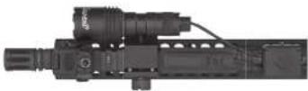
LGL-150 with Remote Pressure Switch mounted on AR using Offset Mount and Wire Management Clamp.
InstructionManual
LGL-150
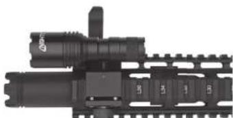
natural_image
Close-up of a mechanical assembly with cylindrical components and mounting brackets (no visible text or symbols)LGL-150 with Tail Cap Switch mounted on AR.
WEAPON SAFETY
FAILURE TO FOLLOW SAFETY AND OPERATING MEASURES WHEN HANDLING A FIREARM OR THE NIGHTSTICK LGL WHEN MOUNTED ON A FIREARM IS DANGEROUS AND CAN RESULT IN SERIOUS INJURY, DAMAGE TO PROPERTY, OR DEATH.
- Use of a firearm under any circumstance is inherently dangerous. SERIOUS INJURY OR EVEN DEATH may result without proper training in the safe handling of firearms. Proper training should be obtained from an accredited firearms safety program conducted by a qualified instructor.
- Read, understand and follow all of the safety instructions that come with your fl rearm before attaching your new LGL.
• Always assume every firearm is loaded and treat that firearm as such. - Never point a firearm at anything that you are not willing to destroy.
- Never service your fi rearm or your LGL when mounted on a fi rearm without fi rst activating the weapon's safety (if applicable), removing the magazine, opening the action and physically and visually inspecting to make sure that no ammunition is installed in the fi rearm.
WEAPON MOUNTED LIGHT SAFETY
- Nightstick recommends that the LGL should only be activated with the non-trigger hand (support hand) while employing a two-hand grip on the weapon and with the trigger finger fully outside the trigger guard when applicable. - Thoroughly practice (employing safe training conditions) with the LGL and an unloaded weapon.
BEFORE ATTACHING, INSPECTING OR SERVICING THE LGL
WARNING: IT IS IMPERATIVE THAT SAFETY MEASURES BE EMPLOYED AT ALL TIMES WHILE HANDLING A FIREARM.
- Engage the safety on the firearm (if applicable).
- Remove the magazine from the firearm (if applicable).
- Open the action and visually and physically inspect the chamber to be sure it is empty.
- Keep the barrel pointed in a safe direction at all times and never place your hand in front of the muzzle.
GENERAL SAFETY WARNINGS
- NOT FOR USE ABOVE HAZARDOUS LOCATIONS
- DO NOT use in explosive atmospheres, near fl ammable liquids, or where explosion proof lamps are required.
- DO NOT use in the proximity of vehicles or equipment when there is a risk of flammable liquids coming into contact with the flashlight.
- DO NOT expose the batteries to water or salt water, or allow the batteries to get wet.
• DO NOT store the batteries with metallic objects that may cause a short circuit. - Immediately discontinue use of the batteries if they emit an unusual smell, feel hot, change color, change shape or appear abnormal in any way.
- Keep out of the reach of children.
INSTALL THE BATTERY
ALWAYS ENSURE HANDGUN IS SAFE AND UNLOADED BEFORE CHANGING THE BATTERY.
Fully charge one of the batteries before use and have the other battery charged and ready as needed.
- Unscrew the tail cap switch or the tail cap on the remote pressure switch.
- Insert 1 CR123 battery into the light with the positive(+) and first.
- Replace the tail cap and fully tighten by hand.
INSTALL REMOTE PRESSURE SWITCH
The product ships with the tail cap switch pre-installed by the factory. It can be replaced with the included Remote Pressure Switch (LGL-RPS1).
- To change to the remote pressure switch, unscrew the tail cap switch. Install the remote pressure switch and tighten.
- Keep tail cap switch for future use so the light can be converted back to a hand-held flashlight in the future.
NOTE: The strain relief of the RPS can be rotated 360 degrees to aid in cable management.
PICATINNY AND OFFSET MOUNTS
Reverse the Picatiny Mount (LGL-SM1)
The factory-installed, standard Picatinny mount is reversible to provide additional clearance on the nille or to better position the thumbscrew.
- Remove the two machine screws and split washers using the included 2.5mm Allen wrench.
• Reverse the mount and reinstall the hardware.
Change to the Offset Mount (LGL-OM1)
The offset mount can be attached to any section of a Picatinny rail and can also be reversed.
- Remove the Picatinny mount as described in previous section above.
- Install the offset mount onto the light and reinstall the hardware.
NOTE: The included machine screws come with blue threadlocker from the factory. Repeated removal and reinstallation of the screws may necessitate adding more threadlocker. CAUTION: Do not use red threadlocker as it will make it too difficult to remove the screws in the future.
MOUNT THE LIGHT ONTO THE RIFLE
ALWAYS ENSURE HANDGUN IS SAFE AND UNLOADED BEFORE MOUNTING THE LIGHT.
- Loosen the thumbscrew on the mount.
- Place the mount and light in the desired location on any section of Picatinny rail.
• Tighten the thumbscrew by hand.
• Periodically check the thumbscrew for tightness.
ATTACH THE PRESSURE PAD SWITCH
Option 1: Rail Connector (NS-PIC1)
The rail connector mount can be used to attach the pressure switch pad to any section of a Picatinny rail.
- Position the mount onto the rail with the open end in the direction you prefer.
- Align the protrusions with the rail slots and snap mount into place.
- Slide the pressure switch pad into the open end of the mount until fully seated.
Option 2: Velcro®
The included Velcro pads come with two strips of pressure sensitive adhesive (PSA) already attached that allow the pressure switch pad to be adhered to any clean smooth surface of your fi rearm. The Velcro allows the pressure switch pad to be temporarily removed from the fi rearm.
- Use the included alcohol prep pad to clean the surface of the firearm where the RPS is to be attached and the back of the RPS. Allow to dry.
- Remove the backing strip from one side of the PSA tape and attach it to the back of the RPS.
- Repeat that process to attach the RPS/Velcro® pad assembly to the firearm.
- Apply even pressure. Allow the PSA tape to cure for approximately 24 hours for the best adhesion.
Option 3: Vertical Fore Grip
Various aftermarket manufacturers make vertical fore grips that the Nightstick pressure switch pad will fit into.
- The TangoDown® (models BGV-MK46 or BGV-QDSF) vertical fore grips allow the pressure switch pad to slide perfectly into the molded slot of their grip.
- Other vertical fore grips that have the same profile will work with the RPS.
SECURE THE RPS CABLE TO THE RIFLE
The Wire Management Clamp (NS-WM1) is used to secure the wire from the RPS to the rifle to prevent a snag hazzard.
- Loosen the cross screw and pull the clamp apart.
- Position the RPS cable through the paths of the molded channels of the clamp. The cable can pass straight through one path, or turn 90 degrees under the clamp and come out on the side.
- Install clamp body onto rail at desired location to hold the cable in place.
- Reassemble clamp using guide pin bosses for alignment.
- Reinstall the Allen cross screw and tighten with the included Allen wrench. Do not overtighten.
OPERATION
Pressing either switch will activate the light. Both provide momentary or constant-on operation,
Tail Cap Switch
- Constant on/off: Press until switch clicks to turn on or off. - Momentary on: Lightly press and hold for .5 seconds or longer. Release to turn off.
Remote Pressure Switch
- Turn on/off: Press the small, square shielded switch until it clicks to turn on or off.
- Momentary on: Lightly press the long tape switch and hold for .5 seconds or longer. Release to turn off.
STROBE WARNING
Exposure to strobing lights may cause dizziness, disorientation, and nausea. A very small percentage of people suffer from photosensitive epilepsy and may experience seizures or blackouts triggered by strobing lights. For more information from the EPILEPSY FOUNDATION about photosensitivity and seizures, please visit www.epilepsy.com. Anyone who has had symptoms linked to this condition should consult a doctor before using this product.
WARRANTY
LIMITED LIFETIME WARRANTY
Bayco Products, Inc. warrants this product to be free from defects in workmanship and materials for the original purchaser's lifetime. The Limited Lifetime Warranty includes the LEDs, housing and lenses. Rechargeable batteries, chargers, switches, electronics and included accessories are warranted for a period of two years with proof of purchase. Normal wear and failures which are caused by accidents, misuse, abuse, faulty installation and lightning damage are excluded.
We will repair or replace this product should we determine it to be defective. This is the only warranty, expressed or implied, including any warranty of merchantability or fitness for a particular purpose.
For a complete copy of the warranty, go to www.baycoproducts.com/nightstick-product-support/warranties. Retain your receipt for proof of purchase.

Bayco Products, Inc. • 640 South Sanden Blvd. • Wylie, TX 75098 • 1-800-233-2155 • 1-469-326-9400 • www.nightslick.com INS-LGL-150-20

Bayoo Products, Inc. • 640 South Sanden Blvd. • Wylie, TX 75098 • 1-800-233-2155 • 1-469-326-9400 • www.nightstick.com INS-LGL-150-20

natural_image
Mechanical assembly with cylindrical components and gear-like elements (no visible text or symbols)SÉCURITÉ DES ARMES
LA NON-CONFORMITÉ AUX INSTRUCTIONS DE SÉCURITÉ ET D'UTILISATION LORS DE LA MANIPULATION DES ARMES À FEU OUDU NIGHTSTICK LGL LORSQU'ILS SONT MONTÉS SUR DES ARMES À FEU EST DANGEREUSE ET PEUT ENTRAÎNER DES BLESSURES GRAVES, DES DOMMAGES MATÉRIELS OU LA MORT.