Cobra 2 Strike A150S - Tripod iFootage - Free user manual and instructions
Find the device manual for free Cobra 2 Strike A150S iFootage in PDF.


User questions about Cobra 2 Strike A150S iFootage
0 question about this device. Answer the ones you know or ask your own.
Ask a new question about this device
Download the instructions for your Tripod in PDF format for free! Find your manual Cobra 2 Strike A150S - iFootage and take your electronic device back in hand. On this page are published all the documents necessary for the use of your device. Cobra 2 Strike A150S by iFootage.
USER MANUAL Cobra 2 Strike A150S iFootage
natural_image
Technical line drawing of a vertical mechanical device with no visible text or symbols
IFOOTAGE
Catalog
■ Features 1
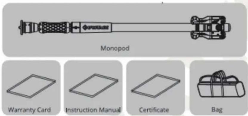
■ In the box 1
■ Technical Data 2
■ Parts Name 2
■ User Guide and More Functions 3
• How to mount the head 3
• How to control the monopod 5
• How to adjust angle 5
• How to adjust the gap 5
• How to operate monopod and low profile tripod 6
• How to extend the height of monopod 7
• How to use low profile tripod 7
■ Maintenance 8
Thank you for purchasing iFootage product. This manual is designed for COBRA V1 Monopod. To get the most of your Monopod, please read the manual fully before use and keep the manual safe for future reference.
Features
- The unique quick locking system allows rapid deployment.
- Extend the sections only by one button, much faster and efficient than other monopod.
- It integrates the monopod, lightstand, low profile tripod and many other functions into one.
- The low profile tripod has 3-angle adjustment.
In the box
text_image
Monopod Warranty Card Instruction Manual Certificate Bag* Do not lose any of the items listed above.
Technical Data
text_image
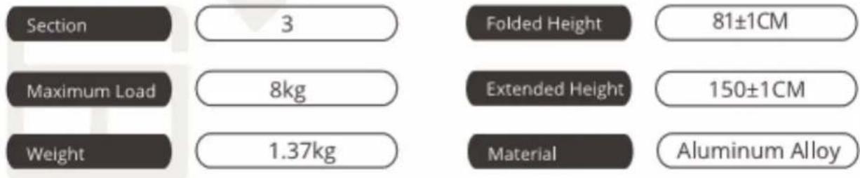
Section 3 Folded Height 81±1CM Maximum Load 8kg Extended Height 150±1CM Weight 1.37kg Material Aluminum AlloyParts Name
text_image
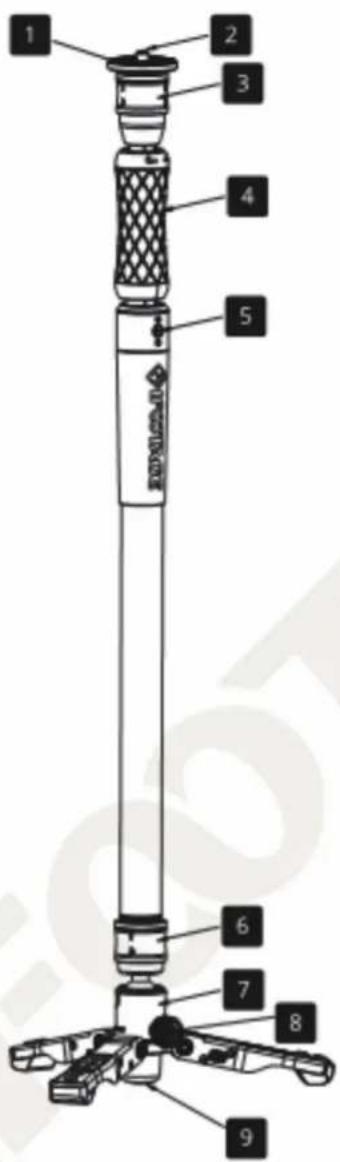
1 2 3 4 5 6 7 8 91 Head
2 1/4"Screw/ 3/8" Screw
3 Top lock
4 Locking Knob
5 Gap Adjustment Screw
6 Bottom lock
7 Low Profile Tripod
8 Angle Adjustment Knob
9 Pad
User Guide and More Functions
How to mount the head
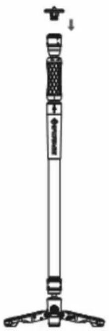
Step 1 : Push down the top lock and remove the head.
natural_image
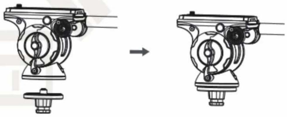
Line drawing of a vertical tripod-mounted device with adjustable legs and base (no text or symbols)Step 2: Tighten the 1/4"screw / 3/8"screw to the 3/8" adapter hole of Pan Head.
natural_image
Mechanical assembly diagram showing a device before and after transformation (no text or symbols)User Guide and More Functions
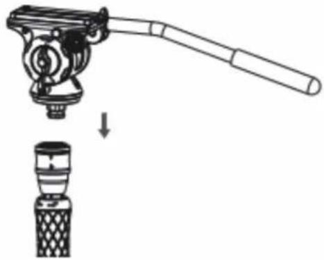
Step 3: Push down the top lock,
push down the pan head to the monopod.
natural_image
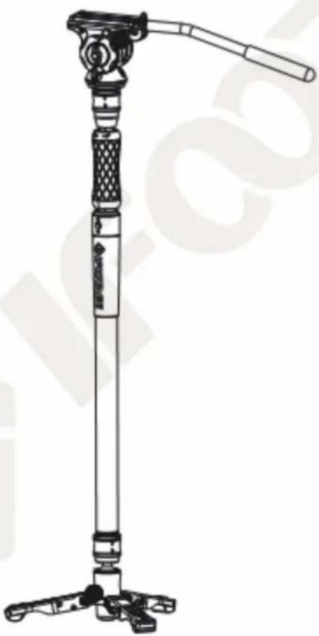
Diagram showing a mechanical device with a lever and a base component, no text or symbols presentStep 4: Release the top lock to secure the pan head.
natural_image
Line drawing of a tripod-mounted device with adjustable handle and base (no text or symbols)User Guide and More Functions
How to control the monopod
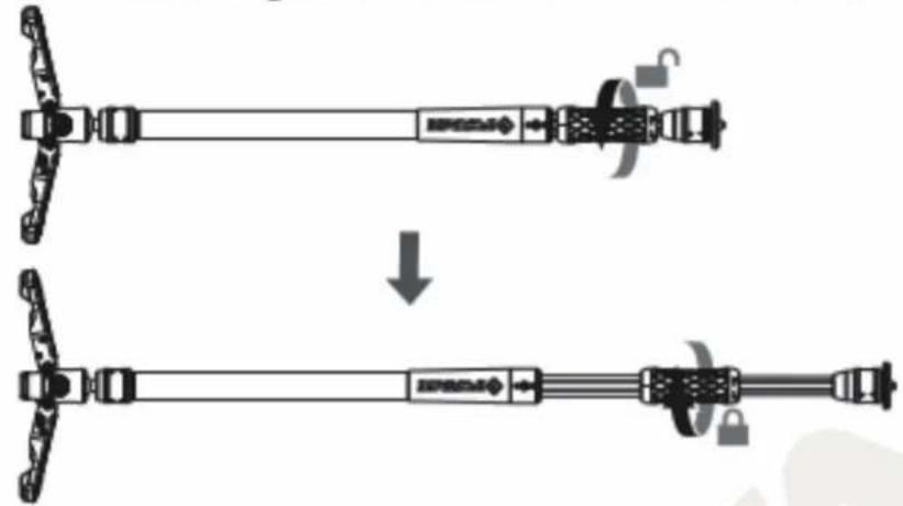
Rotate the locking knob clockwise and extend the telescopic section.
natural_image
Diagram showing a mechanical assembly before and after disassembly, with no visible text or symbols.How to adjust angle
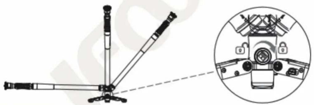
Loosen the locking knob and adjust the angle. The angle from 0 to 90^ maximum.
natural_image
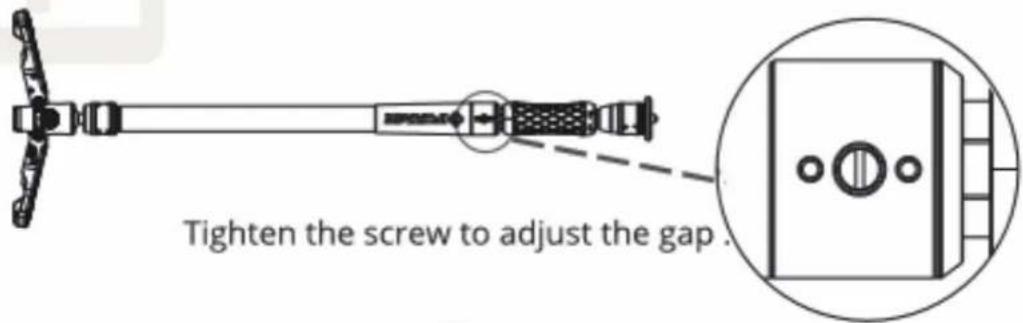
Technical line drawing of a mechanical device with a zoomed-in inset showing internal components (no text or symbols)How to tighten the gap
text_image
Tighten the screw to adjust the gap.User Guide and More Functions
■ How to operate monopod and low profile tripod
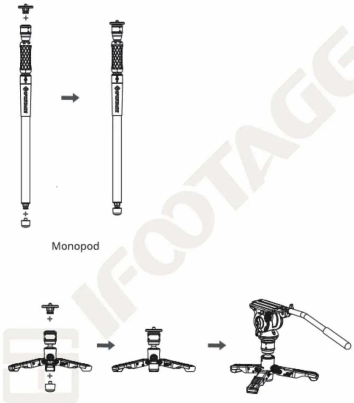
Low profile tripod
User Guide and More Functions
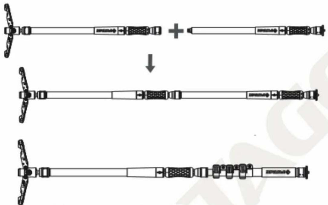
■ How to extend the height of monopod
flowchart
graph TD
    A["Top: Initial state with switch"] --> B["+"]
    B --> C["Downward arrow"]
    C --> D["Left: Component with switch"]
    D --> E["Bottom: Final state with switch"]
    E --> F["Right: Final state with switch"]
Multiple monopods can be connected together.
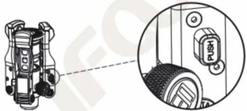
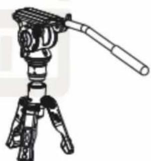
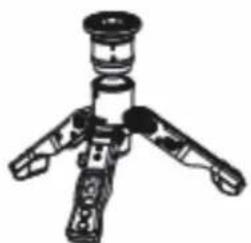
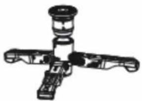
How to use low profile tripod
natural_image
Technical diagram showing a mechanical component with a close-up inset of its internal components (no text or symbols present)Press the Push Button to adjust the angle.
natural_image
Line drawing of a tripod-mounted camera with adjustable arm (no text or symbols)20^
natural_image
Line drawing of a tripod-mounted device with three legs and a central hub (no text or symbols)50^
natural_image
Mechanical component diagram with four arms and central hub (no text or symbols)78^
Maintenance
- Please check the tightness of each screw or joint section before use. Do not over tighten them as this will damage the tube section or parts.
- Gently loosen the upper/down locks sleeve and then it locks automatically. Do not push it hard as this will be difficult to take the head.
- After operation in rain, snow or in water, extend the tube sections and clean them with a damp cloth. Let the tube rest in place for a while and fold it after the moisture evaporates.
- Handle all parts gently and avoid external pressure during storage.
- If there is sand inside the tubes, please clean it using a small brush. After cleaning, the lubricant must only be applied on a few parts of the component. The other parts will automatically be lubricated along with the movement of screw threads. Do not apply regular machine oil or lubrication oil as this will impair the function of the parts. The suggested professional lubricant is the best choice.
INFORMATION OF MANUFACTURER

IFOOTAGE
IFOOTAGE INTERNATIONAL(HK) LIMITED
UK Design & Made in China
Origin : China
Website : www.ifootagegear.com