
MCX-500 - Uncategorized SONY - Free user manual and instructions
Find the device manual for free MCX-500 SONY in PDF.

| Product Type | Multi Camera Live Producer (Video Switcher) |
| Model | Sony MCX-500 |
| Dimensions (W x H x D) | Approx. 362 x 43.5 x 206 mm (14 1/4 x 1 3/4 x 8 1/8 in.) |
| Weight | Approx. 2.1 kg (4 lb 10 oz) |
| Power Requirements | 12 V DC, approx. 23 W |
| Video Inputs | 4x SDI (BNC), 2x VIDEO (BNC), 2x HDMI (Type A), 1x TITLE (RGB D-Sub 15-pin) |
| Video Outputs | 1x PGM SDI (BNC), 1x PGM HDMI (Type A), 1x PGM VIDEO (BNC), 1x MULTI VIEWER HDMI (Type A) |
| Audio Inputs | 4x embedded audio (SDI/HDMI), 1x LINE (XLR/TRS combo L/R) |
| Audio Outputs | 1x PGM LINE (phono L/R), 1x headphones (stereo mini jack) |
| Video Switching | Up to 4 cameras + Title, with mix, wipe, cut transitions and PinP, chroma key, luminance key composites |
| Audio Mixing | 5-line stereo mixing (4 embedded + 1 LINE) with level adjustment and PFL |
| Streaming | H.264 video, AAC audio, RTMP protocol, up to 1920x1080 @ 9 Mbps |
| Recording | AVCHD or XAVC S format to SD/SDHC/SDXC or Memory Stick Pro Duo, up to 1080/60p 50 Mbps |
| Control | Front panel with touch screen, PC UI via web browser (LAN or direct connection) |
| Network | 2x RJ-45 (PC UI and Streaming), 100BASE-TX/1000BASE-T |
| Other Interfaces | USB 2.0 (Mini-B) for maintenance, OPTION (3.5mm) for Remote Commander, TALLY (D-Sub 9-pin) |
| System Format | 1080/59.94p, 1080/59.94i, 1080/50p, 1080/50i (selectable at initial setup) |
| Cleaning | Wipe exterior with a soft dry cloth; do not use solvents. LCD panel may be cleaned with a soft cloth. |
| Consumable Parts | Fan (replace ~5 years), AC adapter capacitor (~5 years at normal use) |
| Safety | Use only supplied AC adapter; do not connect to peripheral devices with excessive voltage; use shielded LAN cables to prevent malfunction. |
| Supplied Accessories | AC adapter, USB cable, OPTION cable, CD-ROM (Operating Instructions) |
Frequently Asked Questions - MCX-500 SONY
User questions about MCX-500 SONY
0 question about this device. Answer the ones you know or ask your own.
Ask a new question about this device
Download the instructions for your Uncategorized in PDF format for free! Find your manual MCX-500 - SONY and take your electronic device back in hand. On this page are published all the documents necessary for the use of your device. MCX-500 by SONY.
USER MANUAL MCX-500 SONY
Multi Camera Live Producer
Operating Instructions
MCX-500
Ver. 2.0

MEMORY STICK™
HDMI
AVCHD

XAVC S
© 2016 Sony Corporation
http://www.sony.net/
Table of Contents
Important Notes....3
Chapter 1: Introduction
Features and Capabilities....4
Parts Identification....7
Basics of Video Switching....16
BKGD Mode and EFFECT Mode....17
Chapter 2: Preparation
Connecting Devices....18
Startup and Shutdown 21
Connecting a Computer for Settings Configuration.....22
Assigning Inputs 75
Chapter 3: Basic Operations
Switching Videos 29
Compositing Videos....34
Inserting Text onto Videos 35
Inserting Logos onto Videos 37
Live Adjustments 38
Chapter 4: Advanced Operations
Customizing the Pattern Icons....40
Selecting Picture-in-Picture (PinP) Patterns....43
Adjustments for Inserting People onto Backgrounds (Chroma Key) 45
Adjustments for Inserting Text onto Videos....47
Adjustments for Inserting Logos onto Videos....50
Changing the Transition Rates....53
Linking to Cameras....54
Useful Functions (Utilities) 56
Chapter 5: Streaming
Streaming....58
Chapter 6: Recording
Recording the PGM Output....63
Chapter 7: Settings
Configuring the Network Settings....67
Configuring the System Settings....69
Chapter 8: Appendix
Transition and Composite Patterns List....70
Menus and Default Settings 72
Troubleshooting....78
Message List 80
Maintenance and Usage Precautions....83
Specifications 85
Notes on the Licenses 90
Glossary 91
Index 97
NOTICE TO USERS
© 2016 Sony Corporation. All rights reserved. This manual or the software described herein, in whole or in part, may not be reproduced, translated or reduced to any machine readable form without prior written approval from Sony Corporation.
SONY CORPORATION PROVIDES NO WARRANTY WITH REGARD TO THIS MANUAL, THE SOFTWARE OR OTHER INFORMATION CONTAINED HEREIN AND HEREBY EXPRESSLY DISCLAIMS ANY IMPLIED WARRANTIES OF MERCHANTABILITY OR FITNESS FOR ANY PARTICULAR PURPOSE WITH REGARD TO THIS MANUAL, THE SOFTWARE OR SUCH OTHER INFORMATION. IN NO EVENT SHALL SONY CORPORATION BE LIABLE FOR ANY INCIDENTAL, CONSEQUENTIAL OR SPECIAL DAMAGES, WHETHER BASED ON TORT, CONTRACT, OR OTHERWISE, ARISING OUT OF OR IN CONNECTION WITH THIS MANUAL, THE SOFTWARE OR OTHER INFORMATION CONTAINED HEREIN OR THE USE THEREOF.
Sony Corporation reserves the right to make any modification to this manual or the information contained herein at any time without notice. The software described herein may also be governed by the terms of a separate user license agreement.
Trademarks
• XAVC S and the XAVC logo are trademarks of Sony Corporation.
- "AVCHD Progressive" and "AVCHD Progressive" logotype are trademarks of Panasonic Corporation and Sony Corporation.
- Windows is a registered trademark of Microsoft Corporation in the United States and/or other countries.
• HDMI, HDMI High-Definition Multimedia Interface, and the HDMI logo are registered trademarks or trademarks of HDMI Licensing LLC in the United States and/or other countries.
• SDXC logo is a trademark of SD-3C, LLC
- Google Chrome is a registered trademark of Google Inc. in the United States and/or other countries.
- USTREAM and its logo are registered trademarks or trademarks of Ustream, Inc. in the United States and/or other countries.
- YouTube and the YouTube logo are trademarks or registered trademarks of Google Inc.
- Facebook, the Facebook logo, and the "I" logo are trademarks or registered trademarks of Facebook, Inc.
- Mudu and the Mudu.tv logo are trademarks of Hangzhou Yagu Technology Co., Ltd.
- Adobe and the Adobe logo are registered trademarks or trademarks of Adobe Systems incorporated in the United States and/or other countries.
- Wowza, Wowza Media Server, and related logos are registered trademarks or trademarks of Wowza Media Systems, LLC in the United States and/or other countries.
All other system names and product names are registered trademarks or trademarks of their respective owners. Further, the * or ™ symbols are not used in this document.
Important Notes
Copyrights
Using the unit for video and/or audio switching, distribution over the Internet, or similar purposes may require the permission of the copyright holder of the video or audio in some cases. To protect copyright, observe the following points carefully when using the unit.
- When connecting a recording device to the unit and recording video or audio, carefully observe laws relating to copyright.
- The showing or distribution of video or audio material for which the copyright is held by a third party, or otherwise permitting private or public access without the permission of the copyright holder is prohibited by law.
- Even with the rights to show or distribute, the act of using the unit to edit original content with wipes or dissolves, for example, may be prohibited by law.
- For the purpose of protecting copyrights, the specifications for the video and audio signals that can be input may change without notice with software upgrades or functional expansions.
- Under copyright law, you may not use recorded video or audio for purposes other than your personal enjoyment without the permission of the copyright holder. Note that shooting may be restricted at live performances, shows, or exhibitions, even if it is for your personal enjoyment.
About the unit
The unit is not dustproof, splashproof, or waterproof.
Condensation
If the unit is suddenly taken from a cold to a warm location, or if ambient temperature suddenly rises, moisture may form on the outer surface of the unit and/or inside of the unit. This is known as condensation. If condensation occurs, turn off the unit and wait until the condensation clears before operating the unit. Operating the unit while condensation is present may damage the unit.
LCD panels
The LCD panel fitted to this unit is manufactured with high precision technology, giving a functioning pixel ratio of at least 99.99%. Thus a very small proportion of pixels may be 'stuck', either always off (black), always on (red, green, or blue), or flashing. In addition, over a long period of use, because of the physical characteristics of the liquid crystal display, such "stuck" pixels may appear spontaneously. These problems are not a malfunction. Note that any such problems have no effect on recorded data.
Consumable parts
- The fan is a consumable part that will need periodic replacement. When operating at room temperature, a normal replacement cycle will be about 5 years. However, this replacement cycle represents only a general guideline and does not imply that the life expectancy of this part is guaranteed. For details on parts replacement, contact your dealer.
- The life expectancy of the AC adapter and the electrolytic capacitor is about 5 years under normal operating temperatures and normal usage (8 hours per day; 25 days per month). If usage exceeds the above normal usage frequency, the life expectancy may be reduced correspondingly.
Security
SONY WILL NOT BE LIABLE FOR DAMAGES OF ANY KIND RESULTING FROM A FAILURE TO IMPLEMENT PROPER SECURITY MEASURES ON TRANSMISSION DEVICES, UNAVOIDABLE DATA LEAKS RESULTING FROM TRANSMISSION SPECIFICATIONS, OR SECURITY PROBLEMS OF ANY KIND. Depending on the operating environment, unauthorized third parties on the network may be able to access the unit. When connecting the unit to the network, be sure to confirm that the network is protected securely.
Do not browse any other website in the Web browser while making settings or after making settings. Since the login status remains in the Web browser, close the Web browser when you complete the settings to prevent unauthorized third parties from using the unit or harmful programs from running.
Network functions
When using the network functions, important personal information (e.g., information necessary for streaming transmissions) will be stored on the unit.
When transferring possession or disposing of the unit, see "Useful Functions (Utilities)" (page 56) and restore the factory default conditions, or see "Configuring the Network Settings for Streaming Transmission" (page 67), and reset the network settings.
Points to check before use
- Perform a test recording, and verify that it was recorded successfully.
- When streaming valuable data, be sure to check the device connections beforehand or carry out a streaming test to make sure that the system is operating normally.
Images used in this manual
The images used in this manual are created to aid in explaining operations. The actual images that are displayed or output during operations may differ.
Features and Capabilities
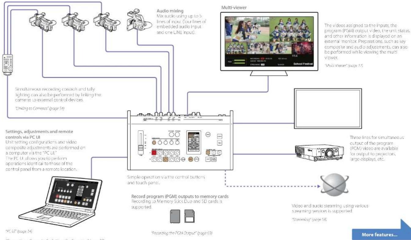
The MCX-500 Multi Camera Live Producer is a compact switcher that allows video switching and audio mixing via simple operations without expert knowledge. Live controls via a computer is also possible using the unit's live Internet distribution function. The unit can be used in a wide variety of venues for events, seminars, etc.
Live video switching
The unit allows switching between up to four cameras.
flowchart
graph TD
    A["PC UI (page 14)"] --> B["User Interface"]
    C["Recording the PGM Output (page 63)"] --> D["Record program (PGM) outputs to memory cards"]
    E["Audio mixing Mix audio using up to 5 lines of input (four lines of embedded audio input and one LINE input)."] --> B
    F["Multi-viewer"] --> G["The video assigned to the inputs, the program (PGM) output video, the unit status, and other information is displayed on an external monitor. Preparations, such as key composite and audio adjustments can also be performed while viewing the multi viewer. "Multi Viewer" (page 12)"]
    B --> H["Simple operation via the control buttons and touch panels."]
    D --> I["Three lines for simultaneous output of the program (PGM) video are available for output to projectors, large displays, etc."]
    G --> J["Video and audio steaming using various streaming services is supported. "Streaming" (page 58)"]
    H --> K["Simultaneous recording controls and tally lighting can also be performed by linking the cameras to external control devices. "Linking to Cameras" (page 54)"]
    I --> L["Settings, adjustments and remote controls via PC UI Unit setting configurations and video composite adjustments are performed on a computer via the "PC UI." The PC UI allows you to perform operations identical to those of the control panel from a remote location."]
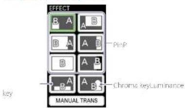
Variety of transition and composite patterns
The unit is equipped with PinP, chroma key, and luminance key video composite functions. Multiple composite patterns are available for PinP and chroma key compositing. Wipe, mix, and cut transition functions are also available. PinP

Chrome keying

Luminance keying

TITLE function
You can overlay text (i.e., images) created on a computer connected to the TITLE (RGB) input connector on the rear of the unit onto the video.

"Adjustments for Inserting Text onto Videos" (page 47)
LOGO function
You can composite 320×320-sized still images onto videos as logos.

Variety of inputs and outputs
The unit supports four lines of video input (HD/SD-SDI, VIDEO, HDMI) in addition to the use of PC signals combined with the HD/SD video. Using these features in conjunction with the variety of composite patterns allows you to produce dynamic videos with high visual impact. Three lines of output (HD-SDI, VIDEO, HDMI) are available for the PGM video. Five lines of audio input (HD/SD-SDI, HDMI, LINE) are also available for mixing.
Menu customization for effect patterns
You can assign up to eight patterns each for the transition and composite effect patterns displayed in the touch panel.
Example for composite patterns
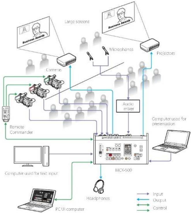
Use at Various Events
You can switch between video inputs from cameras and a computer, and output the video to two projectors. By linking with a Remote Commander, you can light the PGM/NEXT tallies on the cameras. Use the TITLE function to overlay text created on a computer connected via RGB onto the video.
flowchart
graph TD
    A["Large screens"] --> B["Camera"]
    C["Microphones"] --> D["Projectors"]
    B --> E["Audio mixer"]
    D --> E
    E --> F["MCX-500"]
    G["Computer used for presentation"] --> F
    H["Computer used for text input"] --> F
    I["PC UI computer"] --> F
    J["Headphones"] --> F
    K["Remote Commander"] --> F
    L["Business Awards"] --> B
    M["Computer used for text input"] --> F
    N["Input"] --> F
    O["Output"] --> F
    P["Control"] --> F
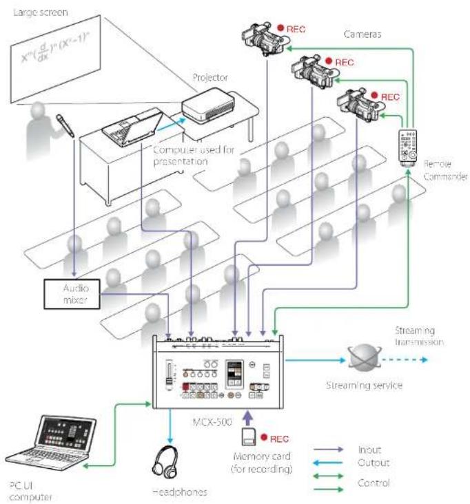
Use at Lectures and Seminars
You can switch between or composite video inputs from cameras and a computer used for presentations and lectures, and stream the video or record it onto a memory card. By linking with a Remote Commander, you can simultaneously control recording start/stop operations on the cameras via recording start/stop controls performed on the unit.
flowchart
graph TD
    A["Large screen X^m(σ/dx)^n(X^2-1)^n"] --> B["Projection"]
    B --> C["Computer used for presentation"]
    C --> D["Audio mixer"]
    D --> E["MCX-500"]
    E --> F["Headphones"]
    F --> G["PC UI computer"]
    G --> H["Streaming service"]
    H --> I["Input"]
    H --> J["Output"]
    H --> K["Control"]
    B --> L["Camera"]
    B --> M["REC"]
    B --> N["REC"]
    B --> O["REC"]
    B --> P["Remote Commander"]
    E --> Q["MCX-500"]
    Q --> R["Headphones"]
    R --> S["PC UI computer"]
    S --> T["Streaming service"]
    T --> U["Streaming transmission"]
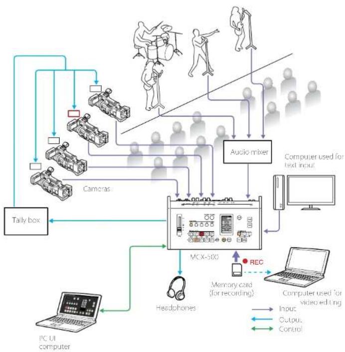
Use at Live Musical Performances
You can switch between live video inputs from cameras, and record them. By linking with a commercially available tally box, you can light the tally of the camera being used for the PGM output. The files recorded to the memory card can be played back or edited on a computer using Sony PlayMemories Home.
flowchart
graph TD
    A["Audio mixer"] --> B["Cameras"]
    B --> C["Tally box"]
    C --> D["PC UI computer"]
    D --> E["Headphones"]
    E --> F["MCX-500"]
    F --> G["Memory card (for recording)"]
    G --> H["REC"]
    H --> I["Computer used for video editing"]
    I --> J["Input"]
    I --> K["Output"]
    I --> L["Control"]
    M["Computer used for text input"] --> N["Computer used for text input"]
    style A fill:#f9f,stroke:#333
    style B fill:#ccf,stroke:#333
    style C fill:#cfc,stroke:#333
    style D fill:#fcc,stroke:#333
    style E fill:#cff,stroke:#333
    style F fill:#ffc,stroke:#333
    style G fill:#cfc,stroke:#333
    style H fill:#fcc,stroke:#333
    style I fill:#ffc,stroke:#333
    style J fill:#fcc,stroke:#333
    style K fill:#fcc,stroke:#333
    style L fill:#fcc,stroke:#333
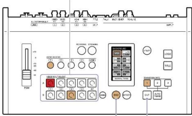
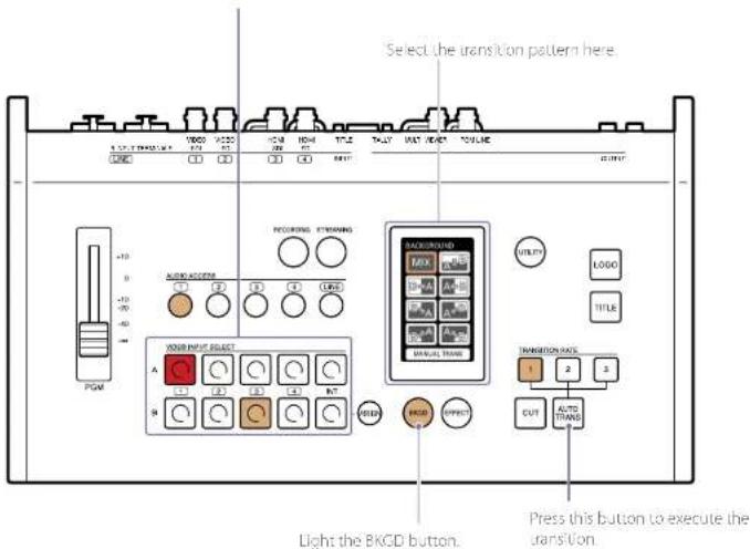
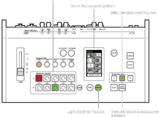
Parts Identification
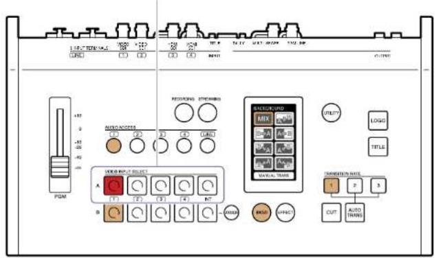
Control Panel
Video switching, audio mixing, and other live controls are performed via the control panel.
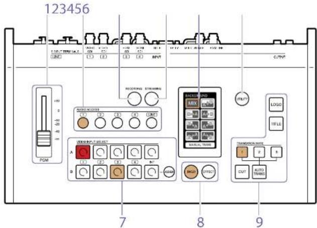
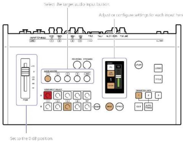
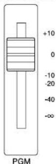
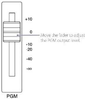
1. PGM master fader
Adjusts the audio output level for the PGM output. The output level will be the same for the L and R channels. The adjustment results can be monitored via the headphones connected to the (headphones) jack on the front of the unit or via the level meters displayed on the multi-viewer.
2. AUDIO ACCESS buttons
Displays menus for adjusting the audio in the menu panel. Pressing the button again hides the menus. Buttons 1 to 4: Displays the audio adjustment menus for audio corresponding to inputs to 4 of the video selection block. LINE button: Displays the audio adjustment menu for the LINE input connectors
When an audio input is being used for PGM output, the corresponding button lights.

(Unlit): Not being used as PGM output.

(Li): Output as PGM in progress.
For details, see "Live Adjustments" (page 38).
3. RECORDING button
Displays the menu for performing recording operations in the menu panel. Pressing the button again hides the menu. The lit status of the button indicates the recording status.

(Unit): Recording is stopped.

(Li): Recording is in progress.
For details, see "Chapter 6: Recording" (page 65).
4. STREAMING button
Displays the menu for performing streaming operations in the menu panel. Pressing the button again hides the menu. The lit status of the button indicates the streaming status.

(Unit): Streaming is stopped or in standby mode

(Lit): Streaming is in progress.
For details, see "Chapter 5: Streaming" (page 58).
5. Menu panel (touch panel)
Displays a menu based on the operation or function being performed. You can perform transition or composite pattern selection and other controls and adjustments for each function here. Confirmation messages and error messages are also displayed here. Example display: Transition pattern selection menu
Example display: Audio adjustment menu
6. UTILITY button
Allows you to adjust the headphone volume, brightness of the menu panel and control buttons, etc. Pressing the button displays the [UTILITY] menu in the menu panel.
for details, see "Useful Functions (Unities)" (page 56).
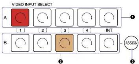
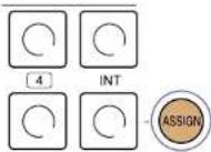
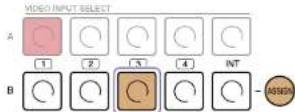
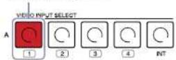
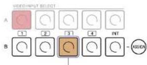
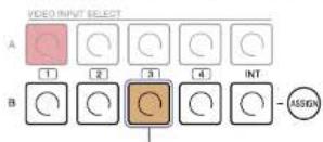
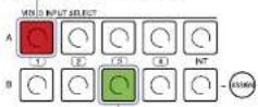
7. Video selection block (VIDEO INPUT SELECT)
Allows you to select videos (materials).
You can view the images available for selection and the selection results on the multi-viewer.
flowchart
graph TD
    A["VIDEO INPUT SELECT"] --> B1["1"]
    A --> B2["2"]
    A --> B3["3"]
    A --> B4["4"]
    A --> B5["INT"]
    B1 --> C1["Circle icon"]
    B2 --> C2["Circle icon"]
    B3 --> C3["Circle icon"]
    B4 --> C4["Circle icon"]
    B5 --> C5["Circle icon"]
    C1 --> D1["ASSIGN button"]
    C2 --> D2["ASSIGN button"]
    C3 --> D3["ASSIGN button"]
    C4 --> D4["ASSIGN button"]
    C5 --> D5["ASSIGN button"]
Buttons 1 to 4: Assigns the materials that are input via video input connectors 1 to 4 on the rear of the unit.
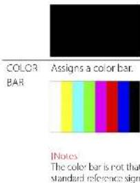
INT buttons: Assigns signals (color bar or black signal); that are generated internally on the unit.
1 Row A buttons
Selects the video (material) to be output as the PGM output.
When you press a button in this row, the button lights red and the material assigned to that input number is output as the PGM output.
2 Row B buttons
Selects the material to be output next as the PGM output (NEXT output). When creating a composite video using PinP or chroma keying, for example, use the row B buttons to select the overlay material.
The color and lit status of the buttons indicate the following.

(Li): Output as PGM in progress.

(Lit): Selected as the NEXT output.

(unli): Not selected

(Completely unit): The button is disabled and cannot be pressed.
③ ASSIGN button
Allows you to change the video input connectors assigned to inputs 1 to 4. Pressing the button displays the menu for the button selected in row B in the menu panel.
When the button is lit, the menu displayed will differ depending on the selected row B button.
For details, see "Assigning Inputs" (page 25).
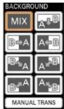
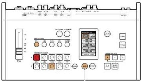
8. Delegation block
Selects the video switching mode (BKGD mode or EFFECT mode)
BKGD mode is used for transitioning videos, and EFFECT mode is used for compositing videos.
Pressing the BKGD button switches to BKGD mode (amber), and pressing the EFFECT
button switches to EFFECT mode (green). The selectable switching patterns for each mode are displayed in the menu panel.
During BKGD mode

(Lit)
During EFFECT mode

(1)
For details on the modes, see "BKGD Mode and EFFECT Mode" (page 17).
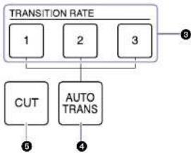
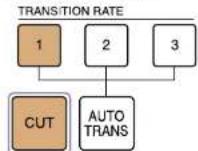
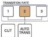
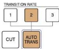
9. Transition block
Allows you to perform transition (video switching) controls.
flowchart
graph TD
    A["TRANSITION RATE"] --> B["1"]
    A --> C["2"]
    A --> D["3"]
    B --> E["CUT"]
    C --> F["AUTO TRANS"]
    D --> G["Output 3"]
    E --> H["5"]
    F --> I["4"]
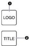
1 LOGO button
Allows you overlay logos (i.e., still images) that have been imported to the unit beforehand onto the video.
The logo is enabled or disabled (i.e., cut in or out) with each press of the button.

(LiU) Enabled (i.e., displayed).
For details, see "Adjustments for inserting logos onto Videos" (page 50).
② TITLE button
Allows you to input RGB text (i.e., images) created on a computer, and overlay it onto the video.
The text is enabled or disabled (i.e., cut in or out) with each press of the button.

(1.4): Enabled (i.e., displayed).
For details, see "Adjustments for Inserting Text onto Videos" (page 47).
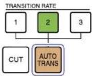
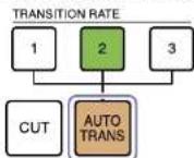
③ TRANSITION RATE buttons 1 to 3
Allows you to select from three presets for the PGM video transition rate by pressing the respective button.
You can change the transition rate presets assigned to buttons 1 to 3.
For details on settings, see 'Changing the Transition Rules' (page 53).
4 AUTO TRANS button
Switches the PGM video according to the selected pattern and transition rate.
For details on operations, see "Applying Transition Effects" (page 31) and "Composting Videos" (page 34).
5 CUT button
Switches the PGM video instantly via a cut. For details on operations, see "Switching via Cuts (Basic Switching)" (page 29).
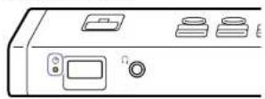
Front
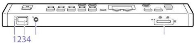
1. ⏻ (power) indicator
Indicates the unit's power status.
(Green): Unit is turned on. (Red): Unit is turned off.
2. Power switch
Turns the unit on/off (page 21).
3. (Headphones) jack (standard stereo phone)
When monitoring audio, connect headphones here.
For details on adjusting the volume, see "Adjusting the Headphone Volume" (page 38).
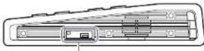
4. (memory card) slot
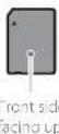
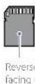
When recording PGM outputs, insert a memory card here. The unit supports Memory Stick Duo and SD cards.
- Insert Memory Stick media with their front sides facing up.
- Insert SD cards with their reverse (terminal) sides facing up.
SD cardMemory Stick Dia
When a memory card is being accessed, the access indicator to the left of the slot blinks. To remove a memory card, gently push it inward once.
[Notes]
- When the access indicator is lit or blinking red, data is being written or read. Do not subject the unit to vibration or excessive shock in such cases. In addition, do not turn off the unit, remove the memory card, or disconnect the AC adapter.
- Only memory cards that were formatted on the unit can be used.
For details on supported memory cards and how to record, see "Chapter 6: Recording" (page 63).
Rear
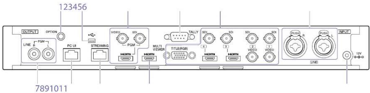
For details on connections, see "Connecting Devices" (page 18).
1. OPTION connector (RS-232C)
Connect a Remote Commander here when using one to control cameras.
For details, see "Linking to Cameras" (page 54).
2. USB port (Mini-B, USB 2.0)
When connecting to PlayMemories Home to edit recorded data on a computer, connect to the computer via this port.
This is also used when performing system updates for the unit.
For details on connections for editing recorded data, see "Using Recorded Files" (page 65).
Eps When performing system updates, both the USB port on the rear and the USB port on the right side of the unit are used.
3. Video output block
Allows simultaneous PGM output from three video output connectors.
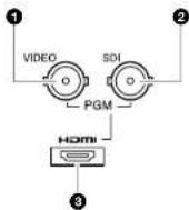
① PGM VIDEO output connector (BNC)
Outputs the finished video processed internally on the unit (i.e., PGM video) as an analog video signal
2 PGM SDI output connector (BNC)
Outputs the finished video processed internally on the unit (i.e., PGM video) as an HD-SDI signal.
For details on aspect ratio settings for SD signals, see "Output" Screen" (page 69) in the "Configuring the System Settings" section.
③ PGM HDMI output connector (Type A)
Outputs the finished video processed internally on the unit (i.e., PGM video) as an HDMI signal.
For details on signal format settings for IDM, see "[Output" Screen" (page 69) in the "Configuring the System Settings" section.
[Notes]
- Proper opera, on may not be possible on some devices (e.g., video or audio is not output).
- Do not connect the output connectors on the unit to those on an external device, as doing so will result in malfunction.
4. TALLY output connector (D-sub 9-pin)
Connects to the tally connector on a commercially available tally box, for example. The tally lamp of a camera can be made to light when its images are being output as PGM.
For details on pin assignments, see "T/LLY connector" (page 89).
5. Video input block
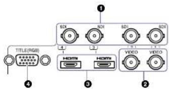
① SDI input connectors 1 to 4 (BNC) Input HD/SD SDI signals
2 VIDEO input connectors 1 and 2 (BNC) Input analog video signals.
Tips
For input connectors 1 and 2, SD and VIDEO signals cannot be input simultaneously from identical y numbered connectors. Only one of the signals can be assigned for operation.
③ HDMI input connectors 3 and 4 (Type A) Input HDMI signals.
When displaying data from a computer during a presentation, for example, connect to the computer via this connector.
In addition, when compositing text using an HDMI signal, connect to the computer via this connector.
[Notes]
Proper operation may not be possible on some connected devices (e.g., video or audio is not output).
[Tips]
- For input connectors 3 and 4, SDI and HDMI signals cannot be input simultaneously from identically numbered connectors. Only one of the signals can be assigned for operation.
- Copyright protected (HDCP) signals cannot be input. (A black screen will be displayed.)
When overlaying text created with a computer to create a composite, connect to the computer via this connector.
For details on overlaying text, see "Adjustments for Inserting Text onto Videos" (page 4/).
[Notes]
Only 1600×1200 (60p) signals are supported for input. Use a computer that supports this output, resolution.
- LINE (line) Input connectors L and R (balanced XLR 3-pin / TRS combo)
Input analog audio signals from an audio mixer, for example.
-
LINE output connectors L and R (pin jacks) Output PGM audio that was mixed down on the unit
-
PC UI network connector (RJ-45 modular jack)
Connect the computer to be used for the PC UI, which allows settings configuration and control of the unit, here.
For details, see "Connecting a Computer for Settings Configuration" (page 22).
- STREAMING network connector (RJ-45 modular jack)
When streaming, connect to the network via this connector.
For details, see "Chapter 5: Streaming" (page 58).
CAUTION
For safety, do not connect connectors for peripheral device wiring that may have excessive voltage to the following ports.
FC UI network connector
STREAMING network connector
Follow the instructions in this document for these parts.
CAUTION
When connecting the unit to a peripheral device via a LAN cable, use a shielded-type cable to prevent malfunction due to radiation noise.
- MULTI VIEWER HDMI output connector (Type A)
Connect the external monitor to be used for the multi-viewer here.
For details, see "Multi-Viewer" (page 12).
For details on signal format settings for HDMI, see "[Output] Screen" (page 69) in the "Configuring the System Settings" section.
[Notes]
- Proper operation may not be possible on some devices (e.g., video or audio is re output).
- Do not connect the output connectors on the unit to those on an external device, as doing so will result in malfunction.
- DC IN 12V (DC power input) connector
Connect the supplied AC adapter here. Be sure to use the nearby cable clamp to prevent the cable from disconnecting.
Right Side
Terminal cover removed
- USB port (Mini-B, USB 2.0)
Used for maintenance (e.g., system updates and displaying licenses).
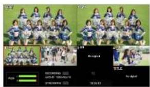
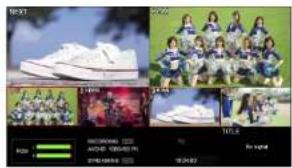
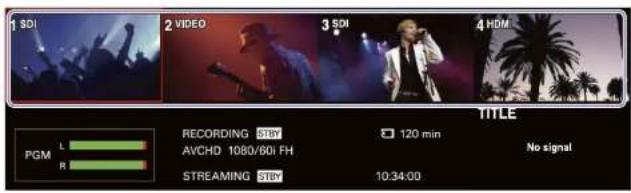
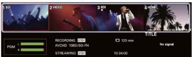
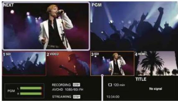
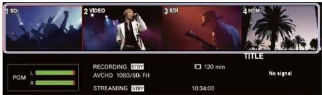
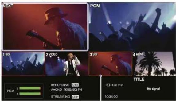
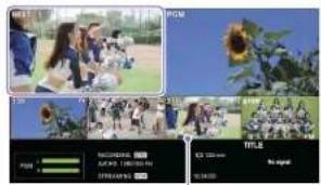
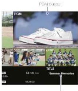
Multi-Viewer
The following items appear on the external monitor (i.e., the multi-viewer) connected to the MULTI VIEWER connector on the rear of the unit. The multi viewer allows you to monitor the input materials, PGM output video, video selected as the NEXT output, key compositions, unit status, and other information. INT material is not displayed
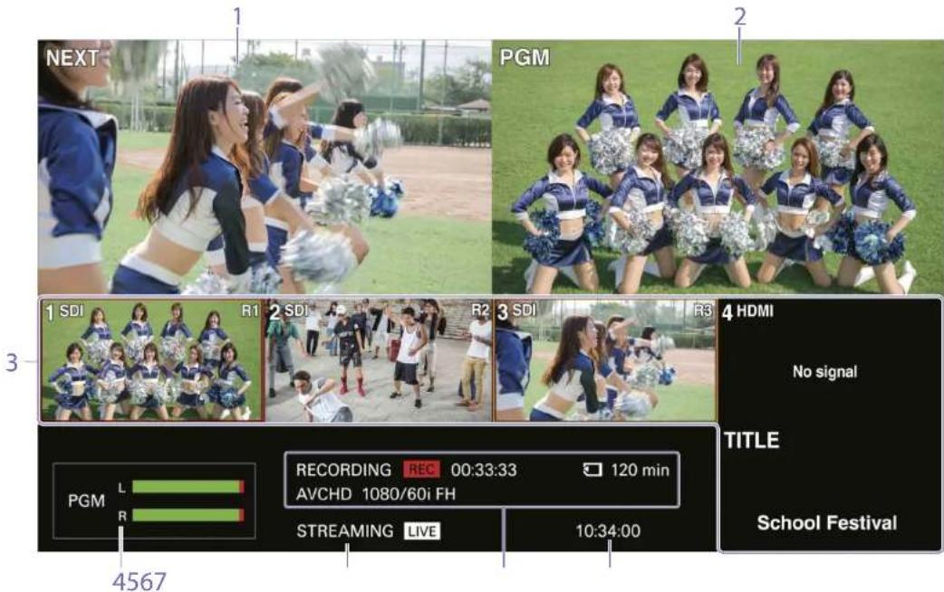
1. [NEXT] viewer
Displays the video selected from among the row B buttons as the NEXT output. If you press and hold a row B button for 1 second or more, the video selected as the NEXT output will be displayed in full screen for as long as the button is held.
Tips
- Depending on the monitor you are using, it may take a few seconds for the image to switch.
- Full-screen display will not occur during automatic transitions. In addition, full-screen display will be exited if a transition starts.
2. [PGM] viewer
Displays the video currently being output as the PGM output.
3. [INPUT] viewer
Displays the materials assigned to inputs 1 to 4 and the TITLE material signal being input from a computer.
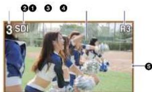
① Input number (1 to 4, TITLE)
② Input material name
Displays the name of the input material
assigned to the respective input number. For details on naming input materials, see "Input" Screen" (page 65) in the "Configuring the System Settings" section.
③ Input image
Displays inputs 1 to 4 and the TITLE material input signal.
4 Remote camera setting
When using a Remote Commander to control cameras, this displays a camera's assignment setting.
5 Tally indicator
Displays a tally for the input material based on its status.

(PGM tally): A red frame appears around the material being output as the PGM output.

(NEXT tally in BKGD mode): An amber frame appears around the input that will be output next as the PGM output.

(NEXT tally in EFFECT mode): A green frame appears around the input that will be output next as the PCM output.
6 Input status
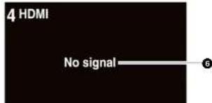
Displays the following statuses if an error occurs with the input signal.
[No Signal]: There is no signal input.
[Format Mismatch]: A signal that is not supported by the unit is being input
[HDCP]: A copyright protected (HDCP)
signal is being input. This is not supported on the unit.
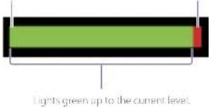
4. Audio level meters
Display the audio levels of the PGM output within a range of 0 to -60 dB in 16 levels.
The left end
represents - and is always lit green.
Over-level indicator lights red at 0 dB.

Lights green up to the current level.
5. [STREAMING] status
Displays the streaming status using an icon.
![SONY MCX-500 - [STREAMING] status - 1](/content/2026/05/760177/images/1fe4ed65e01ab4252f7328451f1b16f5b0865ab3a056a0d968f2b6131b901e21.jpg)
: Streaming is not possible.
![SONY MCX-500 - [STREAMING] status - 2](/content/2026/05/760177/images/8e83380f7f14b515d1c5dd77a3c873214b8b382e00f2ddbc738b2b4ab462bcf0.jpg)
. Streaming is ready to start.
![SONY MCX-500 - [STREAMING] status - 3](/content/2026/05/760177/images/7366d9e5cfb248e32bdba72235e9085f52f3f5c8eaa3e9393870014188003dff.jpg)
Streaming is in progress.
6. [RECORDING] information
Displays the following information concerning recording
![SONY MCX-500 - [RECORDING] information - 1](/content/2026/05/760177/images/538b2284ca1f1cb7be6d00a4dd5ce5e0f26bce8dd67c6c44bd6140f5231a254f.jpg)
1 Recording status

Recording is not possible.

Recording is ready to start.

Recording is in progress. The recording duration is displayed in hours, minutes, and seconds.
② Memory card status

: A memory card is inserted, and recording is possible.

: A memory card is inserted, but recording is not possible.

: A memory card is not inserted.
③ Remaining time for the memory card
When a memory card is inserted, this displays the remaining recording time for the memory card in minutes. When the remaining time is less than 1 minute, a "0 min" display will blink.
4 File format
Displays the currently configured file format.
5 Recording format
Displays the currently configured recording format.
For details on settings, see "Configuring the Recording Settings" (page 63).
7. Clock display
Displays the current time.
For details on settings, see "System" Screen" (page 69) in the "Configuring the System Settings" section.
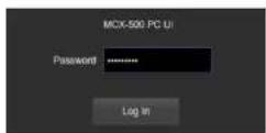
PC UI
Preparations, such as unit setting configurations and composite adjustments, are performed using the PC UI. The PC UI also allows you to perform operations identical to those of the control panel from a remote-location.
For details on displaying the PC UI, see "Connecting a Computer for Settings Configuration" (page 27).
[Notes]
An authentication password is required to use the PCUL. Do not use your web browser's "remember password" function.
[1]75
If there is a problem with the PC UI display, try refreshing the display on the web browser.
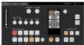
The PC UI consists of tabs. Selecting each tab displays its corresponding screen.
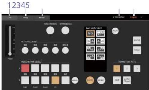
1. [Live] tab
Displays the [Live] screen for performing controls identical to those of the unit's control panel. In the [Live] screen of the PC UI, input material names are displayed under row 3 of the video selection buttons.
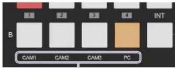
Input material names
For details on naming input materials, see "Input Screen" (page 69) in the "Configuring the System Settings" section.
2. [Setup] tab
Displays the [Setup] screen for configuring settings necessary for live control and other system settings for the unit.
Select the item you want to configure.
The following configurations and operations can be performed in the [Setup] screen.
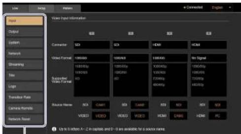
[Input]: View assignment information for inputs 1 to 4, for example.
For details, see "Input" Screen* (page 69).
[Output]: Configure settings related to the PGM output and multi-viewer.
For details, see "Output Screen" (page 69).
[System]: Configure the system settings for the unit.
For details, see "System" Screen (page 69).
[Network]: Configure the network settings necessary for streaming transmissions and direct mode connections for the PC UI.
For details, see "Changing the Unit's IP Address" (page 68), "Configuring the Network Settings for Streaming Transmission" (page 67).
[Streaming]: Configure the settings necessary for streaming transmissions.
For details, see "Streaming" (page 58).
[Title]: Perform composite adjustments when overlaying text created on a computer using RGB input signals.
For details, see "Adjustments for inserting Text onto Videos" (page 47).
[Logo]: Perform composite adjustments when overlaying logos that have been imported to the unit beforehand.
For details, see "Adjustments for Inserting Logos onto Videos" (page 50).
[Transition Rate]: Configure the durations for the three TRANSITION RATE buttons.
For details, see "Changing the Transition Rates" (page 53).
[Camera Remote]: Configure settings for controlling cameras via a Remote Commander. For details, see "Linking to Cameras" (page 54).
[Network Reset]: Reset network settings and streaming settings if necessary.
For details, see "Configuring the Network Settings for Streaming Transmission" (page 67).
3. [Pattern] tab
Displays the [Pattern] screen for performing the following configurations and adjustments.
- Replacing the eight pattern icons used in BKGD mode and EFFECT mode
- Selecting the pattern (PinP, chroma key, luminance key)
- Chroma key adjustment
• Luminance key adjustment
• Enabling/disabling borders
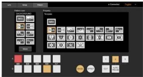
For details, see "Customizing the Pattern Icons" (page 40), "Selecting Picture-in-Picture (PinP) Patterns" (page 43), "Adjustments for inserting People and Backgrounds (Chrome Key)" (page 45), and "Using HDMI Input Signals to insert Text (F-H-F-C1 Model)" (page 48).
4. Communication status
Indicates the status of communication between the unit and the computer.

Communication with the unit is enabled.

Communication with the unit has been severed, and the system is attempting to reconnect. Controls via the PC UI will be disabled.
5. Display language
Allows you to change the display language for the PC UI from a pull-down list.
You can select from [English] and [简体中文] (Simplified Chinese).
For details on changing the display language for the unit's menus, see "Changing the Display Language" (page 57).
Basics of Video Switching
"Video switching" refers to the process of switching between video images. You can use the unit to switch between and mix videos (input signals) from multiple cameras, VIBs, and a computer. By applying video effects, inserting text, and composting images, you can create diverse and dynamic program outputs.
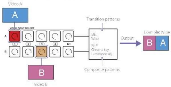
Components of Transitions and Composites
The videos selected in rows A and B are used as a set in a transition or composite.
flowchart
graph TD
    A["Video A"] --> B["Video INPUT SELECT"]
    B --> C["Chromatic key Luminance key"]
    C --> D["Composite patterns"]
    D --> E["Example Wipe"]
    subgraph Video B
        B1["1"] & B2["2"] & B3["3"] & B4["4"] & B5["NT"]
    end
    C --> F["Mix Wipe"]
    F --> G["Output"]
    H["Video B"] --> I["Composite patterns"]
    I --> D
    style A fill:#f9f,stroke:#333
    style B fill:#ccf,stroke:#333
    style C fill:#cfc,stroke:#333
    style D fill:#fcc,stroke:#333
    style E fill:#ffc,stroke:#333
    style F fill:#cff,stroke:#333
    style G fill:#ffc,stroke:#333
    style H fill:#cfc,stroke:#333
Compositing Basics
Picture-in-picture (PinP) compositing
This is an effect achieved by embedding a video within another video. A rectangular area is removed from one image, and the other image is inserted in that area.

Area in which the other image is inserted
Key compositing
This is an effect achieved by removing parts of an image and placing the cutout on another image that serves as the background. To differentiate between the cutout image and the removed parts of the image, a cutout signal (key signal) is created. There are various methods for creating key signals, but the following describes the methods available on the unit: chroma keying and luminance keying.
Chroma keying
When using this method, create a key signal that uses color to differentiate between the cutout image and the removed parts of the image. Typically, a subject is captured in front of a blue background, commonly referred to as a "blue screen."
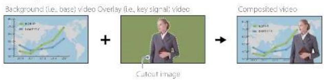
Luminance keying
When using this method, create a key signal that uses brightness to differentiate between the cutout image and the removed parts of the image. Use this method to insert text onto a video. Typically, bright colored text is created on a black background.
Background (i.e., base) video Overlay (i.e., key signal) video Composited video

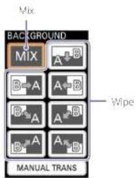
BKGD Mode and EFFECT Mode
Transitions are separated into two categories on the unit, BKGD mode and EFFECT mode.
BKGD mode

Use this mode to switch completely from image A to image B (i.e., for complete replacement).

flowchart
graph LR
    A["A"] --> B["B"]
    B --> A2["A"]
    A2 --> B2["B"]
    B2 -->|Complete replacement| End
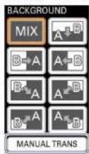
The following transition patterns are available in BKGD mode.
Mix

Wipe
A A/B B


In BKGD mode, the following items light amber along with the BKGD button.
- Row B buttons
• TRANSITION RATE buttons
- Selected menu items
• Tally indicators in the multi-viewer
BKGD button
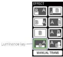
EFFECT mode
EFFECT
Use this mode to insert image B onto image A (i.e., for compositing).
Composite

The following composite patterns are available in EFFECT mode.
Picture-in-picture (PinP)
A background video
(1) video


Luminance key
A B (c) A

In EFFECT mode, the following items light green along with the EFFECT button.
- Row 3 buttons
• TRANSITION RATE buttons
- Selected menu items
• Tally indicators in the multi-viewer
llicsl
- Only video A will be displayed when you switch from EFFECT mode to BKGD mode.
- When switching to F-F-C1 more, whether the video switches to the composited state or simply to video A depends on the composite pattern. (See page 70.)
Connecting Devices
Connect each device to the unit.
If you have already connected the devices, proceed to "Chapter 3: Basic Operations" (page 29).
Connecting the Video and Audio Input Devices
Connect cameras, computers, and other video input devices to the video input connectors on the rear of the unit, and connect an audio mixer and other audio input devices to the LINE input connectors.
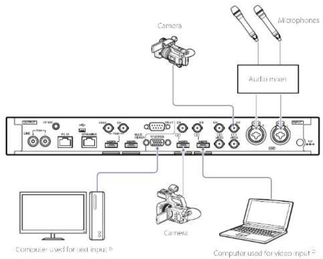
1) When using RGB Input signals to composite text, use a computer that supports the 1600x1700 (60g) output resolution. 2) Use a computer with the same frequency as the system
When linking with a Remote Commander
Use the OPTION cable supplied with the unit to connect the Remote Commander to the unit. Connect the cameras to the Remote Commander and the unit as follows.
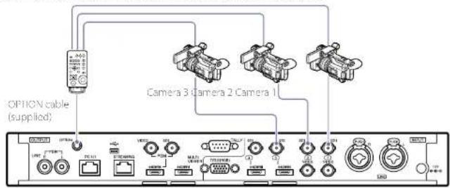
For details on connections, refer to the operating instructions for the Remote Commander and the connected cameras. For details on necessary settings, see "Licking with the Remote Commander" (page 54).
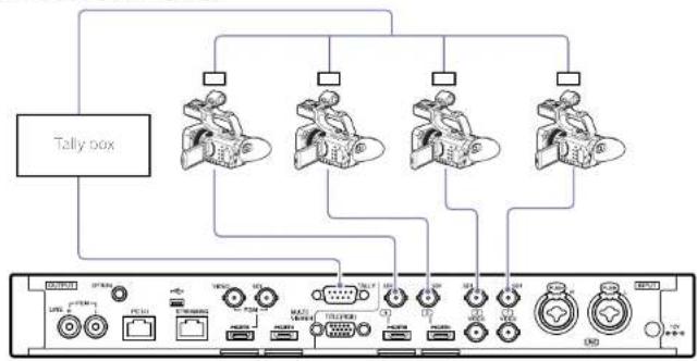
When linking via GPI connection
Connect the unit's TALLY connector to the tally connector on a commercially available tally box. Connect the cameras to the unit as follows.
flowchart
graph TD
    A["Tally box"] --> B["Device 1"]
    A --> C["Device 2"]
    A --> D["Device 3"]
    A --> E["Device 4"]
    B --> F["Port 1"]
    C --> G["Port 2"]
    D --> H["Port 3"]
    E --> I["Port 4"]
    F --> J["Device 5"]
    G --> K["Device 6"]
    H --> L["Device 7"]
    I --> M["Device 8"]
    J --> N["Device 9"]
    K --> O["Device 10"]
    L --> P["Device 11"]
    M --> Q["Device 12"]
    N --> R["Device 13"]
    O --> S["Device 14"]
    P --> T["Device 15"]
    Q --> U["Device 16"]
    R --> V["Device 17"]
    S --> W["Device 18"]
For details on connections, refer to the operating instructions for the tolly box and camera.
For details on pin assignments for the JALY connector, see "JALY connector" (page 89) in the "Pin Assignments" section.
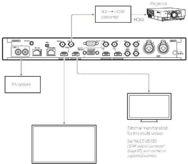
Connecting the Video and Audio Output Devices
Connect projectors, large displays, and other video output devices to the video output connectors on the rear of the unit, and connect PA systems and other audio output devices to the LINE output connectors.
flowchart
graph TD
    A["External monitor used for the multi viewer\nSee "MULTI VIEWER\nNDMI output connector" (page 87); and connect a supported monitor."] --> B["PA system"]
    B --> C["Pod network"]
    C --> D["SDI → HDMI converter"]
    D --> E["Projector"]
    E --> F["HDMI"]
Large display
For details on aspect ratio settings for SD signals and former settings for HDMI signals, see "Output Screen" (page 65) in the "Configuring the System Settings" section.
if there is a discrepancy between the video and the audio, see "PGM Output Delay" (page 69) in the "Output Screen" section, and configure a PGM output delay.
Connecting headphones
Connect headphones for audio monitoring to the headphones jack on the front of the unit.
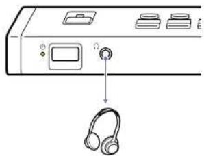
natural_image
Diagram of a CD-ROM drive with headphones and control panel (no text or symbols)Headphones
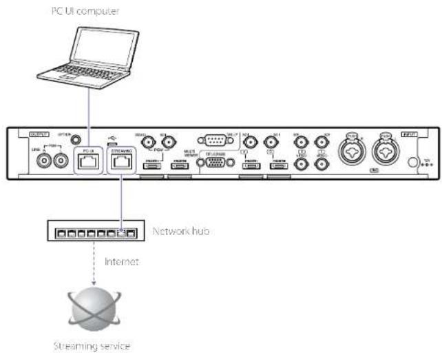
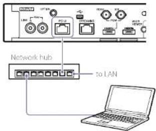
Connecting to a Network
Use the PC UI network connector on the rear of the unit to connect the PC UI computer.
For details on connections, see "Connecting a Computer for Settings Configuration" (page 22).
If you intend to use a streaming service to stream, connect to the network using the STREAMING network connector on the rear of the unit.
For details on network settings for streaming transmission, see "Configuring the Network Settings for Streaming Transmission" (page 6/1).
CAUTION
For safety, do not connect connectors for peripheral device wiring that may have excessive voltage to the following ports.
PC JI network connector
-STREAMING network connector
Follow the instructions in this document for these ports.
CAUTION
When connecting the unit to a peripheral device via a LAN
cable, use a shielded-type cable to prevent malfunction due
to radiation noise.
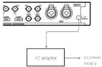
Connecting the Power Supply
Connect the DC output plug of the supplied AC adapter to the DC IN 12V connector on the rear of the unit, and connect the AC adapter to a power supply.
Startup and Shutdown
Configuring the Initial Settings (First-Time Startup)
When turning on the unit for the first time, follow the instructions on the screen to configure the initial settings.
1 Press the power switch on the front of the unit.
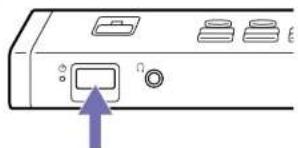
natural_image
Diagram of a device rear panel with buttons and a purple arrow pointing to the button (no text or symbols present)When the unit turns on, the ⏻ (power) indicator lights green.
After startup, the initial settings screen appears on the menu panel (touch panel).
The multi-viewer appears on the external monitor.
2 Configure the initial settings.
① Select the time zone, and tap [DONE].
![TIME ZONE GMT -5.0 New York Bogota ↓ ↑ SUMMER TIME DONE Tap [↓] or [↑] to display your region. Tap IDONE: to proceed to the next screen. Select (light) this to enable daylight savings time.](/content/2026/05/760177/images/8032f7b57f8f4b24d214cd327b27287a4d0bf92fc70e0660ac4b1a4694c2bb83.jpg)
② Configure the current date, and tap [DONE].
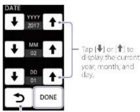
Tap [ ↗ ] to return to the previous screen.
③ Configure the current time, and tap
[DONE]
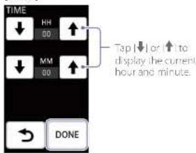
④ Select the video signal format for the unit (i.e., system format), and tap [DONI].
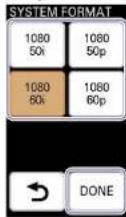
This completes the initial settings, and the unit is ready for operations.
图2
- Controls from a computer connected to the unit will be possible after the initial settings are complete.
- If the unit is not operated for about 3 months, its internal battery will be discharged and the date and time settings will be reset. In such cases, configure the settings again.
Second and Subsequent Startup
Press the power switch on the front of the unit to turn on the unit.
A menu screen will appear on the menu panel (touch panel) after startup, and the unit will be ready for operations.
Auto Power Off Function
The unit is equipped with an auto power off function that automatically turns off the unit if it is not operated for a specified amount of time. A message will appear in the menu panel if no operations are performed on the unit's control panel or on the PC UI computer. If no operations are performed for another 3 minutes, the unit automatically turns off.
You can change the amount of time before auto power off. For details on settings, see "System" Screen" (page 65) in the 'Configuring the System Settings' section.
[Tics]
If you perform an operation while the message is displayed, the unit will return to normal status.
To turn on the unit again after auto power off. Press the power switch twice.
Turning the Unit Off
Press the power switch: When a confirmation message appears, select [YES] to turn off the unit.
Connecting a Computer for Settings Configuration
This section describes how to connect the unit to a PC UI computer that can perform settings configurations and composite adjustments, and how to access the unit from a web browser to display the PC UI.
[1]i:5
The PC UI computer should not be the same as the computers used for video inputs and streaming.
Recommended Computer
Use a computer that meets the following system requirements.
Recommended OS: Windows 10
Web browser: Google Chrome
Recommended monitor size: 10 to 12 in
||i|25
- The PC UI supports both mouse and touch panel operations.
- Use the 100% display settings for the computer display and browser display
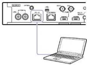
Connecting the Computer to the Unit
The following connection modes are available.
• LAN mode
A DHCP connection is used in this mode. The unit and computer are connected using IP addresses assigned by an external DHCP server.
- Direct mode
The unit's IP address is static in this mode. This allows you to specify an IP address for connection.
Use this connection mode in network environments without DHCP servers, for example.
Under default conditions, the unit's IP address is set to "192.168.0.1."
You can change the unit's IP address if necessary. For details on settings, see "Changing the Unit's IP Address" (page 68).
[1] Ds
If connection in LAN mode is not possible, connect in direct mode.
Connecting in LAN mode
Set the computer's network settings to DHCP beforehand.
1 Use a LAN cable to connect to the LAN via the PC UI network connector on the rear of the unit.
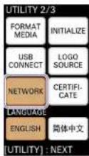
2 Press UTILITY button on the control panel to display the [UTILITY 2/3] menu.


The [NETWORK (PC UI)] menu appears.
4 Tap [LAN] (①) to enable it, and tap [CONNECT] (②).
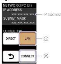
The acquired IP address is displayed. Use this IP address to access the unit via a web browser.
[105]
The IP address is assigned by an external DHCP server.
3 Tap [NETWORK]
Connecting in direct mode
1 Use a LAN cable to connect to the computer via the PC UI network connector on the rear of the unit.
2 Change the IP address of the computer to enable communication with the unit. Under default conditions, the unit's IP address is set to "192.168.0.1." If you intend to use the default setting, configure the computer's IP address as follows.
- Change the IP address to an address that is identical to the unit's up to "192.168.0" and between "192.168.0.2" and "192.168.0.254" but is unique to "192.168.0.1" (e.g., "192.168.0.10").
- Set the subnet mask to '255.755.255.0'
For details on changing the unit's IP address, see "Changing the Unit's IP Address" (page 68).
3 Press UTILITY button on the control panel to display the [UTILITY 2/3] menu.


4 Tap [NETWORK].
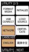
The [NETWORK (PC UI)] menu appears.
5 Tap [DIRECT] (①) to enable it, and tap [CONNECT] (②).
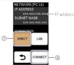
The IP address display is updated.
Accessing the Unit from a Web Browser
An authentication password is required to access the PC UI.
When accessing the PC UI for the first time, you will be prompted to configure the authentication password first.
Enter "http://
2 Configure the authentication password, and select [Log In].
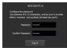
[Password]: Use between 8 to 12 characters, and be sure to include letters, numbers, and symbols (at least one each).
[Confirm Password]: Reenter the same password to confirm.
[Notes]
Do not use your web browse/s "remember password" function.
When the password is authenticated and login is successful, the [Live] screen of the PC UI appears in the web browser.

[Notes]
Communications are not encrypted in HTTP connections, lowering the security level. Be aware of the security risk when using such connections.
When the authentication password is already configured
When the authentication password is already configured, the password entry screen appears. Enter the authentication password, and select [Log In].
[Tips]
If the authentication password is initialized on the unit during access to the PC UI, a message will appear and access will be terminated. Select [OK] to display the configuration screen for the authentication password, and configure the authentication password again. However, if the authentication password is reconfigured before you via another user's computer, for example, the password entry screen appears..
You can reset the authentication password if necessary. For details, see "Restoring Factory Default Conditions" (page 57).
Improving Security
Use HTTPS connections with encrypted communications to improve security. After accessing the unit, download the CA certificate, and install it on your web browser.
1 Start your computer's web browser, and enter "http://
When connection is successful, the "CA certificate for the switcher" appears.
2 Download the 'CA certificate for the switcher' to any location.
3 Install the 'CA certificate for the switcher' on the web browser.
Double-click the downloaded CA certificate file, and follow the instructions on the screen to install.
4 Access "https://
5 Reference the CA certificate using the method used by your web browser. When using Google Chrome, perform the following.
① Click the lock icon on the left side of the address bar, and click [Details] in the menu that appears.
② Click [View certificate]. The certificate viewer appears.
③ Reference the [Issued to] item. Sony-MCX-500
6 Use the following methods to configure the name resolution between the unit's IP address and the CA certificate issue location.
- Register to the hosts file.
7 After finishing configurations, enter "https://Sony-MCX-500
8 Enter the authentication password, and select [Log In]. When the password is authenticated and login is successful, the [Live] screen of the PC UI appears in the web browser.
Notes
When using Google Chrome version 58 or later, a security warning will appear when you display the PC UI. However, you can ignore this warning and proceed with operations.
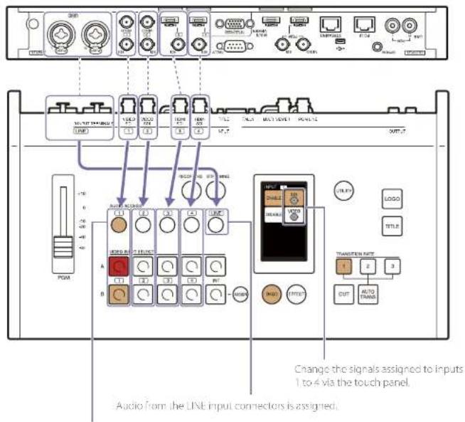
Assigning Inputs
To switch videos and mix audio, the signals from the devices connected to the input connectors on the rear of the unit must be assigned to inputs 1 to 4.
Under default conditions, the signals are assigned as follows
Audio included in SDI and HDMI videos
(embedded audio) will automatically
be assigned to the audio inputs of the
same number
[125]
You can turn off (disab.e) automatically assigned audio. For details, see "Linking embedded audio to its videos" (page 28).
Default conditions
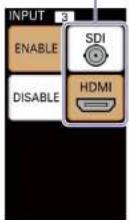
| Video input (VIDEO INPUT SELECT) | Audio input (AUDIO ACCESS) | Connector number | Input signal Status | (ENABLE/ DISABLE) |
| 1 1 1 SD ENABLE | ||||
| 2 2 2 SD ENABLE | ||||
| 3 3 3 SD ENABLE | ||||
| 4 4 4 SD ENABLE | ||||
| INT -- BLACK ENABLE | ||||
| - LINE LINE LINE input audio signals ENABLE | ||||
Assigning Video Inputs
Under default conditions, videos from the devices connected to the SDI input connectors are assigned to inputs 1 to 4. When devices are connected to the VIDEO and HDMI input connectors, you must change the assigned connectors (materials).
1 Check the video inputs in the multi-viewer.
Check that videos from the connected devices appear in the [INPUT] viewer.
Display example: When SDI is assigned to inputs 1 to 4 (default)
!["No Signal" is displayed when there is no signal input. [INPUT] viewer 1:50 2:50 3:50! 4:50 10:34:00 TITLE PGM L R RECORDING AVCHD 1080/601 FH STREAMING No signal No signal](/content/2026/05/760177/images/0be63a8db799cba43dbdee9de9ff5a635fc5fbc9e4f92beb94d11b89c2f762e9.jpg)
If you want to assign different materials, proceed to step 2.
2 Press and light the ASSIGN button.
The [INPUT] menu for the input currently selected in row B appears in the menu panel.
3 Press and light the row 8 button number for which you want to change the input material. If a device is connected to HDMI input connector 3, for example, light button 3.
The [INPUT] menu changes to that of the selected button.
[1ips] You can rename input materials if necessary. For details on naming input materials, see "Input" Screen" (page 69) in the "Configuring the System Settings" section.
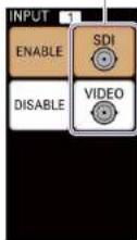
4 Tap and select (light) the target connector. When a connector is selected (lit), it is immediately assigned and its video input appears in the multi-viewer. The selectable connectors differ depending on the input number.
For inputs 1 and 2
Tap and select (light) [SD] or [VIDEO].
Select an option.
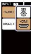
For inputs 3 and 4
Tap and select (light) [SD] or [HDMI].
Select an option.
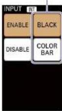
For INT
Tap and select (light) [BLACK] or [COLOR BAR] Select an option.
If there are inputs you do not intend to use Selecting (lighting) [DISABLE] disables the VIDEO INPUT SELECT button for that number. This prevents accidental pressing of buttons that do not have video inputs.
| |ips|
When VID=0 is selected for inputs 1 and 2, the respectively numbered audio inputs will be disabled.
Button Option Description
| 1 and 2 SDI Assigns the materials input tothe SDI input connectors.The embedded audio is alsoassigned to the respectivelynumbered audio inputs. |
| VIDEO Assigns the materials input tothe VIDEO Input connectors.The respectively numberedaudio inputs are disabled. |
| 3 and 4 SDI Assigns the materials input tothe SDI input connectors.The embedded audio is alsoassigned to the respectivelynumbered audio inputs. |
| HDMI Assigns the materials input tothe HDMI input connectors.The embedded audio is alsoassigned to the respectivelynumbered audio inputs. |
INT BLACK Assigns a black signal.
[1]ips
When a 4:2 SD signal is input, the video is displayed at the center of a 16:9 display with black bars on both sides.

5 After finishing configurations, press and unlight the ASSIGN button.
The [INPUT] menu disappears.
6 Check the assigned video input in the multi-viewer.
Tips INT input cannot be checked in the multi-viewer.
Pre-Adjustments and Settings for Audio Inputs
Determine whether to use each channel, adjust input levels, and configure settings for the audio inputs.
[Tips] Decrease the volume before connecting or disconnecting input devices (input signals).
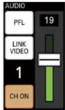
Determining whether to use each channel
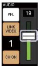
Specify whether to use or disable each channel. Press an AUDIO ACCESS button to display the [AUDIO] menu, and select (use) or deselect [CH ON]. When [CH ON] is deselected, the audio will be disabled.
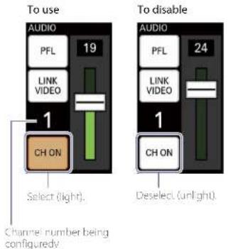
When SDI or HDMI signals are assigned to inputs 1 to 4, the embedded audio is automatically assigned to the respectively numbered audio inputs. However, you can disable the audio via this setting.
Adjusting the audio level of each channel
Adjust the audio level of each channel while viewing the audio level meters in the multi viewer. Perform the adjustments while considering the overall balance.
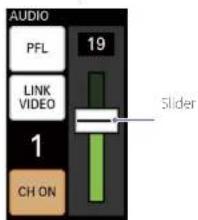
1 Set the PGM master fader to the 0 dB position
2 Press an AUDIO ACCESS button to display the [AUDIO] menu.
3 Drag the slider to adjust the audio level. You can adjust to a value between 0 to 31

Viewing the audio level meters
The left end
represents - and is always lit green.
Over-level indicator Lights red at 0 dB.
4 Repeat the procedure to adjust each audio input.
[196]
If adjustments via the unit are not sufficient, perform adjustment on the input device as well.
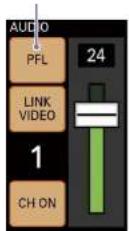
Linking embedded audio to its video
To automatically enable or disable embedded audio in response to PGM output, link the embedded audio to its video.
When a video for which the embedded audio channel is specified as linked is output as the PGM output, the embedded audio is also output in the PGM output. When the video is not being output as the PGM output, the embedded audio is disabled.
To link, select [LINK VIDEO].
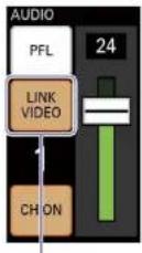
Select (light).
[1]
The embedded audio can be enabled/disabled manually via [CH ON], even when LINK VIDEO is selected.
Switching Videos
This section describes how to switch PGM output videos using simple operations.
Switching via Cuts (Basic Switching)
First, let's try switching videos without applying any effects.

natural_image
Two photos showing a crowd at night and a person holding a microphone, both in silhouettes with no visible text or symbols.Switching videos using only the row A buttons
This is the simplest switching method.
Switch videos using only the buttons in this row.
The buttons in row A are used to select the material to output as the PGM output.
1 Check the assigned videos in the [INPUT] viewer of the multi-viewer.
For details on changing the assigned videos, see "Assigning inputs" (page 25).
2 Press the button for the video you want to output as the PGM output. The selected button lights red, and the video is output as the PGM output.
The button for the current PGM output video lights red.
3 Press the button for the video to which you want to switch. The selected button lights red, and the video switches.
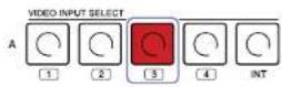
The video switches each time you press a row A button.
1234

natural_image
Sequence of four photos showing a performer on stage, with silhouettes and dramatic lighting in the background (no text or symbols)Previewing videos before switching
Preview the video to be output next as the PCM output in the multi-viewer before switching to it.
Use the buttons in rows A and B.
The buttons in row B are used to select the video to output next as the PGM output.
Check that the BXCD button is it beforehand. If the button is unfit, press and light it.
Press this button to switch the video.
1 Check the assigned videos in the [INPUT] viewer of the multi-viewer.
For details on changing the assigned videos, see "Assigning Inputs" (page 25).
2 Press the button for the video you want to output next as the PGM output.
Video to be output next as the PGM output
The selected video appears in the [NEXT] viewer of the multi-viewer.
A frame indicating selection as the NEXT output appears around the video selected in row B.
3 Press the CUT button.
The video switches.
Applying Transition Effects
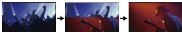
Now, let's try switching using patterns that slowly transition the current PCM video into the next video.
Mix
Dissolve from one video into the next.
A A/B B

natural_image
Three sequential photos showing a person performing on stage with raised arms, under dramatic lighting (no text or symbols visible)Wipe
Wipe the next output video over the PGM video.
A A B B

natural_image
Sequence of three photos showing a person holding a microphone against a stage with raised arms, captured in different lighting and posture (no text or symbols visible)A A/B B
natural_image
Three sequential photos showing a person holding a microphone against a stage with spotlights, captured in different angles (no text or symbols visible)Use the buttons in rows A and B.
The buttons in row B are used to select the video to output next as the PGM output.

Check the assigned videos in the [INPUT] viewer of the multi viewer.
For details on changing the assigned videos, see "Assigning inputs" (page 25).
2 Press the BKGD button to enable BKGD mode. The pattern icons selectable in BKGD mode are displayed in the menu panel.

For details on the modes, see "BGO Mode and I11C1 Mode" (page 17).
3 Press the button for the video you want to output next as the PGM output.
flowchart
graph TD
    A["1"] --> B["2"]
    B --> C["3"]
    C --> D["4"]
    D --> E["INT"]
    E --> F["ASSIGN"]
Video to be output next as the PGM output
The selected video appears in the [NEXT] viewer of the mult-viewer.
A frame indicating selection as the NEXT output appears around the video selected in row B.
4 Tap and select a pattern icon.
Tips
20 wise patterns are available on the unit.
For details on the patterns available on the unit, see 'Transition and Composite Patterns List' (page 70).
5 Select a transition rate with the TRANSITION RATE buttons. Under default conditions, transition rates of 0.5, 1.0, and 1.5 seconds are assigned to TRANSITION RATE buttons 1 to 3.
For details on changing the transition rates assigned to each button, see "Changing the Transition Rates" (page 53).
6 Press the AUTO TRANS button.
The transition starts, and the videos switch.

natural_image
Three sequential photos showing a performer in a hat with raised arms, captured in different lighting and shadow settings (no text or symbols visible)When a link is configured between the video and its embedded audio, the enabling and disabling of the embedded audio is determined by whether the video is being output as the PGM video.
For details on settings, see "Linking embedded audio to its video" (page 28).
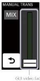
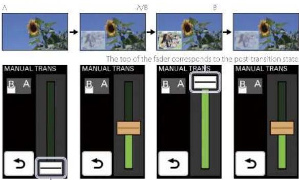
Manually Switching Videos
You can also manually execute transitions using a GUI video fader.
Manual transitions can be performed in both the BKGD and EFFECT modes.
[1]
Manual transitions cannot be performed on the PC UI.
1
Tap and select a pattern icon, and then tap [MANUAL TRANS].
The [MANUAL TRANS] menu appears.
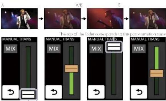
2 Drag the GUI video fader to execute the transition. The video will transition according to the movement of the GUI video fader.
BKGD mode
flowchart
graph LR
    A["Music Player"] --> B["Adder"]
    B --> C["Adder"]
    C --> D["Adder"]
    D --> E["The top of the lader corresponds to the post-transition stage"]

    subgraph Stage_A
        F1["MIX"] --> G1["Transfer"]
        G1 --> H1["Transfer"]
    end

    subgraph Stage_B
        I1["MIX"] --> J1["Transfer"]
        J1 --> K1["Transfer"]
    end

    subgraph Stage_C
        L1["MIX"] --> M1["Transfer"]
        M1 --> N1["Transfer"]
    end

    subgraph Stage_D
        O1["MIX"] --> P1["Transfer"]
        P1 --> Q1["Transfer"]
    end

    style F1 fill:#f9f,stroke:#333
    style I1 fill:#f9f,stroke:#333
    style L1 fill:#f9f,stroke:#333
The bottom of the fader corresponds to just video A
EFFECT mode
flowchart
graph LR
    A["Input Image"] --> B{A/B}
    B --> C["Input Image"]
    C --> D["Post Transition State"]

    subgraph 'The top of the fader corresponds to the post-transition state'
        E1["MANUAL TRANS B A"] --> F1["Green bar with horizontal band"]
        F1 --> G1["Orange bar with horizontal band"]
        G1 --> H1["Green bar with horizontal band"]
        H1 --> I1["Orange bar with horizontal band"]
    end

    subgraph 'Manual Trans' conditions
        J1["MANUAL TRANS B A"] --> K1["Green bar with horizontal band"]
        K1 --> L1["Orange bar with horizontal band"]
        L1 --> M1["Green bar with horizontal band"]
        M1 --> N1["Orange bar with horizontal band"]
        N1 --> O1["Orange bar with horizontal band"]
    end
The bottom of the fader corresponds to the pre-transition state.
A/B
A/B
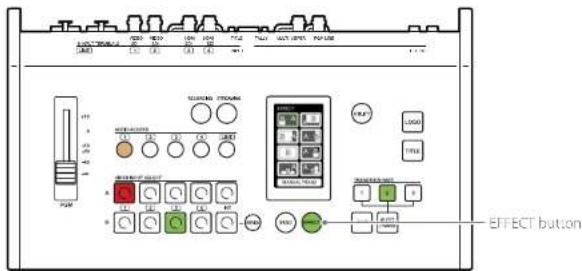
Compositing Videos
Switch to EFT I.CI mode when you want to use the picture-in-picture (PinP) function, insert a person onto a background, or otherwise use composite effects on videos.
Use the buttons in rows A and B.
Select the video to be inserted with the row B buttons.
1 Check the assigned videos in the [INPUT] viewer of the multi-viewer.
For details on changing the assigned videos, see 'Assigning inputs' (page 25).
2 Press the EFFECT button to enable EFFECT mode.


Lit
The pattern icons selectable in EFFECT mode are displayed in the menu panel.
3 Press the row B button for the video you want to insert.
Current PGM output video
Overlay video
The selected video appears in the [NEX] viewer of the multi viewer.
A frame indicating selection as the NEXT output appears around the video selected in row B.
4 Tap and select a pattern icon.

Pre-adjustment may be necessary depending on the pattern. For details, see "Adjustments for Inserting People onto Backgrounds (Chrome Key)" (page 45).
5 Select a transition rate with the TRANSITION RATE buttons.
For details on changing the rates assigned to the buttons, see "Changing the Transition Rates" (page 53).
You can also execute transitions manually. For details on operations, see "Manually Switching Videos" (page 23).
6 Press the AUTO TRANS button.
The transition starts, and the videos are composited.

natural_image
Sunflower in a field with people observing, inset shows group photo (no visible text or symbols)When a link is configured between the video and its embedded audio, the enabling and disabling of the embedded audio is determined by whether the video is being output as the PCM video.
For details on settings, see "Linking embedded audio to its video" (page 28).
TDS
Pressing the CUT button will switch to the composite image instantly.
Canceling composites
Press the AUTO TRANS or CUT button.
The composite will be enabled/disabled with each press.
Inserting Text onto Videos
The procedure will differ depending on the format of the text signal being input from the computer.
Using RGB Input Signals to Insert Text (TITLE Function)
Perform the following to overlay the text (signal) that is input from a computer connected to the TITLE (RGB) input connector on the rear of the unit. The TITLE function can be used in both the BKGD and EFFECT modes, and can be used in conjunction with other video effects.
Pre adjustment is necessary when inserting text onto videos. For details, see "Using RGB Input Signals to Insert Text (101F Function)" (page 47).
1 Check that the RGB signal from the computer is being input in the [INPUT] viewer of the multi-viewer.
Input signal from the computer
2 Select (light) the TITLE button.


The text is composited onto the video via a cut.
Input signal from the computer

Canceling composites
Press the TITLE button
The composite will be enabled/disabled with each press.
Using HDMI Input Signals to Insert Text (EFFECT Mode)
Perform the following to use EFFECT mode to overlay the text (signal) that is input from a computer connected to an HDMI input connector on the rear of the unit. This method cannot be used in conjunction with other video effects.
Pre-adjustment is necessary when inserting text onto videos. For details, see "Using HDMI Input Signals to Insert Text (FHEFCI Mode)" (page 48).
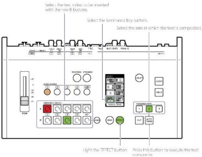
1 Check the assigned videos in the [INPUT] viewer of the multi-viewer. For details on changing the assigned videos, see "Assigning inputs" (page 25).
2 Press the EFFECT button to enable EFFECT mode.

The pattern icons selectable in EFFECT mode are displayed in the menu panel.
3 Press the row B button for the text video you want to insert.
Current PGM output video

Text video
The selected video appears in the [NEXT] viewer of the multi-viewer.
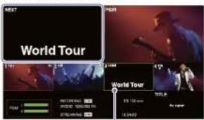
A frame indicating selection as the NEXT output appears around the video selected in row B.
4 Tap and select a luminance key pattern icon.
5 Select a transition rate with the TRANSITION RATE buttons.
For details on changing the rates assigned to the buttons, see "Changing the Transition Rates" (page 53).
You can also execute transactions manually. For details on operations, see "Manually Switching Videos" (page 33).
6 Press the AUTO TRANS button.
The transition starts, and the text is composited.

When a link is configured between the video and its embedded audio, the enabling and disabling of the embedded audio is determined by whether the video is being output as the PGM video.
For details on settings, see "Linking embedded audio to its video" (page 26).
[Tips]
Pressing the CUT button will switch to the composite image instantly.
Canceling composites
Press the AUTO TRANS or CUT button.
The composite will be enabled/disabled with each press.
Inserting Logos onto Videos
Perform the following to composite still images that have been registered to the unit beforehand onto a video as a logo.
The LOGO function can be used in both the BKGD and EFFECT modes, and can be used in conjunction with other video effects.
Pre-adjustment is necessary when inserting logos onto videos. For details, see "Adjustments for inserting logos onto Videos" (page 50).
Although you can register up to two logos, only one of them can be composited at one time. You must select the logo to be composited.
1 Press UTILITY button on the control panel to display the [UTILITY 2/3] menu.


2 Tap [LOGO SOURCE].
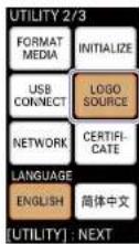
The [LOGO SOURCE] menu appears.
3 Tap and select the button of the logo you want to composite (L OGO 1) or (L OGO 2).
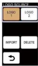
□05
An imported logo file will not be assigned until the unit is restarted. If a previously assigned logo exists, that logo will be displayed.
4 Enable (light) the LOGO button


The logo is composited onto the video via a cut.

-Logo
Canceling composites
Press the LOGO button.
The composite will be enabled/disabled with each press.
Live Adjustments
Switching between Two Devices Connected to a Single Input
You can connect two video input devices each for inputs 1 to 4 and switch input assignments.
Press the ASSIGN button, press the row B button number for which you want to switch the input, and then tap the connector to which you want to switch in the [INPUT] menu.
Tap to switch between the two inputs.
The video may distort at the moment of switching, so be sure to check the video in the [NEXT] viewer.
Adjusting the Headphone Volume
Display the [UTILITY 1/3] menu, lap and select (light) [HEAD PHONES], and adjust the volume using the slider.
You can adjust too a level between 1 to 16 (increments of 1).
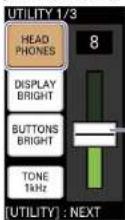
Drag the slider to adjust the volume.
11ips
• Audio is not completely disabled at level 1.
- When using earphones or headphones, be careful not to raise the volume too high. Prolonged exposure to high volumes that stimulate the ears may cause adverse effects to hearing.
- Decrease the volume before connecting or disconnecting input devices (input signals) and headphones
Adjusting the Overall Audio Level
Use the PGM master fader to adjust the PGM output level.
Perform adjustments while viewing the audio level meters in the multi-viewer.
Adjusting Individual Audio Levels
When the voice of a speaker or the sound of an instrument is too loud or small, display the [AUDIO] menu for the corresponding channel and readjust the input level.
Drag the slider to adjust the input level.
Enabling/Disabling Use of Audio Channels
Display the [AUDIO] menu for the corresponding channel, and select or deselect [CH ON].
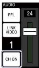
Listening to the Current Audio Input
By lapping and holding [PFL], you can listen to and monitor only the currently selected audio via headphones.
The button remains ill, while it is held, and the current audio can be monitored by itself, regardless of slider adjustments.
[1]35
When [CHON] is deselected, slider adjustments can be performed, but audio cannot be monitored.
For details on headphone volume, see "Adjusting the Headphone Volume" (page 38).
Outputting the Audio Tone Signal with the PGM Output
Display the [UTILITY 1/3] menu, and output the 1 kHz tone signal with the PGM output using [TONE 1kHz].
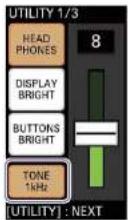
Select (lit): Outputs the 1 kHz tone signal (fixed level ^10 ) with the PGM output.
Deselect (unlit): Does not output the tone signal.
System format Level
501.50p 18dB
60i, 60p -20 dB
Adjusting the Menu Panel Brightness
Display the [UTILITY 1/3] menu, tap and select (light) [DISPLAY BRIGHT], and select the menu panel (touch panel) brightness.
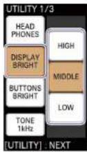
[HIGH]: Brightest level.
[MIDDLE]: Medium brightness level.
[LOW]: Darkest level.
Adjusting the Button Brightness
Display the [UTILITY 1/3] menu, lap and select (light) [BUTTONS BRIGHT], and select the button brightness.
The brightness level will be applied to all buttons.
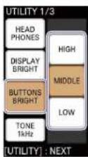
[HIGH]: Brightest level.
[MIDDLE]: Medium brightness level.
[LOW]: Darkest level.
Customizing the Pattern Icons
Up to eight transition pattern or composite pattern icons can be displayed in the [BKGD] and [EFFECT] menus of the menu panel. Under default conditions, the following pattern icons are displayed.
BKGD mode EFFECT mode
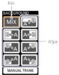
In addition to the above, a number of other pattern icons are available on the unit. If necessary, you can replace the pattern icons that appear in the menus with icons you will use during live operation.
Tips
- You can remove unnecessary pattern icons from the menu to prevent accidental operation.
- You can rearrange the pattern icons for convenience,
Use the PC UI on a computer to perform pattern icon replacement.
[Notes]
Pattern icons cannot be edited unless the [BKGD] or [EFFECT] menu is displayed on the menu panel of the unit and the PC UI's [Live] screen.
Replacing the Pattern Icons in the [BKGD] Menu
Select the transition patterns you want to display from among the templates.
1 Display the [Pattern] screen of the PC UI in BKGD mode. You can also switch to BKGD mode using the BKGD button after displaying the [Pattern] screen.
2 Replace the pattern icons with the desired icons, and check the transitions
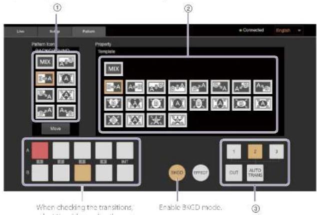
① Select the transition pattern icon you want to replace.
② Select the pattern icon you want displayed in the menu from the [Property] area. BKCD pattern icons appear in the [Property] area. When you select a pattern icon in this area, it replaces the other icon immediately.
③ Select the AUTO TRANS or CUT button to execute the transition. Check the transition effect by viewing the multi-viewer.
Replacing the Pattern Icons in the [EFFECT] Menu
Select the composite patterns you want to display from among the PinP, chroma key, and luminance key templates.
Adjustment values for key compositing can also be configured for chroma key and luminance key pattern icons.
1 Display the [Pattern] screen of the PC UI in EFFECT mode.
You can also switch to EFFECT mode using the EFFECT button after displaying the [Pattern] screen.
2 Replace the pattern icons with the desired icons, and check the compositions.
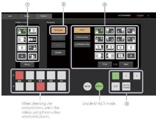
① Select the composite pattern icon you want to replace.
② Select [Template] in the [Property] area menu. Pattern icons appear in the editing area on the right.
③ Select the effect type, and then select the pattern icon you want displayed in the menu. Pattern icons for each effect type appear in the editing area. When you select a pattern icon in this area, it replaces the other icon immediately.
④ Select the AUTO TRANS or CUT button to execute the composite. Check the composition by viewing the multi-viewer.
⑤ Adjust the composition. For details, see the following.
"Adjustments for Inserting People onto Backgrounds (Chrome Key)" (page 45)
"Using HDMI Input Signals to Insert text (F-HFC) Model" (page 48)
Removing Pattern Icons
You can remove pattern icons that you do not intend to use.
1 Select [Move] in the menu panel.
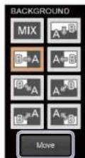
[Move] mode is enabled.
2 Select the unnecessary pattern icon, and select [Delete]
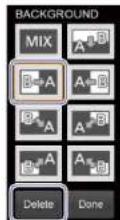
The selected pattern icon is removed and replaced by the [Empty] icon.
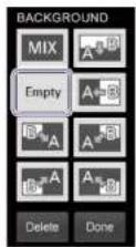
3 After finishing configurations, select [Done].
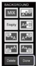
The pattern icons displayed in the menu are changed.
Tips
- The [Empty] icon will not appear on menu panel of the unit and the PC UI's [Live] screen.
- Performing controls on the unit exits (Move) mode.
Rearranging Pattern Icons
1 Enable [Move] mode, and then drag and drop the pattern icon to the desired position.
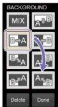
2 After finishing configurations, select [Done]. The arrangement of the pattern icons displayed in the menu is changed.
Selecting Picture-in-Picture (PinP) Patterns
This section describes preparations for video composites that use PinP. PinP is a composite effect that inserts an overlay video (B) onto a background video (A).
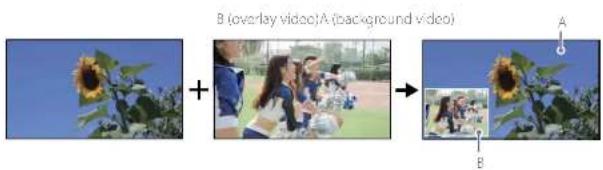
60 PinP patterns are available on the unit. As preparation, select the pattern icons that will be used during live operation, and check the video composition.
1 Display the [Pattern] screen of the PC UI in EFFECT mode.
2 Select the button for the background video in row A of the video selection buttons, and select the overlay video in row B.
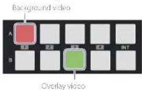
The background video selected in row A appears in the [PGM] viewer of the multi-viewer, and the overlay video selected in row B appears in the [NEXT] viewer.
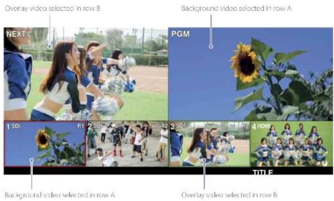
3 Select a PinP pattern icon, and check the composition.
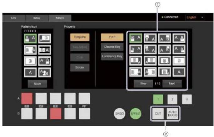
There are three pages of PinP pattern icons.
Selecting [Next] displays the next page, while selecting [Prev] returns to the previous page.
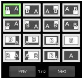
for details on the selectable pattern icons, see "Transition and Composite Patterns List" (page)
② Press the CUT or AUTO TRANS button, and check the composition.
You can view the composition in the multi-viewer.

natural_image
Collage of outdoor scenes including a sunflower, group photos, and children playing soccer (no visible text or symbols)4 Select [Border], and select whether to include a border around the overlay video.
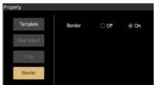
[Off]: Does not include a border. [On]: Includes a border.
Useful tip
When switching from BKGD mode to EFFECT mode, a composite image using the pattern that was last used in EFFECT mode may be output. To avoid such occurrences, operate as follows.
① Assign pattern icon No. 90 to the effect patterns, and make it available for use.

Pattern icon No. 90
② Select pattern icon No. 90 before switching from EFFECT mode to BKGD mode.
The above operation allows you to switch to EFFECT mode without affecting the PCM output video. Afterward, check the B video, select a composite pattern, and execute the composite.
For details on patterns that are output as FGM in their composited state when switching from BKGD mode to EFFECT mode, see "Transition and Composite Patterns List" (page 70).
Useful tip
If you want to display video B in full screen immediately after using a PinP composition, select pattern icon No. 12.

Pattern icon No. 12
When pattern icon No. 12 is selected after a composition was performed via the CUT button or AUTO TRANS button with pattern icon No. 1 selected, the image will switch as follows.

[Yes]
Standard EFFECT mode transitions simply turn the video B display on and off as follows. However, using pattern icon No, 12 allows you to easily display video B in full screen.

Adjustments for Inserting People onto Backgrounds (Chroma Key)
This section describes preparations for video composites that use chroma keying. Chroma keying is a compositing technique that involves removing a specified color in the overlay video (green in the following example) and overlaying the remaining parts of the video (a person in the following example) onto the background video.
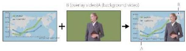
Five chroma key patterns are available on the unit. As preparation, select the pattern icons that will be used during live operation, and adjust the key composition. Composite adjustment values can also be configured for the pattern icon.
1 Display the [Pattern] screen of the PC UI in EFFECT mode.
2 Select the button for the background video in row A of the video selection buttons, and select the overlay video in row B.
Background video
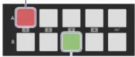
Overlay video
The background video selected in row A appears in the [PGM] viewer of the multi-viewer, and the overlay video selected in row B appears in the [NEXT] viewer.
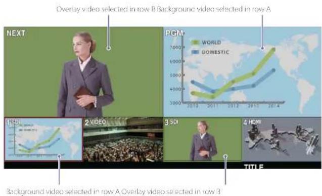
3 Select a chroma key pattern icon, and adjust the key composition.
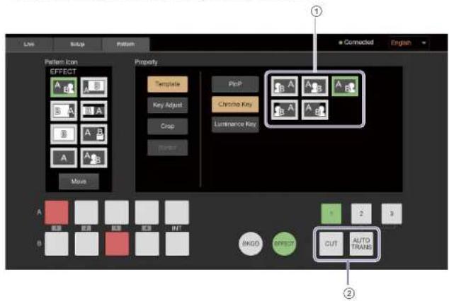
When you select [Auto], the following screen appears.
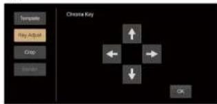
In addition, a sample mark (white frame) appears in the [NEXT] viewer of the multiviewer.
Sample mark (white frame)

5 Move the sample mark to select the color that will be removed for the composite.
①
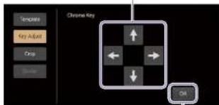
②
① Use the arrow buttons to move the sample mark position to the color you want to remove.
The sample mark moves in the direction of the selected arrow.
Tips
The arrow buttons cannot be used to move the sample mark to positions that cannot be specified.
② Select [OK].
The color on which the sample mark is placed will be used as the basis for color removal.
Perform adjustments while viewing the results in the multi-viewer.
The key adjustment screen for chroma keying appears.
The setting values are automatically configured based on the color on which the sample mark is placed.
Adjusting the composition
View the composition in the [PGM] viewer of the multi-viewer, and perform the following if further adjustments are necessary.
1 Drag each sider to perform fine adjustments. Adjusted values will be reflected in the effect pattern icon.
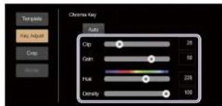
[Clip]: Adjusts the brightness level of the key color to be removed as a value between 0 to 100.
[Gain]: Adjusts the sensitivity of the key (i.e., smoothness of the key edges) as a value between -100 to 100.
[Hue]: Adjusts the hue of the key color to be removed as a value between 0 to 359.
[Density]: Adjusts the density of the video to be inserted as a value between 0 to 100.
2 Select [Crop] to crop unnecessary areas of the overlay video.
①
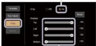
②
① Select [On] to crop unnecessary areas. When you select [On], operation of the [Position] sliders is enabled.
② Drag each slider to specify the area you want to use.
Areas of the video that are outside of the specified area will be cropped.
[Top]: Specifies the top edge of the used video as a value between -100 to +100.
This cannot be lower than the [Bottom] position.
[Left]: Specifies the left edge of the used video as a value between -100 to +100.
This cannot be to the right of the [Right] position.
[Right]: Specifies the right edge of the used video as a value between -100 to +100.
This cannot be to the left of the [Left] position.
[Bottom]: Specifies the bottom edge of the used video as a value between -100 to +100.
This cannot be higher than the [Top] position.
[1]ips
To restore default values, select [Reset].
Adjustments for Inserting Text onto Videos
Two methods are available for inserting text onto videos.
- Using RGB input signals to insert text (TITLE function)
You can overlay the text (signal) that is input from a computer connected to the TITLE (RGB) input connector on the rear of the unit. This feature is called the TITLE function. The TITLE function can be used in both the BKGD and EFFECT modes, and can be used in conjunction with other video effects.
• Using HDMI input signals to insert text (EFFECT mode)
You can use EFFECT mode to overlay the text (signal) that is input from a computer connected to an HDMI input connector on the rear of the unit. This method cannot be used in conjunction with other video effects.
This section describes preparations for video composites that insert text.
Using RGB Input Signals to Insert Text (TITLE Function)
The TITLE function can only be used to overlay text inputs from a computer connected to the TITLE (RGB) input connector on the rear of the unit.
Text Inserted via the TITLE function

[Tips]
Only 1600×1200 (50p) signals are supported for input. Use a computer that supports this output resolution.
As preparation, create the text on the computer, and adjust the composition.
Creating the text on the computer
Create text on backgrounds with significant difference in brightness, such as white text on a black background (as shown in the example), or black text on a white background. We recommend creating a 1600×1200 image.
Example: White text on a black background

[1]ps
Create text with sufficient space around the top and bottom sides. If the space is insufficient, text overlay may not be possible.
Adjusting the composition
Overlay the text input from the computer onto the PGM output video, and adjust the composition. Use the PC UI to perform adjustments while viewing the output video in the multi-viewer.
1 Output the background video as the PGM output.
In addition, check that the input signal from the computer appears in the [INPUT] viewer.
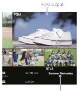
Input signal from the computer
2
Select (light) the TITLE button.


The input signal from the computer is overaid on the video.
Input signal from the computer

3 Select [Title] in the [Setup] screen of the PC UI, and adjust the text composition. Perform adjustments while viewing the PGM output video in the multi viewer.
[Key Adjust]
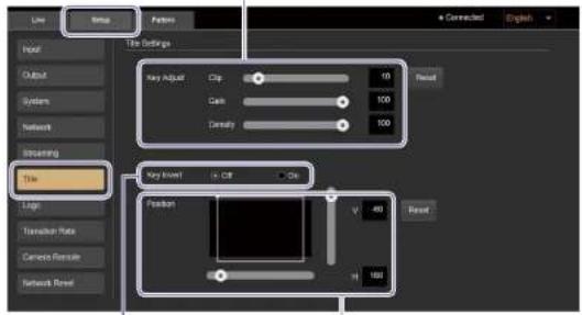
[Key Invert] [Position]
[Key Adjust]
Allows you to adjust the composition via the sliders.
[Clip]: Adjusts the brightness level of the key color to be removed as a value between 0 to 100.
[Gain]: Adjusts the sensitivity of the key (i.e., smoothness of the key edges) as a value between -100 to 100.
[Density]: Adjusts the density of the text as a value between 0 to 100.
[1]
To restore default values of each adjustment, select [Reset].
[Key Invert]
Specifies whether to invert the key signal.
[Off]: Does not invert the signal.
[On]: Inverts the signal.
[Position]
Allows you to specify the position of the inserted text via the sliders.
Specify the position using the top left of the TITLE material (1600×1200) as the base point.
[H]: Adjusts the horizontal position as a value between 0 to 1919 pixels.
[V]: Adjusts the vertical position as a value between -120 to 1079 pixels.
Tips
To restore default values of each adjustment, select [Resc].
Using HDMI Input Signals to Insert Text (EFFECT Mode)
Luminance key patterns are used when inserting text with EFFECT mode.
Luminance keying is a compositing technique that involves removing components in the overly video (B) signal based on brightness (luminance) differences, and overlaying the video on the background video
(A). Typically, bright colored text is created on a black background to be used as a key.
Luminance key ng is supported for HDMI input signals assigned to inputs 3 and 4.
![A AB (key) World Tour World Tour [Key Invert] B (key)](/content/2026/05/760177/images/9f6007f2c7b115bef1bb4e98b7bab4d4dce77bcd1141c2767249a553edff9edb.jpg)
Only one luminance key pattern is available. As preparation, create the text on the computer, and adjust the text composition (i.e., level of key removal). Composite adjustment values can also be configured for the pattern icon.
Creating the text on the computer
Create a black background and text of a color (e.g., white) that differs greatly in brightness from the background.
When recommend creating the material in the 16:9 aspect ratio.

Adjusting the composition (i.e., level of key removal)
1 Display the [Pattern] screen of the PC UI in EFFECT mode.
2 Select the button for video A in row A of the video selection buttons, and select the key video in row B.
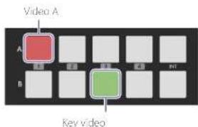
The video selected in row A appears in the [PGM] viewer of the multi viewer, and the key video selected in row B appears in the [NEXT] viewer.
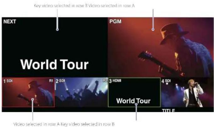
3 Select the luminance key pattern icon, and adjust the level of key removal.
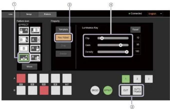
① Select the luminance key pattern icon.

② Press the CUT or AUTO TRANS button. The transition starts, and the videos are composited.

③ Select [Key Adjust].
④ Drag each slider to adjust the level of key removal.
Perform adjustments while viewing the results in the [PGM] viewer of the multi-viewer.
[Clip]: Adjusts the brightness level of the key color to be removed as a value between 0 to 100.
[Gain]: Adjusts the sensitivity of the key (i.e., smoothness of the key edges) as a value between -100 to 100.
[Density]: Adjusts the density of the text as a value between 0 to 100.
|ips
To restore default values of each adjustment, select [Reset].
Adjustments for Inserting Logos onto Videos
You can insert 320x370-sized still images onto videos as logos. We recommend using images that include an alpha channel for logos. However, composite adjustment can be performed without images that include an alpha channel.
Example: Areas defined by the alpha channel are displayed as the logo
Logo with alpha channel


natural_image
Person singing on stage with colorful lighting (no visible text or symbols)As preparation, import logo files onto the unit, and adjust the composition.
Preparing the Logos
Use a memory card to import the logo files onto the unit.
Up to two logos can be imported.
[Notes]
Always use memory cards that were formatted on the unit.
for details on operations, see "Hormoring Memory Cards" (page 56).
1
Create the logo files on a computer.
We recommend using images that include an alpha channel.
When using images that do not include an alpha channel, create the logos on backgrounds with significant difference in brightness, such as a white logo on a black background (as shown in the example) or a black logo on a white background.
Example: White logo on a black background

Recommended size: 320×320
File format .png
File names: For |LOGO 1|: LOGO1.png
For LOGO 2: LOGO2.png
*The file names are case sensitive and must be exactly as above.
2
2 Copy the logo files to the root directory of the memory card.
3
3 Insert the memory card in the memory card slot on the front of the unit.
4
4 Display the [UTILITY 2/3] menu, and tap [LOGO SOURCE].
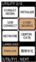
The [LOGO SOURCE] menu appears.
5 Tap and select (light) the logo button that corresponds to the logo file you want to import, and then tap [IMPORT].
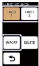
When import of the logo file is complete, a message prompting you to restart the unit appears
6 Tap [OK].
7 Restart the unit.
The imported logo file is ready for compositing.
Lips
An imported logo file will not be assigned until the unit is restarted. If a previously assigned logo exists, that logo will be displayed.
Notes on logo file sizes
Even if a logo file is not 320x320 in size, it can still be imported as long as it is 1920x1080 or less in size.
- Logo files smaller than 320×320
The logo will be positioned at the top left while the remaining space is transparent.
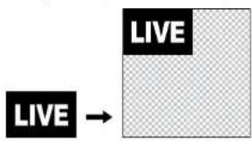
flowchart
graph LR
    A["LIVE"] --> B["Blank Process Box"]
- logo files larger than 320×320
The logo will be positioned at the top left while any part of the logo that exceeds the 320×320 space is deleted.

Deleting logo files
Select (light) the logo button to which the logo you want to delete is assigned, and tap [DELETE]. The logo will not be deleted until the unit is restarted.
Adjusting the Logo Composition
You can adjust the logo composition and its positioning.
Use the PC UI to perform adjustments while viewing the output video in the multi-viewer.
1 Output the background video as the PGM output.
2 Enable (light) the LOGO button.


The logo is composited onto the video.
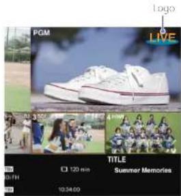
3 Select Logo in the [Setup] screen of the PC UI, and adjust the composition for each logo under Logo Source.
Perform adjustments while viewing the PGM output video in the multi viewer. The [Clip] and [Gain] settings must be adjusted for images that do not include an alpha channel.
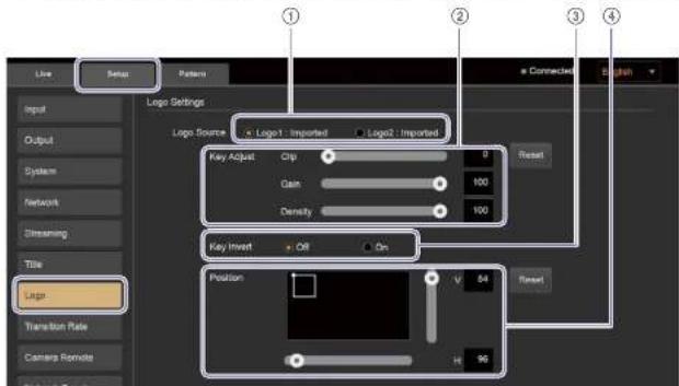
① Select the logo you want to adjust.
② Adjust the composition via the sliders. [Clip]: Adjusts the brightness level of the key color to be removed as a value between 0 to 100.
[Gain]: Adjusts the sensitivity of the key (i.e., smoothness of the key edges) as a
value between 100 to 100.
(Density): Adjusts the density of the logo as a value between 0 to 100.
Tips
To restore default values of each adjustment, select [Reset].
③ Specify whether to invert the key signal.
[Off]: Does not invert the signal.
[On]: Inverts the signal.
④ Specify the position of the inserted logo via the sliders.
Specify the position using the top left of the logo file as the base point.
(H): Adjusts the horizontal position as a value between 0 to 1919 pixels.
[V]: Adjusts the vertical position as a value between 0 to 1079 pixels.
EPS
To restore default values of each adjustment, select [Resc1].
Enabling and disabling logo composites
Select whether to insert the logo on the following outputs from the unit under [Logo Output]. Selecting [Enable] allows you to turn logo display on and off via the LOGO button.
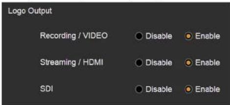
[Recording / VIDEO]: Select whether to allow logo compositing on recorded files and outputs from the PGM VIDEO output connector.
[Streaming / HDMI]: Select whether to allow logo compositing on streaming transmissions and outputs from the PGM HDMI output connector.
[SDI]: Select whether to allow logo compositing on outputs from the PGM SDI output connector.
| Ips
Selecting |Disable| for each setting here will not affect the FGM output display in the multi-viewer.
Changing the Transition Rates
Under default conditions, transition rates of 0.5, 1.0, and 1.5 seconds are assigned to TRANSITION RATE buttons 1 to 3, but you can change the rates if necessary.
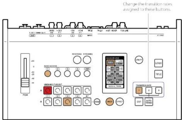
The settings are performed via the PC UI on a computer.
1 Select [Transition Rate] in the [Setup] screen of the PC UI.
![[Setup] tab Line Setup Pattern Corrected English Input Output System Network Shrsing Tile Logo Transition Rate Camera Remote Network Load Transition Rate Settings 0.5 - + Sec. 1.0 - + Sec. 1.5 - + Sec. [Transition Rate]](/content/2026/05/760177/images/eb98e072f25826703198e471c6f8cf8d08f4f1472aaf405bb71f6a0b80ae734d.jpg)
2 Change the transition rates assigned to buttons 1 to 3.
Use [+] or [^-] to change the values.
You can specify a value between 0.0 to 9.9 seconds (increments of 0.1).
Long pressing will change the values continuously.
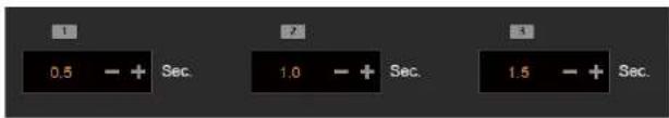
Linking to Cameras
You can perform the following via the unit by linking to cameras.
- Linking with the Remote Commander
Simultaneous recording control and lighting PGM/NEXT tallies
Linking with the Remote Commander
You can perform simultaneous recording controls and light PGM/NEXT tallies by linking with the Remote Commander.
Supported models
Support for the following models has been verified as of January 2017.
Remote Commander
Sony RM 30BP
For the latest information on supported models, contact your local Sony representative.
Camera
Model Function
| Camcorders supporting LANC connection Simultaneous recording start/stop control |
| HXR-NX5R | PGM/NEXT tally control |
| PXW-F55 Ver. 3.0 or later | |
| PXW-Z150 Ver. 2.0 or later | |
| PXW-Z90 | |
| HXR-NX80 | |
| FDR AX700 |
For details on connecting the Remote Commander and camera to the unit, see "When licking with a Remote Commander" (page 18) in the "Connecting the Video and Audio Input Devices" section.
Configuring the link settings
Up to three cameras can be connected via linking with the Remote Commander.
Select [Camera Remote] in the [Setup] screen of the PC UI, and configure the settings for linking with the Remote Commander.
[Assign]
Assign the cameras to be controlled by the Remote Commander here. Perform assignments by selecting input connectors in the [Camera1 (R1)] to [Camera3 (R3)] pull-down lists.
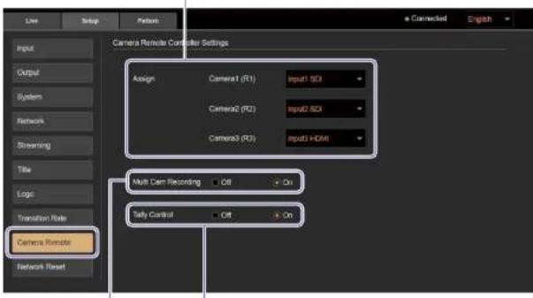
[Tally Control]
Select |On| to light PGM/NEXT talks.
[Multi Cam Recording]
Select [On] to perform simultaneous recording control.
□125
When the same input connector is assigned more than once in [Assign], the last assignment setting will be valid. The previous assignment setting will change to [Off].
Assigning cameras
To perform simultaneous recording controls and light PGM/NEXT lallies by linking with the Remote Commander, the cameras to be linked must be assigned.
When a camera is assigned and either [Multi Cam Recording] or [Tally Control] is set to [On], camera number indicators (R1 to R3) appear in the [Input] viewer of the multi-viewer.

Simultaneous recording control
You can simultaneously apply recording start/stop controls performed in the [R/CORDING] menu to the three cameras controlled by the Remote Commander.
When you start recording via [START] in the [RECORDING] menu, recording on the cameras also starts. When you stop recording via [STOP], recording on the cameras also stops.
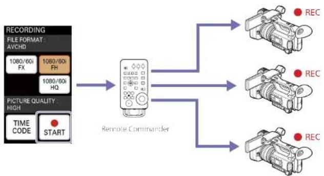
flowchart
graph TD
    A["RECORDING FILE FORMAT AVCHD\n1080/60i FX\n1080/60i FH\n1080/60i HQ"] --> B["Remote Commander"]
    C["PICTURE QUALITY HIGH\nTIME CODE START"] --> B
    B --> D["REC"]
    B --> E["REC"]
    B --> F["REC"]
Timecode settings must be configured to perform simultaneous recording controls.
Make sure the following settings on the unit and each camera match.
• TC FORMAT (DF/NDF)
• TC RUN (REC RUN/FREE RUN)
When you execute [TC RESET] from the unit, timecode resetting is performed simultaneously for all cameras via the Remote Commander.
For details on recording, see "Recording the PGM Output" (page 63).
Lighting PGM/NEXT tallies
You can display tallies on the cameras that are selected for the PGM output and NEXT output. When shooting with multiple cameras, this function notifies each camera operator of when their video will be used, thereby reducing the number of missed shots.
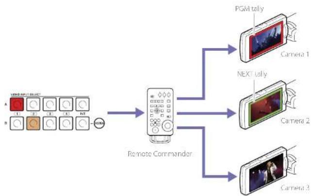
flowchart
graph TD
    A["Input Module A: 1, 2, 3, 4, 5, 6"] --> D["Remote Commander"]
    B["Input Module B: 1, 2, 3, 4, 5"] --> D
    D --> E["PGM tally"]
    D --> F["NEXT tally"]
    D --> G["Camera 1"]
    D --> H["Camera 2"]
    D --> I["Camera 3"]
Useful Functions (Utilities)
The unit's [UTILITY] menu allows you to adjust the unit's settings, format memory cards, and perform other operations.
Displaying the [UTILITY] Menu
Press the UTILITY button on the control panel to display the [UTILITY] menu in the menu panel. The [UTILITY] menu consists of three pages. Each press of the UTILITY button switches the page display.
![UTILITY UTILITY 1/3 HEAD PHONES 8 DISPLAY BRIGHT BUTTONS BRIGHT TONE 1kHz [UTILITY] : NEXT](/content/2026/05/760177/images/deb63b5626fc62473722ee0ff892e61385f6c0b2e735159d99560a6d9333f272.jpg)
Page 1 (1/3)
• Headphone volume adjustment
- Menu panel brightness
adjustment
- Button brightness adjustment
• PGM output of the audio tone signal
For details on operations, see "Live Adjustments" (page 38).
→
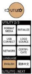
Page 2 (2/3)
• Memory card formatting
• USB connection (page 66)
• Network settings (PC UI connector) (page 22)
• Restoring factory default conditions
- Logo material selection (page 50)
- Root certificate update
- Display language

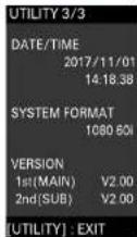
Page 3 (3/3)
Displays the following information.
• Current date and time
- System format
- Unit version
[Non-Text]
[Non-Text]
[Non-Text]
[Non-Text]
[Non-Text]
[Non-Text]
[Non-Text]
[Non-Text]

The menu closes.
Formatting Memory Cards
Format the memory card that will be used for recording the PGM output.
Notes
- Always use memory cards that were formatted on the art.
- Video and audio output may be interrupted while formatting is in progress.
1 Insert the memory card in the memory card slot on the front of the unit.
Orient the memory card in the proper direction.
Insert Memory Stick media with their front sides facing up.
Insert SD cards with their reverse (terminal) sides facing up.
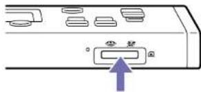
natural_image
Diagram of a device rear panel with a blue arrow pointing to a button (no text or symbols)Memory Stick Duo

Front side-facing up
SD card

Reverse side
(terminal) facing up
A message will appear in the menu panel when memory card formatting is necessary.
2 Display the [UTILITY 2/3] menu, and tap [FORMAT MEDIA].
![SONY MCX-500 - Display the [UTILITY 2/3] menu, and tap [FORMAT MEDIA]. - 1](/content/2026/05/760177/images/a0d8513feb297befdae767eb03d59dbd9e827239eca2e3ebeb2f9ffa8b309940.jpg)
A confirmation message appears.
3 Tap [YES]
![SONY MCX-500 - Tap [YES] - 1](/content/2026/05/760177/images/ef2fa2b7bcd31d9796762064c176968cd23b9def4a24245521ae909997b9a49c.jpg)
Follow the instructions displayed on the screen to finish formatting.
Restoring Factory Default Conditions
Restore the unit to factory default conditions and reset the authentication password for the PC UI with [INITIALIZE].
Restoring factory default conditions
1 Display the [UTILITY 2/3] menu, and tap [INITIALIZE].
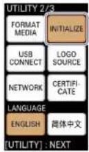
2 Tap [ALL].
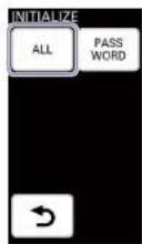
A confirmation message appears.
3 Tao[OK].
The unit restarts automatically. After the unit restarts, the initial settings screen appears as it did during first-time startup.
For details on initial settings, see "Configuring the initial Settings (First Time Startup)" (page 21).
Resetting the authentication password for the PC UI
To change the authentication password for the PC UI, you must first reset it. After initializing the password, the password configuration screen will appear when you connect to the PC UI again.
1 Tap [PASSWORD] under [INITIALIZE].
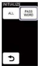
A confirmation message appears.
2 Tap [OK].
When the password is reset, a message appears.
3 Tap [OK]
[Notes]
Be sure to configure a new password after resetting.
Updating the Root Certificate
Use a memory card to import the root certificate issued by the certificate authority onto the unit and perform update.
[1]ps
Always use memory cards that were formatted on the unit.
1 Obtain a PEM-format root certificate from a certificate authority.
2 Change the file name to the following, and copy the file to the root directory of the memory card. File name: certification.pem
3 Insert the memory card in the memory card slot on the front of the unit.
4 Display the [UTILITY 2/3] menu, and tap [CERTIFICATE].
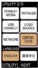
A confirmation message appears.
|Notes|
The row certificate update process may take some time and cannot be canceled once the process has started. Perform the operation when time is not a concern.
Estimated process times
The process times based on the root certificate file size are as follows.
File size Time
Approx. 250 KB Approx. 4 minutes
Approx. 500 KB Approx. 7 minutes
Approx. 750 KB Approx. 11 minutes
Approx. 1 MB Approx. 14 minutes
File sizes of up to 1 M3 are supported for the root certificate file. For details on larger file sizes, contact your local Sony representative.
Root certificate update starts.
When update is complete, a message appears.
5 Tap [OK].
Changing the Display Language
Select the display language for the unit's menus and messages with [LANGUAGE].
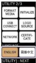
For details on changing the display language for the PC UI, see "Display language" (page 15) in the 'PC UI' section.
Streaming
You can stream PGM videos using various streaming services.
Limitations and restrictions for streaming videos also apply on the side of the streaming service. For details, refer to the streaming service's website. The unit can connect to the following streaming servers. Connection to the following servers has been verified as of October 2017.
- Streaming services
Ustream
- YouTube
Mudu.tv
• Media servers
- Adobe Media Server 5
- Wowza Media Server 3
[Notes]
The unit's streaming function allows third parties to access streaming data during transmissions. In addition, the connection destinations supported by the unit are sites whose content can be viewed by anyone. If you want to protect confidential data during transmissions, we recommend consulting a specialist.
Configuring the Network Settings
Connect the unit to an external network.
For details on settings, see "Configuring the Network Settings for Streaming Transmission" (page 67).
Preparations when Using Ustream
Creating a channel on Ustream
Follow the instructions provided by Ustream to create an account and channel.
Configuring the basic information on the unit
Use the PC UI to configure the basic information necessary for streaming transmissions via the unit.
1 Select [Streaming] in the [Setup] screen of the PC UI, select the [Ustream] tab, and then select [Account Check].
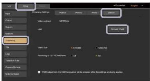
The user name configuration dialog box appears.
2 Enter your Ustream login user name (email address) and password, and select [Account Check].
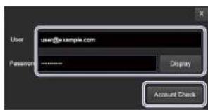
[Tips] The password will be displayed for as long as [Display] is held.
The system verifies whether Ustream login is possible with the specified user name (email address) and password.
When login is successful, the dialog box closes and the user name appears in the [User] field of the [Streaming] screen.
3
Configure the following items.

[Video Size]: Specifies the video size.
640×360
1280×720
[Recording to Ustream Server]: Specifies whether to save recorded data to the Ustream server.
• [Off]: Does not save the recorded data.
• [On]: Saves the recorded data.
[Notes]
When the basic information is configured, important personal information (e.g., information necessary for streaming transmissions) will be stored on the unit. When transmitting possession or disposing of the unit, see "Useful Functions (Utilities)" (page 56) and restore the factory default conditions, or see "Configuring the Network Settings for Streaming Transmission" (page 67) and reset the network settings.
Changing accounts
Select [Change], and change the user name in the dialog box that appears.
The procedure is identical to that of step 2 in the "Configuring the basic information on the unit" section.
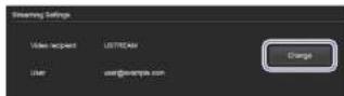
Checking account information
Select [Account Check], and check the user name in the dialog box that appears.
Account information is stored on the unit's memory. The user name display will disappear if you turn off the unit after connecting to Ustream,
but you can check it with [Account Check].
[105]
If a message indicating that, the root certificate has expired appears when you select [Account Check], update the root certificate.
For details on the update procedure, see "Updating the Floor Certificate" (page 57).
Preparations when Using YouTube
There are two methods for streaming on YouTube, "Stream now" and live events.
Using "Stream now"
Creating a live event
1 Connect to the YouTube website on a computer, for example, and select [Stream now].
2 Configure the necessary settings.
The server URL and stream name appear under [ENCODER SETUP].
1 Connect to the YouTube website via a computer, for example, and create a live event.
2 Set [Type] to [Custom], and configure the bitrate under the ingestion settings.
If you configure the settings under [Custom ingestion] here, you can avoid having the stream name change each time you create an event.
3 Select the encoder.
For this unit, select [Other encoders].
4 Copy the URL and stream name that appear
Configuring the basic information on the unit
Use the PC UI to configure the basic information necessary for streaming transmissions via the unit.
1 Select [Streaming] in the [Setup] screen of the PC UI, select the tab in which you want to configure YouTube ([Profile 1] to [Profile 3]), and configure each item.
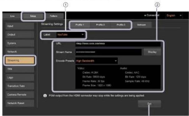
③
① Select the label to be displayed in the unit's [STREAMING] menu (page 62).
② Configure the following items.
[URL]: Enter the upload destination's URL acquired from the YouTube website. If you changed the URL, be sure to also change the stream name in [Stream Name].
[Stream Name]: Enter the stream name acquired from the YouTube website You can display the entered text for as long as [Display] is held any time before the settings are applied with [Set]. The entered text will be hidden after the settings are applied.
[Encode Presets]: Select the preset configuration (encoding preset).
When you select an encoding preset, the setting configurations will appear in the area below.
• [High Bandwidth]: High bandwidth settings
• [Medium Bandwidth]: Medium bandwidth settings
- [Low Bandwidth]: Low bandwidth settings
③ Select [Set].
A message indicating that configuration is complete appears.
Preparations when Using Facebook
Creating a live stream
1 Log Into Facebook via a computer, and select [Live Video].
2 Select [Connect].
3 Copy the [Server URL] and [Stream Key] appear.
Configuring the basic information on the unit
Use the PC UI to configure the basic information necessary for streaming transmissions via the unit.
1 Select [Streaming] in the [Setup] screen of the PC UI, select the tab in which you want to configure Facebook ([Profile 1] to [Profile 3]), and configure each item.
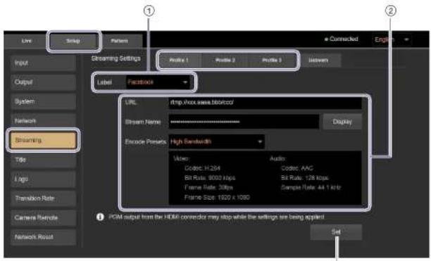
③
① Select the label to be displayed in the unit's [STREAMING] menu (page 62).
② Configure the following items. [URL]: Enter the upload destination's URL acquired from the Facebook website. If you changed the URL, be sure to also change the stream key in [Stream Name].
[Stream Name]: Enter the stream key acquired from the Facebook website You can display the entered text for as long as [Display] is held any time before the settings are applied with [Set]. The entered text will be hidden after the settings are applied.
[Encode Presets]: Select the preset configuration (encoding preset). When you select an encoding preset,
the setting configurations will appear in the area below.
• [High Bandwidth]: High bandwidth settings
• [Medium Bandwidth]: Medium bandwidth settings
- [Low Bandwidth]: Low bandwidth settings
③ Select [Set]
A message indicating that configuration is complete appears.
Preparations when Using Mudu.tv
Creating a channel on Mudu.tv
1 Connect to the Mudu.tv website via a computer, for example, and create a channel 頻道).
2 Copy the URL (直播物流地址
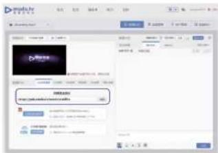
Configuring the basic information on the unit
Use the PC UI to configure the basic information necessary for streaming transmissions via the unit.
1 Select [Streaming] in the [Setup] screen of the PC UI, select the tab in which you want to configure Mudu.tv ([Profile 1] to [Profile 3]), and configure each item.
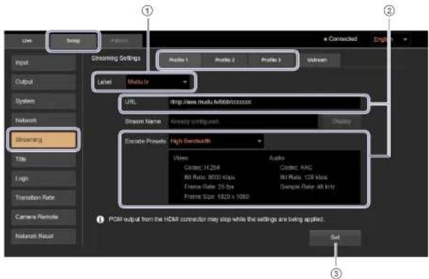
① Select the label to be displayed in the unit's [STREAMING] menu (page 62).
② Configure the following items. [URL]: Enter the upload destination's URL acquired from the Mudutv website. If you changed the URL, be sure to also change the stream name in [Stream Name]. If you changed the URL to one without a stream name, enter random text in the [Stream Name] field, and delete the text before selecting [Set].
[Encode Presets]: Select the preset configuration (encoding preset). When you select an encoding preset, the setting configurations will appear in the area below.
• [High Bandwidth]: High bandwidth settings
• [Medium Bandwidth]: Medium bandwidth settings
- [Low Bandwidth]: Low bandwidth settings
③ Select [Set].
A message indicating that configuration is complete appears.
Preparations when Using Media Servers
Configuring the basic information on the unit
Use the PC UI to configure the basic information necessary for streaming transmissions via the unit.
1 Select [Streaming] in the [Setup] screen of the PC UI, select the tab in which you want to configure the media server ([Profile 1] to [Profile 3]), and configure each item.
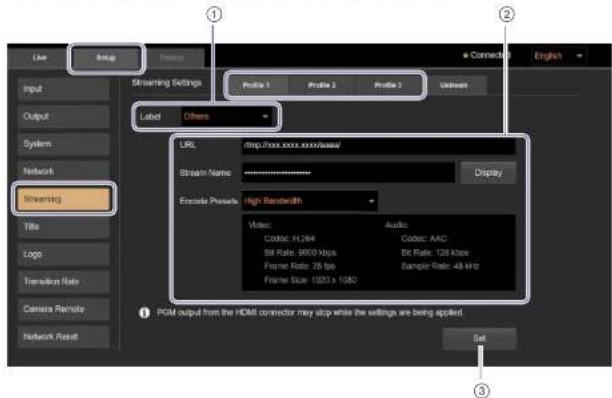
① Select the label to be displayed in the unit's [STREAMING] menu (page 62).
② Configure the following items.
[URL]: Enter the upload destination's URL.
If you changed the URL, be sure to also change the stream name in [Stream Name].
If you changed the URL to one without a stream name, enter random text in the [Stream Name] field, and delete the text before selecting [Set].
[Stream Name]: Enter the upload destination's stream name. You can display the entered text for as
long as [Display] is held any time before the settings are applied with [Set]. The entered text will be hidden after the settings are applied.
[Encode Presets]: Select the preset configuration (encoding preset). When you select an encoding preset, the setting configurations will appear in the area below.
• [High Bandwidth]: High bandwidth settings
• [Medium Bandwidth]: Medium bandwidth settings
- [Low Bandwidth]: Low bandwidth settings
③ Select [Set]. A message indicating that configuration is complete appears.
Starting and Stopping Streaming Transmissions
Transmission controls are performed on the control panel.
Starting transmissions
1 Press the STREAMING button.
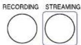
The connection screen of the [STREAMING] menu appears in the menu panel.
2 Tap the streaming server to which you want to connect.
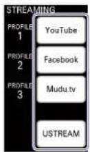
When connection to the streaming server is established, standby mode is entered and STBY appears in the multi-viewer.
When connecting to YouTube, Facebook, Mucu.tv, or media servers, proceed to step 4.
3 When connecting to Ustream, check the channel to be streamed.
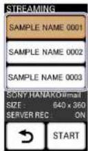
The channel specified as the default will be selected in the [STREAMING] menu. If you want to change the channel, tap the desired channel.
Connection to the Ustream server is reestablished, and the screen appears.
□105 Up to three channels will be displayed.
4 Tap [START]. For Ustream
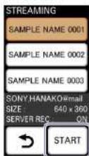
For [Profile 1] to [Profile 3]
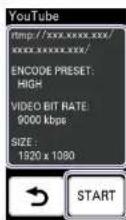
- The URL and settings configured via the PC UI are displayed.
Streaming transmission starts.
If you created a live event on YouTube, start transmission from the Live Control Room on the YouTube website after tapping [START].
The STREAMING button lights blue while transmission is in progress.
RECORDING STREAMING

Stopping transmissions
Tap [STOP].
Display example: When using Ustream
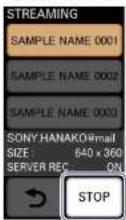
Streaming transmission stops, and the STREAMING
button unlights. The [STREAMING] menu enters standby mode.
Recording the PGM Output
You can record PGM outputs to memory cards. By linking with a Remote Commander, you can have recording start/stop controls on cameras coincide with recording start/stop controls performed on the unit.
For details on the format in which the files are recorded on the unit, see "de formous" (page 88).
Supported memory cards
| Recording format | Media |
| AVCHD SD card | |
| SD memory card (Class 4 or higher) | |
| SDHC memory card (Class 4 or higher) | |
| SDXC memory card (Class 4 or higher) | |
| Memory Stick | |
| Memory Stick PRO Duo (Mark2) | |
| Memory Stick PRO-HG Duo | |
| Memory Stick XC-HG Duo | |
| XAVC S SDXC memory card (Class 10 or higher) | |
Notes
• Operation with all memory cards is not guaranteed.
- Only Memory Stick PRO Duo and Memory Stick XC-HC Duo, which are half the size of the standard Memory Stick and standard sized SD memory cards can be used.
Videos recorded on a Memory Stick XC-HG Duo or SDXC memory card cannot be loaded or played back on computers or AV equipment devices that are connected via US3 cable and that do not support exF AT (i.e., the file system used by Memory Stick XC-HG Duo or SDXC memory card). Verify whether a connected device supports exF AT beforehand. If a device that does not support it is connected, a formatting screen may appear. However, do not execute formatting as doing so will result in the loss of 1 data
Preparation
Formatting the memory card
The memory card that you use must be formatted on the unit.
For details on formatting, see "Formatting Memory Cards" (page 56).
Configuring settings for linking with the Remote Commander
Configure the following settings beforehand to enable recording start/stop controls for cameras via the Remote Commander.
When you execute (TC RESET) from the unit, timecode resetting is performed simultaneously for all cameras via the Remote Commander. For details on settings, see "Configuring the Recording Settings" (page 63).
- Remote settings for cameras
For details on settings, see "Linking to Cameras" (page 54).
- Timecode settings
Make sure the following settings on the unit and each camera match.
TC FORMAT (DF/NDF)
- TC RUN (REC RUN/FREE RUN)
Inserting Memory Cards
Orient the memory card in the proper direction, and insert it until it clicks into place.
Insert Memory Stick media with their front sides facing up.
Insert SD cards with their reverse (terminal) sides facing up.
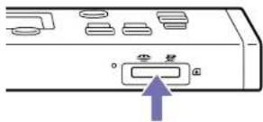
Memory Stick Duo SD card

Front side facing up

Reverse side
(terminal) facing up
Memory card information (status, remaining time, etc.) is displayed in the multi-viewer.
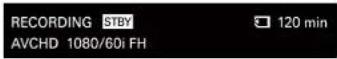
For details, see "RECORDING" information" (page 13) in the Multi-Viewer section.
Notes
- Forchly inserting a memory card in the improper orientation may damage the memory card or micro card slot.
- A message will appear in the menu panel when memory card formatting is necessary. Format the memory card in such cases.
Removing memory cards
Gently press the memory card inward once, and then remove it.
Notes
Be careful to avoid dropping the memory card when inserting or removing it.
Configuring the Recording Settings
Configure the recording format and timecode settings.
1
Press the RECORDING button
RECORDING STREAMING

The [RECORDING] menu appears in the menu panel.
2
Select the recording format or file format. The formats displayed will differ depending on the system format.
Recording formats File formats
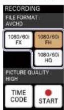
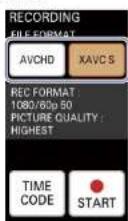
You can select from the following formats depending on the system format.
When the system format is 1080/50
File format Recording format Bit rate Picture size
| AVCHD (fixed) | 1080/50i FX Up to 24 Mbps 1920×1080 |
| 1080/50i FH Approx. 17 Mbps (average) 1920×1080 | |
| 1080/50i HQ Approx. 9 Mbps (average) 1440×1080 |
When the system format is 1080/60
File format Recording format Bit rate Picture size
| 1080/60i FX Up to 24 Mbps 1920×1080 | |
| AVCHD (fixed) | 1080/60i FH Approx. 17 Mbps (average) 1920×1080 |
| 1080/60i HQ Approx. 9 Mbps (average) 1440×1080 |
When the system format is 1080/50p
File format Recording format Bit rate Picture size
| XAVC S 1080/50p 50 (fixed) Up to 50 Mbps 1920×1080 |
| AVCHD 1080/50p PS (fixed) Up to 28 Mbps 1920×1080 |
When the system format is 1080/60p
File format Recording format Bit rate Picture size
| XAVC S 1080/60p 50 (fixed) Up to 50 Mbps 1920×1080 |
| AVCHD 1080/60p PS (fixed) Up to 28 Mbps 1920×1080 |
[Tips]
Recording in XAVC S format can only be selected when the system format is 1080/50p or 1080/60p.
Estimated video recording times
AVCHD
(Unit:minutes)
| PS FX FH HQ | |||
| 16 GB 70(70) | 80(60) | 110(110) | 185(145) |
| 32 GB 145(145) | 170(170) | 225(225) | 375(290) |
| 64 GB 290(290) | 340(340) | 450(450) | 750(590) |
XAVCS
(Jr t: m nutes)
50 Mbps
| 64 GB 155 (155) |
| The numbers in parentheses are minimum recording times. |
| |ips|
- The maximum number of recordable scores is as follows. AVCHD: Up to 3,999
• The continuous recording time is about 13 hours.
- The unit uses VR3 (variable bit rate) to automatically adjust the bit rate (volume of data recorded within a specified period) according to the scene. Therefore, recording times for memory cards may vary. For example, a video with fast moving images will take up a larger amount of space on a memory card to record the images clearly, thereby reducing the total recording time for the card.
- Configure the timecode if necessary.
① Tap [TIME CODE].
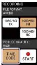
The timecode configuration screen appears.
② Configure each item.
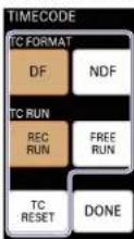
[TC FORMAT]: Select the timecode format.
- [DF]: Enable drop frame timecode.
- [NDF]: Enable non-drop frame timecode.
This is fixed at [NDF] when the system format is 1080/50i or 1080/50p.
[TC RUN]: Select the run setting for the timecode.
- [REC RUN]: The timecode runs only when recording is in progress.
• [FREE RUN]: The timecode runs regardless of the recording status.
[TC RESET]: Reset the timecode to "00:00:00:00."
[Tips]
The [R-C RUN]/[F-R+RUN] settings for [TC RUN] apply to the timecodes on recorded files. The timecode embedded in SDI outputs runs in free run mode.
③ Tap [Done].
The previous screen appears again.
Starting and Stopping Recording
Starting recording
Tap [START ●] in the [RECORDING] menu.
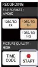
Recording starts, and the button changes to [STOP ■].
The RECORDING button on the control panel lights red while recording is in progress.
RECORDING STREAMING

[Notes]
- When the unit is linked with a Remote Commander and simultaneous recording control is enabled, starting to record via the unit while performing a zoom operation on the Remote Commander may temporarily stop the zoom operation.
- Recording media for which formatting or recording was performed in 60i or 60p (50i or 50p) cannot be used to record in 50i or 50p (60i or 60p). If you want to do so, use a different recording media or format that media using FOXNAT MI DIA. For details, see "formatizing Memory Cards" (page 56).
- When you format media, protected videos will also be deleted.
Stopping recording
Tap [STOP ■]
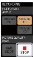
Recording stops, and the button reverts to
[START]
The RECORDING button on the control panel will unlight when recording stops.
Notes
- When the access indicator is lit or blinking red, data is being written or read. Do not subject the unit to vibration or excessive shock in such cases. In addition, do not turn off the unit, remove the memory card, or disconnect the AC adapter. Failure to obey may result in damaged video data.
- When a video file size reaches 2 GB while recording in AVCHD format, file splitting will occur automatically and a new file will be created.
- When the recording time exceeds about 6 hours while recording in XAVC 5 format, file splitting will occur automatically and a new file will be created.
[1]
The videos will be recorded into the 16:9 aspect ratio only.
Using Recorded Files
Sony PlayMemories Home is required to play back or edit files recorded with the unit. Use Sony PlayMemories Home to load the recorded files onto a computer for playback and editing.
For details on operations, refer to the operating instructions for Sony PlayMemories Home.
The files recorded on a memory card can be used via the following methods.
- Inserting the memory card into a computer - Using the memory card while it is inserted in the unit via a USB connection with the computer (USB connection mode)
[Notes]
- In either method, the unit must be connected to a computer once in order to use files recorded with the unit. Follow the instructions in the "Using files in USB (connection mode)" setting to perform USB connection
- In either method, do not modify the files and folders stored on the memory card via a computer. Failure to obey may make the files unplayable.
Using files in USB connection mode
Connect the unit to the computer via a USB connection, and operate the memory card inserted in the unit as a drive on the computer.
1 Use the supplied USB cable to connect the unit to the computer.
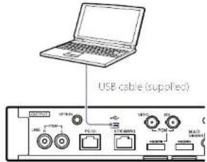
2 Press UTILITY button twice to display the [UTILITY 2/3] menu.

3 Tap [USB CONNECT].
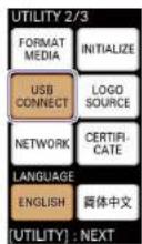
When the connection is established, the following message appears in the menu panel and USB connection mode is enabled. Operation of the memory card inserted in the unit as a drive is now possible.
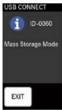
[Notes] Video and audio output, may be interrupted during USB connection mode.
After use
1 Perform safe USB device removal on the computer.
2 Tap [EXIT].
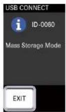
A confirmation message appears.
3 Tap [YES].
USB connection mode is exited.
4 Disconnect the computer that is connected via the USB cable.
Configuring the Network Settings
Configuring the Network Settings for Streaming Transmission
To perform streaming transmissions, configure the settings for connecting the unit to the external network.
When Connecting to a Network via DHCP
DHCP is configured by default. Generally, you do not need to configure settings to use DHCP.
When Manually Configuring the IP Address and Other Settings
Use the PC UI to configure the network settings for streaming transmission.
[Tips]
• The unit supports only IPv4 network environments.
- You cannot change the network while streaming transmission is in progress.
Select [Network] in the [Setup] screen of the PC UI, and display the [Streaming] tab.
2 Select [Manual] for [Mode] to enable manual configuration of the settings, and enter the IP address, subnet mask, default gateway, and DNS server addresses.
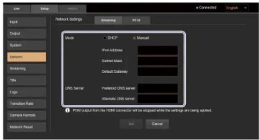
3 Select [Set].
[Tips]
PGM outputs from the HDMI output connector will stop during the few seconds before settings are applied after selecting [Set].
When the settings are successfully applied, a messages appears.
4 Select [OK].
Resetting Network Settings and Streaming Settings
You can reset the network and streaming settings by selecting [Network Reset] in the [Setup] screen, and then selecting [Reset].
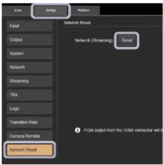
Tips
- Ustream account settings configured on the unit will also be deleted.
- PGM outputs from the HDMI output connector will stop during the few seconds before the reset process is completed after selecting [Reset].
Changing the Unit's IP Address
You can change the IP address used for connecting to the PC UI from a computer from its default (192.168.0.1) to a different static address. When doing so, first connect the unit to the computer in direct mode, change the unit's IP address via the PC UI, and then change the computer's IP address.
1 Connect the unit to the computer in direct mode. For details on operations, see "Connecting in direct mode" (page 23).
2 Access the unit from a web browser.
For details on operations, see "Accessing the Unit from a Web Browser" (page 23).
3 Select [Network] in the [Setup] screen of the PC UI, and display the [PC UI] tab.
4 Configure your desired IP address, and select [Set].
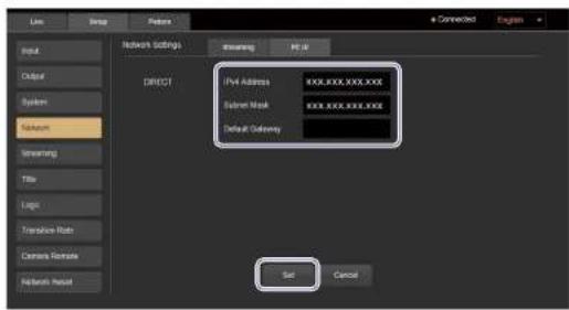
[IPv4 Address]: Enter the IP address. [Subnet Mask]: Enter the subnet mask. [Default Gateway]: Enter the default gateway.
5 Change the IP address of the computer to enable communication with the unit's changed IP address.
6 Tap [CONNECT] in the unit's [NETWORK (PC UI)] menu again. If [DIRECT] is disabled, tap it to enable it.
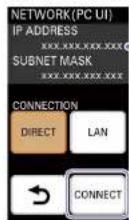
The IP address display is updated.
7 Access the unit again from a web browser
Enter "http://
The authentication password entry screen appears.
8 Enter the authentication password, and select [Log In]. When access is successful, the [Live] screen of the PC UI appears in the web browser.
Configuring the System Settings
You can view input settings, configure output settings, and configure the unit's system settings in the [Setup] screen of the PC UI
[Input] Screen
The [Input] screen allows you to view information on the video inputs assigned to inputs 1 to 4.
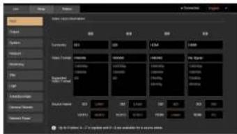
[Connector]: Displays the input connectors that are enabled for inputs 1 to 4.
[Video Format]: Displays the formats of the video signals assigned to inputs 1 to 4. The video format is detected automatically.
[1,75]
- 'Format Mismatch' is displayed for signals that are not supported by the unit.
- "No Signal" is displayed when there is no signal input. - "IDCP" is displayed for HDMI signals that are input from devices that support HDCP.
[Supported Video Format]: Displays a list of input signal formats that are supported by the unit.
[Source Name]: Allows you to configure names for each of the two input connectors under inputs 1 to 4.
You can enter up to five uppercase letters and numbers.
The configured names appear in the multi-viewer and the [Live] screen of the PC UI.
[Tips]
This screen is used only for viewing. Material assignment changes are performed in the [Live] screen or the unit's [ASSIGN] menu.
[Output] Screen
The [Output] screen allows you to configure output settings for video and audio.
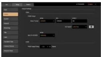
[Video]
Configure video output settings.
[PGM Output]
Allows you to configure the PGM output settings. [HDMI]: Specifies the signal format to be used when the HDMI output connector is used for the PGM output.
[SDI]: When the system format is 1080/50i or 1080/60i, this displays the signal format to be used when the SDI output connector is used for the PGM output. (This cannot be changed.) When the system format is 1080/50p or 1080/60p, this specifies the signal format to be used when the SDI output connector is used for the PGM output. Select Level A or Level B for 3G-SDI according to the connected external device.
Outputs will be in HD SDI only.
[VIDEO]: Displays the signal format to be used when the VIDEO output connector is used for
the PGM output. (This cannot be changed.)
[SD Aspect]: Specifies the output method for SD signals.
![SONY MCX-500 - [PGM Output] - 1](/content/2026/05/760177/images/053e824d45cb20155ab4e31bb8f0c5ca4f6cb9382e9951e9417bc4648f143ce2.jpg)
[Letter Box]: Outputs with black bars on the top and bottom.
![SONY MCX-500 - [PGM Output] - 2](/content/2026/05/760177/images/75efc7896143434ce2135f757d99a08f5519bd3d156377ab0558be8211e8792c.jpg)
[Squeeze]: Outputs with the image squeezed to the 4:3 aspect ratio.
![SONY MCX-500 - [PGM Output] - 3](/content/2026/05/760177/images/5b583164e6af9575c9e29400426005206836709a2419ad0d20590f844824f200.jpg)
(Edge Crop): Outputs with the left and right sides of the image cropped.
[MULTIVIEWER]
Specifies the setting for output to the multi-viewer (external monitor).
[HDMI]: Specifies the signal format to be used for outputs to the MULTI VIEWER output connector.
[Audio]
Configure audio output settings.
[PGM Output Delay]: Specifies the number of frames to delay the L/R channels of the PGM output to ensure that the video and audio match.
Use [+] or [-] to set a value between 0.5 to 2.5 (increments of 0.25).
[System] Screen
The [System] screen allows you to configure the unit's system settings.
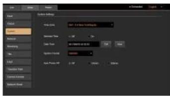
[Time Zone]: Specifies the time zone.
[Summer Time]: Specifies whether to enable daylight savings time.
Select [On] to add 1 hour to the time configured and displayed in [Date Time].
[Date Time]: Displays the current date and time configured on the unit.
Select [Edit] to change the date and time settings.
When you select [Now], the current time is obtained from the computer, displayed in the [Date Time] field, and configured on the unit.
[System Format]: Specifies the system format for the unit.
If you change the system format, the unit will restart after a message is displayed.
[Auto Power Off]: The unit is equipped with an auto power off function that automatically turns off the unit if it is not operated for a specified amount of time. You can specify the amount of time before auto power off is activated. Select [Off] to disable the auto power off function.
Transition and Composite Patterns List
Transition patterns (BKGD mode)
| Mix1 pattern0 | Wipe20 patterns | ||
| 1 | 2 | 3 | |
| A→B | A→B | A→B | |
| 4 | 5 | 6 | |
| B→A | B→A | B→A | |
| 7 | 8 | 9 | |
| A→B | A→B | B | |
| 10 | 11 | 12 | |
| A | B | A | |
| 13 | 14 | 15 | |
| B | A | B | |
| 16 | 17 | 18 | |
| A | B | A | |
| 19 | 20 | ||
Composite patterns (EFFECT mode)
* When switching from BKGD mode to EFFECT mode, video B will be composited automatically with these patterns.
Composite patterns (EFFECT mode)
Page 3/5
26 27

27

20

29

30 31

3

32

33

Page 4/5
64 65

65

66

67

68 * 69

59

70

21

Page 5/5
74 *

75*

76 关

77 *

78 *

79 *

80*

91 x

92 *

92 *

94 *

95 *

96 *

97 *

98 *

99 *

Chroma key
5 patterns
1

52

53

54 ×

55%

Luminance key
1 pattern
:

72 * 73

73 *

Menus and Default Settings
The factory default setting values are indicated in bold (example: AVCHD).
MCX-500 Menu Panel
| Button | Menu Submenu | |
| Screen Setting item Setting values Screen Setting item Setting values | ||
| RICORDING FILE FORMAT AVCHD (fixed) (when system format is 1080/50p or 1080/60p) | ||
| XAVC S, AVCHD (when system format is 1080/50p or 1080/60p) | ||
| FLOC1 FORMAT 1080/501 X, 1080/501 II, 1080/501 IQ (when system format is 1080/50);1080/601 X, 1080/601 IQ (when system format is 1080/60);1080/50p so fixed); (when system format is 1080/50p and file format is XAVC S); 1080/50p PS(fixed) (twcrn system format is 1080/50p and file format is AVCHD);1080/60p SO (fixed); (when system format is 1090/60p and file format is XAVC S); 1080/60p PS(fixed) (twcrn system format is 1080/50p and file format is AVCHD) | ||
| TIME CODE TIME CODE TC FORMAT DF, NDF | ||
| TC RUN REC RUN, TREE RUN | ||
| STREAMING CONNECT PROFILE 1 (YouTube, PROFILE 2 | Facebook), PROFILE 3 | Mudutiv, USTREAM STANDBY | ||
| AUDIO ACCESS [1] AUDIO [1] PRL OFF, ON | ||
| Button | Menu Submenu | ||||
| Screen Setting item Setting values Screen Setting item Setting values | |||||
| ASSIGN [1] INPUT [1]. Enable / disable ENABLE. DISABLE | |||||
| Connector, OR SDI, VIDEO | |||||
| ASSIGN [2] INPUT [2]. Enable / disable ENABLE. DISABLE | |||||
| Connector, OR SDI, VIDEO | |||||
| ASSIGN [3] INPUT [3]. Enable / disable ENABLE. DISABLE | |||||
| Connector, OR SDI, HDMI | |||||
| ASSIGN [4] INPUT [4]. Enable / disable ENABLE. DISABLE | |||||
| Connector, OR SDI, HDMI | |||||
| ASSIGN [NT] INPUT [NT]. Enable / disable ENABLE. DISABLE | |||||
| Internal signal selection BLACK, COLOR BAR | |||||
| BRDG BRDG Pattern selection First (mix at top left) | |||||
| MANUAL, TRANS* MANUAL, TRANS GUI video fader 0% to 100% | Bottom position | ||||
| L.T.LCT LTT.LCT Pattern selection First (PinP at top left) | |||||
| MANUAL, TRANS* MANUAL, TRANS GUI video fader 0% to 100% | Bottom position | ||||
| UTILITY | UTILITY 1/3 | HEADPHONES | Selected | HEADPHONES | 1 to 18(8) |
| DISPLAY BRIGHT Not selected | DISPLAY BRIGHT HIGH, MIDDLE, LOW | ||||
| BUTTONS BRIGHT | Not selected | BUTTONS BRIGHT | HIGH, MIDDLE, LOW | ||
| TONE THZ | OFF, ON | ||||
| UTILITY 2/3 FORMAT MEDIA Not selected | |||||
| USB CONNIC | Not selected | ||||
| NETWORK* | Not selected | NETWORK | DIRECT, LAN | ||
| INITIALIZE* | Not selected | INITIAL ZE | ALL, PASSWORD | ||
| LOGO SOURCE | Not selected | LOGO SOURCE | LOGO1, COO2 | ||
| CHILLICAIT* | Not selected | ||||
| LANGUAGE | ENGLISH, 简体中文 | ||||
| UTILITY 3/3 | |||||
| LOGO | OFF, ON | ||||
| TITLE | OFF, ON | ||||
| TRANSITION RATE 1 | Selected | ||||
| TRANSITION RATE 2 | Not selected | ||||
| TRANSITION RATE 3 | Not selected | ||||
^3 Not displayed in the [I've] tab of PC uL
PC UI
| Tab | Menu | Submenu 1 Submenu 2 | |
| Screen | Setting item Setting values Screen Setting item Setting values Screen Setting item Setting values | ||
| Soup > Input Video Input Information | Connector [1] SDI, VIDEO | ||
| [2] SDI,VIDEO | |||
| [3] SDI, HDMI | |||
| [4] SDI, HDMI | |||
| Video Format [1], to [4] | |||
| Supported Video Format | [1] to [4] | ||
| Source Name [1] SDI,SDI | |||
| [2] SD: SDI | |||
| [3] SD: SDI | |||
| [4] SD: SDI | |||
| [1] VIDEO VIDEO | |||
| [2] VIDEO VIDEO | |||
| [3] HDMI: HDMI | |||
| [4] HDMI: HDMI | |||
| Setup > Output Output Settings PCM Output >Video Format | HDMI, 1080/50p, 1080/50i, 720/50p, 576/50p(when system format is 1080 50p/50i) | ||
| 1080/60p, 1080/60i, 720/60p, 480/60p(when system format is 1080 60p/60i) | |||
| 1080/60p Level A, 1080/60p Level B (when system format is 1080/60p) | |||
| 1080/60p Level A, 1080/60p Level B (when system format is 1080/60p) | |||
| VIDEO | |||
| PGM Output >VIDEO | SD Aspect Letter Box, Squeeze, Edge Crop | ||
| MULTI VLWLF | I HDMI 1080/50p, 1080/50i, 720/50p, 576/50p(when system format is 1080 50p/50i) | ||
| 1080/60p, 1080/50i, 720/50p, 480/50p(when system format is 1080 60p/60i) | |||
| PGM Out Doley | 0.5 to 2.5 (1.5) | ||
| Soup > System | System Settings | Time Zone | GMT - 11.0 to GMT - 5.0 to GMT - 12.0 |
| Summer Time | Off, On | ||
| Date Time | 2017 to 2037 / 01 to 12 / 01 to 31 | ||
| 00 to 23 | |||
| 00 to 59 | |||
| System Format | 1080 50i, 1080 50p, 1080 60i, 1080 60p | ||
| Auto Power OFF | Off, 120min, 300min | ||
| Tab | Menu | Submenu 1 Submenu 2 | ||||
| Screen | Setting item Setting values Screen Setting item Setting values Screen Setting item Setting values | |||||
| Setup > Network | Network Settings | Streaming | Selected | Streaming | Mode | DHCP, Manual |
| IPv4 Address | ||||||
| Subrc, Mask | ||||||
| Default Gateway | ||||||
| DNS Server | Preferred DNS server | |||||
| Alternate DNS server | ||||||
| PC UI Not selected PC UI DIRECT | PVI Andress | |||||
| Subnet Mask | ||||||
| Default Gateway | ||||||
| Setup > Streaming | Streaming Settings | Profile 1 | Selected | Profile 1 | Label | Profile 1, YouTube, Mudutv, Facebook, Others |
| URL | ||||||
| Stream Name | ||||||
| Encode Presets | High Bandwidth, Medium Bandwidth, Low Bandwidth | |||||
| Profile 2 | Not selected | Profile 2 | Label | Profile 2, YouTube, Mudutv, Facebook, Others | ||
| URL | ||||||
| Stream Name | ||||||
| Encode Presets | High Bandwidth, Medium Bandwidth, Low Bandwidth | |||||
| Profile 3 | Not selected | Profile 3 | Label | Profile 3, YouTube, Mudutv, Facebook, Others | ||
| URL | ||||||
| Stream Name | ||||||
| Encode Presets | High Bandwidth, Medium Bandwidth, Low Bandwidth | |||||
| Ustream | Not selected Ustream | Video recipient | ||||
| User | ||||||
| Video Size | 640 x 360, 1280 x 720 | |||||
| Recording to USTRFAM Server | Off, On | |||||
| Tab | Menu | Submenu 1 Submenu 2 | |||
| Screen | Setting item Setting values Screen Setting Item Setting values Screen Setting item Setting values | ||||
| Setup > Title Title Settings Key Adjust Clip 0 to 100 (10) | |||||
| Gain 100 to 100 | |||||
| Display 0 to 100 | |||||
| Key Invert Off, On | |||||
| Position H 0 to 1919 (160) | |||||
| V-1/20 to 1079 (-60) | |||||
| Setup > Logo | Logo Settings | Logo Source | Logo 1 | Imported, No File | |
| Logo 2 | Imported, No File | ||||
| Key Adjust Clip 0 to 100 (10) | |||||
| Gain -100 to 100 | |||||
| Density 0 to 100 | |||||
| Key Invert Off, On | |||||
| Position H 0 to 1919 (Logo 1: 96, Logo 2: 1503) | |||||
| V 0 to 1079 (54) | |||||
| Logo Output | Recording /VIDEO | Disable, Enable | |||
| Streaming /F-DMI | Disable, Enable | ||||
| SDI | Disable, Enable | ||||
| Setup > Transition Rate | Transition Rate Settings | [1] | 0.0 to 9.9 (0.5) | ||
| [2] | 0.0 to 9.9 (1.0) | ||||
| [3] | 0.0 to 9.9 (1.5) | ||||
| Setup > Camera Remote | Camera Remote Controller Settings | Assign Camera1 | IR1 | Off, Input1 SDL, Input2 SDL, Input3 SDL, Input4 SDL, Input1 VIDEO, Input2 VIDEO, Input3 HDMI, Input4 HDMI | |
| Cercre2IF2 | Off, Input1 SDL, Input2 SDL, Input3 SDL, Input4 SDL, Input1 VIDEO, Input2 VIDEO, Input3 HDMI, Input4 HDMI | ||||
| Cercre3IF3 | Off, Input1 SDL, Input2 SDL, Input3 SDL, Input4 SDL, Input1 VIDEO, Input2 VIDEO, Input3 HDMI, Input4 HDMI | ||||
| Mu L Camr Recording | Off, On | ||||
| Tally Control | Off, On | ||||
| Setup > Network Reset | Network Reset | Network (streaming) | |||
| Tab | Menu | Submenu 1 Submenu 2 | |||||
| Screen | Setting item Setting values Screen Setting Item Setting values Screen Setting item Setting values | ||||||
| Pattern | BKGD | Pattern Icon | 0.1, 6, 5, 3, 2, 7, 8 | ||||
| Move | Move | Pattern Icon | 0, 1, 6, 5, 3, 2, 7, 8 | ||||
| Property Template: 0 to 20 | |||||||
| EFFECT | Pattern Icon | 1, 13, 12, 61, 10, 24, 19, 53 | |||||
| Move | Move | Pattern Icon | 1, 13, 12, 61, 10, 24, 19, 53 | ||||
| Property | Template Selected | Template | PinP | 1 to 34, 64 to 80, 90 to 99 | |||
| Chroma Key | 51 to 50 | ||||||
| Luminance Key | 51 | ||||||
| Key Adjust Not selected | Chroma Key (Key Adjust screen when Chroma Key is selected) | Auto | Chrome Key Up, down, left, and right arrow buttons | ||||
| Clip | 0 to 100 (20) | ||||||
| Gain | -100 to 100 (50) | ||||||
| Blue | 0 to 359 (235) | ||||||
| Density | 0 to 100 | ||||||
| Luminance Key (Key Adjust screen when Luminance Key is selected) | Clip | 0 to 100 (10) | |||||
| Gain | 100 to 100 | ||||||
| Density | 0 to 100 | ||||||
| Crop | Not selected | Crop | Crop | Off On | |||
| Too | -100 to 100 | ||||||
| Left | -100 to 100 | ||||||
| Right | -100 to 100 | ||||||
| Bottom | -100 to 100 | ||||||
| Border | Not selected | Border | Border | Depends on the pattern Pattern 1 is selected and this is 'On' immediately after start up. | |||
| Video selection buttons from A) | 1 to 4, IN ^- | ||||||
| Video selection buttons from B) | 1 to 4, IN ^- | ||||||
| Mode selection buttons | BKGD, EFFECT | ||||||
| OUT | |||||||
| Translation rate buttons | 1 to 3 | ||||||
| AUTO TRANS | |||||||
Troubleshooting
Message Displays
If a problem occurs during operation of the unit, a message will appear in the menu panel and the PC UI. Check the content of the message and respond accordingly. If the problem persists, write down the displayed ID number, and contact your local Sony representative.
Menu panel
PC UI
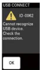
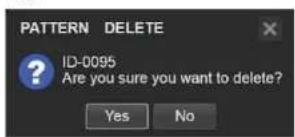
The following types of message exist.
| Icon Type Description | |
| Information Notifications | |
| Verification Messages that request verification | |
| Warning Warnings that indicate that continued operation may result in error | |
| Error Warnings that indicate severe errors, such as inability to continue operation or malfunction | |
Problems and Solutions
Check the following before requesting repairs. If the problem persists, contact your local Sony representative.
| Symptom | Possible cause | Solution |
| The unit does not turn on or start up properly. | The connected devices are not turned on. | O sconnect and reconnect power cords of the devices, and restart the devices. |
| The power turns off automatically. | The unit automatically turned off due to the auto power off function. | The unit is equipped with an auto power off function that automatically turns off the unit if it is not operated for a specified amount of time:If the unit automatically turns off, pressing the power switch twice will turn the unit back on. |
| for details, see "Auto Power Off Function" (page 21). | ||
| Videos cannot be input, or videos do not appear in the multi-viewer. | The cables are not continued properly. | Connect the cables properly. |
| The video input signals are not assigned properly. | Assign the video input signals properly.For detotic, see "Assigning Inputs" (page 25) | |
| Signals that are not supported by the unit are being input. | Check the input signals.If the signal that is not supported by the unit is being input, I format Mismatch* or "HLOC" will appear in the [INPUT] viewer of the multi-viewer. | |
| Videos do not appear when they are input to the 50+ input connectors. | The level settings do not match those of the connected external device. | Check the level A/U settings.For detotic, see "Output" Screen" (page 69). |
| Nothing occurs when the VIDEO INPUT SELECT buttons are pressed. | [DISABLE] is selected Select Right [ENABLE] in the INPUT] menu of the respective input.For details, see "Assigning Inputs" (page 25). | |
| The PC UI cannot be displayed. | Connect to the unit in direct mode. | |
| The PC UI cannot be connected via LAN. | You are attempting to connect in a network environment without DHCP servers. | For details, see "Connecting in direct mode" (page 23). |
| The [Pattern] too of the PC UI is grayed out and cannot be selected. | A menu other than the [BACKING ROUND] menu or [FFFECT] menu is displayed in the menu pane. | the [Pattern] too is only activated when the [BACKING UNIV] menu or [FFFECT] menu is displayed. |
| Text created on a computer is not inserted properly. | Adjustments have not been performed properly. | When inserting text using an RGB input, perform adjustments in the [Title] screen of the PC U. When inserting text using luminance keying in EFFECT mode, perform adjustments in the [Pattern] screen of the PC UI. For details, see "Adjustments for listening, text onto Videos" (page 47). |
| Text cannot be inserted using an RGB input. | The output resolution of the computer is not 1600x1200. | Use a computer with an output resolution of 1600x1200 (60p). |
| The frequency is not 60 Hz. | ||
| I want to insert text using RGB input, but the 1600x1200 sign: from the computer can be output... | - Set your computer's output setting to extended mode to enable external output, and set the resolution for the external output to 1600x1200. | |
| The computer is not equipped with RGB output, so text insertion with the TITLE function is not possible. | - Use luminance keying in EFFECT mode. For details, see "Using HDMI Input Signals to Insert Text (EFFECT Mode)" (page 48). | |
| Logos are composed on some output, videos but not others (e.g., streaming output). | The logo output settings are set to [Disable]. | Change for the setting for the corresponding output to [Encoded]. For details, see "Adjusting the Logo Composition" (page 51). |
| Video from the computer connected to the HDMI input connector is not input. | The frequencies do not match. Make sure to match the output resolution and 'frequency on the connected computer to a signal format that can be input to the unit.' You can check which signals formats can be input to the unit in the [Input] screen of the [PC UI]. For details, see "Input Screen" (page 69). | |
| Streaming transmission starts on the unit, but the images are not transmitted. | The [URL] and [Stream Name] settings are not configured properly. | Reconfigure the [URL] and [Stream Name] settings. If you changed the URL to one without a stream name, enter random text in the [Stream name] field, and describe the text before selecting [set]. For details, see "Streaming" (page 58). |
| Symptom | Possible cause | Solution |
| Audio is not output from the headphones or speakers. | The connected devices are not turned on. | Restart the devices. |
| The cables are not connected properly. | Connect the cables properly. | |
| [CH ON] is selected (unit) in the [AUDIO] menu. | Select flight, 'CH ON'.For detail, see "Live Adjustments" (page 38). | |
| The audio output level is low. Use the channel fader in the [AU DIO] menu to increase the audio level.For detail, see "Live Adjustments" (page 38). | ||
| The PGM master fader is lowered. Raise the 'PGM master fader'For detail, see "Live Adjustments" (page 38). | ||
| Inputs are not assigned. For embedded audio, the audio will not be output. If the video input is not assigned. | ||
| The headphones output level is low. | Raise the headphone volume with [HEAD PHONES], of the [U11-11Y 1/3] menu.For detail, see "Adjusting the Headphone Volume" (page 38). | |
| The audio turns off by itself. [L XK VIDEO] is selected in the [AUDIO] menu. | When [L XK VIDEO] is selected, embedded audio is enabled/disabled in response to whether the video is outout as the PGM output.For details, see "Linking embedded audio to its video" (page 28). | |
| Camera control from the RM-30BP is not possible. | The remote control settings have not been configured. | Configure the remote control settings.For details, see "Linking to Carneros" (page 54). |
| Camera images are displayed upside down. | The settings on the camera are upside down. | Check the vertical image flip setting on the camera.For details, refer to the operating instructions for the camera. |
Message List
| ID | Message Meaning Solution | ||
| 0005 | The main CPU is overheating.Perform shutdown immediately. | The main CPU is overheating.Perform shutdown immediately. | Check that the ventilation holes are not obstructed, and check the operating environment.If the message persists after restarting the unit correct your local Sony representative. |
| 0006 | Cannot record. Movie scene number is full. Cannot record. | Movie scene number is full. | Delete unnecessary files from Sony PlayMemories Home.For details on operations, refer to the operating instructions for Sony PlayMemories Home. |
| 0009 | This is a road-only memory card. A road-only memory card is inserted. Use a writable memory card. | ||
| 0010 | Incompatible type of memory card. An unsupported memory card is inserted. Use a supported memory card. | ||
| For details, see "Supported memory cards" (page 63). | |||
| 0012 | Cannot record.The memory card is full. | Cannot record.the memory card is full. | Delete unnecessary files from Sony PlayMemories Home.For details on operations, refer to the operating instructions for Sony PlayMemories Home. |
| 0013 | The memory card must be formatted. The memory card must be formatted. Format the memory card with the unit. | ||
| For details, see "Formulating Memory Cards" (page 56). | |||
| 0014 | The memory card is locked.Check the tab. | The memory card is locked.Check the data protection tab. | Check the position of the memory card's data protection tab. |
| 0015 | The fan stopped abnormally.Shutdown will be performed. | The fan stopped abnormally. The unit will shut down. | If the message persists after restarting the unit, contact your local Sony representative. |
| 0017 | This media does not support recording and playback of XAVC. S moves. | the memory card does not support XAVC. S recording or playback. | To perform XAVC. S recording or playback, use an SOXC memory card (Class 10 or higher). |
| 0018 | The memory card is invalid. | An invalid memory card is inserted. | Use a writable memory card. |
| 0019 | The main CPU is overheating.Shutdown will be performed. | The main CPU is overheating.The unit will shut down. | Check that the ventilation holes are not obstructed, and check the operating environment.If the message persists after restarting the unit, contact your local Sony representative. |
| 0021 | Access is prohibited on this memory card. | Access is prohibited on the memory card. | Use a writable memory card. |
| 0025 | Cannot record.The image database file is corrupted. Restore media to use again. | The image database file is corrupted.The media must be recovered to enable its use. | This message appears when the image database file is defective, lines, the memory card can again, and follows the instructions in the message (D-0049) to perform recovery. |
| 0032 | Recording has stopped due to buffer overflow. | Recording has stopped due to buffer overflow. | Recording has stopped due to an overflow of the temporary data storage area during video recording. |
| 0033 | Recording has stopped due to the memory card being full. | Recording has stopped due to the memory card being full. | Delete unnecessary files from Sony PlayMemories Home.For details on operations, refer to the operating instructions for Sony PlayMemories Home. |
| 0034 LOGO1.png could not be found.Store the file under the specified location and name.V OGO1.png | LOGO1.png could not be found.Store the file under the specified location and name.V OGO1.png | Check the file name and location on the memory card to which the file was copied.For details, see "Preparing the Logos" (page 59). | |
| 0035 LOGO2.png could not be found.Store the file under the specified location and name.V OGO2.png | LOGO2.png could not be found.Store the file under the specified location and name.V OGO2.png | Check the file name and location on the memory card to which the file was copiedFor details, see "Preparing the Logos" (page 59). | |
| 0044 | Memory card write incomplete. Recover data? | The data written on the memory card is incomplete. Do you want to recover the data? | If the data is not recovered, recording on the unit or playback in Sony PlayMemories Home may not be possible.[Notes]The recovery process does not guarantee complete recovery. For XAVC's data, you will be able to resume recording after recovery, but payback on a computer will not be possible. |
| 0047 | A memory card other than the card to be recovered is inserted. Insert the proper card. | A memory card other than the card to be recovered is inserted. Insert the proper card. | It's message appear when a memory card that requires recovery is replaced with another card without performing recovery. Insert the card that requires recovery. |
| 0049 | Inconsistencies found in the image database file. Recover data? | Inconsistencies were found in the image database file. Do you want to recover the data? | Recording is not possible when there is the image database it is defective. For ow the instructions in the message to perform recovery. |
| 0062 | Cannot recognise UNS device. Check the connection. | the UNS device is cannot be recognized. Check the connection. | Check the connection to the computer and the settings. |
| 0067 | Check the LAN cable connection. Check the LAN cable connection. Check the LAN's cable and its connection. | ||
| 0068 | Failed to acquire an IP address. Change the IP address setting. | Acquisition of the IP address failed. Change the IP address setting. | It's message appears when you attempt to automatically acquire the IP address on a network without a DHCP server. Connect to a network that includes a DHCP server, or configure the static. Setting. |
| 0069 | Failed to acquire an IP address. Check the DNS server setting. | Acquisition of the IP address failed. Check the DNS server setting. | Acquisition of the IP address from the DNS server failed. Check the DNS server setting. |
| 0070 | Cannot execute functions. The function cannot be executed. This is a network error. Check the network. | ||
| 0071 | Could not verify the certificate. Continue connection? | The certificate could not be verified. Do you want to proceed with connection? | Update the certificateFor details see "Modifying the Root Certificate" (page 57). |
| 0072 | The user name or password is invalid. Check the account settings. | The user name or password is invalid. Check the settings. | Check the streaming settings via the PC UI. |
| 0073 | The server rejected the request. | The server rejected the request. | Connection is not possible due to a problem on the Ustream server side. |
| 0074 | Failed to connect to the Ustream server. Check the "Date Time". | Connection to the Ustream server failed. Check the "Date Time" settings. | The Ustream function is referencing the unit's date and time information. Configure the correct date and time. |
| 0075 | Authentication information is invalid. Check the user name and password. | The authentication information is invalid. Check the user name and password. | Reconfigure the Ustream user name and password via the PC UI. |
| 0076 | An invalid channel has been specified. An invalid channel has been specified. Select another channel. | ||
| 0077 | Connection to the server terminated. Check the communication environment. | Connection to the server terminated. Check the communication environment. | Check the communication environment. Alternatively, consult the server actinir script. |
| 0078 | There is a possibility that the movie was not saved correctly on the server. Proper saving to the server. | may not have occurred. | Data may not have been recorded due to a problem on the Ustream server side. |
| 0080 | Not enough stream time. Could not be saved to the server. | The stream duration is insufficient. The data was not saved to the server. | The streamed video could not be recorded to the Ustream server due to its insufficient duration. |
| 0090 | Cannot execute functions. The function cannot be executed. This is a network error. Check the network. | ||
| 0092 | The user name or password is invalid. Do you want to continue configuration? | The user name or password is invalid. Do you want to proceed with configuration? | User authenticated on failed. Reconfigure the Ustream user name and password. |
| 0102 | Streaming error | A streaming error occurred. | Check the user name and password, whether the line speed has dropped, and other possible factors. |
| 0106 | LAN setting error | A wired LAN error occurred. | Check the wired LAN settings and the network communication status. |
| 0107 | Failed to connect to the Ustream server.Check the "Date Time". | Connection to the Ustream server failed.Check the "Date Time" settings. | The Ustream function is referencing the unit's date and time information.Configure the correct date and time. |
| 0112 | The URL or Stream Name is invalid. The URL or stream name is invalid. Check the URL and stream name via the PC UI. | ||
| 0115 | certification perm could not be found.Store the file under the specified location and name. \certification.pem | The "certification perm file could not be found.store the file Under the specified location and name. \certification.pem | Check the file name and location on the memory card to which the file was copied.For details, see "Updating the Root Certificate" (page 57). |
| 0116 | Update failed due to the excessive file size.Contact your local Sony representative. | Update failed due to the excessive file size. Contact your local Sony representative. | File sizes of up to 1 MB are supported for the root certificate file. For details on larger file sizes, contact your local Sony representative. |
| 0124 | Cannot transmit.Check the settings and network environment. | Cannot transmit. Check the settings and network environment. | Check the URL and stream name via the PC UI. Alternatively, check the settings and network environment. |
| 0125 | The settings have been configured.You must perform [CONNECT] from the units [NETWORK (PC UI)] menu to apply the settings. | The settings have been configured.You must perform [CONNECT] from the unit's [NETWORK (PC UI)] menu to apply the settings. | Tap [CONNECT] in the unit's [NETWORK (PC UI)] menu to connect to the unit. |
Maintenance and Usage Precautions
Maintenance
Vent care
Remove dust from the ventilation holes once per month or whenever necessary.
Touch panel care
The surface of the LCD has a coating that can peel off when scratched or damaged. Beware of the following during handling or cleaning.
- Handling with excessive hand oil, hand cream, or other oils on your hands can make it easier for the coating to peel off, so be sure to wipe them off the surface as soon as possible.
- Wiping with excessive force using tissue paper, for example, can scratch the coating.
- Remove any dust, dirt, or sand using a blower. For example, before wiping the surface.
- When wiping the surface, use a cleaning cloth made of soft material, such as an eyeglass cleaning cloth, and wipe gently.
Unit surface care
- For stubborn dirt, use a soft cloth campened with cold or warm water to gently wipe the unit, and then wipe it with a dry cloth.
- Avoid the following to prevent deformation of the unit's surface and damage to the coating.
—Application of thinner, benzine, alcohol, chemical cleaning cloths, insect repellents, insecticides, sunscreen, or other chemicals.
Handling the unit with the above applied on your hands.
—Prolonged contact with rubber or vinyl products.
AVCHD Standard
The unit is capable of recording in HD (high definition) according to the AVCHD standard. Video: MPEG-1AVC / H264
- When 60p selected 1920×1080/60p
- When 50p is selected 1920 × 1080 / 50p
- When 60i is selected 1920 × 1080 / 60i, 1440 × 1080 / 60i
- When 50i is selected 1920×1080/50i, 1440×1080/50i
Audio: LPCM 2ch
Storage media: Memory card
- The AVCHD standard uses compression. Therefore, significant changes in the image, angle of view, or brightness may cause distortion in the video. This is not a malfunction
XAVCS Standard
The unit is capable of recording in high-quality HD (high definition) according to the XAVC S standard. The Long GOP compression format is used. Video: MPEG 4AVC / H.264
- When 60p selected 1920×1080/60p
- When 50p is selected 1920 × 1080 / 50p
Audio: LPCM 2ch
Storage media: Memory card
Memory Cards
- Operation of memory cards that have been formatted on a computer (Windows OS or Mac OS) is not guaranteed on the unit.
- The data read/write speed will vary depending on the pairing of the memory card and device used.
- Video files can be damaged in the following cases. Sony will not be liable for damaged data resulting from circumstances of any kind.
Removing a memory card or turning off the unit while video files are being read or while data is being written to the memory card (i.e., while the access indicator is lit or blinking).
Use in environments exposed to static electricity or electrical noise.
- We recommend backing up important data to your computer's hard disk, for example.
- Do not affix labels, for example, onto memory cards.
- Do not touch the terminals or bring them into contact with metal objects.
- Do not bend, crop, or subject memory cards to excessive shocks.
- Do not dismantle or modify memory cards.
- Do not wet memory cards.
- Keep memory cards away from small children to prevent accidental swallowing.
- Do not insert memory cards of unsupported sizes into the memory card slot, as doing so may result in malfunction.
- Avoid use and storage in the following environments.
High-temperature locations, such as the inside of an automobile parked in the sun. Locations exposed to direct sunlight.
Locations with excessive humidity or corrosive materials present.
If videos are not recorded properly
Format the memory card.
After prolonged use and repeated recording/deleting, the files on the memory card can become fragmented, preventing proper recording of files. In such cases, copy the recorded files to other media before formatting the memory card.
For details, see "Formatting Memory Cards" (page 56).
Video compatibility
- The unit supports the DCF (Design rule for Camera File system) specification as defined by the JEITA (Japan Electronics and Information Technology Industries Association).
- If a memory card that was used on a different device cannot be used, perform the procedure in "Formatting Memory Cards" (page 56) to format the card on the unit. Be aware that formatting the memory card will delete all data stored on the card.
Precautions on disposal and transfer
The U-ORMAT MEDIA function in the unit's [UTILITY 2/3] menu and the formatting and file deletion functions on a computer may not completely erase the data stored on memory cards in some cases. When transferring possession of a memory card, use data erasure software on a computer, for example, to completely erase the data. When disposing of a memory card, we recommend physically destroying the memory card as well.
Precautions on the Touch Panel (LCD)
- Do not press the touch panel with excessive force. Failure to obey may result in distorted image display and damage to the touch panel.
- A trailing effect may appear in the image when operating in cold environments. However, this is not a malfunction.
- The area around the touch panel may heat up during use. However, this is not a malfunction.
- Do not face the LCD toward the sun or other powerful light sources, as doing so may result in malfunction.
Memory Sticks
Supported Memory Sticks
The unit supports Sony Memory Stick PRO Duo (Mark2), Memory Stick PRO-HG Duo, and Memory Stick XC HG Duo media.
Data read/write speeds
The data read/write speed will vary depending on the pairing of the Memory Stick and device used.
Memory Sticks
- The unit does not support standard-sized Memory Stick media.
- Data can be damaged in the following cases.
-Removing a Memory Stick or turning off the unit while data is being read or written to the Memory Stick.
-Use in environments exposed to static electricity or electrical noise.
• We recommend backing up important data.
[Notes]
- Do not touch the terminals or bring them into contact with metal objects.
- Do not bend, drop, or subject Memory Sticks to excessive shocks.
- Do not use excessive force when writing in the merck area.
- Do not dismantle or rocrify Memory Sticks.
- Do not wet Memory Sticks.
- Avoid use and storage in the following environments.
- High-temperature locations, such as the inside of an automobile parked in the sun.
- Locations exposed to direct sunlight. Locations with excessive humidity or corrosive materials present.
- When the access indicator is lit or blinking, data is being read from or written to the Memory Stick. Do not subject the unit to vibration or excessive shock in such cases. In addition, do not turn off the unit or remove the Memory Stick. Failure to obey may result in damaged data.
Usage precautions
- Back up data frequently to prevent data loss. Sony will not be liable for loss of data resulting from circumstances of any kind.
- Under copyright law, you may not use recorded data for purposes other than your personal enjoyment without the permission of the copyright holder. When material such as images or data that is subject to copyright is recorded on a Memory Stick, the material may only be used in accordance with copyright laws.
- Software specifications are subject to change without notice.
- Note that shooting may be restricted at live performances, shows, or exhibitions, even if it is for your personal enjoyment.
• Memory Stick and Memory Stick are trademarks of Sony Corporation.
• Memory Stick Duo and MEMORY STICK DUO are trademarks of Sony Corporation.
• Memory Stick PRO and MEMORY STICK PRO are trademarks of Sony Corporation.
• Memory Stick PRO Duo and MEMORY STICK PRO Duo are trademarks of Sony Corporation.
• Memory Stick PRO-HG Duo and MEMORY STICK PRO-HG Duo are trademarks of Sony Corporation.
• Memory Stick XC-HG Duo and MEMORY STICK XC-HG DUD are trademarks of Sony Corporation.
Specifications
Main Unit
General
Power requirements 12 V DC
Power consumption Approx. 23 W
Dimensions Approx. 362 × 43.5 × 206 mm (14 V_s × 1 V_s × 8 V_s in.) (W×H×D)
Mass Approx. 2.1 kg (4 lb. 10 oz.)
System
Video format
1080/59.94p Hz (60p)
1080/59.94i Hz (60i)
1080/50p Hz (50p)
1080/50i Hz (50i)
Streaming
Video codec H.264
Audio codec AAC
otocol RIMP
Recording
Format
AVCHD, XAVCS
Media
AVCHD-compatible media:
SD, SDHC, and SDXC memory
cards (Class 4 or higher), Memory
SDXC memory card (Class 10 or
higher)
Video switching
Function
Input: 8 video inputs (4 channels can be used
at the same time) + Title
1 M/L + 2 keyers (PinP × 1, Title × 1)
Output: PGM output, multi viewer output
Key type
Chroma key, luminance key
Audio mixer
Function
Input: Analog stereo (1) / stereo embedded
audio input (4)
Mixing: Stereo mixing (5)
Output: PGM (stereo) (1)
Video input
SDI 3NC (4), 75 Ω, 3G SDI/HD/SD
SMPTE 292M/259M/424M/425M
HDMI Type A(2)
(720×480/576, 1280×720,
1920×1080
VIDEO BNC (2), NTSC/PAL
VIDEO: 1.0 Vp-p /5 Ω, negative sync
TITLE D-Sub Shrink 15-pin (1) (female)
RGB (1600×1200)
Video output
HD SDI BNC (1) (PGM) 75 O, 1.5 Gbps
SMPTE 292M
HDMI HDMI (Type A) (1) (PGM) (720×480/576,
HDMI (Type A) (1) (multi-viewer)
(720×480/576, 1280×720,
1920×1080)
VIDEO BNC (1)
VIDEO: 1.0 Vp-p 75 Ω, negative sync
Audio input
Embedded audio input
SDI/HDMI
16-bit, sampling: 48 kHz
Analog input
XLR/TRS combo type (CH-1, CH-2)
Audio output
Embedded audio output
SDI/HDMI
16 bit, sampling: 48 kHz
Analog output
Phono jack (CH-1, CH-2)
Headphones
Stereo min jack (1)
Other interfaces
LAN RJ-45 (2) (PC UI, Streaming)
100BASE-TX, 1000BASE-T
USB 2.0 USB Type-Mini-B (1)
Option φ3.5 mm jack (1)
TALLY D-Sub 9-pin (1) (male)
Supplied accessories
Before Using This Unit (1)
CD-ROM (Operating Instructions) (1)
AC adapter (1)
USB cable (1)
OPTION cable (1)
Design and specifications are subject to change without notice.
Notes
- Always make a test recording, and verify that it was recorded successfully. SONY WILL NOT BE LIABLE FOR DAMAGES OF ANY KIND INCLUDING, BUT NOT LIMITED TO, COMPENSATION OR REIMBURSEMENT ON ACCOUNT OF FAILURE OF THIS UNIT OR ITS RECORDING MEDIA, EXTERNAL STORAGE SYSTEMS OR ANY OTHER MEDIA OR STORAGE SYSTEMS TO RECORD CONTENT OF ANY TYPE.
- Always verify that the unit is operating properly before use. SONY WILL NOT BE LIABLE FOR DAMAGES OF ANY KIND INCLUDING, BUT NOT LIMITED TO COMPENSATION OR REIMBURSEMENT ON ACCOUNT OF THE LOSS OF PRESENT OR PROSPECTIVE PROFITS DUE TO FAILURE OF THIS UNIT, EITHER DURING THE WARRANTY PERIOD OR AFTER EXPIRATION OF THE WARRANTY, OR FOR ANY OTHER REASON WHATSOEVER.
- SONY WILL NOT BE LIABLE FOR CLAIMS OF ANY KIND MADE BY USERS OF THIS UNIT OR MADE BY THIRD PARTIES.
- SONY WILL NOT BE LIABLE FOR THE LOSS, REPAIR, OR REPRODUCTION OF ANY DATA RECORDED ON THE INTERNAL STORAGE SYSTEM, RECORDING MEDIA, EXTERNAL STORAGE SYSTEMS OR ANY OTHER MEDIA OR STORAGE SYSTEMS.
- SONY WILL NOT BE LIABLE FOR THE TERMINATION OR DISCONTINUATION OF ANY SERVICES RELATED TO THIS UNIT THAT MAY RESULT DUE TO CIRCUMSTANCES OF ANY KIND.
Supported Input Formats
SDI input connectors 1 to 4
Video
| HD/SD Resolution Frequency /ip | |
| HD When the system format is 1080 50p or 1080 50i | |
| 1920x1080 50p | |
| 1920x1080 50i | |
| When the system format is 1080 60p or 1080 60i | |
| 1920x1080 59.94p | |
| 1920x1080 59.94i | |
| SD When the system format is 1080 50p or 1080 50i | |
| 720x576 (D1 625) 50i | |
| When the system format is 1080 60p or 1080 60i | |
| 720x480 (D1 525) 59.94i |
Audio
16-bit, 48 kHz, L-PCM, 2 ch (1/2 ch only)
VIDEO input connectors 1 and 2
| Resolution Frequency / Ip |
| When the system format is 1080.50p or 1080.50i: |
| 720×576 (PAL) 50i |
| When the system format is 1080.60p or 1080.60i: |
| 720×480 (NTSC) 59.94i |
HDMI input connectors 3 and 4
Video
| Resolution Frequency / ip |
| When the system format is 1080 50p or 1080 50i: |
| 720×576 (SD) 50p |
| 1280×720 (HD) 50p |
| 1920×1080 (HD) 50i |
| 1920×1080 (HD) 50p |
| When the system format is 1080 60p or 1080 60i: |
| 720×480 (SD) 59.94p |
| 1280×720 (HD) 59.94p |
| 1920×1080 (HD) 59.94i |
| 1920×1080 (HD) 59.94p |
Audio
16-bit, 32 kHz, 44.1 kHz, 48 kHz, L PCM, 2 ch
TITLE (RGB) input connector
| Resolution Frequency / ip |
| 1600×1200 60p |
LINE input connectors L and R
Audio
Analog input
XLR/TRS combo type (CH-1, CH-2)
Supported Output Formats
PGM SDI output connector
Video
| Resolution Frequency / ip | |
| HD When the system format is 1080 50p: | |
| 1920×1060 50p | |
| When the system format is 1080 50i: | |
| 1920×1060 50i | |
| When the system format is 1080 60p: | |
| 1920×1060 59.94p | |
| When the system format is 1080 60i: | |
| 1920×1060 59.94i | |
Audio
16-bit, 48 kHz, L-PCM, 2 ch (1/2 ch only)
PGM VIDEO output connector
| Resolution Frequency / lp |
| When the system format is 1080 50p or 1090 50i: |
| 720x576 (PAL) 50i |
| When the system format is 1080 60p or 1090 60i: |
| 720x480 (NTSC) 59.94i |
PGM HDMI output connector
Video
| Resolution Frequency / ip | |
| When the system format is 1080 50p or 1080 50i: | |
| 720×576 ^1) | 50p |
| 1280×720 (HD) 50p | |
| 1920×1080 (HD) 50i | |
Resolution Frequency / ip
| 1920×1080 (HD) 50p | |
| When the system format is 1080 60p or 1080 60: | |
| 720×180 ^1 | 59.94p |
| 1280×720 (HD) 59.94p | |
| 1920×1080 (HD) 59.94i | |
| 1920×1080 (HD) 59.94p | |
1) Edge Crop:

Audio
16-bit, 48 kHz, 2 ch (fixed)
MULTI VIEWER HDMI output connector
| Resolution Frequency / ip | |
| When the system format is 1080 50p or 1080 50: | |
| 720×576 ^1 | 50p |
| 1280×720 (HD) 50p | |
| 1920×1080 (HD) 50i | |
| 1920×1080 (HD) 50p | |
| When the system format is 1080 60p or 1080 60: | |
| 720×480 ^1 | 59.94p |
| 1280×720 (HD) 59.94p | |
| 1920×1080 (HD) 59.94i | |
| 1920×1080 (HD) 59.94p | |
1) Letter Box:

Audio
Not output from the MULTI VIEWER HDMI output connector.
LINE output connectors L and R
Analog output
Phono jack (CH-1, CH-2)
File Formats
Recording function
Recorded video format
Determined by the [FILE FORMAT] setting in the [RECORDING] menu.
Recording format
File format Recording format Bit rate Picture size
| When the system format is 1080 50i: | |
| AVCHD 1080/50i FX Up to 24 Mbps 1920×1080 | |
| 1080/50i TH Approx. 17 Mbps (average) 1920×1080 | |
| 1080/50i HQ Approx. 9 Mbps (average) 1440×1080 | |
| When the system format is 1080 50p: | |
| AVCHD 1080/50p PS Up to 28 Mbps 1920×1080 | |
| XAVC S 1080/50p 50 Up to 50 Mbps 1920×1080 | |
| When the system format is 1080 60i: | |
| AVCHD 1080/60i FX Up to 24 Mbps 1920×1080 | |
| 1080/60i TH Approx. 17 Mbps (average) 1920×1080 | |
| 1080/60i HQ Approx. 9 Mbps (average) 1440×1080 | |
| When the system format is 1080 60p: | |
| AVCHD 1080/60p PS Up to 28 Mbps 1920×1080 | |
| XAVC S 1080/60p 50 Up to 50 Mbps 1920×1080 | |
Recorded file
Timecode The beginning of the file will be the timecode specified in the [RFCORDING] menu.
| File name For the AVCHD format: | Sequential 5-digit number starting with "00000"For the XAVC S format:Sequential 4-digit number preceded by "C" starting with "0001"Example: C0001,MP4 |
| File extension AVCHD:MTS | XAVC S: MP4 |
Streaming Function
Video
| Frame rate When the system format is 50o or 50i: 25 fpsWhen the system format is 60o or 60i: 30 fps | |
| Bit rate For Us,ream | When the streaming video size is 640 × 360 : 1,000 kbpsWhen the streaming video size is 1280 × 720 : 3,000 kbpsFor [Profile 1] to [Profile 3][High Bandwidth]: 1920 × 1080 , 9,000 kbps[Medium Bandwidth]: 1280 × 720 , 3,000 kbps|Low Bandwidth : 640 × 360 , 1,000 kbps |
Audio
| Sampling rate | 48 kHz |
| Bit rate 128 kops |
Directory Structure on Memory Cards
The unit uses the following directory structure for files and folders on memory cards. Generally, you do not need to be concerned with this when recording with the unit.
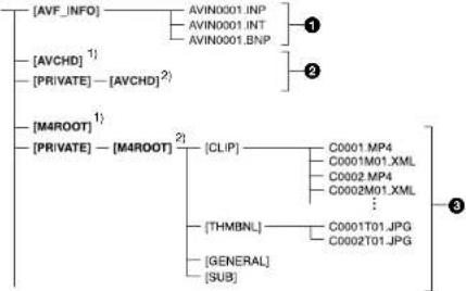
flowchart
graph TD
    A["AVF_INFO"] --> B["AVIN0001.INP"]
    A --> C["AVIN0001.INT"]
    A --> D["AVIN0001.BNP"]
    E["AVCHD"] --> F["1"]
    G["PRIVATE"] --> H["AVCHD"]2]
    I["M4ROOT"] --> J["1"]
    K["PRIVATE"] --> L["M4ROOT"]2]
    M["CLIP"] --> N["C0001.MP4"]
    M --> O["C0001M01.XML"]
    M --> P["C0002.MP4"]
    M --> Q["C0002M01.XML"]
    M --> R["THMBNL"]
    S["GENERAL"] --> T["C0001T01.JPG"]
    S --> U["C0002T01.JPG"]
    V["SUB"] --> W["SUB"]
1) Memory Stick PRO Duo
2) SD memory card, SDHC memory card, SDXC memory card
① Image management files
Deleting these files may prevent proper recording and playback of images.
The files are set as hidden files and are not normally displayed.
② AVCHD video management information folders
Recorded data for AVCHD videos is stored in these folders. Do not operate the folders or the files within the folders on a computer. Failure to obey may result in file damage and prevention of playback.
3 XAVCS video management information folders
Recorded data for XAVCS HD videos is stored in these folders.
The numbers at the ends of the folder names automatically increase sequentially.
Do not operate the folders or the files within the folders on a computer. Failure to obey may result in file damage and prevention of playback.
Pin Assignments
TALLY connector
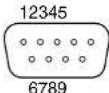
| Pin No. GPI Description | |
| Function Target Specifications | |
| 1 OUT PGM OUT TALLY INPUT1 (SDI) On: SHORT, Off: OPEN | |
| 2 OUT PGM OUT TALLY INPUT2 (SDI) On: SHORT, Off: OPEN | |
| 3 OUT PGM OUT TALLY INPUT3 (SDI) On: SHORT, Off: OPEN | |
| 4 OUT PGM OUT TALLY INPUT4 (SDI) On: SHORT, Off: OPEN | |
| 5 OUT PGM OUT TALLY INPUT1 (VIDEO) On: SHORT, Off: OPEN | |
| 6 OUT PGM OUT TALLY INPUT2 (VIDEO) On: SHORT, Off: OPEN | |
| 7 OUT PGM OUT TALLY INPUT3 (HDMI) On: SHORT, Off: OPEN | |
| 8 OUT PGM OUT TALLY INPUT4 (HDMI) On: SHORT, Off: OPEN | |
| 9 - GND | - |
Notes on the Licenses
THIS PRODUCT IS LICENSED UNDER THE AVC PATENT PORTFOLIO LICENSE FOR THE PERSONAL USE OF A CONSUMER OR OTHER USES IN WHICH IT DOES NOT RECEIVE REMUNERATION TO (i) ENCODE VIDEO IN COMPLIANCE WITH THE AVC STANDARD ("AVC VIDEO")
AND/OR
(ii) DECODE AVC VIDEO THAT WAS ENCODED BY A CONSUMER ENGAGED IN A PERSONAL ACTIVITY AND/OR WAS OBTAINED FROM A VIDEO PROVIDER LICENSED TO PROVIDE AVC VIDEO.
NO LICENSE IS GRANTED OR SHALL BE IMPLIED FOR ANY OTHER USE.
ADDITIONAL INFORMATION MAY BE OBTAINED FROM MPEG LA, LLC.
Software is installed in the unit. We provide this software based on the license agreements of the copyright owners. Based on requests by the owners of copyright of these software applications, we have an obligation to inform you of the following.
Licenses (in English) are recorded in the internal memory of the unit. Connect a computer to the USB port on the right side of the unit, and read the files in the "PMHOME" > "LICENSE" folder.
GNU GPL/LGPL applied software
The software that is eligible for the following GNU General Public License (hereinafter referred to as "GPL") or GNU Lesser General Public License (hereinafter referred to as "LGPL") are included in the unit.
This informs you that you have a right to have access to, modify, and redistribute source code for these software programs under the conditions of the supplied GPL/LGPL.
Source code is provided on the web.
Use the following URL to download it.
http://oss.sony.net/Products/Linux/
We would prefer you do not contact us about the contents of source code.
Licenses (in English) are recorded in the internal memory of the unit.
Connect a computer to the USB port on the
right side of the unit, and read the files in the
"PMHOME" > "LICENSE" folder.
Glossary
Chroma keying
A method of compositing images that removes components in the foreground image that contain a specified color (chroma). Typically, a subject is captured in front of a blue background, commonly referred to as a "blue screen," and the blue background is removed, leaving only to subject for compositing.
Color bar
A test signal which displays vertical colored stripes on a monitor. Used to adjust the hue and saturation of colors on video cameras and monitors.
Default gateway
A router or computer on a network which serves as an entrance to an outside network. Other computers in the network access the outside network via the default gateway.
Delay
A function that delays audio to bring it into synchronization with video and is used when video is input later than the corresponding audio.
DHCP (Dynamic Host Configuration Protocol)
A protocol for automatically assigning IP addresses to devices when they connect to a network, and recovering the addresses when they disconnect.
DNS (Domain Name System)
A system which allows Internet domain names to be translated into IP addresses.
Embedded audio
Audio that is included in a video signal.
Encoding
Data rate conversion that uses compression technology and is performed based on the transmission bandwidth and the capacity of the recording media.
HDCP (High-bandwidth Digital Content Protection)
A form of copyright protection that encrypts digital signals as they travel across connections and prevents unauthorized copying of content.
HDMI (High-Definition Multimedia Interface)
A transmission interface standard for transferring video and audio as a digital signal.
Luminance keying
A method of compositing images that removes components in the foreground image based on brightness (luminance) differences. Typically, this is used to composite text by placing bright colored text on a black background.
Material
Video and audio data that is input to the unit in an unchanged state.
Mix
A transition effect that mixes the next picture into the current picture to eventually replace the current picture.
Mixdown
Combining audio inputs from multiple channels into one channel.
Monitor
Viewing video or listening to audio. Alternatively, a device for viewing and listening.
Picture-in-picture (PinP)
An effect achieved by embedding a video within another video.
PGM (Program)
The final video and audio signals output from this system after the application of effects. This is the video seen by viewers.
RGB
An output signal format which displays pictures by using the three primary colors; Red, Green, and Blue.
SDI (serial digital interface)
A standard for transmitting uncompressed digital video signals and embedded audio over a single coaxial cable.
Streaming
A method of transferring audio and data over a network for real-time playback.
Transition
Switching the video and audio within a specified duration.
Wipe
A transition effect that slides the next picture into the current picture, as if wiping the current picture away.
XLR
A 3-pin connector, often called a Cannon connector. A locking mechanism keeps the connector securely connected even when the cable is pulled. Very stable despite its simple structure, and often used on microphones to suppress handling noise.
Index
A
Aspect ratio 69
ASSIGN button 8
AUDIO ACCESS buttons 7
Audio level meters.... 13
Auto power off function 69
AUTO TRANS button 9
B
BKGD button 8
BKGD mode 17
C
Cameras 54
Chroma keying 45
Compositing videos.... 34
Computer used for settings.... 22
Connecting devices.... 18
Cut 29
CUT button 9
D
DC power input connector.... 11
Delay 69
Displaying the PC UI 22
E
EFFECT button 8
EFFECT mode 17,34
Embedded audio 25
F
File formats 88
Formatting memory cards.... 56
G
GUI video fader 33
H
HDMI input connectors.... 11
HDMI signal format 69
Headphones jack 9
Headphones volume adjustment.... 38
|
Initial settings.... 21
Input assignment 25
Input format support 86
[Input] screen....69
Input status.... 13
[INPUT] viewer.... 12
L
LINE input connectors.... 11
LINE output connectors.... 11
[Logo] 52
Logo 37,50
LOGO button....8
|LOGO SOURCE| menu....50
Luminance keying 49
M
Memory card slot....9
Messages 78
Mix 31
Mixing 38
Multi-viewer.... 12
MULTI VIEWER output connector.... 11
N
[NETWORK (PC UI)] menu.... 22
|Network Reset| screen 67
Network settings.... 22
PC UI computer 22
Streaming transmissions.... 67
[NEXT] viewer 12
0
OPTION connector 10
Output format support 87
|Output| screen....69
P
Parts identification....7
Pattern icons 40
[Pattern] screen.... 40, 41
PC UI 14
PC UI computer 22,23
PC UI network connector 11
PFL 39
PGM HDMI output connector.... 10
PGM master fader 7,38
PGM/NEXT tallies 54
PGM SDI output connector.... 10
PGM VIDEO output connector.... 10
|PGM| viewer 12
Picture-in-picture.... 43
Pin assignments 89
PinP 43
Power off 21
Power switch....9
R
Recording 63
Resetting the network 67
Root Certificate 57
S
SDI input connectors.... 10
SD signals 69
|Setup| screen 69
Simultaneous recording control.... 54
Streaming....58
STREAMING button 7
[STREAMING] menu 62
STREAMING network connector.... 11
Switching videos.... 29
[System] screen 69
T
Tallies 54
Tally indicators 13
TALLY output connector 10
[Title] 48
TITLE button 8
TITLE input connector 11
Tone signal 39
Touch panel 7
Transition rate 53
TRANSITION RATE buttons 9
[Transition Rate] screen 53
Troubleshooting 78
U
USB ports 10
Utilities 56
UTILITY button 8
[UTILITY] menu 56
V
VIDEO input connectors.... 10
VIDEO INPUT SELECT 8
Video selection buttons 8
W
Wipe 31