Pick your language and provide your email: we'll send you a specifically translated version.
This manual is not available in your language
User questions about Pro WS X570-ACE ASUS
0 question about this device. Answer the ones you know or ask your own.
Ask a new question about this device
No questions yet. Be the first to ask one.
Download the instructions for your Motherboard in PDF format for free! Find your manual Pro WS X570-ACE -
ASUS and take your electronic device back in hand. On this page are published all the documents necessary for the use of your device. Pro WS X570-ACE by ASUS.
No part of this manual, including the products and software described in it, may be reproduced, transmitted, transcribed, stored in a retrieval system, or translated into any language in any form or by any means, except documentation kept by the purchaser for backup purposes, without the express written permission of ASUSTeK COMPUTER INC. ("ASUS").
ASUS provides this manual “as is” without warranty of any kind, either express or implied, including but not limited to the implied warranties or conditions of merchantability or fitness for a particular purpose. In no event shall ASUS, its directors, officers, employees, or agents be liable for any indirect, special, incidental, or consequential damages (including damages for loss of profits, loss of business, loss of use or data, interruption of business and the like), even if ASUS has been advised of the possibility of such damages arising from any defect or error in this manual or product.
Specifications and information contained in this manual are furnished for informational use only, and are subject to change at any time without notice, and should not be construed as a commitment by ASUS. ASUS assumes no responsibility or liability for any errors or inaccuracies that may appear in this manual, including the products and software described in it.
Product warranty or service will not be extended if: (1) the product is repaired, modified or altered, unless such repair, modification of alteration is authorized in writing by ASUS; or (2) the serial number of the product is defaced or missing.
Products and corporate names appearing in this manual may or may not be registered trademarks or copyrights of their respective companies, and are used only for identification or explanation and to the owners' benefit, without intent to infringe.
Contents
About this guide ...... xi
Chapter 1: Getting Started
1.1 Windows installation 1-2
1.1.1 Installing ASUS Control Center Express (ACCE) 1-2
1.1.2 Starting ACCE....1-8
1.2 Linux installation.... 1-9
1.2.1 Installing Docker 1-9
1.2.2 Configuring the firewall 1-17
1.2.3 Installing ASUS Control Center Express (ACCE) ...... 1-18
1.2.4 Starting ACCE....1-19
1.2.5 Accessing ACCE....1-19
1.2.6 Stopping ACCE....1-20
1.2.7 Removing a specific ACCE image 1-20
1.3 Configuration.... 1-21
1.3.1 Changing the language....1-21
1.3.2 Changing the account password....1-21
1.3.3 Activating your license key....1-22
1.3.4 Updating ACCE....1-23
2.6.1 Using the menu items 2-23
2.6.2 Using the client device icons....2-24
2.6.3 Switching between different layouts....2-25
2.6.4 Customizing layouts....2-25
2.7 Mailbox.... 2-29
2.7.1 Configuring mailbox notifications 2-30
2.8 QR Code 2-31
2.9 Submit Feedback 2-32
Contents
Chapter 3: Agent Deployment
3.1 Agent management overview 3-2
3.2 Prerequisites 3-4
3.2.1 General prerequisites....3-4
3.2.2 Prerequisites for Windows-based client devices....3-5
3.2.3 Prerequisites for Linux-based client devices....3-6
3.2.4 Installing SSH on a Linux-based client device 3-7
3.2.5 Additional steps for Windows 7 environments ...... 3-11
3.3 Deploying agents 3-13
3.3.1 Automatically scanning and deploying to devices......3-13
3.3.2 Scanning an IP range 3-15
3.3.3 Adding and deploying to devices 3-18
3.3.4 Editing device information....3-20
3.3.5 Installing agents manually....3-21
3.3.6 Installing agents in silent mode....3-24
3.3.7 Upgrading or repairing agents 3-26
3.3.8 Installing an agent onto the main server 3-30
3.4 Deployment troubleshooting 3-31
3.4.1 Viewing detailed error information 3-31
3.4.2 Common errors (Linux) 3-31
3.4.3 Common errors (Windows) 3-31
3.5 Updating agents.... 3-32
3.6 Removing agents 3-35
3.6.1 Removing agents through the main server 3-35
3.6.2 Removing manually installed agents on Windows......3-36
Contents
Chapter 4: Device Information
4.1 Device information overview 4-2
4.2 Device information details 4-3
4.3 Device information functions....4-4
5.10.1 Task scheduler calendar overview....5-152
5.10.2 Setting a new task....5-153
5.10.3 Editing a task 5-163
5.10.4 Deleting a task 5-164
5.11 Screen Broadcast.... 5-165
5.11.1 Setting up the broadcast environment 5-167
5.11.2 Adding a new Broadcast Room 5-169
5.11.3 Managing video playlists....5-173
5.11.4 Starting or stopping a broadcast 5-174
5.11.5 Editing an existing Broadcast Room 5-175
Contents
Chapter 6: Settings
6.1 Options menu....6-2
6.1.1 SMTP settings....6-2
6.1.2 Client rule management....6-3
6.1.3 Main server rule management 6-8
6.1.4 General configuration....6-9
6.1.5 License....6-16
6.1.6 Free up system space....6-21
6.2 Account menu 6-23
6.2.1 Account Settings 6-23
6.2.2 Role privilege management 6-26
6.2.3 Login user 6-28
6.3 Backup and restore.... 6-29
6.3.1 MySQL databases (Windows) 6-29
6.3.2 SQLite databases (Windows) 6-34
6.3.3 MySQL databases (Linux) 6-37
6.4 Migrating settings from ACC CSM 6-39
6.4.1 Migrating configurations of ACC CSM server 6-39
6.4.2 Importing ACC CSM data 6-42
6.4.3 Deploying ACCE agents to ACC CSM devices 6-43
About this guide
This user guide contains the information you need when using and configuring ASUS Control Center Express (ACCE).
How this guide is organized
This guide contains the following parts:
1. Chapter 1: Getting Started
This chapter provides a quick overview of ASUS Control Center Express, and how to install and set it up.
2. Chapter 2: Main Menu
This chapter describes the functions available on the main control panel.
3. Chapter 3: Agent Deployment
This chapter describes how to automatically or manually deploy ASUS Control Center Express agents and remove agents, and updating agents.
4. Chapter 4: Device Information
This chapter describes the device information and software controlled options for managing the device.
5. Chapter 5: Management Functions
This chapter describes the metadata management, software management, task scheduler, and hardware based management functions.
6. Chapter 6: Settings
This chapter describes the User and ASUS Control Center Express settings.
Conventions
To make sure that you perform certain tasks properly, take note of the following symbols used throughout this manual.
DANGER/WARNING: Information to prevent injury to yourself when trying to complete a task.
CAUTION: Information to prevent damage to the components when trying to complete a task.
IMPORTANT: Instructions that you MUST follow to complete a task.
NOTE: Tips and additional information to help you complete a task.
Typography
Bold text Indicates a menu or an item to select.
Italics Used to emphasize a word or a phrase.
Keys enclosed in the less-than and greater-than sign means that you must press the enclosed key.
Example: means that you must press the Enter or Return key.
++ If you must press two or more keys simultaneously, the key names are linked with a plus sign (+).
Example: ++
Command Means that you must type the command exactly as shown, then supply the required item or value enclosed in brackets.
Example: At the command prompt, type the command line: format A:/S
Reference
Visit the ASUS websites worldwide that provide updated information for all ASUS hardware and software products. Refer to the ASUS contact information for details.
Chapter 1
This chapter provides a quick overview of ASUS Control Center Express, and how to install and set it up.
Getting Starred
1.1 Windows installation
It is strongly recommended to backup your data and settings before updating ASUS Control Center Express. Refer to the Backup and Restore section of the Settings chapter for more information.
1.1.1 Installing ASUS Control Center Express (ACCE)
Please visit the product website of your ASUS product to download the ASUS Control Center Express installer.
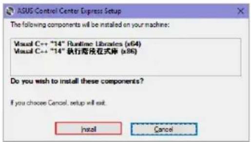
Unzip the installation file, then execute Setup.exe. You should be guided to install vcredist_x64, vcredist_x86, database, and ASUS Control Center Express respectively.
Ensure that Microsoft .NET Framework V4.6.1 or higher is installed before installing ASUS Control Center Express.
If there is an older version of ASUS Control Center Express already installed on your system and you wish to clear the original configurations of the older version, you may check the Clear original configuration option during the installation process to remove the configuration settings of the older version of ASUS Control Center Express.
We DO NOT recommend clearing the configuration settings of older versions of ASUS Control Center Express unless necessary.
text_image
ASUS Control Center Express Setup
The following components will be installed on your machine:
Visual C++ "14" Runtime Libraries (x64)
Visual C++ "14" 执行商程式库 (x86)
Do you wish to install these components?
If you choose Cancel, setup will exit.
Install Cancel
text_image
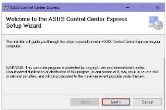
ASUS Control Center Express
Welcome to the ASUS Control Center Express
Setup Wizard
The installer will guide you through the steps required to install ASUS Control Center Express on your computer.
WARNING: This computer program is protected by copyright law and international treaties.
Unauthorized duplication or distribution of this program, or any portion of it, may result in severe civil
or criminal penalties, and will be prosecuted to the maximum extent possible under the law.
The illustrations in this section are for reference only and may differ between options selected. The steps in this section use MySQL as an example, if you wish to use another database, please follow the installation instructions for the database selected.
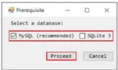
Select the database ( MySQL, SQLite 3) you would like to install for ASUS Control Center Express, then click Proceed. For this example, we will select MySQL.
• We recommend selecting MySQL as the database for ASUS Control Center Express.
- Before installing the database, ensure the main server is connected to a public WAN with a stable connection.
text_image
Prerequisite
Select a database:
✓ MySQL (recommended) ✓ SQLite 3
Proceed Cancel
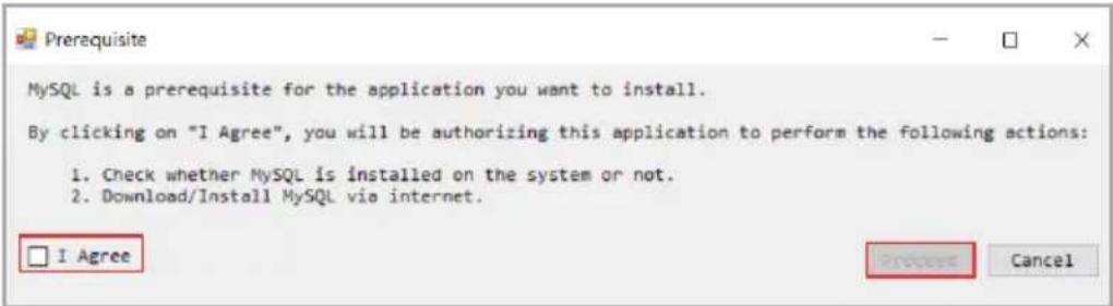
Read through the prerequisites, then check I Agree and click Proceed.
text_image
Prerequisite
MySQL is a prerequisite for the application you want to install.
By clicking on "I Agree", you will be authorizing this application to perform the following actions:
1. Check whether MySQL is installed on the system or not.
2. Download/Install MySQL via internet.
□ I Agree
Process Cancel
Select whether to download the MySQL installation files from the internet, or if you wish to use a preexisting MySQL installed on the system, then click Proceed.
text_image
Prerequisite
Download MySQL (8.0.22)
Use the MySQL installed on the system
Version: 8.0.22
Location: C:\Program Files\MySQL\MySQL Server 8.0\
Process Cancel
Click on Download MySQL to download the MySQL installation files. After the download is completed, a manual installation will be required.
Click on Use the MySQL installed on the system to automatically detect a preexisting MySQL already installed.
Once the database has been setup, the ASUS Control Center Express installation will begin.
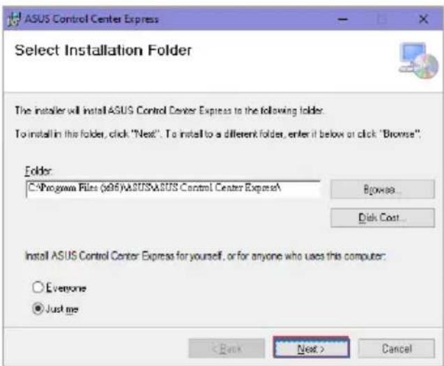
Select the folder you would like to install ASUS Control Center Express to; we recommend using the default folder, then click Next once you have finished.
text_image
ASUS Control Center Express
Select Installation Folder
The installer will install ASUS Control Center Express to the following folders.
To install in this folder, click "Next". To install to a different folder, enter it below or click "Browse".
Folder:
C:\Program Files (x95)\ASUS\ASUS Control Center Express\
Browse...
Disk Cost...
Install ASUS Control Center Express for yourself, or for anyone who uses this computer:
Everyone
Just me
< Back Next > Cancel
Click on Browse... to select a new path to install ASUS Control Center Express.
Click on Disc Cost... to view the server disk space and disk space required to install ASUS Control Center Express.
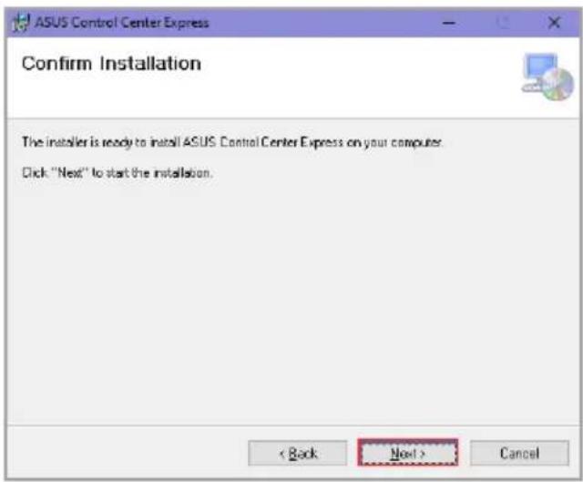
Click on Next to begin the installation.
text_image
ASUS Control Center Express
Confirm Installation
The installer is ready to install ASUS Control Center Express on your computer.
Click "Next" to start the installation.
< Back Next > Cancel
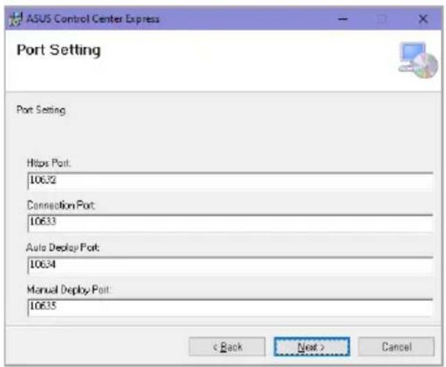
Once in the Port Setting page, you may adjust the default set ports if your working environment is already using a port that is displayed. Once you have finished adjusting the ports or if you wish to use the default ports, click on Next.
Https Port
Main ACCE server log in port.
Connection Port
Main ACCE server and client device connection port.
Auto Deploy Port
Main ACCE server auto deploy port.
Manual Deploy Port
Main ACCE server manual deploy port.
KVM Port
Main ACCE server OOB KVM port
Broadcast Port
Main ACCE server broadcasting port.
MySQL Port
Main ACCE server database port.
Indication
Main ACCE server alert notification function port.
text_image
ASUS Control Center Express
Port Setting
Port Setting
Https Port:
10632
Connection Port:
10633
Auto Deploy Port:
10634
Manual Deploy Port:
10635
< Back Next > Cancel
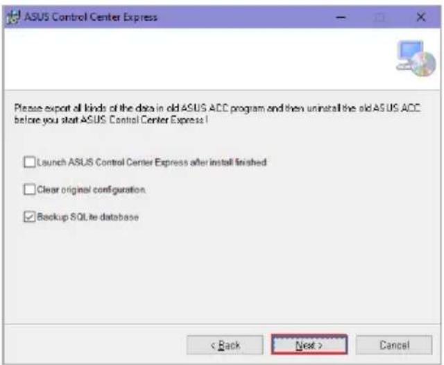
Select and check the options you wish to execute during the installation, then click Next.
Launch ASUS Control Center Express after install finished: Launches ASUS Control Center Express after the installation has finished.
Clear original configuration: (not recommended) Remove previously set data of ASUS Control Center Express. If you wish to use this option, we recommend you backup the data of your ASUS Control Center Express.
Backup SQLite database: (recommended) Backs up any existing SQLite database during installation. The default backup location is set to C:\Program Files (x86)\ASUS\ASUS Control Center Express\apro_console\backup.
text_image
ASUS Control Center Express
Please export all kinds of the data in old ASUS ACC program and then uninstall the old ASUS ACC before you start ASUS Control Center Express!
Launch ASUS Control Center Express after install finished
Clear original configuration
Backup SQL# database
< Back Next > Cancel
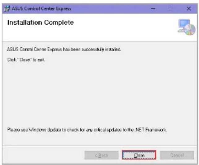
Once the installation is completed, click on Close to finish the installation.
text_image
ASUS Control Center Express
Installation Complete
ASUS Control Center Express has been successfully installed.
Click "Close" to exit.
Please use Windows Update to check for any critical updates to the .NET Framework.
< Back Cancel
1.1.2 Starting ACCE
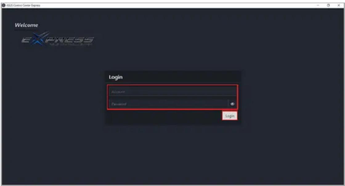
Launch the ASUS Control Center Express by double clicking the ASUS Control Center Express.exe application
Enter your Account and Password. Click Login to enter the ASUS Control Center Express main menu.
The default account is administrator, and the default password is admin. To change the default account and password, refer to the Account Settings section of the Settings chapter.
The account and password is case sensitive.
ASUS Control Center Express supports nine languages (English, Traditional Chinese, Simplified Chinese, Japanese, German, French, Russian, Korean, and Spanish). The display language will be set on first launch according to the operating system language. If the operating system language is not supported, the display language will default to English.
It is strongly recommended to install a database to backup your data and settings. For more information, refer to the Backup and Restore section in the Settings chapter.
text_image
ASUS Control Center Express
Welcome
EXPRESS
Login
Account
Password
Login
1.2 Linux installation
Ensure that the server is connected to the Internet.
The following commands require elevated privileges. Ensure all commands are preceded with the sudo command.
1.2.1 Installing Docker
Compatibility issues may occur if an older version of Docker is already installed. Refer to Docker documentation at https://docs.docker.com/engine/install/ for more information.
Installing Docker in Ubuntu
Open a terminal window, then run the following command to check if Docker is installed:
sudo docker version
Run the following commands to set up the Docker apt repository:
...
Total download size: 93 M
Installed size: 367 M
Is this ok [y/N]:
When prompted, confirm that the displayed GPG key matches "060A 61C5 1B55 8A7F 742B 77AA C52F EB6B 621E 9F35", then enter Y.
...
Importing GPG key 0x621E9F35:
Userid : "Docker Release (CE rpm) <docker@docker.com>"
Fingerprint: 060A 61C5 1B55 8A7F 742B 77AA C52F EB6B 621E 9F35
From : https://download.docker.com/linux/fedora/gpg
Is this ok [y/N]:
Run the following command to start Docker.
sudo systemctl start docker
Installing Docker in openSUSE
Open a terminal window, then run the following command to check if Docker is installed:
sudo docker version
Run the following commands to download and install Docker:
sudo zypper update
sudo zypper install docker
sudo systemctl enable docker
Run the following command to start Docker.
sudo systemctl start docker
Installing Docker in Pardus
Start Pardus Update and ensure that all system components are up to date.
Open a terminal window, then run the following command to check if Docker is installed:
sudo docker version
Run the following commands to download and install Docker:
sudo apt install docker.io
sudo systemctl enable docker
Run the following command to start Docker.
sudo systemctl start docker
1.2.2 Configuring the firewall
ASUS Control Center Express uses the following default ports. Ensure that the following ports are allowed through the firewall before proceeding.
If any of the default ports are in use, adjust the port settings according to your system environment.
SNMP port
162 (default)
HTTPS port
10632 (default)
TCP port
10633 (default)
OOB KVM port
10639 (default)
Broadcast port
10640 (default)
Event alert port
10642 (default)
Proxy port
10643 (default)
Configuring the firewall in Ubuntu/Debian/Pardus
If Uncomplicated Firewall (ufw) is installed, open a terminal window, then run the following command to allow a port through the firewall, replacing with each of the ports listed in the default ports table:
sudo ufw allow <port>
Run the following command to check the firewall status:
sudo ufw status verbose
Configuring the firewall in CentOS/RHEL/Fedora/openSUSE
Run the following command to allow a port through the firewall, replacing with each of the ports listed in the default ports table:
Run the following command to apply the new firewall rules:
sudo firewall-cmd --reload
1.2.3 Installing ASUS Control Center Express (ACCE)
Download the ACCE TAR archive (.tar).
Open a terminal window in the directory of the TAR archive.
Run the following command to extract the TAR archive, replacing with the filename of the TAR archive:
sudo tar -xzvf ./ "<ACCE image>.tar"
Open a terminal window in the ACCE installation directory.
The ACCE installation directory is the directory created after extracting the ACCE TAR archive.
For example, if the TAR archive was saved in /Documents/ACCE/, the new directory created with the ACCE version number (e.g., /Documents/ACCE/1.7.7.0/) is the ACCE installation directory.
Run the following command to start ACCE:
sudo ./ACCE --start
When prompted for port settings, specify a port number or press Enter to use the default port.
Ensure that the default or specified ports are allowed through the system firewall. Refer to the Configuring the firewall section for more information.
Port settings (1~65535)
HTTPS port: Please input (or press enter to use default 10632)
1.2.4 Starting ACCE
Open a terminal window in the ACCE installation directory.
The ACCE installation directory is the directory created after extracting the ACCE TAR archive. Refer to the Installing ASUS Control Center Express (ACCE) section for more information.
Run the following command to start ACCE:
sudo ./ACCE --start
1.2.5 Accessing ACCE
Accessing ACCE using the ExpressBrowser binary
Navigate to the ACCE installation directory, then open the AProConsole folder and double click the ExpressBrowser binary.
Accessing ACCE through a web browser
Open a web browser, then navigate to https://127.0.0.1:10632/AproUI.
Ensure that the HTTPS port 10632 is allowed through the system firewall. Refer to the Configuring the firewall section for more information.
If an alternate HTTPS port was specified during installation, replace 10632 with the specified HTTPS port.
1.2.6 Stopping ACCE
Open a terminal window in the ACCE installation directory.
The ACCE installation directory is the directory created after extracting the ACCE TAR archive. Refer to the Installing ASUS Control Center Express (ACCE) section for more information.
Run the following command to stop ACCE:
sudo ./ACCE --down
1.2.7 Removing a specific ACCE image
Open a terminal window in the ACCE installation directory.
The ACCE installation directory is the directory created after extracting the ACCE TAR archive. Refer to the Installing ASUS Control Center Express (ACCE) section for more information.
Run the following command to stop ACCE:
sudo ./ACCE --down
Run the following command to remove a specific ACCE image, where is the version of the ACCE image (e.g., 1.7.7.0):
sudo docker rmi acce:<version>
1.3 Configuration
1.3.1 Changing the language
Click the 📄 in the top right menu bar, then select a language from the drop down list.
1.3.2 Changing the account password
Log in with the default account and password.
The default account is administrator, and the default password is admin.
• The account and password is case sensitive.
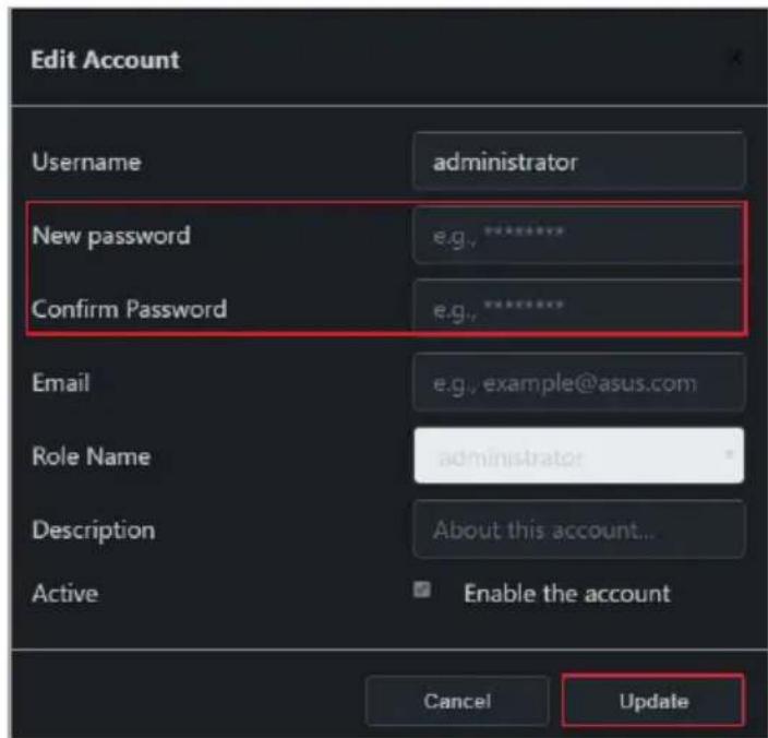
Click on the icon in top right menu bar, then click on Settings.
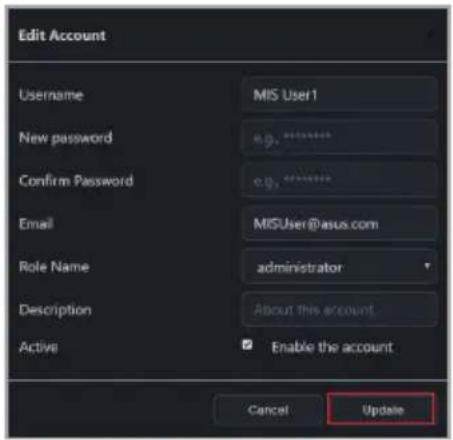
Click on the account to enter a new password, then click on Update to save the changes made.
text_image
Edit Account
Username administrator
New password e.g.******
Confirm Password e.g.******
Email e.g., example@asus.com
Role Name administrator
Description About this account...
Active Enable the account
Cancel Update
1.3.3 Activating your license key
You must activate a license key before deploying an agent. Each client device you wish to deploy an agent to require a corresponding license key.
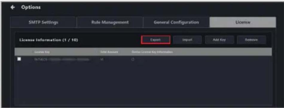
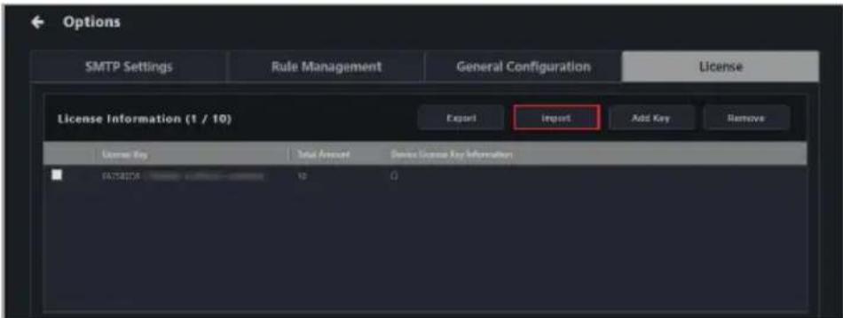
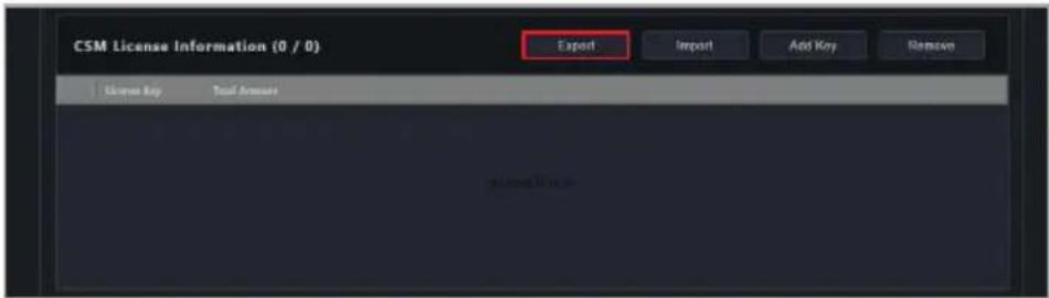
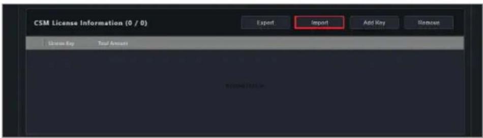
Please use the Import function if you already have a list of license keys to import or a previously exported list of license keys available. For more details on License Keys please refer to the License section of the Settings chapter.
Locate the License Key on the ASUS Control Center Express card bundled in your motherboard's giftbox.
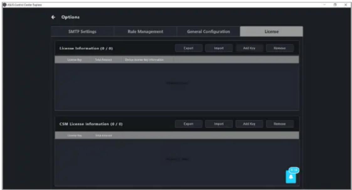
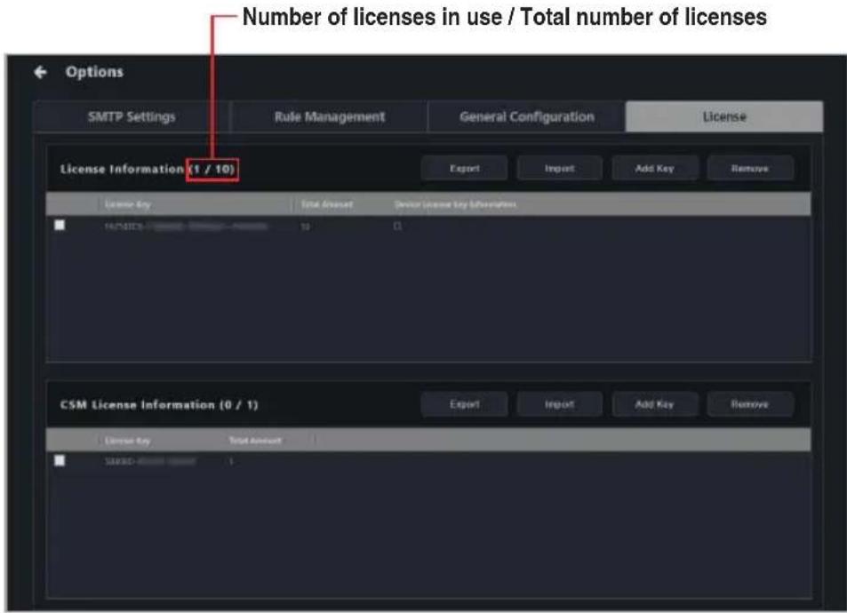
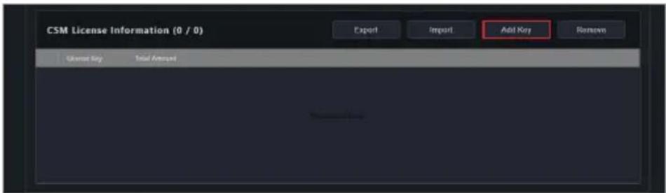
Click on the id then select the Options > License tab.
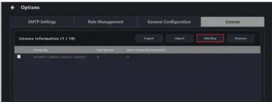
Click on Add Key.
text_image
ASUS Control Center Express
Options
SMTP Settings
Rule Management
General Configuration
License
License Information (0 / 0)
Export
Import
Add Key
Remove
License Key
Total Amount
Device license key information
CSM License Information (0 / 0)
Export
Import
Add Key
Remove
License Key
Initial Amount
0128
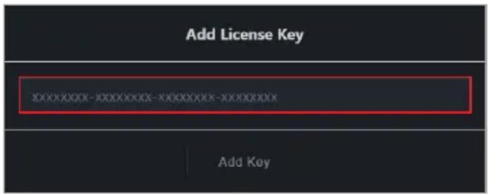
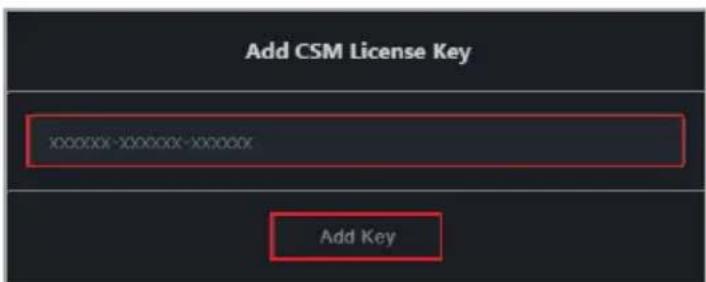
Key in the license key and then click on Add Key to register a license for a single device on ASUS Control Center Express.
It is strongly recommended to backup your data and settings before updating ACCE. Refer to Managing data and settings in MySQL databases or Backing up data and settings in SQLite databases for more information depending on the type of database installed.
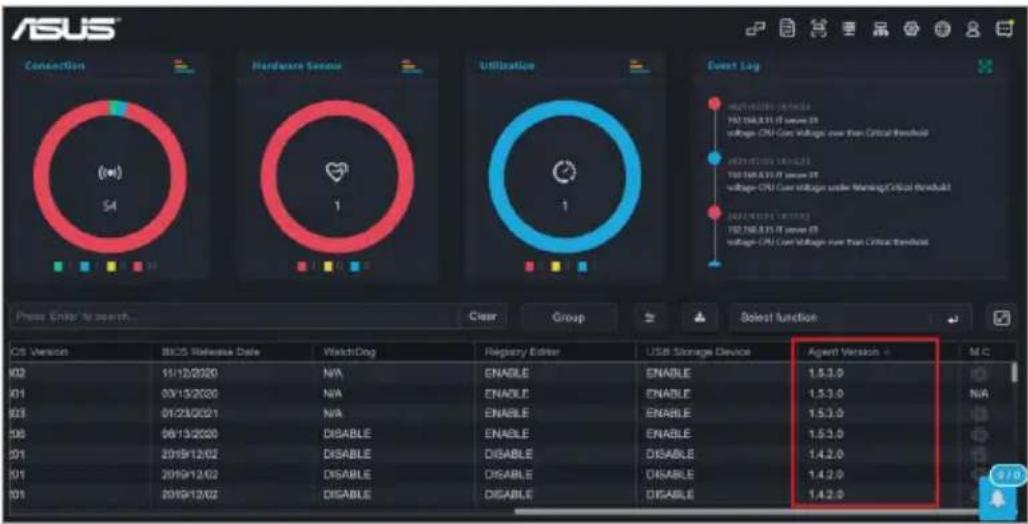
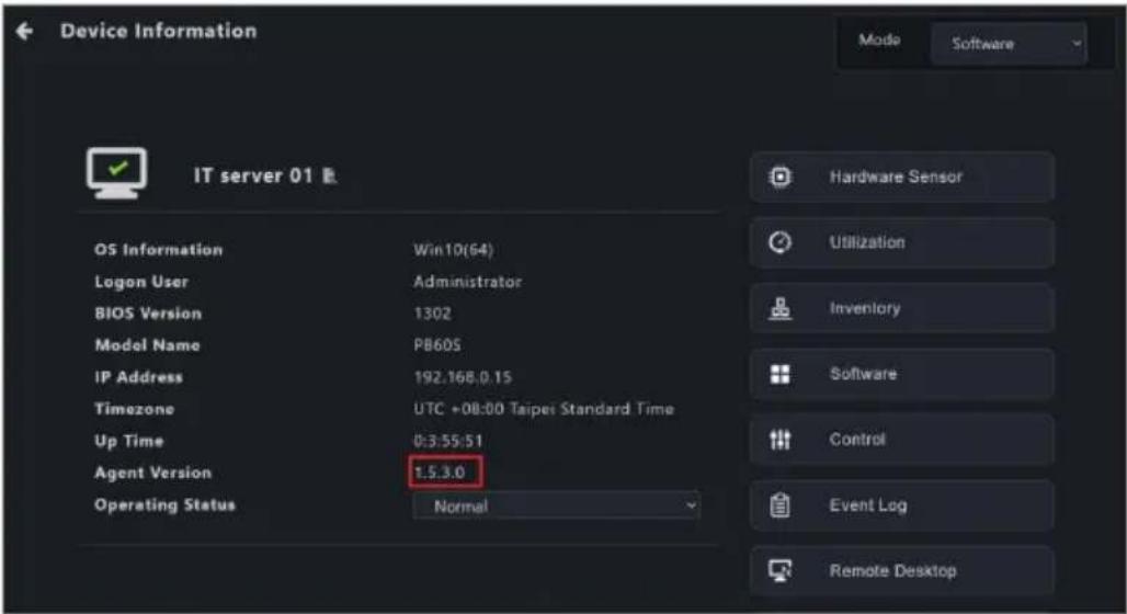
Monitoring and management functions may be affected or unavailable if you only updated the ACCE main software, but did not update the client device agents to v1.6.3 or above. Refer to Upgrading or repairing agents in the Agent Deployment chapter to update the client agent versions.
If you are upgrading from a previous version of ASUS Control Center Express (v1.4.x or earlier) or if you are upgrading from SQLite to MySQL, some time may be needed to convert the database. To prevent loss of data, please do not uninstall any applications or turn off the main server until the database conversion is completed. If for any reason the database conversion fails to complete, you can still continue to use ASUS Control Center Express using the existing database.
If prompted to close ACCE services during an upgrade, click Yes to automatically close background services and continue installation.
Immediate update
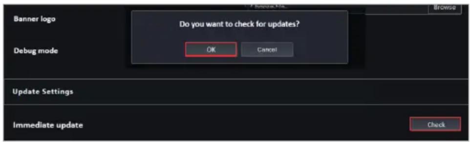
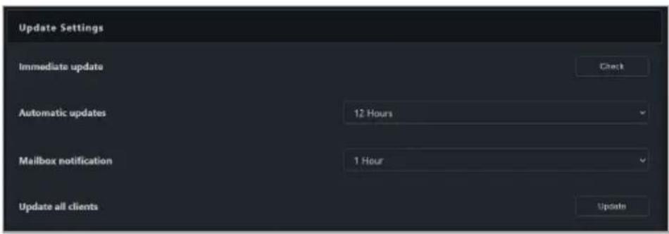
You can immediately update your ASUS Control Center Express from the Update Settings tab under Options.
Click on located at the top right menu bar, then select General Configuration, then scroll to Update Settings. Options >
Click on Check next to the Immediate update field, then click OK.
text_image
Banner logo
Do you want to check for updates?
Debug mode
OK
Cancel
Update Settings
Immediate update
Check
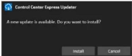
If a new update is available, a pop up notification will appear notifying you of a new update available for ASUS Control Center Express. Click Install on the pop up notification to install the new update, or click Cancel to cancel the update.
text_image
Control Center Express Updater
A new update is available. Do you want to install?
Install Cancel
Click on Install to begin the update. ASUS Control Center Express will automatically close when the update is ongoing, ensure to launch ASUS Control Center Express again after the update is completed.
text_image
Control Center Express Updater
A new update is available. Do you want to install?
Install Cancel
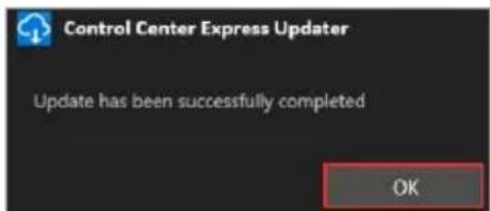
Click on OK once the update has been successfully completed.
text_image
Control Center Express Updater
Update has been successfully completed
OK
Automatic updates
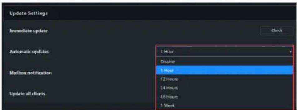
Enable the Automatic updates function to receive a new update pop up notification on the bottom right of your ASUS Control Center Express window. You can choose whether to install or cancel the update from this pop up window.
Click on located at the top right menu bar, then select Options > General Configuration, then scroll to Update Settings.
Select how often to check for updates and prompt update notifications from the Automatic updates drop down menu.
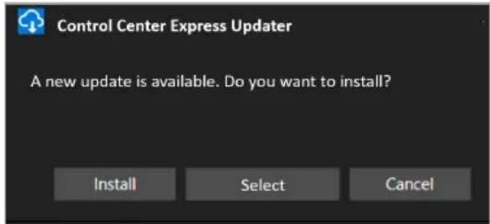
When a new update is available, the pop up notification will appear in the bottom right corner of the ASUS Control Center Express window. You can do one of the following actions when the notification appears:
- Click on Install to immediately download and begin updating.
- Clickon Select to select a different time to prompt you with the update notification.
- (not recommended) Click on Cancel if you do not wish to update ASUS Control Center Express. If you select this option, the update notification will appear again the next time the selected notification time for Automatic updates is reached.
text_image
Control Center Express Updater
A new update is available. Do you want to install?
Install Select Cancel
Manual update
Download the latest version of the ASUS Control Center Express installation file from the product website of your ASUS product.
Unzip the installation file, then refer to the Installing ASUS Control Center Express (ACCE) section to update the ASUS Control Center Express main software on the main server.
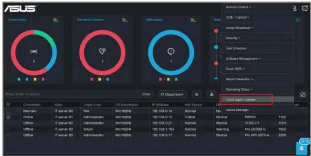
Once the ASUS Control Center Express main software update on the main server is completed, please refer to Client Agent Updater or Upgrading or repairing agents in the Agent Deployment chapter to update the agents on the client device(s).
Chapter 2
This chapter describes the functions available on the main control panel.
Main Menu
2.1 Main menu overview
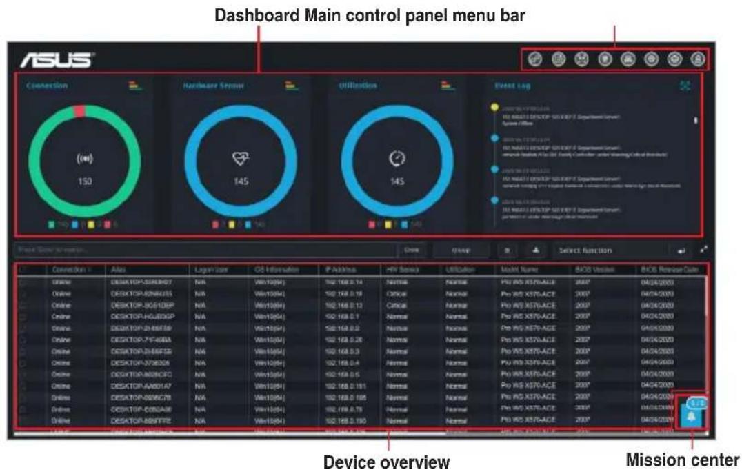
You can toggle between Classic and Graphical views by clicking on
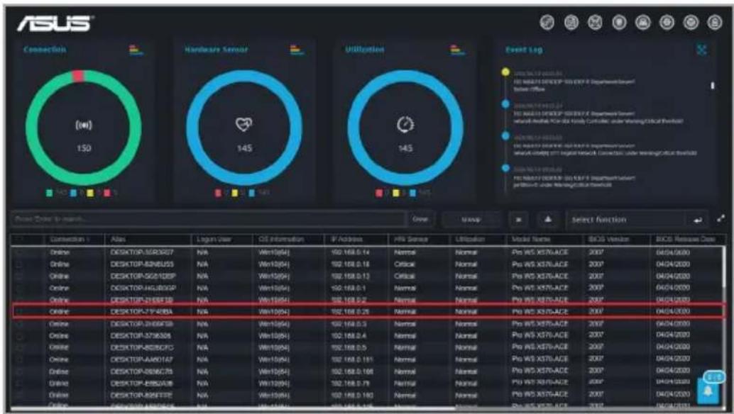
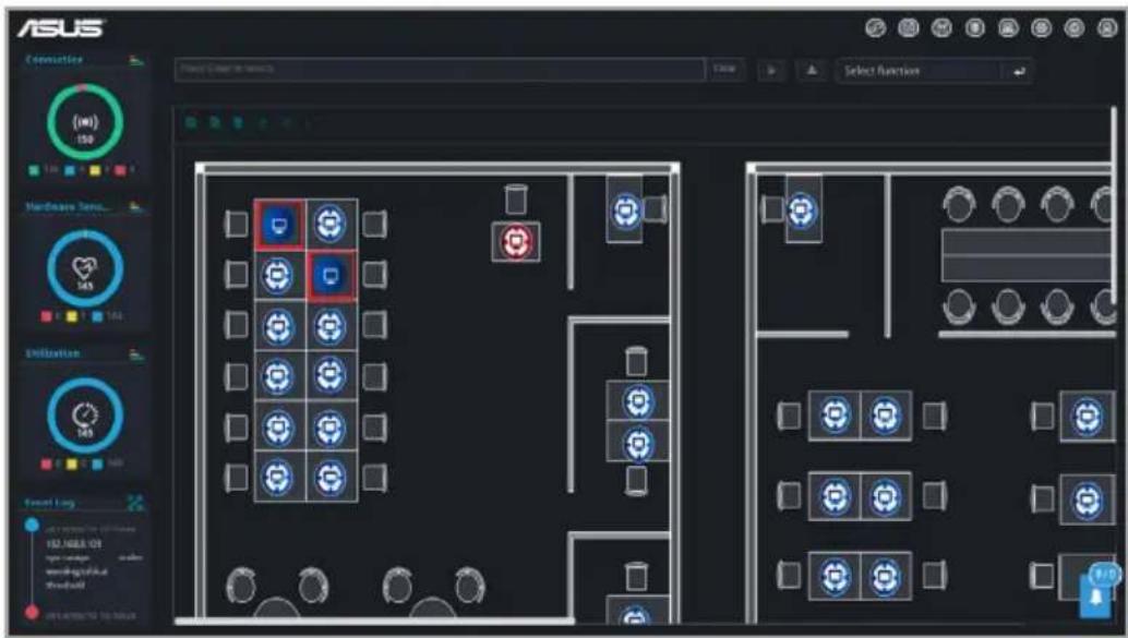
A brief overview of both views of ASUS Control Center Express is displayed as below:
The screenshots in this section are for reference only.
Classic view
text_image
Dashboard Main control panel menu bar
ASUS®
Connection
(10)
150
Hardware Server
145
Utilization
145
Event Log
145
Device View - Version
Close
Unapp
Select function
Connection 1
Also
Logan Case
OS Information
P Address
HP Address
Utilization
Model Name
BOD Version
BOD Release Date
Online
DESKTOP-300R007
NA
Win100(A)
192.168.0.14
Normal
Normal
Pro WIS XSTO-ACE
2007
04/04/2020
Online
DESKTOP-80N8USS
NA
Win100(A)
192.168.0.18
Optical
Normal
Pro WIS XSTO-ACE
2007
04/04/2020
Online
DESKTOP-305I10GP
NA
Win100(A)
192.168.0.13
Critical
Normal
Pro WIS XSTO-ACE
2007
04/04/2020
Online
DESKTOP-HU8DGP
NA
Win100(A)
192.168.0.1
Normal
Normal
Pro WIS XSTO-ACE
2007
04/04/2020
Online
DESKTOP-Z448E6B
NA
Win100(A)
192.168.0.2
Normal
Normal
Pro WIS XSTO-ACE
2007
04/04/2020
Online
DESKTOP-Z7448BA
NA
Win100(A)
192.168.0.26
Normal
Normal
Pro WIS XSTO-ACE
2007
04/04/2020
Online
DESKTOP-Z446F5B
NA
Win100(A)
192.168.0.3
Normal
Normal
Pro WIS XSTO-ACE
2007
04/04/2020
Online
DESKTOP-Z783DGANA
Win100(A)
192.168.0.4
Normal
Normal
Pro WIS XSTO-ACE
2007
04/04/2020
Online
DESKTOP-B839CFONA
Win100(A)
192.168.0.5
Normal
Normal
Pro WIS XSTO-ACE
2007
04/04/2020Online
DESKTOP-A4801A7NA
Win100(A)
192.168.0.181NormalNormalPro WIS XSTO-ACE
200704/04/2020Online
DESKTOP-S596C7BNAWin100(A)
192.168.0.195NormalNormalPro WIS XSTO-ACE
200704/04/2020Online
DESKTOP-C355AABNAWin100(A)
192.168.0.79NormalNormalPro WIS XSTO-ACE200704/04/2020Online
DESKTOP-B84FTENAWin100(A)
192.168.0.193NormalNormalPro WIS XSTO-ACE200704/04/2020Device overview
Mission center
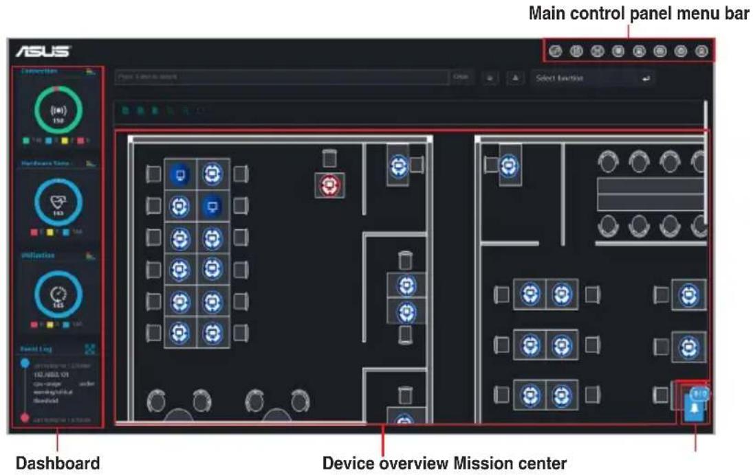
Graphical view
text_image
Main control panel menu bar
ASUS
Dissection
150
Hardware Time
163
Infineless
165
Board Log
100.000.00
on-range
order
on-axis
download
Dashboard
Device overview Mission center
Menu bar items:
The menu bar on the top of the screen has the following menu items:
Top menu bar items Description
Switch view
Switches user interface.
Report generator
Generates graphs and reports of the online/offline status of client devices, and also generates lists and reports of software installation and hardware.
Management control*
Check device hardware and execute functions using the remote management controller, for devices that are powered off, devices that have no OS installed, or devices where you cannot enter the OS.
Metadata
Customize device metadata on a single or multiple devices.
Deploy
Automatically or manually deploy or remove ASUS Control Center Express agents
Settings
Configure SMTP Server setting, notification rules, ASUS Control Center Express main server settings, License key management, and data transfer.
Language
Select the language for ASUS Control Center Express
Account
Add and edit accounts, and permission settings.Scan QR code.Logout.
Mailbox
Read notifications related to ASUS Control Center Express
* To use the Management Control function, ensure that the motherboard you wish to control supports remote management controllers.
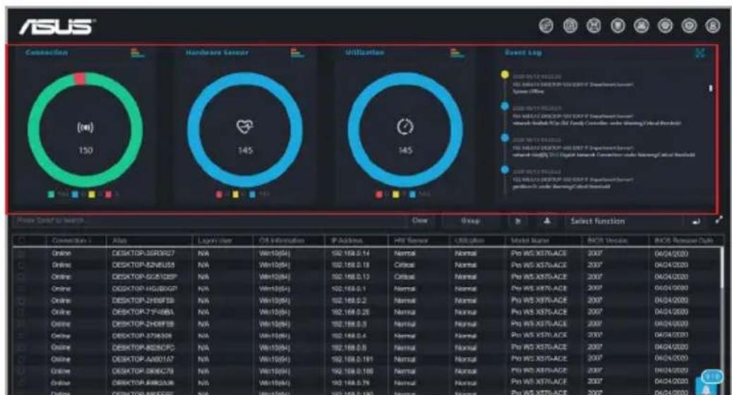
2.2 Dashboard overview
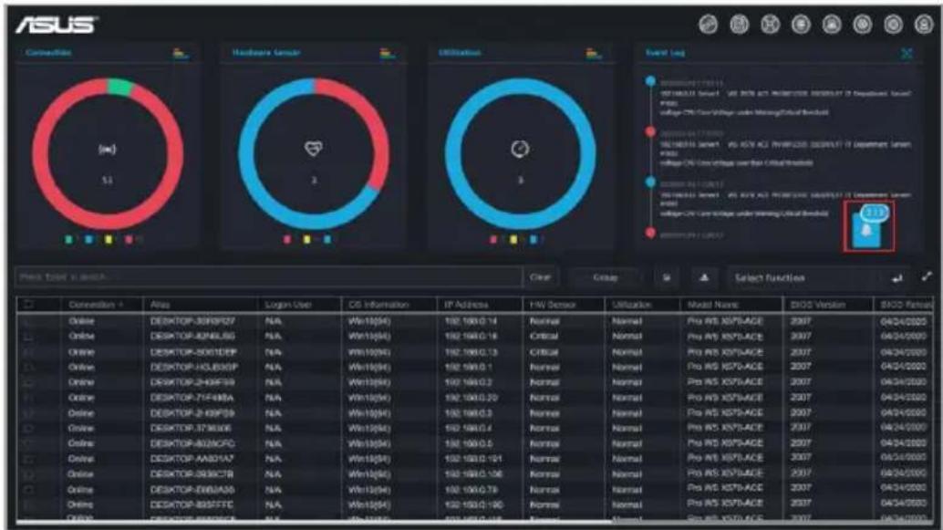
The Dashboard Overview allows you to view activity alerts and event logs to monitor client devices in real time.
text_image
ASUS
Connection
(24)
150
Hardware Server
145
Utilization
145
Event Log
2008 WISV X37V-ACE
WIS VAS22 DISKTOP 100.00% P/ Department Server
System Office
2008 WISV X37V-ACE
WIS VAS22 DISKTOP 100.00% P/ Department Server
network-Shubuk MCP (B) Family Controller under Working/ Virtual Hardware
2008 WISV X37V-ACE
WIS VAS22 DISKTOP 100.00% P/ Department Server
network-Shubuk MCP (B) System Controller under Working/ Virtual Hardware
2008 WISV X37V-ACE
WIS VAS22 DISKTOP 100.00% P/ Department Server
network-Shubuk MCP (B) System Controller under Working/ Virtual Hardware
2008 WISV X37V-ACE
WIS VAS22 DISKTOP 100.00% P/ Department Server
network-Shubuki MCP (B) System Controller under Working/ Virtual Hardware
Price Scaled to Switch...
Close
Group
Select Function
Connection: Atlas
Light User
OS Information
IP Address
HIT Server
USB Station
Model Manager
MACS Version
MACS Remover Help
Online DESKTOP-SSRDSZ7 N/A Win10(54) 192.168.0.14 Normal Normal Pro WS X37V-ACE 2007 04/04/2020
Online DESKTOP-SSNRS5 N/A Win10(54) 192.168.0.18 Critical Normal Pro WS X37V-ACE 2007 04/04/2020
Online DESKTOP-SCS13DXP N/A Win10(54) 192.168.0.13 Critical Normal Pro WS X37V-ACE 2007 04/04/2020
Online DESKTOP-HGUSBQF N/A Win10(54) 192.168.0.1 Normal Normal Pro WS X37V-ACE 2007 04/04/2020
Online DESKTOP-ZHESFBS N/A Win10(54) 192.168.0.2 Normal Normal Pro WS X37V-ACE 2007 04/04/2020
Online DESKTOP-ZYFDBA N/A Win10(54) 192.168.0.28 Normal Normal Pro WS X37V-ACE 2007 04/04/2020
Online DESKTOP-ZHREFBS N/A Win10(54) 192.168.0.3 Normal Normal Pro WS X37V-ACE 2007 04/04/2020
Online DESKTOP-ZTIN5D8 N/A Win10(54) 192.168.0.4 Normal Normal Pro WS X37V-ACE 2007 04/04/2020
Online DESKTOP-BDSDFC N/A Win10(54) 192.168.0.6 Normal Normal Pro WS X37V-ACE 2007 04/04/2020
Online DESKTOP-AAMO1A7 N/A Win10(54) 192.168.0.191 Normal Normal Pro WS X37V-ACE 2007 04/04/2020
Online DESKTOP-DNDCN N/A Win10(54) 192.168.0.199 Normal Normal Pro WS X37V-ACE 2007 04/04/2020
Online DESKTOP-KARDAJ6 N/A Win10(54) 192.168.0.79 Normal Normal Pro WS X37V-ACE 2007 04/04/2020
Online DESKTOP-KRDFBE N/A Win10(54) 192.168.0.197 Normal Normal Pro WS X37V-ACE 2007 04/04/2020
Connection
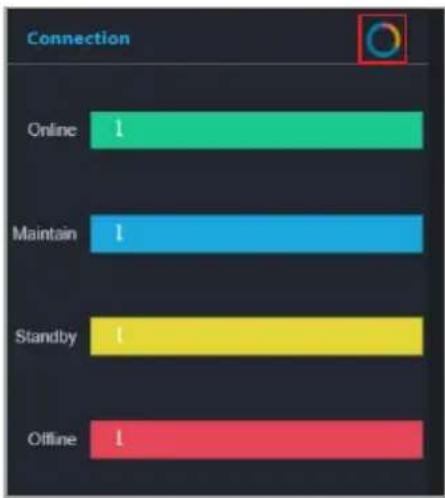
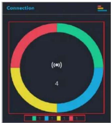
This graph displays a summary of the connection status of all client devices.
Color Status
Green Online
Blue Maintenance
Yellow Standby
Red Offline
Utilization
This graph displays a summary of the utilization status of all online client devices.
Color Status
Red Critical
Yellow Warning
Blue Normal
Hardware Sensor
This graph shows a summary of the hardware status of all online client devices.
Color Status
Red Critical
Yellow Warning
Blue Normal
2.2.1 Switching sensor views
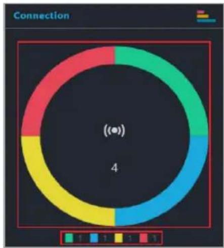
You can customize the information shown on the Connection, Hardware Sensor, and Utilization graphs by clicking on a color block on the graph or using the graph keys to filter devices which match the selected status. For example, on the Connection graph, you can choose to show or hide devices that are Online, under Maintenance, in Standby, or Offline.
pie
Connection
| Segment Color | Value |
|---|---|
| Green | 1 |
| Blue | 1 |
| Yellow | 1 |
| Red | 1 |
The chart contains a central label with '(●)' and the number '4' at the center.
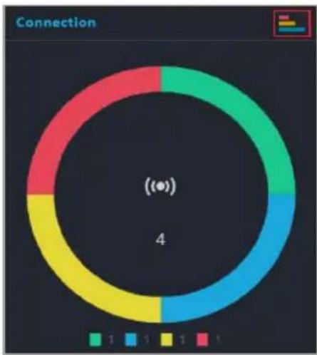
You can also click on the top right corner of each graph to switch between pie graph and bar graph views.
pie
Connection
| Segment | Value |
|---|---|
| Green | 1 |
| Blue | 1 |
| Yellow | 1 |
| Red | 1 |
(●) 4
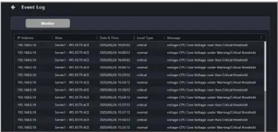
The Event Log displays the status of all client devices in real time, allowing you to keep track of the status changes of your client devices at a quick glance. You can also click on the top right corner of the Event Log block to expand the Event Log to view a detailed list of the event items.
text_image
Event Log
Monitor
IP Address Alias Date & Time Level Type Message
192.168.0.18 Server1 - WS X570 ACE 2020/08/26 16:01:02 critical voltage-CPU Core Voltage over than Critical threshold
192.168.0.18 Server1 - WS X570 ACE 2020/08/26 16:30:52 normal voltage-CPU Core Voltage under Warning/Critical threshold
192.168.0.18 Server1 - WS X570 ACE 2020/08/26 16:00:42 critical voltage-CPU Core Voltage over than Critical threshold
192.168.0.18 Server1 - WS X570 ACE 2020/08/26 16:30:12 normal voltage-CPU Core Voltage under Warning/Critical threshold
192.168.0.18 Server1 - WS X570 ACE 2020/08/26 15:59:52 critical voltage-CPU Core Voltage over than Critical threshold
192.168.0.18 Server1 - WS X570 ACE 2020/08/26 15:39:12 normal voltage-CPU Core Voltage under Warning/Critical threshold
192.168.0.18 Server1 - WS X570 ACE 2020/08/26 15:30:52 critical voltage-CPU Core Voltage over than Critical threshold
192.168.0.18 Server1 - WS X570 ACE 2020/08/26 15:58:12 normal voltage-CPU Core Voltage under Warning/Critical threshold
192.168.0.18 Server1 - WS X570 ACE 2020/08/26 15:57:52 critical voltage-CPU Core Voltage over than Critical threshold
192.168.0.18 Server1 - WS X570 ACE 2020/08/26 15:57:12 normal voltage-CPU Core Voltage under Warning/Critical threshold
192.168.0.18 Server1 - WS X570 ACE 2020/08/26 15:38:37 critical voltage-CPU Core Voltage over than Critical threshold
192.168.0.18 Server1 - WS X570 ACE 2020/08/26 15:36:12 normal voltage-CPU Core Voltage under Warning/Critical threshold
Use the Notification Rule Management menu to manage which events are shown in the Event Log. To set up notification rules, please click 📋 in the top right menu bar of the Dashboard, then select Options > Rule Management. For more information, please refer to the Rule Management section of the Settings chapter.
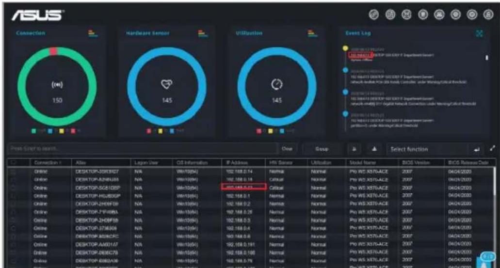
Clicking on a client device IP address on the Event Log will highlight the selected device in the Devices list, helping you quickly locate devices which require immediate attention.
pie
| Category | Connection | Altex | Lagon User | OS Information | IP Address | HMI Sensor | Utilization | Model Name | BIOS Version | BIOS Release Date |
|---|---|---|---|---|---|---|---|---|---|---|
| Hardware Sensor | 150 | N/A | N/A | N/A | 192,168.0.14 | N/A | Normal | Pro WS X570-ACE | 2007 | 04/04/2020 |
| Hardware Sensor | N/A | N/A | N/A | N/A | 192,168.0.14 | Calouar | Normal | Pro WS X570-ACE | 2007 | 04/04/2020 |
| Hardware Sensor | N/A | N/A | N/A | N/A | 192,168.0.14 | Calouar | Normal | Pro WS X570-ACE | 2007 | 04/04/2020 |
| Hardware Sensor | N/A / N/A | N/A | N/A | N/A | 192,168.0.13 | Calouar | Normal | Pro WS X570-ACE | 2007 | 04/04/2020 |
| Hardware Sensor | N/A / N/A | N/A | N/A | N/A | 192,168.0.13 | Calouar | Normal | Pro WS X570-ACE | 2007 | 04/04/2020 (Note: The chart displays a red dot at the center of the 'N/A' label in the 'Utilization' section. It is not explicitly labeled in the image but is included in the text box. The 'Event Log' panel contains three data points: 'N/A' (blue circle), 'N/A' (red circle), and 'N/A' (black circle). The 'Event Log' panel contains three data points: 'N/A' (blue circle), 'N/A' (red circle), and 'N/A' (black circle). The 'Event Log' panel contains three data points: 'N/A' (blue circle), 'N/A' (red circle), and 'N/A' (black circle). The 'Event Log' panel contains three data points: 'N/A' (blue circle), 'N/A' (red circle), 'N/A' (black circle). The chart is created using a grid-based visualization with color-coded circles indicating specific data points. The output values are estimated based on the visual scale of the grid. The chart is presented in a tabular format with labels for each category.
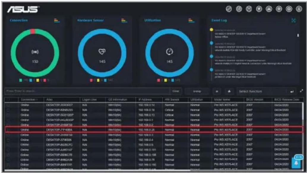
2.3 Device overview
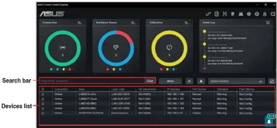
The Device overview lists all your client devices and also allows you to search for client devices using keywords, export the list of client devices, or perform actions on selected client devices using the function shortcut.
Certain fields may show a value of "Not Config" if they have not yet been configured using ASUS Control Center Express.
If a Windows-based client device is powered off, offline, or logged out, the Logon User field will show the username of the last logged in user enclosed in brackets ("[]").
text_image
ASUS Control Center Express
ASUS
Connection
(∞)
5
Hardware Sensor
5
Utilization
5
Event Log
82.16K 1.03 LAB0078-8MC
no switch under Warning/Offshore/Thermal
82.16K 1.03 LAB0078-8MC
no switch over the Warning threshold
82.16K 1.03 LAB0078-8MC
no switch over the Warning threshold
Search bar
Press Enter to search...
Clear
demo
Select function
Devices list
Connection Alias Login User OS Information IP Address HW Sensor Utilization Fail Status
Online LAB0078-vPro LAB-DEV-0070 Win10(84) 192.168.1.163 Normal Warning Not Config
Online LAB0077-Dash LAB-SUP-0077 Win11(64) 192.168.1.161 Normal Warning Not Config
Online LAB0100-BWC LAB-USR-0100 Win11(64) 192.168.1.162 Normal Warning Not Config
Online LAB0059-BWC LAB-DEV-0259 Win10(54) 192.168.1.153 Normal Warning Not Config
Online DESKTCP-STJTPJK [Administrator] Win10(54) 192.168.0.53 Critical Warning Not Config
2.3.1 Filtering client devices
To clear the filter and view all devices, click on Clear in the Search bar.
• To filter devices using the Search bar:
Enter a keyword into the Search bar then press to search for devices with details matching the search criteria. If you wish to remove a keyword, click on the X.
• To filter devices using the Dashboard:
On the Connection, Hardware Sensor, or Utilization overview, click on a color block on the graph or use the graph keys to filter devices which match the selected status.
pie
Connection
| Color | Value |
|---|---|
| Green | 3 |
| Blue | 2 |
| Yellow | 1 |
| Red | 1 |
(●) 4
• To filter the devices using Devices list:
Hover over the column you wish to use as your filter criteria in the Devices list.
Clickon, then select the filter rule (
Equals, Not equal, Starts with, Ends with, Contains, Not contains) and enter the keyword to search.
Click on the name of a column header to sort the filter results alphabetically, in ascending or descending order.
Click on the expand icon in the top right corner of the Devices overview block to expand the client device list; clicking on the expand icon again will revert the list back to its original size.
Click and drag on a column title rearrange the columns of the Devices list.
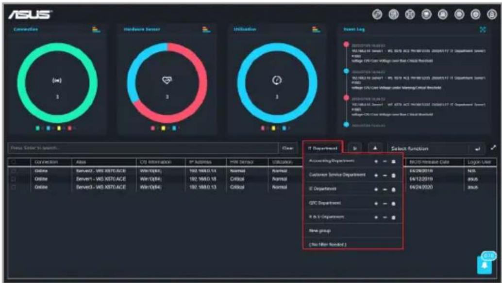
• To filter the devices using Group:
To clear the filter and view all devices, click on (No Filter Needed) in the Group drop down menu.
Click Group, then select a group from the drop down menu to only display the devices in that group.
text_image
ASUS
Convention
Hardware Server
Utilization
Event Log
IT Department
Select function
Connection Alias CTS Information IP Business HW Service Utilization
Online Server2 - WS X070/ACE Win0(84) 192.168.0.13 Normal Normal Normal
Online Server1 - WS X070/ACE Win0(84) 192.168.0.13 Critical Normal Normal
Online Server3 - WS X070/ACE Win0(84) 192.168.0.13 Critical Normal Normal
RECIT Mechanical Code Login User
Customer Service Department
IE Department
CSC Department
R & V Department
New group
(No Filter Wizard)
64/26/2019 N/S
64/12/2019 89/S
64/24/2020 89/S
2.3.2 Redirecting to device information
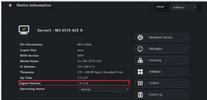
You can view the device information of a device by clicking on a cell for a client device in the device overview list. You can view more detailed information on the client device, or operate different functions available for the client device on the device information page.
For more information on the device information page, please refer to the Device Information chapter.
2.3.3 Customizing device list metadata
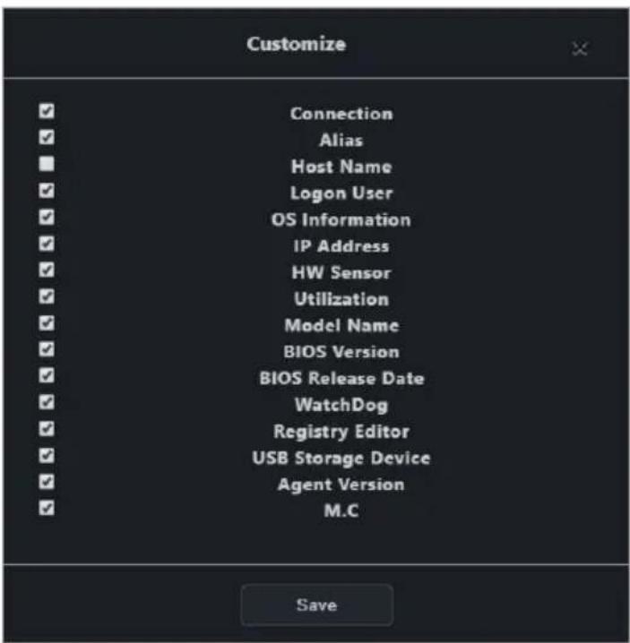
Click on the Customize icon to select which items to display in the client device list, you can also display newly added metadata columns to the device overview list by checking the new metadata item.
text_image
Customize
Connection
Alias
Host Name
Logon User
OS Information
IP Address
HW Sensor
Utilization
Model Name
BIOS Version
BIOS Release Date
WatchDog
Registry Editor
USB Storage Device
Agent Version
M.C
Save
2.3.4 Export device list
You can export the device list to a .csv file for when you need to backup the devices list.
To Export the device list, click on 📁 (Export), then enter your file name and click Save to save the device list as a .csv file.
2.3.5 Creating client device groups
Group client devices on the client device list into groups according to your needs. Using the group function and filter function, you can quickly locate, view, and manage client devices. You can also apply notification rule settings to these groups, or easily add devices which appear on reports from the Report generator to existing groups.
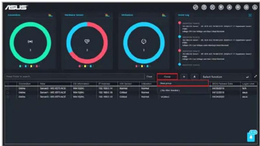
To create a new device group:
Click on Group.
Select New group from the drop down menu.
text_image
ASUS
Connecticut
Hardware Sensor
Utilization
Smart Log
New group
( No filter needed )
04/28/2019
N/A
04/12/2019
USB
04/24/2020
USB
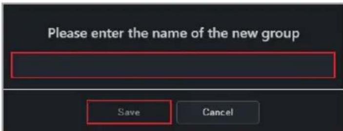
Enter a name for the group, then click Save.
text_image
Please enter the name of the new group
Save Cancel
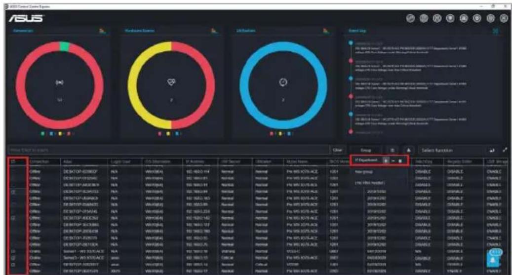
Select the devices you wish to add to the group, then click Group and click +.
Click on to remove the selected devices from the group.
Click on to delete the group.
Click Yes on the confirmation window, then click OK to finish adding devices to a group.
2.4 Shortcut functions
You can perform certain actions or schedule tasks on selected client devices.
- Certain functions may require you to restart the client device for the changes to take effect.
- Certain functions are only supported on Windows-based client devices.
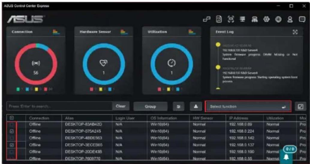
Tick the checkbox for the device(s) you would like to perform an action on.
text_image
ASUS Control Center Express
ASUS
Connection
(10)
56
Hardware Sensor
1
Utilization
1
Event Log
H2.168.3.13 RAD Server
System Firmware progress: DMM Missing or Not Functional
H2.168.3.13 RAD Server
System Firmware progress: Starting operating system boot process
Press "Enter to search...
Clear
Group
Select function
Connection Alias Login User OS Information HW Sensor IP Address Utilization More
Offline DESKTOP-83AB42D N/A Win10(64) Normal 192.168.0.69 Normal Pro
Offline DESKTOP-075A245 N/A Win10(64) Normal 192.168.0.224 Normal Pro
Offline DESKTOP-48DE563 N/A Win10(64) Normal 192.168.0.142 Normal Pro
Offline DESKTOP-3ECEB65 N/A Win10(64) Normal 192.168.0.137 Normal Pro
Offline DESKTOP-20DE43B N/A Win10(64) Normal 192.168.0.190 Normal Pro
Offline DESKTOP-7008770 N/A Win10(64) Normal 192.168.0.55 Normal Pro
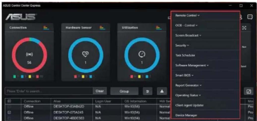
Click on Select function, and select the function you would like to use. Please refer to the table on the next page for a brief summary of each function.
text_image
ASUS Control Center Express
Connection
(##)
56
Hardware Sensor
1
Utilization
1
Remote Control
OCB - Control
Screen Broadcast
Security
Task Scheduler
Software Management
Smart BIOS
Report Generator
Operating Status
Client Agent Updater
Device Manager
Process 'Enter' to search...
Clear
Group
Connection
Alias
Login User
OS Information
HIV Set
Offline
DESKTOP-83AB420
N/A
Win10(64)
Normal
Offline
DESKTOP-075A245
N/A
Win10(64)
Normal
Offline
DESKTOP-48DE563
N/A
Win10(64)
Normal
Use the Mission Center to check if the task was completed successfully. Refer to the Mission Center section for more information.
2.4.1 Remote control
Restart computer
Restart the selected device(s).
Power off
Power off the selected device(s).
Power on
Power on the selected device(s).* A powered off client device can only be powered on if it supports Wake-on-LAN
2.4.2 OOB-Control
Only available on client devices connected using a management LAN port with motherboards which support remote management controllers.
The OOB-Control menu includes functions from the 4 remote management controllers: BMC, DASH, RTL8117, and vPro. If a selected device does not support a selected function, you can view related information in the mission center after executing the function.
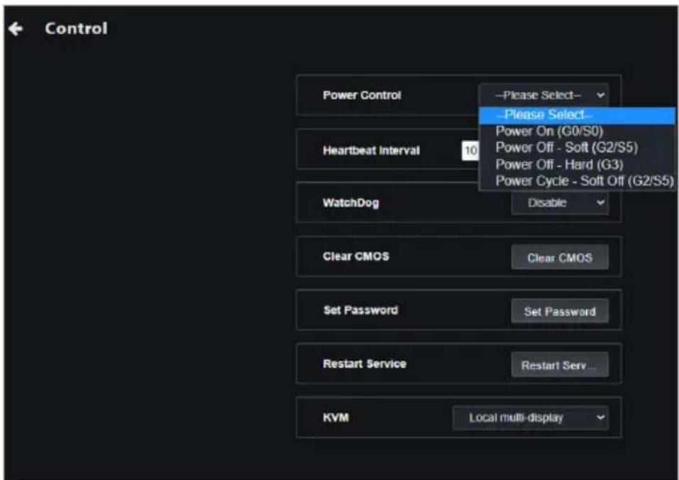
- Power control
Power On (G0/S0)
Power on the selected device(s) through the remote management controller.
Power Off - Soft (G2/S5)
Power off the selected device(s) through the remote management controller.
Power Off - Hard (G3)
Force a power off of the selected device(s) through the remote management controller.
Power Cycle - Soft off (G2/S5)
Set the selected device(s) to restart after shutting down the OS through the remote management controller.
Sleep - Deep (G1/S3)
Set the selected device(s) to enter sleep mode (G1/S3) through the remote management controller.
Master Bus Reset
Reset the hardware of the selected device(s) through the remote management controller.
Hibernate (G1/S4)
Set the selected device(s) to enter hibernate mode (G1/S4) through the remote management controller.
Restart Computer to BIOS
Set the selected device(s) to enter BIOS after a restart through the remote management controller.
Power On to BIOS
Set the selected device(s) to enter BIOS after powering on through the remote management controller.
Restart Computer to IDE-R Floppy
Set the selected device(s) to enter IDE-R floppy drive after a restart through the remote management controller.
Power On to IDE-R Floppy
Set the selected device(s) to enter IDE-R floppy drive after powering on through the remote management controller.
• Power control (continued)
Restart Computer to IDE-R CDROM
Set the selected device(s) to enter IDE-R ODD after a restart through the remote management controller.
Power On to IDE-R CDROM
Set the selected device(s) to enter IDE-R ODD after powering on through the remote management controller.
Sleep - Light (G1/S2)
Set the selected device(s) to enter sleep mode (G1/S2) through the remote management controller.
Power Cycle - Hard Off (G3)
Power off and restart the selected device(s) through the remote management controller.
Diagnostic Interrupt (NMI)
Set the selected device(s) to print error report and restarting through the remote management controller.
Power Off - Soft Graceful (G2/S5)
Normal shut down via the OS of the selected device(s) through the remote management controller.
Power Off - Hard Graceful (G3)
Normal shut down via the hardware of the selected device(s) through the remote management controller.
Master Bus Reset Graceful
Normal shut down and resetting the hardware of the selected device(s) through the remote management controller.
Power Cycle (Graceful Soft Off) (G2/S5)
Normal shut down via the OS then restarting the selected device(s) through the remote management controller.
Power Cycle (Graceful Hard Off) (G3)
Normal shut down via the hardware then restarting the selected device(s) through the remote management controller.
- Watchdog
Watchdog Enable
Enable RTL8117 Watchdog monitoring for selected device(s).
Watchdog Disable
Disable RTL8117 Watchdog monitoring for selected device(s).
- BIOS
Clear CMOS
Clear CMOS for selected device(s) through RTL8117 or BMC to reset them to factory settings.
• Account management
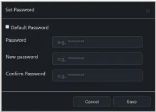
Set password
Set the remote management controller account password for selected RTL8117 or vPro device(s).
Login
Log into the remote management controller account of selected BMC or DASH device(s).
Change default password
Change the default password for selected BMC device(s).* Only applicable for BMC devices that have not had a password set yet
- System
Restart service
Restart the RTL8117 service on selected device(s).
Sync OEM port
Synchronize the BMC port for selected device(s).
• KVM
KVM Remote Multi-display
Set RTL8117 KVM of selected device(s) as remote Multi-display.
KVM Local Multi-display
Set RTL8117 KVM of selected device(s) as local Multi-display.
KVM Remote Single-display
Set RTL8117 KVM of selected device(s) as remote single-display.
KVM Enable
Enable KVM for selected RTL8117 and vPro machine(s).
KVM Disable
Disable KVM for selected vPro machine(s).
KVM Password
Set the vPro KVM password for selected device(s).
- USB redirection
USB Redirection
Configure USB redirection of selected device(s) through the client device's remote management controller.
Enable USB Redirection
Enable USB redirection for selected device(s).
Disable USB Redirection
Disable USB redirection for selected device(s).
- Firmware update
Firmware Update
Update the RTL8117 or BMC firmware of selected device(s).* Firmware update will be disabled if KVM is enabled
- Trust zone
Trust Zone
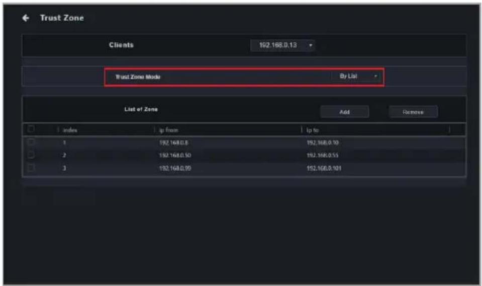
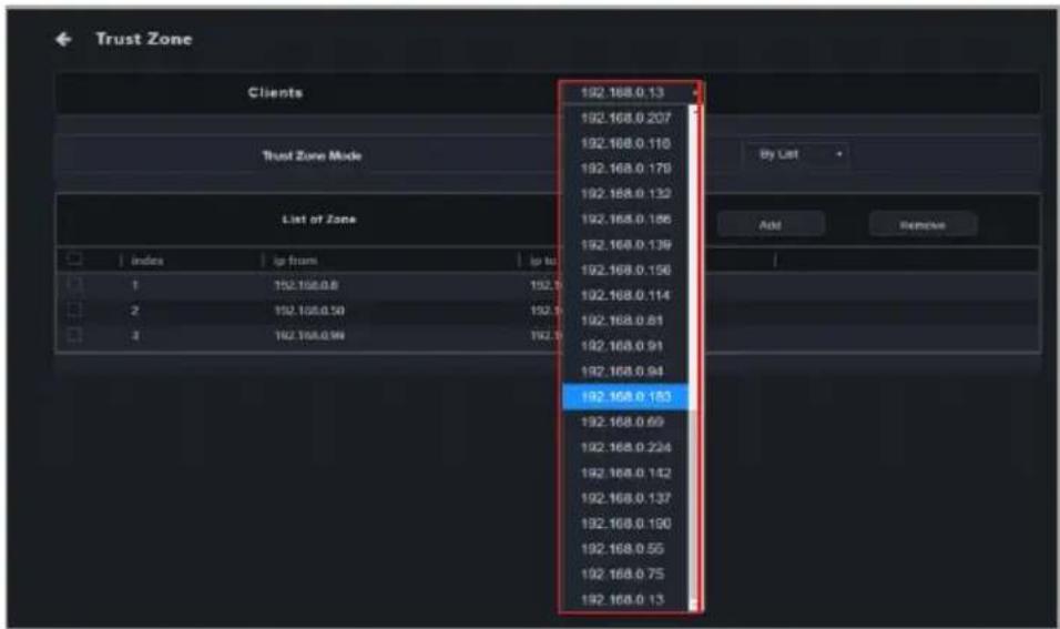
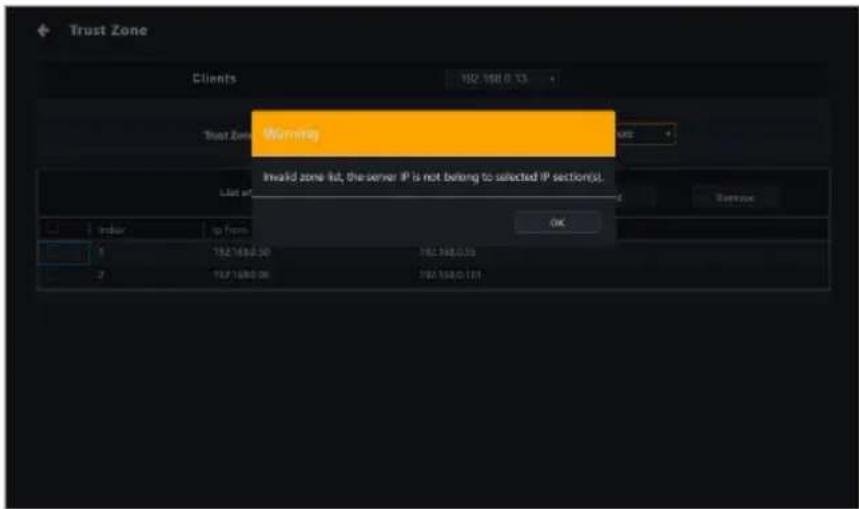
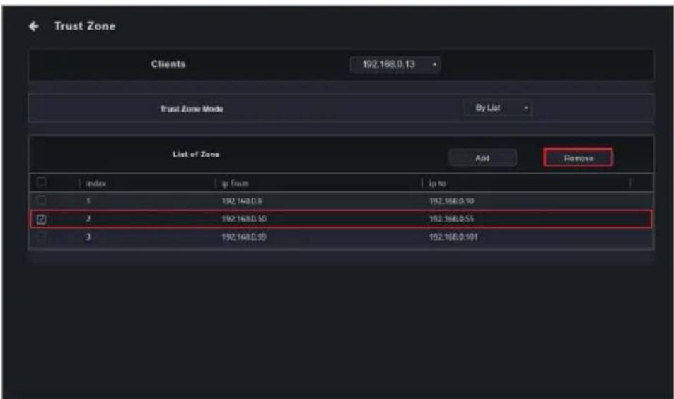
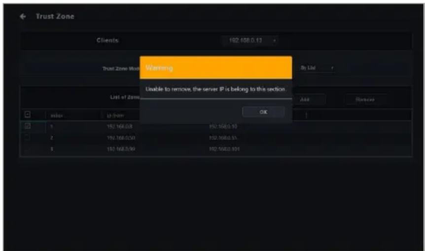
Set the main server IP addresses which are allowed to perform RTL8117 function operations on client devices.
• Certificate management
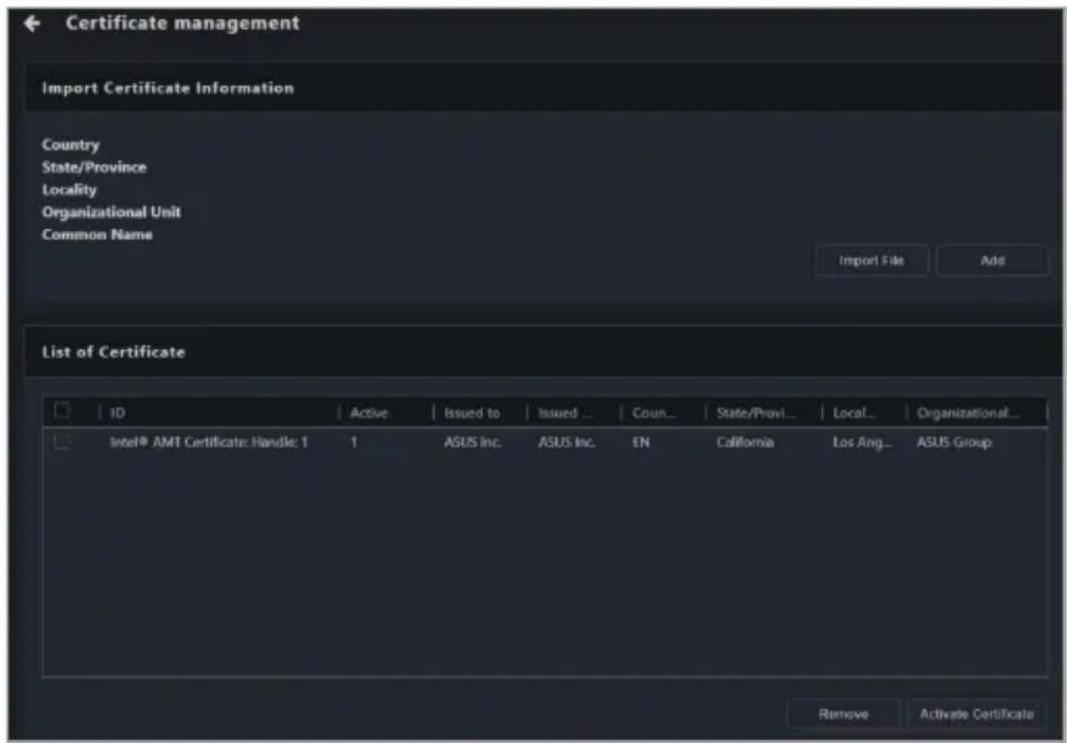
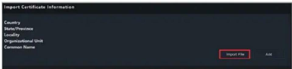
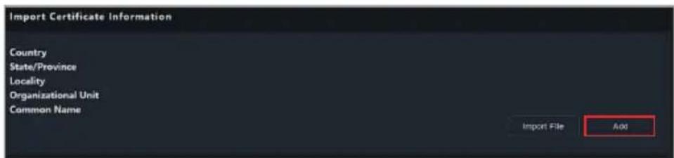
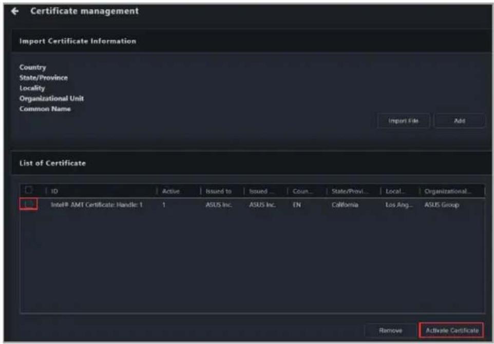
Certificate Management
Manage the vPro certificates for selected device(s).
- System trap alert
Enable Trap Alert
Enable the DASH and vPro system trap alert on selected device(s).
Enable Trap Alert - Info
Set the DASH and vPro system trap alert as information level on selected device(s).
Enable Trap Alert - Warning
Set the DASH and vPro system trap alert as warning level on selected device(s).
Enable Trap Alert - Error
Set the DASH and vPro system trap alert as error level on selected device(s).
Disable Trap Alert
Disable the DASH and vPro system trap alert on selected device(s).
• IPMI
IPMI Tool Lanplus Command Redirect
Configure command redirection on selected BMC device(s).
FRU Info. Write
Write information from the FRU to the BMC device(s).
- Settings
Settings
Configure settings for selected BMC device(s).
- OOB - Control Help
OOB - Control Help
View descriptions of supported OOB control functions.
2.4.3 Screen broadcast
Create a broadcast room
Create a broadcast room and broadcast to selected device(s).
2.4.4 Security and boot settings
If the below settings have not previously been configured using ASUS Control Center Express, the default value of "Not config" will be displayed.
Enable Regedit*
Enable/disable Windows Registry Editor on selected device(s).
Disable Regedit*
Enable USB
Enable/disable USB ports on selected device(s).
Disable USB
USB Read Only
Set the USB ports to read only on selected device(s).
Fast Startup Enable*
Enable/disable fast startup on selected device(s).
Fast Startup Disable*
Enable Windows Update*
Enable/disable Windows Update on selected device(s).
Disable Windows Update*
Enable All Removable
Enable/disable all types of removable media on selected device(s).
Disable All Removable
Enable USB Drive
Enable/disable USB drives on selected device(s).
Disable USB Drive
USB Drive Read Only
Set USB drives to read only on selected device(s).
Enable CD-ROM
Enable/disable optical disc drives on selected device(s).
Disable CD-ROM
CD-ROM Read Only
Set optical disc drives to read only on selected device(s).
* Only supported on Windows-based client devices.
2.4.5 Task scheduler
Task Scheduler Schedule tasks for selected device(s).
2.4.6 Software management
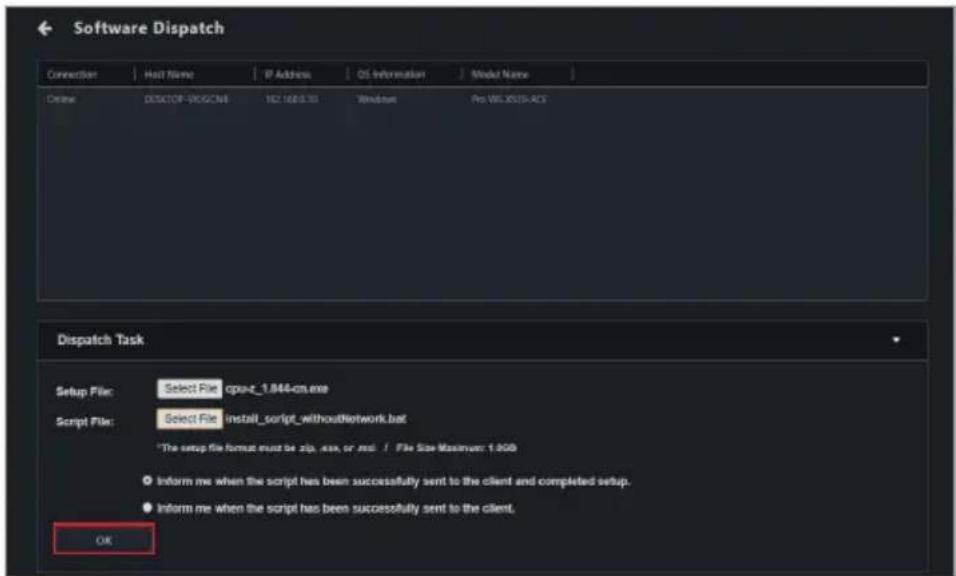
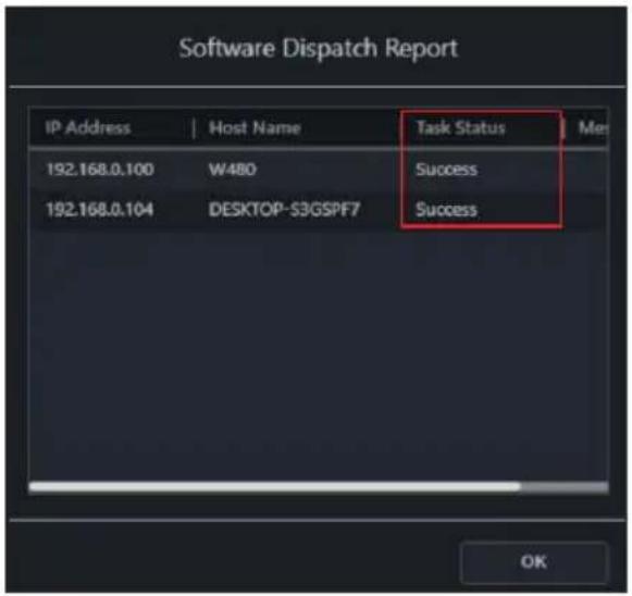
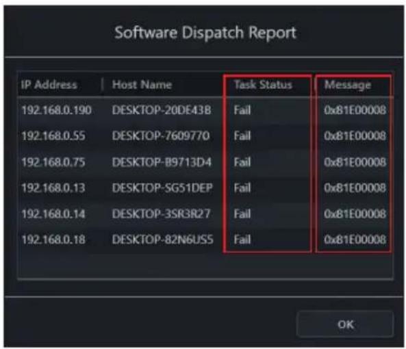
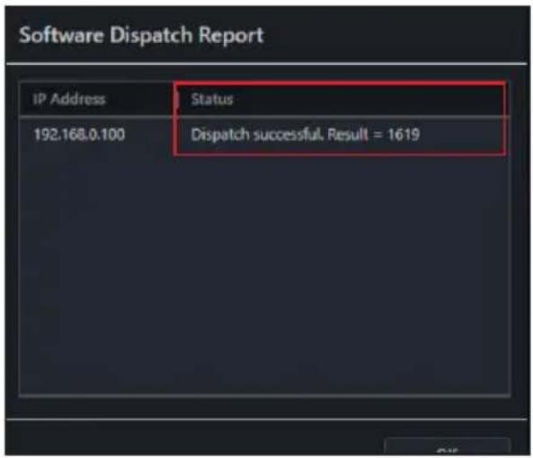
Software Dispatch
Dispatch software and scripts to device(s).
Software Information
View or configure applications, processes or services on device(s).
Software Blacklist*
View or add blacklisted software for device(s).
Installer**
Download or update the driver, utility applications, and BIOS for device(s).
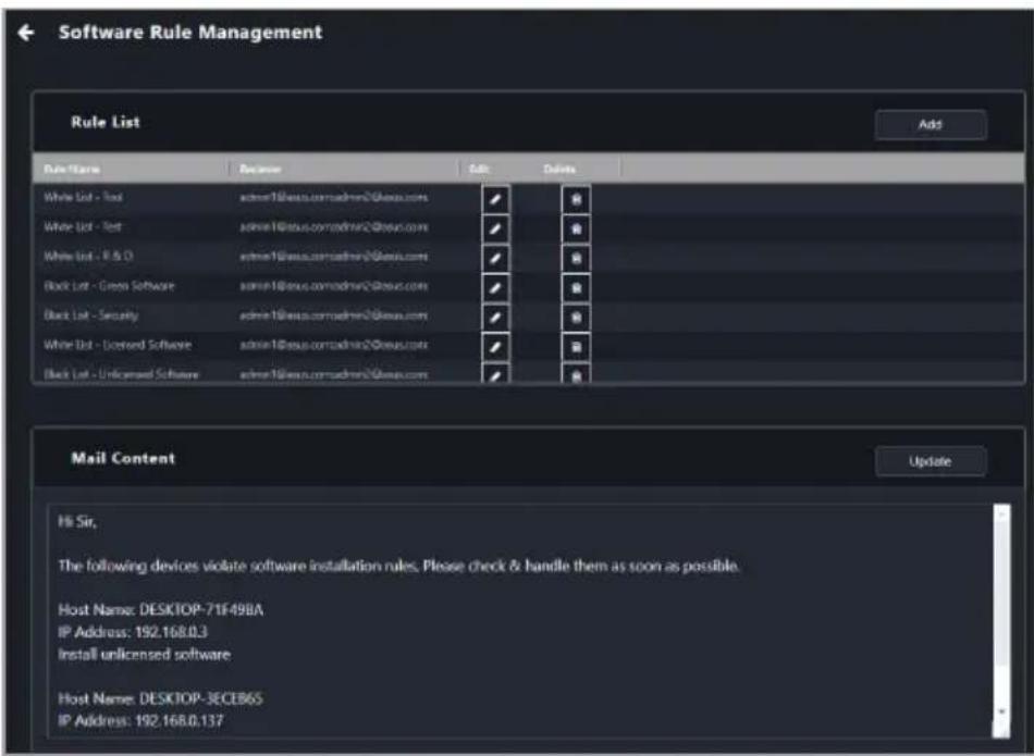
Software Rule Management*
Set rules for software blacklist and whitelist, as well as the email receiver for the notifications.
* Only supported on Windows-based client devices.
** Only BIOS updates are supported on Linux-based client devices.
2.4.7 Smart BIOS
BIOS
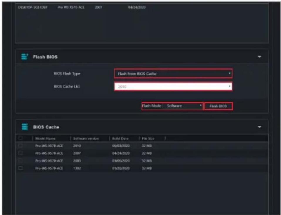
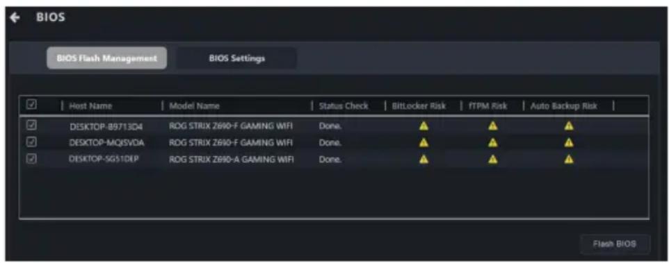
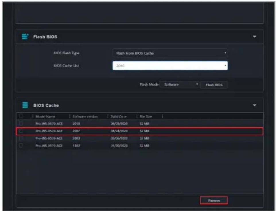
Upload, update or flash the BIOS of the selected device(s)
Enable BIOS settings
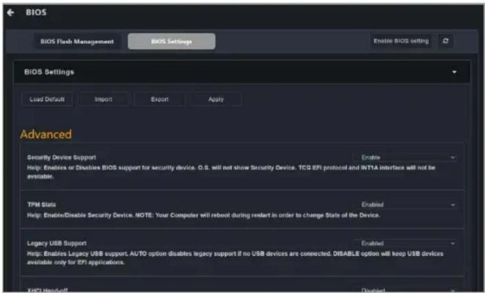
Enable the BIOS settings of client devices.
2.4.8 Report generator
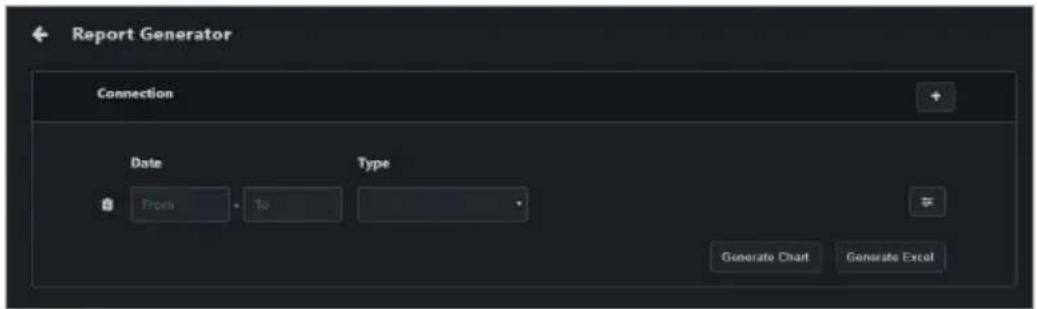
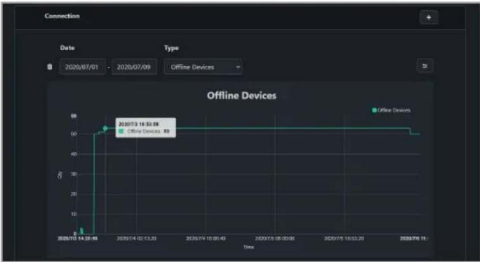
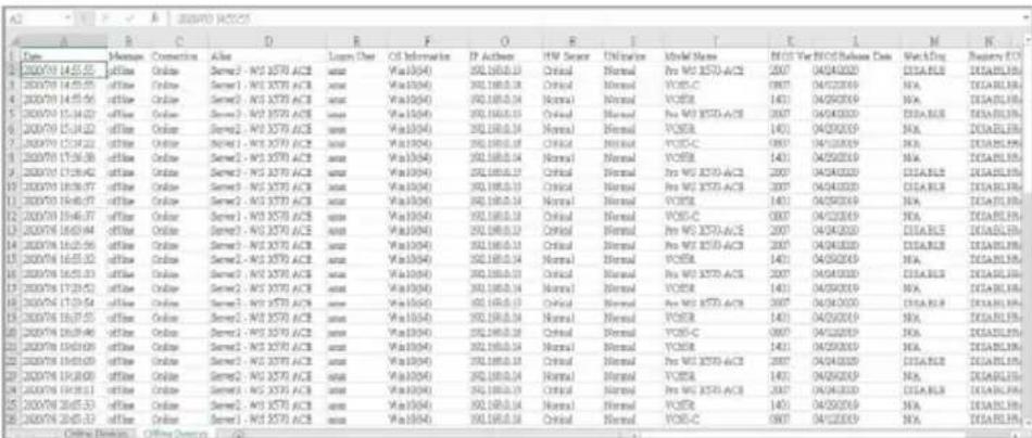
Connection
Generate a report and analysis on connection status (online / offline) of client devices.
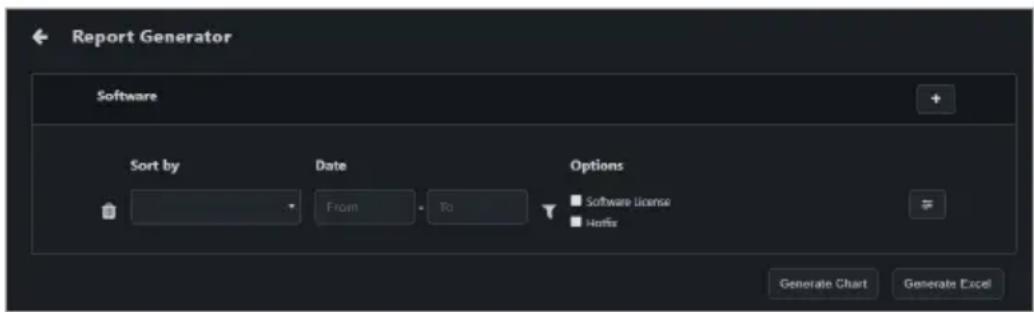
Software
Generate a report and list of software installations and permissions.
Hardware
Generate a report and list of client device’s hardware.
2.4.9 Operating status
Maintenance
Set the operating status of device(s) to maintenance.
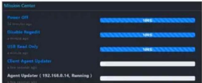
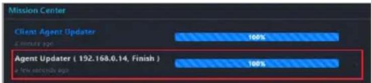
The Mission Center allows you to view the progress and status of tasks. Tasks that are still pending, finished tasks, and ongoing tasks can all be viewed in the Mission Center as well as the progress and execution results of the tasks.
2.5.1 Using the Mission Center
- Reposition the Mission Center:
Click and drag the Mission Center icon to move it to another location.
• Viewing finished/total amount of tasks:
View the number finished tasks (left number) and the total number of tasks (right number) from a quick glance on the Mission Center icon.
- Expanding / minimizing the Mission Center:
You can click the Mission Center icon to expand the Mission Center and view the progress and starting time of the tasks; clicking on the Mission Center icon again will minimize the expanded window.
bar
| Category | Value (%) |
|---|---|
| Power Off | 100 |
| 3rd minute ago | 100 |
| Disable Repedit | 100 |
| a minute ago | 100 |
| USB Read Only | 100 |
| a minute ago | 100 |
| Client Agents Updater | 0 |
| a few seconds ago | 0 |
| Agent Updater (192.168.0.14, Running) | 0 |
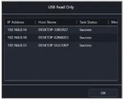
• Viewing task information:
Clicking on a task name in the expanded view of the Mission Center will allow you to view the client devices the task is being performed on as well as the status or results for each client device.
text_image
USB Read Only
IP Address | Host Name | Task Status | Mes
192.168.0.14 DESKTOP-3SR3R27 Success
192.168.0.18 DESKTOP-82N6U55 Success
192.168.0.13 DESKTOP-SG51DEP Success
OK
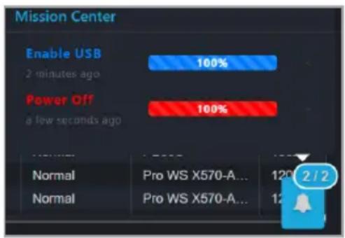
- Failed tasks:
A failed task will be marked in red in the Mission Center. You can click on the task name to view more details on the failed task.
text_image
Mission Center
Enable USB
2 minutes ago
Power Off
a few seconds ago
Normal Pro WS X570-A... 120 2 / 2
Normal Pro WS X570-A... 12
2.5.2 Mission Center tasks
Click on the X next to the task progress bar to delete a completed task. Only completed tasks can be deleted, tasks that are still pending and ongoing tasks cannot be deleted until they are completed.
Tasks that are split up into steps can also be completed through the Mission Center. For example a task that restarts the client device after BIOS update; you can restart the client device through the Mission Center once the BIOS update step has been completed.
The Mission Center will record current ongoing tasks on the ASUS Control Center Express main server, if the ASUS Control Center Express main server is closed and restarted, the mission center's tasks will be reset and only record the ongoing tasks once the ASUS Control Center Express main server has restarted.
2.6 Graphical view
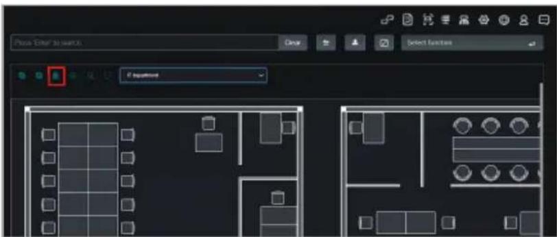
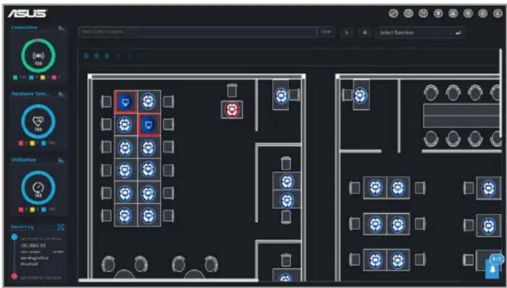
You can toggle between the Classic view or Graphical view. The Graphical view allows you to upload a layout image (such as the office floor) and place shortcut icons of client devices onto their respective places on the layout.
2.6.1 Using the menu items
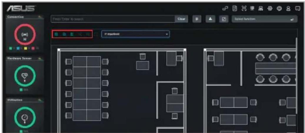
Please refer to the table below for the different functions available on the Graphical view.
text_image
ASUS
Connection
Presn: Order to search
Clear
Select function
(10)
32
If important
Hardware Sensor
Utilization
Check all machines Select all client devices on the layout
Uncheck all machines Deselect all client devices on the layout
Edit Edit the shortcut icons and background, please refer to theCustomizing layoutssection for more information.
Zoom In Zoom in on the layout area
Zoom Out Zoom out on the layout area
2.6.2 Using the client device icons
• Hover over client device icon:
Hover over a client device icon to view the details of the client. You may customize the information shown by clicking on ☐ (Customize) and checking or unchecking the metadata item you wish to display or hide, then click on Save.
- Single click on client device icon:
A single click on the client device icon will select the icon, for when you wish to use a function on a client device or multiple devices. To deselect the icon, click on the client device icon again.
For more details on the functions, please refer to the Device Information and Management Functions chapters.
- Double click on client device icon:
Double clicking on a client device icon will redirect you to the Device information screen.
For more information on the Device Information screen, please refer to the Device Information chapter.
- Client device icon status:
The client device icon will change or change colors depending on the status.
Unchecked Checked Status
Offline
Device online, hardware sensor and utilization status in normal state
Device online, hardware sensor and utilization status in warning state
Device online, hardware sensor and utilization status in critical state
2.6.3 Switching between different layouts
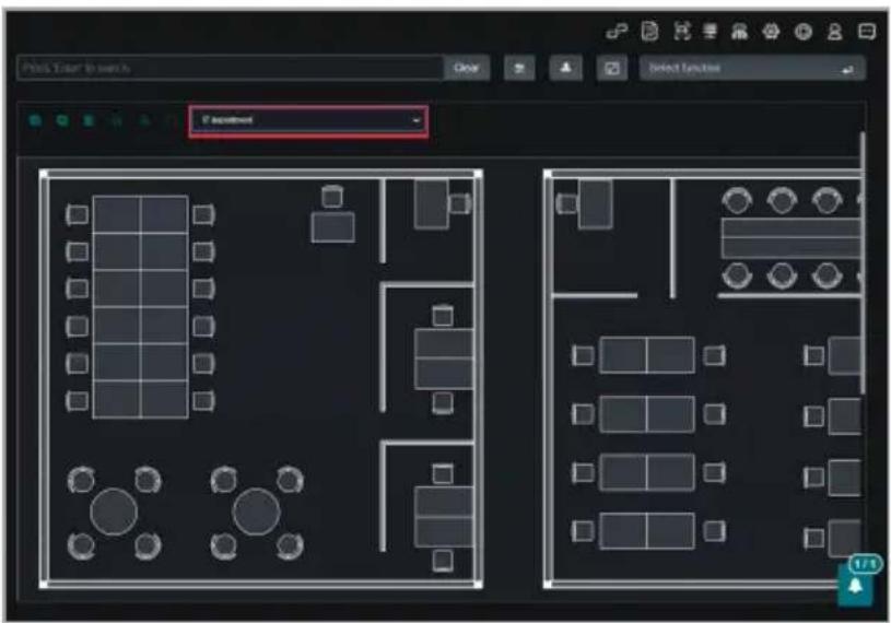
Select a layout from the drop-down menu to switch to the selected a layout.
text_image
Plot, Tater to view
Close
Select Function
Setpoint
1/1
2.6.4 Customizing layouts
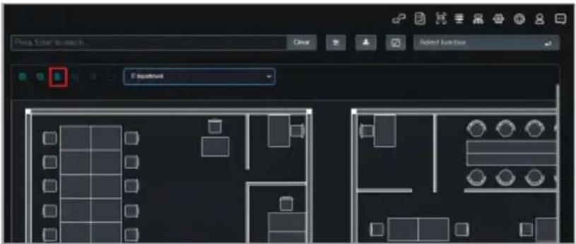
Adding a new layout
Click Edit.
text_image
Play Edit to Insert
Clear
Select Function
Equinox
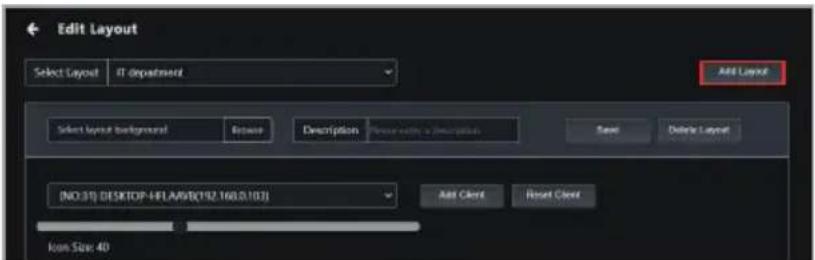
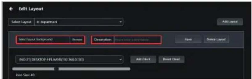
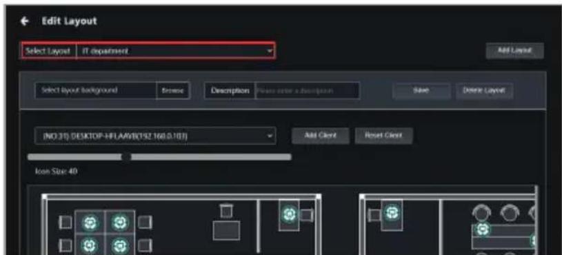
Click Add Layout.
text_image
Edit Layout
Select Layout IT department
Add Layout
Select layout background Return Description None else in a description Save Delete Layout
(NO.31) DESKTOP-HELANS(192.160.0.103)
Add Client Reset Client
Icon Size 40
Click Browse to select an image file to use as the layout background, then enter a description (optional).
If a description is not specified, the current filename and datestamp will be used by default.
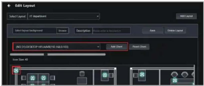
Select a client device from the drop-down list to add a new device icon, then click and drag the device icon to move it to the desired location on the layout.
Click Reset Client to remove the device icon.
text_image
Edit Layout
Select Layout IT department
Add Layout
Select layout background
Browse
Description
Form enter a description
Save
Delete Layout
(NO 31) DESKTOP-HFL.AAMB[192.168.0.103]
Add Client
Reset Client
Issue State 4D
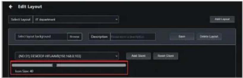
Click and drag the icon size scroll bar to adjust the size of the device icon (optional).
text_image
Edit Layout
Select Layout IT department
Add Layout
Select layout background
Browse
Description
Save
Delete Layout
(NO-31) DESKTOP-MPLAMB(192.168.0.103)
Icon Size: 40
Add Client
Reset Client
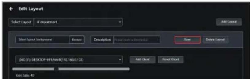
Click Save.
text_image
Edit Layout
Select Layout If department
Add Layout
Select layout background
Browse
Description
Paste to a description
Save
Delete Layout
Editing a layout
1. Click Edit.
text_image
Phase-Enter to search
Close
Select functions
Options
Set Function
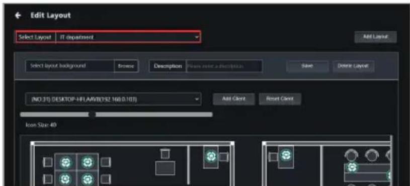
2. Select a layout from the drop-down list, then edit the layout as required.
text_image
Edit Layout
Select Layout IT department
Add Layout
Select layout background
Browse
Description
Private enter a description
Save
Delete Layout
IND 310 DESKTOP-NFLAMR(192.160.5.18)
Add Client
Reset Client
Icon Size 40
3. Click Save.
text_image
Edit Layout
Select Layout IT department
Add Layout
Select layout background
Browse
Description
Create main a description
Save
Delete Layout
[NO:31] DESKTOP-HFLA0YB(192.160.0.103)
Add Client
Reset Client
Icon Size 40
Deleting a layout
1. Click Edit.
text_image
Phase-Enter to search
Insert
Select Function
2. Select a layout from the drop-down list.
text_image
Edit Layout
Select Layout IT department
Add Layout
Select layout background
Browse
Description
Show note a description
Save
Delete Layout
[NO 31] DESKTOP-NFLAMB192.160(0.107)
Add Claver
Reset Claver
Icon Size 40
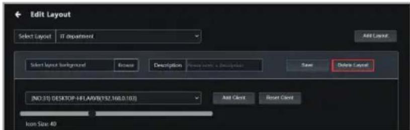
3. Click Delete Layout.
text_image
Edit Layout
Select Layout IT department
Add Layout
Select layout background
Browse Description
Save Delete Layout
[NO:31] DESKTOP-HFL.ASW(192.160.0.10.1)
Add Client Reset Client
Icon Size 40
2.7 Mailbox
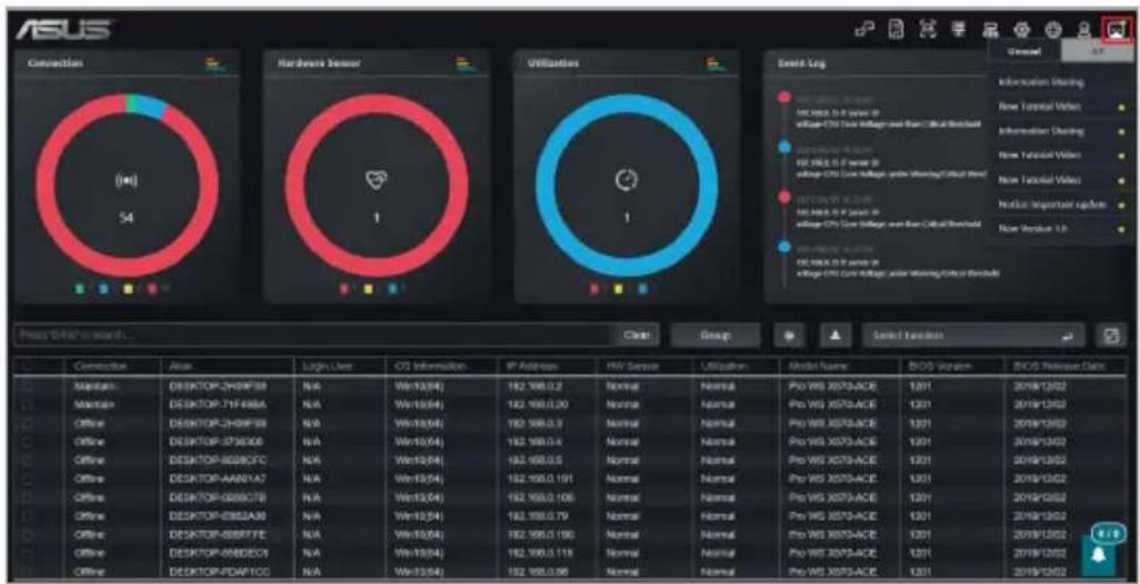
You can read important information and the latest updates on ASUS Control Center Express, such as the latest update released, update notifications, operation precautions, or introductions for new functions from the Mailbox.
To view the items in Mailbox, click on located at the top right menu bar.
text_image
ASUS
Connection
(●)
54
Hardware Sensor
1
Utilization
1
Event Log
New Textural Video
New Textural Video
New Textural Video
New Textural Video
New Textural Video
New Textural Video
New Textural Video
New Textural Video
New Textural Video
Press Date to start...
Close
Group
Select Function
Connector
Alias
Login User
OS Information.
IP Address
HIV Sensor
Utilization
Model Name:
BIOS Version:
BIOS Release Date:
Maintain:
DESKTOP-JH09F88
N/A
Wm10(84)
182.998.0.2
Normal
Normal
Pro WIS 3070-ACE
1301
2018/13/02
Maintain:
DESKTOP-T1F496A
N/A
Wm10(84)
182.998.0.20
Normal
Normal
Pro WIS 3070-ACE
1301
2018/13/02
Office:
DESKTOP-JH09F88
N/A
Wm10(84)
182.998.0.3
Normal
Normal
Pro WIS 3070-ACE
1301
2018/13/02
Office:
DESKTOP-ZT365D6
N/A
Wm10(84)
182.998.0.4
Normal
Normal
Pro WIS 3070-ACE
1301
2018/13/02
Office:
DESKTOP-RG09CFC
N/A
Wm10(84)
182.998.0.5
Normal
Normal
Pro WIS 3070-ACE
1301
2018/13/02
Office:
DESKTOP-AA8NIA7
N/A
Wm10(84)
182.998.0.191
Normal
Normal
Pro WIS 3070-ACE
1301
2018/13/02
Office:
DESKTOP-GS09C7B
N/A
Wm10(84)
182.998.0.106
Normal
Normal
Pro WIS 3070-ACE
1301
2018/13/02
Office:
DESKTOP-ESB2A66
N/A
Wm10(84)
182.998.0.79
Normal
Normal
Pro WIS 3070-ACE
1301
2018/13/02
Office:
DESKTOP-ESB5F7E
N/A
Wm10(84)
182.998.0.190
Normal
Normal
Pro WIS 3070-ACE
1301
2018/13/02
Office:
DESKTOP-ESB5EC63
N/A
Wm10(84)
182.998.0.118
Normal
Normal
Pro WIS 3070-ACE
1301
2018/13/02
Office:
DESKTOP-FIDAPFOG
N/A
Wm10(84)
182.998.0.96
Normal
Normal
Pro WIS 3070-ACE
text_image
Unread All
Information Sharing
New Tutorial Video
Information Sharing
New Tutorial Video
New Tutorial Video
Notice: Important update
New Version 1.6
text_image
New Version 1.6
The latest version 1.6 of ASUS Control Center Express has been released. You can download from the official website and upgrade it. Experience the new features and bring you more convenient and efficient management services.
https://www.asus.com/campaign/ASUS Control Center Express global/
*Note: Please perform the client agent update of the client machines after the ASUS Control Center Express main program of the console server is upgraded.
OK
Unread
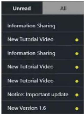
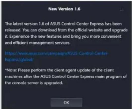
Click to view all unread messages. Clicking on a message will allow you to view the message in detail.
All
Click to view all messages. Clicking on a message will allow you to view the message in detail.
Unread messages will be marked with a yellow dot, once the message is read, the yellow dot will disappear, and the message will be removed from the Unread tab the next time you access the Mailbox.
2.7.1 Configuring mailbox notifications
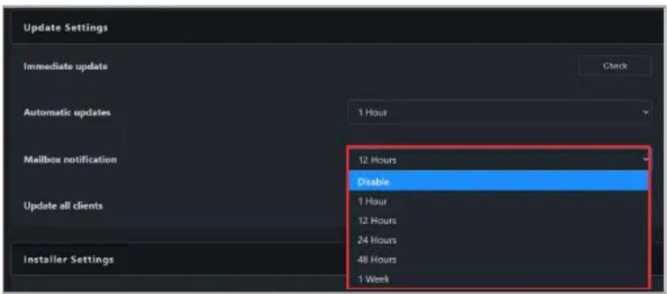
Click on located at the top right menu bar, then select General Configuration, then scroll to Update Settings. Options >
Select how often to check for new notifications or messages and prompt mail notifications from the Mailbox notification drop down menu.
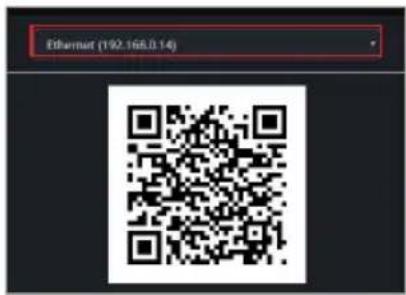
You can scan the QR code to quickly access the web version of ASUS Control Center Express on your mobile device.
To access QR Code, click on 🔒 located at the top right menu bar, then select QR Code.
The mobile device you used to scan the QR code needs to be connected to the main server's IP address.
If the main server's network environment is a domain or a personal network, you will need to ensure your mobile device can connect to the main server (through a WiFi router or VPN) before scanning the QR code.
If the main server's network environment includes a public network, please switch to the public network's QR code by clicking on the drop down menu before scanning the QR code.
text_image
Ethernet (192.168.0.14)
2.9 Submit Feedback
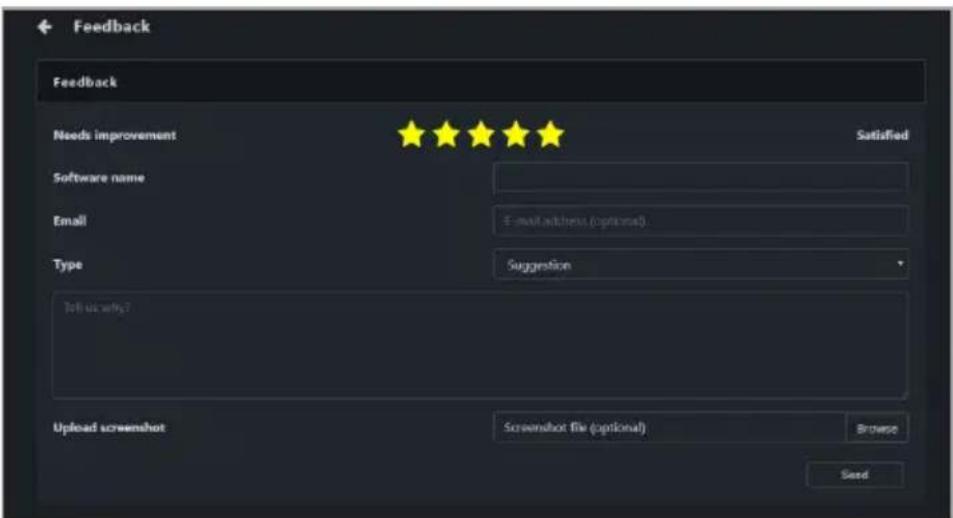
You can provide feedback to the developers using the Feedback function. You may also upload screenshots if required.
To submit feedback, click on 🔒 located at the top right menu bar, then select Feedback.
text_image
Feedback
Feedback
Needs improvement
Satisfied
Software name
Email
E-mail address (optional)
Type
Suggestion
Tell us why?
Upload screenshot
Screenshot file (optional)
Browse
Seed
Chapter 3
This chapter describes how to automatically or manually deploy ASUS Control Center Express agents and remove agents, and updating agents.
Agennt Deputyment
3.1 Agent management overview
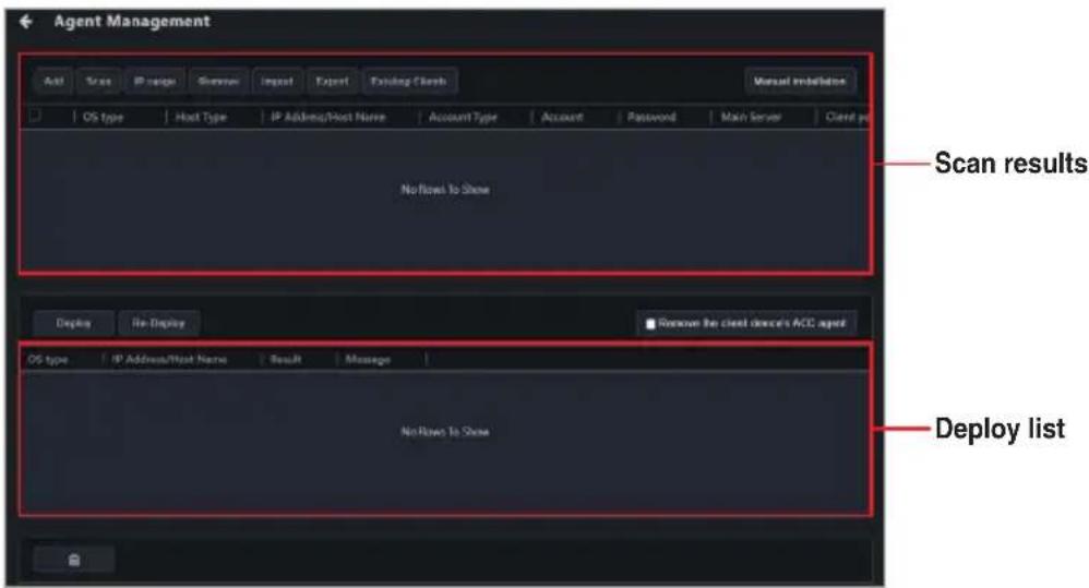
The Agent Management menu allows you to manage ASUS Control Center Express agents, such as automatic or manual agent installation or removal.
To access Agent Management, click on 📁 located at the top right menu bar.
Main window
text_image
Agent Management
Scan results
No Row to Shoe
Deploy
Re-Display
Remove the client client's ACC agent
No Row to Shoe
Deploy list
Scan results
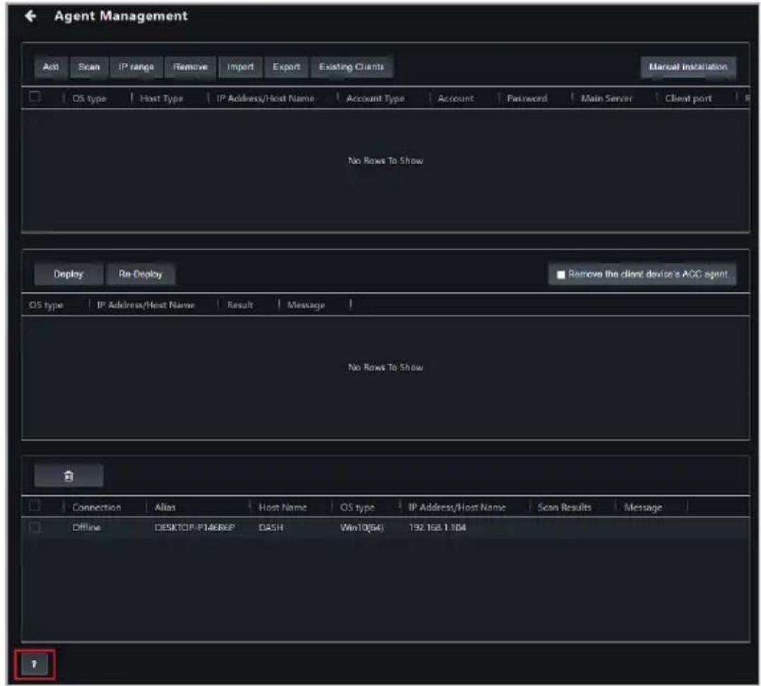
This list shows possible devices that the agent can be deployed to.
Deploy List
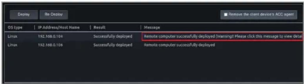
This list shows the deployment results for each device.
Add
Add a single device to deploy an agent to.
Scan
Automatically scan all client devices in the same subnet as the Main server available for agent deployment
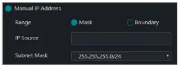
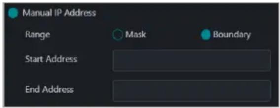
IP Range
Scan an IP Range entered that you wish to scan.
Remove
Remove client device(s) that you do not wish to deploy agent(s) to.
Import
Import an already exported device list (.csv file).
Export
Export the current device list of devices added or scanned to a .csv file.
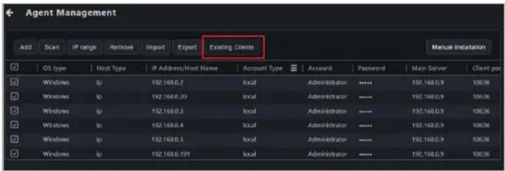
Existing Clients
Display all client device(s) that already have agents deployed.
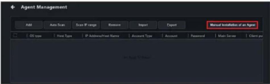
Manual Installation
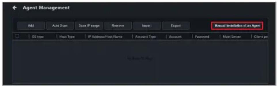
Download the agent installation file, then manually install the agent on the client device, or install the agent in silent mode.
Deploy
Automatically deploys the agent to the selected client device(s) .
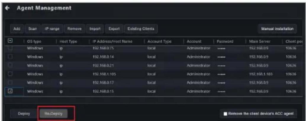
Re-Deploy
Repairs the agent on client device(s) which already have agents installed.
Remove the client device's ACC agent
If an ACC CSM agent is already installed on a client device, checking this option will automatically remove the ACC CSM agent when deploying an ASUS Control Center Express agent.
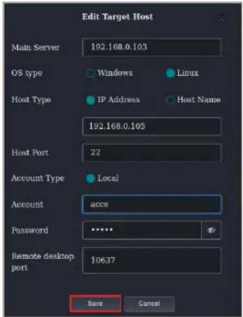
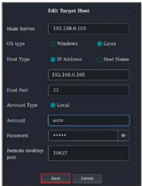
Add/Edit Target Host window
text_image
Edit Target Host
Main Server 192.168.0.103
OS type Windows Linux
Host Type IP Address Host Name
192.168.0.105
Host Port 22
Account Type Local
Account accce
Password ****
Remote desktop port 10637
Save Cancel
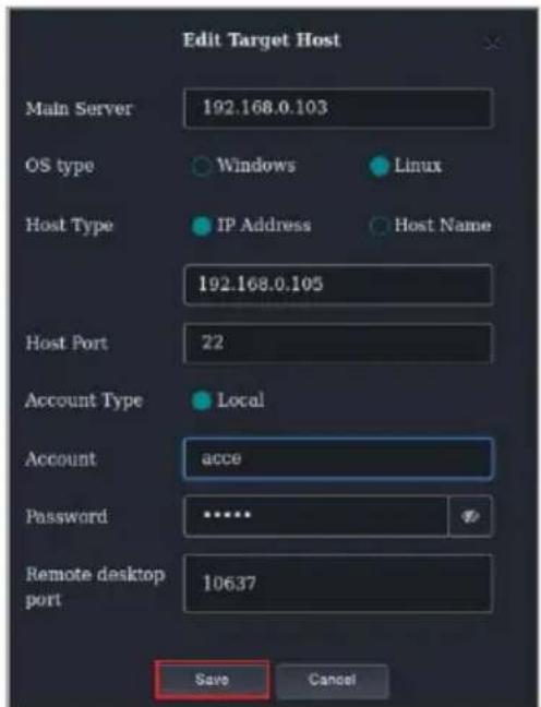
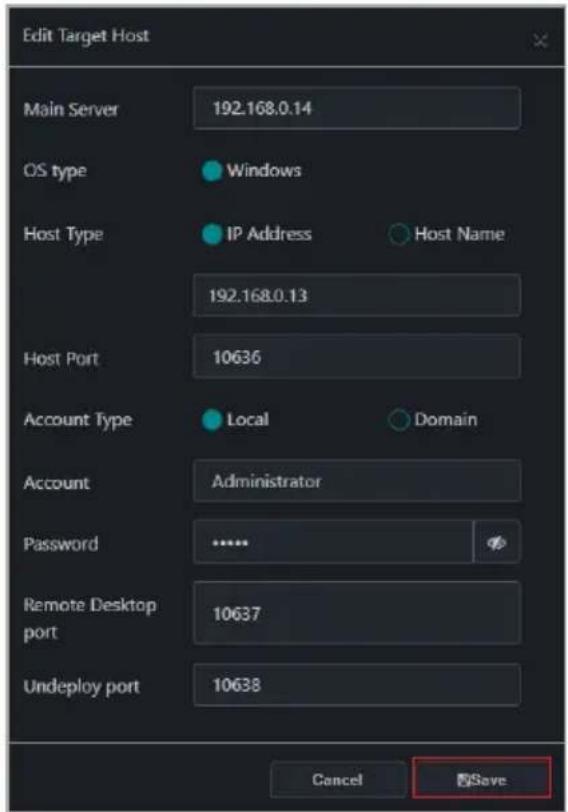
Main Server
Enter the IP of the ASUS Control Center Express server
OS Type
Select the OS type of the client
Host Type
Select either IP address or host nameIP address: IP address of the clientHost name: Host name of the client
Host Port^1
Enter the port
Account Type
Select whether the client account is local or domainLocal: The agent's administrator privileges only allow you to manage the device the agent is installed onDomain: The agent's administrator privileges allow you to manage all devices in the domain
Domain^2
Enter the domain name
Account
Enter the administrator account name of the client
Password
Enter the password for the administrator account of the client
Remote Desktop port^1
Enter the port to use when remotely accessing this client
Undeploy^13
Enter the port to use when removing the agent from this client
1 Refer to the General Configuration section of the Settings chapter to find or change the default port.
2 This field only appears if you selected Domain as the account type.
3 Only supported on Windows-based client devices.
3.2 Prerequisites
3.2.1 General prerequisites
Activate the license keys before deploying agents to client devices. Each client device you wish to deploy an agent to requires a corresponding license key. For more information on activating license keys, please refer to the License section of the Settings chapter.
Ensure that the ACCE client and server are connected to the Internet and are on the same network domain.
Ensure that the client has a password-enabled administrator account. This password should be entered during agent deployment. If no password is specified, the default account and password will be used. Refer to Settings > Options > General Configuration > Agent Device's Administrator Account to view or configure the default account and password.
text_image
Agent Device's Administrator Account
Save
Windows Account Administrator
Windows Password ****
#
Linux Account adults
Linux Account ****
%
The default Agent device's administrator account and password may differ according to your system language, ensure the Agent device's administrator account and password matches the client device's actual administrator account and password before deploying.
The client device's system time and date should not be changed unless necessary.
If an agent has already been deployed to the client device but requires a redeployment, please remove the agent from the client device then redeploy the agent. For more information, please refer to the Removing agents section in this chapter.
The Re-Deploy function is only used for upgrading versions before ASUS Control Express v1.5 and for repairing agents.
3.2.2 Prerequisites for Windows-based client devices
- Ensure that Remote Service Management is allowed to communicate through Windows Firewall. To manage Windows Firewall settings, right click on the Windows Start icon > Settings > Update & Security > Windows Security > Firewall & network protection > Allow an app through firewall
text_image
Allow apps to communicate through Windows Defender Firewall
Allowed apps and features:
Name Domain Private
□ Remote Scheduled Tasks Management □ □
☑ Remote Service Management ☑ ☑
□ Remote Shutdown □ □
Details... Remove
Temporarily disable the client device's anti-virus firewall; you may re-enable the anti-virus firewall once the agent deployment process is successfully completed. For more information on disabling the anti-virus firewall please refer to the user manual or product website for your anti-virus.
If the main server or client device is running Windows 11, connect to the internet, then run Windows Update and confirm that Windows Defender is updated to the latest version before attempting agent deployment.
If the main server or client device is running Windows 7, please install the following: .Net Framework 4.6.1 or above, SHA-2, and TLS 1.2 on the main server before deploying agents. For more information, please refer to the Setting up a Windows 7 deployment environment section in this chapter.
If a client device with Windows 7 OS does not support SHA-2 and TLS 1.2, the necessary installations will still be carried out when deploying an agent to the client device. When the agent deployment is finished, please follow the instructions and reset the client device, then redo the agent deployment process on the client device.
3.2.3 Prerequisites for Linux-based client devices
Install and enable SSH. Refer to the Installing SSH on Linux-based client devices section in this chapter for more information.
Ensure that the port used for SSH is open on the client device and allowed through the firewall, if applicable.
To avoid compatibility issues, it is recommended to update the agent on the client device after system kernel updates. Refer to the Updating agents section in this chapter for more information.
On certain Linux distributions, it may be necessary to update the system kernel and/or software packages before deploying an agent.
On certain Linux distributions, some features may be unavailable due to incompatibilities with the system kernel and/or software packages.
On dual-boot systems, ensure that the agent is deployed on each operating system.
A GNOME (Wayland) desktop environment is required for remote desktop support.
3.2.4 Installing SSH on a Linux-based client device
Installing SSH in Ubuntu/Debian/Pardus
On client devices running Pardus, use Pardus Update to update system components before proceeding.
Open a terminal window, then run the following commands to install and enable the SSH service:
sudo apt-get update
sudo apt install openssh-server
sudo systemctl enable ssh
sudo systemctl start ssh
Run the following command to check the status of the SSH service.
sudo service ssh status
Run the following command to add a firewall exception for the SSH service.
sufo ufw allow ssh
Installing SSH in CentOS/RHEL
Open a terminal window, then run the following commands to install and start the SSH service:
sudo yum install openssh-server
sudo systemctl start sshd
Run the following command to check the status of the SSH service.
sudo systemctl status sshd
Run the following command to enable the SSH service.
sudo systemctl enable sshd
Run the following commands to add a firewall exception for the SSH service (optional).
Open a terminal window, then run the following commands to install and start the SSH service:
sudo dnf install openssh-server
sudo systemctl start sshd
Run the following command to check the status of the SSH service.
sudo systemctl status sshd
Run the following command to enable the SSH service.
sudo systemctl enable sshd
Run the following commands to add a firewall exception for the SSH service (optional).
sudo firewall-cmd --add-service=ssh --permanent
sudo firewall-cmd --reload
Installing SSH in openSUSE
Open a terminal window, then run the following commands to install and start the SSH service:
sudo zypper refresh
sudo zypper install openssh
sudo systemctl start sshd
Run the following command to check the status of the SSH service.
sudo systemctl status sshd
Run the following command to enable the SSH service.
sudo systemctl enable sshd
Run the following commands to add a firewall exception for the SSH service.
sudo firewall-cmd --add-service=ssh --permanent
sudo firewall-cmd --reload
3.2.5 Additional steps for Windows 7 environments
You will need to set up the Windows 7 OS environment before deploying an agent if the main server or the client device is using Windows 7 OS.
Certain features may not be available on client devices running Windows 7 due to antivirus software incompatibilities.
Download the win7patch installation file required for setting up the Windows 7 agent deployment environment from the ASUS website.
Move the win7patch zip file into the same folder as the deployment environment settings file (DeployEnvInstall.exe) located in the ASUS Control Center Express\Thirdparty installation folder.
The default installation path for ASUS Control Center Express is ASUS Control Center Express\Thirdparty, if you selected a different path when installing ASUS Control Center Express, ensure to change the installation folder path accordingly.
text_image
This PC > Local Disk (C) > Program Files (x98) > ASUS > ASUS Control Center Express > Thirdparty
Name Date modified Type Size
BroadcastEnvInstall.exe 10/21/2021 8:16 PM Application 2,595 KB
DeployEnvInstall.exe 10/21/2021 8:16 PM Application 2,407 KB
win7patch.72 10/21/2021 9:20 PM WinRAR archive 137,615 KB
Run DeployEnvInstall.exe as administrator to set the deployment environment settings.
text_image
This PC > Local Disk (C:) > Program Files (x86) > ASUS > ASUS Control Center Express > Thirdparty
Name Date modified Type Size
BroadcastEnvInstall.exe 10/21/2021 8:16 PM Application 2,995 KB
DeployEnvInstall.exe
win7patch.7z Open 2,482 KB
Run as administrator 157,015 KB
Share with Skype
Troubleshoot compatibility
Pin to Start
Share
Open with WinRAR
Add to archive...
Add to "DeployEnvInstall.rar"
Compress and email...
Compress to "DeployEnvInstall.rar" and email
Extract files...
Extract Here
Extract to DeployEnvInstall
Confirm that the required files for Windows 7 deployment are properly installed in the ASUS Control Center Express\apro_console folder.
text_image
Local Disk (C:) > Program Files (x86) > ASUS > ASUS Control Center Express > apro_console > win7Patch >
Name Date modified Type Size
04 10/20/2021 6:35 PM File folder
06 10/20/2021 6:35 PM File folder
cert 10/21/2021 11:30 AM File folder
3.3 Deploying agents
To ensure successful deployment, read the Prerequisites section in this chapter before proceeding with agent deployment.
3.3.1 Automatically scanning and deploying to devices
Click on Auto Scan.
After the scan is completed, the devices should appear in the scan results block shown below.
text_image
Agent Management
Add
Auto Scan
Scan IP range
Remove
Import
Export
Manual Installation of an Agent
OS type
Host Type
IP Address/Host Name
Account Type
Account
Password
Main Server
Client port
Linux
ip
192.168.0.13
local
admin
****
192.168.0.14
10636
Windows
ip
192.168.0.18
local
Administrator
****
192.168.0.14
10636
Deploy
Remove the client device's ACC agent
OS type
IP Address/Host Name
Result
Message
NEW HOME TO SAVE
OS type
IP Address/Host Name
Scan Results
Message
Win10(64)
192.168.0.18
Win10(64)
192.168.0.13
Double click on a device in the scan results to edit the device information, then click Save.
Ensure that the account entered in the Privileges. Account field has administrator
The default account and password displayed is the Agent device's administrator account and password, this can be edited under Settings > Options > General Configurations > Agent device's administrator account. Refer to the General Configuration section of the Settings chapter for more information.
text_image
Edit Target Host
Main Server 192.168.0.103
OS type Windows Linux
Host Type IP Address Host Name
192.168.0.105
Host Port 22
Account Type Local
Account ace
Password ****
Remote desktop port 10637
Save Cancel
Once you have finished editing the scanned device information, select the devices you wish to deploy agents to, then click Deploy.
If ACC CSM is already installed on the client device, please export and backup the data first, then check the Remove the client device's ACC agent option before deploying.
The results of the deployment will be shown in the Deploy List.
In case of an unsuccessful deployment, refer to the Deployment Troubleshooting section in this chapter for more information.
3.3.2 Scanning an IP range
Depending on your network environment, you may set an IP range to scan for devices, helping you deploy agents quickly and efficiently.
Main Server IP address
This will allow you to set the main server's IP as the scan range.
Click on Scan IP range and select Local IP Address.
Select the main server's IP address in the IP Source field and the subnet mask range to scan in the Subnet Mask field.
Click OK to begin scanning.
text_image
Scan IP range
Local IP Address
IP Source 192.168.0.14
Subnet Mask 255.255.255.0/24
Manual IP Address
Range Mask Boundary
IP Source
Subnet Mask 255.255.255.0/24
OK Cancel
Double click on a device in the scan results to edit the device information, then click Save once you are finished.
Once you have finished editing the scanned device information, select the devices you wish to deploy agents to, then click Deploy.
If ACC CSM is already installed on the client device, please export and backup the data first, then check the Remove the client device's ACC agent option before deploying.
The results of the deployment will be shown in the Deploy List.
In case of an unsuccessful deployment, refer to the Deployment Troubleshooting section in this chapter for more information.
Client device IP address
This will allow you to set the client device's IP as the scan range.
Click on Scan IP range and select Manual IP Address.
Select Mask to scan the subnet mask range of the client device, or select Boundary to set a starting IP and ending IP to scan in the Range field.
Mask:
text_image
Manual IP Address
Range
Mask
Boundary
IP Source
Subnet Mask 255.255.255.0/24
IP Source
Enter the client device’s IP.
Subnet Mask
Select a subnet mask range to scan.
Boundary:
text_image
Manual IP Address
Range
Mask
Boundary
Start Address
End Address
Start Address
Enter the start IP address of the client device you wish to scan.
End Address
Enter the end IP address of the client device you wish to scan.
Click OK to begin scanning.
Double click on a device in the scan results to edit the device information, then click Save once you are finished.
Once you have finished editing the scanned device information, select the devices you wish to deploy agents to, then click Deploy.
If ACC CSM is already installed on the client device, please export and backup the data first, then check the Remove the client device's ACC agent option before deploying.
The results of the deployment will be shown in the Deploy List.
In case of an unsuccessful deployment, refer to the Deployment Troubleshooting section in this chapter for more information.
3.3.3 Adding and deploying to devices
Adding a single device
Click on Add.
Enter the information of the device you wish to add, then click on Save.
text_image
Edit Target Host
Main Server 192.168.0.103
OS type Windows Linux
Host Type IP Address Host Name
192.168.0.105
Host Port 22
Account Type Local
Account ace
Password ****
Remote desktop port 10637
Save Cancel
Click on Save, the device should appear in the device list.
Select the devices you wish to deploy agents to in the device list, then click Deploy.
If ACC CSM is already installed on the client device, please export and backup the data first, then select the Remove the client device's ACC agent option before deploying.
The results of the deployment will be shown in the Deploy List.
In case of an unsuccessful deployment, refer to the Deployment Troubleshooting section in this chapter for more information.
Adding multiple devices
If you already have an existing exported device list CSV file for ASUS Control Center Express, you may use the Import function to import multiple devices for deployment.
Click on Import.
Browse for the CSV file you wish to import, then click Open.
The imported devices will appear in the device list, select the devices you wish to deploy agents to, then click Deploy.
If ACC CSM is already installed on the client device, please export and backup the data first, then check the Remove the client device's ACC agent option before deploying.
Click on Export to export the current device list to a CSV file which you may edit using text editor.
The results of the deployment will be shown in the Deploy List.
In case of an unsuccessful deployment, refer to the Deployment Troubleshooting section in this chapter for more information.
3.3.4 Editing device information
You may edit the device information of scanned or added devices before deploying agents.
Double click on the device you wish to edit.
Click on Save once you have finished.
text_image
Edit Target Host
Main Server 192.168.0.14
OS type Windows
Host Type IP Address Host Name
192.168.0.13
Host Port 10636
Account Type Local Domain
Account Administrator
Password ****
Remote Desktop port 10637
Undeploy port 10638
Cancel Save
3.3.5 Installing agents manually
Manual installation on Windows-based client devices
Click Manual Installation of an Agent, then select Windows to download the installation file (Setup.msi).
text_image
Agent Management
Add
Auto Scan
Scan IP range
Remove
Import
Export
Manual Installation of an Agent
OS type
Host Type
IP Address/Host Name
Account Type
Account
Password
Main Server
Client pu
An Agent Selection
Using an external storage device or other file transfer method, copy the installation file to the client device.
On the client device, double click on the installation file to launch the installation.
text_image
Downloads
File Horse Share View
This PC Downloads Search Downloads
Quick access
Desktop
Downloads
Documents
Pictures
Music
Videos
OneDrive
This PC
HOWARD (E)
Network
Setup
1 item
Enter the main server's IP into the Server IP field, then click Next. The Server Port field's default port may be adjusted if necessary.
text_image
ASUS Control Center Express
Please enter information about the deploy :
Server IP
Server Port 10632
Next
Please verify the client device information received by the main server. If any of the default ports are already in use, please make adjustments accordingly after the installation through the ASUS Control Center Express main server.
text_image
Please check information about the deploy
Client IP 192 . 168 . b . 13
Client Port Default : 10636
Account Default : Administrator
Password Default : admin
Desktop Port Default : 10637
UnDeploy Port Default : 10638
Deploy
Click on Deploy, then wait for the deployment to be completed.
Manual installation on Linux-based client devices
Click Manual Installation of an Agent, then select Linux to download the installation file (Setup).
text_image
Agent Management
Add
Auto Scan
Scan IP range
Remove
Import
Export
Manual Installation of an Agent
OS type
Host Type
IP Address/Host Name
Account Type
Account
Password
Main Server
Client port
Using an external storage device or other file transfer method, copy the installation file to the client device.
On the client device, open a terminal window in the directory of the installation file, then run the following commands:
sudo chmod +x Setup
sudo ./Setup
When prompted, enter the IP address, host communication port (default: 10632), SSH port (default: 22), account, and password.
Wait for the deployment to be completed.
3.3.6 Installing agents in silent mode
Silent mode installation parameters
Server IP
ASUS Control Center Express server IP (mandatory)
Client IP
Local host IP (mandatory)
Client port
Local host port (optional)
Account
Local host user account (optional)
Password
Local host user password (optional)
Outfail
Dump deploy fail to file (optional)
Feedback results
0 ERROR_SUCCESS
Action completed successfully
1602 ERROR_INSTALL_USEREXIT
Installation canceled by user
1603 ERROR_INSTALL_FAILURE
Fatal error during installation
1639 ERROR_INVALID_COMMAND_LINE
Invalid command line argument
Please see an example below:
Run Windows PowerShell as Administrator.
text_image
Best match
Windows PowerShell
Desktop app
Run as administrator
Open file location
Pin to Start
Pin to taskbar
Uninstall
Run as Administrator
Run ISE as Administrator
Windows PowerShell ISE
pcw
Enter the command to run the agent installation. For example,
text_image
系统管理员: Windows PowerShell
PS C:\Users\
(Start-Process msiexec 7.1. "P.S.M.C" status data/Node/SSources\all.NanofInstall Control\SapiRuna
start after the process of a new file, new server p=92.168.1.2.01 entry p=92.168.1.250 outfall='0' Now folder full (.txt
/ch -Wait -Passithout.ExitCode_
Once the installation is finished, the results will be saved to D:\New Folder\Fail.txt.
Client device has previously already installed the agent and needs to reinstall
Please remove the installed agent from the client device. For example, (Start-Process msiexec '/x "C:\ Setup.msi" /q '-Wait -Passthru).ExitCode
Run the agent installation command. For example,
(Start-Process msiexec '/i "C:\Setup.msi"
serverip=192.168.1.2 /qb -Wait -Passthru).ExitCode
3.3.7 Upgrading or repairing agents
If the ASUS Control Center Express version is older than version 1.4.27, some functions may not work properly after restarting the client device. Please follow the steps below or click on the information icon on the bottom of the Agent Management page to upgrade the agent or repair the agent.
text_image
Agent Management
Add Scan IP range Remove Import Export Existing Clients
Manual Installation
OS type Host Type IP Address/Host Name Account Type Account Password Main Server Client port
No Rows To Show
Deploy Re-Deploy
■ Remove the client device's ACC agent
OS type IP Address/Host Name Result Message
No Rows To Show
Connection Alias Host Name OS type IP Address/Host Name Scan Results Message
Offline DESKTOP-F146R6P DASH Win10(64) 192.168.1.104
?
Before upgrading or repairing the agent, please check your ASUS Control Center Express version:
• ASUS Control Center Express main software version
Go to Settings > Options > General Configuration, then scroll down to the Appearance Configuration block, the Software version should be displayed there.
text_image
Appearance Configuration
Save Reset
Software version 1.5.3
Choose file Browse
Banner Logo
ASUS®
Debug Mode
- Client device agent version
The agent version of the client device will be displayed in the column in the device list on the device overview.
Agent Version
text_image
ASUS
Conduction
Hardware Sense
Utilization
Event Log
192.768.35 IT server 2F
voltage-CPU Core Voltage over than Critical threshold
192.768.35 IT server 2F
voltage-CPU Core voltage under Warning/Critical threshold
192.768.35 IT server 2F
voltage-CPU Core voltage over than Critical threshold
Phase Enter to search...
Clear
Group
Select function
COS Version
BIOS Release Date
WatchDrag
Registry Editor
USB Storage Device
Agent Version -
M C
K02
11/12/2020
N/A
ENABLE
ENABLE
1.5.3.0
K01
03/13/2020
N/A
ENABLE
ENABLE
1.5.3.0
K03
01/23/2021
N/A
ENABLE
ENABLE
1.5.3.0
K06
09/13/2020
DISABLE
ENABLE
ENABLE
1.5.3.0
K01
2019/12/02
DISABLE
DISABLE
DISABLE
DISABLE
14.2.0
K01
2019/12/02
DISABLE
DISABLE
DISABLE
14.2.0
K01
2019/12/02
DISABLE
You may also view the agent version of a single client device in the Information page by clicking on the client device.
Device
text_image
Device Information
IT server 01
OS Information
Logon User
BIOS Version
Model Name
IP Address
Timezone
Up Time
Agent Version
Operating Status
Win10(64)
Administrator
1302
PB60S
192.168.0.15
UTC +08:00 Taipes Standard Time
0:3:55:51
1.5.3.0
Normal
Hardware Sensor
Utilization
Inventory
Software
Control
Event Log
Remote Desktop
Updating from version 1.4.XX to version 1.5.X
Download the latest version of ASUS Control Center Express (1.5.X or later), then run the installation of the ASUS Control Center Express main software on the main server.
Once the installation is completed, check the device(s) you wish to update or repair from the device list, and select the Client Agent Updater from the shortcut function drop down menu.
text_image
ASUS
Connection
(●)
5
Hardware Sensor
1
Utilization
1
Remote Control
OOB - Control
Screen Broadcast
Security
Task Scheduler
Software Management
Smart BIOS
Report Generator
Operating Status
Press Enter to switch...
Clear IT Department
Client Agent Update
Connection Alias Logos User OS Information IP Address HW Sensor US
Maintain IT server 04 N/A Win10(84) 192.168.0.14 Normal No Device Manager
Online IT server 01 Administrator Win10(84) 192.168.0.15 Critical Normal PBIOS 1302
Offline IT server 02 Administrator Win10(84) 192.168.0.21 Normal Normal VOBS-C1 1001
Offline IT server 03 DASH Win10(84) 192.168.1.105 Normal Warning Pro B950M-C 1823
Offline IT server 05 Administrator Win10(84) 192.168.0.17 Normal Normal Pro WIS X570-A 2206
Click on Yes in the confirmation pop-up window to proceed with the update.
You can view the agent deployment and update results in the mission center.
Updating from version 1.3.X or earlier versions to version 1.5.X
Download the latest version of ASUS Control Center Express (1.5.X or later), then run the installation of the ASUS Control Center Express main software on the main server.
Click on located at the top right menu bar of the main menu.
text_image
ASUS
Connections
Hardware Sensor
Utilization
Event Log
1
5
1
1
1
Clear
IT Department
Select function
Connection Alias Login User OS Information IP Address HW Sensor Utilization M/C Motor Name BIOS Version BIOS
Maintain IT server 04 N/A Win1(964) 182.168.0.14 Normal Normal N/A VCSR 1401 04/20
Offline IT server 02 Administrator Win1(964) 182.168.0.21 Normal Normal N/A VCS-C1 1001 03/15
Offline IT server 03 DASH Win1(964) 182.168.1.195 Normal Washing Pto BSSOM-C 1800 01/23
Offline IT server 06 Administrator Win1(964) 182.168.0.17 Normal Normal Pto WS XSTO-A... 2206 08/13
Online IT server 01 Administrator Win1(964) 182.168.0.15 Normal Normal PB905 1302 11/12
Click on Existing Clients to load and display all client devices with agents already deployed.
text_image
Agent Management
Add Scan IP range Remove Import Export Existing Clients Manual Installation
OS type Host Type IP Address/Host Name Account Type Account Password Main Server Client port
Windows ip 192.168.0.2 local Administrator **** 192.168.0.9 10636
Windows ip 192.168.0.20 local Administrator **** 192.168.0.9 10636
Windows ip 192.168.0.3 local Administrator **** 192.168.0.9 10636
Windows ip 192.168.0.4 local Administrator **** 192.168.0.9 10636
Windows ip 192.168.0.5 local Administrator **** 192.168.0.9 10636
Windows ip 192.168.0.191 local Administrator **** 192.168.0.9 10636
Once the list of client devices with agents already deployed has loaded, please check if the information for the client device(s) are correct, such as administrator account and password, for more information you can refer to 3.2.4 Editing device information. Click Re-Deploy once you have confirmed the information of the client device(s) are correct.
text_image
Agent Management
Add
Scan
IP range
Remove
Import
Export
Existing Clients
Manual installation
OS type
Host Type
IP Address/Host Name
Account Type
Account
Password
Main Server
Client port
Windows
ip
192.168.0.75
local
Administrator
****
192.168.0.9
10636
Windows
ip
192.168.0.14
local
Administrator
****
192.168.0.9
10636
Windows
ip
192.168.0.21
local
Administrator
****
192.168.0.9
10636
Windows
ip
192.168.1.105
local
Administrator
****
192.168.1.103
10636
Windows
ip
192.168.0.17
local
Administrator
****
192.168.0.9
10636
Windows
ip
192.168.0.15
local
Administrator
****
192.168.0.9
10636
Deploy
Re-Deploy
Remove the client device's ACC agent
The results of the deployment will be shown in the Deploy List.
In case of an unsuccessful deployment, refer to the Deployment Troubleshooting section in this chapter for more information.
3.3.8 Installing an agent onto the main server
The agent can also be manually installed on the main server to perform management and maintenance tasks through ASUS Control Center Express.
The main server can only be used as a broadcast source in the Screen Broadcast function in this configuration.
A video feedback loop effect may occur if the Remote Desktop function is used to control the main server.
Manual installation on a Windows-based server
Click on Manual Installation of an Agent to start downloading the installation file (Setup.msi).
Double click on the installation file to launch the installation.
Enter the main server's IP or 127.0.0.1 into the Server IP field, then click Next. The Server Port field's default port may be adjusted if necessary.
Please verify the client device information received by the main server. If any of the default ports are already in use, please make adjustments accordingly after the installation through the ASUS Control Center Express main server.
Click on Deploy, then wait for the deployment to be completed.
Manual installation on a Linux-based server
Click Manual Installation of an Agent, then select Linux to download the installation file (Setup).
Open a terminal window in the directory of the installation file, then run the following commands:
sudo chmod +x Setup
sudo ./Setup
When prompted, enter the IP address, host communication port (default: 10632), SSH port (default: 22), account, and password.
Wait for the deployment to be completed.
3.4 Deployment troubleshooting
3.4.1 Viewing detailed error information
In case of unsuccessful or partially successful deployment, click the corresponding entry in the Deploy List for more information.
text_image
Deploy Re Deploy
■ Remove the client device's ACG agent
OS type IP Address/Host Name Result Message
Linux 192.168.0.104 Successfully deployed Remote computer successfully deployed (Warning!) Please click this message to view detail
Linux 192.168.0.106 Successfully deployed Remote computer successfully deployed
text_image
Warning
IP Address: 192.168.0.124
OS type: Linux
Unable to download the same version of the package as Linux kernel,
below functions may be abnormal: [0x8390001A]
1. Deployment
2. Hardware Sensor > Voltage, Temperature, Fan information
3. BIOS > BIOS Setting > Enable BIOS Setting
OK
3.4.2 Common errors (Linux)
Invalid SSH account or password
Check if the account or password matches the settings on the client device.
3.4.3 Common errors (Windows)
SYSTEM_ERROR: 86
Check if the account or password matches the settings on the client device.
SYSTEM_ERROR: 5
Check if Windows Firewall is configured to allow Remote Service Management on the client device.
3.5 Updating agents
When your main ASUS Control Center Express server has been updated, you can easily update the agents of all client devices, ensuring your main ASUS Control Center Express main server and client agents are all up to date with the latest updates using the Client Agent Updater function.
You can view the current agent version from the device overview on the main menu page or from the Device Information page.
text_image
Device Information
Server3 - WS X570 ACE
OS Information
Logon User
BIOS Version
Model Name
IP Address
Timezone
Up Time
Agent Version
1.4.21.0
Operating Status
Normal
Mode
Software
Hardware Sensor
Utilization
Inventory
Software
Control
Event Log
Select the devices you would like to perform an agent update on.
Classic dashboard
Graphic dashboard
text_image
ASUS
Connective
(00)
150
Hardware Tone...
343
Utilization
343
Reset Log
H2, NBA 01
page number: 0000000000000000000000000000000000000000000000000000000000000000000000000000000000000000000000000000
Close Case to action
Close
Select Function
Click on Select function, then select Client Agent Updater from the drop down menu.
Click Yes on the confirmation pop up window.
You can view the agent deploy and update progress in the Mission Center.
- Agent updates can only be performed on client devices that are online. If you selected multiple devices and some of the devices selected are offline, you can view the failure to deploy and update message in the Mission Center, and update these devices when they are online.
- If the connection is unstable during the agent update process, the agent update status on the Mission Center will be displayed as Finish, and the task name will become grayed out and unclickable, the agent on the client device will be reverted to the version prior to the update. You can update the client device again when it is online.
- If the client device was powered off or restarted during the agent update process, the agent update status on the Mission Center will be displayed as Finish, and the task name will become grayed out and unclickable, and will resume the update process once the client device has restarted and is in OS.
bar
| Category | Value (%) |
|---|---|
| Client Agent Updater (Minute ago) | 100 |
| Agent Updater (192.168.0.14, Finish) a few seconds ago | 100 |
- Certain functions may be affected if the main ASUS Control Center Express server version has already been updated to v1.4.x or above but the client device agent has not been updated (v1.3.x).
3.6 Removing agents
The screenshots in this section are for reference only.
This section will guide you through the agent removal process if you need to redeploy or remove agents.
3.6.1 Removing agents through the main server
On the Agent Management page, double click on a single client device to remove the agent on that device, or check multiple devices you wish to remove agents from.
text_image
OS type | IP Address/Host Name | Scan Results | Message |
Win10(64) 192.168.0.18
Win10(64) 192.168.0.13
Click on the Remove icon 📋, then click OK to remove the agents on all selected devices.
If the selected client device(s) are offline, the agents on these client device(s) will be removed once the client device(s) are online.
If the agent was manually installed onto a Windows-based client device, follow the steps in the Removing manually installed agents on Windows section.
These steps are only required for manually installed agents on Windows-based client devices. No further action is required for Linux-based client devices.
3.6.2 Removing manually installed agents on Windows
If you manually installed an agent on a Windows-based client device, please follow the steps below to remove the agent from the client device.
These steps are only required for manually installed agents on Windows-based client devices.
If a client device with an agent already deployed to it has been in for repairs or maintenance, please remove the agent on the client device, then re-deploy an agent to the device. To deploy an agent to a device please refer to the Deploying agents section.
Ensure to remove the client device from the ASUS Control Center Express server as well as manually remove the agent from the client device.
Ensure that the device is removed from the ASUS Control Center Express server. Refer to the Removing agents through main server section for more information.
On the client device, navigate to the Apps & features menu.
Search for and select click Uninstall. ASUS Control Center Express Manual Deploy, then
text_image
ASUS Control Center Express Manual Deploy
1.53 MB
8/21/2020
1.4.22
Modify Uninstall
Chapter 4
This chapter describes the device information and software controlled options for managing the device.
Device Information
4.1 Device information overview
The Device Information Overview provides you with detailed information about your selected client device, and also provides you with some software controlled management functions such as power control options.
To access Device Information of a client device from the different views, please refer to the following:
Classic view: Click on a client device in the device list.
Graphical view: Double click on a client device shortcut icon.
Hardware Mode (out-of-band management) options are available for client devices connected using a management LAN port with remote management controller support.
Most options are only available when the client device is online and logged into the OS.
Some options are only available when the following requirements are met:
- Client device is online and logged into the OS
- Has already had an agent deployed to it
- Connected using a management LAN port with remote management controller support
- The screenshots in this section are for reference only.
This chapter is only for the Software Mode options, for Hardware Mode options, please refer to the Management Functions chapter.
Toggle between Software and Hardware Mode
text_image
Device Information
Mode
Software
Server3 - WS X570 ACE
OS Information
Logon User
BIOS Version
Model Name
IP Address
Timezone
Up Time
Agent Version
Operating Status
Win10(64)
asus
2007
Pro WS X570-ACE
192.168.0.13
UTC +08:00 Taipei Standard Time
1:1:7:37
1.4.21.0
Normal
Hardware Sensor
Utilization
Inventory
Software
Control
Event Log
Remote Desktop
USB Redirection
BIOS
4.2 Device information details
text_image
Device Information
Server3 - WS X570 ACE
OS Information
Logon User
BIOS Version
Model Name
IP Address
Timezone
Up Time
Agent Version
Operating Status
Win10(64)
asus
2007
Pro WS X570-ACE
192.168.0.13
UTC +08:00 Taipei Standard Time
1:1:7:37
1.4.21.0
Normal
Hardware Sensor
Utilization
Inventory
Software
Control
Event Log
Remote Desktop
USB Redirection
BIOS
Device Name
Displays the device name. Click on to edit the device name.
OS Information
Displays information on the Operating System.
Logon user
Displays the user logged into client device. If the client device is powered off, offline, or logged out, this field will show the last logged in user enclosed in brackets ("[]").
BIOS Version
Displays information on the BIOS version.
Model Name
Displays the model name of client device.
IP Address
Displays the IP address of client device.
Time Zone
Displays the time zone client device is located in.
Up Time
Displays the up time of client device.
Agent Version
Displays information on the Agent version.
Operating Status
Allows you to set the operating status (Maintenance, Standby, Normal) of the device. For more information please refer to the Operating Status section in this chapter.
4.3 Device information functions
text_image
Device Information
Mode
Software
Server3 - WS X570 ACE B
OS Information
Logen User
BIOS Version
Model Name
IP Address
Timezone
Up Time
Agent Version
Operating Status
Win10(04)
ASUS
2007
Pro WS X570-ACE
192.168.0.13
UTC +08:00 Taipei Standard Time
1:1:7:37
1:4:21:0
Normal
Hardware Sensor
Utilization
Inventory
Software
Control
Event Log
Remote Desktop
USB Redirection
BIOS
The Device Information page also allows you to view information or utilize the different functions available to control and manage the device using the functions located to the right of the screen.
Hardware Sensor
Displays the device hardware sensor information.
Utilization
Displays the device utilization information
Inventory
Displays the device disk information and asset information.
Software
Allows you to view and manage software installed on the device.
Control
Allows you to view and adjust the Regedit, USB storage device, and remote power option settings.
Event Log
Allows you to view, import, or export the device event log.
Remote Desktop
Allows you to remotely control the device.
USB Redirection
Allows you share a drive of single device.
BIOS
Allows you to manage the device BIOS.
Installer
Allows you to download and update drivers, applications, and BIOS of the device.* On Linux-based client devices, only BIOS updates are supported
Device List
Allows you to view the system components of the device.* On Linux-based client devices, only PCI devices are shown
System Restore*
Allows you to create, delete, or restore system restore points for the client device.
BitLocker*
Allows you to configure BitLocker on the device.
* Only supported on Windows-based client devices
4.3.1 Operating Status
You can set the operating status of a single or multiple devices to Maintenance, Standby, or Normal. You can set the operating status either through the Device Information screen or by navigating back to the main menu page, then selecting multiple devices and selecting an operating status in the Operating Status field from the Select Function drop down menu.
The operating status changes can be viewed on the Connection overview. The Maintenance or Standby operating status will only be displayed when the client device is offline or powered off. If the device is not offline or powered off, it will display its current connection status as the operating status.
If a powered off or offline device set to Maintenance or Standby is powered on or connected to the network, the Connection overview status will display it as Online.
The screenshot below shows the Operating Status drop down menu on the Device Information screen.
text_image
Device Information
Mode
Software
DESKTOP-CQFO210
OS Information
Win10(64)
Logon User
N/A
BIOS Version
1001
Model Name
Pro WS X570-ACE
IP Address
192.168.0.13
Timezone
UTC -08:00 Pacific Standard Time
Up Time
0:0:21:11
Agent Version
1.2.2.0
Maintain Status
Normal
Maintain
Standby
Normal
Hardware Sensor
Utilization
Inventory
Software
Control
Event Log
Remote Desktop
4.3.2 Hardware Sensor (software)
This item allows you to view S.M.A.R.T attributes or edit the threshold value for items such as voltage, temperature, fans, and graphics card. This item is software controlled and values may differ with the hardware version. Please refer to the following sections in the Management Functions chapter for information on the Hardware mode:
Some options such as graphics card may only be available if you have the component installed on your client device.
Click on to hide or show sub items.
This item will not be available if your device is not logged into an OS environment, or is not connected using a management LAN port remote management controller support.
If your motherboard has a supported remote management controller, you may switch to Hardware mode, or you may view the hardware sensor information of the previous time the device was powered on if the device is currently powered off.
Support for certain device sensors on Linux-based client devices may be unavailable or may vary depending on Linux distribution.
text_image
Hardware Sensor
S.M.A.R.T.
ST1003LM049-2CH172
Normal
Voltage
CPU Core Voltage
COSA
4.980 V
S.M.A.R.T.
Displays disk status, click on this item to show detailed S.M.A.R.T. attribute information.* S.M.A.R.T. information may vary depending on drive specifications and manufacturer-supplied information.
Voltage
Displays the CPU Core Voltage, and other voltage related items. You may edit the threshold for these items.
Temperature
Displays the CPU status and temperature. You may edit the threshold for these items.
Fans
Displays the status and fan speed of connected fans. You may edit the threshold for these items.
Graphics Card
Displays the fan speed, voltage and temperature of NVIDIA or AMD graphics cards. You may edit the threshold for these items.* Graphics card information may vary according to driver support.
Editing the threshold value
Some items such as Voltage items, or Fan items allow you to edit the threshold values. Click on the item you wish to edit, then click on Save once you are finished editing.
The threshold options for each item may vary.
Some items may not have a threshold value you can edit.
text_image
CPU Fan
High threshold 7200
Low threshold 200
Monitor Enable
Check zero value Enable
Save Cancel
High threshold
When the value exceeds this threshold value, the sensor will display Warning (Yellow).When the value exceeds this threshold value by 20%, the sensor will display Critical (Red).
Low threshold
When the value is below this threshold value, the sensor will display Warning (Yellow).When the value is below this threshold value by 20%, the sensor will display Critical (Red).
Monitor
Enable or disable monitoring of this item.
Check zero value
Enable or disable the check for zero value. When enabled, a warning will display if the fan speed for a fan is 0. When disabled, if the fan speed for a fan is 0, it will be recognized as a removed fan (not connected).
4.3.3 Utilization
This item allows you to view and set the utilization threshold value for the CPU, DIMM, Partition, and Network of a single device.
Click on ▼o hide or show sub items.
text_image
Utilization
CPU (B)
Name Status Percentage
CPU0 Normal 11%
CPU1 Normal 11%
CPU2 Normal 11%
CPU3 Normal 0%
DIMM
Name Status Percentage
CPU
Displays CPU utilization status and usage percentile. You may edit the threshold for these items.
DIMM
Displays memory utilization status and usage percentile. You may edit the threshold for these items.
Partition
Displays disk partition utilization status and usage percentile. You may edit the threshold for these items.
Network
Displays disk network utilization status and usage percentile. You may edit the threshold for these items.
Editing the threshold value
Click on the item you wish to edit, then click on Save once you are finished editing.
text_image
CPU Threshold
High Critical 95
High Warning 90
Save Cancel
High Critical
When the value exceeds this threshold value, the sensor will display Critical (Red).
High Warning
When the value exceeds this threshold value, the sensor will display Warning (Yellow).
4.3.4 Inventory (software)
This item will not be available if your device is not logged into an OS environment, or is not connected using a management LAN port which supports a remote management controller.
This item displays more details about a single client device and disk. This item is software controlled and values may differ with the hardware version. Please refer to the following sections in the Management Functions chapter for information on the Hardware mode:
Click on Disk Information for more details on the disk.
text_image
Inventory
Disk Information Asset Information
ST1000LM049-2GH172
Media Type Fixed hard disk media
Serial Number WGSDYETN
Status OK
Manufacturer (Standard disk drives)
Size $31 Gigabytes
SMART TRUE
Disk Name
Displays the disk name.
Media Type
Displays the media type.
Serial Number
Displays the serial number for the disk.
Status
Displays the status of the disk.
Manufacture
Displays the name of the manufacturer of the disk.
Size
Displays the total size of the disk.
S.M.A.R.T.
Displays the S.M.A.R.T. attribute status of the disk.
Asset Information
Click on Asset Information for more details on the client device. You may also edit items with a gray border by double clicking on the item.
text_image
Inventory
Disk Information Asset Information
Base board
Model Name VC65-C
Serial Number SERIAL-1234567890
Asset Tag Default string
Manufacturer ASUSTEK COMPUTER INC.
System
Product Name VC65-C
Manufacturer ASUSTEK COMPUTER INC.
Baseboard
Displays the model name, serial number, asset tag and manufacturer information on the base motherboard.
System
Displays the name and manufacturer of the system.
Memory
Displays the location and size of the memory.
BIOS
Displays the release date, version, and manufacturer information of the BIOS.
Processor
Displays the name, and clock of the processor.
Network Adapter
Displays the name, MAC address, connection status, and adapter type information on the network adapter.
Graphic Card
Displays the name, driver version, and other information of the graphic card.
OEM String
Displays the device's SMBIOS TYPE information.
4.3.5 Software
This item displays details on the software and applications of a single device with the Application, Processes, Services, and Environment tab.
- Some operating system applications, processes, and services cannot be removed, terminated, or stopped.
- Clicking on a column header will sort the information alphabetically based on the items in that column.
Application tab
The Application tab allows you to view information on installed applications on the client device. You may also click on an application then select Uninstall to uninstall the application.
- The Uninstall button will be grayed out if the uninstall option is unavailable for the selected application.
- Click on the (Ie fresh) button to immediately refresh and update the software list.
text_image
Software
Application Processes Services Environment
Software name Software Version Publisher Installation Date
AnyDesk ad 5.4.2 philandro Software GmbH 2020-02-13
ASUS Control Center Express Manual Deploy 1.4.4 ASUS 2020-05-05
CPUID ASUS CPU-Z 1.88 1.88 CPUID, Inc 2020-06-10
CPUID CPU-Z 1.84 1.84 CPUID, Inc 2020-06-08
FileZile Client 3:472.1 3:47.2.1 Tim Klose 2020-04-09
Google Chrome 00.0.3907.163 Google UIC 2020-04-08
HD Tune Pro 5.75 FFD Software 2020-06-02
Processes tab
The Processes tab allows you to view information on active processes. You may also click on a process then select End Task to end the process.
text_image
Software
Application Processes Services Environment
Software name P&D Executable Path
System Idle Process 0
System 4
Registry 144
system.exe 480
context.exe 640
wrink.exe 728
context.exe 736
Services tab
The Services tab allows you to view information on the services available. You may click on a service then choose to start the service by clicking on Start, or stop a running process by clicking on Stop.
text_image
Software
Application Processes Services Environment
Software name PLO Description State
A/BRouter 0 Aldcysn Router Service Stop
A/G 0 Application Layer Gateway Service Stop
AnyDesk 40% AnyDesk Service Running
AppIDsc 0 Application Identity Stop
AppInfo 0 Application Information Stop
AppMgmt 0 Application Management Stop
AppReadiness 0 App Readiness Stop
Environment tab
The Environment tab allows you to view information on the environment variables.
This item will not be available if your device is not logged into an OS environment.
If the below settings have not previously been configured using ASUS Control Center Express, the default value of "Not config" will be displayed.
Use the Mission Center to check if the task was completed successfully. Refer to the Mission Center section for more information.
This item allows you to configure system, USB, power, and boot options. This item is software controlled and values may differ with the hardware version.
Please refer to the following sections in the Management Functions chapter for information on the Hardware mode:
• DASH devices: Control (DASH)
- RTL8117 devices: Control (RTL8117)
• vPro devices: Control (vPro)
• BMC devices: Control (BMC)
text_image
Control
Regedit Enable
USB Storage Device Enable
Mode Software
Enable/Disable Regedit*
Enable or disable the Windows Registry Editor.
USB Storage Device
Enable or disable the USB port, or set it to Read Only.
Restart Computer
Restart the client device.
Power On
Power on the client device, if Wake-on-LAN is supported by the client device.* On Windows-based client devices, disable Quick Startup and enable Wake-on-LAN for the network card in the Device Manager.** On Linux-based client devices, Wake-on-LAN may depend on network card support. Refer to the Enabling Wake-on-LAN sections for more information.
Power Off
Power off the client device.
Removable device(s)
Enable, disable, or set removable devices as read-only.
Fast Startup*
Enable or disable fast startup for the client device.
Windows Update*
Enable or disable Windows Update for the client device.
Set Management Controller
Set the IP address of the vPro or BMC management controller.* This function is only supported if the client device supports vPro or BMC remote management
* Only supported on Windows-based client devices
Enabling Wake-on-LAN in Ubuntu/Debian
Enter the BIOS of the client device, then enable Power on by PCIE.
Boot into the operating system, then open a terminal window and run the following command to install ethtool:
sudo apt install ethtool
Run the following command and note the name of the network adapter (for example, eth0 or enp5s0):
ip a
...
2: enp5s0 <BROADCAST, MULTICAST, UP, LOWER_UP> mtu 1500 ...
Run the following command to check the Wake-on-LAN status of the network adapter, where is the name of the network adapter:
sudo ethtool <adapter> | grep Wake
If the Wake-on-LAN status is d, or disabled, run the following command to enable Wake-on-LAN, where is the name of the network adapter:
sudo ethtool -s <adapter> wol g
Run the following commands to open the Nano text editor:
cd /etc/systemd/system/
sudo nano wol.service
In the Nano text editor, enter the following text, then press + to save your changes and + to close the Nano text editor, where is the name of the network adapter:
[Unit]
Description=Wake-on-LAN
Requires=network.target
After=network.target
[Service]
ExecStart=/sbin/ethtool -s <adapter> wol g
Type=oneshot
[Install]
WantedBy=multi-user.target
Run the following command to enable the Wake-on-LAN service:
sudo systemctl enable wol.service
Enabling Wake-on-LAN in Pardus
Enter the BIOS of the client device, then enable Power on by PCIE.
Boot into the operating system, then open a terminal window and run the following command to install ethtool:
sudo apt install ethtool
Run the following command and note the name of the network adapter (for example, eth0 or enp5s0):
ip a
...
2: enp5s0 <BROADCAST, MULTICAST, UP, LOWER_UP> mtu 1500 ...
Run the following command to check the Wake-on-LAN status of the network adapter, where is the name of the network adapter:
sudo ethtool <adapter> | grep Wake
If the Wake-on-LAN status is d, or disabled, run the following command to enable Wake-on-LAN, where is the name of the network adapter:
sudo ethtool -s <adapter> wol g
Run the following commands to open the Nano text editor:
cd /etc/systemd/system/
sudo nano wol.service
In the Nano text editor, enter the following text, then press + to save your changes and + to close the Nano text editor, where is the name of the network adapter:
[Unit]
Description=Wake-on-LAN
Requires=network.target
After=network.target
[Service]
Type=oneshot
RemainAfterExit=yes
ExecStart=/usr/sbin/ethtool -s <adapter> wol d
ExecStop=/usr/sbin/ethtool -s <adapter> wol g
[Install]
WantedBy=multi-user.target
Run the following command to enable the Wake-on-LAN service:
sudo systemctl enable wol.service
Enabling Wake-on-LAN in CentOS/RHEL
Enter the BIOS of the client device, then enable Power on by PCIE.
Boot into the operating system, then open a terminal window and run the following command to install ethtool:
sudo yum install ethtool
Run the following command and note the name of the network adapter (for example, eth0 or enp5s0):
ip a
...
2: enp5s0 <BROADCAST, MULTICAST, UP, LOWER_UP> mtu 1500 ...
Run the following command to check the Wake-on-LAN status of the network adapter, where is the name of the network adapter:
sudo ethtool <adapter> | grep Wake
If the Wake-on-LAN status is d, or disabled, run the following command to enable Wake-on-LAN, where is the name of the network adapter:
sudo ethtool -s <adapter> wol g
Run the following commands to open the Nano text editor:
cd /etc/udev/rules.d/
sudo nano 99-wakeonlan
In the Nano text editor, enter the following text, then press + to save your changes and + to close the Nano text editor, where is the name of the network adapter:
Run the following commands to open the Nano text editor:
cd /usr/system/
sudo nano systemd-wakeonlan
In the Nano text editor, enter the following text, then press + to save your changes and + to close the Nano text editor, where is the name of the network adapter:
[ $EUID = 0 ] || exit 4
start() {
    ethtool -s <adapter> wol g
}
stop() {
    sleep 0
}
case "$1" in
    start|stop) "$1" ;;
esac
Run the following command to set permissions for systemd-wakeonlan:
sudo chmod +x /usr/lib/systemd/systemd-wakeonlan
Run the following commands to open the Nano text editor:
cd /usr/lib/systemd/system
sudo nano wakeonlan.service
In the Nano text editor, enter the following text, then press + to save your changes and + to close the Nano text editor, where is the name of the network adapter:
Run the following command to enable the Wake-on-LAN service:
sudo systemctl enable wakeonlan.service
Enabling Wake-on-LAN in Fedora
Enter the BIOS of the client device, then enable Power on by PCIE.
Boot into the operating system, then open a terminal window and run the following command to install ethtool:
sudo dnf install ethtool
Run the following command and note the name (for example, eth0 or enp5s0) and MAC address (for example, aa:bb:cc:dd:ee:ff) of the network adapter:
ip a
Run the following command to check the Wake-on-LAN status of the network adapter, where is the name of the network adapter:
sudo ethtool <adapter> | grep Wake
If the Wake-on-LAN status is d, or disabled, run the following command to enable Wake-on-LAN, where is the name of the network adapter:
sudo ethtool -s <adapter> wol g
Run the following commands to open the Nano text editor:
cd /etc/systemd/network/
sudo nano 50-wired.link
In the Nano text editor, enter the following text, then press + to save your changes and + to close the Nano text editor, where is the MAC address of the network adapter:
Run the following commands to open the Nano text editor:
cd /etc/systemd/system/
sudo nano wol.service
In the Nano text editor, enter the following text, then press + to save your changes and + to close the Nano text editor, where is the name of the network adapter:
[Unit]
Description=Wake-on-LAN for <adapter>
Requires=network.target
After=network.target
[Service]
ExecStart=/usr/bin/ethtool -s <adapter> wol g
Type=oneshot
[Install]
WantedBy=multi-user.target
Run the following command to enable the Wake-on-LAN service:
sudo systemctl enable wakeonlan.service
Enabling Wake-on-LAN in openSUSE
Enter the BIOS of the client device, then enable Power on by PCIE.
Boot into the operating system, then open a terminal window and run the following command to install ethtool:
sudo zypper install ethtool
Run the following command and note the name (for example, eth0 or enp5s0) and MAC address (for example, aa:bb:cc:dd:ee:ff) of the network adapter:
ip a
Run the following command to check the Wake-on-LAN status of the network adapter, where is the name of the network adapter:
sudo ethtool <adapter> | grep Wake
If the Wake-on-LAN status is d, or disabled, run the following command to enable Wake-on-LAN, where is the name of the network adapter:
sudo ethtool -s <adapter> wol g
Run the following commands to open the Nano text editor:
cd /etc/systemd/network/
sudo nano 50-wired.link
In the Nano text editor, enter the following text, then press + to save your changes and + to close the Nano text editor, where is the MAC address of the network adapter:
Run the following commands to open the Nano text editor:
cd /etc/systemd/system/
sudo nano wol.service
In the Nano text editor, enter the following text, then press + to save your changes and + to close the Nano text editor, where is the name of the network adapter:
[Unit]
Description=Wake-on-LAN for <adapter>
Requires=network.target
After=network.target
[Service]
ExecStart=/usr/bin/ethtool -s <adapter> wol g
Type=oneshot
[Install]
WantedBy=multi-user.target
Run the following command to enable the Wake-on-LAN service:
sudo systemctl enable wakeonlan.service
4.3.7 Event Log (software)
This item displays the event logs for the client devices of ASUS Control Center Express by clicking on the tabs for the various event log types. In each event log tab you may click on an event to view more details about the event.
You may also export the tables to a .csv file, or import an ACC CSM Event Log .csv file:
To export the table click the Export button, enter a filename, then click Save.
• To import an ACC CSM Event Log table, click the Import button, select the ACC CSM Event Log .csv file you wish to import, then click Open.
This item is software controlled and information available may differ with the hardware version. Please refer to the following sections in the Management Functions chapter for information on the Hardware mode:
Clicking on a column header will sort the information alphabetically based on the items in that column.
Event log on Windows-based client devices
Select an event log type, then select a filter criteria from the Filter Type block and click Query.
Event log type
Monitor
Device-related events detected by Connection, Hardware, and Utilization sensors
Application
Application-related events
System
System-related events
Security
Security-related events
Log level type
-
Ignore this filter
Information
Information level events usually indicate an event which occurred without incident or issue
Warning
Warning level events indicate potential issues which may not require immediate action
Error
Error level events indicate loading or operation failures
Critical
Critical level events indicate the most severe problems and may require immediate action
Filter by total records
Select the amount of events to display, or select “-” to ignore this filter
Filter by timestamp
Select the period of time to filter events, or select “-” to ignore this filter
Event log on Linux-based client devices
Select an event log type, then select a filter criteria from the Filter Type block and click Query.
Available event log types may vary depending on Linux distribution.
Event log type
authentication
Authentication-related events
secure
Secure-related events
boot
Boot-related events
dmesg
Device driver-related events
iptables
Kernel firewall-related events
access
Access-related events
mysql error
MySQL-related events
mail
Mail-related events
cron
Cron-related events
daemon
Daemon-related events
package
Package-related events
kernel
Kernel-related events
system
System-related events
Filter by total records Select the amount of events to display.
4.3.8 Remote Desktop (software)
The Remote Desktop function provides a flexible interface for device management through the desktop accessed in ASUS Control Center Express.
This section is intended for using Remote Desktop in Software mode. Please refer to the following sections in the Management Functions chapter for information on the Hardware mode:
The client device should be powered on and logged into an OS environment.
On Linux-based client devices:
Remote desktop support may vary depending on Linux distribution.
The agent should be updated to the latest version.
A display device may need to be physically connected to the client device.
The client device must be using a GNOME (Wayland) desktop environment.
If prompted, select General to start Remote Desktop in software mode, or select KVM - 8117, KVM - vPro, or KVM - BMC to start Remote Desktop in hardware mode for the specified remote management controller.
After the connection is successful, you can select the remote desktop function or remotely control the connected device.
text_image
ASUS Control Center Express
Quantity
Recycle Subscription v1...
To end the remote control session, scroll to the top of the page, then click on Remote Desktop.
text_image
Remote Desktop
Windows 8.1.1 - Default
Windows 8.1.2 - Default
Windows 8.1.3 - Default
Windows 8.1.4 - Default
Windows 8.1.5 - Default
Windows 8.1.6 - Default
Windows 8.1.7 - Default
Windows 8.1.8 - Default
Windows 8.1.9 - Default
Windows 8.1.10 - Default
Windows 8.1.11 - Default
Windows 8.1.12 - Default
Windows 8.1.13 - Default
Windows 8.1.14 - Default
Windows 8.1.15 - Default
Windows 8.1.16 - Default
Windows 8.1.17 - Default
Windows 8.1.18 - Default
Windows 8.1.19 - Default
Windows 8.1.20 - Default
Windows 8.1.21 - Default
Windows 8.1.22 - Default
Windows 8.1.23 - Default
Windows 8.1.24 - Default
Windows 8.1.25 - Default
Windows 8.1.26 - Default
Windows 8.1.27 - Default
Windows 8.1.28 - Default
Windows 8.1.29 - Default
Windows 8.1.30 - Default
Windows 8.1.31 - Default
Windows 8.1.32 - Default
Windows 8.1.33 - Default
Windows 8.1.34 - Default
Windows 8.1.35 - Default
Windows 8.1.36 - Default
Windows 8.1.37 - Default
Windows 8.1.38 - Default
Windows 8.1.39 - Default
Windows 8.1.40 - Default
Windows 8.1.41 - Default
Windows 8.1.42 - Default
Windows 8.1.43 - Default
Windows 8.1.44 - Default
Windows 8.1.45 - Default
Windows 8.1.46 - Default
Windows 8.1.47 - Default
Windows 8.1.48 - Default
Windows 8.1.49 - Default
Windows 8.1.50 - Default
Windows 8.1.51 - Default
Windows 8.1.52 - Default
Windows 8.1.53 - Default
Windows 8.1.54 - Default
Windows 8.1.55 - Default
Windows 8.1.56 - Default
Windows 8.1.57 - Default
Windows 8.1.58 - Default
Windows 8.1.59 - Default
Windows 8.1.60 - Default
Windows 8.1.61 - Default
Windows 8.1.62 - Default
Windows 8.1.63 - Default
Windows 8.1.64 - Default
Windows 8.1.65 - Default
Windows 8.1.66 - Default
Windows 8.1.67 - Default
Windows 8.1.68 - Default
Windows 8.1.69 - Default
Windows 8.1.70 - Default
Windows 8.1.71 - Default
Windows 8.1.72 - Default
Windows 8.1.73 - Default
Windows 8.1.74 - Default
Windows 8.1.75 - Default
Windows 8.1.76 - Default
Windows 8.1.77 - Default
Windows 8.1.78 - Default
Windows 8.1.79 - Default
Windows 8.1.80 - Default
Windows 8.1.81 - Default
Windows 8.1.82 - Default
Windows 8.1.83 - Default
Windows 8.1.84 - Default
Windows 8.1.85 - Default
Windows 8.1.86 - Default
Windows 8.1.87 - Default
Windows 8.1.88 - Default
Windows 8.1.89 - Default
Windows 8.1.90 - Default
Windows 8.1.91 - Default
Windows 8.1.92 - Default
Windows 8.1.93 - Default
Windows 8.1.94 - Default
Windows 8.1.95 - Default
Windows 8.1.96 - Default
Windows 8.1.97 - Default
Windows 8.1.98 - Default
Windows 8.1.99 - Default
Windows 8.200 - Default
Remote desktop functions
You can adjust the different remote desktop functions such as image quality, screen size, and locations of function buttons.
- The remote desktop functions will differ between remote desktop in Software (General) or Hardware mode.
- The function button for Mouse display status is hidden by default and only shown if there are zero displays and one or more mice connected to the client device.
Quality
Adjust the remote desktop image quality.
Resize
Select between Window Size and Screen Size.
Set button position
Adjust the default position of the remote desktop functions on the screen.
Mouse display status
Select whether to show, hide, or automatically manage the visibility of the connected client's mouse cursor.
Exit
Exit the remote desktop and return to the ASUS Control Center Express main software.
4.3.9 BIOS
This item will allow you to adjust some BIOS settings such as Advanced, Boot, Monitor and Security of a single or multiple devices. It also allows you to update the BIOS of a single or multiple devices by uploading a BIOS file manually or from the BIOS Cache.
If you access the BIOS page from Device Information you will only be able to view, manage BIOS settings, or update the BIOS of the selected device. To view, manage BIOS settings, or update the BIOS of multiple devices, please navigate back to the main menu page, then select multiple devices and select Smart BIOS from the Select Function drop down menu.
This item is software controlled and information available may differ with the hardware version. Please refer to the following sections in the Management Functions chapter for information on the Hardware mode:
Availability of this function may depend on BIOS support.
BIOS Flash Management
You can flash the BIOS by manually uploading a BIOS file or by selecting a previously flashed BIOS file from the BIOS cache. You may also remove BIOS files from the BIOS cache if needed.
Flashing BIOS by manually uploading BIOS file
Manually upload a BIOS file to flash the BIOS of the client device. The BIOS file uploaded and flashed with will be added to the BIOS Cache.
1. Select Manually Upload BIOS File in the BIOS Flash Type field.
This option will only appear if a single device was selected.
BIOS files for multiple devices need to be uploaded separately.
The illustration below shows the options for multiple devices selected.
text_image
BIOS
BIOS Flash Management
BIOS Setting
Host Name Model Name BIOS Version BIOS Release Date
DESKTOP-BJN6055 VCE6-C 0807 04/12/2019
DESKTOP-SGS10EP Pro WS X570-ACE 2007 04/24/2020
Flash BIOS
Upload BIOS Upload BIOS File Browse
VC83-C 0807
Pro WS X570-ACE 2010
Flash Mode Software Flash BIOS
3. Confirm that the BIOS file was successfully uploaded and click OK. The uploaded BIOS file will also be added to the BIOS Cache.
text_image
BIOS
BIOS Flash Management
BIOS Setting
Host Name Modal Name BIOS Version BIOS Release Date
DESKTOP-027N6USS VC65-C 0007 04/12/2019
DESKTOP-SG510EP Pro WS X570-ACE 2007 04/24/2020
Flash BIOS
Upload BIOS Upload BIOS File Browse
VC65-C 0007
Pro WS X570-ACE 2010
Flash Mode Software Flash BIOS
BIOS Cache
Model Name Software version Build Date File Size
VC65-C 0807 04/12/2019 16 MB
VC65-C 0402 08/28/2018 16 MB
Pro-WS-X570-ACE 2010 06/03/2020 52 MB
Pro-WS-X570-ACE 2007 04/24/2020 52 MB
(for multiple devices) Select the BIOS you wish to flash on the devices selected from the drop down menu next to each model name.
Select your Flash Mode, then click on Flash BIOS.
Hardware Flash Mode is only available if the client device is connected using a management LAN port which supports remote management controller.
text_image
BIOS
BIOS Flash Management
BIOS Setting
Host Name Model Name BIOS Version BIOS Release Date
DESKTOP-B2760255 VCS-5-C 0807 04/12/2019
DESKTOP-SQS10EP Pro WS X570-ACE 2007 04/24/2020
Flash BIOS
Upload BIOS Upload BIOS File Browse
VC65-C 0807
Pro WS X570-ACE 2010
Flash Mode Software Flash BIOS
BIOS Cache
Model Name Software version Build Date File Size
VC65-C 0807 04/12/2019 16 MB
VC65-C 0602 08/05/2018 16 MB
The client device will automatically be checked for potential issues that may affect the BIOS flashing procedure. Serious risk of data loss may occur if you proceed without resolving these issues. Carefully review the Status Check, BitLocker Risk, Auto Backup Risk, and fTPM Risk columns before proceeding.
For Status Check issues, confirm if the ASUS Control Center Express agent on the client device is updated to version 1.6.3 or later.
For BitLocker Risk issues, confirm if BitLocker is suspended on the client device. Proceeding anyway may trigger BitLocker encryption that is irreversible without the BitLocker recovery key.
For fTPM Risk issues, confirm if fTPM is disabled on the client device. Proceeding anyway may irreversibly erase fTPM security data.
For Auto Backup Risk issues, ASUS Control Center was not able to automatically backup the BitLocker recovery keys. It is strongly recommended to manually back up the BitLocker recovery keys before proceeding. Refer to Microsoft documentation on BitLocker for more information.
text_image
BIOS
BIOS Flash Management BIOS Settings
Host Name Model Name Status Check BltLocker Risk FTPM Risk Auto Backup Risk
DESKTOP-B9713D4 RDG STRIX Z690-F GAMING WIFI Done.
DESKTOP-MQJ5VDA RDG STRIX Z690-F GAMING WIFI Done.
DESKTOP-SG51DEP RDG STRIX Z690-A GAMING WIFI Done.
Flash BIOS
If you would like to automatically shutdown the client device when the BIOS update is completed, please click Yes on the pop up window. If you would like to manually shutdown the client device click No.
If you selected Yes, the device will automatically shutdown after the update and this action will be reflected in the Mission Center.
If you selected No, the device will update the BIOS and the update result will appear in the Mission Center. Click on the update result in the Mission Center and click Shutdown to manually shutdown the device.
Flashing BIOS from the BIOS cache
You can select a BIOS file from the BIOS cache.
Select Flash from BIOS Cache in the BIOS Flash Type field.
This option will only appear if only a single device was selected.
An applicable BIOS file should be automatically selected, if you wish to select another BIOS file, click on the BIOS Cache List drop down menu. Ensure to select a BIOS file for all devices if you are updating the BIOS for multiple devices.
Select your Flash Mode, then click on Flash BIOS.
Hardware Flash Mode is only available if the client device is connected using a management LAN port which supports RTL 8117 LAN IC.
text_image
DESKTOP-SGS1DEF Pro WS-X570-ACE 2007 04/34/2020
Flash BIOS
BIOS Flash Type Flash From BIOS Cache
BIOS Cache List 2010
Flash Mode Software Flash BIOS
BIOS Cache
Model Name Software version Build Date File Size
Pro-WS-X570-ACE 2010 06/03/2020 32 MB
Pro-WS-X570-ACE 2007 04/24/2020 32 MB
Pro-WS-X570-ACE 2003 03/06/2020 32 MB
Pro-WS-X570-ACE 1302 01/20/2020 32 MB
The client device will automatically be checked for potential issues that may affect the BIOS flashing procedure. Serious risk of data loss may occur if you proceed without resolving these issues. Carefully review the Status Check, BitLocker Risk, Auto Backup Risk, and fTPM Risk columns before proceeding.
For Status Check issues, confirm if the ASUS Control Center Express agent on the client device is updated to version 1.6.3 or later.
For BitLocker Risk issues, confirm if BitLocker is suspended on the client device. Proceeding anyway may trigger BitLocker encryption that is irreversible without the BitLocker recovery key.
For fTPM Risk issues, confirm if fTPM is disabled on the client device. Proceeding anyway may irreversibly erase fTPM security data.
For Auto Backup Risk issues, ASUS Control Center was not able to automatically backup the BitLocker recovery keys. It is strongly recommended to manually back up the BitLocker recovery keys before proceeding. Refer to Microsoft documentation on BitLocker for more information.
text_image
BIOS
BIOS Flash Management BIOS Settings
Host Name Model Name Status Check BltLocker Risk FTPM Risk Auto Backup Risk
DESKTOP-B9713D4 RDG STRIX Z690-F GAMING WIFI Done.
DESKTOP-MQJ5VDA RDG STRIX Z690-F GAMING WIFI Done.
DESKTOP-SG51DEP RDG STRIX Z690-A GAMING WIFI Done.
Flash BIOS
If you would like to automatically shutdown the client device when the BIOS update is completed, please click Yes on the pop up window. If you would like to manually shutdown the client device click No.
If you selected Yes, the device will automatically shutdown after the update and this action will be reflected in the Mission Center.
If you selected No, the device will update the BIOS and the update result will appear in the Mission Center. Click on the update result in the Mission Center and click Shutdown to manually shutdown the device.
Removing a BIOS file from the BIOS cache
You can view the BIOS files available for the client device in the BIOS Cache block. To remove a BIOS file from the BIOS Cache, check the BIOS file you wish to remove, then click on Remove.
text_image
Flash BIOS
BIOS Flash Type Flash From BIOS Cache
BIOS Cache List 2010
Flash Mode Software Flash BIOS
BIOS Cache
Model Name Software version Build Date File Size
Pro-WS-X570-ACE 2010 06/03/2020 32 MB
Pro-WS-X570-ACE 2007 04/28/2020 52 MB
Pro-WS-X570-ACE 2003 03/06/2020 52 MB
Pro-WS-X570-ACE 1302 01/29/2020 52 MB
Remove
BIOS Setting
Adjust the BIOS Advanced, Boot, Monitor and Security settings of a single client device, or multiple client devices.
When the BIOS Setting function is initiated, you will be prompted for the BIOS password of the client device. If a password is not set, leave the field blank and press OK to continue.
On client devices that support protected BIOS system environment variables, entering an incorrect password five times will lock the BIOS settings. If this occurs, restart the client device to unlock the BIOS settings.
The BIOS settings may differ between client devices. Please refer to your client device's motherboard user manual for more information about navigating the BIOS and BIOS settings.
When multiple devices are selected, only BIOS settings that are available on all devices will be displayed in the BIOS Setting tab. If there are different values or configurations between devices for the common options, the configuration will be displayed as a blank option.
text_image
BIOS
BIOS Flash Management BIOS Settings Enable BIOS setting
BIOS Settings
Load Default Import Export Apply
Advanced
Security Device Support Enable
Help: Enables or Disables BIOS support for security device. O.S. will not show Security Device. TCG EPI protocol and INTIA interface will not be available.
TPM Status Enabled
Help: Enable/Disable Security Device. NOTE: Your Computer will reboot during restart in order to change State of the Device.
Legacy USB Support Enabled
Help: Enables Legacy USB support. AUTO option disables legacy support if no USB devices are connected. DISABLE option will keep USB devices available only for EPI applications.
HSP Headoff Disabled
BIOS Setting functions:
Please refer to the table below for the different functions you can use on the BIOS Setting page:
Enable BIOS setting
Enable the BIOS setting for a client device that has the BIOS setting disabled.
Load Default
Loads the default factory BIOS settings. When using this function, you will be required to enter the BIOS administrator password set for the client device.
Import Import the client device's BIOS settings.
Export
Export the client device's BIOS settings.
Apply
Applies the changes made in the BIOS Setting page to the BIOS of the client device. When using this function, you will be required to enter the BIOS administrator password set for the client device.
Ensure to restart the client device if changes were made to the BIOS, or if the default BIOS settings were loaded for the changes to take effect.
If the BIOS administrator password has not been set on the client device, please click on OK on the password prompt window without entering a password when using the Load Default and Apply functions.
BIOS Setting items:
Advanced
Configure the client device's advanced BIOS settings.
Boot
Configure the client device's BIOS boot settings.
Boot Priority
Configure the client device's BIOS boot priority.
Monitor
Configure the client device's BIOS monitoring settings.
Security
Configure the client device's BIOS password.
If the client device does not have BIOS settings enabled, ASUS Control Center Express will not be able to display the BIOS settings of the client device. Please click on Enable BIOS setting, and restart the client device to configure the BIOS settings of the client device.
You can enable, disable, or reorder items in the Boot Priority menu, if supported by the BIOS on the client device.
4.3.10 Installer
This item will allow you to download and update the driver, utility application, and BIOS for a single or multiple devices.
If you access the Installer page from Device Information you will only be able to download and update the driver, utility application, and BIOS of the selected device. To download and update the driver, utility application, and BIOS of multiple devices, please navigate back to the main menu page, then select multiple devices and select Software Management > Installer from the Select Function drop down menu.
Ensure the main server is connected to the Internet and has a stable connection.
Only BIOS updates are supported on Linux-based client devices.
When selecting multiple devices, ensure that most devices selected are online (some devices may be offline), as the download and install process is only applied to online devices. If all devices selected are offline, you will be prompted with a message asking you to select online devices.
ACCE will display the versions of drivers, utility applications, and BIOS already installed only when a single device is selected.
ACCE will automatically check for updated or recommended drivers and utility applications for download and installation only when a single device is selected.
On the Installer page, select if you would like to download from the Support CD or from the Official Website.
text_image
Installer
Download Resources
Support CD
Official Website
Support CD
Downloads and installs drivers, applications, and BIOS from the latest Support CD version for the selected device(s).
Official Website
Downloads the recommended version of drivers and applications from the official website for the selected device(s).
2. Click the
Edit button to select a new download path. If unspecified, the will be used.
text_image
Installer
C:\Program Files\06\ADOS\ADOS Control Center ExpressXPSO console\installer
Download
Download & Install
Check all machines
Uncheck all machines
Clients
Pro WS X570-ACE
Pro WS X570-ACE
VC85R
VC85-C
Model Name
Connection
Pro WS X570-ACE
Online
Check all Items
Uncheck all Items
Driver
Software name
Recommended Version
Manual installation is required
OS Information
AMD Chipset Driver
19.10.16
No
Win10(6+)
Intel(R) Gigabit Ethernet Driver
12.15.184.1
No
Win10(6+)
Roatek Audio Driver
6.01.8646
No
Win10(6+)
Roatek LAN Driver
10.32.1206.2018
No
Win10(6+)
Utility
Software name
Recommended Version
Manual installation is required
OS Information
AMD RAIDport2 Utility
9.20.105
Yes
Win10(6+)
AXUS AI Suite 3
1.00.52
No
Win10(6+)
Select a model from the drop down menu, then select the client device(s) you wish to download software for.
text_image
Installer
C:\Program Files\gb\ADUS\ADUS Control Center Express\pro console\installer
Download
Download & install
Check all machines
Uncheck all machines
Clients
Pro WB X570-ACE
Pro WB X570-ACE
VC85R
VC85-C
Model Name
Connection
Pro WS X570-ACE
Online
Check all Items
Uncheck all Items
Driver
Software name
Recommended Version
Manual installation is required
OS Information
AMD Chipset Driver
19.10.1%
No
Win10(6+)
Intel(R) Gigabit Ethernet Driver
12.15.184.1
No
Win10(6+)
Realtek Audio Driver
6.0.1.8666
No
Win10(6+)
Realtek LAN Driver
10.32.1206.2018
No
Win10(6+)
Utility
Software name
Recommended Version
Manual installation is required
OS Information
AMD RAIDpart2 Utility
9.20.105
No
Win10(6+)
AXUS AI Suite 3
1.00.52
No
Win10(6+)
If you selected Official Website as the download source, use the System dropdown list to select the operating system version.
Operating
This item only appears when Official Website is selected.
5. Select the software you would like to download, then click on Download or Download & Install.
• Download & Install is only available when Support CD is selected.
- Scroll down to view and select available drivers, utilities, and BIOS files. The items displayed may vary between device model.
- The Driver, Utility, and BIOS blocks will display items already installed, as well as recommended available updates.
- Drivers and utility applications marked Yes in the Manual installation is required column require manual installation on the client device (the installation files can be found in the download path you selected on the client device).
- Downloaded BIOS files on the main server will automatically be uploaded to the BIOS cache. Click BIOS Flash Management to update the BIOS after the download is complete.
- You can click Check all items to select all available downloads, or click Uncheck all items to clear the selection.
- The selected software will be downloaded to the specified download path on the ASUS Control Center Express main server.
text_image
Installer
C:\Program Files (.db\)/ASLS/ASLS Control Center Express\apro console\installer
Download
Download & Install
Check all machines
Uncheck all machines
Clients
Pro WS X570-ACE
Pro WS X570-ACE
VC85R
VC85-C
Model Name
Connection
Pro WS X570-ACE
Online
Check all items
Uncheck all items
Driver
Software name
Recommended Version
Manual installation is required
OS Information
AMD Chipset Driver
19.10.16
No
Win10(64)
Intel® Gigabit Ethernet Driver
12.15.184.1
No
Win10(64)
Realtek Audio Driver
6.0.1.8666
No
Win10(64)
Realtek LAN Driver
10.32.1206.2010
No
Win10(64)
Utility
Software name
Recommended Version
Manual installation is required
OS Information
AMD MACD point Utility
9.28.105
Yes
Win10(64)
ASLS AI Suite 3
1.00.52
No
Win10(64)
A status bar will display the download status. Click OK once the download is completed.
4.3.11 Device List
If you access the Device List page from Device Information you will only be able to view information for the selected client device. To view the device list for multiple client devices, please navigate back to the main menu page, then select multiple devices and select Device List from the Select Function drop down menu.
Device List on Windows-based client devices
Single device
text_image
Device List
DESKTOP-SGS1/DBP
Audio inputs and outputs
ASUS VS228 (3- NVIDIA High Definition Audio)
Digital Audio (S/PDIF) (5- High Definition Audio Device)
Computer
Disk driver
Display adapters
Firmware
Human Interface Devices
IDE ATA/ATAPI controllers
Multiple devices
text_image
Device List
Host Name Username IP Address
DESKTOP-ADN6USS N/A 192.168.0.18
DESKTOP-SGS10EP MS40 192.168.0.13
Clicking on a hardware device will allow you to view the details of the hardware device.
text_image
Device Map
ASUS VS229 (3- NVIDIA High Definition Audio)
GUID {c166523c-fe0c-4a94-a586-f1a80cfbbf3e}\0008
Hardware ID MMDEVAPI\AudioEndpoints
Description ASUS VS229 (3- NVIDIA High Definition Audio)
Enumerator SWD
Driver Date 09/14/2018
Drivier Version 10.0.17763.1
Device List on Linux-based client devices
This item will allow you to view a list of PCI devices and devices connected to PCI subsystems.
Single device
text_image
Device List
Device Class | Vendor ID | Device ID | Name
0x010601 0x1922 0x43eb 02:00.1 SATA controller: Advanced Micro Devices, Inc. [AMD] S80 Series Chipset SATA Corp
0x020000 0x10ec 0x8168 01:30.0 Ethernet controller: Realtek Semiconductor Co., Ltd. RTL8111/B108/B411 PCI Exp
0x030000 0x1902 0x1436 08:00.0 VGA compatible controller: Advanced Micro Devices, Inc. [AMD/ATI] Renoir (rev d9)
0x040300 0x1902 0x1637 08:00.1 Audio device: Advanced Micro Devices, Inc. [AMD/ATI] Renoir Radeon High Definiti
0x040300 0x1922 0x15e3 08:00.6 Audio device: Advanced Micro Devices, Inc. [AMD] Family 17h/15th HD Audio Control
Multiple devices
text_image
Device List
Host Name Username IP Address OS Information
ace ace 192.168.0.106 Linux - Perdas GNU/Linux 23 (y...
localhost:localdomain ace 192.168.0.104 Linux - openGUISE Loop TS.S[04]
Clicking on a hardware device will allow you to view the details of the hardware device.
text_image
Subsystem: ASUSTeK Computer Inc. Device 87e1
Flags: bus master, fast devsel, latency 0, IRQ 29
Memory at d0000000 (64-bit, prefetchable) [size=256M]
Memory at e0000000 (64-bit, prefetchable) [size=2M]
I/O ports at e000 [size=256]
Memory at fcd00000 (32-bit, non-prefetchable) [size=512K]
[virtual] Expansion ROM at 000c0000 [disabled] [size=128K]
Click switch between list and column view.
text_image
Device List
Device Class | Vendor ID | Device ID | Name
0x010601 0x1022 0x43eb 02:00.1 SATA controller: Advanced Micro Devices, Inc. [AMD] S80 Series Chipset SATA Cont
0x020000 0x10ec 0x8160 01:00.6 Ethernet controller: Realtek Semiconductor Co., Ltd. RTL8111/B166/B411 PCI Exp
0x030000 0x1062 0x1636 08:00.6 VGA compatible controller: Advanced Micro Devices, Inc. [AMD/ATI] Renoir (rev d)
0x040300 0x1062 0x1637 08:00.1 Audio device: Advanced Micro Devices, Inc. [AMD/ATI] Renoir Radeon High Definiti
0x040300 0x1022 0x15e3 08:00.6 Audio device: Advanced Micro Devices, Inc. [AMD] Family 17h/15th HD Audio Contr
4.3.12 System Restore
This item is only available on Windows-based client devices.
Select one or more client device(s) from the device list to create, restore from, and delete system restore points.
text_image
Refresh list (all selected devices)
Delete system restore point (all selected devices)
Create new system restore point (all selected devices)
Restore from system restore point (all selected devices)
System Restore
Connection | Host Name | UserName | IP Address |
Online | DESKTOP-SG51DEP | Administrator | 192.168.0.15
Online | DESKTOP-3AP41R7 | admin | 192.168.0.102
List of System Restore Points Date: Fount To
DESKTOP-SG51DEP / 192.168.0.15 ( Online )
Creation Date Time | Description | Type | Sequence Number |
12/28/2022, 4:07:06 AM | system restore | 16 | 8
12/28/2022, 12:05:54 AM | My Restore3 | 16 | 7
12/27/2022, 11:35:24 PM | My Restore Point2 | 16 | 6
12/27/2022, 11:39:54 PM | My Restore Point | 16 | 5
Restore from system restore point (current device)
Create new system restore point (current device)
Delete system restore point (current device)
Refresh list (current device)
System restore will be enabled on the client device(s) if not already enabled.
Create, delete, and restore functions are only available when the client device(s) are powered on and connected.
Depending on network conditions, the list of system restore points may take some time to update. Click the ✕ refresh button to manually initiate an update.
Creating a system restore point
Click the Create button.
(Optional) Fill in the Restore Point Description field.
Click Create.
Deleting a system restore point
Select a system restore point from the system restore point list.
Click the Delete button.
Click Delete.
Restoring from a system restore point
Select a system restore point from the system restore point list.
Click the Restore button.
Tick the checkbox to automatically restart the client device(s) after the system restore is complete, then click Restore.
If this checkbox is not ticked, the client device(s) should be manually restarted after the system restore is complete.
4.3.13 BitLocker
This item is only available on Windows-based client devices.
Use this item to enable, disable, and suspend BitLocker, or manage BitLocker backups
text_image
BitLocker
Device list
Host Name Username IP Address Status Check
ACCE ed 192.108.0.104 Fully Encrypted
BitLocker Backup Number : 10 Save
Drive List (ACCE) Current 2024-04-03 03:48:09
Drive Conversion Status Encryption Percent... Keys
C Fully Deropted N/A
D: Encryption In Progress 1%....................................
Enabling BitLocker encryption
Select a device from the Device List, then click Enable.
text_image
BitLocker
Device list
Host Name Username IP Address Status Check
ACCEREL ad 192.168.0.104 Fully Encrypted
Enable Disable Suspend
Select a drive and an encryption mode, then enter the encryption key and click Save.
text_image
BitLocker Encrypt
Drive C
Mode Passphrase
Password
Save Cancel
Disabling BitLocker encryption
Select a device from the Device List, then click Disable.
text_image
BitLocker
Device list
Host Name Username IP Address Status Check
ACCEREL ad 192.168.0.104 Fully Encrypted
Enable Disable Suspend
Enter the decryption key, then click Save.
text_image
BitLocker Decrypt
Drive C
Key
Save Cancel
Suspending BitLocker encryption
Click Suspend.
Suspending BitLocker encryption will suspend encryption for the entire drive, regardless of partition.
Fill in the Count field to set the amount of client device restarts before BitLocker encryption is automatically reenabled, then click Save.
As an example, if the Count field is set to 2, BitLocker will automatically be reenabled after the client device restarts twice.
Use the Mission Center to check if the task was completed successfully. Refer to the Mission Center section for more information.
Switching between BitLocker backup versions
Select a backup version from the drop-down list.
text_image
BitLocker
Device list
Host Name Username IP Address Status Check
ACCE a1 192.168.0.104 Fully Encrypted
BitLocker Backup Number : 10 Save
Drive List (ACCE) Current 2024-04-03 03:48:05
Changing the number of BitLocker backups
Enter the number of BitLocker backups, then click Save.
text_image
BitLocker
Device list
Host Name Username IP Address Status Check
ACCE ed 192.108.0.104 Pully Encrypted
BitLocker Backup Number : 10 Save
Enable Double Suspend
Refreshing the Device List
Select a device from the Device List, then click Refresh.
text_image
BitLocker
Device list
Host Name Username IP Address Status Check
ACCEREL 192.168.0.104 Fully Encrypted
Enable Disable Suspend
BitLocker Backup Number: 10 Save
Drive List (ACCE) Current 2024-04-03 03:48:09
Drive Conversion Status Encryption Percent... Keys
C Fully Decrypted N/A
D Encryption in Progress 1%
4.3.14 Report Generator
You can generate reports on the connection status, software installation history, and hardware information of the client device.
The information entered in this section is for reference only.
Connection Report
The Connection report will generate a report on the connection status of a single or multiple selected device(s).
You can enable or disable connection history recording for reports in Settings
Options > General Configuration under the Report Generator block.
To create a connection report on all devices click on 📄 at the top right menu bar, then select Connection. To create a connection report on multiple devices, select the devices you wish to create a connection report on from the Device Overview, then click on Select Function > Report Generator > Connection.
text_image
Report Generator
Connection
Date
From To Type
Generate Chart Generate Excel
Date
Set a date range to generate the report. If this field is left blank, a report will be generated on all the dates recorded on the main server.
Type
Select if you want to generate a report on Online Devices or Offline Devices.
Customize ( ≈ )
Select the metadata fields you would like to display on the report.
Add (+)
Add additional reports.
Delete ( □ )
Delete the selected generated chart and report information fields.
Generate Chart
Generate a line chart on the information entered or selected.
Generate Excel
Generate an Excel file on the information entered or selected.* The generated Excel file will not include line charts.
Generated Connection Report chart
line
| Date | Offline Devices |
| ---------- | --------------- |
| 2020/07/13 | 53.88 |
Generated Connection Report Excel file
Software Report
The Software report will generate a report on the software installation history of a single or multiple selected device(s).
To create a software report on all devices click on 📄 located at the top right menu bar, then select Software. To create a software report on multiple devices, select the devices you wish to create a software report on from the Device Overview, then click on Select Function > Report Generator > Software.
text_image
Report Generator
Software
Sort by Date Options
From To Software License
Hotfix
Generate Chart Generate Excel
Sort by
Select if you want to sort the generated report by Devices or by Software.Devices: Generate report based on the devices and shows the software installed on it.Software: Generate report based on the software and which devices have this software installed on it.
Date
Set a date range to generate the report. If this field is left blank, a report will be generated on all the dates recorded on the main server.
Options
Check Software License to generate a report only on Software License updates. Check Hotfix to generate a report only on hotfix updates. If this field is left blank, a report will be generated on all options.
Filter (▼)
Use the filter function to select which software you would like to generate a report on. If this field is left blank, a report will be generated on all software recorded on the main server.
Customize (÷)
Select the metadata fields you would like to display on the report.
Add (+)
Add additional reports.
Delete (○)
Delete the selected generated chart and report information fields.
Group
Filter the generated report by an existing group or add a new group to filter by. For more information on adding groups, please refer to the Creating client device groups of the Main Menu chapter.
Generate Chart
Generate a table on the information entered or selected.
Generate Excel
Generate a excel file on the information entered or selected.
Generated Software Report chart
text_image
Software
Sort order Date Options
Devices 2020/06/01 2020/07/08 Software License
Hotia
Device IP InstallDate Publisher SoftwareName Version
192.168.0.14 2020-06-18 Realtek
Semiconductor Corp. Realtek High Definition Audio Driver 6.0.1.8393
192.168.0.14 2020-06-18 NT
AUTHORITY SYSTEM KB4549947
192.168.0.14 2020-06-18 NT
AUTHORITY SYSTEM KB4549949
192.168.0.18 2020-06-18 NT
AUTHORITY SYSTEM KB4506991
192.168.0.18 2020-06-18 NT
AUTHORITY SYSTEM KB4503308
192.168.0.18 2020-06-18 NT
AUTHORITY SYSTEM KB4506472
192.168.0.18 2020-06-18 NT
AUTHORITY SYSTEM KB4509096
192.168.0.13 2020-02-13 philandro Software GmbH AnyOesk ad 5.4.2
The Hardware report will generate a report on the hardware of a single or multiple selected device(s).
To create a hardware report on all devices click on 📋 located at the top right menu bar, then select Hardware. To create a hardware report on multiple devices, select the devices you wish to create a hardware report on from the Device Overview, then click on Select Function > Report Generator > Hardware.
text_image
Report Generator
Hardware
Sort by
Generate Chart Generate Excel
Sort by
Select if you want to sort the generated report by Devices or by Hardware.Devices: Generate report based on the devices and shows the hardware installed on it.Hardware: Generate report based on the hardware and which devices have this hardware installed on it.
Filter (▼)
Use the filter function to select which hardware component you would like to generate a report on. If this field is left blank, a report will be generated on all hardware components recorded on the main server.
Customize (≡)
Select the metadata fields you would like to display on the report.
Add (+)
Add additional reports.
Delete (⊕)
Delete the selected generated chart and report information fields.
Group
Filter the generated report by an existing group or add a new group to filter by. For more information on adding groups, please refer to the Creating client device groups section of the Main Menu chapter.
Generate Chart
Generate a table on the information entered or selected.
Generate Excel
Generate a excel file on the information entered or selected.
Generated Hardware Report chart
Device IP
Class
Description
GUID
HMID
192.168.0.14
SoftwareDevice
Microsoft Radio
Device Enumeration
Bus
(62f9c741-b25a-
46ce-b54c-
9bccc08b6f2)/0000
192.168.0.14
SoftwareDevice
Microsoft GS
Wavetable Synth
(62f9c741-b25a-
46ce-b54c-
9bccc08b6f2)/0001
192.168.0.14
SoftwareDevice
Bluetooth
(62f9c741-b25a-
46ce-b54c-
9bccc08b6f2)/0002
192.168.0.14
SoftwareDevice
Microsoft Device
Association Root
Enumerator
(62f9c741-b25a-
46ce-b54c-
9bccc08b6f2)/0003
192.168.0.14
SoftwareDevice
Wi-Fi
(62f9c741-b25a-
46ce-b54c-
9bccc08b6f2)/0004
192.168.0.14
SoftwareDevice
Microsoft RRAS Root
Enumerator
(62f9c741-b25a-
46ce-b54c-
9bccc08b6f2)/0005
Generated Hardware Report Excel file
text_image
12
A
B
C
D
E
F
G
H
I
J
K
L
M
N
O
P
Q
R
S
T
U
V
W
X
Y
Z
A
B
C
D
E
F
G
H
I
J
K
L
M
N
O
P
Q
R
S
T
U
V
W
X
Y
Z
A
B
C
D
E
F
G
H
I
J
K
L
M
N
O
P
Q
R
S
T
U
V
W
Y
Z
A
B
C
D
E
F
G
H
I
J
K
L
M
N
O
P
Q
R
S
T
U
V
W
X
Y
Z
A
B
C
D
E
F
G
H
I
J
K
L
M
N
O
P
Q
R
S
T
U
W
X
Y
Z
A
B
C
D
E
F
G
H
I
J
K
L
M
N
O
P
Q
R
S
Chapter 5
This chapter describes the metadata management, software management, task scheduler, and hardware based management functions.
Managent Control
5.1 OOB Control
The OOB (Out of band) Control function ASUS Control Center Express provides allows one-to-many management of devices and also supports control of client device(s) with BMC, DASH, RTL8117, or vPro remote management controllers.
To use the OOB Control functions, ensure the client device's motherboard supports BMC, DASH, RTL8117, or vPro remote management controller.
Before using the OOB function on the client device, ensure that the remote management controller settings have been set in the client device's BIOS.
Before using the client device's OOB functions, please set up the login account and password ASUS Control Center Express will use to log into the client device's remote management controller. This will ensure the OOB remote functions are secure.
Please refer to the following methods for setting up the login information ASUS Control Center Express will use to log into the client device's remote management controller:
Setting the account and password in Settings (BMC, DASH, and vPro)
Click on , then navigate to Options > General Configuration, and scroll down to vPro Account, DASH Account and BMC Account.
- To set up a vPro controller, enter the account and password for the client device's remote management controller under vPro Account, then click Save.
MEBx is an Intel BIOS extension option and setting for Intel client devices. The account and password set for MEBx is not the Intel vPro remote management controller account and password.
- The password for vPro Account must be at least 8 characters long, and must contain one uppercase letter (A-Z), number (0-9), and one special character.
- The account and password entered should match the account and password already set on the client device.
- To set up a DASH controller, enter the account and password for the client device's remote management controller under DASH Account. You may choose to enter the port used for DASH, or enable/disable the TLS (Transport Layer Security). Click Save when you are finished.
The account and password for DASH Account is limited to 15 characters.
The account and password entered should match the account and password already set on the client device.
- To set up a BMC controller, enter the account and password for the client device's remote management controller under BMC Account. You may choose to enter the port used for BMC. Click Save when you are finished.
The account for BMC Account must start with a letter (A-z), must contain at least one number (0-9), and is limited to 16 characters. The password must be at least 8 characters long.
The account and password entered should match the account and password already set on the client device.
After setting up the BMC Account, vPro Account, and/or DASH Account information, ASUS Control Center Express will automatically log into the client device's remote management controller. You can perform a scan in the Management Controller page to check the remote management controller login status for the client device(s).
If the default login account and password matches the client device's remote management controller match, the login status will be displayed as Login successful on the Management Controller page after executing a scan.
text_image
Management Controller
Scan Scan IP range Select function
Logon Status UUID IP Address M.C-model Name Description
Login successful 70956D269204C0ABFE43E11G29A4C288 192.168.0.15 vpro PB60S
Login successful 0073EE8C782FEAA311EAD639CBDDA230 192.168.0.17 Raultek RTJ8117 Pro WS X570-ACE
Login successful DF71F465107C00B711E8ED99C786B04 192.168.1.100 Raultek RTJ8117 Pro WS VM480-ACE
Login successful 000102030405060708090A080C3D070 192.168.1.105 DASH Pro B550M-C
The default account and password entered can be used to log into multiple client devices which have the same remote management controller account and password.
Setting the account and password through Management Controller
You can set the remote management controller log in account for ASUS Control Center Express for multiple client devices through the Management Controller page.
If a client device(s) with a remote management controller already has an agent deployed to it, you can also select the client device(s) from the devices list on the main menu page, then: click on Select Function > OOB - Control > Account Management > Set password for RTL8117 and vPro, or click on Select Function > OOB - Control > Account Management > Login for BMC and DASH.
Click on the perform a
Scan or Scan IP Range.
After the scan is completed, you can check if ASUS Control Center Express has successfully logged into the client device's remote management controller. If the account and password entered in ASUS Control Center Express does not match the client device's remote management controller account and password, Login failed will be displayed in the Login Status column.
text_image
Management Controller
Scan IP range Select function
Logon Status UUID IP Address MLC Model Name Description
Login failed 192.168.0.101 vpro
Login failed 192.168.0.17 Realtek RTL8117
Login failed 192.168.0.102 Realtek RTL8117
Login successful 0000102030405060706090A0B0C0D0F0 192.168.1.103 DASH Pro B550M-C
Select the client devices for which you would like to set the account and password ASUS Control Center Express will use to log into the client device's remote management controller.
When selecting multiple client devices to set the account and password, ensure that the selected client devices have the same remote management controller.
Depending on the remote management controller type, the steps for setting the account and password may differ slightly.
For RTL8117 and vPro
a. Click on Select Function > Account Management > Set password.
b. Enter the account and password ASUS Control Center will use to log into the client device's remote management controller, then click Save.
text_image
Set Password
Account Name admin
New Account optional
Name ■
Password .............
New Password .............
Confirm .............
Password
Save Cancel
MEBx is an Intel BIOS extension option and setting for Intel client devices. The account and password set for MEBx is not the Intel vPro remote management controller account and password.
The password for vPro Account must be at least 8 characters long, and must contain one uppercase character (A-Z), numbers (0-9), and one special character.
The password for RTL8117 must be at least 8 characters long, and must contain uppercase characters (A-Z), lower case characters (a-z), and numbers (0-9).
For BMC and DASH
a. Click on
Select Function > Account Management > Login.
b. Enter the account and password ASUS Control Center will use to log into the client device's remote management controller, then click Save.
text_image
Login
Account
Password
Save Cancel
- You can also set the account and password for a single device with DASH remote management controller through Account Management on the Device Management Information page. For more information, please refer to the Account Management (DASH) section in this chapter.
- If the client device selected has multiple BMC or DASH remote management controller accounts you can switch accounts through OOB - Control > Account Management > Login.
You can view the status and results of setting the account and password in the Mission Center.
text_image
Login
IP Address | Host Name | Task Status | Message
192.168.1.105 0000102030405980708090a0b0c0d0f0 Success
Mission Center
Logus
a few messages ago 100%
OK
After the account and password has been set, ASUS Control Center Express will log into the client device's remote management controller. If the login is successful, Login successful will be displayed in the Login Status column and the client device's remote management controller and device name will also be displayed.
text_image
Management Controller
Scan Scan IP Range Select function
Logon Status UUD IP Address M.C.Model Name Description
Login successful 7D996D269204CDA8FE43E11029A4C288 192.168.0.101 vpro PBMS
Login failed 192.168.0.17 Realtek RTJ8117
Login failed 192.168.0.102 Realtek RTJ8117
Login successful 0000102030405060T08090AD800CD0F0 192.168.1.103 DASH Pro 855CM-C
For client devices with BMC or DASH remote management controllers, you can also check which account has been logged in on the Device Management Information page.
Setting the account and password through Management Control Information of a single device
You can set the remote management controller log in account for ASUS Control Center Express for a single client device through the Management Control Information page.
If a client device(s) with a remote management controller already has an agent deployed to it, you can also select the client device(s) from the devices list on the main menu page, then click on Select Function > OOB - Control > Account Management > Set password for RTL8117 and vPro, or click on Select Function > OOB - Control > Account Management > Login for BMC and DASH.
To enter the Management Control Information page you can either
- On the main menu page, click on in the M.C. column of the device you would like to enter the Management Control Information of.
To use this method, the client device should already have an agent deployed to it.
- Clickon then perform a
Scan or Scan IP Range, then click on
in the M.C column of the device you would like to enter the Management Control Information of.
- Enterthe Device Information page of a device, then toggle the Mode to Hardware.
If the login account and password ASUS Control Center Express is using to log into the client device's remote management controller do not match, a pop-up message should show up:
text_image
Warning
Server and remote management controller account and password might be mismatched. Please reset the account and password of the client's remote management controller on ACC Express
OK
Depending on the remote management controller type, the pop up window for setting the account and password may differ slightly.
For RTL8117 and vPro
Enter the account and password ASUS Control Center will use to log into the client device's remote management controller, then click Save.
text_image
Set Password
Account Name admin
New Account optional
Name
Password .............
New Password .............
Confirm .............
Password
Save Cancel
For BMC and DASH
Enter the account and password ASUS Control Center will use to log into the client device's remote management controller, then click Save.
text_image
Login
Account
Password
Save Cancel
You can view the status and results of setting the account and password in the Mission Center. If the account and password setting was successful and the account and password match, ASUS Control Center should automatically log into the client device's remote management controller, and also allow you to begin using the OOB - Control functions.
- You can also set the account and password for a single device with DASH remote management controller through Account Management on the DASH Device Management Information page. For more information, please refer to the Account Management (DASH) section in this chapter.
- MEBx is an Intel ^ BIOS extension option and setting for Intel ^ client devices. The account and password set for MEBx is not the Intel ^ vPro remote management controller account and password.
- The password for vPro Account must be at least 8 characters long, and must contain one uppercase character (A-Z), numbers (0-9), and one special character.
- The password for RTL8117 must be at least 8 characters long, and must contain uppercase characters (A-Z), lower case characters (a-z), and numbers (0-9).
5.1.2 Using OOB - Control functions
To use the OOB - Control functions you can either:
- Select the client device(s) you would like to execute OOB - Control functions on, then click on Select Function > OOB - Control and select a function to use.
- Clickon then form a
Scan or Scan IP Range, select the client
device(s) you would like to execute OOB - Control functions on, then click on Select Function and select a function to use.
Please see the table below for the list of the OOB - Control functions available for the different remote management controllers:
Functions List BMC DASH
RTL8117
vPro
Power Control
Power On (G0/S0)
VVVV
Power Off - Soft (G2/S5)
VVVV
Power Off - Hard (G3)
VVV
Power Cycle - Soft off (G2/S5)
VVVV
Sleep - Deep (G1/S3)
V
V
Master Bus Reset
V
V
Hibernate (G1/S4)
V
V
Restart Computer to BIOS
V
Power On to BIOS
V
Restart Computer to IDE-R Floppy
V
Power On to IDE-R Floppy
V
Restart Computer to IDE-R CDROM
V
Power On to IDE-R CDROM
V
Sleep - Light (G1/S2)
V
Power Cycle - Hard Off (G3)
V
V
Diagnostic Interrupt (NMI)
V
Power Off - Soft Graceful (G2/S5)
V
Power Off - Hard Graceful (G3)
V
Master Bus Reset Graceful
V
Power Cycle (Graceful Soft Off) (G2/S5)
V
Power Cycle (Graceful Hard Off) (G3)
V
WatchDog
WatchDog Enable
V
WatchDog Disable
V
BIOS
Smart BIOS - BIOS update management
V
V
Smart BIOS - User profile
V
Clear CMOS
V
V
Account Management
Set Password
V
V
Login
V
V
(continued on the next page)
Functions List BMC DASH
RTL8117
vPro
System
Restart service
V
Sync OEM port
V
KVM
KVM Remote Multi-display
V
KVM Local Multi-display
V
KVM Remote Single-display
V
KVM Enable
V
KVM Disable
V
V
KVM Password
V
USBRedirection
USB Redirection
VVV
Enable USB Redirection
V
Disable USB Redirection
V
Firmware Update
V
V
Trust Zone
V
Certificate Management
V
System TrapAlert
Enable Trap Alert
V
V
Enable Trap Alert - Info
V
V
Enable Trap Alert - Warning
V
V
Enable Trap Alert - Error
V
V
Disable Trap Alert
V
V
IPMI
IPMI Tool Lanplus Command Redirect
V
FRU Info. Write
V
Settings
V
Configuration
V
OOB - Control Help
VVVV
Function descriptions
Power Control
Execute power actions on the selected device(s) through the remote management controller.
WatchDog
Enable or disable WatchDog of selected RTL8117 device(s).
BIOS
Use the Smart BIOS function, clear CMOS through BMC, or manage BIOS user profile data for supported device(s).
Account Management
Set the login account and password ASUS Control Center Express will use to login into the RTL8117, vPro, BMC, or DASH remote management controller for selected device(s).
System
Set the port used for BMC; or restart the RTL8117 services of the selected device(s).
KVM
Set the RTL8117 KVM display mode; vPro KVM enable, disable, or password setting for selected device(s).
(continued on the next page)
Function descriptions
USB Redirection
Use the USB redirection function of the selected RTL8117, DASH, or vPro device(s); or enable or disable the USB redirection function for selected RTL8117 and vPro device(s).
Firmware Update
Update the BMC or RTL8117 firmware for selected device(s).
Trust Zone
Set the main server IP addresses which are allowed to perform RTL8117 function operations on client devices.
Certificate Management
Manage the certificates for selected vPro device(s).
System Trap Alert
Set the system Trap Alert level, or enable or disable Trap Alert for DASH and vPro device(s).
IPMI
Configure command redirection; or write information from the FRU(s) on selected BMC device(s).
Settings
Configure settings for selected BMC device(s).
Configuration
Backup, restore, or factory reset configuration settings for selected BMC device(s).
OOB - Control Help
View information about OOB functions supported by the selected device(s).
OOB - Control functions are a collection of BMC, DASH, RTL8117, and vPro remote management controller functions. If a selected device does not support a selected OOB - Control function, you can view the details and results of the action in the Mission Center.
Selected OOB - Control functions may not be able to be executed together due to differences between the remote management controllers, for example, USB Redirection function for vPro cannot be executed at the same time as the USB Redirection function for DASH or RTL8117.
The USB redirection function for DASH and vPro does not support NTFS format USB devices.
When using the USB redirection function for vPro, the client device will be displayed as Floppy Disk A, CD Drive (drive code) when successfully mounted.
When using the KVM remote desktop function of a vPro device, the border of the client device screen will flash red and yellow to indicate that the client device is currently running the KVM remote desktop function.
Ensure that port 162 is opened before enabling system trap alerts.
You can add or edit remote management controller notifications in Notification Rule. The Event Log on the dashboard will display the system Trap Alert notifications you have set.
When selecting multiple client devices to set the account and password, ensure to select client devices with the same remote management controller.
The KVM password must contain 8 characters, and must contain uppercase characters (A-Z), lowercase characters, numbers (0-9), and special characters.
Ensure the client device's RTL8117 is enabled if it uses RTL8117 for remote management control, and this is a new machine which is used for the first time or has been reset to factory settings. In the device's BIOS, navigate to Advanced > RTL8117 setting, then enable RTL8117.
If an agent has been deployed to the client device, you can also enable the client device's RTL8117 management controller through the BIOS setting function of ASUS Control Center Express.
You cannot update the RTL8117 remote management controller firmware if KVM is enabled. If you wish to update the RTL8117 remote management controller firmware please disable KVM first.
5.2 Management Control Overview
The Management Control options allow you to manage a client device remotely which is connected via a management LAN port, supports a remote management controller, and also allows out-of-band management.
To access Management Control, click on 📋 located at the top right menu bar.
text_image
Management Controller
Scan Scan IP range Select function
UUID IP Address M.C Model Name Description
0189712657C#A12F1BA23M#E5A2612B T8Z.168.0.11 Raddie 8TLE81 TF Pio WS X5TD-ACE
5.2.1 Scanning for devices
You can scan for client devices which support the Management Control functions by clicking on Scan or Scan IP range. Clicking on a device from the scan results will redirect you to the Management Control Information page.
For more information on scanning an IP range, please refer to the Scanning an IP range section of the Agent Deployment chapter.
5.2.2 Devices with multiple remote management controllers
If the client device supports multiple remote management controllers, you can use ASUS Control Center Express to quickly switch between remote management controllers.
Selecting a management controller via Management Control
Click on Management Control in the menu bar of the main control panel, then click Scan. The detected remote management controller type will be displayed in the M.C column.
Select the entry corresponding to the desired remote management controller to open the Management Control Information page, or click Select function to execute an OOB - Control function.
text_image
Management Controller
Scale IP range Select function
Login Status UID IP Address M.C-model Name Description
Login successful 09000000070006100500040003000/00 192.168.0.5T BMC Pro WS WY80M-ACE SI
Login successful 09000000070006100500040003000/00 192.168.0.5D vpro Pro WS WY80M-ACE SI
If the Login Status field shows "Login failure", please refer to the Setting remote management controller credentials section in this chapter to set the account and password or log into the remote management controller of the indicated device.
Selecting a management controller via Device Information
Select a device from the device list on the main menu to open the Device Information screen, then select the desired remote management controller from the Mode drop down menu.
text_image
Device Information
Mode
Software
Software
BMC
vPro
DESKTOP-E8R0P64
Hardware Sensor
OS Information
Win10(64)
Utilization
Selecting a management controller via the device list
Select the icon corresponding to the desired remote management controller in the M.C column of the device list on the main menu, or click Select function to execute an OOB - Control function.
text_image
Convertible
Abox
Light Unit
Off Information
IP Address
New Sensor
Userdata
Motor Name
MCC
BIOV Version
Online
DENTOPULISIPAM
Administrator
Wit1(60)
192 198.0.50
Normal
Normal
Pro WS WINSINAVOC SE
2026
Online
LABXST-4P30
LAB-DE1-0070
Wit1(64)
192 198.1.190
Normal
Warning
Pro OSTRUMC
2023
Online
LABXST-0077
LAB-SUF-0077
Wit1(66)
192 198.1.191
Normal
Warning
Pro BSSIM-C
2023
Online
LANTID-8MC
LAL-2/5G-2010
Wit1(64)
192 198.1.192
Normal
Warning
Pro WS WTRNE-SAGE SE
2021
Online
LABXST-BMC
LAB-DE1-0059
Wit1(64)
192 198.1.193
Normal
Warning
Pro WS WTRNE-SAGE SE
2021
0021
0021
The vPro icon may not be visible if the IP address of the vPro remote management controller has been changed. To update the vPro IP address, click Device Information > Control > Set Management Controller, then restart the device.
Selecting a remote management controller for an offline device
Select a device from the device list on the main menu to open the Device Information screen, then select the desired function and management controller.
text_image
Please select the management controller to execute:
Realtek RTL8117
DASH
BMC
vPro
OK Cancel
Hardware Sensor requires a BMC, DASH, or RTL 8117 controller.
USB Redirection requires a DASH, RTL 8117, or vPro controller.
• Power requires a vPro controller.
Remote Desktop requires a BMC, RTL 8117, or vPro controller.
5.3 Management Control Information
The Management Control Information provides you with detailed information about your selected client device, and also provides you with some hardware controlled management functions such as power control options for devices which do not have an OS installed yet.
The Management Control Information for DASH, vPro, RTL8117, and BMC may differ from each other.
For DASH, please refer to Management Control Information (DASH).
For RTL8117, please refer to Management Control Information (RTL8117).
For vPro, please refer to Management Control Information (vPro).
For BMC, please refer to Management Control Information (BMC).
To access Management Control Information of a client device, please refer to one of the following methods:
Classic view: Click on a client device in the device list, then select Hardware in the Mode dropdown menu, or click on ■ in the M.C column of the Devices List.
Graphical view: Double click on a client device shortcut icon, then select Hardware in the Mode dropdown menu.
Management Control: Click on a client device in the scan results of the Management Control screen.
Some options are only available when the client device is online and logged into the OS.
You will not be able to toggle between Hardware and Software mode if you accessed the Management Control Information page through Management Control or by clicking on in the M.C column of the Devices List on the main menu page.
This chapter is only for the Hardware Mode options, for Software Mode options, please refer to Chapter 4 Device Information.
Remote Management Controller support on the motherboard is required for Management Control Information.
5.4 Management Control Information (DASH)
The DASH Management Control Information allows you to monitor the hardware status, remote power control, USB redirection, console redirection, or view the hardware assets while the client device is offline.
The functions in this section are hardware controlled and values may differ with the software version. Please refer to the Device Information chapter for more information on Software mode.
The client device needs to support DASH remote management controller, and DASH function needs to be enabled in the client device's BIOS settings.
text_image
Toggle between Software and
Client device details Device Mode*
Management Control Information
0000102030405060708090a0b0c0d0f0
Login User
Administrator
Login Status
Login successful
Management Controller
DASH
Model Name
Pro B550M-C
IP Address
192.168.1.104
Base Desktop and Mobile
1.0.2
CPU
1.0.1
Boot Control
1.0.2
Power State Management
1.0.2
Indications
1.0.0
System Memory
1.0.1
Software Inventory
1.0.1
Sensors
1.0.2
Fan
1.0.1
Power Supply
1.0.1
Physical Asset
1.0.2
Simple Identity Management
1.0.0
Mode Hardware
Hardware Sensor
Inventory
Control
USB Redirection
Network
Text Redirection
Account Management
Event Log
* This item will not be available if you accessed the Management Control Information page through Management Control.
Device icon
Displays the connection status of the client device's DASH remote management controller.
Login user
Displays the user account currently logged into the client device's DASH remote management controller. The login user can be switched.
Login Status
Displays the current login status to the client device's DASH remote management controller.
(continued on the next page)
Management Controller
Displays the remote management controller of the client device.
Model Name
Displays the model name of the client device.
IP Address
Displays the IP address of client device.
Profile versions
Displays the version information for the different profiles of the client device's DASH. This information may vary depending on the support of the client device's DASH remote management controller.
5.4.1 Hardware Sensor (DASH)
This item allows you to view the voltage, temperature, and fan rotation information of the client DASH device.
text_image
Hardware Sensor
Refresh Time Stop
Voltage
CPU Voltage 8.000 V
3.3V Voltage 8.000 V
5V Voltage 8.000 V
12V Voltage 8.000 V
Temperature
CPU TEMPERATURE 31.000 °C
CPU TEMPERATURE 30.000 °C
CPU TEMPERATURE 30.000 °C
Refresh Time
Set the refresh time interval for the Hardware Sensor.
Voltage
Displays the voltage of the device hardware.
Temperature
Displays the temperature of the device hardware.
Fan
Displays the fan rotation speed of the device hardware.
5.4.2 Inventory (DASH)
This item allows you to view system product, model, CPU version, BIOS version, memory, and other hardware information.
text_image
Inventory
Mode Hardware
System
Dedicated Desktop
EnabledState Enabled
IdentifyingDescriptions CIMGUID
OtherIdentifyingInfo 0F0E0DC0B0A090879605043020100
PrimaryOwnerContact ManagedSystem
PrimaryOwnerName SysAdmin
RequestedState No Change
Power Status
Current Status On
PowerChangeCapabilities Power State Settable
5.4.3 Control (DASH)
This item allows you to set or change the client DASH device's password, and also allow you to execute power control operations.
text_image
Control
Power Control -Please Select--
Login Login
Boot Order Setting
Boot Config Setting
Alert Indication Setting
Power Control
Allows you to remotely execute power control functions on the client device through the DASH remote management controller, such as a system restart.
text_image
Power Control
--Please Select--
--Please Select--
Power On (G0/S0)
Power Off - Soft (G2/S5)
Power Off - Hard (G3)
Power Cycle - Soft Off (G2/S5)
Sleep - Deep(G1/S3)
Master Bus Reset
Hibernate (G1/S4)
Power Cycle - Hard Off (G3)
Power Off - Soft Graceful (G2/S5)
Master Bus Reset Graceful
Power Cycle (Graceful Soft Off) (G2/S5)
Power On (G0/S0)
Power on the client device through the DASH remote management controller.
Power Off - Soft (G2/S5)
Power off the client device through the DASH remote management controller.
Power Off - Hard (G3)
Force the client device to power off through the DASH remote management controller when the OS is unresponsive.
Power Cycle - Soft off (G2/S5)
Restart the client device after shutting down from the OS through the DASH remote management controller.
Sleep - Deep (G1/S3)
Set the client device to enter sleep mode (G1/S3) through the DASH remote management controller.
Master Bus Reset
Resetting the hardware of the client device through the DASH remote management controller.
Hibernate (G1/S4)
Set the client device to enter hibernate mode (G1/S4) through the DASH remote management controller.
Power Cycle - Hard Off (G3)
Powering off and restarting the client device through the DASH remote management controller.
Power Off - Soft Graceful (G2/S5)
Normal shut down via the OS of the client device through the DASH remote management controller.
Master Bus Reset Graceful
Normal shut down and resetting the hardware of the client device through the DASH remote management controller.
Power Cycle (Graceful Soft Off) (G2/S5)
Normal shut down via the OS then restarting the client device through the DASH remote management controller.
Login
Allows you to set the account and password ASUS Control Center Express will use to log into the client device's DASH remote management controller. After successfully logging in, the DASH remote management controller will automatically switch to the newly logged in account.
text_image
Login
Account
Password
Save Cancel
Boot Order
Allows you to set the client device's boot order through the DASH remote management controller.
You can readjust the ordering by left-clicking and holding the item you wish to adjust the order of, then dragging it up or down to readjust the boot order.
text_image
Boot Order
CIM:Windows Boot Manager:0
CIM:SATA6G_3: HFS256G32TND-N210A:1
CIM:Realtek Boot Agent:2
Set Default One Change Save Cancel
Boot Config
Allows you to set the client device's boot settings through the DASH remote management controller.
text_image
Boot Config
Windows Boot Manager Enabled
SATA6G_3: HFS256G32TND-
N210A Enabled
Realtek Boot Agent Enabled
Set Default Save Cancel
Alert Indication
Allows you to set the client device's DASH platform event alert indications.
The Alert Indication categories you can set may vary depending on the support of the client device's DASH remote management controller.
You can add or edit remote management controller notification rules from Rule Management, for more information on Rule Management, please refer to 8.1.2 Rule Management. Once the rule has been set, the Event Log on the Dashboard will show the event log.
text_image
Alert Indication
INFO Disabled
HW Disabled
USER Disabled
WARNING Disabled
ERROR Disabled
ALL Disabled
Save Cancel
5.4.4 USB Redirection (DASH)
This item allows you to redirect a USB storage device or image file of a client DASH device.
This item is not supported if the main server is running on Linux.
This item is only supported on Windows-based client devices.
Before using the USB Redirection function, ensure the USB storage device function has been enabled on the client device.
The USB redirection function for DASH does not support NTFS format USB devices.
text_image
USB Redirection
IP Address | UUID | PID | Message | Type | Path
192.160.0.17 0073ee8c782fsea311ead679cbdda230 1544 Ready for communication IMG C:\Users\Administrator\Desktop\New Fi
Share Image Share Drive Share URL
Path C:\Users\Administrator\Desktop\New File\ACCE Demo\ISO\Win10 Setup.iso
USB and device information
The USB Redirection list displays the IP address and other information about the device the USB is connected to.
Share Image
Select an image file you wish to mount onto the client device.
Share Drive
Allow the client device access to a selected USB storage device connected to the main server device.
Share URL
Copy the path or link to an image file you wish to mount onto the client device.
Image Path
The path of your redirected USB device or image file
Share Image
Allows you to share an Image file.
Check Share Image.
Select the image file you wish to mount, then click Mount in the File Picker window.
If the image file is successfully mounted, Ready for communication will be displayed in the Message column.
Share Drive
Allows you to share a USB storage device.
Check Share Drive, and ensure the remote device's USB function is enabled.
Select the USB storage device you wish to mount.
If the USB storage device is successfully mounted, Ready for communication will be displayed in the Message column.
Share URL
Allows you to share an image file URL.
Check Share URL.
Enter the URL of the image file, then click Mount.
If the image file is successfully mounted, Ready for communication will be displayed in the Message column.
5.4.5 Network (DASH)
This item allows you to set the wired and wireless network settings of the client DASH device.
text_image
Network
Wired Interface Settings
DHCP Enabled but Offline
Default Gateway 192.168.1.1
IP Address 192.168.1.104
Subnet Mask 255.250.250.9
Edit
DHCP
Displays the Dynamic Host Configuration Protocol (DHCP) state.
Default Gateway
Displays the default gateway.
IP Address
Displays the IP address.
Subnet Mask
Displays the subnet mask.
Network Settings
You can only configure the network settings if the client device has not booted into OS. Once the client device has booted into OS, you can only view the network settings and will not be able to configure the settings.
text_image
TCP/IP
Automatically use DHCP server
Static IP address
IP Address 192.168.1.104
Subnet Mask 255.255.255.0
Default Gateway 192.168.1.1
Save Cancel
Client IP
Select to use Static IP address, or Automatically use DHCP server for the client device's IP.
IP Address
Allows you to set the IP address.
Subnet Mask
Allows you to set the subnet mask.
Default Gateway
Allows you to set the default gateway.
5.4.6 Text Redirection (DASH)
This item allows you to redirect a keyboard or console of a client DASH device through the BIOS settings.
Before using the Text Redirection function, ensure to complete the COM Port settings for Serial Port Console Redirection connection in the client device's BIOS.
Select the connection method between Telnet or SSH.
Select the character encryption between UTF-8 or ASCII.
Select the resolution of the console.
Select if the next reboot will be a normal boot, or set a hotkey for powering on.
5.4.7 Account Management (DASH)
This item allows you to add, delete, enable, or disable a DASH remote management controller account.
text_image
Account
Add
Username Role Count Active
Administrator 3 ✓
test 2 ✓
Adding a new account
Click on Add.
Enter the information of the new account, then click Save.
text_image
Account
Username
e.g. user-01
Password
e.g. ******
Confirm Password
e.g. ******
Role Name
■ Admin
■ Redirection
■ Basic
Cancel Save
Username
Enter the username.
Password
Enter the password.
Confirm Password
Re-enter the password.
Role Name
Select the role for the account.
The account and password for the DASH remote management controller is limited to 15 characters.
After setting the account and password, ASUS Control Center will log into the client device's remote management controller. If the login is successful, Login successful will be displayed in the Login Status on the Management Controller Information page.
Enabling, disabling, or deleting a new account
Only newly added accounts can be deleted. The default administrator account can only be edited and cannot be deleted.
Click on the account you would like to enable, disable or delete from the Account list.
Click on Enable, Disable, or Delete.
You can view the results of your action (Enable, Disable, or Delete) in the Mission Center.
text_image
Account
Username test
Role Name Admin
Redirection
Basic
Enable Disable Delete
Cancel
5.4.8 Role privileges (DASH)
This item allows you to manage role privileges of a DASH account. To access Role privileges, click on the Role Count of the account you would like to manage role privileges of.
text_image
Account
Add
Username Role Count Active
Administrator 3 ✓
Text 2 ✓
text_image
Role Privilege
Add
Role Name Applied Count
Admin 3
Redirection 3
Basic 18
Adding a new role
Click on Add located at the top right of the Role Privilege page.
Enter the Role Name.
Check the privileges the new role will have from the Privilege Configuration list.
Click Save once you are finished.
text_image
Role Privilege
Role Name
Role Name
Profile Registration
Base Desktop and
Mobile
Simple Identity
Management
Role Based
Authorization
BIOS Management
Boot Control
System Memory
CPU
DHCP Client
Fan
Privilege Configuration
Cancel Save
Editing or deleting a role
Only newly added roles can be deleted. The default administrator role can only be edited and cannot be deleted.
Click on the role you would like to edit or delete.
You may edit the role name and role privileges, or click Delete to delete the role.
If you chose to edit the role, click on Save once you are finished.
text_image
Role Privilege
Role Name Basic
✓ Profile Registration
✓ Base Desktop and
Mobile
■ Simple Identity
Management
■ Role Based
Authorization
✓ BIOS Management
✓ Boot Control
✓ System Memory
✓ CPU
✓ DHCP Client
✓ Fan
Privilege Configuration
Delete
Cancel Save
5.4.9 Event Log (DASH)
This item allows you to view system issues or problems of the client DASH device.
The event categories displayed will vary depending on support of the DASH remote management controller.
You can add or edit remote management controller notification rules from Rule Management. For more information on Rule Management, please refer to the Rule Management section of the Settings chapter. Once the rule has been set, the Event Log on the Dashboard will show the event log.
text_image
Event Log
INFO HW.USER(WARNING ERROR
ALL
Date Time�Message
2021.02.18 15:09:27 Starting cache initialization
2021.02.18 15:09:26 Starting baseboard or motherboard initialization
2021.02.18 15:09:25 Starting cache initialization
2021.02.17 16:52:44 Starting baseboard or motherboard initialization
2021.02.17 16:52:44 Starting cache initialization
2021.02.17 16:52:43 Starting baseboard or motherboard initialization
2021.02.17 16:52:42 Starting cache initialization
2021.02.05 16:19:49 Starting baseboard or motherboard initialization
2021.02.05 16:19:48 Starting cache initialization
2021.02.05 16:19:47 Starting baseboard or motherboard initialization
2021.02.05 16:19:46 Starting cache initialization
2021.02.04 13:10:59 Starting baseboard or motherboard initialization
2021.02.04 13:10:58 Starting cache initialization
5.5 Management Control Information (RTL8117)
The RTL8117 Management Control Information allows you to monitor the hardware status, and perform functions through the RTL8117 remote management controller when there is no OS installed on the client device, or when you cannot enter the OS of the client device.
The functions in this section are hardware controlled and values may differ with the software version. Please refer to Chapter 4 for more information on Software mode.
The client device needs to support RTL8117 remote management controller.
Ensure the client device's RTL8117 is enabled if this is a new machine which is used for the first time or has been reset to factory settings. In the device's BIOS, navigate to Advanced > RTL8117 setting, then enable RTL8117.
text_image
Device icon
Edit device name
Client device details
Management Control Information
0900080007000600050040003000200
Edit device name
Toggle between Software and Hardware Mode*
Mode Hardware
Login User Administrator
Login Status Login successful
Management Controller Realtek RTL8117
Model Name Pro WS W480-ACE
IP Address 192.168.0.101
Up Time 1d 04h 27min 2Ts
Firmware Version 0114_20200706
Kernel Version 4.4.18
U-Boot Version 2017.09
Hardware Sensor
Inventory
Control
Remote Desktop
USB Redirection
Smart BIOS
Firmware Update
* This item will not be available if you accessed the Management Control Information page through Management Control.
Machine Name
Displays the machine name. Click on [RE] to edit the machine name (max. character limit of 32 characters).
Device icon
Click on the device icon to view the event log of this device.
Login User
Displays the user account currently logged into the client device's RTL8117 remote management controller.
(continued on the next page)
Login Status
Displays the current login status to the client device's RTL8117 remote management controller.
Management Controller
Displays the remote management controller of the client device.
Model Name
Displays the model name of the client device.
Up Time
Displays the up time of the client device the previous session.
Firmware Version
Displays the firmware version of client device's RTL8117 remote management controller.
Kernel Version
Displays the kernel version of client device's RTL8117 remote management controller.
U-Boot Version
Displays the U-Boot version of client device's RTL8117 remote management controller.
5.5.1 Hardware Sensor (RTL8117)
This item allows you to view threshold value for items such as voltage, temperature, and fan values of the previous time the device was powered on.
The RTL8117 hardware sensor will only update the data while the client device is in the powering on process (when the client device is restarting).
text_image
Hardware Sensor
Mode Hardware
Voltage
CPU Core Voltage 1.417 V
CPU SOC Voltage 1.016 V
+12V 12.006 V
+5V 5.120 V
+3.3V 3.328 V
DRAM Voltage 1.200 V
1.8V PLL Voltage 1.808 V
1.60V SB Voltage 0.985 V
Temperature
Voltage
Displays the voltage of the device hardware.
Temperature
Displays the temperature of the device hardware.
Fan
Displays the fan rotation speed of the device hardware.
5.5.2 Inventory (RTL8117)
This item displays the client device's hardware details from the previous time the client device was powered on.
text_image
Inventory
Mode Hardware
Base board
Model Name Pro WB X570-ACE
Serial Number MB-1234567890
Asset Tag Default string
Manufacturer ASUSTeK COMPUTER INC.
System
Product Name System Product Name
Manufacturer System manufacturer
Base board
Displays the motherboard model, serial number, asset tag, and manufacturer information.
System
Displays the product name and manufacturer information.
Memory
Displays the memory location and capacity.
BIOS
Displays the BIOS issue date, version, and manufacturer information
Processor
Displays the processor name and clock information.
5.5.3 Control (RTL8117)
This item allows you to manage and control hardware level functions for scenarios where the client may not have an OS installed or cannot enter the OS.
Some functions may require you to restart the client device for the changes to take effect.
text_image
Control
Power Control
-Please Select--
-Please Select--
Power On (G0/S0)
Power Off - Soft (G2/S5)
Power Off - Hard (G3)
Power Cycle - Soft Off (G2/S5)
Heartbeat Interval 10
WatchDog
Disable
Clear CMOS
Clear CMOS
Set Password
Set Password
Restart Service
Restart Serv...
KVM
Local multi-display
Power On (G0/S0)
Power on the client device through the RTL8117 remote management controller.
Power Off - Soft (G2/S5)
Power off the client device through the DASH remote management controller.
Power Off - Hard (G3)
Force the client device to power off through the DASH remote management controller when the OS is unresponsive.
Power Cycle - Soft off (G2/S5)
Restart the client device after shutting down from the OS through the DASH remote management controller.
Heartbeat Interval*
Allows you to set the time interval in seconds for which the hardware signals are checked.
(continued on the next page)
Watchdog*
Enable or disable the Watchdog monitoring function.
If the Watchdog function is enabled and the client device triggered the Watchdog function causing the client device to restart, the Watchdog function will be reverted to the default disabled state. Ensure to re-enable the Watchdog function for the client device.
Clear CMOS
Clears the BIOS setup information through RTL8117 for when the client hangs due to overclocking or other errors.
Ensure the client device is completely powered off before clearing CMOS. Power the client device on after the clearing the CMOS.
Set Password
Set an RTL8117 encryption password.
Restart the client device once you have set the new password for the changes to take effect.
Restart Service
Restart service through RTL8117.
KVM
Enable or disable KVM.
* These functions only appear if an agent is already deployed to this device and if you switch from Software Mode to Hardware Mode
Setting the password for RTL8117
You can set an encryption password for RTL8117 using the Set Password function.
text_image
Set Password
Default Password
Password e.g.
New password e.g.
Confirm Password e.g.
Cancel Save
Default Password
Check this item to load a previously set password to the Password field. If no RTL8117 password was previously set, checking Default Password will load the system's default password.
Password
Enter the current password , or you may check Default Password to load a previously set password.
New Password Enter the new password.
Confirm Password
Re-enter the password.
The password should be a minimum of 8 characters and should only consist of uppercase characters, lowercase characters, and numbers.
Restart the client device once you have set the new password for the changes to take effect.
5.5.4 Remote Desktop (RTL8117)
The Remote Desktop function provides a flexible interface for out-of-band device management through the desktop accessed in ASUS Control Center Express. This method of remote desktop will allow you to control your client device even if it is not in an OS environment, such as BIOS.
This remote control method requires the client device to have KVM enabled, and connected using a management LAN port which supports RTL8117 LAN IC.
The main server will save the current KVM status, if this status has been changed, ensure to reboot the system to ensure the changes are saved.
Setting up KVM before using Remote Desktop
Before using the Out-of-band Management Remote Desktop function, ensure you have enabled KVM, and selected a KVM Display Mode.
Select the device you would like to use out-of-band management remote desktop in the main dashboard overview, and click Select function > OOB-Control > KVM > KVM Enable to enable KVM.
If you need to disable the KVM, click Select function > OOB-Control > KVM > KVM Disable, then restart the client device.
Next, click Select function > OOB-Control > KVM, and select the KVM Display Mode you would like to use. You may refer to the table below for more information.
Remote Multit-Display
BIOS screen will be mirrored on both server remote desktop and client devices.OS screen will only be displayed on the server remote desktop.
Local Multi-Display
BIOS screen will be mirrored on both server remote desktop and client devices.OS screen will only be displayed on the client device.
Remote Single-Display
BIOS and OS screen will only be displayed on the server remote desktop.
Disable
BIOS and OS screen will only be displayed on the client device.
Reboot the client device and enter BIOS setup, then navigate to Advanced > RTL8117 setting and set RTL8117 Manager Controller to [Enabled].
The BIOS settings may differ between client devices. Please refer to your client device's motherboard user manual for more information about navigating the BIOS and BIOS settings.
Click on the drop down menu of the KVM Display Mode option, and select the same display mode as the one selected in step 1.
Using the out-of-band management Remote Desktop
On the Management Control Information page of the RTL8117 device, click Remote Desktop, select KVM - 8117 then click on Yes to remotely control your client device even if it is not in an OS environment.
If you accessed Remote Desktop through a client device's Management Control Information by clicking on Management Control, then clicking on a client device, then Remote Desktop will automatically enter KVM - 8117 mode.
KVM remote desktop is a hardware mode function. The functions between KVM remote desktop and software mode remote desktop may differ.
Clicking on the Function button offers more options for navigating the remote desktop screen.
text_image
Function button
ASUS Control Center Express
UEPE BIOS UTILITY - E2 Mode
16:26° English A2 Timing (MHz/211) Search (MHz)
Information
Pro W51378-402 BOS 9x.2007
AMR System 3.0000 in Core Processor
Speed: 2000 MIN
Memory: B102 MHz/2004 213 MHz
CPU Temperature > CPU Core Voltage
1,433 V
AC Microband Temperature
34°C
E2 System Timing
Click directly to choose an display in a new icon designed
profile for upgraded system performance on a
energy savings.
CRAM Start
COLD: 0.1 Dimer 4132MS213048.0
COLD: 0.2 SLS
COLD: 0.3 SLS
COLD: 0.4 SLS
Storage Information
AFC:
SINTEL: 8 INTEL 5000CS/BWLOWS/CTM
Normal 2
Switch all
D.O.C.P.
Enabled Cancelled
FAN Profile
CPU FAN
COLD FAN
COLD FAN
COLD FAN
COLD FAN
COLD FAN
CPU FAN
COLD FAN
COLD FAN
COLD FAN
COLD FAN
COLD FAN
CPU FAN
COLD FAN
COLD FAN
COLD FAN
COLD FAN
COLD FAN
COLD FAN
COLD FAN
COLD FAN
COLD FAN
COLD FAN
COLD FAN
COLD FAN
COLD FAN
COLD FAN
COLD FAN
COLD FAN
COLD FAN
COLD FAN
COLD FAN
COLD FAN
COLT Menge(IE)
Default(ATS) Save & DoF(FTB) Advanced Mode(FTY)-Search on FAQ
Leave : Return to the previous options
Display remote mouse cursor
: When there is no mouse connected to the client, there may not be a mouse cursor available for the remote screen, click to display a remote mouse cursor on the remote desktop screen.
Leave : Return to the previous options
Switch full screen : Zooms the remote desktop screen to fit within your screen .
Zoom to screen size : Centers the remote desktop screen.
Dynamic zoom size : Zoom in or out by using the horizontal slider.
End the remote control session
5.5.5 USB Redirection (RTL8117)
This item allows your client devices to read USB drives connected to your main server. This is useful for situations where you need to boot up the client device using a USB device, or when you need to access a USB connected to the main server from a remote location.
This function is only available when the client device is connected using a management LAN port which supports RTL8117 LAN.
Before using the USB Redirection function, ensure the USB storage device function has been enabled on the client device.
The USB redirection function for RTL8117 does not support the Share URL function.
text_image
USB Redirection
IP Address | UUID | PID | Message | Type | Path
192.168.0.17 0073eetc782Itea311ead630vddba230 1544 Ready for communication IMG C:\Users\Administrator\Desktop\New Fi
Share Image Share Drive Share URL
Path C:\Users\Administrator\Desktop\New File\ACCE Demo\ISO\Win10 Setup.iso
USB and device information
The USB Redirection list displays the IP address and other information about the device the USB is connected to.
Share Image
Select an image file you wish to mount onto the client device.
Share Drive
Allow the client device access to a selected USB storage device connected to the main server device.
Share URL
Copy the path or link to an image file you wish to mount onto the client device.
Image Path
The path of your redirected USB device or image file
Share Image
Allows you to share an Image file.
Check Share Image.
Select the image file you wish to mount, then click Mount in the File Picker window.
If the image file is successfully mounted, Ready for communication will be displayed in the Message column.
Share Drive
Allows you to share a USB storage device.
Check Share Drive, and ensure the remote device's USB function is enabled.
Select the USB storage device you wish to mount.
If the USB storage device is successfully mounted, Ready for communication will be displayed in the Message column.
5.5.6 Smart BIOS (RTL8117)
This item allows you to update the BIOS of a device by uploading a BIOS file manually or from the BIOS Cache if the device cannot be powered on to perform a BIOS update or repair.
The client device will begin updating the BIOS after shutting down. The update process may take a while, please wait for the update to be finished. Once the BIOS flash is finished the client device will restart.
DO NOT disconnect the power supply during the BIOS flash.
Flashing BIOS by manually uploading a BIOS file
Manually upload a BIOS file to flash the BIOS of the client device. The BIOS file uploaded and flashed with will be added to the BIOS Cache.
Select Manually Upload BIOS File in the BIOS Flash Type field.
Click on Browse to select a BIOS file, then click OK to confirm the BIOS file was uploaded successfully. The uploaded BIOS file will also be added to the BIOS Cache
Click on Flash BIOS.
Flash Mode will default to Hardware Mode.
text_image
BIOS
BIOS Flash Management
Host Name | IP Address | Model Name | BIOS Version | BIOS Release Date
DESPOR VEGEMS | TEL MELU 10 | Pre WIS 6770-ACE | BIOS | 08/01/2019
Flash BIOS
BIOS Flash Type Manually Upload BIOS File
Upload BIOS Upload BIOS File Browse
Flash Mode Hardware Flash BIOS
BIOS Cache
Select if you wish to perform a Normal Mode BIOS flash or if you wish to do a Recovery Mode BIOS flash, then click OK.
Performing a Recovery Mode BIOS Flash will reset all BIOS configurations, and remove all previous configurations.
text_image
Do you really want to update your BIOS?
Normal Mode
Recovery Mode (The data will not be saved)
OK Cancel
Flashing BIOS from the BIOS cache
You can select a BIOS file from the BIOS cache.
Select Flash from BIOS Cache in the BIOS Flash Type field.
Select a BIOS file from the BIOS Cache List drop down menu.
Click on Flash BIOS.
Flash Mode will default to Hardware Mode.
text_image
BIOS Flash Management
Host Name | IP Address | Model Name | BIOS Version | BIOS Release Date |
DESIGN VISIONR 192 MB/30 Pre-WC/XTU-ACE 0801 0801/2010
Flash BIOS
BIOS Flash Type Flash From BIOS Cache
BIOS Cache List 0803
Flash Mode Hardware Flash BIOS
BIOS Cache
Select if you wish to perform a Normal Mode BIOS flash or if you wish to do a Recovery Mode BIOS flash, then click OK.
Performing a Recovery Mode BIOS Flash will reset all BIOS configurations, and remove all previous configurations.
text_image
Do you really want to update your BIOS?
Normal Mode
Recovery Mode (The data will not be saved)
OK Cancel
(Optional) If you selected Recovery Mode, you will be prompted with a warning message, as Recovery Mode will remove all previous BIOS data and configurations. Click Flash to continue with using Recovery Mode.
Removing a BIOS file from the BIOS cache
You can view the BIOS files available for the client device in the BIOS Cache block. To remove a BIOS file from the BIOS Cache, check the BIOS file you wish to remove, then click on Remove.
text_image
Flash BIOS
BIOS Flash Type
Manually Upload BIOS File
Upload BIOS
Upload BIOS File
Browse
Flash Mode Hardware Flash BIOS
BIOS Cache
Model Name Version Build Date File Size
Pin 013.572-462 0803 (MOS/0274) 32 MB
Remove
5.5.7 Firmware Update (RTL8117)
This item allows you to update the firmware of the RTL8117 LAN IC, and also displays the results of the firmware update.
Firmware Update will be disabled when KVM is set to enabled. To update firmware please set KVM to disabled.
Uploading and updating firmware
Click on Import File, then select you firmware file (.img) and click Open.
text_image
Firmware Update
Firmware Information
Firmware Version
Firmware Build Date
Import File Firmware Update
Firmware Update Result
IP Address | UUID Current Version | Status |
192.168.0.13 0589112Bx7c49a1a1bae39435a26128 0111_20200318
Click on Firmware Update, then wait for the update to be completed.
text_image
Firmware Update
Firmware Information
Firmware Version 0111_20200318
Firmware Build Date 2020/03/10 16:34:01
Import File Firmware Update
Firmware Update Result
IP Address | UUID | Current Version | Status |
192.168.0.13 0589112Be7c49a1ef1bae3943Sa26128 0111_20200318
You can check the results of the firmware update in the Firmware Update Result block.
(optional) If the client device's firmware was updated while it was powered on, please reboot the client device after the firmware has been successfully updated.
5.5.8 Trust Zone (RTL8117)
This item will not be available if your device is not logged into an OS environment, or is not connected using a management LAN port which supports RTL 8117 LAN IC.
The Trust Zone function provides a method of protecting your client devices from being accessed by unauthorized or non-trusted connections. This item will allow you to set main server IP addresses to a client device's trust zone, and only main server IP addresses added to the Trust Zone are allowed to perform remote management control functions on the client device.
If you access the Trust Zone page using the following methods:
Clicking on in M.C column of the Devices List.
Scanning, then selecting a device from the Management Controller page.
You will only be able to set the Trust Zone of the selected device. To view the Trust Zone of multiple devices, please navigate back to the main menu page, then select multiple devices and select OOB-Control > Trust Zone from the Select Function drop down menu.
Adding a trust zone
Up to 8 sets of main server IP address ranges may be added to a client device, if you already have 8 sets and wish to add more, please remove an existing set of IP address range from the trust list before adding the new IP address range.
1. Click on Add.
text_image
Trust Zone
Clients 102.168.0.13
Trust Zone Mode By List
List of Zone Add Remove
Index Ip From Ip to
1 192.168.0.8 192.168.0.10
2 192.168.0.50 192.168.0.51
3 192.168.0.90 192.168.0.101
2. Enter the IP address range of a main server you wish to add to the client device's trust zone, then click Save.
text_image
Trust Zone
Clients
192.168.0.13
Trust Zone
Trust Zone Setting
Sections
4
Start Address
192.168.0.151
End Address
IP Address
Save Cancel
Repeat steps 1 and 2 to add more IP address ranges to the trust zone.
Select By List in the Trust Zone Mode field drop down menu to activate the IP addresses added to the trust zone list.
text_image
Trust Zone
Clients 102.168.0.13
Trust Zone Mode By List
List of Zone Add Remove
index ip from lp to
1 192.168.0.8 192.168.0.10
2 192.168.0.50 192.168.0.55
3 192.168.0.99 192.168.0.101
(optional) Select another device from the trust zone for the selected device. Clients drop down list to set the
Only follow this step if you selected multiple devices to set the trust zone.
text_image
Trust Zone
Clients
Trust Zone Mode
List of Zone
index | ip from | ip to
1 192.168.0.6 192.5
2 192.168.0.50 192.5
3 192.168.0.94 192.5
192.168.0.13
192.168.0.207
192.168.0.110
192.168.0.170
192.168.0.132
192.168.0.156
192.168.0.139
192.168.0.150
192.168.0.114
192.168.0.81
192.168.0.91
192.168.0.94
192.168.0.183
192.168.0.60
192.168.0.224
192.168.0.142
192.168.0.137
192.168.0.190
192.168.0.55
192.168.0.75
192.168.0.13
By List
Add Remove
(optional) Repeat steps 1 to 4 to add main server IP address ranges to the trust zone of the newly selected device.
Only follow this step if you selected multiple devices to set the trust zone.
Ensure that the trust zone list contains a main server IP address, if the trust zone list does not contain a main server IP address, the trust zone cannot be activated.
text_image
Trust Zone
Clients
192.198.0.13
Trust Zone
Warning
Invalid zone-list, the server IP is not belong to selected IP section(s).
List at:
OK
Index
Up From
782.198.0.50
782.198.0.55
782.198.0.191
Deleting a trust zone
Check the IP addresses you would like to delete from the trust zone list, then click on Remove.
text_image
Trust Zone
Clients 102.168.0.13
Trust Zone Mode By List
List of Zone Add Remove
index up from Up to
1 192.168.0.8 192.168.0.90
2 192.168.0.50 192.168.0.51
3 192.168.0.99 192.168.0.901
If you wish to disable an activated trust zone list, select Disable from the Trust Zone Mode field drop down menu.
- The main server IP address cannot be removed from an activated trust zone list, ensure that the main server IP address is not included in the IP sections you would like to remove.
text_image
Trust Zone
Clients
192.168.0.13
Trust Zone Mode
Waiting
By List
Unable to remove, the server IP is belong to this section.
List of Zone
OK
Add
Remove
Index
Up from
1
192.168.0.8
192.168.0.95
2
192.168.0.50
192.168.0.55
3
192.168.0.99
192.168.0.931
- If a main server's IP address was changed due to other reasons, and is already included in an activated trust zone of a client device, you will not be able to perform remote management control functions on the client device through the main server with the new IP address as it is not included in the client device's trust zone. You can set the new main server IP address on the client device through BIOS > Advanced > RTL8117 Settings.
5.5.9 Event Log (RTL8117)
This item allows you to view the event log of the last time the client device was powered on, giving you more information to analyze the reason for the problem or issue.
The vPro Management Control Information allows you to remotely perform repairs when an error occurs on the client OS, check the hardware assets when the device powered off, pin point system errors using the event log and trap alert system, and provide network management and network protection for client devices.
The functions in this section are hardware controlled and values may differ with the software version. Please refer to the Device Information chapter for more information on Software mode.
The client device needs to support Intel vPro remote management controller.
Availability of certain functions may vary depending on whether the client device supports Intel Standard Manageability (ISM), Active Management Technology (AMT), or Small Business Technology (SBT). Use Intel MEBx to check which functions are supported on the client device.
Ensure that the client device's BIOS AMT and Intel MEBx settings are set to enable the client device's vPro functions before using these functions through the management controller.
Any mention of the trademark Intel or Intel vPro, are trademarks of Intel Corporation or its subsidiaries.
text_image
Device icon
Client device details
Toggle between Software and Hardware Mode*
Management Control Information
7d996d269204cdabfe43e11029a4c288
Login User admin
Login Status Login successful
OS Information Windows
Management Controller Intel® vPro™
Model Name PB60S
IP Address 192.168.0.15
Firmware Version 12.0.30
Mode Hardware
Inventory
Control
Remote Desktop
USB Redirection
Power
Network
Wake-up Alarm
System Record
Certificate
* This item will not be available if you accessed the Management Control Information page through Management Control.
Device Icon
Displays the connection status of the client device's vPro remote management controller.
Login user
Displays the user account currently logged into the client device's vPro remote management controller.
Login Status
Displays the current login status to the client device's vPro remote management controller.
Management Controller
Displays the remote management controller of the client device.
Model Name
Displays the model name of the client device.
IP Address
Displays the IP address of client device.
Firmware Version
Displays the firmware version of client device's vPro remote management controller.
5.6.1 Inventory (vPro)
This item displays the client device's disk, hardware asset, and memory information.
Disk Information
text_image
Disk Information Asset Information Memory
HFS256G39TND-N210A
Media Type Fixed hard disk media
Status OK
Serial Number EJ89ND41111209K05
DeviceID MEDIA DEV 0
Size 256060514 MB
S.M.A.R.T true
Device Name
Displays the name of the disk device.
Media Type
Displays media type of the disk device.
Status
Displays the current status of the disk device.
Serial Number
Displays the serial number of the disk device.
DeviceID
Displays the ID of the disk device.
Size
Displays the capacity size of the disk device.
S.M.A.R.T
Displays the S.M.A.R.T attribute status.
Asset Information
text_image
Disk Information
Asset Information
Memory
Base board
Model Name
PB605
Serial Number
SERIAL-1234567890
Asset Tag
Default string
Manufacturer
ASUSTeK COMPUTER INC.
Software version
Rev 1.xx
Replaceable?
YES
Base board
Displays the model name, serial number, asset tag, manufacturer and other information of the base board.
Platform
Displays the product name, serial number, manufacturer and other information.
BIOS
Displays the release date, version, manufacturer, and other information of the BIOS.
Processor
Displays the manufacturer, family, model, clock speed, and other information of the processor.
Memory
text_image
Disk Information
Asset Information
Memory
Memory Module 1
Bank Label BANK 0
Serial Number 80A90790
Manufacturer SK Hynix
Form Factor SODIMM
Size 8132 MB
Type DO84
Asset Tag 9676543210
Part Number HMA81GS6AFRIN-UN
Bank Label
Displays the bank label of the memory module.
Serial Number
Displays the serial number of the memory module.
Manufacturer
Displays the manufacturer of the memory module.
Form Factor
Displays the form factor of the memory module.
Size
Displays the capacity of the memory module.
Type
Displays the type of the memory module.
Asset Tag
Displays the asset tag of the memory module.
Part Number
Displays the part number of the memory module.
5.6.2 Control (vPro)
This item allows you to set the account and password, KVM, USB redirection, system trap alert, and system trap log level functions of the vPro device.
You can add or edit remote management controller notifications in Notification Rule. The Event Log on the dashboard will display the system Trap Alert notifications you have set.
The password for vPro Account must be at least 8 characters long, and must contain one uppercase character (A-Z), numbers (0-9), and one special character.
The KVM password must contain 8 characters, and must contain uppercase characters (A-Z), lowercase characters, numbers (0-9), and special characters.
Ensure that port 162 is opened before enabling system trap alerts.
text_image
Control
Login User
vPro Account/Password
KVM Password
Hardware Asset Info
Enable/Disable KVM
Enable/Disable USB Redirection
System Trap Alert
System Trap Log Level
Login
Set Password
Set Password
Update
Disable
Enable
Set Level
Mode
Hardware
vPro Account/Password
Set the account and password of the vPro device.
Hardware Asset Information
Update the hardware asset information of the client device.
KVM Password
Update and set the vPro device's KVM password.
Enable/Disable KVM
Enable or disable the KVM of the device.
Enable/Disable USB Redirection
Enable or disable the USB redirection function.
System Trap Alert
Enable or disable the system trap alert.
System Trap Log Level
Set the log level of system trap (Information, Warning, Error)
5.6.3 Remote Desktop (vPro)
The Remote Desktop function allows you to control a vPro client device through KVM. This is useful for remotely monitoring and repairing the client device, should the client device's OS encounter an error.
Availability of certain functions may vary depending on vPro support and ME version. Remote desktop is not supported by Intel Standard Manageability (ISM).
If the client device is operating from the Intel MEBx, you will not be able to connect using KVM.
The device will not be able to enter the Intel MEBx settings page if the client device was restarted whilst using KVM.
When using the KVM remote desktop function of a vPro device, the border of the client device screen will flash red and yellow to indicate that the client device is currently running the KVM remote desktop function.
Setting up KVM before using Remote Desktop
Before using the Out-of-band Management Remote Desktop function for the first time, ensure that KVM is enabled. On the Management Control Information page of the vPro device, click Control, then click the drop down menu of the Enable/Disable KVM field and select Enable.
To disable KVM, select the Disable option and restart the client device.
text_image
Control
Login User
vPro Account/Password
KVM Password
Hardware Asset Info
Enable/Disable KVM
Enable/Disable USB Redirection
System Trap Alert
System Trap Log Level
Enable
Disable
Update
Enable/Disable USB Redirection
Enable
Set Level
Mode
Hardware
Using the out-of-band management Remote Desktop
On the Management Control Information page of the vPro device, click Remote Desktop, then select the desired connection method
Establish an encrypted connection using the VNC protocol.
Hardware unencrypted connection
Establish an unencrypted connection.
Hardware encrypted connection
Establish an encrypted connection using the TLS protocol.
The default quality for hardware encrypted connections is set to Low. Use the Function button after establishing a connection to adjust the quality. Quality options may vary depending on vPro and ME support.
Ensure that a KVM password is set before attempting to establish a traditional VNC protocol connection. To set the KVM password, open the Control page, then click KVM Password. The KVM password must be at least eight characters and must include at least one upper case, one lower case, and one special character.
Once a connection is established, clicking the Function button offers more options for navigating the remote desktop screen. Refer to 4.9 Remote Desktop (General) for more information on the Function button.
5.6.4 Storage Redirection (vPro)
This item allows your vPro device to redirect USB-R/IDE-R storage.
The USB redirection function for vPro does not support NTFS format USB devices.
When using the USB redirection function for vPro, the client device will be displayed as Floppy Disk A, CD Drive (drive code) when successfully mounted.
text_image
Storage Redirection
Image Mount
IP Address 192.168.50.130
IMG
Select IMG Map
Removable Device / CDROM
Select drive (Removable Device) Select ISO Map
Mount Status
Transfer Information
Volume 0
Speed (Mbps) 0
IP Address
Displays the IP address of the client device.
IMG
Select the image file (.img) to transfer.
Removable Device / CDROM
Select the removable storage device or ISO file (.iso) to transfer.
Mount Status
Displays the mount status of the device and files.
Volume
Displays the amount of data transferred.
Speed(Mbps)
Displays the transfer speed of the data.
Mounting an image file
After enabling USB Redirection on the Control page, please follow the steps below to mount an image file.
Click Select IMG file, then select the image file you wish to mount in the File picker and click OK.
Click Mount.
text_image
Storage Redirection
Image Mount
IP Address 192.168.50.130
NO
Select NO No
Removable Device / COROM
Select Drive (Removable Device) Select ISO The
Mount Status
OK
Mounting a removable device or CDROM (ISO file)
Follow the steps below to mount a removable device or ISO file.
Click Select drive (Removable device), or Select ISO file, then select the device or ISO file you wish to mount in the File picker and click OK.
Click Mount.
text_image
Storage Redirection
Image Mount
IP Address 182.168.50.130
IMG
SELECT IMG TIG
Removable Device / CDROM
Select drive (Removable Device) Select ISO file
Mount Status
Ending storage redirection
Click Stop to end storage redirection.
text_image
Storage Redirection
Image Mount
IP Address 192.168.0.15
Removable Device Dot
Select drive (Removable Device) Select IMO file
CDROM
Select drive (CD-ROM) Select ISO file
Mount Status
Stop
5.6.5 Power (vPro)
This item allows you to view the client vPro device's power status, and also allows you to execute power control functions.
text_image
Power Control
Power Status
Power Up
Refresh
Power Action
Power Up
Sleep
Power Cycle
Hibernate
Power Down
Reset
Soft-off
Soft-reset
Power up to BIOS
Update
Power Policy
Allow AMT to connect after power Off
Do not allow AMT to connect after power Off
Update
Power Status
This item allows you to view the client device's current power status.
Clicking on Refresh will update the information shown on the Power Status page to the latest information.
text_image
Power Status
Power Up
Refresh
Power Action
This item allows you to select the power action the client device should execute.
The power actions available may differ depending on the client device's power and operating system status. Please refer to the actual options available on your screen.
Select a power action from the Power Action list.
Click on Update.
text_image
Power Action
Power Up
Sleep
Power Cycle
Hibemate
Power Down
Reset
Soft-off
Soft reset
Power up to BIOS
Update
Check if the power action is correct in the confirmation window, then click OK.
You can check if the power action has been executed by checking if the Power Status has been updated to the power action you selected.
Power Policy
This item allows you to select whether to allow AMT to connect after powering off.
text_image
Power Policy
Allow AMT to connect after power Off
Do not allow AMT to connect after power Off
Update
If you selected Do not allow AMT to connect after power Off, you will not be able to execute power control functions, refresh the power status, or change power policy while the client device is powered off. If you wish to execute power control functions, please set the power policy to Allow AMT to connect after power Off once the client device has been woken up or powered on.
text_image
Power Action
• Reset
• Soft off
• Soft reset
• Reset up to BIOS
• Reset to BIOS
• Reset to IDE-8 Happy
• Reset on to IDE-8 Happy
• Reset to IDE-8 CUROM
• Reset on to IDE-8 CUROM
Power Action result
Can't come to remote And save.
Power Policy
• Allow AMET to connect after power Off
• Do not allow AMET to connect after power Off
5.6.6 Network (vPro)
This item allows you to set the wired and wireless network settings of the client vPro device, and also allows you to use the System Defense function to implement Internet safety precautions.
Wireless interface settings may be unavailable on vPro client devices with Intel Standard Manageability (ISM).
text_image
Network
Network Connectivity System Defense
Wired Interface
Link State Link is up
Link Policy S0/AC , Sx/AC
MAC Address 04-92-26-6d-99-7d
Respond to ping ICMP · RMCP
IP State Static IP address
Network Connectivity
This item allows you view and manage the wired/wireless network status and settings.
text_image
Network
Network Connectivity
System Defense
Wired Interface
Link State
Link is up
Link Policy
50iAC, Sx/AC
MAC Address
64-82-26-6d-99-7d
Respond to ping
ICMP · RMCP
IP State
Static IP address
• Wired Interface Settings
Displays and allows you to configure wired network settings of the client device.
Link State
Displays the wired network link state.
Link Policy
Displays the wired network link policy.
MAC Address
Displays the wired network MAC address.
Respond to ping
Displays the wired network ping response protocol.
IP State
Displays the wired network IP state.
IP Address
Displays the wired network IP address.
IP Default Gateway
Displays the wired network IP default gateway.
IP Subnet Mask
Displays the wired network IP subnet mask.
IP Domain Name Server
Displays the wired network IP Domain Name Server.
Editing wired interface IP
Click on Edit in the Wired Interface Settings block to set the client device's IP from either IP synchronizes with the operating system, Automatically use DHCP server, or Static IP address.
text_image
Wired Interface
IP synchronizes with the operating system
Automatically use DHCP server
Static IP address
OK Cancel
Setting ping packet response
Click on Set ping packet response in the Wired Interface block to set the client device's wired network pin packet response from either Disable, ICMP, RMCP, or ICMP & RMCP.
Click on Search for device in the Wired Interface block to search for a device within a given IP range. For more information on scanning an IP range, please refer to 3.2.2 Scanning an IP range.
text_image
Scan IP range
Local IP Address
IP Source 192.168.0.9
Subnet Mask 255.255.255.0/24
Manual IP Address
Range Mask Boundary
IP Source
Subnet Mask 255.255.255.0/24
OK Cancel
• Wireless Interface Settings
Displays and allows you to configure wireless network settings of the client device.
Link State
Displays the wireless network link state.
Link Policy
Displays the wireless network link policy.
MAC Address
Displays the wireless network MAC address.
State
Displays the wireless network settings state.
Radio State
Displays the wireless network radio state.
IP Address
Displays the wireless network IP address.
IP Default Gateway
Displays the wireless network IP default gateway.
IP Subnet Mask
Displays the wireless network IP subnet mask.
IP Domain Name Server
Displays the wireless network IP Domain Name Server.
Setting wireless state:
Click on Edit in the Wireless Interface Settings block to set the client device's wireless state from either Disable, Enabled in S0, or Enabled in S0, sX/AC. The wireless network's connection will proceed according to the wireless state selected.
text_image
Wireless State
Disable
Enabled in S0
Enabled in S0, Sx/AC
OK Cancel
• Wi-Fi Profile
This item allows you to add or edit the Wi-Fi profile(s) of the client device. The client device will connect/disconnect according to the Wi-Fi profile and wireless state selected.
Adding a new Wi-Fi profile
1. Click on Add.
text_image
Wifi Profile
MyASUS
MyASUS
Add
Enter the information for the Wi-Fi profile.
Click on OK once you are finished. The newly added Wi-Fi profile should appear in the profile list.
text_image
Add Wifi Profile
Profile Name My ASUS
SSID My ASUS
Priority 1
Authorization WPA2 PSK
Encryption TKIP-RC4
Password: ..........
Confirm Password ..........
OK Cancel
Editing a Wi-Fi profile
To edit an existing Wi-Fi profile click on the edit icon (☐) next to the profile name.
Deleting a Wi-Fi profile
To delete an existing Wi-Fi profile click on the delete icon (图标) next to the profile name.
System Defense
This item allows you to define and execute Internet safety measures on the client device, allowing you to isolate the network and also providing you with an intrusion test function.
text_image
Network
Network Connectivity
System Defense
Packet Statistics
Active Policy
test
Wired Test
0 packets
Wired TX Else Filter
117 packets
Wired RX Else Filter
48 packets
Deactivate Policy
System Defense Filters
Software name | 1 | Action | Proto... | Direc... | IP Address | Port Range | Event
Test 3 L.. Allow,Count TCP Inbound of 192,168,020 of 8080-8089 Off
• System Defense Filters
This item allows you set the outgoing and incoming packets for the isolated network, allow or ban specific IP addresses, and set network traffic filters to calculate and record data transfer.
Click on Refresh to refresh the System Defense Filters list to the latest updated state.
text_image
System Defense Filters
□ Software name | Type | Action | Protocol | Direct... | IP Address | Port Range | Event
□ Test 7 ipvl AllowCount TCP Inbound ≤ 192.1680.20 ≤ 8000-8089 On
□ Test 8 ipvl AllowCount TCP Outbound ≤ 192.1680.20 ≤ 8000-8089 On
Add Filter Add Policy Remove Filter Refresh
Adding a system defense filter
1. Click on Add Filter.
text_image
System Defense Filters
Software name | Type | Action | Protocol | Direct... | IP Address | Port Range | Event
Test 7 ipvt AllowCount TCP Inbound ≤ 192.168.0.20 ≤ 8080-8089 On
Test 8 ipvt AllowCount TCP Outbound ≤ 192.168.0.20 ≤ 8080-8089 On
Add Filter Add Policy Remove Filter Refresh
2. Select and enter the settings for the new system defense filter, then click OK.
text_image
Add System Defense Filter
Software name Test
Type TCP Packet filter
Direction Inbound
Action Allow , Packet Traffic Statistics
Event Do Nothing
IP Address Filter
IP Direction Source
IP Address 192.168.20
Subnet Mask Request
Port Filter
Port Direction Source
Port Range 8080 - 8089
OK Cancel
Repeat steps 1 and 2 to add more system defense filters.
The newly added system defense filter(s) will be displayed in the System Defense Filters list.
Removing a system defense filter
To remove a system defense filter(s), select the system defense filter(s) you would like to remove, then click Remove Filter.
text_image
System Defense Filters
Software name | Type | Action | Protocol | Direct... | IP Address | Port Range | Event
Test 7 lpr4 Allwe.Count TCP Inbound 192.168.0.20 8080-8089 On
Test 8 lpr4 Allwe.Count TCP Outbound 192.168.0.20 8080-8089 On
Add Filter Add Policy Remove Filter Refresh
• System Defense Policy
This item will check incoming and outgoing packets to see if they match or do not match the conditions set in the filter, then act according to the settings of the policy.
Click on Refresh to refresh the System Defense Policy list to the latest updated state.
text_image
System Defense Policies
Software name id Filter ID Tx Action Tx Packet Tx Event Rx Action Rx Packet Rx Event
Test 7 7.8 Allow Display OFF Allow Display Off
Activate Policy Remove Policy Refresh
Adding a system defense policy
Select the system defense filters you would like to add a policy to in the System Defense Filters list, then click Add Policy.
text_image
System Defense Filters
✓ Software name Id Type Action Protocol Direction IP Address Port Range
✓ Test 7 Ipx4 AllowCount TCP Inbound 192.168.0.20 8080-8089
✓ Test 8 Ipx4 AllowCount TCP Outbound 192.168.0.20 8080-8089
Add Filter Add Policy Remove Filter Refresh
Select and enter the settings for the system defense policy, then click OK.
text_image
Add System Defense Policy
Software name Test
Default Tx Action Allow, Packet Traffic Statistics
Tx Event Event On Match
Default Rx Action Allow, Packet Traffic Statistics
Rx Event Event On Match
OK Cancel
The newly added system defense policy will be displayed in the System Defense Policies list.
Removing a system defense policy
Select the system defense policy you would like to remove in the System Defense Policy list, then click Remove Policy.
text_image
System Defense Policies
Software name Id Filter ID Tx Action Tx Packet Tx Event Rx Action Rx Packet Rx Event
Test 7 7.8 Allow Display Off Allow Display Off
Activate Policy Remove Policy Refresh
Activating a system defense policy
Select the system defense policy you would like to activate in the System Defense Policy list, then click Activate Policy.
text_image
System Defense Policies
Software name id Filter ID Tx Action Tx Packet Tx Event Rx Action Rx Packet Rx Event
Test 7 7.8 Allow Display Off Allow Display Off
Activate Policy Remove Policy Refresh
You can view packets statistics if you scroll to the top of the System Defense page, under the Packet Statistics block.
text_image
Network
Network Connectivity
System Defense
Packet Statistics
Active Policy
Test
Wired Test
0 packets
Wired Test
0 packets
Wired TX Else Filter
303 packets
Wired RX Else Filter
145 packets
Deactivate Policy
Only one System Defense Policy may be active at a time, if you wish to use a different System Defense Policy, click on Deactivate Policy in the Packet Statistics block to deactivate the currently active policy, then activate the new policy.
5.6.7 Wake-up Alarm (vPro)
This item allows you to set an alarm to wake up the client vPro device when the client device is in sleep mode or powered down.
text_image
Wake Alarms
Date & Time
Date 2020/10/16
Time 15:42:58
Sync Local Time Refresh Time
Wake Alarms
Software name Data Time Interval
Alarm test 2020/10/17 9:0
Alarm test2 2020/10/20 8:30 9 hours
Refresh Delete Add
Date
Date on the client vPro device.
Time
Time on the client vPro device.
Sync Local Time
Synchronizes the client vPro device's time to match the main server's.
Refresh Time
Updates the client vPro device's time to the latest updated state.
Adding a new wake alarm
Up to five (5) wake alarms can be added to a single client vPro device, if you have reached the maximum limit of wake alarms allowed on a device, please delete an unused wake alarm first.
Click on Refresh to refresh the Wake Alarms list to the latest updated state.
1. Click on Add.
text_image
Wake Alarms
Date & Time
Date 2020/10/16
Time 15:42:58
Sync Local Time Refresh Time
Wake Alarms
Software name Data Time Interval
Alarm test 2020/10/17 9:00
Alarm test2 2020/10/20 8:30 9 hours
Refresh Delete Add
2. Enter the settings for your new wake alarm, then click OK.
text_image
Add a new wake-up alarm
Name AlarmTest
Date 2021-07-20
Time 15 : 17
Interval
OK
The newly added wake alarm will be displayed in the Wake Alarms list.
text_image
Wake Alarms
Software name Date Time Interval
Alarm test 2020/10/17 9:0
Alarm test2 2020/10/20 8:30 9 hours
Refresh Delete Add
Removing a wake alarm
Select the wake alarm you would like to remove in the Wake Alarms list, then click Delete.
text_image
Wake Alarms
Software native Date Time Interval
Alarm test 2020/10/17 9:0
Alarm test2 2020/10/20 8:30 9 hours
Refresh Delete Add
5.6.8 System Record (vPro)
This item allows you to quickly detect the problems or issues on a client vPro device through the event log and alert records.
text_image
System Record
Event Log
Level Type | Date & Time | Source | Message
2020-10-14 15:08:51 Intel® ME Embedded controller/management controller initialization
2020-10-14 15:07:07 BIOS Starting operating system boot process
2020-10-14 15:07:04 BIOS USB resource configuration
2020-10-14 15:07:04 System board Keyboard test
2020-10-14 15:07:03 BIOS PCI resource configuration
2020-10-14 11:53:01 Intel® ME Embedded controller/management controller initialization
Stop Refresh Clear Export
Audit Log
Initiator | Date & Time | Type | Message | Additional message
Local | 2019-09-21 01:15:47 Security Admin Provisioning Started
Local | 2019-09-21 01:15:47 Security Admin Provisioning Completed
admin,192.168.1.69 | 2019-09-21 01:53:17 Redirection Manager IDER Session Opened
admin,192.168.1.69 | 2019-09-21 01:54:47 Redirection Manager IDER Session Opened
admin,192.168.1.69 | 2019-09-21 01:55:28 Redirection Manager IDER Session Opened
Event Log
View the client vPro device's event log records and analyze and detect device issues or problems.
text_image
Event Log
Level Type
Date & Time | Source | Message |
▲ 2020-10-15 17:29:38 | BIOS | Starting operating system boot process |
▲ 2020-10-15 17:27:08 | BIOS | Starting operating system boot process |
▲ 2020-10-15 16:33:35 | BIOS | Starting operating system boot process |
▲ 2020-10-15 15:68:41 | BIOS | Starting operating system boot process |
▲ 2020-10-15 15:33:50 | BIOS | Starting operating system boot process |
▲ 2020-10-15 15:23:41 | BIOS | Starting operating system boot process
▶ Start Refresh Clear Export
Start / Stop
Start or stop recording the event log.
Refresh
Refresh the event log to the latest updated state.
Clear
Clear the event log records.
Export
Export the event log records.
Audit Log
Records specified device system operations and unauthorized visits into the Audit Log. Through tracking the audit log, you can detect various sources of problems, security breaches, or illegal usage.
Ensure to periodically export and clear the client vPro device's audit log.
When you receive an alert about the storage space for the audit log, please export then clear the audit log. Once the audit log's storage space is full, you will not be able to execute any important or events defined as severe issues on the client device.
text_image
Audit Log
Initiator Date & Time Type Message Additional message
Local 2019-09-21 01:15:47 Security Admin Provisioning Started
Local 2019-09-21 01:15:47 Security Admin Provisioning Completed
admin.192.168.1.69 2019-09-21 01:53:17 Redirection Manager IDER Session Opened
admin.192.168.1.69 2019-09-21 01:54:47 Redirection Manager IDER Session Opened
admin.192.168.1.69 2019-09-21 01:56:28 Redirection Manager IDER Session Opened
admin.192.168.1.69 2019-09-21 01:57:43 Redirection Manager IDER Session Opened
Stop Refresh Clear Export
Start / Stop
Start or stop recording the audit log.
Refresh
Refresh the audit log to the latest updated state.
Clear
Clear the audit log records.
Export
Export the audit log records.
5.6.9 Certificate (vPro)
This item allows you to import certificates for encryption and identification. This will ensure the connection between main server and client vPro device is safe and secure.
Please refer to the Certificate supplier information on the Intel website for details on obtaining certificates. Ensure to check the types supported by the certificate.
text_image
Certificate management
Import Certificate Information
Country
State/Province
Locality
Organizational Unit
Common Name
Import File Add
List of Certificate
ID Active Issued to Issued ... Coun... State/Provi... Local... Organizational...
Intel® AMT Certificate: Handle: 1 ASUS Inc. ASUS Inc. EN California Los Ang... ASUS Group
Remove Activate Certificate
Import File
Import a certificate file.
Add
Add the imported certificate to the Certificates list.
Country
Import the certificate's country code.
State/Province
Import the certificate's state/province.
Locality
Import the certificate's locality.
Organization Unit
Import the certificate's organization unit.
Common Name
Import the certificate's common name.
Active
1 represents the certificate is active, and 0 represents the certificate is inactive in the Active column.
Remove
Removes selected certificate(s).
Activate Certificate
Activates selected certificate(s).
Adding and activating a certificate on single device
Click Certificate on the Management Control Information page of a device to add and activate a certificate on a single device.
• Each client vPro device can only have 1 certificate active at a time, ensure to activate the certificate after importing the certificate.
- The Remove and Activate Certificate functions are only supported if you accessed the Certificate function through the Management Control Information page of a single device.
Click on Import File and select the certificate to import.
text_image
Import Certificate Information
Country
State/Province
Locality
Organizational Unit
Common Name
Import File
Add
Check if the imported certificate information is correct in the Certificate Information block, then click Add.
text_image
Import Certificate Information
Country
State/Province
Locality
Organizational Unit
Common Name
Import File Add
The newly added certificate will show up in the List of Certificate. Select the certificate you wish to activate from the List of Certificate block, then click Activate Certificate.
text_image
Certificate management
Import Certificate Information
Country
State/Province
Locality
Organizational Unit
Common Name
Import File
Add
List of Certificate
ID Active Issued to Issued ... Coun... State/Provi... Local... Organizational...
Intel® AMT Certificate: Handle: 1 ASUS Inc. ASUS Inc. EN California Los Ang... ASUS Group
Remove Activate Certificate
Removing a certificate on a single device
Click Certificate on the Management Control Information page of a device to add and activate a certificate on a single device.
The Remove and Activate Certificate functions are only supported if you accessed the Certificate function through the Management Control Information page of a single device.
Select the certificate(s) you wish to remove from the List of Certificate and click Remove.
You cannot delete an active certificate. Please select and activate a different inactive certificate first if you wish to delete a currently active certificate.
text_image
List of Certificate
ID Active Issued to Issued ... Coun... State/Provi... Local... Organizational...
Intel® AMT Certificate Handle 1 1 ASUS Inc. ASUS Inc. EN California Los Ang.. ASUS Group
Remove Activate Certificate
Adding and activating a certificate on multiple device
Select multiple devices on the main menu page, then select OOB-Control> Certificate Management from the Select Function drop down menu.
• Each client vPro device can only have 1 certificate active at a time, ensure to activate the certificate after importing the certificate.
- The Remove and Activate Certificate functions are only supported if you accessed the Certificate function through the Management Control Information page of a single device.
Click on Import File and select the certificate to import.
text_image
Import Certificate Information
Country
State/Province
Locality
Organizational Unit
Common Name
Import File Add
Check if the imported certificate information is correct in the Certificate Information block. Import
If required, check the Do you want to delete the older version of the certificate when adding a new certificate? option.
The Do you want to delete the older version of the certificate when adding a new certificate? option is only available if you accessed the Certificate function through the OOB-Control > Certificate Management.
text_image
Import Certificate Information
Country
State/Province
Locality
Organizational Unit
Common Name
Import File Add
List of Active Certificate
IP ID Issued to Issued by Country State/Province Locality On
192.168.0.15 Inlet® AMT Certificate: Handle: 0 server vpro Vpro CA Certificate am
Do you want to delete the older version of the certificate when adding a new certificate?
5. Click on Add the newly added certificate will be displayed in the List of Active Certificate block.
- If you checked the Do you want to delete the older version of the certificate when adding a new certificate? option in step 4, the newly added certificate will replace the older version of the certificate.
- If you did not check the Do you want to delete the older version of the certificate when adding a new certificate? option, the previously active older version of the certificate will become inactive and not be displayed in the List of Active Certificate block. To delete the older inactive certificate, you will need to access the Certificate page by clicking Certificate on the Management Control Information page of a single device.
text_image
Import Certificate Information
Country
State/Province
Locality
Organizational Unit
Common Name
Import File Add
List of Active Certificate
IP ID Issued to Issued by Country State/Province Locality On
192.168.0.13 Intel® AMT Certificate: Handle: 0 server vpro Vpro CA Certificate
Do you want to delete the older version of the certificate when adding a new certificate?
5.7 Management Control Information (BMC)
The BMC Management Control Information allows you to monitor hardware and asset information or manage functions such as KVM remote control, remote power control, Serial-over-LAN (SOL), media redirection, or IPMITool commands.
- The functions in this section are hardware controlled and values may differ with the software version. Please refer to Chapter 4 for more information on Software mode.
- Click the id to expand or hide additional information.
- Before using BMC management control, please enable BMC functions in the BIOS of the client device, set the BMC username and password on the client device, and ensure that the connection to the BMC device and web console is stable.
- Certain functions such as hardware and asset information are available even when the client device is offline. For other functions, please wait for ASUS Control Center Express to finish connecting to the BMC remote management controller before selecting any functions to avoid unexpected behavior.
- Please ensure that the client device supports the BMC remote management controller and that all sensors are connected and working properly.
text_image
Client device detailsDevice icon
Toggle between Software and Hardware Mode*
Management Control Information
09000800070006000500040003000200
Mode Hardware
Login User admin
Login Status Login successful
Management Controller BMC
IP Address 192.158.0.101
Management OEM Status Support
Model Name RDG STRIK Z690-F GAMING WIFI
BIOS Version 9808
BIOS Build Date 03/10/2022
Firmware Model KOMMANDO
Firmware Version 1.1.9
Firmware Build Date Mar 4 2022
Power Status On
LED Status Off
Up Time 2d 17h
Timezone GMT-05
Hardware Sensor
Inventory
Control
Remote Desktop
Smart BIOS
Firmware Update
Event Log
IPMI
IPMI SOL
* This item will not be available if you accessed the Management Control Information page through Management Control.
Device icon
Displays the connection status of the client device's BMC remote management controller. The client device's web console can be opened by clicking on the device icon.* To return to ASUS Control Center Express, click Sign Out on the left sidebar of the web console.
Login user
Displays the user account currently logged into the client device's BMC remote management controller. The login user can be switched.
Login status
Displays the current login status to the client device's BMC remote management controller.
Management controller
Displays the type of remote management controller of the client device.
IP address
Displays the IP address of the client device.
Management OEM status
Displays whether the client device supports OEM management functionality.
Model name
Displays the model name of the client device.
BIOS version
Displays the BIOS version of the client device.
BIOS build date
Displays the BIOS build date of the client device.
Firmware model
Displays the firmware model of the client device.
Firmware version
Displays the firmware version of the client device.
Firmware build date
Displays the firmware build date of the client device.
Power status
Displays the current power status of the client device.
LED status
Displays the status of the client device's LED indicators.
Uptime
Displays the uptime of the client device.
Timezone
Displays the timezone set for the BMC remote management controller.
5.7.1 Hardware Sensor (BMC)
This item allows you to view the voltage, temperature, fan speed, and sensor information of the client BMC device.
text_image
Hardware Sensor
Refresh Time Stop
Voltage
CPU Voltage 8.000 V
3.3V Voltage 6.000 V
5V Voltage 8.000 V
12V Voltage 8.000 V
Temperature
CPU TEMPERATURE 31.000 °C
CPU TEMPERATURE 30.000 °C
CPU TEMPERATURE 30.000 °C
Refresh Time
Set the refresh time interval for the Hardware Sensor.
Voltage
Displays the voltage of the device hardware.
Current
Displays the current of the device hardware.
Temperature
Displays the temperature of the device hardware.
Fan
Displays the fan rotation speed of the device hardware.
VERSION_ERR sensor
Displays the status of the VERSION_ERR sensor.
Watchdog2 sensor
Displays the status of the Watchdog2 sensor.
5.7.2 Inventory (BMC)
This item allows you to view system, processor, memory, PCIE devices, PCIE functions, storage controller, and other hardware information.
text_image
Inventory
Mode Hardware
System
Dedicated Desktop
EnabledState Enabled
IdentifyingDescriptions CIMGUID
OtherIdentifyinginfo 0F0E00C0B0A0908706950403020100
PrimaryOwnerContact ManagedSystem
PrimaryOwnerName SysAdmin
RequestedState No Change
5.7.3 Control (BMC)
This item allows you to configure login credentials, ports, and LED indicators, clear CMOS, or remotely execute power control functions on a client device.
text_image
Power Control --Please Select--
Clear CMOS Clear CMOS
Login Login
Management Port Set Port
LED Interval 10 Seconds
LED --Please Select--
Power Control
Allows you to remotely execute power control functions on the client device through the BMC remote management controller, such as a system restart.
Power On (G0/S0)
Power on the client device through the BMC remote management controller.
Power Off - Soft (G2/S5)
Power off the client device through the BMC remote management controller.
Power Off - Hard (G3)
Force the client device to power off through the BMC remote management controller when the OS is unresponsive.
Power Cycle - Soft off (G2/S5)
Restart the client device after shutting down from the OS through the BMC remote management controller.
Power Cycle - Hard Off (G3)
Power off and restart the client device through the BMC remote management controller.
Clear CMOS
Allows you to clear the CMOS of the client device's BIOS, restoring it to factory settings. The progress of the operation can be checked in the mission center.
The client device must be powered off before the CMOS can be cleared.
Availability of this function may depend on BIOS and BMC firmware support.
Login
Allows you to enter the account and password that ASUS Control Center Express will use to log into the client device's BMC remote management controller. After successfully logging in, the BMC remote management controller will automatically switch to the newly logged in account.
text_image
Login
Account
Password
Save Cancel
Sync OEM Port
Allows you to synchronize the management port used for the BMC web console.
text_image
Set Port
Management Port
Save Cancel
The management port must match the port used by the BMC web console or BMC functions will not be available.
To set the default management port for all devices, click on Settings in the menu bar of the main control panel, then click Options > General Configuration, and scroll down to BMC Account > Management Port.
LED Interval
Allows you to set the state and blink interval of the client device's LED indicator.
LED On
The client device's LED indicator will turn on.
LED Off
The client device's LED indicator will blink on and off.
LED Interval
The client device's LED indicator will turn on for the specified interval, then return to the “off” state and blink on and off.
5.7.4 Remote Desktop (BMC)
The Remote Desktop function provides a flexible interface for out-of-band device management through the desktop accessed in ASUS Control Center Express. This method of remote desktop will allow you to control your client device even if it is not in an OS environment, such as BIOS.
Video
Pause Video
Pauses Console Redirection
Resume Video
Resumes Console Redirection when the session is paused.
Refresh Video
Updates the display shown in the Console Redirection window.
Display On
Turns on the display of the client device
Display Off
Turns off the display of the client device
Capture Screen
Captures a screenshot of the Console Redirection screen.
Mouse
Show Client Cursor
Shows or hides the local mouse cursor on the client device
Mouse Mode
Switches between Absolute, Relative, and Other mouse modes
Options
Zoom
Adjusts the zoom of the Console Redirection screen
Block Privilege Request
Sets partial or no permissions for privilege requests
Bandwidth
Adjusts the bandwidth used for Console Redirection
Compression Mode
Sets the compression mode
DCT Quantization
Adjusts the image quality for Console Redirection between 0 (best quality) to 7 (best performance)
Keyboard
Switches between U.S., German, and Japanese keyboard layouts
Send keys
Hold Down
Holds down the selected key on the client device
Press and Release
Presses and releases the selected key on the client device
Hot Keys
Add Hot Keys
Creates a new hotkey. Click on Add Hot Keys > Add and place the cursor in the text box, then press then release the key combination to define a macro.
Video Record
Record Video
Starts recording the Console Redirection screen.
Stop Recording
Stops recording the Console Redirection screen
Record Settings
Configures the video recording settings
(continued on the next page)
Power
Remotely executes power control functions
Active Users Shows the currently
active users on the server.
Help
Displays additional information on H5Viewer
Browse File
Click this button to add or modify CD media such as a physical DVD/CD-ROM drive and CD image types such as .iso, then click Start Media to start or stop the redirection.
Start Media
Starts or stops redirection of the media file.
5.7.5 Smart BIOS (BMC)
This item allows you to update the BIOS of a device by uploading a BIOS file manually or from the BIOS Cache if the device cannot be powered on to perform a BIOS update or repair. You can also back up or restore the BIOS user profile and configuration settings.
Availability of this function may depend on BIOS and BMC firmware support.
The client device will begin updating the BIOS after shutting down. The update process may take a while, please wait for the update to be finished. Once the BIOS flash is finished the client device will restart.
DO NOT disconnect the power supply during the BIOS flash.
Flashing BIOS by manually uploading a BIOS file
Manually upload a BIOS file to flash the BIOS of the client device.
Select Manually Upload BIOS File in the BIOS Flash Type field.
Click on Browse to select a BIOS file, then click OK to confirm the BIOS file was uploaded successfully. The uploaded BIOS file will also be added to the BIOS Cache
3. Click on Flash BIOS.
Flash Mode will default to Hardware Mode.
text_image
BIOS
BIOS Flash Management...
Host Name IP Address Model Name BIOS Version BIOS Release Date
CESKTER-VEGECHE 762 MBU10 Pro MDS A370-A35 8021 08/01/2019
Flash BIOS
BIOS Flash Type Manually Upload BIOS File
Upload BIOS Uploaded BIOS File Browse
Flash Mode Hardware Flash BIOS
BIOS Cache
4. Select if you wish to perform a Normal Mode BIOS flash or if you wish to do a Recovery Mode BIOS flash, then click OK.
Performing a Recovery Mode BIOS Flash will reset all BIOS configurations. Some configuration data will be deleted. Please contact an ASUS service center for assistance after the Recovery Mode BIOS flash is completed.
text_image
Do you really want to update your BIOS?
Normal Mode
Recovery Mode (The data will not be saved)
OK Cancel
Flashing BIOS from the BIOS cache
You can select a BIOS file from the BIOS cache.
Select Flash from BIOS Cache in the BIOS Flash Type field.
Select a BIOS file from the BIOS Cache List drop down menu.
Click on Flash BIOS.
Flash Mode will default to Hardware Mode.
text_image
BIOS
BIOS Flash Management
Host Name IP Address Momel Name BIOS Version BIOS Release Date
OBSIOTOP-VISION.NET 102.MULT 10 Pte.WS.X070-ACE 0803 06/01/2019
Flash BIOS
BIOS Flash Type Flash From BIOS Cache
BIOS Cache List 0803
Flash Mode Hardware Flash BIOS
Select if you wish to perform a Normal Mode BIOS flash or if you wish to do a Recovery Mode BIOS flash, then click OK.
Performing a Recovery Mode BIOS Flash will reset all BIOS configurations. BIOS data and configuration settings will also be deleted. Please contact an ASUS service center for assistance after the Recovery Mode BIOS flash is completed.
text_image
Do you really want to update your BIOS?
Normal Mode
Recovery Mode (The data will not be saved)
OK Cancel
(Optional) If you selected Recovery Mode, you will be prompted with a warning message, as Recovery Mode will remove all previous BIOS data and configurations. Click Flash to continue with using Recovery Mode.
text_image
Warning!!
Emergency usage only!!
With Recovery mode, BIOS data, settings will NOT be kept.
Flash Cancel
Removing a BIOS file from the BIOS cache
You can view the BIOS files available for the client device in the BIOS Cache block. To remove a BIOS file from the BIOS Cache, check the BIOS file you wish to remove, then click on Remove.
text_image
BIOS Flash Type
Manually Upload BIOS File
Upload BIOS
Upload BIOS File
Browse
Flash Mode Hardware Flash BIOS
BIOS Cache
Model Name Version Build Date File Size
Pro. WIS 4578-RC2 0601 06/11/2019 32 M8
Remove
Downloading BIOS user profile data
Availability of this function may depend on BIOS, IPMI, and BMC firmware support.
Ensure that the client device has finished booting into the operating system before downloading BIOS user profile data.
If a firmware update was recently completed, restart the client device before downloading BIOS user profile data.
User profile data saved using BMC is not compatible with user profile configuration files created locally by the BIOS on client devices.
Select a client device from the device list.
Fill in the Download path and Download file name fields.
Click Download to download the BIOS user profile data (.CMO).
Uploading BIOS user profile data
After BIOS user profile data is uploaded, the client device(s) will automatically update BIOS settings upon the next startup. DO NOT disconnect the power supply or turn off the client device(s) during the BIOS settings update.
To cancel a BIOS user profile data update, do not restart the client device and click Cancel.
The BIOS version of the saved BIOS user profile data must match the BIOS version of the client device.
It is not recommended to start BIOS OOB update and BIOS user profile update tasks simultaneously.
Ensure that the current BIOS user profile data is backed up before uploading any BIOS user profile data.
Fill in the Upload file path and User profile password (optional) fields.
Click Upload to upload to a single client device, or Upload all devices to upload to multiple client devices.
Once the upload is completed, restart the client device(s).
5.7.6 Firmware Update (BMC)
This item allows you to update the firmware of the BMC remote management controller, and also displays the results of the firmware update.
Uploading and updating firmware
Tick the checkbox for BMC under MC Platform
Click on Select File, then select your firmware file (.img) and click Open.
Click on Firmware Update, then wait for the update to be completed.
You can check the results of the firmware update in the Mission Center.
If the client device's firmware was updated while it was powered on, please reboot the client device after the firmware has been successfully updated.
text_image
Firmware Update
MC Platform
■ MediaTek RTL0157
■ BMC
Firmware Information
Firmware Version 1.01.5
Firmware Build Date Jan-27-2022
Send File Refresh Update
Device List
IP Address | USBD | MC | Current World | Status |
192 168.015 6abc3/192d94c201108/50034a0f7ea BMC 1.15 Support
5.7.7 Event Log (BMC)
This item allows you to view the event log of the last time the client device was powered on, giving you more information to analyze the cause of the problem or issue.
Please use the Notification Rule Management menu to manage which client devices, utilization status messages, hardware sensor events, or management controller alarms are shown in the Event Log. To set up notification rules,
please click on 📋 located at the top right menu bar of the Dashboard, then select Options > Rule Management. For more information, please refer to 8.1.2 Rule Management.
text_image
Event Log
System - Information
System - Mapping
System - Error
System - Critical
System - Emergency
System - Debug
System - RealFunction
System - Alert
Error
Audio
Video
Date | Step | Manage
2022-02-06 25:30:01
2022-02-06 25:31:01
2022-02-06 25:31:39
2022-02-06 25:31:39
2022-02-06 25:31:39
2022-02-06 25:31:39
2022-02-06 25:31:39
2022-02-06 25:31:38
2022-02-06 25:31:38
2022-02-06 25:31:38
2022-02-06 25:31:38
2022-02-06 25:31:38
2022-02-06 25:31:37
2022-02-06 25:31:37
2022-02-06 25:31:37
2022-02-06 25:31:37
2022-02-06 25:31:37
2022-02-06 25:31:36
2022-02-06 25:31:36
2022-02-06 25:31:36
2022-02-06 25:31:36
2022-02-06 25:31:36
2022-02-06 25:31:35
2022-02-06 25:31:35
2022-02-06 25:31:35
2022-02-06 25:31:34
2022-02-06 25:31:34
2022-02-06 25:31:34
2022-02-06 25:31:34
2022-02-06 25:31:34
data source:
data source:
data source:
data source:
data source:
data source:
data source:
data source:
data source:
data source:
data source:
data source:
data source:
data source:
data source:
data source:
data source:
data source:
data source:
data source:
data source:
data source:
data source:
data source:
data source:
data source:
data source:
data source:
data source:
data source:
data source:
data source:
data source:
data source:
Data source:
Data source:
Data source:
Data source:
Data source:
Data source:
Data source:
Data source:
Data source:
Data source:
Data source:
Data source:
Data source:
Data source:
Data source:
Data source:
Data source:
Data source:
Data source:
Data source:
Data source:
Data source:
Data source:
Data source:
Data source:
Data source:
Data source:
Data source:
Data source:
Data source:
Data source:
Data source:
Data source:
Data resource:
5.7.8 IPMI (BMC)
IPMI Tool Lanplus Command Redirect allows remote execution of commands to configure settings or view information on the client device.
text_image
IPMI Tool Longplus Command Radixet
inc Systems code
IPMD Event Generator
CPassis Device
Aux Firmware Rev Info
xW5
xW8
xW9
xW10
MC
not enough parameters given.
MC Commands:
reset
gulo [auto]simlos[IPMS]rfc4122|damp]
Info
watchdog
selftest
Select File Cancel Apply
To execute commands on multiple client devices, please return to the main control panel and select the devices you wish to send commands to, then click Select Function > OOB - Control > IPMI > IPMI Tool Lanplus Command Redirect
In order to write FRU data, please unlock the FRU by executing the following command:
raw 0x30 0x17 0x01
Once the FRU is unlocked, execute the following command to write FRU data:
fru write
Select the desired command from the drop down menu.
Input any required and/or optional command parameters into the input box.
The command parameters will be displayed in the input box.
Click on ? to view additional information about the selected command.
(Optional) Click Select File to upload a .bin file.
Click Apply to execute the command. The progress of the command can be viewed in the mission center. Results of completed commands will be shown in the IPMI Tool window.
If the command was executed on multiple devices, you can click on the name of a device in the Device List to view the result of the completed command.
(Optional) Click Clear to clear the IPMI Tool window.
5.7.9 IPMI Serial-over-LAN (BMC)
This item allows you to access the serial console over Serial-over-LAN (SOL).
Click Start to start Serial-over-LAN via BMC on the client device.
Click Stop to end Serial-over-LAN via BMC on the client device.
text_image
IPMI SOL
Serial Over Lan
Stop
Start
Connect us:
Name: 01. Version: Advanced Version, Manager, Book, Short, Manager & Data
BNC Bndf Test Phase RAIDD Defined An Synthesis IVM
BNC Version ID 32 Include if any type is empty
BNC DevOps Review 83 No LED of the IPMI generation
BNC Filmware Review 1.01.10 Help
LNG Version 2.9 Help
ATM/Blending Times [BLahan] Help
Cd Wtd Time Timeout 10 Help
Cd Wtd Time Fully [New] Help
BNC MM Performance 40.61 Help
HDD Light Speed Sensing [BLahan]
System Reset Log Default Modulation
BNC Network Configuration 12.100000000000000000000000000000000000000000000000000000000000000000000000000000000000000000000000
Net system Reset Log 12.10000000000000000 12.1.1.1.1.1.1.1.1.1.1.1.1.1.1.1.1.1.1.1.1.1.1.1.1.1.1.1.1.1.1.1.1.1.1.1.1.1.1.1.1.1.1.1.1.1.1.1.1.1.1.2
System Reset Log 12.1.1.1.1.1.1.1.1.1.1.1.1.1.1.1.1.1.1.1.1.1.1.1.1.1.1.1.1.1.1.1.1.1.1.1.1.1.1.2
BNC Network Configuration 52.7555555555555555555555555555555555555555555555555555555555555555555555555555555555555555555
Net system Reset Log 62.77777777777777777777777777777777777777777777777777777777777777777777777777777777777777
System Reset Log 62.83333333333333333333333333333333333333333333333333333333333333333333333333333333333333333333333333
5.7.10 Settings (BMC)
This item allows you to configure BMC related settings.
After settings are changed, click on Save select device to update the selected client device with the new settings or click on Save all devices to update all BMC devices with the new settings.
Click on the id to confirm that the changes have been committed. The status of the operation can also be viewed in the Mission Center.
To show additional information about the settings, click the 📞n.
text_image
Settings
Main Services Certificate Network
GUID IP Address M&C Model Name
4ABCC12102CNE29T1000539324C0FTAE 192.168.0.35 BMC ROG STRX 2690-F GAMING WIFI
Current Device 192.168.0.35 Save select device
Save all device
Date & Time
Time zone GMT-05
Automatic NTP Date & Time Automatic PTP Date & Time
Primary NTP Server pod.rtp.org
Secondary NTP Server Grid rnt.gov
LDAPIE-Directory
Active Directory
RADUIS
KVM Mouse
Date & Time
This page allows you to set the date and time on the BMC.
Select Time Zone
Select the time zone from the Select Time Zone drop down menu.
Automatic NTP Date & Time
Enable or disable automatic time and date synchronization with the NTP server.
Primary NTP Server*
Allocate the primary NTP server to automatically update the date and time.
Secondary NTP Server*
Allocate the secondary NTP server to automatically update the date and time.
Automatic PTP Date & Time
Enable or disable the PTP server to automatically update the date and time.
PTP Interface*
Set the PTP server interface.
PTP Preset*
Set the PTP preset type to SlaveOnly or MasterSlave modes (default: SlaveOnly).
PTP Transport*
Set the PTP transport type to IPv4 or Ethernet modes (default: IPv4).
PTP Ipmode*
Set the PTP Ipmode to Unicast or Multicast modes.
PTP Unicast IP*
Set the Master IP address when PTP is in Unicast mode.
PTP Delay Mechanism*
Set the PTP delay mechanism to E2E or P2P (default: E2E).
PTP Inbound Latency*
Set the PTP inbound latency in nanoseconds (default: 0ns).
PTP Outbound Latency*
Set the PTP outbound latency in nanoseconds (default: 0ns).
PTP Priority1*
Set the priority of the PTP clock between 0 and 128 for the Master and 255 for the Slave.
PTP Max Master Capacity*
Set the max master capacity of the PTP clock (default: 5).
PTP Log Request Delay*
Set the PTP log request delay (default: 1).
Panic Mode*
Set PTP clock to not reset if jump is more than 1 second (default: unchecked).
* Only available when Automatic NTP Date & Time or Automatic PTP Date & Time is enabled.
LDAP/E-Directory
This item allows you to set the LDAP/E-directory Settings.
Enable LDAP/E-Directory Authentication
Enable or disable LDAP/E-Directory Authentication.
Encryption Type
Set the LDAP/E-Directory encryption type to No Encryption, SSL, or StartTLS.
Common Name Type
Set the Common Name Type to IP Address or FQDN.
Server Address
Set the LDAP/E-Directory server address.
Port Enter LDAP/E-Directory port.
Bind DN
Set the Bind DN used to authenticate the client in bind operations.
Password
Set the password used to authenticate the client during bind operations.
Search Base
Set which part of the external directory tree is searched by the LDAP/E-directory server.
Attribute of User Login
Set the attribute used to identify the client.
CA Certificate File*
Select the trusted CA certificate file.
Certificate File*
Select the client certificate file.
Private Key*
Select the private key file.
* Only available when SSL or StartTLS is enabled.
Active Directory Settings
This item allows you to set the Active directory Settings.
Enable Active Directory Authentication
Enable or disable Active Directory Authentication.
SSL
Enable or disable SSL encryption.
Secret Username
Set the Active Directory server administrator username.
Secret Password
Set the Active Directory server administrator password.
User Domain Name Set a domain name for the user.
Domain Controller Server Address 1-3
Enter the IP address of at least one Active Directory server.
RADIUS Settings
This item allows you to enable or disable RADIUS authentication and enter the required information to access the RADIUS server.
Enable RADIUS Authentication
Enable or disable RADIUS Authentication.
Server Address
Set the RADIUS server address
Port
Set the RADIUS server port.
Secret
Set the RADIUS server password.
Administrator*
Set the RADIUS administrator attribute.
Operator* Set the RADIUS operator attribute.
User*
Set the RADIUS user attribute.
OEM Proprietary*
Set the RADIUS OEM proprietary attribute.
No Access*
Set the RADIUM no access attribute.
* This advanced setting should be set according to the vendor-specific attributes for RADIUS users on the server.
KVM Mouse Setting
This item allows you to set the mouse mode.
Relative Positioning (Linux)
Calculated relative mouse position displacement is sent to the server.
Absolute Positioning (Windows)
Absolute position of the local mouse is sent to the server. This option is recommended for Windows or later versions on Linux.
Other Mode (SLES-11 OS Installation)
Calculated displacement from the local mouse in the center position is sent to the server.
Log Settings
This item allows you to set the log policy for the event log.
Linear Storage Policy
Set the SEL Log Setting Policy to Linear Storage.
Circular Storage Policy
Set the SEL Log Setting Policy to Circular Storage.
Advanced Log Settings
This item allows you to set advanced log settings for the event log.
System Log
Enable System Log to view all system events. Entries can be filtered based on their classification levels.
Local Log
Check this item to save the logs locally on the BMC device.
Remote Log
Check this item to save the logs in a remote machine.
Port Type
Set the port type to TCP or UDP.
File Size
Set the size of the local log file in bytes between 3 and 65535.
Rotate Count
When logged information exceeds the specified file size, old log information will automatically be rotated to backup based on the rotate count value.* Rotate count value must be 0 or 1. If the rotate count is 0, the old log information will be permanently cleared each time
Remote Log Server
Set the remote server address for the system log.
Remote Server Port
Set the port number for the system log.
Enable Audit Log
Enable this item to view all audit events for the client device.
Media Redirection Settings
This item allows you to set the media redirection settings.
Availability of this function may depend on BMC support.
Settings marked with an asterisk (*) are only available when the checkbox for CIFS is selected.
Local Media Support Enable or disable local media support.
Remote Media Support
Enable or disable remote media support. When enabled, CD/DVD and Hard disk remote media types will appear. Users can configure different settings for the different remote media types. Configuration options will be displayed for each media type, or the same options can be applied to both.
Mount CD/DVD
Server Address for CD/DVD Images
Enter the address of the server where the remote videos are stored.
Path In Server
Enter the path of the media on the remote server.
Share Type for CD/DVD
Set the share type to NFS or Samba (CIFS).
Domain Name*
Enter the domain name of the remote server.
Username*
Enter the username for the remote server.
Password*
Enter the password for the remote server.
Same Settings for Harddisk Images
Apply the server information entered for Mount CD/DVD to Mount Harddisk.
Mount Harddisk
Server Address for CD/DVD Images
Enter the address of the server where the remote videos are stored.
Path In Server
Enter the path of the remote media on the server.
Share Type for CD/DVD
Set the share type to NFS or Samba (CIFS).
Domain Name*
(Optional) Enter the domain name of the remote media.
Username*
Enter the username
Password*
Enter the password
VMedia Instance Settings
This item allows you to configure settings for the redirection of virtual media to supported CD/DVD and/or hard disk devices.
Availability of certain functions depends on client device BMC support.
CD/DVD device instances
Select the number of CD/DVD devices to be supported for Virtual Media redirection.
Hard disk instances
Select the number of Hard disk devices to be supported for Virtual Media redirection.
Remote KVM CD/DVD device instances
Select the number of Remote KVM CD/DVD devices to be supported for Virtual Media redirection.
Remote KVM hard disk instances
Select the number of Remote KVM hard disk devices to be supported for Virtual Media redirection.
Emulate SD Media as USB disk on the host
Enable emulation of SD Media as an USB disk on the host.
Media Remote Session Settings
This item allows you to configure settings for the remote session.
KVM Single Port Application
Allows Single Port Application support in BMC.
Keyboard Language Select the keyboard language.
Virtual Media Attach Mode Select the Virtual Media Attach Mode.
Retry Count
Set the number of times to retry when a KVM failure occurs between 1 to 20.
Retry Time Interval (Seconds)
Set the number of seconds to wait for subsequent retries between 5 to 30 seconds.
Server Monitor OFF Features Status
Enable or disable the Server Monitor OFF feature.
Automatically OFF Server Monitor when KVM Launches
Enable to automatically turn off the monitor of the client device when KVM launches
PAM Order Settings
This item allows you to configure the PAM order for user authentication into the BMC. The list of PAM modules supported by the BMC is displayed. Drag and drop the PAM modules to reorganize their positions in the sequence.
SMTP Settings
This item allows you to configure the SMTP mail server.
LAN Interface Select the LAN interface to be configured.
Sender Email ID
Enter a valid Sender Email ID on the SMTP Server.Maximum allowed size for Email ID is 64 bytes, which includes username and domain name.
Primary/Secondary SMTP Support*
Enable or disable SMTP support for the BMC.
Primary/Secondary Server Name*
Enter the name of the SMTP server for reference purposes.
Primary/Secondary Server IP*
Enter the server address for the SMTP server.
Primary/Secondary SMTP Port*
Enter the SMTP port.
Primary/Secondary Secure SMTP Port*
Enter the SMTP secure port.
Primary/Secondary SMTP Authentication*
Enable or disable SMTP authentication.
Primary/Secondary Username*
Enter the username for the SMTP user account.
Primary/Secondary Password*
Enter the password for the SMTP user account.
Primary/Secondary SMTP SSLTLS Enable*
Enable or disable the SMTP SSLTLS protocol.
Primary/Secondary SMTP STARTTLS Enable*
Enable or disable the SMTP STARTTLS protocol.
* Only available when Primary SMTP or Secondary SMTP is enabled.
Firewall IP Address Rules
This item allows you to configure the firewall IP address rules.
IP Single (or) Range Start
Enter a single IP address or the start of an IP address range.
IP Range End (Optional) Enter the end of an IP address range.
Enable Timeout Enable or disable timeout.
Start Date* Set the date when the firewall rule comes into effect.
Start Time* Set the time when the firewall rule comes into effect.
End Date* Set the date when the firewall rule expires.
End Time* Set the time when the firewall rule expires.
Rule Allow or block the specified IP address or range.
* Only available when Enable Timeout is enabled.
Firewall IP Address Exist Rules
This item shows existing firewall rules. To remove an existing rule, click the X in the corresponding row.
Video Trigger Settings
This item allows you to configure the events that will trigger the auto video recording function of the KVM server.
Critical Events(Temperature/Voltage)
Enable or disable a trigger for the auto video recording function.
Non-critical Events(Temperature/Voltage)
Non-recoverable Events(Temperature/Voltage)
Fan State Changed Events
Watchdog Timer Events
Chassis Power On Events
Chassis Power Off Events
Chassis Reset Events
LPC Reset Events
Date and Time Events
Pre-Event Video Recordings
Enable Pre-Event Video Recordings and set recording to Pre-Crash or Pre-Reset.
Video Remote Storage Settings
This item allows you to configure video remote storage settings.
Record Video to Remote Server
Enable or disable Remote Video support.
Maximum Dumps Set the maximum dump limit between 1 and 100.
Maximum Duration
Set the maximum duration between 1 and 3600 seconds.
Maximum Size
Set the maximum size of dumps between 1 and 500 MB.
Server Address
Set the IP address of the remote server where the remote videos will be stored.
Path in Server Set the path of the media on the remote server.
Share Type Set the share type to NFS or Samba (CIFS).
Domain Name* Enter the domain name of the remote server.
Username* Enter the username for the remote server.
Password*
Enter the password for the remote server.
* Only available when CIFS is enabled.
Pre-Event Video Recording Settings
This item allows you to configure Pre-Event video recording settings.
To enable Pre-Event Video Recording, please go to the Video Trigger Settings section.
Video Quality Select the video quality.
Compression Mode Select the compression mode.
Frames Per Second Select the frames per second (FPS).
Video Duration Select the duration of the video recording in seconds.
SOL Trigger Settings
This item allows you to configure the events that will trigger Serial-over-LAN (SOL) video recording.
Critical Events(Temperature/Voltage)
Enable or disable a trigger for the auto video recording function.
Non-critical Events(Temperature/Voltage)
Non-recoverable Events(Temperature/Voltage)
Fan State Changed Events
Watchdog Timer Events
Chassis Power On Events
Chassis Power Off Events
Chassis Reset Events
LPC Reset Events
Date and Time Events
SOL Remote Video Settings
This item allows you to configure Serial-over-LAN (SOL) video recording settings.
Log Size Set the preferred size of the log file in KB up to 128KB.
Log File Count Set the number of log files between 0 and 1.
Record Video to Remote Server
Enable or disable storing recorded videos on a remote server instead of on the BMC.
Server Address*
Set the IP address of the remote server where the remote videos will be stored.
Path in Server* Set the path of the media on the remote server.
Share Type* Set the share type to NFS or Samba (CIFS).
Domain Name* Enter the domain name of the remote server.
Username* Enter the username for the remote server.
Password* Enter the password for the remote server.
* Only available when Record Video to Remote Server or CIFS is enabled.
SOL Recorded Video
This item shows existing Serial-over-LAN (SOL) recorded videos. Click on a video to download and save it. To delete a video, click the X in the corresponding row.
SOL Configuration
This item allows you to edit SOL configuration options.
Availability of this function depends on client device BMC support.
Volatile Bit Rate Set the volatile bit rate.
Non-volatile Bit Rate Set the non-volatile bit rate.
Fan Mode
This item allows you to view the current fan mode and switch between different fan modes.
Availability of certain fan modes depends on client device BMC support.
Generic Mode Set the fan of the client device to generic mode.
Full Speed Mode Set the fan of the client device to full speed mode.
Silent Mode Set the fan of the client device to silent mode.
Turbo Mode Set the fan of the client device to turbo mode.
Fan Customized
This item allows you to specify a custom fan curve.
Availability of this function depends on client device BMC support.
Fan Temperature Source
This item allows you to select a temperature sensor to control fan speed.
If temperature information is unavailable, the CPU temperature will be used. If the CPU temperature is also unavailable, the fan speed will default to 60%.
To use CHA_FAN sensor and control functions, please ensure that the fans are connected to the corresponding fan headers and that the 6-pin PSU connector is connected to a power supply.
Fan speed control support depends on BMC, motherboard, BIOS, and firmware support.
PSU Redundancy
This item allows you to configure PSU redundancy settings, allowing you to focus system power consumption on one PSU device for improved power efficiency.
PSU Redundancy Enable or disable PSU Redundancy
* To use PSU Redundancy, the PSU PM_BUS header and SMART_PSU switch jumper must be activated.
Service Web Configuration
This item allows you to configure the Web service.
Active Enable or disable the Web service.
Interface Name Select the interface used for the Web service.
Secure Port
Enter the secure port used for the Web service.(default: 443)
Timeout
Configure the session timeout value in multiples of 60 seconds between 300 to 1800 seconds
Maximum Sessions Shows the maximum number of allowed sessions.
Service KVM Configuration
This item allows you to configure the KVM service.
Active Enable or disable the KVM service.
Interface Name Select the interface used for the KVM service.
Secure Port
Enter the secure port used for the KVM service.(default: 443)
Timeout
Configure the session timeout value in multiples of 60 seconds between 300 to 1800 seconds
Maximum Sessions Shows the maximum number of allowed sessions.
Service CD-Media Configuration
This item allows you to configure the CD-Media service.
Active Enable or disable the CD-Media service.
Interface Name Select the interface used for the CD-Media service.
Secure Port
Enter the secure port used for the CD-Media service. (default: 443)
Maximum Sessions Shows the maximum number of allowed sessions.
Service HD-Media Configuration
This item allows you to configure the HD-Media service.
Active Enable or disable the HD-Media service.
Interface Name Select the interface used for the HD-Media service.
Secure Port
Enter the secure port used for the HD-Media service. (default: 443)
Maximum Sessions Shows the maximum number of allowed sessions.
Service SSH Configuration
This item allows you to configure the SSH service.
Active Enable or disable the SSH service.
Interface Name Select the interface used for the SSH service.
Secure Port
Enter the secure port used for the SSH service.(default: 22)
Timeout
Configure the session timeout value in multiples of 60 seconds between 60 to 1800 seconds
Maximum Sessions Shows the maximum number of allowed sessions.
SSL Generate Certificate
This item will allow you to generate an SSL certificate. Click the Generate checkbox to show the SSL Generate Certificate section.
Common Name (CN) Set the common name of the generated certificate.
Organization (O) Set the organization of the generated certificate.
Organization Unit (OI) Set the organization unit of the generated certificate.
City or Locality (L) Set the city or locality of the organization.
State or Province (ST) Set the state or province of the organization.
Country (C) Set the country of the organization.
Email Address Set the email address of the organization.
Valid For
Set the requested validity period of the generated certificate between 1 and 3650 days.
Key Length Set the key length in bits of the generated certificate.
SSL Upload Certificate
This item will allow you to upload an SSL certificate. Click the Upload checkbox to show the SSL Upload Certificate section.
Current Certificate Shows the date and time of the current certificate.
New Certificate Select a new certificate file to upload.
Current Private Key Shows the date and time of the current private key.
New Private Key Select a new private key file to upload.
Current Certificate Information
This item will allow you to view information about the current certificate.
Network IP Configuration
This item will allow you to manage LAN support for the interface.
Enable LAN
Enable or disable LAN support for the selected interface.
LAN Interface Select the interface
to be configured.
MAC Address Shows the MAC address of the selected interface.
Enable IPv4 Enable or disable IPv4 for the selected interface.
Enable IPv4 DHCP
Enable or disable dynamic configuration of IPv4 addresses using Dynamic Host Configuration Protocol (DHCP)
IPv4 Address* Set the static IPv4 address.
(continued on the next page)
IPv4 Subnet* Set the static subnet mask.
IPv4 Gateway* Set the static default gateway.
Enable IPv6 Enable or disable IPv6 for the selected interface.
Enable IPv6 DHCP
Enable or disable dynamic configuration of IPv6 addresses using Dynamic Host Configuration Protocol (DHCP)
IPv6 Index* Set the IPv6 Index.
IPv6 Address* Set the static IPv6 Address.
Subnet Prefix Length* Set the IPv6 Subnet Prefix length
IPv6 Gateway* Set the IPv6 Gateway
Enable VLAN
Enable or disable VLAN support for the selected interface.
VLAN ID Set the VLAN ID.
VLAN Priority Set the VLAN priority.
* Only available when DHCP is disabled and IPv4/IPv6 is enabled.
Network DNS Configuration
This item will allow you manage DNS settings.
DNS Enabled Enable or disable the DNS service.
mDNS Enabled Enable or disable Multicast DNS.
Host Name Setting Set Host Name configuration to Auto or Manual.
Host Name Set the Host Name if it is not configured automatically.
BMC Interface Shows the BMC Interface name.
Register BMC Enable or disable BMC registration.
Registration Method
Select from the following registration methods:- Nsupdate: Register with the DNS server using the nsupdate application.- DHCP Client FQDN: Register with the DNS server using DHCP option 81.- Hostname: Register with the DNS server using DHCP option 12.
TSIG Authentication Enabled Enable or disable TSIG authentication
Current TSIG Private File Info
Shows the date and time of the current TSIG Private File if TSIG Authentication is enabled.
New TSIG Private File
Select a new TSIG Private File to upload if TSIG Authentication is enabled.
(continued on the next page)
Domain Setting Set Domain configuration to Auto or Manual.
Domain Interface
Set the domain interface if the domain is configured automatically.
Domain Name
Set the domain name if the domain is configured manually.
Domain Name Server Setting
Set Domain Name Server configuration to Auto or Manual.
IP Priority
Set the IP priority if the Domain Name Server is configured automatically.
DNS Server 1-3
Set the DNS servers if the Domain Name Server is configured manually.
5.7.11 Configuration (BMC)
This item allows you to backup, restore, or factory reset configuration settings.
text_image
Configuration
UUID
IP Address
MLC
Model Name
GABC12102C04E201100053RJECBFTAE
Y82.16&0.35
BMC
ROG STRIX ZERO-F GAMING WIFI
Backup
Download
Check all
SNMP
KVM
Network & Services
IPM
NTP
Authentication
SYBLOG
Restore
Save
Config File
Select
Restore Factory
Save
Check all
Backup
To backup configuration settings, select the items you wish to backup by ticking the corresponding checkbox or select Check All to select all items at once.
Click Download to save the backup of the configuration settings to your backup location.
Restore
To restore the configuration settings from backup, click Select and choose a previously made backup file.
Click Save to restore the configuration settings from the backup file to the client device.
Restore Factory
To restore configuration settings to factory defaults, select the items you wish to reset by ticking the corresponding checkbox(es) or select Check All to select all items at once.
Click Download to save the backup of the configuration settings to your backup location.
Restoring settings to factory defaults cannot be undone. It is recommended that you create a backup of the current settings before restoring to factory defaults.
5.7.12 FRU Information (BMC)
This item shows information about the BMC's FRU (field replaceable unit) device, including basic information, chassis information, board information, and production information.
In order to write FRU data, please refer to the IPMI (BMC) section in this chapter.
text_image
FRU Information
Available FRU Devices
FRU Device ID 0
FRU Device Name SEEPROM
Chassis Information
Chassis Extra N/A
Chassis Part Number 1.0
Chassis Serial Number 1.0
Chassis Type Main Server Chassis
Chassis Information Area Format Version 1
5.7.13 Image Redirection (BMC)
This item allows you to select images to host as virtual media through BMC. You can start view, clear, and start redirection of available images.
Availability of this function may depend on BMC support.
Administrator privileges are required for image redirection.
To configure the image, you need to enable Remote Media Support in Settings > Media Redirection > General Settings.
• Supported CD/DVD formats: ISO9660, UDF(v1.02\~v2.60)
• Supported CD/DVD media file types: (*.iso), (*.nrg)
• Supported HDD media file types: (*.img), (*.ima)
• Maximum media file size: 5GB
text_image
Image Redirection
Media Type Media Instance Image Name Redirection Status Connected Server Session Ind...
CD/DVD 0 winJoo Started with media boost 0
Hard disk 0 0114_2020 N/A
Redirecting local media
Start redirection
Click the ▶ Play button to redirect the selected image
Stop redirection
Click the ▶ Stop button to stop the remote image redirection.
Upload image
Click the ↑ Upload button to upload an image to the client device.* BMC functions will be unavailable until the upload is completed. Upload speed will depend on network connection and file size.** If an ongoing upload is cancelled, BMC functions will be temporarily unavailable while the system rolls back changes. If this fails to complete in a timely manner, try restarting the client device.
Clear
Click the ▶ Clear button to clear the selected image from the BMC.
Redirecting remote media
Start redirection
Click the Play button to redirect the selected image
Stop redirection
Click the Stop button to stop the remote image redirection.
Clear
Click the Clear button to clear the selected image from the BMC.
5.7.14 Platform Event Filters (BMC)
This item allows you to connect to the BMC web console of the client device to manage platform event filter settings, alert policies, and LAN destinations.
To return to ASUS Control Center Express, click Sign Out on the left sidebar of the web console.
5.7.15 BSOD Capture (BMC)
This item shows the last BSOD (Blue Screen of Death) captured by the BMC device to aid in investigating and diagnosing system abnormalities.
To enable BSOD Capture, the KVM service must be enabled through Settings > Services > KVM.
text_image
Last BSOD Screen Captured
Your PC ran into a problem and needs to restart We're just collecting some error info, and then we'll restart for you.
0% complete
For more information about this issue and possible tasks, we will https://www.bosod.com/sqzgs.exe
For call up your computer, please check the
log file: BOSOD - 500132.16.2018.06
the ticket: https://bosod.com/sqzgs.exe/168.06@168.com
5.7.16 Error Codes (BMC)
0x83100002
Client device does not support BMC.
0x83100003
Command invalid.
0x83100025
Client device must be powered off to clear CMOS.
0x83100026
Check if the SPI connector is connected to the IPMI TPM connector on the motherboard.
0x83100033
Could not connect to the BMC web interface.
0x83100034
BMC login credentials incorrect.
0x83100006
Could not synchronize BMC functions. Check network connectivity and try again. If this issue persists, shut down the client device, disconnect the power, then restart the client device.
0x831F4077
Could not log into BMC on the client device. Check if BMC is working correctly on the client device or reenter BMC login credentials and try again. If this issue persists, shut down the client device, disconnect the power, then restart the client device.
0x831F4038
No response received from BMC on the client device. If this issue persists, shut down the client device, disconnect the power, then restart the client device.
5.8 Metadata Management
This item allows you to add or edit metadata fields and information which is displayed when viewing device information.
To access Metadata Management, click on located at the top right menu bar.
text_image
AOSI Creator Center Expense
Metadata Management
Data Selection to Search...
Enter
Edit User...
Export
Options
Alias
User
Microsoft Excel
Save
Microsoft Windows
Save
Microsoft Web
Save
5.8.1 Adding metadata fields
Click on Editor.
text_image
AUS Censor Center Express
Metadata Management
Phase Select to switch...
Delete
Delete List
Export
Options
Alias
Name
DISCKUP DATA
Size
DISCKUP COMBIM
Size
DISCKUP MUSEUM
Save
Enter the name of the metadata field you would like to add, then click on Add.
text_image
Metadata Editor
Field Name
Add
Field Name
Owner
Exit
Your new metadata field should appear in the metadata management list, click on Save to save the changes done.
For this example we have added the "Location" metadata field.
text_image
Auto Ceramic Center Express
Metadata Management
Press Origin to access...
Editor
Match Out
Export
Options
Alias
Origin
Location
GOVERNMENT
Size
GOVERNMENT
Size
DESPRING MUSEUM
Tens
5.8.2 Removing metadata fields
1. Click on Editor.
text_image
Adobe Creative Center Express
Metadata Management
Press Event to search...
Delete
Catch Unit
Export
Options
Alias
Driver
Microsoft Excel
Sub
Microsoft CSNSM
Sub
Microsoft SQL
Save
2. Click on the X next to the metadata field you would like to remove, then click Yes.
text_image
Metadata Editor
Field Name
Add
Field Name
Owner
Exit
5.8.3 Updating the metadata manually
You can edit the default metadata such as Alias, or user defined metadata of each device by double clicking on the cell of the field you would like to update, then clicking on Save once you are finished to save the changes made. Allowing you to quickly edit the metadata of multiple devices.
text_image
Auto Control Center Expense
Metadata Management
Phase Event to Search...
Delete
Select Ids
Export
Options
Alias
General
DEMOOD-BYFRES
Save
DEMOOD-COMERS
Save
DEMOOD-RESEARCH
Save
Save
5.8.4 Updating the metadata using a batch update
First export a .csv file of the metadata fields you wish to populate by clicking on Export.
To customize which metadata fields to export, click on Options, then select the metadata fields you wish to export. Deselecting a metadata field will hide the metadata field and will not add that field to the exported .csv file.
text_image
AOSI Control Center Expense
Metadata Management
Pres 'Enter' to search...
Editor
Match Upd...
Export
Options
Alias
Done
Location
DBSCTOP-027456
box
DBSCTOP-027456M
box
DBSCTOP-027456K
Save
Update the exported .csv file with the data you wish to populate the metadata fields on ASUS Control Center Express.
Click on Batch Update, then select the .csv file you updated and click Open. Your metadata fields should be populated with the information on the .csv file.
text_image
AUS Control Center Interface
Metadata Management
Prase Order to Search...
Delete
Search Topic
Export
Options
Alias
Done
Location
DESKTOP ACTION
Sim
DESKTOP Python
Sim
DESKTOP AVOCOS
Save
Click on Save to save the changes made.
text_image
Auto Control Order Expense
Metadata Management
Press Default to search...
Delete
Batch Usq
Export
Options
Alias
Create
Location
CREATEOP-2370015
Sim
MS
CREATEOP-CATHROOM
Sim
SaaS Branch
CREATEOP-MUSON
Help
Make Address
Save
5.9 Software Management
This item provides centralized software management, such as dispatching software setup and script files to selected devices, adding software packages to the Software Pool, view software information, blacklisting software, or setting software rules on selected client devices.
5.9.1 Software Dispatch
This item allows you to dispatch software setup and script files.
To access Software Dispatch, select the client device(s) then click on Select Function > Software Management > Software Dispatch.
Dispatching software to client device
Select the Setup File and Script File you would like to upload and dispatch to the client device.
The file size of the setup file should not exceed 1.0 GB.
If you need to package the software setup file and batch file into a zip file, rename the batch file to install_script.bat (Windows) or install_script.sh (Linux) before packaging the files.
On Linux-based main servers, copy the software files to /etc/APRODATA/ WORKDIR/ using the command sudo cp -r ./“” “” or equivalent.
text_image
Software Dispatch
Connection Host Name IP Address OS Information Model Name
Define DESKTOP-VIUGC.NVI 182.168.0.70 Windows Pro: W5.XSTB-ACC
Dispatch Task
Setup File: Select File:cpsz-1.844-cn.exe
Script File: Select File(install_script_withoutNetwork.bat
*The setup file format must be.zip, .exe, or .rml / File Size Maximum: 1.8GB
● Inform me when the script has been successfully sent to the client and completed setup.
● Inform me when the script has been successfully sent to the client,
OK
(optional) Select the notification scenario for when the script has been successfully sent to the client and completed setup, or if the script has been successfully sent to the client.
text_image
Software Dispatch
Connection Host Name P Address OS Information工程项目 Name
Online SECTOR-WGCSN MS-USB-RD Windows Pro WGCSN-ACI
Dispatch Task
Setup File: Sect File:cpsr_1.844-cn.exe
Script File: Select File(install_script_withoutNetwork.bat)
'The setup file format must be.zip.exe, or mail / File Size Maximum: 1.905
● Inform me when the script has been successfully sent to the client and completed setup.
● Inform me when the script has been successfully sent to the client.
OK
Click on OK, then wait for the software dispatch process to finish. Once it is completed you should receive a notification based on the notification scenario selected.
text_image
Software Dispatch
Connection | Host Name | IP Address | OS Information | Model Name |
Online | DESCOP-WGSCNB | 182.1605.70 | Windows | Pro WIS.XGSS-ACE
Dispatch Task
Setup File: Select File: opusz_1.844-cn.exe
Script File: Select File: install_script_withoutNetwork.bat
*The setup file format must be zip, axis, or mail / File Size Maximum: 1.800
● Inform me when the script has been successfully sent to the client and completed setup.
● Inform me when the script has been successfully sent to the client.
OK
The software dispatch process will not display any software installation user interface or notices. Ensure the software you dispatch supports silent mode - an installation that requires no user interaction, and has a script file to execute the installation process in order for the software to automatically install in the background.
The dispatch progress and results can be viewed in the Mission Center. If the dispatch was successful, Success will be displayed in the Task Status column.
text_image
Software Dispatch Report
IP Address | Host Name | Task Status | Mer
192.168.0.100 W480 | Success
192.168.0.104 DESKTOP-S3/GSPF7 | Success
OK
If the dispatch was unsuccessful, Fail will be displayed in the Task Status column, and a dispatch message code will be displayed in the Message column. Please refer to the table below for the dispatch message codes.
Unable to obtain data returned by the client device.
0x81E00008
Please check the connection status of the client device.
The setup results can also be viewed in the Software Dispatch Report
text_image
Software Dispatch Report
IP Address Status
192.168.0.100 Dispatch successful. Result = 1619
Please refer to the MsiExec.exe and InstMsi.exe error message descriptions if the software dispatch results and message codes were returned by the Windows Installer response file script.
Software installation may be affected by the OS anti-virus. If you are certain there are no problems with the software package and script file but the installation is still unsuccessful, you can try temporarily disabling the anti-virus on the client device during the dispatch and installation process.
5.9.2 Software Pool
You can dispatch, remove or modify software packages uploaded to your software pool.
To access the software pool, select the client device(s) and click on Select Function > Software Management > Software Dispatch, then scroll to the bottom of the Software Dispatch screen.
The file size of the setup file should not exceed 1.0 GB.
Adding software packages to the Software Pool
1. Click on Add.
text_image
Software Pool
Software Name | OS Information | Platform. | Version | Created Time | Size | Description | Script File | Setup File |
Add Modify
Enter the required information into the Software Name, OS Type, Platform, and Version fields. You may also type in a brief description of the software package into the Description field.
text_image
Add Software Package
Software Name Google Chrome
OS Type Windows 10
Platform 32 bit
Version 1.0.0.0
Description Install stand alone Chrom
Setup File: Select File googlechromestandaloneenterprise64.msi
Script File: Select File install_chrome.bat
Cancel Save
Select the Setup File and Script File you would like to upload. Click on Save once you have finished.
text_image
Add Software Package
Software Name Google Chrome
OS Type Windows 10
Platform 37.bat
Version 1.0.0.0
Description Install stand alone Chrom
Setup File: Select File googlechromestandaloneenterprise64.msi
Script File: Select File install_chrome.bat
Cancel Save
The added software package should appear in the Software Pool list.
text_image
Software Pool
Software Name OS Information Platform Version Created Time Size Description Script File Seta File
Google Chrome Windows 10 32 bit 18.00 96/20/01, 5:45:58 PM 90% Install start Install dim... connectdots...
Add Modify
Dispatching software using the Software Pool
Click on the software package you would like to dispatch from the Software Pool.
text_image
Software Pool
Software Name OS Information Platform Version Credit Time Size Descriptions controlled Script File Seta File
Google Channel Windows 10 32-bit 1.000 2/6/2018 5:45:38 PM 90% Install here... retail miss... projections...
Add Modify
Select the notification scenario, then click on Dispatch. Once the software dispatch process is completed you should receive a notification based on the notification scenario selected.
text_image
Dispatch Task: Google Chrome
Software Name: Google Chrome
OS Type: Windows 10
Platform: 32 bit
Version: 1.0.0.0
Create Time 9/6/2019, 5:43:30 PM
Description: Install stand alone Chrome
Script File: install_chrome.bat
Setup File: googlechromestandaloneenterprise64.msi
• Inform me when the script has been successfully sent to the client and completed setup.
• Inform me when the script has been successfully sent to the client.
Cancel Dispatch
The software dispatch process will not display any software installation user interface or notices. Ensure the software you dispatch supports silent mode - an installation that requires no user interaction, and has a script file to execute the installation process in order for the software to automatically install in the background.
The dispatch progress and results can be viewed in the Mission Center. If the dispatch was successful, Success will be displayed in the Task Status column.
text_image
Software Dispatch Report
IP Address | Host Name | Task Status | Mer
192.168.0.100 W480 | Success
192.168.0.104 DESKTOP-S3/GSPF7 | Success
OK
If the dispatch was unsuccessful, Fail will be displayed in the Task Status column, and a dispatch message code will be displayed in the Message column. Please refer to the table below for the dispatch message codes.
Unable to obtain data returned by the client device.
0x81E00008
Please check the connection status of the client device.
Please refer to the MsiExec.exe and InstMsi.exe error message descriptions if the software dispatch results and message codes were returned by the Windows Installer response file script.
Software installation may be affected by the OS anti-virus. If you are certain there are no problems with the software package and script file but the installation is still unsuccessful, you can try temporarily disabling the anti-virus on the client device during the dispatch and installation process.
Modifying a software package
Check the software package you would like to modify from the Pool, then click on Modify.
Software
text_image
Software Pool
Software Name OS Information Platform Version Created Time Size Description Script File Setup File
Google Chrome Windows 10 32 bit 1.8.6.0 9M/2019, S:40:38 PM 50%P... Install stand... install.chro... googlechro...
Add Modify
You can edit the Version and Description, once you have finished, click on Save to save the changes made.
text_image
Edit Software Package
Software Name Google Chrome
OS Type Windows 10 *
Platform 32 bit *
Version 1.0.0.0
Create Time 9/6/2019, 5:43:30 PM
Description Install stand alone Chrom
Script File: install_chrome.bat
Setup File: googlechromestandaloneenterprise64.msi
Cancel Remove Save
Deleting a software package
Check the software package you would like to delete from the Software Pool, then click on Modify.
text_image
Software Pool
Software Name OS Information Platforms Version Created Time Size Description Script File Setup File
Google Clouds Windows 12 32 bit 1.8.0 95/03/10, C:40.08 PM 96/7E... Initial island... email class... goq@dbhct...
Add Modify
Click on Remove to remove the software package from the Software Pool.
text_image
Edit Software Package
Software Name Google Chrome
OS Type Windows 10
Platform 32-bit
Version 1.0.0.0
Create Time 9/6/2019, 5:43:30 PM
Description Install stand alone Chrom
Script File: install_chrome.bat
Setup File: googlechromestandaloneenterprise64.msi
Cancel Remove Save
5.9.3 Software Information
You can view the information on Application, Processes, Services and Environment variables of multiple devices, by selecting the client device(s) you wish to view software information on and clicking on Select Function > Software Management > Software Information.
Click on a device in the top block of the Software Information screen and the Application, Processes, Services, and Environment variables of the selected device should be displayed in the different tabs below.
Some operating system applications, processes, and services cannot be removed, terminated, or stopped.
text_image
Software
MAC Address Host Name Username IP Address
80-85:81-83-98 DESKTOP-T27H0M ASUS 182.168.16
80-85-86-88-80-86 DESKTOP-VI0204 TPDC 182.168.10
Application Processes Services Environment
Name Value
ALU22070CPJL C:\ProgramData
Application tab
The Application tab allows you to view information on applications installed on the selected client device. You may also click on an application then select Uninstall to uninstall the application on all selected devices.
- The Uninstall button will be grayed out if the uninstall option is unavailable for the selected application.
- Click on the (fresh) button to immediately refresh and update the software list.
Processes tab
The Processes tab allows you to view information on active processes. You may also click on a process then select End Task to end the process.
Environment tab
The Environment tab allows you to view information on the common environment variables.
Services tab
The Services tab allows you to view information on the services available on the selected device. You may click on a service then choose to start the service by clicking on Start, or stop a running process by clicking on Stop.
5.9.4 Software Blacklist
This item is only supported on Windows-based client devices.
You can add software to the software blacklist of all selected devices.
To access the Software Blacklist, select the client device(s) and click on Select Function > Software Management > Software Blacklist.
Adding a software to the Software Blacklist
1. Click on Add.
text_image
Software Blacklist
MASC Address Host Name Operator IP Address
0F-59-4C 68-59-56 GEMICOF-WGSCN4 SPDOC 152.968.03
Software Blacklist Add Remover
□ Software Name
2. Enter the name of the software you wish to blacklist, then click on Save.
text_image
Add Software
Software Name
Save
Ensure to enter the full name of the software you wish to blacklist, for example cmd.exe. You can view the full name of the software from the Software Information page in ASUS Control Center Express, or through the Windows command line/Task Manager. For more information, please refer to the Software Information section in this chapter.
Removing a software from the Software Blacklist
Select the software from the Software Blacklist and click on Remove, then click on OK.
text_image
Software Blacklist
MAC Adding
Host Name
Username
IP Address
UD-03-4C-08-09-06
DESKTOP-VS-000M
TPOOC
132.768510
Software Blacklist
Add
Remove
Software Name
Messaging Application
Gaming Platform
5.9.5 Installer
This item will allow you to download and update the driver, utility application, and BIOS for a single or multiple devices. For more information on the Installer, please refer to the Installer section of the Device Information chapter.
5.9.6 Software Rule Management
The Software Rule Management allows you to manage software applications the user may install on the client device through setting software rules. You may apply whitelist and blacklist rules to software and when the user installs a software that violates the whitelist rule or complies to the blacklist rule, an email notification will be sent to user-defined receivers notifying them of this software installation.
To access the Software Rule Management, select the client device(s) and click on Select Function > Software Management > Software Rule Management.
- This item is only supported on Windows-based client devices.
- Ensure the SMTP settings are set and can receive the test email before using the Software Rule Management function. For more information please refer to the SMTP Settings section in the Settings chapter.
- A notification email will be sent for each violated/met condition which would send a notification email, for example, if a software was installed on the client device, and it met a blacklist condition and violated a whitelist condition at the same time, two notification emails would be sent.
- If a software that does not comply to the software rules was installed on a client device that is offline, the system will check for violations and send notification emails once the device is online.
text_image
Software Rule Management
Rule List
Add
Rule Name Discus Edit Detect
White List - Text admin1@eus.com roadsmin2@eus.com ✓ #
White List - Text admin1@eus.com roadsmin2@eus.com ✓ #
White List - R & O admin1@eus.com roadsmin2@eus.com ✓ #
Black List - Green Software admin1@eus.com roadsmin2@eus.com ✓ #
Black List - Security admin1@eus.com roadsmin2@eus.com ✓ #
White List - Licensed Software admin1@eus.com roadsmin2@eus.com ✓ #
Black List - Unlicensed Software admin1@eus.com roadsmin2@eus.com ✓ #
Mail Content
Update
Hi Sir,
The following devices violate software installation rules. Please check & handle them as soon as possible.
Host Name: DESKTOP-71F49BA
IP Address: 192.168.0.3
Install unlicensed software
Host Name: DESKTOP-3ECEB6S
IP Address: 192.168.0.137
Adding a new rule to the Rule List
1. Click on Add.
text_image
Rule List
Add
Rule Name Release Start Data
White List - Test admin1@easu.com/admin2@easu.com ✓ #
White List - Test admin1@easu.com/admin2@easu.com ✓ #
White List - R & O admin1@easu.com/admin2@easu.com ✓ #
Black List - Green Software admin1@easu.com/admin2@easu.com ✓ #
Black List - Security admin1@easu.com/admin2@easu.com ✓ #
White List - Licensed Software admin1@easu.com/admin2@easu.com ✓ #
Black List - Unlicensed Software admin1@easu.com/admin2@easu.com ✓ #
2. Enter the required information into the Basic Information block.
text_image
Add Rule
Basic information
Rule Name Licensed software - office tool
Display Name Licensed software rule
Rule Name
Enter the rule name.
Display Name
Enter the email title of the notification email for this rule.
Select whether to add a Blacklist or Whitelist condition, then select the Type and Condition and enter keywords for the rule into the Data field. Click Add to add the blacklist or whitelist condition.
If a blacklist condition and a whitelist condition contradict with each other, the system will prioritize the blacklist condition.
If multiple keywords are entered for a single blacklist/whitelist condition, if any one of the keywords meet the condition or violate the condition set, the blacklist/whitelist condition will be valid.
If multiple blacklist/whitelist conditions are set within a single rule, all conditions have to be valid for the rule to take effect.
- When entering multiple keywords, press after each keyword to separate the keywords.
- The information displayed for may differ between softwares, we recommend referring to the software information displayed in Control Panel > Programs > Programs and Features.
text_image
Organize
Name
ASUS Control Center Express
Google Chrome
Microsoft OneDrive
Microsoft Visual C++ 2015-2019 Redistributable (x84) ...
Microsoft Visual C++ 2015-2019 Redistributable (x86) ...
Realtek High Definition Audio Driver
WinFlash
Publisher
ASUS
Google LLC
Microsoft Corporation
Microsoft Corporation
Microsoft Corporation
Realtek Semiconductor Corp.
ASUSTek COMPUTER INC.
Installed On
Size
443 MB
109 MB
23.1 MB
20.1 MB
6/18/2020
6/18/2020
5.78 MB
84.0.4147.89
18.143.0717.0002
14.21.27702.2
14.21.27702.2
6.0.1.8393
3.2.9.1
- For a full list of the whitelist and blacklist conditions, please refer to the Whitelist conditions and Blacklist conditions section.
text_image
Blacklist
Add
Type Compare Data
Software Name contain Microsoft Office 2015 Microsoft Office 2016 Adobe DC Photoshop
Software version >= 16.0
Publisher contain Microsoft Corporation Adobe Systems Incorporated
Installation Date >= 2020/01/04
Blacklist / Whitelist
Set the rule as a Blacklist or Whitelist condition.
Type
Select the type of data (Software Name, Software Version, Publisher, Installation Date) you would like to enter into the Data field as blacklist or whitelist keywords.
Compare
Select the comparison condition, the options available may vary according to the Type selected.
Data
Enter keywords which correspond to the Type selected as the keywords to compare.
Repeat step 3 to add more blacklist or whitelist conditions.
Enter the email addresses the notifications should be sent to, then enter the email content for the notification email and click Update once you are finished with the email content.
When entering multiple emails, press after each email to separate the emails.
text_image
Mail list
IT_admin1@asus.com IT_admin2@asus.com EX: admin1@asus.com:admin2@asus.com;
Mail Content Update
Hi Sir,
The following devices violate software installation rules. Please check & handle them as soon as possible.
Host Name: DESKTOP-71F498A
IP Address: 192.168.0.3
Install unlicensed software
Host Name: DESKTOP-3ECEB65
IP Address: 192.168.0.137
Click on Next once you are finished.
Select the client devices you want to apply this software rule to, then click Save to finish adding the software rule.
text_image
Licensed software - office tool Host List
Host Name OS Information IP Address
DESKTOP-82N6USS Won10(04) 192.164.0.18
DESKTOP-5G5DEP Won10(04) 192.164.0.13
Preview Save
Whitelist conditions
Type Compare Data
Software Name
Contains
If a software installed on the client device matches a software name entered, no notification email will be sent.
If a software installed on the client device does not match a software name entered, a notification email will be sent.
Does not contain
If a software installed on the client device does not match a software name entered, no notification email will be sent.
If a software installed on the client device matches a software name entered, a notification email will be sent.
Version
>
If a software installed on the client device is a higher version than a version entered, no notification email will be sent.
If a software installed on the client device is a lower version than a version entered, a notification email will be sent.
<
If a software installed on the client device is a lower version than a version entered, no notification email will be sent.
If a software installed on the client device is a higher version than a version entered, a notification email will be sent.
=
If a software installed on the client device is the same version as a version entered, no notification email will be sent.
If a software installed on the client device is not the same version as a version entered, a notification email will be sent.
!=
If a software installed on the client device is not the same version as a version entered, no notification email will be sent.
If a software installed on the client device is the same version as a version entered, a notification email will be sent.
>=
If a software installed on the client device is a higher version or equal to a version entered, no notification email will be sent.
If a software installed on the client device is a lower version than a version entered, a notification email will be sent.
(continued on the next page)
Version <=
If a software installed on the client device is a lower version or equal to a version entered, no notification email will be sent.
If a software installed on the client device is a higher version than a version entered, a notification email will be sent.
Developer
Contains
If a software installed on the client device matches a developer entered, no notification email will be sent.
If a software installed on the client device does not match a developer entered, a notification email will be sent.
Does not contain
If a software installed on the client device does not match a developer entered, no notification email will be sent.
If a software installed on the client device matches a developer entered, a notification email will be sent.
Installation Date
>
If a software's installation date on the client device is later than a date entered, no notification email will be sent.
If a software's installation date on the client device is earlier than a date entered, a notification email will be sent.
<
If a software's installation date on the client device is earlier than a date entered, no notification email will be sent.
If a software's installation date on the client device is later than a date entered, a notification email will be sent.
=
If a software's installation date on the client device is equal to a date entered, no notification email will be sent.
If a software's installation date on the client device is not equal to a date entered, a notification email will be sent.
!=
If a software's installation date on the client device is not equal to a date entered, no notification email will be sent.
If a software's installation date on the client device is equal to a date entered, a notification email will be sent.
(continued on the next page)
Installation Date
>=
If a software's installation date on the client device is later or equal to a date entered, no notification email will be sent.
If a software's installation date on the client device is earlier than a date entered, a notification email will be sent.
<=
If a software's installation date on the client device is earlier or equal to a date entered, no notification email will be sent.
If a software's installation date on the client device is later than a date entered, a notification email will be sent.
Blacklist conditions
Type Compare Data
Software Name
Contains
If a software installed on the client device matches a software name entered, a notification email will be sent.
If a software installed on the client device does not match a software name entered, no notification email will be sent.
Does not contain
If a software installed on the client device does not match a software name entered, a notification email will be sent.
If a software installed on the client device matches a software name entered, no notification email will be sent.
Version
>
If a software installed on the client device is a higher version than a version entered, a notification email will be sent.
If a software installed on the client device is a lower version than a version entered, no notification email will be sent.
<
If a software installed on the client device is a lower version than a version entered, a notification email will be sent.
If a software installed on the client device is a higher version than a version entered, no notification email will be sent.
=
If a software installed on the client device is the same version as a version entered, a notification email will be sent.
If a software installed on the client device is not the same version as a version entered, no notification email will be sent.
(continued on the next page)
Version
!=
If a software installed on the client device is not the same version as a version entered, a notification email will be sent.
If a software installed on the client device is the same version as a version entered, no notification email will be sent.
>=
If a software installed on the client device is a higher version or equal to a version entered, a notification email will be sent.
If a software installed on the client device is a lower version than a version entered, no notification email will be sent.
<=
If a software installed on the client device is a lower version or equal to a version entered, a notification email will be sent.
If a software installed on the client device is a higher version than a version entered, no notification email will be sent.
Developer
Contains
If a software installed on the client device matches a developer entered, a notification email will be sent.
If a software installed on the client device does not match a developer entered, no notification email will be sent.
Does not contain
If a software installed on the client device does not match a developer entered, a notification email will be sent.
If a software installed on the client device matches a developer entered, no notification email will be sent.
Installation Date
>
If a software's installation date on the client device is later than a date entered, a notification email will be sent.
If a software's installation date on the client device is earlier than a date entered, no notification email will be sent.
<
If a software's installation date on the client device is earlier than a date entered, a notification email will be sent.
If a software's installation date on the client device is later than a date entered, no notification email will be sent.
(continued on the next page)
Installation Date
=
If a software's installation date on the client device is equal to a date entered, a notification email will be sent.
If a software's installation date on the client device is not equal to a date entered, no notification email will be sent.
!=
If a software's installation date on the client device is not equal to a date entered, a notification email will be sent.
If a software's installation date on the client device is equal to a date entered, no notification email will be sent.
>=
If a software's installation date on the client device is later or equal to a date entered, a notification email will be sent.
If a software's installation date on the client device is earlier than a date entered, no notification email will be sent.
<=
If a software's installation date on the client device is earlier or equal to a date entered, a notification email will be sent.
If a software's installation date on the client device is later than a date entered, no notification email will be sent.
Modifying a software rule
Click on next to the rule you wish to modify.
Click on Next once you are finished modifying the rule.
Select the client devices you want to apply this software rule to, then click Save to finish modifying the software rule.
text_image
Rule List
Add
Rule Name Controller Rule Depets
White List - Tool adults1@usa.com@admin2@usa.com
White List - Test adults1@usa.com@admin2@usa.com
White List - R & D adults1@usa.com@admin2@usa.com
Black List - Grade Software adults1@usa.com@admin2@usa.com
Black List - Security adults1@usa.com@admin2@usa.com
White List - Licensed Software adults1@usa.com@admin2@usa.com
Black List - Unlicensed Software adults1@usa.com@admin2@usa.com
Deleting a software rule
Click on next to the rule you wish to delete.
text_image
Rule List
Admin Name Run name CEdit Delete
White List - Tool admin1@asus.compadmn2@asus.com ✓ #
White List - Test admin1@asus.compadmn2@asus.com ✓ #
White List - R & D admin1@asus.compadmn2@asus.com ✓ #
Black List - Open Software admin1@asus.compadmn2@asus.com ✓ #
Black List - Security admin1@asus.compadmn2@asus.com ✓ #
White List - Licensed Software admin1@asus.compadmn2@asus.com ✓ #
Black List - Unlicensed Software admin1@asus.compadmn2@asus.com ✓ #
Click on Delete to delete the software rule.
text_image
Are you sure you would like to delete this rule?
[White List - R & D]
Cancel Delete
5.10 Task Scheduler
You can set scheduled tasks for client devices to execute on set dates, or set them to repeat periodically. To begin setting tasks, please select the device(s) you would like to schedule tasks for from the Devices list, then select the Task Scheduler function from the Select function drop down list of functions.
5.10.1 Task scheduler calendar overview
You can view the tasks already set on the task scheduler calendar.
text_image
Previous month /
week / day
Next month /
week / day
Return to current day
Task Scheduler
List of Tasks
Add
Toggle between month,
week, or day view
September 2019
mouse
mouse
mouse
mouse
mouse
mouse
mouse
mouse
mouse
mouse
mouse
mouse
mouse
mouse
mouse
mouse
mouse
mouse
mouse
mouse
mouse
mouse
mouse
mouse
mouse
mouse
mouse
mouse
mouse
mouse
mouse
mouse
mouse
mouse
mouse
mouse
mouse
mouse
mouse
mouse
mouse
mouse
mouse
mouse
mouse
mouse
mouse
mouse
mouse
mouse
mouse
boxerot
boxerot
boxerot
boxerot
boxerot
boxerot
boxerot
boxerot
boxerot
boxerot
boxerot
boxerot
boxerot
boxerot
boxerot
boxerot
boxerot
boxerot
boxerot
boxerot
boxerot
boxerot
boxerot
boxerot
boxerot
boxeroti
boxeroti
5.10.2 Setting a new task
Select the devices you would like to set a new scheduled task for.
Classic view
Graphical view
text_image
ASUS
Connection
(m)
150
Hardware Tools...
345
Emigration
345
Reset Long
192.168.101
type: management software
searching/visual
Threshold
Select Function
Click on menu. Select function, then select Task Scheduler from the drop down
3. Click on Add.
text_image
Task Scheduler
List of Tasks
Add
Today
September 2019
month week day
Sun Mon Tue Wed Thu Fri Sat
1 2 3 4 5 6 7
10:25 BOS flash
8 9 10 11 12 13 14
0:00 Power off device 12:00 USB enable 0:00 Reboot
10:55 Updaher disable 18:00 BOS flash
+2 more
15 16 17 18 19 20 21
Reboot 12:00 USB enable 10:55 Service update
22 23 24 25 26 27 28
4. Enter the Taskset name .
The Taskset name cannot be changed after you have created the task.
text_image
Taskset Editor
Host Route IP Address OS Information.Model Name
DECOOP-DOCSOR 150.000/76 Windows Pro WORKS/O-US
Taskset Information
Taskset Name: Task 1
Start Date & Time:
Repetition Schedule: Repeat
Activation: Enabled Task Schedule
List of Tasks: Add Task
Select a Start Date & Time. If you want the task to repeat for a set period of time, check Repeat, then select the End Date & Time.
The End Date & Time field will only appear when you check Repeat.
text_image
Taskset Editor
Host Name IP Address OS Information Masket Name
DESKTOP-HUGGER ISO 1880.19 Windows Pw WD ESTO-ACE
Taskset Information
Taskset Name: Task 1
Start Date & Time: 2019 09 08 - 15:00 End Date & Time: 2019 09 29 - 00:00
Repetition Schedule: Rupeat Daily Weekly
Activation: Enabled Task Schedule
List of Tasks:
Add Task
(optional) If you checked Repeat in the previous step, select if you want the task to repeat Daily or Weekly. Selecting Weekly will allow you to choose the day you wish to repeat the task each week.
text_image
Taskset Editor
Next Name IP Address OS Information Model Name
DEBITDA-VEGGINER 162.168.0.10 Windows Pres WS X37D-ACS
Taskset Information
Taskset Name: Task 1
Start Date & Time: 2019 09 08 - 15:00 End Date & Time: 2019 09 29 - 00:00
Repetition Schedule: Repeat Daily Weekly
Sun Mon Tue Wed Thu Fri Sat
Activation: Enabled Task Schedule
List of Tasks:
Add Task
Click on Add Task and select Software for software based functions, Hardware for management functions, or DASH or vPro for power control functions.
Hardware functions are only available on client devices connected using a management LAN port which supports remote management controller.
text_image
Add Task
Software
Action Type
Power Control
Delay Time
0 Minute
The time that the task execution is delayed.
Power Action
● Power Off
● Power On
● Power Reboot
Cancel Save
Select an Action Type from the drop down menu. You may refer to the tables on the next page for a brief overview of the Action Type options.
text_image
Add Task
Action Type
Power Control
Delay Time
0 Minute
The time that the task execution is delayed.
Power Action
● Power Off
● Power On
● Power Reboot
Cancel Save
Software
Action type A
Action options Description
Power Control
Power Off Power off device
Power On Power on device
Power Reboot Restart device
Service Control
Service Name Enter the name of the service
Start Start the service
Stop Stop the service
Restart Restart the service
Software Dispatch
Package Name Select a software package from the Software Pool
Security and Boot
Registry Tool
Enable Enable Windows Registry Editor
Disable Disable Windows Registry Editor
USB Control
Enable Enable the USB ports
Disable Disable the USB ports
Read Only Set the USB to Read Only privileges
Fast Startup*
Enable Enable Fast Startup
Disable Disable Fast Startup
Windows Update*
Enable Enable Windows Update
Disable Disable Windows Update
BIOS Cache
BIOS Cache List Select a BIOS file from the BIOS cache list
* Only supported on Windows-based client devices
BIOS Cache tasks may fail to complete if a BitLocker or fTPM risk is detected. It is strongly recommended to resolve these risks before proceeding. Refer to the BIOS section in the Device Information chapter for more information.
If you understand the risks involved, check Allow updating BIOS when BitLocker is unsuspended or unknown, Allow updating BIOS when BitLocker automatic backup of recovery key failed, and Allow erasing fTPM security data when updating BIOS when creating a BIOS Cache task to ignore these risks and proceed anyway.
Hardware
Action type
Action options Description
Power Control
Power Off Power off device
Force Power Off Force
power off device
Power On Power on device
Power Reboot Restart device
Enable / Disable WatchDog
Heartbeat Interval Set the heartbeat interval
Enable Enable Watchdog
Disable Disable Watchdog
Clear CMOS
- Clear the CMOS of device
Enable / Disable KVM
Enable Enable KVM
* These Action Categories are only supported on motherboards which support remote management controllers.
Action type
Action options Description
Power Control
Power On (G0/S0) Power on device
Power Off - Soft (G2/S5)
Power off device
Power Off - Hard (G3)
Force device to power off .
Power Cycle - Soft off (G2/S5)
Restart device after shutting down the OS
Sleep - Deep (G1/S3)
Enter sleep mode (G1/S3)
Master Bus Reset Reset the hardware
Hibernate (G1/S4) Enter hibernate mode (G1/S4)
Restart Computer to BIOS
Enter BIOS after restarting device
Power On to BIOS Enter BIOS after powering on device
Restart Computer to IDE-R Floppy
Enter IDE-R floppy drive after restarting device
Power On to IDE-R Floppy
Enter IDE-R floppy drive after powering on device
Restart Computer to IDE-R CDROM
Enter IDE-R ODD after restarting device
Power On to IDE-R CDROM
Enter IDE-R ODD after powering on device
Sleep - Light (G1/S2) Enter sleep mode (G1/S2)
Power Cycle - Hard Off (G3)
Restart device after forcing device to power off.
Diagnostic Interrupt (NMI)
Print error report and restarting device
Power Off - Soft Graceful (G2/S5)
Normal shut down via the OS
Power Off - Hard Graceful (G3)
Normal shut down via the hardware
Master Bus Reset Graceful
Normal shut down and resetting the hardware
Power Cycle (Graceful Soft Off) (G2/S5)
Normal shut down via the OS then restarting the device
Power Cycle (Graceful Hard Off) (G3)
Normal shut down via the hardware then restarting the device
* These Action Categories are only supported on motherboards which support remote management controllers.
vPro
Action type
Action options Description
Power Control
Power On (G0/S0) Power on device
Power Cycle - Soft off (G2/S5)
Restart device after shutting down the OS
Master Bus Reset Reset the hardware
Sleep - Deep (G1/S3) Enter sleep mode (G1/S3)
Hibernate (G1/S4) Enter hibernate mode (G1/S4)
Power Off - Soft (G2/S5)
Power off device
Power Off - Soft Graceful (G2/S5)
Normal shut down via the OS
Master Bus Reset Graceful
Normal shut down and resetting the hardware
Restart Computer to BIOS
Enter BIOS after restarting device
Power On to BIOS Enter BIOS after powering on device
Restart Computer to IDE-R Floppy
Enter IDE-R floppy drive after restarting device
Power On to IDE-R Floppy
Enter IDE-R floppy drive after powering on device
Restart Computer to IDE-R CDROM
Enter IDE-R ODD after restarting device
Power On to IDE-R CDROM
Enter IDE-R ODD after powering on device
* These Action Categories are only supported on motherboards which support remote management controllers.
BMC
Action type
Action options Description
Power Control
Power On (G0/S0) Power on device
Power Off - Soft (G2/S5)
Power off device
Power Off - Hard (G2/S5)
Force device to power off
Power Cycle - Soft Graceful (G2/S5)
Restart device after shutting down the OS.
Power Cycle - Hard Off (G3)
Restart device after forcing device to power off.
* These Action Categories are only supported on motherboards which support remote management controllers.
Enter the Delay Time (in minutes). The delay time determines the amount of time this task should wait before executing this task once the previous task has finished.
When scheduling multiple tasks, ensure that each task has a delay time set to ensure the tasks are executed properly.
text_image
Add Task
Action Type
Power Control
Delay Time
0 Minute
The time that the task execution is delayed.
Power Action
Power Off
Power On
Power Reboot
Cancel Save
Click on Save to save this task
text_image
Add Task
Action Type
Power Control
Delay Time
0 Minute
The time that the task execution is delayed.
Power Action
● Power Off
● Power On
● Power Reboot
× Cancel Save
Repeat steps 7 to 10 to add more tasks, the tasks added will appear in the List of Tasks.
To delete a task, click on the X next to the task in the List of Tasks.
Once you have finished, click on Add to add the new scheduled task to the task scheduler calendar.
text_image
Taskset Editor
Host Name | IP Address | OS Information | Model Name |
DESKTOP-WUSGNEE | 152.168.0.16 | Windows | Pu WSJ070-ACE |
Taskset Information
Taskset Name: Task 1
Start Date & Time: 2019 09 08 - 15:00 End Date & Time: 2019 09 29 - 00:00
Repetition Schedule: Repeat Daily Weekly
Sun Mon Tue Wed Thu Fri Sat
Activation: Enabled Task Schedule
List of Tasks: Power Action Power Off 8 mins Add Task
Add
5.10.3 Editing a task
Click on the scheduled task you would like to edit on the task scheduler calendar.
You can edit the Start Date & Time, End Date & Time, Repetition Schedule, Activation, and List of tasks.
To delete a task, click on the X next to the task in the List of Tasks.
Once you have finished editing the scheduled task, click on Update.
text_image
Taskset Editor
Host Name IP Address OS Information.Model Name
DESKTOP-00FTS5 192.164.0.13 Windows VOS CT
DESKTOP-127H8W 192.165.0.14 Windows VOS CT
Task Scheduler
Taskset Name: Reboot
Start Date & Time: 2019 09 13 - 00:00 End Date & Time: 2019 09 18 - 00:00
Repetition Schedule: Repeat Daily Weekly
Activation: Enabled Task Schedule
List of Tasks: Power Action Power Reboot 4 mins % Add Task
Update Delete
5.10.4 Deleting a task
Click on the scheduled task you would like to delete on the task scheduler calendar.
Click on Delete to delete the scheduled task.
text_image
Taskset Editor
Host Name: IP Address OS Information Model Name
DESKTOP-1827585 Windows VOIS-C1
DESKTOP-727480M Windows VOIS-C1
Task Scheduler
Taskset Name: Reboot
Start Date & Time: 2019 09 13 - 00:00 End Date & Time: 2019 09 18 - 00:00
Repetition Schedule: Repeat Daily Weekly
Activation: Enabled Task Schedule
List of Tasks: Power Action Power Reboot 6 mins Add Task
Update Delete
5.11 Screen Broadcast
This item is not supported if the main server is running on Linux.
This item is only supported on Windows-based client devices.
Screen broadcast allows either one-to-one or one-to-many access to the client device's screen, video camera devices, and broadcast a selected clip, and also allow you to select the resolution, video quality, and audio quality of the broadcasted video or clip.
To use the Screen Broadcast function, select the device(s) you would like to create a broadcast room with on the main menu page and select Screen Broadcast > Create a broadcast room from the Select Function drop down menu. If a broadcast room has already been created, select Screen Broadcast > the created broadcast room, from the Select Function drop down menu.
text_image
Broadcast Preview
Código
Revise Size
Frequencies
Video Speed
Data Health
AVG 420V
10:08
CPU
Temperature
50°C
CPU Core Voltage
1.449 V
Motherboard Temperature
36°C
DHAM Status
DHAM.C1: Cortex 8792MΩ 2132MΩ
DHAM.42 MΩ
DHAM.37 MΩ
DHAM.62 MΩ
Storage Information
AHG:
SATELC 2: INTEL SSNCC2MH1.20HG (126.9GHz)
D.D.C.P.
Disabled
Disabled
FAN Profile
CPU.FAN
CPU.GPT.TAN
CPU.OPT.TAN
CPU.FAN
CPU.FAN
CPU.FAN
CPU.FAN
CPU.FAN
CPU.FAN
CPU.FAN
CPU.FAN
CPU.FAN
CPU.FAN
CPU.FAN
CPU.FAN
CPU.FAN
CPU.FAN
CPU.FAN
CPU.FAN
CPU.FAN
CPU.FAN
CPU.FAN
CPU.FAN
CPU.FAN
CPU.FAN
CPU.FAN
CPU.FAN
CPU.FAN
CPU FAN
CPU.FAN
CPU.FAN
CPU.FAN
CPU.FAN
CPU.FAN
CPU.FAN
CPU.FAN
CPU.FAN
CPU.FAN
CPU.FAN
CPU.FAN
CPU.FAN
CPU.FAN
CPU.FAN
CPU.FAN
CPU.FAN
CPU.FAN
CPU.FAN
CPU.FAN
CPU.FAN
CPU.FAN
CPU.FAN
CPU.FAN
CPU.FAN
CPU .FAN TAN
CPU .FAN TAN
CPU .FAN TAN
CPU .FAN TAN
CPU .FAN TAN
CPU .FAN TAN
CPU .FAN TAN
CPU .FAN TAN
CPU .FAN TAN
CPU .FAN TAN
CPU .FAN TAN
CPU .FAN TAN
CPU .FAN TAN
CPU .FAN TAN
CPU .FAN TAN
Room Name
Enter the name of the broadcast room
Broadcast Source
Select the device to be the broadcast source
Input Type
Select if you would like to broadcast the broadcast source's display device, camera device, or a video file on the selected device.
Broadcast Target
Select the targets you would like to broadcast to.
Play/Stop
Play or stop the broadcast.
Muted
Mute or unmute the broadcast sound for broadcast target(s) when broadcasting.
Display Zoom
Select the screen size of the broadcast.
Quality
Select the resolution of the broadcast.
Create/Apply
Create the broadcast room, or apply changes to an existing broadcast room.
The main server will be marked in the Broadcast Source. Video files can only be broadcast when the main server is selected as the broadcast source. You can broadcast Display Device and Camera Device from any broadcast source.
The resolution may differ according to the Input Type selected and the resolutions it supports.
5.11.1 Setting up the broadcast environment
Before using the Screen Broadcast function, please set up the main server's playback environment for the broadcast function. Please refer to the following steps or click on ? at the bottom left of the Broadcast Room for information on setting up the Broadcast function playback environment settings.
text_image
Broadcast Target
IP Address | Resolution | Quality | Zoom | Alias | Login User |
192.168.0.21 1024 X 768 Auto Screen Size IT server... Administrator
192.168.1.105 1366 X 768 Auto Screen Size IT server... DASH
192.168.0.17 1920 X 1080 Auto Screen Size IT server... Administrator
? Play Muted Display Zoom Quality Apply
Navigate to https://github.com/GyanD/codexFFmpeg/releases, then scroll down to ffmpeg version 5.1.2, 5.0.1, or 4.4.
Only ffmpeg versions 4.4, 5.0.1, or 5.1.2 or supported.
After the download is completed, move the downloaded ffmpeg installation zip file into the same folder as the ffmpeg environment variables file (BroadcastEnvInstall.exe) located in the ASUS Control Center Express\Thirdparty installation folder.
text_image
This PC > OS (C:) > Program Files (x86) > ASUS > ASUS Control Center Express > Thirdparty
Quick access
OneDrive
This PC
3D Objects
Desktop
Documents
Downloads
Music
Pictures
Videos
OS (C:)
USB Drive (E)
BroadcastEnvInstallLexe
15.2.0
6/29/2021 11:57 AM
ffmpeg-4.4-full_build-shared.7z
WinRAR 层缩模
33.2 MB
The default installation path for ASUS Control Center Express is ASUS Control Center Express\Thirdparty, if you selected a different path when installing ASUS Control Center Express, ensure to change the installation folder path accordingly.
You may change the folder path for the downloaded ffmpeg installation zip file and ffmpeg environment variables file (BroadcastEnvInstall.exe) if required, however, both files need to be located in the same folder.
Launch BroadcastEnvInstall.exe to set the ffmpeg environmental variable settings, then press any key to exit once the settings have been set.
Ensure both downloaded ffmpeg installation zip file and ffmpeg environment variables file (BroadcastEnvInstall.exe) are located in the same folder before setting the ffmpeg environment variables.
Run start install
start unzip
finish unzip
installation succeeded
Press any key to continue . . .
5.11.2 Adding a new Broadcast Room
To use the broadcast function, you will need to create a broadcast room. On the Broadcast Room page, you can configure different settings for the broadcast, such as the selecting the webcam or a video as the broadcast source, or selecting the broadcast target.
Select the device(s) you would like to create a broadcast room with on the main menu page and select Screen Broadcast > Create a broadcast room from the Select Function drop down menu.
Enter the broadcast room name into the Room Name field.
Select the broadcast source from the broadcast source list.
Click on Edit next to Input Type to configure the Device settings.
text_image
Broadcast Room
Room Name
Broadcast Source
IP Address | Alias | Login User | Connection
127.0.0.1 - Console LAPTOP-CSIQI37E admin Online
Device Settings Edit
Input Type | Max Resolution | Stream
Display Device 1920 X 1080 Video
Select the Input Type in the Device Settings window. Depending on the input type selected, the configuration options for Device Settings may differ.
text_image
Device Settings
Input Type Display Device
Max Resolution 1920 X 1080
Audio Output YES
OK Cancel
- Display Device
Set the display device of the broadcast source device for the broadcast.
text_image
Device Settings
Input Type Display Device
Max Resolution 1920 X 1080
Audio Output YES
OK Cancel
Max Resolution
The maximum resolution of the display device.
Audio Output
Select whether to enable or disable audio output for the broadcast.
- Camera Device
Set the camera device of the broadcast source device for the broadcast.
text_image
Device Settings
Input Type Camera Device
Device Model USB2.0 VGA UVC WebCam
Max Resolution 640 X 480
Audio Output YES
Audio Device Microphone (Realtek High Definition)
FPS 30
OK Cancel
Device Model
Select the camera to be used for the broadcast.
Max Resolution
The maximum resolution of the camera.
Audio Output
Select whether to enable or disable audio output for the broadcast.
Audio Device
Select the audio device for the broadcast.
FPS
Select the camera's frames per second (FPS).
The Max Resolution options may differ depending on the resolutions the camera supports. The FPS will be adjusted according to the resolution selected.
- Video File
Select a video file on the broadcast source device for the broadcast.
text_image
Device Settings
Input Type
Video File
Video File
C:\Users\Administrator\Desktop
Max Resolution
1920 X 1080
Play time
Range
Infinite loop
OK Cancel
Video File
Select the video file to be used for the broadcast. Supported video codec formats: MPEG-2, MPEG-4, .AVI, and .WMV.
Max Resolution
The maximum resolution of the video broadcast.
Play time
Select the number of times the video file is looped from either a set range, or a custom number.
Select the number of times to loop, or enter the number manually.
The main server will be marked in the Broadcast Source. Video files can only be broadcast when the main server is selected as the broadcast source.
To select multiple video files and create a playlist, click Edit next to Device Settings again and select the next video file.
To change any configuration options, click again.
Edit next to Device Settings
Check the client devices you would like to broadcast to.
text_image
Broadcast Target
IP Address | Resolution | Quality | Zoom | Volume output | ASAs | Lo
192.168.0.17 1920 X 1080 Auto Screen Size Normal volume DESKTO...
Muted Display Zoom Quality Create
Configure the Display Zoom, Quality, and whether the audio should be muted for the broadcast
text_image
Broadcast Target
IP Address | Resolution | Quality | Zoom | Volume output | Alias | Lo
192.168.0.17 1920 X 1080 Auto Screen Size Normal volume DESKTO... At
Muted Display Zoom Quality Create
Click Create to create the broadcast room.
text_image
Broadcast Target
IP Address | Resolution | Quality | Zoom | Volume output | Alias | Lo
192.168.0.17 1920 X 1080 Auto Screen Size Normal volume DESKTO... At
? Mutod Display Zoom Quality Create
5.11.3 Managing video playlists
When a video file is added, the playlist editor will automatically appear and can be used to view or change the order in which video files are played.
To change the position of a video file in the playlist, click and drag the title of the video file to change its position in the playlist.
To select which video file is played first in the broadcast, click the title of the video file. It will be highlighted and played first when the broadcast is started.
Once a video file is added, click the icon to view information about a video file in the playlist, or click on the icon to delete a video from the playlist.
text_image
Video Edit PlayList
1.4 new Function Introduction-Central control functions - Title.mpl
1.4 new Function Introduction-Device Grouping-Title.mpl
1.4 new Function Introduction-Software Role Management.mpl
If the broadcast is currently active, the playlist viewer will appear instead. The currently playing video will be highlighted with a blue frame and arrow icon. To make changes to the playlist, please stop the broadcast first.
text_image
Video Running PlayList
1 / ∞
1.4 new function introductions-Central control functions + Title.mp4
1.4 new function introductions-Device Grouping+Title.mp4
1.4 new function introductions-Software Rule Management.mp4
5.11.4 Starting or stopping a broadcast
You can start or stop the broadcast of an existing broadcast room by following the below steps:
Navigate to the Broadcast Room of an existing broadcast room.
Scroll to the bottom of the page, then click on Play.
You can view the data transmission rate and health status of the broadcast in the Broadcast Source block.
You can configure or view the settings of the broadcast from the items located at the bottom of the Broadcast Preview.
text_image
Broadcast Preview
CODI: 2013.4/2018
Reversals: 1920 x 5000
Forward: 36
Video Speed: 470 MHz/5000
Data Quality: 9999.915 MB (2014 2113 MHz)
CPU Temperature
CPU Core Voltage
1.449 V
Motherboard Temperature
36°C
DRAM Status
DREAM_ET / Crop#: 811CME F133dB+
DREAM_ET / N/A
DREAM_ET / N/A
DREAM_ET / N/A
DCLE P.
Disabling - Break List
FAN Profile
CPU PAN
N/A
CHAT PAN
2705 RPM
CHAT PAN
N/A
POY PAN
2126 RPM
CPU OPT PAN
N/A
CHAT PAN
N/A
CHAT PAN
N/A
SAND RAINP
N/A
CPU PAN
QFan Control
CPU Core Voltage
1.449 V
Matherboard Temperature
36°C
Storage Information
ADC2
DATA: 3, INTEL: 880628PM7.2CMV (123.9MB)
EZ System Tuning
Check the next button to apply a pre-configured profile for improved power performance in energy savings.
Normal
Boot Priority
Disputes and drag the items.
Switch all
Windows Core Manager Settings, 8.10x70s
SODC2 SWITCHERS (1.00 GB)
Boot Menu(FB)
Video status
Quality
100%y >
LIVE
Source: XLS
Save & Print(P)...
Recoverable Model(F) - ?
Search/FPS
50°C
Next Home (F)
Play / Stop
Play or stop the broadcast.
Volume
Adjust the volume of the preview broadcast of the main server.* This option only affects the volume of the broadcast source, and will not adjust the volume for client devices.
Video Status
Displays the current status of the broadcast.
Settings
Allows you to toggle theVideo statuson/off, and also select the quality of the broadcast.
Picture-in-Picture
Select if you would like to view the preview broadcast in Picture-in-Picture (PiP).
Full Screen
Select if you would like to view the preview broadcast in full screen.
5. Press Stop to end the ongoing broadcast.
You can configure the settings for the Broadcast Room when a broadcast is playing. Please refer to 5.10.4 Editing an existing Broadcast Room for more information.
Clicking on next to the Broadcast Room Name will delete the Broadcast Room if you no longer need the Broadcast Room.
You cannot broadcast to client devices which are offline, if a selected device is offline whilst the broadcast is playing, the broadcast will automatically play when the device changes to online status.
Client device(s) cannot update agents during a broadcast. Stop and close the broadcast first if you wish to update the agents for the device(s).
A device selected as broadcast target can be set as the broadcast source if the Input Type selected is Display Device or Camera Device.
5.11.5 Editing an existing Broadcast Room
(optional) If you wish to add new device(s) to the existing broadcast room, select the new client device(s) you would like to add to the broadcast room before continuing with step 2.
From the Select Function drop down menu, select Screen Broadcast, then select the Broadcast Room you would like to edit.
Follow steps 2-8 of section the Broadcast Room.
5.10.2 Adding a new Broadcast Room to edit
If you added new device(s) to the broadcast room, ensure to select the newly added device(s) in the Broadcast Target block.
4. Click Apply once you are finished to apply the changes made, or click Play to play the broadcast using the new changes.
Clicking on next to the Broadcast Room Name will delete the Broadcast Room if you no longer need the Broadcast Room.
Chapter 6
This chapter describes the User and ASUS Control Center Express settings.
6.1 Options menu
To access Options, click on 📋 at the top right menu bar, then select Options.
6.1.1 SMTP settings
Set up the SMTP (Simple Mail Transfer Protocol) for ASUS Control Center Express to allow feedback on system failures and alerts to be sent via email to the system administrator.
The settings entered may vary depending on the service provider, please refer to the information provided by your service provider.
Fill in and check the required fields.
text_image
Options
SMTP Settings
Rule Management
General Configuration
License
Display Name
ACCE SMTP
SMTP Server
smtp.sendgrid.net
SMTP Port
587
Sender Address
asus@asus.com
Sender Password
The sender's password
Enable SSL
Yes, I want to enable SSL
Send Test Mail
Save
Display Name
The name of this SMTP setting. The display name will not appear on sent emails
SMTP Server
The SMTP server responsible for collecting and sending emails
SMTP Port
Service port for SMTP. Common ports used are 25 (SMTP former default port), 465 (encrypted SMTP), and 587 (new SMTP default)
Sender Address
The email of the ACCE notification sender. This email address must exist within the SMTP Server service* Certain mail servers may require two-factor authentication. Refer to the documentation included with the mail server for more information.
Sender Password
The password for the ACCE notification email sender
Enable SSL
Enables mail sent or forwarded through this SMTP server to be SSL encrypted
(optional) Click on Send Test Mail, then enter an email and click Send to receive the test mail allowing you to check the status of the SMTP. If the SMTP is functioning properly, you should receive an email.
Click Save to save the changes made.
6.1.2 Client rule management
This item allows you to add or delete rules which send notifications when the status of a sensor changes.
text_image
Options
SMTP Settings
Rule Management
General
Configuration
License
Free-up System
Space
Client Rule
MainServer Rule
Rule List
Active Rule | Rule Name | Front Log | Administrator Email List | Edit Rule | Delete Rule |
Next Instructions ✓ admin@css.com ✓ 3
Target Host List
Host Name | IP | OS Type |
ALL ALL ALL
Monitor Connection List
Type | Online | Offline |
Connection:
Monitor Hardware Sensor List
type | Normal | Warning | Critical |
Fan 0 ▲ ▲
Voltage ● ▲ ▲
Temperature 0 ▲ ▲
Adding a new notification rule
Click on Add.
text_image
Options
SMTP Settings
Rule Management
General
Configuration
License
Free-up System
Space
Cloud Rule
MultiServer Rule
Rule List
Action Rule | Rule Name | Event Log | Administrator Email List | Edit Rule | Delete Rule |
Next Modification @ admin1000.com
2. Enter a rule name, then select the devices to apply the rule to. Click Next.
You may use the Search box to search and filter devices according to the keywords you enter. Click Clear to clear any search filters applied.
Selecting a group in the Group option will check the devices in that group on the Host List.
To view more column items in the Host List, click on Options, then check the metadata item you wish to display and click on Save.
Check Apply rules to all machines (including newly deployed machines to apply the new rule to all devices in the Host List
text_image
Add Rule
Step 1: Assign the rule name and select the hosts.
Rule Name
Press Enter to search
Clear
Options
■ Apply rules to all machines ( including newly deployed machines )
Group
Host List
Host Name OS information IP Address
DESKTOP-2H09F59 Win10(64) 192.168.0.2
DESKTOP-71F49BA Win10(64) 192.168.0.20
DESKTOP-2H09F59 Win10(64) 192.168.0.3
DESKTOP-5736306 Win10(64) 192.168.0.4
DESKTOP-8D28CFC Win10(64) 192.168.0.5
DESKTOP-AA001A7 Win10(64) 192.168.0.191
DESKTOP-0936C7B Win10(64) 192.168.0.106
DESKTOP-E8E2AJ6 Win10(64) 192.168.0.79
DESKTOP-2H09F59 Win 168.0 192.168.0.407
Next
3. Enable one or more rule triggers, then click Next.
A notification will be sent when a sensor changes from any status to the selected status. For example, checking Normal will send notifications when the status changes from Warning or Critical to Normal.
text_image
Add Rule
Step 2: Select the hardware sensor or utilization type and status.
■ Connection
✓ Online
■ Offline
■ Hardware Sensor Type Normal Wamping Critical
■ Fan ■ ■ ■
■ Voltage ■ ■ ■
■ Temperature ■ ■ ■
■ S.M.A.R.T. ■ ■ ■
■ Utilization Type Normal Wamping Critical
■ CPU ■ ■ ■
■ DIMM ■ ■ ■
■ Partition ■ ■ ■
■ Network ■ ■ ■
■ Management Controller
■ vPro
■ DASH
■ BMC
Previous Nexi
4. Enable or disable the newly added rule by checking Active Rule.
text_image
Add Rule
Select 3: Select at least one notification method.
Active Rule
Event Log
Email
EX admin1@asus.com admin2@asus.com,
Previous Save
Select the notification method between the following options (multiple notification methods may be selected):
- Event Log
The notification will be displayed on the device's event log and system overview.
text_image
Add Rule
Select 3: Select at least one notification method.
Active Rule
Event Log
Email
EX admin1@asus.com admin2@asus.com
Previous Save
- Email
The notification is sent to the entered email addresses.
Ensure to set up the SMTP server settings before using the email function. For more information please refer to the SMTP Settings section in this chapter.
When entering multiple emails, press after each email to separate the emails.
text_image
Add Rule
Select 3: Select at least one notification method.
Active Rule
Event Log
Email
accessing@asur.com
EX: www.asur.com/azmlc@asur.com
Previous Save
Click on Save after finished selecting your notification method(s).
text_image
Add Rule
Select 3: Select at least one notification method.
Active Rule
Event Log
Email
accading@jus.com
EX.admir1@jus.com.admin2@jus.com;
Previous Save
Editing a notification rule
Use the edit function to add new devices or devices which have been re-deployed to the notification rule.
Select a rule in the Rule column.
Rule List you wish to edit, then click on √ in the Edit
text_image
Options
SMTP Settings
Rule Management
General Configuration
License
Rule List
Add
Active Rule
Rule Name
Event Log
Administrator Email List
Edit Rule
Delete Rule
0 Server Monitor
admin1@aws.com
Notification
admin1@aws.com
Monitor Hardware Sensor List
Host Name
IP
OS type
DESKTOP-824USS
192.168(0.18)
Win30(54)
DESKTOP-SG51DOP
192.168(0.13)
Win30(54)
Monitor Hardware Sensor List
Type
Normal
Warning
Critical
Fan
Voltage
Temperature
SMART
Consolidation
Follow steps 2 to 5 edit your Rule, then click made.
Save to save the changes
Deleting a notification rule
Select a rule in the Rule List you wish to delete, then click on 📄 in the Delete Rule column.
text_image
Options
SMTP Settings
Rule Management
General Configuration
License
Rule List
Add
Active Rule
Rule Name
Event Log
Administrator Email List
Edit Rule
Counter Rule
IT Server Monitor
admin1@asus.com
Notification
admin1@asus.com
Click Delete to delete the rule.
text_image
Delete Rule
Are you sure you would like to delete this rule?
[Notification]
Cancel Delete
6.1.3 Main server rule management
This item allows you to enable or disable notifications when users log in.
text_image
Options
SMTP Settings
Rule Management
General Configuration
License
Client Rule
MultiServer Rule
User Login Notification
Save
Event Log
Email
ADTV120202021
ADTV120202021
LIC Server120202021@advt.com
Event Log
Enable/disable logging of user login events to the event log.
Email
Enter one or more email addresses to receive user login notifications.* Ensure that the SMTP server is configured before using this option.** To add additional email addresses, pressafter entering an email address.
Save
Save changes to the main server rules.
6.1.4 General configuration
The General configurations allows you to configure different settings for the Main Server and agents. Scroll down to view more options.
text_image
Options
SMTP Settings Rule Management General Configuration License
MainServer Settings Save
Theme dark
Web page refresh timer 10 secconds
Check for updates timer 10 hours
MC response timer 60 secconds
Report Generator Save
Connection report
Agent configurations list Save
MainServer Settings:
Configure items for the main ASUS Control Center Express server. Click on Save to save the changes made.
text_image
MainServer Settings
Save
Theme
dark
Web page refresh timer
10 Seconds
MC response timer
60 Seconds
Mission center process limit
10 Processes
Diskless mode
Theme
Select a color theme (acc_csm, acc, dark, metal) for your main server.
Web page refresh timer
Set the time interval in seconds between each refresh of all webpages of the main server.
Mission center process limit
Set the maximum number of mission center processes.
Diskless mode
Enable to allow diskless mode, which allows you to deploy agents to remote machines without storage devices.
Report Generator:
Allows you to enable or disable recording for Connection reports. Click on Save to save the changes made.
text_image
Report Generator
Save
Connection report
Connection report
Enable or disable recording for connection reports.
Agent configuration list:
Configure the agent sensor intervals and response times. Click on Save to save the changes made.
text_image
Agent configurations list
Hardware sensor interval 10 seconds
Utilization time interval 10 seconds
Agent response timer 20 seconds
Hardware sensor interval
Set the time interval in seconds for the hardware sensor to return sensor values.
Utilization time interval
Set the time interval in seconds for the utilization sensor to return sensor values.
Agent response timer
Set the time interval in seconds for the agent to query tasks from the main server.
Agent device's administrator account:
Set the default administrator account and password for client devices if no administrator account and password were entered when deploying agents. Click on Save to save the changes made.
text_image
Agent Device's Administrator Account
Windows Account
Windows Account
Windows Password
Linux Account
Linux Password
Administrator
......
admin
......
Windows account
Set the default administrator account for Windows.
Windows password
Set the default administrator password for Windows.
Linux account
Set the default administrator account for Linux.
Linux password
Set the default administrator password for Linux.
If the account type is a domain account, you may enter the account in the format Domain\Account, which will set the default account used when deploying to a domain account.
When using the default account when deploying, make sure of the language of the client device. The system account with administrator privileges may differ according to the system language, and may affect agent deployment to that device.
vPro Account:
Set the default login account used to log into the client vPro remote management controller. Click on Save to save the changes made.
Set the default account to log into the client device's vPro remote management controller.
Password
Set the default password to log into the client device's vPro remote management controller.
The account and password entered should match the account and password for the client device's vPro remote management controller.
DASH Account:
Set the default login account used to log into the client DASH remote management controller. Click on Save to save the changes made.
text_image
DASH Account
Save
Account
Administrator
Password
******
DASH Port
664
TLS
Account
Set the default account to log into the client device's DASH remote management controller.
Password
Set the default password to log into the client device's DASH remote management controller.
DASH port
Set the port for DASH (default: 664).
TLS
Enable or disable TLS (Transport Layer Security).
The account and password entered should match the account and password for the client device's DASH remote management controller.
BMC Account:
Set the default login account used to log into the client BMC remote management controller. Click on Save to save the changes made.
text_image
BMC Account
Save
Account admin
Password ....
Management Port <43
Account
Set the default account to log into the client device’s BMC remote management controller.
Password
Set the default password to log into the client device’s BMC remote management controller.
Management Port
Set the port for BMC (default: 443).
The account and password entered should match the account and password for the client device's BMC remote management controller.
Agent port:
Configure the ports for the agent and main server to use when connecting to the client device. Click on Save to save the changes made.
We recommend using the default values as this will require no further adjustments to the client device's firewall settings.
text_image
Agent port
HTTPS 10636
Remote Desktop port 10537
Undeploy port 10638
Save
HTTPS
Set the port for webpage access. Default is 10636.
Remote Desktop port
Set the port for remote desktop. Default is 10637.
Undeploy port
Set the port for removing the agent from clients. Default is 10638.
Appearance Configuration:
View the version of the main server, as well as customize the banner logo. Click on Save to save the changes made, or click on Reset to return to the default banner logo.
text_image
Appearance Configuration
Save Reset
Software version 1.5.4
Choose file Browse
Banner logo
ASUS
Debug mode
Software version
Displays the version of the main ASUS Control Center Express server.
Banner Logo
Click Browse to select and upload a new banner logo. The banner logo can be viewed in the top left corner of the main dashboard overview.
Debug mode
Enable or disable debug mode.
Update Settings:
Configure the update settings for the main server and clients.
Click Check to check for and download new updates for the ASUS Control Center Express main software.
Automatic updates
Enable this option to automatically check for ASUS Control Center Express updates and send update notifications.
Mailbox notification
Set the notification and update time for ASUS Control Center Express mailbox.
Update All Clients
Click Update to begin updating all client agents
• Automatic updates is set to Disable by default.
- Mailbox notification is enabled by default.
Installer Settings:
Configure the Installer settings. Click on Save to save the changes made.
text_image
Installer Settings
Installer update period 1 Hours Save
Download path C:\Program Files (x86)\ASUS\ASUS Control Center Express\apro_conscis\installer
Edit
Installer Update Period
Set how often the installer will check for new updates.
Download path
View the current download path.
Edit
Select a new download path.
Remote Machines Discovery:
Enable Search and import to search for deployed devices that have not yet been added to the Device List. If there are devices that were not successfully added, check if sufficient licenses are available and click Retry to try again.
- Disable Search and Import after you finish, as it may interfere with agent management.
- Ensure that the default administrator account and password for client devices is correct, or Linux client devices may fail to be added. Refer to Options > General Configuration > Agent Device's Administrator Account for more information.
text_image
Remote Machines Discovery
Search and import
List of machines that need to be retried
IP Address | Message |
No Rows To Show
Retry
Log Level:
text_image
Log level
Console Log Level
Error
Console log level
Set the log level of the console to Info, Warning, or Error.
6.1.5 License
You may add or remove license keys in this menu. You may also import license information from previous versions of ACC.
Every client device you wish to deploy an agent to requires a corresponding license key.
text_image
Options
SMTP Settings
Rule Management
General Configuration
License
License Information (1 / 10)
Export
Import
Add Key
Remove
License Key
Total Amount
Device License Key Information
SMTPSCTS
50
CSM License Information (0 / 1)
Export
Import
Add Key
Remove
License Key
Total Amount
SMTPSCTS
1
To add a single license key
Locate the License Key on the ASUS Control Center Express card bundled in your motherboard's giftbox.
Click on Add Key.
text_image
Options
SMTP Settings
Rule Management
General Configuration
License
License Information (1 / 10)
Export
Import
Add Key
Distance
Source Key
Total Amount
Device Address Key Information
FASTENDS
60
3
Key in the license key and then click on Add Key to register a license for a single device on ASUS Control Center Express.
Clickon Export to export a template .csv file, then enter the required information in the .csv file.
text_image
Options
SMTP Settings
Rule Management
General Configuration
License
License Information (1 / 10)
Export
Import
Add Key
Remove
License Key
Total Amount
Device Universe Key Information
RSPSOS
10
O
2.Clickon Import to import your edited .csv file.
text_image
Options
SMTP Settings
Rule Management
General Configuration
License
License Information (1 / 10)
Export
Import
Add Key
Remove
License Key
Total Amount
Device License Key Information
FAVSECTOR
10
0
To add an ACC CSM license key
If you wish to deploy to a CSM client device, please enter the 18 character CSM license key in the CSM License Information block to activate the CSM client device. You can also use the Setting Migrator to migrate the CSM license keys from ACC CSM to ASUS Control Center Express. For more information on the Settings Migrator, please refer to Chapter 6 Settings Migrator.
Every CSM client device you wish to deploy an agent to requires a corresponding CSM license key.
Migrated CSM product license keys will be migrated to the CSM License Information list.
Prepare your ACC CSM license key(s).
Click on Add Key.
text_image
CSM License Information (0 / 0)
Export
Import
Add Key
Remove
Gross Set
Total Amount
Key in the license key and then click on Add Key to register a license for a single device on ASUS Control Center Express.
Select the license key(s) or ACC CSM license key(s) you would like to remove, then click Remove.
text_image
Options
SMTP Settings
Rule Management
General Configuration
License
License Information (1 / 11)
Export
Import
Add Key
Remove
License Key
Total Amount
Device License Key Information
PART NUMBER:
18
C
PROCUM:
1
CSM License Information (0 / 1)
License Key
Total Amount
Export
Import
Add Key
Remove
6.1.6 Free up system space
This item allows you to free up system space by deleting Event Log and Mission Center entries.
text_image
Options
SMTP Settings
Rule Management
General Configuration
License
Free-up System Space
Date 2023/07/01 - 2023/11/09
Event Log
All
Connection
Online
Offline
Hardware Sensor
Type Normal Warning Critical
Fan
Voltage
Temperature
S.M.A.R.T.
Utilization Type Normal Warning Critical
To delete entries from the Event Log or Mission Center
Select a date range to delete all entries between the specified dates, or leave blank to delete all entries regardless of date.
In the Event Log or Mission Center panels, select one or more options to delete all entries matching the selected options, or select All to delete entries of all types.
Click Delete to delete all entries matching the selected date and type filters.
text_image
SMTP Settings
Rule Management
General Configuration
License
Free-up System Space
Date 2023/07/01 - 2023/11/09
Event Log
All
Connection
Online
Offline
Hardware Sensor
Type Normal Warning Critical
Fan ✓ ✓ ✓
Voltage ✓ ✓ ✓
Temperature ✓ ✓ ✓
S.M.A.R.T. ✓ ✓ ✓
Utilization Type Normal Warning Critical
CPU ✓ ✓ ✓
DIMM ✓ ✓ ✓
Partition ✓ ✓ ✓
Network ✓ ✓ ✓
Enable or disable (optional). Backup to save a backup of the entries before deletion
Click YES to confirm deletion.
text_image
Delete Event Log
This operation will delete the selected event log.
It is recommended to check the backup box to back up the data before deleting.
Are you sure you want to delete it?
Type Status
Connection Online Offline
Management
Controller vPro DASH BMC
Fan Normal Warning Critical
Voltage Normal Warning Critical
Temperature Normal Warning Critical
S.M.A.R.T.
Normal Warning Critical
CPU Normal Warning Critical
DIMM Normal Warning Critical
Partition Normal Warning Critical
Network Normal Warning Critical
Console System All
Backup
YES Cancel
6.2 Account menu
The Account menu allows you to manage accounts for ASUS Control Center Express. To access the Account Menu, click on 8 located at the top right menu bar, then select Settings.
The information entered in this section is for reference only.
6.2.1 Account Settings
Account settings displays all user accounts on ASUS Control Center Express, and allows you to add, edit, or delete user accounts.
text_image
Account
Account
Delete
Add
Username Role Name Active Email Description
Administrator adminizacnfa SF
Role Privilege Management
Delete
Add
Role Name Applied Count Description
Employees UI No management privileges
- The default account and password for ASUS Control Center Express is administrator and admin respectively.
- Change the default account and password of ASUS Control Center Express to ensure better security.
To add an account
1. Click on Add.
text_image
Account
Account
Delete Add
Username Rust Name Action final Description
administrator administrator if
Enter the required information into the fields, and check Enable the account in the Active field to enable this account, then click on Save to add this new account.
text_image
Add New Account
Username MIS User1
Password ..........
Confirm Password ..........
Email MISUser@asus.com
Role Name administrator
Description About this account...
Active Enable the account
Cancel Save
Username
Username of the account.
Password
Password for the account.
Confirm Password
Confirm the password for the account.
Email
Email associated with the account.
Role Name
The role assigned to the account will determine what privileges it has. You can select to use the preset administrator or viewer roles or add new roles.* To add or modify roles, refer to the Role Privilege Management section in this chapter.
Description
Enter a brief description of the account.
Active
Check to enable the account.
To edit an account
Click on the account you wish to modify.
text_image
Account
Account
Username
Role Name
Action
Email
Description
administrator
x200-0032019
MS User1
admin:express
MS@tom@com.com
You may edit the account details, click on Update once you are finished.
text_image
Edit Account
Username MIS User1
New password e.g. ******
Confirm Password e.g. ******
Email MISUser@asus.com
Role Name administrator
Description About this account
Active Enable the account
Cancel Update
To delete an account
Select the account(s) you wish to delete, then click Delete.
The administrator account for ASUS Control Center Express cannot be deleted.
text_image
Account
Delete
Add
Username Role Name Active Print Description
administrator administrator
MS User1 administrator MSUser@sgu.com
Confirm that you wish to delete the account(s), then click Delete.
text_image
Delete Account
Are you sure that you want to delete this account?
[ MIS User1 ]
Cancel Delete
6.2.2 Role privilege management
The Role Privilege Management displays all roles on ASUS Control Center Express, and allows you to add, edit, or modify permissions of different roles that you may assign to users.
To add a new role
1. Click on Add.
text_image
Role Privilege Management
Delete Add
Role Name Applied Count Description
administrator 78
viewer 30
2. Enter the Role Name and Description for the role, then check the privileges you want to assign to this role in the Privilege Configuration block.
Check the Select All option to select all privileges; clicking on this option again will deselect all privileges.
text_image
Account / Role Privilege
Role Name Manager
Description Manager account privileges
Privilege Configuration
Select All
Macdata
Edit Columns
View Metadata Management
Deployment Management
Display Assets
View Agent Management
Options
SMTP Settings
Edit SMTP
View SMTP
Role Management
Edit Role
View Role Management
General Configuration
Edit General Configuration
View General Configuration
License Management
Edit License
3. Click Add to add the new role.
text_image
Account / Role Privilege
Role Name Manager
Description Manager account privileges
Privilege Configuration
Select Assist
Metadata
Edit Columns
View Metadata Management
Deployment Management
Display Agents
View Agent Management
Options
SMTP Settings
Edit SMTP
View SMTP
Rule Management
Edit Rule
View Rule Management
General Configuration
Edit General Configuration
View General Configuration
License Management
Edit License
To edit a role
1. Click on the role you wish to edit.
text_image
Role Privilege Management
Delete Add
Role Name Applied Count Description
administrator 78
street 39
Manager 19 Manage account privileges
Employee 7 No management privileges
2. You may edit the Role Name and Description, or modify the Privilege Configuration. Click on Update once you are finished.
Select the role(s) you wish to delete, then click Delete.
text_image
Role Privilege Management
Delete
Add
Role Name Applied Count Description
administrator 75
view 39
Manager 19 Manager account privileges
Employees ? No management privileges
Confirm that you wish to delete the account(s), then click Delete.
The preset roles cannot be deleted.
If there are accounts associated with the role(s) you wish to delete, the accounts will also be deleted when you delete the role(s). The pop up message will notify you of the amount of accounts affected by this action.
text_image
Delete the Role
Are you sure you want to delete this role? [ Manager ]
It'll delete all the member of this role. Amount of accounts affected: 1
Cancel Delete
6.2.3 Login user
This item allows you to view which users are currently logged in.
To force a user to log out
Select one or more users, then click Logout User.
text_image
Login User
Username IP Login Time
administrator 127.0.0.1 2024-09-04 08:57:59
Log out users
6.3 Backup and restore
You can backup or restore the data and settings of your ASUS Control Center Express main server. Please follow the instructions for the type of database (MySQL or SQLite) selected during installation of ASUS Control Center Express.
Ensure that your data and settings are backed up on a regular basis.
It is strongly recommended to backup your data and settings before updating ASUS Control Center Express.
For data security reasons, the backup data can only be restored on the original main server and operating system. The backup data cannot be restored if the main server is replaced or if the operating system is reinstalled.
6.3.1 MySQL databases (Windows)
If you have selected MySQL during installation of ASUS Control Center Express, you can use the ACCE DBTool or manually backup and restore your data and settings.
Using the ACCE DBTool to backup, restore, or repair data and settings (recommended):
On the main server, go to Start > ASUS Control Center Express, right click on ACCE DBTool, and click on Run as Administrator.
All data will be deleted during restore, repair, or reinstallation of the MySQL database. It is recommended to create a new backup before initiating these actions.
Please wait for all actions to be completed before continuing to use ASUS Control Center Express.
Navigate to the install directory for ASUS Control Center Express in the Open File prompt and select the database file.
The ASUS Control Center Express folder path will vary depending on the path you selected during installation.
Set the MySQL communication port if it differs from the default setting.
The ACCE DBTool allows you to backup, restore, reinstall, or repair your data. Please refer to the list below for more information:
Backup your data: Backs up the current database.
Restore from backup: Restores your data from a selected backup file.
Reinstall database: Reinstalls the MySQL database.
Repair database: Checks the selected backup file for errors and attempts repairs. Data may not be recovered if it is corrupted beyond repair.
Manually backing up data and settings:
On the main server, please close and exit ASUS Control Center Express, then go to Start > ASUS Control Center Express and click on Stop ACCE Service.
In a command prompt with full Administrator privileges, input the following command to stop the MySQL server:
If you have selected SQLite during installation of ASUS Control Center Express, please follow the below instructions to restore your data. We recommend backing up your current ASUS Control Center Express data and settings before restoring the settings and data of a previous backup. For more details about backing up your ASUS Control Center Express data and settings, please refer to the Backing up data and settings in SQLite databases section.
If your ASUS Control Center Express is currently in operation or in use, please close and exit ASUS Control Center Express.
On the main server, go to Start > ASUS Control Center Express, and click on Stop ACCE Service.
text_image
3D Viewer
Alarms & Clock
ASUS Control Center Express
ASUS Control Center Express.exe
Start ACCE Service
Stop ACCE Service
Calculator
Calender
Camera
Connect
Cortana
Feedback Hub
Get Help
Type here to search
Locate the backup file (config) you would like to restore and copy it and all the files in the backup folder.
Navigate to the folder your ASUS Control Center Express is installed to on your main server, then open the apro_console folder.
- The default folder is set to C:\Program Files (x86)\ASUS\ASUS Control Center Express.
- The ASUS Control Center Express folder path will vary depending on the path you selected during installation.
Replace the config folder and all the files in it by pasting the copied config folder and all the files in it from step 3 into the apro_console folder.
Once the folder and files have been successfully replaced, go to Start > ASUS Control Center Express, and click on Start ACCE Service.
text_image
3D Viewer
Alarms & Clock
ASUS Control Center Express
ASUS Control Center Express.exe
Start ACCE Service
Stop ACCE Service
Calculator
Calendar
Camera
Connect
Cortana
Feedback Hub
Get Help
Type here to search
6.3.3 MySQL databases (Linux)
Backing up data and settings in Linux
Follow the below instructions to back up your data and settings.
Open a terminal window and run the following command, where is an optional parameter to specify the backup location:
If a backup location is not specified, the backup will be saved to the ACCE installation directory.
sudo ./ACCE --dbbackup <PATH>
Press Y when prompted to restart the ACCE service and proceed with the backup.
Restoring data and settings in Linux
Follow the below instructions to restore from a previously made backup.
Open a terminal window and run the following command, where is the full path to the backup file:
All database data will be overwritten. Ensure that your data and settings are backed up before proceeding.
sudo ./ACCE --dbrecovery <PATH>
Press Y when prompted to restart the ACCE service, then press Y again to proceed with the backup
Clearing data and settings in Linux
Follow the below instructions to clear all data and create a fresh database.
Open a terminal window and run the following command:
All database data will be deleted. Ensure that your data and settings are backed up before proceeding.
sudo ./ACCE --dbrestore
Press Y when prompted to restart the ACCE service, then press Y again to proceed with the backup
Repairing data and settings in Linux
In case of database corruption, follow the below instructions to attempt a repair of the database.
Open a terminal window and run the following command:
Depending on the severity of the database corruption, full data recovery may not be guaranteed.
sudo ./ACCE --dbrescure
Press Y when prompted to restart the ACCE service and proceed with the database repair.
6.4 Migrating settings from ACC CSM
If you are already using ACC CSM and wish to import all your ACC CSM configurations to ASUS Control Center Express, you can use the Settings Migrator function. This will also allow you to deploy ASUS Control Center Express agents to existing devices managed by your ACC CSM.
To access Settings Migrator, click on 🎨 located at the top right menu bar, then select Settings Migrator.
The screenshots in this section are for reference only.
6.4.1 Migrating configurations of ACC CSM server
You can migrate the ACC CSM server configurations to ASUS Control Center Express by following the steps below:
(optional) Check the Enable secure transfer protocol option to ensure the data to be migrated is protected with a safety protocol.
Click on Server Setting Migration.
text_image
Settings Migrator
■ Enable secure transfer protocol
Server Setting Migration
Import ACC CSM data
OS type Host Type IP Address/Host Name Account Type Account Password Main Server
IP Address/Host Name
Display Client Setting Migration Remove the client device's ACC agent
OS type IP Address/Host Name Result Message
Add New Security
Enter the required information into the fields, then click on Save.
text_image
Enter server information
ACC CSM server IP 192.168.0.15
ACC CSM account Administrator
ACC CSM password ****
Sync metadata ✓
Sync general settings ✓
Sync SMTP settings ✓
Sync rule management ✓
Sync account settings ✓
Save Cancel
ACC CSM server IP
IP address of the ACC CSM server you wish to import
ACC CSM account
The administrator account of the ACC CSM server you wish to import
ACC CSM password
The password for the administrator account of the ACC CSM server you wish to import
Sync metadata
Check to import metadata fields of ACC CSM
Sync general setting
Check to import specific general settings of ACC CSM. These settings include:MainServer Settings Agent Configuration- Web page refresh timer - Hardware sensor interval- Check for updates timer - Utilization time interval- Agent response timer
Sync SMTP setting
Check to import the SMTP settings of ACC CSM
Sync rule management
Check to import notification rules of ACC CSM* Imported notification rules will only be applied to ACC CSM devices managed by ASUS Control Center Express.** If newly deployed CSM devices are added after you have already migrated server configurations, please use the Setting Migrator again after the deployment to synchronize the configurations.
Sync account setting
Check to import the accounts and roles of ACC CSM* The default account for ACC CSM cannot be imported.** Due to security reasons, the passwords for imported ACC CSM accounts will not be imported to ASUS Control Center Express. The password for these accounts will be set to “admin”. Ensure that the passwords for these accounts are changed after importing.
Migrated CSM product license keys will be migrated to the CSM License Information list under the License tab in ASUS Control Center Express. Refer to the License information section in this chapter for more information.
The results of the configuration and data migration may differ according to the ACC CSM's configurations. You can view the migration results for each option in the mission center.
text_image
Server Setting Migration
Capability | Task Status | Message
syncLicense Success
syncMetaData Fail No deployed device exist
syncGeneralSetting Success
syncSMTP Fail ACC CSM SMTP data is empty or in
syncRule Fail No deployed device exist
syncAccount Success
6.4.2 Importing ACC CSM data
You can import the client device information of ACC CSM which will allow you to deploy ASUS Control Center Express agents to the ACC CSM client devices.
1. Click on Import ACC CSM data.
text_image
Settings Migrator
Enable secure transfer protocol
Server Setting Migration
Import ACC CSM data
OS type Host Type IP Address/Host Name Account Type Account Password Main Server
my Host Subset
Deploy Client Setting Migration Remove the client device's ACC agent
OS type IP Address/Host Name Result Message
2. Enter the required information into the fields.
text_image
Enter server information
ACC Express server IP 192.168.2.103
ACC CSM server IP 192.168.2.101
ACC CSM account Administrator
ACC CSM password ------------------------
Save Cancel
ACC Express server IP
IP address of ASUS Control Center Express server
ACC CSM server IP
IP address of the ACC CSM server you wish to import
ACC CSM account
The administrator account of the ACC CSM server you wish to import
ACC CSM password
The password for the administrator account of the ACC CSM server you wish to import
3. Click on Save when you are finished to begin importing the data of the client devices.
The data of client devices managed by ACC CSM should be imported and appear in the devices block.
If an imported client device has already been deployed with an ASUS Control Center Express agent, This device has already been deployed to will be displayed. If you wish to redeploy to this device, please remove the agent first, refer to the Removing agents section in the Agent Deployment chapter for more information.
6.4.3 Deploying ACCE agents to ACC CSM devices
Before deploying ASUS Control Center Express agents to ACC CSM devices, please ensure you have registered CSM license keys for ACC CSM product devices.
For more information on registering CSM license keys, refer to the License section in this chapter.
Double click on the imported client devices you wish to deploy agents to and change the password to the administrator password of the client device, then click on Save. You can also edit the default Agent device's administrator account and password, under Settings > Options > General Configurations > Agent device's administrator account. Refer to the Agent account password section in this chapter for more information.
Check the devices you wish to deploy an agent to in the imported devices list.
text_image
Settings Migrator
Enable secure transfer protocol
Server Setting Migration
Import ACC CSM data
OS Type Host Type IP Address... Acc... Account Past... Main Set... C1... R... D... Cata...
Windows ip 162.164.2.152 mineral Administrator:xlin 162.164.2.152 close 10007 00:00 user
IP Address/Host Name Result Message
Display Client Setting Migration Remove the client device's ACC agent
OS type IP Address/Host Name Result Message
IP Address/Host Name Result Message
(optional) Check Client setting migration to import the ACC CSM client settings and data for the selected devices when you deploy, this option is checked by default. Please refer to the table below for more information on the client settings and data Client setting migration will import.
Utilization
CPU threshold values
DIMM threshold values
Partition threshold values
Network threshold values
Control
Enable/Disable Regedit setting
USB Storage Device setting
Event log
Event log information on the device
Scheduled tasks
Power Control related scheduled tasks
Service Control related scheduled tasks
Software Dispatch related scheduled tasks
Security Control related scheduled tasks
BIOS Cache related scheduled tasks
(optional) Check Remove the client device's ACC agent to remove any previous versions of ASUS Control Center agents installed on the selected client devices when deploying new agents.
Click on Deploy and wait for the agent deployment to be completed. The results of the deployment may differ according to the ACC CSM's configurations. You can view the deployment and data migration results for each device in the result block.
text_image
Deploy
Client Setting Migration
Remove the traditional software Acc
OS Type | IP Address/Host ... | Result | Message |
Windows 192.168.0.15 Successfully deployed Event Log: ACC CSM event log is empty; Task Scheduler: ACC CSM task schedule data is empty;
Ensure a Windows operating system Administrator account of the client is enabled and has a password set.
If there are imported Scheduled tasks on devices which do not have ASUS Control Center Express agents deployed yet, tasks relating to these devices will be added to the Task Scheduler once ASUS Control Center Express agents have been deployed to these devices.
Other manuals ASUS
Discover other manuals and user guides for the brand ASUS
💬 Hi! I'm your manual assistant.I know your ASUS Pro WS X570-ACE.
How can I help you? (use, settings, error codes, maintenance, explaining a step from the manual, etc.)💡 Examples :
• How do I use it ?
• Error code E3 ?
• How do I clean it ?