
MFS9.9E - Outboard motor Tohatsu - Free user manual and instructions
Find the device manual for free MFS9.9E Tohatsu in PDF.


User questions about MFS9.9E Tohatsu
0 question about this device. Answer the ones you know or ask your own.
Ask a new question about this device
Download the instructions for your Outboard motor in PDF format for free! Find your manual MFS9.9E - Tohatsu and take your electronic device back in hand. On this page are published all the documents necessary for the use of your device. MFS9.9E by Tohatsu.
USER MANUAL MFS9.9E Tohatsu
natural_image
Abstract black and white logo design with symmetrical V-shape inside a circular frame (no text or symbols)TOHATSU
Feel the Wind™
Original instructions
EN
MFS 9.9E MFS 15E MFS 20E
OB No.003-11144-7BB1
BACKS
YOU
UP ^TM
TOHATSU CORPORATION
ENOM00001-0

READ THIS MANUAL BEFORE USING THE OUTBOARD MOTOR. FAILURE TO FOLLOW THE INSTRUCTIONS AND SAFETY PRECAUTIONS IN THIS MANUAL CAN RESULT IN SERIOUS INJURY OR DEAT MANUAL IN A SAFE LOCATION FOR FUTURE REFERENCE.
Copyright © 2022 Tohatsu Corporation. All rights reserved. No part of this manual may be reproduced, transmitted in any from or by any means without the express written permission of Tohatsu Corporation.
To You, Our Customer
Congratulations on your purchase of the TOHATSU outboard motor. You are now the proud owner of an excellent outboard motor that will serve you for many years to come. This owner's manual contains important safety, operational and maintenance information.
The efficiency and longevity of your outboard motor will depend heavily on your operating methods and periodic maintenance. Failure to operate and maintain your outboard motor according to the instruction in this owner's manual may void the limited warranty, as well as reduce the efficiency and reliability of the outboard motor.
Any person operating TOHATSU outboard motor must carefully read and fully understand the entire contents of this manual prior to operation. For safety, follow all safety warnings contained within the owner's manual and the labels applied to your outboard motor. You should keep this owner's manual where accessible while operating your outboard motor. If the outboard motor is resold, make sure the manual is passed on to the next owner. In case you encounter any problems, please contact an authorized TOHATSU service shop or dealer for assistance.
Tohatsu Corporation reserves the right to change, modify, add, or remove a part or whole of the owner's manual without prior notice and incurring any obligations.
We are excited to take a part in your boating adventures and wish for your great and safe boating experience.
TOHATSU CORPORATION
ENOM00113-1
DECLARATION OF CONFORMITY (DoC)
This product conforms to certain portion of the European Parliament directive and UK Regulations. DoC contains the following information;
- Name and Address of the manufacturer, EU - notified body, EU - authorized representative, and UK - approved body.
● Applied community directives and regulations
● Reference standard
● Description of the product. (model name and serial number)
● Signature of the responsible person (name / title / date and place of issue).
ENOM00002-0
OWNER REGISTRATION AND IDENTIFICATION
Upon purchasing this product, be sure that the WARRANTY CARD is correctly and completely filled out and mailed to the addressee noted there on. This WARRANTY CARD identifies you as the legal owner of the product and serves as your warranty registration.
TO THE EXTENT PERMITTED BY APPLICABLE LAW, YOUR OUTBOARD MOTOR WILL NOT BE COVERED BY THE APPLICABLE LIMITED WARRANTY, IF THIS PROCEDURE IS NOT FOLLOWED.
ENOM00003-1
PRE-DELIVERY INSPECTION
Make sure Pre-delivery inspection has been properly done by authorized TOHATSU dealer before operating your outboard motor.
ENOM00005-1
Serial Number
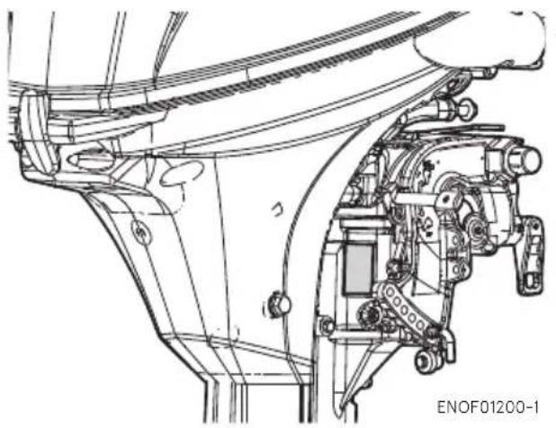
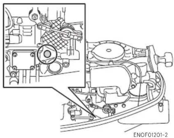
Your outboard motor has a unique serial number. The serial number is identification of outboard motor and is located on the outboard motor as shown in the figures below. The serial number is required for warranty registration, filing a warranty claim as well as making technical inquiries and may be required for other occasions. Therefore, please write down the serial number and date of purchase in the space below.
Serial Number:
natural_image
Technical line drawing of a mechanical assembly with no visible text or symbolsSerial Number:
natural_image
Technical line drawing of a mechanical assembly with internal components and a magnified inset (no text or symbols)Date of purchase:
ENOM00007-0
NOTICE: DANGER/WARNING/CAUTION/Note
Before installing, operating or otherwise handling your outboard motor, be sure to thoroughly read and understand this Owner's Manual and carefully follow all of the instructions. Of particular importance is information preceded by the words "DANGER," "WARNING," "CAUTION," and "Note." Always pay special attention to such information to ensure safe operation of the outboard motor at all times.
ENOW00001-0

DANGER
Failure to observe will result in severe personal injury or death, and possibly property damage.
ENOW00002-0

WARNING
Failure to observe could result in severe personal injury or death, or property damage.
ENOW00003-0

CAUTION
Failure to observe could result in personal injury or property damage.
ENON00001-0
Note
This instruction provides special information to facilitate the use or maintenance of the outboard motor or to clarify important points.
CONTENTS
- GENERAL SAFETY INFORMATION....10
- SPECIFICATIONS 12
- PARTS NAME 15
- LABEL LOCATIONS ..... 17
-
INSTALLATION 20
-
Mounting the outboard motor on boat 20
-
Battery installation.... 23
-
PRE-OPERATING PREPARATIONS 25
-
Fuel handling 25
- Fuel filling 26
- Engine oil filling .....27
- Break-In 29
-
Warning system 30
-
ENGINE OPERATION 32
Before starting 32
- Fuel feeding 32
- Starting the engine 33
- Warming up the engine 38
- Forward, reverse, and acceleration 39
- Stopping the engine .....41
- Steering 43
- Trim angle 44
- Tilt up and tilt down 46
-
Shallow water operation 48
-
REMOVING AND CARRYING THE OUTBOARD MOTOR....50
-
Removing the outboard motor 50
- Carrying the outboard motor 50
-
Trailering 51
-
ADJUSTMENT.... 53
-
Steering friction 53
- Throttle grip friction 53
-
Remote control lever friction 53
-
INSPECTION AND MAINTENANCE.... 55
-
Daily Inspection 56
- Periodic Inspection 61
- Off-season storage 74
- Pre-season check 77
- Submerged outboard motor 77
- Cold weather precautions.... 78
- Striking underwater object 78
-
Auxiliary outboard motor operation.... 78
-
TROUBLESHOOTING....79
-
ACCESSORIES KIT 81
- PROPELLER TABLE 82
INDEX
- GENERAL SAFETY INFORMATION 1
- SPECIFICATIONS 2
- PARTS NAME 3
- LABEL LOCATIONS 4
- INSTALLATION 5
- PRE-OPERATING PREPARATIONS 6
- ENGINE OPERATION 7
- REMOVING AND CARRYING THE OUTBOARD MOTOR 8
- ADJUSTMENT 9
- INSPECTION AND MAINTENANCE
- TROUBLESHOOTING 11
- ACCESSORIES KIT
- PROPELLER TABLE 13
GENERAL SAFETY INFORMATION
1
ENOM00009-1
As the operator/driver of a boat, you are responsible for the safety of those aboard and those in other boat around yours, and for following local boating regulations. You should be thoroughly knowledgeable on how to correctly operate the boat, outboard motor, and accessories. To learn about the correct operation and maintenance of the outboard motor, please read through this manual carefully.
It is very difficult for a person in the water to take evasive action should he or she see a power boat heading in his/her direction, even at a slow speed.
Therefore, when your boat is in the immediate vicinity of people in the water, the outboard motor must be shifted to neutral and shut off.
ENOW00005-0

WARNING
SERIOUS INJURY IS LIKELY IF A PERSON IN THE WATER MAKES CONTACT WITH A MOVING BOAT, GEAR HOUSING, PROPELLER, OR ANY SOLID DEVICE RIGIDLY ATTACHED TO A BOAT OR GEAR HOUSING.
ENOM00247-1
STOP SWITCH LANYARD
The engine can be stopped by pulling out the stop switch lock from the stop switch. The stop switch lanyard is the coiled red cord with the stop switch lock on one end and a metal clip on the other end. With attaching the stop switch lanyard to the operator's body part or operator's personal flotation device (PFD), the engine will stop when the stop switch lanyard is being stretched and pulled out the lock from the switch if the operator accidentally falls overboard or leaves from operator's position. This function may prevent losing control of the boat and minimize or prevent risk of collision with other boats, people and other objects. It is operator's responsibility to use the stop switch lanyard.
ENOW00004-1

WARNING
Accidental activation of the Stop Switch (such as the tether being pulled out in heavy seas) could cause passengers to lose their balance and even fall overboard, or it could result in loss of power in heavy seas, strong currents, or high winds. Loss of control while mooring is another potential hazard.
To minimize accidental activation of the Stop Switch, the 500 mm (20 inch.) stop switch lan-yard is coiled and can extended to a full 1300 mm (51 inch.).
ENOM00800-A
PERSONAL FLOTATION DEVICE
As the operator/driver and passenger of a boat, you are responsible to wear a PFD (Personal Flotation Device) while on the boat.
ENOM00010-1
SERVICING, REPLACEMENT PARTS & LUBRICANTS
We recommend that only an authorized service shop perform service or maintenance on your outboard motor. Be sure to use genuine parts, genuine lubricants, or recommended lubricants. Be aware that the installation and use of parts not approved by Tohatsu Corporation will void warranty and may lead to unsafe operating conditions.
1
ENOM00011-1
MAINTENANCE
As the owner of the outboard motor, you should be acquainted with correct maintenance procedures following by maintenance section of this manual (See page 55). It is the operator's responsibility to perform all safety inspections, proper lubrication and to follow all maintenance instructions for safe operation. You should take the engine to an authorized dealer or service shop for periodic inspection at the prescribed intervals. Correct periodic maintenance and proper care of outboard motor will reduce the chance of problems, limit overall operating expenses and contribute to longevity of your outboard motor.
Carbon Monoxide Poisoning Hazard
Exhaust gas contains carbon monoxide, a colorless and odorless gas which can be fatal if inhaled for any length of time.
Never start or operate the engine indoors or in any space which is not well ventilated.
Gasoline
Gasoline and its vapors are very flammable and can be explosive. Use extreme care when handling gasoline. You should be thoroughly knowledgeable on how to correctly handle gasoline by reading this manual.
SPECIFICATIONS
ENOM00810-A
MODEL FEATURE
| Model F9.9E F15E | F20E | |||||||||||
| Type | MF | EP | MF | EF | EP | EPT | MF | EF | EFT | EP | EPT | |
| Transom heights | S ● ● | ● | ● ● | ● ● | ● ● | ● | ● | |||||
| L ● ● | ● | ● ● | ● ● | ● ● | ● | ● | ||||||
| Tiller Handle ● ● ● ● | ● ● | |||||||||||
| Remote Control | ● ● ● | ● | ● | |||||||||
| Power Tilt | ● | ● ● | ||||||||||
| Manual Tilt | ● | ● ● | ● ● | ● ● | ● | |||||||
ENOM00811-A
MODEL NAME EXAMPLE
F 20E EPTL
| F | 20 | E | E | P | T | L |
| Model description | Horse power | Product generation | Starter system | Steering system | Tilt system | Shaft length |
| F= Four stroke | - | A and up | E= Electrical startM= Manual start | P= Remote Control (Plea-sure)F= Tiller handle (Fisher) | T= Power tiltBlank= Manual tilt | S= Short 15 in L= Long 20 in UL= Ultra long 25 in |
ENOM00301-0
MF, EF, EFT
| Item MODEL | F9.9E/15E/20E | |||
| MF EF EFT | ||||
| Overall Length mm (in) 1038 (40.9) | ||||
| Overall Width mm (in) 343 (13.5) 339 (13.3) | ||||
| Overall Height S·L·UL mm (in) 1116 (43.9) 1258 (49.5) 1386 (54.5) | ||||
| Transom Height S·L·UL mm (in) | 413 (16.3) 562 (22.1) 689 (27.1) | |||
| Weight*1 | S kg (lb) | 43 (95) 47 (104) | 52.5 (116) | |
| L kg (lb) | 44 (97) 48 (106) | 53.5 (118) | ||
| UL kg (lb) | 45.5 (100) | 49.5 (109) | 55 (121) | |
| Output kW (ps) | 9.9E: 7.3 (9.9) 15E: 11.0 (15) 20E: 14.7 (20) | |||
| Max. Operating Range min-1(rpm) | 5400-6100 | |||
| Idle Speed in Forward Gear min-1(rpm) | 950 | |||
| Idle Speed in Neutral Gear min-1(rpm) | 950 | |||
| Engine Type | 4-Stroke FI | |||
| Number of Cylinder | 2 | |||
| Bore × Stroke mm (in) | 61 × 57 (2.40 × 2.24) | |||
| Piston Displacement cm-3(Cu in) | 333 (20.32) | |||
| Exhaust System | Through hub exhaust | |||
| Cooling System | Water cooling | |||
| Engine Lubrication | Trochoid pump | |||
| Starting System | Manual Electric starter motor*2 | |||
| Ignition System | Flywheel Magneto C.D. ignition | |||
| Spark Plug | NGK DCPR6E | |||
| Trim Position | 6 | 5 | ||
| Engine Oil mL (fl.oz.) | API, SH, SJ or SL SAE 10W-30/40, Approx. 1000 (33.8) | |||
| Gear Oil mL (fl.oz.) | Genuine Gear Oil or API GL5, SAE #80-90, Approx. 465 (15.7) | |||
| Fuel | Unleaded Regular Gasoline: R+M/2: 87 or higher RON: 91 or higher | |||
| Fuel Tank Capacity L (US gal) | 12 (3.17) | |||
| Gear Reduction Ratio | 2.15 (13:28) | |||
| Emission Control System | MFI (Multiport Fuel Injection) | |||
| Operator Sound Pressure (ICOMIA 39/94) dB (A) | 84.2 | |||
| Hand Vibration Level (ICOMIA 38/94) m/s2 | 2.5 | |||
Remark: Specifications are subject to change without notice.
*1 With propeller, with battery cable.
*2 With Manual Start
Tohatsu outboard is power rated in accordance with ISO8665 (propeller shaft output).
ENOM00302-0
EP, EPT
| Item MODEL | F9.9E/15E/20E | ||
| EP EPT | |||
| Overall Length mm (in) 629 (24.7) | |||
| Overall Width mm (in) 343 (13.5) 339 (13.3) | |||
| Overall Height S·L·UL mm (in) 1116 (43.9) | 1258 (49.5) 1386 (54.5) | ||
| Transom Height S·L·UL mm (in) | 413 (16.3) 562 (22.1) 689 (27.1) | ||
| Weight | S kg (lb) | 46 (101) | 51.5 (114) |
| L kg (lb) | 47 (104) | 52.5 (116) | |
| UL kg (lb) | 48.5 (107) | 54 (119) | |
| Output kW (ps) | 9.9E: 7.3(9.9) 15E: 11.0 (15) 20E: 14.7 (20) | ||
| Max. Operating Range min-1(rpm) | 5400-6100 | ||
| Idle Speed in Forward Gear min-1(rpm) | 950 | ||
| Idle Speed in Neutral Gear min-1(rpm) | 950 | ||
| Engine Type | 4-Stroke FI | ||
| Number of Cylinder | 2 | ||
| Bore × Stroke mm (in) | 61 × 57 (2.40 × 2.24) | ||
| Piston Displacement cm3(Cu in) | 333 (20.32) | ||
| Exhaust System | Through hub exhaust | ||
| Cooling System | Water cooling | ||
| Engine Lubrication | Trochoid pump | ||
| Starting System | Electric starter motor*2 | ||
| Ignition System | Flywheel Magneto C.D. ignition | ||
| Spark Plug | NGK DCPR6E | ||
| Trim Position | 6 | 5 | |
| Engine Oil mL (fl.oz.) | API, SH, SJ or SL SAE 10W-30/40, Approx. 1000 (33.8) | ||
| Gear Oil mL (fl.oz.) | Genuine Gear Oil or API GL5, SAE #80-90, Approx. 465 (15.7) | ||
| Fuel | Unleaded Regular Gasoline: R+M/2: 87 or higher RON: 91 or higher | ||
| Fuel Tank Capacity L (US gal) | 12 (3.17) | ||
| Gear Reduction Ratio | 2.15 (13 : 28) | ||
| Emission Control System | MFI (Multiport Fuel Injection) | ||
| Operator Sound Pressure (ICOMIA 39/94) dB (A) | 84.2 | ||
| Hand Vibration Level (ICOMIA 38/94) m/s2 | - | ||
Remark: Specifications are subject to change without notice.
*1 With propeller, with battery cable.
*2 With Manual Start
Tohatsu outboard is power rated in accordance with ISO8665 (propeller shaft output).
ENOM00303-0
MF, EF, EP, EFT, EPT
text_image
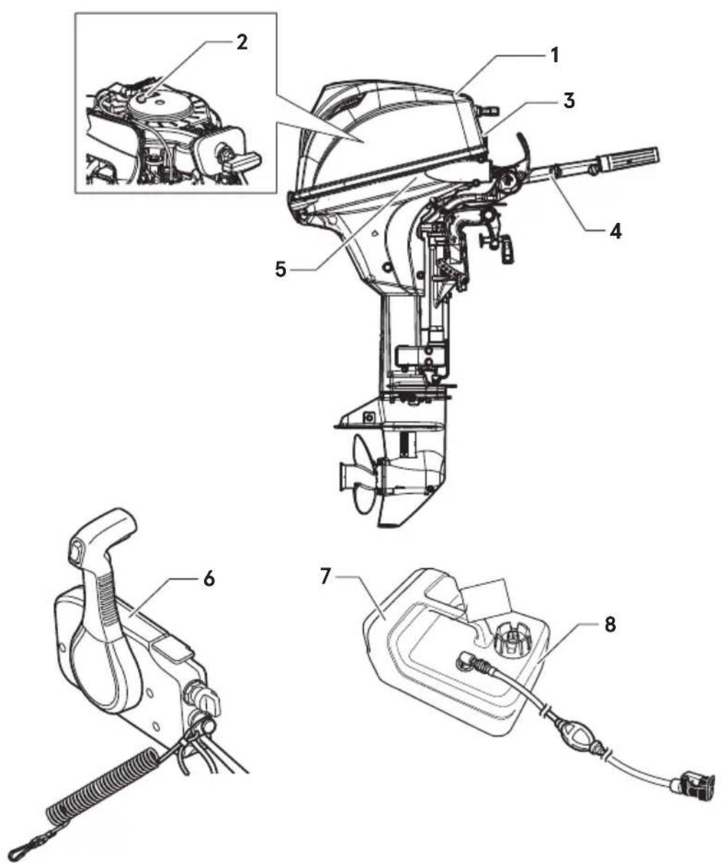
Technical diagram of a boat's internal components with numbered parts for identificationENOF01202-1
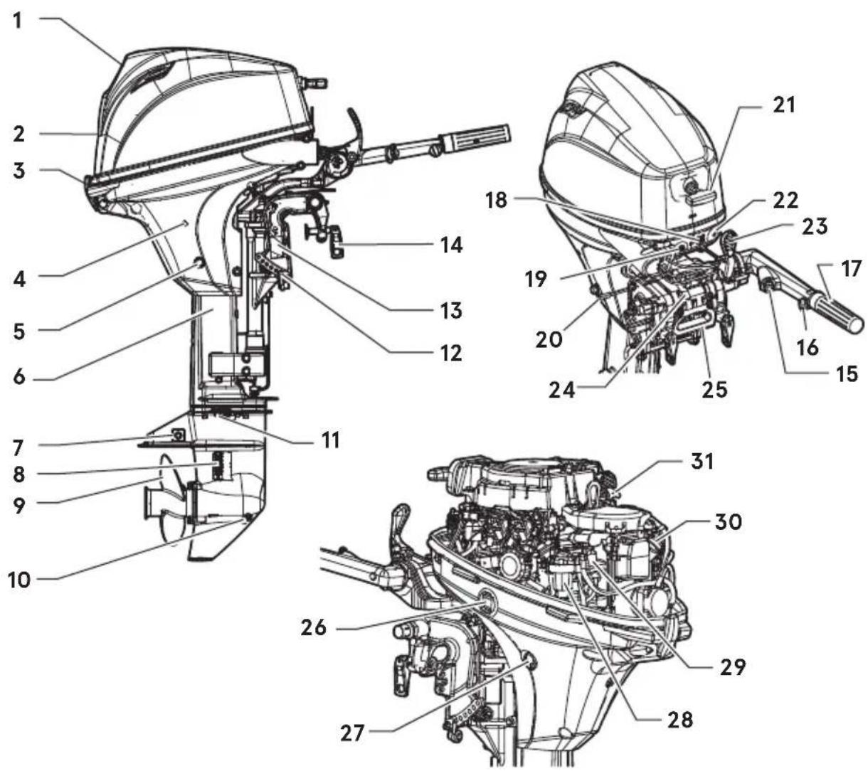
1 Tilt Handle
2 Top Cowl
3 Bottom Cowl
4 Cooling Water Check Port
5 Oil Drain Bolt
6 Drive Shaft Housing
7 Anode
8 Water Inlet
9 Propeller
10 Oil Plug (Lower) (Fill)
11 Oil Plug (Upper) (Level)
12 Thrust Rod
13 Clamp Bracket
14 Clamp Screw
15 Stop Switch ^1
16 Throttle Friction Screw ^4
17 Throttle Grip ^1
18 Warning Lamp
19 Starter Switch ^2
20 Reverse Lock Lever
21 Starter Handle
22 Fuel Connector
23 Shift Lever ^*1
24 Steering Friction Lever
25 Carrying Handle
26 Power Tilt Switch (EPT type only)
27 Flushing Connector Cap
28 Fuel Filter
29 Spark Plug
30 Oil Filler Cap
31 Oil Level Gauge
*1: Tiller handle type only.
*2: Electrical starter type only.
MF, EF, EP, EFT, EPT
3
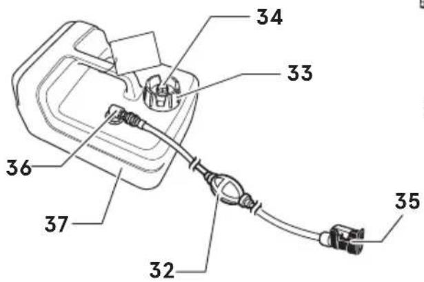
text_image
34 33 36 37 32 35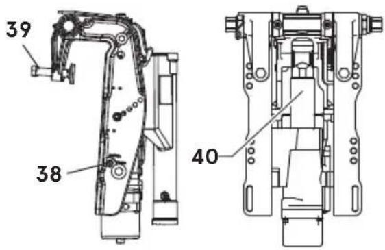
text_image
39 38 40Power Tilt Type
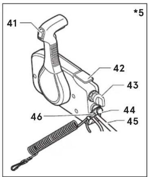
text_image
41 42 43 44 45 46 *5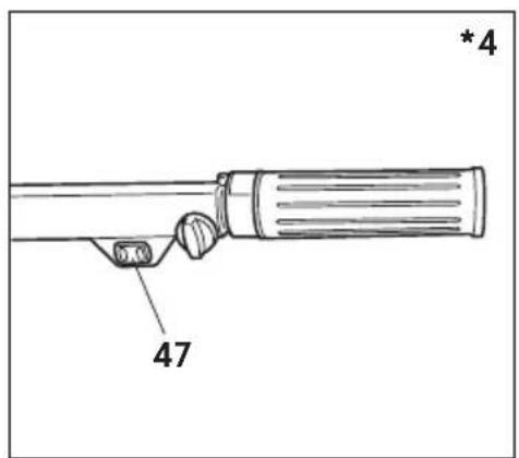
text_image
4 47 *4ENOF01203-3
32 Primer Bulb
33 Fuel Tank Cap
34 Air Vent Screw
35 Fuel Connector
36 Fuel Pick up Elbow
37 Fuel Tank
38 Manual Release Valve ^3
39 Clamp Screw 4
40 Power Tilt ^3
41 Power Tilt Switch ^5
42 Remote Control Box *5
43 Main Switch *5
44 Stop Switch ^5
45 Cord Assembly ^5
46 Engine Stop Switch Cord ^5
47 Power Tilt Switch
*3: Power tilt type only.
*4: Power tilt, tiller handle type only.
*5: Remote control type only.
LABEL LOCATIONS
ENOM00019-A
Warning label locations
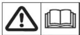
ENOF01204-4
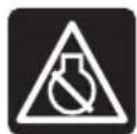
- Read owner's manual.
ENOF00120-0
2-1. Warning regarding starting the engine (See page 33).
2-2. HOT SURFACE
Can cause burns.
Do not touch when operating or immediately after the engine has stopped.
2-3. HAZARD CAUSED BY ROTATING PARTS
Rotating parts can cause severe injury.
Keep hands, feet, hair, and clothing away from all rotating parts to prevent injury.
2-4. ELECTRICAL SHOCK HAZARD
High voltage can cause severe electrical shock.
Do not touch electrical components such as ignition coil or spark plug cord when starting or while the engine is in operation.
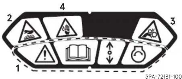
text_image
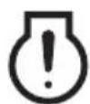
2 4 3 1 3PA-72181-100- Warning lamp (See page 30).
- Engine stop switch (See page 34, 36, 43).
ENOF00131-B
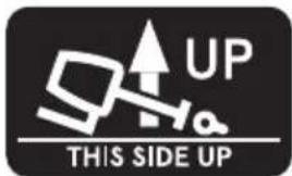
- When laying down the outboard motor, be sure this decal is facing up.
text_image
UP THIS SIDE UP3H6-67572-1
For RC model
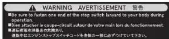
- Warning regarding stop switch lan-yard.
text_image
Warning symbols including a triangle warning, skull crossed, and flameREMOVE FROM BOAT
FOR FILLING
ENOF00005-S
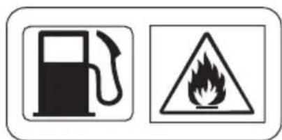
- Warning regarding gasoline (See page 26).
text_image
Warning sign showing a fuel pump and a triangular hazard symbol with flameENOF00005-L
ENOM00019-B
CE label locations
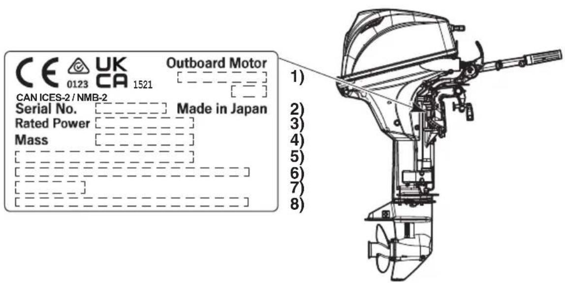
text_image
CE 0123 UK CA 1521 Outboard Motor CAN ICES-2 / NMB-2 Serial No. Made in Japan Rated Power Mass [_______________] [_______________] [_______________] [_______________] [_______________] [_______________] 1) 2) 3) 4) 5) 6) 7) 8)ENOF01237-5
- Model code (Model name)
- Serial No.
- Rated power
- Dry mass weight( Without propeller, with battery cable)
- Manufacturer name
- Manufacturer address
- Authorised representative
- Authorised representative address
Description of serial number year code
Last two digits of alphabet represent production year as below.
| Year Code | BB | BC | BD | BE | BF |
| Year of manufacture | 2022 2023 | 2024 2025 2026 |
ENOM00024-C
1. Mounting the outboard motor on boat
ENOW00006-1B

WARNING
To avoid personal injury or damage of equipment, make sure the allowable lifting capacity of the hoist is at least twice the weight of the outboard motor.
Do not allow the lift hook or chain from the hoist to come in contact with any part of the outbord motor during lifting.
ENOW00006-1

WARNING
Most boats are rated and certified for their maximum allowable horsepower, as shown on the boat's certification plate. Do not equip your boat with an outboard motor that exceeds this limit. If in doubt, contact your dealer.
Do not operate the outboard motor until it has been securely mounted on the boat in accordance with the instructions below.
ENOW00009-2A

WARNING
- Mounting the outboard motor without following this manual can lead to unsafe conditions such as poor maneuverability, lack of control or fire.
- Loose clamp screws and/or mounting hardware can lead to the release or displacement of the outboard motor, possibly resulting in loss of control and/or serious personal injury. Be sure that fasteners are tightened to the specified torque. Check the fasteners for tightness before operating your outboard.
- Be sure to use outboard mounting hardware included in the outboard motor
package or their equivalents in terms of size, material, quality and strength.
Mounting outboard motor must be performed by trained service person(s) in well-equipped place where lift or hoist can be used.
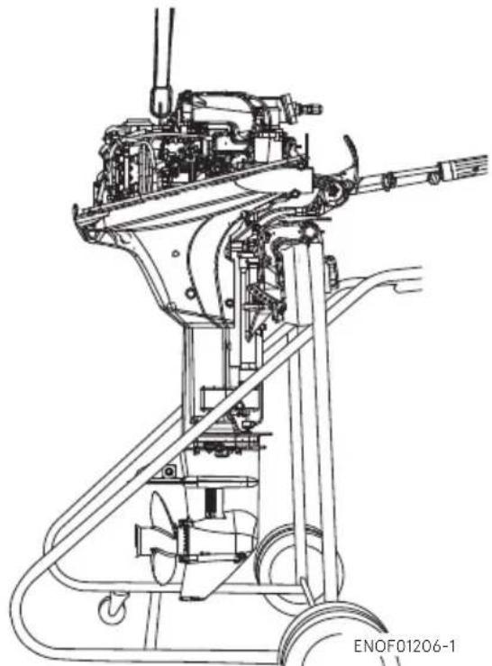
natural_image
Technical line drawing of a mechanical device with no visible text or symbolsKeep the outboard motor in a vertical position when mounting.
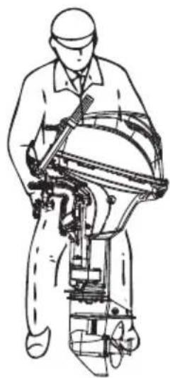
natural_image
Line drawing of a person operating a mechanical device (no text or symbols present)ENOF01239-0
ENOM00025-0
Position ... Above keel line
Place the outboard motor in the center of the boat's transom.
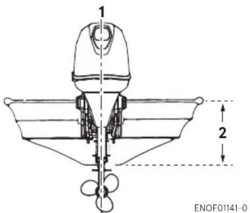
text_image
1 2 ENOF01141-0-
Center of boat
-
Boat transom
ENOM00026-0
Transom matching
Be sure that the anti ventilation plate of the outboard motor is 5-25 mm (0.2-1 in) below the bottom of hull.
If the above condition cannot be met due to the shape of the bottom of your boat, please consult your authorized dealer.
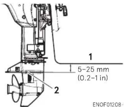
text_image
1 5-25 mm (0.2-1 in) 2 ENOF01208-1-
Bottom of hull
-
Anti ventilation plate
ENOW00007-1

CAUTION
- Before running test, check the boat with maximum loading capacity. Overloading or incorrect weight distribution of the weight may result in boat to lose control,
even swamping or capsizing. Make sure that there is enough distance between bottom cowl and water surface to prevent water from entering the engine.
- Make sure to mount the engine in correct position. If outboard motor is mounted incorrectly, water may intrude the engine from openings of the bottom cowl while cruising. Exposing the engine to such condition may result in severe damage to the engine.
ENOM00830-A
Mounting the outboard motor
MF/EF/EP/EFT type
-
Set the outboard motor to appropriate position.
-
Tighten the clamp screws by turning their handles.
-
Secure the clamp brackets to the transom board using bolts, flat washers and nylon locking nuts.
-
Secure the outboard motor to the boat with a rope to prevent accidental loss of the outboard motor overboard.
ENON00930-1
Note
- Do not use tools to tighten clamp screws. Over tightening could result in damage to the clamp screws and clamp brackets.
- Do not reuse Nylon locking nut.
ENON00931-0
Note
- Mounting hardware is included in the standard accessories for certain engine type only. Please refer 12 "ACCESSORIES KIT".
- A rope is not included in the standard accessories.
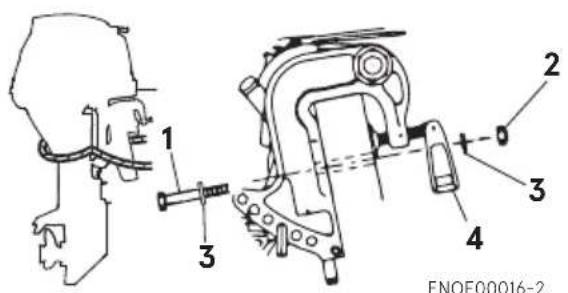
text_image
1 2 3 4 ENOF00016-2- Bolt (8 × 85)
- Nylon locking nut
- Washer
- Clamp screw
ENOW00945-0

CAUTION
- Please inspect whether there is a loosening of the clamp screw or mounting bolts before departure.
- Loosening may cause a dangerous situation, such as loss of control.
EPT type
- To attach the outboard motor to the boat, use the bolts to secure the outboard motor brackets on transom board.
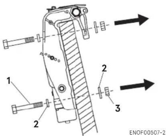
text_image
1 2 2 3 ENOF00507-2- Bolt (8 × 85)
- Washer
- Nylon locking nut
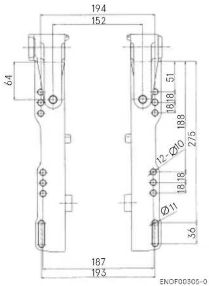
text_image
194 152 64 187 193 ENOF00305-0 12Ø10 18.18 18.18 Ø11 36 275 51 18.18 18.8 194 193ENOW00008-2A

CAUTION
Tighten the bolts securely, otherwise the outboard motor could fall down.
ENON00003-2
Notes
- Apply sealing material, such as silicone sealed between the bolts and the trans- som board holes before tightening the bolts.
- For EP / EFT type, drill the holes in transom board only at left and right of lower side of clamp bracket, and attach outboard motor with supplied bolts.
For EPT type, drill the holes in transom board at 4 points up and down, right and left, and attach outboard motor with supplied bolts.
- Do not reuse Nylon locking nut.
ENOM00029-A
2. Battery installation
ENOW00012-1

WARNING
Battery electrolyte contains sulfuric acid and is hazardous, causes a burn if come in contact with your skin, and poisonous if swallowed.
Keep battery and electrolyte away from reach of children.
When handling the battery, be sure to:
- Read all warnings shown on the battery case.
● Prevent electrolyte from coming in contact with any part of your body. Contact can cause serious burn or, if come in contact with your eye, loss of sight. Use safety glasses and rubber gloves.
In case you came in contact with battery electrolyte:
● For skin, flush thoroughly with water.
- For eye, flush thoroughly with water, and then seek immediate medical treatment.
In case battery electrolyte is swallowed:
- Seek immediate medical treatment.
ENOW00013-B

WARNING
Battery generates explosive hydrogen gas. Be sure to:
- Charge the battery in a well-ventilated place.
- Place the battery away from any source of fire, sparks and open flames such as burners or welding equipment.
- Do not smoke near the battery.
- Do not charge the battery when the electrolyte level is low. Otherwise, the battery will be damaged and may cause malfunction.
ENOW00014-0

CAUTION
● Make sure that the battery leads do not get stuck between the outboard motor and boat when turning, etc.
● The starter motor may fail to operate if the leads are incorrectly connected.
- Be sure to correctly connect the (+) and (−) leads. If not, the charging system will be damaged.
- Do not disconnect the battery leads from battery while the engine is operating, the electrical parts could be damaged.
● Always use a fully charged battery.
ENOW00015-1

CAUTION
Do not use a battery that is not recommended. Use of a battery not recommended can lead to poor performance of, and/or damage to the electrical system.
ENON00006-1E
Note
Minimum battery requirements: 12v 40Ah/20HR, 330 Cold Cranking Amps (CCA).
Larger capacity battery is required when it is using freezing condition.
Larger capacity battery is required when it is used under a freezing condition.
Recommend connecting only the engine battery cables to the starting battery.
Specifications and features of battery vary by manufacturers.
Consult the manufacturer for details.
* The battery should be purchased separately and is not supplied with the outboard motor.
-
Place the battery box in a convenient position and away from possible water spray. Securely fasten both the box and the battery so they do not shake loose.
-
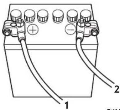
Connect the positive lead (+) to the positive terminal (+) of the battery, and then connect the negative lead (−). When disconnecting the battery, always remove the negative lead (−) first. After connecting the positive terminal (+), securely place a cap on it to prevent short circuits.
natural_image
Diagram of a battery with two labeled terminals (1 and 2) and multiple battery cells, showing wiring connections without any text or symbols.ENOF00022-1
- Battery cord (red)
- Battery cord (black)
PRE-OPERATING PREPARATIONS
ENOM00030-A
1. Fuel handling
ENOW000017-0

CAUTION
Use of improper gasoline can damage your engine. Engine damage resulting from the use of improper gasoline is considered misuse of the engine, and damage caused thereby will not be covered under the limited warranty.
ENOM00031-1
FUEL RATING
Use only major brand unleaded fuel meeting the following specifications:
USA and Canada – having a posted pump
Octane Rating of 87 (R+M)/2 minimum.
Premium gasoline (92 [R+M]/2 Octane) is also acceptable. Do not use leaded gasoline.
Outside USA and Canada — Use unleaded gasoline with declared octane rating of 91 RON or over. Use of premium gasoline of 98 RON is also allowed.
ENOM00032-1
GASOLINES CONTAINING ETHANOL
The fuel system components on your TOHATSU outboard motor will withstand up to 10% ethyl alcohol (hereinafter referred to as the "ethanol") content in the gasoline. If the gasoline in your area contains ethanol, be aware of certain adverse effects that can occur. Increasing the percentage of ethanol in the fuel can also worsen these adverse effects. Some of these adverse effects are caused by ethanol absorbing moisture in the air, which leads to separation of the water/ethanol from the gasoline in the fuel tank.
Use of gasoline containing ethanol may accelerate:
● Corrosion of metal parts
● Deterioration of rubber or plastic parts
- Fuel permeation through rubber fuel lines
● Starting and operating difficulties
If the use of gasoline containing ethanol cannot be avoided or presence of ethanol is suspected in the gasoline, it is recommended to use a filter to separate
water, and frequently check the fuel system for leaks, mechanical parts for corrosion and abnormal wear.
In case any of such abnormality is found, discontinue the use of such gasoline and contact our dealer immediately.
If the outboard motor will only be used infrequently, please see the remarks on fuel deterioration in the STORAGE chapter (P 74) for additional information.
ENOW00975-0

CAUTION
When operating an outboard motor with gasoline containing ethanol, storing gasoline in the fuel tank for long periods should be avoided. Storing gasoline for long periods creates unique problems. In cars, ethanol blended fuels are normally consumed before they can absorb enough moisture to cause problems, but boats often sit idle long enough for separation phase to take place. In addition, internal corrosion may take place during storage if ethanol washes away the oil films protecting internal components.
ENOW00018-1

WARNING
Fuel leakage can cause fire or explosion, potentially leading to severe injury or loss of life. Every part of fuel system should be inspected periodically. Inspect for fuel leak, hardness or any alteration of rubber, expansion and/or corrosion of metals especially after long term storage. In case any indication of fuel leakage or degradation in fuel system is found, replace the part immediately before using the outboard motor.
ENOM00043-B
2. Fuel filling
ENOW00976-0

WARNING
Do not fill the fuel tank over capacity. Under high temperature conditions, excessive gasoline may evaporate/leak through air vent screw when it is loose or open. Leaking of gasoline is a may lead to a dangerous fire hazard.
ENOW00028-1

WARNING
Consult an authorized dealer for details on handling gasoline, if necessary.
Gasoline and its vapor are very flammable and can be explosive.
When carrying a fuel tank containing gasoline:
- Close the fuel tank cap and air vent screw of fuel tank cap, or gasoline may evaporate through the air vent screw and may lead to a fire hazard.
- Do not smoke.
When or before refueling:
- Be sure to remove the static electricity charged in your body before refueling.
- The static electricity may ignite the gasoline vapor during refueling.
- Stop the engine, and do not start the engine during refueling.
- Do not smoke.
- Be careful not to overfill fuel tank. Wipe up any spilled gasoline immediately.
When or before cleaning the gasoline tank:
● Dismount fuel tank from the boat.
- Place the fuel tank away source of ignition, such as sparks or open flames.
- Do the work outdoors or in a well ventilated area.
- Wipe up gasoline well is spilled.
After cleaning gasoline tank:
- Wipe up gasoline well is spilled.
- If the fuel tank is disassembled for cleaning, reassemble carefully. Incorrect assembly may cause a fuel leak, possibly leading to fire or explosion.
- Dispose aged or contaminated gasoline in accordance with local regulations.
EENOW00029-1

WARNING
When opening fuel tank cap, be sure to follow the procedure described below. Fuel could blast out if the fuel tank cap is opened by using another procedure when internal pressure of fuel tank is raised by heat from sources such as sun light.
ENOW00946-0

CAUTION
Separate tank must be fixed at appropriate position so that well ventilated and tank does not move or fall down while operating.
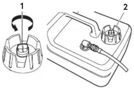
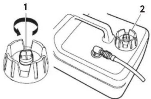
- Fully open the air vent screw on the fuel tank cap and release internal pressure.
text_image
Technical diagram showing a mechanical component with labeled parts and a rotation arrow indicating rotational motion.ENOF00417-1
- Air vent screw
- Tank cap
- Open the fuel tank cap slowly.
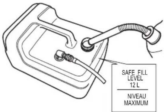
- Fill the fuel carefully not to over flow.
text_image
SAFE FILL LEVEL 12 L NIVEAU MAXIMUMENOF00419-A
- After filling the tank, close the fuel tank cap.
ENOM00037-C
3. Engine oil filling
ENOW00022-2
CAUTION
The engine oil is drained for shipping at the factory. Be sure to fill the engine oil to the proper level before starting the engine.
ENOW00092-1
CAUTION
- Do not overfill engine oil, or eng could leak and/or engine could be damaged. If engine oil level is over upper limit marks of dip stick, drain oil to level lower than upper limit.
- Be sure that outboard motor is upright when checking or changing oil.
- Stop the engine immediately if low oil pressure warning lamp or oil leak is found, or engine could be severely damaged. Consult your dealer.
-
Wipe off engine oil well immediately if spilled and dispose of it in accordance with local fire prevention and environment protection regulations.
-
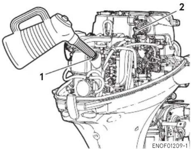
Place the engine in a vertical position.
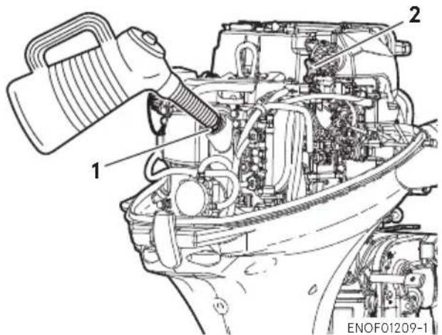
- Remove the top cowl and the oil filler cap.
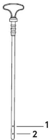
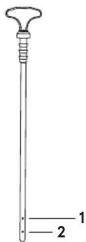
- Fill the engine through filler port with recommended oil to between upper limit and lower limit shown on the dipstick.
- Tighten the oil filler cap.
text_image
1 2 ENOF01209-1- Filler port
- Dipstick
text_image
1 2ENOF01240-0
- Upper limit (Max.)
- Lower limit (Min.)
Engine oil recommendation
Use only high quality 4-stroke outboard motor oil to insure performance and prolonged engine life.
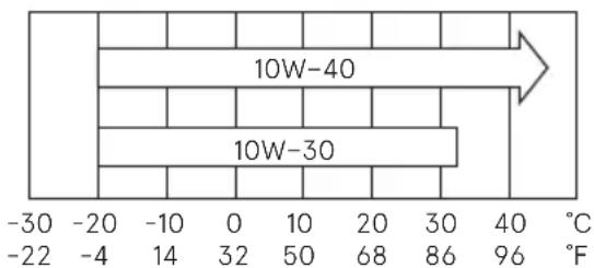
SAE: 10W-30 or 10W-40
API: SH, SJ or SL
Engine oil viscosity must be selected from the following chart according to the average temperatures in your area.
heatmap
| Range | Value | |---|---| | -30 | 10W-40 | | -22 | 10W-30 | | -20 | 10W-40 | | -10 | 10W-30 | | 0 | 10W-30 | | 10 | 10W-30 | | 20 | 10W-30 | | 30 | 10W-30 | | 40 | 10W-30 | | 50 | 10W-30 | | 68 | 10W-30 | | 86 | 10W-30 | | 96 | 10W-30 | | -30 | -4 | | -22 | -4 | | -10 | -4 | | 0 | -4 | | 14 | -4 | | 32 | -4 | | 50 | -4 | | 68 | -4 | | 86 | -4 | | 96 | -4 | The chart displays a single bar for the '10W-40' range, which is explicitly labeled as '10W-30'. The '10W-30' value is also labeled as '10W-40'. The 'F' axis is also labeled as 'F'. The bars are colored differently: darker blue for 10W-40 and lighter blue for 10W-30. The arrow indicates an direction from left to right.ENOF00208-0
Engine oil volume
Approximately 1200 mL (40.6 fl.oz.)
ENOW0002A-A

CAUTION
Use of engine oils that do not meet these requirements will result in reduced engine life, and other engine problems.
ENOM00033-A
4. Break-In
Your new outboard motor and lower unit require break-in for the moving components according to the conditions described in the following time table.
Please refer to ENGINE OPERATION section (See page 32) to learn how to correctly start and operate the outboard motor.
ENOW00024-1

DANGER
Do not operate the outboard motor in closed area or area with not enough ventilation.
Exhaust gas emitted by the outboard motor contains carbon monoxide that may cause dizziness, nausea, other health problem or even death if inhaled continuously.
During operation of the outboard motor:
- Keep peripheral area well ventilated.
● Always stay on the windward side of emission.
ENOW00023-1

CAUTION
Operating the outboard motor without break-in can shorten life.
If any abnormality is experienced during the break-in:
● Discontinue the operation immediately.
- Have the dealer check the product and take proper action(s) if necessary.
ENON00008-2
Note
- During Break-in, run the outboard motor at varied RPM less than specified engine speed. Not following the procedure may result in problems shorten the product life.
- Break-in must be conducted under load in the water in-gear with propeller installed.
6
| 1–10 min | 10 min – 2 hrs | 2–3 hrs | 3–10 hrs | After 10 hrs | |
| Throttle Position | Idle | Less than 1/2 throttle | Less than 3/4 throttle | 3/4 throttle | Full throttle available |
| Speed | Approx. 3000 min ^-1 (rpm) max | Full throttle run allowed for 1 min every 10 min | Approx. 4000 min ^-1 (rpm). Full throttle run allowed for 2 min every 10 min |
ENOM00039-D
5. Warning system
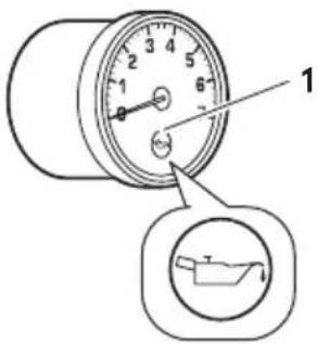
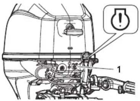
If outboard motor encounters an abnormal condition of fault, the warning buzzer will emit a continuous beep or intermittent short beeps and the warning lamp will synchronize with the buzzer and engine speed will be limited (engine will not be stopped).
*No buzzer is located for tiler handle type and EP type on the motor.
See next page for conditions which will lead to an abnormal condition or fault.
ENOM00040-1
Location of warning buzzer and lamp
■ Warning buzzer
RC model: Located inside the remote control.
Tiller handle model: No warning buzzer.
■ Warning lamp
RC model: Located in the tachometer & bottom cowl.
Tiller handle models: Located on the bottom cowl.
ENON00009-A
Note
Warning lamp for optional tachometer will synchronize with the warning lamp for engine side.
text_image
Diagram of a cylindrical gauge with labeled scale and an inset showing a boat insideENOF00851-A
- Warning lamp
text_image
Technical diagram of a vehicle engine component with labeled parts and an alert iconENOF00314-A2
- Warning lamp
ENOM00041-B
Warning indicators, faults and remedy
| Warning indicators | Description of faults Remedy | ||||
| Sound Lamp | (LED) | Low speed ESG | High speed ESG | ||
| One beep On | for 5 sec. Normal system test when start up | ||||
| Continuous ON | ON | Engine speed exceeds maximum allowable RPM | 1 | ||
| Continuous ^2 | ON ^2 | ON ^2 | Low oil pressure ^1 | 2 | |
| Continuous ON | ON Water over temperature | 3 | |||
| Intermittent short beep ^2 | Blinking ^2 | ON ^2 | Water temp or MAP sensor out of range | 4 | |
Remarks
*1: In this case, oil pressure switch is "ON".
*2: It is necessary to stop the engine, if you want to stop the working indicators and re-set the warning system.
High speed ESG (Electronic Safety Governor)
High speed ESG is a device to prevent over revolution of the engine. If the load to the engine is reduced for some reason, it runs at a higher speed than the usual. In such the case, the buzzer sounds and the ESG is activated not to ignite the spark plug. Therefore the engine speed varies and is controlled under 6300 mih(rpm).
Low speed ESG
Low speed ESG is a device to prevent the engine from getting damage. If the engine has problems cooling water, oil pressure, and sensors, the low speed ESG is activated not to ignite the spark plug, and disable fueling. Therefore the engine speed varies and is controlled under 2800 min ^1 (rpm).
ENOM00126-0
Remedy
- Reduce the speed to less than half open throttle, and move to safe place quickly, and stop the engine.
Check the propeller for bent or damage on blades.
Consult an authorized dealer if engine shows the same result even after replacing propeller with a new one.
- Move to safe place quickly, and stop the engine until it cools down.
Check the engine oil level, and add engine oil if necessary.
Consult your dealer if the engine oil level is too low or too high.
- Move to safe place quickly, and check if cooling water is discharged from the water check port at idle speed and stop the engine.
Remove any foreign matter on the gear case and propeller if necessary. Consult an authorized dealer if no discharge of cooling water.
- Consult an authorized dealer.
ENOW00025-B

CAUTION
- Low speed ESG ON: Engine speed will be limited under 2800 min ^-1 (rpm), however you should not continue to run engine.
- High speed ESG ON: Engine speed will be limited to 6300 min ^-1 (rpm) and engine will run rough until throttle is reduced.
ENGINE OPERATION
ENOM00042-0
Before starting
ENOM00246-0
Oil Level checking
Check the engine oil level before each use. If the oil level is low or too high, the life of the engine will be shortened significantly.(To properly check the engine oil level, follow the instructions,see page 57)
text_image
1 2 ENOF01209-1- Filler port
- Dipstick
text_image
1 2ENOF01240-0
- Upper limit (Max)
- Lower limit (Min.)
ENOW00027-B
CAUTION
Before starting engine for the first time after reassembling engine or off-season storage, disconnect stop switch lock and crank approximately 10 times in order to prime the oil pump.
ENOM00044-C
1. Fuel feeding
ENOW00029-1
WARNING
When opening fuel tank cap, be sure to follow the procedure described below. Fuel could blast out if the fuel tank cap is opened by using another procedure when internal pressure of fuel tank is raised by heat from sources such as sun light.
ENOW00947-0
CAUTION
When using a separate tank, be sure that the fuel line is not kinked and is connected securely.
- Fully open the air vent screw on the fuel tank cap.
text_image
Technical diagram showing a mechanical component with labeled parts and a rotation arrow indicating rotational motion.ENOF00417-1
- Air vent screw
-
Fuel tank cap
-
Open the fuel tank cap release internal pressure completely. After that, close the fuel tank cap.
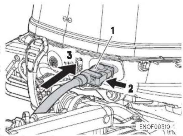
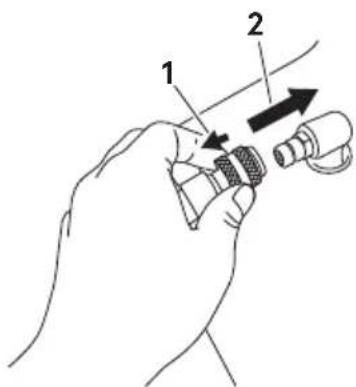
- Connect the fuel connector to the engine and fuel tank.
text_image
1 2 3 ENOF00310-1- Fuel connector
- Push
- Insert
text_image
Diagram showing a hand holding a connector with labeled parts 1 and 2, indicating a mechanical or electrical component.ENOF00861-A
- Pull
- Insert
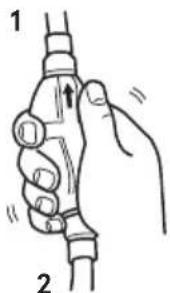
- Squeeze primer bulb until it becomes stiff to feed fuel to vapor separator. Point the arrow mark upward when priming.
text_image
1 2ENOF00862-0
s1l Engine video and
- Fuel tank side
Do not squeeze primer bulb with engine running or when the outboard motor is tilted up to avoid fuel from overflowing.
ENOM00045-F
2. Starting the engine
ENOW00958-1
WARNING
- Do not remove or install the top cowl after the engine has started.
● The exposed rotating engine parts cause serious injury.
ENOW00959-0
CAUTION
The top cowl must be installed while the engine running except in an emergency. If the top cowl is not installed correctly, water splash can damage the engine.
ENOW00036-1A
CAUTION
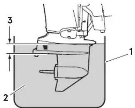
When starting the outboard motor in the test tank, make sure that:
- Water level is at least 10 cm (4 in.) above the anti-ventilation plate to avoid overheating of the engine.
- Run at idling only
- Remove the propeller. (See page 68)
text_image
3 1 2ENOF00863-0
- Test tank
- Water
- Over 10 cm (4 in.)
ENOW00036-1

CAUTION
Operating outboard motor without cooling water will lead to overheating and damage on the outboard motor severely. In case the cooling water check port is not discharging water, stop the outboard motor immediately, check for any object, debris which may be blocking the cooling water check port. If you are unable to locate the cause, consult an authorized dealer immediately.
ENOW00032-A

CAUTION
Do not hold turning starter motor more than 5 seconds, or the battery may be consumed, potentially making the engine starting impossible and/or damaging the starter. If cranking over 5 seconds fails to start engine, return main switch to "ON", and crank engine again after 10 seconds or more. Do not try to crank after engine has started.
This model is provided with start in gear protection.
ENON00010-1
Note
Start-in-gear protection prevents the engine from starting at other than neutral
shift. In-gear starting of engine will move the boat immediately, potentially leading to fall down or causing passenger(s) to be thrown overboard.
Tiller handle type
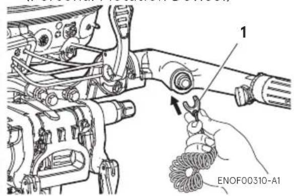
- Be sure to install the stop switch lock to the stop switch, and attach the stop switch lanyard securely to the operator or to the operator's PFD (Personal Flotation Device.)
text_image
1 ENOF00310-A1- Stop switch lock
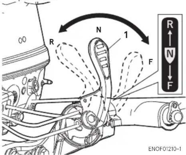
- Set the control lever in the Neutral position.
text_image
R N 1 F R N F ENOF01210-1-
Shift lever
-
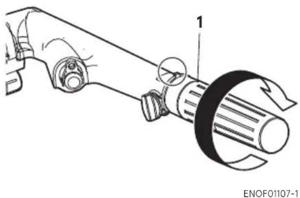
Set the throttle grip to START position.
natural_image
Technical line drawing of a mechanical component with no visible text or symbols- Throttle grip
(For manual starter type)
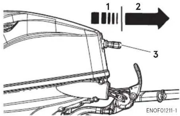
This engine is equipped with a compression release mechanism.
- Pull the starter handle slowly until you feel engagement, keep pulling till you feel less resistance. Then pull it quickly. Repeat the procedure until the outboard motor is started.
text_image
1 2 3 ENOF01211-1- Slowly
- Quickly
- Starter handle
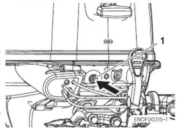
(For electrical starter type)
- Push the starter switch button and release the button when the engine has started.
text_image
1 ENOF00315-1- Starter button
- Check the cooling water from cooling water check port.
natural_image
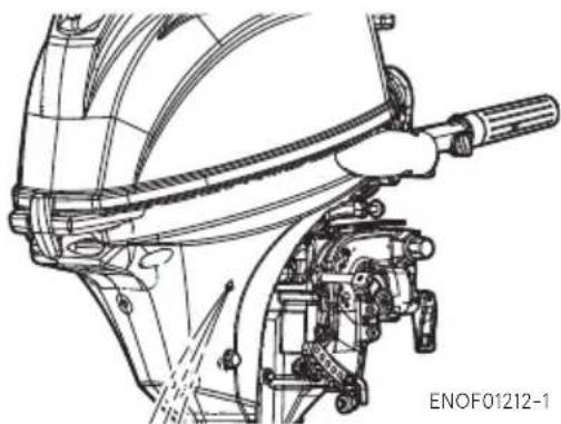
Technical line drawing of a mechanical assembly with no visible text or symbolsSide mount RC type
- Be sure to install the stop switch lock to the stop switch, and attach the stop switch lanyard securely to the operator or to the operator's PFD (Personal Flotation Device.)
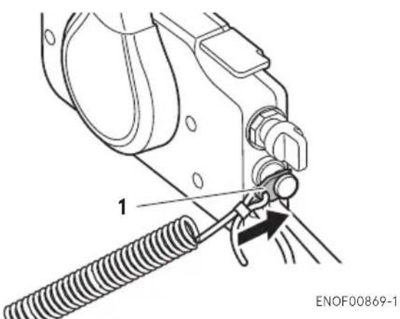
text_image
1 ENOF00869-1- Stop switch lock
- Insert the main switch key.
- Set the control lever in the Neutral position.
ENON00035-1
Note
The free throttle lever cannot be raised when the control lever is in Forward or Reverse.
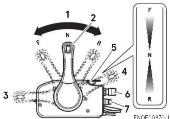
text_image
1 2 F N R 3 4 5 6 7 ENOF00870-1- Neutral (N)
- Control lever
- Fully opened (Forward)
- Fully opened (Reverse)
- Free throttle lever
- Main switch key
-
Stop switch
-
Turns the main switch key to START position.
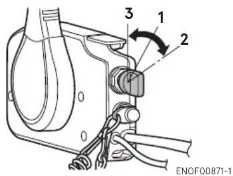
text_image
3 1 2 ENOF00871-1- ON
- START
-
OFF
-
Stop pushing the key when the engine has started.
The key returns to the original position, automatically.
- Returns the free throttle lever to close position.
- Confirm warning lamp light up and then go off after engine has started.
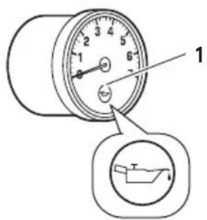
text_image
Diagram of a pressure gauge with labeled component and internal view showing a boat on a surface.ENOF00851-A
- Warning lamp
- Check the cooling water from cooling water check port.
natural_image
Technical line drawing of a mechanical assembly with no visible text or symbolsENOM00042-B
Emergency starting
ENOW00099-1

WARNING
When the emergency starter rope is used for starting engine;
- Start in gear protection does not work. Make sure that shift is in neutral position. If the gear is in Forward or Reverse, the boat can start moving immediately and may lead to accident and personal injury.
- Be careful that of your clothes or other items do not to get caught in the rotating parts.
- To prevent accident and injury by rotating parts, do not re-attach flywheel cover or recoil starter and the top cowl after the engine has been started.
- Do not pull starter rope if any bystander is around.
-
Attach engine stop switch lanyard to clothing or any part of body such as wrist, arm before starting engine the outboard motor.
-
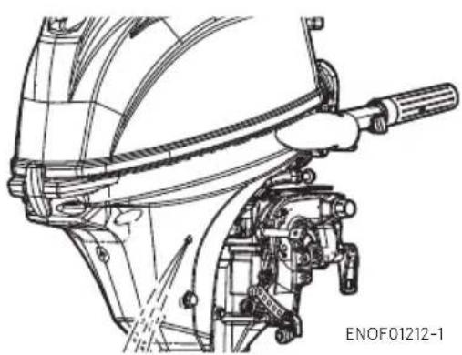
Remove the top cowl.
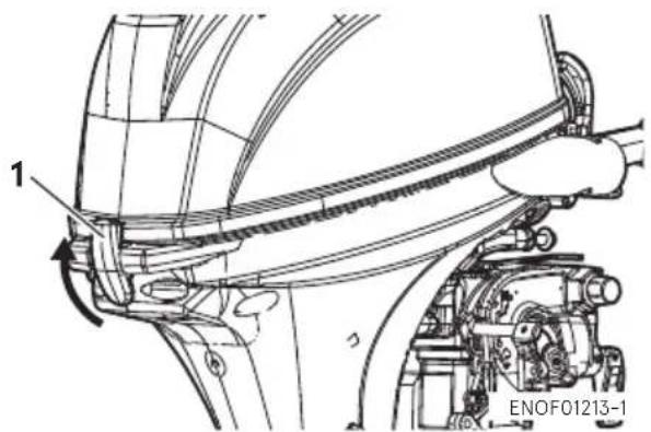
text_image
1 ENOF01213-1- Cowl latch
- Remove the bolts (3pcs) and remove the intake silencer.
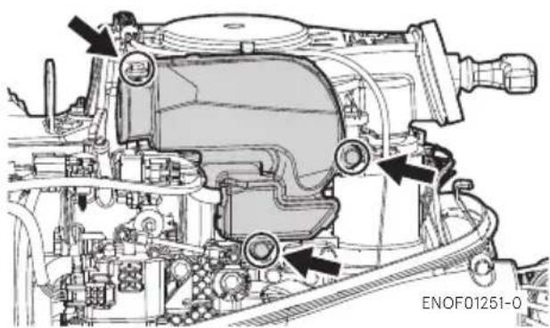
natural_image
Technical diagram of a mechanical assembly with labeled components and arrows indicating parts (no readable text or symbols)- Remove starter lock cable from recoil starter by pulling the starter lock cable.
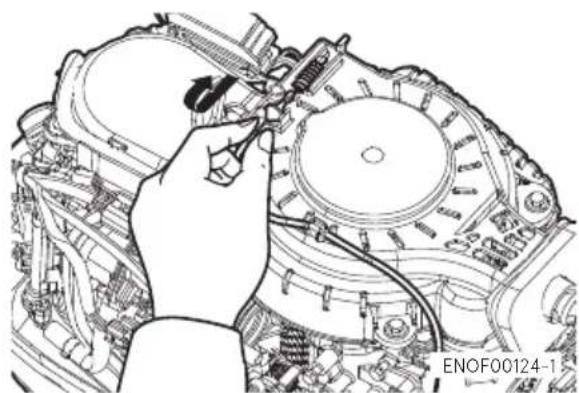
natural_image
Technical line drawing of a mechanical assembly with a hand adjusting components (no text or symbols visible)- Remove the bolts (3pcs) and remove the recoil starter.
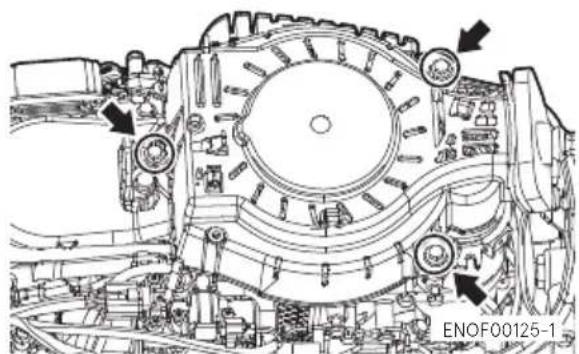
natural_image
Technical line drawing of a mechanical assembly with no visible text or symbols- Insert the knotted end of the starter rope into the notch in the flywheel and wind the rope around the flywheel several turns clockwise.
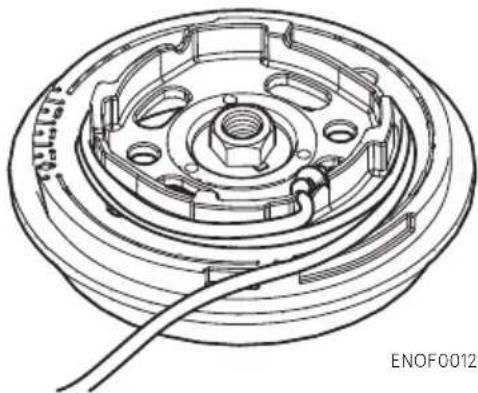
natural_image
Technical line drawing of a mechanical component with concentric rings and a coiled cable (no text or symbols)- Tie a loop in the another end of the emergency starter rope and attach socket wrench. Both the loop and the wrench are provided in outboard motor box.
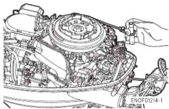
natural_image
Technical line drawing of a mechanical assembly with gears and components, no visible text or symbolsENOW00860-0
CAUTION
Be sure to keep the harness away from the rotation parts.
- Be sure to install the stop switch lock to the stop switch, and attach the stop switch lanyard securely to the operator or to the operator's PFD (Personal Flotation Device.)
- Set the control lever in the Neutral position.
- Pull the starter handle slowly until you feel engagement, keep pulling till you feel less resistance. Then pull it quickly.
- Once the outboard motor is started, do not reinstall the recoil starter and top cowl.
ENOM00043-B
3. Warming up the engine
ENOW00932-1
CAUTION
Be sure to check that cooling water is discharged from the cooling water check port during warm up.
Warm the engine at low engine speeds for about
3 minutes : above 5°C (41°F)
5 minutes at 2000 min ^-1 (rpm): below 5°C (41°F)
This allows the lubricating oil to circulate to all parts of the engine. Operating the engine without warm up shortens the engine's life.
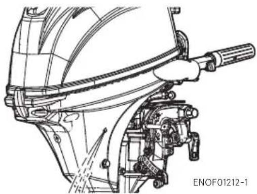
natural_image
Technical line drawing of a mechanical assembly with no visible text or symbolsENOM01826-0
Engine speeds
Idling speed after warming up.
Remark: The idling speed automatically increases depending on the engine temperature. When the engine reaches normal operating temperature, it will return to the specified idling speed.
| Clutch in (In gear) Clutch off (Out of gear) | |
| 950 min ^-1 (rpm) 950 min ^-1 (rpm) |
ENOM00972-0
Free throttle lever (Side mount RC type)
ENOW00956-0

CAUTION
- Keep the free throttle lever fully closed-position when start the engine.
● The free throttle lever is inoperative unless the control lever is in neutral. - Also, the control lever is inoperative unless the free throttle lever is returned to the fully-closed position.
The free throttle lever is for warm-up operation.(Not required for engine starting) With the control lever in neutral, move the free throttle lever upward to open the throttle.
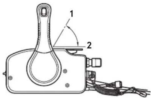
text_image
Technical diagram of a mechanical device with labeled parts 1 and 2, showing internal components and wiring.ENOF00934-0
- Fully-open
- Fully-closed
ENOM00046-A
4. Forward, reverse, and acceleration
ENOW00037-1

WARNING
Before shifting into forward or reverse, make sure that boat is properly moored and outboard motor can be steered fully to the right and left. Make sure that no swimmer(s) is around of the boat.
ENOW00967-0

WARNING
- Attach the other end of emergency stop switch lanyard to the operator's PFD (Personal Flotation device) or arm and keep it attached during cruising.
- Do not attach the lanyard to a part of clothing that can be torn easily when pulled.
- Arrange the lanyard so that will not be caught by any object when pulled.
- Be careful not to pull the lanyard accidentally during cruising. Unintentional stop of engine can cause loss of control of outboard motor. Rapid loss of engine power can lead to fall down or causing passenger(s) to be thrown overboard.
ENOW00042-1

WARNING
- Do not shift into Reverse during planing, or control will be lost leading to serious personal injury, boat may swamp, and/or hull may be damaged.
- Do not shift into Reverse during cruising, or control may be lost, fall down or causing passenger(s) to be thrown overboard. Leading to serious personal injury, and steering system and/or shifting mechanism may be damaged.
ENOW00861-1

WARNING
Do not shift at high boat speed, or control may be lost, fall down or causing passenger(s) to be thrown overboard. Leading to serious personal injury.
ENOW00867-1

WARNING
Sudden acceleration and deceleration may cause passenger(s) to be thrown overboard or fall down.
ENOW00862-1

CAUTION
Gear and clutch damage may occur if shifting at high engine speed.
Engine must be in the slow idle position before shifting.
ENOW00863-0

CAUTION
Idle speed may be higher during warming up of engine. If shifted to Forward or Reverse during warming up, it may be difficult to shift back to neutral. In such case, stop engine, shift to neutral, and restart engine to warm up.
ENON00014-0
Note
Frequent shifting to forward or reverse can accelerate wear or degradation of parts. In such case, replace gear oil earlier than the period specified.
ENOW00864-0

CAUTION
Do not increase engine speed unnecessarily when the shift is in neutral and reverse, or engine damage may occur.
ENOM00890-A
Tiller handle type
ENOW00865-A

CAUTION
Do not force to shift when the throttle grip is not in the fully closed position, otherwise, steering system and/or shifting mechanism may be damaged.
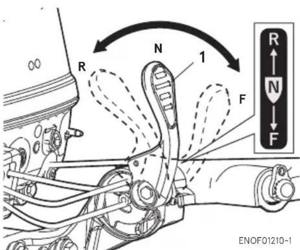
text_image
R N 1 F R N F ENOF01210-1- Shift lever
ENOF01210-1
Forward
- Turn the throttle grip to reduce engine speed.
- When the engine reaches trolling (or idling) speed, quickly pull the shift lever to the Forward position.
Reverse
- Turn the throttle grip to reduce engine speed.
- When the engine reaches trolling (or idling) speed, quickly pull the shift lever to the Reverse position.
Acceleration
Open throttle grip gradually.
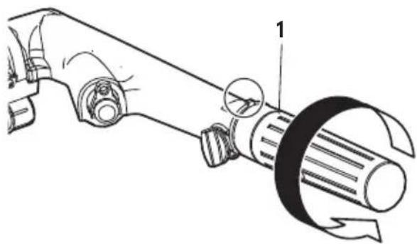
natural_image
Technical line drawing of a mechanical tool with a labeled component (no text or symbols present)ENOF01109-1
- Throttle grip
ENOM0900-0
Side mount RC type
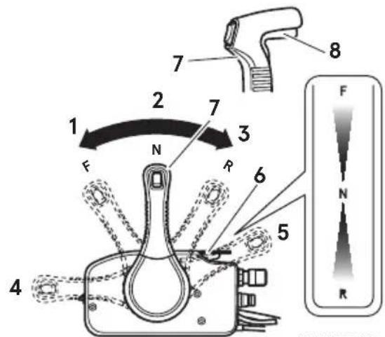
text_image
1 2 7 8 F N R 3 6 5 4 F N RENOF00877-1
- Forward (F)
- Neutral (N)
- Reverse (R)
- Fully opened (Forward)
- Fully opened (Reverse)
- Free throttle lever
- Control lever
- Neutral lock arm
Forward
- Quickly push the control lever to the Forward (F) position 32°, where the gear is connected, while lifting up on the lock button located under the control lever grip.
- Further forward motion will open the throttle.
Reverse
- Quickly pull the control lever to the Reverse (R) position at 32°, where the gear will be connected, while lifting up on the lock button located under the control lever grip.
- Further rearward motion will open the throttle.
Acceleration
Open control lever gradually.
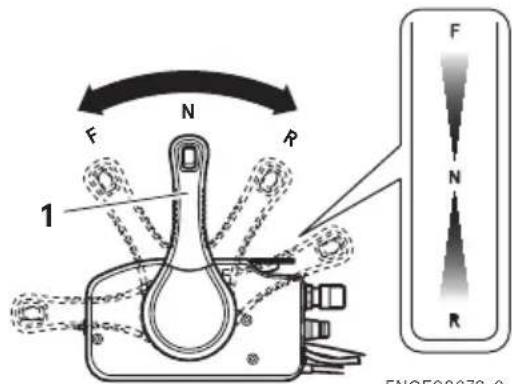
text_image
F N R 1 F N R FNQF00070.2ENOF00879-2
- Control lever
ENOM00049-A
5. Stopping the engine
ENOW00868-1

WARNING
Be careful not to remove engine stop switch lanyard from engine accidentally while boat is running. Sudden stop of engine can cause loss of steering control, speed, possibly leading the crew(s) and or objects on the
boat to be thrown forward due to inertial force.
Tiller handle type
- Turn the throttle grip to the slow position.
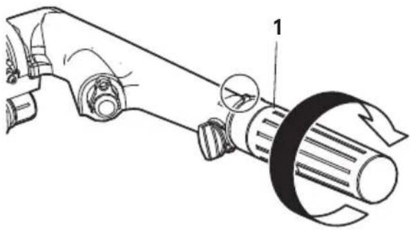
natural_image
Technical line drawing of a mechanical component with labeled parts (no text or symbols present)ENOF01107-1
-
Throttle grip
-
Put the shift lever in the Neutral position.
Run the engine for 2-3 minutes at idling speed for cooling down if it has been running at full speed.
- Turn the main switch key to the OFF position or push the stop switch. (Do not forget to turn the key off).
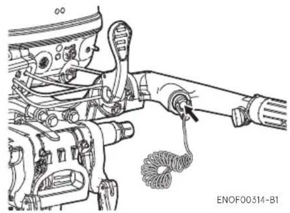
natural_image
Technical line drawing of a mechanical assembly with hoses and a coiled cable (no text or symbols)Side mount RC type
- Put the control lever in the Neutral position and run the engine for 2-3 minutes at idling speed for cooling down if it has been running at full speed.

text_image
F N R 1 2 F N RENOF00881-1
-
Control lever
-
Main switch key
-
Turn the main switch key to the OFF position.
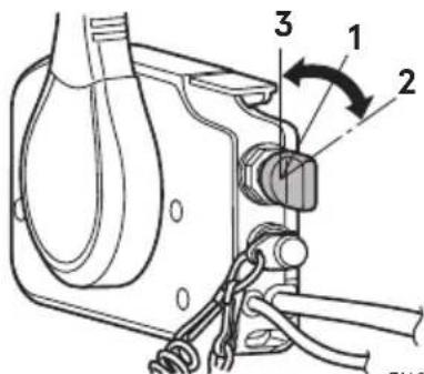
text_image
Technical diagram of a mechanical assembly with numbered components and directional arrows indicating motion or assembly.ENOF00871-1
-
ON
-
START
-
OFF
ENOW00869-1

WARNING
After stopping the engine:
- Close the air vent screw on the fuel tank cap.
- Disconnect the fuel connector from the engine and the fuel tank.
- Disconnect the battery cable, after each use.
Emergency engine stopping
Remove stop switch lock to stop the engine.
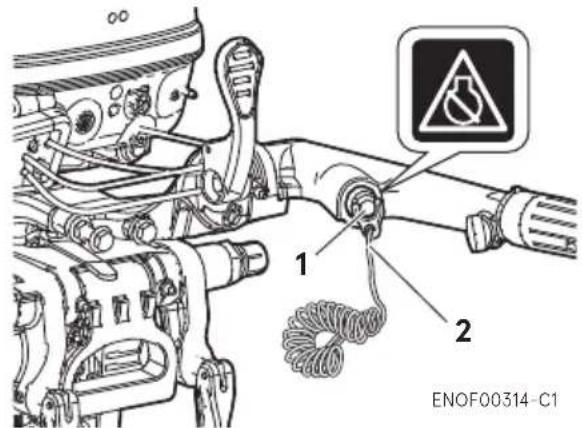
text_image
1 2 ENOF00314-C1- Stop switch
- Stop switch lock
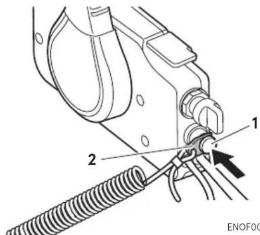
text_image
1 2 ENOF00- Stop switch
- Stop switch lock
ENOM00910-1
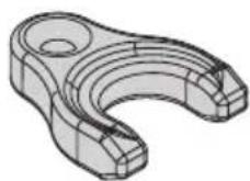
Spare emergency stop switch lock (For CE marking model)
A spare emergency stop switch lock is provided in the accessories bag.
Make sure that spare stop switch lock is available before operating outboard motor.
When used as described, the emergency stop switch clip and emergency stop switch lanyard system stops the engine if the operator is thrown overboard. When
an operator falls into water, be sure to use spare emergency stop switch lock.
ENOF00891-0
ENOM00920-0
6. Steering
ENOW00870-0

WARNING
Sudden steering may cause passenger(s) to be thrown overboard or falling down.
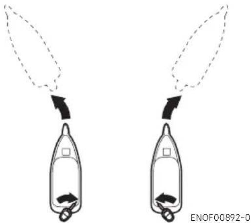
Tiller handle type
Right turn
Move the tiller handle to the left
Left turn
Move the tiller handle to the right.
natural_image
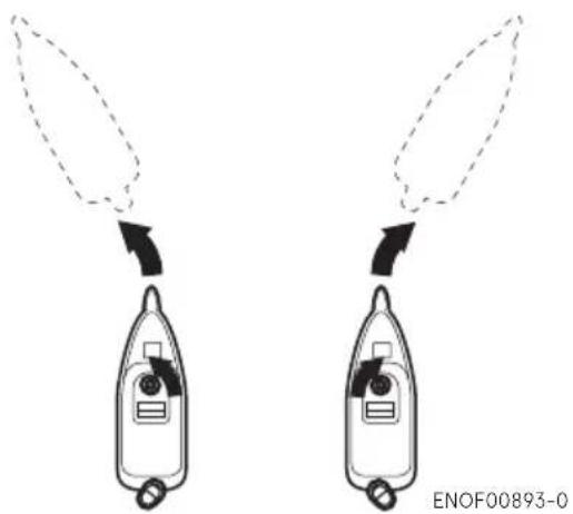
Diagram showing two identical rocket-like objects with directional arrows indicating motion or force (no text or symbols)Remote control type
Right turn
Turn the steering wheel to the right.
Left turn
Turn the steering wheel to the left.
natural_image
Diagram showing two identical devices with arrows indicating motion or force direction, no text or symbols present.ENOM00050-0
7. Trim angle
ENOW00043-1

WARNING
- Adjust the trim angle when the engine is stopped.
- Do not put hand or finger in between outboard motor body and clamp bracket when adjusting trim angle to prevent possible injury.
● Unsuitable trim position can cause loss of control of boat. When testing a trim position, run the boat slowly initially to see if it can be controlled safely.
ENOW00044-1

WARNING
Excessive trim up or down may cause unstable boat operation, loss of control that may leads to accident during cruising.
- For manual tilt model, If you feel the trim is improperly positioned, stop the boat and readjust trim angle before continuing to cruise.
- For outboard motor model with PT or PTT switch on the bottom cowl, do not operate the switch during while cruising, or control of boat may be lost.
The trim angle of the outboard motor can be adjusted to suit the transom angle of the hull, and load conditions. Choose an appropriate trim angle that will allow the anti-ventilation plate to run parallel to the water surface during operation.
ENOM00052-0
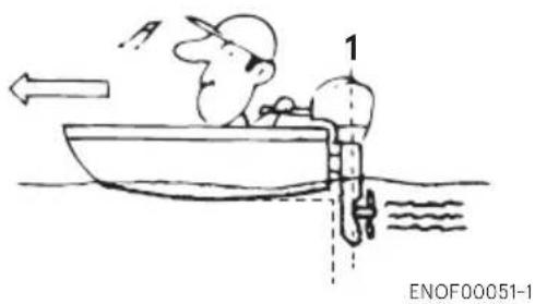
Proper trim angle
The position of the thrust rod is correct if the hull is horizontal during operation.
natural_image
Cartoon illustration of a person in a boat with a speedometer and directional arrows, no text or symbols present.- Perpendicular to the water surface
ENOM00053-0
Improper trim angle (bow rises too high)
Set the thrust rod lower if the bow of the boat rises above horizontal.

natural_image
Cartoon illustration of a man in a boat with an upward arrow, no text or symbols presentENOM00054-0
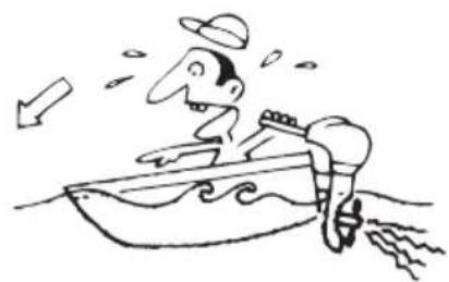
Improper trim angle (bow dips into the water)
Set the thrust rod higher if the bow of the boat is below horizontal.
natural_image
Cartoon illustration of a man in a boat with a hat and arrow, no text or symbols presentENOF00053-0
■ Manual Tilt type
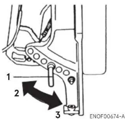
text_image
1 2 3 ENOF00674-A- Thrust rod
- Higher
- Lower
■ Power Tilt type
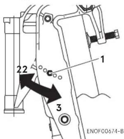
text_image
22 3 1 ENOF00674-B- Trim lock pin
- Higher
- Lower
Trim angle adjustment (Manual tilt type)
The transom angle adjustment
- Stop the engine.
- Shift into neutral position.
- Tilt up the outboard motor.
- Remove the thrust rod as shown picture.
- Reinstall the thrust rod in the desired position securely.
- Gentry tilt down the outboard motor.
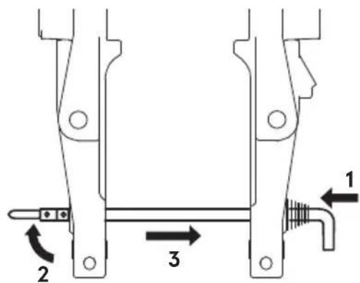
text_image
Technical diagram of a mechanical assembly with labeled parts 1, 2, and 3, showing structural components and directional arrows.ENOF01238-1
- Push in
- Rise the stopper
- Pull out
Trim angle adjustment (Power tilt type)
The transom angle adjustment
- Stop the engine.
- Shift into neutral position.
- Tilt up the outboard motor.
-
Lock the tilt stopper.
-
Change the trim lock pin position as shown in the picture.
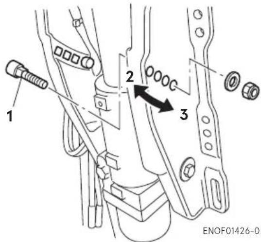
text_image
1 2 3 ENOF01426-0- Trim lock pin
- Higher
- Lower
- Reinstall the trim lock pin securely.
- Operate the Power Tilt switch and tilt down the outboard.
ENOM00060-B
8. Tilt up and down
ENOW00055-1

WARNING
Do not tilt the outboard motor up or down when swimmer(s) and/or passenger(s) are near to prevent them from being caught between outboard motor body and clamp bracket.
ENOW00048-1A

WARNING
When tilting up or down, be careful not to place your hand between the swivel bracket and the clamp bracket.

WARNING
When tilting up outboard motor with fuel joint for over a few minutes, be sure to disconnect fuel hose, or fuel may leak, potentially catching fire.
ENOW00057-1

CAUTION
Do not tilt up the outboard motor while engine is operating, or no cooling water may be discharged, leading to engine seizure due to overheating.
ENON00921-1
Note
After use, leave the outboard motor upright for a minute to drain the water from inside the engine.
ENOM00062-1B
Manual Tilt type
Tilt up
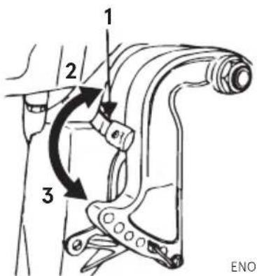
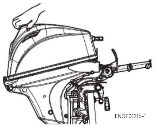
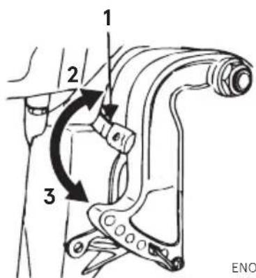
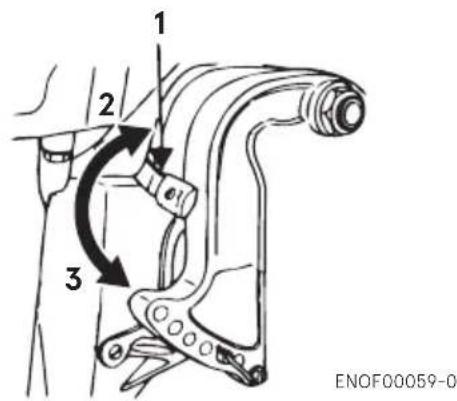
Push the reverse lock lever down until it stops. (This is the tilt up position.) Now, tilt the outboard motor all the way up until it is locked in place.
text_image
1 2 3 ENOENOF00059-0
- Reverse lock lever
- Tilt down position
- Tilt up position
natural_image
Technical line drawing of a mechanical device with a hand adjusting it (no text or symbols visible)ENOM00063-1
Tilt down
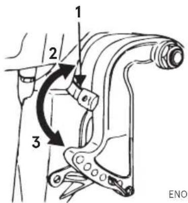
Pull the reverse lock lever upward until it comes to a stop (This is the tilt down position), lift up the outboard motor to free it from the reverse lock, then release to lower the outboard motor.
text_image
1 2 3 ENOENOF00059-0
- Reverse lock lever
- Tilt down position
- Tilt up position
ENOM00069-A
Power Tilt type
Tilt up
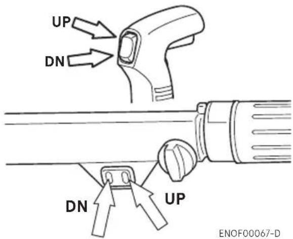
- Operate the Power Tilt switch and tilt the outboard motor up.
- Lock the tilt with the Tilt stopper after the outboard motor has been tilted up
Tilt down
- Release the tilt stopper from the setup position while slightly tilting up outboard motor.
- Operate the Power Tilt switch and tilt the outboard motor down until the motor touches to the thrust rod.
text_image
UP DN DN UP ENOF00067-D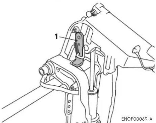
text_image
1 ENOF00069-A- Tilt stopper
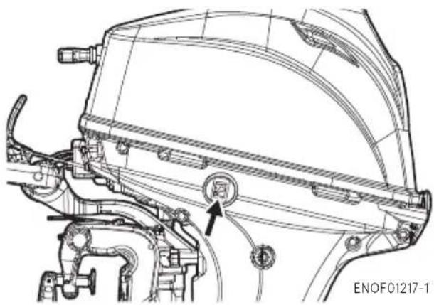
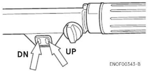
The outboard motor can also be tilted up and down using the switch provided on the bottom cowl.
natural_image
Technical line drawing of a mechanical assembly with no visible text or symbolsIt is possible to tilt up or down whether or not the main switch is "ON" or "OFF".
ENOM00940-1
Manual relief valve
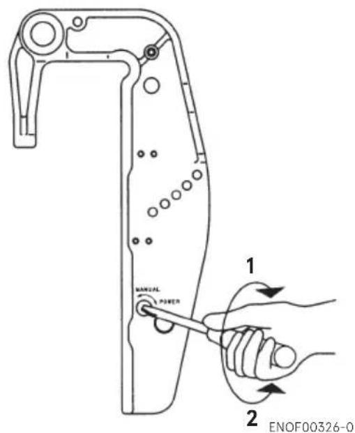
If the battery is dead, and/or the power tilt switch is inoperative open the manual valve completely in the Manual direction. This allows the outboard motor to be tilted manually.
ENOW00872-1

WARNING
Make sure the manual relief valve is closed before operating the outboard motor. If the manual relief valve is not closed, the outboard motor will be tilted up when shifting in reverse.
ENOW00873-1

WARNING
Before opening the manual relief valve, make sure nobody is under the outboard motor. If the outboard motor is in the tilted upposition with the manual relief valve loosend, the outboard motor will be tilted down suddenly.
text_image
MANUAL POWER 1 2 ENOF00326-0- Power
- Manual
Manual relief valve specified tightening torque
2 N·m (1.5 ft·lb, 0.2 kgf·m)
ENOM00068-A
9. Shallow water operation
ENOW00051-0

WARNING
During shallow water operation, be careful not to place your hand between the swivel bracket and the clamp bracket. Be sure to tilt the outboard motor down slowly.
ENOW00053-0

CAUTION
While in shallow water drive position, do not operate the outboard motor in Reverse. Operate the outboard motor at slow speed and keep the cooling water intake submerged.
ENOW00054-1A

CAUTION
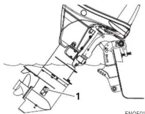
Do not over tilt the outboard motor when driving in shallow water, or air may be sucked through water inlet potentially leading to engine overheating.
natural_image
Technical line drawing of a mechanical component with labeled parts (no readable text or symbols)ENOF01144-A
- Water inlet
Manual tilt type
- Shallow water running position:
Put the reverse lock lever in the tilt up position, and tilt up the outboard motor to put the outboard motor in the shallow water running position.
text_image
1 2 3 ENOENOF00059-0
- Reverse lock lever
- Tilt down position
-
Tilt up position
-
Return to normal running position:
Put the reverse lock lever in the tilt down position, slightly lift up the outboard motor, and then put it down.
text_image
1 2 3 ENOF00059-0- Reverse lock lever
- Tilt down position
- Tilt up position
ENOM00069-A
Power Tilt type
- Operate the Power Tilt switch and tilt the outboard motor up into desired shallow water running position.
text_image
DN UP ENOF00343-B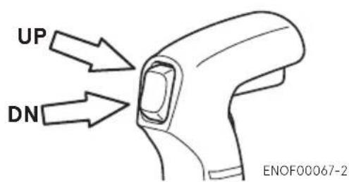
text_image
UP DN ENOF00067-2REMOVING AND CARRYING THE OUTBOARD MOTOR
ENOM00070-A
1. Removing the outboard motor
ENOW00006-1B

WARNING
To avoid personal injury or damage of equipment, make sure the allowable lifting capacity of the hoist is at least twice the weight of the outboard motor.
Do not allow the lift hook or chain from the hoist to come in contact with any part of the outbord motor during lifting..
ENOW00064-1

CAUTION
Engine may be hot immediately after operation and could cause burns if came in contact. Allow engine to cool down before attempting to carry the outboard.
- Stop the engine.
- Remove the top cowl.
- Disconnect the fuel connector, the remote control cables and the battery cords from the outboard motor.
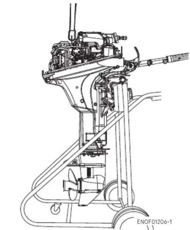
- Attach the hoist hooks to the engine hanger.
- Remove the outboard motor from boat and completely drain the water from the gear case.
natural_image
Technical line drawing of a mechanical device with no visible text or symbolsENOM00071-A
2. Carrying the outboard motor
ENOW00933-0

WARNING
Be sure to disconnect fuel connector except when operating engine.
Fuel leakage is a fire or explosion hazard, which can cause serious injury or death.
ENOW00065-1

WARNING
Close air vent screw on fuel tank before carrying or storing outboard motor and fuel tank, or fuel may leak, potentially catching fire.
ENOW00066-1

CAUTION
- Do not give a shock to an outboard motor during transportation.
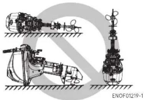
- Do not carry or store outboard motor in any of positions described below.
Otherwise, engine's exterior may be damaged or water may enter the cylinder through the exhaust port and cause engine problems.
natural_image
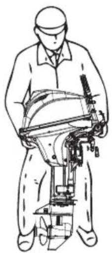
Technical line drawings of three mechanical or industrial components with no visible text or symbolsKeep the outboard motor in a vertical position when carrying.
The optional outboard motor stand is recommended for keeping the outboard motor vertical both during transport and storage.
natural_image
Line drawing of a person operating a manual tool or machine (no text or symbols present)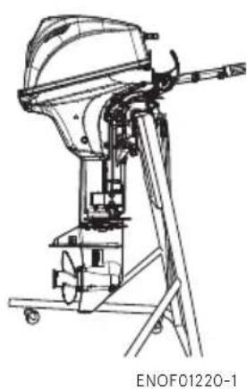
natural_image
Technical line drawing of a mechanical device with no visible text or symbolsENON00021-3
Note
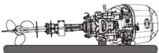
If the outboard motor must be laid down, be sure that fuel is completely drained, then lay the outboard motor with port side down on the cushion as shown in the drawing.
natural_image
Technical line drawing of a mechanical pump assembly (no text or labels)ENOF01221-1
ENOM00072-1A
3. Trailering
ENOW00072-0

CAUTION
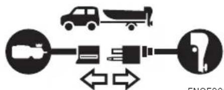
Trailering in the tilted position may cause damage to the outboard motor, boat, etc.
ENOW00073-A

WARNING
Be sure to disconnect fuel connector except when operating engine.
Fuel leakage is a fire or explosion hazard, which can cause serious injury or death.
flowchart
graph TD
    A["Truck"] --> B["Battery"]
    B --> C["Fue Pump"]
    C --> D["Valve"]
    D --> E["Arrow Left"]
    D --> F["Arrow Right"]
ENOF00075-1
ENOW00068-0

WARNING
Close air vent screw of fuel tank and fuel cock before carrying or storing outboard motor and fuel tank, or fuel may leak, potentially catching fire.
ENOW00071-0

CAUTION
The tilt support device supplied on your out-board motor is not intended for towing. It is
intended to support the outboard motor while the boat is docked, beached, etc.
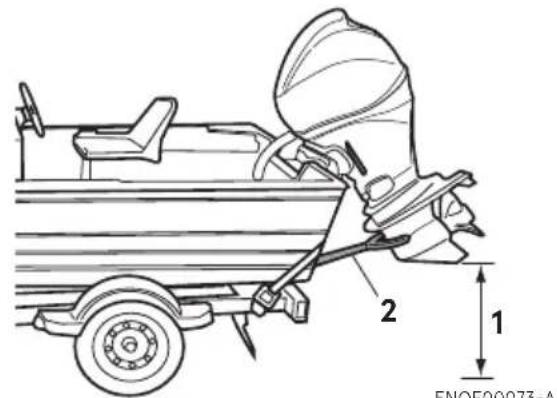
When transporting a boat on a trailer with the outboard motor attached, disconnect the fuel line from the outboard motor beforehand and keep the outboard motor in the vertical or on a trans-som saver bar.
Tiller handle type
While transporting outboard motor attached to the boat on a trailer, properly tighten the steering friction bolt to prevent the outboard motor from moving (page 53).
text_image
1 2 ENOF00073-A-
Ground clearance should be provided sufficiently.
-
Transom saver bar
ENOW00067-0

WARNING
Do not go under outboard motor tilted up even if it is supported by support bar, or accidental fall of outboard motor could lead to severe personal injury.
ADJUSTMENT
ENOM00073-0
1. Steering friction
Tiller handle type
ENOW00074-1

WARNING
Do not overtighten the steering friction lever, it could result in difficult handling of the outboard motor, resulting in the loss of control causing an accident and could lead to severe injury.
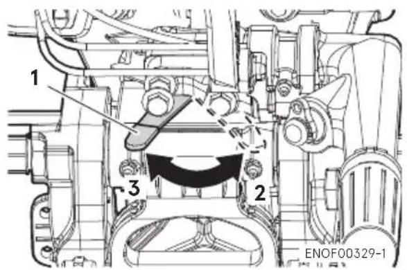
Adjust this lever to achieve the desired steering friction (drag) on the tiller handle. Move lever towards (2) to decrease friction and move lever towards (3) to increase friction.
text_image
1 2 3 ENOF00329-1- Steering friction lever
- Decrease
- Increase
ENOM00074-A
2. Throttle grip friction
ENOW00074-1B

WARNING
Do not overtighten the throttle adjustment screw or it could result in difficult handling of the outboard motor, resulting in the loss of control causing an accident and could lead to severe injury.
Friction adjustment of the throttle grip can be made with the throttle adjustment screw.
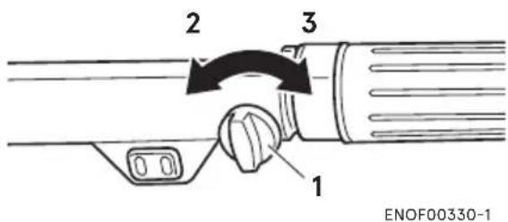
text_image
2 3 1 ENOF00330-1- Throttle friction adjustment screw
- Decrease
- Increase
ENOM00075-0
3. Remote control lever friction
ENOW00074-1C

WARNING
Do not overtighten the remote control throttle friction adjustment screw or it could result in difficult handling of the outboard motor, resulting in the loss of control causing an accident and could lead to severe injury.
To adjust the friction of the remote control lever, turn the throttle friction adjustment screw on the front of the remote control. Turn clockwise to increase the friction and counter-clockwise to decrease it.
Side mount type
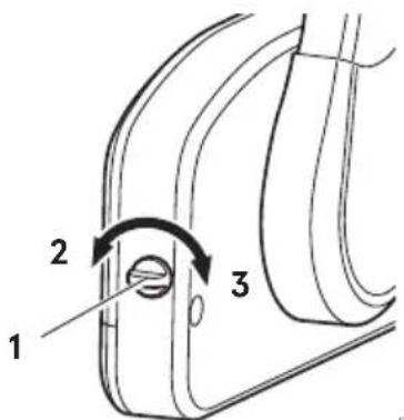
text_image
1 2 3ENOF00078-2
- Throttle friction adjustment screw
- Decrease
- Increase
INSPECTION AND MAINTENANCE
ENOM00077-1
Care of your outboard motor
To keep your outboard motor in the best operating condition, it is very important that you perform daily and periodic maintenance as suggested in the maintenance schedules as follows.
ENOW00077-1

CAUTION
- Your personal safety and that of your passengers depends on how well you maintain your outboard motor. Carefully read all of the inspection and maintenance procedures described in this section.
- The maintenance intervals shown in the checklist apply to an outboard motor in normal use. If you use your outboard motor under severe conditions such as frequent full-throttle operation, frequent operation in brackish water, or for commercial use, maintenance should be performed at shorter intervals. If in doubt, consult your dealer for advice.
- We strongly recommend that you use only genuine replacement parts on your outboard motor. Damage to your outboard motor arising from the use of other than genuine parts is not covered under the warranty.
ENOM00322-1
1. Daily Inspection
Perform the following checks before and after use.
ENOW00078-1

WARNING
Do not use outboard motor if any abnormality is found during pre-operation check otherwise it could result in severe damage to the motor or severe personal injury.
| Item Points to Check Remedy | ||
| Fuel System | ·Check the amount of fuel in the tank. Replenish·Check for debris or water in the fuel filters. Clean or replace if·Check the rubber hoses for fuel leakage. Replace if necessary | necessary |
| Fuel Tank Cap | ·Check for crack, leakage, damage in the fuel tank cap. Replace·Check for crack, damage in the gasket. Replace if necessary·Check for leakage at full close. | if necessaryReplace if necessary |
| Engine Oil | ·Check the oil level. | Fill oil |
| Electrical Equipment | ·Check that the main switch functions normally.·Check that the battery electrolyte level and specific gravity are normal.·Check for loose connections on the battery terminal.·Check that the stop switch functions normally and make sure the stop switch lock is secured.·Check cords for loose connections and damage.·Check the spark plugs for dirt, wear and carbon build-up.·Check the warning LED lamp (ON for 5 to 7 secs.) when start up. | Replace if necessaryReplenish or rechargeRetightenRemedy or replace if necessaryCorrect or replace if necessaryClean or replace if necessaryRepair |
| Recoil starter | ·Check the rope for wear and chafing.·Check the ratchet engagement. | Replace if necessaryReplace if necessary |
| Clutch and Propeller System | ·Check that clutch engages correctly when operating the shift lever.·Visually Check propeller for bent or damaged blades.·Check the propeller nut is tightened and the split pin is in correct position. | AdjustReplace if necessaryTighten or replace |
| Installation of Motor | ·Check all the bolts attaching the motor to the boat.·Check the thrust rod installation. | TightenReplace if necessary |
| Power Tilt | ·Check working of the tilt up and down of the motor. | Repair |
| Cooling Water | ·After starting the outboard motor, make sure that water is being discharged from the cooling water check port. | Repair |
| Tools and Spares | ·Check that there are tools and spare parts for replacing spark plugs, the propeller, etc.·Check that you have the spare rope and stop switch lock. | OrderOrder |
| Item Points | to Check | Remedy | |
| Steering Devices | · Make sure that steering handle and remote control is functioning normally. | Repair | |
| Other parts | · Check if the anode is securely installed. Repair if necessary · Check the anode for corrosion and deformation. Replace | ||
ENOM00081-D
Oil level checking
If the oil level is low, or too high, the life of the engine will be shortened significantly.
- Place the engine in a vertical position.
- Remove the top cowl.
- Remove the dipstick.
- Wipe oil off the dipstick with a clean cloth.
- Insert the dipstick to the hole completely.
-
Remove the dipstick again. Check the oil level on the dipstick. Oil level must be between the upper limit and lower limit shown on the dipstick.
-
Return the dipstick.
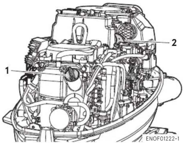
text_image
1 2 ENOF01222-1- Filler cap
- Dipstick
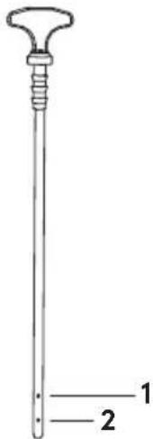
text_image
1 2ENOF01240-0
- Upper limit
- Lower limit
ENON00024-0
Note
The oil level should be checked when the engine is cooled.
ENON00025-0
Note
Consult with an authorized dealer if the engine oil is milky color, or appears contaminated.
ENOM00082-A
Engine oil replenishing
ENOW00079-A

CAUTION
- Do not add engine oil of brand and grade other than existing one. In case engine oil of other brand or grade is added, drain all oil and ask dealer for treatment.
-
In case other than engine oil such as gasoline is put in the oil chamber, empty the chamber and ask dealer for treatment.
-
When replenishing engine oil, be careful not to allow entry of foreign matters such as dust and water into oil chamber.
- Wipe off engine oil well spilled and dispose of it in accordance with local fire prevention and environment protection regulations.
- Do not replenish engine oil over upper limit. If overfilled, remove oil to upper limit. If engine oil is over the upper limit, it can leak potentially leading to engine damage.
If the oil level is low, or at lowest mark, add recommended oil to the middle dipstick mark.
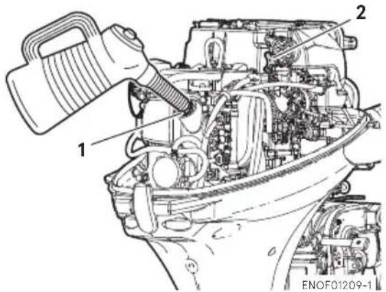
text_image
1 2 ENOF01209-1- Filler port
- Dipstick
ENOM00083-B
Washing outboard motor
ENOW00081-1

WARNING
Do not start engine without removing propeller, turning propeller out in the open may lead to personal injury.
ENOW00082-0

WARNING
Never start or operate the engine indoors or in any space which is not well ventilated. Exhaust gas contains carbon monoxide, a
colorless and odorless gas which can be fatal if inhaled for any length of time.
mediately if

CAUTION
When washing the outboard motor, be careful not to spray the water inside of the top cowl, especially electrical components.
ENON00026-0
Note
It is recommended to check chemical properties of water on which your outboard motor is regularly used.
If outboard motor is used in salt water, brackish water or water with high acidic level, use fresh water to remove salt, chemicals or mud. And flush cooling water passage after every use or before storing outboard motor for long time. Before flushing, remove the propeller and the forward thrust holder.
ENOM00085-E
Flushing hose joint
ENOW00921-0

CAUTION
Do not operate the engine when flushing the outboard motor with a hose joint as this can cause damage to the outboard motor.
ENOW00922-0

CAUTION
To prevent the engine from starting when you are near the propeller, remove the stop switch lock.
-
Tilt down the outboard motor.
-
Remove the flushing connector cap from the outboard motor, and screw in the hose joint.
- Connect a water hose. Turn on the water and adjust the flow.
Continue flushing the outboard motor for 3 to 5 minutes
- After the flushing, be sure to reattach the flushing connector cap.
- Tilt up the outboard motor.
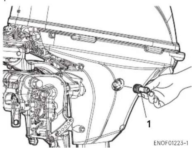
text_image
ENOF01223-1- Hose joint
ENOM00085-A
Flushing by test tank
ENOW00081-1

WARNING
Do not start engine without removing propeller, turning propeller out in the open may lead to personal injury.
ENOW00082-0

WARNING
Never start or operate the engine indoors or in any space which is not well ventilated. Exhaust gas contains carbon monoxide, a colorless and odorless gas which can be fatal if inhaled for any length of time.
ENOW00036-1A

CAUTION
When starting the outboard motor in the test tank, make sure that:
- Water level is at least 10 cm (4 in.) above the anti-ventilation plate to avoid overheating of the engine.
- Run at idling only
- Remove the propeller (See page 68)
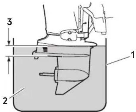
text_image
Technical diagram of a mechanical device with labeled parts and directional arrows indicating motion or flow.ENOF00863-0
- Test tank
- Water
- Over 10 cm (4 in.)
ENOM00950-1
Fuse replacement
ENOW00923-1

CAUTION
Before replacing a fuse, disconnect the battery cable from the battery negative (-) terminal first. Failure to properly remove battery cables may cause a short-circuit.
ENOW00924-0

CAUTION
Never use a fuse with a rating that exceeds the specified rating as this could cause serious damage to the electrical system.
If the fuse has blown, try to determine
the cause and respond to the problem as simply replacing the fuse will likely blown again. If you are unable to respond to the cause or the fuse continues to blow, request an authorized Tohatsu dealer for inspection.
- Stop the engine and disconnect the battery cable from the battery negative (-) terminal.
- Remove the engine cover.
- Remove the fuse box lid.
- Remove the fuse and check it. If the fuse is blown, replace it with a fuse of the same specified rating. The outboard motor is supplied with spare fuses in the spare fuse holder.
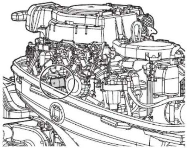
natural_image
Technical line drawing of a mechanical engine assembly (no text or labels)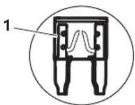
text_image
1ENOF01224-1
- Blown fuse
ENOM01106-1
2. Periodic Inspection
It is important to inspect and maintain your outboard motor regularly. Make sure to perform each service at interval specified in the chart below. Maintenance intervals are determined by the number of hours outboard motor has been used or number of months, whichever comes first.
*1"●" This procedure can be performed by end user (or dealer)
*2"o" This procedure shall be carried out by the dealer.
| Description | Inspection intervals | Inspection procedure Remarks | ||||||
| First 20 hours or 1 month | Every 50 hours or 3 months | Every 100 hours or 6 months | Every 200 hours or 1 year | Every 400 hours or 2 year | ||||
| Fuel System | Fuel filter | ●/○ | Check and clean/Replace if necessary | Refer to P65 | ||||
| High pressure fuel hose*1 | ●/○ | ●/○ | Check/Replace if necessary | |||||
| Fuel filter (Vapor separator)*1 | ○ Check, clean or replace if necessary | |||||||
| Fuel tank | ●/○ | ●/○ | Check and clean | |||||
| Fuel tank cap | ●/○ | ●/○ | Check /Replace if necessary | |||||
| Fuel pump*1 | ○ | Check /Replace if necessary | ||||||
| Fuel pressure*1 O Check | ||||||||
| Hose*2 | ●/○ | ●/○ | Check /Replace if necessary | |||||
| Ignition System | Spark plug | ● | Check and clean/Replace if necessary | Gap (0.80-0.9mm) Refer to P69 | ||||
| Spark plug cap /High tension cord*1 | ○ | ○ | Check /Replace if necessary | |||||
| Starting System | Starter rope*2 | ●/○ | ●/○ | Check /Replace if necessary | ||||
| Starter motor*1 | ○ Check | |||||||
| Battery /Cable connection*1 | ○ | ○ | Check | |||||
| Engine | Engine oil | ● Replace | ● Replace | Replace | Approx.1.0L Oil filter replace 1.2L Refer to P62 | |||
| Oil filter (4 stroke)*1 | ○ Replace | Replace (Every 200 hours or 2 years) | ||||||
| Valve clearance*1 | ○ | Check and adjustment | IN: 0.13-0.17mm EX: 0.18-0.22mm | |||||
| Timing belt*1 | ○ | Check and replace if necessary | ||||||
| Idling speed*1 | ●/○ | ●/○ | Check | |||||
| Compression pressure*1 | ○ Check | |||||||
| Combustion chamber*1 | ○ Check | |||||||
| Thermostat*1 | ○ Check | |||||||
| Lower Unit | Propeller | ● | ● | Check and replace if necessary | Refer to P68 | |||
| Shear pin/Split pin | ● | ● | Check and replace if necessary | Refer to P68 | ||||
| Gear oil | ● Replace | ● | ● Replace | Check and replace | Approx. 465mL Refer to P67 | |||
| Water strainer | ● | ● | Check | |||||
| Water pump impeller*2 | ●/○ | ○ Replace | Check/Replace if necessary | |||||
| Water pump housing*1 | ○ Check and replace if necessary | |||||||
| Description | Inspection intervals | Inspection procedure | Remarks | |||||
| First 20 hours or 1 month | Every 50 hours or 3 months | Every 100 hours or 6 months | Every 200 hours or 1 year | Every 400 hours or 2 year | ||||
| Shift/ Throttle | Throttle cable O Check and replace if necessary | |||||||
| Throttle link*1 O O Check and adjustment | ||||||||
| Shift cable O Check and replace if necessary | ||||||||
| Shift link*1 O O Check and adjustment | ||||||||
| Other | Power trim & Tilt | ●/○ | ●/○ | Check /Replenish | Refer to P72 | |||
| Warning system*1 | ○ Check | |||||||
| Stop switch | ● | ● | Check | |||||
| Meters | ○ ○ Check | |||||||
| Bolt, nut | ○ ○ Retighten | |||||||
| Sliding part /rotation part | ● | ● | Apply grease | Refer to P73 | ||||
| Grease nipple | ● | ● | Pump in grease | Refer to P73 | ||||
| Outer equipment | ● | ● | Check | |||||
| Anode (engine) | ○ | Check and replace if necessary | Refer to P71 | |||||
| Anode (except for engine) | ●/○ | Check /Replace if necessary | Refer to P71 | |||||
| Top cowl/Latch | ●/○ | Check / Adjustment | ||||||
ENON00030-1
Note
It is highly recommended that your outboard motor to go through complete inspection at 300 hours of use.
ENOM00091-A
Engine oil replacement
Engine oil mixed with dust or water will dramatically shorten the life of the engine.
ENOW00091-1

CAUTION
You may be injured due to high engine temperatures if you fill engine oil just after operation. Engine oil should be changed after the engine has been cooled.
ENOW00092-1

CAUTION
- Do not overfill engine oil, or
could leak and/or engine could be damaged. If engine oil level is over upper limit marks of dip stick, drain oil to level lower than upper limit.
- Be sure that outboard motor is upright when checking or changing oil.
- Stop the engine immediately if low oil pressure warning lamp or oil leak is found, or engine could be severely damaged. Consult your dealer.
- Wipe off engine oil well immediately if spilled and dispose of it in accordance with local fire prevention and environment protection regulations.
ENOW00090-0

CAUTION
Use of engine oils that does not meet these requirements will result in reducing engine life, and other engine problems.
engine oil
ENOW00933-0

CAUTION
Engine oil mixed with dust or water will dramatically shorten the life of the engine.
To change engine oil:
Be sure to use recommended engine oil.
- Stop the engine and cool down.
- Tilt up the outboard motor and lock the tilt with the tilt stopper.
- Turn the steering on the outboard motor so that the drain hole is facing downward.
- Put an oil drain pan under the oil drain screw.
- Remove the oil drain screw and completely drain oil from the engine.
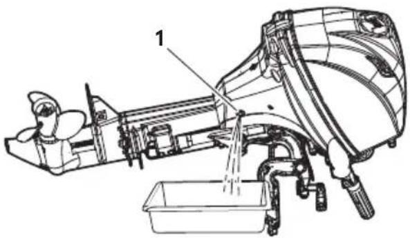
text_image
Technical diagram of a boat's internal structure with labeled component '1'ENOF01225-1
- Drain hole
- Tighten the oil drain screw with applying oil on the sealing surface of screw. (Use new oil drain washer)
Oil drain screw specified torque
24N·m (17 ft·lb, 2.4 kgf·m)
ENON00028-A
Note
If a torque-wrench is not available when you are fitting a oil filter, a good estimate of the correct torque is 3/4 to 1 a turn past finger-tight. Have the oil filter adjusted to
the correct torque as soon as possible with a torque-wrench.
- Reset the engine in a vertical position.
- Repeat 2 to 7 procedures two or three times to drain the trapped oil completely.
- Remove the top cowl and the oil filler cap.
- Fill the engine through filler port with recommended oil to the middle of dipstick mark.
- Tighten the oil filler cap.
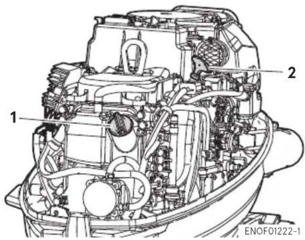
text_image
1 2 ENOF01222-1- Filler cap
- Dipstick
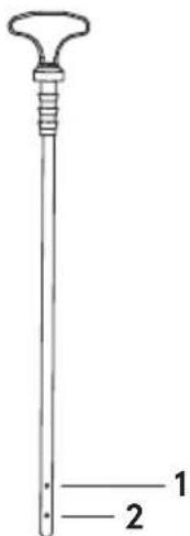
text_image
1 2ENOF01240-0
-
Upper limit (Max.)
-
Lower limit (Min.)
ENON00920-0
Note
Use only recommended engine oil (See page 28)
| Oil volume needed for complete oil replacement | |
| With oil filter replacement | Without oil filter replacement |
| Approximately 1200 mL (40.6 fl.oz.) | Approximately 1000 mL (33.8 fl.oz.) |
ENOW00925-0
CAUTION
Wipe off engine oil well immediately if spilled and dispose of it in accordance with local fire prevention and environment protection regulations.
ENON00031-0
Note
- If any amount of water is found in engine oil, making it milky white, consult dealer.
- If engine oil is contaminated with fuel, emitting strong fuel smell, consult dealer.
- Some oil dilution is normal if engine is idled or trolled for long periods, especially in cooler water temperatures.
ENOM00092-A
Oil filter replacement
ENOW00091-1
CAUTION
You may be injured due to high engine temperatures if you fill engine oil just after operation. Engine oil should be changed after the engine has been cooled.
ENOW00926-0
CAUTION
Wipe off engine oil well immediately if spilled and dispose of it in accordance with local fire prevention and environment protection regulations.
- Drain oil from the engine.
- Place a rag or towel below the oil filter to absorb any spilled oil.
- Unscrew old filter by turning the filter to counter-clockwise.
- Clean the mounting base. Apply film of clean oil to O-ring.
Do not use grease.
Install oil filter and tighten it to specified torque by using oil filter wrench.
Oil filter torque:
18 N·m (13 ft·lb, 1.8 kgf·m)
ENON00028-A
Note
If a torque-wrench is not available when you are fitting a oil filter, a good estimate of the correct torque is 3/4 to 1 a turn past finger-tight. Have the oil filter adjusted to the correct torque as soon as possible with a torque-wrench.
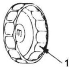
natural_image
Technical line drawing of a mechanical component with no visible text or symbolsENOF00094-0
- Oil filter wrench P/N 3AC-99090-0 P/N 3AC99090M (US. CANADA Only)
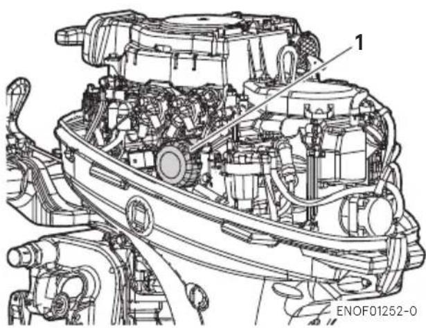
text_image
1 ENOF01252-0- Oil filter
ENOM00093-A
Fuel filters and fuel tank cleaning
ENOW00093-1

WARNING
Gasoline and its vapor is very flammable and can be explosive.
- Do not start this procedure while engine is operating or while engine is hot.
- Place fuel filter away from every source of ignition such as sparks or open flames.
- If gasoline is spilled, wipe up immediately and dispose according to the local regulations.
● Install fuel filter with all related parts in place, or fuel leak could occur, leading to catching fire or explosion. - Check fuel system regularly for leakage.
- Contact authorized dealer for fuel system services. Services by unqualified person could lead to engine damage.
Fuel filters are provided inside the fuel tank and engine.
ENOM00094-0
Fuel filter (for engine)
- Check the cup for water and debris.
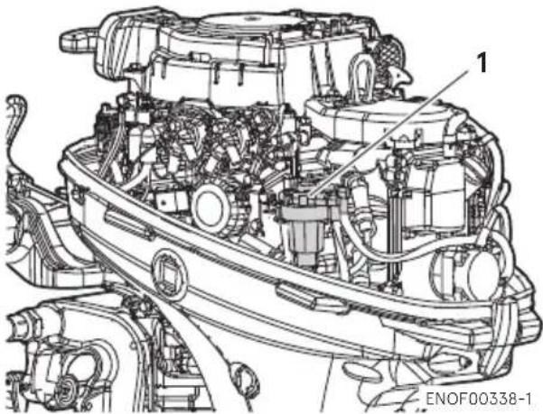
text_image
1 ENOF00338-1- Fuel filter
In case of water entry
- Prepare a container under the outlet of the fuel filter.
- Loosen the drain screw of the fuel filter.
- Squeeze the primer bulb several times. After the water is drained, stop squeezing.
- Tighten the drain screw securely and confirm there is no fuel leaking.
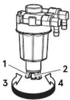
text_image
1 2 3 4ENOF01242-1
- Drain screw
- Drain port
- Loosen
- Tighten
In case of debris
- If present, disconnect hoses from the fuel connector (male) and the fuel pump.
- Remove the cup, filter and O-rings from the fuel filter body.
- Check the wear and clogging for each parts, and replace if necessary.
- Remove fuel and any water or debris from the cup, filter and hoses.
- Reassemble all parts.
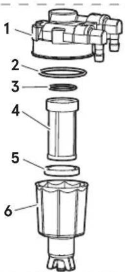
text_image
Exploded view diagram of a mechanical device with numbered parts for identification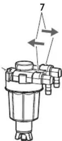
text_image
7ENOF01243-0
- Body
-
O-ring
-
O-ring
- Filter
- Float
- Cup
- Indicate of Fuel Flow
ENOM00096-A
Fuel filter (for fuel tank)
Water or dirt in the fuel tank will cause engine performance problems.
Check and clean the tank at specified times or after the outboard motor has been stored for a long period of time (over three months).
- Remove the fuel pickup elbow of the fuel tank by turning it counterclockwise
- Clean the fuel filter and check the O-ring. Replace it if necessary.
- Reassemble all parts.
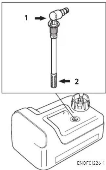
text_image
1 2 ENOF01226-1- Fuel pick up
- Filter
ENOM00098-A
Gear oil replacement
ENOW00076-1

WARNING
- Be sure that the outboard motor is secured to transom or service stand, or accidental drop or fall of outboard motor could lead to severe personal injury.
- Be sure to lock the outboard motor in the tilt up position, or accidental fall of outboard motor could lead to severe personal injury.
-
Do not go under outboard motor in the tilt up position and locked, or accidental fall of outboard motor could lead to severe personal injury.
-
Tilt down the outboard motor.
- Remove the oil plugs (lower and upper), and completely drain the gear oil into a pan.
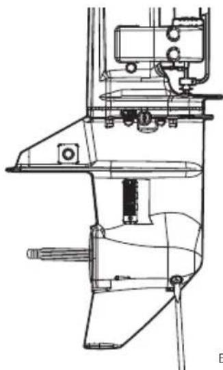
natural_image
Technical line drawing of a mechanical device with no visible text or symbolsENOF01244-0
- Insert the oil tube nozzle into the lower oil plug hole, and fill with gear oil by squeezing the oil tube until oil flows out of the upper plug hole and bubbles is disappeared to remove the air.
ENON00033-1
Note
Use genuine gear oil or the recommended one (API GL-5: SAE #80 to #90).
Required volume: approx. 465 mL (15.7 fl.oz.).
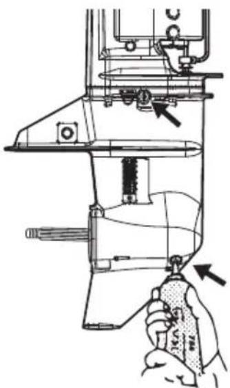
natural_image
Technical line drawing of a sewing machine with a hand operating the base (no text or symbols present)ENOF01245-0
- Install the upper oil plug, and then remove oil tube nozzle and install the lower oil plug.
Oil plug specified tightening torque 4N·m (3 ft·lb, 0.4 kgf·m)
ENOW00095-0

CAUTION
Do not reuse oil plug gasket. Always use new gasket and tighten oil plug properly to prevent entry of water into lower unit.
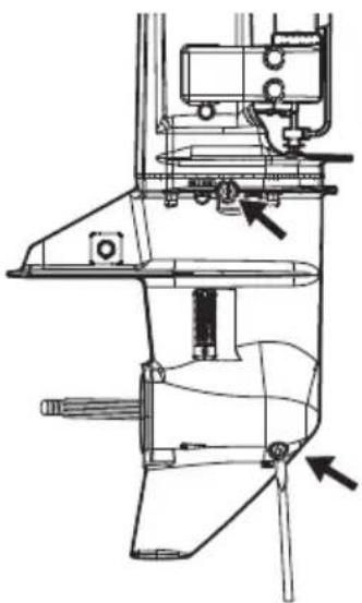
natural_image
Technical line drawing of a mechanical device with no visible text or symbolsENOF01246-0
ENOW00928-1

CAUTION
If gear oil is spilled, wipe off immediately and dispose according to the local regulations.
ENON00032-1
Note
If the gear oil color appears to be milky color, contact your dealer.
ENOM00086-A
Propeller replacement
ENOW00084-1

WARNING
- Do not installation procedure install or remove propeller on the outboard motor with spark plug caps attached, shift in forward or reverse, main switch at other than "OFF", engine stop switch lock attached to the switch, and starter key attached, or engine could accidentally start leading to serious personal injury. Disconnecting battery cable is recommended.
- The propeller edge is thin and sharp. Wear the gloves while installing or removing to protect your hands.
ENOW00086-1

CAUTION
- Do not install propeller without thrust holder, or propeller boss could be damaged.
- Do not reuse split pin.
● After installing split pin, spread bend both end of the pin apart to lock propeller in place.
A worn-out or bent propeller will lower the motor's performance, and cause engine trouble.
- Put a piece of wood block between propeller blade and anti-ventilation plate to hold propeller.
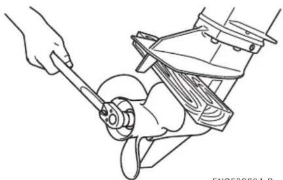
natural_image
Line drawing of a hand using a wrench to adjust the engine compartment (no text or symbols present)ENOF00084-B
- Remove the split pin, propeller nut and washer.
- Remove the propeller and thrust holder.
- Apply waterproof grease to the propeller shaft before installing a new propeller.
- Install the thrust holder, propeller, stopper, washer and propeller nut onto the shaft.
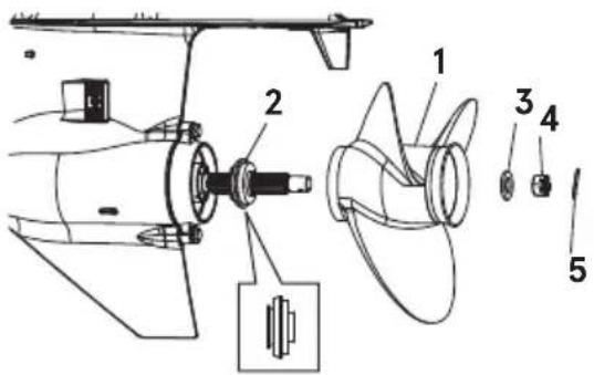
text_image
Technical diagram of a ship's internal components with numbered parts labeled 1 to 5ENOF00084-C
- Propeller
- Thrust holder
- Washer
- Propeller nut
-
Split pin
-
Tighten the propeller nut to specified torque and align one of the grooves with to propeller shaft hole.
Propeller nut torque:
12 N·m (9 ft·lb, 1.2kgf·m)
- Install a new split pin into the nut hole and bend both ends of pin apart to lock propeller in place.
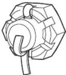
natural_image
Technical line drawing of a mechanical component with no visible text or symbolsENOF00084-E
ENOW00086-0

CAUTION
- Do not install propeller without thrust holder, or propeller boss could be damaged.
- Do not reuse split pin.
- After installing split pin, spread the pin apart to prevent it from falling out which could lead to the propeller coming off during operation.
ENOM00087-A
Spark plugs replacement
ENOW00087-1

WARNING
- Do not reuse spark plug, if the insulation is damaged or sparks can leak through crack, potentially leading to electric shock, explosion and/or fire.
- Do not touch spark plug(s) immediately after stopping engine as they will be hot and could cause severe burns if touched.
ENOW00929-0

CAUTION
Use only the recommended spark plugs. Spark plugs which have an different heat range may cause engine damage.
If the spark plug(s) is fouled, has carbon build up, or is worn, it should be replaced.
When reusing spark plugs, remove dirt from the electrodes and check the spark plug gap.
- Stop the engine.
- Remove the top cowl.
- Remove the spark plug caps.
- Remove the spark plugs by turning it counter-clockwise, using a 5/8" (16 mm) socket wrench and handle that are provided in the tool bag.
-
Inspect the spark plug. Replace the spark plug with wear on electrodes and if the insulators are cracked or chipped.
-
Measure the spark plug gap with a wire type feeler gauge. The gap should be 0.8-0.9 mm (0.031-0.035 inches). If the gap is out of specification, replace the spark plug with a new one
Use spark plug NGK DCPR-6E.
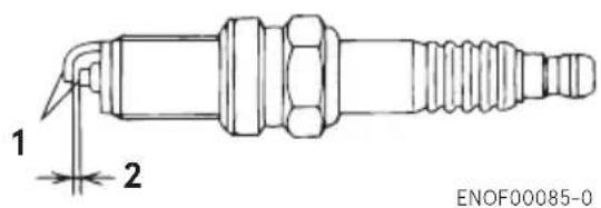
text_image
1 2 ENOF00085-0- Electrode
-
Spark gap (0.8–0.9 mm, 0.031–0.035 in)
-
Install the spark plug by hand and turn it carefully to avoid cross-threading.
-
Tighten the spark plug to the specified torque.
ENON00028-1
Note
- Spark plug tightening torque: 18.0 N·m (13.3 ft·lb) [1.84 kgf·m]
If a torque-wrench is not available when you are installing a spark plug, tighten it 1/4 to 1/2 a turn past finger-tight. Have the spark plug adjusted to the correct torque as soon as possible with a torque-wrench.
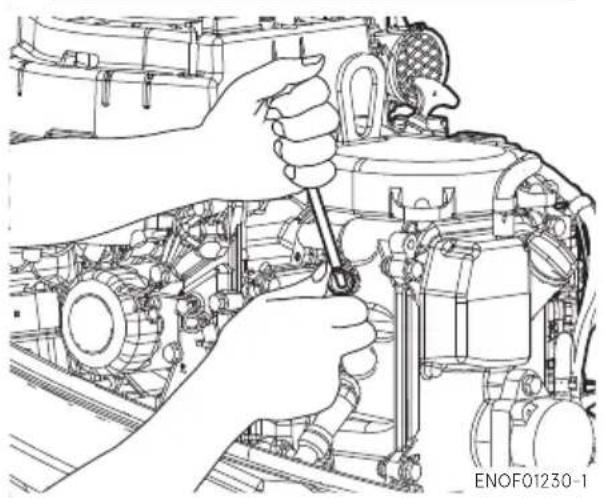
natural_image
Technical line drawing of a mechanical assembly with hands operating a tool on a vehicle engine (no text or symbols visible)ENOM00088-1A
Anode replacement
A sacrificial anode protects the outboard motor from galvanic corrosion. Anode is located on the gear case, cylinder etc.. When the anode is eroded more than 1/3 of original size, replace it.
ENON00029-1
Notes
● Never grease or paint the anode.
- At each inspection, re-tighten all the anode attaching bolts. Those bolts may loosen if the anodes are corroded.
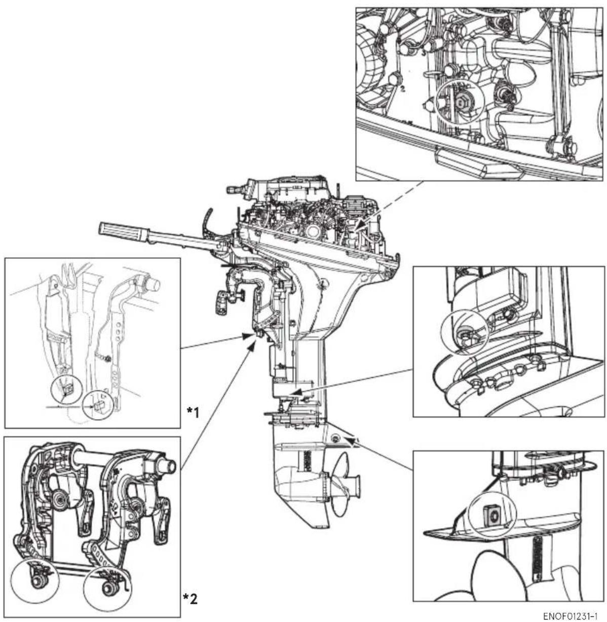
text_image
Technical diagram of a mechanical engine with labeled components and close-ups, including parts numbered 1 and 2.*1: PT model
*2 : Manual tilt model
ENOM00089-B
Power Tilt oil checking
ENOW00088-0

WARNING
- Be sure that outboard motor is secured to transom or service stand, or accidental drop or fall of outboard motor could lead to severe personal injury.
- Be sure to lock outboard mo tilted up, or accidental fall of outboard motor could lead to severe personal injury.
- Do not go under outboard motor tilted up and locked, or accidental fall of outboard motor could lead to severe personal injury.
ENOW00089-A

CAUTION
Do not unscrew the oil cap with the outboard motor tilted down. Pressurized oil in the oil tank may spurt out.
Check the oil level in the reservoir tank while the tank is kept in a vertical position.
- Tilt the outboard motor up and lock the tilt with the tilt stopper.
- Remove the oil cap by turning counter-clockwise, then check if the oil level reaches the bottom line of the plug hole.
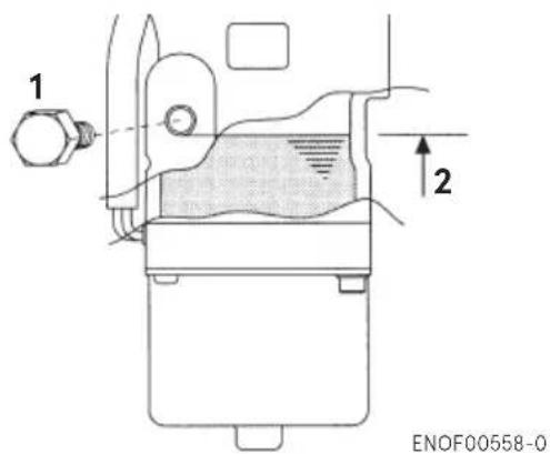
text_image
1 2 ENOF00558-0- Oil cap
- Oil level
Recommended oil
Use automatic transmission fluid or equivalent.
Recommended oil is as shown below.
ATF Dexron III
Air purgting from the Power Trim and Tilt unit.
Trapped air in the Power Tilt unit will cause poor tilting movement and noise.
- With the outboard motor installed on the boat, set the manual release valve to the Manual side, and tilt the outboard motor up/down manually 5-6 times.
- When done, close the valve by turning it clockwise.
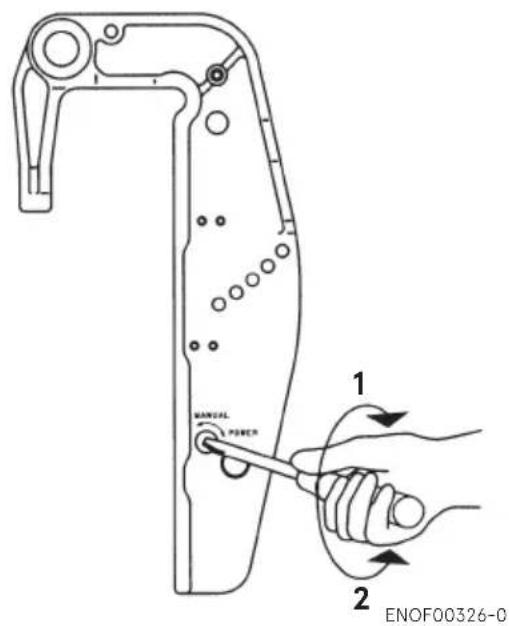
text_image
1 MANUAL POWER 2 ENOF00326-0- POWER
- MANUAL
Manual relief valve specified tightening torque
2 N·m (1.5 ft·lb, 0.2 kgf·m)
ENOM00960-0
Grease point
Apply waterproof grease to the parts shown below.
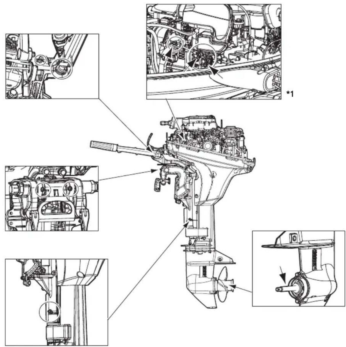
text_image
Technical diagram of an engine with labeled mechanical components and close-ups of internal parts, including a component marked *1.ENOF01232-1
*1: Other side.
ENOM00100-A
3. Off-season storage
ENOW00934-0

WARNING
- Be sure to disconnect except when operating engine.
- Fuel leakage is a fire or explosion hazard, which can cause serious injury or death.
ENOW00097-0

WARNING
Be sure to use cloth to remove fuel remaining in the cowl and dispose of it in accordance with local fire prevention and environment protection regulations.
ENOW00096-0

CAUTION
Before servicing the motor for storage:
- Remove the battery cables.
- Remove the spark plug caps from the spark plugs.
- Do not run the motor out of the water.
Before you put your outboard motor in storage, it is a good opportunity to have it serviced by your dealer.
Be sure to use fuel stabilizer while running the motor before storage. (See page 75)
- Drain all fuel from the fuel hoses, fuel pump, fuel filter (See 65) and vapor separator (See 75), and clean these parts.
Keep in mind that if gasoline is kept in the vapor separator for a long time, fuel connector gum and varnish will be developed, causing the float valve to stick, restricting the fuel flow.
- Remove the spark plugs and put a teaspoon of engine oil or spray storage oil into the combustion chamber through the spark plug holes.
- Turn the starter motor several times to lubricate inside the cylinder. Remove the fuel hose from the outboard motor.
ENOW00930-1

WARNING
- Be sure to remove stop switch lock to prevent the spark plugs from igniting.
-
Put a cloth to spark plug hole and wipe up any spilled engine oil, when cranking the outboard motor.
-
Change the engine oil (See page 62).
- Change the gear oil in the gear case (See page 67).
- Apply grease to grease point (See page 73).
ENOM00101-1A
Engine
-
Wash the engine exterior and flush the cooling water system thoroughly with fresh water. Drain the water completely.
Wipe off water with a cloth. -
Remove the fuel hose from the outboard motor.
-
Place the outboard motor in the vertical position under a dry condition.
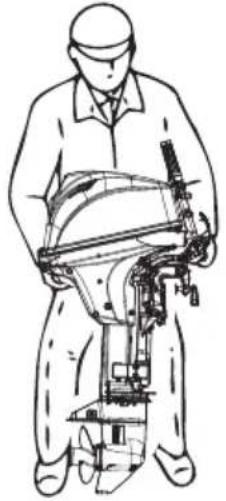
natural_image
Line drawing of a person operating a mechanical device (no text or symbols present)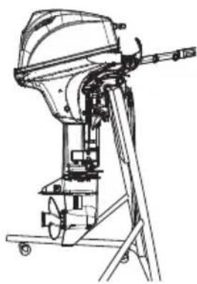
natural_image
Technical line drawing of a mechanical device with no visible text or symbolsENOF01220-1
ENOW00066-1

CAUTION
- Do not give a shock to an outboard motor during transportation. - Do not carry or store outboard motor in any of positions described below.
Otherwise, engine's exterior may be damaged or water may enter the cylinder through the exhaust port and cause engine problems.
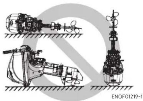
natural_image
Technical line drawings of three mechanical components (no text or symbols visible)ENON00021-3
Note
If the outboard motor must be laid down, be sure that fuel is completely drained, then lay the outboard motor with port side down on the cushion as shown in the drawing.
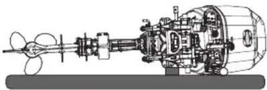
natural_image
Technical line drawing of a mechanical pump assembly (no text or labels)ENOF01221-1
ENOM00950-0
Adding a fuel stabilizer
When adding a fuel stabilizer additive (commercially available), first fill the fuel tank with fresh fuel. If the fuel tank is only partially filled, air in the tank can cause the fuel to deteriorate during storage.
-
Before adding fuel stabilizer additive, drain the vapor separator (See page 75).
-
Follow the instructions on the label when adding the fuel stabilizer additive.
-
After adding the additive, let the outboard motor run in the water for 10 minutes to make sure any old fuel in the fuel system has been completely replaced by the fuel with additive.
-
Turn the engine OFF
ENON00891-1
Note
If your motor is used occasionally, it is recommended to use a high quality fuel stabilizer for the fuel and keep the fuel tank full to reduce condensation and evaporation.
ENOM00970-E
Fuel system draining
ENOW00936-0

WARNING
For details on handling fuel, contact an authorized dealer.
Fuel and fuel vapors are extremely flammable and can be explosive.
● If fuel is spilled, wipe it up immediately.
- Keep the fuel tank well away from sources of ignition, e.g. sparks or open flames
● Perform all work outdoors ventilated place.
ENOW00097-0

WARNING
Be sure to use cloth to remove fuel remaining in the cowl and dispose of it in accordance with local fire prevention and environment protection regulations.
- Disconnect the fuel hose from the outboard motor.
- Remove the top cowl.
- Loosen the screw (3pcs) of the drive shaft housing cover on the port side.
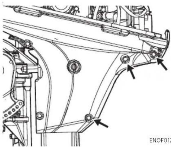
natural_image
Technical line drawing of a mechanical assembly with no visible text or symbolsENOF01248-0
ENON00936-0
Note
To avoid losing the bolts, the loosened bolts cannot be removed.
- Remove the cowl seal and loosen the screw (4pcs) of the drive shaft housing cover on the starboard side.
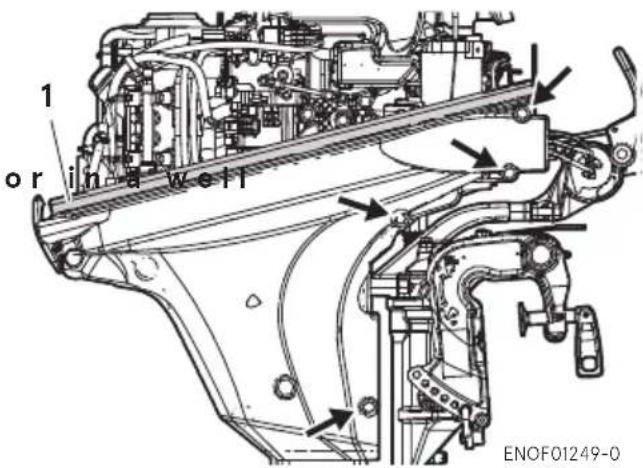
text_image
1 or in a well ENOF01249-0- Cowl seal
- Place an approved fuel container under the drain tube end and use a funnel to avoid spilling fuel.
- Loosen the vapor separator drain screw.
- When thoroughly drained, retighten the drain screw securely.
- Check the drained fuel for the presence of water or other contaminants. If either is present, refill the vapor separator with fuel, and then drain the fuel again. Repeat this procedure until no water or other contaminants are present in the drained fuel.
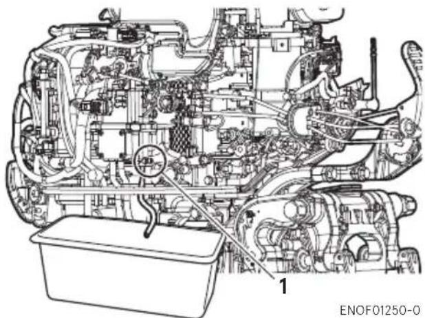
text_image
ENOF01250-0- Drain screw
ENOM00102-0
Battery
ENOW00931-A

WARNING
- Place the battery away from any source of fire, sparks and open flames such as burners or welding equipment.
-
Place the battery away from fuel tank. Accidental sparks of battery may cause explosion of gasoline.
-
Disconnect the battery cables and be sure to remove the negative terminal first.
- Wipe off any chemical deposits, dirt, or grease.
- Apply grease to the battery terminals.
- Charge the battery completely before storing it for the winter.
- Recharge the battery once a month to prevent it from discharging and the electrolyte from deteriorating.
- Store the battery in a dry place.
ENOM00104-A
4. Pre-season check
The following steps must be taken when first using the engine after off-season storage.
- Check that the shift and throttle function properly. (Be sure to turn the propeller shaft when checking the shift function or else the shift linkage may be damaged.)
- Check the electrolyte level, and measure the voltage and specific gravity of the battery.
| Specific Gravity at 20°C | Terminal Voltage (V) | Charge Condition |
| 1.120 10.5 F | fully discharged |
| Specific Gravity at 20°C | Terminal Voltage (V) | Charge Condition |
| 1.160 | 11.1 | 1/4 charged |
| 1.210 | 11.7 | 1/2 charged |
| 1.250 | 12 | 3/4 charged |
| 1.280 | 13.2 | Fully charged |
- Check that the battery is secure and the battery cables are properly installed.
- Change the engine oil (See page 62).
- Before starting the engine, disconnect stop switch lock and crank approximately 10 pulling the recoil starter (Manual start model) or 3 times of 3 sec. turning the starter motor (Electric start model) in order to prime the oil pump.
- Fill fuel tank completely.
- Start the engine and warm engine for 3 minutes in the "NEU-TRAL" position.
- Run the engine for 5 minutes at the slowest speed.
- Run the engine for 10 minutes at half throttle. The oil used for storage inside the engine will be circulated out to assure optimum performance.
ENOM00105-A
5. Submerged outboard motor
ENOW00098-0

CAUTION
Do not attempt to start submerged outboard motor immediately after it is recovered, or engine could be severely damaged.
After taking your outboard motor out of
the water, immediately take it to your dealer.
The following are the emergency measures to be taken for a submerged outboard motor.
- Wash the outboard motor with fresh water to remove salt or dirt.
- Remove the engine oil drain screw and completely drain water and oil from the engine.
- Remove the spark plugs, and completely drain the water from the engine by pulling recoil starter several times.
Replace oil filter and oil to the correct level.
The oil and filter may need to be changed again after running a short period to get all moisture completely out of the crankcase. - Inject a sufficient amount of engine oil through the spark plug holes.
Pull the recoil starter several times to circulate the oil throughout the outboard motor.
ENOM00106-1
6. Cold weather precautions
If you moor your boat in cold weather at temperatures below 0^ C ( 32^ F), water residue in water pump may freeze and may damage the pump, impeller, etc. To avoid, submerge the lower half of the outboard motor into the water.
ENOM00107-A
7. Striking underwater object
ENOW00935-0
CAUTION
Striking the sea bottom or an underwater object may severely damage the outboard motor.
- Stop the engine immediately.
- Check the control system, gear case, boat transom etc.
- Return to the nearest harbor slowly and carefully.
- Consult a dealer check the outboard motor before operation again.
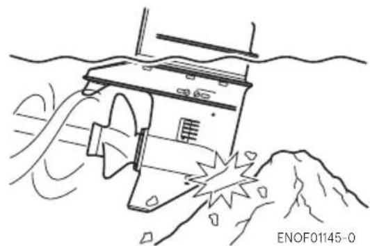
natural_image
Line drawing of a submarine partially submerged in water with visible exhaust plume (no text or symbols)ENOM00120-2
8. Auxiliary outboard motor operation
When the auxiliary outboard motor is not in operation, be sure to remove the stop switch lock, shift into forward, and then tilt the outboard motor up. Otherwise, over-rotation of the propeller due to water spray and water ingestion that could cause damage to the outboard motor.
TROUBLESHOOTING
ENOM01109-0
If you encounter a problem, check the list below to determine the cause and to take the proper action.
An authorized dealer will always be happy to provide any assistance and information.
* Low speed ESG operates.
| Engine will not start. | Engine stalls immediately after starting. | Defective idling | Defective acceleration | Engine speed is very high causing high speed ESG to operate. | Engine speed is very low, causing low speed ESG to operate. | Boat cannot run at high speed. | Engine overheats. | Battery is not charged. | Starter motor will not operate. | Power tilt will not operate. | Warning lamp is lit. | Warning lamp blinks. | Possible cause | |
| Fuel and Lubrication Systems | O | O | Fuel level | s low in the tank. | ||||||||||
| O | O | O | O | O | O | O | Fuel system connection is incomplete. | |||||||
| O | O | O | O | O | O | O | Fuel system sucks air. | |||||||
| O | O | O | O | O | O | O | Fuel pipe is twisted. | |||||||
| O | O | O | O | O | O | O | Cap vent is closed. | |||||||
| O | O | O | O | O | O | O | Fuel filter, fuel pump or injector is clogged. | |||||||
| O | O | O | O | O | Low quality gasoline is used. | |||||||||
| O | Primer bulb is clogged. | |||||||||||||
| O | O | O | O | O | O | O | Fuel feed pump (FFP) malfunctions or is clogged. | |||||||
| O^* O^* | Water temperature sensor or MAP (Manifold Pressure) sensor is defective or the sensor circuit is disconnected. | |||||||||||||
| O | O | O | O | O | Low quality engine oil is used. | |||||||||
| O | O | Engine oil quantity excessive (Exhaust smoke is generated.) | ||||||||||||
| O^* | O | O^* | Engine oil is lacking (Oil pressure switch operates). | |||||||||||
| O^* | O | O^* | Oil filter is clogged (Oil pressure switch operates). | |||||||||||
| O^* | O | O^* | Oil pump is defective (Oil pressure switch operates). | |||||||||||
| Electrical System | O | O | O | O | O | O | O | Use of spark plugs not specified. | ||||||
| O | O | O | O | O | O | Spark plug is contaminated. | ||||||||
| O | O | O | O | O | O | No sparks or weak spark. | ||||||||
| O | Stop switch short-circuited. | |||||||||||||
| O | Stop switch lock is not put. | |||||||||||||
| O | O | O | O | Defective wiring, ground, wire disconnected or loosened. | ||||||||||
| O | O | O | O | Battery charging is defective, or rectifier malfunctions. | ||||||||||
| Cel I (O) | O | O | O | Battery is dead, connection is loose or corroded. Battery electrolyte level is low. | ||||||||||
| O | O | O | O | 20A fuse is blown. | ||||||||||
| O | O | Shift lever neutral (N) position is not proper. | ||||||||||||
| O | O | O | Start switch or main switch is defective. | |||||||||||
| O | O | Starter motor or starter solenoid operation is defective. | ||||||||||||
| O | PT switch or solenoid is defective. | |||||||||||||
| O | Air is mixed in PT fluid. | |||||||||||||
| Compression System | ○ | ○ | ○ | ○ | ○ | Valve timing is not correct (Beit is stretched or installed incorrectly). | ||||||||
| ○ | ○ | ○ | ○ | ○ | Valve clearance is defective. | |||||||||
| ○ | ○ | ○ | ○ | ○ | Valve seat sealing is defective. | |||||||||
| ○ | ○ | ○ | ○ | ○ | Piston, piston ring and/or cylinder is worn excessively. | |||||||||
| ○ | ○ | Combustion chamber car deposition | ||||||||||||
| ○ | ○ | ○ | ○ | Spark plug is loose. | ||||||||||
| Others | ○ | O^* | ○ | ○ | O^* | (Cooling water is lacking.) Pump is defective or clogged. | ||||||||
| O^* | ○ | ○ | O^* | Thermostat operation is defective. | ||||||||||
| ○ | ○ | ○ | ○ | ○ | Anti-cavitation plate is damaged. | |||||||||
| ○ | ○ | ○ | ○ | ○ | ○ | Use of mismatched propeller. | ||||||||
| ○ | ○ | ○ | ○ | ○ | ○ | ○ | Propeller is damaged or deformed. | |||||||
| ○ | ○ | ○ | ○ | ○ | Thrust rod position is not correct. | |||||||||
| ○ | ○ | ○ | ○ | ○ | ○ | Boat is unbalanced by load position. | ||||||||
| ○ | ○ | ○ | ○ | ○ | ○ | Transom installation height is too high or too low. | ||||||||
| ○ | ○ | ○ | Throttle link adjustment is defective. | |||||||||||
s too much.
ACCESSORIES KIT
ENOM00327-0
The followings are a list of the tools and spare parts provided with the motor.
| Items Quantity Remark | |||
| Service tools | Tool bag 1Pliers 1Socket wrench 1 10 × 13 mmSocket wrench 1 16 mmSocket wrench handle 1Screwdrivers 1 Cross-and straight-pointScrewdriver handle 1 | ||
| Spare parts | Emergency starter rope 1Spark plug 1 NGK DCPR6ESplit pin 1Stop switch lock | 1 | |
| Parts Packaged with Engine | Fuel tankPrimer bulb | 1 12 L1 set | |
| Remote control boxRemote control attachmentDrag link | 1 set1 set1 for EP and EPT | for EP and EPTfor EP and EPTand EPT | |
| BoltNylon locking nutWasherBoltNylon locking nutWasher | 448224 | M8 x 85 mm8 mm8 mmM8 x 85 mm EP/EFT8 mm EP/EFT8 mm EP/EFT | |
| Hose joint | 1 For flushing | ||
PROPELLER TABLE
ENOM00329-0
Use a genuine propeller.
A propeller must be selected so that the engine RPM measured at wide open throttle while cruising is within the recommended range.
5400-6100 min ^-1 (rpm)
| Propeller Mark | Propeller Size (Blades × diameter × pitch) | |||
| in. mm | ||||
| Light boats 11.5 3 | × 9.25 × 11.5 3 × | 235 × 292 | ||
| 10 3 × 9.2 | 5 × 10 3 × 235 × 254 | |||
| 9 3 × 9.2 | 5 × 9 3 × 235 × 229 | |||
| 8 3 × 9.2 | 5 × 8 3 × 235 × 203 | |||
| 7 3 × 9.2 | × 6.9 3 × 234 × 174 | |||
| 6 3 × 9.2 | × 6.1 3 × 234 × 155 | |||
| Heavy boats 7 4 × | 10 × 7 | 4 × 254 × 178 | ||
MEMO
MEMO
MEMO
OWNER'S
MANUAL
MFS 9.9E
MFS 15E
MFS 20E
TOHATSU CORPORATION
5-4, Azusawa 3-Chome, Itabashi-Ku
Tokyo 174-0051, Japan
Tel: +81-3-3966-3117 Fax: +81-3-3966-0090
www.tohatsu.com
