
STR-AV270X - Receiver SONY - Free user manual and instructions
Find the device manual for free STR-AV270X SONY in PDF.


User questions about STR-AV270X SONY
0 question about this device. Answer the ones you know or ask your own.
Ask a new question about this device
Download the instructions for your Receiver in PDF format for free! Find your manual STR-AV270X - SONY and take your electronic device back in hand. On this page are published all the documents necessary for the use of your device. STR-AV270X by SONY.
USER MANUAL STR-AV270X SONY
FM Stereo/FM-AM Receiver
Operating Instructions
STR-AV570X
STR-AV270X
Connections
System Connections
Before connection, be sure to set the POWER switch to OFF.
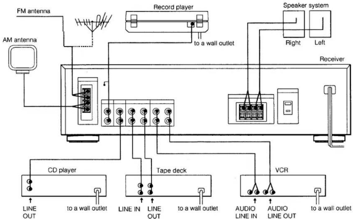
flowchart
graph TD
    A["FM antenna"] --> B["AM antenna"]
    B --> C["CD player"]
    C --> D["to a wall outlet"]
    D --> E["Tape deck"]
    E --> F["to a wall outlet"]
    F --> G["VCR"]
    G --> H["AUDIO LINE IN"]
    G --> I["AUDIO LINE OUT"]
    H --> J["Receiver"]
    I --> J
    K["Record player"] --> L["to a wall outlet"]
    M["Speaker system"] --> N["Right"]
    M --> O["Left"]
Notes on system connection
● The red jacks of the receiver are for right-channel (R) connections and the white jacks for left-channel (L).
- The cable connectors should be fully inserted into the jacks. A loose connection may cause hum and noise.
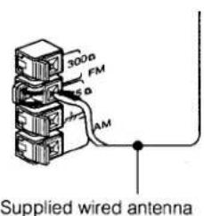
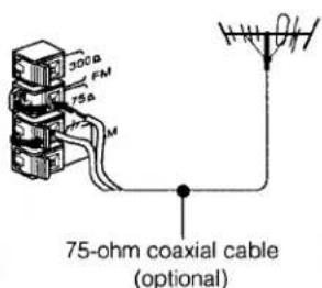
Connecting FM Antenna
For normal use
text_image
300Ω FM 5Ω AM Supplied wired antennaFor higher quality sound
text_image
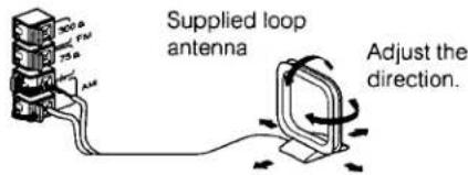
300Ω FM 75Ω M 75-ohm coaxial cable (optional)Connecting AM Antenna
text_image
Supplied loop antenna Adjust the direction.Note on power source connection
- The plug of the AC power cord can only be inserted into a polarized AC outlet.
- Do not connect an electrical home appliance such as an electric iron, fan, TV, or other high-wattage equipment exceeding 120 watts in total power consumption to the AC OUTLET on the receiver.
Connecting Antenna Ground
To prevent hum, connect the ground wire to ANTENNA ground terminal ( +_+ ). When an outdoor antenna is installed, be sure to connect the ground wire for lightning protection.
Connecting Speakers
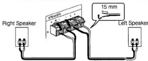
text_image
Right Speaker SPEAKER A L 15 mm Left SpeakerSpeaker impedance and power capability
Use only the speakers having nominal impedance from 8 to 16 ohms, and adequate power handling capability.
Note
As the speakers A and B are connected in series, the sound volume will be slightly decreased with both of the SPEAKERS selectors depressed.
Receiving FM/AM Broadcasts
How to receive a broadcast
| When you know the frequency | See "Direct Access Tuning". |
| When you do not know the frequency | FM: See "Automatic Tuning". AM: See "Manual Tuning". |
| Tuning in a preset frequency | See "Preset Tuning". |
Direct Access Tuning
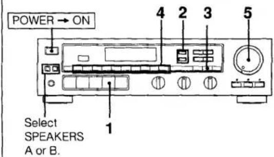
text_image
POWER → ON Select SPEAKERS A or B.1 Press TUNER.
2 Select FM or AM.
3 Press TUNING DIRECT.
4 Press the appropriate numeric buttons to enter the frequency. (See examples below.)
5 Adjust the volume.
Automatic Tuning (for FM reception)
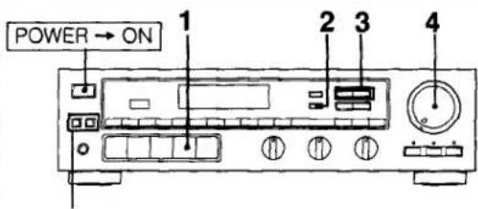
text_image
POWER → ON 1 2 3 4Select SPEAKERS
A or B.
1 Press TUNER.
2 Select FM.
3 Press + or - TUNING.
+ : Starts frequency-ascending sweep
- : Starts frequency-descending sweep
When a station is received, automatic tuning stops automatically. To change the station, press + or - again.
4 Adjust the volume.
When sweeping does not stop at the desired station
The signal strength is weak. Tune in the station as described in "Direct Access Tuning".
Example 1: FM 108.00 MHz
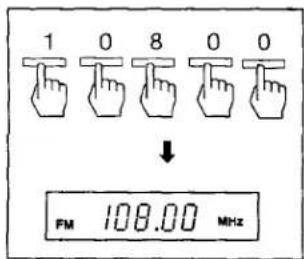
text_image
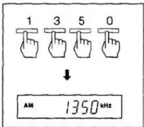
1 0 8 0 0 ↓ FM 108.00 MHzExample 2: AM 1350 kHz
text_image
1 3 5 0 ↓ AM 1350 kHzFor entering AM frequencies
You do not need to enter the last "0".
Correcting the entered frequency
Repeat the above steps from the beginning.
If the frequency figures flash in the display window
The entered number is outside the receiver's frequency range (FM 87.5 to 108 MHz; AM 530 to 1710 kHz).
Enter the correct frequency.
Manual Tuning (for AM reception)
text_image
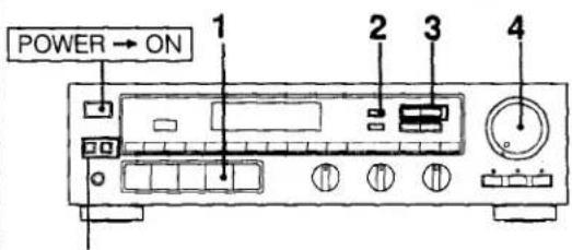
POWER → ON 1 2 3 4Select SPEAKERS A or B.
1 Press TUNER.
2 Select AM.
3 Press + or - TUNING.
- : Starts tuning from 530 kHz.
- : Starts tuning from 1710 kHz.
Each time + or - is pressed, the frequency will change by 10 kHz. To change the frequency continuously, keep the button pressed.
4 Adjust the volume.
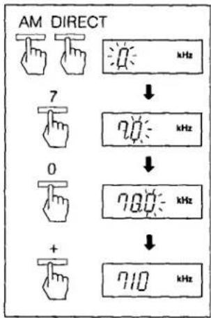
Quickly tuning in a roughly known frequency
Proceed as the following example.
Example: The station between AM 700 and AM 800 kHz.
text_image
AM DIRECT 7 0 + kHz ↓ 700 kHz ↓ 700 kHz ↓ 710 kHz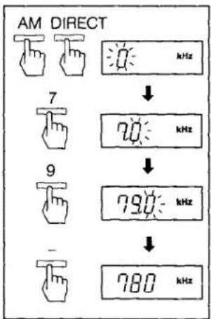
text_image
AM DIRECT 7 9 - 70 kHz 790 kHz 780 kHzPreset Tuning
A total of 30 FM/AM stations can be memorized in any desired sequence.
Memorizing a Station
text_image
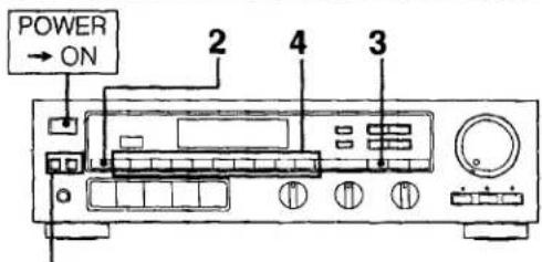
POWER → ON 2 4 3Select SPEAKERS A or B.
1 Tune in the desired station. (See "Automatic Tuning", "Manual Tuning" or "Direct Access Tuning".)
2 Press SHIFT to select the memory page (A, B or C).
3 Press MEMORY.
Memory indicator appears for a few seconds.
4 Press the desired numeric button (1 to 0), while the MEMORY indicator is displayed.
Repeat above steps for presetting other desired stations.
Use of memory pages
The memory pages (A, B and C) can be used to classify stations according to the music category, station band, etc.
Replacing a preset station
Preset another station on the number of the station to be replaced. The previously preset station will be erased.
Tuning in a Preset Station
Method A: Direct
1 Press TUNER.
2 Press SHIFT to select memory page (A, B or C).
3 Press the preset numeric button.
4 Adjust the volume.
Method B: Scan
1 Press TUNER.
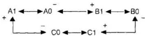
2 Press + or - PRESET.
Each time you press + or -, the preset station of the next higher or lower number is tuned in.
flowchart
graph TD
    A1 --> A0
    A0 --> B1
    B1 --> B0
    B0 --> C1
    C1 --> C0
    C0 --> A1
    A1 --> A0
    A0 --> B1
    B1 --> B0
    B0 --> C1
- If you keep pressing + or -, preset stations are successively tuned in. Release the button when the desired preset station is tuned in.
3 Adjust the volume.
Listening to Program Sources Other than Broadcast

text_image
POWER → ON 1 3 Record player CD player Tape deck VCR 21 Select the program source.
| Program sources | Function |
| Phono record | PHONO |
| Compact disc or other program sources | CD |
| Video programs | VIDEO |
| Tape programs | TAPE |
2 Start the program.
3 Adjust the volume.
Recording on an Audio Tape
Recording
text_image
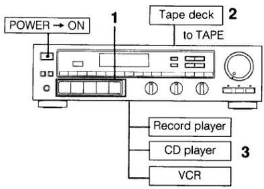
POWER → ON 1 Tape deck to TAPE 2 Record player CD player VCR 31 Select the desired program source.
For an FM/AM broadcast, tune in the desired station.
2 Set the tape deck in the recording mode.
3 Start the desired program source.
Note on recording
The settings of the VOLUME and TONE controls do not have any effect on recording.
Tape Dubbing
text_image
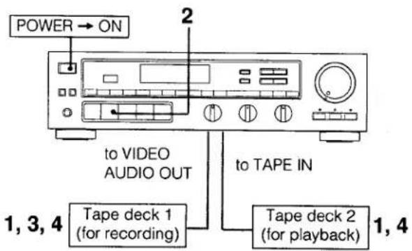
POWER → ON to VIDEO AUDIO OUT to TAPE IN Tape deck 1 (for recording) Tape deck 2 (for playback) 1, 3, 4 1, 41 Insert the recorded tape into tape deck 2 and a blank tape into tape deck 1.
2 Press TAPE.
3 Adjust the recording level of tape deck 1.
4 Start the playback of tape deck 2 and set the tape deck 1 in the recording mode.
Dubbing will start.
Troubleshooting
| Problem | Solution |
| STEREO indicator flickers or does not light up when FM stereo programs are received. | Check the FM antenna connection, and adjust the antenna.Press FM MODE to disengage the stereo mode. |
| The figures in the display window do not stop at the desired station during automatic tuning. | Check the antenna connection and adjust the antenna direction.Tune in the station using the direct access tuning. |
| Stations cannot be tuned in correctly when the numeric button is pressed. | Memorize the frequency correctly. |
| Audio is not heard. | Check the speaker and program source connections.Check that the appropriate function selector is depressed.Check that the appropriate SPEAKERS selector is depressed. If the A and B selectors are both depressed, check that both speaker systems are properly connected. |
| One channel does not transmit audio, or the volume from the left and right speakers is unbalanced. | Adjust the BALANCE control.Check the speaker connections. |
| There is an abrupt loss of sound from one or both of the speakers. (This symptom may be caused when the protection circuit inside the unit activates.) | Turn off the receiver, and check the speaker terminals or speaker cord for a short. |
| Sound transmitted from the speaker is reversed. | Connect the speaker correctly. |
| Severe hum or noise is heard. | Use shielded connecting cords.Keep the audio components further away from the TV.Connect the ground wire to the ANTENNA ground terminal.Clean any dirty plugs and jacks with a cloth lightly moistened with alcohol. |
| The (protection) alarm appears in the display window. | A serious trouble has occurred such as overheating or short-circuiting. Refer servicing to qualified person. |
| The unit cannot be controlled by the Remote Commander. | Correctly point the head of the commander toward the unit. If there is any object between the unit and the commander head, remove it. |
Precautions
Features
On safety
- Operate the unit only on 120 V AC, 60 Hz.
- Should any solid object or liquid fall into the unit, unplug it and have it checked by qualified personnel before operating it any further.
- Unplug the unit from the wall outlet if it is not to be used for an extended period of time. To disconnect the cord, pull it out by grasping the plug. Never pull the cord itself.
- One blade of the plug is wider than the other for the purpose of safety and will fit into the power outlet only one way. If you are unable to insert the plug fully into the outlet, contact your dealer.
On installation
- Do not install the unit in a location near heat sources such as radiators or air ducts, or in a place subject to direct sunlight, excessive dust, mechanical vibration or shock.
- Good air circulation is essential to prevent internal heat buildup in the unit. Place the unit in a location with adequate air circulation. Do not place the unit on a soft surface, such as a rug that would block the ventilation holes on the bottom.
- Do not place anything on top of the cabinet. The top ventilation holes must be unobstructed for the proper operation of the unit and to prolong the life of its components.
On cleaning the cabinet
Clean the cabinet, panel and controls with a soft cloth lightly moistened with mild detergent solution. Do not use any type of abrasive pad, scouring powder or solvent such as alcohol or benzine.
On repacking
Do not throw away the carton and the packing material. It makes an ideal container to transport the unit in.
For detailed safety precautions, see the "IMPORTANT SAFEGUARDS" leaflet.
If you have any question or problem concerning your unit, please consult your nearest Sony dealer.
The STR-AV570X and the STR-AV270X are the combined receivers and audio/video control centers. You can listen to various audio/video program sources through the amplifier of the receiver and the speakers connected to it. Newly designed DBFB (Dynamic Bass Feed Back) circuitry ensures natural sound quality even at a low volume level. Built-in matrix surround decodes ambient information in stereo sources, providing a surround sound effect. In the tuner section, a quartz locked digital synthesizer system allows precise tuning. A total of 30 FM/AM stations can be preset in 3 memory pages (A, B and C).
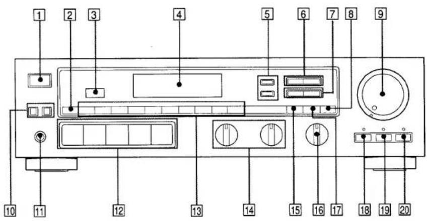
text_image
1 2 3 4 5 6 7 8 9 10 11 12 13 14 15 16 17 18 19 20① POWER switch
② SHIFT button
3 Remote sensor (STR-AV570X only)
4 Display window
5 BAND selectors
⑥ TUNING +/- buttons
⑦ PRESET +/- buttons
8 FM MODE button
When an FM stereo program is noisy or hard to receive, press this button. The STEREO indicator goes out (the sound is heard in monaural, but the reception will be improved). To return to the stereo mode, press again or change the frequency.
9 VOLUME control and indicator
(VOLUME indicator: STR-AV570X only)
10 SPEAKERS selectors
Depress to select which speaker system to drive. For both speaker systems, depress A and B.
11 HEADPHONES jack (stereo phone jack)
Connect the headphones to this jack for private listening.
12 Function selectors
13 Numeric buttons
14 TONE controls
Turn the TREBLE control to adjust the high frequency sound. Turn BASS control to adjust the low frequency sound.
15 MEMORY button
16 BALANCE control
Adjust to correct stereo imaging, when the speaker position is not symmetrical.
17 DIRECT TUNING button
18 DBFB (Dynamic Bass Feed Back) button and indicator
To reinforce the bass frequency sound, press this button.
19 MUTING button and indicator (STR-AV570X only)
Press to attenuate the sound level immediately (-20 dB attenuation). Pressing this button makes the indicator be lighted. To restore the sound level, press again.
20 SURROUND button and indicator
To obtain the surround effect, press this button.
Remote Commander RM-S103 (STR-AV570X only)
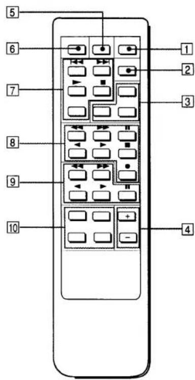
text_image
5 6 7 8 9 10 1 2 3 41 POWER button
② DBFB button
③ TUNER PRESET +/- and SHIFT buttons
④ VOLUME +/- buttons
5 SURROUND button
6 MUTING button
7 CD player operation buttons
D. (disc) SKIP: When your CD player is equipped with a multi-disc changer, use this button to select loaded disc.
CD ▶: Selects the CD function and starts CD playback.
☐ DECK B operation buttons (also for single tape deck)
DECK B ◀/▶: Select tape function and start tape playback on deck B.
9 DECK A operation buttons
DECK A ◀/▶: Select tape function and start tape playback on deck A.
10 Function select buttons
Notes on the remote commander
For the functions other than the receiver's own ones, the remote commander is effective only with Sony components having a remote sensor with a R mark.
Loading the Remote Commander with Batteries
1
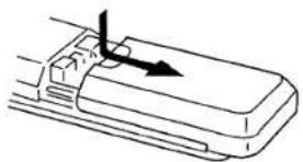
natural_image
Line drawing of a mechanical component with an arrow indicating direction (no text or symbols)2 Two size "AA" (R6) batteries
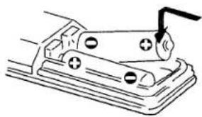
natural_image
Simple line drawing of a mechanical device with a lever and base plate (no text or symbols)Battery life
About half a year of normal operation can be expected when using the Sony SUM-3 (NS) batteries.
Caution
When the commander is not to be used for a long period of time, remove the batteries to avoid damage caused by battery leakage and corrosion.
Warning
WARNING
To prevent fire or shock hazard, do not expose the unit to rain or moisture.
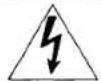
CAUTION
RISK OF ELECTRIC SHOCK DO NOT OPEN

CAUTION: TO REDUCE THE RISK OF ELECTRIC SHOCK,
DO NOT REMOVE COVER (OR BACK).
NO USER-SERVICEABLE PARTS INSIDE.
REFER SERVICING TO QUALIFIED SERVICE PERSONNEL.
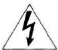
This symbol is intended to alert the user to the presence of uninsulated "dangerous voltage" within the product's enclosure that may be of sufficient magnitude to constitute a risk of electric shock to persons.
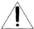
This symbol in intended to alert the user to the presence of important operating and maintenance (servicing) instructions in the literature accompanying the appliance.
Note to CATV system installer
This reminder is provided to call the CATV system installer's attention to Article 820-22 of the NEC that provides guidelines for proper grounding and, in particular, specifies that the cable ground shall be connected to the grounding system of the building, as close to the point of cable entry as practical.
Owner's Record
The model number is located on the rear exterior and serial number is on the rear. Record the serial number in the space provided below. Refer to these numbers whenever you call upon your Sony dealer regarding this product.
Model No.
Serial No.
Specifications
Audio Power Specifications
POWER OUTPUT AND TOTAL HARMONIC DISTORTION
With 8-ohm load, both channels driven, from 40 - 20 kHz, rated 60 watts (STR-AV570X) or 40 watts (STR-AV270X) per channel minimum RMS power, with less than 0.8% total harmonic distortion from 250 milliwatts to rated output.
Other Specifications
Amplifier section
Continuous RMS power output (8 ohms, at 1 kHz less than
0.8% total harmonic distortion)
STR-AV570X: 70 W + 70 W
STR-AV270X: 50 W + 50 W
Dynamic power (at 1 kHz IHF)
STR-AV570X: 75 W + 75 W (8 ohms)
80 W + 80 W(4 ohms)
STR-AV270X: 55 W + 55 W (8 ohms)
60 W + 60 W(4 ohms)
Harmonic distortion
Less than 0.8% at rated output
Frequency response
PHONO: RIAA equalization curve ±0.5 dB

10 Hz - 50 kHz ^+0_-5 dB
Inputs
| Sensitivity | Impedance | S/N (weighting network, input level) | |
| PHONO | 2.5 mV | 50 kilohms | 74 dB72 dB* (A, 2.5 mV) |
| CDVIDEO TAPE | 150 mV | 50 kilohms | 95 dB80 dB* (A, 150 mV) |
* 78 IHF
Outputs
| REC OUT, VIDEO (AUDIO) OUT | Voltage 150 mV Impedance 10 kilohms |
| SPEAKER A, B | Accepts speakers of 8-16 ohms |
| HEADPHONES | Accepts low and high impedance headphones |
Tone controls
BASS: ±10 dB at 100 Hz
TREBLE: ±10 dB at 10 kHz
Muting
-20 dB
DBFB
+12 dB at 70 Hz
Tuner section
| FM tuner section | AM tuner section | |
| Tuning range | 87.5 — 108 MHz | 530 — 1710 kHz |
| Antenna terminals | 300 ohms,balanced75 ohms, unbalanced | External antenna terminal |
| Sensitivity at 50 dB quieting | 18.3 dBf, 4.5 μV (mono)38.3 dBf, 45 μV (stereo) | — |
| Usable sensitivity | 11.2 dBf, 2 μV (IHF) | Loop antenna:500 μV (at 1,000 kHz) |
| Signal-to-noise ratio | 76 dB (mono)70 dB (stereo) | 54 dB (at 50 mV/m) |
| Harmonic distortion | 0.3% (mono), 0.5% (stereo) at 1 kHz | 0.5% (at 50 mV/m, 400 Hz) |
| Selectivity | 60 dB at 400 kHz | 40 dB at 10 kHz |
| Separation | 45 dB at 1 kHz | — |
| Frequency response | 30 Hz — 15 kHz+0.5-2 dB | — |
General
System
Tuner section: PLL quartz-locked digital
synthesizer system
Preamplifier section: low-noise NF type equalizer amp
Power amplifier section: quasi-complementary SEPP
Power requirements
120 V AC, 60 Hz
Power consumption
STR-AV570X (USA model): 105 W
In standby condition: 5 watts
STR-AV270X (USA model): 90 W
AC outlets
One switched (120 W/1A Max.)
Dimensions
Approx. 430 x 122.5 x 300 mm (w/h/d)
(17 × 4 7/8 × 11 7/8 inches)
including projecting parts and controls
Weight
STR-AV570X: Approx. 6.5 kg (14 lb 5 oz)
STR-AV270X: Approx. 6 kg (13 lb 4 oz)
Accessories supplied
FM wire antenna (1)
AM loop antenna (1)
Remote Commander RM-S103 (1) (STR-AV 570X only)
Sony batteries SUM 3(NS) (2) (STR-AV 570X only)
Design and specifications subject to change without notice.